JP7201014B2 - Information processing device, information processing method, and program - Google Patents
Information processing device, information processing method, and program Download PDFInfo
- Publication number
- JP7201014B2 JP7201014B2 JP2021008115A JP2021008115A JP7201014B2 JP 7201014 B2 JP7201014 B2 JP 7201014B2 JP 2021008115 A JP2021008115 A JP 2021008115A JP 2021008115 A JP2021008115 A JP 2021008115A JP 7201014 B2 JP7201014 B2 JP 7201014B2
- Authority
- JP
- Japan
- Prior art keywords
- display
- communication
- image
- unit
- mode
- Prior art date
- Legal status (The legal status is an assumption and is not a legal conclusion. Google has not performed a legal analysis and makes no representation as to the accuracy of the status listed.)
- Active
Links
Images


Classifications
-
- H—ELECTRICITY
- H04—ELECTRIC COMMUNICATION TECHNIQUE
- H04N—PICTORIAL COMMUNICATION, e.g. TELEVISION
- H04N23/00—Cameras or camera modules comprising electronic image sensors; Control thereof
- H04N23/60—Control of cameras or camera modules
- H04N23/66—Remote control of cameras or camera parts, e.g. by remote control devices
-
- G—PHYSICS
- G06—COMPUTING OR CALCULATING; COUNTING
- G06F—ELECTRIC DIGITAL DATA PROCESSING
- G06F1/00—Details not covered by groups G06F3/00 - G06F13/00 and G06F21/00
- G06F1/16—Constructional details or arrangements
- G06F1/1613—Constructional details or arrangements for portable computers
- G06F1/163—Wearable computers, e.g. on a belt
-
- G—PHYSICS
- G06—COMPUTING OR CALCULATING; COUNTING
- G06F—ELECTRIC DIGITAL DATA PROCESSING
- G06F1/00—Details not covered by groups G06F3/00 - G06F13/00 and G06F21/00
- G06F1/26—Power supply means, e.g. regulation thereof
- G06F1/32—Means for saving power
- G06F1/3203—Power management, i.e. event-based initiation of a power-saving mode
- G06F1/3206—Monitoring of events, devices or parameters that trigger a change in power modality
-
- G—PHYSICS
- G06—COMPUTING OR CALCULATING; COUNTING
- G06F—ELECTRIC DIGITAL DATA PROCESSING
- G06F1/00—Details not covered by groups G06F3/00 - G06F13/00 and G06F21/00
- G06F1/26—Power supply means, e.g. regulation thereof
- G06F1/32—Means for saving power
- G06F1/3203—Power management, i.e. event-based initiation of a power-saving mode
- G06F1/3234—Power saving characterised by the action undertaken
- G06F1/325—Power saving in peripheral device
- G06F1/3278—Power saving in modem or I/O interface
-
- G—PHYSICS
- G06—COMPUTING OR CALCULATING; COUNTING
- G06F—ELECTRIC DIGITAL DATA PROCESSING
- G06F3/00—Input arrangements for transferring data to be processed into a form capable of being handled by the computer; Output arrangements for transferring data from processing unit to output unit, e.g. interface arrangements
- G06F3/01—Input arrangements or combined input and output arrangements for interaction between user and computer
- G06F3/048—Interaction techniques based on graphical user interfaces [GUI]
- G06F3/0484—Interaction techniques based on graphical user interfaces [GUI] for the control of specific functions or operations, e.g. selecting or manipulating an object, an image or a displayed text element, setting a parameter value or selecting a range
-
- G—PHYSICS
- G09—EDUCATION; CRYPTOGRAPHY; DISPLAY; ADVERTISING; SEALS
- G09G—ARRANGEMENTS OR CIRCUITS FOR CONTROL OF INDICATING DEVICES USING STATIC MEANS TO PRESENT VARIABLE INFORMATION
- G09G5/00—Control arrangements or circuits for visual indicators common to cathode-ray tube indicators and other visual indicators
-
- H—ELECTRICITY
- H04—ELECTRIC COMMUNICATION TECHNIQUE
- H04N—PICTORIAL COMMUNICATION, e.g. TELEVISION
- H04N23/00—Cameras or camera modules comprising electronic image sensors; Control thereof
- H04N23/50—Constructional details
- H04N23/53—Constructional details of electronic viewfinders, e.g. rotatable or detachable
- H04N23/531—Constructional details of electronic viewfinders, e.g. rotatable or detachable being rotatable or detachable
-
- H—ELECTRICITY
- H04—ELECTRIC COMMUNICATION TECHNIQUE
- H04N—PICTORIAL COMMUNICATION, e.g. TELEVISION
- H04N23/00—Cameras or camera modules comprising electronic image sensors; Control thereof
- H04N23/60—Control of cameras or camera modules
-
- H—ELECTRICITY
- H04—ELECTRIC COMMUNICATION TECHNIQUE
- H04N—PICTORIAL COMMUNICATION, e.g. TELEVISION
- H04N23/00—Cameras or camera modules comprising electronic image sensors; Control thereof
- H04N23/60—Control of cameras or camera modules
- H04N23/63—Control of cameras or camera modules by using electronic viewfinders
- H04N23/631—Graphical user interfaces [GUI] specially adapted for controlling image capture or setting capture parameters
- H04N23/632—Graphical user interfaces [GUI] specially adapted for controlling image capture or setting capture parameters for displaying or modifying preview images prior to image capturing, e.g. variety of image resolutions or capturing parameters
-
- H—ELECTRICITY
- H04—ELECTRIC COMMUNICATION TECHNIQUE
- H04N—PICTORIAL COMMUNICATION, e.g. TELEVISION
- H04N23/00—Cameras or camera modules comprising electronic image sensors; Control thereof
- H04N23/60—Control of cameras or camera modules
- H04N23/63—Control of cameras or camera modules by using electronic viewfinders
- H04N23/633—Control of cameras or camera modules by using electronic viewfinders for displaying additional information relating to control or operation of the camera
-
- H—ELECTRICITY
- H04—ELECTRIC COMMUNICATION TECHNIQUE
- H04N—PICTORIAL COMMUNICATION, e.g. TELEVISION
- H04N7/00—Television systems
- H04N7/18—Closed-circuit television [CCTV] systems, i.e. systems in which the video signal is not broadcast
- H04N7/183—Closed-circuit television [CCTV] systems, i.e. systems in which the video signal is not broadcast for receiving images from a single remote source
- H04N7/185—Closed-circuit television [CCTV] systems, i.e. systems in which the video signal is not broadcast for receiving images from a single remote source from a mobile camera, e.g. for remote control
-
- G—PHYSICS
- G06—COMPUTING OR CALCULATING; COUNTING
- G06F—ELECTRIC DIGITAL DATA PROCESSING
- G06F2203/00—Indexing scheme relating to G06F3/00 - G06F3/048
- G06F2203/038—Indexing scheme relating to G06F3/038
- G06F2203/0384—Wireless input, i.e. hardware and software details of wireless interface arrangements for pointing devices
-
- Y—GENERAL TAGGING OF NEW TECHNOLOGICAL DEVELOPMENTS; GENERAL TAGGING OF CROSS-SECTIONAL TECHNOLOGIES SPANNING OVER SEVERAL SECTIONS OF THE IPC; TECHNICAL SUBJECTS COVERED BY FORMER USPC CROSS-REFERENCE ART COLLECTIONS [XRACs] AND DIGESTS
- Y02—TECHNOLOGIES OR APPLICATIONS FOR MITIGATION OR ADAPTATION AGAINST CLIMATE CHANGE
- Y02D—CLIMATE CHANGE MITIGATION TECHNOLOGIES IN INFORMATION AND COMMUNICATION TECHNOLOGIES [ICT], I.E. INFORMATION AND COMMUNICATION TECHNOLOGIES AIMING AT THE REDUCTION OF THEIR OWN ENERGY USE
- Y02D10/00—Energy efficient computing, e.g. low power processors, power management or thermal management
Landscapes
- Engineering & Computer Science (AREA)
- Theoretical Computer Science (AREA)
- Multimedia (AREA)
- Signal Processing (AREA)
- General Engineering & Computer Science (AREA)
- Physics & Mathematics (AREA)
- General Physics & Mathematics (AREA)
- Human Computer Interaction (AREA)
- Computer Hardware Design (AREA)
- Studio Devices (AREA)
- Selective Calling Equipment (AREA)
- Closed-Circuit Television Systems (AREA)
- Telephone Function (AREA)
- Power Sources (AREA)
- User Interface Of Digital Computer (AREA)
- Indication In Cameras, And Counting Of Exposures (AREA)
Description
本開示は、情報処理装置、および情報処理方法、並びにプログラムに関する。さらに詳細には、カメラの撮影処理や画像表示処理の制御をリモコン操作によって実行する情報処理装置、および情報処理方法、並びにプログラムに関する。 The present disclosure relates to an information processing device, an information processing method, and a program. More specifically, the present invention relates to an information processing device, an information processing method, and a program for controlling photographing processing and image display processing of a camera by remote control operation.
近年、デジタルカメラやデジタルビデオカメラの小型軽量化が進み、また、通信機能を備えたカメラの利用、開発が進んでいる。
例えば、カメラと相互通信可能なリモコンに画像表示用のディスプレイを設け、リモコン操作によって、カメラによる画像撮影の開始や停止等の制御を行い、撮影画像をリモコンのディスプレイに表示可能としたシステムがある。
2. Description of the Related Art In recent years, digital cameras and digital video cameras have become smaller and lighter, and cameras with communication functions have been used and developed.
For example, there is a system in which a remote controller that can communicate with a camera is provided with a display for displaying images, and the remote controller controls the start and stop of image capturing by the camera, and the captured image can be displayed on the display of the remote controller. .
なお、リモコンを利用してカメラ動作を制御可能としたシステムを開示した従来技術して、例えば、特許文献1(特開2015-127920号公報)がある。 For example, Patent Document 1 (Japanese Unexamined Patent Application Publication No. 2015-127920) discloses a system in which camera operations can be controlled using a remote control.
カメラ制御をリモコンによって行うシステムでは、例えばカメラによる撮影画像をリモコンに転送し、リモコン側の表示部(ディスプレイ)に表示し、リモコン操作者であるユーザが、画像の録画開始や停止処理などの指示を実行することができる。 In a system in which a camera is controlled by a remote controller, for example, an image captured by the camera is transferred to the remote controller and displayed on the display unit (display) of the remote controller. can be executed.
カメラやリモコンは、それぞれバッテリ(電池)を搭載し、バッテリからの電源供給によって、画像撮影処理、画像表示処理、さらに、リモコンとカメラ間の通信処理など、様々なデータ処理を実行する。 Cameras and remote controllers are each equipped with a battery (battery), and by supplying power from the battery, perform various data processing such as image capturing processing, image display processing, and communication processing between the remote controller and the camera.
しかし、画像転送や、画像表示処理、その他のデータ通信処理には、多くの電力が消費される。一方、カメラやリモコンに装着されるバッテリの容量には限りがあり、できるだけ消費電力を低減することが要求される。 However, image transfer, image display processing, and other data communication processing consume a lot of power. On the other hand, there is a limit to the capacity of batteries attached to cameras and remote controllers, and it is required to reduce power consumption as much as possible.
本開示は、例えば、上述の問題点に鑑みてなされたものであり、例えばリモコンを利用してカメラの動作制御を行うシステムにおいて、消費電力の低減を実現するとともに、分かり易いユーザ操作を実現する情報処理装置、および情報処理方法、並びにプログラムを提供することを目的とする。 The present disclosure has been made, for example, in view of the above-described problems, and achieves reduction in power consumption and easy-to-understand user operations in, for example, a system that controls the operation of a camera using a remote controller. An object is to provide an information processing device, an information processing method, and a program.
本開示の第1の側面は、
情報処理装置において情報処理を実行させるプログラムであり、
前記情報処理装置は、
撮像装置と通信する通信部と、
前記撮像装置の撮影画像を表示する表示部と、
制御部を有し、
前記プログラムは、前記制御部に、
前記表示部に対する情報の表示制御処理として、
前記撮像装置に対するユーザ入力が有効である操作部を示す有効操作部識別情報の表示制御処理を実行させ、
前記表示部に前記撮影画像を表示しない画像非表示期間は、前記表示部に前記撮影画像を表示する画像表示期間より多くの有効操作部識別情報を表示する表示制御処理を実行させるプログラムにある。
A first aspect of the present disclosure includes:
A program for executing information processing in an information processing device,
The information processing device is
a communication unit that communicates with the imaging device;
a display unit for displaying an image captured by the imaging device;
having a control unit,
The program causes the control unit to:
As information display control processing for the display unit,
executing a display control process of valid operation unit identification information indicating an operation unit for which user input to the imaging device is valid;
The image non-display period during which the photographed image is not displayed on the display section is a program for executing display control processing for displaying more valid operation section identification information than the image display period during which the photographed image is displayed on the display section.
さらに、本開示の第2の側面は、
撮像装置と通信する通信部と、
前記撮像装置の撮影画像を表示する表示部と、
制御部を有し、
前記記制御部は、
前記表示部に対する情報の表示制御処理として、
前記撮像装置に対するユーザ入力が有効である操作部を示す有効操作部識別情報の表示制御処理を実行し、
前記表示部に撮影画像を表示しない画像非表示期間は、撮影画像を表示する画像表示期間より多くの有効操作部識別情報を表示する表示制御処理を実行する情報処理装置にある。
Furthermore, a second aspect of the present disclosure is
a communication unit that communicates with the imaging device;
a display unit for displaying an image captured by the imaging device;
having a control unit,
The control unit is
As information display control processing for the display unit,
executing a display control process of valid operation unit identification information indicating an operation unit for which user input to the imaging device is valid;
The image non-display period during which the captured image is not displayed on the display section is provided in the information processing apparatus that executes display control processing for displaying more valid operation section identification information than during the image display period during which the captured image is displayed.
さらに、本開示の第3の側面は、
情報処理装置において情報処理を実行する情報処理方法であり、
前記情報処理装置は、
撮像装置と通信する通信部と、
前記撮像装置の撮影画像を表示する表示部と、
制御部を有し、
前記制御部は、
前記表示部に対する情報の表示制御処理として、
前記撮像装置に対するユーザ入力が有効である操作部を示す有効操作部識別情報の表示制御処理を実行し、
前記表示部に撮影画像を表示しない画像非表示期間は、撮影画像を表示する画像表示期間より多くの有効操作部識別情報を表示する表示制御処理を実行する情報処理方法にある。
Furthermore, a third aspect of the present disclosure is
An information processing method for executing information processing in an information processing device,
The information processing device is
a communication unit that communicates with the imaging device;
a display unit for displaying an image captured by the imaging device;
having a control unit,
The control unit
As information display control processing for the display unit,
executing a display control process of valid operation unit identification information indicating an operation unit for which user input to the imaging device is valid;
The image non-display period during which the captured image is not displayed on the display section is an information processing method for executing display control processing for displaying more effective operation section identification information than the image display period during which the captured image is displayed.
なお、本開示のプログラムは、例えば、様々なプログラム・コードを実行可能な情報処理装置やコンピュータ・システムに対して、コンピュータ可読な形式で提供する記憶媒体、通信媒体によって提供可能なプログラムである。このようなプログラムをコンピュータ可読な形式で提供することにより、情報処理装置やコンピュータ・システム上でプログラムに応じた処理が実現される。 The program of the present disclosure is, for example, a program that can be provided in a computer-readable format to an information processing device or computer system capable of executing various program codes via a storage medium or communication medium. By providing such a program in a computer-readable format, processing according to the program is realized on the information processing device or computer system.
本開示のさらに他の目的、特徴や利点は、後述する本開示の実施例や添付する図面に基づくより詳細な説明によって明らかになるであろう。なお、本明細書においてシステムとは、複数の装置の論理的集合構成であり、各構成の装置が同一筐体内にあるものには限らない。 Still other objects, features, and advantages of the present disclosure will become apparent from a more detailed description based on the embodiments of the present disclosure and the accompanying drawings, which will be described later. In this specification, a system is a logical collective configuration of a plurality of devices, and the devices of each configuration are not limited to being in the same housing.
本開示の一実施例の構成によれば、本開示の一実施例の構成によれば、ビデオカメラの撮影画像を表示するリモコン等の情報処理装置の消費電力の低減、および操作性の向上が実現される。
具体的には、例えば、リモコン等の情報処理装置は、撮像装置と通信する通信部と、撮像装置の撮影画像を表示する表示部と、制御部を有する。制御部は表示部に対する情報の表示制御処理として、撮像装置に対するユーザ入力が有効である操作部を示す有効操作部識別情報の表示制御処理を実行する。表示部に撮影画像を表示しない画像非表示期間は、表示部に前記撮影画像を表示する画像表示期間より多くの有効操作部識別情報を表示する表示制御処理を実行する。
本構成により、ビデオカメラの撮影画像を表示するリモコン等の情報処理装置の消費電力の低減、および操作性の向上が実現される。
なお、本明細書に記載された効果はあくまで例示であって限定されるものではなく、また付加的な効果があってもよい。
According to the configuration of one embodiment of the present disclosure, according to the configuration of one embodiment of the present disclosure, it is possible to reduce the power consumption of an information processing device such as a remote controller that displays an image captured by a video camera, and to improve the operability. Realized.
Specifically, for example, an information processing device such as a remote controller has a communication unit that communicates with an imaging device, a display that displays an image captured by the imaging device, and a control unit. As information display control processing for the display unit, the control unit executes display control processing of valid operation unit identification information indicating operation units for which user input to the imaging device is valid. During an image non-display period during which the captured image is not displayed on the display section, display control processing is executed to display more valid operation section identification information than during the image display period during which the captured image is displayed on the display section.
With this configuration, it is possible to reduce the power consumption and improve the operability of an information processing device such as a remote controller that displays an image captured by a video camera.
Note that the effects described in this specification are merely examples and are not limited, and additional effects may be provided.
以下、図面を参照しながら本開示の情報処理装置、および情報処理方法、並びにプログラムの詳細について説明する。なお、説明は以下の項目に従って行なう。
1.リモコン操作を可能としたカメラを有する情報処理システムの構成例について
2.ワイファイ(Wi-Fi)通信と、ブルートゥース(BT)通信について
3.ビデオカメラとリモコン間の通信処理とモード遷移について
4.リモコンにおける状態遷移、およびモード遷移について
5.各モードにおける操作可能情報をリモコンに表示する構成について
6.ビデオカメラの表示部の表示情報について
7.リモコンとビデオカメラのモード遷移とモード対応の表示情報について
7-1.(A)録画準備状態の(a1)録画準備画像表示モードにおける通信状態と表示情報とモード遷移について
7-2.(B)録画実行状態の(b1)録画画像表示ノーマルモードにおける通信状態と表示情報とモード遷移について
7-3.(B)録画実行状態の(b2)録画画像非表示スタミナモードにおける通信状態と表示情報とモード遷移について
7-4.(B)録画実行状態の(b3)録画画像非表示ブルートゥース(BT)単独通信モードにおける通信状態と表示情報とモード遷移について
8.リモコンのキー設定と表示情報の変更例について
9.その他の実施例について
10.情報処理装置の構成について
11.本開示の構成のまとめ
Details of the information processing apparatus, the information processing method, and the program according to the present disclosure will be described below with reference to the drawings. The description will be made according to the following items.
1. Configuration example of an information processing system having a camera capable of remote control operation2. Wi-Fi communication and Bluetooth (BT)
[1.リモコン操作を可能としたカメラを有する情報処理システムの構成例について]
まず、リモコン操作を可能としたカメラを有する情報処理システムの構成例について説明する。
図1は、リモコン操作を可能としたカメラの利用例の一例を示す図である。
[1. Configuration example of an information processing system having a camera that allows remote control operation]
First, a configuration example of an information processing system having a camera capable of remote control operation will be described.
FIG. 1 is a diagram showing an example of use of a camera that enables remote control operation.
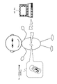
昨今のカメラやビデオカメラは、小型化軽量化が進み、図1に示すように、例えばユーザ(撮影者)の頭部等、体に固定するように装着しても、さほど、重さを感じることなく撮影することができる。 Recent cameras and video cameras have become smaller and lighter, and as shown in FIG. You can shoot without
しかし、図1に示すように、ビデオカメラ10を、ユーザの頭部に装着すると、ビデオカメラ10本体の操作部を操作することができず、またビデオカメラ10本体の表示部の表示画像を見ることができない。
ビデオカメラ10の撮影開始や停止処理、撮影画像の確認処理は、図1に示すユーザの腕に装着した表示部(モニタ)付きのリモコン20を利用して実行することができる。
However, when the
The shooting start and stop processing of the
ビデオカメラ10と、リモコン20は、例えば、ワイファイ(Wi-Fi)通信、あるいはブルートゥース(BT:Bluetooth)通信等を実行する通信部を備え、画像や、操作情報、状態情報(ステータス)等の様々な情報を相互に通信して送受信することが可能な構成を持つ。
The
図2に、リモコン20の構成と、リモコン20の表示部21の表示例を示す。
図2に示すように、リモコン20は、表示部21、操作部22を有する。なお、表示部21は、タッチパネル型の操作部として利用可能な構成としてもよい。
なお、ビデオカメラ10も表示部11を有し、撮影実行状態や、通信状態等の各種情報の表示が行われる。
ビデオカメラ10の表示部11に対する表示情報については、後段で説明する。
FIG. 2 shows the configuration of the
As shown in FIG. 2 , the
The
Display information on the display unit 11 of the
まず、図2、図3を参照して、リモコン20の表示部21に表示される主な表示情報について説明する。
リモコン20の表示部21には、例えば図2(a)に示す表示データが表示される。
図2(a)に示す表示部21の表示例は、ビデオカメラ10による撮影画像を表示した状態である。
表示部の中央領域には、ビデオカメラ10によって撮影された画像が表示される。なお、表示部21には、録画処理の実行中、停止中に関わらず、ビデオカメラ10の撮像部を介して撮影された画像を表示することができる。
First, main display information displayed on the display unit 21 of the
For example, display data shown in FIG. 2A is displayed on the display unit 21 of the
A display example of the display unit 21 shown in FIG. 2A is a state in which an image captured by the
An image captured by the
ユーザ(撮影者)は、例えば、表示部21の表示画像を観察しながら、録画処理の開始、停止処理、あるいは静止画の撮影等、ビデオカメラ10に対する撮影制御を実行することができる。これらの処理は、操作部22の操作によって、実行可能である。
操作部22の操作情報が、リモコン20の通信部からビデオカメラ10の通信部に送信され、ビデオカメラ10の制御部が受信した操作情報に応じた処理を実行する。
A user (photographer) can, for example, control the
Operation information of the operation unit 22 is transmitted from the communication unit of the
なお、リモコン20の表示部21にこれらの操作用の操作ボタン等からなるUI(ユーザインタフェース)を表示して、これらのUIに対する操作(タッチ)等によって、画像の撮影開始、停止等の指示を入力することも可能である。
A UI (user interface) consisting of operation buttons for these operations is displayed on the display unit 21 of the
なお、図2(a)に示すように、表示部21には、撮影画像の他、上部および下部等の表示領域に、様々な情報が表示される。
例えば、表示部21の上部領域には、ビデオカメラ10との通信状態情報としてのワイファイ(Wi-Fi)通信、ブルートゥース(BT:Bluetooth)通信の各通信状態情報、時間情報、バッテリ状態情報等が表示される。
As shown in FIG. 2A, the display unit 21 displays various information in display areas such as upper and lower areas in addition to the photographed image.
For example, in the upper area of the display unit 21, each communication state information of Wi-Fi communication and Bluetooth (BT: Bluetooth) communication as communication state information with the
また、表示部21の下部領域には、録画処理の実行、停止状態情報、記録時間情報、録画画像の画質情報、その他の録画態様情報等が表示される。
図に示す例では、録画処理の実行、停止状態情報は、録画実行中は点灯(白マル)、録画停止中は消灯(黒マル)する設定の録画実行停止識別ランプを利用した例を示している。
In addition, in the lower area of the display unit 21, execution of recording processing, stop state information, recording time information, image quality information of recorded images, other recording mode information, and the like are displayed.
In the example shown in the figure, the recording process execution/stop status information shows an example of using a recording execution/stop identification lamp that is set to turn on (white circle) while recording is in progress and turn off (black circle) while recording is stopped. there is
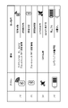
図2(a)に示す表示部21の表示例の上部に表示されるアイコンの一部の表示態様の例について、図3を参照して説明する。
図3には、以下のアイコンに関する説明を示している。
(1)ワイファイ(Wi-Fi)接続情報
(2)ブルートゥース(BT:Bluetooth)接続情報
(3)カメラバッテリ残量情報
(4)リモコンバッテリ残量情報
これらは、図2に示すリモコン20の表示部21の上部に表示されるアイコンの一部である。
An example of the display mode of some of the icons displayed in the upper portion of the display example of the display unit 21 shown in FIG. 2A will be described with reference to FIG.
FIG. 3 shows a description of the following icons.
(1) Wi-Fi connection information (2) Bluetooth (BT) connection information (3) Camera battery level information (4) Remote controller battery level information These are the display section of the
(1)ワイファイ(Wi-Fi)接続情報は、図3に示すように、リモコン20とカメラ10間においてWi-Fi通信が可能なWi-Fi接続状態では、アイコンが表示状態に設定される。
一方、リモコン20とカメラ10間においてWi-Fi通信ができないWi-Fi非接続状態では、アイコンが非表示状態となる。
(1) As for the Wi-Fi connection information, as shown in FIG. 3, in a Wi-Fi connection state in which Wi-Fi communication is possible between the
On the other hand, in a Wi-Fi disconnected state in which Wi-Fi communication cannot be performed between the
(2)ブルートゥース(BT:Bluetooth)接続情報も同様であり、図3に示すように、リモコン20とカメラ10間においてブルートゥース(BT:Bluetooth)通信が可能なブルートゥース(BT)接続状態では、アイコンが表示状態に設定される。
一方、リモコン20とカメラ10間においてブルートゥース(BT)通信ができないブルートゥース(BT)非接続状態では、アイコンが非表示状態となる。
(2) Bluetooth (BT) connection information is the same. As shown in FIG. Set to display state.
On the other hand, in a Bluetooth (BT) non-connection state in which Bluetooth (BT) communication cannot be performed between the
(3)カメラバッテリ残量情報は、ビデオカメラ10に装着されたバッテリのバッテリ残量を示す情報であり、図3に示すように、バッテリ残量に応じて、電池型のアイコンの表示態様が変化する設定である。
(3) Camera battery remaining amount information is information indicating the remaining battery amount of the battery attached to the
(4)リモコンバッテリ残量情報は、リモコン20に装着されたバッテリのバッテリ残量を示す情報であり、図3に示すように、バッテリ残量に応じて、電池型のアイコンの表示態様が変化する設定である。
(4) The remote control battery residual amount information is information indicating the battery residual amount of the battery attached to the
リモコン20は、これらの状態表示に必要な情報を、リモコン関連情報については、リモコン20内部から取得し、ビデオカメラ関連情報については、ビデオカメラ10からの通信データに基づいて取得する。ビデオカメラ10の情報については、ワイファイ(Wi-Fi)通信、またはブルートゥース(BT)通信を介して、随時、受信し、受信情報に基づく表示を行う。
The
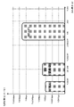
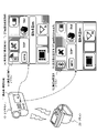
リモコン20の表示部21の表示例について、図4、図5を参照して説明する。
図4は、ビデオカメラ10において録画処理が実行されている場合のリモコン20の表示部21の複数の表示例を示している。
図4には、以下の4状態の表示例を示している。
(1a)撮影画像表示状態(Wi-Fi接続状態)
(1b)撮影画像非表示状態(Wi-Fi接続状態)
(1c)Wi-Fi接続待機状態
(1d)Wi-Fi接続停止状態
A display example of the display unit 21 of the
FIG. 4 shows a plurality of display examples of the display section 21 of the
FIG. 4 shows display examples of the following four states.
(1a) Photographed image display state (Wi-Fi connection state)
(1b) Captured image non-display state (Wi-Fi connection state)
(1c) Wi-Fi connection waiting state (1d) Wi-Fi connection stopped state
(1a)撮影画像表示状態(Wi-Fi接続状態)は、ビデオカメラ10と、リモコン20間においてWi-Fi接続がなされ、Wi-Fi通信によって、ビデオカメラ10の撮影画像(=録画処理画像)がリモコン20に送信され、リモコン20の表示部21の中央領域に画像が表示された状態である。
さらに、表示部21の下部には、録画実行ランプが点灯し、録画態様情報が表示される。
表示部の上部には、Wi-Fi接続アイコン、ブルートゥース(BT)接続アイコンが表示され、ビデオカメラ10とリモコン20間のWi-Fi接続、BT接続、何れも有効であり、Wi-Fi通信、BT通信が実行されていることを示している。
(1a) In the photographed image display state (Wi-Fi connection state), a Wi-Fi connection is made between the
Further, a recording execution lamp is lit at the bottom of the display section 21, and recording mode information is displayed.
A Wi-Fi connection icon and a Bluetooth (BT) connection icon are displayed at the top of the display unit, indicating that both the Wi-Fi connection and the BT connection between the
(1b)撮影画像非表示状態(Wi-Fi接続状態)は、ビデオカメラ10と、リモコン20間においてWi-Fi接続がなされているが、Wi-Fi通信によるビデオカメラ10の撮影画像(=録画処理画像)のリモコン20に対する送信が停止されている状態である。リモコン20の表示部21の中央領域に画像は表示されない。
(1b) In the captured image non-display state (Wi-Fi connection state), the
本開示の構成では、電力消費を抑制するため、ビデオカメラ10による録画処理が実行中でも、予め規定した条件、例えばユーザによるリモコン20に対する無操作状態が所定期間、継続した場合、ビデオカメラ10からリモコン20に対する画像送信を停止し、リモコン20における画像表示処理を停止する。
In the configuration of the present disclosure, in order to suppress power consumption, if a predetermined condition, for example, a state in which the user does not operate the
このような画像の送信停止処理、表示の停止処理を行なうことにより、ビデオカメラ10やリモコン20に搭載したバッテリの消費を抑制し、省電力化を実現している。
画像送信、表示処理の停止条件等については、後段において詳細に説明する。
By performing such image transmission stop processing and display stop processing, the consumption of the battery mounted on the
Conditions for stopping image transmission and display processing will be described later in detail.
なお、この撮影画像非表示状態においても、表示部21の下部には、録画実行ランプが点灯し、録画態様情報が表示される。
表示部の上部には、Wi-Fi接続アイコン、ブルートゥース(BT)接続アイコンが表示され、ビデオカメラ10とリモコン20間のWi-Fi接続、BT接続、何れも有効であり、Wi-Fi通信、BT通信が実行されていることを示している。
ユーザは、これらの情報に基づいて、録画が実行中であることや、通信が維持されていることなどを確認することができる。
It should be noted that even in this photographed image non-display state, the recording execution lamp is lit in the lower part of the display unit 21, and the recording mode information is displayed.
A Wi-Fi connection icon and a Bluetooth (BT) connection icon are displayed at the top of the display unit, indicating that both the Wi-Fi connection and the BT connection between the
Based on these pieces of information, the user can confirm that recording is in progress, communication is being maintained, and the like.
なお、ユーザは、「(1b)撮影画像非表示状態(Wi-Fi接続状態)」において、リモコン20の操作部の操作、あるいは、タッチパネルとして機能する表示部21をタッチ操作するなど、何らかの操作を行うと、リモコン20は、この操作情報を画像表示要求として解釈し、リモコン20からビデオカメラ10に画像送信要求が出力される。
Note that the user may perform some operation such as operating the operation unit of the
ビデオカメラ10は、リモコン20からの要求を受信すると、画像送信を開始する。
この処理によって、図4に示す「(1b)撮影画像非表示状態(Wi-Fi接続状態)」から、図4に示す「(1a)撮影画像表示状態(Wi-Fi接続状態)」に遷移する処理が行われる。
これらの一連の遷移処理については、後段で詳細に説明する。
Upon receiving the request from the
As a result of this process, the "(1b) photographed image non-display state (Wi-Fi connected state)" shown in FIG. 4 transitions to the "(1a) photographed image display state (Wi-Fi connected state)" shown in FIG. processing takes place.
A series of these transition processes will be described in detail later.
(1c)Wi-Fi接続待機状態は、ビデオカメラ10と、リモコン20間においてWi-Fi接続が未接続状態であるが、接続状態に移行する段階の表示部21の表示例である。
Wi-Fi接続アイコンは非表示状態となる。
ただし、録画ランプは点灯状態であり、録画処理は継続している。
(1c)の状態で、Wi-Fi接続がなされた場合には、図4に示す「(1a)撮影画像表示状態(Wi-Fi接続状態)」に遷移する。
(1c) Wi-Fi connection standby state is a display example of the display unit 21 at the stage of shifting to the connected state although the Wi-Fi connection between the
The Wi-Fi connection icon is hidden.
However, the recording lamp remains lit, and the recording process continues.
When the Wi-Fi connection is established in the state (1c), the state transitions to the "(1a) photographed image display state (Wi-Fi connection state)" shown in FIG.
この(1c)の表示状態は、例えばビデオカメラ10における録画処理実行中に、Wi-Fi接続が一時的に中断した場合等の表示例である。
このような場合、ビデオカメラ10における録画処理は継続したまま、リモコン-ビデオカメラ間のWi-Fi接続が試行され、接続が回復すると、図4に示す「(1a)撮影画像表示状態(Wi-Fi接続状態)」に遷移し、録画処理がそのまま継続する。
This display state (1c) is a display example when the Wi-Fi connection is temporarily interrupted during the recording process in the
In such a case, a Wi-Fi connection between the remote controller and the video camera is attempted while the recording process in the
(1d)Wi-Fi接続停止状態は、ビデオカメラ10と、リモコン20間においてWi-Fi接続が未接続状態であり、接続の試行処理も行われていない状態の表示部21の表示例である。
Wi-Fi接続アイコンは非表示状態となる。
ただし、録画ランプは点灯状態であり、録画処理は継続している。
(1d) Wi-Fi connection stopped state is a display example of the display unit 21 in a state in which no Wi-Fi connection is established between the
The Wi-Fi connection icon is hidden.
However, the recording lamp remains lit, and the recording process continues.
本開示のシステムでは、省電力モードの1つとして、ビデオカメラ10と、リモコン20間においてWi-Fi通信を意図的に停止し、ブルートゥース(BT)のみの通信を継続させるモード[ブルートゥース(BT)単独通信モード]を設定している。
この、ブルートゥース(BT)単独通信モードでは、ビデオカメラ10と、リモコン20間におけるWi-Fi通信を停止し、Wi-Fi通信を介した撮影画像の転送も停止する。
In the system of the present disclosure, as one of the power saving modes, Wi-Fi communication is intentionally stopped between the
In this Bluetooth (BT) only communication mode, the Wi-Fi communication between the
本開示の構成では、電力消費を抑制するため、ビデオカメラ10による録画処理が実行中でも、予め規定した条件、例えばユーザによるリモコンに対する無操作状態が所定期間、継続した場合、ビデオカメラ10とリモコン20間のWi-Fi通信を停止し、撮影画像の転送も停止し、必要最小限の情報をブルートゥース(BT)通信を利用して送受信する。このモードをブルートゥース(BT)単独通信モードと呼ぶ。
In the configuration of the present disclosure, in order to suppress power consumption, if a predetermined condition, for example, a state in which the user does not operate the remote controller continues for a predetermined period of time, even while recording processing is being performed by the
このブルートゥース(BT)単独通信モードを利用することによって、ビデオカメラ10やリモコン20に搭載したバッテリの消費をさらに抑制し、さらなる省電力化を実現することが可能となる。
このモード遷移処理等については、後段において詳細に説明する。
By using this Bluetooth (BT) single communication mode, it is possible to further suppress the consumption of the battery installed in the
This mode transition processing and the like will be described in detail later.
なお、図4(1d)に示すWi-Fi接続停止状態においても、表示部21の下部には、録画実行ランプが点灯し、録画態様情報が表示され、ユーザは録画処理が継続していることを認識できる。
ただし、表示部の上部のWi-Fi接続アイコンは消灯し、ブルートゥース(BT)接続アイコンは表示状態とされる。
ビデオカメラ10とリモコン20間では、ブルートゥース(BT)通信のみ有効であり、Wi-Fi通信はできないが、BT通信が実行されていることを示している。
ユーザは、これらの情報に基づいて、録画が実行中であることや、通信状態を確認することができる。
Note that even in the Wi-Fi connection stopped state shown in FIG. 4(1d), the recording execution lamp is lit at the bottom of the display unit 21, recording mode information is displayed, and the user can confirm that the recording process is continuing. can recognize
However, the Wi-Fi connection icon at the top of the display section is turned off, and the Bluetooth (BT) connection icon is displayed.
Only Bluetooth (BT) communication is valid between the
Based on this information, the user can confirm that recording is in progress and the communication status.
なお、ユーザは、「(1d)Wi-Fi接続停止状態」において、リモコン20の操作部の操作、あるいは、タッチパネルとして機能する表示部21をタッチ操作するなど、何らかの操作を行うと、リモコン20は、この操作情報を画像表示要求として解釈し、リモコン20とビデオカメラ10間のWi-Fi接続の回復処理を実行し、さらに、ビデオカメラ10に対して、画像送信要求を出力する。
Note that when the user performs some operation such as operating the operation unit of the
ビデオカメラ10は、リモコン20からの要求を受信すると、再接続されたWi-Fi通信路を介して画像送信を開始する。
この処理によって、図4に示す「(1d)Wi-Fi接続停止状態」から、図4に示す「(1a)撮影画像表示状態(Wi-Fi接続状態)」に遷移する処理が行われる。
これらの一連の処理については、後段で詳細に説明する。
Upon receiving the request from the
By this process, the process of transitioning from the "(1d) Wi-Fi connection stop state" shown in FIG. 4 to the "(1a) photographed image display state (Wi-Fi connection state)" shown in FIG. 4 is performed.
A series of these processes will be described in detail later.
次に、リモコン20の表示部21の表示例として、図5を参照して、ビデオカメラ10における録画処理が実行されていない場合の表示例について説明する。
図5には、ビデオカメラ10における録画処理が実行されていない場合のリモコン20の表示部21の複数の表示例を示している。
Next, as an example of the display on the display unit 21 of the
FIG. 5 shows a plurality of display examples of the display section 21 of the
図5には、以下の4状態の表示例を示している。
(2a)撮影画像表示状態(Wi-Fi接続状態)
(2b)Wi-Fi接続待機状態
(2c)Wi-Fi接続停止状態
FIG. 5 shows display examples of the following four states.
(2a) Photographed image display state (Wi-Fi connection state)
(2b) Wi-Fi connection waiting state (2c) Wi-Fi connection stopped state
なお、ビデオカメラ10において録画処理が実行されていない場合でも、ビデオカメラ10の電源がONである限り、ビデオカメラ10の撮像部を介して画像が撮り込まれており、この撮影画像が、ビデオカメラ10からリモコン20に送信される。
Note that even when the
(2a)撮影画像表示状態(Wi-Fi接続状態)は、ビデオカメラ10と、リモコン20間においてWi-Fi接続がなされ、Wi-Fi通信によって、ビデオカメラ10の撮影画像(=録画処理がなされていない撮影画像)がリモコン20に送信され、リモコン20の表示部21の中央領域に画像が表示される。
(2a) In the photographed image display state (Wi-Fi connection state), a Wi-Fi connection is made between the
しかし、この場合、表示部21の下部の録画実行ランプは消灯し、録画態様情報も表示されない。
ユーザは、これらの情報から、表示画像が録画されていないことを識別することができる。
However, in this case, the recording execution lamp at the bottom of the display unit 21 is turned off, and the recording mode information is not displayed.
From this information, the user can identify that the display image has not been recorded.
表示部の上部には、Wi-Fi接続アイコン、ブルートゥース(BT)接続アイコンが表示され、ビデオカメラ10とリモコン20間のWi-Fi接続、BT接続、何れも有効であり、Wi-Fi通信、BT通信が実行されていることを示している。
A Wi-Fi connection icon and a Bluetooth (BT) connection icon are displayed at the top of the display unit, indicating that both the Wi-Fi connection and the BT connection between the
(2b)Wi-Fi接続待機状態は、ビデオカメラ10と、リモコン20間においてWi-Fi接続が未接続状態であるが、接続状態に移行する段階の表示部21の表示例である。
Wi-Fi接続アイコンは非表示状態となる。
録画ランプは消灯状態であり、録画処理は行われていない。
(2b)の状態で、Wi-Fi接続がなされた場合には、図5に示す「(2a)撮影画像表示状態(Wi-Fi接続状態)」に遷移する。
(2b) Wi-Fi connection waiting state is a display example of the display unit 21 at the stage of shifting to the connected state although the Wi-Fi connection between the
The Wi-Fi connection icon is hidden.
The recording lamp is in an off state, and recording processing is not being performed.
In the state (2b), when the Wi-Fi connection is established, the state transitions to the "(2a) photographed image display state (Wi-Fi connection state)" shown in FIG.
この(2b)の表示状態は、例えばビデオカメラ10において、図5(2a)の撮影画像表示中に、Wi-Fi接続が一時的に中断した場合等の表示例である。
このような場合、ビデオカメラ10における録画処理は停止したまま、リモコンビデオ間のWi-Fi接続が試行され、接続が回復すると、図5に示す「(2a)撮影画像表示状態(Wi-Fi接続状態)」に遷移し、撮影画像の表示が行われる。
The display state of (2b) is a display example when, for example, the
In such a case, a Wi-Fi connection between the remote control videos is attempted while the recording process in the
(2c)Wi-Fi接続停止状態は、ビデオカメラ10と、リモコン20間においてWi-Fi接続が未接続状態であり、接続の試行処理も行われていない状態の表示部21の表示例である。
Wi-Fi接続アイコンは非表示状態となる。
録画ランプも消灯灯状態であり、録画処理は行われていない。
(2c) Wi-Fi connection stopped state is a display example of the display unit 21 in a state where the Wi-Fi connection is not established between the
The Wi-Fi connection icon is hidden.
The recording lamp is also turned off, and recording processing is not being performed.
図4、図5を参照して説明したように、リモコン20の表示部21は、状態に応じて様々な異なる表示態様に変更される。
これらの表示遷移処理については、後段で詳細に説明する。
As described with reference to FIGS. 4 and 5, the display section 21 of the
These display transition processes will be described in detail later.
[2.ワイファイ(Wi-Fi)通信と、ブルートゥース(BT)通信について]
次に、ビデオカメラ10と、リモコン20との間で実行されるワイファイ(Wi-Fi)通信と、ブルートゥース(BT:Bluetooth)通信について説明する。
[2. Regarding Wi-Fi (Wi-Fi) communication and Bluetooth (BT) communication]
Next, Wi-Fi communication and Bluetooth (BT) communication performed between the
図6に示すように、ビデオカメラ10と、リモコン20は、それぞれ通信部を有し、これら双方の通信部を介して、ワイファイ(Wi-Fi)通信と、ブルートゥース(BT:Bluetooth)通信が実行される。
As shown in FIG. 6, the
Wi-Fiの通信規格としては、IEEE802.11a/b/g/n等の複数の規格がある。
Wi-Fi通信では2.4GHz、5GHzの2種類の帯域のいずれかを選択して通信することが可能であり、利用帯域が広く、また通信速度が比較的早く、通信可能距離も比較的大きい(100m程度)という特徴があり、大容量のデータを安定して通信できるという特徴がある。
Wi-Fi communication standards include a plurality of standards such as IEEE802.11a/b/g/n.
In Wi-Fi communication, it is possible to select one of two types of bands, 2.4 GHz and 5 GHz, for communication. (approximately 100 m), and can stably communicate large amounts of data.
一方、ブルートゥース(BT:Bluetooth)通信は、利用可能な帯域は2.4GHzの一種類であり、通信速度はWi-Fiより遅く、また通信可能距離もWi-Fiに比較して短い(10m程度)という特徴がある。
しかし、Wi-Fi通信に比較して消費電力が少ないというメリットがある。
On the other hand, in Bluetooth (BT) communication, the usable band is one type of 2.4 GHz, the communication speed is slower than Wi-Fi, and the communicable distance is shorter than Wi-Fi (about 10m ).
However, it has the advantage of lower power consumption than Wi-Fi communication.
なお、ブルートゥース(BT:Bluetooth)通信にも複数の規格があり、従来のブルートゥース(BT:Bluetooth)通信より、消費電力を低減させたBTLE(Blutooth Low Energy)規格がある。なお、「BTLE」は、「BLE」と表記する場合もある。 There are also a plurality of standards for Bluetooth (BT) communication, and there is a BTLE (Bluetooth Low Energy) standard that reduces power consumption compared to conventional Bluetooth (BT) communication. Note that "BTLE" may also be written as "BLE".
なお、本明細書において説明する「ブルートゥース(BT:Bluetooth)通信」には、従来型のブルートゥース(BT:Bluetooth)通信のみならず、BTLE(Blutooth Low Energy)規格に従ったブルートゥース(BT:Bluetooth)通信も含むものである。 It should be noted that the "Bluetooth (BT) communication" described in this specification includes not only conventional Bluetooth (BT) communication, but also Bluetooth (BT) according to the BTLE (Bluetooth Low Energy) standard. It also includes communication.
図7は、Wi-Fi、BT(従来型)、BTLEの各通信における消費電力と、伝送速度を示した図である。
この図7に示すように、Wi-Fi通信は、伝送速度が速いが、消費電力が大きい。
一方、BT、BTLEは、伝送速度が遅いが、消費電力が小さいという特徴がある。
FIG. 7 is a diagram showing power consumption and transmission speed in each communication of Wi-Fi, BT (conventional type), and BTLE.
As shown in FIG. 7, Wi-Fi communication has a high transmission speed but consumes a large amount of power.
On the other hand, BT and BTLE have a low transmission speed, but are characterized by low power consumption.
本開示のシステムでは、ビデオカメラ10と、リモコン20との間で、ワイファイ(Wi-Fi)通信と、ブルートゥース(Bluetooth)通信を併用して、かつ、これらの通信を制御することで省電力を実現している。
In the system of the present disclosure, Wi-Fi communication and Bluetooth communication are used together between the
[3.ビデオカメラとリモコン間の通信処理とモード遷移について]
次に、図8以下を参照して、本開示のビデオカメラ10とリモコン20との間で実行される通信処理とモード遷移について説明する。
[3. Communication processing and mode transition between video camera and remote controller]
Next, communication processing and mode transitions executed between the
図8は、リモコン20において設定される複数の状態、およびモードと、各状態またはモードにおけるビデオカメラ10との通信態様について説明する図である。
図8に示すように、リモコン20は、
(X)電源オフ状態
(A)録画準備状態
(B)録画実行状態
これらの3状態を遷移する。
FIG. 8 is a diagram for explaining a plurality of states and modes set in
As shown in FIG. 8, the
(X) Power off state (A) Recording preparation state (B) Recording execution state These three states are transitioned.
さらに、リモコン20は、
(A)録画準備状態において、
(a1)録画準備画像表示モード、
に設定される。
また、(B)録画実行状態では、
(b1)録画画像表示ノーマルモード、
(b2)録画画像非表示スタミナモード、
(b3)録画画像非表示ブルートゥース(BT)単独通信モード、
これら3つのモードのいずれかに設定される。
Furthermore, the
(A) In the recording preparation state,
(a1) recording preparation image display mode;
is set to
Also, in the (B) recording execution state,
(b1) recorded image display normal mode;
(b2) recorded image non-display stamina mode;
(b3) recorded image non-display Bluetooth (BT) single communication mode;
It is set to one of these three modes.
リモコン20は、ユーザ操作、あるいは、予め設定されたモード遷移条件が発生した場合、異なるモード間の遷移を行う。
The
図8に示すように、各モードに対応して、リモコン20と、ビデオカメラ10との間で実行される通信態様が規定されており、モード遷移の発生に応じて、通信態様が変更される場合がある。
リモコン20が、以下の2つのモード、すなわち、
(a1)録画準備画像表示モード、
(b1)録画画像表示ノーマルモード、
これら2つのモードのいずれかに設定されている場合、
ビデオカメラ10から画像と、ステータス情報がWi-Fi通信によって、リモコン20に送信され、
リモコン20の操作情報が、Wi-Fi通信と、BT通信を併用してビデオカメラ10に送信される。
As shown in FIG. 8, the mode of communication performed between the
The
(a1) recording preparation image display mode;
(b1) recorded image display normal mode;
When set to either of these two modes,
An image and status information from the
Operation information of the
なお、ビデオカメラ10からWi-Fi通信によって送信される画像データは、
「(a1)録画準備画像表示モード」においては、録画されていない撮影画像である。
「(b1)録画画像表示ノーマルモード」においては、録画されている撮影画像(録画画像)である。
Note that the image data transmitted from the
In the "(a1) recording preparation image display mode", the captured image is not recorded.
In the "(b1) Recorded image display normal mode", it is a photographed image (recorded image) that has been recorded.
ビデオカメラ10からWi-Fi通信によって送信されるステータス情報には、例えば、録画が実行されているか否かの情報、撮影画像の画質(HD、SD等)情報、録画時間情報、ビデオカメラ搭載のバッテリ残量情報等が含まれる。
The status information transmitted from the
また、リモコン20の操作情報は、Wi-Fi通信と、BT通信を併用してビデオカメラ10に送信されるが、各操作情報は、操作種類に応じて、予めWi-Fi通信、BT通信、どちらの通信路を利用するかが規定されている。
例えばビデオカメラ10の電源ON/OFF情報等はBT通信路を利用して送信される。
録画開始、停止処理等の操作情報は、Wi-Fi通信路を利用してビデオカメラ10に送信される。
Operation information of the
For example, power ON/OFF information of the
Operation information such as recording start and stop processing is transmitted to the
その他の各操作情報についても、操作種類に応じて規定されたいずれかの通信路を介してビデオカメラ10に送信される。
なお、Wi-Fi通信、BT通信のいずれか一方のみの通信路が切断された場合には、接続されている他方の通信路を介した操作情報送信が行われる場合もある。
Each other operation information is also transmitted to the
Note that if either one of the Wi-Fi communication and the BT communication is disconnected, the operation information may be transmitted via the other connected communication path.
次に、リモコン20が、図8の中段に示す以下のモードに設定されている場合の通信構成について説明する。
(b2)録画画像非表示スタミナモード、
Next, the communication configuration when the
(b2) recorded image non-display stamina mode;
リモコン20が、このスタミナモードに設定されている場合、図8に示すように、
ビデオカメラ10からステータス情報がWi-Fi通信によって、リモコン20に送信され、
リモコン20の操作情報が、Wi-Fi通信と、BT通信を併用してビデオカメラ10に送信される。
When the
Status information is transmitted from the
Operation information of the
この「(b2)録画画像非表示スタミナモード」においては、ビデオカメラ10からリモコン20に対する画像の送信が行われない。
In this "(b2) Recorded image non-display stamina mode", image transmission from the
このスタミナモードでは、ビデオカメラ10からリモコン20に対する画像の送信を停止し、リモコン20における画像表示も停止する。
画像の送信、表示処理の停止により、バッテリ消費を低減させて省電力化を図る構成としている。
In this stamina mode, transmission of images from the
By stopping image transmission and display processing, battery consumption is reduced and power consumption is reduced.
なお、ビデオカメラ10からWi-Fi通信によって送信されるステータス情報には、例えば、録画が実行されているか否かの情報、録画画像の画質(HD、SD等)情報、録画時間情報、ビデオカメラ搭載のバッテリ残量情報等が含まれる。
The status information transmitted from the
また、リモコン20の操作情報は、Wi-Fi通信と、BT通信を併用してビデオカメラ10に送信されるが、各操作情報は、操作種類に応じて、予めWi-Fi通信、BT通信、どちらの通信路を利用するかが規定されている。
例えばビデオカメラ10の電源ON/OFF情報等はBT通信路を利用して送信される。
録画開始、停止処理等の操作情報は、Wi-Fi通信路を利用してビデオカメラ10に送信される。
Operation information of the
For example, power ON/OFF information of the
Operation information such as recording start and stop processing is transmitted to the
その他の各操作情報についても、操作種類に応じて規定されたいずれかの通信路を介してビデオカメラ10に送信される。
なお、Wi-Fi通信、BT通信のいずれか一方のみの通信路が切断された場合には、接続されている他方の通信路を介した操作情報送信が行われる。
Each other operation information is also transmitted to the
Note that if either one of the Wi-Fi communication and the BT communication is disconnected, the operation information is transmitted via the other connected communication path.
次に、リモコン20が、図8の最下段に示す以下のモードに設定されている場合の通信構成について説明する。
(b3)録画画像非表示ブルートゥース(BT)単独通信モード、
Next, the communication configuration when the
(b3) recorded image non-display Bluetooth (BT) single communication mode;
リモコン20が、このモードに設定されている場合、図8に示すように、
ビデオカメラ10からステータス情報がWi-Fi通信ではなく、BT通信によって、リモコン20に送信され、
リモコン20の操作情報も、BT通信のみを併用してビデオカメラ10に送信される。
When the
Status information is transmitted from the
Operation information of the
すなわち、この「(b3)録画画像非表示ブルートゥース(BT)単独通信モード」においては、
ビデオカメラ10からリモコン20に対する画像の送信が行われないのみならず、
ビデオカメラ10とリモコン20間のWi-Fi接続が切断され、Wi-Fi通信路を介したデータ転送は全て停止される。
That is, in this "(b3) recorded image non-display Bluetooth (BT) single communication mode",
Not only is image transmission from the
The Wi-Fi connection between the
ビデオカメラ10からリモコン20に対するステータス情報の送信、および、リモコン20からビデオカメラ10に対する操作情報の送信等、ビデオカメラ10とリモコン20間の全ての通信がBT通信路のみを利用して実行される。
All communications between the
先に、図7を参照して説明したように、Wi-Fi通信に比較してBT通信は電力消費が少ない。
従って、この「(b3)録画画像非表示ブルートゥース(BT)単独通信モード」において、BT通信のみを利用することで、さらなる省電力が実現される。
なお、本実施例において、BT通信は、図7を参照して説明した従来型のBT通信、または、BTLE(またはBLE)通信のいずれかの通信である。
As described above with reference to FIG. 7, BT communication consumes less power than Wi-Fi communication.
Therefore, in this "(b3) Recorded image non-display Bluetooth (BT) single communication mode", further power saving is realized by using only BT communication.
In this embodiment, BT communication is either conventional BT communication described with reference to FIG. 7 or BTLE (or BLE) communication.
なお、ビデオカメラ10からBT通信によって送信されるステータス情報には、例えば、録画が実行されているか否かの情報、録画画像の画質(HD、SD等)情報、録画時間情報、ビデオカメラ搭載のバッテリ残量情報等が含まれる。
また、リモコン20の操作情報は、すべてBT通信路を利用して送信される。
例えばビデオカメラ10の電源ON/OFF情報、録画開始、停止処理等の操作情報、その他の操作情報のすべてが、BT通信路を利用してビデオカメラ10に送信される。
The status information transmitted from the
Further, all operation information of the
For example, power ON/OFF information of the
[4.リモコンにおける状態遷移、およびモード遷移について]
次に、図9を参照して、リモコン20における状態遷移、およびモード遷移について説明する。
先に図8を参照して説明したように、リモコン20において設定される状態には以下の状態がある。
(X)電源オフ状態
(A)録画準備状態
(B)録画実行状態
これらの3状態がある。
[4. Regarding state transition and mode transition in the remote controller]
Next, state transition and mode transition in the
As described above with reference to FIG. 8, the states set in the
(X) Power off state (A) Recording preparation state (B) Recording execution state There are these three states.
さらに、リモコン20は、
(A)録画準備状態において、
(a1)録画準備画像表示モード、
に設定される。
また、(B)録画実行状態では、
(b1)録画画像表示ノーマルモード、
(b2)録画画像非表示スタミナモード、
(b3)録画画像非表示ブルートゥース(BT)単独通信モード、
これら3つのモードのいずれかに設定される。
Furthermore, the
(A) In the recording preparation state,
(a1) recording preparation image display mode;
is set to
Also, in the (B) recording execution state,
(b1) recorded image display normal mode;
(b2) recorded image non-display stamina mode;
(b3) recorded image non-display Bluetooth (BT) single communication mode;
It is set to one of these three modes.
リモコン20は、これらの複数の状態、またはモード間を、ユーザ操作、あるいは所定の遷移条件の発生に応じて遷移する。
これらの遷移処理は、リモコン20の制御部の制御に基づいて行われる。
リモコン20の制御部は、例えばリモコン20の操作部に対する操作情報の入力、または操作情報入力が無い無操作状態の継続期間に応じて装置モードを変更する制御を行う。さらに、制御部は、記装置モードの変更に応じて、通信部を介した通信形態を変更する処理を実行する。
The
These transition processes are performed under the control of the controller of the
The control unit of the
図9は、リモコン20における状態遷移、モード遷移を説明する図である。
図9には、状態遷移、モード遷移の発生ステップをステップS11~S16として示している。
以下、各ステップの処理について、順次、説明する。
FIG. 9 is a diagram for explaining state transitions and mode transitions in the
In FIG. 9, steps S11 to S16 indicate the steps in which state transitions and mode transitions occur.
The processing of each step will be described below in order.
(ステップS11)
ステップS11は、
(A)録画準備状態の(a1)録画準備画像表示モードから、
(B)録画実行状態の(b1)録画画像表示ノーマルモードへの、
モード遷移ステップである。
このモード遷移は、ユーザによるリモコン20に対する録画開始停止キー(RECキー、またはスタートストップ(SS)キーとも呼ばれる)に対するキー操作によって実行される。
(Step S11)
Step S11 is
(A) From the (a1) recording preparation image display mode in the recording preparation state,
(B) to (b1) recorded image display normal mode in recording execution state,
This is the mode transition step.
This mode transition is executed by key operation of a recording start/stop key (also called a REC key or a start/stop (SS) key) on the
なお、(A)録画準備状態の(a1)録画準備画像表示モードにおいては、ビデオカメラ10の撮影画像がWi-Fiを介してリモコン20に送信されており、リモコン20の表示部21に対する撮影画像(≠録画画像)の表示処理が実行されている。
なお、この表示画像は、録画処理が行われていない画像である。
In the (A) recording preparation state (a1) recording preparation image display mode, the captured image of the
Note that this display image is an image that has not undergone recording processing.
(A)録画準備状態の(a1)録画準備画像表示モードにおいて、ユーザがリモコン20に対する録画開始操作、すなわち録画開始停止キー(RECキー)に対するキー操作を行うと、
(B)録画実行状態の(b1)録画画像表示ノーマルモード、
に移行する。
(A) In the (a1) recording preparation image display mode in the recording preparation state, when the user performs a recording start operation on the
(B) recording execution state (b1) recorded image display normal mode;
transition to
この状態遷移処理に際して、以下の処理が行われる。
(1)リモコン20から、ビデオカメラ10に対する録画開始要求の送信、
(2)ビデオカメラ10による録画処理の開始、
(3)ビデオカメラ10による撮影画像(=録画画像)のリモコン20に対する送信処理、
(4)リモコン20の表示部21に対する撮影画像(=録画画像)の表示処理、
なお、この時点の送信表示画像は、録画処理が行われている画像である。
During this state transition processing, the following processing is performed.
(1) Transmission of a recording start request from the
(2) start of recording processing by the
(3) Transmission processing of an image (=recorded image) taken by the
(4) display processing of the captured image (=recorded image) on the display unit 21 of the
Note that the transmission display image at this time is an image in which recording processing is being performed.
(ステップS12)
ステップS12は、
(B)録画実行状態の(b1)録画画像表示ノーマルモードから、
(B)録画実行状態の(b2)録画画像非表示スタミナモードへの、
モード遷移ステップである。
(Step S12)
Step S12 is
From (b1) recorded image display normal mode in (B) recording execution state,
(B) to the (b2) recorded image non-display stamina mode in the recording execution state,
This is the mode transition step.
このモード遷移は、(b1)録画画像表示ノーマルモードにおいて、リモコン20に対するユーザ操作が規定時間(例えば10秒間)実行されなかった場合に発生する。
This mode transition occurs when the user does not operate the
この状態遷移処理に際して、以下の処理が行われる。
(1)リモコン20から、ビデオカメラ10に対する録画画像送信停止要求の送信、
(2)ビデオカメラ10による撮影画像(=録画画像)のリモコン20に対する送信処理の停止、
(3)リモコン20の表示部21に対する撮影画像(=録画画像)の表示処理の停止、
なお、このモード遷移が発生しても、ビデオカメラ10は、録画処理を継続する。
During this state transition processing, the following processing is performed.
(1) Transmission of a recorded image transmission stop request from the
(2) Stopping the process of transmitting an image (=recorded image) captured by the
(3) Stopping display processing of the captured image (=recorded image) on the display unit 21 of the
Even if this mode transition occurs, the
この処理により、ビデオカメラ10からリモコン20に対する撮影画像の送信が停止され、リモコン20の表示部21に対する撮影画像の表示も停止される。
この処理により、ビデオカメラ10、リモコン20のバッテリ消費は低減し、省電力化が実現される。
As a result of this processing, transmission of the captured image from the
By this processing, the battery consumption of the
(ステップS13)
ステップS13は、
(B)録画実行状態の(b2)録画画像非表示スタミナモードから、
(B)録画実行状態の(b1)録画画像表示ノーマルモードへの、
モード遷移ステップである。
(Step S13)
Step S13 is
(B) From the (b2) recorded image non-display stamina mode in the recording execution state,
(B) to (b1) recorded image display normal mode in recording execution state,
This is the mode transition step.
このモード遷移は、上記の(b2)録画画像非表示スタミナモードにおいて、ユーザがリモコン20に対して、画像表示指示を入力した場合に発生する。
なお、この(b2)録画画像非表示スタミナモードにおいて、ユーザによるリモコン20に対して行われる入力操作中、録画開始停止キー(RECキー(=SSキー))等の特定キー以外のキー操作、あるいはタッチパネルとして機能する表示部に対するタッチ操作のほとんどは、画像表示指示入力として解釈され、このステップS13のモード遷移が発生する。
This mode transition occurs when the user inputs an image display instruction to the
In this (b2) recorded image non-display stamina mode, during an input operation performed on the
このモード遷移により、以下の処理が実行される。
(1)リモコン20から、ビデオカメラ10に対する撮影画像(=録画画像)の送信要求、
(2)ビデオカメラ10による撮影画像(=録画画像)のリモコン20に対する送信処理、
(3)リモコン20の表示部21に対する撮影画像(=録画画像)の表示処理、
なお、この時点の送信表示画像は、録画処理が行われている画像である。
The following processing is executed by this mode transition.
(1) A request from the
(2) transmission processing of an image (=recorded image) captured by the
(3) display processing of the captured image (=recorded image) on the display unit 21 of the
Note that the transmission display image at this time is an image in which recording processing is being performed.
(ステップS14)
ステップS14は、
(B)録画実行状態の(b2)録画画像非表示スタミナモードから、
(B)録画実行状態の(b3)録画画像非表示ブルートゥース(BT)単独通信モードへの、
モード遷移ステップである。
(Step S14)
Step S14 is
(B) From the (b2) recorded image non-display stamina mode in the recording execution state,
(B) Recording execution state (b3) Recorded image non-display Bluetooth (BT) single communication mode,
This is the mode transition step.
このモード遷移は、(b2)録画画像非表示スタミナモードにおいて、リモコン20に対するユーザ操作が規定時間(例えば60秒間)実行されなかった場合に発生する。
This mode transition occurs in the (b2) recorded image non-display stamina mode when the user does not operate the
この状態遷移処理に際して、以下の処理が行われる。
(1)リモコン20とビデオカメラ10とのWi-Fi接続の停止、
(2)ビデオカメラ10からのステータス情報の送信経路をWi-FiからBTに切り替える処理、
(3)リモコン20からビデオカメラ10に対する操作情報をWi-Fiを使用せず、全てBT通信に切り替える処理、
なお、このモード遷移が発生しても、ビデオカメラ10は、録画処理を継続する。
During this state transition processing, the following processing is performed.
(1) Stopping the Wi-Fi connection between the
(2) processing to switch the transmission path of status information from the
(3) Processing for switching all operation information from the
Even if this mode transition occurs, the
この処理により、ビデオカメラ10とリモコン20との間のWi-Fi接続は停止される。
この処理により、ビデオカメラ10、リモコン20のバッテリ消費は、さらに低減し、さらなる省電力化が実現される。
With this process, the Wi-Fi connection between the
This processing further reduces the battery consumption of the
(ステップS15)
ステップS15は、
(B)録画実行状態の(b3)録画画像非表示ブルートゥース(BT)単独通信モード、
(B)録画実行状態の(b1)録画画像表示ノーマルモードへの、
モード遷移ステップである。
(Step S15)
Step S15 is
(B) Recording execution state (b3) Recorded image non-display Bluetooth (BT) single communication mode,
(B) to (b1) recorded image display normal mode in recording execution state,
This is the mode transition step.
このモード遷移は、上記の(b3)録画画像非表示ブルートゥース(BT)単独通信モードにおいて、ユーザがリモコン20に対して、画像表示指示を入力した場合に発生する。
なお、この(b3)録画画像非表示ブルートゥース(BT)単独通信モードにおいて、ユーザによるリモコン20に対して行われる入力操作中、録画開始停止キー(RECキー(=SSキー))等の特定キー以外のキー操作、あるいはタッチパネルとして機能する表示部に対するタッチ操作のほとんどは、画像表示指示入力として解釈され、このステップS15のモード遷移が発生する。
This mode transition occurs when the user inputs an image display instruction to the
In this (b3) recorded image non-display Bluetooth (BT) single communication mode, during an input operation performed on the
このモード遷移により、以下の処理が実行される。
(1)リモコン20から、ビデオカメラ10に対する撮影画像(=録画画像)の送信要求、
(2)ビデオカメラ10による撮影画像(=録画画像)のリモコン20に対する送信処理、
(3)リモコン20の表示部21に対する撮影画像(=録画画像)の表示処理、
なお、この時点の送信表示画像は、録画処理が行われている画像である。
The following processing is executed by this mode transition.
(1) A request from the
(2) transmission processing of an image (=recorded image) captured by the
(3) display processing of the captured image (=recorded image) on the display unit 21 of the
Note that the transmission display image at this time is an image in which recording processing is being performed.
(ステップS16)
ステップS16は、
(B)録画実行状態の(b1)録画画像表示ノーマルモード、または、
(B)録画実行状態の(b2)録画画像非表示スタミナモード、または、
(B)録画実行状態の(b3)録画画像非表示ブルートゥース(BT)単独通信モード、
これら、いずれかのモードから、
(A)録画準備状態の(a1)録画準備画像表示モードへの、
モード遷移ステップである。
(Step S16)
Step S16 is
(B) Recorded image display normal mode in (b1) recording execution state, or
(B) (b2) recorded image non-display stamina mode in the recording execution state, or
(B) Recording execution state (b3) Recorded image non-display Bluetooth (BT) single communication mode,
From any of these modes,
(A) In the recording preparation state (a1) to the recording preparation image display mode,
This is the mode transition step.
このモード遷移は、上記の(b1)~(b3)のいずれかのモードにおいて、ユーザがリモコン20に対して、記録停止の入力操作、すなわち、録画開始停止キー(RECキー(=SSキー))のキー操作を実行した場合に発生する。
例えば録画停止ボタンの操作である。
This mode transition is performed by the user operating the
For example, it is the operation of the recording stop button.
このモード遷移により、以下の処理が実行される。
(1)リモコン20から、ビデオカメラ10に対する録画処理の停止要求送信、
(2)ビデオカメラ10による録画処理の停止処理、
(3)ビデオカメラ10による撮影画像(≠録画画像)のリモコン20に対する送信処理、
(4)リモコン20の表示部21に対する撮影画像(≠録画画像)の表示処理、
なお、このモード遷移後の送信表示画像は、録画処理が行われていない画像である。
The following processing is executed by this mode transition.
(1) Transmission of a recording stop request from the
(2) stop processing of recording processing by the
(3) Transmission processing of the image captured by the video camera 10 (≠recorded image) to the
(4) display processing of the captured image (≠recorded image) on the display unit 21 of the
Note that the transmission display image after this mode transition is an image that has not undergone recording processing.
[5.各モードにおける操作可能情報をリモコンに表示する構成について]
図8、図9を参照して説明したように、リモコンは、ユーザ操作等に応じて、複数の状態やモードを遷移する。リモコンの設定モードに応じて、ユーザがリモコンに対して操作可能な処理の種類は異なる。
[5. Configuration for displaying operable information in each mode on the remote controller]
As described with reference to FIGS. 8 and 9, the remote control transitions between multiple states and modes according to user operations and the like. The types of processing that the user can operate on the remote control differ depending on the setting mode of the remote control.
先に図8、図9を参照して説明したように、リモコンの設定モードには、以下の各モードがある。
(A)録画準備状態の(a1)録画準備画像表示モード、
(B)録画実行状態の(b1)録画画像表示ノーマルモード、
(B)録画実行状態の(b2)録画画像非表示スタミナモード、
(B)録画実行状態の(b3)録画画像非表示ブルートゥース(BT)単独通信モード、
As described above with reference to FIGS. 8 and 9, the setting modes of the remote control include the following modes.
(A) Recording preparation image display mode in (a1) recording preparation state,
(B) recording execution state (b1) recorded image display normal mode;
(B) recording execution state (b2) recorded image non-display stamina mode;
(B) Recording execution state (b3) Recorded image non-display Bluetooth (BT) single communication mode,
例えば、録画開始停止キー(RECキー(=SSキー))は、上記のいずれのモードでも有効である。すなわち、ユーザ操作に応じた処理が実行される。
しかし、例えば、(B)録画実行状態の(b3)録画画像非表示ブルートゥース(BT)単独通信モードにおいては、ビデオカメラ10とのWi-Fi通信が遮断されている。このモードでは、Wi-Fi通信を介してビデオカメラ10に操作情報を送る設定となっているキー操作は、ユーザがキー操作を行っても、ビデオカメラ10に対して、操作情報が送信されず、ユーザがキー操作を繰り返してもユーザの希望する処理が実行されない場合がある。
For example, a recording start/stop key (REC key (=SS key)) is effective in any of the above modes. That is, a process is executed according to the user's operation.
However, for example, in (B) recording execution state (b3) recorded image non-display Bluetooth (BT) single communication mode, Wi-Fi communication with the
なお、先に図8、図9を参照して説明したように、例えば、リモコンの設定モードが以下のいずれかのモードである場合、
(B)録画実行状態の(b2)録画画像非表示スタミナモード、
(B)録画実行状態の(b3)録画画像非表示ブルートゥース(BT)単独通信モード、
これらのモードにある場合は、
録画開始停止キー(RECキー(=SSキー))に対する操作を行うとキーに応じた処理、すなわち、録画停止処理が実行される。
しかし、この録画開始停止キー(RECキー(=SSキー))等の特定キー以外のキー操作のほとんどは、画像表示開始要求として解釈され、この結果、
(B)録画実行状態の(b1)録画画像表示ノーマルモード、
上記モードへのモード移行処理がなされる。
ユーザは、リモコンの各キーに割り当てられた本来の処理を実行しようとしても、その処理は実行されず、上記のモード移行処理がなされることになる。
Incidentally, as described above with reference to FIGS. 8 and 9, for example, if the setting mode of the remote control is one of the following modes
(B) recording execution state (b2) recorded image non-display stamina mode;
(B) Recording execution state (b3) Recorded image non-display Bluetooth (BT) single communication mode,
When in these modes,
When the recording start/stop key (REC key (=SS key)) is operated, processing corresponding to the key, that is, recording stop processing is executed.
However, most key operations other than the specific key such as the recording start/stop key (REC key (=SS key)) are interpreted as a request to start image display, and as a result,
(B) recording execution state (b1) recorded image display normal mode;
Mode transition processing to the above mode is performed.
Even if the user attempts to execute the original processing assigned to each key of the remote control, the processing is not executed, and the above-described mode transition processing is performed.
このような処理が行われると、ユーザに、故障が発生したのではないかといった疑念を抱かせてしまう可能性がある。
以下では、このような問題を解決する構成について説明する。
具体的には、リモコンの表示部に、各モードにおける操作可能情報を表示し、ユーザにどのキーが有効に利用可能であるかを知らせることを可能とした構成である。
If such processing is performed, the user may have doubts that a failure has occurred.
A configuration for solving such a problem will be described below.
Specifically, the configuration is such that it is possible to display operable information in each mode on the display section of the remote controller and to inform the user which keys can be effectively used.
具体例について、図10を参照して説明する。
図10には、以下の2つのモードにおけるリモコン20の表示部21の表示例を示している。
(A)録画準備状態の(a1)録画準備画像表示モード、
(B)録画実行状態の(b2)録画画像非表示スタミナモード、
A specific example will be described with reference to FIG.
FIG. 10 shows display examples of the display section 21 of the
(A) Recording preparation image display mode in (a1) recording preparation state,
(B) recording execution state (b2) recorded image non-display stamina mode;
図10に示すように、(a1)録画準備画像表示モードのリモコン表示部21には、
「モード設定キー操作可能状態識別情報31」が表示される。
図10に示すように、モード設定キー32a,32bは、表示部21のサイドに設けられたユーザ操作可能なキーである。
例えば、モード設定キー32a,32bの操作により、動画撮影モード、静止画撮影モード等の撮影モードの切り換えを行うことができる。
As shown in FIG. 10, the remote control display unit 21 in the (a1) recording preparation image display mode includes:
"Mode setting key operable state identification information 31" is displayed.
As shown in FIG. 10, the mode setting keys 32a and 32b are keys provided on the side of the display unit 21 that can be operated by the user.
For example, by operating the mode setting keys 32a and 32b, it is possible to switch between shooting modes such as a moving image shooting mode and a still image shooting mode.
表示部21に表示されたモード設定キー操作可能状態識別情報31は、モード設定キー32a,32bの操作が有効であることをユーザに通知するための表示情報である。すなわち、この表示情報は有効操作部識別情報として機能する。
ユーザは、表示部21に表示された「モード設定キー操作可能状態識別情報31」を見て、モード設定キー32a,32bが有効であり、これらのキー操作によって動画撮影モード、静止画撮影モード等の撮影モードの切り換えを行うことができることを知ることができる。
The mode setting key operable state identification information 31 displayed on the display unit 21 is display information for notifying the user that the operation of the mode setting keys 32a and 32b is valid. That is, this display information functions as valid operation section identification information.
The user sees the "mode setting key operable state identification information 31" displayed on the display unit 21, and confirms that the mode setting keys 32a and 32b are valid. It is possible to know that switching of shooting modes can be performed.
また、図10の右側には、(b2)録画画像非表示スタミナモードのリモコン表示部21の表示例を示している。表示部21には、
「モード設定キー操作可能状態識別情報31」の他、
「録画開始停止キー操作可能状態識別情報35」
が表示される。
The right side of FIG. 10 shows a display example of the remote control display section 21 in the (b2) recorded image non-display stamina mode. The display unit 21 has
In addition to "mode setting key operable state identification information 31",
"Recording start/stop key operable state identification information 35"
is displayed.
「モード設定キー操作可能状態識別情報31」は、上述したとおり、モード設定キー32a,32bが有効であることを示す情報である。
「録画開始停止キー操作可能状態識別情報35」は、やはり、表示部21のサイドに設けられた録画開始停止キー(RECキー(SSキー))33が有効であることをユーザに通知するために表示される。
The "mode setting key operable state identification information 31" is, as described above, information indicating that the mode setting keys 32a and 32b are valid.
The "recording start/stop key operable state identification information 35" is also used to notify the user that the recording start/stop key (REC key (SS key)) 33 provided on the side of the display unit 21 is valid. Is displayed.
録画開始停止キー(RECキー(SSキー))33は、録画処理の開始、および録画処理の停止を実行するためのキーである。
ユーザは、表示部21に表示された「録画開始停止キー操作可能状態識別情報35」を見て、録画開始停止キー(RECキー(SSキー))33が有効であり、これらのキー操作によって録画処理の開始や停止を行うことができることを知ることができる。
A recording start/stop key (REC key (SS key)) 33 is a key for starting and stopping recording processing.
The user sees the "recording start/stop key operable state identification information 35" displayed on the display unit 21, and sees that the recording start/stop key (REC key (SS key)) 33 is valid, and recording is performed by operating these keys. It is possible to know that processing can be started or stopped.
このように、リモコン20の表示部21には、各モードにおいて有効に利用可能なキーに関する識別情報が表示される。
ユーザは、これらの識別情報を見て、リモコン20のどのキーが利用可能であるかを確認し、この確認の下でキー操作を行うことができる。
In this way, the display section 21 of the
The user can confirm which keys of the
なお、図10に示すように、リモコン20には、録画開始停止キー(RECキー(SSキー))33に隣接して、録画/通信状態表示ランプ34が設けられている。
録画/通信状態表示ランプ34は、ビデオカメラ10による録画処理の実行状態や、リモコン20とビデオカメラとのWi-Fi通信可能状態を示すランプであり。以下のように表示が切り換わる。
(a)青点灯:録画停止状態、かつWi-Fi通信有効状態を示す。
(b)赤点灯:録画実行状態を示す。
(c)消灯:録画停止状態、かつWi-Fi通信無効状態を示す。
As shown in FIG. 10, the
The recording/communication status display lamp 34 is a lamp that indicates the execution status of recording processing by the
(a) Lighting in blue: indicates a recording stop state and a Wi-Fi communication enabled state.
(b) Lighting in red: indicates a recording execution state.
(c) Light off: indicates a recording stopped state and a Wi-Fi communication disabled state.
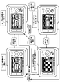
図11に、リモコン20の以下の4つのモード各々において、表示部21に表示される有効利用可能キーに関する識別情報の表示例を示す。
(A)録画準備状態の(a1)録画準備画像表示モード、
(B)録画実行状態の(b1)録画画像表示ノーマルモード、
(B)録画実行状態の(b2)録画画像非表示スタミナモード、
(B)録画実行状態の(b3)録画画像非表示ブルートゥース(BT)単独通信モード、
FIG. 11 shows a display example of identification information relating to validly usable keys displayed on the display unit 21 in each of the following four modes of the
(A) Recording preparation image display mode in (a1) recording preparation state,
(B) recording execution state (b1) recorded image display normal mode;
(B) recording execution state (b2) recorded image non-display stamina mode;
(B) Recording execution state (b3) Recorded image non-display Bluetooth (BT) single communication mode,
(A)録画準備状態の(a1)録画準備画像表示モードにおいては、以下の識別情報が表示される。
「モード設定キー操作可能状態識別情報」
ユーザは、リモコン20の表示部21に表示された「モード設定キー操作可能状態識別情報」を見て、リモコン20のモード設定キーの操作により、モードを変更することができることを知ることができる。
録画/通信状態表示ランプ34は、録画停止状態、かつWi-Fi通信有効状態を示す青点灯に設定される。
(A) In the recording preparation state (a1) recording preparation image display mode, the following identification information is displayed.
"Mode setting key operable state identification information"
The user can see the "mode setting key operable state identification information" displayed on the display unit 21 of the
The recording/communication status display lamp 34 is set to light blue indicating that the recording is stopped and the Wi-Fi communication is enabled.
(B)録画実行状態の(b1)録画画像表示ノーマルモードにおいても、以下の識別情報が表示される。
「モード設定キー操作可能状態識別情報」
ユーザは、リモコン20の表示部21に表示された「モード設定キー操作可能状態識別情報」を見て、リモコン20のモード設定キーの操作により、モードを変更することができることを知ることができる。
録画/通信状態表示ランプ34は、録画実行状態を示す赤点灯に設定される。
(B) The following identification information is also displayed in the (b1) recorded image display normal mode in the recording execution state.
"Mode setting key operable state identification information"
The user can see the "mode setting key operable state identification information" displayed on the display unit 21 of the
The recording/communication status display lamp 34 is set to red lighting to indicate the recording execution status.
(B)録画実行状態の(b2)録画画像非表示スタミナモードにおいては、以下の識別情報が表示される。
「モード設定キー操作可能状態識別情報」
「録画開始停止キー操作可能状態識別情報」
ユーザは、リモコン20の表示部21に表示された「モード設定キー操作可能状態識別情報」を見て、リモコン20のモード設定キーの操作により、モードを変更することができることを知ることができる。
また、リモコン20の表示部21に表示された「録画開始停止キー操作可能状態識別情報」を見て、リモコン20の録画開始停止キーの操作により、録画処理の開始や停止を行うことができることを知ることができる。
録画/通信状態表示ランプ34は、録画実行状態を示す赤点灯に設定される。
In the (b2) recorded image non-display stamina mode in the (B) recording execution state, the following identification information is displayed.
"Mode setting key operable state identification information"
"Recording start/stop key operable state identification information"
The user can see the "mode setting key operable state identification information" displayed on the display unit 21 of the
Also, by looking at the "recording start/stop key operable state identification information" displayed on the display unit 21 of the
The recording/communication status display lamp 34 is set to red lighting to indicate the recording execution status.
(B)録画実行状態の(b3)録画画像非表示ブルートゥース(BT)単独通信モードにおいては、以下の識別情報が表示される。
「録画開始停止キー操作可能状態識別情報」
ユーザは、リモコン20の表示部21に表示された「録画開始停止キー操作可能状態識別情報」を見て、リモコン20の録画開始停止キーの操作により、録画処理の開始や停止を行うことができることを知ることができる。
In the (b3) recorded image non-display Bluetooth (BT) single communication mode in the (B) recording execution state, the following identification information is displayed.
"Recording start/stop key operable state identification information"
The user can see the "recording start/stop key operable state identification information" displayed on the display unit 21 of the
なお、リモコン20の録画開始停止キーの操作情報は、ブルートゥース(BT)通信によってビデオカメラ10に送信される。
リモコン20の制御部は、ビデオカメラ10との間で利用可能な通信路に応じて変更される有効操作部に対応する有効操作部識別情報を表示部21に表示する
録画/通信状態表示ランプ34は、録画実行状態を示す赤点灯に設定される。
リモコン20の制御部は、ビデオカメラ10による録画処理実行期間は、撮影画像表示処理の有無に関わらず、録画処理実行中であることを示す表示、すなわち、録画/通信状態表示ランプ34を、録画実行状態を示す赤点灯に設定する制御を行う。
ユーザは、このランプ表示により、画像の表示有無に関わらず録画処理が行われていることを確認できる。
Operation information of the recording start/stop key of the
The control unit of the
The control unit of the
The user can confirm that the recording process is being performed by the lamp display regardless of whether the image is displayed or not.
前述したように、リモコン20は、ワイファイ(Wi-Fi)通信と、ブルートゥース(BT:Bluetooth)通信を利用してビデオカメラ10との通信を実行する。また、リモコン20は、リモコン20の操作部に対する無操作期間の継続状況に応じてビデオカメラ10とのワイファイ(Wi-Fi)通信を遮断する。
リモコン20の制御部は、ビデオカメラ10との間で利用可能な通信路に応じて変更される有効操作部に対応する有効操作部識別情報を表示部21に表示する。
例えば、ビデオカメラ10とのワイファイ(Wi-Fi)通信停止期間は、ビデオカメラ10に対して、ブルートゥース(BT:Bluetooth)を介して操作情報を送信できる操作部に対応する有効操作部識別情報を表示部21に表示する。
As described above, the
The control unit of the
For example, during a period in which Wi-Fi communication with the
なお、リモコン20の録画開始停止キーは、リモコン20が、以下のどのモードであっても利用可能である。
(A)録画準備状態の(a1)録画準備画像表示モード、
(B)録画実行状態の(b1)録画画像表示ノーマルモード、
(B)録画実行状態の(b2)録画画像非表示スタミナモード、
(B)録画実行状態の(b3)録画画像非表示ブルートゥース(BT)単独通信モード、
リモコン20の録画開始停止キーは、リモコン20が、上記のどのモードであっても利用できる。
Note that the recording start/stop key of the
(A) Recording preparation image display mode in (a1) recording preparation state,
(B) recording execution state (b1) recorded image display normal mode;
(B) recording execution state (b2) recorded image non-display stamina mode;
(B) Recording execution state (b3) Recorded image non-display Bluetooth (BT) single communication mode,
The recording start/stop key of the
しかし、図11に示す例では、
(A)録画準備状態の(a1)録画準備画像表示モード、
(B)録画実行状態の(b1)録画画像表示ノーマルモード、
これらの各モードでは、
「録画開始停止キー操作可能状態識別情報」
の表示処理は実行していない。
この理由は、リモコン20の表示部21に撮影画像が表示されている場合、その画像に重畳して表示する情報を少なくし、画像を見やすくするためである。
すなわち、リモコン20の制御部は、表示部21に撮影画像を表示しない非表示期間は、撮影画像を表示する表示期間より多くの有効操作部識別情報を表示する等の処理を行なう。
However, in the example shown in FIG.
(A) Recording preparation image display mode in (a1) recording preparation state,
(B) recording execution state (b1) recorded image display normal mode;
In each of these modes,
"Recording start/stop key operable state identification information"
display processing is not executed.
The reason for this is that when a photographed image is displayed on the display unit 21 of the
That is, the control unit of the
なお、撮影画像が表示されるモードにおいても、
「録画開始停止キー操作可能状態識別情報」の表示処理を実行する構成としてもよい。
あるいは、画像表示がなされている場合は、「録画開始停止キー操作可能状態識別情報」の表示面積を小さくした小型のアイコンを利用する等の処理を行なう構成としてもよい。
In addition, even in the mode in which the captured image is displayed,
The configuration may be such that the display processing of the "recording start/stop key operable state identification information" is executed.
Alternatively, when an image is being displayed, processing such as using a small icon with a reduced display area for the "recording start/stop key operable state identification information" may be performed.
なお、図11に示す以下のモード、すなわち、
(B)録画実行状態の(b3)録画画像非表示ブルートゥース(BT)単独通信モード、
このモードでは、リモコン20と、ビデオカメラ10間のWi-Fi通信が遮断されている。
Note that the following modes shown in FIG. 11, that is,
(B) Recording execution state (b3) Recorded image non-display Bluetooth (BT) single communication mode,
In this mode, Wi-Fi communication between the
このモードにおいて、図11に示すステップS15の処理、すなわち、画像表示指示処理、あるいは、ステップS16の処理、すなわち、録画停止キーのキー操作等を行うと、
(B)録画実行状態の(b1)録画画像表示ノーマルモード、
(A)録画準備状態の(a1)録画準備画像表示モード、
これらのモードへのモード移行処理が発生する。
In this mode, if the process of step S15 shown in FIG. 11, that is, the image display instruction process, or the process of step S16, that is, the recording stop key is operated,
(B) recording execution state (b1) recorded image display normal mode;
(A) Recording preparation image display mode in (a1) recording preparation state,
Mode transition processing to these modes occurs.
上記のモード移行処理においては、
リモコン20と、ビデオカメラ10との間で、Wi-Fi接続処理を行なうことになる。
このWi-Fi接続処理には、約5~6秒程度の時間を要する。
In the above mode transition processing,
Wi-Fi connection processing is performed between the
This Wi-Fi connection processing takes about 5 to 6 seconds.
この約5~6秒程度の時間は、ユーザは待機する必要があるが、リモコン20の表示部21に何も表示されないと、ユーザは故障、あるいは操作ミスを行ったのではないかといった疑問を持つ場合がある。
このような事態の発生を防止するため、Wi-Fi接続処理を伴うモード変更時には、リモコン20の表示部21にWi-Fi接続処理を実行中であることを示す情報を表示する。
具体例を図12に示す。
The user has to wait for about 5 to 6 seconds, but if nothing is displayed on the display unit 21 of the
In order to prevent such a situation from occurring, information indicating that the Wi-Fi connection process is being executed is displayed on the display unit 21 of the
A specific example is shown in FIG.
例えば図12に示すようなWi-Fi接続中であることを示す情報表示を実行し、Wi-Fi接続に成功した後、ビデオカメラ10から送信される画像表示に切り換える処理を行う。
このような処理を行なうことで、Wi-Fi接続処理を伴うモード変更時に、ユーザにWi-Fi接続処理を実行中であることを知らせる構成としている。
For example, an information display indicating that the Wi-Fi connection is in progress is executed as shown in FIG.
By performing such processing, the user is notified that the Wi-Fi connection processing is being executed when the mode is changed with the Wi-Fi connection processing.
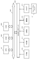
[6.ビデオカメラの表示部の表示情報について]
次に、ビデオカメラ10の表示部11に表示される情報について説明する。
ビデオカメラ10も、リモコン20において設定される各状態、各モードに対応して、複数の状態、モードに設定される。
これらの状態、モードの設定および遷移処理は、ビデオカメラ10の制御部の制御に基づいて行われる。
[6. Information displayed on the display of the video camera]
Next, information displayed on the display unit 11 of the
The
These state and mode settings and transition processing are performed under the control of the control unit of the
ビデオカメラ10の制御部は、例えばリモコン20の操作部に対する操作情報の入力、または操作情報入力が無い無操作状態の継続期間等に応じてモードを変更する制御を行う。さらに、制御部は、モード変更に応じて、通信部を介した通信形態を変更する処理、さらに、ビデオカメラ10の表示部11に対する表示情報の変更処理等を行う。
The control unit of the
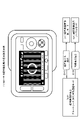
図13を参照して、ビデオカメラ10の表示部11に表示される表示情報の例について説明する。
図13には、以下の2つの表示情報例を示している。
(A)Wi-Fi,ブルートゥース(BT)両通信路が利用可能な設定における表示情報例
(B)ブルートゥース(BT)通信路のみ利用可能な設定における表示情報例
An example of display information displayed on the display unit 11 of the
FIG. 13 shows the following two display information examples.
(A) Example of display information in settings where both Wi-Fi and Bluetooth (BT) communication channels are available (B) Example of display information in settings where only Bluetooth (BT) communication channels are available
「(A)Wi-Fi,ブルートゥース(BT)両通信路が利用可能な設定における表示情報例」では、ビデオカメラ10とリモコン20間の有効な通信路を示す通信状態識別アイコン51が、Wi-Fi,ブルートゥース(BT)両通信路が利用可能であることを示すアイコンとなっている。
In "(A) Example of display information in a setting where both Wi-Fi and Bluetooth (BT) communication paths are available", the communication status identification icon 51 indicating the effective communication path between the
一方、「(B)ブルートゥース(BT)通信路のみ利用可能な設定における表示情報例」では、ビデオカメラ10とリモコン20間の有効な通信路を示す通信状態識別アイコン52が、ブルートゥース(BT)のみの通信路が利用可能であることを示すアイコンとなっている。
On the other hand, in "(B) Example of display information in settings where only the Bluetooth (BT) communication channel can be used", the communication status identification icon 52 indicating the effective communication channel between the
図13(A)に示す通信状態識別アイコン51は、Wi-Fi対応アイコンと、ブルートゥース(BT)対応アイコンを合成して生成した1つのアイコンである。
このようなアイコンを利用することで、Wi-Fi対応アイコンと、ブルートゥース(BT)対応アイコンを個別に表示する場合に比較して、表示スペースを小さくすることが可能となり、限られた表示スペースを有効に利用することが可能となる。
The communication status identification icon 51 shown in FIG. 13A is one icon generated by synthesizing the Wi-Fi compatible icon and the Bluetooth (BT) compatible icon.
By using such icons, the display space can be reduced compared to the case where the Wi-Fi icon and the Bluetooth (BT) icon are displayed separately, and the limited display space can be saved. It can be used effectively.
図14は、ビデオカメラ10の表示部11に表示される主要アイコンについての説明図である。
図14には、以下のアイコンに関する説明を示している。
(1)ワイファイ(Wi-Fi)およびブルートゥース(BT:Bluetooth)接続情報
(2)ブルートゥース(BT:Bluetooth)接続情報
(3)GPS情報
(4)カメラバッテリ残量情報
これらは、図13に示すビデオカメラ10の表示部11に表示されるアイコンの一部である。
FIG. 14 is an explanatory diagram of main icons displayed on the display unit 11 of the
FIG. 14 shows a description of the following icons.
(1) Wi-Fi and Bluetooth (BT) connection information (2) Bluetooth (BT) connection information (3) GPS information (4) Camera battery level information These are the video shown in FIG. These are some of the icons displayed on the display unit 11 of the
(1)に示すアイコンは、ワイファイ(Wi-Fi)およびブルートゥース(BT:Bluetooth)接続情報である。このアイコンは、先に説明したように、ビデオカメラ10とリモコン20間において、Wi-Fi通信とブルートゥース(BT)通信の双方が利用可能な場合に表示されるアイコンである。
ビデオカメラ10とリモコン20間において、Wi-Fi通信とブルートゥース(BT)通信の双方が利用可能でない場合は、アイコンが非表示状態となる。
Icons shown in (1) are Wi-Fi and Bluetooth (BT) connection information. This icon is displayed when both Wi-Fi communication and Bluetooth (BT) communication are available between the
When both Wi-Fi communication and Bluetooth (BT) communication are not available between the
(2)に示すアイコンは、ブルートゥース(BT:Bluetooth)接続情報である。このアイコンは、ビデオカメラ10とリモコン20間においてブルートゥース(BT:Bluetooth)通信のみが利用可能状態で表示されるアイコンである。
ビデオカメラ10とリモコン20間においてブルートゥース(BT)通信ができないブルートゥース(BT)非接続状態では、アイコンが非表示状態となる。
The icon shown in (2) is Bluetooth (BT) connection information. This icon is displayed when only Bluetooth (BT) communication is available between the
When the
(3)に示すアイコンは、GPS情報が利用可能な場合に表示されるアイコンである。
GPS情報が利用できない場合は、非表示とされる。
The icon shown in (3) is an icon displayed when GPS information is available.
When GPS information is not available, it is hidden.
(4)に示すアイコンは、カメラバッテリ残量情報であり、ビデオカメラ10に装着されたバッテリのバッテリ残量を示す。バッテリ残量に応じて、電池型のアイコンの表示態様が変化する設定である。
The icon indicated by ( 4 ) is camera battery remaining information and indicates the battery remaining amount of the battery attached to the
この他にも、ビデオカメラ10の表示部11には、図13に示すように、様々な情報を示す多数のアイコンが表示される。
例えば、撮影画像の種類(MP4,30P)、手ブレ補正態様(Std)、現在時間情報、撮影開始からの経過時間情報、撮影画像の種類(動画/静止画)、画角情報(ノーマル(N)/ワイド(W))等の様々な情報が表示される。
In addition, as shown in FIG. 13, the display unit 11 of the
For example, the type of captured image (MP4, 30P), image stabilization mode (Std), current time information, elapsed time information from the start of shooting, type of captured image (moving image/still image), angle of view information (normal (N )/wide (W)) are displayed.
[7.リモコンとビデオカメラのモード遷移とモード対応の表示情報について]
次に、リモコン20とビデオカメラ10のモード遷移と、各モードにおいてリモコン20の表示部21と、ビデオカメラ10の表示部11に表示される表示情報について説明する。
[7. Regarding the mode transition of the remote control and the video camera and the display information corresponding to the mode]
Next, mode transitions of the
図15は、リモコン20と、ビデオカメラ10のモード遷移に伴う表示情報の変化を示す図である。
図15の上部に、リモコン20のモード遷移と、各モードにおける表示部21の表示情報の例を示している。
一方、図15の下部には、ビデオカメラ10のモード遷移と、各モードにおける表示部11の表示情報の例を示している。
15A and 15B are diagrams showing changes in display information accompanying mode transitions of the
The upper portion of FIG. 15 shows an example of mode transitions of the
On the other hand, the lower part of FIG. 15 shows an example of mode transition of the
図15上部に示すリモコン20のモード遷移の条件として示すステップS11~S16は、先に図9、図11を参照して説明した遷移ステップと同じである。
図15下部に示すビデオカメラ10もリモコンのモード遷移に応じて、リモコン20のモードと同様のモード遷移が発生し、リモコン20の設定モードと同様のモードに設定される。
Steps S11 to S16 shown as conditions for mode transition of the
The
図15には、先に図8~図11を参照して説明したと同様、以下の4つのモードを示している。以下の4つのモードである。
(A)録画準備状態の(a1)録画準備画像表示モード、
(B)録画実行状態の(b1)録画画像表示ノーマルモード、
(B)録画実行状態の(b2)録画画像非表示スタミナモード、
(B)録画実行状態の(b3)録画画像非表示ブルートゥース(BT)単独通信モード、
FIG. 15 shows the following four modes as described above with reference to FIGS. 8-11. The four modes are as follows.
(A) Recording preparation image display mode in (a1) recording preparation state,
(B) recording execution state (b1) recorded image display normal mode;
(B) recording execution state (b2) recorded image non-display stamina mode;
(B) Recording execution state (b3) Recorded image non-display Bluetooth (BT) single communication mode,
以下、各モードにおける(1)通信状態、(2)表示情報(リモコン、ビデオカメラ)、さらに(3)モード遷移について説明する。 Hereinafter, (1) communication state, (2) display information (remote control, video camera), and (3) mode transition in each mode will be described.
[7-1.(A)録画準備状態の(a1)録画準備画像表示モードにおける通信状態と表示情報とモード遷移について]
まず、(A)録画準備状態の(a1)録画準備画像表示モードにおける通信状態と表示情報とモード遷移について説明する。
(1)通信状態
この(A)録画準備状態の(a1)録画準備画像表示モードにおいては、ビデオカメラ10と、リモコン20は、Wi-Fi通信、ブルートゥース(BT)通信の両通信が利用できる。
[7-1. (A) Communication state, display information, and mode transition in (a1) recording preparation image display mode of recording preparation state]
First, the communication state, display information, and mode transition in (a1) recording preparation image display mode in (A) recording preparation state will be described.
(1) Communication state In the (a1) recording preparation image display mode of the (A) recording preparation state, the
(2)表示情報
(2a)リモコン20の表示部21の表示情報
リモコン20の表示部21には、
ビデオカメラ10からWi-Fiを介して送信される撮影画像(≠録画画像)が表示される。
また、表示部21下部の録画実行ランプは消灯し、録画が実行されていないことを示す。
表示部21上部には、Wi-Fi接続アイコン、ブルートゥース(BT)接続アイコンが表示され、ビデオカメラ10とリモコン20間のWi-Fi通信、BT通信、何れも有効であり利用できる状態であることを示している。
(2) Display information (2a) Display information on the display unit 21 of the
A captured image (≠recorded image) transmitted from the
Also, the recording execution lamp at the bottom of the display unit 21 is extinguished, indicating that recording is not being executed.
A Wi-Fi connection icon and a Bluetooth (BT) connection icon are displayed in the upper part of the display unit 21, indicating that both the Wi-Fi communication and BT communication between the
さらに、撮影画像(≠録画画像)上に、以下の識別情報が表示される。
「モード設定キー操作可能状態識別情報」
ユーザは、リモコン20の表示部21に表示された「モード設定キー操作可能状態識別情報」を見て、リモコン20のモード設定キーの操作により、モードを変更することができることを知ることができる。
Furthermore, the following identification information is displayed on the captured image (≠recorded image).
"Mode setting key operable state identification information"
The user can see the "mode setting key operable state identification information" displayed on the display unit 21 of the
(2b)ビデオカメラ10の表示部11の表示情報
ビデオカメラ10の表示部11には、
先に図14(1)を参照して説明したWi-Fi接続とブルートゥース(BT)接続が有効であることを示すWi-Fi/BT接続アイコンが表示され、ビデオカメラ10とリモコン20間のWi-Fi通信、BT通信、何れも利用可能であることが分かる。
(2b) Display information on the display unit 11 of the
A Wi-Fi/BT connection icon indicating that the Wi-Fi connection and Bluetooth (BT) connection described above with reference to FIG. - It can be seen that both Fi communication and BT communication can be used.
(3)モード遷移
この(A)録画準備状態の(a1)録画準備画像表示モードにおいて、ユーザによるリモコン20に対する録画開始停止キー(RECキー(SSキー))に対するキー操作によって、(ステップS11)のモード遷移が発生する。
ステップS11は、
(A)録画準備状態の(a1)録画準備画像表示モードから、
(B)録画実行状態の(b1)録画画像表示ノーマルモードへの、
モード遷移ステップである。
(3) Mode transition In the (a1) recording preparation image display mode of the (A) recording preparation state, the user operates the recording start/stop key (REC key (SS key)) on the
Step S11 is
(A) From the (a1) recording preparation image display mode in the recording preparation state,
(B) to (b1) recorded image display normal mode in recording execution state,
This is the mode transition step.
このモード遷移処理に際して、以下の処理が行われる。
(p)リモコン20から、ビデオカメラ10に対する録画開始要求の送信、
(q)ビデオカメラ10による録画処理の開始、
(r)ビデオカメラ10による撮影画像(=録画画像)のリモコン20に対する送信処理、
(s)リモコン20の表示部21に対する撮影画像(=録画画像)の表示処理、
なお、この時点の送信表示画像は、録画処理が行われている画像である。
In this mode transition processing, the following processing is performed.
(p) sending a recording start request to the
(q) starting the recording process by the
(r) transmission processing of the image captured by the video camera 10 (=recorded image) to the
(s) display processing of the captured image (=recorded image) on the display unit 21 of the
Note that the transmission display image at this time is an image in which recording processing is being performed.
[7-2.(B)録画実行状態の(b1)録画画像表示ノーマルモードにおける通信状態と表示情報とモード遷移について]
次に、(B)録画実行状態の(b1)録画画像表示ノーマルモードにおける通信状態と表示情報とモード遷移について説明する。
(1)通信状態
この(B)録画実行状態の(b1)録画画像表示ノーマルモードにおいては、ビデオカメラ10と、リモコン20は、Wi-Fi通信、ブルートゥース(BT)通信の両通信が利用できる。
[7-2. Communication state, display information, and mode transition in (b1) recorded image display normal mode in (B) recording execution state]
Next, the communication state, display information, and mode transition in the (b1) recorded image display normal mode in the (B) recording execution state will be described.
(1) Communication state In the (b1) recorded image display normal mode of the (B) recording execution state, the
(2)表示情報
(2a)リモコン20の表示部21の表示情報
リモコン20の表示部21には、
ビデオカメラ10からWi-Fiを介して送信される撮影画像(=録画画像)が表示される。
また、表示部21下部の録画実行ランプは点灯し、録画が実行されていることを示す。
表示部21上部には、Wi-Fi接続アイコン、ブルートゥース(BT)接続アイコンが表示され、ビデオカメラ10とリモコン20間のWi-Fi通信、BT通信、何れも有効であり利用できる状態であることを示している。
(2) Display information (2a) Display information on the display unit 21 of the
A captured image (=recorded image) transmitted from the
Also, the recording execution lamp at the bottom of the display unit 21 lights up, indicating that recording is being executed.
A Wi-Fi connection icon and a Bluetooth (BT) connection icon are displayed in the upper part of the display unit 21, indicating that both the Wi-Fi communication and BT communication between the
さらに、撮影画像(=録画画像)上に、以下の識別情報が表示される。
「モード設定キー操作可能状態識別情報」
ユーザは、リモコン20の表示部21に表示された「モード設定キー操作可能状態識別情報」を見て、リモコン20のモード設定キーの操作により、モードを変更することができることを知ることができる。
Furthermore, the following identification information is displayed on the captured image (=recorded image).
"Mode setting key operable state identification information"
The user can see the "mode setting key operable state identification information" displayed on the display unit 21 of the
(2b)ビデオカメラ10の表示部11の表示情報
ビデオカメラ10の表示部11には、
先に図14(1)を参照して説明したWi-Fi接続とブルートゥース(BT)接続が有効であることを示すWi-Fi/BT接続アイコンが表示され、ビデオカメラ10とリモコン20間のWi-Fi通信、BT通信、何れも利用可能であることが分かる。
(2b) Display information on the display unit 11 of the
A Wi-Fi/BT connection icon indicating that the Wi-Fi connection and Bluetooth (BT) connection described above with reference to FIG. - It can be seen that both Fi communication and BT communication can be used.
(3)モード遷移
この(B)録画実行状態の(b1)録画画像表示ノーマルモードにおいて、ユーザによるリモコン20に対する無操作状態が10秒経過すると(ステップS12)のモード遷移が発生する。
ステップS12は、
(B)録画実行状態の(b1)録画画像表示ノーマルモードから、
(B)録画実行状態の(b2)録画画像表示スタミナモードへの、
モード遷移ステップである。
(3) Mode Transition In the (b1) recorded image display normal mode of the (B) recording execution state, when the
Step S12 is
From (b1) recorded image display normal mode in (B) recording execution state,
(B) to the recording execution state (b2) recorded image display stamina mode,
This is the mode transition step.
このモード遷移処理に際して、以下の処理が行われる。
(p)リモコン20から、ビデオカメラ10に対する録画画像送信停止要求の送信、
(q)ビデオカメラ10による撮影画像(=録画画像)のリモコン20に対する送信処理の停止、
(r)リモコン20の表示部21に対する撮影画像(=録画画像)の表示処理の停止、
なお、このモード遷移が発生しても、ビデオカメラ10は、録画処理を継続する。
In this mode transition processing, the following processing is performed.
(p) transmission of a recorded image transmission stop request from the
(q) Stopping the transmission process of the image captured by the video camera 10 (=recorded image) to the
(r) Stopping display processing of the captured image (=recorded image) on the display unit 21 of the
Even if this mode transition occurs, the
また、この(B)録画実行状態の(b1)録画画像表示ノーマルモードにおいて、ユーザがリモコン20に対して、記録停止の入力操作、すなわち、録画開始停止キー(RECキー(=SSキー))のキー操作を実行すると、(ステップS16)のモード遷移が発生し、
(A)録画準備状態の(a1)録画準備画像表示モード、
に移行する。
In the (B) recording execution state (b1) recorded image display normal mode, the user operates the
(A) Recording preparation image display mode in (a1) recording preparation state,
transition to
このモード遷移により、以下の処理が実行される。
(p)リモコン20から、ビデオカメラ10に対する録画処理の停止要求送信、
(q)ビデオカメラ10による録画処理の停止処理、
(r)ビデオカメラ10による撮影画像(≠録画画像)のリモコン20に対する送信処理、
(s)リモコン20の表示部21に対する撮影画像(≠録画画像)の表示処理、
なお、このモード遷移後の送信表示画像は、録画処理が行われていない画像である。
The following processing is executed by this mode transition.
(p) sending a request to stop the recording process from the
(q) stop processing of recording processing by the
(r) transmission processing of an image (≠recorded image) captured by the
(s) display processing of the captured image (≠recorded image) on the display unit 21 of the
Note that the transmission display image after this mode transition is an image that has not undergone recording processing.
[7-3.(B)録画実行状態の(b2)録画画像非表示スタミナモードにおける通信状態と表示情報とモード遷移について]
次に、(B)録画実行状態の(b2)録画画像非表示スタミナモードにおける通信状態と表示情報とモード遷移について説明する。
(1)通信状態
この(B)録画実行状態の(b2)録画画像非表示スタミナモードにおいては、ビデオカメラ10と、リモコン20は、Wi-Fi通信、ブルートゥース(BT)通信の両通信が利用できる。
[7-3. Communication state, display information, and mode transition in (b2) recorded image non-display stamina mode in (B) recording execution state]
Next, the communication state, display information, and mode transition in the (b2) recorded image non-display stamina mode in the (B) recording execution state will be described.
(1) Communication state In the (b2) recorded image non-display stamina mode of the (B) recording execution state, the
(2)表示情報
(2a)リモコン20の表示部21の表示情報
このモードでは、ビデオカメラ10から撮影画像(=録画画像)が送信されない。
従って、リモコン20の表示部21には、撮影画像(=録画画像)は表示されない。
ただし、表示部21下部の録画実行ランプは点灯し、録画が実行されていることを示す。
表示部21上部には、Wi-Fi接続アイコン、ブルートゥース(BT)接続アイコンが表示され、ビデオカメラ10とリモコン20間のWi-Fi通信、BT通信、何れも有効であり利用できる状態であることを示している。
(2) Display information (2a) Display information on the display unit 21 of the
Therefore, the captured image (=recorded image) is not displayed on the display section 21 of the
However, the recording execution lamp in the lower part of the display unit 21 lights up, indicating that recording is being executed.
A Wi-Fi connection icon and a Bluetooth (BT) connection icon are displayed in the upper part of the display unit 21, indicating that both the Wi-Fi communication and BT communication between the
このモードでは、表示部21に対する撮影画像の表示は停止される。ただし、以下の識別情報が表示される。
「モード設定キー操作可能状態識別情報」
ユーザは、リモコン20の表示部21に表示された「モード設定キー操作可能状態識別情報」を見て、リモコン20のモード設定キーの操作により、モードを変更することができることを知ることができる。
In this mode, the display of the captured image on the display unit 21 is stopped. However, the following identification information is displayed.
"Mode setting key operable state identification information"
The user can see the "mode setting key operable state identification information" displayed on the display unit 21 of the
さらに、表示部21には、
「録画開始停止キー操作可能状態識別情報」
が表示される。
ユーザは、リモコン20の表示部21に表示された「録画開始停止キー操作可能状態識別情報」を見て、リモコン20の録画開始停止キー(RECキー(SSキー))が有効であり、このキー操作によって録画処理の開始や停止を行うことができることを知ることができる。
Furthermore, on the display unit 21,
"Recording start/stop key operable state identification information"
is displayed.
The user sees the "recording start/stop key operable state identification information" displayed on the display unit 21 of the
(2b)ビデオカメラ10の表示部11の表示情報
ビデオカメラ10の表示部11には、
先に図14(1)を参照して説明したWi-Fi接続とブルートゥース(BT)接続が有効であることを示すWi-Fi/BT接続アイコンが表示され、ビデオカメラ10とリモコン20間のWi-Fi通信、BT通信、何れも利用可能であることが分かる。
(2b) Display information on the display unit 11 of the
A Wi-Fi/BT connection icon indicating that the Wi-Fi connection and Bluetooth (BT) connection described above with reference to FIG. - It can be seen that both Fi communication and BT communication can be used.
(3)モード遷移
この(B)録画実行状態の(b2)録画画像非表示スタミナモードにおいて、ユーザによるリモコン20に対する無操作状態が60秒継続すると、(ステップS14)のモード遷移が発生する。
ステップS14は、
(B)録画実行状態の(b2)録画画像非表示スタミナモードから、
(B)録画実行状態の(b3)録画画像非表示ブルートゥース(BT)単独通信モードへの、
モード遷移ステップである。
(3) Mode Transition In the (b2) recorded image non-display stamina mode of the (B) recording execution state, when the
Step S14 is
(B) From the (b2) recorded image non-display stamina mode in the recording execution state,
(B) Recording execution state (b3) Recorded image non-display Bluetooth (BT) single communication mode,
This is the mode transition step.
(p)リモコン20とビデオカメラ10とのWi-Fi接続の停止、
(q)ビデオカメラ10からのステータス情報の送信経路をWi-FiからBTに切り替える処理、
(r)リモコン20からビデオカメラ10に対する操作情報をWi-Fiを使用せず、全てBT通信に切り替える処理、
なお、このモード遷移が発生しても、ビデオカメラ10は、録画処理を継続する。
(p) stopping the Wi-Fi connection between the
(q) processing to switch the transmission path of status information from the
(r) Processing for switching all operation information from the
Even if this mode transition occurs, the
また、この(B)録画実行状態の(b1)録画画像非表示スタミナモードにおいて、ユーザによるリモコン20に対する画像表示指示がなされると(ステップS15)のモード遷移が発生する。
ステップS15は、
(B)録画実行状態の(b2)録画画像非表示スタミナモードから、
(B)録画実行状態の(b1)録画画像表示ノーマルモードへの、
モード遷移ステップである。
Also, in the (b1) recorded image non-display stamina mode in the (B) recording execution state, when the user issues an image display instruction to the
Step S15 is
(B) From the (b2) recorded image non-display stamina mode in the recording execution state,
(B) to (b1) recorded image display normal mode in recording execution state,
This is the mode transition step.
なお、この(b2)録画画像非表示スタミナモードにおいて、ユーザによるリモコン20に対して行われる入力操作中、録画開始停止キー(RECキー(SSキー))等の特定キー以外のキー操作、あるいはタッチパネルとして機能する表示部に対するタッチ操作のほとんどは、画像表示指示入力として解釈され、このステップS15のモード遷移が発生する。
In this (b2) recorded image non-display stamina mode, during an input operation performed on the
このモード遷移により、以下の処理が実行される。
(p)リモコン20から、ビデオカメラ10に対する撮影画像(=録画画像)の送信要求、
(q)ビデオカメラ10による撮影画像(=録画画像)のリモコン20に対する送信処理、
(r)リモコン20の表示部21に対する撮影画像(=録画画像)の表示処理、
なお、この時点の送信表示画像は、録画処理が行われている画像である。
The following processing is executed by this mode transition.
(p) a request from the
(q) transmission processing of the image captured by the video camera 10 (=recorded image) to the
(r) display processing of the captured image (=recorded image) on the display unit 21 of the
Note that the transmission display image at this time is an image in which recording processing is being performed.
さらに、この(B)録画実行状態の(b2)録画画像非表示スタミナモードにおいて、ユーザがリモコン20に対して、記録停止の入力操作、すなわち、録画開始停止キー(RECキー(=SSキー))のキー操作を実行すると、(ステップS16)のモード遷移が発生し、
(A)録画準備状態の(a1)録画準備画像表示モード、
に移行する。
Further, in the (B) recording execution state (b2) recorded image non-display stamina mode, the user operates the
(A) Recording preparation image display mode in (a1) recording preparation state,
transition to
このモード遷移により、以下の処理が実行される。
(p)リモコン20から、ビデオカメラ10に対する録画処理の停止要求送信、
(q)ビデオカメラ10による録画処理の停止処理、
(r)ビデオカメラ10による撮影画像(≠録画画像)のリモコン20に対する送信処理、
(s)リモコン20の表示部21に対する撮影画像(≠録画画像)の表示処理、
なお、このモード遷移後の送信表示画像は、録画処理が行われていない画像である。
The following processing is executed by this mode transition.
(p) sending a request to stop the recording process from the
(q) stop processing of recording processing by the
(r) transmission processing of an image (≠recorded image) captured by the
(s) display processing of the captured image (≠recorded image) on the display unit 21 of the
Note that the transmission display image after this mode transition is an image that has not undergone recording processing.
[7-4.(B)録画実行状態の(b3)録画画像非表示ブルートゥース(BT)単独通信モードにおける通信状態と表示情報とモード遷移について]
次に、(B)録画実行状態の(b3)録画画像非表示ブルートゥース(BT)単独通信モードにおける通信状態と表示情報とモード遷移について説明する。
(1)通信状態
この(B)録画実行状態の(b3)録画画像非表示ブルートゥース(BT)単独通信モードにおける通信状態と表示情報とモードにおいては、ビデオカメラ10と、リモコン20は、ブルートゥース(BT)通信のみ利用できる。
[7-4. Communication state, display information, and mode transition in (b3) recorded image non-display Bluetooth (BT) single communication mode in (B) recording execution state]
Next, the communication state, display information, and mode transition in (b3) recorded image non-display Bluetooth (BT) single communication mode in (B) recording execution state will be described.
(1) Communication state In the communication state, display information, and mode in (b3) Recorded image non-display Bluetooth (BT) single communication mode in this (B) recording execution state, the
(2)表示情報
(2a)リモコン20の表示部21の表示情報
このモードでは、ビデオカメラ10から撮影画像(=録画画像)が送信されない。
従って、リモコン20の表示部21には、撮影画像(=録画画像)は表示されない。
ただし、表示部21下部の録画実行ランプは点灯し、録画が実行されていることを示す。
(2) Display information (2a) Display information on the display unit 21 of the
Therefore, the captured image (=recorded image) is not displayed on the display section 21 of the
However, the recording execution lamp in the lower part of the display unit 21 lights up, indicating that recording is being executed.
表示部21上部のWi-Fi接続アイコンは非表示となり、ブルートゥース(BT)接続アイコンのみが表示され、ビデオカメラ10とリモコン20間のBT通信のみ利用できる状態であることを示している。
The Wi-Fi connection icon on the upper part of the display unit 21 is hidden, and only the Bluetooth (BT) connection icon is displayed, indicating that only BT communication between the
このモードでは、表示部21に対する撮影画像の表示は停止される。ただし、以下の識別情報が表示される。
「モード設定キー操作可能状態識別情報」
ユーザは、リモコン20の表示部21に表示された「モード設定キー操作可能状態識別情報」を見て、リモコン20のモード設定キーの操作により、モードを変更することができることを知ることができる。
In this mode, the display of the captured image on the display unit 21 is stopped. However, the following identification information is displayed.
"Mode setting key operable state identification information"
The user can see the "mode setting key operable state identification information" displayed on the display unit 21 of the
さらに、表示部21には、
「録画開始停止キー操作可能状態識別情報」
が表示される。
ユーザは、リモコン20の表示部21に表示された「録画開始停止キー操作可能状態識別情報」を見て、リモコン20の録画開始停止キー(RECキー(SSキー))が有効であり、このキー操作によって録画処理の開始や停止を行うことができることを知ることができる。
Furthermore, on the display unit 21,
"Recording start/stop key operable state identification information"
is displayed.
The user sees the "recording start/stop key operable state identification information" displayed on the display unit 21 of the
(2b)ビデオカメラ10の表示部11の表示情報
ビデオカメラ10の表示部11には、
先に図14(2)を参照して説明したブルートゥース(BT)接続が有効であることを示すブルートゥース(BT)接続アイコンが表示され、ビデオカメラ10とリモコン20間のBT通信が利用可能であることが分かる。
(2b) Display information on the display unit 11 of the
A Bluetooth (BT) connection icon indicating that the Bluetooth (BT) connection described above with reference to FIG. 14B is valid is displayed, and BT communication between the
(3)モード遷移
この(B)録画実行状態の(b3)録画画像非表示ブルートゥース(BT)単独通信モードにおいて、ユーザによるリモコン20に対する画像表示指示がなされると(ステップS15)のモード遷移が発生する。
ステップS15は、
(B)録画実行状態の(b3)録画画像非表示ブルートゥース(BT)単独通信モードから、
(B)録画実行状態の(b1)録画画像表示ノーマルモードへの、
モード遷移ステップである。
(3) Mode transition When the user issues an image display instruction to the
Step S15 is
(B) From the (b3) recorded image non-display Bluetooth (BT) single communication mode in the recording execution state,
(B) to (b1) recorded image display normal mode in recording execution state,
This is the mode transition step.
なお、この(b3)録画画像非表示ブルートゥース(BT)単独通信モードにおいて、ユーザによるリモコン20に対して行われる入力操作中、録画開始停止キー(RECキー(SSキー))等の特定キー以外のキー操作、あるいはタッチパネルとして機能する表示部に対するタッチ操作のほとんどは、画像表示指示入力として解釈され、このステップS15のモード遷移が発生する。
In this (b3) recorded image non-display Bluetooth (BT) single communication mode, during an input operation performed on the
このモード遷移により、以下の処理が実行される。
(p)リモコン20から、ビデオカメラ10に対する撮影画像(=録画画像)の送信要求、
(q)ビデオカメラ10による撮影画像(=録画画像)のリモコン20に対する送信処理、
(r)リモコン20の表示部21に対する撮影画像(=録画画像)の表示処理、
なお、この時点の送信表示画像は、録画処理が行われている画像である。
The following processing is executed by this mode transition.
(p) a request from the
(q) transmission processing of the image captured by the video camera 10 (=recorded image) to the
(r) display processing of the captured image (=recorded image) on the display unit 21 of the
Note that the transmission display image at this time is an image in which recording processing is being performed.
さらに、この(B)録画実行状態の(b3)録画画像非表示ブルートゥース(BT)単独通信モードにおいて、ユーザによるリモコン20に対する録画開始停止キー(RECキー(SSキー))に対するキー操作によって、(ステップS16)のモード遷移が発生する。
ステップS16は、
(B)録画実行状態の(b3)録画画像非表示ブルートゥース(BT)単独通信モードから、
(A)録画準備状態の(a1)録画準備画像表示モードへの、
モード遷移ステップである。
Further, in the (B) recording execution state (b3) recorded image non-display Bluetooth (BT) single communication mode, the user operates the recording start/stop key (REC key (SS key)) on the
Step S16 is
(B) From the (b3) recorded image non-display Bluetooth (BT) single communication mode in the recording execution state,
(A) In the recording preparation state (a1) to the recording preparation image display mode,
This is the mode transition step.
このモード遷移により、以下の処理が実行される。
(p)リモコン20から、ビデオカメラ10に対する録画処理の停止要求送信、
(q)ビデオカメラ10による録画処理の停止処理、
(r)ビデオカメラ10による撮影画像(≠録画画像)のリモコン20に対する送信処理、
(s)リモコン20の表示部21に対する撮影画像(≠録画画像)の表示処理、
なお、このモード遷移後の送信表示画像は、録画処理が行われていない画像である。
The following processing is executed by this mode transition.
(p) sending a request to stop the recording process from the
(q) stop processing of recording processing by the
(r) transmission processing of an image (≠recorded image) captured by the
(s) display processing of the captured image (≠recorded image) on the display unit 21 of the
Note that the transmission display image after this mode transition is an image that has not undergone recording processing.
[8.リモコンのキー設定と表示情報の変更例について]
先に、図10を参照してリモコン20の表示部21に、各モードにおける操作可能情報を表示し、ユーザにどのキーが有効に利用可能であるかを知らせることを可能とした構成について説明した。
図10に示すように、モード設定キー32a,32bは、表示部21のサイドに設けられたユーザ操作可能なキーである。
例えば、モード設定キー32a,32bの操作により、動画撮影モード、静止画撮影モード等の撮影モードの切り換えを行うことができる。
[8. Example of changing remote control key settings and display information]
Previously, with reference to FIG. 10, a configuration has been described in which operable information in each mode is displayed on the display unit 21 of the
As shown in FIG. 10, the mode setting keys 32a and 32b are keys provided on the side of the display unit 21 that can be operated by the user.
For example, by operating the mode setting keys 32a and 32b, it is possible to switch between shooting modes such as a moving image shooting mode and a still image shooting mode.
このモード設定キー32a,32bは、動画と静止画撮影モードの切り換えスイッチとして機能するのみではなく、例えばズームアップとズームダウンのズーム設定キーとして利用することも可能である。
リモコン20には、これらのモード設定キー32a,32bの機能切り替えスイッチが設けられており、このスイッチの操作により、モード設定キー32a,32bをズーム設定キーに変更することができる。
The mode setting keys 32a and 32b not only function as switching switches between moving image and still image shooting modes, but can also be used as zoom setting keys for zooming up and zooming down, for example.
The
このようにリモコン20のキー設定を変更した場合、リモコン20の表示部21に表示される情報も変更される。
具体例について、図16を参照して説明する。
図16には、以下の2つのモートにおけるリモコン20の表示部21の表示例を示している。
(A)録画準備状態の(a1)録画準備画像表示モード、
(B)録画実行状態の(b2)録画画像非表示スタミナモード、
When the key setting of the
A specific example will be described with reference to FIG.
FIG. 16 shows display examples of the display unit 21 of the
(A) Recording preparation image display mode in (a1) recording preparation state,
(B) recording execution state (b2) recorded image non-display stamina mode;
図16に示すように、(a1)録画準備画像表示モードのリモコン表示部21には、
「ズーム設定キー操作可能状態識別情報41」が表示される。
図16に示すように、ズーム設定キー42a,42bは、表示部21のサイドに設けられたユーザ操作可能なキーである。
例えば、ズーム設定キー42a,42bの操作により、ズームアップ、ズームダウンのズーム設定の変更を行うことができる。
As shown in FIG. 16, the remote control display unit 21 in the (a1) recording preparation image display mode includes:
"Zoom setting key operable state identification information 41" is displayed.
As shown in FIG. 16, the zoom setting keys 42a and 42b are provided on the side of the display unit 21 and can be operated by the user.
For example, by operating the zoom setting keys 42a and 42b, it is possible to change the zoom setting such as zooming up or zooming down.
表示部21に表示されたズーム設定キー操作可能状態識別情報41は、ズーム設定キー42a,42bの操作が有効であることをユーザに通知するための表示情報である。
ユーザは、表示部21に表示された「ズーム設定キー操作可能状態識別情報41」を見て、ズーム設定キー42a,42bが有効であり、これらのキー操作によってズームアップ、ズームダウンのズーム調整を行うことができることを知ることができる。
The zoom setting key operable state identification information 41 displayed on the display unit 21 is display information for notifying the user that the operation of the zoom setting keys 42a and 42b is valid.
When the user sees the "zoom setting key operable state identification information 41" displayed on the display unit 21, the zoom setting keys 42a and 42b are valid, and zoom adjustment of zoom up and zoom down can be performed by operating these keys. know what you can do.
また、図16の右側には、(b2)録画画像非表示スタミナモードのリモコン表示部21の表示例を示している。表示部21には、
「ズーム設定キー操作可能状態識別情報41」の他、
「録画開始停止キー操作可能状態識別情報35」
が表示される。
「録画開始停止キー操作可能状態識別情報35」は、やはり、表示部21のサイドに設けられた録画開始停止キー(RECキー(SSキー))33が有効であることをユーザに通知するために表示される。
The right side of FIG. 16 shows a display example of the remote control display section 21 in the (b2) recorded image non-display stamina mode. The display unit 21 has
In addition to "zoom setting key operable state identification information 41",
"Recording start/stop key operable state identification information 35"
is displayed.
The "recording start/stop key operable state identification information 35" is also used to notify the user that the recording start/stop key (REC key (SS key)) 33 provided on the side of the display unit 21 is valid. Is displayed.
録画開始停止キー(RECキー(SSキー))33は、録画処理の開始、および録画処理の停止を実行するためのキーである。
ユーザは、表示部21に表示された「録画開始停止キー操作可能状態識別情報35」を見て、録画開始停止キー(RECキー(SSキー))33が有効であり、これらのキー操作によって録画処理の開始や停止を行うことができることを知ることができる。
A recording start/stop key (REC key (SS key)) 33 is a key for starting and stopping recording processing.
The user sees the "recording start/stop key operable state identification information 35" displayed on the display unit 21, and sees that the recording start/stop key (REC key (SS key)) 33 is valid, and recording is performed by operating these keys. It is possible to know that processing can be started or stopped.
このように、リモコン20の表示部21には、各モードにおいて有効に利用可能なキーに関する識別情報が表示される。
ユーザは、これらの識別情報を見て、リモコン20のどのキーが利用可能であるかを確認し、この確認の下でキー操作を行うことができる。
In this way, the display section 21 of the
The user can confirm which keys of the
[9.その他の実施例について]
上述した実施例は、ビデオカメラ10とリモコン20を利用した実施例であるが、本開示のモード遷移に従った通信形態の変更構成は、その他の様々な通信装置間においても適用可能である。
[9. Other Examples]
The embodiment described above is an embodiment using the
図17を参照して、本開示のモード遷移に従った通信形態の変更処理を適用可能な一構成例について説明する。
図17には、人が呑み込み可能なカプセルに画像撮影可能なカメラを格納したビデオカメラ内蔵カプセル70と、このビデオカメラ内蔵カプセル70と通信を実行するPC80を示している。
With reference to FIG. 17, a configuration example to which the communication mode changing process according to the mode transition of the present disclosure can be applied will be described.
FIG. 17 shows a video camera built-in capsule 70 that houses a camera capable of taking an image in a capsule that can be swallowed by a person, and a
PC80と、ビデオカメラ内蔵カプセル70は、Wi-Fi通信、およびブルートゥース(BT)通信を併用して様々な通信処理を実行する。
具体的には、以下の各処理を実行する。
(a)ビデオカメラ内蔵カプセル70のビデオカメラの撮影した画像をWi-Fi通信を介してPC80に送信する。
(b)ビデオカメラ内蔵カプセル70のビデオカメラの撮影画像情報や、位置情報等のステータス情報をWi-Fi通信、またはBT通信を介してPC80に送信する。
(c)PC80からのコマンド(画像撮影開始、停止、ズーム、フラッシュ撮影等のコマンド)をビデオカメラ内蔵カプセル70内のビデオカメラにWi-Fi通信、またはBT通信を介して送信する。
The
Specifically, each of the following processes is executed.
(a) An image captured by the video camera of the video camera built-in capsule 70 is transmitted to the
(b) Transmits status information such as image information captured by the video camera of the video camera built-in capsule 70 and position information to the
(c) Sending commands from the PC 80 (commands for starting, stopping, zooming, flash photography, etc.) from the
ビデオカメラ内蔵カプセル70のビデオカメラと、PC80間では、これらの様々なデータ通信が実行される。
このようなデータ通信において、先に説明したビデオカメラ10とリモコン20間のモード遷移に従った通信形態の変更を実行することで、バッテリ消費の低減による省電力を実現することができる。
These various data communications are performed between the video camera of the video camera built-in capsule 70 and the
In such data communication, by changing the communication mode in accordance with the mode transition between the
図18を参照して、具体的なモード遷移例について説明する。
図18には、ビデオカメラ内蔵カプセル70のビデオカメラと、PC80間における3つのモード対応のデータ通信態様を示している。
以下の3つのモードである。
(1)画像転送実行モード
(2)画像転送停止モード
(3)画像転送停止&ブルートゥース(BT)単独通信モード
A specific mode transition example will be described with reference to FIG.
FIG. 18 shows the data communication mode corresponding to the three modes between the video camera of the video camera built-in capsule 70 and the
The following three modes are available.
(1) Image transfer execution mode (2) Image transfer stop mode (3) Image transfer stop & Bluetooth (BT) single communication mode
上記3つのモードにおけるビデオカメラ内蔵カプセル70のビデオカメラと、PC80間におけるデータ通信態様を以下のように設定する。
(1)画像転送実行モード
この画像転送実行モードでは、以下のデータ通信を実行する。
(1a)ビデオカメラ内蔵カプセル70のビデオカメラの撮影した画像をWi-Fi通信を介してPC80に送信する。
(1b)ビデオカメラ内蔵カプセル70のビデオカメラの撮影画像情報や、位置情報等のステータス情報をWi-Fi通信、またはBT通信を介してPC80に送信する。
(1c)PC80からのコマンド(画像撮影開始、停止、ズーム、フラッシュ撮影等のコマンド)をビデオカメラ内蔵カプセル70内のビデオカメラにWi-Fi通信、またはBT通信を介して送信する。
The data communication modes between the video camera of the video camera built-in capsule 70 and the
(1) Image Transfer Execution Mode In this image transfer execution mode, the following data communication is performed.
(1a) An image captured by the video camera of the video camera built-in capsule 70 is transmitted to the
(1b) Sending image information captured by the video camera of the video camera built-in capsule 70 and status information such as position information to the
(1c) Sending a command from the PC 80 (a command for starting, stopping, zooming, flash photography, etc.) from the
このモードでは、ビデオカメラ内蔵カプセル70のビデオカメラの撮影した画像が、Wi-Fi通信を介してPC80に送信され、送信画像がPC80の表示部に表示される。
In this mode, an image captured by the video camera of the video camera built-in capsule 70 is transmitted to the
(2)画像転送停止モード
この画像転送停止モードでは、以下のデータ通信を実行する。
(2a)ビデオカメラ内蔵カプセル70のビデオカメラの撮影画像情報や、位置情報等のステータス情報をWi-Fi通信、またはBT通信を介してPC80に送信する。
(2b)PC80からのコマンド(画像撮影開始、停止、ズーム、フラッシュ撮影等のコマンド)をビデオカメラ内蔵カプセル70内のビデオカメラにWi-Fi通信、またはBT通信を介して送信する。
(2) Image Transfer Stop Mode In this image transfer stop mode, the following data communication is performed.
(2a) Transmits status information such as image information captured by the video camera of the video camera built-in capsule 70 and position information to the
(2b) Sending a command from the PC 80 (a command for starting, stopping, zooming, flash photography, etc.) from the
このモードでは、
ビデオカメラ内蔵カプセル70のビデオカメラの撮影した画像のWi-Fi通信を介したPC80への送信処理は行われず、PC80における撮影画像の表示処理も停止される。
この画像送信、表示処理の停止により、ビデオカメラ内蔵カプセル70内のビデオカメラのバッテリや、PC80のバッテリ消費が低減され、省電力が実現される。
In this mode,
The process of transmitting the image captured by the video camera of the video camera built-in capsule 70 to the
By stopping the image transmission and display processing, the battery consumption of the video camera in the video camera built-in capsule 70 and the battery consumption of the
(3)画像転送停止&ブルートゥース(BT)単独通信モード
この画像転送停止&ブルートゥース(BT)単独通信モードでは、以下のデータ通信を実行する。
(3a)ビデオカメラ内蔵カプセル70のビデオカメラの撮影画像情報や、位置情報等のステータス情報をBT通信のみを利用してPC80に送信する。
(3b)PC80からのコマンド(画像撮影開始、停止、ズーム、フラッシュ撮影等のコマンド)をビデオカメラ内蔵カプセル70内のビデオカメラにBT通信のみを利用して送信する。
(3) Image transfer stop & Bluetooth (BT) single communication mode In this image transfer stop & Bluetooth (BT) single communication mode, the following data communication is performed.
(3a) Transmitting image information captured by the video camera of the capsule 70 with a built-in video camera and status information such as position information to the
(3b) Sending commands from the PC 80 (commands for starting, stopping, zooming, flash photography, etc.) from the
このモードでは、
ビデオカメラ内蔵カプセル70のビデオカメラの撮影した画像のWi-Fi通信を介したPC80への送信処理は行われず、PC80における撮影画像の表示処理も停止される。
さらに、その他のデータのWi-Fi通信も停止される。
この画像送信、表示処理の停止、およびWi-Fi通信の停止処理により、ビデオカメラ内蔵カプセル70内のビデオカメラのバッテリや、PC80のバッテリ消費がさらに低減され、さらなる省電力が実現される。
In this mode,
The process of transmitting the image captured by the video camera of the video camera built-in capsule 70 to the
Furthermore, Wi-Fi communication of other data is also stopped.
By stopping the image transmission and the display processing and the processing for stopping the Wi-Fi communication, the consumption of the battery of the video camera in the video camera built-in capsule 70 and the battery of the
図17、図18を参照して説明した構成以外にも、Wi-Fi通信とブルートゥース(BT)通信を併用する様々な通信システムにおいて、本開示のモードに応じた通信態様の変更処理を実行することで、各装置のバッテリ消費を低減し、省電力を実現することができる。 In addition to the configurations described with reference to FIGS. 17 and 18, in various communication systems that use both Wi-Fi communication and Bluetooth (BT) communication, the process of changing the communication mode according to the mode of the present disclosure is executed. As a result, the battery consumption of each device can be reduced, and power saving can be achieved.
[10.情報処理装置の構成について]
次に、本開示の情報処理システムを構成する各情報処理装置のハードウェア構成例について、図19以下を参照して説明する。
[10. About the configuration of the information processing device]
Next, a hardware configuration example of each information processing apparatus that configures the information processing system of the present disclosure will be described with reference to FIG. 19 and subsequent figures.
図19は、図1に示すビデオカメラ10と、リモコン20の構成例を示すブロック図である。
ビデオカメラ10は、制御部101、撮像部102、表示部103、入力部(操作部)104、出力部105、記憶部106、通信部107、計時部108を有する。
FIG. 19 is a block diagram showing a configuration example of the
The
制御部101は、画像の撮影制御、表示制御、データ送受信制御、モード変更制御等、ビデオカメラ10において実行するデータ処理の制御を実行する。制御部101は、プログラム実行機能を有するCPUを有し、記憶部106に格納されたアプリケーション(プログラム)に従った処理等を実行する。
具体的には、例えば先に説明したシーケンスに従った処理等を行なう。
The
Specifically, for example, processing according to the sequence described above is performed.
撮像部102は、画像撮影用の撮像部であり、動画や静止画の撮影を行う。撮影処理に際しては、制御部101の制御下で撮影開始タイミングや終了タイミングが制御される。
The
表示部103は、リモコン20との通信状況の情報、バッテリ残量情報等の表示に利用される。さらに、撮影画像の表示や、撮影済みの画像を記憶部106から読み出して表示する処理などに利用することも可能である。
The
入力部104は、ユーザ操作可能な入力部であり、様々な操作指示などを行うための入力部である。タッチパネル形式の表示部も入力部の一部である。
出力部105は、画像出力、音声出力、その他、外部機器に対するデータ出力部等によって構成される。表示部103も出力部105の構成要素の1つである
The
The
記憶部106は、RAM、ROM、その他の記録メディア等によって構成される。撮影画像の記憶領域として利用され、さらに、制御部101の実行するアプリケーションプログラムの格納領域としても利用される。さらに制御部101の実行するデータ処理に適用するパラメータ等の記憶領域、ワーク領域としても利用される。
The
通信部107は、例えばリモコン20等の外部機器との通信処理に利用される通信部であり、Wi-Fi、ブルートゥース(BT)等の無線通信の他、通信ケーブル等を利用した有線通信等、各種の通信経路を介したデータ通信に利用される。
図19に示す例には、リモコン20の通信部206との通信経路を示している。
The
The example shown in FIG. 19 shows the communication path with the
先に説明した実施例のように、これらの2つの装置の通信部を介して、様々な通信が実行される。
例えば、リモコン20の操作情報等がビデオカメラ10に送信され、ビデオカメラ10による撮影開始、撮影停止等、の制御が行われる。さらに、撮影画像の送信開始、停止等のコマンドがリモコン20からビデオカメラ10に送信され、ビデオカメラ10から撮影画像がリモコン20に送信される。
As with the previously described embodiments, various communications are performed via the communication portions of these two devices.
For example, operation information of the
計時部108は、例えば、現在時間情報を示す時計機能の他、撮影開始からの経過時間を計測するタイマ機能等を含む。さらに、リモコン側からの操作情報の入力の無い期間の計測などにも利用される。
The
リモコン20は、制御部201、表示部202、入力部(操作部)203、出力部204、記憶部205、通信部206、計時部207を有する。
The
制御部201は、リモコン20において実行される画像の表示制御、データ送受信制御、操作情報の解析、モード変更制御等、リモコン20において実行するデータ処理の制御を実行する。制御部201は、プログラム実行機能を有するCPUを有し、記憶部205に格納されたアプリケーション(プログラム)に従った処理等を実行する。
具体的には、例えば先に説明したシーケンスに従った処理等を行なう。
The
Specifically, for example, processing according to the sequence described above is performed.
表示部202は、例えば先に説明したように、ビデオカメラ10による撮影画像、ビデオカメラ10との通信状況の情報、バッテリ残量情報等の表示に利用される。
The
入力部203は、ユーザ操作可能な入力部であり、様々な操作指示などを行うための入力部である。タッチパネル形式の表示部も入力部の一部である。
出力部204は、画像出力、音声出力、その他、外部機器に対するデータ出力部等によって構成される。表示部202も出力部204の構成要素の1つである
An
The
記憶部205は、RAM、ROM、その他の記録メディア等によって構成される。撮影画像の記憶領域として利用され、さらに、制御部201の実行するアプリケーションプログラムの格納領域としても利用される。さらに制御部201の実行するデータ処理に適用するパラメータ等の記憶領域、ワーク領域としても利用される。
The
通信部206は、例えばビデオカメラ10等の外部機器との通信処理に利用される通信部であり、Wi-Fi、ブルートゥース(BT)等の無線通信の他、通信ケーブル等を利用した有線通信等、各種の通信経路を介したデータ通信に利用される。
図19に示す例には、ビデオカメラ10の通信部107との通信経路を示している。
The
The example shown in FIG. 19 shows the communication path with the
先に説明した実施例のように、これらの2つの装置の通信部を介して、様々な通信が実行される。
例えば、リモコン20の操作情報等がビデオカメラ10に送信され、ビデオカメラ10による撮影開始、撮影停止等、の制御が行われる。さらに、撮影画像の送信開始、停止等のコマンドがリモコン20からビデオカメラ10に送信され、ビデオカメラ10から撮影画像がリモコン20に送信される。
As with the previously described embodiments, various communications are performed via the communication portions of these two devices.
For example, operation information of the
計時部207は、例えば、現在時間情報を示す時計機能の他、撮影開始からの経過時間を計測するタイマ機能等を含む。さらに、リモコン20に対するユーザ操作の無い期間の計測などにも利用される。
The
図20は、図1に示すリモコン20や、図18に示すPCとして適用可能な情報処理装置のハードウェア構成例を示す図である。
FIG. 20 is a diagram showing a hardware configuration example of an information processing apparatus applicable to the
CPU(Central Processing Unit)301は、ROM(Read Only Memory)302、または記憶部308に記憶されているプログラムに従って各種の処理を実行する制御部やデータ処理部として機能する。例えば、上述した実施例において説明したシーケンスに従った処理を実行する。RAM(Random Access Memory)303には、CPU301が実行するプログラムやデータなどが記憶される。これらのCPU301、ROM302、およびRAM303は、バス304により相互に接続されている。
A CPU (Central Processing Unit) 301 functions as a control unit and a data processing unit that execute various processes according to programs stored in a ROM (Read Only Memory) 302 or a
CPU301はバス304を介して入出力インタフェース305に接続され、入出力インタフェース305には、各種スイッチ、キーボード、マウス、マイクロホンなどよりなる入力部306、ディスプレイ、スピーカなどよりなる出力部307が接続されている。CPU301は、入力部306から入力される指令に対応して各種の処理を実行し、処理結果を例えば出力部307に出力する。
The
入出力インタフェース305に接続されている記憶部308は、例えばハードディスク等からなり、CPU301が実行するプログラムや各種のデータを記憶する。通信部309は、Wi-Fi通信、ブルートゥース(BT)通信、その他インターネットやローカルエリアネットワークなどのネットワークを介したデータ通信の送受信部として機能し、外部の装置と通信する。
A
入出力インタフェース305に接続されているドライブ310は、磁気ディスク、光ディスク、光磁気ディスク、あるいはメモリカード等の半導体メモリなどのリムーバブルメディア311を駆動し、データの記録あるいは読み取りを実行する。
A
[11.本開示の構成のまとめ]
以上、特定の実施例を参照しながら、本開示の実施例について詳解してきた。しかしながら、本開示の要旨を逸脱しない範囲で当業者が実施例の修正や代用を成し得ることは自明である。すなわち、例示という形態で本発明を開示してきたのであり、限定的に解釈されるべきではない。本開示の要旨を判断するためには、特許請求の範囲の欄を参酌すべきである。
[11. Summary of the configuration of the present disclosure]
Embodiments of the present disclosure have been described in detail above with reference to specific embodiments. However, it is obvious that those skilled in the art can modify or substitute the embodiments without departing from the gist of this disclosure. That is, the present invention has been disclosed in the form of examples and should not be construed as limiting. In order to determine the gist of the present disclosure, the scope of claims should be considered.
なお、本明細書において開示した技術は、以下のような構成をとることができる。
(1) 情報処理装置において情報処理を実行させるプログラムであり、
前記情報処理装置は、
撮像装置と通信する通信部と、
前記撮像装置の撮影画像を表示する表示部と、
制御部を有し、
前記プログラムは、前記制御部に、
前記表示部に対する情報の表示制御処理として、
前記撮像装置に対するユーザ入力が有効である操作部を示す有効操作部識別情報の表示制御処理を実行させ、
前記表示部に前記撮影画像を表示しない画像非表示期間は、前記表示部に前記撮影画像を表示する画像表示期間より多くの有効操作部識別情報を表示する表示制御処理を実行させるプログラム。
In addition, the technique disclosed in this specification can take the following configurations.
(1) A program for executing information processing in an information processing device,
The information processing device is
a communication unit that communicates with the imaging device;
a display unit for displaying an image captured by the imaging device;
having a control unit,
The program causes the control unit to:
As information display control processing for the display unit,
executing a display control process of valid operation unit identification information indicating an operation unit for which user input to the imaging device is valid;
A program for executing display control processing for displaying more effective operation section identification information than during an image display period during which the captured image is displayed on the display section during an image non-display period during which the captured image is not displayed on the display section.
(2) 前記プログラムは、前記制御部に、
前記表示部に表示された撮影画像上に前記有効操作部識別情報を重畳表示する表示制御処理を実行させる(1)に記載のプログラム。
(2) The program causes the control unit to
The program according to (1), executing a display control process of superimposing the valid operation section identification information on the captured image displayed on the display section.
(3) 前記プログラムは、前記制御部に、
録画開始停止キーが操作可能状態であることを示す録画開始停止キー操作可能状態識別情報の表示制御処理を実行させる(1)または(2)に記載のプログラム。
(3) The program causes the control unit to
The program according to (1) or (2) for executing display control processing of recording start/stop key operable state identification information indicating that the recording start/stop key is in an operable state.
(4) 前記プログラムは、前記制御部に、
モード設定キーが操作可能状態であることを示すモード設定キー操作可能状態識別情報の表示制御処理を実行させる(1~3いずれかに記載のプログラム。
(4) The program causes the control unit to
4. The program according to any one of 1 to 3 for executing display control processing of mode setting key operable state identification information indicating that the mode setting key is in an operable state.
(5) 前記プログラムは、前記制御部に、
ズーム設定キーが操作可能状態であることを示すズーム設定キー操作可能状態識別情報の表示制御処理を実行させる(1)~(4)いずれかに記載のプログラム。
(5) The program causes the control unit to
The program according to any one of (1) to (4) for executing display control processing of zoom setting key operable state identification information indicating that the zoom setting key is in an operable state.
(6) 前記通信部は、第1の通信路と、第2の通信路を利用して前記撮像装置との通信を実行する構成であり、
前記プログラムは、前記制御部に、
ユーザの無操作期間の継続状況に応じて前記撮像装置との第1の通信路を遮断させ、
さらに、前記撮像装置との間で利用可能な通信路に応じて変更される有効操作部に対応する有効操作部識別情報を前記表示部に表示させる(1)~(5)いずれかに記載の情報処理装置。
(6) the communication unit is configured to execute communication with the imaging device using a first communication path and a second communication path;
The program causes the control unit to:
blocking the first communication path with the imaging device according to the continuation of the user's non-operation period;
Further, according to any one of (1) to (5), the display unit displays effective operation unit identification information corresponding to the effective operation unit that is changed according to the communication path that can be used with the imaging device. Information processing equipment.
(7) 前記プログラムは、前記制御部に、
前記撮像装置との第1の通信路停止期間は、
前記撮像装置に対する第2の通信路によって操作情報を送信可能な操作部に関する有効操作部識別情報を前記表示部に表示させる(6)に記載の情報処理装置。
(7) The program causes the control unit to
The first communication path stop period with the imaging device is
The information processing apparatus according to (6), wherein valid operation unit identification information relating to an operation unit capable of transmitting operation information via a second communication path to the imaging device is displayed on the display unit.
(8) 前記プログラムは、前記制御部に、
前記撮像装置の撮影中、ユーザの操作状態に応じて前記撮像装置からの撮影画像を表示部へ表示するか否かを制御させる(1)~(7)いずれかに記載の情報処理装置。
(8) The program causes the control unit to
The information processing apparatus according to any one of (1) to (7), for controlling whether or not to display an image captured by the imaging device on a display unit according to an operation state of a user during imaging by the imaging device.
(9) 前記プログラムは、前記制御部に、
前記撮像装置による録画処理実行期間は、前記表示部に対する撮影画像の表示処理の有無に関わらず、録画処理実行中であることを示す表示を行わせる(1)~(8)いずれかに記載の情報処理装置。
(9) The program causes the control unit to
According to any one of (1) to (8), a display indicating that the recording process is being performed is performed regardless of whether or not the captured image is displayed on the display unit during the recording process execution period by the imaging device. Information processing equipment.
(10) 撮像装置と通信する通信部と、
前記撮像装置の撮影画像を表示する表示部と、
制御部を有し、
前記記制御部は、
前記表示部に対する情報の表示制御処理として、
前記撮像装置に対するユーザ入力が有効である操作部を示す有効操作部識別情報の表示制御処理を実行し、
前記表示部に撮影画像を表示しない画像非表示期間は、撮影画像を表示する画像表示期間より多くの有効操作部識別情報を表示する表示制御処理を実行する情報処理装置。
(10) a communication unit that communicates with the imaging device;
a display unit for displaying an image captured by the imaging device;
having a control unit,
The control unit is
As information display control processing for the display unit,
executing a display control process of valid operation unit identification information indicating an operation unit for which user input to the imaging device is valid;
An information processing apparatus that executes display control processing for displaying more valid operation section identification information during an image non-display period during which a photographed image is not displayed on the display section than during an image display period during which a photographed image is displayed.
(11) 情報処理装置において情報処理を実行する情報処理方法であり、
前記情報処理装置は、
撮像装置と通信する通信部と、
前記撮像装置の撮影画像を表示する表示部と、
制御部を有し、
前記制御部は、
前記表示部に対する情報の表示制御処理として、
前記撮像装置に対するユーザ入力が有効である操作部を示す有効操作部識別情報の表示制御処理を実行し、
前記表示部に撮影画像を表示しない画像非表示期間は、撮影画像を表示する画像表示期間より多くの有効操作部識別情報を表示する表示制御処理を実行する情報処理方法。
(11) An information processing method for executing information processing in an information processing device,
The information processing device is
a communication unit that communicates with the imaging device;
a display unit for displaying an image captured by the imaging device;
having a control unit,
The control unit
As information display control processing for the display unit,
executing a display control process of valid operation unit identification information indicating an operation unit for which user input to the imaging device is valid;
An information processing method for executing a display control process for displaying more valid operation section identification information during an image non-display period during which a photographed image is not displayed on the display section than during an image display period during which a photographed image is displayed.
また、明細書中において説明した一連の処理はハードウェア、またはソフトウェア、あるいは両者の複合構成によって実行することが可能である。ソフトウェアによる処理を実行する場合は、処理シーケンスを記録したプログラムを、専用のハードウェアに組み込まれたコンピュータ内のメモリにインストールして実行させるか、あるいは、各種処理が実行可能な汎用コンピュータにプログラムをインストールして実行させることが可能である。例えば、プログラムは記録媒体に予め記録しておくことができる。記録媒体からコンピュータにインストールする他、LAN(Local Area Network)、インターネットといったネットワークを介してプログラムを受信し、内蔵するハードディスク等の記録媒体にインストールすることができる。 Also, the series of processes described in the specification can be executed by hardware, software, or a composite configuration of both. When executing processing by software, a program recording the processing sequence is installed in the memory of a computer built into dedicated hardware and executed, or the program is loaded into a general-purpose computer capable of executing various processing. It can be installed and run. For example, the program can be pre-recorded on a recording medium. In addition to installing the program in the computer from a recording medium, the program can be received via a network such as a LAN (Local Area Network) or the Internet, and installed in a recording medium such as an internal hard disk.
なお、明細書に記載された各種の処理は、記載に従って時系列に実行されるのみならず、処理を実行する装置の処理能力あるいは必要に応じて並列的にあるいは個別に実行されてもよい。また、本明細書においてシステムとは、複数の装置の論理的集合構成であり、各構成の装置が同一筐体内にあるものには限らない。 Various types of processing described in the specification may not only be executed in chronological order according to the description, but may also be executed in parallel or individually according to the processing capacity of the device that executes the processing or as necessary. Further, in this specification, a system is a logical collective configuration of a plurality of devices, and the devices of each configuration are not limited to being in the same housing.
以上、説明したように、本開示の一実施例の構成によれば、ビデオカメラの撮影画像を表示するリモコン等の情報処理装置の消費電力の低減、および操作性の向上が実現される。
具体的には、例えば、リモコン等の情報処理装置は、撮像装置と通信する通信部と、撮像装置の撮影画像を表示する表示部と、制御部を有する。制御部は表示部に対する情報の表示制御処理として、撮像装置に対するユーザ入力が有効である操作部を示す有効操作部識別情報の表示制御処理を実行する。表示部に撮影画像を表示しない画像非表示期間は、表示部に前記撮影画像を表示する画像表示期間より多くの有効操作部識別情報を表示する表示制御処理を実行する。
本構成により、ビデオカメラの撮影画像を表示するリモコン等の情報処理装置の消費電力の低減、および操作性の向上が実現される。
As described above, according to the configuration of the embodiment of the present disclosure, it is possible to reduce power consumption and improve operability of an information processing device such as a remote controller that displays an image captured by a video camera.
Specifically, for example, an information processing device such as a remote controller has a communication unit that communicates with an imaging device, a display that displays an image captured by the imaging device, and a control unit. As information display control processing for the display unit, the control unit executes display control processing of valid operation unit identification information indicating operation units for which user input to the imaging device is valid. During an image non-display period during which the captured image is not displayed on the display section, display control processing is executed to display more valid operation section identification information than during the image display period during which the captured image is displayed on the display section.
With this configuration, it is possible to reduce the power consumption and improve the operability of an information processing device such as a remote controller that displays an image captured by a video camera.
10 ビデオカメラ
11 表示部
20 リモコン
21 表示部
22 操作部
31 モード設定キー操作脳状態識別情報
32 モード設定キー
33 録画開始停止キー
34 録画/通信状態表示ランプ
35 録画開始停止キー操作可能状態識別情報
41 ズーム設定キー操作可能状態識別情報
42 ズーム設定キー
51,52 通信状態識別アイコン
70 ビデオカメラ内蔵カプセル
80 PC
101 制御部
102 撮像部
103 表示部
104 入力部(操作部)
105 出力部
106 記憶部
107 通信部
108 計時部
201 制御部
202 表示部
203 入力部(操作部)
204 出力部
205 記憶部
206 通信部
207 計時部
301 CPU
302 ROM
303 RAM
304 バス
305 入出力インタフェース
306 入力部
307 出力部
308 記憶部
309 通信部
310 ドライブ
311 リムーバブルメディア
10 video camera 11
101
105
204
302 ROMs
303 RAM
304
Claims (11)
前記情報処理装置は、
撮像装置と通信する通信部と、
前記撮像装置の撮影画像を表示する表示部と、
制御部を有し、
前記通信部は、異なる通信規格対応の第1の通信路と、第2の通信路を利用して前記撮像装置との通信を実行する構成であり、
前記プログラムは、前記制御部に、
ユーザ無操作期間の継続状況、またはユーザ操作に応じて前記撮像装置との間で利用可能な通信路の変更処理を実行させ、
前記撮像装置との間で利用可能な前記第1の通信路、または前記第2の通信路に応じて変更される有効操作部に対応する有効操作部識別情報を前記表示部に表示する表示制御処理を実行させ、さらに、
前記表示部に前記撮影画像を表示しない画像非表示期間は、前記表示部に前記撮影画像を表示する画像表示期間より多くの有効操作部識別情報を表示する表示制御処理を実行させるプログラム。 A program for executing information processing in an information processing device,
The information processing device is
a communication unit that communicates with the imaging device;
a display unit for displaying an image captured by the imaging device;
having a control unit,
The communication unit is configured to execute communication with the imaging device using a first communication path and a second communication path compatible with different communication standards,
The program causes the control unit to:
executing a process of changing a communication path that can be used with the imaging device according to the continuation of the user non-operation period or the user's operation;
Display control for displaying, on the display unit, effective operation unit identification information corresponding to the effective operation unit that is changed according to the first communication path or the second communication path that can be used with the imaging device. process , and
A program for executing display control processing for displaying more effective operation section identification information than during an image display period during which the captured image is displayed on the display section during an image non-display period during which the captured image is not displayed on the display section .
前記情報処理装置は、
撮像装置と通信する通信部と、
前記撮像装置の撮影画像を表示する表示部と、
前記撮像装置を制御するための操作部であり、物理的操作部として構成された物理キーと、
制御部を有し、
前記プログラムは、前記制御部に、
ユーザ操作によって物理キー対応の制御が可能な物理キーを示す有効操作部識別情報を前記表示部に表示する表示制御処理を実行させ、さらに、
前記表示部に前記撮影画像を表示しない画像非表示期間は、前記表示部に前記撮影画像を表示する画像表示期間より多くの有効操作部識別情報を表示する表示制御処理を実行させるプログラム。 A program for executing information processing in an information processing device,
The information processing device is
a communication unit that communicates with the imaging device;
a display unit for displaying an image captured by the imaging device;
a physical key configured as a physical operation unit, which is an operation unit for controlling the imaging device;
having a control unit,
The program causes the control unit to:
executing display control processing for displaying on the display unit valid operation unit identification information indicating a physical key capable of being controlled corresponding to a physical key by a user operation ;
A program for executing display control processing for displaying more effective operation section identification information than during an image display period during which the captured image is displayed on the display section during an image non-display period during which the captured image is not displayed on the display section .
前記表示部に表示された撮影画像上に前記有効操作部識別情報を重畳表示する表示制御処理を実行させる請求項1または2に記載のプログラム。 The program causes the control unit to:
3. The program according to claim 1 or 2 , for executing a display control process of superimposing the valid operation section identification information on the photographed image displayed on the display section.
録画開始停止キーが操作可能状態であることを示す録画開始停止キー操作可能状態識別情報の表示制御処理を実行させる請求項1~3いずれかに記載のプログラム。 The program causes the control unit to:
4. The program according to any one of claims 1 to 3 , for executing display control processing of recording start/stop key operable state identification information indicating that the recording start/stop key is in an operable state.
モード設定キーが操作可能状態であることを示すモード設定キー操作可能状態識別情報の表示制御処理を実行させる請求項1~4いずれかに記載のプログラム。 The program causes the control unit to:
5. The program according to any one of claims 1 to 4 , for executing display control processing of mode setting key operable state identification information indicating that the mode setting key is in an operable state.
ズーム設定キーが操作可能状態であることを示すズーム設定キー操作可能状態識別情報の表示制御処理を実行させる請求項1~5いずれかに記載のプログラム。 The program causes the control unit to:
6. The program according to any one of claims 1 to 5 , for executing display control processing of zoom setting key operable state identification information indicating that the zoom setting key is in an operable state.
前記撮像装置との第1の通信路停止期間は、
前記撮像装置に対する第2の通信路によって操作情報を送信可能な操作部に関する有効操作部識別情報を前記表示部に表示させる請求項1~6いずれかに記載のプログラム。 The program causes the control unit to:
The first communication path stop period with the imaging device is
7. The program according to any one of claims 1 to 6 , causing the display unit to display valid operation unit identification information relating to an operation unit capable of transmitting operation information through a second communication path to the imaging device.
前記撮像装置の撮影中、ユーザの操作状態に応じて前記撮像装置からの撮影画像を表示部へ表示するか否かを制御させる請求項1~7いずれかに記載のプログラム。 The program causes the control unit to:
8. The program according to any one of claims 1 to 7 , for controlling whether or not to display an image captured by said imaging device on a display unit according to a user's operation state during imaging by said imaging device.
前記撮像装置による録画処理実行期間は、前記表示部に対する撮影画像の表示処理の有無に関わらず、録画処理実行中であることを示す表示を行わせる請求項1~8いずれかに記載のプログラム。 The program causes the control unit to:
9. The program according to any one of claims 1 to 8 , wherein during a recording processing execution period by said imaging device, a display indicating that recording processing is being executed is performed regardless of whether display processing of a photographed image is being performed on said display unit.
前記撮像装置の撮影画像を表示する表示部と、
制御部を有し、
前記通信部は、異なる通信規格対応の第1の通信路と、第2の通信路を利用して前記撮像装置との通信を実行する構成であり、
前記記制御部は、
ユーザ無操作期間の継続状況、またはユーザ操作に応じて前記撮像装置との間で利用可能な通信路の変更処理を実行し、
前記撮像装置との間で利用可能な前記第1の通信路、または前記第2の通信路に応じて変更される有効操作部に対応する有効操作部識別情報を前記表示部に表示する表示制御処理を実行し、さらに、
前記表示部に前記撮影画像を表示しない画像非表示期間は、前記表示部に前記撮影画像を表示する画像表示期間より多くの有効操作部識別情報を表示する表示制御処理を実行する情報処理装置。 a communication unit that communicates with the imaging device;
a display unit for displaying an image captured by the imaging device;
having a control unit,
The communication unit is configured to execute communication with the imaging device using a first communication path and a second communication path compatible with different communication standards,
The control unit is
executing a process of changing a communication path that can be used with the imaging device according to the continuation of a user non-operation period or a user operation;
Display control for displaying, on the display unit, effective operation unit identification information corresponding to the effective operation unit that is changed according to the first communication path or the second communication path that can be used with the imaging device. process, and
An information processing apparatus that executes display control processing for displaying more effective operation section identification information than during an image display period during which the captured image is displayed on the display section during an image non-display period during which the captured image is not displayed on the display section .
前記情報処理装置は、
撮像装置と通信する通信部と、
前記撮像装置の撮影画像を表示する表示部と、
制御部を有し、
前記通信部は、異なる通信規格対応の第1の通信路と、第2の通信路を利用して前記撮像装置との通信を実行する構成であり、
前記制御部は、
ユーザ無操作期間の継続状況、またはユーザ操作に応じて前記撮像装置との間で利用可能な通信路の変更処理を実行し、
前記撮像装置との間で利用可能な前記第1の通信路、または前記第2の通信路に応じて変更される有効操作部に対応する有効操作部識別情報を前記表示部に表示する表示制御処理を実行し、さらに、
前記表示部に前記撮影画像を表示しない画像非表示期間は、前記表示部に前記撮影画像を表示する画像表示期間より多くの有効操作部識別情報を表示する表示制御処理を実行する情報処理方法。 An information processing method for executing information processing in an information processing device,
The information processing device is
a communication unit that communicates with the imaging device;
a display unit for displaying an image captured by the imaging device;
having a control unit,
The communication unit is configured to execute communication with the imaging device using a first communication path and a second communication path compatible with different communication standards,
The control unit
executing a process of changing a communication path that can be used with the imaging device according to the continuation of a user non-operation period or a user operation;
Display control for displaying, on the display unit, effective operation unit identification information corresponding to the effective operation unit that is changed according to the first communication path or the second communication path that can be used with the imaging device. process, and
An information processing method for executing a display control process of displaying more valid operation portion identification information during an image non-display period during which the captured image is not displayed on the display section than during an image display period during which the captured image is displayed on the display section .
Priority Applications (2)
| Application Number | Priority Date | Filing Date | Title |
|---|---|---|---|
| JP2022203978A JP7540479B2 (en) | 2015-12-22 | 2022-12-21 | Information processing device, information processing system, information processing method, and program |
| JP2024134798A JP7666720B2 (en) | 2015-12-22 | 2024-08-13 | Information processing device, information processing system, information processing method, and program |
Applications Claiming Priority (2)
| Application Number | Priority Date | Filing Date | Title |
|---|---|---|---|
| JP2015249609 | 2015-12-22 | ||
| JP2015249609 | 2015-12-22 |
Related Parent Applications (1)
| Application Number | Title | Priority Date | Filing Date |
|---|---|---|---|
| JP2017557773A Division JP6904258B2 (en) | 2015-12-22 | 2016-11-04 | Information processing equipment, imaging equipment, information processing systems, information processing methods, and programs |
Related Child Applications (1)
| Application Number | Title | Priority Date | Filing Date |
|---|---|---|---|
| JP2022203978A Division JP7540479B2 (en) | 2015-12-22 | 2022-12-21 | Information processing device, information processing system, information processing method, and program |
Publications (2)
| Publication Number | Publication Date |
|---|---|
| JP2021090198A JP2021090198A (en) | 2021-06-10 |
| JP7201014B2 true JP7201014B2 (en) | 2023-01-10 |
Family
ID=59089320
Family Applications (4)
| Application Number | Title | Priority Date | Filing Date |
|---|---|---|---|
| JP2017557773A Active JP6904258B2 (en) | 2015-12-22 | 2016-11-04 | Information processing equipment, imaging equipment, information processing systems, information processing methods, and programs |
| JP2021008115A Active JP7201014B2 (en) | 2015-12-22 | 2021-01-21 | Information processing device, information processing method, and program |
| JP2022203978A Active JP7540479B2 (en) | 2015-12-22 | 2022-12-21 | Information processing device, information processing system, information processing method, and program |
| JP2024134798A Active JP7666720B2 (en) | 2015-12-22 | 2024-08-13 | Information processing device, information processing system, information processing method, and program |
Family Applications Before (1)
| Application Number | Title | Priority Date | Filing Date |
|---|---|---|---|
| JP2017557773A Active JP6904258B2 (en) | 2015-12-22 | 2016-11-04 | Information processing equipment, imaging equipment, information processing systems, information processing methods, and programs |
Family Applications After (2)
| Application Number | Title | Priority Date | Filing Date |
|---|---|---|---|
| JP2022203978A Active JP7540479B2 (en) | 2015-12-22 | 2022-12-21 | Information processing device, information processing system, information processing method, and program |
| JP2024134798A Active JP7666720B2 (en) | 2015-12-22 | 2024-08-13 | Information processing device, information processing system, information processing method, and program |
Country Status (4)
| Country | Link |
|---|---|
| US (5) | US10721385B2 (en) |
| JP (4) | JP6904258B2 (en) |
| CN (2) | CN108370409B (en) |
| WO (1) | WO2017110263A1 (en) |
Families Citing this family (10)
| Publication number | Priority date | Publication date | Assignee | Title |
|---|---|---|---|---|
| CN108370409B (en) | 2015-12-22 | 2021-06-18 | 索尼公司 | Information processing apparatus, imaging apparatus, information processing system, information processing method, and computer-readable medium |
| JP7091613B2 (en) * | 2017-07-05 | 2022-06-28 | ソニーグループ株式会社 | Imaging equipment, camera-mounted drones, and mode control methods, as well as programs |
| JP7143071B2 (en) * | 2017-11-15 | 2022-09-28 | キヤノン株式会社 | Communication device, communication system, communication method, and program |
| US11470196B2 (en) | 2018-10-18 | 2022-10-11 | Teleperformance Se | System and method for automatic indication of contact center status using an illumination device |
| US11403933B2 (en) * | 2019-05-06 | 2022-08-02 | Teleperformance Se | Systems and methods for implementing and using a proximity dashboard |
| CN110505517A (en) * | 2019-07-04 | 2019-11-26 | 西安万像电子科技有限公司 | Data transmission method, system and equipment |
| DE102019134028A1 (en) * | 2019-12-11 | 2021-06-17 | Arnold & Richter Cine Technik Gmbh & Co. Betriebs Kg | Equipment system for cinematographic productions |
| JP2023004172A (en) * | 2021-06-25 | 2023-01-17 | 富士フイルムビジネスイノベーション株式会社 | Information processing system, information processing apparatus and information processing program |
| JP2025115195A (en) * | 2024-01-25 | 2025-08-06 | キヤノン株式会社 | Imaging device, control method, and program |
| JP7817777B1 (en) * | 2025-07-29 | 2026-02-19 | 株式会社日本ビデオシステム | Camera Remote Control System |
Citations (7)
| Publication number | Priority date | Publication date | Assignee | Title |
|---|---|---|---|---|
| JP2011118673A (en) | 2009-12-03 | 2011-06-16 | Ricoh Co Ltd | Information processing apparatus and method for controlling the same |
| JP2011243133A (en) | 2010-05-21 | 2011-12-01 | Nec Casio Mobile Communications Ltd | Terminal device and program |
| JP2012163631A (en) | 2011-02-03 | 2012-08-30 | Canon Inc | Image pickup device and control method for the same, program, and recording medium |
| JP2014027338A (en) | 2012-07-24 | 2014-02-06 | Canon Inc | Remote control system, external device, and program |
| JP2015088789A (en) | 2013-10-28 | 2015-05-07 | キヤノン株式会社 | Imaging device, control method for imaging device and program |
| JP2015127920A (en) | 2013-12-27 | 2015-07-09 | ソニー株式会社 | Information processing apparatus, information processing method, and program |
| JP2017532863A (en) | 2014-09-15 | 2017-11-02 | 華為技術有限公司Huawei Technologies Co.,Ltd. | Wearable device communication method, communication system, and related apparatus |
Family Cites Families (30)
| Publication number | Priority date | Publication date | Assignee | Title |
|---|---|---|---|---|
| JPH06121215A (en) | 1992-10-09 | 1994-04-28 | Sony Corp | Remote control device |
| JP3627770B2 (en) * | 1995-12-06 | 2005-03-09 | ソニー株式会社 | Portable television receiver |
| JPH10173962A (en) * | 1996-12-13 | 1998-06-26 | Canon Inc | Imaging device and image processing device |
| JPH11252488A (en) * | 1998-03-03 | 1999-09-17 | Olympus Optical Co Ltd | Electronic camera |
| JP2000134527A (en) * | 1998-10-26 | 2000-05-12 | Minolta Co Ltd | Digital camera |
| JP4217995B2 (en) * | 1999-05-24 | 2009-02-04 | フジノン株式会社 | Zoom lens device |
| JP4399685B2 (en) | 1999-08-25 | 2010-01-20 | ソニー株式会社 | Information processing apparatus, information processing method, and recording medium |
| US20070078552A1 (en) * | 2006-01-13 | 2007-04-05 | Outland Research, Llc | Gaze-based power conservation for portable media players |
| JP3850219B2 (en) * | 2001-01-12 | 2006-11-29 | 株式会社ケンウッド | Portable terminal, portable terminal control method, and program |
| US8189059B2 (en) * | 2003-01-29 | 2012-05-29 | Nikon Corporation | Digital camera and digital camera system |
| JP4566679B2 (en) * | 2003-11-13 | 2010-10-20 | キヤノン株式会社 | Image forming apparatus, control method, and program |
| JP2005173328A (en) | 2003-12-12 | 2005-06-30 | Canon Inc | Electronic device system, camera system, remote control device, electronic device and camera |
| US20050289363A1 (en) * | 2004-06-28 | 2005-12-29 | Tsirkel Aaron M | Method and apparatus for automatic realtime power management |
| JP2006279927A (en) * | 2005-03-01 | 2006-10-12 | Omron Corp | Monitoring control device, monitoring system, monitoring method, program, and recording medium |
| CN1829317A (en) * | 2005-03-01 | 2006-09-06 | 欧姆龙株式会社 | Monitoring control apparatus, monitoring system, monitoring method, wireless communication apparatus and wireless communication system |
| US7650144B2 (en) * | 2005-03-01 | 2010-01-19 | Omron Corporation | Monitoring control apparatus, monitoring system, monitoring method, wireless communication apparatus and wireless communication system |
| US20100079508A1 (en) * | 2008-09-30 | 2010-04-01 | Andrew Hodge | Electronic devices with gaze detection capabilities |
| JP5457100B2 (en) * | 2009-08-04 | 2014-04-02 | オリンパスイメージング株式会社 | Image capturing apparatus and image capturing apparatus control method |
| JP5524723B2 (en) * | 2010-06-03 | 2014-06-18 | キヤノン株式会社 | Image reading system, server device, image reading device, image reading method, control method, and program |
| KR101766454B1 (en) * | 2010-07-13 | 2017-08-08 | 엘지전자 주식회사 | the remote control equipment and the system thereof |
| KR101782997B1 (en) * | 2011-05-17 | 2017-09-28 | 삼성전자주식회사 | A digital photographing apparatus and method for saving power of the digital photographing apparatus |
| JP5849457B2 (en) * | 2011-06-24 | 2016-01-27 | ソニー株式会社 | Wireless operation terminal and information processing apparatus |
| JP2013046306A (en) * | 2011-08-25 | 2013-03-04 | Sony Corp | Information processing device, information processing system and information processing method |
| KR101974820B1 (en) * | 2012-09-10 | 2019-08-23 | 삼성전자주식회사 | Method for controlling a device and device performing the same |
| JP5957350B2 (en) * | 2012-09-27 | 2016-07-27 | 株式会社東芝 | Information processing apparatus and information processing method |
| JP5854334B2 (en) | 2013-10-11 | 2016-02-09 | カシオ計算機株式会社 | Operation system, power consumption control method, operation device, electronic device, and program |
| JP2015186063A (en) * | 2014-03-25 | 2015-10-22 | キヤノン株式会社 | Wireless remote control system, imaging device, and remote operation device |
| CN104434008B (en) * | 2014-12-12 | 2016-09-21 | 北京大学第三医院 | Endoscope robot |
| JP6598661B2 (en) * | 2015-12-02 | 2019-10-30 | キヤノン株式会社 | Imaging control apparatus, control method, and program |
| CN108370409B (en) * | 2015-12-22 | 2021-06-18 | 索尼公司 | Information processing apparatus, imaging apparatus, information processing system, information processing method, and computer-readable medium |
-
2016
- 2016-11-04 CN CN201680073734.XA patent/CN108370409B/en active Active
- 2016-11-04 US US15/781,271 patent/US10721385B2/en active Active
- 2016-11-04 JP JP2017557773A patent/JP6904258B2/en active Active
- 2016-11-04 WO PCT/JP2016/082769 patent/WO2017110263A1/en not_active Ceased
- 2016-11-04 CN CN202110554718.5A patent/CN113268113B/en active Active
-
2020
- 2020-06-29 US US16/914,912 patent/US11140307B2/en active Active
-
2021
- 2021-01-21 JP JP2021008115A patent/JP7201014B2/en active Active
- 2021-09-07 US US17/447,030 patent/US11588965B2/en active Active
-
2022
- 2022-12-15 US US18/066,494 patent/US11924544B2/en active Active
- 2022-12-21 JP JP2022203978A patent/JP7540479B2/en active Active
-
2023
- 2023-12-19 US US18/545,367 patent/US12273617B2/en active Active
-
2024
- 2024-08-13 JP JP2024134798A patent/JP7666720B2/en active Active
Patent Citations (7)
| Publication number | Priority date | Publication date | Assignee | Title |
|---|---|---|---|---|
| JP2011118673A (en) | 2009-12-03 | 2011-06-16 | Ricoh Co Ltd | Information processing apparatus and method for controlling the same |
| JP2011243133A (en) | 2010-05-21 | 2011-12-01 | Nec Casio Mobile Communications Ltd | Terminal device and program |
| JP2012163631A (en) | 2011-02-03 | 2012-08-30 | Canon Inc | Image pickup device and control method for the same, program, and recording medium |
| JP2014027338A (en) | 2012-07-24 | 2014-02-06 | Canon Inc | Remote control system, external device, and program |
| JP2015088789A (en) | 2013-10-28 | 2015-05-07 | キヤノン株式会社 | Imaging device, control method for imaging device and program |
| JP2015127920A (en) | 2013-12-27 | 2015-07-09 | ソニー株式会社 | Information processing apparatus, information processing method, and program |
| JP2017532863A (en) | 2014-09-15 | 2017-11-02 | 華為技術有限公司Huawei Technologies Co.,Ltd. | Wearable device communication method, communication system, and related apparatus |
Also Published As
| Publication number | Publication date |
|---|---|
| JPWO2017110263A1 (en) | 2018-10-11 |
| US20230121943A1 (en) | 2023-04-20 |
| CN108370409B (en) | 2021-06-18 |
| US12273617B2 (en) | 2025-04-08 |
| US20240121507A1 (en) | 2024-04-11 |
| JP2023024609A (en) | 2023-02-16 |
| US20200329190A1 (en) | 2020-10-15 |
| WO2017110263A1 (en) | 2017-06-29 |
| JP2024149760A (en) | 2024-10-18 |
| US20180359406A1 (en) | 2018-12-13 |
| JP7666720B2 (en) | 2025-04-22 |
| US11588965B2 (en) | 2023-02-21 |
| CN113268113B (en) | 2025-02-07 |
| JP6904258B2 (en) | 2021-07-14 |
| US11924544B2 (en) | 2024-03-05 |
| JP7540479B2 (en) | 2024-08-27 |
| CN108370409A (en) | 2018-08-03 |
| JP2021090198A (en) | 2021-06-10 |
| US11140307B2 (en) | 2021-10-05 |
| US20210400184A1 (en) | 2021-12-23 |
| US10721385B2 (en) | 2020-07-21 |
| CN113268113A (en) | 2021-08-17 |
Similar Documents
| Publication | Publication Date | Title |
|---|---|---|
| JP7201014B2 (en) | Information processing device, information processing method, and program | |
| JP6786797B2 (en) | Information processing equipment, imaging equipment, information processing systems, information processing methods, and programs | |
| JP6436948B2 (en) | COMMUNICATION DEVICE, COMMUNICATION DEVICE CONTROL METHOD, PROGRAM | |
| US9294633B2 (en) | Communication control apparatus and method for controlling the same | |
| US9438797B2 (en) | Electronic apparatus and control method thereof | |
| JP7031715B2 (en) | Information processing equipment, image pickup equipment, information processing system, information processing method, and program | |
| JP6012351B2 (en) | Image processing apparatus, control method thereof, and program | |
| JP3679513B2 (en) | camera | |
| JP6598964B2 (en) | COMMUNICATION DEVICE, COMMUNICATION DEVICE CONTROL METHOD, PROGRAM | |
| JP3890346B2 (en) | camera | |
| JP2025002348A (en) | Imaging control device, control method and program | |
| JP2024015623A (en) | Communication device, control method and program for communication device |
Legal Events
| Date | Code | Title | Description |
|---|---|---|---|
| A621 | Written request for application examination |
Free format text: JAPANESE INTERMEDIATE CODE: A621 Effective date: 20210121 |
|
| A977 | Report on retrieval |
Free format text: JAPANESE INTERMEDIATE CODE: A971007 Effective date: 20211130 |
|
| A131 | Notification of reasons for refusal |
Free format text: JAPANESE INTERMEDIATE CODE: A131 Effective date: 20220104 |
|
| A521 | Request for written amendment filed |
Free format text: JAPANESE INTERMEDIATE CODE: A523 Effective date: 20220121 |
|
| A131 | Notification of reasons for refusal |
Free format text: JAPANESE INTERMEDIATE CODE: A131 Effective date: 20220621 |
|
| A521 | Request for written amendment filed |
Free format text: JAPANESE INTERMEDIATE CODE: A523 Effective date: 20220707 |
|
| TRDD | Decision of grant or rejection written | ||
| A01 | Written decision to grant a patent or to grant a registration (utility model) |
Free format text: JAPANESE INTERMEDIATE CODE: A01 Effective date: 20221122 |
|
| A61 | First payment of annual fees (during grant procedure) |
Free format text: JAPANESE INTERMEDIATE CODE: A61 Effective date: 20221205 |
|
| R151 | Written notification of patent or utility model registration |
Ref document number: 7201014 Country of ref document: JP Free format text: JAPANESE INTERMEDIATE CODE: R151 |