JP3627770B2 - Portable television receiver - Google Patents
Portable television receiver Download PDFInfo
- Publication number
- JP3627770B2 JP3627770B2 JP34480195A JP34480195A JP3627770B2 JP 3627770 B2 JP3627770 B2 JP 3627770B2 JP 34480195 A JP34480195 A JP 34480195A JP 34480195 A JP34480195 A JP 34480195A JP 3627770 B2 JP3627770 B2 JP 3627770B2
- Authority
- JP
- Japan
- Prior art keywords
- signal
- image
- display
- remote operation
- self
- Prior art date
- Legal status (The legal status is an assumption and is not a legal conclusion. Google has not performed a legal analysis and makes no representation as to the accuracy of the status listed.)
- Expired - Fee Related
Links
Images


Description
【0001】
【発明の属する技術分野】
この発明は、例えば、テレビ受信機、ビデオテープレコーダ、ビデオカメラなどの各種の電子機器に対して遠隔操作を行なうことができる携帯用テレビ受信機に関する。
【0002】
【従来の技術】
従来より、携帯用画像表示装置として、表示画面に例えばLCD(液晶ディスプレイ)を用いるなどして、小型化、軽量化された、いわゆる携帯用テレビ受信機が広く提供されている。この携帯用テレビ受信機の電源としては、乾電池などの1次電池や充電式の2次電池が用いられている。
【0003】
このため、携帯用テレビ受信機は、野外など電源の確保が難しい場所などでの使用に適しており、家庭内だけでなく、外出先などでのテレビ放送番組の視聴を可能にしている。
【0004】
また、携帯用テレビ受信機は、ビデオカメラに接続して、そのモニタ装置としても利用することができるようにされている。このため、携帯性に優れていることもあり、野外でのビデオ撮影時のモニタとしても利用することができる。
【0005】
【発明が解決しようとする課題】
ところで、現状では、携帯用テレビ受信機は、前述したように、野外などでの利用度が高く、家庭内での利用度は低いと考えられる。すなわち、通常、各家庭には、固定的に置かれて使用される画面が大きなテレビ受信機が設置されている。このため、家庭内において、あえて携帯用テレビ受信機を使用する必要性が少ないと考えられる。
【0006】
したがって、家庭内においては、携帯用テレビ受信機が有効に活用されることが少なく、携帯用テレビ受信機を所持していても、家庭内においては無駄なものとなっている場合が少なくないと考えられる。
【0007】
一方、家庭内においては、テレビ受信機やビデオテープレコーダ、各種オーディオ機器など、様々な電子機器が利用され、これら電子機器は、遠隔操作が可能なようにされたものが多い。すなわち、各電子機器ごとに、いわゆる遠隔操作装置が存在する。
【0008】
このため、ユーザは、使用する電子機器に応じて、その電子機器に対応する遠隔操作装置を使用する。しかし、電子機器ごとに、異なる遠隔操作装置を用いることは、非常に不便であるため、複数の電子機器の遠隔操作が可能な、いわゆる学習機能付きの遠隔操作装置が提供されるようになった。
【0009】
ところが、この学習機能付き遠隔操作装置は、使用方法が一般のユーザにとって難解な部分がある場合があり、手軽に使用することができない場合がある。
【0010】
このため、このような学習機能付き遠隔操作装置に液晶ディスプレイを設けて、操作情報などを表示するようにすることも考えられるが、遠隔操作装置としては大きくなりすぎてしまいがちである。
【0011】
この発明は、以上のように携帯用テレビ受信機の家庭内での活用範囲の拡大と、複数の電子機器の遠隔操作が可能で、かつ操作が非常に簡単な遠隔操作装置とを実現し、オーディオ・ビジュアルシステムの核となる携帯用テレビ受信機を提供することを目的とする。
【0012】
【課題を解決するための手段】
上記課題を解決するため、この発明による携帯用テレビ受信機は、
ビデオ信号とオーディオ信号とを含む放送波信号を受信するために筐体に取り付けられたアンテナと、
前記筐体内に設けられ、前記アンテナで受信した前記放送波信号から、ユーザの選局操作に応じて指定されたチャンネルの放送波信号を選局するチューナ部と、
前記筐体内に設けられ、前記チューナ部からの中間周波信号を検波してビデオ信号とオーディオ信号を復調する検波回路と、
前記筐体内に設けられ、前記検波回路からのビデオ信号に対して所定の信号処理を行うビデオ信号処理回路と、
前記筐体内に設けられ、前記検波回路からのオーディオ信号に対して所定の信号処理を行うオーディオ信号処理回路と、
前記ビデオ信号処理回路からのビデオ信号の供給を受けて、当該ビデオ信号に応じた画像を表示する比較的に小型のLCD( Liquid Crystal Display )であって、その表示画面が外部に臨むように前記筐体に取り付けられたLCDと、
前記オーディオ信号処理回路からのオーディオ信号の供給を受けて、当該オーディオ信号に応じた音声を放音するスピーカであって、その放音部が外部に臨むように前記筐体に取り付けられたスピーカと、
前記筐体内に設けられ、複数の遠隔操作可能な電子機器の中から遠隔操作の対象となる電子機器を選択するための複数の領域からなる機器選択用画像の表示用信号を形成する第1の表示信号形成手段と、
前記機器選択用画像の表示を指示するための前記筐体の表面に設けられた遠隔操作モードスイッチと、
前記筐体内に設けられ、前記遠隔操作モードスイッチが操作されたときに、前記ビデオ信号処理回路からのビデオ信号による画像に、前記第1の表示信号形成手段からの前記機器選択用の表示用信号による画像を重畳して前記LCDに供給する第1の重畳手段と、
前記LCDの表示画面の前面に設けられたタッチセンサシートと、
前記タッチセンサシートの前記機器選択用の複数の領域中のどの領域がユーザにより触れられたかを検出し、これをユーザからの機器選択指示として受け付ける機器選択指示入力手段と、
前記筐体内に設けられ、前記機器選択指示入力手段を介して機器選択指示を受け付けた場合に、前記機器選択指示に応じた電子機器の複数の機能のそれぞれを選択できるようにするための複数の領域からなる遠隔操作用画像の表示用信号を形成する第2の表示信号形成手段と、
前記筐体内に設けられ、前記ビデオ信号処理回路からのビデオ信号による画像に、前記機器選択用の表示用信号による画像に代えて、前記第2の表示信号形成手段からの前記遠隔操作用画像の前記表示用信号による画像を重畳するようにする第2の重畳手段と、
前記タッチセンサシートの前記遠隔操作用の複数の領域中のどの領域がユーザにより触れられたかを検出し、これをユーザからの遠隔操作指示として受け付ける遠隔操作指示入力手段と、
前記筐体ないに設けられ、前記遠隔操作指示入力手段を介して入力された前記遠隔操作指示に応じて、選択された電子機器に対する遠隔操作信号を形成し、これを送信する遠隔操作信号送信手段と、
前記筐体ないに設けられ、少なくとも前記各部分に対して電池から動作電力を供給する電源回路と
を備えており、
携帯用テレビ受信機として単体で使用できると共に、前記遠隔操作モードスイッチと前記タッチセンサシートを順次操作することにより前記複数の電子機器に対する遠隔操作装置としても使用できるようにしたことを特徴とする。
【0013】
【発明の実施の形態】
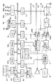
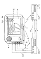
以下、図を参照しながら、この発明の携帯用テレビ受信機の一つの実施の形態について説明する。図1は、この実施の形態の携帯用テレビ受信機を説明するためのブロック図であり、図2は、この携帯用テレビ受信機の外観を示す図である。この携帯用テレビ受信機は、画面のサイズが数インチ、例えば2インチ程度のカラー液晶ディスプレイを用いた携帯用テレビ受信機である。
【0014】
この実施の形態の携帯用テレビ受信機は、アンテナ1、チューナ部2、中間周波増幅および検波回路3、スイッチ回路SW1、SW2,ビデオ信号処理回路4、重畳表示処理回路5、LCD6、オーディオ信号処理回路7、スピーカ8、例えばビデオテープレコーダ(以下、VTRと略称する)などの外部機器からのビデオ信号の入力端子VD、外部機器からのオーディオ信号の入力端子AU、例えばVTRのテープカウンタの値などのデータ入力を受け付ける入力端子DT、ビデオRAM9、ディスプレイコントローラ10、ボタンスイッチRM、FNC、PW、リモコン信号送信部11、タッチセンサシート12、電源回路14、LED(発光ダイオード)15を備えるとともに、マイクロコンピュータによって構成された制御回路100を備えている。
【0015】
なお、この実施の形態の携帯用テレビ受信機は、後述の図2に示すように、オーディオ用として2チャンネルの入力端子Au(L)、Au(R)を備え、オーディオ信号は2チャンネルステレオ信号の再生が可能であるが、図1では、説明の簡単のため、1チャンネルとして示し、例えばオーディオ入力端子は1つの端子Auとして示している。
【0016】
チューナ部2は、アンテナ1で受信した信号から、ユーザの選局操作により指定された放送チャンネルの信号を選局し、選局した放送波信号を中間周波信号に変換する。チューナ部2からの中間周波信号は、中間周波増幅および検波回路3に供給される。
【0017】
中間周波増幅および検波回路3は、中間周波信号を増幅するとともに、検波処理を行なって、ビデオ信号とオーディオ信号を復調する。復調されたビデオ信号は、スイッチ回路SW1の一方の入力端TVに供給され、復調されたオーディオ信号は、スイッチ回路SW2の一方の入力端TVに供給される。
【0018】
そして、スイッチ回路SW1の他方の入力端VTには、VTRなどの外部機器からのビデオ信号が入力端子VDを介して供給される。また、スイッチ回路SW2の他方の入力端VTには、VTRなどの外部機器からのオーディオ信号が入力端子AUを介して供給される。
【0019】
スイッチ回路SW1、SW2はチューナ部2からの信号を出力するか、外部機器からの信号を出力するかの切り換え回路である。スイッチ回路SW1、SW2は、制御回路100からの切り換え制御信号によって、切り換えられる。スイッチ回路SW1、SW2に対する切り換え制御信号は共通である。
【0020】
そして、スイッチ回路SW1、SW2は、ユーザがテレビ放送番組を視聴する場合には、入力端TV側に切り換えられ、VTRなどの外部機器からの映像、音声を視聴する場合には、入力端VT側に切り換えられる。スイッチ回路SW1からのビデオ信号は、ビデオ信号処理回路4に供給される。スイッチ回路SW2からのオーディオ信号は、オーディオ信号処理回路7に供給される。
【0021】
ビデオ信号処理回路4は、例えばビデオ信号用のDSP(デジタル・シグナル・プロセッサ)からなり、制御回路100から、このビデオ信号処理回路4に供給される画質調整用データに応じて、再生画像に対して、例えば、ブライトネス(明るさ)、コントラスト(濃淡)などの画質を調整する処理を行なう。このビデオ信号処理回路4からのビデオ信号は、重畳表示処理回路5に供給される。
【0022】
重畳表示処理回路5は、ビデオ信号処理回路4からのビデオ信号と、後述する文字、図形などを画面に例えばスーパーインポーズにより重畳する処理を行なう。重畳表示処理回路5においての処理は、制御回路100の制御に応じて、適宜行なわれる。重畳すべき信号は、後述するように制御回路100の制御に従って発生するものである。
【0023】
重畳表示処理回路5からのビデオ信号は、この携帯用テレビ受信機においては、LCD6に供給され、このLCD6の画面に、選局したテレビ放送番組の画像や入力端子VDを介して供給されたVTRなどの外部機器からのビデオ信号による画像がカラー表示される。
【0024】
オーディオ信号処理回路7は、スイッチ回路SW2からのオーディオ信号について、再生音声の音量、音質の調整などを行なう。このオーディオ信号処理回路7は、例えばオーディオ信号用のDSPからなり、制御回路100からの再生音声調整用データに応じて音量、音質の調整を行なう。このオーディオ信号処理回路7からのオーディオ信号はスピーカ8に供給され、再生音声が放音される。
【0025】
次に、制御回路100について説明する。制御回路100は、前述したように、マイクロコンピュータを備える構成となっており、システムバス102に対して、CPU101と、ROM103と、DRAM104と、SRAM105とが接続されている。また、システムバス102に対して、I/Oポート111〜116、119が接続され、種々の信号が入出力されるとともに、インターフェース117と118とが接続されている。
【0026】
そして、制御回路100は、チューナ部2に対しては、I/Oポート111を介して選局制御信号を供給し、スイッチ回路SW1、SW2に対しては、I/Oポート113を介して切り換え制御信号を供給する。
【0027】
また、制御回路100は、ビデオ信号処理回路4に対しては、I/Oポート114を介して、前述した画質調整用データを供給し、オーディオ信号処理回路7に対しては、I/Oポート114を介して、音量、音質などの再生音声調整用データを供給する。
【0028】
制御回路100は、重畳表示処理回路5に対しては、I/Oポート115を介して、重畳表示を行なうか否かを制御する制御信号を供給する。重畳表示処理回路5での重畳表示の例としては、チャンネル切り換え時に何チャンネルに切り替わったかをチャンネル番号で示す表示や、現在の受信チャンネルの表示、音量がどの程度大きくなったかをバー表示で知らせる場合の表示の他、後述するような、この携帯用テレビ受信機の遠隔操作機能を用いて、離れた場所にある、例えばVTRやテレビ受信機などの電子機器を遠隔制御するために用いられる、いわゆるタッチパネルとしての画像の表示などが挙げられる。
【0029】
この重畳表示のため、システムバス102に対しては、ビデオRAM9が接続され、ビデオRAM9には、ディスプレイコントローラ10が接続されている。
【0030】
ビデオRAM9は、ROM103に記録されているキャラクタ情報を用いて、制御回路100で形成された文字情報や記号情報を一旦蓄える。
【0031】
ディスプレイコントローラ10は、CPU101のプログラム制御に従って、ビデオRAM9に蓄えられた情報を読み出して、それを画面への重畳表示用として重畳表示処理回路5に供給する。
【0032】
この場合、ROM103には、重畳表示に必要な文字や記号のフォントデータ、イメージデータが蓄えられており、CPU101によって実行されるプログラムに従って、必要な文字や記号のフォントデータやイメージが読み出されて、ビデオRAM9の任意のアドレスに転送される。そして、ビデオRAM9に蓄えられた情報は、ディスプレイコントローラ10を介して、重畳表示処理回路5に供給されることによって、ビデオRAM9のイメージデータがビデオ信号と合成され、LCD6の画面に適宜の時間にわたって表示されることになる。
【0033】
また、この携帯用テレビ受信機においては、図1に示したように入力端子DTとI/Oポート112を介して、外部装置からのデータを制御回路100が取得することができるようにしている。また、I/Oポート116を介してリモコン信号送信部11が、システムバス102に接続され、インターフェース117を介してLCD6の画像の表示面に貼付されたタッチセンサシート12がシステムバス102に接続されている。
【0034】
さらに、インターフェース118を介して、ボタンスイッチRM、FNC、PWがシステムバス102に接続される。また、I/Oポート119を介して電源回路14がシステムバス102に接続されている。
【0035】
リモコン信号送信部11は、制御回路100からの指示情報に応じて、離れた場所にある電子機器を遠隔操作するための、例えば赤外線のリモコン信号を送信する。これにより、例えば、VTR、テレビ受信機、ビデオカメラなど、リモコン信号の受信部などを備え、遠隔制御が可能なようにされている各種の電子機器を遠隔操作することができるようにしている。すなわち、この携帯用テレビ受信機は、各種電子機器を遠隔操作する機能を備えたものである。
【0036】
タッチセンサシート12は、前述したようにLCD6に貼付されたものである。そして、タッチセンサシート12は、ユーザがLCD6の表示面上を、例えば指先などで触れることにより、その接触位置を検知して、この接触位置を示す位置情報をインターフェース117を介して制御回路100に通知する。
【0037】
制御回路100は、タッチセンサシート12から位置情報が通知されると、その位置情報の示すLCD6の表示面上の位置に表示されている表示情報に応じた処理を実行させることができる。このようにタッチセンサシート12は、LCD6に表示された文字や図形などの表示情報とともに、いわゆる操作キーとしての機能を有する。
【0038】
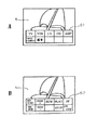
すなわち、詳しくは後述するが、この携帯用テレビ受信機においては、図3Aに示す用にLCD6の表示画面の下側部分の領域に、リモコン信号送信部11からのリモコン信号によって遠隔操作する電子機器を選択するための初期メニューパネル61や、図3Bに示すように、遠隔操作の対象とされた電子機器を遠隔操作するための遠隔操作用ファンクションパネル62などのタッチパネルとしての画像を表示することができるようにされている。
【0039】
そして、前述したように、初期メニューパネル61や遠隔操作用ファンクションパネル62などのタッチパネルとしての画像とタッチセンサシート12とにより、いわゆる操作キーを形成し、ユーザは、初期メニューパネル61や遠隔操作用ファンクションパネル62が表示されたLCD6の表示領域を指などで触れることにより、遠隔操作する電子機器の選択指示や、遠隔操作のための指示などを、この携帯用テレビ受信機に与えることができるようにされている。
【0040】
なお、図3Bに示した遠隔操作用ファンクションパネル62は、VTR用のものであり、この携帯用テレビ受信機においては、初期メニューパネル61の選択操作に応じて、選択された電子機器に対する遠隔操作用ファンクションパネルが表示される。
【0041】
また、この携帯用テレビ受信機においては、電源スイッチPW、遠隔操作モードスイッチRM、ファンクションモードスイッチFNCが、インターフェース118を介して、システムバス102に接続されている。これら各スイッチPW、RM、FNCがユーザにより押されると、その操作に応じた信号がインターフェース118を介してシステムバス102に供給される。この場合、電源スイッチPWは、この携帯用テレビ受信機に対して電源のオン/オフを行なう場合に用いられる。また、遠隔操作モードスイッチRMは、他の電子機器に対する遠隔操作を行なうモードである遠隔操作モードの実行/終了を指示する場合に用いられる。ファンクションモードスイッチFNCは、この携帯用テレビ受信機に対する選局チャンネルの変更情報や、音量、音質、画質などの調整情報を入力するモードである、自機操作用のファンクションモードの実行/終了を指示する場合に用いられる。
【0042】
そして、制御回路100は、各スイッチPW、RM、FNCからインターフェース118を介して制御信号の供給を受けると、その信号に応じて、電源のオン/オフ制御や、遠隔操作モード、ファンクションモードの切り換え制御を行なう。
【0043】
また、制御回路100は、電源回路14に対しては、I/Oポート119を介して電源のオン・オフを制御する制御信号を供給する。
【0044】
電源回路14は、制御回路100からの電源をオンにする制御信号を受けたときには、電池からの電源電圧の供給を受けて、この携帯用テレビ受信機の各部に供給する安定化電源電圧を形成し、これを各部に供給する。このとき、電源電圧は、LED(発光ダイオード)15にも供給され、LED15が点灯することにより、この携帯用テレビ受信機に電源が投入されたことを通知する。
【0045】
また、電源回路14は、制御回路100から電源をオフにする制御信号の供給を受けたときには、この携帯用テレビ受信機の各部への安定化電源電圧の供給を停止する。したがって、LED15も消灯される。
【0046】
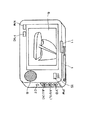
そして、この携帯用テレビ受信機の場合、図2に示すように、筐体の画面6が設けられる前面側の右上に設けられた電源スイッチPWが押され、電源をオンにするように操作されると、前述したように制御回路100は、電源回路14を制御して、各部に電源電圧を供給するように制御する。そして、制御回路100は、SRAM105から前回の視聴終了時に選択されていたチャンネル情報や、音量、音質、画質などの設定情報、いわゆるラストメモリ情報を読み出して、これらの情報を関係する各部に供給する。
【0047】
これにより、チューナ部2において、前回の視聴終了時と同じチャンネルが選局され、中間周波増幅および検波回路3でビデオ信号とオーディオ信号が復調される。復調されたビデオ信号は、スイッチ回路SW1、映像信号処理回路4、重畳信号処理回路5を介して、LCD6に供給され、図2に示すように、選局されたテレビ放送番組の画像がLCD6に表示される。
【0048】
また、復調されたオーディオ信号は、スイッチ回路SW2、オーディオ信号処理回路7を介して、スピーカ8に供給されて、選局されたテレビ放送番組の音声がスピーカ8から放音される。
【0049】
そして、前述したように、この携帯用テレビ受信機は、リモコン信号送信部11を備えており、このリモコン信号送信部11から送信されるリモコン信号が届く範囲内にあるテレビ受信機やVTRなどの各種の電子機器を遠隔操作する機能を有している。
【0050】
すなわち、この携帯用テレビ受信機に電源が投入された状態のときに、図2に示したように、この携帯用テレビ受信機の前面左下に設けられた遠隔操作モードスイッチRMがオンにされると、制御回路100は、この携帯用テレビ受信機を遠隔操作モードにする。
【0051】
この場合、制御回路100は、まずROM103に記憶されている初期メニューパネル61を形成するキャラクタ情報やフォントデータなどを読み出して、図3Aに示すように、遠隔操作の対象となる電子機器を選択するための初期メニューパネル61をビデオRAM9に形成する。そして、制御回路100は、ディスプレイコントローラ10、重畳表示処理回路5を制御して、ビデオRAM9に形成した初期メニューパネル61を、表示画像に重畳させて、LCD6の表示画面の下側部分の領域に表示するようにする。
【0052】
この携帯用テレビ受信機においては、図3Aに示すように、初期メニューパネル61により遠隔操作の対象となる電子機器としてTV(テレビ受信機)、VTR(ビデオテープレコーダ)、LD(レーザディスクプレーヤ)、CD(コンパクトディスクプレーヤ)、AMP(オーディオアンプ)、VIDEO CAMERA(ビデオカメラ)などの電子機器を選択することができるとともに、編集(ビデオ編集)を選んだ場合には、2台のVTRを遠隔制御して、ビデオ編集処理ができるようにされている。このビデオ編集処理についての詳細は後述する。
【0053】
そして、制御回路100は、初期メニューパネル61のTV、VTR、LDなどの個々の表示情報と、それら表示情報が表示された表示領域の位置や大きさを関連付けて管理している。この場合、個々の表示情報が表示された表示領域は、図3Aの初期メニューパネル61に示すように、TV、VTR、LDなどの各表示情報を個々に囲む四角枠内側の領域である。
【0054】
そして、ユーザが、LCD6に表示された初期メニューパネル61上に指などを接触させると、タッチセンサシート12から、その接触位置を示す位置情報が制御回路100に供給される。制御回路100は、供給された位置情報が示す表示領域内に表示されている表示情報は何かを判別することにより、ユーザにより指示された電子機器を判定する。
【0055】
このように、タッチセンサシート12とともに、ユーザからの指示情報の入力を可能にするTV、VTR、LDなどの表示情報を、以下の説明においては、ボタンアイコンという。
【0056】
そして、上述のようにして、例えばVTRが遠隔操作する電子機器として選択された場合には、制御回路100は、図3Bに示したVTR用の遠隔操作用ファンクションパネル62を表示画像に重畳させてLCD6の表示画面の下側部分の領域に表示する。この遠隔操作用ファンクションパネル62もまた、前述の初期メニューパネル61と同様に、制御回路100の制御によって、ROM103に記憶された遠隔操作用ファンクションパネル62を形成するキャラクタ情報などが用いられてビデオRAM9に形成され、ディスプレイコントローラ10、重畳処理回路5を介して、LCD6に表示される。
【0057】
この場合ユーザは、遠隔制御用ファンクションパネル62のボタンアイコンであるREC START(録画開始)、REC STOP(録画停止)、REW(巻き戻し)、PLAY(再生)、FF(早送り)、STOP(停止)、ON/OFF(電源スイッチ)を操作することによって、VTRを遠隔操作することができる。すなわち、ユーザが、LCD6に表示された遠隔制御用ファンクションパネル62のボタンアイコンに触れると、制御回路100は、LCD6に貼付されたタッチセンサシート12からの接触位置を示す情報の供給を受けて、ユーザにより操作されたボタンアイコンは何かを検知する。
【0058】
そして、制御回路100は、検知したボタンアイコンに応じてリモコン信号送信部11を制御して、遠隔操作するVTRに対して目的とする処理を行なわせるための、例えば赤外線のリモコン信号を送信する。
【0059】
そして、このリモコン信号を受信したVTRでは、このリモコン信号に応じて電源のオン/オフや録画の開始、終了、ビデオテープの再生、巻き戻し、早送り、それらの停止などの処理を実行する。
【0060】
また、初期メニューパネル61において、例えばTV(テレビ受信機)を遠隔操作する電子機器として選択した場合には、当該テレビ受信機に対して、電源のオン/オフを行なうためのボタンアイコン、選局チャンネルを変更するためのチャンネルアップボタンアイコン、ダウンボタンアイコン、音量アップボタンアイコン、ダウンボタンアイコンなどのボタンアイコンからなる遠隔操作用ファンクションパネルを表示する。同様に、初期メニューパネル61において、LD(レーザディスクプレーヤ)、CD(コンパクトディスクプレーヤ)、AMP(オーディオアンプ)、VIDEO CAMERA(ビデオカメラ)などの電子機器を選択した場合には、制御回路100は、選択された電子機器を遠隔操作するためのボタンアイコンからなる遠隔操作用ファンクションパネルを表示し、各電子機器に対する遠隔操作を可能にする。
【0061】
遠隔操作を終わる場合には、遠隔操作モードスイッチRMを再度押すことにより、遠隔操作モードを終了させるように指示する信号がインターフェース118を介して制御回路100に供給される。そして、制御回路100は、LCD6に表示した初期メニューパネル61、または、遠隔操作する電子機器に応じた遠隔操作用ファンクションパネルの表示を終了させるなどの処理を行なって、遠隔操作モードを終了させる。
【0062】
また、この携帯用テレビ受信機に電源が投入された状態のときに、図2に示したように、遠隔操作モードスイッチRMの右側に設けられたファンクションモードスイッチFNCがオンにされると、制御回路100は、この携帯用テレビ受信機を自機操作用のファンクションモードにする。
【0063】
すなわち、この場合には、制御回路100は、前述の図3A、Bに示したボタンアイコンと同様にして、この携帯用テレビ受信機に対して選局チャンネルのアップダウンや、音量のアップダウン、音質の調整や画質の調整を行なうためのボタンアイコンからなるタッチパネルを表示する。ユーザは、表示されたタッチパネルのボタンアイコンを操作することで、この携帯用テレビ受信機自体の選局チャンネル変更、音量、音質、画質の調整を行なうことができる。
【0064】
また、この自機操作用のファンクションモードを終了させる場合には、オンにしたファンクションモードスイッチFNCを再度押すことにより、自機操作用のファンクションモードをオフにする信号が制御回路100に供給される。そして、制御回路100は、表示されているタッチパネルを消去するなどの処理を行なって、自機操作用のファンクションモードを終了させる。
【0065】
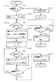
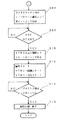
次に、制御回路100の動作について、遠隔操作モード時の動作を中心に、図4のフローチャートを参照しながら説明する。
【0066】
制御回路100は、ボタンスイッチPWが操作されるか、あるいは、ボタンスイッチPWが押され、電源が投入された後に、ボタンスイッチRM、FNCのいずれかが操作され、I/F118からの信号の供給を受けると、図4に示す処理ルーチンを起動する。そして、供給された信号は、ボタンスイッチRMが押されることにより発生し、この携帯用テレビ受信機を遠隔操作モードにする信号か否かを判断する(ステップ201)。ステップ201の判断処理において、遠隔操作モードをオンにする信号でないと判断したときには、供給された信号に応じた処理を行ない(ステップ202)、このルーチンを終了する。
【0067】
ステップ201の判断処理において、遠隔操作モードをオンにする信号が供給されたと判断したときには、制御回路100は、図3Aに示したように、遠隔操作の対象となる電子機器を選択するための初期メニューパネル61をLCD6の表示画面の下側部分の領域に表示する(ステップ203)。
【0068】
次に、制御回路100は、ユーザにより、タッチセンサシート12が貼付されたLCD6の表示画面に指などを接触させるなどするボタンアイコンの選択操作がされたか否かを判断する(ステップ204)。ステップ204の判断処理において、選択操作がされていないと判断したときには、ボタンスイッチRMが再度押されることにより遠隔操作モードがオフにされたか否かを判断する(ステップ205)。
【0069】
ステップ205の判断処理において、遠隔操作モードがオフにされていないと判断したときには、ステップ204からの処理を繰り返す。また、ステップ205の判断処理において、遠隔操作モードがオフにされたと判断したときには、現在表示中の遠隔操作の対象となる電子機器を選択するための初期メニューパネル61を消去して、通常の画像表示に戻し(ステップ206)、このルーチンを終了する。
【0070】
ステップ204の判断処理において、タッチセンサシート12に対して操作がされたと判断したときには、操作されたボタンアイコンを判別して、選択された電子機器を遠隔操作するための、例えば、図3Bに示したような遠隔操作用ファンクションパネルを表示する(ステップ207)。そして、リモコン信号送信部11を動作可能な状態にする(ステップ208)。このステップ208の処理は、ユーザの操作に応じて、遅れることなくリモコン信号を生成/送信することができるようにするための処理であり、リモコン信号の送信機部分の立ち上げ処理である。
【0071】
そして、次に制御回路100は、ステップ204の判断処理と同様に、ボタンアイコンの選択操作がされたか否かを判断する(ステップ209)。
【0072】
ステップ209の判断処理において、ボタンアイコンの選択操作がされたと判断したときには、制御回路100は、リモコン信号送信部11を制御して、選択されたボタンアイコンに応じたリモコン信号を生成し、送信する(ステップ210)。
【0073】
そして、制御回路100は、ステップ205の判断処理と同様に遠隔操作モードがオフにされたか否かを判断し(ステップ211)、オフにされていないと判断したときには、ステップ209からの処理を繰り返す。また、ステップ211の判断処理において、遠隔操作モードがオフにされたと判断したときには、現在表示されている遠隔操作用ファンクションパネルを消去して、通常の画像の表示に戻し(ステップ212)、このルーチンを終了する。
【0074】
また、ステップ209の判断処理において、タッチセンサシート12に対し、ボタンアイコンの選択操作がされていないと判断したときには、ステップ211からの処理を行なう。
【0075】
このように、この携帯用テレビ受信機は、テレビ放送番組などの画像と音声を提供することができるとともに、テレビ受信機、VTR、レーザディスクプレーヤ、コンパクトディスクプレーヤ、オーディオアンプなどの各種の電子機器を、この携帯用テレビ受信機1台で遠隔操作することができる。
【0076】
また、ユーザからの指示情報の入力は、LCD6に貼付されたタッチセンサシート12と、LCD6に表示されるボタンアイコンにより行なうことができるようにされている。各遠隔操作したい電子機器に応じて、必要となるボタンアイコンを表示させて、ユーザからの指示情報の入力を受けるようにすることができ、ボタンアイコンの表示により操作ボタン名などが表示されるため、操作を誤ることなく、簡単にすることができる。また、遠隔操作などのための機械的なボタンスイッチを数多く設けることもないため、携帯用テレビ受信機が大きくなることもない。
【0077】
[ビデオ編集を行なう場合の例]
次に、前述した携帯用テレビ受信機を用いて、2台のVTRを遠隔操作して、ビデオ編集を行なう場合の例について説明する。図5は、ビデオテープレコーダVTR1を録画側のビデオテープレコーダ、ビデオテープレコーダVTR2を再生側のビデオテープレコーダとし、前述した携帯用テレビ受信機をVTR1、VTR2を遠隔操作する携帯用テレビ受信機TV1として構築したビデオ簡易自動編集システムを説明するための図である。なお、以下においては、ビデオテープレコーダVTR1をVTR1と、ビデオテープレコーダVTR2をVTR2と、携帯用テレビ受信機TV1をTV1と略称する。
【0078】
この場合、VTR1と、VTR2は、異なるリモートコントロールプロトコルで動作する。これらのリモートコントロールプロトコルは、携帯用テレビ受信機TV1の例えばSRAM105に登録されている。このため、携帯用テレビ受信機TV1は、VTR1、VTR2の両方に対して、遠隔制御を行なうことができる。
【0079】
図5に示すように、VTR1とVTR2は、ケーブルV、AL、ARにより接続されている。ケーブルVは、ビデオ信号を伝送し、ケーブルAL、ARはオーディオ信号を伝送する。この例の場合、VTR2からVTR1にビデオ信号とオーディオ信号を供給するように接続されている。
【0080】
また、VTR2とTV1もケーブルV、AL、ARにより接続されている。そして、TV1は、VTR2からビデオ信号とオーディオ信号の供給を受けて、画像と音声を再生する。すなわち、TV1は、VTR2のモニタ装置としても用いられる。また、VTR2とTV1は、ケーブルDATAによっても接続されている。ケーブルDATAは、データを伝送するケーブルであり、この例の場合には、VTR2のテープカウンタのデータであるテープカウント値を、TV1に供給する。
【0081】
そして、ユーザは、いわゆるマスターテープとなるビデオテープをVTR2にセットし、編集した画像、音声を記録するスレーブビデオテープをVTR1にセットする。次にユーザは、TV1の前述したような遠隔操作機能を用いてVTR2を遠隔操作して、VTR2にセットしたタイマービデオテープの再生、巻き戻し、早送りを実行し、TV1によってVTR2からの画像と音声をモニタしながらVTR1のビデオテープに記録するシーン、すなわち目的とするシーンの開始の位置を探し出す。このとき、TV1は、目的とするシーンの始まりの位置を示すテープカウント値をケーブルDATAを介して取得する。TV1が取得したテープカウント値は、TV1のDRAM104に記憶する。同様にして、目的とするシーンの終了位置を探し出し、その位置のテープカウント値をTV1のDRAM104に記憶する。
【0082】
そして、TV1は、DRAM104に記憶した目的とするシーンの開始位置、終了位置を示すテープカウント値に基づいて、VTR2、VTR1を制御して、目的とするシーンのビデオ信号とオーディオ信号をVTR2からVTR1に供給し、VTR1は、これを記録する。これを繰り返すことにより、VTR2にセットされたマスターテープから必要なシーンだけがVTR1のスレーブテープに記録される。
【0083】
このように、VTR1、VTR2、TV1によって形成されたこのビデオ簡易自動編集システムの処理について、図6、図7のフローチャートを用いてさらに説明する。
【0084】
図6、図7に示す編集モードルーチンは、前述したように、携帯用テレビ受信機TV1の遠隔操作モードスイッチRMが押された場合に、TV1のLCD6に表示される図3Aに示した初期メニューパネル61の中から、“編集”ボタンアイコンを選択した場合に、TV1の制御回路100において起動されて実行される。
【0085】
この編集モードルーチンがTV1の制御回路100で起動されると、まず制御回路100は、TV1の各部を制御して、VTR2にセットされたマスターテープから、目的とするシーンの開始の位置であるスタートポイントを設定するようにユーザを促すメッセージを、画像や音声により提供する。そして、このとき、図5に示すように、TV1のLCD6にVTR2を遠隔制御するための遠隔操作用ファンクションパネル63を表示する(ステップ301)。
【0086】
そして、ユーザが表示された遠隔操作用ファンクションパネル63のうち、REW(巻き戻し)、PLAY(再生)、FF(早送り)、STOP(停止)の各ボタンアイコンを操作すると、TV1の制御回路100は、リモコン信号送信部11を制御して、VTR2に対して、ビデオテープの走行制御を行なうリモコン信号を送信する(ステップ302)。これにより、VTR2は、TV1からのリモコン信号に応じてビデオテープの走行制御がされて、スタートポイントが検索される。このとき、VTR2からのビデオ信号とオーディオ信号は、TV1に供給されて、TV1により、ユーザは、これらをモニタしながらスタートポイントを検索することができる。
【0087】
次に、TV1の制御回路100は、SETボタンアイコン(確定ボタンアイコン)が選択されたか否かを判断する(ステップ303)。SETボタンアイコンは、目的とするシーンの開始位置、終了位置を示すテープカウント値をTV1に設定する場合に用いられる。ステップ303の判断処理において、SETボタンアイコンが選択されていないと判断したときには、まだスタートポイント検索中であると判断し、ステップ302からの処理を繰り返す。
【0088】
ステップ303の判断処理において、SETボタンアイコンが選択されたと判断したときには、制御回路100は、スタートポイントが検出されたと判断し、SETボタンアイコンが選択された時点にケーブルDATAを介してVTR2から供給されたテープカウント値を取得して、これをDRAM104に保存する(ステップ304)。
【0089】
次に、制御回路100は、TV1の各部を制御して、VTR2にセットされたマスターテープから、目的とするシーンの終了位置であるエンドポイントを設定するようにユーザを促すメッセージを、画像や音声により提供する(ステップ305)。そして、ステップ302と同様に、ユーザにより、TV1のLCD6に表示された遠隔操作用ファンクションパネルの、REW(巻き戻し)、PLAY(再生)、FF(早送り)、STOP(停止)のボタンアイコンが操作されると、制御回路100は、リモコン信号送信部11を制御して、VTR2に対して、リモコン信号を送信する。これにより、VTR2は、ビデオテープの走行制御がされて、エンドポイントが検索される(ステップ306)。
【0090】
このとき、VTR2からのビデオ信号とオーディオ信号は、TV1に供給されるので、スタートポイントの検索時と同様に、ユーザは、TV1により、それらをモニタしながらエンドポイントを検索することができる。
【0091】
そして、TV1の制御回路100は、SETボタンアイコンが選択されたか否かを判断し(ステップ307)、SETボタンアイコンが選択されていないと判断したときには、エンドポイント検索中であると判断して、ステップ306からの処理を繰り返す。
【0092】
ステップ307の判断処理において、SETボタンアイコンが選択されたと判断したときには、エンドポイントが検出されたと判断し、TV1の制御回路100は、SETボタンアイコンが選択された時点にケーブルDATAを介してVTR2から供給されたテープカウント値を取得して、DRAM104に保存する(ステップ308)。
【0093】
そして、スタートポイントとエンドポイントが保持されると、TV1の制御回路100は、目的とするシーンをVTR1のビデオテープに記録するようにする処理を開始させるためのREC START(録画開始)ボタンアイコンが選択されたか否かを監視する(ステップ309)。
【0094】
ステップ309の判断処理において、REC STARTボタンアイコンが選択されたと判断したときには、TV1の制御回路100は、VTR2に対してリモコン信号を送信し、ビデオテープを走行制御して、VTR2のビデオテープをスタートポイント位置で停止させる(ステップ310)。
【0095】
すなわち、TV1の制御回路100は、VTR2にリモコン信号を送信し、VTR2のテープ走行制御を行なう。このとき、TV1の制御回路100は、ケーブルDATAを介して供給されるVTR2からのテープカウント値を監視し、制御回路100が保持しているスタートポイントを示すテープカウント値と一致したところで、VTR2のテープ走行を停止させ、目的とするシーンの開始位置から再生できるようにする。
【0096】
そして、TV1の制御回路100は、VTR1、VTR2双方のビデオテープ走行の同期を取るようにして、VTR1を録画開始、VTR2を再生開始にするように、VTR1、VTR2にリモコン信号を送信し(ステップ311)、VTR2のマスターテープからVTR1のスレーブビデオテープに目的とするシーンを録画する。
【0097】
そして、TV1の制御回路100は、VTR2からケーブルDATAを介して提供されるテープカウント値を監視し、当該テープカウント値と、保持しているエンドポイントを示すテープカウント値とが一致したか否かを判断する(ステップ312)。
【0098】
ステップ312の判断処理において、VTR2からのテープカウント値と、保持しているエンドポイントを示すテープカウント値とが一致するまで、VTR2のマスターテープからのビデオ信号とオーディオ信号がVTR1のスレーブビデオテープに記録される。そして、ステップ312の判断処理において、テープカウント値がエンドポイントになったと判断したときには、TV1の制御回路100は、VTR1、VTR2を停止させるリモコン信号をリモコン信号送信部11から送信させ、VTR1、VTR2を停止させて、この編集モードルーチンを終了する(ステップ313)。
【0099】
このように、この携帯用テレビ受信機は、編集モードを選択することにより、2台のVTRを遠隔操作するようにして、ユーザが目的とするシーンだけを抜き出したり、繋ぎ合わせたりする編集処理を行なうことができる。
【0100】
なお、このビデオ簡易自動編集システムの場合、例えばリモートコントロールプロトコルが同じVTRを2台用いる場合には、例えば、VTR1とVTR2とを区別するために、識別コードをTV1から送信されるリモコン信号に付加するようにする。各VTRでは、リモコン信号に付加された識別コードを判別するようにすることにより、自己のVTRに対するリモコン信号であるかどうかを判別し、自己へのリモコン信号のみを取り込むようにする。
【0101】
また、前述したように、このビデオ簡易自動編集システムにおいては、TV1により、VTR2からの画像と音声をモニタしながら、VTR1、VTR2の両方を遠隔操作できるため、簡単かつ正確にビデオ編集を行なうことができる。また、大きな画面を有するモニタ装置がない場所でもビデオ編集処理を行なうことができる。
【0102】
また、前述の例においては、テープカウント値を用いてビデオ編集処理を行なうようにしたが、TV1により画像と音声をモニタしながらユーザのマニュアル操作により、ビデオ編集処理を行なうようにすることもできる。
【0103】
[ビデオカメラの遠隔制御の例]
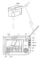
次に、前述した携帯用テレビ受信機を用いて、ビデオカメラを遠隔制御する場合の例について説明する。
【0104】
この例の場合には、図8に示すように、遠隔制御の対象となるビデオカメラCMA1にトランスミッターを取り付けて、ビデオカメラCMA1で捕えた画像と音声をテレビジョン信号(映像情報を含む高周波信号)として送信できるようにしておく。この場合、ビデオカメラCAM1が捕えた画像と音声は、ビデオ撮影時の画像だけでなく、いわゆるビデオ撮影がいつでもできるスタンバイ状態のときにも、捕えている画像と音声を、テレビジョン信号として送信するようにする。
【0105】
そして、この携帯用テレビ受信機TV2は、前述した携帯用テレビ受信機と同様のものであり、前述した初期メニューパネル61の中から、ビデオカメラに対応するボタンアイコン(VIDEO CAMERA)が選択されると、空きチャンネルを用いて、ビデオカメラCMA1からのテレビジョン信号を受信選局するように構成されている。以下においては、携帯用テレビ受信機TV2は、TV2と略称する。
【0106】
これによって、ビデオカメラCMA1によって捕えられている画像がTV2のLCD6に映出される。また、ビデオカメラCMA1のマイクロフォンによって収音された音声が、TV2のスピーカ8から放音される。
【0107】
そして、この場合、図8に示すように、TV2の表示画面には、ビデオカメラCMA1を遠隔制御するための遠隔操作用ファンクションパネル64が表示される。そして、ビデオカメラCMA1からテレビジョン信号として送信されてくる画像と音声を、TV2で視聴しながら、遠隔操作用ファンクションパネル64のボタンアイコンを操作することにより、ビデオカメラCMA1を遠隔制御することができる。
【0108】
この場合、遠隔操作用ファンクションパネルのボタンアイコンREC START(録画開始)、REC STOP(録画停止)、ZOOM+(ズームアップ)、ZOOM−(ズームダウン)、REW(巻き戻し)、PLAY(再生)、FF(早送り)、STOP(停止)を操作することによって、ビデオカメラCAM1に対して録画の開始と停止、捕えている画像のの拡大と縮小、ビデオテープの巻き戻し、再生、早送り、それらの停止などの処理を遠隔操作によって行なわせることができる。
【0109】
このように、この携帯用テレビ受信機TV2は、ビデオカメラCMA1のトランスミッターが送信するテレビジョン信号を受信し、離れた位置からでもビデオカメラCMA1が捕えている画像を確認できる。そして、ユーザは、その画像を確認しながら、ズームなどを調整したり録画をスタートさせたり、停止させたりする遠隔制御を行なうことができる。
【0110】
このように、この携帯用テレビ受信機は、ビデオ簡易自動編集システムやビデオカメラで捕えている画像、音声をモニタしながらのビデオカメラの遠隔制御など、様々な態様で、各種の電子機器を遠隔操作できる。
【0111】
また前述した携帯用テレビ受信機は、LCD6にタッチセンサシート12を貼付し、このタッチセンサシート12と、LCD6に表示されるボタンアイコンとにより、ユーザからの情報の入力を受け付ける入力手段を形成していたが、タッチセンサシートを用いないようにすることもできる。
【0112】
すなわち、図9に示すように、タッチセンサシートに変えて、複数のキー20を携帯用テレビ受信機の前面パネルに設ける。そして、図9に示すように、LCD6に、複数のキー20の配列に対応する操作キー名の表示などを行なう。
【0113】
この場合、表示された操作キー名の表示は、ボタンアイコンとしてではなく、いわゆるガイダンスの役割を果たすものである。そして、ユーザは、表示されたガイダンスのキー操作名の並びを確認し、対応するキー群20の1つのキーを操作することによって、タッチセンサシートを用いた場合と同様に、携帯用テレビ受信機を操作し、活用することができる。その他の部分については、前述の図2の携帯用テレビ受信機と同様である。
【0114】
そして、この場合、自機を操作するためのファンクションモードにする場合には、キー群20のうちの1つを、前述した携帯用テレビ受信機の自機操作用ファンクションモードスイッチFNCとして用いるようにすることにより、自機操作用のガイダンスを表示することもできる。また、ガイダンスを表示するまでもなく、遠隔操作モード時以外のときには、キー群20を自機操作用として各キーに固定的に実行する処理、例えば、選局チャンネルのアップ/ダウン、音量のアップ/ダウンを割り当てておくようにすることもできる。
【0115】
なお、前述の説明においては、この発明を携帯用テレビ受信機に適用した場合として説明したが、チューナ部や、中間周波および検波回路などがない、単なるモニタ装置に、この発明を適用することもできる。この場合には、前述のビデオ簡易自動編集システムのモニタ装置として活用するなどの場合に有効である。
【0116】
【発明の効果】
以上説明したように、この発明による携帯用テレビ受信機によれば、単なる携帯用テレビ受信機や、単なる遠隔操作装置に比べ、その活用範囲が広がり、様々な態様で活用できる携帯用テレビ受信機を提供することができる。
【図面の簡単な説明】
【図1】この発明の携帯用テレビ受信機の一実施の形態を説明するためのブロック図である。
【図2】この発明が適用された一実施の形態の携帯用テレビ受信機の外観の例を示す図である。
【図3】この発明が適用された一実施の形態の携帯用テレビ受信機に用いられるボタンアイコンの例について説明するための図である。
【図4】この発明が適用された一実施の形態の携帯用テレビ受信機においての遠隔操作モード時の動作を説明するためのフローチャートである。
【図5】この発明が適用された一実施の形態の携帯用テレビ受信機の利用例を説明するための図である。
【図6】この発明が適用された一実施の形態の携帯用テレビ受信機の利用例を説明するためのフローチャートである。
【図7】図6に続くフローチャートである。
【図8】この発明が適用された一実施の形態の携帯用テレビ受信機の他の利用例を説明するための図である。
【図9】この発明が適用された一実施の形態の携帯用テレビ受信機の他の例を説明するための図である。
【符号の説明】
1 アンテナ
2 チューナ部
3 中間周波増幅および検波回路
4 ビデオ信号処理回路
5 重畳表示処理回路
6 LCD(液晶ディスプレイ)
7 オーディオ信号処理回路
8 スピーカ
9 ビデオRAM
10 ディスプレイコントローラ
11 リモコン信号送信部
12 タッチセンサシート
14 電源回路
15 LED(発光ダイオード)
SW1、SW2 スイッチ回路
101 CPU
102 システムバス
103 ROM
104 DRAM
105 SRAM
111〜116、119 I/Oポート
117、118 インターフェース[0001]
BACKGROUND OF THE INVENTION
The present invention can remotely control various electronic devices such as a television receiver, a video tape recorder, and a video camera.Portable tv receiverAbout.
[0002]
[Prior art]
2. Description of the Related Art Conventionally, so-called portable television receivers that are reduced in size and weight by using, for example, an LCD (liquid crystal display) as a display screen have been widely provided as portable image display devices. As a power source of the portable television receiver, a primary battery such as a dry battery or a rechargeable secondary battery is used.
[0003]
For this reason, the portable television receiver is suitable for use in places where it is difficult to secure power, such as outdoors, and enables viewing of TV broadcast programs not only in the home but also outside.
[0004]
Further, the portable television receiver can be used as a monitor device by connecting to a video camera. For this reason, it may be excellent in portability, and can be used as a monitor when shooting video outdoors.
[0005]
[Problems to be solved by the invention]
By the way, at present, as described above, the portable television receiver is considered to have high usage in the outdoors and low usage in the home. That is, usually, a television receiver with a large screen that is fixedly placed and used is installed in each home. For this reason, it is considered that there is little need to use a portable television receiver in the home.
[0006]
Therefore, portable television receivers are rarely used effectively in the home, and even if you have a portable television receiver, there are many cases that it is useless in the home. Conceivable.
[0007]
On the other hand, various electronic devices such as a television receiver, a video tape recorder, and various audio devices are used in the home, and many of these electronic devices can be remotely operated. That is, a so-called remote control device exists for each electronic device.
[0008]
For this reason, the user uses a remote control device corresponding to the electronic device depending on the electronic device to be used. However, since it is very inconvenient to use a different remote control device for each electronic device, a remote control device with a so-called learning function capable of remote control of a plurality of electronic devices has been provided. .
[0009]
However, the remote operation device with a learning function may be difficult to use for a general user, and may not be used easily.
[0010]
For this reason, it is conceivable to provide a liquid crystal display in such a remote operation device with a learning function to display operation information and the like, but the remote operation device tends to be too large.
[0011]
As described above, the present inventionPortable tv receiverThe core of the audio-visual system is realized by expanding the range of use in the home and enabling remote operation of multiple electronic devices that are very easy to operate.Portable tv receiverThe purpose is to provide.
[0012]
[Means for Solving the Problems]
In order to solve the above problems, the present inventionAccording to portable TV receiverIs
Includes video and audio signalsbroadcastReceive wave signalAttached to the housing forAn antenna,
Provided in the housing,Received by the antennabroadcastOf the channel specified according to the user's channel selection operationbroadcastA tuner unit that selects a wave signal;
Provided in the housing,A detection circuit that detects an intermediate frequency signal from the tuner unit and demodulates a video signal and an audio signal;
Provided in the housing,A video signal processing circuit for performing predetermined signal processing on the video signal from the detection circuit;
Provided in the housing,An audio signal processing circuit that performs predetermined signal processing on the audio signal from the detection circuit;
In response to the video signal supplied from the video signal processing circuit, an image corresponding to the video signal is displayed.Relatively small LCD ( Liquid Crystal Display LCD mounted on the housing such that its display screen faces the outsideWhen,
A speaker that receives an audio signal from the audio signal processing circuit and emits a sound corresponding to the audio signal.And a speaker attached to the housing such that the sound emission part faces the outside.When,
Provided in the housing, and a plurality ofRemotely controllable electronic deviceEquipment to be remotely controlled fromFirst display signal forming means for forming a display signal for a device selection image composed of a plurality of regions for selecting
A remote operation mode switch provided on the surface of the housing for instructing display of the device selection image;
Provided in the housing, and when the remote operation mode switch is operated,The image by the display signal for device selection from the first display signal forming means is superimposed on the image by the video signal from the video signal processing circuit.And supply to the LCDFirst superimposing means;
SaidLCDA touch sensor sheet provided in front of the display screen,
Device selection instruction input means for detecting which region of the plurality of regions for device selection of the touch sensor sheet is touched by the user and receiving this as a device selection instruction from the user;
Provided in the housing,When a device selection instruction is received via the device selection instruction input means, a remote operation image comprising a plurality of areas for enabling selection of each of a plurality of functions of the electronic device according to the device selection instruction Second display signal forming means for forming a display signal of
Provided in the housing,Instead of an image based on the display signal for device selection instead of an image based on the video signal from the video signal processing circuit, an image based on the display signal of the remote operation image from the second display signal forming means. Second superimposing means for superimposing;
Remote operation instruction input means for detecting which area of the plurality of areas for remote operation of the touch sensor sheet is touched by the user and receiving this as a remote operation instruction from the user;
Provided in the housing not,In response to the remote operation instruction input via the remote operation instruction input means, a remote operation signal transmission means for forming and transmitting a remote operation signal for the selected electronic device;
Provided in the housing not,A power supply circuit for supplying operating power from a battery to at least each of the parts;
WithAnd
It can be used alone as a portable television receiver, and can also be used as a remote control device for the plurality of electronic devices by sequentially operating the remote control mode switch and the touch sensor sheet.It is characterized by that.
[0013]
DETAILED DESCRIPTION OF THE INVENTION
Hereinafter, referring to the figure,Of the portable television receiver of the present inventionOne embodiment will be described. FIG. 1 is a block diagram for explaining the portable television receiver of this embodiment, and FIG. 2 is a diagram showing the appearance of this portable television receiver. This portable television receiver is a portable television receiver using a color liquid crystal display having a screen size of several inches, for example, about 2 inches.
[0014]
The portable television receiver of this embodiment includes an
[0015]
As shown in FIG. 2 described later, the portable television receiver of this embodiment includes 2-channel input terminals Au (L) and Au (R) for audio, and the audio signal is a 2-channel stereo signal. In FIG. 1, for simplicity of explanation, it is shown as one channel, for example, an audio input terminal is shown as one terminal Au.
[0016]
The
[0017]
The intermediate frequency amplification and
[0018]
A video signal from an external device such as a VTR is supplied to the other input terminal VT of the switch circuit SW1 via the input terminal VD. Also, an audio signal from an external device such as a VTR is supplied to the other input terminal VT of the switch circuit SW2 via the input terminal AU.
[0019]
The switch circuits SW1 and SW2 are switching circuits for outputting a signal from the
[0020]
The switch circuits SW1 and SW2 are switched to the input terminal TV side when the user views a television broadcast program, and to the input terminal VT side when viewing video and audio from an external device such as a VTR. Can be switched to. The video signal from the switch circuit SW1 is supplied to the video signal processing circuit 4. The audio signal from the switch circuit SW2 is supplied to the audio signal processing circuit 7.
[0021]
The video signal processing circuit 4 is made up of, for example, a DSP (digital signal processor) for video signals. The video signal processing circuit 4 applies the image quality adjustment data supplied from the
[0022]
The superimposed display processing circuit 5 performs a process of superimposing the video signal from the video signal processing circuit 4 and characters, figures, and the like described later on the screen by, for example, superimposing. The processing in the superimposed display processing circuit 5 is appropriately performed according to the control of the
[0023]
The video signal from the superimposed display processing circuit 5 is supplied to the
[0024]
The audio signal processing circuit 7 adjusts the volume and quality of reproduced sound for the audio signal from the switch circuit SW2. The audio signal processing circuit 7 is composed of, for example, a DSP for audio signals, and adjusts the volume and sound quality in accordance with reproduction sound adjustment data from the
[0025]
Next, the
[0026]
The
[0027]
Further, the
[0028]
The
[0029]
For this superimposed display, a
[0030]
The
[0031]
The
[0032]
In this case, the
[0033]
In this portable television receiver, the
[0034]
Further, button switches RM, FNC, and PW are connected to the
[0035]
In response to the instruction information from the
[0036]
The
[0037]
When the position information is notified from the
[0038]
That is, as will be described in detail later, in this portable television receiver, as shown in FIG. 3A, an electronic device that is remotely operated by a remote control signal from the remote control
[0039]
As described above, so-called operation keys are formed by the
[0040]
The remote
[0041]
In this portable television receiver, the power switch PW, the remote operation mode switch RM, and the function mode switch FNC are connected to the
[0042]
When the
[0043]
The
[0044]
When the
[0045]
When the
[0046]
In the case of this portable television receiver, as shown in FIG. 2, the power switch PW provided at the upper right on the front surface side where the
[0047]
As a result, the
[0048]
The demodulated audio signal is supplied to the
[0049]
As described above, the portable television receiver includes the remote control
[0050]
That is, when the portable television receiver is powered on, as shown in FIG. 2, the remote operation mode switch RM provided at the lower left of the front surface of the portable television receiver is turned on. Then, the
[0051]
In this case, the
[0052]
In this portable television receiver, as shown in FIG. 3A, electronic devices to be remotely operated by an
[0053]
The
[0054]
When the user touches the
[0055]
In this way, display information such as TV, VTR, and LD that allows the user to input instruction information together with the
[0056]
As described above, for example, when the VTR is selected as an electronic device to be remotely operated, the
[0057]
In this case, the user uses REC START (recording start), REC STOP (recording stop), REW (rewind), PLAY (playback), FF (fast forward), and STOP (stop) which are button icons of the
[0058]
Then, the
[0059]
The VTR that has received this remote control signal performs processing such as power on / off, recording start / stop, video tape playback, rewinding, fast-forwarding, and stopping thereof according to the remote control signal.
[0060]
In addition, in the
[0061]
When the remote operation is finished, a signal instructing to end the remote operation mode is supplied to the
[0062]
Further, when the portable television receiver is powered on, as shown in FIG. 2, when the function mode switch FNC provided on the right side of the remote operation mode switch RM is turned on, the control is performed. The
[0063]
That is, in this case, the
[0064]
When the function mode for operating the own device is to be terminated, a signal for turning off the function mode for operating the own device is supplied to the
[0065]
Next, the operation of the
[0066]
The
[0067]
When it is determined in
[0068]
Next, the
[0069]
If it is determined in
[0070]
When it is determined in
[0071]
Then, the
[0072]
If it is determined in the determination processing of
[0073]
Then, the
[0074]
If it is determined in
[0075]
As described above, the portable television receiver can provide images and sounds of a television broadcast program and the like, and various electronic devices such as a television receiver, a VTR, a laser disc player, a compact disc player, and an audio amplifier. Can be remotely controlled by one portable television receiver.
[0076]
In addition, input of instruction information from the user can be performed by a
[0077]
[Example of video editing]
Next, an example in which video editing is performed by remotely operating two VTRs using the above-described portable television receiver will be described. FIG. 5 shows a video tape recorder VTR1 as a video tape recorder on the recording side, a video tape recorder VTR2 as a video tape recorder on the playback side, and the above-described portable television receiver as a portable television receiver TV1 for remotely operating VTR1 and VTR2. It is a figure for demonstrating the video simple automatic edit system constructed | assembled as. In the following, the video tape recorder VTR1 is abbreviated as VTR1, the video tape recorder VTR2 is abbreviated as VTR2, and the portable television receiver TV1 is abbreviated as TV1.
[0078]
In this case, VTR1 and VTR2 operate with different remote control protocols. These remote control protocols are registered in, for example, the
[0079]
As shown in FIG. 5, VTR1 and VTR2 are connected by cables V, AL, and AR. The cable V transmits a video signal, and the cables AL and AR transmit an audio signal. In this example, the video signal and the audio signal are connected from the
[0080]
The
[0081]
Then, the user sets a video tape as a so-called master tape in the
[0082]
Then, the
[0083]
The processing of this simple video automatic editing system formed by VTR1, VTR2, and TV1 will be further described with reference to the flowcharts of FIGS.
[0084]
The edit mode routine shown in FIGS. 6 and 7 is the initial menu shown in FIG. 3A displayed on the
[0085]
When this editing mode routine is started by the
[0086]
When the user operates the REW (rewind), PLAY (play), FF (fast forward), and STOP (stop) button icons on the remote
[0087]
Next, the
[0088]
When determining that the SET button icon has been selected in the determination process of
[0089]
Next, the
[0090]
At this time, since the video signal and the audio signal from the
[0091]
Then, the
[0092]
If it is determined in
[0093]
When the start point and the end point are held, the
[0094]
When it is determined in
[0095]
That is, the
[0096]
Then, the
[0097]
Then, the
[0098]
In the determination process of
[0099]
As described above, the portable television receiver performs an editing process in which only the target scene is extracted or connected by remotely operating the two VTRs by selecting the editing mode. Can be done.
[0100]
In the case of this video simple automatic editing system, for example, when two VTRs having the same remote control protocol are used, for example, an identification code is added to the remote control signal transmitted from
[0101]
In addition, as described above, in this simple video automatic editing system, both the VTR1 and VTR2 can be remotely controlled by the
[0102]
In the above-described example, the video editing process is performed using the tape count value. However, the video editing process may be performed by the user's manual operation while monitoring the image and the sound with the
[0103]
[Example of remote control of video camera]
Next, an example in which the video camera is remotely controlled using the above-described portable television receiver will be described.
[0104]
In the case of this example, as shown in FIG. 8, a transmitter is attached to the video camera CMA1 to be remotely controlled, and the image and sound captured by the video camera CMA1 are converted into a television signal.(High-frequency signal including video information)To be able to send as. In this case, the image and sound captured by the video camera CAM1 are transmitted not only as an image at the time of video shooting but also as a television signal in the standby state in which so-called video shooting can be performed at any time. Like that.
[0105]
The portable television receiver TV2 is the same as the portable television receiver described above, and the button icon (VIDEO CAMERA) corresponding to the video camera is selected from the
[0106]
As a result, the image captured by the video camera CMA1 is displayed on the
[0107]
In this case, as shown in FIG. 8, a remote
[0108]
In this case, button icons REC START (recording start), REC STOP (recording stop), ZOOM + (zoom up), ZOOM- (zoom down), REW (rewind), PLAY (playback), FF on the function panel for remote operation (Fast forward), STOP (stop) operation to start and stop recording on the video camera CAM1, enlarge and reduce the captured image, rewind the videotape, play back, fast forward, stop them, etc. Can be performed by remote control.
[0109]
Thus, the portable television receiver TV2 receives the television signal transmitted by the transmitter of the video camera CMA1, and can confirm the image captured by the video camera CMA1 even from a remote position. Then, the user can perform remote control such as adjusting the zoom or starting or stopping the recording while checking the image.
[0110]
As described above, this portable television receiver can remotely control various electronic devices in various modes such as a video automatic remote editing system and remote control of a video camera while monitoring images and audio captured by the video camera. Can be operated.
[0111]
Further, the portable television receiver described above has a
[0112]
That is, as shown in FIG. 9, instead of a touch sensor sheet, a plurality of
[0113]
In this case, the displayed operation key name is not a button icon but serves as a so-called guidance. Then, the user confirms the arrangement of the key operation names of the displayed guidance, and operates one key of the corresponding
[0114]
In this case, when the function mode for operating the own device is set, one of the
[0115]
In the above description, the present invention has been described as applied to a portable television receiver. However, the present invention may be applied to a simple monitor device that does not have a tuner, an intermediate frequency, and a detection circuit. it can. In this case, it is effective in the case where it is used as a monitor device of the above-described simple video automatic editing system.
[0116]
【The invention's effect】
As explained above, according to the present inventionPortable tv receiverAccording to merePortable tv receiverCompared to simple remote control devices, its range of use is widened and can be used in various ways.Portable tv receiverCan be provided.
[Brief description of the drawings]
FIG. 1 shows the present invention.Of portable tv receiverIt is a block diagram for demonstrating one embodiment.
FIG. 2 is a diagram showing an example of the appearance of a portable television receiver according to an embodiment to which the present invention is applied.
FIG. 3 is a diagram for explaining an example of button icons used in the portable television receiver according to the embodiment to which the invention is applied.
FIG. 4 is a flowchart for explaining an operation in a remote operation mode in a portable television receiver according to an embodiment to which the present invention is applied;
FIG. 5 is a diagram for explaining a usage example of a portable television receiver according to an embodiment to which the present invention is applied;
FIG. 6 is a flowchart for explaining an example of use of a portable television receiver according to an embodiment to which the present invention is applied;
FIG. 7 is a flowchart following FIG. 6;
FIG. 8 is a diagram for explaining another usage example of the portable television receiver according to the embodiment to which the present invention is applied;
FIG. 9 is a diagram for explaining another example of the portable television receiver according to the embodiment to which the invention is applied.
[Explanation of symbols]
1 Antenna
2 Tuner section
3 Intermediate frequency amplification and detection circuit
4 Video signal processing circuit
5 Overlay display processing circuit
6 LCD (Liquid Crystal Display)
7 Audio signal processing circuit
8 Speaker
9 Video RAM
10 Display controller
11 Remote control signal transmitter
12 Touch sensor sheet
14 Power supply circuit
15 LED (Light Emitting Diode)
SW1, SW2 switch circuit
101 CPU
102 System bus
103 ROM
104 DRAM
105 SRAM
111-116, 119 I / O ports
117, 118 interface
Claims (2)
前記筐体内に設けられ、前記アンテナで受信した前記放送波信号から、ユーザの選局操作に応じて指定されたチャンネルの放送波信号を選局するチューナ部と、
前記筐体内に設けられ、前記チューナ部からの中間周波信号を検波してビデオ信号とオーディオ信号を復調する検波回路と、
前記筐体内に設けられ、前記検波回路からのビデオ信号に対して所定の信号処理を行うビデオ信号処理回路と、
前記筐体内に設けられ、前記検波回路からのオーディオ信号に対して所定の信号処理を行うオーディオ信号処理回路と、
前記ビデオ信号処理回路からのビデオ信号の供給を受けて、当該ビデオ信号に応じた画像を表示する比較的に小型のLCD( Liquid Crystal Display )であって、その表示画面が外部に臨むように前記筐体に取り付けられたLCDと、
前記オーディオ信号処理回路からのオーディオ信号の供給を受けて、当該オーディオ信号に応じた音声を放音するスピーカであって、その放音部が外部に臨むように前記筐体に取り付けられたスピーカと、
前記筐体内に設けられ、複数の遠隔操作可能な電子機器の中から遠隔操作の対象となる電子機器を選択するための複数の領域からなる機器選択用画像の表示用信号を形成する第1の表示信号形成手段と、
前記機器選択用画像の表示を指示するための前記筐体の表面に設けられた遠隔操作モードスイッチと、
前記筐体内に設けられ、前記遠隔操作モードスイッチが操作されたときに、前記ビデオ信号処理回路からのビデオ信号による画像に、前記第1の表示信号形成手段からの前記機器選択用の表示用信号による画像を重畳して前記LCDに供給する第1の重畳手段と、
前記LCDの表示画面の前面に設けられたタッチセンサシートと、
前記タッチセンサシートの前記機器選択用の複数の領域中のどの領域がユーザにより触れられたかを検出し、これをユーザからの機器選択指示として受け付ける機器選択指示入力手段と、
前記筐体内に設けられ、前記機器選択指示入力手段を介して機器選択指示を受け付けた場合に、前記機器選択指示に応じた電子機器の複数の機能のそれぞれを選択できるようにするための複数の領域からなる遠隔操作用画像の表示用信号を形成する第2の表示信号形成手段と、
前記筐体内に設けられ、前記ビデオ信号処理回路からのビデオ信号による画像に、前記機器選択用の表示用信号による画像に代えて、前記第2の表示信号形成手段からの前記遠隔操作用画像の前記表示用信号による画像を重畳するようにする第2の重畳手段と、
前記タッチセンサシートの前記遠隔操作用の複数の領域中のどの領域がユーザにより触れられたかを検出し、これをユーザからの遠隔操作指示として受け付ける遠隔操作指示入力手段と、
前記筐体ないに設けられ、前記遠隔操作指示入力手段を介して入力された前記遠隔操作指示に応じて、選択された電子機器に対する遠隔操作信号を形成し、これを送信する遠隔操作信号送信手段と、
前記筐体ないに設けられ、少なくとも前記各部分に対して電池から動作電力を供給する電源回路と
を備えており、
携帯用テレビ受信機として単体で使用できると共に、前記遠隔操作モードスイッチと前記タッチセンサシートを順次操作することにより前記複数の電子機器に対する遠隔操作装置としても使用できるようにした携帯用テレビ受信機。 An antenna attached to the housing for receiving a broadcast wave signal including a video signal and an audio signal;
A tuner unit that is provided in the housing and that tunes a broadcast wave signal of a channel designated according to a user's channel selection operation from the broadcast wave signal received by the antenna;
A detection circuit provided in the housing, for detecting an intermediate frequency signal from the tuner unit and demodulating a video signal and an audio signal;
A video signal processing circuit that is provided in the casing and performs predetermined signal processing on the video signal from the detection circuit;
An audio signal processing circuit that is provided in the housing and performs predetermined signal processing on the audio signal from the detection circuit;
A relatively small LCD ( Liquid Crystal Display ) that receives a video signal supplied from the video signal processing circuit and displays an image corresponding to the video signal, and the display screen faces the outside. An LCD attached to the housing;
A speaker that receives an audio signal from the audio signal processing circuit and emits a sound corresponding to the audio signal, the speaker being attached to the housing such that the sound emitting unit faces the outside; ,
A first signal that is provided in the casing and forms a display signal for a device selection image including a plurality of regions for selecting an electronic device to be remotely operated from a plurality of remotely operable electronic devices. Display signal forming means;
A remote operation mode switch provided on the surface of the housing for instructing display of the device selection image;
A display signal for selecting the device from the first display signal forming means is provided on the image by the video signal from the video signal processing circuit when the remote operation mode switch is operated. First superimposing means for superimposing an image according to the above and supplying the superimposed image to the LCD ;
A touch sensor sheet provided in front of the LCD display screen;
Device selection instruction input means for detecting which region of the plurality of regions for device selection of the touch sensor sheet is touched by the user and receiving this as a device selection instruction from the user;
A plurality of functions provided in the housing and configured to allow selection of each of a plurality of functions of the electronic device according to the device selection instruction when a device selection instruction is received via the device selection instruction input unit. Second display signal forming means for forming a display signal for an image for remote control comprising a region;
An image of the remote operation image from the second display signal forming means is provided in the housing, in place of the image by the video signal from the video signal processing circuit, instead of the image by the display signal for device selection. Second superimposing means for superimposing an image based on the display signal;
Remote operation instruction input means for detecting which area of the plurality of areas for remote operation of the touch sensor sheet is touched by the user and receiving this as a remote operation instruction from the user;
A remote operation signal transmitting means that is provided in the casing and forms a remote operation signal for the selected electronic device in response to the remote operation instruction input via the remote operation instruction input means, and transmits the signal. When,
A power supply circuit that is provided in the casing and supplies operating power from a battery to at least each of the parts ;
A portable television receiver which can be used alone as a portable television receiver and can also be used as a remote operation device for the plurality of electronic devices by sequentially operating the remote operation mode switch and the touch sensor sheet .
自機に対する操作を受け付ける自機操作モードへの切り換えを行うための自操作モードスイッチと、
自機に対する操作入力を受け付けるための複数の領域からなる自操作用画像の表示用信号を形成する第3の表示信号形成手段と、
前記ビデオ信号処理回路からのビデオ信号による画像に、前記第3の表示信号形成手段からの前記自操作用の表示用信号による画像を重畳するようにする第3の重畳手段と、
前記タッチセンサシートの前記自操作用の複数の領域中のどの領域がユーザにより触れられたかを検出し、これをユーザからの自操作指示として受け付ける自操作指示入力手段と、
前記自操作指示入力手段を介して入力された前記自操作指示に応じて、自機の機能を制御する自機制御手段と
を備え、
前記自操作モードスイッチにより自機操作モードとされたときには、前記第3の表示信号形成手段と、前記第3の重畳手段と、前記自操作指示入力手段と、前記自機制御手段とを制御して携帯用テレビ受信機として機能するようにするモード切換制御手段と
を備える携帯用テレビ受信機。The portable television receiver according to claim 1,
A self -operation mode switch for switching to the own device operation mode for accepting operations on the own device;
Third display signal forming means for forming a display signal for a self-operating image composed of a plurality of areas for receiving an operation input to the own device;
Third superimposing means for superimposing the image by the display signal for self-operation from the third display signal forming means on the image by the video signal from the video signal processing circuit;
A self-operation instruction input means for detecting which area of the plurality of areas for the self-operation of the touch sensor sheet is touched by the user and receiving this as a self-operation instruction from the user;
Self-machine control means for controlling the function of the self-machine according to the self-operation instruction input via the self-operation instruction input means,
When the self-operating mode switch is set to the self-operating mode, the third display signal forming means, the third superimposing means, the self-operating instruction input means, and the self-control means are controlled. And a mode switching control means for functioning as a portable television receiver.
Priority Applications (1)
| Application Number | Priority Date | Filing Date | Title |
|---|---|---|---|
| JP34480195A JP3627770B2 (en) | 1995-12-06 | 1995-12-06 | Portable television receiver |
Applications Claiming Priority (1)
| Application Number | Priority Date | Filing Date | Title |
|---|---|---|---|
| JP34480195A JP3627770B2 (en) | 1995-12-06 | 1995-12-06 | Portable television receiver |
Publications (2)
| Publication Number | Publication Date |
|---|---|
| JPH09163253A JPH09163253A (en) | 1997-06-20 |
| JP3627770B2 true JP3627770B2 (en) | 2005-03-09 |
Family
ID=18372098
Family Applications (1)
| Application Number | Title | Priority Date | Filing Date |
|---|---|---|---|
| JP34480195A Expired - Fee Related JP3627770B2 (en) | 1995-12-06 | 1995-12-06 | Portable television receiver |
Country Status (1)
| Country | Link |
|---|---|
| JP (1) | JP3627770B2 (en) |
Families Citing this family (4)
| Publication number | Priority date | Publication date | Assignee | Title |
|---|---|---|---|---|
| US6380930B1 (en) * | 1999-03-09 | 2002-04-30 | K-Tech Devices Corporation | Laptop touchpad with integrated antenna |
| JP4543513B2 (en) * | 2000-07-17 | 2010-09-15 | ソニー株式会社 | Bidirectional communication system, display device, base device, and bidirectional communication method |
| JP4689220B2 (en) * | 2004-09-16 | 2011-05-25 | シャープ株式会社 | Information terminal |
| CN108370409B (en) * | 2015-12-22 | 2021-06-18 | 索尼公司 | Information processing apparatus, imaging apparatus, information processing system, information processing method, and computer-readable medium |
-
1995
- 1995-12-06 JP JP34480195A patent/JP3627770B2/en not_active Expired - Fee Related
Also Published As
| Publication number | Publication date |
|---|---|
| JPH09163253A (en) | 1997-06-20 |
Similar Documents
| Publication | Publication Date | Title |
|---|---|---|
| US5255180A (en) | Control apparatus for systematically operating audio and/or video sets | |
| CN101621613B (en) | Communication apparatus and control method | |
| JPH04290399A (en) | Av system controller | |
| JP4660877B2 (en) | Electronic equipment system | |
| JP2010176786A (en) | Controller, video recording device, and menu display device | |
| JP3627770B2 (en) | Portable television receiver | |
| US20100302455A1 (en) | Source Device Selecting Apparatus | |
| JP2627977B2 (en) | Video TV system | |
| JP3196806B2 (en) | Input signal switching device for video equipment | |
| JP2000350131A (en) | Playback device | |
| JP3709900B2 (en) | Timer device, electronic device with timer function, and remote control device | |
| JPH0652664A (en) | Control device | |
| JP2006352485A (en) | Information recording/reproducing apparatus and television receiver | |
| JP3284661B2 (en) | AV system equipment | |
| JP2007013930A (en) | Remote control device and remote control method | |
| JPH0833061A (en) | Remote control device | |
| JP2662614B2 (en) | Audiovisual equipment | |
| JP2006127600A (en) | Dvd recorder connected to ieee1394 serial bus, and recording device connected to ieee1394 serial bus | |
| JP4050193B2 (en) | Relay device and relay method | |
| JP4875873B2 (en) | TV system | |
| JP2842087B2 (en) | AV system | |
| JPH0589557A (en) | Remote controller | |
| JP2003319478A (en) | Av system and controlling method of its control apparatus | |
| JP2009044275A (en) | Information recording reproducing apparatus | |
| JPH11331714A (en) | System for instantaneously recording viewing program and television receiver |
Legal Events
| Date | Code | Title | Description |
|---|---|---|---|
| A131 | Notification of reasons for refusal |
Free format text: JAPANESE INTERMEDIATE CODE: A131 Effective date: 20040212 |
|
| A521 | Written amendment |
Free format text: JAPANESE INTERMEDIATE CODE: A523 Effective date: 20040412 |
|
| A131 | Notification of reasons for refusal |
Free format text: JAPANESE INTERMEDIATE CODE: A131 Effective date: 20040609 |
|
| A521 | Written amendment |
Free format text: JAPANESE INTERMEDIATE CODE: A523 Effective date: 20040727 |
|
| A131 | Notification of reasons for refusal |
Free format text: JAPANESE INTERMEDIATE CODE: A131 Effective date: 20040818 |
|
| A521 | Written amendment |
Free format text: JAPANESE INTERMEDIATE CODE: A523 Effective date: 20041018 |
|
| TRDD | Decision of grant or rejection written | ||
| A01 | Written decision to grant a patent or to grant a registration (utility model) |
Free format text: JAPANESE INTERMEDIATE CODE: A01 Effective date: 20041117 |
|
| A61 | First payment of annual fees (during grant procedure) |
Free format text: JAPANESE INTERMEDIATE CODE: A61 Effective date: 20041130 |
|
| FPAY | Renewal fee payment (event date is renewal date of database) |
Free format text: PAYMENT UNTIL: 20071217 Year of fee payment: 3 |
|
| FPAY | Renewal fee payment (event date is renewal date of database) |
Free format text: PAYMENT UNTIL: 20081217 Year of fee payment: 4 |
|
| FPAY | Renewal fee payment (event date is renewal date of database) |
Free format text: PAYMENT UNTIL: 20091217 Year of fee payment: 5 |
|
| FPAY | Renewal fee payment (event date is renewal date of database) |
Free format text: PAYMENT UNTIL: 20091217 Year of fee payment: 5 |
|
| FPAY | Renewal fee payment (event date is renewal date of database) |
Free format text: PAYMENT UNTIL: 20101217 Year of fee payment: 6 |
|
| FPAY | Renewal fee payment (event date is renewal date of database) |
Free format text: PAYMENT UNTIL: 20111217 Year of fee payment: 7 |
|
| FPAY | Renewal fee payment (event date is renewal date of database) |
Free format text: PAYMENT UNTIL: 20121217 Year of fee payment: 8 |
|
| LAPS | Cancellation because of no payment of annual fees |