JP7200529B2 - Optometry table and optometry system - Google Patents
Optometry table and optometry system Download PDFInfo
- Publication number
- JP7200529B2 JP7200529B2 JP2018146325A JP2018146325A JP7200529B2 JP 7200529 B2 JP7200529 B2 JP 7200529B2 JP 2018146325 A JP2018146325 A JP 2018146325A JP 2018146325 A JP2018146325 A JP 2018146325A JP 7200529 B2 JP7200529 B2 JP 7200529B2
- Authority
- JP
- Japan
- Prior art keywords
- optometric
- tray
- moving means
- optometry
- moving
- Prior art date
- Legal status (The legal status is an assumption and is not a legal conclusion. Google has not performed a legal analysis and makes no representation as to the accuracy of the status listed.)
- Active
Links
Images


Landscapes
- Eye Examination Apparatus (AREA)
Description
本開示は、検眼装置を載置する検眼用テーブル、及び、検眼装置を用いて検眼を行う検眼システムに関する。 The present disclosure relates to an optometry table on which an optometry device is placed and an optometry system that performs optometry using the optometry device.
検眼装置を載置した載置台をテーブル面上で移動させ、検眼装置を被検者の眼前に配置することで、検眼を実施することができる検眼用テーブルが知られている(例えば、特許文献1参照)。 2. Description of the Related Art An optometry table is known in which an optometry can be performed by moving a table on which an optometry device is placed on a table surface and arranging the optometry device in front of an examinee's eyes (see, for example, Patent Documents 1).
ところで、検眼時には、被検眼の屈折力を他覚的に測定するためのオートレフラクトメータ、被検眼を観察または撮影するためのスリットランプ、等といった複数の検眼装置を用いることがある。従来の検眼用テーブルは、1つの検眼装置を載置できる載置台を備えた構成であり、別の検眼装置を用いるときには被検者を移動させなければならず、検者にとっても被検者にとっても手間であった。 By the way, at the time of eye examination, a plurality of eye examination apparatuses such as an autorefractometer for objectively measuring the refractive power of the eye to be examined, a slit lamp for observing or photographing the eye to be examined, and the like are sometimes used. A conventional optometry table is provided with a mounting table on which one optometry apparatus can be placed. It was very time consuming.
本開示は、上記従来技術に鑑み、複数の検眼装置を用いて容易に検眼を実施することができる検眼用テーブル及び検眼システムを提供することを技術課題とする。 In view of the conventional technology described above, the present disclosure aims to provide an optometric table and an optometric system that can easily perform optometric examination using a plurality of optometric devices.
上記課題を解決するため、本開示は以下の構成を備えることを特徴とする。
(1)本開示の第1態様に係る検眼用テーブルは、検眼装置を載置する検眼用テーブルであって、複数の検眼装置を載置するためのスペースを有する第1テーブルと、前記第1テーブルの下面側に設けられる第2テーブルと、前記第1テーブルと前記第2テーブルとの間に設けられるトレイであって、前記第1テーブルの下面側且つ前記第2テーブルの上面側に設けられるトレイと、前記第1テーブルと、前記トレイと、を連結するための第1移動手段であって、前記第1テーブルを前記トレイに対して水平方向に移動可能とする第1移動手段と、前記第2テーブルと、前記トレイと、を連結するための第2移動手段であって、前記第1移動手段とは異なる移動手段であり、前記トレイを前記第2テーブルに対して水平方向に移動可能とする第2移動手段と、を備え、前記第1テーブルが前記第2テーブル上の所定の位置に位置するように、前記第1テーブルと前記トレイとの少なくともいずれかを前記所定の位置まで水平方向に移動させることで、被検者に対して複数の前記検眼装置を使用可能とし、前記第1テーブルが前記第2テーブル上の前記所定の位置から退避するように、前記第1テーブルと前記トレイとの少なくともいずれかを前記所定の位置から水平方向に移動させることで、前記第2テーブルを使用可能とすることを特徴とする。
(2)本開示の第2態様に係る検眼システムは、被検者に対して複数の検眼装置を用いて検眼を行う検眼システムであって、複数の検眼装置と、複数の前記検眼装置の内、少なくとも第1検眼装置を載置するための第1テーブルと、複数の前記検眼装置の内、少なくとも第2検眼装置を載置するための第2テーブルと、前記第1テーブル及び前記第2テーブルの下面側に設けられる第3テーブルと、前記第1テーブル及び前記第2テーブルを、前記第3テーブルに対して水平方向に移動可能とする移動手段と、を備え、前記第1テーブルが、前記第3テーブル上の所定の位置であって、前記被検者の前に水平移動されることによって、前記被検者に対して少なくとも前記第1検眼装置を使用可能とし、前記第2テーブルが、前記第3テーブル上の前記所定の位置であって、前記被検者の前に水平移動されることによって、前記被検者に対して前記第2テーブルに載置された前記第2検眼装置を使用可能とすることを特徴とする。
In order to solve the above problems, the present disclosure is characterized by having the following configurations.
(1) An optometric table according to a first aspect of the present disclosure is an optometric table on which an optometric device is placed, comprising: a first table having a space for placing a plurality of optometric devices; A second table provided on the lower surface side of the table, and a tray provided between the first table and the second table, wherein the tray is provided on the lower surface side of the first table and on the upper surface side of the second table. a first moving means for connecting the tray, the first table, and the tray, the first moving means enabling the first table to move horizontally with respect to the tray; Second moving means for connecting the second table and the tray, the moving means being different from the first moving means, and capable of horizontally moving the tray with respect to the second table. and a second moving means for horizontally moving at least one of the first table and the tray to the predetermined position so that the first table is positioned at the predetermined position on the second table. By moving the first table and the The second table can be used by moving at least one of the tray from the predetermined position in the horizontal direction.
(2) An optometry system according to a second aspect of the present disclosure is an optometry system that performs optometry on a subject using a plurality of optometric devices, comprising: a plurality of optometric devices; , a first table for placing at least a first optometric apparatus, a second table for placing at least a second optometric apparatus among the plurality of optometric apparatuses, the first table and the second table a third table provided on the lower surface side of the at a predetermined position on a third table and horizontally moved in front of the subject to make at least the first optometry apparatus available to the subject ; the second optometric apparatus placed on the second table relative to the subject by being horizontally moved in front of the subject at the predetermined position on the third table; It is characterized by being usable.
<概要>
本開示の実施形態に係る検眼用テーブルの概要について説明する。なお、以下の<>にて分類された項目は、独立または関連して利用されうる。
<Overview>
An overview of the optometry table according to the embodiment of the present disclosure will be described. In addition, the items classified by <> below can be used independently or in association with each other.
<検眼用テーブル>
本実施形態における検眼用テーブル(例えば、検眼用テーブル1)は、検眼装置を載置することができる検眼用テーブルである。例えば、検眼用テーブルは、第1テーブルを備える。また、例えば、検眼用テーブルは、第2テーブルを備える。また、例えば、検眼用テーブルは、トレイを備える。また、例えば、検眼用テーブルは、第1移動手段を備える。また、例えば、検眼用テーブルは、第2移動手段を備える。
<Table for Optometry>
The optometric table (for example, optometric table 1) in this embodiment is an optometric table on which an optometric apparatus can be placed. For example, the optometry table includes a first table. Also, for example, the optometry table includes a second table. Also, for example, the optometry table includes a tray. Further, for example, the optometry table includes a first moving means. Further, for example, the optometry table includes a second moving means.
例えば、第1テーブル(例えば、第1テーブル11)は、複数の検眼装置を載置するためのスペースを有する。複数の検眼装置は、第1検眼装置と第2検眼装置を含む。もちろん、複数の検眼装置は、第3検眼装置、第4検眼装置、等を含んでもよい。複数の検眼装置を載置するためのスペースは、第1検眼装置、第2検眼装置、第3検眼装置、第4検眼装置、等の複数の検眼装置を載置するためのスペースであってもよい。このような検眼装置としては、被検眼の屈折力を他覚的に測定するためのオートレフラクトメータ、被検眼を観察または撮影するためのスリットランプ、被検眼の屈折力を自覚的に測定するためのレフラクタと視標呈示部を有する自覚式検眼装置、等の少なくともいずれかが載置されてもよい。例えば、本実施例では、第1テーブルが有するスペースに、第1検眼装置と第2検眼装置が載置される場合を例に挙げる。例えば、第1テーブルに載置された検眼装置は、第1テーブルが第2テーブル上に位置するように、第1テーブルとトレイとの少なくともいずれかを水平方向に移動させることで使用可能となる。 For example, a first table (eg, first table 11) has a space for placing a plurality of optometric devices. The plurality of optometric devices includes a first optometric device and a second optometric device. Of course, the plurality of optometric devices may include a third optometric device, a fourth optometric device, and so on. The space for placing a plurality of optometric devices may be a space for placing a plurality of optometric devices such as a first optometric device, a second optometric device, a third optometric device, a fourth optometric device, or the like. good. Such optometric devices include an autorefractometer for objectively measuring the refractive power of an eye to be inspected, a slit lamp for observing or photographing the eye to be inspected, and a slit lamp for subjectively measuring the refractive power of the eye to be inspected. At least one of a subjective optometry apparatus having a refractor and a target presenting unit may be mounted. For example, in this embodiment, a case where a first optometry apparatus and a second optometry apparatus are placed in a space of a first table is taken as an example. For example, the optometric apparatus placed on the first table can be used by horizontally moving at least one of the first table and the tray so that the first table is positioned on the second table. .
例えば、第1テーブルは、複数の検眼装置を固定する固定部を有していてもよい。固定部は、複数の検眼装置を1つの固定部で固定するための固定部であってもよい。また、固定部は、複数の検眼装置をそれぞれの固定部で固定するための固定部であってもよい。本実施例では、第1テーブルに第1検眼装置と第2検眼装置が載置されるため、固定部は、第1検眼装置を固定するための第1固定部(例えば、第1固定部15a)と、第2検眼装置を固定するための第2固定部(例えば、第2固定部15b)と、を有していてもよい。例えば、第1固定部の位置は、第2テーブル上から第1テーブルの突出が開始される側の第1テーブルの側面に対して、第2固定部の位置よりも長手方向に遠い位置に配置されてもよい。もちろん、第1固定部の位置は、第2テーブル上から第1テーブルの突出が開始される側の第1テーブルの側面に対して、第2固定部の位置よりも長手方向に近い位置に配置されてもよい。
For example, the first table may have a fixing portion for fixing a plurality of optometric devices. The fixing part may be a fixing part for fixing a plurality of optometric devices with one fixing part. Further, the fixing part may be a fixing part for fixing a plurality of optometric devices with respective fixing parts. In this embodiment, since the first optometric apparatus and the second optometric apparatus are placed on the first table, the fixing section is a first fixing section (for example, the
例えば、第2テーブル(例えば、第2テーブル12)は、第1テーブルの下面側に設けられる。例えば、第2テーブルは、第1テーブルが第2テーブル上から退避するように、第1テーブルとトレイとの少なくともいずれかを水平方向に移動させることで使用可能となる。例えば、第2テーブルは、検眼用テーブルの基部であって、天板と脚部を備えたテーブルとして用いられてもよい。なお、本実施例において、第2テーブルには昇降ユニット(例えば、昇降ユニット50)が連結されてもよい。この場合、第2テーブルは、昇降ユニットによって上下方向に移動される。 For example, the second table (for example, the second table 12) is provided on the lower surface side of the first table. For example, the second table can be used by horizontally moving at least one of the first table and the tray so that the first table is retracted from the second table. For example, the second table may be the base of the optometry table and may be used as a table having a top plate and legs. In addition, in the present embodiment, a lifting unit (for example, lifting unit 50) may be connected to the second table. In this case, the second table is vertically moved by the lifting unit.
例えば、トレイ(例えば、トレイ20)は、第1テーブルと第2テーブルとの間であって、第1テーブルの下面側かつ第2テーブルの上面側に設けられる。例えば、本実施例におけるトレイには、車輪(例えば、車輪23)が取り付けられてもよい。例えば、本実施例におけるトレイは、第1移動部材を介して、第1テーブルに連結される。また、例えば、本実施例におけるトレイは、第2移動部材を介して、第2テーブルに連結される。 For example, a tray (for example, tray 20) is provided between the first table and the second table, on the lower surface side of the first table and on the upper surface side of the second table. For example, the tray in this embodiment may be fitted with wheels (eg, wheels 23). For example, the tray in this embodiment is connected to the first table via the first moving member. Also, for example, the tray in this embodiment is connected to the second table via the second moving member.
例えば、第1移動手段(例えば、第1移動手段30)は、第1テーブルと、トレイと、を連結するための第1移動手段であって、第1テーブルをトレイに対して水平方向に移動可能とする。例えば、第1移動手段は、ガイドレール(例えば、ガイドレール31)と、ガイドレールに嵌合する嵌合部(例えば、嵌合部32)と、を備えたスライド機構により構成されてもよい。第1移動手段は、第1テーブルに直接連結してもよいし、第1テーブルに支持部材(例えば、レール固定板33)を介して連結してもよい。また、第1移動手段は、トレイに直接連結してもよいし、トレイに支持部材(例えば、嵌合部固定板34)を介して連結してもよい。例えば、このような第1移動手段によって、第1テーブルをトレイに対して水平方向に移動させ、第2テーブル上における第1テーブルの配置を変更することができる。 For example, the first moving means (for example, the first moving means 30) is the first moving means for connecting the first table and the tray, and moves the first table horizontally with respect to the tray. make it possible. For example, the first moving means may be configured by a slide mechanism including a guide rail (for example, guide rail 31) and a fitting portion (for example, fitting portion 32) that fits into the guide rail. The first moving means may be directly connected to the first table, or may be connected to the first table via a support member (for example, rail fixing plate 33). Also, the first moving means may be directly connected to the tray, or may be connected to the tray via a support member (for example, the fitting portion fixing plate 34). For example, such a first moving means can move the first table horizontally with respect to the tray to change the arrangement of the first table on the second table.
例えば、第2移動手段(例えば、第2移動手段40)は、第1移動手段とは異なる移動手段である。例えば、第2移動手段は、第2テーブルと、トレイと、を連結するための第2移動手段であって、トレイを第2テーブルに対して水平方向に移動可能とする。例えば、第2移動手段は、レール板(例えば、レール板41)と、レール板に沿って転動するベアリング(例えば、ベアリング43)と、を備えたスライド機構により構成されてもよい。第2移動手段は、トレイに直接連結してもよいし、トレイに支持部材(例えば、支持部22)を介して連結してもよい。また、第2移動手段は、第2テーブルに直接連結してもよいし、第2テーブルに支持部材を介して連結してもよい。例えば、このような第2移動手段によって、トレイを第2テーブルに対して水平方向に移動させ、第2テーブル上におけるトレイの配置を変更することができる。 For example, the second moving means (for example, the second moving means 40) is a moving means different from the first moving means. For example, the second moving means is a second moving means for connecting the second table and the tray, and allows the tray to move horizontally with respect to the second table. For example, the second moving means may be composed of a slide mechanism including a rail plate (for example, rail plate 41) and a bearing (for example, bearing 43) that rolls along the rail plate. The second moving means may be directly connected to the tray, or may be connected to the tray via a supporting member (for example, the supporting portion 22). Also, the second moving means may be directly connected to the second table, or may be connected to the second table via a support member. For example, such second moving means can move the tray horizontally with respect to the second table to change the placement of the tray on the second table.
なお、本実施例では、第1テーブルとトレイが第1移動手段により連結され、第2テーブルとトレイが第2移動手段により連結されている。このため、トレイを第2テーブルに対して水平方向に移動させ、第2テーブル上におけるトレイの配置を変更することで、第2テーブル上における第1テーブルの配置も連動して変更される。 In addition, in this embodiment, the first table and the tray are connected by the first moving means, and the second table and the tray are connected by the second moving means. Therefore, by moving the tray horizontally with respect to the second table and changing the placement of the tray on the second table, the placement of the first table on the second table is also changed accordingly.
また、本実施例では、第1移動手段と第2移動手段が、同一のスライド機構で構成されてもよい。すなわち、第1移動手段と第2移動手段は、ともにガイドレールと嵌合部を備えたスライド機構により構成されてもよいし、レール板とベアリングを備えたスライド機構により構成されていてもよい。本実施例のように、第1移動手段と第2移動手段が、別々のスライド機構で構成されていてもよい。 Also, in this embodiment, the first moving means and the second moving means may be configured by the same slide mechanism. That is, both the first moving means and the second moving means may be composed of slide mechanisms having guide rails and fitting portions, or may be composed of slide mechanisms having rail plates and bearings. As in this embodiment, the first moving means and the second moving means may be composed of separate slide mechanisms.
上記のような第1テーブル、第2テーブル、トレイ、第1移動手段、及び第2移動手段を少なくとも備える検眼用テーブルは、第1テーブルが第2テーブル上に位置するように、第1テーブルとトレイとの少なくともいずれかを水平方向に移動させることで、被検者に対して複数の検眼装置を使用可能とすることができる。すなわち、第1テーブルが第2テーブル上に位置するように、第1移動手段と第2移動手段の少なくともいずれかを用いて、第1テーブルとトレイとの少なくともいずれかを水平方向に移動させることで、被検者に対して複数の検眼装置を使用可能とすることができる。 The optometric table including at least the first table, the second table, the tray, the first moving means, and the second moving means as described above is arranged with the first table such that the first table is positioned on the second table. By moving at least one of the tray and the tray in the horizontal direction, it is possible to use a plurality of optometric devices for the subject. That is, at least one of the first table and the tray is horizontally moved using at least one of the first moving means and the second moving means so that the first table is positioned above the second table. Therefore, a plurality of optometric apparatuses can be used for the subject.
例えば、第1テーブルが固定部を有する場合には、固定部が第2テーブル上に配置されるように、第1テーブルとトレイとの少なくともいずれかを水平方向に移動させることで、検眼装置が使用可能とされてもよい。本実施例のように、第1テーブルが第1固定部と第2固定部を有する場合には、第1固定部と、第2固定部の少なくとも一部と、が第2テーブル上に配置されるように、第1テーブルとトレイとの少なくともいずれかを水平方向に移動させることで、第1検眼装置が使用可能とされてもよい。また、第1固定部の少なくとも一部と、第2固定部と、が第2テーブル上に配置されるように、第1テーブルとトレイとの少なくともいずれかを水平方向に移動させることで、第2検眼装置が使用可能とされてもよい。 For example, when the first table has a fixed part, by horizontally moving at least one of the first table and the tray so that the fixed part is arranged on the second table, the optometric apparatus can be may be enabled. When the first table has the first fixing portion and the second fixing portion as in this embodiment, the first fixing portion and at least part of the second fixing portion are arranged on the second table. , the first optometric apparatus may be enabled by moving at least one of the first table and the tray in the horizontal direction. Further, by horizontally moving at least one of the first table and the tray so that at least part of the first fixing portion and the second fixing portion are arranged on the second table, Two optometric devices may be enabled.
例えば、このような検眼装置を使用可能とする状態は、少なくとも第1テーブルの固定部が第2テーブル上に配置された状態であってもよい。すなわち、固定部が第2テーブル上に配置された状態であれば、固定部に固定された検眼装置の一部は第2テーブル上に配置された状態でなくてもよい。 For example, the state in which such an optometric apparatus can be used may be a state in which at least the fixed portion of the first table is arranged on the second table. That is, as long as the fixed part is placed on the second table, part of the optometric apparatus fixed to the fixed part does not have to be placed on the second table.
また、上記のような第1テーブル、第2テーブル、トレイ、第1移動手段、及び第2移動手段を少なくとも備える検眼用テーブルは、第1テーブルを第2テーブル上から退避するように、第1テーブルとトレイとの少なくともいずれかを水平方向に移動させることで、第2テーブルを使用可能とすることができる。すなわち、第1テーブルが第2テーブル上から退避するように、第1移動手段と第2移動手段の少なくともいずれかを用いて、第1テーブルとトレイとの少なくともいずれかを水平方向に移動させることで、第2テーブルを使用可能とすることができる。 Further, the optometry table including at least the first table, the second table, the tray, the first moving means, and the second moving means as described above is arranged so as to retract the first table from above the second table. By horizontally moving at least one of the table and the tray, the second table can be made available. That is, at least one of the first table and the tray is horizontally moved using at least one of the first moving means and the second moving means so that the first table is retracted from the second table. , a second table can be enabled.
例えば、第1テーブルが固定部を有する場合には、固定部の少なくとも一部が第2テーブル上から突出するように、第1テーブルとトレイとの少なくともいずれかを水平方向に移動させることで、第2テーブルが使用可能とされてもよい。本実施例のように、第1テーブルが第1固定部と第2固定部を有する場合には、第1固定部の少なくとも一部が第2テーブル上に配置され、第2固定部の少なくとも一部が第2テーブル上から突出するように、第1テーブルとトレイとの少なくともいずれかを水平方向に移動させることで、第2テーブルが使用可能とされてもよい。すなわち、例えば、第1固定部と第2固定部のどちらか一方が第2テーブル上から突出することで、第1テーブルに載置された検眼装置の一方が第2テーブル上から突出する状態であってもよい。また、例えば、第1固定部と第2固定部の双方が第2テーブル上から突出することで、第1テーブルに載置された検眼装置の双方が第2テーブル上から突出する状態であってもよい。 For example, when the first table has a fixed portion, by horizontally moving at least one of the first table and the tray so that at least part of the fixed portion protrudes from the second table, A second table may be enabled. When the first table has the first fixing part and the second fixing part as in this embodiment, at least part of the first fixing part is arranged on the second table, and at least one part of the second fixing part is arranged on the second table. The second table may be enabled by horizontally moving at least one of the first table and the tray so that the portion protrudes from above the second table. That is, for example, when one of the first fixing part and the second fixing part protrudes from the second table, one of the optometry apparatuses placed on the first table protrudes from the second table. There may be. Further, for example, both the first fixing part and the second fixing part protrude from the second table, so that both of the optometry apparatuses placed on the first table protrude from the second table. good too.
例えば、本実施例における検眼用テーブルは、このように、第1テーブルに載置した検眼装置を使用可能な状態と、第2テーブルを使用可能な状態と、を切り換えることができる。これによって、検者は被検者を移動させることなく複数の検眼装置を用いた検眼を実施することができ、従来に比べて検眼が容易になる。また、被検者の移動による負担を軽減させることができる。 For example, the optometry table in this embodiment can thus switch between a state in which the optometry apparatus placed on the first table can be used and a state in which the second table can be used. As a result, the examiner can perform eye examination using a plurality of eye examination apparatuses without moving the examinee, which makes eye examination easier than before. Moreover, it is possible to reduce the burden caused by the movement of the subject.
なお、本実施例における検眼用テーブルは、さらに、第3テーブルを備えていてもよい。第3テーブル(例えば、第3テーブル13)は、第2テーブルにおいて第1テーブルが突出する側面側に設けられる。また、第3テーブルは、第2テーブルを使用可能な状態において、第1テーブルを支持する。なお、このとき、第3テーブルは、第3テーブルと第1テーブルとを連結するための部材を介して、第1テーブルを支持してもよい。例えば、この場合の一例としては、第3テーブルの上面に突出部を設けておいてもよい。第2テーブルを使用可能な状態において、第1テーブルが第3テーブルの突出部上に当接することで、第3テーブルが第1テーブルを支持してもよい。もちろん、第1テーブルの下面にスタンド等の突出部を設けておいてもよい。第2テーブルを使用可能な状態において、第1テーブルの突出部が第3テーブル上に当接することで、第3テーブルが第1テーブルを支持してもよい。 The optometry table in this embodiment may further include a third table. A third table (for example, the third table 13) is provided on the side of the second table from which the first table protrudes. Also, the third table supports the first table while the second table is usable. In addition, at this time, the third table may support the first table via a member for connecting the third table and the first table. For example, as an example in this case, a protrusion may be provided on the upper surface of the third table. The third table may support the first table by bringing the first table into contact with the projecting portion of the third table while the second table is usable. Of course, a protrusion such as a stand may be provided on the lower surface of the first table. In a state in which the second table can be used, the third table may support the first table by bringing the projecting portion of the first table into contact with the third table.
また、本実施例における検眼用テーブルは、さらに、第3移動手段を備えていてもよい。第3移動手段(例えば、第3移動手段25)は、第3テーブルの上面側に設けられる。また、第3移動手段は、第3テーブルに対して、第1テーブルを水平方向に移動可能に支持する。例えば、本実施例では、第1テーブルの下面に車輪(例えば、車輪14)が設けられ、車輪が第3移動手段上を摺動することによって、第3テーブルが第1テーブルを水平方向に移動可能に支持する。第1テーブル上に複数の検眼装置を配置した状態では、第1テーブルを第2テーブルから突出させると第1テーブルに大きな荷重がかかるが、このような構成とすることで、第1テーブル11の荷重を第3テーブルにより支えることができる。すなわち、第3テーブルを設けることで第1テーブル11の耐荷重を強くすることができ、第1テーブル上に検眼装置を安定に載置しておくことができる。 Further, the optometry table in this embodiment may further include a third moving means. A third moving means (for example, a third moving means 25) is provided on the upper surface side of the third table. Also, the third moving means supports the first table so as to be horizontally movable with respect to the third table. For example, in this embodiment, wheels (for example, wheels 14) are provided on the lower surface of the first table, and the wheels slide on the third moving means, thereby causing the third table to move horizontally over the first table. Support possible. When a plurality of optometric apparatuses are arranged on the first table, a large load is applied to the first table when the first table protrudes from the second table. A load can be supported by the third table. That is, by providing the third table, the load resistance of the first table 11 can be increased, and the optometric apparatus can be stably placed on the first table.
<検眼システム>
なお、本実施形態では、被検者に対して複数の検眼装置を用いた検眼を行う検眼システムが構築されてもよい。例えば、検眼システムは、被検者に対して複数の検眼装置を用いて検眼を行うための検眼用テーブルを有する。
<Optical system>
In addition, in this embodiment, an optometry system that performs optometry on a subject using a plurality of optometry apparatuses may be constructed. For example, an eye examination system has an eye examination table for performing eye examination on a subject using a plurality of eye examination apparatuses.
例えば、検眼システムとしては、複数の検眼装置と、複数の検眼装置の内、少なくとも第1検眼装置を載置するための第1テーブルと、複数の検眼装置の内、少なくとも第2検眼装置を載置するための第2テーブルと、第1テーブル及び第2テーブルの下面側に設けられる第3テーブルと、第1テーブル及び第2テーブルを、第3テーブルに対して水平方向に移動可能とする移動手段と、を備えてもよい。例えば、本実施例において、第3テーブルは、検眼用テーブルの基部であって、天板と脚部を備えたテーブルとして用いられてもよい。このような検眼システムにおいては、第1テーブルが第3テーブル上の位置であって、被検者の前に水平移動されることによって、被検者に対して少なくとも第1検眼装置を使用可能としてもよい。また、第2テーブルが第3テーブル上の位置であって、被検者の前に水平移動されることによって、被検者に対して第2テーブルに載置された第2検眼装置を使用可能とするようにしてもよい。 For example, an optometric system may include a plurality of optometric devices, a first table for placing at least a first optometric device among the plurality of optometric devices, and at least a second optometric device among the plurality of optometric devices. a second table for placement, a third table provided on the lower surface side of the first table and the second table, and a movement that allows the first table and the second table to move in the horizontal direction with respect to the third table and a means. For example, in this embodiment, the third table may be the base of the optometry table and may be used as a table having a top plate and legs. In such an optometry system, the first table is positioned above the third table, and is moved horizontally in front of the subject so that at least the first optometric apparatus can be used for the subject. good too. In addition, the second optometric apparatus placed on the second table can be used for the subject by moving the second table horizontally in front of the subject at a position above the third table. You may make it so.
例えば、第1テーブルと第2テーブルは、一体的に形成されるようにしてもよい。例えば、この場合、第1テーブルと第2テーブルが一体的に形成されたテーブルが、第3テーブル上の位置であって、第1検眼装置が被検者の前に位置するように、テーブルを水平方向に移動させることで、被検者に対して第1検眼装置を使用可能としてもよい。また、テーブルが第3テーブル上の位置であって、第1検眼装置が被検者の前に位置するように、テーブルを水平方向に移動させることで、被検者に対して第2検眼装置を使用可能としてもよい。 For example, the first table and the second table may be integrally formed. For example, in this case, the table integrally formed with the first table and the second table is positioned above the third table, and the table is positioned so that the first optometric apparatus is positioned in front of the subject. The first optometric device may be made available to the subject by moving it in the horizontal direction. Further, by horizontally moving the table so that the table is positioned above the third table and the first optometric apparatus is positioned in front of the subject, the second optometric apparatus is positioned relative to the subject. may be made available.
例えば、第1テーブルと第2テーブルは、別途それぞれ設けられるようにしてもよい。例えば、この場合、第1テーブルと第2テーブルは、独立に移動させることができてもよい。例えば、第1テーブルが第3テーブル上の位置であって、第1検眼装置が被検者の前に位置するように、第1テーブルを水平方向に移動させることで、被検者に対して第1検眼装置を使用可能としてもよい。また、第2テーブルが第3テーブル上の位置であって、第2検眼装置が被検者の前に位置するように、第2テーブルを水平方向に移動させることで、被検者に対して第2検眼装置を使用可能としてもよい。 For example, the first table and the second table may be provided separately. For example, in this case, the first table and the second table may be independently movable. For example, by horizontally moving the first table so that the first table is positioned above the third table and the first optometric apparatus is positioned in front of the subject, The first optometric device may be enabled. Further, by horizontally moving the second table so that the second table is positioned above the third table and the second optometric apparatus is positioned in front of the subject, A second optometric device may be enabled.
例えば、移動手段としては、スライド機構を用いてもよい。例えば、スライド機構の一例としては、ガイドレール及びガイドレールに嵌合する嵌合部を備えたスライド機構であってもよい。また、例えば、スライド機構の一例としては、ガイドレール及びガイドレール上を転動する車輪を備えたスライド機構であってもよい。また、例えば、スライド機構の一例としては、レール板とレール板に沿って転動するベアリングを備えたスライド機構であってもよい。もちろん、種々のスライド機構を組み合わせて用いるようにしてもよい。なお、上記移動手段としてはスライド機構を例に挙げているが、別の機構であってもよい。例えば、移動手段としては、第1テーブル及び第2テーブルを、第3テーブルに対して水平方向に移動可能とする構成であればよい。 For example, a slide mechanism may be used as the moving means. For example, an example of the slide mechanism may be a slide mechanism that includes a guide rail and a fitting portion that fits into the guide rail. Further, for example, as an example of the slide mechanism, a slide mechanism including guide rails and wheels that roll on the guide rails may be used. Further, for example, as an example of the slide mechanism, a slide mechanism including a rail plate and a bearing that rolls along the rail plate may be used. Of course, various slide mechanisms may be used in combination. In addition, although the slide mechanism is mentioned as an example of the moving means, another mechanism may be used. For example, the moving means may be configured so that the first table and the second table can be horizontally moved with respect to the third table.
例えば、移動手段は、第1テーブルと第2テーブルとで、少なくとも一部が兼用されてもよい。この場合、例えば、移動手段は、第1テーブルと第2テーブルとで、その全てが兼用される構成であってもよい。また、この場合、例えば、移動手段は、第1テーブルと第2テーブルとで、一部が兼用される構成であってもよい。 For example, at least part of the moving means may be shared by the first table and the second table. In this case, for example, the moving means may be configured such that both the first table and the second table are shared. Further, in this case, for example, the moving means may be configured such that a part thereof is shared by the first table and the second table.
例えば、移動手段は、第1テーブルと第2テーブルとで、その全てが兼用される場合、第1テーブルと第2テーブルと共通の移動手段が用いられるようにしてもよい。一例として、移動手段がガイドレール及びガイドレールに嵌合する嵌合部を備えたスライド機構を有する場合、第1テーブル及び第2テーブルに共通の篏合部を設け、嵌合部が嵌合されるガイドレールを第3テーブルに設けてもよい。これによって、第1テーブル及び第2テーブルが第3テーブルに対して、一体的に移動される。 For example, when the moving means is shared by both the first table and the second table, the moving means may be shared between the first table and the second table. As an example, when the moving means has a guide rail and a slide mechanism having a fitting portion that fits into the guide rail, a common fitting portion is provided for the first table and the second table, and the fitting portion is fitted. A guide rail may be provided on the third table. Thereby, the first table and the second table are integrally moved with respect to the third table.
例えば、移動手段が第1テーブルと第2テーブルとで一部が兼用される例として、移動手段がガイドレール及びガイドレールに嵌合する嵌合部を備えたスライド機構を有する場合、第1嵌合部を第1テーブルに設け、第2嵌合部を第2テーブルに設け、第1嵌合部と第2嵌合部との双方が嵌合されるガイドレールを第3テーブルに設けてもよい。 For example, as an example in which a part of the moving means is shared by the first table and the second table, when the moving means has a guide rail and a slide mechanism having a fitting portion that fits into the guide rail, the first fitting portion Even if the joint portion is provided on the first table, the second fitting portion is provided on the second table, and the guide rail to which both the first fitting portion and the second fitting portion are fitted is provided on the third table, good.
また、例えば、移動手段は、第1テーブルと第2テーブルとで、別々にそれぞれ設けられてもよい。この場合、例えば、第1テーブル用の移動手段が設けられるとともに、第2テーブル用の移動手段が設けられるようにしてもよい。一例として、移動手段がガイドレール及びガイドレールに嵌合する嵌合部を備えたスライド機構を有する場合、第1嵌合部を第1テーブルに設け、第1嵌合部が嵌合される第1ガイドレールを第3テーブルに設けるとともに、第2嵌合部を第2テーブルに設け、第2嵌合部が嵌合される第2ガイドレールを第3テーブルに設けてもよい。 Also, for example, the moving means may be provided separately for the first table and the second table. In this case, for example, moving means for the first table may be provided and moving means for the second table may be provided. As an example, when the moving means has a guide rail and a slide mechanism having a fitting portion that fits into the guide rail, the first fitting portion is provided on the first table, and the first fitting portion is fitted to the second slide mechanism. While providing 1 guide rail in a 3rd table, a 2nd fitting part may be provided in a 2nd table, and the 2nd guide rail with which a 2nd fitting part is fitted may be provided in a 3rd table.
なお、例えば、移動手段は、少なくとも1つの移動手段(例えば、少なくとも1つのスライド機構)によって構成されるようにしてもよい。この場合、例えば、1つの移動手段によって、第1テーブル及び第2テーブルを、第3テーブルに対して水平方向に移動可能とする移動手段であってもよい。また、この場合、例えば、複数の移動手段によって、第1テーブル及び第2テーブルを、第3テーブルに対して水平方向に移動可能とする移動手段であってもよい。 In addition, for example, the moving means may be configured by at least one moving means (for example, at least one slide mechanism). In this case, for example, one moving means may be used to horizontally move the first table and the second table with respect to the third table. Further, in this case, for example, a plurality of moving means may be used for moving the first table and the second table horizontally with respect to the third table.
なお、例えば、検眼システムは、第1テーブル及び第2テーブルと、第3テーブルと、の間にトレイが設けられるようにしてもよい。例えば、この場合、検眼システムは、第1テーブル及び第2テーブルをトレイに対して水平方向に移動可能とする第1移動手段と、第1移動手段とは異なる移動手段であり、トレイを第3テーブルに対して水平方向に移動可能とする第2移動手段と、を備えていてもよい。例えば、第1テーブル及び第2テーブルと、トレイと、は第1移動手段を介して連結されてもよい。つまり、上記の<検眼用テーブル>の構成であってもよい。また、例えば、第1テーブル及び第2テーブルと、トレイと、は、第1移動手段と、第1移動手段とは異なる別の部材(例えば、支持部材、等)と、を介して連結されてもよい。例えば、トレイと第3テーブルとは第2移動手段を介して連結されてもよい。つまり、上記の<検眼用テーブル>の構成であってもよい。また、例えば、トレイと第3テーブルとは、第2移動手段と、第2移動手段とは異なる別の部材(例えば、支持部材、等)と、を介して連結されてもよい。 Note that, for example, the optometric system may be configured such that a tray is provided between the first and second tables and the third table. For example, in this case, the optometry system includes first moving means for horizontally moving the first table and the second table with respect to the tray, moving means different from the first moving means, and moving the tray to the third moving means. and a second moving means capable of moving horizontally with respect to the table. For example, the first table, the second table, and the tray may be connected via the first moving means. In other words, the configuration of <Table for Optometry> described above may be used. Further, for example, the first table, the second table, and the tray are connected via the first moving means and another member (for example, a supporting member, etc.) different from the first moving means. good too. For example, the tray and the third table may be connected via the second moving means. In other words, the configuration of <Table for Optometry> described above may be used. Further, for example, the tray and the third table may be connected via the second moving means and another member (for example, support member, etc.) different from the second moving means.
なお、上記の連結する構成は、種々の異なる連結機構を有する構成を組み合わせて用いるようにしてもよい。一例として、第1テーブル及び第2テーブルと、トレイと、が第1移動手段及び第1移動手段とは異なる別の部材を介して連結され、トレイと第3テーブルとが第2移動手段を介して連結されてもよい。また、一例として、第1テーブル及び第2テーブルと、トレイと、が第1移動手段を介して連結され、トレイと第3テーブルとが第2移動手段及び第2移動手段とは異なる別の部材を介して連結されてもよい。 It should be noted that the above connecting structure may be used by combining various structures having different connecting mechanisms. As an example, the first table, the second table, and the tray are connected via a member different from the first moving means and the first moving means, and the tray and the third table are connected via the second moving means. may be linked together. Further, as an example, the first table, the second table, and the tray are connected via the first moving means, and the tray and the third table are separate members different from the second moving means and the second moving means. may be connected via
また、例えば、上記の連結する構成は、同一の連結機構を用いるようにしてもよい。一例として、第1テーブル及び第2テーブルと、トレイと、が第1移動手段及び別の部材を介して連結され、トレイと第3テーブルとが第2移動手段及び別の部材を介して連結されてもよい。また、一例として、第1テーブル及び第2テーブルと、トレイと、が第1移動手段を介して連結され、トレイと第3テーブルとが第2移動手段を介して連結されてもよい。 Further, for example, the same connecting mechanism may be used for the above connecting structure. As an example, the first and second tables and the tray are connected via the first moving means and another member, and the tray and the third table are connected via the second moving means and another member. may Further, as an example, the first table, the second table, and the tray may be connected via the first moving means, and the tray and the third table may be connected via the second moving means.
なお、例えば、検眼システムは、第1テーブル及び第2テーブルと、第3テーブルと、の間にトレイを有しない構成であってもよい。この場合、例えば、検眼システムは、第1テーブル及び第2テーブルと、第3テーブルと、が移動手段を介して連結する構成であってもよい。また、この場合、例えば、検眼システムは、第1テーブル及び第2テーブルと、第3テーブルと、が移動手段及び移動手段とは異なる別の部材(例えば、支持部材、等)を介して連結する構成であってもよい。 Note that, for example, the optometric system may be configured without a tray between the first and second tables and the third table. In this case, for example, the optometric system may be configured such that the first table, the second table, and the third table are connected via a moving means. Also, in this case, for example, in the optometric system, the first table, the second table, and the third table are connected via moving means and a separate member (e.g., support member, etc.) different from the moving means. It may be a configuration.
<実施例>
以下、本開示における典型的な実施例について、図面を参照して説明する。図1は検眼用テーブルの外観略図である。本実施例では、検眼用テーブルの水平方向(左右方向)をX方向、鉛直方向(上下方向)をY方向、垂直方向(前後方向)をZ方向として説明する。検眼用テーブル1は、第1テーブル11、第2テーブル12、第3テーブル13、トレイ20、第1移動手段30(図2参照)、第2移動手段40(図2参照)、第3移動手段25、昇降ユニット50、等を備える。
<Example>
Exemplary embodiments of the present disclosure will now be described with reference to the drawings. FIG. 1 is a schematic diagram of the appearance of an optometry table. In this embodiment, the horizontal direction (horizontal direction) of the optometry table will be described as the X direction, the vertical direction (vertical direction) as the Y direction, and the vertical direction (back and forth direction) as the Z direction. The optometry table 1 includes a first table 11, a second table 12, a third table 13, a
なお、本実施形態に係る構成と、その一例である本実施例の構成との対応関係を示すに、第1テーブル11は<検眼用テーブル>に係る概要における第1テーブルに対応し、第2テーブル12は<検眼用テーブル>に係る概要における第2テーブルに対応する。また、第1テーブル11は<検眼システム>に係る概要における第1テーブル及び第2テーブルに対応し、第2テーブル12は<検眼システム>に係る概要における第3テーブルに対応する。第1テーブル11は、<検眼システム>に係る概要における第1テーブル及び第2テーブルが一体的に形成されたテーブルである。 To show the correspondence relationship between the configuration according to the present embodiment and the configuration of the present embodiment, which is an example thereof, the first table 11 corresponds to the first table in the overview related to <Table for optometry>, and the second table Table 12 corresponds to the second table in the outline relating to <Table for Optometry>. Also, the first table 11 corresponds to the first and second tables in the outline relating to <eye examination system>, and the second table 12 corresponds to the third table in the outline relating to <eye examination system>. The first table 11 is a table in which the first table and the second table in the overview related to <eye examination system> are integrally formed.
<テーブル>
第1テーブル11は、X方向(水平方向)が長手であり、Z方向(垂直方向)が短手である四角形状を有する。第1テーブル11は、複数の検眼装置を載置するためのスペースを有する。本実施例では、第1テーブル11が、第1検眼装置と、第2検眼装置と、を載置するためのスペースを有する場合を例に挙げる。例えば、第1検眼装置としては、被検眼の屈折力を他覚的に測定するためのオートレフラクトメータ(以下、レフラクトメータ)ARが載置される。例えば、第2検眼装置としては、被検眼を観察または撮影するためのスリットランプSLが載置される。
<Table>
The first table 11 has a quadrangular shape with a long side in the X direction (horizontal direction) and a short side in the Z direction (vertical direction). The first table 11 has a space for placing a plurality of optometric devices. In this embodiment, the case where the first table 11 has a space for placing the first optometric apparatus and the second optometric apparatus will be taken as an example. For example, as the first eye examination apparatus, an autorefractometer (hereinafter referred to as a refractometer) AR for objectively measuring the refractive power of an eye to be examined is mounted. For example, as the second eye examination apparatus, a slit lamp SL for observing or photographing an eye to be examined is placed.
第1テーブル11は、複数の検眼装置を固定する固定部15を有する。本実施例では、固定部15が、第1検眼装置を固定するための第1固定部15aと、第2検眼装置を固定するための第2固定部15bと、で構成される。第1固定部15aは、第1テーブル11の長手方向における第2テーブル12側に配置される。第2固定部15bは、第1テーブル11の長手方向における第3テーブル13側に配置される。すなわち、第2テーブル12から第1テーブル11の突出が開始される側の第1テーブル11の側面に対して、第1固定部15aの位置は第2固定部15bの位置よりも長手方向に遠い位置に配置される。なお、第1テーブル11の突出については後述する。例えば、固定部15aによって、第1検眼装置(レフラクトメータAR)が第1テーブル11上に固定配置される。また、固定部15bによって、第2検眼装置(スリットランプSL)が第1テーブル11上に固定配置される。
The first table 11 has a fixing
第1テーブル11の下面(裏面)には、車輪14が転動可能に取り付けられる。車輪14は、後述する第3移動手段25のガイド部28(図3参照)に保持されるとともに、ガイド部28に沿って水平方向に移動する。車輪14がガイド部28に保持されることで、第1テーブル11が検眼装置の重みで上方向に傾くことを抑制することができる。
また、第1テーブル11の下面には、車輪16(図5参照)が転動可能に取り付けられる。車輪16は、トレイ20上を水平方向に移動する。なお、本実施例において、第1テーブルの下面には必ずしも車輪16を取り付ける必要はない。しかし、後述の第1移動手段30を介して第1テーブル11を移動させたとき、車輪16を取り付けている場合には、車輪16を取り付けていない場合よりも、第1テーブル11をより滑らかに移動させることができる。
A wheel 16 (see FIG. 5) is rotatably attached to the lower surface of the first table 11 .
また、第1テーブル11の下面には、車輪17(図5参照)が収納可能に取り付けられている。車輪17は、第2テーブル12が使用可能な状態(すなわち、後述する図5(a)の状態)、及び、第1検眼装置が検眼状態にある状態(すなわち、後述する図5(b)の状態)では、第1テーブル11の下面にその一部が収納され、トレイ20上を摺動する。また、車輪17は、第1検眼装置が検眼状態にある状態から、さらに第1テーブル11が移動され、第2検眼装置が検眼状態にある状態(すなわち、後述する図5(c)の状態)となると、第1テーブル11から突出し、第2テーブル12上を摺動する。これによって、第1テーブル11が検眼装置の重みで下方向に傾くことを抑制することができる。
Further, wheels 17 (see FIG. 5) are attached to the lower surface of the first table 11 so as to be storable. The
第2テーブル12は、X方向が長手であり、Z方向が短手である四角形状を有する。第2テーブル12は、第1テーブル11の下面側に設けられる。本実施例において、第2テーブル12は、第1テーブル11の下面側、かつ、トレイ20の下面側に設けられる。第2テーブル12は、第1テーブル11を第2テーブル12上から退避するように水平方向に移動させた状態(すなわち、後述する退避状態)において使用可能となる。第2テーブル12には、昇降ユニット50が連結される。
The second table 12 has a rectangular shape with its long side in the X direction and its short side in the Z direction. The second table 12 is provided on the lower surface side of the first table 11 . In this embodiment, the second table 12 is provided on the lower surface side of the first table 11 and the lower surface side of the
第3テーブル13は、X方向が長手であり、Z方向が短手である四角形状を有する。第3テーブル13は、第2テーブル12において第1テーブル11が突出する側面側に設けられる。第3テーブル13は、第1テーブル11を第2テーブル12上から退避するように水平方向に移動させた状態(すなわち、後述する退避状態)において、第1テーブル11を支持する。本実施例では、第3テーブル13が、後述する第3移動手段25を介して第1テーブル11を支持する。第3テーブル13を設けることで、第1テーブル11に複数の検眼装置を載置し、第1テーブル11を第2テーブルから突出させても、第1テーブル11の荷重を支えることができる。すなわち、第3テーブル13を設けることで、第1テーブル11の耐荷重を強くすることができる。 The third table 13 has a rectangular shape with its long side in the X direction and its short side in the Z direction. The third table 13 is provided on the side of the second table 12 from which the first table 11 protrudes. The third table 13 supports the first table 11 in a state in which the first table 11 is horizontally moved so as to be retracted from the second table 12 (that is, in a retracted state to be described later). In this embodiment, the third table 13 supports the first table 11 via third moving means 25, which will be described later. By providing the third table 13, the load of the first table 11 can be supported even when a plurality of optometric apparatuses are placed on the first table 11 and the first table 11 is protruded from the second table. That is, by providing the third table 13, the withstand load of the first table 11 can be increased.
<トレイ>
トレイ20(図2及び図3参照)は、第1テーブル11と第2テーブル12の間に設けられる。トレイ20は、第1テーブル11の下面側、かつ、第2テーブル12の上面側に設けられる。トレイ20は、X方向が短手であり、Z方向が長手である四角形状を有する。トレイ20の四隅には、車輪23が転動可能に取り付けられる。車輪23は第2テーブル12に当接する。なお、本実施例において、トレイ20には必ずしも車輪23を取り付ける必要はない。しかし、後述の第2移動手段40を介してトレイ20を移動させたとき、車輪23を取り付けている場合には、車輪23を取り付けていない場合よりも、トレイ20をより滑らかに移動させることができる。
<Tray>
A tray 20 (see FIGS. 2 and 3) is provided between the first table 11 and the second table 12 . The
本実施例において、トレイ20には支持部22が連結されている。支持部22は、トレイ20と後述する第2移動手段40を連結する。支持部22は、第2テーブル12の上面(表面)から側面を回って下面まで伸びるコの字形状を有する。もちろん、支持部22の形状は種々の形状であってもよく、本実施例に限定されない。
In this embodiment, a
<移動手段>
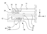
図2は第1移動手段30と第2移動手段40の概略図である。なお、図2は図1のA-A´断面を示している。第1移動手段30は、第1テーブル11とトレイ20とを連結するための移動手段である。第1移動手段30は、第1テーブル11をトレイ20に対して水平方向(X方向)に移動可能にする。第1移動手段30は、ガイドレール31、嵌合部32、等で構成される。ガイドレール31は、第1テーブル11の水平方向に伸びるように、第1テーブル11の下面に固定される。本実施例におけるガイドレール31は、第1テーブル11の下面に設けられたレール固定板33に固定されることで、第1テーブル11の下面に固定されている。嵌合部32は、トレイ20の上面に固定される。本実施例における嵌合部32は、トレイ20の上面に設けられた嵌合部固定板34に固定されることで、トレイ20の上面に固定されている。ガイドレール31と嵌合部32は互いに嵌合する。例えば、嵌合部32がガイドレール31に沿って摺動されることで、第1テーブル11が水平方向に移動される。
<Means of transportation>
FIG. 2 is a schematic diagram of the first moving means 30 and the second moving means 40. As shown in FIG. 2 shows a cross section taken along the line AA' of FIG. The first moving means 30 is a moving means for connecting the first table 11 and the
第2移動手段40は、第1移動手段30とは異なる移動手段である。すなわち、第1移動手段30と第2移動手段40は、別々に設けられた移動手段である。第2移動手段40は、第2テーブル12とトレイ20とを連結するための移動手段である。第2移動手段40は、トレイ20を第2テーブル12に対して水平方向(X方向)に移動可能にする。第2移動手段40は、レール板41、ベアリング42(ベアリング42a及び42b)、等で構成される。レール板41は、第2テーブル12の水平方向に伸びるように、第2テーブル12の下面に固定される。ベアリング42aとベアリング42bは、レール板41を挟むように配置される。ベアリング42aとベアリング42bは、トレイ20に連結された支持部22に転動可能に取り付けられる。例えば、ベアリング42をレール板41に沿って転動させることで、トレイ20は水平方向に移動される。
The second moving means 40 is a moving means different from the first moving means 30 . That is, the first moving means 30 and the second moving means 40 are separately provided moving means. The second moving means 40 is a moving means for connecting the second table 12 and the
本実施例では、上記のように、第1テーブル11とトレイ20が第1移動手段30によって連結され、トレイ20と第2テーブル12が第2移動手段40によって連結される。このため、第1移動手段30を用いて、トレイ20を移動させることなく、第1テーブル11を水平方向に移動させることができる。第2移動手段40を用いて、トレイ20を第2テーブル12に対して水平方向に移動させることでも、第1テーブル11を水平方向に移動させることができる。
In this embodiment, the first table 11 and the
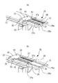
図3は第3移動手段25の概略図である。図3では、第1テーブル11と第1移動手段30の図示を省略している。図3(a)は第3移動手段25が縮んだ状態である。図3(b)は第3移動手段25が伸びた状態である。第3移動手段25は、第3テーブル13の上面側に設けられる。第3移動手段25は、第3テーブル13に対して、第1テーブル11を水平方向に移動可能に支持する。第3移動手段25は、固定部26、スライド部27、ガイド部28、等を備える。固定部26は第3テーブル13に固定される。固定部26は凸部26aを有する。スライド部27はトレイ20の側面に固定される。スライド部27は凹部27aを有する。固定部26とスライド部27は、凸部26aと凹部27aが嵌合するように配置される。ガイド部28は、スライド部27に固定される。第1テーブル11の下面に取り付けられた車輪14が、ガイド部28に保持されるとともに、ガイド部28上を移動する。
FIG. 3 is a schematic diagram of the third moving means 25. As shown in FIG. In FIG. 3, illustration of the first table 11 and the first moving means 30 is omitted. FIG. 3(a) shows a state in which the third moving means 25 is contracted. FIG. 3(b) shows a state in which the third moving means 25 is extended. The third moving means 25 is provided on the upper surface side of the third table 13 . The third moving means 25 supports the first table 11 horizontally movably with respect to the third table 13 . The third moving means 25 includes a fixed
第3移動手段25は、トレイ20の移動位置によって、X方向(左右方向)に伸縮する。例えば、第1テーブル11を第2テーブル12上から退避するように水平方向に移動させた状態(すなわち、後述する退避状態)では、第2テーブル12の端付近にトレイ20が移動される。このとき、スライド部27の凹部27aは固定部26の凸部26a上を摺動し、図2(a)に示すように、スライド部27が固定部26に重なるように配置される。また、例えば、第1テーブル11が第2テーブル12上に位置するように水平方向に移動させた状態(すなわち、後述する検眼状態)では、第2テーブル12の中央付近にトレイ20が移動される。このとき、スライド部27の凹部27aは固定部26の凸部26a上を摺動し、図2(b)に示すように、スライド部27が固定部26から引き出されて配置される。なお、凸部26aには、凸部26aから凹部27bが抜け落ちることを抑制するための部材(例えば、プランジャ等)を設けてもよい。
The third moving means 25 expands and contracts in the X direction (horizontal direction) depending on the movement position of the
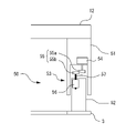
<昇降ユニット>
図4は昇降ユニット50の概略図である。昇降ユニット50は、第2テーブル12に設けられる。昇降ユニット50は、第1支柱51、第2支柱52、上下移動機構53、等で構成される。上下移動機構53は、モータ54、ギヤ55(ギヤ55a及び55b)、ナット部56、送りネジ57、等を備える。第1支柱51は第2テーブル12の下面に連結される。第1支柱51の内部にはモータ54が取り付けられる。モータ54の回転軸にはギヤ55aが固定される。第2支柱52は基台3に連結される。第2支柱52の内部にはナット部56が取り付けられる。ナット部56には送りネジ57が螺合する。送りネジ57の先端にはギヤ55bが固定される。ギヤ55aとギヤ55bは噛み合うように配置される。例えば、モータ54が回転すると、その回転がギヤ55を介して送りネジ57に伝達され、送りネジ57が回転する。これによって、第1支柱51は、第2支柱52に対して上下方向(鉛直方向)にスライドする。なお、昇降ユニット50はこのようなギヤ機構に限らず、アクチュエータ、シリンダ、等により上下方向にスライドする構成としてもよい。
<lifting unit>
FIG. 4 is a schematic diagram of the lifting
昇降ユニット50は、第2テーブル12に設けられた上下移動スイッチ2を操作することで、モータ54を回転させ、上下方向へスライドさせることができる。また、昇降ユニット50は、第1支柱51の上下移動に対する上限と下限を検知するための図示なきマイクロスイッチを備えていてもよい。例えば、マイクロスイッチが第2支柱52に設けられ、第1支柱51の下端がマイクロスイッチに触れたときに、モータ54の回転が停止されてもよい。
The lifting
<退避状態と検眼状態>
本実施例における検眼用テーブル1は、第1テーブル11を水平方向に移動させることで、第2テーブル12の所定の位置にて検眼装置を使用可能な状態と、第2テーブル12の所定の位置にて第2テーブルを使用可能な状態と、を切り換えることができる。すなわち、本実施例における検眼用テーブル1は、第1テーブル11を水平方向に移動させることで、第2テーブル12の所定の位置に検眼装置を配置した検眼状態と、第2テーブル12の所定の位置から検眼装置を退避させた退避状態と、を切り換えることができる。例えば、第2テーブル12の所定の位置は、第2テーブル12を前後方向(Z方向)に挟んで、検者と被検者が対面する位置P(図5参照)である。
<Evacuation state and optometry state>
By moving the first table 11 in the horizontal direction, the optometry table 1 according to the present embodiment is configured such that the optometry apparatus can be used at a predetermined position on the second table 12 and the predetermined position on the second table 12 can be changed. It is possible to switch between a state in which the second table can be used and a state in which the second table can be used. That is, by moving the first table 11 in the horizontal direction, the optometry table 1 in the present embodiment changes the optometry state in which the optometry apparatus is arranged at a predetermined position on the second table 12 and the predetermined position on the second table 12 . A retracted state in which the optometric apparatus is retracted from the position can be switched. For example, the predetermined position of the second table 12 is the position P (see FIG. 5) where the examiner and the subject face each other across the second table 12 in the front-rear direction (Z direction).
図5は退避状態と検眼状態を説明する図である。図5(a)は、第2テーブル12を使用可能な状態である。すなわち、図5(a)は第1検眼装置と第2検眼装置がともに退避状態にある場合を示している。図5(b)と図5(c)は、検眼装置を使用可能な状態である。図5(b)は第1検眼装置が検眼状態にある場合を示している。図5(c)は第2検眼装置が検眼状態にある場合を示している。なお、図5において、第1検眼装置(レフラクトメータAR)は、固定部15aに固定されることで、第1テーブル11の検者に近い側に載置されている。また、第2検眼装置(スリットランプSL)は、固定部15bに固定されることで、第1テーブル11の検者から遠い側に載置されている。
FIG. 5 is a diagram for explaining a retracted state and an eye examination state. FIG. 5(a) shows a state in which the second table 12 can be used. That is, FIG. 5(a) shows a case where both the first optometric apparatus and the second optometric apparatus are in the retracted state. FIGS. 5(b) and 5(c) show the optometric apparatus ready for use. FIG. 5(b) shows the case where the first optometric apparatus is in the optometric state. FIG. 5(c) shows the case where the second optometric apparatus is in the optometric state. In FIG. 5, the first optometric apparatus (refractometer AR) is placed on the side of the first table 11 closer to the examiner by being fixed to the fixing
例えば、第1テーブル11が第2テーブル12上に位置するように、第1テーブル11とトレイ20との少なくともいずれかを水平方向に移動させることで、検眼装置を使用可能とすることができる。このとき、検眼装置を固定する固定部15が第2テーブル12上に配置されるように、第1テーブル11とトレイ20との少なくともいずれかが、第2テーブル12上で水平方向に移動される。本実施例では、第1検眼装置(レフラクトメータAR)を固定する固定部15aと、第2検眼装置(スリットランプSL)を固定する固定部15bと、が第2テーブル12上に配置されるように、第1テーブル11とトレイ20との少なくともいずれかを水平方向に移動させることで、第1検眼装置が使用可能となる。これによって、図5(a)に示す退避状態から、図5(b)に示す検眼状態へと切り換えられる。また、本実施例では、第1固定部15aの少なくとも一部と、第2固定部15bと、が第2テーブル12上に配置されるように、第1テーブル11とトレイ20との少なくともいずれかを水平方向に移動させることで、第2検眼装置が使用可能となる。これによって、図5(a)に示す退避状態、あるいは、図5(b)に示す検眼状態から、図5(c)に示す検眼状態へと切り換えられる。
For example, by horizontally moving at least one of the first table 11 and the
また、例えば、第1テーブル11が第2テーブル12上から退避するように、第1テーブル11とトレイ20との少なくともいずれかを水平方向に移動させることで、第2テーブルを使用可能とすることができる。このとき、検眼装置を固定する固定部15の少なくとも一部が第2テーブル12上から突出するように、第1テーブル11とトレイ20との少なくともいずれかが、第2テーブル12上で水平方向に移動される。本実施例では、第1検眼装置を固定する固定部15aが第2テーブル12上に配置され、第2検眼装置を固定する固定部15bが第2テーブル12上から突出するように、第1テーブル11とトレイ20との少なくともいずれかを水平方向に移動させることで、第2テーブル12が使用可能となる。これによって、図5(b)または図5(c)に示す検眼状態から、図5(a)に示す退避状態へと切り換えられる。
Further, for example, by moving at least one of the first table 11 and the
<動作>
以上のような構成を備える検眼用テーブルの動作を説明する。例えば、第1テーブル11は、図5(a)に示す第2テーブル12を使用可能な状態(すなわち、退避状態)を初期位置として配置されている。初期位置では、第1テーブル11の検者に近い側に配置されたレフラクトメータARが、トレイ20の上部にくるように配置される。すなわち、第1テーブル11の突出が開始される側の側面Sから遠い位置に配置されたレフラクトメータARが、トレイ20の上部にくるように配置される。検者は、被検者に対して問診や診察を行うと、第1テーブル11を図5(b)または図5(c)に示す検眼装置を使用可能な状態(すなわち、検眼状態)に配置し、被検者に対して検眼を行う。
<Action>
The operation of the optometry table having the configuration as described above will be described. For example, the first table 11 is arranged with the state where the second table 12 shown in FIG. 5A can be used (that is, the retracted state) as the initial position. At the initial position, the refractometer AR located on the side of the first table 11 closer to the examiner is placed above the
検者は、まず、レフラクトメータARを用いた検眼を行う。検者は、トレイ20を水平方向に移動させるための図示なきレバーを操作して、トレイ20を第2テーブル12の所定の位置Pまで移動させる。トレイ20は、第2移動手段40によって、第2テーブル12上を水平方向にスライドする。第2テーブル12のスライドに連動して、トレイ20の上部に位置する第1テーブル11の検者に近い側、及び第1テーブル11の検者に近い側に配置されたレフラクトメータARが、所定の位置Pまで移動する。これによって、図5(b)に示す検眼状態となり、検者及び被検者の前にレフラクトメータARが配置されるので、検者は被検者に対してレフラクトメータARを用いた検眼を行うことができる。
The examiner first performs eye examination using the refractometer AR. The examiner operates a lever (not shown) for horizontally moving the
検者は、次に、スリットランプSLを用いた検眼を行う。検者は、第1テーブル11を水平方向に移動させるための図示なきレバーを操作して、第1テーブル11を移動させる。第1テーブル11は、第1移動手段30によって、トレイ20上を水平方向にスライドする。第1テーブル11の検者に近い側、及び第1テーブル11の検者に近い側に配置されたレフラクトメータARは所定の位置Pから離れるとともに、第1テーブル11の検者から遠い側、及び第1テーブル11の検者から遠い側に配置されたスリットランプSLが所定の位置Pに移動される。これによって、図5(b)に示す検眼状態から図5(c)に示す検眼状態となり、検者及び被検者の前にスリットランプSLが配置されるので、検者は被検者に対してスリットランプSLを用いた検眼を行うことができる。なお、図5(c)の検眼状態では、第1テーブル11の検者から遠い側に配置されたスリットランプSLが、トレイ20の上部にくるように配置される。すなわち、第1テーブル11の突出が開始される側の側面Sに近い位置に配置されたスリットランプSLが、トレイ20の上部にくるように配置される。
The examiner then performs eye examination using the slit lamp SL. The examiner moves the first table 11 by operating a lever (not shown) for horizontally moving the first table 11 . The first table 11 slides horizontally on the
検者は、レフラクトメータARを用いた検眼と、スリットランプSLを用いた検眼と、の少なくともいずれかを行って被検者の検眼を終えると、検者及び被検者の前から検眼装置(レフラクトメータAR及びスリットランプSL)を移動させ、第2テーブル12を使用可能な状態にする。例えば、検者は、第1テーブル11を水平方向に移動させるための図示なきレバーを操作して、第1テーブル11をトレイ20に対して水平方向にスライドさせることで、検者及び被検者の前にレフラクトメータARを配置した検眼状態へと戻す。また、例えば、検者は、トレイ20を水平方向に移動させるための図示なきレバーを操作して、トレイ20を第2テーブル12に対して水平方向にスライドさせることで、検者及び被検者の前からレフラクトメータARを退避させ、第2テーブル12を使用可能な状態へと戻す。
The examiner performs at least one of the optometry using the refractometer AR and the optometry using the slit lamp SL. (Refractometer AR and slit lamp SL) are moved to make the second table 12 ready for use. For example, the examiner operates a lever (not shown) for horizontally moving the first table 11, and slides the first table 11 horizontally with respect to the
以上説明したように、例えば、本実施例における検眼用テーブルは、複数の検眼装置を載置するためのスペースを有する第1テーブルと、第1テーブルの下面側に設けられる第2テーブルと、第1テーブルと第2テーブルとの間であり、第1テーブルの下面側かつ第2テーブルの上面側に設けられるトレイと、第1テーブルをトレイに対して水平方向に移動可能とし、第1テーブルとトレイを連結するため第1移動手段と、第1移動手段とは異なる移動手段であり、トレイを第2テーブルに対して水平方向に移動可能とし、第2テーブルとトレイを連結するための第2移動手段と、を備え、第1テーブルが第2テーブル上に位置するように、第1テーブルとトレイとの少なくともいずれかを水平方向に移動させることで、被検者に対して複数の検眼装置を使用可能とし、第1テーブルが第2テーブル上から退避するように、第1テーブルとトレイとの少なくともいずれかを水平方向に移動させることで、第2テーブルを使用可能とする。これによって、検者は被検者を移動させることなく複数の検眼装置を用いた検眼を実施することができ、従来に比べて検眼が容易になる。また、被検者の移動による負担を軽減させることができる。 As described above, for example, the optometric table in this embodiment includes a first table having a space for placing a plurality of optometric devices, a second table provided on the lower surface side of the first table, and a second table. a tray provided between the first table and the second table and on the lower surface side of the first table and the upper surface side of the second table; a first moving means for connecting the tray; and a moving means different from the first moving means, the tray being horizontally movable with respect to the second table, and a second moving means for connecting the second table and the tray. and a moving means for moving at least one of the first table and the tray in the horizontal direction so that the first table is positioned on the second table, thereby moving the plurality of optometric apparatuses to the subject. is enabled, and at least one of the first table and the tray is horizontally moved so that the first table is retracted from the second table, thereby enabling the second table to be used. As a result, the examiner can perform eye examination using a plurality of eye examination apparatuses without moving the examinee, which makes eye examination easier than before. Moreover, it is possible to reduce the burden caused by the movement of the subject.
また、例えば、本実施例における検眼用テーブルは、複数の前記検眼装置を固定する固定部を有し、固定部が第2テーブル上に配置されるように、第1テーブルとトレイとの少なくともいずれかを水平方向に移動させることで、検眼装置を使用可能とし、固定部の少なくとも一部が第2テーブル上から突出するように、第1テーブルとトレイとの少なくともいずれかを水平方向に移動させることで、第2テーブルを使用可能とする。これによって、検眼装置と第2テーブルを効率的に使用することができる。検眼の際には、検者及び被検者の前に検眼装置を配置することができ、問診や診察の際には、第1テーブルを第2テーブル上から突出させて第2テーブルをあけ、第2テーブルを使用することができる。 Further, for example, the optometric table in this embodiment has a fixing portion for fixing the plurality of optometric devices, and at least one of the first table and the tray is arranged so that the fixing portion is arranged on the second table. The optometry apparatus is made usable by moving the first table and/or the tray in the horizontal direction, and at least one of the first table and the tray is moved in the horizontal direction so that at least a part of the fixing part protrudes from above the second table. This makes the second table usable. This allows efficient use of the optometric apparatus and the second table. During optometry, the optometry apparatus can be placed in front of the examiner and the examinee, and during medical interviews and examinations, the first table is protruded from the second table to open the second table, A second table can be used.
また、例えば、本実施例における検眼用テーブルは、第1検眼装置を固定するための第1固定部と、第2検眼装置を固定するための第2固定部と、を有し、第1固定部と第2固定部の少なくとも一部とが第2テーブル上に配置されるように、第1テーブルとトレイとの少なくともいずれかを水平方向に移動させることで、被検者に対して第1検眼装置を使用可能とし、第1固定部の少なくとも一部と第2固定部とが第2テーブル上に配置されるように、第1テーブルとトレイとの少なくともいずれかを水平方向に移動させることで、被検者に対して第2検眼装置を使用可能とし、第1固定部の少なくとも一部が第2テーブル上に配置され、第2固定部の少なくとも一部が第2テーブル上から突出するように、第1テーブルとトレイとの少なくともいずれかを水平方向に移動させることで、第2テーブルを使用可能とする。これによって、第1検眼装置と第2検眼装置を、検眼内容に合わせて容易に切り換えることができる。また、第1検眼装置または第2検眼装置を使用可能な状態と、第2テーブルを使用可能な状態と、を容易に切り換えることができる。 Further, for example, the optometric table in this embodiment has a first fixing part for fixing the first optometric apparatus and a second fixing part for fixing the second optometric apparatus. By horizontally moving at least one of the first table and the tray so that the part and at least part of the second fixing part are arranged on the second table, the first enabling the optometric apparatus, and horizontally moving at least one of the first table and the tray so that at least a part of the first fixing part and the second fixing part are arranged on the second table; The second optometric apparatus is made available to the subject, at least part of the first fixing part is arranged on the second table, and at least part of the second fixing part protrudes from the second table. By horizontally moving at least one of the first table and the tray, the second table can be used. This makes it possible to easily switch between the first optometry apparatus and the second optometry apparatus according to the contents of the optometry. In addition, it is possible to easily switch between a state in which the first optometric apparatus or the second optometric apparatus can be used and a state in which the second table can be used.
また、例えば、本実施例における検眼用テーブルは、第2テーブルにおいて第1テーブルが突出する側面側に設けられた第3テーブルを備え、第2テーブルを使用可能な状態において、第3テーブルが第1テーブルを支持する。第1テーブル上に複数の検眼装置を配置した状態では、第1テーブルを第2テーブルから突出させると第1テーブルに大きな荷重がかかるが、このような構成とすることで、第1テーブル11の荷重を第3テーブルにより支えることができる。すなわち、第3テーブルを設けることで第1テーブル11の耐荷重を強くすることができ、第1テーブル上に検眼装置を安定に載置しておくことができる。
Further, for example, the optometry table in this embodiment includes a third table provided on the side surface of the second table from which the first table protrudes.
<変容例>
なお、本実施例では、第1テーブル11、第2テーブル12、及び第3テーブル13が、それぞれX方向(水平方向)が長手であり、Z方向(垂直方向)が短手である四角形状を有する構成を例に挙げて説明したがこれに限定されない。もちろん、第1テーブル11、第2テーブル12、及び第3テーブル13の形状や寸法は、本実施例とは異なっていてもよい。また、本実施例では、トレイ20が、X方向が短手であり、Z方向が長手である四角形状を有する構成を例に挙げて説明したがこれに限定されない。もちろん、トレイ20の形状や寸法は、本実施例とは異なっていてもよい。
<transformation example>
In this embodiment, each of the first table 11, the second table 12, and the third table 13 has a rectangular shape whose long side is in the X direction (horizontal direction) and whose short side is in the Z direction (vertical direction). Although the description has been made by taking the configuration having as an example, the present invention is not limited to this. Of course, the shape and dimensions of the first table 11, the second table 12, and the third table 13 may differ from those of this embodiment. In this embodiment, the
なお、本実施例では、第1テーブル11を第2テーブル12上で水平方向に移動させる際に、第1テーブル11を直線状に水平方向に移動させる構成を例に挙げて説明したがこれに限定されない。例えば、第1テーブル11を曲線状に水平方向に移動させる構成としてもよい。一例としては、円弧状に水平方向に移動させてもよい。 In this embodiment, the first table 11 is moved horizontally on the second table 12 while moving the first table 11 linearly in the horizontal direction. Not limited. For example, the first table 11 may be configured to move in a curved line in the horizontal direction. As an example, it may be moved horizontally in an arc.
なお、本実施例では、第1固定部15aと第2固定部15bを別に設けることで、第1テーブル11上に第1検眼装置と第2検眼装置を固定配置する構成を例に挙げて説明したがこれに限定されない。例えば、第1固定部15aと第2固定部15bとは兼用されてもよい。すなわち、1つの固定部を用いて、第1テーブル11上に第1検眼装置と第2検眼装置を固定配置する構成としてもよい。
Note that, in this embodiment, a configuration in which the first optometric device and the second optometric device are fixedly arranged on the first table 11 by separately providing the
なお、本実施例では、第2テーブル12を使用可能な状態(すなわち、退避状態)とする場合に、スリットランプSLを固定する固定部15bのみが第2テーブル12上から突出するように、第1テーブル11を第2テーブル上から水平方向に移動させる構成を例に挙げて説明したがこれに限定されない。もちろん、レフラクトメータARを固定する固定部15aと、スリットランプSLを固定する固定部15bと、がどちらも第2テーブル12上から突出するように、第1テーブル11を第2テーブル上から水平方向に移動させる構成としてもよい。例えば、この場合には、トレイ20を第3テーブル13上まで水平方向に移動可能とする第2移動手段40を設けてもよい。
In the present embodiment, when the second table 12 is put into a usable state (that is, a retracted state), the second table 12 is arranged so that only the fixing
なお、本実施例では、第2テーブル12を使用可能な状態(すなわち、退避状態)から、トレイ20を第2テーブル12に対して水平方向に移動させることで、レフラクトメータARを使用可能な状態とする構成を例に挙げて説明したがこれに限定されない。例えば、第2テーブル12を使用可能な状態から、第1テーブル11をトレイ20に対して水平方向に移動させることで、レフラクトメータARを使用可能な状態とする構成であってもよい。この場合には、レフラクトメータARを使用可能な状態から、トレイ20を第2テーブル12に対して水平方向に移動させることで、スリットランプSLを使用可能な状態に切り換えることができる。
In this embodiment, the refractometer AR can be used by moving the
なお、本実施例における検眼用テーブル1は、第1移動手段30による第1テーブル11の水平方向への移動と、第2移動手段40によるトレイ20の水平方向への移動と、の少なくともいずれかに対して、その水平方向への移動を制御するロック機構を設けてもよい。このようなロック機構は、第1テーブル11の水平方向への移動を制御するロック機構と、トレイ20の水平方向への移動を制御するロック機構と、が別々に設けられた構成であってもよいし、兼用される構成であってもよい。例えば、ロック機構は、第1テーブル11やトレイ20に密着するブレーキパッド、ブレーキパットが先端に設けられた解除レバー、等で構成されてもよい。解除レバーを操作しないときは、ブレーキパッドが第1テーブル11やトレイ20に密着することで、これらの水平方向への移動がロックされる。解除レバーを操作したときは、ブレーキパッドが第1テーブル11やトレイ20から離れ、これらの水平方向への移動のロックが解除される。このようなロック機構を設けることによって、第1テーブル11とトレイ20がずれて検眼装置が動いてしまうことを抑制し、より安全に検眼を行うことができるようにしてもよい。
Note that the optometry table 1 in this embodiment moves the first table 11 in the horizontal direction by the first moving means 30, or moves the
1 検眼用テーブル
11 第1テーブル
12 第2テーブル
13 第3テーブル
15 固定部
25 第3移動手段
30 第1移動手段
40 第2移動手段
1 Optometry table 11 First table 12 Second table 13 Third table 15
Claims (5)
複数の検眼装置を載置するためのスペースを有する第1テーブルと、
前記第1テーブルの下面側に設けられる第2テーブルと、
前記第1テーブルと前記第2テーブルとの間に設けられるトレイであって、前記第1テーブルの下面側且つ前記第2テーブルの上面側に設けられるトレイと、
前記第1テーブルと、前記トレイと、を連結するための第1移動手段であって、前記第1テーブルを前記トレイに対して水平方向に移動可能とする第1移動手段と、
前記第2テーブルと、前記トレイと、を連結するための第2移動手段であって、前記第1移動手段とは異なる移動手段であり、前記トレイを前記第2テーブルに対して水平方向に移動可能とする第2移動手段と、
を備え、
前記第1テーブルが前記第2テーブル上の所定の位置に位置するように、前記第1テーブルと前記トレイとの少なくともいずれかを前記所定の位置まで水平方向に移動させることで、被検者に対して複数の前記検眼装置を使用可能とし、
前記第1テーブルが前記第2テーブル上の前記所定の位置から退避するように、前記第1テーブルと前記トレイとの少なくともいずれかを前記所定の位置から水平方向に移動させることで、前記第2テーブルを使用可能とすることを特徴とする検眼用テーブル。 An optometric table for placing an optometric device,
a first table having a space for placing a plurality of optometric devices;
a second table provided on the lower surface side of the first table;
a tray provided between the first table and the second table, the tray provided on the lower surface side of the first table and the upper surface side of the second table;
a first moving means for connecting the first table and the tray, the first moving means enabling the first table to move in a horizontal direction with respect to the tray;
Second moving means for connecting the second table and the tray, the moving means being different from the first moving means, and moving the tray horizontally with respect to the second table. a second means of transportation that enables
with
By horizontally moving at least one of the first table and the tray to the predetermined position such that the first table is positioned on the second table, making it possible to use a plurality of said optometric devices for
By horizontally moving at least one of the first table and the tray from the predetermined position so that the first table is retracted from the predetermined position on the second table, the second An optometry table characterized in that the table can be used.
前記第1テーブルは、複数の前記検眼装置を固定する固定部を有し、
前記固定部が前記第2テーブル上に配置されるように、前記第1テーブルと前記トレイとの少なくともいずれかを水平方向に移動させることで、被検者に対して複数の前記検眼装置を使用可能とし、
前記固定部の少なくとも一部が前記第2テーブル上から突出するように、前記第1テーブルと前記トレイとの少なくともいずれかを水平方向に移動させることで、前記第2テーブルを使用可能とすることを特徴とする検眼用テーブル。 In the optometry table according to claim 1,
The first table has a fixing portion for fixing the plurality of optometric devices,
By moving at least one of the first table and the tray in a horizontal direction so that the fixed part is arranged on the second table, a plurality of the optometric apparatuses are used for the subject. make it possible
making the second table usable by horizontally moving at least one of the first table and the tray so that at least a part of the fixing portion protrudes from the second table; An optometry table characterized by:
複数の前記検眼装置は、第1検眼装置と、第2検眼装置と、を含み、
前記固定部は、前記第1検眼装置を固定するための第1固定部と、前記第2検眼装置を固定するための第2固定部と、を有し、
前記第2テーブル上から前記第1テーブルの突出が開始される側の前記第1テーブルの側面に対して、前記第1固定部の位置が前記第2固定部の位置よりも長手方向に遠い位置に配置され、
前記第1固定部と、前記第2固定部の少なくとも一部と、が前記第2テーブル上に配置されるように、前記第1テーブルと前記トレイとの少なくともいずれかを水平方向に移動させることで、被検者に対して前記第1検眼装置を使用可能とし、
前記第1固定部の少なくとも一部と、前記第2固定部と、が前記第2テーブル上に配置されるように、前記第1テーブルと前記トレイとの少なくともいずれかを水平方向に移動させることで、被検者に対して前記第2検眼装置を使用可能とし、
前記第1固定部の少なくとも一部が前記第2テーブル上に配置され、前記第2固定部の少なくとも一部が前記第2テーブル上から突出するように、前記第1テーブルと前記トレイとの少なくともいずれかを水平方向に移動させることで、前記第2テーブルを使用可能とすることを特徴とする検眼用テーブル。 In the optometry table according to claim 2,
The plurality of optometric devices include a first optometric device and a second optometric device,
The fixing part has a first fixing part for fixing the first optometric device and a second fixing part for fixing the second optometric device,
The position of the first fixing part is farther in the longitudinal direction than the position of the second fixing part with respect to the side surface of the first table on the side where the first table starts to protrude from the second table. is placed in
horizontally moving at least one of the first table and the tray so that the first fixing part and at least part of the second fixing part are arranged on the second table; and enabling the subject to use the first optometric device,
horizontally moving at least one of the first table and the tray so that at least a portion of the first fixing portion and the second fixing portion are arranged on the second table; and enabling the subject to use the second optometric device,
At least part of the first fixing part is arranged on the second table, and at least part of the second fixing part protrudes from the second table. An optometry table, characterized in that the second table can be used by moving one of them in the horizontal direction.
複数の検眼装置と、
複数の前記検眼装置の内、少なくとも第1検眼装置を載置するための第1テーブルと、
複数の前記検眼装置の内、少なくとも第2検眼装置を載置するための第2テーブルと、
前記第1テーブル及び前記第2テーブルの下面側に設けられる第3テーブルと、
前記第1テーブル及び前記第2テーブルを、前記第3テーブルに対して水平方向に移動可能とする移動手段と、
を備え、
前記第1テーブルが、前記第3テーブル上の所定の位置であって、前記被検者の前に水平移動されることによって、前記被検者に対して少なくとも前記第1検眼装置を使用可能とし、
前記第2テーブルが、前記第3テーブル上の前記所定の位置であって、前記被検者の前に水平移動されることによって、前記被検者に対して前記第2テーブルに載置された前記第2検眼装置を使用可能とすることを特徴とする検眼システム。 An optometry system for performing optometry on a subject using a plurality of optometry devices,
a plurality of optometric devices;
a first table for placing at least a first optometric device among the plurality of optometric devices;
a second table for placing at least a second optometric device among the plurality of optometric devices;
a third table provided on the lower surface side of the first table and the second table;
moving means for horizontally moving the first table and the second table with respect to the third table;
with
The first table is at a predetermined position on the third table, and is horizontally moved in front of the subject, thereby making at least the first optometric apparatus available to the subject. ,
The second table is placed on the second table with respect to the subject by moving horizontally in front of the subject at the predetermined position on the third table. An optometry system, characterized in that the second optometry device can be used.
前記第1テーブルと、前記第2テーブルと、は、一体的に形成されており、複数の前記検眼装置を載置するためのスペースを有するテーブルであって、
前記テーブルが前記第3テーブル上の位置であって、前記第1検眼装置が前記被検者の前に位置するように、前記テーブルを水平方向に移動させることで、前記被検者に対して前記第1検眼装置を使用可能とし、
前記テーブルが前記第3テーブル上の位置であって、前記第2検眼装置が前記被検者の前に位置するように、前記テーブルを水平方向に移動させることで、前記被検者に対して前記第2検眼装置を使用可能とすることを特徴とする検眼システム。 In the optometric system of claim 4,
The first table and the second table are integrally formed and have a space for placing a plurality of the optometric devices,
By horizontally moving the table so that the table is positioned on the third table and the first optometry apparatus is positioned in front of the subject, enabling the first optometric device to be used;
By horizontally moving the table so that the table is positioned on the third table and the second optometric apparatus is positioned in front of the subject, An optometry system, characterized in that the second optometry device can be used.
Priority Applications (1)
| Application Number | Priority Date | Filing Date | Title |
|---|---|---|---|
| JP2018146325A JP7200529B2 (en) | 2018-08-02 | 2018-08-02 | Optometry table and optometry system |
Applications Claiming Priority (1)
| Application Number | Priority Date | Filing Date | Title |
|---|---|---|---|
| JP2018146325A JP7200529B2 (en) | 2018-08-02 | 2018-08-02 | Optometry table and optometry system |
Publications (3)
| Publication Number | Publication Date |
|---|---|
| JP2020018711A JP2020018711A (en) | 2020-02-06 |
| JP2020018711A5 JP2020018711A5 (en) | 2021-08-05 |
| JP7200529B2 true JP7200529B2 (en) | 2023-01-10 |
Family
ID=69587736
Family Applications (1)
| Application Number | Title | Priority Date | Filing Date |
|---|---|---|---|
| JP2018146325A Active JP7200529B2 (en) | 2018-08-02 | 2018-08-02 | Optometry table and optometry system |
Country Status (1)
| Country | Link |
|---|---|
| JP (1) | JP7200529B2 (en) |
Citations (2)
| Publication number | Priority date | Publication date | Assignee | Title |
|---|---|---|---|---|
| JP2002345751A (en) | 2001-05-29 | 2002-12-03 | Komura Seisakusho:Kk | Horizontal moving table |
| JP2003245252A (en) | 2002-02-25 | 2003-09-02 | Konan Medical Inc | Automatic control frame for ophthalmologic apparatus |
Family Cites Families (2)
| Publication number | Priority date | Publication date | Assignee | Title |
|---|---|---|---|---|
| DE6750992U (en) * | 1968-07-31 | 1969-01-23 | Rodenstock Optik G | INSTRUMENT SLIDING TABLE FOR OPHTHALMOLOGICAL DEVICES. |
| JP3374997B2 (en) * | 1993-11-19 | 2003-02-10 | 株式会社ニデック | Optometry device |
-
2018
- 2018-08-02 JP JP2018146325A patent/JP7200529B2/en active Active
Patent Citations (2)
| Publication number | Priority date | Publication date | Assignee | Title |
|---|---|---|---|---|
| JP2002345751A (en) | 2001-05-29 | 2002-12-03 | Komura Seisakusho:Kk | Horizontal moving table |
| JP2003245252A (en) | 2002-02-25 | 2003-09-02 | Konan Medical Inc | Automatic control frame for ophthalmologic apparatus |
Also Published As
| Publication number | Publication date |
|---|---|
| JP2020018711A (en) | 2020-02-06 |
Similar Documents
| Publication | Publication Date | Title |
|---|---|---|
| RU2656553C2 (en) | Ultrasound system control panel and display lift | |
| JP4883873B2 (en) | Work table designed especially for surgery | |
| US4225125A (en) | Operation table | |
| US2636793A (en) | Operating table with adjustable top sections | |
| RU2672019C1 (en) | Microsurgeon chair | |
| US10028874B2 (en) | Operating table base for an operating table | |
| RU2562013C1 (en) | General-purpose x-ray imaging system | |
| US3041122A (en) | Surgical table | |
| CN103764032B (en) | Compact mechanism for moving a compression paddle | |
| US4131801A (en) | X-ray cradle top with tilting mechanism | |
| JP7200529B2 (en) | Optometry table and optometry system | |
| US2905952A (en) | Patient stretchers | |
| JP6734662B2 (en) | Ophthalmic medical table | |
| GB1559945A (en) | Operation table | |
| US4041786A (en) | Linear motion devices | |
| JP2008307088A (en) | Low floor type stretcher | |
| RU2587313C1 (en) | Universal x-ray system | |
| CN108245180A (en) | A kind of radiodiagnosis imager | |
| CN212415758U (en) | Centered CT scanning bed with three-axis movement | |
| WO2019097594A1 (en) | Radiation photographing device | |
| CN211432839U (en) | Bracket structure based on ophthalmology inspection | |
| CN109646233B (en) | Operating table with multifunctional combined instrument table | |
| JP3340817B2 (en) | Optometry device | |
| CN112263239A (en) | Nuclear magnetic resonance examination device for humpback patient | |
| JP2024042880A (en) | Ophthalmic equipment and grips |
Legal Events
| Date | Code | Title | Description |
|---|---|---|---|
| A521 | Request for written amendment filed |
Free format text: JAPANESE INTERMEDIATE CODE: A523 Effective date: 20210625 |
|
| A621 | Written request for application examination |
Free format text: JAPANESE INTERMEDIATE CODE: A621 Effective date: 20210625 |
|
| A977 | Report on retrieval |
Free format text: JAPANESE INTERMEDIATE CODE: A971007 Effective date: 20220526 |
|
| A131 | Notification of reasons for refusal |
Free format text: JAPANESE INTERMEDIATE CODE: A131 Effective date: 20220607 |
|
| A521 | Request for written amendment filed |
Free format text: JAPANESE INTERMEDIATE CODE: A523 Effective date: 20220808 |
|
| TRDD | Decision of grant or rejection written | ||
| A01 | Written decision to grant a patent or to grant a registration (utility model) |
Free format text: JAPANESE INTERMEDIATE CODE: A01 Effective date: 20221122 |
|
| A61 | First payment of annual fees (during grant procedure) |
Free format text: JAPANESE INTERMEDIATE CODE: A61 Effective date: 20221205 |
|
| R150 | Certificate of patent or registration of utility model |
Ref document number: 7200529 Country of ref document: JP Free format text: JAPANESE INTERMEDIATE CODE: R150 |
|
| R250 | Receipt of annual fees |
Free format text: JAPANESE INTERMEDIATE CODE: R250 |