JP7200423B1 - BIM data provision system, BIM data provision method and program - Google Patents
BIM data provision system, BIM data provision method and program Download PDFInfo
- Publication number
- JP7200423B1 JP7200423B1 JP2022080643A JP2022080643A JP7200423B1 JP 7200423 B1 JP7200423 B1 JP 7200423B1 JP 2022080643 A JP2022080643 A JP 2022080643A JP 2022080643 A JP2022080643 A JP 2022080643A JP 7200423 B1 JP7200423 B1 JP 7200423B1
- Authority
- JP
- Japan
- Prior art keywords
- data
- bim
- input
- bim data
- unit
- Prior art date
- Legal status (The legal status is an assumption and is not a legal conclusion. Google has not performed a legal analysis and makes no representation as to the accuracy of the status listed.)
- Active
Links
Images


Abstract
【課題】現場管理上のデータとBIMデータとを連動させる。【解決手段】BIMデータを提供するBIMデータ提供システムは、建設に関する、図面データ、複数のエリアデータ及び複数の部材データを含む第1BIMデータを取得し、取得した第1BIMデータに基づいて、図面データ上に重ねて配置するレイヤデータを生成し、生成したレイヤデータに、第1データを配置し、配置した第1データに対して、建設施工の進捗入力を受け付け、受け付けた進捗入力を反映したレイヤデータを、第2BIMデータに変換し、変換した第2BIMデータを提供する。【選択図】図1An object of the present invention is to link data on site management and BIM data. A BIM data providing system for providing BIM data acquires first BIM data including drawing data, a plurality of area data, and a plurality of member data relating to construction, and generates drawing data based on the acquired first BIM data. Generate layer data to be superimposed on top, place the first data in the generated layer data, receive progress input of construction work for the placed first data, and layer reflecting the received progress input The data is transformed into second BIM data and the transformed second BIM data is provided. [Selection drawing] Fig. 1
Description
本発明は、BIM(Building Information Modeling)の提供に有効な技術に関する。 The present invention relates to technology effective in providing BIM (Building Information Modeling).
近年、BIMに関する技術が注目されている。
BIMとは、コンピュータ上に作成した3次元の建築物のデジタルモデルに、コスト、仕上げ、管理データ等の属性データを追加した建築物のデータベースを、設計・施工から維持管理までのあらゆる工程で情報活用を行うためのものである。
例えば、特許文献1では、建物の画像データと、建物を構成する各部材の属性情報とを記憶し、要求に応じて記憶された情報を提供している。建物に対する改修工事を行った施工業者からの費用の情報に基づき、工事対象部材及び工事内容を含む費用の内訳情報を取得し、改修工事の発注元に費用請求の情報を提供することにより、建物の現状に則した建物管理情報を維持する技術が提供されている。
また、他には、特許文献2では、検査対象となる構造物の撮影画像と、設計情報から生成される3次元モデルとを重畳させた画像を表示させることにより、構造物の検査を容易且つ正確に行う技術が提供されている。
In recent years, technology related to BIM has attracted attention.
BIM is a building database created by adding attribute data such as cost, finish, management data, etc. to a three-dimensional digital model of a building created on a computer. It is for utilization.
For example, in
In addition, in
建設現場の管理を効率的に行うために、スマートフォンやタブレット端末等の端末装置に建設現場の図面データを表示して、現場管理を行うことがある。この場合、現場管理を2次元の図面データ上で行うため、BIMの持つ3次元モデルとデータ上の断絶が発生し、現場管理上のデータが、BIMデータと連動しないという問題があった。
特許文献1及び2に記載の技術であっても、同様の問題が存在した。
そこで、本発明者は、BIMデータに基づいて、図面データ上に重ねて配置するレイヤデータを生成し、レイヤデータに対して建設施工の進捗入力及び部材の変更入力を受け付け、これらを反映したレイヤデータをBIMデータに変換して提供する仕組みに着目した。
In order to efficiently manage construction sites, site management may be performed by displaying construction site drawing data on terminal devices such as smartphones and tablet terminals. In this case, since the site management is performed on the two-dimensional drawing data, there is a disconnection between the data and the three-dimensional model of the BIM, and there is a problem that the site management data is not linked with the BIM data.
Even with the techniques described in
Therefore, the present inventor generates layer data to be superimposed on the drawing data based on BIM data, accepts construction progress input and member change input for the layer data, and layers reflecting these We paid attention to the mechanism that converts data into BIM data and provides it.
本発明は、BIMデータに基づいて、図面データ上に重ねて配置するレイヤデータを生成し、レイヤデータに対して建設施工の進捗入力及び部材の変更入力を受け付け、これらを反映したレイヤデータをBIMデータに変換して提供することにより、現場管理上のデータとBIMデータとを連動させることを可能にするBIMデータ提供システム、BIMデータ提供方法及びプログラムを提供することを目的とする。 The present invention generates layer data to be superimposed on drawing data based on BIM data, accepts construction progress input and member change input for the layer data, and converts the layer data reflecting these to BIM It is an object of the present invention to provide a BIM data providing system, a BIM data providing method, and a program that enable interlocking of field management data and BIM data by providing the converted data.
本発明は、BIMデータを提供するBIMデータ提供システムであって、
建設に関する、図面データ、複数のエリアデータ及び複数の部材データを含む第1BIMデータを取得する取得部と、
取得した前記第1BIMデータに基づいて、前記図面データ上に重ねて配置するレイヤデータを生成する生成部と、
生成した前記レイヤデータに、前記第1BIMデータを配置する配置部と、
配置した前記第1BIMデータの複数のエリアデータを一のグループにまとめたデータ及び複数の部材データを一のグループにまとめたデータに対して、建設施工の進捗入力を受け付ける受付部と、
受け付けた前記進捗入力を反映した前記レイヤデータを、第2BIMデータに変換する変換部と、
変換した前記第2BIMデータを提供する提供部と、
を備えるBIMデータ提供システムを提供する。
The present invention is a BIM data providing system for providing BIM data,
an acquisition unit that acquires first BIM data including drawing data, a plurality of area data, and a plurality of member data regarding construction;
a generation unit that generates layer data to be superimposed on the drawing data based on the acquired first BIM data;
an arrangement unit that arranges the first BIM data in the generated layer data;
a reception unit that receives a progress input of construction work with respect to data in which a plurality of area data of the arranged first BIM data are grouped into one group and data in which a plurality of member data are grouped into one group ;
a conversion unit that converts the layer data reflecting the received progress input into second BIM data;
a providing unit that provides the converted second BIM data;
To provide a BIM data provision system comprising:
本発明によれば、BIMデータを提供するBIMデータ提供システムは、建設に関する、図面データ、複数のエリアデータ及び複数の部材データを含む第1BIMデータを取得し、取得した前記第1BIMデータに基づいて、前記図面データ上に重ねて配置するレイヤデータを生成し、生成した前記レイヤデータに、前記第1BIMデータを配置し、配置した前記第1BIMデータの複数のエリアデータを一のグループにまとめたデータ及び複数の部材データを一のグループにまとめたデータに対して、建設施工の進捗入力を受け付け、受け付けた前記進捗入力を反映した前記レイヤデータを、第2BIMデータに変換し、変換した前記第2BIMデータを提供する。 According to the present invention, a BIM data providing system that provides BIM data acquires first BIM data including drawing data, a plurality of area data, and a plurality of member data related to construction, and based on the acquired first BIM data , generating layer data to be superimposed on the drawing data, arranging the first BIM data on the generated layer data, and grouping a plurality of area data of the arranged first BIM data into one group . progress input of construction work is received for data in which the data and a plurality of member data are grouped into one group, the layer data reflecting the received progress input is converted into second BIM data, and the converted said Providing second BIM data.
本発明は、システムのカテゴリであるが、方法及びプログラムであっても同様の作用、効果を奏する。 Although the present invention is in the category of systems, the same actions and effects can be achieved with methods and programs.
本発明によれば、現場管理上のデータとBIMデータとを連動させることが可能となる。 According to the present invention, it is possible to link data on site management and BIM data.
以下、添付図面を参照して、本発明を実施するための形態(以下、実施形態)について詳細に説明する。以降の図においては、実施形態の説明の全体を通して同じ要素には同じ番号又は符号を付している。 EMBODIMENT OF THE INVENTION Hereinafter, with reference to an accompanying drawing, the form (henceforth, embodiment) for implementing this invention is demonstrated in detail. In subsequent figures, the same numbers or symbols are attached to the same elements throughout the description of the embodiments.
[基本概念/基本構成]
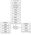
図1は、BIMデータ提供システム1の概要を説明するための図である。BIMデータ提供システム1は、少なくともコンピュータ10を備え、BIMデータを提供するシステムである。
本実施形態では、BIMデータ提供システム1は、コンピュータ10が、BIM業者、建設現場の管理業者等が管理する業者端末20、建設現場で施工を行う作業員、現場監督等の施工者が所持する施工者端末30と、データ通信可能に接続されるシステムである。
[Basic Concept/Basic Configuration]
FIG. 1 is a diagram for explaining the outline of the BIM
In this embodiment, the BIM
本実施形態は、前提として、建設現場において、BIMデータを用いた施工を行うものである。 As a premise, this embodiment is to perform construction using BIM data at a construction site.
BIMデータ提供システム1が、BIMデータを提供する場合についての処理ステップの概要について、図1に基づいて説明する。
An outline of processing steps when the BIM
コンピュータ10は、建設に関する、図面データ、複数のエリアデータ及び複数の部材データを含む第1BIMデータを取得する(ステップS1)。
図面データは、建設の現場における図面に関するデータである。エリアデータは、例えば、部屋、トイレ周り、専有部分、共有部分等のエリアに関するデータである。部材データは、例えば、設置場所、製造メーカ、種類、個数、特性等の部材に関するデータである。エリアデータ及び部材データには、各々の仕様や数量等の属性データが含まれる。第1BIMデータは、これらの他に、建物形状、空間関係、地理情報、施工方法等の建設工程のデジタルデータを含むものである。
業者端末20は、コンピュータ10から、第1BIMデータの送信要求を受信する。業者端末20は、受信した送信要求に基づいて、コンピュータ10が所望した第1BIMデータを、自身が記憶するBIMデータの中から抽出し、抽出したBIMデータを、第1BIMデータとして、コンピュータ10に送信する。
コンピュータ10は、この第1BIMデータを受信することにより、建設に関する図面データ、複数のエリアデータ及び複数の部材データを含む第1BIMデータを取得する。
The
The drawing data is data related to drawings at the construction site. The area data is, for example, data relating to areas such as a room, a toilet area, an exclusive part, a shared part, and the like. The member data is, for example, data relating to members such as installation location, manufacturer, type, number, and characteristics. The area data and member data include attribute data such as specifications and quantities. In addition to these, the first BIM data includes digital data of construction processes such as building shapes, spatial relationships, geographic information, and construction methods.
The
By receiving this first BIM data, the
コンピュータ10は、取得した第1BIMデータに基づいて、複数のエリアデータを一のグループにまとめた第1データ及び複数の部材データを一のグループにまとめた第2データを作成する(ステップS2)。
コンピュータ10は、取得した第1BIMデータにおいて、複数のエリアデータを抽出し、複数のエリアデータを一のグループにまとめた第1データを作成する。また、コンピュータ10は、取得した第1BIMデータにおいて、複数の部材データを抽出し、複数の部材データを一のグループにまとめた第2データを作成する。
Based on the obtained first BIM data, the
The
コンピュータ10は、取得した第1BIMデータに基づいて、図面データ上に重ねて配置するレイヤデータを生成する(ステップS3)。
レイヤデータは、図面データ上に重ねる仮想シートであり、第1データ、第2データ、アイコン、メモ、画像等を出力可能なものである。
コンピュータ10は、図面データと同じサイズ、且つ、図面データを透過表示するレイヤデータを生成する。生成モジュールは、生成したレイヤデータを、図面データ上に重ねて配置する。
Based on the acquired first BIM data, the
The layer data is a virtual sheet superimposed on the drawing data, and can output first data, second data, icons, memos, images, and the like.
The
コンピュータ10は、生成したレイヤデータに、第1データ及び第2データを配置する(ステップS4)。
コンピュータ10は、生成したレイヤデータに第1データを配置する。コンピュータ10は、第1データが示すエリアに該当するレイヤデータ上の箇所に、第1データを配置する。
コンピュータ10は、生成したレイヤデータに第2データを配置する。コンピュータ10は、第2データが示す部材に該当するレイヤデータ上の箇所に、第2データを配置する。
コンピュータ10は、第1データ及び第2データが配置されたレイヤデータが重ねられた図面データを、施工者端末30に送信し、施工者端末30にこの図面データを表示させる。
The
The
The
The
コンピュータ10は、配置した第1データ及び第2データに対して、建設施工の進捗入力を受け付ける(ステップS5)。
進捗入力は、例えば、部材の設置進捗、複数の部材の連結進捗、部材の試運転の検査進捗、部材の実測値、部材の計測値などである。進捗は、施工内容の作業状態や作業状況の進み具合やその内容である。なお、検査進捗は、単に、検査の状況だけに限らず、検査結果が正常であったか異常であったかを含むものであって良い。
施工者端末30は、自身の表示部に表示した図面データに対して、第1データ及び第2データに対する建設施工の進捗入力を受け付ける。施工者端末30は、受け付けた進捗入力をコンピュータ10に送信する。
コンピュータ10は、この進捗入力を受信することにより、配置した第1データ及び第2データに対して、建設施工の進捗入力を受け付ける。
The
The progress input includes, for example, the installation progress of a member, the progress of connection of a plurality of members, the inspection progress of trial operation of a member, the actual measurement value of a member, the measured value of a member, and the like. The progress is the work state of the construction content, the progress of the work situation, and the content thereof. Note that the progress of the inspection is not limited to the status of the inspection, and may include whether the inspection result was normal or abnormal.
The
By receiving this progress input, the
コンピュータ10は、配置した第2データに対して、部材の変更入力を受け付ける(ステップS6)。
変更入力は、例えば、追加、分解、組替、削除であり、これらの内の少なくとも一つであれば良い。
施工者端末30は、自身の表示部に表示した図面データに対して、第2データに対する部材の変更入力を受け付ける。施工者端末30は、受け付けた変更入力をコンピュータ10に送信する。
コンピュータ10は、この変更入力を受信することにより、配置した第2データに対して、部材の変更入力を受け付ける。
The
The change input is, for example, addition, disassembly, rearrangement, or deletion, and at least one of these may be used.
The
By receiving this change input, the
コンピュータ10は、レイヤデータに配置した第1データに、受け付けた進捗入力を反映し、レイヤデータに配置した第2データに、受け付けた進捗入力及び変更入力を反映する(ステップS7)。
コンピュータ10は、受け付けた第1データに対する進捗入力に基づいて、レイヤデータに配置した第1データに進捗入力を反映し、受け付けた第2データに対する進捗入力及び変更入力に基づいて、レイヤデータに配置した第2データに進捗入力及び変更入力を反映する。
The
The
コンピュータ10は、受け付けた進捗入力及び変更入力を反映したレイヤデータを、第2BIMデータに変換する(ステップS8)。
コンピュータ10は、進捗入力を反映した第1データ、及び、進捗入力及び変換入力を反映した第2データをレイヤデータごと、BIMデータに変換する。第2BIMデータは、コンピュータ10が変換したBIMデータである。
The
The
コンピュータ10は、変換した第2BIMデータを提供する(ステップS9)。
コンピュータ10は、変換した第2BIMデータを、業者端末20に送信する。業者端末20は、この第2BIMデータを、受信し、記憶等する。
コンピュータ10は、業者端末20に、第2BIMデータを送信することにより、変換した第2BIMデータを提供する。
なお、コンピュータ10が第2BIMデータを提供する対象は、第1BIMデータを取得した業者端末20に限定されるものではなく、第1BIMデータを取得した業者端末20以外の業者端末20に対して提供しても良い。
The
The
The
The object to which the
このようなBIMデータ提供システム1によれば、現場管理上のデータとBIMデータとを連動させることが可能となる。
According to such a BIM
[機能構成]
図2に基づいて、BIMデータ提供システム1の機能構成について説明する。
BIMデータ提供システム1は、少なくともコンピュータ10を備え、BIMデータを提供するシステムである。
本実施形態では、BIMデータ提供システム1は、コンピュータ10が、BIM業者、建設現場の管理業者等が管理する業者端末20、建設現場で施工を行う作業員、現場監督等の施工者が所持する施工者端末30と、公衆回線網等のネットワーク9を介して、データ通信可能に接続されるシステムである。
BIMデータ提供システム1は、コンピュータ10に加え、業者端末20、施工者端末30、その他の端末や装置類等が含まれていても良い。この場合、BIMデータ提供システム1は、後述する処理を、含まれる端末や装置類等の何れか又は複数の組み合わせにより実行する。
[Function configuration]
Based on FIG. 2, the functional configuration of the BIM
The BIM
In this embodiment, the BIM
In addition to the
コンピュータ10は、サーバ機能を有するコンピュータやパーソナルコンピュータ等であり、BIMデータを提供するものである。
コンピュータ10は、例えば、1台のコンピュータで実現されてもよいし、クラウドコンピュータのように、複数のコンピュータで実現されてもよい。本明細書におけるクラウドコンピュータとは、ある特定の機能を果たす際に、任意のコンピュータをスケーラブルに用いるものや、あるシステムを実現するために複数の機能モジュールを含み、その機能を自由に組み合わせて用いるものの何れであってもよい。
The
The
コンピュータ10は、制御部として、CPU(Central Processing Unit)、GPU(Graphics Processing Unit)、RAM(Random Access Memory)、ROM(Read Only Memory)等を備え、通信部として、他の端末や装置等と通信可能にするためのデバイス、第1BIMデータを取得する取得部11、建設施工の進捗入力を受け付ける第1受付部12、部材の変更入力を受け付ける第2受付部13、第2BIMデータを提供する提供部14等を備える。
また、コンピュータ10は、記憶部として、ハードディスクや半導体メモリ、記憶媒体、メモリカード等によるデータのストレージ部を備える。
また、コンピュータ10は、処理部として、各種処理を実行する各種デバイス、第1データ及び第2データを作成する作成部15、図面データ上に重ねて配置するレイヤデータを生成する生成部16、レイヤデータに第1データ及び第2データを配置する配置部17、第1データに進捗入力を反映し、第2データに進捗入力及び変更入力を反映する反映部18、進捗入力及び変更入力を反映したレイヤデータを第2BIMデータに変換する変換部19等を備える。
The
The
The
コンピュータ10において、制御部が所定のプログラムを読み込みことにより、通信部と協働して、取得モジュール、第1出力モジュール、第1受付モジュール、第2受付モジュール、提供モジュールを実現する。
また、コンピュータ10において、制御部が所定のプログラムを読み込むことにより、処理部と協働して、作成モジュール、アイコン化モジュール、生成モジュール、配置モジュール、反映モジュール、変換モジュール、抽出モジュール、視覚化モジュール、第2出力モジュールを実現する。
In the
Further, in the
業者端末20は、サーバ機能を有するコンピュータやパーソナルコンピュータ等である。
業者端末20は、コンピュータ10と同様に、制御部として、CPU、GPU、RAM、ROM等を備え、通信部として、他の端末や装置等と通信可能にするためのデバイス等を備え、記憶部として、データのストレージ部を備え、処理部として、各種処理を実行する各種デバイス等を備える。
The
As with the
施工者端末30は、携帯電話、スマートフォン、タブレット端末等の携帯端末、HMD(Head Mounted Display)、スマートグラス等のウェアラブル端末等である。
施工者端末30は、端末制御部として、CPU、GPU、RAM、ROM等を備え、通信部として、他の端末や装置等と通信可能にするためのデバイス等を備え、入出力部として、各種データの入出力等を実行するデバイス等を備える。
The
The
以下、BIMデータ提供システム1が実行する各処理について、上述した各モジュールが実行する処理と併せて説明する。
本実施形態において、各モジュールが実行する処理は、各モジュール自体が実行するものであっても良いし、各モジュールが所定のアプリケーションに実行させるものであっても良い。
Each process executed by the BIM
In the present embodiment, the processing executed by each module may be executed by each module itself, or may be executed by a predetermined application by each module.
[コンピュータ10が実行するデータ作成処理]
図3に基づいて、コンピュータ10が実行するデータ作成処理について説明する。同図は、コンピュータ10が実行するデータ作成処理のフローチャートを示す図である。本データ作成処理は、上述した第1BIMデータの取得処理(ステップS1)、第1データ及び第2データの作成処理(ステップS2)の詳細である。
[Data creation process executed by computer 10]
A data creation process executed by the
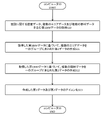
取得モジュールは、建設に関する図面データ、複数のエリアデータ及び複数の部材データを含む第1BIMデータを取得する(ステップS10)。
図面データは、建設の現場における図面に関するデータである。エリアデータは、例えば、部屋、トイレ周り、専有部分、共有部分等のエリアに関するデータである。部材データは、例えば、設置場所、製造メーカ、種類、個数、特性等の部材に関するデータである。エリアデータ及び部材データには、各々の仕様や数量等の属性データが含まれる。第1BIMデータは、これらの他に、建物形状、空間関係、地理情報、施工方法等の建設工程のデジタルデータを含むものである。
取得モジュールは、この第1BIMデータを、業者端末20から取得する。
業者端末20は、コンピュータ10から、第1BIMデータの送信要求を受信する。業者端末20は、受信した送信要求に基づいて、コンピュータ10が所望した第1BIMデータを、自身が記憶するBIMデータの中から抽出し、抽出したBIMデータを、第1BIMデータとして、コンピュータ10に送信する。
取得モジュールは、この第1BIMデータを受信することにより、建設に関する図面データ、複数のエリアデータ及び複数の部材データを含む第1BIMデータを取得する。
The acquisition module acquires first BIM data including construction drawing data, a plurality of area data, and a plurality of member data (step S10).
The drawing data is data related to drawings at the construction site. The area data is, for example, data relating to areas such as a room, a toilet area, an exclusive part, a shared part, and the like. The member data is, for example, data relating to members such as installation location, manufacturer, type, number, and characteristics. The area data and member data include attribute data such as specifications and quantities. In addition to these, the first BIM data includes digital data of construction processes such as building shapes, spatial relationships, geographic information, and construction methods.
The acquisition module acquires this first BIM data from the
The
By receiving this first BIM data, the acquisition module acquires first BIM data including drawing data, a plurality of area data, and a plurality of member data relating to construction.
作成モジュールは、取得した第1BIMデータに基づいて、複数のエリアデータを一のグループにまとめた第1データを作成する(ステップS11)。
作成モジュールは、取得した第1BIMデータにおいて、複数のエリアデータを抽出する。作成モジュールは、抽出した複数のエリアデータの内、所定の条件を満たす複数のエリアデータを一のグループにまとめた第1データを作成する。所定の条件は、例えば、同階のエリア、同種類のエリア、同仕様のエリア、部材が共通のエリア等の、複数のエリアデータを一のグループにまとめることを可能にするものである。
作成モジュールは、全てのエリアデータをまとめて第1データを作成しても良いし、全てのエリアデータを、複数に分類し、分類毎の第1データを作成しても良い。
The creation module creates first data in which a plurality of area data are put together into one group based on the acquired first BIM data (step S11).
The creation module extracts a plurality of area data from the acquired first BIM data. The creation module creates first data in which a plurality of area data satisfying a predetermined condition are grouped together from among the plurality of extracted area data. The predetermined condition enables a plurality of area data such as areas on the same floor, areas of the same type, areas with the same specifications, areas with common members, etc., to be grouped together.
The creation module may create the first data by collecting all the area data, or classify all the area data into a plurality of categories and create the first data for each category.
作成モジュールは、取得した第1BIMデータに基づいて、複数の部材データを一のグループにまとめた第2データを作成する(ステップS12)。
作成モジュールは、取得した第1BIMデータにおいて、複数の部材データを抽出する。作成モジュールは、抽出した複数の部材データの内、所定の条件を満たす複数の部材データを一のグループにまとめた第2データを作成する。所定の条件は、例えば、同設置場所の部材、同種類の部材、同仕様の部材、同製造メーカの部材等の、複数の部材データを一のグループにまとめることを可能にするものである。
作成モジュールは、全ての部材データをまとめて第2データを作成しても良いし、全ての部材データを、複数に分類し、分類毎の第2データを作成しても良い。
The creation module creates second data in which a plurality of member data are put together into one group based on the acquired first BIM data (step S12).
The creation module extracts a plurality of member data from the acquired first BIM data. The creation module creates second data in which a plurality of member data satisfying a predetermined condition are grouped together from among the extracted plurality of member data. The predetermined condition makes it possible, for example, to group a plurality of member data such as members at the same installation location, members of the same type, members with the same specifications, and members from the same manufacturer.
The creation module may create the second data by collecting all the member data, or classify all the member data into a plurality of categories and create the second data for each category.
アイコン化モジュールは、作成した第1データ及び第2データをアイコン化する(ステップS13)。
アイコンは、例えば、数字、テキスト、ピン、円、多角形、チェックリスト等を単独又は組み合わせたものである。本処理でのアイコン化とは、第1データ及び第2データの各々と、アイコンとを紐付けるものである。
アイコン化モジュールは、作成した第1データ及び第2データの各々に、所定のアイコンを紐付ける。所定のアイコンは、予め作成されたものであっても良いし、アイコン化する際に作成するものであっても良い。なお、アイコン化モジュールが用いるアイコンの種類は、上述した例に限定されるものではない。
アイコン化モジュールは、例えば、第1データに、六角形の内部に数字が配置されたアイコンを紐付け、第1データをアイコン化する。また、アイコン化モジュールは、例えば、第2データに、円の内部に数字が配置されたアイコンを紐付け、第2データをアイコン化する。
なお、アイコン化モジュールが実行する第1データ及び第2データのアイコン化は、双方のアイコン化ではなく、何れか一方のみのアイコン化を行う構成であっても良い。
また、ステップS13の処理は、必ずしも実行する必要はない。この場合、コンピュータ10は、後述する処理において、アイコン化前の第1データ及び第2データを直接用いる構成とすれば良い。または、コンピュータ10は、第1データ及び第2データの何れか又は双方を、アイコン化以外の方法、例えば、画像化、ロゴ化、テキスト化する構成も可能である。この場合、コンピュータ10は、後述する処理において、アイコン化した第1データ及び第2データの代わりに、アイコン化以外の方法がなされた第1データ及び第2データを用いれば良い。
The iconization module iconizes the created first data and second data (step S13).
Icons are, for example, numbers, text, pins, circles, polygons, checklists, etc. alone or in combination. Iconization in this process associates each of the first data and the second data with an icon.
The iconization module associates a predetermined icon with each of the created first data and second data. The predetermined icon may be created in advance, or may be created at the time of iconization. Note that the types of icons used by the iconization module are not limited to the examples described above.
The iconization module, for example, associates the first data with an icon in which numbers are arranged inside a hexagon, and iconizes the first data. Further, the iconization module, for example, associates the second data with an icon in which numbers are arranged inside a circle, and iconizes the second data.
It should be noted that the iconization of the first data and the second data executed by the iconization module may be configured to iconize only one of them instead of iconifying both.
Moreover, the process of step S13 does not necessarily have to be executed. In this case, the
以上が、データ作成処理である。
コンピュータ10は、本データ作成処理により作成し、アイコン化された第1データ及び第2データに基づいて、後述する処理を実行する。
The above is the data creation processing.
The
[コンピュータ10が実行するデータ配置処理]
図4に基づいて、コンピュータ10が実行するデータ配置処理について説明する。同図は、コンピュータ10が実行するデータ配置処理のフローチャートを示す図である。本データ配置処理は、上述したレイヤデータの生成処理(ステップS3)、第1データ及び第2データの配置処理(ステップS4)の詳細であり、上述したデータ作成処理の後に実行する処理である。
[Data Arrangement Processing Executed by Computer 10]
The data arrangement process executed by the
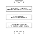
生成モジュールは、取得した第1BIMデータに基づいて、図面データ上に重ねて配置するレイヤデータを生成する(ステップS20)。
レイヤデータは、図面データ上に重ねる仮想シートであり、第1データ、第2データ、アイコン、メモ、画像等を出力可能なものである。
生成モジュールは、図面データと同じサイズ、且つ、図面データを透過表示するレイヤデータを生成する。生成モジュールは、生成したレイヤデータを、図面データ上に重ねて配置する。
なお、レイヤデータの構造は、上述した例に限定されるものではない。
The generation module generates layer data to be superimposed on the drawing data based on the acquired first BIM data (step S20).
The layer data is a virtual sheet superimposed on the drawing data, and can output first data, second data, icons, memos, images, and the like.
The generation module generates layer data having the same size as the drawing data and transparently displaying the drawing data. The generation module overlays the generated layer data on the drawing data.
Note that the structure of layer data is not limited to the example described above.
配置モジュールは、生成したレイヤデータに、第1データ及び第2データを配置する(ステップS21)。
配置モジュールは、生成したレイヤデータに、アイコン化した第1データ及び第2データを配置する。配置モジュールは、第1データが示すエリアに該当するレイヤデータ上の箇所に、アイコン化した第1データを配置する。配置モジュールが配置するアイコン化した第1データの箇所は、第1データが示すエリア内であれば良い。
配置モジュールは、第2データが示す部材に該当するレイヤデータの箇所に、アイコン化した第2データを配置する。配置モジュールが配置するアイコン化した第2データの箇所は、第2データが示す部材上であれば良い。
The arrangement module arranges the first data and the second data in the generated layer data (step S21).
The arrangement module arranges the iconized first data and second data on the generated layer data. The placement module places the iconized first data at a location on the layer data corresponding to the area indicated by the first data. The location of the iconized first data arranged by the arrangement module may be within the area indicated by the first data.
The placement module places the iconized second data at a portion of the layer data corresponding to the member indicated by the second data. The location of the iconized second data to be placed by the placement module may be on the member indicated by the second data.
第1出力モジュールは、第1データ及び第2データが配置されたレイヤデータが重ねられた図面データを出力する(ステップS22)。
第1出力モジュールは、この図面データを、施工者端末30に送信する。この時、図面データには、レイヤデータに配置された第1データのエリアデータ及び第2データの部材データが含まれる。
施工者端末30は、この図面データを受信し、自身の表示部に表示する。施工者端末30は、レイヤデータに配置された各アイコンに対する入力を受け付けることにより、アイコンに紐付けられた第1データのエリアデータ及び第2データの部材データを表示する。
第1出力モジュールは、施工者端末30に、図面データを表示させることにより、第1データ及び第2データが配置されたレイヤデータが重ねられた図面データを出力する。
The first output module outputs drawing data in which the layer data in which the first data and the second data are placed are superimposed (step S22).
The first output module transmits this drawing data to the
The
The first output module causes the
[コンピュータ10が出力する図面データ]
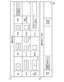
図5に基づいて、第1出力モジュールが出力する図面データについて説明する。同図は、第1出力モジュールが出力する図面データの一例を模式的に示した図である。同図において、図面データ40が示されている。
図面データ40には、レイヤデータ41が重ねて配置されている。更に、レイヤデータ41には、アイコン化された第1データ42(以下、単に第1データ42とも称す)及びアイコン化された第2データ43(以下、単に第2データ43とも称す)が配置されている。
第1データ42は、六角形の内部に数字が配置されたアイコンで示されており、この数字は、エリア毎に異なる数字が割り振られている。第1データ42は、レイヤデータ41に複数存在しているが、その内の一つに、代表例として符号を付与している。
第2データ43は、円形の内部に数字が配置されたアイコンで示されており、この数字は、部材毎の場所毎に異なる数字が割り振られている。第2データ43は、レイヤデータ41に複数存在しているが、その内の一つに、代表例として符号を付与している。
施工者端末30は、この第1データ42に対する入力を受け付けた場合、この第1データ42におけるエリアデータを表示部に表示する。また、施工者端末30は、この第2データ43に対する入力を受け付けた場合、この第2データ43における部材データを表示部に表示する。
[Drawing Data Output by Computer 10]
Drawing data output by the first output module will be described with reference to FIG. This figure is a diagram schematically showing an example of drawing data output by the first output module. In the figure, drawing
The
The
The
以上が、データ配置処理である。
コンピュータ10は、本データ配置処理により、出力した図面データに対する入力内容に基づいて、後述する処理を実行する。
The above is the data arrangement processing.
The
[コンピュータ10が実行するデータ変換処理]
図6に基づいて、コンピュータ10が実行するデータ変換処理について説明する。同図は、コンピュータ10が実行するデータ変換処理のフローチャートを示す図である。本データ変換処理は、上述した建設施工の進捗入力の受付処理(ステップS5)、部材の変更入力の受付処理(ステップS6)、進捗入力及び変更入力の反映処理(ステップS7)、レイヤデータから第2BIMデータへの変換処理(ステップS8)の詳細であり、上述したデータ配置処理の後に実行する処理である。
[Data Conversion Processing Executed by Computer 10]
Data conversion processing executed by the
第1受付モジュールは、配置した第1データ及び第2データに対して、建設施工の進捗入力を受け付ける(ステップS30)。
進捗入力は、例えば、部材の設置進捗、複数の部材の連結進捗、部材の試運転の検査進捗である。進捗は、施工内容の作業状態や作業状況の進み具合やその内容である。なお、検査進捗は、単に、検査の状況だけに限らず、検査結果が正常であったか異常であったかを含むものであって良い。建設施工の進捗に関する内容は、エリア毎、部材毎等の個別に行うものではなく、まとまった内容に対して入力を受け付けることが多いため、一連のグループにしたエリアデータ及び部材データに対して行うことになる。例えば、トイレ1個1個の各部材の建設施工の進捗ではなく、トイレエリア全体に対する必要な部材全体の建設施工の進捗の入力を受け付けるものである。
施工者端末30は、上述したデータ配置処理により、自身に表示した図面データに対する入力を受け付ける。ここで、施工者端末30は、施工者が進捗入力を行うアイコン化された第1データ及び第2データに対する入力を受け付ける。施工者端末30は、レイヤデータ上に配置されたアイコンに対するタップ操作等の入力を受け付ける。施工者端末30は、入力を受け付けたアイコンに紐付けられた第1データ及び第2データに対する進捗入力又は第2データに対する変更入力の何れかの入力であるかを選択する入力を受け付ける。施工者端末30は、受け付けた入力が、進捗入力を選択するものである場合、受け付けたアイコンに紐付けられた第1データ及び第2データに対する進捗入力を受け付ける(図7参照)。ここで、入力を受け付けたアイコンを、ハイライト、強調表示等の入力を受けつけていない他のアイコンとは異なる表示態様で表示する構成も可能である。なお、施工者端末30は、第1データに対する入力を受け付けた場合、選択の入力を受け付けずとも、進捗入力を受け付ける構成も可能である。
施工者端末30は、進捗入力を、テキスト入力、画像入力、電子小黒板入力、動画入力等により受け付ける。施工者端末30は、仮想キーボード等によりテキスト入力を受け付ける。施工者端末30は、自身にインストールされた撮影用アプリケーションにより撮影した画像や、自身にデータ通信可能に接続された撮影装置により撮影された画像を取得することにより、画像入力を受け付ける。施工者端末30は、進捗が入力された電子小黒板の内容を反映することにより、電子小黒板入力を受け付ける。施工者端末30は、自身にインストールされた撮影用アプリケーションにより撮影した動画や、自身にデータ通信可能に接続された撮影装置により撮影された動画を取得することにより、動画入力を受け付ける。なお、施工者端末30は、上述した例以外の方法により、進捗入力を受け付けても良い。
施工者端末30は、受け付けた進捗入力を、コンピュータ10に送信する。
第1受付モジュールは、この進捗入力を受信することにより、配置した第1データ及び第2データに対して、建設施工の進捗入力を受け付ける。
The first reception module receives construction work progress input for the arranged first data and second data (step S30).
The progress input is, for example, the installation progress of a member, the progress of connection of a plurality of members, and the inspection progress of trial run of a member. The progress is the work state of the construction content, the progress of the work situation, and the content thereof. Note that the progress of the inspection is not limited to the status of the inspection, and may include whether the inspection result was normal or abnormal. The contents related to the progress of construction work are not performed individually for each area, each member, etc., but in many cases, input is received for collective content, so it is performed for area data and member data that are grouped in series. It will be. For example, it accepts an input of the progress of the construction work of all necessary members for the entire toilet area, instead of the progress of the construction work of each member of each toilet.
The
The
The
By receiving this progress input, the first reception module receives progress input of construction work for the arranged first data and second data.
[施工者端末30が受け付ける建設施工の進捗入力]
図7は、施工者端末30が受け付ける建設施工の進捗入力の一例を模式的に示した図である。同図において、施工者端末30は、進捗入力を受け付ける進捗入力欄50を示している。本実施形態では、建設施工の内容が、測定機器を用いた風量測定であり、進捗入力欄50が、風量測定に関する進捗入力を受け付ける場合を例として説明する。
施工者端末30は、レイヤデータ上に配置されたアイコン42,43に対する入力を受け付け、進捗入力を選択する入力を受け付けることにより、この進捗入力欄50を表示する。この進捗入力欄50は、独立して表示しても良いし、レイヤデータに重ねて表示しても良い。
施工者端末30は、建設施工の進捗として、判定条件、判定方法、合否、測定日、測定時間、測定値、複数のポイント等の測定内容51及び合否判定、測定風速、測定風量、設計風速、設計風量、測定機器等の測定結果52の入力を受け付ける。
施工者端末30は、入力を受け付けた各項目のデータを、コンピュータ10に送信する。
第1受付モジュールは、この入力を受け付けた各項目のデータを受信することにより、配置した第1データ及び第2データに対して、建設施工の進捗入力を受け付ける。
[Construction Progress Input Received by Builder Terminal 30]
FIG. 7 is a diagram schematically showing an example of construction work progress input received by the
The
The
The
The first receiving module receives the data of each item for which this input has been received, thereby receiving progress input of construction work for the arranged first data and second data.
図6に戻り、データ変換処理の続きを説明する。
第2受付モジュールは、配置した第2データに対して、部材の変更入力を受け付ける(ステップS31)。
変更入力は、例えば、追加、分解、組替、削除であり、これらの内の少なくとも一つであれば良い。部材の変更に関する内容は、エリア毎、部材毎等の個別に行うものではなく、まとまった内容に対して入力を受け付けることが多いため、一連のグループにした部材データに対して行うことになる。例えば、トイレ1個1個の各部材の変更ではなく、トイレエリア全体に対する必要な部材全体の変更の入力を受け付けるものである。
施工者端末30は、上述したデータ配置処理により、自身に表示した図面データに対する入力を受け付ける。ここで、施工者端末30は、施工者が変更入力を行うアイコン化された第2データに対する入力を受け付ける。施工者端末30は、レイヤデータ上に配置されたアイコンに対するタップ操作等の入力を受け付ける。施工者端末30は、入力を受け付けたアイコンに紐付けられた第2データに対する進捗入力又は変更入力の何れかの入力であるかを選択する入力を受け付ける。施工者端末30は、受け付けた入力が、変更入力を選択するものである場合、受け付けたアイコンに紐付けられた第2データに対する変更入力を受け付ける(図8参照)。ここで、入力を受け付けたアイコンを、ハイライト、強調表示等の入力を受けつけていない他のアイコンとは異なる表示態様で表示する構成も可能である。
施工者端末30は、変更入力を、テキスト入力、画像入力、電子小黒板入力、動画入力等により受け付ける。各入力方法については、上述した進捗入力の場合と同様である。
施工者端末30は、受け付けた変更入力を、コンピュータ10に送信する。
第2受付モジュールは、この変更入力を受信することにより、配置した第2データに対して、部材の変更入力を受け付ける。
Returning to FIG. 6, the continuation of the data conversion process will be described.
The second reception module receives an input to change the member for the arranged second data (step S31).
The change input is, for example, addition, disassembly, rearrangement, or deletion, and at least one of these may be used. Contents related to the change of members are not performed individually for each area or each member, but input is often received for collective content, so that it is performed for a series of grouped member data. For example, it accepts inputs for changes to entire parts required for the entire toilet area, rather than changes to individual parts of each toilet.
The
The
The
By receiving this change input, the second reception module receives the change input of the member for the arranged second data.
[施工者端末30が受け付ける部材の変更入力]
図8は、施工者端末30が受け付ける部材の変更入力の一例を模式的に示した図である。同図において、施工者端末30は、変更入力を受け付ける変更入力欄60を示している。本実施形態では、建設施工の内容が、測定機器を用いた風量測定であり、変更入力欄60が、風量に関する部材の変更入力を受け付ける場合を例として説明する。
施工者端末30は、レイヤデータ上に配置されたアイコン43に対する入力を受け付け、変更入力を選択する入力を受け付けることにより、この変更入力欄60を表示する。この変更入力欄60は、独立して表示しても良いし、レイヤデータに重ねて表示しても良い。
施工者端末30は、部材の変更として、階、室名、系統、種類、型式、サイズ、開口率、器具開口面積、設計風量、測定点等の対象部材61及び測定方法、測定部断面積等の測定条件62の入力を受け付ける。
施工者端末30は、入力を受け付けた各項目のデータを、コンピュータ10に送信する。
第2受付モジュールは、この入力を受け付けた各項目のデータを受信することにより、配置した第2データに対して、部材の変更入力を受け付ける。
[Change Input of Member Accepted by Builder Terminal 30]
FIG. 8 is a diagram schematically showing an example of a member change input received by the
The
The
The
The second receiving module receives the data of each item for which this input is received, and receives the member change input for the arranged second data.
なお、上述したステップS30及びS31の処理は、その順番が前後しても良い。また、上述したステップS31の処理は、部材の変更が無かった場合、省略しても良い。 It should be noted that the order of steps S30 and S31 described above may be reversed. Further, the process of step S31 described above may be omitted if there is no change in the member.
図6に戻り、データ変換処理の続きを説明する。
反映モジュールは、レイヤデータに配置した第1データに受け付けた進捗入力を反映する(ステップS32)。
本処理での、進捗入力の反映とは、第1データに、受け付けた進捗入力の各項目の内容を追加することを意図するものである。
反映モジュールは、受け付けた進捗入力に基づいて、レイヤデータに配置した第1データに、受け付けた進捗入力の各項目の内容を反映する。
Returning to FIG. 6, the continuation of the data conversion process will be described.
The reflection module reflects the received progress input in the first data arranged in the layer data (step S32).
In this process, the reflection of the progress input is intended to add the contents of each item of the received progress input to the first data.
The reflection module reflects the content of each item of the received progress input in the first data arranged in the layer data based on the received progress input.
反映モジュールは、レイヤデータに配置した第2データに受け付けた進捗入力及び変更入力を反映する(ステップS33)。
本処理での、進捗入力及び変更入力の反映とは、第2データに、受け付けた進捗入力及び変更入力の各項目の内容を追加することを意図するものである。
反映モジュールは、受け付けた進捗入力及び変更入力に基づいて、レイヤデータに配置した第2データに、受け付けた進捗入力及び変更入力の各項目の内容を反映する。
The reflection module reflects the received progress input and change input in the second data arranged in the layer data (step S33).
Reflection of the progress input and change input in this process is intended to add the contents of each item of the received progress input and change input to the second data.
The reflection module reflects the content of each item of the received progress input and change input in the second data arranged in the layer data based on the received progress input and change input.
なお、上述したステップS32及びS33の処理は、その順番が前後しても良い。また、上述したステップS33の処理は、部材の変更が無かった場合、進捗入力のみを反映すれば良い。 It should be noted that the order of steps S32 and S33 described above may be reversed. Further, in the processing of step S33 described above, if there is no change in the member, only the progress input should be reflected.
変換モジュールは、受け付けた進捗入力及び変更入力を反映したレイヤデータを、第2BIMデータに変換する(ステップS34)。
変換モジュールは、進捗入力を反映した第1データ、及び、進捗入力及び変換入力を反映した第2データをレイヤデータごと、BIMデータに変換する。第2BIMデータは、変換モジュールが変換したBIMデータである。
The conversion module converts the layer data reflecting the received progress input and change input into second BIM data (step S34).
The conversion module converts the first data reflecting the progress input and the second data reflecting the progress input and the conversion input into BIM data for each layer data. The second BIM data is BIM data converted by the conversion module.
以上が、データ変換処理である。
コンピュータ10は、本データ変換処理により、レイヤデータを変換した第2BIMデータに基づいて、後述する処理を実行する。
The above is the data conversion processing.
The
[コンピュータ10が実行する提供処理]
図9に基づいて、コンピュータ10が実行する提供処理について説明する。同図は、コンピュータ10が実行する提供処理のフローチャートを示す図である。本提供処理は、第2BIMデータの提供処理(ステップS9)の詳細であり、上述したデータ変換処理の後に実行する処理である。
[Providing process executed by computer 10]
The providing process executed by the
抽出モジュールは、第2BIMデータから、視覚化に必要なデータを抽出する(ステップS40)。
本処理での視覚化とは、データを、表、グラフ、マップ、指標等により可視化することを意図するものである。視覚化に必要なデータは、建設施工の進捗に関するデータ、部材の変更に関するデータだけでなく、それ以外のデータであっても良い。
抽出モジュールは、予め設定された視覚化の種類や内容等に基づいて、この種類や内容等に該当するデータを、第2BIMデータから特定し、特定したデータを抽出する。
なお、抽出モジュールは、施工者端末30が入力を受け付けた視覚化の種類及び内容等を取得し、取得した視覚化の種類及び内容等に基づいて、第2BIMデータから、必要なデータを抽出しても良い。
The extraction module extracts data necessary for visualization from the second BIM data (step S40).
Visualization in this processing is intended to visualize data in the form of tables, graphs, maps, indices, and the like. The data required for visualization may be not only data on the progress of construction work and data on changes in members, but also other data.
The extraction module identifies, from the second BIM data, data corresponding to the type, content, etc., of visualization set in advance based on the type, content, etc., of visualization, and extracts the identified data.
Note that the extraction module acquires the type and content of visualization that the
視覚化モジュールは、抽出したデータを視覚化する(ステップS41)。
視覚化モジュールは、抽出したデータを、設定された種類に基づいて、視覚化する。視覚化モジュールは、抽出したデータに基づいた表、グラフ、マップ、指標等を作成することにより、抽出したデータを視覚化する。
The visualization module visualizes the extracted data (step S41).
A visualization module visualizes the extracted data based on the set type. A visualization module visualizes the extracted data by creating tables, graphs, maps, indicators, etc. based on the extracted data.
第2出力モジュールは、第2BIMデータを、所定の形式で出力する(ステップS42)。
本処理での所定の形式で出力するとは、例えば、帳票の印刷、所定のデータ形式(例えば、3DPDF(Portable Document Format))に変換、他の端末に表示を意図するものである。ここで、出力とは、生データ又は加工済データをデータ通信可能に接続された端末に送信し、この端末に何らかの処理を実行させること、及び、所定のデータ形式にデータを変換することの両者を意図するものである。
帳票の出力の場合、第2出力モジュールは、第2BIMデータに基づいた所定のフォーマットの帳票データを作成する。第2出力モジュールは、抽出した視覚化に必要なデータ、所定のフォーマットに指定されたデータ等に基づいて、この帳票データを作成する。第2出力モジュールは、作成した帳票データを、データ通信可能に接続されたプリンタに出力し、プリンタに帳票データを印刷させることにより、帳票を出力する。
所定のデータ形式の出力の場合、第2出力モジュールは、第2BIMデータを、所定のデータ形式に変換することにより、所定のデータ形式の第2BIMデータを出力する。
他の端末に表示の場合、第2出力モジュールは、第2BIMデータを、施工者端末30等の他の端末に送信する。他の端末は、この第2BIMデータを受信し、自身の表示部等に表示する。
第2出力モジュールが実行する出力内容は、上述した例に限定されるものでない。また、所定の形式も、同様に、上述した例に限定されるものではない。
The second output module outputs the second BIM data in a predetermined format (step S42).
Outputting in a predetermined format in this process means, for example, printing a form, converting to a predetermined data format (eg, 3DPDF (Portable Document Format)), and displaying on another terminal. Here, output means sending raw data or processed data to a terminal connected for data communication, causing this terminal to execute some processing, and converting data into a predetermined data format. is intended to be
In the case of outputting a form, the second output module creates form data in a predetermined format based on the second BIM data. The second output module creates this form data based on the extracted data necessary for visualization, data specified in a predetermined format, and the like. The second output module outputs the created form data to a printer connected for data communication, and causes the printer to print the form data, thereby outputting the form.
In the case of the output of the predetermined data format, the second output module outputs the second BIM data of the predetermined data format by converting the second BIM data into the predetermined data format.
For display on another terminal, the second output module transmits the second BIM data to another terminal such as the
The output content executed by the second output module is not limited to the example described above. Similarly, the predetermined format is not limited to the examples described above.
提供モジュールは、変換した第2BIMデータを提供する(ステップS43)。
提供モジュールは、上述したデータ変換処理により変換した第2BIMデータを、業者端末20に送信する。業者端末20は、この第2BIMデータを、受信し、記憶する。
提供モジュールは、業者端末20に、第2BIMデータを送信することにより、変換した第2BIMデータを提供する。ここで、提供モジュールが提供する第2BIMデータは、上述したデータ変換処理により変換した第2BIMデータのみだけでなく、視覚化したデータ及び出力した所定の形式を含むものであっても良い。
なお、提供モジュールが第2BIMデータを提供する対象は、上述した第1BIMデータを取得した業者端末20に限定されるものではなく、第1BIMデータを取得した業者端末20以外の業者端末20に対して提供しても良い。
The providing module provides the converted second BIM data (step S43).
The provision module transmits the second BIM data converted by the data conversion process described above to the
The provision module provides the converted second BIM data by transmitting the second BIM data to the
Note that the target to which the provision module provides the second BIM data is not limited to the
以上が、データ提供処理である。 The above is the data provision processing.
上述した各処理は、別個の処理として記載しているが、コンピュータ10は、上述した各処理の一部又は全部を組み合わせて実行する構成も可能である。また、コンピュータ10は、各処理において、説明したタイミング以外のタイミングであっても、その処理を実行する構成も可能である。
Each of the processes described above is described as separate processes, but the
上述した手段、機能は、コンピュータ(CPU、情報処理装置、各種端末を含む)が、所定のプログラムを読み込んで、実行することによって実現される。プログラムは、例えば、コンピュータからネットワーク経由で提供される(SaaS:ソフトウェア・アズ・ア・サービス)形態やクラウドサービスで提供されてよい。また、プログラムは、コンピュータ読取可能な記録媒体に記録された形態で提供されてよい。この場合、コンピュータはその記録媒体からプログラムを読み取って内部記録装置又は外部記録装置に転送し記録して実行する。また、そのプログラムを、記録装置(記録媒体)に予め記録しておき、その記録装置から通信回線を介してコンピュータに提供するようにしてもよい。 The means and functions described above are realized by a computer (including a CPU, an information processing device, and various terminals) reading and executing a predetermined program. The program may be provided, for example, from a computer via a network (SaaS: software as a service) or provided as a cloud service. Also, the program may be provided in a form recorded on a computer-readable recording medium. In this case, the computer reads the program from the recording medium, transfers it to an internal recording device or an external recording device, records it, and executes it. Alternatively, the program may be recorded in advance in a recording device (recording medium) and provided from the recording device to the computer via a communication line.
以上、本発明の実施形態について説明したが、本発明は上述したこれらの実施形態に限るものではない。また、本発明の実施形態に記載された効果は、本発明から生じる最も好適な効果を列挙したに過ぎず、本発明による効果は、本発明の実施形態に記載されたものに限定されるものではない。 Although the embodiments of the present invention have been described above, the present invention is not limited to these embodiments described above. Moreover, the effects described in the embodiments of the present invention are merely enumerations of the most suitable effects resulting from the present invention, and the effects of the present invention are limited to those described in the embodiments of the present invention. is not.
(1)BIMデータを提供するBIMデータ提供システムであって、
建設に関する、図面データ、複数のエリアデータ(例えば、部屋、トイレ周り、専有部分、共有部分等のエリアに関するデータ)及び複数の部材データ(例えば、設置場所、製造メーカ、種類、個数、特性等の部材に関するデータ)を含む第1BIMデータを取得する取得部(例えば、取得部11、取得モジュール)と、
取得した前記第1BIMデータに基づいて、前記複数のエリアデータを一のグループにまとめた第1データ及び前記複数の部材データを一のグループにまとめた第2データを作成する作成部(例えば、作成部15、作成モジュール)と、
取得した前記第1BIMデータに基づいて、前記図面データ上に重ねて配置するレイヤデータを生成する生成部(例えば、生成部16、生成モジュール)と、
生成した前記レイヤデータに、前記第1データ及び前記第2データを配置する配置部(例えば、配置部17、配置モジュール)と、
配置した前記第1データ及び前記第2データに対して、建設施工の進捗入力を受け付ける第1受付部(例えば、第1受付部12、第1受付モジュール)と、
配置した前記第2データに対して、部材の変更入力を受け付ける第2受付部(例えば、第2受付部13、第2受付モジュール)と、
前記レイヤデータに配置した前記第1データに、受け付けた前記進捗入力を反映し、前記レイヤデータに配置した前記第2データに、受け付けた前記進捗入力及び前記変更入力を反映する反映部(例えば、反映部18、反映モジュール)と、
受け付けた前記進捗入力及び前記変更入力を反映した前記レイヤデータを、第2BIMデータに変換する変換部(例えば、変換部19、変換モジュール)と、
変換した前記第2BIMデータを提供する提供部(例えば、提供部14、提供モジュール)と、
を備えるBIMデータ提供システム。
(1) A BIM data providing system for providing BIM data,
Drawing data, multiple area data (for example, data related to areas such as rooms, around toilets, private parts, shared parts, etc.) and multiple component data (for example, installation location, manufacturer, type, number, characteristics, etc.) an acquisition unit (e.g.,
Based on the acquired first BIM data, a creation unit (for example, creation part 15, creation module);
a generation unit (eg,
an arrangement unit (for example, an
a first reception unit (e.g., first reception unit 12, first reception module) that receives construction progress input for the arranged first data and second data;
a second reception unit (for example, a second reception unit 13, a second reception module) that receives an input to change a member for the arranged second data;
A reflecting unit (for example, a reflection unit 18, a reflection module);
a conversion unit (e.g., conversion unit 19, conversion module) that converts the layer data reflecting the received progress input and change input into second BIM data;
a providing unit (e.g., providing unit 14, providing module) that provides the converted second BIM data;
A BIM data provision system comprising:
(1)の発明によれば、現場管理上のデータとBIMデータとを連動させることが可能となる。 According to the invention of (1), it is possible to link the site management data and the BIM data.
(2)前記変更入力が、追加、分解、組替及び削除の内、少なくとも一つである、
(1)に記載のBIMデータ提供システム。
(2) the change input is at least one of addition, disassembly, rearrangement, and deletion;
(1) The BIM data providing system according to the above.
(2)の発明によれば、現場で急遽部材の変更が行われた場合であっても、現場管理上のデータとBIMデータとを連動させることが可能となる。 According to the invention of (2), it is possible to link the site management data and the BIM data even when the members are suddenly changed at the site.
(3)作成した前記第1データ及び前記第2データをアイコン化するアイコン化部(例えば、アイコン化モジュール)と、
を更に備え、
前記配置部は、生成した前記レイヤデータに、アイコン化した前記第1データ及び前記第2データを配置する、
(1)に記載のBIMデータ提供システム。
(3) an iconization unit (for example, an iconization module) that iconizes the first data and the second data that have been created;
further comprising
The placement unit places the iconized first data and second data in the generated layer data.
(1) The BIM data providing system according to the above.
(3)の発明によれば、現場管理上のデータの視認性が向上する。 According to the invention of (3), the visibility of data on site management is improved.
(4)前記第2BIMデータを、所定の形式で出力する出力部(例えば、第2出力モジュール)と、
を更に備え、
前記提供部は、出力した所定の形式を含む前記第2BIMデータを提供する、
(1)に記載のBIMデータ提供システム。
(4) an output unit (for example, a second output module) that outputs the second BIM data in a predetermined format;
further comprising
The providing unit provides the second BIM data including the output predetermined format,
(1) The BIM data providing system according to the above.
(4)の発明によれば、第2BIMデータを活用することが可能となる。 According to the invention of (4), it is possible to utilize the second BIM data.
(5)前記第2BIMデータの視覚化に必要なデータを抽出する抽出部(例えば、抽出モジュール)と、
抽出したデータを視覚化する視覚化部(例えば、視覚化モジュール)と、
を更に備え、
前記提供部は、視覚化したデータを含む前記第2BIMデータを提供する、
(1)に記載のBIMデータ提供システム。
(5) an extractor (e.g., an extraction module) that extracts data necessary for visualization of the second BIM data;
a visualization unit (e.g., a visualization module) that visualizes the extracted data;
further comprising
The providing unit provides the second BIM data including visualized data;
(1) The BIM data providing system according to the above.
(5)の発明によれば、第2BIMデータを活用することが可能となる。 According to the invention of (5), it is possible to utilize the second BIM data.
(6)BIMデータを提供するコンピュータが実行するBIMデータ提供方法であって、
建設に関する、図面データ、複数のエリアデータ及び複数の部材データを含む第1BIMデータを取得するステップ(例えば、ステップS10)と、
取得した前記第1BIMデータに基づいて、前記複数のエリアデータを一のグループにまとめた第1データ及び前記複数の部材データを一のグループにまとめた第2データを作成するステップ(例えば、ステップS11,S12)と、
取得した前記第1BIMデータに基づいて、前記図面データ上に重ねて配置するレイヤデータを生成するステップ(例えば、ステップS20)と、
生成した前記レイヤデータに、前記第1データ及び前記第2データを配置するステップ(例えば、ステップS21)と、
配置した前記第1データ及び前記第2データに対して、建設施工の進捗入力を受け付けるステップ(例えば、ステップS30)と、
配置した前記第2データに対して、部材の変更入力を受け付けるステップ(例えば、ステップS31)と、
前記レイヤデータに配置した前記第1データに、受け付けた前記進捗入力を反映し、前記レイヤデータに配置した前記第2データに、受け付けた前記進捗入力及び前記変更入力を反映するステップ(例えば、ステップS32,S33)と、
受け付けた前記進捗入力及び前記変更入力を反映した前記レイヤデータを、第2BIMデータに変換するステップ(例えば、ステップS34)と、
変換した前記第2BIMデータを提供するステップ(例えば、ステップS43)と、
を備えるBIMデータ提供方法。
(6) A BIM data providing method executed by a computer that provides BIM data,
a step of acquiring first BIM data including drawing data, a plurality of area data and a plurality of member data relating to construction (for example, step S10);
A step of creating first data in which the plurality of area data are grouped into one group and second data in which the plurality of member data are grouped into one group based on the acquired first BIM data (for example, step S11 , S12) and
a step of generating layer data to be superimposed on the drawing data based on the acquired first BIM data (for example, step S20);
a step of arranging the first data and the second data in the generated layer data (for example, step S21);
a step of receiving progress input of construction work for the arranged first data and second data (for example, step S30);
a step of receiving an input to change a member for the arranged second data (for example, step S31);
A step of reflecting the received progress input in the first data arranged in the layer data and reflecting the received progress input and the change input in the second data arranged in the layer data (for example, step S32, S33) and
a step of converting the layer data reflecting the received progress input and the change input into second BIM data (for example, step S34);
providing the transformed second BIM data (eg step S43);
A BIM data providing method comprising:
(7)BIMデータを提供するコンピュータに、
建設に関する、図面データ、複数のエリアデータ及び複数の部材データを含む第1BIMデータを取得するステップ(例えば、ステップS10)、
取得した前記第1BIMデータに基づいて、前記複数のエリアデータを一のグループにまとめた第1データ及び前記複数の部材データを一のグループにまとめた第2データを作成するステップ(例えば、ステップS11,S12)、
取得した前記第1BIMデータに基づいて、前記図面データ上に重ねて配置するレイヤデータを生成するステップ(例えば、ステップS20)、
生成した前記レイヤデータに、前記第1データ及び前記第2データを配置するステップ(例えば、ステップS21)、
配置した前記第1データ及び前記第2データに対して、建設施工の進捗入力を受け付けるステップ(例えば、ステップS30)、
配置した前記第2データに対して、部材の変更入力を受け付けるステップ(例えば、ステップS31、
前記レイヤデータに配置した前記第1データに、受け付けた前記進捗入力を反映し、前記レイヤデータに配置した前記第2データに、受け付けた前記進捗入力及び前記変更入力を反映するステップ(例えば、ステップS32,S33)、
受け付けた前記進捗入力及び前記変更入力を反映した前記レイヤデータを、第2BIMデータに変換するステップ(例えば、ステップS34)、
変換した前記第2BIMデータを提供するステップ(例えば、ステップS43)、
を実行させるためのコンピュータ読み取り可能なプログラム。
(7) to a computer that provides BIM data,
Acquiring first BIM data including drawing data, a plurality of area data, and a plurality of member data relating to construction (for example, step S10);
A step of creating first data in which the plurality of area data are grouped into one group and second data in which the plurality of member data are grouped into one group based on the acquired first BIM data (for example, step S11 , S12),
generating layer data to be superimposed on the drawing data based on the acquired first BIM data (for example, step S20);
a step of arranging the first data and the second data in the generated layer data (for example, step S21);
a step of receiving progress input of construction work for the arranged first data and second data (for example, step S30);
A step of receiving an input to change the member for the arranged second data (for example, step S31,
A step of reflecting the received progress input in the first data arranged in the layer data and reflecting the received progress input and the change input in the second data arranged in the layer data (for example, step S32, S33),
converting the layer data reflecting the received progress input and change input into second BIM data (for example, step S34);
providing the converted second BIM data (for example, step S43);
A computer readable program for executing
1 BIMデータ提供システム
9 ネットワーク
10 コンピュータ
11 取得部
12 第1受付部
13 第2受付部
14 提供部
15 作成部
16 生成部
17 配置部
18 反映部
19 変換部
20 業者端末
30 施工者端末
40 図面データ
41 レイヤデータ
42 アイコン化された第1データ
43 アイコン化された第2データ
50 進捗入力欄
51 測定内容
52 測定結果
60 変更入力欄
61 対象部材
62 測定条件
1 BIM
Claims (7)
建設に関する、図面データ、複数のエリアデータ及び複数の部材データを含む第1BIMデータを取得する取得部と、
取得した前記第1BIMデータに基づいて、前記図面データ上に重ねて配置するレイヤデータを生成する生成部と、
生成した前記レイヤデータに、前記第1BIMデータを配置する配置部と、
配置した前記第1BIMデータの複数のエリアデータを一のグループにまとめたデータ及び複数の部材データを一のグループにまとめたデータに対して、建設施工の進捗入力を受け付ける受付部と、
受け付けた前記進捗入力を反映した前記レイヤデータを、第2BIMデータに変換する変換部と、
変換した前記第2BIMデータを提供する提供部と、
を備えるBIMデータ提供システム。 A BIM data providing system for providing BIM data,
an acquisition unit that acquires first BIM data including drawing data, a plurality of area data, and a plurality of member data regarding construction;
a generation unit that generates layer data to be superimposed on the drawing data based on the acquired first BIM data;
an arrangement unit that arranges the first BIM data in the generated layer data;
a reception unit that receives a progress input of construction work with respect to data in which a plurality of area data of the arranged first BIM data are grouped into one group and data in which a plurality of member data are grouped into one group ;
a conversion unit that converts the layer data reflecting the received progress input into second BIM data;
a providing unit that provides the converted second BIM data;
A BIM data provision system comprising:
を更に備え、
前記配置部は、生成した前記レイヤデータに、アイコン化した前記第1BIMデータを配置する、
請求項1に記載のBIMデータ提供システム。 an iconization unit that iconizes the created first BIM data;
further comprising
The placement unit places the iconized first BIM data on the generated layer data.
The BIM data providing system according to claim 1.
を更に備え、
前記提供部は、出力した所定の形式を含む前記第2BIMデータを提供する、
請求項1に記載のBIMデータ提供システム。 an output unit that outputs the second BIM data in a predetermined format;
further comprising
The providing unit provides the second BIM data including the output predetermined format,
The BIM data providing system according to claim 1.
抽出したデータを視覚化する視覚化部と、
を更に備え、
前記提供部は、視覚化したデータを含む前記第2BIMデータを提供する、
請求項1に記載のBIMデータ提供システム。 an extraction unit for extracting data necessary for visualization of the second BIM data;
a visualization unit for visualizing the extracted data;
further comprising
The providing unit provides the second BIM data including visualized data;
The BIM data providing system according to claim 1.
建設に関する、図面データ、複数のエリアデータ及び複数の部材データを含む第1BIMデータを取得するステップと、
取得した前記第1BIMデータに基づいて、前記図面データ上に重ねて配置するレイヤデータを生成するステップと、
生成した前記レイヤデータに、前記第1BIMデータを配置するステップと、
配置した前記第1BIMデータの複数のエリアデータを一のグループにまとめたデータ及び複数の部材データを一のグループにまとめたデータに対して、建設施工の進捗入力を受け付けるステップと、
受け付けた前記進捗入力を反映した前記レイヤデータを、第2BIMデータに変換するステップと、
変換した前記第2BIMデータを提供するステップと、
を備えるBIMデータ提供方法。 A BIM data providing method executed by a computer that provides BIM data,
obtaining first BIM data including drawing data, a plurality of area data and a plurality of member data regarding construction;
generating layer data to be superimposed on the drawing data based on the acquired first BIM data;
arranging the first BIM data on the generated layer data;
a step of receiving progress input of construction work with respect to data in which a plurality of area data of the arranged first BIM data are grouped into one group and data in which a plurality of member data are grouped into one group ;
converting the layer data reflecting the received progress input into second BIM data;
providing the transformed second BIM data;
A BIM data providing method comprising:
建設に関する、図面データ、複数のエリアデータ及び複数の部材データを含む第1BIMデータを取得するステップ、
取得した前記第1BIMデータに基づいて、前記図面データ上に重ねて配置するレイヤデータを生成するステップ、
生成した前記レイヤデータに、前記第1BIMデータを配置するステップ、
配置した前記第1BIMデータの複数のエリアデータを一のグループにまとめたデータ及び複数の部材データを一のグループにまとめたデータに対して、建設施工の進捗入力を受け付けるステップ、
受け付けた前記進捗入力を反映した前記レイヤデータを、第2BIMデータに変換するステップ、
変換した前記第2BIMデータを提供するステップ、
を実行させるためのコンピュータ読み取り可能なプログラム。 to the computer that provides the BIM data,
Acquiring first BIM data including drawing data, a plurality of area data and a plurality of member data relating to construction;
generating layer data to be superimposed on the drawing data based on the acquired first BIM data;
arranging the first BIM data in the generated layer data;
a step of receiving progress input of construction work with respect to data in which a plurality of area data of the arranged first BIM data are grouped into one group and data in which a plurality of member data are grouped into one group ;
converting the layer data reflecting the received progress input into second BIM data;
providing the transformed second BIM data;
A computer readable program for executing
Priority Applications (1)
| Application Number | Priority Date | Filing Date | Title |
|---|---|---|---|
| JP2022080643A JP7200423B1 (en) | 2021-11-29 | 2022-05-17 | BIM data provision system, BIM data provision method and program |
Applications Claiming Priority (3)
| Application Number | Priority Date | Filing Date | Title |
|---|---|---|---|
| JP2022526404A JP7129586B1 (en) | 2021-11-29 | 2021-11-29 | BIM data provision system, BIM data provision method and program |
| PCT/JP2021/043590 WO2023095322A1 (en) | 2021-11-29 | 2021-11-29 | Bim data providing system, bim data providing method, and program |
| JP2022080643A JP7200423B1 (en) | 2021-11-29 | 2022-05-17 | BIM data provision system, BIM data provision method and program |
Related Parent Applications (1)
| Application Number | Title | Priority Date | Filing Date |
|---|---|---|---|
| JP2022526404A Division JP7129586B1 (en) | 2021-11-29 | 2021-11-29 | BIM data provision system, BIM data provision method and program |
Publications (2)
| Publication Number | Publication Date |
|---|---|
| JP7200423B1 true JP7200423B1 (en) | 2023-01-06 |
| JP2023079992A JP2023079992A (en) | 2023-06-08 |
Family
ID=87846686
Family Applications (1)
| Application Number | Title | Priority Date | Filing Date |
|---|---|---|---|
| JP2022080643A Active JP7200423B1 (en) | 2021-11-29 | 2022-05-17 | BIM data provision system, BIM data provision method and program |
Country Status (1)
| Country | Link |
|---|---|
| JP (1) | JP7200423B1 (en) |
Citations (3)
| Publication number | Priority date | Publication date | Assignee | Title |
|---|---|---|---|---|
| JP2017004227A (en) | 2015-06-09 | 2017-01-05 | 前田建設工業株式会社 | Building management support method, building management support program, and building management support device |
| JP2020009008A (en) | 2018-07-04 | 2020-01-16 | 高砂熱学工業株式会社 | Information process system and program for information process system |
| JP2020166382A (en) | 2019-03-28 | 2020-10-08 | 高砂熱学工業株式会社 | Construction management system, construction management method, mobile terminal and program |
-
2022
- 2022-05-17 JP JP2022080643A patent/JP7200423B1/en active Active
Patent Citations (3)
| Publication number | Priority date | Publication date | Assignee | Title |
|---|---|---|---|---|
| JP2017004227A (en) | 2015-06-09 | 2017-01-05 | 前田建設工業株式会社 | Building management support method, building management support program, and building management support device |
| JP2020009008A (en) | 2018-07-04 | 2020-01-16 | 高砂熱学工業株式会社 | Information process system and program for information process system |
| JP2020166382A (en) | 2019-03-28 | 2020-10-08 | 高砂熱学工業株式会社 | Construction management system, construction management method, mobile terminal and program |
Non-Patent Citations (1)
| Title |
|---|
| 谷内秀敬,5.3 リニューアルエ事におけるBIM活用事例,空気調和・衛生工学 ,公益社団法人空気調和・衛生工学会,2012年12月05日,第86巻,第12号,pp.65-72 |
Also Published As
| Publication number | Publication date |
|---|---|
| JP2023079992A (en) | 2023-06-08 |
Similar Documents
| Publication | Publication Date | Title |
|---|---|---|
| US10607409B2 (en) | Synthetic geotagging for computer-generated images | |
| JP7129586B1 (en) | BIM data provision system, BIM data provision method and program | |
| WO2016081628A1 (en) | System and method for aggregating and analyzing data and creating a spatial and/or non-spatial graphical display based on the aggregated data | |
| JP2020197842A (en) | Three dimensional data management method for architectural structure and mobile terminal realizing the same | |
| US20210081870A1 (en) | System and method for supporting production management | |
| JP7200423B1 (en) | BIM data provision system, BIM data provision method and program | |
| JP7167386B1 (en) | Indication content output system, indication content output method and program | |
| JP6437397B2 (en) | Information processing apparatus and program | |
| JP7219997B1 (en) | How to output blueprints of block objects | |
| CN113436317B (en) | Image processing method and device, electronic equipment and computer readable storage medium | |
| KR20170000287A (en) | Geo-tagging method, geo-tagging apparatus and storage medium storing a program performing the method | |
| EP2645335A1 (en) | Visual assistance system for facility maintenance | |
| JP7309103B1 (en) | Pass/Fail Judgment System, Pass/Fail Judgment Method and Program | |
| JP2021162973A (en) | Inspection system | |
| JP2022142997A (en) | Information processing device, work progress management method, and program | |
| JP7316483B1 (en) | Judgment result output system, judgment result output method and program | |
| JP7320693B1 (en) | ELECTRONIC SMALL BOARD OUTPUT SYSTEM, JUDGMENT RESULT OUTPUT METHOD AND PROGRAM | |
| JP5803216B2 (en) | Information processing apparatus and program | |
| JP2021015572A (en) | Information management system and information management method | |
| WO2022244799A1 (en) | Information sharing support device, system, method, and program | |
| WO2023218499A1 (en) | Electronic slate preparation system, electronic slate preparation method, and program | |
| JP2014170347A (en) | Wide area monitoring control device | |
| WO2023209789A1 (en) | Plant management device, plant management method, and computer-readable storage medium | |
| KR102634016B1 (en) | Web based digital twin service method | |
| JP7121215B1 (en) | CONSTRUCTION WORK MANAGEMENT SYSTEM, CONSTRUCTION WORK MANAGEMENT METHOD AND PROGRAM |
Legal Events
| Date | Code | Title | Description |
|---|---|---|---|
| A621 | Written request for application examination |
Free format text: JAPANESE INTERMEDIATE CODE: A621 Effective date: 20220607 |
|
| A871 | Explanation of circumstances concerning accelerated examination |
Free format text: JAPANESE INTERMEDIATE CODE: A871 Effective date: 20220607 |
|
| A131 | Notification of reasons for refusal |
Free format text: JAPANESE INTERMEDIATE CODE: A131 Effective date: 20220830 |
|
| A521 | Request for written amendment filed |
Free format text: JAPANESE INTERMEDIATE CODE: A523 Effective date: 20221004 |
|
| TRDD | Decision of grant or rejection written | ||
| A01 | Written decision to grant a patent or to grant a registration (utility model) |
Free format text: JAPANESE INTERMEDIATE CODE: A01 Effective date: 20221220 |
|
| A61 | First payment of annual fees (during grant procedure) |
Free format text: JAPANESE INTERMEDIATE CODE: A61 Effective date: 20221221 |
|
| R150 | Certificate of patent or registration of utility model |
Ref document number: 7200423 Country of ref document: JP Free format text: JAPANESE INTERMEDIATE CODE: R150 |