JP7219997B1 - How to output blueprints of block objects - Google Patents
How to output blueprints of block objects Download PDFInfo
- Publication number
- JP7219997B1 JP7219997B1 JP2022116787A JP2022116787A JP7219997B1 JP 7219997 B1 JP7219997 B1 JP 7219997B1 JP 2022116787 A JP2022116787 A JP 2022116787A JP 2022116787 A JP2022116787 A JP 2022116787A JP 7219997 B1 JP7219997 B1 JP 7219997B1
- Authority
- JP
- Japan
- Prior art keywords
- block
- information
- block parts
- user terminal
- user
- Prior art date
- Legal status (The legal status is an assumption and is not a legal conclusion. Google has not performed a legal analysis and makes no representation as to the accuracy of the status listed.)
- Active
Links
- 238000000034 method Methods 0.000 claims abstract description 36
- 238000012545 processing Methods 0.000 claims abstract description 25
- 230000003190 augmentative effect Effects 0.000 claims abstract description 6
- 238000004891 communication Methods 0.000 description 18
- 230000010365 information processing Effects 0.000 description 12
- 238000010586 diagram Methods 0.000 description 10
- 238000013461 design Methods 0.000 description 9
- 230000006870 function Effects 0.000 description 5
- 238000012986 modification Methods 0.000 description 3
- 230000004048 modification Effects 0.000 description 3
- 241001465754 Metazoa Species 0.000 description 2
- 239000000470 constituent Substances 0.000 description 2
- 239000003550 marker Substances 0.000 description 2
- 238000006467 substitution reaction Methods 0.000 description 2
- 230000005540 biological transmission Effects 0.000 description 1
- 230000004397 blinking Effects 0.000 description 1
- 239000011449 brick Substances 0.000 description 1
- 239000003086 colorant Substances 0.000 description 1
- 239000000463 material Substances 0.000 description 1
- 238000012800 visualization Methods 0.000 description 1
Images


Classifications
-
- Y—GENERAL TAGGING OF NEW TECHNOLOGICAL DEVELOPMENTS; GENERAL TAGGING OF CROSS-SECTIONAL TECHNOLOGIES SPANNING OVER SEVERAL SECTIONS OF THE IPC; TECHNICAL SUBJECTS COVERED BY FORMER USPC CROSS-REFERENCE ART COLLECTIONS [XRACs] AND DIGESTS
- Y02—TECHNOLOGIES OR APPLICATIONS FOR MITIGATION OR ADAPTATION AGAINST CLIMATE CHANGE
- Y02P—CLIMATE CHANGE MITIGATION TECHNOLOGIES IN THE PRODUCTION OR PROCESSING OF GOODS
- Y02P90/00—Enabling technologies with a potential contribution to greenhouse gas [GHG] emissions mitigation
- Y02P90/30—Computing systems specially adapted for manufacturing
Abstract
【課題】ユーザがブロックパーツを使ってブロックオブジェクトを組み立てやすくする方法を提供することを目的とする。【解決手段】複数のユーザ端末とネットワークを介して接続されるサーバ端末の処理部によって実行される、組み立て可能な、複数種のブロックパーツで構成されるブロックオブジェクトの設計図を出力する方法であって、前記サーバ端末の処理部は、前記ユーザ端末から、ブロックオブジェクトに関する情報を取得し、前記ユーザ端末に表示される拡張現実空間において、前記ブロックオブジェクトの画像を表示させ、前記ユーザ端末から、ブロックパーツに関する情報を受信し、前記拡張現実空間において、前記ブロックパーツの画像を、前記ブロックオブジェクトに対して識別可能なように表示させる。【選択図】図6An object of the present invention is to provide a method that enables a user to easily assemble a block object using block parts. A method for outputting a blueprint of an assembleable block object composed of a plurality of types of block parts, which is executed by a processing unit of a server terminal connected to a plurality of user terminals via a network. The processing unit of the server terminal obtains information about the block object from the user terminal, displays the image of the block object in an augmented reality space displayed on the user terminal, and receives the block object from the user terminal. Information about the part is received, and an image of the block part is displayed in the augmented reality space so as to be identifiable with respect to the block object. [Selection drawing] Fig. 6
Description
本発明は、ブロックオブジェクトの設計図を出力する方法に関する。 The present invention relates to a method for outputting a blueprint of a block object.
ユーザが、レゴブリックのようなブロックパーツを使って動物、建物、乗り物等のブロックオブジェクトモデルを組み立てる玩具が普及している。 Toys in which a user builds block object models such as animals, buildings, vehicles, etc. using block parts such as Lego bricks are popular.
例えば、特許文献1において、ブロックオブジェクトを構成するブロックパーツの設計を効率化させる方法が開示されている。
For example,
しかしながら、上記特許文献1に開示されている技術によって、ブロックパーツの設計の効率化及び可視化を実現することは可能なものの、ユーザ視点に立って、ブロックオブジェクトを組み立てるイメージを可視化する方法を実現する方法は開示されていない。
However, although the technique disclosed in
そこで、本発明は、ユーザがブロックパーツを使ってブロックオブジェクトを組み立てやすくする方法を提供することを目的とする。 SUMMARY OF THE INVENTION Accordingly, it is an object of the present invention to provide a method that makes it easier for a user to assemble a block object using block parts.
本発明の一態様における、ユーザ端末とネットワークを介して接続されるサーバ端末の処理部によって実行される、組み立て可能な、複数種のブロックパーツで構成されるブロックオブジェクトの設計図を出力する方法であって、前記サーバ端末の処理部は、前記ユーザ端末から、ブロックパーツに関する情報を取得し、前記ブロックパーツに関する情報に基づいて、組み立て可能なブロックオブジェクトを決定し、前記ブロックオブジェクトの設計図情報及び前記ブロックパーツに関する情報を表示させ、前記ブロックオブジェクトの設計図情報を更新し、前記更新された設計図情報に基づいてブロックパーツに関する情報を更新し、前記更新されたブロックパーツに関する情報を表示させる。本発明の一態様における、ユーザ端末とネットワークを介して接続されるサーバ端末の処理部によって実行される、組み立て可能な、複数種のブロックパーツで構成されるブロックオブジェクトの設計図を出力する方法であって、前記サーバ端末の処理部は、前記ユーザ端末から、ブロックオブジェクトに関する情報を取得し、前記ユーザ端末に表示される拡張現実空間において、前記ブロックオブジェクトの画像を表示させ、前記ユーザ端末から、ブロックパーツに関する情報を受信し、前記拡張現実空間において、前記ブロックパーツの画像を、前記ブロックオブジェクトに対して識別可能なように表示させる。 In one aspect of the present invention, a method for outputting a blueprint of an assembleable block object composed of a plurality of types of block parts, which is executed by a processing unit of a server terminal connected to a user terminal via a network. The processing unit of the server terminal acquires information about block parts from the user terminal, determines block objects that can be assembled based on the information about the block parts, and blueprint information of the block objects and Information about the block parts is displayed, blueprint information of the block object is updated, information about the block parts is updated based on the updated blueprint information, and information about the updated block parts is displayed. In one aspect of the present invention, a method for outputting a blueprint of an assembleable block object composed of a plurality of types of block parts, which is executed by a processing unit of a server terminal connected to a user terminal via a network. A processing unit of the server terminal acquires information about a block object from the user terminal, displays an image of the block object in an augmented reality space displayed on the user terminal, and from the user terminal, Information about the block parts is received, and an image of the block parts is displayed in the augmented reality space so as to be identifiable with respect to the block object.
本発明によれば、ユーザがブロックパーツを使ってブロックオブジェクトを組み立てやすくする方法を提供することができる。 According to the present invention, it is possible to provide a method that makes it easier for a user to assemble a block object using block parts.
以下、本発明の実施形態について図面を参照して説明する。なお、以下に説明する実施形態は、特許請求の範囲に記載された本発明の内容を不当に限定するものではない。また、実施形態に示される構成要素のすべてが、本発明の必須の構成要素であるとは限らない。 BEST MODE FOR CARRYING OUT THE INVENTION Hereinafter, embodiments of the present invention will be described with reference to the drawings. It should be noted that the embodiments described below do not unduly limit the scope of the invention described in the claims. Moreover, not all the constituent elements shown in the embodiments are essential constituent elements of the present invention.
<構成>
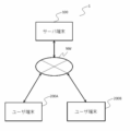
図1は、本発明の第一実施形態に係る、ブロックオブジェクトを推奨する方法を提供するシステムを示すブロック構成図である。本システム1は、ユーザ端末200またはセンサ装置300から取得したブロックパーツの座標情報に基づいて、ブロックオブジェクトの設計図情報を生成するサーバ端末100と、ブロックオブジェクトを組み立てる各ユーザに関連付けられた、ユーザ端末200A、200Bとで構成される。以下、説明の便宜のため、ユーザ端末200A、200Bを総称して、ユーザ端末200として説明する。
<Configuration>
FIG. 1 is a block diagram illustrating a system for providing a method for recommending block objects according to a first embodiment of the present invention. This
ここで、複数のブロックパーツで構成されるブロックオブジェクトの例として、本実施形態において、動物オブジェクトを例として説明するが、他に、人、ロボット、乗り物及び建物等が挙げられ、一つの例に限定されない。 Here, as an example of a block object composed of a plurality of block parts, an animal object will be described as an example in this embodiment. Not limited.
サーバ端末100とユーザ端末200は各々、ネットワークNWを介して接続される。ネットワークNWは、インターネット、イントラネット、無線LAN(Local Area Network)やWAN(Wide Area Network)等により構成される。
The
サーバ端末100は、例えば、ワークステーションやパーソナルコンピュータのような汎用コンピュータとしてもよいし、或いはクラウド・コンピューティングによって論理的に実現されてもよい。本実施形態においては、説明の便宜上サーバ端末として1台を例示しているが、これに限定されず、複数台であってもよい。
The
ユーザ端末200は、例えば、パーソナルコンピュータやタブレット端末等の情報処理装置であるが、スマートフォンや携帯電話、PDA等により構成しても良い。
The
本実施形態では、システム1は、サーバ端末100及びユーザ端末200を有し、ユーザがユーザ端末200を利用して、サーバ端末100に対する操作を行う構成として説明するが、サーバ端末100がスタンドアローンで構成され、サーバ端末自身に、各ユーザが直接操作を行う機能を備えても良い。
In this embodiment, the
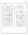
図2は、図1のサーバ端末100の機能ブロック構成図である。サーバ端末100は、通信部110と、記憶部120と、制御部130とを備える。
FIG. 2 is a functional block configuration diagram of the
通信部110は、ネットワークNWを介してユーザ端末200と通信を行うための通信インターフェースであり、例えばTCP/IP(Transmission Control Protocol/Internet Protocol)等の通信規約により通信が行われる。
The
記憶部120は、各種制御処理や制御部130内の各機能を実行するためのプログラム、入力データ等を記憶するものであり、RAM(Random Access Memory)、ROM(Read Only Memory)等から構成される。また、記憶部120は、オブジェクトモデルに関連する情報等を格納する、オブジェクトモデル情報格納部121、及びオブジェクトモデルを基に生成されたブロックパーツ情報等を格納する、ブロックパーツ情報格納部122を有する。なお、各種データを格納したデータベース(図示せず)が記憶部120またはサーバ端末100外に構築されていてもよい。
The
制御部130は、記憶部120に記憶されているプログラムを実行することにより、サーバ端末100の全体の動作を制御するものであり、CPU(Central Processing Unit)やGPU(Graphics Processing Unit)等から構成される。制御部130の機能として、ユーザ端末200からの指示等の情報を受け付ける情報受付部131、オブジェクトモデルに関連する各種情報を参照し、処理する、オブジェクトモデル情報処理部132、ブロックパーツに関連する各種情報を参照し、処理するブロックパーツ情報処理部133、及び、ブロックオブジェクトに関連する設計図情報をユーザ端末に出力させるよう送信する処理を行う出力処理部134を有する。この情報受付部131、オブジェクトモデル情報処理部132、ブロックパーツ情報処理部133、及び出力処理部134は、記憶部120に記憶されているプログラムにより起動されてコンピュータ(電子計算機)であるサーバ端末100により実行される。
The
情報受付部131は、サーバ端末100が提供し、ユーザ端末200において、ウェブブラウザまたはアプリケーションを介して表示される画面等のユーザインターフェースを介して、ユーザが、(テキストを入力したり、アイコンを押下する等して)所定の要求を行ったとき、ユーザ端末200から情報を受け付け、または、センサ装置300で生成された、ブロックパーツの座標情報を、ユーザ端末200及び通信部110を介して受付ける。
The information reception unit 131 is provided by the
オブジェクトモデル処理部132は、オブジェクトモデルに関連する情報をオブジェクトモデル情報格納部121に格納したり、格納されたオブジェクトモデル情報を参照する処理を行う。
The object
ブロックパーツ情報処理部133は、ブロックパーツに関連する情報をブロックパーツ情報格納部122に格納したり、格納されたブロックパーツ情報を参照する処理を行う。
The block parts
出力処理部134は、ユーザ端末200にブロックオブジェクトに関連する設計図情報等を表示させるため、ユーザ端末200に対し必要な情報を送信する処理を行う。この際、出力処理部134は、記憶部120に格納された画像及びテキストデータを素材として、所定のレイアウト規則に基づいて、各種画像及びテキストをユーザインターフェースの所定の領域に配置することで、ユーザ端末200のインターフェースに表示されるために必要な画面情報を生成することができる。この画面情報生成処理は、GPU(Graphics Processing Unit)によって実行することもできる。
The
図3は、図1のユーザ端末200を示す機能ブロック構成図である。ユーザ端末200は、通信部210と、表示操作部220と、記憶部230と、制御部240とを備える。
FIG. 3 is a functional block configuration diagram showing the
通信部210は、ネットワークNWを介してサーバ端末100と通信を行うための通信インターフェースであり、例えばTCP/IP等の通信規約により通信が行われる。また、通信部210は、近距離無線通信等を介してセンサ装置300と通信を行うための通信インターフェースを備えることもできる。
The
表示操作部220は、ユーザが指示を入力し、制御部240からの入力データに応じてテキスト、画像等を表示するために用いられるユーザインターフェースであり、ユーザ端末200がパーソナルコンピュータで構成されている場合はディスプレイとキーボードやマウスにより構成され、ユーザ端末200がスマートフォンまたはタブレット端末で構成されている場合はタッチパネル等から構成される。この表示操作部220は、記憶部230に記憶されている制御プログラムにより起動されてコンピュータ(電子計算機)であるユーザ端末200により実行される。
The
記憶部230は、各種制御処理や制御部240内の各機能を実行するためのプログラム、入力データ等を記憶するものであり、RAMやROM等から構成される。また、記憶部230は、サーバ端末100との通信内容を一時的に記憶している。
The
制御部240は、記憶部230に記憶されているプログラムを実行することにより、ユーザ端末200の全体の動作を制御するものであり、CPUやGPU等から構成される。
The
なお、サーバ端末100に表示操作部の機能を備える構成としても良く、この場合、ユーザ端末200を備えない構成としても良い。また、その他、ユーザ端末200は、(図示しない)カメラを備えてもよく、この場合、カメラは、ブロックパーツに備えられるARマーカを撮像することで、ブロックパーツの(形状、色等によって決定される)種類等を識別し、拡張現実(AR)空間における座標を決定することができる。
Note that the
図4は、サーバ100に格納されるオブジェクトモデル情報の一例を示す図である。
FIG. 4 is a diagram showing an example of object model information stored in the
図4に示すオブジェクトモデル情報1000は、サーバ端末100に関連するサービス運営者またはユーザ端末200に関連するユーザが生成したオブジェクトモデルに関連する情報等を格納する。図4において、説明の便宜上、一オブジェクトモデル(オブジェクトID「10001」で識別されるユーザ)の例を示すが、複数のオブジェクトモデルの情報を格納することができる。オブジェクトモデルに関連する各種データとして、オブジェクトモデルの3Dモデルデータ、オブジェクトモデルの断面データ、また、オブジェクトモデルを組み立てるために必要な、一または複数種のブロックパーツ及び個数に関連するデータ、断面の層(レイヤー)毎に配置されるブロックパーツに関連する設計図情報等の情報を含むことができる。ここで、3Dモデルデータは、2Dモデルデータを所定の処理により3Dモデルに変換されたものとして格納することもできる。
The object model information 1000 shown in FIG. 4 stores information related to an object model generated by a service operator related to the
図5は、サーバ100に格納されるブロックパーツ情報の一例を示す図である。
FIG. 5 is a diagram showing an example of block parts information stored in the
図5に示すブロックパーツ情報2000は、ブロックパーツの形状、サイズ、色及び重さに関連する情報等を格納する。図5において、説明の便宜上、一ブロックパーツ(ID「20001」で識別されるブロックパーツ)の例を示すが、複数のブロックパーツに関連する情報を格納することができる。ブロックパーツに関連する各種データとして、例えば、ブロックオブジェクトを組み立てる部品に相当するブロックパーツに関連する(ブロックパーツの形状、サイズ、色、各々のブロックパーツの個数等からなる)データを含むことができる。ここで、複数種のブロックパーツの各々は固有の色と関連づけられることができるが、これに限らない。 The block parts information 2000 shown in FIG. 5 stores information related to the shape, size, color and weight of block parts. FIG. 5 shows an example of one block part (a block part identified by ID "20001") for convenience of explanation, but information related to a plurality of block parts can be stored. Various data related to block parts can include, for example, data related to block parts corresponding to parts for assembling a block object (consisting of the shape, size, color, number of each block part, etc.). . Here, each of the plurality of types of block parts can be associated with a unique color, but is not limited to this.
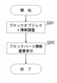
図6は、本発明の第一実施形態に係る、ブロックオブジェクトの設計図の出力方法を示すフローチャートの一例である。 FIG. 6 is an example of a flowchart showing a method for outputting a design drawing of a block object according to the first embodiment of the present invention.
事前の処理として、ユーザは、ユーザ端末200のウェブブラウザまたは(アプリケーションをインストールする場合は)アプリケーション等を利用してサーバ端末100にアクセスする。ウェブサイトまたはアプリケーション等を介してユーザインターフェース上に所定の画面が表示される。ユーザは、事前に、後述する基本ブロックパーツを手元に所有しており、基本ブロックパーツに関する情報が、サーバ端末100の記憶部120のブロックパーツ情報格納部122に格納されている。
As a preliminary process, the user accesses the
そして、ステップS101の処理として、サーバ端末100の制御部130の情報受付部131は、ユーザ端末200から、ネットワーク及び通信部110を介して、ユーザがこれから組み立てたい、とする、ブロックオブジェクトに関する情報を受信する。ここで、ユーザは、ユーザ端末200上で表示されるユーザーインターフェース画面において、複数のブロックオブジェクトの中から、所望のブロックオブジェクトを選択することができる。本例においては、ユーザは、図8(a)に示すような、カエルのブロックオブジェクトを組み立てたい、と考え、ユーザ端末200上で表示されるユーザーインターフェース画面において、カエルのブロックオブジェクトを組み立てたい旨入力操作を行うと、サーバ端末100は、カエルに対応するブロックオブジェクトに関する情報を受信する。
Then, as the process of step S101, the information reception unit 131 of the
続いて、ステップS102の処理として、サーバ端末100の制御部130のオブジェクトモデル情報処理部132は、受信されたブロックオブジェクトモデルに関する情報に基づいて、記憶部120のオブジェクトモデル情報格納部121を参照し、ユーザが選択したブロックオブジェクトの3Dデータに基づいて、ユーザ端末200にブロックオブジェクトを表示させる処理を実行する。ここで、ユーザ端末200のユーザーインターフェース画面には、AR空間が表示され、ユーザ端末200に備えられたカメラによって撮像される現実空間に、上記3Dデータに基づいて生成されるブロックオブジェクトの画像が表示される。ここで、ユーザは、AR空間内に表示されるブロックオブジェクトの画像を、所定のコントローラやタッチパネルのピンチやズーム等の操作により、拡大、縮小、回転等させることができる。
Subsequently, as the process of step S102, the object model
続いて、ステップS103の処理として、サーバ端末100の制御部130の情報受付部131は、ユーザ端末200から、ネットワーク及び通信部110を介して、ユーザが所有する一のブロックパーツに関する情報を受信する。ここで、ユーザは、ユーザ端末200に備えられたカメラによって自らが所有するブロックパーツを撮影すると、ブロックパーツに貼付等されたARマーカを識別し、識別された情報がサーバ端末100に送信される。ARマークを介して識別された情報を基に、サーバ端末100のブロックパーツ情報処理部133は、ブロックパーツの種類(形状、色及び大きさのいずれかまたは組合せ等で定義される種類)を識別する。また、ブロックパーツ情報処理部133は、ブロックパーツのAR空間内における座標を識別することもできる。
Subsequently, as the process of step S103, the information reception unit 131 of the
続いて、ステップS104の処理として、サーバ端末100の制御部130のオブジェクトモデル情報処理部132は、記憶部120のオブジェクトモデル情報格納部121に格納された、オブジェクトモデルの設計図情報を参照し、受信したブロックパーツに関する情報から識別されたブロックパーツに関する情報を基に、当該ブロックパーツが、ブロックオブジェクトの組み立てに必要なブロックパーツであるか否かを決定し、ブロックオブジェクトの組み立てに必要なブロックパーツである場合には、サーバ端末100の制御部130の出力処理部134は、ユーザ端末200のユーザーインターフェース画面を介して表示されるAR空間に配置されるブロックオブジェクトにおいて、当該ブロックパーツ部分を色分け表示させたり、点滅表示させる等して、ブロックパーツの識別表示を行う。
Subsequently, as the process of step S104, the object model
例えば、図8(b)は、カエルのオブジェクトモデルの設計図データの一部の例である。設計図データは、各層において、オブジェクトモデルを構成するために必要なブロックパーツの配置領域を、座標情報とともに、色別に示すものである。本設計図データとともに、ブロックパーツ情報処理部133は、記憶部120のブロックパーツ情報格納部122に格納されるブロックパーツ情報を参照し、図9に示すような、予め決められたブロックパーツのうち、いずれのブロックパーツが、設計図情報に含まれるブロックパーツの配置領域において、いずれの領域で使用されるかを決定し、受信されたブロックパーツが、当該決定されたブロックパーツと一致するかを確認する。ここで、ブロックパーツ同士が一致することを確認すると、すなわち、ユーザが所有するブロックパーツがブロックオブジェクトの組み立てに使用されることを確認すると、出力処理部134は、図10に示すようの、AR空間内に表示されるユーザオブジェクトのうち、当該ブロックパーツを使用する箇所がわかるよう、ブロックパーツの画像を色分け表示させたり、点滅表示させたりする等して識別表示を行う。
For example, FIG. 8(b) is an example of part of the blueprint data of the frog object model. The blueprint data indicates, in each layer, the placement area of the block parts required to configure the object model, along with coordinate information, by color. Along with this design drawing data, the block parts
図7は、本発明の第一実施形態に係る、ブロックオブジェクトの設計図の出力方法を示すフローチャートの他の一例である。 FIG. 7 is another example of a flowchart showing a method for outputting a design drawing of a block object according to the first embodiment of the present invention.
本例においては、上記ステップS104の処理において、ブロックパーツを識別表示させる際に、AR空間内にユーザの手持ちのブロックパーツを表示させるときに、表示されるブロックパーツの実際の大きさに合わせて、同じくAR空間内に表示させるブロックオブジェクトの大きさを再調整し、ブロックパーツと重ね合わせて表示させる等して、ユーザが手持ちのブロックパーツを用いて容易にブロックオブジェクトを組み立てできるようにするものである。 In this example, in the process of step S104, when the block parts are displayed in an identifiable manner in the AR space, when the block parts held by the user are displayed in the AR space, , Similarly, readjusting the size of the block object displayed in the AR space and displaying it overlaid with the block parts, etc., so that the user can easily assemble the block object using the block parts on hand. is.
まず、ステップS201の処理において、サーバ端末100の制御部130のオブジェクトモデル情報処理部132は、記憶部120のオブジェクトモデル情報格納部121に格納された、オブジェクトモデルの3Dモデル情報を参照し、上記受信された、ユーザの手持ちのブロックパーツに備えられたARマーカを介したブロックパーツのAR空間内の座標情報を基に、ブロックパーツの大きさを判定し、AR空間内に表示させるオブジェクトモデルの大きさを、オブジェクトモデルを構成するブロックパーツの大きさが、ユーザにより所有される実際のブロックパーツの大きさに合うように再調整(リサイズ)する。
First, in the process of step S201, the object model
続いて、ステップS202の処理において、サーバ端末100の制御部130の出力処理部134は、上記の通り、大きさを再調整されたブロックオブジェクトの画像を、ユーザ端末200のユーザーインターフェース画面に表示されるAR空間内において、ブロックパーツの画像に重畳させて表示させる。ここで、出力処理部134は、ブロックオブジェクトを半透明にして表示させることで、ブロックオブジェクトとブロックパーツとを区別して表示させることができるため、ユーザは、より容易にブロックオブジェクトを組み立てることができる。
Subsequently, in the processing of step S202, the
以上のように、本実施形態によれば、ユーザが、ブロックオブジェクトを組み立てるときに、AR空間内において、ブロックオブジェクトとともに、手持ちのブロックパーツを使用箇所等を識別して表示させることで、ユーザは、容易にブロックオブジェクトを組み立てることができる。 As described above, according to the present embodiment, when the user assembles a block object, the user can identify and display the block parts he/she has along with the block object in the AR space by identifying where they are used. , can easily assemble block objects.
以上、発明に係る実施形態について説明したが、これらはその他の様々な形態で実施することが可能であり、種々の省略、置換および変更を行なって実施することが出来る。これらの実施形態および変形例ならびに省略、置換および変更を行なったものは、特許請求の範囲の技術的範囲とその均等の範囲に含まれる。 Although the embodiments according to the invention have been described above, they can be implemented in various other forms, and can be implemented with various omissions, substitutions, and modifications. These embodiments, modifications, omissions, substitutions and modifications are included within the technical scope of the claims and their equivalents.
1 システム 100 サーバ端末、110 通信部、120 記憶部、130 制御部、200 ユーザ端末、NW ネットワーク
1
Claims (5)
前記サーバ端末の処理部は、
前記ユーザ端末から、ブロックオブジェクトに関する情報を取得し、
前記ユーザ端末に表示される拡張現実空間において、前記ブロックオブジェクトの画像を表示させ、
前記ユーザ端末から、ブロックパーツに関する情報を受信し、
前記ブロックパーツが、ブロックオブジェクトの組み立てに必要なブロックパーツであるか否かを決定し、ブロックオブジェクトの組み立てに必要なブロックパーツである場合に、前記拡張現実空間において、前記ブロックパーツの画像を、前記ブロックオブジェクトに対して識別可能なように表示させる、方法。 A method for outputting a blueprint of an assembleable block object composed of a plurality of types of block parts, which is executed by a processing unit of a server terminal connected to a user terminal via a network, comprising:
The processing unit of the server terminal,
obtaining information about block objects from the user terminal;
displaying an image of the block object in an augmented reality space displayed on the user terminal;
receiving information about block parts from the user terminal;
determining whether or not the block parts are block parts necessary for assembling a block object; A method of displaying the block object so as to be identifiable.
2. The method of claim 1, wherein the image of the block object is made translucent.
Priority Applications (2)
| Application Number | Priority Date | Filing Date | Title |
|---|---|---|---|
| JP2022116787A JP7219997B1 (en) | 2022-07-21 | 2022-07-21 | How to output blueprints of block objects |
| JP2023008419A JP2024014682A (en) | 2022-07-21 | 2023-01-23 | How to output the blueprint of a block object |
Applications Claiming Priority (1)
| Application Number | Priority Date | Filing Date | Title |
|---|---|---|---|
| JP2022116787A JP7219997B1 (en) | 2022-07-21 | 2022-07-21 | How to output blueprints of block objects |
Related Child Applications (1)
| Application Number | Title | Priority Date | Filing Date |
|---|---|---|---|
| JP2023008419A Division JP2024014682A (en) | 2022-07-21 | 2023-01-23 | How to output the blueprint of a block object |
Publications (2)
| Publication Number | Publication Date |
|---|---|
| JP7219997B1 true JP7219997B1 (en) | 2023-02-09 |
| JP2024014161A JP2024014161A (en) | 2024-02-01 |
Family
ID=85173907
Family Applications (2)
| Application Number | Title | Priority Date | Filing Date |
|---|---|---|---|
| JP2022116787A Active JP7219997B1 (en) | 2022-07-21 | 2022-07-21 | How to output blueprints of block objects |
| JP2023008419A Pending JP2024014682A (en) | 2022-07-21 | 2023-01-23 | How to output the blueprint of a block object |
Family Applications After (1)
| Application Number | Title | Priority Date | Filing Date |
|---|---|---|---|
| JP2023008419A Pending JP2024014682A (en) | 2022-07-21 | 2023-01-23 | How to output the blueprint of a block object |
Country Status (1)
| Country | Link |
|---|---|
| JP (2) | JP7219997B1 (en) |
Cited By (1)
| Publication number | Priority date | Publication date | Assignee | Title |
|---|---|---|---|---|
| JP7411294B1 (en) | 2023-04-19 | 2024-01-11 | 株式会社G-ant | How to output the blueprint of a block object |
Citations (3)
| Publication number | Priority date | Publication date | Assignee | Title |
|---|---|---|---|---|
| JP2007109221A (en) | 2005-09-15 | 2007-04-26 | Ricoh Co Ltd | Part management system, part management method, program and recording medium |
| JP2014515961A (en) | 2011-05-23 | 2014-07-07 | レゴ エー/エス | Toy construction system for augmented reality |
| JP6978141B1 (en) | 2021-08-18 | 2021-12-08 | 株式会社G−ant | How to generate a blueprint for a block object |
-
2022
- 2022-07-21 JP JP2022116787A patent/JP7219997B1/en active Active
-
2023
- 2023-01-23 JP JP2023008419A patent/JP2024014682A/en active Pending
Patent Citations (3)
| Publication number | Priority date | Publication date | Assignee | Title |
|---|---|---|---|---|
| JP2007109221A (en) | 2005-09-15 | 2007-04-26 | Ricoh Co Ltd | Part management system, part management method, program and recording medium |
| JP2014515961A (en) | 2011-05-23 | 2014-07-07 | レゴ エー/エス | Toy construction system for augmented reality |
| JP6978141B1 (en) | 2021-08-18 | 2021-12-08 | 株式会社G−ant | How to generate a blueprint for a block object |
Cited By (1)
| Publication number | Priority date | Publication date | Assignee | Title |
|---|---|---|---|---|
| JP7411294B1 (en) | 2023-04-19 | 2024-01-11 | 株式会社G-ant | How to output the blueprint of a block object |
Also Published As
| Publication number | Publication date |
|---|---|
| JP2024014682A (en) | 2024-02-01 |
| JP2024014161A (en) | 2024-02-01 |
Similar Documents
| Publication | Publication Date | Title |
|---|---|---|
| JP6978141B1 (en) | How to generate a blueprint for a block object | |
| JP5776201B2 (en) | Information processing apparatus, information sharing method, program, and terminal apparatus | |
| TWI625699B (en) | Cloud 3d model constructing system and constructing method thereof | |
| CN111414225B (en) | Three-dimensional model remote display method, first terminal, electronic device and storage medium | |
| CN112070906A (en) | Augmented reality system and augmented reality data generation method and device | |
| KR20150131358A (en) | Content creation tool | |
| JP7209474B2 (en) | Information processing program, information processing method and information processing system | |
| JP6938494B2 (en) | Flowerbed ordering system and planting plan support program | |
| JP7219997B1 (en) | How to output blueprints of block objects | |
| CN112070907A (en) | Augmented reality system and augmented reality data generation method and device | |
| JP2004317583A5 (en) | ||
| JP7122584B1 (en) | How to output blueprints of block objects | |
| JP7122583B1 (en) | How to generate blueprints for block objects | |
| KR101317869B1 (en) | Device for creating mesh-data, method thereof, server for guide service and smart device | |
| JP2020184267A (en) | Three-dimensional cad device and three-dimensional cad program | |
| JP7241441B1 (en) | How to output blueprints of block objects | |
| JP7411294B1 (en) | How to output the blueprint of a block object | |
| JP2018195302A (en) | Customer grasping system using virtual object display system, customer grasping system program, and customer grasping method | |
| CN113678099B (en) | Software analysis supporting system and computer readable recording medium thereof | |
| CN113872798A (en) | Method and device for constructing space network topological graph, storage medium and electronic equipment | |
| JP7470466B1 (en) | How to generate blueprints for block objects | |
| JP4646273B2 (en) | Architectural design support system, method and program thereof | |
| JP2007026088A (en) | Model creation apparatus | |
| JP7115790B1 (en) | Information processing system, information processing method and program | |
| KR102630775B1 (en) | Apparatus and method for verifiing prototypes based on xr |
Legal Events
| Date | Code | Title | Description |
|---|---|---|---|
| A621 | Written request for application examination |
Free format text: JAPANESE INTERMEDIATE CODE: A621 Effective date: 20221027 |
|
| A871 | Explanation of circumstances concerning accelerated examination |
Free format text: JAPANESE INTERMEDIATE CODE: A871 Effective date: 20221027 |
|
| A131 | Notification of reasons for refusal |
Free format text: JAPANESE INTERMEDIATE CODE: A131 Effective date: 20221115 |
|
| A521 | Request for written amendment filed |
Free format text: JAPANESE INTERMEDIATE CODE: A523 Effective date: 20221226 |
|
| TRDD | Decision of grant or rejection written | ||
| A01 | Written decision to grant a patent or to grant a registration (utility model) |
Free format text: JAPANESE INTERMEDIATE CODE: A01 Effective date: 20230117 |
|
| A61 | First payment of annual fees (during grant procedure) |
Free format text: JAPANESE INTERMEDIATE CODE: A61 Effective date: 20230123 |
|
| R150 | Certificate of patent or registration of utility model |
Ref document number: 7219997 Country of ref document: JP Free format text: JAPANESE INTERMEDIATE CODE: R150 |