JP7182940B2 - Recording device and recording method - Google Patents
Recording device and recording method Download PDFInfo
- Publication number
- JP7182940B2 JP7182940B2 JP2018145430A JP2018145430A JP7182940B2 JP 7182940 B2 JP7182940 B2 JP 7182940B2 JP 2018145430 A JP2018145430 A JP 2018145430A JP 2018145430 A JP2018145430 A JP 2018145430A JP 7182940 B2 JP7182940 B2 JP 7182940B2
- Authority
- JP
- Japan
- Prior art keywords
- recording
- recording medium
- adjustment
- conveying
- reading
- Prior art date
- Legal status (The legal status is an assumption and is not a legal conclusion. Google has not performed a legal analysis and makes no representation as to the accuracy of the status listed.)
- Active
Links
Images


Classifications
-
- B—PERFORMING OPERATIONS; TRANSPORTING
- B41—PRINTING; LINING MACHINES; TYPEWRITERS; STAMPS
- B41J—TYPEWRITERS; SELECTIVE PRINTING MECHANISMS, i.e. MECHANISMS PRINTING OTHERWISE THAN FROM A FORME; CORRECTION OF TYPOGRAPHICAL ERRORS
- B41J2/00—Typewriters or selective printing mechanisms characterised by the printing or marking process for which they are designed
- B41J2/005—Typewriters or selective printing mechanisms characterised by the printing or marking process for which they are designed characterised by bringing liquid or particles selectively into contact with a printing material
- B41J2/01—Ink jet
- B41J2/21—Ink jet for multi-colour printing
- B41J2/2132—Print quality control characterised by dot disposition, e.g. for reducing white stripes or banding
- B41J2/2135—Alignment of dots
-
- B—PERFORMING OPERATIONS; TRANSPORTING
- B41—PRINTING; LINING MACHINES; TYPEWRITERS; STAMPS
- B41J—TYPEWRITERS; SELECTIVE PRINTING MECHANISMS, i.e. MECHANISMS PRINTING OTHERWISE THAN FROM A FORME; CORRECTION OF TYPOGRAPHICAL ERRORS
- B41J11/00—Devices or arrangements of selective printing mechanisms, e.g. ink-jet printers or thermal printers, for supporting or handling copy material in sheet or web form
- B41J11/008—Controlling printhead for accurately positioning print image on printing material, e.g. with the intention to control the width of margins
-
- B—PERFORMING OPERATIONS; TRANSPORTING
- B41—PRINTING; LINING MACHINES; TYPEWRITERS; STAMPS
- B41J—TYPEWRITERS; SELECTIVE PRINTING MECHANISMS, i.e. MECHANISMS PRINTING OTHERWISE THAN FROM A FORME; CORRECTION OF TYPOGRAPHICAL ERRORS
- B41J11/00—Devices or arrangements of selective printing mechanisms, e.g. ink-jet printers or thermal printers, for supporting or handling copy material in sheet or web form
- B41J11/36—Blanking or long feeds; Feeding to a particular line, e.g. by rotation of platen or feed roller
- B41J11/42—Controlling printing material conveyance for accurate alignment of the printing material with the printhead; Print registering
- B41J11/46—Controlling printing material conveyance for accurate alignment of the printing material with the printhead; Print registering by marks or formations on the paper being fed
-
- B—PERFORMING OPERATIONS; TRANSPORTING
- B41—PRINTING; LINING MACHINES; TYPEWRITERS; STAMPS
- B41J—TYPEWRITERS; SELECTIVE PRINTING MECHANISMS, i.e. MECHANISMS PRINTING OTHERWISE THAN FROM A FORME; CORRECTION OF TYPOGRAPHICAL ERRORS
- B41J13/00—Devices or arrangements of selective printing mechanisms, e.g. ink-jet printers or thermal printers, specially adapted for supporting or handling copy material in short lengths, e.g. sheets
- B41J13/009—Diverting sheets at a section where at least two sheet conveying paths converge, e.g. by a movable switching guide that blocks access to one conveying path and guides the sheet to another path, e.g. when a sheet conveying direction is reversed after printing on the front of the sheet has been finished and the sheet is guided to a sheet turning path for printing on the back
-
- G—PHYSICS
- G06—COMPUTING; CALCULATING OR COUNTING
- G06K—GRAPHICAL DATA READING; PRESENTATION OF DATA; RECORD CARRIERS; HANDLING RECORD CARRIERS
- G06K15/00—Arrangements for producing a permanent visual presentation of the output data, e.g. computer output printers
- G06K15/02—Arrangements for producing a permanent visual presentation of the output data, e.g. computer output printers using printers
- G06K15/027—Test patterns and calibration
-
- G—PHYSICS
- G06—COMPUTING; CALCULATING OR COUNTING
- G06K—GRAPHICAL DATA READING; PRESENTATION OF DATA; RECORD CARRIERS; HANDLING RECORD CARRIERS
- G06K15/00—Arrangements for producing a permanent visual presentation of the output data, e.g. computer output printers
- G06K15/02—Arrangements for producing a permanent visual presentation of the output data, e.g. computer output printers using printers
- G06K15/10—Arrangements for producing a permanent visual presentation of the output data, e.g. computer output printers using printers by matrix printers
- G06K15/102—Arrangements for producing a permanent visual presentation of the output data, e.g. computer output printers using printers by matrix printers using ink jet print heads
- G06K15/105—Multipass or interlaced printing
- G06K15/107—Mask selection
-
- H—ELECTRICITY
- H04—ELECTRIC COMMUNICATION TECHNIQUE
- H04N—PICTORIAL COMMUNICATION, e.g. TELEVISION
- H04N1/00—Scanning, transmission or reproduction of documents or the like, e.g. facsimile transmission; Details thereof
- H04N1/46—Colour picture communication systems
- H04N1/56—Processing of colour picture signals
- H04N1/60—Colour correction or control
- H04N1/603—Colour correction or control controlled by characteristics of the picture signal generator or the picture reproducer
- H04N1/6033—Colour correction or control controlled by characteristics of the picture signal generator or the picture reproducer using test pattern analysis
- H04N1/605—Colour correction or control controlled by characteristics of the picture signal generator or the picture reproducer using test pattern analysis for controlling ink amount, strike-through, bleeding soakage or the like
-
- B—PERFORMING OPERATIONS; TRANSPORTING
- B41—PRINTING; LINING MACHINES; TYPEWRITERS; STAMPS
- B41J—TYPEWRITERS; SELECTIVE PRINTING MECHANISMS, i.e. MECHANISMS PRINTING OTHERWISE THAN FROM A FORME; CORRECTION OF TYPOGRAPHICAL ERRORS
- B41J3/00—Typewriters or selective printing or marking mechanisms characterised by the purpose for which they are constructed
- B41J3/60—Typewriters or selective printing or marking mechanisms characterised by the purpose for which they are constructed for printing on both faces of the printing material
-
- H—ELECTRICITY
- H04—ELECTRIC COMMUNICATION TECHNIQUE
- H04N—PICTORIAL COMMUNICATION, e.g. TELEVISION
- H04N1/00—Scanning, transmission or reproduction of documents or the like, e.g. facsimile transmission; Details thereof
- H04N1/46—Colour picture communication systems
- H04N1/50—Picture reproducers
- H04N1/506—Reproducing the colour component signals picture-sequentially, e.g. with reproducing heads spaced apart from one another in the subscanning direction
Description
本発明は、記録媒体への記録位置を調整するための調整パターンの記録および読取を行うことが可能な記録装置および記録方法に関する。 The present invention relates to a recording apparatus and a recording method capable of recording and reading an adjustment pattern for adjusting a recording position on a recording medium.
インクジェット記録装置で高画質な記録を行うためには、記録媒体に付与するインクの着弾位置の調整(記録位置調整)を行う必要がある。このため、記録ヘッドを主走査方向へと移動させながら記録を行なうシリアル型のインクジェット記録装置では、インクの着弾位置の調整が、次のような方法によって行われている。 In order to perform high-quality printing with an inkjet printing apparatus, it is necessary to adjust the landing position of ink applied to a printing medium (printing position adjustment). Therefore, in a serial type inkjet printing apparatus that prints while moving the print head in the main scanning direction, the ink landing position is adjusted by the following method.
双方向記録における往走査時と副走査時の記録位置調整は、往走査と副走査とで記録タイミングを調整することにより、相対的な記録位置条件を変えながら罫線等の記録位置調整パターンを記録媒体上に記録する。そして、記録位置調整パターンに基づいて、最適な記録位置条件を選択する。 Printing position adjustment during forward scanning and sub-scanning in bi-directional printing is performed by adjusting the print timing between forward scanning and sub-scanning to print print position adjustment patterns such as ruled lines while changing relative print position conditions. Record on media. Then, the optimum print position condition is selected based on the print position adjustment pattern.
記録位置調整パターンに基づいて、最適な記録位置条件を選択する手法の一つとして、特許文献1には、記録ヘッド近傍に備えられた光学センサを用いて記録位置調整パターンを読み取り、読み取った結果に基づき、自動的に記録位置調整を行う方法が開示されている。光学センサは記録ヘッドに対して記録媒体の搬送方向上流側に位置するようにキャリッジに固定されているため、記録位置調整パターンを記録する度に記録媒体を搬送方向に沿って逆方向に搬送した後、読み取りを行う。記録媒体の搬送は、搬送ローラと搬送ローラより下流側に配置した排紙ローラを備えた搬送機構によって行う。 As one method for selecting the optimum printing position condition based on the printing position adjustment pattern, Japanese Patent Application Laid-Open No. 2002-200001 describes reading the printing position adjustment pattern using an optical sensor provided near the printing head, and reading the result. discloses a method for automatically adjusting the recording position. Since the optical sensor is fixed to the carriage so as to be positioned on the upstream side of the print head in the transport direction of the print medium, the print medium is transported in the reverse direction along the transport direction each time the print position adjustment pattern is printed. Then read. The recording medium is conveyed by a conveying mechanism having a conveying roller and a discharge roller arranged downstream of the conveying roller.
ところで、上述したような記録装置では、搬送ローラの搬送量より排紙ローラの搬送量をやや大きく設定し、記録媒体に張りを持たせて平坦な状態で搬送することが行われる。これより、記録ヘッドと記録媒体との間の距離の変動を抑制し、安定した記録や読取を行うことができる。しかし、このような搬送機構によって記録媒体を搬送方向に沿って逆方向に搬送すると、搬送ローラの搬送量より排紙ローラの搬送量が大きいことから記録媒体に撓みが生じてしまい、光学センサでの読取精度が低下する虞がある。そこで、記録位置調整パターンの記録後、搬送方向逆方向に、光学センサまでの距離よりも少し長めに搬送を行い、さらに順方向に搬送することで記録媒体のたわみを解消しようとする方法を採った。 By the way, in the recording apparatus as described above, the conveying amount of the discharge roller is set slightly larger than the conveying amount of the conveying roller so that the recording medium is stretched and conveyed in a flat state. As a result, fluctuations in the distance between the recording head and the recording medium can be suppressed, and stable recording and reading can be performed. However, when the recording medium is conveyed in the opposite direction along the conveying direction by such a conveying mechanism, the conveying amount of the discharge roller is larger than the conveying amount of the conveying roller, so that the recording medium is bent, and the optical sensor detects the movement of the recording medium. There is a possibility that the reading accuracy of is degraded. Therefore, after printing the print position adjustment pattern, a method is adopted in which the recording medium is conveyed in the opposite direction of the conveyance direction a little longer than the distance to the optical sensor, and further conveyed in the forward direction to eliminate the bending of the recording medium. rice field.
しかしながら、読取動作の度に前記のような制御を実施すると搬送距離が全体的に長くなり、多くの時間を要することになる。 However, if the above-described control is performed every time a reading operation is performed, the conveying distance becomes longer as a whole, and a lot of time is required.
本発明は、記録位置調整のための読取動作を効率的かつ高精度に実行できるようにすることを目的とする。 SUMMARY OF THE INVENTION An object of the present invention is to enable a reading operation for print position adjustment to be performed efficiently and with high accuracy.
本発明は、記録媒体を排紙する方向である順方向および前記順方向と逆方向に記録媒体を搬送するように搬送を行う搬送ローラと排紙ローラとを有する搬送手段と、前記搬送手段によって逆方向へ搬送された前記記録媒体の表裏を反転させる反転手段と、前記搬送手段によって搬送される記録媒体への記録を行う記録手段と、前記記録手段による記録媒体上の記録位置を調整するための複数の記録位置調整項目のそれぞれに対応する複数の調整パターンを記録媒体に記録させる記録制御手段と、前記搬送手段の搬送経路における読み取り位置で記録媒体に記録されている前記調整パターンを読み取る読取手段と、を備えた記録装置であって、前記順方向において、前記排紙ローラは前記搬送ローラより下流に設けられており、前記記録手段及び前記読取手段は前記搬送ローラと前記排紙ローラとの間に配置され、前記搬送手段が記録媒体を順方向に搬送しながら、前記記録制御手段は、前記複数の前記調整パターンを前記記録媒体の表面に記録させた後、前記反転手段は前記記録媒体を反転させ、前記搬送手段が前記記録媒体を前記順方向に搬送しながら、前記記録制御手段は、前記複数の前記調整パターンを前記記録媒体の裏面に記録し、前記反転手段は前記記録媒体を反転させ、前記搬送手段が前記記録媒体を順方向に搬送しながら前記読み取り手段が前記読み取り位置で前記表面に記録された前記複数の前記調整パターンを連続して読み取ることを特徴とする。 According to the present invention, there is provided a conveying means having a conveying roller for conveying a recording medium in a forward direction, which is a direction in which a recording medium is discharged, and a direction opposite to the forward direction, and a discharge roller, and the conveying means. reversing means for turning over the recording medium conveyed in the opposite direction; recording means for recording on the recording medium conveyed by the conveying means; and adjusting a recording position on the recording medium by the recording means. a recording control means for recording, on a recording medium, a plurality of adjustment patterns corresponding to each of the plurality of recording position adjustment items; means, wherein in the forward direction, the paper discharge roller is provided downstream of the transport roller, and the recording means and the reading means are arranged between the transport roller and the paper discharge roller. While the conveying means conveys the recording medium in the forward direction, the recording control means causes the plurality of adjustment patterns to be recorded on the surface of the recording medium, and then the reversing means causes the recording While the medium is reversed, and the conveying means conveys the recording medium in the forward direction, the recording control means records the plurality of adjustment patterns on the back surface of the recording medium, and the reversing means controls the recording medium. is reversed, and while the conveying means conveys the recording medium in the forward direction, the reading means continuously reads the plurality of adjustment patterns recorded on the surface at the reading position.
本発明は、記録媒体を排紙する方向である順方向および前記順方向と逆方向に記録媒体を搬送するように搬送を行う搬送ローラと排紙ローラとを有する搬送手段と、前記搬送手段によって逆方向へ搬送された前記記録媒体の表裏を反転させる反転手段と、前記搬送手段によって搬送される記録媒体への記録を行う記録手段と、前記搬送手段の搬送経路における読み取り位置で記録媒体に記録されているパターンを読み取る読取手段と、を用いて記録を行う記録方法であって、前記順方向において、前記排紙ローラは前記搬送ローラより下流に設けられており、前記記録手段及び前記読取手段は前記搬送ローラと前記排紙ローラとの間に配置され、前記搬送手段によって記録媒体を順方向に搬送しながら、前記記録媒体上の記録位置を調整するための複数の記録位置調整項目のそれぞれに対応する複数の調整パターンを前記記録手段によって前記記録媒体の表面に記録させる工程と、前記反転手段によって前記記録媒体を反転させて、前記記録媒体を前記搬送ローラよりも前記逆方向側の位置にくるように搬送する第1の搬送工程と、前記搬送手段によって前記記録媒体を前記順方向に搬送しながら、前記複数の前記調整パターンを前記記録手段によって前記記録媒体の裏面に記録させる工程と、前記反転手段によって前記記録媒体を反転させて、前記記録媒体を前記搬送ローラよりも前記逆方向側の位置にくるように搬送する第2の搬送工程と、前記搬送手段によって前記記録媒体を再び前記順方向に搬送して、前記記録媒体の表面に記録された前記複数の前記調整パターンを前記読み取り位置に到達させる工程と、前記搬送手段によって前記記録媒体を順方向に搬送しながら、前記読み取り手段によって前記読み取り位置で、前記記録媒体の表面に記録された前記複数の前記調整パターンを連続して読み取る工程と、を備えることを特徴とする記録方法。 According to the present invention, there is provided a conveying means having a conveying roller for conveying a recording medium in a forward direction, which is a direction in which a recording medium is discharged, and a direction opposite to the forward direction, and a discharge roller, and the conveying means. reversing means for turning over the recording medium conveyed in the opposite direction; recording means for recording on the recording medium conveyed by the conveying means; and recording on the recording medium at a reading position on the conveying path of the conveying means. and a reading means for reading a pattern formed on the printed pattern, wherein the paper discharge roller is provided downstream of the conveying roller in the forward direction, and the recording means and the reading means are arranged between the conveying roller and the discharge roller, and each of a plurality of recording position adjustment items for adjusting the recording position on the recording medium while conveying the recording medium in the forward direction by the conveying means. a step of recording a plurality of adjustment patterns corresponding to the above on the surface of the recording medium by the recording means; and reversing the recording medium by the reversing means to move the recording medium to a position on the opposite side of the conveying roller. and a step of recording the plurality of adjustment patterns on the rear surface of the recording medium by the recording means while conveying the recording medium in the forward direction by the conveying means . a second conveying step of inverting the recording medium by the reversing means and conveying the recording medium so that the recording medium is positioned on the opposite side of the conveying roller; a step of conveying the recording medium in the forward direction to allow the plurality of adjustment patterns recorded on the surface of the recording medium to reach the reading position; and continuously reading the plurality of adjustment patterns recorded on the surface of the recording medium at the reading position by means.
本発明によれば、記録位置調整のための読取動作を効率的かつ高精度に実行することが可能になる。 According to the present invention, it is possible to efficiently and highly accurately perform the reading operation for adjusting the recording position.
以下、添付図面を参照して本発明の実施形態について説明する。なお、以下に説明する実施形態は、あくまで本発明を説明するための例示であり、本発明は以下の実施形態に限定されるものではない。 BEST MODE FOR CARRYING OUT THE INVENTION Hereinafter, embodiments of the present invention will be described with reference to the accompanying drawings. The embodiments described below are merely examples for explaining the present invention, and the present invention is not limited to the following embodiments.
1.基本構成
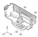
図1(a)および(b)は、本発明が適用されるインクジェット記録装置(以下、単に記録装置と称す)の概略構成を説明するための平面図および側面図である。記録装置1内に供給された記録媒体Pは、搬送ローラ106とピンチローラ107とからなるローラ対、および排紙ローラ104と拍車105とからなるローラ対に挟持された状態で、これらの回転に伴ってY方向(搬送方向)へ移動する。これら2つのローラ対の間には、X方向に延在するガイドシャフト109に案内支持されて、搬送方向と交差(本実施形態では直交)する主走査方向(X方向)へ往復移動可能なキャリッジ108が配備されている。キャリッジ108にはインクを吐出可能な記録ヘッド101が搭載されている。
1. Basic Configuration FIGS. 1A and 1B are a plan view and a side view for explaining a schematic configuration of an inkjet recording apparatus (hereinafter simply referred to as a recording apparatus) to which the present invention is applied. The recording medium P fed into the
記録ヘッド101は、キャリッジ108がX方向に沿って移動する間に、画像データに基づいてインクを-Z方向に向けて吐出し、搬送経路上に位置する記録媒体Pに1行分の画像を記録する。なお、記録ヘッド101がインクを吐出しつつ主走査方向へと移動する動作を記録走査という。1行分の記録走査が完了すると、搬送ローラ106および排紙ローラ104が回転し、記録媒体をY方向に沿って順方向(Y1方向)へと搬送する。このような記録走査と搬送動作を交互に繰り返すことにより、記録媒体Pには段階的に画像が形成されていく。記録ヘッド101によって記録される領域にある記録媒体Pは、プラテン110によってその裏面から支持され、通常は、記録面が平坦な状態に保たれている。なお、Z方向は記録媒体Pの記録面に対して実質的に垂直な方向である。
The
本実施形態の記録ヘッド101は、シアン、マゼンタ、イエロー、ブラックの染料インクおよびブラックの顔料インクの5種類のインクを吐出可能に構成されている。キャリッジ108には、記録ヘッド101とともに、これらにインクを供給するための5つのインクタンクが搭載されている。記録ヘッド101のインク吐出性能の維持回復を図るためのメンテナンス処理を行うとき、キャリッジ108は図のホームポジションHに移動する。ホームポジションHには、記録ヘッド101に対する回復処理、例えば、吸引処理、ワイピング処理、予備吐出処理等を行うための機構が配備されている。
The
図2は記録ヘッド101を示す斜視図である。記録ヘッド101は、吐出のために必要な電力や駆動信号を、コンタクトパッド201を介して記録装置本体から受信する。また、インクを滴として吐出可能な複数の吐出口を備えた記録チップが設けられている。本実施形態の記録ヘッド101には、顔料インクを吐出するための記録チップ102と、染料インクを吐出するための記録チップ103とが設けられている。顔料インク用の記録チップ102には、ブラックの顔料インクを滴として吐出する複数の吐出口がY方向に沿って配列され、それらの吐出口によって吐出口列が構成されている。
FIG. 2 is a perspective view showing the
一方、記録チップ103には、シアンインク、マゼンタインク、イエローインク、およびブラックインクなどの複数種類の染料インクをそれぞれ吐出する複数の吐出口がY方向に沿って配列され、インクに対応した吐出口列(不図示)が構成されている。以上の各記録チップ102、103に形成された吐出口列は、互いにX方向に並列配置されている。
On the other hand, in the
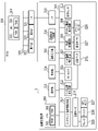
図3は、記録装置1に関する制御システムの構成を示すブロック図である。本実施形態の制御システムは、記録装置1とこれに接続されるホスト装置200とにより構成される。
FIG. 3 is a block diagram showing the configuration of a control system for the
記録装置1の構成要素は、ソフト系制御手段とハード系処理手段とに大別することができる。ソフト系制御手段には、画像入力部305、画像信号処理部306、記録装置1を統括的に制御するCPU300等の処理手段が含まれる。画像入力部305は、ホスト装置200よりインターフェイス(I/F)318を介して受信した画像データを一時的に保存するためのものである。画像入力部305に入力された画像データは、画像信号処理部306によって記録装置1の記録に適したデータ(記録データ)へと逐次処理される。
The components of the
一方、ハード系処理手段には、操作部303、表示部304、メンテナンス動作制御回路313、ヘッド温度制御回路312、ヘッド駆動制御回路310、キャリッジ駆動制御回路308、搬送制御回路309等の処理手段が含まれる。また、操作部303はユーザが種々のコマンドを入力する部分である。表示部304はユーザに対し情報提供の表示を行う。メンテナンス動作制御回路313は、回復モータ314を介してブレード315、キャップ316、吸引ポンプ317等の動作を制御し、ホームポジションHに移動してきた記録ヘッド101に対し各種メンテナンス処理を行う。
On the other hand, hardware system processing means includes processing means such as an
ヘッド駆動制御回路310は、画像信号処理部306が生成した記録データやサーミスタ311の検出結果に従って記録ヘッド101の駆動(インク吐出動作)を制御する。ヘッド温度制御回路312は、サーミスタ311の検出結果に基づいて、記録ヘッド101の温度を調整する。キャリッジ駆動制御回路308は、キャリッジモータ326の駆動を制御して、キャリッジ108のX方向における移動(往復走査)を制御する。搬送制御回路309は、搬送モータ327の駆動を制御して、搬送ローラ106や排紙ローラ104の回転を制御し、記録媒体PのY方向への搬送を制御する。光学センサ111は、記録媒体Pに記録された記録位置調整パターンの検出を行う。以上の各制御回路は、バスライン307を介して互いに接続されており、CPU300によって制御される。
A head driving
CPU300は、ROM301およびRAM302を備えており、ROM301に記憶されているプログラムや各種パラメータに従い、RAM302をワークエリアとして利用しながら、記録装置1全体を制御する。例えば、CPU300は、記録コマンドを受けたとき、記録ヘッド101のヒータに印加するための駆動パルスを、ROM301に予め記憶されているテーブルに従って設定し、ヘッド駆動制御回路310に提供する。また、ユーザによって設定された記録モードに基づいて、対応するキャリッジ108の駆動条件や記録媒体の搬送条件を予めROM301に記憶されているテーブルより読み出し、これをキャリッジ駆動制御回路308や搬送制御回路309に提供する。また、ROM301には、記録ヘッド101のメンテナンス処理を実行するためのタイミングチャートプログラムも格納されている。CPU300は、そのタイミングチャートプログラムに従ってメンテナンス動作制御回路313やヘッド駆動制御回路310を制御し、予備吐出動作や吸引回復動作を適宜実行する。このように、CPU300は、本発明における記録制御手段、読取制御手段、搬送制御手段、相対移動制御手段としての機能を果す。さらに、CPU300は、記録位置を調整するための調整値を設定する調整値設定手段としての処理も行う。
The
記録装置1に接続されているホスト装置200には、一般的なPCをはじめとして、携帯電話、スマートフォン、タブレット、デジタルカメラ、および携帯/据置端末などが適用可能である。ホスト装置200の内部構成は、装置の主目的によって変わるが、基本的にはCPU319、操作部322、表示部323およびインターフェイスI/ F324を備えており、これらがバスライン325を介して相互に電気的に接続されている。操作部322には、例えばキーボードやマウスを適用することができ、表示部323には、例えばLCDなどを適用することができる。
The
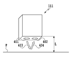
図4は、本実施形態に用いられる光学センサ111を説明するための模式図である。光学センサ111は、記録媒体Pに記録された記録位置調整パターン等を読み取る際に用いられる。光学センサ111は、発光部401と受光部402とを有し、キャリッジ108に取り付けられる。発光部401から発せられた光403は記録媒体Pで反射され、その反射光404は受光部402によって検出される。光学センサ111の検出信号は、キャリッジフレキシブルフラットケーブル(不図示)を介して記録装置の回路基板上に形成される制御回路に伝えられ、その制御回路に接続されたA/D変換器によりデジタル信号に変換される。
FIG. 4 is a schematic diagram for explaining the
光学センサ111がキャリッジ108に取り付けられる位置は、記録走査時に記録ヘッド101の吐出口列が移動する部分を通過しない位置に配置されている。これは、インク等の飛沫が光学センサ111に付着することを避けるためである。さらに、図1(b)のように構成された搬送機構(搬送手段)では、拍車105よりピンチローラ107の方が記録媒体への押し付け力が大きいため、ピンチローラ107の近い搬送経路上流側に光学センサ111を配置している。
The position where the
光学センサ111によって検出するインクとしては、記録装置1で用いられるインクの中で、光学センサ111の発色に適した色調のインクに適したインクを用いる。例えば、赤色LEDもしくは赤外線LEDの発色に対して光の吸収特性に優れている色のインクを用い、そのインクによって形成されるドットを処理の対象とする。本実施形態では、光の吸収特性の点から、ブラックまたはシアンのインクを対象とすることが好ましい。これに対し、マゼンタやイエローなどのインクによって記録された部分を、光学センサ111で検出した場合、十分な濃度特性およびS/N比を得ることは難しい。このように、LEDの特性等による発色をインク色に対応させることが好ましい。
As the ink to be detected by the
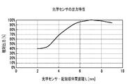
図5は、図4に示すような反射型光学センサ111の出力特性の一例を示す図である。横軸は、光学センサ111と記録媒体Pの間の距離L(図4参照)を、縦軸は、光学センサ111の相対出力(電圧値)を表している。図5に示す出力曲線は、距離Lの変化に伴って、相対出力電圧も変化することを示している。本実施形態では、光学センサ111によって記録媒体Pに記録された、後述の記録位置調整パターンを読み取り、その結果に基づいて記録位置の調整を行う。このため、記録位置調整を高精度に行うためには、光学センサ111と記録媒体Pとの間の距離Lの変動をできる限り抑制した状態で読み取りを行う必要がある。
FIG. 5 is a diagram showing an example of output characteristics of the reflective
2.特徴構成
以下、本実施形態で適用される記録位置調整方法の特徴について説明する。
2. Characteristic Configuration Hereinafter, the characteristics of the printing position adjustment method applied in this embodiment will be described.
[第1の実施形態]
図6は、第1の実施形態における記録位置調整手順の一例を示すフローチャートである。図7は、記録位置調整パターンのレイアウトの一例を示す図である。なお、以下に説明するフローチャートにおいて、「S」はフローチャートにおいて実行される各ステップを表している。
[First embodiment]
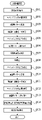
FIG. 6 is a flow chart showing an example of a print position adjustment procedure according to the first embodiment. FIG. 7 is a diagram showing an example of the layout of print position adjustment patterns. In the flowcharts described below, "S" represents each step executed in the flowcharts.
以下、記録装置1による記録媒体Pへの記録位置を適正化するための記録位置調整項目(以下、単に調整項目と称す)としては種々の項目がある。例えば調整項目としては、所定の吐出口列による往路記録位置と復路記録位置の相対的な位置関係の調整、異なるノズル列による記録位置の相対的な位置関係の調整などが調整項目として挙げられる。さらに、同一のインクを吐出する複数のノズル列の中の奇数ノズル列による記録位置と偶数ノズル列による記録位置との相対的な位置関係の調整なども、調整項目として挙げられる。このような、種々の調整項目のうち、本実施形態では、一例として、2つの調整項目を実施する例を説明する。ここで、第1の調整項目は、ブラックのインクを吐出する吐出口列による往路記録位置と復路記録位置の相対的な位置関係の調整であり、第2の調整項目は、シアンのインクを吐出する吐出口列による往路記録位置と復路記録位置の相対的な位置関係の調整である。
Below, there are various items as recording position adjustment items (hereinafter simply referred to as adjustment items) for optimizing the recording position on the recording medium P by the
まず、S601では、記録位置調整パターンを記録するための記録媒体P0を給紙し、搬送ローラ106とピンチローラ107とからなるローラ対、および排紙ローラ104と拍車105とからなるローラ対に挟持される領域まで搬送する。次に、S602では、キャリッジ108のZ方向における位置を調整し、キャリッジ108に搭載された記録ヘッド101の吐出口面(吐出口が形成されている面)から記録媒体の記録面までの距離を記録に適した距離に設定する。以下、記録ヘッド101の吐出口面から記録媒体の記録面までの距離を紙間と称す。
First, in S601, a printing medium P0 for printing a printing position adjustment pattern is fed and nipped between a roller pair consisting of a conveying
次に、S603では、前述の第1の調整項目に対応した粗調整パターン701と、第2の調整項目に対応した粗調整パターン711を記録する(図7参照)。粗調整パターン701は、ブラックの顔料インクによる往路記録の記録位置と復路記録の記録位置との相対な位置関係を粗く調整するためのパターンである。また、粗調整パターン711は、シアンインクによる往路記録の記録位置と復路記録の記録位置との相対的な位置関係を粗く調整するためのパターンである。これらの粗調整パターン701と711は、いずれも往路記録による記録位置に対して復路記録による記録位置を相対的に300dpiの解像度でずらしながら記録した複数(各粗調整パターンに5個)のパッチ(パターン構成要素)701a,701b,701c,701b’,701c’と、711a,711b,711c,711b’,711c’により構成されている。粗調整パターンの詳細については後述する。
Next, in S603, a
次に、S604では、粗調整パターン701、711が形成された記録媒体P0を逆方向(Y2方向)へ搬送した後、順方向(Y1方向)へと搬送することによって粗調整パターンを読み取るための再給紙を行う。ここで、記録媒体P0の逆方向への搬送では、第1の調整項目に対応する粗調整パターン701が光学センサ111の位置に到達する距離より多くの距離を搬送する。つまり、順搬送方向において光学センサ111の位置より上流側に粗調整パターン701が位置するように逆方向へ搬送する。これは、逆方向への搬送において、搬送ローラ106と排紙ローラ104との搬送量の差により生じる記録媒体P0の撓みを、その後の順方向(Y1方向)への搬送で解消するためである。ここで、順方向においては記録媒体P0が引っ張られるようにしてテンションを掛けて搬送が行われる。これは、例えば搬送ローラ106に対して排紙ローラ104の回転量を多くするようにして、排紙ローラ104側に記録媒体P0を引っ張ることで実現する。一方、逆方向への搬送においても排紙ローラ104側の回転量を搬送ローラ106の回転量よりも大きくするので、上述したような撓みが生じる。
Next, in S604, the recording medium P0 on which the
次に、S605では、キャリッジ108のZ方向の位置を変更する。図5に示すように、本実施形態で採用した光学センサ111の出力特性は、光学センサ111と記録媒体Pとの間の距離Lが7mmとなる付近で安定する。このため、S605では、距離Lが7mmとなるように、キャリッジの108の位置を設定する。
Next, in S605, the position of the
次に、S606では、第1の調整項目と第2の調整項目のそれぞれに対応する粗調整パターン701、711の読み取りを行う。具体的には、まず、第1の調整項目に対応する粗調整パターン701が光学センサ111の位置に来るように順方向(Y1方向)へ記録媒体P0を搬送する。この後、キャリッジ108を主走査させて、光学センサ111により粗調整パターン701の読み取りを行う。次に記録媒体P0を順方向へ搬送することにより第2の調整項目に対応する粗調整パターン711を光学センサ111の位置へと移動させる。その後、キャリッジ108を主走査させて粗調整パターン711の読み取りを行う。
Next, in S606,
本実施形態では、記録された複数の調整パターンの読取を連続して実施する。このため、調整パターンの記録と読み取りとを交互に行う従来の記録装置に比べ、調整パターンの記録と読み取りに要する時間を大幅に短縮することが可能になる。 In this embodiment, reading of a plurality of recorded adjustment patterns is continuously performed. Therefore, it is possible to greatly shorten the time required for recording and reading the adjustment pattern, compared with a conventional recording apparatus that alternately performs recording and reading of the adjustment pattern.
従来の記録装置では、読取動作のために記録媒体を逆方向へ搬送する動作を2回行う必要があり、その都度、記録媒体に撓みが生じる。この撓みを取るためには、パターンの記録位置を光学センサの位置より上流側に戻す必要があり、その動作を2回行う必要がある。これに対し、本実施形態では、読み取り動作のために記録媒体を逆方向へと搬送する動作は1回であるため、逆方向への搬送時に生じる撓みを取るために調整パターンの記録位置を光学センサ111の位置より上流側に戻す回数も1回で済む。このため、従来の記録装置に比べ、逆方向への搬送動作による搬送量は削減され、記録媒体を逆方向に搬送するための時間は短縮される。ここでは、2つの調整パターンを記録する例を示したが、調整項目の数が増えれば、さらに本実施形態と従来の記録装置とで、記録媒体への調整パターンの記録、読取に関する所要時間の差は顕著になる。これにより、記録位置を調整するための読取動作を効率的かつ正確に行うことが可能になり、記録装置としての精度、およびスループットを向上させることができる。
In the conventional recording apparatus, it is necessary to perform the operation of conveying the recording medium in the opposite direction twice for the reading operation, and each time the recording medium is bent. In order to remove this deflection, it is necessary to return the pattern recording position to the upstream side from the position of the optical sensor, and it is necessary to perform this operation twice. On the other hand, in the present embodiment, the operation of conveying the recording medium in the reverse direction for the reading operation is performed only once. The number of times of returning to the upstream side from the position of the
次に、ステップS607で、各調整項目に対応した粗調整パターン701、711それぞれの読取結果に基づいて、各粗調整値α(α1、α2)を決定する。つまり、第1の調整項目の粗調整値α1と第2の粗調整値α2とを決定する。なお、ここでは調整パターンの読取動作と調整値の決定とを別ステップで行ったが、調整パターンの読取動作毎に調整値を決定してもよい。
Next, in step S607, each coarse adjustment value α (α1, α2) is determined based on the reading result of each of the
次に、S608では、粗調整パターン711が記録ヘッド101の走査領域より下流側に位置するまで、記録媒体P0を順方向へと搬送する。この後、ステップS609では、キャリッジ108をZ方向へと移動させ、粗調整パターン701、711の記録時と同様の紙間を設定する。
Next, in S608, the printing medium P0 is conveyed in the forward direction until the
次に、S610で、第1の調整項目に対応した微調整パターン702と、第2の調整項目に対応した微調整パターン712とを記録する(図7参照)。微調整パターン702は、ブラックの顔料インクによる往路記録の記録位置と復路記録の記録位置との相対的な位置関係を微細に調整するためのパターンである。また、微調整パターン712は、シアンインクによる往路記録の記録位置と復路記録の記録位置との相対的な位置関係を微細に調整するためのパターンである。これらの微調整パターン702と712は、いずれも600dpiの解像度で記録位置を相対的にずらしながら記録した複数(各微調整パターンに7個)のパッチ702a,702b,702c,702d,702a’,702b’,702c’と、712a,712b,712c,712d,712a’,712b’,712c’により構成されるパターンである。なお、微調整パターンの詳細については後述する。
Next, in S610, a
次に、S611では、微調整パターン702、712が形成された記録媒体P0を逆方向(Y2方向)へ搬送した後、順方向(Y1方向)へと搬送することによって微調整パターンを読み取るための再給紙を行う。ここで、記録媒体P0の逆方向への搬送では、第1の調整項目に対応する微調整パターン702が光学センサ111の位置に到達する距離より多くの距離を搬送する。つまり、順搬送方向において光学センサ111の位置より上流側に微調整パターン702が位置するように逆方向へ搬送する。これは、S604で行う搬送動作と同様に、記録媒体P0の撓みを解消するためである。
Next, in S611, the recording medium P0 on which the
次に、S612では、キャリッジ108のZ方向の位置を変更し、パターンの読取に適した距離Lを設定する。S613では、第1、第2の調整項目に対応した微調整パターン702、712の読み取りを行う。まず、第1の調整項目に対応する微調整パターン702が光学センサ111の位置に来るように順方向へ記録媒体P0を搬送する。この後、キャリッジ108を走査させて、光学センサ111により微調整パターン702の読取を行う。次に記録媒体P0を順方向へ搬送することによって、第2の調整項目に対応する微調整パターン712を光学センサ111の位置へと移動させる。その後、キャリッジ108を主走査させて微調整パターン712の読取を行う。
Next, in S612, the position of the
次に、ステップS614で、各調整項目に対応した微調整パターン702、712の読取結果に基づいて微調整値β(β1、β2)を決定すると共に、第1、第2の調整項目に対応する記録位置調整値γ(γ1、γ2)を決定する。つまり、第1の調整項目の微調整値β1を決定すると共に、粗調整値α1と微調整値β1とを加算することにより記録位置調整値γ1を決定する。同様に、第2の調整項目の微調整値β2を決定すると共に、粗調整値α2と微調整値β2とを加算することにより記録位置調整値γ2を決定する。なお、ここでは調整パターン読取と調整値の決定を別ステップで行ったが、調整パターン読取毎に調整値を決定してもよい。
Next, in step S614, fine adjustment values β (β1, β2) are determined based on the reading results of the
この後、全ての調整パターンの記録、読み取り、および各調整値の決定処理が終了すると、S615で記録媒体P0を排紙する。 After that, when the printing and reading of all the adjustment patterns and the determination processing of each adjustment value are completed, the printing medium P0 is discharged in S615.
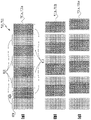
ここで、図8を参照し、粗調整パターンについて説明する。図8(a)~(c)は、本実施形態における往路記録の記録位置と復路記録の記録位置の相対的な位置関係を粗く調整するための粗調整パターン701、711の一例を示す図である。図8(a)~(c)において、白抜きのドット800は往路記録時に記録されるドットであり、パッチ形成パターン801を形成する。斜線のドット810は復走査時に記録されるドットであり、パッチ形成パターン811を形成する。各ドット800、810は、同一の記録ヘッドから吐出されるインクによって形成されるドットであり、X方向、Y方向ともに600dpiの間隔で配置されている。
Now, with reference to FIG. 8, the rough adjustment pattern will be described. FIGS. 8A to 8C are diagrams showing examples of
図8において、(a)は図7に示すパッチ701a,711aの詳細を示している。これらのパッチ701a,711aは、いずれも往路記録調整用のパッチ形成パターン801と復路記録調整用のパッチ形成パターン811のそれぞれの記録位置が合っている時に形成される基準となるパッチを示している。
In FIG. 8, (a) shows details of the
(b)は図7に示すパッチ701b,711bの詳細を示しており、基準となる往路記録調整用のパッチ形成パターン801に対し、復路記録調整用のパッチ形成パターン811の記録位置を300dpi×1だけ右方向(+方向)にずらした時に形成されるパッチを示している。
(b) shows the details of the
(c)は図7に示すパッチ701c,711cの詳細を示しており、基準となる往路記録調整用のパッチ形成パターン801に対し、復路記録調整用のパッチ形成パターン811の記録位置を300dpi×2だけ右方向にずらした時に形成されるパッチを示している。
(c) shows the details of the
本実施形態の粗調整用パターンは、往路記録調整用のパッチ形成パターン801に対し、復路記録調整用のパッチ形成パターン811の記録位置のずれが大きくなるに従って、記録濃度が低くなるよう設定されている。すなわち、図8(a)に示す各パターン801、811は、その記録領域に対するドットの被覆率が略100%となっている。これに対し、図8(b)、(c)のように、復路記録調整用のパッチ形成パターン811の記録位置がずれてパターン801、811の重なりが大きくなると、それにつれて被覆率が低下するため、記録濃度は低下する。
The coarse adjustment pattern of the present embodiment is set so that the print density becomes lower as the print position deviation of the
さらに、パターン801、811を、図8(a)から左方向(-方向)にも300dpiずつ相対的にずらしたパッチを形成する。従ってここでは、基準となるパッチと、ここから300dpiずつ+方向へずらした2つのパッチと、-方向へずらした2つのパッチの合計5つのパッチからなるパターンを粗調整パターンとして記録する。
Furthermore, the
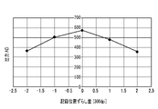
図9は、粗調整パターンにおける上記5つのパッチの記録濃度を光学センサ111によって読み取った結果を示す図である。図9に示すように、光学センサ111のAD出力値(反射光を受光しA/D変換した値)は、記録位置のずらし量に対応した値となる。この読み取り結果に基づいて、A/D出力値(反射濃度)が最大のポイントを往路記録と復路記録の粗調整値として決定する。この際、粗調整値は、調整パターンを読み取ったときの出力値を単純に数値比較することで決定することができる。また、内分計算等の数学的な計算を行って最適な粗調整値を決定することも可能である。つまり、必要とされる記録位置調整精度に応じて、適切な粗調整値の決定処理を行う。この粗調整における調整精度は記録媒体上での解像度として、例えば600dpi程度である。
FIG. 9 is a diagram showing the results of reading the printing densities of the five patches in the rough adjustment pattern by the
なお、調整パターン801、811は、同一インクを用いた往路記録と復路記録の記録位置を調整するためだけでなく、その他の調整項目にも適用可能である。例えば、ブラックインクを吐出するノズル列とカラーインク(例えばシアンインク)を吐出するノズル列の記録位置調整、同一インクの偶奇ノズル列間の記録位置調整、または同一インクの大ドット形成用のノズル列と小ドット形成用のノズル列の記録位置調整等の調整項目を実施するために適用することも可能である。
Note that the
図10(a)~(d)は、本実施形態における往路記録の位置と復路記録の位置の相対的な位置関係を微細に調整するための微調整用パターン702、712の一例を示す図である。図10(a)~(d)において、白抜きのドット1000は往走査時に記録されるドットであり、パッチ形成パターン1001を形成する。斜線のドット1010は復走査時に記録されるドットであり、パッチ形成パターン1011を形成する。各ドット1000、1010は、同一の記録ヘッドから吐出されるインクによって形成されるドットであり、X方向、Y方向ともに600dpiの間隔で配置されている。
FIGS. 10A to 10D are diagrams showing examples of
図10において、(a)は図7に示すパッチ702a,712aの詳細を示している。これらのパッチ702a,712aは、基準となる往路記録調整用のパッチ形成パターン1001に対し、復路記録調整用のパッチ形成パターン1011の記録位置を600dpi×3だけ右方向(+方向)にずらした時に形成されるパッチを示している。
In FIG. 10, (a) shows details of the
(b)は図7に示すパッチ702b,712bの詳細を示している。これらのパッチ702b,712bは、基準となる往路記録調整用のパッチ形成パターン1001に対し、復路記録調整用のパッチ形成用パターン1011の記録位置を600dpi×2だけ右方向(+方向)にずらした時に形成されるパッチを示している。
(b) shows details of the
(c)は図7に示すパッチ702c,712cの詳細を示している。これらのパッチ702c,712cは、基準となる往路記録調整用のパッチ形成用パターン1001に対し、復路記録調整用のパッチ形成パターン1011の記録位置を600dpi×1だけ右方向(+方向)にずらした時に形成されるパッチを示している。
(c) shows details of the
(d)は図7に示すパッチ702d,712dの詳細を示している。これらのパッチ702d,712dは、いずれも往路記録調整用のパッチ形成パターン1001と復路記録調整用のパッチ形成パターン1011のそれぞれの記録位置が合っている時に形成されるパッチを示している。
(d) shows details of the
図10(d)に示すパターンを形成する際には、粗調整用パターンより得られた粗調整値を反映して形成する。そして、図10(d)に示すパターンの往路記録調整用のパッチ形成パターン1001に対し、復路記録調整用のパッチ形成パターン1011の記録位置を相対的に徐々にずらして、図10(c)、(b)、(a)に示すパッチを形成する。
When forming the pattern shown in FIG. 10D, the rough adjustment value obtained from the rough adjustment pattern is reflected in the formation. Then, the print position of the
本実施形態の微調整用パターンは、粗調整用パターンとは異なり、往路記録調整用のパッチ形成パターン1001に対し、復路記録調整用のパッチ形成パターン1011の記録位置がずれるに従って、記録濃度が高くなるよう設定されている。すなわち、図10(d)は、その記録領域内における被覆率が最低であり、図10(c)、(b)、(a)のように、記録位置がずれてパッチ形成パターン1001と1011の重なりが小さくなるにつれて被覆率が増加するため、記録濃度が変化する。さらに、パッチ形成パターン1011をパッチ形成パターン1001に対し、図10(d)から左方向(-方向)にも同様に600dpiずつ相対的にずらしたパターンを形成する。従ってここでは、基準となるパッチ形成パターン1001と、600dpiずつ+方向へずらした3つのパッチと、-方向へずらした3つのパッチの合計7つのパッチからなるパターンを微調整パターンとして記録する。
Unlike the coarse adjustment pattern, the fine adjustment pattern according to the present embodiment has a higher print density than the forward print adjustment
図11は、微調整パターンにおける上記7つのパッチの記録濃度を光学センサ111によって読み取った結果を示す図である。図11に示すように、光学センサ111のAD出力値は、記録位置のずらし量に対応した値となる。この読み取り結果に基づいて、A/D出力値(反射濃度)が最小となるポイントを往路記録と復路記録の微調整値として決定する。この際、微調整値は、調整パターンを読み取ったときの出力値を単純に数値比較することで決定することができる。また、内分計算等の数学的な計算を行って最適な微調整値を決定することも可能である。つまり、必要とされる記録位置調整精度に応じて、適切な微調整値の決定処理を行う。この微調整における調整精度は粗調整よりも高く、記録媒体上での解像度で例えば2400dpi程度とすることができる。
FIG. 11 is a diagram showing the result of reading the print density of the seven patches in the fine adjustment pattern by the
なお、パッチ形成パターン1001、1011は、同一インクの往路記録と復路記録の記録位置を調整するためだけでなく、その他の調整項目にも適用可能である。例えば、ブラックインクを吐出するノズル列とカラーインク(例えばシアンインク)を吐出するノズル列の記録位置調整や、同一インクの偶奇ノズル列間の記録位置調整、または同一インクの大ドット形成用ノズル列と小ドット形成用ノズル列の記録位置調整等の調整項目を実施するために適用することも可能である。
Note that the
また、本実施形態では、最後の粗調整パターンの記録から、最初の微調整パターンの記録までに時間が空いてしまうため、記録ヘッドの吐出口近辺のインクの粘度が増加し吐出が不安定になる虞がある。そこで、調整パターンの読み取り時に適切な時間間隔でホームポジションHまでキャリッジ108を移動させて、予備吐出を行うようにしてもよい。
In addition, in this embodiment, since there is a time interval between the printing of the last rough adjustment pattern and the printing of the first fine adjustment pattern, the viscosity of the ink near the ejection openings of the print head increases and ejection becomes unstable. There is a possibility that Therefore, the
[第2の実施形態]
次に、本発明の第2の実施形態を図12ないし図14などを参照しつつ説明する。図12は、第2の実施形態におけるインクジェット記録装置の概略図である。本実施形態における記録装置100は、記録装置本体400と、記録装置本体400に供給する記録媒体の表裏を反転させる反転機構1400とを備える。記録装置本体400は、図1に示す記録装置1と同様の構成を有しており、ここでは記録装置本体400の詳細説明は省略する。反転機構1400は、記録装置本体400の搬送ローラ106より上流側に配置されており、環状の反転経路1401が構成されている。反転経路1401の搬入口1401aおよび排出口1401bは、記録装置本体200の搬送ローラ106近傍に配置されている。
[Second embodiment]
Next, a second embodiment of the present invention will be described with reference to FIGS. 12 to 14 and the like. FIG. 12 is a schematic diagram of an inkjet recording apparatus according to the second embodiment. The
記録装置100内に搬送されている記録媒体Pを、搬送ローラ106によって逆方向(Y2方向)へと搬送することにより、搬入口1401aから反転経路1401内へと記録媒体Pを送り込むことができる。反転経路1401に送り込まれた記録媒体Pは、反転経路1401内に配置された中間ローラ1402によって環状の反転経路1401を経て中間ローラ1403へと送られ、中間ローラ1403の回転によって搬送ローラ106へと再給紙される。この間に、記録媒体Pの第1面とその反対側の第2面の位置が反転する。つまり、反転経路1401を通過する前の段階では、記録ヘッド101と対向する記録面(表面)であった第1面が記録ヘッドと対向しない非記録面となり、その反対側の面(第2面)が記録面となって記録装置に再度給紙される。
By conveying the recording medium P conveyed inside the
従って、記録装置100によれば、記録媒体Pの両面に画像を記録することが可能になる。なお、本実施形態に関する制御システムは、図3に示したものと同様である。また、中間ローラ1402、1403の駆動源である給紙モータ(図示せず)の駆動は、CPU300によって制御される。
Therefore, according to the
図13は、記録装置100により実行される記録位置調整手順を示すフローチャートである。また、図14は記録位置調整パターンのレイアウトの一例を示す図である。
図13において、まず、S1201では、調整パターンを記録するための記録媒体P1を給紙し、搬送ローラ106とピンチローラ107とからなるローラ対、および排紙ローラ104と拍車105とからなるローラ対に挟持される領域まで搬送する。次に、S1202では、キャリッジ108のZ方向への位置を変更して、所望の紙間に変更する。例えば、ここでは普通紙への記録に適した紙間に変更する。
FIG. 13 is a flowchart showing a printing position adjustment procedure executed by the
In FIG. 13, first, in S1201, a recording medium P1 for recording an adjustment pattern is fed, and a roller pair consisting of a conveying
次に、S1203では、記録媒体P1の第1面に第1の調整項目に対応した粗調整パターン1301と第2の調整項目に対応した粗調整パターン1311を記録する(図14参照)。粗調整パターン1301は、ブラックの顔料インクによる往路記録の記録位置と復路記録の記録位置との相対的な位置関係を粗く調整するためのパターンである。また、粗調整パターン1311は、シアンインクによる往路記録の記録位置と復路記録の記録位置との相対的な位置関係を粗く調整するためのパターンである。これらの粗調整パターン1301、1311は、いずれも往路記録の記録位置に対し復路記録の記録位置を300dpiの解像度でずらしながら記録した複数のパッチにより構成されている。
Next, in S1203, a
次に、S1204では、記録媒体P1の第2面への記録が終了したか否かの判断を行う。この段階では、第2面への記録は終了していないため、S1205へ移行する。S1205では、反転機構1400を用いて記録媒体P1を反転し、第2面を記録面として記録装置本体400へと給紙する。その後、給紙された記録媒体P1を、搬送ローラ106とピンチローラ107とからなるローラ対、および排紙ローラ104と拍車105とからなるローラ対に挟持される領域まで搬送する。
Next, in S1204, it is determined whether or not recording on the second surface of the recording medium P1 has been completed. At this stage, the recording on the second surface has not been completed, so the process proceeds to S1205. In S1205, the reversing
次に、S1202では、キャリッジ108をZ方向の位置を変更し、前回とは異なる紙間に変更する。例えば、特殊紙へ記録を行うために適した紙間に変更する。次に、S1203では、記録媒体P1の第2面に、第3の調整項目に対応する粗調整パターン1321、第4の調整項目に対応する粗調整パターン1331を記録する(図14参照)。第3の調整項目に対応する粗調整パターン1321は、ブラックの顔料インクの往路記録の記録位置と復路記録の記録位置との相対的な位置関係を粗く調整するためのパターンである。また、第4の調整項目に対応する粗調整パターン1331は、シアンインクの往路記録の記録位置と復路記録の記録位置との相対的な位置関係を粗く調整するためのパターンである。これらの粗調整パターン1321、1331は、いずれも往路記録の記録位置に対して復路記録の記録位置を相対的に300dpiの低解像度でずらしながら記録した複数のパッチにより構成されている。
Next, in S1202, the position of the
ここで、記録媒体P1の第1面に記録した調整パターン1301、1311と、第2面に記録した調整パターン1321、1331は、光学センサ111で読み取る際に影響を受けないよう、互いに重ならない位置に記録する。
Here, the
次に、S1204では、第2面への記録が終了したか否かの判断を行う。この段階では、第2面への記録が終了しているため、S1206へ移行する。S1206ではキャリッジ108のZ方向の位置を変更し、光学センサ111と記録媒体P1との間の距離をパターンの読み取りに適した距離に変更する。次に、S1207では、反転機構1400を用いて記録媒体P1を反転し、第1面に記録した調整パターンの読み取りを行うための給紙を行う。
Next, in S1204, it is determined whether or not the recording on the second surface has been completed. At this stage, since the recording on the second surface has been completed, the process proceeds to S1206. In S1206, the position of the
次に、S1208では、普通紙への記録に適した紙間で記録した各調整項目に対応する粗調整パターンの読取を行う。具体的には、まず、第1の調整項目に対応する粗調整パターン1301が光学センサ111の位置に来るように順方向に記録媒体P1を搬送する。この後、キャリッジ108を走査させて、光学センサ111により第1面に記録した粗調整パターン1301の読取を行う。次に、第2調整項目に対応する粗調整パターン1311が光学センサ111の位置に来るように記録媒体P1を順方向に搬送した後、キャリッジ108を主走査させて粗調整パターン1311の読み取りを行う。
Next, in S1208, a coarse adjustment pattern corresponding to each adjustment item printed at intervals suitable for printing on plain paper is read. Specifically, first, the
次に、S1209では、普通紙の記録に適する紙間で記録した各調整項目に対応する粗調整パターンの読み取り結果に基づいて、各粗調整値α(α1、α2)を決定する。つまり、第1調整項目の粗調整値α1と第2調整項目の粗調整値α2を決定する。なお、ここでは調整パターンの読取と調整値の決定を別ステップで行ったが、調整パターンの読取毎に調整値を決定してもよい。 Next, in S1209, each coarse adjustment value α (α1, α2) is determined based on the reading result of the coarse adjustment pattern corresponding to each adjustment item printed at intervals suitable for printing on plain paper. That is, the coarse adjustment value α1 of the first adjustment item and the coarse adjustment value α2 of the second adjustment item are determined. Here, reading of the adjustment pattern and determination of the adjustment value are performed in separate steps, but the adjustment value may be determined each time the adjustment pattern is read.
次に、S1210では、記録媒体P1の第2面の読み取りが終了したか否かの判断を行う。この段階では、第2面の読取は終了していないため、S1207へ移行する。S1207では、反転機構1400を用いて記録媒体P1を反転し、第2面に記録した調整パターンを読み取るための再給紙を行う。
Next, in S1210, it is determined whether reading of the second surface of the recording medium P1 has been completed. At this stage, reading of the second side is not completed, so the process moves to S1207. In S1207, the reversing
次に、S1208では、特殊紙記録に適した紙間での各調整項目に対応した粗調整パターンの読取を行う。具体的には、まず、第3の調整項目に対応する粗調整パターン1321が光学センサ111の位置に来るように順方向に記録媒体P1を搬送する。この後、キャリッジ108を走査させて光学センサ111により、第2面に記録した粗調整パターン1321の読み取りを行う。次に、第4調整項目に対応する粗調整パターン1331が光学センサ111の位置に来るように記録媒体P1を順方向に搬送した後、キャリッジ108を走査させて粗調整パターン1331の読み取りを行う。
Next, in S1208, a rough adjustment pattern corresponding to each adjustment item between sheets suitable for printing on special paper is read. Specifically, first, the recording medium P1 is conveyed in the forward direction so that the
次に、S1209では、特殊紙の記録に適した紙間で記録した各調整項目に対応する粗調整パターンの読み取り結果に基づいて、各粗調整値α(α3、α4)を決定する。つまり、第3調整項目の粗調整値α3と第4調整項目の粗調整値α4を決定する。 Next, in S1209, each coarse adjustment value α (α3, α4) is determined based on the reading result of the coarse adjustment pattern corresponding to each adjustment item printed at intervals suitable for printing on special paper. That is, the coarse adjustment value α3 of the third adjustment item and the coarse adjustment value α4 of the fourth adjustment item are determined.
次に、S1210では、記録媒体P1の第2面の読取が終了したか否かの判断を行う。この段階では、第2面の読取は終了しているため、S1211へ移行し、記録媒体P1を排紙する。 Next, in S1210, it is determined whether or not reading of the second surface of the recording medium P1 has been completed. At this stage, since the reading of the second surface has been completed, the process proceeds to S1211 and the recording medium P1 is discharged.
1枚目の調整パターンの記録、および読取が終了すると、S1212において、続きの調整パターンを記録するための2枚目の記録媒体P2の給紙を行う。その後、給紙した記録媒体P2を、搬送ローラ106とピンチローラ107とからなるローラ対、および排紙ローラ104と拍車105とからなるローラ対に挟持される領域まで搬送する。
When printing and reading of the first adjustment pattern are completed, in S1212, the second printing medium P2 is fed for printing the subsequent adjustment pattern. After that, the fed recording medium P2 is conveyed to an area sandwiched by a roller pair consisting of a conveying
次に、S1213では、第1調整項目に対応する粗調整パターン1301、第2調整項目に対応する粗調整パターン1311を記録したときと同じ紙間となるように、キャリッジ108をZ方向へと移動させる。つまり、ここでは普通紙への記録に適した紙間に変更する。
Next, in S1213, the
次に、S1214では、記録媒体P2の第1面に、第1の調整項目に対応した微調整パターン1302、第2の調整項目に対応した微調整パターン1312を記録する。第1の調整項目に対応する微調整パターン1302は、ブラックの顔料インクの往路記録の記録位置と復路記録の記録位置との相対的な位置関係を微細に調整するためのパターンである。また、第2の調整項目に対応した微調整パターン1312は、シアンインクの往路記録の記録位置と復路記録の記録位置との相対的な位置関係を微細に調整するためのパターンである。これらの微調整パターン1302、1312は、いずれも往路記録の記録位置に対し復路記録の記録位置を600dpiの解像度でずらしながら記録した複数のパッチにより構成されている。
Next, in S1214, a
次に、S1215では、記録媒体P2の第2面への記録が終了したか否か判断を行う。この段階では、第2面への記録は終了していないため、S1216へ移行する。S1216では、反転機構1400を用いて記録媒体P2を反転し、第2面を記録面として記録装置本体400へ給紙する。その後、給紙された記録媒体P2を、搬送ローラ106とピンチローラ107とからなるローラ対、および排紙ローラ104と拍車105とからなるローラ対に挟持される領域まで搬送する。
Next, in S1215, it is determined whether or not recording on the second surface of the recording medium P2 is completed. At this stage, the recording on the second surface is not completed, so the process proceeds to S1216. In S1216, the reversing
次に、ステップS1213では、第3調整項目に対応する粗調整パターン1321と第4調整項目に対応する粗調整パターン1331を記録したときと同じ紙間となるように、キャリッジ108を移動させる。つまり、ここでは特殊紙への記録に適した紙間に変更する。
Next, in step S1213, the
次に、S1214では、記録媒体P2の第2面に、第3調整項目に対応する微調整パターン1322、第4調整項目に対応する微調整パターン1332を記録する。第3調整項目に対応する微調整パターン1322は、ブラックの顔料インクの往路記録の記録位置と復路記録の記録位置との相対的な位置関係を微細に調整するためのパターンである。第4調整項目に対応する微調整パターン1332は、シアンインクの往路記録の記録位置と復路記録の記録位置との相対的な位置関係を微細に調整するためのパターンである。これらの微調整パターン1322、1332は、いずれも往路記録の記録位置に対して復路記録の記録位置を相対的に600dpiの解像度でずらしながら記録した複数のパッチにより構成されている。
Next, in S1214, a
ここで、記録媒体P2の第1面に記録した調整パターン1302、1312と、第2面に記録した調整パターン1322、1332は、光学センサ111で読み取る際に影響を受けないよう、互いに重ならない位置に記録する。
Here, the
次に、S1215では、第2面への記録が終了したか否かの判断を行う。この段階では、第2面への記録が終了しているため、S1217へ移行する。S1217ではキャリッジ108のZ方向の位置を変更し、光学センサ111と記録媒体P2との間の距離をパターン読み取りに適した距離に変更する。次に、S1218では、反転機構1400を用いて記録媒体P2を反転し、第1面に記録した調整パターンの読取を行うための給紙を行う。
Next, in S1215, it is determined whether or not the recording on the second surface has been completed. At this stage, the recording on the second surface has been completed, so the process proceeds to S1217. In S1217, the position of the
次に、S1219では、普通紙への記録に適した紙間で記録した各調整項目に対応する微調整パターンの読み取りを行う。具体的には、まず、第1の調整項目に対応する微調整パターン1302が光学センサ111の位置に来るように順方向に記録媒体P2を搬送する。その後、キャリッジ108を主走査させて、光学センサ111により第1面に記録した微調整パターン1302の読取を行う。次に、第2の調整項目に対応した微調整パターン1312が光学センサ111の位置に来るように記録媒体P2を順方向に搬送した後、キャリッジ108を主走査させて微調整パターン1312の読取を行う。
Next, in S1219, a fine adjustment pattern corresponding to each adjustment item printed at intervals suitable for printing on plain paper is read. Specifically, first, the printing medium P2 is conveyed forward so that the
次に、S1220では、普通紙の記録に適する紙間で記録した各調整項目に対応する微調整パターンの読み取り結果に基づいて各微調整値βを決定し、粗調整値αおよび微調整値βより記録位置調整値γを決定する。つまり、第1調整項目に対応する微調整値β1を決定し、α1とβ1とを加算することにより第1の調整項目の記録位置調整値γ1を決定する。同様に、第2の調整項目の微調整値β2を決定し、α2とβ2とを加算することにより第2の調整項目の記録位置調整値γ2を決定する。なお、ここでは調整パターンの読取と調整値の決定を別ステップで行ったが、調整パターンの読取毎に調整値を決定してもよい。 Next, in S1220, each fine adjustment value β is determined based on the reading result of the fine adjustment pattern corresponding to each adjustment item printed at intervals suitable for printing on plain paper, and the coarse adjustment value α and fine adjustment value β are determined. Then, the recording position adjustment value γ is determined. That is, the fine adjustment value β1 corresponding to the first adjustment item is determined, and the recording position adjustment value γ1 of the first adjustment item is determined by adding α1 and β1. Similarly, the fine adjustment value β2 of the second adjustment item is determined, and the recording position adjustment value γ2 of the second adjustment item is determined by adding α2 and β2. Here, reading of the adjustment pattern and determination of the adjustment value are performed in separate steps, but the adjustment value may be determined each time the adjustment pattern is read.
次に、S1221では、記録媒体P2の第2面の読取が終了したか否かの判断を行う。この段階では、第2面の読取は終了していないため、S1218へ移行する。S1218では、反転機構1400を用いて記録媒体P2を反転し、第2面に記録した調整パターンを読み取るための再給紙を行う。
Next, in S1221, it is determined whether or not reading of the second surface of the recording medium P2 is completed. At this stage, reading of the second surface has not been completed, so the process proceeds to S1218. In S1218, the reversing
次に、S1219では、特殊紙記録に適した紙間での各調整項目に対応した微調整パターンの読取を行う。具体的には、まず、第3の調整項目に対応する微調整パターン1322が光学センサ111の位置に来るように順方向に記録媒体P2を搬送する。この後、キャリッジ108を走査させて光学センサ111により、第2面に記録した微調整パターン1322の読取を行う。次に、第4の調整項目に対応する微調整パターン1332が光学センサ111の位置に来るように記録媒体P2を順方向に搬送した後、キャリッジ108を主走査させて微調整パターン1332の読取を行う。
Next, in S1219, a fine adjustment pattern corresponding to each adjustment item between sheets suitable for printing on special paper is read. Specifically, first, the recording medium P2 is conveyed forward so that the
次に、S1220では、特殊紙の記録に適した紙間で記録した各調整項目に対応する微調整パターンの読取結果に基づいて各微調整値βを決定し、粗調整値αおよび微調整値βにより記録位置調整値γを決定する。つまり、第3の調整項目の微調整値β3を決定し、α3とβ3とを加算することにより第3の調整項目の記録位置調整値γ3を決定する。同様に、第4の調整項目の微調整値β4を決定し、α4とβ4とを加算することにより第4の調整項目の記録位置調整値γ4を決定する。 Next, in S1220, each fine adjustment value β is determined based on the reading result of the fine adjustment pattern corresponding to each adjustment item printed with a paper interval suitable for printing on special paper, and the coarse adjustment value α and the fine adjustment value are determined. A recording position adjustment value γ is determined by β. That is, the fine adjustment value β3 of the third adjustment item is determined, and the recording position adjustment value γ3 of the third adjustment item is determined by adding α3 and β3. Similarly, the fine adjustment value β4 of the fourth adjustment item is determined, and the recording position adjustment value γ4 of the fourth adjustment item is determined by adding α4 and β4.
次に、S1221では、第2面の読み取りが終了したか否かの判断を行う。この段階では、第2面の読み取りは終了しているため、S1222へ移行し、記録媒体P2を排紙する。 Next, in S1221, it is determined whether or not the reading of the second surface has been completed. At this stage, since the reading of the second surface has been completed, the process proceeds to S1222, and the recording medium P2 is discharged.
なお、本実施形態においても、上記第1の実施形態と同様に、調整パターンの読取時に適切な時間間隔でホームポジションHまでキャリッジ108を移動させ、記録ヘッドにより予備吐出を行ってもよい。例えばS1208における調整パターンの読取時に予備吐出を行うようにしてもよい。
Also in this embodiment, as in the first embodiment, the
また、S1201において記録位置調整パターンを記録するための記録媒体P1を給紙したとき、あるいはステップS1212で記録媒体P2を給紙したときに、記録媒体幅(X方向の長さ)を確認するようにしてもよい。例えば、記録位置の調整に利用する記録媒体のサイズがA4/LTRである場合には、実際に給紙されている記録媒体の幅がA4以上であるか否かを光学センサ111によって確認し、A4/LTR未満と判断された場合はエラーとする。これによれば、記録媒体のサイズ不足による調整パターンの欠落などの発生を未然に防ぐことができる。
Also, when the recording medium P1 for recording the recording position adjustment pattern is fed in S1201 or when the recording medium P2 is fed in step S1212, the width of the recording medium (length in the X direction) is confirmed. can be For example, when the size of the recording medium used for adjusting the recording position is A4/LTR, the
また、記録媒体P1、P2の一方の面に調整パターンを記録した後、記録媒体の搬送方向における長さ(Y方向の長さ)を検出し、検出した記録媒体の長さが調整パターンの記録に必要とされるサイズ以下である場合にはエラーとするようにしてもよい。これによれば、記録媒体のサイズ不足による裏表のパターンの重なりなどの発生を未然に防ぐことができる。記録媒体の搬送方向における長さは、記録媒体の移動経路中に設けた後端検出センサを用いて記録媒体の前端および後端を検出し、その間の記録媒体の搬送量(搬送ローラの回転量)に基づいて取得することができる。 After the adjustment pattern is printed on one surface of the print media P1 and P2, the length of the print medium in the conveying direction (the length in the Y direction) is detected, and the detected length of the print medium is used for printing the adjustment pattern. An error may occur if the size is less than the size required for . According to this, it is possible to prevent occurrence of overlapping of patterns on the front and back due to insufficient size of the recording medium. The length of the recording medium in the conveying direction is determined by detecting the leading and trailing edges of the recording medium using a trailing edge detection sensor provided in the movement path of the recording medium, and calculating the amount of conveyance of the recording medium therebetween (the amount of rotation of the conveying roller). ) can be obtained based on
また、S1208、S1219で読み取りを行うための記録媒体の頭出しを行った後、記録媒体の搬送方向の誤差を取得して、読み取り精度を高めるようにしてもよい。誤差の取得方法としては、例えば次のような方法を採ることができる。まず、調整パターンより搬送方向上流側の位置に読み取り精度調整用のパッチPT(図14(a)参照)を記録する。このパッチPTを調整パターン1301の読取に先行して読み取る。この際、パッチPTの端部を光学センサで読み取り、読み取った端部の位置からパッチの中心を求め、パッチの中心の位置に基づき、記録媒体の位置との誤差を算出する。その後、算出した誤差がキャンセルされるように搬送量を補正して搬送する。
Further, after locating the recording medium for reading in S1208 and S1219, the error in the conveying direction of the recording medium may be acquired to improve reading accuracy. As a method of obtaining the error, for example, the following method can be adopted. First, a patch PT for reading accuracy adjustment (see FIG. 14A) is recorded at a position on the upstream side in the transport direction from the adjustment pattern. This patch PT is read prior to reading the
一般に頭出しのための搬送は搬送距離が長く大きな誤差が発生し易い。従って、誤差を算出した後は、頭出し位置から調整パターンの読取が行われまでの記録媒体の搬送動作において、誤差がキャンセルされるように搬送量を制御する。これによれば、調整パターンの読取動作において光学センサと調整パターンとを所望の位置関係に定めることができ、その後の搬送を設定された通りに行うことで、調整パターンの読取を正確に行うことができる。 In general, conveyance for indexing is long and a large error is likely to occur. Therefore, after the error is calculated, the conveying amount is controlled so that the error is canceled in the conveying operation of the recording medium from the cue position to the reading of the adjustment pattern. According to this, the optical sensor and the adjustment pattern can be set to a desired positional relationship in the operation of reading the adjustment pattern, and the adjustment pattern can be accurately read by carrying out the subsequent transport as set. can be done.
第2の実施形態における記録装置100では、各記録媒体の第1面と第2面に調整パターンを記録したが、第1の実施形態と同様に1枚の記録媒体の第1面に複数の調整パターンの全てを記録することも可能である。この場合、記録媒体を反転させずに、記録媒体を逆方向に搬送した後、順方向へと搬送することで正確な読取動作を行うことが可能になる。
In the
また、上記実施形態では、記録媒体の第1面、第2面への記録を行った後、記録媒体を反転させて第1面に記録した複数の調整パターンを連続的に読み取り、その後、記録媒体を反転させて第2面に記録した複数の調整パターンを連続的に読み取るようにした。 Further, in the above-described embodiment, after recording is performed on the first and second surfaces of the recording medium, the recording medium is reversed and the plurality of adjustment patterns recorded on the first surface are continuously read, and then recorded. A plurality of adjustment patterns recorded on the second surface were read continuously by inverting the medium.
しかし、第1面への調整パターンの記録を行った後、記録媒体を反転させずに逆方向への搬送および順方向への搬送を行うことで第1面に記録した調整パターンの読取を行うことも可能である。この場合、第1面の読取が終了した後、記録媒体を反転させて第2面への記録を行い、第1面の読取と同様に、記録媒体の逆方向への搬送および順方向への搬送を行うことで、第2面に記録した調整パターンを読み取る。このような手順で両面への調整パターンの記録および読取を行うようにしてもよい。 However, after the adjustment pattern is printed on the first surface, the adjustment pattern printed on the first surface is read by conveying the recording medium in the reverse direction and the forward direction without reversing the recording medium. is also possible. In this case, after the reading of the first surface is completed, the recording medium is reversed and the recording is performed on the second surface. By carrying out the transport, the adjustment pattern recorded on the second surface is read. Recording and reading of adjustment patterns on both sides may be performed in such a procedure.
但し、いずれの手順を採る場合にも、複数の調整項目に対応する調整パターンのうち、同一の記録条件で記録可能な複数の調整パターンが存在する場合には、それらのパターンを連続して記録し、記録された複数の調整パターンを連続して読み取るようにする。このような方式によって調整パターンの記録、読取を行うようにすれば、上記いずれの手順で両面記録を行ったとしても、従来の記録装置に比べ効率的に調整パターンの記録と読取を行うことが可能になる。 However, regardless of which procedure is adopted, if there are a plurality of adjustment patterns that can be printed under the same printing conditions among adjustment patterns corresponding to a plurality of adjustment items, those patterns are printed continuously. and continuously read the recorded adjustment patterns. If the adjustment pattern is recorded and read by such a method, the adjustment pattern can be recorded and read more efficiently than the conventional recording apparatus regardless of the double-sided recording performed by any of the procedures described above. be possible.
[その他の実施形態]
本発明は、インクジェット記録装置に限らず、他の記録方式を採る記録装置にも広く適用することができる。また、本発明は、上述のシリアル型の記録装置の他、記録媒体上の記録領域の幅方向全域に亘る長尺な記録ヘッドを用いる、いわゆるフルライン型の記録装置にも適用することができる。また、記録調整パターンは、上述した実施形態に限定されるものではなく、読取手段の読取結果に基づいて記録位置調整用の調整値が取得できるパターンであればよい。
[Other embodiments]
The present invention can be widely applied not only to inkjet recording apparatuses but also to recording apparatuses employing other recording methods. In addition to the serial type recording apparatus described above, the present invention can also be applied to a so-called full-line type recording apparatus that uses a long recording head that covers the entire width of the recording area on the recording medium. . Also, the recording adjustment pattern is not limited to the above-described embodiment, and any pattern may be used as long as the adjustment value for recording position adjustment can be obtained based on the reading result of the reading means.
1 インクジェット記録装置
101 記録ヘッド(記録手段)
104 排紙ローラ
105 拍車
106 搬送ローラ
107 ピンチローラ
108 キャリッジ
111 光学センサ(読取手段)
300 CPU(記録制御手段、読取制御手段)
701,711 粗調整パターン
702,712 微調整パターン
1401 反転経路
1402 中間ローラ対
1403 中間ローラ対
P,P0,P1,P2 記録媒体
1
104
300 CPU (recording control means, reading control means)
701, 711
Claims (17)
前記搬送手段によって逆方向へ搬送された前記記録媒体の表裏を反転させる反転手段と、
前記搬送手段によって搬送される記録媒体への記録を行う記録手段と、
前記記録手段による記録媒体上の記録位置を調整するための複数の記録位置調整項目のそれぞれに対応する複数の調整パターンを記録媒体に記録させる記録制御手段と、
前記搬送手段の搬送経路における読み取り位置で記録媒体に記録されている前記調整パターンを読み取る読取手段と、を備えた記録装置であって、
前記順方向において、前記排紙ローラは前記搬送ローラより下流に設けられており、
前記記録手段及び前記読取手段は前記搬送ローラと前記排紙ローラとの間に配置され、
前記搬送手段が記録媒体を順方向に搬送しながら、前記記録制御手段は、前記複数の前記調整パターンを前記記録媒体の表面に記録させた後、
前記反転手段は前記記録媒体を反転させ、
前記搬送手段が前記記録媒体を前記順方向に搬送しながら、前記記録制御手段は、前記複数の前記調整パターンを前記記録媒体の裏面に記録し、
前記反転手段は前記記録媒体を反転させ、
前記搬送手段が前記記録媒体を順方向に搬送しながら前記読み取り手段が前記読み取り位置で前記表面に記録された前記複数の前記調整パターンを連続して読み取ることを特徴とする記録装置。 Conveying means having a conveying roller for conveying the recording medium in a forward direction, which is a direction in which the recording medium is discharged, and a direction opposite to the forward direction, and a discharge roller;
reversing means for reversing the front and back of the recording medium conveyed in the opposite direction by the conveying means;
a recording means for recording on a recording medium conveyed by the conveying means;
recording control means for recording, on a recording medium, a plurality of adjustment patterns respectively corresponding to a plurality of recording position adjustment items for adjusting the recording position on the recording medium by the recording means;
a reading unit that reads the adjustment pattern recorded on the recording medium at a reading position on the conveying path of the conveying unit,
In the forward direction, the discharge roller is provided downstream from the transport roller,
the recording means and the reading means are arranged between the conveying roller and the discharge roller;
While the conveying means conveys the recording medium in the forward direction, the recording control means causes the plurality of adjustment patterns to be recorded on the surface of the recording medium, and
the reversing means for reversing the recording medium ;
While the conveying means conveys the recording medium in the forward direction, the recording control means records the plurality of adjustment patterns on the back surface of the recording medium;
the reversing means for reversing the recording medium;
A recording apparatus, wherein the reading means continuously reads the plurality of adjustment patterns recorded on the surface at the reading position while the conveying means conveys the recording medium in a forward direction.
前記記録媒体の面に垂直な方向における前記キャリッジと前記記録媒体との間の距離を変更する変更手段と、
をさらに有し、
前記記録手段が前記複数の前記調整パターンを前記記録媒体に記録した後、前記読み取り手段が前記読み取り位置で前記複数の前記調整パターンを読み取るまで間に前記変更手段は前記距離を変更することを特徴とする請求項1乃至4のいずれか1項に記載の記録装置。 a carriage on which the recording means and the reading means are mounted and which is movable in a main scanning direction intersecting with the forward direction;
changing means for changing the distance between the carriage and the recording medium in a direction perpendicular to the surface of the recording medium;
further having
The changing means changes the distance after the recording means records the plurality of adjustment patterns on the recording medium until the reading means reads the plurality of adjustment patterns at the reading position. 5. The recording apparatus according to any one of claims 1 to 4.
前記記録制御手段は、前記調整値設定手段によって設定された調整値に基づき、前記記録手段による前記記録媒体への記録位置を制御することを特徴とする請求項1乃至5のいずれか1項に記載の記録装置。 further comprising adjustment value setting means for setting an adjustment value for the recording position by the recording means based on the reading result of the reading means;
6. The apparatus according to any one of claims 1 to 5 , wherein said recording control means controls a recording position on said recording medium by said recording means based on the adjustment value set by said adjustment value setting means. Recording device as described.
前記記録媒体を搬送するときの前記排紙ローラの回転量は、前記搬送ローラの回転量より大であることを特徴とする請求項1乃至5のいずれか1項に記載の記録装置。 The conveying means includes a conveying roller arranged upstream from the recording means and the reading means in the forward direction, and a paper discharge roller arranged downstream from the recording means and the reading means in the forward direction; including
6. A recording apparatus according to claim 1 , wherein the amount of rotation of said discharge roller when conveying said recording medium is larger than the amount of rotation of said conveyance roller.
前記搬送手段は、前記複数の調整パターンが前記読み取り位置よりも前記逆方向側の位置となるまで前記記録媒体を逆方向に搬送した後に前記記録媒体を再び順方向に搬送して前記調整パターンを前記読み取り位置に到達させ、
前記搬送手段によって前記記録媒体を前記逆方向へと搬送させずに順方向へと搬送しながら前記読み取り手段が前記読み取り位置で前記複数の前記調整パターンを連続して読み取ることを特徴とする請求項1乃至5のいずれか1項に記載の記録装置。 While causing the recording medium to be transported in the forward direction without being transported in the reverse direction by the transporting means, the recording means records the plurality of adjustment patterns on the recording medium;
The conveying means conveys the recording medium in the reverse direction until the plurality of adjustment patterns are positioned on the opposite side of the reading position, and then conveys the recording medium in the forward direction again to read the adjustment patterns. reaching the reading position;
3. The reading means continuously reads the plurality of adjustment patterns at the reading position while the conveying means conveys the recording medium in the forward direction without conveying the recording medium in the reverse direction. 6. The recording apparatus according to any one of 1 to 5.
前記搬送手段によって搬送される記録媒体への記録を行う記録手段と、
前記記録手段による記録媒体上の記録位置を調整するための複数の記録位置調整項目のそれぞれに対応する複数の調整パターンを記録媒体に記録させる記録制御手段と、
前記搬送手段の搬送経路における読み取り位置で記録媒体に記録されている前記調整パターンを読み取る読み取り手段と、
前記記録手段および前記読み取り手段を搭載し、前記順方向と交差する主走査方向に移動可能なキャリッジと、
前記記録媒体の面に垂直な方向における前記キャリッジと前記記録媒体との間の距離を変更する変更手段と、
を備えた記録装置であって、
前記搬送手段が記録媒体を順方向に搬送しながら、前記記録制御手段は、前記複数の前記調整パターンを前記記録媒体に記録させた後、
前記搬送手段は前記複数の調整パターンが前記読み取り位置よりも前記逆方向側の位置となるまで前記記録媒体を前記逆方向に搬送した後に前記記録媒体を再び前記順方向に搬送して前記調整パターンを前記読み取り位置に到達させ、
前記搬送手段が前記記録媒体を順方向に搬送しながら前記読み取り手段が前記読み取り位置で前記複数の前記調整パターンを連続して読み取り、
前記記録手段が前記複数の前記調整パターンを前記記録媒体に記録した後、前記読み取り手段が前記読み取り位置で前記複数の前記調整パターンを読み取るまで間に前記変更手段は前記距離を変更することを特徴とする記録装置。 Conveying means for conveying the recording medium so as to convey the recording medium in a forward direction, which is a direction in which the recording medium is discharged, and in a direction opposite to the forward direction;
a recording means for recording on a recording medium conveyed by the conveying means;
recording control means for recording, on a recording medium, a plurality of adjustment patterns respectively corresponding to a plurality of recording position adjustment items for adjusting the recording position on the recording medium by the recording means;
reading means for reading the adjustment pattern recorded on the recording medium at a reading position on the conveying path of the conveying means;
a carriage on which the recording means and the reading means are mounted and which is movable in a main scanning direction intersecting with the forward direction;
changing means for changing the distance between the carriage and the recording medium in a direction perpendicular to the surface of the recording medium;
A recording device comprising
While the conveying means conveys the recording medium in the forward direction, the recording control means causes the plurality of adjustment patterns to be recorded on the recording medium, and
The conveying means conveys the recording medium in the reverse direction until the plurality of adjustment patterns are positioned on the opposite side of the reading position, and then conveys the recording medium in the forward direction again to read the adjustment patterns. reaches the reading position,
while the conveying means conveys the recording medium in a forward direction, the reading means continuously reads the plurality of adjustment patterns at the reading position;
The changing means changes the distance after the recording means records the plurality of adjustment patterns on the recording medium until the reading means reads the plurality of adjustment patterns at the reading position. recording device.
前記順方向において、前記排紙ローラは前記搬送ローラより下流に設けられており、
前記記録手段及び前記読取手段は前記搬送ローラと前記排紙ローラとの間に配置され、
前記搬送手段によって記録媒体を順方向に搬送しながら、前記記録媒体上の記録位置を調整するための複数の記録位置調整項目のそれぞれに対応する複数の調整パターンを前記記録手段によって前記記録媒体の表面に記録させる工程と、
前記反転手段によって前記記録媒体を反転させて、前記記録媒体を前記搬送ローラよりも前記逆方向側の位置にくるように搬送する第1の搬送工程と、
前記搬送手段によって前記記録媒体を前記順方向に搬送しながら、前記複数の前記調整パターンを前記記録手段によって前記記録媒体の裏面に記録させる工程と、
前記反転手段によって前記記録媒体を反転させて、前記記録媒体を前記搬送ローラよりも前記逆方向側の位置にくるように搬送する第2の搬送工程と、
前記搬送手段によって前記記録媒体を再び前記順方向に搬送して、前記記録媒体の表面に記録された前記複数の前記調整パターンを前記読み取り位置に到達させる工程と、
前記搬送手段によって前記記録媒体を順方向に搬送しながら、前記読み取り手段によって前記読み取り位置で、前記記録媒体の表面に記録された前記複数の前記調整パターンを連続して読み取る工程と、を備えることを特徴とする記録方法。 Conveying means having a conveying roller for conveying the recording medium in a forward direction, which is a direction in which the recording medium is discharged, and a discharge roller for conveying the recording medium in a direction opposite to the forward direction, and conveying in a reverse direction by the conveying means. reversing means for reversing the printed recording medium; recording means for recording on the recording medium conveyed by the conveying means; and a pattern recorded on the recording medium at a reading position on the conveying path of the conveying means. A recording method for recording using a reading means for reading
In the forward direction, the discharge roller is provided downstream from the transport roller,
the recording means and the reading means are arranged between the conveying roller and the discharge roller;
While conveying the recording medium in the forward direction by the conveying means, a plurality of adjustment patterns corresponding to each of a plurality of recording position adjustment items for adjusting a recording position on the recording medium are formed on the recording medium by the recording means. imprinting on the surface ;
a first conveying step of inverting the recording medium by the reversing means and conveying the recording medium so that the recording medium is positioned on the opposite side of the conveying roller;
a step of recording the plurality of adjustment patterns on the back surface of the recording medium by the recording means while conveying the recording medium in the forward direction by the conveying means;
a second conveying step of inverting the recording medium by the reversing means and conveying the recording medium so that the recording medium is positioned on the opposite side of the conveying roller;
a step of conveying the recording medium in the forward direction again by the conveying means to cause the plurality of adjustment patterns recorded on the surface of the recording medium to reach the reading position;
and continuously reading the plurality of adjustment patterns recorded on the surface of the recording medium by the reading means at the reading position while the recording medium is transported forward by the transport means. A recording method characterized by
前記順方向に搬送される前記複数の調整パターンが記録された前記記録媒体に対して、前記記録手段による記録媒体上の記録位置を調整するための更なる調整パターンを記録することを特徴とする請求項12に記載の記録方法。 After continuously reading the plurality of adjustment patterns by the reading means at the reading position, further conveying the recording medium in the forward direction,
A further adjustment pattern for adjusting a recording position on the recording medium by the recording means is recorded on the recording medium conveyed in the forward direction on which the plurality of adjustment patterns have been recorded. The recording method according to claim 12 .
前記更なる調整パターンは、前記第1の調整精度より高い第2の調整精度で調整を行うために用いられることを特徴とする請求項13または14に記載の記録方法。 The plurality of adjustment patterns are used to adjust the recording position with a first adjustment accuracy,
5. A recording method according to claim 1 , wherein said further adjustment pattern is used for performing adjustment with a second adjustment accuracy higher than said first adjustment accuracy.
前記搬送手段が記録媒体を順方向に搬送しながら、前記記録制御手段は、前記複数の前記調整パターンを前記記録媒体に記録させる工程と、
前記搬送手段は前記複数の調整パターンが前記読み取り位置よりも前記逆方向側の位置となるまで前記記録媒体を前記逆方向に搬送した後に前記記録媒体を再び前記順方向に搬送して前記調整パターンを前記読み取り位置に到達させる工程と、
前記搬送手段が前記記録媒体を順方向に搬送しながら前記読み取り手段が前記読み取り位置で前記複数の前記調整パターンを連続して読み取る工程と、
前記記録手段が前記複数の前記調整パターンを前記記録媒体に記録した後、前記読み取り手段が前記読み取り位置で前記複数の前記調整パターンを読み取るまでの間に前記変更手段は前記距離を変更する工程と、を備えることを特徴とする記録方法。 Conveying means for conveying the recording medium in a forward direction, which is a direction in which the recording medium is discharged, and in a direction opposite to the forward direction; and recording means for recording on the recording medium conveyed by the conveying means. recording control means for recording on a recording medium a plurality of adjustment patterns respectively corresponding to a plurality of recording position adjustment items for adjusting the recording position on the recording medium by said recording means; reading means for reading the adjustment pattern recorded on the recording medium at a position; a carriage on which the recording means and the reading means are mounted and movable in a main scanning direction intersecting the forward direction; and a surface of the recording medium. and a changing means for changing the distance between the carriage and the recording medium in a direction perpendicular to the
a step in which the recording control means causes the plurality of adjustment patterns to be recorded on the recording medium while the conveying means conveys the recording medium in a forward direction;
The conveying means conveys the recording medium in the reverse direction until the plurality of adjustment patterns are positioned on the opposite side of the reading position, and then conveys the recording medium in the forward direction again to read the adjustment patterns. reaching the reading position;
a step in which the reading means continuously reads the plurality of adjustment patterns at the reading position while the conveying means conveys the recording medium in a forward direction;
after the recording means records the plurality of adjustment patterns on the recording medium and until the reading means reads the plurality of adjustment patterns at the reading position, the changing means changes the distance. A recording method comprising:
Priority Applications (2)
| Application Number | Priority Date | Filing Date | Title |
|---|---|---|---|
| JP2018145430A JP7182940B2 (en) | 2018-08-01 | 2018-08-01 | Recording device and recording method |
| US16/519,391 US11084298B2 (en) | 2018-08-01 | 2019-07-23 | Printing apparatus and printing method |
Applications Claiming Priority (1)
| Application Number | Priority Date | Filing Date | Title |
|---|---|---|---|
| JP2018145430A JP7182940B2 (en) | 2018-08-01 | 2018-08-01 | Recording device and recording method |
Publications (3)
| Publication Number | Publication Date |
|---|---|
| JP2020019240A JP2020019240A (en) | 2020-02-06 |
| JP2020019240A5 JP2020019240A5 (en) | 2021-09-09 |
| JP7182940B2 true JP7182940B2 (en) | 2022-12-05 |
Family
ID=69229444
Family Applications (1)
| Application Number | Title | Priority Date | Filing Date |
|---|---|---|---|
| JP2018145430A Active JP7182940B2 (en) | 2018-08-01 | 2018-08-01 | Recording device and recording method |
Country Status (2)
| Country | Link |
|---|---|
| US (1) | US11084298B2 (en) |
| JP (1) | JP7182940B2 (en) |
Families Citing this family (1)
| Publication number | Priority date | Publication date | Assignee | Title |
|---|---|---|---|---|
| DE102020107294A1 (en) * | 2020-03-17 | 2021-09-23 | Notion Systems GmbH | Method for calibrating inkjet nozzles in a printing device and a printing device for operating with such a method |
Citations (6)
| Publication number | Priority date | Publication date | Assignee | Title |
|---|---|---|---|---|
| JP2000238339A (en) | 1998-12-21 | 2000-09-05 | Canon Inc | Recording apparatus and method for correcting recording position for the apparatus |
| JP2001277673A (en) | 2000-03-31 | 2001-10-09 | Olympus Optical Co Ltd | Ink jet recorder |
| JP2005081569A (en) | 2003-09-04 | 2005-03-31 | Canon Inc | Recorder, method for setting recording position adjusting value, and recording method |
| JP2007152793A (en) | 2005-12-06 | 2007-06-21 | Canon Inc | Inkjet recorder and method for adjusting recording position |
| US20080049089A1 (en) | 2006-08-23 | 2008-02-28 | Canon Kabushiki Kaisha | Printing apparatus and conveyance control method |
| WO2017071724A1 (en) | 2015-10-30 | 2017-05-04 | Hewlett-Packard Development Company, L.P. | Calibrating a media advance system of a page wide array printing device |
Family Cites Families (1)
| Publication number | Priority date | Publication date | Assignee | Title |
|---|---|---|---|---|
| JP4428970B2 (en) * | 2003-08-29 | 2010-03-10 | キヤノン株式会社 | Recording device |
-
2018
- 2018-08-01 JP JP2018145430A patent/JP7182940B2/en active Active
-
2019
- 2019-07-23 US US16/519,391 patent/US11084298B2/en active Active
Patent Citations (7)
| Publication number | Priority date | Publication date | Assignee | Title |
|---|---|---|---|---|
| JP2000238339A (en) | 1998-12-21 | 2000-09-05 | Canon Inc | Recording apparatus and method for correcting recording position for the apparatus |
| JP2001277673A (en) | 2000-03-31 | 2001-10-09 | Olympus Optical Co Ltd | Ink jet recorder |
| JP2005081569A (en) | 2003-09-04 | 2005-03-31 | Canon Inc | Recorder, method for setting recording position adjusting value, and recording method |
| JP2007152793A (en) | 2005-12-06 | 2007-06-21 | Canon Inc | Inkjet recorder and method for adjusting recording position |
| US20080049089A1 (en) | 2006-08-23 | 2008-02-28 | Canon Kabushiki Kaisha | Printing apparatus and conveyance control method |
| JP2008049556A (en) | 2006-08-23 | 2008-03-06 | Canon Inc | Recording apparatus and conveyance controlling method |
| WO2017071724A1 (en) | 2015-10-30 | 2017-05-04 | Hewlett-Packard Development Company, L.P. | Calibrating a media advance system of a page wide array printing device |
Also Published As
| Publication number | Publication date |
|---|---|
| US20200039248A1 (en) | 2020-02-06 |
| JP2020019240A (en) | 2020-02-06 |
| US11084298B2 (en) | 2021-08-10 |
Similar Documents
| Publication | Publication Date | Title |
|---|---|---|
| US7296877B2 (en) | Ink jet printing apparatus and print position setting method | |
| JP4966085B2 (en) | Recording apparatus and conveyance control method | |
| JP5105777B2 (en) | Image processing method and inkjet recording apparatus | |
| US20060274100A1 (en) | Ink jet printing apparatus, ink jet print head, ink jet printing method, and method and program for setting print conditions | |
| JP5025327B2 (en) | Ink jet recording apparatus and recording method | |
| JP2003034021A (en) | Ink jet printing device, ink jet printing method, program, and storage medium having program stored thereon which can be read by computer | |
| JP4693528B2 (en) | Recording apparatus and recording position control method | |
| US7290855B2 (en) | Printing apparatus and printing method | |
| JP3762230B2 (en) | Inkjet printing apparatus and inkjet printing method | |
| JP2007152793A (en) | Inkjet recorder and method for adjusting recording position | |
| US6712443B2 (en) | Ink jet recording apparatus and ink jet recording method | |
| JP5094514B2 (en) | Inkjet recording apparatus and inkjet recording method | |
| US20090161130A1 (en) | Ink jet recording apparatus and ink jet printing method | |
| JP7182940B2 (en) | Recording device and recording method | |
| JP2009000836A (en) | Ink jet recording device and ink jet recording method | |
| JP2001096770A (en) | Printing apparatus and printing method | |
| JPH09193470A (en) | Printing method and printing device | |
| JP2020019240A5 (en) | ||
| US7252364B2 (en) | Ink jet printing apparatus and printing position setting method of the apparatus | |
| JP4632416B2 (en) | Inkjet recording apparatus and inkjet recording method | |
| JP5031234B2 (en) | Ink jet recording apparatus and recording method | |
| JP2008254303A (en) | Inkjet recorder and inkjet recording method | |
| JP2008296562A (en) | Recording device and recording method | |
| JP4133014B2 (en) | Printing pattern printing method for transport deviation detection | |
| JP2003305830A (en) | Recording apparatus and recording method |
Legal Events
| Date | Code | Title | Description |
|---|---|---|---|
| A521 | Request for written amendment filed |
Free format text: JAPANESE INTERMEDIATE CODE: A523 Effective date: 20210730 |
|
| A621 | Written request for application examination |
Free format text: JAPANESE INTERMEDIATE CODE: A621 Effective date: 20210730 |
|
| A977 | Report on retrieval |
Free format text: JAPANESE INTERMEDIATE CODE: A971007 Effective date: 20220525 |
|
| A131 | Notification of reasons for refusal |
Free format text: JAPANESE INTERMEDIATE CODE: A131 Effective date: 20220531 |
|
| A521 | Request for written amendment filed |
Free format text: JAPANESE INTERMEDIATE CODE: A523 Effective date: 20220801 |
|
| A131 | Notification of reasons for refusal |
Free format text: JAPANESE INTERMEDIATE CODE: A131 Effective date: 20220823 |
|
| A521 | Request for written amendment filed |
Free format text: JAPANESE INTERMEDIATE CODE: A523 Effective date: 20221019 |
|
| TRDD | Decision of grant or rejection written | ||
| A01 | Written decision to grant a patent or to grant a registration (utility model) |
Free format text: JAPANESE INTERMEDIATE CODE: A01 Effective date: 20221025 |
|
| A61 | First payment of annual fees (during grant procedure) |
Free format text: JAPANESE INTERMEDIATE CODE: A61 Effective date: 20221122 |
|
| R151 | Written notification of patent or utility model registration |
Ref document number: 7182940 Country of ref document: JP Free format text: JAPANESE INTERMEDIATE CODE: R151 |