JP7181925B2 - Applicator with small nozzle distance - Google Patents
Applicator with small nozzle distance Download PDFInfo
- Publication number
- JP7181925B2 JP7181925B2 JP2020518024A JP2020518024A JP7181925B2 JP 7181925 B2 JP7181925 B2 JP 7181925B2 JP 2020518024 A JP2020518024 A JP 2020518024A JP 2020518024 A JP2020518024 A JP 2020518024A JP 7181925 B2 JP7181925 B2 JP 7181925B2
- Authority
- JP
- Japan
- Prior art keywords
- actuator
- actuators
- nozzle
- nozzles
- valve
- Prior art date
- Legal status (The legal status is an assumption and is not a legal conclusion. Google has not performed a legal analysis and makes no representation as to the accuracy of the status listed.)
- Active
Links
Images


Classifications
-
- B—PERFORMING OPERATIONS; TRANSPORTING
- B05—SPRAYING OR ATOMISING IN GENERAL; APPLYING FLUENT MATERIALS TO SURFACES, IN GENERAL
- B05B—SPRAYING APPARATUS; ATOMISING APPARATUS; NOZZLES
- B05B1/00—Nozzles, spray heads or other outlets, with or without auxiliary devices such as valves, heating means
- B05B1/30—Nozzles, spray heads or other outlets, with or without auxiliary devices such as valves, heating means designed to control volume of flow, e.g. with adjustable passages
- B05B1/3033—Nozzles, spray heads or other outlets, with or without auxiliary devices such as valves, heating means designed to control volume of flow, e.g. with adjustable passages the control being effected by relative coaxial longitudinal movement of the controlling element and the spray head
- B05B1/304—Nozzles, spray heads or other outlets, with or without auxiliary devices such as valves, heating means designed to control volume of flow, e.g. with adjustable passages the control being effected by relative coaxial longitudinal movement of the controlling element and the spray head the controlling element being a lift valve
- B05B1/3046—Nozzles, spray heads or other outlets, with or without auxiliary devices such as valves, heating means designed to control volume of flow, e.g. with adjustable passages the control being effected by relative coaxial longitudinal movement of the controlling element and the spray head the controlling element being a lift valve the valve element, e.g. a needle, co-operating with a valve seat located downstream of the valve element and its actuating means, generally in the proximity of the outlet orifice
- B05B1/3053—Nozzles, spray heads or other outlets, with or without auxiliary devices such as valves, heating means designed to control volume of flow, e.g. with adjustable passages the control being effected by relative coaxial longitudinal movement of the controlling element and the spray head the controlling element being a lift valve the valve element, e.g. a needle, co-operating with a valve seat located downstream of the valve element and its actuating means, generally in the proximity of the outlet orifice the actuating means being a solenoid
-
- B—PERFORMING OPERATIONS; TRANSPORTING
- B05—SPRAYING OR ATOMISING IN GENERAL; APPLYING FLUENT MATERIALS TO SURFACES, IN GENERAL
- B05B—SPRAYING APPARATUS; ATOMISING APPARATUS; NOZZLES
- B05B1/00—Nozzles, spray heads or other outlets, with or without auxiliary devices such as valves, heating means
- B05B1/14—Nozzles, spray heads or other outlets, with or without auxiliary devices such as valves, heating means with multiple outlet openings; with strainers in or outside the outlet opening
- B05B1/16—Nozzles, spray heads or other outlets, with or without auxiliary devices such as valves, heating means with multiple outlet openings; with strainers in or outside the outlet opening having selectively- effective outlets
- B05B1/1609—Nozzles, spray heads or other outlets, with or without auxiliary devices such as valves, heating means with multiple outlet openings; with strainers in or outside the outlet opening having selectively- effective outlets with a selecting mechanism comprising a lift valve
-
- B—PERFORMING OPERATIONS; TRANSPORTING
- B41—PRINTING; LINING MACHINES; TYPEWRITERS; STAMPS
- B41J—TYPEWRITERS; SELECTIVE PRINTING MECHANISMS, i.e. MECHANISMS PRINTING OTHERWISE THAN FROM A FORME; CORRECTION OF TYPOGRAPHICAL ERRORS
- B41J2/00—Typewriters or selective printing mechanisms characterised by the printing or marking process for which they are designed
- B41J2/005—Typewriters or selective printing mechanisms characterised by the printing or marking process for which they are designed characterised by bringing liquid or particles selectively into contact with a printing material
- B41J2/01—Ink jet
- B41J2/015—Ink jet characterised by the jet generation process
- B41J2/04—Ink jet characterised by the jet generation process generating single droplets or particles on demand
-
- B—PERFORMING OPERATIONS; TRANSPORTING
- B05—SPRAYING OR ATOMISING IN GENERAL; APPLYING FLUENT MATERIALS TO SURFACES, IN GENERAL
- B05B—SPRAYING APPARATUS; ATOMISING APPARATUS; NOZZLES
- B05B1/00—Nozzles, spray heads or other outlets, with or without auxiliary devices such as valves, heating means
- B05B1/30—Nozzles, spray heads or other outlets, with or without auxiliary devices such as valves, heating means designed to control volume of flow, e.g. with adjustable passages
- B05B1/3033—Nozzles, spray heads or other outlets, with or without auxiliary devices such as valves, heating means designed to control volume of flow, e.g. with adjustable passages the control being effected by relative coaxial longitudinal movement of the controlling element and the spray head
- B05B1/304—Nozzles, spray heads or other outlets, with or without auxiliary devices such as valves, heating means designed to control volume of flow, e.g. with adjustable passages the control being effected by relative coaxial longitudinal movement of the controlling element and the spray head the controlling element being a lift valve
- B05B1/3046—Nozzles, spray heads or other outlets, with or without auxiliary devices such as valves, heating means designed to control volume of flow, e.g. with adjustable passages the control being effected by relative coaxial longitudinal movement of the controlling element and the spray head the controlling element being a lift valve the valve element, e.g. a needle, co-operating with a valve seat located downstream of the valve element and its actuating means, generally in the proximity of the outlet orifice
- B05B1/306—Nozzles, spray heads or other outlets, with or without auxiliary devices such as valves, heating means designed to control volume of flow, e.g. with adjustable passages the control being effected by relative coaxial longitudinal movement of the controlling element and the spray head the controlling element being a lift valve the valve element, e.g. a needle, co-operating with a valve seat located downstream of the valve element and its actuating means, generally in the proximity of the outlet orifice the actuating means being a fluid
-
- B—PERFORMING OPERATIONS; TRANSPORTING
- B05—SPRAYING OR ATOMISING IN GENERAL; APPLYING FLUENT MATERIALS TO SURFACES, IN GENERAL
- B05B—SPRAYING APPARATUS; ATOMISING APPARATUS; NOZZLES
- B05B15/00—Details of spraying plant or spraying apparatus not otherwise provided for; Accessories
- B05B15/14—Arrangements for preventing or controlling structural damage to spraying apparatus or its outlets, e.g. for breaking at desired places; Arrangements for handling or replacing damaged parts
- B05B15/18—Arrangements for preventing or controlling structural damage to spraying apparatus or its outlets, e.g. for breaking at desired places; Arrangements for handling or replacing damaged parts for improving resistance to wear, e.g. inserts or coatings; for indicating wear; for handling or replacing worn parts
-
- B—PERFORMING OPERATIONS; TRANSPORTING
- B05—SPRAYING OR ATOMISING IN GENERAL; APPLYING FLUENT MATERIALS TO SURFACES, IN GENERAL
- B05B—SPRAYING APPARATUS; ATOMISING APPARATUS; NOZZLES
- B05B15/00—Details of spraying plant or spraying apparatus not otherwise provided for; Accessories
- B05B15/50—Arrangements for cleaning; Arrangements for preventing deposits, drying-out or blockage; Arrangements for detecting improper discharge caused by the presence of foreign matter
- B05B15/55—Arrangements for cleaning; Arrangements for preventing deposits, drying-out or blockage; Arrangements for detecting improper discharge caused by the presence of foreign matter using cleaning fluids
-
- B—PERFORMING OPERATIONS; TRANSPORTING
- B05—SPRAYING OR ATOMISING IN GENERAL; APPLYING FLUENT MATERIALS TO SURFACES, IN GENERAL
- B05B—SPRAYING APPARATUS; ATOMISING APPARATUS; NOZZLES
- B05B15/00—Details of spraying plant or spraying apparatus not otherwise provided for; Accessories
- B05B15/50—Arrangements for cleaning; Arrangements for preventing deposits, drying-out or blockage; Arrangements for detecting improper discharge caused by the presence of foreign matter
- B05B15/58—Arrangements for cleaning; Arrangements for preventing deposits, drying-out or blockage; Arrangements for detecting improper discharge caused by the presence of foreign matter preventing deposits, drying-out or blockage by recirculating the fluid to be sprayed from upstream of the discharge opening back to the supplying means
-
- B—PERFORMING OPERATIONS; TRANSPORTING
- B25—HAND TOOLS; PORTABLE POWER-DRIVEN TOOLS; MANIPULATORS
- B25J—MANIPULATORS; CHAMBERS PROVIDED WITH MANIPULATION DEVICES
- B25J11/00—Manipulators not otherwise provided for
- B25J11/0075—Manipulators for painting or coating
-
- B—PERFORMING OPERATIONS; TRANSPORTING
- B41—PRINTING; LINING MACHINES; TYPEWRITERS; STAMPS
- B41J—TYPEWRITERS; SELECTIVE PRINTING MECHANISMS, i.e. MECHANISMS PRINTING OTHERWISE THAN FROM A FORME; CORRECTION OF TYPOGRAPHICAL ERRORS
- B41J2/00—Typewriters or selective printing mechanisms characterised by the printing or marking process for which they are designed
- B41J2/005—Typewriters or selective printing mechanisms characterised by the printing or marking process for which they are designed characterised by bringing liquid or particles selectively into contact with a printing material
- B41J2/01—Ink jet
- B41J2/015—Ink jet characterised by the jet generation process
- B41J2/04—Ink jet characterised by the jet generation process generating single droplets or particles on demand
- B41J2/045—Ink jet characterised by the jet generation process generating single droplets or particles on demand by pressure, e.g. electromechanical transducers
- B41J2/04501—Control methods or devices therefor, e.g. driver circuits, control circuits
- B41J2/04581—Control methods or devices therefor, e.g. driver circuits, control circuits controlling heads based on piezoelectric elements
-
- B—PERFORMING OPERATIONS; TRANSPORTING
- B41—PRINTING; LINING MACHINES; TYPEWRITERS; STAMPS
- B41J—TYPEWRITERS; SELECTIVE PRINTING MECHANISMS, i.e. MECHANISMS PRINTING OTHERWISE THAN FROM A FORME; CORRECTION OF TYPOGRAPHICAL ERRORS
- B41J2/00—Typewriters or selective printing mechanisms characterised by the printing or marking process for which they are designed
- B41J2/005—Typewriters or selective printing mechanisms characterised by the printing or marking process for which they are designed characterised by bringing liquid or particles selectively into contact with a printing material
- B41J2/01—Ink jet
- B41J2/135—Nozzles
- B41J2/14—Structure thereof only for on-demand ink jet heads
- B41J2/14201—Structure of print heads with piezoelectric elements
-
- B—PERFORMING OPERATIONS; TRANSPORTING
- B41—PRINTING; LINING MACHINES; TYPEWRITERS; STAMPS
- B41J—TYPEWRITERS; SELECTIVE PRINTING MECHANISMS, i.e. MECHANISMS PRINTING OTHERWISE THAN FROM A FORME; CORRECTION OF TYPOGRAPHICAL ERRORS
- B41J2/00—Typewriters or selective printing mechanisms characterised by the printing or marking process for which they are designed
- B41J2/005—Typewriters or selective printing mechanisms characterised by the printing or marking process for which they are designed characterised by bringing liquid or particles selectively into contact with a printing material
- B41J2/01—Ink jet
- B41J2/135—Nozzles
- B41J2/16—Production of nozzles
- B41J2/1607—Production of print heads with piezoelectric elements
-
- B—PERFORMING OPERATIONS; TRANSPORTING
- B41—PRINTING; LINING MACHINES; TYPEWRITERS; STAMPS
- B41J—TYPEWRITERS; SELECTIVE PRINTING MECHANISMS, i.e. MECHANISMS PRINTING OTHERWISE THAN FROM A FORME; CORRECTION OF TYPOGRAPHICAL ERRORS
- B41J2/00—Typewriters or selective printing mechanisms characterised by the printing or marking process for which they are designed
- B41J2/005—Typewriters or selective printing mechanisms characterised by the printing or marking process for which they are designed characterised by bringing liquid or particles selectively into contact with a printing material
- B41J2/01—Ink jet
- B41J2/135—Nozzles
- B41J2/16—Production of nozzles
- B41J2/1621—Manufacturing processes
- B41J2/164—Manufacturing processes thin film formation
- B41J2/1642—Manufacturing processes thin film formation thin film formation by CVD [chemical vapor deposition]
-
- B—PERFORMING OPERATIONS; TRANSPORTING
- B41—PRINTING; LINING MACHINES; TYPEWRITERS; STAMPS
- B41J—TYPEWRITERS; SELECTIVE PRINTING MECHANISMS, i.e. MECHANISMS PRINTING OTHERWISE THAN FROM A FORME; CORRECTION OF TYPOGRAPHICAL ERRORS
- B41J2/00—Typewriters or selective printing mechanisms characterised by the printing or marking process for which they are designed
- B41J2/005—Typewriters or selective printing mechanisms characterised by the printing or marking process for which they are designed characterised by bringing liquid or particles selectively into contact with a printing material
- B41J2/01—Ink jet
- B41J2/17—Ink jet characterised by ink handling
- B41J2/175—Ink supply systems ; Circuit parts therefor
- B41J2/17596—Ink pumps, ink valves
-
- B—PERFORMING OPERATIONS; TRANSPORTING
- B41—PRINTING; LINING MACHINES; TYPEWRITERS; STAMPS
- B41M—PRINTING, DUPLICATING, MARKING, OR COPYING PROCESSES; COLOUR PRINTING
- B41M7/00—After-treatment of prints, e.g. heating, irradiating, setting of the ink, protection of the printed stock
- B41M7/0018—After-treatment of prints, e.g. heating, irradiating, setting of the ink, protection of the printed stock using ink-fixing material, e.g. mordant, precipitating agent, after printing, e.g. by ink-jet printing, coating or spraying
-
- C—CHEMISTRY; METALLURGY
- C09—DYES; PAINTS; POLISHES; NATURAL RESINS; ADHESIVES; COMPOSITIONS NOT OTHERWISE PROVIDED FOR; APPLICATIONS OF MATERIALS NOT OTHERWISE PROVIDED FOR
- C09K—MATERIALS FOR MISCELLANEOUS APPLICATIONS, NOT PROVIDED FOR ELSEWHERE
- C09K3/00—Materials not provided for elsewhere
- C09K3/10—Materials in mouldable or extrudable form for sealing or packing joints or covers
-
- B—PERFORMING OPERATIONS; TRANSPORTING
- B05—SPRAYING OR ATOMISING IN GENERAL; APPLYING FLUENT MATERIALS TO SURFACES, IN GENERAL
- B05B—SPRAYING APPARATUS; ATOMISING APPARATUS; NOZZLES
- B05B1/00—Nozzles, spray heads or other outlets, with or without auxiliary devices such as valves, heating means
- B05B1/30—Nozzles, spray heads or other outlets, with or without auxiliary devices such as valves, heating means designed to control volume of flow, e.g. with adjustable passages
- B05B1/3033—Nozzles, spray heads or other outlets, with or without auxiliary devices such as valves, heating means designed to control volume of flow, e.g. with adjustable passages the control being effected by relative coaxial longitudinal movement of the controlling element and the spray head
- B05B1/304—Nozzles, spray heads or other outlets, with or without auxiliary devices such as valves, heating means designed to control volume of flow, e.g. with adjustable passages the control being effected by relative coaxial longitudinal movement of the controlling element and the spray head the controlling element being a lift valve
- B05B1/3046—Nozzles, spray heads or other outlets, with or without auxiliary devices such as valves, heating means designed to control volume of flow, e.g. with adjustable passages the control being effected by relative coaxial longitudinal movement of the controlling element and the spray head the controlling element being a lift valve the valve element, e.g. a needle, co-operating with a valve seat located downstream of the valve element and its actuating means, generally in the proximity of the outlet orifice
-
- B—PERFORMING OPERATIONS; TRANSPORTING
- B41—PRINTING; LINING MACHINES; TYPEWRITERS; STAMPS
- B41J—TYPEWRITERS; SELECTIVE PRINTING MECHANISMS, i.e. MECHANISMS PRINTING OTHERWISE THAN FROM A FORME; CORRECTION OF TYPOGRAPHICAL ERRORS
- B41J2/00—Typewriters or selective printing mechanisms characterised by the printing or marking process for which they are designed
- B41J2/005—Typewriters or selective printing mechanisms characterised by the printing or marking process for which they are designed characterised by bringing liquid or particles selectively into contact with a printing material
- B41J2/01—Ink jet
- B41J2/015—Ink jet characterised by the jet generation process
- B41J2/04—Ink jet characterised by the jet generation process generating single droplets or particles on demand
- B41J2002/041—Electromagnetic transducer
-
- B—PERFORMING OPERATIONS; TRANSPORTING
- B41—PRINTING; LINING MACHINES; TYPEWRITERS; STAMPS
- B41J—TYPEWRITERS; SELECTIVE PRINTING MECHANISMS, i.e. MECHANISMS PRINTING OTHERWISE THAN FROM A FORME; CORRECTION OF TYPOGRAPHICAL ERRORS
- B41J2/00—Typewriters or selective printing mechanisms characterised by the printing or marking process for which they are designed
- B41J2/005—Typewriters or selective printing mechanisms characterised by the printing or marking process for which they are designed characterised by bringing liquid or particles selectively into contact with a printing material
- B41J2/01—Ink jet
- B41J2/135—Nozzles
- B41J2/14—Structure thereof only for on-demand ink jet heads
- B41J2002/14475—Structure thereof only for on-demand ink jet heads characterised by nozzle shapes or number of orifices per chamber
-
- B—PERFORMING OPERATIONS; TRANSPORTING
- B41—PRINTING; LINING MACHINES; TYPEWRITERS; STAMPS
- B41J—TYPEWRITERS; SELECTIVE PRINTING MECHANISMS, i.e. MECHANISMS PRINTING OTHERWISE THAN FROM A FORME; CORRECTION OF TYPOGRAPHICAL ERRORS
- B41J2202/00—Embodiments of or processes related to ink-jet or thermal heads
- B41J2202/01—Embodiments of or processes related to ink-jet heads
- B41J2202/05—Heads having a valve
Landscapes
- Engineering & Computer Science (AREA)
- Manufacturing & Machinery (AREA)
- Chemical & Material Sciences (AREA)
- Materials Engineering (AREA)
- Organic Chemistry (AREA)
- Robotics (AREA)
- Mechanical Engineering (AREA)
- Coating Apparatus (AREA)
- Nozzles (AREA)
- Closures For Containers (AREA)
Description
本発明は、部品(例えば、車体部品)にコーティング剤(例えば、塗料)を塗布するためのアプリケータ(例えば、プリントヘッド)に関連する。 The present invention relates to an applicator (e.g. printhead) for applying a coating (e.g. paint) to a part (e.g. a body part).
いわゆる、ドロップオンデマンド型のプリントヘッドが、最新技術から知られており(例えば、特許文献1)、該プリントヘッドは液滴ジェット又は連続するコーティング剤ジェットを放出し、それにより、これらの既知のドロップオンデマンド型のプリントヘッドの操作原理は、電磁バルブの使用に基づく。磁気的に駆動されるピストンは、コイル内でガイドされ、バルブニードルを動かし、バルブニードルはコイルに供給される電流によって移動され、ノズルを開放する又は閉じる。
So-called drop-on-demand printheads are known from the state of the art (
そのようなプリントヘッドは、引用文献2でも説明されている。これらの周知のプリントヘッドは、バルブピストンを用いても動き、電気アクチュエータによって動かされ、それによってバルブピストンはコイル内のガイドチューブ(内部コイルチューブ)内を動く。
Such a printhead is also described in
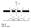
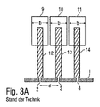
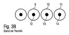
図1、2、3A及び3Bを参照して以下に説明するように、周知のドロップオンデマンド型のプリントヘッドの問題はノズル間の距離である。例えば、周知のドロップオンデマンド型プリントヘッドは、多数のノズル2、3、4を備えるノズルプレート1を通常有しており、それにより液滴5、6、7がノズル2~4を介して、部品8へと放出される。ノズル5~7は、ノズルプレート1において線形ノズル列に配置される。加えて、周知のドロップオンデマンド型プリントヘッドは、ノズル2~4を開閉するためのアクチュエータ9~11を有し、該アクチュエータは、例えば電磁アクチュエータとして設計することができ、それぞれ1つのアクチュエータニードル12~14を動かす。図3Aに示すように、アクチュエータニードル12~14の位置において、アクチュエータニードル12~14は、ノズル2~4を閉じ、その結果、コーティング剤はノズル2~4を通って放出されない。ノズル2~4はノズル列に沿って特定のノズル距離dで配置され、他方、アクチュエータ9~11はノズル列に沿って特定の幅bを有する。これは、隣接するノズル2~4間のノズル距離dが、アクチュエータ9~11の幅bより小さくなることができず、それ以外の場合、ノズル列に沿う利用可能な取付位置が、アクチュエータ9~11にとって十分とはならないことを意味する。
As discussed below with reference to Figures 1, 2, 3A and 3B, a problem with known drop-on-demand printheads is the distance between nozzles. For example, a well-known drop-on-demand printhead typically has a
従って、図1に示す図において、液滴5~7が部品8上で非常に離れてしまい、液滴5~7は、部品8上で連続するコーティング膜とはならず、受け入れ得るものではない。
Thus, in the view shown in FIG. 1, droplets 5-7 are so far apart on
それゆえ、操作の間、周知のドロップオンデマンド型プリントヘッドは、部品8の表面に対して垂直であり、且つ描画平面に垂直な塗料経路に対して垂直である、回転軸15の周りを回転する。結果として、描画平面における、つまり塗料経路に対して直角であるノズル距離dが減少する。ドロップオンデマンド型プリントヘッドのこの回転は、部品8の表面上で液滴5~7を共に非常に接近させることができ、塗布後に、図2に示すように連続するコーティング膜が形成される。従って、ドロップオンデマンド型ノズルヘッドの回転により、最小のノズル距離dがアクチュエータ9~11の幅bによって下方に制限されるという問題が解決される。しかしながら、そのような回転の必要がなく、できることが望まれている。特に、プリントヘッドにおけるノズル距離を減少させることが望まれている。
Therefore, during operation, the known drop-on-demand printhead rotates about an axis of
本発明の一般的な背景技術に関して、特許文献3、特許文献4、特許文献5、特許文献6、特許文献7、特許文献8及び特許文献9も引用されるべきである。 Reference should also be made to US Pat.
それゆえ、本発明は、対応して改善されたアプリケータ(例えば、プリントヘッド)を作成するという課題に基づく。 The present invention is therefore based on the problem of creating a correspondingly improved applicator (eg printhead).
この課題は、主請求項に係り本発明に係るアプリケータ(例えば、プリントヘッド)によって解決される。 This problem is solved by an applicator (eg print head) according to the invention according to the main claim.
本発明に係るアプリケータ(例えば、プリントヘッド)は、コーティング剤の塗布のために一般に適している。それゆえ、本発明は、塗布されるコーティング剤の種類に関して特定のコーティング剤に限定されない。しかしながら、好ましくは、プリントヘッドは塗料の塗布のために設計される。代わりに、本発明の範囲内において、コーティング剤は、例えば、自動車車体部品における継ぎ目を封止するための、接着剤又は封止材である可能性もある。それゆえ、本発明に係るアプリケータは、接着剤アプリケータ又は封止材アプリケータとして設計することもできる。 Applicators (eg printheads) according to the present invention are generally suitable for the application of coating agents. Therefore, the present invention is not limited to any particular coating with respect to the type of coating applied. Preferably, however, the printhead is designed for the application of paint. Alternatively, within the scope of the present invention, the coating agent may also be an adhesive or sealant, for example for sealing seams in automotive body parts. The applicator according to the invention can therefore also be designed as a glue applicator or as a sealant applicator.
本発明に係るアプリケータ(例えば、プリントヘッド)は、コーティング剤(例えば、塗料)を特定の部品に塗布するために一般に適していることにも言及すべきである。コーティングされる部品の種類について、本発明も限定されない。しかしながら、好ましくは、本発明に係るプリントヘッドは、コーティング剤(例えば、塗料)を、自動車車体部品又は自動車車体部品の追加部品に塗布するために設計される。 It should also be mentioned that the applicator (eg print head) according to the present invention is generally suitable for applying coating agents (eg paint) to specific parts. The invention is also not limited to the type of parts to be coated. Preferably, however, the printhead according to the invention is designed for applying a coating agent (eg paint) to an automobile body part or an additional part of an automobile body part.
本発明に係るアプリケータ(例えば、プリントヘッド)は、ジェット形状のコーティング剤を塗布するために、最新技術に従って、複数のノズルを備えるノズル列を最初に有し、それにより、共通のノズル平面においてノズル列に沿って、ノズルが配置される。 The applicator (e.g. print head) according to the invention, according to the state of the art, for applying the jet-shaped coating agent initially has a nozzle row with a plurality of nozzles, whereby in a common nozzle plane Nozzles are arranged along the nozzle row.
本発明に係るアプリケータ(例えばプリントヘッド)は、ノズルからコーティング剤のスプレーミストを放出するのではなく、より小さなジェットの膨張を伴う空間的に限定されたジェットを放出することに言及すべきである。従って、本発明に係るプリントヘッドは、空間的に限られたコーティング剤のジェットを放出するのではなく、コーティング剤のスプレーを放出するアトマイザ(例えばロータリーアトマイザ、エアアトマイザ等)とは異なる。 It should be mentioned that the applicator (e.g. printhead) according to the present invention does not emit a spray mist of coating material from the nozzle, but rather a spatially confined jet with smaller jet expansion. be. The printhead according to the present invention thus differs from atomizers (eg rotary atomizers, air atomizers, etc.) which emit a spray of coating agent rather than a spatially confined jet of coating agent.
ここで、アプリケータによって放出されるそれぞれのコーティング剤ジェットは、ジェットの長軸方向に互いに離間する多数の液滴からなり得ることにも言及するべきである。しかしながら、代わりに、個々のコーティング剤ジェットが、ジェットの長軸方向につながり、それゆえ連続するコーティング剤ジェットとして呼ばれ得ることも可能である。 It should also be mentioned here that each coating agent jet emitted by the applicator may consist of a number of droplets spaced apart from each other in the longitudinal direction of the jet. Alternatively, however, it is also possible for the individual coating agent jets to lead in the longitudinal direction of the jet and thus to be referred to as continuous coating agent jets.
本発明に係るアプリケータ(例えば、プリントヘッド)が、ノズルが好ましくは等距離に配置されている単一のノズル列を有し得ることも言及すべきである。しかしながら、本発明の範囲内において、プリントヘッドが、好ましくは互いに平行に配置された複数のノズル列を有することも可能である。 It should also be mentioned that an applicator (eg a printhead) according to the present invention may have a single row of nozzles in which the nozzles are preferably equidistantly arranged. However, it is also possible within the scope of the invention for the printhead to have several nozzle rows, preferably arranged parallel to each other.
加えて、本発明に係るアプリケータ(例えば、プリントヘッド)は、最新の技術に従い、ノズルを開放する又は閉じるための複数のアクチュエータを有する。アクチュエータは、電磁アクチュエータ、ピエゾアクチュエータ、又は空気圧アクチュエータであることができ、これらはごく一例である。それゆえ、本発明は、アクチュエータの動作の物理的原理に関して特定のアクチュエータの種類に限定されない。 In addition, the applicator (eg print head) according to the present invention has multiple actuators for opening or closing the nozzles according to the state of the art. Actuators can be electromagnetic actuators, piezo actuators, or pneumatic actuators, to name but a few. Therefore, the present invention is not limited to any particular actuator type with respect to the physical principles of actuator operation.
ここで、本発明は、ノズル列に沿ったアクチュエータの線形充填密度(lineare Packungsdichte)を高くすることと、ノズル列に沿って隣接するノズルのノズル距離を小さくすることと、を可能とするため、アクチュエータがノズル列に対して垂直に異なる距離だけオフセットされることを提供する。 Here, the invention enables a high linear packing density of the actuators along the nozzle row and a small nozzle distance between adjacent nozzles along the nozzle row, It provides that the actuators are offset by different distances perpendicular to the nozzle row.
本発明の変形例では、異なるアクチュエータが、ノズル平面に対して異なる垂直距離で上下に配置され、それにより、ノズル列に沿ったアクチュエータの線形充填密度を高くすることと、ノズル列に沿って隣接するノズルのノズル距離を小さくすることと、を可能とする。ノズル平面に対して上下に互いに平行に異なる平面において異なるアクチュエータを配置することで、異なる平面におけるアクチュエータは、それらの外輪郭がノズル列に沿って重なることが可能となる。これは、アクチュエータが同じ平面に配置されているのではなく、ノズル平面から異なる距離にある異なる平面に配置されているという事実によって可能となる。これは、すぐ隣のノズルのノズル距離を、ノズル列に沿ったアクチュエータの幅より小さくすることを可能とする。 In a variant of the invention, the different actuators are arranged above and below the nozzle plane at different vertical distances, thereby increasing the linear packing density of actuators along the nozzle row and adjacent actuators along the nozzle row. and to reduce the nozzle distance of the nozzle to be used. By arranging different actuators in different planes parallel to each other above and below the nozzle plane, the actuators in different planes can have their outlines overlap along the nozzle row. This is made possible by the fact that the actuators are not arranged in the same plane, but in different planes at different distances from the nozzle plane. This allows the nozzle distance of adjacent nozzles to be less than the width of the actuator along the row of nozzles.
これに対して、本発明の別の変形例では、ノズル平面において、ノズル列に対して異なる水平距離でアクチュエータが配置され、これにより、ノズル列に沿ったアクチュエータの線形充填密度を高くすることと、ノズル列に沿って隣接するノズルのノズル距離を小さくすることを可能とする。この場合、アクチュエータは、異なる距離で、ノズル列の側でノズル平面に対して平行に配置される。これも、隣接するノズル間のノズル距離を、ノズル列に沿うアクチュエータの幅より小さくすることを可能とする。この変形例でも、ノズル列に沿うアクチュエータの充填密度を増加させることができ、それに応じてノズル距離が減少する。 In contrast, in another variant of the invention, the actuators are arranged at different horizontal distances in the nozzle plane with respect to the row of nozzles, thereby increasing the linear packing density of the actuators along the row of nozzles. , it is possible to reduce the nozzle distance between adjacent nozzles along the nozzle row. In this case the actuators are arranged parallel to the nozzle plane on the side of the nozzle row at different distances. This also allows the nozzle distance between adjacent nozzles to be smaller than the width of the actuator along the row of nozzles. This variant also allows the packing density of the actuators along the nozzle row to be increased and the nozzle distance to be reduced accordingly.
従って、第1の変形例は、垂直にオフセットされたアクチュエータの配置を提供し、一方、第2の変形例は、水平にオフセットされたアクチュエータの配置を提供する。「水平」及び「垂直」の用語はノズル平面を指す、つまり、アクチュエータの水平なオフセットの配置の場合、アクチュエータは、ノズル平面に対して平行にオフセットされ、一方、垂直なオフセットは、アクチュエータがノズル平面に対して直角にオフセットされることを意味する。 Thus, the first variant provides a vertically offset actuator arrangement, while the second variant provides a horizontally offset actuator arrangement. The terms "horizontal" and "vertical" refer to the nozzle plane, i.e., for a horizontally offset arrangement of the actuator, the actuator is offset parallel to the nozzle plane, while for a vertical offset, the actuator is offset from the nozzle plane. It means offset perpendicular to the plane.
上述した本発明の2つの変形例は、単独で又は互いに組み合わせて使用することができる。 The two variants of the invention described above can be used alone or in combination with each other.
本発明は、アクチュエータのノズル列に沿う外形寸法を、ノズル列に沿うノズル距離より大きくすることを可能とする。それゆえ、本発明は、アクチュエータを小型化することなくノズル距離を減少することができる。 The present invention allows the outer dimensions of the actuator along the nozzle row to be greater than the nozzle distance along the nozzle row. Therefore, the present invention can reduce the nozzle distance without miniaturizing the actuator.
本発明の好適な実施形態において、アクチュエータは、それぞれ、スライドバルブニードルに互いに接続される。プリントヘッドのノズルは、バルブニードルによって開放される又は閉じられる。従って、アクチュエータは、ノズル列に対して平行な線形のアクチュエータ列に配置することができる。アクチュエータからバルブニードルへの動力伝達は、アーム(ハンマー)、リフティングビーム、又はロッカーアームのような機械的接続部材によって行うことができ、それによりロッカーアームは旋回可能であり、片側又は両側に作用することができる。 In a preferred embodiment of the invention, the actuators are each interconnected with a slide valve needle. The printhead nozzles are opened or closed by valve needles. The actuators can thus be arranged in a linear row of actuators parallel to the row of nozzles. The power transmission from the actuator to the valve needle can be done by a mechanical connecting member such as an arm (hammer), a lifting beam or a rocker arm, whereby the rocker arm can pivot and act on one or both sides. be able to.
本発明の変形例では、アクチュエータニードル自体が、バルブニードルでもあり、その結果、アクチュエータニードルとバルブニードルとの間の接続部材を省略することができる。 In a variant of the invention, the actuator needle itself is also the valve needle, so that the connecting member between the actuator needle and the valve needle can be omitted.
しかしながら、本発明の別の変形例では、アクチュエータニードルに加え、個々のバルブニードルが提供される。アクチュエータニードルは、接続部材(例えば、アーム、ロッカーアーム、ハンマー)を介してバルブニードルに作用する。 However, in another variant of the invention, individual valve needles are provided in addition to actuator needles. The actuator needle acts on the valve needle through a connecting member (eg arm, rocker arm, hammer).
本発明の変形例では、複数の(例えば2つ)アクチュエータは、特に共通するリフティングビームを介して、共同してバルブニードルにそれぞれ作用する。2つのアクチュエータは、リフティングビームに外部から作用することができ、バルブニードルはリフティングビームにより、リフティングビームの中央で駆動される。2つのアクチュエータは、リフティングビームを閉位置に引く、又は開位置に押すことができ、若しくは反対に閉位置に押す、又は開位置に引くことができる。 In a variant of the invention, several (for example two) actuators act jointly on the valve needle respectively, in particular via a common lifting beam. Two actuators can act externally on the lifting beam, the valve needle being driven by the lifting beam in the middle of the lifting beam. The two actuators can pull the lifting beam to the closed position or push it to the open position, or vice versa.
本発明の変形例では、アクチュエータがノズル平面から異なる垂直距離でオフセットされて配置されることが提供されることは既に上述した。それゆえ、異なるアクチュエータとノズル平面との間の距離は、異なる。これは、バルブニードルが異なる長さとなることを可能とする。そして、ノズル平面から更に離れた位置にあるアクチュエータは、ノズル平面により近い位置にあるアクチュエータよりも、長いバルブニードルを有する。 It has already been mentioned above that in a variant of the invention it is provided that the actuators are arranged offset at different vertical distances from the nozzle plane. Therefore, the distance between different actuators and the nozzle plane is different. This allows the valve needles to be of different lengths. And actuators further away from the nozzle plane have longer valve needles than actuators closer to the nozzle plane.
しかしながら、バルブニードルの長さが異なることはバルブニードルが異なる慣性挙動を有することを意味し、その結果、バルブニードルの長さに応じて、アクチュエータの動的応答動作が異なる。それゆえ、全てのアクチュエータが、ノズル平面からの距離に関わらず本質的に同じ長さ及び/又は重量のバルブニードルを有することも理にかない、その結果、アクチュエータの動的応答は、ノズル平面からの距離に関わらず均一である。そして、異なるアクチュエータは、ノズル平面から異なる距離で、均一に長いバルブニードルに係合する。 However, different valve needle lengths mean that the valve needles have different inertial behavior, resulting in different dynamic response behavior of the actuator, depending on the valve needle length. It is therefore also reasonable for all actuators to have valve needles of essentially the same length and/or weight regardless of their distance from the nozzle plane, so that the dynamic response of the actuators is is uniform regardless of the distance of Different actuators then engage uniformly long valve needles at different distances from the nozzle plane.
バルブニードルは、1ピース又はマルチピース(例えば、2ピース)であり得る。 The valve needle can be one-piece or multi-piece (eg, two-piece).
本発明の1つの実施形態において、バルブニードルは、自由端に向かって錐状に先細になるバルブニードルチップをそれぞれ有する。 In one embodiment of the invention, the valve needles each have a valve needle tip that tapers conically towards the free end.
更には、本発明の範囲内で、個々のバルブニードルチップは、個別の封止部材をそれぞれに有することが可能である。 Furthermore, within the scope of the present invention, individual valve needle tips can each have individual sealing members.
例えば、個別の封止部材は、バルブニードルチップに接着されることができる。代わりに、バルブニードルチップが、封止部材が挿入されるソケットを有することも可能である。代わりに、バルブニードルチップがその長さの一部にわたって、個別の封止部材で囲まれることも可能である。 For example, a separate sealing member can be glued to the valve needle tip. Alternatively, it is possible that the valve needle tip has a socket into which the sealing member is inserted. Alternatively, the valve needle tip can be surrounded by a separate sealing member over part of its length.
バルブニードルと封止部材とは異なる材料から形成されることができ、特にバルブニードルは金属、封止部材はプラスチックから形成されることができることにも言及すべきである。 It should also be mentioned that the valve needle and the sealing member can be made of different materials, in particular the valve needle can be made of metal and the sealing member of plastic.
封止部材は、ほんの一例であるが、射出成形、浸漬、溶接又は加硫によりバルブニードルの先端に取り付けることが出来る。 The sealing member can be attached to the tip of the valve needle by injection molding, dipping, welding or vulcanizing, to name but a few examples.
本発明の1つの実施形態は、少なくとも1つのアクチュエータニードルが複数のノズルを閉じることを提供する。この1つの可能性は、1つのアクチュエータニードルが、それぞれが1つのノズルを閉じる複数のスライドバルブニードルに機械的に作用することである。この技術的設計を実現する別の可能性は、少なくとも1つのアクチュエータニードルが、複数のノズルを共に開閉する封止部材に接続されることである。 One embodiment of the present invention provides that at least one actuator needle closes multiple nozzles. One possibility for this is for one actuator needle to mechanically act on multiple slide valve needles, each closing one nozzle. Another possibility of realizing this technical design is that at least one actuator needle is connected to a sealing member that jointly opens and closes multiple nozzles.
更に、本発明の実施形態は、個別の封止部材を備えるバルブシートが、個々のノズルとそれぞれ結び付けられ、それによりバルブシートが、バルブニードルチップによって選択的に閉鎖又は開放されることを提供する。バルブニードルチップとバルブシートにおける封止部材とは、例えば、金属、プラスチック、セラミック、又は半導体から形成されることができ、その結果、一方のノズルニードルチップと、他方のバルブシートにおける封止部材とは、金属、セラミック、半導体及び/又はプラスチックの材料の組み合わせとすることができる。 Further, embodiments of the present invention provide valve seats with separate sealing members associated with respective individual nozzles such that the valve seats are selectively closed or opened by valve needle tips. . The valve needle tip and the sealing member at the valve seat can be formed, for example, from metal, plastic, ceramic, or semiconductor so that the nozzle needle tip on the one hand and the sealing member at the valve seat on the other. can be a combination of metal, ceramic, semiconductor and/or plastic materials.
本発明の1つの実施形態において、バルブニードル又はアクチュエータニードルは、戻しばねによって復元力を受け、それにより復元力は、開位置又は閉位置のいずれかで作用することができる。 In one embodiment of the invention, the valve needle or actuator needle is subjected to a restoring force by a return spring, whereby the restoring force can act in either the open or closed position.
特別な実施形態において、アクチュエータは二重に、つまり双方向に作用する。この場合、ばねはリセットのために必要ない。 In a particular embodiment, the actuator is dual, ie bi-directional. In this case no spring is needed for resetting.
加えて、個々のアクチュエータは、プリントヘッド内でアクチュエータの位置を調節するための位置調節をそれぞれ有することができる。例えば、そのような位置調節は、止めねじ、止め輪、又はシム用のスペースを有することができる。 Additionally, the individual actuators can each have a position adjustment for adjusting the position of the actuator within the printhead. For example, such position adjustments may have room for set screws, retaining rings, or shims.
個々のアクチュエータは、好ましくは、アクチュエータハウジング、ハンマー、電機子(プランジャ)、カバー及び/又は軟磁性材料、特に0.01T、2.4T又は0.6~2.4Tの飽和磁化からなるコアを有することも言及すべきである。アクチュエータハウジングは、例えば、円柱状であることができ、個別のカバーを備えることができる。カバーは、アクチュエータハウジングに、例えば接着又はねじ止めによって接続されることができる。 The individual actuators preferably comprise an actuator housing, a hammer, an armature (plunger), a cover and/or a core made of soft magnetic material, in particular a saturation magnetization of 0.01T, 2.4T or 0.6-2.4T. It should also be mentioned that it has The actuator housing can, for example, be cylindrical and can be provided with a separate cover. The cover can be connected to the actuator housing by gluing or screwing, for example.
アクチュエータ、アクチュエータニードル、及び/又はノズルニードル及びノズルプレートは、ハウジング内に載置されてもよい。特別な実施形態において、ハウジングは少なくとも2ピースである。特に、アクチュエータが中に配置されるハウジングのパーツは、2つの部分から構成され、その結果、例えば、アクチュエータ及びアクチュエータロッドの半分は、ハウジングの第1の半分に割り当てられ、アクチュエータ及びアクチュエータロッドの次の半分は、ハウジングの第2の半分に割り当てられる。アクチュエータは、互いの上の複数の平面に配置することができ、複数のアクチュエータは、各アクチュエータ平面に互いに隣接して配置されることができる。 The actuator, actuator needle, and/or nozzle needle and nozzle plate may be mounted within the housing. In a particular embodiment, the housing is at least two pieces. In particular, the part of the housing in which the actuator is arranged is composed of two parts, so that, for example, the actuator and the actuator rod half are assigned to the first half of the housing and the actuator and the actuator rod half are allocated to the first half of the housing. is assigned to the second half of the housing. The actuators can be arranged in multiple planes above each other, and the multiple actuators can be arranged adjacent to each other in each actuator plane.
特に有利な実施形態において、垂直アクチュエータ列のバルブニードルは、互いからノズル開口の距離で互いに隣接して配置される。これに隣接し、ハウジングの別の半分の垂直アクチュエータ列のバルブニードルが配置されるギャップがある。 In a particularly advantageous embodiment, the valve needles of the vertical actuator row are arranged adjacent to each other at a nozzle opening distance from each other. Adjacent to this is a gap in which the valve needles of the vertical actuator row of the other half of the housing are located.
最小可能ノズル距離は、アクチュエータの水平及び垂直配置と、関連付けられたアクチュエータニードル又はバルブニードルとから、以下の式:

ここで、
a=ノズル間の距離[mm]
n=ノズルの数
e=平面の数
r=列におけるアクチュエータの数
h=ハウジングパーツの数
に従って得られる。
例:n=48、e=6、r=4及びh=2は、1mmの最小可能ノズル距離である。
平面の数eは、≧2、≧6又は更に≧12であることができる。
列におけるアクチュエータの数rは、≧1、≧4、≧10又は更に≧100であることができる。
ハウジングのパーツの数hは、≧1、≧2又は更に≧4であることができる。
The minimum possible nozzle distance is determined from the horizontal and vertical orientation of the actuator and the associated actuator or valve needle by the following formula:
here,
a = distance between nozzles [mm]
n=number of nozzles e=number of planes r=number of actuators in a row h=obtained according to the number of housing parts.
Example: n=48, e=6, r=4 and h=2 is the minimum possible nozzle distance of 1 mm.
The number of planes e can be ≧2, ≧6 or even ≧12.
The number r of actuators in a row can be ≧1, ≧4, ≧10 or even ≧100.
The number h of parts of the housing can be ≧1, ≧2 or even ≧4.
本文脈において、最大アクチュエータ直径d(その隔壁を含む)は、式:

又は

から得られる。
例:e=6及びh=2は、12mmの最大可能アクチュエータ直径である。
In the present context, the maximum actuator diameter d (including its septum) is defined by the formula:
or
obtained from
Example: e=6 and h=2 is the maximum possible actuator diameter of 12mm.
本発明に係るプリントヘッドの場合、互いにすぐ横に隣接するノズルは、それらのノズル中心に対して非常に小さいノズル距離を有してもよく、この距離は、例えば、最大で3mm、2mm、1.5mm、1.3mm、1mm、又は更に最大0.8mmであることができる。 In the case of a printhead according to the invention, nozzles immediately laterally adjacent to each other may have very small nozzle distances with respect to their nozzle centers, which distances are, for example, up to 3 mm, 2 mm, 1 .5 mm, 1.3 mm, 1 mm, or even up to 0.8 mm.
直接垂直方向に隣接するアクチュエータは、それらのバルブニードルの長軸方向に対するアクチュエータ距離を、最大3mm、2mm、1.5mm、1.3mm、1mm、又は更に0.8mmで有することができる。 Directly vertically adjacent actuators may have an actuator distance to their valve needle longitudinal axis of up to 3 mm, 2 mm, 1.5 mm, 1.3 mm, 1 mm, or even 0.8 mm.
ノズルは、線状のノズル列に配置することができ、特に等距離で配置することができることも言及されるべきである。 It should also be mentioned that the nozzles can be arranged in linear rows of nozzles, in particular equidistant.
異なるバルブニードルは、好ましくは互いに平行であり、特にノズル平面に対して直角であることも言及されるべきである。 It should also be mentioned that the different valve needles are preferably parallel to each other, in particular perpendicular to the nozzle plane.
合計で、プリントヘッドは、多数のノズル、例えば、20、30、40、50、100、150、又は更には200より多いノズルを含むことができる。 In total, the printhead can include a large number of nozzles, eg, 20, 30, 40, 50, 100, 150, or even more than 200 nozzles.
更には、プリントヘッドは、個々のアクチュエータニードル又はバルブニードルのためのガイド部材(例えば、ガイドレール)を有してもよく、ガイド部材は、ノズル平面への経路上でニードルを安定させる、又はノズル平面への経路を決定し、それにより、アクチュエータニードル又はバルブニードルの座屈を防ぐ。従って、ガイド部材は、アクチュエータニードル又はバルブニードルを半径方向にガイドする。 Furthermore, the printhead may have guide members (e.g., guide rails) for the individual actuator needles or valve needles, which stabilize the needles on their path to the plane of the nozzles or nozzles. Determining a path to a plane, thereby preventing buckling of the actuator needle or valve needle. The guide member thus radially guides the actuator or valve needle.
個々のアクチュエータニードル又はバルブニードルに関して、それらは、長さに対する直径の特定の比率を有することができ、その比は、本発明の範囲内において、0.2、0.15、0.007、又は0.005よりも小さくてもよいことに言及すべきである。 For individual actuator needles or valve needles, they may have a specific ratio of diameter to length, which ratio may be 0.2, 0.15, 0.007, or It should be mentioned that it can be less than 0.005.
個々のアクチュエータニードル又はバルブニードルの長さに関して、これが、好ましくは20mm~500mm、75mm~300mm、又は75mm~150mmの範囲にあってもよいことに言及されるべきである。 Regarding the length of the individual actuator needle or valve needle, it should be mentioned that this may preferably range from 20 mm to 500 mm, 75 mm to 300 mm, or 75 mm to 150 mm.
他方、個々のアクチュエータニードル又はバルブニードルの軸方向の最大ストロークは、好ましくは、10μm~500μm、30μm~200μm、又は30μm~100μmの範囲である。 On the other hand, the maximum axial stroke of an individual actuator needle or valve needle is preferably in the range of 10 μm to 500 μm, 30 μm to 200 μm, or 30 μm to 100 μm.
バルブニードルは、腐食を防ぐための防食コーティングを施され得ることにも言及すべきである。この防食コーティングは、例えば、ダイヤモンドライクカーボン又は窒化炭素からなってもよく、防食コーティングは、化学気相成長法(CVD)又は物理気相成長法(PVD)によって形成することができる。 It should also be mentioned that the valve needle may be provided with an anti-corrosion coating to prevent corrosion. This anti-corrosion coating may, for example, consist of diamond-like carbon or carbon nitride, and the anti-corrosion coating can be formed by chemical vapor deposition (CVD) or physical vapor deposition (PVD).
アクチュエータが、電磁的、圧電的、又は空気圧(単動又は複動)で動作できることは既に簡単に言及した。従って、本発明は、アクチュエータの種類に関して特定の動作原理に限定されない。 It was already mentioned briefly that the actuators can be operated electromagnetically, piezoelectrically or pneumatically (single-acting or double-acting). Accordingly, the present invention is not limited to any particular principle of operation with respect to actuator type.
電磁アクチュエータとして実行される場合、アクチュエータは好ましくは、10~2000、200~1000又は250~900の巻き数のコイルを有する。 When implemented as an electromagnetic actuator, the actuator preferably has a coil with 10-2000, 200-1000 or 250-900 turns.
更に、好ましくは、コイルは、0.05mm~2mm、0.1mm~1mm又は0.1mm~0.5mmの線径を有するコイル線で巻かれる。 Further preferably, the coil is wound with a coil wire having a wire diameter of 0.05 mm to 2 mm, 0.1 mm to 1 mm or 0.1 mm to 0.5 mm.
本発明に係るプリントヘッドにおける電気的に制御されたアクチュエータの電気的接触は、例えば、統合された接触ピンによって、又はコイル線を引き出すことによって行われることができる。 Electrical contacting of the electrically controlled actuators in the printhead according to the invention can be done, for example, by means of integrated contact pins or by pulling out coil wires.
動作中に発生する熱を放散させるために、アクチュエータに、流体、特に圧縮空気のようなガスを吹き込む又は流すことができる。流体は、ハウジングの内側又は外側のいずれかを介して排出できる。 In order to dissipate the heat generated during operation, the actuator can be blown or blown with a fluid, in particular a gas such as compressed air. Fluid can be discharged through either the inside or the outside of the housing.
本発明に係るプリントヘッドの外形寸法(つまり、最大長さ、幅、又は高さ)は、好ましくは、最大で550mm、450mm、又は350mmである。 The outer dimensions (ie maximum length, width or height) of the printhead according to the invention are preferably at most 550 mm, 450 mm or 350 mm.
プリントヘッドは、例えば、コーティング剤の供給のため、フラッシング剤の供給のため、圧縮空気の供給のため、及び/又は戻りへの戻りラインのための接続部を有してもよいことにも留意されたい。これにより、プリントヘッドにおける統合された物質循環が可能となる。 It is also noted that the print head may have connections for example for the supply of coating agent, for the supply of flushing agent, for the supply of compressed air and/or for the return line to the return. want to be This allows integrated material circulation in the printhead.
本発明は、単一の部品として上述したプリントヘッドについての保護を主張するだけではないことにも言及すべきである。むしろ、本発明は、そのようなプリントヘッドを備えるコーティングロボット(例えば、塗装ロボット)についての保護も主張する。 It should also be noted that the present invention does not only claim protection for the printhead described above as a single component. Rather, the present invention also claims protection for coating robots (eg painting robots) equipped with such printheads.
例えば、プリントヘッドは、迅速に交換可能な装置によって交換可能な方法でコーティングロボットに取り付けられることができる。そのような迅速に交換可能な装置は、例えばクランプ栓を有することができ、最新技術から知られているため、詳細な説明は必要とされない。 For example, the printheads can be attached to the coating robot in a replaceable manner by a quick replaceable device. Such quick-exchange devices, which can have clamping plugs for example, are known from the state of the art and do not require a detailed description.
本発明の他の有利な更なる変形例は、従属項に示される、又は本発明の好適な実施形態の説明と共に以下により詳細に説明される。 Other advantageous further variants of the invention are indicated in the subclaims or are explained in more detail below together with the description of preferred embodiments of the invention.
図4は、本発明に係るプリントヘッドの概略図を示し、図3A及び3Bに示す既知のプリントヘッドに部分的に対応するため、対応する詳細には同一の参照符号を使用し、繰り返しを避けるために上記の説明を引用する。 FIG. 4 shows a schematic view of a printhead according to the present invention and corresponds in part to the known printhead shown in FIGS. 3A and 3B, so corresponding details will be given the same reference numerals to avoid repetition. To quote the above description.
本実施形態の特別な特徴は、アクチュエータ9~11が、ノズルプレート1の平面に対して平行な同じ平面に配置されないことである。むしろ、アクチュエータ9~11は、ノズルプレート1の平面から異なる距離で配置され、結果として、それらの外輪郭が垂直方向で(つまり、ノズルプレート1の平面に垂直に)重複しない。これは、アクチュエータ9~11の付加的な小型化を必要とせずに、ノズル列に沿うアクチュエータ9~11間の距離を短くすることを可能とする。それゆえ、ノズル距離dを、個々のアクチュエータ9~11の幅bより小さくすることができる。
A special feature of this embodiment is that the actuators 9 - 11 are not arranged in the same plane parallel to the plane of the
図4に示す実施形態において、アクチュエータ9~11は、ノズルプレート1の平面に対して平行な3つの異なるアクチュエータ平面に配置される。
In the embodiment shown in FIG. 4 the actuators 9 - 11 are arranged in three different actuator planes parallel to the plane of the
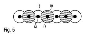
図5に示す代替の実施形態において、異なるアクチュエータ9及び10は、ノズルプレート1の平面に対して平行な2つの異なるアクチュエータ平面に配置される。
In an alternative embodiment shown in FIG. 5 the
図6は、本発明の別の可能な実施形態の概略図を示し、これも上述した実施形態に部分的に対応しており、繰り返しを避けるため上述の説明を引用する。 FIG. 6 shows a schematic diagram of another possible embodiment of the invention, which also partially corresponds to the above-described embodiment, citing the above description to avoid repetition.
ここでの特別な特徴は、アクチュエータ9~11が垂直方向及び水平方向の両方でオフセットされることである。バルブ機能は、機械的な接続部材19~21(例えば、アーム、リフティングビーム、ロッカーアーム)を介してアクチュエータ9~11によって駆動されるバルブニードル16~18によって実現される。 A special feature here is that the actuators 9-11 are offset both vertically and horizontally. The valve function is realized by valve needles 16-18 driven by actuators 9-11 via mechanical connecting members 19-21 (eg arms, lifting beams, rocker arms).
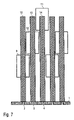
図7は、図4に示される実施形態の変形例を示し、繰り返しを避けるために、対応する詳細には同じ参照符号を使用し、上述の説明を引用する。 FIG. 7 shows a variant of the embodiment shown in FIG. 4, using the same reference numerals for corresponding details to avoid repetition and referring to the description above.
この実施形態の特別な特徴は、ここではバルブニードル12~14が均一の長さを有し、それにより均一の質量も有することである。これは、アクチュエータ9~10の動的応答動作が異なる慣性質量によって変わらないので、有利である。 A special feature of this embodiment is that the valve needles 12-14 here have a uniform length and therefore also a uniform mass. This is advantageous because the dynamic response behavior of actuators 9-10 does not change with different inertial masses.
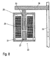
図8は、二重矢印方向に動作可能な電機子23、ハウジング24、コイル25、コイルフォーマ26及び磁気コア27を備える本発明に係るアクチュエータ22の断面図を示す。
FIG. 8 shows a cross-sectional view of an
スライドする電機子23は、その動きをハンマー28を介してバルブニードル29に伝える。
A sliding
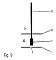
図9は、付加的な封止を備えるバルブニードルチップ31を備えるバルブニードル30の概略図を示す。
FIG. 9 shows a schematic diagram of a
加えて、コーティング剤で満たされたノズルチャンバ33をアクチュエータチャンバ34から分離する封止膜32が示される。封止膜32は、コーティング剤がノズルチャンバ33からアクチュエータチャンバ34へと移動することを防ぎ、アクチュエータを汚染することを防ぐ。
In addition, a sealing
図10は、本発明の実施形態を示し、それにより、アクチュエータニードル36を備えるアクチュエータ35が、5つのバルブニードル37にそれぞれ作用し、従って、ノズルプレート39内の複数のノズル38を任意に閉じる又は開く。
Figure 10 shows an embodiment of the invention whereby an
図11は、図10に係る設計の変形例を示す。ここで、アクチュエータニードル36は、選択的に複数のノズル38を開放する又は閉じる封止部材40に作用する。
FIG. 11 shows a variant of the design according to FIG. Here, the
図12は、図8の変形例を示し、繰り返しを避けるために上記の説明を引用し、対応する詳細には同じ参照符号を使用する。 FIG. 12 shows a variant of FIG. 8, citing the above description to avoid repetition and using the same reference numerals for corresponding details.
この図の特別な特徴は、プリントヘッドのアクチュエータ22の位置を調節する調節装置41も示されていることである。
A special feature of this figure is that the
加えて、統合されたフィッティング面又はフィッティングピン42が示される。
Additionally, an integrated fitting face or
最後に、図12は、コイル25の電気的接触のための統合されたコンタクト43も示す。
Finally, FIG. 12 also shows an
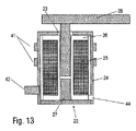
図13は、図12の変形例を示し、繰り返しを避けるため、上記の説明を引用し、対応する詳細には同じ参照符号を使用する。 FIG. 13 shows a variant of FIG. 12 and, in order to avoid repetition, cites the above description and uses the same reference numerals for corresponding details.
この実施形態の特別な特徴は、統合された電気的なコンタクト43の代わりに、電気的接触のためのホール44が設けられることである。コイル線の端は、このホールから引き出すことができる。
A special feature of this embodiment is that instead of integrated
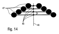
図14は、第2の発明の変形例の概略図を示す。ここで、ノズル45は、ノズル列46に沿って特定のノズル距離dで等間隔に配置される。ノズル距離dは、ノズル距離dとノズル距離dとによって決定される。
FIG. 14 shows a schematic diagram of a modification of the second invention. Here, the
ノズル45は、図示しないバルブニードルによって開放される又は閉じられ、それにより個々のバルブニードルはアクチュエータ47によって機械的に駆動される。アクチュエータ47は、ノズル列46に対してノズル列46の側で異なる距離でオフセットされる。これは、アクチュエータ47の線形充填密度を、ノズル列46に沿って増加させることを可能とし、その結果、それに従いノズル距離dも減少させることができる。
The
図15は、封止膜49を通ってガイドされ、ノズルプレート52おいて任意にノズル51を開放する又は閉じるバルブニードルチップ50を備えるノズルニードル48の機械的な制御の概略図を示す。
FIG. 15 shows a schematic diagram of the mechanical control of
ノズルニードル48の駆動は、共通のリフティングビーム55を介してノズルニードル48上に共同して作用する2つのアクチュエータ53及び54によって実現される。
Actuation of the
2つのアクチュエータ53、54は、リフティングビーム55の外側に作用し、他方、リフティングビーム55は、ノズルニードル48にその中心で作用する。
The two
この文脈内では、2つのアクチュエータ5363、54は、ノズルニードル48を閉位置に引く及び反対の開位置に押すことにも言及すべきである。
Within this context it should also be mentioned that the two
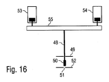
図16は、図15の変形例を示し、繰り返しを避けるため、対応する詳細には同一の参照符号を使用して上記の説明を引用する。 FIG. 16 shows a variant of FIG. 15 and, in order to avoid repetition, refer to the above description using the same reference numerals for corresponding details.
この実施形態の特別な特徴は、2つのアクチュエータ53、54はノズルニードル48を閉位置に押し、及びノズルニードル48を開位置に引くことである。
A special feature of this embodiment is that the two
図17は、それぞれ図15及び16の変形例を示し、繰り返しを避けるため、対応する詳細には同一の参照符号を使用し、再び上記の説明を引用する。 FIG. 17 shows a variant of FIGS. 15 and 16 respectively, and to avoid repetition, the same reference numerals are used for corresponding details and the above description is again referred to.
この実施形態の特別な特徴は、ノズルニードル48が、片側ロッカーアーム57を介して単一のアクチュエータ56によって駆動され、それによりロッカーアーム57は支持部58内で回転することである。
A special feature of this embodiment is that the
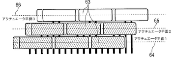
図18A及び18Bは、図6に示す実施形態の変形例を示し、繰り返しを避けるため、上記の説明も引用する。 Figures 18A and 18B show a variant of the embodiment shown in Figure 6 and also refer to the above description to avoid repetition.
ノズル列60内の複数のノズル59は、互いに前後に等距離に配置される。
The plurality of
ノズル列60の両側では、アクチュエータ列61、62がノズル列60に平行に配置される。
アクチュエータ列62は、図18Bに示すように、3つのアクチュエータ平面64、65、66内に互いに上に配置された複数のアクチュエータ63を含む。他のアクチュエータ列61も、3つのアクチュエータ平面64~66内に互いに上に配置された複数のアクチュエータ67を含む。
従って、アクチュエータは水平(つまり、ノズル列60を横切る)及び垂直(つまり、ノズル平面に垂直)の両方に部分的に引き離されて配置される。これにより、ノズル列60の隣接するノズル59間のノズル距離を減少させることが可能となる。
Accordingly, the actuators are partially spaced apart both horizontally (ie across the nozzle row 60) and vertically (ie perpendicular to the nozzle plane). This makes it possible to reduce the nozzle distance between
ここで、ノズル列60のノズル59のためのバルブニードルが、2つのアクチュエータ列61、62のアクチュエータ67、63に交互に接続される。
Here, the valve needles for the
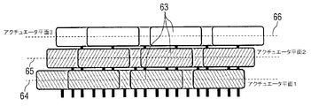
図19A及び19Bは、図18A及び18Bに係る実施形態の変形例を示し、対応する詳細には同一の参照符号を使用し、繰り返しを避けるために上記の説明を引用する。 Figures 19A and 19B show a variant of the embodiment according to Figures 18A and 18B, using the same reference numerals for corresponding details and citing the above description to avoid repetition.
この実施形態の特別な特徴は、アクチュエータ63、67が、ノズル59について対応するバルブニードルのグループに常に接続されることである。従って、ノズル列60の最初の3つのノズル59のためのバルブニードルは、アクチュエータ列61の最初の3つのアクチュエータ67によって制御される。そして、ノズル列60の次の3つのノズル59のためのバルブニードルは、他のアクチュエータ列62の最初の3つのアクチュエータ63によって制御される。
A special feature of this embodiment is that the
図20は、垂直方向(つまり、ノズル平面に垂直)及び水平方向(つまり、ノズル平面に平行)の両方に部分的に引き離されたアクチュエータの概略図を示す。 FIG. 20 shows a schematic view of the actuator partially disengaged both vertically (ie perpendicular to the nozzle plane) and horizontally (ie parallel to the nozzle plane).
ここで、2つのアクチュエータ列が、例示するように3つのアクチュエータ平面において、互いに平行に及びノズル列に平行に配置される。 Here, two actuator rows are arranged parallel to each other and parallel to the nozzle rows in three actuator planes as illustrated.
上側アクチュエータ平面において、右アクチュエータ列は、例として2つのアクチュエータa.1.1及びa.1.2を含み、他方、他のアクチュエータ列は、例として2つのアクチュエータb.1.1及びb.1.2を含む。 In the upper actuator plane, the right actuator row contains, by way of example, two actuators a.1.1 and a.1.2, while the other actuator row by way of example contains two actuators b.1.1 and b.1.2.
中間アクチュエータ平面についても同じことが適用され、中間アクチュエータ平面も、それぞれ2つのアクチュエータa.2.1、a.2.2及びb.2.1、b.2.2を備える2つのアクチュエータ列をそれぞれ備える。 The same applies for the intermediate actuator plane, which also comprises two rows of actuators each comprising two actuators a.2.1, a.2.2 and b.2.1, b.2.2.
最後に、下側アクチュエータ平面も、例としてそれぞれ2つのアクチュエータa.3.1、a.3.2及びb.3.1、b.3.2を備える2つのアクチュエータ列を含む。 Finally, the lower actuator plane also contains, by way of example, two rows of actuators each with two actuators a.3.1, a.3.2 and b.3.1, b.3.2.
ここで、個々のアクチュエータ列におけるアクチュエータの数は、説明の目的で示されている及び上述されている数よりも、実際はかなり多いことに言及すべきである。 It should be noted here that the number of actuators in an individual actuator row is actually much higher than shown and described above for purposes of explanation.
図21は、図20の変形例を示すので、繰り返しを避けるため、対応する詳細に同じ参照符号を使用して、上記の説明を引用する。 Since FIG. 21 shows a variant of FIG. 20, the above description is referred to using the same reference numerals for corresponding details to avoid repetition.
この実施形態の特別な特徴は、アクチュエータa.1.1、a.1.2、a.2.1、a.2.2、a.3.1、a.3.2が、部分的に垂直方向にだけ、つまり3つのアクチュエータ平面において互いに上下に引き離されることである。しかし、水平方向(つまりノズル列を横切る)に部分的に引き離されない。 A special feature of this embodiment is that the actuators a.1.1, a.1.2, a.2.1, a.2.2, a.3.1, a.3.2 are only partially perpendicular to each other, ie in the three actuator planes. It is to be separated up and down. However, they are not partially pulled apart horizontally (ie across the nozzle row).
図22A及び22Bは、圧縮空気72によるアクチュエータ68~71の冷却を説明するための概略図を示し、圧縮空気72は、圧縮空気分配器73からノズル74を通って流れ出て、アクチュエータ68~71まで導かれてアクチュエータ68~71を冷却する。
22A and 22B show schematic diagrams to illustrate the cooling of actuators 68-71 by
個々のアクチュエータ68~71は、ハンマー75を介して、バルブニードル76上にそれぞれ作用する。
Individual actuators 68 - 71 each act on a
図23~25は、封止膜78を通るバルブニードル77の通過、接続又は配置のための様々な可能な設計を示す。
23-25 show various possible designs for passage, connection or placement of the
図23において、バルブニードル77は連続しており、このため、ノズル閉鎖チップ79を備え、対応するバルブシートを閉じる又は開放するための封止部材も形成する。
In FIG. 23, the
加えて、封止カラー80は、封止膜14上に一体に形成されており、封止膜78からアクチュエータチャンバ81及びノズルチャンバ82の両方に向かって突出することが、図から理解し得る。
Additionally, it can be seen from the figures that the sealing
図24に示す設計において、ノズル閉鎖チップ79は、バルブニードル77から分かれており、バルブニードル77にねじ込まれている。封止膜78は、バルブニードル77とノズル閉鎖チップ79との間で押されており、その結果、バルブニードル77は封止膜78に対して固く接続される。従って、バルブニードル77の変位は、封止膜78の対応する撓みをもたらす。
In the design shown in FIG. 24,
図25に示す実施形態において、封止膜78は、バルブニードル77を通すためのホールを有しない。むしろ、ノズル閉鎖チップ79が、封止膜78上に一体に形成される。ここで、また、バルブニードル77は、封止膜78に固く接続されるので、バルブニードル77の変位は、封止膜78の対応する撓みにつながる。
In the embodiment shown in FIG. 25, the sealing
図26は、一体のノズル閉鎖チップ79を備える封止膜78を示す。バルブニードル77は、封止膜78に接続されることもできるが、単に取り付けられることもできる。バルブニードル77だけが取り付けられる場合、ノズルの開口が塗料圧力によって生ずる。塗料圧力は、アクチュエータチャンバ81の方向にノズルチャンバ82から離れるように封止膜78を変形させる。
FIG. 26 shows a sealing
本発明は上述した好適な実施形態に限られない。むしろ、多くの数の変形例、修正例が可能であり、それらも本発明のアイディアも使用するため、保護の範囲に入る。特に、本発明は、それぞれの場合に言及されている請求項に関係なく、特に主請求項の際だった特徴がなくとも、従属項の主題及び特徴の保護も請求する。従って、本発明は、それぞれが独立して保護を享受する本発明の様々な態様を包含する。 The invention is not limited to the preferred embodiments described above. Rather, a large number of variations and modifications are possible, which also use the idea of the invention and thus fall within the scope of protection. In particular, the invention also claims the subject matter and features of the dependent claims, irrespective of the claims referred to in each case, even without the distinctive features of the main claim. Accordingly, this invention encompasses various aspects of the invention, each of which is entitled to independent protection.
[付記]
[付記1]
コーティング剤、特に塗料を部品に、特に自動車車体部品に塗布するためのアプリケータ、特にプリントヘッドであって、
a)前記コーティング剤をそれぞれの場合でジェットの形態で吐出するための複数のノズル(2~4、38、45、51)を有する少なくとも1つのノズル列(46)であって、前記ノズル(2~4、38、45、51)は、該ノズル列(46)に沿って及び共通のノズル平面内に配置されたノズル列(46)、及び、
b)前記ノズル(2~4、38、45、51)の制御された開閉のための複数のアクチュエータ(9~11、22、35、47、53、54、56)、
を備え、
c)個々の前記アクチュエータ(9~11、22、35、47、53、54、56)が、前記ノズル列(46)に沿ったノズル距離(d)より大きい前記ノズル列(46)に沿った外形寸法(b)をそれぞれ有する、
ことを特徴とするアプリケータ。
[Note]
[Appendix 1]
An applicator, in particular a printhead, for applying coating agents, in particular paints, to parts, in particular automotive body parts, comprising:
a) at least one nozzle row (46) having a plurality of nozzles (2-4, 38, 45, 51) for ejecting said coating agent in each case in the form of a jet, said nozzle (2 4, 38, 45, 51) are nozzle rows (46) arranged along said nozzle row (46) and in a common nozzle plane, and
b) a plurality of actuators (9-11, 22, 35, 47, 53, 54, 56) for controlled opening and closing of said nozzles (2-4, 38, 45, 51),
with
c) each said actuator (9-11, 22, 35, 47, 53, 54, 56) along said nozzle row (46) greater than the nozzle distance (d) along said nozzle row (46) each having an external dimension (b),
An applicator characterized by:
[付記2]
a)前記アクチュエータ(9~11)は、前記ノズル列(46)に沿って隣接する前記ノズル(2~4)の小さなノズル距離(d)を可能とするために、関連する前記ノズルに対して異なる距離で及び/又は異なる方向に配置される、及び/又は、
b)前記アクチュエータ(9~11)は、前記ノズル平面からの異なる垂直距離で、互いに上に配置される、及び/又は、
c)前記アクチュエータ(9~11)は、前記ノズル列に対して互いに異なる水平距離で配置される、及び/又は、
d)前記アクチュエータ(9~11)は、前記ノズル列から、等しい水平距離で並んで配置される、
ことを特徴とする付記1に記載のアプリケータ。
[Appendix 2]
a) the actuators (9-11) are positioned relative to the associated nozzles to allow a small nozzle distance (d) of adjacent nozzles (2-4) along the nozzle row (46) located at different distances and/or in different directions; and/or
b) the actuators (9-11) are arranged above each other at different vertical distances from the nozzle plane and/or
c) the actuators (9-11) are arranged at different horizontal distances relative to the row of nozzles and/or
d) said actuators (9-11) are arranged side by side at equal horizontal distances from said row of nozzles;
The applicator according to
[付記3]
a)前記アクチュエータは、複数のアクチュエータ平面内に配置され、個々の前記アクチュエータ平面は前記ノズル平面に対して平行に広がる、及び、
b)2つのアクチュエータ列は、それぞれの場合、個々の前記アクチュエータ平面における前記ノズル列のいずれかの側に配置され、前記アクチュエータ列は、それぞれ複数のアクチュエータを含む、
ことを特徴とする付記1又は2に記載のアプリケータ。
[Appendix 3]
a) said actuators are arranged in a plurality of actuator planes, each said actuator plane extending parallel to said nozzle plane, and
b) two rows of actuators are in each case arranged on either side of said rows of nozzles in respective said actuator planes, said rows of actuators each comprising a plurality of actuators,
The applicator according to
[付記4]
a)垂直に隣接する前記アクチュエータ平面は、互いにオフセットされており、
b)垂直に隣接する前記アクチュエータ平面間の前記オフセットは、本質的に、
b1)前記ノズル列において隣接する前記ノズル間の前記ノズル距離(d)と同じである、又は、
b2)前記ノズル距離(d)の整数倍である、及び/又は
c)前記アクチュエータ列における前記アクチュエータは、実質的に等間隔に配置される、
ことを特徴とする付記3に記載のアプリケータ。
[Appendix 4]
a) said vertically adjacent actuator planes are offset from each other;
b) said offset between said vertically adjacent actuator planes is essentially:
b1) is the same as the nozzle distance (d) between the adjacent nozzles in the nozzle row, or
b2) is an integer multiple of said nozzle distance (d); and/or c) said actuators in said actuator array are substantially equally spaced.
The applicator according to
[付記5]
a)前記アクチュエータは、変位可能なアクチュエータニードルをそれぞれ備える、
b)前記ノズルは、スライディングバルブニードルによってそれぞれ開閉可能である、及び、
c)個々の前記アクチュエータニードルは、関連する前記バルブニードルに機械的接続部材、特にアーム又は回転可能な片側又は両側ロッカーアームによってそれぞれ接続される、
ことを特徴とする付記1乃至4のいずれか1つに記載のアプリケータ。
[Appendix 5]
a) the actuators each comprise a displaceable actuator needle,
b) the nozzles are each openable and closable by a sliding valve needle; and
c) the individual actuator needles are each connected to the associated valve needle by a mechanical connecting member, in particular an arm or a rotatable single-sided or double-sided rocker arm;
The applicator according to any one of
[付記6]
前記アクチュエータは、変位可能なアクチュエータニードルをそれぞれ有し、前記アクチュエータニードルは、位置に応じて関連するノズルを開放する又は閉じるバルブニードルを形成する、
ことを特徴とする付記1乃至4のいずれか1つに記載のアプリケータ。
[Appendix 6]
the actuators each having a displaceable actuator needle, the actuator needles forming valve needles that open or close the associated nozzle depending on position;
The applicator according to any one of
[付記7]
a)前記アプリケータはハウジングを有する、
b)前記ハウジングは、複数のハウジング部品からなる、
c)前記アクチュエータは、2つの前記ハウジング部品の1つに半分ずつ設けられる、及び、
d)平行に配置されるバルブニードルは、2つの前記ハウジング部品の1つと組み合わせられる、
ことを特徴とする付記1乃至6のいずれか1つに記載のアプリケータ。
[Appendix 7]
a) said applicator has a housing;
b) said housing consists of a plurality of housing parts,
c) said actuators are provided half-by-halves in one of said two housing parts, and
d) parallel arranged valve needles are associated with one of said two housing parts,
The applicator according to any one of
[付記8]
a)動作中に生ずる熱を放散するために、前記アクチュエータに流体を流す、
b)前記流体はハウジングの内部から排出される、又は、
c)前記流体は、前記ハウジングの外部から排出される、
ことを特徴とする付記1乃至7のいずれか1つに記載のアプリケータ。
[Appendix 8]
a) flowing a fluid through the actuator to dissipate heat generated during operation;
b) the fluid is discharged from the interior of the housing, or
c) the fluid is discharged from the exterior of the housing;
The applicator according to any one of
[付記9]
複数の、特に2つのアクチュエータ(53、54)は、特に共通のリフティングビーム(55)を介してバルブニードル(48)に共同して作用し、前記2つのアクチュエータ(53、54)は、外部から前記リフティングビーム(55)に作用し、前記バルブニードル(48)は、前記リフティングビーム(55)の中心で前記リフティングビーム(55)によって駆動される、
ことを特徴とする付記1乃至8のいずれか1つに記載のアプリケータ。
[Appendix 9]
A plurality, in particular two actuators (53, 54) act jointly on the valve needle (48), in particular via a common lifting beam (55), said two actuators (53, 54) being externally acting on said lifting beam (55), said valve needle (48) being driven by said lifting beam (55) at the center of said lifting beam (55);
The applicator according to any one of
[付記10]
a)前記アクチュエータ(9~11)は、前記ノズル平面からの距離に応じて異なる長さのバルブニードル(12~14)に接続され、前記アクチュエータ(9~11)は、前記ノズル平面により近い前記アクチュエータ(9~11)よりも長いバルブニードル(12~14)に接続されている前記ノズル平面から、更に離れている、又は、
b)前記アクチュエータ(9~11)は、
b1)前記ノズル平面からの距離に関わらず、全てが、実質的に同じ長さ及び/又は重量のバルブニードル(12~14)に接続される、及び/又は、
b2)前記ノズル平面から異なる距離にある係合点で、前記バルブニードル(12~14)を係合する、
ことを特徴とする付記1乃至9のいずれか1つに記載のアプリケータ。
[Appendix 10]
a) said actuators (9-11) are connected to valve needles (12-14) of different lengths depending on the distance from said nozzle plane, said actuators (9-11) being closer to said further away from said nozzle plane connected to valve needles (12-14) longer than actuators (9-11), or
b) said actuators (9-11) are
b1) are all connected to valve needles (12-14) of substantially the same length and/or weight, regardless of their distance from said nozzle plane; and/or
b2) engaging said valve needles (12-14) at engagement points at different distances from said nozzle plane;
The applicator according to any one of
[付記11]
a)バルブニードル(30)は、自由端に向かって円錐状に先細になるバルブニードルチップをそれぞれ有する、及び/又は、
b)個々の前記バルブニードル(30)は、前記バルブニードルチップに個別の封止部材をそれぞれ有する、及び/又は、
c)個別の前記封止部材は、
c1)前記バルブニードルチップに接着される、又は、
c2)前記バルブニードルチップにおいてソケットに保持される、又は、
c3)前記バルブニードルの前記チップで、長さの一部を覆う、及び/又は、
d)前記バルブニードル(30)及び前記封止部材は、異なる材料、特に前記バルブニードルについては金属から、前記封止部材についてはプラスチックから形成される、及び/又は、
e)前記封止部材は、以下の
e1)射出成形プロセス、
e2)ディッピング、
e3)溶接、
e4)加硫、
を介して前記バルブニードルチップに取り付けられる、
ことを特徴とする付記10に記載のアプリケータ。
[Appendix 11]
a) the valve needles (30) each have a valve needle tip that tapers conically towards the free end and/or
b) each individual valve needle (30) has an individual sealing member at the valve needle tip; and/or
c) said discrete sealing member comprises:
c1) adhered to the valve needle tip, or
c2) held in a socket at the valve needle tip, or
c3) the tip of the valve needle covers part of its length; and/or
d) said valve needle (30) and said sealing member are formed from different materials, in particular from metal for said valve needle and from plastic for said sealing member, and/or
e) the sealing member is formed by: e1) an injection molding process;
e2) dipping;
e3) welding;
e4) vulcanization,
attached to the valve needle tip via
The applicator according to
[付記12]
a)アクチュエータニードル(36)の少なくとも1つは、複数のノズル(38)を閉鎖する又は開放する、及び/又は、
b)複数のノズル(38)を閉鎖する又は開放する少なくとも1つのアクチュエータニードル(36)は、
b1)複数のバルブニードル(37)に接続される、又は、
b2)前記複数のノズル(38)を閉鎖する又は開放する封止部材(40)に接続される、
ことを特徴とする付記1乃至11のいずれか1つに記載のアプリケータ。
[Appendix 12]
a) at least one of the actuator needles (36) closes or opens the plurality of nozzles (38) and/or
b) at least one actuator needle (36) for closing or opening the plurality of nozzles (38);
b1) connected to a plurality of valve needles (37), or
b2) connected to a sealing member (40) closing or opening said plurality of nozzles (38);
The applicator according to any one of
[付記13]
a)個々の前記ノズル(2~4、38、45、51)は、個別の封止部材を備えるバルブシートがそれぞれ割り当てられる、及び/又は、
b)前記バルブシートは、バルブニードルチップにより任意に閉じる又は開放される、
c)前記バルブシートにおける前記封止部材は、金属又は半金属から形成される、及び/又は、
d)前記バルブニードルチップは、金属又は半金属から形成され、それにより、前記バルブニードルチップ及び前記バルブシートにおける前記封止部材は、金属-金属、金属-半金属、半金属-金属又は半金属-半金属の材料ペアを形成する、
ことを特徴とする付記1乃至12のいずれか1つに記載のアプリケータ。
[Appendix 13]
a) the individual nozzles (2-4, 38, 45, 51) are each assigned a valve seat with an individual sealing member and/or
b) the valve seat is optionally closed or opened by a valve needle tip;
c) the sealing member in the valve seat is formed from a metal or semi-metal and/or
d) said valve needle tip is formed of a metal or semi-metal whereby said valve needle tip and said sealing member at said valve seat are metal-metal, metal-semi-metal, semi-metal-metal or semi-metal; - forming a semi-metallic material pair,
13. The applicator according to any one of
[付記14]
a)前記バルブニードル又は前記アクチュエータニードルは、戻しばねによって作用する、及び/又は、
b)前記戻しばねは、前記バルブニードル又は前記アクチュエータニードルを、開位置又は閉位置で予荷重をかける、
ことを特徴とする付記1乃至13のいずれか1つに記載のアプリケータ。
[Appendix 14]
a) the valve needle or the actuator needle is acted upon by a return spring and/or
b) the return spring preloads the valve needle or the actuator needle in an open or closed position;
14. The applicator according to any one of
[付記15]
a)前記アクチュエータ(22)のそれぞれは、前記アプリケータ内のそれぞれの前記アクチュエータ(22)の位置を調節する位置調節(41)を有する、及び/又は、
b)前記位置調節(41)は、セットねじ、セットカラー、又は小ワッシャーのために確保されたスペースを有する、
ことを特徴とする付記1乃至14のいずれか1つに記載のアプリケータ。
[Appendix 15]
a) each of the actuators (22) has a position adjustment (41) for adjusting the position of the respective actuator (22) within the applicator; and/or
b) said position adjustment (41) has a space reserved for a set screw, set collar or small washer,
15. The applicator according to any one of
[付記16]
a)前記個々のアクチュエータ(22)は、アクチュエータハウジング(24)、ハンマー(28)、電機子(23)、カバー及び/又は軟磁性材料、特に0.01T~2.4T又は0.6~2.4Tの飽和磁化を備える軟磁性材料で成るコア(27)をそれぞれ有する、及び/又は、
b)前記アクチュエータハウジング(24)は、カバーを備える円柱である、及び/又は、
c)前記カバーは、接着又はねじ込み継手により前記アクチュエータハウジング(24)と接続される、
ことを特徴とする付記1乃至15のいずれか1つに記載のアプリケータ。
[Appendix 16]
a) said individual actuators (22) are composed of actuator housing (24), hammer (28), armature (23), cover and/or soft magnetic material, in particular 0.01 T to 2.4 T or 0.6 to 2 each having a core (27) made of a soft magnetic material with a saturation magnetization of .4T and/or
b) said actuator housing (24) is a cylinder with a cover and/or
c) said cover is connected with said actuator housing (24) by means of a glued or threaded joint;
16. The applicator according to any one of
[付記17]
a)直接隣接する前記ノズル(2~4、38、45、51)のノズル距離(d)は、前記ノズルの中心点に対して最大3mm、2mm、1.5mm、1.3mm、1mm又は0.8mmである、及び/又は、
b)直接隣接する前記アクチュエータ(9~11、22、35、47、53、54、56)のアクチュエータ距離は、前記アクチュエータに接続された前記バルブニードルの長軸に対して最大3mm、2mm、1.5mm、1.3mm、1mm又は0.8mmである、及び/又は、
c)前記ノズル(2~4、38、45、51)は、線形ノズル列(46)に、特に等間隔で、特に単一のノズル列(36)で配置される、及び/又は、
d)前記アクチュエータ(9~11、22、35、47、53、54、56)は、変位可能なバルブニードル(12~14、30、36)にそれぞれ接続され、全ての前記アクチュエータ(9~11、22、35、47、53、54、56)の前記バルブニードル(12~14、30、36)は互いに平行に、特に前記ノズル平面に対して直角に延びる、及び/又は、
e)前記アプリケータは、特に共通のノズル列(46)において、20、30、40、50、100、150又は200より多いノズル(2~4、38、45、51)を有する、及び/又は、
f)前記アプリケータは、個々のアクチュエータニードル(12~14、30、36)及び/又は個々の前記バルブニードルをガイドするためのガイド手段を有し、それにより個々の前記アクチュエータニードル(12~14、30、36)及び/又は個々の前記バルブニードルの座屈又は圧縮を防ぐ、及び/又は、
g)個々の前記アクチュエータニードル(12~14、30、36)及び/又は個々の前記バルブニードルは、0.2、0.15、0.007又は0.005より小さい長さに対する直径の比を有する、及び/又は、
h)個々の前記アクチュエータニードル(12~14、30、36)及び/又は個々の前記バルブニードルは、20mm~500mm、75mm~300mm、又は75mm~150mmの長さを有する、及び/又は、
i)個々の前記アクチュエータニードル(12~14、30、36)及び/又は個々の前記バルブニードルは、10m~500m、30m~200m、又は30m~100mのストロークを有する、及び/又は、
j)防食のための前記バルブニードルは、特にダイヤモンドライクカーボン又は窒化炭素の防食コーティングが設けられ、コーティングは特に化学気相成長法又は物理気相成長法によって形成される、及び/又は、
k)前記アクチュエータ(9~11、22、35、47、53、54、56)は、電磁的、圧電的又は空気圧的に動作する、及び/又は、
l)電磁的な前記アクチュエータ(9~11、22、35、47、53、54、56)は、10~2000、200~1000、250~900の巻数のコイル(25)を有する、及び/又は、
m)電磁的な前記アクチュエータ(9~11、22、35、47、53、54、56)は、0.05mm~2mm、0.1mm~1mm又は0.1mm~0.5mmの線径を有するコイル線で巻かれたコイル(25)をそれぞれ有する、及び/又は、
n)電機的な前記アクチュエータ(9~11、22、35、47、53、54、56)の前記コイル(25)は、電機的な接触のための統合された接触ピン(43)を有する、又は、電気駆動装置で前記コイル線と接触される、及び/又は、
o)前記アプリケータは、550mm、450mm又は350mm未満の最大外形寸法(b)を有する、及び/又は、
p)前記アプリケータは、以下の
p1)コーティング剤供給ライン、
p2)フラッシング剤供給ライン、
p3)圧縮空気供給ライン、及び/又は、
p4)フィードバックのための戻りライン、
の接続を有する、及び/又は
q)前記アプリケータは物質循環を有する、
ことを特徴とする付記1乃至16のいずれか1つに記載のアプリケータ。
[Appendix 17]
a) the nozzle distance (d) of said nozzles (2-4, 38, 45, 51) directly adjacent to them is up to 3 mm, 2 mm, 1.5 mm, 1.3 mm, 1 mm or 0 with respect to the center point of said nozzles; .8 mm and/or
b) the actuator distance of the directly adjacent actuators (9-11, 22, 35, 47, 53, 54, 56) is maximum 3 mm, 2 mm, 1 with respect to the longitudinal axis of the valve needle connected to the actuator; .5 mm, 1.3 mm, 1 mm or 0.8 mm, and/or
c) said nozzles (2-4, 38, 45, 51) are arranged in a linear nozzle row (46), in particular equidistant, in particular in a single nozzle row (36), and/or
d) said actuators (9-11, 22, 35, 47, 53, 54, 56) are respectively connected to displaceable valve needles (12-14, 30, 36) and all said actuators (9-11 , 22, 35, 47, 53, 54, 56) run parallel to each other, in particular at right angles to the nozzle plane, and/or
and/or ,
f) said applicator comprises guide means for guiding the individual actuator needles (12-14, 30, 36) and/or the individual valve needles, whereby the individual actuator needles (12-14) , 30, 36) and/or prevent buckling or compression of the individual valve needles; and/or
g) each said actuator needle (12-14, 30, 36) and/or each said valve needle has a diameter to length ratio of less than 0.2, 0.15, 0.007 or 0.005; have and/or
h) each said actuator needle (12-14, 30, 36) and/or each said valve needle has a length between 20 mm and 500 mm, between 75 mm and 300 mm, or between 75 mm and 150 mm, and/or
i) the individual actuator needles (12-14, 30, 36) and/or the individual valve needles have a stroke of 10 m to 500 m, 30 m to 200 m, or 30 m to 100 m, and/or
j) said valve needle for corrosion protection is provided with an anti-corrosion coating, in particular of diamond-like carbon or carbon nitride, the coating being applied in particular by chemical vapor deposition or physical vapor deposition, and/or
k) said actuators (9-11, 22, 35, 47, 53, 54, 56) operate electromagnetically, piezoelectrically or pneumatically and/or
l) said electromagnetic actuators (9-11, 22, 35, 47, 53, 54, 56) have a coil (25) with 10-2000, 200-1000, 250-900 turns and/or ,
m) said electromagnetic actuators (9-11, 22, 35, 47, 53, 54, 56) have a wire diameter of 0.05 mm to 2 mm, 0.1 mm to 1 mm or 0.1 mm to 0.5 mm each having a coil (25) wound with coil wire; and/or
n) the coils (25) of the electrical actuators (9-11, 22, 35, 47, 53, 54, 56) have integrated contact pins (43) for electrical contact, or in contact with the coil wire with an electric drive, and/or
o) said applicator has a maximum outer dimension (b) of less than 550 mm, 450 mm or 350 mm; and/or
p) The applicator is: p1) a coating agent supply line;
p2) flushing agent supply line,
p3) compressed air supply line and/or
p4) return line for feedback,
and/or q) said applicator has a material circulation,
Applicator according to any one of
[付記18]
コーティングロボット、特に塗装ロボットであって、
付記1乃至17のいずれか1つに記載のアプリケータを備える、
コーティングロボット。
[Appendix 18]
A coating robot, in particular a painting robot,
An applicator according to any one of
coating robot.
[付記19]
前記アプリケータは、迅速に交換可能な装置によって、特にクランプ栓を用いて交換可能に前記コーティングロボットに取り付けられる、
ことを特徴とする付記18に記載のコーティングロボット。
[Appendix 19]
the applicator is exchangeably attached to the coating robot by means of a quick exchange device, in particular using a clamping stopper,
The coating robot according to
1 ノズルプレート
2~4 ノズル
5~7 液滴
8 部品
9~11 アクチュエータ
12~14 アクチュエータニードル
15 回転軸
16~18 ノズルニードル
19~21 接続部材
22 アクチュエータ
23 電機子
24 ハウジング
25 コイル
26 コイルフォーマ
27 コア
28 ハンマー
29 ノズルニードル
30 バルブニードル
31 アクチュエータニードルチップ
32 封止膜
33 ノズルチャンバ
34 アクチュエータチャンバ
35 アクチュエータ
36 アクチュエータニードル
37 ノズルニードル
38 ノズル
39 ノズルプレート
40 封止部材
41 調節装置
42 フィッティング面/フィッティングピン
43 統合されたコンタクト
44 電気的なコンタクトのためのホール
45 ノズル
46 ノズル列
47 アクチュエータ
48 ノズルニードル
49 封止膜
50 ノズルニードルチップ
51 ノズル
52 ノズルプレート
53、54 アクチュエータ
55 リフティングビーム
56 アクチュエータ
57 ロッカーアーム
58 支持部
59 ノズル
60 ノズル列
61、62 アクチュエータ列
63 アクチュエータ
64~66 アクチュエータ平面
67 アクチュエータ
68~71 アクチュエータ
72 圧縮空気
73 圧縮空気分配器
74 ノズル
75 ハンマー
76 バルブニードル
77 バルブニードル
78 封止膜
79 ノズル閉鎖チップ
80 封止カラー
81 アクチュエータチャンバ
82 ノズルチャンバ
b ノズル列沿いのアクチュエータの幅
d ノズル距離
a.1.1 上部アクチュエータ平面の右アクチュエータ列のアクチュエータ
a.1.2 上部アクチュエータ平面の右アクチュエータ列のアクチュエータ
b.1.1 上部アクチュエータ平面の左アクチュエータ列のアクチュエータ
b.1.2 上部アクチュエータ平面の左アクチュエータ列のアクチュエータ
a.2.1 中間アクチュエータ平面の右アクチュエータ列のアクチュエータ
a.2.2 中間アクチュエータ平面の右アクチュエータ列のアクチュエータ
b.2.1 中間アクチュエータ平面の左アクチュエータ列のアクチュエータ
b.2.2 中間アクチュエータ平面の左アクチュエータ列のアクチュエータ
a.3.1 下部アクチュエータ平面の右アクチュエータ列のアクチュエータ
a.3.2 下部アクチュエータ平面の右アクチュエータ列のアクチュエータ
b.3.1 下部アクチュエータ平面の左アクチュエータ列のアクチュエータ
b.3.2 下部アクチュエータ平面の左アクチュエータ列のアクチュエータ
1 Nozzle plate 2-4 Nozzles 5-7
a.1.1 Actuators in the right row of actuators in the upper actuator plane
a.1.2 Actuators in the right row of actuators in the upper actuator plane
b.1.1 Left Actuator Row Actuator in Top Actuator Plane
b.1.2 Actuators in Left Actuator Row in Top Actuator Plane
a.2.1 Actuators in the Right Actuator Row in the Middle Actuator Plane
a.2.2 Actuators in the Right Actuator Row in the Middle Actuator Plane
b.2.1 Left Actuator Row Actuator in Middle Actuator Plane
b.2.2 Left Actuator Row Actuator in Middle Actuator Plane
a.3.1 Actuators in the right row of actuators in the lower actuator plane
a.3.2 Actuators in the right row of actuators in the lower actuator plane
b.3.1 Left Actuator Row Actuator in Lower Actuator Plane
b.3.2 Actuators in the Left Actuator Row in the Lower Actuator Plane
Claims (19)
a)前記コーティング剤をそれぞれの場合でジェットの形態で吐出するための複数のノズル(2~4、38、45、51)を有する少なくとも1つのノズル列(46)であって、前記ノズル(2~4、38、45、51)は、該ノズル列(46)に沿って及び共通のノズル平面内に配置されたノズル列(46)、及び、
b)前記ノズル(2~4、38、45、51)の制御された開閉のための複数のアクチュエータ(9~11、22、35、47、53、54、56)、
を備え、
c)個々の前記アクチュエータ(9~11、22、35、47、53、54、56)が、前記ノズル列(46)に沿ったノズル距離(d)より大きい前記ノズル列(46)に沿った外形寸法(b)をそれぞれ有し、
d)前記アクチュエータ(9~11)は、前記ノズル平面からの異なる垂直距離で、互いに上に配置される、
ことを特徴とするアプリケータ。 An applicator, in particular a printhead, for applying coating agents, in particular paints, to parts, in particular automotive body parts, comprising:
a) at least one nozzle row (46) having a plurality of nozzles (2-4, 38, 45, 51) for ejecting said coating agent in each case in the form of a jet, said nozzle (2 4, 38, 45, 51) are nozzle rows (46) arranged along said nozzle row (46) and in a common nozzle plane, and
b) a plurality of actuators (9-11, 22, 35, 47, 53, 54, 56) for controlled opening and closing of said nozzles (2-4, 38, 45, 51),
with
c) each said actuator (9-11, 22, 35, 47, 53, 54, 56) along said nozzle row (46) greater than the nozzle distance (d) along said nozzle row (46) each having an external dimension (b),
d) said actuators (9-11) are arranged above each other at different vertical distances from said nozzle plane ,
An applicator characterized by:
b)前記アクチュエータ(9~11)は、前記ノズル列に対して互いに異なる水平距離で配置される、及び/又は、
c)前記アクチュエータ(9~11)は、前記ノズル列から、等しい水平距離で並んで配置される、
ことを特徴とする請求項1に記載のアプリケータ。 a) the actuators (9-11) are positioned relative to the associated nozzles to allow a small nozzle distance (d) of adjacent nozzles (2-4) along the nozzle row (46) located at different distances and/or in different directions; and/or
b ) the actuators (9-11) are arranged at different horizontal distances relative to the row of nozzles, and/or
c ) said actuators (9-11) are arranged side by side at equal horizontal distances from said row of nozzles,
The applicator according to claim 1, characterized in that:
b)2つのアクチュエータ列は、それぞれの場合、個々の前記アクチュエータ平面における前記ノズル列のいずれかの側に配置され、前記アクチュエータ列は、それぞれ複数のアクチュエータを含む、
ことを特徴とする請求項1又は2に記載のアプリケータ。 a) said actuators are arranged in a plurality of actuator planes, each said actuator plane extending parallel to said nozzle plane, and
b) two rows of actuators are in each case arranged on either side of said rows of nozzles in respective said actuator planes, said rows of actuators each comprising a plurality of actuators,
The applicator according to claim 1 or 2, characterized in that:
b)垂直に隣接する前記アクチュエータ平面間の前記オフセットは、本質的に、
b1)前記ノズル列において隣接する前記ノズル間の前記ノズル距離(d)と同じである、又は、
b2)前記ノズル距離(d)の整数倍である、及び/又は
c)前記アクチュエータ列における前記アクチュエータは、実質的に等間隔に配置される、
ことを特徴とする請求項3に記載のアプリケータ。 a) said vertically adjacent actuator planes are offset from each other;
b) said offset between said vertically adjacent actuator planes is essentially:
b1) is the same as the nozzle distance (d) between the adjacent nozzles in the nozzle row, or
b2) is an integer multiple of said nozzle distance (d); and/or c) said actuators in said actuator array are substantially equally spaced.
4. The applicator according to claim 3, characterized in that:
a)前記コーティング剤をそれぞれの場合でジェットの形態で吐出するための複数のノズル(2~4、38、45、51)を有する少なくとも1つのノズル列(46)であって、前記ノズル(2~4、38、45、51)は、該ノズル列(46)に沿って及び共通のノズル平面内に配置されたノズル列(46)、及び、
b)前記ノズル(2~4、38、45、51)の制御された開閉のための複数のアクチュエータ(9~11、22、35、47、53、54、56)、
を備え、
c)個々の前記アクチュエータ(9~11、22、35、47、53、54、56)が、前記ノズル列(46)に沿ったノズル距離(d)より大きい前記ノズル列(46)に沿った外形寸法(b)をそれぞれ有し、
d)前記アクチュエータは、変位可能なアクチュエータニードルをそれぞれ備え、
e)前記ノズルは、スライド可能なバルブニードルによってそれぞれ開閉可能であり、及び、
f)個々の前記アクチュエータニードルは、関連する前記バルブニードルに機械的接続部材、特にアーム又は回転可能な片側又は両側ロッカーアームによってそれぞれ接続される、
ことを特徴とするアプリケータ。 An applicator, in particular a printhead, for applying coating agents, in particular paints, to parts, in particular automotive body parts, comprising:
a) at least one nozzle row (46) having a plurality of nozzles (2-4, 38, 45, 51) for ejecting said coating agent in each case in the form of a jet, said nozzle (2 4, 38, 45, 51) are nozzle rows (46) arranged along said nozzle row (46) and in a common nozzle plane, and
b) a plurality of actuators (9-11, 22, 35, 47, 53, 54, 56) for controlled opening and closing of said nozzles (2-4, 38, 45, 51),
with
c) each said actuator (9-11, 22, 35, 47, 53, 54, 56) along said nozzle row (46) greater than the nozzle distance (d) along said nozzle row (46) each having an external dimension (b),
d ) said actuators each comprise a displaceable actuator needle;
e ) the nozzles are each closable by a slidable valve needle; and
f ) the individual actuator needles are each connected to the associated valve needle by a mechanical connecting member, in particular an arm or a rotatable single-sided or double-sided rocker arm,
An applicator characterized by:
ことを特徴とする請求項1乃至4のいずれか1項に記載のアプリケータ。 the actuators each having a displaceable actuator needle, the actuator needles forming valve needles that open or close the associated nozzle depending on position;
The applicator according to any one of claims 1 to 4, characterized in that:
a)前記コーティング剤をそれぞれの場合でジェットの形態で吐出するための複数のノズル(2~4、38、45、51)を有する少なくとも1つのノズル列(46)であって、前記ノズル(2~4、38、45、51)は、該ノズル列(46)に沿って及び共通のノズル平面内に配置されたノズル列(46)、及び、
b)前記ノズル(2~4、38、45、51)の制御された開閉のための複数のアクチュエータ(9~11、22、35、47、53、54、56)、
を備え、
c)個々の前記アクチュエータ(9~11、22、35、47、53、54、56)が、前記ノズル列(46)に沿ったノズル距離(d)より大きい前記ノズル列(46)に沿った外形寸法(b)をそれぞれ有し、
d)前記アプリケータはハウジングを有し、
e)前記ハウジングは、複数のハウジング部品からなり、
f)前記アクチュエータの半分は、2つの前記ハウジング部品の一方に設けられ、前記アクチュエータの残りの半分は、2つの前記ハウジング部品の他方に設けられ、及び、
g)平行に配置されるバルブニードルは、2つの前記ハウジング部品の1つと組み合わせられる、
ことを特徴とするアプリケータ。 An applicator, in particular a printhead, for applying coating agents, in particular paints, to parts, in particular automotive body parts, comprising:
a) at least one nozzle row (46) having a plurality of nozzles (2-4, 38, 45, 51) for ejecting said coating agent in each case in the form of a jet, said nozzle (2 4, 38, 45, 51) are nozzle rows (46) arranged along said nozzle row (46) and in a common nozzle plane, and
b) a plurality of actuators (9-11, 22, 35, 47, 53, 54, 56) for controlled opening and closing of said nozzles (2-4, 38, 45, 51),
with
c) each said actuator (9-11, 22, 35, 47, 53, 54, 56) along said nozzle row (46) greater than the nozzle distance (d) along said nozzle row (46) each having an external dimension (b),
d ) said applicator has a housing;
e ) said housing consists of a plurality of housing parts,
f ) half of the actuators are provided on one of the two housing parts and the other half of the actuators are provided on the other of the two housing parts, and
g ) a parallel arranged valve needle is associated with one of said two housing parts,
An applicator characterized by:
b)前記流体はハウジングの内部から排出される、又は、
c)前記流体は、前記ハウジングの外部から排出される、
ことを特徴とする請求項1乃至7のいずれか1項に記載のアプリケータ。 a) flowing a fluid through the actuator to dissipate heat generated during operation;
b) the fluid is discharged from the interior of the housing, or
c) the fluid is discharged from the exterior of the housing;
The applicator according to any one of claims 1 to 7, characterized in that:
a)前記コーティング剤をそれぞれの場合でジェットの形態で吐出するための複数のノズル(2~4、38、45、51)を有する少なくとも1つのノズル列(46)であって、前記ノズル(2~4、38、45、51)は、該ノズル列(46)に沿って及び共通のノズル平面内に配置されたノズル列(46)、及び、
b)前記ノズル(2~4、38、45、51)の制御された開閉のための複数のアクチュエータ(9~11、22、35、47、53、54、56)、
を備え、
c)個々の前記アクチュエータ(9~11、22、35、47、53、54、56)が、前記ノズル列(46)に沿ったノズル距離(d)より大きい前記ノズル列(46)に沿った外形寸法(b)をそれぞれ有し、
複数の、特に2つのアクチュエータ(53、54)は、特に共通のリフティングビーム(55)を介してバルブニードル(48)に共同して作用し、前記2つのアクチュエータ(53、54)は、外部から前記リフティングビーム(55)に作用し、前記バルブニードル(48)は、前記リフティングビーム(55)の中心で前記リフティングビーム(55)によって駆動される、
ことを特徴とするアプリケータ。 An applicator, in particular a printhead, for applying coating agents, in particular paints, to parts, in particular automotive body parts, comprising:
a) at least one nozzle row (46) having a plurality of nozzles (2-4, 38, 45, 51) for ejecting said coating agent in each case in the form of a jet, said nozzle (2 4, 38, 45, 51) are nozzle rows (46) arranged along said nozzle row (46) and in a common nozzle plane, and
b) a plurality of actuators (9-11, 22, 35, 47, 53, 54, 56) for controlled opening and closing of said nozzles (2-4, 38, 45, 51),
with
c) each said actuator (9-11, 22, 35, 47, 53, 54, 56) along said nozzle row (46) greater than the nozzle distance (d) along said nozzle row (46) each having an external dimension (b),
A plurality, in particular two actuators (53, 54) act jointly on the valve needle (48), in particular via a common lifting beam (55), said two actuators (53, 54) being externally acting on said lifting beam (55), said valve needle (48) being driven by said lifting beam (55) at the center of said lifting beam (55);
An applicator characterized by:
b)前記アクチュエータ(9~11)は、
b1)前記ノズル平面からの距離に関わらず、全てが、実質的に同じ長さ及び/又は重量のバルブニードル(12~14)に接続される、及び/又は、
b2)前記ノズル平面から異なる距離にある係合点で、前記バルブニードル(12~14)を係合する、
ことを特徴とする請求項1乃至9のいずれか1項に記載のアプリケータ。 a) said actuators (9-11) are connected to valve needles (12-14) of different lengths depending on the distance from said nozzle plane, said actuators (9-11) being closer to said further away from said nozzle plane connected to valve needles (12-14) longer than actuators (9-11), or
b) said actuators (9-11) are
b1) are all connected to valve needles (12-14) of substantially the same length and/or weight, regardless of their distance from said nozzle plane; and/or
b2) engaging said valve needles (12-14) at engagement points at different distances from said nozzle plane;
The applicator according to any one of claims 1 to 9, characterized in that:
b)個々の前記バルブニードル(30)は、前記バルブニードルチップに個別の封止部材をそれぞれ有する、及び/又は、
c)個別の前記封止部材は、
c1)前記バルブニードルチップに接着される、又は、
c2)前記バルブニードルチップにおいてソケットに保持される、又は、
c3)前記バルブニードルの前記チップで、長さの一部を覆う、及び/又は、
d)前記バルブニードル(30)及び前記封止部材は、異なる材料、特に前記バルブニードルについては金属から、前記封止部材についてはプラスチックから形成される、及び/又は、
e)前記封止部材は、以下の
e1)射出成形プロセス、
e2)ディッピング、
e3)溶接、
e4)加硫、
を介して前記バルブニードルチップに取り付けられる、
ことを特徴とする請求項10に記載のアプリケータ。 a) the valve needles (30) each have a valve needle tip that tapers conically towards the free end and/or
b) each individual valve needle (30) has an individual sealing member at the valve needle tip; and/or
c) said discrete sealing member comprises:
c1) adhered to the valve needle tip, or
c2) held in a socket at the valve needle tip, or
c3) the tip of the valve needle covers part of its length; and/or
d) said valve needle (30) and said sealing member are formed from different materials, in particular from metal for said valve needle and from plastic for said sealing member, and/or
e) the sealing member is formed by: e1) an injection molding process;
e2) dipping;
e3) welding;
e4) vulcanization,
attached to the valve needle tip via
11. The applicator according to claim 10, characterized in that:
b)複数のノズル(38)を閉鎖する又は開放する少なくとも1つのアクチュエータニードル(36)は、
b1)複数のバルブニードル(37)に接続される、又は、
b2)前記複数のノズル(38)を閉鎖する又は開放する封止部材(40)に接続される、
ことを特徴とする請求項1乃至11のいずれか1項に記載のアプリケータ。 a) at least one of the actuator needles (36) closes or opens the plurality of nozzles (38) and/or
b) at least one actuator needle (36) for closing or opening the plurality of nozzles (38);
b1) connected to a plurality of valve needles (37), or
b2) connected to a sealing member (40) closing or opening said plurality of nozzles (38);
12. The applicator according to any one of claims 1 to 11, characterized in that:
b)前記バルブシートは、バルブニードルチップにより任意に閉じる又は開放される、
c)前記バルブシートにおける前記封止部材は、金属又は半金属から形成される、及び/又は、
d)前記バルブニードルチップは、金属又は半金属から形成され、それにより、前記バルブニードルチップ及び前記バルブシートにおける前記封止部材は、金属-金属、金属-半金属、半金属-金属又は半金属-半金属の材料ペアを形成する、
ことを特徴とする請求項1乃至12のいずれか1項に記載のアプリケータ。 a) the individual nozzles (2-4, 38, 45, 51) are each assigned a valve seat with an individual sealing member and/or
b) the valve seat is optionally closed or opened by a valve needle tip;
c) the sealing member in the valve seat is formed from a metal or semi-metal and/or
d) said valve needle tip is formed of a metal or semi-metal whereby said valve needle tip and said sealing member at said valve seat are metal-metal, metal-semi-metal, semi-metal-metal or semi-metal; - forming a semi-metallic material pair,
13. The applicator according to any one of claims 1 to 12, characterized in that:
b)前記戻しばねは、前記バルブニードル又は前記アクチュエータニードルを、開位置又は閉位置で予荷重をかける、
ことを特徴とする請求項1乃至13のいずれか1項に記載のアプリケータ。 a) the valve needle or the actuator needle is acted upon by a return spring and/or
b) the return spring preloads the valve needle or the actuator needle in an open or closed position;
14. The applicator according to any one of claims 1 to 13, characterized in that:
b)前記位置調節(41)は、セットねじ、セットカラー、又は小ワッシャーのために確保されたスペースを有する、
ことを特徴とする請求項1乃至14のいずれか1項に記載のアプリケータ。 a) each of the actuators (22) has a position adjustment (41) for adjusting the position of the respective actuator (22) within the applicator; and/or
b) said position adjustment (41) has a space reserved for a set screw, set collar or small washer,
15. The applicator according to any one of claims 1 to 14, characterized in that:
b)前記アクチュエータハウジング(24)は、カバーを備える円柱である、及び/又は、
c)前記カバーは、接着又はねじ込み継手により前記アクチュエータハウジング(24)と接続される、
ことを特徴とする請求項1乃至15のいずれか1項に記載のアプリケータ。 a) said individual actuators (22) are composed of actuator housing (24), hammer (28), armature (23), cover and/or soft magnetic material, in particular 0.01 T to 2.4 T or 0.6 to 2 each having a core (27) made of a soft magnetic material with a saturation magnetization of .4T and/or
b) said actuator housing (24) is a cylinder with a cover and/or
c) said cover is connected with said actuator housing (24) by means of a glued or threaded joint;
16. The applicator according to any one of claims 1 to 15, characterized in that:
b)直接隣接する前記アクチュエータ(9~11、22、35、47、53、54、56)のアクチュエータ距離は、前記アクチュエータに接続された前記バルブニードルの長軸に対して最大3mm、2mm、1.5mm、1.3mm、1mm又は0.8mmである、及び/又は、
c)前記ノズル(2~4、38、45、51)は、線形ノズル列(46)に、特に等間隔で、特に単一のノズル列(36)で配置される、及び/又は、
d)前記アクチュエータ(9~11、22、35、47、53、54、56)は、変位可能なバルブニードル(12~14、30、36)にそれぞれ接続され、全ての前記アクチュエータ(9~11、22、35、47、53、54、56)の前記バルブニードル(12~14、30、36)は互いに平行に、特に前記ノズル平面に対して直角に延びる、及び/又は、
e)前記アプリケータは、特に共通のノズル列(46)において、20、30、40、50、100、150又は200より多いノズル(2~4、38、45、51)を有する、及び/又は、
f)前記アプリケータは、個々のアクチュエータニードル(12~14、30、36)及び/又は個々の前記バルブニードルをガイドするためのガイド手段を有し、それにより個々の前記アクチュエータニードル(12~14、30、36)及び/又は個々の前記バルブニードルの座屈又は圧縮を防ぐ、及び/又は、
g)個々の前記アクチュエータニードル(12~14、30、36)及び/又は個々の前記バルブニードルは、0.2、0.15、0.007又は0.005より小さい長さに対する直径の比を有する、及び/又は、
h)個々の前記アクチュエータニードル(12~14、30、36)及び/又は個々の前記バルブニードルは、20mm~500mm、75mm~300mm、又は75mm~150mmの長さを有する、及び/又は、
i)個々の前記アクチュエータニードル(12~14、30、36)及び/又は個々の前記バルブニードルは、10m~500m、30m~200m、又は30m~100mのストロークを有する、及び/又は、
j)防食のための前記バルブニードルは、特にダイヤモンドライクカーボン又は窒化炭素の防食コーティングが設けられ、コーティングは特に化学気相成長法又は物理気相成長法によって形成される、及び/又は、
k)前記アクチュエータ(9~11、22、35、47、53、54、56)は、電磁的、圧電的又は空気圧的に動作する、及び/又は、
l)電磁的な前記アクチュエータ(9~11、22、35、47、53、54、56)は、10~2000、200~1000、250~900の巻数のコイル(25)を有する、及び/又は、
m)電磁的な前記アクチュエータ(9~11、22、35、47、53、54、56)は、0.05mm~2mm、0.1mm~1mm又は0.1mm~0.5mmの線径を有するコイル線で巻かれたコイル(25)をそれぞれ有する、及び/又は、
n)電機的な前記アクチュエータ(9~11、22、35、47、53、54、56)の前記コイル(25)は、電機的な接触のための統合された接触ピン(43)を有する、又は、電気駆動装置で前記コイル線と接触される、及び/又は、
o)前記アプリケータは、550mm、450mm又は350mm未満の最大外形寸法(b)を有する、及び/又は、
p)前記アプリケータは、以下の
p1)コーティング剤供給ライン、
p2)フラッシング剤供給ライン、
p3)圧縮空気供給ライン、及び/又は、
p4)フィードバックのための戻りライン、
の接続を有する、
q)前記アプリケータは物質循環を有する、
ことを特徴とする請求項1乃至16のいずれか1項に記載のアプリケータ。 a) the nozzle distance (d) of said nozzles (2-4, 38, 45, 51) directly adjacent to them is up to 3 mm, 2 mm, 1.5 mm, 1.3 mm, 1 mm or 0 with respect to the center point of said nozzles; .8 mm and/or
b) the actuator distance of the directly adjacent actuators (9-11, 22, 35, 47, 53, 54, 56) is maximum 3 mm, 2 mm, 1 with respect to the longitudinal axis of the valve needle connected to the actuator; .5 mm, 1.3 mm, 1 mm or 0.8 mm, and/or
c) said nozzles (2-4, 38, 45, 51) are arranged in a linear nozzle row (46), in particular equidistant, in particular in a single nozzle row (36), and/or
d) said actuators (9-11, 22, 35, 47, 53, 54, 56) are respectively connected to displaceable valve needles (12-14, 30, 36) and all said actuators (9-11 , 22, 35, 47, 53, 54, 56) run parallel to each other, in particular at right angles to the nozzle plane, and/or
and/or ,
f) said applicator comprises guide means for guiding the individual actuator needles (12-14, 30, 36) and/or the individual valve needles, whereby the individual actuator needles (12-14) , 30, 36) and/or prevent buckling or compression of the individual valve needles; and/or
g) each said actuator needle (12-14, 30, 36) and/or each said valve needle has a diameter to length ratio of less than 0.2, 0.15, 0.007 or 0.005; have and/or
h) each said actuator needle (12-14, 30, 36) and/or each said valve needle has a length between 20 mm and 500 mm, between 75 mm and 300 mm, or between 75 mm and 150 mm, and/or
i) the individual actuator needles (12-14, 30, 36) and/or the individual valve needles have a stroke of 10 m to 500 m, 30 m to 200 m, or 30 m to 100 m, and/or
j) said valve needle for corrosion protection is provided with an anti-corrosion coating, in particular of diamond-like carbon or carbon nitride, the coating being applied in particular by chemical vapor deposition or physical vapor deposition, and/or
k) said actuators (9-11, 22, 35, 47, 53, 54, 56) operate electromagnetically, piezoelectrically or pneumatically and/or
l) said electromagnetic actuators (9-11, 22, 35, 47, 53, 54, 56) have a coil (25) with 10-2000, 200-1000, 250-900 turns and/or ,
m) said electromagnetic actuators (9-11, 22, 35, 47, 53, 54, 56) have a wire diameter of 0.05 mm to 2 mm, 0.1 mm to 1 mm or 0.1 mm to 0.5 mm each having a coil (25) wound with coil wire; and/or
n) the coils (25) of the electrical actuators (9-11, 22, 35, 47, 53, 54, 56) have integrated contact pins (43) for electrical contact, or in contact with the coil wire with an electric drive, and/or
o) said applicator has a maximum outer dimension (b) of less than 550 mm, 450 mm or 350 mm; and/or
p) The applicator is: p1) a coating agent supply line;
p2) flushing agent supply line,
p3) compressed air supply line and/or
p4) return line for feedback,
having a connection of
q) said applicator has a material circulation,
17. The applicator according to any one of claims 1-16, characterized in that:
請求項1乃至17のいずれか1項に記載のアプリケータを備える、
コーティングロボット。 A coating robot, in particular a painting robot,
An applicator according to any one of claims 1 to 17,
coating robot.
ことを特徴とする請求項18に記載のコーティングロボット。 the applicator is exchangeably attached to the coating robot by means of a quick exchange device, in particular using a clamping stopper,
19. The coating robot according to claim 18, characterized by:
Applications Claiming Priority (3)
| Application Number | Priority Date | Filing Date | Title |
|---|---|---|---|
| DE102017122493.9A DE102017122493A1 (en) | 2017-09-27 | 2017-09-27 | Applicator with small nozzle spacing |
| DE102017122493.9 | 2017-09-27 | ||
| PCT/EP2018/075504 WO2019063417A1 (en) | 2017-09-27 | 2018-09-20 | APPLICATOR WITH LOW NOZZLE DISTANCE |
Publications (2)
| Publication Number | Publication Date |
|---|---|
| JP2020535009A JP2020535009A (en) | 2020-12-03 |
| JP7181925B2 true JP7181925B2 (en) | 2022-12-01 |
Family
ID=63685968
Family Applications (1)
| Application Number | Title | Priority Date | Filing Date |
|---|---|---|---|
| JP2020518024A Active JP7181925B2 (en) | 2017-09-27 | 2018-09-20 | Applicator with small nozzle distance |
Country Status (11)
| Country | Link |
|---|---|
| US (1) | US11673149B2 (en) |
| EP (1) | EP3687700B1 (en) |
| JP (1) | JP7181925B2 (en) |
| KR (1) | KR102522866B1 (en) |
| CN (1) | CN111148576B (en) |
| DE (1) | DE102017122493A1 (en) |
| ES (1) | ES2924691T3 (en) |
| HU (1) | HUE059769T2 (en) |
| MX (1) | MX2020003544A (en) |
| PL (1) | PL3687700T3 (en) |
| WO (1) | WO2019063417A1 (en) |
Cited By (1)
| Publication number | Priority date | Publication date | Assignee | Title |
|---|---|---|---|---|
| WO2025114792A1 (en) | 2023-11-30 | 2025-06-05 | Ricoh Company, Ltd. | Liquid discharge head and liquid discharge apparatus |
Families Citing this family (7)
| Publication number | Priority date | Publication date | Assignee | Title |
|---|---|---|---|---|
| DE102021109850A1 (en) * | 2021-04-19 | 2022-10-20 | Vermes Microdispensing GmbH | dosing module |
| DE102022103375A1 (en) | 2022-02-14 | 2023-08-17 | Dürr Systems Ag | Piezo actuator device, preferably with a transversely deflectable nozzle |
| JP2023140940A (en) | 2022-03-23 | 2023-10-05 | 株式会社リコー | Droplet ejection head and droplet ejection device |
| KR102753079B1 (en) * | 2023-01-13 | 2025-01-14 | 이승구 | Marking Head System |
| IT202300002250A1 (en) * | 2023-02-09 | 2024-08-09 | Antonella Dolcini | DEVICE FOR ENAMELING OBJECTS |
| IT202300004104A1 (en) * | 2023-03-08 | 2024-09-08 | Durst Group Ag | "Print head for an inkjet printer, especially for coating print media" |
| DE102024118640B3 (en) | 2024-07-02 | 2025-08-21 | Dr. Ing. H.C. F. Porsche Aktiengesellschaft | Fluid power system with a monitoring device, painting device and method for detecting volume flow losses |
Citations (4)
| Publication number | Priority date | Publication date | Assignee | Title |
|---|---|---|---|---|
| JP2008119554A (en) | 2006-11-08 | 2008-05-29 | Nireco Corp | Marking nozzle device |
| JP2009106934A (en) | 2007-10-31 | 2009-05-21 | Nordson Corp | Fluid dispenser and method for dispensing viscous fluid with improved edge definition |
| WO2013140814A1 (en) | 2012-03-22 | 2013-09-26 | 株式会社安川電機 | Coating application device |
| JP2015096322A (en) | 2013-10-07 | 2015-05-21 | 株式会社ミマキエンジニアリング | Printing device, inkjet head, and printing method |
Family Cites Families (43)
| Publication number | Priority date | Publication date | Assignee | Title |
|---|---|---|---|---|
| US2296079A (en) * | 1939-01-23 | 1942-09-15 | Gen Mills Inc | Gluing head |
| US4128345A (en) | 1975-03-28 | 1978-12-05 | Universal Technology, Inc. | Fluid impulse matrix printer |
| US4157149A (en) * | 1977-10-31 | 1979-06-05 | Moen Lenard E | Multiple nozzle fluid dispenser for complex fluid delivery patterns |
| DE3302617C2 (en) * | 1983-01-27 | 1987-04-23 | Domino Printing Sciences Plc, Cambridge | Paint spray head |
| DE3506393A1 (en) | 1985-02-23 | 1986-08-28 | Windmöller & Hölscher, 4540 Lengerich | Glue application device |
| DE3624844A1 (en) * | 1986-07-23 | 1988-01-28 | Josef Schucker | TEMPERATURE DEVICE FOR LIQUID ADHESIVES |
| DE3634137A1 (en) | 1986-10-07 | 1988-04-21 | Willett Int Ltd | Process and apparatus for the discontinuous application of a setting substance to an article |
| GB8700203D0 (en) * | 1987-01-07 | 1987-02-11 | Domino Printing Sciences Plc | Ink jet printing head |
| US5022629A (en) * | 1988-01-04 | 1991-06-11 | Interface, Inc. | Valve construction |
| US5066216A (en) * | 1989-09-22 | 1991-11-19 | Binney & Smith Inc. | Apparatus for injection of viscous material |
| US5087930A (en) * | 1989-11-01 | 1992-02-11 | Tektronix, Inc. | Drop-on-demand ink jet print head |
| US5145689A (en) | 1990-10-17 | 1992-09-08 | Exxon Chemical Patents Inc. | Meltblowing die |
| JPH05293959A (en) | 1992-04-22 | 1993-11-09 | Citizen Watch Co Ltd | Ink jet head |
| US5769947A (en) | 1994-10-22 | 1998-06-23 | Itw Dynatech Gmbh Klebetechnik | Applicator for adhesive and corresponding nozzle plate |
| US5800614A (en) | 1996-09-24 | 1998-09-01 | Foust; Paul William | Adhesive applier for screen printing machine |
| US7628468B2 (en) * | 1997-07-15 | 2009-12-08 | Silverbrook Research Pty Ltd | Nozzle with reciprocating plunger |
| JP2001146010A (en) | 1999-11-18 | 2001-05-29 | Nec Corp | Ink-jet recording head |
| US7152962B1 (en) * | 2000-05-24 | 2006-12-26 | Silverbrook Research Pty Ltd | Ink jet printhead having a moving nozzle with an externally arranged actuator |
| US20030131791A1 (en) | 2000-11-21 | 2003-07-17 | Schultz Carl L. | Multiple orifice applicator system and method of using same |
| US6776360B2 (en) * | 2001-06-26 | 2004-08-17 | Spraying Systems Co. | Spray gun with improved needle shut-off valve sealing arrangement |
| KR100439084B1 (en) | 2001-11-15 | 2004-07-09 | 주식회사 프로텍 | A dispenser head able to control a rotation and up-down of a poston in a high-speed, fixed-amount, precise discharge type |
| CN101351273B (en) * | 2005-11-03 | 2011-07-27 | 喷雾系统公司 | Electrostatic spray assembly |
| JP2007320042A (en) * | 2006-05-30 | 2007-12-13 | Mimaki Engineering Co Ltd | Fluid delivering apparatus and fluid delivering apparatus group |
| ITTV20060124A1 (en) | 2006-07-17 | 2008-01-18 | Hip Mitsu Srl | CUTTING HEAD STRUCTURE, PARTICULARLY OF ONE OR MORE ADHESIVES OR MIXTURES OF STICKERS |
| DE202006016377U1 (en) | 2006-10-20 | 2007-02-01 | Lincoln Gmbh | Lubricating block for heavy industrial machinery has internal lubricant dosing unit and router linked to an array of outlet injectors |
| EP1938911A1 (en) | 2006-12-27 | 2008-07-02 | VAI Industries (UK) Ltd. | Apparatus and method for controlled cooling |
| JP4643625B2 (en) | 2007-09-25 | 2011-03-02 | 株式会社東芝 | Droplet ejecting head |
| CN101939171A (en) | 2007-12-31 | 2011-01-05 | 埃克阿泰克有限责任公司 | Apparatus and method for printing three-dimensional articles |
| DE102008053178A1 (en) * | 2008-10-24 | 2010-05-12 | Dürr Systems GmbH | Coating device and associated coating method |
| CN101480642B (en) | 2008-12-30 | 2011-07-27 | 大连华工创新科技有限公司 | Multi-valve linkage glue-spraying device |
| WO2010134153A1 (en) | 2009-05-18 | 2010-11-25 | 三菱電機株式会社 | Heat pump device and method of controlling regulation valve |
| CN201415168Y (en) | 2009-07-16 | 2010-03-03 | 东莞市事通达机电科技有限公司 | Spray gun for paint spraying manipulator |
| EP3587121B1 (en) | 2010-10-27 | 2021-04-07 | Matthews International Corporation | Valve jet printer with inert plunger tip |
| DE202010013054U1 (en) * | 2010-12-03 | 2012-03-05 | Baumer Hhs Gmbh | Device for applying viscous media |
| ES2553749T7 (en) * | 2011-07-22 | 2024-04-23 | Durst Group Ag | Print head for an inkjet printer |
| JP2013107256A (en) * | 2011-11-18 | 2013-06-06 | Seiko Epson Corp | Liquid ejecting head and liquid ejecting apparatus |
| DE102013208751A1 (en) * | 2013-05-13 | 2014-11-13 | Koenig & Bauer Aktiengesellschaft | press |
| CN104324866B (en) * | 2013-07-22 | 2016-05-11 | 泰科电子(上海)有限公司 | In the groove of workpiece, inject the method for fluid sealant |
| WO2015186014A1 (en) * | 2014-06-04 | 2015-12-10 | System S.P.A. | A device for the inkjet printing of fluids, in particular glazes, onto tiles |
| JP6549216B2 (en) | 2014-08-15 | 2019-07-24 | ディエルエイチ・ボウルズ・インコーポレイテッドdlhBOWLES Inc. | Multiple inlet multi spray fluid cup nozzle with shared interaction area and spray generation method |
| DE102014013158A1 (en) | 2014-09-11 | 2016-03-17 | Burkhard Büstgens | Free jet facility |
| CN104647903B (en) | 2015-02-09 | 2016-07-06 | 清华大学深圳研究生院 | A kind of printing head device based on micro-fluidic chip |
| AU2018241251B2 (en) * | 2017-03-31 | 2024-06-27 | Vaxxas Pty Limited | Device and method for coating surfaces |
-
2017
- 2017-09-27 DE DE102017122493.9A patent/DE102017122493A1/en not_active Withdrawn
-
2018
- 2018-09-20 CN CN201880062988.0A patent/CN111148576B/en active Active
- 2018-09-20 MX MX2020003544A patent/MX2020003544A/en unknown
- 2018-09-20 JP JP2020518024A patent/JP7181925B2/en active Active
- 2018-09-20 PL PL18778868.2T patent/PL3687700T3/en unknown
- 2018-09-20 EP EP18778868.2A patent/EP3687700B1/en active Active
- 2018-09-20 WO PCT/EP2018/075504 patent/WO2019063417A1/en not_active Ceased
- 2018-09-20 US US16/649,217 patent/US11673149B2/en active Active
- 2018-09-20 ES ES18778868T patent/ES2924691T3/en active Active
- 2018-09-20 HU HUE18778868A patent/HUE059769T2/en unknown
- 2018-09-20 KR KR1020207006081A patent/KR102522866B1/en active Active
Patent Citations (4)
| Publication number | Priority date | Publication date | Assignee | Title |
|---|---|---|---|---|
| JP2008119554A (en) | 2006-11-08 | 2008-05-29 | Nireco Corp | Marking nozzle device |
| JP2009106934A (en) | 2007-10-31 | 2009-05-21 | Nordson Corp | Fluid dispenser and method for dispensing viscous fluid with improved edge definition |
| WO2013140814A1 (en) | 2012-03-22 | 2013-09-26 | 株式会社安川電機 | Coating application device |
| JP2015096322A (en) | 2013-10-07 | 2015-05-21 | 株式会社ミマキエンジニアリング | Printing device, inkjet head, and printing method |
Cited By (1)
| Publication number | Priority date | Publication date | Assignee | Title |
|---|---|---|---|---|
| WO2025114792A1 (en) | 2023-11-30 | 2025-06-05 | Ricoh Company, Ltd. | Liquid discharge head and liquid discharge apparatus |
Also Published As
| Publication number | Publication date |
|---|---|
| MX2020003544A (en) | 2020-07-29 |
| KR102522866B1 (en) | 2023-04-19 |
| JP2020535009A (en) | 2020-12-03 |
| US11673149B2 (en) | 2023-06-13 |
| HUE059769T2 (en) | 2022-12-28 |
| PL3687700T3 (en) | 2022-11-14 |
| KR20200061333A (en) | 2020-06-02 |
| CN111148576B (en) | 2022-05-31 |
| ES2924691T3 (en) | 2022-10-10 |
| CN111148576A (en) | 2020-05-12 |
| EP3687700B1 (en) | 2022-07-06 |
| EP3687700A1 (en) | 2020-08-05 |
| WO2019063417A1 (en) | 2019-04-04 |
| US20200298254A1 (en) | 2020-09-24 |
| DE102017122493A1 (en) | 2019-03-28 |
Similar Documents
| Publication | Publication Date | Title |
|---|---|---|
| JP7181925B2 (en) | Applicator with small nozzle distance | |
| US9904298B2 (en) | Metering valve and metering method | |
| KR102329370B1 (en) | Piezoelectric jetting system with quick release jetting valve | |
| KR102559677B1 (en) | Piezoelectric jetting system and method | |
| CN108472677B (en) | Liquid material discharge device | |
| US9339839B2 (en) | Dosing system and dosing method | |
| US9457935B2 (en) | Dosing system, dosing method and production method | |
| KR102686001B1 (en) | Print head for the application of a coating agent | |
| JP2018524151A (en) | Piezoelectric injection system having an amplification mechanism and injection method | |
| JP2020501888A (en) | Printhead with temperature control device | |
| KR102186889B1 (en) | Droplet ejection device | |
| KR102228891B1 (en) | Dosing system, dosing method and production method | |
| CN111526948B (en) | Applicator with short nozzle distance | |
| US20200248725A1 (en) | Oscillation cylinder arrangement | |
| JP5756984B1 (en) | speed controller | |
| US20120292405A1 (en) | Apparatus and method for jetting liquid material in desired patterns | |
| KR102036503B1 (en) | Dispenser apparatus | |
| HK40061785A (en) | Liquid material ejection device | |
| HK1261403B (en) | Liquid Material Ejection Device |
Legal Events
| Date | Code | Title | Description |
|---|---|---|---|
| A621 | Written request for application examination |
Free format text: JAPANESE INTERMEDIATE CODE: A621 Effective date: 20210702 |
|
| A977 | Report on retrieval |
Free format text: JAPANESE INTERMEDIATE CODE: A971007 Effective date: 20220613 |
|
| A131 | Notification of reasons for refusal |
Free format text: JAPANESE INTERMEDIATE CODE: A131 Effective date: 20220705 |
|
| A521 | Request for written amendment filed |
Free format text: JAPANESE INTERMEDIATE CODE: A523 Effective date: 20221004 |
|
| TRDD | Decision of grant or rejection written | ||
| A01 | Written decision to grant a patent or to grant a registration (utility model) |
Free format text: JAPANESE INTERMEDIATE CODE: A01 Effective date: 20221101 |
|
| A61 | First payment of annual fees (during grant procedure) |
Free format text: JAPANESE INTERMEDIATE CODE: A61 Effective date: 20221118 |
|
| R150 | Certificate of patent or registration of utility model |
Ref document number: 7181925 Country of ref document: JP Free format text: JAPANESE INTERMEDIATE CODE: R150 |
|
| R250 | Receipt of annual fees |
Free format text: JAPANESE INTERMEDIATE CODE: R250 |