JP7177073B2 - Assay optics, devices and systems - Google Patents
Assay optics, devices and systems Download PDFInfo
- Publication number
- JP7177073B2 JP7177073B2 JP2019543054A JP2019543054A JP7177073B2 JP 7177073 B2 JP7177073 B2 JP 7177073B2 JP 2019543054 A JP2019543054 A JP 2019543054A JP 2019543054 A JP2019543054 A JP 2019543054A JP 7177073 B2 JP7177073 B2 JP 7177073B2
- Authority
- JP
- Japan
- Prior art keywords
- sample
- optical
- imaging
- light
- camera
- Prior art date
- Legal status (The legal status is an assumption and is not a legal conclusion. Google has not performed a legal analysis and makes no representation as to the accuracy of the status listed.)
- Active
Links
- 238000003556 assay Methods 0.000 title description 11
- 230000003287 optical effect Effects 0.000 claims description 336
- 238000003384 imaging method Methods 0.000 claims description 186
- 238000005286 illumination Methods 0.000 claims description 127
- 230000005284 excitation Effects 0.000 claims description 18
- 239000006096 absorbing agent Substances 0.000 claims description 15
- 230000031700 light absorption Effects 0.000 claims description 4
- 239000000523 sample Substances 0.000 description 538
- 238000000034 method Methods 0.000 description 149
- 125000006850 spacer group Chemical group 0.000 description 113
- 238000001514 detection method Methods 0.000 description 58
- 210000001519 tissue Anatomy 0.000 description 58
- 239000003795 chemical substances by application Substances 0.000 description 54
- 239000012491 analyte Substances 0.000 description 51
- 238000004422 calculation algorithm Methods 0.000 description 36
- 239000000835 fiber Substances 0.000 description 31
- 238000010186 staining Methods 0.000 description 29
- 238000003825 pressing Methods 0.000 description 28
- 210000004027 cell Anatomy 0.000 description 27
- -1 reservoirs Substances 0.000 description 26
- 230000008859 change Effects 0.000 description 24
- 238000010586 diagram Methods 0.000 description 24
- 239000012192 staining solution Substances 0.000 description 23
- WZUVPPKBWHMQCE-UHFFFAOYSA-N Haematoxylin Chemical compound C12=CC(O)=C(O)C=C2CC2(O)C1C1=CC=C(O)C(O)=C1OC2 WZUVPPKBWHMQCE-UHFFFAOYSA-N 0.000 description 22
- 238000012549 training Methods 0.000 description 22
- 230000008569 process Effects 0.000 description 21
- 238000010295 mobile communication Methods 0.000 description 19
- 230000006870 function Effects 0.000 description 18
- 239000013307 optical fiber Substances 0.000 description 18
- 238000004458 analytical method Methods 0.000 description 16
- 239000000427 antigen Substances 0.000 description 16
- 102000036639 antigens Human genes 0.000 description 16
- 108091007433 antigens Proteins 0.000 description 16
- 238000012545 processing Methods 0.000 description 15
- 239000000243 solution Substances 0.000 description 15
- 238000012360 testing method Methods 0.000 description 15
- 210000004369 blood Anatomy 0.000 description 14
- 239000008280 blood Substances 0.000 description 14
- 238000013461 design Methods 0.000 description 14
- 230000009977 dual effect Effects 0.000 description 13
- 238000007901 in situ hybridization Methods 0.000 description 13
- 238000003325 tomography Methods 0.000 description 12
- 230000002055 immunohistochemical effect Effects 0.000 description 11
- 239000000758 substrate Substances 0.000 description 11
- 238000000151 deposition Methods 0.000 description 10
- 239000007788 liquid Substances 0.000 description 10
- 108091032973 (ribonucleotides)n+m Proteins 0.000 description 9
- RBTBFTRPCNLSDE-UHFFFAOYSA-N 3,7-bis(dimethylamino)phenothiazin-5-ium Chemical compound C1=CC(N(C)C)=CC2=[S+]C3=CC(N(C)C)=CC=C3N=C21 RBTBFTRPCNLSDE-UHFFFAOYSA-N 0.000 description 9
- 239000003153 chemical reaction reagent Substances 0.000 description 9
- 239000012530 fluid Substances 0.000 description 9
- 229960000907 methylthioninium chloride Drugs 0.000 description 9
- 238000012546 transfer Methods 0.000 description 9
- 238000007398 colorimetric assay Methods 0.000 description 8
- 238000010205 computational analysis Methods 0.000 description 8
- 238000013527 convolutional neural network Methods 0.000 description 8
- 230000004807 localization Effects 0.000 description 8
- 230000009466 transformation Effects 0.000 description 8
- 238000004737 colorimetric analysis Methods 0.000 description 7
- NALREUIWICQLPS-UHFFFAOYSA-N 7-imino-n,n-dimethylphenothiazin-3-amine;hydrochloride Chemical compound [Cl-].C1=C(N)C=C2SC3=CC(=[N+](C)C)C=CC3=NC2=C1 NALREUIWICQLPS-UHFFFAOYSA-N 0.000 description 6
- 108020004414 DNA Proteins 0.000 description 6
- 206010036790 Productive cough Diseases 0.000 description 6
- 239000002981 blocking agent Substances 0.000 description 6
- 210000001175 cerebrospinal fluid Anatomy 0.000 description 6
- 210000002939 cerumen Anatomy 0.000 description 6
- 238000009826 distribution Methods 0.000 description 6
- MHMNJMPURVTYEJ-UHFFFAOYSA-N fluorescein-5-isothiocyanate Chemical compound O1C(=O)C2=CC(N=C=S)=CC=C2C21C1=CC=C(O)C=C1OC1=CC(O)=CC=C21 MHMNJMPURVTYEJ-UHFFFAOYSA-N 0.000 description 6
- 238000000799 fluorescence microscopy Methods 0.000 description 6
- 238000007490 hematoxylin and eosin (H&E) staining Methods 0.000 description 6
- 230000033001 locomotion Effects 0.000 description 6
- 238000010801 machine learning Methods 0.000 description 6
- 210000003097 mucus Anatomy 0.000 description 6
- 239000012188 paraffin wax Substances 0.000 description 6
- AFAIELJLZYUNPW-UHFFFAOYSA-N pararosaniline free base Chemical compound C1=CC(N)=CC=C1C(C=1C=CC(N)=CC=1)=C1C=CC(=N)C=C1 AFAIELJLZYUNPW-UHFFFAOYSA-N 0.000 description 6
- 239000008191 permeabilizing agent Substances 0.000 description 6
- 238000011002 quantification Methods 0.000 description 6
- 241000894007 species Species 0.000 description 6
- 210000003802 sputum Anatomy 0.000 description 6
- 208000024794 sputum Diseases 0.000 description 6
- AXDJCCTWPBKUKL-UHFFFAOYSA-N 4-[(4-aminophenyl)-(4-imino-3-methylcyclohexa-2,5-dien-1-ylidene)methyl]aniline;hydron;chloride Chemical compound Cl.C1=CC(=N)C(C)=CC1=C(C=1C=CC(N)=CC=1)C1=CC=C(N)C=C1 AXDJCCTWPBKUKL-UHFFFAOYSA-N 0.000 description 5
- 230000005540 biological transmission Effects 0.000 description 5
- 238000000339 bright-field microscopy Methods 0.000 description 5
- 238000003745 diagnosis Methods 0.000 description 5
- 239000000975 dye Substances 0.000 description 5
- YQGOJNYOYNNSMM-UHFFFAOYSA-N eosin Chemical compound [Na+].OC(=O)C1=CC=CC=C1C1=C2C=C(Br)C(=O)C(Br)=C2OC2=C(Br)C(O)=C(Br)C=C21 YQGOJNYOYNNSMM-UHFFFAOYSA-N 0.000 description 5
- ZBQZBWKNGDEDOA-UHFFFAOYSA-N eosin B Chemical compound O1C(=O)C2=CC=CC=C2C21C1=CC([N+]([O-])=O)=C(O)C(Br)=C1OC1=C2C=C([N+]([O-])=O)C(O)=C1Br ZBQZBWKNGDEDOA-UHFFFAOYSA-N 0.000 description 5
- SEACYXSIPDVVMV-UHFFFAOYSA-L eosin Y Chemical compound [Na+].[Na+].[O-]C(=O)C1=CC=CC=C1C1=C2C=C(Br)C(=O)C(Br)=C2OC2=C(Br)C([O-])=C(Br)C=C21 SEACYXSIPDVVMV-UHFFFAOYSA-L 0.000 description 5
- 238000002073 fluorescence micrograph Methods 0.000 description 5
- 238000004519 manufacturing process Methods 0.000 description 5
- 239000000463 material Substances 0.000 description 5
- 230000007246 mechanism Effects 0.000 description 5
- 108090000623 proteins and genes Proteins 0.000 description 5
- YBJHBAHKTGYVGT-ZKWXMUAHSA-N (+)-Biotin Chemical compound N1C(=O)N[C@@H]2[C@H](CCCCC(=O)O)SC[C@@H]21 YBJHBAHKTGYVGT-ZKWXMUAHSA-N 0.000 description 4
- JKYKXTRKURYNGW-UHFFFAOYSA-N 3,4-dihydroxy-9,10-dioxo-9,10-dihydroanthracene-2-sulfonic acid Chemical compound O=C1C2=CC=CC=C2C(=O)C2=C1C(O)=C(O)C(S(O)(=O)=O)=C2 JKYKXTRKURYNGW-UHFFFAOYSA-N 0.000 description 4
- ALJHHTHBYJROOG-UHFFFAOYSA-N 7-(dimethylamino)phenothiazin-3-one Chemical compound C1=CC(=O)C=C2SC3=CC(N(C)C)=CC=C3N=C21 ALJHHTHBYJROOG-UHFFFAOYSA-N 0.000 description 4
- MPVDXIMFBOLMNW-ISLYRVAYSA-N 7-hydroxy-8-[(E)-phenyldiazenyl]naphthalene-1,3-disulfonic acid Chemical compound OC1=CC=C2C=C(S(O)(=O)=O)C=C(S(O)(=O)=O)C2=C1\N=N\C1=CC=CC=C1 MPVDXIMFBOLMNW-ISLYRVAYSA-N 0.000 description 4
- CKLBXIYTBHXJEH-UHFFFAOYSA-J 75881-23-1 Chemical compound [Cl-].[Cl-].[Cl-].[Cl-].[Cu+2].[N-]1C(N=C2C3=CC=C(CSC(N(C)C)=[N+](C)C)C=C3C(N=C3C4=CC=C(CSC(N(C)C)=[N+](C)C)C=C4C(=N4)[N-]3)=N2)=C(C=C(CSC(N(C)C)=[N+](C)C)C=C2)C2=C1N=C1C2=CC(CSC(N(C)C)=[N+](C)C)=CC=C2C4=N1 CKLBXIYTBHXJEH-UHFFFAOYSA-J 0.000 description 4
- QFIIYGZAUXVPSZ-UHFFFAOYSA-N 8-(2,4-dihydroxy-6-methylanilino)-2-(2,4-dihydroxy-6-methylphenyl)imino-7-hydroxy-1,9-dimethyldibenzofuran-3-one Chemical compound CC1=CC(=CC(=C1NC2=C(C3=C(C=C2O)OC4=CC(=O)C(=NC5=C(C=C(C=C5C)O)O)C(=C43)C)C)O)O QFIIYGZAUXVPSZ-UHFFFAOYSA-N 0.000 description 4
- 208000005443 Circulating Neoplastic Cells Diseases 0.000 description 4
- 239000004214 Fast Green FCF Substances 0.000 description 4
- RZSYLLSAWYUBPE-UHFFFAOYSA-L Fast green FCF Chemical compound [Na+].[Na+].C=1C=C(C(=C2C=CC(C=C2)=[N+](CC)CC=2C=C(C=CC=2)S([O-])(=O)=O)C=2C(=CC(O)=CC=2)S([O-])(=O)=O)C=CC=1N(CC)CC1=CC=CC(S([O-])(=O)=O)=C1 RZSYLLSAWYUBPE-UHFFFAOYSA-L 0.000 description 4
- XXACTDWGHQXLGW-UHFFFAOYSA-M Janus Green B chloride Chemical compound [Cl-].C12=CC(N(CC)CC)=CC=C2N=C2C=CC(\N=N\C=3C=CC(=CC=3)N(C)C)=CC2=[N+]1C1=CC=CC=C1 XXACTDWGHQXLGW-UHFFFAOYSA-M 0.000 description 4
- WWKGVZASJYXZKN-UHFFFAOYSA-N Methyl violet 2B Chemical compound [Cl-].C1=CC(N(C)C)=CC=C1C(C=1C=CC(N)=CC=1)=C1C=CC(=[N+](C)C)C=C1 WWKGVZASJYXZKN-UHFFFAOYSA-N 0.000 description 4
- 108020005187 Oligonucleotide Probes Proteins 0.000 description 4
- 239000004218 Orcein Substances 0.000 description 4
- PLXBWHJQWKZRKG-UHFFFAOYSA-N Resazurin Chemical compound C1=CC(=O)C=C2OC3=CC(O)=CC=C3[N+]([O-])=C21 PLXBWHJQWKZRKG-UHFFFAOYSA-N 0.000 description 4
- FHNINJWBTRXEBC-UHFFFAOYSA-N Sudan III Chemical compound OC1=CC=C2C=CC=CC2=C1N=NC(C=C1)=CC=C1N=NC1=CC=CC=C1 FHNINJWBTRXEBC-UHFFFAOYSA-N 0.000 description 4
- 108010076830 Thionins Proteins 0.000 description 4
- ZHAFUINZIZIXFC-UHFFFAOYSA-N [9-(dimethylamino)-10-methylbenzo[a]phenoxazin-5-ylidene]azanium;chloride Chemical compound [Cl-].O1C2=CC(=[NH2+])C3=CC=CC=C3C2=NC2=C1C=C(N(C)C)C(C)=C2 ZHAFUINZIZIXFC-UHFFFAOYSA-N 0.000 description 4
- DEXKHGVSCDMMLD-UHFFFAOYSA-N [ClH]1N=CC=C1 Chemical compound [ClH]1N=CC=C1 DEXKHGVSCDMMLD-UHFFFAOYSA-N 0.000 description 4
- 238000010521 absorption reaction Methods 0.000 description 4
- DGOBMKYRQHEFGQ-UHFFFAOYSA-L acid green 5 Chemical compound [Na+].[Na+].C=1C=C(C(=C2C=CC(C=C2)=[N+](CC)CC=2C=C(C=CC=2)S([O-])(=O)=O)C=2C=CC(=CC=2)S([O-])(=O)=O)C=CC=1N(CC)CC1=CC=CC(S([O-])(=O)=O)=C1 DGOBMKYRQHEFGQ-UHFFFAOYSA-L 0.000 description 4
- CQPFMGBJSMSXLP-UHFFFAOYSA-M acid orange 7 Chemical compound [Na+].OC1=CC=C2C=CC=CC2=C1N=NC1=CC=C(S([O-])(=O)=O)C=C1 CQPFMGBJSMSXLP-UHFFFAOYSA-M 0.000 description 4
- KSCQDDRPFHTIRL-UHFFFAOYSA-N auramine O Chemical compound [H+].[Cl-].C1=CC(N(C)C)=CC=C1C(=N)C1=CC=C(N(C)C)C=C1 KSCQDDRPFHTIRL-UHFFFAOYSA-N 0.000 description 4
- QZKHGYGBYOUFGK-UHFFFAOYSA-L azocarmine B Chemical compound [Na+].[Na+].[O-]S(=O)(=O)C1=CC(S(=O)(=O)[O-])=CC=C1NC(C1=CC(=CC=C1C1=NC2=CC=CC=C22)S([O-])(=O)=O)=CC1=[N+]2C1=CC=CC=C1 QZKHGYGBYOUFGK-UHFFFAOYSA-L 0.000 description 4
- LUERODMRBLNCFK-UHFFFAOYSA-M azocarmine G Chemical compound [Na+].C1=CC(S(=O)(=O)[O-])=CC=C1NC(C1=CC(=CC=C1C1=NC2=CC=CC=C22)S([O-])(=O)=O)=CC1=[N+]2C1=CC=CC=C1 LUERODMRBLNCFK-UHFFFAOYSA-M 0.000 description 4
- BDFZFGDTHFGWRQ-UHFFFAOYSA-N basic brown 1 Chemical compound NC1=CC(N)=CC=C1N=NC1=CC=CC(N=NC=2C(=CC(N)=CC=2)N)=C1 BDFZFGDTHFGWRQ-UHFFFAOYSA-N 0.000 description 4
- 210000001124 body fluid Anatomy 0.000 description 4
- 235000012730 carminic acid Nutrition 0.000 description 4
- 230000006835 compression Effects 0.000 description 4
- 238000007906 compression Methods 0.000 description 4
- IQFVPQOLBLOTPF-HKXUKFGYSA-L congo red Chemical compound [Na+].[Na+].C1=CC=CC2=C(N)C(/N=N/C3=CC=C(C=C3)C3=CC=C(C=C3)/N=N/C3=C(C4=CC=CC=C4C(=C3)S([O-])(=O)=O)N)=CC(S([O-])(=O)=O)=C21 IQFVPQOLBLOTPF-HKXUKFGYSA-L 0.000 description 4
- 239000013078 crystal Substances 0.000 description 4
- 238000009792 diffusion process Methods 0.000 description 4
- IINNWAYUJNWZRM-UHFFFAOYSA-L erythrosin B Chemical compound [Na+].[Na+].[O-]C(=O)C1=CC=CC=C1C1=C2C=C(I)C(=O)C(I)=C2OC2=C(I)C([O-])=C(I)C=C21 IINNWAYUJNWZRM-UHFFFAOYSA-L 0.000 description 4
- 235000012732 erythrosine Nutrition 0.000 description 4
- 229940011411 erythrosine Drugs 0.000 description 4
- 239000004174 erythrosine Substances 0.000 description 4
- UKZQEOHHLOYJLY-UHFFFAOYSA-M ethyl eosin Chemical compound [K+].CCOC(=O)C1=CC=CC=C1C1=C2C=C(Br)C(=O)C(Br)=C2OC2=C(Br)C([O-])=C(Br)C=C21 UKZQEOHHLOYJLY-UHFFFAOYSA-M 0.000 description 4
- IDAQSADEMXDTKN-UHFFFAOYSA-L ethyl green Chemical compound [Cl-].[Br-].C1=CC([N+](C)(C)CC)=CC=C1C(C=1C=CC(=CC=1)N(C)C)=C1C=CC(=[N+](C)C)C=C1 IDAQSADEMXDTKN-UHFFFAOYSA-L 0.000 description 4
- 235000019240 fast green FCF Nutrition 0.000 description 4
- KHLVKKOJDHCJMG-QDBORUFSSA-L indigo carmine Chemical compound [Na+].[Na+].N/1C2=CC=C(S([O-])(=O)=O)C=C2C(=O)C\1=C1/NC2=CC=C(S(=O)(=O)[O-])C=C2C1=O KHLVKKOJDHCJMG-QDBORUFSSA-L 0.000 description 4
- 229960003988 indigo carmine Drugs 0.000 description 4
- 235000012738 indigotine Nutrition 0.000 description 4
- 239000004179 indigotine Substances 0.000 description 4
- 230000000670 limiting effect Effects 0.000 description 4
- 229940107698 malachite green Drugs 0.000 description 4
- FDZZZRQASAIRJF-UHFFFAOYSA-M malachite green Chemical compound [Cl-].C1=CC(N(C)C)=CC=C1C(C=1C=CC=CC=1)=C1C=CC(=[N+](C)C)C=C1 FDZZZRQASAIRJF-UHFFFAOYSA-M 0.000 description 4
- 239000002184 metal Substances 0.000 description 4
- 229940012189 methyl orange Drugs 0.000 description 4
- STZCRXQWRGQSJD-GEEYTBSJSA-M methyl orange Chemical compound [Na+].C1=CC(N(C)C)=CC=C1\N=N\C1=CC=C(S([O-])(=O)=O)C=C1 STZCRXQWRGQSJD-GEEYTBSJSA-M 0.000 description 4
- PGSADBUBUOPOJS-UHFFFAOYSA-N neutral red Chemical compound Cl.C1=C(C)C(N)=CC2=NC3=CC(N(C)C)=CC=C3N=C21 PGSADBUBUOPOJS-UHFFFAOYSA-N 0.000 description 4
- XJCPMUIIBDVFDM-UHFFFAOYSA-M nile blue A Chemical compound [Cl-].C1=CC=C2C3=NC4=CC=C(N(CC)CC)C=C4[O+]=C3C=C(N)C2=C1 XJCPMUIIBDVFDM-UHFFFAOYSA-M 0.000 description 4
- 239000002751 oligonucleotide probe Substances 0.000 description 4
- 235000019248 orcein Nutrition 0.000 description 4
- NTGBUUXKGAZMSE-UHFFFAOYSA-N phenyl n-[4-[4-(4-methoxyphenyl)piperazin-1-yl]phenyl]carbamate Chemical compound C1=CC(OC)=CC=C1N1CCN(C=2C=CC(NC(=O)OC=3C=CC=CC=3)=CC=2)CC1 NTGBUUXKGAZMSE-UHFFFAOYSA-N 0.000 description 4
- GVKCHTBDSMQENH-UHFFFAOYSA-L phloxine B Chemical compound [Na+].[Na+].[O-]C(=O)C1=C(Cl)C(Cl)=C(Cl)C(Cl)=C1C1=C2C=C(Br)C(=O)C(Br)=C2OC2=C(Br)C([O-])=C(Br)C=C21 GVKCHTBDSMQENH-UHFFFAOYSA-L 0.000 description 4
- 102000004169 proteins and genes Human genes 0.000 description 4
- CXZRDVVUVDYSCQ-UHFFFAOYSA-M pyronin B Chemical compound [Cl-].C1=CC(=[N+](CC)CC)C=C2OC3=CC(N(CC)CC)=CC=C3C=C21 CXZRDVVUVDYSCQ-UHFFFAOYSA-M 0.000 description 4
- INCIMLINXXICKS-UHFFFAOYSA-M pyronin Y Chemical compound [Cl-].C1=CC(=[N+](C)C)C=C2OC3=CC(N(C)C)=CC=C3C=C21 INCIMLINXXICKS-UHFFFAOYSA-M 0.000 description 4
- OARRHUQTFTUEOS-UHFFFAOYSA-N safranin Chemical compound [Cl-].C=12C=C(N)C(C)=CC2=NC2=CC(C)=C(N)C=C2[N+]=1C1=CC=CC=C1 OARRHUQTFTUEOS-UHFFFAOYSA-N 0.000 description 4
- 108700024661 strong silver Proteins 0.000 description 4
- 239000000126 substance Substances 0.000 description 4
- YCUVUDODLRLVIC-VPHDGDOJSA-N sudan black b Chemical compound C1=CC(=C23)NC(C)(C)NC2=CC=CC3=C1\N=N\C(C1=CC=CC=C11)=CC=C1\N=N\C1=CC=CC=C1 YCUVUDODLRLVIC-VPHDGDOJSA-N 0.000 description 4
- 229940099373 sudan iii Drugs 0.000 description 4
- ANRHNWWPFJCPAZ-UHFFFAOYSA-M thionine Chemical compound [Cl-].C1=CC(N)=CC2=[S+]C3=CC(N)=CC=C3N=C21 ANRHNWWPFJCPAZ-UHFFFAOYSA-M 0.000 description 4
- 229950003937 tolonium Drugs 0.000 description 4
- HNONEKILPDHFOL-UHFFFAOYSA-M tolonium chloride Chemical compound [Cl-].C1=C(C)C(N)=CC2=[S+]C3=CC(N(C)C)=CC=C3N=C21 HNONEKILPDHFOL-UHFFFAOYSA-M 0.000 description 4
- 206010003445 Ascites Diseases 0.000 description 3
- 206010050337 Cerumen impaction Diseases 0.000 description 3
- 101000649946 Homo sapiens Vacuolar protein sorting-associated protein 29 Proteins 0.000 description 3
- 208000002151 Pleural effusion Diseases 0.000 description 3
- 238000001069 Raman spectroscopy Methods 0.000 description 3
- 208000033809 Suppuration Diseases 0.000 description 3
- 102100028290 Vacuolar protein sorting-associated protein 29 Human genes 0.000 description 3
- 230000002378 acidificating effect Effects 0.000 description 3
- 210000004381 amniotic fluid Anatomy 0.000 description 3
- 210000001742 aqueous humor Anatomy 0.000 description 3
- 230000008901 benefit Effects 0.000 description 3
- 239000012472 biological sample Substances 0.000 description 3
- 210000001268 chyle Anatomy 0.000 description 3
- 210000004913 chyme Anatomy 0.000 description 3
- 238000013135 deep learning Methods 0.000 description 3
- 201000010099 disease Diseases 0.000 description 3
- 208000037265 diseases, disorders, signs and symptoms Diseases 0.000 description 3
- 238000001035 drying Methods 0.000 description 3
- 238000005401 electroluminescence Methods 0.000 description 3
- 210000003060 endolymph Anatomy 0.000 description 3
- 238000005516 engineering process Methods 0.000 description 3
- 210000003743 erythrocyte Anatomy 0.000 description 3
- 210000003608 fece Anatomy 0.000 description 3
- 238000001914 filtration Methods 0.000 description 3
- 210000003811 finger Anatomy 0.000 description 3
- 239000000834 fixative Substances 0.000 description 3
- 210000004051 gastric juice Anatomy 0.000 description 3
- 230000036541 health Effects 0.000 description 3
- 210000004251 human milk Anatomy 0.000 description 3
- 235000020256 human milk Nutrition 0.000 description 3
- 238000003364 immunohistochemistry Methods 0.000 description 3
- 238000004020 luminiscence type Methods 0.000 description 3
- 239000011159 matrix material Substances 0.000 description 3
- 238000005259 measurement Methods 0.000 description 3
- 238000000386 microscopy Methods 0.000 description 3
- 238000012544 monitoring process Methods 0.000 description 3
- 210000002569 neuron Anatomy 0.000 description 3
- 150000007523 nucleic acids Chemical class 0.000 description 3
- 210000004049 perilymph Anatomy 0.000 description 3
- 238000005424 photoluminescence Methods 0.000 description 3
- 210000002381 plasma Anatomy 0.000 description 3
- 210000004915 pus Anatomy 0.000 description 3
- 210000003296 saliva Anatomy 0.000 description 3
- 238000010845 search algorithm Methods 0.000 description 3
- 210000002374 sebum Anatomy 0.000 description 3
- 210000000582 semen Anatomy 0.000 description 3
- 210000002966 serum Anatomy 0.000 description 3
- 210000004243 sweat Anatomy 0.000 description 3
- 210000001179 synovial fluid Anatomy 0.000 description 3
- 210000001138 tear Anatomy 0.000 description 3
- 238000000844 transformation Methods 0.000 description 3
- 230000032258 transport Effects 0.000 description 3
- 210000002700 urine Anatomy 0.000 description 3
- 210000004127 vitreous body Anatomy 0.000 description 3
- 210000004916 vomit Anatomy 0.000 description 3
- 230000008673 vomiting Effects 0.000 description 3
- OCKKUZVCJCWWHM-UHFFFAOYSA-L (7-amino-8-methylphenoxazin-3-ylidene)-diethylazanium;dichlorozinc;dichloride Chemical compound [Cl-].[Cl-].[Cl-].[Cl-].[Zn+2].CC1=C(N)C=C2OC3=CC(=[N+](CC)CC)C=CC3=NC2=C1.CC1=C(N)C=C2OC3=CC(=[N+](CC)CC)C=CC3=NC2=C1 OCKKUZVCJCWWHM-UHFFFAOYSA-L 0.000 description 2
- 102100028175 Abasic site processing protein HMCES Human genes 0.000 description 2
- 102000002260 Alkaline Phosphatase Human genes 0.000 description 2
- 108020004774 Alkaline Phosphatase Proteins 0.000 description 2
- 241000196324 Embryophyta Species 0.000 description 2
- 101001006387 Homo sapiens Abasic site processing protein HMCES Proteins 0.000 description 2
- 101100537375 Homo sapiens TMEM107 gene Proteins 0.000 description 2
- 108010001336 Horseradish Peroxidase Proteins 0.000 description 2
- 108020004711 Nucleic Acid Probes Proteins 0.000 description 2
- 208000005228 Pericardial Effusion Diseases 0.000 description 2
- 208000036071 Rhinorrhea Diseases 0.000 description 2
- 206010039101 Rhinorrhoea Diseases 0.000 description 2
- 102100036728 Transmembrane protein 107 Human genes 0.000 description 2
- 230000003044 adaptive effect Effects 0.000 description 2
- 230000001464 adherent effect Effects 0.000 description 2
- 230000003321 amplification Effects 0.000 description 2
- 238000013459 approach Methods 0.000 description 2
- 238000013528 artificial neural network Methods 0.000 description 2
- 229940052223 basic fuchsin Drugs 0.000 description 2
- 239000000090 biomarker Substances 0.000 description 2
- 229960002685 biotin Drugs 0.000 description 2
- 235000020958 biotin Nutrition 0.000 description 2
- 239000011616 biotin Substances 0.000 description 2
- 230000000903 blocking effect Effects 0.000 description 2
- 230000002759 chromosomal effect Effects 0.000 description 2
- 210000000349 chromosome Anatomy 0.000 description 2
- 125000000853 cresyl group Chemical group C1(=CC=C(C=C1)C)* 0.000 description 2
- 238000007405 data analysis Methods 0.000 description 2
- 230000001419 dependent effect Effects 0.000 description 2
- 230000000694 effects Effects 0.000 description 2
- 230000007613 environmental effect Effects 0.000 description 2
- 239000010408 film Substances 0.000 description 2
- 235000013305 food Nutrition 0.000 description 2
- 210000004211 gastric acid Anatomy 0.000 description 2
- 230000003100 immobilizing effect Effects 0.000 description 2
- 238000011532 immunohistochemical staining Methods 0.000 description 2
- 210000000265 leukocyte Anatomy 0.000 description 2
- 210000002751 lymph Anatomy 0.000 description 2
- 239000012528 membrane Substances 0.000 description 2
- 108020004999 messenger RNA Proteins 0.000 description 2
- 238000001000 micrograph Methods 0.000 description 2
- 239000000203 mixture Substances 0.000 description 2
- 238000003199 nucleic acid amplification method Methods 0.000 description 2
- 239000002853 nucleic acid probe Substances 0.000 description 2
- 108020004707 nucleic acids Proteins 0.000 description 2
- 102000039446 nucleic acids Human genes 0.000 description 2
- 210000004912 pericardial fluid Anatomy 0.000 description 2
- 230000000737 periodic effect Effects 0.000 description 2
- 230000010076 replication Effects 0.000 description 2
- 230000004044 response Effects 0.000 description 2
- 239000010865 sewage Substances 0.000 description 2
- 239000007787 solid Substances 0.000 description 2
- 230000007480 spreading Effects 0.000 description 2
- 238000003892 spreading Methods 0.000 description 2
- 210000003813 thumb Anatomy 0.000 description 2
- 239000013598 vector Substances 0.000 description 2
- 238000005406 washing Methods 0.000 description 2
- XOSXWYQMOYSSKB-UHFFFAOYSA-L water blue Chemical compound [Na+].[Na+].[O-]S(=O)(=O)C1=C(N)C(C)=CC(C(=C2C=CC(C=C2)=NC=2C=CC(=CC=2)S([O-])(=O)=O)C=2C=CC(NC=3C=CC(=CC=3)S(O)(=O)=O)=CC=2)=C1 XOSXWYQMOYSSKB-UHFFFAOYSA-L 0.000 description 2
- FWBHETKCLVMNFS-UHFFFAOYSA-N 4',6-Diamino-2-phenylindol Chemical compound C1=CC(C(=N)N)=CC=C1C1=CC2=CC=C(C(N)=N)C=C2N1 FWBHETKCLVMNFS-UHFFFAOYSA-N 0.000 description 1
- QRXMUCSWCMTJGU-UHFFFAOYSA-N 5-bromo-4-chloro-3-indolyl phosphate Chemical compound C1=C(Br)C(Cl)=C2C(OP(O)(=O)O)=CNC2=C1 QRXMUCSWCMTJGU-UHFFFAOYSA-N 0.000 description 1
- 102100028780 AP-1 complex subunit sigma-2 Human genes 0.000 description 1
- 102100031650 C-X-C chemokine receptor type 4 Human genes 0.000 description 1
- 102100022210 COX assembly mitochondrial protein 2 homolog Human genes 0.000 description 1
- 108020004635 Complementary DNA Proteins 0.000 description 1
- 108020004394 Complementary RNA Proteins 0.000 description 1
- 241000255581 Drosophila <fruit fly, genus> Species 0.000 description 1
- 108090000790 Enzymes Proteins 0.000 description 1
- 102000004190 Enzymes Human genes 0.000 description 1
- LFQSCWFLJHTTHZ-UHFFFAOYSA-N Ethanol Chemical compound CCO LFQSCWFLJHTTHZ-UHFFFAOYSA-N 0.000 description 1
- 102100029203 F-box only protein 8 Human genes 0.000 description 1
- 101100321670 Fagopyrum esculentum FA18 gene Proteins 0.000 description 1
- 238000010867 Hoechst staining Methods 0.000 description 1
- 241000282412 Homo Species 0.000 description 1
- 101100055680 Homo sapiens AP1S2 gene Proteins 0.000 description 1
- 101000922348 Homo sapiens C-X-C chemokine receptor type 4 Proteins 0.000 description 1
- 101000900446 Homo sapiens COX assembly mitochondrial protein 2 homolog Proteins 0.000 description 1
- 101100280298 Homo sapiens FAM162A gene Proteins 0.000 description 1
- 101100334493 Homo sapiens FBXO8 gene Proteins 0.000 description 1
- 101100257194 Homo sapiens SMIM8 gene Proteins 0.000 description 1
- 101000741917 Homo sapiens Serine/threonine-protein phosphatase 1 regulatory subunit 10 Proteins 0.000 description 1
- 101000911790 Homo sapiens Sister chromatid cohesion protein DCC1 Proteins 0.000 description 1
- 101000631695 Homo sapiens Succinate dehydrogenase assembly factor 3, mitochondrial Proteins 0.000 description 1
- 108020005198 Long Noncoding RNA Proteins 0.000 description 1
- 241001465754 Metazoa Species 0.000 description 1
- 206010028980 Neoplasm Diseases 0.000 description 1
- CTQNGGLPUBDAKN-UHFFFAOYSA-N O-Xylene Chemical compound CC1=CC=CC=C1C CTQNGGLPUBDAKN-UHFFFAOYSA-N 0.000 description 1
- 108091034117 Oligonucleotide Proteins 0.000 description 1
- 101100170008 Oryza sativa subsp. japonica DBB1 gene Proteins 0.000 description 1
- 229930040373 Paraformaldehyde Natural products 0.000 description 1
- 102100023788 Protein FAM162A Human genes 0.000 description 1
- 108020004518 RNA Probes Proteins 0.000 description 1
- 239000003391 RNA probe Substances 0.000 description 1
- 101100127688 Saccharomyces cerevisiae (strain ATCC 204508 / S288c) FAA1 gene Proteins 0.000 description 1
- 101100127690 Saccharomyces cerevisiae (strain ATCC 204508 / S288c) FAA2 gene Proteins 0.000 description 1
- 102100038743 Serine/threonine-protein phosphatase 1 regulatory subunit 10 Human genes 0.000 description 1
- 102100027040 Sister chromatid cohesion protein DCC1 Human genes 0.000 description 1
- 102100024789 Small integral membrane protein 8 Human genes 0.000 description 1
- 102100028996 Succinate dehydrogenase assembly factor 3, mitochondrial Human genes 0.000 description 1
- GYDJEQRTZSCIOI-UHFFFAOYSA-N Tranexamic acid Chemical compound NCC1CCC(C(O)=O)CC1 GYDJEQRTZSCIOI-UHFFFAOYSA-N 0.000 description 1
- 238000010817 Wright-Giemsa staining Methods 0.000 description 1
- JLCPHMBAVCMARE-UHFFFAOYSA-N [3-[[3-[[3-[[3-[[3-[[3-[[3-[[3-[[3-[[3-[[3-[[5-(2-amino-6-oxo-1H-purin-9-yl)-3-[[3-[[3-[[3-[[3-[[3-[[5-(2-amino-6-oxo-1H-purin-9-yl)-3-[[5-(2-amino-6-oxo-1H-purin-9-yl)-3-hydroxyoxolan-2-yl]methoxy-hydroxyphosphoryl]oxyoxolan-2-yl]methoxy-hydroxyphosphoryl]oxy-5-(5-methyl-2,4-dioxopyrimidin-1-yl)oxolan-2-yl]methoxy-hydroxyphosphoryl]oxy-5-(6-aminopurin-9-yl)oxolan-2-yl]methoxy-hydroxyphosphoryl]oxy-5-(6-aminopurin-9-yl)oxolan-2-yl]methoxy-hydroxyphosphoryl]oxy-5-(6-aminopurin-9-yl)oxolan-2-yl]methoxy-hydroxyphosphoryl]oxy-5-(6-aminopurin-9-yl)oxolan-2-yl]methoxy-hydroxyphosphoryl]oxyoxolan-2-yl]methoxy-hydroxyphosphoryl]oxy-5-(5-methyl-2,4-dioxopyrimidin-1-yl)oxolan-2-yl]methoxy-hydroxyphosphoryl]oxy-5-(4-amino-2-oxopyrimidin-1-yl)oxolan-2-yl]methoxy-hydroxyphosphoryl]oxy-5-(5-methyl-2,4-dioxopyrimidin-1-yl)oxolan-2-yl]methoxy-hydroxyphosphoryl]oxy-5-(5-methyl-2,4-dioxopyrimidin-1-yl)oxolan-2-yl]methoxy-hydroxyphosphoryl]oxy-5-(6-aminopurin-9-yl)oxolan-2-yl]methoxy-hydroxyphosphoryl]oxy-5-(6-aminopurin-9-yl)oxolan-2-yl]methoxy-hydroxyphosphoryl]oxy-5-(4-amino-2-oxopyrimidin-1-yl)oxolan-2-yl]methoxy-hydroxyphosphoryl]oxy-5-(4-amino-2-oxopyrimidin-1-yl)oxolan-2-yl]methoxy-hydroxyphosphoryl]oxy-5-(4-amino-2-oxopyrimidin-1-yl)oxolan-2-yl]methoxy-hydroxyphosphoryl]oxy-5-(6-aminopurin-9-yl)oxolan-2-yl]methoxy-hydroxyphosphoryl]oxy-5-(4-amino-2-oxopyrimidin-1-yl)oxolan-2-yl]methyl [5-(6-aminopurin-9-yl)-2-(hydroxymethyl)oxolan-3-yl] hydrogen phosphate Polymers Cc1cn(C2CC(OP(O)(=O)OCC3OC(CC3OP(O)(=O)OCC3OC(CC3O)n3cnc4c3nc(N)[nH]c4=O)n3cnc4c3nc(N)[nH]c4=O)C(COP(O)(=O)OC3CC(OC3COP(O)(=O)OC3CC(OC3COP(O)(=O)OC3CC(OC3COP(O)(=O)OC3CC(OC3COP(O)(=O)OC3CC(OC3COP(O)(=O)OC3CC(OC3COP(O)(=O)OC3CC(OC3COP(O)(=O)OC3CC(OC3COP(O)(=O)OC3CC(OC3COP(O)(=O)OC3CC(OC3COP(O)(=O)OC3CC(OC3COP(O)(=O)OC3CC(OC3COP(O)(=O)OC3CC(OC3COP(O)(=O)OC3CC(OC3COP(O)(=O)OC3CC(OC3COP(O)(=O)OC3CC(OC3COP(O)(=O)OC3CC(OC3CO)n3cnc4c(N)ncnc34)n3ccc(N)nc3=O)n3cnc4c(N)ncnc34)n3ccc(N)nc3=O)n3ccc(N)nc3=O)n3ccc(N)nc3=O)n3cnc4c(N)ncnc34)n3cnc4c(N)ncnc34)n3cc(C)c(=O)[nH]c3=O)n3cc(C)c(=O)[nH]c3=O)n3ccc(N)nc3=O)n3cc(C)c(=O)[nH]c3=O)n3cnc4c3nc(N)[nH]c4=O)n3cnc4c(N)ncnc34)n3cnc4c(N)ncnc34)n3cnc4c(N)ncnc34)n3cnc4c(N)ncnc34)O2)c(=O)[nH]c1=O JLCPHMBAVCMARE-UHFFFAOYSA-N 0.000 description 1
- AXIKDPDWFVPGOD-UHFFFAOYSA-O [7-(dimethylamino)phenothiazin-3-ylidene]-dimethylazanium;2-(2,4,5,7-tetrabromo-3,6-dihydroxyxanthen-10-ium-9-yl)benzoic acid Chemical compound C1=CC(=[N+](C)C)C=C2SC3=CC(N(C)C)=CC=C3N=C21.OC(=O)C1=CC=CC=C1C1=C(C=C(Br)C(O)=C2Br)C2=[O+]C2=C1C=C(Br)C(O)=C2Br AXIKDPDWFVPGOD-UHFFFAOYSA-O 0.000 description 1
- 230000001133 acceleration Effects 0.000 description 1
- 239000002253 acid Substances 0.000 description 1
- 239000000853 adhesive Substances 0.000 description 1
- 230000001070 adhesive effect Effects 0.000 description 1
- 238000000149 argon plasma sintering Methods 0.000 description 1
- 239000011324 bead Substances 0.000 description 1
- 239000011230 binding agent Substances 0.000 description 1
- 239000012148 binding buffer Substances 0.000 description 1
- 230000033228 biological regulation Effects 0.000 description 1
- 238000001574 biopsy Methods 0.000 description 1
- 210000000601 blood cell Anatomy 0.000 description 1
- 238000009534 blood test Methods 0.000 description 1
- 239000010839 body fluid Substances 0.000 description 1
- 239000011449 brick Substances 0.000 description 1
- 239000000872 buffer Substances 0.000 description 1
- 238000010804 cDNA synthesis Methods 0.000 description 1
- 238000004364 calculation method Methods 0.000 description 1
- 201000011510 cancer Diseases 0.000 description 1
- 230000001413 cellular effect Effects 0.000 description 1
- 238000006243 chemical reaction Methods 0.000 description 1
- 238000004891 communication Methods 0.000 description 1
- 239000002299 complementary DNA Substances 0.000 description 1
- 239000003184 complementary RNA Substances 0.000 description 1
- 239000002361 compost Substances 0.000 description 1
- 150000001875 compounds Chemical class 0.000 description 1
- 238000004590 computer program Methods 0.000 description 1
- 239000004567 concrete Substances 0.000 description 1
- 238000010276 construction Methods 0.000 description 1
- 230000008094 contradictory effect Effects 0.000 description 1
- 238000012937 correction Methods 0.000 description 1
- 230000008021 deposition Effects 0.000 description 1
- 239000003599 detergent Substances 0.000 description 1
- 238000002405 diagnostic procedure Methods 0.000 description 1
- WZRZTHMJPHPAMU-UHFFFAOYSA-L disodium;(3e)-3-[(4-amino-3-sulfonatophenyl)-(4-amino-3-sulfophenyl)methylidene]-6-imino-5-methylcyclohexa-1,4-diene-1-sulfonate Chemical compound [Na+].[Na+].C1=C(S([O-])(=O)=O)C(=N)C(C)=CC1=C(C=1C=C(C(N)=CC=1)S([O-])(=O)=O)C1=CC=C(N)C(S(O)(=O)=O)=C1 WZRZTHMJPHPAMU-UHFFFAOYSA-L 0.000 description 1
- 238000006073 displacement reaction Methods 0.000 description 1
- 239000003651 drinking water Substances 0.000 description 1
- 235000020188 drinking water Nutrition 0.000 description 1
- 238000001493 electron microscopy Methods 0.000 description 1
- 229920005570 flexible polymer Polymers 0.000 description 1
- 238000007667 floating Methods 0.000 description 1
- GNBHRKFJIUUOQI-UHFFFAOYSA-N fluorescein Chemical compound O1C(=O)C2=CC=CC=C2C21C1=CC=C(O)C=C1OC1=CC(O)=CC=C21 GNBHRKFJIUUOQI-UHFFFAOYSA-N 0.000 description 1
- 238000002509 fluorescent in situ hybridization Methods 0.000 description 1
- 239000011521 glass Substances 0.000 description 1
- PCHJSUWPFVWCPO-UHFFFAOYSA-N gold Chemical compound [Au] PCHJSUWPFVWCPO-UHFFFAOYSA-N 0.000 description 1
- 238000005534 hematocrit Methods 0.000 description 1
- 238000009396 hybridization Methods 0.000 description 1
- 238000011065 in-situ storage Methods 0.000 description 1
- 238000005305 interferometry Methods 0.000 description 1
- 230000001926 lymphatic effect Effects 0.000 description 1
- 210000001161 mammalian embryo Anatomy 0.000 description 1
- 108091070501 miRNA Proteins 0.000 description 1
- 239000002679 microRNA Substances 0.000 description 1
- 238000012986 modification Methods 0.000 description 1
- 230000004048 modification Effects 0.000 description 1
- 238000012015 optical character recognition Methods 0.000 description 1
- 238000005457 optimization Methods 0.000 description 1
- 230000008520 organization Effects 0.000 description 1
- 229920002866 paraformaldehyde Polymers 0.000 description 1
- 239000002245 particle Substances 0.000 description 1
- 238000010827 pathological analysis Methods 0.000 description 1
- 230000010363 phase shift Effects 0.000 description 1
- 239000004033 plastic Substances 0.000 description 1
- 230000010287 polarization Effects 0.000 description 1
- 230000005855 radiation Effects 0.000 description 1
- 229910052704 radon Inorganic materials 0.000 description 1
- SYUHGPGVQRZVTB-UHFFFAOYSA-N radon atom Chemical compound [Rn] SYUHGPGVQRZVTB-UHFFFAOYSA-N 0.000 description 1
- 238000012124 rapid diagnostic test Methods 0.000 description 1
- 230000009467 reduction Effects 0.000 description 1
- 238000002310 reflectometry Methods 0.000 description 1
- 238000011160 research Methods 0.000 description 1
- PYWVYCXTNDRMGF-UHFFFAOYSA-N rhodamine B Chemical compound [Cl-].C=12C=CC(=[N+](CC)CC)C=C2OC2=CC(N(CC)CC)=CC=C2C=1C1=CC=CC=C1C(O)=O PYWVYCXTNDRMGF-UHFFFAOYSA-N 0.000 description 1
- 239000011435 rock Substances 0.000 description 1
- 239000004576 sand Substances 0.000 description 1
- 230000035945 sensitivity Effects 0.000 description 1
- 239000002689 soil Substances 0.000 description 1
- 238000007447 staining method Methods 0.000 description 1
- 230000003068 static effect Effects 0.000 description 1
- 210000002784 stomach Anatomy 0.000 description 1
- 238000003860 storage Methods 0.000 description 1
- 239000008399 tap water Substances 0.000 description 1
- 235000020679 tap water Nutrition 0.000 description 1
- JGVWCANSWKRBCS-UHFFFAOYSA-N tetramethylrhodamine thiocyanate Chemical compound [Cl-].C=12C=CC(N(C)C)=CC2=[O+]C2=CC(N(C)C)=CC=C2C=1C1=CC=C(SC#N)C=C1C(O)=O JGVWCANSWKRBCS-UHFFFAOYSA-N 0.000 description 1
- 239000010409 thin film Substances 0.000 description 1
- 230000036962 time dependent Effects 0.000 description 1
- 230000000007 visual effect Effects 0.000 description 1
- 239000001993 wax Substances 0.000 description 1
- 239000002023 wood Substances 0.000 description 1
- 239000008096 xylene Substances 0.000 description 1
Images


Classifications
-
- G—PHYSICS
- G01—MEASURING; TESTING
- G01N—INVESTIGATING OR ANALYSING MATERIALS BY DETERMINING THEIR CHEMICAL OR PHYSICAL PROPERTIES
- G01N21/00—Investigating or analysing materials by the use of optical means, i.e. using sub-millimetre waves, infrared, visible or ultraviolet light
- G01N21/84—Systems specially adapted for particular applications
- G01N21/8483—Investigating reagent band
-
- B—PERFORMING OPERATIONS; TRANSPORTING
- B01—PHYSICAL OR CHEMICAL PROCESSES OR APPARATUS IN GENERAL
- B01L—CHEMICAL OR PHYSICAL LABORATORY APPARATUS FOR GENERAL USE
- B01L3/00—Containers or dishes for laboratory use, e.g. laboratory glassware; Droppers
- B01L3/50—Containers for the purpose of retaining a material to be analysed, e.g. test tubes
- B01L3/502—Containers for the purpose of retaining a material to be analysed, e.g. test tubes with fluid transport, e.g. in multi-compartment structures
- B01L3/5027—Containers for the purpose of retaining a material to be analysed, e.g. test tubes with fluid transport, e.g. in multi-compartment structures by integrated microfluidic structures, i.e. dimensions of channels and chambers are such that surface tension forces are important, e.g. lab-on-a-chip
- B01L3/502715—Containers for the purpose of retaining a material to be analysed, e.g. test tubes with fluid transport, e.g. in multi-compartment structures by integrated microfluidic structures, i.e. dimensions of channels and chambers are such that surface tension forces are important, e.g. lab-on-a-chip characterised by interfacing components, e.g. fluidic, electrical, optical or mechanical interfaces
-
- B—PERFORMING OPERATIONS; TRANSPORTING
- B01—PHYSICAL OR CHEMICAL PROCESSES OR APPARATUS IN GENERAL
- B01L—CHEMICAL OR PHYSICAL LABORATORY APPARATUS FOR GENERAL USE
- B01L9/00—Supporting devices; Holding devices
- B01L9/52—Supports specially adapted for flat sample carriers, e.g. for plates, slides, chips
-
- G—PHYSICS
- G01—MEASURING; TESTING
- G01N—INVESTIGATING OR ANALYSING MATERIALS BY DETERMINING THEIR CHEMICAL OR PHYSICAL PROPERTIES
- G01N21/00—Investigating or analysing materials by the use of optical means, i.e. using sub-millimetre waves, infrared, visible or ultraviolet light
- G01N21/62—Systems in which the material investigated is excited whereby it emits light or causes a change in wavelength of the incident light
- G01N21/63—Systems in which the material investigated is excited whereby it emits light or causes a change in wavelength of the incident light optically excited
- G01N21/64—Fluorescence; Phosphorescence
- G01N21/645—Specially adapted constructive features of fluorimeters
- G01N21/6456—Spatial resolved fluorescence measurements; Imaging
- G01N21/6458—Fluorescence microscopy
-
- G—PHYSICS
- G01—MEASURING; TESTING
- G01N—INVESTIGATING OR ANALYSING MATERIALS BY DETERMINING THEIR CHEMICAL OR PHYSICAL PROPERTIES
- G01N21/00—Investigating or analysing materials by the use of optical means, i.e. using sub-millimetre waves, infrared, visible or ultraviolet light
- G01N21/75—Systems in which material is subjected to a chemical reaction, the progress or the result of the reaction being investigated
- G01N21/77—Systems in which material is subjected to a chemical reaction, the progress or the result of the reaction being investigated by observing the effect on a chemical indicator
- G01N21/78—Systems in which material is subjected to a chemical reaction, the progress or the result of the reaction being investigated by observing the effect on a chemical indicator producing a change of colour
-
- G—PHYSICS
- G01—MEASURING; TESTING
- G01N—INVESTIGATING OR ANALYSING MATERIALS BY DETERMINING THEIR CHEMICAL OR PHYSICAL PROPERTIES
- G01N21/00—Investigating or analysing materials by the use of optical means, i.e. using sub-millimetre waves, infrared, visible or ultraviolet light
- G01N21/84—Systems specially adapted for particular applications
-
- G—PHYSICS
- G01—MEASURING; TESTING
- G01N—INVESTIGATING OR ANALYSING MATERIALS BY DETERMINING THEIR CHEMICAL OR PHYSICAL PROPERTIES
- G01N33/00—Investigating or analysing materials by specific methods not covered by groups G01N1/00 - G01N31/00
- G01N33/48—Biological material, e.g. blood, urine; Haemocytometers
- G01N33/483—Physical analysis of biological material
-
- G—PHYSICS
- G02—OPTICS
- G02B—OPTICAL ELEMENTS, SYSTEMS OR APPARATUS
- G02B21/00—Microscopes
- G02B21/0004—Microscopes specially adapted for specific applications
- G02B21/0008—Microscopes having a simple construction, e.g. portable microscopes
-
- G—PHYSICS
- G02—OPTICS
- G02B—OPTICAL ELEMENTS, SYSTEMS OR APPARATUS
- G02B21/00—Microscopes
- G02B21/0004—Microscopes specially adapted for specific applications
- G02B21/002—Scanning microscopes
- G02B21/0024—Confocal scanning microscopes (CSOMs) or confocal "macroscopes"; Accessories which are not restricted to use with CSOMs, e.g. sample holders
- G02B21/0052—Optical details of the image generation
- G02B21/0076—Optical details of the image generation arrangements using fluorescence or luminescence
-
- G—PHYSICS
- G02—OPTICS
- G02B—OPTICAL ELEMENTS, SYSTEMS OR APPARATUS
- G02B21/00—Microscopes
- G02B21/06—Means for illuminating specimens
- G02B21/08—Condensers
- G02B21/12—Condensers affording bright-field illumination
-
- G—PHYSICS
- G02—OPTICS
- G02B—OPTICAL ELEMENTS, SYSTEMS OR APPARATUS
- G02B21/00—Microscopes
- G02B21/16—Microscopes adapted for ultraviolet illumination ; Fluorescence microscopes
-
- G—PHYSICS
- G02—OPTICS
- G02B—OPTICAL ELEMENTS, SYSTEMS OR APPARATUS
- G02B21/00—Microscopes
- G02B21/24—Base structure
-
- G—PHYSICS
- G02—OPTICS
- G02B—OPTICAL ELEMENTS, SYSTEMS OR APPARATUS
- G02B7/00—Mountings, adjusting means, or light-tight connections, for optical elements
- G02B7/02—Mountings, adjusting means, or light-tight connections, for optical elements for lenses
- G02B7/023—Mountings, adjusting means, or light-tight connections, for optical elements for lenses permitting adjustment
-
- H—ELECTRICITY
- H04—ELECTRIC COMMUNICATION TECHNIQUE
- H04N—PICTORIAL COMMUNICATION, e.g. TELEVISION
- H04N23/00—Cameras or camera modules comprising electronic image sensors; Control thereof
- H04N23/50—Constructional details
- H04N23/51—Housings
-
- H—ELECTRICITY
- H04—ELECTRIC COMMUNICATION TECHNIQUE
- H04N—PICTORIAL COMMUNICATION, e.g. TELEVISION
- H04N23/00—Cameras or camera modules comprising electronic image sensors; Control thereof
- H04N23/50—Constructional details
- H04N23/55—Optical parts specially adapted for electronic image sensors; Mounting thereof
-
- H—ELECTRICITY
- H04—ELECTRIC COMMUNICATION TECHNIQUE
- H04N—PICTORIAL COMMUNICATION, e.g. TELEVISION
- H04N23/00—Cameras or camera modules comprising electronic image sensors; Control thereof
- H04N23/56—Cameras or camera modules comprising electronic image sensors; Control thereof provided with illuminating means
-
- H—ELECTRICITY
- H04—ELECTRIC COMMUNICATION TECHNIQUE
- H04N—PICTORIAL COMMUNICATION, e.g. TELEVISION
- H04N23/00—Cameras or camera modules comprising electronic image sensors; Control thereof
- H04N23/57—Mechanical or electrical details of cameras or camera modules specially adapted for being embedded in other devices
-
- H—ELECTRICITY
- H04—ELECTRIC COMMUNICATION TECHNIQUE
- H04N—PICTORIAL COMMUNICATION, e.g. TELEVISION
- H04N23/00—Cameras or camera modules comprising electronic image sensors; Control thereof
- H04N23/60—Control of cameras or camera modules
- H04N23/67—Focus control based on electronic image sensor signals
-
- B—PERFORMING OPERATIONS; TRANSPORTING
- B01—PHYSICAL OR CHEMICAL PROCESSES OR APPARATUS IN GENERAL
- B01L—CHEMICAL OR PHYSICAL LABORATORY APPARATUS FOR GENERAL USE
- B01L2200/00—Solutions for specific problems relating to chemical or physical laboratory apparatus
- B01L2200/02—Adapting objects or devices to another
- B01L2200/025—Align devices or objects to ensure defined positions relative to each other
Landscapes
- Physics & Mathematics (AREA)
- Chemical & Material Sciences (AREA)
- Health & Medical Sciences (AREA)
- Analytical Chemistry (AREA)
- General Physics & Mathematics (AREA)
- Engineering & Computer Science (AREA)
- Life Sciences & Earth Sciences (AREA)
- Multimedia (AREA)
- Signal Processing (AREA)
- Optics & Photonics (AREA)
- General Health & Medical Sciences (AREA)
- Biochemistry (AREA)
- Pathology (AREA)
- Immunology (AREA)
- Chemical Kinetics & Catalysis (AREA)
- Hematology (AREA)
- Biomedical Technology (AREA)
- Clinical Laboratory Science (AREA)
- Molecular Biology (AREA)
- Biophysics (AREA)
- Plasma & Fusion (AREA)
- Nuclear Medicine, Radiotherapy & Molecular Imaging (AREA)
- Dispersion Chemistry (AREA)
- Urology & Nephrology (AREA)
- Food Science & Technology (AREA)
- Medicinal Chemistry (AREA)
- Investigating, Analyzing Materials By Fluorescence Or Luminescence (AREA)
- Microscoopes, Condenser (AREA)
- Investigating Or Analysing Materials By Optical Means (AREA)
Description
関連出願の相互参照
この出願は、2017年2月8日に出願された米国仮特許出願第62/456.590号、2017年2月15日に出願された同第62/459,554号、および2017年2月16日に出願された同第62/460,075号、2017年2月8日に出願された第62/456,504号(ESX045PRV)、2017年2月16日に出願された第62/460,062号(ESX045PRV2)、および2017年2月9日に出願された第62/457,133号(ESX046PRV)(それらの全内容はあらゆる目的のために参照により本明細書に組み込まれる)に対する優先権を主張する。
CROSS-REFERENCE TO RELATED APPLICATIONS This application is subject to U.S. Provisional Patent Application Nos. 62/456.590, filed February 8, 2017; and 62/460,075 filed February 16, 2017, 62/456,504 filed February 8, 2017 (ESX045PRV), filed February 16, 2017 No. 62/460,062 (ESX045PRV2) filed February 9, 2017 (ESX046PRV), the entire contents of which are incorporated herein by reference for all purposes. incorporated).
分野
とりわけ、本発明は、生物学的および化学的アッセイ、ならびに計算撮像を行うデバイスおよび方法に関する。
FIELD In particular, the present invention relates to devices and methods for performing biological and chemical assays and computational imaging.
背景
生物学的および化学的アッセイ(例えば、診断試験)では、多くの場合、撮像を含む簡単で高速かつ高感度のアッセイが必要である。本発明は、とりわけ、撮像を含む、簡単で高速かつ高感度のアッセイのためのデバイスおよび方法を提供する。
BACKGROUND Biological and chemical assays (eg, diagnostic tests) often require simple, fast, and sensitive assays that involve imaging. The present invention provides, among other things, devices and methods for simple, fast and sensitive assays involving imaging.
当業者は、以下に記載される図面が単に例示目的のためであることを理解するであろう。図面は、決して本教示の範囲を限定することを意図していない。図面は全体的に縮尺どおりではない。実験データ点を提示する図では、データ点をつなぐ線は、単にデータの表示を示すためのものであり、他の意味はない。 Those skilled in the art will appreciate that the drawings, described below, are for illustration purposes only. The drawings are not intended to limit the scope of the present teachings in any way. The drawings are generally not to scale. In figures presenting experimental data points, the lines connecting the data points are merely to show the presentation of the data and have no other meaning.
以下の詳細な説明は、限定ではなく例として本発明のいくつかの実施形態を図示する。本明細書で使用されるセクションの見出しおよび任意のサブタイトルは、単に構成上の目的のためであり、決して説明される主題を限定するものとして解釈されるべきではない。セクションの見出しおよび/またはサブタイトル下の内容は、セクションの見出しおよび/またはサブタイトルに限定されず、本発明の説明全体に適用される。 DETAILED DESCRIPTION The following detailed description illustrates some embodiments of the invention by way of example and not by way of limitation. The section headings and any subtitles used herein are for organizational purposes only and are not to be construed as limiting the subject matter described in any way. The content under section headings and/or subtitles is not limited to the section headings and/or subtitles and applies to the entire description of the invention.
あらゆる出版物の引用は、出願日前のその開示のためであり、本特許請求の範囲が先行発明によりそのような出版物に先行する権利がないことを認めるものと解釈されるべきではない。さらに、提供される出版日は実際の出版日とは異なる可能性があり、個別に確認する必要がある。 Citation of any publication is for its disclosure prior to the filing date of the application and should not be construed as an admission that the claims are not entitled to antedate such publication by virtue of prior invention. Further, the dates of publication provided may be different from the actual publication dates which may need to be independently confirmed.
7つの例示的な実施形態を以下のように例示する:スマートフォンに取り付けられた明視野および蛍光顕微鏡撮像用の光学アダプタの一実施形態。傾斜したファイバ端面を光源として使用したスマートフォンに取り付けられた比色測定用の光学アダプタの一実施形態。リング形状のファイバの側面照明を光源として使用したスマートフォンに取り付けられた比色測定用の光学アダプタの一実施形態。断層撮影のデバイスおよび方法の一実施形態。機械学習支援アッセイおよび撮像の一実施形態。組織染色および細胞撮像のデバイスおよび方法の一実施形態。デュアルレンズ撮像システムの一実施形態。 Seven exemplary embodiments are illustrated as follows: One embodiment of an optical adapter for brightfield and fluorescence microscopy imaging attached to a smart phone. An embodiment of an optical adapter for colorimetric measurements attached to a smartphone using a tilted fiber endface as the light source. An embodiment of an optical adapter for colorimetric measurements attached to a smart phone using side illumination of a ring-shaped fiber as the light source. An embodiment of a tomography device and method. One embodiment of machine learning-assisted assays and imaging. One embodiment of a tissue staining and cell imaging device and method. An embodiment of a dual lens imaging system.
A.スマートフォンへの明視野および蛍光顕微鏡アタッチメント用の光学アダプタ
明視野および蛍光顕微鏡は、健康管理、疾患診断、科学教育などに広く応用されている試料のある特性を人々が検査できる非常に強力な技術である。しかしながら、従来、顕微鏡画像を撮影するには、一般の人々がアクセスが制限されている、高価な顕微鏡と、経験豊富な人員とが必要である。スマートフォンを明視野顕微鏡に変えることができる最近発明されたアクセサリがいくつか存在するが、明視野顕微鏡画像は試料の非常に限られた情報しか提供しない。
A. Optical Adapter for Brightfield and Fluorescence Microscope Attachment to Smartphones Brightfield and fluorescence microscopy is a very powerful technology that allows people to examine certain properties of samples with wide applications in health care, disease diagnosis, science education, etc. be. However, conventionally, taking microscopic images requires expensive microscopes and experienced personnel that have limited access to the general public. Although there are some recently invented accessories that can turn a smartphone into a brightfield microscope, brightfield microscopy images provide very limited information of the sample.
本明細書で説明する本発明は、光学アダプタとスマートフォンを備えるシステムを提供することにより、この問題に対処する。光学アダプタデバイスは、スマートフォンに適合し、スマートフォンを試料の蛍光画像および明視野画像の両方を撮影することができる顕微鏡に変換する。このシステムは、あらゆる場所で一般の人々が便利にかつ確実に操作することができる。光学アダプタは、カメラ、光源、プロセッサ、およびディスプレイ画面を含むスマートフォンの既存のリソースを活用し、ユーザが明視野および蛍光顕微鏡検査を行える低コストのソリューションを提供する。 The invention described herein addresses this problem by providing a system comprising an optical adapter and a smart phone. The optical adapter device fits a smart phone and transforms the smart phone into a microscope capable of taking both fluorescence and bright field images of the sample. The system can be conveniently and reliably operated by ordinary people at any location. The optical adapter leverages the smartphone's existing resources, including cameras, light sources, processors, and display screens, to provide a low-cost solution that allows users to perform brightfield and fluorescence microscopy.
本発明において、光学アダプタデバイスは、スマートフォンの上部に適合するホルダフレームと、試料容器スロットおよび照明光学系を有するホルダに取り付けられた光学ボックスとを備える。いくつかの先行技術(米国特許第2016/029091号および米国特許第2011/0292198号)では、それらの光学アダプタ設計は、スマートフォンに適合するクリップオン機構部品および機能性光学系素子の両方を含む一体部品である。この設計には、スマートフォンの特定のモデルごとに一体部品の光学アダプタを再設計する必要があるという問題がある。しかし、本発明では、光学アダプタは、スマートフォンに適合させるためのみのホルダフレームと、すべての機能部品を含む汎用光学ボックスとに分離される。寸法の異なるスマートフォンの場合、カメラおよび光源の相対位置が同じである限り、ホルダフレームしか再設計する必要がなく、設計および製造のコストを大幅に削減する。 In the present invention, the optical adapter device comprises a holder frame that fits on top of a smart phone and an optical box attached to the holder with sample container slots and illumination optics. In some prior art (US 2016/029091 and US 2011/0292198), their optical adapter designs are integrated with both smart phone compatible clip-on mechanical components and functional optical elements. It is a part. The problem with this design is that the one-piece optical adapter needs to be redesigned for each specific model of smartphone. However, in the present invention, the optical adapter is separated into a holder frame only to fit the smart phone and a universal optical box containing all functional parts. For smartphones with different dimensions, only the holder frame needs to be redesigned, as long as the relative positions of the camera and the light source are the same, greatly reducing the design and manufacturing costs.
光学アダプタの光学ボックスは、スマートフォンカメラの視野および焦点範囲内の試料スライドに試料を受容し位置付ける容器スロットと、試料の明視野顕微鏡画像を撮影するための明視野照明光学系と、試料の蛍光顕微鏡画像を撮影するための蛍光照明光学系と、光学ボックスの内側および外側にスライドさせることにより、明視野照明光学系と蛍光照明光学系を切り替えるレバーとを備える。 The optical box of the optical adapter includes a container slot to receive and position the sample on the sample slide within the field of view and focus range of the smartphone camera, brightfield illumination optics for taking brightfield microscope images of the sample, and fluorescence microscope images of the sample. It has a fluorescence illumination optical system for taking an image, and a lever that switches between the bright-field illumination optical system and the fluorescence illumination optical system by sliding inside and outside the optical box.
容器スロットにはゴム製のドアが取り付けられており、スロットを完全に覆い、周囲光が光学ボックスに入りカメラによって収集されるのを防ぐ。先行技術(米国特許第2016/0290916号)では、その試料スロットは常に周囲光に曝されるが、明視野顕微鏡検査のみを行うため、あまり問題は生じない。しかし、本発明は、周囲光がカメラの画像センサに多くのノイズをもたらすため、蛍光顕微鏡検査を行うときにこのゴム製ドアを活用することができる。 A rubber door is attached to the container slot to completely cover the slot and prevent ambient light from entering the optical box and being collected by the camera. In the prior art (US2016/0290916), the sample slot is always exposed to ambient light, which poses less of a problem since only bright field microscopy is performed. However, the present invention can take advantage of this rubber door when performing fluorescence microscopy because ambient light introduces a lot of noise into the camera's image sensor.
良好な蛍光顕微鏡画像を撮影するには、励起光がカメラにほとんど入らず、試料により放射される蛍光のみがカメラによって収集されることが望ましい。しかしながら、すべての一般的なスマートフォンでは、光源により放射されるビームの発散角が大きく、コリメートされていないビームでは光学フィルタがうまく機能しないため、カメラの前に置かれた光学フィルタは、スマートフォンの光源から放射される光の所望されない波長範囲をうまく遮断することができない。この問題に対処するために、スマートフォンの光源により放射されるビームをコリメートするようにコリメーション光学系を設計することができるが、このアプローチではアダプタのサイズおよびコストが増加する。代わりに、本発明では、蛍光照明光学系は、励起光がカメラによってほとんど収集されず、カメラに入るノイズ信号を低減するように、励起光が部分的に試料スライド内の導波路から、そして大きな斜め入射角で部分的に試料側の裏側から試料を照らすことを可能にする。 To obtain good fluorescence microscopy images, it is desirable that little excitation light enters the camera and that only the fluorescence emitted by the sample is collected by the camera. However, in all common smartphones, the divergence angle of the beam emitted by the light source is large, and the optical filter does not work well with the uncollimated beam, so the optical filter placed in front of the camera is the light source of the smartphone. do not successfully block the undesired wavelength range of light emitted from. To address this issue, collimation optics can be designed to collimate the beam emitted by the smartphone's light source, but this approach increases the size and cost of the adapter. Instead, in the present invention, the fluorescence illumination optics are designed such that the excitation light is partially from a waveguide within the sample slide and a large It makes it possible to illuminate the sample partially from the back side of the sample side at an oblique angle of incidence.
アダプタの明視野照明光学系は、通常の入射角で試料を裏側から照らすために、光源により放射されたビームを受光し、その方向を変える。 The adapter's brightfield illumination optics receive and redirect the beam emitted by the light source to back-illuminate the sample at a normal angle of incidence.
典型的には、光学ボックスは、それに設置され、スマートフォンのカメラと整列するレンズも備え、これはカメラで撮影された画像を拡大する。カメラで撮影された画像は、スマートフォンのプロセッサによりさらに処理され得、分析結果がスマートフォンの画面に出力される。 Typically, the optical box also has a lens mounted on it and aligned with the smartphone's camera, which magnifies the image taken by the camera. The images captured by the camera can be further processed by the smartphone's processor, and the analysis results are output to the smartphone's screen.
本発明では、同じ光学アダプタで明視野照明および蛍光照明光学系の両方を実現するために、スライド可能なレバーが使用される。蛍光照明光学系の光学素子はレバー上に設置され、レバーが光学ボックス内に完全にスライドすると、蛍光照明光学系素子は明視野照明光学系の光路を遮断し、照明光学系を蛍光照明光学系に切り替える。そして、レバーが外にスライドすると、レバー上に設置された蛍光照明光学系素子が光路から出て、照明光学系を明視野照明光学系に切り替える。このレバー設計により、2つの異なる単一モード光学ボックスを設計する必要なく、明視野および蛍光照明モードの両方で光学アダプタが機能する。 In the present invention, a slidable lever is used to implement both bright field illumination and fluorescence illumination optics with the same optical adapter. The optical elements of the fluorescence illumination optics are installed on the lever, and when the lever slides completely into the optical box, the fluorescence illumination optics element blocks the light path of the brightfield illumination optics and replaces the illumination optics with the fluorescence illumination optics. switch to Then, when the lever slides outward, the fluorescence illumination optical system element mounted on the lever comes out of the optical path, switching the illumination optical system to the bright field illumination optical system. This lever design allows the optical adapter to work in both brightfield and fluorescence illumination modes without having to design two different single mode optical boxes.
レバーは、異なる高さの異なる平面の2つの平面を備える。 The lever comprises two planes of different planes with different heights.
いくつかの実施形態では、2つの平面は、垂直バーで一緒に接合され、光学ボックスの内外に一緒に移動することができる。いくつかの実施形態では、2つの平面は分離されてもよく、各平面は個別に光学ボックスの内外に移動することができる。 In some embodiments, the two planes are joined together by a vertical bar and can move together in and out of the optical box. In some embodiments, the two planes may be separated and each plane can be individually moved in and out of the optical box.
上部レバー平面は、限定されないが、光学フィルタであり得る、少なくとも1つの光学素子を備える。上部レバー平面は光源の下を移動し、上部レバー平面と光源との間の好ましい距離は0~5mmの範囲である。 The upper lever plane comprises at least one optical element, which can be, but is not limited to, an optical filter. The upper lever plane moves under the light source and the preferred distance between the upper lever plane and the light source is in the range of 0-5 mm.
底部レバー平面の一部は、画像平面と平行ではない。また、底部レバー平面の非平行部分の表面は、95%を超える高反射率の鏡面仕上げである。底部レバー平面の非平行部分は光源の下を移動し、光源から放射された光を偏向して、カメラの真下の試料領域を裏側から照らす。底部レバー平面の非平行部分の好ましい傾斜角は45度~65度の範囲であり、傾斜角は非平行底平面と垂直面との間の角度として定義される。 A portion of the bottom lever plane is not parallel to the image plane. Also, the surface of the non-parallel portion of the bottom lever plane is a mirror finish with a high reflectance of greater than 95%. A non-parallel portion of the bottom lever plane moves under the light source and deflects the light emitted by the light source to back-illuminate the sample area directly below the camera. The preferred tilt angle of the non-parallel portions of the bottom lever planes ranges from 45 degrees to 65 degrees, where the tilt angle is defined as the angle between the non-parallel bottom planes and the vertical plane.
底部レバー平面の一部は、画像平面と平行であり、試料の下に位置し、試料から1mm~10mm離れている。底部レバー平面の平行部分の表面は、高光吸収性であり、95%を超える光吸収率を有する。この吸収性表面は、小さな入射角で試料に対して裏側から照らす反射光を排除するためのものである。 A portion of the bottom lever plane is parallel to the image plane, is located below the sample, and is 1-10 mm away from the sample. The surface of the parallel portion of the bottom lever plane is highly light absorbing, having a light absorption rate of over 95%. This absorptive surface is intended to eliminate reflected light that strikes the sample from the back at small angles of incidence.
レバーを使用して照明光学系を内外にスライドさせて切り替えるには、アダプタから外側に引いたときにレバーを所定の位置で停止させるために、レバー上にボールプランジャおよび溝を備えるストッパ設計を使用する。これにより、ユーザは任意の力でレバーを引くことができるが、光学アダプタの作動モードが明視野照明に切り替わる固定位置でレバーを停止させることができる。 To switch illumination optics by sliding them in and out using a lever, use a stopper design with a ball plunger and groove on the lever to stop the lever in place when pulled outward from the adapter do. This allows the user to pull the lever with any force, but to stop the lever in a fixed position where the mode of operation of the optical adapter switches to brightfield illumination.
試料スライダは、QMAXデバイスを受容するように容器スロット内に設置され、スマートフォンカメラの視野および焦点範囲内にQMAXデバイスの試料を位置付ける。 A sample slider is placed in the container slot to receive the QMAX device and positions the sample of the QMAX device within the field of view and focus range of the smartphone camera.
試料スライダは、固定されたトラックフレームと、可動アームとを備える。 The specimen slider comprises a fixed track frame and a movable arm.
フレームトラックは、光学ボックスの容器スロットに固定して設置されている。また、トラックフレームは、QMAXデバイスがトラックに沿ってスライドすることができるように、QMAXデバイスの幅および厚さに適合するスライド式トラックスロットを有する。トラックスロットの幅および高さは、QMAXデバイスがスライド平面においてスライド方向に垂直な方向に0.5mm未満シフトし、QMAXデバイスの厚さ方向に沿って0.2mm未満シフトするように慎重に構成されている。 The frame track is fixedly installed in the container slot of the optics box. The track frame also has sliding track slots that match the width and thickness of the QMAX device so that the QMAX device can slide along the track. The width and height of the track slots are carefully configured so that the QMAX device shifts in the plane of the slide by less than 0.5 mm perpendicular to the sliding direction and by less than 0.2 mm along the thickness of the QMAX device. ing.
フレームトラックには、スマートフォンのカメラの視野の下に開かれたウィンドウがあり、光が試料を裏側から照らすことを可能にする。 The frame track has a window that opens below the field of view of the smartphone camera, allowing light to illuminate the sample from behind.
可動アームは、トラックフレームのスライド式トラックスロットに予め組み込まれており、QMAXデバイスと一緒に移動して、トラックフレーム内のQMAXデバイスの移動を誘導する。 A movable arm is pre-installed in a sliding track slot in the track frame and moves with the QMAX device to guide movement of the QMAX device within the track frame.
2つの所定の停止位置を有する停止機構を備えた可動アーム。1つの位置では、QMAXデバイス上の固定された試料領域がスマートフォンのカメラの真下にある位置でアームがQMAXデバイスを停止させる。もう一方の位置では、QMAXデバイス上の試料領域がスマートフォンの視野から外れた位置でアームがQMAXデバイスを停止させ、QMAXデバイスをトラックスロットから簡単に取り出すことができる。 A movable arm with a stop mechanism having two predetermined stop positions. In one position, the arm stops the QMAX device in a position where the fixed sample area on the QMAX device is directly below the smartphone's camera. In the other position, the arm stops the QMAX device at a position where the sample area on the QMAX device is out of the field of view of the smart phone, allowing the QMAX device to be easily removed from the track slot.
可動アームは、QMAXデバイスおよび可動アームを一緒にトラックスロットの端まで押圧してから放すことにより、2つの停止位置を切り替える。 The moveable arm switches between two rest positions by pushing the QMAX device and moveable arm together to the end of the track slot and then releasing.
可動アームは、QMAXデバイスが正しい方向に挿入されているかどうかを示すことができる。QMAXデバイスの1つの角の形状は、他の3つの直角の角とは異なるように構成されている。また、可動アームの形状は、正しい方向においてのみ、QMAXデバイスがトラックスロットの正しい位置にスライドすることができるように、特殊な形状を有する角の形状と一致する。 A movable arm can indicate whether the QMAX device is inserted in the correct orientation. One corner shape of the QMAX device is configured differently than the other three right-angled corners. Also, the shape of the movable arm is matched with specially shaped corners so that the QMAX device can slide into the correct position in the track slot only in the correct direction.
図1-A、1-B、および1-Cは、蛍光照明モードで試料を試験するシステム19の概略図である。特に、図1-Bおよび図1-Cは、システム19の分解図であり、それぞれ正面および背面から示される。システム19は、スマートフォン1、スマートフォン1の上部に適合する光学アダプタデバイス18、試料スライド5上の試料がスマートフォン1のカメラモジュール1Cの視野および焦点範囲内に位置付けられるようにデバイス18の容器スロット4に挿入される試料スライド5を備える。システム19が蛍光照明モードで動作するように、レバー8はデバイス18に完全に押圧される。試料スライド5が入った後、デバイス18に取り付けられたゴム製のドア16は、周囲光が容器スロット4に入り、試験に影響を及ぼすのを防ぐために、容器スロット4を覆う。
Figures 1-A, 1-B, and 1-C are schematic diagrams of a system 19 for examining samples in fluorescence illumination mode. In particular, FIGS. 1-B and 1-C are exploded views of system 19, shown from the front and back respectively. The system 19 includes a
スマートフォン1にインストールされたソフトウェア(図示せず)は、試料のある特性を得るために、スマートフォン1の光源1Lが光を放射している間にカメラモジュール1Cによって収集された画像を分析し、結果をスマートフォン1のディスプレイ画面1fに出力する。
A software (not shown) installed on the
図2-A、2-B、および2-Cは、明視野照明モードで試料を試験するシステム20の概略図である。特に、図2-Bおよび2-Cは、システム20の分解図であり、それぞれ正面および背面から示される。システム20は、スマートフォン1、スマートフォン1の上部に適合する光学アダプタデバイス18、試料スライド5上の試料がスマートフォン1のカメラモジュール1Cの視野および焦点範囲内に位置付けられるようにデバイス18の容器スロット4に挿入される試料スライド5を備える。システム20が明視野照明モードで動作するように、レバー8をデバイス18から外側に引き、デバイス18の予め設計された位置でストッパ(図示せず)により停止させる。
Figures 2-A, 2-B, and 2-C are schematic diagrams of a
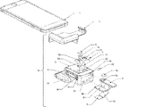
図3は、システム19およびシステム20の光学アダプタデバイス18の分解概略図である。デバイス18は、スマートフォン1の上部に適合するホルダケース2、容器スロット4、光学系チャンバ3C、レバー8がスライドするトラック6bおよび6t、ならびに容器スロット4を覆うためにトレンチ4sに挿入されたゴム製ドア16を含むケース2に取り付けられた光学ボックス3を備える。光学系インサート7は、光学系チャンバ3Cの上部に適合し、スマートフォン1の光源1Lおよびカメラ1C(図2-Bに示される)と整列する出口開口部7Lおよび入口開口部7Cを有する。レンズ11は、光学系インサート7の入射口7Cに設置され、容器スロット4に挿入された試料スライド5の試料がカメラ1Cの作動距離内に位置付けられるように構成されている(図2-Bおよび1-Bに示す)。レンズ11は、カメラ1C(図2-Bおよび1-Bに示される)により撮影された試料の画像を拡大するように機能する。ロングパス光学フィルタ12は、入射口7Cのレンズ11の上部に設置される。一対の直角ミラー13および14は、光学系チャンバ3Cの底部に設置され、ミラー13およびミラー14がそれぞれ光源1Lおよびカメラ1C(図2-Bおよび1-Bに示される)と整列するように構成されている。デバイス18における明視野照明光学系としての動作が以下の図4で説明されるミラー13およびミラー14。レバー8は2つのレベルバーを備え、上段のバーはスロット8aに設置された帯域通過光学フィルタ15を備え、下段のバーは水平面8b上に設置された光吸収体9および傾斜面8c上に設置された反射ミラー10を備える。デバイス18における蛍光照明光学系としての動作が以下の図5で説明される光学フィルタ15、光吸収体9、およびミラー10。レバー8の上段のバーはボックス3のトラック6tに沿ってスライドし、下段のバー8bおよび8cはボックス3のトラック6bに沿ってスライドする。レバー8は、ボックス3の2つの異なる位置で停止して、明視野照明光学系と蛍光照明光学系を切り替える。レバー8はボックス3に完全に挿入されて、デバイス18を切り替えて蛍光照明光学系で作動する。ボールプランジャ17はトラック6tの側壁に設置され、レバー8がボックス3から外側に引かれて明視野照明光学系で作動するようにデバイス18を切り替えるときに、レバー8を所定の位置で停止させる。
FIG. 3 is an exploded schematic view of
図4は、明視野照明モードで試料を試験するシステム20、特にデバイス18の詳細を示す断面概略図である。この図は、図3を参照して上述された要素の機能を図示する。レバー8(図3に示される)をデバイス18から外側に引き、ミラー13およびミラー14がカメラ1Cおよび光源1Lに曝され、かつそれらに整列するように、所定の位置でストッパ17(図3に示す)によって停止させる。光源1Lは、スマートフォン1から離れて光ビームBB1を放射する。ビームBB1は、ミラー14によって90度偏向されてビームBB2になり、ビームBB2は、ミラー13によってさらに90度偏向されてビームBB3になる。ビームBB3は、通常の入射角で試料スライド5の試料を裏側から照らす。レンズ11は、カメラ1Cの画像センサ平面上に試料の拡大画像を作成する。スマートフォン1は画像を撮影して処理して、試料のある特性を得る。
FIG. 4 is a cross-sectional schematic diagram showing details of
図5は、蛍光照明モードで試料を試験するシステム19、特にデバイス18の詳細を示す断面概略図である。この図は、図3を参照して上述された要素の機能を図示する。光吸収体9および傾斜ミラー10がカメラ1Cおよび光源1Lの視野下にあり、光源1Lと13および14の一対のミラーとの間の光路を遮断するように、レバー8(図3に示される)をデバイス18に完全に挿入する。そして、帯域通過光学フィルタ15は、光源1Lの真下にある。光源1Lは、スマートフォン1から離れて光ビームBF1を放射する。光学フィルタ15は、試料スライド5の蛍光試料の励起波長に一致する特定の波長範囲のビームBF1を通過させる。ビームBF1の一部は、透明な試料スライド5の縁部を照らし、試料スライド5を進む導波路ビームBF3に結合し、レンズ11下の試料領域を照らす。ビームBF1の一部はミラー10上を照らす。傾斜ミラー10は、ビームBF1をビームBF2に偏向し、レンズ11の真下の試料スライド5の試料領域を大きな傾斜角で裏側から照らす。大きな発散角のビームBF1の残りの部分(すなわち、ビームBF4)は吸収体9上を照らし、ビームBF4の反射光が小さな入射角でカメラ1Cに入らないように吸収される。レンズ11下の試料領域から来る光は、レンズ11を通過し、試料スライド5の蛍光試料によって放射される特定の波長範囲の光のみがカメラ1Cに入り、画像を形成するように、ロングパスフィルタ12によってフィルタ補正される。スマートフォン1は画像を撮影して処理して、試料のある特性を得る。ゴム製のドア16をデバイス18に挿入して試料スライド5を覆い、周囲光がデバイス18に入り試験に影響を与えるのを防ぐ。
FIG. 5 is a schematic cross-sectional view showing details of system 19, in
図6-Aおよび図6-Bは、デバイス18から外側に引いたときにレバー8を所定の位置で停止させる設計を示す断面概略図である。ボールプランジャ17はトラックスロット6tの側壁に設置され、溝8gはレバー8の側壁に穿設され、ボールプランジャ17のボールの形状と一致する形状である。レバー8をデバイス18から外側に引き、図6-Aに示すように所定の位置に達していない場合、ボールプランジャ17のボールは、レバー8がトラック6tに沿ってスライドすることができるように、レバー8の側壁によってその本体に押圧される。図6-Bに示すように、レバー8上の溝8gがボールプランジャ17の位置に達すると、ボールプランジャ17のボールは溝8gに入り、レバー8を停止させる。
6-A and 6-B are cross-sectional schematics showing a design that stops lever 8 in place when pulled outward from
図7は、QMAXデバイスを保持する試料スライダの構造の概略図である。試料スライダは、QMAXデバイスをスライドさせるトラックスロットを有するトラックフレーム、QMAXデバイスと一緒に移動してその移動を誘導するトラックスロットに予め組み込まれた可動アームを備える。QMAXデバイスを2つの所定の停止位置で停止させる停止機構を備えた可動アーム。トラックスロットの幅および高さは、QMAXデバイスがスライド方向に垂直な水平方向に0.5mm未満シフトし、QMAXデバイスの厚さ方向に沿って0.2mm未満シフトするように慎重に構成されている。 FIG. 7 is a schematic diagram of the structure of the sample slider holding the QMAX device. The sample slider comprises a track frame with a track slot into which the QMAX device slides, and a movable arm pre-loaded into the track slot that moves with the QMAX device and guides its movement. A movable arm with a stop mechanism that stops the QMAX device at two predetermined stop positions. The width and height of the track slots are carefully configured so that the QMAX device shifts less than 0.5 mm horizontally, perpendicular to the sliding direction, and less than 0.2 mm along the thickness of the QMAX device. .
図8は、2つの所定の停止位置間で切り替わる可動アームの概略図である。QMAXデバイスおよび可動アームを一緒にトラックスロットの端まで押圧してから放すことにより、QMAXカードは、QMAXデバイスをスライダから簡単に取り出すために試料領域がスマートフォンカメラの視野外にある位置1、または画像を撮影するために試料領域がスマートフォンカメラの視野の真下にある位置2のいずれかで停止することができる。
FIG. 8 is a schematic diagram of a movable arm switching between two predetermined rest positions. By pushing the QMAX device and movable arm together to the end of the track slot and then releasing, the QMAX card can be moved to
図9は、QMAXデバイスが正しい方向に挿入されているかどうかをスライダがどのように示すかの概略図である。QMAXデバイスの1つの角の形状は、他の3つの直角の角とは異なるように構成されている。また、可動アームの形状は、正しい方向においてのみ、QMAXデバイスがトラックスロットの正しい位置にスライドすることができるように、特殊な形状を有する角の形状と一致する。QMAXデバイスが裏返されるか、または反対側から挿入される場合、スライダの外側のQMAXデバイスの部分は、QMAXデバイスが正しく挿入されたときよりも長い。 FIG. 9 is a schematic illustration of how the slider indicates whether the QMAX device is inserted in the correct orientation. One corner shape of the QMAX device is configured differently than the other three right-angled corners. Also, the shape of the movable arm is matched with specially shaped corners so that the QMAX device can slide into the correct position in the track slot only in the correct direction. If the QMAX device is flipped over or inserted from the opposite side, the portion of the QMAX device outside the slider is longer than when the QMAX device is correctly inserted.
蛍光画像および明視野画像の両方が利用可能な場合、蛍光画像の知識を用いて明視野画像を処理するか、または明視野画像の知識を用いて蛍光画像を処理するか、または2つの画像をまとめて処理することができる。蛍光画像および明視野画像の視野は異なる場合があり、したがって、2つの画像は、画素ごとに空間的に整列されない。 If both fluorescence and brightfield images are available, either use knowledge of the fluorescence image to process the brightfield image, or use knowledge of the brightfield image to process the fluorescence image, or combine the two images. can be processed together. The fields of view of the fluorescence and brightfield images may be different, so the two images are not spatially aligned pixel-by-pixel.
蛍光画像と明視野画像との間のずれを解決するために、これら2つの画像に画像レジストレーションを適用することができる。画像レジストレーションは、ある画像から別の画像への空間的位置を関連付ける幾何学的変換を見つける。限定されないが、特徴点ベース、相互相関ベース、フーリエアライメントベースなどを含む様々な画像レジストレーションアルゴリズムを使用して、蛍光画像および明視野画像を整列することができる。画像レジストレーションは、ある画像から別の画像への空間的位置(座標)をマッピングする幾何学的変換を出力する。 Image registration can be applied to the two images to resolve the shift between the fluorescence and brightfield images. Image registration finds geometric transformations that relate spatial locations from one image to another. Various image registration algorithms can be used to align fluorescence and brightfield images including, but not limited to, feature point-based, cross-correlation-based, Fourier alignment-based, and the like. Image registration outputs a geometric transformation that maps spatial positions (coordinates) from one image to another.
蛍光画像および明視野画像を整列させた後、2つの画像の情報を利用して、1つの画像の処理を精密化するか、または2つの画像をまとめて処理することができる。 After aligning the fluorescence and brightfield images, the information in the two images can be used to refine the processing of one image or to process the two images together.
A1.
i.ホルダフレームと、
ii.ホルダフレームに取り外し可能に取り付けられている光学ボックスと、
を備え、
ホルダフレームが、モバイルデバイス上に取り外し可能に適合し、モバイルデバイスに組み込まれたカメラおよび照明源に光学ボックスを整列させるように構成され、
光学ボックスが、試料容器スロットおよび照明光学系を備える、光学アダプタ。
A1.
i. a holder frame;
ii. an optical box removably attached to the holder frame;
with
a holder frame configured to removably fit over the mobile device and align the optical box with a camera and illumination source incorporated in the mobile device;
An optical adapter, wherein the optical box comprises a sample container slot and illumination optics.
B1.
i.実施形態A1の光学アダプタと、
ii.第1のプレートおよび第2のプレートを備えるQMAXカードであって、第1のプレートおよび第2のプレートが、液体試料を200μm未満の均一な厚さの層に圧縮する、QMAXカードと、
iii.QMAXカードを収容し、光学ボックスにアサートされるように構成されたスライダと、
を備える、光学システム。
B1.
i. the optical adapter of embodiment A1;
ii. a QMAX card comprising a first plate and a second plate, wherein the first plate and the second plate compress the liquid sample into a layer of uniform thickness of less than 200 μm;
iii. a slider that accommodates the QMAX card and is configured to be asserted to the optics box;
An optical system comprising:
C1.モバイルデバイスがスマートフォンである、先行する実施形態のいずれかに記載のアダプタまたはシステム。 C1. An adapter or system as in any preceding embodiment, wherein the mobile device is a smart phone.
C2.ホルダフレームが、異なるモバイルデバイスに対して異なるサイズを有する他のホルダケースと交換可能であるように構成されたホルダケースを備える、先行する実施形態のいずれかに記載のアダプタまたはシステム。 C2. An adapter or system as in any of the preceding embodiments, wherein the holder frame comprises a holder case configured to be interchangeable with other holder cases having different sizes for different mobile devices.
C3.ホルダフレームが、光学アダプタをモバイルデバイスの上部に取り外し可能に適合するサイズである、先行する実施形態のいずれかに記載のアダプタまたはシステム。 C3. An adapter or system according to any of the preceding embodiments, wherein the holder frame is sized to removably fit the optical adapter on top of the mobile device.
C4.光学アダプタの光学ボックスが、
i.QMAXカードを受容しカメラの視野および焦点範囲の試料スライドに位置付けるように構成された、容器スロットと、
ii.試料の明視野顕微鏡画像を撮影するように構成された明視野照明光学系と、
iii.試料の蛍光顕微鏡画像を撮像するように構成された蛍光照明光学系と、
iv.光学ボックス内で内側および外側にスライドさせることにより、明視野照明光学系と蛍光照明光学系を切り替えるように構成されたレバーと、
を備える、先行する実施形態のいずれかに記載のアダプタまたはシステム。
C4. The optical box of the optical adapter is
i. a container slot configured to receive a QMAX card and position it on the sample slide in the camera's field of view and focus range;
ii. brightfield illumination optics configured to capture a brightfield microscope image of the sample;
iii. fluorescence illumination optics configured to capture a fluorescence microscope image of the sample;
iv. a lever configured to switch between brightfield and fluorescence illumination optics by sliding in and out within the optics box;
An adapter or system as in any of the preceding embodiments, comprising:
C5.容器スロットが、スロットを完全に覆い、周囲光が光学ボックスに入りカメラによって収集されるのを防ぐことができるゴム製のドアを備える、先行する実施形態のいずれかに記載のアダプタまたはシステム。 C5. An adapter or system according to any of the preceding embodiments, wherein the container slot comprises a rubber door that can completely cover the slot and prevent ambient light from entering the optical box and being collected by the camera.
C6.アダプタの明視野照明光学系が、通常の入射角で試料を裏側から照らすために、光源により放射されたビームを受光するようにおよびその方向を変えるように構成されている、先行する実施形態のいずれかに記載のアダプタまたはシステム。 C6. of the preceding embodiment, wherein the brightfield illumination optics of the adapter are configured to receive and redirect the beam emitted by the light source to back-illuminate the sample at a normal angle of incidence. Any of the described adapters or systems.
C7.光学ボックスが、それに設置され、モバイルデバイスのカメラと整列され、カメラによって撮影された画像を拡大するレンズをさらに備える、先行する実施形態のいずれかに記載のアダプタまたはシステム。 C7. An adapter or system as in any of the preceding embodiments, wherein the optical box further comprises a lens mounted therein and aligned with the camera of the mobile device to magnify images taken by the camera.
C8.カメラによって撮影された画像が、モバイルデバイスのプロセッサによってさらに処理され、モバイルデバイスの画面に分析結果を出力する、先行する実施形態のいずれかに記載のアダプタまたはシステム。 C8. An adapter or system according to any of the preceding embodiments, wherein the images captured by the camera are further processed by the mobile device's processor and output the analysis results to the mobile device's screen.
C9.レベルがスライド可能であり、同じ光学アダプタ内で明視野照明および蛍光照明の両方の光学系を実現するように構成されている、先行する実施形態のいずれかに記載のアダプタまたはシステム。 C9. An adapter or system according to any of the preceding embodiments, wherein the level is slidable and configured to provide both brightfield and fluorescence illumination optics within the same optical adapter.
C10.蛍光照明光学系の光学素子が、レバーに設置されており、レバーが光学ボックス内に完全にスライドすると、先行する実施形態のいずれかに記載のアダプタまたはシステム。 C10. An adapter or system as in any of the preceding embodiments, wherein the optics of the fluorescence illumination optics are mounted on a lever, the lever sliding fully into the optics box.
C11.蛍光照明光学系素子を有するレバーが、明視野照明光学系の光路を遮断し、照明光学系を蛍光照明光学系に切り替える、先行する実施形態のいずれかに記載のアダプタまたはシステム。 C11. An adapter or system according to any of the preceding embodiments, wherein a lever with fluorescence illumination optics interrupts the optical path of the brightfield illumination optics and switches the illumination optics to fluorescence illumination optics.
C12.レバーが外にスライドすると、レバー上に設置された蛍光照明光学系素子が光路から出て、照明光学系を明視野照明光学系に切り替える、先行する実施形態のいずれかに記載のアダプタまたはシステム。 C12. An adapter or system according to any of the preceding embodiments, wherein the lever slides out to move the fluorescence illumination optics element mounted on the lever out of the optical path, switching the illumination optics to bright field illumination optics.
C13.レバーが、異なる高さの2つの平面を備える、先行する実施形態のいずれかに記載のアダプタまたはシステム。 C13. An adapter or system according to any of the preceding embodiments, wherein the lever comprises two planes of different heights.
C14.2つの平面が、垂直バーで一緒に接合され、光学ボックスの内外に一緒に移動する、先行する実施形態のいずれかに記載のアダプタまたはシステム。 C14. An adapter or system according to any of the preceding embodiments, wherein the two planes are joined together by a vertical bar and move together in and out of the optical box.
C15.2つの平面が分離され得、各平面が個別に光学ボックスの内外に移動することができる、先行する実施形態のいずれかに記載のアダプタまたはシステム。 C15. An adapter or system according to any of the preceding embodiments, wherein the two planes can be separated and each plane can be individually moved in and out of the optical box.
C16.上部レバー平面が、限定されないが、光学フィルタであり得る、少なくとも1つの光学素子を備える、先行する実施形態のいずれかに記載のアダプタまたはシステム。 C16. An adapter or system according to any of the preceding embodiments, wherein the upper lever plane comprises at least one optical element, which can be, but is not limited to, an optical filter.
C17.上部レバー平面が、光源の下を移動し、上部レバー平面と光源との間の好ましい距離が0~5mmの範囲である、先行する実施形態のいずれかに記載のアダプタまたはシステム。 C17. An adapter or system according to any of the preceding embodiments, wherein the upper lever plane moves under the light source and the preferred distance between the upper lever plane and the light source is in the range of 0-5 mm.
C18.下部レバー平面の一部が、画像平面に平行ではない、先行する実施形態のいずれかに記載のアダプタまたはシステム。 C18. An adapter or system according to any of the preceding embodiments, wherein a portion of the lower lever plane is non-parallel to the image plane.
C19.底部レバー平面の非平行部分の表面が、95%を超える高反射率の鏡面仕上げである、先行する実施形態のいずれかに記載のアダプタまたはシステム。 C19. An adapter or system according to any of the preceding embodiments, wherein the surface of the non-parallel portion of the bottom lever plane has a high reflectivity greater than 95% mirror finish.
C20.底部レバー平面の非平行部分が、光源の下を移動し、光源から放射された光を偏向して、カメラの真下の試料領域を裏側から照らす、先行する実施形態のいずれかに記載のアダプタまたはシステム。 C20. An adapter according to any of the preceding embodiments, wherein a non-parallel portion of the bottom lever plane moves under the light source and deflects the light emitted by the light source to back-illuminate the sample area directly below the camera or system.
C21.底部レバー平面の非平行部分の好ましい傾斜角が45度~65度の範囲であり、傾斜角が非平行底平面と垂直面との間の角度として定義される、先行する実施形態のいずれかに記載のアダプタまたはシステム。 C21. Any of the preceding embodiments, wherein the preferred tilt angle of the non-parallel portions of the bottom lever planes is in the range of 45 degrees to 65 degrees, wherein the tilt angle is defined as the angle between the non-parallel bottom planes and the vertical plane. Any adapter or system listed.
C22.底部レバー平面の一部が、画像平面と平行であり、試料の下に位置し、試料から1mm~10mm離れている、先行する実施形態のいずれかに記載のアダプタまたはシステム。 C22. An adapter or system according to any of the preceding embodiments, wherein a portion of the bottom lever plane is parallel to the image plane, under the sample and 1 mm to 10 mm away from the sample.
C23.底部レバー平面の平行部分の表面が、高光吸収性であり、95%を超える光吸収率を有する、先行する実施形態のいずれかに記載のアダプタまたはシステム。 C23. An adapter or system according to any of the preceding embodiments, wherein the surface of the parallel portion of the bottom lever plane is highly light absorbing, having a light absorption rate of greater than 95%.
C24.吸収性表面が、小さな入射角で試料に対して裏側から照らす反射光を排除するためのものである、先行する実施形態のいずれかに記載のアダプタまたはシステム。 C24. An adapter or system according to any of the preceding embodiments, wherein the absorptive surface is for rejecting reflected light back-illuminating the sample at small angles of incidence.
C25.レバーが、レバーを停止するように構成されたストッパを備える、先行する実施形態のいずれかに記載のアダプタまたはシステム。 C25. An adapter or system as in any of the preceding embodiments, wherein the lever comprises a stop configured to stop the lever.
C26.ストッパがボールプランジャを備え、アダプタから外側に引いたときにレバーを所定の位置で停止させるために、レバー上の溝が使用される、先行する実施形態のいずれかに記載のアダプタまたはシステム。 C26. An adapter or system as in any of the preceding embodiments, wherein the stopper comprises a ball plunger and a groove on the lever is used to stop the lever in place when pulled outwardly from the adapter.
C27.ストッパが、ユーザが任意の力でレバーを引くことができるが、光学アダプタの作動モードが明視野照明に切り替わる固定位置でレバーを停止させることができるように構成されている、先行する実施形態のいずれかに記載のアダプタまたはシステム。 C27. of the preceding embodiment, wherein the stop is configured to allow the user to pull the lever with any force, but to stop the lever in a fixed position where the operating mode of the optical adapter switches to bright field illumination; Any of the described adapters or systems.
C28.試料スライダが、QMAXデバイスを受容するように容器スロット内に設置され、スマートフォンカメラの視野および焦点範囲内でQMAXデバイスに試料を位置付ける、先行する実施形態のいずれかに記載のアダプタまたはシステム。 C28. An adapter or system according to any of the preceding embodiments, wherein a sample slider is installed in the container slot to receive the QMAX device and positions the sample on the QMAX device within the field of view and focus range of a smartphone camera.
C29.可動アームが、QMAXデバイスおよび可動アームを一緒にトラックスロットの端まで押圧してから放すことにより、2つの停止位置を切り替える、先行する実施形態のいずれかに記載のアダプタまたはシステム。 C29. An adapter or system according to any of the preceding embodiments, wherein the movable arm switches between two rest positions by pushing the QMAX device and the movable arm together to the end of the track slot and then releasing.
C30.可動アームが、QMAXデバイスが正しい方向に挿入されているかどうかを示すことができる、先行する実施形態のいずれかに記載のアダプタまたはシステム。 C30. An adapter or system as in any of the preceding embodiments, wherein the movable arm can indicate whether the QMAX device is inserted in the correct orientation.
C31.QMAXデバイスの1つの角の形状が、他の3つの直角の角とは異なるように構成されている、先行する実施形態のいずれかに記載のアダプタまたはシステム。 C31. An adapter or system as in any of the preceding embodiments, wherein the shape of one corner of the QMAX device is configured differently than the other three right-angled corners.
C31.可動アームの形状が、正しい方向においてのみ、QMAXデバイスがトラックスロットの正しい位置にスライドすることができるように、特殊な形状を有する角の形状と一致する、先行する実施形態のいずれかに記載のアダプタまたはシステム。 C31. 12. Any of the preceding embodiments, wherein the shape of the movable arm matches the shape of the specially shaped corners so that the QMAX device can slide into the correct position in the track slot only in the correct direction. adapter or system.
C32.スライダが、固定されたトラックフレームと、可動アームと、を備える、先行する実施形態のいずれかに記載のアダプタまたはシステム。 C32. An adapter or system according to any of the preceding embodiments, wherein the slider comprises a fixed track frame and a movable arm.
C33.フレームトラックが、光学ボックスの容器スロットに固定して設置されており、トラックフレームが、QMAXデバイスがトラックに沿ってスライドすることができるように、QMAXデバイスの幅および厚さに適合するスライド式トラックスロットを有する、先行する実施形態のいずれかに記載のアダプタまたはシステム。トラックスロットの幅および高さは、QMAXデバイスがスライド平面においてスライド方向に垂直な方向に0.5mm未満シフトし、QMAXデバイスの厚さ方向に沿って0.2mm未満シフトするように慎重に構成されている。 C33. A sliding track in which the frame track is fixedly installed in the container slot of the optics box and the track frame adapts to the width and thickness of the QMAX device so that the QMAX device can slide along the track. An adapter or system as in any preceding embodiment having a slot. The width and height of the track slots are carefully configured so that the QMAX device shifts in the plane of the slide by less than 0.5 mm perpendicular to the sliding direction and by less than 0.2 mm along the thickness of the QMAX device. ing.
C34.フレームトラックが、スマートフォンのカメラの視野の下に開かれたウィンドウを有し、光が試料を裏側から照らすことを可能にする、先行する実施形態のいずれかに記載のアダプタまたはシステム。 C34. An adapter or system according to any of the preceding embodiments, wherein the frame track has a window that opens under the field of view of the smartphone's camera to allow light to illuminate the sample from behind.
C35.可動アームが、トラックフレームのスライド式トラックスロットに予め組み込まれており、QMAXデバイスと一緒に移動して、トラックフレーム内のQMAXデバイスの移動を誘導する、先行する実施形態のいずれかに記載のアダプタまたはシステム。 C35. An adapter according to any of the preceding embodiments, wherein the movable arm is pre-installed in a sliding track slot of the track frame and moves with the QMAX device to guide movement of the QMAX device within the track frame. or system.
C36.可動アームが、2つの所定の停止位置を有する停止機構を備える、先行する実施形態のいずれかに記載のアダプタまたはシステム。 C36. An adapter or system according to any of the preceding embodiments, wherein the movable arm comprises a stop mechanism with two predetermined stop positions.
B.スマートフォンへの比色リーダーアタッチメント用の光学アダプタ(傾斜ファイバ端照明)
比色アッセイは、健康監視、疾患診断、化学分析などに広く応用されている非常に強力な技術である。正確な比色アッセイ結果を得るための重要な要素は、色の変化を正確に定量化することである。従来、比色試験ストリップの色の変化は、色の変化を標準の色見本と比較することによって分析される。しかし、この比較は人間の目で行われ、環境の光条件によって容易に影響を受け、色の変化を定量化する精度が制限される。
B. Optical adapter for colorimetric reader attachment to smartphones (tilted fiber end illumination)
Colorimetric assays are very powerful techniques that are widely applied in health monitoring, disease diagnosis, chemical analysis, etc. A key factor in obtaining accurate colorimetric assay results is the accurate quantification of the color change. Conventionally, the color change of colorimetric test strips is analyzed by comparing the color change to standard color swatches. However, this comparison is made by the human eye and is easily affected by environmental lighting conditions, limiting the accuracy with which color changes can be quantified.
本明細書で説明する本発明は、光学アダプタおよびスマートフォンを備えるシステムを提供することにより、この問題に対処する。光学アダプタデバイスは、スマートフォンに適合し、スマートフォンを、一貫した均一な照明を提供して比色試験カードの前面を照らし、試料の画像を撮影して色の変化を分析することができる比色リーダーに変換する。このシステムは、あらゆる場所で一般の人々が便利にかつ確実に操作することができる。光学アダプタは、カメラ、光源、プロセッサ、およびディスプレイ画面を含むスマートフォンの既存のリソースを活用し、比色アッセイの色の変化を正確に定量化する低コストのソリューションを提供する。 The invention described herein addresses this problem by providing a system comprising an optical adapter and a smart phone. The optical adapter device fits into a smart phone and turns the smart phone into a colorimetric reader that can provide consistent, uniform illumination to illuminate the front of the colorimetric test card, take an image of the sample and analyze the color change. Convert to The system can be conveniently and reliably operated by ordinary people at any location. The optical adapter leverages the smartphone's existing resources, including cameras, light sources, processors, and display screens, to provide a low-cost solution to accurately quantify color changes in colorimetric assays.
本発明において、光学アダプタデバイスは、スマートフォンの上部に適合するホルダフレームと、試料容器スロットおよび照明光学系を有するホルダに取り付けられた光学ボックスとを備える。スマートフォン用のアタッチメントアダプタのいくつかの先行技術では、それらのアダプタ設計は、スマートフォンに適合するクリップオン機構部品および機能性要素の両方を含む一体部品である。この設計には、スマートフォンの特定のモデルごとに一体部品のアダプタを再設計する必要があるという問題がある。しかし、本発明では、光学アダプタは、スマートフォンに適合させるためのみのホルダフレームと、すべての機能部品を含む汎用光学ボックスとに分離される。寸法の異なるスマートフォンの場合、カメラおよび光源の相対位置が同じである限り、ホルダフレームしか再設計する必要がなく、設計および製造のコストを大幅に削減する。 In the present invention, the optical adapter device comprises a holder frame that fits on top of a smart phone and an optical box attached to the holder with sample container slots and illumination optics. In some prior art attachment adapters for smartphones, their adapter design is a unitary piece that includes both clip-on mechanical components and functional elements that fit the smartphone. The problem with this design is that the one-piece adapter needs to be redesigned for each specific model of smartphone. However, in the present invention, the optical adapter is separated into a holder frame only to fit the smart phone and a universal optical box containing all functional parts. For smartphones with different dimensions, only the holder frame needs to be redesigned, as long as the relative positions of the camera and the light source are the same, greatly reducing the design and manufacturing costs.
光学アダプタの光学ボックスは、比色試料を受容しそれをスマートフォンのカメラの視野および焦点範囲に位置付ける容器スロットと、任意の外部条件とは無関係に試料上に均一かつ一貫した照明を作り出し、試料画像を撮影するための照明および撮像光学系とを備える。 The optical box of the optical adapter, with a container slot that receives the colorimetric sample and positions it in the field of view and focus range of the smartphone's camera, creates a uniform and consistent illumination on the sample independent of any external conditions, resulting in a sample image. and an illumination and imaging optical system for photographing.
色の変化を正確に表す試料画像を撮影するには、カメラの下の試料領域が均一に照明されることが望ましい。しかし、すべての一般的なスマートフォンでは、光源とカメラとの間には常に距離がある。追加の照明光学系なしに試料をスマートフォンのカメラの非常に近くに設置すると、領域は光源によって均一に正面から照らされ得、光源の真下にあるが、カメラの視野内にはない。この問題を解決するために、本発明では、傾斜した大型コア光ファイバを使用して、光源から放射される光ビームの方向を変えて、カメラの真下の試料領域を均一に照らす。 Uniform illumination of the sample area under the camera is desirable to capture an image of the sample that accurately represents color changes. However, in all popular smartphones there is always some distance between the light source and the camera. By placing the sample very close to the smartphone's camera without additional illumination optics, an area can be uniformly front-lit by the light source, directly below the light source, but not within the camera's field of view. To solve this problem, the present invention uses a tilted large-core optical fiber to redirect the light beam emitted by the light source to uniformly illuminate the sample area beneath the camera.
また、より均一な照明を作り出すために、スマートフォンのLED点光源からではなく、面光源からの光ビームが望ましい。この目的のために、光ファイバの端面の前に設置される別個の拡散体が提供され得るが、このアプローチは光学アダプタの要素を増やし、コストを増加させる。代わりに、本発明では、光ファイバの両端面は、試料に向かう端面が試料上により均一な照明を生成する面光源となり得るように、拡散体として機能する艶消し仕上げである。 Also, a light beam from an area light source rather than from a smart phone LED point light source is desirable to create a more uniform illumination. A separate diffuser placed in front of the end face of the optical fiber can be provided for this purpose, but this approach increases the elements of the optical adapter and increases its cost. Instead, in the present invention, both ends of the optical fiber have a matte finish that acts as a diffuser so that the end facing the sample can be an area light source that produces a more uniform illumination on the sample.
典型的には、光学ボックスは、それに設置され、スマートフォンのカメラと整列するレンズも備え、これにより試料がカメラの焦点範囲内となる。カメラで撮影された画像は、色の変化を分析するためにスマートフォンのプロセッサによりさらに処理され、分析結果がスマートフォンの画面に出力される。 Typically, the optics box also has a lens mounted on it and aligned with the smartphone camera so that the sample is within the camera's focal range. The image captured by the camera is further processed by the smartphone's processor to analyze the color change, and the analysis results are output on the smartphone's screen.
試料スライダは、QMAXデバイスを受容するように容器スロット内に設置され、スマートフォンカメラの視野および焦点範囲内にQMAXデバイスに試料を位置付ける。 A sample slider is placed in the container slot to receive the QMAX device and positions the sample on the QMAX device within the field of view and focus range of the smartphone camera.
試料スライダは、固定されたトラックフレームと、可動アームとを備える。 The specimen slider comprises a fixed track frame and a movable arm.
フレームトラックは、光学ボックスの容器スロットに固定して設置されている。また、トラックフレームは、QMAXデバイスがトラックに沿ってスライドすることができるように、QMAXデバイスの幅および厚さに適合するスライド式トラックスロットを有する。トラックスロットの幅および高さは、QMAXデバイスがスライド平面においてスライド方向に垂直な方向に0.5mm未満シフトし、QMAXデバイスの厚さ方向に沿って0.2mm未満シフトするように慎重に構成されている。 The frame track is fixedly installed in the container slot of the optics box. The track frame also has sliding track slots that match the width and thickness of the QMAX device so that the QMAX device can slide along the track. The width and height of the track slots are carefully configured so that the QMAX device shifts in the plane of the slide by less than 0.5 mm perpendicular to the sliding direction and by less than 0.2 mm along the thickness of the QMAX device. ing.
フレームトラックには、スマートフォンのカメラの視野の下に開かれたウィンドウがあり、光が試料を裏側から照らすことを可能にする。 The frame track has a window that opens below the field of view of the smartphone camera, allowing light to illuminate the sample from behind.
可動アームは、トラックフレームのスライド式トラックスロットに予め組み込まれており、QMAXデバイスと一緒に移動して、トラックフレーム内のQMAXデバイスの移動を誘導する。 A movable arm is pre-installed in a sliding track slot in the track frame and moves with the QMAX device to guide movement of the QMAX device within the track frame.
2つの所定の停止位置を有する停止機構を備えた可動アーム。1つの位置では、QMAXデバイス上の固定された試料領域がスマートフォンのカメラの真下にある位置でアームがQMAXデバイスを停止させる。もう一方の位置では、QMAXデバイス上の試料領域がスマートフォンの視野から外れた位置でアームがQMAXデバイスを停止させ、QMAXデバイスをトラックスロットから簡単に取り出すことができる。 A movable arm with a stop mechanism having two predetermined stop positions. In one position, the arm stops the QMAX device in a position where the fixed sample area on the QMAX device is directly below the smartphone's camera. In the other position, the arm stops the QMAX device at a position where the sample area on the QMAX device is out of the field of view of the smart phone, allowing the QMAX device to be easily removed from the track slot.
可動アームは、QMAXデバイスおよび可動アームを一緒にトラックスロットの端まで押圧してから放すことにより、2つの停止位置を切り替える。 The moveable arm switches between two rest positions by pushing the QMAX device and moveable arm together to the end of the track slot and then releasing.
可動アームは、QMAXデバイスが正しい方向に挿入されているかどうかを示すことができる。QMAXデバイスの1つの角の形状は、他の3つの直角の角とは異なるように構成されている。また、可動アームの形状は、正しい方向においてのみ、QMAXデバイスがトラックスロットの正しい位置にスライドすることができるように、特殊な形状を有する角の形状と一致する。 A movable arm can indicate whether the QMAX device is inserted in the correct orientation. One corner shape of the QMAX device is configured differently than the other three right-angled corners. Also, the shape of the movable arm is matched with specially shaped corners so that the QMAX device can slide into the correct position in the track slot only in the correct direction.
図10-A、10-B、および10-Cは、スマートフォン比色リーダーのシステム10の概略図である。特に、図10-Bおよび10-Cは、システム10の分解図であり、それぞれ正面および背面から示される。システム10は、スマートフォン1、スマートフォン1の上部に適合する光学アダプタデバイス13、試料カード137上の試料領域がスマートフォン1のカメラモジュール1Cの視野および焦点範囲内に位置付けられるようにデバイス13の容器スロット136に挿入される比色試験カード137を備える。スマートフォン1にインストールされたソフトウェア(図示せず)は、比色試験の色の変化を分析するために、スマートフォン1の光源1Lが光を放射している間にカメラモジュール1Cによって収集された画像を分析し、結果をスマートフォン1のディスプレイ画面1fに出力する。
10-A, 10-B, and 10-C are schematic diagrams of
図11は、システム10の光学アダプタデバイス13の分解概略図である。デバイス13は、スマートフォン1の上部に適合するホルダケース131、容器スロット136を含むケース131に取り付けられた光学ボックス132、光学系チャンバ132Cを備える。光学系インサート134は、光学系チャンバ132Cの上部に適合し、スマートフォン1の光源1Lおよびカメラ1C(図10-Bに示される)と整列する出口開口部134Lおよび入口開口部134Cを有する。レンズ133は、光学系インサート134の入口開口部134Cに設置され、容器スロット136に挿入される比色試料カード137上の試料領域がカメラ1C(図10-Bに示される)の作動距離内に位置するように構成されている。大型コア光ファイバ135は、傾斜角で出口開口部134Lに設置される。ファイバ135の両端面は、艶消し仕上げである。デバイス13において照明光学系として動作するファイバ135が以下の図B3で説明される。
FIG. 11 is an exploded schematic view of
図12は、比色カードを読み取るシステム10、特にデバイス13の詳細を示す断面概略図である。この図は、図11を参照して上述された要素の機能を図示する。光源1Lは、スマートフォン1から離れて光ビームB1を放射する。ビームB1は、第1の端面を通してファイバ135に結合され、ファイバ135の方向に沿って進み、第2の端面から放射されてビームB2になる。ビームB2は、カメラ1Cの真下の比色試料カード137の試料領域を正面から照らし、均一な照明を作り出す。ファイバ135の端面は艶消しおよび拡散仕上げされているため、ビームB2は面光源からの放射とみなすことができ、より均一な照明を作り出すのに役立つ。ファイバ135が設置される傾斜角は、カメラの真下の試料カード137の領域上にビームB2照明の中央トレイを作るように設定される。レンズ11は、カメラ1Cの画像センサ平面上に試料領域の画像を作り出す。スマートフォン1は、画像を取得して処理し、画像の色情報を分析して、比色アッセイの色の変化を定量化する。
FIG. 12 is a schematic cross-sectional view showing details of the
C.スマートフォンへの比色リーダーアタッチメント用の光学アダプタ(ファイバリング照明)
比色アッセイは、健康監視、疾患診断、化学分析などに広く応用されている非常に強力な技術である。正確な比色アッセイ結果を得るための重要な要素は、色の変化を正確に定量化することである。従来、比色試験ストリップの色の変化は、色の変化を標準の色見本と比較することによって分析される。しかし、この比較は人間の目で行われ、環境の光条件によって容易に影響を受け、色の変化を定量化する精度が制限される。
C. Optical adapter for colorimetric reader attachment to smartphones (fiber ring illumination)
Colorimetric assays are very powerful techniques that are widely applied in health monitoring, disease diagnosis, chemical analysis, etc. A key factor in obtaining accurate colorimetric assay results is the accurate quantification of the color change. Conventionally, the color change of colorimetric test strips is analyzed by comparing the color change to standard color swatches. However, this comparison is made by the human eye and is easily affected by environmental lighting conditions, limiting the accuracy with which color changes can be quantified.
本明細書で説明する本発明は、光学アダプタおよびスマートフォンを備えるシステムを提供することにより、この問題に対処する。光学アダプタデバイスは、スマートフォンに適合し、スマートフォンを、一貫した均一な照明を提供して比色試験カードの前面を照らし、試料の画像を撮影して色の変化を分析することができる比色リーダーに変換する。このシステムは、あらゆる場所で一般の人々が便利にかつ確実に操作することができる。光学アダプタは、カメラ、光源、プロセッサ、およびディスプレイ画面を含むスマートフォンの既存のリソースを活用し、比色アッセイの色の変化を正確に定量化する低コストのソリューションを提供する。 The invention described herein addresses this problem by providing a system comprising an optical adapter and a smart phone. The optical adapter device fits into a smart phone and turns the smart phone into a colorimetric reader that can provide consistent, uniform illumination to illuminate the front of the colorimetric test card, take an image of the sample and analyze the color change. Convert to The system can be conveniently and reliably operated by ordinary people at any location. The optical adapter leverages the smartphone's existing resources, including cameras, light sources, processors, and display screens, to provide a low-cost solution to accurately quantify color changes in colorimetric assays.
本発明において、光学アダプタデバイスは、スマートフォンの上部に適合するホルダフレームと、試料容器スロットおよび照明光学系を有するホルダに取り付けられた光学ボックスとを備える。スマートフォン用のアタッチメントアダプタのいくつかの先行技術では、それらのアダプタ設計は、スマートフォンに適合するクリップオン機構部品および機能性要素の両方を含む一体部品である。この設計には、スマートフォンの特定のモデルごとに一体部品のアダプタを再設計する必要があるという問題がある。しかし、本発明では、光学アダプタは、スマートフォンに適合させるためのみのホルダフレームと、すべての機能部品を含む汎用光学ボックスとに分離される。寸法の異なるスマートフォンの場合、カメラおよび光源の相対位置が同じである限り、ホルダフレームしか再設計する必要がなく、設計および製造のコストを大幅に削減する。 In the present invention, the optical adapter device comprises a holder frame that fits on top of a smart phone and an optical box attached to the holder with sample container slots and illumination optics. In some prior art attachment adapters for smartphones, their adapter design is a unitary piece that includes both clip-on mechanical components and functional elements that fit the smartphone. The problem with this design is that the one-piece adapter needs to be redesigned for each specific model of smartphone. However, in the present invention, the optical adapter is separated into a holder frame only to fit the smart phone and a universal optical box containing all functional parts. For smartphones with different dimensions, only the holder frame needs to be redesigned, as long as the relative positions of the camera and the light source are the same, greatly reducing the design and manufacturing costs.
光学アダプタの光学ボックスは、比色試料を受容しそれをスマートフォンのカメラの視野および焦点範囲に位置付ける容器スロットと、任意の外部条件とは無関係に試料上に均一かつ一貫した照明を作り出し、試料画像を撮影するための照明および撮像光学系とを備える。 The optical box of the optical adapter, with a container slot that receives the colorimetric sample and positions it in the field of view and focus range of the smartphone's camera, creates a uniform and consistent illumination on the sample independent of any external conditions, resulting in a sample image. and an illumination and imaging optical system for photographing.
色の変化を正確に表す試料画像を撮影するには、カメラの下の試料領域が均一に照明されることが望ましい。しかし、すべての一般的なスマートフォンでは、光源は、常に点光源であり、カメラの隣にある程度の距離を置いて設置されている、つまり、光源はカメラに対して中心対称ではない。これにより、追加の照明光学系の補助なしに試料をスマートフォンのカメラの非常に近くに設置すると、カメラの視野内の試料の前面の照明パターンに、直線方向における勾配強度の変化があるという問題が生じる。したがって、大きな放射面積を有し、カメラに対して中心対称の光源を作り出すことが望ましい。この目的を達成するために、本発明では、プラスチックの側面放射型ファイバリングをスマートフォンのカメラの周りに置いて、ファイバリングをカメラに対して中心対称にする。また、ファイバリングの2つの端面は、スマートフォンの光源に向かって設置される。これにより、元の単一点光源は、スマートフォンのカメラから等しい距離で円上に分散された、ほぼ等しい光度を有する無数の小さな光源に変換される。リングファイバの側壁から放射された光はさらに拡散膜を通過して放射面積を増やし、照明をより均一にする。カメラの真下の試料領域は、側面放射型ファイバリングに基づいて設計された照明光学系によって均一に正面から照らされる。 Uniform illumination of the sample area under the camera is desirable to capture an image of the sample that accurately represents color changes. However, in all common smartphones, the light source is always a point light source and placed next to the camera at some distance, i.e. the light source is not centrosymmetric with respect to the camera. This leads to the problem that when the sample is placed very close to the smartphone camera without the aid of additional illumination optics, the illumination pattern in front of the sample in the camera's field of view has gradient intensity variations in the linear direction. occur. Therefore, it is desirable to create a light source that has a large emissive area and is centrosymmetric with respect to the camera. To this end, in the present invention, a plastic side-emitting fiber ring is placed around the smartphone's camera to make the fiber ring centrosymmetric with respect to the camera. Also, the two end faces of the fiber ring are placed facing the light source of the smart phone. This transforms the original single point light source into a myriad of small light sources with approximately equal luminosity distributed on a circle at equal distances from the smartphone camera. Light emitted from the sidewalls of the ring fiber further passes through the diffusion film to increase the emission area and make the illumination more uniform. The sample area beneath the camera is uniformly front-illuminated by an illumination optics designed based on a side-emitting fiber ring.
比色試料の色がどのように表されるかは照明条件に大きく依存するため、光学ボックス内の照明をあらゆる外部光条件とは無関係に一貫して制御することが重要である。この問題を解決するために、容器スロットにはゴム製のドアが取り付けられており、スロットを完全に覆い、光学ボックスに入ってくる環境光により照明条件が変化するのを防ぐことができる。 Since how the color of a colorimetric sample is represented is highly dependent on the lighting conditions, it is important to consistently control the illumination within the optical box independent of any external light conditions. To solve this problem, the container slot is fitted with a rubber door that completely covers the slot and prevents ambient light entering the optical box from altering the lighting conditions.
典型的には、光学ボックスは、それに設置され、スマートフォンのカメラと整列するレンズも備え、これにより試料がカメラの焦点範囲内となる。カメラで撮影された画像は、色の変化を分析するためにスマートフォンのプロセッサによりさらに処理され、分析結果がスマートフォンの画面に出力される。 Typically, the optics box also has a lens mounted on it and aligned with the smartphone camera so that the sample is within the camera's focal range. The image captured by the camera is further processed by the smartphone's processor to analyze the color change, and the analysis results are output on the smartphone's screen.
試料スライダは、QMAXデバイスを受容するように容器スロット内に設置され、スマートフォンカメラの視野および焦点範囲内にQMAXデバイスの試料を位置付ける。 A sample slider is placed in the container slot to receive the QMAX device and positions the sample of the QMAX device within the field of view and focus range of the smartphone camera.
試料スライダは、固定されたトラックフレームと、可動アームとを備える。 The specimen slider comprises a fixed track frame and a movable arm.
フレームトラックは、光学ボックスの容器スロットに固定して設置されている。また、トラックフレームは、QMAXデバイスがトラックに沿ってスライドすることができるように、QMAXデバイスの幅および厚さに適合するスライド式トラックスロットを有する。トラックスロットの幅および高さは、QMAXデバイスがスライド平面においてスライド方向に垂直な方向に0.5mm未満シフトし、QMAXデバイスの厚さ方向に沿って0.2mm未満シフトするように慎重に構成されている。 The frame track is fixedly installed in the container slot of the optics box. The track frame also has sliding track slots that match the width and thickness of the QMAX device so that the QMAX device can slide along the track. The width and height of the track slots are carefully configured so that the QMAX device shifts in the plane of the slide by less than 0.5 mm perpendicular to the sliding direction and by less than 0.2 mm along the thickness of the QMAX device. ing.
フレームトラックには、スマートフォンのカメラの視野の下に開かれたウィンドウがあり、光が試料を裏側から照らすことを可能にする。 The frame track has a window that opens below the field of view of the smartphone camera, allowing light to illuminate the sample from behind.
可動アームは、トラックフレームのスライド式トラックスロットに予め組み込まれており、QMAXデバイスと一緒に移動して、トラックフレーム内のQMAXデバイスの移動を誘導する。 A movable arm is pre-installed in a sliding track slot in the track frame and moves with the QMAX device to guide movement of the QMAX device within the track frame.
2つの所定の停止位置を有する停止機構を備えた可動アーム(「レバー」とも呼ばれる)。1つの位置では、QMAXデバイス上の固定された試料領域がスマートフォンのカメラの真下にある位置でアームがQMAXデバイスを停止させる。もう一方の位置では、QMAXデバイス上の試料領域がスマートフォンの視野から外れた位置でアームがQMAXデバイスを停止させ、QMAXデバイスをトラックスロットから簡単に取り出すことができる。 A movable arm (also called a "lever") with a stop mechanism with two predetermined stop positions. In one position, the arm stops the QMAX device in a position where the fixed sample area on the QMAX device is directly below the smartphone's camera. In the other position, the arm stops the QMAX device at a position where the sample area on the QMAX device is out of the field of view of the smart phone, allowing the QMAX device to be easily removed from the track slot.
可動アームは、QMAXデバイスおよび可動アームを一緒にトラックスロットの端まで押圧してから放すことにより、2つの停止位置を切り替える。 The moveable arm switches between two rest positions by pushing the QMAX device and moveable arm together to the end of the track slot and then releasing.
可動アームは、QMAXデバイスが正しい方向に挿入されているかどうかを示すことができる。QMAXデバイスの1つの角の形状は、他の3つの直角の角とは異なるように構成されている。また、可動アームの形状は、正しい方向においてのみ、QMAXデバイスがトラックスロットの正しい位置にスライドすることができるように、特殊な形状を有する角の形状と一致する。 A movable arm can indicate whether the QMAX device is inserted in the correct orientation. One corner shape of the QMAX device is configured differently than the other three right-angled corners. Also, the shape of the movable arm is matched with specially shaped corners so that the QMAX device can slide into the correct position in the track slot only in the correct direction.
いくつかの実施形態
1.ファイバリング照明器
光学アセンブリのいくつかの実施形態では、
A.側面照明リング(illunmring)ファイバの半径は10mmであり、
b.リングファイバの直径は、少なくとも5mm、10mm、15mm、20mm、25mm、30mm、40mm、50mm、60mm、80mm、もしくは100mm、またはいずれの2つの値間の範囲内であってよく、
c.リングファイバの断面の直径は、少なくとも0.5mm、1.0mm、1.5mm、2.0mm、2.5mm、3mm、4mm、5mm、6mm、8mm、もしくは10mm、またはいずれの2つの値間の範囲内であってよい。
Some
A. The radius of the side illumination ring fiber is 10 mm,
b. the diameter of the ring fiber may be at least 5 mm, 10 mm, 15 mm, 20 mm, 25 mm, 30 mm, 40 mm, 50 mm, 60 mm, 80 mm, or 100 mm, or within a range between any two values;
c. The cross-sectional diameter of the ring fiber is at least 0.5 mm, 1.0 mm, 1.5 mm, 2.0 mm, 2.5 mm, 3 mm, 4 mm, 5 mm, 6 mm, 8 mm, or 10 mm, or any two values between may be within the range.
光学アセンブリのいくつかの実施形態では、
d.外部イメージャレンズの直径は6mmであり、
e.イメージャレンズの直径は、少なくとも2mm、3mm、4mm、5mm、10mm、15mm、20mm、25mm、30mm、40mm、もしくは50mm、またはいずれの2つの値間の範囲内であってよい。
In some embodiments of the optical assembly,
d. The diameter of the external imager lens is 6 mm,
e. The imager lens diameter may be at least 2 mm, 3 mm, 4 mm, 5 mm, 10 mm, 15 mm, 20 mm, 25 mm, 30 mm, 40 mm, or 50 mm, or within a range between any two values.
光学アセンブリのいくつかの実施形態では、リングファイバは、マイクロレンズアレイと組み合わせて使用するか、またはマイクロレンズアレイで置き換えることができる。 In some embodiments of the optical assembly, the ring fiber can be used in combination with or replaced by a microlens array.
光学アセンブリのいくつかの実施形態では、光学アセンブリは、試料とリングファイバとの間に光拡散板を備え、光拡散板は、カメラと整列するように構成された開口部を有する。 In some embodiments of the optical assembly, the optical assembly includes a light diffuser plate between the sample and the ring fiber, the light diffuser plate having an aperture configured to align with the camera.
光学アセンブリのいくつかの実施形態では、拡散板の一辺の長さは、少なくとも5mm、10mm、15mm、20mm、25mm、30mm、40mm、50mm、100mm、150mm、もしくは200mm、またはいずれの2つの値間の範囲内であってよく、拡散板の厚さは、少なくとも2mm、3mm、4mm、5mm、10mm、15mm、もしくは20mm、またはいずれの2つの値間の範囲内であってよい。 In some embodiments of the optical assembly, the diffuser has a side length of at least 5 mm, 10 mm, 15 mm, 20 mm, 25 mm, 30 mm, 40 mm, 50 mm, 100 mm, 150 mm, or 200 mm, or any two values between and the diffuser thickness may be at least 2 mm, 3 mm, 4 mm, 5 mm, 10 mm, 15 mm, or 20 mm, or within any range between any two values.
光学アセンブリのいくつかの実施形態では、拡散板とリングファイバとの間の距離は、少なくとも1mm、10mm、15mm、20mm、25mm、30mm、40mm、50mm、100mm、またはいずれの2つの値間の範囲内であってよい。 In some embodiments of the optical assembly, the distance between the diffuser and the ring fiber is at least 1 mm, 10 mm, 15 mm, 20 mm, 25 mm, 30 mm, 40 mm, 50 mm, 100 mm, or any range between any two values. may be within
試料とリングファイバとの間の距離が、少なくとも2mm、10mm、15mm、20mm、25mm、30mm、40mm、50mm、100mm、150mm、200mm、またはいずれの2つの値間の範囲内であり得る、請求項2に記載の光学アセンブリ。 4. The distance between the sample and the ring fiber can be at least 2 mm, 10 mm, 15 mm, 20 mm, 25 mm, 30 mm, 40 mm, 50 mm, 100 mm, 150 mm, 200 mm, or within a range between any two values. 3. The optical assembly according to 2.
レバー:
1.可動アーム上の第1の平面と光源との間の距離が、少なくとも0.5mm、2mm、4mm、8mm、10mm、20mm、50mm、100mm、またはいずれの2つの値間の範囲内であり得る、請求項3に記載の光学アセンブリ。
lever:
1. the distance between the first plane on the movable arm and the light source can be at least 0.5 mm, 2 mm, 4 mm, 8 mm, 10 mm, 20 mm, 50 mm, 100 mm, or within a range between any two values; 4. An optical assembly according to claim 3.
2.可動アームの第1の平面と第2の平面との間の距離が、少なくとも5mm、10mm、15mm、20mm、40mm、100mm、200mm、またはいずれの2つの値間の範囲内であり得る、請求項3に記載の光学アセンブリ。 2. 4. The distance between the first plane and the second plane of the movable arm can be at least 5 mm, 10 mm, 15 mm, 20 mm, 40 mm, 100 mm, 200 mm, or within a range between any two values. 4. The optical assembly according to 3.
3.異なる位置間で切り替えるために可動アームを移動する必要がある距離は、少なくとも1mm、5mm、15mm、20mm、40mm、100mm、またはいずれの2つの値間の範囲内であり得る、請求項5に記載の光学アセンブリ。 3. 6. The method of claim 5, wherein the distance the movable arm needs to be moved to switch between different positions can be at least 1 mm, 5 mm, 15 mm, 20 mm, 40 mm, 100 mm, or in the range between any two values. optical assembly.
4.第2の平面が傾斜面に接続されており、ミラーが傾斜面に設置されている、請求項3に記載の光学アセンブリ。 4. 4. The optical assembly of claim 3, wherein the second plane is connected to the slanted surface and the mirror is mounted on the slanted surface.
5.傾斜面の好ましい傾斜角が、少なくとも10度、30度、60度、80度、またはいずれの2つの値間の範囲内であり、傾斜角が、第2の平面と傾斜面との間の角度として定義される、請求項4に記載の光学アセンブリ。 5. A preferred angle of inclination of the inclined plane is at least 10 degrees, 30 degrees, 60 degrees, 80 degrees, or within a range between any two values, wherein the angle of inclination is the angle between the second plane and the inclined plane 5. The optical assembly of claim 4, defined as:
図13-A、13-B、および13-Cは、スマートフォン比色リーダーのシステム10の概略図である。特に、図13-Bおよび図13-Cは、システム10の分解図であり、それぞれ正面および背面から示される。システム10は、スマートフォン1、スマートフォン1の上部に適合する光学アダプタデバイス13、試料カード138上の試料がスマートフォン1のカメラモジュール1Cの視野および焦点範囲内に位置付けられるようにデバイス13の容器スロット137に挿入される比色試料カード138を備える。試料カード138が入った後、デバイス18に取り付けられたゴム製のドア139は、周囲光が光学アダプタ13に入り、試験に影響を及ぼすのを防ぐために、容器スロット137を覆う。スマートフォン1にインストールされたソフトウェア(図示せず)は、比色試験の色の変化を分析するために、スマートフォン1の光源1Lが光を放射している間にカメラモジュール1Cによって収集された画像を分析し、結果をスマートフォン1のディスプレイ画面1fに出力する。
Figures 13-A, 13-B, and 13-C are schematic diagrams of the
図14は、システム10の光学アダプタデバイス13の分解概略図である。デバイス13は、スマートフォン1の上部に適合するホルダケース131、容器スロット137、光学系チャンバ132C、および容器スロット137を覆うためにトレンチ137sに挿入されたゴム製ドア139を含むケース131に取り付けられた光学ボックス132を備える。光学系インサート134は、光学系チャンバ132Cの上部に適合し、スマートフォン1の光源1Lおよびカメラ1C(図13-Bに示される)と整列する出口開口部134Lおよび入口開口部134Cを有する。レンズ133は、光学系インサート134の入口開口部134Cに設置され、容器スロット137に挿入される比色試料カード138上の試料領域がカメラ1C(図13-Bに示される)の作動距離内に位置するように構成されている。側面放射型光ファイバリング135は、カメラ1Cがファイバリング135の中心となるように構成された光学系インサート134に設置される。光ファイバリング135の両端面は、光源1Lに面する出口開口部134Lに設置される。光拡散膜136は、光ファイバリング135の下に置かれ、レンズの開口部のために開けられた穴を有する。デバイス13において照明光学系として動作する光ファイバリング135が以下の図15-A~cで説明される。
FIG. 14 is an exploded schematic view of
図15-A、15-B、および15-Cは、比色カードを読み取るシステム10、特にデバイス13の詳細を示す概略図である。図15-Aは、デバイス13の詳細を示す断面図である。そして、図15-Bおよび図15-Cは、デバイス13内の光学素子の構成のみを示す概略図である。これらの図は、図14を参照して上述された要素の機能を図示する。光源1Lから放射された光は、ファイバリング135の2つの端面から側面放射型光ファイバリング135に結合され、リングに沿って内部に進む。ビームB1は、ファイバリングの側壁から放出され、拡散膜136を通過する。ビームB1は、カメラ1Cの真下の比色試料カード138の試料領域を正面から照らし、均一な照明を作り出す。照らされた試料領域は、ビームB1の一部を吸収し、ビームB1をビームB2に反射する。ビームB2は、レンズ133によって収集され、カメラ1Cに入る レンズ133は、カメラ1Cの画像センサ平面上に試料領域の画像を作成する。スマートフォン1は、画像を取得して処理し、画像の色情報を分析して、比色アッセイの色の変化を定量化する。
Figures 15-A, 15-B, and 15-C are schematic diagrams showing details of the
D.断層撮影用のデバイスおよびシステム
D-1.QMAX構造を有する断層撮影デバイス
ナノスケールの高解像度で生物学的検体のスライス可能な仮想3次元コピーを再構成する断層撮影デバイスが開示される。このデバイスは、図16-Aにあるように、撮像センサ、レンズ、およびQMAXデバイスからなる。
D. Devices and systems for tomography D-1. TOMOGRAPHIC DEVICE WITH QMAX STRUCTURE A tomography device is disclosed that reconstructs a sliceable virtual three-dimensional copy of a biological specimen at nanoscale high resolution. The device consists of an imaging sensor, a lens, and a QMAX device, as shown in Figure 16-A.
QMAXデバイスは周期的な柱アレイを有する。生物学的検体は、QMAXデバイスに含まれる。屈折率整合液を使用して光の散乱を低減し、検体全体の屈折率の不均一性を低減することができる。QMAX構造により、6桁(またはそれ以上)の検出感度が増強される。 A QMAX device has a periodic pillar array. A biological specimen is contained in the QMAX device. Index-matching fluids can be used to reduce light scattering and reduce refractive index non-uniformity across the specimen. The QMAX structure enhances detection sensitivity by 6 orders of magnitude (or more).
D-2.QMAX構造に基づいた較正
柱アレイは、各柱の上部に金属製のディスクを有する。金属製のディスクは、撮像センサによって撮影された画像の空間および高さの両方の較正についての較正信号を提供する。金属製のディスクの形状は、迅速な較正を容易にするように設計され得る。例えば、金属製のディスクの形状は、文字Eのようであってよく、このような柱アレイを図16-Bに示す。
D-2. Calibration Based on QMAX Structure The pillar array has a metal disk on top of each pillar. The metal disk provides calibration signals for both spatial and height calibration of the image captured by the imaging sensor. The shape of the metal disc can be designed to facilitate rapid calibration. For example, the shape of the metal disk may be like the letter E, such a column array is shown in FIG. 16-B.
撮像センサが生物学的検体の有無にかかわらずQMAX構造の画像を撮影する場合、撮影された画像は空間的に較正することができ、カメラの焦点距離も定量的に較正することができる。 If the imaging sensor captures images of the QMAX structure with or without the biological specimen, the captured images can be spatially calibrated and the focal length of the camera can also be quantitatively calibrated.
空間較正では、撮影された画像は物体検出を受ける。物体検出スキームは、テンプレート一致、光学文字認識、形状検出、またはその分野で使用される他のスキームであり得る。物体検出は、検出されたパターンの配向を取得し、これは、図16-Bの例では文字Eである。配向パラメータを用いて、2次元の幾何学的変換により空間較正を実現する。 In spatial calibration, the captured image undergoes object detection. Object detection schemes can be template matching, optical character recognition, shape detection, or other schemes used in the field. Object detection obtains the orientation of the detected pattern, which is the letter E in the example of FIG. 16-B. Orientation parameters are used to achieve spatial calibration through a two-dimensional geometric transformation.
柱アレイによる焦点距離の定量的較正を開示する。図16-Cに示すように、撮影された画像に対する焦点距離の影響は、薄レンズモデルによって説明される。感知デバイスが焦点面から距離δにある場合、点Qは直径kσの円に投影され、その放射輝度はこの円にわたって広がり、Qは焦点がずれる。焦点面の位置vは、レンズの焦点距離fおよび物体からの距離uに依存する。これらの3つの変数の間の関係は、よく知られているガウスレンズ法則または薄レンズの公式:
![]()
![]()
撮影された画像の焦点の度合いを測定し、焦点面の位置を差し引く。焦点の度合いは、画像全体またはすべての画像画素のいずれかの焦点レベルを測定する。文献では、勾配ベース、ラプラシアンベース、ウェーブレットベース、統計ベース、コサイン変換/フーリエ変換ベースなど、多種多様のアルゴリズムおよび演算子が焦点の度合いを測定するために提案されている。 Measure the degree of focus of the captured image and subtract the position of the focal plane. The degree of focus measures the focus level of either the entire image or all image pixels. A wide variety of algorithms and operators have been proposed in the literature to measure the degree of focus, including gradient-based, Laplacian-based, wavelet-based, statistical-based, and cosine-transform/Fourier-transform-based.
異なる焦点面で撮影された柱アレイの焦点の度合いは、事前に測定され、ルックアップテーブルに保存され得る。撮像センサが柱アレイの新しい画像を撮影する場合、例えば、図16-Dが図16-Bの例示的な柱アレイの撮影された画像を示す場合、新しく撮影された画像の焦点の度合いを計算し、焦点の度合いをルックアップテーブルに照会し、その対応する焦点面の位置を見つける。 The degree of focus of the column array imaged at different focal planes can be pre-measured and stored in a lookup table. When the imaging sensor captures a new image of the pillar array, for example, when FIG. 16-D shows the captured image of the exemplary pillar array of FIG. 16-B, calculate the degree of focus of the newly captured image. and query the lookup table for the degree of focus to find its corresponding focal plane position.
D-3.断層撮影システム
断層撮影の目的は、生物学的検体のいくつかの投影を通して生物学的検体の3次元ボリュームを再構築することである。終端間の断層撮影には、光源、撮像、および3次元再構成が含まれる。
D-3. Tomography System The purpose of tomography is to reconstruct a three-dimensional volume of a biological specimen through several projections of the biological specimen. End-to-end tomography includes source, imaging, and three-dimensional reconstruction.
光源
撮像センサによって捕捉される光は、検体から屈折する、検体から放射されるなどであり得る。
Light Source The light captured by the imaging sensor may be refracted from the specimen, emitted from the specimen, and the like.
撮像
撮像部品は、撮像センサの投影を撮影する。投影は、異なる焦点距離、異なる角度、異なる照明などで撮影され得る。
Imaging The imaging component captures the projection of the imaging sensor. Projections can be taken at different focal lengths, different angles, different lighting, and so on.
異なる焦点距離で複数の画像が撮影されてもよい。レンズは、ステップサイズまたはステップサイズの倍数でQMAX構造に向かってまたは後方に移動する。ステップサイズの値およびレンズの移動は、アプリケーションプログラムインターフェースを介してハードウェアまたはソフトウェアによって制御され得る。画像センサは、撮影された画像を記録する。 Multiple images may be taken at different focal lengths. The lens moves towards or behind the QMAX structure in step sizes or multiples of step sizes. The step size value and lens movement can be controlled by hardware or software via the application program interface. The image sensor records captured images.
異なる角度で複数の画像が撮影されてもよい。検体を回転させて、それを通る直線投影に近い光学画像を撮影する。検体は一連の角度位置まで回転し、各配向で画像が撮影される。各平面に関する投影データが撮像センサによって収集されるように、装置を慎重に整列させて、回転軸が光軸に垂直になるようにする。焦点面は、回転軸とレンズに最も近いQMAXカードとの中間に位置付けられ得る。つまり、すべての画像は、検体の前半分(レンズに最も近い半分)の焦点の合ったデータおよび検体の後ろ半分の焦点外データの両方を含む。焦点外データは使用されないが、焦点の合ったデータは3次元ボリュームの再構築に利用される。焦点の合ったデータを選択するために、帯域通過フィルタが装備され得る。 Multiple images may be taken at different angles. Rotate the specimen and take an optical image that approximates a straight line projection through it. The specimen is rotated to a series of angular positions and an image is taken at each orientation. The apparatus is carefully aligned so that the axis of rotation is perpendicular to the optical axis so that projection data for each plane is collected by the imaging sensor. The focal plane can be positioned halfway between the axis of rotation and the QMAX card closest to the lens. That is, all images contain both in-focus data for the front half of the specimen (the half closest to the lens) and out-of-focus data for the back half of the specimen. Out-of-focus data is not used, but in-focus data is used to reconstruct the 3D volume. A bandpass filter can be provided to select focused data.
光学投影断層撮影は、標準の断層撮影アルゴリズムを使用して行われる。回転軸に対する焦点面の位置により、互いに180度離れて撮影された2つの画像は、検体の異なる部分に焦点が合わせられる。検体の焦点の合った部分に対応する領域への逆投影を制限することにより、結果の品質が向上する。検体を通して様々な配向のデータが蓄積されると、帯域通過フィルタとして機能するセミディスクマスクを回転させて、焦点の合ったデータのみが逆投影されるようにすることができる。 Optical projection tomography is performed using standard tomography algorithms. Due to the position of the focal plane relative to the axis of rotation, two images taken 180 degrees apart from each other are focused on different parts of the specimen. Restricting the backprojection to regions corresponding to in-focus portions of the specimen improves the quality of the results. As data for various orientations accumulates through the specimen, a semi-disc mask that acts as a bandpass filter can be rotated so that only in-focus data is backprojected.
異なる照明でいくつかの画像が撮影されてもよい。試料ビームに対する参照ビームの周波数シフトにより誘導される時間依存干渉パターンからの定量的位相画像を得ることができる。検流計が設置された傾斜ミラーを使用して、照明の角度を変えることができる。レーザービームは、レーザービームの周波数をシフトする2つの音響光学変調器を通過する。第2のビームスプリッタは、検体と参照レーザービームを再結合させ、撮像センサで撮影される干渉パターンを形成する。次に、位相シフト干渉法を適用して位相画像を計算する。屈折率のコントラストが小さい薄い検体の近接面波照明の場合、透過場の位相は、ビーム伝搬の経路に沿った屈折率の線積分に等しい良好な近似値に対してである。したがって、位相画像は、単純に屈折率の投影として解釈され得る。 Several images may be taken with different lighting. A quantitative phase image can be obtained from the time-dependent interference pattern induced by the frequency shift of the reference beam relative to the sample beam. A tilting mirror fitted with a galvanometer can be used to change the angle of illumination. The laser beam passes through two acousto-optic modulators that shift the frequency of the laser beam. A second beam splitter recombines the sample and reference laser beams to form an interference pattern that is imaged by the imaging sensor. Phase shift interferometry is then applied to compute the phase image. For near plane wave illumination of thin specimens with low refractive index contrast, the phase of the transmitted field is to a good approximation equal to the line integral of the refractive index along the path of beam propagation. A phase image can therefore be interpreted simply as a projection of the refractive index.
帯域通過フィルタに加えて、様々な撮像フィルタを、画像撮影中に、
(1)信号選択、これにより、撮影された画像の一部が選択される、
(2)信号強調、これにより、撮影された画像の一部または全体が強調される、
(3)信号変換、これにより、撮影された画像の一部または全体が、周波数表現、マルチスケール表現などの別の表現に変換される、
(4)信号複製、これにより、撮影された画像の一部が撮影された画像の別の部分、または撮影された画像の別の部分の表現に置き換えられる、
(5)または(1)~(4)の任意の組み合わせ(限定されないが、これらを含む)の目的のために使用することができる。
In addition to bandpass filters, various imaging filters are applied during image capture,
(1) signal selection, whereby a portion of the captured image is selected;
(2) signal enhancement, whereby part or all of the captured image is enhanced;
(3) signal transformation, whereby part or all of the captured image is transformed into another representation, such as a frequency representation, a multi-scale representation;
(4) signal duplication, whereby part of the captured image is replaced with another part of the captured image or a representation of another part of the captured image;
(5) or any combination of (1)-(4), including but not limited to.
撮影された画像は、コントラストの強調、色の強調、ノイズの低減などのフィルタ補正により強調され得る。画素強度のダイナミックレンジを増大し、色温度を調整し、信号対ノイズ比を高めることなどができる。 A captured image may be enhanced with filter corrections such as contrast enhancement, color enhancement, noise reduction, and the like. The dynamic range of pixel intensities can be increased, the color temperature can be adjusted, the signal-to-noise ratio can be increased, and so on.
撮影された画像は、3次元の再構成により適する場合がある別の表現に変換され得る。それは、異なる形式(8ビットから16ビット、整数から浮動小数点など)、異なる色空間(RGBからHSVなど)、異なるドメイン(空間ドメインから周波数ドメインなど)などに変換することができる。 The captured images can be converted to another representation that may be more suitable for three-dimensional reconstruction. It can be transformed into different formats (8-bit to 16-bit, integer to floating point, etc.), different color spaces (RGB to HSV, etc.), different domains (spatial domain to frequency domain, etc.), and so on.
撮影された画像の一部は、撮影された画像の別の部分に置き換える(または別の部分の変換)ことができる。それは、境界の周りの反射拡張など、別の領域の変換によって置き換えられる空間領域であり得る。それは、高周波数サブバンドが低周波数サブバンドなどからの推定により置き換えられるなど、別の周波数サブバンドの変換により置き換えられる周波数サブバンドであり得る。 A portion of the captured image can be replaced (or transformed) by another portion of the captured image. It can be a spatial domain that is replaced by a transformation of another domain, such as a reflective extension around a boundary. It can be a frequency subband that is replaced by a transform of another frequency subband, such as a high frequency subband replaced by an estimate from a low frequency subband, and so on.
3次元再構成
生物学的試料の3次元ボリュームをその投影から再構築することは、逆問題である。3次元体積再構成は、位相画像取得スキーム、逆投影スキーム、非線形近似スキーム、最適化スキームなどを用いることができる。
3D Reconstruction Reconstructing a 3D volume of a biological specimen from its projections is an inverse problem. Three-dimensional volumetric reconstruction can employ phase image acquisition schemes, backprojection schemes, non-linear approximation schemes, optimization schemes, and the like.
いくつかの画像が異なる焦点距離で撮影される場合、これらの画像の焦点の度合いを計算し、これらの焦点の度合いをベクトルとして列記する。次に、ベクトルをルックアップテーブルと照会し、それらの対応する焦点面距離を見つける。対応するものは、距離ベース、相関ベース、または最適な一致を選択する他の基準であってよい。 If several images are taken at different focal lengths, compute the degree of focus of these images and list these degrees of focus as a vector. The vectors are then queried with a lookup table to find their corresponding focal plane distances. Corresponding may be distance-based, correlation-based, or other criteria for selecting the best match.
図16-Eに位相画像取得ベースのスキームの図を示す。次の4つの構成要素からなる:
●焦点距離の計算
●位相画像取得
●高さ推定
●3次元ボリューム再構築
A diagram of the phase image acquisition-based scheme is shown in FIG. 16-E. Consists of four components:
● Focal length calculation ● Phase image acquisition ● Height estimation ● 3D volume reconstruction
第2の構成要素である位相取得は、強度輸送(TIE)方程式に基づいた定量的位相撮像技術によるものである。TIE方程式は以下を示し、
![]()
![]()
![]()
![]()
TIE方程式は、高速フーリエ変換、離散コサイン変換を使用した解法であり、例えば、“Boundary-artifact-free phase retrieval with the transport of intensity equation:fast solution with use of discrete cosine transform”,C.Zuo,Q.Chen,and A.Asundi,Optics Express,Vol.22,No.8,April 2014を参照されたい。位相画像φはTIE方程式から取得される。 The TIE equation is a solution method using fast Fourier transform and discrete cosine transform. Zuo, Q. Chen, and A. Asundi, Optics Express, Vol. 22, No. 8, April 2014. The phase image φ is obtained from the TIE equation.
位相画像が与えられたら、生物学的検体の高さ(厚さ)を推定する。厚さtおよび屈折率nの試料の場合、対応する光路長Lpは以下であることを想起する。
Lp=t×n
Given a phase image, estimate the height (thickness) of the biological specimen. Recall that for a sample of thickness t and refractive index n, the corresponding optical path length Lp is
L p =t×n
生物学的検体の高さは、既知の屈折率で計算することができる。 The height of the biological specimen can be calculated with a known refractive index.
さらに進むと、生物学的検体の3次元ボリュームを再構築することができる。 Going further, a three-dimensional volume of the biological specimen can be reconstructed.
逆投影アルゴリズムは、断層撮影の3次元再構築において一般的に使用される。これには、フーリエ変換ベースのアルゴリズム、フィルタ補正逆投影アルゴリズム、逆投影およびフィルタリングアルゴリズム、ならびに反復アルゴリズムが含まれる。 Backprojection algorithms are commonly used in tomographic three-dimensional reconstruction. This includes Fourier transform-based algorithms, filtered backprojection algorithms, backprojection and filtering algorithms, and iterative algorithms.
回転軸に対する焦点面の位置が異なる場合、互いに180度離れて撮影された2つの画像は、検体の異なる部分に焦点が合わせられる。補正するために、半平面調整逆投影アルゴリズムを用いることができる。したがって、検体の焦点の合った部分に対応する領域に逆投影を制限することにより、結果の品質が向上する。検体を通して様々な配向のデータが蓄積されると、セミディスクマスクを回転させて、焦点の合ったデータのみが逆投影されるようにすることができる。 If the positions of the focal planes with respect to the axis of rotation are different, two images taken 180 degrees apart from each other will be focused on different parts of the specimen. A half-plane adjusted backprojection algorithm can be used to correct. Therefore, restricting the backprojection to regions corresponding to in-focus portions of the specimen improves the quality of the results. As data are accumulated for various orientations through the specimen, the semi-disk mask can be rotated so that only the in-focus data is backprojected.
逆投影アルゴリズムの別の実施形態として、フィルタ補正逆投影方法に基づく手順を適用することができる。離散逆ラドン変換は、ビーム回転方向のすべてのx-θスライスに適用され、xは傾斜方向の座標、θは対物レンズの光軸に対するレーザービーム方向の相対角度である。撮像方向と照明方向との間の角度を補正するために、x値はcosθで除される。欠落している投影の影響を低減するために、反復制約方法を適用することができる。 As another embodiment of the backprojection algorithm, a procedure based on the filtered backprojection method can be applied. The inverse discrete Radon transform is applied to all x-θ slices in the beam rotation direction, where x is the tilt direction coordinate and θ is the relative angle of the laser beam direction to the optical axis of the objective lens. The x value is divided by cos θ to correct for the angle between the imaging direction and the illumination direction. An iterative constraint method can be applied to reduce the impact of missing projections.
その投影から3次元ボリュームを再構築する逆問題の場合、得られる3次元ボリュームがぼやける場合がある。ランプフィルタを使用して、ぼやけを除去または低減することができる。 For the inverse problem of reconstructing a 3D volume from its projections, the resulting 3D volume may be blurred. A ramp filter can be used to remove or reduce the blur.
ぼやけ除去フィルタのほかに、様々な撮像フィルタを、
(1)画像もしくは画像ボリュームの一部が選択される信号選択、
(2)画像もしくは画像ボリュームの一部もしくは全体が強調される信号強調、
(3)画像もしくは画像ボリュームの一部もしくは全体が、周波数表現、マルチスケール表現などの別の表現に変換される信号変換、
(4)画像もしくは画像ボリュームの一部が、撮影された画像の別の部分、もしくは撮影された画像の別の部分の表現に置き換えられる信号複製、
(5)または(1)~(4)の任意の組み合わせ(限定されないが、これらを含む)のために、3次元ボリューム再構築に使用することができる。
In addition to the deblurring filter, various imaging filters,
(1) signal selection in which a portion of an image or image volume is selected;
(2) signal enhancement in which part or all of an image or image volume is enhanced;
(3) signal transformations in which part or all of an image or image volume is transformed into another representation, such as a frequency representation, a multi-scale representation;
(4) signal duplication in which a portion of an image or image volume is replaced with another portion of a captured image or a representation of another portion of a captured image;
For (5) or any combination of (1)-(4), including but not limited to, it can be used for 3D volume reconstruction.
D-4.本発明の実施例
DA1.QMAXデバイスと、イメージャと、を備える、試料撮像のためのデバイスであって、
(1)QMAXデバイスが、
第1のプレートと、第2のプレートと、スペーサと、を備え、
i.前記プレートが、異なる構成へと互いに対して移動可能であり、
ii.一方または両方のプレートが可撓性であり、
iii.プレートの各々が、そのそれぞれの内表面上に、変形可能な試料と接触するための試料接触領域を有し、
iv.プレートの一方または両方が、それぞれのプレートで固定される前記スペーサを備え、
v.スペーサが、所定の実質的に均一な高さ、および所定のスペーサ間距離を有し、
vi.スペーサの少なくとも1つが、試料接触領域内にあり、
構成のうちの1つは開放構成であり、開放構成では、2つのプレートが分離され、プレート間の間隔がスペーサによって調節されず、試料が、プレートの一方または両方に付着し、
構成のうちのもう1つは、開放構成において試料が付着した後に構成される閉鎖構成であり、閉鎖構成では、試料の少なくとも一部が、2つのプレートによって均一な厚さの層に圧縮され、層の均一な厚さが、2つのプレートの内表面によって限定され、プレートおよびスペーサによって調節され、
(2)イメージャが、均一な厚さの層の少なくとも一部から発せられる信号の画像を撮影するように構成されている、デバイス。
D-4. Inventive Example DA1. A device for imaging a sample comprising a QMAX device and an imager,
(1) QMAX device
a first plate, a second plate and a spacer;
i. the plates are movable relative to each other to different configurations;
ii. one or both plates are flexible,
iii. each of the plates having a sample contact area on its respective inner surface for contacting the deformable sample;
iv. one or both of the plates comprises said spacers secured with the respective plates;
v. the spacers having a predetermined substantially uniform height and a predetermined spacer-to-spacer distance;
vi. at least one of the spacers is within the sample contacting region;
One of the configurations is an open configuration, in which the two plates are separated, the spacing between the plates is not adjusted by spacers, the sample adheres to one or both of the plates,
Another of the configurations is a closed configuration constructed after the sample has been deposited in the open configuration, in which at least a portion of the sample is compressed into a layer of uniform thickness by the two plates, a uniform thickness of the layer defined by the inner surfaces of the two plates and adjusted by the plates and spacers;
(2) the device, wherein the imager is configured to capture an image of the signal emanating from at least a portion of the layer of uniform thickness;
DB1.QMAXデバイスと、イメージャと、ホルダと、制御デバイスと、を備える、断層撮影のためのシステムであって、
(1)QMAXデバイスが、第1のプレートと、第2のプレートと、スペーサと、を備え、
i.プレートが、異なる構成へと互いに対して移動可能であり、
ii.一方または両方のプレートが可撓性であり、
iii.プレートの各々が、そのそれぞれの内表面上に、変形可能な試料と接触するための試料接触領域を有し、
iv.プレートの一方または両方が、それぞれのプレートで固定されるスペーサを備え、
v.スペーサが、所定の実質的に均一な高さ、および所定のスペーサ間距離を有し、
vi.スペーサの少なくとも1つが、試料接触領域内にあり、
構成のうちの1つは開放構成であり、開放構成では、2つのプレートが分離され、プレート間の間隔がスペーサによって調節されず、試料が、プレートの一方または両方に付着し、
構成のうちのもう1つは、開放構成において前記試料が付着した後に構成される閉鎖構成であり、閉鎖構成では、試料の少なくとも一部が、2つのプレートによって均一な厚さの層に圧縮され、層の均一な厚さが、2つのプレートの内表面によって限定され、プレートおよびスペーサによって調節され、
(2)イメージャが、画像センサと、レンズと、を備え、
i.レンズが、均一な厚さの層の少なくとも一部から発せられる信号を集束させ、集束した信号を画像センサに投影するように構成されており、
ii.画像センサが、前記集束した信号の画像を撮影するように構成されており、
(3)ホルダが、QMAXデバイスとイメージャとの間の相対位置を調整するように構成されており、
(4)制御デバイスが、ホルダによって行われた位置調整を制御および/または推定し、前記画像を受信し、3次元ボリュームに再構築するためのハードウェアおよびソフトウェアを備える、システム。
DB1. A system for tomography comprising a QMAX device, an imager, a holder and a control device,
(1) a QMAX device comprising a first plate, a second plate and a spacer;
i. the plates are movable relative to each other into different configurations;
ii. one or both plates are flexible,
iii. each of the plates having a sample contact area on its respective inner surface for contacting the deformable sample;
iv. one or both of the plates with a spacer secured with the respective plate;
v. the spacers having a predetermined substantially uniform height and a predetermined spacer-to-spacer distance;
vi. at least one of the spacers is within the sample contacting region;
One of the configurations is an open configuration, in which the two plates are separated, the spacing between the plates is not adjusted by spacers, the sample adheres to one or both of the plates,
Another of the configurations is a closed configuration constructed after said sample has been deposited in an open configuration, in which at least a portion of the sample is compressed by two plates into a layer of uniform thickness. , the uniform thickness of the layer is defined by the inner surfaces of the two plates and adjusted by the plates and spacers,
(2) the imager comprises an image sensor and a lens;
i. a lens configured to focus a signal emanating from at least a portion of the layer of uniform thickness and project the focused signal onto an image sensor;
ii. an image sensor configured to capture an image of the focused signal;
(3) the holder is configured to adjust the relative position between the QMAX device and the imager;
(4) The system, wherein the control device comprises hardware and software for controlling and/or estimating the positioning adjustments made by the holder, receiving said images and reconstructing them into a three-dimensional volume.
DBB1.QMAXデバイスと、イメージャと、ホルダと、制御デバイスと、を備える、断層撮影のためのシステムであって、
(1)QMAXデバイスが、第1のプレートと、第2のプレートと、スペーサと、を備え、
i.プレートが、異なる構成へと互いに対して移動可能であり、
ii.一方または両方のプレートが可撓性であり、
iii.プレートの各々が、そのそれぞれの内表面上に、変形可能な試料と接触するための試料接触領域を有し、
iv.プレートの一方または両方が、それぞれのプレートで固定されるスペーサを備え、
v.スペーサが、所定の実質的に均一な高さ、および所定のスペーサ間距離を有し、
vi.スペーサの少なくとも1つが、試料接触領域内にあり、
構成のうちの1つは開放構成であり、開放構成では、2つのプレートが分離され、プレート間の間隔がスペーサによって調節されず、試料が、プレートの一方または両方に付着し、
構成のうちのもう1つは、開放構成において前記試料が付着した後に構成される閉鎖構成であり、閉鎖構成では、試料の少なくとも一部が、2つのプレートによって均一な厚さの層に圧縮され、層の均一な厚さが、2つのプレートの内表面によって限定され、プレートおよびスペーサによって調節され、
(2)イメージャが、焦点面を変更することが可能であり、画像センサと、レンズと、を備え、
i.レンズが、均一な厚さの層の少なくとも一部から発せられる信号を集束させ、集束した信号を画像センサに投影するように構成されており、
ii.画像センサが、前記集束した信号の画像を撮影するように構成されており、
iii.レンズが、単レンズ、またはいくつかのレンズで構成される複合レンズであり、
iv.レンズの少なくとも1つの素子レンズが、イメージセンサからの距離を変更してイメージャの焦点面を変更するように移動可能であり、
v.可動レンズが、コンピュータまたは手動で制御されるステッピングモーターおよび/または電磁力によって駆動され得、
かつ
(4)制御デバイスが、ホルダによって行われた位置調整を制御および/または推定し、前記画像を受信し、3次元ボリュームに再構築するためのハードウェアおよびソフトウェアを備える、システム。
DBB1. A system for tomography comprising a QMAX device, an imager, a holder and a control device,
(1) a QMAX device comprising a first plate, a second plate and a spacer;
i. the plates are movable relative to each other into different configurations;
ii. one or both plates are flexible,
iii. each of the plates having a sample contact area on its respective inner surface for contacting the deformable sample;
iv. one or both of the plates with a spacer secured with the respective plate;
v. the spacers having a predetermined substantially uniform height and a predetermined spacer-to-spacer distance;
vi. at least one of the spacers is within the sample contacting region;
One of the configurations is an open configuration, in which the two plates are separated, the spacing between the plates is not adjusted by spacers, the sample adheres to one or both of the plates,
Another of the configurations is a closed configuration constructed after said sample has been deposited in an open configuration, in which at least a portion of the sample is compressed by two plates into a layer of uniform thickness. , the uniform thickness of the layer is defined by the inner surfaces of the two plates and adjusted by the plates and spacers,
(2) the imager is capable of changing focal planes and comprises an image sensor and a lens;
i. a lens configured to focus a signal emanating from at least a portion of the layer of uniform thickness and project the focused signal onto an image sensor;
ii. an image sensor configured to capture an image of the focused signal;
iii. the lens is a single lens or a compound lens composed of several lenses,
iv. at least one element lens of the lens is movable to change the distance from the image sensor to change the focal plane of the imager;
v. the movable lens may be driven by a computer or manually controlled stepper motor and/or electromagnetic force;
and (4) the control device comprises hardware and software for controlling and/or estimating the alignment made by the holder, receiving said images and reconstructing them into a three-dimensional volume.
DC1.断層撮影の方法であって、
(a)先行するデバイスまたはシステムの実施形態のいずれかに記載のQMAXデバイスに試料を付着させるステップと、
(b)(a)の後、QMAXデバイスの2つのプレートを使用して、試料の少なくとも一部を、プレートの試料接触表面によって限定される実質的に均一な厚さの層に圧縮するステップであって、層の均一な厚さがスペーサおよびプレートによって調節され、圧縮が、
2つのプレートを一緒にし、
並行してまたは順次のいずれかで、プレートの少なくとも一方の領域を適合押圧して、プレートを一緒に閉鎖構成へと押圧すること
を含み、適合押圧が、試料の少なくとも一部にわたってプレート上に実質的に均一な圧力を生じさせ、押圧が、プレートの試料接触表面間で試料の少なくとも一部を横方向に広げ、閉鎖構成が、均一な厚さ領域の層におけるプレート間の間隔がスペーサによって調節される構成である、前記ステップと、
(c)先行するデバイスまたはシステムの実施形態のいずれかに記載のイメージャを使用して、均一な厚さの層の少なくとも一部から発せられる信号の画像を撮影するステップと、
(d)QMAXデバイスとイメージャとの間の相対位置を調整し、ステップ(c)を繰り返すステップと、
(e)一連のステップ(c)の後、撮影された画像を、層の少なくとも一部の3次元ボリュームに再構築するステップであって、
適合押圧は、プレートの外表面の形状変化に関係なく、ある領域に適用される圧力を実質的に一定にする方法であり、
並行押圧は、目的の領域に同時に圧力を適用し、順次押圧は、目的の領域の一部に圧力を適用し、徐々に他の領域に移動する、前記ステップと、
を含む、方法。
DC1. A method of tomography, comprising:
(a) attaching a sample to a QMAX device according to any of the preceding device or system embodiments;
(b) after (a), using two plates of the QMAX device to compress at least a portion of the sample into a layer of substantially uniform thickness defined by the sample contacting surfaces of the plates; The uniform thickness of the layer is adjusted by the spacers and plates, and the compression is
put the two plates together
either in parallel or sequentially, pressing at least one region of the plate to press the plates together into a closed configuration, wherein the matching pressing substantially rests on the plate over at least a portion of the sample. the pressing laterally spreads at least a portion of the sample between the sample-contacting surfaces of the plates, and the closing configuration is such that the spacing between the plates in the uniform thickness region layer is adjusted by spacers. and
(c) taking an image of the signal emanating from at least a portion of the uniform thickness layer using an imager according to any of the preceding device or system embodiments;
(d) adjusting the relative position between the QMAX device and the imager and repeating step (c);
(e) reconstructing the captured images after the sequence of steps (c) into a three-dimensional volume of at least a portion of the layer;
Adaptive pressing is a method of making the pressure applied to an area substantially constant regardless of changes in the shape of the outer surface of the plate,
Parallel pressing applies pressure to a region of interest simultaneously, and sequential pressing applies pressure to a portion of a region of interest and gradually moves to other regions;
A method, including
DCC1.異なる焦点面で画像を撮影する方法であって、
(a)イメージャ内の可動レンズをコンピュータまたは手動で初期位置に制御するステップと、
(b)可動レンズの位置を焦点面の位置に対応させるステップと、
(c)イメージャの画像センサを使用して画像を撮影し、焦点面の位置を記録するステップと、
(d)可動レンズを次の位置に移動させる変位ステップをコンピュータまたは手動で追加するステップと、
(e)ステップ(b)~(d)を繰り返すステップと、
(f)一連のステップ(e)の後、異なる焦点面でいくつかの画像が撮影されるステップと、
を含む、方法。
DCC1. A method of capturing images at different focal planes, comprising:
(a) computer or manually controlling a movable lens in the imager to an initial position;
(b) corresponding the position of the movable lens to the position of the focal plane;
(c) taking an image using the imager's image sensor and recording the position of the focal plane;
(d) computer or manually adding a displacement step to move the movable lens to the next position;
(e) repeating steps (b)-(d);
(f) after the sequence of steps (e) several images are taken at different focal planes;
A method, including
DA21.QMAXデバイスが、試料を染色する、一方または両方のプレートにコーティングされた乾燥試薬をさらに含む、先行する実施形態のいずれかに記載のデバイス。 DA21. A device according to any of the preceding embodiments, wherein the QMAX device further comprises a dry reagent coated on one or both plates for staining the sample.
DA22.
i.一方または両方のプレートの試料接触領域が、各々がそれぞれの分析物に結合し、それを固定化する1つまたは複数の結合部位を備えるか、または
ii.一方または両方のプレートの試料接触領域が、各々が試薬(複数可)を収容する1つまたは複数の収容部位を備え、ステップ(c)の間または後に、試薬(複数可)が試料中に溶解および拡散し、試料が1つまたは複数の分析物を含むか、または
iii.分析物または標識が増幅部位から500nmである場合、各々分析物または分析物の標識からの信号を増幅することが可能である1つまたは複数の増幅部位、または
iv.i~iiiの任意の組み合わせである、先行する実施形態のいずれかに記載のデバイス。
DA22.
i. the sample contacting areas of one or both plates comprise one or more binding sites, each binding to and immobilizing a respective analyte, or ii. the sample contacting area of one or both plates comprises one or more receiving sites each containing a reagent(s), wherein during or after step (c) the reagent(s) dissolve into the sample; and diffuse and the sample contains one or more analytes, or iii. one or more amplification sites each capable of amplifying the signal from the analyte or label of the analyte when the analyte or label is 500 nm from the amplification site, or iv. A device according to any preceding embodiment, which is any combination of i-iii.
DA23.イメージャが、撮像のために均一な厚さの層の照明または励起のための光を提供する光源をさらに備える、先行する実施形態のいずれかに記載のデバイス。 DA23. A device according to any of the preceding embodiments, wherein the imager further comprises a light source for providing light for illumination or excitation of the uniform thickness layer for imaging.
DA24.光源が、LED、レーザー、白熱灯、およびそれらの任意の組み合わせからなる群から選択される、実施形態DA23に記載のデバイス。 DA24. The device of embodiment DA23, wherein the light source is selected from the group consisting of LEDs, lasers, incandescent lamps, and any combination thereof.
DB2.信号が、光反射、光屈折、光透過、発光信号、およびそれらの任意の組み合わせからなる群から選択される光信号を含む、実施形態DB1に記載のシステム。 DB2. The system of embodiment DB1, wherein the signal comprises an optical signal selected from the group consisting of optical reflection, optical refraction, optical transmission, luminescent signal, and any combination thereof.
DB3.イメージャが、撮像のために均一な厚さの前記層を照らす光を提供する光源をさらに備え、光源が、白熱灯、LED、CFL、レーザー、およびそれらの任意の組み合わせからなる群から選択される、先行する実施形態のいずれかに記載のシステム。 DB3. The imager further comprises a light source that provides light to illuminate the layer of uniform thickness for imaging, the light source being selected from the group consisting of incandescent lamps, LEDs, CFLs, lasers, and any combination thereof. A system according to any of the preceding embodiments.
DB4.イメージャが、撮像のために均一な厚さの前記層からの蛍光放射を励起する励起光を提供する光源をさらに備え、光源が、LEDおよび/またはレーザーである、先行する実施形態のいずれかに記載のシステム。 DB4. Any of the preceding embodiments, wherein the imager further comprises a light source for providing excitation light to excite fluorescent emission from said layer of uniform thickness for imaging, wherein the light source is an LED and/or a laser. System as described.
DB5.ホルダが、レンズの焦点面位置を変更するために、その光軸に沿ってQMAXデバイスに対するレンズの相対位置を調整することが可能である、先行する実施形態のいずれかに記載のシステム。 DB5. A system according to any of the preceding embodiments, wherein the holder is capable of adjusting the relative position of the lens with respect to the QMAX device along its optical axis to change the focal plane position of the lens.
DB6.ホルダが、レンズとQMAXデバイスとの間の相対位置を調整して撮像角度を変更することが可能であり、撮像角度が、レンズの焦点面と均一な厚さの層との間の角度である、先行する実施形態のいずれかに記載のシステム。 DB6. A holder can adjust the relative position between the lens and the QMAX device to change the imaging angle, where the imaging angle is the angle between the focal plane of the lens and the uniform thickness layer. A system according to any of the preceding embodiments.
DB7.イメージャが、撮像のための照明光を提供する光源をさらに備え、ホルダが、光源とQMAXデバイスとの間の相対位置を調整して、照明光の入射角を変更することが可能であり、入射角が、照明光と均一な厚さの層に垂直な線との間の角度である、先行する実施形態のいずれかに記載のシステム。 DB7. The imager further comprises a light source that provides illumination light for imaging, the holder is capable of adjusting the relative position between the light source and the QMAX device to change the angle of incidence of the illumination light, and A system according to any of the preceding embodiments, wherein the angle is the angle between the illuminating light and a line normal to a layer of uniform thickness.
DB8.制御デバイスが、位置調整を定義する命令をホルダに送信するためのハードウェアおよびソフトウェアを備え、ホルダが前記命令を受信して10%以下の偏差で調整を行うように構成されている、先行する実施形態のいずれかに記載のシステム。 DB8. A control device comprising hardware and software for sending instructions defining a position adjustment to the holder, the holder being configured to receive said instructions and make the adjustment with a deviation of 10% or less. A system according to any of the embodiments.
DB9.制御デバイスが、位置調整を定義する命令をホルダに送信するためのハードウェアおよびソフトウェアを備え、ホルダが前記命令を受信して1%以下の偏差で調整を行うように構成されている、先行する実施形態のいずれかに記載のシステム。 DB9. A control device comprising hardware and software for sending instructions defining a position adjustment to a holder, wherein the holder is configured to receive said instructions and make the adjustment with a deviation of 1% or less. A system according to any of the embodiments.
DB10.制御デバイスが、位置調整を定義する入力を受信し、入力をホルダが調整を行うための命令に変換するためのハードウェアおよびソフトウェアを備えている、実施形態DB8~DB9のいずれかに記載のシステム。 DB10. The system according to any of embodiments DB8-DB9, wherein the control device comprises hardware and software for receiving input defining the position adjustment and converting the input into instructions for the holder to make the adjustment. .
DB11.システムが複数の較正柱をさらに備え、
(1)前記複数の較正柱が、閉鎖構成で2つのプレートの試料接触領域の間に設置され、互いに異なる高さを有し、これらはすべてスペーサの均一な高さよりも小さく、
(2)前記画像が、共通の光軸に沿った異なる焦点面で撮影され、
(3)制御デバイスが、(a)前記画像の各々の焦点スコアを計算するための、および(b)前記焦点スコアをルックアップテーブルと比較することにより、前記画像の各々が撮影される焦点面位置を推定するためのハードウェアとソフトウェアを備え、焦点スコアは、撮影された画像の各画素について計算された焦点の度合いのマトリックスであり、ルックアップテーブルは事前に決定されており、前記共通の光軸に沿った所定の焦点面位置の行、および対応する較正焦点スコアの行を含み、較正焦点スコアの各々は、対応する所定の焦点面で撮影された較正柱の画像に基づいて計算される、先行する実施形態のいずれかに記載のシステム。
DB11. the system further comprising a plurality of calibration posts,
(1) the plurality of calibration posts are placed between the sample contact areas of the two plates in a closed configuration and have different heights, all of which are less than the uniform height of the spacers;
(2) the images are taken at different focal planes along a common optical axis;
(3) the focal plane in which the control device (a) calculates a focus score for each of said images, and (b) compares said focus scores to a lookup table, from which each of said images is taken Equipped with hardware and software for estimating position, the focus score is a matrix of degrees of focus calculated for each pixel of the captured image, the lookup table is predetermined, and the common A row of predetermined focal plane positions along the optical axis and a row of corresponding calibration focus scores, each of which is calculated based on an image of the calibration pillar taken at the corresponding predetermined focal plane. A system according to any of the preceding embodiments, wherein:
DB12.前記画像が共通の光軸に沿った異なる焦点面で撮影され、制御デバイスが、(a)層の前記少なくとも一部の生物学的実体の位相画像を生成することであって、位相画像が、生物学的実体からの信号を含む前記画像の少なくとも一部を撮像するために使用される照明光の波長、および前記画像がそれぞれ撮影される焦点面位置に基づいて計算される位相分布である、前記生成するための、および(b)位相画像および試料の屈折率に基づいて生物学的実体の厚さを推定するためのハードウェアおよびソフトウェアを備え、生物学的実体が層の前記少なくとも一部の一部または全体である、先行する実施形態のいずれかに記載のシステム。 DB12. wherein said images are taken at different focal planes along a common optical axis, and a control device generates phase images of said at least some biological entities of (a) a layer, said phase images comprising: a phase distribution calculated based on the wavelength of illumination light used to capture at least a portion of said image containing a signal from a biological entity and the focal plane position at which each of said images is taken; hardware and software for generating and (b) estimating a thickness of the biological entity based on the phase image and the refractive index of the sample, the biological entity comprising said at least a portion of the layer; A system according to any of the preceding embodiments, which is part or all of a.
DB13.制御デバイスが、推定された厚さに基づいて画像の前記少なくとも一部を生物学的実体の3次元ボリュームに再構築するためのハードウェアおよびソフトウェアを備える、実施形態DB8に記載のシステム。 DB13. The system of embodiment DB8, wherein the control device comprises hardware and software for reconstructing the at least a portion of the image into a three-dimensional volume of the biological entity based on the estimated thickness.
DB14.前記画像が異なる撮像角度で撮影され、制御デバイスが、(1)前記画像の各々の撮像角度を知るまたは推定する、および(2)逆投影アルゴリズムを使用して、既知/推定撮像角度に基づいて、前記画像を3次元ボリュームに再構築するためのハードウェアおよびソフトウェアを備え、撮像角度が、レンズの焦点面と均一な厚さの層との間の角度である、先行する実施形態のいずれかに記載のシステム。 DB14. The images are taken at different imaging angles, and the control device (1) knows or estimates the imaging angle of each of the images, and (2) uses a backprojection algorithm based on the known/estimated imaging angles. any of the preceding embodiments, comprising hardware and software for reconstructing said image into a three-dimensional volume, wherein the imaging angle is the angle between the focal plane of the lens and the layer of uniform thickness. The system described in .
DB15.前記画像が異なる入射角の照明光で撮影され、制御デバイスが、(1)前記画像の各々の入射角を知るまたは推定する、および(2)逆投影アルゴリズムを使用して、既知/推定入射角に基づいて、前記画像を3次元ボリュームに再構築するためのハードウェアおよびソフトウェアを備え、照明光の入射角が、照明光と均一な厚さの層に垂直な線との間の角度である、先行する実施形態のいずれかに記載のシステム。 DB15. The images are taken with illumination light at different angles of incidence, and the control device (1) knows or estimates the angle of incidence for each of the images, and (2) uses a backprojection algorithm to determine the known/estimated angles of incidence. hardware and software for reconstructing said image into a three-dimensional volume based on, wherein the angle of incidence of the illumination light is the angle between the illumination light and a line perpendicular to the layer of uniform thickness A system according to any of the preceding embodiments.
DB16.逆投影アルゴリズムが、フーリエ変換ベースのアルゴリズム、フィルタ補正逆投影アルゴリズム、逆投影およびフィルタリングアルゴリズム、反復アルゴリズム、およびそれらの任意の組み合わせからなる群から選択される、実施形態DB14またはDB15のいずれかに記載のシステム。 DB16. As described in any of embodiments DB14 or DB15, wherein the backprojection algorithm is selected from the group consisting of Fourier transform-based algorithms, filtered backprojection algorithms, backprojection and filtering algorithms, iterative algorithms, and any combination thereof. system.
DB17.前記イメージャが撮像フィルタを備え、撮影された画像が、(1)信号選択、これにより、撮影された画像の一部が選択される、(2)信号強調、これにより、撮影された画像の一部または全体が強調される、(3)信号変換、これにより、撮影された画像の一部または全体が、周波数表現、マルチスケール表現などの別の表現に変換される、(4)信号複製、これにより、撮影された画像の一部が撮影された画像の別の部分、または撮影された画像の別の部分の表現に置き換えられる、または(1)~(4)の任意の組み合わせのための撮像フィルタおよび/または制御デバイスのソフトウェアによってフィルタ補正される、先行する実施形態のいずれかに記載のシステム。 DB17. The imager is equipped with an imaging filter, and the captured image is characterized by: (1) signal selection, whereby a portion of the captured image is selected; and (2) signal enhancement, whereby a portion of the captured image is (3) signal transformation, whereby part or all of the captured image is transformed into another representation, such as a frequency representation, a multi-scale representation, etc.; (4) signal replication; This replaces a portion of the captured image with another portion of the captured image, or a representation of another portion of the captured image, or for any combination of (1)-(4). A system according to any of the preceding embodiments, filtered by an imaging filter and/or software of the control device.
DB18.前記制御デバイスが、画像の前記少なくとも一部を3次元ボリュームに再構築するためのハードウェアおよびソフトウェアをさらに備え、3次元ボリュームの再構築中に、画像および3次元ボリュームが、(1)画像もしくは画像ボリュームの一部が選択される信号選択、(2)画像もしくは画像ボリュームの一部もしくは全体が強調される信号強調、(3)画像もしくは画像ボリュームの一部もしくは全体が、周波数表現、マルチスケール表現などの別の表現に変換される信号変換、(4)画像もしくは画像ボリュームの一部が、撮影された画像の別の部分、もしくは撮影された画像の別の部分の表現に置き換えられる信号複製、または(1)~(4)の任意の組み合わせのための撮像フィルタおよび/もしくは制御デバイスのソフトウェアによってフィルタ補正される、先行する実施形態のいずれかに記載のシステム。 DB18. The control device further comprises hardware and software for reconstructing the at least part of the image into a three-dimensional volume, wherein during reconstruction of the three-dimensional volume, the image and the three-dimensional volume are: (1) an image or (2) signal-enhanced, where part or all of the image or image volume is enhanced; (3) part or all of the image or image volume is frequency-represented, multi-scale. (4) signal replication in which a portion of an image or image volume is replaced with another portion of a captured image or a representation of another portion of a captured image; , or any combination of (1)-(4) and/or filtered by the software of the control device.
DC2.ステップ(c)の前に、試料を色素で染色することをさらに含む、実施形態DC1に記載の方法。 DC2. The method of embodiment DC1, further comprising staining the sample with a dye prior to step (c).
DC3.ステップ(b)の間、適合押圧が人間の手によるものである、先行する方法の実施形態のいずれかに記載の方法。 DC3. A method according to any of the preceding method embodiments, wherein during step (b) the conforming pressing is by a human hand.
DC4.ステップ(d)の適合押圧が、加圧液体、加圧ガス、または適合材料によって提供される、先行する方法の実施形態のいずれかに記載の方法。 DC4. A method according to any of the preceding method embodiments, wherein the conforming pressure of step (d) is provided by a pressurized liquid, a pressurized gas, or a conforming material.
DC5.調整ステップ(d)が、レンズの焦点面位置を変更するために、その光軸に沿ってQMAXデバイスに対するレンズの相対位置を調整するステップを含む、先行する方法の実施形態のいずれかに記載の方法。 DC5. Any of the preceding method embodiments, wherein the adjusting step (d) comprises adjusting the relative position of the lens with respect to the QMAX device along its optical axis to change the focal plane position of the lens. Method.
DC6.調整ステップ(d)が、レンズとQMAXデバイスとの間の相対位置を調整して撮像角度を変更するステップを含み、撮像角度が、焦点面と均一な厚さの層との間の角度である、先行する方法の実施形態のいずれかに記載の方法。 DC6. The adjusting step (d) includes adjusting the relative position between the lens and the QMAX device to change the imaging angle, where the imaging angle is the angle between the focal plane and the layer of uniform thickness. A method according to any of the preceding method embodiments.
DC7.イメージャが、撮像のための照明光を提供する光源をさらに備え、調整ステップ(d)が、光源のQMAXデバイスに対する相対位置を調整して、照明光の入射角を変更するステップを含み、入射角が、照明光と均一な厚さの層に垂直な線との間の角度である、先行する方法の実施形態のいずれかに記載の方法。 DC7. The imager further comprises a light source that provides illumination light for imaging, wherein adjusting step (d) includes adjusting the relative position of the light source with respect to the QMAX device to change the angle of incidence of the illumination light, wherein the angle of incidence A method according to any of the preceding method embodiments, wherein is the angle between the illuminating light and a line perpendicular to the layer of uniform thickness.
DC8.調整ステップ(d)が手動で行われる、先行する方法の実施形態のいずれかに記載の方法。 DC8. A method according to any of the preceding method embodiments, wherein the adjusting step (d) is performed manually.
DC9.調整ステップ(d)が、ホルダに作動可能に結合された制御デバイスを介して行われ、制御デバイスが、位置調整を定義する入力を受信し、命令をホルダに送信するためのハードウェアおよびソフトウェアを備え、ホルダが前記命令を受信して10%以下の偏差で調整を行うように構成されている、先行する方法の実施形態のいずれかに記載の方法。 DC9. The adjusting step (d) is performed via a control device operably coupled to the holder, the control device receiving input defining the position adjustment and providing hardware and software for sending instructions to the holder. A method according to any of the preceding method embodiments, comprising: a holder receiving said command and configured to make an adjustment with a deviation of 10% or less.
DC10.調整ステップ(d)が、ホルダに作動可能に結合された制御デバイスを介して行われ、制御デバイスが、位置調整を定義する入力を受信し、命令をホルダに送信するためのハードウェアおよびソフトウェアを備え、ホルダが前記命令を受信して1%以下の偏差で調整を行うように構成されている、先行する方法の実施形態のいずれかに記載の方法。 DC10. The adjusting step (d) is performed via a control device operably coupled to the holder, the control device receiving input defining the position adjustment and providing hardware and software for sending instructions to the holder. A method according to any of the preceding method embodiments, comprising: a holder receiving said command and configured to make an adjustment with a deviation of 1% or less.
DC11.前記画像が、共通の光軸に沿った異なる焦点面で撮影され、再構築ステップ(e)が、(i)前記画像の各々の焦点スコアを計算するステップ、および(ii)前記焦点スコアをルックアップテーブルと比較することにより、前記画像の各々が撮影される焦点面位置を推定するステップを含み、焦点スコアは、撮影された画像の各画素について計算された焦点の度合いのマトリックスであり、ルックアップテーブルは事前に決定されており、前記共通の光軸に沿った所定の焦点面位置の行、および対応する較正焦点スコアの行を含み、較正焦点スコアの各々は、対応する所定の焦点面で撮影された較正柱の画像に基づいて計算される、先行する方法の実施形態のいずれかに記載の方法。 DC11. The images are taken at different focal planes along a common optical axis, and the reconstruction step (e) comprises (i) calculating a focus score for each of the images; and (ii) looking up the focus scores. estimating the focal plane position at which each of said images is captured by comparing with an up-table, the focus score being a matrix of degrees of focus calculated for each pixel of the captured image; The up-table is predetermined and includes a row of predetermined focal plane positions along said common optical axis, and a row of corresponding calibrated focus scores, each calibrated focus score corresponding to a corresponding predetermined focal plane. A method according to any of the preceding method embodiments, wherein the method is calculated based on an image of the calibration column taken at .
DC12.前記画像が共通の光軸に沿った異なる焦点面で撮影され、再構築ステップ(e)が、(i)層の前記少なくとも一部の生物学的実体の位相画像を生成するステップであって、位相画像が、生物学的実体からの信号を含む前記画像の少なくとも一部を撮像するために使用される照明光の波長、および前記画像が撮影される焦点面位置に基づいて計算される位相分布である、前記ステップ、および(ii)位相画像および試料の屈折率に基づいて生物学的実体の厚さを推定するステップを含み、生物学的実体が層の前記少なくとも一部の一部または全体である、先行する方法の実施形態のいずれかに記載の方法。 DC12. wherein the images are taken at different focal planes along a common optical axis and the reconstructing step (e) comprises generating a phase image of the at least a portion of the biological entity in the (i) layer, A phase distribution calculated based on the wavelength of illumination light used to capture at least a portion of said image, wherein said phase image contains signals from a biological entity, and the focal plane position at which said image is captured. and (ii) estimating the thickness of the biological entity based on the phase image and the refractive index of the sample, wherein the biological entity comprises part or all of said at least a portion of the layer A method according to any of the preceding method embodiments wherein
DC13.再構築ステップ(e)が、推定された厚さに基づいて画像の前記少なくとも一部を生物学的実体の3次元ボリュームに再構築するステップをさらに含む、実施形態DC12に記載の方法。 DC13. The method of embodiment DC12, wherein reconstructing step (e) further comprises reconstructing the at least a portion of the image into a three-dimensional volume of the biological entity based on the estimated thickness.
DC14.前記画像が、異なる撮像角度で撮影され、再構築ステップ(e)が、(i)前記画像の各々の撮像角度を知るまたは推定するステップ、および(ii)逆投影アルゴリズムを使用して、既知/推定撮像角度に基づいて、前記画像を3次元ボリュームに再構築するステップを含み、撮像角度が、レンズの焦点面と均一な厚さの層との間の角度である、先行する方法の実施形態のいずれかに記載の方法。 DC14. The images are taken at different imaging angles, and the reconstruction step (e) comprises (i) knowing or estimating the imaging angle of each of the images, and (ii) using a backprojection algorithm, known/ An embodiment of the preceding method comprising reconstructing said image into a three-dimensional volume based on an estimated imaging angle, wherein the imaging angle is the angle between the focal plane of the lens and the layer of uniform thickness. The method according to any one of
DC15.前記画像が照明光の異なる入射角で撮影され、再構築ステップ(e)が、(i)前記画像の各々の入射角を知るまたは推定するステップ、および(ii)逆投影アルゴリズムを使用して、既知/推定入射角に基づいて、前記画像を3次元ボリュームに再構築するステップを含み、照明光の入射角が、照明光と均一な厚さの層に垂直な線との間の角度である、先行する方法の実施形態のいずれかに記載の方法。 DC15. wherein the images are taken at different angles of incidence of the illumination light, and the reconstruction step (e) comprises (i) knowing or estimating the angle of incidence of each of the images, and (ii) using a backprojection algorithm, Reconstructing the image into a three-dimensional volume based on known/estimated angles of incidence, wherein the angle of incidence of the illumination light is the angle between the illumination light and a line normal to the layer of uniform thickness. A method according to any of the preceding method embodiments.
DC16.逆投影アルゴリズムが、フーリエ変換ベースのアルゴリズム、フィルタ補正逆投影アルゴリズム、逆投影およびフィルタリングアルゴリズム、反復アルゴリズム、およびそれらの任意の組み合わせからなる群から選択される、実施形態DC14またはDC15のいずれかに記載の方法。 DC16. Any of embodiments DC14 or DC15, wherein the backprojection algorithm is selected from the group consisting of Fourier transform-based algorithms, filtered backprojection algorithms, backprojection and filtering algorithms, iterative algorithms, and any combination thereof. the method of.
DC17.試料が、細胞、組織、体液、便、およびそれらの任意の組み合わせからなる群から選択される生物学的試料である、先行する方法の実施形態のいずれかに記載の方法。 DC17. A method according to any of the preceding method embodiments, wherein the sample is a biological sample selected from the group consisting of cells, tissue, body fluid, stool, and any combination thereof.
DC18.前記試料が、河川、湖、池、海、氷河、氷山、雨、雪、下水、貯水池、水道水、飲料水など、土壌、堆肥、砂、岩、コンクリート、木材、レンガからの固形試料、下水、空気、水中熱排気口、産業排気、車両排気、およびそれらの任意の組み合わせからなる群から選択される環境源からの環境試料である、先行する方法の実施形態のいずれかに記載の方法。 DC18. The sample is solid samples from rivers, lakes, ponds, seas, glaciers, icebergs, rain, snow, sewage, reservoirs, tap water, drinking water, etc., soil, compost, sand, rocks, concrete, wood, bricks, sewage. , air, underwater heat exhaust, industrial exhaust, vehicle exhaust, and any combination thereof.
DC19.試料が、生の食材、調理済み食品、植物および動物の食糧源、前処理済みの食品、部分的または完全に加工済みの食品、およびそれらの任意の組み合わせからなる群から選択される食品試料である、先行する方法の実施形態のいずれかに記載の方法。 DC19. A food sample wherein the sample is selected from the group consisting of raw foodstuffs, cooked foodstuffs, plant and animal food sources, pretreated foodstuffs, partially or fully processed foodstuffs, and any combination thereof. A method according to any of the preceding method embodiments.
DC20.試料が血液であり、生物学的実体が、赤血球、白血球、および/または血小板である、先行する方法の実施形態のいずれかに記載の方法。 DC20. A method according to any of the preceding method embodiments, wherein the sample is blood and the biological entity is red blood cells, white blood cells, and/or platelets.
DC21.
(f)それらのそれぞれの再構成された3次元ボリュームに基づいて、赤血球、白血球、および/または血小板の容積を計算することをさらに含む、実施形態DC20に記載の方法。
DC21.
(f) The method of embodiment DC20, further comprising calculating red blood cell, white blood cell, and/or platelet volumes based on their respective reconstructed three-dimensional volumes.
DC22.
(g)計算された容積に基づいて、平均赤血球容積(MCV)、ヘマトクリット、赤血球分布幅(RDW)、平均血小板容積(MPV)、血小板分布幅(PDW)、未熟血小板画分(IPF)、およびそれらの任意の組み合わせからなる群から選択される血液検査情報を決定することをさらに含む、実施形態DC21に記載の方法。
DC22.
(g) Mean Cell Volume (MCV), Hematocrit, Red Blood Cell Distribution Width (RDW), Mean Platelet Volume (MPV), Platelet Distribution Width (PDW), Immature Platelet Fraction (IPF), and The method of embodiment DC21, further comprising determining blood test information selected from the group consisting of any combination thereof.
E.機械学習により支援されるアッセイおよび撮像
E-1.アッセイおよび撮像用QMAXデバイス
QMAXデバイス、イメージャ、およびコンピューティングユニットを備える、生物学的分析物の検出および位置特定のためのデバイスが開示される。QMAXデバイスで生物学的試料が推測される。試料に含まれる分析物の計数および位置は、本開示によって得られる。
E. Assays and Imaging Assisted by Machine Learning E-1. QMAX Device for Assays and Imaging A device for the detection and localization of biological analytes is disclosed comprising a QMAX device, an imager, and a computing unit. A biological sample is inferred with the QMAX device. The count and location of analytes contained in the sample are obtained by the present disclosure.
イメージャは生物学的試料の画像を撮影する。画像はコンピューティングユニットに送信される。コンピューティングユニットは、イメージャに物理的に直接接続されるか、ネットワークを介して接続されるか、または画像転送を介して間接的に接続され得る。 An imager takes an image of the biological sample. Images are sent to a computing unit. The computing unit may be directly physically connected to the imager, connected via a network, or indirectly connected via image transfer.
E-2.ワークフロー
開示される分析物の検出および位置特定は、機械学習のディープラーニングを用いる。機械学習アルゴリズムは、データから学習することができるアルゴリズムである。機械学習のより厳密な定義は、「Pによって測定されるTのタスクでのそのパフォーマンスがエクスペリエンスEによって向上する場合、タスクTのいくつかのクラスおよびパフォーマンス測定Pに関して、コンピュータプログラムはエクスペリエンスEから学習する」と言われている。それは、データから学習し、予測を行うことができるアルゴリズムの研究および構築を調査する。このようなアルゴリズムは、試料入力からモデルを構築することにより、データ駆動の予測または決定を行うことによって、後の厳密に静的なプログラム命令を克服する。
E-2. Workflow The disclosed analyte detection and localization uses machine learning deep learning. Machine learning algorithms are algorithms that can learn from data. A more rigorous definition of machine learning is: "For some class of tasks T and performance measure P, a computer program learns from experience E if experience E improves its performance on tasks of T measured by P. It is said that It explores the research and construction of algorithms that can learn from data and make predictions. Such algorithms overcome later strictly static program instructions by making data-driven predictions or decisions by building models from sample inputs.
ディープラーニングは、データの高レベルの抽象化をモデル化しようとする一連のアルゴリズムに基づく特定の種類の機械学習である。単純な場合では、入力信号を受信するニューロン、および出力信号を送信するニューロンの2つのセットがあり得る。入力層が入力を受信すると、入力の修正バージョンを次の層に伝える。ディープネットワークでは、入力と出力の間に多くの層があり(層はニューロンで作られていないが、そのように考えると役立つ場合がある)、アルゴリズムが複数の線形および非線形変換から構成される複数の処理層を使用することを可能にする。 Deep learning is a specific type of machine learning based on a set of algorithms that seek to model high-level abstractions of data. In a simple case, there can be two sets of neurons that receive input signals and neurons that transmit output signals. When an input layer receives an input, it passes a modified version of the input to the next layer. In deep networks, there are many layers between inputs and outputs (layers are not made of neurons, but it can be helpful to think of it that way), and algorithms are composed of multiple linear and nonlinear transformations. of processing layers.
図17-Aにあるように、開示される分析物の検出および位置特定のワークフローは、訓練および予測の2つの段階からなる。次の段落で、訓練および予測の段階を説明する。 As in FIG. 17-A, the disclosed analyte detection and localization workflow consists of two stages: training and prediction. The following paragraphs describe the training and prediction stages.
訓練
訓練段階では、注釈付きの訓練データが畳み込みニューラルネットワークに供給される。畳み込みニューラルネットワークは、既知のグリッドのようなトポロジーを有するデータを処理するための特殊な種類のニューラルネットワークである。例としては、一定の時間間隔で試料を取得する1Dグリッドとみなすことができる時系列データ、および画素の2Dグリッドとみなすことができる画像データが挙げられる。畳み込みネットワークは、実際のアプリケーションで非常に成功している。「畳み込みニューラルネットワーク」という名称は、ネットワークが畳み込みと呼ばれる数学的操作を用いることを示す。畳み込みは、特殊な種類の線形操作である。畳み込みネットワークは、それらの層の少なくとも1つで一般的な行列乗算の代わりに畳み込みを使用する単純なニューラルネットワークである。
Training During the training phase, annotated training data is fed to the convolutional neural network. A convolutional neural network is a special type of neural network for processing data with a known grid-like topology. Examples include time series data, which can be viewed as a 1D grid of sample acquisitions at regular time intervals, and image data, which can be viewed as a 2D grid of pixels. Convolutional networks have been very successful in practical applications. The name "convolutional neural network" indicates that the network uses a mathematical operation called convolution. Convolution is a special kind of linear operation. A convolutional network is a simple neural network that uses convolution in at least one of its layers instead of common matrix multiplication.
検出される分析物の訓練データに注釈が付けられる。注釈は、訓練データに分析物が存在するかどうかを示す。注釈は、分析物、または分析物の中心位置を完全に含む境界ボックスの形で行われ得る。後者の場合、中心位置はさらに分析物を覆う円に変換される。 The training data for detected analytes is annotated. Annotations indicate whether an analyte is present in the training data. The annotation can be in the form of a bounding box that completely contains the analyte, or the central location of the analyte. In the latter case, the center position is also transformed into a circle overlying the analyte.
訓練データのサイズが大きい場合、注釈(通常は人が行う)には時間がかかり、訓練には計算コストがかかるという2つの課題がある。これらの課題を克服するために、訓練データを小さなサイズのパッチに分割し、その後、これらのパッチまたはこれらのパッチの一部に注釈を付けて訓練することができる。 For large training data sizes, there are two challenges: annotation (usually done by humans) is time consuming and training is computationally expensive. To overcome these challenges, we can split the training data into patches of small size and then annotate these patches or some of these patches for training.
注釈付き訓練データは、モデル訓練のために畳み込みニューラルネットワークに供給される。出力は、画像の画素レベルの予測に使用することができるモデルである。Caffeライブラリを完全畳み込みネットワーク(FCN)で使用する。TensorFlowなど、他の畳み込みニューラルネットワークアーキテクチャを使用することもできる。 The annotated training data is fed to a convolutional neural network for model training. The output is a model that can be used for pixel-level prediction of the image. We use the Caffe library with a fully convolutional network (FCN). Other convolutional neural network architectures such as TensorFlow can also be used.
訓練段階では、予測段階で使用されるモデルを生成する。このモデルは、入力画像の予測段階で繰り返し使用することができる。したがって、コンピューティングユニットは、生成されたモデルへのアクセスしか必要としない。訓練データにアクセスする必要も、訓練段階をコンピューティングユニットで実行する必要もない。 The training phase produces the model that is used in the prediction phase. This model can be used repeatedly in the prediction stage of the input image. Therefore, the computing unit only needs access to the generated model. There is no need to access training data, nor to run the training phase on a computing unit.
予測
予測段階では、検出コンポーネントが入力画像に適用され、位置特定コンポーネントがそれに続く。予測段階の出力は、各分析物の位置とともに、試料に含まれる分析物の計数である。
Prediction In the prediction stage, the detection component is applied to the input image, followed by the localization component. The output of the prediction stage is the count of analytes contained in the sample along with the location of each analyte.
検出コンポーネントでは、訓練段階で生成されたモデルとともに、入力画像が畳み込みニューラルネットワークに供給される。検出段階の出力は、ヒートマップの形式の画素レベルの予測である。ヒートマップは、入力画像と同じサイズを有するか、または入力画像の縮小版であってもよい。ヒートマップの各画素は0~1の値を有し、画素が分析物に属するかどうかの確率(信念)とみなすことができる。値が高いほど、分析物に属する可能性が大きくなる。 In the detection component, the input image is fed to the convolutional neural network along with the model generated during the training phase. The output of the detection stage is a pixel-level prediction in the form of a heatmap. The heatmap may have the same size as the input image or may be a scaled down version of the input image. Each pixel in the heatmap has a value between 0 and 1 and can be viewed as a probability (belief) of whether the pixel belongs to the analyte. The higher the value, the more likely it belongs to the analyte.
ヒートマップは、位置特定コンポーネントの入力である。分析物の中心を位置特定するアルゴリズムを開示する。主な概念は、ヒートマップから局所ピークを繰り返し検出することである。ピークを見つけた後、値は小さいが、ピークを取り囲む局所領域を計算する。この領域をヒートマップから削除し、残りの画素から次のピークを見つける。このプロセスは、すべての画素がヒートマップから削除されるだけ繰り返される。 A heatmap is an input for the localization component. An algorithm for locating the center of an analyte is disclosed. The main idea is to iteratively detect local peaks from heatmaps. After finding the peak, we compute the local area surrounding the peak, albeit a small value. Remove this region from the heatmap and find the next peak from the remaining pixels. This process is repeated until all pixels have been removed from the heatmap.
位置特定アルゴリズムの一実施形態は、ヒートマップ値を最高値から最低値まで1次元の順序付きリストに分類することである。次に、最も高い値の画素を選択し、その画素をその近傍とともにリストから削除する。すべての画素がリストから削除されるまで、リスト内で最も高い値の画素を選択するプロセスを繰り返す。
大域探索アルゴリズム(ヒートマップ)
入力:
ヒートマップ
出力:
軌跡
軌跡←{}
分類(ヒートマップ)
(ヒートマップは空ではない)とき{
s←表示(ヒートマップ)
D←{半径Rでのsとしてのディスク中心}
ヒートマップ=ヒートマップ¥D//ヒートマップからDを削除
軌跡にsを追加
}
One embodiment of the localization algorithm is to sort the heatmap values into a one-dimensional ordered list from highest value to lowest value. Then select the pixel with the highest value and remove that pixel along with its neighbors from the list. Repeat the process of selecting the highest valued pixel in the list until all pixels are removed from the list.
Global Search Algorithm (Heatmap)
input:
Heatmap output:
Trajectory Trajectory←{}
Classification (Heatmap)
When (heatmap is not empty) {
s ← display (heat map)
D ← {disc center as s at radius R}
Heat map = Heat map \ D // Delete D from heat map Add s to trajectory }
分類後、ヒートマップは1次元の順序付きリストであり、ヒートマップ値は最高から最低の順に並べられる。各ヒートマップ値は、その対応する画素座標に関連付けられる。ヒートマップの最初の項目は最高値を有するものであり、表示(ヒートマップ)関数の出力である。中心が最高のヒートマップ値を有するものの画素座標である1つのディスクが作成される。次に、画素座標がディスク内にあるすべてのヒートマップ値がヒートマップから削除される。アルゴリズムは、項目がヒートマップから削除されるまで、現在のヒートマップで最高値を繰り返し表示し、その周囲のディスクを削除する。 After sorting, the heatmap is a one-dimensional ordered list, with the heatmap values ordered from highest to lowest. Each heatmap value is associated with its corresponding pixel coordinate. The first item in the heatmap is the one with the highest value and is the output of the display (heatmap) function. A disk is created whose center is the pixel coordinate of the one with the highest heatmap value. Next, all heatmap values whose pixel coordinates are in disk are removed from the heatmap. The algorithm repeatedly displays the highest value in the current heatmap and removes the disk around it until the item is removed from the heatmap.
順序付きリストヒートマップでは、各項目は前の項目および次の項目の知識を有する。順序付きリストから項目を削除するときに、図17-Bに図示するように、次の変更を行う。
●削除する項目がxrであり、その前の項目がxpであり、その次の項目がxfであると仮定する。
●前の項目xpについて、その次の項目を削除する項目の次の項目に再定義する。したがって、xpの次の項目が現在xfである。
●削除項目xrについて、その前の項目および次の項目の定義を解除し、順序付きリストから削除する。
●次の項目xfについて、その前の項目を削除した項目の前の項目に再定義する。したがって、xfの前の項目は現在xpである。
In an ordered list heatmap, each item has knowledge of the previous and next item. When removing an item from an ordered list, make the following changes, as illustrated in FIG. 17-B.
• Suppose the item to be deleted is xr , the previous item is xp , and the next item is xf .
● For the previous item x p , redefine the next item to the item next to the deleted item. Therefore, the next entry in x p is now x f .
● For delete item xr , undefine the previous item and the next item and delete them from the ordered list.
● For the next item xf , redefine the previous item to the item before the deleted item. Therefore, the previous entry in xf is now xp .
すべての項目が順序付きリストから削除された後、位置特定アルゴリズムは完了する。設定された軌跡の要素の数は分析物の計数であり、位置情報は設定された軌跡の各sの画素座標である。 After all items have been removed from the ordered list, the location algorithm is complete. The number of elements of the set trajectory is the count of the analyte, and the position information is the pixel coordinates of each s of the set trajectory.
別の実施形態は、最高のヒートマップ値を有するものである必要はない局所ピークを探索する。各局所ピークを検出するには、ランダムな開始点から開始し、局所最大値を探索する。ピークを見つけた後、値は小さいが、ピークを取り囲む局所領域を計算する。この領域をヒートマップから削除し、残りの画素から次のピークを見つける。このプロセスは、すべての画素がヒートマップから削除されるだけ繰り返される。
局所探索アルゴリズム(s、ヒートマップ)
入力:
s:開始位置(x、y)
ヒートマップ
出力:
s:局所ピークの位置。
値が>0の画素のみを考慮する。
網羅アルゴリズム(s、ヒートマップ)
入力:
s:局所ピークの位置。
ヒートマップ:
出力:
網羅:ピークで網羅された画素のセット:
Another embodiment searches for the local peak, which need not be the one with the highest heatmap value. To find each local peak, start from a random starting point and search for a local maximum. After finding the peak, we compute the local area surrounding the peak, albeit a small value. Remove this region from the heatmap and find the next peak from the remaining pixels. This process is repeated until all pixels have been removed from the heatmap.
Local search algorithm (s, heatmap)
input:
s: start position (x, y)
Heatmap output:
s: position of the local peak.
Only pixels with values >0 are considered.
Exhaustive algorithm (s, heatmap)
input:
s: position of the local peak.
Heatmap:
output:
Coverage: the set of pixels covered by the peak:
これは、sから始まる幅優先探索アルゴリズムであり、訪問ポイントの条件が1つ変更されている:現在の位置qの近傍pは、ヒートマップ[p]>0かつヒートマップ[p]<=ヒートマップ[q]の場合を網羅するためのみに追加される。したがって、網羅されている各画素は、局所ピークsに至る非下降パスを有する。
位置特定アルゴリズム(ヒートマップ)
入力:
ヒートマップ
出力:
軌跡
軌跡←{}
画素←{ヒートマップからのすべての画素}
画素が空ではないとき{
s←画素からの任意の画素
s←局所探索(s、ヒートマップ)//sは現在局所ピークである
より良い局所ピークを得るために、sを取り囲む半径Rの局所領域をプローブする
r←網羅(s、ヒートマップ)
画素←画素¥r //網羅されているすべての画素を削除
軌跡にsを追加
This is a breadth-first search algorithm starting from s, with one modification of the visit point condition: the neighborhood p of the current position q has heatmap[p]>0 and heatmap[p]<=heatmap Added only to cover case [q]. Therefore, each covered pixel has a non-descending path to the local peak s.
Localization Algorithm (Heatmap)
input:
Heatmap output:
Trajectory Trajectory←{}
pixel←{all pixels from heatmap}
When the pixel is not empty {
s ← any pixel from pixel s ← local search(s, heatmap) // s is now a local peak Probe a local region of radius R surrounding s to get better local peaks r ← coverage (s, heatmap)
pixel ← pixel\r // Delete all covered pixels Add s to the trajectory
E-3.本発明の実施例
EA1.データ分析のためのディープラーニングの方法であって、
(a)試験試料の画像を受信することであって、試料がQMAXデバイスに装填され、画像がQMAXデバイスに接続されたイメージャによって撮影され、画像が試験試料中の分析物からの検出可能な信号を含む、前記受信することと、
(b)検出モデルを用いて画像を分析し、画像の2Dデータアレイを生成することであって、2Dデータアレイが、画像内の各位置の分析物の確率データを含み、検出モデルが、
i.注釈付きデータセットを畳み込みニューラルネットワークに供給することであって、注釈付きデータセットが、試験試料と同じ種類であり、同じ分析物のための試料からである、前記供給すること、および
ii.畳み込みによる検出モデルを訓練および確立すること
を含む訓練プロセスを通して確立される、前記生成することと、
(c)2Dデータアレイを分析して、
i.信号リストプロセス、または
ii.局所探索プロセスにより局所信号ピークを検出することと、
(d)局所信号ピーク情報に基づいて分析物の量を計算することと、を含む、方法。
E-3. Inventive Example EA1. A deep learning method for data analysis, comprising:
(a) receiving an image of a test sample, the sample being loaded into the QMAX device, the image being captured by an imager connected to the QMAX device, the image being the detectable signal from the analyte in the test sample; the receiving comprising
(b) analyzing the image using the detection model to generate a 2D data array of the image, the 2D data array comprising probability data for the analyte at each location in the image, the detection model comprising:
i. supplying an annotated data set to the convolutional neural network, said annotated data set being of the same type as the test sample and from a sample for the same analyte; and ii. said generating, established through a training process comprising training and establishing a convolutional detection model;
(c) analyzing the 2D data array to
i. a signal list process, or ii. detecting local signal peaks by a local search process;
(d) calculating the amount of analyte based on the local signal peak information.
EB1.
QMAXデバイスと、イメージャと、コンピューティングユニットと、を備える、データ分析のためのシステムであって、
(a)QMAXデバイスが、試験試料の少なくとも一部を非常に均一な厚さの層に圧縮するように構成されており、
(b)イメージャが、均一な厚さの層で試料の画像を生成するように構成され、画像が、試験試料中の分析物からの検出可能な信号を含み、
(c)コンピューティングユニットが、
i.イメージャから画像を受信し、
ii.検出モデルを用いて画像を分析し、画像の2Dデータアレイを生成し、ここで2Dデータアレイが、画像内の各位置の分析物の確率データを含み、検出モデルが、
注釈付きデータセットを畳み込みニューラルネットワークに供給することであって、注釈付きデータセットが、試験試料と同じ種類であり、同じ分析物のための試料からである、前記供給すること、および
畳み込みによる検出モデルを訓練および確立すること
を含む訓練プロセスを通して確立され、かつ
iii.(c)2Dデータアレイを分析して、信号リストプロセスまたは局所検索プロセスにより局所信号ピークを検出し、かつ
iv.局所信号ピーク情報に基づいて分析物の量を計算する
ように構成されている、システム。
EB1.
A system for data analysis comprising a QMAX device, an imager and a computing unit,
(a) the QMAX device is configured to compress at least a portion of the test sample into a layer of very uniform thickness;
(b) the imager is configured to produce an image of the sample in a layer of uniform thickness, the image comprising detectable signals from the analytes in the test sample;
(c) the computing unit:
i. receive an image from the imager,
ii. Analyze the image using the detection model to generate a 2D data array of the image, where the 2D data array includes probability data for the analyte at each location within the image, and the detection model:
providing an annotated data set to a convolutional neural network, wherein the annotated data set is of the same type as the test sample and from a sample for the same analyte; and detection by convolution. established through a training process that includes training and establishing a model, and iii. (c) analyzing the 2D data array to detect local signal peaks by a signal list process or a local search process; and iv. A system configured to calculate an amount of an analyte based on local signal peak information.
EA2.信号リストプロセスが、
i.2Dデータアレイから局所ピークを繰り返し検出することにより信号リストを確立し、検出された局所ピークを取り囲む局所領域を計算し、検出されたピークおよび局所領域データを順番に信号リストに移すことと、
ii.信号リストから最高信号および最高信号の周辺の信号を順次かつ繰り返し削除して、局所信号ピークを検出することと、を含む、実施形態EA1に記載の方法。
EA2. The signal list process
i. establishing a signal list by repeatedly detecting local peaks from the 2D data array, computing local regions surrounding the detected local peaks, and transferring the detected peaks and local region data to the signal list in order;
ii. The method of embodiment EA1 comprising sequentially and repeatedly deleting the highest signal and signals around the highest signal from the signal list to detect local signal peaks.
EA3.局所探索プロセスが、
i.ランダムな点から開始して、2Dデータアレイの局所最大値を探索することと、
ii.値はより小さいが、ピークを取り囲む局所領域を計算することと、
iii.2Dデータアレイから局所最大値および周囲の小さい値を削除することと、
iv.ステップi~iiiを繰り返して、局所信号のピークを検出することと、を含む、実施形態EAの実施形態のいずれかに記載の方法。
EA3. The local search process is
i. searching for local maxima in a 2D data array starting from a random point;
ii. calculating a local region surrounding the peak, but with a smaller value;
iii. removing local maxima and surrounding small values from the 2D data array;
iv. The method of any of the embodiments of embodiment EA, comprising repeating steps i-iii to detect local signal peaks.
EA4.注釈付きデータセットが、注釈の前に分割される、先行するEA実施形態のいずれかに記載の方法。 EA4. A method according to any preceding EA embodiment, wherein the annotated dataset is split before annotation.
EB2.イメージャが、カメラを備える、実施形態EB1に記載のシステム。 EB2. The system of embodiment EB1, wherein the imager comprises a camera.
EB3.カメラが、モバイル通信デバイスの一部である、実施形態EB2に記載のシステム。 EB3. The system of embodiment EB2, wherein the camera is part of the mobile communication device.
EB4.コンピューティングユニットが、モバイル通信デバイスの一部である、先行するEB実施形態のいずれかに記載のシステム。 EB4. A system as in any preceding EB embodiment, wherein the computing unit is part of a mobile communication device.
F.組織染色および細胞撮像のためのデバイスおよび方法
F-1.組織染色および細胞撮像のためのQMAXデバイスの例
図18-Aは、ヒンジを有するまたは有さない一般的なQMAXデバイスの実施形態を示し、Q:定量化;M:拡大;A:試薬の添加;X:加速;圧縮調節オープンフロー(CROF)デバイスとも呼ばれる。一般的なQMAXデバイスは、第1のプレート10と、第2のプレート20とを備える。特に、パネル(A)は、第1のプレートがスペーサを有する、第1のプレート10および第2のプレート20の斜視図を示す。しかしながら、スペーサは、第2のプレート20(図示せず)または第1のプレート10および第2のプレート20(図示せず)の両方にも固定されることに留意されたい。パネル(B)は、開放構成で第1のプレート10上に試料90が付着する斜視図および断面図を示す。しかしながら、試料90は、第2のプレート20(図示せず)または第1のプレート10および第2のプレート20(図示せず)の両方にも付着することに留意されたい。パネル(c)は、(i)試料90を広げて(プレートの内表面間の試料の流れ)試料の厚さを低減するために第1のプレート10および第2のプレート20を使用する、および(ii)スペーサおよびプレートを使用して、QMAXデバイスの閉鎖構成で試料の厚さを調節することを図示する。各プレートの内表面は、1つもしくは複数の結合部位およびまたは収容部位(図示せず)を有してもよい。
F. Devices and methods for tissue staining and cell imaging F-1. Examples of QMAX Devices for Tissue Staining and Cell Imaging FIG. 18-A shows a general QMAX device embodiment with or without hinges, Q: quantification; M: magnification; A: addition of reagents. ; X: Acceleration; Also called Compression Modulated Open Flow (CROF) device. A typical QMAX device comprises a
いくつかの実施形態では、スペーサ40は、所定の均一な高さおよび所定の均一なスペーサ間距離を有する。図18-Aのパネル(C)に示すように、閉鎖構成では、プレート間の間隔、したがって、試料90の厚さはスペーサ40によって調節される。いくつかの実施形態では、試料90の均一な厚さは、スペーサ40の均一な高さに実質的に類似する。図18-Aは、プレートの1つに固定されているスペーサ40を示すが、いくつかの実施形態では、スペーサは固定されていないことに留意されたい。例えば、ある特定の実施形態では、試料が薄い層に圧縮されると、均一なサイズを有する剛性ビーズまたは粒子であるスペーサが試料層の厚さを調節するように、スペーサが試料と混合される。
In some embodiments,
図18-Aは、細胞撮像に使用されるQMAXデバイスの実施形態を示す。図に示すように、デバイスは、第1のプレート10と、第2のプレート20と、スペーサ40とを備える。プレートは、異なる構成へと互いに対して移動可能であり、一方または両方のプレートは可撓性である。プレートの各々は、そのそれぞれの内表面上に、染色液910および/または標的分析物を含む疑いのある組織試料90と接触するための試料接触領域(図示せず)を有する。第2のプレート20は、その内表面21に固定されているスペーサ40を備える。スペーサ40は、所定の実質的に均一な高さおよび所定のスペーサ間距離を有し、スペーサの少なくとも1つは、試料接触領域の内側にある。
FIG. 18-A shows an embodiment of a QMAX device used for cell imaging. As shown, the device comprises a
図18-Aのパネル(A)および(B)は、構成のうちの1つである開放構成を図示する。図に示すように、開放構成では、2つのプレートは、部分的または全体的に分離され、プレート間の間隔102はスペーサ40によって調節されず、染色液910および試料90は第1のプレート10に付着する。染色液910および試料90は、第2のプレート20または両方のプレートに付着させることもできることに留意されたい。
Panels (A) and (B) of FIG. 18-A illustrate one of the configurations, the open configuration. As shown, in the open configuration, the two plates are partially or wholly separated, the spacing 102 between the plates is not controlled by the
図18-Aのパネル(C)は、2つのプレートの構成のうちのもう1つである閉鎖構成を示す。パネル(B)に示すように、閉鎖構成は、開放構成での染色液910および試料90の付着後に構成される。そして、閉鎖構成では、試料90の少なくとも一部は2つのプレートの間にあり、染色液910の少なくとも一部の層は試料90の少なくとも一部と第2のプレート20との間にあり、染色液層の少なくとも一部の厚さは、プレート、試料90、およびスペーサ40によって調節され、試料表面と第2のプレート表面との間の平均距離は、わずかなばらつきがあるが、250μm以下である。
Panel (C) of FIG. 18-A shows another of the two plate configurations, the closed configuration. As shown in panel (B), the closed configuration is configured after deposition of
いくつかの実施形態では、試料は、開放構成で、その上で乾燥され、試料は、羊水、房水、硝子体液、血液(例えば、全血、分画血液、血漿、または血清)、母乳、脳脊髄液(CSF)、耳垢(cerumen)(耳垢(earwax))、乳び、キームス、内リンパ、外リンパ、糞便、呼気、胃酸、胃液、リンパ液、粘液(鼻漏および痰を含む)、心膜液、腹水、胸水、膿、粘膜分泌物、唾液、呼気凝縮液、皮脂(sebum)、精液、喀痰、汗、滑液、涙、嘔吐物、尿、およびそれらの任意の組み合わせからなる群から選択される体液を含む。 In some embodiments, the sample is dried thereon in an open configuration and the sample is amniotic fluid, aqueous humor, vitreous humor, blood (e.g., whole blood, fractionated blood, plasma, or serum), breast milk, Cerebrospinal fluid (CSF), cerumen (earwax), chyle, chymes, endolymph, perilymph, feces, breath, gastric acid, gastric juice, lymph, mucus (including rhinorrhea and sputum), heart from the group consisting of membrane fluid, ascites, pleural effusion, pus, mucosal secretions, saliva, exhaled breath condensate, sebum, semen, sputum, sweat, synovial fluid, tears, vomit, urine, and any combination thereof Including selected bodily fluids.
いくつかの実施形態では、プレートの一方または両方の試料接触領域は、試料が開放構成でその上で乾燥され得るように構成され、試料は血液塗抹標本を含み、一方または両方のプレート上で乾燥される。 In some embodiments, the sample contacting area of one or both of the plates is configured such that a sample can be dried thereon in an open configuration, the sample comprising a blood smear, and drying on one or both of the plates. be done.
いくつかの実施形態では、試料は、1~200umの範囲の厚さを有する固形組織切片であり、プレートの一方または両方の試料接触領域は、試料に接着性である。いくつかの実施形態では、試料はパラフィン包埋されている。いくつかの実施形態では、試料は固定されている。 In some embodiments, the sample is a solid tissue section having a thickness in the range of 1-200 um, and one or both sample contacting areas of the plate are adherent to the sample. In some embodiments, the sample is paraffin-embedded. In some embodiments the sample is stationary.
いくつかの実施形態では、染色液は、特に試料の特性を変更することが可能な成分を含まない純粋な緩衝液である。いくつかの実施形態では、染色液は、試料を固定することが可能な固定剤を含む。いくつかの実施形態では、染色液は遮断剤を含み、遮断剤は、試料中の非特異的な内因性種を無効にして標的分析物を特異的に標識するために使用される検出剤と反応するように構成されている。いくつかの実施形態では、染色液は、試料中のパラフィンを除去することが可能な脱パラフィン剤を含む。いくつかの実施形態では、染色液は、標的分析物を含む組織試料中の細胞を透過化することが可能な透過化剤を含む。いくつかの実施形態では、染色液は、抗原の賦活化を容易にすることが可能な抗原賦活化剤を含む。いくつかの実施形態では、染色液は、試料中の標的分析物を特異的に標識する検出剤を含む。 In some embodiments, the staining solution is a pure buffer without components that can specifically alter the properties of the sample. In some embodiments, the staining solution includes a fixative capable of fixing the sample. In some embodiments, the staining solution comprises a blocking agent, which is used to neutralize non-specific endogenous species in the sample and to specifically label the target analyte. configured to react. In some embodiments, the staining solution includes a deparaffinizing agent capable of removing paraffin in the sample. In some embodiments, the stain comprises a permeabilizing agent capable of permeabilizing cells in the tissue sample containing the target analyte. In some embodiments, the staining solution comprises an antigen retrieval agent that can facilitate antigen retrieval. In some embodiments, the staining solution includes a detection agent that specifically labels target analytes in the sample.
いくつかの実施形態では、一方または両方のプレートの試料接触領域は、遮断剤を含む収容部位を備え、遮断剤は、試料中の非特異的な内因性種を無効にして標的分析物を特異的に標識するために使用される検出剤と反応するように構成されている。いくつかの実施形態では、一方または両方のプレートの試料接触領域は、試料中のパラフィンを除去することが可能な脱パラフィン剤を含む収容部位を備える。いくつかの実施形態では、一方または両方のプレートの試料接触領域は、標的分析物を含む組織試料中の細胞を透過化することが可能な透過化剤を含む収容部位を備える。いくつかの実施形態では、一方または両方のプレートの試料接触領域は、抗原の賦活化を容易にすることが可能な抗原賦活化剤を含む収容部位を備える。いくつかの実施形態では、一方または両方のプレートの試料接触領域は、試料中の標的分析物を特異的に標識する検出剤を含む収容部位を備える。いくつかの実施形態では、プレートの一方または両方の試料接触領域は、捕捉剤を含む結合部位を備え、捕捉剤は、試料中の細胞の表面上の標的分析物に結合し、細胞を固定化するように構成されている。 In some embodiments, the sample contacting area of one or both plates comprises a housing site containing a blocking agent, which neutralizes non-specific endogenous species in the sample to specific target analytes. are configured to react with the detection agent used to label them. In some embodiments, the sample contacting area of one or both plates comprises a receiving site containing a deparaffinizing agent capable of removing paraffin in the sample. In some embodiments, the sample contacting area of one or both plates comprises a receiving site containing a permeabilizing agent capable of permeabilizing cells in the tissue sample containing the target analyte. In some embodiments, the sample contacting area of one or both plates comprises a receiving site comprising an antigen retrieval agent capable of facilitating antigen retrieval. In some embodiments, the sample contacting area of one or both plates comprises a receiving site containing a detection agent that specifically labels target analytes in a sample. In some embodiments, one or both sample contacting areas of the plate comprise a binding site comprising a capture agent, which binds to target analytes on the surface of cells in the sample, immobilizing the cells. is configured to
いくつかの実施形態では、検出剤は、酸性フクシン、アルシアンブルー8GX、アリザリンレッドS、アニリンブルーWS、オーラミンO、アゾカルミンB、アゾカルミンG、アズールA、アズールB、アズールC、塩基性フクシン、ビスマルクブラウンY、ブリリアントクレシルブルー、ブリリアントグリーン、カーマイン、クロラゾールブラックE、コンゴレッド、C.I.クレシルバイオレット、クリスタルバイオレット、ダローレッド、エオシンB、エオシンY、エリスロシン、エチルエオシン、エチルグリーン、ファストグリーンFCF、フルオレセインイソチオシアネート、ギムザ染色、ヘマトキシリン、ヘマトキシリン&エオシン、インディゴカーマイン、ヤヌスグリーンB、ジェンナーステイン1899、ライトグリーンSF、マラカイトグリーン、マルチウスイエロー、メチルオレンジ、メチルバイオレット2B、メチレンブルー、メチレンブルー、メチレンバイオレット、(ベルントゼン)、ニュートラルレッド、ニグロシン、ナイルブルーA、ニュークリアファストレッド、オイルレッド、オレンジG、オレンジII、オルセイン、パラロサニリン、フロキシンB、プロタルゴールS、ピロニンB、ピロニン、レサズリン、ローズベンガル、サフラニンO、スーダンブラックB、スーダンIII、スーダンIV、テトラクロム染色(MacNeal)、チオニン、トルイジンブルー、ワイゲルト、ライト染色、およびそれらの任意の組み合わせからなる群から選択される染色用の色素を含む。 In some embodiments, the detection agent is Acidic Fuchsine, Alcian Blue 8GX, Alizarin Red S, Aniline Blue WS, Auramine O, Azocarmine B, Azocarmine G, Azure A, Azure B, Azure C, Basic Fuchsine, Bismarck Brown Y, Brilliant Cresyl Blue, Brilliant Green, Carmine, Chlorazole Black E, Congo Red, C.I. I. Cresyl Violet, Crystal Violet, Darrow Red, Eosin B, Eosin Y, Erythrosine, Ethyl Eosin, Ethyl Green, Fast Green FCF, Fluorescein Isothiocyanate, Giemsa Stain, Hematoxylin, Hematoxylin & Eosin, Indigo Carmine, Janus Green B, Jennerstain 1899 , Light Green SF, Malachite Green, Martius Yellow, Methyl Orange, Methyl Violet 2B, Methylene Blue, Methylene Blue, Methylene Violet, (Berndsen), Neutral Red, Nigrosine, Nile Blue A, Nuclear Fast Red, Oil Red, Orange G, Orange II, Orcein, Pararosaniline, Phloxine B, Protargol S, Pyronin B, Pyronin, Resazurin, Rose Bengal, Safranin O, Sudan Black B, Sudan III, Sudan IV, Tetrachrome Stain (MacNeal), Thionin, Toluidine Blue, including staining dyes selected from the group consisting of Weigert's, Wright's stains, and any combination thereof.
いくつかの実施形態では、検出剤は、試料中のタンパク質分析物に特異的に結合するように構成された抗体を含む。 In some embodiments, the detection agent comprises an antibody configured to specifically bind to a protein analyte in the sample.
いくつかの実施形態では、検出剤は、試料中のDNAおよび/またはRNAに特異的に結合するように構成されたオリゴヌクレオチドプローブを含む。 In some embodiments, the detection agent comprises an oligonucleotide probe configured to specifically bind DNA and/or RNA in a sample.
いくつかの実施形態では、検出剤はレポーター分子で標識され、レポーター分子は、読み取りおよび分析される検出可能な信号を提供するように構成されている。 In some embodiments, the detection agent is labeled with a reporter molecule, the reporter molecule configured to provide a detectable signal that is read and analyzed.
いくつかの実施形態では、信号は、
i.光ルミネセンス、エレクトロルミネセンス、および電気化学ルミネセンスから選択されるルミネセンス、
ii.光の吸収、反射、透過、回折、散乱、または拡散、
iii.表面ラマン散乱、
iv.抵抗、静電容量、およびインダクタンスから選択される電気インピーダンス、
v.磁気緩和能、ならびに
vi.i~Vの任意の組み合わせからなる群から選択される。
In some embodiments, the signal is
i. luminescence selected from photoluminescence, electroluminescence and electrochemiluminescence;
ii. absorption, reflection, transmission, diffraction, scattering, or diffusion of light;
iii. surface Raman scattering,
iv. electrical impedance, selected from resistance, capacitance, and inductance;
v. magneto relaxivity, and vi. selected from the group consisting of any combination of i-V.
F-2.免疫組織化学
いくつかの実施形態では、本発明のデバイスおよび方法は、試料で免疫組織化学を実施するのに有用である。
F-2. Immunohistochemistry In some embodiments, the devices and methods of the invention are useful for performing immunohistochemistry on a sample.
免疫組織化学(IHC)染色法では、組織試料を(例えば、パラホルムアルデヒドに)固定し、任意選択でワックスに包埋し、100um未満の厚さ(例えば、2um~6umの厚さ)の薄切片にスライスし、その後ガラススライドなどの支持体上に設置する。設置したら、濃度を上げてアルコール洗浄して組織切片を脱水し、キシレンなどの洗剤で洗浄することができる。 For immunohistochemical (IHC) staining, tissue samples are fixed (e.g., in paraformaldehyde), optionally embedded in wax, and thinly sectioned less than 100 um thick (e.g., 2-6 um thick). It is sliced into halves and then placed on a support such as a glass slide. Once in place, the tissue section can be dehydrated with a concentrated alcohol wash and washed with a detergent such as xylene.
大半のIHC方法では、一次および二次抗体を使用することができる。そのような方法では、一次抗体は目的の抗原(例えば、バイオマーカー)に結合し、標識されない。二次抗体は一次抗体に結合し、レポーター分子または溶液中のレポーター分子を動員することができるリンカー分子(例えば、ビオチン)のいずれかに直接コンジュゲートされる。あるいは、一次抗体自体が、レポーター分子または溶液中のレポーター分子を動員することができるリンカー分子(例えば、ビオチン)のいずれかに直接コンジュゲートされてもよい。レポーター分子には、フルオロフォア(例えば、FITC、TRITC、AMCA、フルオレセイン、およびローダミン)、ならびにアルカリホスファターゼ(AP)および西洋ワサビペルオキシダーゼ(HRP)などの酵素が含まれ、これらには、DABまたはBCIP/NBTなどの様々な蛍光発生、発色性、および化学発光基質がある。 Most IHC methods allow the use of primary and secondary antibodies. In such methods, the primary antibody binds to the antigen of interest (eg, biomarker) and is unlabeled. The secondary antibody binds to the primary antibody and is conjugated directly to either a reporter molecule or a linker molecule (eg biotin) capable of recruiting the reporter molecule in solution. Alternatively, the primary antibody itself may be conjugated directly to either a reporter molecule or a linker molecule (eg biotin) capable of recruiting the reporter molecule in solution. Reporter molecules include fluorophores (eg, FITC, TRITC, AMCA, fluorescein, and rhodamine) and enzymes such as alkaline phosphatase (AP) and horseradish peroxidase (HRP), which include DAB or BCIP/ There are a variety of fluorogenic, chromogenic, and chemiluminescent substrates such as NBT.
直接法では、組織切片を結合緩衝液中の標識された一次抗体(例えば、FITCコンジュゲート抗体)とともにインキュベートする。一次抗体は組織切片の抗原に直接結合し、組織切片を洗浄して未結合の一次抗体を除去した後、切片を顕微鏡で分析する。 In the direct method, tissue sections are incubated with labeled primary antibody (eg, FITC-conjugated antibody) in binding buffer. The primary antibody binds directly to the antigen on the tissue section, and after washing the tissue section to remove unbound primary antibody, the section is analyzed microscopically.
間接法では、組織切片を組織内の標的抗原に結合させる非標識の一次抗体とともにインキュベートする。組織切片を洗浄して未結合の一次抗体を除去した後、組織切片を一次抗体に結合させる標識された二次抗体とともにインキュベートする。 In the indirect method, tissue sections are incubated with unlabeled primary antibodies that bind to target antigens within the tissue. After washing the tissue section to remove unbound primary antibody, the tissue section is incubated with a labeled secondary antibody that binds the primary antibody.
抗原の免疫組織化学染色後、組織試料を別の色素、例えば、ヘマトキシリン、ヘキスト染色、およびDAPIで染色して、コントラストを提供し、かつ/または他の特徴を特定することができる。 After immunohistochemical staining for antigen, the tissue sample can be stained with another dye, such as hematoxylin, Hoechst stain, and DAPI, to provide contrast and/or identify other features.
本デバイスは、組織試料を染色する免疫組織化学(IHC)に使用され得る。これらの実施形態では、デバイスは、第1のプレートと、第2のプレートとを備えていてもよく、プレートは、異なる構成へと互いに対して移動可能であり、一方または両方のプレートは可撓性であり、プレートの各々は、そのそれぞれの表面上に、組織試料またはIHC染色液と接触するための試料接触領域を有し、第1のプレートの試料接触領域は滑らかで平面であり、第2のプレートの試料接触領域は、表面に固定され、所定の実質的に均一な高さおよび7μm~200μmの範囲の所定の一定のスペーサ間距離を有するスペーサを備え、
構成のうちの1つは開放構成であり、開放構成では、2つのプレートが完全または部分的に分離され、プレート間の間隔はスペーサによって調節されず、構成のうちのもう1つは、開放構成において試料およびIHC染色液が付着した後に構成される閉鎖構成であり、閉鎖構成では、試料の少なくとも一部は2つのプレート間にあり、染色液の少なくとも一部の層は試料の少なくとも一部と第2のプレートとの間にあり、染色液層の少なくとも一部の厚さは、プレート、試料、およびスペーサによって調節され、わずかなばらつきがあるが250μm以下である試料表面と第2のプレート表面との間の平均距離を有する。
The device can be used for immunohistochemistry (IHC) staining tissue samples. In these embodiments, the device may comprise a first plate and a second plate, the plates being movable relative to each other to different configurations and one or both plates being flexible each of the plates has a sample contacting area on its respective surface for contacting a tissue sample or IHC stain, the sample contacting area of the first plate being smooth and planar; the sample contacting area of the two plates comprises spacers fixed to the surface and having a predetermined substantially uniform height and a predetermined constant spacer-to-spacer distance in the range of 7 μm to 200 μm;
One of the configurations is an open configuration, in which two plates are completely or partially separated and the spacing between the plates is not adjusted by spacers, and the other one of the configurations is an open configuration. , wherein at least a portion of the sample is between two plates and at least a layer of stain is formed with at least a portion of the sample. The thickness of at least a portion of the stain layer between the second plate and the sample surface and the second plate surface, adjusted by the plate, the sample, and the spacer, with a slight variation of 250 μm or less has an average distance between
いくつかの実施形態では、デバイスは、一方または両方のプレートの試料接触領域にコーティングされた乾燥IHC染色剤を含み得る。いくつかの実施形態では、デバイスは、第2のプレートの試料接触領域にコーティングされた乾燥IHC染色剤を含み得、IHC染色液は、乾燥IHC染色剤を溶解する液体を含む。試料の厚さが2um~6umである、請求項1に記載のデバイス。
In some embodiments, the device may include a dry IHC stain coated onto the sample contacting area of one or both plates. In some embodiments, the device may include a dry IHC stain coated onto the sample contacting area of the second plate, the IHC stain comprising a liquid that dissolves the dry IHC stain. The device of
F-3.H&Eおよび特殊染色
いくつかの実施形態では、本発明のデバイスおよび方法は、H&E染色および特殊染色を実施するのに有用である。
F-3. H&E and Special Staining In some embodiments, the devices and methods of the present invention are useful for performing H&E staining and special staining.
ヘマトキシリンおよびエオシン染色またはヘマトキシリンおよびエオシン染色(H&E染色またはHE染色)は、組織学における主要な染色の1つである。それは医学診断において最も広く使用されている染色であり、ゴールドスタンダードであることが多い。例えば、病理学者が癌の疑いがある生検を調べる場合、組織切片はH&Eで染色される可能性が高く、「H&E切片」、「H+E切片」、または「HE切片」と呼ばれる。ヘマトキシリンおよびエオシンの組み合わせは、青、紫、および赤をもたらす。 Hematoxylin and eosin staining or hematoxylin and eosin staining (H&E staining or HE staining) is one of the major stains in histology. It is the most widely used stain in medical diagnostics and is often the gold standard. For example, when a pathologist examines a biopsy suspected of cancer, the tissue section is likely to be stained with H&E and is called an "H&E section," "H+E section," or "HE section." A combination of hematoxylin and eosin yields blue, purple, and red.
診断病理学では、「特殊染色」の用語は、臨床環境で最も一般的に使用され、単に検体に色を付けるために使用されるH&E方法以外の任意の技術を意味する。これには、免疫組織化学染色およびin situハイブリダイゼーション染色も含まれる。一方、H&E染色は、組織学および医療診断研究所で最も一般的な染色方法である。 In diagnostic pathology, the term "special staining" refers to any technique other than H&E methods that are most commonly used in clinical settings and are used simply to color a specimen. This also includes immunohistochemical staining and in situ hybridization staining. H&E staining, on the other hand, is the most common staining method in histology and medical diagnostic laboratories.
任意の実施形態では、乾燥結合部位は、抗体または核酸などの捕捉剤を含み得る。いくつかの実施形態では、放出可能な乾燥試薬は、蛍光標識試薬などの標識された試薬、例えば、蛍光標識された抗体、またはロマノフスキー染色、リーシュマン染色、メイ・グリュンワルド染色、ギムザ染色、ジェンナー染色、ライト染色、またはそれらの任意の組み合わせ(例えば、ライト-ギムザ染色)などの細胞染色であり得る。そのような染色には、メチレンブルーを含むエオシンYまたはエオシンBが含まれる。ある特定の実施形態では、染色は、ヘマトキシリンなどのアルカリ染色であり得る。 In any embodiment, the dry binding site can include a capture agent such as an antibody or nucleic acid. In some embodiments, the releasable dry reagent is a labeled reagent such as a fluorescently labeled reagent, e.g. It may be a cell stain such as a stain, a Wright stain, or any combination thereof (eg, Wright-Giemsa stain). Such stains include Eosin Y or Eosin B with methylene blue. In certain embodiments, the stain can be an alkaline stain such as hematoxylin.
いくつかの実施形態では、特殊染色は、限定されないが、酸性フクシン、アルシアンブルー8GX、アリザリンレッドS、アニリンブルーWS、オーラミンO、アゾカルミンB、アゾカルミンG、アズールA、アズールB、アズールC、塩基性フクシン、ビスマルクブラウンY、ブリリアントクレシルブルー、ブリリアントグリーン、カーマイン、クロラゾールブラックE、コンゴレッド、C.I.クレシルバイオレット、クリスタルバイオレット、ダローレッド、エオシンB、エオシンY、エリスロシン、エチルエオシン、エチルグリーン、ファストグリーンFCF、フルオレセインイソチオシアネート、ギムザ染色、ヘマトキシリン、ヘマトキシリン&エオシン、インディゴカーマイン、ヤヌスグリーンB、ジェンナーステイン1899、ライトグリーンSF、マラカイトグリーン、マルチウスイエロー、メチルオレンジ、メチルバイオレット2B、メチレンブルー、メチレンブルー、メチレンバイオレット、(ベルントゼン)、ニュートラルレッド、ニグロシン、ナイルブルーA、ニュークリアファストレッド、オイルレッド、オレンジG、オレンジII、オルセイン、パラロサニリン、フロキシンB、プロタルゴールS、ピロニンB、ピロニン、レサズリン、ローズベンガル、サフラニンO、スーダンブラックB、スーダンIII、スーダンIV、テトラクロム染色(MacNeal)、チオニン、トルイジンブルー、ワイゲルト、ライト染色、およびそれらの任意の組み合わせを含む。 In some embodiments, the specialty stains include, but are not limited to Acid Fuchsine, Alcian Blue 8GX, Alizarin Red S, Aniline Blue WS, Auramine O, Azocarmine B, Azocarmine G, Azure A, Azure B, Azure C, Base Fuchsine, Bismarck Brown Y, Brilliant Cresyl Blue, Brilliant Green, Carmine, Chlorazole Black E, Congo Red, C.I. I. Cresyl Violet, Crystal Violet, Darrow Red, Eosin B, Eosin Y, Erythrosine, Ethyl Eosin, Ethyl Green, Fast Green FCF, Fluorescein Isothiocyanate, Giemsa Stain, Hematoxylin, Hematoxylin & Eosin, Indigo Carmine, Janus Green B, Jennerstain 1899 , Light Green SF, Malachite Green, Martius Yellow, Methyl Orange, Methyl Violet 2B, Methylene Blue, Methylene Blue, Methylene Violet, (Berndsen), Neutral Red, Nigrosine, Nile Blue A, Nuclear Fast Red, Oil Red, Orange G, Orange II, Orcein, Pararosaniline, Phloxine B, Protargol S, Pyronin B, Pyronin, Resazurin, Rose Bengal, Safranin O, Sudan Black B, Sudan III, Sudan IV, Tetrachrome Stain (MacNeal), Thionin, Toluidine Blue, Including Weigert's, Wright's stains, and any combination thereof.
F-4.In Situハイブリダイゼーション
いくつかの実施形態では、本発明のデバイスおよび方法は、組織学的試料でin situハイブリダイゼーション(ISH)を実施するのに有用である。
F-4. In Situ Hybridization In some embodiments, the devices and methods of the invention are useful for performing in situ hybridization (ISH) on histological samples.
In situハイブリダイゼーション(ISH)は、標識された相補的DNA、RNA、または修飾された核酸鎖(すなわち、プローブ)を使用して、特定のDNAまたはRNA配列を、組織の一部もしくは切片(in situ)、または組織が十分に小さい場合(例えば、植物の種子、ショウジョウバエの胚)、組織全体(ホールマウントISH)、細胞、および循環腫瘍細胞(CTC)に局在化するハイブリダイゼーションの種類である。 In situ hybridization (ISH) uses labeled complementary DNA, RNA, or modified nucleic acid strands (i.e., probes) to identify specific DNA or RNA sequences in portions or sections of tissue (in situ), or if the tissue is sufficiently small (e.g., plant seeds, Drosophila embryo), the type of hybridization that localizes to whole tissues (whole-mount ISH), cells, and circulating tumor cells (CTCs). .
In situハイブリダイゼーションを使用して、染色体または組織内の特定の核酸配列の位置を明らかにし、これは、遺伝子の構成、調節、および機能を理解するための重要なステップである。現在使用されている重要な技術には、オリゴヌクレオチドおよびRNAプローブとのmRNAのin situハイブリダイゼーション(放射能標識およびハプテン標識の両方)、光学顕微鏡および電子顕微鏡による分析、ホールマウントin situハイブリダイゼーション、RNAおよびRNA+タンパク質の二重検出、ならびに染色体配列を検出するための蛍光in situハイブリダイゼーションが含まれる。DNA ISHは、染色体の構造を決定するために使用され得る。蛍光DNA ISH(FISH)は、例えば、染色体の完全性を評価するための医療診断で使用され得る。RNA ISH(RNA in situハイブリダイゼーション)は、組織切片、細胞、ホールマウント、および循環腫瘍細胞(CTC)内のRNA(mRNA、lncRNA、およびmiRNA)の測定および局在化に使用される。 In situ hybridization is used to localize specific nucleic acid sequences within chromosomes or tissues, which is an important step in understanding gene organization, regulation and function. Important techniques currently in use include in situ hybridization of mRNA with oligonucleotides and RNA probes (both radiolabeled and hapten labeled), analysis by light and electron microscopy, whole mount in situ hybridization, Dual detection of RNA and RNA+protein and fluorescent in situ hybridization to detect chromosomal sequences are included. DNA ISH can be used to determine the structure of chromosomes. Fluorescent DNA ISH (FISH) can be used, for example, in medical diagnostics to assess chromosomal integrity. RNA ISH (RNA in situ hybridization) is used to measure and localize RNA (mRNA, lncRNA, and miRNA) within tissue sections, cells, whole mounts, and circulating tumor cells (CTCs).
いくつかの実施形態では、検出剤は、in situハイブリダイゼーション染色のための核酸プローブを含む。核酸プローブには、限定されないが、試料中のDNAおよび/またはRNAに特異的に結合させるように構成されたオリゴヌクレオチドプローブが含まれる。 In some embodiments, detection agents include nucleic acid probes for in situ hybridization staining. Nucleic acid probes include, but are not limited to, oligonucleotide probes configured to specifically bind to DNA and/or RNA in a sample.
F-5.組織染色および細胞撮像のためのシステムおよび方法
携帯電話を使用して組織試料を迅速に染色および分析するためのシステムも提供され、本システムは、
(a)上述の試料、染色液、およびデバイスと、
(b)モバイル通信デバイスであって、
i.試料を検出および/または撮像するための1つまたは複数のカメラ、
ii.検出された信号および/または試料の画像を受信および/または処理し、遠隔通信するための電子機器、信号プロセッサ、ハードウェア、およびソフトウェア
を備える、モバイル通信デバイスと、
(c)モバイル通信デバイスまたは外部源のいずれかからの光源と、
を備える。
F-5. Systems and Methods for Tissue Staining and Cell Imaging A system is also provided for rapid staining and analysis of tissue samples using a mobile phone, the system comprising:
(a) a sample, stain, and device as described above;
(b) a mobile communication device,
i. one or more cameras for detecting and/or imaging the sample;
ii. a mobile communication device comprising electronics, signal processors, hardware and software for receiving and/or processing and remotely communicating detected signals and/or images of a sample;
(c) a light source, either from a mobile communication device or an external source;
Prepare.
携帯電話を使用して組織試料を迅速に染色および分析するための方法も提供され、本方法は、
(a)上述のシステムのデバイス上に組織試料および染色液を付着させ、2つのプレートを閉鎖構成に設置することと、
(b)撮像、データ処理、および通信のハードウェアおよびソフトウェアを有する携帯電話を得ることと、
(c)携帯電話によってCROFデバイスに付着した組織試料でアッセイして、結果を生成することと、
(d)携帯電話からの結果を携帯電話から離れた位置に通信することと、
を含む。
A method for rapid staining and analysis of tissue samples using a mobile phone is also provided, the method comprising:
(a) depositing the tissue sample and stain on the device of the system described above and placing the two plates in a closed configuration;
(b) obtaining a mobile phone with imaging, data processing and communication hardware and software;
(c) assaying a tissue sample attached to the CROF device by a mobile phone to generate a result;
(d) communicating results from the mobile phone to a location remote from the mobile phone;
including.
組織試料を染色するための方法も提供され、本方法は、
(a)組織試料を得ることと、
(b)染色液を得ることと、
(c)第1のプレートおよび第2のプレートを得ることであって、
プレートが、異なる構成へと互いに対して移動可能であり、
一方または両方のプレートが可撓性であり、
プレートの各々が、そのそれぞれの表面上に、組織試料またはIHC染色液と接触するための試料接触領域を有し、
第1のプレートの試料接触領域が滑らか5かつ平面であり、
第2のプレートの試料接触領域が、表面に固定され、所定の実質的に均一な高さおよび7μm~200μmの範囲の所定の一定のスペーサ間距離を有するスペーサを備える、
前記得ることと、
(c)プレートが開放構成に構成されているときに、組織試料および染色液をプレート上に付着させることであって、開放構成が、2つのプレートが部分的または完全にのいずれかに分離され、プレート間の間隔がスペーサによって調節されない構成である、前記付着させることと、
(d)(c)の後、2つのプレートを使用して、組織試料の少なくとも一部および染色液の少なくとも一部を閉鎖構成に圧縮することであって、
閉鎖構成では、試料の少なくとも一部は2つのプレート間にあり、染色液の少なくとも一部の層は試料の少なくとも一部と第2のプレートとの間にあり、染色液層の少なくとも一部の厚さは、プレート、試料、およびスペーサによって調節され、わずかなばらつきがあるが、250μm以下である試料表面と第2のプレート表面との間の平均距離を有する、
前記圧縮することと、
を含む。
Also provided is a method for staining a tissue sample, the method comprising:
(a) obtaining a tissue sample;
(b) obtaining a staining solution;
(c) obtaining a first plate and a second plate,
the plates are movable relative to each other into different configurations;
one or both plates are flexible,
each of the plates having a sample contact area on its respective surface for contacting the tissue sample or IHC stain;
the sample contacting area of the first plate is smooth 5 and planar;
the sample contacting area of the second plate comprises spacers fixed to the surface and having a predetermined substantially uniform height and a predetermined constant spacer-to-spacer distance in the range of 7 μm to 200 μm;
said obtaining;
(c) depositing the tissue sample and stain onto the plate when the plate is configured in an open configuration, wherein the open configuration is where the two plates are either partially or completely separated; , said attaching wherein the spacing between plates is not adjusted by spacers;
(d) after (c), using two plates to compress at least a portion of the tissue sample and at least a portion of the stain into a closed configuration;
In the closed configuration, at least a portion of the sample is between the two plates, at least a layer of stain is between at least a portion of the sample and the second plate, and at least a portion of the layer of stain is The thickness is adjusted by the plate, sample, and spacer, with a slight variation, but with an average distance between the sample surface and the second plate surface that is no more than 250 μm.
said compressing;
including.
他の実施形態の利益および利点(例えば、反応の加速、結果の高速化など)のすべては、このデバイス、システム、および方法に適用され得る。 All of the benefits and advantages of other embodiments (eg, accelerated reactions, faster results, etc.) can be applied to this device, system, and method.
さらに、他の実施形態の文脈で上述したすべてのパラメータ(例えば、スペーサのサイズ、間隔、および形状、スペーサおよびプレートの可撓性、ならびにデバイスおよびシステムがどのように使用されるかなど)を、このセクションで説明するIHCの実施形態に組み込むことができる。 In addition, all parameters described above in the context of other embodiments (e.g., spacer size, spacing, and shape, spacer and plate flexibility, and how devices and systems are used, etc.) It can be incorporated into the IHC embodiments described in this section.
例えば、いくつかの実施形態では、均一な厚さの層を調節するスペーサ(すなわち、層内でプレートを互いに離間させるスペーサ)は、少なくとも1%、例えば、少なくとも2%、または少なくとも5%の「充填率」を有し、充填率は、均一な厚さの層と接触している全プレート面積に対する、均一な厚さの層と接触しているスペーサ面積の比率である。いくつかの実施形態では、均一な厚さの層を調節するスペーサに関して、スペーサのヤング率×スペーサの充填率は、10MPa以上、例えば、少なくとも15MPaまたは少なくとも20MPaであり、充填率は、均一な厚さの層と接触している全プレート面積に対する、均一な厚さの層と接触しているスペーサ面積の比率である。いくつかの実施形態では、可撓性プレートの厚さ×可撓性プレートのヤング率は、60~550GPa-um、例えば、100~300GPa-umの範囲内である。いくつかの実施形態では、可撓性プレートに関して、スペーサ間距離の4乗(ISD)を可撓性プレートの厚さ(h)および可撓性プレートのヤング率(E)で割ったISD4/(hE)は、5または106um3/GPa未満、例えば、105um3/GPa未満、104um3/GPa未満、または103um3/GPa未満である。 For example, in some embodiments, the spacers that control the uniform thickness layer (i.e., the spacers that space the plates apart within the layer) are at least 1%, e.g., at least 2%, or at least 5%. The fill factor is the ratio of the spacer area in contact with the uniform thickness layer to the total plate area in contact with the uniform thickness layer. In some embodiments, for spacers that modulate a uniform thickness layer, the Young's modulus of the spacer times the fill factor of the spacer is 10 MPa or greater, such as at least 15 MPa or at least 20 MPa, and the fill factor is equal to or greater than the uniform thickness. It is the ratio of the spacer area in contact with a layer of uniform thickness to the total plate area in contact with a layer of uniform thickness. In some embodiments, the thickness of the flexible plate times the Young's modulus of the flexible plate is in the range of 60-550 GPa-um, such as 100-300 GPa-um. In some embodiments, for a flexible plate, ISD 4 / the fourth power of the inter-spacer distance (ISD) divided by the thickness of the flexible plate (h) and the Young's modulus of the flexible plate (E) (hE) is less than 5 or 10 um 3 /GPa, such as less than 10 5 um 3 /GPa, less than 10 4 um 3 /GPa, or less than 10 3 um 3 /GPa.
いくつかの実施形態では、一方または両方のプレートは、プレートの表面上または内部のいずれかに、プレートの位置、例えば、分析される位置または切片が付着するべき位置の情報を提供する位置マーカーを備える。場合によっては、一方または両方のプレートは、プレートの表面上または内部のいずれかに、切片および/またはプレートの構造の横方向の寸法の情報を提供する尺度マーカーを備え得る。いくつかの実施形態では、一方または両方のプレートは、プレートの表面上または内部のいずれかに、試料の撮像を補助する撮像マーカーを備える。例えば、撮像マーカーは、撮像デバイスの焦点を合わせるか、または撮像デバイスをデバイス上の位置に指向するのに役立ち得る。いくつかの実施形態では、スペーサは、位置マーカー、尺度マーカー、撮像マーカー、またはそれらの任意の組み合わせとして機能し得る。 In some embodiments, one or both plates carry position markers, either on or within the plate, that provide information about the position of the plate, e.g., the position to be analyzed or the position to which sections should be attached. Prepare. Optionally, one or both plates may be provided with scale markers, either on or within the plate, that provide lateral dimension information of the section and/or structure of the plate. In some embodiments, one or both plates comprise imaging markers either on the surface or within the plate to assist in imaging the sample. For example, the imaging markers can help focus or direct the imaging device to a location on the device. In some embodiments, spacers can function as location markers, scale markers, imaging markers, or any combination thereof.
いくつかの実施形態では、スペーサ間距離は実質的に周期的であり得る。場合によっては、スペーサは規則的なパターンであってよく、隣接するスペーサ間の間隔はほぼ同じであり得る。いくつかの実施形態では、スペーサは、丸形、多角形、円形、正方形、長方形、楕円形、長円形、またはそれらの任意の組み合わせから選択される断面形状を有する柱であり、いくつかの実施形態では、スペーサは、実質的に平坦な上面を有し得、各スペーサに関して、スペーサの横方向の寸法とその高さとの比率は少なくとも1である。場合によっては、スペーサの最小横方向の寸法は、試料中の分析物の最小寸法よりも小さいか、または実質的に等しい。スペーサの最小横方向の寸法は、0.5um~100umの範囲、例えば、2um~50umまたは0.5um~10umの範囲内である。 In some embodiments, the inter-spacer distance can be substantially periodic. In some cases, the spacers may be in a regular pattern and the spacing between adjacent spacers may be approximately the same. In some embodiments, the spacer is a post having a cross-sectional shape selected from round, polygonal, circular, square, rectangular, elliptical, oval, or any combination thereof; In a form, the spacers can have a substantially flat top surface, and for each spacer the ratio of the lateral dimension of the spacer to its height is at least one. In some cases, the minimum lateral dimension of the spacer is less than or substantially equal to the minimum dimension of the analyte in the sample. The minimum lateral dimension of the spacer is in the range 0.5um to 100um, such as 2um to 50um or 0.5um to 10um.
いくつかの実施形態では、スペーサは柱形状を有し、スペーサの側壁角は、少なくとも1μm、例えば、少なくとも1.2μm、少なくとも1.5μm、または少なくとも2.0μmの曲率半径を有する丸い形状を有する。スペーサは、任意の便利な密度、例えば、少なくとも1000/mm2の密度、例えば、少なくとも1000/mm2の密度、少なくとも2000/mm2の密度、少なくとも5,000/mm2の密度、または少なくとも10,000/mm2の密度を有し得る。 In some embodiments, the spacer has a pillar shape and sidewall corners of the spacer have a rounded shape with a radius of curvature of at least 1 μm, such as at least 1.2 μm, at least 1.5 μm, or at least 2.0 μm. . The spacers may have any convenient density, such as a density of at least 1000/mm 2 , such as a density of at least 1000/mm 2 , a density of at least 2000/mm 2 , a density of at least 5,000/mm 2 , or a density of at least 10 ,000/mm 2 .
このデバイスでは、プレートの少なくとも一方が透明であり、それにより、アッセイを光学的に読み取ることができる。同様に、このデバイスでは、プレートの少なくとも1つが可撓性ポリマーで作られていてもよく、それにより、プレートを一緒に圧縮することで試料を効率的に広げることができる。いくつかの実施形態では、プレートを圧縮する圧力、スペーサは圧縮可能ではなく、かつ/または独立して、プレートの一方のみが可撓性である。可撓性プレートは、20um~200um、例えば、50um~150umの範囲の厚さを有し得る。上記のように、閉鎖位置では、均一な厚さの層の厚さにはわずかなばらつきがある。 In this device, at least one of the plates is transparent, allowing the assay to be read optically. Similarly, in this device, at least one of the plates may be made of a flexible polymer so that compressing the plates together effectively spreads the sample. In some embodiments, pressure compressing the plates, the spacers are not compressible and/or independently only one of the plates is flexible. The flexible plate may have a thickness ranging from 20um to 200um, such as from 50um to 150um. As noted above, in the closed position there is a slight variation in the thickness of the uniform thickness layer.
いくつかの実施形態では、ばらつきは10%未満、5%未満、または2%未満であり得、領域の厚さが平均厚さの+/-10%、+/-5%5、または+/-2%を超えないことを意味する。 In some embodiments, the variation may be less than 10%, less than 5%, or less than 2%, and the thickness of the regions may be +/-10%, +/-5%5, or +/-5% of the average thickness. - means not to exceed 2%.
いくつかの実施形態では、第1および第2のプレートが接続され、プレートを折り畳むことにより、デバイスを開放構成から閉鎖構成に変更することができる。いくつかの実施形態では、第1および第2のプレートがヒンジで接続され、デバイスがヒンジに沿って曲がるようにプレートを折り畳むことにより、デバイスを開放構成から閉鎖構成に変更することができる。ヒンジは、プレートに取り付けられた別個の材料であり得るか、または場合によっては、プレートはプレートと一体であり得る。 In some embodiments, the first and second plates are connected and the plates can be folded to change the device from an open configuration to a closed configuration. In some embodiments, the first and second plates are hinged and the device can be changed from an open configuration to a closed configuration by folding the plates such that the device bends along the hinge. The hinge can be a separate material attached to the plate, or in some cases the plate can be integral with the plate.
いくつかの実施形態では、デバイスは、非常に迅速に切片を分析することが可能であり得る。場合によっては、分析は、60秒以内、30秒以内、20秒以内、または15秒以内、または10秒以内に行われ得る。 In some embodiments, the device may be capable of analyzing sections very quickly. In some cases, analysis may be performed within 60 seconds, within 30 seconds, within 20 seconds, or within 15 seconds, or within 10 seconds.
いくつかの実施形態では、システムは、加えて、(d)試料を保持し、モバイル通信デバイスに設置されるように構成されたハウジングを備えてもよい。ハウジングは、モバイル通信デバイスによる試料の撮像および/または信号処理を容易にするための光学系、およびモバイル通信デバイス上に光学系を保持するように構成されたマウントを備えてもよい。場合によっては、試料が少なくとも2つのチャネルで撮像され得るように、デバイスの光学系素子(レンズ、フィルタ、ミラー、プリズム、またはビームスプリッタなどは可動であり得る)。 In some embodiments, the system may additionally comprise (d) a housing configured to hold the sample and be installed in the mobile communication device. The housing may comprise optics for facilitating imaging of the specimen and/or signal processing by the mobile communication device, and a mount configured to hold the optics on the mobile communication device. In some cases, the optical elements of the device (lenses, filters, mirrors, prisms, beam splitters, etc. can be movable) so that the sample can be imaged in at least two channels.
いくつかの実施形態では、モバイル通信デバイスは、医療専門家(例えば、MD)、医療施設(例えば、病院または試験所)または保険会社に試験結果を通信するように構成され得る。加えて、モバイル通信デバイスは、対象の情報(例えば、対象の年齢、性別、体重、住所、名前、以前の試験結果、以前の病歴など)を医療専門家、医療施設、または保険会社と通信するように構成され得る。ある特定の実施形態では、モバイル通信デバイスは、医療専門家から処方、診断、または勧告を受信するように構成され得る。例えば、いくつかの実施形態では、モバイル通信デバイスは、医療専門家が診断を下す遠隔地にアッセイ結果を送信し得る。診断は、モバイル通信デバイスを介して対象に通信され得る。 In some embodiments, the mobile communication device may be configured to communicate test results to a medical professional (eg, MD), medical facility (eg, hospital or lab), or insurance company. In addition, the mobile communication device communicates the subject's information (eg, the subject's age, gender, weight, address, name, previous test results, previous medical history, etc.) to a medical professional, medical facility, or insurance company. can be configured as In certain embodiments, mobile communication devices may be configured to receive prescriptions, diagnoses, or recommendations from medical professionals. For example, in some embodiments, a mobile communication device may transmit assay results to a remote location for diagnosis by a medical professional. Diagnosis can be communicated to the subject via the mobile communication device.
いくつかの実施形態では、モバイル通信デバイスは、(a)試料の画像を撮影する、(b)画像内の試験場所および対照場所を分析する、ならびに(c)試験場所の分析から得られた値を、迅速な診断試験を特徴付ける閾値と比較することを可能にするハードウェアおよびソフトウェアを含み得る。場合によっては、モバイル通信デバイスは、ワイヤレスネットワークまたはセルラーネットワークを介して遠隔地と通信する。 In some embodiments, the mobile communication device (a) captures an image of the sample, (b) analyzes the test and control locations within the image, and (c) the values obtained from the analysis of the test locations. to thresholds that characterize rapid diagnostic tests. In some cases, mobile communication devices communicate with remote locations via wireless or cellular networks.
任意の実施形態では、モバイル通信デバイスは携帯電話であり得る。 In any embodiment, the mobile communication device may be a mobile phone.
本システムは、(a)システムのデバイス上の試料、(b)デバイス上に付着した試料をアッセイして結果を生成すること、および(c)結果をモバイル通信デバイスからモバイル通信デバイスから離れた場所に通信することを含む方法において使用することができる。本方法は、遠隔地で結果を分析して分析結果を提供することと、分析結果を遠隔地からモバイル通信デバイスに通信することと、を含み得る。上記のように、分析は遠隔地の医療専門家が行うことができる。そして、いくつかの実施形態では、モバイル通信デバイスは、遠隔地の医療専門家から処方、診断、または勧告を受信することができる。 The system comprises: (a) a sample on the device of the system; (b) assaying the sample deposited on the device to generate a result; can be used in any method including communicating to The method may include remotely analyzing the results and providing analytical results, and communicating the analytical results from the remote location to the mobile communication device. As noted above, the analysis can be performed by a remote medical professional. And, in some embodiments, the mobile communication device can receive prescriptions, diagnoses, or recommendations from remote medical professionals.
組織切片を分析するための方法も提供される。いくつかの実施形態では、この方法は、上述のデバイスを得ることと、デバイスの一方または両方のプレートに切片を付着させることと、プレートを閉鎖構成に設置し、プレートの少なくとも一部にわたって外力を適用することと、プレートが閉鎖構成である間に、均一な厚さの層の試料を分析することと、を含み得る。 A method for analyzing tissue sections is also provided. In some embodiments, the method comprises obtaining a device as described above, attaching sections to one or both plates of the device, placing the plates in a closed configuration, and applying an external force across at least a portion of the plates. applying and analyzing the sample of the uniform thickness layer while the plate is in the closed configuration.
いくつかの実施形態では、この方法は、
(a)組織切片を得ることと、
(b)異なる構成へと互いに対して移動可能な第1および第2のプレートを得ることであって、各プレートが、実質的に平面である試料接触表面を有し、一方または両方のプレートが可撓性であり、プレートの一方または両方が、それぞれの試料接触表面で固定されているスペーサを含み、スペーサが、
i.所定の実質的に均一な高さ、
ii.実質的に均一な断面および平坦な上面を有する柱の形状、
iii.幅と高さとの比率が1以上、
iv.10μm~200μmの範囲である所定の一定のスペーサ間距離、
v.1%以上の充填率を有する、
前記得ることと、
(c)プレートが開放構成に構成されているときに、切片をプレートの一方または両方に付着させることであって、開放構成が、52つのプレートが部分的または完全にのいずれかに分離され、プレート間の間隔がスペーサによって調節されない構成である、前記付着させることと、
(d)(c)の後、2つのプレートを使用して、切片の少なくとも一部を、プレートの試料接触表面によって限定される実質的に均一な厚さの層に圧縮することであって、層の均一な厚さがスペーサおよびプレートによって調節され、10%未満のばらつきで1.8μm~3μmの範囲の平均値を有し、圧縮が、
2つのプレートを一緒にし、
並行してまたは順次のいずれかで、プレートの少なくとも一方の領域を適合押圧して、プレートを一緒に閉鎖構成へと押圧することを含み、適合押圧が、試料の少なくとも一部にわたってプレート上に実質的に均一な圧力を生じさせ、押圧が、プレートの試料接触表面間で試料の少なくとも一部を横方向に広げ、閉鎖構成が、均一な厚さ領域の層におけるプレート間の間隔がスペーサによって調節される構成である、
前記圧縮することと、
(e)プレートが閉鎖
構成である間に、均一な厚さの層の切片を分析することと、
を含み、
充填率は、全プレート面積に対するスペーサ接触面積の比率であり、
適合押圧は、プレートの外表面の形状変化に関係なく、ある領域に適用される圧力を実質的に一定にする方法であり、
並行押圧は、目的の領域に同時に圧力を適用し、順次押圧は、目的の領域の一部に圧力を適用し、徐々に他の領域に移動する。
In some embodiments, the method comprises
(a) obtaining a tissue section;
(b) obtaining first and second plates movable relative to each other into different configurations, each plate having a sample contacting surface that is substantially planar, one or both plates having flexible, one or both of the plates including spacers fixed at their respective sample-contacting surfaces, the spacers comprising:
i. a predetermined substantially uniform height;
ii. a pillar shape having a substantially uniform cross-section and a flat top surface;
iii. The ratio of width to height is 1 or more,
iv. a predetermined constant inter-spacer distance ranging from 10 μm to 200 μm;
v. having a filling rate of 1% or more,
said obtaining;
(c) attaching a segment to one or both of the plates when the plates are configured in an open configuration, the open configuration being either partially or completely separated by the two plates; said attaching wherein the spacing between plates is not adjusted by spacers;
(d) after (c), using two plates to compress at least a portion of the section into a layer of substantially uniform thickness defined by the sample-contacting surfaces of the plates; The uniform thickness of the layer is controlled by the spacers and plates, has an average value ranging from 1.8 μm to 3 μm with less than 10% variation, and the compression is
put the two plates together
either in parallel or sequentially, pressing at least one region of the plate to press the plates together into a closed configuration, wherein the matching pressing substantially rests on the plate over at least a portion of the sample; the pressing laterally spreads at least a portion of the sample between the sample-contacting surfaces of the plates, and the closing configuration is such that the spacing between the plates in the uniform thickness region layer is adjusted by spacers. is a configuration that
said compressing;
(e) analyzing slices of the uniform thickness layer while the plate is in the closed configuration;
including
The fill factor is the ratio of the spacer contact area to the total plate area,
Adaptive pressing is a method of making the pressure applied to an area substantially constant regardless of changes in the shape of the outer surface of the plate,
Parallel pressing applies pressure to the target area simultaneously, while sequential pressing applies pressure to a part of the target area and gradually moves to other areas.
いくつかの実施形態では、この方法は、プレートが閉鎖構成になった後、外力を除去することと、プレートが閉鎖構成である間、均一な厚さの層の切片を撮像することと、を含み得る。上記のように、これらの実施形態では、スペーサ間距離は、20um~200umまたは5um~20umの範囲内であり得る。これらの実施形態では、充填率とスペーサのヤング率の積は、2MPa以上である。いくつかの実施形態では、表面のばらつきは30nm未満である。 In some embodiments, the method includes removing the external force after the plate is in the closed configuration and imaging a slice of the uniform thickness layer while the plate is in the closed configuration. can contain. As noted above, in these embodiments, the spacer-to-spacer distance may be in the range of 20um to 200um or 5um to 20um. In these embodiments, the product of the fill factor and the Young's modulus of the spacer is greater than or equal to 2 MPa. In some embodiments, the surface variation is less than 30 nm.
これらの実施形態のいずれにおいても、撮像および計数は、i.均一な厚さの層の切片を照らす、ii.CCDまたはCMOSセンサを使用して、切片の1つ以上の画像を撮影することによって行われ得る。 In any of these embodiments, imaging and counting i. Illuminate a slice of uniform thickness layer, ii. It can be done by taking one or more images of the section using a CCD or CMOS sensor.
いくつかの実施形態では、外力は、例えば、親指などの指を使用して押し下げるか、または親指と同じ手の人差し指などの別の指の間でつまむことによって、人間の5手によって提供され得る。 In some embodiments, the external force may be provided by the human five-hand, for example, by pressing down using a finger such as the thumb or pinching between another finger such as the index finger of the same hand as the thumb. .
いくつかの実施形態では、プレートの1つ以上は、一方または両方のプレート上にコーティングされた乾燥試薬(例えば、結合剤、染色剤、検出剤、またはアッセイ試薬)を含み得る。 In some embodiments, one or more of the plates may contain dry reagents (eg, binding agents, staining agents, detection agents, or assay reagents) coated on one or both plates.
いくつかの実施形態では、均一な厚さの試料の層は、最大+/-5%、例えば、最大+/-2%または最大+/-1%の厚さの均一性を得る。 In some embodiments, a layer of sample of uniform thickness achieves a thickness uniformity of up to +/-5%, such as up to +/-2% or up to +/-1%.
いくつかの実施形態では、スペーサは、丸形、多角形、円形、正方形、長方形、楕円形、長円形、またはそれらの任意の組み合わせから選択される断面形状を有する柱である。 In some embodiments, the spacer is a post having a cross-sectional shape selected from round, polygonal, circular, square, rectangular, oval, oval, or any combination thereof.
F-6.本発明の実施例
FA1.組織試料を分析するためのデバイスであって、
第1のプレートと、第2のプレートと、スペーサと、を備え、
i.前記プレートが、異なる構成へと互いに対して移動可能であり、
ii.一方または両方のプレートが可撓性であり、
iii.プレートの各々が、そのそれぞれの内表面上に、染色液および/または標的分析物を含む疑いのある組織試料と接触するための試料接触領域を有し、
iv.プレートの一方または両方が、それぞれのプレートで固定されるスペーサを備え、
v.スペーサが、所定の実質的に均一な高さ、および所定のスペーサ間距離を有し、
vi.スペーサの少なくとも1つが、試料接触領域内にあり、
構成のうちの1つは開放構成であり、開放構成では、2つのプレートが部分的または全体的に分離され、プレート間の間隔がスペーサによって調節されず、染色液および試料が、プレートの一方または両方に付着し、
構成のうちのもう1つは、開放構成において染色液および試料が付着した後に構成される閉鎖構成であり、閉鎖構成では、試料の少なくとも一部が2つのプレート間にあり、染色液の少なくとも一部の層が試料の少なくとも一部と第2のプレートとの間にあり、染色液層の少なくとも一部の厚さが、プレート、試料、およびスペーサによって調節され、わずかなばらつきがあるが、250μm以下である試料表面と第2のプレート表面との間の平均距離を有する、デバイス。
F-6. Inventive Embodiment FA1. A device for analyzing a tissue sample, comprising:
a first plate, a second plate and a spacer;
i. the plates are movable relative to each other to different configurations;
ii. one or both plates are flexible,
iii. each of the plates having a sample contact area on its respective inner surface for contacting a tissue sample suspected of containing the stain and/or target analyte;
iv. one or both of the plates with a spacer secured with the respective plate;
v. the spacers having a predetermined substantially uniform height and a predetermined spacer-to-spacer distance;
vi. at least one of the spacers is within the sample contacting region;
One of the configurations is the open configuration, in which the two plates are partially or wholly separated, the spacing between the plates is not controlled by spacers, and the stain and sample can be placed on one side of the plate or on the other. stick to both
Another of the configurations is the closed configuration, which is configured after the staining fluid and the sample are attached in the open configuration, in which at least a portion of the sample is between the two plates and at least one of the staining fluid is present. A layer of stain is between at least a portion of the sample and the second plate, and the thickness of at least a portion of the stain layer is adjusted by the plate, sample, and spacer to 250 μm with slight variations. A device having an average distance between the sample surface and the second plate surface that is:
FAA1.組織試料を分析するためのデバイスであって、
第1のプレートと、第2のプレートと、スペーサと、を備え、
i.前記プレートが、異なる構成へと互いに対して移動可能であり、
ii.一方または両方のプレートが可撓性であり、
iii.プレートの各々が、そのそれぞれの内表面上に、移送溶液および/または標的分析物を含む疑いのある組織試料と接触するための試料接触領域を有し、
iv.プレートの一方または両方が、それぞれの試料接触領域上で乾燥され、移送溶液と接触すると、移送溶液に溶解し、組織試料を染色するように構成された染色剤を含み、
v.プレートの一方または両方が、それぞれのプレートで固定されるスペーサを備え、
vi.スペーサが、所定の実質的に均一な高さ、および所定のスペーサ間距離を有し、
vii.スペーサの少なくとも1つが、試料接触領域内にあり、
構成のうちの1つは開放構成であり、開放構成では、2つのプレートが部分的または全体的に分離され、プレート間の間隔がスペーサによって調節されず、染色液および試料が、プレートの一方または両方に付着し、
構成のうちのもう1つは、開放構成において染色液および試料が付着した後に構成される閉鎖構成であり、閉鎖構成では、試料の少なくとも一部が2つのプレート間にあり、移送溶液の少なくとも一部の層が試料の少なくとも一部と第2のプレートとの間にあり、移送溶液層の少なくとも一部の厚さが、プレート、試料、およびスペーサによって調節され、わずかなばらつきがあるが、250μm以下である試料表面と第2のプレート表面との間の平均距離を有する、デバイス。
FAA1. A device for analyzing a tissue sample, comprising:
a first plate, a second plate and a spacer;
i. the plates are movable relative to each other to different configurations;
ii. one or both plates are flexible,
iii. each of the plates has a sample contact area on its respective inner surface for contacting a tissue sample suspected of containing a transport solution and/or a target analyte;
iv. one or both of the plates are dried on their respective sample contact areas and comprise a stain configured to dissolve in the transfer solution and stain the tissue sample upon contact with the transfer solution;
v. one or both of the plates with a spacer secured with the respective plate;
vi. the spacers having a predetermined substantially uniform height and a predetermined spacer-to-spacer distance;
vii. at least one of the spacers is within the sample contacting region;
One of the configurations is the open configuration, in which the two plates are partially or wholly separated, the spacing between the plates is not controlled by spacers, and the stain and sample can be placed on one side of the plate or on the other. stick to both
Another of the configurations is a closed configuration configured after the staining solution and the sample have been deposited in the open configuration, in which at least a portion of the sample is between the two plates and at least a portion of the transfer solution. A thin layer is between at least a portion of the sample and the second plate, and the thickness of at least a portion of the transport solution layer is adjusted by the plate, sample, and spacer to 250 μm with slight variations. A device having an average distance between the sample surface and the second plate surface that is:
FB1.組織試料を分析するための方法であって、
(a)標的分析物を含む疑いのある組織試料および染色液を得るステップと、
(b)第1のプレートと、第2のプレートと、スペーサと、を得るステップであって、
i.プレートが、異なる構成へと互いに対して移動可能であり、
ii.一方または両方のプレートが可撓性であり、
iii.プレートの各々が、そのそれぞれの内表面上に、染色液および/または組織試料と接触するための試料接触領域を有し、
iv.プレートの一方または両方が、それぞれのプレートで固定されるスペーサを備え、
v.スペーサが、所定の実質的に均一な高さ、および所定のスペーサ間距離を有し、
vi.スペーサの少なくとも1つが、試料接触領域内にある、
前記得るステップと、
(c)プレートが開放構成にあるときに、プレートの一方または両方に染色液および組織試料を付着させるステップであって、
開放構成は、2つのプレートが部分的または全体的に分離され、2つのプレート間の間隔がスペーサによって調節されず、試料および染色液が、プレートの一方または両方に付着する構成である、
前記付着させるステップと、
(d)(c)の後、2つのプレートを合わせて、プレートを閉鎖構成へと押圧するステップであって、
押圧が、並行してまたは順次のいずれかで、プレートの少なくとも一方の領域を適合押圧して、プレートを一緒に閉鎖構成へと押圧することを含み、適合押圧が、試料の少なくとも一部にわたってプレート上に実質的に均一な圧力を生じさせ、押圧が、プレートの内表面間で試料の少なくとも一部を横方向に広げ、
構成のうちのもう1つは、開放構成において染色液および試料が付着した後に構成される閉鎖構成であり、閉鎖構成では、試料の少なくとも一部が2つのプレート間にあり、染色液の少なくとも一部の層が試料の少なくとも一部と第2のプレートとの間にあり、染色液層の少なくとも一部の厚さが、プレート、試料、およびスペーサによって調節され、わずかなばらつきがあるが、250μm以下である試料表面と第2のプレート表面との間の平均距離を有する、
前記押圧するステップと、
(e)プレートが閉鎖構成にあるときに標的分析物を分析するステップと、
を含む、方法。
FB1. A method for analyzing a tissue sample, comprising:
(a) obtaining a tissue sample and a staining solution suspected of containing the target analyte;
(b) obtaining a first plate, a second plate and spacers, comprising:
i. the plates are movable relative to each other into different configurations;
ii. one or both plates are flexible,
iii. each of the plates has a sample contact area on its respective inner surface for contacting the stain and/or the tissue sample;
iv. one or both of the plates with a spacer secured with the respective plate;
v. the spacers having a predetermined substantially uniform height and a predetermined spacer-to-spacer distance;
vi. at least one of the spacers is within the sample contacting area;
the obtaining step;
(c) depositing a staining solution and a tissue sample on one or both of the plates when the plates are in the open configuration;
An open configuration is one in which the two plates are partially or totally separated, the spacing between the two plates is not adjusted by spacers, and the sample and stain adhere to one or both of the plates.
the adhering step;
(d) after (c), bringing the two plates together and pressing the plates into a closed configuration;
The pressing comprises conformingly pressing at least one region of the plate, either in parallel or sequentially, to compress the plates together into a closed configuration, wherein the conforming pressing comprises pressing the plate over at least a portion of the sample. causing a substantially uniform pressure on the plate, the pressing laterally spreading at least a portion of the sample between the inner surfaces of the plates;
Another of the configurations is the closed configuration, which is configured after the staining fluid and the sample have been applied in the open configuration, in which at least a portion of the sample is between the two plates and at least one of the staining fluid is present. A layer of stain is between at least a portion of the sample and the second plate, and the thickness of at least a portion of the stain layer is adjusted by the plate, sample, and spacer to 250 μm with slight variations. with an average distance between the sample surface and the second plate surface that is
the pressing step;
(e) analyzing the target analyte while the plate is in the closed configuration;
A method, including
FBB1.組織試料を分析するための方法であって、
(a)標的分析物を含む疑いのある組織試料および移送溶液を得るステップと、
(b)第1のプレートと、第2のプレートと、スペーサと、を得るステップであって、
i.プレートが、異なる構成へと互いに対して移動可能であり、
ii.一方または両方のプレートが可撓性であり、
iii.プレートの各々が、そのそれぞれの内表面上に、染色液および/または標的分析物を含む疑いのある組織試料と接触するための試料接触領域を有し、
iv.プレートの一方または両方が、それぞれの試料接触領域上にコーティングされ、移送溶液と接触すると、移送溶液に溶解し、組織試料を染色するように構成された染色剤を含み、
v.プレートの一方または両方が、それぞれのプレートで固定されるスペーサを備え、
vi.スペーサが、所定の実質的に均一な高さ、および所定のスペーサ間距離を有し、
vii.スペーサの少なくとも1つが、試料接触領域内にある、
前記得るステップと、
(c)プレートが開放構成にあるときに、プレートの一方または両方に染色液および組織試料を付着させるステップであって、
開放構成は、2つのプレートが部分的または全体的に分離され、2つのプレート間の間隔がスペーサによって調節されず、試料および染色液が、プレートの一方または両方に付着する構成である、前記付着させるステップと、
(d)(c)の後、2つのプレートを合わせて、プレートを閉鎖構成へと押圧するステップであって、
押圧が、並行してまたは順次のいずれかで、プレートの少なくとも一方の領域を適合押圧して、プレートを一緒に閉鎖構成へと押圧することを含み、適合押圧が、試料の少なくとも一部にわたってプレート上に実質的に均一な圧力を生じさせ、押圧が、プレートの内表面間で試料の少なくとも一部を横方向に広げ、
構成のうちのもう1つは、開放構成において染色液および試料が付着した後に構成される閉鎖構成であり、閉鎖構成では、試料の少なくとも一部が2つのプレート間にあり、染色液の少なくとも一部の層が試料の少なくとも一部と第2のプレートとの間にあり、染色液層の少なくとも一部の厚さが、プレート、試料、およびスペーサによって調節され、わずかなばらつきがあるが、250μm以下である試料表面と第2のプレート表面との間の平均距離を有する、
前記押圧するステップと、
(e)プレートが閉鎖構成にあるときに標的分析物を分析するステップと、
を含む、方法。
FBB1. A method for analyzing a tissue sample, comprising:
(a) obtaining a tissue sample suspected of containing the target analyte and a transfer solution;
(b) obtaining a first plate, a second plate and spacers, comprising:
i. the plates are movable relative to each other into different configurations;
ii. one or both plates are flexible,
iii. each of the plates has a sample contact area on its respective inner surface for contacting a tissue sample suspected of containing the stain and/or the target analyte;
iv. one or both of the plates is coated on a respective sample contact area and comprises a stain configured to dissolve in the transfer solution and stain the tissue sample upon contact with the transfer solution;
v. one or both of the plates with a spacer secured with the respective plate;
vi. the spacers having a predetermined substantially uniform height and a predetermined spacer-to-spacer distance;
vii. at least one of the spacers is within the sample contacting area;
the obtaining step;
(c) depositing a staining solution and a tissue sample on one or both of the plates when the plates are in the open configuration;
An open configuration is a configuration in which the two plates are partially or totally separated, the spacing between the two plates is not controlled by a spacer, and the sample and stain are attached to one or both of the plates. a step of causing
(d) after (c), bringing the two plates together and pressing the plates into a closed configuration;
The pressing comprises conformingly pressing at least one region of the plate, either in parallel or sequentially, to compress the plates together into a closed configuration, wherein the conforming pressing comprises pressing the plate over at least a portion of the sample. causing a substantially uniform pressure on the plate, the pressing laterally spreading at least a portion of the sample between the inner surfaces of the plates;
Another of the configurations is the closed configuration, which is configured after the staining fluid and the sample have been applied in the open configuration, in which at least a portion of the sample is between the two plates and at least one of the staining fluid is present. A layer of stain is between at least a portion of the sample and the second plate, and the thickness of at least a portion of the stain layer is adjusted by the plate, sample, and spacer to 250 μm with slight variations. with an average distance between the sample surface and the second plate surface that is
the pressing step;
(e) analyzing the target analyte while the plate is in the closed configuration;
A method, including
FA2.プレートの一方または両方が、試料が、開放構成で、その上で乾燥されるように構成されており、試料が、羊水、房水、硝子体液、血液(例えば、全血、分画血液、血漿、または血清)、母乳、脳脊髄液(CSF)、耳垢(cerumen)(耳垢(earwax))、乳び、キームス、内リンパ、外リンパ、糞便、呼気、胃酸、胃液、リンパ液、粘液(鼻漏および痰を含む)、心膜液、腹水、胸水、膿、粘膜分泌物、唾液、呼気凝縮液、皮脂(sebum)、精液、喀痰、汗、滑液、涙、嘔吐物、尿、およびそれらの任意の組み合わせからなる群から選択される体液を含む、実施形態FA1に記載のデバイス。 FA2. One or both of the plates are configured for a sample to be dried thereon in an open configuration, wherein the sample is amniotic fluid, aqueous humor, vitreous humor, blood (e.g., whole blood, fractionated blood, plasma). or serum), breast milk, cerebrospinal fluid (CSF), cerumen (earwax), chyle, chymes, endolymph, perilymph, feces, breath, stomach acid, gastric juice, lymph, mucus (nasal drip) and sputum), pericardial fluid, ascites, pleural effusion, pus, mucosal secretions, saliva, exhaled breath condensate, sebum, semen, sputum, sweat, synovial fluid, tears, vomit, urine, and The device of embodiment FA1, comprising bodily fluids selected from the group consisting of any combination.
FAA2.染色液が、0.1~3.5mPa Sの範囲の粘度を有する、先行する実施形態のいずれかに記載のデバイス。 FAA2. A device according to any of the preceding embodiments, wherein the staining liquid has a viscosity in the range of 0.1-3.5 mPa s.
FA3.プレートの一方または両方の試料接触領域が、試料が開放構成でその上で乾燥され得るように構成され、試料が血液塗抹標本を含み、一方または両方のプレート上で乾燥される、先行する実施形態のいずれかに記載のデバイス。 FA3. The preceding embodiment wherein the sample contact area of one or both of the plates is configured such that a sample can be dried thereon in an open configuration, the sample comprising a blood smear and being dried on one or both of the plates. A device as described in any of
FA4.プレートの一方または両方の試料接触領域が試料に接着性であり、試料が1~200umの範囲の厚さを有する組織切片である、先行する実施形態のいずれかに記載のデバイス。 FA4. A device according to any of the preceding embodiments, wherein one or both of the plate's sample contacting areas are adherent to the sample, and the sample is a tissue section having a thickness in the range of 1-200 um.
FA5.試料が、パラフィン包埋されている、実施形態FA4に記載のデバイス。 FA5. The device of embodiment FA4, wherein the sample is paraffin-embedded.
FA6.試料が固定されている、実施形態のいずれかに記載のデバイス。 FA6. A device according to any of the embodiments, wherein the sample is immobilized.
FA7.染色液が、試料を固定することが可能な固定剤を含む、先行する実施形態のいずれかに記載のデバイス。 FA7. A device according to any of the preceding embodiments, wherein the staining solution comprises a fixative capable of fixing the sample.
FA8.染色液が遮断剤を含み、遮断剤が、試料中の非特異的な内因性種を無効にして標的分析物を特異的に標識するために使用される検出剤と反応するように構成されている、先行する実施形態のいずれかに記載のデバイス。 FA8. The staining solution includes a blocking agent configured to react with the detection agent used to neutralize non-specific endogenous species in the sample and specifically label the target analyte. A device according to any of the preceding embodiments, wherein
FA9.染色液が、試料中のパラフィンを除去することが可能な脱パラフィン剤を含む、先行する実施形態のいずれかに記載のデバイス。 FA9. A device according to any of the preceding embodiments, wherein the staining solution comprises a deparaffinizing agent capable of removing paraffin in the sample.
FA10.染色液が、標的分析物を含む組織試料中の細胞を透過化することが可能な透過化剤を含む、先行する実施形態のいずれかに記載のデバイス。 FA10. A device according to any of the preceding embodiments, wherein the stain comprises a permeabilizing agent capable of permeabilizing cells in the tissue sample containing the target analyte.
FA11.染色液が、抗原の賦活化を容易にすることが可能な抗原賦活化剤を含む、先行する実施形態のいずれかに記載のデバイス。 FA11. A device according to any of the preceding embodiments, wherein the stain comprises an antigen retrieval agent capable of facilitating antigen retrieval.
FA12.染色液が、試料中の標的分析物を特異的に標識する検出剤を含む、先行する実施形態のいずれかに記載のデバイス。 FA12. A device according to any of the preceding embodiments, wherein the stain comprises a detection agent that specifically labels target analytes in the sample.
FA13.一方または両方のプレートの試料接触領域が、遮断剤を含む収容部位を備え、遮断剤が、試料中の非特異的な内因性種を無効にして標的分析物を特異的に標識するために使用される検出剤と反応するように構成されている、先行する実施形態のいずれかに記載のデバイス。 FA13. The sample contacting area of one or both plates comprises a housing site containing a blocking agent, which is used to neutralize non-specific endogenous species in the sample and specifically label target analytes. A device according to any of the preceding embodiments, wherein the device is configured to react with a detection agent to be detected.
FA14.一方または両方のプレートの試料接触領域が、試料中のパラフィンを除去することが可能な脱パラフィン剤を含む収容部位を備える、先行する実施形態のいずれかに記載のデバイス。 FA14. A device according to any of the preceding embodiments, wherein the sample contacting area of one or both plates comprises a containment site containing a deparaffinizing agent capable of removing paraffin in the sample.
FA15.一方または両方のプレートの試料接触領域が、標的分析物を含む組織試料中の細胞を透過化することが可能な透過化剤を含む収容部位を備える、先行する実施形態のいずれかに記載のデバイス。 FA15. A device according to any of the preceding embodiments, wherein the sample contacting area of one or both plates comprises a receiving site containing a permeabilizing agent capable of permeabilizing cells in a tissue sample containing a target analyte. .
FA16.一方または両方のプレートの試料接触領域が、抗原の賦活化を容易にすることが可能な抗原賦活化剤を含む収容部位を備える、先行する実施形態のいずれかに記載のデバイス。 FA16. A device according to any of the preceding embodiments, wherein the sample contacting area of one or both plates comprises a receiving site comprising an antigen retrieval agent capable of facilitating antigen retrieval.
FA17.一方または両方のプレートの試料接触領域が、試料中の標的分析物を特異的に標識する検出剤を含む収容部位を備える、先行する実施形態のいずれかに記載のデバイス。 FA17. A device according to any of the preceding embodiments, wherein the sample contacting area of one or both plates comprises a receiving site containing a detection agent that specifically labels a target analyte in the sample.
FA18.検出剤が、酸性フクシン、アルシアンブルー8GX、アリザリンレッドS、アニリンブルーWS、オーラミンO、アゾカルミンB、アゾカルミンG、アズールA、アズールB、アズールC、塩基性フクシン、ビスマルクブラウンY、ブリリアントクレシルブルー、ブリリアントグリーン、カーマイン、クロラゾールブラックE、コンゴレッド、C.I.クレシルバイオレット、クリスタルバイオレット、ダローレッド、エオシンB、エオシンY、エリスロシン、エチルエオシン、エチルグリーン、ファストグリーンFCF、フルオレセインイソチオシアネート、ギムザ染色、ヘマトキシリン、ヘマトキシリン&エオシン、インディゴカーマイン、ヤヌスグリーンB、ジェンナーステイン1899、ライトグリーンSF、マラカイトグリーン、マルチウスイエロー、メチルオレンジ、メチルバイオレット2B、メチレンブルー、メチレンブルー、メチレンバイオレット、(ベルントゼン)、ニュートラルレッド、ニグロシン、ナイルブルーA、ニュークリアファストレッド、オイルレッド、オレンジG、オレンジII、オルセイン、パラロサニリン、フロキシンB、プロタルゴールS、ピロニンB、ピロニン、レサズリン、ローズベンガル、サフラニンO、スーダンブラックB、スーダンIII、スーダンIV、テトラクロム染色(MacNeal)、チオニン、トルイジンブルー、ワイゲルト、ライト染色、およびそれらの任意の組み合わせからなる群から選択される染色用の色素を含む、先行する実施形態のいずれかに記載のデバイス。 FA18. The detection agent is acidic fuchsin, alcian blue 8GX, alizarin red S, aniline blue WS, auramine O, azocarmine B, azocarmine G, azur A, azur B, azur C, basic fuchsin, Bismarck brown Y, brilliant cresyl blue. , Brilliant Green, Carmine, Chlorazole Black E, Congo Red, C.I. I. Cresyl Violet, Crystal Violet, Darrow Red, Eosin B, Eosin Y, Erythrosine, Ethyl Eosin, Ethyl Green, Fast Green FCF, Fluorescein Isothiocyanate, Giemsa Stain, Hematoxylin, Hematoxylin & Eosin, Indigo Carmine, Janus Green B, Jennerstain 1899 , Light Green SF, Malachite Green, Martius Yellow, Methyl Orange, Methyl Violet 2B, Methylene Blue, Methylene Blue, Methylene Violet, (Berndsen), Neutral Red, Nigrosine, Nile Blue A, Nuclear Fast Red, Oil Red, Orange G, Orange II, Orcein, Pararosaniline, Phloxine B, Protargol S, Pyronin B, Pyronin, Resazurin, Rose Bengal, Safranin O, Sudan Black B, Sudan III, Sudan IV, Tetrachrome Stain (MacNeal), Thionin, Toluidine Blue, A device according to any of the preceding embodiments, comprising a dye for staining selected from the group consisting of Weigert, Wright's stain, and any combination thereof.
FA19.検出剤が、試料中のタンパク質分析物に特異的に結合するように構成された抗体を含む、先行する実施形態のいずれかに記載のデバイス。 FA19. A device according to any of the preceding embodiments, wherein the detection agent comprises an antibody configured to specifically bind to a protein analyte in the sample.
FA20.検出剤が、試料中のDNAおよび/またはRNAに特異的に結合するように構成されたオリゴヌクレオチドプローブを含む、先行する実施形態のいずれかに記載のデバイス。 FA20. A device according to any of the preceding embodiments, wherein the detection agent comprises an oligonucleotide probe configured to specifically bind to DNA and/or RNA in the sample.
FA21.検出剤がレポーター分子で標識され、レポーター分子が、読み取りおよび分析される検出可能な信号を提供するように構成されている、先行する実施形態のいずれかに記載のデバイス。 FA21. A device according to any of the preceding embodiments, wherein the detection agent is labeled with a reporter molecule, the reporter molecule configured to provide a detectable signal that is read and analyzed.
FA22.信号が、
i.光ルミネセンス、エレクトロルミネセンス、および電気化学ルミネセンスから選択されるルミネセンス、
ii.光の吸収、反射、透過、回折、散乱、または拡散、
iii.表面ラマン散乱、
iv.抵抗、静電容量、およびインダクタンスから選択される電気インピーダンス、
v.磁気緩和能、ならびに
vi.i~Vの任意の組み合わせ
からなる群から選択される、実施形態FA21に記載のデバイス。
FA22. the signal is
i. luminescence selected from photoluminescence, electroluminescence and electrochemiluminescence;
ii. absorption, reflection, transmission, diffraction, scattering, or diffusion of light;
iii. surface Raman scattering,
iv. electrical impedance, selected from resistance, capacitance, and inductance;
v. magneto relaxivity, and vi. The device of embodiment FA21 selected from the group consisting of any combination of i-V.
FA23.プレートの一方または両方の試料接触領域が、捕捉剤を含む結合部位を備え、捕捉剤が、試料中の細胞の表面上の標的分析物に結合し、細胞を固定化するように構成されている、先行する実施形態のいずれかに記載のデバイス。 FA23. One or both of the sample contacting areas of the plate comprises a binding site containing a capture agent, the capture agent configured to bind target analytes on the surface of cells in the sample and immobilize the cells. , a device according to any of the preceding embodiments.
FB2.付着ステップ(c)が、試料をプレートの一方または両方に付着させ乾燥させた後に、残りの染色液を乾燥させた試料の上部に付着させるステップを含み、試料が、羊水、房水、硝子体液、血液(例えば、全血、分画血液、血漿、または血清)、母乳、脳脊髄液(CSF)、耳垢(cerumen)(耳垢(earwax))、乳び、キームス、内リンパ、外リンパ、糞便、呼気、胃酸、胃液、リンパ液、粘液(鼻漏および痰を含む)、心膜液、腹水、胸水、膿、粘膜分泌物、唾液、呼気凝縮液、皮脂(sebum)、精液、喀痰、汗、滑液、涙、嘔吐物、尿、およびそれらの任意の組み合わせからなる群から選択される体液を含む、実施形態FB1に記載の方法。 FB2. The depositing step (c) comprises depositing the sample on one or both of the plates and drying, then depositing the remaining stain on top of the dried sample, wherein the sample is amniotic fluid, aqueous humor, vitreous humor , blood (e.g., whole blood, fractionated blood, plasma, or serum), breast milk, cerebrospinal fluid (CSF), cerumen (earwax), chyle, chymes, endolymph, perilymph, feces , breath, gastric acid, gastric juice, lymphatic fluid, mucus (including rhinorrhea and sputum), pericardial fluid, ascites, pleural effusion, pus, mucosal secretions, saliva, breath condensate, sebum, semen, sputum, sweat, The method of embodiment FB1, comprising a bodily fluid selected from the group consisting of synovial fluid, tears, vomit, urine, and any combination thereof.
FBB2.染色液が、0.1~3.5mPa Sの範囲の粘度を有する、先行する実施形態のいずれかに記載の方法。 FBB2. A method according to any of the preceding embodiments, wherein the staining liquid has a viscosity in the range of 0.1-3.5 mPa s.
FB3.付着ステップ(c)が、試料をプレートの一方または両方に付着させ乾燥させた後に、残りの染色液を乾燥させた試料の上部に付着させるステップを含み、試料が血液塗抹標本を含み、一方または両方のプレート上で乾燥される、先行する実施形態のいずれかに記載の方法。 FB3. The depositing step (c) comprises depositing the remaining stain on top of the dried sample after the sample has been deposited on one or both of the plates and allowed to dry, wherein the sample comprises a blood smear and one or A method according to any of the preceding embodiments, wherein the drying is on both plates.
FB4.付着ステップ(c)が、試料をプレートの一方または両方に付着させ取り付けた後に、染色液を試料の上部に付着させるステップを含み、一方または両方のプレートの試料接触領域が、試料に接着性であり、試料が、1~200μmの範囲の厚さを有する組織切片である、先行する実施形態のいずれかに記載の方法。 FB4. The attaching step (c) includes attaching the staining solution to the top of the sample after attaching and attaching the sample to one or both of the plates, wherein the sample contacting area of one or both of the plates is adhesive to the sample. A method according to any of the preceding embodiments, wherein the sample is a tissue section having a thickness in the range of 1-200 μm.
FB5.試料が、パラフィン包埋されている、実施形態FA4に記載のデバイス。 FB5. The device of embodiment FA4, wherein the sample is paraffin-embedded.
FB6.試料が固定されている、実施形態のいずれかに記載の方法。 FB6. A method according to any of the embodiments, wherein the sample is immobilized.
FB7.染色液が、試料を固定することが可能な固定剤を含む、先行する実施形態のいずれかに記載の方法。 FB7. A method according to any of the preceding embodiments, wherein the staining solution comprises a fixative capable of fixing the sample.
FB8.染色液が遮断剤を含み、遮断剤が、試料中の非特異的な内因性種を無効にして標的分析物を特異的に標識するために使用される検出剤と反応するように構成されている、先行する実施形態のいずれかに記載の方法。 FB8. The staining solution includes a blocking agent configured to react with the detection agent used to neutralize non-specific endogenous species in the sample and specifically label the target analyte. A method according to any preceding embodiment, wherein the method comprises:
FB9.染色液が、試料中のパラフィンを除去することが可能な脱パラフィン剤を含む、先行する実施形態のいずれかに記載の方法。 FB9. A method according to any of the preceding embodiments, wherein the staining solution comprises a deparaffinizing agent capable of removing paraffin in the sample.
B10.染色液が、標的分析物を含む組織試料中の細胞を透過化することが可能な透過化剤を含む、先行する実施形態のいずれかに記載の方法。 B10. A method according to any of the preceding embodiments, wherein the staining solution comprises a permeabilizing agent capable of permeabilizing cells in the tissue sample containing the target analyte.
FB11.染色液が、抗原の賦活化を容易にすることが可能な抗原賦活化剤を含む、先行する実施形態のいずれかに記載の方法。 FB11. A method according to any of the preceding embodiments, wherein the stain comprises an antigen retrieval agent capable of facilitating antigen retrieval.
FB12.染色液が、試料中の標的分析物を特異的に標識する検出剤を含む、先行する実施形態のいずれかに記載の方法。 FB12. A method according to any of the preceding embodiments, wherein the staining solution comprises a detection agent that specifically labels a target analyte in the sample.
FB13.一方または両方のプレートの試料接触領域が、遮断剤を含む収容部位を備え、遮断剤が、試料中の非特異的な内因性種を無効にして標的分析物を特異的に標識するために使用される検出剤と反応するように構成されている、先行する実施形態のいずれかに記載の方法。 FB13. The sample contacting area of one or both plates comprises a housing site containing a blocking agent, which is used to neutralize non-specific endogenous species in the sample and specifically label target analytes. A method according to any of the preceding embodiments, wherein the method is configured to react with a detection agent to be detected.
FB14.一方または両方のプレートの試料接触領域が、試料中のパラフィンを除去することが可能な脱パラフィン剤を含む収容部位を備える、先行する実施形態のいずれかに記載の方法。 FB14. A method according to any of the preceding embodiments, wherein the sample contacting area of one or both plates comprises a receiving site containing a deparaffinizing agent capable of removing paraffin in the sample.
FB15.一方または両方のプレートの試料接触領域が、標的分析物を含む組織試料中の細胞を透過化することが可能な透過化剤を含む収容部位を備える、先行する実施形態のいずれかに記載の方法。 FB15. A method according to any of the preceding embodiments, wherein the sample contacting area of one or both plates comprises a receiving site containing a permeabilizing agent capable of permeabilizing cells in the tissue sample containing the target analyte. .
FB16.一方または両方のプレートの試料接触領域が、抗原の賦活化を容易にすることが可能な抗原賦活化剤を含む収容部位を備える、先行する実施形態のいずれかに記載の方法。 FB16. A method according to any of the preceding embodiments, wherein the sample contacting area of one or both plates comprises a receiving site comprising an antigen retrieval agent capable of facilitating antigen retrieval.
FB17.一方または両方のプレートの試料接触領域が、試料中の標的分析物を特異的に標識する検出剤を含む収容部位を備える、先行する実施形態のいずれかに記載の方法。 FB17. A method according to any of the preceding embodiments, wherein the sample contacting area of one or both plates comprises a receiving site containing a detection agent that specifically labels a target analyte in the sample.
FB18.検出剤が、酸性フクシン、アルシアンブルー8GX、アリザリンレッドS、アニリンブルーWS、オーラミンO、アゾカルミンB、アゾカルミンG、アズールA、アズールB、アズールC、塩基性フクシン、ビスマルクブラウンY、ブリリアントクレシルブルー、ブリリアントグリーン、カーマイン、クロラゾールブラックE、コンゴレッド、C.I.クレシルバイオレット、クリスタルバイオレット、ダローレッド、エオシンB、エオシンY、エリスロシン、エチルエオシン、エチルグリーン、ファストグリーンFCF、フルオレセインイソチオシアネート、ギムザ染色、ヘマトキシリン、ヘマトキシリン&エオシン、インディゴカーマイン、ヤヌスグリーンB、ジェンナーステイン1899、ライトグリーンSF、マラカイトグリーン、マルチウスイエロー、メチルオレンジ、メチルバイオレット2B、メチレンブルー、メチレンブルー、メチレンバイオレット、(ベルントゼン)、ニュートラルレッド、ニグロシン、ナイルブルーA、ニュークリアファストレッド、オイルレッド、オレンジG、オレンジII、オルセイン、パラロサニリン、フロキシンB、プロタルゴールS、ピロニンB、ピロニン、レサズリン、ローズベンガル、サフラニンO、スーダンブラックB、スーダンIII、スーダンIV、テトラクロム染色(MacNeal)、チオニン、トルイジンブルー、ワイゲルト、ライト染色、およびそれらの任意の組み合わせからなる群から選択される染色用の色素を含む、先行する実施形態のいずれかに記載の方法。 FB18. The detection agent is acidic fuchsin, alcian blue 8GX, alizarin red S, aniline blue WS, auramine O, azocarmine B, azocarmine G, azur A, azur B, azur C, basic fuchsin, Bismarck brown Y, brilliant cresyl blue. , Brilliant Green, Carmine, Chlorazole Black E, Congo Red, C.I. I. Cresyl Violet, Crystal Violet, Darrow Red, Eosin B, Eosin Y, Erythrosine, Ethyl Eosin, Ethyl Green, Fast Green FCF, Fluorescein Isothiocyanate, Giemsa Stain, Hematoxylin, Hematoxylin & Eosin, Indigo Carmine, Janus Green B, Jennerstain 1899 , Light Green SF, Malachite Green, Martius Yellow, Methyl Orange, Methyl Violet 2B, Methylene Blue, Methylene Blue, Methylene Violet, (Berndsen), Neutral Red, Nigrosine, Nile Blue A, Nuclear Fast Red, Oil Red, Orange G, Orange II, Orcein, Pararosaniline, Phloxine B, Protargol S, Pyronin B, Pyronin, Resazurin, Rose Bengal, Safranin O, Sudan Black B, Sudan III, Sudan IV, Tetrachrome Stain (MacNeal), Thionin, Toluidine Blue, A method according to any of the preceding embodiments, comprising a dye for staining selected from the group consisting of Weigert's, Wright's stains, and any combination thereof.
FB19.検出剤が、試料中のタンパク質分析物に特異的に結合するように構成された抗体を含む、先行する実施形態のいずれかに記載の方法。 FB19. A method according to any of the preceding embodiments, wherein the detection agent comprises an antibody configured to specifically bind to a protein analyte in the sample.
FB20.検出剤が、試料中のDNAおよび/またはRNAに特異的に結合するように構成されたオリゴヌクレオチドプローブを含む、先行する実施形態のいずれかに記載の方法。 FB20. A method according to any of the preceding embodiments, wherein the detection agent comprises an oligonucleotide probe configured to specifically bind to DNA and/or RNA in the sample.
FB21.検出剤がレポーター分子で標識され、レポーター分子が、読み取りおよび分析される検出可能な信号を提供するように構成されている、先行する実施形態のいずれかに記載の方法。 FB21. A method according to any of the preceding embodiments, wherein the detection agent is labeled with a reporter molecule, the reporter molecule configured to provide a detectable signal that is read and analyzed.
FB22.信号が、
i.光ルミネセンス、エレクトロルミネセンス、および電気化学ルミネセンスから選択されるルミネセンス、
ii.光の吸収、反射、透過、回折、散乱、または拡散、
iii.表面ラマン散乱、
iv.抵抗、静電容量、およびインダクタンスから選択される電気インピーダンス、
v.磁気緩和能、ならびに
vi.i~Vの任意の組み合わせ
からなる群から選択される、実施形態FB21に記載のデバイス。
FB22. the signal is
i. luminescence selected from photoluminescence, electroluminescence and electrochemiluminescence;
ii. absorption, reflection, transmission, diffraction, scattering, or diffusion of light;
iii. surface Raman scattering,
iv. electrical impedance, selected from resistance, capacitance, and inductance;
v. magneto relaxivity, and vi. The device of embodiment FB21 selected from the group consisting of any combination of i-V.
FB23.プレートの一方または両方の試料接触領域が、捕捉剤を含む結合部位を備え、捕捉剤が、試料中の細胞の表面上の標的分析物に結合し、細胞を固定化するように構成されている、先行する実施形態のいずれかに記載の方法。 FB23. One or both of the sample contacting areas of the plate comprises a binding site containing a capture agent, the capture agent configured to bind target analytes on the surface of cells in the sample and immobilize the cells. A method according to any of the preceding embodiments.
FB24.ステップ(e)の前に、検出剤が均一な厚さの層および試料にわたって拡散するのにかかる時間よりも長い時間の間、閉鎖構成で試料をインキュベートすることをさらに含む、先行する実施形態のいずれかに記載の方法。 FB24. of the preceding embodiment, further comprising, prior to step (e), incubating the sample in a closed configuration for a time longer than the time it takes for the detection agent to diffuse across the uniform thickness layer and sample. Any method described.
FB25.ステップ(e)の前に、30~75℃の範囲の所定の温度で、閉鎖構成で試料をインキュベートすることをさらに含む、先行する実施形態のいずれかに記載の方法。 FB25. The method of any preceding embodiment, further comprising incubating the sample in a closed configuration at a predetermined temperature in the range of 30-75° C. prior to step (e).
FB26.染色液が移送溶液を含む、先行する実施形態のいずれかに記載の方法。 FB26. A method according to any of the preceding embodiments, wherein the staining solution comprises a transfer solution.
G.デュアルレンズ撮像システム
しかし最近では、デュアルカメラは最先端のスマートフォンでますます一般的になり、スマートフォンベースの撮像の可能性をさらに提示する。2つのカメラを使用することにより、試料の2つの異なる領域を同時に撮像でき、これは、はるかに大きな視野に相当する。さらに、各カメラを使用して、異なる解像度で顕微鏡撮像を行うことができる。例えば、1つのカメラは、低解像度だが試料内の大きな物体を撮像するためのより大きい視野で顕微鏡検査を行うことができ、もう1つのカメラは、高解像度だが小さな物体を撮像するためのより小さな視野で顕微鏡検査を行うことができる。これは、撮像用の試料が小さな物体と大きな物体との混在である場合に有用である。したがって、デュアルカメラに基づくスマートフォン撮像システムをユーザに提供することが非常に望ましい。
G. Dual-Lens Imaging Systems Recently, however, dual cameras have become increasingly common in cutting-edge smartphones, further presenting the potential of smartphone-based imaging. By using two cameras, two different areas of the sample can be imaged simultaneously, which corresponds to a much larger field of view. Additionally, each camera can be used to perform microscopy imaging at different resolutions. For example, one camera can perform microscopy with low resolution but a larger field of view for imaging large objects within the sample, and another camera with high resolution but a smaller field of view for imaging small objects. Microscopy can be performed on the visual field. This is useful when the sample for imaging is a mixture of small and large objects. Therefore, it is highly desirable to provide users with a smartphone imaging system based on dual cameras.
デュアルカメラ撮像システム
図19-Aは、デュアルカメラ撮像システムの概略図である。デュアルカメラ撮像システムは、2つの組み込まれたカメラモジュール、2つの外部レンズ、QMAXデバイス、および光源を有するモバイルコンピューティングデバイス(例えば、スマートフォン)を備える。各カメラモジュールは、内部レンズおよび画像センサを有する。QMAXデバイスは、2つのカメラモジュールの下に位置する。各外部レンズは、QMAXデバイスの試料が画像センサに明確に焦点を合わせることができる適切な高さで、QMAXデバイスとその対応する内部レンズとの間に設置される。各外部レンズは、その対応する内部レンズと整列される。撮像センサによって捕捉される光は、検体から屈折する、検体から放射されるなどであり得る。撮像センサによって捕捉される光は、可視波長を網羅し、QMAXデバイスの試料を通常または斜めの入射角で裏側または上側から照らすことができる。
Dual Camera Imaging System FIG. 19-A is a schematic diagram of a dual camera imaging system. A dual-camera imaging system comprises a mobile computing device (eg, smart phone) with two integrated camera modules, two external lenses, a QMAX device, and a light source. Each camera module has an internal lens and an image sensor. A QMAX device is located below the two camera modules. Each external lens is placed between the QMAX device and its corresponding internal lens at an appropriate height that allows the sample of the QMAX device to be clearly focused on the image sensor. Each outer lens is aligned with its corresponding inner lens. Light captured by the imaging sensor may be refracted from the specimen, emitted from the specimen, and the like. The light captured by the imaging sensor covers the visible wavelengths and can illuminate the QMAX device sample from the back or top at normal or oblique angles of incidence.
大きなFOV撮像用のデュアルカメラ撮像システム
一実施形態は、デュアルカメラ撮像システムが大きなFOV撮像に使用されることである。この実施形態では、両方のカメラによって撮影された画像は、同じ尺度または光学倍率を有する。これを実現するために、外部レンズ1の焦点距離fE1、内部レンズ1の焦点距離fN1、外部レンズ2の焦点距離fE2、および内部レンズ2の焦点距離fN2は、
![]()
![]()
2つのカメラ間の距離は、両方のカメラのFOVが重なるように適切な値に選択される。図19-Bに示すように、文字「A」は試料を表し、2つのカメラのFOV間の重なりにより、文字「A」の一部は、カメラ1のFOVおよびカメラ2のFOVの両方に存在する。
The distance between the two cameras is chosen to be an appropriate value so that the FOVs of both cameras overlap. As shown in FIG. 19-B, the letter “A” represents the sample, and due to the overlap between the FOVs of the two cameras, part of the letter “A” is present in both the FOV of
さらに画像処理ステップを使用して、カメラ1およびカメラ2で撮影された2つの画像により共有される同じ特徴を一致させることにより、2つの画像を1つの大きな画像に統合する。
Further image processing steps are used to merge the two images into one larger image by matching the same features shared by the two images taken by
デュアル解像度撮像用のデュアルカメライ撮像システム
レンズベースの撮像システムは、FOVのサイズと解像度との間でトレードオフがあるという本質的な欠点がある。大きなFOVを実現するには、撮像システムの解像度を犠牲にする必要がある。この問題は、大幅に異なるサイズスケールで試料が小さな物体と大きな物体との混在である場合により懸念される。十分な数の大きな物体を撮像するために、FOVを十分に大きくする必要があるが、小さな物体の詳細を得るための解像度が失われる。この問題を解決するために、この実施形態では、デュアルカメラ撮像システムを使用して、同じ試料でデュアル解像度撮影を実現する。この場合、カメラ1(または2)は低解像度および大きなFOV撮像に使用され、カメラ2(または1)は高解像度および小さなFOV撮像に使用される。
Dual-Camera Imaging System for Dual-Resolution Imaging Lens-based imaging systems suffer from the inherent drawback that there is a trade-off between FOV size and resolution. Achieving a large FOV requires sacrificing the resolution of the imaging system. This problem is more of a concern when the sample is a mixture of small and large objects at widely different size scales. The FOV needs to be large enough to image a sufficient number of large objects, but resolution is lost to obtain details of small objects. To solve this problem, in this embodiment a dual camera imaging system is used to achieve dual resolution imaging on the same sample. In this case camera 1 (or 2) is used for low resolution and large FOV imaging and camera 2 (or 1) is used for high resolution and small FOV imaging.
撮像システムの解像度は光学倍率に依存し、光学倍率は内部長の焦点距離に対する外部レンズの焦点距離の比率に等しい。例えば、この実施形態では、カメラ1は低解像度撮像に使用され、カメラ2は高解像度撮像に使用され、外部レンズ1の焦点距離fE1、内部レンズ1の焦点距離fN1、外部レンズ2の焦点距離fE2、および内部レンズ2の焦点距離fN2は、
![]()
![]()
両方のカメラのFOVは、重なるか、または重ならなくてもよい。 The FOVs of both cameras may or may not overlap.
図19-Cに示すように、カメラ1によって撮影された試料画像は、より大きなFOVを網羅し、単一のFOVにおいてより多くの物体を含むが、小さな物体の詳細を解像することはできない。また、カメラ2で撮影された画像は、比較的小さなFOVを網羅し、単一のFOVにおいて少ない物体を含むが、小さな物体の詳細を解像することができる高解像度を有する。
As shown in FIG. 19-C, the sample image taken by
本発明の実施例
A1.デュアルレンズ撮像デバイスであって、
第1の外部レンズと、第2の外部レンズと、ハウジングユニットと、カードユニットと、を備え、
i.ハウジングユニットが、第1および第2の外部レンズ、ならびにカードユニットを収容し、デュアルレングス撮像デバイスをモバイルデバイスに接続するように構成されており、
ii.第1および第2の外部レンズが、モバイルデバイスの2つの内部レンズとそれぞれ整列するように構成されており、
iii.カードユニットが、試料を含む検体カードを収容するように構成されており、
カードユニットは、外部レンズと内部レンズとの間に位置付けられ、
外部レンズは、検体カードから屈折または放射される照明光をモバイルデバイスの画像センサに集束させ、画像センサが試料の画像を撮影できるように構成されている、デュアルレンズ撮像デバイス。
Example of the present invention A1. A dual lens imaging device comprising:
a first external lens, a second external lens, a housing unit, and a card unit;
i. a housing unit containing the first and second external lenses and the card unit and configured to connect the dual length imaging device to the mobile device;
ii. the first and second external lenses are configured to respectively align with two internal lenses of the mobile device;
iii. a card unit configured to receive a specimen card containing a specimen;
The card unit is positioned between the outer lens and the inner lens,
A dual-lens imaging device, wherein the external lens is configured to focus illumination light refracted or emitted from the specimen card onto an image sensor of the mobile device so that the image sensor can capture an image of the sample.
B1.デュアルレンズ撮像システムであって、
(a)実施形態A1のデュアルレンズ撮像デバイスと、
(b)デュアルレンズ撮像デバイスを介して試料の画像を撮影および処理するハードウェアおよびソフトウェアを備える、モバイルデバイスと、
を備える、デュアルレンズ撮像システム。
B1. A dual lens imaging system,
(a) the dual-lens imaging device of Embodiment A1;
(b) a mobile device with hardware and software for capturing and processing images of a sample via a dual-lens imaging device;
A dual-lens imaging system with
C1.検体カードがQMAXカードである、先行する実施形態のいずれかに記載のデバイスまたはシステム。 C1. A device or system according to any of the preceding embodiments, wherein the specimen card is a QMAX card.
C2.モバイルデバイスがモバイル通信デバイスである、先行する実施形態のいずれかに記載のデバイスまたはシステム。 C2. A device or system as in any preceding embodiment, wherein the mobile device is a mobile communication device.
C3.モバイルデバイスがスマートフォンである、先行する実施形態のいずれかに記載のデバイスまたはシステム。 C3. A device or system according to any of the preceding embodiments, wherein the mobile device is a smart phone.
C4.モバイルデバイスが、検体カードに光を提供する光源を備える、先行する実施形態のいずれかに記載のデバイスまたはシステム。 C4. A device or system according to any of the preceding embodiments, wherein the mobile device comprises a light source that provides light to the specimen card.
C5.2つの外部レンズが、少なくとも部分的に重なっている、重なっている画像を撮影するように構成されている、先行する実施形態のいずれかに記載のデバイスまたはシステム。 C5. The device or system of any of the preceding embodiments, wherein the two external lenses are configured to capture overlapping images that are at least partially overlapping.
C6.重なっている画像が同じ解像度を有する、実施形態C5に記載のデバイスまたはシステム。 C6. The device or system of embodiment C5, wherein the overlapping images have the same resolution.
C7.ソフトウェアが、重なっている画像を処理して、試料の結合画像を生成するように構成されている、実施形態C6に記載のデバイスまたはシステム。 C7. The device or system of embodiment C6, wherein the software is configured to process the overlapping images to generate a combined image of the specimen.
C8.重なっている画像が異なる解像度を有する、実施形態C5に記載のデバイスまたはシステム。 C8. The device or system of embodiment C5, wherein the overlapping images have different resolutions.
C9.ソフトウェアが、重なっている画像を処理し、低解像度の画像の特定の部分を図示するように構成されている、実施形態C8に記載のデバイスまたはシステム。 C9. The device or system of embodiment C8, wherein the software is configured to process overlapping images and delineate particular portions of the lower resolution image.
C10.2つの外部レンズが、Qカードの試料領域の2つの異なる位置を撮像するように構成されている、先行する実施形態のいずれかに記載のデバイスまたはシステム。 C10. The device or system of any of the preceding embodiments, wherein the two external lenses are configured to image two different positions of the sample area of the Q-card.
C11.2つの外部レンズが、異なるサイズのFoV(互いからの視野)を有するように構成されている、先行する実施形態のいずれかに記載のデバイスまたはシステム。 C11. The device or system of any of the preceding embodiments, wherein the two external lenses are configured to have different sized FoVs (field of view from each other).
C12.2つの外部レンズが、異なるサイズのFoV(互いからの視野)を有するように構成され、2つの異なるFoVの比率が、1.1、1.2、1.5、2、5、10、15、20、30、50、100、200、1000、または2つの任意の値の範囲内である、先行する実施形態のいずれかに記載のデバイスまたはシステム。好ましい比率は、1.2、1.5、2、5、10、20、または2つの任意の値の範囲内である。 C12. The two external lenses are configured to have different size FoVs (fields of view from each other) and the ratios of the two different FoVs are 1.1, 1.2, 1.5, 2, 5, 10 , 15, 20, 30, 50, 100, 200, 1000, or any value of two. Preferred ratios are within the range of 1.2, 1.5, 2, 5, 10, 20, or any of the two values.
C13.2つの外部レンズのFoVの重なりが、約1%、5%、10%、20%、50%、60%、70%、80%、90%、または、これらの値のいずれか2つの間の範囲である、先行する実施形態のいずれかに記載のデバイスまたはシステム。 C13. The FoV overlap of the two external lenses is about 1%, 5%, 10%, 20%, 50%, 60%, 70%, 80%, 90%, or any two of these values. A device or system according to any of the preceding embodiments that ranges between.
C14.2つの外部レンズが、異なる光学フィルタおよび/または偏光子と光学的に結合される、先行する実施形態のいずれかに記載のデバイスまたはシステム。 C14. A device or system according to any of the preceding embodiments, wherein the two external lenses are optically coupled with different optical filters and/or polarizers.
他の実施形態
光源、単一のカメラ、およびコンピュータプロセッサを有する携帯撮像デバイスを使用して試料を撮像するための光学アダプタであって、
筐体と、
筐体内の空洞と、
空洞内のレバーと、
を備え、
レバーが、少なくとも1つの光学素子を備え、第1の位置と第2の位置との間で移動可能であるように構成され、(i)第1の位置では、撮像デバイスは、明視野モードで試料を撮像することが可能であり、(ii)第2の位置では、撮像デバイスは、蛍光励起モードで試料を撮像することが可能である、光学アダプタ。
Other Embodiments An optical adapter for imaging a sample using a portable imaging device having a light source, a single camera, and a computer processor, comprising:
a housing;
a cavity within the housing;
a lever in the cavity;
with
A lever comprises at least one optical element and is configured to be movable between a first position and a second position, wherein (i) in the first position the imaging device is in brightfield mode; An optical adapter capable of imaging a sample, and (ii) in a second position the imaging device is capable of imaging the sample in fluorescence excitation mode.
光源、単一のカメラ、およびコンピュータプロセッサを有する携帯撮像デバイスを使用して試料を撮像するための光学アダプタであって、
筐体と、
カメラに視野を提供するように配置されたレンズと、
試料を受容しカメラの前記視野内に試料を位置付けるための筐体内の空洞であって、レンズが、カメラの視野内にあるときに試料によって屈折または放射される光を受光するように位置付けられている、空洞と、
空洞内のレバーと、
を備え、
レバーが、少なくとも1つの光学素子を備え、第1の位置と第2の位置との間で移動可能であるように構成され、(i)第1の位置では、撮像デバイスは、明視野モードで試料を撮像することが可能であり、(ii)第2の位置では、撮像デバイスは、蛍光励起モードで試料を撮像することが可能である、光学アダプタ。
An optical adapter for imaging a sample using a portable imaging device having a light source, a single camera, and a computer processor, comprising:
a housing;
a lens positioned to provide a field of view for a camera;
A cavity within a housing for receiving a sample and positioning the sample within said field of view of a camera, wherein a lens is positioned to receive light refracted or emitted by the sample when within the field of view of the camera. there is a cavity and
a lever in the cavity;
with
A lever comprises at least one optical element and is configured to be movable between a first position and a second position, wherein (i) in the first position the imaging device is in brightfield mode; An optical adapter capable of imaging a sample, and (ii) in a second position the imaging device is capable of imaging the sample in fluorescence excitation mode.
光源、単一のカメラ、およびコンピュータプロセッサを有する携帯撮像デバイスを使用して試料を撮像するための光学アダプタであって、
筐体と、
試料を受容しカメラの視野内に試料を位置付けるための筐体内の空洞と、
空洞内のレバーと、
を備え、
レバーが、少なくとも1つの光学素子を備え、第1の位置と第2の位置との間で移動可能であるように構成され、(i)第1の位置では、撮像デバイスは、明視野モードで試料を撮像することが可能であり、(ii)第2の位置では、撮像デバイスは、蛍光励起モードで試料を撮像することが可能であり、
レバーが、第1の平面に沿って延在する第1の平面領域と、第1の平面領域から第1の方向に沿って横方向に変位し第2の平面に沿って延在する第2の平面領域と、を備え、第1の平面が、前記第2の平面から第2の方向に沿って異なる高さに配置され、第2の方向が、第1の方向と直交する、光学アダプタ。
An optical adapter for imaging a sample using a portable imaging device having a light source, a single camera, and a computer processor, comprising:
a housing;
a cavity within the housing for receiving the sample and positioning the sample within the field of view of the camera;
a lever in the cavity;
with
A lever comprises at least one optical element and is configured to be movable between a first position and a second position, wherein (i) in the first position the imaging device is in bright field mode; the sample is capable of being imaged; (ii) in a second position the imaging device is capable of imaging the sample in fluorescence excitation mode;
A lever has a first planar region extending along a first plane and a second planar region laterally displaced from the first planar region along a first direction and extending along a second plane. wherein the first plane is positioned at different heights from the second plane along a second direction, the second direction being orthogonal to the first direction .
光源、単一のカメラ、およびコンピュータプロセッサを有する携帯撮像デバイスを使用して試料を撮像するための光学アダプタであって、
筐体と、
試料を受容しカメラの視野内に試料を位置付けるための筐体内の空洞と、
空洞内のレバーと、
を備え、
レバーが、少なくとも1つの光学素子を備え、第1の位置と第2の位置との間で移動可能であるように構成され、(i)第1の位置では、撮像デバイスは、明視野モードで試料を撮像することが可能であり、(ii)第2の位置では、撮像デバイスは、蛍光励起モードで試料を撮像することが可能であり、
レバーが、第1の平面に沿って延在する第1の平面領域と、第1の平面領域から第1の方向に沿って横方向に変位し第2の平面に沿って延在する第2の平面領域と、を備え、第1の平面が、第2の平面から第2の方向に沿って異なる高さに配置され、第2の方向が、第1の方向と直交し、
第1の平面領域が、少なくとも1つの光学素子を備え、第2の平面領域が、少なくとも1つの光学素子を備える、光学アダプタ。
An optical adapter for imaging a sample using a portable imaging device having a light source, a single camera, and a computer processor, comprising:
a housing;
a cavity within the housing for receiving the sample and positioning the sample within the field of view of the camera;
a lever in the cavity;
with
A lever comprises at least one optical element and is configured to be movable between a first position and a second position, wherein (i) in the first position the imaging device is in bright field mode; the sample is capable of being imaged; (ii) in a second position the imaging device is capable of imaging the sample in fluorescence excitation mode;
A lever has a first planar region extending along a first plane and a second planar region laterally displaced from the first planar region along a first direction and extending along a second plane. wherein the first plane is located at different heights from the second plane along a second direction, the second direction being orthogonal to the first direction;
An optical adapter, wherein the first planar region comprises at least one optical element and the second planar region comprises at least one optical element.
光源、単一のカメラ、およびコンピュータプロセッサを有する携帯撮像デバイスを使用して試料を撮像するための光学アダプタであって、
筐体と、
筐体内の空洞と、
空洞内のレバーと、
を備え、
レバーが、少なくとも1つの光学素子を備え、少なくとも3つの異なる位置の間で移動可能であるように構成され、(i)第1の位置では、撮像デバイスは、明視野モードで試料を撮像することが可能であり、(ii)第2の位置では、撮像デバイスは、蛍光励起モードで試料を撮像することが可能であり、(iii)第3の位置では、撮像デバイスは、試料の光吸収を測定することが可能である、光学アダプタ。
An optical adapter for imaging a sample using a portable imaging device having a light source, a single camera, and a computer processor, comprising:
a housing;
a cavity within the housing;
a lever in the cavity;
with
a lever comprising at least one optical element and configured to be movable between at least three different positions; (i) in a first position the imaging device images the sample in brightfield mode; (ii) in a second position the imaging device is capable of imaging the sample in a fluorescence excitation mode; (iii) in a third position the imaging device is capable of An optical adapter that can be measured.
光源、単一のカメラ、およびコンピュータプロセッサを有する携帯撮像デバイスを使用して試料を撮像するための光学アダプタであって、
筐体と、
カメラに視野を提供するように構成されたレンズと、
試料を受容しカメラの視野内に試料を位置付けるための筐体内の空洞と、
筐体内の開口部であって、試料を照らすために光源から光源光を受光するように配置されている、開口部と、
空洞内のレバーと、
を備え、
レバーが、少なくとも1つの光学素子を備え、第1の位置と第2の位置との間で移動可能であるように構成され、(i)第1の位置では、撮像デバイスは、明視野モードで試料を撮像することが可能であり、(ii)第2の位置では、撮像デバイスは、蛍光励起モードで試料を撮像することが可能であり、蛍光励起モードでは、レンズは、試料が光源光によって照らされるときに試料によって放射される光を受光するように配置されている、光学アダプタ。
An optical adapter for imaging a sample using a portable imaging device having a light source, a single camera, and a computer processor, comprising:
a housing;
a lens configured to provide a field of view to a camera;
a cavity within the housing for receiving the sample and positioning the sample within the field of view of the camera;
an opening in the housing, the opening positioned to receive source light from the light source to illuminate the sample;
a lever in the cavity;
with
A lever comprises at least one optical element and is configured to be movable between a first position and a second position, wherein (i) in the first position the imaging device is in bright field mode; (ii) in a second position, the imaging device is capable of imaging the sample in a fluorescence excitation mode, in which the lens is configured such that the sample is illuminated by the source light; An optical adapter arranged to receive light emitted by the sample when illuminated.
光源、単一のカメラ、およびコンピュータプロセッサを有するスマートフォンを使用して試料を撮像するための光学アダプタであって、
筐体と、
カメラに視野を提供するように構成されたレンズと、
試料を受容しカメラの視野内に試料を位置付けるための筐体内の空洞と、
空洞内のレバーと、
を備え、
レバーが、少なくとも1つの光学素子を備え、第1の位置と第2の位置との間で移動可能であるように構成され、(i)第1の位置では、撮像デバイスは、明視野モードで試料を撮像することが可能であり、(ii)第2の位置では、撮像デバイスは、蛍光励起モードで試料を撮像することが可能である、光学アダプタ。
An optical adapter for imaging a sample using a smartphone having a light source, a single camera, and a computer processor, comprising:
a housing;
a lens configured to provide a field of view to a camera;
a cavity within the housing for receiving the sample and positioning the sample within the field of view of the camera;
a lever in the cavity;
with
A lever comprises at least one optical element and is configured to be movable between a first position and a second position, wherein (i) in the first position the imaging device is in bright field mode; An optical adapter capable of imaging a sample, and (ii) in a second position the imaging device is capable of imaging the sample in fluorescence excitation mode.
光源、カメラ、およびコンピュータプロセッサを有する携帯電子デバイスに取り付け可能な光学アセンブリであって、光学アセンブリが、光源からの光による試料の照明によってカメラによる試料の顕微鏡撮像を可能にするように構成され、光学アセンブリが、
筐体と、
筐体内の空洞と、
カメラに顕微鏡視野を提供するように構成されたレンズと、
空洞内の可動アームであって、可動アームが、第1の位置と第2の位置との間で切り替わるように構成可能であり、可動アームが第1の位置にあるとき、光学アセンブリは明視野モードにあり、可動アームが第2の位置にあるとき、光学アセンブリは蛍光励起モードにある、可動アームと、
を備える、光学アセンブリ。
An optical assembly attachable to a portable electronic device having a light source, a camera, and a computer processor, the optical assembly configured to allow illumination of the sample with light from the light source to allow microscopic imaging of the sample by the camera; the optical assembly
a housing;
a cavity within the housing;
a lens configured to provide a microscope field of view to a camera;
A movable arm within the cavity, the movable arm being configurable to switch between a first position and a second position, wherein the optical assembly is in the bright field when the movable arm is in the first position. the movable arm, wherein the optical assembly is in the fluorescence excitation mode when in the mode and the movable arm is in the second position;
an optical assembly.
筐体が、
空洞内の試料容器領域と、
筐体の側面上のスロットと、
を備え、スロットが、試料容器領域内に試料基板を受容しカメラの視野内に試料を位置付けるように配置されている、実施形態のいずれかに記載の光学アセンブリ。
The housing
a sample container region within the cavity;
a slot on the side of the housing;
and wherein the slot is arranged to receive the sample substrate within the sample container area and position the sample within the field of view of the camera.
可動アームが第1の位置にあるとき試料の明視野照明を提供するために、光源に対応する筐体の第1の開口部から入る光を受光するように、および、第1の開口部から入る光を、第1の経路に沿って、カメラに対応する筐体の第2の開口部に向けて方向転換するように配置された、1つ以上の光学素子の第1のセットをさらに備える、実施形態に記載の光学アセンブリ。 to receive light entering through a first opening in the housing corresponding to the light source and from the first opening to provide bright field illumination of the sample when the movable arm is in the first position; further comprising a first set of one or more optical elements arranged to redirect incoming light along a first path toward a second opening in the housing corresponding to the camera , an optical assembly according to embodiments.
1つ以上の光学素子の第1のセットが、第1の直角ミラーおよび第2の直角ミラーを備え、第1の直角ミラーおよび第2の直角ミラーが、第1の経路にあり、光源からの光を反射してカメラに垂直に入射するように配置されている、実施形態に記載の光学アセンブリ。 A first set of one or more optical elements comprises a first right-angle mirror and a second right-angle mirror, the first right-angle mirror and the second right-angle mirror being on the first path and directing light from the light source. An optical assembly according to an embodiment arranged to reflect light into the camera at normal incidence.
光源が、同じ波面で試料を照らすことにより透明な試料の干渉撮像を達成する点源である、実施形態に記載の光学アセンブリ。 An optical assembly according to embodiments, wherein the light source is a point source that achieves interferometric imaging of a transparent sample by illuminating the sample with the same wavefront.
可動アームが第2の位置にあるとき試料の蛍光照明を提供するために、可動アームに機械的に結合され、第1の開口部から入る光を受光するように、および、第1の開口部から入る光を第2の経路に沿って方向転換して試料を斜めに照らすように配置された、1つ以上の光学素子の第2のセットをさらに備える、実施形態に記載の光学アセンブリ。 mechanically coupled to the moveable arm for receiving light entering through the first aperture and through the first aperture for providing fluorescent illumination of the sample when the moveable arm is in the second position; An optical assembly according to an embodiment, further comprising a second set of one or more optical elements arranged to redirect light entering from along a second path to obliquely illuminate the sample.
傾斜角が、カメラの視野を提供するように構成されたレンズの収集角よりも大きい、実施形態に記載の光学アセンブリ。 An optical assembly according to embodiments, wherein the tilt angle is greater than the collection angle of a lens configured to provide the field of view of the camera.
1つ以上の光学素子の第2のセットが、ミラーおよび光吸収体を備え、ミラーが、光を反射して試料を斜めに照らし、光吸収体が、筐体の第2の開口部をさもなければ通過して蛍光励起モードのカメラを圧倒するであろう第1の開口部からの外部光を吸収する、実施形態に記載の光学アセンブリ。 A second set of one or more optical elements comprises a mirror and a light absorber, the mirror reflecting light to obliquely illuminate the sample, and the light absorber also passing through the second opening of the housing. An optical assembly according to an embodiment that absorbs extraneous light from the first aperture that would otherwise pass through and overwhelm the camera in fluorescence excitation mode.
吸収体が、第1の開口部を通過した後にミラーに入射しない光を吸収し、光吸収体が薄膜光吸収体である、実施形態に記載の光学アセンブリ。 An optical assembly according to embodiments, wherein the absorber absorbs light that does not enter the mirror after passing through the first opening, and wherein the light absorber is a thin film light absorber.
第1の開口部から入る光を受光するように、および、可動アームの第2の開口部に入り、第1の経路に沿って可動アーム上の光拡散体に向かって進む光を方向転換するように配置され、垂直方向に試料を照らし、試料の光吸収を測定する、1つ以上の光学素子の第3のセットをさらに備える、実施形態に記載の光学アセンブリ。 to receive light entering through the first opening and to redirect light entering the second opening in the movable arm and traveling along the first path toward the light diffuser on the movable arm; An optical assembly according to an embodiment, further comprising a third set of one or more optical elements arranged to vertically illuminate the sample and measure the optical absorption of the sample.
1つ以上の光学素子の第3のセットが、光拡散体、第1の直角ミラーおよび第2の直角ミラーを備え、第1の直角ミラーおよび第2の直角ミラーが、第1の経路にあり、光源からの光を光拡散体に向けて反射するように、およびその後カメラに垂直に入射するように配置されている、実施形態に記載の光学アセンブリ。 A third set of one or more optical elements comprises a light diffuser, a first right-angle mirror and a second right-angle mirror, the first right-angle mirror and the second right-angle mirror being in the first path , arranged to reflect light from a light source toward a light diffuser and then into the camera at normal incidence.
光拡散体が、10%~90%の範囲の不透明度の半不透明な拡散体である、実施形態に記載の光学アセンブリ。 An optical assembly according to embodiments, wherein the light diffuser is a semi-opaque diffuser with an opacity ranging from 10% to 90%.
周囲光が空洞に入るのを防ぐために、試料容器を覆うためのゴム製のドアをさらに備える、実施形態に記載の光学アセンブリ。 An optical assembly according to embodiments further comprising a rubber door for covering the sample container to prevent ambient light from entering the cavity.
光源およびカメラが、互いに対して一定の距離で携帯電子デバイスの同じ側面に位置付けられている、先行するいずれかの実施形態のいずれかに記載の光学アセンブリ。 An optical assembly according to any of any of the preceding embodiments, wherein the light source and camera are positioned on the same side of the portable electronic device at a fixed distance from each other.
先行するいずれかの実施形態のいずれかに記載の光学アセンブリと、
光学アセンブリに結合するように構成された第1の側面および携帯電子デバイスに結合するように構成された第2の反対側の側面を備える携帯電話アタッチメントと、
を備え、携帯電子デバイスが、携帯電話である、システム。
An optical assembly according to any of the preceding embodiments; and
a mobile phone attachment comprising a first side configured to couple to an optical assembly and a second opposite side configured to couple to a portable electronic device;
and wherein the portable electronic device is a mobile phone.
携帯電話アタッチメントが、異なるサイズの携帯電話にアタッチメントを提供するために交換可能である、実施形態のいずれかに記載のシステム。 A system according to any of the embodiments, wherein the cell phone attachment is interchangeable to provide attachments for different size cell phones.
携帯電話アタッチメントのサイズが調整可能である、実施形態のいずれかに記載のシステム。 A system according to any of the embodiments, wherein the size of the mobile phone attachment is adjustable.
携帯モバイル電子デバイス用の光学アセンブリであって、
筐体と、
筐体内の空洞と、
空洞内の複数の光学素子であって、筐体の第1の開口部から入る光を受光するように、および第1の開口部から入る光を第1の経路に沿って筐体の第2の開口部に向けて方向転換するように配置されている、複数の光学素子と、
筐体内の少なくとも2つの異なる位置で構成可能な可動アームと、
筐体内の少なくとも3つの異なる位置で構成可能な可動アームと、
を備え、
可動アームは、光を反射するための光反射体部分を備え、
可動アームは、光を均質化して光のコヒーレンスを破壊するための光拡散体を備え、
可動アームは、筐体の入口開口部と整列する開口部を備え、
可動アームが筐体内の第1の位置にあるとき、光反射体部分が、第1の開口部から入る光の複数の光学素子への入射を遮断するように、光反射体部分は筐体の入口開口部と複数の光学素子との間に位置付けられ、
可動アームが筐体内の第2の位置にあるとき、第1の開口部から入る光は、複数の光学素子に入射し、可動アームが筐体内の第3の位置にあるとき、第1の開口部から入る光は、可動アーム上の開口部を通過し、その後光拡散体に入射する、光学アセンブリ。
An optical assembly for a portable mobile electronic device, comprising:
a housing;
a cavity within the housing;
A plurality of optical elements within the cavity for receiving light entering the housing through a first opening and directing light entering the housing through the first opening along a first path to a second optical element in the housing. a plurality of optical elements arranged to turn toward an opening of
a movable arm configurable in at least two different positions within the housing;
a movable arm configurable in at least three different positions within the housing;
with
The movable arm has a light reflector portion for reflecting light,
the movable arm comprises a light diffuser for homogenizing the light and breaking the coherence of the light;
the movable arm has an opening aligned with the entrance opening of the housing;
When the movable arm is at the first position within the housing, the light reflector portion blocks light entering the first opening from entering the plurality of optical elements. positioned between the entrance aperture and the plurality of optical elements;
Light entering through the first opening is incident on the plurality of optical elements when the movable arm is at the second position within the housing, and enters the first opening when the movable arm is at the third position within the housing. An optical assembly in which light entering from the portion passes through an opening on the movable arm and then enters the light diffuser.
筐体の側面上のスロットを備え、スロットが、
基板がスロット内に完全に挿入され、可動アームが筐体内の第2の位置にあるとき、第1の経路は試料基板と交差し、
試料基板がスロット内に完全に挿入され、可動アームが筐体内の第1の位置にあるとき、光反射体部分により反射された光は、試料基板へと方向転換され、
試料基板がスロット内に完全に挿入され、可動アームが筐体内の第3の位置にあるとき、光は第1の経路に沿って光拡散体に向かって進み、次に試料基板を照らす
ように、試料基板を受容するように配置されている、実施形態のいずれかに記載の光学アセンブリ。
With a slot on the side of the housing, the slot
the first path intersects the sample substrate when the substrate is fully inserted into the slot and the movable arm is at the second position within the housing;
light reflected by the light reflector portion is redirected to the sample substrate when the sample substrate is fully inserted into the slot and the movable arm is in the first position within the housing;
When the sample substrate is fully inserted into the slot and the movable arm is in the third position within the housing, light travels along the first path toward the light diffuser and then illuminates the sample substrate. , arranged to receive a sample substrate.
可動アームが、第1の開口部を通過した後にミラーに入射しない光を吸収するための光吸収体部分を備える、実施形態のいずれかに記載の光学アセンブリ。 An optical assembly according to any of the embodiments, wherein the movable arm comprises a light absorber portion for absorbing light that does not enter the mirror after passing through the first opening.
可動アームが、
光反射体部分の上に位置付けられた第1の容器と、
容器に装着された光学フィルタと、開口部部分の上に位置付けられた第2の容器と、容器に装着された光学フィルタと、
を備える、実施形態のいずれかに記載の光学アセンブリ。
the movable arm
a first container positioned over the light reflector portion;
an optical filter attached to the container, a second container positioned over the opening portion, an optical filter attached to the container;
An optical assembly according to any of the embodiments, comprising:
可動アームが第1の位置にあるとき、容器に装着された前記光学フィルタが、筐体の第1の開口部から入る光を受光するように位置付けられ、可動アームが第3の位置にあるとき、容器に装着された光学フィルタは、筐体の第1の開口部から入る光を受光するように位置付けられている、実施形態のいずれかに記載の光学アセンブリ。 The optical filter mounted on the container is positioned to receive light entering through the first opening of the housing when the movable arm is in the first position, and when the movable arm is in the third position. 2. An optical assembly according to any of the embodiments, wherein the optical filter mounted on the container is positioned to receive light entering through the first opening of the housing.
可動アームが第1の位置にあるとき、容器に装着された光学フィルタは、試料基板がスロット内に完全に挿入されたとき、試料基板の一部が位置する領域と重なる、実施形態のいずれかに記載の光学アセンブリ。 Any of the embodiments wherein, when the movable arm is in the first position, the optical filter mounted on the container overlaps the area in which a portion of the sample substrate lies when the sample substrate is fully inserted into the slot The optical assembly as described in .
実施形態のいずれかに記載の光学アセンブリと、
光学アセンブリに結合するように構成された第1の側面を備え、携帯電話に結合するように構成された第2の反対側の側面を備える、携帯電話アタッチメントと、
を備え、携帯電話アタッチメントのサイズが調整可能である、システム。
An optical assembly according to any of the embodiments;
a cell phone attachment comprising a first side configured to couple to an optical assembly and a second opposite side configured to couple to a cell phone;
and wherein the size of the mobile phone attachment is adjustable.
光源、カメラ、およびコンピュータプロセッサを有する携帯電子デバイスに取り付け可能な光学アセンブリであって、光学アセンブリが、光源からの光による試料の照明によってカメラによる試料の顕微鏡撮像を可能にするように構成され、光学アセンブリが、
カメラに顕微鏡視野を提供するように構成されたレンズと、
試料を受容し試料を前記顕微鏡視野内に位置付けるための容器と、
光源から光を受光するようにおよび容器を照らすように構成された光ファイバと、
を備える、光学アセンブリ。
An optical assembly attachable to a portable electronic device having a light source, a camera, and a computer processor, the optical assembly configured to allow illumination of the sample with light from the light source to allow microscopic imaging of the sample by the camera; the optical assembly
a lens configured to provide a microscope field of view to a camera;
a container for receiving a sample and positioning the sample within the microscope field;
an optical fiber configured to receive light from a light source and to illuminate the container;
an optical assembly.
光学アセンブリが携帯電子デバイスに取り付けられたときに、レンズおよびカメラが光軸を画定し、光ファイバが光軸の範囲を定める、実施形態のいずれかに記載の光学アセンブリ。 An optical assembly according to any of the embodiments, wherein the lens and camera define an optical axis and the optical fiber delimits the optical axis when the optical assembly is mounted in a portable electronic device.
光ファイバがリング形状である、実施形態のいずれかに記載の光学アセンブリ。 An optical assembly according to any of the embodiments, wherein the optical fiber is ring-shaped.
光ファイバが側面放射型ファイバである、実施形態のいずれかに記載の光学アセンブリ。 An optical assembly according to any of the embodiments, wherein the optical fiber is a side emitting fiber.
光学アセンブリが、容器を画定する筐体を備え、リング形状ファイバが、筐体の溝に収まり、筐体が、光源およびリング形状ファイバの両端面と整列して光源から光を受光するように構成された開口部を備える、実施形態のいずれかに記載の光学アセンブリ。 An optical assembly comprises a housing defining a housing, a ring-shaped fiber received in a groove of the housing, the housing configured to align with the light source and end faces of the ring-shaped fiber to receive light from the light source. 12. An optical assembly according to any of the embodiments, comprising a truncated aperture.
光が、リング形状ファイバの側面から放射して、光軸におけるカメラの真下の試料領域を照らす、実施形態のいずれかに記載の光学アセンブリ。 An optical assembly according to any of the embodiments, wherein light emanates from the side of the ring-shaped fiber to illuminate the sample area directly below the camera on the optical axis.
光学アセンブリが、容器を画定する筐体を備え、筐体が、光源と整列するように構成された第1の開口部を備え、光ファイバの第1の端面が、第1の開口部内に位置付けられて光源から光を受光する、実施形態のいずれかに記載の光学アセンブリ。 The optical assembly comprises a housing defining a container, the housing comprising a first opening configured to align with the light source, the first end face of the optical fiber positioned within the first opening. An optical assembly according to any of the embodiments, wherein the optical assembly is arranged to receive light from a light source.
筐体が、カメラと整列するように構成された第2の開口部を備え、光ファイバが、第1の開口部内に位置付けられた第1の端部を備え、かつ第2の開口部内に位置付けられた第2の端部を備える、実施形態のいずれかに記載の光学アセンブリ。 A housing includes a second opening configured to align with the camera, and an optical fiber includes a first end positioned within the first opening and positioned within the second opening. An optical assembly according to any of the embodiments, comprising a flared second end.
光ファイバの第1の端面および光ファイバの第2の端面のうちの少なくとも一方が、艶消しされている、実施形態のいずれかに記載の光学アセンブリ。 An optical assembly according to any of the embodiments, wherein at least one of the first end face of the optical fiber and the second end face of the optical fiber is frosted.
光学アセンブリが携帯電子デバイスに取り付けられたとき、光ファイバが、光源に対して傾斜しており、
光ファイバの第2の端面が、レンズの真下に位置する試料の領域を照らすように配置されている、実施形態のいずれかに記載の光学アセンブリ。
When the optical assembly is attached to the portable electronic device, the optical fibers are angled with respect to the light source, and
An optical assembly according to any of the embodiments, wherein the second end face of the optical fiber is arranged to illuminate a region of the sample located directly below the lens.
光学アセンブリが、容器を画定する筐体を備え、筐体が溝を備え、光ファイバが溝内に配置される、実施形態のいずれかに記載の光学アセンブリ。 An optical assembly according to any of the embodiments, wherein the optical assembly comprises a housing defining a container, the housing comprising a groove, and the optical fiber disposed within the groove.
光源、カメラ、およびコンピュータプロセッサを有する携帯電子デバイスに取り付け可能な光学アセンブリであって、光学アセンブリが、光源からの光による試料の照明によってカメラによる試料の顕微鏡蛍光撮像を可能にするように構成され、光学アセンブリが、
カメラに顕微鏡視野を提供するように構成されたレンズと、
試料を受容し試料を顕微鏡視野内に位置付けるための容器と、
レンズの光軸からオフセットされ、光源からの光を反射するようにおよび光軸に対して傾斜角の範囲にわたって試料を照らすように位置付けられたミラーと、
傾斜照明に応じて試料により放射される蛍光を通過させるために、試料とカメラとの間に位置付けられた波長フィルタと、
を備える、光学アセンブリ。
An optical assembly attachable to a portable electronic device having a light source, a camera, and a computer processor, the optical assembly configured to allow illumination of the sample with light from the light source to enable microscopic fluorescence imaging of the sample by the camera. , the optical assembly is
a lens configured to provide a microscope field of view to a camera;
a container for receiving the sample and positioning the sample within a microscope field;
a mirror offset from the optical axis of the lens and positioned to reflect light from the light source and illuminate the sample over a range of tilt angles with respect to the optical axis;
a wavelength filter positioned between the sample and the camera for passing fluorescence emitted by the sample in response to the oblique illumination;
an optical assembly.
レンズが試料の前面に位置付けられ、ミラーが試料の裏側から試料を斜めに照らすように位置付けられ、傾斜角がレンズの収集角よりも大きい、実施形態のいずれかに記載の光学アセンブリ。 An optical assembly according to any of the embodiments, wherein the lens is positioned in front of the sample, the mirror is positioned to obliquely illuminate the sample from behind the sample, and the tilt angle is greater than the collection angle of the lens.
ミラーによって反射されない光源からの光を吸収するために、ミラーに隣接する光軸上に位置付けられた光吸収体をさらに備える、実施形態のいずれかに記載の光学アセンブリ。 An optical assembly as in any of the embodiments, further comprising a light absorber positioned on the optical axis adjacent to the mirror to absorb light from the light source that is not reflected by the mirror.
ミラーおよび光吸収体が共通の構造上に設置され、互いに対して傾斜している、実施形態のいずれかに記載の光学アセンブリ。 13. An optical assembly according to any of the embodiments, wherein the mirror and light absorber are mounted on a common structure and tilted with respect to each other.
試料を照らすためのある特定の波長を選択するために、光源とミラーとの間の照明光の経路に位置付けられた第2の波長フィルタをさらに備える、実施形態のいずれかに記載の光学アセンブリ。 An optical assembly as in any of the embodiments, further comprising a second wavelength filter positioned in the path of the illumination light between the light source and the mirror for selecting a particular wavelength for illuminating the sample.
試料が、平面構造を備える試料ホルダによって支持され、容器が、平面構造を光源からの照明光の経路に部分的に延在するように位置付けて、照明光を平面構造に結合させるように構成されている、先行するいずれかの実施形態のいずれかに記載の光学アセンブリ。 A sample is supported by a sample holder comprising a planar structure, and the container is configured to position the planar structure to extend partially into the path of illumination light from the light source to couple illumination light to the planar structure. An optical assembly according to any of the preceding embodiments, comprising:
容器が、照明光の経路が平面構造の縁部に入射するように、平面構造を位置付けるように構成され、縁部は、視野を含む平面に垂直な平面に沿って延在している、実施形態6のいずれかに記載の光学アセンブリ。 The container is configured to position the planar structure such that the path of the illumination light is incident on an edge of the planar structure, the edge extending along a plane perpendicular to the plane containing the field of view. 7. An optical assembly according to any of aspects 6.
ミラーが、光を反射して平面構造の裏側から試料を部分的に斜めに照らすように、および平面構造の縁部を部分的に照らして照明光を平面構造に結合させるように配置されている、実施形態のいずれかに記載の光学アセンブリ。 A mirror is positioned to reflect light to partially obliquely illuminate the sample from the back side of the planar structure and to partially illuminate the edge of the planar structure to couple the illumination light into the planar structure. , an optical assembly according to any of the embodiments.
周囲光が光学アセンブリに入ってカメラに入るのを防ぐために、試料容器を覆うためのゴム製のドアをさらに備える、実施形態のいずれかに記載の光学アセンブリ。 An optical assembly according to any of the embodiments, further comprising a rubber door for covering the sample container to prevent ambient light from entering the optical assembly and into the camera.
平面構造が、結合された照明光を試料に導波して試料を照らしかつ試料に蛍光を放射させるように構成されている、実施形態のいずれかに記載の光学アセンブリ。 An optical assembly according to any of the embodiments, wherein the planar structure is configured to guide coupled illumination light to the sample to illuminate the sample and cause the sample to emit fluorescent light.
試料ホルダをさらに備える、実施形態のいずれかに記載の光学アセンブリ。 An optical assembly according to any of the embodiments, further comprising a sample holder.
試料が液体試料であり、試料ホルダが、液体試料を挟む第1および第2のプレートを備える、実施形態6のいずれかに記載の光学アセンブリ。 7. An optical assembly according to any of embodiments 6, wherein the sample is a liquid sample and the sample holder comprises first and second plates that sandwich the liquid sample.
レンズ、容器、ミラー、および波長フィルタが、共通の光学ボックス内に支持され、光学アセンブリが、光学ボックスを携帯電子デバイスに取り付けるための交換可能なホルダフレームをさらに備える、先行するいずれかの実施形態のいずれかに記載の光学アセンブリ。 Any of the preceding embodiments, wherein the lens, container, mirror, and wavelength filter are supported within a common optical box, and wherein the optical assembly further comprises an interchangeable holder frame for attaching the optical box to a portable electronic device. An optical assembly according to any of the preceding claims.
光源およびカメラが、互いに対して一定の距離で携帯電子デバイスの同じ側面に位置付けられている、実施形態のいずれかに記載の光学アセンブリ。 An optical assembly according to any of the embodiments, wherein the light source and camera are positioned on the same side of the portable electronic device at a fixed distance from each other.
携帯電子デバイスがスマートフォンである、実施形態のいずれかに記載の光学アセンブリ。 An optical assembly according to any of the embodiments, wherein the portable electronic device is a smart phone.
先行するいずれかの実施形態のいずれかに記載の光学アセンブリと、携帯電子デバイスと、を備える、装置。 An apparatus comprising an optical assembly according to any of the preceding embodiments and a portable electronic device.
光源、カメラ、およびコンピュータプロセッサを有する携帯電子デバイスに取り付け可能な光学アセンブリであって、光学アセンブリが、光源からの光による試料の照明によってカメラによる試料の顕微鏡蛍光撮像を可能にするように構成され、光学アセンブリが、
カメラに顕微鏡視野を提供するように構成されたレンズと、
試料を受容し試料を顕微鏡視野内に位置付けるための容器であって、
試料が、平面構造を備える試料ホルダによって支持され、容器が、平面構造を光源からの照明光の経路に部分的に延在するように位置付けて、照明光を平面構造に結合させかつ試料に蛍光を放射させるように構成されている、容器と、
照明に応じて試料により放射される蛍光を通過させるために、試料とカメラとの間に位置付けられた波長フィルタと、
を備える、光学アセンブリ。
An optical assembly attachable to a portable electronic device having a light source, a camera, and a computer processor, the optical assembly configured to allow illumination of the sample with light from the light source to enable microscopic fluorescence imaging of the sample by the camera. , the optical assembly is
a lens configured to provide a microscope field of view to a camera;
A container for receiving a sample and positioning the sample within a microscope field,
A sample is supported by a sample holder comprising a planar structure, and a container positions the planar structure to extend partially into the path of illumination light from a light source to couple illumination light to the planar structure and emit fluorescent light to the sample. a container configured to emit a
a wavelength filter positioned between the sample and the camera for passing fluorescence emitted by the sample in response to illumination;
an optical assembly.
周囲光が容器を通して光学アセンブリに入るのを防ぐために、試料容器を覆うためのゴム製のドアをさらに備える、実施形態のいずれかに記載の光学アセンブリ。 An optical assembly according to any of the embodiments, further comprising a rubber door for covering the sample container to prevent ambient light from entering the optical assembly through the container.
平面構造が、結合された照明光を試料に導波して試料を照らしかつ試料に蛍光を放射させるように構成されている、実施形態のいずれかに記載の光学アセンブリ。 An optical assembly according to any of the embodiments, wherein the planar structure is configured to guide coupled illumination light to the sample to illuminate the sample and cause the sample to emit fluorescent light.
前記試料ホルダをさらに備える、実施形態のいずれかに記載の光学アセンブリ。 An optical assembly according to any of the embodiments, further comprising the sample holder.
前記試料が液体試料であり、試料ホルダが、液体試料を挟む第1および第2のプレートを備える、実施形態のいずれかに記載の光学アセンブリ。 An optical assembly according to any of the embodiments, wherein the sample is a liquid sample and the sample holder comprises first and second plates sandwiching the liquid sample.
光源と光の経路に部分的に延在する試料ホルダの一部との間の照明光の経路に位置付けられた第2の波長フィルタをさらに備える、実施形態のいずれかに記載の光学アセンブリ。 An optical assembly according to any of the embodiments, further comprising a second wavelength filter positioned in the path of the illumination light between the light source and the portion of the sample holder that extends partially into the light path.
レンズ、容器、および波長フィルタが、共通の光学ボックス内に支持され、光学アセンブリが、光学ボックスを携帯電子デバイスに取り付けるための交換可能なホルダフレームをさらに備える、先行するいずれかの実施形態のいずれかに記載の光学アセンブリ。 Any of the preceding embodiments, wherein the lens, container, and wavelength filter are supported within a common optical box, and wherein the optical assembly further comprises an interchangeable holder frame for attaching the optical box to a portable electronic device. An optical assembly according to any one of the preceding claims.
光源およびカメラが、互いに対して一定の距離で携帯電子デバイスの同じ側面に位置付けられている、実施形態のいずれかに記載の光学アセンブリ。 An optical assembly according to any of the embodiments, wherein the light source and camera are positioned on the same side of the portable electronic device at a fixed distance from each other.
携帯電子デバイスがスマートフォンである、実施形態のいずれかに記載の光学アセンブリ。 An optical assembly according to any of the embodiments, wherein the portable electronic device is a smart phone.
先行するいずれかの実施形態のいずれかに記載の光学アセンブリと、携帯電子デバイスと、を備える、装置。 An apparatus comprising an optical assembly according to any of the preceding embodiments and a portable electronic device.
光源、第1のカメラモジュール、第2のカメラモジュール、およびコンピュータプロセッサを有する携帯電子デバイスに取り付け可能な光学アセンブリであって、光学アセンブリが、光源からの光による試料の照明によって第1のカメラおよび第2のカメラによる試料の顕微鏡撮像を可能にするように構成され、光学アセンブリが、
第1のカメラモジュールに第1の顕微鏡視野を提供するように構成された第1のアセンブリレンズと、
第2のカメラモジュールに第2の顕微鏡視野を提供するように構成された第2のアセンブリレンズと、
試料を受容し試料を第1の顕微鏡視野内および第2の顕微鏡視野内に位置付けるための容器と、
を備える、光学アセンブリ。
An optical assembly attachable to a portable electronic device having a light source, a first camera module, a second camera module, and a computer processor, the optical assembly illuminating a sample with light from the light source to illuminate the first camera and an optical assembly configured to allow microscopic imaging of the sample by a second camera,
a first assembly lens configured to provide a first microscope field of view to the first camera module;
a second assembly lens configured to provide a second microscope field of view to the second camera module;
a container for receiving the sample and positioning the sample within the first microscopic field of view and within the second microscopic field of view;
an optical assembly.
第1のカメラモジュールが第1の内部レンズを備え、第2のカメラモジュールが第2の内部レンズを備え、第1のアセンブリレンズおよび第1の内部レンズにより提供される第1の光学倍率が、第2のアセンブリレンズおよび第2の内部レンズにより提供される第2の光学倍率と同じである、実施形態のいずれかに記載の光学アセンブリ。 the first camera module comprising a first internal lens, the second camera module comprising a second internal lens, a first optical magnification provided by the first assembly lens and the first internal lens comprising: 6. An optical assembly according to any of the embodiments, wherein the second optical power provided by the second assembly lens and the second internal lens is the same.
第1の内部レンズの焦点距離に対する第1のアセンブリレンズの焦点距離の第1の比率が、第2の内部レンズの焦点距離に対する第2のアセンブリレンズの焦点距離の第2の比率と等しい、実施形態のいずれかに記載の光学アセンブリ。 Implementation wherein a first ratio of the focal length of the first assembly lens to the focal length of the first inner lens equals a second ratio of the focal length of the second assembly lens to the focal length of the second inner lens An optical assembly according to any of the aspects.
第1のカメラモジュールおよび第1のアセンブリレンズにより提供される第1の画像解像度が、第2のカメラモジュールおよび第2のアセンブリレンズにより提供される第2の画像解像度と同じである、実施形態のいずれかに記載の光学アセンブリ。 An embodiment wherein the first image resolution provided by the first camera module and the first lens assembly is the same as the second image resolution provided by the second camera module and the second lens assembly. An optical assembly according to any one of the preceding claims.
第1のカメラモジュールが第1の内部レンズを備え、第2のカメラモジュールが第2の内部レンズを備え、第1のアセンブリレンズおよび第1の内部レンズにより提供される第1の光学倍率が、第2のアセンブリレンズおよび第2の内部レンズにより提供される第2の光学倍率とは異なる、実施形態のいずれかに記載の光学アセンブリ。 the first camera module comprising a first internal lens, the second camera module comprising a second internal lens, a first optical magnification provided by the first assembly lens and the first internal lens comprising: 6. An optical assembly according to any of the embodiments, wherein the second optical power provided by the second assembly lens and the second internal lens is different.
第1の内部レンズの焦点距離に対する第1のアセンブリレンズの焦点距離の第1の比率が、第2の内部レンズの焦点距離に対する第2のアセンブリレンズの焦点距離の第2の比率よりも小さい、実施形態のいずれかに記載の光学アセンブリ。 a first ratio of the focal length of the first assembly lens to the focal length of the first internal lens is less than a second ratio of the focal length of the second assembly lens to the focal length of the second internal lens; An optical assembly according to any of the embodiments.
第1のカメラモジュールおよび第1のアセンブリレンズにより提供される第1の画像解像度が、第2のカメラモジュールおよび第2のアセンブリレンズにより提供される第2の画像解像度よりも低い、実施形態のいずれかに記載の光学アセンブリ。 Any of the embodiments wherein the first image resolution provided by the first camera module and the first lens assembly is lower than the second image resolution provided by the second camera module and the second lens assembly An optical assembly according to any one of the preceding claims.
第1の顕微鏡視野が、第2の顕微鏡視野と重なる、先行するいずれかの実施形態のいずれかに記載の光学アセンブリ。 An optical assembly according to any of the preceding embodiments, wherein the first microscopic field of view overlaps the second microscopic field of view.
第1の顕微鏡視野と第2の顕微鏡視野との重なる量が、1%~90%である、実施形態のいずれかに記載の光学アセンブリ。 An optical assembly according to any of the embodiments, wherein the amount of overlap between the first microscopic field and the second microscopic field is between 1% and 90%.
第1の顕微鏡視野が、第2の顕微鏡視野と重ならない、いずれかの実施形態のいずれかに記載の光学アセンブリ。 An optical assembly according to any of any of the embodiments, wherein the first microscopic field of view does not overlap with the second microscopic field of view.
第1のアセンブリレンズおよび第2のアセンブリレンズの各々が、試料によって散乱または放射される光を受光するように配置されている、先行するいずれかの実施形態のいずれかに記載の光学アセンブリ。 An optical assembly according to any of the preceding embodiments, wherein each of the first assembly lens and the second assembly lens are arranged to receive light scattered or emitted by the specimen.
第1の顕微鏡視野が、第2の顕微鏡視野よりも小さい、先行するいずれかの実施形態のいずれかに記載の光学アセンブリ。 An optical assembly according to any of the preceding embodiments, wherein the first microscopic field of view is smaller than the second microscopic field of view.
第1のアセンブリレンズの画角が、第2のアセンブリレンズの画角よりも小さい、先行するいずれかの実施形態のいずれかに記載の光学アセンブリ。 12. An optical assembly according to any of the preceding embodiments, wherein the angle of view of the first lens assembly is smaller than the angle of view of the second lens assembly.
第1のアセンブリレンズの画角と第2のアセンブリレンズの画角の比率が、1.1~1000である、実施形態のいずれかに記載の光学アセンブリ。 An optical assembly according to any of the embodiments, wherein the ratio of the angle of view of the first assembly lens to the angle of view of the second assembly lens is 1.1-1000.
第1のアセンブリレンズへの、または第1のアセンブリレンズからの第1の照明経路に配置される第1の光学フィルタと、
第2のアセンブリレンズへの、または第2のアセンブリレンズからの第2の照明経路に配置される第2の光学フィルタと、
を備える、先行するいずれかの実施形態のいずれかに記載の光学アセンブリ。
a first optical filter positioned in a first illumination path to or from the first lens assembly;
a second optical filter positioned in a second illumination path to or from the second lens assembly;
An optical assembly according to any of the preceding embodiments, comprising:
第1の光学フィルタが、第1の波長範囲をフィルタするように構成され、第2の光学フィルタが、第2の波長範囲をフィルタするように構成され、第1の波長範囲が、第2の波長範囲とは異なる、実施形態のいずれかに記載の光学アセンブリ。 A first optical filter is configured to filter a first wavelength range, a second optical filter is configured to filter a second wavelength range, the first wavelength range is configured to filter a second An optical assembly according to any of the embodiments, different from the wavelength range.
第1のアセンブリレンズへの、または第1のアセンブリレンズからの第1の照明経路に配置される第1の偏光子と、
第2のアセンブリレンズへの、または第2のアセンブリレンズからの第2の照明経路に配置される第2の偏光子と、
を備える、先行するいずれかの実施形態のいずれかに記載の光学アセンブリ。
a first polarizer positioned in a first illumination path to or from the first lens assembly;
a second polarizer positioned in a second illumination path to or from the second assembly lens;
An optical assembly according to any of the preceding embodiments, comprising:
第1の偏光子および第2の偏光子が、異なる偏光依存性光透過特性および遮断特性を有する、実施形態のいずれかに記載の光学アセンブリ。 An optical assembly according to any of the embodiments, wherein the first polarizer and the second polarizer have different polarization dependent light transmission and blocking properties.
先行するいずれかの実施形態のいずれかに記載の光学アセンブリと、携帯電子デバイスと、を備える、装置。 An apparatus comprising an optical assembly according to any of the preceding embodiments and a portable electronic device.
携帯電子デバイスがスマートフォンである、実施形態のいずれかに記載の装置。 An apparatus according to any of the embodiments, wherein the portable electronic device is a smart phone.
携帯電子デバイスが、第1のカメラモジュールから得られる第1の画像を、第2のカメラモジュールから得られる第2の画像と計算的に統合するように構成されている、実施形態のいずれかに記載の装置。 Any of the embodiments wherein the portable electronic device is configured to computationally combine a first image obtained from a first camera module with a second image obtained from a second camera module. Apparatus as described.
試料を2つのプレート間で圧縮することであって、2つのプレートが、スペーサのアレイによって互いに分離され、そのうちの少なくとも1つが基準マークを有する、前記圧縮することと、
カメラおよび少なくとも1つのレンズを備える撮像システムを使用して、試料の複数の画像を取得することであって、各画像が、試料の厚さ内の異なる物体平面に対応する、前記取得することと、
基準マークの1つ以上に基づいて、各画像を計算的に分析して対応する物体平面に関する情報を決定することと、
複数の画像および対応する物体平面に関する情報に基づいて、試料の3次元画像を計算的に構築することと、
を含む、撮像方法。
compressing the sample between two plates, the two plates being separated from each other by an array of spacers, at least one of which has a fiducial mark;
Acquiring a plurality of images of the specimen using an imaging system comprising a camera and at least one lens, each image corresponding to a different object plane within the thickness of the specimen. ,
computationally analyzing each image to determine information about a corresponding object plane based on one or more of the fiducial marks;
computationally constructing a three-dimensional image of the specimen based on information about the plurality of images and corresponding object planes;
An imaging method, comprising:
対応する物体平面に関する決定された情報が、撮像システムに対する物体平面の深さを含む、実施形態のいずれかに記載の撮像方法。 13. A method of imaging according to any of the embodiments, wherein the determined information about the corresponding object plane comprises the depth of the object plane with respect to the imaging system.
スペーサの少なくともいくつかが各々、基準マークを有する、いずれかの実施形態2の実施形態のいずれかに記載の撮像方法。 3. The imaging method of any of the embodiments of any 2, wherein at least some of the spacers each have a fiducial mark.
対応する物体平面に関する決定された情報が、撮像システムに対する物体平面の深さおよび配向を含む、実施形態のいずれかに記載の撮像方法。 An imaging method according to any of the embodiments, wherein the determined information about the corresponding object plane comprises depth and orientation of the object plane with respect to the imaging system.
各画像の計算分析が、基準マークの1つ以上の焦点ぼけの程度を決定することを含む、先行するいずれかの実施形態のいずれかに記載の撮像方法。 13. A method of imaging according to any of the preceding embodiments, wherein computational analysis of each image includes determining a degree of defocus of one or more of the fiducial marks.
各画像の計算分析が、基準マークの複数のものの各々の深さをそのような各基準マークの焦点ぼけの程度に基づいて決定することと、基準マークの決定された深さに基づいて撮像システムに対する対応する物体平面の深さおよび配向を決定することと、を含む、実施形態のいずれかに記載の撮像方法。 the computational analysis of each image determining the depth of each of the plurality of fiducial marks based on the degree of defocus of each such fiducial mark; and determining the depth and orientation of the corresponding object plane for .
基準マークが、プレートの少なくとも1つに垂直な軸に関して回転対称ではない、先行するいずれかの実施形態のいずれかに記載の撮像方法。 12. A method of imaging according to any of the preceding embodiments, wherein the fiducial marks are not rotationally symmetric about an axis perpendicular to at least one of the plates.
各画像の計算分析が、撮像システムに対する軸の周りの基準マークの1つ以上の回転配向を決定することを含む、実施形態のいずれかに記載の撮像方法。 13. The imaging method of any of the embodiments, wherein computational analysis of each image includes determining one or more rotational orientations of fiducial marks about an axis relative to the imaging system.
各画像の計算分析が、基準マークに関する画像情報を、基準マークに関する先験的知識と比較することを含む、先行するいずれかの実施形態のいずれかに記載の撮像方法。 13. A method of imaging according to any of the preceding embodiments, wherein the computational analysis of each image comprises comparing image information about the fiducial marks with a priori knowledge about the fiducial marks.
基準マークに関する先験的知識が、各基準マークの形状およびプレートに対する各基準マークの位置のうちの1つ以上に基づく、実施形態のいずれかに記載の撮像方法。 The imaging method of any of the embodiments, wherein the a priori knowledge of the fiducial marks is based on one or more of the shape of each fiducial mark and the position of each fiducial mark relative to the plate.
スペーサが柱である、先行するいずれかの実施形態のいずれかに記載の撮像方法。 An imaging method according to any of the preceding embodiments, wherein the spacers are posts.
複数の画像の取得が、試料を挟むプレートに対して撮像システムの1つ以上の構成要素を移動させることを含む、先行するいずれかの実施形態のいずれかに記載の撮像方法。 13. An imaging method according to any of the preceding embodiments, wherein acquiring the plurality of images comprises moving one or more components of the imaging system relative to plates that sandwich the sample.
3次元画像の計算構築が、焦点ずれの特徴を除去するために各取得画像を処理することを含む、先行するいずれかの実施形態のいずれかに記載の撮像方法。 12. A method of imaging according to any of the preceding embodiments, wherein computationally constructing the three-dimensional image comprises processing each acquired image to remove defocus features.
焦点ずれの特徴を除去するために各取得画像を処理することが、帯域通過フィルタを使用することを含む、実施形態のいずれかに記載の撮像方法。 The imaging method of any of the embodiments, wherein processing each acquired image to remove features of defocus comprises using a bandpass filter.
取得画像が、カメラにおいて試料に向けられていない参照光と試料からの光を組み合わせることにより形成される干渉画像に対応する、先行するいずれかの実施形態のいずれかに記載の撮像方法。 12. An imaging method according to any of the preceding embodiments, wherein the acquired image corresponds to an interferometric image formed by combining light from the sample with reference light not directed at the sample in the camera.
カメラおよび少なくとも1つのレンズを備える撮像システムと、
撮像システムに対して試料カートリッジを支持するための試料ホルダであって、2つのプレートを備える試料カートリッジが、スペーサのアレイによって互いに分離され、スペーサの少なくとも1つが基準マークを有し、撮像される試料が2つのプレート間で圧縮されるように構成されている、前記試料ホルダと、
試料ホルダおよびカメラに結合され、撮像システムを使用して試料の複数の画像を取得するように構成された、処理および制御システムであって、各画像が試料の厚さ内の異なる物体平面に対応する、前記処理および制御システムと、
を備え、
処理および制御システムは、
基準マークの1つ以上に基づいて、各画像を計算的に分析して対応する物体平面に関する情報を決定し、
複数の画像および対応する物体平面に関する情報に基づいて、試料の3次元画像を計算的に構築する
ようにさらに構成されている、撮像装置。
an imaging system comprising a camera and at least one lens;
A sample holder for supporting a sample cartridge to an imaging system, the sample cartridge comprising two plates separated from each other by an array of spacers, at least one of the spacers having a fiducial mark, the sample to be imaged. the sample holder configured to be compressed between the two plates;
A processing and control system coupled to the sample holder and the camera and configured to acquire multiple images of the sample using the imaging system, each image corresponding to a different object plane within the thickness of the sample. said processing and control system;
with
The processing and control system is
computationally analyzing each image to determine information about a corresponding object plane based on one or more of the fiducial marks;
An imaging device further configured to computationally construct a three-dimensional image of the specimen based on information about the plurality of images and corresponding object planes.
対応する物体平面に関する決定された情報が、撮像システムに対する物体平面の深さを含む、実施形態のいずれかに記載の撮像装置。 An imaging device according to any of the embodiments, wherein the determined information about the corresponding object plane comprises the depth of the object plane with respect to the imaging system.
スペーサの少なくともいくつかが各々、基準マークを有する、実施形態またはのいずれかに記載の撮像装置。 An imaging device according to any of the embodiments or any of the preceding embodiments, wherein at least some of the spacers each have a fiducial mark.
対応する物体平面に関する決定された情報が、撮像システムに対する物体平面の深さおよび配向を含む、実施形態のいずれかに記載の撮像装置。 An imaging device according to any of the embodiments, wherein the determined information about the corresponding object plane includes depth and orientation of the object plane with respect to the imaging system.
各画像の計算分析が、基準マークの1つ以上の焦点ぼけの程度を決定することを含む、先行するいずれかの実施形態のいずれかに記載の装置。 12. An apparatus according to any of the preceding embodiments, wherein computational analysis of each image includes determining a degree of defocus of one or more of the fiducial marks.
各画像の計算分析が、基準マークの複数のものの各々の深さをそのような各基準マークの焦点ぼけの程度に基づいて決定することと、基準マークの決定された深さに基づいて撮像システムに対する対応する物体平面の深さおよび配向を決定することと、を含む、実施形態20のいずれかに記載の装置。 the computational analysis of each image determining the depth of each of the plurality of fiducial marks based on the degree of defocus of each such fiducial mark; and determining the depth and orientation of the corresponding object plane for .
基準マークが、プレートの少なくとも1つに垂直な軸に関して回転対称ではない、先行するいずれかの実施形態のいずれかに記載の装置。 An apparatus according to any of the preceding embodiments, wherein the fiducial marks are not rotationally symmetric about an axis perpendicular to at least one of the plates.
各画像の計算分析が、撮像システムに対する軸の周りの基準マークの1つ以上の回転配向を決定することを含む、実施形態のいずれかに記載の装置。 The apparatus of any of the embodiments, wherein computational analysis of each image includes determining one or more rotational orientations of fiducial marks about an axis with respect to the imaging system.
各画像の計算分析が、基準マークに関する画像情報を、基準マークに関する先験的知識と比較することを含む、先行するいずれかの実施形態のいずれかに記載の装置。 13. An apparatus according to any of the preceding embodiments, wherein computational analysis of each image includes comparing image information about the fiducial marks with a priori knowledge about the fiducial marks.
基準マークに関する先験的知識が、各基準マークの形状およびプレートに対する各基準マークの位置のうちの1つ以上に基づく、実施形態のいずれかに記載の装置。 An apparatus according to any of the embodiments, wherein the a priori knowledge of the fiducial marks is based on one or more of the shape of each fiducial mark and the position of each fiducial mark relative to the plate.
スペーサが柱である、先行するいずれかの実施形態のいずれかに記載の装置。 An apparatus according to any of the preceding embodiments, wherein the spacers are posts.
制御システムが、複数の画像を取得するために、試料を挟むプレートに対して撮像システムの1つ以上の構成要素を移動させるように構成されている、先行するいずれかの実施形態のいずれかに記載の装置。 Any of the preceding embodiments, wherein the control system is configured to move one or more components of the imaging system relative to the plates that sandwich the sample to acquire a plurality of images. Apparatus as described.
3次元画像の計算構築が、焦点ずれの特徴を除去するために各取得画像を処理することを含む、先行するいずれかの実施形態のいずれかに記載の装置。 13. An apparatus according to any of the preceding embodiments, wherein computationally constructing the three-dimensional image comprises processing each acquired image to remove defocus features.
焦点ずれの特徴を除去するために各取得画像を処理することが、帯域通過フィルタを使用することを含む、実施形態のいずれかに記載の装置。 An apparatus according to any of the embodiments, wherein processing each acquired image to remove defocus features comprises using a bandpass filter.
取得画像が、カメラにおいて試料に向けられていない参照光と試料からの光を組み合わせることにより形成される干渉画像に対応する、先行するいずれかの実施形態のいずれかに記載の装置。 12. An apparatus according to any of the preceding embodiments, wherein the acquired image corresponds to an interferometric image formed by combining light from the sample with reference light not directed at the sample in the camera.
さらなる他の実施形態
本発明は、様々な構成要素が互いに矛盾しない限り、複数の方法で組み合わせることができる様々な実施形態を含む。実施形態は、単一の発明出願とみなされるべきであり、各出願は、個別に独立しているものとしてではなく、参考文献として他の出願を有し、その全体およびすべての目的のためにも参照される。これらの実施形態は、現在の出願の開示だけでなく、本明細書で参照されるか、組み込まれるか、または優先権が主張される文書も含む。
Still Other Embodiments The present invention includes various embodiments that can be combined in multiple ways, so long as the various components are not mutually exclusive. The embodiments are to be considered as a single invention application, each application having the other application by reference, not as a separate and independent application, and for all purposes See also These embodiments include not only the disclosure of the current application, but also documents referenced, incorporated in, or claiming priority in this specification.
(1)定義
本明細書で開示されるデバイス、システム、および方法の説明に使用される用語は、現在の出願、またはそれぞれ2016年8月10日および2016年9月14日に出願されたPCT出願(米国指定)第PCT/US2016/045437号および第PCT/US0216/051775号、2017年2月7日に出願された米国仮出願第62/456065号、2017年2月8日に出願された米国仮出願第62/426065号、2017年2月8日に出願された米国仮出願第62/456504号(これらの出願のすべてはすべての目的のためにそれらの全体が本明細書に組み込まれる)において定義されている。
(1) Definitions The terms used in describing the devices, systems and methods disclosed herein refer to the current application or the PCT Application (U.S. Designation) Nos. PCT/US2016/045437 and PCT/US0216/051775, U.S. Provisional Application No. 62/456065 filed February 7, 2017, filed February 8, 2017 U.S. Provisional Application No. 62/426,065, U.S. Provisional Application No. 62/456,504, filed Feb. 8, 2017 (all of these applications are incorporated herein in their entirety for all purposes). ).
「CROFカード(CROF Card)(またはカード(card))」、「COFカード」、「QMAXカード」、「Qカード」、「CROFデバイス」、「COFデバイス」、「QMAXデバイス」、「CROFプレート」、「COFプレート」、および「QMAXプレート」という用語は、交換可能であるが、例外として、いくつかの実施形態では、COFカードはスペーサを備えておらず、また、これらの用語は、異なる構成(開放構成および閉鎖構成を含む)へと互いに対して移動可能な第1のプレートと、第2のプレートと、を備え、かつプレート間の間隔を調節するスペーサ(COFカードのいくつかの実施形態を除く)を備えるデバイスを指す。「Xプレート」という用語は、CROFカードの2つのプレートのうちの1つを指し、スペーサはこのプレートに固定されている。COFカード、CROFカード、およびXプレートのさらなる説明は、2017年2月7日に出願された仮出願第62/456065号に記載されており、すべての目的のためにその全体が本明細書に組み込まれる。 "CROF Card (or card)", "COF Card", "QMAX Card", "Q Card", "CROF Device", "COF Device", "QMAX Device", "CROF Plate" , “COF plate”, and “QMAX plate” are interchangeable, with the exception that in some embodiments the COF card does not include spacers and these terms are used in different configurations. Some embodiments of the COF card include a spacer (COF card ) refers to a device equipped with The term "X-plate" refers to one of the two plates of the CROF card to which the spacer is fixed. Further description of COF cards, CROF cards, and X-plates can be found in Provisional Application Serial No. 62/456065, filed February 7, 2017, which is incorporated herein in its entirety for all purposes. incorporated.
(2)Qカード、スペーサ、および均一な試料厚さ
本明細書で開示されるデバイス、システム、および方法は、試料の検出、分析、および定量化のために、Qカード、スペーサ、および均一な試料厚さの実施形態を含むか、または使用することができる。いくつかの実施形態では、Qカードは、試料の少なくとも一部を非常に均一性の層にするのに役立つスペーサを備える。スペーサの構造、材料、機能、変形、および寸法、ならびにスペーサおよび試料層の均一性は、本明細書に開示されるか、またはそれぞれ2016年8月10日および2016年9月14日に出願されたPCT出願(米国指定)第PCT/US2016/045437号および第PCT/US0216/051775号、2017年2月7日に出願された米国仮出願第62/456065号、2017年2月8日に出願された米国仮出願第62/426065号、2017年2月8日に出願された米国仮出願第62/456504号(これらの出願のすべてはすべての目的のためにそれらの全体が本明細書に組み込まれる)において列記、記載、および要約されている。
(2) Q-cards, spacers, and uniform sample thickness The devices, systems, and methods disclosed herein provide Q-cards, spacers, and uniform sample thickness for sample detection, analysis, and quantification. Embodiments of sample thickness may be included or used. In some embodiments, the Q-card includes spacers that help layer at least a portion of the sample into a highly uniform layer. The structure, materials, functions, variations and dimensions of the spacers and uniformity of the spacers and sample layers are disclosed herein or filed on Aug. 10, 2016 and Sep. 14, 2016, respectively. PCT Application (U.S. Designation) Nos. PCT/US2016/045437 and PCT/US0216/051775, U.S. Provisional Application No. 62/456065 filed February 7, 2017, filed February 8, 2017 U.S. Provisional Application No. 62/426,065, filed February 8, 2017, U.S. Provisional Application No. 62/456,504, all of which are incorporated herein in their entireties for all purposes. Incorporated).
(3)ヒンジ、開口ノッチ、陥凹端部、およびスライダ
本明細書で開示されるデバイス、システム、および方法は、試料の検出、分析、および定量化のために、Qカードを含むか、または使用することができる。いくつかの実施形態では、Qカードは、Qカードの操作および試料の測定を容易にするのに役立つヒンジ、ノッチ、陥凹、およびスライダを備える。ヒンジ、ノッチ、陥凹、およびスライダの構造、材料、機能、変形、および寸法は、本明細書に開示されるか、またはそれぞれ2016年8月10日および2016年9月14日に出願されたPCT出願(米国指定)第PCT/US2016/045437号および第PCT/US0216/051775号、2017年2月7日に出願された米国仮出願第62/456065号、2017年2月8日に出願された米国仮出願第62/426065号、2017年2月8日に出願された米国仮出願第62/456504号(これらの出願のすべてはすべての目的のためにそれらの全体が本明細書に組み込まれる)において列記、記載、および要約されている。
(3) Hinges, Opening Notches, Recessed Ends, and Sliders The devices, systems, and methods disclosed herein include Q-cards, or for sample detection, analysis, and quantification. can be used. In some embodiments, the Q-card includes hinges, notches, recesses, and sliders that help facilitate manipulation of the Q-card and measurement of samples. The structures, materials, functions, variations and dimensions of the hinge, notch, recess and slider are disclosed herein or filed Aug. 10, 2016 and Sep. 14, 2016, respectively. PCT Applications (U.S. Designation) Nos. PCT/US2016/045437 and PCT/US0216/051775, U.S. Provisional Application No. 62/456065, filed February 7, 2017 U.S. Provisional Application No. 62/426,065, U.S. Provisional Application No. 62/456,504, filed February 8, 2017, all of which are incorporated herein in their entirety for all purposes. listed, described, and summarized in
(4)Qカード、スライダ、およびスマートフォン検出システム
本明細書で開示されるデバイス、システム、および方法は、試料の検出、分析、および定量化のために、Qカードを含むか、または使用することができる。いくつかの実施形態では、Qカードは、カードがスマートフォン検出システムによって読み取られることを可能にするスライダとともに使用される。Qカード、スライダ、およびスマートフォン検出システムの構造、材料、機能、変形、寸法、および接続は、本明細書に開示されるか、またはそれぞれ2016年8月10日および2016年9月14日に出願されたPCT出願(米国指定)第PCT/US2016/045437号および第PCT/US0216/051775号、2017年2月7日に出願された米国仮出願第62/456065号、2017年2月8日に出願された米国仮出願第62/426065号、2017年2月8日に出願された米国仮出願第62/456504号(これらの出願のすべてはすべての目的のためにそれらの全体が本明細書に組み込まれる)において列記、記載、および要約されている。
(4) Q-Cards, Sliders, and Smartphone Detection Systems The devices, systems, and methods disclosed herein include or use Q-cards for sample detection, analysis, and quantification. can be done. In some embodiments, the Q-card is used with a slider that allows the card to be read by a smart phone detection system. The structure, materials, functions, variations, dimensions, and connections of the Q-card, slider, and smartphone detection system are disclosed herein or filed on Aug. 10, 2016 and Sep. 14, 2016, respectively. PCT Applications (U.S. Designation) Nos. PCT/US2016/045437 and PCT/US0216/051775, U.S. Provisional Application No. 62/456065, filed February 7, 2017, dated February 8, 2017 U.S. Provisional Application No. 62/426,065, filed February 8, 2017, U.S. Provisional Application No. 62/456,504, all of which are incorporated herein in their entirety for all purposes. (incorporated in ).
QMAXのいくつかの実施形態では、プレートの一方または両方の試料接触領域は、COF後にどれだけのフローが発生したかを監視するように構成された圧縮オープンフロー監視表面構造(MSS)を備える。例えば、いくつかの実施形態では、MSSは、試料中の成分(例えば、血液中の血球)に摩擦を引き起こす浅い正方形のアレイを備える。試料のいくつかの成分の分布を確認することにより、COF下で試料およびその成分のフローに関連する情報を得ることができる。 In some embodiments of QMAX, one or both sample contact areas of the plate comprise a compression open flow monitoring surface structure (MSS) configured to monitor how much flow has occurred after COF. For example, in some embodiments, the MSS comprises an array of shallow squares that cause friction on components in the sample (eg, blood cells in blood). By ascertaining the distribution of several components of the sample, information relating to the flow of the sample and its components under COF can be obtained.
MSSの深さは、突出またはウェルのいずれかの形態で、スペーサの高さの1/1000、1/100、1/100、1/5、1/2、または任意の2つの値の範囲であり得る。 The depth of the MSS, either in the form of protrusions or wells, is 1/1000, 1/100, 1/100, 1/5, 1/2, or any two values of the height of the spacer. could be.
(5)検出方法
本明細書で開示されるデバイス、システム、および方法は、様々な種類の検出方法を含むか、または様々な種類の検出方法において使用され得る。検出方法は、本明細書に開示されるか、またはそれぞれ2016年8月10日および2016年9月14日に出願されたPCT出願(米国指定)第PCT/US2016/045437号および第PCT/US0216/051775号、2017年2月7日に出願された米国仮出願第62/456065号、2017年2月8日に出願された米国仮出願第62/426065号、2017年2月8日に出願された米国仮出願第62/456504号(これらの出願のすべてはすべての目的のためにそれらの全体が本明細書に組み込まれる)において列記、記載、および要約されている。
(5) Detection Methods The devices, systems, and methods disclosed herein include or can be used in various types of detection methods. The detection methods are disclosed herein or PCT Applications (U.S. Designation) Nos. PCT/US2016/045437 and PCT/US0216, filed Aug. 10, 2016 and Sep. 14, 2016, respectively. /051775, U.S. Provisional Application No. 62/456065 filed Feb. 7, 2017, U.S. Provisional Application No. 62/426065 filed Feb. 8, 2017, filed Feb. 8, 2017 No. 62/456,504 filed, all of which are incorporated herein in their entireties for all purposes.
(6)標識
本明細書で開示されるデバイス、システム、および方法は、分析物検出に使用される様々な種類の標識を用いることができる。標識は、本明細書に開示されるか、またはそれぞれ2016年8月10日および2016年9月14日に出願されたPCT出願(米国指定)第PCT/US2016/045437号および第PCT/US0216/051775号、2017年2月7日に出願された米国仮出願第62/456065号、2017年2月8日に出願された米国仮出願第62/426065号、2017年2月8日に出願された米国仮出願第62/456504号(これらの出願のすべてはすべての目的のためにそれらの全体が本明細書に組み込まれる)において列記、記載、および要約されている。
(6) Labels The devices, systems, and methods disclosed herein can employ various types of labels used for analyte detection. The label is disclosed herein or in PCT Applications (U.S. Designation) Nos. PCT/US2016/045437 and PCT/US0216/, filed Aug. 10, 2016 and Sep. 14, 2016, respectively. 051775, U.S. Provisional Application No. 62/456065 filed Feb. 7, 2017, U.S. Provisional Application No. 62/426065 filed Feb. 8, 2017, filed Feb. 8, 2017 No. 62/456,504, all of which are incorporated herein in their entireties for all purposes.
(7)分析物
本明細書に開示されるデバイス、システム、および方法は、様々な種類の分析物(バイオマーカーを含む)の操作および検出に適用することができる。分析物およびは、本明細書に開示されるか、またはそれぞれ2016年8月10日および2016年9月14日に出願されたPCT出願(米国指定)第PCT/US2016/045437号および第PCT/US0216/051775号、2017年2月7日に出願された米国仮出願第62/456065号、2017年2月8日に出願された米国仮出願第62/426065号、2017年2月8日に出願された米国仮出願第62/456504号(これらの出願のすべてはすべての目的のためにそれらの全体が本明細書に組み込まれる)において列記、記載、および要約されている。
(7) Analytes The devices, systems, and methods disclosed herein can be applied to manipulate and detect various types of analytes (including biomarkers). The analyte and are disclosed herein or PCT Applications (US Designation) Nos. PCT/US2016/045437 and PCT/US2016/045437, filed Aug. 10, 2016 and Sep. 14, 2016, respectively. US0216/051775, U.S. Provisional Application No. 62/456065 filed Feb. 7, 2017, U.S. Provisional Application No. 62/426065 filed Feb. 8, 2017, Feb. 8, 2017 No. 62/456,504 filed, all of which are incorporated herein in their entireties for all purposes.
(8)用途(分野および試料)
本明細書で開示されるデバイス、システム、および方法は、様々な用途(分野および試料)に使用することができる。用途は、本明細書に開示されるか、またはそれぞれ2016年8月10日および2016年9月14日に出願されたPCT出願(米国指定)第PCT/US2016/045437号および第PCT/US0216/051775号、2017年2月7日に出願された米国仮出願第62/456065号、2017年2月8日に出願された米国仮出願第62/426065号、2017年2月8日に出願された米国仮出願第62/456504号(これらの出願のすべてはすべての目的のためにそれらの全体が本明細書に組み込まれる)において列記、記載、および要約されている。
(8) Application (field and sample)
The devices, systems and methods disclosed herein can be used in a variety of applications (fields and samples). Applications are disclosed herein or PCT Applications (U.S. Designation) Nos. PCT/US2016/045437 and PCT/US0216/ filed Aug. 10, 2016 and Sep. 14, 2016, respectively. 051775, U.S. Provisional Application No. 62/456065 filed February 7, 2017, U.S. Provisional Application No. 62/426065 filed February 8, 2017, filed February 8, 2017 No. 62/456,504, all of which are incorporated herein in their entireties for all purposes.
(9)クラウド
本明細書で開示されるデバイス、システム、および方法は、データの転送、保存、および/または分析のためにクラウド技術を用いることができる。関連クラウド技術は、本明細書に開示されるか、またはそれぞれ2016年8月10日および2016年9月14日に出願されたPCT出願(米国指定)第PCT/US2016/045437号および第PCT/US0216/051775号、2017年2月7日に出願された米国仮出願第62/456065号、2017年2月8日に出願された米国仮出願第62/426065号、2017年2月8日に出願された米国仮出願第62/456504号(これらの出願のすべてはすべての目的のためにそれらの全体が本明細書に組み込まれる)において列記、記載、および要約されている。
(9) Cloud The devices, systems, and methods disclosed herein can use cloud technology for data transfer, storage, and/or analysis. Related cloud technologies are disclosed herein or PCT Applications (U.S. Designation) Nos. PCT/US2016/045437 and PCT/US2016/045437, filed Aug. 10, 2016 and Sep. 14, 2016, respectively. US0216/051775, U.S. Provisional Application No. 62/456065 filed Feb. 7, 2017, U.S. Provisional Application No. 62/426065 filed Feb. 8, 2017, Feb. 8, 2017 No. 62/456,504 filed, all of which are incorporated herein in their entireties for all purposes.
追加の留意点
本開示による本発明の主題のさらなる例は、以下に列挙される段落に記載される。
Additional Notes Further examples of inventive subject matter according to this disclosure are set forth in the paragraphs listed below.
本明細書および添付の特許請求の範囲で使用されるように、単数形「a」、「an」、および「the」は、文脈が別様に明確に指示しない限り、例えば、「単一」という語が使用されない限り、複数の指示対象を含むことに留意しなければならない。例えば、「分析物」への言及は単一の分析物および複数の分析物を含み、「捕捉剤」への言及は単一の捕捉剤および複数の捕捉剤を含み、「検出剤」への言及は単一の検出剤および複数の検出剤を含み、「剤」への言及には、単一の剤および複数の剤を含む。 As used in this specification and the appended claims, the singular forms "a," "an," and "the" refer, for example, to "single," unless the context clearly dictates otherwise. It should be noted that unless the word is used, it includes plural referents. For example, reference to "analyte" includes single analyte and multiple analytes, reference to "capture agent" includes single capture agent and multiple capture agents, and reference to "detection agent" includes both single and multiple analytes. Reference includes single detection agents and multiple detection agents, and reference to an "agent" includes single agents and multiple agents.
本明細書で使用される「適応された」および「構成された」という用語は、要素、構成要素、または他の主題が所与の機能を実行するように設計および/または意図されることを意味する。したがって、「適応された」および「構成された」という用語の使用は、所与の要素、構成要素、または他の主題が所与の機能を単に実行する「ことができる」ことを意味すると解釈されるべきではない。同様に、特定の機能を実行するように構成されていると列挙されている主題は、加えてまたは代替として、その機能を実行するように作動するものとして説明され得る。 As used herein, the terms "adapted" and "configured" mean that an element, component, or other subject matter is designed and/or intended to perform a given function. means. Thus, use of the terms "adapted" and "configured" should be construed to mean that a given element, component, or other subject matter is simply "capable of" performing a given function. should not be. Similarly, subject matter recited as being configured to perform a particular function may additionally or alternatively be described as operative to perform that function.
本明細書で使用される、「例えば」という語句、「例として」という語句、ならびに/または単に「例」および「例示」という用語は、本開示による1つ以上の構成要素、特徴、詳細、構造、実施形態、および/または方法に関して使用される場合、記載される構成要素、特徴、詳細、構造、実施形態、および/または方法が、本開示による構成要素、特徴、詳細、構造、実施形態、および/または方法の例示的で非排他的な例であることを伝えることを意図している。したがって、説明される構成要素、機能、詳細、構造、実施形態、および/または方法は、限定的、必須、または排他的/網羅的であることを意図しておらず、構造的および/または機能的に類似および/または同等の構成要素、機能、詳細、構造、実施形態、および/または方法を含む他の構成要素、機能、詳細、構造、実施形態、および/または方法も、本開示の範囲内である。 As used herein, the phrase “for example,” the phrase “by way of example,” and/or simply the terms “example” and “exemplary” refer to one or more elements, features, details, according to the present disclosure. When used in the context of structures, embodiments and/or methods, the described components, features, details, structures, embodiments and/or methods are equivalent to the components, features, details, structures, embodiments according to the present disclosure. , and/or are intended to convey illustrative and non-exclusive examples of methods. Accordingly, the described components, functions, details, structures, embodiments, and/or methods are not intended to be limiting, essential, or exclusive/exhaustive, and are not intended to be structural and/or functional. Other components, functions, details, structures, embodiments and/or methods, including substantially similar and/or equivalent components, functions, details, structures, embodiments and/or methods, are also within the scope of the present disclosure. is within.
本明細書で使用される、2つ以上の実体のリストに関して「~の少なくとも1つ」および「~の1つ以上」という語句は、実体のリスト内の実体の任意の1つ以上を意味し、実体のリスト内に具体的に列記されているあらゆる実体の少なくとも1つに限定されない。例えば、「AおよびBの少なくとも1つ」(または、同等に「AまたはBの少なくとも1つ」、または同等に「Aおよび/またはBの少なくとも1つ」)は、Aのみ、Bのみ、またはAおよびBの組み合わせを指す場合がある。 As used herein, the phrases "at least one of" and "one or more of" with respect to a list of two or more entities mean any one or more of the entities in the list of entities. , to at least one of every entity specifically listed in the list of entities. For example, "at least one of A and B" (or equivalently "at least one of A or B" or equivalently "at least one of A and/or B") means only A, only B, or May refer to a combination of A and B.
本明細書で使用される、第1の実体と第2の実体との間に置かれる「および/または」という用語は、(1)第1の実体、(2)第2の実体、ならびに(3)第1の実体および第2の実体の1つを意味する。「および/または」により列記された複数の実体は、同じように、つまり、そのように結合された実体の「1つ以上」と解釈されるべきである。具体的に特定されたそれらの実体に関連するか無関係であるかにかかわらず、「および/または」節で具体的に特定された実体以外に、他の実体が任意選択で存在する場合がある。 As used herein, the term "and/or" placed between a first entity and a second entity refers to (1) the first entity, (2) the second entity, and ( 3) means one of the first entity and the second entity; Multiple entities listed with "and/or" should be construed in the same fashion, ie, "one or more" of the entities so conjoined. Other entities may optionally be present other than those specifically identified in the "and/or" clause, whether related or unrelated to those entities specifically identified. .
数値範囲が本明細書で言及される場合、本発明は、エンドポイントが含まれる実施形態、両方のエンドポイントが除外される実施形態、および一方のエンドポイントが含まれ他方が除外される実施形態を含む。特に指定のない限り、両方のエンドポイントが含まれると想定するべきである。さらに、特に指示のない限り、または文脈および当業者の理解から明白でない限り。 When a numerical range is referred to herein, the invention includes embodiments that include the endpoints, embodiments that exclude both endpoints, and embodiments that include one endpoint and exclude the other. including. Both endpoints should be assumed to be included unless otherwise specified. Further, unless otherwise indicated or clear from the context and understanding of one of ordinary skill in the art.
任意の特許、特許出願、または他の参考文献が、参照により本明細書に組み込まれ、かつ(1)本開示の組み込まれていない部分または他の組み込まれた参考文献のいずれかと矛盾する方法で用語を定義する場合、および/または(2)本開示の組み込まれない部分または他の組み込まれた参考文献のいずれかと別様に矛盾する場合、本開示の組み込まれていない部分が優先するものとし、本明細書における用語または組み込まれた開示は、その用語が定義されている、および/または組み込まれた開示が元々存在していた参考文献に関してのみ優先するものとする。 No patent, patent application, or other reference is incorporated herein by reference and (1) in a manner that contradicts any unincorporated portion of this disclosure or any other incorporated reference; When defining terms, and/or (2) otherwise contradicting any non-incorporated portion of this disclosure or any other incorporated reference, the non-incorporated portion of this disclosure shall control. , any term or incorporated disclosure herein shall take precedence only with respect to the reference in which the term is defined and/or in which the incorporated disclosure originally resided.
他の実施形態
本発明はその詳細な説明と併せて説明されてきたが、前述の説明は、添付の特許請求の範囲によって定義される本発明の範囲を例示するものであり、限定するものではないことを理解されたい。
OTHER EMBODIMENTS While the present invention has been described in conjunction with the detailed description thereof, the foregoing description is intended to illustrate and not limit the scope of the invention, which is defined by the appended claims. It should be understood that no
Claims (21)
筐体と、
前記筐体内の空洞と、
前記空洞内のレバーと、
を備え、
前記レバーが、少なくとも1つの光学素子を備え、第1の位置と第2の位置との間で移動可能であるように構成され、(i)前記第1の位置では、前記撮像デバイスは、明視野モードで試料を撮像することが可能であり、(ii)前記第2の位置では、前記撮像デバイスは、蛍光励起モードで前記試料を撮像することが可能であり、
前記レバーが、一緒に移動する第1のバーと第2のバーとをさらに備え、
前記第1のバーが、少なくとも1つの光学素子を備えた第1の平面を備え、
前記第2のバーが、少なくとも1つの光学素子を備えた第2の平面を備える、
光学アダプタ。 An optical adapter for imaging a sample using a portable imaging device having a light source, a single camera, and a computer processor, comprising:
a housing;
a cavity within the housing;
a lever within the cavity;
with
The lever comprises at least one optical element and is configured to be movable between a first position and a second position; capable of imaging a sample in field-of-view mode; (ii) in said second position, said imaging device is capable of imaging said sample in fluorescence excitation mode;
said lever further comprising a first bar and a second bar that move together;
said first bar comprising a first planar surface comprising at least one optical element;
the second bar comprises a second planar surface comprising at least one optical element;
optical adapter.
筐体と、
前記試料を受容し前記カメラの視野内に前記試料を位置付けるための前記筐体内の空洞と、
前記空洞内のレバーと、
を備え、
前記レバーが、少なくとも1つの光学素子を備え、第1の位置と第2の位置との間で移動可能であるように構成され、(i)前記第1の位置では、前記撮像デバイスは、明視野モードで試料を撮像することが可能であり、(ii)前記第2の位置では、前記撮像デバイスは、蛍光励起モードで前記試料を撮像することが可能であり、
前記レバーが、第1の平面に沿って延在する第1の平面領域と、前記第1の平面領域から第1の方向に沿って横方向に変位し第2の平面に沿って延在する第2の平面領域と、を備え、前記第1の平面が、前記第2の平面から第2の方向に沿って異なる高さに配置され、前記第2の方向が、前記第1の方向と直交する、光学アダプタ。 An optical adapter for imaging a sample using a portable imaging device having a light source, a single camera, and a computer processor, comprising:
a housing;
a cavity within the housing for receiving the sample and positioning the sample within a field of view of the camera;
a lever within the cavity;
with
The lever comprises at least one optical element and is configured to be movable between a first position and a second position; capable of imaging a sample in field-of-view mode; (ii) in said second position, said imaging device is capable of imaging said sample in fluorescence excitation mode;
The lever has a first planar region extending along a first plane and laterally displaced from the first planar region along a first direction and extending along a second plane. and a second planar region, wherein the first plane is located at different heights from the second plane along a second direction, the second direction being aligned with the first direction. Orthogonal optical adapter.
Applications Claiming Priority (17)
| Application Number | Priority Date | Filing Date | Title |
|---|---|---|---|
| US201762456590P | 2017-02-08 | 2017-02-08 | |
| US201762456504P | 2017-02-08 | 2017-02-08 | |
| US201762456598P | 2017-02-08 | 2017-02-08 | |
| US62/456,590 | 2017-02-08 | ||
| US62/456,504 | 2017-02-08 | ||
| US62/456,598 | 2017-02-08 | ||
| US201762457133P | 2017-02-09 | 2017-02-09 | |
| US201762456904P | 2017-02-09 | 2017-02-09 | |
| US62/457,133 | 2017-02-09 | ||
| US62/456,904 | 2017-02-09 | ||
| US201762459554P | 2017-02-15 | 2017-02-15 | |
| US62/459,554 | 2017-02-15 | ||
| US201762460075P | 2017-02-16 | 2017-02-16 | |
| US201762460062P | 2017-02-16 | 2017-02-16 | |
| US62/460,075 | 2017-02-16 | ||
| US62/460,062 | 2017-02-16 | ||
| PCT/US2018/017504 WO2018148471A2 (en) | 2017-02-08 | 2018-02-08 | Optics, device, and system for assaying |
Publications (3)
| Publication Number | Publication Date |
|---|---|
| JP2020509403A JP2020509403A (en) | 2020-03-26 |
| JP2020509403A5 JP2020509403A5 (en) | 2021-03-18 |
| JP7177073B2 true JP7177073B2 (en) | 2022-11-22 |
Family
ID=63107057
Family Applications (1)
| Application Number | Title | Priority Date | Filing Date |
|---|---|---|---|
| JP2019543054A Active JP7177073B2 (en) | 2017-02-08 | 2018-02-08 | Assay optics, devices and systems |
Country Status (5)
| Country | Link |
|---|---|
| EP (1) | EP3580597A4 (en) |
| JP (1) | JP7177073B2 (en) |
| CN (2) | CN111465882B (en) |
| CA (1) | CA3053009A1 (en) |
| WO (1) | WO2018148471A2 (en) |
Families Citing this family (36)
| Publication number | Priority date | Publication date | Assignee | Title |
|---|---|---|---|---|
| CA2982146A1 (en) | 2015-04-10 | 2016-10-13 | Spatial Transcriptomics Ab | Spatially distinguished, multiplex nucleic acid analysis of biological specimens |
| WO2020047177A1 (en) * | 2018-08-28 | 2020-03-05 | Essenlix Corporation | Assay accuracy improvement |
| USD898221S1 (en) | 2018-11-15 | 2020-10-06 | Essenlix Corporation | Assay plate |
| USD897555S1 (en) | 2018-11-15 | 2020-09-29 | Essenlix Corporation | Assay card |
| USD898224S1 (en) | 2018-11-15 | 2020-10-06 | Essenlix Corporation | Assay plate with sample landing mark |
| USD898939S1 (en) | 2018-11-20 | 2020-10-13 | Essenlix Corporation | Assay plate with sample landing mark |
| USD910202S1 (en) | 2018-11-21 | 2021-02-09 | Essenlix Corporation | Assay plate with sample landing mark |
| USD893469S1 (en) | 2018-11-21 | 2020-08-18 | Essenlix Corporation | Phone holder |
| USD910203S1 (en) | 2018-11-27 | 2021-02-09 | Essenlix Corporation | Assay plate with sample landing mark |
| USD893470S1 (en) | 2018-11-28 | 2020-08-18 | Essenlix Corporation | Phone holder |
| USD912842S1 (en) | 2018-11-29 | 2021-03-09 | Essenlix Corporation | Assay plate |
| US20220049294A1 (en) | 2018-12-10 | 2022-02-17 | 10X Genomics, Inc. | Imaging system hardware |
| USD898222S1 (en) | 2019-01-18 | 2020-10-06 | Essenlix Corporation | Assay card |
| CN110297322A (en) * | 2019-01-21 | 2019-10-01 | 福鼎市一雄光学仪器有限公司 | The mobile phone high definition close-shot enlarging lens device of built-in fiber illumination |
| CN111289443A (en) * | 2019-07-03 | 2020-06-16 | 无锡市人民医院 | Drainage liquid colorimetric card convenient for recycling and colorimetric method thereof |
| AU2020309098A1 (en) * | 2019-07-11 | 2022-03-10 | Sensibility Pty Ltd | Machine learning based phone imaging system and analysis method |
| WO2021011944A2 (en) * | 2019-07-18 | 2021-01-21 | Essenlix Corporation | Imaging based homogeneous assay |
| EP3798614A1 (en) * | 2019-09-30 | 2021-03-31 | IAssay, Inc. | Modular multiplex analysis devices and platforms |
| GB201918948D0 (en) | 2019-12-20 | 2020-02-05 | Oxford Immune Algorithmics Ltd | Portable device for imaging biological sample |
| CN113155555B (en) * | 2020-01-23 | 2023-04-11 | 天津市政工程设计研究总院有限公司 | Manufacturing method of magnesium alloy model for simulating concrete pipe gallery |
| US11768175B1 (en) | 2020-03-04 | 2023-09-26 | 10X Genomics, Inc. | Electrophoretic methods for spatial analysis |
| EP4414459A3 (en) | 2020-05-22 | 2024-09-18 | 10X Genomics, Inc. | Simultaneous spatio-temporal measurement of gene expression and cellular activity |
| US12031177B1 (en) | 2020-06-04 | 2024-07-09 | 10X Genomics, Inc. | Methods of enhancing spatial resolution of transcripts |
| EP4162074B1 (en) | 2020-06-08 | 2024-04-24 | 10X Genomics, Inc. | Methods of determining a surgical margin and methods of use thereof |
| EP4164796A4 (en) * | 2020-06-10 | 2024-03-06 | 10x Genomics, Inc. | Fluid delivery methods |
| US10991185B1 (en) | 2020-07-20 | 2021-04-27 | Abbott Laboratories | Digital pass verification systems and methods |
| CN116419709A (en) * | 2020-08-23 | 2023-07-11 | 迈奥诊断公司 | Apparatus and method for determining hemoglobin level |
| US20240033743A1 (en) * | 2020-09-18 | 2024-02-01 | 10X Genomics, Inc. | Sample handling apparatus and fluid delivery methods |
| CN112276370B (en) * | 2020-11-27 | 2021-10-08 | 华中科技大学 | Three-dimensional code laser marking method and system based on spatial light modulator |
| WO2022119459A1 (en) * | 2020-12-03 | 2022-06-09 | Pictor Limited | Device and method of analyte detection |
| EP4121555A1 (en) | 2020-12-21 | 2023-01-25 | 10X Genomics, Inc. | Methods, compositions, and systems for capturing probes and/or barcodes |
| EP4275087A1 (en) * | 2021-01-06 | 2023-11-15 | Scopgenx Private Limited | A compact portable multimodal microscopy |
| US20240151737A1 (en) * | 2021-02-18 | 2024-05-09 | Peek Technologies, Inc. | Configurable diagnostic platform systems and methods for performing chemical test assays |
| WO2022256503A1 (en) | 2021-06-03 | 2022-12-08 | 10X Genomics, Inc. | Methods, compositions, kits, and systems for enhancing analyte capture for spatial analysis |
| CN113984759B (en) * | 2021-09-24 | 2023-12-12 | 暨南大学 | Optical instant detection system and body fluid slide crystallization and detection method |
| WO2024092682A1 (en) * | 2022-11-04 | 2024-05-10 | 深圳华大智造科技股份有限公司 | Optical system and detection method |
Citations (5)
| Publication number | Priority date | Publication date | Assignee | Title |
|---|---|---|---|---|
| JP2005099786A (en) | 2003-08-29 | 2005-04-14 | Olympus Corp | Optical element switching device of microscope |
| JP2014503822A (en) | 2010-12-21 | 2014-02-13 | ザ リージェンツ オブ ザ ユニバーシティ オブ カリフォルニア | Compact and wide-field fluorescence imaging in portable devices |
| WO2016011534A1 (en) | 2014-07-24 | 2016-01-28 | University Health Network | Collection and analysis of data for diagnostic purposes |
| JP2016161550A (en) | 2015-03-05 | 2016-09-05 | アークレイ株式会社 | Colorimetric measuring adapter |
| JP2016526687A (en) | 2013-07-12 | 2016-09-05 | カルロバッツ,ネベン | General purpose rapid diagnostic test reader with transvisual sensitivity |
Family Cites Families (10)
| Publication number | Priority date | Publication date | Assignee | Title |
|---|---|---|---|---|
| US7372985B2 (en) * | 2003-08-15 | 2008-05-13 | Massachusetts Institute Of Technology | Systems and methods for volumetric tissue scanning microscopy |
| DE102004034975A1 (en) * | 2004-07-16 | 2006-02-16 | Carl Zeiss Jena Gmbh | Method for acquiring images of a sample with a microscope |
| JP5080186B2 (en) * | 2007-09-26 | 2012-11-21 | 富士フイルム株式会社 | Molecular analysis photodetection method, molecular analysis photodetection device used therefor, and sample plate |
| CN103033922A (en) * | 2008-01-02 | 2013-04-10 | 加利福尼亚大学董事会 | High numerical aperture telemicroscopy apparatus |
| CN103181154A (en) * | 2010-10-29 | 2013-06-26 | 加利福尼亚大学董事会 | Cellscope apparatus and methods for imaging |
| EP3080590B1 (en) * | 2013-12-12 | 2020-08-12 | G.M.S. Global Mobile Solutions Ltd. | Home testing device |
| TWI551269B (en) * | 2014-03-21 | 2016-10-01 | 財團法人工業技術研究院 | Portable analytical device and system |
| TWI533025B (en) * | 2014-07-07 | 2016-05-11 | 億觀生物科技股份有限公司 | Portable microscope |
| CN204439554U (en) * | 2015-03-27 | 2015-07-01 | 华南师范大学 | Smart mobile phone wide field fluoroscope imager |
| US10068145B2 (en) * | 2015-07-30 | 2018-09-04 | Fuji Xerox Co., Ltd. | Photographing system configured to hold a pill |
-
2018
- 2018-02-08 CN CN201880020973.8A patent/CN111465882B/en active Active
- 2018-02-08 CN CN202310507084.7A patent/CN116794819A/en active Pending
- 2018-02-08 CA CA3053009A patent/CA3053009A1/en active Pending
- 2018-02-08 WO PCT/US2018/017504 patent/WO2018148471A2/en unknown
- 2018-02-08 JP JP2019543054A patent/JP7177073B2/en active Active
- 2018-02-08 EP EP18751754.5A patent/EP3580597A4/en active Pending
Patent Citations (5)
| Publication number | Priority date | Publication date | Assignee | Title |
|---|---|---|---|---|
| JP2005099786A (en) | 2003-08-29 | 2005-04-14 | Olympus Corp | Optical element switching device of microscope |
| JP2014503822A (en) | 2010-12-21 | 2014-02-13 | ザ リージェンツ オブ ザ ユニバーシティ オブ カリフォルニア | Compact and wide-field fluorescence imaging in portable devices |
| JP2016526687A (en) | 2013-07-12 | 2016-09-05 | カルロバッツ,ネベン | General purpose rapid diagnostic test reader with transvisual sensitivity |
| WO2016011534A1 (en) | 2014-07-24 | 2016-01-28 | University Health Network | Collection and analysis of data for diagnostic purposes |
| JP2016161550A (en) | 2015-03-05 | 2016-09-05 | アークレイ株式会社 | Colorimetric measuring adapter |
Also Published As
| Publication number | Publication date |
|---|---|
| EP3580597A4 (en) | 2021-05-05 |
| CN116794819A (en) | 2023-09-22 |
| WO2018148471A3 (en) | 2018-10-04 |
| EP3580597A2 (en) | 2019-12-18 |
| JP2020509403A (en) | 2020-03-26 |
| CN111465882B (en) | 2023-05-26 |
| CA3053009A1 (en) | 2018-08-16 |
| CN111465882A (en) | 2020-07-28 |
| WO2018148471A2 (en) | 2018-08-16 |
Similar Documents
| Publication | Publication Date | Title |
|---|---|---|
| JP7177073B2 (en) | Assay optics, devices and systems | |
| US11463608B2 (en) | Image-based assay using mark-assisted machine learning | |
| JP7084959B2 (en) | Devices and systems for analyzing samples, especially blood, and how to use them. | |
| US11842483B2 (en) | Systems for cell shape estimation | |
| US20200302603A1 (en) | Method of computing tumor spatial and inter-marker heterogeneity | |
| US20220407988A1 (en) | Image-Based Assay Using Mark-Assisted Machine Learning | |
| Liu et al. | Pocket MUSE: an affordable, versatile and high-performance fluorescence microscope using a smartphone | |
| US11326989B2 (en) | Devices and methods for tissue and cell staining | |
| US8916390B2 (en) | Portable rapid diagnostic test reader | |
| US11885952B2 (en) | Optics, device, and system for assaying and imaging | |
| US10267742B2 (en) | Analysis of colorimetric or fluorometric test assays | |
| JP2018532999A (en) | Apparatus and system for collecting and analyzing vapor condensate, in particular exhaled breath condensate, and methods for their use | |
| Trueb et al. | Robust visualization and discrimination of nanoparticles by interferometric imaging | |
| US9255884B2 (en) | Fluorescence strip, fluorescence excitation device and portable fluorescence analysis system with the same | |
| US20210247317A1 (en) | Enhanced, rapid, homogeneous, cell staining and assay | |
| Deshmukh et al. | A confirmatory test for sperm in sexual assault samples using a microfluidic-integrated cell phone imaging system | |
| Lazarus et al. | Optimization, design and avoiding pitfalls in manual multiplex fluorescent immunohistochemistry | |
| US20220065795A1 (en) | System and methods for remote assessment of a sample assay for disease diagnostics | |
| Gordon et al. | Low cost microscope for malarial parasitemia quantification in microfluidically generated blood smears | |
| Spaziani et al. | SERS optrode for human thyroglobulin detection in liquid biopsy | |
| JP2023501279A (en) | Method for labeling images of patient cells and computerized system therefor |
Legal Events
| Date | Code | Title | Description |
|---|---|---|---|
| RD01 | Notification of change of attorney |
Free format text: JAPANESE INTERMEDIATE CODE: A7426 Effective date: 20191016 |
|
| RD04 | Notification of resignation of power of attorney |
Free format text: JAPANESE INTERMEDIATE CODE: A7424 Effective date: 20210121 |
|
| A521 | Request for written amendment filed |
Free format text: JAPANESE INTERMEDIATE CODE: A523 Effective date: 20210208 |
|
| A621 | Written request for application examination |
Free format text: JAPANESE INTERMEDIATE CODE: A621 Effective date: 20210208 |
|
| A871 | Explanation of circumstances concerning accelerated examination |
Free format text: JAPANESE INTERMEDIATE CODE: A871 Effective date: 20210208 |
|
| A975 | Report on accelerated examination |
Free format text: JAPANESE INTERMEDIATE CODE: A971005 Effective date: 20210210 |
|
| A977 | Report on retrieval |
Free format text: JAPANESE INTERMEDIATE CODE: A971007 Effective date: 20210526 |
|
| A131 | Notification of reasons for refusal |
Free format text: JAPANESE INTERMEDIATE CODE: A131 Effective date: 20210531 |
|
| A601 | Written request for extension of time |
Free format text: JAPANESE INTERMEDIATE CODE: A601 Effective date: 20210827 |
|
| A521 | Request for written amendment filed |
Free format text: JAPANESE INTERMEDIATE CODE: A523 Effective date: 20211129 |
|
| A131 | Notification of reasons for refusal |
Free format text: JAPANESE INTERMEDIATE CODE: A131 Effective date: 20220117 |
|
| A601 | Written request for extension of time |
Free format text: JAPANESE INTERMEDIATE CODE: A601 Effective date: 20220414 |
|
| A521 | Request for written amendment filed |
Free format text: JAPANESE INTERMEDIATE CODE: A523 Effective date: 20220713 |
|
| TRDD | Decision of grant or rejection written | ||
| A01 | Written decision to grant a patent or to grant a registration (utility model) |
Free format text: JAPANESE INTERMEDIATE CODE: A01 Effective date: 20220912 |
|
| A601 | Written request for extension of time |
Free format text: JAPANESE INTERMEDIATE CODE: A601 Effective date: 20221011 |
|
| A61 | First payment of annual fees (during grant procedure) |
Free format text: JAPANESE INTERMEDIATE CODE: A61 Effective date: 20221110 |
|
| R150 | Certificate of patent or registration of utility model |
Ref document number: 7177073 Country of ref document: JP Free format text: JAPANESE INTERMEDIATE CODE: R150 |