JP7176540B2 - hydraulic supply system - Google Patents
hydraulic supply system Download PDFInfo
- Publication number
- JP7176540B2 JP7176540B2 JP2020005504A JP2020005504A JP7176540B2 JP 7176540 B2 JP7176540 B2 JP 7176540B2 JP 2020005504 A JP2020005504 A JP 2020005504A JP 2020005504 A JP2020005504 A JP 2020005504A JP 7176540 B2 JP7176540 B2 JP 7176540B2
- Authority
- JP
- Japan
- Prior art keywords
- pressure
- hydraulic
- oil pump
- oil
- value
- Prior art date
- Legal status (The legal status is an assumption and is not a legal conclusion. Google has not performed a legal analysis and makes no representation as to the accuracy of the status listed.)
- Active
Links
Images


Classifications
-
- F—MECHANICAL ENGINEERING; LIGHTING; HEATING; WEAPONS; BLASTING
- F16—ENGINEERING ELEMENTS AND UNITS; GENERAL MEASURES FOR PRODUCING AND MAINTAINING EFFECTIVE FUNCTIONING OF MACHINES OR INSTALLATIONS; THERMAL INSULATION IN GENERAL
- F16H—GEARING
- F16H61/00—Control functions within control units of change-speed- or reversing-gearings for conveying rotary motion ; Control of exclusively fluid gearing, friction gearing, gearings with endless flexible members or other particular types of gearing
- F16H61/0021—Generation or control of line pressure
- F16H61/0025—Supply of control fluid; Pumps therefore
- F16H61/0031—Supply of control fluid; Pumps therefore using auxiliary pumps, e.g. pump driven by a different power source than the engine
-
- F—MECHANICAL ENGINEERING; LIGHTING; HEATING; WEAPONS; BLASTING
- F16—ENGINEERING ELEMENTS AND UNITS; GENERAL MEASURES FOR PRODUCING AND MAINTAINING EFFECTIVE FUNCTIONING OF MACHINES OR INSTALLATIONS; THERMAL INSULATION IN GENERAL
- F16H—GEARING
- F16H61/00—Control functions within control units of change-speed- or reversing-gearings for conveying rotary motion ; Control of exclusively fluid gearing, friction gearing, gearings with endless flexible members or other particular types of gearing
- F16H61/38—Control of exclusively fluid gearing
- F16H61/40—Control of exclusively fluid gearing hydrostatic
-
- B—PERFORMING OPERATIONS; TRANSPORTING
- B60—VEHICLES IN GENERAL
- B60K—ARRANGEMENT OR MOUNTING OF PROPULSION UNITS OR OF TRANSMISSIONS IN VEHICLES; ARRANGEMENT OR MOUNTING OF PLURAL DIVERSE PRIME-MOVERS IN VEHICLES; AUXILIARY DRIVES FOR VEHICLES; INSTRUMENTATION OR DASHBOARDS FOR VEHICLES; ARRANGEMENTS IN CONNECTION WITH COOLING, AIR INTAKE, GAS EXHAUST OR FUEL SUPPLY OF PROPULSION UNITS IN VEHICLES
- B60K25/00—Auxiliary drives
-
- B—PERFORMING OPERATIONS; TRANSPORTING
- B60—VEHICLES IN GENERAL
- B60K—ARRANGEMENT OR MOUNTING OF PROPULSION UNITS OR OF TRANSMISSIONS IN VEHICLES; ARRANGEMENT OR MOUNTING OF PLURAL DIVERSE PRIME-MOVERS IN VEHICLES; AUXILIARY DRIVES FOR VEHICLES; INSTRUMENTATION OR DASHBOARDS FOR VEHICLES; ARRANGEMENTS IN CONNECTION WITH COOLING, AIR INTAKE, GAS EXHAUST OR FUEL SUPPLY OF PROPULSION UNITS IN VEHICLES
- B60K6/00—Arrangement or mounting of plural diverse prime-movers for mutual or common propulsion, e.g. hybrid propulsion systems comprising electric motors and internal combustion engines ; Control systems therefor, i.e. systems controlling two or more prime movers, or controlling one of these prime movers and any of the transmission, drive or drive units Informative references: mechanical gearings with secondary electric drive F16H3/72; arrangements for handling mechanical energy structurally associated with the dynamo-electric machine H02K7/00; machines comprising structurally interrelated motor and generator parts H02K51/00; dynamo-electric machines not otherwise provided for in H02K see H02K99/00
- B60K6/20—Arrangement or mounting of plural diverse prime-movers for mutual or common propulsion, e.g. hybrid propulsion systems comprising electric motors and internal combustion engines ; Control systems therefor, i.e. systems controlling two or more prime movers, or controlling one of these prime movers and any of the transmission, drive or drive units Informative references: mechanical gearings with secondary electric drive F16H3/72; arrangements for handling mechanical energy structurally associated with the dynamo-electric machine H02K7/00; machines comprising structurally interrelated motor and generator parts H02K51/00; dynamo-electric machines not otherwise provided for in H02K see H02K99/00 the prime-movers consisting of electric motors and internal combustion engines, e.g. HEVs
- B60K6/42—Arrangement or mounting of plural diverse prime-movers for mutual or common propulsion, e.g. hybrid propulsion systems comprising electric motors and internal combustion engines ; Control systems therefor, i.e. systems controlling two or more prime movers, or controlling one of these prime movers and any of the transmission, drive or drive units Informative references: mechanical gearings with secondary electric drive F16H3/72; arrangements for handling mechanical energy structurally associated with the dynamo-electric machine H02K7/00; machines comprising structurally interrelated motor and generator parts H02K51/00; dynamo-electric machines not otherwise provided for in H02K see H02K99/00 the prime-movers consisting of electric motors and internal combustion engines, e.g. HEVs characterised by the architecture of the hybrid electric vehicle
- B60K6/44—Series-parallel type
- B60K6/445—Differential gearing distribution type
-
- F—MECHANICAL ENGINEERING; LIGHTING; HEATING; WEAPONS; BLASTING
- F16—ENGINEERING ELEMENTS AND UNITS; GENERAL MEASURES FOR PRODUCING AND MAINTAINING EFFECTIVE FUNCTIONING OF MACHINES OR INSTALLATIONS; THERMAL INSULATION IN GENERAL
- F16H—GEARING
- F16H57/00—General details of gearing
- F16H57/04—Features relating to lubrication or cooling or heating
- F16H57/0434—Features relating to lubrication or cooling or heating relating to lubrication supply, e.g. pumps ; Pressure control
- F16H57/0436—Pumps
-
- F—MECHANICAL ENGINEERING; LIGHTING; HEATING; WEAPONS; BLASTING
- F16—ENGINEERING ELEMENTS AND UNITS; GENERAL MEASURES FOR PRODUCING AND MAINTAINING EFFECTIVE FUNCTIONING OF MACHINES OR INSTALLATIONS; THERMAL INSULATION IN GENERAL
- F16H—GEARING
- F16H57/00—General details of gearing
- F16H57/04—Features relating to lubrication or cooling or heating
- F16H57/0434—Features relating to lubrication or cooling or heating relating to lubrication supply, e.g. pumps ; Pressure control
- F16H57/0446—Features relating to lubrication or cooling or heating relating to lubrication supply, e.g. pumps ; Pressure control the supply forming part of the transmission control unit, e.g. for automatic transmissions
-
- F—MECHANICAL ENGINEERING; LIGHTING; HEATING; WEAPONS; BLASTING
- F16—ENGINEERING ELEMENTS AND UNITS; GENERAL MEASURES FOR PRODUCING AND MAINTAINING EFFECTIVE FUNCTIONING OF MACHINES OR INSTALLATIONS; THERMAL INSULATION IN GENERAL
- F16H—GEARING
- F16H61/00—Control functions within control units of change-speed- or reversing-gearings for conveying rotary motion ; Control of exclusively fluid gearing, friction gearing, gearings with endless flexible members or other particular types of gearing
- F16H61/38—Control of exclusively fluid gearing
- F16H61/40—Control of exclusively fluid gearing hydrostatic
- F16H61/4008—Control of circuit pressure
-
- F—MECHANICAL ENGINEERING; LIGHTING; HEATING; WEAPONS; BLASTING
- F16—ENGINEERING ELEMENTS AND UNITS; GENERAL MEASURES FOR PRODUCING AND MAINTAINING EFFECTIVE FUNCTIONING OF MACHINES OR INSTALLATIONS; THERMAL INSULATION IN GENERAL
- F16H—GEARING
- F16H3/00—Toothed gearings for conveying rotary motion with variable gear ratio or for reversing rotary motion
- F16H3/44—Toothed gearings for conveying rotary motion with variable gear ratio or for reversing rotary motion using gears having orbital motion
- F16H2003/445—Toothed gearings for conveying rotary motion with variable gear ratio or for reversing rotary motion using gears having orbital motion without permanent connection between the input and the set of orbital gears
-
- F—MECHANICAL ENGINEERING; LIGHTING; HEATING; WEAPONS; BLASTING
- F16—ENGINEERING ELEMENTS AND UNITS; GENERAL MEASURES FOR PRODUCING AND MAINTAINING EFFECTIVE FUNCTIONING OF MACHINES OR INSTALLATIONS; THERMAL INSULATION IN GENERAL
- F16H—GEARING
- F16H61/00—Control functions within control units of change-speed- or reversing-gearings for conveying rotary motion ; Control of exclusively fluid gearing, friction gearing, gearings with endless flexible members or other particular types of gearing
- F16H61/0021—Generation or control of line pressure
- F16H2061/0037—Generation or control of line pressure characterised by controlled fluid supply to lubrication circuits of the gearing
-
- F—MECHANICAL ENGINEERING; LIGHTING; HEATING; WEAPONS; BLASTING
- F16—ENGINEERING ELEMENTS AND UNITS; GENERAL MEASURES FOR PRODUCING AND MAINTAINING EFFECTIVE FUNCTIONING OF MACHINES OR INSTALLATIONS; THERMAL INSULATION IN GENERAL
- F16H—GEARING
- F16H61/00—Control functions within control units of change-speed- or reversing-gearings for conveying rotary motion ; Control of exclusively fluid gearing, friction gearing, gearings with endless flexible members or other particular types of gearing
- F16H61/02—Control functions within control units of change-speed- or reversing-gearings for conveying rotary motion ; Control of exclusively fluid gearing, friction gearing, gearings with endless flexible members or other particular types of gearing characterised by the signals used
- F16H61/0202—Control functions within control units of change-speed- or reversing-gearings for conveying rotary motion ; Control of exclusively fluid gearing, friction gearing, gearings with endless flexible members or other particular types of gearing characterised by the signals used the signals being electric
- F16H61/0251—Elements specially adapted for electric control units, e.g. valves for converting electrical signals to fluid signals
- F16H2061/0255—Solenoid valve using PWM or duty-cycle control
-
- F—MECHANICAL ENGINEERING; LIGHTING; HEATING; WEAPONS; BLASTING
- F16—ENGINEERING ELEMENTS AND UNITS; GENERAL MEASURES FOR PRODUCING AND MAINTAINING EFFECTIVE FUNCTIONING OF MACHINES OR INSTALLATIONS; THERMAL INSULATION IN GENERAL
- F16H—GEARING
- F16H2200/00—Transmissions for multiple ratios
- F16H2200/003—Transmissions for multiple ratios characterised by the number of forward speeds
- F16H2200/0043—Transmissions for multiple ratios characterised by the number of forward speeds the gear ratios comprising four forward speeds
-
- F—MECHANICAL ENGINEERING; LIGHTING; HEATING; WEAPONS; BLASTING
- F16—ENGINEERING ELEMENTS AND UNITS; GENERAL MEASURES FOR PRODUCING AND MAINTAINING EFFECTIVE FUNCTIONING OF MACHINES OR INSTALLATIONS; THERMAL INSULATION IN GENERAL
- F16H—GEARING
- F16H2200/00—Transmissions for multiple ratios
- F16H2200/20—Transmissions using gears with orbital motion
- F16H2200/2002—Transmissions using gears with orbital motion characterised by the number of sets of orbital gears
- F16H2200/2007—Transmissions using gears with orbital motion characterised by the number of sets of orbital gears with two sets of orbital gears
-
- F—MECHANICAL ENGINEERING; LIGHTING; HEATING; WEAPONS; BLASTING
- F16—ENGINEERING ELEMENTS AND UNITS; GENERAL MEASURES FOR PRODUCING AND MAINTAINING EFFECTIVE FUNCTIONING OF MACHINES OR INSTALLATIONS; THERMAL INSULATION IN GENERAL
- F16H—GEARING
- F16H2200/00—Transmissions for multiple ratios
- F16H2200/20—Transmissions using gears with orbital motion
- F16H2200/203—Transmissions using gears with orbital motion characterised by the engaging friction means not of the freewheel type, e.g. friction clutches or brakes
- F16H2200/2041—Transmissions using gears with orbital motion characterised by the engaging friction means not of the freewheel type, e.g. friction clutches or brakes with four engaging means
-
- F—MECHANICAL ENGINEERING; LIGHTING; HEATING; WEAPONS; BLASTING
- F16—ENGINEERING ELEMENTS AND UNITS; GENERAL MEASURES FOR PRODUCING AND MAINTAINING EFFECTIVE FUNCTIONING OF MACHINES OR INSTALLATIONS; THERMAL INSULATION IN GENERAL
- F16H—GEARING
- F16H2200/00—Transmissions for multiple ratios
- F16H2200/20—Transmissions using gears with orbital motion
- F16H2200/203—Transmissions using gears with orbital motion characterised by the engaging friction means not of the freewheel type, e.g. friction clutches or brakes
- F16H2200/2066—Transmissions using gears with orbital motion characterised by the engaging friction means not of the freewheel type, e.g. friction clutches or brakes using one freewheel mechanism
-
- F—MECHANICAL ENGINEERING; LIGHTING; HEATING; WEAPONS; BLASTING
- F16—ENGINEERING ELEMENTS AND UNITS; GENERAL MEASURES FOR PRODUCING AND MAINTAINING EFFECTIVE FUNCTIONING OF MACHINES OR INSTALLATIONS; THERMAL INSULATION IN GENERAL
- F16H—GEARING
- F16H2200/00—Transmissions for multiple ratios
- F16H2200/20—Transmissions using gears with orbital motion
- F16H2200/2079—Transmissions using gears with orbital motion using freewheel type mechanisms, e.g. freewheel clutches
- F16H2200/2082—Transmissions using gears with orbital motion using freewheel type mechanisms, e.g. freewheel clutches one freewheel mechanisms
-
- F—MECHANICAL ENGINEERING; LIGHTING; HEATING; WEAPONS; BLASTING
- F16—ENGINEERING ELEMENTS AND UNITS; GENERAL MEASURES FOR PRODUCING AND MAINTAINING EFFECTIVE FUNCTIONING OF MACHINES OR INSTALLATIONS; THERMAL INSULATION IN GENERAL
- F16H—GEARING
- F16H3/00—Toothed gearings for conveying rotary motion with variable gear ratio or for reversing rotary motion
- F16H3/44—Toothed gearings for conveying rotary motion with variable gear ratio or for reversing rotary motion using gears having orbital motion
- F16H3/62—Gearings having three or more central gears
- F16H3/66—Gearings having three or more central gears composed of a number of gear trains without drive passing from one train to another
-
- F—MECHANICAL ENGINEERING; LIGHTING; HEATING; WEAPONS; BLASTING
- F16—ENGINEERING ELEMENTS AND UNITS; GENERAL MEASURES FOR PRODUCING AND MAINTAINING EFFECTIVE FUNCTIONING OF MACHINES OR INSTALLATIONS; THERMAL INSULATION IN GENERAL
- F16H—GEARING
- F16H57/00—General details of gearing
- F16H57/04—Features relating to lubrication or cooling or heating
- F16H57/0434—Features relating to lubrication or cooling or heating relating to lubrication supply, e.g. pumps ; Pressure control
- F16H57/0435—Pressure control for supplying lubricant; Circuits or valves therefor
-
- F—MECHANICAL ENGINEERING; LIGHTING; HEATING; WEAPONS; BLASTING
- F16—ENGINEERING ELEMENTS AND UNITS; GENERAL MEASURES FOR PRODUCING AND MAINTAINING EFFECTIVE FUNCTIONING OF MACHINES OR INSTALLATIONS; THERMAL INSULATION IN GENERAL
- F16H—GEARING
- F16H57/00—General details of gearing
- F16H57/04—Features relating to lubrication or cooling or heating
- F16H57/0434—Features relating to lubrication or cooling or heating relating to lubrication supply, e.g. pumps ; Pressure control
- F16H57/0436—Pumps
- F16H57/0439—Pumps using multiple pumps with different power sources or a single pump with different power sources, e.g. one and the same pump may selectively be driven by either the engine or an electric motor
-
- F—MECHANICAL ENGINEERING; LIGHTING; HEATING; WEAPONS; BLASTING
- F16—ENGINEERING ELEMENTS AND UNITS; GENERAL MEASURES FOR PRODUCING AND MAINTAINING EFFECTIVE FUNCTIONING OF MACHINES OR INSTALLATIONS; THERMAL INSULATION IN GENERAL
- F16H—GEARING
- F16H61/00—Control functions within control units of change-speed- or reversing-gearings for conveying rotary motion ; Control of exclusively fluid gearing, friction gearing, gearings with endless flexible members or other particular types of gearing
- F16H61/02—Control functions within control units of change-speed- or reversing-gearings for conveying rotary motion ; Control of exclusively fluid gearing, friction gearing, gearings with endless flexible members or other particular types of gearing characterised by the signals used
- F16H61/0262—Control functions within control units of change-speed- or reversing-gearings for conveying rotary motion ; Control of exclusively fluid gearing, friction gearing, gearings with endless flexible members or other particular types of gearing characterised by the signals used the signals being hydraulic
-
- Y—GENERAL TAGGING OF NEW TECHNOLOGICAL DEVELOPMENTS; GENERAL TAGGING OF CROSS-SECTIONAL TECHNOLOGIES SPANNING OVER SEVERAL SECTIONS OF THE IPC; TECHNICAL SUBJECTS COVERED BY FORMER USPC CROSS-REFERENCE ART COLLECTIONS [XRACs] AND DIGESTS
- Y02—TECHNOLOGIES OR APPLICATIONS FOR MITIGATION OR ADAPTATION AGAINST CLIMATE CHANGE
- Y02T—CLIMATE CHANGE MITIGATION TECHNOLOGIES RELATED TO TRANSPORTATION
- Y02T10/00—Road transport of goods or passengers
- Y02T10/60—Other road transportation technologies with climate change mitigation effect
- Y02T10/62—Hybrid vehicles
Landscapes
- Engineering & Computer Science (AREA)
- General Engineering & Computer Science (AREA)
- Mechanical Engineering (AREA)
- Chemical & Material Sciences (AREA)
- Combustion & Propulsion (AREA)
- Transportation (AREA)
- Control Of Transmission Device (AREA)
- Hybrid Electric Vehicles (AREA)
- Hydraulic Clutches, Magnetic Clutches, Fluid Clutches, And Fluid Joints (AREA)
Description
本発明は、複数のオイルポンプと調圧弁と制御装置とを備えた油圧供給システムに関するものである。 TECHNICAL FIELD The present invention relates to a hydraulic supply system including a plurality of oil pumps, pressure regulating valves, and control devices.
第1オイルポンプと、作動状態を制御可能な第2オイルポンプと、前記第1オイルポンプ及び前記第2オイルポンプから吐出された作動油の油圧を油圧指示値に応じてドレンポートを開放して減圧することによりライン圧に調圧する調圧弁と、前記第2オイルポンプの作動状態を制御し、且つ、前記油圧指示値を設定することにより前記調圧弁の調圧動作を制御し、且つ、前記ライン圧を元圧として油圧式係合装置のトルク容量を調整する制御装置とを備えた油圧供給システムが良く知られている。例えば、特許文献1に記載されたハイブリッド車両がそれである。この特許文献1には、第1オイルポンプとしての機械式オイルポンプから吐出された作動油の油圧が必要ライン圧よりも低下したことが検知されると、第2オイルポンプとしての電動オイルポンプの運転を開始すると共に、電動オイルポンプの運転開始に合わせて調圧弁に対する油圧指示値を必要ライン圧に所定の上乗せ補正量を加えた値に設定することが開示されている。
A first oil pump, a second oil pump whose operating state can be controlled, and the hydraulic pressure of the hydraulic oil discharged from the first oil pump and the second oil pump are controlled by opening the drain port according to the hydraulic pressure instruction value. a pressure regulating valve for regulating the line pressure by reducing the pressure, controlling the operation state of the second oil pump, setting the hydraulic pressure instruction value to control the pressure regulating operation of the pressure regulating valve, and A hydraulic supply system is well known that includes a control device that adjusts the torque capacity of a hydraulic engagement device using line pressure as a source pressure. For example, a hybrid vehicle described in
ところで、調圧弁に対する油圧指示値は、燃費向上のうえで、油圧式係合装置の必要伝達トルクに応じた値に設定される。一方で、例えば第1オイルポンプの運転を停止するような車両状態へ移行する要求が為されると、第1オイルポンプからの作動油の吐出流量が減少していく。第1オイルポンプの吐出流量が不足して、設定された油圧指示値にて得られるはずのライン圧を維持することができなくなると、油圧式係合装置のトルク容量が必要伝達トルクに対して不足して油圧式係合装置に滑りが生じる。その為、油圧式係合装置のトルク容量が必要伝達トルクに対して不足する前に、すなわち、第1オイルポンプの吐出流量の低下が予想された時点又は第1オイルポンプの吐出流量の低下が検知された時点から第2オイルポンプの運転を開始することが望ましい。他方で、調圧弁は、調圧弁に供給された作動油の油圧を油圧指示値に応じた油圧に調圧動作するものの、調圧動作の応答遅れにより、供給される作動油の流量の減少過渡に見合ったドレンポートを閉じる側への動作ができない場合がある。その為、油圧式係合装置のトルク容量が必要伝達トルクに対して不足する前に、第2オイルポンプの運転を開始したとしても、つまり供給される作動油の流量に不足がなくても、第1オイルポンプからの作動油の吐出流量が減少していく過程において、設定された油圧指示値にて得られるはずのライン圧を維持することができない場合がある。そこで、特許文献1を参照すれば、第2オイルポンプの運転開始と同時に調圧弁に対する油圧指示値を必要伝達トルクに応じた値よりも一時的に高い値に設定し、ドレンポートを閉じる側への動作を促進することが考えられる。しかしながら、この場合には、ライン圧が高い状態で第2オイルポンプが運転させられることになり、第2オイルポンプの耐久性が悪化するおそれがある。
By the way, the hydraulic pressure instruction value for the pressure regulating valve is set to a value corresponding to the required transmission torque of the hydraulic engagement device in view of improving fuel efficiency. On the other hand, when a request is made to shift to a vehicle state in which the operation of the first oil pump is stopped, for example, the flow rate of the hydraulic oil discharged from the first oil pump decreases. When the discharge flow rate of the first oil pump is insufficient and the line pressure that should be obtained at the set oil pressure instruction value cannot be maintained, the torque capacity of the hydraulic engagement device becomes smaller than the required transmission torque. Insufficient and slippage occurs in the hydraulic engagement device. Therefore, before the torque capacity of the hydraulic engagement device becomes insufficient with respect to the required transmission torque, that is, at the time when a decrease in the discharge flow rate of the first oil pump is expected, or when the decrease in the discharge flow rate of the first oil pump occurs. It is desirable to start the operation of the second oil pump from the time when it is detected. On the other hand, the pressure regulating valve adjusts the hydraulic pressure of the hydraulic oil supplied to the pressure regulating valve to the hydraulic pressure according to the hydraulic pressure instruction value, but due to the response delay of the pressure regulating action, the flow rate of the supplied hydraulic oil is reduced transiently. It may not be possible to move to the side that closes the drain port. Therefore, even if the operation of the second oil pump is started before the torque capacity of the hydraulic engagement device becomes insufficient with respect to the required transmission torque, that is, even if the flow rate of the supplied hydraulic oil is sufficient, In the process of decreasing the discharge flow rate of hydraulic oil from the first oil pump, it may not be possible to maintain the line pressure that should be obtained at the set hydraulic pressure command value. Therefore, referring to
本発明は、以上の事情を背景として為されたものであり、その目的とするところは、第2オイルポンプの耐久性の悪化を抑制しつつ、第1オイルポンプからの作動油の吐出流量が減少していく過程におけるライン圧の低下を抑制することができる油圧供給システムを提供することにある。 The present invention has been made against the background of the above circumstances, and its object is to suppress the deterioration of the durability of the second oil pump and increase the discharge flow rate of hydraulic oil from the first oil pump. To provide a hydraulic supply system capable of suppressing a drop in line pressure in the process of decreasing the line pressure.
第1の発明の要旨とするところは、(a)第1オイルポンプと、作動状態を制御可能な第2オイルポンプと、前記第1オイルポンプ及び前記第2オイルポンプから吐出された作動油の油圧を油圧指示値に応じてドレンポートを開放して減圧することによりライン圧に調圧する調圧弁と、前記第2オイルポンプの作動状態を制御し、且つ、前記油圧指示値を設定することにより前記調圧弁の調圧動作を制御し、且つ、前記ライン圧を元圧として油圧式係合装置のトルク容量を調整する制御装置とを備えた油圧供給システムであって、(b)前記制御装置は、前記油圧指示値を前記油圧式係合装置の必要伝達トルクに応じた値に設定する一方で、前記第1オイルポンプの吐出流量の低下が予想された時点又は前記第1オイルポンプの吐出流量の低下が検知された時点から前記第2オイルポンプの運転を開始すると共に、前記第2オイルポンプの運転を開始した時点から前記ライン圧が所定圧よりも低下する所定時間経過後に前記油圧指示値を一時的に前記必要伝達トルクに応じた値よりも高い値に設定して、前記ドレンポートを閉じる側に動作するように前記調圧弁を制御することにある。 The gist of the first invention is (a) a first oil pump, a second oil pump whose operating state can be controlled, and hydraulic oil discharged from the first oil pump and the second oil pump. By controlling the operating state of a pressure regulating valve that adjusts the hydraulic pressure to line pressure by opening a drain port according to the hydraulic pressure instruction value and the second oil pump, and setting the hydraulic pressure instruction value A hydraulic supply system comprising: a control device that controls the pressure regulating operation of the pressure regulating valve and adjusts torque capacity of a hydraulic engagement device using the line pressure as a source pressure, wherein: (b) the control device sets the hydraulic pressure instruction value to a value corresponding to the required transmission torque of the hydraulic engagement device, while at the time when a decrease in the discharge flow rate of the first oil pump is expected, or when the discharge of the first oil pump The operation of the second oil pump is started at the time when the drop in the flow rate is detected, and the oil pressure instruction is issued after a predetermined time elapses for the line pressure to drop below a predetermined pressure from the time the operation of the second oil pump is started. The value is temporarily set to a value higher than the value corresponding to the required transmission torque, and the pressure regulating valve is controlled so as to operate to close the drain port.
また、第2の発明は、前記第1の発明に記載の油圧供給システムにおいて、前記所定圧は、前記必要伝達トルクに応じた値に設定された前記油圧指示値にて得られるライン圧、又は、前記第2オイルポンプの耐久性の悪化を抑制する為の予め定められたライン圧の上限値である。 A second invention is the hydraulic supply system according to the first invention, wherein the predetermined pressure is the line pressure obtained at the hydraulic pressure instruction value set to a value corresponding to the required transmission torque, or , is a predetermined upper limit value of the line pressure for suppressing deterioration of the durability of the second oil pump.
また、第3の発明は、前記第1の発明又は第2の発明に記載の油圧供給システムにおいて、前記制御装置は、前記所定時間を、前記第2オイルポンプの運転を開始した以降において一時的に上昇傾向にあった前記ライン圧が低下傾向に切り替わってからの前記ライン圧の低下度合に応じて設定するものであり、前記ライン圧の低下度合が大きいときには小さいときに比べて前記所定時間を短くすることにある。 In a third invention, in the hydraulic pressure supply system according to the first invention or the second invention, the control device temporarily sets the predetermined time after starting the operation of the second oil pump. The predetermined time is set according to the degree of decrease in the line pressure after the line pressure, which had been on an upward trend at the beginning of the period, switched to a downward trend, and when the degree of decrease in the line pressure is large, the predetermined time It is to be shortened.
また、第4の発明は、前記第1の発明又は第2の発明に記載の油圧供給システムにおいて、前記制御装置は、前記所定時間を、前記作動油の温度に応じて設定することにある。 Further, according to a fourth invention, in the hydraulic supply system according to the first invention or the second invention, the control device sets the predetermined time according to the temperature of the hydraulic oil.
また、第5の発明は、前記第1の発明又は第2の発明に記載の油圧供給システムにおいて、前記制御装置は、前記所定時間を、前記第2オイルポンプの運転を開始してからの前記第1オイルポンプの吐出流量の低下度合に応じて設定するものであり、前記吐出流量の低下度合が大きいときには小さいときに比べて前記所定時間を短くすることにある。 In a fifth aspect of the invention, in the hydraulic supply system according to the first aspect or the second aspect, the control device controls the operation of the second oil pump after starting the operation of the second oil pump for the predetermined time. It is set according to the degree of decrease in the discharge flow rate of the first oil pump, and the predetermined time is shortened when the degree of decrease in the discharge flow rate is large compared to when it is small.
また、第6の発明は、前記第1の発明から第5の発明の何れか1つに記載の油圧供給システムにおいて、前記制御装置は、前記第2オイルポンプの運転を開始した時点から前記所定時間経過後に前記油圧指示値を前記必要伝達トルクに応じた値よりも高い所定値に設定し、その後、前記油圧指示値を前記必要伝達トルクに応じた値とするように前記所定値から徐々に小さくすることにある。 Further, according to a sixth invention, in the hydraulic supply system according to any one of the first invention to the fifth invention, the control device controls the predetermined pressure from the time when the operation of the second oil pump is started. After a lapse of time, the hydraulic pressure instruction value is set to a predetermined value higher than the value corresponding to the required transmission torque, and then the hydraulic pressure instruction value is gradually increased from the predetermined value so as to be a value corresponding to the required transmission torque. It's about making it smaller.
また、第7の発明は、前記第6の発明に記載の油圧供給システムにおいて、前記所定値は、前記ライン圧を前記必要伝達トルクに応じた値に設定された前記油圧指示値にて得られるライン圧よりも低下し難くする為の予め定められた値である。 A seventh invention is the hydraulic supply system according to the sixth invention, wherein the predetermined value is obtained by the hydraulic pressure command value in which the line pressure is set to a value corresponding to the required transmission torque. It is a predetermined value for making it more difficult for the line pressure to drop.
前記第1の発明によれば、第1オイルポンプの吐出流量の低下が予想又は検知された時点から第2オイルポンプの運転が開始させられるので、第1オイルポンプの吐出流量が不足しても、油圧式係合装置の必要伝達トルクに応じた値に設定された油圧指示値にて得られるはずのライン圧を維持し易くされる。又、第2オイルポンプの運転を開始した時点からライン圧が所定圧よりも低下する所定時間経過後に油圧指示値が一時的に必要伝達トルクに応じた値よりも高い値に設定されて、ドレンポートを閉じる側に動作するように調圧弁が制御されるので、ライン圧が高い状態で第2オイルポンプが運転させられることが抑制されると共に、第1オイルポンプからの作動油の吐出流量が減少していく過程における調圧弁の調圧動作の応答遅れが抑制される。よって、第2オイルポンプの耐久性の悪化を抑制しつつ、第1オイルポンプからの作動油の吐出流量が減少していく過程におけるライン圧の低下を抑制することができる。 According to the first aspect of the invention, the operation of the second oil pump is started when a decrease in the discharge flow rate of the first oil pump is predicted or detected. Therefore, even if the discharge flow rate of the first oil pump is insufficient, , the line pressure that should be obtained at the hydraulic pressure instruction value set to a value corresponding to the required transmission torque of the hydraulic engagement device can be easily maintained. Further, after a predetermined time elapses from when the operation of the second oil pump is started until the line pressure becomes lower than the predetermined pressure, the oil pressure instruction value is temporarily set to a value higher than the value corresponding to the required transmission torque, and the drain Since the pressure regulating valve is controlled to close the port, it is possible to prevent the second oil pump from operating when the line pressure is high, and the discharge flow rate of the hydraulic oil from the first oil pump is reduced. A response delay in the pressure regulating operation of the pressure regulating valve in the process of decreasing is suppressed. Therefore, it is possible to suppress the decrease in the line pressure in the process of decreasing the flow rate of the hydraulic oil discharged from the first oil pump while suppressing deterioration of the durability of the second oil pump.
また、前記第2の発明によれば、前記所定圧は、必要伝達トルクに応じた値に設定された油圧指示値にて得られるライン圧、又は、第2オイルポンプの耐久性の悪化を抑制する為の予め定められたライン圧の上限値であるので、ライン圧が高い状態で第2オイルポンプが運転させられることが適切に抑制されると共に、第1オイルポンプからの作動油の吐出流量が減少していく過程における調圧弁の調圧動作の応答遅れが適切に抑制される。 Further, according to the second invention, the predetermined pressure is the line pressure obtained by the hydraulic pressure command value set to a value corresponding to the required transmission torque, or suppresses the deterioration of the durability of the second oil pump. Since it is the upper limit value of the line pressure determined in advance to achieve the above, it is appropriately suppressed that the second oil pump is operated in a state where the line pressure is high, and the discharge flow rate of the hydraulic oil from the first oil pump is reduced. response delay in the pressure regulation operation of the pressure regulation valve in the process of decreasing is appropriately suppressed.
また、前記第3の発明によれば、第2オイルポンプの運転を開始した以降において一時的に上昇傾向にあったライン圧が低下傾向に切り替わってからのライン圧の低下度合が大きいときには小さいときに比べて前記所定時間が短くされるので、第2オイルポンプの運転を開始してからのライン圧の低下度合が異なったとしても、ライン圧が所定圧よりも低下させられた時点で油圧指示値が一時的に高い値に設定され易くされる。これにより、ライン圧が高い状態で第2オイルポンプが運転させられることが適切に抑制されると共に、第1オイルポンプからの作動油の吐出流量が減少していく過程における調圧弁の調圧動作の応答遅れが適切に抑制される。 Further, according to the third aspect of the present invention, when the degree of decrease in the line pressure after the line pressure, which had been on an upward trend temporarily after the operation of the second oil pump is started, switches to a downward trend, when the degree of decrease is large, the Since the predetermined time is shortened compared to , even if the degree of decrease in the line pressure after the operation of the second oil pump is started differs, the hydraulic pressure command value is set at the time when the line pressure is decreased below the predetermined pressure. is likely to be temporarily set to a high value. As a result, the operation of the second oil pump while the line pressure is high is appropriately suppressed, and the pressure regulating operation of the pressure regulating valve in the process of decreasing the flow rate of the hydraulic oil discharged from the first oil pump. response delay is appropriately suppressed.
また、前記第4の発明によれば、作動油の温度に応じて前記所定時間が設定されるので、作動油の温度の違いによって調圧弁の調圧動作の応答性やドレンポートからの作動油の排出速度が変化して第2オイルポンプの運転を開始してからのライン圧の低下度合が異なったとしても、ライン圧が所定圧よりも低下させられた時点で油圧指示値が一時的に高い値に設定され易くされる。これにより、ライン圧が高い状態で第2オイルポンプが運転させられることが適切に抑制されると共に、第1オイルポンプからの作動油の吐出流量が減少していく過程における調圧弁の調圧動作の応答遅れが適切に抑制される。 Further, according to the fourth aspect of the invention, since the predetermined time is set according to the temperature of the hydraulic oil, the responsiveness of the pressure regulating operation of the pressure regulating valve and the flow of hydraulic oil from the drain port vary depending on the difference in the temperature of the hydraulic oil. Even if the degree of decrease in line pressure after the start of operation of the second oil pump changes due to a change in the discharge speed of the second oil pump, the oil pressure indication value temporarily It is easy to set to a high value. As a result, the operation of the second oil pump while the line pressure is high is appropriately suppressed, and the pressure regulating operation of the pressure regulating valve in the process of decreasing the flow rate of the hydraulic oil discharged from the first oil pump. response delay is appropriately suppressed.
また、前記第5の発明によれば、第2オイルポンプの運転を開始してからの第1オイルポンプの吐出流量の低下度合が大きいときには小さいときに比べて前記所定時間が短くされるので、第1オイルポンプの吐出流量の低下度合の違いによって第2オイルポンプの運転を開始してからのライン圧の低下度合が異なったとしても、ライン圧が所定圧よりも低下させられた時点で油圧指示値が一時的に高い値に設定され易くされる。これにより、ライン圧が高い状態で第2オイルポンプが運転させられることが適切に抑制されると共に、第1オイルポンプからの作動油の吐出流量が減少していく過程における調圧弁の調圧動作の応答遅れが適切に抑制される。 Further, according to the fifth aspect, when the degree of decrease in the discharge flow rate of the first oil pump after the start of operation of the second oil pump is large, the predetermined time is shortened compared to when it is small. Even if the degree of decrease in the line pressure after the start of operation of the second oil pump differs due to the difference in the degree of decrease in the discharge flow rate of the first oil pump, the hydraulic pressure instruction is given when the line pressure is decreased below the predetermined pressure. The value is made easier to temporarily set to a higher value. As a result, the operation of the second oil pump while the line pressure is high is appropriately suppressed, and the pressure regulating operation of the pressure regulating valve in the process of decreasing the flow rate of the hydraulic oil discharged from the first oil pump. response delay is appropriately suppressed.
また、前記第6の発明によれば、第2オイルポンプの運転を開始した時点から前記所定時間経過後に油圧指示値が必要伝達トルクに応じた値よりも高い所定値に設定され、その後、油圧指示値が必要伝達トルクに応じた値とされるようにその所定値から徐々に小さくされるので、第1オイルポンプからの作動油の吐出流量が減少していく過程における調圧弁の調圧動作の応答遅れが適切に抑制されると共に、ライン圧が高い状態で第2オイルポンプが運転させられることが適切に抑制される。 Further, according to the sixth aspect, the hydraulic pressure command value is set to a predetermined value higher than the value corresponding to the required transmission torque after the predetermined time has passed since the operation of the second oil pump was started. Since the indicated value is gradually decreased from the predetermined value so as to correspond to the required transmission torque, the pressure regulating operation of the pressure regulating valve in the process in which the flow rate of the hydraulic oil discharged from the first oil pump decreases. is appropriately suppressed, and the operation of the second oil pump while the line pressure is high is appropriately suppressed.
また、前記第7の発明によれば、前記所定値は、ライン圧を必要伝達トルクに応じた値に設定された油圧指示値にて得られるライン圧よりも低下し難くする為の予め定められた値であるので、第1オイルポンプからの作動油の吐出流量が減少していく過程におけるライン圧の低下を適切に抑制することができる。 Further, according to the seventh aspect, the predetermined value is a predetermined value that makes it difficult for the line pressure to drop below the line pressure obtained at the hydraulic pressure instruction value set to a value corresponding to the required transmission torque. Therefore, it is possible to appropriately suppress the decrease in the line pressure in the process of decreasing the flow rate of the hydraulic oil discharged from the first oil pump.
以下、本発明の実施例を図面を参照して詳細に説明する。 Hereinafter, embodiments of the present invention will be described in detail with reference to the drawings.
図1は、本発明が適用される車両10の概略構成を説明する図であると共に、車両10における各種制御の為の制御系統の要部を説明する図である。図1において、車両10は、エンジン12、第1回転機MG1、及び第2回転機MG2を備えたハイブリッド車両である。又、車両10は、駆動輪14と、エンジン12と駆動輪14との間の動力伝達経路に設けられた動力伝達装置16とを備えている。
FIG. 1 is a diagram for explaining a schematic configuration of a
エンジン12は、車両10の動力源であり、ガソリンエンジンやディーゼルエンジン等の公知の内燃機関である。エンジン12は、後述する電子制御装置90によって、車両10に備えられたスロットルアクチュエータや燃料噴射装置や点火装置等を含むエンジン制御装置50が制御されることによりエンジン12の出力トルクであるエンジントルクTeが制御される。
The
第1回転機MG1及び第2回転機MG2は、電動機(モータ)としての機能及び発電機(ジェネレータ)としての機能を有する回転電気機械であって、所謂モータジェネレータである。第1回転機MG1及び第2回転機MG2は、車両10の走行用の動力源となり得る。第1回転機MG1及び第2回転機MG2は、各々、車両10に備えられたインバータ52を介して、車両10に備えられたバッテリ54に接続されている。第1回転機MG1及び第2回転機MG2は、各々、後述する電子制御装置90によってインバータ52が制御されることにより、第1回転機MG1の出力トルクであるMG1トルクTg及び第2回転機MG2の出力トルクであるMG2トルクTmが制御される。回転機の出力トルクは、例えば正回転の場合、加速側となる正トルクでは力行トルクであり、減速側となる負トルクでは回生トルクである。バッテリ54は、第1回転機MG1及び第2回転機MG2の各々に対して電力を授受する蓄電装置である。第1回転機MG1及び第2回転機MG2は、車体に取り付けられる非回転部材であるケース18内に設けられている。
The first rotary machine MG1 and the second rotary machine MG2 are rotary electric machines having a function as an electric motor (motor) and a function as a generator (generator), and are so-called motor generators. The first rotary machine MG1 and the second rotary machine MG2 can serve as power sources for the
動力伝達装置16は、ケース18内において共通の軸心上に直列に配設された、電気式無段変速部20及び機械式有段変速部22等を備えている。電気式無段変速部20は、直接的に或いは図示しないダンパーなどを介して間接的にエンジン12に連結されている。機械式有段変速部22は、電気式無段変速部20の出力側に連結されている。又、動力伝達装置16は、機械式有段変速部22の出力回転部材である出力軸24に連結された差動歯車装置26、差動歯車装置26に連結された車軸28等を備えている。動力伝達装置16において、エンジン12や第2回転機MG2から出力される動力は、機械式有段変速部22へ伝達され、その機械式有段変速部22から差動歯車装置26等を介して駆動輪14へ伝達される。尚、以下、電気式無段変速部20を無段変速部20、機械式有段変速部22を有段変速部22という。又、動力は、特に区別しない場合にはトルクや力も同意である。又、無段変速部20や有段変速部22等は上記共通の軸心に対して略対称的に構成されており、図1ではその軸心の下半分が省略されている。上記共通の軸心は、エンジン12のクランク軸、そのクランク軸に連結された連結軸30などの軸心である。
The
無段変速部20は、第1回転機MG1と、エンジン12の動力を第1回転機MG1及び無段変速部20の出力回転部材である中間伝達部材32に機械的に分割する動力分割機構としての差動機構34とを備えている。中間伝達部材32には第2回転機MG2が動力伝達可能に連結されている。無段変速部20は、第1回転機MG1の運転状態が制御されることにより差動機構34の差動状態が制御される電気式無段変速機である。尚、第1回転機MG1の運転状態を制御することは、第1回転機MG1の運転制御を行うことである。
The continuously
差動機構34は、シングルピニオン型の遊星歯車装置にて構成されており、サンギヤS0、キャリアCA0、及びリングギヤR0を備えている。キャリアCA0には連結軸30を介してエンジン12が動力伝達可能に連結され、サンギヤS0には第1回転機MG1が動力伝達可能に連結され、リングギヤR0には第2回転機MG2が動力伝達可能に連結されている。差動機構34において、キャリアCA0は入力要素として機能し、サンギヤS0は反力要素として機能し、リングギヤR0は出力要素として機能する。
The
有段変速部22は、中間伝達部材32と駆動輪14との間の動力伝達経路、つまり無段変速部20と駆動輪14との間の動力伝達経路の一部を構成する有段変速機としての機械式変速機構である。中間伝達部材32は、有段変速部22の入力回転部材としても機能する。中間伝達部材32には第2回転機MG2が一体回転するように連結されている。有段変速部22は、例えば第1遊星歯車装置36及び第2遊星歯車装置38の複数組の遊星歯車装置と、ワンウェイクラッチF1を含む、クラッチC1、クラッチC2、ブレーキB1、ブレーキB2の複数の係合装置とを備えている、公知の遊星歯車式の自動変速機である。以下、クラッチC1、クラッチC2、ブレーキB1、及びブレーキB2については、特に区別しない場合は単に係合装置CBという。
The stepped
係合装置CBは、油圧アクチュエータにより押圧される多板式或いは単板式のクラッチやブレーキ、油圧アクチュエータによって引き締められるバンドブレーキなどにより構成される、油圧式の摩擦係合装置である。すなわち、係合装置CBは、油圧式係合装置である。係合装置CBは、調圧された係合装置CBの各係合油圧PRcbによりそれぞれのトルク容量である係合トルクTcbが変化させられることで、各々、係合や解放などの状態である作動状態が切り替えられる。各係合油圧PRcbは、車両10に備えられた油圧制御回路56内のソレノイドバルブSL1-SL4等から各々出力される係合装置CBの各油圧Pc1、Pc2、Pb1、Pb2(後述する図4参照)である。係合装置CBを滑らすことなく中間伝達部材32と出力軸24との間で、例えば有段変速部22に入力される入力トルクであるAT入力トルクTiを伝達する為には、AT入力トルクTiに対して係合装置CBの各々にて受け持つ必要がある伝達トルクが得られる係合トルクTcbが必要になる。係合装置CBを滑らせないことは、係合装置CBに差回転速度を生じさせないことである。係合装置CBの各々にて受け持つ必要がある伝達トルクは、係合装置CBの分担トルクであり、本実施例では必要伝達トルクTcbnと称する。係合トルクTcbと係合油圧PRcbとは、例えば係合装置CBのパック詰めに必要な係合油圧PRcbを供給する領域を除けば、略比例関係にある。
The engagement device CB is a hydraulic friction engagement device including a multi-plate or single-plate clutch or brake that is pressed by a hydraulic actuator, a band brake that is tightened by a hydraulic actuator, or the like. That is, the engagement device CB is a hydraulic engagement device. The engagement device CB is operated in an engaged state or a disengaged state by changing the engagement torque Tcb, which is the torque capacity of each engagement device CB, by the regulated engagement hydraulic pressure PRcb of the engagement device CB. state can be switched. Each engagement hydraulic pressure PRcb is each hydraulic pressure Pc1, Pc2, Pb1, Pb2 of the engagement device CB output from solenoid valves SL1 to SL4, etc. in the
有段変速部22は、第1遊星歯車装置36及び第2遊星歯車装置38の各回転要素が、直接的に或いは係合装置CBやワンウェイクラッチF1を介して間接的に、一部が互いに連結されたり、中間伝達部材32、ケース18、或いは出力軸24に連結されている。第1遊星歯車装置36の各回転要素は、サンギヤS1、キャリアCA1、リングギヤR1であり、第2遊星歯車装置38の各回転要素は、サンギヤS2、キャリアCA2、リングギヤR2である。
In the stepped
有段変速部22は、複数の係合装置のうちの何れかの係合装置である例えば所定の係合装置の係合によって、変速比(ギヤ比ともいう)γat(=AT入力回転速度Ni/出力回転速度No)が異なる複数の変速段(ギヤ段ともいう)のうちの何れかのギヤ段が形成される有段変速機である。つまり、有段変速部22は、複数の係合装置の何れかが係合されることで、ギヤ段が切り替えられるすなわち変速が実行される。有段変速部22は、複数のギヤ段の各々が形成される、有段式の自動変速機である。本実施例では、有段変速部22にて形成されるギヤ段をATギヤ段と称す。AT入力回転速度Niは、有段変速部22の入力回転部材の回転速度である有段変速部22の入力回転速度であって、中間伝達部材32の回転速度と同値であり、又、第2回転機MG2の回転速度であるMG2回転速度Nmと同値である。AT入力回転速度Niは、MG2回転速度Nmで表すことができる。出力回転速度Noは、有段変速部22の出力回転速度である出力軸24の回転速度であって、無段変速部20と有段変速部22とを合わせた全体の変速機である複合変速機40の出力回転速度でもある。複合変速機40は、エンジン12と駆動輪14との間の動力伝達経路の一部を構成する変速機である。
The stepped
有段変速部22は、例えば図2の係合作動表に示すように、複数のATギヤ段として、AT1速ギヤ段(図中の「1st」)-AT4速ギヤ段(図中の「4th」)の4段の前進用のATギヤ段が形成される。AT1速ギヤ段の変速比γatが最も大きく、ハイ側のATギヤ段程、変速比γatが小さくなる。又、後進用のATギヤ段(図中の「Rev」)は、例えばクラッチC1の係合且つブレーキB2の係合によって形成される。つまり、後述するように、後進走行を行う際には、例えばAT1速ギヤ段が形成される。図2の係合作動表は、各ATギヤ段と複数の係合装置の各作動状態との関係をまとめたものである。すなわち、図2の係合作動表は、各ATギヤ段と、各ATギヤ段において各々係合される係合装置である所定の係合装置との関係をまとめたものである。図2において、「○」は係合、「△」はエンジンブレーキ時や有段変速部22のコーストダウンシフト時に係合、空欄は解放をそれぞれ表している。
For example, as shown in the engagement operation table of FIG. 2, the stepped
有段変速部22は、後述する電子制御装置90によって、ドライバー(すなわち運転者)のアクセル操作や車速V等に応じて形成されるATギヤ段が切り替えられる、すなわち複数のATギヤ段が選択的に形成される。例えば、有段変速部22の変速制御においては、係合装置CBの何れかの掴み替えにより変速が実行される、すなわち係合装置CBの係合と解放との切替えにより変速が実行される、所謂クラッチツゥクラッチ変速が実行される。
The stepped
車両10は、更に、ワンウェイクラッチF0、機械式のオイルポンプであるMOP58、電動式のオイルポンプであるEOP60等を備えている。
The
ワンウェイクラッチF0は、キャリアCA0を回転不能に固定することができるロック機構である。すなわち、ワンウェイクラッチF0は、エンジン12のクランク軸と連結された、キャリアCA0と一体的に回転する連結軸30を、ケース18に対して固定することができるロック機構である。ワンウェイクラッチF0は、相対回転可能な2つの部材のうちの一方の部材が連結軸30に一体的に連結され、他方の部材がケース18に一体的に連結されている。ワンウェイクラッチF0は、エンジン12の運転時の回転方向である正回転方向に対して空転する一方で、エンジン12の運転時とは逆の回転方向に対して自動係合する。従って、ワンウェイクラッチF0の空転時には、エンジン12はケース18に対して相対回転可能な状態とされる。一方で、ワンウェイクラッチF0の係合時には、エンジン12はケース18に対して相対回転不能な状態とされる。すなわち、ワンウェイクラッチF0の係合により、エンジン12はケース18に固定される。このように、ワンウェイクラッチF0は、エンジン12の運転時の回転方向となるキャリアCA0の正回転方向の回転を許容し且つキャリアCA0の負回転方向の回転を阻止する。すなわち、ワンウェイクラッチF0は、エンジン12の正回転方向の回転を許容し且つ負回転方向の回転を阻止することができるロック機構である。
The one-way clutch F0 is a lock mechanism that can fix the carrier CA0 so that it cannot rotate. That is, the one-way clutch F0 is a lock mechanism that can fix the connecting
MOP58は、連結軸30に連結されており、エンジン12の回転と共に回転させられて動力伝達装置16にて用いられる作動油OILを吐出する。MOP58は、例えばエンジン12により回転させられて作動油OILを吐出する。EOP60は、車両10に備えられたオイルポンプ専用のモータ62により回転させられて作動油OILを吐出する。MOP58やEOP60が吐出した作動油OILは、油圧制御回路56へ供給される(後述する図4参照)。係合装置CBは、作動油OILを元にして油圧制御回路56により調圧された各油圧Pc1、Pc2、Pb1、Pb2によって作動状態が切り替えられる。MOP58は、EOP60に比べて高容量且つ高負荷な第1オイルポンプである。EOP60は、MOP58に比べて低容量且つ低負荷であって、例えばEV走行モード時に運転させられる第2オイルポンプである。EV走行モードは、後述するように、HV走行モードに比べて要求駆動パワーPrdemが小さなときに成立させられる走行モードである。前記第1オイルポンプ及び前記第2オイルポンプのうちの少なくとも前記第2オイルポンプは、後述する電子制御装置90によって、運転と停止との状態である作動状態を制御可能なオイルポンプである。
The
図3は、無段変速部20と有段変速部22とにおける各回転要素の回転速度の相対的関係を表す共線図である。図3において、無段変速部20を構成する差動機構34の3つの回転要素に対応する3本の縦線Y1、Y2、Y3は、左側から順に第2回転要素RE2に対応するサンギヤS0の回転速度を表すg軸であり、第1回転要素RE1に対応するキャリアCA0の回転速度を表すe軸であり、第3回転要素RE3に対応するリングギヤR0の回転速度(すなわち有段変速部22の入力回転速度)を表すm軸である。又、有段変速部22の4本の縦線Y4、Y5、Y6、Y7は、左から順に、第4回転要素RE4に対応するサンギヤS2の回転速度、第5回転要素RE5に対応する相互に連結されたリングギヤR1及びキャリアCA2の回転速度(すなわち出力軸24の回転速度)、第6回転要素RE6に対応する相互に連結されたキャリアCA1及びリングギヤR2の回転速度、第7回転要素RE7に対応するサンギヤS1の回転速度をそれぞれ表す軸である。縦線Y1、Y2、Y3の相互の間隔は、差動機構34の歯車比ρ0に応じて定められている。又、縦線Y4、Y5、Y6、Y7の相互の間隔は、第1、第2遊星歯車装置36、38の各歯車比ρ1、ρ2に応じて定められている。共線図の縦軸間の関係においてサンギヤとキャリアとの間が「1」に対応する間隔とされるとキャリアとリングギヤとの間が遊星歯車装置の歯車比ρ(=サンギヤの歯数/リングギヤの歯数)に対応する間隔とされる。
FIG. 3 is a collinear diagram showing the relative relationship between the rotational speeds of the rotating elements in the continuously
図3の共線図を用いて表現すれば、無段変速部20の差動機構34において、第1回転要素RE1にエンジン12(図中の「ENG」参照)が連結され、第2回転要素RE2に第1回転機MG1(図中の「MG1」参照)が連結され、中間伝達部材32と一体回転する第3回転要素RE3に第2回転機MG2(図中の「MG2」参照)が連結されて、エンジン12の回転を中間伝達部材32を介して有段変速部22へ伝達するように構成されている。無段変速部20では、縦線Y2を横切る各直線L0e、L0m、L0Rにより、サンギヤS0の回転速度とリングギヤR0の回転速度との関係が示される。
3, in the
又、有段変速部22において、第4回転要素RE4はクラッチC1を介して中間伝達部材32に選択的に連結され、第5回転要素RE5は出力軸24に連結され、第6回転要素RE6はクラッチC2を介して中間伝達部材32に選択的に連結されると共にブレーキB2を介してケース18に選択的に連結され、第7回転要素RE7はブレーキB1を介してケース18に選択的に連結されている。有段変速部22では、係合装置CBの係合解放制御によって縦線Y5を横切る各直線L1、L2、L3、L4、LRにより、出力軸24における「1st」、「2nd」、「3rd」、「4th」、「Rev」の各回転速度が示される。
In the stepped
図3中の実線で示す、直線L0e及び直線L1、L2、L3、L4は、少なくともエンジン12を動力源として走行するハイブリッド走行(=HV走行)が可能なHV走行モードでの前進走行における各回転要素の相対速度を示している。このHV走行モードでは、差動機構34において、キャリアCA0に入力される正トルクのエンジントルクTeに対して、第1回転機MG1による負トルクの反力トルクとなるMG1トルクTgがサンギヤS0に入力されると、リングギヤR0には正回転にて正トルクとなるエンジン直達トルクTd(=Te/(1+ρ0)=-(1/ρ0)×Tg)が現れる。そして、要求駆動力に応じて、エンジン直達トルクTdとMG2トルクTmとの合算トルクが車両10の前進方向の駆動トルクとして、AT1速ギヤ段-AT4速ギヤ段のうちの何れかのATギヤ段が形成された有段変速部22を介して駆動輪14へ伝達される。第1回転機MG1は、正回転にて負トルクを発生する場合には発電機として機能する。第1回転機MG1の発電電力Wgは、バッテリ54に充電されたり、第2回転機MG2にて消費される。第2回転機MG2は、発電電力Wgの全部又は一部を用いて、或いは発電電力Wgに加えてバッテリ54からの電力を用いて、MG2トルクTmを出力する。
Straight lines L0e and straight lines L1, L2, L3, and L4 indicated by solid lines in FIG. 3 are respective rotations in forward running in an HV running mode in which hybrid running (=HV running) is possible using at least the
図3中の一点鎖線で示す直線L0m及び図3中の実線で示す直線L1、L2、L3、L4は、エンジン12の運転を停止した状態で第1回転機MG1及び第2回転機MG2のうちの少なくとも一方の回転機を動力源として走行するモータ走行(=EV走行)が可能なEV走行モードでの前進走行における各回転要素の相対速度を示している。EV走行モードでの前進走行におけるEV走行としては、例えば第2回転機MG2のみを動力源として走行する単駆動EV走行と、第1回転機MG1及び第2回転機MG2を共に動力源として走行する両駆動EV走行とがある。単駆動EV走行では、キャリアCA0はゼロ回転とされ、リングギヤR0には正回転にて正トルクとなるMG2トルクTmが入力される。このとき、サンギヤS0に連結された第1回転機MG1は、無負荷状態とされて負回転にて空転させられる。単駆動EV走行では、ワンウェイクラッチF0が解放されており、連結軸30はケース18に対して固定されていない。両駆動EV走行では、キャリアCA0がゼロ回転とされた状態で、サンギヤS0に負回転にて負トルクとなるMG1トルクTgが入力されると、キャリアCA0の負回転方向への回転が阻止されるようにワンウェイクラッチF0が自動係合される。ワンウェイクラッチF0の係合によってキャリアCA0が回転不能に固定された状態においては、MG1トルクTgによる反力トルクがリングギヤR0へ入力される。加えて、両駆動EV走行では、単駆動EV走行と同様に、リングギヤR0にはMG2トルクTmが入力される。キャリアCA0がゼロ回転とされた状態で、サンギヤS0に負回転にて負トルクとなるMG1トルクTgが入力された際に、MG2トルクTmが入力されなければ、MG1トルクTgによる単駆動EV走行も可能である。EV走行モードでの前進走行では、エンジン12は駆動されず、エンジン12の回転速度であるエンジン回転速度Neはゼロとされ、MG1トルクTg及びMG2トルクTmのうちの少なくとも一方のトルクが車両10の前進方向の駆動トルクとして、AT1速ギヤ段-AT4速ギヤ段のうちの何れかのATギヤ段が形成された有段変速部22を介して駆動輪14へ伝達される。EV走行モードでの前進走行では、MG1トルクTgは負回転且つ負トルクの力行トルクであり、MG2トルクTmは正回転且つ正トルクの力行トルクである。
A straight line L0m indicated by a dashed dotted line in FIG. 3 and straight lines L1, L2, L3, and L4 indicated by solid lines in FIG. 1 shows the relative speed of each rotating element in forward running in an EV running mode in which motor running (=EV running) in which at least one of the rotary machines is used as a power source is possible. The EV traveling in the forward traveling in the EV traveling mode includes, for example, single-drive EV traveling in which only the second rotary machine MG2 is used as a power source, and traveling in which both the first rotary machine MG1 and the second rotary machine MG2 are used as power sources. There is a dual-drive EV running. In the single-drive EV running, the carrier CA0 rotates at zero, and the MG2 torque Tm, which becomes positive torque at forward rotation, is input to the ring gear R0. At this time, the first rotary machine MG1 connected to the sun gear S0 is brought into a no-load state and idled in a negative rotation. In single-drive EV running, the one-way clutch F0 is released and the connecting
図3中の破線で示す、直線L0R及び直線LRは、EV走行モードでの後進走行における各回転要素の相対速度を示している。このEV走行モードでの後進走行では、リングギヤR0には負回転にて負トルクとなるMG2トルクTmが入力され、そのMG2トルクTmが車両10の後進方向の駆動トルクとして、AT1速ギヤ段が形成された有段変速部22を介して駆動輪14へ伝達される。車両10では、後述する電子制御装置90によって、複数のATギヤ段のうちの前進用のロー側のATギヤ段である例えばAT1速ギヤ段が形成された状態で、前進走行時における前進用のMG2トルクTmとは正負が反対となる後進用のMG2トルクTmが第2回転機MG2から出力させられることで、後進走行を行うことができる。EV走行モードでの後進走行では、MG2トルクTmは負回転且つ負トルクの力行トルクである。尚、HV走行モードにおいても、直線L0Rのように第2回転機MG2を負回転とすることが可能であるので、EV走行モードと同様に後進走行を行うことが可能である。
A straight line L0R and a straight line LR indicated by dashed lines in FIG. 3 indicate the relative speed of each rotating element during reverse travel in the EV travel mode. During reverse travel in this EV travel mode, MG2 torque Tm, which becomes negative torque at negative rotation, is input to the ring gear R0, and the MG2 torque Tm serves as the drive torque in the reverse direction of the
動力伝達装置16では、エンジン12が動力伝達可能に連結された第1回転要素RE1としてのキャリアCA0と第1回転機MG1が動力伝達可能に連結された第2回転要素RE2としてのサンギヤS0と中間伝達部材32が連結された第3回転要素RE3としてのリングギヤR0との3つの回転要素を有する差動機構34を備えて、第1回転機MG1の運転状態が制御されることにより差動機構34の差動状態が制御される電気式変速機構としての無段変速部20が構成される。中間伝達部材32が連結された第3回転要素RE3は、見方を換えれば第2回転機MG2が動力伝達可能に連結された第3回転要素RE3である。つまり、動力伝達装置16では、エンジン12が動力伝達可能に連結された差動機構34と差動機構34に動力伝達可能に連結された第1回転機MG1とを有して、第1回転機MG1の運転状態が制御されることにより差動機構34の差動状態が制御される無段変速部20が構成される。無段変速部20は、入力回転部材となる連結軸30の回転速度と同値であるエンジン回転速度Neと、出力回転部材となる中間伝達部材32の回転速度であるMG2回転速度Nmとの比の値である変速比γ0(=Ne/Nm)が変化させられる電気的な無段変速機として作動させられる。
In the
例えば、HV走行モードにおいては、有段変速部22にてATギヤ段が形成されたことで駆動輪14の回転に拘束されるリングギヤR0の回転速度に対して、第1回転機MG1の回転速度を制御することによってサンギヤS0の回転速度が上昇或いは下降させられると、キャリアCA0の回転速度つまりエンジン回転速度Neが上昇或いは下降させられる。従って、HV走行では、エンジン12を効率の良いエンジン動作点にて作動させることが可能である。このエンジン動作点は、エンジン回転速度NeとエンジントルクTeとで表されるエンジン12の運転点である。動力伝達装置16では、ATギヤ段が形成された有段変速部22と無段変速機として作動させられる無段変速部20とで、無段変速部20と有段変速部22とが直列に配置された複合変速機40全体として無段変速機を構成することができる。
For example, in the HV driving mode, the rotation speed of the first rotary machine MG1 is higher than the rotation speed of the ring gear R0, which is restrained by the rotation of the
又は、無段変速部20を有段変速機のように変速させることも可能であるので、動力伝達装置16では、ATギヤ段が形成される有段変速部22と有段変速機のように変速させる無段変速部20とで、複合変速機40全体として有段変速機のように変速させることができる。つまり、複合変速機40において、エンジン回転速度Neの出力回転速度Noに対する比の値を表す変速比γt(=Ne/No)が異なる複数のギヤ段を選択的に成立させるように、有段変速部22と無段変速部20とを制御することが可能である。本実施例では、複合変速機40にて成立させられるギヤ段を模擬ギヤ段と称する。変速比γtは、直列に配置された、無段変速部20と有段変速部22とで形成されるトータル変速比であって、無段変速部20の変速比γ0と有段変速部22の変速比γatとを乗算した値(γt=γ0×γat)となる。
Alternatively, it is possible to change the speed of the continuously
模擬ギヤ段は、例えば有段変速部22の各ATギヤ段と1又は複数種類の無段変速部20の変速比γ0との組合せによって、有段変速部22の各ATギヤ段に対してそれぞれ1又は複数種類を成立させるように割り当てられる。例えば、AT1速ギヤ段に対して模擬1速ギヤ段-模擬3速ギヤ段が成立させられ、AT2速ギヤ段に対して模擬4速ギヤ段-模擬6速ギヤ段が成立させられ、AT3速ギヤ段に対して模擬7速ギヤ段-模擬9速ギヤ段が成立させられ、AT4速ギヤ段に対して模擬10速ギヤ段が成立させられるように予め定められている。複合変速機40では、出力回転速度Noに対して所定の変速比γtを実現するエンジン回転速度Neとなるように無段変速部20が制御されることによって、あるATギヤ段において異なる模擬ギヤ段が成立させられる。又、複合変速機40では、ATギヤ段の切替えに合わせて無段変速部20が制御されることによって、模擬ギヤ段が切り替えられる。
The simulated gear stage is set for each AT gear stage of the stepped
図1に戻り、車両10は、エンジン12、無段変速部20、及び有段変速部22などの制御に関連する車両10の制御装置を含むコントローラとしての電子制御装置90を備えている。よって、図1は、電子制御装置90の入出力系統を示す図であり、又、電子制御装置90による制御機能の要部を説明する機能ブロック図である。電子制御装置90は、例えばCPU、RAM、ROM、入出力インターフェース等を備えた所謂マイクロコンピュータを含んで構成されており、CPUはRAMの一時記憶機能を利用しつつ予めROMに記憶されたプログラムに従って信号処理を行うことにより車両10の各種制御を実行する。電子制御装置90は、必要に応じてエンジン制御用、回転機制御用、油圧制御用等の各コンピュータを含んで構成される。
Returning to FIG. 1, the
電子制御装置90には、車両10に備えられた各種センサ等(例えばエンジン回転速度センサ70、出力回転速度センサ72、MG1回転速度センサ74、MG2回転速度センサ76、アクセル開度センサ78、スロットル弁開度センサ80、バッテリセンサ82、油温センサ84など)による検出値に基づく各種信号等(例えばエンジン回転速度Ne、車速Vに対応する出力回転速度No、第1回転機MG1の回転速度であるMG1回転速度Ng、AT入力回転速度Niと同値であるMG2回転速度Nm、運転者の加速操作の大きさを表す運転者のアクセル操作量であるアクセル開度θacc、電子スロットル弁の開度であるスロットル弁開度θth、バッテリ54のバッテリ温度THbatやバッテリ充放電電流Ibatやバッテリ電圧Vbat、作動油OILの温度である作動油温THoilなど)が、それぞれ供給される。
The
電子制御装置90からは、車両10に備えられた各装置(例えばエンジン制御装置50、インバータ52、油圧制御回路56、モータ62など)に各種指令信号(例えばエンジン12を制御する為のエンジン制御指令信号Se、第1回転機MG1及び第2回転機MG2を各々制御する為の回転機制御指令信号Smg、係合装置CBの作動状態を制御する為の油圧制御指令信号Sat、EOP60の作動状態を制御する為のEOP制御指令信号Seopなど)が、それぞれ出力される。
Various command signals (for example, engine control commands for controlling the engine 12) are sent from the
図4は、油圧制御回路56を説明する図であり、又、油圧制御回路56へ作動油OILを供給する油圧源や油圧制御回路56等を制御する電子制御装置90などを含む油圧供給システム100を説明する図である。図4において、油圧供給システム100は、油圧制御回路56、MOP58、EOP60、モータ62、電子制御装置90、オイルパン102、ストレーナ104、及び吐出油路106、108などを備えている。MOP58とEOP60とは、作動油OILが流通する油路の構成上、並列に設けられている。MOP58及びEOP60は、各々、係合装置CBの各々の作動状態を切り替えたり、動力伝達装置16の各部に潤滑油を供給したりする為の油圧の元となる作動油OILを吐出する。MOP58及びEOP60は、各々、ケース18の下部に設けられたオイルパン102に還流した作動油OILを、共通の吸い込み口であるストレーナ104を介して吸い上げて、各々の吐出油路106、108へ吐出する。吐出油路106、108は、各々、油圧制御回路56が備える油路、例えばライン圧PLが流通する油路であるライン圧油路110に連結されている。MOP58から作動油OILが吐出される吐出油路106は、油圧制御回路56に備えられたMOP用チェックバルブ112を介してライン圧油路110に連結されている。EOP60から作動油OILが吐出される吐出油路108は、油圧制御回路56に備えられたEOP用チェックバルブ114を介してライン圧油路110に連結されている。MOP58は、エンジン12と共に回転し、エンジン12により回転駆動されることで作動油OILの油圧を発生する。EOP60は、エンジン12の回転状態に拘わらず、モータ62により回転駆動されることで作動油OILの油圧を発生する。電子制御装置90は、EOP60の作動状態を制御するようにモータ62に対してEOP制御指令信号Seopを出力する。
FIG. 4 is a diagram for explaining the
油圧制御回路56は、前述したライン圧油路110、MOP用チェックバルブ112、及びEOP用チェックバルブ114の他に、レギュレータバルブ116、各ソレノイドバルブSLT、SL1-SL4などを備えている。
The
レギュレータバルブ116は、MOP58及びEOP60の少なくとも一方が吐出する作動油OILを元にしてライン圧PLを調圧する。ソレノイドバルブSLTは、例えばリニアソレノイドバルブであり、パイロット圧Psltをレギュレータバルブ116へ出力するように電子制御装置90により制御される。レギュレータバルブ116においては、スプール118がパイロット圧Psltによって付勢され、ドレンポート120の開口面積の変化を伴ってスプール118が軸方向に移動させられることにより、パイロット圧Psltに応じてライン圧PLが調圧される。ソレノイドバルブSLTに入力される元圧は、例えばライン圧PLを元圧として不図示のモジュレータバルブによって一定値に調圧されたモジュレータ圧PMである。ドレンポート120より排出された作動油OILは、例えば動力伝達装置16の各部を潤滑する潤滑油として用いられたりした後に、オイルパン102に還流させられる。
The
ソレノイドバルブSL1-SL4は、何れも例えばリニアソレノイドバルブであり、ライン圧油路110を介して供給されるライン圧PLを元圧として、係合装置CBの各係合油圧PRcbを出力するように電子制御装置90により制御される。ソレノイドバルブSL1は、クラッチC1の油圧アクチュエータへ供給するC1油圧Pc1を調圧する。ソレノイドバルブSL2は、クラッチC2の油圧アクチュエータへ供給するC2油圧Pc2を調圧する。ソレノイドバルブSL3は、ブレーキB1の油圧アクチュエータへ供給するB1油圧Pb1を調圧する。ソレノイドバルブSL4は、ブレーキB2の油圧アクチュエータへ供給するB2油圧Pb2を調圧する。電子制御装置90は、各ソレノイドバルブSL1-SL4を駆動する駆動回路を備えている。電子制御装置90は、各油圧Pc1、Pc2、Pb1、Pb2の値に対応する各ソレノイドバルブSL1-SL4用の油圧指示値であるPCB指示圧を設定し、その駆動回路を介してPCB指示圧に応じた駆動電流又は駆動電圧を油圧制御回路56へ出力する。電子制御装置90は、ライン圧PLを元圧として係合装置CBの係合トルクTcbを調整するように各ソレノイドバルブSL1-SL4を駆動する為の油圧制御指令信号Satを出力する。
Each of the solenoid valves SL1-SL4 is, for example, a linear solenoid valve, and uses the line pressure PL supplied through the line
ライン圧PLは、係合装置CBの必要伝達トルクTcbnが得られる各係合油圧PRcbをソレノイドバルブSL1-SL4が適切に出力できる油圧とすることが望ましい。又、ライン圧PLは、燃費向上の観点から、できるだけ小さな油圧とすることが望ましい。このようなことから、ライン圧PLは、必要伝達トルクTcbnが得られる各係合油圧PRcbをソレノイドバルブSL1-SL4が適切に出力できるライン圧PLの範囲のうちの最低限のライン圧PLであれば良い。本実施例では、この最低限のライン圧PLを必要ライン圧PLnと称する。電子制御装置90は、ソレノイドバルブSLTを駆動する駆動回路を備えている。電子制御装置90は、必要伝達トルクTcbnつまりAT入力トルクTi等に応じて必要ライン圧PLnの値に対応するソレノイドバルブSLT用の油圧指示値であるPL指示圧を設定し、その駆動回路を介してPL指示圧に応じた駆動電流又は駆動電圧を油圧制御回路56へ出力する。電子制御装置90は、ライン圧PLを調整するようにソレノイドバルブSLTを駆動する為の油圧制御指令信号Satを出力する。これにより、ライン圧PLは、必要伝達トルクTcbnに応じた油圧すなわち必要ライン圧PLnとされる。このように、電子制御装置90は、PL指示圧を係合装置CBの必要伝達トルクTcbnに応じた値に設定する。ソレノイドバルブSLTは、PL指示圧に応じたパイロット圧Psltをレギュレータバルブ116へ出力し、レギュレータバルブ116は、PL指示圧によって変化させられるパイロット圧Psltに応じてライン圧PLを調圧する。PL指示圧は、レギュレータバルブ116に対する油圧指示値と見ることもできる。レギュレータバルブ116は、MOP58及びEOP60の下流に設けられており、MOP58及びEOP60から吐出された作動油OILの油圧をPL指示圧に応じてドレンポート120を開放して減圧することによりライン圧PLに調圧する調圧弁である。電子制御装置90は、PL指示圧を設定することによりレギュレータバルブ116の調圧動作を制御する。
It is desirable that the line pressure PL be a hydraulic pressure that allows the solenoid valves SL1-SL4 to appropriately output each engagement hydraulic pressure PRcb that provides the required transmission torque Tcbn of the engagement device CB. Also, from the viewpoint of improving fuel efficiency, it is desirable that the line pressure PL be as low as possible. For this reason, the line pressure PL should be the minimum line pressure PL within the range of the line pressure PL that allows the solenoid valves SL1 to SL4 to appropriately output each engagement oil pressure PRcb that provides the required transmission torque Tcbn. Good luck. In this embodiment, this minimum line pressure PL is called the required line pressure PLn. The
図1に戻り、電子制御装置90は、車両10における各種制御を実現する為に、AT変速制御手段すなわちAT変速制御部92、及びハイブリッド制御手段すなわちハイブリッド制御部94を備えている。
Returning to FIG. 1 , the
AT変速制御部92は、予め実験的に或いは設計的に求められて記憶された関係すなわち予め定められた関係である例えば図5に示すようなATギヤ段変速マップを用いて有段変速部22の変速判断を行い、必要に応じて有段変速部22の変速制御を実行する為の油圧制御指令信号Satを油圧制御回路56へ出力する。上記ATギヤ段変速マップは、例えば車速V及び要求駆動力Frdemを変数とする二次元座標上に、有段変速部22の変速が判断される為の変速線を有する所定の関係である。ここでは、車速Vに替えて出力回転速度Noなどを用いても良いし、又、要求駆動力Frdemに替えて要求駆動トルクTrdemやアクセル開度θaccやスロットル弁開度θthなどを用いても良い。上記ATギヤ段変速マップにおける各変速線は、実線に示すようなアップシフトが判断される為のアップシフト線、及び破線に示すようなダウンシフトが判断される為のダウンシフト線である。
The AT
ハイブリッド制御部94は、エンジン12の作動を制御するエンジン制御手段すなわちエンジン制御部としての機能と、インバータ52を介して第1回転機MG1及び第2回転機MG2の作動を制御する回転機制御手段すなわち回転機制御部としての機能とを含んでおり、それらの制御機能によりエンジン12、第1回転機MG1、及び第2回転機MG2によるハイブリッド駆動制御等を実行する。
The
ハイブリッド制御部94は、予め定められた関係である例えば駆動要求量マップにアクセル開度θacc及び車速Vを適用することで駆動要求量としての駆動輪14における要求駆動力Frdemを算出する。前記駆動要求量としては、要求駆動力Frdem[N]の他に、駆動輪14における要求駆動トルクTrdem[Nm]、駆動輪14における要求駆動パワーPrdem[W]、出力軸24における要求AT出力トルク等を用いることもできる。ハイブリッド制御部94は、バッテリ54の充電可能電力Winや放電可能電力Wout等を考慮して、要求駆動トルクTrdemと車速Vとに基づく要求駆動パワーPrdemを実現するように、エンジン12を制御する指令信号であるエンジン制御指令信号Seと、第1回転機MG1及び第2回転機MG2を制御する指令信号である回転機制御指令信号Smgとを出力する。エンジン制御指令信号Seは、例えばそのときのエンジン回転速度NeにおけるエンジントルクTeを出力するエンジン12のパワーであるエンジンパワーPeの指令値である。回転機制御指令信号Smgは、例えばエンジントルクTeの反力トルクとしての指令出力時のMG1回転速度NgにおけるMG1トルクTgを出力する第1回転機MG1の発電電力Wgの指令値であり、又、指令出力時のMG2回転速度NmにおけるMG2トルクTmを出力する第2回転機MG2の消費電力Wmの指令値である。
The
バッテリ54の充電可能電力Winは、バッテリ54の入力電力の制限を規定する入力可能電力であり、バッテリ54の放電可能電力Woutは、バッテリ54の出力電力の制限を規定する出力可能電力である。バッテリ54の充電可能電力Winや放電可能電力Woutは、例えばバッテリ温度THbat及びバッテリ54の充電状態値SOC[%]に基づいて電子制御装置90により算出される。バッテリ54の充電状態値SOCは、バッテリ54の充電状態を示す値であり、例えばバッテリ充放電電流Ibat及びバッテリ電圧Vbatなどに基づいて電子制御装置90により算出される。
The chargeable power Win of the
ハイブリッド制御部94は、例えば無段変速部20を無段変速機として作動させて複合変速機40全体として無段変速機として作動させる場合、最適エンジン動作点等を考慮して、要求駆動パワーPrdemを実現するエンジンパワーPeが得られるエンジン回転速度NeやエンジントルクTeとなるように、エンジン12を制御すると共に第1回転機MG1の発電電力Wgを制御することで、無段変速部20の無段変速制御を実行して無段変速部20の変速比γ0を変化させる。この制御の結果として、無段変速機として作動させる場合の複合変速機40の変速比γtが制御される。最適エンジン動作点は、例えば要求エンジンパワーPedemを実現するときに、エンジン12単体の燃費にバッテリ54における充放電効率等を考慮した車両10におけるトータル燃費が最も良くなるエンジン動作点として予め定められている。
For example, when the continuously
ハイブリッド制御部94は、例えば無段変速部20を有段変速機のように変速させて複合変速機40全体として有段変速機のように変速させる場合、予め定められた関係である例えば模擬ギヤ段変速マップを用いて複合変速機40の変速判断を行い、AT変速制御部92による有段変速部22のATギヤ段の変速制御と協調して、複数の模擬ギヤ段を選択的に成立させるように無段変速部20の変速制御を実行する。複数の模擬ギヤ段は、それぞれの変速比γtを維持できるように出力回転速度Noに応じて第1回転機MG1によりエンジン回転速度Neを制御することによって成立させることができる。各模擬ギヤ段の変速比γtは、出力回転速度Noの全域に亘って必ずしも一定値である必要はなく、所定領域で変化させても良いし、各部の回転速度の上限や下限等によって制限が加えられても良い。このように、ハイブリッド制御部94は、エンジン回転速度Neを有段変速のように変化させる変速制御が可能である。複合変速機40全体として有段変速機のように変速させる模擬有段変速制御は、例えば運転者によってスポーツ走行モード等の走行性能重視の走行モードが選択された場合や要求駆動トルクTrdemが比較的大きい場合に、複合変速機40全体として無段変速機として作動させる無段変速制御に優先して実行するだけでも良いが、所定の実行制限時を除いて基本的に模擬有段変速制御が実行されても良い。
For example, in the case where the continuously
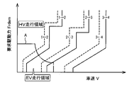
ハイブリッド制御部94は、走行モードとして、EV走行モード或いはHV走行モードを走行状態に応じて選択的に成立させる。例えば、ハイブリッド制御部94は、要求駆動パワーPrdemが予め定められた閾値よりも小さなEV走行領域にある場合には、EV走行モードを成立させる一方で、要求駆動パワーPrdemが予め定められた閾値以上となるHV走行領域にある場合には、HV走行モードを成立させる。図5の一点鎖線Aは、HV走行モードとEV走行モードとを切り替える為のHV走行領域とEV走行領域との境界線である。この図5の一点鎖線Aに示すような境界線を有する予め定められた関係は、車速V及び要求駆動力Frdemを変数とする二次元座標で構成された走行モード切替マップの一例である。尚、図5では、便宜上、この走行モード切替マップをATギヤ段変速マップと共に示している。
The
ハイブリッド制御部94は、EV走行モードを成立させたときに、第2回転機MG2のみで要求駆動パワーPrdemを実現できる場合には、第2回転機MG2による単駆動EV走行にて車両10を走行させる。一方で、ハイブリッド制御部94は、EV走行モードを成立させたときに、第2回転機MG2のみでは要求駆動パワーPrdemを実現できない場合には、両駆動EV走行にて車両10を走行させる。ハイブリッド制御部94は、第2回転機MG2のみで要求駆動パワーPrdemを実現できるときであっても、第2回転機MG2のみを用いるよりも第1回転機MG1及び第2回転機MG2を併用した方が効率が良い場合には、両駆動EV走行にて車両10を走行させても良い。
When the EV running mode is established, the
ハイブリッド制御部94は、要求駆動パワーPrdemがEV走行領域にあるときであっても、バッテリ54の充電状態値SOCが予め定められたエンジン始動閾値未満となる場合やエンジン12の暖機が必要な場合などには、HV走行モードを成立させる。前記エンジン始動閾値は、エンジン12を強制的に始動してバッテリ54を充電する必要がある充電状態値SOCであることを判断する為の予め定められた閾値である。
Even when the required driving power Prdem is in the EV driving region, the
ハイブリッド制御部94は、エンジン12の運転停止時にHV走行モードを成立させた場合には、エンジン12を始動するエンジン始動制御を行う。ハイブリッド制御部94は、エンジン12を始動するときには、例えば第1回転機MG1によりエンジン回転速度Neを上昇させつつ、エンジン回転速度Neが点火可能な所定点火可能回転速度以上となったときに点火することでエンジン12を始動する。すなわち、ハイブリッド制御部94は、第1回転機MG1によりエンジン12をクランキングすることでエンジン12を始動する。
The
ハイブリッド制御部94は、例えばエンジン12の運転時にEV走行モードを成立させた場合には又はエンジン12の運転時に車両10が停止したことでエンジン12を一時的に停止する公知のアイドリングストップ制御を実施する場合には、エンジン12を停止するエンジン停止制御を行う。ハイブリッド制御部94は、エンジン停止制御を行う際には、エンジン12への燃料供給を停止する。この際、ハイブリッド制御部94は、例えばエンジン回転速度Neにおける共振域を速やかに通過させてエンジン12を回転停止させる為に、エンジン回転速度Neを低下させるトルクをエンジン12に付与するようにMG1トルクTgを制御する。
The
ここで、エンジン停止制御の開始後にエンジン回転速度Neが低下してエンジン12が回転停止させられるとMOP58から作動油OILが吐出されないので、エンジン12の停止時には、EOP60が運転させられる。電子制御装置90は、必要ライン圧PLnを維持するだけの作動油OILの流量を確保する為に、例えばエンジン12の運転時に、エンジン12を停止した時点すなわちエンジン停止制御を開始した時点からEOP60の運転を開始する。つまり、電子制御装置90は、エンジン12の停止に際して、エンジン12が回転停止させられる前であって、必要ライン圧PLnを維持するだけの十分な作動油OILの流量をMOP58が吐出可能な状態である時点からEOP60の運転を開始する。エンジン停止制御を開始した時点は、MOP58の吐出流量の低下が予想された時点に相当する。
Here, when the engine rotation speed Ne decreases after the engine stop control is started and the
ところで、エンジン停止制御の過程では、エンジン回転速度Neが速やかに低下させられるので、MOP58からの吐出流量が急減させられる。これにより、レギュレータバルブ116では、ドレンポート120を閉じる側にスプール118が動作させられる。レギュレータバルブ116では、このようなスプール118の動作に伴ってパイロット圧Psltを受け入れる油室の容積が変化して、負圧発生によるパイロット圧Psltの低下が生じる。そして、MOP58からの吐出流量の急減に対してスプール118の動作に応答遅れが生じる。その為、エンジン停止制御の過程では、MOP58とEOP60との両方で作動油OILが吐出されているにも拘わらず、つまり必要ライン圧PLnを維持するだけの作動油OILの流量が確保されているにも拘わらず、実際のライン圧PLが必要ライン圧PLnよりも低下する現象が発生する。本実施例では、実際のライン圧PLをPL実圧と称する。このような現象に対して、EOP60の運転を開始したと同時に、PL指示圧を必要ライン圧PLnに対応した値つまり必要伝達トルクTcbnに応じた値よりも一時的に高い値に設定し、ドレンポート120を閉じる側にスプール118を強制的に動作させることが考えられる。しかしながら、EOP60の運転開始と同時にPL指示圧を高い圧に設定すると、PL実圧が高い状態でEOP60が運転させられることになり、EOP60の耐久性が悪化するおそれがある。
By the way, in the process of engine stop control, the engine rotation speed Ne is rapidly lowered, so the discharge flow rate from the
そこで、電子制御装置90は、EOP60の運転を開始した時点から所定時間TMa経過後にPL指示圧を一時的に必要伝達トルクTcbnに応じた値よりも高い値に設定して、ドレンポート120を閉じる側に動作するようにレギュレータバルブ116を制御する。
Therefore, the
電子制御装置90は、EOP60の耐久性の悪化を抑制しつつ、MOP58からの作動油OILの吐出流量が減少していく過程におけるPL実圧の低下を抑制することができる油圧供給システム100を実現する為に、更に、状態判定手段すなわち状態判定部96、及び油圧低下抑制手段すなわち油圧低下抑制部98を備えている。
The
状態判定部96は、HV走行中であるか否か、つまりエンジン走行中であるか否かを判定する。状態判定部96は、エンジン走行中であると判定したときに、ハイブリッド制御部94によりエンジン12が停止させられたか否かすなわちエンジン停止制御が開始されたか否かを判定する。
The
油圧低下抑制部98は、状態判定部96によりハイブリッド制御部94によるエンジン停止制御が開始されたと判定された場合には、EOP60の運転を開始する。
When the
状態判定部96は、油圧低下抑制部98によりEOP60の運転が開始された時点から所定時間TMa経過したか否かを判定する。所定時間TMaは、例えば状態判定部96によりハイブリッド制御部94によるエンジン停止制御が開始されたと判定された時点から、PL実圧が所定圧PLfよりも低下するまでの時間として予め定められた閾値である。所定圧PLfは、例えば必要伝達トルクTcbnに応じた値に設定されたPL指示圧にて得られるはずのPL実圧、又は、EOP60の耐久性の悪化を抑制する為の予め定められたPL実圧の上限値である。
The
EOP60の運転を開始してからの、MOP58からの吐出流量の低下に伴うPL実圧の低下度合が異なると、PL実圧が所定圧PLfよりも低下するまでの時間が異なる。電子制御装置90は、所定時間TMaを、EOP60の運転を開始した以降において一時的に上昇傾向にあったPL実圧が低下傾向に切り替わってからのPL実圧の低下度合に応じて設定する。PL実圧の低下度合が大きい程、PL実圧が所定圧PLfよりも低下するまでの時間が短くされる。電子制御装置90は、PL実圧の低下度合が大きいときには小さいときに比べて所定時間TMaを短くする。PL実圧は、例えば油圧制御回路56内に設けられた不図示の油圧センサによって検出された値が用いられる。
If the degree of decrease in the actual PL pressure due to the decrease in the discharge flow rate from the
MOP58からの吐出流量の低下度合が異なると、EOP60の運転を開始してからのPL実圧の低下度合が異なる。電子制御装置90は、所定時間TMaを、EOP60の運転を開始してからのMOP58の吐出流量の低下度合に応じて設定しても良い。MOP58の吐出流量の低下度合が大きい程、PL実圧が所定圧PLfよりも低下するまでの時間が短くされる。電子制御装置90は、MOP58の吐出流量の低下度合が大きいときには小さいときに比べて所定時間TMaを短くする。MOP58の吐出流量の低下度合は、エンジン回転速度Neの低下度合に比例する。電子制御装置90は、MOP58の吐出流量の低下度合として、例えばエンジン回転速度Neの低下度合を用いる。
If the degree of decrease in the discharge flow rate from the
EOP60の運転を開始した時点でのMOP58の吐出流量が多いとつまりエンジン回転速度Neが高いと、PL実圧が所定圧PLfよりも低下するまでの時間が異なる。電子制御装置90は、所定時間TMaを、EOP60の運転を開始した時点でのMOP58の吐出流量つまりエンジン回転速度Neに応じて設定しても良い。
When the discharge flow rate of the
作動油温THoilが異なると、EOP60の運転を開始してからのPL実圧の低下度合が異なる。例えば、作動油温THoilが常温域よりも低温側である程、レギュレータバルブ116の調圧動作の応答性が悪く、ドレンポート120を閉じる側への応答遅れによってドレンポート120からの作動油OILの排出が早くなり、PL実圧の低下度合が大きくされる。但し、作動油温THoilが極低温であると、逆に、作動油OILの粘性が高くされてドレンポート120からの作動油OILの排出速度が遅くされる為、PL実圧の低下度合が小さくされる。電子制御装置90は、所定時間TMaを、作動油温THoilに応じて設定しても良い。
When the operating oil temperature THoil differs, the degree of decrease in the PL actual pressure after the
油圧低下抑制部98は、EOP60の運転を開始した時点から、状態判定部96により所定時間TMa経過したと判定された場合には、つまり所定時間TMa経過後に、PL指示圧を必要伝達トルクTcbnに応じた値よりも高い所定値PLupに設定する油圧指示アップ制御(=油圧指示UP制御)を行う。所定値PLupは、必要伝達トルクTcbnに応じた値よりも指示圧アップ量ΔPL分高いPL指示圧であって、例えばPL実圧を必要伝達トルクTcbnに応じた値に設定されたPL指示圧にて得られるはずのPL実圧よりも低下し難くする為の予め定められた値である。つまり、所定値PLupは、ドレンポート120を閉じる側へのレギュレータバルブ116の調圧動作の応答性を確保する為の予め定められた値である。前述したように、作動油温THoilの違いによってレギュレータバルブ116の調圧動作の応答性やドレンポート120からの作動油OILの排出速度が変化する。電子制御装置90は、指示圧アップ量ΔPLを、例えば作動油温THoilに応じて設定しても良い。つまり、電子制御装置90は、所定値PLupを、作動油温THoilに応じて設定しても良い。PL指示圧が異なると、PL指示圧にて得られるはずのPL実圧の低下のし易さが異なる可能性がある。PL指示圧は必要伝達トルクTcbnに応じて変化させられる為、電子制御装置90は、指示圧アップ量ΔPLを、例えば必要伝達トルクTcbnに応じて設定しても良い。つまり、電子制御装置90は、所定値PLupを、必要伝達トルクTcbnに応じて設定しても良い。
When the
燃費の悪化やEOP60の耐久性の悪化を抑制するという観点では、指示圧アップ量ΔPLはできるだけ小さな値とされて、所定値PLupは必要最低限のPL指示圧になるように設定される方が良い。油圧低下抑制部98は、油圧指示UP制御では、PL指示圧を所定値PLupに設定した後、PL指示圧を必要伝達トルクTcbnに応じた値とするように所定値PLupから徐々に小さくする。例えば、油圧低下抑制部98は、PL指示圧を所定値PLupから必要伝達トルクTcbnに応じた値まで所定時間TMbで漸減する。電子制御装置90は、所定時間TMaの設定にあたっての観点と同様に、所定時間TMbを、油圧指示UP制御を開始してからのエンジン回転速度Neの低下度合、又は、油圧指示UP制御を開始した時点でのエンジン回転速度Ne、又は、作動油温THoilなどに応じて設定する。
From the viewpoint of suppressing deterioration of fuel consumption and deterioration of durability of EOP60, it is better to set the instruction pressure increase amount ΔPL as small as possible and set the predetermined value PLup to the minimum required PL instruction pressure. good. In the hydraulic pressure command UP control, the hydraulic pressure
状態判定部96は、油圧低下抑制部98により油圧指示UP制御が開始された時点から所定時間TMb経過したか否かを判定する。
The
油圧低下抑制部98は、油圧指示UP制御を開始した時点から、状態判定部96により所定時間TMb経過したと判定された場合には、つまり所定時間TMb経過後に、油圧指示UP制御を終了する、つまり油圧指示UP制御を解除する。
When the
図6は、電子制御装置90の制御作動の要部を説明するフローチャートであって、EOP60の耐久性の悪化を抑制しつつMOP58からの作動油OILの吐出流量が減少していく過程におけるPL実圧の低下を抑制することができる油圧供給システム100を実現する為の制御作動を説明するフローチャートであり、例えば繰り返し実行される。図7は、図6のフローチャートに示す制御作動を実行した場合のタイムチャートの一例を示す図である。
FIG. 6 is a flow chart for explaining the main part of the control operation of the
図6において、先ず、状態判定部96の機能に対応するステップ(以下、ステップを省略する)S10において、エンジン走行中であるか否かが判定される。このS10の判断が否定される場合は本ルーチンが終了させられる。このS10の判断が肯定される場合は状態判定部96の機能に対応するS20において、エンジン12が停止させられたか否かすなわちエンジン停止制御が開始されたか否かが判定される。このS20の判断が否定される場合は本ルーチンが終了させられる。このS20の判断が肯定される場合は油圧低下抑制部98の機能に対応するS30において、EOP60の運転が開始させられる。次いで、状態判定部96の機能に対応するS40において、所定時間TMa経過したか否かが判定される。このS40の判断が否定される場合はこのS40が繰り返し実行させられる。このS40の判断が肯定される場合は油圧低下抑制部98の機能に対応するS50において、油圧指示UP制御が行われる。次いで、状態判定部96の機能に対応するS60において、所定時間TMb経過したか否かが判定される。このS60の判断が否定される場合は上記S50へ戻される。このS60の判断が肯定される場合は油圧低下抑制部98の機能に対応するS70において、油圧指示UP制御が終了させられる。
In FIG. 6, first, in step S10 (hereinafter, step omitted) corresponding to the function of the
図7は、エンジン走行中にエンジン12が停止させられた場合の一例を示す図である。図7において、t1時点は、エンジン走行中にエンジン12が停止させられたとの判定が為された時点を示している。このt1時点からEOP60の運転が開始させられる。EOP60の運転では、作動油OILの吐出圧を速やかに立ち上げる為に、最初は一時的に高いEOP60の回転速度とされている。EOP60の回転速度は、この一時的に高い回転速度から目標の回転速度へ向かって徐々に低下させられる。この際、EOP60の回転速度は、図示するように、オーバーシュートやアンダーシュートが生じる。破線に示す比較例では、PL指示圧は、t1時点以降も必要伝達トルクTcbnに応じた値とされている。その為、PL実圧は、EOP60の運転開始によって一旦は上昇させられるものの、エンジン回転速度Neの低下に伴って下降させられ(t1時点-t2時点参照)、更に、エンジン12が回転停止する(t3時点参照)までのMOP58からの吐出流量の急減に対するレギュレータバルブ116の調圧動作の応答遅れによってPL実圧が必要ライン圧PLnよりも低下する現象が発生する(t2時点以降参照)。実線に示す本実施例では、PL実圧が必要ライン圧PLnよりも低下しないように、油圧指示UP制御が実行させられる。EOP60の運転開始と同時に油圧指示UP制御が実行させられると、PL実圧が高い状態でEOP60が運転させられてEOP60の耐久性が悪化するおそれがある。その為、本実施例では、EOP60の運転開始時点から所定時間TMa経過後に油圧指示UP制御が開始させられる(t2時点参照)。油圧指示UP制御では、PL指示圧は、必要伝達トルクTcbnに応じた値よりも指示圧アップ量ΔPL分高い所定値PLupとされた後、所定値PLupから必要伝達トルクTcbnに応じた値まで所定時間TMbで漸減させられる(t2時点-t4時点参照)。尚、油圧指示UP制御中に必要伝達トルクTcbnが変化した場合には、その変化に合わせて油圧指示UP制御におけるPL指示圧が変化させられても良い。
FIG. 7 is a diagram showing an example in which the
上述のように、本実施例によれば、MOP58の吐出流量の低下が予想された時点からEOP60の運転が開始させられるので、MOP58の吐出流量が不足しても、必要伝達トルクTcbnに応じた値に設定されたPL指示圧にて得られるはずのPL実圧を維持し易くされる。又、EOP60の運転を開始した時点から所定時間TMa経過後にPL指示圧が一時的に必要伝達トルクTcbnに応じた値よりも高い値に設定されて、ドレンポート120を閉じる側に動作するようにレギュレータバルブ116が制御されるので、PL実圧が高い状態でEOP60が運転させられることが抑制されると共に、MOP58からの作動油OILの吐出流量が減少していく過程におけるレギュレータバルブ116の調圧動作の応答遅れが抑制される。よって、EOP60の耐久性の悪化を抑制しつつ、MOP58からの作動油OILの吐出流量が減少していく過程におけるPL実圧の低下を抑制することができる。
As described above, according to the present embodiment, the operation of the
また、本実施例によれば、所定圧PLfは、必要伝達トルクTcbnに応じた値に設定されたPL指示圧にて得られるPL実圧、又は、EOP60の耐久性の悪化を抑制する為の予め定められたPL実圧の上限値であるので、PL実圧が高い状態でEOP60が運転させられることが適切に抑制されると共に、MOP58からの作動油OILの吐出流量が減少していく過程におけるレギュレータバルブ116の調圧動作の応答遅れが適切に抑制される。
Further, according to this embodiment, the predetermined pressure PLf is the PL actual pressure obtained by the PL command pressure set to a value corresponding to the required transmission torque Tcbn, or Since it is the predetermined upper limit value of the actual PL pressure, it is appropriately suppressed that the
また、本実施例によれば、EOP60の運転を開始した以降において一時的に上昇傾向にあったPL実圧が低下傾向に切り替わってからのPL実圧の低下度合が大きいときには小さいときに比べて所定時間TMaが短くされるので、EOP60の運転を開始してからのPL実圧の低下度合が異なったとしても、PL実圧が所定圧PLfよりも低下させられた時点でPL指示圧が一時的に高い値に設定され易くされる。又は、作動油温THoilに応じて所定時間TMaが設定されるので、作動油温THoilの違いによってレギュレータバルブ116の調圧動作の応答性やドレンポート120からの作動油OILの排出速度が変化してEOP60の運転を開始してからのPL実圧の低下度合が異なったとしても、PL実圧が所定圧PLfよりも低下させられた時点でPL指示圧が一時的に高い値に設定され易くされる。又は、EOP60の運転を開始してからのMOP58の吐出流量の低下度合が大きいときには小さいときに比べて所定時間TMaが短くされるので、MOP58の吐出流量の低下度合の違いによってEOP60の運転を開始してからのPL実圧の低下度合が異なったとしても、PL実圧が所定圧PLfよりも低下させられた時点でPL指示圧が一時的に高い値に設定され易くされる。これにより、PL実圧が高い状態でEOP60が運転させられることが適切に抑制されると共に、MOP58からの作動油OILの吐出流量が減少していく過程におけるレギュレータバルブ116の調圧動作の応答遅れが適切に抑制される。
Further, according to the present embodiment, after the operation of the
また、本実施例によれば、EOP60の運転を開始した時点から所定時間TMa経過後にPL指示圧が必要伝達トルクTcbnに応じた値よりも高い所定値PLupに設定され、その後、PL指示圧が必要伝達トルクTcbnに応じた値とされるように所定値PLupから徐々に小さくされるので、MOP58からの作動油OILの吐出流量が減少していく過程におけるレギュレータバルブ116の調圧動作の応答遅れが適切に抑制されると共に、PL実圧が高い状態でEOP60が運転させられることが適切に抑制される。
Further, according to this embodiment, the PL command pressure is set to the predetermined value PLup higher than the value corresponding to the required transmission torque Tcbn after the lapse of the predetermined time TMa from the time when the operation of the
また、本実施例によれば、所定値PLupは、PL実圧を必要伝達トルクTcbnに応じた値に設定されたPL指示圧にて得られるPL実圧よりも低下し難くする為の予め定められた値であるので、MOP58からの作動油OILの吐出流量が減少していく過程におけるPL実圧の低下を適切に抑制することができる。
Further, according to the present embodiment, the predetermined value PLup is predetermined to make it difficult for the actual PL pressure to drop below the actual PL pressure obtained at the PL command pressure set to a value corresponding to the required transmission torque Tcbn. Therefore, it is possible to appropriately suppress a decrease in the PL actual pressure in the process in which the discharge flow rate of the hydraulic oil OIL from the
以上、本発明の実施例を図面に基づいて詳細に説明したが、本発明はその他の態様においても適用される。 Although the embodiments of the present invention have been described in detail above with reference to the drawings, the present invention is also applicable to other aspects.
例えば、前述の実施例では、第1オイルポンプとして機械式のオイルポンプであるMOP58を例示し、第2オイルポンプとして電動式のオイルポンプであるEOP60を例示したが、この態様に限らない。例えば、第1オイルポンプは、電動式のオイルポンプであっても良い。又、第2オイルポンプは、機械式のオイルポンプであっても良い。例えば、第1オイルポンプは、必要伝達トルクTcbnが比較的大きな高負荷な状態の走行時に運転させられるオイルポンプであり、又、第2オイルポンプは、必要伝達トルクTcbnが比較的小さな低負荷な状態の走行時に単独で運転させられるオイルポンプであれば良い。加えて、第2オイルポンプは、電子制御装置90により作動状態が制御可能であれば良い。第2オイルポンプが機械式のオイルポンプである場合は、例えばクラッチを介して動力伝達装置16の回転部材に第2オイルポンプが連結されており、クラッチの作動状態を制御することで第2オイルポンプの作動状態が制御される。動力伝達装置16の回転部材は、例えば出力軸24、差動歯車装置26のリングギヤ等である。
For example, in the above-described embodiment, the mechanical
また、前述の実施例では、エンジン12が回転停止させられる前であって、必要ライン圧PLnを維持するだけの十分な作動油OILの流量をMOP58が吐出可能な状態である時点からEOP60の運転を開始する為に、EOP60の運転を開始する時点をMOP58の吐出流量の低下が予想された時点つまりエンジン停止制御を開始した時点としたが、この態様に限らない。例えば、MOP58の吐出流量の低下が予想された時点は、MOP58の運転を停止するような車両状態へ移行する要求が為された時点、エンジン停止制御の開始前であってエンジン12を停止する必要がある車両状態になったと判断した時点などであっても良い。又、EOP60の運転を開始する時点をMOP58の吐出流量の低下が検知された時点としても良い。MOP58の吐出流量の低下が検知された時点としては、MOP58の運転停止時にMOP58の回転速度の低下を検知した時点、エンジン12への燃料供給の停止後にエンジン回転速度Neの低下を検知した時点などが挙げられる。
Further, in the above-described embodiment, the
また、前述の実施例では、本発明が適用される車両として、無段変速部20と有段変速部22とを直列に備えた車両10を例示したが、この態様に限らない。例えば、第1オイルポンプと、作動状態を制御可能な第2オイルポンプと、レギュレータバルブ116と、ライン圧PLを元圧として係合トルクTcbが調整される油圧式係合装置と、前記第2オイルポンプの作動状態、レギュレータバルブ116の調圧動作、及び係合トルクTcbを制御可能な電子制御装置90とを油圧供給システムとして備えた車両であれば、本発明を適用することができる。
Further, in the above-described embodiment, the
尚、上述したのはあくまでも一実施形態であり、本発明は当業者の知識に基づいて種々の変更、改良を加えた態様で実施することができる。 It should be noted that what has been described above is just one embodiment, and the present invention can be implemented in aspects with various modifications and improvements based on the knowledge of those skilled in the art.
58:MOP(第1オイルポンプ)
60:EOP(第2オイルポンプ)
90:電子制御装置(制御装置)
100:油圧供給システム
116:レギュレータバルブ(調圧弁)
120:ドレンポート
CB:係合装置(油圧式係合装置)
OIL:作動油
58: MOP (first oil pump)
60: EOP (second oil pump)
90: Electronic control device (control device)
100: Hydraulic supply system 116: Regulator valve (pressure regulating valve)
120: Drain port CB: Engagement device (hydraulic engagement device)
OIL: Hydraulic oil
Claims (7)
前記制御装置は、前記油圧指示値を前記油圧式係合装置の必要伝達トルクに応じた値に設定する一方で、前記第1オイルポンプの吐出流量の低下が予想された時点又は前記第1オイルポンプの吐出流量の低下が検知された時点から前記第2オイルポンプの運転を開始すると共に、前記第2オイルポンプの運転を開始した時点から前記ライン圧が所定圧よりも低下する所定時間経過後に前記油圧指示値を一時的に前記必要伝達トルクに応じた値よりも高い値に設定して、前記ドレンポートを閉じる側に動作するように前記調圧弁を制御することを特徴とする油圧供給システム。 A first oil pump, a second oil pump whose operating state can be controlled, and the hydraulic pressure of the hydraulic oil discharged from the first oil pump and the second oil pump are controlled by opening the drain port according to the hydraulic pressure instruction value. a pressure regulating valve for regulating the line pressure by reducing the pressure, controlling the operation state of the second oil pump, setting the hydraulic pressure instruction value to control the pressure regulating operation of the pressure regulating valve, and A hydraulic supply system comprising a control device that adjusts the torque capacity of a hydraulic engagement device using line pressure as a source pressure,
The control device sets the hydraulic pressure instruction value to a value corresponding to the required transmission torque of the hydraulic engagement device, and at the time when a decrease in the discharge flow rate of the first oil pump is expected or when the first oil The operation of the second oil pump is started at the time when a drop in the discharge flow rate of the pump is detected, and after a predetermined time has passed since the operation of the second oil pump is started and the line pressure is lower than the predetermined pressure. A hydraulic pressure supply system characterized by temporarily setting the hydraulic pressure instruction value to a value higher than a value corresponding to the required transmission torque, and controlling the pressure regulating valve so as to operate to close the drain port. .
Priority Applications (3)
| Application Number | Priority Date | Filing Date | Title |
|---|---|---|---|
| JP2020005504A JP7176540B2 (en) | 2020-01-16 | 2020-01-16 | hydraulic supply system |
| US17/034,761 US11441670B2 (en) | 2020-01-16 | 2020-09-28 | Hydraulic supply system |
| CN202011352589.3A CN113137470B (en) | 2020-01-16 | 2020-11-26 | Hydraulic supply system |
Applications Claiming Priority (1)
| Application Number | Priority Date | Filing Date | Title |
|---|---|---|---|
| JP2020005504A JP7176540B2 (en) | 2020-01-16 | 2020-01-16 | hydraulic supply system |
Publications (2)
| Publication Number | Publication Date |
|---|---|
| JP2021113567A JP2021113567A (en) | 2021-08-05 |
| JP7176540B2 true JP7176540B2 (en) | 2022-11-22 |
Family
ID=76809359
Family Applications (1)
| Application Number | Title | Priority Date | Filing Date |
|---|---|---|---|
| JP2020005504A Active JP7176540B2 (en) | 2020-01-16 | 2020-01-16 | hydraulic supply system |
Country Status (3)
| Country | Link |
|---|---|
| US (1) | US11441670B2 (en) |
| JP (1) | JP7176540B2 (en) |
| CN (1) | CN113137470B (en) |
Citations (4)
| Publication number | Priority date | Publication date | Assignee | Title |
|---|---|---|---|---|
| JP2002206630A (en) | 2000-12-28 | 2002-07-26 | Aisin Aw Co Ltd | Drive controller of oil pump |
| JP2002371969A (en) | 2001-06-14 | 2002-12-26 | Toyota Motor Corp | Oil pump control device for automatic transmission |
| JP2006153091A (en) | 2004-11-26 | 2006-06-15 | Honda Motor Co Ltd | Control device of vehicle |
| JP2006161850A (en) | 2004-12-02 | 2006-06-22 | Honda Motor Co Ltd | Hydraulic supply device |
Family Cites Families (14)
| Publication number | Priority date | Publication date | Assignee | Title |
|---|---|---|---|---|
| JP2004278713A (en) * | 2003-03-17 | 2004-10-07 | Toyota Motor Corp | Controller for hybrid vehicle |
| JP4570418B2 (en) * | 2003-09-16 | 2010-10-27 | 株式会社小松製作所 | Control device for hydraulic-mechanical transmission |
| US7556120B2 (en) * | 2006-05-25 | 2009-07-07 | Gm Global Technology Operations, Inc. | Method and apparatus to control hydraulic pressure in an electro-mechanical transmission |
| JP5141981B2 (en) * | 2009-03-17 | 2013-02-13 | アイシン・エィ・ダブリュ株式会社 | Control device for automatic transmission |
| GB2475844B (en) * | 2009-12-01 | 2017-01-04 | Gm Global Tech Operations Llc | Oil supply system for an automatic transmission of a vehicle, an automatic transmission and a vehicle comprising the oil supply system |
| JP5116789B2 (en) * | 2010-03-09 | 2013-01-09 | ジヤトコ株式会社 | Hydraulic control device for transmission and control method therefor |
| JP5501937B2 (en) * | 2010-11-02 | 2014-05-28 | ジヤトコ株式会社 | Control device for hybrid vehicle |
| KR101541261B1 (en) * | 2011-10-17 | 2015-07-31 | 도요타지도샤가부시키가이샤 | Vehicle control device |
| US9328821B2 (en) * | 2013-06-10 | 2016-05-03 | Caterpillar Inc. | Hydrostatic drive system |
| JP6187445B2 (en) * | 2014-12-18 | 2017-08-30 | トヨタ自動車株式会社 | Control device for hybrid vehicle |
| JP6410648B2 (en) * | 2015-03-26 | 2018-10-24 | ジヤトコ株式会社 | Hydraulic control device for vehicle |
| JP6168107B2 (en) * | 2015-06-16 | 2017-07-26 | トヨタ自動車株式会社 | Power transmission control device |
| JP6560720B2 (en) * | 2017-08-10 | 2019-08-14 | 本田技研工業株式会社 | Hydraulic control device |
| JP7223675B2 (en) * | 2019-11-12 | 2023-02-16 | 本田技研工業株式会社 | hydraulic controller |
-
2020
- 2020-01-16 JP JP2020005504A patent/JP7176540B2/en active Active
- 2020-09-28 US US17/034,761 patent/US11441670B2/en active Active
- 2020-11-26 CN CN202011352589.3A patent/CN113137470B/en active Active
Patent Citations (4)
| Publication number | Priority date | Publication date | Assignee | Title |
|---|---|---|---|---|
| JP2002206630A (en) | 2000-12-28 | 2002-07-26 | Aisin Aw Co Ltd | Drive controller of oil pump |
| JP2002371969A (en) | 2001-06-14 | 2002-12-26 | Toyota Motor Corp | Oil pump control device for automatic transmission |
| JP2006153091A (en) | 2004-11-26 | 2006-06-15 | Honda Motor Co Ltd | Control device of vehicle |
| JP2006161850A (en) | 2004-12-02 | 2006-06-22 | Honda Motor Co Ltd | Hydraulic supply device |
Also Published As
| Publication number | Publication date |
|---|---|
| CN113137470B (en) | 2022-08-09 |
| CN113137470A (en) | 2021-07-20 |
| JP2021113567A (en) | 2021-08-05 |
| US20210222768A1 (en) | 2021-07-22 |
| US11441670B2 (en) | 2022-09-13 |
Similar Documents
| Publication | Publication Date | Title |
|---|---|---|
| JP4501925B2 (en) | Control device for vehicle drive device | |
| US10000206B2 (en) | Control apparatus for power transmission system | |
| JP2008155802A (en) | Control device of vehicle driving device | |
| EP3647103A1 (en) | Control device of hybrid vehicle | |
| EP2103496B1 (en) | Control device for vehicular drive system | |
| US11383693B2 (en) | Hybrid vehicle | |
| JP2020029168A (en) | Vehicle control device | |
| JP7331548B2 (en) | Hybrid vehicle control device | |
| JP2012046003A (en) | Control device of power transmission device for vehicle | |
| EP3647102B1 (en) | Control device of hybrid vehicle | |
| JP6635019B2 (en) | Transmission control device for automatic transmission | |
| JP7176540B2 (en) | hydraulic supply system | |
| CN111322393B (en) | Control device for linear solenoid valve | |
| JP7107783B2 (en) | vehicle controller | |
| JP6658490B2 (en) | Vehicle control device | |
| JP5018871B2 (en) | Control device for vehicle drive device | |
| JP5206559B2 (en) | Control device for vehicle power transmission device | |
| JP7272213B2 (en) | Hybrid vehicle control device | |
| JP7201469B2 (en) | vehicle controller | |
| JP2023008333A (en) | Controller of hybrid vehicle | |
| JP2010162962A (en) | Device for controlling vehicle power transmission device |
Legal Events
| Date | Code | Title | Description |
|---|---|---|---|
| A621 | Written request for application examination |
Free format text: JAPANESE INTERMEDIATE CODE: A621 Effective date: 20220214 |
|
| TRDD | Decision of grant or rejection written | ||
| A01 | Written decision to grant a patent or to grant a registration (utility model) |
Free format text: JAPANESE INTERMEDIATE CODE: A01 Effective date: 20221011 |
|
| A977 | Report on retrieval |
Free format text: JAPANESE INTERMEDIATE CODE: A971007 Effective date: 20221013 |
|
| A61 | First payment of annual fees (during grant procedure) |
Free format text: JAPANESE INTERMEDIATE CODE: A61 Effective date: 20221024 |
|
| R151 | Written notification of patent or utility model registration |
Ref document number: 7176540 Country of ref document: JP Free format text: JAPANESE INTERMEDIATE CODE: R151 |