JP7163401B2 - A conversion device that converts linear motion in a fixed system into pivotal motion about a pivot axis in a system that rotates about an axis of rotation - Google Patents
A conversion device that converts linear motion in a fixed system into pivotal motion about a pivot axis in a system that rotates about an axis of rotation Download PDFInfo
- Publication number
- JP7163401B2 JP7163401B2 JP2020549591A JP2020549591A JP7163401B2 JP 7163401 B2 JP7163401 B2 JP 7163401B2 JP 2020549591 A JP2020549591 A JP 2020549591A JP 2020549591 A JP2020549591 A JP 2020549591A JP 7163401 B2 JP7163401 B2 JP 7163401B2
- Authority
- JP
- Japan
- Prior art keywords
- pivot axis
- linear motion
- closure cover
- motion
- closure
- Prior art date
- Legal status (The legal status is an assumption and is not a legal conclusion. Google has not performed a legal analysis and makes no representation as to the accuracy of the status listed.)
- Active
Links
- 238000006243 chemical reaction Methods 0.000 title claims description 16
- 239000000463 material Substances 0.000 claims description 19
- 230000008878 coupling Effects 0.000 claims 1
- 238000010168 coupling process Methods 0.000 claims 1
- 238000005859 coupling reaction Methods 0.000 claims 1
- 238000010276 construction Methods 0.000 description 3
- 239000012530 fluid Substances 0.000 description 3
- 238000012377 drug delivery Methods 0.000 description 1
- 238000000034 method Methods 0.000 description 1
- 239000002245 particle Substances 0.000 description 1
Images


Classifications
-
- B—PERFORMING OPERATIONS; TRANSPORTING
- B01—PHYSICAL OR CHEMICAL PROCESSES OR APPARATUS IN GENERAL
- B01F—MIXING, e.g. DISSOLVING, EMULSIFYING OR DISPERSING
- B01F29/00—Mixers with rotating receptacles
- B01F29/10—Mixers with rotating receptacles with receptacles rotated about two different axes, e.g. receptacles having planetary motion
-
- B—PERFORMING OPERATIONS; TRANSPORTING
- B01—PHYSICAL OR CHEMICAL PROCESSES OR APPARATUS IN GENERAL
- B01F—MIXING, e.g. DISSOLVING, EMULSIFYING OR DISPERSING
- B01F35/00—Accessories for mixers; Auxiliary operations or auxiliary devices; Parts or details of general application
- B01F35/45—Closures or doors specially adapted for mixing receptacles; Operating mechanisms therefor
- B01F35/452—Closures or doors specially adapted for mixing receptacles; Operating mechanisms therefor by moving them in the plane of the opening
-
- B—PERFORMING OPERATIONS; TRANSPORTING
- B01—PHYSICAL OR CHEMICAL PROCESSES OR APPARATUS IN GENERAL
- B01F—MIXING, e.g. DISSOLVING, EMULSIFYING OR DISPERSING
- B01F29/00—Mixers with rotating receptacles
- B01F29/30—Mixing the contents of individual packages or containers, e.g. by rotating tins or bottles
- B01F29/31—Mixing the contents of individual packages or containers, e.g. by rotating tins or bottles the containers being supported by driving means, e.g. by rotating rollers
-
- B—PERFORMING OPERATIONS; TRANSPORTING
- B01—PHYSICAL OR CHEMICAL PROCESSES OR APPARATUS IN GENERAL
- B01F—MIXING, e.g. DISSOLVING, EMULSIFYING OR DISPERSING
- B01F29/00—Mixers with rotating receptacles
- B01F29/40—Parts or components, e.g. receptacles, feeding or discharging means
- B01F29/403—Disposition of the rotor axis
- B01F29/4034—Disposition of the rotor axis variable, e.g. tiltable during the operation
-
- B—PERFORMING OPERATIONS; TRANSPORTING
- B01—PHYSICAL OR CHEMICAL PROCESSES OR APPARATUS IN GENERAL
- B01F—MIXING, e.g. DISSOLVING, EMULSIFYING OR DISPERSING
- B01F29/00—Mixers with rotating receptacles
- B01F29/40—Parts or components, e.g. receptacles, feeding or discharging means
- B01F29/403—Disposition of the rotor axis
- B01F29/4035—Disposition of the rotor axis with a receptacle rotating around two or more axes
- B01F29/40351—Disposition of the rotor axis with a receptacle rotating around two or more axes having different, non-perpendicular inclinations, e.g. skew axes
-
- B—PERFORMING OPERATIONS; TRANSPORTING
- B01—PHYSICAL OR CHEMICAL PROCESSES OR APPARATUS IN GENERAL
- B01F—MIXING, e.g. DISSOLVING, EMULSIFYING OR DISPERSING
- B01F29/00—Mixers with rotating receptacles
- B01F29/80—Mixers with rotating receptacles rotating about a substantially vertical axis
- B01F29/83—Mixers with rotating receptacles rotating about a substantially vertical axis with rotary paddles or arms, e.g. movable out of the receptacle
-
- B—PERFORMING OPERATIONS; TRANSPORTING
- B01—PHYSICAL OR CHEMICAL PROCESSES OR APPARATUS IN GENERAL
- B01F—MIXING, e.g. DISSOLVING, EMULSIFYING OR DISPERSING
- B01F35/00—Accessories for mixers; Auxiliary operations or auxiliary devices; Parts or details of general application
- B01F35/30—Driving arrangements; Transmissions; Couplings; Brakes
-
- B—PERFORMING OPERATIONS; TRANSPORTING
- B01—PHYSICAL OR CHEMICAL PROCESSES OR APPARATUS IN GENERAL
- B01F—MIXING, e.g. DISSOLVING, EMULSIFYING OR DISPERSING
- B01F35/00—Accessories for mixers; Auxiliary operations or auxiliary devices; Parts or details of general application
- B01F35/45—Closures or doors specially adapted for mixing receptacles; Operating mechanisms therefor
- B01F35/451—Closures or doors specially adapted for mixing receptacles; Operating mechanisms therefor by rotating them about an axis parallel to the plane of the opening
-
- B—PERFORMING OPERATIONS; TRANSPORTING
- B01—PHYSICAL OR CHEMICAL PROCESSES OR APPARATUS IN GENERAL
- B01F—MIXING, e.g. DISSOLVING, EMULSIFYING OR DISPERSING
- B01F35/00—Accessories for mixers; Auxiliary operations or auxiliary devices; Parts or details of general application
- B01F35/75—Discharge mechanisms
- B01F35/751—Discharging by opening a gate, e.g. using discharge paddles
-
- B—PERFORMING OPERATIONS; TRANSPORTING
- B01—PHYSICAL OR CHEMICAL PROCESSES OR APPARATUS IN GENERAL
- B01F—MIXING, e.g. DISSOLVING, EMULSIFYING OR DISPERSING
- B01F35/00—Accessories for mixers; Auxiliary operations or auxiliary devices; Parts or details of general application
- B01F35/75—Discharge mechanisms
- B01F35/754—Discharge mechanisms characterised by the means for discharging the components from the mixer
- B01F35/7547—Discharge mechanisms characterised by the means for discharging the components from the mixer using valves, gates, orifices or openings
-
- B—PERFORMING OPERATIONS; TRANSPORTING
- B01—PHYSICAL OR CHEMICAL PROCESSES OR APPARATUS IN GENERAL
- B01F—MIXING, e.g. DISSOLVING, EMULSIFYING OR DISPERSING
- B01F29/00—Mixers with rotating receptacles
- B01F29/40—Parts or components, e.g. receptacles, feeding or discharging means
- B01F29/403—Disposition of the rotor axis
- B01F29/4032—Disposition of the rotor axis vertical
-
- B—PERFORMING OPERATIONS; TRANSPORTING
- B01—PHYSICAL OR CHEMICAL PROCESSES OR APPARATUS IN GENERAL
- B01F—MIXING, e.g. DISSOLVING, EMULSIFYING OR DISPERSING
- B01F35/00—Accessories for mixers; Auxiliary operations or auxiliary devices; Parts or details of general application
- B01F35/30—Driving arrangements; Transmissions; Couplings; Brakes
- B01F35/33—Transmissions; Means for modifying the speed or direction of rotation
-
- F—MECHANICAL ENGINEERING; LIGHTING; HEATING; WEAPONS; BLASTING
- F16—ENGINEERING ELEMENTS AND UNITS; GENERAL MEASURES FOR PRODUCING AND MAINTAINING EFFECTIVE FUNCTIONING OF MACHINES OR INSTALLATIONS; THERMAL INSULATION IN GENERAL
- F16H—GEARING
- F16H25/00—Gearings comprising primarily only cams, cam-followers and screw-and-nut mechanisms
- F16H25/18—Gearings comprising primarily only cams, cam-followers and screw-and-nut mechanisms for conveying or interconverting oscillating or reciprocating motions
Landscapes
- Chemical & Material Sciences (AREA)
- Chemical Kinetics & Catalysis (AREA)
- Engineering & Computer Science (AREA)
- General Engineering & Computer Science (AREA)
- Mechanical Engineering (AREA)
- Mixers With Rotating Receptacles And Mixers With Vibration Mechanisms (AREA)
- Mixers Of The Rotary Stirring Type (AREA)
- Transmission Devices (AREA)
- Processing And Handling Of Plastics And Other Materials For Molding In General (AREA)
- Accessories For Mixers (AREA)
Description
本発明は、固定系における直線運動を、回転軸線周りを回転する系における枢動軸線周りの枢動運動に変換する変換装置に関する。 The present invention relates to a conversion device for converting linear motion in a fixed system into pivotal motion about a pivot axis in a system rotating about a rotation axis.
一緒に回転する要素が枢動軸線周りを枢動し、枢動軸線が、回転軸線の延長ではなく、またそれと平行ではない回転系には多数の用途がある。枢動運動を生成するためには適切な駆動装置が必要である。その場合、駆動装置は、それと共に回転するように回転系内に設けることができる。しかしながら、駆動装置には動力が供給されなければならず、さらに、回転系内の配置によって適切なスペースが必要となる。特に、駆動装置が高い質量の場合、又は回転系が高い回転速度で回転軸線を中心に回転する場合には、駆動装置の重量を補償するために、ある状況下でバランス要素が必要となる。 There are many applications for rotating systems in which co-rotating elements pivot about a pivot axis that is neither an extension of nor parallel to the axis of rotation. A suitable drive is required to generate the pivoting motion. In that case, the drive may be provided within the rotating system to rotate therewith. However, the drive must be powered and additionally requires adequate space due to its placement within the rotating system. Balancing elements are required under certain circumstances to compensate for the weight of the drive, especially if the drive has a high mass or if the rotating system rotates about its axis of rotation at high rotational speeds.
一例の適用として、混合プロセス中に回転し、混合材料が収容される混合容器を有する混合装置がある。このような混合装置は、しばしば偏心して配置された混合器具を有し、それ自体が動作中に再び回転することができる。混合操作が行われた後、混合器を空にするために、混合容器の下面に閉鎖カバーが配置される。このような混合装置は、例えば、特許文献1から知られている。 An example application is a mixing device that rotates during the mixing process and has a mixing vessel in which the mixed material is contained. Such mixing devices often have an eccentrically arranged mixing device, which itself can rotate again during operation. A closing cover is placed on the underside of the mixing vessel in order to empty the mixer after the mixing operation has taken place. Such a mixing device is known, for example, from US Pat.
その中に示される構造では、閉鎖カバーは、装着ヨークと装着ジャーナルとによってキャリアアームに連結され、したがって装着ジャーナルの傾斜軸を中心として枢動することができる。このような混合装置において、閉鎖カバーは、混合材料が移動する平坦な底面が形成されるように、容器の底部と同一面でしばしば終了する。これにより、混合器具では到達しない閉鎖カバーの上にデッドスペースがないため、すべての混合材料の効率的な徹底的な混合が保証される。 In the structure shown therein, the closure cover is connected to the carrier arm by means of a mounting yoke and a mounting journal and can therefore pivot about the tilting axis of the mounting journal. In such mixing devices, the closure cover often ends flush with the bottom of the container so that a flat bottom surface is formed for the mixed material to travel. This ensures efficient and thorough mixing of all mixed materials as there is no dead space above the closure cover which is not reached by the mixing device.
閉鎖カバーが容器底部と一直線になるようにするための要件は、閉鎖カバーの設計構成およびガイダンスに関して困難を引き起こす。 The requirement for the closure cover to be aligned with the bottom of the container poses difficulties regarding closure cover design configuration and guidance.
基本的に、閉鎖カバーは、まず、開口部を開くために、直線的に下方に動かさなければならない。しかし、開口部が容器の底部に配置されることによって、混合材料は、閉鎖カバーの全ての縁部表面の上を流れ、場合によっては閉鎖カバーの駆動部を汚染することさえあるという結果を有する。しかしながら、閉鎖カバーの実質的に円筒状又は切頭円錐状の接触面及び開口部によって、開口部の外への閉鎖カバーの排他的に横方向の枢動移動は不可能である。 Basically, the closing cover must first be moved linearly downwards to open the opening. However, the arrangement of the opening at the bottom of the container has the consequence that the mixed material flows over all edge surfaces of the closure cover and possibly even contaminates the drive of the closure cover. . However, due to the substantially cylindrical or frusto-conical contact surface and opening of the closure cover, an exclusively lateral pivotal movement of the closure cover out of the opening is not possible.
そのため、特許文献1に開示されている閉鎖カバーの駆動は、枢動シャフトの周りおよび装着ジャーナルの周りの両方で枢動運動を可能にする。示された実施形態では、キャリアアームは、閉鎖カバーが開口部に嵌め込まれた状態で容器と一緒に回転する間、固定系内に位置決めされる。したがって、閉鎖カバーは、キャリアアーム上に回転可能に取り付けられる。 As such, the drive of the closure cover disclosed in US Pat. No. 5,800,003 allows for pivotal movement both about the pivot shaft and about the mounting journal. In the embodiment shown, the carrier arm is positioned within the stationary system while rotating with the container with the closure cover fitted over the opening. The closure cover is thus rotatably mounted on the carrier arm.
原理的には、閉鎖カバーが、その開放または閉鎖のために枢動軸線周りでのみ枢動されなければならない場合には有利でる。それにもかかわらず、それが容器の底部で面一に終了するようにするためには、閉鎖要素のエッジ表面は、開口部を開閉するために、閉鎖要素を概念的な球面上にあるように湾曲した構成でなければならず、その結果、閉鎖要素は、概念的な球面の中心点を通って延びるその枢動軸線の周りを枢動され得る。 In principle, it would be advantageous if the closure cover had to be pivoted only about the pivot axis for opening or closing it. Nevertheless, in order for it to end flush with the bottom of the container, the edge surface of the closure element should lie on a notional spherical surface to open and close the opening. It must be of curved configuration so that the closure element can be pivoted about its pivot axis extending through the center point of the notional sphere.
しかし、その場合、閉鎖カバーがキャリアアームに対して回転するように設計することはできない。代わりに、駆動装置は、上述の欠点を伴って、ロータリ・システムに移動しなければならない。従って、これまで、閉鎖カバーは記載された形態では実施されていなかった。 However, in that case the closing cover cannot be designed to rotate with respect to the carrier arm. Instead, the drive must be moved to a rotary system with the drawbacks mentioned above. Up to now, therefore, the closing cover has not been embodied in the form described.
従って、本発明の目的は、固定系における直線運動を、回転軸線周りで回転する系における枢動軸線を中心とした枢動運動に変換するための変換装置を提供することである。また、本発明の目的は、記載された種類の混合装置を提供することであり、閉鎖カバーを枢動軸線周りで枢動させることができ、この場合、駆動装置は固定系内に配置される。 SUMMARY OF THE INVENTION It is therefore an object of the present invention to provide a conversion device for converting linear motion in a fixed system into pivotal motion about a pivot axis in a system rotating about an axis of rotation. It is also an object of the invention to provide a mixing device of the described kind, in which the closure cover can be pivoted about a pivot axis, in which case the drive is arranged in a stationary system. .
本発明によれば、その目的は記載された変換装置によって達成することができ、変換装置は、リフト装置によって固定系に対する並進移動を伴って移動することができるリフト要素と、直線運動を枢動運動に変換する装置とを有する。その場合、前記リフト要素は、第1のリフト要素部と第2のリフト要素部とを有し、2つのリフト要素部は、前記第1のリフト要素部が、前記第2のリフト要素部に対して回転軸受の軸線回りで回転可能なように回転軸受を介して互いに連結され、リフト要素の2つのリフト要素部は、リフト装置の並進運動の方向にポジティブロックの係止関係で互いに連結され、第1のリフト要素部はリフト装置に連結され、その一方で、第2のリフト要素部は直線運動を枢動運動に変換する装置に連結され、その結果、直線運動を枢動運動に変換する装置は、第2のリフト要素部の直線運動が枢動軸線回りのシャフトの枢動運動に変換されるように、枢動軸線上に位置するシャフトに連結される。 According to the invention, the object can be achieved by the described conversion device, which comprises a lifting element that can be moved with a translational movement relative to the fixed system by a lifting device and a linear movement that can be pivoted. and a device that converts to motion. In that case, said lifting element comprises a first lifting element portion and a second lifting element portion, the two lifting element portions being such that said first lifting element portion is connected to said second lifting element portion. The two lift element portions of the lift element are coupled together in a positive locking locking relationship in the direction of translational movement of the lift device. , the first lift element part is connected to a lifting device, while the second lift element part is connected to a device for converting linear motion into pivotal motion, thereby converting linear motion into pivotal motion. The device is coupled to a shaft located on the pivot axis such that linear movement of the second lift element portion is converted to pivotal movement of the shaft about the pivot axis.
従って、リフト装置及びリフト要素は固定系内に配置される。リフト装置によって、リフト素要素は、2つの位置、即ち、下位置と上位置の間で直線的に往復移動することができる。「下」と「上」の用語はここでランダムに選択される。原理的には、垂直方向である代わりに、リフト装置の移動は、水平方向または他の任意の所望の方向にも行われ得る。 The lifting device and lifting elements are thus arranged in a fixed system. The lifting device allows the lifting elements to linearly reciprocate between two positions, a lower position and an upper position. The terms "bottom" and "top" are here randomly selected. In principle, instead of being vertical, the movement of the lifting device can also be done horizontally or in any other desired direction.
好ましい実施形態では、リフト装置の移動は、回転系の回転軸線に平行である。
リフト装置は、固定系の駆動装置で、2つの位置の間でリフト要素のみを往復動作させることができる。リフト要素自体は、第1のリフト要素部及び第2のリフト要素部の2つの部分を備える。第1のリフト要素部は、リフト装置に非回転自在に連結されている。第2のリフト要素部は、回転軸受によって第1のリフト要素部に連結されており、第2のリフト要素部は、回転軸受の軸を中心として第1のリフト要素部に対して回転することができる。好ましい実施形態では、回転軸受の軸線は、回転系の回転軸線上に存在する。
In a preferred embodiment the movement of the lifting device is parallel to the axis of rotation of the rotating system.
The lifting device is a fixed system drive and is capable of reciprocating only the lifting element between two positions. The lifting element itself comprises two parts, a first lifting element part and a second lifting element part. The first lift element portion is non-rotatably coupled to the lift device. A second lift element portion is coupled to the first lift element portion by a rotatable bearing, the second lift element portion rotating relative to the first lift element portion about the axis of the rotatable bearing. can be done. In a preferred embodiment, the axis of the rotary bearing lies on the axis of rotation of the rotating system.
先に説明した構造の結果は、第2のリフト要素部は、第1のリフト要素部に対して回転軸線の周りで回転することができ、同時に、リフト装置は、第1のリフト要素部を回転軸線の方向に往復運動させることができることである。 A result of the previously described structure is that the second lifting element section can rotate about the axis of rotation relative to the first lifting element section while the lifting device is capable of moving the first lifting element section. It is capable of reciprocating motion in the direction of the axis of rotation.
次に、第2のリフト要素部は直線運動を回転運動に変換するための装置に連結される。第2のリフト要素部も、第1のリフト要素部へポジティブロック連結により、第1のリフト要素部と共に回転軸線の方向に往復運動することにより、第2のリフト要素部は、第2のリフト要素部の直線運動を伴う。直線運動を枢動運動に変換するための装置は、第2のリフト要素部に連結されており、従って、回転系にある。枢動軸線上に位置し、直線運動を枢動運動に変換するための装置に連結されているシャフトは、リフト装置が直線運動を行うとき、枢動軸線周りで常に枢動される。 The second lift element section is then connected to a device for converting linear motion into rotary motion. The second lift element portion is also reciprocated in the direction of the rotational axis with the first lift element portion in a positive locking connection to the first lift element portion such that the second lift element portion is coupled to the second lift element portion. Accompanied by linear motion of the elements. A device for converting linear motion into pivotal motion is connected to the second lifting element part and is therefore in the rotary system. A shaft located on the pivot axis and connected to a device for converting linear motion into pivot motion is always pivoted about the pivot axis when the lifting device performs linear motion.
好ましい実施形態は、リフト装置は、少なくとも1つ、好ましくは少なくとも4つのリフトピストンを有し、前記固定系を前記第1のリフト要素部に連結し、第1のリフト要素部を前記固定系に対して直線的に移動させることができる。 A preferred embodiment is characterized in that the lifting device comprises at least one, preferably at least four lifting pistons, connecting said locking system to said first lifting element part and connecting said first lifting element part to said locking system. It can be moved in a straight line.
さらなる好ましい実施形態では、第1及び/又は第2のリフト要素部は環状構成である。例えば、第2のリフト要素部は、混合容器の円筒状の排出通路を含み、回転軸線周りで回転をすることができる。 In a further preferred embodiment the first and/or second lifting element portion is of annular configuration. For example, the second lift element portion may include a cylindrical discharge passage for the mixing vessel and rotate about an axis of rotation.
更に好ましい実施形態において、直線運動を枢動運動に変換するための装置は、第2のリフト要素部に連結されたカムプレートと、カムプレートに接触し、枢動軸線上に配置されたシャフトに連結されたレバーと、を有する。 In a further preferred embodiment, the device for converting linear motion into pivotal motion comprises a cam plate connected to the second lift element portion and a shaft contacting the cam plate and arranged on the pivot axis. and a connected lever.
この実施形態は、例えばギア-ラックの組合せのような枢動運動に並進運動を変換する他の装置が考えられる場合であっても、特に実用可能であることが分かっている。 This embodiment has been found to be particularly practicable even if other devices for converting translational motion into pivotal motion are conceivable, such as gear-rack combinations, for example.
更なる好ましい実施形態では、直線運動を枢動運動に変換するための更なる装置が提供され、この装置は、第2のリフト要素部に連結され、枢動軸線上に配置された第2シャフトに連結される。そのようにして、枢動軸線上に位置決めされたシャフトは、例えば、枢動軸線が配置された開口領域をクリアに保つために、2つの部分構造とすることができる。 In a further preferred embodiment, a further device is provided for converting linear motion into pivotal motion, which device comprises a second shaft connected to the second lifting element part and arranged on the pivot axis. connected to As such, the shaft positioned on the pivot axis can be of two-part construction, for example to keep clear the open area in which the pivot axis is located.
混合装置について、本明細書に記載されている目的は、混合材料を受け入れる容器を有する混合装置が提供されることにより達成され、混合装置は、容器軸周りを回転可能であり、その底部には開口部が配置されている。混合装置は、開口部を閉鎖するための閉鎖カバーと、ミキサーベースを有し、容器はミキサーベースに対して回転可能である。本発明によれば、先に説明したように、ミキサーベースが固定系の一部であり、容器が回転系の一部であり、閉鎖カバーが開口部を開閉するための枢動軸線周りで回転することができる変換装置が使用されている。 With respect to the mixing device, the objects described herein are achieved by providing a mixing device having a container for receiving mixed material, the mixing device being rotatable about a container axis and having at its bottom a An opening is placed. The mixing device has a closing cover for closing the opening and a mixer base, the container being rotatable relative to the mixer base. According to the invention, as previously explained, the mixer base is part of the stationary system, the container is part of the rotating system, and the closure cover rotates about the pivot axis for opening and closing the opening. A conversion device is used that can
混合装置の特に好ましい実施形態では、直線運動を回転運動に変換するための2つの装置を有し、これらの装置は両方とも第2のリフト要素部に連結されており、両者はそれぞれピボット枢動軸上に配置されたシャフトに連結されている。このようにして、カバー部は2つの閉鎖カバー部を備えることも可能であり、2つの閉鎖カバー部は、2つの閉鎖カバー部が互いに接触する閉鎖位置と、2つの閉鎖カバー部が互いに離間する開放位置との間で、互いの枢動軸線周りを往復枢動可能であり、閉鎖位置と開放位置との間を往復運動させるために、容器から混合材料を除去するための開口部が、2つの閉鎖カバー部の間に形成されるように、2つの閉鎖カバー部は互いから間隔を開けている。その場合、両方の閉鎖カバー部は、同じ枢動軸線周りで枢動可能であり、一方の閉鎖カバー部は、直線運動を回転運動に変換するための装置に連結され、他方の閉鎖カバー部は、直線運動を回転運動に変換するための更なる装置に連結される。 A particularly preferred embodiment of the mixing device comprises two devices for converting linear motion into rotary motion, both of which are connected to the second lifting element part, both of which are respectively pivotable. It is connected to a shaft arranged on an axis. In this way the cover part can also comprise two closure cover parts, one in a closed position in which the two closure cover parts are in contact with each other and the other in a closed position in which the two closure cover parts are spaced apart from each other. Two openings for removing mixed material from the container reciprocally pivotable about each other's pivot axes between the open position and for reciprocating movement between the closed and open positions. The two closure cover parts are spaced apart from each other so as to be formed between two closure cover parts. In that case both closure cover parts are pivotable about the same pivot axis, one closure cover part being connected to a device for converting linear motion into rotary motion and the other closure cover part being pivotable about the same pivot axis. , is coupled to a further device for converting linear motion into rotary motion.
好都合には、混合装置は、容器の内部に配置された回転可能な混合ツールを有する。前記閉鎖要素は、前記開口部が閉鎖されたときに前記容器の内部に配置される内面と、前記開口部が閉鎖されたときに前記容器の外部に配置される外面と、前記開口部が閉鎖されたときに前記開口部のエッジ面の反対に配置されるエッジ面と、を有することができる。 Conveniently, the mixing device comprises a rotatable mixing tool arranged inside the container. The closure element has an inner surface that is positioned inside the container when the opening is closed, an outer surface that is positioned outside the container when the opening is closed, and an outer surface that is positioned outside the container when the opening is closed. an edge surface positioned opposite the edge surface of the opening when closed.
好ましい実施態様において、前記閉鎖要素、前記開口部、前記枢動軸線は、前記枢動軸線から最も離れて配置された点が、前記枢動移動における前記閉鎖要素の内面またはエッジ面上の円を記述するような構成および配置であり、前記閉鎖要素は、前記円内に配置され、前記開口部のエッジ面は、前記円の外側に配置される。 In a preferred embodiment, said closure element, said opening and said pivot axis are arranged such that the point furthest from said pivot axis forms a circle on the inner surface or edge surface of said closure element in said pivot movement. The construction and arrangement as described, wherein the closure element is arranged within the circle and the edge surface of the opening is arranged outside the circle.
その手段によって、閉鎖要素は、開口部を閉じるために枢動軸を中心に回転されなければならない。開口部は、この開口部のエッジ表面が枢動中に閉鎖要素と衝突することができないような構成および配置である。 By that means the closing element has to be rotated about the pivot axis in order to close the opening. The opening is constructed and arranged such that the edge surfaces of this opening cannot collide with the closure element during pivoting.
原則的には、開口部内の閉鎖素子の閉鎖位置においてさえも、閉鎖要素のエッジ表面と開口部のエッジ表面との間にギャップを残すことができる。しかしながら、ギャップ幅は、混合材料が閉鎖要素の閉鎖位置で混合容器から流出するのを防止するために、処理される混合材料の最小粒度未満であるべきである。 In principle, even in the closed position of the closure element in the opening, a gap can be left between the edge surface of the closure element and the edge surface of the opening. However, the gap width should be less than the minimum particle size of the mixed material to be processed in order to prevent the mixed material from flowing out of the mixing vessel in the closed position of the closure element.
好ましい実施形態は、開口部と閉鎖要素とが、閉鎖要素が開口部内に配置されたときに互いに接触する互いに対応するエッジ部表面を有することを提供する。 A preferred embodiment provides that the opening and the closure element have corresponding edge surfaces that contact each other when the closure element is placed in the opening.
その手段は、閉鎖カバーの閉鎖位置において開口部と閉鎖要素との間に隙間が残らないことを保証する。 The means ensure that no gap remains between the opening and the closure element in the closed position of the closure cover.
さらなる好ましい実施形態は、閉鎖要素のエッジ表面が、概念球上に存在し、概念球の中心点が枢動軸上に存在するように、湾曲した構成であることを提供する。 A further preferred embodiment provides that the edge surface of the closure element is of curved configuration such that it lies on the conceptual sphere and the central point of the conceptual sphere lies on the pivot axis.
特に好ましくは、閉鎖要素は、閉鎖要素が開口部内に配置されたときに平坦な底面が与えられるように底部と同一平面上で終わる。 Particularly preferably, the closure element ends flush with the bottom so that a flat bottom surface is provided when the closure element is placed in the opening.
エッジ表面のこのような構成は、球形セグメント弁部材の構造に類似している。球形セグメント弁部材は、薬液投薬ラインおよび供給ライン内の遮断部材として用いられる。しかしながら、球状セグメント弁部材の場合には、可動弁部材は、球状セグメント形状であること、すなわち、対応する弁座に接触する接触面は、曲線形状であるだけでなく、弁部材全体は、球状キャップの形状であることに留意されたい。このようなバルブ部材は、閉鎖カバーとして見るべきではないという事実とは別に、キャップ形状によって容器底部に扁平状配置を許容するものではない。 This configuration of edge surfaces resembles the construction of a spherical segmented valve member. Spherical segment valve members are used as shutoff members in drug delivery and supply lines. However, in the case of a spherical segmented valve member, the movable valve member is of spherical segment shape, i.e. not only is the contact surface contacting the corresponding valve seat curved, but the valve member as a whole is spherical. Note the shape of the cap. Apart from the fact that such a valve member should not be viewed as a closure cover, the cap shape does not allow flattened placement on the bottom of the container.
本発明による構成は、閉鎖カバーが、開口部を閉じたり開いたりするために、枢動軸を中心として容易に枢動され得るという利点を有する。 The arrangement according to the invention has the advantage that the closure cover can be easily pivoted about the pivot axis for closing and opening the opening.
本発明のさらなる利点、特徴および可能な使用は、好ましい実施形態の以下の説明および関連する図から明らかであろう。 Further advantages, features and possible uses of the present invention will become apparent from the following description of preferred embodiments and the associated figures.
図1は、本発明による装置を備えた混合装置を切断した断面を示す。円筒状の混合容器1は、この混合容器内に偏心して配置されると共に、中央のミキサーシャフト3に張り出して支持される混合器具2と、上方から垂直に張り出して取り付けられた壁/底部スクレーパ(図示せず)と、を有する。容器底部の表面に対して小さな間隔を開けて作動する底部ブレード4が、混合器具2の最下面に垂直下方に突出して固定されている。
FIG. 1 shows a section through a mixing device equipped with a device according to the invention. A cylindrical mixing vessel 1 is arranged eccentrically within this mixing vessel and has a
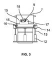
開口部5は混合容器1の中央にある。この開口部は、閉鎖カバー6の形態の閉鎖要素で閉鎖することができる。混合容器底部7を見ることができる。
The
容器底部7は、回転軸線8周りで混合容器と一緒に回転する。閉塞カバー6は、この開閉カバー6を開閉する枢動軸線9の周りを枢動する。これが可能となるように、開口部および閉鎖カバーは、好ましくは、開口部を開閉するために、閉鎖要素部分を、概念球の中心点が存在する枢動軸線周りで枢動できるように、概念球上に存在するように湾曲した互いに対応するエッジ面を有する。
The
一般に、混合材料は混合容器底部7の上方に配置された混合容器内に配置され、閉鎖カバー6が開放されると、開口部5を通って混合材料排出部10内に落下する。混合材料排出部10は容器底部に連結されており、容器と共に同じ回転をするようになっている。混合材料排出部10に配置されているのは、固定系に連結された裾部11である。混合材料排出部10および裾部11は、回転軸受16を介して互いに対して回転可能である。
Generally, the mixed material is placed in a mixing vessel located above the mixing
リフト装置12、13もまた、固定系、すなわち、例えば、対応する混合装置が配置されたミキサーベースに連結されて配置される。図示の例では、2つのリフトストロークピストン13がピストンハウジング12内の対応するチャンバ内に配置されている。それ自体公知の方法では、リフトピストン13によって形成される流体チャンバには、例えば図2および図3に示されるその2つの極端な位置の間でハウジング12内でリフトピストン13を往復運動させるために、ピストンハウジング12内で圧力流体を作用させることができる。
The
リフトピストン13は、第1のリフト要素部14に連結されている。リフト装置12、13が作動すると、リフト要素部14は、リフトピストン13とともに上方および下方に移動することができる。リフト要素部は、第1リフ要素部14及び第2のリフト要素部15を含む。2つのリフト要素部14、15は、回転軸受16を介して互いに対して回転可能である。第1のリフト要素部14がリフトピストン13に固定されるので、すなわち固定系に配置され、混合容器と一緒に回転しない。第2のリフト要素部15は、混合材料排出部10に連結され、混合容器の駆動時に混合材料排出部10及び混合容器と共に回転する。第1のリフト要素部と第2のリフト要素部とが、リフト装置12,13の直線運動の方向にポジティブロックの係止関係で互いに連結されるように配置されており、これは、第1のリフト要素部14が図2に示す下方位置から図3に示す上方位置に移動すると、第2のリフト要素部15も持ち上がることを意味する。
A
特に図2及び図3から分かるように、カムプレート17が第2のリフト要素部15に連結されている。レバー18は、カムプレートを走行し、混合容器または混合材料排出部10に連結される。ここで、リフト装置が作動してリフト要素部を低い図2の位置から高い図3位置に移動させると、レバー18はカムプレート17に沿って走行し、枢動軸線9を中心として時計回りに枢動する。枢動軸線9上の枢動シャフト19が閉鎖カバー6に連結されるため、閉鎖カバー6も枢動軸線9を中心に枢動する。
As can be seen in particular from FIGS. 2 and 3, a
図4は、多部品閉鎖カバーにおける図1~図3の閉鎖領域の断面図を示す。この場合、第2のリフト要素部15は、直線運動を枢動運動に変換するための2つの器具17′、17″、18′、18″を有し、これらは共に第2のリフト要素部15に連結されている。カム板17′、17″は対向関係に配置された第2のリフト要素部15に連結されている。カムプレート17’、17”は、好ましくは、閉鎖カバー部6’、6”(図示せず)の互に反対の動きに対して一致するものであり、すなわち、それらは鏡像対称の構成ではない。適切なレバー18’、18”は、カムプレート内をそれぞれ走行し、両レバーは、枢動軸線上に配置された枢動シャフト19’、19”にそれぞれ連結され、レバーは枢動シャフトにそれぞれ関連付けられた閉鎖カバー部6’、6”にそれぞれ連結されている。閉鎖カバーは2つの閉鎖カバー部6’、6”を備え、2つの閉鎖カバー部6’、6”は閉鎖位置と枢動軸線周りの開位置との間で往復移動するように、枢動軸線の周りの閉鎖位置と開位置との間で互いに対して往復移動する。この構成では、両方の閉鎖カバー部は、同じ枢動軸線9の周りで枢動可能であり、一方の閉鎖カバー6部’は、直線運動を枢動運動に変換するための装置17’、18’、19’に連結され、他方の閉鎖カバー6部”は、直線運動を枢動運動に変換するためのさらなる装置17”、18”、19”に連結され、同一のカムプレート17’および17”を使用する場合、一方の枢動シャフト19’は時計回り方向に旋回し、他方、同じ枢動軸線9上に配置された第2の枢動シャフト19”は、反時計回り方向に移動する。
FIG. 4 shows a cross-sectional view of the closure area of FIGS. 1-3 in a multi-part closure cover. In this case, the second
記載された変換装置のおかげで、並進移動によって固定系から回転系内で枢動運動を生じさせることが簡単な方法で可能である。 Thanks to the described conversion device it is possible in a simple way to produce a pivoting movement in a rotating system from a fixed system by means of a translational movement.
1 混合容器
2 混合器具
3 ミキサーシャフト
4 底部ブレード
5 開口部
6 閉鎖カバー
6’,6” 閉鎖カバー部
7 混合容器底部
8 回転軸線
9 枢動軸線
10 混合材料排出部
11 裾部
12 ピストンハウジング
13 リフト装置
14 第1のリフト要素部
15 第2のリフト要素部
16 回転軸受
17 カムプレート
18 レバー
19,19’,19” 枢動シャフト
1 mixing
Claims (9)
前記枢動軸線と前記回転軸線は同一ではなく、かつ互いに平行に延びていなく、前記枢動軸線と前記回転軸線とは互いに垂直に延びていることが好ましく、リフト装置によって前記固定系に対する並進移動を伴って移動することができるリフト要素と、直線運動を枢動運動に変換するための装置と、を備え、
前記リフト要素は第1のリフト要素部と第2のリフト要素部とを有し、2つのリフト要素部は、前記第1のリフト要素部が回転軸受の軸線周りを前記第2のリフト要素部に対して回転することができるように、回転軸受を介して互いに連結され、
前記リフト要素の2つの要素部は、前記リフト装置の前記並進移動の方向にポジティブロックの係止関係で互いに連結されて、
前記第1のリフト要素部は前記リフト装置に連結され、前記第2のリフト要素部は、直線運動を回転運動に変換する変換装置に連結され、
前記直線運動を回転運動に変換する変換装置は、前記第2のリフト要素部の直線運動が前記枢動軸線周りの回転運動に変換されるように、前記枢動軸線上に配置されたシャフトに連結され、
直線運動を回転運動に変換する前記変換装置が、前記第2のリフト要素部に連結されたカムプレートと、該カムプレートに接触し、前記シャフトに連結されたレバーと、を有する、変換装置。 A conversion device for converting linear motion in a fixed system to pivotal motion about a pivot axis in a system rotating about an axis of rotation, comprising:
Preferably, said pivot axis and said rotation axis are not the same and do not extend parallel to each other, said pivot axis and said rotation axis extending perpendicular to each other, a translational movement relative to said fixed system by means of a lifting device. and a device for converting linear motion into pivotal motion,
The lift element has a first lift element portion and a second lift element portion, the two lift element portions being configured such that the first lift element portion revolves around the axis of the rotary bearing and the second lift element portion. connected to each other via a rotary bearing so as to be able to rotate with respect to
the two element portions of the lifting element being coupled together in a positive locking locking relationship in the direction of the translational movement of the lifting device;
said first lift element portion being coupled to said lifting device and said second lift element portion being coupled to a conversion device for converting linear motion into rotary motion;
A conversion device for converting linear motion to rotary motion is provided on a shaft disposed on said pivot axis such that linear motion of said second lift element portion is converted to rotary motion about said pivot axis. concatenated ,
The conversion device for converting linear motion to rotary motion comprises a cam plate connected to the second lift element portion and a lever contacting the cam plate and connected to the shaft .
請求項1~5の何れか一項に記載の変換装置を備え、前記ミキサーベースは前記固定系の一部であり、前記容器は前記回転系の一部であり、前記閉鎖カバーは、前記開口部を開閉するための枢動軸線周りを回転可能である、ことを特徴とする混合装置。 A container for receiving a mixed material, said container being rotatable about a container axis and having an opening arranged in its bottom, a closing cover for closing said opening, a container in a mixer base that is rotatable and a mixing device comprising
6. A conversion device according to any one of claims 1 to 5 , wherein the mixer base is part of the stationary system, the container is part of the rotating system, and the closure cover comprises the opening A mixing device, characterized in that it is rotatable about a pivot axis for opening and closing the part.
前記2つの閉鎖カバー部の間に前記混合材料を除去する開口部が、前記閉鎖位置と前記開放位置との間を前記2つの閉鎖カバー部が往復運動するように形成され、
前記2つの閉鎖カバー部は同一の枢動軸線周りを枢動可能であり、
直線運動を回転運動に変換するための更なる装置が設けられ、該装置は、前記第2のリフト要素部と、前記枢動軸線上に配置された第2シャフトと、に連結され、
直線運動を回転運動に変換する2つの装置は、前記枢動軸線上に配置された2つのシャフトが互いに反対方向に移動するような構成であり、
一方の閉鎖カバー部は、直線運動を回転運動に変換するための変換装置に連結され、他方の閉鎖カバー部は、直線運動を回転運動に変換するための更なる装置に連結されていることを特徴とする請求項6に記載の混合装置。 The closure cover comprises two closure cover parts, the two closure cover parts having a closed position in which the two closure cover parts are in contact to form the closure cover and a closed position in which the two closure cover parts are spaced apart from each other. pivotable relative to each other about a pivot axis between an open position in which the
an opening between the two closure cover parts for removing the mixed material is formed as the two closure cover parts reciprocate between the closed position and the open position;
the two closure cover parts are pivotable about the same pivot axis;
a further device is provided for converting linear motion into rotary motion, said device being coupled to said second lifting element portion and to a second shaft arranged on said pivot axis;
the two devices for converting linear motion into rotary motion are arranged such that two shafts arranged on said pivot axis move in opposite directions;
It is noted that one closure cover part is connected to a conversion device for converting linear motion into rotary motion and the other closure cover part is connected to a further device for converting linear motion into rotary motion. 7. Mixing device according to claim 6 .
Applications Claiming Priority (3)
| Application Number | Priority Date | Filing Date | Title |
|---|---|---|---|
| DE102018106188.9 | 2018-03-16 | ||
| DE102018106188.9A DE102018106188A1 (en) | 2018-03-16 | 2018-03-16 | Device for converting a linear movement in a stationary system into a rotational movement about a pivot axis in a system rotating about a rotation axis |
| PCT/EP2019/055843 WO2019175049A1 (en) | 2018-03-16 | 2019-03-08 | Device for converting a linear movement in a stationary system into a rotational movement about a pivot axis in a system which rotates about a rotational axis |
Publications (2)
| Publication Number | Publication Date |
|---|---|
| JP2021518510A JP2021518510A (en) | 2021-08-02 |
| JP7163401B2 true JP7163401B2 (en) | 2022-10-31 |
Family
ID=65729351
Family Applications (1)
| Application Number | Title | Priority Date | Filing Date |
|---|---|---|---|
| JP2020549591A Active JP7163401B2 (en) | 2018-03-16 | 2019-03-08 | A conversion device that converts linear motion in a fixed system into pivotal motion about a pivot axis in a system that rotates about an axis of rotation |
Country Status (12)
| Country | Link |
|---|---|
| US (1) | US11325085B2 (en) |
| EP (1) | EP3765183B1 (en) |
| JP (1) | JP7163401B2 (en) |
| KR (1) | KR102580679B1 (en) |
| CN (1) | CN111902205B (en) |
| BR (1) | BR112020016872A2 (en) |
| CA (1) | CA3091972C (en) |
| DE (1) | DE102018106188A1 (en) |
| ES (1) | ES2954517T3 (en) |
| PL (1) | PL3765183T3 (en) |
| UA (1) | UA126097C2 (en) |
| WO (1) | WO2019175049A1 (en) |
Families Citing this family (3)
| Publication number | Priority date | Publication date | Assignee | Title |
|---|---|---|---|---|
| DE102018106189A1 (en) * | 2018-03-16 | 2019-09-19 | Maschinenfabrik Gustav Eirich Gmbh & Co. Kg | hygiene mixer |
| DE102018106188A1 (en) * | 2018-03-16 | 2019-09-19 | Maschinenfabrik Gustav Eirich Gmbh & Co. Kg | Device for converting a linear movement in a stationary system into a rotational movement about a pivot axis in a system rotating about a rotation axis |
| KR20220047023A (en) | 2020-10-08 | 2022-04-15 | 에스케이온 주식회사 | Anode active material for lithium secondary battery and methode of manufacturing the same |
Citations (9)
| Publication number | Priority date | Publication date | Assignee | Title |
|---|---|---|---|---|
| DE19546848A1 (en) | 1995-12-15 | 1997-06-19 | Zimmermann Benno Dipl Ing Fh | Mixing arrangement for highly viscous liquids |
| JP2000213926A (en) | 1999-01-28 | 2000-08-04 | Commuter Helicopter Senshin Gijutsu Kenkyusho:Kk | Fault detecting device and higher harmonic actuator system |
| JP3110688B2 (en) | 1996-10-04 | 2000-11-20 | ホシザキ電機株式会社 | Agitator mounting structure |
| JP2005296805A (en) | 2004-04-12 | 2005-10-27 | Fujiki:Kk | Material mixing method and mixer |
| WO2012076705A2 (en) | 2010-12-09 | 2012-06-14 | Altade | Aircraft rotor comprising rotary wings |
| JP5152177B2 (en) | 2007-03-23 | 2013-02-27 | パナソニック株式会社 | Conductive bump, manufacturing method thereof, and electronic component mounting structure |
| JP5216489B2 (en) | 2008-08-29 | 2013-06-19 | 株式会社東芝 | Automatic ticket gate and gate control method for automatic ticket gate |
| US20150060597A1 (en) | 2012-06-26 | 2015-03-05 | Bell Helicopter Textron Inc. | Dual Series Pitch Link Bearing |
| JP2016539052A (en) | 2013-10-23 | 2016-12-15 | 深セン聯合飛机科技有限公司Shenzhen United Aircraft Technology Co., Ltd | Rotor driving method and rotor driving device |
Family Cites Families (28)
| Publication number | Priority date | Publication date | Assignee | Title |
|---|---|---|---|---|
| US1757098A (en) * | 1929-03-14 | 1930-05-06 | Union Machinery Company | Mixing machine |
| US3434697A (en) * | 1967-07-12 | 1969-03-25 | A & R Meats Inc | Mixing machine |
| JPS6011318Y2 (en) * | 1974-10-18 | 1985-04-15 | 松下電器産業株式会社 | motion transmission device |
| JPS5216489U (en) * | 1975-07-24 | 1977-02-05 | ||
| DE2903951C3 (en) * | 1979-02-02 | 1985-01-03 | Eirich, Hubert | Device for closing an emptying opening in a container bottom |
| DE3302109A1 (en) * | 1983-01-22 | 1984-08-09 | Hubert Eirich | DEVICE FOR CLOSING AND CONTINUOUSLY EMPTYING THE CONTAINER OF A PROCESSING MACHINE |
| DE3520409A1 (en) * | 1985-06-07 | 1986-12-11 | Hubert Eirich | PRESSURE-RESISTANT MIXER |
| RU2028523C1 (en) | 1988-04-13 | 1995-02-09 | Миллер Франц-Георг | Device for converting rotation to reciprocation and vice versa |
| DE3838981A1 (en) * | 1988-11-18 | 1990-05-23 | Eirich Walter | AGITATOR BALL MILL |
| SE462811B (en) * | 1989-05-09 | 1990-09-03 | Hans Karlsson | DEVICE FOR CONVERSION OF A PROMOTING AND ATTACHING MOVEMENT TO A ROTATING MOVEMENT |
| DE4002099A1 (en) * | 1990-01-25 | 1991-08-01 | Draiswerke Gmbh | MIXER |
| US5249861A (en) * | 1991-07-18 | 1993-10-05 | Kusel Equipment Co. | Apparatus for cooling, washing, draining, and blending liquid suspended materials |
| RU2050961C1 (en) | 1993-05-06 | 1995-12-27 | Уральский научно-технический комплекс | Continuous operation drum mixer |
| DE9400396U1 (en) * | 1994-01-12 | 1994-04-14 | Glatt GmbH Systemtechnik, 01277 Dresden | Container mixer |
| KR970002324B1 (en) * | 1994-10-20 | 1997-03-03 | 기아자동차 주식회사 | The module carrier panel of an automotive door |
| JPH10201437A (en) * | 1997-01-22 | 1998-08-04 | Suzumo Kiko Kk | Automatic mixing device for rice and mixed vinegar or the like for manufacturing sushi rice |
| DE102008054842A1 (en) * | 2008-12-17 | 2010-07-01 | Maschinenfabrik Gustav Eirich Gmbh & Co. Kg | mixer |
| DE102010027885A1 (en) | 2010-04-16 | 2012-02-09 | Maschinenfabrik Gustav Eirich Gmbh & Co. Kg | Mixing device with wear protection lining |
| KR101195571B1 (en) * | 2010-05-10 | 2012-10-29 | 유한회사 금영토건 | mixing device of quick-hardening cocrete manufacturing for movable concrete batch plant |
| US9415529B2 (en) * | 2012-05-08 | 2016-08-16 | Basf Se | Method for operating an apparatus with at least one rotating shaft |
| WO2015169458A1 (en) * | 2014-05-06 | 2015-11-12 | Veit Herbert | Device for receiving and discharging mixable materials |
| CN106237923A (en) * | 2016-07-19 | 2016-12-21 | 柳州首光科技有限公司 | A kind of high reliability chemical fertilizer automatic mixing machine based on zigbee network |
| CN106746460A (en) * | 2016-12-29 | 2017-05-31 | 长兴创智科技有限公司 | A kind of sludge treatment equipment |
| DE102017104842A1 (en) * | 2017-03-08 | 2018-09-13 | Maschinenfabrik Gustav Eirich Gmbh & Co. Kg | Mixer with cleaning nozzle |
| CN107694432A (en) * | 2017-06-23 | 2018-02-16 | 胡将龙 | A kind of new mixed fodder agitating device |
| DE102018106188A1 (en) * | 2018-03-16 | 2019-09-19 | Maschinenfabrik Gustav Eirich Gmbh & Co. Kg | Device for converting a linear movement in a stationary system into a rotational movement about a pivot axis in a system rotating about a rotation axis |
| DE102018106192A1 (en) * | 2018-03-16 | 2019-09-19 | Maschinenfabrik Gustav Eirich Gmbh & Co. Kg | Mixing device with two-part cap |
| DE102019108869A1 (en) * | 2019-04-04 | 2020-10-08 | Maschinenfabrik Gustav Eirich Gmbh & Co. Kg | Mixer with sealing cap |
-
2018
- 2018-03-16 DE DE102018106188.9A patent/DE102018106188A1/en active Pending
-
2019
- 2019-03-08 CA CA3091972A patent/CA3091972C/en active Active
- 2019-03-08 WO PCT/EP2019/055843 patent/WO2019175049A1/en active Application Filing
- 2019-03-08 JP JP2020549591A patent/JP7163401B2/en active Active
- 2019-03-08 ES ES19710382T patent/ES2954517T3/en active Active
- 2019-03-08 US US16/981,062 patent/US11325085B2/en active Active
- 2019-03-08 KR KR1020207029687A patent/KR102580679B1/en active IP Right Grant
- 2019-03-08 BR BR112020016872-6A patent/BR112020016872A2/en unknown
- 2019-03-08 CN CN201980019760.8A patent/CN111902205B/en active Active
- 2019-03-08 UA UAA202005698A patent/UA126097C2/en unknown
- 2019-03-08 EP EP19710382.3A patent/EP3765183B1/en active Active
- 2019-03-08 PL PL19710382.3T patent/PL3765183T3/en unknown
Patent Citations (9)
| Publication number | Priority date | Publication date | Assignee | Title |
|---|---|---|---|---|
| DE19546848A1 (en) | 1995-12-15 | 1997-06-19 | Zimmermann Benno Dipl Ing Fh | Mixing arrangement for highly viscous liquids |
| JP3110688B2 (en) | 1996-10-04 | 2000-11-20 | ホシザキ電機株式会社 | Agitator mounting structure |
| JP2000213926A (en) | 1999-01-28 | 2000-08-04 | Commuter Helicopter Senshin Gijutsu Kenkyusho:Kk | Fault detecting device and higher harmonic actuator system |
| JP2005296805A (en) | 2004-04-12 | 2005-10-27 | Fujiki:Kk | Material mixing method and mixer |
| JP5152177B2 (en) | 2007-03-23 | 2013-02-27 | パナソニック株式会社 | Conductive bump, manufacturing method thereof, and electronic component mounting structure |
| JP5216489B2 (en) | 2008-08-29 | 2013-06-19 | 株式会社東芝 | Automatic ticket gate and gate control method for automatic ticket gate |
| WO2012076705A2 (en) | 2010-12-09 | 2012-06-14 | Altade | Aircraft rotor comprising rotary wings |
| US20150060597A1 (en) | 2012-06-26 | 2015-03-05 | Bell Helicopter Textron Inc. | Dual Series Pitch Link Bearing |
| JP2016539052A (en) | 2013-10-23 | 2016-12-15 | 深セン聯合飛机科技有限公司Shenzhen United Aircraft Technology Co., Ltd | Rotor driving method and rotor driving device |
Also Published As
| Publication number | Publication date |
|---|---|
| PL3765183T3 (en) | 2023-11-13 |
| JP2021518510A (en) | 2021-08-02 |
| CA3091972A1 (en) | 2019-09-19 |
| WO2019175049A1 (en) | 2019-09-19 |
| CA3091972C (en) | 2024-03-19 |
| RU2020130256A3 (en) | 2022-04-18 |
| EP3765183C0 (en) | 2023-07-12 |
| CN111902205A (en) | 2020-11-06 |
| UA126097C2 (en) | 2022-08-10 |
| ES2954517T3 (en) | 2023-11-22 |
| RU2020130256A (en) | 2022-04-18 |
| EP3765183B1 (en) | 2023-07-12 |
| KR20200130433A (en) | 2020-11-18 |
| DE102018106188A1 (en) | 2019-09-19 |
| CN111902205B (en) | 2022-07-05 |
| US20210023519A1 (en) | 2021-01-28 |
| EP3765183A1 (en) | 2021-01-20 |
| BR112020016872A2 (en) | 2020-12-15 |
| KR102580679B1 (en) | 2023-09-21 |
| US11325085B2 (en) | 2022-05-10 |
Similar Documents
| Publication | Publication Date | Title |
|---|---|---|
| JP7163401B2 (en) | A conversion device that converts linear motion in a fixed system into pivotal motion about a pivot axis in a system that rotates about an axis of rotation | |
| US11986788B2 (en) | Mixing device having a two-part closure lid | |
| RU2768399C1 (en) | Hygienic mixer | |
| CN203955158U (en) | Flat mixer outlet valve | |
| US20220161209A1 (en) | Mixer having a closing cover | |
| RU2775736C2 (en) | Apparatus for converting linear motion in a stationary system into rotational motion around a pivot in a system rotating around an axis of rotation | |
| CN213687756U (en) | Discharge port mechanism of coulter dryer | |
| CN111867713B (en) | Mixing device with closure element | |
| CN110107704A (en) | New-type manual simplified gate valve | |
| RU2802210C2 (en) | Agitator with locking lid | |
| CN219729237U (en) | Full-sealed blanking valve | |
| CN110360323A (en) | Separate type outlet valve | |
| RU2175883C1 (en) | Device for mixing liquids in standard vessels |
Legal Events
| Date | Code | Title | Description |
|---|---|---|---|
| A521 | Request for written amendment filed |
Free format text: JAPANESE INTERMEDIATE CODE: A523 Effective date: 20201015 |
|
| A621 | Written request for application examination |
Free format text: JAPANESE INTERMEDIATE CODE: A621 Effective date: 20211105 |
|
| A977 | Report on retrieval |
Free format text: JAPANESE INTERMEDIATE CODE: A971007 Effective date: 20220915 |
|
| TRDD | Decision of grant or rejection written | ||
| A01 | Written decision to grant a patent or to grant a registration (utility model) |
Free format text: JAPANESE INTERMEDIATE CODE: A01 Effective date: 20221004 |
|
| A61 | First payment of annual fees (during grant procedure) |
Free format text: JAPANESE INTERMEDIATE CODE: A61 Effective date: 20221019 |
|
| R150 | Certificate of patent or registration of utility model |
Ref document number: 7163401 Country of ref document: JP Free format text: JAPANESE INTERMEDIATE CODE: R150 |