JP7150421B2 - game machine - Google Patents
game machine Download PDFInfo
- Publication number
- JP7150421B2 JP7150421B2 JP2017176298A JP2017176298A JP7150421B2 JP 7150421 B2 JP7150421 B2 JP 7150421B2 JP 2017176298 A JP2017176298 A JP 2017176298A JP 2017176298 A JP2017176298 A JP 2017176298A JP 7150421 B2 JP7150421 B2 JP 7150421B2
- Authority
- JP
- Japan
- Prior art keywords
- display
- image
- displayed
- game
- light
- Prior art date
- Legal status (The legal status is an assumption and is not a legal conclusion. Google has not performed a legal analysis and makes no representation as to the accuracy of the status listed.)
- Active
Links
Images


Landscapes
- Display Devices Of Pinball Game Machines (AREA)
Description
本発明は、遊技を行なう遊技機に関する。 The present invention relates to a gaming machine for playing games.
従来、可動役物などの役物に対して効果を加える画像であるエフェクト画像が、表示装置の画面に表示している画像の全体に重畳する遊技機があった(たとえば、特許文献1参照)。
2. Description of the Related Art Conventionally, there have been gaming machines in which an effect image, which is an image that adds an effect to a character such as a movable character, is superimposed on the entire image displayed on the screen of a display device (see
特許文献1のような遊技機によれば、役物が重畳している画像の視認性が著しく妨げられ、遊技の興趣が低下する虞があった。
According to the game machine disclosed in
(A) 遊技を行い、遊技者にとって有利な有利状態に制御可能な遊技機であって、
表示手段と、
前記表示手段において、遊技に対するのめり込み防止に関する注意喚起画像を前記表示手段に表示可能な注意喚起手段と、
動作可能な可動役物と、
前記表示手段において、前記有利状態に制御されるか否かを示唆するリーチ演出を実行可能なリーチ演出実行手段と、
を備え、
前記リーチ演出実行手段は、前記リーチ演出において前記表示手段の前面側にて前記可動役物を動作させることが可能であり、
前記注意喚起手段は、
少なくともデモンストレーション表示可能な待機状態における所定期間と、前記有利状態が終了するときと、において前記注意喚起画像を前記表示手段に表示可能であり、
前記有利状態が終了するときに前記注意喚起画像を表示する場合、前記表示手段の前記リーチ演出において前記可動役物が動作する位置と重複する表示領域において前記注意喚起画像を表示可能であり、
前記注意喚起画像は、第1注意喚起画像と、第2注意喚起画像と、を含み、
前記所定期間は、
前記第1注意喚起画像がフェードイン態様にて表示される第1特別期間と、
前記第1注意喚起画像が通常態様にて表示される第2特別期間と、
前記第1注意喚起画像がフェードアウト態様にて表示された後、非表示となる第3特別期間と、
前記第2注意喚起画像がフェードイン態様にて表示される第1特定期間と、
前記第2注意喚起画像が通常態様にて表示される第2特定期間と、
前記第2注意喚起画像がフェードアウト態様にて表示された後、非表示となる第3特定期間と、を含み、
前記第2特別期間は、前記第1特別期間と前記第3特別期間との合計よりも長く、
前記第2特定期間は、前記第1特定期間と前記第3特定期間との合計よりも長く、
前記第2特別期間の長さと前記第2特定期間の長さとが異なり、
前記遊技機が電断から復旧してから前記待機状態において前記注意喚起画像が表示されるまでの期間と、前記遊技機が初期化されてから前記待機状態において前記注意喚起画像が表示されるまでの期間とが異なる。
遊技機は、以下のように構成されてもよい。
(1) 遊技を行なう遊技機(たとえば、パチンコ遊技機1、スロットマシン)であって、
表示手段(たとえば、画像表示装置5)と、
前記表示手段の近傍に設けられ変化(たとえば、位置または形状が変化(変位、変形))可能な部品(たとえば、可動役物400)とを備え、
前記表示手段は、前記部品の変化に対応した所定画像(たとえば、エフェクト画像P3、第2発光ユニット320~第9発光ユニット390から発せられる複数の点状の光L1のパターンP1を模した点状の光画像L2のパターン画像P2)を表示しているときに、前記所定画像とは異なる特定画像(たとえば、遊技者にとって有利な有利状態となるか否かを示唆するキャラクタ画像C1~C3などの示唆画像)を表示可能であり、
前記所定画像は、前記特定画像に重畳する第1部分と、前記特定画像に重畳しない第2部分とを含む(たとえば、図17,図20参照)。
(A) A gaming machine capable of performing a game and being able to be controlled in an advantageous state for the player,
display means;
an alerting means capable of displaying, on the display means, an alerting image for preventing addiction to a game;
a operable movable object;
a ready-to-win effect executing means capable of executing a ready-to-win effect indicating whether or not the display means is controlled to the advantageous state;
with
The ready-to-win effect execution means can operate the movable accessory on the front side of the display means in the ready-to-win effect,
The alerting means is
The alert image can be displayed on the display means at least during a predetermined period in a standby state in which demonstration display is possible and when the advantageous state ends,
When the alert image is displayed when the advantageous state ends, the alert image can be displayed in a display area overlapping a position where the movable accessory moves in the ready-to-win effect of the display means,
The alert image includes a first alert image and a second alert image,
The predetermined period is
a first special period in which the first alert image is displayed in a fade-in mode ;
a second special period in which the first alert image is displayed in a normal mode ;
a third special period in which the first alert image is displayed in a fade-out manner and then is not displayed ;
a first specific period during which the second alert image is displayed in a fade-in mode;
a second specific period during which the second alert image is displayed in a normal mode;
After the second alert image is displayed in a fade-out mode, it is hidden for a third specific period,
The second special period is longer than the sum of the first special period and the third special period,
The second specific period is longer than the sum of the first specific period and the third specific period,
The length of the second special period and the length of the second specific period are different,
A period from when the game machine is restored from power failure to when the attention image is displayed in the standby state, and from when the game machine is initialized to when the attention image is displayed in the standby state. is different from the period of
The gaming machine may be configured as follows.
(1) A gaming machine (for example, a
a display means (for example, an image display device 5);
A part (for example, movable accessory 400) that is provided near the display means and can be changed (for example, position or shape can be changed (displacement, deformation)),
The display means displays a predetermined image corresponding to the change in the parts (for example, an effect image P3, a dot-like image simulating a pattern P1 of a plurality of dot-like lights L1 emitted from the second
The predetermined image includes a first portion superimposed on the specific image and a second portion not superimposed on the specific image (see FIGS. 17 and 20, for example).
このような構成によれば、所定画像が重畳する特定画像の視認性が妨げられ難くすることができる。その結果、興趣の低下を抑制することができる。 According to such a configuration, visibility of the specific image on which the predetermined image is superimposed is less likely to be hindered. As a result, it is possible to suppress the decrease in interest.
(2) 上記(1)の遊技機において、
前記所定画像の前記第1部分の面積は、変化可能である(たとえば、図20,図21で示すように、部品の変位または変形に応じて変化可能である)。
(2) In the gaming machine of (1) above,
The area of the first portion of the predetermined image is variable (eg, variable in response to displacement or deformation of the part, as shown in Figures 20 and 21).
このような構成によれば、所定画像の特定画像に重畳する部分の面積の変化によって、特定画像へ視線を集めることができる。 According to such a configuration, it is possible to draw the line of sight to the specific image by changing the area of the portion of the predetermined image that overlaps the specific image.
(3) 上記(1)または(2)の遊技機において、
前記部品は、位置が変化可能であり、
前記表示手段は、前記部品が前記表示手段に重畳する面積が広い場合は、狭い場合よりも、前記第1部分を大きくする(たとえば、図20,図21参照)。
(3) In the game machine of (1) or (2) above,
the part is changeable in position;
When the area where the part overlaps the display means is large, the display means makes the first portion larger than when the area is small (see FIGS. 20 and 21, for example).
このような構成によれば、所定画像の演出効果を高めることができるとともに、部品を
用いた演出を盛り上げることができる。
According to such a configuration, it is possible to enhance the presentation effect of the predetermined image, and to liven up the presentation using the parts.
(4) 上記(1)から(3)のいずれかの遊技機において、
前記表示手段は、前記所定画像の態様を演出の進行に応じて変化させることが可能である(たとえば、図20,図21参照)。
(4) In any one of the gaming machines (1) to (3) above,
The display means can change the mode of the predetermined image in accordance with the progress of the presentation (see FIGS. 20 and 21, for example).
このような構成によれば、遊技者を所定画像の態様に注目させることができる。
(5) 上記(1)から(4)のいずれかの遊技機において、
前記表示手段は、前記所定画像を特定態様(たとえば、赤色の態様)で表示する場合、前記特定態様で表示しない場合と比較して高い割合で、前記特定画像を特別態様(たとえば、遊技者にとって有利な有利状態となる期待度の高い態様、図17,図20等で示すようなキャラクタ画像C1~C3が手を振っている態様)で表示する(たとえば、図19参照)。
According to such a configuration, it is possible to make the player pay attention to the aspect of the predetermined image.
(5) In any one of the gaming machines (1) to (4) above,
When the predetermined image is displayed in a specific mode (for example, a red mode), the display means displays the specific image in a special mode (for example, a The character images C1 to C3 are displayed in an advantageous advantageous state with a high degree of expectation, as shown in FIGS. 17 and 20, etc. (see FIG. 19, for example).
このような構成によれば、所定画像を用いて特定画像への期待感を遊技者に持たせることができる。 According to such a configuration, it is possible to give the player a feeling of anticipation for the specific image by using the predetermined image.
(6) 上記(1)から(5)のいずれかの遊技機において、
前記遊技機は、遊技者にとって有利な有利状態(たとえば、大当り状態)に制御可能であり、
遊技に対するのめり込み防止に関する注意喚起を実行可能な注意喚起手段(たとえば、のめり込み防止画像131を表示する演出制御用CPU120)をさらに備え、
前記注意喚起手段は、
少なくとも非遊技状態(たとえば、客待ちデモ状態)のときと、前記有利状態が終了したとき(たとえば、エンディング期間)とでのめり込み防止に関する注意喚起を実行可能であり、
前記非遊技状態のときと、前記有利状態が終了したときとで異なる態様によりのめり込み防止に関する注意喚起を実行する(たとえば、客待ちデモ状態のときには、図25(h)に示すように画像表示装置5の画面の下部にのめり込み防止画像131を大きく表示し、エンディング期間では、図28(b)に示すように画像表示装置5の画面の左下隅にのめり込み防止画像136を小さく表示する、図23に示すように、客待ちデモ状態のときよりも大当り終了後のエンディング期間のときの方がのめり込み防止画像の表示期間が短い等)。
(6) In any one of the gaming machines (1) to (5) above,
The gaming machine is controllable to an advantageous state (for example, a jackpot state) that is advantageous to the player,
It further includes an alerting means (for example, a
The alerting means is
At least during a non-gaming state (for example, customer waiting demonstration state) and when the advantageous state ends (for example, ending period), it is possible to call attention to preventing addiction,
In the non-gaming state and when the advantageous state ends, attention is drawn to the prevention of immersion in different modes (for example, in the customer waiting demonstration state, an image display device as shown in FIG. 25(h) is executed. 5, a large
このような構成によれば、好適にのめり込み防止に関する注意喚起を実行することができる。 According to such a configuration, it is possible to suitably call attention to prevention of immersion.
(パチンコ遊技機1)
(パチンコ遊技機1の全体構成等)
図1は、パチンコ遊技機1の正面図であり、主要部材の配置レイアウトを示す。パチンコ遊技機(遊技機)1は、遊技盤面を構成する遊技盤(ゲージ盤)2と、遊技盤2を支持固定する遊技機用枠(台枠)3とを有する。遊技盤2には、遊技領域が形成され、この遊技領域には、遊技媒体としての遊技球が、所定の打球発射装置から発射されて打ち込まれる。なお、この実施の形態では、左打ち(矢印R0→R1参照)及び右打ち(矢印R0→R2→R3参照)が可能なように、遊技領域が形成されている。
(Pachinko machine 1)
(Overall Configuration of
FIG. 1 is a front view of the
遊技盤2の所定位置(遊技領域の下方)には、第1特別図柄(第1特図ともいう。)の可変表示(第1特図ゲームともいう)を行う第1特別図柄表示装置4Aと、第2特別図柄(第2特図ともいう。)の可変表示(第2特図ゲームともいう)を行う第2特別図柄表示装置4Bと、が設けられている。なお、第1特図ゲーム及び第2特図ゲームを総称して特図ゲームということがある。また、普通図柄(「普図」あるいは「普通図」ともいう)の可変表示(普図ゲームともいう。)を行う普通図柄表示器20が設けられている。これらは、7セグメントのLED(Light Emitting Diode)などからなり、特別図柄や普通図柄は、「0」~「9」を示す数字や「-」などの点灯パターンやLEDを全て消灯したパターンなどの複数種類の識別情報を示すものであればよい。
At a predetermined position (below the game area) of the
なお、「可変表示」とは、例えば、複数種類の図柄を更新表示などにより変動させる(変動可能に表示する)ことである(後述の飾り図柄(以下「演出図柄」ともいう)の可変表示についても同じ)。可変表示の最後には、表示結果(可変表示結果)として所定の図柄が停止表示(導出表示などともいう)される(後述の飾り図柄の可変表示についても同
じ)。なお、図柄(特に、後述の飾り図柄)の変動として、スクロール表示、変形、拡大/縮小などが行われてもよい。
In addition, "variable display" means, for example, to change (variably display) a plurality of types of patterns by updating display, etc. the same). At the end of the variable display, a predetermined pattern is stopped and displayed (also referred to as derived display) as a display result (variable display result) (the same applies to the variable display of decorative patterns, which will be described later). In addition, scroll display, deformation, enlargement/reduction, etc. may be performed as the variation of the pattern (especially, the decoration pattern described later).
特図ゲームでの可変表示結果としては、「大当り」の図柄(例えば、「確変大当り」の「7」及び「非確変大当り」の「3」)、「ハズレ」の図柄(例えば、「-」)がある。普図ゲームでの可変表示結果としては、「普図当り」の図柄(例えば、「7」)、「普図ハズレ」の図柄(例えば、「-」)がある。 As a variable display result in the special game, a "jackpot" pattern (for example, "7" for "probability variation jackpot" and "3" for "non-probability variation jackpot"), a "losing" pattern (for example, "-" ). As variable display results in the general-purpose game, there are a symbol of "win" (for example, "7") and a symbol of "loss in general-purpose" (eg, "-").
「大当り」の図柄が導出表示されたときには、パチンコ遊技機1は、大当り遊技状態に制御される。大当り遊技状態では、後述の大入賞口が開放状態となる。「大当り」が「確変大当り」のときには、大当り遊技状態終了後の遊技状態が確変状態及び時短状態に制御される。「大当り」が「非確変大当り」のときには、大当り遊技状態終了後の遊技状態が時短状態に制御される(確変状態には制御されない)。確変状態は、確変状態となっていないとき(非確変状態)よりも、特図ゲームにおいて「大当り」(「確変大当り」及び「非確変大当り」)の図柄が導出表示されやすい。また、時短状態は、時短状態となっていないとき(非時短状態)よりも、特図ゲームの実行時間が短くなり、また、普図ゲームの実行時間が短くなったり、普図ゲームにおいて「普図当り」の図柄が導出表示されやすくなったりする(所謂高ベース状態)。
When the "big win" symbol is derived and displayed, the
遊技盤2の後方(遊技者側を前方とする。)には、画像表示装置5が配置されている。画像表示装置5は、例えばLCD(液晶表示装置)等から構成され、各種の演出画像を表示する表示領域を形成している。画像表示装置5は、遊技盤2の中央に設けられた孔2Aを介して遊技者に視認される。
An
画像表示装置5の画面上では、第1特図ゲームや第2特図ゲームと同期して、特別図柄とは異なる複数種類の装飾識別情報としての飾り図柄(数字などを示す図柄など)の可変表示が行われる。一例として、画像表示装置5の画面上では、第1特図ゲーム又は第2特図ゲームに同期して、「左」、「中」、「右」の各飾り図柄表示エリア5L、5C、5Rにて飾り図柄の可変表示(例えば上下方向のスクロール表示や更新表示)が行われる。
On the screen of the
特図ゲームにおいて「大当り」が導出表示されるときには、「左」、「中」、「右」の飾り図柄表示エリア5L、5C、5Rにおける所定の有効ライン上に同一の飾り図柄(例えば、「確変大当り」のときに「7」、「非確変大当り」のときに「6」など)が揃って停止表示(導出表示)される。なお、「ハズレ」のときは、同一の飾り図柄が揃わない。 When the "jackpot" is derived and displayed in the special game, the same decorative pattern (for example, " "7" for "probability variable big hit", "6" for "non-probability variable big hit", etc.) are all stop-displayed (derived display). It should be noted that, when "losing", the same decoration pattern is not aligned.
画像表示装置5の画面上では、飾り図柄の可変表示がリーチ状態になったことに伴ってリーチ演出が実行されたり、その他、大当り期待度(特図ゲームにおいて「大当り」が導出表示され、大当り遊技状態に制御される可能性)を報知する各種演出(予告演出等)が実行されたりする。
On the screen of the
画像表示装置5の画面上には、表示エリア5Hも配置されている。表示エリア5Hには、実行が保留されている特図ゲーム(飾り図柄の可変表示)に対応する第1保留表示画像5HA(ここでは、丸の画像)、第2保留表示画像5HB(ここでは、丸の画像)が表示される。第1保留表示画像5HAは、実行が保留されている第1特図ゲーム(飾り図柄の可変表示)を示し、左詰めで表示される。第2保留表示画像5HBは、実行が保留されている第2特図ゲーム(飾り図柄の可変表示)を示し、左詰めで表示される。
A
また、遊技盤2の所定位置(遊技領域の下方)には、第1特図ゲームの保留数を表示する第1保留表示器25Aと、第2特図ゲームの保留数を表示する第2保留表示器25Bとが設けられている。また、普図ゲームの保留数を表示する普図保留表示器25Cも設けら
れている。これらは、複数のLEDを含んで構成され、LEDの点灯個数によって、保留数を表示する。
In addition, at a predetermined position (below the game area) of the
また、遊技盤2の下部左側には、普通入賞球装置6Aが設けられ、遊技盤2の下部右側には、普通可変入賞球装置6Bが設けられている。
A normal
普通入賞球装置6Aは、例えば所定の玉受部材によって常に遊技球が進入(以下、入賞ともいう。)可能な一定の開放状態に保たれる第1始動入賞口を形成する。第1始動入賞口に遊技球が入賞したときには、第1始動口スイッチ22A(図2参照)がオンし、これによって、当該遊技球の入賞が検出される。この検出により、所定個(例えば3個)の賞球が払い出されるとともに、第1特図ゲームが開始される。なお、すでに他の特図ゲームが実行されているときなどには、当該入賞による第1特図ゲームは保留される。また、保留数がすでに予め定められた最大数(例えば4つ)のときには、当該入賞は無効化される。第1始動入賞口への有効な入賞(保留を増やす入賞)は、第1始動入賞ともいう。普通入賞球装置6Aには、左打ちされた遊技球が入賞する。
Ordinary winning
普通可変入賞球装置6Bは、第2始動入賞口を形成する。普通可変入賞球装置6Bは、普通電動役物用のソレノイド81(図2参照)によって前後方向に移動する図示しない板体を備え、板体が前進位置に位置することで、第2始動入賞口を閉鎖状態(遊技球が進入(以下、入賞ともいう。)できない状態)とし、板体が後退位置に位置することで、第2始動入賞口を開放状態(遊技球が入賞できる状態)とする。第2始動入賞口は、通常閉鎖しており、普図ゲームで普図当りとなったときに開放状態となる。第2始動入賞口に遊技球が入賞したときには、第2始動口スイッチ22B(図2参照)がオンし、これによって、当該遊技球の入賞が検出される。この検出により、所定個(例えば3個)の賞球が払い出されるとともに、第2特図ゲームが開始される。なお、すでに他の特図ゲームが実行されているときなどには、当該入賞による第2特図ゲームは保留される。また、保留数がすでに予め定められた最大数(例えば4つ)のときには、当該入賞は無効化される。第2始動入賞口への有効な入賞(保留を増やす入賞)は、第2始動入賞ともいう。普通入賞球装置6Bには、右打ちされた遊技球が入賞する。
The normal variable winning
遊技盤2の右側領域には、通過ゲート41が設けられている。遊技球が通過ゲート41を通過したときには、図2のゲートスイッチ21がオンになり、これにより当該遊技球の通過が検出され、普図ゲームが開始される。なお、すでに他の普図ゲームが実行されているときなどには、当該入賞による普図ゲームは保留される。また、保留数がすでに予め定められた最大数(例えば4つ)のときには、当該通過は無効化される。通過ゲート41には、右打ちされた遊技球が通過する。
A
遊技盤2の下部中央には、特別可変入賞球装置7が設けられている。特別可変入賞球装置7は、大入賞口扉用となるソレノイド82(図2参照)によって開閉駆動される大入賞口扉を備え、その大入賞口扉によって開放状態(遊技球が進入(以下、入賞ともいう。)可能な状態)と閉鎖状態(遊技球が入賞不可の状態)とに変化する特定領域としての大入賞口を形成する。大入賞口は、大当り遊技状態のときに開放状態に変化する。
A special variable winning
大入賞口に遊技球が入賞したときには、カウントスイッチ23(図2参照)がオンし、これによって、当該遊技球の入賞が検出される。このときには、所定個数(例えば14個)の遊技球が賞球として払い出される。こうして、大入賞口に遊技球が入賞したときには、例えば第1始動入賞口や第2始動入賞口に遊技球が入賞したときよりも多くの賞球が払い出される。 When a game ball wins in the big winning hole, the count switch 23 (see FIG. 2) is turned on, whereby the winning of the game ball is detected. At this time, a predetermined number (for example, 14) of game balls are paid out as prize balls. In this way, when game balls enter the big winning hole, more prize balls are paid out than when game balls enter the first start winning hole or the second starting winning hole, for example.
遊技盤2の孔2Aの下側かつ大入賞口の上方には、遊技球が転がることができる玉受け
部材51が配置されている。玉受け部材51は、遊技盤2と画像表示装置5との間に配置される。また、遊技盤2には、左打ちされた遊技球を玉受け部材51上に導く中空のトンネル部材52が取り付けられている。左打ちされた複数の遊技球のうちの一部は(矢印R4)、トンネル部材52に進入して当該トンネル部材52内を通り、玉受け部材51上を転がり(矢印R5)、玉受け部材51の中央から遊技領域の下部(大入賞口を設けた部分)に流下する(矢印R6)。大入賞口が開放状態のとき、玉受け部材51の中央から落下する遊技球が当該大入賞口に入賞しやすい。
Below the
遊技盤2の表面(遊技領域)には、上記の構成以外にも、遊技球の流下方向や速度を変化させる風車及び多数の障害釘が設けられている。遊技領域の最下方には、いずれの入賞口にも進入しなかった遊技球が取り込まれるアウト口が設けられている。
The surface (game area) of the
なお、遊技盤2における遊技領域(上記障害釘や風車を含む)を形成する部分は、透明な樹脂で形成されている。このため、この実施の形態では、遊技領域が透明であり、遊技者が、遊技領域(遊技盤2)の後方を視認できる。
A portion of the
遊技盤2の後方には、発光装飾ユニット300が配置されている。例えば、発光装飾ユニット300は、遊技盤2の裏面(後側の面)に取り付けられている。発光装飾ユニット300の詳細については後述する。
A light-emitting
遊技機用枠3の左右上部位置には、効果音等を再生出力するためのスピーカ8L、8Rが設けられており、さらに遊技機用枠3の遊技領域周辺部には、遊技効果用の遊技効果ランプ9が設けられている。遊技効果ランプ9は、LEDを含んで構成されている。
遊技機用枠3の右下部位置には、遊技媒体としての遊技球を打球発射装置により遊技領域に向けて発射するために遊技者等によって操作される打球操作ハンドル(操作ノブ)が60設けられている。
At the lower right position of the
遊技領域の下方における遊技機用枠3の所定位置には、賞球として払い出された遊技球や所定の球貸機により貸し出された遊技球を、打球発射装置へと供給可能に保持(貯留)する上皿(打球供給皿)が設けられている。遊技機用枠3の下部には、上皿から溢れた余剰球などを、パチンコ遊技機1の外部へと排出可能に保持(貯留)する下皿が設けられている。
At a predetermined position of the
この実施の形態では、非時短状態のときには、普図ゲームで「普図当り」が導出される可能性が極めて低い。このため、非時短状態のときには、右打ちしても第2始動入賞を期待出来ないため、右打ちが行われる。一方、時短状態のときには、第2始動入賞を期待して右打ちを行う(例えば、左打ちよりも右打ちの方が効率的に遊技球を第2始動入賞口に入賞させることができる、第2特図ゲームの方が第1特図ゲームよりも「大当り」が「確変大当り」である可能性が高いなどのため、第2特図ゲームを実行させたい)。大当り遊技状態のときには、トンネル部材52に遊技球を入球させたいので、左打ちを行う。
In this embodiment, when the non-time saving state, the possibility of deriving "per normal pattern" in the general pattern game is extremely low. Therefore, in the non-time-saving state, right-handed hitting is performed because the second start winning prize cannot be expected even if right-handed hitting is performed. On the other hand, in the time-saving state, right-handed hitting is performed in anticipation of the second start-up winning (for example, right-handed hitting can make the game ball enter the second start-up winning port more efficiently than left-handed hitting, Since the 2nd special game has a higher possibility that the ``jackpot'' is a ``probable variable jackpot'' than the 1st special game, the second special game is desired to be executed). In the jackpot game state, the player wants to enter the game ball into the
(パチンコ遊技機1の基板構成)
パチンコ遊技機1には、例えば図2に示すような主基板11、演出制御基板12、音声制御基板13、ランプ制御基板14、中継基板15などが搭載されている。その他にも、パチンコ遊技機1における遊技盤などの背面には、例えば払出制御基板、情報端子基板、発射制御基板、電源基板などといった、各種の基板が配置されている。
(Board configuration of pachinko game machine 1)
The
主基板11は、メイン側の制御基板であり、パチンコ遊技機1における遊技の進行を制御する機能を有する。主基板11は、遊技制御用マイクロコンピュータ100、スイッチ
回路110、ソレノイド回路111などを有する。
The
主基板11に搭載された遊技制御用マイクロコンピュータ100は、例えば1チップのマイクロコンピュータであり、ROM(Read Only Memory)101と、RAM(Random Access Memory)102と、CPU(Central Processing Unit)103と、乱数回路10
4と、I/O(Input/Output port)105とを備える。
The
4 and an I/O (Input/Output port) 105 .
一例として、CPU103がROM101に記憶されたプログラムを実行することにより、主基板11の機能(遊技の進行の制御)を実現する。このとき、ROM101が記憶する各種データ(変動パターン、演出制御コマンド、各種テーブルなどのデータ)が用いられ、RAM102がメインメモリとして使用される。
As an example, the
乱数回路104は、遊技の進行を制御するときに使用される各種の乱数値(遊技用乱数)を示す数値データを更新可能にカウントする。遊技用乱数は、CPU103が所定のコンピュータプログラムを実行することで更新されるもの(ソフトウェアで更新されるもの)であってもよい。
The
I/O105は、例えば各種信号が入力される入力ポートと、各種信号を伝送するための出力ポートとを含んで構成される。例えば、CPU103は、I/O105を介して、第1特別図柄表示装置4A、第2特別図柄表示装置4B、普通図柄表示器20、第1保留表示器25A、第2保留表示器25B、普図保留表示器25Cなどを制御(駆動)する。
The I/
スイッチ回路110は、遊技球検出用の各種スイッチ(ゲートスイッチ21、始動口スイッチ(第1始動口スイッチ22Aおよび第2始動口スイッチ22B)、カウントスイッチ23)からの検出信号(遊技媒体が通過又は進入してスイッチがオンになったことを示す検出信号など)を取り込んで遊技制御用マイクロコンピュータ100に伝送する。
The
ソレノイド回路111は、遊技制御用マイクロコンピュータ100からのソレノイド駆動信号(例えば、ソレノイド81やソレノイド82をオンする信号など)を、普通電動役物用のソレノイド81や大入賞口扉用のソレノイド82に伝送する。
また、主基板11(遊技制御用マイクロコンピュータ100)は、演出制御基板12に向けて演出制御コマンド(主基板11に遊技の進行状況を通知するためのコマンド)を伝送する。当該演出制御コマンドは、中継基板15によって中継される。
In addition, the main board 11 (game control microcomputer 100) transmits an effect control command (a command for notifying the
上記構成により、主基板11は、遊技の進行の制御において、例えば、(1)特図ゲームや普図ゲームの保留管理(スイッチ回路110からの検出信号などに基づいて行う。保留される特図ゲーム等の情報(遊技用乱数値等)は、RAM102に格納される。また、第1保留表示器25Aなどの制御による各種保留数の表示も行われる。)、(2)特図ゲームや普図ゲームの可変表示結果や変動パターンの決定、(3)特図ゲームや普図ゲームの実行(第1特別図柄表示装置4A、第2特別図柄表示装置4B、普通図柄表示器20を制御して行う)、(4)大当り遊技状態(大入賞口の開放制御)や「普図当り」に基づく第2始動入賞口の開放制御(ソレノイド81、82の駆動等により行う。また、大当り遊技状態では、カウントスイッチ23からの検出信号に基づいて所謂ラウンド遊技が制御される)、(5)遊技状態(時短状態、確変状態)の制御、(6)遊技の進行に応じた演出制御コマンドの、演出制御基板12への送信、(7)各種入賞口への入賞に基づく賞球の払い出しの、払出制御基板への指示などを行う。なお、可変表示結果や変動パターンの決定などの各種の決定は、抽選により行われる。抽選とは、ROM101に格納されたテーブルを参照し、遊技用乱数に基づいて各種の決定を行うことである。
With the above configuration, the
演出制御基板12は、主基板11とは独立したサブ側の制御基板であり、中継基板15を介して主基板11から伝送された演出制御コマンドを受信し、受信した演出制御コマンドに基づいて各種の演出(飾り図柄の可変表示を含む。)を実行する機能を有する。
The
演出制御基板12には、演出制御用CPU120と、ROM121と、RAM122と、表示制御部123と、乱数回路124と、I/O125とが搭載されている。
The
一例として、演出制御用CPU120がROM121に記憶されたプログラムを実行することにより、演出制御基板12の機能(演出の実行)を実現する。このとき、ROM121が記憶する各種データ(演出制御パターンに用いるデータや各種テーブルなどのデータ)が用いられ、RAM122がメインメモリとして使用される。
As an example, the
表示制御部123は、演出制御用CPU120からの表示制御指令に基づき、画像表示装置5において表示する演出画像の映像信号を出力し、画像表示装置5に演出画像を表示する。一例として、表示制御部123には、VDP(Video Display Processor)、CG
ROM(Character Generator ROM)、VRAM(Video RAM)などが搭載されていればよい。
The
A ROM (Character Generator ROM), a VRAM (Video RAM), etc. may be installed.
乱数回路124は、演出動作を制御するときに使用される各種の乱数値(演出用乱数)を示す数値データを更新可能にカウントする。演出用乱数は、演出制御用CPU120が所定のコンピュータプログラムを実行することで更新されるもの(ソフトウェアで更新されるもの)であってもよい。
The
演出制御基板12に搭載されたI/O125は、例えば主基板11などから伝送された演出制御コマンドを取り込むための入力ポートと、各種信号を伝送するための出力ポートとを含んで構成される。
The I/
音声制御基板13は、演出制御基板12からの効果音信号に基づき、スピーカ8L、8Rから音声(効果音信号が指定する音声)を出力させる機能を有する。
The
ランプ制御基板14は、演出制御基板12からの電飾信号に基づき、遊技効果ランプ9、後述の発光装飾ユニット300の点灯/消灯駆動(電飾信号が示す駆動内容による点灯/消灯)を行う機能を有する。
The
画像表示装置5は、液晶パネル、EL(Electro-Luminescence)パネルなどからなる表示パネルと、当該表示パネルを駆動するドライバ回路などを備える。表示制御部123からI/O125を介して画像表示装置5に供給された映像信号は、前記ドライバ回路に入力される。ドライバ回路は、当該映像信号が表す画像を表示パネルに表示させる。これによって、画像表示装置5には、各種の演出画像などが表示されることになる。
The
後述の発光装飾ユニット300の第1発光ユニット310の裏面側には、可動役物400が設けられている。可動役物400は、演出制御基板12からの制御信号に基づき、後述の図17で示すように、待機位置である第1発光ユニット310の裏面側から画像表示装置5の前面側に変位することが可能である。また、可動役物400は、演出制御基板12からの制御信号に基づき、後述の図17で示すように、変形(拡大/縮小)することが可能である。
A
演出制御基板12は、上記構成により、主基板11からの演出制御コマンドに基づいて、画像表示装置5を制御して演出画像を表示したり、ランプ制御基板14を介して、遊技効果ランプ9、後述の発光装飾ユニット300を制御して、これらを点灯/消灯制御した
り、音声制御基板13を介して、スピーカ8L、8Rから音声を出力させたりすることで各種演出を実行する。特に、特図ゲームの開始時には、開始する特図ゲームの可変表示結果や変動パターンが、主基板11からの演出制御コマンドにより、演出制御基板12に通知され、演出制御基板12は、これに基づいて、飾り図柄の可変表示や、リーチ演出(変動パターンがリーチ演出の実行を指定しているとき)、大当り期待度を示唆する各種演出などを実行する。なお、前記各種演出の実行の有無や、その態様は抽選(例えば、ROM121に格納されたテーブルを参照し、演出用乱数に基づいて決定を行うこと)により決定してもよい。
Based on the effect control command from the
(発光装飾ユニット300)
発光装飾ユニット300は、画像表示装置5の上方に位置する第1発光ユニット310、右上方に位置する第2発光ユニット320、右方に位置する第3発光ユニット330、右下方に位置する第4発光ユニット340、下方に位置する第5発光ユニット350及び第6発光ユニット360、左下方に位置する第7発光ユニット370、左方に位置する第8発光ユニット380、及び、左上方に位置する第9発光ユニット390から構成されている(図1及び図3)。発光装飾ユニット300は、遊技盤2の後方に位置し、パチンコ遊技機1を正面から見た場合(正面視した場合)に、画像表示装置5を囲む形状を有する(図1参照)。
(Luminous decoration unit 300)
The light-emitting
図1に示すように、発光装飾ユニット300の一部(第1発光ユニット310の一部、第3発光ユニット330の一部など)は、遊技盤2の孔2Aを介して視認可能である。また、発光装飾ユニット300の他の一部(第3発光ユニット330の一部、第4発光ユニット340の一部など)は、遊技盤2の透明な遊技領域を介して視認される。図3に示すように、第1発光ユニット310~第9発光ユニット390は、それぞれ、光を出射する発光面310A~390Aを有する。発光面310A~390Aは、パチンコ遊技機1を正面視した場合のその視線方向に対して傾斜している(遊技領域の盤面や画像表示装置5の画面に対して傾斜している、画像表示装置5の画面の法線方向に対して傾斜しているとも言える)。発光面310A~390Aは、発光装飾ユニット300の内側(画像表示装置5側)の方が、外側よりも後方に位置する方向に傾斜している。つまり、発光面310A~390Aは、画像表示装置5を底面とする、略すり鉢形状を形成している。
As shown in FIG. 1, a part of the light-emitting decoration unit 300 (a part of the first light-emitting
第1発光ユニット310は、内部にLEDを有し、当該LEDからの光により発光面310Aが発光する。なお、発光面310Aには、立体形状の装飾310AAが施されている。また、発光面310Aの一部は、第1発光ユニット310の筐体の一部を構成する立体形状の装飾部310B(非透光性)により覆われている。
The first
第2発光ユニット320~第9発光ユニット390は、形状等は異なるが略同様の構造を有するので、以下、第3発光ユニット330を例にとって(図4~図6を参照)、これらの構造を説明する。
The second light-emitting
第3発光ユニット330は、前側筐体331、透光部材332、ハーフミラー333、支持体334(図6では省略)、LED基板335、ミラー336、ミラー337、後側筐体338を有する。
The third
前側筐体331は、第3発光ユニット330の前側の筐体である。前側筐体331は、前後が開口した本体331Aと、本体331Aの前側の開口の一部(縁部)を覆う立体形状の装飾部(レリーフ)331Bと、を有する。本体331Aと装飾部331Bとは、一体成型により形成される。本体331Aと装飾部331Bとは、樹脂製、又は、金属製の非透光性の部材である。本体331Aは、後側筐体338の後述の爪338Aが引っ掛かる貫通孔331AAを有する。
The
透光部材332は、板状の樹脂製の透明な透光性の部材(例えば、レンズ)である。透光部材332の前面は、所定の装飾(レリーフ)332Aを形成する凹凸を有する(なお、後面は、平面である)。透光部材332の前面(前側を向く面)が上述の発光面330Aとなる。透光部材332は、ビスB1により、前側筐体331に固定されている。これにより、前側筐体331の装飾部331Bが、透光部材332の前面の一部(装飾332Aの周囲)を覆う。
The
ハーフミラー333は、シート状であり、透光部材332の後面に取り付けられている。例えば、ハーフミラー333は、両面テープ(例えば、目立たないように、前側筐体331の装飾部331Bと重なる位置に配置する。)、透明な接着材などによる接着、透光部材332に適宜設ける爪等による引っ掛けなどにより、透光部材332に固定されている。後述のように、ハーフミラー333は、ミラー336と平行に対向する。
The
ハーフミラー333は、シート状であり、入射光の半分が透過し、残り半分を反射するミラーである。ハーフミラー333は、ガラス基板(樹脂基板でもよい)と、当該ガラス基板に蒸着された、例えばアルミニウムやクロム、亜鉛等からなる金属膜と、から構成されている。ここで、金属膜の膜厚は、入射光の半分が透過し、残り半分を反射する厚さに設定されている。
The
支持体334は、LED基板335を支持する部材である。支持体334は、ビスB2により後側筐体338に固定されている。
The
LED基板335は、基板335Aと、基板335Aに実装された複数のLED335Bと、基板335Aに実装された駆動回路(LED335Bを駆動するための回路)と、を有する。LED基板335は、ビスB3により、支持体334に固定されている。支持体334に固定されたLED基板335(基板335A)が延びる方向は、ハーフミラー333(又は後述のミラー336)が延びる方向と直交している。つまり、LED基板335とハーフミラー333(又は後述のミラー336)とは、垂直の位置関係を有する。
The
複数のLED335Bは、マトリックス状に配置されている。ここで、図5に示す第1方向に沿った並びを「列」とし、第2方向に沿った並びを「行」とする。第1方向は、ここではLED基板335の短尺方向であり、LED基板335(基板335A)が延びる方向のうち、ハーフミラー333や後述のミラーの反射面の法線方向と平行な方向(ハーフミラー333からミラー336に向かう方向)である。第2方向は、ここではLED基板335の長尺方向であり、LED基板335(基板335A)が延びる方向のうち前記の法線方向に直交する方向(LED基板335とハーフミラー333とが延びる方向)である。LED335Bは、24行2列に並んでいる。なお、2列のLED335Bのうち、ハーフミラー333側(前側)の一列のLED335B(ハーフミラー333側に位置して、第2方向に沿って並んでいるLED335B)を、LED335BAと呼び、ミラー336側(後側)の一列のLED335B(ミラー336側に位置して、第2方向に沿って並んでいるLED335B)を、LED335BBと呼ぶことがある。
A plurality of
なお、LED基板335は、パチンコ遊技機1を正面視したとき(発光装飾ユニット300を正面視したとき)に、第3発光ユニット330の画像表示装置5側(発光装飾ユニット300の内側)の輪郭線近傍に、この輪郭線に沿って配置されている。このため、LED335Bは、発光装飾ユニット300の内側から外側に向かって光を出射する。また、LED335の少なくとも一部(例えば、LED335BA)は、パチンコ遊技機1を正面視した場合に、前側筐体331の装飾部331Bの背後に位置し、パチンコ遊技機1を正面視する遊技者に対して目立たないようになっている(視認困難になっている)。
In addition, when the
ミラー336、337は、シート状であり、後側筐体338に取り付けられている。例えば、ミラー336、337は、両面テープ、接着材などによる接着、後側筐体338に適宜設ける爪等による引っ掛けなどにより、後側筐体338に固定されている。このように固定されているミラー336、337は、ハーフミラー333と対向している(光の入射面(反射面)が互いに向き合っている)。ミラー336は、ハーフミラー333と平行である(それぞれの光の入射面(反射面)が平行)。また、ミラー337は、LED335Bから遠ざかるほど、ハーフミラー333に近づく態様で、ハーフミラー333に対して傾斜している(光の入射面(反射面)が傾斜している)。
The
ミラー336、337は、ガラス基板(樹脂基板でもよい)と、当該ガラス基板に蒸着された、例えばアルミニウムやクロム、亜鉛等からなる金属膜と、から構成されている。ここで、金属膜の膜厚は、入射した光を全反射する厚さとなっている。
The
後側筐体338は、第3発光ユニット330の後側の筐体である。後側筐体338は、前側筐体331にビスB4により固定されている。後側筐体338は、前側筐体331に固定されたときに、当該前側筐体331の貫通孔331AAに引っ掛かる爪338Aを有する。後側筐体338と前側筐体331とは、透光部材332、ハーフミラー333、支持体334(図6では省略)、LED基板335、ミラー336、ミラー337、後側筐体338を内部に収容している。
The
次に、第3発光ユニット330の発光時の動作(作用)を、図6を参照して説明する。複数のLED335Bは、発光により、ハーフミラー333とミラー336及びミラー337との間に光を出射する。LED335Bが出射した光は、ハーフミラー333、ミラー336、ミラー337により反射され、LED335Bから遠ざかる方向(LED335Bの出射方向)に導光される。このとき、ハーフミラー333は、入射した光(LED335Bから直接入射される光、ミラー336、ミラー337により反射される光)の半分を透過し、残り半分を反射する。ミラー336は、入射した光(LED335Bから直接入射される光、ハーフミラー333やミラー337により反射される光)を全反射する。ミラー337は、入射した光(LED335Bから直接入射される光、ハーフミラー333やミラー336により反射される光)を全反射する。
Next, the operation (function) of the third
この実施の形態では、ハーフミラー333を透過した光は、透光部材332を透過して、その前面つまり発光面330Aから出射される。この実施の形態では、発光面330Aから出射される光が、複数の点状の光L1から構成された発光パターンを構成する(つまり、発光面330Aは、このような発光パターンで発光する)。このような発光パターンによる発光は、パチンコ遊技機1を装飾するものである。つまり、点状の光L1は、パチンコ遊技機1を装飾する装飾光である。なお、発光面330Aは、装飾332Aを有するので、複数の点状の光L1から構成される発光パターンは、装飾332Aを反映した(装飾332Aの凹凸によりハーフミラー333からの出射光が屈折等した)発光パターンとして視認される(装飾332Aが後方から照明されたようにも見える場合もある)。
In this embodiment, the light transmitted through the
(第2発光ユニット320~第9発光ユニット390)
第2発光ユニット320、第4発光ユニット340~第9発光ユニット390は、形状等は異なるが第3発光ユニット330と略同様の構造を有し、各発光面320A、340A~390Aは、発光面330Aと同様に、複数の点状の光L1から構成された発光パターン(発光面に装飾がある場合には、装飾を反映した点状の光L1からなる発光パターン)で光を出射する(発光する)(図7参照)。なお、第2発光ユニット320、第4発光ユニット340~第9発光ユニット390それぞれが備える各LEDは、第3発光ユニット330と同様に、パチンコ遊技機1を正面視した場合の内側(画像表示装置5側)に位
置する(発光装飾ユニット300の内側の輪郭線近傍に、当該輪郭線に沿って配置される。)。そして、LEDは、それぞれ外側に光を出射する。このため、第2発光ユニット320~第9発光ユニット390の発光面320A~390Aそれぞれで発せられる点状の光L1は、画像表示装置5を囲んで略放射状に点在する。具体的には、点状の光L1が内側から外側に向かって一列に並んだパターンP1が複数列構成される(図7参照)。
(Second
The second light-emitting
また、発光装飾ユニット300は、遊技盤2の後方に位置しており、その一部は、透明な遊技領域の背後に位置する。従って、第2発光ユニット320~第9発光ユニット390からの点状の光L1(装飾光)により遊技領域は後から照明される(点状の光が遊技領域を介して視認されるともいえる)。
Also, the light-emitting
(本実施形態の効果)
この実施の形態では、LED335Bが2列配列されているので、発光時の点状の光L1の密度(点状の光L1の数)が、LED335Bが1列のときよりも向上している。また、各光L1の明るさも、LED335Bが1列のときよりも全体的に向上している(特に、LED335Bが1列のときと2列のときとで、視認される点状の光L1の数を同程度にした場合にこのことがいえる。また、LED335Bに近い位置では、1列と2列とで明るさが変わらない場合もある)。従って、LED335Bから離れた位置から出射される点状の光L1の明るさもある程度確保できる。一般に、LED335Bなどの光源から出射され、対向するハーフミラー及びミラーにより導光される光は、光源から遠ざかるにつれて減衰する(入射光がハーフミラー333を一部透過するため)。従って、発光面から出射される光は、光源から遠い位置で暗くなるが、この実施の形態では、LED335Bを2列配列したので、点状の光L1の明るさを全体的に高くでき(特に、LED335Bが1列のときと2列のときとで、視認される点状の光L1の数を同程度にした場合。LED335Bからの光がハーフミラー333で反射/透過する回数が減るからと考えられる。LED335Bに近い位置では、1列と2列とで明るさが変わらない場合もある。)、その結果、LED335Bから離れた位置から出射される点状の光L1の明るさもある程度確保できる。また、この実施の形態では、ミラー336が、LED335Bから遠い方がハーフミラー333に近くなる向きで傾斜しているため、ミラー336まで導光された光の多くをハーフミラー333(特に、LED335から遠い領域)に向けて反射できるので、LED335Bから出射される点状の光L1を、ミラー336がハーフミラー333に平行としたときよりも、明るくできる(点状の光L1の明るさの、LED335Bから遠ざかるにつれての減衰を軽減できる)。ミラー336の傾斜角は、適宜調整できるが、LED335Bの光軸方向に対して35度~45度程度であるとよい。なお、以上のことは、第2発光ユニット320などの他の発光ユニットにも言える。以上のように、この実施の形態では、上記の構成により、点状の光L1(パチンコ遊技機1を装飾する装飾光)の明るさを確保でき、また、点状の光L1の密度も高くすることができる。これにより、装飾性が向上している。
(Effect of this embodiment)
In this embodiment, since the
また、この実施の形態では、ハーフミラー333を透過した光が、装飾332Aが形成された透光部材332を透過するので、発光面330Aから出射する点状の光L1が装飾332Aで屈折等し、光L1が装飾332Aの影響を受ける(また、点状の光L1により、装飾332Aが照明されたようにも見える場合もある)。このため、装飾332Aにより発光面330Aの見た目を向上させることができ、装飾性が向上する。なお、これは、第2発光ユニット320などの他の発光ユニットにも言える。
Further, in this embodiment, the light that has passed through the
また、この実施の形態では、第2発光ユニット320~第9発光ユニット390は、画像表示装置5を囲んでおり、発光面320A~390Aそれぞれで発せられる点状の光L1は、画像表示装置5を囲んで略放射状に点在するので、パチンコ遊技機1の見た目を向上させることができ、装飾性が向上している。さらに、発光面320A~390Aそれぞ
れは、発光装飾ユニット300の内側の位置が外側の位置よりも後方に位置する向きで傾斜しており、発光面320A~390Aそれぞれで発せられる点状の光L1により、立体感を表現でき、装飾性が向上している。また、発光装飾ユニット300は、透明な遊技領域の背後(発光装飾ユニット300の一部は、パチンコ遊技機1を正面視したときに、遊技領域と重なる位置)に位置し、当該遊技領域を照明するので(特に、明るく、密度の濃い点状の光L1で照明するので)、遊技領域を明るく、密度の濃い点状の光L1で埋めることができ(遊技領域を介して光L1を視認するため、このように見える)、遊技領域の見た目が良くなり、装飾性が向上している。
Further, in this embodiment, the second light-emitting
また、発光装飾ユニット330のLED335Bの少なくとも一部(例えば、LED335BA)は、上述のように、前側筐体331の装飾部331Bの背後に位置し、パチンコ遊技機1を正面視する遊技者に対して目立たないようになっている。これにより、見た目が悪くなることを防止できる。
In addition, at least a part of the
(発光装飾ユニット300による演出等について)
演出制御用CPU120は、ランプ制御基板14を介して、発光装飾ユニット300の第1~第9発光ユニット310~390それぞれに搭載されたLED(LED335B等)の点灯/消灯を制御する。当該点灯/消灯は、演出制御用CPU120により実行される演出等の一部として実行される。例えば、当該演出としては、リーチ演出(特にスーパーリーチ、バトル演出などを含む)、一発告知(実行中の可変表示の大当り期待度が高い場合に実行される予告演出の一種)、各種予告演出(大当り期待度を予告する演出)、選択演出(これから実行される演出を選択する演出)、擬似連、先読み予告、大当り遊技状態時における演出、特定の演出モード等がある。先読み予告とは、保留されている可変表示(特図ゲーム)の大当り期待度などを、当該可変表示が実行される前に予告する演出である。先読み予告は、第1又は第2始動入賞発生時に行われる先読み判定(始動入賞発生時に抽出される遊技用乱数値に基づいて当該始動入賞発生時に行われる大当りか否か、変動パターンなどの判定)の判定結果に基づいて行われる。例えば、主基板11が、先読み判定を行って判定結果を演出制御コマンドにより演出制御基板12に通知し、演出制御基板12の演出制御用CPU120が先読み予告の実行の有無や態様を決定する。
(Regarding production by the
The
演出制御用CPU120は、実行する演出に応じて、LED(LED335B等)の点灯態様を変えてもよい。
The
例えば、図8に示すように、LEDの点灯の態様(第2発光ユニット320~第9発光ユニット390の発光態様)を変える。図中、1列目のLEDは、第2発光ユニット320~第9発光ユニット390における前側のLED(第3発光ユニット330におけるLED335BA等)であり、2列目のLEDは、第2発光ユニット320~第9発光ユニット390における後側のLED(第3発光ユニット330におけるLED335BB等)である。ここでは、第2発光ユニット320~第9発光ユニット390を同様に発光させるものとする。第1発光ユニット310内のLED(発光面310Aの発光)は、常に点灯されてもよいし、演出に応じて点灯されてもよい。
For example, as shown in FIG. 8, the lighting modes of the LEDs (the light emitting modes of the second
例えば、演出制御用CPU120は、演出1(例えば、予告演出等)を実行するときには、1列目LEDと2列目のLEDとを交互に駆動する。これによって、例えば、複数の点状の光L1のうち、一部の光L1と他の一部の光L1とが交互に点灯/消灯を繰り返す発光パターンが得られる。なお、点灯時の輝度は、予め定められた輝度であればよい。
For example, the
例えば、演出制御用CPU120は、演出2(例えば、先読み予告等)を実行するときには、1列目LEDの発光輝度と2列目のLEDの発光輝度とを異ならせる。これによって、複数の点状の光L1のうち、例えば、一部を明るくし、他の一部を暗くすることがで
きる。なお1列目のLEDと2列目のLEDとで、元々の最大輝度を異ならせ、演出2のときに、両者ともに最大輝度で発光させてもよい。
For example, the
例えば、演出制御用CPU120は、演出3(例えば、スーパーリーチ等)を実行するときには、1列目LEDの発光輝度と2列目のLEDの発光輝度とを最大にさせる。これによって、複数の点状の光L1を目立たせることができる。
For example, the
なお、パチンコ遊技機1は、一般的に、エラー(例えば、玉詰まり等。磁気検出等の不正の可能性がある状態も含む。)を検出する手段と、エラーを検出したときにエラーを報知する手段(例えば、画像表示装置5にエラーを表示したり、遊技効果ランプ9を点滅させたりする、演出制御基板12など)と、を有する。演出制御用CPU120は、例えば、エラー報知のときには、発光装飾ユニット300による発光を制限(禁止を含む)してもよい。具体的には、第1発光ユニット310~第9発光ユニット390の発光を中止してもよいし、発光の輝度(LED335Bなどの各LEDの輝度)を非エラー時よりも小さくしてもよい。このようにすることで、エラー報知の視認性を良くするとともに(エラーの視認性の低下を防止できる)、発光装飾ユニット300が暗いので、一見してエラーが発生していることが分かる。
Incidentally, the
なお、各演出では、第2発光ユニット320~第9発光ユニット390を全て同じように発光させてもよいし、演出の種類に応じて、特定の発光ユニットのみ発光させてもよいし、発光ユニットに応じて発光態様を変化させてもよい。
In each effect, the second
また、第1発光ユニット310~第9発光ユニット390(前記のように、一部の発光ユニットであってもよい)を用いた演出は、画像表示装置5や遊技効果ランプ9と連動した演出であってもよいし(例えば、画像表示装置5の表示に合わせて点灯又は消灯したり、遊技効果ランプ9の点灯/消灯に合わせて点灯又は消灯するなど)、第1発光ユニット310~第9発光ユニット390(前記のように、一部の発光ユニットであってもよい)単独での演出であってもよい。
Also, the effect using the first
第1発光ユニット310~第9発光ユニット390(前記のように、一部の発光ユニットであってもよい)を用いた演出においては、第1発光ユニット310~第9発光ユニット390のうちの少なくともいずれかの発光時の輝度により、大当り期待度、スーパーリーチが実行される期待度(なお、当該期待度も、結局は大当り期待度となる)などを報知してもよい。
In the production using the first
第1発光ユニット310を、第3発光ユニット330などと同様に、複数の点状の光L1の発光パターンにより発光するものとしてもよい。
Like the third
図9は、各乱数を示す説明図である。図9においては、乱数の種別、更新範囲、用途、および、加算条件が示されている。各乱数は、以下のように使用される。 FIG. 9 is an explanatory diagram showing each random number. FIG. 9 shows the random number type, update range, application, and addition conditions. Each random number is used as follows.
(1)ランダムR:大当りにするか否かを判定する当り判定用のランダムカウンタである。ランダムRは、10MHzで1ずつ更新され、0から加算更新されてその上限である65535まで加算更新された後再度0から加算更新される。 (1) Random R: A random counter for judging whether or not to make a big hit. Random R is updated by 1 at 10 MHz, updated from 0, updated to the upper limit of 65535, and then updated from 0 again.
(2)ランダム1(MR1):大当りの種類(種別、通常大当り、および、確変大当りのいずれかの種別)および大当り図柄を決定する(大当り種別判定用、大当り図柄決定用)。 (2) Random 1 (MR1): Determines the type of jackpot (type, normal jackpot, or variable probability jackpot) and jackpot design (for jackpot type determination and jackpot design determination).
(3)ランダム2(MR2):変動パターンの種類(種別)を決定する(変動パターン
種別判定用)。
(3) Random 2 (MR2): Determines the type (type) of the fluctuation pattern (for fluctuation pattern type determination).
(4)ランダム3(MR3):変動パターン(変動時間)を決定する(変動パターン判定用)。 (4) Random 3 (MR3): Determines a variation pattern (variation time) (for variation pattern determination).
(5)ランダム4(MR4):普通図柄に基づく当りを発生させるか否か決定する(普通図柄当り判定用)。 (5) Random 4 (MR4): Determines whether or not to generate a win based on normal symbols (for normal symbol win determination).
(6)ランダム5(MR5):ランダム4の初期値を決定する(ランダム4初期値決定用)。 (6) Random 5 (MR5): Determines the initial value of random 4 (for random 4 initial value determination).
この実施の形態では、特定遊技状態である大当りとして、通常大当り、および、確変大当りという複数の種別が含まれている。したがって、大当り判定用乱数(ランダムR)の値に基づいて、大当りとする決定がされたときには、大当り種別判定用乱数(ランダム1)の値に基づいて、大当りの種別が、これらいずれかの大当り種別に決定される。さらに、大当りの種別が決定されるときに、同時に大当り種別判定用乱数(ランダム1)の値に基づいて、大当り図柄も決定される。したがって、ランダム1は、大当り図柄決定用乱数でもある。
In this embodiment, the jackpots in the specific game state include a plurality of types of normal jackpots and variable probability jackpots. Therefore, when it is determined to be a big hit based on the value of the random number for judging the big hit (random R), the type of the big hit is one of these big hits based on the value of the random number for judging the kind of big hit (random 1). Determined by type. Furthermore, when the jackpot type is determined, the jackpot pattern is also determined based on the value of the jackpot type determination random number (random 1). Therefore, the
また、変動パターンは、まず、変動パターン種別判定用乱数(ランダム2)を用いて変動パターン種別を決定し、変動パターン判定用乱数(ランダム3)を用いて、決定した変動パターン種別に含まれるいずれかの変動パターンに決定する。そのように、この実施の形態では、2段階の抽選処理によって変動パターンが決定される。変動パターン種別とは、複数の変動パターンをその変動態様の特徴にしたがってグループ化したものである。変動パターン種別には、1または複数の変動パターンが属している。変動パターン種別は、変動種別と呼ばれる場合もある。 In addition, the variation pattern first determines the variation pattern type using the random number for determining the variation pattern type (random 2), and uses the random number for determining the variation pattern (random 3), any included in the determined variation pattern type Determine the variation pattern. As such, in this embodiment, a variation pattern is determined by a two-stage lottery process. The variation pattern type is obtained by grouping a plurality of variation patterns according to the characteristics of the variation mode. One or more variation patterns belong to the variation pattern type. Variation pattern type may also be referred to as variation type.
この実施の形態では、変動パターンが、リーチを伴なわない変動パターン種別である通常変動パターン種別と、リーチを伴なう変動パターン種別であるリーチ変動パターン種別とに種別分けされている。 In this embodiment, the fluctuation pattern is classified into a normal fluctuation pattern type that is a fluctuation pattern type without reach and a reach fluctuation pattern type that is a fluctuation pattern type with reach.
このような変動パターン種別は、表示結果がはずれとなる場合に、時短状態であるときと、時短状態でないときとで、変動パターン種別の選択割合が異なるように設定されていることにより、時短状態であるときには、時短状態でないときと比べて、変動時間が短縮される。たとえば、時短状態では、時短状態でないときと比べて、変動時間の平均時間を短くするために、所定の変動パターンの変動時間が時短でないときよりも短く設定されたり、変動パターン種別のうち最も変動時間が短い変動パターン種別が選択される割合が高くなり、リーチ種別が選択されるときでも変動パターン種別のうち最も変動時間が短いノーマルリーチの変動パターンが選択される割合が高くなるように設定されたりすることで、時短状態でないときと比べて、変動時間の平均時間が短くなる。 Such a variation pattern type is set so that the selection ratio of the variation pattern type is different when the display result is out, when it is in the time saving state and when it is not in the time saving state, so that the time saving state When , the fluctuation time is shortened compared to when it is not in the time saving state. For example, in the time-saving state, in order to shorten the average time of the fluctuation time compared to when it is not in the time-saving state, the fluctuation time of the predetermined fluctuation pattern is set shorter than when it is not short-time, or the most fluctuation among the fluctuation pattern types The rate of selecting the fluctuation pattern type with the shortest time is high, and even when the reach type is selected, it is set so that the rate of choosing the normal reach fluctuation pattern with the shortest fluctuation time among the fluctuation pattern types is high. By doing so, the average time of fluctuation time is shorter than when it is not in the time saving state.
なお、このような変動パターン種別は、変動表示をする各特別図柄の保留記憶数が所定数以上であるときと、所定数未満であるときとで選択割合が異なるように設定されることにより、変動表示をする各特別図柄の保留記憶数が所定数以上であるときには、各特別図柄の保留記憶数が所定数未満であるときと比べて、変動表示時間が短縮される保留数短縮制御を実行するようにしてもよい。たとえば、保留数短縮制御状態では、保留数短縮制御状態でないときと比べて、通常変動パターン種別のような変動表示時間が短い変動パターン種別が選択される割合が高くなるように設定されることで、保留数短縮制御状態でないときと比べて、変動表示時間の平均時間が短くなるようにしてもよい。また、保留数短縮制御では、保留数短縮制御状態でないときと比べて、同じ変動パターン種別が選択される
場合でも、その変動パターン種別の変動表示時間自体を短くしてもよい。
In addition, such a variation pattern type is set so that the selection ratio is different when the number of reserved memories of each special symbol to be displayed is a predetermined number or more and when it is less than a predetermined number. When the reserved memory number of each special symbol to be displayed in a variable display is equal to or greater than a predetermined number, execution of reserved number reduction control for shortening the variable display time compared to when the reserved memory number of each special symbol is less than the predetermined number. You may make it For example, in the hold number reduction control state, compared to when it is not in the hold number reduction control state, it is set so that the rate of selecting a fluctuation pattern type with a short fluctuation display time such as a normal fluctuation pattern type is higher , The average time of the variable display time may be shortened compared to when the number of holds reduction control state is not in effect. Further, in the hold number reduction control, even if the same change pattern type is selected, the change display time itself of the change pattern type may be shortened compared to when the hold number reduction control state is not performed.
また、変動パターンは、変動パターン種別を決定してから変動パターンを決定する2段階の決定方法ではなく、1回の乱数抽選により変動パターンが決定される1段階の決定方法としてもよい。 Also, the variation pattern may be a one-stage determination method in which the variation pattern is determined by one random number lottery instead of the two-stage determination method in which the variation pattern type is determined and then the variation pattern is determined.
図10は、大当り判定テーブルおよび大当り種別判定テーブルを示す説明図である。図10(A)は、大当り判定テーブルを示す説明図である。大当り判定テーブルとは、ROM101に記憶されているデータの集まりであって、ランダムRと比較される大当り判定値が設定されているテーブルである。大当り判定テーブルには、通常状態(確変状態でない遊技状態、すなわち非確変状態)において用いられる通常時(非確変時)大当り判定テーブルと、確変状態において用いられる確変時大当り判定テーブルとがある。
FIG. 10 is an explanatory diagram showing a big-hit determination table and a big-hit type determination table. FIG. 10A is an explanatory diagram showing a big hit determination table. The jackpot determination table is a collection of data stored in the
通常時大当り判定テーブルには、図10(A)の左欄に記載されている各数値が大当り判定値として設定され、確変時大当り判定テーブルには、図10(A)の右欄に記載されている各数値が大当り判定値として設定されている。確変時大当り判定テーブルに設定された大当り判定値は、通常時大当り判定テーブルに設定された大当り判定値と共通の大当り判定値(通常時大当り判定値または第1大当り判定値という)に、確変時固有の大当り判定値が加えられたことにより、確変時大当り判定テーブルよりも多い個数(10倍の個数)の大当り判定値(確変時大当り判定値または第2大当り判定値という)が設定されている。これにより、確変状態には、通常状態よりも高い確率で大当りとする判定がなされる。 In the normal jackpot determination table, each numerical value described in the left column of FIG. Each numerical value is set as a big hit judgment value. The jackpot judgment value set in the probability variable jackpot judgment table is the jackpot judgment value common to the jackpot judgment value set in the normal jackpot judgment table (called the normal jackpot judgment value or the first jackpot judgment value). By adding a unique jackpot judgment value, a larger number (10 times the number) than the jackpot judgment table at probability variation (called a jackpot judgment value at probability fluctuation or second jackpot judgment value) is set. . As a result, in the variable probability state, it is determined that the game is a big hit with a higher probability than in the normal state.
CPU103は、所定の時期に、乱数回路104のカウント値を抽出して抽出値を大当り判定用乱数(ランダムR)の値と比較するのであるが、大当り判定用乱数値が図10(A)に示すいずれかの大当り判定値に一致すると、特別図柄に関して大当り(通常大当り、または、確変大当り)にすることに決定する。なお、図10(A)に示す「確率」は、大当りになる確率(割合)を示す。
The
図10(B),(C)は、ROM101に記憶されている大当り種別判定テーブルを示す説明図である。図10(B)は、遊技球が第1始動入賞口に入賞したことに基づく保留記憶(第1保留記憶ともいう)を用いて大当り種別を決定する場合(第1特別図柄の変動表示が行なわれるとき)に用いる第1特別図柄大当り種別判定テーブル(第1特別図柄用)である。図10(C)は、遊技球が第2始動入賞口に入賞したことに基づく保留記憶(第2保留記憶ともいう)を用いて大当り種別を決定する場合(第2特別図柄の変動表示が行なわれるとき)に用いる第2特別図柄大当り種別判定テーブルである。
10B and 10C are explanatory diagrams showing the big hit type determination table stored in the
図10(B)、および、図10(C)の第1,第2特別図柄大当り種別判定テーブルのそれぞれは、変動表示結果を大当り図柄にする旨の判定がなされたときに、大当り種別判定用の乱数(ランダム1)に基づいて、大当りの種別を「通常大当り」と「確変大当り」とのうちのいずれかに決定するとともに、大当り図柄を決定するために参照される。 Each of the first and second special symbol jackpot type determination tables in FIG. 10(B) and FIG. Based on the random number (random 1), the type of jackpot is determined to be either "normal jackpot" or "probability variable jackpot", and the jackpot pattern is determined.
図10(B)の第1特別図柄大当り種別判定テーブルには、ランダム1の値と比較される数値であって、「通常大当り」、「確変大当り」のそれぞれに対応した判定値(大当り種別判定値)が設定されている。図10(C)の第2特別図柄大当り種別判定テーブルには、ランダム1の値と比較される数値であって、「通常大当り」、「確変大当り」のそれぞれに対応した判定値(大当り種別判定値)が設定されている。 In the first special symbol big hit type determination table of FIG. 10 (B), the numerical value to be compared with the value of random 1, the determination value (jackpot type determination value) is set. In the second special symbol jackpot type determination table of FIG. value) is set.
また、図10(B),(C)に示すように、大当り種別判定値は、第1特別図柄および第2特別図柄の大当り図柄を決定する判定値(大当り図柄判定値)としても用いられる。
「通常大当り」に対応した判定値は、第1特別図柄および第2特別図柄の大当り図柄の「3」に対応した判定値としても設定されている。「確変大当り」に対応した判定値は、第1特別図柄および第2特別図柄の大当り図柄の「7」に対応した判定値としても設定されている。
In addition, as shown in FIGS. 10B and 10C, the jackpot type determination value is also used as a decision value (jackpot pattern determination value) for determining the jackpot patterns of the first special pattern and the second special pattern.
The determination value corresponding to the "normal jackpot" is also set as the determination value corresponding to the jackpot symbol "3" of the first special symbol and the second special symbol. The determination value corresponding to the "variable probability big hit" is also set as the determination value corresponding to the big hit symbol "7" of the first special symbol and the second special symbol.
大当り種別判定テーブルを用いて、CPU103は、大当り種別として、ランダム1の値が一致した大当り種別判定値に対応する種別を決定するともに、大当り図柄として、ランダム1の値が一致した大当り図柄を決定する。これにより、大当り種別と、大当り種別に対応する大当り図柄とが同時に決定される。
Using the jackpot type determination table, the
図10(B)の第1特別図柄大当り種別判定テーブルと図10(C)の第2特別図柄大当り種別判定テーブルとは、確変大当りに決定される割合が同じである。このような場合には、第1特別図柄と第2特別図柄とで大当り種別判定テーブルを分けなくてもよい。また、大当り種別として、大当り遊技状態での最大ラウンド数が異なる複数種類の大当りのうちから大当り種別を選択するときには、図10(C)の第2特別図柄大当り種別判定テーブルの方が、図10(B)の第1特別図柄大当り種別判定テーブルよりも、ラウンド数が多い大当り種別が選択される割合が高くなるように設定してもよい。このようにすれば、高ベース状態において、大当りの種別選択が遊技者にとって有利となり、遊技の興趣を向上させることができる。また、図10(C)の第2特別図柄大当り種別判定テーブルの方が、図10(B)の第1特別図柄大当り種別判定テーブルよりも、確変大当りに決定される割合を高くしてもよい。そうすることにより、第2特別図柄の変動表示の方が、第1特別図柄の変動表示よりも、確変大当りとなる割合を高くすることができる。また、第1特別図柄大当り種別判定テーブルの方が、第2特別図柄大当り種別判定テーブルよりも、確変大当りに決定される割合が高くなるようにしてもよい。 The first special symbol big hit type determination table shown in FIG. 10B and the second special symbol big hit type determination table shown in FIG. In such a case, it is not necessary to divide the jackpot type determination table between the first special symbol and the second special symbol. Also, as the jackpot type, when selecting a jackpot type from a plurality of types of jackpots with different maximum number of rounds in the jackpot gaming state, the second special symbol jackpot type determination table in FIG. It may be set so that the ratio of selecting a big hit type with a large number of rounds is higher than in the first special symbol big hit type determination table of (B). In this way, in the high base state, the selection of the jackpot type is advantageous for the player, and the interest in the game can be improved. Also, the second special symbol big hit type determination table of FIG. 10(C) may have a higher rate of determination of the probability variable big hit than the first special symbol big hit type determination table of FIG. 10(B). . By doing so, the variable display of the second special symbol can increase the ratio of the probability variable big hit as compared to the variable display of the first special symbol. Also, the first special symbol big hit type determination table may have a higher probability of being determined as a variable probability big hit than the second special symbol big hit type determination table.
図11は、遊技制御用マイクロコンピュータ100が送信する演出制御コマンドの内容の一例を示す説明図である。遊技制御用マイクロコンピュータ100においては、図11に示すように、遊技制御状態に応じて、各種の演出制御コマンドを演出制御用CPU120へ送信する。
FIG. 11 is an explanatory diagram showing an example of the content of the effect control command transmitted by the
図11のうち、主なコマンドを説明する。コマンド80XX(H)は、特別図柄の変動表示に対応して画像表示装置5において変動表示される演出図柄の変動パターンを指定する演出制御コマンド(変動パターンコマンド)である(それぞれ変動パターンXXに対応)。つまり、使用され得る変動パターンのそれぞれに対して一意な番号を付した場合に、その番号で特定される変動パターンのそれぞれに対応する変動パターンコマンドがある。「(H)」は16進数であることを示す。また、変動パターンを指定する演出制御コマンドは、変動開始を指定するためのコマンドでもある。したがって、演出制御用CPU120は、コマンド80XX(H)を受信すると、画像表示装置5において演出図柄の変動表示を開始するように制御する。
Main commands in FIG. 11 will be described. The command 80XX (H) is an effect control command (variation pattern command) that designates the variation pattern of the effect symbols to be variably displayed on the
コマンド8C01(H)~8C03(H)は、大当りとするか否か、および大当り種別を示す表示結果指定コマンドである。 Commands 8C01(H) to 8C03(H) are display result designation commands indicating whether or not to make a big hit and the kind of big win.
コマンド8D01(H)は、第1特別図柄の変動表示を開始することを示す第1図柄変動指定コマンドである。コマンド8D02(H)は、第2特別図柄の変動表示を開始することを示す第2図柄変動指定コマンドである。コマンド8F00(H)は、第1,第2特別図柄の変動を終了することを指定するコマンド(図柄確定指定コマンド)である。 Command 8D01 (H) is a first symbol variation designation command indicating to start variable display of the first special symbol. Command 8D02 (H) is a second symbol variation designation command indicating to start variable display of the second special symbol. Command 8F00 (H) is a command (symbol determination designation command) for designating the end of the variation of the first and second special symbols.
コマンド8F00(H)は、第1,第2特別図柄の変動を終了することを指定する図柄確定指定コマンドである。コマンド9000(H)は、遊技機に関する電力供給が開始さ
れたときに送信される初期化を指定(電源投入時の初期画面を表示することを指定)するコマンドである。コマンド9200(H)は、遊技機に関する電力供給が再開されたときに送信される停電の復旧を指定(停電復旧画面を表示することを指定)するコマンドである。コマンド9F00(H)は、客待ちのデモンストレーション表示を指定(客待ちデモ状態であることを指定)するコマンドである。演出制御用CPU120は、客待ちデモ指定コマンドを受信後、所定期間経過後に遊技者が遊技を行なっていない非遊技中(客待ち状態)であると判定し、デモンストレーション画面の表示を実行する。なお、変動表示中や大当り遊技状態中等の遊技の進行中に停電復旧した場合には、停電したときの遊技の進行状況に対応した状態で復旧される。
The command 8F00(H) is a symbol confirmation designation command for designating the end of the variation of the first and second special symbols. A command 9000 (H) is a command that specifies initialization (specifies that an initial screen is displayed when the power is turned on) that is transmitted when power supply to the gaming machine is started. A command 9200 (H) is a command that designates recovery from a power failure (designates display of a power failure recovery screen) that is transmitted when the power supply to the gaming machine is resumed. The command 9F00(H) is a command for designating a customer waiting demonstration display (designating a customer waiting demonstration state). The
コマンドA001~A002(H)は、大当りの種別(通常大当り、または、確変大当り)ごとに大当り遊技状態開始を指定する大当り開始指定コマンドである。 Commands A001 to A002 (H) are jackpot start designation commands that designate the start of the jackpot game state for each jackpot type (normal jackpot or variable probability jackpot).
コマンドA1XX(H)は、XXで示す回数目(ラウンド)の大入賞口開放中の表示を示す大入賞口開放中指定コマンドである。A2XX(H)は、XXで示す回数目(ラウンド)の大入賞口開放後(閉鎖)を示す大入賞口開放後指定コマンドである。 Command A1XX(H) is a special prize opening designation command indicating that the special prize opening is being opened for the number of times (round) indicated by XX. A2XX(H) is a post-opening big winning hole designation command indicating after opening (closing) the big winning hole for the number of times (round) indicated by XX.
コマンドA301~A302(H)は、大当りの種別(通常大当り、または、確変大当り)ごとに大当り遊技状態終了を指定する大当り終了指定コマンドである。 Commands A301 to A302 (H) are jackpot end designation commands that designate the end of the jackpot game state for each jackpot type (normal jackpot or variable probability jackpot).
コマンドA401(H)は、第1始動入賞があったことを指定する第1始動入賞指定コマンドである。コマンドA402(H)は、第2始動入賞があったことを指定する第2始動入賞指定コマンドである。 Command A401 (H) is a first start prize designation command that designates that there has been a first start prize. Command A402 (H) is a second start prize designation command that designates that there has been a second start prize.
コマンドB000(H)は、遊技状態が通常状態(低確率状態)であることを指定する通常状態指定コマンドである。コマンドB001(H)は、遊技状態が時短状態(高ベース状態)であることを指定する時短状態指定コマンドである。コマンドB002(H)は、遊技状態が確変状態(高確率状態)であることを指定する確変状態指定コマンドである。 Command B000 (H) is a normal state designation command that designates that the game state is a normal state (low probability state). Command B001 (H) is a time-saving state designation command that designates that the game state is a time-saving state (high base state). Command B002 (H) is a variable probability state designation command that designates that the gaming state is a variable probability state (high probability state).
コマンドC0XX(H)は、合算保留記憶数を示す合算保留記憶数指定コマンドである。コマンドC100(H)は、合算保留記憶数が1減算されることを示す合算保留記憶数減算指定コマンドである。この実施の形態では、合算保留記憶数指定コマンドは、第1始動入賞口または第2始動入賞口への遊技球の始動入賞時(たとえば、後述する始動口スイッチ通過処理の実行時)に、演出制御用CPU120に送られる。また、合算保留記憶数減算指定コマンドは、変動表示開始時(たとえば、後述する特別図柄変動表示中処理の実行時)に演出制御用CPU120に送られる。なお、合算保留記憶指定コマンドおよび保留記憶数減算指定コマンドを兼用してもよい。たとえば、合算保留記憶数指定コマンドを、減算後の保留記憶数を特定可能なコマンドとして用いてもよい。なお、合算保留記憶数としてではなく、第1保留記憶数と第2保留記憶数とを特定可能なコマンドをそれぞれ送信し、演出制御用CPU120が第1保留記憶数と第2保留記憶数との合計値を合算保留記憶数として特定してもよい。
Command C0XX(H) is a total pending storage number designation command indicating the total pending storage number. Command C100(H) is a total reserved storage number subtraction designation command indicating that the total reserved storage number is to be decremented by one. In this embodiment, the total pending storage number designation command is the first start winning opening or the second starting winning opening when the game ball starts winning (for example, when executing the starting opening switch passing process described later), the production It is sent to the
コマンドC2XX(H)およびコマンドC3XX(H)は、第1始動入賞口または第2始動入賞口への始動入賞時における大当り判定、大当り種別判定、変動パターン種別判定等の入賞時判定結果の内容を示す演出制御コマンドである。このうち、コマンドC2XX(H)は、入賞時判定結果のうち、大当りとなるか否か、および、大当りの種別の判定結果を示す図柄指定コマンドである。また、コマンドC3XX(H)は、入賞時判定結果のうち、変動パターン種別判定用乱数の値がいずれの判定値の範囲となるかの判定結果(変動パターン種別の判定結果)を示す変動種別コマンドである。 Command C2XX (H) and command C3XX (H) are the contents of the judgment result at the time of winning such as jackpot judgment, jackpot type judgment, variation pattern type judgment at the time of start winning to the first start winning mouth or second start winning mouth It is a production control command shown. Among them, the command C2XX(H) is a symbol designating command indicating whether or not a big win will be made and the judgment result of the type of big win among the winning judgment results. In addition, the command C3XX (H) is a variation type command indicating the determination result (variation pattern type determination result) of the determination value range of the variation pattern type determination random number value among the winning determination results is.
この実施の形態では、遊技制御用マイクロコンピュータ100が、始動入賞時に、大当りとなるか否か、大当りの種別、変動パターン種別判定用乱数の値がいずれの判定値の範囲となるかを判定する。そして、図柄指定コマンドのEXTデータに、大当りとなることを指定する値、および、大当りの種別を指定する値を設定し、演出制御用CPU120に送信する制御を行なう。変動種別コマンドのEXTデータに変動パターン種別の判定結果としての判定値の範囲を指定する値を設定し、演出制御用CPU120に送信する制御を行なう。この実施の形態では、演出制御用CPU120が、図柄指定コマンドに設定されている値に基づき、始動入賞時に、表示結果が大当りとなるか否か、および、大当りの種別を認識できるとともに、変動種別コマンドに基づき、変動パターン種別を認識できる。
In this embodiment, the
次に、遊技制御用マイクロコンピュータ100側での保留記憶に対応する乱数等のデータ(保留記憶データ)を保存する領域(保留記憶バッファ)の構成例を説明する。保留記憶バッファは、RAM102に設けられる。
Next, a configuration example of an area (suspended storage buffer) for storing data such as random numbers (suspended storage data) corresponding to suspended storage on the
第1保留記憶バッファには、第1保留記憶数の上限値(この例では4)に対応した保存領域が確保されている。また、第2保留記憶バッファには、第2保留記憶数の上限値(この例では4)に対応した保存領域が確保されている。第1保留記憶バッファおよび第2保留記憶バッファには、ハードウェア乱数である大当り判定用乱数(ランダムR)、および、ソフトウェア乱数である大当り種別決定用乱数(ランダム1)、変動パターン種別判定用乱数(ランダム2)、および、変動パターン判定用乱数(ランダム3)が記憶される。 In the first reserved storage buffer, a storage area corresponding to the upper limit value of the first reserved storage number (4 in this example) is secured. In addition, a storage area corresponding to the upper limit value of the second reserved storage number (4 in this example) is secured in the second reserved storage buffer. In the first reservation storage buffer and the second reservation storage buffer, a hardware random number for judging a jackpot (random R), a random number for judging a jackpot type (random 1) as a software random number, and a random number for judging a variation pattern type (random 2) and a random number for variation pattern determination (random 3) are stored.
第1始動入賞口または第2始動入賞口への入賞に基づいて、CPU103は、乱数回路104およびソフトウェア乱数を生成するためのランダムカウンタからこのような乱数値を抽出し、それらを、第1保留記憶バッファまたは第2保留記憶バッファにおける保存領域に保存(格納)する処理を実行する。具体的に、第1始動入賞口への入賞に基づいて、これら乱数値が抽出されて第1保留記憶バッファに保存される。また、第2始動入賞口への入賞に基づいて、これら乱数値が抽出されて第2保留記憶バッファに保存される。
Based on the winning of the first starting winning slot or the second starting winning slot, the
第1保留記憶バッファまたは第2保留記憶バッファに前述のような始動入賞に関する情報が記憶されることを「保留記憶される」と示す場合がある。なお、変動パターン種別判定用乱数(ランダム2)および変動パターン判定用乱数(ランダム3)は、始動入賞時に抽出して保存領域に予め格納しておくのではなく、後述する変動パターン設定処理(特別図柄の変動開始時)に抽出するようにしてもよい。 Storing such information regarding the initial winning in the first pending storage buffer or the second pending storage buffer may be referred to as "stored pending." In addition, the random number for determining the variation pattern type (random 2) and the random number for determining the variation pattern (random 3) are not extracted at the time of starting winning and stored in advance in the storage area, but the variation pattern setting process (special It may be extracted at the start of pattern fluctuation).
このように保留記憶バッファに記憶されたデータは、後述するように、始動入賞時に読出されて先読み予告演出のために用いられるとともに、変動表示開始時に読出されて変動表示のために用いられる。 As will be described later, the data stored in the reserve storage buffer are read out at the time of start-up winning and used for the look-ahead advance notice effect, and are read out at the start of the variable display and used for the variable display.
第1始動入賞口または第2始動入賞口への始動入賞があったときには、図柄指定コマンド、変動種別コマンド、第1(第2)始動入賞指定コマンド、および、合算保留記憶数指定コマンドというような、始動入賞時判定処理の判定結果を示すコマンドが、主基板11から演出制御基板12へと送信される。演出制御基板12のRAM122に設けられた始動入賞時受信コマンドバッファには、受信した図柄指定コマンド、変動種別コマンド、第1(第2)始動入賞指定コマンド、および、合算保留記憶数指定コマンド等の各種コマンドを対応付けて格納できるように、受信したコマンドを特定可能なデータを記憶する記憶領域が確保されている。
When there is a start winning to the first start winning opening or the second starting winning opening, such as a symbol designation command, a variation type command, a first (second) start winning designation command, and a total pending memory number designation command , a command indicating the determination result of the starting winning determination process is transmitted from the
この実施の形態において、第1特別図柄および第2特別図柄の変動表示に対応して行なわれる演出図柄の演出制御パターンは、複数種類の変動パターンに対応して、演出図柄の
変動表示動作、リーチ演出等における演出表示動作、あるいは、演出図柄の変動表示を伴わない各種の演出動作というような、様々な演出動作の制御内容を示すデータ等から構成されている。また、予告演出制御パターンは、予め複数パターンが用意された予告パターンに対応して実行される予告演出となる演出動作の制御内容を示すデータ等から構成されている。各種演出制御パターンは、パチンコ遊技機1における遊技の進行状況に応じて実行される各種の演出動作に対応して、その制御内容を示すデータ等から構成されている。
In this embodiment, the effect control pattern of the effect pattern performed corresponding to the variable display of the first special symbol and the second special symbol is a variable display operation of the effect symbol, reach It is composed of data and the like indicating the control contents of various production operations such as production display operations in production and the like, or various production operations not accompanied by variable display of production patterns. Further, the notice effect control pattern is composed of data and the like indicating the control contents of the effect operation as the notice effect executed corresponding to the notice patterns prepared in advance. Various effect control patterns correspond to various effect operations to be executed according to the progress of the game in the
次に遊技機の動作について説明する。図12は、遊技機に対して電力供給が開始され遊技制御用マイクロコンピュータ100へのリセット信号がハイレベルになったことに応じて遊技制御用マイクロコンピュータ100のCPU103が実行するメイン処理を示すフローチャートである。リセット信号が入力されるリセット端子の入力レベルがハイレベルになると、遊技制御用マイクロコンピュータ100のCPU103は、プログラムの内容が正当か否かを確認するための処理であるセキュリティチェック処理を実行した後、ステップS(以下、単に「S」と示す)1以降のメイン処理を開始する。メイン処理において、CPU103は、まず、必要な初期設定を行なう(S1~S5)。
Next, the operation of the gaming machine will be explained. FIG. 12 is a flow chart showing the main processing executed by the
次いで、CPU103は、クリアスイッチがオンされているか否か確認する(S6)。S6でクリアスイッチがオンでない場合には、遊技機への電力供給が停止したときにバックアップRAM領域のデータ保護処理(たとえばパリティデータの付加等の電力供給停止時処理)が行なわれたか否か確認する(S7)。この実施の形態では、電力供給の停止が生じた場合には、バックアップRAM領域のデータを保護するための処理が行なわれている。そのような電力供給停止時処理が行なわれていたことを確認した場合には、CPU103は、電力供給停止時処理が行なわれた、すなわち電力供給停止時の制御状態が保存されていると判定する。電力供給停止時処理が行なわれていないことを確認した場合には、CPU103は初期化処理を実行する。
Next, the
電力供給停止時処理が行なわれていたか否かは、電力供給停止時処理においてバックアップRAM領域に保存されるバックアップ監視タイマの値が、電力供給停止時処理を実行したことに応じた値(たとえば2)になっているか否かによって確認される。 Whether or not the power supply interruption process has been performed is determined by the value of the backup monitoring timer stored in the backup RAM area in the power supply interruption process being a value (for example, 2) corresponding to the execution of the power supply interruption process. ).
電力供給停止時の制御状態が保存されていると判定したら、CPU103は、バックアップRAM領域のデータチェック(この例ではパリティチェック)を行なう(S8)。
If it is determined that the control state at the time of power supply stop is saved, the
電力供給停止時処理において、上記の処理と同様の処理によってチェックサムが算出され、チェックサムはバックアップRAM領域に保存されている。S8では、算出したチェックサムと保存されているチェックサムとを比較する。不測の停電等の電力供給停止が生じた後に復旧した場合には、バックアップRAM領域のデータは保存されているはずであるから、チェック結果(比較結果)は正常(一致)になる。チェック結果が正常でないということは、バックアップRAM領域のデータが、電力供給停止時のデータとは異なっている可能性があることを意味する。そのような場合には、内部状態を電力供給停止時の状態に戻すことができないので、電力供給の停止からの復旧時でない電源投入時に実行される初期化処理(S10~S13の処理)を実行する。 In the power supply stop processing, the checksum is calculated by the same processing as the above processing, and the checksum is stored in the backup RAM area. In S8, the calculated checksum is compared with the stored checksum. If the power supply is restored after an unexpected power outage or other power failure, the data in the backup RAM area should be saved, so the check result (comparison result) will be normal (match). If the check result is not normal, it means that the data in the backup RAM area may differ from the data when the power supply was stopped. In such a case, the internal state cannot be returned to the state at the time when the power supply was stopped, so the initialization processing (processing of S10 to S13) that is executed when the power is turned on, not when the power supply is restored from the stoppage of the power supply, is executed. do.
チェック結果が正常であれば、CPU103は、遊技制御手段の内部状態と演出制御手段等の電気部品制御手段の制御状態を電力供給停止時の状態に戻すための遊技状態復旧処理(S41~S42の処理)を行なう。たとえば、電力供給停止時の状態に戻すために、バックアップRAMにバックアップしていた特別図柄プロセスフラグ、異常状態を示すフラグ、遊技停止状態を示すフラグ等のデータを読み出す。このように、バックアップしていた各種データが読み出されると、そのデータを用いて電力供給停止時の状態からパチンコ遊技機1の遊技制御が開始される。そして、S14に移行する。
If the check result is normal, the
S14において、CPU103は、乱数回路104を初期設定する乱数回路設定処理を実行する。そして、CPU103は、所定時間(たとえば2ms)ごとに定期的にタイマ割込がかかるように遊技制御用マイクロコンピュータ100に内蔵されているCTCのレジスタの設定を行なうタイマ割込設定処理を実行する(S15)。
In S<b>14 , the
タイマ割込の設定が完了すると、CPU103は、まず、割込禁止状態にして(S16)、初期値用乱数更新処理(S18)と、表示用乱数更新処理(S18)とを実行して、再び割込許可状態にする(S19)。すなわち、CPU103は、初期値用乱数更新処理および表示用乱数更新処理が実行されるときには割込禁止状態にして、初期値用乱数更新処理および表示用乱数更新処理の実行が終了すると割込許可状態にする。
When the setting of the timer interrupt is completed, the
なお、初期値用乱数更新処理とは、初期値用乱数を発生するためのカウンタのカウント値を更新する処理である。初期値用乱数とは、変動パターン種別を決定するための判定用乱数を発生するためのカウンタ(判定用乱数発生カウンタ)等のカウント値の初期値を決定するための乱数である。判定用乱数発生カウンタのカウント値が1周すると、そのカウンタに初期値が設定される。 The initial value random number update process is a process of updating the count value of the counter for generating the initial value random number. The random number for initial value is a random number for determining the initial value of the count value of a counter (random number generation counter for determination) for generating a random number for determination for determining the type of variation pattern. When the count value of the judgment random number generation counter reaches one cycle, the initial value is set to the counter.
また、表示用乱数更新処理とは、表示用乱数を発生するためのカウンタのカウント値を更新する処理である。表示用乱数とは、特別図柄表示器の表示を決定するための乱数である。この実施の形態では、表示用乱数として、特別図柄の変動パターンを決定するための変動パターン決定用乱数等が用いられる。 The display random number update process is a process of updating the count value of a counter for generating display random numbers. The random number for display is a random number for determining the display of the special symbol display. In this embodiment, as the random number for display, a random number for determining the variation pattern for determining the variation pattern of the special symbol is used.
また、初期値用乱数更新処理および表示用乱数更新処理が実行されるときに割込禁止状態にされるのは、表示用乱数更新処理および初期値用乱数更新処理が後述するタイマ割込処理でも実行される(すなわち、タイマ割込処理のS24,S25でも同じ処理が実行される)ことから、タイマ割込処理における処理と競合してしまうのを避けるためである。すなわち、S17,S18の処理中にタイマ割込が発生してタイマ割込処理中で初期値用乱数や表示用乱数を発生するためのカウンタのカウント値を更新してしまったのでは、カウント値の連続性が損なわれる場合がある。しかし、S17,S18の処理中では割込禁止状態にしておけば、そのような不都合が生ずることはない。 Also, when the random number update process for initial value and the random number update process for display are executed, interrupts are disabled. This is to avoid conflict with the timer interrupt processing because it is executed (that is, the same processing is executed in S24 and S25 of the timer interrupt processing). That is, if a timer interrupt occurs during the processing of S17 and S18 and the count value of the counter for generating the random number for the initial value and the random number for display is updated during the timer interrupt processing, the count value continuity may be lost. However, if the interrupt disabled state is set during the processing of S17 and S18, such inconvenience will not occur.
パチンコ遊技機1においては、主基板11における遊技制御用マイクロコンピュータ100が予め定められたメイン処理を実行すると、所定時間(たとえば2ms)毎に定期的にタイマ割込がかかりタイマ割込処理が実行されることにより、各種の遊技制御が実行可能となる。
In the
図13は、タイマ割込処理を示すフローチャートである。タイマ割込が発生すると、CPU103は、図13に示すステップS20~S34のタイマ割込処理を実行する。タイマ割込処理において、まず、電源断信号が出力されたか否か(オン状態になったか否か)を検出する電源断検出処理を実行する(S20)。次いで、スイッチ回路110を介して、ゲートスイッチ21、第1始動口スイッチ22A、第2始動口スイッチ22Bおよびカウントスイッチ23の検出信号を入力し、それらの状態判定を行なう(スイッチ処理:S21)。
FIG. 13 is a flowchart showing timer interrupt processing. When a timer interrupt occurs, the
次に、CPU103は、第1特別図柄表示装置4A、第1特別図柄表示装置4B、普通図柄表示器20、第1保留表示器25A、第2保留表示器25B、普通保留表示器25Cの表示制御を行なう表示制御処理を実行する(S22)。第1特別図柄表示装置4A、第1特別図柄表示装置4Bおよび普通図柄表示器20については、S32,S33で設定される出力バッファの内容に応じて各表示器に対して駆動信号を出力する制御を実行する。
Next, the
また、遊技制御に用いられる普通図柄当り判定用乱数および大当り種別判定用乱数等の各判定用乱数を生成するための各カウンタのカウント値を更新する処理を行なう(判定用乱数更新処理:S23)。CPU103は、さらに、初期値用乱数および表示用乱数を生成するためのカウンタのカウント値を更新する処理を行なう(初期値用乱数更新処理,表示用乱数更新処理:S24,S25)。
In addition, a process of updating the count value of each counter for generating each judgment random number such as a normal symbol hit judgment random number and a big hit type judgment random number used for game control is performed (judgment random number update process: S23). .
さらに、CPU103は、特別図柄プロセス処理を行なう(S26)。特別図柄プロセス処理では、第1特別図柄表示装置4A、第1特別図柄表示装置4Bおよび大入賞口を所定の順序で制御するための特別図柄プロセスフラグにしたがって該当する処理を実行し、特別図柄プロセスフラグの値を、遊技状態に応じて更新する。
Further,
次いで、普通図柄プロセス処理を行なう(S27)。普通図柄プロセス処理では、CPU103は、普通図柄表示器20の表示状態を所定の順序で制御するための普通図柄プロセスフラグにしたがって該当する処理を実行し、普通図柄プロセスフラグの値を、遊技状態に応じて更新する。
Then, normal symbol process processing is performed (S27). In the normal design process process, the
また、CPU103は、演出制御用CPU120に演出制御コマンドを送出する処理を行なう(演出制御コマンド制御処理:S28)。さらに、CPU103は、たとえばホール管理用コンピュータに供給される大当り情報、始動情報、確率変動情報等のデータを出力する情報出力処理を行なう(S29)。
Further, the
また、CPU103は、第1始動口スイッチ22A、第2始動口スイッチ22Bおよびカウントスイッチ23の検出信号に基づく賞球個数の設定等を行なう賞球処理を実行する(S30)。
Further, the
この実施の形態では、出力ポートの出力状態に対応したRAM領域(出力ポートバッファ)が設けられているのであるが、CPU103は、出力ポートの出力状態に対応したRAM領域におけるソレノイドのオン/オフに関する内容を出力ポートに出力する(S31:出力処理)。 In this embodiment, a RAM area (output port buffer) corresponding to the output state of the output port is provided. The content is output to the output port (S31: output processing).
また、CPU103は、特別図柄プロセスフラグの値に応じて特別図柄の演出表示を行なうための特別図柄表示制御データを特別図柄表示制御データ設定用の出力バッファに設定する特別図柄表示制御処理を行なう(S32)。
In addition, the
さらに、CPU103は、普通図柄プロセスフラグの値に応じて普通図柄の演出表示を行なうための普通図柄表示制御データを普通図柄表示制御データ設定用の出力バッファに設定する普通図柄表示制御処理を行なう(S33)。また、CPU103は、出力バッファに設定された表示制御データに応じて、S22において駆動信号を出力することによって、普通図柄表示器20における普通図柄の演出表示を実行する。
Furthermore, the
その後、割込許可状態に設定し(S34)、処理を終了する。以上の制御によって、この実施の形態では、遊技制御処理は所定時間毎に起動されることになる。 After that, the interrupt enabled state is set (S34), and the process ends. By the above control, in this embodiment, the game control process is started at predetermined time intervals.
図14は、特別図柄プロセス処理(S26)を示すフローチャートである。特別図柄プロセス処理では、第1特別図柄表示装置4Aまたは第1特別図柄表示装置4Bおよび大入賞口を制御するための処理が実行される。特別図柄プロセス処理においては、始動口スイッチ通過処理を実行する(S312)。そして、内部状態に応じて、S300~S307のうちのいずれかの処理を行なう。
FIG. 14 is a flow chart showing the special symbol process (S26). In the special symbol process processing, processing for controlling the first special
遊技制御用マイクロコンピュータ100において、RAM102には、前述したように、第1始動入賞口への始動入賞に基づいて得られる大当り判定用乱数等の保留記憶データ(第1保留記憶データ)が記憶される第1保留記憶バッファと、第2始動入賞口への始動入賞に基づいて得られる大当り判定用乱数等の保留記憶データ(第2保留記憶データ)が記憶される第2保留記憶バッファとが設けられている。これら各保留記憶バッファには、各保留記憶の記憶数の上限値(この例では4)に対応した保存領域が確保されている。
In the
始動口スイッチ通過処理では、第1始動口スイッチ22Aがオンしていれば、第1保留記憶数が上限値(たとえば、4)に達していないことを条件として、第1保留記憶データの記憶数を計数する第1保留記憶数カウンタの値を1増やし、乱数回路104やソフトウェア乱数を生成するためのカウンタから数値データ(たとえば、大当り判定用乱数、変動パターン種別判定用乱数、および、変動パターン判定用乱数)を抽出し、それらを、第1保留記憶バッファにおける保存領域に保存(格納)する処理を実行する。さらに、合算保留記憶数カウンタの値を1増やし、合算後の合算保留記憶数カウンタの値に対応した保留特定領域に「第1」を示すデータを保存(格納)する処理を実行する。一方、第2始動口スイッチ22Bがオンしていれば、第2保留記憶数が上限値(たとえば、4)に達していないことを条件として、第2保留記憶データの記憶数を計数する第2保留記憶数カウンタの値を1増やし、乱数回路104やソフトウェア乱数を生成するためのカウンタから数値データ(たとえば、大当り判定用乱数、変動パターン種別判定用乱数、および、変動パターン判定用乱数)を抽出し、それらを、第2保留記憶バッファにおける保存領域に保存(格納)する処理を実行する。さらに、合算保留記憶数カウンタの値を1増やし、合算後の合算保留記憶数カウンタの値に対応した保留特定領域に「第2」を示すデータを保存(格納)する処理を実行する。
In the starting port switch passage processing, if the first starting port switch 22A is turned on, the number of memories of the first reserved memory data Increase the value of the first reserved memory number counter that counts by 1, and numerical data from the
S300~S307の処理は、以下のような処理である。特別図柄通常処理(S300)は、変動表示の表示結果を大当りとするか否かの決定、および、大当りとする場合の大当り種別の決定等を行なう処理である。変動パターン設定処理(S301)は、変動パターンの決定(変動パターン種別判定用乱数および変動パターン判定用乱数を用いた変動パターンの決定)、および、決定された変動パターンに応じて変動時間を計時するための変動時間タイマの計時開始等の制御を行なう処理である。 The processing of S300 to S307 is as follows. The special symbol normal process (S300) is a process of determining whether or not the display result of the variable display is to be a big hit, and of determining the type of the big win when it is to be a big hit. The variation pattern setting process (S301) determines the variation pattern (determines the variation pattern using the random number for determining the variation pattern type and the random number for determining the variation pattern), and measures the variation time according to the determined variation pattern. This is a process for controlling the start of time measurement by a variable time timer for
表示結果指定コマンド送信処理(S302)は、演出制御用CPU120に、表示結果指定コマンドを送信する制御を行なう処理である。特別図柄変動中処理(S303)は、変動パターン設定処理で選択された変動パターンの変動時間が経過すると特別図柄停止処理にプロセスを進める処理である。特別図柄停止処理(S304)は、決定された変動パターンに対応する変動時間の経過が変動時間タイマにより計時されたときに第1特別図柄表示装置4Aまたは第1特別図柄表示装置4Bにおける変動表示を停止して停止図柄を導出表示させる処理である。
The display result designation command transmission process (S302) is a process for controlling transmission of a display result designation command to the
大入賞口開放前処理(S305)は、大当りの種別に応じて、特別可変入賞球装置7において大入賞口を開放する制御等を行なう処理である。大入賞口開放中処理(S306)は、大当り遊技状態中のラウンド表示演出用の演出制御コマンドを演出制御用CPU120に送信する制御、および、大入賞口の閉成条件の成立を確認する処理等を行なう処理である。大入賞口の閉成条件が成立し、かつ、まだ残りラウンドがある場合には、大入賞口開放前処理(S305)に移行する。また、全てのラウンドを終えた場合には、大当り終了処理(S307)に移行する。大当り終了処理(S307)は、大当り遊技状態が終了したことを遊技者に報知する表示制御を演出制御用CPU120に行なわせるための制御等を行なう処理である。
The big winning hole opening pre-processing (S305) is a process for performing control for opening the big winning hole in the special variable winning
次に、演出制御用CPU120の動作を説明する。図15は、演出制御基板12に搭載
されている演出制御用CPU120が実行する演出制御メイン処理を示すフローチャートである。
Next, operation|movement of CPU120 for production|presentation control is demonstrated. FIG. 15 is a flow chart showing the effect control main process executed by the
演出制御用CPU120は、電源が投入されると、演出制御メイン処理の実行を開始する。演出制御メイン処理では、まず、RAM領域のクリアや各種初期値の設定、また演出制御の起動間隔(たとえば、2ms)を決めるためのタイマの初期設定等を行なうための初期化処理を行なう(S701)。その後、演出制御用CPU120は、タイマ割込フラグの監視(S702)を行なうループ処理に移行する。タイマ割込が発生すると、演出制御用CPU120は、タイマ割込処理においてタイマ割込フラグをセットする。演出制御メイン処理において、タイマ割込フラグがセットされていたら、演出制御用CPU120は、そのフラグをクリアし(S703)、以下の演出制御処理を実行する。
When power is turned on, the
演出制御処理において、演出制御用CPU120は、まず、受信した演出制御コマンドを解析し、受信した演出制御コマンドがどのようなことを指示するコマンドであるかを特定可能なフラグ等のデータをセットする処理(たとえば、RAM122に設けられた各種コマンド格納領域に受信したコマンドを特定可能なデータを格納する処理等)等を行なう(コマンド解析処理:S704)。次いで、演出制御用CPU120は、演出制御プロセス処理を行なう(S705)。演出制御プロセス処理では、S704で解析した演出制御コマンドの内容にしたがって画像表示装置5での演出図柄の変動表示等の各種演出を行なうために、制御状態に応じた各プロセスのうち、現在の制御状態(演出制御プロセスフラグ)に対応した処理を選択して演出制御を実行する。
In the effect control process, the
次いで、演出制御用CPU120が用いる乱数(演出図柄の左停止図柄決定用のSR1-1、演出図柄の中停止図柄決定用のSR1-2、演出図柄の右停止図柄決定用のSR1-3等)を生成するためのカウンタのカウント値を更新する乱数更新処理を実行する(S706)。このような乱数SR1-1~SR1-3のそれぞれは、ソフトウェアによりカウント値を更新するランダムカウンタのカウントにより生成されるものであり、それぞれについて予め定められた範囲内でそれぞれ巡回更新され、それぞれについて定められたタイミングで抽出されることにより乱数として用いられる。 Next, the random number used by the effect control CPU 120 (SR1-1 for determining the left stop pattern of the effect pattern, SR1-2 for determining the middle stop pattern of the effect pattern, SR1-3 for determining the right stop pattern of the effect pattern, etc.) is executed to update the count value of the counter for generating (S706). Each of such random numbers SR1-1 to SR1-3 is generated by counting a random counter that updates the count value by software, and is cyclically updated within a predetermined range. It is used as a random number by being extracted at a predetermined timing.
次いで、保留表示エリアにおける保留表示の表示状態の制御(保留表示の移動、消去等)を行なう保留記憶表示制御処理を実行する(S707)。 Next, a pending storage display control process for controlling the display state of the pending display in the pending display area (moving, erasing, etc.) of the pending display is executed (S707).
このような演出制御メイン処理が実行されることにより、演出制御用CPU120では、遊技制御用マイクロコンピュータ100から送信され、受信した演出制御コマンドに応じて、画像表示装置5、各種ランプ、および、スピーカ8L,8R等の演出装置を制御することにより、遊技状態に応じた各種の演出制御が行なわれる。
By executing such an effect control main process, the
図16は、図15に示された演出制御メイン処理における演出制御プロセス処理(S705)を示すフローチャートである。演出制御プロセス処理では、演出制御用CPU120は、先読み演出を実行するか否かの決定、および、先読み演出の種類の選択をする先読み演出処理(S700)を実行した後、演出制御プロセスフラグの値に応じてS800~S807のうちのいずれかの処理を行なう。
FIG. 16 is a flow chart showing the effect control process (S705) in the effect control main process shown in FIG. In the effect control process processing, the
演出制御プロセス処理では、以下のような処理が実行される。演出制御プロセス処理では、画像表示装置5の表示状態が制御され、演出図柄の変動表示が実現されるが、第1特別図柄の変動に同期した演出図柄の変動表示に関する制御も、第2特別図柄の変動に同期した演出図柄の変動表示に関する制御も、一つの演出制御プロセス処理において実行される。
In the production control process processing, the following processing is executed. In the effect control process processing, the display state of the
先読み演出処理(S700)は、先読み演出を実行するか否か等の先読み判定、および、先読み演出を実行するときの演出態様の決定等を行なう処理である。先読み演出とは、ある保留情報(保留記憶情報)に基づいた特別図柄の変動表示(図柄変動)の順番が到来する前に、その保留情報を先読みしてその保留情報に基づいた特別図柄の変動表示の内容を判定して、将来の特別図柄の変動表示がどのようになるかを、それよりも前の段階で予告をする等の演出技術である。たとえば、保留情報が大当りであるときに、当該保留情報による変動表示が実行される前に、当該保留情報に対応する保留表示の表示態様に基づいて、後に大当りが発生する可能性のあることを予告するといった類の演出が先読み演出として行なわれる。以下では、先読み演出の対象とした保留情報に基づいた変動表示を「ターゲットの変動表示」と称する。 The look-ahead effect processing (S700) is a process of performing look-ahead determination such as whether or not to execute a look-ahead effect, determination of the effect mode when the look-ahead effect is to be executed, and the like. A look-ahead effect is a special design variation based on the reservation information by reading the reservation information before the turn of the special design variation display (design variation) based on the reservation information (reservation storage information) arrives. This is a performance technique such as judging the content of the display and giving an advance notice of how the future variable display of the special pattern will be in an earlier stage. For example, when the pending information is a big hit, it is possible that a big win will occur later, based on the display mode of the pending display corresponding to the pending information, before the variable display by the pending information is executed. A kind of effect such as giving a notice is performed as a look-ahead effect. Hereinafter, the variable display based on the hold information targeted for the look-ahead effect will be referred to as "target variable display".
変動パターンコマンド受信待ち処理(S800)は、遊技制御用マイクロコンピュータ100から変動パターンコマンドを受信しているか否か確認する処理等を行なう処理である。変動パターンコマンドを受信していれば、演出図柄変動開始処理に移行する。
Variation pattern command reception waiting processing (S800) is a processing for checking whether or not a variation pattern command is received from the
演出図柄変動開始処理(S801)は、演出図柄(飾り図柄)の変動表示が開始されるように制御するための処理である。演出図柄変動中処理(S802)は、変動パターンを構成する各変動状態(変動速度)の切替えタイミングを制御する処理等を行なう処理である。演出図柄変動停止処理(S803)は、演出図柄(飾り図柄)の変動表示を停止し、変動表示の表示結果(最終停止図柄)を導出表示する制御を行なう処理である。 The effect symbol variation start process (S801) is a process for controlling the start of the variable display of the effect symbol (decorative symbol). The effect symbol change process (S802) is a process of controlling the switching timing of each change state (change speed) constituting the change pattern. The effect symbol variation stop process (S803) is a process of controlling to stop the variable display of the effect symbol (decorative symbol) and derive and display the display result of the variable display (final stop symbol).
大当り表示処理(S804)は、変動時間の終了後、画像表示装置5に大当りの発生を報知するためのファンファーレ演出を表示する制御等の表示制御を行なう処理である。ラウンド中処理(S805)は、ラウンド中の表示制御を行なう処理である。ラウンド終了条件が成立したときに、最終ラウンドが終了していなければ、ラウンド後処理に移行し、最終ラウンドが終了していれば、大当り終了処理に移行する。ラウンド後処理(S806)は、ラウンド間の表示制御を行なう処理である。ラウンド開始条件が成立したら、ラウンド中処理に移行する。大当り終了演出処理(S807)は、画像表示装置5において、大当り遊技状態が終了したことを遊技者に報知する表示制御を行なう処理である。
The big win display process (S804) is a process of performing display control such as control for displaying a fanfare effect for informing the occurrence of a big win on the
演出制御用CPU120は、変動表示の開始時から変動表示の停止時まで、および、大当り遊技状態開始時から大当り遊技状態終了時までの予め定められた演出制御期間中に、ROM121に格納されたプロセステーブルに設定されているプロセスデータに従って画像表示装置5等の演出装置(演出用部品)の制御を行なう。
The
プロセステーブルは、プロセスタイマ設定値と、表示制御実行データ、ランプ制御実行データおよび音番号データの組合せが複数集まったデータとで構成されている。表示制御実行データには、演出図柄(飾り図柄)の変動表示の変動時間(変動表示時間)中の変動態様を構成する各変動の態様を示すデータ等が記載されている。具体的には、画像表示装置5の表示画面の変更に関わるデータが記載されている。また、プロセスタイマ設定値には、その変動の態様での変動時間が設定されている。演出制御用CPU120は、プロセステーブルを参照し、プロセスタイマ設定値に設定されている時間だけ表示制御実行データに設定されている変動の態様で演出図柄を表示させる制御を行なう。このようなプロセステーブルは、各変動パターンに応じて用意されている。
The process table is composed of process timer set values and data in which a plurality of combinations of display control execution data, lamp control execution data and sound number data are collected. The display control execution data includes data indicating each variation mode constituting the variation mode during the variation time (variation display time) of the variation display of the effect pattern (decorative pattern). Specifically, data related to changing the display screen of the
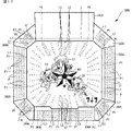
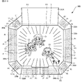
[発光装飾ユニットの発光と画像表示装置の表示とを用いた演出]
図17は、発光装飾ユニット300の発光と画像表示装置5の表示とを用いた演出の例を示す図である。図17を参照して、本実施の形態では、遊技における演出の1つとして、画像表示装置5の近傍に設けられた前述の発光装飾ユニット300の発光による演出に加えて、当該発光態様に対応した複数の光画像L2からなるパターン画像P2を、複数、
画像表示装置5に表示させる演出を実行する。
[Effect Using Light Emission of Light-Emitting Decoration Unit and Display of Image Display Device]
17A and 17B are diagrams showing examples of effects using the light emission of the light emitting
An effect to be displayed on the
なお、画像表示装置5の近傍とは、本実施の形態においては、図1および図17等で示すように、パチンコ遊技機1の正面から見た場合に画像表示装置5に接して見える位置にあることをいう。しかし、これに限定されず、遊技領域のいずれかの位置を含むようにしてもよいし、遊技機用枠3のいずれかの位置を含むようにしてもよい。
In this embodiment, the vicinity of the
光画像L2は、発光装飾ユニット300の第2発光ユニット320から第9発光ユニット390から発せられる複数の点状の光L1を模した画像である。パターン画像P2は、光L1のパターンP1を模した画像のパターンである。
The light image L2 is an image simulating a plurality of dots of light L1 emitted from the second
また、画像表示装置5には、パターン画像P2の他に、パターン画像P2とは異なる他の画像、たとえば、キャラクタ画像C1~C3を表示する場合がある。この場合に、パターン画像P2は、キャラクタ画像C1~C3に重畳する部分(以下「重畳部分」という)と、キャラクタ画像C1~C3に重畳しない部分(以下「非重畳部分」という)とを含む。このように、パターン画像P2は非重畳部分を含むので、重畳部分を含む場合であっても、キャラクタ画像C1~C3の視認性が妨げられ難くすることができ、遊技の興趣の低下を抑制することができる。
In addition to the pattern image P2, the
パターン画像P2の非重畳部分は、重畳部分よりも広くなるようにされる。これにより、パターン画像P2によってキャラクタ画像C1~C3の視認性が妨げられる割合を少なくすることができ、キャラクタ画像C1~C3の視認性を確保することができる。 The non-overlapping portion of the pattern image P2 is made wider than the overlapping portion. As a result, it is possible to reduce the rate at which the visibility of the character images C1 to C3 is hindered by the pattern image P2, and to ensure the visibility of the character images C1 to C3.
画像表示装置5には、キャラクタ画像C1~C3のうちの顔や手などの特定の部分が、パターン画像P2が表示されていない表示領域に表示される。これにより、パターン画像P2によってキャラクタ画像C1~C3のうちの特定の部分の視認性が妨げられないようにすることができ、当該特定の部分の視認性を確保することができる。
On the
また、画像表示装置5の前面には、可動役物400などの役物が、第1発光ユニット310の裏面側から変位することが可能である。また、可動役物400は、画像表示装置5の前面で変形(拡大/縮小)することが可能である。
In addition, on the front surface of the
また、飾り図柄の変動表示中に、飾り図柄表示エリア5L,5C,5Rにおいて、キャラクタ画像C1~C3などの画像を用いた演出が実行される場合、画像表示装置5の一部の領域(ここでは右下部)に、飾り図柄の小図柄5Sが表示される。この小図柄5Sは、他の画像(たとえば、パターン画像P2)などよりも高い優先度、つまり、他の画像よりも手前(パチンコ遊技機1の前面側、遊技者側)のレイヤーに表示される。
In addition, during the variable display of the decorative design, in the decorative
図18は、パターン画像P2の表示態様を決定するテーブルを示す説明図である。図18を参照して、演出制御用CPU120は、図16で示した演出制御プロセス処理のS801の演出図柄変動開始処理において、パターン画像P2の表示態様を決定する。
FIG. 18 is an explanatory diagram showing a table for determining the display mode of the pattern image P2. Referring to FIG. 18,
特別図柄の表示結果を大当りとすることが決定されているときに、0~99までの100個の判定値のうちから抽出した乱数値が、赤のパターン画像P2に対応する50個の所定の判定値のいずれかであれば、赤のパターン画像P2を表示すると決定する。白のパターン画像P2に対応する40個の所定の判定値のいずれかであれば、白のパターン画像P2を表示すると決定する。パターン画像P2を不表示とすることに対応する10個の所定の判定値のいずれかであれば、パターン画像P2を表示しないと決定する。 When it is determined that the display result of the special symbol is a big hit, the random number extracted from 100 determination values from 0 to 99 is 50 predetermined values corresponding to the red pattern image P2. If it is one of the determination values, it is determined to display the red pattern image P2. If it is one of the 40 predetermined determination values corresponding to the white pattern image P2, it is determined to display the white pattern image P2. If it is one of ten predetermined determination values corresponding to not displaying the pattern image P2, it is determined not to display the pattern image P2.
特別図柄の表示結果をはずれとすることが決定されているときに、抽出した乱数値が、
赤のパターン画像P2に対応する5個の所定の判定値のいずれかであれば、赤のパターン画像P2を表示すると決定する。白のパターン画像P2に対応する10個の所定の判定値のいずれかであれば、白のパターン画像P2を表示すると決定する。パターン画像P2を不表示とすることに対応する85個の所定の判定値のいずれかであれば、パターン画像P2を表示しないと決定する。
When it is determined that the display result of the special symbol is lost, the extracted random value is
If it is one of the five predetermined determination values corresponding to the red pattern image P2, it is determined to display the red pattern image P2. If it is one of ten predetermined determination values corresponding to the white pattern image P2, it is determined to display the white pattern image P2. If it is one of the 85 predetermined determination values corresponding to not displaying the pattern image P2, it is determined not to display the pattern image P2.
図19は、キャラクタ画像C1~C3の表示態様を決定するテーブルを示す説明図である。図19を参照して、演出制御用CPU120は、図16で示した演出制御プロセス処理のS801の演出図柄変動開始処理において、パターン画像P2の表示態様を決定した後に、キャラクタ画像C1~C3の表示態様を決定する。
FIG. 19 is an explanatory diagram showing a table for determining display modes of character images C1 to C3. Referring to FIG. 19,
大当りとすることが決定され、かつ、赤のパターン画像P2を表示すると決定されているときに、0~99までの100個の判定値のうちから抽出した乱数値が、手を振っているキャラクタ画像C1~C3に対応する90個の所定の判定値のいずれかであれば、手を振っているキャラクタ画像C1~C3を表示すると決定する。手を振っていないキャラクタ画像C1~C3に対応する9個の所定の判定値のいずれかであれば、手を振っていないキャラクタ画像C1~C3を表示すると決定する。キャラクタ画像C1~C3を不表示とすることに対応する1個の所定の判定値であれば、キャラクタ画像C1~C3を表示しないと決定する。 When it is determined to be a big hit and to display a red pattern image P2, a random value extracted from 100 determination values from 0 to 99 is a waving character. If it is one of the 90 predetermined determination values corresponding to the images C1 to C3, it is determined to display the character images C1 to C3 waving their hands. If it is one of the nine predetermined determination values corresponding to the character images C1 to C3 that are not waving their hands, it is determined that the character images C1 to C3 that are not waving their hands are to be displayed. If it is one predetermined determination value corresponding to not displaying the character images C1 to C3, it is determined not to display the character images C1 to C3.
大当りとすることが決定され、かつ、白のパターン画像P2を表示すると決定されているときに、抽出した乱数値が、手を振っているキャラクタ画像C1~C3に対応する70個の所定の判定値のいずれかであれば、手を振っているキャラクタ画像C1~C3を表示すると決定する。手を振っていないキャラクタ画像C1~C3に対応する20個の所定の判定値のいずれかであれば、手を振っていないキャラクタ画像C1~C3を表示すると決定する。キャラクタ画像C1~C3を不表示とすることに対応する10個の所定の判定値のいずれかであれば、キャラクタ画像C1~C3を表示しないと決定する。 When it is determined to be a big hit and to display a white pattern image P2, 70 predetermined determinations corresponding to the character images C1 to C3 with the extracted random number values waving their hands. If it is any of the values, it is determined to display the character images C1 to C3 waving their hands. If it is one of the 20 predetermined determination values corresponding to the character images C1 to C3 that do not wave their hands, it is determined that the character images C1 to C3 that do not wave their hands are to be displayed. If it is one of ten predetermined determination values corresponding to not displaying the character images C1 to C3, it is determined not to display the character images C1 to C3.
はずれとすることが決定され、かつ、赤のパターン画像P2を表示すると決定されているときに、抽出した乱数値が、手を振っているキャラクタ画像C1~C3に対応する1個の所定の判定値であれば、手を振っているキャラクタ画像C1~C3を表示すると決定する。手を振っていないキャラクタ画像C1~C3に対応する1個の所定の判定値であれば、手を振っていないキャラクタ画像C1~C3を表示すると決定する。キャラクタ画像C1~C3を不表示とすることに対応する98個の所定の判定値のいずれかであれば、キャラクタ画像C1~C3を表示しないと決定する。 When it is determined to be a failure and to display a red pattern image P2, the extracted random number is one predetermined determination corresponding to the character images C1 to C3 waving their hands. If it is a value, it is determined to display the character images C1 to C3 waving their hands. If there is one predetermined determination value corresponding to the character images C1 to C3 that do not wave their hands, it is determined that the character images C1 to C3 that do not wave their hands are to be displayed. If it is any of the 98 predetermined determination values corresponding to non-display of the character images C1-C3, it is determined not to display the character images C1-C3.
はずれとすることが決定され、かつ、白のパターン画像P2を表示すると決定されているときに、抽出した乱数値が、手を振っているキャラクタ画像C1~C3に対応する10個の所定の判定値のいずれかであれば、手を振っているキャラクタ画像C1~C3を表示すると決定する。手を振っていないキャラクタ画像C1~C3に対応する20個の所定の判定値のいずれかであれば、手を振っていないキャラクタ画像C1~C3を表示すると決定する。キャラクタ画像C1~C3を不表示とすることに対応する70個の所定の判定値のいずれかであれば、キャラクタ画像C1~C3を表示しないと決定する。 Ten predetermined determinations corresponding to the character images C1 to C3 waving their hands when the extracted random value is determined to be a failure and to display the white pattern image P2. If it is any of the values, it is determined to display the character images C1 to C3 waving their hands. If it is one of the 20 predetermined determination values corresponding to the character images C1 to C3 that do not wave their hands, it is determined that the character images C1 to C3 that do not wave their hands are to be displayed. If it is one of the 70 predetermined determination values corresponding to not displaying the character images C1 to C3, it is determined not to display the character images C1 to C3.
このように、パターン画像P2を、赤色の態様で表示する場合、赤色の態様で表示しない場合と比較して高い割合で、キャラクタ画像C1~C3を、遊技者にとって有利な有利状態となる期待度の高い態様である図17等で示すようなキャラクタ画像C1~C3が手を振っている態様で表示する。これにより、パターン画像P2を用いてキャラクタ画像C1~C3への期待感を遊技者に持たせることができる。 In this way, when the pattern image P2 is displayed in red, the degree of expectation that the character images C1 to C3 will be in an advantageous state for the player is higher than when the pattern image P2 is not displayed in red. Character images C1 to C3 are displayed as shown in FIG. Thus, the pattern image P2 can be used to give the player a sense of expectation for the character images C1 to C3.
また、発光装飾ユニット300は、画像表示装置5でパターン画像P2を表示させるときに、遊技の演出の進行に応じて断続的に発光する態様で発光するように、演出制御用CPU120によって制御される。画像表示装置5は、発光装飾ユニット300の点状の光L1のパターンP1が継続的に発光する態様を模した態様で、パターン画像P2を表示するよう、演出制御用CPU120によって制御される。これによって、画像表示装置5によって発光装飾ユニット300が発光する態様を模した態様のパターン画像P2による演出効果を維持しつつも、発光装飾ユニット300によって演出が進行していることを表現することで、演出効果を低下させないようにすることができる。
In addition, when the pattern image P2 is displayed on the
これに替えて、断続的に発光する態様と継続的に発光する態様を逆にしてもよい。また、断続的または継続的とするのを、発光装飾ユニット300のパターンP1と画像表示装置5のパターン画像P2とで随時入れ替えるようにしてもよい。
Alternatively, intermittent light emission and continuous light emission may be reversed. Further, intermittent or continuous may be switched between the pattern P1 of the light-emitting
なお、光画像L2のパターン画像P2に替えて、可動役物400などの役物に対して効果を加えて画像であるエフェクト画像を表示するようにしてもよい。エフェクト画像を表示する例については後述するようにしてもよい。
Instead of the pattern image P2 of the light image L2, an effect image, which is an image obtained by adding an effect to a role object such as the
また、遊技の演出の進行に応じて断続的に発光する態様とは、たとえば、演出の動きに合わせて発光装飾ユニット300の複数の点状の光L1が動いて見えるように(たとえば、画像表示装置5に表示されているキャラクタが右側に移動しているときに、複数の点状の光L1で右側へ移動しているような光の流れに見えるように)、それぞれの点状の光L1の点滅のタイミングを組合せた態様である。
In addition, the aspect of intermittently emitting light according to the progress of the game effect is, for example, so that the plurality of point-like lights L1 of the light emitting
[可動役物の変化と画像表示装置の表示とを用いた演出]
図20は、可動役物400の変化と画像表示装置5の表示とを用いた演出の例を示す第1の図である。図21は、可動役物400の変化と画像表示装置5の表示とを用いた演出の例を示す第2の図である。図22は、可動役物400の変化と画像表示装置5の表示とを用いた演出の例を示す第3の図である。
[Production Using Changes in Movable Accessory and Display on Image Display Device]
FIG. 20 is a first diagram showing an example of an effect using the change of the
図20から図22を参照して、本実施の形態では、遊技における演出の1つとして、画像表示装置5の近傍に設けられた可動役物400の変化(変位や変形)による演出に加えて、当該可動役物400の変化に対応したエフェクト画像P3を、複数、画像表示装置5に表示させる演出を実行する。
20 to 22, in the present embodiment, as one of the effects in the game, in addition to the effect by changing (displacement or deformation) of the
なお、画像表示装置5の近傍とは、本実施の形態においては、図17,図21,図22で示すように、可動役物400が変位または変形することによって画像表示装置5に重畳するような位置にあることをいう。しかし、これに限定されず、可動役物400が変位または変形した場合であっても画像表示装置5に重畳しないが画像表示装置5の近くにある場合を含むようにしてもよい。
In this embodiment, the vicinity of the
画像表示装置5には、図21で示すように、可動役物400が画像表示装置5に重畳した場合に表示されるエフェクト画像P3’が、図20で示すように、前兆のエフェクト画像P3として、可動役物400が画像表示装置5に重畳する前から表示される。このような可動役物400が画像表示装置5に重畳する面積が大きいパターンの演出は、スーパーリーチの最終局面での大当りがほぼ確定する場面など、遊技において比較的重要な局面で実行されるようにする。また、可動役物400が画像表示装置5に重畳する面積が小さいまたは0であるパターンの演出は、予告演出として実行するなど、遊技において比較的重要でない局面で実行されるようにする。
On the
図17の場合と同様、画像表示装置5には、エフェクト画像P3,P3’の他に、エフ
ェクト画像とは異なる他の画像、たとえば、キャラクタ画像C1~C3を表示する場合がある。この場合に、エフェクト画像P3,P3’は、キャラクタ画像C1~C3との重畳部分と、キャラクタ画像C1~C3との非重畳部分とを含む。このように、エフェクト画像P3,P3’は非重畳部分を含むので、重畳部分を含む場合であっても、キャラクタ画像C1~C3の視認性が妨げられ難くすることができ、遊技の興趣の低下を抑制することができる。
As in the case of FIG. 17, the
エフェクト画像P3,P3’のキャラクタ画像C1~C3との重畳部分の面積は、可動役物400の変位または変形に応じて変化可能とする。このようにすれば、エフェクト画像P3,P3’のキャラクタ画像C1~C3との重畳部分の面積の変化によって、キャラクタ画像C1~C3へ遊技者の視線を集めることができる。
The area of the overlapping portions of the effect images P3 and P3' with the character images C1 to C3 can be changed according to the displacement or deformation of the
可動役物400の位置が変化して、可動役物400が画像表示装置5に重畳する面積が広くなる場合は、狭い場合よりも、エフェクト画像P3,P3’のキャラクタ画像C1~C3との重畳部分を大きくするようにしてもよい。これにより、エフェクト画像P3,P3’の演出効果を高めることができるとともに、可動役物400を用いた演出を盛り上げることができる。
When the position of the
可動役物400の位置が変化して、可動役物400が画像表示装置5に重畳する面積が広くなる場合は、狭い場合よりも、図20,図21で示すように、エフェクト画像P3,P3’を大きくするようにしてもよい。
When the position of the
また、画像表示装置5では、図20,図21で示すように、エフェクト画像P3,P3’の態様を演出の進行に応じて変化させることが可能である。これにより、遊技者をエフェクト画像P3,P3’に注目させることができる。なお、ここでは、エフェクト画像の大きさを変化させるようにしたが、エフェクト画像の色を、たとえば、擬似連ごとに、青、緑、赤など複数の色に順次変化させるようにしてもよい。
Further, in the
また、図19で示した場合と同様に、エフェクト画像P3,P3’を、赤色の態様で表示する場合、赤色の態様で表示しない場合と比較して高い割合で、キャラクタ画像C1~C3を、遊技者にとって有利な有利状態となる期待度の高い態様である図17等で示すようなキャラクタ画像C1~C3が手を振っている態様で表示するようにしてもよい。これにより、キャラクタ画像P3,P3’を用いてキャラクタ画像C1~C3への期待感を遊技者に持たせることができる。 Also, as in the case shown in FIG. 19, when the effect images P3 and P3′ are displayed in the red mode, the character images C1 to C3 are displayed at a higher rate than when they are not displayed in the red mode. The character images C1 to C3 may be displayed in a manner such as shown in FIG. 17, etc., in which the character images C1 to C3 are waving as shown in FIG. As a result, the character images P3 and P3' can be used to give the player a sense of expectation for the character images C1 to C3.
スーパーリーチの終盤の大当りか否かを報知するタイミングでプッシュボタンなどの操作手段を操作させて、図22で示すように、キャラクタ画像C1~C3が可動役物400に作用すれば、大当りがほぼ確定するようにしてもよい。この場合、キャラクタ画像が可動役物400に作用している部分は、可動役物400に隠れている。しかし、このようなキャラクタ画像C1~C3の手や顔などの特定の部分は、演出上重要な部分であり、作用する部分であったり、大当りとなるか否かの信頼度を示唆する部分であったりする場合があるので、遊技者が見易いように表示することが好ましい。
At the timing of notifying whether or not a big hit is reached in the final stage of Super Reach, an operation means such as a push button is operated, and as shown in FIG. It may be fixed. In this case, the part where the character image acts on the
なお、エフェクト画像P3,P3’に替えて、前述のパターン画像P2を表示するようにしてもよい。 Note that the aforementioned pattern image P2 may be displayed instead of the effect images P3 and P3'.
また、演出の進行に応じて、発光装飾ユニット300の点状の光画像L2の色が変化するように構成して、パターン画像P2やエフェクト画像P3,P3’の色も、その変化に合わせて変化させるようにしてもよい。
In addition, the color of the dot-like light image L2 of the
パターン画像P2やエフェクト画像P3,P3’は、静止している訳ではなく、演出を盛り上げるために、変形したり、色が変化したりしている。また、キャラクタ画像C1~C3も、静止している訳ではなく、演出を盛り上げるために、位置や形状が変化したり、色が変化したりしている。このように両者が変化したとしても、キャラクタ画像C1~C3の顔や手などの特定の部分は、パターン画像P2やエフェクト画像P3,P3’が表示されていない表示領域に表示するようにする。 The pattern image P2 and the effect images P3 and P3' are not static, but are deformed or changed in color in order to liven up the presentation. Also, the character images C1 to C3 are not static, but change in position and shape, and change in color in order to liven up the presentation. Even if both are changed in this way, the specific parts such as the faces and hands of the character images C1 to C3 are displayed in the display area where the pattern image P2 and the effect images P3 and P3' are not displayed.
たとえば、キャラクタの服の色を赤く表示することで演出の信頼度を示唆する場合、服の色の部分を隠さないようにしてもよい。アクションによって信頼度を示唆する場合、アクションを隠さないようにしてもよい。この場合、アクションの動きに合わせて、パターン画像P2やエフェクト画像P3,P3’などの所定画像を重ならないように変化させるようにしてもよい。 For example, when indicating the reliability of the presentation by displaying the color of the character's clothes in red, the colored part of the clothes may not be hidden. Actions may not be hidden if they imply confidence. In this case, the predetermined images such as the pattern image P2 and the effect images P3 and P3' may be changed in accordance with the movement of the action so that they do not overlap.
両者を重畳させる場合であっても、重畳する面積が重畳しない部分の面積に対して比較的大きくならないようにする。パターン画像P2やエフェクト画像P3,P3’と、キャラクタ画像C1~C3との距離に応じて、パターン画像P2やエフェクト画像P3,P3’の透明度が増すようにしてもよい。これにより、キャラクタ画像C1~C3の視認性の低下を抑制することができる。 To prevent the overlapping area from becoming relatively large with respect to the area of a non-overlapping part even when both are overlapped. The transparency of the pattern image P2 and the effect images P3 and P3' may be increased according to the distance between the pattern image P2 and the effect images P3 and P3' and the character images C1 to C3. This makes it possible to suppress deterioration in the visibility of the character images C1 to C3.
パターン画像P2やエフェクト画像P3,P3’に加えて、または、替えて、画像表示装置5の発光装飾ユニット300との境界部分を、発光装飾ユニット300の発光の色と同一または類似の色で、ぼやかして表示するようにしてもよい。
In addition to or instead of the pattern image P2 and the effect images P3 and P3′, the boundary portion between the
前述したパターン画像P2やエフェクト画像P3,P3’を表示する演出は、スーパーリーチ中などのリーチ中や、通常変動中や、リーチ中と通常変動中とに跨る期間などに、一定期間、継続して実行される演出である。しかし、これに限定されず、擬似連や予告が発生するときに実行する演出としてもよい。 The effect of displaying the pattern image P2 and the effect images P3 and P3' described above continues for a certain period of time, such as during the reach such as during the super reach, during the normal fluctuation, or during the period between the reach and the normal fluctuation. It is a production that is executed by However, the present invention is not limited to this, and may be an effect that is executed when a pseudo continuation or an advance notice occurs.
キャラクタ画像C1~C3の周辺の空白部分にも、パターン画像P2やエフェクト画像P3,P3’を表示するようにしてもよい。 The pattern image P2 and the effect images P3 and P3' may also be displayed in blank areas around the character images C1 to C3.
パターン画像P2やエフェクト画像P3,P3’がキャラクタ画像C1~C3に、まったく重ならないようにしてもよい。 The pattern image P2 and the effect images P3 and P3' may not overlap the character images C1 to C3 at all.
パターン画像P2やエフェクト画像P3,P3’などの所定画像とともに表示する画像を、キャラクタ画像C1~C3に替えて他の特定画像としてもよい。このようにする場合、特定画像の種類に応じて、異なる割合で所定画像の種類を選択して表示するようにしてもよい。 The images displayed together with the predetermined images such as the pattern image P2 and the effect images P3 and P3' may be other specific images instead of the character images C1 to C3. In this case, the types of predetermined images may be selected and displayed at different ratios according to the types of specific images.
[注意喚起について]
本実施の形態では、遊技者に対して各種の注意喚起が実行される。注意喚起としては、遊技者に対して遊技についての様々な注意をパチンコ遊技機1を用いて報知する制御が行なわれる。たとえば、注意喚起として、過度な遊技を抑制させるための報知が行なわれる。本実施の形態では、画像表示装置5の画面上に各種の注意喚起に対応する画像が表示される。なお、このような注意喚起は、画像を表示するだけではなく音を出力することともに実行されるようにしてもよい。以下では、注意喚起として画像表示装置5に表示される注意喚起表示の一例について具体的に説明する。
[About alert]
In this embodiment, various alerts are issued to the player. As the attention calling, control is performed to notify the player of various cautions about the game using the
[のめり込み防止表示について]
注意喚起表示としては、遊技者に対してパチンコ遊技機1やスロットマシンへの遊技に
対してのめり込み過ぎることを防止するための表示としてののめり込み防止表示がある。のめり込み防止表示では、たとえば、「パチンコ・スロットは適度に楽しむ遊びです。のめり込みに注意しましょう。」という文字と文字の周りを囲む画像とが表示される。また、のめり込み防止画像には、文字の内容は同じであるが文字の周りを囲む画像や表示面積が異なる複数種類態様の画像が設けられている。このようなのめり込み防止表示により、遊技者に対して遊技にのめり込むことを抑制または注意、遊技者に対して遊技に大金を注ぎ込むことを抑制または注意が行なわれる。
[Regarding the immersion prevention display]
As a warning display, there is an addiction prevention display as a display for preventing the player from being too immersed in the game of the
[取り忘れ防止表示について]
注意喚起表示としては、遊技に使用可能な遊技球等の遊技用価値の大きさを特定可能な情報として残高情報等が記録された遊技用記録媒体としてのプリペイドカード等の取り忘れに関するカード取り忘れ防止の表示としての取り忘れ防止表示がある。取り忘れ防止表示では、たとえば、「プリペイドカードの取り忘れや盗難にご注意ください。」という文字とともにカードの排出を示す画像が表示される。なお、カードではなく遊技に使用可能な遊技球等の遊技用価値の大きさを特定可能な情報として残高情報等が記録された遊技用記録媒体としてのコイン等の別の形状のものを対象として注意喚起を実行してもよい。
[Regarding the display to prevent forgetting to take]
As a warning display, forgetting to take out a prepaid card etc. as a game recording medium in which balance information etc. are recorded as information that can specify the size of game value such as game balls that can be used in the game There is a forget-to-take prevention display as a prevention display. In the forgetting prevention display, for example, an image indicating the ejection of the card is displayed together with the words "Please be careful not to forget to take out the prepaid card or have it stolen." It should be noted that the object is not a card but a game ball that can be used in a game, and a game recording medium of a different shape such as a coin on which balance information etc. is recorded as information that can specify the value of the game. A warning may be executed.
[その他の注意喚起表示について]
その他の注意喚起表示として「18歳未満の遊技は法令により禁止されています。」という18歳未満の遊技を禁止する注意喚起表示、「不正行為は犯罪です。」という不正行為を抑制するための注意喚起表示、「攻略法を装った詐欺にご注意ください。」という詐欺行為を抑制するための注意喚起表示等が文字と画像とにより表示される。なお、その他の注意喚起表示は、上記に示すもの以外であってもよく、たとえば、パチンコ遊技機1の外枠等に可動式の役物を設けた場合に、当該可動式の役物の動きにより、けがをしないように注意するものであってもよい。
[About other warning signs]
Other warning signs include a notice that prohibits gaming by those under the age of 18, saying, “Playing games by persons under the age of 18 is prohibited by law.” A warning display, a warning display for suppressing fraud such as "Please beware of fraud disguised as a strategy" is displayed using characters and images. Note that other warning displays may be other than those shown above. It may be something to be careful not to get injured.
[表示タイミングついて]
上記のような注意喚起表示は、所定期間に亘り遊技を実行していない場合に移行される客待ちデモ状態中、大当り遊技状態が終了したときのエンディング期間中、演出内容を変更するためのメニュー画面の表示期間中等の各表示期間において表示される。注意喚起表示は、表示の種類や表示期間に応じて様々な表示態様で表示される。このような、注意喚起表示について以降に説明する。
[About display timing]
The attention-calling display as described above is a menu for changing the contents of the production during the customer waiting demonstration state that is shifted when the game is not executed for a predetermined period, during the ending period when the jackpot game state ends. It is displayed in each display period, such as during the screen display period. The warning display is displayed in various display modes according to the display type and display period. Such a warning display will be described below.
図23は、客待ちデモ状態中および大当り終了後の各種表示について説明するための図である。図23(a)は、客待ちデモ状態中(以下、単にデモ中とも称する)におけるのめり込み防止表示を含む各種表示について説明するための図である。また、図23(b),(c)は、大当り終了後のエンディング期間中におけるのめり込み防止表示を含む各種表示について説明するための図である。図23(b)は、1回目の大当り終了後の表示を示し、図23(c)は、大当りが連続したときの2回目以降の大当り終了後の表示を示している。 FIG. 23 is a diagram for explaining various displays during the customer waiting demonstration state and after the jackpot is finished. FIG. 23(a) is a diagram for explaining various displays including an immersion prevention display during the customer waiting demonstration state (hereinafter also simply referred to as demonstration). FIGS. 23(b) and 23(c) are diagrams for explaining various displays including the immersion prevention display during the ending period after the end of the big win. FIG. 23(b) shows the display after the first big win, and FIG. 23(c) shows the display after the second and subsequent big wins when the big wins are consecutive.
本実施の形態では、客待ちデモ指定コマンドを受信後に所定期間経過すると非遊技中であると判定し、デモンストレーション画面の表示を実行する。客待ちデモ指定コマンドは、始動入賞が発生せず第1保留記憶バッファまたは第2保留記憶バッファに保留記憶データがない場合に、遊技制御用マイクロコンピュータ100側から演出制御用CPU120側に送信される。デモ状態は、新たな始動入賞の発生等の遊技が開始されたことに伴って終了する。
In the present embodiment, when a predetermined period of time has elapsed after receiving the customer waiting demonstration designation command, it is determined that the game is not being played, and the demonstration screen is displayed. The customer waiting demonstration designation command is transmitted from the
図23(a)に示すように、デモ中には、画像表示装置5の画面上に最終のハズレの停止図柄である3図柄(たとえば、「375」等の3つの数字図柄等)の表示が15秒間表
示された後に、パチンコ遊技機1の遊び方や演出等の機能を紹介する映像としての機能紹介ムービーが39秒間表示される。その後、注意喚起表示として、その他注意喚起表示とのめり込み防止表示とが6秒間表示される。詳細な表示内容については、図25で後述する。
As shown in FIG. 23(a), during the demonstration, three symbols (for example, three number symbols such as "375") are displayed on the screen of the
また、図23(a)に示すように、パチンコ遊技機1を初期化した場合には、デモ状態の最初の画面である3図柄表示から画面上の表示が始まる。それに対し、客待ちデモ中に停電により電力供給が停止され再開する停電復旧があった場合には、デモ状態の最初の画面である3図柄表示から演出が開始されるのではなく、その他注意喚起表示とのめり込み防止表示とが実行されるタイミングから画面上の表示が始まる。
Further, as shown in FIG. 23(a), when the
次に、図23(b)に示すように、1回目の大当り終了後のエンディング期間中において、エンディング表示がされる。エンディング表示では、エンディングの背景画像が10秒間表示されている間に大当り中に選択された大当り終了後の演出モードについての情報であるモード表示が実行され、その後、大当り終了後の確変回数(時短回数)を示す確変回数表示(時短回数表示)が表示される。また、エンディング表示の終了2秒前からは、エンディング表示とともにプリペイドカード取り忘れ防止表示とのめり込み防止表示とが表示される。その後、パチンコ遊技機1の製造者を示すメーカーロゴ表示(製造者情報とも称する)とともに、のめり込み防止表示が2秒間表示される。 Next, as shown in FIG. 23(b), the ending is displayed during the ending period after the first big win. In the ending display, while the background image of the ending is displayed for 10 seconds, the mode display, which is information about the production mode after the end of the big win selected during the big win, is executed, and then the probability variable number of times after the end of the big win (time saving The number of times) is displayed. Two seconds before the end of the ending display, a display for preventing forgetting to take out the prepaid card and a display for preventing immersion are displayed together with the ending display. After that, a maker's logo indicating the manufacturer of the pachinko game machine 1 (also referred to as manufacturer's information) is displayed, and an immersion prevention display is displayed for two seconds.
また、図23(c)に示すように、2回目以降の大当り終了後のエンディング期間中において、エンディング表示がされる。ここで、2回目以降の大当りとは、最初の大当りを含む大当り終了後の100回の変動表示中(確変状態中や時短状態中)に再度大当りとなったときの大当りである。このような連続した2回目以降の大当りでは、1回目の大当りと同じように、エンディング表示として、10秒間エンディングの背景画像が表示されている間に大当り中に選択された大当り終了後の演出モードについての情報であるモード表示と大当り終了後の確変回数(時短回数)を示す情報である確変回数表示(時短回数表示)とが表示される。しかし、1回目の大当りとは異なり、エンディング表示の終了2秒前からは、エンディング表示とともにのめり込み防止表示が表示されるが、プリペイドカード取り忘れ防止表示は表示されない。その後、パチンコ遊技機1の製造者を示すメーカーロゴ表示とともに、のめり込み防止表示が2秒間表示される。
Also, as shown in FIG. 23(c), the ending is displayed during the ending period after the second and subsequent big wins. Here, the second and subsequent big wins are big wins when a big win occurs again during 100 times of variable display (during the variable probability state or the time saving state) after the end of the big win including the first big win. In the second and subsequent consecutive big wins, as in the case of the first big win, the effect mode after the end of the big win is selected during the big win while the background image of the ending is displayed for 10 seconds as the ending display. A mode display that is information about and a probability variation frequency display (time reduction frequency display) that is information indicating the probability variation frequency (time reduction frequency) after the end of the big hit are displayed. However, unlike the first big hit, two seconds before the end of the ending display, the immersion prevention display is displayed together with the ending display, but the prepaid card prevention display is not displayed. After that, the maker's logo indicating the manufacturer of the
図23に示すように、客待ちデモ状態のときよりも大当り終了後のエンディング期間のときの方がのめり込み防止画像の表示期間が短いため、大当りが終了したときに過度に注意喚起表示を行なうことにより遊技の興趣が低下してしまうことを防止しつつ、好適に注意喚起表示を実行することができる。 As shown in FIG. 23, the display period of the immersion prevention image is shorter in the ending period after the big win than in the customer waiting demonstration state. Therefore, it is possible to suitably perform the attention-calling display while preventing the interest of the game from being lowered.
[節電モードついて]
次に、節電モードについて説明する。本実施の形態では、所定時間客待ちデモ状態が継続したときは、画像表示装置5の液晶のバックライトの輝度を低く抑えて省電力状態とする節電モードが実行される。節電モードは、図23で示した3図柄表示の15秒、機能紹介ムービーの39秒、その他注意喚起表示とのめり込み防止表示との6秒の合計60秒のデモ状態が3回実行された後に移行される。つまり、客待ちデモ状態が開始されてから3分経過後に節電モードへと移行する。また、節電モードは、遊技を開始することを条件に終了する。たとえば、節電モードは、遊技球を遊技領域に打込んだことにより終了する。また、節電モードは、プッシュボタンやスティックコントローラなどの操作手段を遊技者が操作することにより終了する。なお、節電モードは、ハンドルにセンサが設けられている場合に、当該センサに触れることで遊技者の操作を検知することにより終了するようにしてもよい。
[About power saving mode]
Next, the power saving mode will be explained. In the present embodiment, when the customer waiting demonstration state continues for a predetermined time, a power saving mode is executed in which the brightness of the backlight of the liquid crystal of the
このような、節電モードは、遊技店員によりON/OFFの設定が可能となっている。節電モードの設定方法は、たとえば、演出制御基板12に機械的なハードスイッチを設け、このハードスイッチが特定の態様となっている状態で電源投入されると、設定画面が表示されるようにすればよい。ここで、特定の態様とは、0~9、A~Fの項目にスイッチを切替可能なもので、たとえば、項目Fに設置されている状態である。項目Fに設置された状態で電源投入がされると節電モードが実行するか否かの設定画面が表示される。その後、ハードスイッチを0~5のいずれかにすれば遊技者が音量調整可能な状態となり(0が最少音、5が最大音)、6~Bのいずれかにすれば遊技者が音量調整できず音量が固定される状態となる(6が最少音、Bが最大音)。なお、光量調整は、どの状態でも設定可能である。光量調整のみの場合であれば、メニュー画面を開いたとしても音量調整はできないようになる。また、C~Eが選択されている場合は、0と同じ状態である。
Such a power saving mode can be set ON/OFF by the game clerk. The power saving mode can be set, for example, by providing a mechanical hardware switch on the
図24は、客待ちデモ状態中および節電モード中の各種表示について説明するための図である。図24(a)は、客待ちデモ状態中から節電モード中へ移行する際の各種表示を示している。また、図24(b)は、客待ちデモ状態中において、特に、その他注意喚起表示とのめり込み防止表示との表示態様について示している。 FIG. 24 is a diagram for explaining various displays during the customer waiting demonstration state and during the power saving mode. FIG. 24(a) shows various displays when shifting from the customer waiting demonstration state to the power saving mode. Also, FIG. 24(b) shows, in particular, the display mode of other alerting display and immersion prevention display during the customer waiting demonstration state.
図24(a)に示すように、客待ちデモ状態として3図柄表示、機能紹介ムービー、その他注意喚起表示とのめり込み防止表示とを1セットとするデモ状態が3回実行された後に節電モードに移行される。節電モードでは、画像表示装置5の液晶のバックライトの輝度が低下するため画面が暗くなる。よって、節電モード中は、暗い画面において3図柄表示が15秒実行された後、機能紹介ムービーが39秒実行されることとなる。しかしながら、節電モード中は、機能紹介ムービーの後にその他の注意喚起表示とのめり込み防止表示とが表示されることはない。節電モード中は、機能紹介ムービーの後に再び3図柄表示へと移行される。
As shown in FIG. 24(a), as a customer waiting demonstration state, a demonstration state consisting of a three-pattern display, function introduction movie, other warning display, and immersion prevention display is performed three times, after which the power saving mode is entered. be done. In the power saving mode, the brightness of the backlight of the liquid crystal of the
そして、節電モードが終了したときには、最初に表示される画面においてのめり込み防止表示が5秒間表示される。その後、始動入賞による図柄の変動表示が開始されなければ、再度3図柄表示から始まるデモ状態に移行する。 Then, when the power saving mode ends, the immersion prevention display is displayed for 5 seconds on the first displayed screen. After that, if the variable display of symbols is not started due to the start winning, the game moves to the demonstration state again starting from the display of 3 symbols.
次に、その他注意喚起表示と、のめり込み防止表示との表示態様について図24(b)により説明する。その他注意喚起表示としては、前述した18歳未満の遊技を禁止する注意喚起表示等がある。ここでは、説明の都合上、複数種類のその他注意喚起表示のうち、18歳未満の遊技を禁止する注意喚起表示を注意喚起A、不正行為を抑制するための注意喚起表示を注意喚起B、詐欺行為を抑制するための注意喚起表示を注意喚起Cとして説明する。 Next, the display modes of the other warning display and the immersion prevention display will be described with reference to FIG. 24(b). Other warning displays include the above-mentioned warning display that prohibits players under the age of 18 from playing games. Here, for the sake of explanation, among the multiple types of other warning displays, the warning display prohibiting games under the age of 18 is called attention A, the caution display for suppressing fraudulent acts is called attention B, and fraud A warning display for suppressing an action will be described as a warning C. FIG.
図24(b)に示すように、その他注意喚起表示とのめり込み表示とは6秒間の間に表示と消去とが実行される。ここで、表示の単位として1F(フレーム)を用いる。本実施の形態では、1Fが1/30秒に相当する。まず、複数のその他注意喚起表示のうち注意喚起Aが15F(0.5S)のフェードイン期間に亘りフェードインし、142Fの表示期間に亘り表示される。その後、注意喚起Aは、9F(0.3S)のフェードアウト期間に亘りフェードアウトし、14Fの非表示期間に亘り非表示となる。 As shown in FIG. 24(b), the other attention calling display and the immersive display are displayed and erased for 6 seconds. Here, 1F (frame) is used as a display unit. In this embodiment, 1F corresponds to 1/30 second. First, among a plurality of other attention-calling displays, attention-calling A fades in over a fade-in period of 15F (0.5S) and is displayed over a display period of 142F. After that, the alert A fades out for a fade-out period of 9F (0.3S) and is hidden for a non-display period of 14F.
注意喚起Bは、6Fの非表示期間の後、注意喚起Aのフェードイン期間の途中から15F(0.5S)のフェードイン期間に亘りフェードインし、136Fの表示期間に亘り表示される。その後、注意喚起Bは、9F(0.3S)のフェードアウト期間に亘りフェードアウトし、14Fの非表示期間に亘り非表示となる。 Alert B fades in for a fade-in period of 15F (0.5S) from the middle of the fade-in period of alert A after a non-display period of 6F, and is displayed for a display period of 136F. After that, alert B fades out for a fade-out period of 9F (0.3S) and is hidden for a non-display period of 14F.
注意喚起Cは、12Fの非表示期間の後、注意喚起Aおよび注意喚起Bのフェードイン
期間の途中から15F(0.5S)のフェードイン期間に亘りフェードインし、130Fの表示期間に亘り表示される。その後、注意喚起Cは、9F(0.3S)のフェードアウト期間に亘りフェードアウトし、14Fの非表示期間に亘り非表示となる。
After the non-display period of 12F, the alert C fades in over the fade-in period of 15F (0.5S) from the middle of the fade-in period of the alert A and the alert B, and is displayed over the display period of 130F. be done. After that, the alert C fades out for a fade-out period of 9F (0.3S) and is hidden for a non-display period of 14F.
のめり込み防止表示は、35Fの非表示期間の後、注意喚起A、注意喚起Bおよび注意喚起Cのフェードイン期間の終了後に10Fのフェードイン期間に亘りフェードインし、112Fの表示期間に亘り表示される。その後、のめり込み防止表示は、9F(0.3S)のフェードアウト期間に亘りフェードアウトし、14Fの非表示期間に亘り非表示となる。のめり込み防止表示のフェードイン期間は、他の注意喚起表示よりも短く設定されている。このようにすれば、最終ののめり込み防止表示を他の注意喚起よりも早く出現させることができ、表示にメリハリを付けることができる。 After the non-display period of 35F, the immersion prevention display fades in over the fade-in period of 10F after the fade-in periods of the alert A, the alert B, and the alert C, and is displayed over the display period of 112F. be. After that, the immersion prevention display fades out for a fade-out period of 9F (0.3S) and is hidden for a non-display period of 14F. The fade-in period of the immersion prevention display is set shorter than that of other alert displays. In this way, the final immersion prevention display can be made to appear earlier than other alerts, and the display can be sharpened.
図24(b)に示すように、注意喚起A、注意喚起B、注意喚起Cおよびのめり込み防止表示は、順番にフェードインし、重なる期間において表示された後、同じタイミングでフェードアウトする表示制御を行なわれる。なお、他の注意喚起のフェードイン期間とのめり込み防止のフェードイン期間は重なっていないが、重なるようにフェードインされてもよい。 As shown in FIG. 24(b), display control is performed such that the alert A, alert B, alert C, and immersion prevention display fade in in order, are displayed in overlapping periods, and then fade out at the same timing. be It should be noted that the fade-in period for other alerts and the fade-in period for immersion prevention do not overlap, but may be faded in so as to overlap.
このように、のめり込み防止表示と他の注意喚起表示とを同一の期間に表示可能であり、各注意喚起表示の表示タイミングを異ならせて表示することができる。これによれば、複数の注意喚起を同一の期間に表示するときに、一気に複数の情報を表示することで遊技者が情報を確認しきれなくなることを抑制できる。 In this manner, the immersion prevention display and the other attention-calling display can be displayed in the same period, and the display timing of each attention-calling display can be varied. According to this, when a plurality of alerts are displayed in the same period, it is possible to prevent the player from being unable to check the information by displaying a plurality of pieces of information at once.
また、のめり込み防止表示をその他の注意喚起表示と同一の期間に表示可能であり、その他の注意喚起表示をフェードインさせた後、のめり込み防止表示をフェードインさせ、その他の注意喚起表示とのめり込み防止表示とが全て出そろった後、共通のタイミングでフェードアウトさせる。このようにすれば、見栄えの良い注意喚起表示の表示制御を実行することができる。 In addition, the immersion prevention display can be displayed in the same period as the other attention-calling display, and after fading in the other attention-calling display, the immersion-prevention display is faded in, and the other attention-calling display and the immersion-prevention display are faded in. and fade out at a common timing. By doing so, it is possible to perform display control of an appealing display that looks good.
[客待ちデモ状態中の画面]
次に、画像表示装置5の画面で表示される各種表示について説明する。図25は、客待ちデモ状態中における画面を示す図である。図25(a)に示すように、客待ちデモ状態の開始時には、左,中,右の飾り図柄表示エリア5L,5C,5Rの飾り図柄が画面中央部ではずれ表示結果となる態様で表示される。このような3図柄表示は、15秒間に亘り表示される。次いで、図25(b)に示すように、パチンコ遊技機1の遊び方や演出等の機能を紹介する映像としての機能紹介ムービーが39秒間に亘り表示される。
[Screen during customer waiting demo]
Next, various displays displayed on the screen of the
次いで、図25(c)~(f)にかけて、3つの他の注意喚起表示130が左から順番にフェードインする。他の注意喚起表示130は、画面中央上側に表示される。その後、図25(g),(h)に示すように、他の注意喚起表示130の下方にのめり込みを防止するためののめり込み防止画像131がフェードインする。その後、図25(i)に示すように、他の注意喚起表示130およびのめり込み防止画像131が同じタイミングでフェードアウトする。そして、図25(j)に示すように、フェードアウト後に所定期間画面が非表示となる。
Then, in FIGS. 25(c)-(f), three other alerting
図25に示すように、のめり込み防止に関する注意喚起表示であるのめり込み防止画像131を他の注意喚起表示130と同一の期間に表示可能であり、各注意喚起表示の表示タイミングを異ならせて表示する制御が行なわれる。このようにすれば、複数の注意喚起表示を同一の期間に表示するときに、一気に複数の情報を表示することで遊技者が情報を確認しきれなくなることを抑制できる。よって、遊技者は、複数の注意喚起表示に関する
情報を的確に認識することが可能となる。
As shown in FIG. 25, it is possible to display an
また、図25に示すように、のめり込み防止に関する注意喚起表示であるのめり込み防止画像131を他の注意喚起表示130と同一の期間に表示可能であり、他の注意喚起表示130をフェードインさせた後、のめり込み防止画像131をフェードインさせ、他の注意喚起表示130とのめり込み防止画像131とが全て出そろった後、共通のタイミングでフェードアウトさせる制御が行なわれる。このようにすれば、見栄えの良い注意喚起表示の表示制御を実行することができる。
Further, as shown in FIG. 25, an
[メニュー画面]
メニュー画面は、たとえば、客待ちデモ状態中において、画像表示装置5で、遊技者により選択可能な各種設定項目を選択肢形式(メニュー形式)のアイコン画像で提示する表示画面である。メニュー画面は、階層構造となっている。主な設定項目が一覧形式で表示可能な最初の画面から1つの項目を選択すると、選択された項目ごとに詳細な設定が可能となる。たとえば、主な設定項目として、遊技を実行するときの演出に対応するキャラクタの選択、音量・光量調整、演出のカスタマイズの選択等が可能である。
[Menu screen]
The menu screen is, for example, a display screen on the
メニュー画面では、前後方向および左右方向に操作可能なスティックコントローラが傾倒操作されることに応じて、上下方向および左右方向に項目の選択が可能であり、プッシュボタンが操作されると選択していた項目に決定される。1つ前の画面に戻る場合には、「戻る」の項目でプッシュボタンを操作すればよい。 On the menu screen, items can be selected in the vertical and horizontal directions by tilting the stick controller, which can be operated in the front, back, and left and right directions, and selected when the push button is operated. determined by the item. In order to return to the previous screen, the push button should be operated in the item of "Return".
[メニュー操作中の画面]
図26は、メニュー操作中における画面を示す図である。図26(a),(b)に示す客待ちデモ状態中の画面から、プッシュボタンを操作することにより、図26(c)のメニュー画面132が表示される。メニュー画面132には、選択可能な複数の項目が表示されているが図面を省略する。メニュー画面132の下方には、のめり込み防止画像131が表示される。
[Screen during menu operation]
FIG. 26 is a diagram showing a screen during menu operation. 26(a) and (b), the
ここで、メニュー画面132は複数の画像の階層構造で構成されている。そして、メニュー画面132のいずれの階層でものめり込み防止画像が表示される。なお、メニュー画面132の表示階層毎にのめり込み防止画像の表示態様を異ならせてもよい。このようにすれば、メニュー画面132に表示される内容に応じた態様でのめり込み防止画像を表示することができる。
Here, the
また、本実施の形態では、注意喚起を実行する前後の演出状態に応じてのめり込み防止画像の表示態様が異なる。具体的には、のめり込み防止画像による注意喚起を実行する前の演出状態として、メニュー画面132においていずれかのキャラクタの違いによりのめり込み防止画像の表示態様が異なるようになっている。また、後述するように、のめり込み防止画像による注意喚起を実行した後の演出状態として、大当り遊技中において選択した確変中のモードの違いによりエンディング時ののめり込み防止画像の表示態様が異なるようになっている。
Further, in the present embodiment, the display mode of the addiction prevention image differs depending on the rendering state before and after executing the attention calling. Specifically, the display mode of the addiction-preventing image differs depending on the character on the
図26(c)におけるメニュー画面で、スティックコントローラの操作とプッシュボタンとによりキャラクタ選択の項目に決定された場合には、図26(d)の画面が表示される。ここで、図26(d)のデフォルトの表示態様は、いずれのキャラクタも設定されていない状態の表示態様である。図26(d)に示すように、複数種類のキャラクタとしてキャラクタXとキャラクタYとのうちいずれかが選択可能な画面が表示される。キャラクタの選択画面においても、のめり込み防止画像131が表示される。このときののめり込み防止画像131は、図26(c)の表示態様と同じである。また、こののめり込み防止
画像131がデフォルトの表示態様である。なお、図26(c)のときののめり込み防止画像の表示態様と図26(d)のときののめり込み防止画像の表示態様とは表示態様が異なるようにしてもよい。表示態様が異なるとは、たとえば、違う位置に表示されるもの、違う位置で異なる表示がされるもの(一方に比べて縮小表示されるもの)等である。
In the menu screen shown in FIG. 26(c), when the character selection item is selected by operating the stick controller and pressing the push button, the screen shown in FIG. 26(d) is displayed. Here, the default display mode in FIG. 26(d) is a display mode in which no character is set. As shown in FIG. 26(d), a screen is displayed in which one of character X and character Y can be selected as a plurality of types of characters. The
図26(d)の後に、遊技者がプッシュボタンを操作し、キャラクタXが選択されたとする。その後に各種メニューのうち音量・光量調整画面が選択された場合には、図26(e)に示すように、音量・光量調整アイコンの下方にのめり込み防止画像133が表示される。図26(e)ののめり込み防止画像133は、図26(c),(d)に示すのめり込み防止画像131とは異なる態様で表示される。なお、音量や光量は、スティックコントローラの左右の動作により小・中・大のいずれかの項目が選択された後、プッシュボタンを操作することにより選択された音量や光量に決定される。
Assume that the player operates the push button after FIG. 26(d) to select the character X. After that, when the volume/light amount adjustment screen is selected from various menus, an
また、図26(d)の後に、遊技者がプッシュボタンを操作し、キャラクタYが選択されたとする。その後に各種メニューのうち音量・光量調整画面が選択された場合には、図26(f)に示すように、音量・光量調整アイコンの下方にのめり込み防止画像134が表示される。図26(f)ののめり込み防止画像134は、図26(c),(d)に示すのめり込み防止画像131、および、図26(e)に示すのめり込み防止画像133とは異なる態様で表示される。なお、音量や光量は、スティックコントローラの左右の動作により小・中・大のいずれかの項目が選択された後、プッシュボタンを操作することにより選択された音量や光量に決定される。
Further, after FIG. 26(d), it is assumed that the player operates the push button to select the character Y. After that, when the volume/light amount adjustment screen is selected from various menus, an
ここで、いずれのキャラクタも選択せず、デフォルトの表示態様のままであった場合には、図26(c),(d)に示すようなデフォルトののめり込み防止画像131が音量・光量調整アイコンの下方に引き続き表示される。
Here, if none of the characters is selected and the default display mode remains, the default
図26(e),(f)の状態からスティックコントローラの操作とプッシュボタンとの操作によりメニュー画面を終了すると、図26(g)の画面となる。図26(g)では、のめり込み防止画像135が画像表示装置5の画面の中央で大きく表示される。このように、メニュー画面132の表示を終了することに基づいて、最初にのめり込み防止画像135が表示されるように制御される。その後、始動入賞が生じなければ、図26(a)に示す客待ちデモ状態の画面となる。なお、図26(g)に示すのめり込み防止画像が、選択したキャラクタの種類に応じて異なるようにしてもよい。また、大当り遊技状態中の表示が、キャラクタの種類に応じて異なるようにしてもよい。
When the menu screen is terminated from the states shown in FIGS. 26(e) and (f) by operating the stick controller and the push button, the screen shown in FIG. 26(g) is displayed. In FIG. 26G, the
ここで、メニュー画面においてのめり込み防止表示がされないものであれば、客待ちデモ状態中にメニュー画面を開くことでのめり込み防止表示が途切れてしまうと、のめり込み防止表示を見る機会が減ってしまう。そこで、本実施の形態では、メニュー画面の階層のいずれの階層にものめり込み防止表示を表示することで、のめり込み防止表示を見る機会を増加させることができる。さらに、メニュー画面の終了時には、画面の中央で大きくのめり込み防止表示が表示されるので、のめり込み防止表示に遊技者を注目させることができる。 Here, if the immersion prevention display is not displayed on the menu screen, if the immersion prevention display is interrupted by opening the menu screen during the customer waiting demonstration state, the chances of seeing the immersion prevention display decrease. Therefore, in the present embodiment, by displaying the immersion prevention display in any hierarchy of the menu screen, it is possible to increase the chances of viewing the immersion prevention display. Furthermore, when the menu screen ends, a large immersion prevention display is displayed in the center of the screen, so that the player can be made to pay attention to the immersion prevention display.
なお、メニュー画面の終了時には、通常の客待ちデモ状態で最後の方に設定されているのめり込み防止表示を最初に表示させる制御を行なうことで、メニュー画面の終了時に最初にのめり込み防止表示が表示されるようにしてもよい。 In addition, when the menu screen ends, the immersion prevention display, which is set toward the end in the normal customer waiting demonstration state, is displayed first, so that the immersion prevention display is displayed first when the menu screen ends. You may do so.
また、メニュー画面中に選択されたキャラクタを判定する判定手段を備えるようにすればよい。メニュー画面中に選択されたキャラクタ情報は、たとえば、RAM122に記憶され、その情報を元に演出制御用CPU120が設定されたキャラクタを判定し、のめり
込み防止に関する注意喚起表示の態様を異ならせるようにすればよい。
Further, it is sufficient to provide determination means for determining the character selected in the menu screen. The character information selected in the menu screen is stored in the
また、遊技者の操作に応じてのめり込み防止に関する注意喚起表示の態様が異なるのではなく、遊技中の演出状態に応じてのめり込み防止に関する注意喚起表示の態様が異なるようにしてもよい。たとえば、特定の演出状態への移行抽選に当選し、当該特定の演出状態となったことに応じて、のめり込み防止に関する注意喚起表示の態様が異なるようにしてもよい。より具体的には、所定の抽選や所定のゲーム数により背景変化するものにおいて、背景変化前と背景変化後とでのめり込み防止に関する注意喚起表示の態様が異なるようにしてもよい。 Further, instead of changing the mode of alerting display regarding addiction prevention according to the player's operation, the mode of alerting display regarding addiction prevention may differ according to the performance state during the game. For example, depending on whether a lottery for transition to a specific state of production is won and the specific state of production is entered, the form of the warning display regarding prevention of addiction may be changed. More specifically, in the case where the background changes according to a predetermined lottery or a predetermined number of games, the mode of alerting display regarding immersion prevention may differ between before the background change and after the background change.
[節電モード中の画面]
次に節電モード中における画面について説明する。図27は、節電モード中における画面を示す図である。客待ちデモ状態として図27(a)に示す3図柄表示、図27(b)に示す機能紹介ムービーが実行された後に、図27(c)に示す注意喚起表示130とのめり込み防止画像131とが表示される。このような、図27(a)~(c)のデモ状態が3回実行された後に図27(d)に示す節電モードへと移行する。
[Screen in power saving mode]
Next, the screen during the power saving mode will be described. FIG. 27 is a diagram showing a screen during power saving mode. After the 3-pattern display shown in FIG. 27A and the function introduction movie shown in FIG. Is displayed. After the demonstration state shown in FIGS. 27(a) to 27(c) is executed three times, the power saving mode shown in FIG. 27(d) is entered.
節電モード中は、画面の輝度が低下するが、客待ちデモ状態中の演出は継続される。図27(d)に示すように、画面の輝度が低下している状態において3図柄表示が実行された後に、図27(e)に示す機能紹介ムービーが実行される。節電モード中は、その後に注意喚起表示130とのめり込み防止画像131とが表示されることはなく、図(f)に示す画面の輝度が低下している状態における3図柄表示が実行された後に、図27(g)に示す機能紹介ムービーが実行され、以下繰返される。
During the power saving mode, the brightness of the screen is reduced, but the production during the customer waiting demonstration state is continued. As shown in FIG. 27(d), after the three-pattern display is executed in a state where the brightness of the screen is lowered, the function introduction movie shown in FIG. 27(e) is executed. During the power saving mode, the
図27(g)に示す状態から節電モード中からプッシュボタンが操作されることにより節電モードが終了すると、図27(h)の画面へと移行する。図27(h)では、画面の輝度が元の明るさに戻るとともに、のめり込み防止画像135が画像表示装置5の画面の中央で大きく表示される。その後、始動入賞が生じなければ、図27(a)に示す客待ちデモ状態の画面となる。
When the power saving mode is ended by operating the push button in the power saving mode from the state shown in FIG. 27(g), the screen shifts to the screen shown in FIG. In FIG. 27(h), the brightness of the screen returns to the original brightness, and the
[大当り終了後の画面]
次に大当り終了後の画面について説明する。図28は、大当り終了後における画面を示す図である。図28(a)は、大当り遊技中の画面を示している。大当り遊技中は、15ラウンドのラウンド遊技が実行され、ラウンド遊技終了後に図28(b)に示すエンディング期間に亘ってエンディングの背景画像示すエンディング画像138が表示される。エンディング画像138は、図示しないキャラクタ等が背景として表示されるエンディング映像である。エンディング画像138のフェードイン後、モード情報がフェードインし、その後、大当り後の確変回数情報(または時短回数情報)がフェードインする。モードには、AモードとBモードとが設けられており、大当り遊技中にいずれのモードにするかの選択が可能となっている。各モードによって、大当り終了後に実行される確変状態や時短状態で実行される演出が異なる。
[Screen after the jackpot ends]
Next, the screen after the end of the jackpot will be described. FIG. 28 is a diagram showing a screen after the big hit. FIG. 28(a) shows the screen during the jackpot game. During the jackpot game, a round game of 15 rounds is executed, and an ending
エンディング期間には、エンディング画像とは別に、画面の左下隅の目立たない位置に残高情報が記憶されたプリペイドカードの取り忘れ防止画像137が表示され、その下方にのめり込み防止画像136が表示される。エンディング期間では、エンディング画像、および、モードや確変回数情報が表示された後に、取り忘れ防止画像137と、のめり込み防止画像136とが表示される。取り忘れ防止画像137およびのめり込み防止画像136の表示の詳細については、図28(c)~(f)において説明する。なお、目立たない位置とは、画面の中央よりも端側の位置等の中央から外れた位置である。また、エンディング期間におけるのめり込み防止画像136の文字の内容は、客待ちデモ状態における
のめり込み防止画像131の文字の内容と同じである。
During the ending period, apart from the ending image, an
図28(c)に示すように、エンディング期間においては、プリペイドカードの取り忘れ防止画像137がのめり込み防止画像136よりも先にフェードインする。その後、図28(d)に示すように、のめり込み防止画像136がフェードインする。そして、図28(e)に示すように、取り忘れ防止画像137とのめり込み防止画像136とが所定時間表示される。その後、図28(f)に示すように、同じタイミングで取り忘れ防止画像137とのめり込み防止画像136とがフェードアウトする。
As shown in FIG. 28(c), during the ending period, the prepaid card forgetting
図28(a)~(f)では、エンディング画像138、モード情報、確変回数情報(または時短回数情報)、取り忘れ防止画像137、のめり込み防止画像136の順でフェードインし、これらの画像がフェードアウトした後に図28(g)の表示となる。図28(g)では、パチンコ遊技機1の製造者を示すメーカロゴ表示としての製造者画像139が画面中央に表示されるとともに、製造者画像139の下方にのめり込み防止画像131が表示される。
28 (a) to (f), the ending
このような1回目の大当りの後、図28(h)に示すように、確変状態中や時短状態中に連続して大当り表示結果となったときには、図28(i)に示す大当り遊技中に制御される。連続した2回目の大当りでは、大当り遊技中にBモードが選択されたものとする。そのような場合、図28(j)に示すように、エンディング期間に亘ってエンディング画像138が表示される。エンディング画像138では、図示しないエンディング画像が表示される。また、エンディング画像138の後にBモードの情報、100回の確変回数(時短回数)の情報とが表示される。しかしながら、2回目の大当り遊技の終了後には、1回目の大当り遊技の終了後のときのように、取り忘れ防止画像137が表示されず、のめり込み防止画像136のみが画面の左下に小さく表示される。なお、2回目以降の大当り遊技の終了後には、取り忘れ防止画像137とのめり込み防止画像136との両方が表示されないようにしてもよい。
After such a first big hit, as shown in FIG. 28(h), when the big win display result is continuously displayed during the variable probability state or the time saving state, during the big hit game shown in FIG. 28(i) controlled. It is assumed that the B mode is selected during the big win game for the second consecutive big win. In such a case, as shown in FIG. 28(j), an ending
そして、エンディング画像138の表示が消去された後に、図28(k)の表示となる。図28(k)では、製造者画像139が画面中央に表示されるとともに、製造者画像139の下方にのめり込み防止画像140が表示される。のめり込み防止画像140は、図28(g)に示すのめり込み防止画像131とは異なる態様で表示される。このような、のめり込み防止画像の表示態様の違いは、遊技者が大当り遊技中に選択したモードの種類によるものである。なお、図28(g)ののめり込み防止画像131や図28(k)ののめり込み防止画像140は、客待ちデモ状態中に表示されるのめり込み防止画像131よりも表示面積が小さくなるようにしてもよい。
After the display of the ending
また、大当り遊技中に選択されたモードを判定する判定手段を備えるようにすればよい。大当り遊技中に選択されたモード情報は、たとえば、RAM122に記憶され、その情報を元に演出制御用CPU120が設定されたモードを判定し、のめり込み防止に関する注意喚起表示の態様を異ならせるようにすればよい。
In addition, it is sufficient to provide a determination means for determining the mode selected during the jackpot game. The mode information selected during the jackpot game is stored, for example, in the
図28に示すように、のめり込み防止に関する注意喚起表示であるのめり込み防止画像136を取り忘れ防止画像137と同一の期間に表示可能であり、のめり込み防止画像136と取り忘れ防止画像137との表示タイミングを異ならせて表示する制御が行なわれる。このようにすれば、複数の注意喚起表示を同一の期間に表示するときに、一気に複数の情報を表示することで遊技者が情報を確認しきれなくなることを抑制できる。よって、遊技者は、複数の注意喚起表示に関する情報を的確に認識することが可能となる。
As shown in FIG. 28, the
また、図28に示すように、のめり込み防止に関する注意喚起表示であるのめり込み防
止画像136を取り忘れ防止画像137と同一の期間に表示可能であり、取り忘れ防止画像137をフェードインさせた後、のめり込み防止画像136をフェードインさせ、取り忘れ防止画像137とのめり込み防止画像136とが全て出そろった後、共通のタイミングでフェードアウトさせる制御が行なわれる。このようにすれば、見栄えの良い注意喚起表示の表示制御を実行することができる。
Further, as shown in FIG. 28, an
なお、取り忘れ防止画像137をエンディング画像138が表示された後、製造者画像139が消去されるまで表示し続けるようにしてもよい。また、取り忘れ防止画像137を表示し続ける場合には、1回目の大当りの後は、エンディング画像138の表示から製造者画像139の表示にかけて取り忘れ防止画像137を表示するが、連続した2回目の大当り以降では、エンディング画像138の表示中は取り忘れ防止画像137を表示するが製造者画像139を表示する際に取り忘れ防止画像137を表示しないようにしてもよい。また、のめり込み防止画像136をエンディング画像138が表示された後、製造者画像139が消去されるまで表示し続けるようにしてもよい。のめり込み防止画像を表示し続ける場合には、エンディング画像138が製造者画像139に切替るときにも共通ののめり込み防止画像を表示し続けるようにすればよい。
Note that the forget-to-
また、エンディング期間中に表示される各種の画像は、1つの画像の表示が完全に終了した後に次の画像が表示されるようにしてもよい。また、画像がフェードインするタイミングが一部重なるものと重ならないものがあってもよい。また、エンディング画像138、モード情報および確変回数情報は同時に表示されるようにし、その後、取り忘れ防止画像137をフェードインさせた後、のめり込み防止画像136をフェードインさせてもよい。
In addition, among the various images displayed during the ending period, the next image may be displayed after one image is completely displayed. Also, the timings of fading in images may partially overlap and may not overlap. Alternatively, the ending
[主な効果]
次に、前述した実施の形態により得られる主な効果を説明する。
[Main effects]
Next, main effects obtained by the above-described embodiment will be described.
(1-1) 遊技を行なう遊技機(たとえば、パチンコ遊技機1、スロットマシン)であって、
表示手段(たとえば、画像表示装置5)と、
前記表示手段の近傍に設けられ、発光手段(たとえば、LED335B)を有する部品(たとえば、発光装飾ユニット300、第2発光ユニット320~第9発光ユニット390。発光手段を備えるようにした可動役物であってもよい。)とを備え、
前記表示手段は、前記発光手段の発光態様を模した所定画像(たとえば、第2発光ユニット320~第9発光ユニット390から発せられる複数の点状の光L1のパターンP1を模した点状の光画像L2のパターン画像P2、エフェクト画像P3)を表示しているときに、前記所定画像とは異なる特定画像(たとえば、遊技者にとって有利な有利状態となるか否かを示唆するキャラクタ画像C1~C3などの示唆画像)を表示可能であり、
前記所定画像は、前記特定画像に重畳する第1部分と、前記特定画像に重畳しない第2部分とを含む(たとえば、図17,図20参照)。
(1-1) A gaming machine (for example, a
a display means (for example, an image display device 5);
Parts (for example, light-emitting
The display means displays a predetermined image simulating the light emission mode of the light emitting means (for example, a dot-like light simulating a pattern P1 of a plurality of dot-like lights L1 emitted from the second
The predetermined image includes a first portion superimposed on the specific image and a second portion not superimposed on the specific image (see FIGS. 17 and 20, for example).
このような構成によれば、所定画像が重畳する特定画像の視認性が妨げられ難くすることができる。その結果、興趣の低下を抑制することができる。 According to such a configuration, visibility of the specific image on which the predetermined image is superimposed is less likely to be hindered. As a result, it is possible to suppress the decrease in interest.
(1-2) 上記(1-1)の遊技機において、
前記第2部分は、前記第1部分よりも広い(たとえば、図17,図20参照)。
(1-2) In the gaming machine of (1-1) above,
The second portion is wider than the first portion (see, eg, FIGS. 17 and 20).
このような構成によれば、所定画像によって特定画像の視認性が妨げられる割合を少なくすることができる。その結果、特定画像の視認性を確保することができる。 According to such a configuration, it is possible to reduce the rate at which the visibility of the specific image is hindered by the predetermined image. As a result, visibility of the specific image can be ensured.
(1-3) 上記(1-1)または(1-2)の遊技機において、
前記表示手段は、前記特定画像のうちの特定部(たとえば、図17,図20で示すようなキャラクタ画像C1~C3の顔や手の部分)を、前記所定画像が表示されていない表示領域に表示する。
(1-3) In the gaming machine of (1-1) or (1-2) above,
The display means displays a specific portion of the specific image (for example, face and hand portions of character images C1 to C3 shown in FIGS. 17 and 20) in a display area where the predetermined image is not displayed. indicate.
このような構成によれば、所定画像によって特定画像のうちの特定部の視認性が妨げられないようにすることができる。その結果、特定画像の特定部の視認性を確保することができる。 According to such a configuration, it is possible to prevent the visibility of the specific portion of the specific image from being hindered by the predetermined image. As a result, visibility of the specific portion of the specific image can be ensured.
(1-4) 上記(1-1)から(1-3)のいずれかの遊技機において、
前記発光手段は、遊技の演出の進行に応じて断続的に発光する態様で発光する一方、
前記表示手段は、前記発光手段が継続的に発光する態様を模した態様で前記所定画像を表示する。
(1-4) In any of the gaming machines (1-1) to (1-3) above,
While the light emitting means emits light in a manner of intermittently emitting light according to the progress of the game effect,
The display means displays the predetermined image in a mode imitating a mode in which the light emitting means continuously emits light.
このような構成によれば、表示手段によって発光手段が発光する態様を模した態様の所定画像による演出効果を維持しつつも、発光手段によって演出が進行していることを表現することで、演出効果を低下させないようにすることができる。 According to such a configuration, it is possible to express that the rendering is progressing by means of the light emitting means while maintaining the rendering effect of the predetermined image in a mode imitating the mode in which the light emitting means emits light by the display means. You can avoid reducing the effect.
(1-5) 上記(1-1)から(1-4)のいずれかの遊技機において、
前記表示手段は、前記所定画像を特定態様(たとえば、赤色の態様)で表示する場合、前記特定態様で表示しない場合と比較して高い割合で、前記特定画像を特別態様(たとえば、遊技者にとって有利な有利状態となる期待度の高い態様、図17,図20等で示すようなキャラクタ画像C1~C3が手を振っている態様)で表示する(たとえば、図19参照)。
(1-5) In any of the gaming machines (1-1) to (1-4) above,
When the predetermined image is displayed in a specific mode (for example, a red mode), the display means displays the specific image in a special mode (for example, a The character images C1 to C3 are displayed in an advantageous advantageous state with a high degree of expectation, as shown in FIGS. 17 and 20, etc. (see FIG. 19, for example).
このような構成によれば、所定画像を用いて特定画像への期待感を遊技者に持たせることができる。 According to such a configuration, it is possible to give the player a feeling of anticipation for the specific image by using the predetermined image.
(1-6) 上記(1-1)から(1-5)のいずれかの遊技機において、
前記遊技機は、遊技者にとって有利な有利状態(たとえば、大当り状態)に制御可能であり、
遊技に対するのめり込み防止に関する注意喚起を実行可能な注意喚起手段(たとえば、のめり込み防止画像131を表示する演出制御用CPU120)をさらに備え、
前記注意喚起手段は、
少なくとも非遊技状態(たとえば、客待ちデモ状態)のときと、前記有利状態が終了したとき(たとえば、エンディング期間)とでのめり込み防止に関する注意喚起を実行可能であり、
前記非遊技状態のときと、前記有利状態が終了したときとで異なる態様によりのめり込み防止に関する注意喚起を実行する(たとえば、客待ちデモ状態のときには、図25(h)に示すように画像表示装置5の画面の下部にのめり込み防止画像131を大きく表示し、エンディング期間では、図28(b)に示すように画像表示装置5の画面の左下隅にのめり込み防止画像136を小さく表示する、図23に示すように、客待ちデモ状態のときよりも大当り終了後のエンディング期間のときの方がのめり込み防止画像の表示期間が短い等)。
(1-6) In any of the gaming machines (1-1) to (1-5) above,
The gaming machine is controllable to an advantageous state (for example, a jackpot state) that is advantageous to the player,
It further includes an alerting means (for example, a
The alerting means is
At least during a non-gaming state (for example, customer waiting demo state) and when the advantageous state ends (for example, ending period), it is possible to call attention to prevent addiction,
In the non-gaming state and when the advantageous state ends, attention is drawn to the prevention of immersion in different modes (for example, in the customer waiting demonstration state, an image display device as shown in FIG. 25(h) is executed. 5, a large
このような構成によれば、好適にのめり込み防止に関する注意喚起を実行することができる。 According to such a configuration, it is possible to suitably call attention to prevention of immersion.
(2-1) 遊技を行なう遊技機(たとえば、パチンコ遊技機1、スロットマシン)であって、
表示手段(たとえば、画像表示装置5)と、
前記表示手段の近傍に設けられ変化(たとえば、位置または形状が変化(変位、変形))可能な部品(たとえば、可動役物400)とを備え、
前記表示手段は、前記部品の変化に対応した所定画像(たとえば、エフェクト画像P3、第2発光ユニット320~第9発光ユニット390から発せられる複数の点状の光L1のパターンP1を模した点状の光画像L2のパターン画像P2)を表示しているときに、前記所定画像とは異なる特定画像(たとえば、遊技者にとって有利な有利状態となるか否かを示唆するキャラクタ画像C1~C3などの示唆画像)を表示可能であり、
前記所定画像は、前記特定画像に重畳する第1部分と、前記特定画像に重畳しない第2部分とを含む(たとえば、図17,図20参照)。
(2-1) A gaming machine (for example, a
a display means (for example, an image display device 5);
A part (for example, movable accessory 400) that is provided near the display means and can be changed (for example, position or shape can be changed (displacement, deformation)),
The display means displays a predetermined image corresponding to the change in the parts (for example, an effect image P3, a dot-like image simulating a pattern P1 of a plurality of dot-like lights L1 emitted from the second
The predetermined image includes a first portion superimposed on the specific image and a second portion not superimposed on the specific image (see FIGS. 17 and 20, for example).
このような構成によれば、所定画像が重畳する特定画像の視認性が妨げられ難くすることができる。その結果、興趣の低下を抑制することができる。 According to such a configuration, visibility of the specific image on which the predetermined image is superimposed is less likely to be hindered. As a result, it is possible to suppress the decrease in interest.
(2-2) 上記(2-1)の遊技機において、
前記所定画像の前記第1部分の面積は、変化可能である(たとえば、図20,図21で示すように、部品の変位または変形に応じて変化可能である)。
(2-2) In the gaming machine of (2-1) above,
The area of the first portion of the predetermined image is variable (eg, variable in response to displacement or deformation of the part, as shown in Figures 20 and 21).
このような構成によれば、所定画像の特定画像に重畳する部分の面積の変化によって、特定画像へ視線を集めることができる。 According to such a configuration, it is possible to draw the line of sight to the specific image by changing the area of the portion of the predetermined image that overlaps the specific image.
(2-3) 上記(2-1)または(2-2)の遊技機において、
前記部品は、位置が変化可能であり、
前記表示手段は、前記部品が前記表示手段に重畳する面積が広い場合は、狭い場合よりも、前記第1部分を大きくする(たとえば、図20,図21参照)。
(2-3) In the gaming machine of (2-1) or (2-2) above,
the part is changeable in position;
When the area where the part overlaps the display means is large, the display means makes the first portion larger than when the area is small (see FIGS. 20 and 21, for example).
このような構成によれば、所定画像の演出効果を高めることができるとともに、部品を用いた演出を盛り上げることができる。 According to such a configuration, it is possible to enhance the presentation effect of the predetermined image, and to liven up the presentation using the parts.
(2-4) 上記(2-1)から(2-3)のいずれかの遊技機において、
前記表示手段は、前記所定画像の態様を演出の進行に応じて変化させることが可能である(たとえば、図20,図21参照)。
(2-4) In any gaming machine from (2-1) to (2-3) above,
The display means can change the mode of the predetermined image in accordance with the progress of the presentation (see FIGS. 20 and 21, for example).
このような構成によれば、遊技者を所定画像の態様に注目させることができる。
(2-5) 上記(2-1)から(2-4)のいずれかの遊技機において、
前記表示手段は、前記所定画像を特定態様(たとえば、赤色の態様)で表示する場合、前記特定態様で表示しない場合と比較して高い割合で、前記特定画像を特別態様(たとえば、遊技者にとって有利な有利状態となる期待度の高い態様、図17,図20等で示すようなキャラクタ画像C1~C3が手を振っている態様)で表示する(たとえば、図19参照)。
According to such a configuration, it is possible to make the player pay attention to the aspect of the predetermined image.
(2-5) In any gaming machine from (2-1) to (2-4) above,
When the predetermined image is displayed in a specific mode (for example, a red mode), the display means displays the specific image in a special mode (for example, a The character images C1 to C3 are displayed in an advantageous advantageous state with a high degree of expectation, as shown in FIGS. 17 and 20, etc. (see FIG. 19, for example).
このような構成によれば、所定画像を用いて特定画像への期待感を遊技者に持たせることができる。 According to such a configuration, it is possible to give the player a feeling of anticipation for the specific image by using the predetermined image.
(2-6) 上記(2-1)から(2-5)のいずれかの遊技機において、
前記遊技機は、遊技者にとって有利な有利状態(たとえば、大当り状態)に制御可能であり、
遊技に対するのめり込み防止に関する注意喚起を実行可能な注意喚起手段(たとえば、のめり込み防止画像131を表示する演出制御用CPU120)をさらに備え、
前記注意喚起手段は、
少なくとも非遊技状態(たとえば、客待ちデモ状態)のときと、前記有利状態が終了したとき(たとえば、エンディング期間)とでのめり込み防止に関する注意喚起を実行可能であり、
前記非遊技状態のときと、前記有利状態が終了したときとで異なる態様によりのめり込み防止に関する注意喚起を実行する(たとえば、客待ちデモ状態のときには、図25(h)に示すように画像表示装置5の画面の下部にのめり込み防止画像131を大きく表示し、エンディング期間では、図28(b)に示すように画像表示装置5の画面の左下隅にのめり込み防止画像136を小さく表示する、図23に示すように、客待ちデモ状態のときよりも大当り終了後のエンディング期間のときの方がのめり込み防止画像の表示期間が短い等)。
(2-6) In any gaming machine from (2-1) to (2-5) above,
The gaming machine is controllable to an advantageous state (for example, a jackpot state) that is advantageous to the player,
It further includes an alerting means (for example, a
The alerting means is
At least during a non-gaming state (for example, customer waiting demonstration state) and when the advantageous state ends (for example, ending period), it is possible to call attention to prevent addiction,
In the non-gaming state and when the advantageous state ends, attention is drawn to the prevention of immersion in different modes (for example, in the customer waiting demonstration state, an image display device as shown in FIG. 25(h) is executed. 5, a large
このような構成によれば、好適にのめり込み防止に関する注意喚起を実行することができる。 According to such a configuration, it is possible to suitably call attention to prevention of immersion.
(3-1) 遊技者にとって有利な有利状態(たとえば、大当り状態等)に制御可能な遊技機(たとえば、パチンコ遊技機1等)であって、
遊技に対するのめり込み防止に関する注意喚起を実行可能な注意喚起手段(たとえば、のめり込み防止画像131を表示する演出制御用CPU120等)を備え、
前記注意喚起手段は、
少なくとも非遊技状態(たとえば、客待ちデモ状態等)のときと、前記有利状態が終了したとき(たとえば、エンディング期間等)とでのめり込み防止に関する注意喚起を実行可能(たとえば、のめり込み防止画像131を表示する等)であり、
前記非遊技状態のときと、前記有利状態が終了したときとで異なる態様によりのめり込み防止に関する注意喚起を実行する(たとえば、客待ちデモ状態のときには、図25(h)に示すように画像表示装置5の画面の下部にのめり込み防止画像131を大きく表示し、エンディング期間では、図28(b)に示すように画像表示装置5の画面の左下隅にのめり込み防止画像136を小さく表示する、図23に示すように、客待ちデモ状態のときよりも大当り終了後のエンディング期間のときの方がのめり込み防止画像の表示期間が短い等)。
(3-1) A gaming machine (for example,
Equipped with an alerting means (for example, an
The alerting means is
It is possible to call attention to addiction prevention (for example, display addiction prevention image 131) at least in a non-game state (for example, customer waiting demo state) and when the advantageous state ends (for example, ending period). etc.) and
In the non-gaming state and when the advantageous state ends, attention is drawn to the prevention of immersion in different modes (for example, in the customer waiting demonstration state, an image display device as shown in FIG. 25(h) is executed. 5, a large
このようにすれば、大当りが終了したときに過度にのめり込み防止の注意喚起を実行することで、遊技の興趣が低下してしまうことを防ぐことができる。これにより、好適にのめり込み防止に関する注意喚起を実行することができる。 In this way, it is possible to prevent the interest of the game from being lowered by calling attention to prevent excessive immersion when the big win is over. As a result, it is possible to suitably call attention to prevention of immersion.
(3-2) 上記(3-1)の遊技機において、
前記注意喚起手段は、注意喚起として、前記非遊技状態のときと、前記有利状態が終了したときとで一部が共通の態様ののめり込み防止に関する注意喚起表示を表示手段に表示可能であり(たとえば、客待ちデモ状態のときとエンディング期間のときとのいずれにおいても、表示される文字の内容が同じのめり込み防止画像を画像表示装置5に表示可能である等)、
前記非遊技状態のときよりも前記有利状態が終了したときの方がのめり込み防止に関する注意喚起表示の表示期間が短い(たとえば、図23に示すように、客待ちデモ状態のときよりも大当り終了後のエンディング期間のときの方がのめり込み防止画像の表示期間が短い等)。
(3-2) In the game machine of (3-1) above,
The attention calling means is capable of displaying on the display means an attention calling display relating to prevention of addiction, which is partly common in the non-gaming state and when the advantageous state ends (for example, , in both the customer waiting demonstration state and the ending period, it is possible to display the same immersion prevention image on the
The display period of the warning display for preventing immersion is shorter when the advantageous state ends than when the non-gaming state ends (for example, as shown in FIG. (e.g., the display period of the immersion prevention image is shorter during the ending period of ).
このようにすれば、有利状態が終了したときに過度に注意喚起表示を行なうことにより遊技の興趣が低下してしまうことを防止しつつ、好適に注意喚起表示を実行することができる。 In this way, it is possible to suitably execute the attention calling display while preventing the interest of the game from being lowered due to the excessive attention calling display when the advantageous state ends.
(3-3) 上記(3-1)の遊技機において、
前記注意喚起手段は、前記注意喚起として、前記非遊技状態のときと、前記有利状態が終了したときとで一部が共通の態様ののめり込み防止に関する注意喚起表示を表示手段に表示可能であり(たとえば、客待ちデモ状態のときとエンディング期間のときとのいずれにおいても、表示される文字の内容が同じのめり込み防止画像を画像表示装置5に表示可能である等)、
前記非遊技状態のときよりも前記有利状態が終了したときの方がのめり込み防止に関する注意喚起表示の表示面積が小さい(たとえば、図25(h),図28(b)に示すように、客待ちデモ状態のときよりも大当り終了後のエンディング期間のときの方がのめり込み防止画像の表示面積が小さい等)。
(3-3) In the gaming machine of (3-1) above,
The attention calling means is capable of displaying on the display means, as the attention calling, an attention calling display relating to prevention of addiction, which is partly common in the non-gaming state and when the advantageous state ends ( For example, it is possible to display the immersion prevention image with the same content of displayed characters on the
The display area of the warning display for preventing immersion is smaller when the advantageous state ends than when the non-gaming state (for example, as shown in FIGS. 25(h) and 28(b), the customer waiting For example, the display area of the immersion prevention image is smaller during the ending period after the end of the jackpot than during the demonstration state).
このようにすれば、有利状態が終了したときに過度に注意喚起表示を行なうことにより遊技の興趣が低下してしまうことを防止しつつ、好適に注意喚起表示を実行することができる。 In this way, it is possible to suitably execute the attention calling display while preventing the interest of the game from being lowered due to the excessive attention calling display when the advantageous state ends.
(3-4) 上記(3-1)の遊技機において、
前記注意喚起手段は、前記注意喚起として、前記非遊技状態のときと、前記有利状態が終了したときとで一部が共通の態様ののめり込み防止に関する注意喚起表示を表示手段に表示可能であり(たとえば、客待ちデモ状態のときとエンディング期間のときとのいずれにおいても、表示される文字の内容が同じのめり込み防止画像を画像表示装置5に表示可能である等)、
前記非遊技状態のときよりも前記有利状態が終了したときの方がのめり込み防止に関する注意喚起表示が遊技者に対して目立たない位置に表示される(とえば、図25(h),図28(b)に示すように、客待ちデモ状態のときよりも大当り終了後のエンディング期間のときの方がのめり込み防止画像が遊技者に対して目立たない画面の隅に表示される等)。
(3-4) In the gaming machine of (3-1) above,
The attention calling means is capable of displaying on the display means, as the attention calling, an attention calling display relating to prevention of addiction, which is partly common in the non-gaming state and when the advantageous state ends ( For example, it is possible to display the immersion prevention image with the same content of displayed characters on the
At the end of the advantageous state, the attention-calling display regarding the prevention of immersion is displayed at a less conspicuous position for the player than in the non-game state (for example, FIG. 25(h), FIG. 28 ( As shown in b), during the ending period after the end of the big win, the immersion prevention image is displayed in a corner of the screen that is less conspicuous to the player than during the customer waiting demonstration state.
このようにすれば、有利状態が終了したときに過度に注意喚起表示を行なうことにより遊技の興趣が低下してしまうことを防止しつつ、好適に注意喚起表示を実行することができる。 In this way, it is possible to suitably execute the attention calling display while preventing the interest of the game from being lowered due to the excessive attention calling display when the advantageous state ends.
(3-5) 上記(3-1)~(3-4)のいずれかの遊技機において、
前記注意喚起手段は、注意喚起として、のめり込み防止に関する注意喚起表示を他の注意喚起表示と同一の表示期間において表示可能であり、各注意喚起表示の表示開始タイミングを異ならせて表示する(たとえば、図25に示すように、のめり込み防止画像131を他の注意喚起表示130と同一の期間に表示可能であり、各注意喚起表示の表示タイミングを異ならせて表示する。図28に示すように、のめり込み防止に関する注意喚起表示であるのめり込み防止画像136を取り忘れ防止画像137と同一の期間に表示可能であり、のめり込み防止画像136と取り忘れ防止画像137との表示タイミングを異ならせて表示する制御が行なわれる。)
このようにすれば、複数の注意喚起表示を同一の期間に表示するときに、一気に複数の情報を表示することで遊技者が情報を確認しきれなくなることを抑制できる。よって、遊技者は、複数の注意喚起表示に関する情報を的確に認識することが可能となる。
(3-5) In any of the gaming machines (3-1) to (3-4) above,
The attention calling means is capable of displaying, as an attention call, an attention call indication relating to immersion prevention in the same display period as other attention call indications, and displaying the respective attention call indications at different display start timings (for example, As shown in Fig. 25, the
In this way, when a plurality of alert displays are displayed in the same period, it is possible to prevent the player from being unable to check the information by displaying a plurality of pieces of information at once. Therefore, the player can accurately recognize the information regarding the plurality of attention-calling displays.
(3-6) 上記(3-4)の遊技機において、
前記注意喚起手段は、注意喚起として、のめり込み防止に関する注意喚起表示を他の注意喚起表示と同一の表示期間において表示可能であり、各注意喚起表示を順番にフェードインさせ、共通のタイミングでフェードアウトさせる(たとえば、図25に示すように、のめり込み防止画像131を他の注意喚起表示130と同一の期間に表示可能であり、他の注意喚起表示130をフェードインさせた後、のめり込み防止画像131をフェードインさせ、他の注意喚起表示130とのめり込み防止画像131とが全て出そろった後、共
通のタイミングでフェードアウトさせる。図28に示すように、のめり込み防止に関する注意喚起表示であるのめり込み防止画像136を取り忘れ防止画像137と同一の期間に表示可能であり、取り忘れ防止画像137をフェードインさせた後、のめり込み防止画像136をフェードインさせ、取り忘れ防止画像137とのめり込み防止画像136とが全て出そろった後、共通のタイミングでフェードアウトさせる制御が行なわれる。)
このようにすれば、見栄えの良い注意喚起表示の表示制御を実行することができる。
(3-6) In the gaming machine of (3-4) above,
The attention calling means is capable of displaying, as an attention call, an attention call display related to immersion prevention in the same display period as other attention call displays, and causing each attention call display to fade in in order and fade out at a common timing. (For example, as shown in FIG. 25, the addiction-preventing
By doing so, it is possible to perform display control of an appealing display that looks good.
本実施の形態では、図23,図28に示すように、エンディング期間に表示されるエンディング画像138および製造者画像139が表示されている期間に亘ってのめり込み防止画像131,のめり込み防止画像136が表示される。このようにすれば、全ての情報を別々で表示することでエンディング期間が間延びすることを防ぎ、大当り遊技状態が終了した後の限られた期間において好適にのめり込み防止に関する注意喚起を実行することができる。
In this embodiment, as shown in FIGS. 23 and 28, the
本実施の形態では、図23,図28に示すように、モード情報や確変回数情報が表示された後に、のめり込み防止画像136がされる。このようにすれば、先に遊技に関する情報を表示することで、遊技者を表示に注目させることができ、大当り遊技状態が終了した後の期間において好適にのめり込み防止に関する注意喚起を実行することができる。
In this embodiment, as shown in FIGS. 23 and 28, the
本実施の形態では、図28(g)に示すように、エンディング画像138の後に遊技機の製造者を示す製造者画像139を表示し、その下方にのめり込み防止画像131を表示する。このようにすれば、製造者情報を表示させつつ、好適にのめり込み防止に関する注意喚起を実行することができる。
In this embodiment, as shown in FIG. 28(g), a
本実施の形態では、図28に示すように、取り忘れ防止画像137の後にのめり込み防止画像136をフェードインし、製造者画像139に切替ることに関連して取り忘れ防止画像137の表示は終了するが、のめり込み防止画像131は、製造者画像139の表示が終了するまで継続して表示される。このようにすれば、好適にのめり込み防止に関する注意喚起を実行することができる。
In the present embodiment, as shown in FIG. 28, the
本実施の形態では、図23,図28(j)に示すように大当りが連続した場合には、取り忘れ防止画像137は1回目の大当りのときにしか表示しないが、のめり込み防止画像136は大当り毎に表示する制御を行なっている。これによれば、大当り遊技状態に連続して制御されたときにおいて好適に注意喚起を実行することができる。
In this embodiment, as shown in FIGS. 23 and 28(j), when the big wins are consecutive, the forgetting
本実施の形態では、図26(e),(f)に示すように、メニュー画面132においていずれかのキャラクタの違いによりのめり込み防止画像の表示態様が異なるように制御される。このようにすれば、注意喚起を実行する前の演出状態とのめり込み防止に関する注意喚起の実行態様との関係について考慮することで、好適に注意喚起を実行することができる。
In this embodiment, as shown in FIGS. 26(e) and 26(f), the
本実施の形態では、図28(b),(k)に示すように、大当り遊技中において確変中のモードの違いによりのめり込み防止画像の表示態様が異なるように制御される。このようにすれば、注意喚起を実行した後の演出状態とのめり込み防止に関する注意喚起の実行態様との関係について考慮することで、好適に注意喚起を実行することができる。 In this embodiment, as shown in FIGS. 28(b) and (k), the display mode of the immersion prevention image is controlled to differ according to the difference in the mode during probability variation during the jackpot game. In this way, by considering the relationship between the performance state after executing the attention calling and the execution mode of the attention calling regarding prevention of immersion, it is possible to suitably execute the attention calling.
本実施の形態では、スティックコントローラやプッシュボタンの操作に応じて設定されたキャラクタやモードに応じてのめり込み防止画像の表示態様を異ならせるように制御される。このようにすれば、遊技者の好みに応じた好適な注意喚起を実行することができる。 In this embodiment, control is performed so that the display mode of the immersion prevention image is varied according to the character or mode set according to the operation of the stick controller or push button. By doing so, it is possible to execute suitable alerting according to the taste of the player.
本実施の形態では、大当り遊技中において選択した確変中のモードによりのめり込み防止画像の表示態様を異ならせるように制御される。このようにすれば、遊技者の好みに応じた好適な注意喚起を実行することができる。なお、後述する第2実施形態のように、大当り中に楽曲(楽曲に対応する映像)の選択が可能なものであってもよい。このような場合には、大当り中に選択した楽曲(楽曲に対応する映像)によってのめり込み防止画像の表示態様を異ならせるようにしてもよい。 In the present embodiment, control is performed so that the display mode of the immersion prevention image is varied according to the variable probability mode selected during the jackpot game. By doing so, it is possible to execute suitable alerting according to the taste of the player. It should be noted that, as in a second embodiment, which will be described later, it may be possible to select a song (video corresponding to the song) during the big win. In such a case, the display mode of the immersion prevention image may be changed according to the music (video corresponding to the music) selected during the big win.
本実施の形態では、大当り遊技状態に制御されたときに設定されているキャラクタに応じてのめり込み防止画像の表示態様を異ならせるようにしてもよい。このようにすれば、遊技者の好みに応じた好適な注意喚起を実行することができる。 In this embodiment, the display mode of the immersion prevention image may be varied according to the character set when the game is controlled to the jackpot game state. By doing so, it is possible to execute suitable alerting according to the taste of the player.
本実施の形態では、図23に示すように、停電復旧したときと、初期化したときとで、のめり込み防止画像が表示されるまでの実行時間が異なるように制御されていた。より具体的には、客待ちデモ遊技中において、停電復旧したときと、初期化したときとで、のめり込み防止画像の表示が開始されるまでの時間が異なる。このようにすれば、好適なタイミングでのめり込み防止に関する注意喚起を実行することができる。 In this embodiment, as shown in FIG. 23, control is performed so that the execution time until the immersion prevention image is displayed differs between when the power is restored and when the initialization is performed. More specifically, during the customer waiting demo game, the time until the display of the addiction prevention image is started differs between when the power is restored and when the initialization is performed. By doing so, it is possible to call attention to the prevention of immersion at a suitable timing.
本実施の形態では、図26に示すように、のめり込み防止画像を音量・光量調整アイコンとは重ならない位置に表示するように制御される。このようにすれば、好適にのめり込み防止に関する注意喚起を実行することができる。 In this embodiment, as shown in FIG. 26, the immersion prevention image is controlled to be displayed at a position not overlapping the volume/light amount adjustment icon. In this way, it is possible to suitably call attention to prevention of immersion.
本実施の形態では、図26に示すように、メニュー画面132は複数の画像による階層構造で構成されている。そして、のめり込み防止画像はメニュー画面132のいずれの階層にも表示されるように制御される。このようにすれば、のめり込み防止に関する注意喚起を好適に実行することができる。
In this embodiment, as shown in FIG. 26, the
本実施の形態では、図26(g)に示すように、メニュー画面132の表示を終了することに基づいて、最初にのめり込み防止画像135が表示されるように制御される。このようにすれば、遊技者がのめり込み防止に関する注意喚起を見逃すことがなく、状況に合わせて注意喚起を好適に実行することができる。
In this embodiment, as shown in FIG. 26(g), when the display of the
本実施の形態では、図24(a),図27に示すように、節電モード中に画面輝度が低下した輝度低下画像が画像表示装置5に表示されているときには、のめり込み防止画像を表示しないように制御される。このようにすれば、節電モード中にさらにのめり込み防止画像を表示しないようにすることで、節電モード中に可動意欲が著しく低下することを防止することができる。
In the present embodiment, as shown in FIGS. 24A and 27, when the
本実施の形態では、図27(h)に示すように、節電モードを終了することに基づいて、最初にのめり込み防止画像135が表示されるように制御される。このようにすれば、遊技者がのめり込み防止に関する注意喚起を見逃すことがなく、状況に合わせて注意喚起を好適に実行することができる。
In this embodiment, as shown in FIG. 27(h), control is performed so that the
本実施の形態では、図27(b)に示すように、客待ちデモ状態中において、機能紹介ムービーを画像表示装置5に表示可能である。そして、図27(e),(g)に示すように、節電モード中において、のめり込み防止画像以外の機能紹介ムービーを画像表示装置5に表示可能である。このようにすれば、節電モード中に可動意欲が著しく低下することを防止することができる。
In this embodiment, as shown in FIG. 27(b), a function introduction movie can be displayed on the
[変形例等]
次に、以上に説明した実施の形態の変形例や特徴点等を以下に列挙する。
[Modifications, etc.]
Next, modifications, features, etc. of the above-described embodiments are listed below.
前述した実施の形態では、のめり込み防止に関する注意喚起が音の出力や光の発光により実行されてもよい。そして、のめり込み防止に関する注意喚起が実行される状況により表示態様のみではなく音や光の態様が異なるようにしてもよい。なお、表示を変えずに音と光とのみの態様変えてもよいし、音は同じであるが、表示と光との組合わせの態様を変えてもよい。 In the above-described embodiments, the alert regarding prevention of immersion may be executed by outputting sound or emitting light. Further, not only the display mode but also the mode of sound and light may be changed depending on the situation in which the alert regarding prevention of immersion is executed. It should be noted that only the mode of sound and light may be changed without changing the display, or the mode of combination of display and light may be changed while the sound is the same.
前述した実施の形態では、のめり込み防止に関する注意喚起を客待ちデモ状態中や大当り遊技状態のタイミング以外のタイミングで実行されるようにしてもよい。たとえば、変動表示中にのめり込み防止に関する注意喚起が実行されるようにしてもよい。このような場合には、のめり込み防止に関する注意喚起を複数変動に亘って出すものでもよいし、一変動内のみで出すようなものでもよい。また、のめり込み防止に関する注意喚起を出すタイミングとして、時短終了後の1回転目のタイミングや、電源が投入された朝一番のタイミングや、変動表示が1000回実行されたときのタイミングであってもよい。 In the above-described embodiment, it is also possible to call attention to prevention of immersion at a timing other than the customer waiting demonstration state or the jackpot game state. For example, a warning regarding immersion prevention may be executed during the variable display. In such a case, the warning regarding the immersion prevention may be issued over a plurality of fluctuations, or may be issued only within one fluctuation. In addition, the timing of issuing a warning regarding prevention of immersion may be the timing of the first rotation after the end of the time saving, the timing of the first thing in the morning when the power is turned on, or the timing when the variable display is executed 1000 times. .
前述した実施の形態では、遊技者あるいは店側でのめり込み防止に関する注意喚起を実行する頻度、タイミング、場面等を変更できるようにしてもよい。たとえば、元々のめり込み過ぎるまで遊技をすることがないという遊技者にとっては、のめり込み防止に関する注意喚起を不快に感じる恐れがある。よって、遊技者がプッシュボタン等の操作手段を用いメニュー画面からのめり込み防止に関する注意喚起の実行を制限できるようにしてもよい。 In the above-described embodiment, the frequency, timing, scene, etc. of alerting the player or the store to prevent addiction may be changed. For example, a player who has never played a game until he or she has become too addicted to the game may feel uncomfortable with the warning regarding the prevention of addiction. Therefore, the player may use an operation means such as a push button to restrict the execution of a warning regarding prevention of immersion from the menu screen.
前述した実施の形態では、のめり込み防止に関する注意喚起表示を他の注意喚起表示と同一の表示期間において表示可能であり、他の注意喚起表示をフェードインした後に、のめり込み防止に関する注意喚起表示をフェードインさせる表示制御を行なっていた。しかしながら、のめり込み防止に関する注意喚起表示を先にフェードインさせた後に、他の注意喚起表示をフェードインさせるようにしてもよい。このようにすれば、のめり込み防止に関する注意喚起表示の表示期間を長くとることができる。 In the above-described embodiment, the warning display regarding addiction prevention can be displayed in the same display period as other warning displays, and after the other warning displays are faded in, the warning display regarding addiction prevention is faded in. I was doing display control to make it. However, after first fading in the warning display related to the immersion prevention, other warning displays may be faded in. By doing so, it is possible to lengthen the display period of the warning display regarding the immersion prevention.
前述した実施の形態では、のめり込み防止に関する注意喚起表示を他の注意喚起表示と同一の表示期間において表示可能であり、他の注意喚起表示をフェードインした後に、のめり込み防止に関する注意喚起表示をフェードインさせる表示制御を行なっていた。しかしながら、のめり込み防止に関する注意喚起表示と他の注意喚起表示とを同一のタイミングでフェードインさせた後に、いずれか一方の表示を先にフェードアウトしてもよい。 In the above-described embodiment, the warning display regarding addiction prevention can be displayed in the same display period as other warning displays, and after the other warning displays are faded in, the warning display regarding addiction prevention is faded in. I was doing display control to make it. However, after fading in the warning display related to immersion prevention and the other warning display at the same timing, one of the displays may be faded out first.
前述した実施の形態では、のめり込み防止に関する注意喚起表示と他の注意喚起表示とを同一のタイミングでフェードインした後に、同一のタイミングでフェードアウトするようにしてもよい。また、のめり込み防止に関する注意喚起表示と他の注意喚起表示とを同時にフェードイン(またはフェードアウト)するときと、異なるタイミングでフェードイン(またはフェードアウト)するときとで表示態様を異ならせるようにしてもよい。 In the above-described embodiment, after fading in at the same timing the alerting display regarding immersion prevention and other alerting displays, they may be faded out at the same timing. In addition, the display mode may be different between when the warning display related to immersion prevention and other warning displays fade in (or fade out) at the same time and when they fade in (or fade out) at different timings. .
前述した実施の形態では、大当り遊技状態の終了時にエンディング画像138とともに、取り忘れ防止画像137とのめり込み防止画像136とが表示された後に、製造者画像139が表示される場合を説明した。そして、取り忘れ防止画像137とのめり込み防止画像136とは一度消去された後に、製造者画像139とともにのめり込み防止画像131が再び表示されていた。しかしながら、エンディング画像138が表示されているときに表示されたのめり込み防止画像は、製造者画像139の表示が終了するまで表示し続けるようにしてもよい。具体的には、のめり込み防止画像を表示したままで、エンディング画像138と取り忘れ防止画像137の表示から製造者画像139の表示に切替わるよう
にすればよい。
In the above-described embodiment, the case where the
前述した実施の形態では、大当り遊技状態の終了時にエンディング画像138とともに、取り忘れ防止画像137とのめり込み防止画像136とが表示された後に、製造者画像139が表示される場合を説明した。しかし、大当り遊技状態の終了時にエンディング画像138を表示した後に、製造者画像139を表示し、その後、取り忘れ防止画像137とのめり込み防止画像136とを表示してもよい。そして、大当りが連続した場合には、2回目以降の大当りにおいて製造者画像139を表示した後に、取り忘れ防止画像137とのめり込み防止画像136とを表示しないようにしてもよい。
In the above-described embodiment, the case where the
前述した実施の形態では、客待ちデモ状態のときよりも大当り終了後のエンディング期間のときの方が、のめり込み防止画像の表示期間が短い場合について説明した。しかしながら、大当り終了後のエンディング期間のときよりも客待ちデモ状態のときの方が、のめり込み防止画像の表示期間が短いようにしてもよい。このようにすれば、エンディング期間のときの表示期間を長くすることにより、好適に注意喚起表示を実行することができる。 In the above-described embodiment, the case where the display period of the immersion prevention image is shorter during the ending period after the end of the jackpot than during the customer waiting demonstration state has been described. However, the display period of the addiction prevention image may be shorter in the customer waiting demonstration state than in the ending period after the end of the big win. In this way, by lengthening the display period during the ending period, it is possible to suitably execute the attention-calling display.
前述した実施の形態では、客待ちデモ状態のときよりも大当り終了後のエンディング期間のときの方が、のめり込み防止画像の表示面積が小さい場合について説明した。しかしながら、大当り終了後のエンディング期間のときよりも客待ちデモ状態のときの方が、のめり込み防止画像の表示面積が小さくなるようにしてもよい。このようにすれば、エンディング期間において、好適に注意喚起表示を実行することができる。 In the above-described embodiment, the case where the display area of the immersion prevention image is smaller during the ending period after the end of the big win than during the customer waiting demonstration state has been described. However, the display area of the immersion prevention image may be made smaller during the customer waiting demonstration state than during the ending period after the end of the big win. In this way, it is possible to suitably perform the warning display during the ending period.
前述した実施の形態では、客待ちデモ状態のときと大当り終了後のエンディング期間のときとで、のめり込み防止画像の素材として同じ素材を用いるようにしてもよい。このようにすれば、データ容量を削減することができる。 In the above-described embodiment, the same material may be used as the material for the immersion prevention image in the customer waiting demonstration state and in the ending period after the end of the big win. By doing so, the data capacity can be reduced.
前述した実施の形態では、客待ちデモ状態のときよりも大当り終了後のエンディング期間のときの方が、のめり込み防止画像の表示位置が目立たない位置で表示される場合を説明した。しかしながら、大当り終了後のエンディング期間のときよりも客待ちデモ状態のときの方が、のめり込み防止画像の表示位置が目立たない位置で表示されるようにしてもよい。このようにすれば、エンディング期間のときの表示位置を目立たせることができ、好適に注意喚起表示を実行することができる。 In the above-described embodiment, the case where the display position of the immersion prevention image is displayed at a less conspicuous position during the ending period after the end of the big win than during the customer waiting demonstration state has been described. However, the display position of the immersion prevention image may be displayed at a less conspicuous position during the customer waiting demonstration state than during the ending period after the end of the big win. In this way, the display position during the ending period can be made conspicuous, and the attention calling display can be preferably performed.
前述した実施の形態では、客待ちデモ状態中は、画面の隅で常にのめり込み防止に関する注意喚起が実行されるようにしてもよい。また、前述した実施の形態では、始動入賞が発生しデモ状態が終了したときには、すぐにのめり込み防止に関する注意喚起を終了してもよいし、始動入賞が発生した後の所定期間のめり込み防止に関する注意喚起を実行した後に終了するようにしてもよい。 In the above-described embodiment, during the customer waiting demonstration state, a warning regarding the prevention of immersion may be always executed at the corner of the screen. Further, in the above-described embodiment, when the start-up winning occurs and the demonstration state ends, the alert regarding the prevention of addiction may be terminated immediately, or the alert regarding the prevention of immersion may be issued for a predetermined period after the start-up winning occurs. may be terminated after executing
前述した実施の形態では、大当りのエンディング期間において、図25(h)に示したような他の注意喚起表示が実行されるようにしてもよい。このような場合であっても、まずエンディング画像としてエンディング映像を表示し、モードの表示や大当り後の確変回数(または時短回数)といった遊技に関する情報を表示した後に、他の注意喚起表示が表示されるようにすればよい。また、他の注意喚起表示は、製造者画像139が表示された後に表示されるようにしてもよい。
In the above-described embodiment, during the ending period of the jackpot, another warning display such as that shown in FIG. 25(h) may be executed. Even in such a case, the ending video is first displayed as the ending image, and after displaying information about the game such as the mode display and the number of probability variations after the big hit (or the number of time reductions), other warning displays are displayed. You can do so. Also, other alert displays may be displayed after the
前述した実施の形態では、図23,図28に示すように、1回目の大当りでは、取り忘れ防止画像137と、のめり込み防止画像136とが表示され、連続した2回目以降の大当りでは、取り忘れ防止画像137が表示されず、のめり込み防止画像136のみが表示
される場合について説明した。しかしながら、1回目の大当りと2回目以降の大当りとで注意喚起の態様が異なるものではなく、2回目までの大当りと3回目以降の大当りとで注意喚起の態様が異なるものでもよく、大当りが所定回数連続したことを条件として注意喚起の態様が異なるものでもよい。たとえば、大当りが5回までは、取り忘れ防止画像137を表示せず、のめり込み防止画像136のみを表示し、大当りが5回以上連続したときは、取り忘れ防止画像137とともにのめり込み防止画像136も表示されないように制限してもよい。
In the above-described embodiment, as shown in FIGS. 23 and 28, for the first big win, the forgetting
前述した実施の形態では、確変状態には制御されるが出玉を得られない突然確変大当りを設けてもよい。そして、突然確変大当りに制御された場合には、1回目の大当りまたは連続した大当りに関係なく取り忘れ防止画像137とともにのめり込み防止画像136を表示しないようにしてもよい。このように、不利な大当りに当選したときには、有利な大当りに当選したときと異なる態様としてもよい。
In the above-described embodiment, a sudden variable probability big hit may be provided in which the variable probability state is controlled but no ball is obtained. Then, when the variable probability big win is suddenly controlled, the
前述した実施の形態では、確変大当りのときには、取り忘れ防止画像137を表示せず、のめり込み防止画像136のみを表示し、通常大当りのときには、取り忘れ防止画像137を表示するとともに、のめり込み防止画像136を表示してもよい。このように、大当りの種類により注意喚起の態様を異ならせるようにしてもよい。
In the above-described embodiment, when the probability variable jackpot is won, only the
前述した実施の形態では、客待ちデモ状態のときとエンディング期間のときとのいずれにおいても、表示される文字の内容が同じのめり込み防止画像を画像表示装置5に表示可能であった。しかしながら、のめり込み防止画像は、文字の内容が全く同じものに限らず、表現が類似しており同じ情報を伝えるものであれば別の態様であってもよい。
In the above-described embodiment, the
前述した実施の形態では、大当り遊技状態に制御される前に選択したキャラクタの種類により、メニュー画面におけるのめり込み防止に関する注意喚起の実行態様が異なっていた。しかしながら、大当り遊技状態に制御される前に選択したキャラクタの種類により、大当り遊技状態終了後のエンディング期間におけるのめり込み防止に関する注意喚起の実行態様が異なるようにしてもよい。また、通常遊技状態において複数種類の演出モードを設定可能とし、その設定されたモードに応じて、客待ちデモ状態中やエンディング期間中ののめり込み防止に関する注意喚起の実行態様が異なるようにしてもよい。 In the above-described embodiment, the execution mode of calling attention to the prevention of immersion in the menu screen differs depending on the type of character selected before being controlled to the jackpot game state. However, depending on the type of the character selected before being controlled to the big win game state, the execution mode of calling attention regarding the prevention of immersion in the ending period after the end of the big win game state may differ. In addition, it is possible to set a plurality of types of presentation modes in the normal game state, and depending on the set mode, the execution mode of calling attention to prevent immersion in the customer waiting demonstration state or the ending period may be different. .
前述した実施の形態では、注意喚起としてのめり込み防止画像の表示態様と、のめり込み防止の表示に対応する音の出力とが含まれているようにしてもよい。そして、遊技者が選択したモードによってのめり込み防止画像として共通の画像を表示し、のめり込み防止の表示に対応する音として異なる音を出力するようにしてもよい。 In the above-described embodiment, the display mode of the immersion prevention image as a warning and the sound output corresponding to the immersion prevention display may be included. Depending on the mode selected by the player, a common image may be displayed as the addiction prevention image, and a different sound may be output as the sound corresponding to the addiction prevention display.
前述した実施の形態では、のめり込み防止画像の表示の有無を設定可能なスイッチを設けてもよい。たとえば、このようなスイッチは、演出制御基板12の所定位置に設けるようにすればよい。そして、スイッチをONした状態で電源が投入されることにより、節電モードを実行するか否かの設定と、のめり込み防止画像の表示の有無の設定が実行できるようにすればよい。このようにすれば、遊技店側において好適にのめり込み防止に関する注意喚起を実行することができる。なお、のめり込み防止画像の表示の有無とは別に、のめり込み防止画像の表示の大小や表示位置を変更できる操作手段が別途設けられていてもよい。
In the above-described embodiment, a switch capable of setting whether or not to display the immersion prevention image may be provided. For example, such a switch may be provided at a predetermined position on the
前述した実施の形態では、図23に示すように、初期化時には、客待ちデモ状態の最初のタイミングである3図柄表示の頭からの画面が表示され、停電復旧時には、客待ちデモ状態の途中のタイミングであるその他注意喚起表示とのめり込み防止表示が実行されるタイミングの画面から表示される場合について説明した。しかし、初期化時と停電復旧時と
でのめり込み防止に関する注意喚起を実行するタイミングが異なっていればよく、別のタイミングであってもよい。たとえば、初期化時に通常背景を15秒程度表示し、その後、客待ちデモ状態を開始させ、最後のタイミングでのめり込み防止表示が実行されてもよい。また、停電復旧時には、その他注意喚起表示を実行することなくのめり込み防止表示が実行されるようにしてもよい。
In the above-described embodiment, as shown in FIG. 23, at the time of initialization, the screen from the beginning of the three-pattern display, which is the first timing of the customer-waiting demonstration state, is displayed. A case has been described in which the screen is displayed from the timing at which the other attention calling display and the immersion prevention display are executed. However, it is sufficient that the timing of executing the alert regarding the immersion prevention is different at the time of initialization and at the time of restoration from power failure, and may be different timings. For example, the normal background may be displayed for about 15 seconds at the time of initialization, after which the customer waiting demonstration state may be started, and the immersion prevention display may be executed at the final timing. Further, when the power is restored, the immersion prevention display may be executed without executing the other warning display.
前述した実施の形態では、図25の客待ちデモ状態中の方が、図26のメニュー画面の表示中よりものめり込み防止表示を画面の中央で大きく表示するようにしてもよい。このようにすれば、状況に合わせのめり込み防止に関する注意喚起を好適に実行することができる。なお、メニュー画面の表示中の方が客待ちデモ状態中よりものめり込み防止表示の表示面積が大きくなるようにしてもよい。また、客待ちデモ状態中とメニュー画面の表示中とで、のめり込み防止表示の表示位置が異なることにより遊技者からの見えやすさが異なるようにしてもよい。 In the above-described embodiment, during the customer waiting demonstration state of FIG. 25, the immersion prevention display may be displayed larger in the center of the screen than during the display of the menu screen of FIG. In this way, it is possible to appropriately call the user's attention regarding the prevention of immersion according to the situation. It should be noted that the display area of the immersion prevention display may be larger during the display of the menu screen than during the customer waiting demonstration state. Also, the display position of the immersion prevention display may be different between during the customer waiting demonstration state and during display of the menu screen, so that the easiness of visibility from the player may differ.
前述した実施の形態では、画面輝度を低下させた節電モード中においても客待ちデモ状態中の演出が継続されていた。しかしながら、節電モード中は客待ちデモ状態中の演出を実行しないようにしてもよい。 In the above-described embodiment, even during the power saving mode in which the screen brightness is lowered, the production during the customer waiting demonstration state is continued. However, during the power saving mode, the production during the customer waiting demonstration state may not be executed.
前述した実施の形態では、客待ちデモ状態中において、のめり込み防止画像を常に表示するようにしてもよい。このような場合に、節電モード中において、のめり込み防止画像の表示を消去するようにしてもよい。このようにすれば、節電モード中にさらにのめり込み防止画像を表示しないようにすることで、節電モード中に可動意欲が著しく低下することを防止することができる。 In the above-described embodiment, the immersion prevention image may be always displayed during the customer waiting demonstration state. In such a case, the display of the immersion prevention image may be deleted during the power saving mode. In this way, by preventing the immersion prevention image from being displayed during the power saving mode, it is possible to prevent a significant reduction in the motivation to move during the power saving mode.
(変形例)
この発明は、上記実施の形態などに限定されず、上記実施の形態などについて様々な変形及び応用が可能である。例えばパチンコ遊技機1は、上記実施の形態で示した全ての技術的特徴を備えるものでなくてもよく、当業者が当然認識し得る従来技術における少なくとも1つの課題(例えば、上記で示した課題以外の課題でもよい)を解決できるように、上記実施の形態で説明した一部の構成を備えたものであってもよい。以下に上記実施の形態の変形例を例示するが、各変形例の少なくとも一部は矛盾が生じない限り組み合わせることができる。
(Modification)
The present invention is not limited to the above embodiments and the like, and various modifications and applications of the above embodiments and the like are possible. For example, the
(変形例1)
遊技機用枠3に設けられた遊技効果ランプ9を、発光装飾ユニット300のより近傍に設け、遊技効果ランプ9と発光装飾ユニット300とをより連動させるようにしてもよい。
(Modification 1)
The
例えば、図29に示すように、第3発光ユニット330の発光面330Aと第8発光ユニット380の発光面380Aとのそれぞれの近傍の位置で、遊技機用枠3に遊技機効果ランプ9を設ける。遊技機効果ランプ9は、マトリックス状に配置された前方に向かって光を出射するLEDと、当該LEDをカバーする透明なカバー体と、を有し、各LEDが発光することで、点状の光L2、L3を出射する(発光装飾ユニット300とは異なり、1つの光L2は、1つのLEDからの光により構成される。つまり、光L2、L3は、前記のカバー体を介して視認される発光時のLEDでもある)。
For example, as shown in FIG. 29, game
演出制御用CPU120は、例えば、遊技効果ランプ9のLEDのうち、外側で上下方向に並んでいるLED(光L2を出射するLED)と、内側で上下方向に並んでいるLED(光L3を出射するLED)とを交互に点灯させるとともに、第3発光ユニット330と第8発光ユニット380とにおける1列目のLEDと、2列目のLEDとを交互に点灯
させる。このような演出により、光L1~L3について、上下方向に伸びる列ごとの光が順次外側から内側に向かって移動するように見える。これにより、遊技効果ランプ9の発光と、発光装飾ユニット300の発光とを用いた演出の演出効果が向上する。なお、これら発光に連動した画像を画像表示装置5に表示させてもよい。例えば、順次外側から内側に向かって移動する光が、さらに画像表示装置5内を移動するように見える画像を画像表示装置5に表示させてもよい。また、例えば、画像表示装置5での表示の有無等で大当り期待度を異ならせても良い。また、光がどこまで移動するかで、大当り期待度を異ならせてもよい(例えば、画像表示装置5の中央まで光が移動する場合には大当り確定で、発光装飾ユニット300で光が止まる場合には高期待度で、遊技効果ランプ9のみの場合には低期待度など)。
For example, among the LEDs of the
その他、演出制御用CPU120は、遊技効果ランプ9のLEDと、発光装飾ユニット300における所定のLEDとを、同時に点灯させたり、交互に点灯させたり、同時に点滅させたりしてもよい。これらにより、遊技効果ランプ9の発光と、発光装飾ユニット300の発光とを用いた演出の演出効果が向上する。
In addition, the
(変形例2)
ハーフミラー333は、入射光の一部が透過し、他の一部(残りの全部でもよいし、残りの一部(例えば入射光の吸収が起きる場合)でもよい)を反射するものであればよい。
(Modification 2)
If the
(変形例3)
ミラー336、337は、入射光を全反射するものでなくてもよい。また、ミラー337を省略してもよい。また、ハーフミラー333とミラー336とは、対向していればよく、一方が他方に対して傾斜してもよい(例えば、LED335Bから遠ざかるほど、両者が近づくように傾斜する)。
(Modification 3)
(変形例4)
前側筐体331の装飾部331Bや透光部材332は、設けなくても良い。また、透光部材332の装飾332Aを設けなくても良く、当該装飾332Aを透光部材332の後面に設けてもよい。また、透光部材332は、光を拡散する部材としてもよい(これにより、上記実施形態とは異なる視覚効果(装飾効果)が得られる。)。また、装飾部331Bを透明としてもよい。
(Modification 4)
The
(変形例5)
上記で言及した透明は、無色透明であっても、有色透明であってもよい。例えば、透光部材332は、青色の透明等であってもよい。この場合、点状の光L1が青く見え装飾効果が向上する。
(Modification 5)
The transparent referred to above may be colorless transparent or colored transparent. For example, the
(変形例6)
LED335Bは、3列以上配列されてもよい。
(Modification 6)
The
(変形例7)
LED基板335は、LED335Bからの光を、ハーフミラー333とミラー336、337の間に出射できればよく、ハーフミラー333やミラー336と垂直の位置関係になくてもよい(傾いていてもよい)。また、LED基板335は、ハーフミラー333とミラー336から離れていてもよい。
(Modification 7)
The
(上記実施形態等の少なくとも一部を一例とする構成など)
次に、上記実施形態や変形例等の少なくとも一部を一例とする構成やさらなる変形例などについて説明するが、下記の構成は、適宜一部省略してもよいし、一部のみを採用して
遊技機を構成してもよい。
(A configuration, etc., in which at least a part of the above-described embodiment, etc. is used as an example)
Next, configurations and further modifications, etc., which are examples of at least a part of the above-described embodiments and modifications, will be described. You may configure a gaming machine.
(1)入射する光を反射する第1反射手段(例えば、ミラー336、337など)と、
前記第1反射手段と対向し、入射する光の一部が透過し他の一部を反射する第2反射手段(例えば、ハーフミラー333など)と、
発光により前記第1反射手段と前記第2反射手段との間に光を出射する発光手段(例えば、LED335Bなど)と、を備え、
前記発光手段から出射された光のうち前記第2反射手段を透過した光(例えば、LED335Bから直接ハーフミラー333に入射して透過した光や、ミラー336、ハーフミラー333、ミラー337で少なくとも1回反射され(導光され)、ハーフミラー333を透過した光など)は、装飾光(例えば、パチンコ遊技機1を装飾する装飾光(点状の光L1)など)として出射され、
前記発光手段は、前記第1反射手段と前記第2反射手段との間に複数列配置されている(例えば、ハーフミラー333からミラー336に向かう方向に2列に並んだLED335BA及び335BBなど)、
ことを特徴とする遊技機。
(1) a first reflecting means (for example, mirrors 336, 337, etc.) that reflects incident light;
a second reflecting means (for example, a
A light emitting means (for example,
Of the light emitted from the light emitting means, the light transmitted through the second reflecting means (for example, the light directly incident on the
The light emitting means are arranged in a plurality of rows between the first reflecting means and the second reflecting means (for example, LEDs 335BA and 335BB arranged in two rows in the direction from the
A gaming machine characterized by:
発光手段は、LEDの他、EL発光素子などであってもよい。
装飾光は、遊技機を装飾するものであればよく、点状の光L1などのように、当該光そのものが装飾効果を発揮するものであるものの他、例えば、遊技機の特定の役物などを照明することで遊技機を装飾する光であってもよい、例えば、ハーフミラー333により透過された点状の光L1(装飾光)により、特定の役物などを前方又は側方から照明するように、発光ユニットを構成してもよい。
The light-emitting means may be an EL light-emitting element or the like in addition to the LED.
The decorative light may be anything that decorates the game machine, such as the dot-like light L1, which itself exhibits a decorative effect, or, for example, a specific accessory of the game machine. For example, a point-like light L1 (decorative light) transmitted by the
「第2反射手段を透過した光は、装飾光として出射され」とは、第2反射手段を透過した光が、最終的に装飾光として出射されればよい表現であり、第2反射手段を透過し、第2反射手段から出射された光がそのまま装飾光になる構成(例えば、透光部材332を省略した構成)、第2反射手段が透過した光が他の部材を透過して又は他の部材により反射されて装飾光として当該他の部材から出射される構成(例えば、ハーフミラー333を透過した光が透光部材332を透過して当該透光部材332から装飾光として出射される構成)を含む表現である。なお、上記の実施形態では、ハーフミラー333を透過した光がすでに点状の光となっているので(装飾光としての機能を有しているので)、透光部材332があったとしても、ハーフミラー333を透過した光は、装飾光としてハーフミラー333から出射されているともいえる。
"The light that has passed through the second reflecting means is emitted as decorative light" is an expression in which the light that has passed through the second reflecting means is finally emitted as decorative light, and the second reflecting means is used. A configuration in which the light transmitted and emitted from the second reflecting means becomes decorative light as it is (for example, a configuration in which the
なお、第2反射手段を透過した光や、装飾光は、上記点状の光L1のような発光パターンを有さなくてもよい。例えば、上記のように、装飾光は、第2反射手段を透過した光を拡散したものであってもよい。 The light transmitted through the second reflecting means and the decorative light may not have a light emission pattern like the dot-like light L1. For example, as described above, the decorative light may be diffused light transmitted through the second reflecting means.
複数列それぞれの発光手段は、例えば、第1反射手段から第2反射手段に向かう方向に沿って1列に並んでいなくでもよい。例えば、図5において、LED335BAとLED335BBとは、同じ行のもの同士で、第1方向(列の方向)に沿って1列にならんでいるが(第2方向にずれていないが)、LED335BAとLED335BBとのいずれかを第2方向に沿って移動させ、LED335BAとLED335BBとを第2方向において互い違いに配置してもよい(LED335BAとLED335BBとが第2方向にずれていてもよい)。また、各列の発光手段の個数は、全ての列で同じでなくてよく、1以上であればよい。 Each of the plurality of rows of light emitting means may not be arranged in one row along the direction from the first reflecting means to the second reflecting means, for example. For example, in FIG. 5, LEDs 335BA and LEDs 335BB are in the same row and are arranged in a row along the first direction (column direction) (although they are not shifted in the second direction). Either of the LEDs 335BB may be moved along the second direction, and the LEDs 335BA and the LEDs 335BB may be staggered in the second direction (the LEDs 335BA and the LEDs 335BB may be shifted in the second direction). Also, the number of light emitting means in each column may not be the same in all columns, and may be one or more.
このような構成によれば、例えば、発光手段を1列にしたときよりも遊技機の見た目が良くなり、装飾性が向上する。 With such a configuration, for example, the appearance of the game machine is better than when the light emitting means are arranged in a single row, and the decorativeness is improved.
(2)前記第1反射手段と、前記第2反射手段と、前記発光手段とは、発光ユニット(例えば、第2発光ユニット320~第9発光ユニット390など)を構成し、
前記発光ユニットは、前記遊技機を正面から見た場合に、遊技領域(例えば、遊技領域の背後など、遊技領域に重なる位置)に所定領域(例えば、画像表示装置5など)を囲むように複数配置されている(例えば、図1参照)、
ようにしてもよい。
(2) the first reflecting means, the second reflecting means, and the light emitting means constitute a light emitting unit (for example, the second
When the gaming machine is viewed from the front, the light-emitting units are arranged in a plurality so as to surround a predetermined area (for example, the
You may do so.
「発光ユニットは、・・・所定領域を囲むように複数配置されている」とは、360度周囲を囲む他、360度未満で囲む場合も含む。所定領域は、遊技領域上の領域であってもよい。 "A plurality of light-emitting units are arranged so as to surround a predetermined area" includes the case of surrounding the area by 360 degrees and less than 360 degrees. The predetermined area may be an area on the game area.
遊技領域は、遊技球の経路(例えば、流下する経路)を構成する領域であればよい。上記実施の形態では、遊技領域を透明として、発光ユニットを遊技領域の背後に位置させたが(これにより、例えば、点状の光L1で遊技領域を埋めることができ、装飾性が向上している)、遊技領域を非透過とし、背後の発光ユニットからの光のうち遊技領域の周囲から漏れる光により、遊技領域の装飾性を向上させてもよい。 The game area may be any area that constitutes the path of the game ball (for example, a flowing path). In the above embodiment, the game area is transparent and the light-emitting unit is positioned behind the game area (this allows, for example, the game area to be filled with point-like light L1, which improves the decorativeness of the game area). ), the game area may be made non-transmissive, and the decorativeness of the game area may be improved by light leaking from the periphery of the game area, out of the light emitted from the light emitting units behind the game area.
このような構成によれば、装飾性が向上する。なお、上記実施形態のように、複数の前記発光ユニットにおいて前記第1反射手段と前記第2反射手段とにより導光される光の光路は、前記遊技機を正面から見た場合に、略放射状になっている(例えば、図7参照)ようにしてもよく、これにより装飾性が向上する。略放射状とは、発光ユニット内の光の各光路は平行であるが、異なる発光ユニット同士の光の光路は、内側から外側に向かって徐々に離れる形状などである。 According to such a configuration, decorativeness is improved. As in the above embodiment, the optical paths of the light guided by the first reflecting means and the second reflecting means in the plurality of light emitting units are substantially radial when the gaming machine is viewed from the front. (see, for example, FIG. 7), which improves the decorativeness. The term "substantially radial" refers to a shape in which the optical paths of light within the light emitting units are parallel, but the optical paths of light between different light emitting units gradually separate from the inside toward the outside.
(3)エラーを表示する表示手段(例えば、エラーを表示する画像表示装置5など)と、
前記表示手段によりエラーが表示されているときに、前記発光手段の発光を制限する制限手段(例えば、エラー報知時に発光を制限する演出制御用CPU120など。図7参照)と、をさらに備える、
ようにしてもよい。
(3) display means for displaying errors (for example,
Limiting means for limiting light emission of the light emitting means when an error is displayed by the display means (for example,
You may do so.
このような構成によれば、エラーの視認性の低下を軽減できる。なお、制限とは、発光の禁止と、発光時の輝度を低下させることの両者を含む。 According to such a configuration, it is possible to reduce the deterioration of error visibility. Note that the restriction includes both prohibition of light emission and reduction of luminance during light emission.
(4)前記遊技機の枠(例えば、遊技機用枠3など)に設けられた演出用ランプ(例えば、遊技効果ランプ9など)と、
前記発光手段の発光と前記演出用ランプの発光とを連動させた演出を実行する演出実行手段(例えば、演出制御用CPU120など、変形例1などを参照)と、をさらに備える、
ようにしてもよい。
(4) production lamps (e.g.,
An effect execution means (for example,
You may do so.
発光手段の発光と演出用ランプの発光とを連動させた演出とは、両発光により、1つの演出が行われるものであればよい。 The effect in which the light emission of the light emitting means and the light emission of the effect lamp are interlocked may be one effect as long as both light emissions are performed.
このような構成によれば、遊技の興趣を向上させることができる。
(5)前記第2反射部材を透過した光が透過する透過部材(例えば、透光部材332など)をさらに備え、
前記透過部材には、装飾(例えば、装飾332Aなど)が施されている、
ようにしてもよい。
According to such a configuration, it is possible to improve the amusement of the game.
(5) further comprising a transmissive member (for example, a
The transparent member is decorated (for example,
You may do so.
このような構成によれば、装飾性が向上する。なお、装飾は、凹凸の他、印刷等により施されたものであってもよい。 According to such a configuration, decorativeness is improved. The decoration may be made by printing or the like, in addition to the unevenness.
(6)前記複数列のうちの第1列の発光手段の発光時の輝度と第2列の発光手段の発光時の輝度とを異ならせることが可能である(例えば、図8参照)、
ようにしてもよい。
(6) It is possible to make the luminance when the light-emitting means in the first row among the plurality of rows emit light and the luminance when the light-emitting means in the second row emit light (see, for example, FIG. 8);
You may do so.
このような構成によれば、装飾性が向上する。
(7)前記発光手段は、視認困難な位置に配置されている(例えば、LED335BAなど)、
ようにしてもよい。
According to such a configuration, decorativeness is improved.
(7) The light emitting means is arranged at a position that is difficult to see (for example, LED335BA etc.),
You may do so.
このような構成によれば、デザイン性が低下してしまうことを防止できる。なお、遊技者側から視認困難な位置とは、遊技者側から見て目立たない位置などであり、遊技機を正面視した場合に発光手段が非透光性の部材の背後に隠れて見えない位置又はのぞき込まないと見えない位置などであればよい。 According to such a configuration, it is possible to prevent deterioration of the design. In addition, the position that is difficult to see from the player side is a position that is not conspicuous from the player side, and when the gaming machine is viewed from the front, the light emitting means is hidden behind the non-translucent member and cannot be seen. Any position or a position that cannot be seen unless one looks into it may be used.
前述した実施の形態では、遊技者にとって有利な有利状態として、大当り遊技状態を代表例として説明した。しかし、これに限らず、遊技者にとって有利な有利状態としては、高確率状態(確変状態)、時短状態、および、高ベース状態等のその他の有利状態が含まれてもよい。 In the above-described embodiment, the jackpot game state has been described as a representative example as an advantageous state advantageous to the player. However, not limited to this, the advantageous state advantageous to the player may include other advantageous states such as a high probability state (probability variable state), a time saving state, and a high base state.
本実施の形態として、入賞の発生に応じて遊技媒体を遊技者の手元に払い出す遊技機を説明したが、遊技媒体が封入され、入賞の発生に応じて遊技媒体を遊技者の手元に払い出すことなく遊技点(得点)を加算する封入式の遊技機を採用してもよい。封入式の遊技機には、遊技媒体の一例となる複数の玉を遊技機内で循環させる循環経路が形成されているとともに、遊技点を記憶する記憶部が設けられており、玉貸操作に応じて遊技点が記憶部に加算され、玉の発射操作に応じて遊技点が記憶部から減算され、入賞の発生に応じて遊技点が記憶部に加算されるものである。 As the present embodiment, a gaming machine that pays out game media to the player's hand in accordance with the occurrence of winning has been described. An enclosed game machine that adds game points (scores) without taking out may be adopted. The enclosed type game machine is formed with a circulation path for circulating a plurality of balls, which are an example of game media, within the game machine, and is also provided with a storage unit for storing game points. The game points are added to the storage unit by the operation, the game points are subtracted from the storage unit according to the ball shooting operation, and the game points are added to the storage unit according to the occurrence of winning.
前述した実施の形態では、たとえば「1」~「9」の複数種類の特別図柄や演出図柄を変動表示し表示結果を導出表示する場合を示したが、変動表示は、そのような態様にかぎられない。たとえば、変動表示される図柄と導出表示される図柄とが必ずしも同じである必要はなく、変動表示された図柄とは異なる図柄が導出表示されるものであってもよい。また、必ずしも複数種類の図柄を変動表示する必要はなく、1種類の図柄のみを用いて変動表示を実行するものであってもよい。この場合、たとえば、その1種類の図柄表示を交互に点灯および点滅を繰り返すことによって、変動表示を実行するものであってもよい。そして、この場合であっても、その変動表示に用いられる1種類の図柄が最後に導出表示されるものであってもよいし、その1種類の図柄とは異なる図柄が最後に導出表示されるものであってもよい。 In the above-described embodiment, for example, a case of variably displaying a plurality of types of special symbols and effect symbols from "1" to "9" and deriving and displaying the display result was shown, but the variable display is limited to such a mode. can't For example, the symbol to be variably displayed and the symbol to be derived and displayed do not necessarily have to be the same, and a symbol different from the symbol to be variably displayed may be derived and displayed. Also, it is not always necessary to variably display a plurality of types of symbols, and variably displaying may be performed using only one type of symbol. In this case, for example, the variable display may be executed by alternately repeating lighting and blinking of the one type of pattern display. Even in this case, one type of pattern used for the variable display may be derived and displayed last, or a pattern different from the one type of pattern may be derived and displayed last. can be anything.
前述した実施の形態では、「割合(比率、確率)」として、0%を越える所定の値を具体例に挙げて説明した。しかしながら、「割合(比率、確率)」としては、0%であってもよい。たとえば、所定の遊技期間における所定の遊技状態1の発生割合と他の遊技状態2との発生割合とを比較して、「一方の発生割合が他方の発生割合よりも高い」とした場合には、一方の遊技状態の発生割合が0%の場合も含んでいる。
In the above-described embodiment, a specific example of a predetermined value exceeding 0% has been described as the "proportion (ratio, probability)". However, the "proportion (ratio, probability)" may be 0%. For example, when comparing the rate of occurrence of a
前述した実施の形態では、変動表示の表示結果を確変大当りとすることが決定されたときの変動表示結果が導出表示された後、大当り遊技状態の終了後に、無条件で確変状態に
制御される確変状態制御例を示した。しかし、これに限らず、特別可変入賞球装置7における大入賞口内に設けられた特定領域を遊技球が通過したことが検出手段により検出されたときに、確変状態に制御される、確変判定装置タイプの確変状態制御が実行されるようにしてもよい。
In the above-described embodiment, after the variable display result is derived and displayed when it is determined that the display result of the variable display is the probability variable big hit, after the jackpot game state is finished, the variable probability state is unconditionally controlled. An example of variable state control is shown. However, not limited to this, when the detection means detects that the game ball has passed through the specific area provided in the special winning
なお、今回開示された実施の形態はすべての点で例示であって制限的なものではないと考えられるべきである。本発明の範囲は上記した説明ではなく特許請求の範囲によって示され、特許請求の範囲と均等の意味および範囲内でのすべての変更が含まれることが意図される。 It should be noted that the embodiments disclosed this time should be considered as examples in all respects and not restrictive. The scope of the present invention is indicated by the scope of the claims rather than the above description, and is intended to include all modifications within the meaning and range of equivalents of the scope of the claims.
1 パチンコ遊技機、2 遊技盤、3 遊技機用枠、4A,4B 特別図柄表示装置、5 画像表示装置、6A 普通入賞球装置、6B 普通可変入賞球装置、7 特別可変入賞球装置、8L,8R スピーカ、9 遊技効果ランプ、11 主基板、12 演出制御基板、13 音声制御基板、14 ランプ制御基板、15 中継基板、20 普通図柄表示器、300 発光装飾ユニット、310~390 第1発光ユニット~第9発光ユニット、331 前側筐体、332 透光部材、333 ハーフミラー、335 LED基板、335B LED、336,337 ミラー、338 後側筐体。 1 pachinko machine, 2 game board, 3 frame for game machine, 4A, 4B special symbol display device, 5 image display device, 6A normal winning ball device, 6B normal variable winning ball device, 7 special variable winning ball device, 8L, 8R speaker, 9 game effect lamp, 11 main board, 12 production control board, 13 voice control board, 14 lamp control board, 15 relay board, 20 normal symbol display, 300 light emitting decoration unit, 310 to 390 first light emitting unit ~ 9th light emitting unit, 331 front housing, 332 translucent member, 333 half mirror, 335 LED board, 335B LED, 336, 337 mirror, 338 rear housing.
Claims (1)
表示手段と、
前記表示手段において、遊技に対するのめり込み防止に関する注意喚起画像を前記表示手段に表示可能な注意喚起手段と、
動作可能な可動役物と、
前記表示手段において、前記有利状態に制御されるか否かを示唆するリーチ演出を実行可能なリーチ演出実行手段と、
を備え、
前記リーチ演出実行手段は、前記リーチ演出において前記表示手段の前面側にて前記可動役物を動作させることが可能であり、
前記注意喚起手段は、
少なくともデモンストレーション表示可能な待機状態における所定期間と、前記有利状態が終了するときと、において前記注意喚起画像を前記表示手段に表示可能であり、
前記有利状態が終了するときに前記注意喚起画像を表示する場合、前記表示手段の前記リーチ演出において前記可動役物が動作する位置と重複する表示領域において前記注意喚起画像を表示可能であり、
前記注意喚起画像は、第1注意喚起画像と、第2注意喚起画像と、を含み、
前記所定期間は、
前記第1注意喚起画像がフェードイン態様にて表示される第1特別期間と、
前記第1注意喚起画像が通常態様にて表示される第2特別期間と、
前記第1注意喚起画像がフェードアウト態様にて表示された後、非表示となる第3特別期間と、
前記第2注意喚起画像がフェードイン態様にて表示される第1特定期間と、
前記第2注意喚起画像が通常態様にて表示される第2特定期間と、
前記第2注意喚起画像がフェードアウト態様にて表示された後、非表示となる第3特定期間と、を含み、
前記第2特別期間は、前記第1特別期間と前記第3特別期間との合計よりも長く、
前記第2特定期間は、前記第1特定期間と前記第3特定期間との合計よりも長く、
前記第2特別期間の長さと前記第2特定期間の長さとが異なり、
前記遊技機が電断から復旧してから前記待機状態において前記注意喚起画像が表示されるまでの期間と、前記遊技機が初期化されてから前記待機状態において前記注意喚起画像が表示されるまでの期間とが異なる、遊技機。 A game machine capable of performing a game and controlling it to an advantageous state for a player,
display means;
an alerting means capable of displaying, on the display means, an alerting image for preventing addiction to a game;
a operable movable object;
a ready-to-win effect executing means capable of executing a ready-to-win effect indicating whether or not the display means is controlled to the advantageous state;
with
The ready-to-win effect execution means can operate the movable accessory on the front side of the display means in the ready-to-win effect,
The alerting means is
The alert image can be displayed on the display means at least for a predetermined period in a standby state in which demonstration display is possible and at the end of the advantageous state,
When the alert image is displayed when the advantageous state ends, the alert image can be displayed in a display area overlapping a position where the movable accessory moves in the ready-to-win effect of the display means,
The alert image includes a first alert image and a second alert image,
The predetermined period is
a first special period in which the first alert image is displayed in a fade-in mode ;
a second special period in which the first alert image is displayed in a normal mode ;
a third special period in which the first alert image is displayed in a fade-out manner and then is not displayed ;
a first specific period during which the second alert image is displayed in a fade-in mode;
a second specific period during which the second alert image is displayed in a normal mode;
and a third specific period in which the second alert image is hidden after being displayed in a fade-out manner,
The second special period is longer than the sum of the first special period and the third special period,
The second specific period is longer than the sum of the first specific period and the third specific period,
The length of the second special period and the length of the second specific period are different,
A period from when the game machine recovers from power failure to when the attention image is displayed in the standby state, and from when the game machine is initialized to when the attention image is displayed in the standby state. A game machine with a different period.
Priority Applications (1)
| Application Number | Priority Date | Filing Date | Title |
|---|---|---|---|
| JP2017176298A JP7150421B2 (en) | 2017-09-14 | 2017-09-14 | game machine |
Applications Claiming Priority (1)
| Application Number | Priority Date | Filing Date | Title |
|---|---|---|---|
| JP2017176298A JP7150421B2 (en) | 2017-09-14 | 2017-09-14 | game machine |
Publications (3)
| Publication Number | Publication Date |
|---|---|
| JP2019050958A JP2019050958A (en) | 2019-04-04 |
| JP2019050958A5 JP2019050958A5 (en) | 2021-04-30 |
| JP7150421B2 true JP7150421B2 (en) | 2022-10-11 |
Family
ID=66012552
Family Applications (1)
| Application Number | Title | Priority Date | Filing Date |
|---|---|---|---|
| JP2017176298A Active JP7150421B2 (en) | 2017-09-14 | 2017-09-14 | game machine |
Country Status (1)
| Country | Link |
|---|---|
| JP (1) | JP7150421B2 (en) |
Families Citing this family (4)
| Publication number | Priority date | Publication date | Assignee | Title |
|---|---|---|---|---|
| JP7479863B2 (en) | 2020-02-13 | 2024-05-09 | 株式会社平和 | Gaming Machines |
| JP7406805B2 (en) * | 2020-09-16 | 2023-12-28 | 株式会社ニューギン | gaming machine |
| JP7406807B2 (en) * | 2020-09-16 | 2023-12-28 | 株式会社ニューギン | gaming machine |
| JP7406806B2 (en) * | 2020-09-16 | 2023-12-28 | 株式会社ニューギン | gaming machine |
Citations (7)
| Publication number | Priority date | Publication date | Assignee | Title |
|---|---|---|---|---|
| JP2007117557A (en) | 2005-10-31 | 2007-05-17 | Taiyo Elec Co Ltd | Game machine |
| JP2011125549A (en) | 2009-12-18 | 2011-06-30 | Kyoraku Sangyo Kk | Game machine, performance method of the game machine and performance program |
| JP2011125550A (en) | 2009-12-18 | 2011-06-30 | Kyoraku Sangyo Kk | Game machine, performance method of the game machine and performance program |
| JP2014094081A (en) | 2012-11-08 | 2014-05-22 | Sophia Co Ltd | Game machine |
| JP2016019624A (en) | 2014-07-14 | 2016-02-04 | 株式会社サンセイアールアンドディ | Game machine |
| JP2016073539A (en) | 2014-10-08 | 2016-05-12 | 株式会社藤商事 | Game machine |
| JP2017047321A (en) | 2016-12-14 | 2017-03-09 | 京楽産業.株式会社 | Game machine |
-
2017
- 2017-09-14 JP JP2017176298A patent/JP7150421B2/en active Active
Patent Citations (7)
| Publication number | Priority date | Publication date | Assignee | Title |
|---|---|---|---|---|
| JP2007117557A (en) | 2005-10-31 | 2007-05-17 | Taiyo Elec Co Ltd | Game machine |
| JP2011125549A (en) | 2009-12-18 | 2011-06-30 | Kyoraku Sangyo Kk | Game machine, performance method of the game machine and performance program |
| JP2011125550A (en) | 2009-12-18 | 2011-06-30 | Kyoraku Sangyo Kk | Game machine, performance method of the game machine and performance program |
| JP2014094081A (en) | 2012-11-08 | 2014-05-22 | Sophia Co Ltd | Game machine |
| JP2016019624A (en) | 2014-07-14 | 2016-02-04 | 株式会社サンセイアールアンドディ | Game machine |
| JP2016073539A (en) | 2014-10-08 | 2016-05-12 | 株式会社藤商事 | Game machine |
| JP2017047321A (en) | 2016-12-14 | 2017-03-09 | 京楽産業.株式会社 | Game machine |
Also Published As
| Publication number | Publication date |
|---|---|
| JP2019050958A (en) | 2019-04-04 |
Similar Documents
| Publication | Publication Date | Title |
|---|---|---|
| JP7150421B2 (en) | game machine | |
| JP2016077458A (en) | Game machine | |
| JP7186193B2 (en) | game machine | |
| JP2023130707A (en) | Game machine | |
| JP5070420B2 (en) | Game machine | |
| JP7150420B2 (en) | game machine | |
| JP5370875B2 (en) | Game machine | |
| JP2008295828A (en) | Game machine | |
| JP2019030416A (en) | Game machine | |
| JP2019030415A (en) | Game machine | |
| JP7410095B2 (en) | gaming machine | |
| JP7410097B2 (en) | gaming machine | |
| JP7404319B2 (en) | gaming machine | |
| JP7410096B2 (en) | gaming machine | |
| JP7430674B2 (en) | gaming machine | |
| JP7456984B2 (en) | gaming machine | |
| JP7419306B2 (en) | gaming machine | |
| JP7346507B2 (en) | gaming machine | |
| JP7374965B2 (en) | gaming machine | |
| JP7434238B2 (en) | gaming machine | |
| JP7430688B2 (en) | gaming machine | |
| JP7430684B2 (en) | gaming machine | |
| JP7456985B2 (en) | gaming machine | |
| JP7239526B2 (en) | game machine | |
| JP7399920B2 (en) | gaming machine |
Legal Events
| Date | Code | Title | Description |
|---|---|---|---|
| A621 | Written request for application examination |
Free format text: JAPANESE INTERMEDIATE CODE: A621 Effective date: 20200819 |
|
| A521 | Request for written amendment filed |
Free format text: JAPANESE INTERMEDIATE CODE: A523 Effective date: 20210319 |
|
| A131 | Notification of reasons for refusal |
Free format text: JAPANESE INTERMEDIATE CODE: A131 Effective date: 20210831 |
|
| A521 | Request for written amendment filed |
Free format text: JAPANESE INTERMEDIATE CODE: A523 Effective date: 20211022 |
|
| A131 | Notification of reasons for refusal |
Free format text: JAPANESE INTERMEDIATE CODE: A131 Effective date: 20220405 |
|
| A521 | Request for written amendment filed |
Free format text: JAPANESE INTERMEDIATE CODE: A523 Effective date: 20220526 |
|
| TRDD | Decision of grant or rejection written | ||
| A01 | Written decision to grant a patent or to grant a registration (utility model) |
Free format text: JAPANESE INTERMEDIATE CODE: A01 Effective date: 20220927 |
|
| A61 | First payment of annual fees (during grant procedure) |
Free format text: JAPANESE INTERMEDIATE CODE: A61 Effective date: 20220928 |
|
| R150 | Certificate of patent or registration of utility model |
Ref document number: 7150421 Country of ref document: JP Free format text: JAPANESE INTERMEDIATE CODE: R150 |