JP7148468B2 - construction machinery - Google Patents

construction machinery Download PDF

Info

Publication number
JP7148468B2
JP7148468B2 JP2019161903A JP2019161903A JP7148468B2 JP 7148468 B2 JP7148468 B2 JP 7148468B2 JP 2019161903 A JP2019161903 A JP 2019161903A JP 2019161903 A JP2019161903 A JP 2019161903A JP 7148468 B2 JP7148468 B2 JP 7148468B2
Authority
JP
Japan
Prior art keywords
female
frame member
male
frame
cab
Prior art date
Legal status (The legal status is an assumption and is not a legal conclusion. Google has not performed a legal analysis and makes no representation as to the accuracy of the status listed.)
Active
Application number
JP2019161903A
Other languages
Japanese (ja)
Other versions
JP2021038603A (en
Inventor
琴子 三宅
友幸 田中
隆司 樋口
陽平 岩元
良三 藤川
在濬 張
Current Assignee (The listed assignees may be inaccurate. Google has not performed a legal analysis and makes no representation or warranty as to the accuracy of the list.)
Hitachi Construction Machinery Tierra Co Ltd
Original Assignee
Hitachi Construction Machinery Tierra Co Ltd
Priority date (The priority date is an assumption and is not a legal conclusion. Google has not performed a legal analysis and makes no representation as to the accuracy of the date listed.)
Filing date
Publication date
Application filed by Hitachi Construction Machinery Tierra Co Ltd filed Critical Hitachi Construction Machinery Tierra Co Ltd
Priority to JP2019161903A priority Critical patent/JP7148468B2/en
Publication of JP2021038603A publication Critical patent/JP2021038603A/en
Application granted granted Critical
Publication of JP7148468B2 publication Critical patent/JP7148468B2/en
Active legal-status Critical Current
Anticipated expiration legal-status Critical

Links

Images

Description

本開示は、キャブ内に空調機を備えた油圧ショベル等の建設機械に関する。 The present disclosure relates to a construction machine such as a hydraulic excavator having an air conditioner in its cab.

一般に、建設機械の代表例である油圧ショベルは、自走可能な下部走行体と、下部走行体上に旋回可能に設けられた上部旋回体と、上部旋回体の前部に俯仰の動作が可能に設けられた作業装置とによって構成されている。 In general, a hydraulic excavator, which is a representative example of construction machinery, has a self-propelled undercarriage, an upper swinging body provided on the undercarriage so that it can swivel, and a front part of the upper swinging body that can be raised and lowered. It is configured by a working device provided in the

上部旋回体は、車体の支持構造体をなす旋回フレームを備え、この旋回フレームには、キャブボックスに囲まれた内部が運転室となったキャブが設けられている。また、キャブ内には、運転室に調和空気(冷気、暖気等)を供給する空調機が設けられている。さらに、キャブのキャブボックスには、空調機に外気を導入するための外気ダクトが設けられている(特許文献1)。この外気ダクトと空調機の外気取入口とは、中間ダクトによって接続されている。 The upper revolving body has a revolving frame that forms a support structure for the vehicle body, and the revolving frame is provided with a cab that is surrounded by a cab box and has a cab inside. Further, an air conditioner for supplying conditioned air (cold air, warm air, etc.) to the driver's cab is provided in the cab. Furthermore, the cab box of the cab is provided with an outside air duct for introducing outside air into the air conditioner (Patent Document 1). The outside air duct and the outside air intake of the air conditioner are connected by an intermediate duct.

特開2001-071736号公報Japanese Patent Application Laid-Open No. 2001-071736

ところで、中間ダクトは、外気ダクトと空調機の外気取入口とに対して、例えば、ボルト等を用いて接続されている。この場合、ボルトを締付けるためには、工具を取扱うための作業スペースが必要になる。この結果、中間ダクトを含む空調機を設ける場合には、作業スペースを設けた分、運転室の居住スペースが狭くなるから、運転室の居住性が低下する虞がある。 By the way, the intermediate duct is connected to the outside air duct and the outside air intake of the air conditioner using bolts or the like, for example. In this case, a work space for handling tools is required to tighten the bolts. As a result, when an air conditioner including an intermediate duct is provided, the living space in the driver's cab becomes narrower due to the provision of the working space.

本発明の一実施形態の目的は、運転室の居住性を向上できる建設機械を提供することにある。 An object of one embodiment of the present invention is to provide a construction machine capable of improving the comfortability of the driver's cab.

本発明の一実施形態は、キャブボックスに囲まれた内部が運転室となったキャブと、前記キャブ内に設けられ前記運転室に調和空気を供給する空調機と、前記キャブの前記キャブボックスに設けられ前記空調機に外気を導入するための外気ダクトと、前記外気ダクトと前記空調機の外気取入口とを接続する中間ダクトとを備えてなる建設機械において、前記中間ダクトの前記空調機側の下流端部と前記空調機の前記外気取入口との間には、スライド接続機構が設けられ、前記スライド接続機構は、前記空調機の前記外気取入口に設けられ、上側が開放されると共に内側面に連続して凹溝が形成された雌枠部材と、前記中間ダクトの前記下流端部に設けられ、前記雌枠部材に対して上側からスライドさせることにより前記凹溝に嵌合する鍔部を有する雄枠部材とにより構成され、前記雄枠部材の上部には、前記雌枠部材の上部に固定される固定部を有していることを特徴としている。

An embodiment of the present invention includes a cab having an interior surrounded by a cab box that serves as an operator's cab, an air conditioner provided in the cab that supplies conditioned air to the operator's cab, and the cab box of the cab. A construction machine comprising an outside air duct for introducing outside air into the air conditioner and an intermediate duct connecting the outside air duct and an outside air intake port of the air conditioner, wherein the intermediate duct is located on the side of the air conditioner. A slide connection mechanism is provided between the downstream end of the air conditioner and the outside air intake of the air conditioner. a female frame member having a groove continuously formed on an inner surface thereof; and a flange provided at the downstream end of the intermediate duct and fitted into the groove by sliding the female frame member from above. and an upper portion of the male frame member having a fixing portion to be fixed to the upper portion of the female frame member .

本発明の一実施形態によれば、運転室の居住性を向上できる。 ADVANTAGE OF THE INVENTION According to one Embodiment of this invention, the comfortability of a driver's cab can be improved.

本発明の実施形態による油圧ショベルを示す左側面図である。1 is a left side view showing a hydraulic excavator according to an embodiment of the present invention; FIG. 図1中のキャブを拡大して左前側から見た一部破断の斜視図である。FIG. 2 is a partially cutaway perspective view of the cab in FIG. 1, viewed from the front left side in an enlarged manner; 空調機、外気ダクト、中間ダクト、スライド接続機構をキャブの一部と一緒に拡大して示す横断面図である。FIG. 4 is a lateral cross-sectional view showing an air conditioner, an outside air duct, an intermediate duct, and a slide connection mechanism in an enlarged manner together with a part of the cab; 空調機と外気ダクトと中間ダクトとを分解して示す分解斜視図である。Fig. 3 is an exploded perspective view showing an air conditioner, an outside air duct, and an intermediate duct in an exploded manner; スライド接続機構の雌枠部材と雄枠部材とを分解した状態を中間ダクトと一緒に示す分解斜視図である。FIG. 4 is an exploded perspective view showing a disassembled state of the female frame member and the male frame member of the slide connection mechanism together with the intermediate duct; 図5中の雄枠部材を中間ダクトの一部と一緒に示す斜視図である。6 is a perspective view showing the male frame member in FIG. 5 together with part of the intermediate duct; FIG. 図5中の雌枠部材を単体で示す斜視図である。FIG. 6 is a perspective view showing the female frame member in FIG. 5 alone; 雌枠部材の凹溝と雄枠部材の鍔部と外気シールとの固定状態を拡大して示す断面図である。FIG. 5 is an enlarged cross-sectional view showing a fixed state between the groove of the female frame member, the collar portion of the male frame member, and the external air seal;

以下、本発明の実施形態による建設機械として、クローラ式の油圧ショベルを例に挙げ、図1ないし図8を参照しつつ詳細に説明する。なお、実施形態では、下部走行体が自走する前,後方向に対して直交した水平方向を左,右方向とし、各機器、部材の構成、配置について説明する。 A crawler type hydraulic excavator will be exemplified below as a construction machine according to an embodiment of the present invention, and will be described in detail with reference to FIGS. 1 to 8. FIG. In the embodiment, the horizontal directions perpendicular to the front and rear directions of the lower traveling body are assumed to be the left and right directions, and the configuration and arrangement of each device and member will be described.

図1において、建設機械としての油圧ショベル1は、前,後方向に自走可能なクローラ式の下部走行体2と、下部走行体2上に旋回可能に設けられた上部旋回体3と、上部旋回体3に俯仰の動作が可能に設けられた作業装置4とを含んで構成されている。ここで、下部走行体2および上部旋回体3は、油圧ショベル1の車体を構成している。 In FIG. 1, a hydraulic excavator 1 as a construction machine includes a crawler-type lower traveling body 2 capable of self-propelled forward and backward; It is configured to include a work device 4 provided on a revolving body 3 so as to be able to move up and down. Here, the lower running body 2 and the upper revolving body 3 constitute the vehicle body of the hydraulic excavator 1 .

上部旋回体3は、支持構造体をなす旋回フレーム5と、旋回フレーム5の左前側に設けられたキャブ8と、キャブ8の後側に位置して旋回フレーム5に搭載されたエンジン、油圧ポンプ等(いずれも図示せず)を覆う建屋カバー6と、旋回フレーム5の後部に取付けられ作業装置4との重量バランスを取るカウンタウエイト7とを含んで構成されている。 The upper revolving structure 3 includes a revolving frame 5 forming a support structure, a cab 8 provided on the front left side of the revolving frame 5, and an engine and a hydraulic pump mounted on the revolving frame 5 positioned behind the cab 8. etc. (none of which are shown), and a counterweight 7 attached to the rear portion of the revolving frame 5 to balance the weight with the working device 4 .

ここで、上部旋回体3は、円弧状に形成されたカウンタウエイト7が旋回中心に近付いた位置に配置されている。これにより、油圧ショベル1は、上部旋回体3が下部走行体2上で旋回したときに、カウンタウエイト7の外周面7Aが下部走行体2の車幅寸法の120%以内に収まる後方超小旋回型の油圧ショベルとして構成されている。 Here, the upper swing body 3 is arranged at a position where the arc-shaped counterweight 7 is close to the swing center. As a result, the hydraulic excavator 1 achieves a very small rear swing radius in which the outer peripheral surface 7A of the counterweight 7 is within 120% of the vehicle width dimension of the lower traveling body 2 when the upper rotating body 3 swings on the lower traveling body 2. It is configured as a hydraulic excavator.

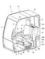
図2に示すように、キャブ8は、旋回フレーム5の左前側に設けられている。キャブ8は、フロア部材9とキャブボックス10とを含んで構成されている。また、キャブボックス10に囲まれた内部は、オペレータが乗り込む後述の運転室16(居住スペース)になっている。 As shown in FIG. 2 , the cab 8 is provided on the front left side of the revolving frame 5 . The cab 8 includes a floor member 9 and a cab box 10. As shown in FIG. Further, the inside surrounded by the cab box 10 is a later-described driver's cab 16 (living space) in which an operator gets in.

フロア部材9は、キャブ8の床面を構成している。フロア部材9は、前,後方向に長尺な長方形状の板体として形成されている。フロア部材9は、その四隅を含む複数箇所が防振マウント(図示せず)を介して旋回フレーム5に支持されている。一方、フロア部材9のほぼ中央位置には、上,下方向に扁平なボックス形状をした運転席取付台9Aが設けられている。運転席取付台9A上には、後述する運転席17が設けられている。ここで、運転席取付台9Aの内部は、空洞となっている。運転席取付台9Aの内部には、後述する空調機21が収容されている。 The floor member 9 constitutes the floor surface of the cab 8 . The floor member 9 is formed as a rectangular plate elongated in the front and rear directions. The floor member 9 is supported by the revolving frame 5 at a plurality of locations including four corners thereof via anti-vibration mounts (not shown). On the other hand, at a substantially central position of the floor member 9, a driver's seat mounting base 9A having a box shape flattened upward and downward is provided. A driver's seat 17, which will be described later, is provided on the driver's seat mount 9A. Here, the inside of the driver's seat mounting base 9A is hollow. An air conditioner 21, which will be described later, is accommodated inside the driver's seat mount 9A.

キャブボックス10は、フロア部材9上に設けられている。キャブボックス10は、前面部11、後面部12、左面部13(図1参照)、右面部14および天面部15によりボックス状に形成され、周面となる前面部11、後面部12、左面部13、右面部14の下部がフロア部材9の周囲に取付けられている。 A cab box 10 is provided on the floor member 9 . The cab box 10 is formed in a box shape by a front surface portion 11, a rear surface portion 12, a left surface portion 13 (see FIG. 1), a right surface portion 14, and a top surface portion 15. 13, the lower part of the right side part 14 is attached to the periphery of the floor member 9;

ここで、後面部12は、フロア部材9の後端位置から上側に延びた下縦板12Aと、下縦板12Aの上部から後側に延びた横板12Bと、横板12Bの後部から天面部15まで上側に延びた上縦板12Cとによりステップ状に形成されている。後面部12の下縦板12Aの後側には、後述する外気ダクト22を設置するための空間が形成されている。さらに、後面部12の下縦板12Aには、外気ダクト22の下流側の接続口22E(図4参照)が運転室16内に開口して接続されている。例えば、下縦板12Aには、中間ダクト23の上流端部23Aを接続口22Eに位置決めした状態で上流端部23Aを固定するためのねじ穴(図示せず)が設けられている。 Here, the rear surface portion 12 includes a lower vertical plate 12A extending upward from the rear end position of the floor member 9, a horizontal plate 12B extending rearward from the upper portion of the lower vertical plate 12A, and a ceiling from the rear portion of the horizontal plate 12B. An upper vertical plate 12</b>C extending upward to the surface portion 15 forms a stepped shape. On the rear side of the lower vertical plate 12A of the rear surface portion 12, a space is formed for installing an outside air duct 22, which will be described later. Further, a connection port 22E (see FIG. 4) on the downstream side of the outside air duct 22 is connected to the lower vertical plate 12A of the rear surface portion 12 so as to open into the driver's cab 16. As shown in FIG. For example, the lower vertical plate 12A is provided with a screw hole (not shown) for fixing the upstream end 23A of the intermediate duct 23 in a state where it is positioned at the connection port 22E.

運転室16は、キャブボックス10に囲まれた内部の空間として形成されている。運転室16は、オペレータが各種作業を行うための居住スペースを備えている。ここで、運転室16のうち、居住スペースは、後述する中間ダクト23を取付けるために必要な作業スペースを小さくしたことにより、同じ大きさのキャブと比較して広く形成することができる。 The driver's cab 16 is formed as an internal space surrounded by the cab box 10 . The operator's cab 16 has a living space for the operator to perform various operations. Here, the living space in the driver's cab 16 can be made wider than a cab of the same size by reducing the work space required for installing an intermediate duct 23, which will be described later.

運転席17は、フロア部材9の運転席取付台9A上に設けられている。運転席17には、オペレータが着座する。運転席17の左,右両側には、作業装置4等を操作する操作レバー18が設けられている。一方、運転席17の前側となるフロア部材9の前側位置には、下部走行体2を走行させるための左,右の走行レバー・ペダル装置19(図2に一部のみ図示)が設けられている。 The driver's seat 17 is provided on the driver's seat mount 9A of the floor member 9. As shown in FIG. An operator sits in the driver's seat 17 . On both left and right sides of the driver's seat 17, operation levers 18 for operating the working device 4 and the like are provided. On the other hand, left and right running lever/pedal devices 19 (only part of which is shown in FIG. 2) for running the lower running body 2 are provided on the front side of the floor member 9, which is the front side of the driver's seat 17. there is

また、運転席17の後側位置には、後面部12の上,下方向の中間部分を覆うようにカバー部材20が設けられている。カバー部材20は、電気部品(図示せず)等を覆っている。また、カバー部材20には、上側に位置して運転室16内に調和空気を吹き出すための吹出口20Aが設けられている。 A cover member 20 is provided at the rear side of the driver's seat 17 so as to cover the upper and lower intermediate portions of the rear surface portion 12 . The cover member 20 covers electrical components (not shown) and the like. Further, the cover member 20 is provided with an outlet 20</b>A positioned on the upper side for blowing the conditioned air into the cab 16 .

空調機21は、キャブ8内に設けられている。空調機21は、フロア部材9の運転席取付台9A内に収容された室内機を構成している。図4に示すように、空調機21は、左,右方向に延びる箱形状に形成されている。また、空調機21内には、ファン、エバポレータ等(いずれも図示せず)が設けられている。空調機21は、運転室16内の空気(内気)とキャブ8の外部の空気(外気)とを選択的に吸込み、調和空気として運転室16に供給する。これにより、空調機21は、キャブ8内をオペレータが望む温度環境に調整することができる。 The air conditioner 21 is provided inside the cab 8 . The air conditioner 21 constitutes an indoor unit housed in the driver's seat mount 9A of the floor member 9. As shown in FIG. As shown in FIG. 4, the air conditioner 21 is formed in a box shape extending in left and right directions. In addition, the air conditioner 21 is provided with a fan, an evaporator, etc. (none of which are shown). The air conditioner 21 selectively draws in air (inside air) inside the cab 16 and air (outside air) outside the cab 8 and supplies the air to the cab 16 as conditioned air. Thereby, the air conditioner 21 can adjust the inside of the cab 8 to the temperature environment desired by the operator.

ここで、空調機21は、後述する中間ダクト23の構造が外気ダクト22と空調機21との間に取付けるときに、大きな作業スペースを必要としない構造になっていることから、キャブボックス10の後面部12に近い位置に配置することができる。 Here, the air conditioner 21 has a structure that does not require a large work space when the structure of the intermediate duct 23 described later is installed between the outside air duct 22 and the air conditioner 21. It can be arranged at a position close to the rear face part 12 .

箱形状の空調機21内で空気が流通するときの上流側となる空調機21の左側の端面には、運転室16内の空気を取入れる内気取入口21Aが設けられている。また、空調機21の後面の左側寄りには、外気取入口を構成する外気取入ダクト21Bが取付けられている。この外気取入ダクト21Bは、空調機21の後面から後側に延びつつ、上側に屈曲している。外気取入ダクト21Bの端部は、キャブボックス10を構成する後面部12の下縦板12Aと対面するように垂直に開口し、その横長な矩形状の開口端部には、後述するスライド接続機構24の雌枠部材25が取付けられている。これにより、空調機21は、スライド接続機構24を介して中間ダクト23、外気ダクト22と接続している。 An internal air intake 21A for taking in the air in the cab 16 is provided on the left end face of the box-shaped air conditioner 21, which is the upstream side when the air circulates. Further, an outside air intake duct 21B constituting an outside air intake is attached to the left side of the rear surface of the air conditioner 21 . The outside air intake duct 21B extends rearward from the rear surface of the air conditioner 21 and bends upward. The end of the outside air intake duct 21B opens vertically so as to face the lower vertical plate 12A of the rear surface 12 constituting the cab box 10, and the laterally long rectangular opening end has a slide connection, which will be described later. A female frame member 25 of mechanism 24 is attached. Thereby, the air conditioner 21 is connected to the intermediate duct 23 and the outside air duct 22 via the slide connection mechanism 24 .

一方、下流側となる空調機21の右側には、吐出口21C(図4参照)が上向きに開口して設けられている。この吐出口21Cは、空調機21で調整された空気(調和空気)をカバー部材20の吹出口20A等に向けて吐出する。また、空調機21の右側には、運転席17よりも前側に配置された他の吹出口(図示せず)に向けて調和空気を吐出する他の吐出口(いずれも図示せず)が設けられている。 On the other hand, on the right side of the air conditioner 21 on the downstream side, a discharge port 21C (see FIG. 4) is provided so as to open upward. The discharge port 21C discharges the air (conditioned air) adjusted by the air conditioner 21 toward the blowout port 20A of the cover member 20 and the like. Further, on the right side of the air conditioner 21, there is provided another discharge port (neither shown) for discharging conditioned air toward another discharge port (not shown) arranged on the front side of the driver's seat 17. It is

外気ダクト22は、キャブ8のキャブボックス10に設けられている。具体的には、外気ダクト22は、キャブボックス10の後面部12を形成する下縦板12Aの左側位置に取付けられている。外気ダクト22は、外気を空調機21に導入するための空気経路を、中間ダクト23、空調機21の外気取入ダクト21Bと共に構成している。図3に示すように、外気ダクト22は、左面部13との間に隙間を形成した状態で、下縦板12Aから後側に延びて設けられた左,右方向に扁平なボックス状のフィルタケース22Aと、フィルタケース22Aの右面の開口(図示せず)から下縦板12Aに向けて延びたダクト部22Bとを含んで構成されている。 The outside air duct 22 is provided in the cab box 10 of the cab 8 . Specifically, the outside air duct 22 is attached to the left side of the lower vertical plate 12A forming the rear surface portion 12 of the cab box 10 . The outside air duct 22 constitutes an air path for introducing outside air into the air conditioner 21 together with the intermediate duct 23 and the outside air intake duct 21B of the air conditioner 21 . As shown in FIG. 3, the external air duct 22 is a box-shaped filter that is flattened in the left and right directions and extends rearward from the lower vertical plate 12A with a gap formed between it and the left surface portion 13. It includes a case 22A and a duct portion 22B extending from an opening (not shown) on the right side of the filter case 22A toward the lower vertical plate 12A.

外気ダクト22には、外気の取入れ口(図示せず)が設けられたフィルタケース22Aの左面に、開口カバー22Cが設けられている。この開口カバー22Cは、下方のみに開口したボックス形状に形成されることで、雨水や塵埃、虫等の異物が吸込まれるのを抑制している。また、フィルタケース22Aには、外気に含まれる異物を捕捉して清浄な空気を空調機21側に供給するフィルタエレメント22Dが着脱可能に収容されている。 The outside air duct 22 is provided with an opening cover 22C on the left side of a filter case 22A having an outside air intake (not shown). The opening cover 22C is formed in a box shape that is opened only downward, thereby suppressing the intake of foreign matter such as rainwater, dust, and insects. A filter element 22D that captures foreign matter contained in the outside air and supplies clean air to the air conditioner 21 side is detachably housed in the filter case 22A.

さらに、図4に示すように、ダクト部22Bの下流端部は、後面部12の下縦板12Aに開口した状態で取付けられている。これにより、ダクト部22Bの下流端部は、下縦板12Aに開口した縦長な接続口22Eとなっている。接続口22Eには、中間ダクト23の上流端部23Aが連通状態で接続される。 Furthermore, as shown in FIG. 4, the downstream end of the duct portion 22B is attached to the lower vertical plate 12A of the rear surface portion 12 in an open state. As a result, the downstream end of the duct portion 22B forms a vertically long connection port 22E that opens to the lower vertical plate 12A. An upstream end portion 23A of the intermediate duct 23 is connected to the connection port 22E in a communicating state.

中間ダクト23は、外気ダクト22と空調機21の外気取入ダクト21Bとを接続している。中間ダクト23は、空調機21の外気取入ダクト21B、外気ダクト22と共に、外気を空調機21に導入するための空気経路を構成している。中間ダクト23の外気ダクト22側の上流端部23Aは、外気ダクト22の接続口22Eに対応するように、上,下方向に長尺な縦長開口として形成されている。この上で、上流端部23Aは、下流端部23Bが後述のスライド接続機構24を介して空調機21の外気取入ダクト21Bに取付けられた状態で、接続口22Eに対面している。また、上流端部23Aには、後面部12の下縦板12Aに設けられたねじ穴に対応する位置に固定用のフランジ部(図示せず)が設けられている。 The intermediate duct 23 connects the outside air duct 22 and the outside air intake duct 21B of the air conditioner 21 . The intermediate duct 23 constitutes an air path for introducing outside air into the air conditioner 21 together with the outside air intake duct 21B of the air conditioner 21 and the outside air duct 22 . An upstream end portion 23A of the intermediate duct 23 on the outside air duct 22 side is formed as a vertically elongated opening that is elongated in the upward and downward directions so as to correspond to the connection port 22E of the outside air duct 22 . Above this, the upstream end portion 23A faces the connection port 22E while the downstream end portion 23B is attached to the outside air intake duct 21B of the air conditioner 21 via a slide connection mechanism 24, which will be described later. Further, the upstream end portion 23A is provided with a fixing flange portion (not shown) at a position corresponding to the screw hole provided in the lower vertical plate 12A of the rear surface portion 12. As shown in FIG.

上流端部23Aは、後述するスライド接続機構24の雌枠部材25と雄枠部材26とを接続し、下流端部23Bを空調機21の外気取入ダクト21Bに固定することで、接続口22Eに対して位置決め状態で配置される。即ち、中間ダクト23は、空調機21に対する取付作業を行うだけで、上流端部23Aを外気ダクト22の接続口22Eに自動的に連通させることができる。そして、接続口22Eに位置決めされた上流端部23Aは、フランジ部に挿通したボルト(図示せず)を下縦板12Aのねじ穴に螺着することにより、下縦板12Aに取付けることができる。 The upstream end portion 23A connects the female frame member 25 and the male frame member 26 of the slide connection mechanism 24, which will be described later, and the downstream end portion 23B is fixed to the outside air intake duct 21B of the air conditioner 21 to form the connection port 22E. is positioned with respect to the That is, the intermediate duct 23 can automatically communicate the upstream end 23A with the connection port 22E of the outside air duct 22 simply by performing the mounting work on the air conditioner 21 . The upstream end portion 23A positioned at the connection port 22E can be attached to the lower vertical plate 12A by screwing a bolt (not shown) inserted through the flange portion into a screw hole of the lower vertical plate 12A. .

中間ダクト23の空調機21側の下流端部23Bは、スライド接続機構24の雄枠部材26に取付けられている。これにより、中間ダクト23の下流端部23Bは、スライド接続機構24を介して空調機21の外気取入ダクト21Bに接続することができる。 A downstream end 23B of the intermediate duct 23 on the side of the air conditioner 21 is attached to a male frame member 26 of the slide connection mechanism 24 . Thereby, the downstream end portion 23B of the intermediate duct 23 can be connected to the outside air intake duct 21B of the air conditioner 21 via the slide connection mechanism 24 .

次に、本実施形態の特徴部分となるスライド接続機構24の構成および接続作業について詳しく説明する。 Next, the configuration and connection work of the slide connection mechanism 24, which are features of this embodiment, will be described in detail.

図3、図4に示すように、スライド接続機構24は、中間ダクト23の下流端部23Bと空調機21の外気取入ダクト21Bとの間に設けられている。スライド接続機構24は、空調機21と中間ダクト23とを接続するものである。スライド接続機構24は、後述の雌枠部材25と雄枠部材26とにより構成されている。 As shown in FIGS. 3 and 4, the slide connection mechanism 24 is provided between the downstream end 23B of the intermediate duct 23 and the outside air intake duct 21B of the air conditioner 21. As shown in FIG. The slide connection mechanism 24 connects the air conditioner 21 and the intermediate duct 23 . The slide connection mechanism 24 is composed of a female frame member 25 and a male frame member 26 which will be described later.

雌枠部材25は、空調機21の外気取入ダクト21Bに設けられている。雌枠部材25は、外気取入ダクト21Bの開口端部に対応するように、横長な(左,右方向に長尺な)矩形状の枠体として形成されている。雌枠部材25は、外気取入ダクト21Bの開口端部に一体的に固着されている。これにより、雌枠部材25は、キャブボックス10の後面部12を形成する下縦板12A側の取付面に対して平行となるように垂直に配置されている。雌枠部材25は、上部に位置して左,右方向に延びた雌上枠25Aと、下部に位置して左,右方向に延びた雌下枠25Bと、雌上枠25Aの長さ方向の端部と雌下枠25Bの長さ方向の端部を接続する左,右で一対の雌側枠25Cとを備えている。 The female frame member 25 is provided in the outside air intake duct 21B of the air conditioner 21 . The female frame member 25 is formed as a laterally long (left and right direction elongated) rectangular frame so as to correspond to the open end of the outside air intake duct 21B. The female frame member 25 is integrally fixed to the open end of the outside air intake duct 21B. Thereby, the female frame member 25 is arranged vertically so as to be parallel to the mounting surface of the lower vertical plate 12</b>A forming the rear surface portion 12 of the cab box 10 . The female frame member 25 includes an upper female frame 25A extending in the left and right direction, a lower female frame 25B extending in the left and right direction at the lower portion, and a longitudinal direction of the upper female frame 25A. and a pair of left and right female side frames 25C connecting the ends of the lower female frame 25B in the longitudinal direction.

また、図7に示すように、雌枠部材25は、中間ダクト23側に凹溝25Dを有している。この凹溝25Dは、雌下枠25Bの内側面となる上面に左,右方向に延びて設けられた下溝25D1と、下溝25D1の両端から各雌側枠25Cの内側面(対向面)を上側に延びた側溝25D2とにより構成されている。これにより、凹溝25Dは、雌枠部材25の雌下枠25Bと各雌側枠25Cの内側面に連続して設けられている。凹溝25Dは、各側溝25D2が上側に開放され、雌枠部材25には、この開放された上部から後述する雄枠部材26の鍔部26Dを嵌合することができる。 Further, as shown in FIG. 7, the female frame member 25 has a concave groove 25D on the intermediate duct 23 side. This concave groove 25D includes a lower groove 25D1 extending in the left and right directions on the upper surface serving as the inner surface of the female lower frame 25B, and the inner surface (opposing surface) of each female side frame 25C from both ends of the lower groove 25D1. It is composed of a side groove 25D2 extending to the Thus, the recessed groove 25D is continuously formed on the inner side surfaces of the lower female frame 25B of the female frame member 25 and the respective female side frames 25C. Each side groove 25D2 of the recessed groove 25D is opened upward, and a collar portion 26D of a male frame member 26, which will be described later, can be fitted to the female frame member 25 from the opened upper portion.

さらに、雌枠部材25の雌上枠25Aには、その上面25A1に開口して2個のねじ穴25Eが設けられている。雌上枠25Aの上面25A1には、雄枠部材26の固定部27の下面が気密状態で当接する。また、各ねじ穴25Eには、固定部27を固定するためのボルト28が螺着される。 Further, the upper female frame 25A of the female frame member 25 is provided with two screw holes 25E that are open to the upper surface 25A1. The lower surface of the fixing portion 27 of the male frame member 26 abuts against the upper surface 25A1 of the female upper frame 25A in an airtight state. A bolt 28 for fixing the fixing portion 27 is screwed into each screw hole 25E.

雄枠部材26は、中間ダクト23の下流端部23Bに設けられている。雄枠部材26は、雌枠部材25と対面して接続されるもので、雌枠部材25と同様の横長な矩形状の枠体として形成されている。雄枠部材26は、中間ダクト23の下流端部23Bに一体的に固着されている。また、雄枠部材26は、雌枠部材25と対面できるように、雌枠部材25と同様に垂直に配置されている。これにより、雄枠部材26は、雌枠部材25に対して上側から下側に向けてスライドさせることによって雌枠部材25と密着状態で接続することができる。 A male frame member 26 is provided at the downstream end 23B of the intermediate duct 23 . The male frame member 26 faces and is connected to the female frame member 25 , and is formed as a laterally long rectangular frame like the female frame member 25 . The male frame member 26 is integrally fixed to the downstream end portion 23B of the intermediate duct 23. As shown in FIG. Similarly to the female frame member 25, the male frame member 26 is arranged vertically so as to face the female frame member 25. As shown in FIG. As a result, the male frame member 26 can be connected to the female frame member 25 in close contact with the female frame member 25 by sliding the male frame member 26 from the upper side to the lower side.

雄枠部材26は、上部に位置して左,右方向に延びた雄上枠26Aと、下部に位置して左,右方向に延びた雄下枠26Bと、雄上枠26Aの長さ方向の端部と雄下枠26Bの長さ方向の端部を接続する左,右で一対の雄側枠26Cとを備えている。 The male frame member 26 includes an upper male frame 26A extending in the left and right direction, a lower male frame 26B positioned in the lower portion and extending in the left and right direction, and a longitudinal direction of the upper male frame 26A. and a pair of male side frames 26C on the left and right that connect the ends of the male lower frame 26B in the longitudinal direction.

図6に示すように、雄枠部材26は、雄下枠26Bと一対の雄側枠26Cとに形成されると共に、雌枠部材25の凹溝25Dに対し上側からスライドして嵌合する鍔部26Dを有している。この鍔部26Dは、雄下枠26Bの外縁となる下縁部に左,右方向に延びて設けられた下鍔26D1と、下鍔26D1の両端から各雄側枠26Cの外縁を上側に延びて設けられた左,右で一対の側鍔26D2とにより構成されている。これにより、雄枠部材26には、鍔部26Dが雄下枠26Bと各雄側枠26Cの外縁部に連続して設けられている。 As shown in FIG. 6, the male frame member 26 is formed by a male lower frame 26B and a pair of male side frames 26C. It has a portion 26D. The flanges 26D include lower flanges 26D1 extending leftward and rightward from the lower edge of the male lower frame 26B and extending upward from both ends of the lower flanges 26D1 along the outer edges of the male side frames 26C. It consists of a pair of left and right side flanges 26D2. As a result, the male frame member 26 is provided with a collar portion 26D that is continuous with the outer edge portions of the lower male frame 26B and the male side frames 26C.

鍔部26Dは、下鍔26D1が雌枠部材25の凹溝25Dの下溝25D1に対して上側から嵌合し、左,右の側鍔26D2が凹溝25Dの各側溝25D2に対して開放された上側から嵌合する構成となっている。従って、鍔部26Dは、雌枠部材25に対して雄枠部材26を上側から下側に向けてスライドさせることにより、凹溝25Dに嵌合することができる。 In the flange portion 26D, the lower flange 26D1 is fitted into the lower groove 25D1 of the concave groove 25D of the female frame member 25 from above, and the left and right side flanges 26D2 are open to the side grooves 25D2 of the concave groove 25D. It is configured to be fitted from above. Therefore, by sliding the male frame member 26 downward with respect to the female frame member 25, the collar portion 26D can be fitted into the concave groove 25D.

このときに、鍔部26Dは、外気の流通方向に対して交差する方向に嵌合している。具体的には、凹溝25Dと鍔部26Dとの間に形成される隙間は、外気の流通方向に対して直交しているから、この隙間には、外気が積極的に流入することがない。しかも、凹溝25Dと鍔部26Dとの嵌合構造では、凹部と凸部とによってU字状のシール部を形成することができるから、少ないスペースでシール(密着)距離を確保することができる。 At this time, the collar portion 26D is fitted in a direction intersecting with the circulation direction of the outside air. Specifically, since the gap formed between the concave groove 25D and the collar portion 26D is perpendicular to the circulation direction of the outside air, the outside air does not actively flow into this gap. . Moreover, in the fitting structure of the concave groove 25D and the flange portion 26D, a U-shaped sealing portion can be formed by the concave portion and the convex portion, so the sealing (close contact) distance can be secured in a small space. .

さらに、雄枠部材26は、雄上枠26Aに設けられた固定部27を有している。固定部27は、雌枠部材25に対して雄枠部材26を上側から下側に向けてスライドさせることにより雌枠部材25の雌上枠25Aに当接される。この状態で、固定部27は、ボルト28を用いて雌枠部材25の雌上枠25Aに固定されている。 Further, the male frame member 26 has a fixing portion 27 provided on the male upper frame 26A. The fixed portion 27 is brought into contact with the female upper frame 25A of the female frame member 25 by sliding the male frame member 26 downward from the upper side with respect to the female frame member 25 . In this state, the fixing portion 27 is fixed to the female upper frame 25A of the female frame member 25 using bolts 28. As shown in FIG.

固定部27は、雄上枠26Aから雌枠部材25に向けて庇状に延びた長方形状の板体として形成されている。長方形状の板体からなる固定部27は、雌枠部材25に対して雄枠部材26を上側からスライドさせたときに、下面を雌枠部材25の雌上枠25Aの上面25A1に気密状態に当接させることができる。従って、固定部27は、雌枠部材25の雌上枠25Aに当接して外気の漏れを防ぐシール部材を兼ねている。 The fixing portion 27 is formed as a rectangular plate extending like an eave from the male upper frame 26A toward the female frame member 25 . The fixing portion 27, which is a rectangular plate, has a lower surface airtightly attached to the upper surface 25A1 of the female upper frame 25A of the female frame member 25 when the male frame member 26 is slid with respect to the female frame member 25 from above. can be abutted. Therefore, the fixing portion 27 also serves as a sealing member that abuts against the female upper frame 25A of the female frame member 25 to prevent leakage of outside air.

また、固定部27には、上,下方向に貫通して2個のボルト挿通孔27Aが設けられている。各ボルト挿通孔27Aは、雌枠部材25の雌上枠25Aに設けた2個のねじ穴25Eに対応して配置されている。そして、固定部27は、各ボルト挿通孔27Aに挿通したそれぞれのボルト28を雌上枠25Aの各ねじ穴25Eに螺着することにより、雌枠部材25の上部、即ち、雌上枠25Aに対して固定される。この場合、各ボルト28の締付け作業は、スライド接続機構24の上側から行うことができるから、容易に手が届く上に、スパナ、ラチェットレンチ等の工具を取扱うためのスペースを確保でき、容易に作業することができる。 The fixed portion 27 is provided with two bolt insertion holes 27A penetrating vertically. Each bolt insertion hole 27A is arranged corresponding to two screw holes 25E provided in the upper female frame 25A of the female frame member 25. As shown in FIG. The fixing portion 27 is attached to the upper portion of the female frame member 25, that is, the female upper frame 25A by screwing the bolts 28 inserted through the bolt insertion holes 27A into the screw holes 25E of the female upper frame 25A. fixed against. In this case, the bolts 28 can be tightened from the upper side of the slide connection mechanism 24, so that they can be easily reached and a space can be secured for tools such as wrenches and ratchet wrenches. can work.

図5、図8に示すように、外気シール29は、雄枠部材26の鍔部26Dに設けられている。外気シール29は、雄枠部材26の鍔部26Dと雌枠部材25の凹溝25Dとの間をシールする。外気シール29は、例えば弾性を有する樹脂材料を用いて断面U字状に形成されている。外気シール29は、鍔部26Dの下鍔26D1を覆うように取付けられた下シール部29Aと、下シール部29Aの両端から上側に延び、各側鍔26D2を覆うように取付けられた各側シール部29Bとにより構成されている。これにより、外気シール29は、雌枠部材25の凹溝25Dと雄枠部材26の鍔部26Dとの間の隙間を埋めることによってシール性を高めている。また、弾性を有する外気シール29は、凹溝25Dと鍔部26Dとの衝突を回避して静粛性を高めることができる。 As shown in FIGS. 5 and 8, the outside air seal 29 is provided on the flange portion 26D of the male frame member 26. As shown in FIGS. The outside air seal 29 seals between the collar portion 26D of the male frame member 26 and the groove 25D of the female frame member 25. As shown in FIG. The external air seal 29 is formed with a U-shaped cross section using, for example, an elastic resin material. The outside air seal 29 includes a lower seal portion 29A attached to cover the lower collar 26D1 of the collar portion 26D, and each side seal extending upward from both ends of the lower seal portion 29A and attached to cover each side collar 26D2. 29B. As a result, the outside air seal 29 fills the gap between the groove 25D of the female frame member 25 and the flange 26D of the male frame member 26, thereby improving the sealing performance. In addition, the elastic external air seal 29 can avoid collision between the concave groove 25D and the collar portion 26D to improve quietness.

次に、スライド接続機構24を用いて中間ダクト23を外気ダクト22と空調機21の外気取入ダクト21Bに接続するときの作業手順の一例について説明する。 Next, an example of a work procedure for connecting the intermediate duct 23 to the outside air duct 22 and the outside air intake duct 21B of the air conditioner 21 using the slide connection mechanism 24 will be described.

キャブ8に空調機21と外気ダクト22を取付けたら、中間ダクト23を運転室16に持ち込む。この中間ダクト23は、空調機21と外気ダクト22との間の上方に配置し、空調機21と外気ダクト22との間に向けて下向きに移動させる。このときに、スライド接続機構24は、雌枠部材25に対して雄枠部材26を対面させた状態でスライド移動させる。詳しくは、雌枠部材25の凹溝25Dに雄枠部材26の鍔部26Dを上側から差込み、下鍔26D1を下溝25D1に嵌合させる。これにより、雌枠部材25と雄枠部材26とは、外気の流通方向で一体的に固定されている。 After the air conditioner 21 and the outside air duct 22 are attached to the cab 8, the intermediate duct 23 is brought into the driver's cab 16. - 特許庁The intermediate duct 23 is arranged above between the air conditioner 21 and the outside air duct 22 and moved downward toward between the air conditioner 21 and the outside air duct 22 . At this time, the slide connection mechanism 24 causes the male frame member 26 to face the female frame member 25 in a sliding manner. Specifically, the flange 26D of the male frame member 26 is inserted into the groove 25D of the female frame member 25 from above, and the lower flange 26D1 is fitted into the lower groove 25D1. Thereby, the female frame member 25 and the male frame member 26 are integrally fixed in the air circulation direction.

この状態で、固定部27の各ボルト挿通孔27Aに挿通したボルト28を雌枠部材25の雌上枠25Aの各ねじ穴25Eに螺着する。これにより、中間ダクト23の下流端部23Bは、スライド接続機構24を介して空調機21の外気取入ダクト21Bに一体的に接続することができる。 In this state, the bolts 28 inserted through the bolt insertion holes 27A of the fixing portion 27 are screwed into the screw holes 25E of the upper female frame 25A of the female frame member 25. As shown in FIG. Thereby, the downstream end portion 23B of the intermediate duct 23 can be integrally connected to the outside air intake duct 21B of the air conditioner 21 via the slide connection mechanism 24 .

一方、中間ダクト23の下流端部23Bを空調機21の外気取入ダクト21Bに接続した状態では、中間ダクト23の上流端部23Aが外気ダクト22の接続口22Eに対して位置決め状態で配置される。そこで、中間ダクト23の上流端部23Aは、固定用のフランジ部に挿通したボルトを後面部12の下縦板12Aに設けられたねじ穴に螺着することにより、外気ダクト22の接続口22Eに一体的に接続することができる。 On the other hand, when the downstream end 23B of the intermediate duct 23 is connected to the outside air intake duct 21B of the air conditioner 21, the upstream end 23A of the intermediate duct 23 is positioned relative to the connection port 22E of the outside air duct 22. be. Therefore, the upstream end portion 23A of the intermediate duct 23 is connected to the connection port 22E of the outside air duct 22 by screwing a bolt inserted through the fixing flange portion into a screw hole provided in the lower vertical plate 12A of the rear surface portion 12. can be integrally connected to

実施形態による油圧ショベル1は上述の如き構成を有するもので、次に、その動作について説明する。 The hydraulic excavator 1 according to the embodiment has the configuration as described above, and the operation thereof will now be described.

まず、オペレータは、キャブ8に搭乗し、左,右の走行レバー・ペダル装置19を操作することにより、下部走行体2を前進または後退させることができる。一方、キャブ8内のオペレータは、左,右の操作レバー18を操作することにより、作業装置4等を動作させて土砂の掘削作業等を行うことができる。 First, the operator gets on the cab 8 and operates the left and right traveling lever/pedal devices 19 to move the lower traveling body 2 forward or backward. On the other hand, the operator in the cab 8 operates the left and right operation levers 18 to operate the work device 4 and the like to perform earth and sand excavation work.

油圧ショベル1の作業時には、キャブ8内の居住環境を良好にするために、空調機21を運転して運転室16に調和空気を供給する。この場合、運転室16には、運転室16内の空気(内気)と外部の空気(外気)とを選択して供給することができる。空調機21を外気側に切換えた場合には、外気が外気ダクト22および中間ダクト23を介して外気取入ダクト21Bから空調機21に流入する。一方、空調機21を内気側に切換えた場合には、内気が内気取入口21Aから空調機21に流入する。そして、空調機21は、吐出口21C等から所望の温度に調整された調和空気を運転室16に供給する。 During operation of the hydraulic excavator 1 , the air conditioner 21 is operated to supply conditioned air to the operator's cab 16 in order to improve the living environment in the cab 8 . In this case, the air in the operator's cab 16 (inside air) and the air outside (outside air) can be selectively supplied to the operator's cab 16 . When the air conditioner 21 is switched to the outside air side, the outside air flows into the air conditioner 21 from the outside air intake duct 21B via the outside air duct 22 and the intermediate duct 23 . On the other hand, when the air conditioner 21 is switched to the inside air side, the inside air flows into the air conditioner 21 from the inside air intake port 21A. Then, the air conditioner 21 supplies conditioned air adjusted to a desired temperature to the operating room 16 from the discharge port 21C or the like.

かくして、実施形態によれば、中間ダクト23の空調機21側の下流端部23Bと空調機21の外気取入ダクト21Bとの間には、スライド接続機構24が設けられている。スライド接続機構24は、空調機21の外気取入ダクト21Bに設けられ、上側が開放されると共に内側面に連続して凹溝25Dが形成された雌枠部材25と、中間ダクト23の下流端部23Bに設けられ、雌枠部材25に対して上側からスライドさせることにより凹溝25Dに嵌合する鍔部26Dを有する雄枠部材26とにより構成されている。 Thus, according to the embodiment, a sliding connection mechanism 24 is provided between the downstream end 23B of the intermediate duct 23 on the air conditioner 21 side and the outside air intake duct 21B of the air conditioner 21 . The slide connection mechanism 24 is provided in the outside air intake duct 21B of the air conditioner 21, and includes a female frame member 25 having an open upper side and a concave groove 25D continuously formed on the inner surface, and the downstream end of the intermediate duct 23. A male frame member 26 is provided on the portion 23B and has a collar portion 26D that is fitted into the concave groove 25D by being slid on the female frame member 25 from above.

この構成によれば、雄枠部材26は、雌枠部材25に対して上側から下側に向けてスライドさせることにより、雄枠部材26の鍔部26Dを雌枠部材25の凹溝25Dに嵌合させることができる。 According to this configuration, the male frame member 26 is slid from the upper side to the lower side with respect to the female frame member 25 so that the flange portion 26D of the male frame member 26 is fitted into the concave groove 25D of the female frame member 25. can be combined.

このスライド接続機構24を用いた接続作業では、スライド接続機構24の上側からだけの作業で接続することができるから、例えばフランジ接続を用いたものに比較して、中間ダクト23を空調機21に接続するために必要な作業スペースを小さくすることができる。この結果、作業スペースを縮小した分だけ運転室16の居住スペースを広くすることができ、運転室16の居住性を向上できる。 In the connection work using this slide connection mechanism 24, the connection can be made only from the upper side of the slide connection mechanism 24. Therefore, compared to, for example, a flange connection, the intermediate duct 23 is connected to the air conditioner 21. The working space required for connection can be reduced. As a result, the living space of the driver's cab 16 can be increased by the reduced work space, and the comfort of the driver's cab 16 can be improved.

実施形態によれば、雄枠部材26の上部には、雌枠部材25の上部に固定される固定部27を有している。この構成によれば、雄枠部材26の固定部27を雌枠部材25の雌上枠25Aに固定することにより、スライド接続機構24を用いて空調機21の外気取入ダクト21Bと中間ダクト23とを一体的に接続することができる。 According to the embodiment, the upper portion of the male frame member 26 has a fixing portion 27 that is fixed to the upper portion of the female frame member 25 . According to this configuration, by fixing the fixing portion 27 of the male frame member 26 to the female upper frame 25A of the female frame member 25, the slide connection mechanism 24 is used to connect the outside air intake duct 21B and the intermediate duct 23 of the air conditioner 21. and can be integrally connected.

実施形態によれば、雌枠部材25は、雌上枠25A、雌下枠25Bおよび雌上枠25Aの長さ方向の端部と雌下枠25Bの長さ方向の端部を接続する一対の雌側枠25Cから矩形状の枠体として形成されると共に、雌下枠25Bと各雌側枠25Cの内側面に連続して凹溝25Dが形成されている。また、雄枠部材26は、雄上枠26A、雄下枠26Bおよび雄上枠26Aの長さ方向の端部と雄下枠26Bの長さ方向の端部を接続する一対の雄側枠26Cから矩形状の枠体として形成される。鍔部26Dは、雄下枠26Bと一対の雄側枠26Cとに形成されると共に、雌枠部材25の凹溝25Dに対し上側からスライドして嵌合する。固定部27は、雄上枠26Aに設けられて、雌枠部材25の雌上枠25Aに固定されている。 According to the embodiment, the female frame member 25 comprises a female upper frame 25A, a female lower frame 25B and a pair of longitudinal ends connecting the longitudinal ends of the female upper frame 25A and the female lower frame 25B. A rectangular frame body is formed from the female side frame 25C, and concave grooves 25D are formed continuously on the inner surfaces of the female lower side frame 25B and the respective female side side frames 25C. The male frame member 26 includes a male upper frame 26A, a male lower frame 26B, and a pair of male side frames 26C connecting the longitudinal ends of the male upper frame 26A and the longitudinal ends of the male lower frame 26B. It is formed as a rectangular frame. The flanges 26D are formed on the male lower frame 26B and the pair of male side frames 26C, and are fitted into the grooves 25D of the female frame member 25 by sliding from above. The fixing portion 27 is provided on the male upper frame 26A and fixed to the female upper frame 25A of the female frame member 25. As shown in FIG.

この構成によれば、雌枠部材25の凹溝25Dに対し上側から雄枠部材26の鍔部26Dをスライドして嵌合しているから、凹溝25Dと鍔部26Dは、外気の流通方向に対して交差する方向に嵌合している。即ち、凹溝25Dと鍔部26Dとの隙間は、外気の流通方向に対して直交しているから、外気が積極的に流入することがない。しかも、凹溝25Dと鍔部26Dとの嵌合構造では、凹部と凸部とによってU字状のシール部を形成することができるから、少ないスペースでシール(密着)距離を確保することができる。これらの構成によって、外気の漏れを防止することができる。 According to this configuration, since the collar portion 26D of the male frame member 26 is slid and fitted into the groove 25D of the female frame member 25 from above, the groove 25D and the collar portion 26D are aligned in the direction of air circulation. are fitted in a direction that intersects with That is, since the gap between the concave groove 25D and the collar portion 26D is perpendicular to the circulation direction of the outside air, the outside air does not actively flow into the gap. Moreover, in the fitting structure of the concave groove 25D and the flange portion 26D, a U-shaped sealing portion can be formed by the concave portion and the convex portion, so the sealing (close contact) distance can be secured in a small space. . These configurations can prevent outside air from leaking.

実施形態によれば、雄枠部材26の鍔部26Dには、雌枠部材25の凹溝25Dとの間をシールする外気シール29が設けられている。また、雄枠部材26の固定部27は、雌枠部材25の雌上枠25Aに当接してシールするシール部材を兼ねている。 According to the embodiment, the flange 26D of the male frame member 26 is provided with an external air seal 29 for sealing between the flange 26D and the groove 25D of the female frame member 25. As shown in FIG. The fixed portion 27 of the male frame member 26 also serves as a sealing member that contacts and seals the upper female frame 25A of the female frame member 25. As shown in FIG.

この構成によれば、雄枠部材26の鍔部26Dが雌枠部材25の凹溝25Dに嵌合したときに、外気シール29は、雌枠部材25の凹溝25Dと雄枠部材26の鍔部26Dとの間の隙間を埋めることによってシール性を高めることができる。また、弾性を有する外気シール29は、凹溝25Dと鍔部26Dとの衝突を回避して静粛性を高めることができる。一方、固定部27は、スライド接続機構24の上側から外気が漏れるのを抑制するシール部材として機能することができる。 According to this configuration, when the collar portion 26D of the male frame member 26 is fitted into the groove 25D of the female frame member 25, the outside air seal 29 is positioned between the groove 25D of the female frame member 25 and the flange of the male frame member 26. By filling the gap between the portion 26D and the portion 26D, the sealing performance can be improved. In addition, the elastic external air seal 29 can avoid collision between the concave groove 25D and the collar portion 26D to improve quietness. On the other hand, the fixed portion 27 can function as a sealing member that suppresses leakage of outside air from the upper side of the slide connection mechanism 24 .

なお、実施形態では、雄枠部材26の鍔部26Dに、雌枠部材25の凹溝25Dとの間をシールする外気シール29を設けた場合を例示している。しかし、本発明はこれに限るものではなく、外気シールを省略し、鍔部を凹溝に直接的に嵌合させる構成としてもよい。 In the embodiment, an external air seal 29 is provided for sealing between the collar portion 26D of the male frame member 26 and the concave groove 25D of the female frame member 25. As shown in FIG. However, the present invention is not limited to this, and a configuration may be adopted in which the outside air seal is omitted and the flange portion is directly fitted into the concave groove.

また、実施形態では、建設機械としてクローラ式の下部走行体2を備えた後方超小旋回型の油圧ショベルを例に挙げて説明した。しかし、本発明はこれに限るものではなく、例えば超小旋回型の油圧ショベル、標準仕様の油圧ショベル、ホイール式の油圧ショベル、油圧クレーン等の建設機械にも広く適用することができる。 In addition, in the embodiment, the hydraulic excavator having a crawler type undercarriage 2 and having a very small rear swing radius has been described as an example of the construction machine. However, the present invention is not limited to this, and can be widely applied to construction machines such as ultra-small swing hydraulic excavators, standard specification hydraulic excavators, wheel hydraulic excavators, and hydraulic cranes.

1 油圧ショベル(建設機械)
2 下部走行体(車体)
3 上部旋回体(車体)
5 旋回フレーム
8 キャブ
10 キャブボックス
16 運転室
21 空調機
21B 外気取入ダクト(外気取入口)
22 外気ダクト
23 中間ダクト
23B 下流端部
24 スライド接続機構
25 雌枠部材
25A 雌上枠(上部)
25B 雌下枠
25C 雌側枠
25D 凹溝
26 雄枠部材
26A 雄上枠(上部)
26B 雄下枠
26C 雄側枠
26D 鍔部
27 固定部
29 外気シール
1 Hydraulic excavator (construction machinery)
2 Undercarriage (body)
3 Upper revolving body (body)
5 swing frame 8 cab 10 cab box 16 cab 21 air conditioner 21B outside air intake duct (outside air intake)
22 Outside air duct 23 Intermediate duct 23B Downstream end 24 Slide connection mechanism 25 Female frame member 25A Female upper frame (upper part)
25B Female lower frame 25C Female side frame 25D Concave groove 26 Male frame member 26A Male upper frame (upper part)
26B Male lower frame 26C Male side frame 26D Flange 27 Fixing part 29 Outside air seal

Claims (3)

キャブボックスに囲まれた内部が運転室となったキャブと、
前記キャブ内に設けられ前記運転室に調和空気を供給する空調機と、
前記キャブの前記キャブボックスに設けられ前記空調機に外気を導入するための外気ダクトと、
前記外気ダクトと前記空調機の外気取入口とを接続する中間ダクトとを備えてなる建設機械において、
前記中間ダクトの前記空調機側の下流端部と前記空調機の前記外気取入口との間には、スライド接続機構が設けられ、
前記スライド接続機構は、
前記空調機の前記外気取入口に設けられ、上側が開放されると共に内側面に連続して凹溝が形成された雌枠部材と、
前記中間ダクトの前記下流端部に設けられ、前記雌枠部材に対して上側からスライドさせることにより前記凹溝に嵌合する鍔部を有する雄枠部材とにより構成され
前記雄枠部材の上部には、前記雌枠部材の上部に固定される固定部を有していることを特徴とする建設機械。
A cab surrounded by a cab box with an interior that became a driver's cab,
an air conditioner provided in the cab and supplying conditioned air to the cab;
an outside air duct provided in the cab box of the cab for introducing outside air into the air conditioner;
A construction machine comprising an intermediate duct that connects the outside air duct and the outside air intake of the air conditioner,
A slide connection mechanism is provided between the downstream end of the intermediate duct on the air conditioner side and the outside air intake of the air conditioner,
The slide connection mechanism includes:
a female frame member provided at the outside air intake of the air conditioner, having an open upper side and having a concave groove continuously formed on an inner side surface;
a male frame member provided at the downstream end of the intermediate duct and having a collar portion that fits into the concave groove by sliding the female frame member from above ;
A construction machine , wherein an upper portion of the male frame member has a fixing portion fixed to an upper portion of the female frame member .
請求項に記載の建設機械において、
前記雌枠部材は、雌上枠、雌下枠および前記雌上枠の端部と前記雌下枠の端部を接続する一対の雌側枠から矩形状の枠体として形成されると共に、前記雌下枠と前記各雌側枠の内側面に連続して前記凹溝が形成されており、
前記雄枠部材は、雄上枠、雄下枠および前記雄上枠の端部と前記雄下枠の端部を接続する一対の雄側枠から矩形状の枠体として形成され、
前記鍔部は、前記雄下枠と前記一対の雄側枠とに形成されると共に、前記雌枠部材の前記凹溝に対し上側からスライドして嵌合し、
前記固定部は、前記雄上枠に設けられて、前記雌枠部材の前記雌上枠に固定されていることを特徴とする建設機械。
In the construction machine according to claim 1 ,
The female frame member is formed as a rectangular frame body from a female upper frame, a female lower frame, and a pair of female side frames connecting the ends of the female upper frame and the female lower frame. The concave groove is formed continuously on the inner surface of the female lower frame and each of the female side frames,
The male frame member is formed as a rectangular frame from a male upper frame, a male lower frame, and a pair of male side frames connecting the ends of the male upper frame and the male lower frame,
said flanges are formed on said male lower frame and said pair of male side frames, and are fitted into said concave grooves of said female frame member by sliding from above;
The construction machine, wherein the fixed portion is provided on the male upper frame and fixed to the female upper frame of the female frame member.
請求項に記載の建設機械において、
前記雄枠部材の前記鍔部には、前記雌枠部材の前記凹溝との間をシールする外気シールが設けられ、
前記雄枠部材の前記固定部は、前記雌枠部材の前記上部に当接してシールするシール部材を兼ねていることを特徴とする建設機械。
In the construction machine according to claim 1 ,
The brim of the male frame member is provided with an external air seal for sealing between the concave groove of the female frame member,
The construction machine according to claim 1, wherein the fixed portion of the male frame member also serves as a sealing member that contacts and seals the upper portion of the female frame member.
JP2019161903A 2019-09-05 2019-09-05 construction machinery Active JP7148468B2 (en)

Priority Applications (1)

Application Number Priority Date Filing Date Title
JP2019161903A JP7148468B2 (en) 2019-09-05 2019-09-05 construction machinery

Applications Claiming Priority (1)

Application Number Priority Date Filing Date Title
JP2019161903A JP7148468B2 (en) 2019-09-05 2019-09-05 construction machinery

Publications (2)

Publication Number Publication Date
JP2021038603A JP2021038603A (en) 2021-03-11
JP7148468B2 true JP7148468B2 (en) 2022-10-05

Family

ID=74846922

Family Applications (1)

Application Number Title Priority Date Filing Date
JP2019161903A Active JP7148468B2 (en) 2019-09-05 2019-09-05 construction machinery

Country Status (1)

Country Link
JP (1) JP7148468B2 (en)

Citations (6)

* Cited by examiner, † Cited by third party
Publication number Priority date Publication date Assignee Title
JP2000006640A (en) 1998-06-18 2000-01-11 Zexel Corp Automobile air conditioner unit
JP2001071736A (en) 1999-09-08 2001-03-21 Komatsu Ltd Outside air introducing device for air conditioner of construction machine
JP2001295319A (en) 2000-04-11 2001-10-26 Hitachi Constr Mach Co Ltd Air conditioner for construction machinery
JP2001336794A (en) 2000-05-30 2001-12-07 Toto Ltd Bathroom air conditioner
JP2004098727A (en) 2002-09-05 2004-04-02 Denso Corp Air duct connection structure for vehicular air conditioner
JP2004136757A (en) 2002-10-17 2004-05-13 Shin Caterpillar Mitsubishi Ltd Cab

Family Cites Families (1)

* Cited by examiner, † Cited by third party
Publication number Priority date Publication date Assignee Title
JP2554951Y2 (en) * 1992-05-18 1997-11-19 日本プラスト株式会社 Air-conditioning duct connection structure

Patent Citations (6)

* Cited by examiner, † Cited by third party
Publication number Priority date Publication date Assignee Title
JP2000006640A (en) 1998-06-18 2000-01-11 Zexel Corp Automobile air conditioner unit
JP2001071736A (en) 1999-09-08 2001-03-21 Komatsu Ltd Outside air introducing device for air conditioner of construction machine
JP2001295319A (en) 2000-04-11 2001-10-26 Hitachi Constr Mach Co Ltd Air conditioner for construction machinery
JP2001336794A (en) 2000-05-30 2001-12-07 Toto Ltd Bathroom air conditioner
JP2004098727A (en) 2002-09-05 2004-04-02 Denso Corp Air duct connection structure for vehicular air conditioner
JP2004136757A (en) 2002-10-17 2004-05-13 Shin Caterpillar Mitsubishi Ltd Cab

Also Published As

Publication number Publication date
JP2021038603A (en) 2021-03-11

Similar Documents

Publication Publication Date Title
JP5758338B2 (en) Working machine
US7900996B2 (en) Construction machine
US9255381B2 (en) Construction machine
US20110017537A1 (en) Working Vehicle
US8616619B2 (en) Construction machine
WO2015079764A1 (en) Vehicle body cover and work vehicle
US8967309B2 (en) Construction machine
JP5096626B1 (en) Work vehicle
JP2006273055A (en) Turning working machine
JP7148468B2 (en) construction machinery
WO2001083895A1 (en) Swing operation vehicle
JP4541989B2 (en) Construction machinery
JP5484362B2 (en) Outside air introduction device for air conditioner for work equipment
JP2008285162A (en) Air conditioning device for hydraulic shovel
JP4236550B2 (en) Tank mounting structure for swivel work machine
JP7329434B2 (en) working machine
KR101637141B1 (en) Hydraulic shovel
JP2013174121A (en) Cab for work vehicle, and work vehicle
JP4101849B2 (en) Swivel work machine
JP2005061086A (en) Small shovel
JP5286304B2 (en) Air duct unit for air conditioner of swivel work machine
US10968599B2 (en) Work machine
JP2012102500A (en) Construction machine
JP2008080873A (en) Waterproof seal structure for work vehicle
JP4208180B2 (en) Engine heat transfer cutoff structure to cab in hydraulic excavator

Legal Events

Date Code Title Description
A621 Written request for application examination

Free format text: JAPANESE INTERMEDIATE CODE: A621

Effective date: 20210706

A977 Report on retrieval

Free format text: JAPANESE INTERMEDIATE CODE: A971007

Effective date: 20220414

A131 Notification of reasons for refusal

Free format text: JAPANESE INTERMEDIATE CODE: A131

Effective date: 20220419

A521 Request for written amendment filed

Free format text: JAPANESE INTERMEDIATE CODE: A523

Effective date: 20220607

TRDD Decision of grant or rejection written
A01 Written decision to grant a patent or to grant a registration (utility model)

Free format text: JAPANESE INTERMEDIATE CODE: A01

Effective date: 20220920

A61 First payment of annual fees (during grant procedure)

Free format text: JAPANESE INTERMEDIATE CODE: A61

Effective date: 20220922

R150 Certificate of patent or registration of utility model

Ref document number: 7148468

Country of ref document: JP

Free format text: JAPANESE INTERMEDIATE CODE: R150