JP7146770B2 - Method and system for extending the life of optical components in laser processing equipment - Google Patents
Method and system for extending the life of optical components in laser processing equipment Download PDFInfo
- Publication number
- JP7146770B2 JP7146770B2 JP2019535826A JP2019535826A JP7146770B2 JP 7146770 B2 JP7146770 B2 JP 7146770B2 JP 2019535826 A JP2019535826 A JP 2019535826A JP 2019535826 A JP2019535826 A JP 2019535826A JP 7146770 B2 JP7146770 B2 JP 7146770B2
- Authority
- JP
- Japan
- Prior art keywords
- beam path
- scan
- deflecting
- positioner
- laser
- Prior art date
- Legal status (The legal status is an assumption and is not a legal conclusion. Google has not performed a legal analysis and makes no representation as to the accuracy of the status listed.)
- Active
Links
Images

Classifications
-
- B—PERFORMING OPERATIONS; TRANSPORTING
- B23—MACHINE TOOLS; METAL-WORKING NOT OTHERWISE PROVIDED FOR
- B23K—SOLDERING OR UNSOLDERING; WELDING; CLADDING OR PLATING BY SOLDERING OR WELDING; CUTTING BY APPLYING HEAT LOCALLY, e.g. FLAME CUTTING; WORKING BY LASER BEAM
- B23K26/00—Working by laser beam, e.g. welding, cutting or boring
- B23K26/0006—Working by laser beam, e.g. welding, cutting or boring taking account of the properties of the material involved
-
- B—PERFORMING OPERATIONS; TRANSPORTING
- B23—MACHINE TOOLS; METAL-WORKING NOT OTHERWISE PROVIDED FOR
- B23K—SOLDERING OR UNSOLDERING; WELDING; CLADDING OR PLATING BY SOLDERING OR WELDING; CUTTING BY APPLYING HEAT LOCALLY, e.g. FLAME CUTTING; WORKING BY LASER BEAM
- B23K26/00—Working by laser beam, e.g. welding, cutting or boring
- B23K26/08—Devices involving relative movement between laser beam and workpiece
-
- B—PERFORMING OPERATIONS; TRANSPORTING
- B23—MACHINE TOOLS; METAL-WORKING NOT OTHERWISE PROVIDED FOR
- B23K—SOLDERING OR UNSOLDERING; WELDING; CLADDING OR PLATING BY SOLDERING OR WELDING; CUTTING BY APPLYING HEAT LOCALLY, e.g. FLAME CUTTING; WORKING BY LASER BEAM
- B23K26/00—Working by laser beam, e.g. welding, cutting or boring
- B23K26/02—Positioning or observing the workpiece, e.g. with respect to the point of impact; Aligning, aiming or focusing the laser beam
- B23K26/04—Automatically aligning, aiming or focusing the laser beam, e.g. using the back-scattered light
-
- B—PERFORMING OPERATIONS; TRANSPORTING
- B23—MACHINE TOOLS; METAL-WORKING NOT OTHERWISE PROVIDED FOR
- B23K—SOLDERING OR UNSOLDERING; WELDING; CLADDING OR PLATING BY SOLDERING OR WELDING; CUTTING BY APPLYING HEAT LOCALLY, e.g. FLAME CUTTING; WORKING BY LASER BEAM
- B23K26/00—Working by laser beam, e.g. welding, cutting or boring
- B23K26/02—Positioning or observing the workpiece, e.g. with respect to the point of impact; Aligning, aiming or focusing the laser beam
- B23K26/06—Shaping the laser beam, e.g. by masks or multi-focusing
- B23K26/062—Shaping the laser beam, e.g. by masks or multi-focusing by direct control of the laser beam
- B23K26/0622—Shaping the laser beam, e.g. by masks or multi-focusing by direct control of the laser beam by shaping pulses
- B23K26/0624—Shaping the laser beam, e.g. by masks or multi-focusing by direct control of the laser beam by shaping pulses using ultrashort pulses, i.e. pulses of 1ns or less
-
- B—PERFORMING OPERATIONS; TRANSPORTING
- B23—MACHINE TOOLS; METAL-WORKING NOT OTHERWISE PROVIDED FOR
- B23K—SOLDERING OR UNSOLDERING; WELDING; CLADDING OR PLATING BY SOLDERING OR WELDING; CUTTING BY APPLYING HEAT LOCALLY, e.g. FLAME CUTTING; WORKING BY LASER BEAM
- B23K26/00—Working by laser beam, e.g. welding, cutting or boring
- B23K26/02—Positioning or observing the workpiece, e.g. with respect to the point of impact; Aligning, aiming or focusing the laser beam
- B23K26/06—Shaping the laser beam, e.g. by masks or multi-focusing
- B23K26/064—Shaping the laser beam, e.g. by masks or multi-focusing by means of optical elements, e.g. lenses, mirrors or prisms
- B23K26/0648—Shaping the laser beam, e.g. by masks or multi-focusing by means of optical elements, e.g. lenses, mirrors or prisms comprising lenses
-
- B—PERFORMING OPERATIONS; TRANSPORTING
- B23—MACHINE TOOLS; METAL-WORKING NOT OTHERWISE PROVIDED FOR
- B23K—SOLDERING OR UNSOLDERING; WELDING; CLADDING OR PLATING BY SOLDERING OR WELDING; CUTTING BY APPLYING HEAT LOCALLY, e.g. FLAME CUTTING; WORKING BY LASER BEAM
- B23K26/00—Working by laser beam, e.g. welding, cutting or boring
- B23K26/08—Devices involving relative movement between laser beam and workpiece
- B23K26/082—Scanning systems, i.e. devices involving movement of the laser beam relative to the laser head
-
- B—PERFORMING OPERATIONS; TRANSPORTING
- B23—MACHINE TOOLS; METAL-WORKING NOT OTHERWISE PROVIDED FOR
- B23K—SOLDERING OR UNSOLDERING; WELDING; CLADDING OR PLATING BY SOLDERING OR WELDING; CUTTING BY APPLYING HEAT LOCALLY, e.g. FLAME CUTTING; WORKING BY LASER BEAM
- B23K26/00—Working by laser beam, e.g. welding, cutting or boring
- B23K26/08—Devices involving relative movement between laser beam and workpiece
- B23K26/083—Devices involving movement of the workpiece in at least one axial direction
-
- B—PERFORMING OPERATIONS; TRANSPORTING
- B23—MACHINE TOOLS; METAL-WORKING NOT OTHERWISE PROVIDED FOR
- B23K—SOLDERING OR UNSOLDERING; WELDING; CLADDING OR PLATING BY SOLDERING OR WELDING; CUTTING BY APPLYING HEAT LOCALLY, e.g. FLAME CUTTING; WORKING BY LASER BEAM
- B23K26/00—Working by laser beam, e.g. welding, cutting or boring
- B23K26/08—Devices involving relative movement between laser beam and workpiece
- B23K26/0869—Devices involving movement of the laser head in at least one axial direction
- B23K26/0876—Devices involving movement of the laser head in at least one axial direction in at least two axial directions
-
- B—PERFORMING OPERATIONS; TRANSPORTING
- B23—MACHINE TOOLS; METAL-WORKING NOT OTHERWISE PROVIDED FOR
- B23K—SOLDERING OR UNSOLDERING; WELDING; CLADDING OR PLATING BY SOLDERING OR WELDING; CUTTING BY APPLYING HEAT LOCALLY, e.g. FLAME CUTTING; WORKING BY LASER BEAM
- B23K26/00—Working by laser beam, e.g. welding, cutting or boring
- B23K26/20—Bonding
- B23K26/21—Bonding by welding
-
- B—PERFORMING OPERATIONS; TRANSPORTING
- B23—MACHINE TOOLS; METAL-WORKING NOT OTHERWISE PROVIDED FOR
- B23K—SOLDERING OR UNSOLDERING; WELDING; CLADDING OR PLATING BY SOLDERING OR WELDING; CUTTING BY APPLYING HEAT LOCALLY, e.g. FLAME CUTTING; WORKING BY LASER BEAM
- B23K26/00—Working by laser beam, e.g. welding, cutting or boring
- B23K26/352—Working by laser beam, e.g. welding, cutting or boring for surface treatment
-
- B—PERFORMING OPERATIONS; TRANSPORTING
- B23—MACHINE TOOLS; METAL-WORKING NOT OTHERWISE PROVIDED FOR
- B23K—SOLDERING OR UNSOLDERING; WELDING; CLADDING OR PLATING BY SOLDERING OR WELDING; CUTTING BY APPLYING HEAT LOCALLY, e.g. FLAME CUTTING; WORKING BY LASER BEAM
- B23K26/00—Working by laser beam, e.g. welding, cutting or boring
- B23K26/36—Removing material
- B23K26/362—Laser etching
-
- B—PERFORMING OPERATIONS; TRANSPORTING
- B23—MACHINE TOOLS; METAL-WORKING NOT OTHERWISE PROVIDED FOR
- B23K—SOLDERING OR UNSOLDERING; WELDING; CLADDING OR PLATING BY SOLDERING OR WELDING; CUTTING BY APPLYING HEAT LOCALLY, e.g. FLAME CUTTING; WORKING BY LASER BEAM
- B23K26/00—Working by laser beam, e.g. welding, cutting or boring
- B23K26/36—Removing material
- B23K26/38—Removing material by boring or cutting
- B23K26/382—Removing material by boring or cutting by boring
-
- B—PERFORMING OPERATIONS; TRANSPORTING
- B23—MACHINE TOOLS; METAL-WORKING NOT OTHERWISE PROVIDED FOR
- B23K—SOLDERING OR UNSOLDERING; WELDING; CLADDING OR PLATING BY SOLDERING OR WELDING; CUTTING BY APPLYING HEAT LOCALLY, e.g. FLAME CUTTING; WORKING BY LASER BEAM
- B23K2101/00—Articles made by soldering, welding or cutting
- B23K2101/36—Electric or electronic devices
Landscapes
- Physics & Mathematics (AREA)
- Optics & Photonics (AREA)
- Engineering & Computer Science (AREA)
- Plasma & Fusion (AREA)
- Mechanical Engineering (AREA)
- Laser Beam Processing (AREA)
- Lasers (AREA)
Description
本出願は、2016年12月30日に提出された米国仮特許出願第62/440,925号の利益を主張する。この仮出願はその全体が参照により組み込まれる。 This application claims the benefit of US Provisional Patent Application No. 62/440,925, filed December 30, 2016. This provisional application is incorporated by reference in its entirety.
I.関連技術の説明
レーザ加工装置内には、ミラー、レンズ(例えば、リレーレンズ、スキャンレンズなど)、ビームエキスパンダなどの光学要素が、レーザエネルギーが伝搬可能なビーム経路内に配置される。時間の経過とともに、ビーム経路に沿って伝搬するレーザエネルギーが光学要素にダメージを与える。一般的に、このダメージは、「レーザ誘起ダメージ」と呼ばれ、材料の軟化、溶融、蒸発、反り、孔食、クラッキング、シャタリングなどとして発現し得る。
I. Description of the Related Art Within a laser processing apparatus, optical elements such as mirrors, lenses (eg, relay lenses, scan lenses, etc.), beam expanders, etc. are placed in the beam path through which laser energy can propagate. Over time, laser energy propagating along the beam path damages optical elements. This damage is commonly referred to as "laser-induced damage" and can manifest as material softening, melting, vaporization, warping, pitting, cracking, shattering, and the like.
一般的に、レーザエネルギーからなる入射ビームのエネルギー成分が十分に高い場合を想定すると、レーザエネルギーの熱的吸収により、あるいは非線形吸収(例えば、多光子吸収、アバランシェイオン化など)により、あるいはこれらの組み合わせによりレーザ誘起ダメージが生じ得る。熱的吸収は、典型的に、連続波(CW)放射又は10msよりも長いパルス持続時間を有するレーザパルスと高いパルス繰り返し率で生成されるレーザパルスとに関連付けられる。非線形吸収は、極短パルス持続時間(すなわち、典型的には数十psの期間よりも短いパルス持続時間)の高強度レーザパルスの利用により生じる。パルス持続時間及びパルス繰り返し率に加えて、レーザ誘起ダメージは、空間強度プロファイル、時間的パルスプロファイルやレーザエネルギービームの波長などの1以上の他の要因にも依存し得る。 In general, given that the energy content of an incident beam of laser energy is sufficiently high, it can can cause laser-induced damage. Thermal absorption is typically associated with continuous wave (CW) radiation or laser pulses with pulse durations longer than 10 ms and laser pulses generated at high pulse repetition rates. Nonlinear absorption results from the use of high-intensity laser pulses of ultrashort pulse duration (ie, pulse durations typically less than a few tens of ps duration). In addition to pulse duration and pulse repetition rate, laser-induced damage may also depend on one or more other factors such as spatial intensity profile, temporal pulse profile and wavelength of the laser energy beam.
従来から、レーザ加工装置内の光学要素に対するレーザ誘起ダメージは、ダメージを受けた光学要素を単純に取り替えることにより解決されてきた。光学系パージ技術やデブリ除去技術を用いることにより、光学要素を取り替える必要が生じるまでの時間を遅くすることができるが、最終的には依然として光学要素を取り替える必要がある。加えて、光学要素、特にスキャンレンズを取り替えることは高価になり得る。 Traditionally, laser-induced damage to optical elements in laser processing equipment has been resolved by simply replacing the damaged optical element. Optics purging and debris removal techniques can be used to slow down the time before an optic needs to be replaced, but eventually the optic still needs to be replaced. Additionally, replacing optical elements, particularly scan lenses, can be expensive.
一実施形態において、方法は、レーザエネルギービームを生成し、スキャンレンズと交差するビーム経路に沿って上記レーザエネルギービームを案内し、上記スキャンレンズに上記レーザエネルギービームを伝搬させ、上記スキャンレンズの第1の領域内で上記ビーム経路を偏向して、上記スキャンレンズを伝搬した上記レーザエネルギービームで第1のワークピースを加工し、上記スキャンレンズの上記第1の領域内で上記ビーム経路を偏向した後、上記スキャンレンズの第2の領域内で上記ビーム経路を偏向して、上記スキャンレンズを伝搬した上記レーザエネルギービームで第2のワークピースを加工するものとして特徴付けることができる。 In one embodiment, the method includes generating a laser energy beam, guiding the laser energy beam along a beam path that intersects a scan lens, propagating the laser energy beam through the scan lens, and deflecting the beam path within a region to process a first workpiece with the laser energy beam propagated through the scan lens and deflecting the beam path within the first region of the scan lens; Thereafter, the beam path may be deflected within a second region of the scan lens to process a second workpiece with the laser energy beam propagated through the scan lens.
他の実施形態において、方法は、レーザエネルギービームを生成し、スキャンレンズと交差するビーム経路に沿って上記レーザエネルギービームを案内し、上記スキャンレンズに上記レーザエネルギービームを伝搬させ、上記スキャンレンズの第1の領域内で上記ビーム経路を偏向して、上記スキャンレンズを伝搬した上記レーザエネルギービームで第1のワークピースを加工し、上記スキャンレンズの上記第1の領域内で上記ビーム経路を偏向した後、上記スキャンレンズの第2の領域内で上記ビーム経路を偏向して、上記スキャンレンズを伝搬した上記レーザエネルギービームで上記第1のワークピースを加工するものとして特徴付けることができる。 In another embodiment, a method includes generating a laser energy beam, guiding said laser energy beam along a beam path intersecting a scan lens, propagating said laser energy beam through said scan lens, deflecting the beam path within a first region to process a first workpiece with the laser energy beam propagated through the scan lens; deflecting the beam path within the first region of the scan lens; and then deflecting the beam path within a second region of the scan lens to process the first workpiece with the laser energy beam propagated through the scan lens.
他の実施形態において、方法は、レーザエネルギービームを生成し、スキャンレンズと交差するビーム経路に沿って上記レーザエネルギービームを案内し、上記スキャンレンズに上記レーザエネルギービームを伝搬させ、上記スキャンレンズのスキャン領域内で上記ビーム経路を偏向して、上記スキャンレンズを伝搬した上記レーザエネルギービームで第1のワークピースを加工し、上記スキャン領域は、上記スキャンレンズの第1の領域を占め、上記スキャンレンズの記第1の領域内で上記ビーム経路を偏向した後、上記スキャン領域が上記スキャンレンズの第2の領域を占めるように上記スキャン領域をシフト方向にシフトし、上記スキャンレンズの上記第2の領域内で上記ビーム経路を偏向して、上記スキャンレンズを伝搬した上記レーザエネルギービームで上記第1のワークピースを加工するものとして特徴付けることができる。 In another embodiment, a method includes generating a laser energy beam, guiding said laser energy beam along a beam path intersecting a scan lens, propagating said laser energy beam through said scan lens, deflecting the beam path within a scan region to process a first workpiece with the laser energy beam propagated through the scan lens, the scan region occupying a first region of the scan lens; After deflecting the beam path within the first region of the lens, shifting the scan region in a shift direction such that the scan region occupies a second region of the scan lens, and shifting the second region of the scan lens. to deflect the beam path within the region of to process the first workpiece with the laser energy beam propagated through the scan lens.
他の実施形態において、装置は、ビーム経路に沿って伝搬可能なレーザエネルギービームを生成するように構成されるレーザ源と、上記ビーム経路内に配置されたスキャンレンズと、上記ビーム経路内に配置され、上記スキャンレンズに対して上記ビーム経路を偏向するように構成される少なくとも1つのポジショナと、ワークピースを支持し、上記スキャンレンズに対して上記ワークピースを移動するように構成される任意的な少なくとも1つのポジショナと、上記少なくとも1つポジショナと通信可能に連結されたコントローラとを含むものとして特徴付けることができる。上記コントローラは、上記少なくとも1つのポジショナが応答する1以上の制御信号を生成するように構成されるプロセッサと、上記プロセッサによりアクセス可能なコンピュータメモリであって、上記プロセッサにより実行された際に上記段落で例示的に述べられた方法を実施する命令が格納されたコンピュータメモリとを含むものとして特徴付けることができる。 In another embodiment, the apparatus comprises a laser source configured to produce a beam of laser energy propagable along a beam path; a scan lens positioned within said beam path; and positioned within said beam path. at least one positioner configured to deflect the beam path with respect to the scan lens; and optionally, support a workpiece and configured to move the workpiece with respect to the scan lens. and at least one positioner, and a controller communicatively coupled to the at least one positioner. The controller comprises a processor configured to generate one or more control signals to which the at least one positioner is responsive, and a computer memory accessible by the processor, wherein the controller, when executed by the processor, comprises: and a computer memory in which instructions for implementing the method illustratively described in are stored.
本明細書においては、実施形態の例が添付図面を参照して述べられる。明確にそうでないことが記載されていない限り、図面においては、構成要素、特徴、要素などのサイズや位置など、またそれらの間の距離は、必ずしも縮尺通りではなく、明確にするために誇張されている。図面を通して同様の数字は同様の要素を意味している。このため、同一又は類似の数字は、対応する図面で言及又は説明されていない場合であっても、他の図面を参照して述べられることがある。また、参照番号の付されていない要素であっても、他の図面を参照して述べられることがある。 Example embodiments are described herein with reference to the accompanying drawings. In the drawings, the size, position, etc., of components, features, elements, etc., and distances therebetween, are not necessarily to scale and may be exaggerated for clarity, unless expressly stated otherwise. ing. Like numbers refer to like elements throughout the drawings. As such, the same or similar numerals may be referred to in other drawings even if not mentioned or described in the corresponding drawing. Also, elements not numbered may be described with reference to other drawings.
明細書において使用される用語は、特定の例示的な実施形態を説明するためだけのものであり、限定を意図しているものではない。特に定義されている場合を除き、本明細書において使用される(技術的用語及び科学的用語を含む)すべての用語は、当業者により一般的に理解されるのと同じ意味を有する。本明細書で使用される場合には、内容が明確にそうではないことを示している場合を除き、単数形は複数形を含むことを意図している。さらに、「備える」及び/又は「備えている」という用語は、本明細書で使用されている場合には、述べられた特徴、整数、ステップ、動作、要素、及び/又は構成要素の存在を特定するものであるが、1つ以上の他の特徴、整数、ステップ、動作、要素、構成要素、及び/又はそのグループの存在又は追加を排除するものではないことを理解すべきである。特に示している場合を除き、値の範囲が記載されているときは、その範囲は、その範囲の上限と下限の間にあるサブレンジだけではなく、その上限及び下限を含むものである。特に示している場合を除き、「第1」や「第2」などの用語は、要素を互いに区別するために使用されているだけである。例えば、あるノードを「第1のノード」と呼ぶことができ、同様に別のノードを「第2のノード」と呼ぶことができ、あるいはこれと逆にすることもできる。 The terminology used herein is for the purpose of describing particular example embodiments only and is not intended to be limiting. Unless otherwise defined, all terms (including technical and scientific terms) used herein have the same meaning as commonly understood by one of ordinary skill in the art. As used herein, the singular is intended to include the plural unless the content clearly dictates otherwise. Furthermore, the terms "comprising" and/or "comprising", as used herein, denote the presence of the stated features, integers, steps, acts, elements, and/or components. It should be understood that although specific, it does not exclude the presence or addition of one or more other features, integers, steps, acts, elements, components, and/or groups thereof. Unless otherwise indicated, when a range of values is stated, that range includes the upper and lower limits as well as the subranges between the upper and lower limits of that range. Unless otherwise indicated, terms such as "first" and "second" are only used to distinguish elements from one another. For example, one node may be referred to as a "first node," and similarly another node may be referred to as a "second node," or vice versa.
特に示されている場合を除き、「約」や「その前後」などの用語は、量、サイズ、配合、パラメータ、及び他の数量及び特性が、正確ではなく、また正確である必要がなく、必要に応じて、あるいは許容誤差、換算係数、端数計算、測定誤差など、及び当業者に知られている他のファクタを反映して、概数であってもよく、さらに/あるいは大きくても小さくてもよいことを意味している。本明細書において、「下方」、「下」、「下側」、「上方」、及び「上側」などの空間的に相対的な用語は、図に示されるような、ある要素又は特徴の他の要素又は特徴に対する関係を述べる際に説明を容易にするために使用され得るものである。空間的に相対的な用語は、図において示されている方位に加えて異なる方位を含むことを意図するものであることは理解すべきである。例えば、他の要素又は特徴の「下方」又は「下」にあるとして説明される要素は、図中の対象物が反転した場合には、他の要素又は特徴の「上方」を向くことになる。このように、「下方」という例示的な用語は、上方及び下方の方位の双方を含み得るものである。対象物が他の方位を向く場合(例えば90度回転される場合や他の方位にある場合)には、本明細書において使用される空間的に相対的な記述子はこれに応じて解釈され得る。 Unless otherwise indicated, terms such as "about" and "before or after" are not, and need not be, exact amounts, sizes, formulations, parameters, and other quantities and characteristics; may be approximate and/or larger or smaller, as appropriate or to reflect tolerances, conversion factors, rounding, measurement error, etc., and other factors known to those skilled in the art. means good. As used herein, spatially relative terms such as “below,” “below,” “below,” “above,” and “above” refer to an element or feature other than that shown in the figures. may be used to facilitate explanation when describing relationships to elements or features of It should be understood that spatially relative terms are intended to include different orientations in addition to those shown in the figures. For example, an element described as being "below" or "below" another element or feature would face "above" the other element or feature if the object in the drawing were flipped. . As such, the exemplary term "lower" can include both an orientation of above and below. If the object is oriented at other orientations (e.g., rotated 90 degrees or at other orientations), the spatially relative descriptors used herein should be interpreted accordingly. obtain.
本明細書において使用されているセクション見出しは、整理のためだけのものであり、述べられた主題を限定するものと解釈すべきではない。本開示の精神及び教示を逸脱することなく、多くの異なる形態、実施形態及び組み合わせが考えられ、本開示を本明細書で述べた実施形態の例に限定して解釈すべきではないことは理解できよう。むしろ、これらの例及び実施形態は、本開示が完全かつすべてを含むものであって、本開示の範囲を当業者に十分に伝えるように提供されるものである。 The section headings used herein are for organizational purposes only and are not to be construed as limiting the subject matter described. It is understood that many different forms, embodiments and combinations are possible without departing from the spirit and teachings of this disclosure and that this disclosure should not be construed as limited to the example embodiments set forth herein. Let's do it. Rather, these examples and embodiments are provided so that this disclosure will be thorough and complete, and will fully convey the scope of the disclosure to those skilled in the art.
I.概説
本明細書において述べられる実施形態は、概して、ワークピースをレーザ加工する(すなわち、より簡単に言えば「加工する」)ための方法及び装置に関するものである。一般的に、レーザ放射でワークピースを照射して、ワークピースを加熱したり、溶融したり、蒸発させたり、アブレートしたり、クラックしたり、脱色したり、研磨したり、粗くしたり、炭化したり、発泡させたり、あるいはワークピースを形成している1以上の材料の1以上の特質又は特性(例えば、化学的組成、原子構造、イオン構造、分子構造、電子構造、マイクロ構造、ナノ構造、濃度、粘度、屈折率、透磁率、比誘電率、テクスチャ、色、硬度、電磁放射に対する透過率など、あるいはこれらを任意に組み合わせたもの)を変化させたりするなどにより加工の全体又は一部が行われる。加工される材料は、加工前又は加工中にワークピースの外部に位置していてもよく、加工前又は加工中にワークピースの内部に完全に位置してもよい(すなわち、ワークピースの外部に位置していなくてもよい)。
I. General Description The embodiments described herein generally relate to methods and apparatus for laser machining (or, more simply, "machining") a workpiece. Generally, laser radiation is used to irradiate a workpiece to heat, melt, vaporize, ablate, crack, decolorize, grind, roughen, or carbonize the workpiece. one or more properties or characteristics (e.g., chemical composition, atomic structure, ionic structure, molecular structure, electronic structure, microstructure, nanostructure, , density, viscosity, refractive index, magnetic permeability, relative permittivity, texture, color, hardness, transmittance to electromagnetic radiation, or any combination of these, etc.). is done. The material to be processed may be located external to the workpiece before or during processing, or may be located entirely within the workpiece before or during processing (i.e., external to the workpiece). may not be located).
図示されたレーザ加工用装置により行われ得るプロセスの具体的な例としては、ビアドリリング又は他の孔形成、カッティング、打ち抜き、溶接、スクライビング、エングレービング、マーキング(例えば、表面マーキング、サブ表面マーキングなど)、レーザ誘起フォワード転送、洗浄、漂白、高輝度ピクセルの修復(例えば、カラーフィルタ暗化、OLED材料の改質など)、膜除去、表面テクスチャリング(例えば、粗くする、滑らかにするなど)、又はこれに類似するもの、あるいはこれらを任意に組み合わせたものが挙げられる。このように、加工の結果として、ワークピース上に、あるいはワークピース内に形成され得る1以上のフィーチャは、開口、スロット、ビア又は他の孔、溝、トレンチ、スクライブライン、切溝、凹部、導電トレース、オーム接触、抵抗パターン、人間が読み取ることができる又は機械により読み取ることができる印(例えば、視覚的に又はテクスチャにおいて区別できる1以上の特性を有するワークピース内又はそのようなワークピース上の1以上の領域を備える)など、あるいはこれらを任意に組み合わせたものを含み得る。開口、スロット、ビア、孔などのフィーチャは、上面視において任意の好適な又は望ましい形状(例えば、円形、楕円形、正方形、矩形、三角形、環状、又はこれに類似するもの、あるいはこれらを任意に組み合わせたもの)を有していてもよい。さらに、開口、スロット、ビア、孔などのフィーチャは、(例えば、いわゆる「貫通ビア」、「貫通孔」などを形成するように)ワークピースを完全に貫通して延びていてもよいし、あるいは(いわゆる「非貫通ビア」、「非貫通孔」などを形成するように)ワークピース内を部分的にのみ延びていてもよい。 Specific examples of processes that may be performed by the illustrated apparatus for laser machining include via drilling or other hole forming, cutting, punching, welding, scribing, engraving, marking (e.g., surface marking, sub-surface marking, etc.). etc.), laser-induced forward transfer, cleaning, bleaching, high brightness pixel repair (e.g. color filter darkening, OLED material modification, etc.), film removal, surface texturing (e.g. roughening, smoothing, etc.) , or similar, or any combination thereof. Thus, one or more features that may be formed on or in the workpiece as a result of processing are openings, slots, vias or other holes, grooves, trenches, scribe lines, kerfs, recesses, Conductive traces , ohmic contacts, resistive patterns, human readable or machine readable indicia (e.g., in or on a workpiece having one or more visually or texturally distinguishable characteristics) ), etc., or any combination thereof. Features such as openings, slots, vias, holes, etc., may have any suitable or desired shape (eg, circular, oval, square, rectangular, triangular, annular, or the like) in top view. combination). Additionally, features such as openings, slots, vias, holes, etc. may extend completely through the workpiece (eg, to form so-called "through vias,""throughholes," etc.), or It may extend only partially into the workpiece (to form so-called "blind vias", "blind holes", etc.).
加工可能なワークピースは、(例えば、合金、化合物、混合物、溶液、又は複合物であるかにかかわらず)金属、高分子、セラミック、複合物、あるいはこれらを任意に組み合わせたものとして包括的に特徴付けることができる。加工可能なワークピースの具体例としては、プリント回路基板(PCB)のパネル(本明細書においては「PCBパネル」ともいう)、PCB、フレキシブルプリント回路(FPC)、集積回路(IC)、ICパッケージ(ICP)、発光ダイオード(LED)、LEDパッケージ、半導体ウェハ、電子又は光学デバイス基板(例えば、Al2O3、AlN、BeO、Cu、GaAS、GaN、Ge、InP、Si、SiO2、SiC、Si1-xGex(0.0001<x<0.9999)など、あるいはこれらを任意に組み合わせたもの又はその合金から形成される基板)、リードフレーム、リードフレームブランク、プラスチック、非強化ガラス、熱強化ガラス、(例えば、イオン交換プロセスによる)化学強化ガラス、石英、サファイヤ、プラスチック、シリコンなどから形成される物、電子ディスプレイの構成要素(例えば、TFT、カラーフィルタ、有機LED(OLED)アレイ、量子ドットLEDアレイなど、又はこれらを任意に組み合わせたものが形成された基板)、レンズ、ミラー、スクリーンプロテクタ、タービン翼、粉末、膜、箔、板、型(例えば、ワックスモールド、射出成形プロセス用の型、インベストメント鋳造プロセスなど)、布地(織物、フェルトなど)、外科用器具、医療用インプラント、パッケージされた電化製品、靴、自転車、自動車、自動車部品又は航空部品(例えば、フレーム、ボディパネルなど)、器具(例えば、電子レンジ、オーブン、冷蔵庫など)、(例えば、腕時計、コンピュータ、スマートフォン、タブレットコンピュータ、ウェアラブル電子デバイスなど、あるいはこれらを任意に組み合わせたもののための)デバイスハウジングが挙げられる。 Workpieces that can be processed are inclusive of metals, polymers, ceramics, composites, or any combination thereof (whether, for example, alloys, compounds, mixtures, solutions, or composites). can be characterized. Examples of work pieces that can be processed include printed circuit board (PCB) panels (also referred to herein as "PCB panels"), PCBs, flexible printed circuits (FPC), integrated circuits (ICs), and IC packages. (ICP), light emitting diodes (LED), LED packages, semiconductor wafers, electronic or optical device substrates (e.g. Al2O3 , AlN, BeO, Cu, GaAS, GaN, Ge, InP, Si, SiO2 , SiC, Si 1-x Ge x (0.0001<x<0.9999, etc., or substrates formed from any combination thereof or alloys thereof), lead frames, lead frame blanks, plastics, non-tempered glass, heat-strengthened glass, Objects formed from chemically strengthened glass (e.g. by ion exchange processes), quartz, sapphire, plastics, silicon, etc. Electronic display components (e.g. TFTs, color filters, organic LED (OLED) arrays, quantum dot LED arrays) etc., or any combination thereof), lenses, mirrors, screen protectors, turbine blades, powders, films, foils, plates, molds (e.g. wax molds, molds for injection molding processes, investment casting processes, etc.), fabrics (fabrics, felts, etc.), surgical instruments, medical implants, packaged electrical appliances, shoes, bicycles, automobiles, auto parts or aviation parts (e.g. frames, body panels, etc.), instruments (e.g. microwave ovens, ovens, refrigerators, etc.), device housings (eg, for watches, computers, smart phones, tablet computers, wearable electronic devices, etc., or any combination thereof).
したがって、処理され得る材料は、Al、Ag、Au、Cu、Fe、In、Mg、Pt、Sn、Tiなど、あるいはこれらを任意に組み合わせたもの(例えば、合金であるか、複合物であるかなどを問わない)などの1以上の金属、導電性金属酸化物(例えばITOなど)、透明な導電性ポリマー、セラミック、ワックス、樹脂、(例えば、酸化ケイ素、窒化ケイ素、酸窒化ケイ素など、あるいはこれらを任意に組み合わせたもののように層間誘電体構造として用いられる)無機誘電材料、low-k誘電体材料(例えば、メチルシルセスキオキサン(MSQ)、水素シルセスキオキサン(HSQ)、フッ化オルトケイ酸テトラエチル(FTEOS)など、あるいはこれらを任意に組み合わせたもの)、有機誘電体材料(例えば、SILK、ベンゾシクロブテン、Nautilus(いずれもDow社により製造される)、ポリフルオロテトラエチレン(DuPont社により製造される)、FLARE(Allied Chemical社により製造される)など、あるいはこれらを任意に組み合わせたもの)、ファイバガラス、高分子材料(ポリアミド、ポリイミド、ポリエステル、ポリアセタール、ポリカーボネート、改質ポリフェニレンエーテル、ポリブチレンテレフタレート、ポリフェニレンサルファイド、ポリエーテルスルホン、ポリエーテルイミド、ポリエーテルエーテルケトン、液晶ポリマー、アクリロニトリルブタジエンスチレン、及びこれらの任意の化合物、複合物、又は混ぜ物)、革、紙、組立材(例えば、「ABF」としても知られる、味の素ビルドアップフィルムなど)、ガラス繊維強化エポキシ積層体(例えばFR4)、プリプレグ、ソルダレジストなど、あるいはこれらの任意の複合物、積層体、又は他の組み合わせを含む。 Accordingly, materials that can be processed include Al, Ag, Au, Cu, Fe, In, Mg, Pt, Sn, Ti, etc., or any combination thereof (e.g., alloys, composites, etc.). etc.), conductive metal oxides (such as ITO), transparent conductive polymers, ceramics, waxes, resins (such as silicon oxides, silicon nitrides, silicon oxynitrides, etc.), or inorganic dielectric materials (e.g., methylsilsesquioxane (MSQ), hydrogen silsesquioxane (HSQ), fluoride tetraethyl orthosilicate (FTEOS), or any combination thereof), organic dielectric materials (e.g., SILK, benzocyclobutene, Nautilus (all manufactured by Dow), polyfluorotetraethylene (DuPont). (manufactured by Allied Chemical Company), FLARE (manufactured by Allied Chemical Company), etc., or any combination thereof), fiberglass, polymeric materials (polyamides, polyimides, polyesters, polyacetals, polycarbonates, modified polyphenylene ethers, polybutylene terephthalate, polyphenylene sulfide, polyether sulfone, polyether imide, polyether ether ketone, liquid crystal polymer, acrylonitrile butadiene styrene, and any of these compounds, composites, or mixtures), leather, paper, assembly materials (e.g. , Ajinomoto Build-up Film, also known as "ABF"), fiberglass reinforced epoxy laminates (e.g. FR4), prepregs, soldermasks, etc., or any composites, laminates, or other combinations thereof .
II.システム-概要
図1は、本発明の一実施形態におけるワークピースを加工するための装置を模式的に示している。
II. System-Overview FIG. 1 schematically illustrates an apparatus for processing a workpiece in one embodiment of the invention.
図1に示される実施形態を参照すると、ワークピースを加工するための装置100は、レーザパルスを生成するためのレーザ源104と、第1のポジショナ106と、第2のポジショナ108と、第3のポジショナ110と、スキャンレンズ112と、コントローラ114とを含んでいる。
Referring to the embodiment shown in FIG. 1, an
以下の説明を考慮すると、装置100が第2のポジショナ108、第3のポジショナ110、又はこれらを組み合わせたものを含んでいるのであれば、第1のポジショナ106を含めることは任意である(すなわち、装置100は、第1のポジショナ106を含んでいる必要がない)ことを理解すべきである。同様に、装置100が第1のポジショナ106、第3のポジショナ110、又はこれらを組み合わせたものを含んでいるのであれば、第2のポジショナ108を含めることは任意である(すなわち、装置100は、第2のポジショナ108を含んでいる必要がない)ことを理解すべきである。最後に、装置100が第1のポジショナ106、第2のポジショナ108、又はこれらを組み合わせたものを含んでいるのであれば、第3のポジショナ110を含めることは任意である(すなわち、装置100は、第3のポジショナ110を含んでいる必要がない)ことを理解すべきである。
Given the discussion below, the inclusion of the
図示されていないが、装置100は、レーザ源104により生成されたレーザパルスをスキャンレンズ112に至る1以上のビーム経路(例えばビーム経路116)に沿って集束し、拡大し、コリメートし、成形し、偏光し、フィルタし、分割し、結合し、クロップし、あるいは改質し、調整し、方向付け、モニタリングし、又は測定するための1以上の光学要素(例えば、ビームエキスパンダ、ビーム整形器、アパーチャ、フィルタ、コリメータ、レンズ、レンズ、ミラー、偏光器、波長板、回折光学素子、屈折光学素子など、あるいはこれらを任意に組み合わせたもの)も含んでいる。米国特許第4,912,487号、第5,633,747号、第5,638,267号、第5,751,585号、第5,847,960号、第5,917,300号、第6,314,473号、第6,430,465号、第6,700,600号、第6,706,998号、第6,706,999号、第6,816,294号、第6,947,454号、第7,019,891号、第7,027,199号、第7,133,182号、第7,133,186号、第7,133,187号、第7,133,188号、第7,245,412号、第7,259,354号、第7,611,745号、第7,834,293号、第8,026,158号、第8,076,605号、第8,158,493号、第8,288,679号、第8,404,998号、第8,497,450号、第8,648,277号、第8,680,430号、第8,847,113号、第8,896,909号、第8,928,853号、第9,259,802号又は上述の米国特許出願公開第2014/0026351号、第2014/0197140号、第2014/0263201号、第2014/0263212号、第2014/0263223号、第2014/0312013号、又はドイツ連邦特許第DE102013201968B4号、又は国際特許公開第WO2009/087392号、あるいはこれらを任意に組み合わせたものに開示されているように、上記の構成要素のうち1つ以上を設けてもよく、あるいは、装置100が1以上の付加的な構成要素を含んでいてもよいこともさらに理解できよう。これらの公報のそれぞれは参照によりその全体が本明細書に組み込まれる。
Although not shown,
スキャンレンズ112を通過したレーザパルスは、ワークピース102に照射されるようにビーム軸に沿って伝搬する。ワークピース102に照射されたレーザパルスは、ガウス形空間強度プロファイル又は非ガウス形(すなわち「整形された」)空間強度プロファイル(例えば、「トップハット」空間強度プロファイル)を有するものとして特徴付けられていてもよい。空間強度プロファイルの種類にかかわらず、空間強度プロファイルは、ビーム軸(又はビーム経路116)に沿って伝搬するレーザパルスの形状(すなわち断面形状)として特徴付けることもでき、このレーザパルスの形状は、円形、楕円形、正方形、矩形、三角形、六角形、リング形状など、又は任意の形状であり得る。本明細書で使用される場合には、「スポットサイズ」という用語は、照射されるレーザパルスによって少なくとも部分的に処理されるワークピース102の一領域を横切る位置(「プロセススポット」、「スポット位置」又はより単純に「スポット」とも呼ばれる)における、照射されるレーザパルスの直径又は最大空間幅を意味する。本明細書における議論においては、スポットサイズは、ビーム軸から、光学強度がビーム軸での光強度の1/e2にまで下がるところまでの半径方向距離又は横断距離として測定される。一般的に、レーザパルスのスポットサイズはビームウェストで最小となる。
After passing through
照射されるレーザパルスは、2μmから200μmの範囲のスポットサイズでワークピース102に当たるものとして特徴付けることができる。しかしながら、スポットサイズは、2μmより小さくでき、あるいは200μmよりも大きくできることは理解できよう。このように、ワークピース102に照射される少なくとも1つのレーザパルスは、2μm、3μm、5μm、7μm、10μm、15μm、30μm、35μm、40μm、45μm、50μm、55μm、80μm、100μm、150μm、200μmなどよりも大きいか、小さいか、あるいは等しいスポットサイズ、あるいはこれらの値のいずれかの間のスポットサイズを有することができる。一実施形態においては、ワークピース102に照射されるレーザパルスは、25μmから60μmの範囲のスポットサイズを有することができる。他の実施形態においては、ワークピース102に照射されるレーザパルスは、35μmから50μmの範囲のスポットサイズを有することができる。
The emitted laser pulse can be characterized as striking the
A.レーザ源
一般的に、レーザ源104はレーザパルスを生成することができる。このため、レーザ源104は、パルスレーザ源、CWレーザ源、QCWレーザ源、バーストモードレーザなど、又はこれらを任意に組み合わせたものを含み得る。レーザ源104がQCWレーザ源又はCWレーザ源を含む場合、レーザ源104は、QCWレーザ源又はCWレーザ源から出力されるレーザ放射のビームを時間的に変調するパルスゲーティングユニット(例えば、音響光学(AO)変調器(AOM)、ビームチョッパなど)をさらに含み得る。図示されていないが、装置100は、レーザ源104により出力される光の波長を変換するように構成される1以上の高調波発生結晶(「波長変換結晶」としても知られている)を必要に応じて含むことができる。他の実施形態においては、レーザ源104は、QCWレーザ源又はCWレーザ源として設けられ、パルスゲーティングユニットを含んでいなくてもよい。したがって、ワークピース102に最終的に照射されるレーザエネルギー(一連のレーザパルスとして提供されるか、あるいはCWビームなどとして提供されるかを問わない)は、紫外光(UV)、可視光(例えば紫色、青色、緑色、赤色など)、赤外光(IR)の範囲の電磁スペクトル、あるいはこれらを任意に組み合わせたもののうち1つ以上における1以上の波長を有するものとして特徴付けられていてもよい。UV範囲の電磁スペクトルを有するレーザ光は、10nm、121nm、124nm、157nm、200nm、334nm、337nm、351nm、380nmなど、あるいはこれらの値のいずれかの間の波長のような、10nm(又はその前後)から385nm(又はその前後)の範囲にある1以上の波長を有していてもよい。可視緑色範囲の電磁スペクトルを有するレーザ光は、511nm、515nm、530nm、532nm、543nm、568nmなど、あるいはこれらの値のいずれかの間の波長のような、500nm(又はその前後)から570nm(又はその前後)の範囲にある1以上の波長を有していてもよい。IR範囲の電磁スペクトルを有するレーザ光は、700nmから1000nm、752.5nm、780nmから1060nm、799.3nm、980nm、1047nm、1053nm、1060nm、1064nm、1080nm、1090nm、1152nm、1150nmから1350nm、1540nm、2.6μmから4μm、4.8μmから8.3μm、9.4μm、10.6μmなど、あるいはこれらの値のいずれかの間の波長のような、750nm(又はその前後)から15μm(又はその前後)の範囲にある1以上の波長を有していてもよい。
A. Laser Source In general,
レーザ源104により出力されるレーザパルスは、10fsから900msの範囲にあるパルス幅又はパルス持続時間(すなわち、時間に対するパルス中の光パワーの半値全幅(FWHM)に基づく)を有することができる。しかしながら、パルス持続時間を10fsよりも短くしてもよく、あるいは900msよりも長くしてもよいことは理解できよう。このように、レーザ源104により出力される少なくとも1つのレーザパルスは、10fs、15fs、30fs、50fs、100fs、150fs、200fs、300fs、500fs、700fs、750fs、800fs、850fs、900fs、950fs、1ps、2ps、3ps、4ps、5ps、7ps、10ps、15ps、25ps、50ps、75ps、100ps、200ps、500ps、1ns、1.5ns、2ns、5ns、10ns、20ns、50ns、100ns、200ns、400ns、800ns、1000ns、2μs、5μs、10μs、50μs、100μs、300μs、500μs、900μs、1ms、2ms、5ms、10ms、20ms、50ms、100ms、300ms、500ms、900ms、1sなど、あるいはこれらの値のいずれかの間の値よりも短いパルス持続時間、これらよりも長いパルス持続時間、あるいはこれらと等しいパルス持続時間を有することができる。
The laser pulses output by
レーザ源104により出力されるレーザパルスは、5mWから50kWの範囲にある平均パワーを有することができる。しかしながら、平均パワーを5mWよりも小さくしてもよく、あるいは50kWよりも大きくしてもよいことは理解できよう。このように、レーザ源104により出力されるレーザパルスは、5mW、10mW、15mW、20mW、25mW、50mW、75mW、100mW、300mW、500mW、800mW、1W、2W、3W、4W、5W、6W、7W、10W、15W、18W、25W、30W、50W、60W、100W、150W、200W、250W、500W、2kW、3kW、20kW、50kWなど、あるいはこれらの値のいずれかの間の値よりも小さい平均パワー、これらよりも大きい平均パワー、あるいはこれらと等しい平均パワーを有することができる。
The laser pulses output by
レーザ源104によりレーザパルスを5kHzから1GHzの範囲にあるパルス繰り返し率で出力することができる。しかしながら、パルス繰り返し率は、5kHzより低くてもよく、あるいは1GHzよりも高くてもよいことは理解できよう。このように、レーザ源104によりレーザパルスを、5kHz、50kHz、100kHz、175kHz、225kHz、250kHz、275kHz、500kHz、800kHz、900kHz、1MHz、1.5MHz、1.8MHz、1.9MHz、2MHz、2.5MHz、3MHz、4MHz、5MHz、10MHz、20MHz、50MHz、70MHz、100MHz、150MHz、200MHz、250MHz、300MHz、350MHz、500MHz、550MHz、700MHz、900MHz、2GHz、10GHzなど、あるいはこれらの値のいずれかの間の値よりも低いパルス繰り返し率、これらよりも高いパルス繰り返し率、これらと等しいパルス繰り返し率で出力することができる。
波長、パルス持続時間、平均パワー及びパルス繰り返し率に加えて、ワークピース102に照射されるレーザパルスは、パルスエネルギー、ピークパワーなどのような1以上の他の特性により特徴付けることができる。このレーザパルスは、(例えば、1以上の所望の特性を有する1以上のフィーチャを形成するように)ワークピース102を加工するのに十分な(W/cm2で測定される)光強度、(J/cm2で測定される)フルエンスなどでプロセススポットにおいてワークピース102を照射するために(例えば、必要に応じて、波長、パルス持続時間、平均パワー及びパルス繰り返し率などの1以上の他の特性に基づいて)選択することができる。
In addition to wavelength, pulse duration, average power, and pulse repetition rate, laser pulses directed at
レーザ源104を特徴付け得るレーザの種類の例としては、ガスレーザ(例えば、二酸化炭素レーザ、一酸化炭素レーザ、エキシマレーザなど)、固体レーザ(例えば、Nd:YAGレーザなど)、ロッドレーザ、ファイバレーザ、フォトニック結晶ロッド/ファイバレーザ、パッシブモードロック固体バルク又はファイバレーザ、色素レーザ、モードロックダイオードレーザ、パルスレーザ(例えば、msパルスレーザ、nsパルスレーザ、psパルスレーザ、fsパルスレーザ)、CWレーザ、QCWレーザなど、あるいはこれらを任意に組み合わせたものが挙げられる。構成によっては、1以上のモード(例えば、CWモード、QCWモード、パルスモード、又はこれらを任意に組み合わせたもの)で動作するようにガスレーザ(例えば二酸化炭素レーザなど)を構成してもよい。レーザ源104として提供され得るレーザ源の具体例としては、EOLITE社により製造されるBOREAS、HEGOA、SIROCCO又はCHINOOKシリーズのレーザ、PYROPHOTONICS社により製造されるPYROFLEXシリーズのレーザ、COHERENT社により製造されるPALADIN Advanced 355又はDIAMONDシリーズのレーザ(例えば、DIAMOND Eシリーズ、Gシリーズ、J-2シリーズ、J-3シリーズ、J-5シリーズ)、SYNRAD社により製造されるPULSTARシリーズ又はFIRESTARシリーズのレーザ、TRUMPF社により製造されるTRUFLOWシリーズのレーザ(例えば、TRUFLOW 2000、2700、3200、3600、4000、5000、6000、7000、8000、10000、12000、15000、20000)、TRUCOAXシリーズのレーザ(例えばTRUCOAX 1000)又はTRUDISKシリーズ、TRUPULSEシリーズ、TRUDIODEシリーズ、TRUFIBERシリーズ、又はTRUMICROシリーズのレーザ、IMRA AMERICA社により製造されるFCPAμJEWEL又はFEMTOLITEシリーズのレーザ、AMPLITUDE SYSTEMES社により製造されるTANGERINE及びSATSUMAシリーズのレーザ(及びMIKAN及びT-PULSEシリーズの発振器)、IPG PHOTONICS社により製造されるCLシリーズ、CLPFシリーズ、CLPNシリーズ、CLPNTシリーズ、CLTシリーズ、ELMシリーズ、ELPFシリーズ、ELPNシリーズ、ELPPシリーズ、ELRシリーズ、ELSシリーズ、FLPNシリーズ、FLPNTシリーズ、FLTシリーズ、GLPFシリーズ、GLPNシリーズ、GLRシリーズ、HLPNシリーズ、HLPPシリーズ、RFLシリーズ、TLMシリーズ、TLPNシリーズ、TLRシリーズ、ULPNシリーズ、ULRシリーズ、VLMシリーズ、VLPNシリーズ、YLMシリーズ、YLPFシリーズ、YLPNシリーズ、YLPPシリーズ、YLRシリーズ、YLSシリーズ、FLPMシリーズ、FLPMTシリーズ、DLMシリーズ、BLMシリーズ、又はDLRシリーズのレーザ(例えば、GPLN-100-M、GPLN-500-QCW、GPLN-500-M、GPLN-500-R、GPLN-2000-Sなどを含む)、又はこれに類するもの、あるいはこれらを任意に組み合わせたもののような1以上のレーザ源が挙げられる。
Examples of types of lasers that may characterize the
B.第1のポジショナ
第1のポジショナ106は、ビーム経路116に配置され、位置付けられ、あるいは設置されており、レーザ源104により生成されたレーザパルスを回折し、反射し、屈折し、又はこれに類似することを行い、あるいはこれらを任意に組み合わせて(すなわち、レーザパルスを「偏向」して)ビーム経路116を(例えば、スキャンレンズ112に対して)移動し、その結果、ワークピース102に対してビーム軸を移動させるように動作することができる。一般的に、第1のポジショナ106は、X軸(又はX方向)及びY軸(又はY方向)に沿ってビーム軸をワークピース102に対して移動させるように構成される。図示されていないが、X軸(又はX方向)は、図示されたY軸(又はY方向)及びZ軸(又はZ方向)に直交する軸(又は方向)を意味するものと理解できよう。
B. First Positioner A
第1のポジショナ106によりなされるワークピース102に対するビーム軸の移動は、概して、X方向及びY方向に0.01mmから4.0mm延びる第1のスキャンフィールド又は「第1のスキャニング範囲」内でプロセススポットをスキャン、移動あるいは位置決めできるように制限される。しかしながら、第1のスキャニング範囲は、(例えば、第1のポジショナ106の構成、ビーム経路116に沿った第1のポジショナ106の位置、第1のポジショナ106に入射するレーザパルスのビームサイズ、スポットサイズなどの1以上のファクタに応じて)X方向又はY方向のいずれかに0.01mmよりも短く延びていてもよく、あるいは4.0mmよりも長く延びていてもよいことは理解できよう。このように、第1のスキャニング範囲は、X方向及びY方向のいずれかに、0.01mm、0.04mm、0.1mm、0.5mm、1.0mm、1.4mm、1.5mm、1.8mm、2mm、2.5mm、3.0mm、3.5mm、4.0mm、4.2mm、5mm、10mm、25mm、50mm、70mmなど、又はこれらの値のいずれかの間の値よりも短い距離、これらよりも長い距離、あるいはこれらと等しい距離だけ延びていてもよい。本明細書で使用される場合には、「ビームサイズ」という用語は、レーザパルスの直径又は幅を意味し、ビーム軸から光学強度がビーム経路116に沿った伝搬軸での光強度の1/e2にまで下がるところまでの半径方向距離又は横断距離として測定され得る。このように、ある実施形態においては、(例えば、X方向又はY方向、あるいはその他の方向における)第1のスキャニング範囲の最大寸法は、ワークピース102に形成されるフィーチャ(例えば、開口、凹部、ビア、トレンチなど)の対応する最大寸法(XY平面で測定される)以上であり得る。しかしながら、他の実施形態においては、第1のスキャニング範囲の最大寸法は、形成されるフィーチャの最大寸法未満であり得る。
Movement of the beam axis relative to the
一般的に、第1のポジショナ106が第1のスキャニング範囲内の任意の位置にプロセススポットを位置決め(これによりビーム軸を移動)できる速度(「位置決め速度」とも呼ばれる)は、50kHz(又はその前後)から250MHz(又はその前後)の範囲にある。この範囲は、本明細書では第1の位置決め帯域幅とも呼ばれる。しかしながら、第1の位置決め帯域幅は、50kHzよりも低くてもよく、あるいは250MHzよりも高くてもよいことは理解できよう。位置決め速度の逆数は、本明細書では「位置決め時間」と呼ばれ、プロセススポットの位置を第1のスキャニング範囲内のある位置から第1のスキャニング範囲内の任意の他の位置に変えるために必要な最短時間を意味する。このように、第1のポジショナ106は、20μs(又はその前後)から0.004μs(又はその前後)の範囲の位置決め時間により特徴付けることができる。一実施形態においては、第1の位置決め帯域幅は、100kHz(又はその前後)から10MHz(又はその前後)の範囲にある。例えば、第1の位置決め帯域幅は2MHz(又はその前後)、1MHz(又はその前後)などである。
Generally, the speed at which the
第1のポジショナ106は、マイクロエレクトロメカニカルシステム(MEMS)ミラー又はミラーアレイ、音響光学(AO)偏向器(AOD)システム、電気光学偏向器(EOD)システム、圧電アクチュエータ、電歪アクチュエータ、ボイスコイルアクチュエータ、ガルバノメータミラーシステム、回転多面スキャナなどを組み込んだファーストステアリングミラー(FSM)要素、又はこれに類似するもの、あるいはこれらを任意に組み合わせたものであり得る。一実施形態においては、第1のポジショナ106は、少なくとも1つ(例えば、1つ、2つなど)の単一素子AODシステム、少なくとも1つ(例えば、1つ、2つなど)のフェイズドアレイAODシステムなど、あるいはこれらを任意に組み合わせたものを含むAODシステムである。双方のAODシステムは、結晶Ge、PbMoO4、又はTeO2、ガラス状SiO2、石英、As2S3などの材料から形成されるAOセルを含んでいる。本明細書で使用される場合には、「単一素子」AODシステムは、AOセルに音響的に連結された1つだけの超音波変換器素子を有するAODシステムを意味し、「フェイズドアレイ」AODシステムは、共通のAOセルに音響的に連結された少なくとも2つの超音波変換器素子からなるフェイズドアレイを含んでいる。
The
当業者に理解されるように、AO技術(例えば、AOD、AOMなど)は、AOセルを伝搬する音波により生じる回折効果を利用して、AOセルを同時に伝搬する光波(すなわち、本出願の文脈においてはレーザエネルギーのビーム)の1以上の特性を変調するものである。典型的には、AOセルは、同一領域で音波と光波の両方を維持することができる。音波は、AOセル内の屈折率に摂動を与える。音波は、典型的には、1以上のRF周波数で超音波変換器素子を駆動することによりAOセルに送り出される。音波の特性(例えば、振幅、周波数、位相など)を制御することによって、伝搬する光波の1以上の特性を制御可能に変調して(例えばスキャンレンズ112に対して)ビーム経路116を移動させることができる。また、AOセルを通過する際にレーザエネルギーのビーム内のエネルギーを減衰する公知技術を用いてAOセルに送り出された音波の特性を制御できることを理解すべきである。したがって、AODシステムも作動させて、最終的にワークピース102に照射されるレーザパルスのパルスエネルギー(及びこれに応じてフルエンス、ピークパワー、光強度、平均パワーなど)を変調することができる。
As will be appreciated by those skilled in the art, AO techniques (e.g., AODs, AOMs, etc.) utilize diffraction effects caused by acoustic waves propagating through an AO cell to simultaneously propagate light waves through the AO cell (i.e., in a beam of laser energy). Typically, an AO cell can sustain both sound and light waves in the same area. Acoustic waves perturb the refractive index in the AO cell. Acoustic waves are typically launched into the AO cell by driving ultrasonic transducer elements with one or more RF frequencies. Controllably modulating one or more properties of a propagating light wave to move beam path 116 (e.g., relative to scan lens 112) by controlling properties of the sound wave (e.g., amplitude, frequency, phase, etc.) can be done. It should also be understood that known techniques for attenuating the energy in the beam of laser energy as it passes through the AO cell can be used to control the properties of the sound waves launched into the AO cell. Therefore, the AOD system can also be activated to modulate the pulse energy (and accordingly fluence, peak power, light intensity, average power, etc.) of the laser pulses that ultimately strike the
AODシステムのいずれかを、ビーム経路116を偏向することにより、(例えば、単一の方向に沿ってビーム軸を移動するように構成される)単軸AODシステムとして、又は(例えば、複数の方向、例えばX方向及びY方向に沿ってビーム軸を移動するように構成される)多軸AODシステムとして提供してもよい。一般的に、多軸AODシステムは、マルチセルシステム又はシングルセルシステムとすることができる。マルチセル多軸システムは、典型的には、それぞれ異なる軸に沿ってビーム軸を移動するように構成される複数のAODシステムを含んでいる。例えば、マルチセル多軸システムは、X方向に沿ってビーム軸を移動するように構成される第1のAODシステム(例えば「X軸AODシステム」)(例えば、単一素子又はフェイズドアレイAODシステム)と、Y方向に沿ってビーム軸を移動するように構成される第2のAODシステム(例えば「Y軸AODシステム」)(例えば、単一素子又はフェイズドアレイAODシステム)とを含むことができる。シングルセル多軸システム(例えば「X/Y軸AODシステム」)は、典型的には、X方向及びY方向に沿ってビーム軸を移動するように構成される単一のAODシステムを含んでいる。例えば、シングルセルシステムは、共通のAOセルの異なる平面、ファセット、側面などと音響的に結合された少なくとも2つの超音波変換器素子を含むことができる。
By deflecting the
C.第2のポジショナ
第1のポジショナ106と同様に、第2のポジショナ108は、ビーム経路116に設置され、レーザ源104により生成され、第1のポジショナ106を通過したレーザパルスを回折し、反射し、屈折し、又はこれに類似することを行い、あるいはこれらを任意に組み合わせて、スキャンレンズ112に対するビーム経路116の移動を介して、ワークピース102に対して(例えば、X方向、Y方向、又はこれらを任意に組み合わせたものに沿って)ビーム軸を移動するように動作することができる。第2のポジショナ108により行われる、ワークピース102に対するビーム軸の移動は、概して、第1のスキャニング範囲よりも大きな領域にわたってX方向及び/又はY方向に延びる第2のスキャンフィールド又は「スキャニング範囲」内でプロセススポットをスキャン、移動あるいは位置決めできるように制限される。本明細書で述べられる構成では、第1のポジショナ106により行われるビーム軸の移動を第2のポジショナ108により行われるビーム軸の移動に重ねることができることは理解すべきである。このように、第2のポジショナ108は、第2のスキャニング範囲内で第1のスキャニング範囲をスキャンするように動作可能である。
C. Second Positioner Similar to
一実施形態においては、第2のスキャニング範囲は、X方向及び/又はY方向に1mmから1.5m延びている。他の実施形態においては、第2のスキャニング範囲は、X方向及び/又はY方向に15mmから50mm延びている。しかしながら、第2のスキャニング範囲がX方向/又はY方向のいずれかに1mm未満又は1.5mよりも長く延びるように第2のポジショナ108が構成されていてもよいことは理解できよう。このように、ある実施形態においては、(例えば、X方向又はY方向、あるいはその他の方向における)第2のスキャニング範囲の最大寸法は、ワークピース102に形成されるフィーチャ(例えば、ビア、トレンチ、スクライブライン、凹部、導電トレースなど)の対応する最大寸法(XY平面で測定される)以上であり得る。しかしながら、他の実施形態においては、第2のスキャニング範囲の最大寸法は、形成されるフィーチャの最大寸法未満であり得る。
In one embodiment, the second scanning range extends from 1 mm to 1.5 m in the X and/or Y directions. In other embodiments, the second scanning range extends between 15 mm and 50 mm in the X and/or Y directions. However, it will be appreciated that the
一般的に、第2のポジショナ108が第2のスキャニング範囲内の任意の位置にプロセススポットを位置決め(これにより第2のスキャニング範囲内でビーム軸を移動及び/又は第2のスキャニング範囲内で第1のスキャニング範囲をスキャン)できる位置決め速度は、第1の位置決め帯域幅よりも狭い範囲(本明細書においては「第2の位置決め帯域幅」とも呼ぶ)に及んでいる。一実施形態においては、第2の位置決め帯域幅は、900Hzから5kHzの範囲にある。他の実施形態においては、第1の位置決め帯域幅は、2kHzから3kHz(例えば約2.5kHz)の範囲にある。
Generally, a
第2のポジショナ108は、2つのガルバノメータミラーコンポーネントを含むガルバノメータミラーシステムとして提供され得る。1つのガルバノメータミラーコンポーネント(例えば、X軸ガルバノメータミラーコンポーネント)は、ワークピース102に対してX方向に沿ってビーム軸を移動するように構成されており、他のガルバノメータミラーコンポーネントは、ワークピース102に対してY方向に沿ってビーム軸を移動するように構成されている。しかしながら、他の実施形態においては、第2のポジショナ108は、ワークピース102に対してX方向及びY方向に沿ってビーム軸を移動するように構成された単一のガルバノメータミラーコンポーネントを含むガルバノメータミラーシステムとして提供されてもよい。さらに他の実施形態においては、第2のポジショナ108は、回転多面鏡システムなどとして提供されてもよい。このように、第2のポジショナ108及び第1のポジショナ106の特定の構成によっては、第2の位置決め帯域幅が第1の位置決め帯域幅以上であってもよいことは理解されよう。
The
D.第3のポジショナ
第3のポジショナ110は、スキャンレンズ112に対してワークピース102を移動させ、この結果、ビーム軸に対してワークピース102を移動させるように動作することができる。ビーム軸に対するワークピース102の移動は、概して、第2のスキャニング範囲よりも大きな領域にわたってX方向及び/又はY方向に延びる第3のスキャンフィールド又は「スキャニング範囲」内でプロセススポットをスキャン、移動あるいは位置決めできるように制限される。一実施形態においては、第3のスキャニング範囲は、X方向及び/又はY方向に25mmから2m延びている。他の実施形態においては、第3のスキャニング範囲は、X方向及び/又はY方向に0.5mから1.5m延びている。一般的に、(例えば、X方向又はY方向、あるいはその他の方向における)第3のスキャニング範囲の最大寸法は、ワークピース102に形成されるフィーチャの対応する最大寸法(XY平面で測定される)以上である。必要に応じて、第3のポジショナ110は、Z方向に(例えば、1mmから50mmの範囲にわたって)延びるスキャニング範囲内でビーム軸に対してワークピース102を移動させるように構成されていてもよい。このため、第3のスキャニング範囲は、X方向、Y方向及び/又はZ方向に沿って延びていてもよい。
D. Third
本明細書で述べられる構成では、第1のポジショナ106及び/又は第2のポジショナ108により行われるビーム軸の移動を第3のポジショナ110により行われるワークピース102の移動に重ねることができることは理解すべきである。このように、第3のポジショナ110は、第3のスキャニング範囲内で第1のスキャニング範囲及び/又は第2のスキャニング範囲をスキャンするように動作可能である。一般的に、第3のポジショナ110が第3のスキャニング範囲内の任意の位置にプロセススポットを位置決め(これによりワークピース102を移動し、第3のスキャニング範囲内で第1のスキャニング範囲をスキャンし、さらに/あるいは第3のスキャニング範囲内で第2のスキャニング範囲をスキャン)できる位置決め速度は、第2の位置決め帯域幅よりも狭い範囲(本明細書においては「第3の位置決め帯域幅」ともいう)に及ぶ。一実施形態においては、第3の位置決め帯域幅は、10Hz(又はその前後)、あるいはそれ未満の範囲にある。
It will be appreciated that in the configurations described herein, the beam axis movement provided by the
一実施形態においては、第3のポジショナ110は、(例えば、それぞれX方向、Y方向及び/又はZ方向に沿ってワークピース102を並進移動可能な)1以上の直動ステージ、(例えば、それぞれX方向、Y方向及び/又はZ方向に平行な軸を中心とした回転移動をワークピース102に与えることが可能な)1以上の回転ステージ、これに類似するもの、あるいはこれらを任意に組み合わせたものとして提供される。一実施形態においては、第3のポジショナ110は、ワークピース102をX方向に沿って移動するためのX軸ステージと、X軸ステージにより支持され(これによりX軸ステージによりX方向に沿って移動可能であり)、ワークピース102をY方向に沿って移動するためのY軸ステージとを含んでいる。図示されていないが、装置100は、第3のポジショナ110を支持するオプションのベース(例えば花崗岩ブロック)を含んでいてもよい。
In one embodiment, the
図示はされていないが、装置100は、第3のポジショナ110に連結されたオプションのチャックを含んでいてもよく、このチャックにワークピース102を機械的にクランプ、固着、保持、固定あるいは支持することができる。一実施形態においては、チャックの典型的には平坦な主支持面に直接接触するようにワークピース102をクランプ、固着、保持、固定あるいは支持することができる。他の実施形態においては、チャックの支持面から離間するようにワークピース102をクランプ、固着、保持、固定あるいは支持することができる。他の実施形態においては、チャックからワークピース102に与えられるか、ワークピース102とチャックとの間に存在する力(例えば、静電力、真空力、電磁力)によりワークピース102を固着、保持、又は固定することができる。
Although not shown,
これまで述べたように、装置100は、第1のポジショナ106、第2のポジショナ108、スキャンレンズ112などの構成要素の位置が、第3のポジショナ110を介して移動されるワークピース102に対して(例えば、周知なように1以上の支持部、フレームなどを介して)装置100内で静止している、いわゆる「スタック型」位置決めシステムを利用している。他の実施形態においては、第3のポジショナ110が、第1のポジショナ106、第2のポジショナ108、スキャンレンズ112などの1以上の構成要素を移動させるように配置及び構成されていてもよく、ワークピース102が静止していてもよい。
As previously mentioned, the
さらに他の実施形態においては、装置100は、第1のポジショナ106、第2のポジショナ108、スキャンレンズ112などの1以上の構成要素が1以上の直動又は回転ステージにより搬送され、ワークピース102が1以上の他の直動又は回転ステージによって搬送される分割軸位置決めシステムを用いることができる。そのような実施形態においては、第3のポジショナ110は、第1のポジショナ106、第2のポジショナ108、スキャンレンズ112などの1以上の構成要素を(例えばX方向に)移動するように配置及び構成された1以上の直動又は回転ステージと、ワークピース102を(例えばY方向に)移動するように配置及び構成された1以上の直動又は回転ステージとを含んでいる。第3のポジショナ110は、例えば、ワークピース102を(例えばY方向に)移動させ、第2のポジショナ108及びスキャンレンズ112を移動させてもよい。装置100において有益に又は有利に用いることが可能な分割軸位置決めシステムの例としては、米国特許第5,751,585号、第5,798,927号、第5,847,960号、第6,706,999号、第7,605,343号、第8,680,430号、第8,847,113号、又は米国特許出願公開第2014/0083983号に開示されたもののいずれか、あるいはこれらを任意に組み合わせたものが挙げられる。これらの公報のそれぞれは、参照によりその全体が本明細書に組み込まれる。
In still other embodiments,
他の実施形態においては、第1のポジショナ106、第2のポジショナ108、スキャンレンズ112などの1以上の構成要素は、多軸関節ロボットアーム(例えば、2軸、3軸、4軸、5軸、又は6軸アーム)により搬送され得る。そのような実施形態においては、第2のポジショナ108及び/又はスキャンレンズ112は、必要に応じて、ロボットアームのエンドエフェクタにより搬送され得る。さらに他の実施形態においては、ワークピース102は、多軸関節ロボットアームのエンドエフェクタ上で直接(すなわち第3のポジショナ110なしで)搬送され得る。さらに他の実施形態においては、第3のポジショナ110は、多軸関節ロボットアームのエンドエフェクタ上で搬送され得る。
In other embodiments, one or more components such as the
D.スキャンレンズ
概して、(例えば、単純なレンズ又は複合レンズのいずれかとして提供される)スキャンレンズ112は、典型的には、所望のプロセススポット又はその近傍に位置し得るビームウェストを生成するようにビーム経路に沿って方向付けられたレーザパルスの焦点を合わせるように構成されている。スキャンレンズ112は、fシータレンズ、テレセントリックレンズ、アキシコンレンズ(その場合には、一連のビームウェストが生成され、ビーム軸に沿って互いにずれた複数のプロセススポットが生じる)など、あるいはこれらを任意に組み合わせたものとして提供され得る。一実施形態においては、スキャンレンズ112は、固定焦点距離レンズとして提供され、(例えば、ビーム軸に沿ってビームウェストの位置を変化させるように)スキャンレンズ112を移動するように構成されるレンズアクチュエータ(図示せず)に連結される。例えば、レンズアクチュエータは、Z方向に沿ってスキャンレンズ112を直線的に並進させるように構成されるボイスコイルとして提供されてもよい。この場合には、スキャンレンズ112は、溶融シリカ、光学ガラス、セレン化亜鉛、硫化亜鉛、ゲルマニウム、ガリウムヒ素、フッ化マグネシウムなどの材料から形成されていてもよい。他の実施形態においては、スキャンレンズ112は、ビーム軸に沿ってビームウェストの位置を変化させるために(例えばレンズアクチュエータを介して)作動され得る可変焦点距離レンズ(例えば、ズームレンズ、又はCOGNEX社、VARIOPTIC社などにより現在提供されている技術を組み込んだ、いわゆる「液体レンズ」など)として提供される。
D. Scan Lens In general, a scan lens 112 (e.g., provided as either a simple lens or a compound lens) typically directs the beam to produce a beam waist that can be located at or near the desired process spot. It is configured to focus laser pulses directed along the path.
一実施形態においては、スキャンレンズ112及び第2のポジショナ108は、共通ハウジング又は「スキャンヘッド」に一体化される。このように、装置100がレンズアクチュエータを含む実施形態においては、レンズアクチュエータは、(例えば、スキャンヘッド内で第2のポジショナ108に対してスキャンレンズ112が移動可能となるように)スキャンレンズ112に連結されていてもよい。あるいは、レンズアクチュエータは、(例えば、スキャンヘッド自体を移動可能とするように(その場合、スキャンレンズ112及び第2のポジショナ108は一緒に移動する))スキャンヘッドに連結されていてもよい。他の実施形態においては、スキャンレンズ112及び第2のポジショナ108は、(例えば、スキャンレンズ112が一体化されるハウジングが、第2のポジショナ108が一体化されるハウジングに対して移動可能となるように)異なるハウジングに一体化される。スキャンヘッドの構成要素又はスキャンヘッド全体が、スキャンヘッドの構成要素を単に取り外して他の構成要素に取り替えることができる、あるいはあるスキャンヘッドを単に取り外して他のスキャンヘッドに取り替えることができるなどのような、モジュラアセンブリであってもよい。
In one embodiment,
E.コントローラ
一般的に、コントローラ114は、レーザ源104、第1のポジショナ106、第2のポジショナ108、第3のポジショナ110、レンズアクチュエータなどの装置100の1以上の構成要素と(例えば、USB、Ethernet、Firewire、Wi-Fi、RFID、NFC、Bluetooth、Li-Fi、SERCOS、MARCO、EtherCATなど、あるいはこれらを任意に組み合わせたもののような1以上の有線又は無線通信リンクを介してシリアル又はパラレルに)通信可能に連結されている。これらの装置100の1以上の構成要素は、コントローラ114により出力される1以上の制御信号に応じて動作可能となっている。上述した構成要素のうち1つ以上に行わせるように制御可能な動作の例としては、上述した米国特許第4,912,487号、第5,633,747号、第5,638,267号、第5,751,585号、第5,847,960号、第5,917,300号、第6,314,473号、第6,430,465号、第6,700,600号、第6,706,998号、第6,706,999号、第6,816,294号、第6,947,454号、第7,019,891号、第7,027,199号、第7,133,182号、第7,133,186号、第7,133,187号、第7,133,188号、第7,245,412号、第7,259,354号、第7,611,745号、第7,834,293号、第8,026,158号、第8,076,605号、第8,288,679号、第8,404,998号、第8,497,450号、第8,648,277号、第8,680,430号、第8,847,113号、第8,896,909号、第8,928,853号、第9,259,802号において、あるいは上述した米国特許出願公開第2014/0026351号、第2014/0197140号、第2014/0263201号、第2014/0263212号、第2014/0263223号、第2014/0312013号において、あるいはドイツ連邦特許第DE102013201968B4号において、あるいは国際特許公開第WO2009/087392号において、あるいはこれらを任意に組み合わせたものにおいて開示されているような動作、機能、プロセス、及び方法などが挙げられる。
E. Controller In general, the
一般的に、コントローラ114は、命令を実行する際に上述した制御信号を生成するように構成される1以上のプロセッサを含んでいる。プロセッサは、命令を実行するように構成されるプログラマブルプロセッサ(例えば、1以上の汎用コンピュータプロセッサ、マイクロプロセッサ、デジタル信号プロセッサなど、あるいはこれらを任意に組み合わせたものを含む)として提供され得る。プロセッサにより実行可能な命令は、ソフトウェア、ファームウェアなど、あるいは、プログラマブルロジックデバイス(PLD)、フィールドプログラマブルゲートアレイ(FPGA)、フィールドプログラマブルオブジェクトアレイ(FPOA)、特定用途向け集積回路(ASIC)を含む(デジタル回路、アナログ回路、アナログ/デジタル混合回路を含む)好適な形態の回路など、あるいはこれらを任意に組み合わせて実現され得る。命令の実行は、1つのプロセッサ上で行ってもよく、複数のプロセッサに分散させてもよく、1つのデバイス内又はデバイスのネットワークにわたる複数のプロセッサにわたって並行に行っても、あるいはこれに類する方法でも、あるいはこれらを任意に組み合わせて行ってもよい。
Generally,
一実施形態においては、コントローラ114は、(例えば、1以上の有線又は無線通信リンクを介して)プロセッサによりアクセス可能なコンピュータメモリのような有形媒体を含んでいる。本明細書で使用される場合には、「コンピュータメモリ」は、磁気媒体(例えば、磁気テープ、ハードディスクドライブなど)、光学ディスク、揮発性又は不揮発性半導体メモリ(例えば、RAM、ROM、NAND型フラッシュメモリ、NOR型フラッシュメモリ、SONOSメモリなど)などを含んでおり、ローカルアクセス可能なもの、又は(例えばネットワークを通じて)遠隔アクセス可能なもの、又はこれらを組み合わせたものであってもよい。一般的に、命令は、コンピュータソフトウェア(例えば、実行コード、ファイル、命令など、ライブラリファイルなど)として格納され得る。そのようなコンピュータソフトウェアは、例えば、C、C++、Visual Basic、Java、Python、Tel、Perl、Scheme、Ruby、アセンブリ言語、ハードウェア記述言語(例えば、VHDL、VERILOGなど)などによって書かれ、当業者によって本明細書で述べられた説明から簡単に作成することができる。コンピュータソフトウェアは、通常、コンピュータメモリにより伝達される1以上のデータ構造に格納される。
In one embodiment,
図示はされていないが、1以上のドライバ(例えば、RFドライバ、サーボドライバ、ラインドライバ、電源など)が、レーザ源104、第1のポジショナ106、第2のポジショナ108、第3のポジショナ110、レンズアクチュエータなどのような1以上の構成要素の入力と通信可能に連結され得る。一実施形態においては、それぞれのドライバは、典型的には、コントローラ114が通信可能に連結される入力を含んでおり、これにより、コントローラ114は1以上の制御信号(例えばトリガ信号など)を生成可能となっている。この制御信号は、装置100の1以上の構成要素に関連付けられた1以上のドライバの入力に伝達され得る。このように、レーザ源104、第1のポジショナ106、第2のポジショナ108、第3のポジショナ110、レンズアクチュエータなどの構成要素は、コントローラ114により生成された制御信号に応答するようになっている。
Although not shown, one or more drivers (e.g., RF drivers, servo drivers, line drivers, power supplies, etc.) may drive
他の実施形態においては、図示はされていないが、1以上の付加的なコントローラ(例えば、構成要素固有のコントローラ)が、必要に応じて、レーザ源104、第1のポジショナ106、第2のポジショナ108、第3のポジショナ110、レンズアクチュエータなどの構成要素と通信可能に連結された(そして当該構成要素に関連付けられた)ドライバの入力と通信可能に連結され得る。この実施形態において、それぞれの構成要素固有のコントローラは、コントローラ114と通信可能に連結され、コントローラ114から受信した1以上の制御信号に応答して1以上の制御信号(例えばトリガ信号など)を生成可能であってもよい。この1以上の制御信号は、その後、これと通信可能に連結されたドライバの入力に伝達され得る。この実施形態において、構成要素固有のコントローラは、コントローラ114に関して述べたのと同様に構成され得る。
In other embodiments, not shown, one or more additional controllers (e.g., component-specific controllers) optionally control the
1以上の構成要素固有のコントローラが設けられる他の実施形態においては、ある構成要素(例えばレーザ源104)に関連付けられた構成要素固有のコントローラは、ある構成要素(例えば第1のポジショナ106など)に関連付けられた構成要素固有のコントローラと通信可能に連結され得る。この実施形態においては、構成要素固有のコントローラのうち1つ以上が、1以上の他の構成要素固有のコントローラから受信した1以上の制御信号に応答して、1以上の制御信号(例えばトリガ信号など)を生成可能である。
In other embodiments where one or more component-specific controllers are provided, the component-specific controller associated with a component (eg, laser source 104) controls a component (eg,
III.光学要素の寿命を長くすることに関する実施形態
一般的に、装置100は、装置100に含まれるスキャンレンズ112などの光学要素がレーザ誘起ダメージの影響を受けやすい構成となっている。このため、本発明のある実施形態によれば、レーザ加工中に、レーザパルスが、レーザ誘起ダメージの蓄積量が望ましくない程度にはなっていないスキャンレンズ112の領域を通じて伝搬され、ワークピース102の所望の位置に照射されることを確保するように、第1のポジショナ106、第2のポジショナ108、及び第3のポジショナ110からなる群から選択される1以上の構成要素の動作を制御することができる。本明細書で使用される場合には、光学要素内のレーザ誘起ダメージが望ましくない程度の量になることは、その光学要素の透過率又は反射率に悪影響を与えるか、その光学要素が望ましくない形態で光を散乱させたり、その光学要素の表面に望ましくない形態で蓄積し得るデブリを発生させたり、あるいはその光学要素が壊滅的に故障してしまったりする可能性がある。
III. Embodiments Relating to Prolonging the Lifetime of Optical Elements In general,
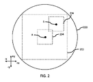
図2を参照すると、スキャンレンズ112は、ビーム経路116が(例えば、ワークピース102上をビーム軸に沿って)伝搬し得る通過領域200を含むものとして特徴付けることができる。装置100が、上述した第1のポジショナ106、第2のポジショナ108、又はこれらを組み合わせたもののような1以上のポジショナを含んでいる場合には、ビーム経路116は、典型的には、スキャンレンズ112の幾分小さい領域(すなわち伝搬領域202)を伝搬する。一般的に、伝搬領域202の形状及び/又はサイズは、(例えば、装置100が第2のポジショナ108を含む場合には)ワークピース102上に投影される第2のスキャニング範囲の形状及び/又はサイズに対応するか、(例えば、装置100が第1のポジショナ106を含むが、第2のポジショナ108は含んでいない場合には)ワークピース102上に投影される第1のスキャニング範囲の形状及び/又はサイズに対応し得る。
Referring to FIG. 2,
伝搬領域202は、正方形の形状であるものとして図示されているが、伝搬領域202は、例えば、設けられるポジショナ(例えば、第1のポジショナ106、第2のポジショナ108、第3のポジショナ110、又はこれらを任意に組み合わせたもの)の構成及び配置、ビーム経路116に沿って配置されるマスク又は他の光学部品の有無など、あるいはこれらを任意に組み合わせたものに応じて、他の所望の形状又は有利な形状(例えば、矩形、三角形、五角形、六角形、八角形、楕円形、不規則形状など)を有していてもよいことは理解できよう。伝搬領域202は、通過領域200よりも小さいものとして図示されているが、伝搬領域202は、通過領域200と同一サイズであってもよいことは理解できよう。
Although the
典型的には、装置100は、(例えば、第1のポジショナ106、第2のポジショナ108、及び第3のポジショナ110のうち1つ以上のポジショナを用いて)所望の軌跡に沿ってプロセススポットをスキャンしてワークピース(例えばワークピース102)上又はその内部にフィーチャを形成するように作動する。軌跡に沿ってプロセススポットをスキャンする際には、ビーム経路116は、伝搬領域202の比較的小さい領域又は「スキャン領域」(例えばスキャン領域204)の内部でのみ偏向される。ビーム経路116がスキャン領域204内で偏向される際にビーム経路116が交差する伝搬領域202の部分は、本明細書において「ビーム経路偏向ルート」と呼ばれる。スキャン領域204は、正方形の形状であるものとして図示されているが、スキャン領域204は、例えば、設けられるポジショナの構成及び配置、ワークピース102の内部に1以上のフィーチャを形成するためにプロセススポットがスキャンされる1以上の所望の軌跡の構成など、あるいはこれらを任意に組み合わせたものに応じて、他の所望の形状又は有利な形状(例えば、矩形、三角形、五角形、六角形、八角形、円形、楕円形、不規則形状など)を有していてもよいことは理解できよう。スキャン領域204は、伝搬領域202の中心に位置しているように図示されているが、スキャン領域204は、伝搬領域202内の異なる位置に配置されていてもよいことは理解できよう。
Typically, apparatus 100 (eg, using one or more of
装置100は、(例えば、1つのワークピースを加工するために、あるいは複数のワークピースを順次加工するために)1以上の軌跡に沿ってプロセススポットをスキャンするように作動するので、時間が経過すると、スキャンレンズ112のスキャン領域204内の1以上の位置でレーザ誘起ダメージが蓄積し得る。望ましくない程度の量のレーザ誘起ダメージが蓄積している、あるいは蓄積すると予想されるスキャンレンズ112の部分にレーザパルスが照射されないように、伝搬領域202内のスキャン領域204の位置をシフトさせてもよい。換言すれば、スキャン領域204の重心、すなわち幾何学的中心が伝搬領域202内の第1の位置(例えば、図2に示される位置「A」)から伝搬領域202内の第2の位置(例えば、図2に示される位置「B」)にシフトするように、伝搬領域202内でスキャン領域204をシフト又は並進させることができる。スキャン領域204の重心の移動動作は、本明細書において「スキャン領域シフト」とも呼ばれる。スキャン領域シフトは、ランダムに行ってもよいし、定期的に行ってもよいし、連続的に行ってもよいし、これに類する方法で行ってもよいし、あるいはこれらを任意に組み合わせて行ってもよい。プロセススポットがスキャンされる軌跡によっては、スキャン領域204の重心が(例えば、位置「A」から位置「B」に)シフトされた後にスキャン領域204を通って伝搬するレーザパルスは、必ずとは言えないまでも、多くの場合、望ましくない程度の量のレーザ誘起ダメージが蓄積していない、あるいは蓄積すると予想されていないスキャンレンズ112の部分を伝搬することになる。
As the
図2は、第2の位置「B」でのスキャン領域204が第1の位置「A」でのスキャン領域204に重なるようにスキャン領域204の位置がシフトされるように図示しているが、第2の位置「B」でのスキャン領域204が第1の位置「A」でのスキャン領域204に(重なってはいないが)接することができるように、あるいは、第2の位置「B」でのスキャン領域204が第1の位置「A」でのスキャン領域204から離間できるようにスキャン領域204の位置をシフトしてもよいことは理解できよう。したがって、レーザパルスが位置「A」に重心を有するスキャン領域204の外側のスキャンレンズ112の部分を伝搬していない、あるいは、位置「A」に重心を有するスキャン領域204の外側のスキャンレンズ112の部分には望ましくない程度の量のレーザ誘起ダメージが蓄積していないと仮定すると、スキャン領域204の重心が(例えば、位置「A」から位置「B」に)シフトした後にスキャン領域204を伝搬するレーザパルスは、望ましくない程度の量のレーザ誘起ダメージが蓄積していない、あるいは蓄積すると予想されていないスキャンレンズ112の部分を常に伝搬することとなる。
Although FIG. 2 illustrates the position of the
上述したようにスキャン領域204をシフトすることによって、スキャンレンズ112の寿命を効果的に延ばしつつ、(すなわち、1以上の軌跡に沿ってプロセススポットをスキャンしてワークピース上又はワークピース内に1以上のフィーチャを形成することによって)ワークピースを加工することができ、あるいは、(すなわち、1以上の軌跡に沿ってプロセススポットをスキャンして複数のワークピース上又は複数のワークピース内に1以上のフィーチャを形成することによって)複数のワークピースを順次加工することができる。複数のワークピースを加工する際に、異なるワークピースに対して(すなわちプロセススポットが)同一の軌跡又は異なる軌跡をスキャンしてもよいことは理解すべきである。
Shifting the
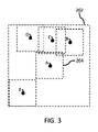
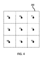
図2は、スキャン領域204が一度だけシフトされる実施形態を図示しているが、一度よりも多い回数(例えば、2回、3回、4回、5回、9回、10回、20回、30回など、あるいはこれらの値のいずれかの間の回数)スキャン領域204がシフトされてもよいことは理解できよう。例えば、図3を参照すると、スキャン領域204の重心を(例えば、最初に位置「A」から位置「B」に、その後、位置「B」から位置「C」に、そして位置「C」から位置「D」に、その後、位置「D」から位置「E」に移動するシフト順序で)4回シフトしてもよい。上記で述べた順序にかかわらず、他の好適な又は望ましいシフト順序で(例えば、最初に位置「A」から位置「C」に、その後、位置「C」から位置「E」に、そして位置「E」から位置「D」に、その後、位置「D」から位置「B」に移動するシフト順序で)スキャン領域204の重心をシフトできることは理解すべきである。同様に、図4に示される他の例では、位置「A」、位置「F」、位置「G」、位置「H」、位置「I」、位置「J」、位置「K」、位置「L」、及び位置「M」の一部又はすべての中でスキャン領域204の重心を移動させる任意のシフト順序でスキャン領域204の重心を様々な方法でシフトすることができる。上述した説明から、伝搬領域202内の異なる位置に重心を有する任意の組のスキャン領域204は、互いに重なっていてもよく、互いに接していてもよく、あるいは互いに離間していてもよいことは明らかであろう。一実施形態においては、それぞれのスキャン領域204は、他の1以上のスキャン領域204又は他のすべてのスキャン領域204と重なっている。伝搬領域202内で連続的に指定される位置に重心を有する任意の組のスキャン領域204は、互いに重なっていてもよく、互いに接していてもよく、あるいは互いに離間していてもよい。本明細書において使用される場合には、スキャン領域204の重心がその位置にあるとき、又はその位置にシフトされたときに伝搬領域202内の位置が「指定」される。このように、スキャン領域204の重心が(図3に示されるように)位置「A」から位置「C」にシフトされたとき、位置「A」及び位置「C」は「連続的に指定される位置」であると考えることができる。
Although FIG. 2 illustrates an embodiment in which the
指定可能な一意な位置の数、指定可能な伝搬領域202内のそれぞれの位置の場所、スキャン領域204をシフト可能な回数、及びスキャン領域204の重心が移動されるシフト順序など、あるいはこれらを任意に組み合わせたものは、(例えば、コントローラ114と通信可能に連結された図示しないユーザインタフェイスを介して)装置100のユーザ、操作者、技術者、又はメーカーによって特定されてもよく、あるいは、1以上のアルゴリズム(例えば、最適化アルゴリズム、発見的アルゴリズム、予測アルゴリズムなど)を実行することによって決定されてもよく、あるいはこれに類するものであってもよく、あるいはこれらを任意に組み合わせたものであってもよい。例えば、装置100の動作中にスキャンされるプロセススポットの軌跡、プロセススポットが特定の軌跡をスキャンする回数、プロセススポットが特定の軌跡をスキャンしている間、装置100が稼働している時間数、(特定の軌跡に沿ってプロセススポットをスキャンすることにより)加工されたワークピースの数、装置100の動作中にスキャンレンズ112を伝搬するレーザエネルギー中の光の波長、装置100の動作中にスキャンレンズ112を伝搬するレーザエネルギーの平均パワー又はピークパワー、装置100の動作中にスキャンレンズ112を伝搬するレーザパルスのパルス持続時間、スキャンレンズ112を構成する材料、スキャンレンズ112のサイズ、伝搬領域202のサイズ、伝搬領域202の寸法など、あるいはこれらを任意に組み合わせたものを表す1以上の入力変数に基づいて、そのようなアルゴリズムのいずれかを実行することができる。
The number of unique positions that can be specified, the location of each position within the
一実施形態においては、スキャンレンズ112の状態とは無関係にプロセススポットを軌跡(例えば第1の軌跡)に沿ってスキャンしつつ、ビーム経路偏向ルート(例えば第1のビーム経路偏向ルート)に沿ってビーム経路116を偏向するように第1のポジショナ106及び/又は第2のポジショナ108の動作を制御するために使用可能な1以上の制御信号(それぞれ本明細書においては「第1の基準制御信号」という)を(例えば、コントローラ114で、構成要素固有のコントローラで、あるいはこれに類するところで、あるいはこれらを任意に組み合わせたところで)取得することにより、スキャン領域204の位置がシフトされる。第1の基準制御信号の例としては、X軸ガルバノメータミラーコンポーネントのような関連するポジショナの動作を制御するために使用可能な制御信号、Y軸ガルバノメータミラーコンポーネントのような関連するポジショナの動作を制御するために使用可能な制御信号、X軸AODシステムのような関連するポジショナの動作を制御するために使用可能な制御信号、Y軸AODシステムのような関連するポジショナの動作を制御するために使用可能な制御信号など、あるいはこれらを任意に組み合わせたものが挙げられる。
In one embodiment, while scanning the process spot along a trajectory (eg, first trajectory) regardless of the state of
シフトの方向(本明細書においては「シフト方向」ともいう)、シフトの距離(本明細書においては「シフト距離」ともいう)など、あるいはこれらを任意に組み合わせたもののような1以上のファクタに応じて、(例えば、コントローラ114で、構成要素固有のコントローラで、あるいはこれに類するところで、あるいはこれらを任意に組み合わせたところで)1以上の対応する「第1の修正制御信号」を生成するために、第1の基準制御信号のようなものの1つ以上が(例えば、位置的オフセットを加えることにより)処理される。例えば、第1の方向に(例えば、図2に示される+X方向に)スキャン領域204の位置をシフトするために、位置的オフセットを(例えば、+X方向に所望の距離又は有益な距離だけ)加えることにより、X軸ガルバノメータミラーコンポーネントのような関連するポジショナの動作を制御することを意図する第1の基準制御信号を(例えば、コントローラ114で、構成要素固有のコントローラで、あるいはこれに類するところで、あるいはこれらを任意に組み合わせたところで)処理してもよい。他の例では、スキャン領域204の位置を第2の方向に(例えば、+X方向及び+Y方向のベクトル和に対応する方向に)シフトすることができ、それぞれの第1の基準制御信号に位置的オフセットを(例えば、+X方向及び+Y方向にそれぞれ所望の距離又は有益な距離だけ)加えることにより、X軸ガルバノメータミラーコンポーネント及びY軸ガルバノメータミラーコンポーネントのような関連するポジショナの動作を制御することを意図する第1の基準制御信号を(例えば、コントローラ114で、X軸ガルバノメータミラーコンポーネント及び/又はY軸ガルバノメータミラーコンポーネントに関連付けられた構成要素固有のコントローラで、あるいはこれに類するところで、あるいはこれらを任意に組み合わせたところで)処理してもよい。
depending on one or more factors such as direction of shift (also referred to herein as "shift direction"), distance of shift (also referred to herein as "shift distance"), etc., or any combination thereof. In response, to generate one or more corresponding "first modified control signals" (e.g., at
第1の修正制御信号が生成されると、これを(これのみで、あるいは1以上の他の第1の修正制御信号、1以上の第1の基準信号、又はこれらを任意に組み合わせたものとともに)用いて、ポジショナの動作を制御して、軌跡(例えば、第1の軌跡又は第1の軌跡とは異なる第2の軌跡)に沿ってプロセススポットをスキャンしつつ、ビーム経路偏向ルート(例えば、第1のビーム経路偏向ルート又は第1のビーム経路偏向ルートとは異なる第2のビーム経路偏向ルート)に沿ってビーム経路116を偏向してもよい。例えば、上述した第1の方法(すなわち+X方向)にスキャン領域204の位置をシフトするために、上述した第1の修正制御信号を用いてX軸ガルバノメータミラーコンポーネントの動作を制御してもよく、Y軸ガルバノメータミラーコンポーネント、X軸AODシステム、Y軸AODシステムなど、あるいはこれらを任意に組み合わせたものを制御して、第1の基準制御信号のうちの他の第1の基準制御信号を必要に応じて用いて、軌跡(例えば、第1の軌跡又は第2の軌跡)に沿ってプロセススポットをスキャンしつつ、ビーム経路偏向ルート(例えば、第1のビーム経路偏向ルート又は第2のビーム経路偏向ルート)に沿ってビーム経路116を偏向してもよい。他の例では、上述した第2の方法に(すなわち、+X方向及び+Y方向のベクトル和に対応する方向に)スキャン領域204の位置をシフトするために、第1の修正制御信号を用いてX軸ガルバノメータミラーコンポーネント及びY軸ガルバノメータミラーコンポーネントの動作を制御してもよく、第1の基準制御信号のうちの他の第1の基準制御信号を必要に応じて用いて、X軸AODシステム、Y軸AODシステムなど、あるいはこれらを任意に組み合わせたものを制御して、軌跡(例えば、第1の軌跡又は第2の軌跡)に沿ってプロセススポットをスキャンしつつ、ビーム経路偏向ルート(例えば、第1のビーム経路偏向ルート又は第2のビーム経路偏向ルート)に沿ってビーム経路116を偏向してもよい。
Once the first modified control signal is generated, it (alone or together with one or more other first modified control signals, one or more first reference signals, or any combination thereof) ) to control the motion of the positioner to scan the process spot along a trajectory (e.g., a first trajectory or a second trajectory different from the first trajectory) while defining a beam path deflection route (e.g., The
一実施形態においては、装置100は、第1のポジショナ106及び/又は第2のポジショナ108に加えて、第3のポジショナ110を含んでいる。この場合において、第3のポジショナ110は、直動ステージ(例えば、第2のポジショナ108及びスキャンレンズ112を直進移動するように構成された、あるいはワークピース102を直進移動するように構成されたもの)又は複数の直動ステージ(例えば、第2のポジショナ108及びスキャンレンズ112を直進移動するように構成されたものと、ワークピース102を直進移動するように構成されたもの)を含んでいてもよい。第3のポジショナ110の直動ステージは、第1のポジショナ106及び/又は第2のポジショナ108が第1の修正制御信号に基づいて駆動される際に、それぞれの第1の基準制御信号に与えられる1以上の位置的オフセットを補償し、レーザエネルギーが確実にワークピース102の1以上の所望の位置に照射されるように動作し得る。例えば、第1の修正制御信号に組み込まれる位置的オフセットによって、ビーム経路116が1つの方向に(例えば、上述した第1の方向に)特定の距離だけ(例えば、「第1の距離」だけ)シフトされる場合、第3のポジショナ110は、第2のポジショナ108及びスキャンレンズ112を第1の方向とは反対の他の方向に(例えば、図2に示される-X方向に)当該特定の距離だけ(例えば、第1の距離だけ)移動させることにより位置的オフセットを補償するように動作し得る。他の例では、第1の修正制御信号に組み込まれる位置的オフセットによって、ビーム経路116が1つの方向に(例えば第1の方向に)特定の距離だけ(例えば第1の距離だけ)シフトされる場合、第3のポジショナ110は、ワークピース102を同一の方向に(例えば第1の方向に)当該特定の距離だけ(例えば第1の距離だけ)移動させることにより位置的オフセットを補償するように動作し得る。
In one embodiment,
ワークピース102の加工中に第3のポジショナ110の動作を(スキャンレンズ112の状態とは関係なく)制御するために使用されるであろう制御信号(本明細書では「第2の基準制御信号」という)を(例えば、コントローラ114で、構成要素固有のコントローラなどで)修正してもよい。例えば、その中のコマンドに位置的オフセットを追加することにより第2の基準制御信号を修正してもよい。上述したようにして修正された第2の基準制御信号は、本明細書では「第2の修正制御信号」と呼ばれる。ワークピース102の後続の加工中に(例えば、上述したような)第3のポジショナ110の動作を制御する制御信号として第2の修正制御信号を用いてもよい。位置的オフセットを第2の基準制御信号に加えると、第1のポジショナ106及び/又は第2のポジショナ108を第1の修正制御信号に基づいて駆動する場合であっても、この位置的オフセットによってレーザエネルギーをワークピース102の1以上の所望の位置に照射することができる。
A control signal (herein referred to as the "second reference control signal ) may be modified (eg, in
他の実施形態においては、装置100は第3のポジショナ110を含んでいないが、修正制御信号に基づいて第1のポジショナ106及び/又は第2のポジショナ108が駆動される場合にワークピース102の1以上の所望の位置にレーザエネルギーが確実に照射されるように(例えば、装置100のユーザにより)ワークピース102をスキャンレンズ112に対して手動で移動させることがある。これに加えて、あるいはこれに代えて、修正制御信号に基づいて第1のポジショナ106及び/又は第2のポジショナ108が駆動される場合にワークピース102の1以上の所望の位置にレーザエネルギーが確実に照射されるように(例えば、装置100のユーザにより)スキャンレンズ112をワークピース102に対して手動で移動させることがある。
In other embodiments, the
本明細書において述べた実施形態により、サービスコストを低減することができ、スキャンレンズ112のような光学要素の交換によるダウンタイムを短縮することができる。これらの利点は、ワークピースに形成されるフィーチャが伝搬領域202よりもずっと小さい場合、相対的に小さなスキャンレンズを用いて定期的に交換するよりも、好適に大きなスキャンレンズを分割する方が安価な場合、あるいは、光学部品の意図した保証期間よりも早くスキャンレンズ112が損傷を受ける場合、第1のポジショナ106により与えられるビーム軸の移動が第2のポジショナ108により与えられるビーム軸の同時移動に重ねられる場合など、あるいはこれらを任意に組み合わせたような場合に最も実現される。
The embodiments described herein can reduce service costs and reduce downtime due to replacement of optical elements such as
IV.結論
上記は、本発明の実施形態及び例を説明したものであって、これに限定するものとして解釈されるものではない。いくつかの特定の実施形態及び例が図面を参照して述べられたが、当業者は、本発明の新規な教示や利点から大きく逸脱することなく、開示された実施形態及び例と他の実施形態に対して多くの改良が可能であることを容易に認識するであろう。したがって、そのような改良はすべて、特許請求の範囲において規定される本発明の範囲に含まれることを意図している。例えば、当業者は、そのような組み合わせが互いに排他的になる場合を除いて、いずれかの文や段落、例又は実施形態の主題を他の文や段落、例又は実施形態の一部又は全部の主題と組み合わせることができることを理解するであろう。したがって、本発明の範囲は、以下の特許請求の範囲とこれに含まれるべき請求項の均等物とによって決定されるべきである。
IV. CONCLUSION The foregoing describes embodiments and examples of the present invention and is not to be construed as limiting. Although several specific embodiments and examples have been described with reference to the drawings, those skilled in the art will appreciate that the disclosed embodiments and examples and other implementations can be made without departing substantially from the novel teachings and advantages of the present invention. One will readily recognize that many modifications to the configuration are possible. Accordingly, all such modifications are intended to be included within the scope of this invention as defined in the claims. For example, one skilled in the art will recognize the subject matter of any sentence, paragraph, example or embodiment as part or all of another sentence, paragraph, example or embodiment, except where such combinations are mutually exclusive. will understand that it can be combined with the subject of Accordingly, the scope of the invention should be determined by the following claims, with equivalents of the claims to be included therein.
Claims (17)
前記伝搬領域のうち第1のスキャン領域内で前記ビーム経路を偏向して、前記スキャンレンズを伝搬した前記レーザエネルギービームで複数の第1のワークピースを順次加工し、前記複数の第1のワークピースを加工する際に前記第1のスキャン領域内で前記スキャンレンズに望ましくない程度の量のレーザ誘起ダメージが蓄積し、
前記第1のスキャン領域内で前記ビーム経路を偏向して前記複数の第1のワークピースを加工した後、前記伝搬領域のうち、望ましくない程度のレーザ誘起ダメージが蓄積していない第2のスキャン領域内で前記ビーム経路を偏向して、前記スキャンレンズを伝搬した前記レーザエネルギービームで複数の第2のワークピースを順次加工する、
方法。 A method of operating a laser processing system having a scan lens capable of focusing laser energy propagating along a beam path and a positioner capable of deflecting the beam path relative to the scan lens within a propagation area of the scan lens. and
sequentially processing a plurality of first workpieces with the laser energy beam propagated through the scan lens by deflecting the beam path within a first scanning area of the propagation area; accumulating an undesirable amount of laser-induced damage to the scan lens in the first scan region during processing of the piece;
After deflecting the beam path within the first scan region to process the plurality of first workpieces, a second scan of the propagation region in which an undesirable degree of laser-induced damage has not accumulated . deflecting the beam path within a region to sequentially process a plurality of second workpieces with the laser energy beam propagated through the scan lens;
Method.
前記第2のスキャン領域内で前記ビーム経路を偏向する際に、前記第1のビーム経路偏向ルートに沿って前記ビーム経路を偏向する、
請求項1から6のいずれかの方法。 deflecting the beam path along a first beam path deflection route when deflecting the beam path within the first scan region;
deflecting the beam path along the first beam path deflection route when deflecting the beam path within the second scan region;
7. The method of any of claims 1-6.
前記スキャンレンズの前記第2のスキャン領域内で前記ビーム経路を偏向する際に、前記第1のビーム経路偏向ルートとは異なる第2のビーム経路偏向ルートに沿って前記ビーム経路を偏向する、
請求項1から6のいずれかの方法。 deflecting the beam path along a first beam path deflection route when deflecting the beam path within the first scan area of the scan lens;
deflecting the beam path along a second beam path deflection route different from the first beam path deflection route when deflecting the beam path within the second scan area of the scan lens;
7. The method of any of claims 1-6.
前記ビーム経路内に配置されたスキャンレンズと、
前記ビーム経路内に配置され、前記スキャンレンズに対して前記ビーム経路を偏向するように構成される少なくとも1つの第1のポジショナと、
前記少なくとも1つの第1のポジショナと通信可能に連結されたコントローラであって、
前記少なくとも1つの第1のポジショナが応答する1以上の制御信号を生成するように構成されるプロセッサと、
前記プロセッサによりアクセス可能なコンピュータメモリであって、前記プロセッサにより実行された際に請求項1から10のいずれか一項に記載された方法を実施する命令が格納されたコンピュータメモリと
を含むコントローラと
を備える、
装置。 a laser source configured to produce a laser energy beam propagable along a beam path;
a scan lens positioned in the beam path;
at least one first positioner disposed in the beam path and configured to deflect the beam path with respect to the scan lens;
a controller communicatively coupled to the at least one first positioner, comprising:
a processor configured to generate one or more control signals to which the at least one first positioner responds;
a controller comprising a computer memory accessible by said processor, said computer memory storing instructions for implementing the method of any one of claims 1 to 10 when executed by said processor; comprising a
Device.
前記伝搬領域のうち第1のスキャン領域内で前記ビーム経路を偏向して、前記スキャンレンズを伝搬した前記レーザエネルギービームで複数の第1のワークピースを順次加工し、前記複数の第1のワークピースを加工する際に前記第1のスキャン領域内で前記スキャンレンズに望ましくない程度の量のレーザ誘起ダメージが蓄積するように前記ポジショナを制御し、
前記第1のスキャン領域内で前記ビーム経路を偏向した後、前記伝搬領域のうち、望ましくない程度のレーザ誘起ダメージが蓄積していない第2のスキャン領域内で前記ビーム経路を偏向して、前記スキャンレンズを伝搬した前記レーザエネルギービームで複数の第2のワークピースを順次加工するように前記ポジショナを制御する
動作を実行させるためのプログラム。 to a processor of a laser processing system having a scan lens capable of focusing laser energy propagating along a beam path and a positioner capable of deflecting the beam path relative to the scan lens within a propagation area of the scan lens;
sequentially processing a plurality of first workpieces with the laser energy beam propagated through the scan lens by deflecting the beam path within a first scanning area of the propagation area; controlling the positioner to accumulate an undesirable amount of laser-induced damage to the scan lens in the first scan region when processing a piece;
After deflecting the beam path within the first scan region, deflecting the beam path within a second scan region of the propagation region where an undesired degree of laser-induced damage has not accumulated ; A program for executing an operation of controlling the positioner to sequentially process a plurality of second workpieces with the laser energy beam propagated through the scan lens.
第1のビーム経路偏向ルートに沿って前記ビーム経路を偏向することによって前記第1のスキャン領域内で前記ビーム経路を偏向し、
前記第1のビーム経路偏向ルートに沿って前記ビーム経路を偏向することによって前記第2のスキャン領域内で前記ビーム経路を偏向する
動作を実行させるための請求項13のプログラム。 The processor further comprising:
deflecting the beam path within the first scan region by deflecting the beam path along a first beam path deflection route;
14. The program product of claim 13, for performing the act of deflecting the beam path within the second scan region by deflecting the beam path along the first beam path deflection route.
前記第2のスキャン領域内での前記ビーム経路の偏向に対する前記第1のスキャン領域内での前記ビーム経路の偏向の変化を補償するように前記複数の第1のワークピースとは異なる方法で前記複数の第2のワークピースを前記スキャンレンズに対して位置決めする
動作を実行させるための請求項13又は14のプログラム。 The processor further comprising:
the plurality of first workpieces in a manner different from the plurality of first workpieces to compensate for variations in deflection of the beam path within the first scan area relative to deflection of the beam path within the second scan area; 15. A program according to claim 13 or 14, for executing an operation of positioning a plurality of second workpieces with respect to said scan lens.
前記第2のスキャン領域内での前記ビーム経路の偏向に対する前記第1のスキャン領域内での前記ビーム経路の偏向の変化を補償するように前記複数の第1のワークピースに対するのとは異なる方法で前記複数の第2のワークピースに対して前記スキャンレンズを位置決めする
動作を実行させるための請求項13又は14のプログラム。 The processor further comprising:
A different method for the plurality of first workpieces to compensate for variations in deflection of the beam path within the first scan area relative to deflection of the beam path within the second scan area. 15. The program according to claim 13 or 14, for performing an operation of positioning said scan lens with respect to said plurality of second workpieces in.
第1のビーム経路偏向ルートに沿って前記ビーム経路を偏向することによって前記スキャンレンズの前記第1のスキャン領域内で前記ビーム経路を偏向し、
前記第1のビーム経路偏向ルートとは異なる第2のビーム経路偏向ルートに沿って前記ビーム経路を偏向することによって前記スキャンレンズの前記第2のスキャン領域内で前記ビーム経路を偏向する
動作を実行させるための請求項13のプログラム。 The processor further comprising:
deflecting the beam path within the first scan area of the scan lens by deflecting the beam path along a first beam path deflection route;
performing the act of deflecting the beam path within the second scan area of the scan lens by deflecting the beam path along a second beam path deflection route different from the first beam path deflection route; 14. The program of claim 13 for causing.
Applications Claiming Priority (3)
| Application Number | Priority Date | Filing Date | Title |
|---|---|---|---|
| US201662440925P | 2016-12-30 | 2016-12-30 | |
| US62/440,925 | 2016-12-30 | ||
| PCT/US2017/068833 WO2018126078A1 (en) | 2016-12-30 | 2017-12-28 | Method and system for extending optics lifetime in laser processing apparatus |
Publications (3)
| Publication Number | Publication Date |
|---|---|
| JP2020504675A JP2020504675A (en) | 2020-02-13 |
| JP2020504675A5 JP2020504675A5 (en) | 2020-11-26 |
| JP7146770B2 true JP7146770B2 (en) | 2022-10-04 |
Family
ID=62710089
Family Applications (1)
| Application Number | Title | Priority Date | Filing Date |
|---|---|---|---|
| JP2019535826A Active JP7146770B2 (en) | 2016-12-30 | 2017-12-28 | Method and system for extending the life of optical components in laser processing equipment |
Country Status (6)
| Country | Link |
|---|---|
| US (1) | US11260472B2 (en) |
| JP (1) | JP7146770B2 (en) |
| KR (1) | KR102401037B1 (en) |
| CN (2) | CN114654082A (en) |
| TW (1) | TWI774721B (en) |
| WO (1) | WO2018126078A1 (en) |
Families Citing this family (10)
| Publication number | Priority date | Publication date | Assignee | Title |
|---|---|---|---|---|
| US12090571B2 (en) * | 2018-04-10 | 2024-09-17 | Talens Systems, S.L.U. | Apparatus and method for processing cardboard |
| US20220091318A1 (en) * | 2019-01-31 | 2022-03-24 | King Abdullah University Of Science And Technology | Light processing device based on multilayer nano-elements |
| TWI843784B (en) * | 2019-01-31 | 2024-06-01 | 美商伊雷克托科學工業股份有限公司 | Laser-processing apparatus, a controller and a non-transitory computer-readable medium for use with the laser-processing apparatus |
| JP7404043B2 (en) * | 2019-03-22 | 2023-12-25 | ビアメカニクス株式会社 | Laser processing equipment and laser processing method |
| CN110814546B (en) * | 2019-11-20 | 2021-10-15 | 东莞市盛雄激光先进装备股份有限公司 | Turnover mechanism |
| JP6793892B1 (en) * | 2020-02-10 | 2020-12-02 | 三菱電機株式会社 | Laser processing method and laser processing equipment |
| US12064830B2 (en) * | 2020-03-12 | 2024-08-20 | Rohr, Inc. | Substrate perforation system and method using beamlets |
| KR20220011848A (en) * | 2020-07-21 | 2022-02-03 | 삼성디스플레이 주식회사 | Laser apparatus and method for manufacturing display device |
| CN113226632A (en) * | 2021-03-31 | 2021-08-06 | 长江存储科技有限责任公司 | Laser system for cutting semiconductor structure and operation method thereof |
| JP7331056B2 (en) * | 2021-09-21 | 2023-08-22 | 三菱重工業株式会社 | Composite material processing device and composite material processing method |
Citations (2)
| Publication number | Priority date | Publication date | Assignee | Title |
|---|---|---|---|---|
| JP2001205467A (en) | 2000-01-25 | 2001-07-31 | Matsushita Electric Ind Co Ltd | Machine for laser machining and method of machining |
| US20090073412A1 (en) | 2006-03-07 | 2009-03-19 | Carl Zeiss Smt Ag | Off-axis objectives with rotatable optical element |
Family Cites Families (54)
| Publication number | Priority date | Publication date | Assignee | Title |
|---|---|---|---|---|
| US4912487A (en) | 1988-03-25 | 1990-03-27 | Texas Instruments Incorporated | Laser scanner using focusing acousto-optic device |
| US5638267A (en) | 1994-06-15 | 1997-06-10 | Convolve, Inc. | Method and apparatus for minimizing unwanted dynamics in a physical system |
| US5633747A (en) | 1994-12-21 | 1997-05-27 | Tencor Instruments | Variable spot-size scanning apparatus |
| US5751585A (en) | 1995-03-20 | 1998-05-12 | Electro Scientific Industries, Inc. | High speed, high accuracy multi-stage tool positioning system |
| US5847960A (en) | 1995-03-20 | 1998-12-08 | Electro Scientific Industries, Inc. | Multi-tool positioning system |
| US5917300A (en) | 1997-03-10 | 1999-06-29 | Convolve, Inc. | Method and apparatus for the control of gantry machines |
| US6314473B1 (en) | 1998-03-05 | 2001-11-06 | Convolve, Inc. | System for removing selected unwanted frequenices in accordance with altered settings in a user interface of a data storage device |
| SE516347C2 (en) | 1999-11-17 | 2001-12-17 | Micronic Laser Systems Ab | Laser scanning system and method for microlithographic writing |
| EP1275036B1 (en) | 2000-01-11 | 2005-10-26 | Electro Scientific Industries, Inc. | Abbe error correction system and method |
| US20030024913A1 (en) * | 2002-04-15 | 2003-02-06 | Downes Joseph P. | Laser scanning method and system for marking articles such as printed circuit boards, integrated circuits and the like |
| WO2001054854A1 (en) | 2000-01-28 | 2001-08-02 | Gsi Lumonics, Inc. | Laser scanning method and system for marking articles such as printed circuit boards, integrated circuits and the like |
| KR100500343B1 (en) | 2000-08-29 | 2005-07-12 | 미쓰비시덴키 가부시키가이샤 | Laser machining apparatus |
| US6816294B2 (en) | 2001-02-16 | 2004-11-09 | Electro Scientific Industries, Inc. | On-the-fly beam path error correction for memory link processing |
| US8497450B2 (en) | 2001-02-16 | 2013-07-30 | Electro Scientific Industries, Inc. | On-the fly laser beam path dithering for enhancing throughput |
| US7245412B2 (en) | 2001-02-16 | 2007-07-17 | Electro Scientific Industries, Inc. | On-the-fly laser beam path error correction for specimen target location processing |
| US6706998B2 (en) | 2002-01-11 | 2004-03-16 | Electro Scientific Industries, Inc. | Simulated laser spot enlargement |
| JP4270891B2 (en) | 2003-01-21 | 2009-06-03 | 三洋電機株式会社 | Laser repair method for EL display device |
| US6706999B1 (en) | 2003-02-24 | 2004-03-16 | Electro Scientific Industries, Inc. | Laser beam tertiary positioner apparatus and method |
| JP2004361862A (en) | 2003-06-09 | 2004-12-24 | Mitsubishi Electric Corp | Condenser lens system, laser beam machining device, and method for adjusting condenser lens |
| US6947454B2 (en) | 2003-06-30 | 2005-09-20 | Electro Scientific Industries, Inc. | Laser pulse picking employing controlled AOM loading |
| KR101193723B1 (en) | 2003-07-18 | 2012-10-22 | 하마마츠 포토닉스 가부시키가이샤 | Semiconductor substrate, cutting method for semiconductor substrate and cutting method for workpiece |
| US7238913B2 (en) * | 2003-10-17 | 2007-07-03 | Gsi Group Corporation | Flexible scan field |
| JP4601965B2 (en) | 2004-01-09 | 2010-12-22 | 浜松ホトニクス株式会社 | Laser processing method and laser processing apparatus |
| US7133187B2 (en) | 2004-06-07 | 2006-11-07 | Electro Scientific Industries, Inc. | AOM modulation techniques employing plurality of transducers to improve laser system performance |
| US8383982B2 (en) * | 2004-06-18 | 2013-02-26 | Electro Scientific Industries, Inc. | Methods and systems for semiconductor structure processing using multiple laser beam spots |
| US7259354B2 (en) | 2004-08-04 | 2007-08-21 | Electro Scientific Industries, Inc. | Methods for processing holes by moving precisely timed laser pulses in circular and spiral trajectories |
| KR100462359B1 (en) | 2004-08-18 | 2004-12-17 | 주식회사 이오테크닉스 | Laser Processing Apparatus and Method Using Polygon Mirror |
| JP2006136923A (en) * | 2004-11-12 | 2006-06-01 | Hitachi Via Mechanics Ltd | Laser beam machine and laser beam machining method |
| JP4527567B2 (en) | 2005-03-01 | 2010-08-18 | フェトン株式会社 | Laser processing apparatus and laser processing method |
| DE502006000708D1 (en) * | 2005-09-09 | 2008-06-12 | Highyag Lasertechnologie Gmbh | Tactile guided laser processing optics |
| US7834293B2 (en) | 2006-05-02 | 2010-11-16 | Electro Scientific Industries, Inc. | Method and apparatus for laser processing |
| US8026158B2 (en) | 2007-06-01 | 2011-09-27 | Electro Scientific Industries, Inc. | Systems and methods for processing semiconductor structures using laser pulses laterally distributed in a scanning window |
| US8076605B2 (en) | 2007-06-25 | 2011-12-13 | Electro Scientific Industries, Inc. | Systems and methods for adapting parameters to increase throughput during laser-based wafer processing |
| KR101516742B1 (en) | 2007-09-19 | 2015-05-04 | 엘렉트로 사이언티픽 인더스트리즈 인코포레이티드 | Link processing with high speed beam deflection |
| GB0800333D0 (en) | 2008-01-09 | 2008-02-20 | Ucl Business Plc | Beam deflection apparatus and methods |
| CN102006964B (en) | 2008-03-21 | 2016-05-25 | Imra美国公司 | Material processing method based on laser and system |
| US20100078419A1 (en) * | 2008-09-26 | 2010-04-01 | Electro Scientific Industries, Inc | Post-lens steering of a laser beam for micro-machining applications |
| US8680430B2 (en) | 2008-12-08 | 2014-03-25 | Electro Scientific Industries, Inc. | Controlling dynamic and thermal loads on laser beam positioning system to achieve high-throughput laser processing of workpiece features |
| US8350187B2 (en) * | 2009-03-28 | 2013-01-08 | Electro Scientific Industries, Inc. | Method and apparatus for laser machining |
| TWI523720B (en) | 2009-05-28 | 2016-03-01 | 伊雷克托科學工業股份有限公司 | Acousto-optic deflector applications in laser processing of features in a workpiece, and related laser processing method |
| TWI395630B (en) * | 2009-06-30 | 2013-05-11 | Mitsuboshi Diamond Ind Co Ltd | Apparatus for processing glass substrate by laser beam |
| CN102918186A (en) | 2010-06-03 | 2013-02-06 | 纽约市哥伦比亚大学理事会 | Single-scan line-scan crystallization using superimposed scanning elements |
| TWI430000B (en) | 2010-07-02 | 2014-03-11 | Ind Tech Res Inst | Method and system for repairing flat panel display |
| KR20220046706A (en) | 2010-10-22 | 2022-04-14 | 일렉트로 싸이언티픽 인더스트리이즈 인코포레이티드 | Laser processing systems and methods for beam dithering and skiving |
| US8896909B2 (en) | 2010-11-04 | 2014-11-25 | Micronic Ab | Method and device scanning a two-dimensional brush through an acousto-optic deflector (AOD) having an extended field in a scanning direction |
| US8648277B2 (en) | 2011-03-31 | 2014-02-11 | Electro Scientific Industries, Inc. | Laser direct ablation with picosecond laser pulses at high pulse repetition frequencies |
| US9266192B2 (en) * | 2012-05-29 | 2016-02-23 | Electro Scientific Industries, Inc. | Method and apparatus for processing workpieces |
| US9259802B2 (en) | 2012-07-26 | 2016-02-16 | Electro Scientific Industries, Inc. | Method and apparatus for collecting material produced by processing workpieces |
| US9610653B2 (en) | 2012-09-21 | 2017-04-04 | Electro Scientific Industries, Inc. | Method and apparatus for separation of workpieces and articles produced thereby |
| CN104903044B (en) | 2013-01-11 | 2018-01-12 | 伊雷克托科学工业股份有限公司 | Laser pulse energy amount control system and method |
| KR102245810B1 (en) | 2013-03-15 | 2021-04-30 | 일렉트로 싸이언티픽 인더스트리이즈 인코포레이티드 | Laser systems and methods for aod rout processing |
| CN105121088B (en) | 2013-03-15 | 2017-03-08 | 伊雷克托科学工业股份有限公司 | Laser processing apparatus and the method processing workpiece via laser tool operation |
| KR102166134B1 (en) | 2013-03-15 | 2020-10-16 | 일렉트로 싸이언티픽 인더스트리이즈 인코포레이티드 | Laser emission-based control of beam positioner |
| JP2016516584A (en) | 2013-03-15 | 2016-06-09 | エレクトロ サイエンティフィック インダストリーズ インコーポレーテッド | Linking beam angle and workpiece movement for taper control |
-
2017
- 2017-12-28 CN CN202210454517.2A patent/CN114654082A/en active Pending
- 2017-12-28 JP JP2019535826A patent/JP7146770B2/en active Active
- 2017-12-28 WO PCT/US2017/068833 patent/WO2018126078A1/en active Application Filing
- 2017-12-28 US US16/464,551 patent/US11260472B2/en active Active
- 2017-12-28 KR KR1020197021585A patent/KR102401037B1/en active IP Right Grant
- 2017-12-28 CN CN201780078945.7A patent/CN110139727B/en active Active
- 2017-12-29 TW TW106146527A patent/TWI774721B/en active
Patent Citations (2)
| Publication number | Priority date | Publication date | Assignee | Title |
|---|---|---|---|---|
| JP2001205467A (en) | 2000-01-25 | 2001-07-31 | Matsushita Electric Ind Co Ltd | Machine for laser machining and method of machining |
| US20090073412A1 (en) | 2006-03-07 | 2009-03-19 | Carl Zeiss Smt Ag | Off-axis objectives with rotatable optical element |
Also Published As
| Publication number | Publication date |
|---|---|
| JP2020504675A (en) | 2020-02-13 |
| CN114654082A (en) | 2022-06-24 |
| TWI774721B (en) | 2022-08-21 |
| US20210107091A1 (en) | 2021-04-15 |
| US11260472B2 (en) | 2022-03-01 |
| CN110139727A (en) | 2019-08-16 |
| WO2018126078A1 (en) | 2018-07-05 |
| CN110139727B (en) | 2022-04-05 |
| TW201830810A (en) | 2018-08-16 |
| KR102401037B1 (en) | 2022-05-24 |
| KR20190093222A (en) | 2019-08-08 |
Similar Documents
| Publication | Publication Date | Title |
|---|---|---|
| JP7146770B2 (en) | Method and system for extending the life of optical components in laser processing equipment | |
| JP7404316B2 (en) | Laser processing apparatus, method for laser processing a workpiece, and related configurations | |
| KR102655354B1 (en) | Laser processing device, its operation method and method of processing workpieces using it | |
| JP2022518898A (en) | Laser machining equipment, how to operate it, and how to machine workpieces with it | |
| KR20190025721A (en) | Laser processing apparatus and method for laser processing a workpiece | |
| KR20220016855A (en) | Laser processing apparatus, method for operating the same, and method for processing a workpiece using the same | |
| US20210331273A1 (en) | Laser processing apparatus and methods of laser-processing workpieces |
Legal Events
| Date | Code | Title | Description |
|---|---|---|---|
| A521 | Request for written amendment filed |
Free format text: JAPANESE INTERMEDIATE CODE: A523 Effective date: 20201013 |
|
| A621 | Written request for application examination |
Free format text: JAPANESE INTERMEDIATE CODE: A621 Effective date: 20201013 |
|
| A977 | Report on retrieval |
Free format text: JAPANESE INTERMEDIATE CODE: A971007 Effective date: 20210930 |
|
| A131 | Notification of reasons for refusal |
Free format text: JAPANESE INTERMEDIATE CODE: A131 Effective date: 20211026 |
|
| A521 | Request for written amendment filed |
Free format text: JAPANESE INTERMEDIATE CODE: A523 Effective date: 20211227 |
|
| A131 | Notification of reasons for refusal |
Free format text: JAPANESE INTERMEDIATE CODE: A131 Effective date: 20220524 |
|
| A521 | Request for written amendment filed |
Free format text: JAPANESE INTERMEDIATE CODE: A523 Effective date: 20220822 |
|
| TRDD | Decision of grant or rejection written | ||
| A01 | Written decision to grant a patent or to grant a registration (utility model) |
Free format text: JAPANESE INTERMEDIATE CODE: A01 Effective date: 20220906 |
|
| A61 | First payment of annual fees (during grant procedure) |
Free format text: JAPANESE INTERMEDIATE CODE: A61 Effective date: 20220921 |
|
| R150 | Certificate of patent or registration of utility model |
Ref document number: 7146770 Country of ref document: JP Free format text: JAPANESE INTERMEDIATE CODE: R150 |