JP7146743B2 - Methods and compositions for detecting analytes - Google Patents
Methods and compositions for detecting analytes Download PDFInfo
- Publication number
- JP7146743B2 JP7146743B2 JP2019515808A JP2019515808A JP7146743B2 JP 7146743 B2 JP7146743 B2 JP 7146743B2 JP 2019515808 A JP2019515808 A JP 2019515808A JP 2019515808 A JP2019515808 A JP 2019515808A JP 7146743 B2 JP7146743 B2 JP 7146743B2
- Authority
- JP
- Japan
- Prior art keywords
- hsa
- mir
- sample
- test
- amplification
- Prior art date
- Legal status (The legal status is an assumption and is not a legal conclusion. Google has not performed a legal analysis and makes no representation as to the accuracy of the status listed.)
- Active
Links
Images


Classifications
-
- G—PHYSICS
- G01—MEASURING; TESTING
- G01N—INVESTIGATING OR ANALYSING MATERIALS BY DETERMINING THEIR CHEMICAL OR PHYSICAL PROPERTIES
- G01N35/00—Automatic analysis not limited to methods or materials provided for in any single one of groups G01N1/00 - G01N33/00; Handling materials therefor
- G01N35/00029—Automatic analysis not limited to methods or materials provided for in any single one of groups G01N1/00 - G01N33/00; Handling materials therefor provided with flat sample substrates, e.g. slides
-
- B—PERFORMING OPERATIONS; TRANSPORTING
- B01—PHYSICAL OR CHEMICAL PROCESSES OR APPARATUS IN GENERAL
- B01L—CHEMICAL OR PHYSICAL LABORATORY APPARATUS FOR GENERAL USE
- B01L3/00—Containers or dishes for laboratory use, e.g. laboratory glassware; Droppers
- B01L3/50—Containers for the purpose of retaining a material to be analysed, e.g. test tubes
- B01L3/502—Containers for the purpose of retaining a material to be analysed, e.g. test tubes with fluid transport, e.g. in multi-compartment structures
- B01L3/5027—Containers for the purpose of retaining a material to be analysed, e.g. test tubes with fluid transport, e.g. in multi-compartment structures by integrated microfluidic structures, i.e. dimensions of channels and chambers are such that surface tension forces are important, e.g. lab-on-a-chip
- B01L3/502715—Containers for the purpose of retaining a material to be analysed, e.g. test tubes with fluid transport, e.g. in multi-compartment structures by integrated microfluidic structures, i.e. dimensions of channels and chambers are such that surface tension forces are important, e.g. lab-on-a-chip characterised by interfacing components, e.g. fluidic, electrical, optical or mechanical interfaces
-
- B—PERFORMING OPERATIONS; TRANSPORTING
- B01—PHYSICAL OR CHEMICAL PROCESSES OR APPARATUS IN GENERAL
- B01L—CHEMICAL OR PHYSICAL LABORATORY APPARATUS FOR GENERAL USE
- B01L3/00—Containers or dishes for laboratory use, e.g. laboratory glassware; Droppers
- B01L3/50—Containers for the purpose of retaining a material to be analysed, e.g. test tubes
- B01L3/508—Containers for the purpose of retaining a material to be analysed, e.g. test tubes rigid containers not provided for above
- B01L3/5085—Containers for the purpose of retaining a material to be analysed, e.g. test tubes rigid containers not provided for above for multiple samples, e.g. microtitration plates
- B01L3/50851—Containers for the purpose of retaining a material to be analysed, e.g. test tubes rigid containers not provided for above for multiple samples, e.g. microtitration plates specially adapted for heating or cooling samples
-
- B—PERFORMING OPERATIONS; TRANSPORTING
- B01—PHYSICAL OR CHEMICAL PROCESSES OR APPARATUS IN GENERAL
- B01L—CHEMICAL OR PHYSICAL LABORATORY APPARATUS FOR GENERAL USE
- B01L7/00—Heating or cooling apparatus; Heat insulating devices
- B01L7/52—Heating or cooling apparatus; Heat insulating devices with provision for submitting samples to a predetermined sequence of different temperatures, e.g. for treating nucleic acid samples
-
- C—CHEMISTRY; METALLURGY
- C12—BIOCHEMISTRY; BEER; SPIRITS; WINE; VINEGAR; MICROBIOLOGY; ENZYMOLOGY; MUTATION OR GENETIC ENGINEERING
- C12Q—MEASURING OR TESTING PROCESSES INVOLVING ENZYMES, NUCLEIC ACIDS OR MICROORGANISMS; COMPOSITIONS OR TEST PAPERS THEREFOR; PROCESSES OF PREPARING SUCH COMPOSITIONS; CONDITION-RESPONSIVE CONTROL IN MICROBIOLOGICAL OR ENZYMOLOGICAL PROCESSES
- C12Q1/00—Measuring or testing processes involving enzymes, nucleic acids or microorganisms; Compositions therefor; Processes of preparing such compositions
- C12Q1/68—Measuring or testing processes involving enzymes, nucleic acids or microorganisms; Compositions therefor; Processes of preparing such compositions involving nucleic acids
- C12Q1/6804—Nucleic acid analysis using immunogens
-
- C—CHEMISTRY; METALLURGY
- C12—BIOCHEMISTRY; BEER; SPIRITS; WINE; VINEGAR; MICROBIOLOGY; ENZYMOLOGY; MUTATION OR GENETIC ENGINEERING
- C12Q—MEASURING OR TESTING PROCESSES INVOLVING ENZYMES, NUCLEIC ACIDS OR MICROORGANISMS; COMPOSITIONS OR TEST PAPERS THEREFOR; PROCESSES OF PREPARING SUCH COMPOSITIONS; CONDITION-RESPONSIVE CONTROL IN MICROBIOLOGICAL OR ENZYMOLOGICAL PROCESSES
- C12Q1/00—Measuring or testing processes involving enzymes, nucleic acids or microorganisms; Compositions therefor; Processes of preparing such compositions
- C12Q1/68—Measuring or testing processes involving enzymes, nucleic acids or microorganisms; Compositions therefor; Processes of preparing such compositions involving nucleic acids
- C12Q1/6806—Preparing nucleic acids for analysis, e.g. for polymerase chain reaction [PCR] assay
-
- C—CHEMISTRY; METALLURGY
- C12—BIOCHEMISTRY; BEER; SPIRITS; WINE; VINEGAR; MICROBIOLOGY; ENZYMOLOGY; MUTATION OR GENETIC ENGINEERING
- C12Q—MEASURING OR TESTING PROCESSES INVOLVING ENZYMES, NUCLEIC ACIDS OR MICROORGANISMS; COMPOSITIONS OR TEST PAPERS THEREFOR; PROCESSES OF PREPARING SUCH COMPOSITIONS; CONDITION-RESPONSIVE CONTROL IN MICROBIOLOGICAL OR ENZYMOLOGICAL PROCESSES
- C12Q1/00—Measuring or testing processes involving enzymes, nucleic acids or microorganisms; Compositions therefor; Processes of preparing such compositions
- C12Q1/68—Measuring or testing processes involving enzymes, nucleic acids or microorganisms; Compositions therefor; Processes of preparing such compositions involving nucleic acids
- C12Q1/6813—Hybridisation assays
- C12Q1/6816—Hybridisation assays characterised by the detection means
- C12Q1/6825—Nucleic acid detection involving sensors
-
- B—PERFORMING OPERATIONS; TRANSPORTING
- B01—PHYSICAL OR CHEMICAL PROCESSES OR APPARATUS IN GENERAL
- B01L—CHEMICAL OR PHYSICAL LABORATORY APPARATUS FOR GENERAL USE
- B01L2200/00—Solutions for specific problems relating to chemical or physical laboratory apparatus
- B01L2200/04—Exchange or ejection of cartridges, containers or reservoirs
-
- B—PERFORMING OPERATIONS; TRANSPORTING
- B01—PHYSICAL OR CHEMICAL PROCESSES OR APPARATUS IN GENERAL
- B01L—CHEMICAL OR PHYSICAL LABORATORY APPARATUS FOR GENERAL USE
- B01L2200/00—Solutions for specific problems relating to chemical or physical laboratory apparatus
- B01L2200/06—Fluid handling related problems
- B01L2200/0647—Handling flowable solids, e.g. microscopic beads, cells, particles
- B01L2200/0663—Stretching or orienting elongated molecules or particles
-
- B—PERFORMING OPERATIONS; TRANSPORTING
- B01—PHYSICAL OR CHEMICAL PROCESSES OR APPARATUS IN GENERAL
- B01L—CHEMICAL OR PHYSICAL LABORATORY APPARATUS FOR GENERAL USE
- B01L2300/00—Additional constructional details
- B01L2300/06—Auxiliary integrated devices, integrated components
- B01L2300/0627—Sensor or part of a sensor is integrated
- B01L2300/0645—Electrodes
-
- C—CHEMISTRY; METALLURGY
- C12—BIOCHEMISTRY; BEER; SPIRITS; WINE; VINEGAR; MICROBIOLOGY; ENZYMOLOGY; MUTATION OR GENETIC ENGINEERING
- C12Q—MEASURING OR TESTING PROCESSES INVOLVING ENZYMES, NUCLEIC ACIDS OR MICROORGANISMS; COMPOSITIONS OR TEST PAPERS THEREFOR; PROCESSES OF PREPARING SUCH COMPOSITIONS; CONDITION-RESPONSIVE CONTROL IN MICROBIOLOGICAL OR ENZYMOLOGICAL PROCESSES
- C12Q2527/00—Reactions demanding special reaction conditions
- C12Q2527/101—Temperature
-
- C—CHEMISTRY; METALLURGY
- C12—BIOCHEMISTRY; BEER; SPIRITS; WINE; VINEGAR; MICROBIOLOGY; ENZYMOLOGY; MUTATION OR GENETIC ENGINEERING
- C12Q—MEASURING OR TESTING PROCESSES INVOLVING ENZYMES, NUCLEIC ACIDS OR MICROORGANISMS; COMPOSITIONS OR TEST PAPERS THEREFOR; PROCESSES OF PREPARING SUCH COMPOSITIONS; CONDITION-RESPONSIVE CONTROL IN MICROBIOLOGICAL OR ENZYMOLOGICAL PROCESSES
- C12Q2531/00—Reactions of nucleic acids characterised by
- C12Q2531/10—Reactions of nucleic acids characterised by the purpose being amplify/increase the copy number of target nucleic acid
- C12Q2531/119—Strand displacement amplification [SDA]
-
- C—CHEMISTRY; METALLURGY
- C12—BIOCHEMISTRY; BEER; SPIRITS; WINE; VINEGAR; MICROBIOLOGY; ENZYMOLOGY; MUTATION OR GENETIC ENGINEERING
- C12Q—MEASURING OR TESTING PROCESSES INVOLVING ENZYMES, NUCLEIC ACIDS OR MICROORGANISMS; COMPOSITIONS OR TEST PAPERS THEREFOR; PROCESSES OF PREPARING SUCH COMPOSITIONS; CONDITION-RESPONSIVE CONTROL IN MICROBIOLOGICAL OR ENZYMOLOGICAL PROCESSES
- C12Q2563/00—Nucleic acid detection characterized by the use of physical, structural and functional properties
- C12Q2563/116—Nucleic acid detection characterized by the use of physical, structural and functional properties electrical properties of nucleic acids, e.g. impedance, conductivity or resistance
-
- C—CHEMISTRY; METALLURGY
- C12—BIOCHEMISTRY; BEER; SPIRITS; WINE; VINEGAR; MICROBIOLOGY; ENZYMOLOGY; MUTATION OR GENETIC ENGINEERING
- C12Q—MEASURING OR TESTING PROCESSES INVOLVING ENZYMES, NUCLEIC ACIDS OR MICROORGANISMS; COMPOSITIONS OR TEST PAPERS THEREFOR; PROCESSES OF PREPARING SUCH COMPOSITIONS; CONDITION-RESPONSIVE CONTROL IN MICROBIOLOGICAL OR ENZYMOLOGICAL PROCESSES
- C12Q2565/00—Nucleic acid analysis characterised by mode or means of detection
- C12Q2565/60—Detection means characterised by use of a special device
- C12Q2565/629—Detection means characterised by use of a special device being a microfluidic device
-
- G—PHYSICS
- G01—MEASURING; TESTING
- G01N—INVESTIGATING OR ANALYSING MATERIALS BY DETERMINING THEIR CHEMICAL OR PHYSICAL PROPERTIES
- G01N35/00—Automatic analysis not limited to methods or materials provided for in any single one of groups G01N1/00 - G01N33/00; Handling materials therefor
- G01N35/00029—Automatic analysis not limited to methods or materials provided for in any single one of groups G01N1/00 - G01N33/00; Handling materials therefor provided with flat sample substrates, e.g. slides
- G01N2035/00099—Characterised by type of test elements
- G01N2035/00158—Elements containing microarrays, i.e. "biochip"
-
- G—PHYSICS
- G01—MEASURING; TESTING
- G01N—INVESTIGATING OR ANALYSING MATERIALS BY DETERMINING THEIR CHEMICAL OR PHYSICAL PROPERTIES
- G01N35/00—Automatic analysis not limited to methods or materials provided for in any single one of groups G01N1/00 - G01N33/00; Handling materials therefor
- G01N2035/00346—Heating or cooling arrangements
- G01N2035/00356—Holding samples at elevated temperature (incubation)
- G01N2035/00366—Several different temperatures used
Description
関連出願
本出願は、「ウイルス標的を検出するための方法および組成物」と題された2016年9月23日出願の米国特許仮出願62/398,959号、「バクテリア標的を検出するための方法および組成物」と題された2016年9月23日出願の米国特許仮出願62/399,047号、「抗原を検出するための方法および組成物」と題された2016年9月23日出願の米国特許仮出願62/398,925号、「寄生生物を検出するための方法および組成物」と題された2016年9月23日出願の米国特許仮出願62/398,913号、「マイクロRNAを検出するための方法および組成物」と題された2016年9月23日出願の米国特許仮出願62/398,955号、ならびに「農業関連の分析種を検出するための方法および組成物」と題された2016年9月23日出願の米国特許仮出願62/398,965号に基づく優先権を主張するものであり、これらはいずれも参照によりその全体が本明細書に援用される。
RELATED APPLICATIONS This application is related to U.S. Provisional Patent Application No. 62/398,959, filed September 23, 2016, entitled "Methods and Compositions for Detecting Viral Targets," entitled "Methods and Compositions for Detecting Viral Targets," U.S. Provisional Patent Application No. 62/399,047, filed September 23, 2016, entitled "Methods and Compositions," September 23, 2016, entitled "Methods and Compositions for Detecting Antigens." U.S. Provisional Application No. 62/398,925, filed September 23, 2016, entitled "Methods and Compositions for Detecting Parasites," U.S. Provisional Application No. 62/398,913, entitled U.S. Provisional Patent Application No. 62/398,955, filed September 23, 2016, entitled "Methods and Compositions for Detecting MicroRNAs" and "Methods and Compositions for Detecting Agricultural Analytes". No. 62/398,965, filed September 23, 2016, entitled "Products", both of which are hereby incorporated by reference in their entirety. be.
配列表の参照
本出願は、配列表と共に、電子的に提出される。この配列表は、2017年9月13日に作成されたALVEO010WOSEQという名称のファイルとして提供される。このファイルのサイズは、約4キロバイトである。この配列表の電子形式の情報は、参照によりその全体が本明細書に援用される。
REFERENCE TO SEQUENCE LISTING This application is submitted electronically along with a sequence listing. The Sequence Listing is provided as a file named ALVEO010WOSEQ created on September 13, 2017. The size of this file is approximately 4 kilobytes. The information in electronic form of this Sequence Listing is hereby incorporated by reference in its entirety.
分野
本出願は概して、病原体、ゲノム物質、タンパク質、および/または他の小分子もしくはバイオマーカーを検出および/または同定するための診断のためのシステム、方法およびデバイスを対象とする。いくつかの実施形態において、低価格の省スペース型デバイスにより、迅速かつロバストな検出および同定が提供される。そのようなデバイスは、医療の分野において、医療の現場であるいは現場により近い場所で、1つ以上の標的を一度に検出するために、マイクロ流体工学、生化学および電子工学を利用しうる。
FIELD This application is generally directed to diagnostic systems, methods and devices for detecting and/or identifying pathogens, genomic material, proteins, and/or other small molecules or biomarkers. In some embodiments, low-cost, space-saving devices provide rapid and robust detection and identification. In the medical field, such devices may utilize microfluidics, biochemistry and electronics to detect one or more targets at once, at or near the point of care.
特定のゲノム物質(DNAまたはRNA)を検出することにより、試料中に存在する病原体が同定されるかもしれない。病原体の検出の域を越えて、がんを早期に発見したり、出生前の重大な情報を得たり、患者の微生物叢についての理解を深めたりするための分子を含む、他の多くのバイオマーカーを、試験に利用することができる。従来の核酸試験(「NAT」)では、試料中に存在するゲノム物質はまず、存在するDNAが十分に測定可能な量になるまで、ポリメラーゼ連鎖反応(「PCR」)として知られている分子増幅の手法を使用して、指数関数的に複製されることもある。多くのウイルスのゲノム物質であるRNAの場合には、PCRによる増幅に先立ってまず該RNAをDNAに転写するためのさらなる工程が含まれることもある。 Detection of specific genomic material (DNA or RNA) may identify pathogens present in a sample. Beyond pathogen detection, many other biologics contain molecules for early cancer detection, critical prenatal information, and a better understanding of a patient's microbiome. Markers are available for testing. In conventional nucleic acid testing (“NAT”), genomic material present in a sample is first subjected to molecular amplification, known as the polymerase chain reaction (“PCR”), until sufficient measurable amounts of DNA are present. may be exponentially replicated using the technique of In the case of RNA, which is the genomic material of many viruses, an additional step may be included to first transcribe the RNA into DNA prior to amplification by PCR.
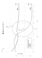
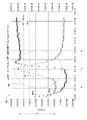
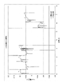
いくつかの実施形態は、標的物質を検出するためのシステムを含み、該システムは、分析カートリッジおよび読取装置を含むこと、前記分析カートリッジが励起電極と検出電極とを含有する試験ウェルを含み、該試験ウェルが増幅プロセスに供される標的物質を含む試料を含有するよう構成されていること、ならびに前記読取装置が、分析カートリッジからの受信を行う領域と、使用時に分析カートリッジを加熱するようキャビティ内に位置付けられたヒーターと、少なくともコンピュータ可読な記憶命令を格納するメモリと、プロセッサとを含み、該プロセッサが 前記命令によって、少なくとも、試験ウェル内で増幅プロセスが行われるよう、ヒーターによって、分析カートリッジを所定の温度まで加熱し、増幅プロセスの実行時間の少なくとも一部にわたって励起電極に励起電流を供給し、検出電極から、少なくとも試験ウェル内の試料により減衰した励起電流を表す信号を受信し、該信号を抵抗成分とリアクタンス成分とに分解し、リアクタンス成分を分析し、増幅プロセスの実行時間の前記少なくとも一部において試料が標的物質を含むことを示す信号のクリフが生じているか否かを判定し、かつ信号のクリフが生じたと判定された場合には陽性であるという試験結果を出力し、信号のクリフが生じなかったと判定された場合には陰性であるという試験結果を出力するよう構成されていること
を特徴とする。
Some embodiments include a system for detecting a target substance, said system comprising an assay cartridge and a reader, said assay cartridge comprising test wells containing excitation and detection electrodes, said a test well configured to contain a sample containing a target substance to be subjected to an amplification process; a memory storing at least computer readable storage instructions; and a processor, the processor causing the heater to cause at least an amplification process to occur in the test wells. heating to a predetermined temperature, supplying an excitation current to the excitation electrode for at least a portion of the duration of the amplification process, receiving from the detection electrode a signal representative of at least the excitation current attenuated by the sample in the test well; into a resistance component and a reactance component, analyzing the reactance component, and determining whether a signal cliff indicating that the sample contains the target substance occurs during said at least a portion of the runtime of the amplification process; and outputting a positive test result when it is determined that a signal cliff has occurred, and outputting a negative test result when it is determined that a signal cliff has not occurred. It is characterized by
いくつかの実施形態において、前記分析カートリッジは、試料を受け入れるよう構成された試料導入部と、試料導入部と試験ウェルとを流体連通させる流路とをさらに含む。 In some embodiments, the assay cartridge further includes a sample introduction portion configured to receive a sample, and a channel in fluid communication between the sample introduction portion and the test well.
いくつかの実施形態において、前記分析カートリッジは、前記増幅プロセス用の液体成分を含有する密封チャンバをさらに含み、該密封チャンバは、分析カートリッジにおいて前記流路へと通じる開口部を有する領域に位置し、前記試料導入部は、流路に沿って開口部と試験ウェルとの間に位置し、前記分析カートリッジはまた、空気インターフェースと該分析カートリッジにおける前記領域とを流体連通させる空気流路を含み、該領域において前記増幅プロセス用の乾燥成分が試験ウェルに供給される。 In some embodiments, the assay cartridge further comprises a sealed chamber containing liquid components for the amplification process, the sealed chamber being located in an area of the assay cartridge having an opening leading to the flow path. wherein the sample introduction portion is positioned along a flow path between the opening and the test well, the assay cartridge also including an air flow path providing fluid communication between the air interface and the region in the assay cartridge; Dry ingredients for the amplification process in the region are supplied to the test wells.
いくつかの実施形態において、前記読取装置は、空気インターフェースを通じて圧力を加えるよう構成された空気圧システムを含み、前記プロセッサはさらに、前記命令によって少なくとも、前記密封チャンバを破裂させて前記液体成分を前記分析カートリッジの前記領域に流入させるよう位置付けられた作動装置に連結されたモータを作動させ、前記空気圧システムを作動させて、前記液体成分を前記流路に流入させ、かつ前記試料導入部で受け入れた試料を試験ウェルへと搬送するよう構成されている。 In some embodiments, the reader includes a pneumatic system configured to apply pressure through an air interface, and the processor is further configured by the instructions to at least rupture the sealed chamber to release the liquid component to the analysis. actuating a motor coupled to an actuator positioned to flow into said region of the cartridge to actuate said pneumatic system to force said liquid component into said flow path and sample received at said sample introduction portion; into the test well.
いくつかの実施形態において、前記分析カートリッジは、流路に沿って試料導入部と試験ウェルとの間に位置付けられた混合チャンバをさらに含み、該混合チャンバは、前記液体成分と前記試料とを混合して実質的に均一に混合された試験流体とするよう構成されている。 In some embodiments, the assay cartridge further comprises a mixing chamber positioned along the flow path between the sample introduction portion and the test well, the mixing chamber mixing the liquid component and the sample. and a substantially uniformly mixed test fluid.
いくつかの実施形態において、前記分析カートリッジは、前記励起電極に通じる第1の接続パッドと、前記検出電極に通じる第2の接続パッドとを含む第1の電極インターフェースを含む。 In some embodiments, the assay cartridge includes a first electrode interface including first connection pads leading to the excitation electrodes and second connection pads leading to the detection electrodes.
いくつかの実施形態において、前記読取装置は、前記第1の電極インターフェースを介して、該読取装置の前記領域に受け入れられた分析カートリッジと連結されるよう構成されている第2の電極インターフェースを含む。 In some embodiments, the reader includes a second electrode interface configured to be coupled via the first electrode interface with an assay cartridge received in the region of the reader. .
いくつかの実施形態において、前記読取装置は、励起電流を生成するよう構成された電圧源をさらに含み、前記第2の電極インターフェースは、電圧源に連結され、かつ前記第1の接続パッドに連結するよう位置付けられた第3の接続パッドと、メモリに連結され、かつ前記第2の接続パッドに連結するよう位置付けられた第4の接続パッドとを含む。 In some embodiments, the reader further includes a voltage source configured to generate an excitation current, the second electrode interface coupled to the voltage source and coupled to the first connection pad. and a fourth connection pad coupled to the memory and positioned to couple to the second connection pad.
いくつかの実施形態において、前記信号を抵抗成分とリアクタンス成分とに分解するために、前記プロセッサはさらに、前記命令によって少なくとも、試料のインピーダンスを示す信号のサンプリングを該信号のナイキスト周波数よりも速く行い、該信号を同相成分と異相成分とに分解し、かつ該同相成分に基づいて抵抗成分を計算し、該異相成分に基づいてリアクタンス成分を計算するよう構成されている。 In some embodiments, the processor further causes the instructions to at least sample a signal indicative of the impedance of the sample faster than the Nyquist frequency of the signal to decompose the signal into resistive and reactive components. , is configured to decompose the signal into an in-phase component and an out-of-phase component, calculate a resistance component based on the in-phase component, and calculate a reactance component based on the out-of-phase component.
いくつかの実施形態において、リアクタンス成分を計算するために、前記プロセッサはさらに、前記命令によって少なくとも、メモリ内に格納されている信号のクリフに関する所定の期待特性にアクセスするよう構成されている。 In some embodiments, the processor is further configured by the instructions to access at least predetermined expected characteristics of signal cliffs stored in memory to calculate reactance components.
いくつかの実施形態において、前記メモリ内に格納されている、信号のクリフに関する所定の期待特性は、増幅プロセスの前記実行時間において信号のクリフが生じると予測される時間枠を含む。 In some embodiments, the predetermined expected characteristic for signal cliffs stored in the memory includes a time window during which signal cliffs are expected to occur during the run-time of the amplification process.
いくつかの実施形態において、前記メモリ内に格納されている、信号のクリフに関する所定の期待特性は、リアクタンス成分の値の閾値変化を含む。 In some embodiments, the predetermined expected characteristic of signal cliffs stored in the memory includes a threshold change in the value of a reactance component.
いくつかの実施形態において、前記メモリ内に格納されている、信号のクリフに関する所定の期待特性は、増幅プロセスの前記実行時間の少なくとも一部を通してサンプリングされたリアクタンス成分の値を示す曲線の閾値勾配を含む。 In some embodiments, the predetermined expected characteristic of a signal cliff stored in said memory is a threshold slope of a curve representing values of reactance components sampled throughout at least a portion of said run time of an amplification process. including.
いくつかの実施形態において、前記増幅プロセスは、処理を施した前記試料を捕捉プローブと接触させることを含む。いくつかの実施形態において、前記捕捉プローブは、抗体またはその抗体の抗原結合性フラグメント、タンパク質受容体および核酸からなる群から選択される。いくつかの実施形態において、前記捕捉プローブは、検出可能な核酸を含む。いくつかの実施形態において、前記検出可能な核酸は、増幅される。 In some embodiments, the amplification process comprises contacting the treated sample with a capture probe. In some embodiments, the capture probe is selected from the group consisting of antibodies or antigen-binding fragments of antibodies thereof, protein receptors and nucleic acids. In some embodiments, the capture probes comprise detectable nucleic acids. In some embodiments, the detectable nucleic acid is amplified.
いくつかの実施形態において、前記増幅プロセスは等温増幅を含む。いくつかの実施形態において、前記増幅プロセスは、自律配列複製反応(3SR);90-I;BAD増幅;交差プライミング増幅(CPA);等温指数関数的増幅反応(EXPAR);等温キメラプライマー開始核酸増幅(ICAN);等温多置換増幅(IMDA);ライゲーション媒介SDA;多置換増幅;ポリメラーゼスパイラル反応(PSR);制限カスケード指数関数的増幅(RCEA);スマート増幅法(SMAP2);単一プライマー等温増幅(SPIA);転写ベースの増幅系(TAS);転写媒介増幅(TMA);リガーゼ連鎖反応(LCR);および交差多置換増幅(MCDA)からなる群から選択される等温増幅反応を含む。いくつかの実施形態において、前記増幅プロセスは、ループ媒介等温増幅(LAMP)を含む。 In some embodiments, the amplification process comprises isothermal amplification. In some embodiments, the amplification process comprises an autonomous sequence replication reaction (3SR); 90-I; BAD amplification; cross-priming amplification (CPA); isothermal exponential amplification reaction (EXPAR); Ligation-Mediated SDA; Multiple Displacement Amplification; Polymerase Spiral Reaction (PSR); Restricted Cascade Exponential Amplification (RCEA); Smart Amplification Method (SMAP2); Transcription-Mediated Amplification (TMA); Ligase Chain Reaction (LCR); and Cross-Multiple Displacement Amplification (MCDA). In some embodiments, the amplification process comprises loop-mediated isothermal amplification (LAMP).
いくつかの実施形態において、前記試験ウェル内で前記増幅プロセスを実施するための前記所定の温度は、30℃よりも高い。いくつかの実施形態において、いくつかの実施形態において、前記試験ウェル内で前記増幅プロセスを実施するための前記所定の温度は、37℃よりも高い。いくつかの実施形態において、前記試験ウェル内で前記増幅プロセスを実施するための前記所定の温度は、60℃よりも高い。いくつかの実施形態において、前記試験ウェル内で前記増幅プロセスを実施するための前記所定の温度は、60℃~70℃の範囲内にある。 In some embodiments, the predetermined temperature for performing the amplification process within the test well is higher than 30°C. In some embodiments, the predetermined temperature for performing the amplification process within the test well is higher than 37°C. In some embodiments, the predetermined temperature for performing the amplification process within the test well is higher than 60°C. In some embodiments, said predetermined temperature for performing said amplification process within said test well is in the range of 60°C to 70°C.
いくつかの実施形態において、前記増幅プロセスの前記液体成分は、抗体またはその抗体の抗原結合性フラグメント、タンパク質受容体、プライマーなどの核酸、緩衝液、およびポリメラーゼなどの酵素からなる群から選択される。 In some embodiments, the liquid components of the amplification process are selected from the group consisting of antibodies or antigen-binding fragments of antibodies thereof, protein receptors, nucleic acids such as primers, buffers, and enzymes such as polymerases. .
いくつかの実施形態において、前記増幅プロセスの前記乾燥成分は、抗体またはその抗体の抗原結合性フラグメント、タンパク質受容体、プライマーなどの核酸、緩衝液、およびポリメラーゼなどの酵素からなる群から選択される。 In some embodiments, the dry components of the amplification process are selected from the group consisting of antibodies or antigen-binding fragments of antibodies thereof, protein receptors, nucleic acids such as primers, buffers, and enzymes such as polymerases. .
いくつかの実施形態は、試料中の標的物質の有無を調べるためのデバイスを含み、該デバイスは、標的物質を含む試料を受け入れるよう構成された試料導入部;励起電極と検出電極とを含有する試験ウェル;および前記試料導入部と前記試験ウェルとを流体連通させる流路を含むこと、ならびに該試験ウェルが、増幅プロセスの間、試料を含有し、該増幅プロセスの間、前記励起電極を使用して試料に電流を流し、かつ前記検出電極を使用して、少なくとも試験ウェル内の試料により減衰した電流を表す信号を検出することを特徴とする。 Some embodiments include a device for determining the presence or absence of a target substance in a sample, the device containing a sample introduction portion configured to receive a sample containing the target substance; an excitation electrode and a detection electrode. a test well; and a flow path in fluid communication between said sample introduction portion and said test well, and said test well containing a sample during an amplification process and using said excitation electrodes during said amplification process. to pass a current through the sample, and the detection electrode is used to detect a signal representative of the current attenuated by the sample in at least the test well.
いくつかの実施形態は、前記増幅プロセス用の液体成分を含有する密封チャンバと、前記試験ウェル内に供給される、増幅プロセス用の乾燥成分とをさらに含み、前記密封チャンバは、当該デバイスにおいて前記流路へと通じる開口部を有する領域に位置し、前記試料導入部は、流路に沿って開口部と試験ウェルとの間に位置する。 Some embodiments further comprise a sealed chamber containing liquid components for the amplification process and dry components for the amplification process provided within the test wells, wherein the sealed chamber comprises the Located in a region having an opening leading to the channel, the sample introduction part is located between the opening and the test well along the channel.
いくつかの実施形態は、前記密封チャンバを破裂させることによって前記液体成分を前記領域に流入させるための鋭利部分と、前記空気インターフェースと当該デバイスの前記領域とを流体連通させる空気流路とをさらに含み、該空気流路は、前記領域に圧力を加えることによって前記液体成分を前記流路に流入させ、かつ前記試料導入部で受け入れた試料を試験ウェルへと搬送するよう構成されている。 Some embodiments further include a sharp point for rupturing the sealed chamber to allow the liquid component to enter the region, and an air channel for fluid communication between the air interface and the region of the device. wherein the air flow path is configured to force the liquid component into the flow path by applying pressure to the region and to convey the sample received at the sample introduction portion to the test well.
いくつかの実施形態は、流路に沿って試料導入部と試験ウェルとの間に位置付けられた混合チャンバをさらに含み、該混合チャンバは、前記液体成分と前記試料とを混合して実質的に均一に混合された試験流体とするよう構成されている。 Some embodiments further include a mixing chamber positioned along the flow path between the sample introduction portion and the test well, the mixing chamber mixing the liquid component and the sample to substantially It is configured to provide a uniformly mixed test fluid.
いくつかの実施形態において、前記分析カートリッジは、前記励起電極に通じる第1の接続パッドと、前記検出電極に通じる第2の接続パッドとを含む第1の電極インターフェースを含む。 In some embodiments, the assay cartridge includes a first electrode interface including first connection pads leading to the excitation electrodes and second connection pads leading to the detection electrodes.
いくつかの実施形態は、励起電極と検出電極とを含む回路基板をさらに含み、前記試料導入部と、前記流路の少なくとも一部とは液体不浸透性材料で一体に形成されており、前記回路基板は、該液体不浸透性材料の一部に接着されている。 Some embodiments further include a circuit board including an excitation electrode and a detection electrode, the sample introduction part and at least part of the channel are integrally formed of a liquid-impermeable material, and the A circuit board is adhered to a portion of the liquid impermeable material.
いくつかの実施形態は、前記液体不浸透性材料と前記回路基板との上に位置するカバーをさらに含み、該カバーは、前記試料導入部の上に位置付けられた開口部と、該開口部を開放可能に密封するよう構成されたキャップとを含む。 Some embodiments further include a cover positioned over the liquid impermeable material and the circuit board, the cover including an opening positioned over the sample introduction portion and a a cap configured to releasably seal.
いくつかの実施形態において、前記試験ウェルの側面は、前記液体不浸透性材料に設けられた円形開口部として形成され、該試験ウェルの底面は、前記回路基板によって形成されている。 In some embodiments, the sides of the test well are formed as circular openings in the liquid impermeable material and the bottom of the test well is formed by the circuit board.
いくつかの実施形態において、前記励起電極および前記検出電極は、前記試験ウェルの底面上に、該試験ウェルの側面から離れて位置付けられている。 In some embodiments, the excitation electrode and the detection electrode are positioned on the bottom surface of the test well and away from the sides of the test well.
いくつかの実施形態において、前記励起電極および前記検出電極は、前記回路基板の下位層と実質的に同一平面状にあるよう構成されている。 In some embodiments, the excitation electrodes and the detection electrodes are configured to be substantially coplanar with underlying layers of the circuit board.
いくつかの実施形態は、前記試験ウェルから気体を放出するよう構成されている通気口をさらに含み、該通気口が、液体不浸透性かつ気体浸透性のフィルタで覆われている。 Some embodiments further include a vent configured to release gas from the test well, the vent covered with a liquid impermeable, gas permeable filter.
いくつかの実施形態において、前記励起電極は、前記ウェルの中心に配置された円形電極を含み、前記検出電極は、該励起電極を囲むよう同心に位置付けられた環状電極を含む。 In some embodiments, the excitation electrode comprises a circular electrode centrally located in the well and the detection electrode comprises a ring electrode concentrically positioned to surround the excitation electrode.
いくつかの実施形態において、前記環状電極は、該環状電極の半径とほぼ等しい間隙によって前記円形状電極から隔てられている。 In some embodiments, the annular electrode is separated from the circular electrode by a gap approximately equal to the radius of the annular electrode.
いくつかの実施形態において、前記環状電極は、該環状電極の半径の少なくとも2倍の間隙によって前記円形状電極から隔てられている。 In some embodiments, the annular electrode is separated from the circular electrode by a gap of at least twice the radius of the annular electrode.
いくつかの実施形態において、前記励起電極は第1の半円電極を含み、前記検出電極は、該第1の半円電極から間隙によって隔てられた第2の半円電極を含み、該第1の半円電極と該第2の半円電極の直線部分は、該間隙を挟んで互いに対面している。 In some embodiments, the excitation electrode comprises a first semi-circular electrode, the detection electrode comprises a second semi-circular electrode separated from the first semi-circular electrode by a gap, the first semi-circular electrode and the linear portion of the second semicircular electrode face each other across the gap.
いくつかの実施形態において、前記励起電極は第1の線状電極を含み、前記検出電極は、該第1の線状電極から間隙によって隔てられた第2の線状電極を含む。 In some embodiments, the excitation electrode comprises a first linear electrode and the sensing electrode comprises a second linear electrode separated from the first linear electrode by a gap.
いくつかの実施形態において、前記励起電極は第1の方形電極を含み、前記検出電極は、該第1の線状電極から間隙によって隔てられた第2の方形電極を含む。 In some embodiments, the excitation electrode comprises a first rectangular electrode and the detection electrode comprises a second rectangular electrode separated from the first linear electrode by a gap.
いくつかの実施形態において、前記増幅プロセスは、処理を施した前記試料を捕捉プローブと接触させることを含む。いくつかの実施形態において、前記捕捉プローブは、抗体またはその抗体の抗原結合性フラグメント、タンパク質受容体および核酸からなる群から選択される。いくつかの実施形態において、前記捕捉プローブは、検出可能な核酸を含む。いくつかの実施形態において、前記検出可能な核酸は、増幅される。 In some embodiments, the amplification process comprises contacting the treated sample with a capture probe. In some embodiments, the capture probe is selected from the group consisting of antibodies or antigen-binding fragments of antibodies thereof, protein receptors and nucleic acids. In some embodiments, the capture probes comprise detectable nucleic acids. In some embodiments, the detectable nucleic acid is amplified.
いくつかの実施形態において、前記増幅プロセスは、等温増幅を含む。いくつかの実施形態において、前記増幅プロセスは、自律配列複製反応(3SR);90-I;BAD増幅;交差プライミング増幅(CPA);等温指数関数的増幅反応(EXPAR);等温キメラプライマー開始核酸増幅(ICAN);等温多置換増幅(IMDA);ライゲーション媒介SDA;多置換増幅;ポリメラーゼスパイラル反応(PSR);制限カスケード指数関数的増幅(RCEA);スマート増幅法(SMAP2);単一プライマー等温増幅(SPIA);転写ベースの増幅系(TAS);転写媒介増幅(TMA);リガーゼ連鎖反応(LCR);および交差多置換増幅(MCDA)からなる群から選択される等温増幅反応を含む。いくつかの実施形態において、前記増幅プロセスは、ループ媒介等温増幅(LAMP)を含む。 In some embodiments, the amplification process comprises isothermal amplification. In some embodiments, the amplification process comprises an autonomous sequence replication reaction (3SR); 90-I; BAD amplification; cross-priming amplification (CPA); isothermal exponential amplification reaction (EXPAR); Ligation-Mediated SDA; Multiple Displacement Amplification; Polymerase Spiral Reaction (PSR); Restricted Cascade Exponential Amplification (RCEA); Smart Amplification Method (SMAP2); Transcription-Mediated Amplification (TMA); Ligase Chain Reaction (LCR); and Cross-Multiple Displacement Amplification (MCDA). In some embodiments, the amplification process comprises loop-mediated isothermal amplification (LAMP).
いくつかの実施形態において、前記試験ウェルは、前記試料を30℃よりも高い温度まで加熱するよう構成されている。いくつかの実施形態において、前記試験ウェルは、前記試料を37℃よりも高い温度まで加熱するよう構成されている。いくつかの実施形態において、前記試験ウェルは、前記試料を60℃よりも高い温度まで加熱するよう構成されている。いくつかの実施形態において、前記試験ウェルは、前記試料を60℃~70℃の範囲にある温度まで加熱するよう構成されている。 In some embodiments, the test well is configured to heat the sample to a temperature greater than 30°C. In some embodiments, the test well is configured to heat the sample to a temperature greater than 37°C. In some embodiments, the test well is configured to heat the sample to a temperature greater than 60°C. In some embodiments, the test well is configured to heat the sample to a temperature in the range of 60°C to 70°C.
いくつかの実施形態において、前記増幅プロセスの前記液体成分は、抗体またはその抗体の抗原結合性フラグメント、タンパク質受容体、プライマーなどの核酸、緩衝液、およびポリメラーゼなどの酵素からなる群から選択される。 In some embodiments, the liquid components of the amplification process are selected from the group consisting of antibodies or antigen-binding fragments of antibodies thereof, protein receptors, nucleic acids such as primers, buffers, and enzymes such as polymerases. .
いくつかの実施形態において、前記増幅プロセスの前記乾燥成分は、抗体またはその抗体の抗原結合性フラグメント、タンパク質受容体、プライマーなどの核酸、緩衝液、およびポリメラーゼなどの酵素からなる群から選択される。 In some embodiments, the dry components of the amplification process are selected from the group consisting of antibodies or antigen-binding fragments of antibodies thereof, protein receptors, nucleic acids such as primers, buffers, and enzymes such as polymerases. .
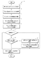
いくつかの実施形態は、命令を格納している非一時的コンピュータ可読媒体を含み、該媒体は、標的物質を含む試料と試験ウェルとを含有する分析カートリッジを受け入れるよう構成されている読取装置による実行時に、該読取装置に、試験ウェル内で行われる増幅プロセスの実行時間の少なくとも一部にわたって、試験ウェル内に位置する励起電極に励起電流を供給すること、試験ウェル内に位置する検出電極から、少なくとも試験ウェル内で増幅プロセスに供されている試料により減衰した励起電流を表す信号を受信すること、該信号を抵抗成分とリアクタンス成分とに分解すること、リアクタンス成分を分析し、増幅プロセスの実行時間の前記少なくとも一部において試料が標的物質を含むことを示す信号のクリフが生じているか否かを判定すること、および信号のクリフが生じたと判定された場合には陽性であるという試験結果を出力し、信号のクリフが生じなかったと判定された場合には陰性であるという試験結果を出力することを含む操作を実行させる。 Some embodiments include a non-transitory computer readable medium storing instructions by a reader configured to receive an assay cartridge containing a sample containing a target substance and a test well. When running, supplying the reader with an excitation current for at least a portion of the execution time of an amplification process occurring in the test well to an excitation electrode located within the test well; from a detection electrode located within the test well; receiving a signal representative of an excitation current attenuated by a sample undergoing an amplification process in at least a test well; decomposing the signal into a resistive component and a reactive component; analyzing the reactive component and performing an amplification process; Determining whether a signal cliff indicating that the sample contains the target substance has occurred during said at least a portion of the run time, and a positive test result if it is determined that a signal cliff has occurred. and outputting a negative test result if it is determined that no signal cliff occurred.
いくつかの実施形態において、前記操作は、増幅プロセスが行われるよう、ヒーターによって前記分析カートリッジを所定の温度まで加熱することをさらに含む。 In some embodiments, the operation further comprises heating the analysis cartridge to a predetermined temperature with a heater so that an amplification process can occur.
いくつかの実施形態において、前記操作は、前記陽性であるという試験結果または前記陰性であるという試験結果をネットワーク上で伝送することをさらに含む。 In some embodiments, the operation further comprises transmitting the positive test result or the negative test result over a network.
いくつかの実施形態において、前記操作は、試料のインピーダンスを示す信号のサンプリングを、該信号のナイキスト周波数よりも速く行うこと、該信号を同相成分と異相成分とに分解すること、および該同相成分に基づいて抵抗成分を計算し、該異相成分に基づいてリアクタンス成分を計算することをさらに含む。 In some embodiments, the operations include: sampling a signal indicative of the impedance of the sample faster than the Nyquist frequency of the signal; resolving the signal into in-phase and out-of-phase components; and calculating a reactance component based on the out-of-phase component.
いくつかの実施形態において、リアクタンス成分を分析するための前記操作は、メモリ内に格納されている、信号のクリフに関する所定の期待特性にアクセスすることをさらに含む。 In some embodiments, the operation to analyze the reactance component further comprises accessing predetermined expected characteristics of signal cliffs stored in memory.
いくつかの実施形態において、前記メモリ内に格納されている、信号のクリフに関する所定の期待特性は、増幅プロセスの実行時間において信号のクリフが生じると予測される時間枠を含む。 In some embodiments, the predetermined expected characteristics for signal cliffs stored in the memory include time windows during which signal cliffs are expected to occur during the amplification process.
いくつかの実施形態において、前記メモリ内に格納されている、信号のクリフに関する所定の期待特性は、リアクタンス成分の値の閾値変化を含む。 In some embodiments, the predetermined expected characteristic of signal cliffs stored in the memory includes a threshold change in the value of a reactance component.
いくつかの実施形態において、前記メモリ内に格納されている、信号のクリフに関する所定の期待特性は、増幅プロセスの前記実行時間の少なくとも一部を通してサンプリングされたリアクタンス成分の値を示す曲線の閾値勾配を含む。 In some embodiments, the predetermined expected characteristic of a signal cliff stored in said memory is a threshold slope of a curve representing values of reactance components sampled throughout at least a portion of said run time of an amplification process. including.
いくつかの実施形態において、前記操作は、空気圧システムを作動させて前記分析カートリッジの流路に圧力を加えることによって、前記試料を前記増幅プロセスの成分と混合し、かつ前記試験ウェル内へと流入させることをさらに含む。 In some embodiments, the operation includes activating a pneumatic system to apply pressure to the flow path of the assay cartridge to mix the sample with components of the amplification process and flow into the test well. further including causing
いくつかの実施形態において、前記操作は、モータを作動させて作動装置を分析カートリッジのブリスターパックに押し込み、前記増幅プロセス用の液体成分を流路内へと放出することをさらに含む。 In some embodiments, said operation further comprises activating a motor to push an actuator into a blister pack of an assay cartridge to expel a liquid component for said amplification process into a flow path.
いくつかの実施形態において、前記増幅プロセスは、処理を施した前記試料を捕捉プローブと接触させることを含む。いくつかの実施形態において、前記捕捉プローブは、抗体またはその抗体の抗原結合性フラグメント、タンパク質受容体および核酸からなる群から選択される。いくつかの実施形態において、前記捕捉プローブは、検出可能な核酸を含む。いくつかの実施形態において、前記検出可能な核酸は、増幅される。 In some embodiments, the amplification process comprises contacting the treated sample with a capture probe. In some embodiments, the capture probe is selected from the group consisting of antibodies or antigen-binding fragments of antibodies thereof, protein receptors and nucleic acids. In some embodiments, the capture probes comprise detectable nucleic acids. In some embodiments, the detectable nucleic acid is amplified.
いくつかの実施形態において、前記増幅プロセスは、等温増幅を含む。いくつかの実施形態において、前記増幅プロセスは、自律配列複製反応(3SR);90-I;BAD増幅;交差プライミング増幅(CPA);等温指数関数的増幅反応(EXPAR);等温キメラプライマー開始核酸増幅(ICAN);等温多置換増幅(IMDA);ライゲーション媒介SDA;多置換増幅;ポリメラーゼスパイラル反応(PSR);制限カスケード指数関数的増幅(RCEA);スマート増幅法(SMAP2);単一プライマー等温増幅(SPIA);転写ベースの増幅系(TAS);転写媒介増幅(TMA);リガーゼ連鎖反応(LCR);および交差多置換増幅(MCDA)からなる群から選択される等温増幅反応を含む。いくつかの実施形態において、前記増幅プロセスは、ループ媒介等温増幅(LAMP)を含む。 In some embodiments, the amplification process comprises isothermal amplification. In some embodiments, the amplification process comprises an autonomous sequence replication reaction (3SR); 90-I; BAD amplification; cross-priming amplification (CPA); isothermal exponential amplification reaction (EXPAR); Ligation-Mediated SDA; Multiple Displacement Amplification; Polymerase Spiral Reaction (PSR); Restricted Cascade Exponential Amplification (RCEA); Smart Amplification Method (SMAP2); Transcription-Mediated Amplification (TMA); Ligase Chain Reaction (LCR); and Cross-Multiple Displacement Amplification (MCDA). In some embodiments, the amplification process comprises loop-mediated isothermal amplification (LAMP).
いくつかの実施形態において、前記増幅プロセスを実施するための前記所定の温度は、30℃よりも高い。いくつかの実施形態において、前記増幅プロセスを実施するための前記所定の温度は、37℃よりも高い。いくつかの実施形態において、前記増幅プロセスを実施するための前記所定の温度は、60℃よりも高い。いくつかの実施形態において、前記増幅プロセスを実施するための前記所定の温度は、60℃~70℃の範囲内にある。 In some embodiments, the predetermined temperature for performing the amplification process is higher than 30°C. In some embodiments, the predetermined temperature for performing the amplification process is higher than 37°C. In some embodiments, the predetermined temperature for performing the amplification process is higher than 60°C. In some embodiments, said predetermined temperature for performing said amplification process is in the range of 60°C to 70°C.
いくつかの実施形態において、前記増幅プロセスの前記液体成分は、抗体またはその抗体の抗原結合性フラグメント、タンパク質受容体、プライマーなどの核酸、緩衝液、およびポリメラーゼなどの酵素からなる群から選択される。 In some embodiments, the liquid components of the amplification process are selected from the group consisting of antibodies or antigen-binding fragments of antibodies thereof, protein receptors, nucleic acids such as primers, buffers, and enzymes such as polymerases. .
いくつかの実施形態において、前記増幅プロセスは、抗体またはその抗体の抗原結合性フラグメント、タンパク質受容体、プライマーなどの核酸、緩衝液、およびポリメラーゼなどの酵素からなる群から選択される乾燥成分をさらに含む。 In some embodiments, the amplification process further comprises dry components selected from the group consisting of antibodies or antigen-binding fragments thereof, protein receptors, nucleic acids such as primers, buffers, and enzymes such as polymerases. include.
いくつかの実施形態は、標的物質を検出するための方法を含み、該方法は、励起電極と検出電極とを含む試験ウェルを含むカートリッジを提供すること、標的物質を含む試料を前記カートリッジに導入すること、読取装置に前記カートリッジを挿入すること、前記試験ウェル内の前記試料に含まれている標的物質の増幅を行うこと、前記読取装置からの励起信号を前記励起電極に印加すること、前記励起電極を使用して、前記試験ウェルからの信号すなわち増幅に供されている試料のインピーダンスを示す信号を検出すること、前記読取装置に前記信号を伝送すること、および前記インピーダンスのリアクタンス部分を分析する前記読取装置に基づいて前記標的物質を検出することを含む。 Some embodiments include a method for detecting a target substance comprising: providing a cartridge comprising test wells comprising excitation electrodes and detection electrodes; introducing a sample comprising the target substance into said cartridge; inserting the cartridge into a reader; amplifying a target substance contained in the sample in the test well; applying an excitation signal from the reader to the excitation electrode; using excitation electrodes to detect a signal from the test well, ie, a signal indicative of the impedance of the sample being amplified; transmit the signal to the reader; and analyze the reactive portion of the impedance. and detecting the target substance based on the reader for detecting the target substance.
いくつかの実施形態は、前記カートリッジの試料導入部に前記試料を導入すること、前記カートリッジ内の密封チャンバを破裂させて、前記増幅プロセス用の液体成分を該カートリッジの流路へと放出すること、および前記試験ウェルに通じる流路に沿って前記液体成分と前記試料とを流れさせ、それによって該液体成分と該試料とを混合し、試験流体とすることをさらに含む。 Some embodiments include introducing the sample into a sample introduction portion of the cartridge and rupturing a sealed chamber within the cartridge to release the liquid components for the amplification process into the flow path of the cartridge. and flowing the liquid component and the sample along a flow path leading to the test well, thereby mixing the liquid component and the sample into a test fluid.
いくつかの実施形態は、前記試験ウェル内に供給された増幅プロセス用の乾燥成分を、前記試験流体で水和させることをさらに含む。 Some embodiments further comprise hydrating dry ingredients for an amplification process provided in the test well with the test fluid.
いくつかの実施形態は、前記試験流体内にトラップされている気体を、前記試験ウェルと流体連通している通気口を通じて押し出すことをさらに含む。 Some embodiments further include forcing gas trapped within the test fluid through a vent in fluid communication with the test well.
いくつかの実施形態は、前記信号のリアクタンス部分を分析して、陽性である試験結果を示す信号のクリフを同定することをさらに含む。 Some embodiments further comprise analyzing the reactive portion of the signal to identify signal cliffs that indicate a positive test result.
いくつかの実施形態は、前記増幅プロセスの所定の時間枠における値の閾値変化および/または時間的な位置よりも大きなリアクタンス部分に基づいて生成された曲線の一部に基づいて信号のクリフを同定することをさらに含む。 Some embodiments identify signal cliffs based on a portion of a curve generated based on a reactance portion greater than a threshold change in value and/or position in time over a predetermined timeframe of the amplification process. further comprising:
いくつかの実施形態において、前記増幅プロセスは、処理を施した前記試料を捕捉プローブと接触させることを含む。いくつかの実施形態において、前記捕捉プローブは、抗体またはその抗体の抗原結合性フラグメント、タンパク質受容体および核酸からなる群から選択されるいくつかの実施形態において、前記捕捉プローブは、検出可能な核酸を含む。いくつかの実施形態において、前記検出可能な核酸は、増幅される。 In some embodiments, the amplification process comprises contacting the treated sample with a capture probe. In some embodiments, the capture probe is selected from the group consisting of antibodies or antigen-binding fragments of antibodies thereof, protein receptors and nucleic acids. including. In some embodiments, the detectable nucleic acid is amplified.
いくつかの実施形態において、前記増幅は、等温増幅を含む。いくつかの実施形態において、前記増幅は、自律配列複製反応(3SR);90-I;BAD増幅;交差プライミング増幅(CPA);等温指数関数的増幅反応(EXPAR);等温キメラプライマー開始核酸増幅(ICAN);等温多置換増幅(IMDA);ライゲーション媒介SDA;多置換増幅;ポリメラーゼスパイラル反応(PSR);制限カスケード指数関数的増幅(RCEA);スマート増幅法(SMAP2);単一プライマー等温増幅(SPIA);転写ベースの増幅系(TAS);転写媒介増幅(TMA);リガーゼ連鎖反応(LCR);および交差多置換増幅(MCDA)からなる群から選択される等温増幅反応を含む。いくつかの実施形態において、前記増幅プロセスは、ループ媒介等温増幅(LAMP)を含む。 In some embodiments, said amplification comprises isothermal amplification. 90-I; BAD amplification; cross-priming amplification (CPA); isothermal exponential amplification reaction (EXPAR); Ligation-Mediated SDA; Multiple Displacement Amplification; Polymerase Spiral Reaction (PSR); Restricted Cascade Exponential Amplification (RCEA); Smart Amplification Method (SMAP2); ); transcription-based amplification system (TAS); transcription-mediated amplification (TMA); ligase chain reaction (LCR); and cross-multiple displacement amplification (MCDA). In some embodiments, the amplification process comprises loop-mediated isothermal amplification (LAMP).
いくつかの実施形態において、前記標的物質の増幅を行うことは、前記試料を30℃よりも高い温度まで加熱することを含む。いくつかの実施形態において、前記標的物質の増幅を行うことは、前記試料を37℃よりも高い温度まで加熱することを含む。いくつかの実施形態において、前記標的物質の増幅を行うことは、前記試料を60℃よりも高い温度まで加熱することを含む。いくつかの実施形態において、前記標的物質の増幅を行うことは、前記試料を60℃~70℃の範囲にある温度まで加熱することを含む。 In some embodiments, amplifying the target material comprises heating the sample to a temperature greater than 30°C. In some embodiments, amplifying the target material comprises heating the sample to a temperature greater than 37°C. In some embodiments, amplifying the target material comprises heating the sample to a temperature greater than 60°C. In some embodiments, amplifying the target material comprises heating the sample to a temperature in the range of 60°C to 70°C.
いくつかの実施形態において、前記増幅プロセスの前記液体成分は、抗体またはその抗体の抗原結合性フラグメント、タンパク質受容体、プライマーなどの核酸、緩衝液、およびポリメラーゼなどの酵素からなる群から選択される。 In some embodiments, the liquid components of the amplification process are selected from the group consisting of antibodies or antigen-binding fragments of antibodies thereof, protein receptors, nucleic acids such as primers, buffers, and enzymes such as polymerases. .
いくつかの実施形態において、前記増幅プロセスの前記乾燥成分は、抗体またはその抗体の抗原結合性フラグメント、タンパク質受容体、プライマーなどの核酸、緩衝液、およびポリメラーゼなどの酵素からなる群から選択される。 In some embodiments, the dry components of the amplification process are selected from the group consisting of antibodies or antigen-binding fragments of antibodies thereof, protein receptors, nucleic acids such as primers, buffers, and enzymes such as polymerases. .
いくつかの実施形態は、標的物質を検出するための方法を含み、該方法は、励起電極と検出電極とを含むデバイスを提供すること、標的物質を含む試料を前記デバイスに導入すること、前記デバイス内の試料を処理すること、および処理を施した前記試料の電気特性を測定することによって当該標的を検出することを含む。 Some embodiments include a method for detecting a target substance, comprising: providing a device comprising an excitation electrode and a detection electrode; introducing a sample comprising the target substance into the device; Processing a sample in the device and detecting the target by measuring an electrical property of the processed sample.
いくつかの実施形態において、前記電気特性は、複素アドミタンス、インピーダンス、導電率、抵抗率、抵抗および比誘電率からなる群から選択される。 In some embodiments, the electrical property is selected from the group consisting of complex admittance, impedance, conductivity, resistivity, resistance and dielectric constant.
いくつかの実施形態において、前記電気特性は、複素アドミタンスである。 In some embodiments, the electrical property is complex admittance.
いくつかの実施形態において、検出は、前記励起電極に励起信号を印加することを含む。 In some embodiments, detecting comprises applying an excitation signal to said excitation electrodes.
いくつかの実施形態において、前記励起信号は、交流電流を含む。 In some embodiments, the excitation signal comprises alternating current.
いくつかの実施形態において、前記励起信号は、直流電流を含む。 In some embodiments, the excitation signal comprises direct current.
いくつかの実施形態において、前記励起信号は、電圧および周波数が変化するスイープ信号を含む。 In some embodiments, the excitation signal comprises a sweep signal that varies in voltage and frequency.
いくつかの実施形態において、検出は、前記検出電極における誘導電流を測定することを含む。 In some embodiments, detecting comprises measuring an induced current in said sensing electrode.
いくつかの実施形態において、前記電気特性は、一定の時間にわたって測定される。 In some embodiments, the electrical property is measured over time.
いくつかの実施形態において、少なくとも1つの電極は、不動態化されている。 In some embodiments, at least one electrode is passivated.
いくつかの実施形態において、前記電極は、誘電材料で不動態化されている。 In some embodiments, the electrodes are passivated with a dielectric material.
いくつかの実施形態において、前記電極は、酸化チタンで不動態化されている。 In some embodiments, the electrodes are passivated with titanium oxide.
いくつかの実施形態において、検出は、処理を施した前記試料を捕捉プローブと接触させることを含む。いくつかの実施形態において、前記捕捉プローブは、磁気ビーズを含む。 In some embodiments, detecting comprises contacting said treated sample with a capture probe. In some embodiments, the capture probes comprise magnetic beads.
いくつかの実施形態において、前記捕捉プローブは、抗体またはその抗体の抗原結合性フラグメント、タンパク質受容体および核酸からなる群から選択される。いくつかの実施形態において、前記捕捉プローブは、検出可能な核酸を含む。いくつかの実施形態において、検出は、前記検出可能な核酸を増幅することを含む。 In some embodiments, the capture probe is selected from the group consisting of antibodies or antigen-binding fragments of antibodies thereof, protein receptors and nucleic acids. In some embodiments, the capture probes comprise detectable nucleic acids. In some embodiments, detecting comprises amplifying said detectable nucleic acid.
いくつかの実施形態において、前記増幅は、等温増幅を含む。いくつかの実施形態において、前記増幅は、ループ媒介等温増幅(LAMP)を含む。いくつかの実施形態において、前記処理した試料は、低イオン溶液を含む。 In some embodiments, said amplification comprises isothermal amplification. In some embodiments, said amplification comprises loop-mediated isothermal amplification (LAMP). In some embodiments, the processed sample comprises a low ionic solution.
いくつかの実施形態において、前記処理した試料は、硫酸アンモニウムを含まない。 In some embodiments, the processed sample does not contain ammonium sulfate.
いくつかの実施形態において、検出は、前記試料を、該試料を含む溶液の導電率の変化を増大させる物質と接触させることを含む。いくつかの実施形態において、前記物質は、無機ピロリン酸と結合する。いくつかの実施形態において、前記物質は、Cd2+-サイクレン-クマリン;ビス(2-ピリジルメチル)アミン(DPA)単位を有するZn2+錯体;DPA-2Zn2+-フェノキシド;アクリジン-DPA-Zn2+;DPA-Zn2+ピレン;およびアザクラウン-Cu2+錯体からなる群から選択される。いくつかの実施形態において、前記物質は、2-アミノ-6-メルカプト-7-メチルプリンリボヌクレオシドを含む。 In some embodiments, detecting comprises contacting the sample with a substance that increases the change in conductivity of a solution containing the sample. In some embodiments, the agent binds inorganic pyrophosphate. In some embodiments, the substance is Cd 2+ -cyclen-coumarin; Zn 2+ complex with bis(2-pyridylmethyl)amine (DPA) units; DPA-2Zn 2+ -phenoxide; acridine-DPA-Zn 2+ ; DPA-Zn 2+ pyrene; and azacrown-Cu 2+ complexes. In some embodiments, the substance comprises 2-amino-6-mercapto-7-methylpurine ribonucleoside.
いくつかの実施形態は、周波数依存性容量結合非接触導電率検出デバイスを使用して標的物質を検出する方法を含み、該方法は、標的物質を含む試料を前記デバイスに導入すること、前記デバイス内の試料を処理すること、および該試料の周波数依存性容量結合非接触導電率を分析することによって標的を検出することを含む。 Some embodiments include a method of detecting a target substance using a frequency dependent capacitively coupled non-contact conductivity detection device, the method comprising: introducing a sample containing the target substance into said device; and detecting the target by analyzing the frequency dependent capacitively coupled non-contact conductivity of the sample.
いくつかの実施形態において、処理は、前記試料中の前記標的物質を濃縮すること、前記試料から非標的物質を除去すること、細胞を溶解させること、タンパク質を沈殿させること、および防腐剤を加えることからなる群から選択される工程を含む。 In some embodiments, the treatment comprises enriching the target material in the sample, removing non-target material from the sample, lysing cells, precipitating proteins, and adding a preservative. a step selected from the group consisting of
いくつかの実施形態において、検出は、処理を施した前記試料を捕捉プローブと接触させることを含む。いくつかの実施形態において、前記捕捉プローブは、抗体またはその抗体の抗原結合性フラグメント、タンパク質受容体および核酸からなる群から選択される。いくつかの実施形態において、前記捕捉プローブは、検出可能な核酸を含む。いくつかの実施形態において、検出は、前記検出可能な核酸を増幅することを含む。 In some embodiments, detecting comprises contacting said treated sample with a capture probe. In some embodiments, the capture probe is selected from the group consisting of antibodies or antigen-binding fragments of antibodies thereof, protein receptors and nucleic acids. In some embodiments, the capture probes comprise detectable nucleic acids. In some embodiments, detecting comprises amplifying said detectable nucleic acid.
いくつかの実施形態において、前記増幅は、等温増幅を含む。いくつかの実施形態において、前記増幅は、自律配列複製反応(3SR);90-I;BAD増幅;交差プライミング増幅(CPA);等温指数関数的増幅反応(EXPAR);等温キメラプライマー開始核酸増幅(ICAN);等温多置換増幅(IMDA);ライゲーション媒介SDA;多置換増幅;ポリメラーゼスパイラル反応(PSR);制限カスケード指数関数的増幅(RCEA);スマート増幅法(SMAP2);単一プライマー等温増幅(SPIA);転写ベースの増幅系(TAS);転写媒介増幅(TMA);リガーゼ連鎖反応(LCR);および交差多置換増幅(MCDA)からなる群から選択される等温増幅反応を含む。いくつかの実施形態において、前記増幅は、ループ媒介等温増幅(LAMP)を含む。 In some embodiments, said amplification comprises isothermal amplification. 90-I; BAD amplification; cross-priming amplification (CPA); isothermal exponential amplification reaction (EXPAR); Ligation-Mediated SDA; Multiple Displacement Amplification; Polymerase Spiral Reaction (PSR); Restricted Cascade Exponential Amplification (RCEA); Smart Amplification Method (SMAP2); ); transcription-based amplification system (TAS); transcription-mediated amplification (TMA); ligase chain reaction (LCR); and cross-multiple displacement amplification (MCDA). In some embodiments, said amplification comprises loop-mediated isothermal amplification (LAMP).
いくつかの実施形態において、検出は、前記試料を、該試料を含む溶液の導電率の変化を増大させる物質と接触させることを含む。いくつかの実施形態において、前記物質は、無機ピロリン酸と結合する。いくつかの実施形態において、前記物質は、Cd2+-サイクレン-クマリン;ビス(2-ピリジルメチル)アミン(DPA)単位を有するZn2+錯体;DPA-2Zn2+-フェノキシド;アクリジン-DPA-Zn2+;DPA-Zn2+ピレン;およびアザクラウン-Cu2+錯体からなる群から選択される。いくつかの実施形態において、前記物質は、2-アミノ-6-メルカプト-7-メチルプリンリボヌクレオシドを含む。 In some embodiments, detecting comprises contacting the sample with a substance that increases the change in conductivity of a solution containing the sample. In some embodiments, the agent binds inorganic pyrophosphate. In some embodiments, the substance is Cd 2+ -cyclen-coumarin; Zn 2+ complex with bis(2-pyridylmethyl)amine (DPA) units; DPA-2Zn 2+ -phenoxide; acridine-DPA-Zn 2+ ; DPA-Zn 2+ pyrene; and azacrown-Cu 2+ complexes. In some embodiments, the substance comprises 2-amino-6-mercapto-7-methylpurine ribonucleoside.
いくつかの実施形態において、前記検出は、交流電流を利用する。 In some embodiments, the sensing utilizes alternating current.
いくつかの実施形態において、前記検出は、高周波交流電流を利用する。 In some embodiments, the detection utilizes high frequency alternating current.
いくつかの実施形態において、前記検出は、直流電流を利用する。 In some embodiments, the detection utilizes direct current.
いくつかの実施形態は、試料中の標的物質を検出するためのデバイスを含み、該デバイスは、液体試料を含有することの可能なチャンバ;前記チャンバと流体連通し、核酸増幅のための1種以上の試薬を含み、少なくとも1つの側壁を有するチャネル;前記チャネルを熱することの可能なヒーター;前記側壁に接している第1の電極;前記側壁に接し、前記チャネルに沿って前記第1の電極とは隔置されている第2の電極;ならびに前記第1の電極および前記第2の電極と電気的に接続され、該第1の電極に電流を流し、第2の電極が受信した、標的物質の存在を示す電流信号を検出することの可能な回路を含む。 Some embodiments comprise a device for detecting a target substance in a sample, the device comprising a chamber capable of containing a liquid sample; a channel containing the above reagents and having at least one sidewall; a heater capable of heating said channel; a first electrode in contact with said sidewall; a second electrode spaced apart from the electrode; and electrically connected to said first electrode and said second electrode to pass a current through said first electrode and received by said second electrode; It includes circuitry capable of detecting a current signal indicative of the presence of the target substance.
いくつかの実施形態において、前記電流は、直流電流である。 In some embodiments, the current is direct current.
いくつかの実施形態において、前記電流は、交流電流である。 In some embodiments, the current is alternating current.
いくつかの実施形態において、前記ヒーターは、液体試料を少なくとも30℃まで加熱することができる。いくつかの実施形態において、前記ヒーターは、液体試料を少なくとも37℃まで加熱することができる。いくつかの実施形態において、前記ヒーターは、液体試料を少なくとも60℃まで加熱することができる。いくつかの実施形態において、前記ヒーターは、液体試料を60℃~70℃の範囲にある温度まで加熱することができる。 In some embodiments, the heater is capable of heating the liquid sample to at least 30°C. In some embodiments, the heater is capable of heating the liquid sample to at least 37°C. In some embodiments, the heater is capable of heating the liquid sample to at least 60°C. In some embodiments, the heater can heat the liquid sample to a temperature in the range of 60°C to 70°C.
いくつかの実施形態において、前記チャネルは誘電体基板内に形成され、前記ヒーターはチャネルに隣接して配置されている。 In some embodiments, the channel is formed in a dielectric substrate and the heater is positioned adjacent to the channel.
いくつかの実施形態において、前記デバイスは、併用する装置と電子的かつ機械的に連結されるよう構成されている。 In some embodiments, the device is configured to be electronically and mechanically coupled to a companion device.
いくつかの実施形態において、前記併用する装置は、プロセッサ、メモリ、グラフィックユーザディスプレイを含む消費者製品である。 In some embodiments, the associated device is a consumer product that includes a processor, memory, and graphical user display.
いくつかの実施形態において、前記併用する装置は、スマートフォン、タブレット、ラップトップおよびスマートウォッチからなる群から選択される。 In some embodiments, the associated device is selected from the group consisting of smartphones, tablets, laptops and smartwatches.
いくつかの実施形態において、前記核酸増幅のための1種以上の試薬は、プライマーおよびポリメラーゼを含む。 In some embodiments, the one or more reagents for nucleic acid amplification comprise primers and polymerases.
いくつかの実施形態において、前記核酸増幅のための1種以上の試薬は、前記試料を含む溶液の導電率の変化を増大させる物質を含む。いくつかの実施形態において、前記物質は、無機ピロリン酸と結合する。いくつかの実施形態において、前記物質は、Cd2+-サイクレン-クマリン;ビス(2-ピリジルメチル)アミン(DPA)単位を有するZn2+錯体;DPA-2Zn2+-フェノキシド;アクリジン-DPA-Zn2+;DPA-Zn2+ピレン;およびアザクラウン-Cu2+錯体からなる群から選択される。いくつかの実施形態において、前記物質は、2-アミノ-6-メルカプト-7-メチルプリンリボヌクレオシドを含む。 In some embodiments, the one or more reagents for nucleic acid amplification comprise substances that increase the change in conductivity of a solution containing the sample. In some embodiments, the agent binds inorganic pyrophosphate. In some embodiments, the substance is Cd 2+ -cyclen-coumarin; Zn 2+ complex with bis(2-pyridylmethyl)amine (DPA) units; DPA-2Zn 2+ -phenoxide; acridine-DPA-Zn 2+ ; DPA-Zn 2+ pyrene; and azacrown-Cu 2+ complexes. In some embodiments, the substance comprises 2-amino-6-mercapto-7-methylpurine ribonucleoside.
前記実施形態のいくつかは、前記標的物質が、ウイルス核酸、ウイルスカプシドタンパク質、ウイルス構造タンパク質、ウイルス糖タンパク質、ウイルス膜融合タンパク質、ウイルスプロテアーゼおよびウイルスポリメラーゼからなる群から選択される、システム、デバイス、非一時的コンピュータ可読媒体または方法を含む。 Some of the above embodiments are systems, devices, wherein the target agent is selected from the group consisting of viral nucleic acids, viral capsid proteins, viral structural proteins, viral glycoproteins, viral membrane fusion proteins, viral proteases and viral polymerases. Including non-transitory computer readable media or methods.
いくつかの実施形態において、前記標的物質は、ウイルスに含まれている。 In some embodiments, the target substance is contained in a virus.
いくつかの実施形態において、前記ウイルスは、二本鎖DNAウイルス、一本鎖DNAウイルス、二本鎖RNAウイルス、一本鎖(+)RNAウイルス、一本鎖(-)RNAウイルス、一本鎖逆転写RNAウイルスおよび二本鎖逆転写DNAウイルスからなる群から選択される。 In some embodiments, the virus is a double-stranded DNA virus, a single-stranded DNA virus, a double-stranded RNA virus, a single-stranded (+) RNA virus, a single-stranded (-) RNA virus, a single-stranded Selected from the group consisting of reverse transcribed RNA viruses and double-stranded reverse transcribed DNA viruses.
いくつかの実施形態において、前記ウイルスは、アデノ随伴ウイルス、アイチウイルス、オーストラリアコウモリウイルス、BKポリオーマウイルス、バンナウイルス、バーマ森林ウイルス、ブニヤンベラウイルス、ブニヤウイルス科ラクロスウイルス、ブニヤウイルス科カンジキウサギウイルス、オナガザルヘルペスウイルス、チャンディプラウイルス、チクングニアウイルス、コサウイルスA、牛痘ウイルス、コクサッキーウイルス、クリミア・コンゴ出血熱ウイルス、デング熱ウイルス、ドーリウイルス、Dugbeウイルス、ドゥベンヘイジウイルス、東部ウマ脳炎ウイルス、エボラウイルス、エコーウイルス、脳心筋炎ウイルス、エプスタイン・バーウイルス、ヨーロッパコウモリウイルス、GBウイルスC/G型肝炎ウイルス、ハンタウイルス、ヘンドラウイルス、A型肝炎ウイルス、B型肝炎ウイルス、C型肝炎ウイルス、E型肝炎ウイルス、デルタ肝炎ウイルス、馬痘ウイルス、ヒトアデノウイルス、ヒトアストロウイルス、ヒトコロナウイルス、ヒトサイトメガロウイルス、ヒトエンテロウイルス68型、70型、ヒトヘルペスウイルス1型、ヒトヘルペスウイルス2型、ヒトヘルペスウイルス6型、ヒトヘルペスウイルス7型、ヒトヘルペスウイルス8型、ヒト免疫不全ウイルス、ヒトパピローマウイルス2型、ヒトパピローマウイルス16型、18型、ヒトパピローマウイルス、ヒトパラインフルエンザ、ヒトパルボウイルスB19、ヒトRSウイルス、ヒトライノウイルス、ヒトSARSコロナウイルス、ヒトスプーマレトロウイルス、ヒトTリンパ球向性ウイルス、ヒトトロウイルス、インフルエンザA型ウイルス、インフルエンザB型ウイルス、インフルエンザC型ウイルス、イスファハンウイルス、JCポリオーマウイルス、日本脳炎ウイルス、フニンアレナウイルス、KIポリオーマウイルス、クンジンウイルス、ラゴスコウモリウイルス、ビクトリア湖マールブルグウイルス、ランガトウイルス、ラッサウイルス、Lordsdaleウイルス、跳躍病ウイルス、リンパ球性脈絡髄膜炎ウイルス、マチュポウイルス、マヤロウイルス、MERSコロナウイルス、はしかウイルス、メンゴ脳心筋炎ウイルス、メルケル細胞ポリオーマウイルス、モコラウイルス、伝染性軟属腫ウイルス、サル痘ウイルス、ムンプスウイルス、マレー渓谷脳炎ウイルス、ニューヨークウイルス、ニパウイルス、ノーウォークウイルス、オニョンニョンウイルス、オルフウイルス、オロプーシェウイルス、ピチンデウイルス、ポリオウイルス、プンタトロフレボウイルス、プーマラウイルス、狂犬病ウイルス、リフトバレー熱ウイルス、RosaウイルスA、ロスリバーウイルス、A群ロタウイルス、B群ロタウイルス、C群ロタウイルス、風疹ウイルス、サギヤマウイルス、サリウイルスA、サシチョウバエ熱シチリア型ウイルス、サッポロウイルス、セムリキ森林ウイルス、ソウルウイルス、サル泡沫状ウイルス、シミアンウイルス5、シンドビスウイルス、サザンプトンウイルス、セントルイス脳炎ウイルス、ダニ媒介ポワッサンウイルス、トルクテノウイルス、トスカーナウイルス、Uukuniemiウイルス、ワクシニアウイルス、水痘・帯状疱疹ウイルス、痘瘡ウイルス、ベネズエラウマ脳炎ウイルス、水疱性口内炎ウイルス、西部ウマ脳炎ウイルス、WUポリオーマウイルス、西ナイルウイルス、ヤバサル腫瘍ウイルス、ヤバ様疾患ウイルス、黄熱ウイルスおよびジカウイルスからなる群から選択される。 In some embodiments, the virus is adeno-associated virus, Aichi virus, Australian bat virus, BK polyoma virus, vannavirus, verma forest virus, bunyambera virus, lacrosse virus of the family bunyaviridae, snowshoe rabbit virus of the family bunyaviridae, Cercopithecus herpesvirus, Chandipura virus, Chikungunya virus, Cosavirus A, Cowpox virus, Coxsackie virus, Crimean-Congo hemorrhagic fever virus, Dengue virus, Dori virus, Dugbe virus, Duvenhage virus, Eastern equine encephalitis virus, Ebola virus, Echo Viruses, encephalomyocarditis virus, Epstein-Barr virus, European bat virus, GB virus, hepatitis C/G virus, hantavirus, Hendra virus, hepatitis A virus, hepatitis B virus, hepatitis C virus, hepatitis E Viruses, hepatitis delta virus, horsepox virus, human adenovirus, human astrovirus, human coronavirus, human cytomegalovirus, human enterovirus types 68 and 70, human herpes virus type 1, human herpes virus type 2, human herpes virus type 6, human herpesvirus type 7, human herpesvirus type 8, human immunodeficiency virus, human papillomavirus type 2, human papillomavirus type 16, type 18, human papillomavirus, human parainfluenza, human parvovirus B19, human respiratory syncytial virus, human Rhinovirus, human SARS coronavirus, human spumaretrovirus, human T lymphotropic virus, human torovirus, influenza A virus, influenza B virus, influenza C virus, Isfahan virus, JC polyoma virus, Japanese encephalitis Viruses, Junin Arenavirus, KI Polyoma Virus, Kunjin Virus, Lagos Bat Virus, Lake Victoria Marburg Virus, Langato Virus, Lassa Virus, Lordsdale Virus, Jumping Disease Virus, Lymphocytic Choriomeningitis Virus, Machupo Virus , Mayarovirus, MERS coronavirus, Measles virus, Mengo encephalomyocarditis virus, Merkel cell polyoma virus, Mokola virus, Molluscum contagiosum virus, Monkeypox virus, Mumps virus, Murray Valley Encephalitis virus, New York virus, Nipah virus , Norwalk virus, Onyong Nyong virus, Orff virus, Oropouche virus, Pichinde virus, Polio virus, Puntatrophlebovirus, Puumala virus, Rabies virus, Rift Valley fever virus, Rosa virus A, Ross River virus , Group A rotavirus, Group B rotavirus, Group C rotavirus, Rubella virus, Sagiyama virus, Salivirus A, Sandfly fever Sicilian virus, Sapporo virus, Semliki Forest virus, Seoul virus, Simian foamy virus, Simian Virus 5, Sindbis virus, Southampton virus, St. Louis encephalitis virus, tick-borne Powassan virus, Torquetenovirus, Tuscany virus, Ukuniemi virus, vaccinia virus, varicella-zoster virus, smallpox virus, Venezuelan equine encephalitis virus, vesicular stomatitis virus, western equine encephalitis virus, WU polyoma virus, west nile virus, yaba monkey tumor virus, yaba-like disease virus, yellow fever virus and zika virus.
前記実施形態のいくつかは、前記標的物質が、バクテリア核酸、バクテリアタンパク質およびバクテリア毒素からなる群から選択される、システム、デバイス、非一時的コンピュータ可読媒体または方法を含む。 Some of the above embodiments include a system, device, non-transitory computer readable medium or method wherein the target substance is selected from the group consisting of bacterial nucleic acids, bacterial proteins and bacterial toxins.
いくつかの実施形態において、前記標的物質は、バクテリアに含まれている。 In some embodiments, the target substance is contained in bacteria.
いくつかの実施形態において、前記バクテリアは、グラム陽性菌またはグラム陰性菌からなる群から選択される。 In some embodiments, said bacteria are selected from the group consisting of Gram-positive or Gram-negative bacteria.
いくつかの実施形態において、前記バクテリアは、緑膿菌、蛍光菌、シュードモナス・アシドボランス、シュードモナス・アルカリゲネス、シュードモナス・プチダ、ステノトロホモナス・マルトフィリア、バークホルデリア・セパシア、エロモナス・ハイドロフィラ、大腸菌、サイトロバクター・フレウンディイ、ネズミチフス菌、チフス菌、パラチフス菌、腸炎菌、志賀赤痢菌、フレクスナー赤痢菌、ソンネ赤痢菌、エンテロバクター・クロアカエ、エンテロバクター・アエロゲネス、肺炎桿菌、クレブシエラ・オキシトカ、霊菌、野兎病菌、モーガネラ・モーガニイ、プロテウス・ミラビリス、プロテウス・ブルガリス、プロビデンシア・アルカリファシエンス、プロビデンシア・レットゲリ、プロビデンシア・スチュアルティイ、アシネトバクター・バウマンニイ、アシネトバクター・カルコアセチカス、アシネトバクター・ヘモリティカス、腸炎エルシニア、ペスト菌、偽結核菌、エルシニア・インターメディア、百日咳菌、パラ百日咳菌、気管支敗血症菌、インフルエンザ菌、パラインフルエンザ菌、ヘモフィラス・ヘモリティカス、ヘモフィラス・パラヘモリティカス、軟性下疳菌、パスツレラ・ムルトシダ、マンヘイミア・ヘモリティカ、モラクセラ・カタラーリス、ヘリコバクター・ピロリ、カンピロバクター・フィタス、キャンピロバクター・ジェジュニ、カンピロバクター・コリ、ボレリア・ブルグドルフェリ、コレラ菌、腸炎ビブリオ、レジュネラ・ニューモフィラ、リステリア・モノサイトゲネス、淋菌、髄膜炎菌、キンゲラ属、モラクセラ属、ガードネレラ・バギナリス、バクテロイデス・フラギリス、バクテロイデス・ディスタソニス、バクテロイデス3452Aホモロジー群、バクテロイデス・ブルガータス、バクテロイデス・オバルス(Bacteroides ovalus)、バクテロイデス・シータイオタオミクロン、バクテロイデス・ユニフォルミス、バクテロイデス・エガーシイ、バクテロイデス・スプランクニカス、クロストリジウム・ディフィシル、結核菌、鳥結核菌、バテー杆菌、癩菌、ジフテリア菌、コリネバクテリウム・アルセランス、肺炎連鎖球菌、ストレプトコッカス・アガラクティエ、化膿連鎖球菌、エンテロコッカス・フェカーリス、エンテロコッカス・フェシウム、黄色ブドウ球菌、表皮ブドウ球菌、スタフィロコッカス・サプロフィティクス、スタフィロコッカス・インターメジウス、スタフィロコッカス・ヒイカス亜種ヒイカス、スタフィロコッカス・ヘモリチカス、スタフィロコッカス・ホミニスおよびスタフィロコッカス・サッカロリティカスからなる群から選択される。 In some embodiments, the bacterium is Pseudomonas aeruginosa, Pseudomonas fluorescens, Pseudomonas acidovorans, Pseudomonas alcaligenes, Pseudomonas putida, Stenotrophomonas maltophilia, Burkholderia cepacia, Aeromonas hydrophila, Escherichia coli, Cytrobacter freundii, Salmonella typhimurium, Salmonella typhi, Salmonella Paratyphi, Enteritidis, Shigella Shiga, Shigella flexneri, Shigella flexneri, Shigella sonnei, Enterobacter cloacae, Enterobacter aerogenes, Klebsiella pneumoniae, Klebsiella oxytoca, Serratia marcescens, Tularemia, Morganella morganii, Proteus mirabilis, Proteus vulgaris, Providencia alkalinefaciens, Providencia rettgeri, Providencia stuartii, Acinetobacter baumannii, Acinetobacter calcoaceticus, Acinetobacter haemolyticus, Yersinia enteritidis, Yersinia pestis, Pseudotuberculosis, Yersinia intermedia, Bordetella pertussis, Bordetella parapertussis, Bordetella bronchiseptica, Haemophilus influenzae, Haemophilus influenzae, Haemophilus haemolyticus, Haemophilus parahaemolyticus, Chancilla molluscum, Pasteurella multocida, Mannheimia haemolytica, Moraxella catarrhalis, Helicobacter pylori, Campylobacter phytus, Campylobacter jejuni, Campylobacter coli, Borrelia burgdorferi, Vibrio cholerae, Vibrio parahaemolyticus, Legjunella pneumophila, Listeria monocytogenes, Neisseria gonorrhoeae, Meningitis Bacteria, Kingella, Moraxella, Gardnerella vaginalis, Bacteroides fragilis, Bacteroides distasonis, Bacteroides 3452A homology group, Bacteroides vulgarus, Bacteroides ovalus, Bacteroides thetaiotaomicron, Bacteroides uniformis, Bacteroides eggasii , Bacteroides splanchnicus, Clostridium difficile, Mycobacterium tuberculosis, Mycobacterium avian, Bate bacillus, Leprosy, Corynebacterium alcelans, Streptococcus pneumoniae, Streptococcus agalactiae, Streptococcus pyogenes, Enterococcus faecalis, Enterococcus・Faecium, Staphylococcus aureus, Staphylococcus epidermidis, Staphylococcus saprophyticus, Staphylococcus selected from the group consisting of Phylococcus intermegius, Staphylococcus hyikaus subsp.
前記実施形態のいくつかは、前記標的物質が、タンパク質、ポリペプチド、核酸、小分子および医薬化合物からなる群から選択される、システム、デバイス、非一時的コンピュータ可読媒体または方法を含む。 Some of said embodiments include systems, devices, non-transitory computer readable media or methods wherein said target agent is selected from the group consisting of proteins, polypeptides, nucleic acids, small molecules and pharmaceutical compounds.
前記実施形態のいくつかは、前記標的物質が寄生生物に含まれている、システム、デバイス、非一時的コンピュータ可読媒体または方法を含む。 Some of the above embodiments include systems, devices, non-transitory computer readable media or methods, wherein the target substance is contained in a parasite.
いくつかの実施形態において、前記寄生生物は、内部寄生虫および外部寄生虫からなる群から選択される。 In some embodiments, said parasite is selected from the group consisting of endoparasites and ectoparasites.
いくつかの実施形態において、前記寄生生物は、原虫、蠕虫、吸虫および回虫からなる群から選択される。 In some embodiments, the parasite is selected from the group consisting of protozoa, helminths, flukes and roundworms.
いくつかの実施形態において、前記内部寄生虫は、アカントアメーバ属、バベシア属、多型バベシア、フタゴバベシア、小形馬バベシア、ネズミバベシア、バベシアダンカニ、バラムチア・マンドリルリス、大腸パランチジウム、ブラストシスチス属、クリプトスポリジウム属、サイクロスポーラ、二核アメーバ、赤痢アメーバ、ランブル鞭毛虫、戦争イソスポラ、リーシュマニア属、フォーラーネグレリア、熱帯熱マラリア原虫、三日熱マラリア原虫、卵形マラリア原虫(Plasmodium ovale curtisi)、卵形マラリア原虫(Plasmodium ovale wallikeri)、四日熱マラリア原虫、サルマラリア原虫、リノスポリジウム症菌、肉胞子虫(Sarcocystis bovihominis)、肉胞子虫(Sarcocystis suihominis)、トキソプラズマ、膣トリコモナス、ブルーストリパノソーマ、クルーズトリパノソーマ、新世界ザル条虫、サル条虫、条虫綱、多頭条虫、広節裂頭条虫、蝟粒条虫、多包条虫、フォーゲル包条虫、ヤマネコ包条虫、小形条虫、縮小条虫、マンソン裂頭条虫、無鉤条虫、有鉤条虫、肝吸虫;タイ肝吸虫(Clonorchis viverrini)、槍形吸虫、棘口吸虫(Echinostoma echinatum)、肝蛭、巨大肝蛭、肥大吸虫、有棘顎口虫、剛棘顎口虫、横川吸虫、メトロキスコンジャンクタス(Metorchis conjunctus)、タイ肝吸虫(Opisthorchis viverrini)、ネコ肝吸虫、肝吸虫、ウェステルマン肺吸虫、アフリカ灰吸虫、カリエンシス肺吸虫(Paragonimus caliensis)、ケリコット肺吸虫、スクリヤビン肺吸虫;フォーゲル肺吸虫、ビルハルツ住血吸虫、日本住血吸虫、マンソン住血吸虫およびインターカラーツム住血吸虫、メコン住血吸虫、住血吸虫属、トリコビルハルジアレジェンティ(Trichobilharzia regenti)、住血吸虫科、十二指腸鉤虫、アメリカ鉤虫、コスタリカ住血線虫、アニサキス属、回虫属、回虫、アライグマ回虫、マレー糸状虫、チモール糸状虫、腎虫、メジナ虫、ヒト蟯虫、蟯虫、有害桿線虫、ロア糸状虫、捻尾糸状虫、回旋糸状虫、ヒト糞線虫、カリフォルニア眼虫、東洋眼虫、イヌ回虫、ネコ回虫、旋毛虫(Trichinella spiralis、Trichinella britovi、Trichinella nelsoni、Trichinella nativa)、ヒト鞭虫、イヌ鞭虫、バンクロフト糸状虫、原始鉤頭虫目、鎖状鉤頭虫、鼻腔舌虫、ヒツジバエ上科、クロバエ科、ニクバエ科、アメリカオビキンバエ(クロバエ科)、スナノミ、トコジラミ科:トコジラミ、ならびにヒトヒフバエからなる群から選択される。 In some embodiments, the endoparasite is Acanthamoeba, Babesia, Polymorphic Babesia, Phthagobavesia, Babesia Dwarf, Babesia Murus, Babesia Duncani, Balamuthia mandrillis, Palanthidium large intestine, Blastocystis, Cryptosporidium, Cyclospora, Amoeba dinuclear, Entamoeba histolytica, Giardia lamblia, War isospora, Leishmania, Naegleria fowleri, Plasmodium falciparum, Plasmodium vivax, Plasmodium ovale curtisi ), Plasmodium ovale walllikeri, Plasmodium ovale wallikeri, Plasmodium falciparum, Salmon malaria, Plasmodium rhinosporidiosis, Sarcocystis bovihominis, Sarcocystis suihominis, Toxoplasma, Trichomonas vaginalis, Bruce Trypanosoma, Trypanosoma cruzi, New World monkey tapeworm, Monkey tapeworm, Taenia, Taenia multicephalus, Taenia var. Tapeworm Minor, Tapeworm Miniature, Tapeworm Mansoni, Taenia Solium, Taenia Solium, Liver Fluke; Clonorchis viverrini, Spear fluke, Echinostoma echinatum, Liver Fluke Giant liver fluke, hypertrophic fluke, spinous fluke, spinous fluke, Yokogawa fluke, Metorchis conjunctus, Thai liver fluke (Opisthorchis viverrini), cat liver fluke, liver fluke, Westermann lung fluke, African ash fluke, Paragonimus caliensis, Kericot fluke, Scryavin fluke; Vogel fluke, Billhardt fluke, Schistosoma japonicum, Schistosoma mansoni and Intercolorum Schistosoma, Mekong Schistosoma, Schistosoma, Trichobilharzia regenti, schistosomiidae, hookworm duodenum, hookworm, costa rica, bloodworm, Anisakis, roundworm, roundworm, raccoon roundworm, Malayan roundworm, thymol roundworm, kidney worm, guinea pig Insects, human pinworms, pinworms, harmful rod nematodes, loa threadworms, twisted threadworms, spiral threadworms, human strongyloidiasis, California eyeworms, oriental eyeworms, roundworms, roundworms, Trichine lla spiralis, Trichinella britovii, Trichinella nelsoni, Trichinella nativa), Human Trichuris, Trichinella canis, Bancroft's filamentous worm, Primitive Anatomycidae, Chained Acanthoma, Nasaloglossal worms, Ophitopodae, Aphrodiidae, Monyfly family, thrombi (Blowfly), sandfly, bedbugs: bedbugs, and human thrips.
いくつかの実施形態において、前記寄生生物は、ヒトジラミ、アタマジラミ、ケジラミ、ニキビダニ、コニキビダニ、イヌニキビダニ、疥癬虫、ツツガムシ科、ヒトノミ、マダニ科およびヒメダニ科からなる群から選択される外部寄生虫である。 In some embodiments, the parasite is an ectoparasite selected from the group consisting of body lice, head lice, pubic lice, demodex, demodex, demodex, dog mites, scabies, chiggeridae, human fleas, ixodidae, and pygmy mites.
前記実施形態のいくつかは、前記標的物質がマイクロRNAに含まれている、システム、デバイス、非一時的コンピュータ可読媒体または方法を含む。 Some of the above embodiments include systems, devices, non-transitory computer readable media or methods, wherein the target agent is contained in a microRNA.
いくつかの実施形態において、前記マイクロRNAは、哺乳類のマイクロRNAである。いくつかの実施形態において、前記マイクロRNAは、ヒトのマイクロRNAである。 In some embodiments, the microRNA is a mammalian microRNA. In some embodiments, the microRNA is a human microRNA.
いくつかの実施形態において、前記マイクロRNAは、hsa-miR-1、hsa-miR-1-2、hsa-miR-100、hsa-miR-100-1、hsa-miR-100-2、hsa-miR-101、hsa-miR-101-1、hsa-miR-101a、hsa-miR-101b-2、hsa-miR-102、hsa-miR-103、hsa-miR-103-1、hsa-miR-103-2、hsa-miR-104、hsa-miR-105、hsa-miR-106a、hsa-miR-106a-1、hsa-miR-106b、hsa-miR-106b-1、hsa-miR-107、hsa-miR-10a、hsa-miR-10b、hsa-miR-122、hsa-miR-122a、hsa-miR-123、hsa-miR-124a、hsa-miR-124a-1、hsa-miR-124a-2、hsa-miR-124a-3、hsa-miR-125a、hsa-miR-125a-5p、hsa-miR-125b、hsa-miR-125b-1、hsa-miR-125b-2、hsa-miR-126、hsa-miR-126-5p、hsa-miR-127、hsa-miR-128a、hsa-miR-128b、hsa-miR-129、hsa-miR-129-1、hsa-miR-129-2、hsa-miR-130、hsa-miR-130a、hsa-miR-130a-1、hsa-miR-130b、hsa-miR-130b-1、hsa-miR-132、hsa-miR-133a、hsa-miR-133b、hsa-miR-134、hsa-miR-135a、hsa-miR-135b、hsa-miR-136、hsa-miR-137、hsa-miR-138、hsa-miR-138-1、hsa-miR-138-2、hsa-miR-139、hsa-miR-139-5p、hsa-miR-140、hsa-miR-140-3p、hsa-miR-141、hsa-miR-142-3p、hsa-miR-142-5p、hsa-miR-143、hsa-miR-144、hsa-miR-145、hsa-miR-146a、hsa-miR-146b、hsa-miR-147、hsa-miR-148a、hsa-miR-148b、hsa-miR-149、hsa-miR-15、hsa-miR-150、hsa-miR-151、hsa-miR-151-5p、hsa-miR-152、hsa-miR-153、hsa-miR-154、hsa-miR-155、hsa-miR-15a、hsa-miR-15a-2、hsa-miR-15b、hsa-miR-16、hsa-miR-16-1、hsa-miR-16-2、hsa-miR-16a、hsa-miR-164、hsa-miR-170、hsa-miR-172a-2、hsa-miR-17、hsa-miR-17-3p、hsa-miR-17-5p、hsa-miR-17-92、hsa-miR-18、hsa-miR-18a、hsa-miR-18b、hsa-miR-181a、hsa-miR-181a-1、hsa-miR-181a-2、hsa-miR-181b、hsa-miR-181b-1、hsa-miR-181b-2、hsa-miR-181c、hsa-miR-181d、hsa-miR-182、hsa-miR-183、hsa-miR-184、hsa-miR-185、hsa-miR-186、hsa-miR-187、hsa-miR-188、hsa-miR-189、hsa-miR-190、hsa-miR-191、hsa-miR-192、hsa-miR-192-1、hsa-miR-192-2、hsa-miR-192-3、hsa-miR-193a、hsa-miR-193b、hsa-miR-194、hsa-miR-195、hsa-miR-196a、hsa-miR-196a-2、hsa-miR-196b、hsa-miR-197、hsa-miR-198、hsa-miR-199a、hsa-miR-199a-1、hsa-miR-199a-1-5p、hsa-miR-199a-2、hsa-miR-199a-2-5p、hsa-miR-199a-3p、hsa-miR-199b、hsa-miR-199b-5p、hsa-miR-19a、hsa-miR-19b、hsa-miR-19b-1、hsa-miR-19b-2、hsa-miR-200a、hsa-miR-200b、hsa-miR-200c、hsa-miR-202、hsa-miR-203、hsa-miR-204、hsa-miR-205、hsa-miR-206、hsa-miR-207、hsa-miR-208、hsa-miR-208a、hsa-miR-20a、hsa-miR-20b、hsa-miR-21、hsa-miR-22、hsa-miR-210、hsa-miR-211、hsa-miR-212、hsa-miR-213、hsa-miR-214、hsa-miR-215、hsa-miR-216、hsa-miR-217、hsa-miR-218、hsa-miR-218-2、hsa-miR-219、hsa-miR-219-1、hsa-miR-22、hsa-miR-220、hsa-miR-221、hsa-miR-222、hsa-miR-223、hsa-miR-224、hsa-miR-23a、hsa-miR-23b、hsa-miR-24、hsa-miR-24-1、hsa-miR-24-2、hsa-miR-25、hsa-miR-26a、hsa-miR-26a-1、hsa-miR-26a-2、hsa-miR-26b、hsa-miR-27a、hsa-miR-27b、hsa-miR-28、hsa-miR-296、hsa-miR-298、hsa-miR-299-3p、hsa-miR-299-5p、hsa-miR-29a、hsa-miR-29a-2、hsa-miR-29b、hsa-miR-29b-1、hsa-miR-29b-2、hsa-miR-29c、hsa-miR-301、hsa-miR-302、hsa-miR-302a、hsa-miR-302b、hsa-miR-302c、hsa-miR-302c、hsa-miR-302d、hsa-miR-30a、hsa-miR-30a-3p、hsa-miR-30a-5p、hsa-miR-30b、hsa-miR-30c、hsa-miR-30c-1、hsa-miR-30d、hsa-miR-30e、hsa-miR-30e、hsa-miR-30e-5p、hsa-miR-31、hsa-miR-31a、hsa-miR-32、hsa-miR-32、hsa-miR-320、hsa-miR-320-2、hsa-miR-320a、hsa-miR-322、hsa-miR-323、hsa-miR-324-3p、hsa-miR-324-5p、hsa-miR-325、hsa-miR-326、hsa-miR-328、hsa-miR-328-1、hsa-miR-33、hsa-miR-330、hsa-miR-331、hsa-miR-335、hsa-miR-337、hsa-miR-337-3p、hsa-miR-338、hsa-miR-338-5p、hsa-miR-339、hsa-miR-339-5p、hsa-miR-34a、hsa-miR-340、hsa-miR-340、hsa-miR-341、hsa-miR-342、hsa-miR-342-3p、hsa-miR-345、hsa-miR-346、hsa-miR-347、hsa-miR-34a、hsa-miR-34b、hsa-miR-34c、hsa-miR-351、hsa-miR-352、hsa-miR-361、hsa-miR-362、hsa-miR-363、hsa-miR-355、hsa-miR-365、hsa-miR-367、hsa-miR-368、hsa-miR-369-5p、hsa-miR-370、hsa-miR-371、hsa-miR-372、hsa-miR-373、hsa-miR-374、hsa-miR-375、hsa-miR-376a、hsa-miR-376b、hsa-miR-377、hsa-miR-378、hsa-miR-378、hsa-miR-379、hsa-miR-381、hsa-miR-382、hsa-miR-383、hsa-miR-409-3p、hsa-miR-419、hsa-miR-422a、hsa-miR-422b、hsa-miR-423、hsa-miR-424、hsa-miR-429、hsa-miR-431、hsa-miR-432、hsa-miR-433、hsa-miR-449a、hsa-miR-451、hsa-miR-452、hsa-miR-451、hsa-miR-452、hsa-miR-452、hsa-miR-483、hsa-miR-483-3p、hsa-miR-484、hsa-miR-485-5p、hsa-miR-485-3p、hsa-miR-486、hsa-miR-487b、hsa-miR-489、hsa-miR-491、hsa-miR-491-5p、hsa-miR-492、hsa-miR-493-3p、hsa-miR-493-5p、hsa-miR-494、hsa-miR-495、hsa-miR-497、hsa-miR-498、hsa-miR-499、hsa-miR-5、hsa-miR-500、hsa-miR-501、hsa-miR-503、hsa-miR-508、hsa-miR-509、hsa-miR-510、hsa-miR-511、hsa-miR-512-5p、hsa-miR-513、hsa-miR-513-1、hsa-miR-513-2、hsa-miR-515-3p、hsa-miR-516-5p、hsa-miR-516-3p、hsa-miR-518b、hsa-miR-519a、hsa-miR-519d、hsa-miR-520a、hsa-miR-520c、hsa-miR-521、hsa-miR-532-5p、hsa-miR-539、hsa-miR-542-3p、hsa-miR-542-5p、hsa-miR-550、hsa-miR-551a、hsa-miR-561、hsa-miR-563、hsa-miR-565、hsa-miR-572、hsa-miR-582、hsa-miR-584、hsa-miR-594、hsa-miR-595、hsa-miR-598、hsa-miR-599、hsa-miR-600、hsa-miR-601、hsa-miR-602、hsa-miR-605、hsa-miR-608、hsa-miR-611、hsa-miR-612、hsa-miR-614、hsa-miR-615、hsa-miR-615-3p、hsa-miR-622、hsa-miR-627、hsa-miR-628、hsa-miR-635、hsa-miR-637、hsa-miR-638、hsa-miR-642、hsa-miR-648、hsa-miR-652、hsa-miR-654、hsa-miR-657、hsa-miR-658、hsa-miR-659、hsa-miR-661、hsa-miR-662、hsa-miR-663、hsa-miR-664、hsa-miR-7、hsa-miR-7-1、hsa-miR-7-2、hsa-miR-7-3、hsa-miR-708、hsa-miR-765、hsa-miR-769-3p、hsa-miR-802、hsa-miR-885-3p、hsa-miR-9、hsa-miR-9-1、hsa-miR-9-3、hsa-miR-9-3p、hsa-miR-92、hsa-miR-92-1、hsa-miR-92-2、hsa-miR-9-2、hsa-miR-92、hsa-miR-92a、hsa-miR-93、hsa-miR-95、hsa-miR-96、hsa-miR-98、hsa-miR-99aおよび/またはhsa-miR-99bからなる群から選択される。 In some embodiments, the microRNA is hsa-miR-1, hsa-miR-1-2, hsa-miR-100, hsa-miR-100-1, hsa-miR-100-2, hsa- miR-101, hsa-miR-101-1, hsa-miR-101a, hsa-miR-101b-2, hsa-miR-102, hsa-miR-103, hsa-miR-103-1, hsa-miR- 103-2, hsa-miR-104, hsa-miR-105, hsa-miR-106a, hsa-miR-106a-1, hsa-miR-106b, hsa-miR-106b-1, hsa-miR-107, hsa-miR-10a, hsa-miR-10b, hsa-miR-122, hsa-miR-122a, hsa-miR-123, hsa-miR-124a, hsa-miR-124a-1, hsa-miR-124a- 2, hsa-miR-124a-3, hsa-miR-125a, hsa-miR-125a-5p, hsa-miR-125b, hsa-miR-125b-1, hsa-miR-125b-2, hsa-miR- 126, hsa-miR-126-5p, hsa-miR-127, hsa-miR-128a, hsa-miR-128b, hsa-miR-129, hsa-miR-129-1, hsa-miR-129-2, hsa-miR-130, hsa-miR-130a, hsa-miR-130a-1, hsa-miR-130b, hsa-miR-130b-1, hsa-miR-132, hsa-miR-133a, hsa-miR- 133b, hsa-miR-134, hsa-miR-135a, hsa-miR-135b, hsa-miR-136, hsa-miR-137, hsa-miR-138, hsa-miR-138-1, hsa-miR- 138-2, hsa-miR-139, hsa-miR-139-5p, hsa-miR-140, hsa-miR-140-3p, hsa-miR-141, hsa-miR-142-3p, hsa-miR- 142-5p, hsa-miR-143, hsa-miR-144, hsa-miR-145, hsa-miR-146a, hsa-miR-146b, hsa-miR-147, hsa-miR-148a, hsa-miR- 148b, hsa-miR-149, hsa - miR-15, hsa-miR-150, hsa-miR-151, hsa-miR-151-5p, hsa-miR-152, hsa-miR-153, hsa-miR-154, hsa-miR-155, hsa - miR-15a, hsa-miR-15a-2, hsa-miR-15b, hsa-miR-16, hsa-miR-16-1, hsa-miR-16-2, hsa-miR-16a, hsa-miR -164, hsa-miR-170, hsa-miR-172a-2, hsa-miR-17, hsa-miR-17-3p, hsa-miR-17-5p, hsa-miR-17-92, hsa-miR -18, hsa-miR-18a, hsa-miR-18b, hsa-miR-181a, hsa-miR-181a-1, hsa-miR-181a-2, hsa-miR-181b, hsa-miR-181b-1 , hsa-miR-181b-2, hsa-miR-181c, hsa-miR-181d, hsa-miR-182, hsa-miR-183, hsa-miR-184, hsa-miR-185, hsa-miR-186 , hsa-miR-187, hsa-miR-188, hsa-miR-189, hsa-miR-190, hsa-miR-191, hsa-miR-192, hsa-miR-192-1, hsa-miR-192 -2, hsa-miR-192-3, hsa-miR-193a, hsa-miR-193b, hsa-miR-194, hsa-miR-195, hsa-miR-196a, hsa-miR-196a-2, hsa - miR-196b, hsa-miR-197, hsa-miR-198, hsa-miR-199a, hsa-miR-199a-1, hsa-miR-199a-1-5p, hsa-miR-199a-2, hsa - miR-199a-2-5p, hsa-miR-199a-3p, hsa-miR-199b, hsa-miR-199b-5p, hsa-miR-19a, hsa-miR-19b, hsa-miR-19b-1 , hsa-miR-19b-2, hsa-miR-200a, hsa-miR-200b, hsa-miR-200c, hsa-miR-202, hsa-miR-203, hsa-miR-204, hsa-miR-205 , hsa-miR-206, hsa-miR-207, hsa - miR-208, hsa-miR-208a, hsa-miR-20a, hsa-miR-20b, hsa-miR-21, hsa-miR-22, hsa-miR-210, hsa-miR-211, hsa-miR -212, hsa-miR-213, hsa-miR-214, hsa-miR-215, hsa-miR-216, hsa-miR-217, hsa-miR-218, hsa-miR-218-2, hsa-miR -219, hsa-miR-219-1, hsa-miR-22, hsa-miR-220, hsa-miR-221, hsa-miR-222, hsa-miR-223, hsa-miR-224, hsa-miR -23a, hsa-miR-23b, hsa-miR-24, hsa-miR-24-1, hsa-miR-24-2, hsa-miR-25, hsa-miR-26a, hsa-miR-26a-1 , hsa-miR-26a-2, hsa-miR-26b, hsa-miR-27a, hsa-miR-27b, hsa-miR-28, hsa-miR-296, hsa-miR-298, hsa-miR-299 -3p, hsa-miR-299-5p, hsa-miR-29a, hsa-miR-29a-2, hsa-miR-29b, hsa-miR-29b-1, hsa-miR-29b-2, hsa-miR -29c, hsa-miR-301, hsa-miR-302, hsa-miR-302a, hsa-miR-302b, hsa-miR-302c, hsa-miR-302c, hsa-miR-302d, hsa-miR-30a , hsa-miR-30a-3p, hsa-miR-30a-5p, hsa-miR-30b, hsa-miR-30c, hsa-miR-30c-1, hsa-miR-30d, hsa-miR-30e, hsa - miR-30e, hsa-miR-30e-5p, hsa-miR-31, hsa-miR-31a, hsa-miR-32, hsa-miR-32, hsa-miR-320, hsa-miR-320-2 , hsa-miR-320a, hsa-miR-322, hsa-miR-323, hsa-miR-324-3p, hsa-miR-324-5p, hsa-miR-325, hsa-miR-326, hsa-miR -328, hsa-miR-328-1, hsa-miR-33, hsa - miR-330, hsa-miR-331, hsa-miR-335, hsa-miR-337, hsa-miR-337-3p, hsa-miR-338, hsa-miR-338-5p, hsa-miR-339 , hsa-miR-339-5p, hsa-miR-34a, hsa-miR-340, hsa-miR-340, hsa-miR-341, hsa-miR-342, hsa-miR-342-3p, hsa-miR -345, hsa-miR-346, hsa-miR-347, hsa-miR-34a, hsa-miR-34b, hsa-miR-34c, hsa-miR-351, hsa-miR-352, hsa-miR-361 , hsa-miR-362, hsa-miR-363, hsa-miR-355, hsa-miR-365, hsa-miR-367, hsa-miR-368, hsa-miR-369-5p, hsa-miR-370 , hsa-miR-371, hsa-miR-372, hsa-miR-373, hsa-miR-374, hsa-miR-375, hsa-miR-376a, hsa-miR-376b, hsa-miR-377, hsa -miR-378, hsa-miR-378, hsa-miR-379, hsa-miR-381, hsa-miR-382, hsa-miR-383, hsa-miR-409-3p, hsa-miR-419, hsa - miR-422a, hsa-miR-422b, hsa-miR-423, hsa-miR-424, hsa-miR-429, hsa-miR-431, hsa-miR-432, hsa-miR-433, hsa-miR -449a, hsa-miR-451, hsa-miR-452, hsa-miR-451, hsa-miR-452, hsa-miR-452, hsa-miR-483, hsa-miR-483-3p, hsa-miR -484, hsa-miR-485-5p, hsa-miR-485-3p, hsa-miR-486, hsa-miR-487b, hsa-miR-489, hsa-miR-491, hsa-miR-491-5p , hsa-miR-492, hsa-miR-493-3p, hsa-miR-493-5p, hsa-miR-494, hsa-miR-495, hsa-miR-497, hsa-miR-498, hsa-miR -499,h sa-miR-5, hsa-miR-500, hsa-miR-501, hsa-miR-503, hsa-miR-508, hsa-miR-509, hsa-miR-510, hsa-miR-511, hsa- miR-512-5p, hsa-miR-513, hsa-miR-513-1, hsa-miR-513-2, hsa-miR-515-3p, hsa-miR-516-5p, hsa-miR-516- 3p, hsa-miR-518b, hsa-miR-519a, hsa-miR-519d, hsa-miR-520a, hsa-miR-520c, hsa-miR-521, hsa-miR-532-5p, hsa-miR- 539, hsa-miR-542-3p, hsa-miR-542-5p, hsa-miR-550, hsa-miR-551a, hsa-miR-561, hsa-miR-563, hsa-miR-565, hsa- miR-572, hsa-miR-582, hsa-miR-584, hsa-miR-594, hsa-miR-595, hsa-miR-598, hsa-miR-599, hsa-miR-600, hsa-miR- 601, hsa-miR-602, hsa-miR-605, hsa-miR-608, hsa-miR-611, hsa-miR-612, hsa-miR-614, hsa-miR-615, hsa-miR-615- 3p, hsa-miR-622, hsa-miR-627, hsa-miR-628, hsa-miR-635, hsa-miR-637, hsa-miR-638, hsa-miR-642, hsa-miR-648, hsa-miR-652, hsa-miR-654, hsa-miR-657, hsa-miR-658, hsa-miR-659, hsa-miR-661, hsa-miR-662, hsa-miR-663, hsa- miR-664, hsa-miR-7, hsa-miR-7-1, hsa-miR-7-2, hsa-miR-7-3, hsa-miR-708, hsa-miR-765, hsa-miR- 769-3p, hsa-miR-802, hsa-miR-885-3p, hsa-miR-9, hsa-miR-9-1, hsa-miR-9-3, hsa-miR-9-3p, hsa- miR-92, hsa-miR-92-1, hsa-miR-92-2, hsa-m iR-9-2, hsa-miR-92, hsa-miR-92a, hsa-miR-93, hsa-miR-95, hsa-miR-96, hsa-miR-98, hsa-miR-99a and/or is selected from the group consisting of hsa-miR-99b;
前記実施形態のいくつかは、前記標的物質が農業関連の分析種に含まれている、システム、デバイス、非一時的コンピュータ可読媒体または方法を含む。 Some of the above embodiments include systems, devices, non-transitory computer readable media or methods wherein the target substance is included in an agriculturally relevant analyte.
いくつかの実施形態において、前記農業関連の分析種は、食品の供給源を示す。いくつかの実施形態において、前記農業関連の分析種は、食品の動物性供給源を示す。いくつかの実施形態において、前記農業関連の分析種は、前記動物性供給源の属を示す。いくつかの実施形態において、前記農業関連の分析種は、食品の植物性供給源を示す。いくつかの実施形態において、前記農業関連の分析種は、前記植物性供給源の属を示す。 In some embodiments, the agro-analyte is indicative of a food source. In some embodiments, the agro-analyte is indicative of an animal source of food. In some embodiments, the agronomic analyte represents the genus of the animal source. In some embodiments, the agronomic analyte represents a botanical source of food. In some embodiments, said agronomic analyte represents the genus of said botanical source.
いくつかの実施形態において、前記農業関連の分析種は、農薬である。いくつかの実施形態において、前記農薬は、除草剤、殺虫剤、および殺菌剤からなる群から選択される農薬である。いくつかの実施形態において、前記農業関連の分析種は、2,4-ジクロロフェノキシ酢酸(2,4-D)、アトラジン、グリホサート、メコプロップ、ジカンバ、パラコート、グルホシネート、メタムナトリウム、ダゾメット、ジチオピル(dithopyr)、ペンディメタリン、EPTC、トリフルラリン、フラザスルフロン、メソスルフロンメチル、ジウロン、ニトロフェン、ニトロフルオルフェン、アシフルオルフェン、メソトリオン、スルコトリオンおよびニチシノンからなる群から選択される除草剤である。いくつかの実施形態において、前記農業関連の分析種は、有機塩化物、有機リン酸塩、カルバミン酸塩、ピレスロイド、ネオニコチノイドおよびリアノイドからなる群から選択される殺虫剤である。いくつかの実施形態において、前記農業関連の分析種は、カルベンダジム、ジエトフェンカルブ、アゾキシストロビン、メタラキシル、メタラキシルM、ストレプトマイシン、オキシテトラサイクリン、クロロタロニル、テブコナゾール、ジネブ、マンゼブ、テブコナゾール、ミクロブタニル、トリアジメホン、フェンブコナゾール、デオキシニバレノールおよびマンゼブからなる群から選択される殺菌剤である。 In some embodiments, the agriculturally relevant analyte is a pesticide. In some embodiments, the pesticide is a pesticide selected from the group consisting of herbicides, insecticides, and fungicides. In some embodiments, the agronomic analyte is 2,4-dichlorophenoxyacetic acid (2,4-D), atrazine, glyphosate, mecoprop, dicamba, paraquat, glufosinate, metamsodium, dazomet, dithiopyr ( dithopyr), pendimethalin, EPTC, trifluralin, flazasulfuron, mesosulfuron-methyl, diuron, nitrophene, nitrofluorfen, acifluorfen, mesotrione, sulcotrione and nitisinone. In some embodiments, the agriculturally relevant analyte is an insecticide selected from the group consisting of organochlorides, organophosphates, carbamates, pyrethroids, neonicotinoids and ryanoids. In some embodiments, the agriculturally relevant analyte is carbendazim, diethofencarb, azoxystrobin, metalaxyl, metalaxyl M, streptomycin, oxytetracycline, chlorothalonil, tebuconazole, zineb, mancozeb, tebuconazole, microbutanil, triadimefon, fen A fungicide selected from the group consisting of buconazole, deoxynivalenol and mancozeb.
前記実施形態のいくつかは、前記標的物質が疾患のバイオマーカーに含まれている、システム、デバイス、非一時的コンピュータ可読媒体または方法を含む。いくつかの実施形態において、前記疾患は、がんである。いくつかの実施形態において、前記疾患は、乳がん、結腸直腸がん、胃がん、消化管間質腫瘍、白血病およびリンパ腫、肺がん、黒色腫、脳腫瘍および膵臓がんから選択されるがんである。いくつかの実施形態において、前記バイオマーカーは、エストロゲン受容体、プロゲステロン受容体、HER-2/neu、EGFR、KRAS、UGT1A1、c-KIT、CD20、CD30、FIP1L1-PDGFRα、PDGFR、フィラデルフィア染色体(BCR/ABL)、PML/RARα、TPMT、UGT1A1、EML4/ALK、BRAF、ならびにロイシン、イソロイシンおよびバリンのような特定のアミノ酸の濃度の亢進から選択される。 Some of the above embodiments include systems, devices, non-transitory computer readable media or methods wherein the target agent is included in a disease biomarker. In some embodiments, the disease is cancer. In some embodiments, the disease is a cancer selected from breast cancer, colorectal cancer, gastric cancer, gastrointestinal stromal tumor, leukemia and lymphoma, lung cancer, melanoma, brain cancer and pancreatic cancer. In some embodiments, the biomarkers are estrogen receptor, progesterone receptor, HER-2/neu, EGFR, KRAS, UGT1A1, c-KIT, CD20, CD30, FIP1L1-PDGFRα, PDGFR, Philadelphia chromosome ( BCR/ABL), PML/RARα, TPMT, UGT1A1, EML4/ALK, BRAF, and elevated levels of specific amino acids such as leucine, isoleucine and valine.
前記実施形態のいくつかは、前記試料が鳥類から得た試料である、システム、デバイス、非一時的コンピュータ可読媒体または方法を含む。 Some of the above embodiments include systems, devices, non-transitory computer readable media or methods wherein the sample is a sample obtained from an avian species.
前記実施形態のいくつかは、前記試料が哺乳類から得た試料である、システム、デバイス、非一時的コンピュータ可読媒体または方法を含む。 Some of the above embodiments include systems, devices, non-transitory computer readable media or methods wherein the sample is a sample obtained from a mammal.
前記実施形態のいくつかは、前記試料がヒトから得た試料である、システム、デバイス、非一時的コンピュータ可読媒体または方法を含む。 Some of the above embodiments include systems, devices, non-transitory computer readable media or methods wherein the sample is a sample obtained from a human.
前記実施形態のいくつかは、前記試料が、血液、血清、血漿、尿、唾液、腹水、髄液、精液、肺洗浄液、痰(sputum)、痰(phlegm)、粘液、細胞または核酸を含む液体培地、細胞または核酸を含む固形培地、および組織からなる群から選択される、システム、デバイス、非一時的コンピュータ可読媒体または方法を含む。 Some of the above embodiments provide that the sample is a liquid comprising blood, serum, plasma, urine, saliva, ascites, spinal fluid, semen, lung lavage, sputum, phlegm, mucus, cells or nucleic acids. A system, device, non-transitory computer readable medium or method selected from the group consisting of medium, solid medium containing cells or nucleic acids, and tissue.
前記実施形態のいくつかは、前記試料が、指先穿刺、踵穿刺、静脈穿刺、成人鼻腔吸引、小児鼻腔吸引、鼻咽頭洗浄、鼻咽頭吸引、綿棒による採取、カップ内へのバルク収集、組織生検および洗浄からなる群から選択される工程を行うことによって得られる、システム、デバイス、非一時的コンピュータ可読媒体または方法を含む。 Some of the above embodiments include that the sample is a finger stick, heel stick, venipuncture, adult nasal aspirate, pediatric nasal aspirate, nasopharyngeal wash, nasopharyngeal aspirate, swab collection, bulk collection into a cup, tissue biopsy. It includes a system, device, non-transitory computer readable medium or method obtained by performing a step selected from the group consisting of testing and washing.
前記実施形態のいくつかは、前記試料が植物である、システム、デバイス、非一時的コンピュータ可読媒体または方法を含む。 Some of the above embodiments include systems, devices, non-transitory computer readable media or methods wherein the sample is a plant.
前記実施形態のいくつかは、前記試料が環境試料である、システム、デバイス、非一時的コンピュータ可読媒体または方法を含む。 Some of the above embodiments include systems, devices, non-transitory computer readable media or methods wherein the sample is an environmental sample.
前記実施形態のいくつかは、前記試料が土壌の試料または水の試料である、システム、デバイス、非一時的コンピュータ可読媒体または方法を含む。 Some of the above embodiments include systems, devices, non-transitory computer readable media or methods wherein the sample is a soil sample or a water sample.
本明細書に開示される態様は、試料中に存在する標的を検出するための、増幅および非接触電気的検出の使用に関する。そのような診断プラットフォームは、光学検出に使用される複雑な光学システムおよび高価な蛍光標識、ならびに通常の電子部品を使用する既存の電気化学技術およびFET技術において使用される電極および電気活性剤に置き換わるかもしれない。いくつかの態様において、前記増幅は等温増幅でありうる。本明細書に記載されるプラットフォームは、安価、頑丈かつポータブルであり、従来の診断システムと比べて消費電力も少ない。いくつかの態様において、この診断プラットフォームは、消費者の手のひらに収まるほど小さく、また現場で、例えば診療所、家庭、医療設備から遠く離れた場所などで実施することができる。 Embodiments disclosed herein relate to the use of amplification and contactless electrical detection to detect targets present in a sample. Such diagnostic platforms replace complex optical systems and expensive fluorescent labels used for optical detection, as well as electrodes and electroactive agents used in existing electrochemical and FET technologies that use conventional electronic components. Maybe. In some embodiments, the amplification can be isothermal amplification. The platform described herein is inexpensive, rugged, portable, and consumes less power than conventional diagnostic systems. In some aspects, the diagnostic platform is small enough to fit in the palm of a consumer's hand, and can be performed on-site, such as in a doctor's office, home, remote location from medical facilities, and the like.
市販されている多くの核酸検出プラットフォームは、従来のPCRを利用するものであり、よって温度サイクル、蛍光標識および光学的検出機器を必要とする。このような要素により、高価な、検査室に設置された機器が必要となり、振動の影響を受けやすい繊細な検出器、高価な蛍光マーカーおよび大きな設置面積を使用することとなる。この装置は、高度に訓練された人員による操作および頻繁な較正を必要とする。 Many commercially available nucleic acid detection platforms utilize conventional PCR and thus require temperature cycling, fluorescent labeling and optical detection instrumentation. Such factors require expensive laboratory-based equipment, use sensitive vibration-sensitive detectors, expensive fluorescent markers and large footprints. This equipment requires operation and frequent calibration by highly trained personnel.
このような大型で扱い難いプラットフォームによって、従来のNATを診療所で日常的に使用することは難しく、ましてや家庭での使用はさらに困難である。NATは、集中型実験施設と密接に結び付けられた、高価かつ時間のかかる戦略のままであり続けている。本明細書において開示される技術は、対照的に、そのような困難を回避するものである。 Such large and cumbersome platforms make conventional NATs difficult to use routinely in a doctor's office, much less at home. NAT remains an expensive and time-consuming strategy, closely tied to centralized laboratories. The technology disclosed herein, by contrast, avoids such difficulties.
ポイントオブケア(「POC」)試験へのハードルは、全血や粘液のような処理されていない生の臨床試料においてしばしば生じることであるが、阻害物質によって増幅が抑制されうることである。増幅阻害を緩和することは、臨床的に関連のある生物試料から標的核酸を直接検出することへの挑戦であるかもしれない。 A hurdle to point-of-care (“POC”) testing, which often occurs in raw unprocessed clinical samples such as whole blood and mucus, is that amplification can be suppressed by inhibitors. Mitigating amplification inhibition may be a challenge to direct detection of target nucleic acids from clinically relevant biological samples.
従来の検出方法は、一般に、蛍光検出技術に依存している。そのような技術は、複雑であったり、費用がより多くかかったり、精密な光学システムを必要としたりするかもしれない。しかしながら、本発明の開示は、概して電気的検出システムを利用するものである。そのような電気的検出システムは、比較的消費電力が低く、大量生産によりコストを抑えて製造することのできるマイクロエレクトロニクスを活用しうる。したがって、ゲノム物質の電気的な検出は、コンピュータ産業の進歩をバイオアッセイにおける検出へと伝えるものであるかもしれない。 Conventional detection methods generally rely on fluorescence detection techniques. Such techniques may be complex, more expensive, or require precision optical systems. However, the present disclosure generally utilizes electrical detection systems. Such electrical detection systems may utilize microelectronics that consume relatively low power and can be manufactured cost-effectively by mass production. Thus, electrical detection of genomic material may translate the computational industry's advances into detection in bioassays.
増幅をモニタリングするための既存の電子的な方法では、表面に対する、電気化学的に活性な標識の結合または増幅された物質の選択的結合が要求されるかもしれない。しかしながら、これらの技術を実際の臨床応用において使用する場合には、応答に時間がかかること、電極や結合表面の生物付着により信号対雑音比が悪くなること、ならびにデバイスの寿命および信頼性に限界があることなどにしばしば悩まされる。高い感度を得られる可能性はあるものの、電気化学的検出または電界効果トランジスタ「FET」による検出は、検出をより一層複雑にする。これは、POCや、その他の民生用アプリケーションよりも高価かつ脆弱な戦略につながりうる。したがって、さらなる診断デバイスの必要性は明白である。 Existing electronic methods for monitoring amplification may require binding of electrochemically active labels or selective binding of amplified material to surfaces. However, the use of these techniques in real clinical applications suffers from slow response times, poor signal-to-noise ratios due to biofouling of electrodes and binding surfaces, and limited device longevity and reliability. I am often annoyed by the fact that there is Although potentially highly sensitive, electrochemical detection or detection by field effect transistor "FET" complicates detection even more. This can lead to a more expensive and fragile strategy than POC and other consumer applications. Therefore, the need for additional diagnostic devices is clear.
本明細書において開示されるプラットフォームは、核酸増幅の間に生じる導電率の変化の測定を利用する。要するに、ヌクレオチド三リン酸からDNAが生化学的に合成される間に、電荷を帯びた分子の数および移動度は変化する。その結果、増幅の進行と共に溶液の導電率が変化することとなる。溶液の導電率におけるこの変化を、周波数依存性容量結合非接触導電率検出(「fC4D」)を使用して検出できるかもしれない。 The platform disclosed herein utilizes the measurement of conductivity changes that occur during nucleic acid amplification. In short, the number and mobility of charged molecules change during the biochemical synthesis of DNA from nucleotide triphosphates. As a result, the conductivity of the solution changes as the amplification progresses. This change in solution conductivity could be detected using frequency-dependent capacitively-coupled non-contact conductivity sensing (“fC 4 D”).
いくつかの実施形態において、fC4Dは、増幅チャンバ内の流体のごく近くに、ただし接触はしないように配置された1対の電極を使用して、溶液の電気特性を測定する。このようにして、直接的に接触することなく溶液の特性を測定できることで、他の電気的測定法に共通する表面への付着物の問題が回避される。 In some embodiments, fC 4 D uses a pair of electrodes placed in close proximity, but not in contact, with the fluid in the amplification chamber to measure the electrical properties of the solution. In this way, the ability to measure properties of solutions without direct contact avoids the problem of surface fouling common to other electrical measurements.
いくつかの実施形態では、fC4Dを利用して、励起電極に高周波の交流(「AC」)信号が印加される。この信号は、溶液を通じて容量的に結合され、信号電極において検出される。励起信号と信号電極における信号とを比較することによって、溶液の導電率を測定することができる。 In some embodiments, fC 4 D is used to apply a high frequency alternating current (“AC”) signal to the excitation electrodes. This signal is capacitively coupled through the solution and detected at the signal electrode. By comparing the excitation signal and the signal at the signal electrode, the conductivity of the solution can be measured.
高分解能有限要素モデルおよび実証的研究から得た情報によれば、fC4Dに基づく技術において許容差を特定の値とすることで、プラットフォームの特定の実施形態に最適な検出感度および検出のダイナミックレンジが達成されるかもしれない。マイクロ流体のサイズ、容量結合特性および印加周波数のパラメータをそのように計算し、実証的に決定することで、溶液の導電率の変化の検出に有効なパラメータを決定することが可能となりうる
いくつかの実施形態において、最適検出に相当するパラメータは、相互依存変数でありうる。以下の等式によれば、インピーダンスの測定値は、溶液抵抗、静電容量および印加周波数の関数である。
Z = R - (1/pi*f*C)*j
Information from high-resolution finite element models and empirical studies indicates that specific tolerances in fC 4 D-based techniques can optimize detection sensitivity and detection dynamics for specific implementations of the platform. range may be achieved. Such calculated and empirical determination of the parameters of microfluidic size, capacitive coupling properties and applied frequency may allow the determination of effective parameters for detecting changes in solution conductivity. In embodiments of , parameters corresponding to optimal detection may be interdependent variables. According to the following equation, impedance measurements are a function of solution resistance, capacitance and applied frequency.
Z = R - (1/pi*f*C)*j
電極不動態化層の厚さが増すほど、この層による寄生容量は増加する。したがって、fC4Dによって溶液導電率を測定する際の最適AC周波数は、不動態化層の静電容量に対して選択することができる。 As the thickness of the electrode passivation layer increases, the parasitic capacitance due to this layer increases. Therefore, the optimum AC frequency for measuring solution conductivity by fC 4 D can be chosen for the capacitance of the passivation layer.
いくつかの態様において、試料中に存在する標的を検出するためのシステムは、併用する読取装置に連結することのできる取り外し可能な流体工学カートリッジを含む。ユーザは、カートリッジに試料を導入し、次いで該カートリッジを読取装置に挿入することができる。この読取装置は、カートリッジを用いて試験の手順を実施し、また試験データを分析することによって、試料中の標的の有無の判定や標的の量の測定を行うよう構成されている。例えば、試料中に当初から存在する標的を増幅するための増幅プロセスを目的として、カートリッジに所望の物質、タンパク質または他の化学物質を供給することができる。具体的に言えば、いくつかのカートリッジには、核酸試験のための所望の化学物質を供給することができ、このカートリッジにおいて、試料中のゲノム物質は、本明細書に記載するように、分子増幅プロセスを用いて指数関数的に複製される。カートリッジはさらに、増幅プロセスを含むための試験ウェルを含みうる。この試験ウェルは、ウェル、チャンバ、チャネル、または試験液と増幅プロセスの構成要素とを含む(もしくは実質的に含む)よう構成された別の形態を指す。読取装置は、カートリッジにおいて増幅プロセスが促進されるような所望の温度またはその他の試験環境パラメータを維持してもよく、増幅プロセスの一部または全部にわたって、カートリッジの試験ウェルを電子的にモニターすることができる。このようにして、読取装置は、増幅プロセスの時間にわたって試験ウェルのインピーダンスを示す信号データを収集し、本明細書に記載するように、このインピーダンスを分析して、試料中の標的の有無またはその量を確認することができる。一例において、増幅プロセスの時間は5分~60分の範囲にあり、別のいくつかの例では、10分~30分の範囲でありうる。いくつかの好ましい実施形態では、増幅産物はウェル内の流体に懸濁された状態で検出される。すなわち、該増幅産物は、ウェルに接着したり固定されたりすることなく、またウェルに結合されているプローブに固定されたり結合されたりすることのない状態において検出される。別の実施形態では、増幅産物は、ウェルに接着したり固定された状態で、例えば、ウェルに結合されているプローブに固定されたり結合された状態で検出される。 In some embodiments, a system for detecting targets present in a sample includes a removable fluidics cartridge that can be coupled to an associated reader. A user can introduce a sample into the cartridge and then insert the cartridge into the reader. The reader is configured to perform a test procedure with the cartridge and analyze the test data to determine the presence or absence of the target and to determine the amount of the target in the sample. For example, the cartridge can be supplied with a desired substance, protein or other chemical for the amplification process to amplify a target originally present in the sample. Specifically, some cartridges can be supplied with desired chemicals for nucleic acid testing, in which the genomic material in the sample is converted to molecular It is replicated exponentially using an amplification process. The cartridge may further include test wells for containing the amplification process. The test well refers to a well, chamber, channel, or other configuration configured to contain (or substantially contain) a test fluid and components of an amplification process. The reader may maintain the desired temperature or other test environment parameters to facilitate the amplification process in the cartridge, and electronically monitor the test wells of the cartridge during part or all of the amplification process. can be done. In this manner, the reader collects signal data indicative of the impedance of the test well over the time of the amplification process, and analyzes this impedance as described herein to determine the presence or absence of the target in the sample. You can check the quantity. In one example, the duration of the amplification process can range from 5 minutes to 60 minutes, and in some other examples can range from 10 minutes to 30 minutes. In some preferred embodiments, the amplified product is detected suspended in the fluid within the well. That is, the amplification products are detected without being attached or immobilized to the wells and without being immobilized or bound to the probes bound to the wells. In another embodiment, the amplification product is detected while attached or immobilized to the well, eg, immobilized or bound to a probe that is bound to the well.
このようなシステムは、試料を増幅および分析のために検査室へ送ることを必要とせず、臨床の場において、さらにはユーザの家庭においても標的の検出を行うことが可能であるため、有益である。これによって、臨床の場では、従来の核酸試験の遅れを回避することができ、臨床医は、患者が診療所を訪れる定型的時間枠内で診断を確定できるようになる。したがって、開示されるこのようなシステムによれば、臨床医は、検査室から戻って来る試験結果を受け取るまで何時間も、あるいは何日間も待つ必要はなく、患者の最初の来院時に、その患者の治療計画を立てることができるようになる。例えば、患者が診療所を訪れた際に、看護師または他の医療関係者が患者から試料を採取し、記載のシステムを用いて試験を開始することができる。患者が医師の診察を受けて治療計画が決定されるまでに、このシステムは試験結果を提供できる。特に、急速に進行する病状の診断に使用される場合、開示のシステムは、患者の治療および経過に悪影響を及ぼしうる、検査室試験に関する遅れを回避することができる。 Such a system is beneficial because it does not require the sample to be sent to a laboratory for amplification and analysis, and allows target detection to occur in the clinical setting as well as in the user's home. be. In the clinical setting, this avoids the delays of traditional nucleic acid testing and allows clinicians to confirm a diagnosis within the routine time frame of a patient's visit to the clinic. Thus, with such a disclosed system, clinicians do not have to wait hours or days to receive test results back from the laboratory, but rather can see the patient's results at their first visit. to be able to make a treatment plan for For example, when a patient visits a doctor's office, a nurse or other medical personnel can take a sample from the patient and initiate a test using the described system. By the time the patient sees a doctor and a treatment plan is determined, the system can provide test results. Particularly when used to diagnose rapidly progressing medical conditions, the disclosed system can avoid delays associated with laboratory tests that can adversely affect patient treatment and progress.
別の利点として、開示のシステムは、臨床の場以外(例えば、診療所に容易にアクセスできない野外やへき地など)で、接触伝染病(例えばエボラなど)のような健康状態を検出するために使用することができ、それによって、接触伝染病の広がりを予防または緩和するために、適切な人員が直ちに行動を取ることが可能となる。同様に、開示のシステムは、野外や危険な汚染(例えば、炭疽菌など)の疑われる場所で、試料が該危険な汚染物質を含有しているか否かを迅速に判定するために使用することができ、それによって、該汚染物質への人の曝露を予防または緩和するために、適切な人員が直ちに行動を取ることが可能となる。さらに、開示のシステムは、供給される血液もしくは血漿または食品産業において汚染物質を検出するために使用することができる。標的をリアルタイムで検出することが、離れた場所にある検査室へ試料を送ることによる遅れた検出と比べてより有効な行動を可能にするような他のシナリオにおいても、開示のシステムが同様の利点を提供できることは、理解されるであろう。 As another advantage, the disclosed system can be used to detect health conditions such as contagious diseases (e.g. Ebola) in non-clinical settings (e.g. fields or remote areas where clinics are not readily accessible). appropriate personnel to take immediate action to prevent or mitigate the spread of contagious disease. Similarly, the disclosed system can be used in the field or in locations where hazardous contamination (e.g., anthrax, etc.) is suspected to rapidly determine whether a sample contains the hazardous contaminant. , so that appropriate personnel can take immediate action to prevent or mitigate human exposure to the contaminant. Additionally, the disclosed system can be used to detect contaminants in the blood or plasma supply or food industry. In other scenarios where real-time detection of a target allows for more effective action compared to delayed detection by sending samples to a remote laboratory, the disclosed system can be used as well. It will be appreciated that advantages can be provided.
このようなシステムのまた別の利点は、廉価な使い捨てのカートリッジを、再使用可能な読取装置と共に使用することである。この読取装置は、カートリッジを替えて、かつ/または標的の異なる試験のために、何度も使用することができる。 Yet another advantage of such a system is the use of inexpensive, disposable cartridges with reusable readers. The reader can be used multiple times with different cartridges and/or for different testing of targets.
図1A~図1Dは、標的を検出するよう構成されたカートリッジ100の例を示す。本明細書に記載されるように、該標的は、ウイルス標的、バクテリア標的、抗原標的、寄生生物標的、マイクロRNA標的または農業関連の分析種であってよい。カートリッジ100のいくつかの実施形態は、単一の標的について試験を行うよう構成することができ、カートリッジ100の別のいくつかの実施形態は、複数の標的について試験を行うよう構成することができる。
Figures 1A-1D show an example of a
図1Aは、ベース部125の上にカバー105を備えたカートリッジ100を示す。使用時、カバー105によって、供給された試料をカートリッジ100内に密封することで、操作者の試料への曝露を予防し、また関連付けられた読取装置の電子機器へと液体が流出することを予防できる。カバー105は、ベース部125に恒久的に取り付けられていてもよく、また特定の実施形態では、取り外し可能であってもよい。カバー105は、プラスチックのような適切な材料から形成することができ、図に示したように不透明であってもよく、別の実施例では、半透明または透明であってもよい。
FIG. 1A shows
カバー105は、ベース部125の試料導入部120の上に位置付けられた開口部115を含む。ここでは、カートリッジ100を、開口部115を含むカバー105の平面と直交するよう上から見下ろした場合に、試料導入部120の上方にある開口部115に注目する。カバー105はさらに、開口部115を通じて試料が供給される前後に開口部115を流体密封するように構成されたキャップ110を含む。キャップ110は、キャップ110で開口部115を密封する際に開口部115に押し込まれる円筒状突起111と、キャップ110が開口部115を密封している場合にユーザが開口部115からキャップ110を引くことを助けるよう構成された開放つまみ113と、キャップ110を、カバー105に固定された状態に維持しつつ、開口部115から離して試料供給路から外すことを可能にするよう構成されたヒンジ112とを含む。開口部115の密封を達成するために他の様々な形状のキャップ110も同様に使用可能であり、またいくつかの実施形態においてヒンジ112および/または開放つまみ113の変形または省略が可能であることは、理解されるであろう。図示した実施形態において、カバー105とキャップ110とは同じ材料から一体に形成されているが、別の実施形態では、キャップ110はカバー105とは別の構造体でありうる。
Cover 105 includes an
使用時、ユーザはキャップ110を開き、カバーに設けられた開口部115を通じて、標的を含む可能性のある試料をベース部125の試料導入部120へと導入する。例えば、ユーザは指を刺し、例えば毛細管を通じて全血試料を試料導入部120へと導入することができる。カートリッジ100は、1以上の液体、半固体および固体の試料を受け入れるよう構成することができる。試料を導入した後、ユーザは、キャップ110を閉じて開口部115を密封することができる。ベース部125の流路の入口を密封すると、試料(および他の液体)はベース部125の流路を通って試験ウェルへと移動することとなり、有利である。例えば、ユーザは、本明細書に記載したように、試料を含む密封したカートリッジ100を読取装置に挿入することができ、読取装置は、試料を試験ウェルへと移動させるための、任意選択の空気インターフェースを活性化することができる。流路および試験ウェルについては、図1Bおよび図1Cに関してより詳細に説明する。また、読取装置の例は、図6に関して説明する。
In use, the user opens the
カバー105は、ベース部125の電極インターフェース135を露出させるための凹部130を含む。これについては、以下でより詳細に説明する。いくつかの実施形態において、カバー105は、使用時まで電極インターフェース135を保護するための可動フラップまたは取り外し可能なシースを含みうる。
Cover 105 includes
図1Bは、図1Aのカートリッジ100を、ベース部125の特徴がわかるようにカバーを除去して示す。ベース部125は、液体不浸透性材料から形成することができ、例えば、射出成形されていてもよく、切削したアクリルまたはプラスチックであってもよい。ベース部125は、試料導入部120、ブリスターパック140、空気インターフェース160、試験ウェル175を含む試験領域170Aおよび流路150を含み、流路150は、導入された試料をブリスターパック140に含まる液体と混合し、この混合された液体を試験ウェル175へと運ぶよう構成されている。これらの特徴の、特定の幾何学的形状や相対的配置が、他の実施形態において様々に変更されうることは理解されるであろう。
FIG. 1B shows the
ブリスターパック140は、フィルム、例えば熱成形されたプラスチックであるフィルムを含み、このフィルムは、導入された試料と混合するための液体を含む密封チャンバを形成している。これらの液体は、増幅試薬、緩衝液、水、または試験プロセスのためのその他所望の液体成分を含みうる。これらの液体は、カートリッジ100を用いて試験しようとしている特定の標的に合わせて、その特定の選択および化学的性質を変更することができる。ブリスターパック140のいくつかの実施形態では、封入されている液体に溶解または懸濁された非液体化合物がさらに含まれうる。ブリスターパック140はベース部125に、例えば空気流路161を有する流体密封チャンバ内に固定することができ、空気流路161は、チャンバおよび開口部141へと続いており、チャンバから出た後は流路150へと続いている。例えば、ブリスターパック140を所定の位置に固定するために、ブリスターパック140の一面または両面の外縁に沿って粘着剤を環状に配置して使用することができる。
The
使用時、ユーザまたは読取装置は、鋭利部分(例えば、鋭い先端を有する針など)を機械的に作動させることによって、ブリスターパック140を刺し、その液状内容物を、開口部141を通じて流路150の第1のセグメントへと放出させることができる。鋭利部分はカートリッジ100に組み込まれていてもよく、例えば、ブリスターパック140を含み、かつ流路の第1のセグメント151と流体連通しているチャンバ内に位置していてもよい。本明細書において、流体連通とは、流体(例えば、液体、気体)が移動可能であることを指す。別の一実施形態において、ユーザまたは読取装置は、ブリスターパック140の下側表面(図1Bでは示されていないが、下側表面は見えている表面の反対側にある)を鋭利部分に食い込むよう押し上げることにより、鋭利部分でブリスターパック140を刺すことができる。他の実施形態において、鋭利部分が含まれていない場合もあり、ユーザまたは読取装置は、ブリスターパック140がその液状内容物の圧力によって破裂するまで、ブリスターパック140を圧縮することができる。破裂可能なブリスターパックについて説明したが、他の実施形態においては、機械的に開けることのできるチャンバを備え、封入されている液体を同様に流路150の第1のセグメント151へと放出するよう構成することもできる。
In use, a user or reading device pierces
上述したように、試料を導入した後、ユーザはカバーの開口部115を密封し、それによって、カートリッジ100内の流路150を密封する。空気インターフェース160は、流路150に沿って試験ウェル175に至る所望の方向への流体の流れを促進するために、ブリスターパックチャンバを通じて密封された流路150内へ空気などの流体を供給するよう構成されている。空気インターフェース160は、空気流路161と流体連通しつつ該空気流路161に至る開口部であってもよく、該空気流路161は、ブリスターパック140またはブリスターパック140を含むチャンバと流体連通しつつ該ブリスターパック140または該チャンバへと続いている。いくつかの実施形態において、空気インターフェース160は、圧縮されると外気を強制的に空気流路161へと送り込み、減圧時には周囲から外気を取り入れる圧縮可能な一方向弁であってもよい。このような実施形態では、空気インターフェース160に繰り返し圧力をかけることで、カートリッジ内の流体を強制的に流路に沿って流すことができる。
After introducing the sample, the user seals the
流路150は、試料導入部120、試験ウェル175、試験ウェル流入路176および試験ウェル流出路177と共にセグメント151、152、153、154、155および156を含む。流路150の第1のセグメント151は、ブリスターパック140から出て試料導入部120へと通じている。流路150の第2のセグメント152は、試料導入部120から出て混合チャンバ153へと通じている。混合チャンバ153は、流路150の第3のセグメントであり、第2のセグメント152および第4のセグメント154よりも広くなっている。流路150の第4のセグメント154は、混合チャンバ153から出て流路の第5のセグメント155へと通じている。流路150の第5のセグメント155は、試験領域170Aの中に形成されている。流路150の第5のセグメント155は、第1の試験ウェルの流入路176と、流路150の第6のセグメント156とのいずれにも通じている。流路150の第6のセグメント156はそれぞれ、隣り合う試験ウェル流入路同士をつないでおり、これによって流路150から最後の試験ウェル176までがつながっている。試験ウェル流入路176は、試験ウェル175と流路150とを流体連通させており、バルブ174によって、例えば、試験ウェル間の交差増幅を防止するために閉鎖されていてもよい。試験ウェル流出路177は、試験ウェル175から出て、出口開口部178へと通じており、これによって、気体が試験ウェル175から出てカートリッジ100の外へと出ることが可能となる。
ブリスターパック140から出た液体と導入された試料とを均一あるいは一様に混合することにより、いくつかの実施形態における試験結果が、より正確なものとなる。そのため、混合チャンバ153は、ブリスターパック140から出た液体と導入された試料との均一な混合を容易に行えるよう構成されており、例えば、混合チャンバ153内での液体の流れが層流ではなく乱流となるように、湾曲した領域および/または断面形状を含んでいる。乱流とは、流体力学における一流動様式であり、流体の圧力および流速の無秩序な変動を特徴とする。乱流は層流と対照をなすものであり、層流とは、流体が平行な層状に流れ、層間に乱れがないものを指す。
A homogenous or homogeneous mixture of the liquid exiting the
流路150のセグメント151、152、153、154は、ベース部125の材料で完全に覆われていてもよく、3つの表面がベース部125の材料から形成され、カバー105がこれらのチャネルを密封する上面を形成していてもよい。流路150のセグメント155、156ならびに試験ウェル流入路176および試験ウェル流出路177は、ベース部125の材料で完全に覆われていてもよく、3つの表面がベース部125の材料から形成され、カバー105がこれらの要素を密封する上面を形成していてもよく、また、2つの表面がベース部125の材料から形成され、回路基板179がこれらの要素の上面を形成し、カバー105がこれらの要素の上面を形成していてもよい。
図1Cは、流路150に沿った流れの方向を示し、丸で囲んだ数字は、流路に沿った特定の点を示すものである。丸で囲んだ数字については、カートリッジ100内の流路150を通って移動する流体180の進行の例示的ステップとして、以下で説明する。ステップごとに、そのステップにおける流体の移動の方向を示す矢印が付されている。
FIG. 1C shows the direction of flow along the
ステップ(1)に先立って、ユーザは試料導入部120に試料を導入する。図1Cを簡単かつ明瞭にするため、図1Bにおいて参照番号を付した構成要素に関して、図1Cではその番号を表示しない。また、ステップ(1)に先立って、ブリスターパック140を破裂させ、その液状内容物を、あらかじめ密封したチャンバから放出させる。
Prior to step (1), the user introduces the sample into the
ステップ(1)において、空気インターフェース160から流れて来た空気または他の流体は、空気流路161に沿って、破裂したブリスターパック140に向かって、図示した方向に移動する。
In step (1), air or other fluid coming from
ステップ(2)において、破裂したブリスターパック140から放出された液体(本明細書中、「マスターミックス」と称する)は、開口部141を通って、図示した方向に移動し、流路150の第1のセグメントへと入る。このマスターミックスは、第1のセグメント151に沿って流れ続け、ステップ(3)では試料導入部120に入り、ここからは自体と共に試料を搬送しながら、流路に沿ってさらに流れる。
In step (2), the liquid released from the ruptured blister pack 140 (herein referred to as the “master mix”) moves through the
ステップ(4)において、マスターミックスと試料は試料導入部120を離れ、流路150の第2のセグメント152に沿って、図示した方向に流れる。マスターミックスの容量は、導入された試料を試料導入部120から完全に、あるいは実質的に完全に流し去るように、かつ/または少なくとも試験ウェル175およびそれらの流入路176を満たすように、あらかじめ選択することができる。
In step (4), the master mix and sample leave
ステップ(5)において、マスターミックスと試料は図示した方向に流れて、流路150の中で幅が広くなっている第3のセグメント153に通じる入口に入り、ステップ(6)において、マスターミックスと試料とが混合されて、試料がマスターミックス全体に均一に分配されている均質な溶液となる。上述したように、第3のセグメント153は、マスターミックスと試料との混合を促進するよう構成された湾曲したセグメントと平坦な混合チャンバとを含む。いくつかの実施形態において、空気インターフェース160によって供給される流体の割合は、この混合をさらに促進するように選択できる。
In step (5), the master mix and sample flow in the direction shown into the inlet leading to the widened
ステップ(7)において、混合されたマスターミックスと試料(「試験液」と称する)は、混合チャンバ153を離れ、試験領域170Aと続く流路150の第4のセグメント154に入る。
In step (7), the mixed master mix and sample (referred to as the “test fluid”) leave mixing
ステップ(8)において、試験液は流路150の第5のセグメント155に沿って図示した方向に移動し、試験領域170Aを通って試験ウェル175に向かう。
In step (8), the test liquid travels along the
ステップ(9)において、試験液は第1の試験ウェル流入路176に到達し、その流れは、ステップ(9)の流路の矢印から三叉に分かれて示された3つの可能な経路に沿って導かれる。
In step (9), the test liquid reaches the first test
ステップ(10)の経路は、流路150のセグメント156に沿ってさらに次の試験ウェル流入路176へと進む試験液の流れを示す。任意選択で、試験ウェル流入路176のバルブ174は、ステップ(10)へと進む試験液の流れを防止するために閉鎖されていてもよい。
The path of step ( 10 ) shows the flow of test liquid along
ステップ(11)の経路は、バルブ174を通る試験液の気体部分の流れを示しており、これは任意選択の流れである。いくつかの実施形態において、バルブ174は、試験液中に存在する気体を試験ウェル175に入る前にバルブ174を通して排出するために、液体不浸透性かつ気体浸透性のフィルタを含んでいてもよい。いくつかの実施形態において、バルブ174は、気体を排出するように構成されていなくてもよい。
The path of step (11) shows the flow of the gaseous portion of the test liquid through
ステップ(12)の経路は、試験ウェル175へと入る試験液の流れの方向を示す。いくつかの実施形態において、バルブ174は、所定のトリガの発生に際して試験ウェル175を密封するために閉鎖されうる。このトリガは、少なくとも試験ウェル175(さらに流入路および流出路176,177)の容量に相当する所定容量の液体がステップ(12)の経路に沿って流れた後に生じうる。バルブ閉鎖トリガの別の例は、この容量の液体がステップ(12)の経路に沿って流れために要すると見込まれる時間に相当する所定の時間が経過した後に生じうる。別の実施形態において、このトリガは、空気インターフェース160の非活性化であり、流体が図示した経路に沿って逆方向に流れ始め、異なる試験ウェルにおける増幅プロセスの交差汚染を引き起こしかねない点がトリガとなりうる。いくつかの実施形態において、バルブ174の位置は、図に描かれた場所ではなく液体不浸透性かつ気体浸透性のフィルタで任意に覆われた気体排出開口部であってもよく、このバルブは、試験ウェル流入路176または流路セグメント156に沿って位置しうる。
The path of step ( 12 ) indicates the direction of flow of the test fluid entering test well 175 . In some embodiments,
ステップ(13)の経路は、流出路177を通って試験ウェル175から出る試験液または気体成分の流れの方向を示す。流出路177は、試験ウェル175から出るチャネルであってもよく、空気インターフェース160によって与えられる圧力によって試験液を流出路177に押し込むことができる。いくつかの実施形態において、試験液の気体成分のみが流出路177を通って流れるように、液体不浸透性かつ気体浸透性のフィルタを、試験ウェル175と流出路177とのインターフェースに備えることができる。
The path of step (13) indicates the direction of flow of test liquid or gaseous components out of test well 175 through
ステップ(14)において、試験液から出る気体は、排出開口部178を通ってカートリッジ100から放出される。排出開口部178は、液体不浸透性かつ気体浸透性のフィルタで覆うことによって、カートリッジ100から気体を逃がしつつ液体の漏出を防止することができる。試験液から気体が抜けることを可能にし、促進することで、試験ウェルに残存する気体を最小限にし、試験ウェル内の液体の量を最大限にできるため、有益である。後述するように、電極間の経路に気泡が生ずる可能性を最小限にすることは、より信頼性の高い信号およびより正確な試験結果につながるため、有益である。
In step ( 14 ), gas from the test liquid is expelled from
図1Bに戻ると、試験領域170Aは、流路150のセグメント155,156、試験ウェル175、試験ウェル流入路176、試験ウェル流出路177、開口部/バルブ176,178および回路基板179を含む。回路基板179は、試験ウェルの電極171A,171B、電流および他の電気信号を運ぶためのコンダクタ172ならびに電極インターフェース135を含む。電極インターフェース135は、接続パッド173を含み、接続パッド173の半数は、読取装置の電圧源または電流源と試験ウェルの励起電極とを連結するよう構成され、接続パッド173の残りの半数は、試験ウェルの信号電極と該試験装置の信号読取コンダクタとを電気的に連結するよう構成されている。図1Bを明瞭にするため、試験領域170Aにおいて繰り返される要素に関しては、特定のものにのみ参考番号を付している。
Returning to FIG. 1B,
回路基板179は、プリント回路基板、例えば、多層のスクリーン印刷回路基板またはシルクスクリーン印刷回路基板などであってもよい。回路基板179は、柔軟性のあるプラスチック基板上または半導体基板上に印刷することができる。回路基板179は、少なくとも部分的に、ベース部125とは別の材料から形成して、重なり領域126を有するベース部125の下側に固定することができ、ベース部125の重なり領域126は、流路150のセグメント155,156、試験ウェル175、試験ウェル流入路176、試験ウェル流出路177、開口部/バルブ176,178を含む。例えば、回路基板179は、重なり領域126のアクリル樹脂に接着、固定または積層された多層のプリント回路基板であってもよい。電極インターフェース135は、重なり領域126の端部を越えて伸びていてもよい。試験ウェル175は、重なり領域126の材料に設けられた穴として、回路基板179の電極171A,171Bがウェル175内で露出されるように形成することができる。したがって、電極171A,171Bは、ウェル175に流れ込む流体と直接的に接触しうる。回路基板179は、試験ウェルの底面となる滑らかな平坦面を作成するために、その上面を樹脂によってコーティングすることができる。
試験ウェル175には、試験プロセスのために、固体の乾燥成分、例えばプライマーやタンパク質などを供給することができる。これらの乾燥成分は、カートリッジ100を用いて試験しようとしている特定の標的に合わせて、その特定の選択および化学的性質を変更することができる。試験ウェル175に供給される乾燥成分は、同一であってもそれぞれ異なっていてもよい。これらの乾燥成分は、試験ウェルに流れ込む液体(例えば、ブリスターパック140から出て、導入された試料と混合された液体)で水和し、試験手順のために活性化することができる。ブリスターパック140内の液体成分と、試験ウェル175内の乾燥固体成分とを別々に供給することで、使用前のカートリッジ100を、増幅プロセスに必要とされる成分を収容した状態で使用時まで保管することが可能となり、また試料が導入されるまで増幅の開始を遅らせることが可能となるため、有益である。
試験ウェル175は、電極インターフェース135からの距離に差をつけて交互に2列に配置された円形のウェルとして描かれている。試験ウェル175は、通常は円筒形状であってよく、例えば、上側および下側が平面によって(例えば、上側がカバー105または重なり領域126の一部によって、下側が回路基板179によって)境界付けられている、重なり領域126の材料内に形成された円形の穴であってよい。試験ウェル175はそれぞれ、2つの電極171A,171Bを含む。一方の電極は、試験ウェル175に入っている試料に電流を流すよう構成された励起電極であり、他方の電極は、励起電極から液体試料を通って流れて来た電流を検出するよう構成された信号電極である。いくつかの実施形態において、カートリッジ100内の流体の温度をモニタリングするために、1つ以上の試験ウェルが、電極の代わりにサーミスタを有してもよい。
The
試験ウェルはそれぞれ、他の試験ウェルから独立してモニタリングすることができるため、試験ウェルごとに異なる試験を構成することができる。各試験ウェル内に描かれている電極171A,171Bは、互いに平行に位置付けられた線状電極である。図示された試験ウェル175の配置であれば、流路150から各試験ウェル175までのアクセスを有するコンパクトな試験領域170Aが得られる。いくつかの実施形態では、単一の試験ウェルのみが含まれることもあるが、様々な実施形態において、他の構成で配置された2つ以上の試験ウェルが含まれることもある。さらに、試験ウェルの形状は、他の実施形態では変化させることができ、また電極の形状は、図4A~図4Gに示される電極のいずれであってもよい。
Each test well can be monitored independently from other test wells, so different tests can be configured for each test well. The
いくつかの実施形態において、試験ウェル175内の気泡は、特に電極171A,171Bの間の電流路に沿って位置する場合、信号電極が拾い上げる信号にノイズを生じさせることがある。このノイズは、信号電極から得られる信号に基づいて決定される試験結果の精度を低下させる可能性がある。電流路に沿って液体のみが存在する場合、あるいは電流路に沿って存在する気泡が最小限である場合に、所望の高品質な信号が得られるかもしれない。上述したように、流路150に沿って流れる流体中に当初存在する空気はすべて、排出開口部178を通って押し出すことができる。さらに、電極171A,171Bおよび/または試験ウェル175は、液体試料の核生成(液体試料中に空気または気体の泡が生じ、電極に沿って集まる)を軽減または防止するように形作ることができる。
In some embodiments, air bubbles in test well 175, especially if located along the current path between
例えば、電極171A,171Bは、試験ウェル175の底面に位置付けられる。これにより、空気または気体はすべて試験ウェル内の流体の最上部へと上昇し、電極間の経路から離れることとなる。本明細書中、試験ウェルの底面とは、重力によって、より重い液体が沈んでいる試験ウェルの部分を指し、また試験ウェルの最上部とは、より軽い気体がより重い液体の上に浮いている試験ウェルの部分を指す。さらに、電極171A、171Bは、典型的に気泡核形成が生じる場所である試験ウェルの周囲または端部から離して位置付けられる。
For example,
さらに、電極171A,171Bは、試験ウェルの底面を形成している、下部の回路基板層との関連において最小限の高さを有する、薄く平坦な材料の層から形成することができる。いくつかの実施形態において、電極171A,171Bは、例えば、高さが約300nmである金属フィルムの薄層を形成するための電着およびパターニングを使用して形成することができる。このように高さを最小にすることは、気泡が電極と下位層との間のインターフェースに沿ってトラップされることを防止または軽減する助けとなる。いくつかの実施形態において、各電極の上に導電材料の層を設けることによって、電極の端部と試験ウェルの底面との間の遷移をより滑らにすることができる。例えば、薄いポリイミド層(例えば、高さ約5ミクロン)を電極上に設けたり、回路基板をコーティングしたりすることができる。それに加えて、あるいは別法として、電極の高さとほぼ等しい深さを有する溝を備えた下位層の溝の中に、電極を位置付けることができる。これらの方法および他の適切な方法によって、ほぼ平坦またはウェルの底面とほぼ同じ高さにある電極を得ることができる。
Additionally, the
上述の特徴は、電極171A,171Bを液体に包まれた状態に保ち、かつ気泡が電極171A,171Bの間の電流路に沿って位置するようになることを防止または低減する助けとなるため、有益である。
The features described above help keep the
図1Dは、カートリッジ100の試験領域170Bの平面図を線画で描いたものである。図1Bと同様、図1Dを簡単かつ明瞭にするために、特定の繰り返される要素に関しては、1箇所のみに参照番号を付している。
FIG. 1D is a line drawing of a plan view of
試験領域170Bは、試験領域170Aの代わりとなる実施形態であり、2つの実施形態の違いは、試験ウェル175内の電極構成が異なることである。試験領域170Bの実施形態において、試験ウェルには、環状電極171Cおよび171Dが備えられている。試験領域170Aの線状電極171A,171Bにおいて、いずれかの電極が励起電極または信号電極となりうる。試験領域170Bのこの実施形態では、内側電極171Dが励起電極であり、外側電極171Cが信号電極である。
内側電極171Dは、電流を供給するコンダクタ172Bに連結された円板形状または円形状の電極であってよく、コンダクタ172Bは次に、読取装置から内側電極171Dへと電流(例えば、特定周波数のAC電流)を伝える電極インターフェース135の電流供給パッド173に連結されている。内側電極171Dは、試験ウェル175の中心に位置付けることができる。外側電極171Cは、内側電極171Dの周りで同心になるよう形成され、間隙によって内側電極171Dから隔てられた半円形の電極である。外側電極171Cの半円の切れ目は、導電性リードが電流供給コンダクタ172Bと内側電極171Dとを接続する箇所に位置している。外側電極171Cは、電流を検出するコンダクタ172Bに連結されており、コンダクタ172Bは次に、検出された電流を読取装置へと伝える電極インターフェース135の電流検出パッド173に連結されている。
The inner electrode 171D may be a disc-shaped or circular electrode coupled to a
図1A~図1Dのカートリッジ100は、増幅に基づく標的の試験、例えば、試料中のゲノム物質が、分子増幅プロセスを用いて指数関数的に複製される核酸試験を行うための、自己完結型かつ使用の簡単なデバイスを提供する。いくつかの実施形態において、ユーザは、単に試料を導入し、読取装置にカートリッジ100を挿入するだけで試験結果を得ることができ、有利である。これは、増幅プロセスの液体成分と固体成分がカートリッジ内にあらかじめ備えられ、自動的に試料と混合されることによる。いくつかの実施形態において、カートリッジおよび読取装置のいずれかまたはいずれもが、カートリッジを増幅に望ましい温度に維持するために、ヒーターと、ヒーターを操作するよう構成されたコントローラとを含んでいてもよい。いくつかの実施形態において、カートリッジおよび読取装置のいずれかまたはいずれもが、トラップされている気体をすべて液体の最上部へと上昇させて試験ウェルから排出するために、カートリッジに振動を与えるか、あるいは他の方法でカートリッジを攪拌するためのモータを含んでいてもよい。
The
図2に、標的を検出するための、別の例示的カートリッジ200の写真を示す。カートリッジ200は、本明細書に記載された試験データのいくつかを生成するために使用されたものであり、カートリッジ100に関して説明された構成要素のいくつかが別の構成で配置されている。
FIG. 2 shows a photograph of another
カートリッジ200は、プリント回路基板層205およびアクリル層210を含み、アクリル層210は、プリント回路基板層205の一部を覆い、粘着剤を使用して該一部に接着されている。アクリル層210は、複数の試験ウェル215Aと、アクリル層210の高さ全体を通じて伸びる円形開口部として形成された複数の温度監視ウェル215Bを含む。プリント回路基板層205は、上述した回路基板179と同様に形成することができ、それぞれの試験ウェル215A内に位置付けられた1対の電極220と、それぞれの温度監視ウェル215B内に位置付けられたサーミスタ225を含む。電極220およびサーミスタ225はそれぞれ、プリント回路基板の複数のリード230で終了するコンダクタに連結されている。図示されているように、リードのうち6つは信号電極用であり、「SIG」の後に1~6の番号が続くよう表示され、リードのうち6つは励起電極用であり、「EXC」の後に1~6の番号が続くよう表示され、2つのリードは、サーミスタ用としてRT1およびRT2と表示されている。
本明細書に記載する試験のいくつかにおいて、以下の例示的なプロトコルを実施した。最初に、ユーザは、ウェル215Aを試験液で満たし、これを鉱油で覆った。試験液はプライマー対照を有さず、増幅を引き起こすプライマーが存在しないことから、確定的陰性対照が可能となった。 The following exemplary protocol was performed in some of the studies described herein. First, the user filled well 215A with the test solution and covered it with mineral oil. The test fluid did not have a primer control and the absence of primers causing amplification allowed for definitive negative controls.
次いで、ユーザは、カートリッジ200を65℃で10分間加熱し、試験流体内にトラップされている気体を膨張させ、泡として液体の最上部まで上昇させる。この最初の加熱の間に、ウェル215A内に泡が生じた。
The user then heats the
次のステップにおいて、ユーザは、ピペットまたは他のツールを使用して、ウェル215A内の液体の表面にある泡をこすり落とした。上述のように、気泡を除去することで、試験結果はより正確なものとなりうる。
In the next step, the user used a pipette or other tool to scrape off any bubbles on the surface of the liquid in
泡を除去した後、ユーザは、カートリッジ200を室温まで冷却した。次いで、ユーザは、ループ媒介等温増幅(LAMP)陽性対照(PC)を各試験ウェル215Aの底部に注入し、カートリッジ200をヒートブロック上に配置し、LAMP試験を開始した。信号電極から検出された信号は、本明細書に記載するように分析され、陽性を示す信号のクリフが同定された。
After removing the bubbles, the user cooled the
図3Aおよび図3Bは、標的を検出するよう構成された、別の例示的カートリッジ300を示す。図3Aは、カートリッジ300を、左前上方から見た斜視図であり、図3Bは、カートリッジ300のウェル320の輪郭を示す斜視断面図である。カートリッジ300では、カートリッジ100に関して説明された構成要素のいくつかが別の構成で配置されている。
3A and 3B show another
カートリッジ300は、試料導入部305、中央チャネル310、試験ウェル320、試験ウェル320と中央チャネル310とを流体連通させる分岐315、各試験ウェル320内に位置付けられた電極325A,325B、および電極インターフェース320を含む。電極インターフェース320は接続パッドを含み、接続パッドは、電極325A,325Bのそれぞれに連結されたコンダクタに連結され、読取装置との間で信号の送受信を行うよう構成されている。図3Bで示されるように、各ウェルが全体として半球状となるように、ウェル320は湾曲した底面を有しうる。カートリッジ300は、その内部の構成要素が明らかになるよう、上部が開かれた状態で描かれているが、使用時には、カートリッジ300の流路を密封するために、カバーまたは他の上位層を備えることができる。カバーは、カートリッジ300から気体を逃がすための通気口を含んでもよく、例えば、図1A~図1Dに関して上述したように、液体不浸透性かつ気体浸透性のフィルタを備えることができる。
試料導入部305に導入された流体試料は、例えば、試料導入部305の上に連結されたポートを通って試料をカートリッジ300の中へと注入する読取装置からの圧力を受けて、中央チャネル310を下って流れる。いくつかの実施形態では、そのような読取装置に、例えば積み重ねられた1組のカートリッジを提供することができ、各カートリッジに供給される試料は同一であっても異なっていてもよい。流体試料の大部分は、気体が溶解または(例えば気泡として)トラップされている液体でありうる。流体は、中央チャネル310から分岐チャネル315を通って試験ウェル320の中へと流れうる。分岐チャネル315は、ウェルの最上部につながっていてもよく、異なる試験ウェル間での増幅プロセスの交差汚染につながりうる流体の逆流を防止または軽減するために、屈曲していても(例えば、半径の小さな湾曲部を複数含んでいても)よい。
A fluid sample introduced into
図4A~図4Gは、図1A~図3Bのカートリッジの試験ウェル内または本明細書に記載される別の適切な標的検出カートリッジの試験ウェル内もしくはチャネル内で使用することのできる様々な電極構成の例を示す。図4A~図4Gに描かれている試験ウェルは円形であるが、これらの電極は、別の例では、別の形状の試験ウェル内で使用することができる。特に断りのない限り、図4A~図4Gの黒丸は、開示される電極と、該電極につながるコンダクタとの接点を表す。以下で使用する「幅」は、図4A~図4Gのページの水平方向に沿った寸法を指し、以下で使用する「高さ」は、図4A~図4Gのページの垂直方向に沿った寸法を指す。特定の方向で描かれているが、図4A~図4Gで示される電極は、別の実施形態では回転していてもよい。さらに、開示される例示的寸法は、電極構成400A~400Gの実施可能な形態における特定の例を表したものであり、様々な変形では、提示される例示的寸法間の比率に従った異なる寸法であってもよい。図4A~図4Gに示される電極は、白金、金、鋼および錫を含む適切な材料から作られうる。実験的試験において、錫および白金は、特定の試験設定および試験標的に対して、同様に適切に機能した。
4A-4G illustrate various electrode configurations that can be used within the test wells of the cartridges of FIGS. 1A-3B or within the test wells or channels of another suitable target detection cartridge described herein. shows an example of Although the test wells depicted in FIGS. 4A-4G are circular, these electrodes can be used in other shaped test wells in other examples. Unless otherwise noted, the black circles in FIGS. 4A-4G represent contact points between the disclosed electrodes and the conductors leading to the electrodes. As used below, "width" refers to the dimension along the horizontal direction of the pages of Figures 4A-4G, and "height", as used below, refers to the dimension along the vertical direction of the pages of Figures 4A-4G. point to Although drawn in a particular orientation, the electrodes shown in FIGS. 4A-4G may be rotated in alternate embodiments. Moreover, the exemplary dimensions disclosed are representative of specific examples of possible forms of
図4Aは第1の電極構成400Aを示したものであり、第1の電極405Aおよび第2の電極405Bは、それぞれ半円の外周として形成されている。第1の電極405Aの直線状の縁は、第2の電極405Bの直線状の縁に隣接し、構成400Aの幅に沿って間隙により隔てられている。この間隙は、電極の半円の半径より大きい。したがって、第1の電極405Aおよび第2の電極405Bは、鏡に映った半円の外周のように位置付けられている。第1の電極構成400Aの一例において、第1の電極405Aと第2の電極405Bとが最も接近している部分の間隙は約26.369mmであり、第1の電極405Aおよび第2の電極405Bそれぞれの(直線状の縁に沿った)高さは約25.399mmであり、また第1の電極405Aおよび第2の電極405Bそれぞれの半円の半径は約12.703mmである。
FIG. 4A shows a
図4Bは第2の電極構成400Bを示す。第1の電極構成400Aと同様に、第2の電極構成400Bの第1の電極410Aおよび第2の電極410Bは、それぞれ半円の外周として形成され、直線状の縁同士が向かい合う、鏡に映った半円の外周のように位置付けられている。第2の電極構成400Bの第1の電極410Aおよび第2の電極410Bは、第1の電極構成400Aの第1の電極405Aおよび第2の電極405Bと同じ大きさであってよい。第2の電極構成400Bにおいて、第1の電極410Aと第2の電極410Bとの間の、構成400Bの幅に沿った間隙は、第1の電極410Aおよび第2の電極410Bの半円の半径よりも小さい。第2の電極構成400Bの一例において、第1の電極410Aと第2の電極410Bとが最も接近している部分の間隙は約10.158mmであり、第1の電極410Aおよび第2の電極410Bそれぞれの(直線状の縁に沿った)高さは約25.399mmであり、また第1の電極410Aおよび第2の電極410Bそれぞれの半円の半径は約12.703mmである。
FIG. 4B shows a
図4Cは、第1の線状電極415Aおよび第2の線状電極415Bを有する第3の電極構成400Cを示し、第1の線状電極415Aと第2の線状電極415Bは、電極415Aおよび415Bの高さとほぼ等しい間隙によって、構成400Cの幅に沿って隔てられている。電極415Aおよび415Bの幅は、これらの電極の高さの約2分の1から3分の1である。第3の電極構成400Cの一例において、第1の電極415Aと第2の電極415Bとが最も接近している部分の間隙は約25.399mmであり、第1の電極415Aおよび第2の電極415Bそれぞれの高さも約25.399mmであり、また第1の電極415Aおよび第2の電極415Bそれぞれの幅は約10.158mmである。第1の電極415Aおよび第2の電極415Bの端部は丸みをつけられていてもよく、例えば、約5.078mmの半径を有していてもよい。
FIG. 4C shows a
図4Dは、第1の方形電極420Aおよび第2の方形電極420Bを有する第4の電極構成400Dを示し、第1の方形電極420Aと第2の方形電極420Bとは、電極420Aおよび420Bの幅とほぼ等しい間隙によって、構成400Dの幅に沿って隔てられている。第4の電極構成400Dの一例において、第1の電極420Aと第2の電極420Bとが最も接近している部分の間隙は約20.325mmであり、第1の電極420Aおよび第2の電極420Bそれぞれの高さは約23.496mmであり、また第1の電極420Aおよび第2の電極420Bそれぞれの幅は約17.777mmである。
FIG. 4D shows a
図4Eは、第1の線状電極425Aおよび第2の線状電極425Bを有する第5の電極構成400Eを示し、第1の線状電極425Aと第2の線状電極425Bは、電極425Aおよび425Bの高さとほぼ等しい間隙によって、構成400Eの幅に沿って隔てられている。第5の電極構成400Eは、電極構成400Cと同様であるが、電極425Aおよび425Bの高さは同じであるものの、その幅は、電極415Aおよび415Bの幅の約2分の1から3分の2まで減じられている。第5の電極構成400Eの一例において、第1の電極425Aと第2の電極425Bとが最も接近している部分の間隙は約25.399mmであり、第1の電極425Aおよび第2の電極425Bそれぞれの高さも約25.399mmであり、また第1の電極425Aおよび第2の電極425Bそれぞれの幅は約5.078mmである。第1の電極425Aおよび第2の電極425Bの端部は丸みをつけられていてもよく、例えば、約2.542mmの半径を有していてもよい。
FIG. 4E shows a
図4Fは、同心の環状電極430Aおよび430Bを有する第6の電極構成400Fを示す。第6の電極構成400Fは、図1Dの試験ウェル175で示した構成である。内側電極430Bは、試験ウェルの中心に位置付けられてもよい円板形状または円形状の電極でありうる。外側電極430Aは、内側電極430Bの周りで同心になるよう形成され、間隙によって内側電極430Bから隔てられた半円形の電極でありうる。第6の電極構成400Fにおいて、間隙は、内側電極430Bの半径とほぼ等しい。外側電極430Aの半円の切れ目は、導電性リードが電流供給コンダクタと内側電極430Bとを接続する箇所に位置している。第6の電極構成400Fの一例において、環状の第1の電極430Aの内縁と円形の第2の電極430Bの外周との間隙は約11.430mmであり、円形の第2の電極430Bの半径は約17.777mmであり、また環状の第1の電極430Aの環の厚さは約5.080mmである。第1の電極430Aの端部は丸みをつけられていてもよく、例えば、約2.555mmの半径を有していてもよい。また、第1の電極435Aの環の開放端間の間隙は、頂部から頂部までが約28.886mmであってよい。
FIG. 4F shows a
図4Gは、同心の環状電極435Aおよび435Bを有する第7の電極構成400Gを示す。図4Fの実施形態と同様に、内側電極435Bは、内側電極430Bと同一の半径を有する円板形状または円形状の電極であってよく、試験ウェルの中心に位置付けられていてもよい。外側電極435Aは、内側電極435Bの周りで同心になるよう形成され、間隙によって内側電極435Bから隔てられた半円形の電極でありうる。第7の電極構成400Gにおいて、間隙は、内側電極435Bの半径より大きく、例えば、2倍から3倍の大きさである。相応して、外側電極435Bの半径は、外側電極430Bの半径より大きい。第7の電極構成400Gの一例において、環状の第1の電極435Aの内縁と円形の第2の電極435Bの外周との間隙は約24.131mmであり、円形の第2の電極435Bの半径は約17.777mmであり、また環状の第1の電極435Aの環の厚さは約5.080mmである。第1の電極435Aの端部は丸みをつけられていてもよく、例えば、約2.555mmの半径を有していてもよい。また、第1の電極435Aの環の開放端間の間隙は、頂部から頂部までが約46.846mmであってよい。
FIG. 4G shows a
図4A~図4Eの実施形態において、いずれかの電極を励起電極として使用することができ、他方の電極を信号電極として使用することができる。図4Fおよび図4Gの実施形態では、内側電極430B,435Bは励起電極として使用されるよう構成されており(例えば、電流源に連結されている)、外側電極430A,435Aは信号電極として使用されるよう構成されている(例えば、自体の信号を、メモリまたはプロセッサに提供する)。いくつかの例示的試験において、第6の電極構成400Fは、図4A~図4Gで示される構成の中で最高のパフォーマンスを示した。
In the embodiments of Figures 4A-4E, either electrode can be used as an excitation electrode and the other electrode can be used as a signal electrode. In the embodiments of FIGS. 4F and 4G,
図5Aは、図1A~図3Bのカートリッジの試験ウェル内または本明細書に記載される別の適切な標的検出カートリッジの試験ウェル内もしくはチャネル内で互いに間隔を空けて配置されてもよい、第1の電極または励起電極、および第2の電極または信号電極を示す。 5A may be spaced from one another within the test wells of the cartridges of FIGS. 1A-3B or within the test wells or channels of another suitable target detection cartridge described herein. One electrode or excitation electrode and a second electrode or signal electrode are shown.
例えば、図1A~図3Bのカートリッジの試験ウェル内での増幅プロセスの間に、凝集塊、核酸複合体または重合体が形成されると、チャネルを通って送られる1つ以上の電気信号の波形特性に影響する場合がある。図5Aに示すように、第1の電極または励起電極510Aは、第2の電極または検出電極510Bとは間隔を空けて試験ウェル505内に配置される。試験ウェル505は、増幅プロセスに供される試験液を含むことができる。このプロセスの一部または全部において、励起電圧515を励起電極510Aに供給することができ、この励起電極から、ウェル505内の流体(好ましくは液体の全体または実質的に全体)に励起電圧515を送ることができる。
For example, one or more waveforms of electrical signals sent through the channel when aggregates, nucleic acid complexes or polymers are formed during the amplification process within the test wells of the cartridges of FIGS. 1A-3B. characteristics may be affected. As shown in FIG. 5A, a first or
液体試料(抵抗RおよびリアクタンスXによって図式的に表示)を通過して減衰した励起電圧は、検出電極510Bで感知または検出される。この流体は、励起電極510Aおよび検出電極510Bと直列になった抵抗器Rとして作用する。この流体はさらに、リアクタンスXによって示されている直列コンデンサとして作用する。試験の一部または全部において検出された生の信号は、プロット520に示すような、振幅が変化する正弦曲線として経時的に表すことができる。
The excitation voltage decayed through the liquid sample (schematically represented by resistance R and reactance X) is sensed or detected at
励起電圧515は、所定の駆動周波数の交流電流でありうる。選択された特定の周波数は、例えば、検出しようとしている特定の標的、試験試料の培地、増幅プロセスの成分の化学的組成、増幅プロセスの温度および/または励起電圧に依存しうる。図1A~図3Bのカートリッジのいくつかの実施形態では、励起駆動周波数は、可能な限り低い励起電圧において1kHz~10kHzの間でありうる。一例を挙げると、5%全血に加えたインフルエンザ菌(H.Influienza)(反応あたり106コピー)を標的として同定するために実施した試験では、励起センサ駆動周波数は、0.15Vにおいて100Hz~100,000Hzの範囲で変化した。これらの試験から、所望の「信号のクリフ」、試験試料が陽性であることを示唆する信号の一部におけるアーチファクト(これについては、後により詳細に説明する)は100Hz未満で容易に検出することが可能となり、1kHz~10kHzの間で最も容易に検出できることが明らかになった。さらに、1kHz~10kHzの範囲の周波数を用いた場合、12分間の試験時間が経過する前に信号のクリフが同定されうるため、有利である。信号のクリフを迅速に同定できれば、試験時間の短縮につながり、これによって試験結果をすばやく提供することが可能となり、1日あたりに実施できる試験数が多くなるため、有益である。1kHz未満の周波数では、(陽性試料において信号のクリフが見出されうる)信号のリアクタンス成分は、単調に減少した。センサ駆動周波数も同様に、パフォーマンスを最適化するために、すなわち信号のクリフの検出可能性を最適化するために、他の試験のために微調整することができる。信号のクリフの検出可能性とは、陽性試料と陰性試料とを一貫して識別する能力を指す。
The
図5Bに、検出電極510Bによって提供される生信号520から抽出することのできるインピーダンス信号530を示す例示的なプロット525を示す。インピーダンス信号530は、試験ウェルの電気インピーダンスZを経時的に表したものである。インピーダンスZは、デカルトの複素数方程式によって以下のように表すことができる:
Z = R + jX
ここで、Rは試験ウェルの抵抗を表し、上記の方程式の実数部分である。また、Xは試験ウェルのリアクタンスを表し、上記の方程式の虚数部分(jで示す)である。したがって、試験ウェルのインピーダンスは、分析によって2つの成分、抵抗RおよびリアクタンスXへと分解することができる。
FIG. 5B shows an
Z = R + jX
where R represents the resistance of the test well and is the real part of the above equation. Also, X represents the reactance of the test well and is the imaginary part of the above equation (denoted by j). Therefore, the impedance of the test well can be resolved into two components, resistance R and reactance X, by analysis.
まず、抵抗Rの値は、増幅プロセスに先立って、またはその開始時に試験ウェルのベースライン測定を行うことによって決定できる。試験液の抵抗は、試験の実行時間を通じてのこのベースライン値から離れることもありうるが、試験液の抵抗に基づいて検出電極510Bによって検出される電流は、励起電極510Aによって提供される信号と同相でありうる。したがって、抵抗の変動またはドリフトは、信号520の同相成分の経時的な値によって同定することができる。リアクタンスは、試験液のインダクタンス、試験液の静電容量またはこれらの両方の影響を受けて発生する可能性があり、この影響によって試験液が一時的に電流(例えば、励起電極510Aによって供給された電子)を保持することがある。しばらくすると、この保持されていた電流は、試験液から検出電極510Bへと流れ込む。この遅延により、試験液のリアクタンスに基づいて検出電極510Bによって検出された電流は、試験液の抵抗に基づいて検出された電流とは異相となりうる。したがって、試験液のリアクタンスの値は、信号520の異相成分の経時的な値によって同定することができる。リアクタンスは、増幅プロセスによる試験液の化学的成分の変化に基づいて、試験の実行時間を通じて変動しうる。陽性試料であることを示唆する信号のクリフ(例えば、閾値率または閾値の大きさ以上の、および/または所定の時間枠内の、リアクタンスの上昇または下降)は、リアクタンスXに見出されうる。
First, the value of resistance R can be determined by taking a baseline measurement of the test well prior to or at the beginning of the amplification process. Although the resistance of the test liquid may deviate from this baseline value over the course of the test run, the current detected by the
試験中、励起電極510Aは、いくらかの振幅および電圧で正弦波的に励起することができる。励起電極510Aは、抵抗器Rと見なすことのできるウェル内の試験液と直列になっている。抵抗器(例えば、試験液)と電極とで分圧器が形成される。この分圧器の電圧は、抵抗器と電極の化学的性質/インピーダンスの比率によって決まる。結果として生じ、検出電極510Bで検出された電圧波形は、複素インピーダンス信号530を示す。いくつかの実施形態において、インピーダンス信号530のような曲線が生成されないこともあるが、本明細書に記載するように、生の検出信号520を抵抗成分およびリアクタンス成分へと分解することができる。インピーダンス信号530は、試験液の抵抗と試験液のリアクタンスの両方を経時的に示す曲線の組み合わせとして提示される。複素インピーダンス信号530は、直交変調波形(例えば、試験液の抵抗に起因する同相波形と、試験液のリアクタンスに起因する異相波形との組み合わせ)として解釈することができ、そこでは、同相成分と異相成分とが、変調周波数よりもはるかに大きな時間スケールで変化する。同相波形は、複素インピーダンスの合成波形と同相である。いくつかの実施形態では、生の信号520から同相成分と異相成分を抽出し、それらの振幅と位相を計算するために、同期検出器(例えば、フィールドプログラマブルゲートアレイ(FPGA)内に乗算器および低域通過フィルタを有する)を使用することができる。
During testing, the
インピーダンス信号530(または生の検出信号520)を、それを構成する抵抗成分とリアクタンス成分とに分解するために、検出電極510Bにおける電圧波形520を、そのナイキスト周波数よりも速く(例えば、励起電圧の最高周波数の2倍)サンプリングし、次いで、同相成分(抵抗)と異相成分(リアクタンス)とに分解する。同相成分と異相成分は、既知の直列抵抗(例えば、Rの値)を使用してインピーダンス(リアクタンス)の実数成分とインピーダンス(リアクタンス)の虚数成分とを計算することによって、算出できる。
In order to decompose the impedance signal 530 (or raw detection signal 520) into its constituent resistive and reactive components, the
図5Cは、例示的陽性試験に基づいて生成された生の信号520から抽出した抵抗成分540Aおよびリアクタンス成分540Bの経時的な(t=3分~t=45分)プロット541を示す。図中、信号のクリフ545は、特定の時間枠TWにおけるリアクタンス540Bの変化ΔRを示す。信号のクリフ545は、陽性試料であることを示唆している。信号のクリフ545以前の時間において、リアクタンス曲線540Bは比較的平らであり、安定していると言える。また、信号のクリフ545以後のリアクタンス曲線540Bも、再び比較的平らな、安定した状態にある。したがって、この実施形態において、プロット541によって表される、特定の試験パラメータを用いた場合の信号のクリフ545は、予測された領域535内のΔRの低下として生じている。
FIG. 5C shows a
陽性試料の信号のクリフ545に相当するリアクタンスの変化ΔRの大きさ、ならびに信号のクリフ545が生じると予測される特定の時間枠TWの位置および/または持続時間は、試験における複数のパラメータに依存して変化しうる。このようなパラメータとしては、特定の試験標的(例えば、その標的の増幅速度)、励起電圧の周波数、励起電極および検出電極の構成(例えば、各々の形状および寸法、電極を隔てる間隙ならびに電極の材料)、サンプリング速度、試験開始時に供給される増幅剤の量、増幅プロセスの温度ならびに試料中に存在する標的の量が挙げられる。いくつかの実施形態では、陽性試料と陰性試料とを識別するために、例えば実験を通じてあらかじめ定められた、陽性試料の信号のクリフの予測される特性を使用することができる。いくつかの実施形態において、信号のクリフの予測される特性を使用することによって、例えば特定の信号クリフ特性と試料中の標的の特定の初期量との相関によって、病状の重症度または進行を判定することができる。試験カートリッジの検出電極から信号を受信するよう構成された読取装置に、このようなあらかじめ定められた予測される特性を提供し、格納しておくことで、試験結果を決定する際にアクセスすることが可能となる。
The magnitude of the change in reactance ΔR corresponding to the positive
与えられた試験に関して、陽性試料におけるリアクタンスの変化ΔRの予測される大きさ、および信号のクリフ545の予測される時間枠TWは、陽性対照試料(および任意選択で陰性対照試料)によって生じるリアクタンス曲線のモニタリングおよび分析に基づいて、実験的に決定することができる。いくつかの実施形態において、信号のクリフに影響を及ぼすこのような試験パラメータを変化させて微調整することにより、正確に識別可能な信号のクリフに相当するパラメータを同定することができる。本明細書に記載される読取装置およびカートリッジは、試験構成と一致するように構成することができ、この装置およびカートリッジに対して、当該試験のための予測される信号クリフ特性を提供することができる。
For a given test, the expected magnitude of the change in reactance ΔR in the positive sample and the expected time frame TW of the
例えば、インフルエンザ菌の一連の実験的試験において、試験液は当初、増幅プライマーと追加された標的1,000,000コピーを含んでいた。励起電圧は200mV P2Pであり、試験パラメータとしては、励起電流の周波数に対して10kHzのスイープスタートおよび10MHzのスイープストップ、また電極間の間隙は、狭いものが2.55mm、広いものが5mmとなるよう配置した。増幅温度は65.5℃に設定し、2つの電極設定(間隙の大小それぞれにつき1つ)には白金電極を含めた。低周波(10kHz~100kHz)において、間隙が5mmの電極構成を使用した場合、検出可能な信号のクリフは、約10kHzでは増幅開始から約23分、約100kHzでは約30分で始まると同定され、リアクタンスの変化の大きさは、10kHzで約3.5~4オーム、100kHzでは約3.25~3.5オームまで低下した。低周波(10kHz~100kHz)において、間隙が2.5mmの電極構成を使用した場合、検出可能な信号のクリフは、約10kHzでは増幅開始から約25分、約100kHzでは約30分で始まると同定され、リアクタンスの変化の大きさは、約3.5~4オームであった。高周波では、信号のクリフのリアクタンスの低下は小さくなり、この小さな信号クリフが同定された時間は、増幅プロセスの後方へシフトした。したがって、この実施例において、試験カートリッジ内の試験ウェルは、電極間隙5mmとして構成されてもよく、読取装置は、増幅中の試験カートリッジに10kHzの励起電流を供給するよう構成されてもよい。この電流を供給した後、増幅全体を通して、あるいは予測される信号クリフ時間(ここでは23分)の周辺の時間枠において、例えば20分から35分の間において、試験ウェルに生じるリアクタンスをモニタリングするよう、読取装置に指示することができる。また、読取装置に対して、増幅開始から約23分、あるいは予測される信号クリフ時間の周辺の時間枠において、約3.5~4オームの変化を示すリアクタンスに基づいて陽性試料を同定するよう指示することもできる。 For example, in a series of experimental tests for Haemophilus influenzae, the test fluid initially contained amplification primers and 1,000,000 copies of target added. The excitation voltage was 200 mV P2P, the test parameters were 10 kHz sweep start and 10 MHz sweep stop for the frequency of the excitation current, and the gap between the electrodes was 2.55 mm narrow and 5 mm wide. placed like this. The amplification temperature was set at 65.5° C. and two electrode setups (one for each large and small gap) included platinum electrodes. At low frequencies (10 kHz to 100 kHz), when using an electrode configuration with a 5 mm gap, the detectable signal cliff was identified to begin at about 23 minutes from the onset of amplification at about 10 kHz and at about 30 minutes at about 100 kHz; The magnitude of the change in reactance decreased to about 3.5-4 ohms at 10 kHz and about 3.25-3.5 ohms at 100 kHz. At low frequencies (10 kHz to 100 kHz), when using an electrode configuration with a gap of 2.5 mm, the detectable signal cliff was determined to begin at about 25 minutes from the start of amplification at about 10 kHz and about 30 minutes at about 100 kHz. and the magnitude of change in reactance was about 3.5-4 ohms. At higher frequencies, the reactance drop of the signal cliff became smaller and the time at which this small signal cliff was identified shifted later in the amplification process. Thus, in this example, the test wells in the test cartridge may be configured with an electrode gap of 5 mm, and the reader may be configured to provide a 10 kHz excitation current to the test cartridge during amplification. After applying this current, to monitor the reactance produced in the test well throughout the amplification or in a time frame around the expected signal cliff time (here 23 minutes), for example between 20 minutes and 35 minutes, A reader can be instructed. The reader is also instructed to identify positive samples based on a reactance that exhibits a change of about 3.5-4 ohms in a time frame about 23 minutes from the start of amplification or around the expected signal cliff time. You can also give instructions.
同定されたΔRとTWの値は、その特定の試験において陽性試料と陰性試料とを識別するために、読取装置に提供することができる。いくつかの実施例において、そのような装置は、リアクタンス曲線540Bが同定された時間枠TW内に信号のクリフに相当する要求値および/または傾斜を有するか否かを判定することができる。別の実施形態において、読取装置は、経時的リアクタンス曲線の形状を分析することによって、該曲線に信号のクリフが含まれるか否かを判定することができる。いくつかの実施形態において、読取装置は、信号のクリフ545が生じると予測される、同定された時間枠TWに基づいて、試験手順を変更することができる。例えば、この枠内においてのみ励起電圧を供給して生じる信号のモニタリングを行うことによって、試験時間全体にわたってモニタリングを継続する場合と比べて電力および処理資源を節約することができ、有利である。
The identified ΔR and TW values can be provided to a reader to distinguish between positive and negative samples in that particular test. In some embodiments, such a device can determine whether the reactance curve 540B has a desired value and/or slope corresponding to a signal cliff within the identified time window TW. In another embodiment, the reader can determine whether the curve contains signal cliffs by analyzing the shape of the reactance curve over time. In some embodiments, the reader can alter the test procedure based on the identified time window TW in which the
図5Dは、陽性対照および陰性対照の例示的試験における検出電極510Bの生の検出データから抽出された抵抗成分およびリアクタンス成分を示す。具体的に言えば、プロット551は、35分間の試験時間にわたる、陽性試料の抵抗の曲線550A、陽性試料のリアクタンスの曲線550B、陽性試料の抵抗の曲線550C、および陽性試料のリアクタンスの曲線550Dを示す。図5Dに示されるように、陽性試料の信号のクリフは試験開始後約17分で生じ、この信号のクリフまでのリアクタンス曲線550Bは、比較的平坦であり安定している。対照的に、同じ時間において、陰性試料のリアクタンス曲線550Dに信号のクリフは見られず、t=8分頃から試験終了まで、二次曲線が維持されている。
FIG. 5D shows the resistance and reactance components extracted from the raw sensing data of
図5Eは、例示的陽性試験に基づいて生成された生の信号520から抽出した抵抗成分560Aおよびリアクタンス成分560Bの経時的な(増幅開始後t=0分~t=60分)プロット561を示す。図中、信号のクリフ565は、特定の時間枠TWにおけるリアクタンス560Bの変化ΔRを示す。信号のクリフ565は、陽性試料であることを示唆している。信号のクリフ565以前の時間において、リアクタンス曲線560Bは比較的平らであり、安定していると言える。また、信号のクリフ565以後のリアクタンス曲線560Bも、わずかな凹みはあるものの、再び比較的平らな、安定したものとなっている。プロット561によって表される、特定の試験パラメータを用いた場合の信号のクリフ565は、予測された領域535内でピーク、スパイクまたは釣鐘曲線として現れ、その間にリアクタンスの値は、概ね放物線を描きながらΔRだけ上昇または下降している。本明細書に記載するように、特定の試験パラメータ(例えば、試験ウェルの構成、増幅成分の化学的性質および当初の量、標的、ならびに励起電流の特性)を変化させることで、陽性試料から得られる信号のクリフの形状を変化させうる。したがって、いくつかの実施形態において、リアクタンス値対時間曲線における「信号のクリフ」の形状は、試験ごとに変化しうる。ただし、特定の試験では、その試験で用いる陽性試料のいずれにおいても、曲線の形状および/または信号のクリフのタイミングがリアクタンスの変化および/またはタイミングパラメータと一致したままとなる。
図6は、本明細書に記載されるカートリッジ、例えばカートリッジ100または300と共に使用することのできる例示的読取装置600の略ブロック図を示す。読取装置600は、メモリ605、プロセッサ610、通信モジュール615、ユーザインターフェース620、ヒーター625、電極インターフェース630、電圧源635、圧縮空気貯蔵部640、モータ650、およびカートリッジを挿入できるキャビティ660を含む。
FIG. 5E shows a
FIG. 6 shows a schematic block diagram of an
試験カートリッジ100が読取装置に挿入されると、カートリッジの電極インターフェース135が読取装置600の電極インターフェース630と連結される。これにより、読取装置600は、カートリッジが挿入されたことを、例えば通信経路が確立されたか否かを試験することによって、検出できるようになる。さらに、そのような通信により、読取装置600は、挿入された特定の試験カートリッジ100を同定し、対応する試験プロトコルにアクセスできるようになる。試験プロトコルには、試験の実行時間、試験の温度、陽性試料のインピーダンス曲線の特性、および得られた試験結果に基づいてユーザに対して出力すべき様々な情報が含まれうる。別の実施形態において、読取装置600は、ユーザインターフェース620を介して、カートリッジが挿入されたという指標を(例えば、ユーザが「試験開始」というコマンドおよび任意で試験カートリッジ識別子を入力することによって)受信することができる。
When
メモリ605は、読取装置600の演算を制御するためのコンピュータによる実行の可能な命令と、読取装置600の使用の間に生成されたデータとを格納するよう構成された1つ以上の物理的電子記憶装置を含む。例えば、メモリ605は電極インターフェース630に連結された検出電極からのデータを受信し格納することができる。
プロセッサ610は、試験中に読取装置600の演算を制御するためのコンピュータによる実行の可能な命令を、例えばユーザインターフェース620を管理し、ヒーター625を制御し、通信モジュール615を制御し、電圧源635と圧縮空気640とモータ650を作動させることによって実行する1つ以上のハードウェアプロセッサを含む。試験操作の一実施例を、図7Aに関して以下で説明する。プロセッサ610はまた、命令によって、例えば以下で説明する図7Bのプロセスを実行することによって、挿入された試験カートリッジの励起電極から受信したデータに基づいて試験結果を決定するよう構成されうる。プロセッサ610は、単一のカートリッジの異なる試験ウェルから受信した信号に基づいて同一の試験試料中の異なる標的を同定するよう構成することができたり、異なる試験ウェルからの信号の個別分析または集計分析に基づいて単一の標的を同定することができたりする。
通信モジュール615は、任意選択で読取装置600内に備えることができ、ネットワーク対応のハードウェア構成要素、例えば読取装置600と遠隔計算装置との間にネットワークによる通信を提供するための、有線または無線のネットワーク構成要素を含む。適切なネットワーク構成要素としては、WiFi、ブルートゥース、セルラーモデム、イーサネットポート、USBポートなどが挙げられる。ネットワーキングが可能であることにより、読取装置600は、試験結果およびその他の試験データを、ネットワークを通じて特定の遠隔計算装置に、例えば、電子カルテを格納している病院の情報システムおよび/または実験室の情報システム、全国健康機関データベース、ならびに臨床医または他の特定の人員の計算装置に送ることができる。例えば、医師は、特定の患者の試験結果を、試験結果が読取装置によって判定されると同時に自身のモバイル機器、ラップトップまたは診察室のデスクトップで受信することができるため、より短時間で診断および治療計画を提供できる。さらに、ネットワーキングが可能であることにより、読取装置600は、遠隔計算装置からネットワークを通じて、例えば既存の試験用の更新済み信号クリフパラメータ、新しい試験用の新しい信号クリフパラメータ、更新済みまたは新しい試験プロトコルなどの情報を受け取ることができる。
A
ユーザインターフェース620は、ユーザに試験結果および他の試験情報を提示するためにディスプレイと共に、ユーザが読取装置600にコマンドや試験データを入力するための入力装置(例えば、ボタン、タッチディスプレイ)を含みうる。
User interface 620 may include input devices (eg, buttons, touch display) for the user to enter commands and test data into
ヒーター625は、挿入されたカートリッジを増幅プロセスのための所望の温度まで加熱するために、キャビティ660に隣接して位置付けることができる。キャビティ660の片側に描かれているが、いくつかの実施形態において、ヒーター625はキャビティを囲みうる。
A heater 625 can be positioned
本明細書に記載するように、電圧源635は、挿入された試験カートリッジの励起電極それぞれに、所定の電圧および周波数で励起信号を供給することができる。圧縮空気貯蔵部640は、試験カートリッジ内の液体の流れを促進するために、チャネル645を経由して試験カートリッジ100の空気インターフェース160へと空気圧を供給するために使用することができる。圧縮空気貯蔵部640は、あらかじめ圧縮空気を貯蔵することも、読取装置600による求めに応じて圧縮空気を生成することもできる。別の実施形態において、貯蔵または生成された圧縮空気の代わりに、他の適切な空気ポンプおよび圧力供給機構を使用してもよい。モータ650は、上述したように、挿入されたカートリッジのブリスターパック140を破裂させるために、アクチュエータ655を移動させてブリスターパックに近づけたりブリスターパックから遠ざけたりするように作動させることができる。
As described herein,
図7Aは、本明細書に記載されるような試験の間に読取装置を動作させるための、例示的プロセス700のフローチャートを示す。プロセス700は、上述した読取装置600によって実行することができる。
FIG. 7A shows a flowchart of an
ブロック705において、読取装置600は、例えば、ユーザの入力に応じて、または挿入されたカートリッジとの信号経路の確立に応じて、分析カートリッジ100,200,300が挿入されたことを検出できる。いくつかの実施形態において、カートリッジ100,200,300は、読取装置600が行うべき特定の試験を同定する情報要素を含むことができ、任意選択で、試験プロトコル情報を含む。
At
ブロック710において、読取装置600は、カートリッジ100,200,300を増幅のための所定の温度まで加熱することができる。例えば、該温度は、カートリッジ100,200,300に格納された情報によって与えられてもよく、またはカートリッジ100,200,300の同定に応じて、読取装置600の内部メモリにアクセスして得ることもできる。
At
ブロック715において、読取装置600は、ブリスターパック穿刺機構、例えばモータ650およびアクチュエータ655を作動させることができる。ブリスターパックを穿刺すると、あらかじめ密封したチャンバから、増幅を促進するために化学成分を含むその液状内容物が放出される。
At
ブロック720において、読取装置600は、試料と液体とをカートリッジの流路を通ってブリスターパックから試験ウェルへと移動させるために、空気ポンプを作動させることができる。上述したように、試験ウェルは、カートリッジの流路を通して液体を押すことを可能にし、さらにトラップされた空気を逃がすことを可能にするような通気口を含みうる。空気ポンプは圧縮空気640または別の適切な圧力源を含むことができ、空気インターフェース160と流体連通することができる。
At
ブロック725において、読取装置600は、例えば、ある特定の抵抗が検出されるまでカートリッジの流路を通して液体を押すことによって(例えば、流路の液体は、通気口に設けられた液体不浸透性かつ気体浸透性のフィルタに向かって押される)、トラップされた空気を試験ウェルから放出することができる。ブロック725は、トラップされた空気または他の気体の気泡が液体と通気口を通って移動することを促進するために、挿入されたカートリッジを撹拌することを任意で含んでもよい。さらに、ブロック725において、読取装置600は、増幅プロセスの混合を回避するために、試験ウェル間に位置付けられたバルブを閉鎖させる信号を、任意選択でカートリッジに提供することができる。
At
判定ブロック730において、読取装置600は、試験が所定の試験時間内にあるか否かを判断することができる。例えば、陽性試料に信号のクリフが現れることが予測される時間枠が既知である場合、試験時間は、その枠の終了時または枠の終了後所定のいくらかの時間を置いた後に終了してもよい。試験時間内にある場合、プロセス700は、任意選択の判定ブロック735へと移動するが、ブロック735を省略する実施形態では、ブロック740へと移動する。
At
任意選択の判定ブロック735において、読取装置600は、試験ウェルの検出電極から得たデータの記録から、試験ウェルの増幅をモニタリングすべきか否かを判定する。例えば、読取装置600は、試験の特定の(1つまたは複数の)枠において、試験ウェルのインピーダンスのみをモニタリングするという命令を受けてもよい。読取装置600が試験ウェルの増幅のモニタリングを行わないと判定した場合、プロセス700は判定ブロック730に戻る。
At
読取装置600が試験ウェルの増幅をモニタリングすると判定した場合、プロセス700は、ブロック740へと移動する。ブロック740において、読取装置600は、挿入されたカートリッジの試験ウェルの励起電極に、励起信号を提供する。上述したように、これは特定の周波数および電圧の交流でありうる。
If the
ブロック745において、読取装置600は、挿入されたカートリッジの試験ウェルの検出電極からのデータを検出し、記録する。いくつかの実施形態において、このデータは後の分析のために、例えば試験終了後に分析を行うために保存することができる。いくつかの実施形態において、読取装置600は、リアルタイムで(例えば、試験が行われている最中に)このデータを分析することができ、ひとたび陽性試料の信号クリフが同定されれば、試験を終了してもよい。
At
ブロック730において、読取装置600が、試験が指定された時間内にないと判定した場合、プロセス700はブロック750に移動し、試験データの分析および試験結果の出力を行う。試験結果は、試験した試料が標的に関して陽性であるか陰性であるかという表示を含むことができ、より具体的に、試験した試料中の標的の推定量を示すこともできる。
At
図7Bは、本明細書に記載されるような標的を検出するために試験データを解析するための、例示的プロセスのフローチャートを示し、このプロセスは図7Aのブロック750として読取装置600によって実行できる。
FIG. 7B shows a flowchart of an exemplary process for analyzing test data to detect targets as described herein, which can be performed by
ブロック755において、読取装置600は、ウェルの電極から受け取って記録された信号データにアクセスすることができる。カートリッジに複数のウェルがある場合も、各ウェルからのデータを個別に分析することができる。カートリッジ内で行われたすべての試験に基づいて試験結果を後に総体的に分析して、単一の標的のための単一の試験結果の判定を行ってもよく、複数の標的に関する複数の試験結果の判定を行ってもよい。
At
ブロック760において、読取装置600は、試験の異なる時点の一部または全部についての信号を、抵抗成分およびリアクタンス成分へと分解することができる。例えば、上述したように、読取装置600は、サンプリングされた生の電圧波形の同相成分および異相成分を各時点において判定し、次いで、この電気回路の既知の直列抵抗を使用してこれらの成分のデコンボリューションを行い、試験ウェルのインピーダンスにおける同相(抵抗)部分および異相(リアクタンス)部分を計算することができる。
At
ブロック765において、読取装置600は、経時的なリアクタンス値の曲線を生成することができる。さらに、ブロック765において、読取装置600は、任意選択で経時的な抵抗値の曲線を生成することができる。
At
ブロック770において、読取装置600は、試験が陽性であることを示唆する信号の変化を特定するためにリアクタンス曲線を分析することができる。図5Cの信号のクリフに関して上述したように、読取装置600は、閾値よりも大きなリアクタンスの変化を探したり、所定の時間枠内でそのような変化を探したり、所定の時間におけるリアクタンス曲線の傾きを分析したり、信号のクリフ(例えば、信号が比較的安定して続く中での上昇または下降)が存在するか否かを判定するためにリアクタンス曲線の全体的な形状を分析したりすることができる。
At
判定ブロック775において、読取装置600は、ブロック770で実施した分析に基づいて、求める信号の変化がリアクタンス曲線において確認されるか否かを判定することができる。確認された場合、プロセス750は、陽性であるという試験結果をユーザに対して出力するブロック780へと移動する。確認されない場合、プロセス750は、陰性であるという試験結果をユーザに対して出力するブロック785へと移動する。結果は、局所的に、例えば読取装置のディスプレイ上に出力することもでき、またネットワークを通じて指定された遠隔計算処理装置に出力することもできる。
At
例示的デバイスの概要
本明細書で提供する方法、システムおよび組成物のいくつかの実施形態は、励起電極および検出電極を含む。いくつかの実施形態において、励起電極および検出電極は、試料の電気特性を測定する。いくつかの実施形態において、電気特性には、複素アドミタンス、インピーダンス、導電率、抵抗率、抵抗および/または誘電率が含まれる。
Overview of Exemplary Devices Some embodiments of the methods, systems and compositions provided herein include excitation electrodes and detection electrodes. In some embodiments, the excitation and detection electrodes measure electrical properties of the sample. In some embodiments, electrical properties include complex admittance, impedance, conductivity, resistivity, resistance and/or permittivity.
いくつかの実施形態において、前記電気特性は、測定中に変化することのない電気特性を有する試料で測定される。いくつかの実施形態において、前記電気特性は、動的な電気特性を有する試料で測定される。いくつかの実施形態において、前記動的電気特性は、リアルタイムで測定される。 In some embodiments, the electrical properties are measured on a sample that has electrical properties that do not change during the measurement. In some embodiments, the electrical property is measured on a sample with dynamic electrical properties. In some embodiments, the dynamic electrical properties are measured in real time.
いくつかの実施形態において、励起電極には励起信号が印加される。励起信号は直流の電流もしくは電圧および/または交流の電流もしくは電圧を含みうる。いくつかの実施形態において、励起電極は、試料と/試料を通じて容量的に結合される。いくつかの実施形態において、励起電極および/または検出電極は、試料と電極との直接的接触を防止するために不動態化されている。 In some embodiments, an excitation signal is applied to the excitation electrodes. The excitation signal may include direct current or voltage and/or alternating current or voltage. In some embodiments, the excitation electrodes are capacitively coupled to/through the sample. In some embodiments, the excitation and/or detection electrodes are passivated to prevent direct contact between the sample and the electrodes.
いくつかの実施形態において、パラメータは、試料の電気特性に合わせて最適化される。そのような実施形態のいくつかにおいて、パラメータは、当該試料の容量および/または構造に関する、印加電圧、印加周波数および/または電極構成を含みうる。 In some embodiments, the parameters are optimized for the electrical properties of the sample. In some such embodiments, the parameters may include applied voltage, applied frequency and/or electrode configuration related to the volume and/or structure of the sample.
いくつかの実施形態において、励起電圧の電圧および周波数は、測定の間、固定されていても変化してもよい。例えば、測定には、検出中に電圧および周波数をスイープすること、または試料ごとに最適化されていてもよい特定の電圧および周波数を選択することが含まれていてもよい。いくつかの実施形態では、デバイスのアドミタンスおよび/または試料の特性に応じて変化しうる電極を、励起電圧によって信号電極上に誘導することができる。 In some embodiments, the voltage and frequency of the excitation voltage may be fixed or varied during the measurement. For example, measurements may involve sweeping voltage and frequency during detection, or selecting a particular voltage and frequency that may be optimized for each sample. In some embodiments, an excitation voltage can induce an electrode onto the signal electrode that can change depending on the admittance of the device and/or the properties of the sample.
いくつかの実施形態において、検出パラメータは、電極試料結合インピーダンス、試料インピーダンスおよび電極間寄生インピーダンスからなる集中定数等価回路を用いてアドミタンス、デバイスおよび試料のモデリングを行うことによって最適化される。集中定数等価回路のパラメータは、1つのデバイスについて1つまたは複数の励起周波数で電極試料系のアドミタンスを測定することにより決定される。いくつかの実施形態において、電極試料系の複素(実数成分と虚数成分のいずれもを有する数)アドミタンスは、大きさ検出技術および位相検出技術をいずれも使用して測定される。タンスを測定することで周波数域間の移行に相応する周波数を判定することにより、最適化される。いくつかの実施形態において、検出パラメータは、与えられた集中定数モデルの値からの計算によって周波数域間の移行に相応する周波数を判定することにより、最適化される。 In some embodiments, detection parameters are optimized by modeling admittance, device and sample using a lumped equivalent circuit consisting of electrode-sample coupling impedance, sample impedance and inter-electrode parasitic impedance. The parameters of the lumped equivalent circuit are determined by measuring the admittance of the electrode-sample system at one or more excitation frequencies for a device. In some embodiments, the complex (a number with both real and imaginary components) admittance of the electrode-sample system is measured using both magnitude and phase detection techniques. Optimizing is achieved by determining the frequencies corresponding to the transitions between frequency ranges by measuring the stance. In some embodiments, the detection parameters are optimized by determining the frequencies corresponding to transitions between frequency ranges by calculation from given lumped parameter model values.
いくつかの実施形態において、容量的に結合された電極試料系のアドミタンスは、3つの周波数領域、すなわち電極試料結合インピーダンスに支配される低周波領域、試料インピーダンスに支配される中周波領域、および電極間寄生インピーダンスに支配される高周波領域を含む。電極試料結合領域のアドミタンスは本質的に容量性であり、周波数につれて大きさが直線的に増加するという特徴を有し、位相は90°である。試料領域のアドミタンスは本質的に導電性であり、周波数が変化してもアドミタンスに大きな変化はないという特徴を有し、位相は約0°である。電極間領域のアドミタンスは本質的に容量性であり、周波数につれて大きさが直線的に増加するという特徴を有し、位相は90°である。 In some embodiments, the admittance of a capacitively coupled electrode-sample system has three frequency regions: a low-frequency region dominated by the electrode-sample coupling impedance, a mid-frequency region dominated by the sample impedance, and an electrode-sample coupling impedance. Including high frequency region dominated by parasitic impedance. The admittance of the electrode-sample coupling region is capacitive in nature, characterized by a linear increase in magnitude with frequency, and a phase of 90°. The admittance of the sample region is inherently conductive, characterized by no significant change in admittance with frequency, and the phase is about 0°. The admittance of the interelectrode region is capacitive in nature, characterized by a linear increase in magnitude with frequency, and a phase of 90°.
いくつかの実施形態において、検出電極における誘導電流は、励起電圧および複素アドミタンスと、次の関係にある。
電流=(複素アドミタンス)×(電圧)
In some embodiments, the induced current at the sensing electrode is related to the excitation voltage and the complex admittance as follows.
Current = (complex admittance) x (voltage)
いくつかの実施形態において、前記装置は、励起電圧の大きさと誘導電流の大きさをいずれも測定し、複素アドミタンスの大きさを判定する。いくつかの実施形態において、前記装置は、既知の励起電圧に合わせて調整された後、誘導電流の大きさを測定する。複素アドミタンスの位相を判定するために、前記装置は、励起電圧と誘導電流の間の相対位相差を測定してもよい。 In some embodiments, the device measures both the magnitude of the excitation voltage and the magnitude of the induced current to determine the magnitude of the complex admittance. In some embodiments, the device measures the magnitude of the induced current after being adjusted to a known excitation voltage. To determine the phase of the complex admittance, the device may measure the relative phase difference between the excitation voltage and the induced current.
いくつかの実施形態において、前記大きさおよび位相は直接測定される。 In some embodiments, the magnitude and phase are measured directly.
いくつかの実施形態において、前記大きさおよび位相は間接的に、例えば、同期検出および非同期検出をいずれも使用することによって測定される。同期検出器により、誘導電流の同相成分が得られる。非同期検出器により、誘導電流の直交成分が得られる。両成分を組み合わせることにより、複素アドミタンスを決定することができる。 In some embodiments, the magnitude and phase are measured indirectly, eg, by using both synchronous and asynchronous detection. A synchronous detector provides the in-phase component of the induced current. Asynchronous detectors provide quadrature components of the induced current. By combining both components, the complex admittance can be determined.
いくつかの実施形態において、電極は不動態化されていない。 In some embodiments, the electrodes are not passivated.
いくつかの実施形態において、励起電極および/または検出電極は不動態化されている。いくつかの実施形態において、励起電極および/または検出電極は不動態化されている。励起電極および/または検出電極は、例えば、該電極と試料または試料中の成分との不適切な接着、付着、吸着または他の不都合な物理的相互作用を防止するために不動態化されていてもよい。いくつかの実施形態において、不動態化層は誘電材料を含む。いくつかの実施形態において、不動態化により、電極と試料との効率的な容量結合が可能となる。結合効率は、電極試料系の特性を測定することにより決定することができ、そのような特性としては、例えば、不動態化層の誘電特性、不動態化層の厚さ、不動態化-試料インターフェースの面積、不動態化面の粗さ、試料-不動態化インターフェースにおける電気二重層、温度、印加電圧および印加周波数、試料の電気特性、電極物質の電気特性および/または化学特性などが挙げられる。 In some embodiments, the excitation electrodes and/or detection electrodes are passivated. In some embodiments, the excitation electrodes and/or detection electrodes are passivated. The excitation and/or detection electrodes are passivated, for example, to prevent improper adhesion, adhesion, adsorption or other adverse physical interactions between the electrodes and the sample or components in the sample. good too. In some embodiments, the passivation layer comprises dielectric material. In some embodiments, passivation allows efficient capacitive coupling between the electrode and the sample. Coupling efficiency can be determined by measuring properties of the electrode-sample system, such properties such as passivation layer dielectric properties, passivation layer thickness, passivation-sample interface area, passivation surface roughness, electrical double layer at the sample-passivation interface, temperature, applied voltage and frequency, electrical properties of the sample, electrical and/or chemical properties of the electrode material, etc. .
いくつかの実施形態において、電極の構成および構造は、電極間の不適切な寄生結合を軽減するために最適化される。これは、電界シールド、様々な誘電率の電極基材の使用、配置の最適化および/または層の接地によって達成されてもよい。 In some embodiments, the configuration and structure of the electrodes are optimized to mitigate inappropriate parasitic coupling between electrodes. This may be achieved by electric field shielding, use of electrode substrates of varying dielectric constants, optimization of placement and/or grounding of layers.
生体分子検出用例示的デバイスの概要
本明細書で提供する方法、システムおよび組成物のいくつかの実施形態は、生体分子などの標的を検出するためのデバイスを含む。そのような実施形態のいくつかにおいて、試料の電気特性の測定が、検出戦略として生体分子を分析するための検出戦略として使用される。
Overview of Exemplary Devices for Biomolecule Detection Some embodiments of the methods, systems and compositions provided herein include devices for detecting targets such as biomolecules. In some such embodiments, the measurement of electrical properties of the sample is used as a detection strategy for analyzing biomolecules as a detection strategy.
いくつかの実施形態において、標的は、核酸、タンパク質、小分子、薬物、代謝産物、毒素、寄生生物、無傷ウイルス、バクテリア、胞子または他の抗原であり、これらは捕捉プローブ部分および/または検知プローブ部分によって認識および/または検出されてもよい。 In some embodiments, targets are nucleic acids, proteins, small molecules, drugs, metabolites, toxins, parasites, intact viruses, bacteria, spores or other antigens, which are capture probe moieties and/or sensing probes. It may be recognized and/or detected by moieties.
いくつかの実施形態において、前記標的は核酸である。いくつかの実施形態において、方法には核酸増幅が含まれる。いくつかの実施形態において、増幅には等温増幅が含まれる。いくつかの実施形態において、核酸増幅反応は、反応溶液の電気特性またはそれらの変化を測定することにより定量される。いくつかの実施形態において、増幅反応の電気特性を反応の経過を通してリアルタイムで測定してもよく、反応の前後において測定した電気特性を比較する比較測定が行われてもよい。 In some embodiments, said target is a nucleic acid. In some embodiments, the method includes nucleic acid amplification. In some embodiments, amplification includes isothermal amplification. In some embodiments, nucleic acid amplification reactions are quantified by measuring the electrical properties of the reaction solution or changes in them. In some embodiments, electrical properties of an amplification reaction may be measured in real-time over the course of the reaction, and comparative measurements may be made that compare electrical properties measured before and after the reaction.
いくつかの実施形態において、標的抗原は、例えば抗体、アプタマーまたはその他の分子認識部分および/または分子結合部分などの検出プローブの、抗原への特異的結合によって検出される。例示的な一実施形態において、検出抗体は、核酸配列に連結されて抗体核酸のキメラ複合体を形成する。キメラ複合体は、抗原を検出する目的で分析に先立って合成される。単一の抗体に多くの異なる核酸を結合させることによって、抗原に対するキメラ複合体の結合の検出感度を増加させてもよい。抗原に結合していない過剰のキメラ複合体を除去した後、キメラ複合体の核酸部分を増幅し、この増幅反応を、本明細書に記載するように反応溶液の電気特性(またはそれらの変化)を測定することによって定量する。このように、キメラ複合体を通じて抗原に結合する核酸の増幅の程度から、標的抗原の存在を知ることができ、抗原を定量することができる。抗原認識において第2の増幅代表を使用し、電気的な検出と組み合わせることによって、他の抗原検出法よりも容易、高感度かつダイナミックレンジの大きな検出が可能となる。 In some embodiments, a target antigen is detected by specific binding of a detection probe, such as an antibody, aptamer or other molecular recognition and/or binding moiety, to the antigen. In one exemplary embodiment, the detection antibody is linked to a nucleic acid sequence to form a chimeric complex of antibody-nucleic acid. Chimeric conjugates are synthesized prior to analysis for the purpose of detecting antigen. By attaching many different nucleic acids to a single antibody, the sensitivity of detection of chimeric complex binding to antigen may be increased. After removing excess chimeric complexes not bound to antigen, the nucleic acid portion of the chimeric complexes is amplified, and this amplification reaction is analyzed by measuring the electrical properties of the reaction solution (or their changes) as described herein. Quantify by measuring Thus, the presence of the target antigen can be known and the antigen can be quantified from the degree of amplification of the nucleic acid that binds to the antigen through the chimeric complex. The use of a second amplification representative in antigen recognition, combined with electrical detection, allows easier, more sensitive and dynamic range detection than other antigen detection methods.
いくつかの実施形態において、抗体、アプタマーまたはその他の分子認識部分および/または抗原に対する結合部分などの捕捉プローブは、共役または連結によって表面に結合する。捕捉プローブを表面に固定化することにより、結合していない過剰の試薬および/または抗原を洗浄によって除去できる。キメラ複合体が表面に捕捉されたこの抗原に結合することで、結合していないキメラ複合体を洗浄によって除去することが可能となる。このように、捕捉された抗原のみが、キメラ複合体による検出のために保持される。図8に、例示的な実施形態を示す。いくつかの実施形態において、捕捉プローブと検出抗体は同一である。 In some embodiments, capture probes such as antibodies, aptamers or other molecular recognition moieties and/or binding moieties for antigens are attached to the surface by conjugation or linkage. By immobilizing the capture probes on a surface, excess unbound reagents and/or antigens can be removed by washing. The binding of the chimeric complex to this surface-captured antigen allows the unbound chimeric complex to be removed by washing. Thus, only the captured antigen is retained for detection by the chimeric conjugate. An exemplary embodiment is shown in FIG. In some embodiments, the capture probe and detection antibody are the same.
いくつかの実施形態において、捕捉プローブは、共役、ストレプトアビジン-ビオチン連結の使用または当分野で慣用のよく知られた他の生体共役法および分子固定化法の使用によって、表面に固定化される。いくつかの実施形態において、前記表面は、平面、足場、フィルタ、ミクロスフェア、任意の形状の粒子、ナノ粒子またはビーズなどである。図9に、例示的な実施形態を示す。 In some embodiments, capture probes are immobilized on the surface by use of conjugation, streptavidin-biotin linkages or other well-known bioconjugation and molecular immobilization methods routine in the art. . In some embodiments, the surface is a flat surface, a scaffold, a filter, a microsphere, a particle of any shape, a nanoparticle or a bead, or the like. An exemplary embodiment is shown in FIG.
例示的磁性ビーズの概要
本明細書で提供する方法、システムおよび組成物のいくつかの実施形態は、磁性ビーズまたはその使用を含む。いくつかの実施形態において、前記ミクロスフェア、粒子またはビーズは、磁化されている、かつ/または磁化可能である。そのような実施形態において磁性支持体を使用することによって、過剰の抗原および/または非特異的に吸着したキメラ複合体を表面から除去するためにビーズを洗浄することが容易になる。磁性粒子支持体の使用を含む方法は、磁気増幅免疫測定(MAIA)を含んでもよい。図10に、例示的な実施形態を示す。
Overview of Exemplary Magnetic Beads Some embodiments of the methods, systems and compositions provided herein comprise magnetic beads or uses thereof. In some embodiments, the microspheres, particles or beads are magnetized and/or magnetizable. The use of a magnetic support in such embodiments facilitates washing the beads to remove excess antigen and/or non-specifically adsorbed chimeric complexes from the surface. Methods involving the use of magnetic particle supports may include magnetic amplified immunoassay (MAIA). An exemplary embodiment is shown in FIG.
いくつかの実施形態において、磁性ビーズは標的の捕捉に有用であり、純粋に電気的な(MEMS)試料の処理および/または増幅/検出カートリッジにおける磁気泳動の操作に使用され、流体工学における流れ/圧力による移動性への依存を低減または除去できる。いくつかの実施形態において、磁性ビーズは、試料中の標的ゲノム材料の抽出および/または濃縮に使用される。例えば、Tekin,HC.et al.,によるLab Chip DOI:10.1039/c3lc50477hを参照のこと。この文献は、参照によりその全体が援用される。本明細書で提示される実施形態において有用である自動マイクロ流体処理プラットフォームについては、Sasso,LA.et al.,によるMicrofluid Nanofluidics13:603-612に記載されており、この文献は、参照によりその全体が援用される。本明細書で提示される実施形態において有用であるビーズの例としては、核酸IVD用Dynabeads(登録商標)(ThermoFisher Scientific)またはDynabeads(登録商標)SILANEウイルスNAキット(ThermoFisher Scientific)が挙げられる。 In some embodiments, magnetic beads are useful for target capture, used for purely electrical (MEMS) sample processing and/or magnetophoretic manipulation in amplification/detection cartridges, flow/ Dependence on pressure mobility can be reduced or eliminated. In some embodiments, magnetic beads are used to extract and/or enrich target genomic material in a sample. See, for example, Tekin, HC. et al. See Lab Chip DOI: 10.1039/c3lc50477h by Phys. This document is incorporated by reference in its entirety. Automated microfluidic processing platforms useful in the embodiments presented herein are described in Sasso, LA. et al. , Microfluid Nanofluidics 13:603-612, which is incorporated by reference in its entirety. Examples of beads that are useful in the embodiments presented herein include Dynabeads® for nucleic acid IVD (ThermoFisher Scientific) or Dynabeads® SILANE Viral NA Kit (ThermoFisher Scientific).
例示的fC 4 Dの励磁および検出の概要
いくつかの実施形態において、開示のデバイス、システムおよび/または方法は、核酸増幅をリアルタイムでモニタリングするために、fC4Dに基づくアプローチを利用する。したがって、試料内の1つ以上の標的が、1つ以上の位相敏感電気伝導度測定によって示されうる。
Exemplary fC 4 D Excitation and Detection Overview In some embodiments, the disclosed devices, systems and/or methods utilize fC 4 D-based approaches for real-time monitoring of nucleic acid amplification. Accordingly, one or more targets within the sample can be indicated by one or more phase-sensitive conductance measurements.
いくつかの態様において、方法には、増幅に関連する試料の導電率が最大となる最適励起周波数(fopt)を決定するために、特定の駆動電圧値で急速に周波数をスイープすることが含まれる。foptにおいて、センサの出力は、励起電圧と誘導電流との最小相対位相差に相当するため、伝導度測定を通じた高感度な生体定量が可能となる。 In some embodiments, the method includes rapidly frequency sweeping at a particular drive voltage value to determine the optimum excitation frequency (f opt ) at which the sample conductivity associated with amplification is maximized. be At f opt , the output of the sensor corresponds to the minimum relative phase difference between the excitation voltage and the induced current, thus allowing sensitive bioquantitation through conductometric measurements.
いくつかの実施形態において、fC4D検出システムは、少なくとも2つの電極を使用する。2つの電極は、核酸増幅が行われるマイクロチャネルと比較的近接するように配置される。2つの電極のうち1つに、交流信号が印加される。信号が印加される電極は、2つの電極のうちの第2の電極に、マイクロチャネルを通じて容量的に連結されていてもよい。したがって、いくつかの態様において、第1の電極は信号電極であり、第2の電極は信号電極である。 In some embodiments, the fC 4 D detection system uses at least two electrodes. The two electrodes are placed in relatively close proximity to the microchannel where nucleic acid amplification takes place. An alternating signal is applied to one of the two electrodes. The electrode to which the signal is applied may be capacitively coupled through the microchannel to the second of the two electrodes. Thus, in some embodiments, the first electrode is the signal electrode and the second electrode is the signal electrode.
一般に、信号電極で検出される信号は、信号電極に印加された交流信号と同一の周波数であるが、大きさは印加信号よりも小さく、負に位相シフトしている。ピックアップ電流は、次いで増幅されてもよい。いくつかの態様において、ピックアップ電流は電圧に変換される。いくつかの態様において、電圧は整流される。いくつかの態様において、整流された電圧は低域通過フィルタを使用してDC信号に変換される。さらに処理するためにDAQシステムへと送る前に、信号をゼロにバイアスしてもよい。 Generally, the signal detected at the signal electrode is at the same frequency as the AC signal applied to the signal electrode, but smaller in magnitude and negatively phase-shifted than the applied signal. The pick-up current may then be amplified. In some embodiments, the pick-up current is converted to voltage. In some embodiments the voltage is rectified. In some aspects, the rectified voltage is converted to a DC signal using a low pass filter. The signal may be biased to zero before being sent to the DAQ system for further processing.
上述の系は、一連のコンデンサおよび抵抗器によって表されてもよい。チャネル内の核酸増幅の間に生じる導電率の変化により、系全体のインピーダンスが減少し、生成されるピックアップ信号のレベルは上昇しうる。結果として生じる出力信号のレベルのそのような変化は、DAQシステムにおける1つ以上のピークとして現れうる。 The system described above may be represented by a series of capacitors and resistors. Conductivity changes that occur during nucleic acid amplification in the channel can reduce the overall system impedance and increase the level of the pick-up signal generated. Such changes in the level of the resulting output signal may appear as one or more peaks in the DAQ system.
信号の生成および復調用の電子装置は、回路によって実装される。例えば、プリント回路基板(「PCB」)、ASICデバイスまたは他の集積回路(「IC」)は、従来の製造技術を使用して作られる。いくつかの態様において、そのような電子装置は、その全体または一部が使い捨てのかつ/または消耗品である部品として設計される。そのような回路の物理的形状および電気特性(不動態化層の厚さ、電極パッドの面積、チャネルの断面積および長さならびに絶縁耐力)は、所望の結果を達成するために変更される。 The electronics for signal generation and demodulation are implemented by circuits. For example, printed circuit boards (“PCBs”), ASIC devices or other integrated circuits (“ICs”) are made using conventional manufacturing techniques. In some embodiments, such electronic devices are designed in whole or in part as components that are disposable and/or consumable. The physical geometry and electrical properties (passivation layer thickness, electrode pad area, channel cross-sectional area and length, and dielectric strength) of such circuits are varied to achieve the desired results.
核酸検出システムの一例は、少なくとも1つのチャネルを含み、チャネルの長さに沿った少なくとも1つの部分において、pH、光学特性、電気特性などの物理特性および/または性質を検出し、チャネルに目的とする特定の核酸および/または目的とする特定のヌクレオチドが含まれるか否かを判定する。 One example of a nucleic acid detection system includes at least one channel and detects physical properties and/or properties, such as pH, optical properties, electrical properties, etc., in at least one portion along the length of the channel to determine whether the specific nucleic acid and/or the specific nucleotide of interest is included.
検出システムの一例は、試料および1つ以上のセンサ化合物(例えば、1つ以上の核酸プローブ)を収容するための1つ以上のチャネル、試料およびセンサ化合物をチャネルに導入するための1つ以上の入口ポート、ならびにいくつかの実施形態では、チャネルの内容物がそこから除去されてもよい1つ以上の出口ポートを含むよう構成されている。 One example of a detection system is one or more channels for containing a sample and one or more sensor compounds (e.g., one or more nucleic acid probes), one or more channels for introducing the sample and sensor compounds into the channels. It is configured to include an inlet port and, in some embodiments, one or more outlet ports through which the contents of the channel may be removed.
1つ以上のセンサ化合物(例えば、1つ以上の核酸プローブ)は、目的とする核酸および/またはヌクレオチド(試料中に存在する場合)と該センサ化合物の粒子とが直接的または間接的に相互作用して凝集塊を形成し、この凝集塊によってチャネルの長さの少なくとも1つの部分におけるpH、光学特性または電気特性ならびに/または性質が変化するように選択されてもよい。 One or more sensor compounds (e.g., one or more nucleic acid probes) interact directly or indirectly with the nucleic acid and/or nucleotides (if present in the sample) of interest and the particles of the sensor compound. may be selected to form agglomerates that alter pH, optical or electrical properties and/or properties in at least one portion of the length of the channel.
特定の場合において、凝集塊、核酸複合体または重合体の形成は、チャネル内の流体の流れを抑制または遮断し、その結果、チャネルの長さに沿って測定される導電率および電流に、測定可能な低下をもたらす。同様に、このような場合、凝集塊、核酸複合体または重合体の形成は、チャネルの長さに沿って測定される抵抗率に、測定可能な上昇をもたらす。別の特定の場合において、凝集塊、核酸複合体または重合体は導電性であり、このような凝集塊、核酸複合体または重合体の形成は、チャネルの長さの少なくとも1つの部分に沿った電気経路を強化し、その結果、チャネルの長さに沿った導電率および電流に、測定可能な増加をもたらす。このような場合、凝集塊、核酸複合体または重合体の形成は、チャネルの長さに沿って測定される抵抗率に、測定可能な低下をもたらす。 In certain cases, the formation of aggregates, nucleic acid complexes or polymers inhibits or blocks fluid flow in the channel, resulting in conductivity and current measured along the length of the channel, result in possible degradation. Similarly, in such cases, formation of aggregates, nucleic acid complexes or polymers results in a measurable increase in resistivity measured along the length of the channel. In another particular case, the aggregate, nucleic acid complex or polymer is electrically conductive, and formation of such aggregate, nucleic acid complex or polymer occurs along at least one portion of the length of the channel. Strengthens the electrical pathway, resulting in a measurable increase in conductivity and current flow along the length of the channel. In such cases, formation of aggregates, nucleic acid complexes or polymers results in a measurable decrease in resistivity measured along the length of the channel.
特定の場合において、凝集塊、核酸複合体または重合体の形成は、チャネルを通じて送信される1つ以上の電気信号の波形特性に影響を与える。図11の例に示されるように、第1の電極または励起電極1116と、第2の電極(「ピックアップ」電極または「検出」電極)118は、チャネル1104に沿って互いに間隔を空けて配置されている。図11は、図5A~図5Dに関して上述したアプローチの代替的または補完的アプローチを表す。第1の電極1116および第2の電極1118は、チャネル1104内に含まれている測定溶液と接触していなくてもよい。この意味で、第1の電極1116および第2の電極1118は、チャネル1104内の溶液と容量的に結合されている。容量結合の強さは、電極の形状、不動態化層の厚さおよび不動態化層の材料(特にその相対絶縁耐力)に依存する。
In certain cases, the formation of aggregates, nucleic acid complexes or polymers affects the waveform characteristics of one or more electrical signals transmitted through the channel. As shown in the example of FIG. 11, a first or
いくつかの態様において、溶液はチャネル1104に閉じ込められている。このチャネルは、ミクロンスケールの断面積を有していてもよい。この場合、溶液は、その抵抗が溶液の導電率およびチャネル1104の形状に依存する抵抗器として作用する。
In some embodiments, the solution is confined in
いくつかの実施形態において、交流電流/電圧が励起電極1116に印加され、誘導電流が信号電極1118で測定される。誘導電流は、電極間インピーダンスに比例し、このインピーダンスは溶液の導電率と共に変化しうる。示されるように、励起電圧1400が励起電極1116に印加され、誘導電流1410が信号電極1118で検出される。
In some embodiments, an alternating current/voltage is applied to
いくつかの実施形態において、検出感度は、少なくとも部分的に励起周波数に依存する。したがって、いくつかの態様において、誘導電流の位相の絶対値が最小である場合に感度は最大となる。この領域において、チップインピーダンスは流体インピーダンスに支配される。流体インピーダンスは、流体の導電率およびチップ形状の関数である。最大検出感度および正確な検出動作を保証するために、複素インピーダンス情報は重要である。 In some embodiments, detection sensitivity is at least partially dependent on excitation frequency. Therefore, in some embodiments, sensitivity is maximized when the absolute value of the phase of the induced current is minimal. In this region the chip impedance is dominated by the fluidic impedance. Fluid impedance is a function of fluid conductivity and tip geometry. Complex impedance information is important to ensure maximum detection sensitivity and accurate detection operation.
等価回路用の集中パラメータモデルの分析から、検出感度が、結合容量の強度CWALL、溶液抵抗RLAMPおよび寄生容量CXと密接な関係にあることが示された。具体的に言うと、励起周波数fが以下を満たすときに、導電率の変化に関する電極間インピーダンスの変化は最大となる。
1/(π RLAMP CWALL) << f << 1/(π RLAMP CX)
From the analysis of the lumped parameter model for the equivalent circuit, the detection sensitivity is determined by the strength of the coupling capacitance CWALL, solution resistance RLAMPand parasitic capacitance CXwas shown to be closely related to Specifically, the change in inter-electrode impedance with respect to change in conductivity is greatest when the excitation frequency f satisfies the following:
1/(π RLAMPC.WALL) << f << 1/(π RLAMPC.X)
図12に示すように、信号のインピーダンスは励起周波数に依存し、チャネル1104においてLAMP反応が生じた後、変化する。図12からさらに、左側の平らでない部分から、それを下回ると結合インピーダンスが支配的になり、溶液のインピーダンスの変化が実質的に不可視となるような周波数領域が定義されうることがわかる。右側の平らでない部分からは、それを上回ると寄生効果が支配的になり、電極1116および1118が実質的に短絡された状態となるような周波数領域が定義されうる。
As shown in FIG. 12, the signal impedance depends on the excitation frequency and changes after the LAMP response occurs in
図13に示すように、両側の極値領域ではインピーダンスがコンデンサ様となり、励起電圧とは異相である(90°に近づく)。2つの領域の間で、インピーダンスは、単純な抵抗器の限界に接近し始め、インピーダンスの対周波数応答は平らになる。実際に、最大の検出感度は、インピーダンスの位相の最小に相当する。 As shown in FIG. 13, in the extreme regions on both sides the impedance is capacitor-like and out of phase with the excitation voltage (approaching 90°). Between the two regions, the impedance begins to approach the limits of a simple resistor and the impedance versus frequency response flattens out. In practice, the maximum detection sensitivity corresponds to the minimum phase of the impedance.
同期検出の必要性を明らにするために、単純化モデルにおける電流の2本の並列経路:流体チャネルを経由してチップを通る電流および寄生容量または形状容量を考慮してもよい。特定の周波数fにおける特定の励起信号Vを与えられた場合、誘導電流Iは以下のようになる。
![]()
![]()
同期検出器では、ピックアップ電流に同相矩形波mを乗じ、次いで低域通過フィルタリングを行う。

変調信号から90°ずれた信号の寄与がゼロとなるであることは明快に示されるため、この分析において寄生容量は無視してもよいだろう。流体経路を通る電流に対する同期検出の効果を見るため、誘導電流(寄生の寄与は差し引く)に変調波を乗じることができる。


あるいは、


or,
チップの単純な回路モデルが与えられれば、インピーダンスは明示的に計算され、同期検出器の出力が予測される。 Given a simple circuit model of the chip, the impedance is calculated explicitly and the output of the synchronous detector is predicted.
単純な等価回路モデルは、抵抗器Rと直列である2つのコンデンサCを含む。上述したように、抵抗Rは主としてマイクロ流体の形状および溶液の導電率の関数である。静電容量は、主として電極面積、不動態化層に使用される誘電体および不動態化層の厚さの関数である。単純化された回路のインピーダンスZは、

インピーダンスの大きさの2乗は
![]()
同期検出器の出力は

![]()
の2乗を乗じている。
A simple equivalent circuit model includes two capacitors C in series with a resistor R. As mentioned above, the resistance R is primarily a function of the microfluidic geometry and the conductivity of the solution. The capacitance is primarily a function of the electrode area, the dielectric used for the passivation layer and the thickness of the passivation layer. The impedance Z of the simplified circuit is
The square of the magnitude of the impedance is
![]()
The output of the synchronous detector is
![]()
is multiplied by the square of .
導電率計に関して、セル定数kは、


分析の助けとなるように、無次元導電率パラメータ
![]()

![]()
検出器出力の無次元導電率
![]()
![]()
![]()
![]()
Dimensionless conductivity parameter to aid analysis
![]()
![]()
Dimensionless conductivity of detector output
![]()
![]()
![]()
![]()
検出器の応答が無次元導電率に依存するのであれば、チップと検出器の設計を緊密に結合することは重要である。実際の導電率に関して上述の点を書き換えると、以下のようになる。
![]()

![]()
![]()
![]()
言い換えると、励起周波数を増加させると、同期検出器の出力が線形となる導電率の範囲が広くなる。無次元導電率に関してプロットした同期検出器の応答を図15に示す。 In other words, increasing the excitation frequency increases the range of conductivities over which the output of the synchronous detector is linear. The synchronous detector response plotted in terms of dimensionless conductivity is shown in FIG.
集中パラメータモデルの妥当性を評価するために、導電率が既知であるKCl溶液検出器応答を測定した。チップのチャネルは2mmであり、断面積は0.01mm2であった。2つの電極はそれぞれ9mm2であり、SU8フォトレジストの10umの層で不動態化されていた。セル定数と静電容量を推定し、検出器出力の非線形性に相当する導電率が約5mS/cmとなるように励起周波数を選択した。励起周波数を10kHz、15kHzおよび20kHzとして実験を繰り返した。 To assess the validity of the lumped parameter model, the KCl solution detector response with known conductivity was measured. The channel of the chip was 2 mm and the cross-sectional area was 0.01 mm 2 . The two electrodes were 9 mm 2 each and were passivated with a 10 um layer of SU8 photoresist. The cell constant and capacitance were estimated, and the excitation frequency was chosen such that the conductivity, which corresponds to the nonlinearity of the detector output, was approximately 5 mS/cm. The experiment was repeated with excitation frequencies of 10 kHz, 15 kHz and 20 kHz.
LAMP前の化学的性質において導電率を測定したところ、約10mS/cmであった。以下のTABLE1に、以前に見出された制約、すなわち

[表1]

[Table 1]
図16に示したモデルの結果は、広範な導電率、および所与の段階の周波数において、検出器の出力がよく一致することを実証している。各周波数において、同じ2つのパラメータ、すなわちkおよびCが使用されていることに留意すべきである。このモデルは、検出器の応答の質的挙動を予測するものである。すなわち、応答および励起周波数に非線形性が生じる臨界導電率への依存を形成する。このモデルは、臨界導電率を過ぎた後の導電率に関する周波数依存挙動の発散を過大に評価している。 The model results shown in FIG. 16 demonstrate good agreement between the detector outputs over a wide range of conductivities and frequencies for a given step. Note that the same two parameters, k and C, are used at each frequency. This model predicts the qualitative behavior of the detector response. That is, it forms a dependence on the critical conductivity that results in nonlinearity in response and excitation frequency. This model overestimates the divergence of the frequency-dependent behavior for conductivity after passing the critical conductivity.
導電率および壁の静電容量を迅速に評価するツールとして、フリンジフィールド効果に加えて表面導電率および静電容量効果を無視してもよい。形状特有有限要素モデルを用いて、この生の評価をさらに精緻化することができる。 As a tool to quickly assess conductivity and wall capacitance, surface conductivity and capacitance effects may be neglected in addition to fringe field effects. A shape-specific finite element model can be used to further refine this raw estimate.
電極は、面積AE、相対絶縁耐力εrの誘電体によって分離され、厚さがtである平行平板電極コンデンサとしてモデル化される。次いで、静電容量は以下のように概算される。

流体は、断面積AF、長さlおよび導電率σの単純な抵抗器としてモデル化されてもよい。したがって、流路の導電率は

いくつかの態様において、前記装置は、チップが導入された後、「インピーダンススペクトル」を判定するよう構成される。該装置は、デジタル制御された励起周波数を含んでいてもよい。該装置は、迅速に周波数をスイープする能力を有してもよい。該装置は、それを基に複素インピーダンスを決定できるような、誘導信号の同相成分および直交成分を含んでいてもよい。インピーダンススペクトルの適合性は、曲線あてはめまたは他のヒューリスティクスに少なくとも一部基づいて判定され、それによって適切なチップの挿入および/または適切な試料の導入が判定される。いくつかの態様において、該装置は最初に、最初のスイープによって決定された周波数で励起することにより試験される。いくつかの実施形態において、該装置は、同期検出を利用する検出器を含む。このようにして、流路(最小位相における)に起因する測定誘導電流を、リアルタイムで検出してもよい。 In some embodiments, the device is configured to determine an "impedance spectrum" after the chip has been introduced. The device may include a digitally controlled excitation frequency. The device may have the ability to sweep frequencies rapidly. The device may include in-phase and quadrature components of the induced signal from which the complex impedance can be determined. The suitability of the impedance spectrum is determined based at least in part on curve fitting or other heuristics to determine proper tip insertion and/or proper sample introduction. In some embodiments, the device is first tested by exciting at the frequency determined by the first sweep. In some embodiments, the apparatus includes a detector that utilizes synchronous detection. In this way, the measured induced current due to the flow path (at minimum phase) may be detected in real time.
例示的チャネルの概要
いくつかの実施形態において、チャネルは以下の寸法を有する:検出システムの基板と平行な平面に沿って伸び、最長寸法(y軸)に沿って測定される長さ;基板と平行な平面に沿って伸び、最長寸法と垂直な軸(x軸)に沿って測定される幅;および基板と平行な平面に垂直な軸(z軸)に沿って測定される深さ。チャネルの一例は、その幅および深さよりも実質的に大きい長さを有してもよい。いくつかの場合、長さ:幅の比は、2:1、3:1、4:1、5:1、6:1、7:1、8:1、9:1、10:1、11:1、12:1、13:1、14:1、15:1、16:1、17:1、18:1、19:1または20:1であってもよく、あるいはこれらの比のいずれか2つで定められる範囲内にあってもよい。
Overview of Exemplary Channels In some embodiments, a channel has the following dimensions: a length extending along a plane parallel to the substrate of the detection system and measured along the longest dimension (y-axis); Width measured along an axis extending along parallel planes and perpendicular to the longest dimension (x-axis); and depth measured along an axis perpendicular to the plane parallel to the substrate (z-axis). An example channel may have a length substantially greater than its width and depth. In some cases, the length:width ratio is 2:1, 3:1, 4:1, 5:1, 6:1, 7:1, 8:1, 9:1, 10:1, 11 : 1, 12:1, 13:1, 14:1, 15:1, 16:1, 17:1, 18:1, 19:1 or 20:1, or any of these ratios or within a range defined by two.
いくつかの実施形態において、チャネルは、チャネル内で形成される凝集塊、核酸複合体または重合体の直径と実質的に同じであるかまたはそれ以下である深さおよび/または幅を有するよう構成される。凝集塊、核酸複合体または重合体は、好ましくは、チャネル内の懸濁液中で、目的の核酸と、目的の核酸を検出するために使用されるセンサ化合物(例えば1つ以上の核酸プローブ)の粒子との間の相互作用により形成される。 In some embodiments, a channel is configured to have a depth and/or width that is substantially the same as or less than the diameter of an aggregate, nucleic acid complex, or polymer formed within the channel. be done. The aggregates, nucleic acid complexes or polymers are preferably in suspension within the channel and the nucleic acid of interest and the sensor compound (e.g., one or more nucleic acid probes) used to detect the nucleic acid of interest. are formed by interactions between particles of
いくつかの実施形態において、チャネルは、x軸に沿って約1nm~約50,000nmまたはこの範囲にある任意の2つの数によって定義される範囲内の幅を有してもよいが、これらの例示的な範囲に限定されるものではない。チャネルの一例において、その長さは、y軸に沿って約10nm~約2cmであるか、またはこの範囲にある任意の2つの数によって定義される範囲内の長さであってもよいが、これらの例示的な範囲に限定されるものではない。チャネルの一例において、その深さは、z軸に沿って約1nm~約1ミクロンであるか、またはこの範囲にある任意の2つの数によって定義される範囲内の深さであってもよいが、これらの例示的な範囲に限定されるものではない。 In some embodiments, the channel may have a width along the x-axis between about 1 nm and about 50,000 nm, or within the range defined by any two numbers in this range, although these Exemplary ranges are not intended to be limiting. In one example of the channel, its length can be from about 10 nm to about 2 cm along the y-axis, or any length within the range defined by any two numbers in this range, These exemplary ranges are not intended to be limiting. In one example of the channel, its depth may be from about 1 nm to about 1 micron along the z-axis, or any depth within the range defined by any two numbers in this range. , are not limited to these exemplary ranges.
いくつかの実施形態において、チャネルは、任意適切な横断面形状(例えば、x-z平面に沿った断面)を有し、該形状としては、円、楕円、長方形、正方形、D形(等方性エッチングによる)などが挙げられるが、これらに限定はされない。 In some embodiments, the channel has any suitable cross-sectional shape (eg, a cross-section along the xz plane), including circular, elliptical, rectangular, square, D-shaped (isotropic by chemical etching) and the like, but are not limited to these.
いくつかの実施形態において、チャネルは10nm~10cmの範囲にある長さを有し、例えば、少なくとも10nm、50nm、100nm、200nm、400nm、600nm、800nm、1μm、10μm、50μm、100μm、300μm、600μm、900μm、1cm、3cm、5cm、7cmもしくは10cmであるか、またはこれらと等しい長さ、またはこれらのうち任意の2つによって定義される範囲内の長さを有する。いくつかの実施形態において、チャネルは1nm~50μmの範囲にある深さを有し、例えば、少なくとも1nm、5nm、7nm、10nm、50nm、100nm、200nm、400nm、600nm、800nm、1μm、10μm、20μm、30μm、40μm、50μm、100μm、500μmもしくは1mmであるか、またはこれらと等しい深さ、またはこれらのうち任意の2つによって定義される範囲内の深さを有する。いくつかの実施形態において、チャネルは1nm~50μmの範囲にある幅を有し、例えば、少なくとも1nm、5nm、7nm、10nm、50nm、100nm、200nm、400nm、600nm、800nm、1μm、10μm、20μm、30μm、40μm、50μm、100μm、500μmもしくは1mmであるか、またはこれらと等しい幅、またはこれらのうち任意の2つによって定義される範囲内の幅を有する。 In some embodiments, the channel has a length ranging from 10 nm to 10 cm, such as at least 10 nm, 50 nm, 100 nm, 200 nm, 400 nm, 600 nm, 800 nm, 1 μm, 10 μm, 50 μm, 100 μm, 300 μm, 600 μm. , 900 μm, 1 cm, 3 cm, 5 cm, 7 cm or 10 cm, or a length within the range defined by any two of these. In some embodiments, the channel has a depth ranging from 1 nm to 50 μm, such as at least 1 nm, 5 nm, 7 nm, 10 nm, 50 nm, 100 nm, 200 nm, 400 nm, 600 nm, 800 nm, 1 μm, 10 μm, 20 μm. , 30 μm, 40 μm, 50 μm, 100 μm, 500 μm or 1 mm, or a depth equal thereto, or a depth within the range defined by any two of these. In some embodiments, the channel has a width ranging from 1 nm to 50 μm, such as at least 1 nm, 5 nm, 7 nm, 10 nm, 50 nm, 100 nm, 200 nm, 400 nm, 600 nm, 800 nm, 1 μm, 10 μm, 20 μm, It has a width that is or equal to 30 μm, 40 μm, 50 μm, 100 μm, 500 μm or 1 mm, or a width within the range defined by any two of these.
いくつかの実施形態において、チャネルは、後に前記装置へと挿入されるカートリッジ内に形成される。いくつかの態様において、カートリッジは使い捨てのカートリッジであってもよい。いくつかの態様において、カートリッジは、コスト効率の良いプラスチック材料から作られる。いくつかの態様において、少なくともカートリッジの一部は、流体工学用の紙およびラミネートベースの材料から作られる。 In some embodiments the channel is formed in a cartridge that is later inserted into the device. In some embodiments, the cartridge may be a disposable cartridge. In some embodiments, the cartridge is made from cost effective plastic material. In some embodiments, at least a portion of the cartridge is made from fluidics paper and laminate based materials.
試料中に特定の核酸および/または特定のヌクレオチドが存在するか否かを検出するために使用される検出システム2100の一実施形態を、図17A~図17Bに示す。図17Aは該システムの上面図であり、図17Bは該システムの側断面図である。検出システム2100は、実質的に水平なx-y平面に沿って伸びる基板2102を含む。いくつかの実施形態において、基板2102は、誘電材料、例えばシリカから作られていてもよい。基板2102の材料の別の例としては、ガラス、サファイアまたはダイヤモンドが挙げられるが、これらに限定はされない。
One embodiment of a
基板2102は、少なくとも流体を収容するための内部表面2106と内部空間2108とを有するチャネル2104を、支持するかまたは含んでいる。いくつかの場合において、チャネル2104は、基板2102の上面にエッチングされる。チャネル2104の内部表面2106の材料の例としては、ガラスまたはシリカが挙げられるが、これらに限定はされない。
The
特定の実施形態において、チャネル2104および基板2102は、ガラスから作られる。ガラスが体液に徐々に溶解したり、タンパク質や小分子がガラスの表面に接着したりするため、生物学的条件は、ガラスでできたインプラントの使用の妨げとなる。特定の非限定的な実施形態では、自己集合単分子層を使用した表面修飾によって核酸の検出および分析のためのガラス表面を修飾するアプローチが提供される。特定の実施形態において、チャネル2104の内部表面2106の少なくとも一部は、該内部表面に対するセンサ化合物の特異的共有結合を可能にする材料を含むか、またはそのような材料でコーティングするために、前処理されたり、共有結合によって修飾されたりする。特定の実施形態では、チャネルをカバーするカバー2114もまた、何らかの材料を用いて共有結合によって修飾されてもよい。
In certain embodiments,
チャネル2104の内部表面2106を修飾するために使用される典型的な材料としては、シラン化合物(例えば、トリクロロシラン、アルキルシラン、トリエトキシシラン、パーフルオロシラン)、両性イオン性スルトン、ポリ(6-9)エチレングリコール(PEG)、パーフルオロオクチル、フルオレセイン、アルデヒドまたはグラフェン化合物が挙げられる。チャネルの内部表面の共有結合性修飾によって、特定の分子の非特異的吸収が低減する。一実施例では、内部表面の共有結合性修飾によって、内部表面による他の分子の非特異的吸収を防止しつつ、内部表面へのセンサ化合物分子の共有結合を可能にしうる。例えば、ポリエチレングリコール(PEG)は、チャネル2104の内部表面2106を修飾して、内部表面に対する材料の非特異的吸着を低減させるために使用される。
Typical materials used to modify the
いくつかの実施形態において、チャネル2104は、明確に定義された滑らかな内部表面2106を有するよう、ナノスケールまたはマイクロスケールで微細に作製されている。チャネルを作製し、チャネルの内部表面を修飾するための典型的な技術としては、Sumita Pennathur and Pete Crisallai (2014),“Low Temperature Fabrication and Surface Modification Methods for Fused Silica Micro- and Nanochannels”,MRS Proceedings,1659,pp15-26.doi:l0.1557/opl.2014.32に教示されており、その内容の全体が、参照により本明細書に明示的に援用される。
In some embodiments,
チャネル2104の第1の端部は、入口ポート2110を含むか、または入口ポート2110と流体連通しており、チャネル2104の第2の端部は、出口ポート2112を含むか、または出口ポート2112と流体連通している。特定の非限定的な実施形態において、ポート2110および2112は、チャネル2104の末側に備えられる。
A first end of
チャネル2104およびポート2110,2112を有する基板2102の上面は、いくつかの実施形態において、カバー2114で覆われ、密封されている。いくつかの実施形態において、上面を含むチャネルを定めるために硬質プラスチックを使用してもよく、半透膜を使用してもよい。
The top surface of
第1の電極2116は、チャネル2104の第1の端部において、例えば入口ポート2110またはその近傍において、電気的に接続されている。第2の電極2118は、チャネル2104の第2の端部において、例えば出口ポート2112またはその近傍において、電気的に接続されている。第1の電極2116と第2の電極2118との間に電位差を生じさせるために、第1の電極および第2の電極は、電源または電圧源2120と電気的に接続されている。すなわち、チャネルの長さの少なくとも一部にわたって、電位差が与えられる。チャネル2104内に流体が存在し、与えられた電圧差の影響下にある場合、電極2116,2118と流体とが完全な電気経路を形成する。
A
電源または電圧源2120は、チャネルの長さに沿った(y軸に沿った)第1の方向および逆方向である第2の(y軸に沿った)方向に電位差が与えられるように、可逆的に電界を発生させるよう構成されている。電界または電位差の方向が第1の方向である一実施例において、陽極は、チャネル2104の第1の端部において、例えば入口ポート2110またはその近傍において接続され、陰極は、チャネル2104の第2の端部において、例えば出口ポート2112またはその近傍において接続されている。電界または電位差の方向が第2の逆方向である別の一実施例において、陰極は、チャネル2104の第1の端部において、例えば入口ポート2110またはその近傍において接続され、陽極は、チャネル2104の第2の端部において、例えば出口ポート2112またはその近傍において接続されている。
A power supply or
いくつかの実施形態において、電源または電圧源2120は、交流信号を印加するよう構成されている。この交流信号の周波数は、動的に変更されてもよい。いくつかの態様において、電源または電圧源2120は、10~109Hzの間にある周波数を有する電気信号を供給するよう構成されている。いくつかの態様において、電源または電圧源2120は、105~107Hzの間にある周波数を有する電気信号を供給するよう構成されている。
In some embodiments, power or
チャネル2104の第1の端部および第2の端部(例えば、入口ポート2110および出口ポート2112またはそれらの近傍)は、特定の核酸および/またはヌクレオチドがチャネル2104の中に存在するか否かを判定するためにチャネル2104の1つ以上の電気特性の値を検出するようプログラムまたは構成された核酸検出回路2122と、電気的に接続されている。電気特性値は、単一の期間(例えば、試料および1つ以上のセンサ化合物がチャネル内へ導入された後の特定の期間)、または複数の異なる期間(例えば、試料および1つ以上のセンサ化合物の両方がチャネル内へ導入される前後)に検出される。いくつかの態様において、電気特性値は、試料の導入から、LAMP増幅を通して設定された期間にわたって連続的に検出される。検出される電気特性の例としては、電流、導電圧、抵抗、周波数または波形が挙げられるが、これらに限定はされない。核酸検出回路2122の特定の例は、例えば、図18に示す装置1700として、プロセッサまたは計算処理装置を含むか、または該装置として構成されている。別の特定の核酸検出回路2122は、アンメータ、電圧計、オーム計、またはオシロスコープを含むが、これらに限定はされない。
A first end and a second end of channel 2104 (eg,
一実施形態において、核酸検出回路2122は、チャネル2104の長さの少なくとも一部に沿って1つ以上の電気特性値を測定するようにプログラムまたは構成された測定回路2123を含む。核酸検出回路2122はさらに、チャネルの電気特性の1つ以上の値を、ある期間にわたって周期的にまたは連続的にモニタリングするように、かつ/または値が平衡に達した後(例えば、分散または許容差に閾値を越える変動が見られなくなった後)に値のうち1つを選択するようにプログラムまたは構成されている平衡回路2124を含む。
In one embodiment, nucleic acid detection circuitry 2122 includes
核酸検出回路2122はさらに、チャネルの2つ以上の電気特性値を比較するように、例えば、ある基準電気特性値(例えば、試料およびすべてのセンサ化合物がチャネルに導入される前の状態で測定される)と、別の電気特性値(例えば、試料およびすべてのセンサ化合物がチャネルに導入された後に測定される)とを比較するようにプログラムまたは構成されている比較回路2126を含んでもよい。比較回路2126は、核酸がチャネル内に存在するか否かを判断するために、前記比較を使用してもよい。一実施形態において、比較回路2126は、測定された電気特性値と基準電気特性値との差を計算し、この差をチャネル内の核酸の有無を示す所定の値と比較する。また、この情報は、対象の病態または感染の有無を診断または予測するために使用される。
Nucleic acid detection circuit 2122 further compares two or more electrical property values of the channel, for example, a reference electrical property value (e.g., measured before the sample and all sensor compounds are introduced into the channel). ) with another electrical property value (e.g., measured after the sample and all sensor compounds have been introduced into the channel). A
特定の実施形態では、チャネルへの試料およびセンサ化合物のいずれもの導入に際して、比較回路2126は、電界または電位差がチャネルの長さに沿った第1の方向にチャネルにわたって印加された場合の第1の電気特性値(例えば電流の大きさ)と、電界または電位差がチャネルの長さに沿った第2の逆方向にチャネルにわたって印加された場合の第2の電気特性値(例えば電流の大きさ)とを比較するようにプログラムまたは構成されている。一実施形態において、比較回路2126は、第1の値と第2の値の大きさの差を計算し、この差をチャネル内の核酸の有無を示す所定の値と比較する(例えば、その差が実質的にゼロであるか否かを判断する)。例えば、差が実質的にゼロであれば、チャネル内で分散していたり、重合体の形態にあったり、集合状態にあったりするかもしれない核酸は存在しないことが示される。差が実質的にゼロでない場合、チャネル内で分散形態にあったり、重合体の形態にあったり、集合状態にあったりするかもしれない核酸の存在が示される。
In certain embodiments, upon introduction of both the sample and the sensor compound into the channel, the
特定の実施形態において、核酸検出回路2122は、試料中に存在する核酸の絶対的濃度、および/または試料中に存在する1つ以上のさらなる物質に対する核酸の相対濃度を判定するようにプログラムまたは構成されている。 In certain embodiments, nucleic acid detection circuitry 2122 is programmed or configured to determine the absolute concentration of nucleic acids present in the sample and/or the relative concentration of nucleic acids to one or more additional substances present in the sample. It is
いくつかの実施形態において、比較回路2124および平衡回路2126は、別個の回路またはモジュールとして構成されているが、別の実施形態においては、単一の集積回路またはモジュールとして構成されている。
In some embodiments, compare
核酸検出回路2122は出力2128を有し、いくつかの実施形態において、この出力は1つ以上の外部装置またはモジュールに接続されていてもよい。例えば、核酸検出回路2122は、基準電気特性値および/または1つ以上の測定された電気特性値を、さらなる計算、処理および分析のためのプロセッサ2130、値の記憶のための非一時的記憶装置またはメモリ2132、ならびに/または、値をユーザに対して表示するための視覚表示装置2134のうち1つ以上に対して送信してもよい。いくつかの実施形態において、核酸検出回路2122は、試料が核酸を含んでいるか否かを示す結果を生成し、これをプロセッサ2130、非一時的な記憶装置またはメモリ2132および/または視覚表示装置2134に送信する。
Nucleic acid detection circuit 2122 has an
図17Aおよび図17Bのシステムを使用する方法の一例では、1つ以上のセンサ化合物(例えば、1つ以上の核酸プローブ)および試料が、順次にまたは同時にチャネルへと導入される。流体の流れおよび/または流体中の荷電粒子の流れに制約がない(これは、例えば、凝集塊が存在しないことによる)場合、流体中の導電性粒子またはイオンは、チャネル2104の長さの少なくとも一部に沿って、入口ポート2110からy軸に沿って出口ポート2112に向かって移動する。導電性粒子またはイオンが移動することによって、第1のまたは「基準」の電気特性値(例えば電流、導電率、抵抗率または周波数)またはその範囲が作成または生成され、これが核酸検出回路2122によって、チャネル2104の長さの少なくとも一部に沿って検出される。いくつかの実施形態において、平衡回路2124は、値が平衡に達するまでのある期間にわたって、電気特性値の周期的または連続的なモニタリングを行う。次いで、平衡回路2124は、電気特性における過渡的変化の影響を避けるために、値のうち1つを基準電気特性値として選択する。
In one example of a method using the system of Figures 17A and 17B, one or more sensor compounds (eg, one or more nucleic acid probes) and sample are introduced into the channel either sequentially or simultaneously. If the flow of fluid and/or the flow of charged particles in the fluid is unrestricted (e.g., due to the absence of agglomerates), the conductive particles or ions in the fluid will travel at least the length of
本明細書中、「基準」電気特性値は、試料およびセンサ化合物(例えば1つ以上の核酸プローブ)のすべてがチャネルに導入される前の電気特性値またはその範囲を指す。すなわち、この基準値は、試料中の核酸とセンサ化合物との間に何らかの相互作用が生じる以前のチャネルを特徴付ける値である。いくつかの場合において、基準値は、センサ化合物の1つがチャネルに導入された後、試料およびさらなるセンサ化合物がチャネルに導入される前のある期間に検出される。いくつかの場合において、基準値は、センサ化合物の1つと試料とがチャネルに導入された後、さらなるセンサ化合物がチャネルに導入される前のある期間に検出される。いくつかの場合において、基準値は、試料またはセンサ化合物がチャネルに導入される前のある期間に検出される。いくつかの場合において、基準値は、あらかじめ定められ、アクセス可能な非一時的記憶媒体に格納される。 As used herein, a "baseline" electrical property value refers to an electrical property value or range thereof before all of the sample and sensor compounds (eg, one or more nucleic acid probes) are introduced into the channel. That is, the reference value is a value that characterizes the channel before any interaction occurs between the nucleic acids in the sample and the sensor compound. In some cases, the reference value is detected a period of time after one of the sensor compounds is introduced into the channel and before the sample and additional sensor compounds are introduced into the channel. In some cases, the reference value is detected a period of time after one of the sensor compounds and the sample are introduced into the channel and before a further sensor compound is introduced into the channel. In some cases, the reference value is detected some time period before the sample or sensor compound is introduced into the channel. In some cases, the reference values are predetermined and stored in accessible non-transitory storage media.
いくつかの場合において、チャネル内での導電性凝集塊、重合体または核酸複合体の形成(例えば、試料中の目的の核酸と1つ以上の核酸プローブとの間の相互作用による)は、チャネル2104の長さの少なくとも一部に沿った電気経路を強化する。この場合、核酸検出回路2122は、第2の電気特性値またはその範囲(例えば電流、導電率、抵抗率または周波数)を、チャネル2104の長さの少なくとも一部に沿って検出する。いくつかの実施形態において、核酸検出回路2122は、試料およびすべてのセンサ化合物がチャネルに導入された後、第2の電気特性値を検出する前に、待機期間または調整期間を提供する。この待機期間または調整期間に、チャネル内で凝集塊、重合体または核酸複合体が、好ましくはチャネル内に懸濁された状態で形成されることが可能となり、これらの凝集塊、重合体、または核酸複合体の形成によって、好ましくはこれらがチャネル内に懸濁された状態において、チャネルの電気特性が変化しうる。
In some cases, the formation of conductive aggregates, polymers or nucleic acid complexes within the channel (e.g., due to interaction between the nucleic acid of interest in the sample and one or more nucleic acid probes) is associated with the channel Strengthen the electrical pathway along at least a portion of the length of 2104 . In this case, nucleic acid detection circuitry 2122 detects a second electrical property value or range thereof (eg, current, conductivity, resistivity or frequency) along at least a portion of the length of
いくつかの実施形態において、平衡回路2124は、試料およびすべてのセンサ化合物がチャネルに導入された後、値が平衡に達するまでのある期間にわたって、電気特性値の周期的または連続的なモニタリングを行う。次いで、平衡回路2124は、電気特性における過渡的変化の影響を避けるために、値のうち1つを第2の電気特性値として選択してもよい。
In some embodiments, the
比較回路2126は、第2の電気特性値を基準電気特性値と比較する。第2の値と基準値との差が、電流もしくは導電率の増加(または抵抗率の低下)についてあらかじめ定めた範囲に相当すると判定された場合、核酸検出回路2122は、チャネル内に凝集塊、重合体または核酸複合体が存在すること、したがって試料中に標的核酸が存在する(または検出される)ことを確定する。これに基づいて、対象における標的の有無、および病態または感染状態を診断または確認することができる。
A
他の特定の実施形態において、チャネル内の流体の流れおよび/または流体中の荷電粒子の流れが部分的にあるいは完全に(例えば、凝集塊、重合体または核酸複合体の形成によって)遮断されている場合、流体中の導電性粒子またはイオンは、チャネル2104の長さの少なくとも一部に沿って、入口ポート2110からy軸に沿って出口ポート2112に向かって自由に移動できない。導電性粒子またはイオンの移動が妨害または阻止されることによって、第3の電気特性値またはその範囲(例えば電流もしくは電気信号、導電率、抵抗率または周波数)が作成または生成され、これが核酸検出回路2122によって、チャネル2104の長さの少なくとも一部に沿って検出される。第3の電気特性値は、第2の電気特性値に加えて、または第2の電気特性値の代わりに、検出される。いくつかの実施形態において、核酸検出回路2122は、試料およびすべてのセンサ化合物がチャネルに導入された後、第3の電気特性値を検出する前に、待機期間または調整期間の間、待機してもよい。この待機期間または調整期間に、チャネル内で凝集塊、重合体または核酸複合体が形成されることが可能となり、これらの凝集塊、重合体、または核酸複合体の形成によって、チャネルの電気特性が変化しうる。
In certain other embodiments, the flow of fluid in the channel and/or the flow of charged particles in the fluid is partially or completely blocked (e.g., by formation of aggregates, polymers or nucleic acid complexes). If so, conductive particles or ions in the fluid cannot move freely along at least part of the length of
いくつかの実施形態において、平衡回路2124は、試料およびすべてのセンサ化合物がチャネルに導入された後、値が平衡に達するまでのある期間にわたって、電気特性値の周期的または連続的なモニタリングを行う。次いで、平衡回路2124は、電気特性における過渡的変化の影響を避けるために、値のうち1つを第3の電気特性値として選択する。
In some embodiments, the
比較回路2126は、第3の電気特性値を基準電気特性値と比較する。第3の値と基準値との差が、電流もしくは導電率の低下(または抵抗率の増加)についてあらかじめ定めた範囲に相当すると判定された場合、核酸検出回路2122は、チャネル内に凝集塊、重合体または核酸複合体が存在すること、したがって試料中に標的核酸が存在することを確定する。
A
チャネルの長さに沿った流体の流れは、チャネルの寸法に対する凝集塊、重合体または核酸複合体の大きさに依存し、また、チャネルの内部表面の電気二重層(EDL)の形成に依存する。 Fluid flow along the length of a channel depends on the size of the aggregate, polymer or nucleic acid complex relative to the dimensions of the channel and on the formation of an electrical double layer (EDL) on the inner surface of the channel. .
一般的に、EDLは、荷電した固体(例えば、チャネルの内部表面、分析種の粒子、凝集塊、重合体または核酸複合体)と電解質含有溶液(例えば、チャネル内の流動性内容物)との間の正味の荷電領域である。EDLは、チャネルの内部表面と、チャネル内のあらゆる核酸粒子、凝集塊、重合体または核酸複合体の周囲とに存在する。電解質由来の対イオンは、チャネルの内部表面の電荷に引き寄せられ、正味の電荷を有する領域を生じさせる。EDLは、チャネル内ならびに分析種の粒子および凝集塊、重合体または目的の核酸複合体の周囲の流れに影響を与え、ダイオード様の挙動を示す。その結果、対イオンはいずれも、チャネルの長さを通り抜けることができなくなる。 In general, an EDL is a reaction between a charged solid (e.g., inner surface of a channel, analyte particles, agglomerates, polymers or nucleic acid complexes) and an electrolyte-containing solution (e.g., fluid contents within a channel). is the net charge area between The EDL resides on the inner surface of the channel and around any nucleic acid particles, aggregates, polymers or nucleic acid complexes within the channel. Electrolyte-derived counterions are attracted to the inner surface charge of the channel, giving rise to a net charged region. The EDL affects the flow in the channel and around the analyte particles and aggregates, polymers or nucleic acid complexes of interest, exhibiting diode-like behavior. As a result, none of the counterions can pass through the length of the channel.
EDLの特性長を数学的に解くために、ポアソン-ボルツマン(「PB」)方程式および/またはポアソン-ネルンスト-プランク方程式(「PNP」)を解く。これらの解を流体の流れを表すナビエ-ストークス(NS)方程式と連立させて連立方程式の非線形のセットを作成し、例示的な系の動作を理解するために分析する。 To mathematically solve the EDL characteristic length, the Poisson-Boltzmann (“PB”) equation and/or the Poisson-Nernst-Planck equation (“PNP”) are solved. These solutions are coupled with the Navier-Stokes (NS) equations representing the fluid flow to form a nonlinear set of simultaneous equations and analyzed to understand the behavior of the exemplary system.
チャネル表面、EDL、および凝集塊、重合体または核酸複合体の間の寸法上の相互作用を考慮して、例示的チャネルは、ある所定の大きさの凝集塊、重合体または核酸複合体がチャネル内で形成された場合にチャネルの長さに沿った導電性イオンの流れが実質的に抑制されることを保証するよう注意深く選択された寸法パラメータを用いて構成・構築される。特定の場合において、例示的チャネルは、核酸検出中にチャネル内で形成された凝集粒子の直径と実質的に同じであるかまたはそれよりも小さな深さおよび/または幅を有するよう構成される。特定の実施形態においては、EDLのサイズもまた、チャネルの寸法パラメータを選択する際に考慮される。特定の場合において、例示的チャネルは、チャネルの内部表面およびチャネル内の凝集塊、重合体または核酸複合体の周囲に生じたEDLの寸法と実質的に同じであるかまたはそれよりも小さな深さおよび/または幅を有するよう構成される。 Given the dimensional interactions between the channel surface, the EDL, and the aggregates, polymers or nucleic acid complexes, an exemplary channel is one in which aggregates, polymers or nucleic acid complexes of a given size are Constructed with carefully selected dimensional parameters to ensure that the flow of conductive ions along the length of the channel is substantially inhibited when formed within. In certain cases, an exemplary channel is configured to have a depth and/or width that is substantially the same as or less than the diameter of aggregated particles formed within the channel during nucleic acid detection. In certain embodiments, the size of the EDL is also considered in selecting the dimensional parameters of the channel. In certain cases, an exemplary channel has a depth that is substantially the same as or less than the dimensions of the EDL generated around the inner surface of the channel and the aggregates, polymers, or nucleic acid complexes within the channel. and/or width.
特定の実施形態においては、検出システムを使用する前に、チャネルにセンサ化合物(例えば1つ以上の核酸プローブ)は一切存在しない。すなわち、検出システムの製造者は、センサ化合物を含むような前処理や修飾をチャネルに対して行わなくてもよい。この場合、使用中にユーザが、例えば電解質緩衝液中の1つ以上のセンサ化合物をチャネルに導入して、センサ化合物は存在するが試料は存在しない状態でのチャネルの基準電気特性値を検出することとなる。 In certain embodiments, no sensor compounds (eg, one or more nucleic acid probes) are present in the channel prior to use of the detection system. That is, the detection system manufacturer need not pre-treat or modify the channel to include the sensor compound. In this case, during use, a user introduces one or more sensor compounds into the channel, for example in an electrolyte buffer, and detects a baseline electrical property value of the channel in the presence of the sensor compounds but no sample. It will happen.
別の特定の実施形態においては、検出システムを使用する前に、チャネルに対して前処理または修飾を行い、内部表面の少なくとも一部が、センサ化合物(例えば1つ以上の核酸捕捉プローブ)を含むか、センサ化合物でコーティングされた状態とする。一実施例においては、製造者が、センサ化合物で修飾されたチャネルの基準電気特性値を検出し、ユーザは、使用中に、格納されたその基準電気特性値を使用してもよい。すなわち、検出システムの製造者は、センサ化合物を含むようにチャネルの前処理または修飾を行ってもよい。この場合、ユーザは、試料と1つ以上のさらなるセンサ化合物とをチャネルに導入する必要がある。 In another specific embodiment, prior to use of the detection system, the channel is pretreated or modified such that at least a portion of the interior surface comprises sensor compounds (e.g., one or more nucleic acid capture probes). or coated with a sensor compound. In one example, a manufacturer may detect a reference electrical property value of a channel modified with a sensor compound, and a user may use that stored reference electrical property value during use. That is, the detection system manufacturer may pre-treat or modify the channels to include the sensor compounds. In this case, the user needs to introduce the sample and one or more additional sensor compounds into the channel.
特定の例示的検出システムでは、1つのチャネルのみが含まれる。別の特定の例示的検出システムでは、1つの基板上に複数のチャネルが含まれる。このような検出システムは、任意適切な数のチャネルを含んでもよく、その数としては、少なくとも2、3、4、5、6、7、8、9もしくは10、またはこれらの数のうち任意の2つによって定義される範囲内の数以上のチャネル数が挙げられるが、これらに限定はされない。 In certain exemplary detection systems only one channel is included. Another particular exemplary detection system includes multiple channels on a single substrate. Such detection systems may include any suitable number of channels, including at least 2, 3, 4, 5, 6, 7, 8, 9 or 10, or any number thereof. The number of channels greater than or equal to the number within the range defined by two includes, but is not limited to.
一実施形態において、検出システムは、少なくとも2つのチャネルが互いから独立して作動する複数のチャネルを含む。例示的チャネル2104および図17A~図17Bに示される関連する構成要素を、同じ基板上で複製することにより、そのようなマルチチャネル検出システムを得ることができる。マルチチャネルは、同一の試料中の同一の核酸、同一の試料中の異なる核酸、異なる試料中の同一の核酸、および/または異なる試料中の異なる核酸を検出するために使用される。別の実施形態において、検出システムは、少なくとも2つのチャネルが互いと連携して作動する複数のチャネルを含む。いくつかの態様において、各チャネルは、検出対象である標的に応じて、異なる形状で作製される。
In one embodiment, the detection system includes multiple channels with at least two channels operating independently of each other. Such a multi-channel detection system can be obtained by duplicating the
ポイントオブケア用例示的デバイスの概要
いくつかの態様において、前記装置はポータブルであり、試料中の1つ以上の標的を検出するよう構成されている。図19に示されるように、該装置は、fC4D回路905を制御するよう構成されたプロセッサ900を含む。fC4D回路905は、信号発生器907を含む。上述したように、信号発生器907は、チャネル2104または試験ウェルを通じて1つ以上の信号を供給するよう構成されている。信号発生器907は、該信号発生器907からの1つ以上の信号を増幅するための前増幅器915に連結される。該1つ以上の信号は、マルチプレクサ909およびチャネル2104を通して送信される。チャネル2104からの信号は後増幅器911によって増幅され、デマルチプレクサ913によって復調される。アナログ・デジタル変換器917は、信号を復元し、デジタル信号をプロセッサ900へと転送する。プロセッサ900は、所望の標的が試料中で検出されたか否かを判定するために、測定、平衡化、比較などを行うよう構成された回路を含む。いくつかの実施形態では、アナログ・デジタル変換が最初に行われてもよい。そのような実施形態のいくつかにおいては、誘導波全体をサンプリングし、ソフトウェア内でのデジタル処理により復調することができる。
Overview of Exemplary Devices for Point-of-Care In some aspects, the apparatus is portable and configured to detect one or more targets in a sample. As shown in FIG. 19, the apparatus includes processor 900 configured to control fC 4 D circuitry 905 . The fC 4 D circuit 905 includes a
いくつかの実施形態において、プロセッサ900は、1つ以上の発熱体920にも連結されている。該1つ以上の発熱体920は、抵抗発熱体であってもよい。1つ以上の発熱体920は試料および/またはチャネル2104内の溶液を加熱するよう構成される。いくつかの実施形態において、試料は、0℃、5℃、10℃、15℃、20℃、25℃、30℃、35℃、40℃、45℃、50℃、55℃、60℃、65℃、70℃、75℃、80℃、85℃、90℃、95℃、100℃、105℃、110℃、115℃、120℃、130℃、140℃、150℃、160℃、170℃、180℃、190℃、200℃、210℃、220℃、230℃、240℃、250℃、260℃または任意の温度またはこれらの数のうち2つの間の任意の範囲と等しいか、またはそれよりも高い温度まで加熱される。いくつかの実施形態において、試料は、40℃、35℃、30℃、25℃、20℃、15℃、10℃、5℃、0℃、-5℃、-10℃、-15℃、-20℃または任意の温度またはこれらの数のうち2つの間の任意の範囲と等しいか、またはそれよりも低い温度まで冷却される。上記を考慮して、プロセッサ900および/または他の回路は、試料および/またはチャネル2104の温度925を読み取り、所望の加熱設定値930に達するまで、1つ以上の発熱体920を制御するよう構成される。いくつかの態様において、チャネル2104は、その全体が1つ以上の発熱体920によって加熱されるよう構成される。別の態様において、チャネル2104は、その一部のみが1つ以上の発熱体920によって加熱されるよう構成される。
In some embodiments, processor 900 is also coupled to one or
プロセッサ900は、キーパッド、タッチスクリーン、ボタン、スイッチまたはマイクロホンのような1つ以上のユーザ入力装置からユーザ入力940を受信するよう構成される。データは出力950され、記録951、ユーザへの報告953、クラウドベースの記憶システムへの送信952などが行われる。いくつかの実施形態において、データは、処理のための別の装置への送信および/またはさらなる処理に供される。例えば、fC4Dデータは、クラウドに送信され、その後、試料中の標的の有無を判定するために処理されてもよい。
Processor 900 is configured to receive
いくつかの態様において、前記装置は、比較的低消費電力であるように構成される。例えば、該装置が必要とする電力は、たった1~10ワットであるかもしれない。いくつかの態様において、該装置が必要とする電力は7ワット以下である。該装置は、データの処理、他の1つ以上の装置とのワイヤレス通信、チャネルを通じた信号の送信および検出、試料/チャネルの加熱、ならびに/または、タッチ対応ディスプレイを用いた入出力の検出および表示を行うよう構成される。 In some aspects, the device is configured to have relatively low power consumption. For example, the power required by the device may be only 1-10 Watts. In some embodiments, the power required by the device is 7 Watts or less. The device can process data, wirelessly communicate with one or more other devices, transmit and detect signals through channels, heat samples/channels, and/or detect and input inputs and outputs using a touch-enabled display. configured to display.
いくつかの実施形態において、試料採取装置、試料調製装置および流体工学カートリッジは、個別の物理的装置として形成される。したがって、第1の試料採取装置が、試料を採取するために使用される。試料は、唾液、粘液、血液、血漿、便または脳脊髄液を含んでもよい。次いで、試料は第2の試料調製装置に移される。試料調製装置は、核酸増幅に必要な成分および試薬を含む。調製された試料は、流体工学カートリッジを含む第3の装置へと移され、ここで増幅およびfC4Dによる励起および測定が行われる。いくつかの実施形態において、試料の採取および調製は、単一の装置によって遂行される。いくつかの実施形態において、試料調製と流体工学カートリッジとは、単一の装置に含まれる。いくつかの実施形態では、単一の装置が、試料の採取、試料の調製、少なくとも試料の一部の増幅、およびfC4Dを用いた試料の分析を行うよう構成される。 In some embodiments, the sample collection device, sample preparation device and fluidics cartridge are formed as separate physical devices. Accordingly, a first sampling device is used to take the sample. Samples may include saliva, mucus, blood, plasma, stool or cerebrospinal fluid. The sample is then transferred to a second sample preparation device. The sample preparation device contains the components and reagents necessary for nucleic acid amplification. The prepared sample is transferred to a third device containing a fluidics cartridge, where amplification and fC 4 D excitation and measurement take place. In some embodiments, sample collection and preparation are accomplished by a single device. In some embodiments, the sample preparation and fluidics cartridge are contained in a single device. In some embodiments, a single device is configured to collect the sample, prepare the sample, amplify at least a portion of the sample, and analyze the sample using fC4D .
例示的小型流体工学カートリッジの概要
いくつかの態様において、前記装置は、併用する装置に連結することのできる取り外し可能な流体工学カートリッジを含む。該取り外し可能な流体工学カートリッジは、使い捨てのカートリッジであるよう構成されている。いくつかの実施形態において、該カートリッジは複数のチャネルを含む。複数のチャネルは、異なる形状で作製されてもよい。いくつかの態様において、4つの形状のチャネルが使用され、精度を保証するために繰り返される。いくつかの態様において、4つよりも多くの形状のチャネルが使用され、精度を保証するために繰り返される。いくつかの態様において、各チャネルは、唯一の標的を検出するよう構成される。別の態様では、各チャネルは、同一の標的を検出するよう構成される。いくつかの実施形態において、カートリッジは1つ以上の発熱体を含む。一般に、流体工学カートリッジは、fC4D分析のために構成された少なくとも1つのチャネルを含んでもよい。
Overview of Exemplary Miniaturized Fluidics Cartridge In some embodiments, the device includes a removable fluidics cartridge that can be coupled to a companion device. The removable fluidics cartridge is configured to be a disposable cartridge. In some embodiments, the cartridge includes multiple channels. Multiple channels may be made with different shapes. In some aspects, four shaped channels are used and repeated to ensure accuracy. In some aspects, more than four shaped channels are used and repeated to ensure accuracy. In some embodiments, each channel is configured to detect only one target. In another aspect, each channel is configured to detect the same target. In some embodiments, the cartridge includes one or more heating elements. In general, the fluidics cartridge may include at least one channel configured for fC4D analysis.
いくつかの態様において、前記カートリッジは多層のラミネート構造を含む。1つ以上のチャネルが、打ち抜きおよび/またはレーザ切断によって基板に作製される。いくつかの実施形態において、基板は、ポリプロピレンフィルムを含む。フィルムの一面または両面が、接着剤でコーティングされる。このチャネルの全部または一部を加熱するために、チャネル層は、ポリアミドヒーターコイル上に固定される。チャネルは、少なくとも一部が、親水性のPET層によって覆われる。PET層の下には、プリント電極が配置されてもよい。いくつかの態様において、温度のフィードバックのために、チャネル当たり少なくとも1つのサーミスタが供給される。 In some embodiments, the cartridge comprises a multi-layer laminate construction. One or more channels are made in the substrate by stamping and/or laser cutting. In some embodiments, the substrate comprises polypropylene film. One or both sides of the film are coated with an adhesive. To heat all or part of this channel, the channel layer is clamped onto a polyamide heater coil. The channels are at least partially covered by a hydrophilic PET layer. A printed electrode may be placed under the PET layer. In some aspects, at least one thermistor is provided per channel for temperature feedback.
別の態様において、カートリッジは射出成型されたプラスチックを含む。該射出成型されたプラスチック内に、1つ以上のチャネルが配置される。チャネルの全部または一部に対し、前記IM(射出成型)プラスチックへのPETのレーザ溶接によって、PET層またはかPETフィルムのコーティングが施される。射出成形によって剛性および3D構造が提供されることは有利であり、さらに、バルブや、フレームのような取り扱いを容易にするための機能が与えられる。特定の設定に応じて、カートリッジは、プリントされた電子機器および/または発熱体および/またはサーミスタを含んでも含まなくてもよい。 In another aspect, the cartridge comprises injection molded plastic. One or more channels are disposed within the injection molded plastic. All or part of the channel is coated with a PET layer or PET film by laser welding PET to the IM (injection molded) plastic. The rigidity and 3D structure provided by injection molding is advantageous, as well as features to facilitate handling such as valves and frames. Depending on the particular setting, the cartridge may or may not contain printed electronics and/or heating elements and/or thermistors.
流体工学カートリッジ500の例示的な実施形態を、図20に示す。示されているように、カートリッジ2500は4つの層を含む。PCB/PWB層2501の上には、電極2505がトレースされている。電極は、原子蒸着のような方法を用いて、30nmの二酸化チタン層で不動態化することができる。PCB/PWB層は、4つの層をまとめるためのねじまたは別の保持手段のためのエントリーポイント2506を含むことができる。電源および検出回路を、PCB/PWB層に連結することができる。ガスケット層2510は、切り抜き部2513および2514ならびにエントリーポイント2506を有する。ガスケット層は、フルオロシリコーンのような材料から製造することができる。下位の硬質基板層2520は、エントリーポイント2506および入口ポート2522を含む。入口点2506を含んでいる上位の硬質層2530は、エントリーポイント2506および入口ポート2522を含む。上下の硬質層は、それぞれアクリル樹脂のような材料から製造することができる。4つの層が組み立てられ、それぞれの層のいくつかのエントリーポイント2506を通るねじまたは別の保持手段によって固定されると、4つのチャネルが形成される。切り抜き部2513および2514は、チャネルの側面を形成する。切り抜き部513は、2つの台形の端部を有するチャネルを形成し、また、切り抜き部2514は、実質的に直線状の側面を有するチャネルを形成する。電極2505を含むPCB/PWB層2501の一部は、チャネルの底部を形成する。下位の硬質層2520は、チャネルの最上部を形成し、入口ポート2522は、チャネルへの入口ポートおよび出口ポートを提供する。上位層の入口ポート2522および上位の硬質層の入口ポートは、各チャネルに試薬を提供する手段を提供する。いくつかの実施形態において、2つの台形の端部を有するチャネルは、約30μl~50μlの容量を有しうる。いくつかの実施形態において、実質的に直線状の側面を有するチャネルは、約20μl~30μlの容量を有しうる。そのような容量は、少なくともガスケット層の圧縮度を変えることにより調節できる。図21は、図20の流体工学カートリッジ2500の平面図であり、ねじまたは別の保持手段のためのエントリーポイント506と、チャネル2550と流体連通する入口ポート2522と、電極2505とを有する。図22は、2つの電極2505の寸法の例を示す。図23は、2つの台形状の端部を有するチャネル2550の寸法の例を示す。いくつかの実施形態において、チャネルは、60℃、61℃、62℃、63℃、64℃、65℃、66℃、67℃、68℃、69℃、70℃、71℃、72℃、73℃、74℃もしくは75℃またはこれらの数のうち任意の2つで定義される範囲内の温度まで加熱され、加圧される。いくつかの態様において、チャネルは、1気圧、2気圧、3気圧、4気圧、5気圧もしくは6気圧またはこれらの圧力のうち任意の2つで定義される範囲内の圧力まで加圧することができる。
An exemplary embodiment of a
いくつかの実施形態において、流体工学デバイスのチャネルは、1μl、2μl、3μl、4μl、5μl、6μl、7μl、8μl、9μl、10μl、20μl、30μl、40μl、50μl、60μl、70μl、80μl、90μl、100μl、200μl、300μl、400μl、500μl、600μl、700μl、800μl、900μlもしくは1000μlまたはこれらの容量のうち任意の2つの間の範囲にある容量と等しいか、それよりも大きい容量を保持できるよう、調整または構成することができる。いくつかの実施形態において、流体工学デバイスのチャネルは、加圧に適するよう構成されうる。いくつかの実施形態において、チャネル内の試料は、1気圧、2気圧、3気圧、4気圧、5気圧、6気圧、7気圧、8気圧、9気圧、10気圧またはこれらの圧力のうち任意の2つの間の範囲と等しいか、それよりも大きい圧力まで加圧することができる。いくつかの実施形態において、流体工学デバイスのチャネルは、-20℃、-15℃、-10℃、-5℃、0℃、5℃、10℃、15℃、20℃、25℃、30℃、35℃、40℃、45℃、50℃、55℃、60℃、65℃、70℃、85℃、80℃、85℃、90℃、95℃、100℃、105℃、110℃、115℃、120℃、130℃、140℃、150℃、160℃、170℃、180℃、190℃、200℃、210℃、220℃、230℃、240℃、250℃、260℃または任意の温度またはこれらの温度のうち2つの間の任意の範囲と等しいか、またはそれよりも高い温度を維持できるよう構成することができる。 In some embodiments, the channels of the fluidics device are: Adjusted to hold a volume equal to or greater than 100 μl, 200 μl, 300 μl, 400 μl, 500 μl, 600 μl, 700 μl, 800 μl, 900 μl or 1000 μl or a range between any two of these volumes or can be configured. In some embodiments, the channels of the fluidics device can be configured for pressurization. In some embodiments, the sample in the channel is at 1 atmosphere, 2 atmospheres, 3 atmospheres, 4 atmospheres, 5 atmospheres, 6 atmospheres, 7 atmospheres, 8 atmospheres, 9 atmospheres, 10 atmospheres, or any of these pressures. It can be pressurized to pressures equal to or greater than the range between the two. In some embodiments, the channels of the fluidics device are -20°C, -15°C, -10°C, -5°C, 0°C, 5°C, 10°C, 15°C, 20°C, 25°C, 30°C. , 35°C, 40°C, 45°C, 50°C, 55°C, 60°C, 65°C, 70°C, 85°C, 80°C, 85°C, 90°C, 95°C, 100°C, 105°C, 110°C, 115°C ℃, 120℃, 130℃, 140℃, 150℃, 160℃, 170℃, 180℃, 190℃, 200℃, 210℃, 220℃, 230℃, 240℃, 250℃, 260℃ or any temperature Or it can be configured to maintain a temperature equal to or greater than any range between two of these temperatures.
例示的試料採取の概要
いくつかの実施形態において、本明細書に開示される方法、システムおよびデバイスは、単純かつ直接的な試料採取法を利用する。このようにして、試料の採取から分析までのステップ数は削減される。言い換えると、いくつかの実施形態において、試料の汚染を回避するためには、ユーザが試料の移動および/または操作を行う回数は、最小限であることが望ましい。いくつかの態様において、本明細書に開示されるデバイスは、あらゆるタイプの試験環境に適合させるために、複数の試料採取方法に対応するよう構成される。したがって、いくつかの態様において、均質なバイアル‐チップインターフェースが利用される。試料採取システムを調整すれば、採取され分析される試料のタイプにかかわらず、検出ハードウェアは同じにしておくことができる。
Exemplary Sampling Overview In some embodiments, the methods, systems and devices disclosed herein utilize a simple and direct sampling method. In this way the number of steps from sample collection to analysis is reduced. In other words, in some embodiments, it is desirable to minimize the number of times the user moves and/or manipulates the sample to avoid contamination of the sample. In some aspects, the devices disclosed herein are configured to accommodate multiple sampling methods to suit any type of testing environment. Accordingly, in some embodiments a homogenous vial-tip interface is utilized. Tuning the sampling system allows the detection hardware to remain the same regardless of the type of sample being collected and analyzed.
例示的分析の概要
本明細書で提供する方法、システムおよび組成物のいくつかの実施形態は、単一の容器内の生の試料からの標的の単純な溶解/増幅/検出を含む。いくつかの実施形態は、非核酸標的を検出するための免疫増幅を含む。いくつかの実施形態は、反応に加えることで導電率の変化を増加させる試薬を含む。いくつかの実施形態は、LAMP、SDAおよび/またはRCAなどの等温増幅法を含む。いくつかの実施形態において、検出する標的は、タンパク質、医薬または麻酔剤などの小分子、または毒素のような生物兵器などのバイオマーカーである。そのような標的の検出は、等温増幅反応に関与する核酸と共に、抗体またはアプタマーなどの免疫結合試薬を結合させることにより達成することができる。いくつかの実施形態では、増幅反応に添加剤を加えることにより、標的の定量と関連する溶液導電率の変化を増加させることができる。添加剤の使用により、検出の感度およびダイナミックレンジを増加させることができる。
Overview of Exemplary Assays Several embodiments of the methods, systems and compositions provided herein involve simple lysis/amplification/detection of targets from raw samples in a single container. Some embodiments include immunoamplification to detect non-nucleic acid targets. Some embodiments include reagents that increase the change in conductivity upon addition to the reaction. Some embodiments include isothermal amplification methods such as LAMP, SDA and/or RCA. In some embodiments, the target to be detected is a biomarker such as a protein, a small molecule such as a drug or anesthetic, or a bioweapon such as a toxin. Detection of such targets can be accomplished by coupling immunological binding reagents such as antibodies or aptamers with nucleic acids that participate in isothermal amplification reactions. In some embodiments, additives can be added to the amplification reaction to increase the change in solution conductivity associated with target quantification. The use of additives can increase the sensitivity and dynamic range of detection.
本明細書で提供される方法のいくつかの実施形態では、試料の採取および処理が以下の望ましい特徴の1つ以上を有しうる:遠心の必要がない;ポータブルである;安価である;使い捨てである;壁付コンセントを必要としない;使用が容易または直感的に使用できる;使用に必要な技術的手腕が比較的低い;少量の試料(例えば70μL)からRNAおよび/またはDNAを抽出できる;増幅までのRNAおよび/またはDNAを安定化できる;熱に安定な試薬を使用することにより、低温保存の必要がない;試料濃度が低くても(例えば、1,000コピー/mL以下の試料)分析が可能である;および/または、例えば、少なくとも4桁にわたってウイルス量を検出できるダイナミックレンジを有する。 In some embodiments of the methods provided herein, sample collection and processing can have one or more of the following desirable characteristics: no need for centrifugation; portable; inexpensive; disposable does not require a wall outlet; is easy or intuitive to use; requires relatively low technical skill to use; can extract RNA and/or DNA from small sample volumes (e.g., 70 μL); Can stabilize RNA and/or DNA until amplification; use of heat-stable reagents eliminates the need for cryopreservation; even at low sample concentrations (e.g., samples below 1,000 copies/mL) and/or have a dynamic range that can detect viral load over, for example, at least four orders of magnitude.
本明細書で提供する方法、システムおよび組成物のいくつかの実施形態は、本明細書に記載される診断デバイスにおける使用のための、試料の採取および処理を含む。採取される試料は、生物試料とも称されるが、例えば、植物、血液、血清、血漿、尿、唾液、腹水、髄液、精液、肺洗浄液、痰(sputum)、痰(phlegm)、粘液、糞便、細胞または核酸を含む液体培地、細胞または核酸を含む固形培地、組織などを含む。試料を得るための方法は、指先穿刺、踵穿刺、静脈穿刺、成人鼻腔吸引、小児鼻腔吸引、鼻咽頭洗浄、鼻咽頭吸引、綿棒による採取、カップ内へのバルク収集、組織生検または洗浄試料の使用を含みうる。さらなる例としては、土壌試料、水試料などが挙げられる。 Some embodiments of the methods, systems and compositions provided herein include sample collection and processing for use in the diagnostic devices described herein. The sample collected, also referred to as a biological sample, includes, for example, plants, blood, serum, plasma, urine, saliva, ascites, cerebrospinal fluid, semen, lung lavage, sputum, phlegm, mucus, Includes feces, liquid media containing cells or nucleic acids, solid media containing cells or nucleic acids, tissues, and the like. Methods for obtaining samples include finger stick, heel stick, venipuncture, adult nasal aspirate, pediatric nasal aspirate, nasopharyngeal wash, nasopharyngeal aspirate, collection by cotton swab, bulk collection into a cup, tissue biopsy or wash sample. can include the use of Further examples include soil samples, water samples, and the like.
例示的増幅の概要
本明細書で提供する方法、システムおよび組成物のいくつかの実施形態は、核酸標的の増幅を含む。核酸増幅の方法はよく知られており、PCRのような、反応の間に温度を変化させる方法が挙げられる。
Exemplary Amplification Overview Some embodiments of the methods, systems and compositions provided herein involve amplification of nucleic acid targets. Methods of nucleic acid amplification are well known and include methods of varying temperature during the reaction, such as PCR.
さらなる例としては、実質的に一定の温度で反応が起こりうる等温増幅が挙げられる。いくつかの実施形態において、核酸標的の等温増幅により、溶液の導電率の変化がもたらされる。等温核酸増幅の方法にはいくつかのタイプがある。例えば、nucleic acid sequence-based amplification(NASBA)法、strand displacement amplification(SDA)法、ループ媒介等温増幅(LAMP)法、インベーダー法、ローリングサークル増幅(RCA)法、signal mediated amplification of RNA technology(SMART)法、helicase-dependent amplification(HDA)法、recombinase polymerase amplification(RPA)法、nicking endonuclease signal amplification(NESA)法、ニッキングエンドヌクレアーゼによるナノ粒子の活性化(NENNA)法、ニッキングエンドヌクレアーゼによる標的リサイクル、Junction or Y-probes法、スプリットDNAZymeデオキシリボザイム増幅法、テンプレート指向化学反応による増幅信号、非共有DNA触媒反応、hybridization chain reactions(HCR)法およびDNAプローブの自己集合による超分子構造を介した検出などである。例えば、Yan L.,et al.,Mol.BioSyst.,(2014)10:970-1003を参照のこと。この文献は、その内容の全体が、参照により本明細書に明示的に援用される。 A further example is isothermal amplification, in which the reaction can occur at a substantially constant temperature. In some embodiments, isothermal amplification of nucleic acid targets results in changes in the conductivity of the solution. There are several types of isothermal nucleic acid amplification methods. For example, nucleic acid sequence-based amplification (NASBA) method, strand displacement amplification (SDA) method, loop-mediated isothermal amplification (LAMP) method, invader method, rolling circle amplification (RCA) method, signal mediated amplification of RNA technology (Snology RT) method, helicase-dependent amplification (HDA) method, recombinease polymerase amplification (RPA) method, nicking endonuclease signal amplification (NESA) method, nanoparticle activation by nicking endonuclease (NENNA) method, targeted nicking endonuclease recycling by nuclease or Y-probes method, split DNAZyme deoxyribozyme amplification method, amplification signal by template-directed chemical reaction, non-covalent DNA catalytic reaction, hybridization chain reactions (HCR) method and detection via supramolecular structure by self-assembly of DNA probes. be. For example, Yan L. , et al. , Mol. BioSyst. , (2014) 10:970-1003. This document is expressly incorporated herein by reference in its entirety.
LAMPの一例において、フォワードプライマーセット中の2つのプライマーは、インナー(F1c-F2、cは「相補的」を意味する)プライマーおよびアウター(F3)プライマーと呼ばれる。60℃において、インナープライマーのF2領域が最初に標的とハイブリダイズし、DNAポリメラーゼによって伸長される。次いで、アウタープライマーF3が、同じ標的鎖のF3cに結合し、ポリメラーゼがF3を伸長して、新たに合成された鎖と置き換える。置き換えられた鎖は、F1cおよびF1領域のハイブリダイゼーションにより5’末端でステムループ構造を形成する。3’末端では、リバースプライマーセットがこの鎖にハイブリダイズすることができ、両末端にステムループ構造を備えた新たな鎖がポリメラーゼによって作製される。このダンベル構造のDNAが指数関数的な増幅サイクルに入り、伸長と鎖の置き換えを繰り返すことにより、標的DNAのいくつかの逆方向反復を有する鎖を作製することができる。本明細書で提供される方法のいくつかの実施形態において、LAMPのための構成要素には、4つのプライマー、DNAポリメラーゼおよびdNTPsが含まれる。ELAMPによるウイルス性の病原菌の増幅の例としては、デング熱(M.Parida,et al.,J.Clin.Microbiol.,2005,43,2895-2903)、日本脳炎(M.M.Parida,et al.,J.Clin.Microbiol.,2006,44,4172-4178)、チクングンヤ熱(M.M.Parida,et al.,J.Clin.Microbiol.,2007,45,351-357)、西ナイル熱(M.Parida,et al.,J.Clin.Microbiol.,2004,42,257-263)、重症急性呼吸器症候群(SARS)(T.C.T.Hong,Q.L.Mai,D.V.Cuong,M.Parida,H.Minekawa,T.Notomi,F.Hasebe and K.Morita,J.Clin.Microbiol.,2004,42,1956-1961)および高病原性鳥インフルエンザ(HPAI)H5N1(M.Imai,et al.,J.Virol.Methods,2007,141,173-180),が挙げられ、これらの文献は、その内容の全体が、参照により本明細書に明示的に援用される。 In one example of LAMP, the two primers in the forward primer set are called the inner (F1c-F2, where c stands for "complementary") primer and the outer (F3) primer. At 60° C., the F2 region of the inner primer hybridizes first to the target and is extended by DNA polymerase. Outer primer F3 then binds to F3c on the same target strand and the polymerase extends F3 to replace it with the newly synthesized strand. The displaced strand forms a stem-loop structure at the 5' end by hybridization of the F1c and F1 regions. At the 3' end, a reverse primer set can hybridize to this strand and a new strand with stem-loop structures at both ends is generated by the polymerase. This dumbbell-structured DNA goes through an exponential amplification cycle, with repeated extension and strand displacement, which can produce strands with several inverted repeats of the target DNA. In some embodiments of the methods provided herein, the components for LAMP include four primers, a DNA polymerase and dNTPs. Examples of amplification of viral pathogens by ELAMP include dengue fever (M. Parida, et al., J. Clin. Microbiol., 2005, 43, 2895-2903), Japanese encephalitis (MM Parida, et al. ., J. Clin. Microbiol., 2006, 44, 4172-4178), Chikungunya fever (MM Parida, et al., J. Clin. Microbiol., 2007, 45, 351-357), West Nile fever (M. Parida, et al., J. Clin. Microbiol., 2004, 42, 257-263), severe acute respiratory syndrome (SARS) (TCT Hong, QL Mai, D. V. Cuong, M. Parida, H. Minekawa, T. Notomi, F. Hasebe and K. Morita, J. Clin. Microbiol., 2004, 42, 1956-1961) and highly pathogenic avian influenza (HPAI) H5N1 ( M. Imai, et al., J. Virol. Methods, 2007, 141, 173-180), the entire contents of which are expressly incorporated herein by reference. .
SDAの一例において、プローブは2つの部分を含む。すなわち5’末端のHinc II認識部位および標的に相補的な配列を含む別のセグメントである。DNAポリメラーゼによってプライマーは伸長され、デオキシアデノシン5’-[α-チオ]-三リン酸(dATP[αS])を取り込む。次いで、制限エンドヌクレアーゼHinc IIは、プローブ鎖のHinc II認識部位でニックを形成するが、これは、このエンドヌクレアーゼが、チオリン酸修飾を含む他方の鎖を開裂させることはできないためである。エンドヌクレアーゼによる切断の結果として3’-OHが露出し、次いでDNAポリメラーゼによって伸長される。新しく生成した鎖も、Hinc IIによるニッキング部位を含んでいる。新たに合成された二本鎖におけるさらなるニッキングと、その後のDNAポリメラーゼを介した伸長とが複数回繰り返されることで、等温増幅カスケードが起こる。本明細書で提供される方法のいくつかの実施形態において、SDAのための構成要素には、4つのプライマー、DNAポリメラーゼ、REase HincII、dGTP、dCTP、dTTPおよびdATPαSが含まれる。SDAの応用の一例としては、結核菌ゲノムDNA(M.Vincent,et al.,EMBO Rep.,2004,5,795-800)が挙げられる。この文献は、参照によりその内容の全体が本明細書に明示的に援用される。 In one example of SDA, the probe contains two parts. another segment containing a Hinc II recognition site at the 5' end and a sequence complementary to the target. The primer is extended by DNA polymerase to incorporate deoxyadenosine 5'-[α-thio]-triphosphate (dATP[αS]). The restriction endonuclease Hinc II then forms a nick at the Hinc II recognition site of the probe strand, since it cannot cleave the other strand containing the thiophosphate modification. The 3'-OH is exposed as a result of endonuclease cleavage and is then extended by a DNA polymerase. The newly generated strand also contains a nicking site by Hinc II. Multiple rounds of further nicking in the newly synthesized duplexes followed by DNA polymerase-mediated extension result in an isothermal amplification cascade. In some embodiments of the methods provided herein, the components for SDA include four primers, DNA polymerase, REase HincII, dGTP, dCTP, dTTP and dATPαS. An example of an application of SDA is Mycobacterium tuberculosis genomic DNA (M. Vincent, et al., EMBO Rep., 2004, 5, 795-800). This document is expressly incorporated herein in its entirety by reference.
NASBAの一例において、フォワードプライマー1(P1)は、2つの部分から構成され、うち1つはRNA標的の3’末端に相補的であり、他方はT7プロモーター配列に相補的である。P1がRNA標的(RNA(+))に結合すると、逆転写酵素(RT)がこのプライマーを伸長させ、当該RNAに相補的なDNA(DNA(+))とする。次いで、RNase Hが、RNA-DNA(+)ハイブリッドのRNA鎖を分解する。次いで、リバースプライマー2(P2)がDNA(+)に結合し、逆転写酵素(RT)により二本鎖DNA(dsDNA)を生成するが、これにはT7プロモーター配列が含まれる。この最初の段階の後、系は増幅段階に入る。T7 RNAポリメラーゼは、dsDNAに基づく多くのRNA鎖(RNA(-)を生成し、リバースプライマー(P2)は新たに形成されたRNA(-)と結合する。RTがリバースプライマーを伸長させ、RNase HがRNA-cDNA二本鎖のRNAを分解して単鎖DNAとする。次いで、新たに生成したcDNA(DNA(+))がP1のためのテンプレートとなり、このサイクルが繰り返される。本明細書で提供される方法のいくつかの実施形態において、NASBAのための構成要素には、2つのプライマー、逆転写酵素、RNase H、RNAポリメラーゼ、dNTPおよびrNTPが含まれる。NASBAの応用の例としては、HIV-1ゲノムRNA(D.G.Murphy,et al.,J.Clin.Microbiol.,2000,38,4034-4041)、C型肝炎ウイルスRNA(M.Damen,et al.,J.Virol.Methods,1999,82,45-54)、ヒトサイトメガロウイルスmRNA(F.Zhang,et al.,J.Clin.Microbiol.,2000,38,1920-1925)、細菌種における16S RNA(S.A.Morre,et al.,J.Clin.Pathol.:Clin.Mol.Pathol.,1998,51,149-154)および腸内ウイルスゲノムRNA(J.D.Fox,et al.,J.Clin.Virol.,2002,24,117-130)が挙げられる。上述の参照文献はそれぞれ、参照によりその全体が本明細書に明示的に援用される。 In one NASBA example, forward primer 1 (P1) consists of two parts, one complementary to the 3' end of the RNA target and the other complementary to the T7 promoter sequence. When P1 binds to an RNA target (RNA(+)), reverse transcriptase (RT) extends this primer to DNA complementary to the RNA (DNA(+)). RNase H then degrades the RNA strand of the RNA-DNA(+) hybrid. Reverse primer 2 (P2) then binds to DNA (+) to generate double-stranded DNA (dsDNA) by reverse transcriptase (RT), which includes the T7 promoter sequence. After this initial stage, the system enters the amplification stage. T7 RNA polymerase generates many RNA strands based on dsDNA (RNA(-), reverse primer (P2) binds to newly formed RNA(-). RT extends reverse primer, RNase H cleaves the RNA of the RNA-cDNA duplex into single-stranded DNA, then the newly generated cDNA (DNA(+)) serves as the template for P1, repeating the cycle. In some embodiments of the methods provided, the components for NASBA include two primers, reverse transcriptase, RNase H, RNA polymerase, dNTPs and rNTPs.Examples of NASBA applications include: HIV-1 genomic RNA (DG Murphy, et al., J. Clin. Microbiol., 2000, 38, 4034-4041), hepatitis C virus RNA (M. Damen, et al., J. Virol. Methods, 1999, 82, 45-54), human cytomegalovirus mRNA (F. Zhang, et al., J. Clin. Microbiol., 2000, 38, 1920-1925), 16S RNA in bacterial species (SA Morre, et al., J. Clin. Pathol.: Clin. Mol. Pathol., 1998, 51, 149-154) and enteroviral genomic RNA (JD Fox, et al., J. Clin. Virol., 2002, 24, 117-130) Each of the above references is expressly incorporated herein by reference in its entirety.
等温増幅法のさらなる例としては、自律配列複製反応(3SR);90-I;BAD増幅;交差プライミング増幅(CPA);等温指数関数的増幅反応(EXPAR);等温キメラプライマー開始核酸増幅(ICAN);等温多置換増幅(IMDA);ライゲーション媒介SDA;多置換増幅;ポリメラーゼスパイラル反応(PSR);制限カスケード指数関数的増幅(RCEA);スマート増幅法(SMAP2);単一プライマー等温増幅(SPIA);転写ベースの増幅系(TAS);転写媒介増幅(TMA);リガーゼ連鎖反応(LCR);および/または交差多置換増幅(MCDA)が挙げられる。 Further examples of isothermal amplification methods include autonomous sequence replication reaction (3SR); 90-I; BAD amplification; cross-priming amplification (CPA); isothermal exponential amplification reaction (EXPAR); Isothermal Multiple Displacement Amplification (IMDA); Ligation-Mediated SDA; Multiple Displacement Amplification; Polymerase Spiral Reaction (PSR); Restricted Cascade Exponential Amplification (RCEA); transcription-based amplification system (TAS); transcription-mediated amplification (TMA); ligase chain reaction (LCR); and/or cross-multiple displacement amplification (MCDA).
本明細書で提供する方法、システムおよび組成物のいくつかの実施形態は、非核酸標的を検出するための免疫等温増幅の使用を含む。そのようないくつかの実施形態においては、等温増幅法に有用であるプライマーが、抗体もしくはそのフラグメント、またはアプタマーに連結される。本明細書中、「アプタマー」は、標的分子に特異的に結合するペプチドまたはオリゴヌクレオチドを含みうる。いくつかの実施形態において、抗体またはアプタマーは、等温増幅法に有用であるプライマーに、共有結合または非共有結合によって連結されうる。そのようないくつかの実施形態において、等温増幅法に有用であるプライマーは、抗体またはアプタマーに、ビオチンおよびストレプトアビジンのリンカーを通じて連結されうる。いくつかの実施形態において、等温増幅法に有用であるプライマーは、抗体またはアプタマーに、THUNDER-LINK (Innova Biosciences,UK)を用いて連結されうる。 Some embodiments of the methods, systems and compositions provided herein involve the use of immunoisothermal amplification to detect non-nucleic acid targets. In some such embodiments, primers useful for isothermal amplification methods are linked to antibodies or fragments thereof, or aptamers. As used herein, an "aptamer" can include a peptide or oligonucleotide that specifically binds to a target molecule. In some embodiments, antibodies or aptamers can be covalently or non-covalently linked to primers that are useful in isothermal amplification methods. In some such embodiments, primers useful for isothermal amplification methods can be linked to antibodies or aptamers through biotin and streptavidin linkers. In some embodiments, primers useful for isothermal amplification methods can be linked to antibodies or aptamers using THUNDER-LINK (Innova Biosciences, UK).
いくつかの実施形態において、標的抗原が抗体またはアプタマーに結合し、該抗体またはアプタマーに連結されているプライマーは、等温増幅のための基質であるか、等温増幅を開始するものである。例えば、Pourhassan-Moghaddam et al., Nanoscale Research letters,8:485-496を参照のこと。この文献は、参照によりその内容の全体が本明細書に明示的に援用される。いくつかの実施形態において、標的抗原は、2つの抗体またはアプタマー(Ab)すなわち抗原に特異的に結合する捕捉抗体または検出抗体の間にサンドイッチ形態で捕捉される。あらかじめ固体支持体の表面に固定化されている捕捉Abが標的Agを捕捉し、等温増幅法に有用であるプライマーに連結されている検出Abが、捕捉されたAgに結合する。洗浄の後に等温増幅が行われ、増幅産物の存在によって、試料中の標的Agの存在が間接的に示される。 In some embodiments, the target antigen is bound to an antibody or aptamer and the primers linked to the antibody or aptamer are substrates for or initiate isothermal amplification. For example, Pourhassan-Moghaddam et al. , Nanoscale Research letters, 8:485-496. This document is expressly incorporated herein in its entirety by reference. In some embodiments, the target antigen is captured in a sandwich format between two antibodies or aptamers (Abs), ie, capture or detection antibodies that specifically bind to the antigen. A capture Ab previously immobilized on the surface of a solid support captures the target Ag, and a detection Ab linked to primers useful in isothermal amplification methods binds to the captured Ag. After washing, isothermal amplification is performed and the presence of amplification products indirectly indicates the presence of the target Ag in the sample.
導電率変化の増強例の概要
本明細書で提供する方法、システムおよび組成物のいくつかの実施形態は、核酸の増幅で得られた溶液における導電率の変化の増強を含む。いくつかの実施形態において、核酸増幅に起因するピロリン酸塩(「PPi」)のキレート化を使用して、増幅反応継続中の溶液の導電率の変化を増強することができる。1つの理論に束縛されるものではないが、核酸の増幅中に生じうる導電率の変化は、マグネシウムの陽イオンとPPiイオンとが溶液から沈殿することに基づいているかもしれない。本明細書で提供されるいくつかの実施形態は、マグネシウムの陽イオンとPPiイオンとの沈殿を防止するよう平衡を変化させて導電率の変化を増強することを含みうる。いくつかの実施形態において、これは、PPiを求めてマグネシウムの陽イオンと競合する分子を添加することによって達成される。そのような実施形態のいくつかにおいては、溶液全体の導電率が高まるような、イオン移動度の高い化合物が提供される。したがって、PPiと共に沈殿させることによってそのような化合物を溶液から除去することで、溶液の導電率に劇的な変化がもたらされる。本明細書で提供される方法のいくつかの実施形態において、増幅の継続中にPPiと結合して溶液の導電率に変化および/または増強された変化をもたらしうる化合物/複合体には、Cd2+-サイクレン-クマリン;ビス(2-ピリジルメチル)アミン(DPA)単位とのZn2+複合体;DPA-2Zn2+-フェノキシド;アクリジン-DPA-Zn2+;DPA-Zn2+ピレン;およびアザクラウン-Cu2+複合体が含まれる。例えば、Kim S.K.et al.,(2008)Accounts of Chemical Research2:23-31;およびLee D-H,et al.,(2007)Bull.Korean Chem.Soc. 29:497-498;Credo G.M.et al.,(2011)Analyst 137:1351-1362;ならびにHaldar B.C.(1950)“Pyrophosphato-Complexes of Nickel and Cobalt in Solution”Nature 4226:744-745を参照のこと。上述の参照文献はそれぞれ、参照によりその全体が本明細書に明示的に援用される。
SUMMARY OF EXAMPLES OF ENHANCED CONDUCTIVITY CHANGE Some embodiments of the methods, systems and compositions provided herein involve the enhancement of conductivity change in solutions resulting from the amplification of nucleic acids. In some embodiments, pyrophosphate (“PPi”) chelation resulting from nucleic acid amplification can be used to enhance the change in conductivity of the solution during the ongoing amplification reaction. Without wishing to be bound by one theory, the change in conductivity that can occur during nucleic acid amplification may be based on the precipitation of magnesium cations and PPi ions from solution. Some embodiments provided herein can include altering the equilibrium to prevent precipitation of magnesium cations and PPi ions to enhance conductivity changes. In some embodiments, this is accomplished by adding molecules that compete with the magnesium cation for PPi. In some such embodiments, compounds with high ionic mobility are provided such that the overall solution conductivity is enhanced. Therefore, removal of such compounds from solution by co-precipitation with PPi leads to dramatic changes in the conductivity of the solution. In some embodiments of the methods provided herein, compounds/complexes that can bind to PPi during ongoing amplification to result in a change and/or an enhanced change in the conductivity of the solution include Cd Zn 2+ complex with bis(2-pyridylmethyl)amine (DPA) units; DPA-2Zn 2+ -phenoxide; acridine -DPA-Zn 2+ ; DPA-Zn 2+ pyrene ; 2+ complexes are included. For example, Kim S. K. et al. , (2008) Accounts of Chemical Research 2:23-31; and Lee DH, et al. , (2007) Bull. Korean Chem. Soc. 29:497-498; Credo G.; M. et al. , (2011) Analyst 137:1351-1362; C. (1950) "Pyrophosphoto-Complexes of Nickel and Cobalt in Solution" Nature 4226:744-745. Each of the above references is expressly incorporated herein by reference in its entirety.
いくつかの実施形態には、2-アミノ-6-メルカプト-7-メチルプリンリボヌクレオシド(MESG)などの化合物が含まれる。MESGは、EnzChek(登録商標)Pyrophosphate Assay Kit(ThermoFischer Scientific)などのピロリン酸塩を検出するためのキット中で使用され、無機リン酸塩の存在下でプリンヌクレオシドホスホリラーゼ(PNP)によってリボース-1-リン酸と2-アミノ-6-メルカプト-7-メチルプリンとに変換される。MESGの酵素変換によって、吸収極大は330nmから360nmへとシフトする。PNPは、ピロリン酸塩から2つのリン酸塩等価物への変換を触媒する。次いで、このリン酸塩はMESG/PNP反応によって消費され、360nmにおける吸収度の増加によって検出される。ピロリン酸塩1分子がリン酸塩2分子に増幅されることによって、感度はさらに高められる。別のキットとしては、PIPER Pyrophosphate Assay Kit(ThermoFischer Scientific)が挙げられる。 Some embodiments include compounds such as 2-amino-6-mercapto-7-methylpurine ribonucleoside (MESG). MESG is used in kits for detecting pyrophosphate, such as the EnzChek® Pyrophosphate Assay Kit (ThermoFischer Scientific), and is converted to ribose-1- by purine nucleoside phosphorylase (PNP) in the presence of inorganic phosphate. It is converted to phosphate and 2-amino-6-mercapto-7-methylpurine. Enzymatic conversion of MESG shifts the absorption maximum from 330 nm to 360 nm. PNP catalyzes the conversion of pyrophosphate to two phosphate equivalents. This phosphate is then consumed by the MESG/PNP reaction and detected by an increase in absorbance at 360 nm. The sensitivity is further enhanced by amplifying one molecule of pyrophosphate to two molecules of phosphate. Another kit includes the PIPER Pyrophosphate Assay Kit (ThermoFischer Scientific).
いくつかの実施形態において、核酸の増幅で得られた溶液における導電率の変化の増強は、増幅されたDNAに結合する化合物を含む。そのような実施形態のいくつかにおいて、増幅の継続中、増幅され増量したDNAに電荷担体種が結合することによって、溶液の導電率は全体として低下する。いくつかの実施形態において、電荷担体種には、DNA/RNAの染色剤/染料として通常使用される正荷電分子、例えば、臭化エチジウム、クリスタルバイオレット、SYBRが含まれ、これらは静電引力によって核酸に結合する。これらの荷電した小さな分子種が、大きく移動の低い増幅産物に結合することによって、色素分子の電荷移動性を効果的に低減させ、溶液の導電率を低下させうる。この静電引力のメカニズムはゲル電気泳動法のためのDNAの染色にしばしば用いられているが、アンプリコンに結合する分子がDNA染色に従来使用されている化合物である必要はないことに留意されたい。これらの分子が使用されるのは、電荷担体(溶液導電率に寄与する)としての機能およびアンプリコンに結合する能力のためであり、DNAに対する何らかの染色性能を有する必要はない。 In some embodiments, enhancing the change in conductivity in a solution resulting from nucleic acid amplification comprises a compound that binds to amplified DNA. In some such embodiments, the overall conductivity of the solution is reduced during continued amplification due to the binding of charge-carrying species to the amplified and increased amount of DNA. In some embodiments, charge-carrying species include positively charged molecules commonly used as stains/dyes for DNA/RNA, e.g., ethidium bromide, crystal violet, SYBR, which are attracted by electrostatic attraction. Binds nucleic acids. These small charged molecular species can effectively reduce the charge mobility of the dye molecules and lower the conductivity of the solution by binding to the large, low-mobility amplification products. Note that although this electrostatic attraction mechanism is often used to stain DNA for gel electrophoresis, the molecule that binds the amplicon need not be a compound conventionally used for DNA staining. sea bream. These molecules are used because of their function as charge carriers (contributing to solution conductivity) and their ability to bind amplicons, and need not have any staining ability for DNA.
いくつかの実施形態は、ナノ粒子に連結された抗体またはアプタマーの使用を含む。そのような実施形態のいくつかにおいて、標的抗原の存在によって抗体が凝集し、溶液の導電率が変化する。1つの理論に束縛されるものではないが、液体中に懸濁したナノコロイドの有効導電率は、電気二重層(EDL)特性、容積比率、イオン濃度および他の物理化学特性に複雑に依存しうる。例えば、Angayarkanni SA.,et al.,Journal of Nanofluids,3:17-25を参照のこと。この文献は、参照によりその内容の全体が本明細書に明示的に援用される。抗体に連結されるナノ粒子は、当技術分野ではよく知られている。また、Arruebo M.et al.,Journal of Nanomaterials 2009:Article ID 439389;およびZawrah MF.,et al.,HBRC Journal 2014.12.001を参照のこと。これらはそれぞれ、参照によりその内容の全体が本明細書に明示的に援用される。本明細書で提供される方法において有用であるナノ粒子としては、γ-Al2O3、SiO2、TiO2およびα-Al2O3ならびに金ナノ粒子が挙げられる。例えば、Abdelhalim,MAK.,et al.,International Journal of the Physical Sciences,6:5487-5491を参照のこと。この文献は、参照によりその内容の全体が本明細書に明示的に援用される。ナノ粒子に連結された抗体を使用することで、電気化学インピーダンス分光法(EIS)を使用して行われる測定を通じて表面に生じる信号もまた増強されうる。例えば、Lu J.,et al.,Anal Chem.84:327-333を参照のこと。この文献は、参照によりその内容の全体が本明細書に明示的に援用される。 Some embodiments involve the use of antibodies or aptamers linked to nanoparticles. In some such embodiments, the presence of the target antigen causes the antibodies to aggregate and the conductivity of the solution to change. Without wishing to be bound by one theory, the effective conductivity of nanocolloids suspended in liquids depends intricately on electrical double layer (EDL) properties, volume fractions, ion concentration and other physicochemical properties. sell. For example, Angayarkanni SA. , et al. , Journal of Nanofluids, 3:17-25. This document is expressly incorporated herein in its entirety by reference. Antibody-linked nanoparticles are well known in the art. Also, Arruebo M.; et al. , Journal of Nanomaterials 2009: Article ID 439389; and Zawrah MF. , et al. , HBRC Journal 2014.12.001. each of which is expressly incorporated herein by reference in its entirety. Nanoparticles useful in the methods provided herein include γ-Al 2 O 3 , SiO 2 , TiO 2 and α-Al 2 O 3 and gold nanoparticles. See, for example, Abdelhalim, MAK. , et al. , International Journal of the Physical Sciences, 6:5487-5491. This document is expressly incorporated herein in its entirety by reference. The use of antibodies linked to nanoparticles can also enhance the signal generated at the surface through measurements made using electrochemical impedance spectroscopy (EIS). For example, Lu J. , et al. , Anal Chem. 84:327-333. This document is expressly incorporated herein in its entirety by reference.
本明細書で提供する方法、システムおよび組成物のいくつかの実施形態は、酵素に連結された抗体またはアプタマーの使用を含む。いくつかの実施形態では、酵素活性によって溶液の導電率の変化がもたらされる。そのようないくつかの実施形態において、導電率の変化は、分析成分と接触する基質への電荷移動によって検出される。 Some embodiments of the methods, systems and compositions provided herein involve the use of enzyme-linked antibodies or aptamers. In some embodiments, enzymatic activity results in a change in conductivity of the solution. In some such embodiments, the change in conductivity is detected by charge transfer to a substrate in contact with the analyte.
例示的ウイルス標的の概要
本明細書で提供する方法、システムおよび組成物のいくつかの実施形態は、特定のウイルスおよびウイルス標的の検出を含む。ウイルス標的は、ウイルス核酸、ウイルスタンパク質および/または酵素もしくはその活性などのウイルス活性産物を含む。本明細書で提供される方法およびデバイスを用いて検出されるウイルスタンパク質としては、ウイルスカプシドタンパク質、ウイルス構造タンパク質、ウイルス糖タンパク質、ウイルス膜融合タンパク質、ウイルスプロテアーゼまたはウイルスポリメラーゼが挙げられる。前記ウイルスタンパク質をコードする遺伝子の少なくとも一部に相当するウイルス核酸配列(RNAおよび/またはDNA)もまた、本明細書に記載される方法およびデバイスを用いて検出される。そのような標的のためのヌクレオチド配列は、公開データベースから容易に得られる。等温増幅に有用なプライマーは、そのような所望のウイルス標的の核酸配列から容易に設計される。そのようなウイルスのタンパク質に対する抗体およびアプタマーもまた、市販品および/または当技術分野で公知の技術を利用して容易に得られる。本明細書で提供される方法、システムおよび組成物を用いて検出されるウイルスとしては、二本鎖DNAウイルスおよび一本鎖ウイルスなどのDNAウイルス;二本鎖RNAウイルス、一本鎖(+)RNAウイルス、一本鎖(-)RNAウイルスなどのRNAウイルス;ならびに一本鎖逆転写RNAウイルスおよび二本鎖逆転写DNAウイルスなどの逆転写ウイルスが挙げられる。この技術を利用して検出されるウイルスとしては、ヒトウイルス、飼育動物ウイルス、家畜ウイルスなどの動物ウイルスまたは植物ウイルスが挙げられる。本明細書で提供される方法、システムおよび組成物を用いて検出されるヒトウイルスとしては、以下の表2-1に記載のウイルスが挙げられる。表2-1はさらに、増幅に有用なプライマーを容易に設計するための代表的なヌクレオチド配列を提供する。
[表2-1]


[Table 2-1]
例示的バクテリア標的の概要
本明細書で提供する方法、システムおよび組成物のいくつかの実施形態は、特定のバクテリアおよびバクテリア標的の検出を含む。バクテリア標的は、バクテリア核酸、バクテリアタンパク質ならびに/または毒素および酵素活性などのバクテリア活性産物を含む。特定のバクテリアを示すヌクレオチド配列は、公開データベースから容易に得られる。等温増幅に有用なプライマーは、そのようなバクテリア標的の核酸配列から容易に設計される。特定のバクテリアのタンパク質に対する抗体およびアプタマーは、市販品および/または当技術分野で公知の技術を利用して容易に得られる。本明細書で提供される方法、システムおよび組成物を用いて検出されるバクテリアとしては、グラム陰性菌またはグラム陽性菌が挙げられる。本明細書で提供される方法、システムおよび組成物を用いて検出されるバクテリアとしては、緑膿菌、蛍光菌、シュードモナス・アシドボランス、シュードモナス・アルカリゲネス、シュードモナス・プチダ、ステノトロホモナス・マルトフィリア、バークホルデリア・セパシア、エロモナス・ハイドロフィラ、大腸菌、サイトロバクター・フレウンディイ、ネズミチフス菌、チフス菌、パラチフス菌、腸炎菌、志賀赤痢菌、フレクスナー赤痢菌、ソンネ赤痢菌、エンテロバクター・クロアカエ、エンテロバクター・アエロゲネス、肺炎桿菌、クレブシエラ・オキシトカ、霊菌、野兎病菌、モーガネラ・モーガニイ、プロテウス・ミラビリス、プロテウス・ブルガリス、プロビデンシア・アルカリファシエンス、プロビデンシア・レットゲリ、プロビデンシア・スチュアルティイ、アシネトバクター・バウマンニイ、アシネトバクター・カルコアセチカス、アシネトバクター・ヘモリティカス、腸炎エルシニア、ペスト菌、偽結核菌、エルシニア・インターメディア、百日咳菌、パラ百日咳菌、気管支敗血症菌、インフルエンザ菌、パラインフルエンザ菌、ヘモフィラス・ヘモリティカス、ヘモフィラス・パラヘモリティカス、軟性下疳菌、パスツレラ・ムルトシダ、マンヘイミア・ヘモリティカ、モラクセラ・カタラーリス、ヘリコバクター・ピロリ、カンピロバクター・フィタス、キャンピロバクター・ジェジュニ、カンピロバクター・コリ、ボレリア・ブルグドルフェリ、コレラ菌、腸炎ビブリオ、レジュネラ・ニューモフィラ、リステリア・モノサイトゲネス、淋菌、髄膜炎菌、キンゲラ属、モラクセラ属、ガードネレラ・バギナリス、バクテロイデス・フラギリス、バクテロイデス・ディスタソニス、バクテロイデス3452Aホモロジー群、バクテロイデス・ブルガータス、バクテロイデス・オバルス(Bacteroides ovalus)、バクテロイデス・シータイオタオミクロン、バクテロイデス・ユニフォルミス、バクテロイデス・エガーシイ、バクテロイデス・スプランクニカス、クロストリジウム・ディフィシル、結核菌、鳥結核菌、バテー杆菌、癩菌、ジフテリア菌、コリネバクテリウム・アルセランス、肺炎連鎖球菌、ストレプトコッカス・アガラクティエ、化膿連鎖球菌、エンテロコッカス・フェカーリス、エンテロコッカス・フェシウム、黄色ブドウ球菌、表皮ブドウ球菌、スタフィロコッカス・サプロフィティクス、スタフィロコッカス・インターメジウス、スタフィロコッカス・ヒイカス 亜種ヒイカス、スタフィロコッカス・ヘモリチカス、スタフィロコッカス・ホミニスおよびスタフィロコッカス・サッカロリティカスが挙げられる。さらなる例としては、炭疽菌、枯草菌、ブルセラ菌、葉腐細菌または野兎病菌が挙げられる。
Overview of Exemplary Bacterial Targets Some embodiments of the methods, systems and compositions provided herein involve the detection of specific bacteria and bacterial targets. Bacterial targets include bacterial nucleic acids, bacterial proteins and/or bacterial activity products such as toxins and enzymatic activities. Nucleotide sequences representing specific bacteria are readily obtained from public databases. Primers useful for isothermal amplification are readily designed from the nucleic acid sequences of such bacterial targets. Antibodies and aptamers against specific bacterial proteins are readily available from commercial sources and/or using techniques known in the art. Bacteria detected using the methods, systems and compositions provided herein include Gram-negative or Gram-positive bacteria. Bacteria that are detected using the methods, systems and compositions provided herein include Pseudomonas aeruginosa, Fluorescent bacteria, Pseudomonas acidovorans, Pseudomonas alcaligenes, Pseudomonas putida, Stenotrophomonas maltophilia, Burke Holderia cepacia, Aeromonas hydrophila, Escherichia coli, Cytrobacter freundii, Salmonella typhimurium, Typhi, Paratyphi, Enteritidis, Shigella Shiga, Shigella flexneri, Shigella sonnei, Enterobacter cloacae, Enterobacter Aerogenes, Klebsiella pneumoniae, Klebsiella oxytoca, Serratia marcescens, Tularemia tularensis, Morganella morganii, Proteus mirabilis, Proteus vulgaris, Providencia alkafaciens, Providencia rettgeri, Providencia stuartii, Acinetobacter baumannii, Acinetobacter baumannii Calcoaceticus, Acinetobacter haemolyticus, Yersinia enteritis, Yersinia pestis, Pseudotuberculosis, Yersinia intermedia, B. pertussis, B. parapertussis, B. bronchiseptica, Haemophilus influenzae, B. parainfluenza, Haemophilus haemolyticus, Haemophilus parahaemolyticus, chancroid, Pasteurella multocida, Mannheimia haemolytica, Moraxella catarrhalis, Helicobacter pylori, Campylobacter phytus, Campylobacter jejuni, Campylobacter coli, Borrelia burgdorferi, Vibrio cholerae, Vibrio parahaemolyticus, Legjunella pneumophila , Listeria monocytogenes, Neisseria gonorrhoeae, Meningococcus, Kingella, Moraxella, Gardnerella vaginalis, Bacteroides fragilis, Bacteroides distasonis, Bacteroides 3452A homology group, Bacteroides vulgarus, Bacteroides ovalus, Bacteroides・Thetaiotaomicron, Bacteroides uniformis, Bacteroides eggerii, Bacteroides splanchnicus, Clostridium difficile, Mycobacterium tuberculosis, Mycobacterium avian, Bate bacillus, Mycobacterium leprae, Corynebacterium alcelans, Streptococcus pneumoniae, Streptococcus・Agalactiae, Streptococcus pyogenes, Enterococcus faecalis, Enterococcus faecium, Staphylococcus aureus, Staphylococcus epidermidis, Staphi Rococcus saprophyticus, Staphylococcus intermegius, Staphylococcus hyikaus subsp. Further examples include Bacillus anthracis, Bacillus subtilis, Brucella, leaf rot or Tularemia.
例示的抗原標的の概要
本明細書で提供する方法、システムおよび組成物のいくつかの実施形態は、特定の抗原および抗原標的の検出を含む。抗原は、抗体、その結合性フラグメント、または等温増幅などの増幅のために構成されたプライマーに連結されたアプタマーを使用して検出される。特定の抗原に対する抗体およびアプタマーは、市販品および/または当技術分野で公知の技術を利用して容易に得られる。本明細書において「抗原」は、抗体、その結合性フラグメント、またはアプタマーが特異的に結合する化合物または組成物を含む。本明細書で提供される方法、システムおよび組成物を用いて検出される抗原としては、タンパク質、ポリペプチド、核酸、および医薬品などの小分子が挙げられる。分析種のさらなる例としては、リシン、アブリン、ボツリヌス毒素またはブドウ球菌エンテロトキシンBなどの毒素が挙げられる。
Overview of Exemplary Antigen Targets Some embodiments of the methods, systems and compositions provided herein involve the detection of specific antigens and antigenic targets. Antigens are detected using aptamers linked to antibodies, binding fragments thereof, or primers configured for amplification, such as isothermal amplification. Antibodies and aptamers against specific antigens are readily obtained using commercially available products and/or techniques known in the art. As used herein, "antigen" includes any compound or composition to which an antibody, binding fragment thereof, or aptamer specifically binds. Antigens detected using the methods, systems and compositions provided herein include small molecules such as proteins, polypeptides, nucleic acids, and pharmaceuticals. Further examples of analytes include toxins such as ricin, abrin, botulinum toxin or staphylococcal enterotoxin B.
例示的寄生生物標的の概要
本明細書で提供する方法、システムおよび組成物のいくつかの実施形態は、特定の寄生生物標的の検出を含む。寄生生物標的は、寄生生物核酸、寄生生物タンパク質ならびに/または毒素および/もしくは酵素もしくは酵素活性などの寄生生物活性産物を含む。特定の寄生生物を示すヌクレオチド配列は、公開データベースから容易に得られる。等温増幅に有用なプライマーは、そのような寄生生物標的の核酸配列から容易に設計される。特定の寄生生物のタンパク質に対する抗体およびアプタマーは、市販品および/または当技術分野で公知の技術を利用して容易に得られる。本明細書で提供される方法、システムおよび組成物を用いて検出される寄生生物としては、アカントアメーバ属、バベシア属、多型バベシア、フタゴバベシア、小形馬バベシア、ネズミバベシア、バベシアダンカニ、バラムチア・マンドリルリス、大腸パランチジウム、ブラストシスチス属、クリプトスポリジウム属、サイクロスポーラ、二核アメーバ、赤痢アメーバ、ランブル鞭毛虫、戦争イソスポラ、リーシュマニア属、フォーラーネグレリア、熱帯熱マラリア原虫、三日熱マラリア原虫、卵形マラリア原虫(Plasmodium ovale curtisi)、卵形マラリア原虫(Plasmodium ovale wallikeri)、四日熱マラリア原虫、サルマラリア原虫、リノスポリジウム症菌、肉胞子虫(Sarcocystis bovihominis)、肉胞子虫(Sarcocystis suihominis)、トキソプラズマ、膣トリコモナス、ブルーストリパノソーマまたはクルーズトリパノソーマなどの原虫;新世界ザル条虫、サル条虫、条虫綱、多頭条虫、広節裂頭条虫、蝟粒条虫、多包条虫、フォーゲル包条虫、ヤマネコ包条虫、小形条虫、縮小条虫、マンソン裂頭条虫、無鉤条虫、有鉤条虫などの特定の蠕虫;肝吸虫、タイ肝吸虫(Clonorchis viverrini)、槍形吸虫、棘口吸虫(Echinostoma echinatum)、肝蛭、巨大肝蛭、肥大吸虫、有棘顎口虫、剛棘顎口虫、横川吸虫、メトロキスコンジャンクタス(Metorchis conjunctus)、タイ肝吸虫(Opisthorchis viverrini)、ネコ肝吸虫、肝吸虫、ウェステルマン肺吸虫、アフリカ灰吸虫、カリエンシス肺吸虫(Paragonimus caliensis)、ケリコット肺吸虫、スクリヤビン肺吸虫;フォーゲル肺吸虫、ビルハルツ住血吸虫、日本住血吸虫、マンソン住血吸虫およびインターカラーツム住血吸虫、メコン住血吸虫、住血吸虫属、トリコビルハルジアレジェンティ(Trichobilharzia regenti)または住血吸虫科などの特定の吸虫;十二指腸鉤虫、アメリカ鉤虫、コスタリカ住血線虫、アニキサス、回虫種 ヒト回虫、アライグマ回虫、マレー糸状虫、チモール糸状虫、腎虫、メジナ虫、ヒト蟯虫、蟯虫、有害桿線虫、ロア糸状虫、捻尾糸状虫、回旋糸状虫、ヒト糞線虫、カリフォルニア眼虫、東洋眼虫、イヌ回虫、ネコ回虫、旋毛虫(Trichinella spiralis、Trichinella britovi、Trichinella nelsoni、Trichinella nativa)、ヒト鞭虫、イヌ鞭虫またはバンクロフト糸状虫などの特定の回虫;原始鉤頭虫目、鎖状鉤頭虫、鼻腔舌虫、ヒツジバエ上科、クロバエ科、ニクバエ科、アメリカオビキンバエ(クロバエ科)、スナノミ、トコジラミ科:トコジラミまたはヒトヒフバエなどの他の寄生生物などの内部寄生生物が挙げられる。寄生生物のさらなる例としては、ヒトジラミ、アタマジラミ、ケジラミ、ニキビダニ、コニキビダニ、イヌニキビダニ、疥癬虫、ツツガムシなどのクモ綱またはヒトノミまたはマダニ科および/もしくはヒメダニ科などのクモ綱などの外部寄生虫が挙げられる。
Overview of Exemplary Parasite Targets Some embodiments of the methods, systems and compositions provided herein involve the detection of specific parasite targets. Parasite targets include parasite nucleic acids, parasite proteins and/or parasite active products such as toxins and/or enzymes or enzymatic activities. Nucleotide sequences representing specific parasites are readily obtained from public databases. Primers useful for isothermal amplification are readily designed from the nucleic acid sequences of such parasite targets. Antibodies and aptamers to specific parasite proteins are readily obtained using commercially available products and/or techniques known in the art. Parasites detected using the methods, systems and compositions provided herein include Acanthamoeba, Babesia, Polymorphic Babesia, Phthagobabesia, Small Horse Babesia, Mouse Babesia, Babesia Duncan, Balamuthia Mandrill squirrel, Palanthidium large intestine, Blastocystis sp., Cryptosporidium sp., Cyclospora, Dinuclear amoeba, Entamoeba histolytica, Giardia lamblia, War isospora, Leishmania sp., Naegleria fowleri, Plasmodium falciparum, P. vivax Plasmodium ovale curtisi, Plasmodium ovale curtisi, Plasmodium ovale wallikeri, Plasmodium ovale wallikeri, Plasmodium falciparum, Monkey malaria, Rhinosporidiosis, Sarcocystis bovihominis, Sarcosporidia (Sarcocystis suihominis), protozoa such as Toxoplasma, Trichomonas vaginalis, Trypanosoma brucei or Trypanosoma cruzi; Certain helminths, such as Echinococcus, Vogel, Echinococcus, Echinococcus dwarf, Echinococcus minor, Echinococcus mansoni, Taenia solium, Taenia solium; Liver fluke, Thai liver fluke ( Clonorchis viverrini, spear fluke, Echinostoma echinatum, liver fluke, giant liver fluke, enlarged fluke, spinous jawworm, stony jawworm, Yokogawa fluke, Metorchis conjunctus, Thai liver fluke (Opisthorchis viverrini), cat liver fluke, liver fluke, Westermann fluke, African ash fluke, Paragonimus caliensis, Kericot fluke, Scryavin fluke; Vogel fluke, Schistosoma Billharz, Schistosoma japonicum , Schistosoma mansoni and Schistosoma intercolor, Schistosoma Mekong, Schistosoma, Trichobilharzia regenti or certain flukes such as the family Schistosoma; , anixus, roundworm species human roundworm, raccoon roundworm, Malayan roundworm, thymol roundworm, kidney worm, guinea worm, human pinworm, pinworm, harmful rod nematode, loa roundworm, twisted roundworm, roundworm roundworm, human feces nematodes, california certain roundworms, such as Trichinella spiralis, Trichinella britovii, Trichinella nelsoni, Trichinella nativa, Trichuris canis, Trichuris canis or Bancroft's hookworm; Cephalothorax, Chained Acanthocer, Rhinoceroglossodium, Ophinoidea, Blowflyidae, Saccharinidae, Scrophulariidae (Cryptididae), Gallworms, Bedbugs: Endoparasites such as bed bugs or other parasites such as human leopard flies organisms. Further examples of parasites include ectoparasites such as arachnids such as body lice, head lice, pubic lice, demodex, demodex, demodex, demodex mites, scabies, chiggers or ectoparasites such as human fleas or arachnids such as Ixodidae and/or Acaridae. .
例示的マイクロRNA標的の概要
本明細書で提供する方法、システムおよび組成物のいくつかの実施形態は、特定のマイクロRNA(miRNA)標的の検出を含む。miRNAとしては、RNAサイレンシングまたは遺伝子発現の転写後調節において機能する、小分子ノンコーディングRNAが挙げられる。miRNAには、異常なDNAメチル化およびヒストン修飾パターンを含む異常なエピジェネティックパターンによって引き起こされる様々なヒト疾患における脱制御に関連するものがある。例えば、対象から得た試料中に特定のmiRNAが存在するか否かによって、疾患または病態が示される。miRNAの検出および等温増幅に有用なプライマーは、miRNAのヌクレオチド配列から容易に設計される。miRNAのヌクレオチド配列は、公開データベースから容易に得られる。本明細書で提供される方法、システムおよび組成物を用いて検出されるmiRNA標的としては、hsa-miR-1、hsa-miR-1-2、hsa-miR-100、hsa-miR-100-1、hsa-miR-100-2、hsa-miR-101、hsa-miR-101-1、hsa-miR-101a、hsa-miR-101b-2、hsa-miR-102、hsa-miR-103、hsa-miR-103-1、hsa-miR-103-2、hsa-miR-104、hsa-miR-105、hsa-miR-106a、hsa-miR-106a-1、hsa-miR-106b、hsa-miR-106b-1、hsa-miR-107、hsa-miR-10a、hsa-miR-10b、hsa-miR-122、hsa-miR-122a、hsa-miR-123、hsa-miR-124a、hsa-miR-124a-1、hsa-miR-124a-2、hsa-miR-124a-3、hsa-miR-125a、hsa-miR-125a-5p、hsa-miR-125b、hsa-miR-125b-1、hsa-miR-125b-2、hsa-miR-126、hsa-miR-126-5p、hsa-miR-127、hsa-miR-128a、hsa-miR-128b、hsa-miR-129、hsa-miR-129-1、hsa-miR-129-2、hsa-miR-130、hsa-miR-130a、hsa-miR-130a-1、hsa-miR-130b、hsa-miR-130b-1、hsa-miR-132、hsa-miR-133a、hsa-miR-133b、hsa-miR-134、hsa-miR-135a、hsa-miR-135b、hsa-miR-136、hsa-miR-137、hsa-miR-138、hsa-miR-138-1、hsa-miR-138-2、hsa-miR-139、hsa-miR-139-5p、hsa-miR-140、hsa-miR-140-3p、hsa-miR-141、hsa-miR-142-3p、hsa-miR-142-5p、hsa-miR-143、hsa-miR-144、hsa-miR-145、hsa-miR-146a、hsa-miR-146b、hsa-miR-147、hsa-miR-148a、hsa-miR-148b、hsa-miR-149、hsa-miR-15、hsa-miR-150、hsa-miR-151、hsa-miR-151-5p、hsa-miR-152、hsa-miR-153、hsa-miR-154、hsa-miR-155、hsa-miR-15a、hsa-miR-15a-2、hsa-miR-15b、hsa-miR-16、hsa-miR-16-1、hsa-miR-16-2、hsa-miR-16a、hsa-miR-164、hsa-miR-170、hsa-miR-172a-2、hsa-miR-17、hsa-miR-17-3p、hsa-miR-17-5p、hsa-miR-17-92、hsa-miR-18、hsa-miR-18a、hsa-miR-18b、hsa-miR-181a、hsa-miR-181a-1、hsa-miR-181a-2、hsa-miR-181b、hsa-miR-181b-1、hsa-miR-181b-2、hsa-miR-181c、hsa-miR-181d、hsa-miR-182、hsa-miR-183、hsa-miR-184、hsa-miR-185、hsa-miR-186、hsa-miR-187、hsa-miR-188、hsa-miR-189、hsa-miR-190、hsa-miR-191、hsa-miR-192、hsa-miR-192-1、hsa-miR-192-2、hsa-miR-192-3、hsa-miR-193a、hsa-miR-193b、hsa-miR-194、hsa-miR-195、hsa-miR-196a、hsa-miR-196a-2、hsa-miR-196b、hsa-miR-197、hsa-miR-198、hsa-miR-199a、hsa-miR-199a-1、hsa-miR-199a-1-5p、hsa-miR-199a-2、hsa-miR-199a-2-5p、hsa-miR-199a-3p、hsa-miR-199b、hsa-miR-199b-5p、hsa-miR-19a、hsa-miR-19b、hsa-miR-19b-1、hsa-miR-19b-2、hsa-miR-200a、hsa-miR-200b、hsa-miR-200c、hsa-miR-202、hsa-miR-203、hsa-miR-204、hsa-miR-205、hsa-miR-206、hsa-miR-207、hsa-miR-208、hsa-miR-208a、hsa-miR-20a、hsa-miR-20b、hsa-miR-21、hsa-miR-22、hsa-miR-210、hsa-miR-211、hsa-miR-212、hsa-miR-213、hsa-miR-214、hsa-miR-215、hsa-miR-216、hsa-miR-217、hsa-miR-218、hsa-miR-218-2、hsa-miR-219、hsa-miR-219-1、hsa-miR-22、hsa-miR-220、hsa-miR-221、hsa-miR-222、hsa-miR-223、hsa-miR-224、hsa-miR-23a、hsa-miR-23b、hsa-miR-24、hsa-miR-24-1、hsa-miR-24-2、hsa-miR-25、hsa-miR-26a、hsa-miR-26a-1、hsa-miR-26a-2、hsa-miR-26b、hsa-miR-27a、hsa-miR-27b、hsa-miR-28、hsa-miR-296、hsa-miR-298、hsa-miR-299-3p、hsa-miR-299-5p、hsa-miR-29a、hsa-miR-29a-2、hsa-miR-29b、hsa-miR-29b-1、hsa-miR-29b-2、hsa-miR-29c、hsa-miR-301、hsa-miR-302、hsa-miR-302a、hsa-miR-302b、hsa-miR-302c、hsa-miR-302c、hsa-miR-302d、hsa-miR-30a、hsa-miR-30a-3p、hsa-miR-30a-5p、hsa-miR-30b、hsa-miR-30c、hsa-miR-30c-1、hsa-miR-30d、hsa-miR-30e、hsa-miR-30e、hsa-miR-30e-5p、hsa-miR-31、hsa-miR-31a、hsa-miR-32、hsa-miR-32、hsa-miR-320、hsa-miR-320-2、hsa-miR-320a、hsa-miR-322、hsa-miR-323、hsa-miR-324-3p、hsa-miR-324-5p、hsa-miR-325、hsa-miR-326、hsa-miR-328、hsa-miR-328-1、hsa-miR-33、hsa-miR-330、hsa-miR-331、hsa-miR-335、hsa-miR-337、hsa-miR-337-3p、hsa-miR-338、hsa-miR-338-5p、hsa-miR-339、hsa-miR-339-5p、hsa-miR-34a、hsa-miR-340、hsa-miR-340、hsa-miR-341、hsa-miR-342、hsa-miR-342-3p、hsa-miR-345、hsa-miR-346、hsa-miR-347、hsa-miR-34a、hsa-miR-34b、hsa-miR-34c、hsa-miR-351、hsa-miR-352、hsa-miR-361、hsa-miR-362、hsa-miR-363、hsa-miR-355、hsa-miR-365、hsa-miR-367、hsa-miR-368、hsa-miR-369-5p、hsa-miR-370、hsa-miR-371、hsa-miR-372、hsa-miR-373、hsa-miR-374、hsa-miR-375、hsa-miR-376a、hsa-miR-376b、hsa-miR-377、hsa-miR-378、hsa-miR-378、hsa-miR-379、hsa-miR-381、hsa-miR-382、hsa-miR-383、hsa-miR-409-3p、hsa-miR-419、hsa-miR-422a、hsa-miR-422b、hsa-miR-423、hsa-miR-424、hsa-miR-429、hsa-miR-431、hsa-miR-432、hsa-miR-433、hsa-miR-449a、hsa-miR-451、hsa-miR-452、hsa-miR-451、hsa-miR-452、hsa-miR-452、hsa-miR-483、hsa-miR-483-3p、hsa-miR-484、hsa-miR-485-5p、hsa-miR-485-3p、hsa-miR-486、hsa-miR-487b、hsa-miR-489、hsa-miR-491、hsa-miR-491-5p、hsa-miR-492、hsa-miR-493-3p、hsa-miR-493-5p、hsa-miR-494、hsa-miR-495、hsa-miR-497、hsa-miR-498、hsa-miR-499、hsa-miR-5、hsa-miR-500、hsa-miR-501、hsa-miR-503、hsa-miR-508、hsa-miR-509、hsa-miR-510、hsa-miR-511、hsa-miR-512-5p、hsa-miR-513、hsa-miR-513-1、hsa-miR-513-2、hsa-miR-515-3p、hsa-miR-516-5p、hsa-miR-516-3p、hsa-miR-518b、hsa-miR-519a、hsa-miR-519d、hsa-miR-520a、hsa-miR-520c、hsa-miR-521、hsa-miR-532-5p、hsa-miR-539、hsa-miR-542-3p、hsa-miR-542-5p、hsa-miR-550、hsa-miR-551a、hsa-miR-561、hsa-miR-563、hsa-miR-565、hsa-miR-572、hsa-miR-582、hsa-miR-584、hsa-miR-594、hsa-miR-595、hsa-miR-598、hsa-miR-599、hsa-miR-600、hsa-miR-601、hsa-miR-602、hsa-miR-605、hsa-miR-608、hsa-miR-611、hsa-miR-612、hsa-miR-614、hsa-miR-615、hsa-miR-615-3p、hsa-miR-622、hsa-miR-627、hsa-miR-628、hsa-miR-635、hsa-miR-637、hsa-miR-638、hsa-miR-642、hsa-miR-648、hsa-miR-652、hsa-miR-654、hsa-miR-657、hsa-miR-658、hsa-miR-659、hsa-miR
-661、hsa-miR-662、hsa-miR-663、hsa-miR-664、hsa-miR-7、hsa-miR-7-1、hsa-miR-7-2、hsa-miR-7-3、hsa-miR-708、hsa-miR-765、hsa-miR-769-3p、hsa-miR-802、hsa-miR-885-3p、hsa-miR-9、hsa-miR-9-1、hsa-miR-9-3、hsa-miR-9-3p、hsa-miR-92、hsa-miR-92-1、hsa-miR-92-2、hsa-miR-9-2、hsa-miR-92、hsa-miR-92a、hsa-miR-93、hsa-miR-95、hsa-miR-96、hsa-miR-98、hsa-miR-99aおよび/またはhsa-miR-99bが挙げられる。
Overview of Exemplary MicroRNA Targets Some embodiments of the methods, systems and compositions provided herein involve the detection of specific microRNA (miRNA) targets. miRNAs include small non-coding RNAs that function in RNA silencing or post-transcriptional regulation of gene expression. Some miRNAs are associated with deregulation in various human diseases caused by abnormal epigenetic patterns, including abnormal DNA methylation and histone modification patterns. For example, the presence or absence of a particular miRNA in a sample obtained from a subject is indicative of a disease or condition. Primers useful for detection and isothermal amplification of miRNAs are readily designed from the nucleotide sequences of miRNAs. Nucleotide sequences of miRNAs are readily obtained from public databases. miRNA targets detected using the methods, systems and compositions provided herein include hsa-miR-1, hsa-miR-1-2, hsa-miR-100, hsa-miR-100- 1, hsa-miR-100-2, hsa-miR-101, hsa-miR-101-1, hsa-miR-101a, hsa-miR-101b-2, hsa-miR-102, hsa-miR-103, hsa-miR-103-1, hsa-miR-103-2, hsa-miR-104, hsa-miR-105, hsa-miR-106a, hsa-miR-106a-1, hsa-miR-106b, hsa- miR-106b-1, hsa-miR-107, hsa-miR-10a, hsa-miR-10b, hsa-miR-122, hsa-miR-122a, hsa-miR-123, hsa-miR-124a, hsa- miR-124a-1, hsa-miR-124a-2, hsa-miR-124a-3, hsa-miR-125a, hsa-miR-125a-5p, hsa-miR-125b, hsa-miR-125b-1, hsa-miR-125b-2, hsa-miR-126, hsa-miR-126-5p, hsa-miR-127, hsa-miR-128a, hsa-miR-128b, hsa-miR-129, hsa-miR- 129-1, hsa-miR-129-2, hsa-miR-130, hsa-miR-130a, hsa-miR-130a-1, hsa-miR-130b, hsa-miR-130b-1, hsa-miR- 132, hsa-miR-133a, hsa-miR-133b, hsa-miR-134, hsa-miR-135a, hsa-miR-135b, hsa-miR-136, hsa-miR-137, hsa-miR-138, hsa-miR-138-1, hsa-miR-138-2, hsa-miR-139, hsa-miR-139-5p, hsa-miR-140, hsa-miR-140-3p, hsa-miR-141, hsa-miR-142-3p, hsa-miR-142-5p, hsa-miR-143, hsa-miR-144, hsa-miR-145, hsa-miR-146a, hsa-miR-146b, hsa-miR- 147, hsa-miR-148a, hsa-miR-1 48b, hsa-miR-149, hsa-miR-15, hsa-miR-150, hsa-miR-151, hsa-miR-151-5p, hsa-miR-152, hsa-miR-153, hsa-miR- 154, hsa-miR-155, hsa-miR-15a, hsa-miR-15a-2, hsa-miR-15b, hsa-miR-16, hsa-miR-16-1, hsa-miR-16-2, hsa-miR-16a, hsa-miR-164, hsa-miR-170, hsa-miR-172a-2, hsa-miR-17, hsa-miR-17-3p, hsa-miR-17-5p, hsa- miR-17-92, hsa-miR-18, hsa-miR-18a, hsa-miR-18b, hsa-miR-181a, hsa-miR-181a-1, hsa-miR-181a-2, hsa-miR- 181b, hsa-miR-181b-1, hsa-miR-181b-2, hsa-miR-181c, hsa-miR-181d, hsa-miR-182, hsa-miR-183, hsa-miR-184, hsa- miR-185, hsa-miR-186, hsa-miR-187, hsa-miR-188, hsa-miR-189, hsa-miR-190, hsa-miR-191, hsa-miR-192, hsa-miR- 192-1, hsa-miR-192-2, hsa-miR-192-3, hsa-miR-193a, hsa-miR-193b, hsa-miR-194, hsa-miR-195, hsa-miR-196a, hsa-miR-196a-2, hsa-miR-196b, hsa-miR-197, hsa-miR-198, hsa-miR-199a, hsa-miR-199a-1, hsa-miR-199a-1-5p, hsa-miR-199a-2, hsa-miR-199a-2-5p, hsa-miR-199a-3p, hsa-miR-199b, hsa-miR-199b-5p, hsa-miR-19a, hsa-miR- 19b, hsa-miR-19b-1, hsa-miR-19b-2, hsa-miR-200a, hsa-miR-200b, hsa-miR-200c, hsa-miR-202, hsa-miR-203, hsa- miR-204, hsa-miR-205, hsa-miR- 206, hsa-miR-207, hsa-miR-208, hsa-miR-208a, hsa-miR-20a, hsa-miR-20b, hsa-miR-21, hsa-miR-22, hsa-miR-210, hsa-miR-211, hsa-miR-212, hsa-miR-213, hsa-miR-214, hsa-miR-215, hsa-miR-216, hsa-miR-217, hsa-miR-218, hsa- miR-218-2, hsa-miR-219, hsa-miR-219-1, hsa-miR-22, hsa-miR-220, hsa-miR-221, hsa-miR-222, hsa-miR-223, hsa-miR-224, hsa-miR-23a, hsa-miR-23b, hsa-miR-24, hsa-miR-24-1, hsa-miR-24-2, hsa-miR-25, hsa-miR- 26a, hsa-miR-26a-1, hsa-miR-26a-2, hsa-miR-26b, hsa-miR-27a, hsa-miR-27b, hsa-miR-28, hsa-miR-296, hsa- miR-298, hsa-miR-299-3p, hsa-miR-299-5p, hsa-miR-29a, hsa-miR-29a-2, hsa-miR-29b, hsa-miR-29b-1, hsa- miR-29b-2, hsa-miR-29c, hsa-miR-301, hsa-miR-302, hsa-miR-302a, hsa-miR-302b, hsa-miR-302c, hsa-miR-302c, hsa- miR-302d, hsa-miR-30a, hsa-miR-30a-3p, hsa-miR-30a-5p, hsa-miR-30b, hsa-miR-30c, hsa-miR-30c-1, hsa-miR- 30d, hsa-miR-30e, hsa-miR-30e, hsa-miR-30e-5p, hsa-miR-31, hsa-miR-31a, hsa-miR-32, hsa-miR-32, hsa-miR- 320, hsa-miR-320-2, hsa-miR-320a, hsa-miR-322, hsa-miR-323, hsa-miR-324-3p, hsa-miR-324-5p, hsa-miR-325, hsa-miR-326, hsa-miR-328, hsa-miR-3 28-1, hsa-miR-33, hsa-miR-330, hsa-miR-331, hsa-miR-335, hsa-miR-337, hsa-miR-337-3p, hsa-miR-338, hsa- miR-338-5p, hsa-miR-339, hsa-miR-339-5p, hsa-miR-34a, hsa-miR-340, hsa-miR-340, hsa-miR-341, hsa-miR-342, hsa-miR-342-3p, hsa-miR-345, hsa-miR-346, hsa-miR-347, hsa-miR-34a, hsa-miR-34b, hsa-miR-34c, hsa-miR-351, hsa-miR-352, hsa-miR-361, hsa-miR-362, hsa-miR-363, hsa-miR-355, hsa-miR-365, hsa-miR-367, hsa-miR-368, hsa- miR-369-5p, hsa-miR-370, hsa-miR-371, hsa-miR-372, hsa-miR-373, hsa-miR-374, hsa-miR-375, hsa-miR-376a, hsa- miR-376b, hsa-miR-377, hsa-miR-378, hsa-miR-378, hsa-miR-379, hsa-miR-381, hsa-miR-382, hsa-miR-383, hsa-miR- 409-3p, hsa-miR-419, hsa-miR-422a, hsa-miR-422b, hsa-miR-423, hsa-miR-424, hsa-miR-429, hsa-miR-431, hsa-miR- 432, hsa-miR-433, hsa-miR-449a, hsa-miR-451, hsa-miR-452, hsa-miR-451, hsa-miR-452, hsa-miR-452, hsa-miR-483, hsa-miR-483-3p, hsa-miR-484, hsa-miR-485-5p, hsa-miR-485-3p, hsa-miR-486, hsa-miR-487b, hsa-miR-489, hsa- miR-491, hsa-miR-491-5p, hsa-miR-492, hsa-miR-493-3p, hsa-miR-493-5p, hsa-miR-494, hsa-miR-495, hsa-miR- 497, hsa-mi R-498, hsa-miR-499, hsa-miR-5, hsa-miR-500, hsa-miR-501, hsa-miR-503, hsa-miR-508, hsa-miR-509, hsa-miR- 510, hsa-miR-511, hsa-miR-512-5p, hsa-miR-513, hsa-miR-513-1, hsa-miR-513-2, hsa-miR-515-3p, hsa-miR- 516-5p, hsa-miR-516-3p, hsa-miR-518b, hsa-miR-519a, hsa-miR-519d, hsa-miR-520a, hsa-miR-520c, hsa-miR-521, hsa- miR-532-5p, hsa-miR-539, hsa-miR-542-3p, hsa-miR-542-5p, hsa-miR-550, hsa-miR-551a, hsa-miR-561, hsa-miR- 563, hsa-miR-565, hsa-miR-572, hsa-miR-582, hsa-miR-584, hsa-miR-594, hsa-miR-595, hsa-miR-598, hsa-miR-599, hsa-miR-600, hsa-miR-601, hsa-miR-602, hsa-miR-605, hsa-miR-608, hsa-miR-611, hsa-miR-612, hsa-miR-614, hsa- miR-615, hsa-miR-615-3p, hsa-miR-622, hsa-miR-627, hsa-miR-628, hsa-miR-635, hsa-miR-637, hsa-miR-638, hsa- miR-642, hsa-miR-648, hsa-miR-652, hsa-miR-654, hsa-miR-657, hsa-miR-658, hsa-miR-659, hsa-miR
-661, hsa-miR-662, hsa-miR-663, hsa-miR-664, hsa-miR-7, hsa-miR-7-1, hsa-miR-7-2, hsa-miR-7-3 , hsa-miR-708, hsa-miR-765, hsa-miR-769-3p, hsa-miR-802, hsa-miR-885-3p, hsa-miR-9, hsa-miR-9-1, hsa -miR-9-3, hsa-miR-9-3p, hsa-miR-92, hsa-miR-92-1, hsa-miR-92-2, hsa-miR-9-2, hsa-miR-92 , hsa-miR-92a, hsa-miR-93, hsa-miR-95, hsa-miR-96, hsa-miR-98, hsa-miR-99a and/or hsa-miR-99b.
例示的農業関連分析種の概要
本明細書で提供する方法、システムおよび組成物のいくつかの実施形態は、特定の農業関連の分析種の検出を含む。農業関連の分析種は、核酸、タンパク質または小分子を含む。特定の農業関連分析種を示すヌクレオチド配列は、公開データベースから容易に得られる。等温増幅に有用なプライマーは、そのような農業関連分析種の核酸配列から容易に設計される。特定の農業関連分析種のタンパク質に対する抗体およびアプタマーは、市販品および/または当技術分野で公知の技術を利用して容易に得られる。
Overview of Exemplary Agro-Related Analytes Some embodiments of the methods, systems and compositions provided herein involve the detection of specific agro-relevant analytes. Agriculture-relevant analytes include nucleic acids, proteins or small molecules. Nucleotide sequences representing specific agriculturally relevant analytes are readily obtained from public databases. Primers useful for isothermal amplification are readily designed from the nucleic acid sequences of such agriculturally relevant analytes. Antibodies and aptamers directed against proteins of specific agriculturally relevant analytes are readily obtained using commercially available products and/or techniques known in the art.
本明細書で提供する方法およびデバイスのいくつかの実施形態は、肉加工品、魚加工品またはビール、ブドウ酒もしくはパンのような酵母製品中の生物または生物の産物の存在を確認するために使用される。いくつかの実施形態において、種に特異的な抗体もしくはアプタマー、または種に特異的なプライマーが、食品中の特定生物の存在を確認するために使用される。 Some embodiments of the methods and devices provided herein are used to confirm the presence of organisms or products of organisms in processed meats, processed fish or yeast products such as beer, wine or bread. used. In some embodiments, species-specific antibodies or aptamers, or species-specific primers are used to confirm the presence of specific organisms in foods.
本明細書で提供する方法、システムおよび組成物のいくつかの実施形態は、農薬の検出を含む。いくつかの実施形態において、農薬は土壌試料または食品試料のような試料において検出される。本明細書に記載されるデバイスおよび方法を用いて検出される農薬としては、除草剤、殺虫剤または殺菌剤が挙げられる。除草剤の例としては、2,4-ジクロロフェノキシ酢酸(2,4-D)、アトラジン、グリホサート、メコプロップ、ジカンバ、パラコート、グルホシネート、メタムナトリウム、ダゾメット、ジチオピル(dithopyr)、ペンディメタリン、EPTC、トリフルラリン、フラザスルフロン、メソスルフロンメチル、ジウロン、ニトロフェン、ニトロフルオルフェン、アシフルオルフェン、メソトリオン、スルコトリオンまたはニチシノンが挙げられる。本明細書に記載されるデバイスおよび方法を用いて検出される殺虫剤の例としては、有機塩化物、有機リン酸塩、カルバミン酸塩、ピレスロイド、ネオニコチノイドまたはリアノイドが挙げられる。本明細書に記載されるデバイスおよび方法を用いて検出される殺菌剤の例としては、カルベンダジム、ジエトフェンカルブ、アゾキシストロビン、メタラキシル、メタラキシルM、ストレプトマイシン、オキシテトラサイクリン、クロロタロニル、テブコナゾール、ジネブ、マンゼブ、テブコナゾール、ミクロブタニル、トリアジメホン、フェンブコナゾール、デオキシニバレノールまたはマンゼブが挙げられる。 Some embodiments of the methods, systems and compositions provided herein involve detection of pesticides. In some embodiments, pesticides are detected in samples such as soil samples or food samples. Pesticides detected using the devices and methods described herein include herbicides, insecticides or fungicides. Examples of herbicides include 2,4-dichlorophenoxyacetic acid (2,4-D), atrazine, glyphosate, mecoprop, dicamba, paraquat, glufosinate, metamsodium, dazomet, dithopyr, pendimethalin, EPTC. , trifluralin, flazasulfuron, mesosulfuron-methyl, diuron, nitrophen, nitrofluorfen, acifluorfen, mesotrione, sulcotrione or nitisinone. Examples of pesticides detected using the devices and methods described herein include organochlorides, organophosphates, carbamates, pyrethroids, neonicotinoids or ryanoids. Examples of microbicides detected using the devices and methods described herein include carbendazim, diethofencarb, azoxystrobin, metalaxyl, metalaxyl M, streptomycin, oxytetracycline, chlorothalonil, tebuconazole, zineb, mancozeb , tebuconazole, microbutanil, triadimefon, fenbuconazole, deoxynivalenol or mancozeb.
例示的バイオマーカーの概要
本明細書で提供する方法、システムおよび組成物のいくつかの実施形態は、特定の疾患の特定のバイオマーカーの検出を含む。バイオマーカーは、核酸、タンパク質、タンパク質フラグメントおよび抗原を含みうる。いくつかのバイオマーカーは、本明細書で提示される標的を含みうる。疾患の例としては、乳がん、結腸直腸がん、胃がん、消化管間質腫瘍、白血病およびリンパ腫、肺がん、黒色腫、脳腫瘍および膵臓がんなどのがんが挙げられる。いくつかの実施形態は、試料中のバイオマーカーの有無またはバイオマーカーの濃度の検出を含む。バイオマーカーは、特定の疾患の存在、非存在または特定の疾患のステージを示しうる。バイオマーカーの例としては、エストロゲン受容体、プロゲステロン受容体、HER-2/neu、EGFR、KRAS、UGT1A1、c-KIT、CD20、CD30、FIP1L1-PDGFRα、PDGFR、フィラデルフィア染色体(BCR/ABL)、PML/RARα、TPMT、UGT1A1、EML4/ALK、BRAF、ならびにロイシン、イソロイシンおよびバリンのような特定のアミノ酸の濃度の亢進が挙げられる。
Summary of Exemplary Biomarkers Some embodiments of the methods, systems and compositions provided herein involve the detection of particular biomarkers of particular diseases. Biomarkers can include nucleic acids, proteins, protein fragments and antigens. Some biomarkers can include the targets presented herein. Examples of diseases include cancers such as breast cancer, colorectal cancer, gastric cancer, gastrointestinal stromal tumor, leukemia and lymphoma, lung cancer, melanoma, brain cancer and pancreatic cancer. Some embodiments involve detecting the presence or absence of biomarkers or the concentration of biomarkers in a sample. A biomarker can indicate the presence, absence, or stage of a particular disease. Examples of biomarkers include estrogen receptor, progesterone receptor, HER-2/neu, EGFR, KRAS, UGT1A1, c-KIT, CD20, CD30, FIP1L1-PDGFRα, PDGFR, Philadelphia chromosome (BCR/ABL), PML/RARa, TPMT, UGT1A1, EML4/ALK, BRAF, and elevated concentrations of certain amino acids such as leucine, isoleucine and valine.
[実施例1]fC4D LAMPによる、PDMS内での増幅前/後の検出
標的としてインフルエンザ菌のゲノムの5’末端非翻訳領域を使用するNEBの標準プロトコルに従って、LAMP反応ミックスを調製した。このミックスを等分し、増幅前バイアル(-対照)と増幅後バイアル(+対照)に入れた。増幅前バイアルは、増幅を予防するために85℃で20分間加熱し、不活化した。増幅後バイアルは、63℃で60分間の増幅に供した。PDMS/ガラスチップv.1.1上に、各バイアルからの一定分量を、室温で交互に連続してロードしながら、リアルタイムでデータの収集を行った。図24は、センサ電圧の経時変化を示すグラフである。
Example 1 Pre/Post Amplification Detection in PDMS with fC4D LAMP A LAMP reaction mix was prepared according to NEB's standard protocol using the 5' untranslated region of the H. influenzae genome as the target. This mix was aliquoted into pre-amplification vials (-control) and post-amplification vials (+controls). Pre-amplification vials were inactivated by heating at 85° C. for 20 minutes to prevent amplification. Post-amplification vials were subjected to amplification at 63° C. for 60 minutes. PDMS/glass chip v. Data collection was performed in real time while alternating aliquots from each vial were continuously loaded onto 1.1 at room temperature. FIG. 24 is a graph showing changes in sensor voltage over time.
[実施例2]fC4Dによる、PDMS内での全血を用いた増幅前/後の検出
0%、1%および5%(v/v)の全血と共に標的としてインフルエンザ菌のゲノムの5’末端非翻訳領域を使用して、反応ミックスを調製した。このミックスを等分し、増幅前バイアル(-対照)と増幅後バイアル(+対照)に入れた。増幅前バイアルは、増幅を予防するために85℃で20分間加熱し、不活化した。増幅後バイアルは、63℃で60分間の増幅に供した。PDMS/ガラスチップv.1.1上に、各バイアルからの一定分量を、室温で交互に連続してロードしながら、リアルタイムでデータの収集を行った。図25、図26、図27は、センサ電圧の経時変化を、それぞれ0%、1%および5%の全血の増幅前(-対照)および増幅後(+対照)に関して示すグラフである。
Example 2 Pre/Post Amplification Detection with fC4D Using Whole Blood in PDMS The 5′ end of the H. influenzae genome as a target with 0%, 1% and 5% (v/v) whole blood. A reaction mix was prepared using the untranslated region. This mix was aliquoted into pre-amplification vials (-control) and post-amplification vials (+controls). Pre-amplification vials were inactivated by heating at 85° C. for 20 minutes to prevent amplification. Post-amplification vials were subjected to amplification at 63° C. for 60 minutes. PDMS/glass chip v. Data collection was performed in real time while alternating aliquots from each vial were continuously loaded onto 1.1 at room temperature. 25, 26 and 27 are graphs showing the change in sensor voltage over time for 0%, 1% and 5% whole blood before (-control) and after (+control) amplification, respectively.
[実施例3]LAMP増幅前/後のろ過
実施例1と同様にして試料を調製した。測定に先立ち、すべての(ただし対照としての1つは除く)試料を、50kDのフィルタを用いてスピンろ過した。PDMS/ガラスチップv.1.1上に、各バイアルからの一定分量を、室温で交互に連続してロードしながら、リアルタイムでデータの収集を行った。ろ過により、S/N比および導電率の変化が改善された。図28および図29はそれぞれ、ろ過されていない試料およびろ過した試料として0%全血を用いた場合のセンサ電圧の経時変化を、増幅前(-対照)および増幅後(+対照)に関して示すグラフである。
[Example 3] Filtration before/after LAMP amplification A sample was prepared in the same manner as in Example 1. All samples (except one as a control) were spin filtered using a 50 kD filter prior to measurement. PDMS/glass chip v. Data collection was performed in real time while alternating aliquots from each vial were continuously loaded onto 1.1 at room temperature. Filtration improved the S/N ratio and conductivity change. 28 and 29 are graphs showing the change in sensor voltage over time with 0% whole blood as the unfiltered and filtered samples, respectively, before amplification (-control) and after amplification (+control). is.
[実施例4]1k-1M標的コピーの導電率検出
標的としてインフルエンザ菌のゲノムの5’末端非翻訳領域を使用して、反応ミックスを調製した。検出は、fC4D装置を用いて実施した。データは、3回の反復の平均を取った。図30は、標的の量を変化させ、それに関する時間を、標準偏差を表すエラーバーと共に示すグラフである。テンプレートのない陰性対照は、60分の加熱で信号を示さなくなった。
Example 4 Conductivity Detection of 1k-1M Target Copies A reaction mix was prepared using the 5′ terminal untranslated region of the H. influenzae genome as the target. Detection was performed using the fC4D device. Data were averaged from three replicates. FIG. 30 is a graph showing varying amounts of target and the associated time with error bars representing the standard deviation. A negative control without template showed no signal at 60 minutes of heating.
[実施例5]fC4Dによる、PDMS内での全血を用いた増幅前/後の検出
0%または1%(v/v)の全血と共に標的としてインフルエンザ菌のゲノムの5’末端非翻訳領域を使用して、反応ミックスを調製した。このミックスを等分し、増幅前バイアル(-対照)と増幅後バイアル(+対照)に入れた。増幅前バイアルは、増幅を予防するために85℃で20分間加熱し、不活化した。増幅後バイアルは、63℃で60分間の増幅に供した。PDMS/ガラスチップv.1.1上に、各バイアルからの一定分量を、室温で交互に連続してロードしながら、リアルタイムでデータの収集を行った。図31は、増幅前(-対照)バイアルおよび増幅後(+対照)バイアルから得た様々な試料の導電率を示すグラフである。
Example 5 Pre/Post Amplification Detection with fC4D Using Whole Blood in
[実施例6]MAIAを用いたB型肝炎表面抗原の検出
ビオチン化されたポリクローナル抗体捕捉プローブ(抗HBsAg)を、ストレプトアビジンにより機能化した1ミクロンの磁性ミクロスフェア(Dynal T1)に結合させた。キメラ検出複合体は、ビオチン化されたポリクローナル抗体捕捉プローブ(抗HBsAg)をストレプトアビジンに結合させ、さらにこのストレプトアビジン-抗体複合体をビオチン化されたDNA標的結合させて合成した。抗体により機能化されたビーズは、溶液中のHBs抗原を捕捉した。HBs抗原は、キメラAb-DNA複合体の結合と、それに続く該キメラ複合体のDNAテンプレート部分の増幅によって検出される。図32は、抗原(核酸で結合した抗体)間の結合を描く。図33は、B型肝炎表面抗原の検出を示すグラフである。
Example 6 Detection of Hepatitis B Surface Antigen Using MAIA A biotinylated polyclonal antibody capture probe (anti-HBsAg) was bound to 1 micron magnetic microspheres (Dynal T1) functionalized with streptavidin. . A chimeric detection complex was synthesized by binding a biotinylated polyclonal antibody capture probe (anti-HBsAg) to streptavidin and then binding this streptavidin-antibody complex to a biotinylated DNA target. Antibody functionalized beads captured HBs antigen in solution. HBs antigens are detected by binding of chimeric Ab-DNA complexes followed by amplification of the DNA template portion of the chimeric complexes. FIG. 32 depicts binding between antigens (antibodies bound by nucleic acid). Figure 33 is a graph showing detection of hepatitis B surface antigen.
[実施例7]低イオン強度緩衝液を用いた検出
市販の増幅溶液およびT10増幅溶液を、それぞれ表2-2および表3に記載の試薬を用いて調製した。市販の増幅溶液は、一般的な増幅反応において通常使用されるものである。T10増幅溶液は、トリスHClの含有量が少なく、また硫安は非含有であった。それぞれ400μLの溶液を調製し、各溶液の15μLを実験用カートリッジの異なるチャネルにロードした。溶液を63.0℃に加熱した。データの収集にはデータ収集ボードを使用した。
Example 7 Detection Using Low Ionic Strength Buffer A commercially available amplification solution and a T10 amplification solution were prepared using the reagents listed in Tables 2-2 and 3, respectively. Commercially available amplification solutions are those commonly used in common amplification reactions. The T10 amplification solution was low in Tris-HCl and free of ammonium sulfate. 400 μL of each solution was prepared and 15 μL of each solution was loaded into different channels of the experimental cartridge. The solution was heated to 63.0°C. A data collection board was used to collect the data.
結果を図34に示す。T10増幅緩衝液の場合、市販の増幅溶液によって得られた信号と比較すると、少なくとも30%大きな信号が得られた。
[表2-2]


[Table 2-2]
[実施例8]流体工学カートリッジのインピーダンス特性
図17Aに描かれた流体工学カートリッジのチャネルに1288mS/cm基準緩衝液を満たし、励起周波数を約100Hz未満から約1MHzを超えるまでスイープし、周波数に対するインピーダンス|Z|またはargZを測定した。結果を図35に示す。ここでは、周波数に対する|Z|またはargZを示している。
Example 8 Impedance Characteristics of a Fluidics Cartridge The channel of the fluidics cartridge depicted in FIG. |Z| or argZ was measured. The results are shown in FIG. Here, |Z| or argZ versus frequency is shown.
[実施例9]HCV配列を含む核酸の増幅
C型肝炎ウイルス(HCV)配列を含む核酸を含有する試料を、様々な条件下の一連の実験においてLAMPによって増幅した。標準偏差(SD)および%相対標準偏差(RSD)と共に、閾値サイクル(Ct)値を求めた。核酸には、HCV配列を含む合成核酸およびHCV配列を含む合成RNAが含まれていた。いずれの反応にも5%Tween20を使用した。約100万コピーのHCV配列を含む合成核酸を用いた反応を伴う実験において、平均Ctは856、RSDは1.72%であった。
Example 9 Amplification of Nucleic Acid Containing HCV Sequences A sample containing nucleic acid containing hepatitis C virus (HCV) sequences was amplified by LAMP in a series of experiments under varying conditions. Threshold cycle (Ct) values were determined along with standard deviation (SD) and % relative standard deviation (RSD). Nucleic acids included synthetic nucleic acids containing HCV sequences and synthetic RNA containing HCV sequences. 5
HCV配列を含む合成RNAを含有する血漿の試料を、「未処理」、「合成RNAの添加前に加熱処理」、「合成RNAの添加後に加熱処理」、および「100mMのDTTを添加」を含む様々な条件下で、LAMPによって増幅した。各反応において、含まれる核酸は約25kコピーであった。結果を表4にまとめる。
[表4]

[Table 4]
RSDによって示されるように、「100mMのDTTの添加」または「合成RNAの添加前の血漿の加熱処理」を行うと、未処理の試料と比較して、増幅が改善された。「DTTの添加」または「合成RNAの添加前の血漿の加熱処理」を行うと、未処理の試料と比較して、増幅の速度も高まった(約50秒)(それぞれP=0.03および0.002)。 As shown by RSD, "addition of 100 mM DTT" or "heat treatment of plasma prior to addition of synthetic RNA" improved amplification compared to untreated samples. "Addition of DTT" or "heat treatment of plasma prior to addition of synthetic RNA" also increased the rate of amplification (approximately 50 seconds) compared to untreated samples (P=0.03 and 0.002).
HCVを含有する血漿(SeraCare,ミルフォードMA)の試料を、「血漿の加熱処理」、「100mMのDTTの添加」ならびに「SDSおよび/またはDTTの添加」を含む様々な条件下で、LAMPによって増幅した。表5に結果をまとめる。
[表5]

[Table 5]
RSDによって示されるように、「血漿の加熱処理」または「DTTの添加」を行うと、未処理の血漿と比較して、増幅結果が改善された。0.05%または0.1%のSDSを添加すると、「未処理」、「加熱処理」または「DTTの添加」の血漿と比較して、増幅の再現性および速度が低下した。 As shown by RSD, "heat treatment of plasma" or "addition of DTT" improved amplification results compared to untreated plasma. Addition of 0.05% or 0.1% SDS decreased the reproducibility and speed of amplification compared to 'untreated', 'heat treated' or 'addition of DTT' plasma.
[実施例10]HCVを含有する臨床試料の増幅
HCVを含有する臨床血漿試料を、様々なDTT濃度を用いて、LAMPによって増幅した。WarmStart LAMPマスターミックス(New England Biolabs)を用いて、各試料につき同じものを4つずつ準備した。試料は、約20kコピー/反応のHCVを含有する5%の血漿(SeraCare,ミルフォードMA)、50U/反応のマウス由来RNase阻害剤、ならびに様々な濃度のTweenおよびDTTを含むものであった。HCV配列(1Mコピー/反応)を含む合成核酸を含有する試料は、1%および5%のTweenを用いて試験した。標的非含有対照(NTC)についても試験した。LAMPは67℃で行い、結果は、Zeus QS3システム上で、1分/サイクルの60サイクルにわたって測定した。各サイクルでデータの取得を行い、LAMPが完了した後に、上昇/下降融解曲線を適用した。結果を表6にまとめて示す。
[表6]

[Table 6]
RSD値によって示されるように、5%のTweenを含有する試料では、1%のTweenを含有する試料と比較して、増幅が改善された。反応管内のTweenの濃度をさらに変化させて、同様の検討を行った。結果を表7にまとめて示す。
[表7]

[Table 7]
TweenおよびDTTの濃度が高い反応は、HCV試料の増幅結果の再現性が良く、特に、同条件での複製において、極端な外れ値や増幅の失敗が少なく、増幅後のRSDは低かった。5mMのDTTおよび10mMのDTTでは、Tweenの濃度にかかわらず、複製のすべてにおいて増幅が見られた。同様に、4%および5%のTweenでは、DTTの濃度が低い(1mM以下)場合を除いて、増幅の失敗や極端な外れ値はなかった。 Reactions with higher concentrations of Tween and DTT gave better reproducibility of amplification results for HCV samples, especially in replicates under the same conditions, with fewer extreme outliers and amplification failures, and lower post-amplification RSDs. At 5 mM DTT and 10 mM DTT, amplification was seen in all replicates regardless of Tween concentration. Similarly, at 4% and 5% Tween, there were no amplification failures or extreme outliers except at low concentrations of DTT (below 1 mM).
[実施例11]カートリッジを用いた標的の増幅
6つのウェルを有し、各ウェルが環状電極を有する、図2に示すカートリッジと実質的に同様のカートリッジを用いて、一連の3つの実験を実施した。ウェルはそれぞれ、1本の測定チャネルに関連付けられていた。試料は、インフルエンザ菌(Hinf)またはB型肝炎ウイルス(HBV)由来の配列を含む標的核酸を含んでいた。LAMPによって試料を増幅し、インピーダンスの変化を測定した。
Example 11 Target Amplification Using Cartridge A series of three experiments were performed using a cartridge substantially similar to that shown in FIG. did. Each well was associated with one measurement channel. Samples contained target nucleic acids containing sequences from Haemophilus influenzae (Hinf) or Hepatitis B virus (HBV). The samples were amplified by LAMP and impedance changes were measured.
ウェルの準備として、72℃で20分間の予備加熱、25μlのテンプレートプライマー非含有対照(NTPC)緩衝液の充填、鉱油による緩衝液の被覆、カートリッジに対する72℃で20分間の加熱、ウェルから気泡の除去、室温に10分間置くことによるカートリッジの冷却を行った。試料を、充填の済んだウェルの底に注入し、カートリッジを67℃または76.5℃に置き、個別の実験のためのLAMPを実施した。Hinfの実験に使用した周波数は60kHzであった。各カートリッジにおける試料および対応するウェル/チャネルを表8に記載する。標的配列およびプライマーは、表9に記載する。反応の成分は、表10に記載する。
[表8]


[Table 8]
65℃のカートリッジで行ったLAMPのデータを、図36Aおよび36Bに示す。図36Aは、図2のカートリッジの試験ウェルで、励起信号が弱まって検出された異相部分を示すグラフである。図中、x軸は時間を表し、またNTPCの試料ならびにHinfおよび合成HBVの例のLAMPが、それぞれ表示の付いた線で示されている。図36Bは、図2のカートリッジの試験ウェルで、励起信号が弱まって検出された同相部分を示すグラフである。図中のそれぞれの線は、合成HBV(チャネル1~3)、NTPC(チャネル)およびHinf(チャネル5~6)を表している。合成HBVを含有する試料は、65℃のカートリッジ上では増幅されなかった。Hinfと表示した試料では、陽性試料であることを示す信号クリフの例が見られる。 Data for LAMP run on 65° C. cartridges are shown in FIGS. 36A and 36B. 36A is a graph showing out-of-phase moieties detected at reduced excitation signals in the test wells of the cartridge of FIG. 2. FIG. In the figure, the x-axis represents time and the LAMP of the NTPC sample and the Hinf and synthetic HBV examples are indicated by labeled lines, respectively. FIG. 36B is a graph showing the in-phase portion detected at reduced excitation signal in the test wells of the cartridge of FIG. Each line in the figure represents composite HBV (channels 1-3), NTPC (channels) and Hinf (channels 5-6). Samples containing synthetic HBV did not amplify on the 65°C cartridge. In samples labeled Hinf, an example of a signal cliff is seen indicating a positive sample.
67℃のカートリッジで行ったLAMPのデータを、図36Cおよび36Dに示す。図36Cは、図2のカートリッジの試験ウェルで、励起信号が弱まって検出された異相部分を示すグラフである。図中、x軸は時間を表し、またNTPCの試料ならびにHinfおよび合成HBVの例のLAMPが、それぞれ表示の付いた線で示されている。図36Dは、図2のカートリッジの試験ウェルで、励起信号が弱まって検出された同相部分を示すグラフである。図中のそれぞれの線は、合成HBV(チャネル1~3)、NTPC(チャネル)およびHinf(チャネル5~6)を表している。合成HBVを含有する試料は、67℃、49分では、カートリッジ上で増幅されなかった。Hinfと表示した試料では、陽性試料であることを示す信号クリフの例が見られる。 Data for LAMP run on 67° C. cartridges are shown in FIGS. 36C and 36D. 36C is a graph showing out-of-phase moieties detected at reduced excitation signals in the test wells of the cartridge of FIG. 2. FIG. In the figure, the x-axis represents time and the LAMP of the NTPC sample and the Hinf and synthetic HBV examples are indicated by labeled lines, respectively. FIG. 36D is a graph showing in-phase portions detected at reduced excitation signals in the test wells of the cartridge of FIG. Each line in the figure represents composite HBV (channels 1-3), NTPC (channels) and Hinf (channels 5-6). Samples containing synthetic HBV did not amplify on the cartridge at 67°C for 49 minutes. Samples labeled Hinf show an example of signal cliffs indicating a positive sample.
67℃のカートリッジで行ったLAMPのデータを、図36Eおよび36Fに示す。図36Eは、図2のカートリッジの試験ウェルで、励起信号が弱まって検出された異相部分を示すグラフである。図中、x軸は時間を表し、またNTPCの試料ならびにHinfおよび合成HBVの例のLAMPが、それぞれ表示の付いた線で示されている。図36Fは、図2のカートリッジの試験ウェルで、励起信号が弱まって検出された同相部分を示すグラフである。図中のそれぞれの線は、合成HBV(チャネル1~3)、NTPC(チャネル)およびHinf(チャネル5~6)を表している。合成HBVを含有する試料は、67℃、46分では、カートリッジ上で増幅されなかった。 Data for LAMP run on 67° C. cartridges are shown in FIGS. 36E and 36F. FIG. 36E is a graph showing out-of-phase moieties detected at reduced excitation signals in the test wells of the cartridge of FIG. In the figure, the x-axis represents time and the LAMP of the NTPC sample and the Hinf and synthetic HBV examples are indicated by labeled lines, respectively. FIG. 36F is a graph showing in-phase portions detected at reduced excitation signals in the test wells of the cartridge of FIG. Each line in the figure represents composite HBV (channels 1-3), NTPC (channels) and Hinf (channels 5-6). Samples containing synthetic HBV did not amplify on the cartridge at 67°C for 46 minutes.
各試料について、さらにApplied BiosystemsのQuantStudio(登録商標)3リアルタイムPCR システムを用いて、67℃における定量PCR試験を行った。Thermo FisherのQS3ソフトウェアを用いて、閾値を100kに設定し、また同一の反応のセットには同一のベースライン値を設定して、閾値サイクル(Ct)を計算した。表11に、Hinfまたは合成HBVを含有する試料の平均Ct値を記す。
[表11]

[Table 11]
システムの組み込みと用語
本明細書で開示される実施形態は、標的分析種の有無およびその量を検出するためのシステム、方法、および装置を提供する。当業者であれば、これらの実施形態をハードウェアまたはハードウェアとソフトウェアおよび/またはファームウェアとの組み合わせに組み込み可能であることを理解するであろう。
System Incorporation and Terminology Embodiments disclosed herein provide systems, methods, and devices for detecting the presence, absence, and amount of a target analyte. Those skilled in the art will appreciate that these embodiments can be implemented in hardware or a combination of hardware and software and/or firmware.
本明細書に記載の信号処理および読取装置制御機能は、プロセッサ可読媒体上またはコンピュータ可読媒体上に1以上の命令として格納されてもよい。「コンピュータ可読媒体」という語は、コンピュータまたはプロセッサによるアクセスの可能な、利用可能な任意の媒体を指す。そのような媒体としては、RAM、ROM、EEPROM、フラッシュメモリ、CD-ROMもしくは他の光学ディスク記憶装置、磁気ディスク記憶装置もしくは他の磁気記憶装置、または命令もしくはデータ構造の形態にある所望のプログラムコードを格納することができ、かつコンピュータによるアクセスの可能な他の任意の媒体が挙げられるが、これらは例示であって、これらに限定はされない。コンピュータ可読媒体は、実体を有する非一時的媒体であってもよいことに留意されたい。「コンピュータプログラム製品」という語は、計算装置またはプロセッサによって実行されてもよいコードまたは命令(例えば「プログラム」)と組み合わせた計算装置またはプロセッサを指す。本明細書中、「コード」という語は、計算装置またはプロセッサによって実行されるソフトウェア、命令、コードまたはデータを指してもよい。 The signal processing and reader control functions described herein may be stored as one or more instructions on a processor-readable medium or computer-readable medium. The term "computer-readable medium" refers to any available medium that can be accessed by a computer or processor. Such media may include RAM, ROM, EEPROM, flash memory, CD-ROM or other optical disk storage, magnetic disk storage or other magnetic storage, or any desired program in the form of instructions or data structures. By way of example and not limitation, any other medium that can store code and that is accessible by a computer is included. Note that the computer-readable medium may be a tangible, non-transitory medium. The term "computer program product" refers to a computing device or processor in combination with code or instructions (eg, a "program") that may be executed by the computing device or processor. As used herein, the term "code" may refer to software, instructions, code or data that is executed by a computing device or processor.
本明細書に開示される実施形態に関して説明された様々な例示的論理ブロックおよびモジュールは、汎用プロセッサ、デジタルシグナルプロセッサ(DSP)、特定用途向け集積回路(ASIC)、フィールドプログラマブルゲートアレイ(FPGA)または他のプログラマブルロジックデバイス、ディスクリートゲートもしくはトランジスタロジック、ディスクリートハードウェア構成要素のようなマシンまた本明細書に記載の機能を遂行するよう設計された、これらの任意の組み合わせによって実装または実行できる。汎用プロセッサはマイクロプロセッサであってもよいが、代替的には、コントローラ、マイクロコントローラ、これらの組み合わせなどであってもよい。プロセッサは、計算装置の組み合わせ、例えばDSPとマイクロプロセッサとの組み合わせ、複数のマイクロプロセッサ、1つ以上のマイクロプロセッサとDSPコアとの併用、または他のそのような併用であってもよい。本明細書では、主としてデジタル技術に関して記載したが、プロセッサは、アナログが主体である構成要素を含みうる。例えば、本系最初に記載の信号処理アルゴリズムのいずれかを、アナログ回路中に実装してもよい。コンピュータ環境は、任意の種類のコンピュータシステムを含んでもよく、いくつかを挙げると、マイクロプロセッサに基づくコンピュータシステム、メインフレームコンピュータ、デジタルシグナルプロセッサ、ポータブルコンピュータデバイス、電子手帳、デバイスコントローラおよび電化製品内の計算エンジンが含まれるが、これらに限定はされない。 The various exemplary logic blocks and modules described with respect to the embodiments disclosed herein may be general purpose processors, digital signal processors (DSPs), application specific integrated circuits (ASICs), field programmable gate arrays (FPGAs) or It can be implemented or performed by machines such as other programmable logic devices, discrete gate or transistor logic, discrete hardware components, or any combination thereof designed to perform the functions described herein. A general purpose processor may be a microprocessor, but in the alternative, may be a controller, microcontroller, combinations thereof, or the like. A processor may be a combination of computing devices, such as a combination of a DSP and a microprocessor, multiple microprocessors, one or more microprocessors combined with a DSP core, or other such combination. Although described herein primarily in terms of digital technology, the processor may include predominantly analog components. For example, any of the signal processing algorithms described at the beginning of this series may be implemented in analog circuitry. The computer environment may include any type of computer system, microprocessor-based computer systems, mainframe computers, digital signal processors, portable computing devices, electronic organizers, device controllers, and devices within appliances, to name a few. Calculation engines include, but are not limited to.
本明細書に開示される方法は、記載の方法を達成するための1つ以上のステップまたはアクションを含む。このような方法のステップおよび/またはアクションは、請求項の範囲から逸脱することなく互いに入れ替えることができる。言い換えると、記載の方法を適正に行うためにステップまたはアクションの特定の順序が求められている場合を除き、それらの順序ならびに/または特定のステップおよび/もしくはアクションの使用は、請求項の範囲から逸脱することなく変更されてもよい。 The methods disclosed herein comprise one or more steps or actions for achieving the described method. Such method steps and/or actions may be interchanged with one another without departing from the scope of the claims. In other words, unless a specific order of steps or actions is required in order to properly perform the described method, that order and/or use of specific steps and/or actions may fall out of the scope of the claims. Modifications may be made without deviation.
本明細書中、「含む」という語は、「含んでいる」、「含有する」または「特徴を有する」と同義であり、包含的またはオープンエンドであり、記載されていない他の要素や方法のステップを排除するものではない。 As used herein, the term "comprising" is synonymous with "comprising," "contains," or "characterized by," is inclusive or open-ended, and includes other elements or methods not described. step is not excluded.
上記の説明により、本発明のいくつかの方法および材料が開示される。本発明は、方法および材料に変更を加え易く、また製作技術および装置の改変を行い易い。そのような変更は、本発明の開示または本明細書に開示される発明の実施を考慮すれば、当業者には明らかであろう。したがって、本明細書に開示される具体的な実施形態に本発明が限定されることは意図されず、本発明の真の範囲および精神の内にある変更および代替物はすべて本発明に包含される。 The above description discloses several methods and materials of the present invention. The invention is amenable to changes in methods and materials, and to modifications in fabrication techniques and equipment. Such modifications will become apparent to those skilled in the art from a consideration of this disclosure or practice of the invention disclosed herein. Therefore, it is not intended that the invention be limited to the specific embodiments disclosed herein, but the invention encompasses all modifications and alterations that fall within the true scope and spirit of the invention. be.
本願明細書に引用される参照物(特許出願、特許および参考文献を含むがこれらに限定はされない)は、公開・非公開を問わずいずれも、参照によりその全体が本明細書に援用され、本明細書の一部となる。参照により援用される刊行物、特許または特許出願が本明細書の開示と相反する場合、そのような相反するいかなる事項に対しても本明細書が優位かつ/または優先することが意図される。 All references (including but not limited to patent applications, patents and references) cited herein, whether published or unpublished, are hereby incorporated by reference in their entirety, become part of this specification. To the extent any publication, patent, or patent application incorporated by reference conflicts with the disclosure of this specification, it is intended that the specification supersede and/or take precedence over any such conflicting matter.
Claims (24)
該システムが分析カートリッジおよび読取装置を含むこと、
前記分析カートリッジが励起電極と検出電極とを含有する試験ウェルを含み、該試験ウェルが増幅プロセスに供される核酸を含む試料を含有するよう構成されていること、ならびに
前記読取装置が
分析カートリッジを受け入れる領域と、
使用時に分析カートリッジを加熱するよう前記領域内に位置付けられたヒーターと、
少なくともコンピュータ可読な記憶命令を格納するメモリと、
前記命令によって、少なくとも
試験ウェル内で増幅プロセスが行われるよう、ヒーターによって、分析カートリッジを所定の温度まで加熱し、
増幅プロセスの実行時間の少なくとも一部にわたって励起電極に励起電流を供給し、
検出電極から、少なくとも試験ウェル内の試料により減衰した励起電流を表す信号を受信し、
該信号を抵抗成分とリアクタンス成分とに分解し、
リアクタンス成分を分析し、増幅プロセスの実行時間の前記少なくとも一部において、核酸を含む陽性試料であることを示す信号のクリフがリアクタンス成分に含まれるか否かを判定し、かつ
信号のクリフが生じたと判定された場合には陽性であるという試験結果を出力し、信号のクリフが生じなかったと判定された場合には陰性であるという試験結果を出力する
よう構成されたプロセッサと
を含むこと
を特徴とするシステム。 A system for detecting nucleic acids , comprising:
the system comprising an analytical cartridge and a reader;
said assay cartridge comprising a test well containing excitation and detection electrodes, said test well being configured to contain a sample containing nucleic acids to be subjected to an amplification process; areas of acceptance and
a heater positioned within said region to heat the analytical cartridge in use;
a memory storing at least computer-readable storage instructions;
By said instruction, at least
heating the analysis cartridge to a predetermined temperature by means of a heater so that an amplification process takes place in the test well;
supplying an excitation current to the excitation electrode for at least a portion of the runtime of the amplification process;
receiving from the detection electrode a signal representative of at least the excitation current attenuated by the sample in the test well;
decomposing the signal into a resistance component and a reactance component;
analyzing the reactance components to determine whether the reactance components include signal cliffs indicative of a positive sample containing nucleic acids during said at least a portion of the run time of the amplification process; and
a processor configured to output a positive test result if it is determined that a signal cliff has occurred and a negative test result if it is determined that a signal cliff has not occurred; A system characterized by comprising:
前記分析カートリッジが、空気インターフェースと該分析カートリッジにおける前記領域とを流体連通させる空気流路をさらに含むこと、ならびに
試験ウェルに、前記増幅プロセス用の乾燥成分が供給されること
を特徴とする、請求項2に記載のシステム。 The assay cartridge further comprises a sealed chamber containing a liquid component for the amplification process, the sealed chamber being located in a region of the assay cartridge having an opening leading to the flow channel, the sample introduction portion comprising: located between the opening and the test well along the flow path;
4. The assay cartridge further comprising an air flow path providing fluid communication between an air interface and said region in said assay cartridge, and wherein test wells are supplied with dry ingredients for said amplification process. Item 3. The system according to item 2.
前記密封チャンバを破裂させて前記液体成分を前記分析カートリッジの前記領域に流入させるよう位置付けられた作動装置に連結されたモータを作動させ、
前記空気圧システムを作動させて、前記液体成分を前記流路に流入させ、かつ前記試料導入部で受け入れた試料を試験ウェルへと搬送するよう構成されている、
請求項3に記載のシステム。 The reader includes a pneumatic system configured to apply pressure through an air interface, and the processor is further positioned such that the instructions rupture at least the sealed chamber to allow the liquid component to flow into the region of the assay cartridge. actuating a motor coupled to an actuator connected to the
configured to actuate the pneumatic system to cause the liquid component to flow into the channel and to convey a sample received at the sample introduction portion to a test well;
4. The system of claim 3.
電圧源に連結され、かつ前記第1の接続パッドに連結するよう位置付けられた第3の接続パッドと、
メモリに連結され、かつ前記第2の接続パッドに連結するよう位置付けられた第4の接続パッドと
を含む、請求項7に記載のシステム。 the reader further comprising a voltage source configured to generate an excitation current, the second electrode interface comprising:
a third connection pad coupled to a voltage source and positioned to couple to the first connection pad;
8. The system of claim 7, comprising a fourth connection pad coupled to memory and positioned to couple to said second connection pad.
試料のインピーダンスを示す信号のサンプリングを、該信号のナイキスト周波数よりも速く行い、
該信号を同相成分と異相成分とに分解し、かつ
該同相成分に基づいて抵抗成分を計算し、該異相成分に基づいてリアクタンス成分を計算する
よう構成されている、請求項1~8のいずれか1項に記載のシステム。 the processor further according to the instructions to sample a signal indicative of at least the impedance of the sample faster than the Nyquist frequency of the signal to decompose the signal into resistive and reactive components;
The signal is decomposed into an in-phase component and an out-of-phase component, and a resistance component is calculated based on the in-phase component, and a reactance component is calculated based on the out-of-phase component. or the system according to item 1.
励起電極と検出電極とを含む試験ウェルを含むカートリッジを提供すること、
核酸を含む試料を前記カートリッジに導入すること、
読取装置に前記カートリッジを挿入すること、
前記試験ウェル内の前記試料に含まれている核酸の増幅を行うこと、
前記読取装置からの励起信号を前記励起電極に印加すること、
前記励起電極を使用して、前記試験ウェルからの信号すなわち増幅に供されている試料のインピーダンスを示す信号を検出すること、
前記読取装置に前記信号を伝送すること、および
前記読取装置に基づいて前記核酸を検出し、核酸の増幅の実行時間の少なくとも一部において、核酸を含む陽性試料であることを示す信号のクリフが前記インピーダンスのリアクタンス部分に含まれるか否かを判定すること
を含む方法。 A method for detecting nucleic acids , comprising:
providing a cartridge containing test wells containing excitation and detection electrodes;
introducing a sample containing nucleic acids into the cartridge;
inserting the cartridge into a reader;
amplifying nucleic acids contained in the sample in the test well;
applying an excitation signal from the reader to the excitation electrodes;
using the excitation electrodes to detect a signal from the test well, ie a signal indicative of the impedance of the sample being amplified;
transmitting the signal to the reader; and detecting the nucleic acid based on the reader such that, at least part of a run time of amplification of the nucleic acid, there is a signal cliff indicative of a positive sample containing the nucleic acid . A method comprising determining whether it is included in the reactance portion of said impedance.
前記カートリッジ内の密封チャンバを破裂させて、前記増幅プロセス用の液体成分を該カートリッジの流路へと放出すること、および
前記試験ウェルに通じる前記流路に沿って前記液体成分と前記試料とを流れさせ、それによって該液体成分と該試料とを混合し、試験流体とすること
をさらに含む、請求項16に記載の方法。 introducing the sample into the sample introduction portion of the cartridge;
rupturing a sealed chamber within the cartridge to release a liquid component for the amplification process into a flow path of the cartridge; 17. The method of claim 16, further comprising flowing, thereby mixing the liquid component and the sample into a test fluid.
Priority Applications (1)
| Application Number | Priority Date | Filing Date | Title |
|---|---|---|---|
| JP2022150239A JP2022191255A (en) | 2016-09-23 | 2022-09-21 | Methods and compositions for detecting analytes |
Applications Claiming Priority (13)
| Application Number | Priority Date | Filing Date | Title |
|---|---|---|---|
| US201662398965P | 2016-09-23 | 2016-09-23 | |
| US201662399047P | 2016-09-23 | 2016-09-23 | |
| US201662398955P | 2016-09-23 | 2016-09-23 | |
| US201662398959P | 2016-09-23 | 2016-09-23 | |
| US201662398925P | 2016-09-23 | 2016-09-23 | |
| US201662398913P | 2016-09-23 | 2016-09-23 | |
| US62/398,965 | 2016-09-23 | ||
| US62/398,913 | 2016-09-23 | ||
| US62/398,955 | 2016-09-23 | ||
| US62/398,959 | 2016-09-23 | ||
| US62/399,047 | 2016-09-23 | ||
| US62/398,925 | 2016-09-23 | ||
| PCT/US2017/052555 WO2018057647A1 (en) | 2016-09-23 | 2017-09-20 | Methods and compositions for detecting analytes |
Related Child Applications (1)
| Application Number | Title | Priority Date | Filing Date |
|---|---|---|---|
| JP2022150239A Division JP2022191255A (en) | 2016-09-23 | 2022-09-21 | Methods and compositions for detecting analytes |
Publications (3)
| Publication Number | Publication Date |
|---|---|
| JP2020501511A JP2020501511A (en) | 2020-01-23 |
| JP2020501511A5 JP2020501511A5 (en) | 2020-11-12 |
| JP7146743B2 true JP7146743B2 (en) | 2022-10-04 |
Family
ID=60084064
Family Applications (2)
| Application Number | Title | Priority Date | Filing Date |
|---|---|---|---|
| JP2019515808A Active JP7146743B2 (en) | 2016-09-23 | 2017-09-20 | Methods and compositions for detecting analytes |
| JP2022150239A Pending JP2022191255A (en) | 2016-09-23 | 2022-09-21 | Methods and compositions for detecting analytes |
Family Applications After (1)
| Application Number | Title | Priority Date | Filing Date |
|---|---|---|---|
| JP2022150239A Pending JP2022191255A (en) | 2016-09-23 | 2022-09-21 | Methods and compositions for detecting analytes |
Country Status (11)
| Country | Link |
|---|---|
| US (2) | US11465141B2 (en) |
| EP (1) | EP3516077A1 (en) |
| JP (2) | JP7146743B2 (en) |
| KR (2) | KR20220151011A (en) |
| CN (1) | CN109996888A (en) |
| AU (1) | AU2017330304A1 (en) |
| CA (1) | CA3037494A1 (en) |
| IL (1) | IL265396A (en) |
| MX (1) | MX2019003273A (en) |
| TW (2) | TW202246768A (en) |
| WO (1) | WO2018057647A1 (en) |
Families Citing this family (46)
| Publication number | Priority date | Publication date | Assignee | Title |
|---|---|---|---|---|
| US10196678B2 (en) | 2014-10-06 | 2019-02-05 | ALVEO Technologies Inc. | System and method for detection of nucleic acids |
| JP7146743B2 (en) | 2016-09-23 | 2022-10-04 | アルヴェオ テクノロジーズ インコーポレイテッド | Methods and compositions for detecting analytes |
| EP3512933A4 (en) * | 2016-11-15 | 2020-08-26 | Aerovirus Technologies Inc. | Device and method for real-time detection of aeropathogens |
| KR101987388B1 (en) * | 2017-10-19 | 2019-06-12 | 경상대학교산학협력단 | Composition for colorimetric isothermal detecting of vibrio species containing molecular beacon and uses thereof |
| WO2020023934A1 (en) * | 2018-07-27 | 2020-01-30 | Zepto Life Technology, LLC | System and method for processing analyte signals in gmr-based detection of biomarkers |
| CN110846309B (en) * | 2018-08-20 | 2023-03-24 | 中国农业科学院兰州兽医研究所 | Primer pair and primer probe set for identifying echinococcus multilocularis and application of primer pair and primer probe set |
| CN109061155B (en) * | 2018-09-21 | 2021-05-11 | 中国烟草总公司郑州烟草研究院 | Test strip for detecting metalaxyl and preparation method and application thereof |
| CN109355407B (en) * | 2018-09-26 | 2021-09-21 | 华南理工大学 | Primer, kit and method for detecting pseudomonas aeruginosa through PSR isothermal amplification reaction |
| CN109402129B (en) * | 2018-09-30 | 2021-09-10 | 中山大学 | Angiostrongylus cantonensis Acsod3 gene and application thereof in treating or relieving angiostrongylus cantonensis disease |
| DE102018130134A1 (en) | 2018-11-28 | 2020-05-28 | Technische Universität Dresden | Method for the detection of analytes in samples |
| DE102018130133A1 (en) | 2018-11-28 | 2020-05-28 | Technische Universität Dresden | Method for the detection of analytes based on immobilized proteins |
| KR102051434B1 (en) * | 2018-12-07 | 2019-12-03 | 주식회사 엘지화학 | Chip of diagnosing allergy and method of manufacturing the same |
| CN109342537B (en) * | 2018-12-13 | 2020-12-15 | 上海大学 | Method for detecting bifenthrin residue in vegetable by using 430 stainless steel wire bundle electrode |
| CN113508179A (en) * | 2018-12-20 | 2021-10-15 | 阿尔韦奥科技公司 | Impedance-based handheld diagnostic test system for detecting analytes |
| EP3899025A4 (en) * | 2018-12-20 | 2023-02-22 | Alveo Technologies Inc. | Methods and compositions for detection of amplification products |
| US10789266B2 (en) | 2019-02-08 | 2020-09-29 | Innovaccer Inc. | System and method for extraction and conversion of electronic health information for training a computerized data model for algorithmic detection of non-linearity in a data |
| US10706045B1 (en) | 2019-02-11 | 2020-07-07 | Innovaccer Inc. | Natural language querying of a data lake using contextualized knowledge bases |
| US20210001333A1 (en) | 2019-07-03 | 2021-01-07 | King Abdulaziz University | Microfluidic device for measuring the enzymatic activity of thiopurin s-methyltransferase |
| CN112239719A (en) * | 2019-07-19 | 2021-01-19 | 成都万众壹芯生物科技有限公司 | Digital PCR amplification device based on micropore array chip and method for amplifying by using same |
| CN112403539A (en) * | 2019-08-23 | 2021-02-26 | 无锡源清天木生物科技有限公司 | Micro-fluidic chip |
| TWI706132B (en) * | 2019-10-10 | 2020-10-01 | 鴻海精密工業股份有限公司 | Sensor and detection device applying the same sensor |
| CN112649597A (en) * | 2019-10-10 | 2021-04-13 | 鸿富锦精密工业(深圳)有限公司 | Sensor and detection device using same |
| US10789461B1 (en) | 2019-10-24 | 2020-09-29 | Innovaccer Inc. | Automated systems and methods for textual extraction of relevant data elements from an electronic clinical document |
| US11719667B2 (en) * | 2019-10-30 | 2023-08-08 | City University Of Hong Kong | Electrochemical detector |
| CN110699418B (en) * | 2019-11-14 | 2023-06-06 | 浙江星博生物科技股份有限公司 | Detection method based on GC-MS sperm count for non-diagnostic purpose |
| KR102440141B1 (en) * | 2019-12-31 | 2022-09-05 | 프리시젼바이오 주식회사 | Apparatus for Heating Sample Solution for In Vitro Diagnostics |
| US20230149928A1 (en) * | 2020-04-03 | 2023-05-18 | Femtodx, Inc. | Sensor-based systems and methods for diagnostic and field use detection of nucleic acids |
| WO2021231706A1 (en) * | 2020-05-13 | 2021-11-18 | The Trustees Of Columbia University In The City Of New York | Methods and compositions for rapid testing for a target nucleic acid including viral nucleic acid |
| US11376588B2 (en) | 2020-06-10 | 2022-07-05 | Checkable Medical Incorporated | In vitro diagnostic device |
| WO2022036005A2 (en) * | 2020-08-14 | 2022-02-17 | Alveo Technologies, Inc. | Nucleic acids for detection of infectious agents |
| CN112033867B (en) * | 2020-09-07 | 2021-05-18 | 中国水产科学研究院黄海水产研究所 | On-site counting method for phytoplankton in seawater |
| EP4244512A4 (en) | 2020-11-16 | 2024-01-17 | Siemens Healthcare Diagnostics Inc | Valve for microfluidic device |
| WO2022115755A1 (en) * | 2020-11-30 | 2022-06-02 | Opteev Technologies, Inc. | Systems and processes for detecting aerosolized viral loads |
| CN112538051B (en) * | 2020-12-17 | 2022-03-22 | 桂林理工大学 | Benzimidazole fluorescent probe for trifluralin detection and synthesis method thereof |
| CN112725531B (en) * | 2021-01-20 | 2023-03-21 | 贵州中医药大学第二附属医院 | Hepatitis B virus rapid detection system combining MCDA with biosensor |
| CN112779189B (en) * | 2021-01-27 | 2022-04-08 | 华南农业大学 | Bacillus proteus soil and application thereof |
| CN114317732B (en) * | 2021-04-08 | 2023-08-18 | 博尔诚(北京)科技有限公司 | Composition for lung cancer screening and application thereof |
| CN113667766A (en) * | 2021-07-23 | 2021-11-19 | 华南理工大学 | CPA detection primer for enterotoxigenic B staphylococcus aureus, detection kit and method thereof |
| CN115725708A (en) * | 2021-08-30 | 2023-03-03 | 四川大学 | Method for detecting nucleotide by using biological Hermite |
| CN113684317B (en) * | 2021-09-09 | 2023-09-26 | 贵州中医药大学第二附属医院 | Ultra-sensitive rapid detection and identification system for B type and C type hepatitis B virus based on CRISPR-Cas12B |
| CN113736860A (en) * | 2021-09-10 | 2021-12-03 | 常州先趋医疗科技有限公司 | Gene rapid screening method and device |
| WO2023055340A1 (en) * | 2021-09-28 | 2023-04-06 | Hewlett-Packard Development Company, L.P. | Apparatuses with immobilized capture agents in a reaction region of a chamber |
| CN114002290B (en) * | 2022-01-04 | 2022-03-22 | 苏州大学 | Transient photovoltage measurement system and method in particle-scale sample in-situ reaction |
| KR20240014389A (en) | 2022-07-25 | 2024-02-01 | 경희대학교 산학협력단 | Composition for preventing, improving or treating Monkeypox virus infection comprising compound isolated from Agrimonia pilosa extract and Galla rhois extract as an active ingredient |
| CN116426648B (en) * | 2023-03-27 | 2024-03-08 | 艾一生命科技(广东)有限公司 | miRNA combination for identifying stem cell exosomes and qRCR primer thereof |
| CN117327841A (en) * | 2023-11-03 | 2024-01-02 | 山东省医学科学院基础医学研究所 | Method for jointly detecting monkey pox virus and chikungunya virus by capillary modified LAMP method |
Citations (4)
| Publication number | Priority date | Publication date | Assignee | Title |
|---|---|---|---|---|
| JP2001527220A (en) | 1997-12-24 | 2001-12-25 | シーフィード | Integrated fluid operation cartridge |
| JP2011517769A (en) | 2008-03-24 | 2011-06-16 | デジタル ジェノミクス インコーポレイテッド | Method for electrically detecting physiologically active substance and biochip for the same |
| WO2016064635A1 (en) | 2014-10-14 | 2016-04-28 | Becton, Dickinson And Company | Reactance and capacitance sensing platform for detecting microorganisms |
| JP2016527510A (en) | 2013-07-29 | 2016-09-08 | アトラス・ジェネティクス・リミテッドAtlas Genetics Limited | Fluid cartridge for nucleic acid amplification and detection |
Family Cites Families (135)
| Publication number | Priority date | Publication date | Assignee | Title |
|---|---|---|---|---|
| JPS59139624A (en) | 1983-01-31 | 1984-08-10 | Fujitsu Ltd | Heating method of sample |
| US6403367B1 (en) | 1994-07-07 | 2002-06-11 | Nanogen, Inc. | Integrated portable biological detection system |
| US6524532B1 (en) | 1995-06-20 | 2003-02-25 | The Regents Of The University Of California | Microfabricated sleeve devices for chemical reactions |
| US5589136A (en) | 1995-06-20 | 1996-12-31 | Regents Of The University Of California | Silicon-based sleeve devices for chemical reactions |
| JPH11241977A (en) | 1998-02-25 | 1999-09-07 | Shimadzu Corp | Fluid concentration measuring device |
| US6699713B2 (en) | 2000-01-04 | 2004-03-02 | The Regents Of The University Of California | Polymerase chain reaction system |
| US6489785B2 (en) | 2000-12-05 | 2002-12-03 | Agilent Technologies, Inc. | Comparative contactless conductivity detector |
| US6576459B2 (en) | 2001-03-23 | 2003-06-10 | The Regents Of The University Of California | Sample preparation and detection device for infectious agents |
| GB0116384D0 (en) | 2001-07-04 | 2001-08-29 | Diagnoswiss Sa | Microfluidic chemical assay apparatus and method |
| US20030203504A1 (en) | 2002-04-26 | 2003-10-30 | John Hefti | Diffusion-based system and method for detecting and monitoring activity of biologic and chemical species |
| JP4092990B2 (en) | 2002-09-06 | 2008-05-28 | 株式会社日立製作所 | Biological and chemical sample inspection equipment |
| ITTO20020808A1 (en) | 2002-09-17 | 2004-03-18 | St Microelectronics Srl | INTEGRATED DNA ANALYSIS DEVICE. |
| AU2003270832A1 (en) | 2002-09-24 | 2004-04-19 | U.S. Government As Represented By The Secretary Of The Army | Portable thermocycler |
| KR100858080B1 (en) | 2002-11-12 | 2008-09-10 | 삼성전자주식회사 | A method for detecting a PCR product by measuring a electrical signal |
| US7062385B2 (en) | 2002-11-25 | 2006-06-13 | Tufts University | Intelligent electro-optical nucleic acid-based sensor array and method for detecting volatile compounds in ambient air |
| JP3923917B2 (en) * | 2003-03-26 | 2007-06-06 | 株式会社東芝 | Target production method, target sequence detection method, target and target sequence detection assay kit |
| BRPI0413294B1 (en) | 2003-08-06 | 2019-01-02 | Bridger Tech Inc | device, method and system |
| US8346482B2 (en) | 2003-08-22 | 2013-01-01 | Fernandez Dennis S | Integrated biosensor and simulation system for diagnosis and therapy |
| JP3952042B2 (en) | 2004-06-07 | 2007-08-01 | ソニー株式会社 | Hybridization detection unit including an electrode having a concave portion and a DNA chip including the detection unit |
| CN102759466A (en) | 2004-09-15 | 2012-10-31 | 英特基因有限公司 | Microfluidic devices |
| JP5165376B2 (en) | 2004-10-18 | 2013-03-21 | ブランデイズ ユニバーシティー | Reagents and methods for improving reproducibility and reducing mispriming in PCR amplification |
| JP5165383B2 (en) | 2004-12-23 | 2013-03-21 | アイ−スタツト・コーポレイシヨン | Molecular diagnostic system and method |
| US20060176179A1 (en) | 2005-01-26 | 2006-08-10 | Battelle Memorial Institute | Bendable, active radio-frequency sensor tags and a system of same |
| EP1853911A1 (en) | 2005-02-25 | 2007-11-14 | Inverness Medical Switzerland GmbH | Fluidic gating device |
| US20060264779A1 (en) | 2005-05-09 | 2006-11-23 | Kemp Timothy M | Fluidic medical devices and uses thereof |
| US20150141264A1 (en) | 2005-05-20 | 2015-05-21 | Apdn (B.V.I.) Inc. | In-field dna extraction, detection and authentication methods and systems therefor |
| AU2006267082A1 (en) * | 2005-07-14 | 2007-01-18 | Nano-Ditech Corporation | Microfluidic devices and methods of preparing and using the same |
| EP1941035B1 (en) | 2005-09-01 | 2017-11-22 | Canon U.S. Life Sciences, Inc. | Method and molecular diagnostic device for detection, analysis and identification of genomic dna |
| US20070141605A1 (en) | 2005-11-21 | 2007-06-21 | Applera Corporation | Portable preparation, analysis, and detection apparatus for nucleic acid processing |
| US8173077B2 (en) | 2005-12-16 | 2012-05-08 | The Curators Of The University Of Missouri | Reusable PCR amplification system and method |
| AR059361A1 (en) | 2006-02-07 | 2008-03-26 | Antara Biosciences Inc | DEVICE AND METHODS TO DETECT AND QUANTIFY ONE OR MORE OBJECTIVE AGENTS |
| US20090061450A1 (en) | 2006-03-14 | 2009-03-05 | Micronics, Inc. | System and method for diagnosis of infectious diseases |
| US7998708B2 (en) | 2006-03-24 | 2011-08-16 | Handylab, Inc. | Microfluidic system for amplifying and detecting polynucleotides in parallel |
| US9562837B2 (en) | 2006-05-11 | 2017-02-07 | Raindance Technologies, Inc. | Systems for handling microfludic droplets |
| US7708944B1 (en) | 2006-06-13 | 2010-05-04 | Research Foundation Of State University Of New York | Ultra-sensitive, portable capillary sensor |
| US20070298487A1 (en) | 2006-06-23 | 2007-12-27 | Becton, Dickinson And Company | Radio Frequency Transponder Assay |
| US20120058547A1 (en) | 2006-08-11 | 2012-03-08 | The Hong Kong University Of Science And Technology | Method and system for nucleic acid detection using electroconductive or electrochemically active labels |
| GB0618966D0 (en) | 2006-09-26 | 2006-11-08 | Iti Scotland Ltd | Cartridge system |
| US20100075312A1 (en) | 2006-09-28 | 2010-03-25 | Stokes Bio Limited | Qpcr analysis apparatus |
| WO2008066747A2 (en) | 2006-11-22 | 2008-06-05 | The Board Of Trustees Of Michigan State University | Electroluminescent-based fluorescence detection device |
| US7483805B2 (en) | 2006-12-26 | 2009-01-27 | Integrated Sensing Systems, Inc. | Sensing and analysis system, network, and method |
| ES2307430B1 (en) | 2007-05-09 | 2009-10-20 | Consejo Superior De Investigaciones Cientificas | BIOSENSOR AND ITS APPLICATIONS. |
| US8198658B2 (en) | 2007-06-13 | 2012-06-12 | Samsung Electronics Co., Ltd. | Device and method for detecting biomolecules using adsorptive medium and field effect transistor |
| US8133671B2 (en) | 2007-07-13 | 2012-03-13 | Handylab, Inc. | Integrated apparatus for performing nucleic acid extraction and diagnostic testing on multiple biological samples |
| BRPI0703025B1 (en) | 2007-08-08 | 2018-07-17 | Universidade De São Paulo - Usp | Multilayer microdevice, Multilayer microdevice preparation process |
| CN104502579B (en) | 2007-10-02 | 2018-04-13 | 赛拉诺斯知识产权有限责任公司 | Modular point-of-care devices and its application |
| CL2008003007A1 (en) | 2007-10-12 | 2009-10-02 | Bigtec Private Ltd | A microchip with layers of low temperature firing ceramics (ltcc) forming a reaction chamber, conductive rings that surround the reaction chamber and a heater that supplies heat to the rings, the microchip manufacturing method and a micro polymerase chain reaction (pcr) device. |
| US8480980B2 (en) | 2007-12-10 | 2013-07-09 | Samsung Electronics Co., Ltd. | Thin film bio valve device and its controlling apparatus |
| US8865401B2 (en) | 2007-12-14 | 2014-10-21 | The Johns Hopkins University | Purification and concentration of proteins and DNA from a complex sample using isotachophoresis and a device to perform the purification |
| US8614059B2 (en) | 2007-12-14 | 2013-12-24 | The Johns Hopkins University | Purification and concentration of proteins and DNA from a complex sample using isotachophoresis and a device to perform the purification |
| DE102007062441A1 (en) | 2007-12-20 | 2009-06-25 | Aj Innuscreen Gmbh | Mobile rapid test system for nucleic acid analysis |
| KR101608749B1 (en) | 2008-01-21 | 2016-04-06 | 삼성전자주식회사 | Thin film layered centrifuge device and analysis method using the same |
| DE102008009920A1 (en) | 2008-02-15 | 2009-08-20 | Aj Innuscreen Gmbh | Mobile device for nucleic acid isolation |
| WO2010019898A1 (en) | 2008-08-14 | 2010-02-18 | Zygem Corporation Limited | Temperature controlled nucleic-acid detection method suitable for practice in a closed-system |
| CN102203288A (en) | 2008-09-03 | 2011-09-28 | 康特姆斯集团有限公司 | Methods and kits for nucleic acid sequencing |
| US8882980B2 (en) | 2008-09-03 | 2014-11-11 | Nabsys, Inc. | Use of longitudinally displaced nanoscale electrodes for voltage sensing of biomolecules and other analytes in fluidic channels |
| WO2010033604A2 (en) | 2008-09-18 | 2010-03-25 | X-Bar Diagnostic System, Inc. | Fully automated portable dna detection system |
| GB0818609D0 (en) | 2008-10-10 | 2008-11-19 | Univ Hull | apparatus and method |
| US20100122904A1 (en) | 2008-11-17 | 2010-05-20 | Board Of Regents, The University Of Texas System | Incorporating cmos integrated circuits in the design of affinity-based biosensor systems |
| US8551767B2 (en) | 2008-11-20 | 2013-10-08 | Agency Of Science, Technology And Research | Sensor for detection of nucleic acid |
| WO2010078420A2 (en) | 2008-12-30 | 2010-07-08 | Redhorse Fluidics | Systems, devices, methods and kits for fluid handling |
| EP2391883B1 (en) | 2009-01-30 | 2018-03-07 | Micronics, Inc. | Portable high gain fluorescence detection system |
| FR2942041B1 (en) | 2009-02-06 | 2011-02-25 | Commissariat Energie Atomique | ONBOARD DEVICE FOR ANALYZING A BODILY FLUID. |
| US20100216225A1 (en) | 2009-02-25 | 2010-08-26 | Ag-Defense Systems, Inc. | Portable microorganism detection unit |
| US8106428B2 (en) | 2009-03-03 | 2012-01-31 | Board Of Regents, The University Of Texas System | Nano-scale bridge biosensors |
| WO2010111605A2 (en) | 2009-03-27 | 2010-09-30 | Nabsys, Inc. | Devices and methods for analyzing biomolecules and probes bound thereto |
| US9393564B2 (en) | 2009-03-30 | 2016-07-19 | Ibis Biosciences, Inc. | Bioagent detection systems, devices, and methods |
| EP2443256A1 (en) | 2009-06-15 | 2012-04-25 | BG Research Ltd | Nucleic acid detection |
| KR101217576B1 (en) | 2009-09-22 | 2013-01-03 | 한국전자통신연구원 | The bio sensor and the driving method thereof |
| US20110136104A1 (en) | 2009-12-04 | 2011-06-09 | Massachusetts Institute Of Technology | Multiplexed quantitative pcr end point analysis of nucleic acid targets |
| KR20110080067A (en) | 2010-01-04 | 2011-07-12 | 엘지전자 주식회사 | Cartridge for sample assay and cartridge reader for sample assay |
| WO2011086497A2 (en) | 2010-01-12 | 2011-07-21 | Ahram Biosystems, Inc. | Three-stage thermal convection apparatus and uses thereof |
| KR102032523B1 (en) | 2010-01-12 | 2019-10-15 | 아람 바이오시스템 주식회사 | Two-Stage Thermal Convection Apparatus And Uses Thereof |
| US10295472B2 (en) | 2010-05-05 | 2019-05-21 | Alverix, Inc. | Assay reader operable to scan a test strip |
| CN102004126A (en) | 2010-05-11 | 2011-04-06 | 中国科学院上海应用物理研究所 | Electrochemical biosensor and detecting method thereof |
| US20110312712A1 (en) | 2010-06-17 | 2011-12-22 | Geneasys Pty Ltd | Genetic analysis loc for pcr amplification of nucleic acids from whole blood |
| US9029168B2 (en) | 2010-06-28 | 2015-05-12 | The Trustees Of Princeton University | Use and making of biosensors utilizing antimicrobial peptides for highly sensitive biological monitoring |
| US8951472B2 (en) | 2010-07-19 | 2015-02-10 | Andalyze, Inc. | Portable fluorimetric apparatus, method and system |
| EP2749887A3 (en) | 2010-07-23 | 2014-10-01 | Beckman Coulter, Inc. | System Or Method Of Including Analytical Units |
| US8865075B2 (en) | 2010-11-01 | 2014-10-21 | Princeton Biochemicals, Inc. | Multi-task immunoaffinity device secured to a peripheral box and integrated to a capillary electrophoresis apparatus |
| US9696299B2 (en) | 2010-11-01 | 2017-07-04 | Norberto Guzman | Integrated modular unit including an analyte concentrator microreactor device connected to a cartridge-cassette |
| JP2013545475A (en) | 2010-11-30 | 2013-12-26 | クワンタムディーエックス・グループ・リミテッド | Design, manufacture and use of microfluidic multi-temperature flexible reaction devices |
| US9877673B2 (en) | 2010-12-10 | 2018-01-30 | Clinitech, Llc | Transdermal sampling and analysis device |
| JP2012177599A (en) | 2011-02-25 | 2012-09-13 | Arkray Inc | Refreshable microchip, measuring device using the same, and method for refreshing microchip |
| WO2012122564A2 (en) | 2011-03-10 | 2012-09-13 | Xagenic, Inc. | Diagnostic and sample preparation devices and methods |
| WO2012142192A2 (en) | 2011-04-11 | 2012-10-18 | Gray Mark A | Apparatus and method for making uniform emulsions |
| US9988668B2 (en) | 2011-06-23 | 2018-06-05 | Anitoa Systems, Llc | Apparatus for amplification of nucleic acids |
| US20140349298A1 (en) | 2011-07-14 | 2014-11-27 | William Eugene Stanchina | Portable, low power instrument for the optoelectronic detection of pathogens using isothermal nucleic acid amplification protocols |
| US9051605B2 (en) | 2011-07-29 | 2015-06-09 | Auburn University | Magnetic bead quantum dot nanoparticle assay |
| CN103946364B (en) | 2011-09-25 | 2018-04-24 | 赛拉诺斯知识产权有限责任公司 | System and method for multiple analysis |
| US9417210B2 (en) | 2011-09-30 | 2016-08-16 | Pandora Genomics, LLC | System, apparatus and method for evaluating samples or analytes using a point-of-care device |
| US9030215B2 (en) | 2011-10-04 | 2015-05-12 | The Regents Of The University Of California Corporation | Real-time, label-free detection of nucleic acid amplification in droplets using impedance spectroscopy and solid-phase substrate |
| US9335292B2 (en) * | 2011-10-13 | 2016-05-10 | Auburn University | Electrochemical proximity assay |
| JP6250565B2 (en) * | 2012-02-15 | 2017-12-20 | ベクトン・ディキンソン・アンド・カンパニーBecton, Dickinson And Company | Impedance-based bacterial detection system |
| US10928321B2 (en) | 2012-03-09 | 2021-02-23 | Ubiquitome Limited | Portable device for detecting molecule(s) |
| US10180421B2 (en) | 2012-03-30 | 2019-01-15 | Boston Microfluidics | Methods and systems to collect a biological sample |
| US9797006B2 (en) | 2012-04-10 | 2017-10-24 | Keck Graduate Institute Of Applied Life Sciences | System and cartridge for efficient nucleic acid testing |
| US10132802B2 (en) | 2012-04-17 | 2018-11-20 | i-calQ, LLC | Device for performing a diagnostic test and methods for use thereof |
| WO2013159116A1 (en) | 2012-04-20 | 2013-10-24 | University Of Chicago | Fluidic devices for biospecimen preservation |
| JP6196661B2 (en) | 2012-04-20 | 2017-09-13 | スリップチップ, エルエルシー | Fluidic devices and systems for sample preparation or autonomous analysis |
| US20130309676A1 (en) | 2012-05-18 | 2013-11-21 | Alfred E. Mann Foundation For Scientific Research | Biased n-mers identification methods, probes and systems for target amplification and detection |
| CA2884531A1 (en) | 2012-09-12 | 2014-03-20 | Xagenic Inc. | Systems, devices, and methods for identifying a disease state in a biological host using internal controls |
| US20140099636A1 (en) | 2012-10-10 | 2014-04-10 | Baker Hughes Incorporated | FIELD-BASED qPCR MICROBIAL MONITORING |
| US9957553B2 (en) | 2012-10-24 | 2018-05-01 | Genmark Diagnostics, Inc. | Integrated multiplex target analysis |
| US8956858B2 (en) | 2013-03-14 | 2015-02-17 | Src, Inc. | Tactical and portable PCR/HRM genome identification system |
| US10933417B2 (en) | 2013-03-15 | 2021-03-02 | Nanobiosym, Inc. | Systems and methods for mobile device analysis of nucleic acids and proteins |
| KR20140115210A (en) | 2013-03-20 | 2014-09-30 | 한국전자통신연구원 | System and method for DNA analysis using application of mobile device |
| WO2015021337A1 (en) | 2013-08-07 | 2015-02-12 | Xagenic Inc. | Precision bipolar current-mode-digital-to-analog converter |
| CN105849277A (en) | 2013-08-07 | 2016-08-10 | 艾克泽基因公司 | Systems, devices, and methods for deploying onboard reagents in a diagnostic device |
| WO2015021338A1 (en) | 2013-08-07 | 2015-02-12 | Xagenic Inc. | Sensor growth controller |
| US20150041336A1 (en) | 2013-08-07 | 2015-02-12 | Xagenic Inc. | Potentiostat reference electrode interface |
| WO2015019194A2 (en) | 2013-08-07 | 2015-02-12 | Xagenic Inc. | Systems, methods and devices for electrochemical detection using helper oligonucleotides |
| CN105593332B (en) | 2013-08-07 | 2018-05-15 | 艾克泽基因公司 | Microchip structure and the processing for Electrochemical Detection |
| CN110452809B (en) | 2013-11-17 | 2022-07-01 | 宽腾矽公司 | Instrument connected with measuring chip through interface |
| WO2015191916A1 (en) | 2014-06-11 | 2015-12-17 | Micronics, Inc. | Microfluidic cartridges and apparatus with integrated assay controls for analysis of nucleic acids |
| US9506908B2 (en) | 2014-10-06 | 2016-11-29 | Alveo Technologies, Inc. | System for detection of analytes |
| US10196678B2 (en) | 2014-10-06 | 2019-02-05 | ALVEO Technologies Inc. | System and method for detection of nucleic acids |
| US10352899B2 (en) | 2014-10-06 | 2019-07-16 | ALVEO Technologies Inc. | System and method for detection of silver |
| US9921182B2 (en) | 2014-10-06 | 2018-03-20 | ALVEO Technologies Inc. | System and method for detection of mercury |
| US10627358B2 (en) | 2014-10-06 | 2020-04-21 | Alveo Technologies, Inc. | Method for detection of analytes |
| US10210410B2 (en) | 2014-10-22 | 2019-02-19 | Integenx Inc. | Systems and methods for biometric data collections |
| US10005080B2 (en) | 2014-11-11 | 2018-06-26 | Genmark Diagnostics, Inc. | Instrument and cartridge for performing assays in a closed sample preparation and reaction system employing electrowetting fluid manipulation |
| KR101709762B1 (en) | 2015-02-09 | 2017-02-23 | 광운대학교 산학협력단 | Biomolecular preconcentrator integrative electrical sensor and fabrication method thereof |
| WO2016201142A1 (en) | 2015-06-09 | 2016-12-15 | Life Technologies Corporation | Methods, systems, compositions, kits, apparatus and computer-readable media for molecular tagging |
| US10303843B2 (en) | 2015-08-06 | 2019-05-28 | Microsoft Technology Licensing, Llc | Computing system for identifying health risk regions |
| CA3008273A1 (en) | 2015-12-18 | 2017-06-22 | Clear Gene, Inc. | Methods, compositions, kits and devices for rapid analysis of biological markers |
| US11649484B2 (en) | 2016-02-26 | 2023-05-16 | Abbott Diagnostics Scarborough, Inc. | Redox labeled oligonucleotide probes and their use |
| US10544456B2 (en) | 2016-07-20 | 2020-01-28 | Genapsys, Inc. | Systems and methods for nucleic acid sequencing |
| JP7146743B2 (en) | 2016-09-23 | 2022-10-04 | アルヴェオ テクノロジーズ インコーポレイテッド | Methods and compositions for detecting analytes |
| TW201832726A (en) | 2016-11-01 | 2018-09-16 | 美商海科生醫有限責任公司 | Immunoassay system capable of suggesting assays based on input data |
| US10427162B2 (en) | 2016-12-21 | 2019-10-01 | Quandx Inc. | Systems and methods for molecular diagnostics |
| EP3899023A4 (en) | 2018-12-20 | 2022-10-12 | Alveo Technologies Inc. | Methods and compositions to reduce nonspecific amplification in isothermal amplification reactions |
| CN113508179A (en) | 2018-12-20 | 2021-10-15 | 阿尔韦奥科技公司 | Impedance-based handheld diagnostic test system for detecting analytes |
| CA3123825A1 (en) | 2018-12-20 | 2020-06-25 | Alveo Technologies, Inc. | Isothermal amplification with electrical detection |
| EP3899025A4 (en) | 2018-12-20 | 2023-02-22 | Alveo Technologies Inc. | Methods and compositions for detection of amplification products |
-
2017
- 2017-09-20 JP JP2019515808A patent/JP7146743B2/en active Active
- 2017-09-20 AU AU2017330304A patent/AU2017330304A1/en not_active Abandoned
- 2017-09-20 CA CA3037494A patent/CA3037494A1/en active Pending
- 2017-09-20 CN CN201780072185.9A patent/CN109996888A/en active Pending
- 2017-09-20 KR KR1020227037472A patent/KR20220151011A/en not_active Application Discontinuation
- 2017-09-20 US US16/334,647 patent/US11465141B2/en active Active
- 2017-09-20 KR KR1020197010551A patent/KR102461735B1/en active IP Right Grant
- 2017-09-20 WO PCT/US2017/052555 patent/WO2018057647A1/en unknown
- 2017-09-20 MX MX2019003273A patent/MX2019003273A/en unknown
- 2017-09-20 EP EP17784448.7A patent/EP3516077A1/en not_active Withdrawn
- 2017-09-22 TW TW111128399A patent/TW202246768A/en unknown
- 2017-09-22 TW TW106132600A patent/TWI774693B/en active
-
2019
- 2019-03-15 IL IL265396A patent/IL265396A/en unknown
-
2022
- 2022-09-21 JP JP2022150239A patent/JP2022191255A/en active Pending
- 2022-09-26 US US17/935,513 patent/US20230158491A1/en active Pending
Patent Citations (4)
| Publication number | Priority date | Publication date | Assignee | Title |
|---|---|---|---|---|
| JP2001527220A (en) | 1997-12-24 | 2001-12-25 | シーフィード | Integrated fluid operation cartridge |
| JP2011517769A (en) | 2008-03-24 | 2011-06-16 | デジタル ジェノミクス インコーポレイテッド | Method for electrically detecting physiologically active substance and biochip for the same |
| JP2016527510A (en) | 2013-07-29 | 2016-09-08 | アトラス・ジェネティクス・リミテッドAtlas Genetics Limited | Fluid cartridge for nucleic acid amplification and detection |
| WO2016064635A1 (en) | 2014-10-14 | 2016-04-28 | Becton, Dickinson And Company | Reactance and capacitance sensing platform for detecting microorganisms |
Also Published As
| Publication number | Publication date |
|---|---|
| MX2019003273A (en) | 2019-09-13 |
| AU2017330304A1 (en) | 2019-04-11 |
| KR102461735B1 (en) | 2022-11-01 |
| CA3037494A1 (en) | 2018-03-29 |
| US20230158491A1 (en) | 2023-05-25 |
| JP2020501511A (en) | 2020-01-23 |
| RU2019107945A (en) | 2020-10-23 |
| TWI774693B (en) | 2022-08-21 |
| KR20220151011A (en) | 2022-11-11 |
| TW201827818A (en) | 2018-08-01 |
| US20190232282A1 (en) | 2019-08-01 |
| WO2018057647A1 (en) | 2018-03-29 |
| US11465141B2 (en) | 2022-10-11 |
| EP3516077A1 (en) | 2019-07-31 |
| IL265396A (en) | 2019-05-30 |
| JP2022191255A (en) | 2022-12-27 |
| CN109996888A (en) | 2019-07-09 |
| RU2019107945A3 (en) | 2020-12-28 |
| KR20190062438A (en) | 2019-06-05 |
| TW202246768A (en) | 2022-12-01 |
Similar Documents
| Publication | Publication Date | Title |
|---|---|---|
| JP7146743B2 (en) | Methods and compositions for detecting analytes | |
| US20220048031A1 (en) | Methods and compositions for detection of amplification products | |
| US20220073975A1 (en) | Isothermal amplification with electrical detection | |
| Wei et al. | Construction of an autonomously concatenated hybridization chain reaction for signal amplification and intracellular imaging | |
| US11016079B2 (en) | Integrated membrane sensor for rapid molecular detection | |
| Sonnenberg et al. | Dielectrophoretic isolation and detection of cancer‐related circulating cell‐free DNA biomarkers from blood and plasma | |
| WO2015019194A2 (en) | Systems, methods and devices for electrochemical detection using helper oligonucleotides | |
| Zhang et al. | Sequence-specific detection of microRNAs related to clear cell renal cell carcinoma at fM concentration by an electroosmotically driven nanopore-based device | |
| EP3495811A1 (en) | Field portable handheld, recirculating surface acoustic wave and method for operating the same | |
| RU2464578C2 (en) | Automatic detection of infectious diseases | |
| RU2772116C2 (en) | Methods, systems and devices for detecting analytes | |
| CN102839211A (en) | System and method for determining whether human body has abnormal state | |
| WO2014078521A1 (en) | Isolation and enrichment of nucleic acids on microchip | |
| JP7242081B2 (en) | Methods for detecting small RNA | |
| WO2022036005A2 (en) | Nucleic acids for detection of infectious agents |
Legal Events
| Date | Code | Title | Description |
|---|---|---|---|
| A521 | Request for written amendment filed |
Free format text: JAPANESE INTERMEDIATE CODE: A523 Effective date: 20200923 |
|
| A621 | Written request for application examination |
Free format text: JAPANESE INTERMEDIATE CODE: A621 Effective date: 20200923 |
|
| A977 | Report on retrieval |
Free format text: JAPANESE INTERMEDIATE CODE: A971007 Effective date: 20210716 |
|
| A131 | Notification of reasons for refusal |
Free format text: JAPANESE INTERMEDIATE CODE: A131 Effective date: 20210727 |
|
| A601 | Written request for extension of time |
Free format text: JAPANESE INTERMEDIATE CODE: A601 Effective date: 20211021 |
|
| A601 | Written request for extension of time |
Free format text: JAPANESE INTERMEDIATE CODE: A601 Effective date: 20211216 |
|
| A131 | Notification of reasons for refusal |
Free format text: JAPANESE INTERMEDIATE CODE: A131 Effective date: 20220419 |
|
| A521 | Request for written amendment filed |
Free format text: JAPANESE INTERMEDIATE CODE: A523 Effective date: 20220629 |
|
| TRDD | Decision of grant or rejection written | ||
| A01 | Written decision to grant a patent or to grant a registration (utility model) |
Free format text: JAPANESE INTERMEDIATE CODE: A01 Effective date: 20220823 |
|
| A61 | First payment of annual fees (during grant procedure) |
Free format text: JAPANESE INTERMEDIATE CODE: A61 Effective date: 20220921 |
|
| R150 | Certificate of patent or registration of utility model |
Ref document number: 7146743 Country of ref document: JP Free format text: JAPANESE INTERMEDIATE CODE: R150 |