JP7144875B2 - Cylindrical container cleaning equipment - Google Patents
Cylindrical container cleaning equipment Download PDFInfo
- Publication number
- JP7144875B2 JP7144875B2 JP2021032547A JP2021032547A JP7144875B2 JP 7144875 B2 JP7144875 B2 JP 7144875B2 JP 2021032547 A JP2021032547 A JP 2021032547A JP 2021032547 A JP2021032547 A JP 2021032547A JP 7144875 B2 JP7144875 B2 JP 7144875B2
- Authority
- JP
- Japan
- Prior art keywords
- support
- cleaning
- cylindrical container
- drop
- cylindrical
- Prior art date
- Legal status (The legal status is an assumption and is not a legal conclusion. Google has not performed a legal analysis and makes no representation as to the accuracy of the status listed.)
- Active
Links
- 238000004140 cleaning Methods 0.000 title claims description 256
- 230000007246 mechanism Effects 0.000 claims description 322
- 230000005540 biological transmission Effects 0.000 claims description 100
- 238000001035 drying Methods 0.000 claims description 85
- 210000000078 claw Anatomy 0.000 claims description 62
- 238000003860 storage Methods 0.000 claims description 42
- XLYOFNOQVPJJNP-UHFFFAOYSA-N water Substances O XLYOFNOQVPJJNP-UHFFFAOYSA-N 0.000 claims description 36
- 230000004308 accommodation Effects 0.000 claims description 33
- 238000005406 washing Methods 0.000 claims description 26
- 238000001514 detection method Methods 0.000 claims description 15
- 238000011010 flushing procedure Methods 0.000 claims description 12
- 238000007664 blowing Methods 0.000 claims description 7
- 230000004913 activation Effects 0.000 claims 1
- 235000001674 Agaricus brunnescens Nutrition 0.000 description 16
- 238000010586 diagram Methods 0.000 description 8
- 238000000034 method Methods 0.000 description 8
- 230000000694 effects Effects 0.000 description 7
- 235000016640 Flammulina velutipes Nutrition 0.000 description 6
- 240000006499 Flammulina velutipes Species 0.000 description 6
- 230000033001 locomotion Effects 0.000 description 5
- 230000008569 process Effects 0.000 description 5
- 239000003638 chemical reducing agent Substances 0.000 description 4
- 230000004044 response Effects 0.000 description 4
- 239000007921 spray Substances 0.000 description 4
- 230000009471 action Effects 0.000 description 3
- 239000000463 material Substances 0.000 description 3
- 230000013011 mating Effects 0.000 description 3
- 230000004048 modification Effects 0.000 description 3
- 238000012986 modification Methods 0.000 description 3
- 238000009423 ventilation Methods 0.000 description 3
- 238000004519 manufacturing process Methods 0.000 description 2
- NJPPVKZQTLUDBO-UHFFFAOYSA-N novaluron Chemical compound C1=C(Cl)C(OC(F)(F)C(OC(F)(F)F)F)=CC=C1NC(=O)NC(=O)C1=C(F)C=CC=C1F NJPPVKZQTLUDBO-UHFFFAOYSA-N 0.000 description 2
- 235000014443 Pyrus communis Nutrition 0.000 description 1
- 239000000853 adhesive Substances 0.000 description 1
- 230000001070 adhesive effect Effects 0.000 description 1
- 230000003247 decreasing effect Effects 0.000 description 1
- 238000007599 discharging Methods 0.000 description 1
- 238000010981 drying operation Methods 0.000 description 1
- 238000005516 engineering process Methods 0.000 description 1
- 235000013305 food Nutrition 0.000 description 1
- 238000005304 joining Methods 0.000 description 1
- 239000007788 liquid Substances 0.000 description 1
- 235000008935 nutritious Nutrition 0.000 description 1
- 230000002093 peripheral effect Effects 0.000 description 1
- 238000003825 pressing Methods 0.000 description 1
- 238000005507 spraying Methods 0.000 description 1
- 230000000087 stabilizing effect Effects 0.000 description 1
- 238000006467 substitution reaction Methods 0.000 description 1
- 239000000758 substrate Substances 0.000 description 1
Images


Landscapes
- Cleaning In General (AREA)
- Specific Conveyance Elements (AREA)
Description
本発明は、筒状容器の洗浄装置の技術分野に関し、特に、キノコ栽培用の筒状のカバー等を洗浄乾燥する筒状容器の洗浄装置に関する。 TECHNICAL FIELD The present invention relates to the technical field of cleaning devices for cylindrical containers, and more particularly to a cleaning device for cylindrical containers that cleans and dries a cylindrical cover or the like for mushroom cultivation.
キノコ、例えば、エノキタケは栄養が豊富で、味がよくて大衆に愛されている。エノキタケの生産性と品質を保証するために、既存の技術では通常、培養基部のビンを盛装した開口部にシメノキを囲み、カバーを包むことで構成された形作りをして、エノキタケの成長環境を提供している。 Mushrooms, such as Enokitake, are highly nutritious and delicious, and are popular with the public. In order to ensure the productivity and quality of enokitake mushrooms, existing techniques usually enclose the shimenoki mushrooms in the bottle-filled openings of the culture substrate and create a shape consisting of a wrapping cover to create a growing environment for the enokitake mushrooms. providing.
キノコ、例えばエノキタケを材料瓶(袋)に包むセット方式に基づいて、キノコ栽培用カバーは、材料瓶(袋)に被せる筒状のカバーを使用している。筒状のキノコ栽培用カバーの両端には粘着ボタンなどの取り外し可能な接続構造を設けたものもある(特許文献1参照)。 The cover for mushroom cultivation uses a cylindrical cover that covers the material bottle (bag) based on the set method of wrapping mushrooms, for example, Enokitake mushrooms in the material bottle (bag). There is also a cylindrical mushroom cultivation cover provided with a detachable connection structure such as an adhesive button at both ends (see Patent Document 1).
しかしながら、特許文献2に示す円筒状容器又は円錐容器の洗浄装置では、例えば、特許文献1のキノコ栽培用カバーの洗浄には適用が困難である。キノコ栽培用カバー等、繰り返し使用するときに洗浄し、乾燥する数量が大量であるにもかかわらず、筒状のキノコ栽培用カバーを手作業で洗浄しているので、洗浄効率が極めて低かった。労働強度が高くなり、洗浄乾燥の際に筒状容器をきれいに整理できず、乾燥するときの時間も長いので、キノコ栽培用カバーをきれいに洗って乾かす効率が低い。したがって、洗浄乾燥作業がキノコの生産性と品質に影響しやすく、筒状容器の洗浄装置を開発する必要がある。
However, it is difficult to apply the cylindrical or conical container cleaning apparatus disclosed in
これに鑑みて、本発明は、筒状容器を自動的に洗浄し、より高い洗浄効率を実現する洗浄装置を提案することを目的とし、特に、洗浄待ちの筒状容器が順次に落下・フラッシング・洗浄・収集されるプロセスが自動化され、人力作業に比べて洗浄効率を大幅に向上させることができる洗浄装置を提案することを目的とする。 In view of this, it is an object of the present invention to provide a cleaning apparatus that automatically cleans cylindrical containers and achieves higher cleaning efficiency.・The purpose is to propose a cleaning device that automates the cleaning and collection process and can greatly improve the cleaning efficiency compared to manual work.
前記の目的を達成するために、本発明は、制御部(600)、支持構造物(1)、及び前記支持構造物(1)に設けられた駆動源(5,201,406,905)を含み、前記支持構造物(1)に順次配置された落下機構(2)、洗浄機構(3)、清掃機構(4)、及び収容機構(9)を含み、前記支持構造物(1)には、複数の支持架(103)と通孔(102)を有する回転部(101)が設けられ、前記駆動源(5)の駆動を受けて前記回転部(101)が間欠的に回動し、前記支持架(103)が前記落下機構(2)、洗浄機構(3)、清掃機構(4)、及び収容機構(9)の上側の一部または全部、のそれぞれの下に停止しながら、巡回するように構成され、前記落下機構(2)は、積み重なって配置された複数の筒状容器(8)(有底のものを除く。)を載せることができる落下支持部(203)と、前記筒状容器(8)を前記支持架(103)に個別に落下させることができる落下伝動ユニット(198,199,200)とを含み、前記洗浄機構(3)は、外部の水路と接続され、前記筒状容器(8)をフラッシングするためのフラッシング部(301)を有し、清掃機構(4)は、筒状容器(8)の中に入れて、回転可能にして、内面を洗浄する内部清掃部(401)と、筒状容器(8)の外側を放射状に包むことができる外部清掃部(402)を含むことを特徴とする筒状容器の洗浄装置である。 To achieve the above object, the present invention includes a control unit (600), a support structure (1), and a drive source (5, 201, 406, 905) provided in the support structure (1), (1) including a drop mechanism (2), a washing mechanism (3), a cleaning mechanism (4) and a storage mechanism (9) arranged in sequence, said support structure (1) comprising a plurality of support racks ( 103) and a through hole (102). stops under each of the dropping mechanism (2), the cleaning mechanism (3), the cleaning mechanism (4), and part or all of the upper part of the storage mechanism (9), The drop mechanism (2) includes a drop support section (203) on which a plurality of stacked cylindrical containers (8) (excluding those with bottoms) can be placed, and the cylindrical container (8). into the support frame (103) individually, and the cleaning mechanism (3) is connected to an external water channel to flush the cylindrical container (8). The cleaning mechanism (4) has a flushing part (301) for cleaning the inner surface of the cylindrical container (8), and the cleaning mechanism (4) includes an internal cleaning part (401) for cleaning the inner surface of the cylindrical container (8) by making it rotatable. A cleaning device for cylindrical containers characterized by including an external cleaning part (402) capable of radially wrapping the outside of (8).
本発明の洗浄装置は、順次配置される落下機構、洗浄機構、清掃機構、乾燥機構、及び収容機構により、洗浄待ち筒状容器の落下から洗浄、清掃から洗浄後の筒状容器の乾燥、収容までのプロセスをすべて自動化することができ、人間の作業に比べて洗浄効率を大幅に向上させることができる。 The cleaning apparatus of the present invention has a dropping mechanism, a cleaning mechanism, a cleaning mechanism, a drying mechanism, and a storage mechanism, which are arranged in sequence, so that the cylindrical container awaiting cleaning is dropped, cleaned, cleaned, dried, and stored. All processes up to and including cleaning can be automated, and cleaning efficiency can be greatly improved compared to human work.
ここでいう「筒状容器」は、工業用、食品用の生産、栽培等に適用される。特に農業用、とりわけ、キノコ栽培用の容器カバーに適用される。例えば、エノキタケ栽培用カバーであって、両端の直径が異なる筒状容器が例示されるが、上下方向の両端の直径が同じものでもよい。 The “cylindrical container” referred to here is applied to industrial use, food production, cultivation, and the like. It applies in particular to container covers for agriculture, especially for mushroom cultivation. For example, it is a cover for cultivating enokitake mushrooms, and a cylindrical container having both ends with different diameters is exemplified, but it may have the same diameter at both ends in the vertical direction.
「フラッシング」とは、水等の洗浄液を勢いよく流し、筒状容器を洗浄することである。 "Flushing" is to wash a cylindrical container by vigorously flushing a washing liquid such as water.
「清掃機構」は、筒状容器の内面をきれいにする内部清掃部と、筒状容器の外部の壁をきれいにする外部清掃部とで、筒状容器を半径方向に包むことができる。 A "cleaning mechanism" can radially enclose the tube with an inner cleaning section that cleans the inner surface of the tube and an outer cleaning section that cleans the outer wall of the tube.
「収容機構」は、支持架に支持されている筒状容器を支持架から取り外し、外部に移転する機構である。 The "accommodation mechanism" is a mechanism that removes the cylindrical container supported by the support rack from the support rack and transfers it to the outside.
前記筒状容器の洗浄装置において、前記支持構造物(1)上の前記清掃機構(4)と前記収容機構(9)との間に、乾燥機構(7)が設けられ、前記乾燥機構(7)が外力によって駆動されて前記支持架(103)に移動し、前記筒状容器(8)の内外をそれぞれ乾かすことができる内部乾燥部(701)と外部乾燥部(702)が設けられている。 In the apparatus for cleaning cylindrical containers, a drying mechanism (7) is provided between the cleaning mechanism (4) on the support structure (1) and the storage mechanism (9), and the drying mechanism (7) is ) is driven by an external force to move to the support frame (103), and an internal drying section (701) and an external drying section (702) are provided that can dry the inside and outside of the cylindrical container (8), respectively. .
「乾燥」は、筒状容器に熱風を当てて、乾燥させることをいう。 "Drying" refers to applying hot air to the cylindrical container to dry it.
前記筒状容器の洗浄装置において、前記落下機構(2)と前記乾燥機構(7)の間に、前記洗浄機構(3)と前記清掃機構(4)の、少なくとも2つのセットが、前記支持架(103)が前記洗浄機構(3)、前記清掃機構(4)の順序で巡回するように設けられている。 In the washing apparatus for cylindrical containers, at least two sets of the washing mechanism (3) and the cleaning mechanism (4) are arranged between the dropping mechanism (2) and the drying mechanism (7). (103) is provided so as to circulate in the order of the cleaning mechanism (3) and the cleaning mechanism (4) .
前記筒状容器の洗浄装置において、前記内部乾燥部(7701)が、空気を吹き出す通気孔(7701f)が側面に設けられた内部乾燥部材を有し、前記内部乾燥部材は、外部移動力によって、前記筒状容器(8)の内壁に突き当たるように前記筒状容器(8)内に取り込まれ、外部からの回転力によって前記筒状容器(8)に対して回転でき、前記通気孔(7701f)から前記筒状容器(8)の内壁に空気を吹きかけるように構成され、前記外部乾燥部(7702)が、下方向に空気を吹き出す通気口(7702b)が内側上部に設けられ、外部の開閉駆動力を受けて、所定方向に開閉可能な複数の外部乾燥部材を有し、閉じた複数の前記外部乾燥部材は、前記筒状容器(8)の外側を包み、前記通気口(7702b)から前記筒状容器(8)の外側に空気を吹きかけるように構成されていることが好ましい。この構成によれば、前記筒状容器を十分に乾燥させることができる。 In the apparatus for cleaning a cylindrical container, the internal drying section (7701) has an internal drying member having a side surface provided with a vent hole (7701f) for blowing out air, and the internal drying member is caused to: It is taken into the cylindrical container (8) so as to abut against the inner wall of the cylindrical container (8), can be rotated with respect to the cylindrical container (8) by a rotational force from the outside, and the ventilation hole (7701f) The external drying part (7702) is provided with a vent (7702b) for blowing downward air at the upper part of the inner side, and the external opening and closing drive is provided. It has a plurality of external drying members that can be opened and closed in a predetermined direction by receiving a force. It is preferably configured to blow air to the outside of the tubular container (8). According to this configuration, the tubular container can be sufficiently dried.
前記筒状容器の洗浄装置において、前記落下機構(2)の前記落下支持部(203)は、前記筒状容器(8)内側に配設される落下支持柱(203a)と、前記落下支持柱(203a)の底端に設置された、径方向の支持力を提供できる、前記筒状容器(8)内に挿入される落下支持体(205)とを含み、前記落下機構(2)は、さらに、前記落下支持柱(203a)の下方に位置し、外力による駆動によって相対的に開閉可能な2つの開閉板(207)と、落下待ちの前記筒状容器(8)の上方に位置し、外力による駆動によって相対的に開閉可能であり、積み重ねられている落下待ち以外の筒状容器(8)をクランプ又は緩和する、対向して設けられた2つの把持部(204)と、対向して設けられた2つの突当部(206)とを含み、各突当部(206)は、落下待ちの筒状容器(8)の上方に位置する突当ピン(206c~206f)を備え、2つの開閉板(207)が開いて2つの把持部(204)が閉じているとき、前記突当部(206)の突当ピン(206c~206f)が外力駆動によって、落下待ちの筒状容器(8)を前記落下支持柱(203a)から分離させる。 In the cylindrical container cleaning apparatus, the drop support portion (203) of the drop mechanism (2) includes a drop support column (203a) disposed inside the cylindrical container (8) and the drop support column. a drop support (205) inserted into the tubular container (8), which is located at the bottom end of (203a) and can provide radial support, wherein the drop mechanism (2) comprises: Furthermore, two opening/closing plates (207) positioned below the drop support column (203a) and relatively openable and closable by being driven by an external force, and positioned above the cylindrical container (8) waiting to be dropped, Two holding parts (204) provided facing each other, which can be relatively opened and closed by driving by an external force, and clamp or relax the stacked cylindrical containers (8) other than those waiting to be dropped. and two abutments (206) provided, each abutment (206) having an abutment pin (206c-206f) positioned above the cylindrical container (8) waiting to be dropped; When the two opening/closing plates (207) are open and the two gripping portions (204) are closed, the abutment pins (206c to 206f) of the abutment portion (206) are driven by an external force to drive the cylindrical container ( 8) is separated from the drop support column (203a).
前記筒状容器の洗浄装置において、開閉板(207)と、把持部(204)と、突当部(206)が受ける外力は、駆動源(5)によって提供され、駆動源(5)と開閉板(207)と、把持部(204)と、突当部(206)との間にそれぞれ、開閉板伝動ユニット(198)と、把持部伝動ユニット(200)と、突当伝動ユニット(199)が設けられ、前記開閉板伝動ユニット(198)は、第1落下アクチュエータ(2010)と、前記駆動源(5)に伝動接続される落下カム(2012)と、前記第1落下アクチュエータ(2010)の一端が連結し、前記開閉板(207)を駆動する第1落下ロッド(208)と、を備え、第1落下ロッド(208)は、駆動源(5)の駆動を受けて、接続された前記開閉板(207)を往復運動させ、2つの開閉板(207)間の相対的な開閉を構成することができ、把持部伝動ユニット(200)は、前記開閉板伝動ユニット(198)と同様の構造である。 In the cylindrical container cleaning apparatus, the external force applied to the opening/closing plate (207), the grip portion (204), and the abutment portion (206) is provided by the drive source (5), and the drive source (5) opens and closes with the drive source (5). Between the plate (207), the gripping part (204) and the abutment part (206), the opening/closing plate transmission unit (198), the gripping part transmission unit (200) and the abutment transmission unit (199) are respectively provided. is provided, and the opening/closing plate transmission unit (198) includes a first drop actuator (2010), a drop cam (2012) that is transmission-connected to the drive source (5), and the first drop actuator (2010). A first drop rod (208) connected at one end to drive the opening/closing plate (207), the first drop rod (208) being driven by a drive source (5) and connected to the The opening and closing plate (207) can be reciprocated to constitute relative opening and closing between the two opening and closing plates (207), and the grip part transmission unit (200) is similar to the opening and closing plate transmission unit (198). Structure.
前記筒状容器の洗浄装置において、前記落下機構(2)の突当ピン(206c~206f)を弾性フック(7206)に変更してもよい。この構成によれば、前記落下待ちの筒状容器(8)を前記落下支持柱(203a)から分離させる動作をより正確に行うことができる。 In the cylindrical container cleaning apparatus, the abutment pins (206c to 206f) of the dropping mechanism (2) may be changed to elastic hooks (7206). With this configuration, the operation of separating the cylindrical container (8) waiting to be dropped from the drop support column (203a) can be performed more accurately.
前記筒状容器の洗浄装置において、前記落下機構(2)の前記突当ピン(206d、206f)を、先端部が略円弧状である突下部材(7206a)に変更してもよい。この構成においても、前記落下待ちの筒状容器(8)を前記落下支持柱(203a)から分離させる動作をより正確に行うことができる。 In the cleaning apparatus for cylindrical containers, the abutting pins (206d, 206f) of the dropping mechanism (2) may be changed to projecting members (7206a) having substantially arcuate tips. Also in this configuration, the operation of separating the cylindrical container (8) waiting to be dropped from the drop support column (203a) can be performed more accurately.
前記落下機構(2)が、前記落下支持部(203)に替えて、積み重なって配置された複数の前記筒状容器(8)を収容する筒部(7014)を有する構成であってもよい。この構成によれば、前記筒部(7014)の上部から前記筒状容器(8)を追加することができ、前記筒状容器(8)の洗浄効率を向上させることができる。 The drop mechanism (2) may have a cylindrical portion (7014) for accommodating a plurality of the cylindrical containers (8) arranged in a pile instead of the drop support portion (203). According to this configuration, the cylindrical container (8) can be added from the top of the cylindrical portion (7014), and the cleaning efficiency of the cylindrical container (8) can be improved.
前記筒状容器の洗浄装置において、前記内部清掃部(401)は、内部清掃部材(401a)を有し、外部移動力によって、前記内部清掃部材(401a)を前記筒状容器(8)内に取り込むことができ、前記筒状容器(8)の内壁に突き当たるとともに、外部からの回転力によって、前記内部清掃部材(401a)は、前記筒状容器(8)に対して回転でき、前記筒状容器(8)の内壁を洗浄することができ、前記外部清掃部(402)は、外部の開閉駆動力を受けて、所定方向に開閉可能な複数の外部清掃部材(402)を有し、閉じた複数の前記外部清掃部材(402)は、前記筒状容器(8)の外側を包み、前記筒状容器(8)の外面に当接することができる。 In the cylindrical container cleaning device, the internal cleaning part (401) has an internal cleaning member (401a), and the internal cleaning member (401a) is moved into the cylindrical container (8) by an external moving force. The internal cleaning member (401a) can be brought into the tubular container (8) and hits the inner wall of the tubular container (8), and the internal cleaning member (401a) can rotate relative to the tubular container (8) by a rotational force from the outside. The inner wall of the container (8) can be cleaned, and the external cleaning part (402) has a plurality of external cleaning members (402) that can be opened and closed in a predetermined direction by receiving an external opening/closing driving force. The plurality of external cleaning members (402) can wrap around the cylindrical container (8) and come into contact with the outer surface of the cylindrical container (8).
これにより、筒状容器の内部と外部を別々に清掃することで、筒状容器の洗浄効果を高めることができる。 Accordingly, cleaning the inside and the outside of the cylindrical container separately can enhance the cleaning effect of the cylindrical container.
前記筒状容器の洗浄装置において、前記収容機構(9)は、前記筒状容器(8)を支えることができる収容支持部(901)と、前記回転部(101)の下方に設けられた係合部(903,9014)とを含み、前記係合部(903,9014)が外力を受けて前記通孔(102)を通って前記支持架(103)に載せられた前記筒状容器(8)を押すことにより、前記筒状容器(8)を前記収容支持部(901)に置くことができ、前記収容支持部(901)は、前記回転部(101)の上方に配置された支持柱(901a)と、支持端(9081)が構成され、前記支持柱(901a)の周方向に間隔を空けて設けられた複数の支持爪(908)とを含み、前記複数の支持爪(908)は、外力によってそれぞれの前記支持端(9081)を突出又は退避させることができ、前記係合部(903,9014)は、前記回転部(101)の下方で、前記通孔(102)に対応する位置に設けられた、係合棒(903)と、係合棒(903)の周方向に間隔配置された複数の係合爪(9014)とを有し、前記係合爪(9014)と前記支持爪(908)は前記支持柱(901a)の周方向に交互に配置され、前記係合棒(903)と係合爪(9014)は、外力を受けて前記通孔(102)を突き抜けることができ、前記筒状容器(8)を前記収容支持部(901)に突き上げることができる構成でもよい。 In the cylindrical container cleaning apparatus, the containing mechanism (9) includes a containing support portion (901) capable of supporting the cylindrical container (8), and an engaging portion provided below the rotating portion (101). and a joining portion (903, 9014), wherein the engaging portion (903, 9014) passes through the through hole (102) and is placed on the support frame (103) by receiving an external force. ), the cylindrical container (8) can be placed on the accommodation support (901), and the accommodation support (901) is supported by a support column arranged above the rotating part (101). (901a), and a plurality of support claws (908) having support ends (9081) and provided at intervals in the circumferential direction of the support post (901a), wherein the plurality of support claws (908) can protrude or retract the respective support ends (9081) by an external force, and the engaging portions (903, 9014) correspond to the through holes (102) below the rotating portion (101). and a plurality of engaging claws (9014) spaced apart in the circumferential direction of the engaging rod (903), wherein the engaging claws (9014) and The support claws (908) are alternately arranged in the circumferential direction of the support column (901a), and the engagement rods (903) and the engagement claws (9014) receive an external force and pass through the through holes (102). The cylindrical container (8) may be pushed up into the housing support (901).
前記筒状容器の洗浄装置において、前記支持爪(908)と前記係合棒(903)を駆動させる外力は、いずれも前記駆動源(5)によって提供され、前記駆動源(905)と前記支持爪(908)との間に支持爪伝動ユニット(9010)が設けられており、前記支持爪伝動ユニット(9010)は、前記支持柱(901a)の内部は中空であり、支持柱(901a)に挿入された収容支持棒(9011)と、収容支持棒(9011)の上部にセットされた駆動輪(9020)と、前記駆動源(5)に伝動連結され、前記駆動輪(9020)に当接する回転カム(909)とを備え、前記回転カム(909)が前記駆動源(5)の駆動を受けて、前記収容支持棒(9011)を上下に駆動することができ、前記各支持爪(908)は、前記収容支持棒(9011)の下部に設けられた連結体(9013c)によって前記収容支持棒(9011)と接続され、前記支持爪(908)は、前記支持柱(901a)に対して回動可能に支持され、前記連結体(9013c)には前記支持爪(908)の一端がスライド可能に埋め込まれたスライド溝(9013d)が設けられている。 In the cylindrical container cleaning apparatus, the external force for driving the supporting claws (908) and the engaging rods (903) is provided by the driving source (5). A supporting claw transmission unit (9010) is provided between the claws (908). The inserted storage support rod (9011), the drive wheel (9020) set on the upper part of the storage support rod (9011), are transmission-connected to the drive source (5), and abut against the drive wheel (9020). A rotating cam (909) is provided, and the rotating cam (909) is driven by the driving source (5) to drive the housing support rod (9011) up and down. ) is connected to the accommodation support rod (9011) by a connector (9013c) provided at the bottom of the accommodation support rod (9011), and the support claw (908) is connected to the support column (901a). A slide groove (9013d), which is rotatably supported and in which one end of the support claw (908) is slidably embedded, is provided in the connecting body (9013c).
前記筒状容器の洗浄装置において、前記駆動源(905)の動力出力端には接続板(9021)が設けられ、前記収容支持部(901)は、前記駆動源(905)の軸に対して前記接続板(9021)上に対応して2つ設けられ、回動検出部(906)は、前記支持構造物(1)に設けられ、前記2つの収容支持部(901)が前記接続板(9021)に従って回動するとき、前記回動検出部(906)は、前記収容支持部(901)が前記回転部(101)の外に回動したことを検出でき、前記制御部(600)は、支持爪(908)の退避回数を記録するカウンタ(604)を有し、前記カウンタ(604)のカウント値Nが予め設定されたカウント閾値Mに達することで、前記駆動源(905)の起動を制御し、前記回動検出部(906)が前記収容支持部(901)が前記回転部(101)の外に回動したことを検出することにより、前記駆動源(905)の停止を制御できる。 In the apparatus for cleaning a cylindrical container, a connection plate (9021) is provided at the power output end of the drive source (905), and the housing support portion (901) is arranged with respect to the shaft of the drive source (905). Two corresponding to the connection plate (9021) are provided, the rotation detection part (906) is provided in the support structure (1), and the two accommodation support parts (901) are connected to the connection plate ( 9021), the rotation detection section (906) can detect that the housing support section (901) has rotated out of the rotation section (101), and the control section (600) , a counter (604) for recording the number of retractions of the support claw (908), and when the count value N of the counter (604) reaches a preset count threshold value M, the drive source (905) is activated. is controlled, and the rotation detection section (906) detects that the accommodation support section (901) has rotated out of the rotation section (101), thereby controlling the stop of the drive source (905). can.
前記筒状容器の洗浄装置において、前記収容機構(9)が、前記筒状容器(8)を前記回転部(101)の外側に向けて放出する放出機構(5000)を有し、前記筒状容器(8)を受け取り、該筒状容器(8)を整理する整理機構(12)をさらに備える構成でもよい。この構成によれば、前記筒状容器の整理が容易である。 In the apparatus for cleaning a cylindrical container, the housing mechanism (9) has a discharge mechanism (5000) for discharging the cylindrical container (8) toward the outside of the rotating part (101), The configuration may further include an arrangement mechanism (12) for receiving the container (8) and for arranging the cylindrical container (8). According to this configuration, it is easy to organize the cylindrical containers.
前記筒状容器の洗浄装置が、シュータ(11)をさらに有し、前記シュータ(11)が、前記収容機構(9)から放出される前記筒状容器(8)を受け取り、該筒状容器(8)を前記整理機構(12)に受け渡すことが好ましい。この構成によれば、前記収容機構から前記整理機構への前記筒状容器の受け渡しを正確に行うことができる。 The cylindrical container cleaning device further has a shooter (11), the shooter (11) receives the cylindrical container (8) discharged from the accommodation mechanism (9), and 8) is preferably transferred to said organizing mechanism (12). According to this configuration, it is possible to accurately transfer the cylindrical container from the storage mechanism to the arranging mechanism.
前記筒状容器の洗浄装置において、前記シュータ(11)が前後方向にスライド運動を行うことが好ましい。この構成によれば、前記収容機構から前記整理機構への前記筒状容器の受け渡しをより正確に行うことができる。 In the cleaning apparatus for cylindrical containers, it is preferable that the chute (11) performs a sliding motion in the front-rear direction. According to this configuration, the delivery of the cylindrical container from the storage mechanism to the arrangement mechanism can be performed more accurately.
前記筒状容器の洗浄装置において、前記駆動源(5)の軸に接続された分割器(10)が設けられ、前記回転部(101)は、前記分割器(10)の出力端に接続され、前記支持架(103)が、前記分割器(10)の出力端の周方向に均等に分布するように複数設けられ、前記分割器(10)の伝動によって駆動され、前記落下機構(2)、洗浄機構(3)、清掃機構(4)、収容機構(9)の下に1つずつ移動し停止しながら巡回することができる。 In the apparatus for cleaning cylindrical containers, a divider (10) connected to the shaft of the drive source (5) is provided, and the rotating part (101) is connected to an output end of the divider (10). , a plurality of support racks (103) are evenly distributed in the circumferential direction of the output end of the divider (10), driven by the transmission of the divider (10), and the dropping mechanism (2) , cleaning mechanism (3), cleaning mechanism (4), and storage mechanism (9).
前記筒状容器の洗浄装置において、前記洗浄機構(3)がシャワーヘッド(7003a)を備えることが好ましい。この構成によれば、洗浄水の噴水範囲及び噴水量を制御することが容易である。 In the cylindrical container cleaning apparatus, the cleaning mechanism (3) preferably includes a shower head (7003a). With this configuration, it is easy to control the spray range and the spray amount of the cleansing water.
前記筒状容器の洗浄装置が、前記回転部(101)の下方に水を貯留する水槽(8000)を備え、前記水槽(8000)内に貯留する水を前記洗浄機構(3)に供給する水中ポンプ(6000)が、前記水槽(8000)内に配置されることが好ましい。この構成によれば、前記水中ポンプ(6000)により、前記洗浄機構(3)におけるフラッシングに使用する水を前記水槽(8000)供給することが可能である。 The washing device for cylindrical containers includes a water tank (8000) for storing water below the rotating part (101), and the water stored in the water tank (8000) is supplied to the washing mechanism (3). A pump (6000) is preferably arranged in the water tank (8000). According to this configuration, the submersible pump (6000) can supply the water tank (8000) with water used for flushing in the cleaning mechanism (3).
本発明第1実施形態の筒状容器の洗浄装置について、図1~図22を参照して説明する。 A cleaning apparatus for cylindrical containers according to a first embodiment of the present invention will be described with reference to FIGS. 1 to 22. FIG.
本発明の一部を構成する図面は、本発明のさらなる理解を提供するために用いられ、本発明の例示的な実施形態及びその説明は本発明を説明するために用いられ、本発明に対する不当な限定を構成するものではない。 The drawings, which form part of the invention, are used to provide a further understanding of the invention, and the exemplary embodiments of the invention and their descriptions are used to explain the invention, and to avoid any misrepresentation of the invention. does not constitute any limitation.
本発明の実施形態の構成要件は、要素が競合しない場合には互いに組み合わせられ得る。 Elements of embodiments of the invention may be combined with each other if the elements do not conflict.
本実施形態において、用語「上」、「下」、「左」、「右」などの方位又は位置関係は、図面に示す方位又は位置関係に基づいており、本実施形態の説明を容易にするためだけであり、装置又は要素が特定の方位を有すると限定するべきではない。用語「第1」、「第2」などは、説明の目的だけに用いられ、相対的な重要性を示したり暗示したりするものではない。 In this embodiment, orientations or positional relationships such as the terms "upper", "lower", "left", "right" are based on the orientations or positional relationships shown in the drawings to facilitate the description of the embodiments. for purposes of illustration only and should not be construed as limiting the device or elements to have any particular orientation. The terms "first", "second", etc. are used for descriptive purposes only and do not indicate or imply any relative importance.
以下、本発明第1実施形態の筒状容器の洗浄装置100(以下、洗浄装置100という。)を、図面を参照して、詳細に説明する。 DETAILED DESCRIPTION OF THE INVENTION A cylindrical container cleaning apparatus 100 (hereinafter referred to as cleaning apparatus 100) according to a first embodiment of the present invention will be described in detail below with reference to the drawings.
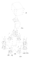
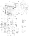
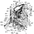
図1、図4に示す通り、洗浄装置100は、エノキタケ栽培袋をカバーする、上下方向の両端開口の直径が異なる筒状構造のカバー8を洗浄する装置である。洗浄装置100は、支持構造物1、この支持構造物1に設置された第1モータ5、第2モータ201、第3モータ406、第4モータ905、支持構造物1に順次配置された、カバー8を落下させる落下機構2、カバー8を水洗する洗浄機構3、カバー8をブラシで清掃する清掃機構4、カバー8を乾燥する乾燥機構7、この乾燥機構7の処理を終了したカバー8を収集し収容する収容機構9、落下機構2、洗浄機構3、及び清掃機構4を制御する制御部600を含む。洗浄機構3の汚水が清掃機構4の作業領域に跳ねないようにするため、洗浄機構3と清掃機構4の間に水除け板(図示略)が設置されている。水除け板には支柱が通る通路(図示略)が設けられている。
As shown in FIGS. 1 and 4, the
カバー8の回転サイクルを短縮するために、図1に示すように、清掃機構4と収容機構9の間に、乾燥機構7を設けて、カバー8の内外表面をそれぞれ乾燥している。洗浄効果をさらに高めるために、落下機構2と乾燥機構7の間に少なくとも2組の洗浄機構3と清掃機構4がある。反時計周りに、順に、落下機構2、洗浄機構3、清掃機構4、洗浄機構3、清掃機構4、乾燥機構7、乾燥機構7、収容機構9の順序で円周状に配置されている。
In order to shorten the rotation cycle of the
図4、図5に示すように、支持構造物1は、例えば、直方体状の支持構造物構造である。支持構造物1の上部領域には、第1モータ5、第2モータ201、第3モータ406、駆動力の伝動のために接続された分割器10が取り付けられている。
As shown in FIGS. 4 and 5, the
図4~図6に示すように、支持構造物1の下部には、回転部101が設けられており、回転部101は、分割器10の出力端に接続される。回転部101は、各機構2,3,4,7,9に対応する8つの支持架103と支持架103を支持する基部104が周設され、分割器10の出力軸10aが回転部101の中心に固定され、各支持架103が出力軸10aの周方向に均等に分布して配置されている。回転部101は、第1モータ5の駆動を受けて間欠的に反時計方向Rに回転することができる。各支持架103を各機構2,3,4,7,9の下に間欠的に回転させ、カバー8は各機構2,3,4,7,9を巡回しながら各処理を受けることができる。
As shown in FIGS. 4 to 6, a
図6に示すように、支持架103は、環状に分布した複数の棒を含み、各棒は、カバー8を包むように縦方向に配置され、カバー8は複数の棒で構成される空間内に支持され、カバー8の外面が各棒に当接することにより、カバー8の径方向への移動を防止することができる。支持架103の各棒はカバー8を包むのに適するように配置され、各棒の自由端は外側に折り曲げられたように構成されている。回転部101上には、図6に示すように、中央の円孔(図示略)と、回転部101の基部104に構築された通孔102とが設けられ、この通孔102には中央部の円孔102aとその径方向に沿って延びるいくつかの矩形孔102bが設けられている。矩形孔102bは、円孔102aの周囲に均等に配置された4つの孔である。
As shown in FIG. 6, the
図4に示すように、第1モータ5、第2モータ201、第4モータ905は、特に支持構造物1の上側領域に取り付けられ、回転力を出力することができる。第1モータ5の動力出力端子(図示略)には減速機6が接続されている。減速機6は、ウォーム歯車を採用し、図9、図10に示すように、その出力軸は減速機6の両側にそれぞれ突出した第1出力端子6aと第2出力端子6bを有する。図7に示すように、第1出力端子6aの出力は、チェーン伝達機構60を介して分割器10の軸i(図13参照)に連動して接続される。第2出力端子6bは、第1モータ5の動力を、チェーン伝達機構61を介して順に並べられた軸aに伝達し、軸aはチェーン伝達機構62を介して軸bに伝達し、軸a及び軸bは共に支持構造物1に回転可能に設けられている。
As shown in FIG. 4, the
支持構造物1には、軸bと直交配置された軸cが回転可能に設置され、軸cと軸bとの間に、傘歯車63が設けられている。図7、図8に示すように、支持構造物1には、軸aとチェーン伝達機構64で接続された軸dと、軸dとチェーン伝達機構65で接続された軸eとが設けられている。軸eは軸dの下に平行に配置されている。各軸a~iの間をチェーン式の伝達機構で接続する以外に、ベルト式の機構で接続することもできる。
The
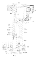
図9に示すように、落下機構2は、縦方向に積層されて束になった複数のカバー8を載置する落下支持部203を備えている。落下したカバー8は、支持架103上に1個ずつ載置することができる。図9に示すように、落下支持部203は、カバー8内に配設された落下支持柱203aと、落下支持柱203aの下に位置し、カバー8内に挿入される落下支持体205とを備えている。この落下支持体205は、カバー8が径方向に押されたときに、カバー8に対して半径方向の支持力を提供し、カバー8が偏らないようにしている。図9に示すように、加工・製造を容易にするために、落下支持体205は落下支持筒を採用している。複数の洗浄対象のカバー8を落下支持柱203aに積層するために、落下支持柱203aの上下運動を駆動する第2モータ201が支持構造物1に設けられている。この第2モータ201は、回転力を出力し、第2モータ201の動力出力軸に歯車(図示略)が固着され、落下支持柱203aには、その長手方向に配列された歯条部203bが形成されている。
As shown in FIG. 9, the
落下支持柱203aは、支持効果を高めるために、並列に2本が接続され、その1つの落下支持柱203aは、歯車(図示略)と噛合して接続され、図9に示すように、上下方向Zに移動可能であり、その高さ位置を調整可能である。落下支持柱203aは、積層されたカバー8を落下機構2にセットする際に、上下方向Zに移動させるが、落下動作時には、高さは固定状態である。第2モータ201の上下両端には、それぞれ、ストロークスイッチ202が設けられており、各ストロークスイッチ202に対応して、落下支持柱203aの両端にはそれぞれ対応するストロークスイッチ202との接触が可能な嵌合物202aが構成されている。図9に示すように、第2モータ201の上端のストロークスイッチ202と組み合わせるための嵌合物202aは、特に支持構造物1に設けられた嵌合板であり、第2モータ201の下端のストロークスイッチ202と嵌合するための嵌合板も設けられている。
Two
落下機構2は、図9に示すように、落下支持柱203aの下方に位置し、外力を受けて、2つの開閉板207を水平にX方向に移動させて、その間隔を開けることと、2つの開閉板207を水平にX方向の逆方向に移動させて、その間隔を閉じることにより、カバー8を開閉板207と落下支持体205で保持したり、解放する構成を含む。落下動作時には、落下支持体205の高さは固定されている。落下機構2は把持部204を含む。この把持部204は、2つの対向する把持板204aを含む。2つの把持板204aは、挟込板2042を含み、開閉板207が開いたときに、現在の落下待ちであるカバー8より上のカバー8を両側から落下支持体205の外表面に押圧力を加えて保持することで、このカバー8の上に積層された残りのカバー8を保持する。
As shown in FIG. 9, the
図12に示すように、突当部206は、対向して一対設けられ、上下方向に間欠的に往復動する、2つの突当206a,206bと、突当206aの下面に向けて垂直方向に延び出す突当ピン206c,206d,突当206bの下面に向けて垂直方向に延び出す突当ピン206e,206fを備えている。突当ピン206c,206fの上端は、それぞれ、各突当206a,206bの下面と当接する。この突当ピン206c,206d,206e,206fは、スプリングにピンが嵌装されたものである。突当ピン206d,206e,が、カバー8に突き当たることにより、カバー8が損傷することを防止するために、突き当て力を緩衝するスプリングが設けられている。突当ピン206c,206d,206e,206fは、挟込板2042に貫設されている。図12(b)に示すように、2つの開閉板207は、把持板204aが閉じた状態で、カバー8の挟み込みを解除する。図12(c)に示すように、2つの開閉板207が開いて、2つの把持板204aが閉じて把持板204aがカバー8を挟んでいるときに、突当206a,206bは、突当ピン206d,206eが落下支持柱203aから、落下待ちのカバー8を突き下げることができるように、突当ピン206c、206fに対し、下方への外力を加える。図9、図11に示すように、両突当部206は、それぞれ、対応側を通る突き当て端は、突当板2061に連結されている。
As shown in FIG. 12, a pair of
図10に示すように、支持構造物1には、落下支持柱203aの外側に設けられた、横断面がU字ないしコ字形状の覆い板2014が設けられており、把持部204と突当部206が移動するための開口2021が設けられている。把持部204、突当部206、及び開閉板207が受ける外力は、いずれも第1モータ5によって提供される。第1モータ5と、開閉板207、把持部204、及び突当部206の間には、それぞれ、開閉板伝動ユニット198、突当伝動ユニット199、及び把持部伝動ユニット200が設けられている。落下伝動ユニットは、開閉板伝動ユニット198、突当伝動ユニット199、及び把持部伝動ユニット200により構成されている。
As shown in FIG. 10, the
開閉板伝動ユニット198は、図9、図10に示すように、第1モータ5と連動する、溝を有する第1落下カム2012と、軸fと、一端が第1落下カム2012の溝にスライド付けされた第1落下駆動棒2010と、第1落下駆動棒2010の下端にヒンジ結合して設けられた第1落下ロッド208と、第1落下ロッド208と連結するスライド棒2020(図12参照)と、を備える。
9 and 10, the opening/closing
図9、図10に示すように、軸fが軸cの下に平行に位置し、第1落下駆動棒2010は、軸fに設けられている。第1落下ロッド208はスライド棒2020を介して支持ブロック2015bに連結されており、スライド棒2020は支持ブロック2015b内に設けられている。
As shown in FIGS. 9 and 10, the axis f is positioned below and parallel to the axis c, and the first
開閉板伝動ユニット198の駆動系統を説明する。図8、図9、図10等に示すように、第1モータ5の第2出力端子6bがチェーン伝達機構61を駆動させ、軸aを回転させ、チェーン伝達機構62を駆動させ、軸bを駆動させ、傘歯車63により軸cを回転させる。これに伴い、開閉板伝動ユニット198が駆動され、開閉板207を左右方向Xに往復運動させることができ、2つの開閉板207の相対的な閉じ又は開放を構成する動作を繰り返す。
A drive system of the opening/closing
図10、図11に示すように、突当伝動ユニット199は、第1モータ5と連動する、溝を有する第3落下カム2016と、一端が第3落下カム2016の溝にスライド付けされた第3落下駆動棒2017と、第3落下駆動棒2017の他端とヒンジを介して接続し、突当部206に連結する第3落下ロッド2018と、を備えている。図11に示すように、第3落下駆動棒2017は、軸gに設けられている。第3落下カム2016、第3落下駆動棒2017、軸g、第3落下ロッド2018とが連携して、突当部206を上下方向Zに上下動させる。
As shown in FIGS. 10 and 11, the
突当伝動ユニット199の駆動系統を説明する。図8、図9、図11等に示すように、第1モータ5の第2出力端子6bがチェーン伝達機構61を駆動させ、軸aを回転させ、チェーン伝達機構62を駆動させ、軸bを駆動させる。これに伴い、突当伝動ユニット199が駆動され、突当部206を上下方向Zに往復駆動させる動作を繰り返す。
A drive system of the
把持部伝動ユニット200の構造は、開閉板伝動ユニット198の構造と類似しており、把持部204を駆動するものである。
The structure of the
図10に示すように、把持部伝動ユニット200は、支持構造物1に設けられ、第1モータ5と連動する、溝を有する第2落下カム2013と、軸fと、一端を第2落下カム2013の溝にスライド付けされた第2落下ガイド2011と、第2落下ガイド2011と連結する第2落下ロッド209とを含む。
As shown in FIG. 10, the
図9及び図10に示すように、把持部204は、軸を摺動させる支持ブロック2015aと、第2落下ロッド209に接続された押板2041と、カバー8に当接し、落下支持体205との間でカバー8を挟む挟込板2042と、を含む。押板2041と挟込板2042との間は、スプリングにより弾性的に摺動させる。
As shown in FIGS. 9 and 10, the
把持部伝動ユニット200の駆動系統を説明する。図8、図9、図10等に示すように、第1モータ5の第2出力端子6bがチェーン伝達機構61を駆動させ、軸aを回転させ、チェーン伝達機構62を駆動させ、軸bを回転させ、傘歯車63を介して軸cを回転させる。これに伴い、把持部伝動ユニット200が駆動され、把持部204を左右方向Xに往復駆動させることができ、2つの把持部204間の相対的な閉状態又は開状態を構成する動作を繰り返す。
A drive system of the
図9、図10に示すように、覆い板2014には制御部600と電気的に接続された落下検出部2019が設けられている。落下検出部2019は、近接スイッチを採用している。落下検出部2019は、カバー8の両側に一対設けられ、制御部600は、落下検出部2019の検出信号に応答して、第1モータ5を制御し、開閉板207による開閉等のタイミングを制御することができる。
As shown in FIGS. 9 and 10, the
以上の通り、制御部600は、落下機構2の開閉板伝動ユニット198、突当伝動ユニット199、及び把持部伝動ユニット200のそれぞれの開閉板207、突当部206、及び把持部204の動作の制御を行うことで、カバー8の支持架103への落下動作を行う。
As described above, the
洗浄機構3は、図4、図5に示すように、外部水路から供給される水により、カバー8を洗浄するフラッシング部301を有している。カバー8に対する洗浄効果を高めるために、図4及び図5に示すように、洗浄機構3は、支持構造物1に設けられ、洗浄機構3の下に回動し停止した支持架103とカバー8に対して、フラッシング部301が洗浄水を噴射し、回転部101の駆動に同期して、噴射を停止する。これらの動作を繰り返す。
The
2つの清掃機構4の構成は同じであるが、両者は支持構造物1上の配置が異なるため、2番目の清掃機構4を例に挙げて図13及び図14を参照して、説明する。清掃機構4は、カバー8内に降下し、回転可能で、カバー8の内面を清掃する内部清掃部401と、カバー8の外面を清掃する外部清掃部402とを備える。内部清掃部401は、外部移動力を受けて内部清掃部401をカバー8内に入れることができ、その外周面がカバー8の内面に当接することができる。内部清掃部401は外部からの回転力によって駆動されるため、内部清掃部401はカバー8に対して回転することにより清掃ができる。外部清掃部402は、前後方向Yに加えられる外部の開閉力を受けて、開閉できる複数(ここでは一対)の外面掃除具を備えており、外面掃除具を閉じることで、カバー8を包む外面を構成する。
Although the two
図13、図14に示すように、内部清掃部401は、中心軸401bと、中心軸401bの下端部に取り付けられ円柱状のブラシである回転可能なブラシ部401aと、を設けたものである。第1モータ5と内部清掃部401との間に内部伝動ユニット400aが設けられ、内部伝動ユニット400aは第1モータ5の駆動を受けて内部清掃部401を駆動する。
As shown in FIGS. 13 and 14, the
図13、図14に示すように、内部伝動ユニット400aは、第1モータ5と伝動接続される軸aの一端に取り付けられる昇降用カム4090と、昇降用カム4090と連結し上下方向に往復動する内部清掃ロッド4010と、内部清掃ロッド4010に連結し上下方向に往復動し底面に中心軸401bが回転可能に取り付けられ、上面に第3モータ406が固定された取付ホルダ4011と、取付ホルダ4011を上下方向に案内する清掃スライドレール4013と、を備えている。取付ホルダ4011が支持構造物1に対して上下方向Zにガイドスライド動作を行う。これにより取付ホルダ4011と連結された内部清掃部401を上下方向Zに間欠的に上下駆動させる動作を繰り返す。
As shown in FIGS. 13 and 14, the
内部伝動ユニット400aの駆動系統を説明する。図8、図13、図14等に示すように、第1モータ5の第2出力端子6bがチェーン伝達機構61を駆動させ、軸aを回転させる。これに伴い、内部伝動ユニット400aが駆動され、内部清掃部401を上下方向Zに間欠的に上下駆動させることができる。
A drive system of the
図13に示すように、取付ホルダ4011の上面に伝動ベルト4014が設けられており、内部清掃部401が下降し、カバー8内で停止した後、第3モータ406により伝動ベルト4014を駆動させることで、中心軸401bを回転させ、ブラシ部401aを回転させる。
As shown in FIG. 13, a
清掃機構4は2つあり、図13、図14等に示すように、第3モータ406はそれぞれ伝動ベルト4014を介して各清掃機構4の各内部清掃部401に連動するように接続されている。ベルト駆動効果を高めるために、取付ホルダ4011には伝動ベルト4014の張力を調整するための増締め輪4015が設けられており、増締め輪4015の構造と取り付け方式は従来の技術と類似している。
There are two cleaning
外部清掃部402は、一対のアーチ状の部材が対向した構造であり、内側面にはブラシが設けられ、外部清掃部402が閉じた状態では円筒体を構成する。
The
図13及び図14に示すように、外部伝動ユニット400bは、外部清掃部402と第1モータ5の間にあり、清掃歯車403、清掃歯車403に噛合されスライド駆動する2つの清掃ラック404、清掃ロッド405、軸gに設けられ、一端は清掃カム408の溝にスライド結合され、その他端は清掃ロッド405にヒンジで結合されている駆動棒407、及び軸bに取り付けられている清掃カム408、を備えている。2対の清掃ラック404は、2つの外部清掃部402に1対ずつ接続されている。
13 and 14, the
図13、図14に示すように、2対の清掃ラック404は、各アーチ状の外部清掃部402に設けられた部材であり、清掃歯車403、清掃ロッド405、駆動棒407、及び清掃カム408の駆動によって、2つの外部清掃部402を同期させて左右方向Xにそれぞれスライドさせ、2つの外部清掃部402間の相対的な閉じ、又は開放を行う。外部清掃部402に、カバー8の清掃効果を高めるために、外部水路(図示略)に接続できる部材(図示略)を設置し、この部材(図示略)から放出される水でカバー8を洗浄してもよい。
As shown in FIGS. 13 and 14, two pairs of cleaning
外部伝動ユニット400bの駆動系統を説明する。図8、図13、図14等に示すように、第1モータ5の第2出力端子6bがチェーン伝達機構61を駆動させ、軸aを回転させ、チェーン伝達機構62を駆動させ、軸bを駆動させ、傘歯車63により軸cを回転させる。これに伴い、外部伝動ユニット400bが駆動され、最初の外部清掃部402を前後方向Yに往復駆動させ、2番目の外部清掃部402を左右方向Xに往復駆動させる動作を繰り返す。
A drive system of the
支持架103が清掃機構4の下方に回転し停止すると、内部清掃部401がカバー8の内部への進入を開始して停止し回転してブラシでカバー8の内面を清掃し、2つの外部清掃部402が相対的に閉じた状態となりブラシでカバー8の外面を清掃する。清掃が終了すると、内部清掃部401がカバー8の内部から離脱し、2つの外部清掃部402が相対的に開いた状態となり、これらの動作を繰り返す。
When the
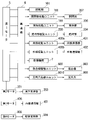
洗浄制御等を司る制御部600の一例を示す制御回路について図2を参照して説明する。この制御部600は、CPU601、RAM602、ROM603、カウンタ604、タイマ605、音声制御部606、入力部607、入出力インタフェース609、第1モータ5、第2モータ201、第3モータ406、第4モータ905、落下検出部2019、回動検出部906を、バス610により相互に接続したものである。CPU601が初期設定、或いは入力信号を受けて所定の演算等を行い、それらに対して、制御信号が第1モータ5、第2モータ201、第3モータ406、第4モータ905に送信されるようになっている。
A control circuit showing an example of the
CPU601は、各部に出力する制御信号を生成し、プログラム制御によって、制御信号を出力することで、制御を実行する。プログラム制御に代えて、LSIロジック等のハードウェア制御によっても実施が可能である。RAM602は、データを一時的に読み書きするものである。ROM603にプログラムが読み出し専用で格納されている。
The
カウンタ604は、支持爪908の退避回数を記録するカウント値Nを示す計数部等として機能するものであり、電源投入後、カウンタ604のカウント値Nの初期値を「0」、予め設定されたカウント閾値をMとし、各種入力信号を参照して、カウント値Nの増減を行うものである。
The
タイマ605は時間等に関する時間演算処理等を行なうものである。
A
音声制御部606は音源IC及び増幅器等から構成され、スピーカ等の駆動制御を司るものである。
A
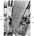
図15に示すように、乾燥機構7は、内部乾燥部701、外部乾燥部702、連結ホルダ703、送風管704を備えている。リング状のそれぞれの内部乾燥部701及び外部乾燥部702は、それぞれ、外部の風源(図示略)と接続されている。内部乾燥部701と外部乾燥部702は、内部に内部乾燥部701が挿入されるように、径方向に間隔をおいて配置され、外部乾燥部702は、カバー8の外部にセットされ、内部乾燥部701と外部乾燥部702には、それぞれ、カバー8を包む方向に設けられた吹出口701a、702aが設けられている。支持架103を乾燥機構7の下に移動することができ、乾燥機構7は、それぞれ、カバー8を内外から熱風乾燥させる。乾燥機構7はこれらの動作を繰り返す。
As shown in FIG. 15, the
内部乾燥部701の中央部には外部の風源(図示略)と接続する送風管704が設けられ、外部乾燥部702の外面には周方向間隔で配置され、外部の風源(図示略)と接続する送風インタフェース702bが設けられている。内部乾燥部701及び外部乾燥部702は、ともに連結ホルダ703を介して固着されている。この連結ホルダ703は、接続柱705を介して取付ホルダ4011と固着されている。これにより、乾燥機構7が取付ホルダ4011の上下スライドとともに支持架103から上方に離脱、又は支持架103に装着されるよう移動することができる。
An
図15に示すように、使用効果を高めるために、内部乾燥部701がガイドバー701bを介して連結ホルダ703に設けられている。ガイドバー701bには、連結ホルダ703との間に緩衝用のバネ701cが設けられている。乾燥機構7が取付ホルダ4011とともに下降するとき、内部乾燥部701と回転部101との間のハードコンタクトを効果的に防止し、内部乾燥部701の破損を防止できる。
As shown in FIG. 15, an
乾燥機構7の駆動系統を説明する。図15等に示すように、第1モータ5の第2出力端子6bがチェーン伝達機構61を駆動させ、軸aを回転させ、昇降用カム4090が回転し、内部清掃ロッド4010と取付ホルダ4011と連結ホルダ703が清掃スライドレール4013に沿って上下動し、乾燥機構7が間欠的な上下方向Zの上下駆動を繰り返す。
A drive system of the
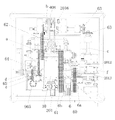
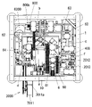
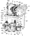
収容機構9は、図16~図18に示すように、カバー8を支持することができる収容支持部901と、収容支持部901の下方に設けられた収容部902と、支持架103上のカバー8を収容部902に突き上げる係合棒903及び係合爪9014と、軸dと係合棒903の間に設けられ係合棒903を上下に駆動する係合棒駆動ユニット900と、第1モータ5と支持爪908との間に設けられ支持爪908を駆動する支持爪伝動ユニット9010と、を備えている。収容支持部901と収容部902は一対が間隔を設けて設置される。収容支持部901は、回転部101の上方にある中空の支持柱901aを含み、支持柱901aは回転部101の上方に配置される。収容支持部901は、支持柱901aにセットされたカバー8を支持するように構成される。なお、片方の収容部902は内部構造の説明を行うため、その外殻の図示を省略している。
As shown in FIGS. 16 to 18, the
図16~図18に示すように、係合棒駆動ユニット900は、第1モータ5の駆動力を伝達する軸dと連結して回転するカム904と、リードブロック9015と、リードブロック9015に垂直に固定された板9016と、上端部がカム904に軸着され、下端部が板9016に軸9017で軸着するロッド907と、板9016に固定される複数の把手9018と、把手9018と係合するレール9019と、リードブロック9015に固定される垂直な棒901bと、垂直な棒に水平に固定され、係合棒903を垂直上方に固定する棒901cと、を備えている。図22等に示すように、複数の係合爪9014は、係合棒903の上端に固定されている。係合棒903と係合爪9014は回転部101の下方に設けられた通孔102を通過可能であり、係合棒903は通孔102の円孔102aに、係合爪9014は通孔102の矩形孔102bに対応して配置されている。
As shown in FIGS. 16 to 18, the engagement
図22に示すように、係合爪9014と支持爪908は、支持柱901aの周方向に交互に配置される。支持架103上にカバー8がある状態で、係合棒903と係合爪9014が外力を受けて通孔102を下から上に通過すると、支持架103上のカバー8を係合爪9014で片方の収容部902に突き上げる。これとともに、支持爪908を一旦退避させた後で突出させ、収容部902の切欠9025から突出させ、カバー8を収容部902に対して支持する。カバー8が支持爪908で支持されると、係合棒903及び係合爪9014は、通孔102を通って下に下がる。
As shown in FIG. 22, the engaging
係合棒903の駆動系統を説明する。図7、図8、図16~図18等に示すように、第1モータ5の第2出力端子6bがチェーン伝達機構61を駆動させ、軸aを回転させ、チェーン伝達機構64を駆動させ、軸dを駆動させ、カム904、ロッド907、リードブロック9015を駆動させ、棒901b、901cを介して、係合棒903を上下に駆動する。係合棒903が上昇するとき、係合爪9014は、通孔102を突き抜けることができ、カバー8を突き上げることができる。これにより、係合棒903が支持架103に載置されたカバー8を通孔102を介して突き上げて、支持架103から収容支持部901に押し上げることができる。次に係合棒903を下降させて、カバー8を支持する次の支持架103が収容機構9の下に来たら、次のカバー8を収容支持部901に収容する。係合棒903はこれらの動作を繰り返す。
A drive system for the
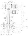
図17~図20に示すように、支持爪伝動ユニット9010は、それぞれの収容支持部901に設けられ、駆動源は第1モータ5である。支持爪伝動ユニット9010は、第1モータ5と連動する、凸部909aを有し、軸hに固定された回転カム909、第4モータ905の下方で支持構造物1に固定された固定カム9012と、支持柱901aの内部中空に挿入された、左右一対の2本の収容支持棒9011と、収容支持棒9011の上部にセットされ回転カム909、固定カム9012に当接する左右一対の駆動輪9020(図19参照)と、収容支持棒9011の下端を貫通させ支持爪908とヒンジ9013bで結合する連結体9013aと、を備えている。第1モータ5の駆動を受けて回転カム909が回転し、駆動輪9020が回転カム909の凸部909aを走行する際に、回転部101の上にある収容支持部901の収容支持棒9011が間欠的に上下方向Zに繰り返し駆動される。当然、回転部101の外にある収容支持棒9011は、駆動されない。
As shown in FIGS. 17 to 20, the support
図22に示すように、支持柱901aの周方向間隔に設けられた複数の支持爪908を有し、各支持爪908には支持端9081が設けられる。各支持爪908は、収容支持棒9011によって、それぞれの支持端9081を退避又は突出させ、カバー8の保持状態を形成又は解除するように構成される。
As shown in FIG. 22, a plurality of
図22等に示すように、支持爪908は、連結体9013aによって、接続されている。また、収容支持棒9011の底部が、連結体9013cによって、支持爪908に接続されている。連結体9013cには支持爪908のピン9027をスライド方向Jにスライド可能に移動させるスライド溝9013dが設けられている。図22には支持爪908が突出した状態が示されている。収容支持棒9011が上方向へ駆動されると、連結体9013cが上方へ移動し、スライド溝9013dに対してピン9027が移動し、スライド方向Jの内側にスライドすることで、支持端9081がD方向に回動し、支持爪908が退避状態となる。このように、支持爪908は支持柱901aに対して回動方向Dに退避又は突出できる。各支持爪908と、係合爪9014は、収容部902に対して、周方向に交互に配置されている。
As shown in FIG. 22, etc., the
支持爪908の駆動系統を説明する。図7、図8、図16等に示すように、第1モータ5の第2出力端子6bがチェーン伝達機構61を駆動させ、軸aを回転させ、チェーン伝達機構62を駆動させ、軸bを回転させ、チェーン伝達機構64を駆動させ、軸dを駆動させ、チェーン伝達機構65を駆動させ、軸eを駆動させ、傘歯車9030を回転させる。図16に示すように、軸eと傘歯車9030を介して軸hを回転することにより、回転カム909を回転させる。回転カム909の回転に伴い、回転部101の上にある収容支持部901の支持爪伝動ユニット9010が駆動されて、収容支持棒9011を上下方向Zに上下駆動し、支持爪908を退避又は突出させる。この動作を繰り返す。支持爪908は、係合棒903に同期して駆動し、カバー8が支持架103から円滑に収容支持部901上に移動し収容されるように協働する。
A drive system for the
第4モータ905は、図16に示すように、支持構造物1に設けられ、第4モータ905の動力出力軸は接続板9021に固定され、接続板9021の両端部に収容支持部901が2つ設けられ、収容支持部901が下方に延び出している。収容支持部901が水平面内で間欠的に半回転する。これにより、既満タンの収容支持部901と、新たに満タンとなった収容支持部901とが回動方向Hに回転されて、互いの位置が交換される。回動検出部906が、支持構造物1に設けられ、2つの収容支持部901が接続板9021に従って回動方向Hに半回転し、検出片906aと接触した状態のときに、収容支持部901が回転部101の上に位置することを検出し、検出片906aが回動検出部906から離脱するとき、収容支持部901が回転部101の外に位置することを検出する。
As shown in FIG. 16, the
支持柱901aの水平回転の駆動系統を説明する。第4モータ905が駆動すると、接続板9021と支持柱901aが半回転し、停止し、この動作を繰り返す。
A drive system for horizontal rotation of the
収容機構9の動作を説明する。図4、図5等に示すように、積層されたカバー8は、支持端9081で下端を支持された状態である。支持架103に支持されたカバー8が収容機構9の下に来ると、係合棒903と係合爪9014が下方から通孔102を通過して、係合爪9014がカバー8の下端を支持しながら収容部902まで上昇させて、積層されたカバー全体を上げて、新たなカバー8を底に追加し、カバー8が収容支持部901上に収納され、収納が完了する。この動作を繰り返して、支持架103のカバー8を収容部902に追加してゆく。
The operation of the
制御部600は、支持爪908の退避回数を記録するカウンタ604を有し、カウンタ604のカウント値Nが予め設定されたカウント閾値Mに達することで、カバー8の所定個数が収容され満タンと判定し、第4モータ905を駆動し停止させる。これにより、新たに所定数のカバー8が収容され満タンとなった収容支持部901が、接続板9021により回動方向Hに半回転し、空の収容支持部901と、180度、位置が切り替わる。前記の新たに満タンとなった収容支持部901は、回転部101の外に位置する。このとき、収容支持部901における固定カム9012の凸部9012aが駆動輪9020の下部に当接して、収容支持棒9011が上昇し、各支持爪908を退避状態とさせることで、すべてのカバー8が落下し、この収容支持部901はカバー8が空の状態となる。落下したカバー8をかご等で受け止めることにより、洗浄されたカバー8を積層した状態で得ることができる。収容支持部901の回動検出部906の検出によってカバー8の落下を検出し、落下したカバー8の個数を記録する。このように同様の動作が繰り返し行われる。
The
洗浄装置100の全体の動作を説明する。落下機構2では、カバー8が支持架103に落下する。この支持架103は洗浄機構3の下に移動し、停止し、カバー8は水で洗浄される。この支持架103は清掃機構4の下に移動し、停止し、内部清掃部401と外部清掃部402によるカバー8の清掃が行われる。この支持架103は2番目の洗浄機構3の下に移動し、停止し、カバー8は水で洗浄される。この支持架103は2番目の清掃機構4の下に移動し、停止し、内部清掃部401と外部清掃部402によるカバー8の清掃が行われる。この支持架103は乾燥機構7の下に移動し、停止し、カバー8の乾燥が行われる。この支持架103は2番目の乾燥機構7の下に移動し、停止し、カバー8の乾燥が行われる。この支持架103は収容機構9の一部の下に移動し、停止し、収容機構9の働きにより、積層した状態のカバー8を、収容機構9の下方に落下させる。上記の工程はカバー8について、連続的に繰り返し行われる。
The overall operation of the
以上の全体的な説明に基づいて、洗浄装置100は、順次配置され、各機構同士が同期して動作する落下機構2、洗浄機構3、清掃機構4、乾燥機構7、及び収容機構9を設置することにより、洗浄後のカバー8の収容過程まで全て自動化される。カバー8の洗浄効率を大幅に向上させることができる。2個の清掃機構と2個の洗浄機構を設置することにより、カバー8に対する清掃効率が向上する。
Based on the overall description above, the
本発明第2実施形態の洗浄装置1000について図23及び24を参照して説明する。洗浄装置1000は、第1実施形態の洗浄装置100の収容機構9を変更し、収容機構1009とし、固定式のシュータ11と、整理機構12と、収容バスケット13と、をさらに備えたものである。第1実施形態と同一の部品には同一番号を付してその説明を援用し、主に相違点を説明する。収容機構1009から放出されるカバー8を、シュータ11を介して整理機構12へ受け渡し、整理機構12で整理された複数のカバー8は収容バスケット13に収容される。
A cleaning apparatus 1000 according to a second embodiment of the present invention will be described with reference to FIGS. 23 and 24. FIG. The cleaning apparatus 1000 is a
収容機構1009は、支持爪伝動ユニット9010、収容支持棒9011等に代えて、カバー8を回転部101の外側に放出する放出機構1009aを有する。放出機構1009aは、係合棒903により突き上げられたカバー8を回転部101の外側に位置するシュータ11に向けて放出し、受け渡すものであり、長手方向が弓なりに湾曲した板である湾曲板1009bと、湾曲板1009bの湾曲した一対の辺から湾曲の内側方向に延出するように平行に配置された一対のガイド板1009cと、を有する。放出機構1009aは、係合棒903の上方において、シュータ11と対向するように配置されている。湾曲板1009bは、係合棒903により突き上げられたカバー8を、湾曲板1009bの湾曲した面に沿って傾かせ、カバー8の上部がシュータ11の方向に向いた状態で放出することができる。ガイド板1009cは、カバー8を放出する際に、カバー8がシュータ11の上に放出されるように誘導するためのものである。
The
収容機構1009の動作を説明する。図24(a)~(d)に示す通り、支持架103に支持されたカバー8が収容機構1009の下に来ると、係合棒903が、カバー8を突き上げる。その後、突き上げられたカバー8を湾曲板1009bにより傾かせ、カバー8の上部がシュータ11の方向に向いた状態で、カバー8をシュータ11に放出する。
The operation of the
シュータ11は、放出機構1009aの正面の下方に位置し、収容機構1009側から整理機構12側に向かって下方に傾斜した状態で整理機構12に固定されており、放出機構1009aから放出されるカバー8を整理機構12へ受け渡すことができる。
The
整理機構12は、シュータ11から受け渡されたカバー8を整理するものであり、コンベア12aと、コンベア12aを駆動させる第5モータ12bと、カバー8を整理する整理部12cと、スライド機構12dと、架台12eと、を有している。コンベア12aは、図23に示す通り、架台12eの上部に配置されており、シュータ11から離れる方向であるY方向にカバー8を搬送する。整理部12cは、コンベア12aの搬送方向に沿ってコンベア12a側部の上側に設けられた一対の側壁12fと、一対の側壁12fのコンベア12aの下流側の端部を繋ぎ、コンベア12aによって運ばれるカバー8を受け止めるように配置された受け部材12gと、コンベア12aの側方に配置され、軸に偏心輪が取り付けられた第6モータ12hと、を含む構成である。スライド機構12dは、図1に示す通り、整理部12cを左右方向であるX方向に移動させるものであり、DC(Direct current)電動プッシュロッド等を採用可能である。
The arranging
整理機構12の動作を説明する。図23に示す通り、コンベア12aが、シュータ11から受け渡されたカバー8を整理部12cに搬送し、受け部材12gが搬送されたカバー8を、カバー8の上部がコンベア12aの搬送方向に向いて倒れた状態で受け止める。別のカバー8が搬送されると、第6モータ12hの偏心輪が打撃を与えることによってコンベア12aのベルトを振動させるため、受け部材12gによって受け止められたカバー8の下部に、別のカバー8の上部が被さり、受け止められたカバー8に別のカバー8が積層される。受け部材12gに積層された状態で受け止められたカバー8の数が所定の数に達した場合には、コンベア12a及び第6モータ12hの駆動を停止し、スライド機構12dにより、受け止めたカバー8を伴って整理部12cが左右方向に移動し、整理部12cが受け止めた複数のカバー8がコンベア12aの側方で落下する。落下した複数のカバー8は、整理機構12の側方に配置された収容バスケット13に収容される。
The operation of the
洗浄装置1000は、収容機構1009と、シュータ11と、整理機構12と、収容バスケット13と、を備えることにより、カバー8の整理及び収容の機構を洗浄装置100よりも簡素化することができる。
The cleaning device 1000 can simplify the mechanism for arranging and storing the
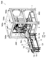
本発明第3実施形態の洗浄装置7000について図25~図44を参照して説明する。洗浄装置7000は、第2実施形態の洗浄装置1000の落下機構2と、洗浄機構3と、乾燥機構7と収容機構1009と、シュータ11とを変更し、落下機構7002と、洗浄機構7003と、乾燥機構7007と、収容機構7009とシュータ7011としたものである。洗浄装置7000は、カバー8の乾燥性能を高めるために、複数(本実施形態においては2つ)の乾燥機構7007を有している。第1実施形態又は第2実施形態と同一の部品には同一番号を付してその説明を援用し、主に相違点を説明する。図26~28に示す通り、洗浄装置7000の上部には、複数の吊上部7000aを有しており、クレーン等により洗浄装置7000を上方に吊り上げることができる。
A
図28、図40及び41の手書サークルP1~P3に示す通り、落下機構7002は、落下機構2の突当ピン206c~206fを、正面視で略J字状の弾性フック7206に変更したものである。これにより、カバー8の支持架103への落下をより安定なものとすることができる。
As shown in handwritten circles P 1 to P 3 in FIGS. 28, 40 and 41, the
図27、図28、図31及び図33~図36等に示す通り、洗浄機構7003のフラッシング部301にシャワーヘッド7003aを備える。ノズルを用いてフラッシング部301からカバー8に向けて洗浄水を噴射する場合には、噴水範囲と噴水量が大きすぎて制御できない場合があり、その場合にはシャワーヘッドとすることが便利である。
As shown in FIGS. 27, 28, 31, 33 to 36, etc., the
図26~図28に示す通り、洗浄装置7000は、回転部101の下方に、水を貯留する水槽8000と、水槽8000内に貯留する水を洗浄機構7003に供給する水中ポンプ6000と、を備えている。水中ポンプ6000は、水槽8000内に配置されている。水槽8000は、洗浄機構7003のフラッシングに使用する水を貯留することができる。水槽8000内に配置される水中ポンプ6000を使用することにより、水槽の外部に設置する増圧ポンプを使用する場合と比較して、洗浄装置7000の敷地面積を減少させることができる。
As shown in FIGS. 26 to 28, the
図31~図33、図35、図37、図38、図42及び図43等に示す通り、乾燥機構7007は、内部乾燥部7701と、外部乾燥部7702と、排気口800aから空気を供給するファン800と、を備えている。内部乾燥部7701は、清掃機構4の内部清掃部401に送風機能を追加したものであり、中心軸401bとブラシ部401aとに代えて、中心軸7701aとブラシ部7701bを有する。中心軸7701aは、空気が通過可能な流路7701cを内部に有し、流路7701cへ空気を供給可能な送風インタフェース7701dが上側先端部近傍に設けたものである。ブラシ部7701bは、中心軸7701aの流路7701cと連通する空気が通過可能な流路7701eを内部に有し、流路7701eと連通し、空気を吹き出す通気孔7701fを表面に設けたものである。送風インタフェース7701dとファン800の排気口800aとを接続することにより、通気孔7701fから空気を吹き出すことができる。ブラシ部7701bがカバー8内に位置する際には、ブラシ部7701bの回転により、カバー8の内壁に付着した水滴を飛ばし、通気孔7701fから吹き出す空気によりカバー8の内部を乾燥させることができる。
As shown in FIGS. 31 to 33, 35, 37, 38, 42 and 43, etc., the
外部乾燥部7702は、清掃機構4の外部清掃部402に送風機能を追加したものであり、外部清掃部402に送風インタフェース7702aを設け、図42の手書きサークルSに示す内側上部に下方向に空気を吹き出す通気口7702bを配設した構成である。外部乾燥部7702が閉じてカバー8の外側を包んだ際に、通気口7702bから吹き出す空気及び内側に設けられたブラシによりカバー8の外部を乾燥させることができる。
The
ファン800は、排気口800aと吸気口800bを有し、排気口800aから空気を供給するものである。排気口800aは複数であってもよく、排気口800aの向きは、異なる方向とすることができるため、1つのファン800から複数の箇所に空気を供給することができる。
The
図30、図34~図36及び図39等に示す通り、収容機構7009は、支持爪伝動ユニット9010、収容支持棒9011等に代えて、カバー8を回転部101の外側に向けて放出する放出機構5000を有する。放出機構5000は、落下支持体205と同様の構造であり、先端部に球状体5001が固定された垂直な棒5002が、板9016に固定された水平な板5003に接続部材5004を介して固定されている。そのため、図30に示す通り、放出機構5000は、上下方向であるZ方向に移動する。放出機構5000は、下方向に移動し、カバー8内に球状体5001を嵌入し、その後に上方向に移動することにより、カバー8を把持しながら、一体的に持ち上げることができる。放出機構5000が、頂点に達したならば、その下に、シュータ7011が移動し、カバー8がコ字状の板部材5005に接触して球状体5001から離脱し、シュータ7011に放出される(図39(a)~(c)参照)。板部材5005がコ字状であるため、上方向に移動した棒5002及び接続部材5004とは接触しない。本実施形態においては、放出機構5000の先端部には、球状体5001が固定されているが、カバー8を把持し、一体的に持ち上げることが可能な形状なものであれば採用可能である。例えば、楕円体、略洋梨型等の形状が挙げられる。
As shown in FIGS. 30, 34 to 36, 39, etc., the
放出機構5000の駆動系統を説明する。図29、図30、図32及び図34~図36等に示すように、第1モータ5の第2出力端子6bがチェーン伝達機構61を駆動させ、軸aを回転させ、チェーン伝達機構64を駆動させ、軸dを駆動させ、カム904、ロッド907、板9016を駆動させることにより、板9016に固定された放出機構5000が上下方向に駆動する。
A drive system of the
図30及び図34~図36等に示す通り、シュータ7011は、収容機構7009から放出されるカバー8を受け取り、前後方向であるY方向にスライド運動を行い、整理機構12にカバー8を受け渡すものである。シュータ7011は、段部7011aを有し、収容機構7009側から整理機構12側に向かって下方に傾斜しているため、受け取ったカバー8を、段部7011aにより、上部が整理機構12側に向いて倒れた状態で整理機構12に向かって移動させることができる。収容機構7009からカバー8が放出され、シュータ7011が受け取る際には、シュータ7011は、放出機構5000の下に位置する。カバー8を受け取った後は、カバー8を整理機構12に受け渡すために、整理機構12側に移動する。
As shown in FIGS. 30 and 34 to 36, the
シュータ7011の駆動系統を説明する。図30及び図34~図36等に示すように、シュータ7011は駆動機構3000を介して、放出機構5000と同期して駆動する。放出機構5000の板5003がチェーン伝達機構3001と固着しているため、板5003の上下の駆動によりチェーン伝達機構3001を駆動し、スプロケット3002を駆動させ、チェーン伝達機構3003を駆動させることにより、図30に示す通り、チェーン伝達機構3003と固着するシュータ7011が前後方向であるY方向に駆動する。
The drive system of the
収容機構7009及びシュータ7011の動作を説明する。図39(a)~(c)に示す通り、支持架103に支持されたカバー8が収容機構7009の下に来ると、放出機構5000が、カバー8を把持する。その後、放出機構5000がカバー8を一体的に持ち上げ、放出機構5000の下に移動したシュータ7011にカバー8を放出する。その後、シュータ7011が整理機構12側に向かって移動し、カバー8を整理機構12に受け渡し、放出機構5000が下方向に移動し、次のカバー8を把持する。収容機構7009及びシュータ7011は同様の動作を繰り返す。
Operations of the
洗浄装置7000は、落下機構7002と、洗浄機構7003と、乾燥機構7007と、収容機構7009と、シュータ7011とを備えることにより、カバー8の支持架103への落下をより安定させること、洗浄水の制御をすること、カバー8を効率的に乾燥させること、収容機構7009から整理機構12へのカバー8の受け渡しをより安定させることができる。
The
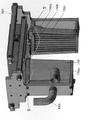
落下機構7002の変形例である落下機構7002aを、図44を参照して説明する。落下機構7002aは、挟込板2042の下部に略半円弧状の挟込部材7042を有し、落下支持部203及び覆い板2014と、に替えて、カバー8を積層した状態で収容する筒部7014を有している。落下機構7002では、落下機構2の突当ピン206c~206fを、正面視で略J字状の弾性フック7206に変更したが、落下機構7002aでは、突当ピン206d、206eを、先端部が略円弧状である突下部材7206aに変更した。挟込部材7042は、挟込板2042が閉じた際に、筒部7014に収容されたカバー8のうちの下から2番目のカバー8の上部近傍において略全周に渡って当接し、支持力を与える。突下部材7206aは、その先端部の形状が略円弧状であり、弾性フック7206と比較して、カバー8と当接する面積が大きいため、カバー8の突き下げをより安定させることができる。筒部7014は、挟込板2042と、内部に収容したカバー8と、の当接を可能にする切欠部7014aを有している。落下機構7002aは、挟込板2042と挟込部材7042とにより、落下支持部203なしに、筒部7014に収容されたカバー8を支持することができるため、上部から筒部7014に収納されるカバー8を追加することができる。
図44(a)~(d)を参照して落下機構7002aの動作を説明する。図44(a)に示す通り、開閉板207の上部に載置され、積層された状態で筒部7014にカバー8が収納されている。図44(b)に示す通り、挟込板2042及び挟込部材7042が閉じてカバー8を支持し、開閉板207が開く。図44(c)に示す通り、突下部材7206aが下方に移動することにより、一番下に収容された落下待ちのカバー8が突き下げられて落下し、支持架103に載置される。図44(d)に示す通り、一番下に収容されたカバー8が落下した後は、突下部材7206aが上方に移動し、開閉板207が閉じる。その後、挟込板2042及び挟込部材7042が開き、カバー8が開閉板207の上部に載置され、積層されて筒部7014に収容された状態に戻る(図44(a))。この一連の動作を繰り返すことにより、落下機構7002aに収容されたカバー8を1つずつ支持架103に載置することができる。
The operation of the
落下機構7002aを採用することにより、より安定してカバー8を支持架103に載置することができる。落下機構7002aは、筒部7014の上部からカバー8を追加することができ、落下機構7002aにカバー8を追加する際に、洗浄装置7000の動作を停止させる必要がないため、カバー8の洗浄効率を向上させることができる。
By adopting the
以上述べたのは本発明の好ましい実施形態にすぎないので、本発明を限定する必要はなく、本発明の精神と原則の中で行ったいかなる修正、均等、置換、改善等も、本発明の保護範囲に含まれるべきである。 The above descriptions are only preferred embodiments of the present invention, which should not be construed as limiting the present invention, and any modifications, equivalents, substitutions, improvements, etc. made within the spirit and principle of the present invention may be incorporated into the scope of the present invention. should be included in the scope of protection.
筒状容器の洗浄装置を各種産業に提供することで、筒状容器の洗浄、清掃、乾燥の作業効率の向上を図ることができ、産業上の利用価値は大である。 By providing the cylindrical container cleaning apparatus to various industries, it is possible to improve the work efficiency of cleaning, cleaning, and drying of the cylindrical container, and the industrial utility value is great.
1 支持構造物
2,7002,7002a 落下機構
3,7003 洗浄機構
4 清掃機構
5 第1モータ
6 減速機
6a 第1出力端子
6b 第2出力端子
7,7007 乾燥機構
8 カバー(筒状容器)
9,1009,7009 収容機構
10 分割器
10a 出力軸
11,7011 シュータ
12 整理機構
12a コンベア
12b 第5モータ
12c 整理部
12d スライド機構
12e 架台
12f 側壁
12g 受け部材
12h 第6モータ
13 収容バスケット
60,61,62,64,65 チェーン伝達機構
63 傘歯車
100,1000,7000 洗浄装置
101 回転部
102 通孔
102a 円孔
102b 矩形孔
103 支持架
104 基部
198 開閉板伝動ユニット(落下伝動ユニット)
199 突当伝動ユニット(落下伝動ユニット)
200 把持部伝動ユニット(落下伝動ユニット)
201 第2モータ
202 ストロークスイッチ
202a 嵌合物
203 落下支持部
203a 落下支持柱
203b 歯条部
204 把持部
204a 把持板
205 落下支持体
206 突当部
206a,206b 突当
206c,206d,206e,206f 突当ピン
207 開閉板
208 第1落下ロッド
209 第2落下ロッド
301 フラッシング部
400a 内部伝動ユニット
400b 外部伝動ユニット
401 内部清掃部
401a ブラシ部(内部清掃部材)
401b 中心軸
402 外部清掃部(外部清掃部材)
402b スライド棒
403 清掃歯車
404 清掃ラック
405 清掃ロッド
406 第3モータ
407 駆動棒
408 清掃カム
600 制御部
601 CPU
602 RAM
603 ROM
604 カウンタ
605 タイマ
606 音声制御部
607 入力部
609 入出力インタフェース
610 バス
701 内部乾燥部
701a、702a 吹出口
701b ガイドバー
701c バネ
702 外部乾燥部
702b 送風インタフェース
703 連結ホルダ
704 送風管
705 接続柱
800 ファン
800a 排気口
800b 吸気口
900 係合棒駆動ユニット
901 収容支持部
901a 支持柱
901b 棒
901c 棒
902 収容部
903 係合棒(係合部)
904 カム
905 第4モータ
906 回動検出部
906a 検出片
907 ロッド
908 支持爪
909 回転カム
909a 凸部
1009a,5000 放出機構
1009b 湾曲板
1009c ガイド板
2010 第1落下駆動棒(第1落下アクチュエータ)
2011 第2落下ガイド
2012 第1落下カム
2013 第2落下カム
2014 覆い板
2015a 支持ブロック
2015b 支持ブロック
2016 第3落下カム
2017 第3落下駆動棒
2018 第3落下ロッド
2019 落下検出部
2020 スライド棒
2021 開口
2041 押板
2042 挟込板
2061 突当板
3000 駆動機構
3001,3003 チェーン伝達機構
3002 スプロケット
4010 内部清掃ロッド
4011 取付ホルダ
4013 清掃スライドレール
4014 伝動ベルト
4015 増締め輪
4090 昇降用カム
5001 球状体
5002 棒
5003 板
5004 接続部材
5005 板部材
6000 水中ポンプ
7000a 吊上部
7014 筒部
7014a 切欠部
7206 弾性フック
7206a 突下部材
7042 挟込部材
7701 内部乾燥部
7701a 中心軸
7701b ブラシ部
7701c 流路
7701d 送風インタフェース
7701e 流路
7701f 通気孔
7702 外部乾燥部
7702a 送風インタフェース
7702b 通気口
8000 水槽
9010 支持爪伝動ユニット
9011 収容支持棒
9012 固定カム
9012a 凸部
9013a 連結体
9013b ヒンジ
9013c 連結体
9013d スライド溝
9014 係合爪(係合部材)
9015 リードブロック
9016 板
9017 軸
9018 把手
9019 レール
9020 駆動輪
9021 接続板
9025 切欠
9027 ピン
9030 傘歯車
9081 支持端
a,b,c,d,e,f,g,h,i 軸
D,G,H 回動方向
J スライド方向
M カウント閾値
N カウント値
P1~P3、S 手書サークル
R 反時計方向
X 左右方向
Y 前後方向
Z 上下方向
1 support structure
2, 7002, 7002a drop mechanism
3, 7003 cleaning mechanism
4 cleaning mechanism
5 1st motor
6 Reducer
6a First output terminal
6b 2nd output terminal
7, 7007 drying mechanism
8 Cover (cylindrical container)
9, 1009, 7009 containment mechanism
10 divider
10a output shaft
11, 7011 Shooter
12 Organizing mechanism
12a Conveyor
12b 5th motor
12c Sorting Department
12d slide mechanism
12e Mounting frame
12f side wall
12g receiving member
12h 6th motor
13 containment basket
60, 61, 62, 64, 65 Chain transmission mechanism
63 bevel gear
100, 1000, 7000 Washer
101 rotating parts
102 through hole
102a circular hole
102b rectangular hole
103 support frame
104 base
198 Opening/Closing Plate Transmission Unit (Drop Transmission Unit)
199 Strike Transmission Unit (Drop Transmission Unit)
200 Grip transmission unit (Drop transmission unit)
201 Second motor
202 stroke switch
202a fitting
203 drop support
203a Drop Support Pole
203b Toothed portion
204 Grip
204a Grip plate
205 Drop support
206 Abutment
206a, 206b butt
206c, 206d, 206e, 206f Abutment pin
207 Door
208 1st drop rod
209 2nd drop rod
301 Flushing section
400a internal transmission unit
400b External transmission unit
401 Internal cleaning section
401a brush part (internal cleaning member)
401b central axis
402 External cleaning part (external cleaning member)
402b Slide Bar
403 Cleaning Gear
404 cleaning rack
405 Cleaning Rod
406 3rd motor
407 Drive Rod
408 cleaning cam
600 control unit
601 CPUs
602 RAM
603 ROMs
604 Counter
605 Timer
606 Audio Control Unit
607 Input section
609 input/output interface
610 Bus
701 Internal drying section
701a, 702a outlet
701b Guide bar
701c Spring
702 External drying section
702b Air Blower Interface
703 Connection holder
704 Air Duct
705 Connection Pole
800 fans
800a exhaust port
800b air intake
900 Engagement rod drive unit
901 Containment Support
901a Support column
901b Bar
901c bar
902 Containment Unit
903 Engagement bar (engagement part)
904 Cam
905 4th motor
906 Rotation detector
906a detection piece
907 Rod
908 Support Claw
909 Rotating Cam
909a Convex part
1009a, 5000 release mechanism
1009b curved plate
1009c guide plate
2010 First drop drive rod (first drop actuator)
2011 2nd drop guide
2012 1st drop cam
2013 2nd drop cam
2014 cover plate
2015a support block
2015b support block
2016 3rd drop cam
2017 3rd drop drive rod
2018 3rd falling rod
2019 Fall detector
2020 slide bar
2021 opening
2041 push plate
2042 Clamping plate
2061 butt plate
3000 drive mechanism
3001, 3003 chain transmission mechanism
3002 Sprocket
4010 Internal cleaning rod
4011 Mounting holder
4013 cleaning slide rail
4014 Transmission belt
4015 Tightening ring
4090 Lifting cam
5001 spherical body
5002 bar
5003 Board
5004 connecting member
5005 Plate material
6000 submersible pump
7000a lifting part
7014 Cylinder
7014a Notch
7206 elastic hook
7206a Projecting member
7042 Clamping member
7701 Internal drying section
7701a central shaft
7701b Brush part
7701c Flow path
7701d Air Blower Interface
7701e Channel
7701f vent
7702 External drying section
7702a Air Blower Interface
7702b Vent
8000 aquarium
9010 Support claw transmission unit
9011 Accommodating support bar
9012 Fixed cam
9012a Convex part
9013a Connectors
9013b Hinge
9013c Concatenation
9013d slide groove
9014 Engagement pawl (engagement member)
9015 Lead Block
9016 board
9017 axis
9018 Handle
9019 rail
9020 drive wheel
9021 Connection plate
9025 Notch
9027 pin
9030 bevel gear
9081 support end
a, b, c, d, e, f, g, h, i axes D, G, H rotating direction J sliding direction M count threshold value N count values P 1 to P 3 , S handwriting circle R counterclockwise direction X Left-right direction Y Front-back direction Z Up-down direction
Claims (19)
前記支持構造物に順次配置された落下機構、洗浄機構、清掃機構、及び収容機構を含み、
前記支持構造物には、複数の支持架と通孔を有する回転部が設けられ、前記駆動源の駆動を受けて前記回転部が間欠的に回動し、前記支持架が前記落下機構、洗浄機構、清掃機構、及び収容機構の上側の一部または全部、のそれぞれの下に停止しながら、巡回するように構成され、
前記落下機構は、積み重なって配置された複数の筒状容器(有底のものを除く。)を載せることができる落下支持部と、前記筒状容器を前記支持架に個別に落下させることができる落下伝動ユニットとを含み、
前記洗浄機構は、外部の水路と接続され、前記筒状容器をフラッシングするためのフラッシング部を有し、
前記清掃機構は、前記筒状容器の中に入れて、回転可能にして、内面を洗浄する内部清掃部と、前記筒状容器の外側を放射状に包むことができる外部清掃部を含むことを特徴とする筒状容器の洗浄装置。 A control unit, a support structure, and a drive source provided in the support structure,
a dropping mechanism, a cleaning mechanism, a cleaning mechanism, and a storage mechanism sequentially arranged on the support structure;
The support structure is provided with a plurality of support racks and a rotating portion having a through hole, and the rotating portion is intermittently rotated by being driven by the drive source, and the support rack is connected to the dropping mechanism and the washing mechanism. configured to cycle while stopping under each of the mechanism, the cleaning mechanism, and part or all of the upper side of the containment mechanism;
The drop mechanism includes a drop support section on which a plurality of stacked cylindrical containers (excluding those with bottoms) can be placed, and a cylindrical container that can be individually dropped onto the support rack. a drop transmission unit;
The washing mechanism is connected to an external water channel and has a flushing part for flushing the cylindrical container,
The cleaning mechanism includes an internal cleaning part that is put into the cylindrical container and made rotatable to clean the inner surface, and an external cleaning part that can radially wrap the outer surface of the cylindrical container. A washing device for cylindrical containers.
前記乾燥機構が外力によって駆動されて前記支持架に移動し、前記筒状容器の内外をそれぞれ乾かすことができる内部乾燥部と外部乾燥部が設けられている請求項1に記載の筒状容器の洗浄装置。 a drying mechanism is provided between the cleaning mechanism and the containment mechanism on the support structure;
2. A cylindrical container according to claim 1, wherein said drying mechanism is driven by an external force to move to said support frame, and is provided with an internal drying section and an external drying section capable of drying the inside and outside of said cylindrical container, respectively. cleaning equipment.
前記内部乾燥部材は、外部移動力によって、前記筒状容器の内壁に突き当たるように前記筒状容器内に取り込まれ、外部からの回転力によって前記筒状容器に対して回転でき、前記通気孔から前記筒状容器の内壁に空気を吹きかけるように構成され、
前記外部乾燥部が、下方向に空気を吹き出す通気口が内側上部に設けられ、外部の開閉駆動力を受けて、所定方向に開閉可能な複数の外部乾燥部材を有し、
閉じた複数の前記外部乾燥部材は、前記筒状容器の外側を包み、前記通気口から前記筒状容器の外側に空気を吹きかけるように構成される請求項2又は3に記載の筒状容器の洗浄装置。 The internal drying unit has an internal drying member having a side surface provided with a vent hole for blowing air,
The internal drying member is taken into the cylindrical container by an external moving force so as to abut against the inner wall of the cylindrical container, is rotatable with respect to the cylindrical container by a rotational force from the outside, and passes through the vent hole. configured to blow air onto the inner wall of the cylindrical container;
The external drying unit has a plurality of external drying members that are provided with a vent for blowing air downward in an upper inner part and that can be opened and closed in a predetermined direction by receiving an external opening and closing driving force,
4. The cylindrical container according to claim 2 or 3, wherein the plurality of closed external drying members are configured to wrap the outer side of the cylindrical container and blow air from the vent to the outer side of the cylindrical container. cleaning equipment.
前記落下機構は、さらに、前記落下支持柱の下方に位置し、外力による駆動によって相対的に開閉可能な2つの開閉板と、
落下待ちの前記筒状容器の上方に位置し、外力による駆動によって相対的に開閉可能であり、積み重ねられている落下待ち以外の筒状容器をクランプ又は緩和する、対向して設けられた2つの把持部と、
対向して設けられた2つの突当部とを含み、
前記各突当部は、前記落下待ちの筒状容器の上方に位置する突当ピンを備え、前記2つの開閉板が開いて前記2つの把持部が閉じているとき、前記突当部の突当ピンが外力駆動によって、前記落下待ちの筒状容器を前記落下支持柱から分離させる請求項1~4のいずれか1項に記載の筒状容器の洗浄装置。 The drop support part includes a drop support post disposed inside the tubular container, and a bottom end of the drop support post inserted into the tubular container, which can provide radial support. a drop support that
The drop mechanism further includes two opening/closing plates positioned below the drop support column and capable of opening and closing relative to each other by being driven by an external force;
Two opposed cylindrical containers are located above the cylindrical containers waiting to be dropped, can be relatively opened and closed by being driven by an external force, and clamp or relax the stacked cylindrical containers other than the cylindrical containers waiting to be dropped. a gripping portion;
and two abutments provided facing each other,
Each of the abutment portions has an abutment pin positioned above the cylindrical container waiting to be dropped, and when the two opening/closing plates are opened and the two gripping portions are closed, the abutment portions 5. The apparatus for cleaning a cylindrical container according to any one of claims 1 to 4, wherein the pin is driven by an external force to separate the cylindrical container waiting to be dropped from the drop support column.
前記開閉板伝動ユニットは、第1落下アクチュエータと、前記駆動源に伝動接続される落下カムと、前記第1落下アクチュエータの一端が連結し、前記開閉板を駆動する第1落下ロッドと、を備え、
前記第1落下ロッドは、前記駆動源の駆動を受けて、接続された前記開閉板を往復運動させ、前記2つの開閉板間の相対的な開閉を構成することができ、
前記把持部伝動ユニットは、前記開閉板伝動ユニットと同様の構造である請求項5に記載の筒状容器の洗浄装置。 The external force received by the opening/closing plate, the gripping portion, and the abutment portion is provided by the driving source, and between the driving source, the opening/closing plate, the gripping portion, and the abutment portion, respectively, An opening/closing plate transmission unit, a gripping portion transmission unit, and an abutment transmission unit are provided,
The open/close plate transmission unit includes a first drop actuator, a drop cam connected to the driving source, and a first drop rod connected to one end of the first drop actuator and driving the open/close plate. ,
The first drop rod is driven by the drive source to reciprocate the connected opening and closing plates, thereby configuring relative opening and closing between the two opening and closing plates,
6. The cylindrical container cleaning apparatus according to claim 5, wherein the gripping portion transmission unit has a structure similar to that of the opening/closing plate transmission unit.
前記外部清掃部は、外部の開閉駆動力を受けて、所定方向に開閉可能な複数の外部清掃部材を有し、閉じた複数の前記外部清掃部材は、前記筒状容器の外側を包み、前記筒状容器の外面に当接することができる請求項1~9のいずれか1項に記載の筒状容器の洗浄装置。 The internal cleaning part has an internal cleaning member, which can be taken into the cylindrical container by an external moving force, hits the inner wall of the cylindrical container, and is rotated by an external rotational force. , the internal cleaning member is rotatable relative to the tubular container and is capable of cleaning the inner wall of the tubular container;
The external cleaning unit has a plurality of external cleaning members that can be opened and closed in a predetermined direction by receiving an external opening/closing driving force. 10. The apparatus for cleaning a cylindrical container according to any one of claims 1 to 9, wherein the cleaning device is capable of coming into contact with the outer surface of the cylindrical container.
前記収容支持部は、前記回転部の上方に配置された支持柱と、支持端が構成され、前記支持柱の周方向に間隔を空けて設けられた複数の支持爪とを含み、
前記複数の支持爪は、外力によってそれぞれの前記支持端を突出又は退避させることができ、
前記係合部は、前記回転部の下方で、前記通孔に対応する位置に設けられた、係合棒と、該係合棒の周方向に間隔配置された複数の係合爪とを有し、
前記係合爪と前記支持爪は前記支持柱の周方向に交互に配置され、
前記係合棒と前記係合爪は、外力を受けて前記通孔を突き抜けることができ、前記筒状容器を前記収容支持部に突き上げることができる請求項1~10のいずれか1項に記載の筒状容器の洗浄装置。 The housing mechanism includes a housing support portion capable of supporting the cylindrical container, and an engaging portion provided below the rotating portion. By pushing the cylindrical container placed on the support frame, the cylindrical container can be placed on the housing support,
The accommodation support portion includes a support column arranged above the rotating portion, and a plurality of support claws each having a support end and provided at intervals in the circumferential direction of the support column,
The plurality of supporting claws can project or retract the respective supporting ends by an external force,
The engaging portion has an engaging rod provided at a position corresponding to the through hole below the rotating portion, and a plurality of engaging pawls arranged at intervals in the circumferential direction of the engaging rod. death,
The engaging claws and the supporting claws are alternately arranged in the circumferential direction of the supporting columns,
11. The engaging rod and the engaging pawl according to any one of claims 1 to 10, wherein the engaging rod and the engaging claw are able to pass through the through hole under external force, and push the cylindrical container up toward the housing support portion. washing equipment for cylindrical containers.
前記支持爪伝動ユニットは、前記支持柱の内部は中空であり、前記支持柱に挿入された収容支持棒と、該収容支持棒の上部にセットされた駆動輪と、前記駆動源に伝動連結され、前記駆動輪に当接する回転カムとを備え、前記回転カムが前記駆動源の駆動を受けて、前記収容支持棒を上下に駆動することができ、
前記各支持爪は、前記収容支持棒の下部に設けられた連結体によって前記収容支持棒と接続され、前記支持爪は、前記支持柱に対して回動可能に支持され、前記連結体には前記支持爪の一端がスライド可能に埋め込まれたスライド溝が設けられている請求項11に記載の筒状容器の洗浄装置。 External force for driving the supporting claws and the engaging rods is provided by the driving source, and a supporting claw transmission unit is provided between the driving source and the supporting claws,
The support pawl transmission unit has a hollow inside of the support column, and is transmission-connected to a storage support rod inserted into the support column, a driving wheel set on the top of the storage support rod, and the drive source. and a rotating cam abutting on the driving wheel, the rotating cam being driven by the driving source to drive the housing support rod up and down,
Each of the support claws is connected to the accommodation support rod by a connecting body provided at the bottom of the accommodation support rod, the support claw is rotatably supported with respect to the support column, and the connection body has 12. The apparatus for cleaning a cylindrical container according to claim 11, wherein a slide groove is provided in which one end of said support claw is slidably embedded.
回動検出部は、前記支持構造物に設けられ、前記2つの収容支持部が前記接続板に従って回動するとき、前記回動検出部は、前記収容支持部が前記回転部の外に回動したことを検出でき、
前記制御部は、前記支持爪の退避回数を記録するカウンタを有し、前記カウンタのカウント値が予め設定されたカウント閾値に達することで、前記駆動源の起動を制御し、前記回動検出部が前記収容支持部が前記回転部の外に回動したことを検出することにより、前記駆動源の停止を制御できる請求項11又は12に記載の筒状容器の洗浄装置。 A connection plate is provided at the power output end of the drive source, and two housing support portions are provided on the connection plate corresponding to the shaft of the drive source,
The rotation detection unit is provided in the support structure, and detects when the two housing support units rotate according to the connection plate, and the rotation detection unit detects that the housing support unit rotates out of the rotating unit. can detect that
The control unit has a counter that records the number of retractions of the supporting claws, and controls activation of the drive source when the count value of the counter reaches a preset count threshold value, thereby detecting the rotation detection unit. 13. The cleaning apparatus for cylindrical containers according to claim 11, wherein stopping of said drive source can be controlled by detecting that said housing support portion has rotated out of said rotating portion.
前記筒状容器を受け取り、該筒状容器を整理する整理機構をさらに備える請求項1~10のいずれか1項に記載の筒状容器の洗浄装置。 The accommodation mechanism has a release mechanism for releasing the cylindrical container toward the outside of the rotating part,
The cleaning apparatus for cylindrical containers according to any one of claims 1 to 10, further comprising an arranging mechanism for receiving the cylindrical containers and arranging the cylindrical containers.
前記シュータが、前記収容機構から放出される前記筒状容器を受け取り、該筒状容器を前記整理機構に受け渡す請求項14に記載の筒状容器の洗浄装置。 Equipped with a shooter,
15. The cylindrical container cleaning apparatus according to claim 14, wherein the chute receives the cylindrical container released from the storage mechanism and transfers the cylindrical container to the arrangement mechanism.
前記支持架が、前記分割器の出力端の周方向に均等に分布するように前記回転部に複数設けられ、前記分割器の伝動によって駆動され、前記落下機構、洗浄機構、清掃機構、収容機構の下に1つずつ移動し停止しながら巡回することができる請求項1~16のいずれか1項に記載の筒状容器の洗浄装置。 a divider connected to the shaft of the drive source is provided, the rotating part is connected to the output end of the divider;
A plurality of the support racks are provided on the rotating part so as to be evenly distributed in the circumferential direction of the output end of the divider, and are driven by the power transmission of the divider to provide the dropping mechanism, the cleaning mechanism, the cleaning mechanism, and the storage mechanism. 17. The cylindrical container cleaning apparatus according to any one of claims 1 to 16, which can move downward one by one and circulate while stopping.
Applications Claiming Priority (10)
| Application Number | Priority Date | Filing Date | Title |
|---|---|---|---|
| CN202020280051.5 | 2020-03-09 | ||
| CN202020279995.0U CN212550660U (en) | 2020-03-09 | 2020-03-09 | Cleaning mechanism and cleaning device |
| CN202020279994.6 | 2020-03-09 | ||
| CN202010158929.2A CN111545500A (en) | 2020-03-09 | 2020-03-09 | Cleaning device |
| CN202020279993.1U CN212550658U (en) | 2020-03-09 | 2020-03-09 | Cleaning device |
| CN202010158929.2 | 2020-03-09 | ||
| CN202020279995.0 | 2020-03-09 | ||
| CN202020279993.1 | 2020-03-09 | ||
| CN202020280051.5U CN212550661U (en) | 2020-03-09 | 2020-03-09 | Blanking mechanism and cleaning device |
| CN202020279994.6U CN212550659U (en) | 2020-03-09 | 2020-03-09 | Receiving agencies and belt cleaning device |
Publications (2)
| Publication Number | Publication Date |
|---|---|
| JP2021137803A JP2021137803A (en) | 2021-09-16 |
| JP7144875B2 true JP7144875B2 (en) | 2022-09-30 |
Family
ID=77667331
Family Applications (1)
| Application Number | Title | Priority Date | Filing Date |
|---|---|---|---|
| JP2021032547A Active JP7144875B2 (en) | 2020-03-09 | 2021-03-02 | Cylindrical container cleaning equipment |
Country Status (1)
| Country | Link |
|---|---|
| JP (1) | JP7144875B2 (en) |
Families Citing this family (8)
| Publication number | Priority date | Publication date | Assignee | Title |
|---|---|---|---|---|
| CN114425546B (en) * | 2021-12-24 | 2023-11-14 | 安徽扬天金塑新能源装备有限公司 | Alcohol cleaning device for austenitic stainless steel container |
| CN114308766B (en) * | 2022-01-06 | 2023-01-20 | 上饶市兴杰达光电科技有限公司 | Optical lens shell maintenance device |
| CN116493328B (en) * | 2022-11-04 | 2023-09-19 | 江苏恒信机电设备安装有限公司 | Hydraulic machine part cleaning, repairing and maintaining device |
| CN115932342B (en) * | 2023-02-20 | 2023-05-16 | 天津伍嘉联创科技发展股份有限公司 | Adjustable test bench for electronic component detection |
| CN116809575B (en) * | 2023-07-07 | 2024-07-23 | 湖北华键医药集团有限公司 | Cleaning device and method for marmite for processing traditional Chinese medicine decoction pieces |
| CN116786485B (en) * | 2023-08-22 | 2023-10-27 | 江苏维卡金属合金材料有限公司 | Alloy accessory conveying equipment |
| CN116984306B (en) * | 2023-09-25 | 2023-12-01 | 江苏攀森智能科技有限公司 | Ultrasonic cleaning device for machining motor shell and cleaning process of ultrasonic cleaning device |
| CN117244887B (en) * | 2023-11-16 | 2024-01-30 | 西安彬林电子科技有限公司 | Automatic cleaning system for material drying barrel |
Citations (3)
| Publication number | Priority date | Publication date | Assignee | Title |
|---|---|---|---|---|
| JP2001000381A (en) | 1999-06-17 | 2001-01-09 | Katsuyoshi Tezuka | Glass washer |
| JP2007007511A (en) | 2005-06-28 | 2007-01-18 | Fuji Electric Retail Systems Co Ltd | Reuse cup cleaning machine |
| CN105615271A (en) | 2016-01-30 | 2016-06-01 | 李宪秋 | Test tube cleaner adopting spiral brushing rod |
Family Cites Families (2)
| Publication number | Priority date | Publication date | Assignee | Title |
|---|---|---|---|---|
| JPH09314083A (en) * | 1996-05-30 | 1997-12-09 | Onomori Tekkosho:Kk | Washing device of vessel |
| JPH10216667A (en) * | 1997-02-04 | 1998-08-18 | Ishino Sangyo Kk | Washing machine for tea cups |
-
2021
- 2021-03-02 JP JP2021032547A patent/JP7144875B2/en active Active
Patent Citations (3)
| Publication number | Priority date | Publication date | Assignee | Title |
|---|---|---|---|---|
| JP2001000381A (en) | 1999-06-17 | 2001-01-09 | Katsuyoshi Tezuka | Glass washer |
| JP2007007511A (en) | 2005-06-28 | 2007-01-18 | Fuji Electric Retail Systems Co Ltd | Reuse cup cleaning machine |
| CN105615271A (en) | 2016-01-30 | 2016-06-01 | 李宪秋 | Test tube cleaner adopting spiral brushing rod |
Also Published As
| Publication number | Publication date |
|---|---|
| JP2021137803A (en) | 2021-09-16 |
Similar Documents
| Publication | Publication Date | Title |
|---|---|---|
| JP7144875B2 (en) | Cylindrical container cleaning equipment | |
| CN207138398U (en) | A kind of chopsticks conveying device with cleaning function | |
| JP5121481B2 (en) | Surface treatment equipment | |
| KR20120083786A (en) | Garlic screening device | |
| CN105013777B (en) | A kind of automatization's purging system that smoke box depth can be cleared up | |
| CN108636965A (en) | A kind of equipment and its cleaning for bottle cleaning | |
| KR20200064672A (en) | Cleaning System of Tray for Anchovy Boiling And Method for Cleaning ray for Anchovy Boiling | |
| CN109399082A (en) | Mushroom discharge device | |
| KR101244379B1 (en) | Tray automatic washing machine | |
| CN116899954B (en) | Automatic cleaning and sterilizing equipment for medical equipment | |
| CN109430906B (en) | Mushroom processing holder | |
| JP2012030203A (en) | Ultrasonic cleaning device | |
| CN109573433B (en) | Mushroom processing fills up set of cover and establishes device | |
| CN208740637U (en) | A kind of Full-automatic frying machine | |
| CN109527616A (en) | Agricultural product device for discharging | |
| CN217133120U (en) | Special pesticide residue detection device of edible agricultural product | |
| CN112545011B (en) | Corn preservation equipment and processing method thereof | |
| CN109430905B (en) | Processing method of agricultural products | |
| CN109592370B (en) | Agricultural product processing system | |
| KR20210046387A (en) | Automatic anchovy collecting apparatus of double type | |
| CN109573434B (en) | Agricultural product processing receiving device | |
| CN109573550B (en) | Fungus mushroom extracting device | |
| CN109845991A (en) | Full-automatic lime-preserved egg machine | |
| CN109520264B (en) | Dictyophora indusiata processing system | |
| CN109430904B (en) | Fungus mushroom belt cleaning device |
Legal Events
| Date | Code | Title | Description |
|---|---|---|---|
| A621 | Written request for application examination |
Free format text: JAPANESE INTERMEDIATE CODE: A621 Effective date: 20220112 |
|
| A871 | Explanation of circumstances concerning accelerated examination |
Free format text: JAPANESE INTERMEDIATE CODE: A871 Effective date: 20220112 |
|
| A131 | Notification of reasons for refusal |
Free format text: JAPANESE INTERMEDIATE CODE: A131 Effective date: 20220418 |
|
| A521 | Request for written amendment filed |
Free format text: JAPANESE INTERMEDIATE CODE: A523 Effective date: 20220608 |
|
| TRDD | Decision of grant or rejection written | ||
| A01 | Written decision to grant a patent or to grant a registration (utility model) |
Free format text: JAPANESE INTERMEDIATE CODE: A01 Effective date: 20220902 |
|
| A61 | First payment of annual fees (during grant procedure) |
Free format text: JAPANESE INTERMEDIATE CODE: A61 Effective date: 20220909 |
|
| R150 | Certificate of patent or registration of utility model |
Ref document number: 7144875 Country of ref document: JP Free format text: JAPANESE INTERMEDIATE CODE: R150 |