JP7129067B2 - Measuring device, measuring system, moving object, and measuring method - Google Patents
Measuring device, measuring system, moving object, and measuring method Download PDFInfo
- Publication number
- JP7129067B2 JP7129067B2 JP2019552647A JP2019552647A JP7129067B2 JP 7129067 B2 JP7129067 B2 JP 7129067B2 JP 2019552647 A JP2019552647 A JP 2019552647A JP 2019552647 A JP2019552647 A JP 2019552647A JP 7129067 B2 JP7129067 B2 JP 7129067B2
- Authority
- JP
- Japan
- Prior art keywords
- laser
- unit
- measurement
- laser beam
- data
- Prior art date
- Legal status (The legal status is an assumption and is not a legal conclusion. Google has not performed a legal analysis and makes no representation as to the accuracy of the status listed.)
- Active
Links
Images


Classifications
-
- G—PHYSICS
- G01—MEASURING; TESTING
- G01N—INVESTIGATING OR ANALYSING MATERIALS BY DETERMINING THEIR CHEMICAL OR PHYSICAL PROPERTIES
- G01N29/00—Investigating or analysing materials by the use of ultrasonic, sonic or infrasonic waves; Visualisation of the interior of objects by transmitting ultrasonic or sonic waves through the object
- G01N29/34—Generating the ultrasonic, sonic or infrasonic waves, e.g. electronic circuits specially adapted therefor
- G01N29/348—Generating the ultrasonic, sonic or infrasonic waves, e.g. electronic circuits specially adapted therefor with frequency characteristics, e.g. single frequency signals, chirp signals
-
- G—PHYSICS
- G01—MEASURING; TESTING
- G01H—MEASUREMENT OF MECHANICAL VIBRATIONS OR ULTRASONIC, SONIC OR INFRASONIC WAVES
- G01H9/00—Measuring mechanical vibrations or ultrasonic, sonic or infrasonic waves by using radiation-sensitive means, e.g. optical means
-
- G—PHYSICS
- G01—MEASURING; TESTING
- G01M—TESTING STATIC OR DYNAMIC BALANCE OF MACHINES OR STRUCTURES; TESTING OF STRUCTURES OR APPARATUS, NOT OTHERWISE PROVIDED FOR
- G01M7/00—Vibration-testing of structures; Shock-testing of structures
- G01M7/08—Shock-testing
-
- G—PHYSICS
- G01—MEASURING; TESTING
- G01N—INVESTIGATING OR ANALYSING MATERIALS BY DETERMINING THEIR CHEMICAL OR PHYSICAL PROPERTIES
- G01N29/00—Investigating or analysing materials by the use of ultrasonic, sonic or infrasonic waves; Visualisation of the interior of objects by transmitting ultrasonic or sonic waves through the object
- G01N29/04—Analysing solids
- G01N29/045—Analysing solids by imparting shocks to the workpiece and detecting the vibrations or the acoustic waves caused by the shocks
-
- G—PHYSICS
- G01—MEASURING; TESTING
- G01N—INVESTIGATING OR ANALYSING MATERIALS BY DETERMINING THEIR CHEMICAL OR PHYSICAL PROPERTIES
- G01N29/00—Investigating or analysing materials by the use of ultrasonic, sonic or infrasonic waves; Visualisation of the interior of objects by transmitting ultrasonic or sonic waves through the object
- G01N29/04—Analysing solids
- G01N29/11—Analysing solids by measuring attenuation of acoustic waves
-
- G—PHYSICS
- G01—MEASURING; TESTING
- G01N—INVESTIGATING OR ANALYSING MATERIALS BY DETERMINING THEIR CHEMICAL OR PHYSICAL PROPERTIES
- G01N29/00—Investigating or analysing materials by the use of ultrasonic, sonic or infrasonic waves; Visualisation of the interior of objects by transmitting ultrasonic or sonic waves through the object
- G01N29/22—Details, e.g. general constructional or apparatus details
- G01N29/24—Probes
- G01N29/2418—Probes using optoacoustic interaction with the material, e.g. laser radiation, photoacoustics
-
- G—PHYSICS
- G01—MEASURING; TESTING
- G01N—INVESTIGATING OR ANALYSING MATERIALS BY DETERMINING THEIR CHEMICAL OR PHYSICAL PROPERTIES
- G01N29/00—Investigating or analysing materials by the use of ultrasonic, sonic or infrasonic waves; Visualisation of the interior of objects by transmitting ultrasonic or sonic waves through the object
- G01N29/22—Details, e.g. general constructional or apparatus details
- G01N29/32—Arrangements for suppressing undesired influences, e.g. temperature or pressure variations, compensating for signal noise
-
- G—PHYSICS
- G01—MEASURING; TESTING
- G01N—INVESTIGATING OR ANALYSING MATERIALS BY DETERMINING THEIR CHEMICAL OR PHYSICAL PROPERTIES
- G01N29/00—Investigating or analysing materials by the use of ultrasonic, sonic or infrasonic waves; Visualisation of the interior of objects by transmitting ultrasonic or sonic waves through the object
- G01N29/34—Generating the ultrasonic, sonic or infrasonic waves, e.g. electronic circuits specially adapted therefor
-
- G—PHYSICS
- G01—MEASURING; TESTING
- G01N—INVESTIGATING OR ANALYSING MATERIALS BY DETERMINING THEIR CHEMICAL OR PHYSICAL PROPERTIES
- G01N21/00—Investigating or analysing materials by the use of optical means, i.e. using sub-millimetre waves, infrared, visible or ultraviolet light
- G01N21/84—Systems specially adapted for particular applications
- G01N21/88—Investigating the presence of flaws or contamination
- G01N21/95—Investigating the presence of flaws or contamination characterised by the material or shape of the object to be examined
- G01N21/954—Inspecting the inner surface of hollow bodies, e.g. bores
-
- G—PHYSICS
- G01—MEASURING; TESTING
- G01N—INVESTIGATING OR ANALYSING MATERIALS BY DETERMINING THEIR CHEMICAL OR PHYSICAL PROPERTIES
- G01N2291/00—Indexing codes associated with group G01N29/00
- G01N2291/02—Indexing codes associated with the analysed material
- G01N2291/023—Solids
- G01N2291/0232—Glass, ceramics, concrete or stone
Description
本発明の実施形態は、計測装置、計測システム、移動体、および計測方法に関する。
本願は、2018年3月27日に、日本に出願された特願2018-060867号に基づき優先権を主張し、その内容をここに援用する。TECHNICAL FIELD Embodiments of the present invention relate to a measuring device, a measuring system, a mobile object, and a measuring method.
This application claims priority based on Japanese Patent Application No. 2018-060867 filed in Japan on March 27, 2018, the content of which is incorporated herein.
トンネルなどのインフラの保守保全作業は、技術者の目視確認、手作業(触診・打音・叩き落とし)で行われている。このため、保守保全作業には非常に時間がかかり、大きな危険が伴っている。そこで、トンネルなどのインフラの保守保全作業を、自動化、効率化することが求められている。
トンネル内壁などのコンクリート構造体の内部欠陥を検査する技術に関して、レーザー誘起振動波を用いた診断方法が提案されている(例えば、特許文献1参照)。Maintenance work for infrastructure such as tunnels is carried out by visual confirmation and manual work (palpation, hammering, tapping) by engineers. Therefore, maintenance work is very time-consuming and involves great danger. Therefore, it is required to automate and improve the efficiency of maintenance work for infrastructure such as tunnels.
A diagnosis method using a laser-induced vibration wave has been proposed as a technique for inspecting internal defects in concrete structures such as inner walls of tunnels (see, for example, Patent Document 1).
レーザー誘起振動波を用いた診断方法では、レーザーアブレーションが試料に振動を与える最も基本的な手法であり、試料にレーザー光を照射した場合に生じる振動に基づいて被照射試料を診断する。レーザーアブレーションは、高出力のレーザーパルス照射により生じる試料の急加熱やプラズマ化による噴射や蒸散現象である。試料に生じた振動は、レーザードップラー振動計、レーザー干渉計などのレーザー計測技術を用いた装置により測定される。レーザー計測技術を用いた装置で計測された試料に生じた振動は、時間に対する振幅波形で表される。時間に対する振幅波形は、フーリエ変換されることによって、振動の周波数スペクトルへ変換される。振動の周波数スペクトルの変化に基づいて、欠陥箇所の振動が大きくなるため、空洞などの内部欠陥が生じていないかなど、検査対象の状態を検査することができる。 In diagnostic methods using laser-induced vibration waves, laser ablation is the most basic technique for vibrating a sample, and the irradiated sample is diagnosed based on the vibration that occurs when the sample is irradiated with laser light. Laser ablation is a rapid heating of a sample caused by high-power laser pulse irradiation, and jetting and transpiration phenomena due to plasmification. The vibration generated in the sample is measured by a device using laser measurement technology, such as a laser Doppler vibrometer and a laser interferometer. Vibration generated in a sample measured by a device using laser measurement technology is represented by an amplitude waveform with respect to time. The amplitude versus time waveform is converted to a frequency spectrum of vibrations by being Fourier transformed. Based on the change in the frequency spectrum of the vibration, the vibration at the defect location is increased, so it is possible to inspect the condition of the inspection object, such as whether there is an internal defect such as a cavity.
屋外で、レーザー誘起振動波を用いて測定するには、測定環境の影響を強く受けるため、高速で高精度の計測を実現することは困難であった。例えば、環境音(周囲の雑音、反響音)により振動スペクトルにノイズが生じ、照射箇所の凹凸や付属物の有無によって適切なレーザー照射が困難となる場合があった。
本発明は、上記問題を解決すべくなされたもので、試料にレーザー光を照射した場合に生じる振動に基づいて被照射試料を計測する場合に、計測精度を向上できる計測装置、計測システム、移動体、および計測方法を提供することを目的とする。It was difficult to realize high-speed and high-precision measurement because the outdoor measurement using the laser-induced oscillatory wave is strongly affected by the measurement environment. For example, environmental sounds (surrounding noise, reverberant sound) may cause noise in the vibration spectrum, and appropriate laser irradiation may be difficult depending on the unevenness of the irradiation site and the presence or absence of appendages.
SUMMARY OF THE INVENTION The present invention has been made to solve the above problems. The object is to provide a body and a measurement method.
(1)本発明の一態様は、検査対象にレーザー光を照射した場合に生じる振動に基づいて、前記検査対象を計測する計測装置であって、前記レーザー光を照射するレーザー装置と、前記レーザー光の照射箇所との間の距離に基づいて、前記レーザー光を集光するレーザー集光ユニットの集光位置の調整量を導出する集光位置導出部と、前記調整量を示す情報を含む制御情報を、前記レーザー集光ユニットへ送信する通信部とを備える、計測装置である。
(2)本発明の一態様は、上記(1)に記載の計測装置において、前記検査対象の前記レーザー光を照射する予定の箇所の画像を表す情報に基づいて、前記レーザー光を照射する箇所を選択する照射箇所解析部をさらに備え、前記通信部は、前記照射箇所解析部が選択した前記レーザー光を照射する箇所を示す情報を含む制御情報を、前記レーザー光を掃引する掃引装置へ送信する。
(3)本発明の一態様は、上記(1)又は上記(2)に記載の計測装置において、前記検査対象に前記レーザー光を照射した場合に生じる残響音の時系列データを取得する残響音データ取得部と、前記残響音データ取得部が取得した前記残響音の時系列データの残響音の強度に基づいて、前記検査対象に前記レーザー光を照射するタイミングを取得する残響音解析部とをさらに備え、前記通信部は、前記残響音解析部が取得した前記タイミングを示す情報を含む制御情報を、前記レーザー光を照射する前記レーザー装置へ送信する。
(4)本発明の一態様は、上記(1)から上記(3)のいずれか一項に記載の計測装置において、前記検査対象に生じる振動の計測データから、前記検査対象に前記レーザー光を照射した時間から所定の時間の間のデータを除去するデータ除去部をさらに備える。
(5)本発明の一態様は、上記(1)から上記(4)のいずれか一項に記載の計測装置において、前記検査対象に生じる振動の計測データと、前記計測データの評価関数との間の相関係数に基づいて、前記計測データからノイズを除去するノイズ除去部をさらに備える。
(6)本発明の一態様は、上記(1)から上記(5)のいずれか一項に記載の計測装置において、前記検査対象に生じる振動の計測データと、計測データの時系列データの位相をずらしたデータとに基づいて、前記振動の前記計測データからノイズを除去するノイズ除去部をさらに備える。
(7)本発明の一態様は、上記(1)から上記(6)のいずれか一項に記載の計測装置において、前記検査対象に前記レーザー光を照射して検査対象に振動を誘起した場合に取得される計測データと、前記検査対象に前記振動を誘起するレーザー光を照射しない場合に取得される計測データとに基づいて、前記検査対象の前記レーザー光を照射した箇所の健全性を判定する判定部をさらに備える。
(8)本発明の一態様は、上記(1)から上記(7)のいずれか一項に記載の計測装置において、少なくとの前記レーザー集光ユニットは、防音性能を有する筐体に格納されている。
(9)本発明の一態様は、検査対象にレーザー光を照射した場合に生じる振動に基づいて、前記検査対象を計測する計測システムであって、検査対象に振動を生じさせるレーザー光である加振レーザー光を照射する加振レーザー装置と、前記加振レーザー装置が照射する加振レーザー光を集光する加振レーザー光集光ユニットと、前記加振レーザー装置と、前記加振レーザー装置が照射する加振レーザー光の照射箇所との間の距離に基づいて、前記加振レーザー光集光ユニットの集光位置の第1調整量を導出する集光位置導出部と、前記第1調整量を示す情報を含む制御情報を、前記加振レーザー光集光ユニットへ送信する通信部とを備える、計測装置とを備える、計測システムである。
(10)本発明の一態様は、上記(9)に記載の計測システムにおいて、前記検査対象に誘起された振動を検出するためのレーザー光である計測レーザー光を、前記検査対象に照射する計測レーザー装置と、前記計測レーザー装置が照射する計測レーザー光を集光する計測レーザー集光ユニットとを備え、前記集光位置導出部は、前記計測レーザー装置と、前記計測レーザー装置が照射する計測レーザー光の照射箇所との間の距離に基づいて、前記計測レーザー集光ユニットの集光位置の第2調整量を導出し、前記通信部は、前記第2調整量を示す情報を含む制御情報を、前記計測レーザー集光ユニットへ送信する。
(11)本発明の一態様は、上記(10)に記載の計測システムにおいて、前記加振レーザー装置が出力する前記加振レーザー光と、前記計測レーザー装置が出力する計測レーザー光とを掃引する掃引部備える。
(12)本発明の一態様は、上記(9)から上記(11)のいずれか一項に記載の計測システムにおいて、少なくとも、前記加振レーザー光集光ユニットは、防音性能を有する筐体に格納されている。
(13)本発明の一態様は、上記(9)から上記(11)のいずれか一項に記載の計測システムを搭載した移動体である。
(14)本発明の一態様は、検査対象にレーザー光を照射した場合に生じる振動に基づいて、前記検査対象を計測する計測装置が実行する計測方法であって、前記レーザー光を照射するレーザー装置と、前記レーザー光の照射箇所との間の距離に基づいて、前記レーザー光を集光するレーザー集光ユニットの集光位置の調整量を導出するステップと、前記調整量を示す情報を含む制御情報を、前記レーザー集光ユニットへ送信するステップとを有する。
(15)本発明の一態様は、上記(14)に記載の計測方法において、前記検査対象の前記レーザー光を照射する予定の箇所の画像を表す情報に基づいて、前記レーザー光を照射する箇所を選択するステップと、前記レーザー光を照射する箇所を示す情報を含む制御情報を、前記レーザー光を掃引する掃引装置へ送信するステップとをさらに有する。
(16)本発明の一態様は、上記(14)又は上記(15)に記載の計測方法において、検査対象にレーザー光を一定のタイミングで照射した場合に生じる残響音の時系列データを取得するステップと、前記残響音の時系列データの残響音の強度に基づいて、前記検査対象に前記レーザー光を照射するタイミングを取得するステップと、前記タイミングを示す情報を含む制御情報を、前記レーザー光を照射するレーザー装置へ送信するステップとをさらに有する。
(17)本発明の一態様は、上記(14)から上記(16)のいずれか一項に記載の計測方法において、前記検査対象に生じる振動の計測データから、前記検査対象に前記レーザー光を照射した時間から所定の時間の間のデータを除去するステップをさらに有する。
(18)本発明の一態様は、上記(14)から上記(17)のいずれか一項に記載の計測方法において、前記検査対象に生じる振動の計測データと、前記計測データの評価関数との間の相関係数に基づいて、前記計測データからノイズを除去するステップをさらに有する。
(19)本発明の一態様は、上記(14)から上記(18)のいずれか一項に記載の計測方法において、前記検査対象に生じる振動の計測データと、計測データの時系列データの位相をずらしたデータとに基づいて、前記振動の前記計測データからノイズを除去するステップをさらに有する。
(20)本発明の一態様は、上記(14)から上記(19)のいずれか一項に記載の計測方法において、前記検査対象に前記レーザー光を照射して検査対象に振動を誘起した場合に取得される計測データと、前記検査対象に前記振動を誘起するレーザー光を照射しない場合に取得される計測データとに基づいて、前記検査対象の前記レーザー光を照射した箇所の健全性を判定するステップをさらに有する。(1) One aspect of the present invention is a measuring device that measures an object to be inspected based on vibrations generated when the object to be inspected is irradiated with a laser beam, comprising: a laser device that irradiates the laser beam; A condensing position derivation unit for deriving an adjustment amount of a condensing position of a laser condensing unit that condenses the laser beam based on the distance from the light irradiation point, and a control including information indicating the adjustment amount. a communication unit for transmitting information to the laser focusing unit.
(2) In one aspect of the present invention, in the measuring apparatus according to (1) above, the location to be irradiated with the laser beam is based on information representing an image of the location to be irradiated with the laser beam on the inspection object. and the communication unit transmits control information including information indicating the location to be irradiated with the laser beam selected by the irradiation location analysis unit to a sweep device that sweeps the laser beam. do.
(3) In one aspect of the present invention, in the measuring device according to (1) or (2) above, reverberant sound that acquires time-series data of reverberant sound generated when the inspection object is irradiated with the laser beam a data acquisition unit; and a reverberation sound analysis unit that acquires the timing of irradiating the inspection object with the laser light based on the intensity of the reverberation sound in the time-series data of the reverberation sound acquired by the reverberation sound data acquisition unit. Further, the communication unit transmits control information including the information indicating the timing acquired by the reverberation analysis unit to the laser device that emits the laser light.
(4) In one aspect of the present invention, in the measuring apparatus according to any one of (1) to (3) above, the laser beam is applied to the inspection object based on measurement data of vibration occurring in the inspection object. A data remover is further provided for removing data for a predetermined time from the irradiation time.
(5) One aspect of the present invention is the measurement apparatus according to any one of (1) to (4) above, wherein measurement data of vibration occurring in the inspection object and an evaluation function of the measurement data It further comprises a noise remover that removes noise from the measurement data based on the correlation coefficient between them.
(6) An aspect of the present invention is the measurement apparatus according to any one of (1) to (5) above, wherein the measurement data of the vibration occurring in the inspection object and the phase of the time-series data of the measurement data and a noise removal unit that removes noise from the measurement data of the vibration based on the shifted data.
(7) In one aspect of the present invention, in the measuring device according to any one of (1) to (6) above, the object to be inspected is irradiated with the laser beam to induce vibration in the object to be inspected. Determining the soundness of the location irradiated with the laser beam of the inspection object based on the measurement data acquired in and the measurement data acquired when the inspection object is not irradiated with the laser beam that induces the vibration. It further includes a determination unit for determining
(8) An aspect of the present invention is the measurement device according to any one of (1) to (7) above, wherein at least the laser focusing unit is housed in a housing having soundproof performance. ing.
(9) One aspect of the present invention is a measurement system that measures an object to be inspected based on vibrations generated when the object to be inspected is irradiated with a laser beam, wherein the laser beam is a laser beam that causes the object to be inspected to vibrate. A vibration laser device that irradiates a vibration laser beam, a vibration laser beam condensing unit that collects the vibration laser beam irradiated by the vibration laser device, the vibration laser device, and the vibration laser device. a condensing position deriving unit for deriving a first adjustment amount of the condensing position of the excitation laser beam condensing unit based on the distance from the irradiation point of the excitation laser beam to be irradiated; and the first adjustment amount. A measurement system comprising a measurement device, and a communication unit configured to transmit control information including information indicating to the excitation laser beam condensing unit.
(10) In one aspect of the present invention, in the measurement system according to (9) above, measurement is performed by irradiating the inspection object with a measurement laser beam that is a laser beam for detecting vibration induced in the inspection object. A laser device and a measurement laser beam condensing unit for condensing a measurement laser beam emitted by the measurement laser device, and the condensed position derivation unit receives the measurement laser beam emitted by the measurement laser device and the measurement laser beam emitted by the measurement laser device. Based on the distance from the light irradiation point, a second adjustment amount of the condensing position of the measurement laser condensing unit is derived, and the communication unit transmits control information including information indicating the second adjustment amount. , to the measurement laser focusing unit.
(11) In one aspect of the present invention, in the measurement system according to (10) above, the excitation laser beam output by the excitation laser device and the measurement laser beam output by the measurement laser device are swept. Equipped with a sweeping unit.
(12) An aspect of the present invention is the measurement system according to any one of (9) to (11) above, wherein at least the excitation laser beam condensing unit is housed in a housing having soundproof performance. stored.
(13) An aspect of the present invention is a moving object equipped with the measurement system according to any one of (9) to (11).
(14) One aspect of the present invention is a measurement method executed by a measuring device that measures an object to be inspected based on vibrations that occur when the object to be inspected is irradiated with a laser beam, wherein the laser that irradiates the laser beam a step of deriving an adjustment amount of a focusing position of a laser focusing unit that focuses the laser beam based on the distance between the device and the location irradiated with the laser beam; and information indicating the adjustment amount. and sending control information to the laser focusing unit.
(15) In one aspect of the present invention, in the measurement method according to (14) above, the location to be irradiated with the laser beam is based on information representing an image of the location to be irradiated with the laser beam on the inspection object. and transmitting control information including information indicating a location to be irradiated with the laser beam to a sweeping device for sweeping the laser beam.
(16) In one aspect of the present invention, in the measurement method described in (14) or (15) above, time-series data of reverberant sound generated when the object to be inspected is irradiated with a laser beam at a constant timing is acquired. acquiring the timing for irradiating the inspection target with the laser beam based on the intensity of the reverberation sound in the time-series data of the reverberation sound; to a laser device that irradiates the .
(17) In one aspect of the present invention, in the measurement method according to any one of (14) to (16) above, the measurement data of the vibration generated in the inspection object is used to irradiate the laser beam onto the inspection object. There is further the step of removing data between a predetermined time from the time of illumination.
(18) In one aspect of the present invention, in the measurement method according to any one of (14) to (17) above, measurement data of vibration occurring in the inspection object and an evaluation function of the measurement data and removing noise from the measured data based on the correlation coefficient between.
(19) In one aspect of the present invention, in the measurement method according to any one of (14) to (18) above, measurement data of vibration occurring in the inspection object and phases of time-series data of the measurement data and removing noise from the measured data of the vibration based on the shifted data.
(20) An aspect of the present invention is the measurement method according to any one of (14) to (19) above, wherein the laser beam is irradiated onto the inspection object to induce vibration in the inspection object. Determining the soundness of the location irradiated with the laser beam of the inspection object based on the measurement data acquired in and the measurement data acquired when the inspection object is not irradiated with the laser beam that induces the vibration. and the step of:
本発明の実施形態によれば、検査対象にレーザー光を照射した場合に生じる振動に基づいて検査対象を計測する場合に、計測精度を向上できる。 According to the embodiment of the present invention, it is possible to improve the measurement accuracy when measuring the inspection object based on the vibration generated when the inspection object is irradiated with the laser beam.
次に、本実施形態の計測装置、計測システム、移動体、および計測方法を、図面を参照しつつ説明する。以下で説明する実施形態は一例に過ぎず、本発明が適用される実施形態は、以下の実施形態に限られない。
なお、実施形態を説明するための全図において、同一の機能を有するものは同一符号を用い、繰り返しの説明は省略する。
また、本願でいう「XXに基づいて」とは、「少なくともXXに基づく」ことを意味し、XXに加えて別の要素に基づく場合も含む。また、「XXに基づいて」とは、XXを直接に用いる場合に限定されず、XXに対して演算や加工が行われたものに基づく場合も含む。「XX」は、任意の要素(例えば、任意の情報)である。Next, a measuring device, a measuring system, a moving object, and a measuring method of this embodiment will be described with reference to the drawings. The embodiments described below are merely examples, and embodiments to which the present invention is applied are not limited to the following embodiments.
In addition, in all the drawings for explaining the embodiments, the same reference numerals are used for the parts having the same functions, and repeated explanations are omitted.
In addition, "based on XX" in the present application means "based on at least XX", and includes cases based on other elements in addition to XX. Moreover, "based on XX" is not limited to the case of using XX directly, but also includes the case of being based on what has been calculated or processed with respect to XX. "XX" is an arbitrary element (for example, arbitrary information).
本実施形態によると、計測装置は、屋外(環境が一定でない)で高速計測を行う際に、計測誤差の原因となる「レーザー照射部と測定対象との距離の変化」、「測定対象表面の変化」、「突発的ノイズ」などの測定精度を低下させる要因をリアルタイムに排除しながら計測する。計測装置は、レーザー照射部位の状態によって、加振レーザーにより誘起される振動が変化することを利用し、検査対象Mを計測することができる。ここで、検査対象とは、強度、耐性などの各種の性能試験のために、規格に基づいて作成された試料である。検査対象Mの外観からは把握し難い構造(内部の空洞、亀裂の進展方向)を計測することが可能である。例えばコンクリートを主体としたインフラ構造物の計測に好適である。また、迅速な計測が可能であるから、例えばトンネル、橋梁などの計測に対して、詳細な計測や広範囲に渡る計測を実施することに適している。 According to the present embodiment, the measuring device can perform measurement errors at high speed outdoors (where the environment is not constant). Measures while eliminating factors that reduce measurement accuracy, such as "changes" and "sudden noise" in real time. The measuring device can measure the inspection target M by utilizing the fact that the vibration induced by the excitation laser changes depending on the state of the laser irradiation site. Here, the test object is a sample prepared according to standards for various performance tests such as strength and resistance. It is possible to measure the structure (internal cavities, crack propagation direction) that is difficult to grasp from the appearance of the inspection target M. For example, it is suitable for measuring infrastructure structures mainly made of concrete. Moreover, since rapid measurement is possible, it is suitable for performing detailed measurement and wide-range measurement, for example, for measurement of tunnels, bridges, and the like.
(第1の実施形態)
(レーザー誘起振動波計測システム)
図1は、第1の実施形態のレーザー誘起振動波計測システムの一例を示す図である。図1において、実線は光路を表し、破線は信号線を表す。
レーザー誘起振動波計測システム20は、検査対象Mにレーザー光を照射した場合に生じる振動に基づいて、その検査対象Mを計測する。レーザー誘起振動波計測システム20は、加振レーザー装置1と、計測レーザー装置2と、ガルバノスキャナユニット3と、二軸ミラーユニット5と、残響音モニター7と、ミラー8aと、ミラー8bと、ミラー8cと、測距レーザー装置9と、加振レーザー集光ユニット10と、計測レーザー集光ユニット11と、撮像装置13と、処理ユニット100とを備える。(First embodiment)
(Laser induced oscillatory wave measurement system)
FIG. 1 is a diagram showing an example of a laser-induced vibration wave measuring system according to a first embodiment. In FIG. 1, solid lines represent optical paths, and dashed lines represent signal lines.
The laser-induced vibration
加振レーザー装置1は、高出力のレーザーパルスを出力し、出力された高出力のレーザーパルスは、検査対象Mに照射される。これにより、検査対象Mに振動が生じる(誘起される)。加振レーザー装置1の一例は、高出力パルスレーザーであり、QスイッチNd:YAGレーザーが例示される。
計測レーザー装置2は、検査対象Mに誘起された振動を検出する。計測レーザー装置2は、検査対象Mに誘起された振動を検出するためのレーザー光(以下「計測レーザー光」という)を生成し、生成した計測レーザー光を出力する。計測レーザー装置2は、検査対象Mが反射または散乱したレーザー光を取得し、取得したレーザー光を、変位量、変異速度などの振動量へ変換する。計測レーザー装置2は、レーザー光を変換することによって得られた振動量を示す情報を、処理ユニット100へ出力する。計測レーザー装置2の一例は、レーザー干渉計、レーザードップラー振動計などである。ここで、レーザー干渉計であれば変位量として、レーザードップラー振動であれば速度として、情報が取得されるため、かかる情報を振動量に変換する。なお、レーザーを利用した計測装置を例として説明するが、検査対象Mに誘起された振動を検出可能である限りこれに限定されない。The
The
測距レーザー装置9は、測距レーザー装置9と検査対象Mとの間の距離(以下「照射距離」という)を計測し、計測することによって得られる照射距離を示す情報を、処理ユニット100へ出力する。かかる測距レーザー装置9は従来公知の装置を特に制限なく使用可能である。なお、以下、レーザー光を利用した測距装置を例として説明するが、照射距離を測定可能である限りこれに限定されない。
ガルバノスキャナユニット3と二軸ミラーユニット5とは、加振レーザー装置1が出力するレーザー光(以下「加振レーザー光」という)と、計測レーザー装置2が出力する計測レーザー光と、測距レーザー装置9が出力するレーザー光(以下「測距レーザー光」という)とを掃引する。なお、加振レーザー光、計測レーザー光、および測距レーザー光を掃引する機構としてガルバノスキャナユニット3と二軸ミラーユニット5の組み合わせを例として説明するが、かかるレーザー光掃引機構はこれらのレーザー光のうちの少なくとも1つを掃引可能である限り、ガルバノスキャナユニット3と二軸ミラーユニット5の組み合わせに限定されない。The distance measuring
The
残響音モニター7は、検査対象Mの表面のアブレーションによって発生する爆発音が残響音モニター7の内部に侵入して信号波形にノイズとして重畳した音(以下「残響音」という)の時系列データを取得する。具体的には、残響音モニター7は、加振レーザー光と計測レーザー光とのいずれか一方又は両方が検査対象Mに照射されることによって生じる音の強度を計測し、音の強度を計測することによって得られる音情報を、処理ユニット100へ出力する。
残響音モニター7は、例えば、マイクロフォンなどの所謂音響計測装置を用いて計測した音を電気信号に変換し、電気信号へ変換することで実現される。或いは、残響音に起因する計測装置(典型的には当該計測装置の一部)の振動を加速度センサーで計測し、残響音の音情報を取得してもよい。なお、上記残響音モニター7で計測する残響音は、可聴周波数(例えば20Hz~20kHz)の音に限らず、周波数が20kHz以上の所謂超音波を包含する。加振レーザーにより誘起された検査対象Mの振動の測定に影響を与える周波数を残響音として測定すればよい。
残響音モニター7の設置場所は、残響音を測定可能であれば特に限定されない。図1は、二軸ミラーユニット5に取り付けられている。本実施形態では、残響音モニター7は、加振レーザー光が検査対象Mに照射されることによって生じる音を取得する場合について説明を続ける。残響音モニター7が二軸ミラーユニット5に取り付けられることによって、検査対象Mに加振レーザー光が照射される最も近い位置で、音を計測できる。
ミラー8aは、加振レーザー装置1が出力する加振レーザー光の光路を、直角に曲げる。ミラー8bは、測距レーザー装置9が出力する測距レーザー光の光路を、直角に曲げる。The reverberant sound monitor 7 collects time-series data of the sound (hereinafter referred to as "reverberant sound") superimposed as noise on the signal waveform after the explosion sound generated by the ablation of the surface of the inspection object M penetrates into the
The reverberant sound monitor 7 is realized by, for example, converting sound measured using a so-called acoustic measuring device such as a microphone into an electric signal and converting the electric signal into an electric signal. Alternatively, the sound information of the reverberant sound may be obtained by measuring the vibration of the measuring device (typically part of the measuring device) caused by the reverberant sound with an acceleration sensor. The reverberant sound measured by the reverberant sound monitor 7 is not limited to sound with an audible frequency (for example, 20 Hz to 20 kHz), and includes so-called ultrasonic waves with a frequency of 20 kHz or higher. A frequency that affects the measurement of the vibration of the inspection object M induced by the excitation laser may be measured as reverberant sound.
The installation location of the reverberant sound monitor 7 is not particularly limited as long as the reverberant sound can be measured. FIG. 1 is attached to the
The
加振レーザー集光ユニット10は、加振レーザー装置1が出力する加振レーザー光を集光させる。加振レーザー集光ユニット10は、加振レーザー光を集光させるためのレンズ12aとレンズ12bとを含む。
ミラー8cは、加振レーザー集光ユニット10が集光させた加振レーザー光の光路を、直角に曲げる。
計測レーザー集光ユニット11は、計測レーザー装置2が出力する計測レーザー光を集光させる。計測レーザー集光ユニット11は、計測レーザー光を集光させるためのレンズ12cとレンズ12dとを含む。The excitation
The
The measurement
撮像装置13は、二軸ミラーユニット5に取り付けられ、検査対象Mのレーザー光を照射する予定の箇所を撮像する。撮像装置13は、撮像することによって得られた検査対象Mのレーザー光を照射する予定の箇所の画像を表す情報を、処理ユニット100へ出力する。撮像装置13が二軸ミラーユニット5に取り付けられることによって、二軸ミラーユニット5の動きにしたがって、レーザー光を照射する予定の箇所の画像を取得できる。
The
加振レーザー装置1の光路は、ミラー8aによって直角に曲げられ、加振レーザー集光ユニット10に導入される。つまり、加振レーザー装置1が出力した加振レーザー光は、ミラー8aによって直角に曲げられ、加振レーザー集光ユニット10へ進行する。加振レーザー集光ユニット10は、検査対象Mの表面上に集光するように、加振レーザー光を出力する加振レーザー集光ユニット10が出力した加振レーザー光は、ミラー8cで直角に曲げられ、ガルバノスキャナユニット3へ進行する。
The optical path of the
計測レーザー装置2の光路は、計測レーザー集光ユニット11に導入される。つまり、計測レーザー装置2が出力した計測レーザー光は、計測レーザー集光ユニット11へ進行する。計測レーザー集光ユニット11は、計測レーザー光を集光し、集光した計測レーザー光を、ガルバノスキャナユニット3へ出力する。
The optical path of the
ガルバノスキャナユニット3は、ガルバノスキャナミラー4aとガルバノスキャナミラー4bとをモータで適切な角度に回転させることで、加振レーザー光と計測レーザー光とのいずれか一方又は両方の光路を、任意の方向および角度に調整する。ガルバノスキャナユニット3によって、光路が、任意の方向および角度に調整された加振レーザー光と計測レーザー光とは、二軸ミラーユニット5へ出力される。
二軸ミラーユニット5は、二軸ミラー6を調整することによって、ガルバノスキャナユニット3では難しい粗動照射位置を設定する。二軸ミラーユニット5へ出力された加振レーザー光と計測レーザー光とは、二軸ミラーユニット5によって設定された検査対象Mの照射予定位置へ照射される。The
The
図2は、第1の実施形態のレーザー誘起振動波計測システムの掃引の概念図である。
二軸ミラーユニット5は、検査対象Mへ、加振レーザー光と計測レーザー光とを照射する場合に、予め設定される掃引順序SO-1にしたがって、二軸ミラー照射エリア203-1、二軸ミラー照射エリア203-2、二軸ミラー照射エリア203-3、二軸ミラー照射エリア203-4の順に掃引を行う。
二軸ミラーユニット5が、二軸ミラー照射エリア203-1を掃引する場合に、予め設定される掃引順序SO-11にしたがって、ガルバノスキャナユニット3は、照射エリア200-11、照射エリア200-12、照射エリア200-13、照射エリア200-14、照射エリア200-15の順に掃引を行う。ガルバノスキャナユニット3が、照射エリア200-11を掃引する場合に、ガルバノスキャナミラー4aとガルバノスキャナミラー4bとをモータで適切な角度に回転させることで、加振レーザー光と計測レーザー光とが、それぞれ加振レーザー光照射箇所と計測レーザー光照射箇所とに照射される。
ガルバノスキャナユニット3が、照射エリア200-12~照射エリア200-15を掃引する場合にも、照射エリア200-11を掃引する場合の処理を適用できる。二軸ミラーユニット5が、二軸ミラー照射エリア203-2~二軸ミラー照射エリア203-4を掃引する場合にも、二軸ミラー照射エリア203-1を掃引する場合の処理を適用できる。
このように、ガルバノスキャナユニット3と、二軸ミラーユニット5とを組み合わせることによって、検査対象Mの任意の箇所に、レーザー光を高速掃引できる。具体例として、半径5m~10mのトンネルである場合、1回の測定範囲である0.1m~1m四方の領域203の中で、打点200の間隔は10mm~300mmが好適な範囲となる。図1に戻り説明を続ける。FIG. 2 is a conceptual diagram of sweeping of the laser-induced vibration wave measurement system of the first embodiment.
The
When the
The processing for sweeping the irradiation area 200-11 can also be applied when the
By combining the
レーザー誘起振動波計測システム20は、加振レーザー集光ユニット10の集光位置を調整する。具体的には、レーザー誘起振動波計測システム20は、加振レーザー集光ユニット10に搭載されたレンズ12aとレンズ12bとの間の距離を調整することによって、集光位置を調整する。レーザー誘起振動波計測システム20は、計測レーザー集光ユニット11に搭載されたレンズ12cとレンズ12dとの間の距離を調整する。
また、レーザー誘起振動波計測システム20は、検査対象Mの加振レーザー光と計測レーザー光とを照射する箇所を設定する。
また、レーザー誘起振動波計測システム20は、加振レーザー光と計測レーザー光とのいずれか一方又は両方が、検査対象Mに照射されることによって音が生じ、生じた音が直接届くことによる影響とその音が反響することによる影響を低減する。The laser-induced vibration
In addition, the laser-induced vibration
In addition, the laser-induced vibration
加振レーザー集光ユニット10に搭載されたレンズ12aとレンズ12bとの間の距離と、計測レーザー集光ユニット11に搭載されたレンズ12cとレンズ12dとの間の距離とを調整する処理について説明する。加振レーザー集光ユニット10に搭載されたレンズ12aとレンズ12bとの間の距離と、計測レーザー集光ユニット11に搭載されたレンズ12cとレンズ12dとの間の距離とが調整されることによって、「レーザー照射部と測定対象との距離の変化」をレーザー集光位置の調整により補償できるため、高速計測を行う際の計測精度を向上できる。
測距レーザー装置9が出力した測距レーザー光は、ミラー8bによって直角に曲げられ、ガルバノスキャナユニット3へ進行する。ガルバノスキャナユニット3は、ガルバノスキャナミラー4aとガルバノスキャナミラー4bとを備える。ガルバノスキャナユニット3は、ガルバノスキャナミラー4aとガルバノスキャナミラー4bとをモータで適切な角度に回転させることで、測距レーザー光の光路を、任意の方向および角度に調整する。ガルバノスキャナユニット3によって、光路が、任意の方向および角度に調整された測距レーザー光は、二軸ミラーユニット5へ出力される。Processing for adjusting the distance between the
The distance measuring laser beam output from the distance measuring
二軸ミラーユニット5は、二軸ミラー6を備え、二軸ミラー6を調整することによって、ガルバノスキャナユニット3では難しい粗動照射位置を設定する。二軸ミラーユニット5へ出力された測距レーザー光は、二軸ミラーユニット5によって設定された検査対象Mの照射位置へ照射される。
検査対象Mの照射位置へ照射された測距レーザー光の反射光は、二軸ミラーユニット5、ガルバノスキャナユニット3、ミラー8bを経由して、測距レーザー装置9へ進行し、測距レーザー装置9の受光素子で検出される。測距レーザー装置9は、受光素子が検出した反射光に基づいて、測距レーザー装置9と検査対象Mとの間の照射距離を導出し、導出した照射距離を示す情報(照射距離情報)を、処理ユニット100へ出力する。The
The reflected light of the distance measuring laser beam irradiated to the irradiation position of the inspection object M travels to the distance measuring
処理ユニット100は、測距レーザー装置9が出力した照射距離を示す情報を取得し、取得した照射距離を示す情報に基づいて、加振レーザー集光ユニット10のレンズ12aとレンズ12bとの間の距離の調整量とその調整に要する時間とを導出する。処理ユニット100は、導出した調整量に基づいて、レンズ12aとレンズ12bとの間の距離を調整する。具体的には、処理ユニット100は、導出したレンズ12aとレンズ12bとの間の距離の調整量を示す情報を、加振レーザー集光ユニット10へ出力する。加振レーザー集光ユニット10は、処理ユニット100が出力したレンズ12aとレンズ12bとの間の距離の調整量を示す情報を取得し、取得したレンズ12aとレンズ12bとの間の距離の調整量を示す情報に基づいて、レンズ12aとレンズ12bとの間の距離を調整する。レンズ12aとレンズ12bとの間の距離の調整は、レンズ12aとレンズ12bのいずれか一方又は両方を動かすことによって行われる。レンズ12aとレンズ12bとの間の距離を調整することによって、加振レーザー光を集光して検査対象Mへ照射することができる。
The
図3Aと、図3Bとは、第1の実施形態のレーザー誘起振動波計測システムの処理ユニットで得られる誘起された振動の周波数スペクトルの一例を示す図である。図3Aと、図3Bとにおいて、横軸は誘起された振動の周波数であり、縦軸は規格化振動強度である。規格化振動強度は、調整前のピーク値を1とした場合のものである。図3Aは、レンズ12aとレンズ12bとの間の距離を調整しない場合に得られる周波数スペクトルである。また、図3Bは、レンズ12aとレンズ12bとの間の距離を調整した場合に得られる周波数スペクトルである。例えば、図3Aと図3Bとにおいて、レンズ12aとレンズ12bとの間の距離を調整しない加振レーザー光の集光径(図3A)は7.9mmであり、レンズ12aとレンズ12bとの間の距離を調整した加振レーザー光の集光径(図3B)は4.4mmである。
図3Aによれば、レンズ12aとレンズ12bとの間の距離を調整しない場合には、加振レーザー光の集光径が広がっているため、検査対象Mの表面振動を励起する加振レーザー光の単位面積当たりの照射強度が下がる。このため、周波数スペクトルにおける信号強度が低下する。
図3Aと図3Bとに示される誘起された振動の周波数スペクトルは、アブレーションモードにより加振を行うことによって得られたものである。また、集光径を広げることで信号強度は減少するが熱膨張のみで表面をアブレーションで傷つけずに測定するサーマルモードに切り替えることができる。サーマルモードの場合、加振レーザー光の集光径は、100mm程度となる。このため、加振レーザー光の集光径は、100μm~100mmが好適である。
図3Bによれば、レンズ12aとレンズ12bとの間の距離を調整した場合には、加振レーザー光の集光径が狭くなるため、検査対象Mの表面振動を励起する加振レーザー光の単位面積当たりの照射強度が上がる。このため、周波数スペクトルにおける信号強度が向上する。単位面積当たりの照射強度は、10mJ/cm2~10kJ/cm2が好適範囲となる。図1に戻り説明を続ける。3A and 3B are diagrams showing examples of frequency spectra of induced vibrations obtained by the processing unit of the laser-induced vibration wave measurement system of the first embodiment. 3A and 3B, the horizontal axis is the frequency of the induced vibration and the vertical axis is the normalized vibration intensity. The normalized vibration intensity is obtained when the peak value before adjustment is set to 1. FIG. 3A is the frequency spectrum obtained when the distance between
According to FIG. 3A, when the distance between the
The frequency spectra of the induced vibration shown in FIGS. 3A and 3B were obtained by applying vibration in the ablation mode. In addition, although the signal intensity decreases by widening the condensing diameter, it is possible to switch to a thermal mode in which measurement is performed only by thermal expansion without damaging the surface by ablation. In the case of the thermal mode, the focal diameter of the excitation laser beam is approximately 100 mm. Therefore, it is preferable that the condensing diameter of the excitation laser beam is 100 μm to 100 mm.
According to FIG. 3B, when the distance between the
処理ユニット100は、測距レーザー装置9が出力した照射距離を示す情報を取得し、取得した照射距離を示す情報に基づいて、計測レーザー集光ユニット11のレンズ12cとレンズ12dとの間の距離の調整量とその調整に要する時間とを導出する。処理ユニット100は、導出した調整量に基づいて、レンズ12cとレンズ12dとの間の距離を調整する。具体的には、処理ユニット100は、導出したレンズ12cとレンズ12dとの間の距離の調整量を示す情報を、加振レーザー集光ユニット10へ出力する。加振レーザー集光ユニット10は、処理ユニット100が出力したレンズ12cとレンズ12dとの間の距離の調整量を示す情報を取得し、取得したレンズ12cとレンズ12dとの間の距離の調整量を示す情報に基づいて、レンズ12cとレンズ12dとの間の距離を調整する。レンズ12cとレンズ12dとの間の距離の調整は、レンズ12cとレンズ12dのいずれか一方又は両方を動かすことによって行われる。レンズ12cとレンズ12dとの間の距離を調整することによって、計測レーザー光を集光して検査対象Mへ照射することができる。
レンズ12cとレンズ12dとの間の距離を調整しない場合には、集光位置の振動を検出する計測レーザーシステムにおいて、検査対象上に集光位置が設定されていないため測定できなくなってしまう。The
If the distance between the
次に、加振レーザー光、計測レーザー光、測距レーザー光のうちの少なくとも一つを照射する検査対象Mの箇所を設定する処理について説明する。加振レーザー光、計測レーザー光、測距レーザー光のうちの少なくとも一つを照射する検査対象Mの箇所が設定されることによって、「測定対象表面の変化」を排除することができるため、高速計測を行う際の計測誤差の原因の一つを排除できる。
撮像装置13は、検査対象Mのレーザー光を照射する予定の箇所を撮像する。撮像装置13は、撮像することによって得られた検査対象Mの加振レーザー光、計測レーザー光、測距レーザー光のうちの少なくとも一つを照射する予定の箇所の画像(以下「レーザー照射予定箇所画像」という)を表す情報を、処理ユニット100へ送信する。具体的には、撮像装置13は、図2を参照して説明した照射エリア200-11、・・・、照射エリア200-15、・・・を撮像する。
処理ユニット100は、撮像装置13が送信したレーザー照射予定箇所画像を表す情報を取得し、取得したレーザー照射予定箇所画像を示す情報を画像処理する。処理ユニット100は、画像処理することによって得られたレーザー照射予定箇所画像に基づいて、濡れや形状、付属物などの検査対象Mの状態を検出する。処理ユニット100は、検査対象Mの状態に基づいて、複数のレーザー照射予定箇所から、加振レーザー光と計測レーザー光のいずれか一方又は両方を照射するレーザー照射予定箇所を選択する。Next, a description will be given of the process of setting the location of the inspection object M to be irradiated with at least one of the excitation laser beam, the measurement laser beam, and the distance measurement laser beam. By setting the location of the inspection object M irradiated with at least one of the excitation laser beam, the measurement laser beam, and the distance measurement laser beam, it is possible to eliminate "changes in the surface of the measurement object". It is possible to eliminate one of the causes of measurement errors when performing measurements.
The
The
例えば、検査対象Mの状態に基づいて、凹凸影がなく、平坦で、他のレーザー照射予定箇所と同等の濡れであり、付属物がないレーザー照射予定箇所を選択するのが好ましい。レーザー照射予定箇所として、付属物がある箇所、ひび割れ部(ひび割れの中)、補修箇所、マーキング箇所は、避けるのが好ましい。
処理ユニット100は、選択したレーザー照射予定箇所に基づいて、選択したレーザー照射予定箇所の全てを線で結んだ場合に、その結んだ線によって示されるレーザー光を照射するルートのうち、その長さが最短となるルートを選択する。また、処理ユニット100は、付属物上を通過してしまうルートがある場合には、レーザー光が付属物に照射されないように、物理シャッタでレーザー光を遮断すると仮定して、最短となるルートを選択してもよい。処理ユニット100は、選択したルートを、掃引ルートとして、掃引ルートを示す情報を含む照射する箇所を選択した結果を、ガルバノスキャナユニット3と二軸ミラーユニット5とへ出力する。
ガルバノスキャナユニット3と二軸ミラーユニット5とは、処理ユニット100が出力した照射する箇所を選択した結果に基づいて、加振レーザー光、計測レーザー光、測距レーザー光のうち、少なくとも一つを掃引する。For example, based on the state of the inspection object M, it is preferable to select a planned laser irradiation location that is free from uneven shadows, is flat, has the same level of wetness as other planned laser irradiation locations, and has no appendages. It is preferable to avoid areas with appendages, cracks (inside cracks), repair areas, and marking areas as locations to be irradiated with the laser.
Based on the selected laser irradiation scheduled locations, the
The
加振レーザー光、計測レーザー光、測距レーザー光のうち、少なくとも一つが、検査対象Mに照射されることによって生じた音による影響とその音が反響することによる影響とを低減する処理について説明する。検査対象Mに照射されることによって生じた音と、その音の反響音とを合わせて残響音という。加振レーザー光、計測レーザー光、測距レーザー光のうち、少なくとも一つが、検査対象Mに照射されることによって生じた音による影響とその音が反響することによる影響とが低減されることによって、「検査環境に由来するノイズ」を排除することができるため、高速計測を行う際の計測誤差の原因の一つを排除できる。
トンネルなどの閉鎖された空間で、レーザー誘起振動波計測を実施する場合に、加振レーザー光と計測レーザー光とのいずれか一方又は両方が、検査対象Mに照射されることによって生じた音が反響し、反響した音がノイズになる場合がある。
検査対象Mに加振レーザー光と計測レーザー光のいずれか一方又は両方が、第1のタイミングで照射される。
残響音モニター7は、検査対象Mに加振レーザー光と計測レーザー光のいずれか一方又は両方が、第1のタイミングで照射された場合に生じる音の強度を計測する。ここで、音には、検査対象Mに加振レーザー光と計測レーザー光のいずれか一方又は両方を照射したときに生じる音と、その音がトンネルの壁などで反響する音と残響音とが含まれる。残響音モニター7は、計測した音を電気信号へ変換し、電気信号へ変換したことによって得られる音の強度(以下「音情報」という)を、処理ユニット100へ出力する。Processing for reducing the effects of sound generated by irradiating the inspection object M with at least one of the excitation laser light, the measurement laser light, and the distance measurement laser light, and the effect of the reverberation of the sound will be described. do. A sound produced by irradiating the inspection target M and a reverberation sound of the sound are collectively referred to as a reverberation sound. At least one of the excitation laser beam, the measurement laser beam, and the distance measurement laser beam is applied to the inspection object M, thereby reducing the effect of the sound and the effect of the reverberation of the sound. , "noise derived from the inspection environment" can be eliminated, so that one of the causes of measurement errors during high-speed measurement can be eliminated.
When laser-induced vibration wave measurement is performed in a closed space such as a tunnel, the sound generated by irradiating the inspection object M with either one or both of the excitation laser light and the measurement laser light. It may reverberate and the reverberated sound may become noise.
Either one or both of the excitation laser light and the measurement laser light are applied to the inspection target M at a first timing.
The reverberant sound monitor 7 measures the intensity of the sound generated when the object M to be inspected is irradiated with either or both of the excitation laser light and the measurement laser light at the first timing. Here, the sound includes the sound generated when the object to be inspected M is irradiated with either one or both of the excitation laser light and the measurement laser light, the sound reverberating on the wall of the tunnel, etc., and the reverberation sound. included. The reverberant sound monitor 7 converts the measured sound into an electrical signal, and outputs the intensity of the sound (hereinafter referred to as “sound information”) obtained by the conversion into the electrical signal to the
処理ユニット100は、残響音モニター7が出力した音情報に基づいて、残響音の強度の時系列データを生成する。
残響音モニター7は、検査対象に加振レーザー光と計測レーザー光とのいずれか一方又は両方が照射された場合に生じる音の強度を計測する。残響音モニター7は、計測した音を電気信号へ変換し、電気信号へ変換したことによって得られる音情報を、処理ユニット100へ出力する。処理ユニット100は、残響音モニター7が出力した音情報に基づいて、残響音の強度の時系列データを生成する。
残響音の時系列データについて図7Aを用いて説明する。S1は、検査対象に加振レーザー光と計測レーザー光とのいずれか一方又は両方がタイミング0msで照射された場合に計測された残響音の時系列データである。例えばS1において20ms、50ms、75ms等に観測された信号が残響音である。残響音の時系列データは、計測環境(例えばトンネルの大きさ、形状、検査対象までの距離等)によって変化するため、計測環境が変化する毎に計測し、処理ユニット100へ出力することが望ましい。The
The reverberant sound monitor 7 measures the intensity of the sound generated when either one or both of the excitation laser light and the measurement laser light are irradiated to the inspection object. The reverberant sound monitor 7 converts the measured sound into an electrical signal, and outputs sound information obtained by the conversion into the electrical signal to the
Time-series data of reverberant sound will be described with reference to FIG. 7A. S1 is time-series data of reverberation sound measured when the test object is irradiated with either one or both of the excitation laser light and the measurement laser light at a timing of 0 ms. For example, signals observed at 20 ms, 50 ms, 75 ms, etc. in S1 are reverberation sounds. Since the time-series data of the reverberation sound changes depending on the measurement environment (for example, the size and shape of the tunnel, the distance to the object to be inspected, etc.), it is desirable to measure and output to the
処理ユニット100は、残響音の時系列データに基づいて、残響音の影響が少なく、検査対象Mの振動を計測可能な時間帯が最も長くなるレーザーの照射タイミングを導出する。例えば、図7Aでは、20msの間隔で合計4回のレーザー照射と計測を行っている。x回目の照射において発生する残響音の時系列データがSxであり、計測はレーザー照射直後のMxの時間帯に行われる。残響音は、それぞれの照射に対して発生するため、Mxの計測時間帯には、x-1回目までのレーザー照射の響音(S1からS(x-1))が加算されて残留している。計測時間帯に残響音のピークが含まれると計測精度が低下する。例えば、M3の計測時間帯では、S1とS2それぞれのピークが含まれている。処理ユニット100は、各計測に対してそれ以前の照射の残響音の影響が最小となるレーザーの照射タイミングを導出する。具体的には、図7Bに示すように、Mxの計測時間帯において、S1からS(x-1)を加算した時系列データの強度が最小となるレーザーの照射タイミング(間隔)を導出する。なお、1回のレーザー照射で発生する残響音の時系列データは、計測環境が変化しなければ毎回同じであるため、計測環境が変化しなければS1からSxは同じ時系列データを用いてよい。処理ユニット100は、導出したタイミングを示す情報を、加振レーザー装置1と、計測レーザー装置2のいずれか一方又は両方へ出力する。ガルバノスキャナユニット3で高速掃引する間にタイミングを変更すること好ましくないため、処理ユニット100は、二軸ミラーユニット5で高速掃引範囲を変更するタイミング、つまり高速掃引ユニットの停止中に、タイミングを変更するのが好適である。
加振レーザー装置1と、計測レーザー装置2のいずれか一方又は両方は、処理ユニット100が出力したタイミングを示す情報に基づいて、加振レーザー光と、計測レーザー光とのいずれか一方又は両方を出力する。The
Either one or both of the
レーザー誘起振動波計測システム20を構成する処理ユニット100について、詳細に説明する。
(処理ユニット100)
図4は、第1の実施形態のレーザー誘起振動波計測システムの処理ユニットの一例を示すブロック図である。
処理ユニット100は、パーソナルコンピュータ、サーバ、スマートフォン、タブレットコンピュータ又は産業用コンピューターなどの装置によって実現される。
処理ユニット100は、例えば、通信部110と、情報処理部120と、表示部130と、記憶部140とを備える。
通信部110は、通信モジュールによって実現される。通信部110はネットワークを介して、他の外部の装置と通信する。通信部110は、例えば無線LAN(Local Area Network)、有線LAN、ブルートゥース(Bluetooth)(登録商標)又はLTE(Long Term Evolution)(登録商標)など等の通信方式で通信してもよい。The
(processing unit 100)
FIG. 4 is a block diagram showing an example of a processing unit of the laser-induced vibration wave measurement system of the first embodiment;
The
The
通信部110は、測距レーザー装置9が出力した照射距離を示す情報を受信し、受信した照射距離を示す情報を、情報処理部120へ出力する。通信部110は、照射距離を示す情報に対して、情報処理部120が出力したレンズ12aとレンズ12bとの間の距離の調整量などの集光位置の調整量を示す情報を含む制御情報を取得し、取得した集光位置の調整量を示す情報を含む制御情報を、加振レーザー集光ユニット10へ出力する。
また、通信部110は、照射距離を示す情報に対して、情報処理部120が出力したレンズ12cとレンズ12dとの間の距離の調整量などの集光位置の調整量を示す情報を含む制御情報を取得し、取得した制御情報を、計測レーザー集光ユニット11へ出力する。
通信部110は、撮像装置13が出力したレーザー照射予定箇所画像を表す情報を受信し、受信したレーザー照射予定箇所画像を表す情報を、情報処理部120へ出力する。通信部110は、レーザー照射箇所画像を表す情報に対して、情報処理部120が出力した照射する箇所を選択した結果を含む制御情報を取得し、取得した制御情報を、ガルバノスキャナユニット3と二軸ミラーユニット5とへ出力する。
通信部110は、残響音モニター7が出力した音情報を、情報処理部120へ出力する。通信部110は、音情報に対して、情報処理部120が出力したタイミングを示す情報を含む制御情報を取得し、取得した制御情報を、加振レーザー装置1と計測レーザー装置2のいずれか一方又は両方へ出力する。
通信部110は、計測レーザー装置2が出力した振動データを、情報処理部120へ出力する。The
In addition, the
The
The
The
表示部130は、例えば液晶ディスプレイ等によって構成され、検査対象Mの加振レーザー光が照射された部分の健全性の検査結果を表示する。
記憶部140は、例えば、RAM(Random Access Memory)、ROM(Read Only Memory)、HDD(Hard Disk Drive)、フラッシュメモリ、またはこれらのうち複数が組み合わされたハイブリッド型記憶装置などにより実現される。記憶部140の一部または全部は、処理ユニット100の一部として設けられる場合に代えて、NAS(Network Attached Storage)や外部のストレージサーバなど、処理ユニット100のプロセッサがネットワークを介してアクセス可能な外部装置により実現されてもよい。記憶部140には、情報処理部120により実行されるプログラム142と、レンズ間距離テーブル144と、周辺測定データDB(DataBase)146とが記憶される。
レンズ間距離テーブル144は、照射距離を示す情報と、その照射距離で焦点を合わせるための加振レーザー集光ユニット10で調整される焦点位置と、計測レーザー集光ユニット11で調整される焦点位置と、焦点位置の調整に要する時間とを関連付けたテーブル形式の情報である。本実施形態では、レンズ12aとレンズ12bとの間のレンズ間距離を調整することで、計測レーザー集光ユニット11で焦点位置が調整され、レンズ12cとレンズ12dとの間のレンズ間距離を調整することで、計測レーザー集光ユニット11の焦点位置が調整される場合について、説明を続ける。
周辺測定データDB146は、過去に計測した振動データを記憶する。The
The
The inter-lens distance table 144 contains information indicating the irradiation distance, the focal position adjusted by the excitation
The peripheral
情報処理部120は、例えば、CPU(Central Processing Unit)などのプロセッサが記憶部140に格納されたプログラム142を実行することにより実現される機能部(以下、ソフトウェア機能部と称する)である。なお、情報処理部120の全部または一部は、LSI(Large Scale Integration)、ASIC(Application Specific Integrated Circuit)、またはFPGA(Field-Programmable Gate Array)などのハードウェアにより実現されてもよく、ソフトウェア機能部とハードウェアとの組み合わせによって実現されてもよい。
情報処理部120は、例えば、情報取得部122と、計測部124と、解析部126とを備える。
情報取得部122は、照射距離データ取得部122aと、照射箇所データ取得部122bと、残響音データ取得部122cと、振動データ取得部122dとを備える。
照射距離データ取得部122aは、通信部110が出力した照射距離を示す情報を取得し、取得した照射距離を示す情報を、計測部124へ出力する。
照射箇所データ取得部122bは、通信部110が出力したレーザー照射予定箇所画像を表す情報を取得し、取得したレーザー照射予定箇所画像を表す情報を、計測部124へ出力する。
残響音データ取得部122cは、通信部110が出力した音情報を取得し、取得した音情報を、計測部124へ出力する。
振動データ取得部122dは、通信部110が出力した振動データを取得し、取得した振動データを、解析部126へ出力する。The
The
The
The irradiation distance
The irradiation point data acquisition unit 122 b acquires information representing the image of the planned laser irradiation area output by the
The reverberation sound data acquisition unit 122 c acquires sound information output by the
The vibration
(計測部124)
計測部124は、集光位置導出部124aと、照射箇所解析部124bと、残響音解析部124cと、タイミング導出部124dとを備える。
集光位置導出部124aは、照射距離データ取得部122aが出力した照射距離を示す情報を取得し、取得した照射距離を示す情報に基づいて、レンズ12aとレンズ12bとの間の距離の調整量と、レンズ12cとレンズ12dとの間の距離の調整量と、レンズ間距離の調整に要する時間とを導出する。
具体的には、集光位置導出部124aは、加振レーザー集光ユニット10から、レンズ12aとレンズ12bとの間の現在の距離を示す情報を取得し、取得したレンズ12aとレンズ12bとの間の現在の距離を示す情報を記憶している。集光位置導出部124aは、ガルバノスキャナユニット3の高速掃引間、換言すれば、ガルバノスキャナユニット3が停止するタイミングで、レンズ12aとレンズ12bとの間の現在の距離を示す情報を取得するのが好ましい。また、集光位置導出部124aは、計測レーザー集光ユニット11から、レンズ12cとレンズ12dとの間の現在の距離を示す情報を取得し、取得したレンズ12cとレンズ12dとの間の現在の距離を示す情報とを記憶している。集光位置導出部124aは、ガルバノスキャナユニット3の高速掃引間、換言すれば、ガルバノスキャナユニット3が停止するタイミングで、レンズ12cとレンズ12dとの間の現在の距離を示す情報を取得するのが好ましい。(Measurement unit 124)
The
The condensing
Specifically, the condensing
集光位置導出部124aは、照射距離を示す情報を取得した場合、レンズ間距離テーブル144を参照し、取得した照射距離を示す情報に関連付けて記憶されているレンズ12aとレンズ12bとの間のレンズ間距離と、レンズ間距離の調整に要する時間とを取得する。集光位置導出部124aは、取得したレンズ12aとレンズ12bとの間のレンズ間距離とレンズ12aとレンズ12bとの間の現在の距離との差を導出することによって、レンズ12aとレンズ12bとの間の距離の調整量を導出する。集光位置導出部124aは、導出したレンズ12aとレンズ12bとの間の距離の調整量を示す情報と、レンズ間距離の調整に要する時間情報とを、タイミング導出部124dへ出力する。
また、集光位置導出部124aは、照射距離を示す情報を取得した場合、レンズ間距離テーブル144を参照し、取得した照射距離を示す情報に関連付けて記憶されているレンズ12cとレンズ12dとの間のレンズ間距離と、レンズ間距離の調整に要する時間とを取得する。集光位置導出部124aは、取得したレンズ12cとレンズ12dとの間のレンズ間距離とレンズ12cとレンズ12dとの間の現在の距離との差を導出することによって、レンズ12cとレンズ12dとの間の距離の調整量を導出する。集光位置導出部124aは、導出したレンズ12cとレンズ12dとの間の距離の調整量を示す情報と、レンズ間距離の調整に要する時間情報とを、タイミング導出部124dへ出力する。When the information indicating the irradiation distance is acquired, the condensing
Further, when acquiring the information indicating the irradiation distance, the condensing
照射箇所解析部124bは、照射箇所データ取得部122bが出力したレーザー照射予定箇所画像を表す情報を取得し、取得したレーザー照射予定箇所画像を表す情報を画像処理する。照射箇所解析部124bは、画像処理することによって得られたレーザー照射予定箇所画像に基づいて、濡れや形状、付属物などの検査対象Mの状態を検出する。照射箇所解析部124bは、検査対象Mの状態に基づいて、凹凸影がなく、平坦で、他のレーザー照射予定箇所と同等の濡れであり、付属物がないレーザー照射予定箇所を選択する。
照射箇所解析部124bは、例えば、選択したレーザー照射予定箇所に基づいて、選択したレーザー照射予定箇所の全てを線で結んだ場合に、その結んだ線によって示されるルートのうち、その長さが最短となるルートを選択する。また、照射箇所解析部124bは、付属物上を通過してしまうルートがある場合には、レーザー光が付属物に照射されないように、物理シャッタでレーザー光を遮断すると仮定して、最短となるルートを選択してもよい。照射箇所解析部124bは、選択したルートを、掃引ルートとして、掃引ルートを示す情報を含む照射する箇所を選択した結果を、タイミング導出部124dへ出力する。選択したレーザー照射予定箇所の全てを線で結んだルートのうち、その長さが最短となるルートを掃引ルートとすることによって、最速で、掃引を行うことができる。The irradiation
For example, when all the selected laser irradiation scheduled locations are connected with lines based on the selected laser irradiation scheduled locations, the irradiation
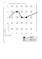
図5は、レーザー照射予定箇所画像の一例を示す図である。図5に示されるレーザー照射予定箇所画像の一例には、縦五個と横五個の合計二十五個のレーザー(加振レーザー)照射予定箇所が示されている。さらに、レーザー照射予定箇所画像の一例には、ケーブルCが示されている。
照射箇所解析部124bは、レーザー照射予定箇所画像に基づいて、二十五個のレーザー照射予定箇所のうち、(X,Y)が(2,4)、(3,3)、(4,3)で示されるレーザー照射予定箇所については、それらのレーザー照射予定箇所の上にケーブルCがあるため、レーザー照射不可とする。照射箇所解析部124bは、(X,Y)が(2,4)、(3,3)、(4,3)で示されるレーザー照射予定箇所以外のレーザー照射予定箇所を選択し、選択したレーザー照射予定箇所の全てを結んだ線によって示されるルートのうち、その長さが最短となるルートを選択する。照射箇所解析部124bは、選択したルートを、掃引ルートとして、掃引ルートを示す情報を含む照射する箇所を選択した結果を、タイミング導出部124dへ出力する。図4に戻り説明を続ける。FIG. 5 is a diagram showing an example of an image of a planned laser irradiation location. An example of the image of the scheduled laser irradiation area shown in FIG. 5 shows a total of 25 laser (exciting laser) irradiation scheduled areas, 5 vertically and 5 horizontally. Furthermore, the cable C is shown in an example of the image of the planned laser irradiation area.
Based on the image of the scheduled laser irradiation site, the irradiation
残響音解析部124cは、残響音データ取得部122cが出力した音情報に基づいて、計測条件を導出する。
図6は、音情報の一例(その1)を示す図である。図6において、横軸は時間[ms]であり、縦軸は音の強度(arb.unit)である。この音情報は、検査速度50Hz、つまり、一秒間に50回測定が行われたものである。図6に示される例では、20ms毎に、検査対象Mに、加振レーザー光が照射される。このため、20ms毎に、加振レーザー光が検査対象Mに照射されることによって音が生じ、その音によるピークLが複数検出される。さらに、複数のピークLの各々の8ms以降に、加振レーザー光が検査対象Mに照射されることによって生じた音の残響音によるピークNと減衰波形が数ミリ秒間検出される。複数のピークNと減衰波形の各々はノイズであるため、仮に、複数のピークNの各々が検出される時間を計測時間に含めた場合、計測精度が悪くなる。具体的に説明する。The reverberant
FIG. 6 is a diagram showing an example (part 1) of sound information. In FIG. 6, the horizontal axis is time [ms] and the vertical axis is sound intensity (arb.unit). This sound information was measured at an inspection speed of 50 Hz, that is, 50 times per second. In the example shown in FIG. 6, the inspection target M is irradiated with the excitation laser beam every 20 ms. For this reason, sound is generated by irradiating the inspection object M with the excitation laser light every 20 ms, and a plurality of peaks L due to the sound are detected. Furthermore, after 8 ms of each of the plurality of peaks L, the peak N and the decay waveform of the reverberant sound generated by irradiating the inspection object M with the excitation laser light are detected for several milliseconds. Since each of the plurality of peaks N and the decay waveform is noise, if the time during which each of the plurality of peaks N is detected is included in the measurement time, the measurement accuracy deteriorates. A specific description will be given.
図7Aと図7Bとは、音情報の一例(その2)を示す図である。
図8Aと図8Bとは、音情報の一例(その3)を示す図である。
図7Aは、20ms間隔(50Hz)で、検査対象Mに加振レーザー光を順次照射した場合に、順次照射した加振レーザー光の各々で生じる残響音を示したものである。図7Aは、図6とは測定環境が異なるため、反響音によるによるノイズが発生するタイミングが異なっている。また、反響音の波形が、図6では単一のピークに見え、図7Aでは減衰波形に見えるが、これは、照射エネルギーの違いである。残像音は、加振レーザー光の照射時間以外に到達する周期的な音信号である。
図7Bは、30ms間隔(33Hz)で、検査対象Mに加振レーザー光を順次照射した場合に、順次照射した加振レーザー光の各々で生じる残響音を示したものである。
図7Aと図7Bとにおいて、S1-S4は、検査対象Mに加振レーザー光が順次照射されることによって発生する残響音を示す波形である。M1-M4は、順次照射されるレーザー光に対して、検査対象Mに発生する振動を計測する時間帯である。上向きの矢印は、加振レーザー光を照射するタイミングである。7A and 7B are diagrams showing an example (part 2) of sound information.
8A and 8B are diagrams showing an example (part 3) of sound information.
FIG. 7A shows the reverberation sound produced by each of the sequentially irradiated excitation laser beams when the inspection object M is sequentially irradiated with the excitation laser beams at intervals of 20 ms (50 Hz). In FIG. 7A, since the measurement environment is different from that in FIG. 6, the timing of occurrence of noise due to reverberation sound is different. Also, the waveform of the reverberant sound appears as a single peak in FIG. 6 and as an attenuated waveform in FIG. 7A, but this is due to the difference in irradiation energy. The afterimage sound is a periodic sound signal that arrives outside the irradiation time of the exciting laser light.
FIG. 7B shows the reverberation sound produced by each of the sequentially irradiated excitation laser beams when the inspection object M is sequentially irradiated with the excitation laser beams at intervals of 30 ms (33 Hz).
In FIGS. 7A and 7B, S1-S4 are waveforms representing reverberant sounds generated by sequentially irradiating the object M to be inspected with excitation laser light. M1 to M4 are time periods during which vibrations generated in the inspection object M are measured with respect to the sequentially irradiated laser beams. The upward arrow indicates the timing of irradiating the excitation laser beam.
図8Aは、25ms間隔(40Hz)で、検査対象Mに加振レーザー光を順次照射した場合に、順次照射した加振レーザー光の各々で生じる残響音を示したものである。
図8Bは、40ms間隔(25Hz)で、検査対象Mに加振レーザー光を順次照射した場合に、順次照射した加振レーザー光の各々で生じる残響音を示したものである。
図8Aと図8Bとにおいて、S1-S4は、検査対象Mに加振レーザー光が順次照射されることによって発生する残響音を示す波形である。M1-M4は、順次照射されるレーザー光に対して、検査対象Mに発生する振動を計測する時間帯である。上向きの矢印は、加振レーザー光を照射するタイミングである。FIG. 8A shows the reverberation sound produced by each of the sequentially irradiated excitation laser beams when the inspection object M is sequentially irradiated with the excitation laser beams at intervals of 25 ms (40 Hz).
FIG. 8B shows the reverberation sound produced by each of the sequentially irradiated excitation laser beams when the inspection object M is sequentially irradiated with the excitation laser beams at intervals of 40 ms (25 Hz).
In FIGS. 8A and 8B, S1 to S4 are waveforms representing reverberant sounds generated by sequentially irradiating the inspection object M with excitation laser light. M1 to M4 are time periods during which vibrations generated in the inspection object M are measured with respect to the sequentially irradiated laser beams. The upward arrow indicates the timing of irradiating the excitation laser beam.
図7Aと図7Bと図8Aと図8Bとによれば、M2-M4で表される二回目以降の計測(計測)を行う時間帯では、前の照射による残響音(ノイズ)が計測結果に含まれる。つまり、Mn(nは、n>1の整数)の時間帯で計測される振動には、波形S1-波形Snのすべてを加算することによって得られる波形が含まれる。具体的には、図7Aの場合、M4の時間帯で計測される振動には、波形S1-波形S4が計測結果に含まれる。波形S1-波形S4のうち、波形S2と波形S3とは、特に振幅が大きく、ノイズ成分が大きくなっている。しかし、図7Bの場合、M4の時間帯で計測される振動には、波形S1-波形S4が計測結果に含まれるが、波形S1-波形S4のうち、いずれの波形も振幅が小さく、ノイズ成分が少なくなっている。
図8Aの場合、M4の時間帯で計測される振動には、波形S1-波形S4が計測結果に含まれる。波形S1-波形S4のうち、波形S2は、特に振幅が大きく、ノイズ成分が大きくなっている。図8Bの場合、M4の時間帯で計測される振動には、波形S1-波形S4が計測結果に含まれる。波形S1-波形S4のうち、波形S3は、特に振幅が大きく、ノイズ成分が大きくなっている。According to FIGS. 7A, 7B, 8A, and 8B, during the second and subsequent measurement (measurement) periods represented by M2-M4, the reverberation sound (noise) due to the previous irradiation is reflected in the measurement results. included. That is, the vibration measured in the time period of Mn (n is an integer of n>1) includes the waveform obtained by adding all of the waveforms S1-Sn. Specifically, in the case of FIG. 7A, waveforms S1 to S4 are included in the measurement results of the vibration measured in the time period M4. Of the waveforms S1 to S4, the waveforms S2 and S3 have particularly large amplitudes and large noise components. However, in the case of FIG. 7B, the vibration measured in the time period M4 includes the waveforms S1 to S4 in the measurement results. is decreasing.
In the case of FIG. 8A, the vibration measured in the time period M4 includes waveforms S1 to S4 in the measurement results. Among the waveforms S1 to S4, the waveform S2 has a particularly large amplitude and a large noise component. In the case of FIG. 8B, waveforms S1 to S4 are included in the measurement results of the vibrations measured in the time period M4. Among the waveforms S1 to S4, the waveform S3 has a particularly large amplitude and a large noise component.
残響音の時間波形は、トンネルの大きさ、道路(路面)、橋脚床板、コンクリート壁、残響音モニター7の位置などの照射環境によって異なる。残響音解析部124cは、振動を計測する前に残響音モニター7が取得した音情報に基づいて、ノイズ成分が最小となる繰り返し数(タイミング)などの計測条件を導出する。例えば、残響音解析部124cは、図6によれば、加振レーザー照射後に、未照射時(バックグラウンド)の信号量の2倍程度以下まで静音になり、その時間が10ms程度確保できるタイミングを導出する。例えば、後述する移動体などに、レーザー誘起振動波計測システム20が搭載されている場合には、静止して、そのタイミングを導出する。
図7Aと図7Bと図8Aと図8Bとに示される残響音が得られた場合には、残響音解析部124cは、計測条件として、30ms間隔(33Hz)を導出し、導出した計測条件を、タイミング導出部124dと、解析部126とへ出力する。このように、繰り返し数(タイミング)を最適化することによって、順次照射される加振レーザー光によって生じるノイズ成分の影響を低減した計測を可能にできる。図4に戻り、説明を続ける。The time waveform of the reverberant sound varies depending on the irradiation environment such as the size of the tunnel, the road (road surface), the floor plate of the pier, the concrete wall, the position of the
When the reverberant sounds shown in FIGS. 7A, 7B, 8A, and 8B are obtained, the reverberant
タイミング導出部124dは、集光位置導出部124aが出力したレンズ12aとレンズ12bとの間の距離の調整量を示す情報と、レンズ間距離の調整に要する時間情報とを取得し、取得したレンズ間距離の調整に要する時間情報に基づいて、取得したレンズ12aとレンズ12bとの間の距離の調整量を示す情報を含む制御情報を、所定のタイミングで、通信部110へ出力する。
タイミング導出部124dは、集光位置導出部124aが出力したレンズ12cとレンズ12dとの間の距離の調整量を示す情報と、レンズ間距離の調整に要する時間情報とを取得し、取得したレンズ間距離の調整に要する時間情報に基づいて、取得したレンズ12cとレンズ12dとの間の距離の調整量を示す情報を含む制御情報を、所定のタイミングで、通信部110へ出力する。
タイミング導出部124dは、照射箇所解析部124bが出力した照射する箇所を選択した結果を示す情報を取得し、取得した照射する箇所を選択した結果を示す情報を含む制御情報を、所定のタイミングで、通信部110へ出力する。
タイミング導出部124dは、残響音解析部124cが出力した計測条件を示す情報を取得し、取得した計測条件を含む制御情報を、所定のタイミングで、通信部110へ出力する。The
The
The
The
(解析部126)
解析部126は、データ処理部126aと、判定部126bとを備える。
データ処理部126aは、タイミング導出部124dが出力した計測条件と、振動データ取得部122dが出力した振動データとを取得し、取得した計測条件に基づいて、取得した振動データを処理する。データ処理部126aは、一定の時間のデータを除去した後に、設定された計測時間のデータを取得する。具体的には、データ処理部126aは、例えば計測時間を10msと設定した場合、10msのデータを除去した場合、照射10ms-20msのデータを取得する。
ここで、振動データは、検査対象Mの同一箇所を計測する場合には、加振レーザー光を単発照射したことによって得られた振動データであっても、複数照射したことによって得られた振動データであってもよい。ただし、加振レーザー光を複数照射することによって得られたデータを使用する場合には、データ処理部126aは、振動データ取得部122dが出力した振動データを、平均化してもよいし、積算化してもよい。(analysis unit 126)
The
The
Here, in the case of measuring the same portion of the inspection target M, the vibration data may be vibration data obtained by irradiating a single excitation laser beam, or vibration data obtained by irradiating a plurality of excitation laser beams. may be However, when using data obtained by irradiating multiple excitation laser beams, the
データ処理部126aは、タイミング導出部124dが出力した計測条件に基づいて、振動データから、計測を行う時間帯M1、M2、・・のデータを抽出する。また、データ処理部126aは、抽出した時間帯M1、M2、・・・のデータから、加振レーザーによって発生する振動の最大変位量から任意に決定される減少量を除去する。ここで、減少量の一例は、1/10、1/100などであり、例えば、加振レーザー光を照射してから、0.5ms-10msなどの所定の時間のデータである。加振レーザー光を照射してから、加振レーザーによって発生する振動の最大変位量から任意に決定される減少量を除去することによって、加振レーザー光を照射した直後に生じるノイズの影響を低減できるため、計測精度を向上できる。
図9Aと、図9Bとは、第1の実施形態のレーザー誘起振動波計測システムのノイズ除去の効果を示す図である。図9Aと、図9Bとは、振動データを、高速フーリエ変換することによって得られる周波数スペクトルを示す。図9Aは、振動データからノイズを除去しなかったものであり、図9Bは振動データからノイズを除去したものである。
図9Aによれば、加振レーザー光を照射したことによって生じる音によるノイズの影響が大きく、全体的に浮き上がったようなホワイトノイズが生じている。これに対し、図9Bによれば、ホワイトノイズが減少し、細やかなピークが見られる。The
9A and 9B are diagrams showing the effect of noise removal in the laser-induced vibration wave measurement system of the first embodiment. 9A and 9B show frequency spectra obtained by fast Fourier transforming the vibration data. FIG. 9A is the vibration data without noise removal, and FIG. 9B is the vibration data with noise removal.
According to FIG. 9A, the noise caused by the sound generated by the irradiation of the excitation laser light has a great influence, and white noise that seems to stand out as a whole is generated. On the other hand, according to FIG. 9B, white noise is reduced and fine peaks can be seen.
また、データ処理部126aは、取得した振動データに突発的な測定不良で生じるノイズが含まれているか否かを判定する。レーザー誘起振動波計測では、検査対象Mに生じる振動は、加振レーザー光を照射した直後が最も強く、その後、時間の経過とともに、指数関数的に減少する。データ処理部126aは、その指数関数を評価関数として、その傾向と一定以上の相関係数が得られない振動データには、突発的な測定不良で生じるノイズが含まれるとアルゴリズム的に判定する。
図10は、第1の実施形態のレーザー誘起振動波計測システムのノイズ除去の一例を示す図である。図10において、(a)は正常な信号(減衰波形)であり、(b)は突発的な測定不良で生じるノイズである。データ処理部126aは、(a)に示される減衰波形を評価関数として、(b)に示される波形との間の相関係数を導出する。データ処理部126aは、相関係数が相関係数閾値以上である場合には、(b)に示される波形は信号であると判定する。また、データ処理部126aは、相関係数が相関係数閾値未満である場合には、(b)に示される波形は信号でなく、突発的な測定不良で生じるノイズであると判定する。データ処理部126aは、突発的な測定不良で生じるノイズが含まれると判定したデータを無効なデータと判定し、無効なデータを除去する。図4に戻り、説明を続ける。The
FIG. 10 is a diagram showing an example of noise removal in the laser-induced vibration wave measurement system of the first embodiment. In FIG. 10, (a) is a normal signal (attenuation waveform), and (b) is noise caused by sudden measurement failure. The
データ処理部126aは、無効なデータを除去することによって得られた有効なデータを取得する。
ここで、データ処理部126aは、取得した有効なデータが、検査対象Mの同一箇所に、加振レーザー光を複数照射したことによって得られたデータである場合に、その有効なデータから、同一箇所に加振レーザー光を複数照射したことによって突発的に発生したノイズを除去する。具体的には、振動データに、同一箇所に加振レーザー光を複数照射したことによって突発的に発生したノイズが混入する回数は、全照射回数に比べて少数であるため、データ処理部126aは、振動データを時間平均することによって得られる波形との相関係数が高い方から所定の数の波形を抽出することによって、同一箇所に加振レーザー光を複数照射したことによって突発的に発生したノイズを含むデータを除去する。
データ処理部126aは、突発的な測定不良で生じるノイズと突発的に発生したノイズとのいずれか一方を除去するようにしてもよいし、両方を除去するようにしてもよい。The
Here, if the acquired effective data is data obtained by irradiating the same portion of the inspection object M with a plurality of excitation laser beams, the
The
図11は、第1の実施形態のレーザー誘起振動波計測システムが取得する振動データの一例を示す図である。図11は、10Hzの検査速度において、検査対象Mの同一箇所を160回計測した場合の16秒間の振動データであり、横軸は時間(秒)であり、縦軸は振動強度(arb.unit)である。仮に、この160回の計測を分割し、160個のデータを平均化したものを、高速フーリエ変換(FFT: fast Fourier transform)した場合には、図9Bと同様の周波数スペクトルが得られる。
図11によれば、振動強度が-0.001-0.001の一連の帯状信号において、100ms毎の加振レーザー光を照射したときに生じる定期的なピーク以外に、突発的に発生したノイズによるピークが見られる。具体的には、図11のNが、突発的なノイズが生じた信号の箇所である。突発的なノイズが生じた場合、標準で示される黒い帯体が膨らむ。図11において、等間隔の細いラインは、ホワイトノイズである。FIG. 11 is a diagram showing an example of vibration data acquired by the laser-induced vibration wave measurement system of the first embodiment. FIG. 11 shows vibration data for 16 seconds when the same portion of the inspection object M is measured 160 times at an inspection speed of 10 Hz, the horizontal axis is time (seconds), and the vertical axis is vibration intensity (arb.unit ). If the 160 measurements are divided and the 160 data averaged are subjected to fast Fourier transform (FFT), a frequency spectrum similar to that in FIG. 9B is obtained.
According to FIG. 11, in a series of belt-like signals with vibration intensity of −0.001 to 0.001, in addition to periodic peaks that occur when an excitation laser beam is irradiated every 100 ms, noise that suddenly occurs A peak due to is seen. Specifically, N in FIG. 11 is the portion of the signal where sudden noise occurs. In the event of sudden noise, the standard black band bulges. In FIG. 11, equally spaced thin lines are white noise.
図12は、第1の実施形態のレーザー誘起振動波計測システムが突発的に生じたノイズを除去した効果を示す図である。図12は、突発的に生じたノイズを除去した後に、FFTを行うことによって得られる周波数スペクトルを示す。突発的に生じたノイズを除去しないで、FFTを行うことによって得られる周波数スペクトル(図9の下図)と比較して、より鮮明な周波数スペクトルが得られている。データ処理部126aは、周波数スペクトルを表す情報を、判定部126bへ出力する。データ処理部126aは、取得した振動データと、ノイズを除去する過程で得られたデータと、周波数スペクトルを表す情報とを、記憶部140の周辺測定データDB146に記憶する。図4に戻り説明を続ける。
12A and 12B are diagrams showing the effect of removing noise suddenly generated by the laser-induced vibration wave measurement system of the first embodiment. FIG. FIG. 12 shows the frequency spectrum obtained by performing FFT after removing noise that occurred suddenly. A clearer frequency spectrum is obtained than the frequency spectrum (lower diagram in FIG. 9) obtained by performing FFT without removing sudden noise. The
判定部126bは、データ処理部126aが出力した周波数スペクトルに基づいて、検査対象Mの加振レーザー光が照射された部分の健全性を検査する。具体的には、判定部126bは、空洞などの内部欠陥の有無、もしくは当該内部欠陥が生じている可能性を検出する。
また、判定部126bは、加振レーザー光を検査対象Mに照射したことによって得られた周波数スペクトルと、記憶部140の周辺測定データDB146に記憶されている周波数スペクトルとを使用して、検査対象Mの加振レーザー光が照射された部分の健全性を検査する。具体的には、判定部126bは、空洞などの内部欠陥の有無、もしくは当該内部欠陥が生じている可能性を検出する。判定部126bは、機械学習を適用して、検査対象Mの加振レーザー光が照射された部分の健全性を検査してもよい。判定部126bは、検査対象Mの加振レーザー光が照射された部分の健全性を検査する場合に、加振レーザー光を照射しない場合に得られる周波数スペクトルを使用してもよい。Based on the frequency spectrum output from the
Further, the
図13Aと図13Bとは、第1の実施形態のレーザー誘起振動波計測システム20が判定する周波数スペクトルの一例を示す図である。図13Aは、検査対象Mに加振レーザー光を照射した場合に得られる周波数スペクトルである。図13Bは、検査対象Mに加振レーザー光を照射しない場合に得られる周波数スペクトルである。つまり、図13Bは、バックグランドデータである。図13Bによれば、検査対象Mに加振レーザー光を照射しない場合でも、2.5KHzと5.5KHz付近に固有振動のピークが見られる。図13Aによれば、検査対象Mに加振レーザー光を照射した場合、固有振動のピークが大きくなっているのが分かる。記憶部140の周辺測定データDB146に記憶される周波数スペクトルには、判定部126bは、バックグランドデータを含む。判定部126bは、バックグランドデータなどの固有振動など判定に影響を及ぼす情報を反映させることによって、正確な判断基準を自動的に生成してもよい。判定部126bは、検査対象Mの加振レーザー光が照射された部分の健全性を検査した結果を示す情報を、表示部130へ表示する。
13A and 13B are diagrams showing examples of frequency spectra determined by the laser-induced vibration
(レーザー誘起振動波計測システム20の動作(その1))
図14は、第1の実施形態のレーザー誘起振動波計測システムの動作の一例(その1)を示すシーケンスチャートである。図14は、加振レーザー集光ユニット10の集光位置を調整する一例として、レンズ12aとレンズ12bとの間の距離と、計測レーザー集光ユニット11のレンズ12cとレンズ12dとの間の距離とを調整する処理を示す。
(ステップS101)
測距レーザー装置9は、測距レーザー光を出力する。
(ステップS102)
測距レーザー装置9は、出力した測距レーザー光が、検査対象Mで反射した反射光に基づいて、測距レーザー光と検査対象Mとの間の照射距離を導出する。
(ステップS103)
測距レーザー装置9は、導出した照射距離を示す情報(照射距離情報)を、処理ユニット100へ送信する。
(ステップS104)
処理ユニット100の通信部110は、測距レーザー装置9が送信した照射距離情報を受信し、受信した照射距離情報を、情報取得部122へ出力する。情報取得部122の照射距離データ取得部122aは、通信部110が出力した照射距離情報を取得し、取得した照射距離情報を、計測部124へ出力する。計測部124の集光位置導出部124aは、照射距離データ取得部122aが出力した照射距離情報を取得し、取得した照射距離情報に関連付けられているレンズ12aとレンズ12bとの間のレンズ間距離を、記憶部140に記憶されているレンズ間距離テーブル144から取得する。(Operation of Laser Induced Oscillatory Wave Measurement System 20 (Part 1))
FIG. 14 is a sequence chart showing an example (part 1) of the operation of the laser-induced vibration wave measurement system of the first embodiment. FIG. 14 shows, as an example of adjusting the condensing position of the excitation
(Step S101)
A ranging
(Step S102)
The distance measuring
(Step S103)
The ranging
(Step S104)
The
(ステップS105)
集光位置導出部124aは、取得したレンズ12aとレンズ12bとの間のレンズ間距離と、レンズ12aとレンズ12bとの間の現在の距離との差を導出することによって、レンズ12aとレンズ12bとの間の距離の調整量を導出する。集光位置導出部124aは、導出したレンズ12aとレンズ12bとの間の距離の調整量を示す情報を、タイミング導出部124dへ出力する。
(ステップS106)
タイミング導出部124dは、集光位置導出部124aが出力したレンズ12aとレンズ12bとの間の距離の調整量を示す情報を取得し、取得したレンズ12aとレンズ12bとの間の距離の調整量を示す情報を含む制御情報を作成し、作成した制御情報を、通信部110へ出力する。通信部110は、タイミング導出部124dが出力した制御情報を、加振レーザー集光ユニット10へ送信する。(Step S105)
The condensing
(Step S106)
The
(ステップS107)
加振レーザー集光ユニット10は、処理ユニット100が送信した制御情報を受信する。加振レーザー集光ユニット10は、受信した制御情報に含まれるレンズ12aとレンズ12bとの間の距離の調整量を示す情報に基づいて、レンズ12aとレンズ12bとの間の距離を調整する。
(ステップS108)
処理ユニット100の通信部110は、測距レーザー装置9が送信した照射距離情報を受信し、受信した照射距離情報を、情報取得部122へ出力する。情報取得部122の照射距離データ取得部122aは、通信部110が出力した照射距離情報を取得し、取得した照射距離情報を、計測部124へ出力する。計測部124の集光位置導出部124aは、照射距離データ取得部122aが出力した照射距離情報を取得し、取得した照射距離情報に関連付けられているレンズ12cとレンズ12dとの間のレンズ間距離を、記憶部140に記憶されているレンズ間距離テーブル144から取得する。
(ステップS109)
集光位置導出部124aは、取得したレンズ12cとレンズ12dとの間のレンズ間距離と、レンズ12cとレンズ12dとの間の現在の距離との差を導出することによって、レンズ12cとレンズ12dとの間の距離の調整量を導出する。集光位置導出部124aは、導出したレンズ12cとレンズ12dとの間の距離の調整量を示す情報を、タイミング導出部124dへ出力する。(Step S107)
The excitation
(Step S108)
The
(Step S109)
The condensing
(ステップS110)
タイミング導出部124dは、集光位置導出部124aが出力したレンズ12cとレンズ12dとの間の距離の調整量を示す情報を取得し、取得したレンズ12cとレンズ12dとの間の距離の調整量を示す情報を含む制御情報を作成し、作成した制御情報を、通信部110へ出力する。通信部110は、タイミング導出部124dが出力した制御情報を、計測レーザー集光ユニット11へ送信する。
(ステップS111)
計測レーザー集光ユニット11は、処理ユニット100が送信した制御情報を受信する。計測レーザー集光ユニット11は、受信した制御情報に含まれるレンズ12cとレンズ12dとの間の距離の調整量を示す情報に基づいて、レンズ12cとレンズ12dとの間の距離を調整する。
図14に示されるシーケンスチャートにおいて、ステップS104-S107と、ステップS108-S111とは入れ替えてもよい。また、ステップS104の後に、ステップS108が行われてもよいし、ステップS105の後にステップS108が行われてもよい。(Step S110)
The
(Step S111)
The measurement
In the sequence chart shown in FIG. 14, steps S104-S107 and steps S108-S111 may be exchanged. Moreover, step S108 may be performed after step S104, and step S108 may be performed after step S105.
(レーザー誘起振動波計測システム20の動作(その2))
図15は、第1の実施形態のレーザー誘起振動波計測システムの動作の一例(その2)を示すシーケンスチャートである。図15は、ガルバノスキャナユニット3と二軸ミラーユニット5によって、検査対象Mの照射箇所を制御する処理を示す。
(ステップS201)
撮像装置13は、検査対象Mのレーザー光を照射する予定の箇所を撮像する。
(ステップS202)
撮像装置13は、撮像することによって得られた検査対象Mのレーザー照射予定箇所画像を表す情報を、処理ユニット100へ送信する。(Operation of Laser Induced Oscillatory Wave Measurement System 20 (Part 2))
FIG. 15 is a sequence chart showing an example (part 2) of the operation of the laser-induced vibration wave measurement system of the first embodiment. FIG. 15 shows the process of controlling the irradiation point of the inspection object M by the
(Step S201)
The
(Step S202)
The
(ステップS203)
処理ユニット100の通信部110は、撮像装置13が送信した検査対象Mのレーザー照射予定箇所画像を表す情報を受信し、受信した検査対象Mのレーザー照射予定箇所画像を表す情報を、情報取得部122へ出力する。情報取得部122の照射箇所データ取得部122bは、通信部110が出力した検査対象Mのレーザー照射予定箇所画像を表す情報を取得し、取得した検査対象Mのレーザー照射予定箇所画像を表す情報を、計測部124へ出力する。計測部124の照射箇所解析部124bは、照射箇所データ取得部122bが出力した検査対象Mのレーザー照射予定箇所画像を表す情報を取得し、取得した検査対象Mのレーザー照射予定箇所画像を表す情報を画像処理する。
(ステップS204)
処理ユニット100の照射箇所解析部124bは、画像処理することによって得られたレーザー照射予定箇所画像に基づいて、濡れや形状、付属物などの検査対象Mの状態を検出する。
(ステップS205)
処理ユニット100の照射箇所解析部124bは、検査対象Mの状態に基づいて、複数のレーザー照射予定箇所から、加振レーザー光、計測レーザー光、測距レーザー光のうち、少なくとも一つを照射するレーザー照射予定箇所を選択する。(Step S203)
The
(Step S204)
The irradiation
(Step S205)
Based on the state of the inspection object M, the irradiation
(ステップS206)
処理ユニット100の照射箇所解析部124bは、選択したレーザー照射予定箇所に基づいて、選択したレーザー照射予定箇所の全てを線で結んだ場合に、その結んだ線によって示されるルートのうち、その長さが最短となるルートを選択する。また、照射箇所解析部124bは、付属物上を通過してしまうルートがある場合には、レーザー光が付属物に照射されないように、物理シャッタでレーザー光を遮断すると仮定して、最短となるルートを選択してもよい。処理ユニット100は、選択したルートを、掃引ルートとして、掃引ルートを示す情報を含む照射する箇所を選択した結果を、タイミング導出部124dへ出力する。
(ステップS207)
タイミング導出部124dは、照射箇所解析部124bが出力した照射する箇所を選択した結果を取得し、取得した照射する箇所を選択した結果を含む制御情報を作成し、作成した制御情報を、通信部110へ出力する。通信部110は、タイミング導出部124dが出力した制御情報を、ガルバノスキャナユニット3と二軸ミラーユニット5とへ送信する。
(ステップS208)
ガルバノスキャナユニット3は、処理ユニット100が送信した制御情報を取得し、取得した制御情報に含まれる照射する箇所を選択した結果に基づいて、加振レーザー光、計測レーザー光、測距レーザー光のうち、少なくとも一つの光路を調整する。
(ステップS209)
二軸ミラーユニット5は、処理ユニット100が送信した制御情報を取得し、取得した制御情報に含まれる照射する箇所を選択した結果に基づいて、加振レーザー光、計測レーザー光、測距レーザー光のうち、少なくとも一つの光路を調整する。(Step S206)
Based on the selected laser irradiation scheduled locations, the irradiation
(Step S207)
The
(Step S208)
The
(Step S209)
The
(レーザー誘起振動波計測システム20の動作(その3))
図16は、第1の実施形態のレーザー誘起振動波計測システムの動作の一例(その3)を示すシーケンスチャートである。図16は、加振レーザー光の出力タイミングを制御する処理を示す。図16には、一例として、加振レーザー光が、検査対象Mに照に照射されることによって生じる音の強度に基づいて、加振レーザー光を出力するタイミングを導出する場合について説明する。
(ステップS301)
処理ユニット100の残響音解析部124cは、加振レーザー装置1に加振レーザー光を照射させる情報である加振レーザー光照射情報を作成し、作成した加振レーザー光照射情報を、通信部110へ出力する。通信部110は、残響音解析部124cが出力した加振レーザー光照射情報を取得し、取得した加振レーザー光照射情報を、加振レーザー装置1へ送信する。加振レーザー光照射情報には、加振レーザー光を出力するタイミングを示す情報が含まれる。具体的には、加振レーザー光照射情報には、加振レーザー光を出力するタイミングとして、第1のタイミング、第2のタイミング、・・・、第iのタイミングが含まれる。
(ステップS302)
加振レーザー装置1は、処理ユニット100が送信した加振レーザー光照射情報にしたがって、加振レーザー光を出力する。加振レーザー装置1が出力した加振レーザー光は、検査対象Mに照射される。
(ステップS303)
残響音モニター7は、検査対象Mに加振レーザー光が、第1のタイミング、第2のタイミング、・・・、第iのタイミングの各々で照射された場合に生じる音を計測する。残響音モニター7は、計測した音を電気信号へ変換し、電気信号へ変換した音情報を取得する。(Operation of Laser Induced Oscillatory Wave Measurement System 20 (Part 3))
FIG. 16 is a sequence chart showing an example (part 3) of the operation of the laser-induced vibration wave measurement system of the first embodiment. FIG. 16 shows a process of controlling the output timing of excitation laser light. In FIG. 16, as an example, the case of deriving the timing of outputting the excitation laser beam based on the intensity of the sound generated when the excitation laser beam irradiates the inspection target M will be described.
(Step S301)
The
(Step S302)
The
(Step S303)
The reverberant sound monitor 7 measures sounds generated when the excitation laser light is irradiated to the inspection object M at each of the first timing, the second timing, . . . , the i-th timing. The reverberant sound monitor 7 converts the measured sound into an electric signal and obtains the sound information converted into the electric signal.
(ステップS304)
残響音モニター7は、取得した音情報を、処理ユニット100へ送信する。
(ステップS305)
処理ユニット100の通信部110は、残響音モニター7が送信した音情報を受信し、受信した音情報を、情報取得部122へ出力する。情報取得部122の残響音データ取得部122cは、通信部110が出力した音情報を取得し、取得した音情報を、計測部124へ出力する。計測部124の残響音解析部124cは、残響音データ取得部122cが出力した音情報を取得し、取得した音情報に基づいて、計測条件を導出する。残響音解析部124cは、導出した計測条件を示す情報を、タイミング導出部124dへ出力する。
(ステップS306)
タイミング導出部124dは、タイミング導出部124dが出力した計測条件を示す情報を取得し、取得した計測条件を示す情報を含む制御情報を作成し、作成した制御情報を、通信部110へ出力する。通信部110は、タイミング導出部124dが出力した制御情報を、加振レーザー装置1へ送信する。
(ステップS307)
加振レーザー装置1は、処理ユニット100が送信した制御情報を取得し、取得した制御情報に含まれる計測条件にしたがって、加振レーザー光を出力する。(Step S304)
The reverberation monitor 7 transmits the acquired sound information to the
(Step S305)
The
(Step S306)
The
(Step S307)
The
(レーザー誘起振動波計測システム20の動作(その4))
図17は、第1の実施形態のレーザー誘起振動波計測システムの動作の一例(その4)を示すフローチャートである。図17は、振動データを処理することによって、検査対象Mの加振レーサー光を照射した箇所が健全か否かを判定する処理を示す。
(ステップS401)
処理ユニット100の通信部110は、計測レーザー装置2が送信した振動データ(振動量)を受信し、受信した振動データを、情報取得部122へ出力する。情報取得部122の振動データ取得部122dは、通信部110が出力した振動データを取得する。
(ステップS402)
振動データ取得部122dは、取得した振動データを、解析部126へ出力する。解析部126のデータ処理部126aは、振動データ取得部122dが出力した振動データと、タイミング導出部124dが出力した計測条件とに基づいて、振動データから、計測を行う時間帯のデータを抽出する。
(ステップS403)
データ処理部126aは、抽出した時間帯のデータから、加振レーザーによって発生する振動の最大変位量から任意に決定される減少量を除去することによって、突発的な測定不良で生じるノイズを除去する。ここで、減少量の一例は、1/10、1/100などである。
(ステップS404)
データ処理部126aは、取得した振動データに突発的なノイズが含まれているか否かを判定する。データ処理部126aは、突発的なノイズが含まれると判定したデータを無効なデータと判定し、無効なデータを除去する。
(ステップS405)
判定部126bは、データ処理部126aが出力した周波数スペクトルに基づいて、検査対象Mの加振レーザー光が照射された部分の健全性を検査する。(Operation of Laser Induced Oscillatory Wave Measurement System 20 (Part 4))
FIG. 17 is a flow chart showing an example (part 4) of the operation of the laser-induced vibration wave measurement system of the first embodiment. FIG. 17 shows a process of determining whether or not the portion of the inspection object M irradiated with the excitation racer light is sound by processing the vibration data.
(Step S401)
The
(Step S402)
The vibration
(Step S403)
The
(Step S404)
The
(Step S405)
Based on the frequency spectrum output from the
(ステップS406)
表示部130は、検査対象Mの加振レーザー光が照射された部分の健全性の検査結果を表示する。
ステップS406の処理が終了した後に、タイミング導出部124dは、集光位置導出部124aが出力するレンズ12aとレンズ12bとの間の距離の調整量を示す情報と、レンズ12cとレンズ12dとの間の距離の調整量を示す情報と、レンズ間距離の調整に要する時間情報と、照射箇所解析部124bが出力した照射する箇所を選択した結果を示す情報と、残響音解析部124cが出力した計測条件を示す情報とに基づいて、タイミングを導出し、導出したタイミングに基づいて、次の加振レーザー光を照射する処理へ移行する。タイミング導出部124dは、導出したタイミングを示す情報を、通信部110から、加振レーザー装置1、ガルバノスキャナユニット3、二軸ミラーユニット5、加振レーザー集光ユニット10、計測レーザー集光ユニット11へ送信する。加振レーザー装置1のレーザー照射調整部は、処理ユニット100が送信したタイミングを示す情報を取得し、取得したタイミングを示す情報に基づいて、マスタークロックや物理シャッタなどを調整することによって、加振レーザー光を出力するタイミングを修正する。ガルバノスキャナユニット3、二軸ミラーユニット5加振レーザー集光ユニット10、計測レーザー集光ユニット11の各々の駆動調整部は、処理ユニット100が送信したタイミングを示す情報を取得し、取得したタイミングを示す情報に基づいて、適切な速度で駆動するとともに、適切な時間に駆動する。
図17に示されるフローチャートにおいて、ステップS403とステップS404とを入れ替えてもよい。(Step S406)
The
After the process of step S406 is completed, the
In the flowchart shown in FIG. 17, step S403 and step S404 may be interchanged.
前述した実施形態では、残響音モニター7が、加振レーザー光が検査対象Mに照射されることによって生じる音を計測する場合について説明したが、この例に限られない。例えば、残響音モニター7が、計測レーザー光が検査対象Mに照射されることによって生じる音を計測するようにしてもよい。
前述した実施形態では、残響音モニター7が二軸ミラーユニット5に取り付けられる場合について説明したが、この例に限られない。例えば、残響音モニター7がガルバノスキャナユニット3に取り付けられてもよいし、加振レーザー装置1や、計測レーザー装置2に取り付けられてもよい。
前述した実施形態では、残響音モニター7の一例として、マイクロフォンなどの所謂音響計測装置を用いる場合について説明したが、この例に限られない。例えば、残響音モニター7として、レーザー誘起振動波計測システムに加速度センサーを設置し、残響音による筐体や光学素子の振動を計測することによって、音を計測してもよい。
前述した実施形態では、ミラー8aが、加振レーザー光の光路を、直角に曲げ、ミラー8bが、測距レーザー光の光路を、直角に曲げ、ミラー8cが、加振レーザー光の光路を、直角に曲げる場合について説明したがこの例に限られない。例えば、ミラー8aが、加振レーザー光の光路を、30degや60degなどの光学素子の設計によって任意の角度に曲げるように光学系を設計してもよい。また、ミラー8bが、測距レーザー光の光路を、30degや60degなどの光学素子の設計によって任意の角度に曲げるように光学系を設計してもよい。また、ミラー8cが、加振レーザー光の光路を、30degや60degなどの光学素子の設計によって任意の角度に曲げるように光学系を設計してもよい。
前述した実施形態では、加振レーザー集光ユニット10が、レンズ12aとレンズ12bとを含む場合について説明したが、この例に限られない。例えば、加振レーザー集光ユニット10が、一枚の単レンズを含んでもよいし、三枚以上の組み合わせレンズを含んでもよい。そして、一枚の単レンズや、三枚以上の組み合わせレンズの設置位置の調整による集光位置や、集光度が調整されてもよい。レンズは、凸レンズであってもよいし、凹レンズであってもよい。
前述した実施形態では、計測レーザー集光ユニット11が、レンズ12cとレンズ12dとを含む場合について説明したが、この例に限られない。例えば、計測レーザー集光ユニット11が、一枚の単レンズを含んでもよいし、三枚以上の組み合わせレンズを含んでもよい。そして、一枚の単レンズや、三枚以上の組み合わせレンズの設置位置の調整による集光位置や、集光度が調整されてもよい。レンズは、凸レンズであってもよいし、凹レンズであってもよい。
前述した実施形態では、ガルバノスキャナユニット3が、ガルバノスキャナミラー4aとガルバノスキャナミラー4bとの二枚のミラーを含む場合について説明したが、この例に限られない。例えば、ガルバノスキャナユニット3が、一枚のガルバノスキャナミラーを含んでもよいし、三枚以上のガルバノスキャナミラーを含んでもよい。
前述した実施形態では、二軸ミラーユニット5が、二軸ミラーを含む場合について説明したが、この例に限られない。例えば、二軸ミラーユニット5が、二枚以上の二軸ミラーを含んでもよい。
前述した実施形態では、第1の実施形態のレーザー誘起振動波計測システム20が、ガルバノスキャナユニット3と、二軸ミラーユニット5とを組み合わせて、加振レーザー光と、計測レーザー光とのいずれか一方又は両方を掃引させる場合について説明したが、この例に限られない。例えば、ガルバノスキャナユニット3と、二軸ミラーユニット5とのいずれか一方が、加振レーザー光と、計測レーザー光とのいずれか一方又は両方を掃引させるようにしてもよい。In the above-described embodiment, the case where the reverberant sound monitor 7 measures the sound generated by irradiating the inspection target M with the excitation laser beam has been described, but the present invention is not limited to this example. For example, the reverberant sound monitor 7 may measure the sound generated by the irradiation of the inspection object M with the measurement laser light.
In the above-described embodiment, the case where the
In the above-described embodiment, as an example of the
In the above-described embodiment, the
In the above-described embodiment, the excitation
In the above-described embodiment, the case where the measurement
In the above-described embodiment, the case where the
In the above-described embodiment, the case where the
In the above-described embodiment, the laser-induced vibration
前述した実施形態では、処理ユニット100の照射箇所解析部124bが、撮像装置13によって撮像されたレーザー照射予定箇所画像に基づいて、照射する箇所を選択した結果を取得する場合について説明したが、この例に限られない。例えば、3Dスキャナ、サーモグラフィーなどの検査対象Mの表面の情報を取得できる装置が取得した情報に基づいて、照射する箇所を選択した結果を取得するようにしてもよい。
前述した実施形態では、処理ユニット100の照射箇所解析部124bが、レーザー照射予定箇所画像に基づいて、凹凸影がなく、平坦で、他のレーザー照射予定箇所と同等の濡れであり、付属物がないレーザー照射予定箇所を選択する場合について説明したが、これは一例であり、選定項目、基準、選択する個数は、使用者によって任意に決定可能である。
前述した実施形態では、データ処理部126aが、その指数関数を評価関数として、その傾向と一定以上の相関係数が得られないデータには、突発的なノイズが含まれると判定する場合について説明したが、この例に限られない。例えば、残響音モニター7に環境音を計測させる。処理ユニット100のデータ処理部126aは、残響音モニター7が計測した環境音に基づいて、振動データに含まれるノイズ成分を除去するようにしてもよい。また、レーザー誘起振動波計測システム20自身の振動を計測する振動計測装置を備えるようにしてもよい。そして、処理ユニット100のデータ処理部126aは、振動計測装置が計測した振動に基づいて、振動データに含まれるノイズ成分を除去するようにしてもよい。
前述した実施形態では、データ処理部126aが振動データをFFTした結果を用いて、判定部126bが、加振レーザー光を照射した箇所の健全性を判定する場合について説明したが、この例に限られない。例えば、データ処理部126aがウェーブレット解析した結果を用いて、判定部126bが、加振レーザー光を照射した箇所の健全性を判定するようにしてもよい。
前述した実施形態において、情報処理部120の処理に、機械学習が適用されてもよい。In the above-described embodiment, a case has been described in which the irradiation
In the above-described embodiment, the irradiation
In the above-described embodiment, the
In the above-described embodiment, the
In the above-described embodiment, machine learning may be applied to the processing of the
第1の実施形態に係るレーザー誘起振動波計測システム20によれば、レーザー誘起振動波計測システム20は、検査対象Mに加振レーザー光を照射した場合に生じる振動に基づいて、検査対象Mを計測する。レーザー誘起振動波計測システム20は、加振レーザー光を照射するレーザー装置と、加振レーザー光の照射箇所との間の距離に基づいて、加振レーザー光を集光する加振レーザー集光ユニットの集光位置の調整量を導出する集光位置導出部と、調整量を示す情報を含む制御情報を、加振レーザー集光ユニットへ送信する通信部とを備える。このように構成することによって、加振レーザー集光ユニットから出力する加振レーザー光の集光径を小さくできるため、加振レーザー光の単位面積当たりの照射強度を向上させることができる。周波数スペクトルにおける信号強度を向上させることができるため、検査対象Mの計測精度を向上できる。
According to the laser-induced oscillatory
また、検査対象Mの加振レーザー光を照射する予定の箇所の画像を表す情報に基づいて、加振レーザー光を照射する箇所を選択する照射箇所解析部をさらに備え、通信部は、照射箇所解析部が選択した加振レーザー光を照射する箇所を示す情報を含む制御情報を、加振レーザー光を掃引する掃引装置へ送信する。
このように構成することによって、加振レーザー光を照射すべきでない箇所に、加振レーザー光を照射した場合のノイズを低減できるため、検査対象Mの計測精度を向上できる。
また、検査対象Mに加振レーザー光を照射した場合に生じる残響音の時系列データを取得する残響音データ取得部122cと、残響音データ取得部122cが取得した残響音の時系列データの残響音の強度に基づいて、検査対象Mに加振レーザー光を照射するタイミングを取得する残響音解析部124cとをさらに備え、通信部は、残響音解析部124cが取得したタイミングを示す情報を含む制御情報を、加振レーザー光を照射する加振レーザー装置1へ送信する。
このように構成することによって、残響音解析部は、残響音の時系列データの残響音の強度に基づいて、残響音の強度が残響音閾値以下の時間範囲が広くなるタイミングを取得し、取得したタイミングを示す情報を含む制御情報を、加振レーザー装置1へ送信することができる。加振レーザー装置1は、制御情報を受信し、受信した制御情報に含まれるタイミングで、加振レーザー光を照射する。加振レーザー装置1は、残響音の影響が少ない時間範囲が広くなるタイミングで、加振レーザー光を照射させることができるため、加振レーザー光を照射する周期が短い場合に生じる残響音の影響を低減することができる。検査対象Mに加振レーザー光を照射した場合に生じる振動を表す時間に対する振幅波形のノイズ成分を低減できるため、検査対象Mの計測精度を向上できる。
また、検査対象Mに生じる振動の計測データから、その検査対象Mに加振レーザー光を照射した時間から所定の時間の間のデータを除去するデータ除去部をさらに備える。このように構成することによって、加振レーザー光を照射した直後に生じるノイズの影響を低減できるため、検査対象Mの計測精度を向上できる。Further, an irradiation point analysis unit that selects a point to be irradiated with the excitation laser light based on information representing an image of a point to be irradiated with the excitation laser light of the inspection object M, and the communication unit Control information including information indicating the location to be irradiated with the excitation laser beam selected by the analysis unit is transmitted to the sweep device that sweeps the excitation laser beam.
By configuring in this way, the measurement accuracy of the inspection object M can be improved because the noise when the excitation laser light is applied to a portion that should not be irradiated with the excitation laser light can be reduced.
In addition, a reverberation sound data acquisition unit 122c that acquires time-series data of reverberation sound generated when an excitation laser beam is applied to the inspection object M, and reverberation of the time-series data of the reverberation sound acquired by the reverberation sound data acquisition unit 122c. A reverberant
With such a configuration, the reverberant sound analysis unit acquires the timing at which the time range in which the reverberant sound intensity is equal to or lower than the reverberant sound threshold increases based on the reverberant sound intensity of the reverberant sound time-series data, and acquires It is possible to transmit control information including information indicating the timing of the excitation to the
Further, the apparatus further includes a data removal unit that removes data for a predetermined period from the time when the inspection target M was irradiated with the excitation laser light from the measurement data of the vibration generated in the inspection target M. By configuring in this way, the influence of noise generated immediately after irradiation with the excitation laser beam can be reduced, so that the measurement accuracy of the inspection object M can be improved.
また、検査対象Mに生じる振動の計測データと、計測データの評価関数との間の相関係数に基づいて、振動の計測データからノイズを除去するノイズ除去部をさらに備える。このように構成することによって、突発的に生じたノイズの影響を低減できるため、検査対象Mの計測精度を向上できる。
また、検査対象Mに加振レーザー光を照射して検査対象Mに振動を誘起した場合に取得される計測データと、検査対象Mに振動を誘起する加振レーザー光を照射しない場合に取得される計測データとに基づいて、検査対象Mの加振レーザー光を照射した箇所の健全性を判定する判定部をさらに備える。このように構成することによって、検査対象Mに加振レーザー光を照射しない場合に取得される計測データに基づいて、検査対象Mに加振レーザー光を照射した場合に取得される計測データのノイズ成分を低減できるため、検査対象Mの計測精度を向上できる。The apparatus further includes a noise removal unit that removes noise from the vibration measurement data based on the correlation coefficient between the vibration measurement data generated in the inspection object M and the evaluation function of the measurement data. By configuring in this way, the influence of noise that occurs suddenly can be reduced, so that the measurement accuracy of the inspection object M can be improved.
Measurement data acquired when the inspection object M is irradiated with the excitation laser beam to induce vibration, and measurement data acquired when the inspection object M is not irradiated with the excitation laser beam that induces vibration. It further includes a determination unit that determines the soundness of the portion of the inspection object M irradiated with the excitation laser beam based on the measurement data. By configuring in this way, the noise in the measurement data acquired when the inspection target M is irradiated with the excitation laser light is based on the measurement data acquired when the inspection target M is not irradiated with the excitation laser light. Since the component can be reduced, the measurement accuracy of the inspection target M can be improved.
(第2の実施形態)
(レーザー誘起振動波計測システム)
第2の実施形態のレーザー誘起振動波計測システム20aの一例は、図1を適用できる。ただし、処理ユニット100の代わりに処理ユニット100aを備える。
(処理ユニット100a)
図18は、第2の実施形態のレーザー誘起振動波計測システムの処理ユニットの一例を示すブロック図である。
処理ユニット100aは、パーソナルコンピュータ、サーバ、スマートフォン、タブレットコンピュータ又は産業用コンピューターなどの装置によって実現される。
処理ユニット100aは、例えば、通信部110と、情報処理部120aと、表示部130と、記憶部140aとを備える。(Second embodiment)
(Laser induced oscillatory wave measurement system)
FIG. 1 can be applied to an example of the laser-induced vibration wave measurement system 20a of the second embodiment. However, instead of the
(
FIG. 18 is a block diagram showing an example of a processing unit of the laser-induced vibration wave measurement system of the second embodiment.
The
The
情報処理部120aは、例えば、CPUなどのプロセッサが記憶部140aに格納されたプログラム142aを実行することにより実現されるソフトウェア機能部である。なお、情報処理部120aの全部または一部は、LSI、ASIC、またはFPGAなどのハードウェアにより実現されてもよく、ソフトウェア機能部とハードウェアとの組み合わせによって実現されてもよい。
情報処理部120aは、例えば、情報取得部122と、計測部124と、解析部126dとを備える。The
The
(解析部126d)
解析部126dは、データ処理部126cと、判定部126bとを備える。
データ処理部126cは、タイミング導出部124dが出力した計測条件と、振動データ取得部122dが出力した振動データとを取得し、取得した計測条件に基づいて、取得した振動データを処理する。
ここで、振動データは、検査対象Mの同一箇所を計測する場合には、加振レーザー光を単発照射したことによって得られた振動データであっても、複数照射したことによって得られた振動データであってもよい。ただし、加振レーザー光を複数照射することによって得られたデータを使用する場合には、データ処理部126cは、振動データ取得部122dが出力した振動データを、平均化してもよいし、積算化してもよい。
データ処理部126cは、タイミング導出部124dが出力した計測条件に基づいて、振動データから、計測を行う時間帯M1、M2、・・のデータを抽出する。また、データ処理部126cは、抽出した時間帯M1、M2、・・・のデータから、加振レーザー光を照射してから、加振レーザーによって発生する振動の最大変位量から任意に決定される減少量を除去する。ここで、減少量の一例は、1/10、1/100などであり、0.5ms-10msなどの所定の時間のデータである。加振レーザー光を照射してから、加振レーザーによって発生する振動の最大変位量から任意に決定される減少量を除去することによって、加振レーザー光を照射した直後に生じるノイズの影響を低減できるため、計測精度を向上できる。(
The
The
Here, in the case of measuring the same portion of the inspection target M, the vibration data may be vibration data obtained by irradiating a single excitation laser beam, or vibration data obtained by irradiating a plurality of excitation laser beams. may be However, when using data obtained by irradiating a plurality of excitation laser beams, the
The
また、データ処理部126cは、取得した振動データから、突発的なノイズを低減する。具体的には、データ処理部126cは、取得した振動データと、その振動データの位相をずらしたデータとを足し合わせることによって、取得した振動データのノイズ成分を低減させる。ここで、位相をずらす量は、予め設定されている。
図19は、第2の実施形態のレーザー誘起振動波計測システム20aのノイズ除去の一例を示す図である。図19において、(a)は音響ノイズであり、(b)は(a)の音響ノイズの位相をπすらした信号であり、(c)は(a)と(b)とを足し合わせた信号である。図18に戻り、説明を続ける。The
FIG. 19 is a diagram showing an example of noise removal in the laser-induced vibration wave measurement system 20a of the second embodiment. In FIG. 19, (a) is acoustic noise, (b) is a signal with the phase of the acoustic noise of (a) shifted by π, and (c) is a signal obtained by adding (a) and (b). is. Returning to FIG. 18, the description is continued.
データ処理部126cは、振動データのノイズ成分を低減させることによって得られた有効なデータを取得する。
ここで、データ処理部126cは、取得した有効なデータが、検査対象Mの同一箇所に、加振レーザー光を複数照射したことによって得られたデータである場合に、その有効なデータから、同一箇所に加振レーザー光を複数照射したことによって突発的に発生したノイズを除去する。具体的には、振動データに、同一箇所に加振レーザー光を複数照射したことによって突発的に発生したノイズが混入する回数は、全照射回数に比べて少数であるため、データ処理部126cは、振動データを時間平均することによって得られる波形との相関係数が高い方から閾値以上の波形を抽出することによって、同一箇所に加振レーザー光を複数照射したことによって突発的に発生したノイズを含むデータを除去する。データ処理部126cは、周波数スペクトルを表す情報を、判定部126bへ出力する。The
Here, if the acquired valid data is data obtained by irradiating the same portion of the inspection object M with a plurality of excitation laser beams, the
加振レーザー集光ユニット10のレンズ12aとレンズ12bとの間の距離と、計測レーザー集光ユニット11のレンズ12cとレンズ12dとの間の距離とを調整する処理は、図14を適用できる。
ガルバノスキャナユニット3と二軸ミラーユニット5によって、検査対象Mの照射箇所を制御する処理は、図15を適用できる。
加振レーザー光の出力タイミングを制御する処理は、図16を適用できる。
レーザー誘起振動波計測システム20aの動作の一例は、図17を適用できる。ただし、ステップS404では、検査対象Mに生じる振動の計測データと、計測データの時系列データの位相をずらしたデータとに基づいて、振動の計測データからノイズを除去する。
前述した実施形態において、情報処理部120aの処理に、機械学習が適用されてもよい。
第2の実施形態に係るレーザー誘起振動波計測システム20aによれば、レーザー誘起振動波計測システム20aは、検査対象Mに加振レーザー光を照射した場合に生じる振動に基づいて、検査対象Mを計測する。レーザー誘起振動波計測システム20aは、レーザー誘起振動波計測システム20aは、加振レーザー光を照射するレーザー装置と、加振レーザー光の照射箇所との間の距離に基づいて、加振レーザー光を集光する加振レーザー集光ユニットの集光位置の調整量を導出する集光位置導出部と、調整量を示す情報を含む制御情報を、加振レーザー集光ユニットへ送信する通信部とを備える。このように構成することによって、加振レーザー集光ユニットから出力する加振レーザー光の集光径を小さくできるため、加振レーザー光の単位面積当たりの照射強度を向上させることができる。周波数スペクトルにおける信号強度を向上させることができるため、検査対象Mの計測精度を向上できる。
また、検査対象Mに生じる振動の計測データと、計測データの時系列データの位相をずらしたデータとに基づいて、振動の計測データからノイズを除去するノイズ除去部をさらに備える。検査対象Mに生じる振動の計測データと、計測データの時系列データの位相をずらしたデータとを重ね合わせることによって、ノイズ成分の少なくとも一部は相殺され、ノイズの影響を低減できるため、検査対象Mの計測精度を向上できる。FIG. 14 can be applied to the process of adjusting the distance between the
FIG. 15 can be applied to the process of controlling the irradiated portion of the inspection object M by the
FIG. 16 can be applied to the process of controlling the output timing of the excitation laser light.
FIG. 17 can be applied to an example of the operation of the laser-induced vibration wave measurement system 20a. However, in step S404, noise is removed from the vibration measurement data based on the vibration measurement data generated in the inspection object M and the phase-shifted data of the time-series data of the measurement data.
In the above-described embodiment, machine learning may be applied to the processing of the
According to the laser-induced oscillatory wave measurement system 20a according to the second embodiment, the laser-induced oscillatory wave measurement system 20a moves the inspection object M based on the vibration generated when the inspection object M is irradiated with the excitation laser beam. measure. The laser-induced vibration wave measurement system 20a measures the excitation laser light based on the distance between the laser device that irradiates the excitation laser light and the irradiation point of the excitation laser light. A focusing position deriving unit that derives the adjustment amount of the focusing position of the excitation laser focusing unit for focusing, and a communication unit that transmits control information including information indicating the adjustment amount to the excitation laser focusing unit. Prepare. With this configuration, the focused diameter of the excitation laser beam output from the excitation laser beam condensing unit can be reduced, so that the irradiation intensity per unit area of the excitation laser beam can be improved. Since the signal intensity in the frequency spectrum can be improved, the measurement accuracy of the inspection object M can be improved.
The apparatus further includes a noise removal unit that removes noise from the vibration measurement data based on the vibration measurement data generated in the inspection object M and the phase-shifted data of the time-series data of the measurement data. By superimposing the measurement data of the vibration generated in the inspection object M and the phase-shifted data of the time-series data of the measurement data, at least part of the noise component can be canceled and the influence of the noise can be reduced. The measurement accuracy of M can be improved.
(変形例1)
(レーザー誘起振動波計測システム)
第1の実施形態及び第2の実施形態の変形例について説明する。第1の実施形態の変形例1は、一又は複数の筐体を備え、複数の筐体の各々に、第1の実施形態のレーザー誘起振動波計測システム20を構成する要素を格納したものである。第2の実施形態の変形例1は、一又は複数の筐体を備え、複数の筐体の各々に、第2の実施形態のレーザー誘起振動波計測システム20aを構成する要素を格納したものである。ここでは、一例として、第1の実施形態の変形例1について説明を続ける。(Modification 1)
(Laser induced oscillatory wave measurement system)
Modified examples of the first and second embodiments will be described.
図20は、第1の実施形態の変形例1のレーザー誘起振動波計測システムの例1を示す図である。図20に示されるように、第1の実施形態の変形例1のレーザー誘起振動波計測システムは、三個の筐体を備える。三個の筐体の各々を、第1筐体H01、第2筐体H02、第3筐体H03と呼ぶ。好ましくは、これら第1筐体H01、第2筐体H02、第3筐体H03は後述する防音壁で覆われている。
第1筐体H01には、加振レーザー装置1と、ミラー8aとが格納される。第1筐体H01に格納される加振レーザー装置1とミラー8aはレーザー誘起振動波計測システム20(ここでは第1筐体H01)外部の騒音の影響を受けても後述の第2筐体H02に格納される計測系への影響が少なく、計測結果への影響が少ないため、その周りが防音壁で覆われていなくてもよい。加振レーザー装置1は、加振レーザー光を出力する。加振レーザー装置1が出力した加振レーザー光の光路は、ミラー8aによって曲げられて(図20では直角に曲げられて)、第1筐体H01と、第2筐体H02との境界に形成されたレーザー光ポートLP01から第2筐体へ進行する。レーザー光ポートLP01については後述する。FIG. 20 is a diagram showing Example 1 of a laser-induced vibration wave measurement system according to
The
第2筐体H02には、計測レーザー装置2と、ガルバノスキャナユニット3と、ミラー8cと、測距レーザー装置9と、加振レーザー集光ユニット10と、計測レーザー集光ユニット11とが備えられる。図20には示されていないが、第2筐体H02に、残響音モニター7と、ミラー8bと、撮像装置13と、処理ユニット100とが備えられてもよい。第2筐体H02には、計測処理を行う装置が格納されており、レーザー誘起振動波計測システム20(ここでは第2筐体H02)外部の騒音の影響が計測結果に影響しがちである。このため、第2筐体H02の周りが防音壁SWで覆われているのが好ましい。
第1筐体H01からの加振レーザー光は、レーザー光ポートLP01を通過して加振レーザー集光ユニット10に入射する。加振レーザー集光ユニット10は、加振レーザー装置1が出力する加振レーザー光を集光させる。加振レーザー集光ユニット10が集光させた加振レーザー光の光路は、ミラー8cによって曲げられ(図20では直角に曲げられ)、ガルバノスキャナユニット3へ進行する。The second housing H02 includes a
The excitation laser light from the first housing H01 is incident on the excitation laser
一方、計測レーザー装置2は、検査対象Mに誘起された振動を検出するために、計測レーザー光を出力する。計測レーザー集光ユニット11は、計測レーザー装置2が出力する計測レーザー光を集光させる。計測レーザー集光ユニット11が集光させた計測レーザー光は、ガルバノスキャナユニット3へ進行する。ガルバノスキャナユニット3は、加振レーザー光と計測レーザー光とのいずれか一方又は両方の光路を、任意の方向および角度に調整する。ガルバノスキャナユニット3が出力する加振レーザー光と計測レーザー光とのいずれか一方又は両方は、第2筐体H02と、第3筐体H03との境界に形成されたレーザー光ポートLP02から第3筐体へ進行する。レーザー光ポートLP02については後述する。
第3筐体H03には、二軸ミラーユニット5が備えられる。二軸ミラーユニット5は、二軸ミラー6を備え、二軸ミラー6を調整する。第3筐体H03には検査対象Mに対してレーザーを導くため、出射用のレーザー光ポートが設けられている。第3筐体H03には、二軸ミラーユニット5が格納されるため、第3筐体03の周りが防音壁SWで覆われているのが好ましい。なお、第3筐体H03に格納される二軸ミラーユニット5が、レーザー誘起振動波計測システム20(ここでは第3筐体H03)の外部の騒音の影響により振動しづらい構成で第3筐体H03内に格納される場合には、第3筐体H03の周りが防音壁で覆われていなくてもよい。例えば、二軸ミラーユニット5が重量物である場合、振動抑制機構を備える場合には外部の騒音の影響が低減されているため防音壁SWを必須としない。On the other hand, the
A
図20は、第3筐体H03の周りが防音壁SWで覆われておらず、ドーム型(かまぼこ型)のレーザー光ポートを備える場合を例示している。ドーム型のレーザー光ポートは、後述するレーザー窓LWと同様の材質で構成することが好ましく、同様の反射防止膜コーティングが施されていることが好ましい。二軸ミラーユニット5へ出力されたレーザー光(加振レーザー光、計測レーザー光、測距レーザー光の少なくとも一つ又は全て)は、二軸ミラーユニット5によって設定された検査対象Mの照射位置へ、第3筐体H03に形成されたレーザー光ポートから、第3筐体H03の外部へ照射される。
FIG. 20 illustrates a case where the circumference of the third housing H03 is not covered with the soundproof wall SW, and is provided with a dome-shaped (bamboo-shaped) laser light port. The dome-shaped laser light port is preferably made of the same material as the laser window LW, which will be described later, and is preferably coated with the same antireflection coating. The laser light (at least one or all of excitation laser light, measurement laser light, and distance measurement laser light) output to the
図21は、第1の実施形態の変形例1のレーザー誘起振動波計測システムの例2を示す図である。第1の実施形態の変形例1のレーザー誘起振動波計測システムの例2は、二個の筐体を備える。二個の筐体の各々を、第3筐体H03、第4筐体H04と呼ぶ。なお、図21には、第3筐体03がドーム型(かまぼこ型)のレーザー光ポートを備えない場合を例示する。
第1の実施形態の変形例1のレーザー誘起振動波計測システムの例2は、図20に示す例1の第1筐体H01と、第2筐体H02とを一体化したものである。即ち、第4の筐体H04は、図20に示す例1の第1筐体H01と、第2筐体H02とを一体化したものである。
第4筐体H04には、加振レーザー装置1と、ミラー8aと、計測レーザー装置2と、ガルバノスキャナユニット3と、ミラー8cと、測距レーザー装置9と、加振レーザー集光ユニット10と、計測レーザー集光ユニット11とが備えられる。図21には示されていないが、第4筐体H04に、残響音モニター7と、ミラー8bと、撮像装置13と、処理ユニット100とが備えられてもよい。第4筐体H04には、計測処理を行う装置が格納されるため、その周りが防音壁SWで覆われているのが好ましい。
ガルバノスキャナユニット3が出力する加振レーザー光と計測レーザー光および測距レーザー光の少なくとも一つ又は全ては、第4筐体H04と、第3筐体H03との境界に形成されたレーザー光ポートLP03から第3筐体H03へ進行する。レーザー光ポートLP03については後述する。
第1の実施形態の変形例1のレーザー誘起振動波計測システムの例2は第4筐体H04内に加振レーザー装置1を収容するため、当該加振レーザー由来の振動が計測処理を行う装置に影響を与える場合がある。このため第1の実施形態の変形例1のレーザー誘起振動波計測システムの例2では、フラッシュランプ励起方式を用いた場合と比較して静音型である半導体レーザー(LD: Laser Diode)励起方式の高出力レーザーを、加振レーザー装置1として用いることが好ましい。FIG. 21 is a diagram showing Example 2 of the laser-induced vibration wave measurement system of
Example 2 of the laser-induced vibration wave measurement system of
In the fourth housing H04, an
At least one or all of the excitation laser light, the measurement laser light, and the distance measurement laser light output by the
In the example 2 of the laser-induced vibration wave measurement system of the modified example 1 of the first embodiment, since the
図22は、第1の実施形態の変形例1のレーザー誘起振動波計測システムの例3を示す図である。第1の実施形態の変形例1のレーザー誘起振動波計測システムの例3は、第1の実施形態の変形例1のレーザー誘起振動波計測システムの例1において、第1筐体H01と第2筐体H02と第3筐体H03とを一体化、又は第1の実施形態の変形例1のレーザー誘起振動波計測システムの例2において、第4筐体H04と第3筐体H03とを一体化したものである。第1筐体H01と第2筐体H02と第3筐体H03とを一体化した筐体、又は第4筐体H04と第3筐体H03とを一体化した筐体を、第5筐体H05と呼ぶ。
第5筐体H05には、加振レーザー装置1と、ミラー8aと、計測レーザー装置2と、ガルバノスキャナユニット3と、ミラー8cと、測距レーザー装置9と、加振レーザー集光ユニット10と、計測レーザー集光ユニット11と、二軸ミラーユニット5とが備えられる。図22には示されていないが、第5筐体H05に、残響音モニター7と、ミラー8bと、撮像装置13と、処理ユニット100とが備えられてもよい。第5筐体H05には、計測処理を行う装置が格納されるため、その周りが防音壁SWで覆われているのが好ましい。
二軸ミラーユニット5は、二軸ミラー6を備え、二軸ミラー6を調整する。二軸ミラーユニット5へ出力されたレーザー光(加振レーザー光、計測レーザー光、測距レーザー光のうちの少なくとも一つ又は全て)は、二軸ミラーユニット5によって設定された検査対象Mの照射位置へ、第5筐体H05に形成されたレーザー光ポートLP04から、第5筐体H05の外部へ照射される。FIG. 22 is a diagram showing Example 3 of the laser-induced vibration wave measurement system of
In the fifth housing H05, an
A
(レーザー光ポート)
第1の実施形態の変形例1のレーザー誘起振動波計測システムの例1から例3で示したレーザー光ポートについて説明する。ここで、第1筐体H01と、第2筐体H02と、第3筐体H03と、第4筐体H04、第5筐体H05とのうち、任意の筐体を、筐体Hと呼ぶ。また、レーザー光ポートLP01と、レーザー光ポートLP02と、レーザー光ポートLP03と、レーザー光ポートLP04とは同様の構成である。レーザー光ポートLP01と、レーザー光ポートLP02と、レーザー光ポートLP03と、レーザー光ポートLP04とのうち、任意のレーザー光ポートを、レーザー光ポートLPと呼ぶ。
図23Aと、図23Bとは、第1の実施形態の変形例1のレーザー誘起振動波計測システムの例1から例3で示したレーザー光ポートLPの一例を示す図である。
図23Aは、第1の実施形態の変形例1のレーザー誘起振動波計測システムのレーザー光ポートLPの側面図を示す図である。
レーザー光ポートLPは、スペーサSPと、レーザー窓LWと、抑え板PPとを備える。スペーサSPは、筐体Hにボルト留めされる。ここで、スペーサSPは、筐体Hにボルト留めされるとともに、又は筐体Hにボルト留めされる代わりに、筐体Hに溶接されるのが好ましい。
レーザー窓LWは、その材質がレーザー光の透過率が高く、高強度のレーザー光に耐えることができると共に、耐候性、機械的剛性、化学的安定性を備えていることが好ましい。レーザー窓LWの一例は、石英ガラスである。レーザー窓LWは、屈折率界面での反射を抑制するため、反射防止膜コーティングが施されていることが望ましい。レーザー窓LWは、屈折率界面での計測レーザー光の反射によって計測に影響を及ぼさないようにするため、レーザー窓LWに進行する方向に直交する方向に対して、数度の角度(以下「設置角度」という)を付けておくことが望ましい。ただし、レーザー窓LWは、レーザー窓LWに進行する方向に直交する方向と平行、つまり、設置角度が0度であってもよい。設置角度は、5度から12度が好ましく、より好ましくは、8度から10度である。例えば、設置角度は10度とする。
抑え板PPは、レーザー窓LWを、スペーサSPに固定するための部材である。
図23Bは、第1の実施形態の変形例1のレーザー誘起振動波計測システムのレーザー光ポートLPの正面図を示す図である。図23Bは、図23Aにおいて、矢印Eの方向から見た図である。図23Bによれば、筐体Hに開口が形成され、形成された開口からレーザー窓LWが露出するように、開口が形成されたスペーサSPと、開口が形成された抑え板PPによって、レーザー窓LWが固定される。図23Aと、図23Bとには、レーザー窓LWが露出する部分が円形である場合について示したが、この例に限られない。例えば、レーザー窓LWが露出する部分が楕円であってもよいし、四角形などの矩形であってもよいし、多角形であってもよい。(laser light port)
The laser light ports shown in Examples 1 to 3 of the laser-induced vibration wave measurement system of
FIGS. 23A and 23B are diagrams showing an example of the laser light port LP shown in Examples 1 to 3 of the laser-induced oscillatory wave measurement system of
FIG. 23A is a diagram showing a side view of the laser light port LP of the laser-induced oscillatory wave measurement system of
The laser light port LP comprises a spacer SP, a laser window LW and a restraining plate PP. The spacer SP is bolted to the housing H. Here, the spacer SP is preferably bolted to the housing H or, instead of being bolted to the housing H, welded to the housing H.
It is preferable that the material of the laser window LW has high laser light transmittance, can withstand high-intensity laser light, and has weather resistance, mechanical rigidity, and chemical stability. An example of the laser window LW is quartz glass. The laser window LW is desirably coated with an antireflection film to suppress reflection at the refractive index interface. The laser window LW is set at an angle of several degrees (hereinafter referred to as “installation angle"). However, the laser window LW may be parallel to the direction orthogonal to the direction in which the laser window LW advances, that is, the installation angle may be 0 degrees. The installation angle is preferably 5 to 12 degrees, more preferably 8 to 10 degrees. For example, the installation angle is 10 degrees.
The pressing plate PP is a member for fixing the laser window LW to the spacer SP.
23B is a diagram showing a front view of the laser light port LP of the laser-induced oscillatory wave measurement system of
(設置角度の範囲)
ここで、レーザー窓LWの望ましい設置角度の範囲について説明する。
図24は、レーザー窓LWの設置角度の最小角度を説明するための図であり、図25はレーザー窓LWの設置角度の最大角度を説明するための図である。
設置角度の範囲は、図24で示すように「レーザー装置から出射されるレーザー光」が、「レーザー窓LWで反射されたレーザー光」と、レーザー装置が、レーザー光を出射する位置で重ならない(ΔD>d+d’)角度以上で、且つ図25で示すように「レーザー装置から出射されるレーザー光」が透過することができる開口径が確保(2d’<A’)される角度以下であるのが好ましい。つまり、設置角度をθとした場合に、式(1)が成り立つ。(Range of installation angle)
Here, the range of desirable installation angles of the laser window LW will be described.
FIG. 24 is a diagram for explaining the minimum installation angle of the laser window LW, and FIG. 25 is a diagram for explaining the maximum installation angle of the laser window LW.
As for the range of installation angles, as shown in FIG. 24, the "laser light emitted from the laser device" and the "laser light reflected by the laser window LW" do not overlap at the position where the laser device emits the laser light. (ΔD>d+d') angle or more, and as shown in FIG. 25, the opening diameter through which "laser light emitted from the laser device" can pass is secured (2d'<A') angle or less. is preferred. That is, when the installation angle is θ, Equation (1) holds.

式(1)において、角度はrad表記である。式(1)のπ/2を90degと書き換えることによって、deg表記に変更できる。dはレーザー光のビーム半径であり、Lはレーザー装置からレーザー窓LWまでの距離であり、Ldisはレーザー装置からレーザー窓LWを反射してレーザー光出射位置に戻ってくるまでの距離であり、θLaserはレーザー発散角である。ここで、θLaserは、広がりも、絞れもせずに真っ直ぐ進む平行光であれば無視できる。また、θは、レーザー窓LWの設置角度であり、レーザービームに正対する角度を0degと定義する。Aは、レーザー窓LWの直径である。
式(1)は、平行光の場合(θLaserを無視できる場合)には、式(2)に示されるように簡略化できる。In Equation (1), angles are in rad notation. By rewriting π/2 in Equation (1) to 90 deg, it can be changed to deg notation. d is the beam radius of the laser light, L is the distance from the laser device to the laser window LW, and L dis is the distance from the laser device to the laser light emission position after being reflected by the laser window LW. , θ Laser is the laser divergence angle. Here, θ Laser can be ignored if parallel light travels straight without spreading or narrowing. θ is the installation angle of the laser window LW, and the angle facing the laser beam is defined as 0 deg. A is the diameter of the laser window LW.
Equation (1) can be simplified as shown in Equation (2) for parallel light (where θ Laser can be ignored).

第1の実施形態の変形例1において、筐体Hの形状は、直方体に限らず、任意の形状を適用できる。また、筐体Hに格納される装置についても、任意に変更可能である。
ここでは、一例として、第1の実施形態のレーザー誘起振動波計測システム20を一又は複数の筐体に格納した場合について、説明したが、この限りでない。例えば、第2の実施形態のレーザー誘起振動波計測システム20aを一又は複数の筐体に格納した場合についても同様の効果が得られる。
第1の実施形態の変形例1によれば、レーザー誘起振動波計測システム20を構成する装置が、一又は複数の筐体Hに格納されることによって、防音性能を向上できるため、検査対象Mの計測精度を向上できる。In Modified Example 1 of the first embodiment, the shape of the housing H is not limited to a rectangular parallelepiped, and any shape can be applied. Also, the devices stored in the housing H can be arbitrarily changed.
Here, as an example, the case where the laser-induced vibration
According to
(変形例2)
(レーザー誘起振動波計測システム)
第1の実施形態の変形例2のレーザー誘起振動波計測システムは、第1の実施形態のレーザー誘起振動波計測システム20を移動体に搭載したものである。
図26は、第1の実施形態の変形例2のレーザー誘起振動波計測システムの一例を示す図である。図26に示されるように、第1の実施形態の変形例2のレーザー誘起振動波計測システムは、第1の実施形態のレーザー誘起振動波計測システム20がトラック500などの移動体に搭載される。図26には、移動体に加えて、トンネルTUも示している。移動体は、トンネルTUの内部に位置している。図26に示される例では、第1の実施形態のレーザー誘起振動波計測システム20がトラック500に搭載される。具体的には、トラック500に、機材庫250と、装置筐体300と、二軸ミラー筐体400とが搭載されている。
機材庫250は、レーザー誘起振動波計測システム20に含まれる装置の電源、即ち、加振レーザー装置1、計測レーザー装置2、ガルバノスキャナユニット3、二軸ミラーユニット5、残響音モニター7、測距レーザー装置9、加振レーザー集光ユニット10、計測レーザー集光ユニット11、撮像装置13、処理ユニット100などの装置の電源や、冷却水チラー、処理ユニット100を格納する。機材庫250に格納される装置は、騒音源や、熱源になる場合があるため、装置筐体300とは異なる外部の筐体に保管されるのが望ましい。機材庫250に格納される装置は、倉庫管理する必要はないが雨風がしのげる、つまり雨風があたらないほうが望ましい。機材庫250に格納される装置は、熱源となる場合があるため、機材庫250は、換気機能と、空調機能とのいずれか一方又は両方が備わっているのが好ましい。(Modification 2)
(Laser induced oscillatory wave measurement system)
A laser-induced vibration wave measurement system according to
FIG. 26 is a diagram illustrating an example of a laser-induced vibration wave measurement system according to
The
装置筐体300は、加振レーザー装置1と、計測レーザー装置2と、ガルバノスキャナユニット3と、残響音モニター7と、ミラー8aと、ミラー8bと、ミラー8cと、測距レーザー装置9と、加振レーザー集光ユニット10と、計測レーザー集光ユニット11と、撮像装置13とを格納する。
装置筐体300は、防音壁SWによって、その周りが覆われているのが好ましい。さらに、装置筐体300は、防塵、防湿の機能が備わっていることが望ましい。The
The
ただし、加振レーザー装置1は動作音が騒音源になるので、装置筐体300から切り離し、装置筐体300とは異なる筐体に格納されるのが好ましい。加振レーザー装置1を装置筐体300から切り離し、装置筐体300とは異なる筐体に格納する場合には、ミラー8aを用いて、加振レーザー装置1が出力する加振レーザー光を、計測レーザー装置2などが格納される装置筐体300へ送られてもよい。例えば、前述した変形例1の例1(図20)のように、加振レーザー装置1を、計測処理を行う装置とは異なる筐体に格納する構成が例示される。
二軸ミラー筐体400は、二軸ミラーユニット5が格納される。二軸ミラー筐体400は、防音壁SWによって、その周りが覆われているのが好ましい。さらに、二軸ミラー筐体400は、防塵、防湿の機能が備わっていることが望ましい。図26では二軸ミラーユニット5が装置筐体300とは別の二軸ミラー筐体400に格納される場合を例に説明したが、これに限定されず、前述した変形例1の例3(図22)のように、装置筐体300内に二軸ミラーユニット5を格納してもよい。However, since the operating sound of the
The
典型的には、第1の実施形態の変形例2のレーザー誘起振動波計測システムは、第1の実施形態の変形例1(例1、例2、例3)のレーザー誘起振動波計測システム、即ち、筐体H(H01、H02、H03、H04、H05)に格納されたレーザー誘起振動波計測システム20と、機材庫250とがトラック500に搭載したものである。
Typically, the laser-induced vibration wave measurement system of
第1の実施形態の変形例2のレーザー誘起振動波計測システムでは、二軸ミラー筐体400に格納された二軸ミラーユニット5は、トンネルTUの内壁へ、加振レーザー光と計測レーザー光とを照射する。二軸ミラーユニット5は、予め設定される掃引順序にしたがって、加振レーザー光と、計測レーザー光とを掃引する。
In the laser-induced vibration wave measurement system of
第1の実施形態の変形例2では、レーザー誘起振動波計測システム20がトラック500に搭載されている場合について説明したが、この例に限られない。レーザー誘起振動波計測システム20を従来公知の手法で移動可能とした構成であり得る。移動手段は車輪の有無に限定されない。例えば、レーザー誘起振動波計測システム20が、手押し車、自動車、鉄道車両などの移動体に搭載されていてもよい。或いはまた、レーザー誘起振動波計測システム20に移動手段(例えば車輪など)を取り付けて移動可能としてもよい。
In
第1の実施形態の変形例2では、レーザー誘起振動波計測システム20の電源が、装置筐体300と、二軸ミラー筐体400と同じ移動体に搭載される場合について説明したが、この例に限られない。例えば、レーザー誘起振動波計測システム20の電源が、装置筐体300と、二軸ミラー筐体400とを搭載する移動体とは異なる移動体に搭載されてもよい。レーザー誘起振動波計測システム20の電源が、装置筐体300と、二軸ミラー筐体400とを搭載する移動体とは異なる移動体に搭載される場合には、電源を搭載する移動体は、振動対策が施されているのが好ましい。
In
ここでは、一例として、第1の実施形態のレーザー誘起振動波計測システム20を、移動体に搭載した場合について、説明したが、この限りでない。例えば、第2の実施形態のレーザー誘起振動波計測システム20aを移動体に搭載した場合についても同様の効果が得られる。
第1の実施形態の変形例2によれば、レーザー誘起振動波計測システム20と移動体に搭載することによって、移動を容易にできるため、検査対象Mの計測を容易にできる。Here, as an example, the case where the laser-induced vibration
According to Modified Example 2 of the first embodiment, the laser-induced vibration
(変形例3)
(レーザー誘起振動波計測システム)
第1の実施形態及び第2の実施形態の変形例3について説明する。第1の実施形態の変形例3は、第1の実施形態のレーザー誘起振動波計測システム20を構成する構成要素の一部又は全部の周りに、防音壁を備えたものである。第2の実施形態の変形例1は、第2の実施形態のレーザー誘起振動波計測システム20aを構成する構成要素の一部又は全部の周りに、防音壁を備えたものである。換言すると、前述の変形例1(例1、例2、例3)のレーザー誘起振動波計測システム、即ち、一又は複数の筐体Hの各々にレーザー誘起振動波計測システム20を構成する要素を格納し、当該筐体H(H01、H02、H03、H04、H05)の一部又は全部の周りに防音壁を備えたものである。ここでは、一例として、第1の実施形態の変形例3について説明を続ける。
図27Aは、第1の実施形態の変形例3のレーザー誘起振動波計測システムの一例を示す図である。図27Aには、第1の実施形態の変形例3のレーザー誘起振動波計測システムの上面図を示す。図27Aに示されるように、レーザー誘起振動波計測システム20の四方が防音壁SWで覆われている。防音性能を向上させるために、レーザー誘起振動波計測システム20の四方に加え、上下にも防音壁SWを備えるのが好ましい。つまり、レーザー誘起振動波計測システム20が、防音壁SWで覆われているのが好ましい。
図27Bは、第1の実施形態の変形例3のレーザー誘起振動波計測システムの部分拡大図である。図27Bは、図27AのAの部分拡大図を示す。防音壁SWは、吸音材SMを含んで構成される。
吸音材SMは、音を吸収する部材である。吸音材SMの一例は、スポンジのような多孔質の材質である。吸音材SMは、レーザー誘起振動波計測システム20の周りを、隙間なく密着して覆う。吸音材SMは、レーザー誘起振動波計測システム20の周りをちょうど覆うことが可能である、もしくは少し迫り出している方が望ましい。
防音壁SWは、吸音材SMに加えて枠板FPを含んで構成されてもよい。枠板FPは、吸音材SMを覆う板状の部材である。枠板FPは、吸音材SMに押し当てられ、その端部が固定される。例えばボルトや留め金具などで固定すればよい。このように構成することによって、吸音材SMが、レーザー誘起振動波計測システム20と、枠板FPとの間で、固定される。外部からの音を反射するために、枠板FPは、密度が高く(重く)、剛性があるものが望ましい。枠板FPの一例は、鉄板である。(Modification 3)
(Laser induced oscillatory wave measurement system)
27A is a diagram illustrating an example of a laser-induced vibration wave measurement system according to
FIG. 27B is a partially enlarged view of the laser-induced vibration wave measurement system of
The sound absorbing material SM is a member that absorbs sound. An example of the sound absorbing material SM is a porous material such as sponge. The sound absorbing material SM covers the laser-induced vibration
The soundproof wall SW may include a frame plate FP in addition to the sound absorbing material SM. The frame plate FP is a plate-like member that covers the sound absorbing material SM. The frame plate FP is pressed against the sound absorbing material SM and fixed at its end. For example, it may be fixed with bolts or fasteners. By configuring in this way, the sound absorbing material SM is fixed between the laser-induced vibration
図28Aは、第1の実施形態の変形例3のレーザー誘起振動波計測システムの防音壁の効果の例1を示す図である。図28Aに示される例では、第1の実施形態のレーザー誘起振動波計測システム20の周りに防音壁SWを装着した場合と、装着しない場合とで、音圧を測定した結果を示す。
図28Aに示す評価では、適当な筐体内(前述した第2筐体H02)に計測レーザー装置2と、ガルバノスキャナユニット3と、ミラー8cと、測距レーザー装置9と、加振レーザー集光ユニット10と、計測レーザー集光ユニット11とを格納し、当該筐体の周囲(側壁)を覆うように防音壁SWを装着した。筐体下面は設置床と密着し、筐体上面は前述した図20で示すような第1筐体H01が積載している。加振レーザー装置1、二軸ミラーユニット5の周囲には防音壁SWが配置されていない。遮音の対象は、レーザー光(典型的には加振レーザー)の照射音や外部環境で発生する騒音(車の通過音やレーザー装置電源・冷却水生成用チラーなどの機器動作音)である。レーザー誘起振動波計測システム20(第2筐体H02)の筐体内にマイクロフォンを設置し、0.01kHz~20kHzの範囲の音域を測定の対象とした。図28Aによれば、レーザー誘起振動波計測システム20の周りに防音壁SWを装着することによって、35dB程度、遮音性能が向上することが分かる。FIG. 28A is a diagram showing an example 1 of the effect of the soundproof wall of the laser-induced vibration wave measurement system according to
In the evaluation shown in FIG. 28A, the
図28Bは、第1の実施形態の変形例3のレーザー誘起振動波計測システムの防音壁の効果の例2を示す図である。図28Bに示される例では、第1の実施形態のレーザー誘起振動波計測システム20の周りに防音壁SWを一重に装着した場合と、二重に装着した場合と、装着しない場合とで、音圧を測定した結果を示す。
図28Bに示す評価では、適当な筐体内(前述した第2筐体H02)に計測レーザー装置2と、ガルバノスキャナユニット3と、ミラー8cと、測距レーザー装置9と、加振レーザー集光ユニット10と、計測レーザー集光ユニット11とを格納し、当該筐体の周囲(側壁)を覆うように防音壁SWを装着した。筐体下面は設置床と密着し、筐体上面は前述した図20で示したような第1筐体H01が積載している。加振レーザー装置1、二軸ミラーユニット5の周囲には防音壁SWが配置されていない。遮音の対象は、0.1kHzの単音の音源である。レーザー誘起振動波計測システム20の筐体内にマイクロフォンを設置し、0.1kHzを測定の対象とした。図28Bによれば、レーザー誘起振動波計測システム20(第2筐体H02)の周りに防音壁SWを一重装着することによって、21.6dB程度の遮音性能が向上することが分かる。また、防音壁SWを二重装着することによって、13.3dB程度の遮音性能が向上することが分かる。ここで、防音壁SWを一重に装着した場合の方が、レーザー誘起振動波計測システム20の周りに防音壁SWを二重に装着した場合と比較して、防音性能が向上した。これは、防音壁SWを二重に装着した場合には、追加した防音壁SWが共鳴して振動するためであると想定される。このことから、遮音性能が高い防音壁を一重に装着する、または、防音壁SWの共鳴振動を考慮することによって、防音性能を向上できる。28B is a diagram showing example 2 of the effect of the soundproof wall of the laser-induced vibration wave measurement system according to
In the evaluation shown in FIG. 28B, the
図29は、第1の実施形態の変形例3のレーザー誘起振動波計測システムの防音壁の効果の例3を示す図である。図29に示される例では、第1の実施形態のレーザー誘起振動波計測システム20の周りに防音壁SWを装着した場合と、装着しない場合とで、音圧を測定した結果を示す。
図29に示す評価では、適当な筐体内(前述した第3筐体H03)に二軸ミラーユニット5を格納し、当該筐体の周囲(側壁)および上面を覆うように防音壁SWを装着した。また、下面は床に設置されている。なお、計測レーザー装置2と、ガルバノスキャナユニット3と、ミラー8cと、測距レーザー装置9と、加振レーザー集光ユニット10と、計測レーザー集光ユニット11、加振レーザー装置1は適当な筐体(後述する第1筐体H01、第2筐体H02)に格納され、その周囲に防音壁が配置されている。遮音の対象は、レーザーの照射音である。第3筐体H03の内部にマイクロフォンを設置し、0kHz~20kHzの範囲の音域を測定の対象とした。図29によれば、第3筐体H03の周りに防音壁SWを装着することによって、18dB程度の遮音性能が向上することが分かる。FIG. 29 is a diagram showing Example 3 of the effect of the soundproof wall of the laser-induced vibration wave measurement system of
In the evaluation shown in FIG. 29, the two-
第1の実施形態の変形例3によれば、レーザー誘起振動波計測システム20の周りに防音壁SWを装着することによって、防音性能を向上できるため、検査対象Mの計測精度を向上できる。
ここでは、一例として、第1の実施形態のレーザー誘起振動波計測システム20の周りに、防音壁SWを備えた場合について、説明したが、この限りでない。例えば、第2の実施形態のレーザー誘起振動波計測システム20aの周りに、防音壁SWを備えた場合についても同様の効果が得られる。According to Modified Example 3 of the first embodiment, by mounting the soundproof wall SW around the laser-induced vibration
Here, as an example, the case where the soundproof wall SW is provided around the laser-induced vibration
(レーザー誘起振動波計測システム20の動作)
図30は、第1の実施形態のレーザー誘起振動波計測システムの動作の一例を示すシーケンスチャートである。図30は、加振レーザー集光ユニット10の集光位置を調整し、ガルバノスキャナユニット3と二軸ミラーユニット5によって、検査対象Mへのレーザー照射箇所を制御し、レーザーを照射するまでの処理を示す。つまり、第1の実施形態の図14と、図15とを連動させた処理について説明する。ここでは、図14と、図15とが適宜参照される。
(ステップS501)
照射エリアが指定される。
(ステップS502)
図14のステップS101と、S102とが実行される。
(ステップS503)
処理ユニット100の通信部110は、測距レーザー装置9が送信した照射距離情報を受信し、受信した照射距離情報を、情報取得部122へ出力する。情報取得部122の照射距離データ取得部122aは、通信部110が出力した照射距離情報を取得し、取得した照射距離情報を、計測部124へ出力する。計測部124の集光位置導出部124aは、照射距離データ取得部122aが出力した照射距離情報を取得し、取得した照射距離情報に関連付けられているレンズ12aとレンズ12bとの間のレンズ間距離を、記憶部140に記憶されているレンズ間距離テーブル144から取得する。
処理ユニット100の通信部110は、測距レーザー装置9が送信した照射距離情報を受信し、受信した照射距離情報を、情報取得部122へ出力する。情報取得部122の照射距離データ取得部122aは、通信部110が出力した照射距離情報を取得し、取得した照射距離情報を、計測部124へ出力する。計測部124の集光位置導出部124aは、照射距離データ取得部122aが出力した照射距離情報を取得し、取得した照射距離情報に関連付けられているレンズ12cとレンズ12dとの間のレンズ間距離を、記憶部140に記憶されているレンズ間距離テーブル144から取得する。
集光位置導出部124aは、取得したレンズ12aとレンズ12bとレンズ12cとレンズ12dとで集光可能な距離範囲であるか否かを判定する。(Operation of laser-induced vibration wave measurement system 20)
30 is a sequence chart showing an example of the operation of the laser-induced vibration wave measurement system of the first embodiment; FIG. FIG. 30 shows the process of adjusting the focusing position of the vibrating
(Step S501)
An irradiation area is specified.
(Step S502)
Steps S101 and S102 of FIG. 14 are executed.
(Step S503)
The
The
The condensing
(ステップS504)
集光位置導出部124aは、集光可能な距離範囲でないと判定した場合に、エラーを出力する。集光位置導出部124aは、表示部130にエラーであることを表示してもよい。
(ステップS505)
集光位置導出部124aは、検査を継続するか否かを判定する。検査を継続する場合には、ステップS501へ移行する。検査を継続しない場合には、終了する。
(ステップS506)
ステップS503で、集光可能な距離範囲であると判定されて場合に、図14のステップS101からS111が実行される。
(ステップS507)
図15のステップS201からS204が実行される。
(ステップS508)
処理ユニット100の照射箇所解析部124bは、レーザー照射可能な箇所は存在するか否かを判定する。レーザー照射可能な箇所が存在しない場合には、ステップS504へ移行する。
(ステップS509)
ステップS508で、レーザー照射可能な箇所が存在しないと判定した場合には、図15のステップS205からS206が実行される。(Step S504)
The condensing
(Step S505)
The condensing
(Step S506)
Steps S101 to S111 of FIG. 14 are executed when it is determined in step S503 that the range of distance is condensable.
(Step S507)
Steps S201 to S204 in FIG. 15 are executed.
(Step S508)
The irradiation
(Step S509)
If it is determined in step S508 that there is no location that can be irradiated with laser, steps S205 to S206 of FIG. 15 are executed.
(ステップS510)
処理ユニット100の照射箇所解析部124bは、汚れや水分が他の箇所よりも顕著に差異が認められる箇所があるか否かを判定する。
(ステップS511)
ステップS510で、汚れや水分が他の箇所よりも顕著に差異が認められる箇所があると判定した場合、照射箇所解析部124bは、警告を、表示部130に表示する。
(ステップS512)
ステップS510で、汚れや水分が他の箇所よりも顕著に差異が認められる箇所がないと判定した場合、照射箇所解析部124bは、レーザー照射不可な箇所を避ける掃引ルートは存在するか否かを判定する。レーザー照射不可な箇所を避ける掃引ルートが存在しない場合に、終了する。
(ステップS513)
ステップS511で、警告を、表示部130に表示した後、又はステップS512で、レーザー照射不可な箇所を避ける掃引ルートが存在する場合に、加振レーザー装置1は、加振レーザー光を照射し、計測レーザー装置2は、計測レーザー光を照射する。
ステップS501からステップS513において、いずれかのステップが省略されて実行されてもよいし、ステップの順序が変更されてもよい。(Step S510)
The irradiation
(Step S511)
If it is determined in step S510 that there is a location where the dirt or moisture is more significantly different than other locations, the irradiation
(Step S512)
If it is determined in step S510 that there is no location where the difference in dirt or moisture is more pronounced than other locations, the irradiation
(Step S513)
After the warning is displayed on the
In steps S501 to S513, any step may be omitted, or the order of the steps may be changed.
(レーザー誘起振動波計測システム20の動作)
図31は、第1の実施形態のレーザー誘起振動波計測システムの動作の一例を示すシーケンスチャートである。図31は、加振レーザー光の出力タイミングを制御し、加振レーザー光と、計測レーザー光とを照射し、振動データを処理することによって、検査対象Mの加振レーサー光を照射した箇所が健全か否かを判定する処理を示す。つまり、第1の実施形態の図16と、図17とを連動させた処理について説明する。ここでは、図2と、図16と、図17とが適宜参照される。
(ステップS601)
処理ユニット100の残響音解析部124cは、測定範囲S0-1を指定する。
(ステップS602)
処理ユニット100の残響音解析部124cは、測定レーザー光の照射パルス数p指定する。
(ステップS603)
処理ユニット100の残響音解析部124cは、測定エリア数203の数aを指定する。
(ステップS604)
図16のステップS301からS307が実行される。
(ステップS605)
処理ユニット100の残響音解析部124cは、反響音ノイズが低減される時間領域があるか否かを判定する。(Operation of laser-induced vibration wave measurement system 20)
FIG. 31 is a sequence chart showing an example of the operation of the laser-induced vibration wave measurement system of the first embodiment; In FIG. 31, by controlling the output timing of the excitation laser light, irradiating the excitation laser light and the measurement laser light, and processing the vibration data, the location of the inspection target M irradiated with the excitation laser light is determined. A process for judging whether or not it is sound is shown. 16 and 17 of the first embodiment will be described. Here, FIG. 2, FIG. 16, and FIG. 17 are appropriately referred to.
(Step S601)
The reverberant
(Step S602)
The
(Step S603)
The reverberant
(Step S604)
Steps S301 to S307 in FIG. 16 are executed.
(Step S605)
The reverberant
(ステップS606)
残響音解析部124cは、反響音ノイズが低減される時間領域がないと判定した場合に、エラーを出力する。残響音解析部124cは、表示部130にエラーを表示してもよい。
(ステップS607)
残響音解析部124cは、検査を継続するか否かを判定する。検査を継続する場合には、ステップS601へ移行する。
(ステップS608)
検査を継続しない場合には、表示部130は、検査対象Mの加振レーザー光が照射された部分の健全性の検査結果を表示する。
(ステップS609)
ステップS605で、反響音ノイズが低減される時間領域があると判定された場合には、タイミング導出部124dは、i=0とする。
(ステップS610)
タイミング導出部124dは、j=1とする。(Step S606)
The reverberant
(Step S607)
The reverberant
(Step S608)
If the inspection is not continued, the
(Step S609)
If it is determined in step S605 that there is a time region in which echo noise is reduced, the
(Step S610)
The
(ステップS611)
タイミング導出部124dは、i>pであるか否かを判定する。
(ステップS612)
i≧pである場合に、加振レーザー装置1は、加振レーザー光を照射し、計測レーザー装置2は、計測レーザー光を照射する。
(ステップS613)
処理ユニット100の通信部110は、計測レーザー装置2が送信した振動データ(振動量)を受信し、受信した振動データを、情報取得部122へ出力する。情報取得部122の振動データ取得部122dは、通信部110が出力した振動データを取得する。
振動データ取得部122dは、取得した振動データを、解析部126へ出力する。
(ステップS614)
タイミング導出部124dは、i=i+1とし、ステップS611へ戻る。
(ステップS615)
図17のステップS401からS404が実行される。(Step S611)
The
(Step S612)
When i≧p, the
(Step S613)
The
The vibration
(Step S614)
The
(Step S615)
Steps S401 to S404 in FIG. 17 are executed.
(ステップS616)
データ処理部126aは、j>aであるか否かを判定する。j>aである場合、ステップS607へ移行する。
(ステップS617)
タイミング導出部124dは、測定エリアを移動させる。例えば、タイミング導出部124dは、二軸ミラー照射エリア203-1から、二軸ミラー照射エリア203-2へ移動させる。
(ステップS618)
タイミング導出部124dは、j=j+1に設定し、ステップS611に移行する。
ステップS601からステップS609において、いずれかのステップが省略されて実行されてもよいし、ステップの順序が変更されてもよい。(Step S616)
The
(Step S617)
The
(Step S618)
The
In steps S601 to S609, any of the steps may be omitted, or the order of the steps may be changed.
ここでは、一例として、第1の実施形態のレーザー誘起振動波計測システム20を例としてその動作を説明したが、この限りでない。例えば、第2の実施形態のレーザー誘起振動波計測システム20a或いは、第1の実施形態のレーザー誘起振動波計測システム20または第2の第2の実施形態のレーザー誘起振動波計測システム20aの変形例についても同様である。
Here, as an example, the operation of the laser-induced vibration
以上、本発明の実施形態を説明したが、これらの実施形態は、例として提示したものであり、発明の範囲を限定することは意図していない。これら実施形態は、その他の様々な形態で実施されることが可能であり、発明の要旨を逸脱しない範囲で、種々の省略、置き換え、変更、組合せを行うことができる。これら実施形態及びその変形例は、発明の範囲や要旨に含まれると同時に、特許請求の範囲に記載された発明とその均等の範囲に含まれるものである。
なお、前述の処理ユニット100と、処理ユニット100aは内部にコンピューターを有している。そして、前述した各装置の各処理の過程は、プログラムの形式でコンピューター読み取り可能な記録媒体に記憶されており、このプログラムをコンピューターが読み出して実行することによって、上記処理が行われる。ここでコンピューター読み取り可能な記録媒体とは、磁気ディスク、光磁気ディスク、CD-ROM、DVD-ROM、半導体メモリなどをいう。また、このコンピュータープログラムを通信回線によってコンピューターに配信し、この配信を受けたコンピューターが当該プログラムを実行するようにしてもよい。
また、上記プログラムは、前述した機能の一部を実現するためのものであってもよい。
さらに、前述した機能をコンピューターシステムにすでに記録されているプログラムとの組み合わせで実現できるもの、いわゆる差分ファイル(差分プログラム)であってもよい。
前述した実施形態において、処理ユニット100と処理ユニット100aとは計測装置の一例であり、検査対象Mは検査対象の一例であり、加振レーザー光はレーザーの一例であり、データ処理部126aと、データ処理部126cはデータ除去部とノイズ除去部の一例であり、ガルバノスキャナユニット3と二軸ミラーユニット5とは掃引装置の一例であり、加振レーザー装置はレーザー装置の一例であり、ガルバノスキャナユニット3と、二軸ミラーユニット5とは掃引部の一例である。Although embodiments of the present invention have been described above, these embodiments are presented as examples and are not intended to limit the scope of the invention. These embodiments can be implemented in various other forms, and various omissions, replacements, changes, and combinations can be made without departing from the scope of the invention. These embodiments and their modifications are included in the scope and gist of the invention, as well as in the scope of the invention described in the claims and equivalents thereof.
The
Further, the program may be for realizing part of the functions described above.
Furthermore, it may be a so-called difference file (difference program) that can realize the above-described functions in combination with a program already recorded in the computer system.
In the above-described embodiment, the
20、20a…レーザー誘起振動波計測システム、 1…加振レーザー装置、 2…計測レーザー装置、 3…ガルバノスキャナユニット、 4a、4b…ガルバノスキャナミラー、 5…二軸ミラーユニット、 6…二軸ミラー、 7…残響音モニター、 8a、8b、8c…ミラー、 9…測距レーザー装置、 10…加振レーザー集光ユニット、 11…計測レーザー集光ユニット、 12a、12b、12c、12d…レンズ、 13…撮像装置、 100、100a…処理ユニット、 110…通信部、120、120a…情報処理部、 122…情報取得部、 122a…照射距離データ取得部、 122b…照射箇所データ取得部、 122c…残響音データ取得部、 122d…振動データ取得部、 124…計測部、 124a…集光位置導出部、 124b…照射箇所解析部、 124c…残響音解析部、 124d…タイミング導出部、 126、126d…解析部、 126a、126c…データ処理部、 126b…判定部、 140、140a…記憶部、 142、142a…プログラム、 144…レンズ間距離テーブル、 146…周辺測定データDB、250…機材庫、300…装置筐体、400…二軸ミラー筐体、500…トラック
20, 20a... Laser-induced vibration
Claims (18)
前記レーザー光を照射するレーザー装置と、前記レーザー光の照射箇所との間の距離に基づいて、前記レーザー光を集光するレーザー集光ユニットの集光位置の調整量を導出する集光位置導出部と、
前記調整量を示す情報を含む制御情報を、前記レーザー集光ユニットへ送信する通信部と、
前記検査対象に前記レーザー光を照射した場合に生じる残響音の時系列データを取得する残響音データ取得部と、
前記残響音データ取得部が取得した前記残響音の時系列データの残響音の強度に基づいて、前記検査対象に前記レーザー光を照射するタイミングを取得する残響音解析部と
を備え、
前記通信部は、前記残響音解析部が取得した前記タイミングを示す情報を含む制御情報を、前記レーザー光を照射する前記レーザー装置へ送信し、
前記残響音は、前記検査対象に前記レーザー光が照射されることによって生じた音の反響音である、計測装置。 A measuring device for measuring an object to be inspected based on vibrations generated when the object to be inspected is irradiated with a laser beam,
Condensing position derivation for deriving an adjustment amount of a condensing position of a laser condensing unit for condensing the laser light based on the distance between the laser device that irradiates the laser light and the irradiation point of the laser light Department and
a communication unit that transmits control information including information indicating the adjustment amount to the laser focusing unit ;
a reverberant sound data acquisition unit that acquires time-series data of reverberant sound generated when the laser beam is irradiated onto the inspection target;
a reverberant sound analysis unit that acquires the timing of irradiating the inspection target with the laser light based on the intensity of the reverberant sound in the time-series data of the reverberant sound acquired by the reverberant sound data acquisition unit;
with
The communication unit transmits control information including information indicating the timing acquired by the reverberation analysis unit to the laser device that irradiates the laser light,
The measuring apparatus according to claim 1, wherein the reverberating sound is a reverberating sound of sound generated by irradiating the inspection target with the laser beam .
をさらに備え、
前記通信部は、前記照射箇所解析部が選択した前記レーザー光を照射する箇所を示す情報を含む制御情報を、前記レーザー光を掃引する掃引装置へ送信する、請求項1に記載の計測装置。 an irradiation point analysis unit that selects a point to be irradiated with the laser light based on information representing an image of the point to be irradiated with the laser light of the inspection target,
2. The measuring device according to claim 1, wherein the communication unit transmits control information including information indicating the location to be irradiated with the laser beam selected by the irradiation location analysis unit to a sweep device that sweeps the laser beam.
をさらに備える、請求項1又は請求項2に記載の計測装置。 3. The method according to claim 1 , further comprising a data removal unit that removes data for a predetermined period from the time when the laser beam is applied to the inspection target from the measurement data of the vibration generated in the inspection target. measuring device.
をさらに備える、請求項1から請求項3のいずれか一項に記載の計測装置。 3 , further comprising a noise removal unit that removes noise from the measurement data based on a correlation coefficient between the measurement data of the vibration occurring in the inspection target and the evaluation function of the measurement data. The measuring device according to any one of 1.
をさらに備える、請求項1から請求項4のいずれか一項に記載の計測装置。 from claim 1, further comprising a noise removal unit that removes noise from the measurement data of the vibration based on the measurement data of the vibration occurring in the inspection target and the phase-shifted data of the time-series data of the measurement data The measuring device according to claim 4 .
をさらに備える、請求項1から請求項5のいずれか一項に記載の計測装置。 Measurement data acquired when the laser beam is irradiated onto the inspection object to induce vibration in the inspection object, and measurement data acquired when the inspection object is not irradiated with the laser beam that induces the vibration. The measuring device according to any one of claims 1 to 5 , further comprising: a judging unit that judges soundness of the portion irradiated with the laser beam of the inspection object based on the above.
検査対象に振動を生じさせるレーザー光である加振レーザー光を照射する加振レーザー装置と、
前記加振レーザー装置が照射する加振レーザー光を集光する加振レーザー光集光ユニットと、
前記加振レーザー装置と、前記加振レーザー装置が照射する加振レーザー光の照射箇所との間の距離に基づいて、前記加振レーザー光集光ユニットの集光位置の第1調整量を導出する集光位置導出部と、前記第1調整量を示す情報を含む制御情報を、前記加振レーザー光集光ユニットへ送信する通信部と、前記検査対象に前記加振レーザー光を照射した場合に生じる残響音の時系列データを取得する残響音データ取得部と、前記残響音データ取得部が取得した前記残響音の前記時系列データの残響音の強度に基づいて、前記検査対象に前記加振レーザー光を照射するタイミングを取得する残響音解析部とを備え、前記通信部は、前記残響音解析部が取得した前記タイミングを示す情報を含む制御情報を、前記加振レーザー装置へ送信する、計測装置と
を備え、
前記残響音は、前記検査対象に前記レーザー光が照射されることによって生じた音の反響音である、計測システム。 A measurement system for measuring an object to be inspected based on vibrations generated when the object to be inspected is irradiated with a laser beam,
an excitation laser device that irradiates an excitation laser beam that is a laser beam that causes vibration to an object to be inspected;
an excitation laser beam condensing unit for condensing the excitation laser beam irradiated by the excitation laser device;
Based on the distance between the excitation laser device and the irradiation location of the excitation laser beam irradiated by the excitation laser device, a first adjustment amount of the focusing position of the excitation laser beam focusing unit is derived. a condensing position derivation unit that transmits the control information including the information indicating the first adjustment amount to the excitation laser light condensing unit; and when the inspection object is irradiated with the excitation laser light a reverberant sound data acquisition unit that acquires time-series data of reverberation sound generated in the test object; a reverberation sound analysis unit that acquires the timing of irradiating the vibration laser light, and the communication unit transmits control information including the information indicating the timing acquired by the reverberation sound analysis unit to the vibration laser device. equipped with a measuring device and
The measurement system according to claim 1, wherein the reverberant sound is a reverberant sound of sound generated by irradiating the inspection object with the laser light .
前記計測レーザー装置が照射する計測レーザー光を集光する計測レーザー集光ユニットと
を備え、
前記集光位置導出部は、前記計測レーザー装置と、前記計測レーザー装置が照射する計測レーザー光の照射箇所との間の距離に基づいて、前記計測レーザー集光ユニットの集光位置の第2調整量を導出し、
前記通信部は、前記第2調整量を示す情報を含む制御情報を、前記計測レーザー集光ユニットへ送信する、請求項8に記載の計測システム。 a measurement laser device that irradiates the inspection object with measurement laser light, which is a laser beam for detecting vibration induced in the inspection object;
a measurement laser condensing unit for condensing the measurement laser beam emitted by the measurement laser device;
The condensing position derivation unit performs a second adjustment of the condensing position of the measurement laser condensing unit based on the distance between the measurement laser device and a location irradiated with the measurement laser light emitted by the measurement laser device. derive the quantity,
The measurement system according to claim 8 , wherein said communication section transmits control information including information indicating said second adjustment amount to said measurement laser focusing unit.
を備える、請求項9に記載の計測システム。 10. The measurement system according to claim 9 , further comprising a sweeping section that sweeps the excitation laser beam output from the excitation laser device and the measurement laser beam output from the measurement laser device.
前記レーザー光を照射するレーザー装置と、前記レーザー光の照射箇所との間の距離に基づいて、前記レーザー光を集光するレーザー集光ユニットの集光位置の調整量を導出するステップと、
前記調整量を示す情報を含む制御情報を、前記レーザー集光ユニットへ送信するステップと、
前記検査対象に前記レーザー光を一定のタイミングで照射した場合に生じる残響音の時系列データを取得するステップと、
前記残響音の前記時系列データの残響音の強度に基づいて、前記検査対象に前記レーザー光を照射するタイミングを取得するステップと、
前記タイミングを示す情報を含む制御情報を、前記レーザー光を照射する前記レーザー装置へ送信するステップと
を有し、
前記残響音は、前記検査対象に前記レーザー光が照射されることによって生じた音の反響音である、計測方法。 A measurement method executed by a measuring device that measures an object to be inspected based on vibrations generated when the object to be inspected is irradiated with a laser beam,
a step of deriving an adjustment amount of a focusing position of a laser focusing unit that focuses the laser beam based on the distance between the laser device that irradiates the laser beam and the location where the laser beam is irradiated;
transmitting control information including information indicating the amount of adjustment to the laser focusing unit ;
a step of acquiring time-series data of reverberation sound generated when the laser beam is irradiated to the inspection object at a constant timing;
obtaining a timing for irradiating the inspection object with the laser light based on the intensity of the reverberant sound in the time-series data of the reverberant sound;
a step of transmitting control information including information indicating the timing to the laser device that irradiates the laser light;
has
The measurement method according to claim 1, wherein the reverberating sound is a reverberating sound of sound generated by irradiating the inspection target with the laser beam .
前記レーザー光を照射する箇所を示す情報を含む制御情報を、前記レーザー光を掃引する掃引装置へ送信するステップと
をさらに有する、請求項13に記載の計測方法。 a step of selecting a location to be irradiated with the laser beam based on information representing an image of the location to be irradiated with the laser beam of the inspection target;
14. The measuring method according to claim 13 , further comprising: transmitting control information including information indicating a location to be irradiated with the laser beam to a sweeping device that sweeps the laser beam.
をさらに有する、請求項13又は請求項14に記載の計測方法。 15. The measuring method according to claim 13 , further comprising the step of removing data for a predetermined time from the time when said laser beam was applied to said inspection object from the measurement data of the vibration generated in said inspection object. .
をさらに有する、請求項13から請求項15のいずれか一項に記載の計測方法。 16. The method according to any one of claims 13 to 15 , further comprising removing noise from the measurement data based on a correlation coefficient between the measurement data of vibration occurring in the inspection object and an evaluation function of the measurement data. or the measurement method described in item 1.
をさらに有する、請求項13から請求項16のいずれか一項に記載の計測方法。 Claims 13 to 13, further comprising the step of removing noise from the measurement data of the vibration based on the measurement data of the vibration occurring in the inspection object and the phase-shifted data of the time-series data of the measurement data. 17. The measuring method according to any one of 16 .
をさらに有する、請求項13から請求項17のいずれか一項に記載の計測方法。 Measurement data acquired when the laser beam is irradiated onto the inspection object to induce vibration in the inspection object, and measurement data acquired when the inspection object is not irradiated with the laser beam that induces the vibration. Based on, the step of determining the soundness of the portion irradiated with the laser beam of the inspection target
The measuring method according to any one of claims 13 to 17 , further comprising:
Priority Applications (2)
| Application Number | Priority Date | Filing Date | Title |
|---|---|---|---|
| JP2022127322A JP7421761B2 (en) | 2018-03-27 | 2022-08-09 | Measuring device, measuring system, moving object, and measuring method |
| JP2023222910A JP2024038218A (en) | 2018-03-27 | 2023-12-28 | Measuring device, measuring system, moving object, and measuring method |
Applications Claiming Priority (3)
| Application Number | Priority Date | Filing Date | Title |
|---|---|---|---|
| JP2018060867 | 2018-03-27 | ||
| JP2018060867 | 2018-03-27 | ||
| PCT/JP2019/013302 WO2019189429A1 (en) | 2018-03-27 | 2019-03-27 | Measuring device, measuring system, moving body, and measuring method |
Related Child Applications (1)
| Application Number | Title | Priority Date | Filing Date |
|---|---|---|---|
| JP2022127322A Division JP7421761B2 (en) | 2018-03-27 | 2022-08-09 | Measuring device, measuring system, moving object, and measuring method |
Publications (2)
| Publication Number | Publication Date |
|---|---|
| JPWO2019189429A1 JPWO2019189429A1 (en) | 2021-02-12 |
| JP7129067B2 true JP7129067B2 (en) | 2022-09-01 |
Family
ID=68059061
Family Applications (3)
| Application Number | Title | Priority Date | Filing Date |
|---|---|---|---|
| JP2019552647A Active JP7129067B2 (en) | 2018-03-27 | 2019-03-27 | Measuring device, measuring system, moving object, and measuring method |
| JP2022127322A Active JP7421761B2 (en) | 2018-03-27 | 2022-08-09 | Measuring device, measuring system, moving object, and measuring method |
| JP2023222910A Pending JP2024038218A (en) | 2018-03-27 | 2023-12-28 | Measuring device, measuring system, moving object, and measuring method |
Family Applications After (2)
| Application Number | Title | Priority Date | Filing Date |
|---|---|---|---|
| JP2022127322A Active JP7421761B2 (en) | 2018-03-27 | 2022-08-09 | Measuring device, measuring system, moving object, and measuring method |
| JP2023222910A Pending JP2024038218A (en) | 2018-03-27 | 2023-12-28 | Measuring device, measuring system, moving object, and measuring method |
Country Status (5)
| Country | Link |
|---|---|
| US (2) | US11674933B2 (en) |
| EP (1) | EP3779431A4 (en) |
| JP (3) | JP7129067B2 (en) |
| CN (1) | CN111936850B (en) |
| WO (1) | WO2019189429A1 (en) |
Families Citing this family (3)
| Publication number | Priority date | Publication date | Assignee | Title |
|---|---|---|---|---|
| JP7270216B2 (en) * | 2019-08-23 | 2023-05-10 | パナソニックIpマネジメント株式会社 | LASER PROCESSING DEVICE, LASER PROCESSING METHOD, AND CORRECTION DATA GENERATION METHOD |
| KR102460185B1 (en) * | 2020-03-03 | 2022-10-31 | (주)인피니어 | Apparatus for determining error electric driver |
| WO2023147199A1 (en) * | 2022-01-31 | 2023-08-03 | Government Of The United States Of America, As Represented By The Secretary Of Commerce | Photothermal actuation of vibrations for measurements using laser doppler vibrometers |
Citations (8)
| Publication number | Priority date | Publication date | Assignee | Title |
|---|---|---|---|---|
| JP2001318081A (en) | 2000-05-10 | 2001-11-16 | Toshiba Corp | Laser ultrasonic inspection device |
| JP2002296244A (en) | 2001-03-30 | 2002-10-09 | Kajima Corp | Method and device for diagnosing concrete structure |
| JP2003185639A (en) | 2001-12-20 | 2003-07-03 | Toshiba Corp | Laser ultrasonograph |
| JP2005147813A (en) | 2003-11-14 | 2005-06-09 | Kansai Electric Power Co Inc:The | Method and device for non-destructive material inspection by laser ultrasonic wave |
| JP2007017297A (en) | 2005-07-07 | 2007-01-25 | Toshiba Corp | Laser ultrasonic inspection device and system equipped with it |
| JP2013061180A (en) | 2011-09-12 | 2013-04-04 | Ashimori Ind Co Ltd | Lining material curing condition inspection method |
| JP2015203592A (en) | 2014-04-11 | 2015-11-16 | 賢一郎 室▲崎▼ | Laser doppler measurement device and measurement method |
| JP2018013348A (en) | 2016-07-19 | 2018-01-25 | 日本電信電話株式会社 | Hammering testing system and hammering testing method |
Family Cites Families (22)
| Publication number | Priority date | Publication date | Assignee | Title |
|---|---|---|---|---|
| JPH0485161U (en) * | 1990-11-29 | 1992-07-23 | ||
| US5844149A (en) * | 1996-09-19 | 1998-12-01 | Nkk Corporation | Method for analyzing solid specimen and apparatus therefor |
| US6694173B1 (en) * | 1999-11-12 | 2004-02-17 | Thomas Bende | Non-contact photoacoustic spectroscopy for photoablation control |
| JP2001264302A (en) | 2000-03-17 | 2001-09-26 | Murakami Yukitaka | Method and apparatus for inspecting concrete structure in non-contact state |
| JP2005046247A (en) * | 2003-07-31 | 2005-02-24 | Topcon Corp | Laser surgery apparatus |
| US9022037B2 (en) | 2003-08-11 | 2015-05-05 | Raydiance, Inc. | Laser ablation method and apparatus having a feedback loop and control unit |
| JP4412180B2 (en) | 2005-01-19 | 2010-02-10 | トヨタ自動車株式会社 | Laser ultrasonic inspection method and laser ultrasonic inspection device |
| EP2148195A1 (en) * | 2005-07-07 | 2010-01-27 | Kabushiki Kaisha Toshiba | Laser-based apparatus for ultrasonic flaw detection |
| US8001841B2 (en) | 2005-10-14 | 2011-08-23 | Olympus Ndt | Ultrasonic fault detection system using a high dynamic range analog to digital conversion system |
| GB2460648A (en) * | 2008-06-03 | 2009-12-09 | M Solv Ltd | Method and apparatus for laser focal spot size control |
| JP4973750B2 (en) | 2009-03-05 | 2012-07-11 | 横河電機株式会社 | Component measuring device |
| JP5421763B2 (en) | 2009-12-24 | 2014-02-19 | ヤマハ発動機株式会社 | Inspection apparatus and inspection method |
| US9217731B2 (en) * | 2010-05-21 | 2015-12-22 | Kabushiki Kaisha Toshiba | Welding inspection method and apparatus thereof |
| WO2012174413A1 (en) * | 2011-06-15 | 2012-12-20 | University Of Southern California | Optical coherence photoacoustic microscopy |
| JP5847476B2 (en) | 2011-07-28 | 2016-01-20 | 公益財団法人レーザー技術総合研究所 | Defect inspection equipment |
| JP5922532B2 (en) * | 2012-09-03 | 2016-05-24 | 富士フイルム株式会社 | Light source unit and photoacoustic measuring apparatus using the same |
| US10105061B2 (en) * | 2013-10-31 | 2018-10-23 | Canon Kabushiki Kaisha | Subject information obtaining apparatus |
| FR3031183B1 (en) | 2014-12-31 | 2018-01-26 | Arianegroup Sas | METHOD AND DEVICE FOR LASER CHECKING THE CONDITION OF A SURFACE |
| CN104960546A (en) | 2015-07-16 | 2015-10-07 | 无锡市崇安区科技创业服务中心 | Flaw detecting car for inspecting steel rails of high-speed rail |
| JP6430351B2 (en) | 2015-09-14 | 2018-11-28 | 株式会社東芝 | Vibration measurement system |
| JP2018060867A (en) | 2016-10-03 | 2018-04-12 | 株式会社ディスコ | Method for manufacturing light-emitting diode chip |
| CN207066466U (en) | 2017-06-14 | 2018-03-02 | 昆明理工大学 | A kind of active noise reducing device for pipe ultrasonic Guided waves |
-
2019
- 2019-03-27 WO PCT/JP2019/013302 patent/WO2019189429A1/en unknown
- 2019-03-27 CN CN201980021570.XA patent/CN111936850B/en active Active
- 2019-03-27 EP EP19776123.2A patent/EP3779431A4/en active Pending
- 2019-03-27 JP JP2019552647A patent/JP7129067B2/en active Active
- 2019-03-27 US US16/981,717 patent/US11674933B2/en active Active
-
2022
- 2022-08-09 JP JP2022127322A patent/JP7421761B2/en active Active
-
2023
- 2023-04-17 US US18/301,576 patent/US11913910B2/en active Active
- 2023-12-28 JP JP2023222910A patent/JP2024038218A/en active Pending
Patent Citations (8)
| Publication number | Priority date | Publication date | Assignee | Title |
|---|---|---|---|---|
| JP2001318081A (en) | 2000-05-10 | 2001-11-16 | Toshiba Corp | Laser ultrasonic inspection device |
| JP2002296244A (en) | 2001-03-30 | 2002-10-09 | Kajima Corp | Method and device for diagnosing concrete structure |
| JP2003185639A (en) | 2001-12-20 | 2003-07-03 | Toshiba Corp | Laser ultrasonograph |
| JP2005147813A (en) | 2003-11-14 | 2005-06-09 | Kansai Electric Power Co Inc:The | Method and device for non-destructive material inspection by laser ultrasonic wave |
| JP2007017297A (en) | 2005-07-07 | 2007-01-25 | Toshiba Corp | Laser ultrasonic inspection device and system equipped with it |
| JP2013061180A (en) | 2011-09-12 | 2013-04-04 | Ashimori Ind Co Ltd | Lining material curing condition inspection method |
| JP2015203592A (en) | 2014-04-11 | 2015-11-16 | 賢一郎 室▲崎▼ | Laser doppler measurement device and measurement method |
| JP2018013348A (en) | 2016-07-19 | 2018-01-25 | 日本電信電話株式会社 | Hammering testing system and hammering testing method |
Non-Patent Citations (2)
| Title |
|---|
| レーザーによるコンクリート欠陥検出技術における外部振動・騒音の影響とその対策,土木学会論文集F3(土木情報学),2016年,Vol.72 No.1,pp.11-23 |
| 錦野将元 他,レーザー打音高速検査システム,建設機械,2017年05月01日,Vol.53 No.5,pp.20-24 |
Also Published As
| Publication number | Publication date |
|---|---|
| WO2019189429A1 (en) | 2019-10-03 |
| US11674933B2 (en) | 2023-06-13 |
| CN111936850B (en) | 2023-11-07 |
| EP3779431A4 (en) | 2021-12-08 |
| JP2024038218A (en) | 2024-03-19 |
| US20230258609A1 (en) | 2023-08-17 |
| JP7421761B2 (en) | 2024-01-25 |
| CN111936850A (en) | 2020-11-13 |
| US20210247366A1 (en) | 2021-08-12 |
| JPWO2019189429A1 (en) | 2021-02-12 |
| EP3779431A1 (en) | 2021-02-17 |
| JP2022163150A (en) | 2022-10-25 |
| US11913910B2 (en) | 2024-02-27 |
Similar Documents
| Publication | Publication Date | Title |
|---|---|---|
| JP7421761B2 (en) | Measuring device, measuring system, moving object, and measuring method | |
| JP6376980B2 (en) | Structural deformation detector | |
| Kurahashi et al. | Demonstration of 25-Hz-inspection-speed laser remote sensing for internal concrete defects | |
| JP6267659B2 (en) | Structural deformation detector | |
| Squicciarini et al. | Use of a reciprocity technique to measure the radiation efficiency of a vibrating structure | |
| JP6700054B2 (en) | Non-contact acoustic exploration system | |
| JP2022163150A5 (en) | ||
| US9213019B2 (en) | Method of determining a size of a defect using an ultrasonic linear phased array | |
| Akamatsu et al. | Study on non contact acoustic imaging method for concrete structures | |
| JP2004069301A (en) | Acoustic inspection method and acoustic inspection device | |
| JP2001343481A (en) | Crack diagnostic method for reactor core internal structure | |
| Sugimoto et al. | Long distance measurement over 30m by high-speed noncontact acoustic inspection method using acoustic irradiation induced vibration | |
| JP2020034319A (en) | Vibration detector and vibration detection system | |
| JP2020190460A (en) | Noncontact acoustic analysis system | |
| Comesana et al. | Further development of velocity-based airborne tpa: Scan & paint tpa as a fast tool for sound source ranking | |
| CZ308186B6 (en) | Non-destructive inspection method of materials and the equipment for it | |
| JP7464024B2 (en) | Test method for vibration characteristics of automobile body | |
| Sugimoto et al. | Noncontact inspection using identifying each resonance frequency of defect and laser Doppler vibrometer by spatial spectral entropy | |
| JP2016156730A (en) | Acoustic inspection device and method | |
| Sugimoto et al. | Study on concrete internal defect detection from a moving cart equipped with LDVs and a sound source | |
| CN116105907A (en) | Laser ultrasonic stress detection system and method based on DOE beam splitter | |
| JP2017090079A (en) | Internal defect inspection device and method | |
| Sugimoto et al. | Long-Range Over 25m Detection of Internal Defects of Shotcrete by SSE Analysis for Noncontact Acoustic Inspection | |
| Hayashi | Remote imaging of plate-like structures with E-camera | |
| CN115453278A (en) | Detection method, device and system for gas insulated switchgear |
Legal Events
| Date | Code | Title | Description |
|---|---|---|---|
| A521 | Request for written amendment filed |
Free format text: JAPANESE INTERMEDIATE CODE: A523 Effective date: 20191009 |
|
| A521 | Request for written amendment filed |
Free format text: JAPANESE INTERMEDIATE CODE: A523 Effective date: 20191024 |
|
| A625 | Written request for application examination (by other person) |
Free format text: JAPANESE INTERMEDIATE CODE: A625 Effective date: 20201203 |
|
| A131 | Notification of reasons for refusal |
Free format text: JAPANESE INTERMEDIATE CODE: A131 Effective date: 20220104 |
|
| A521 | Request for written amendment filed |
Free format text: JAPANESE INTERMEDIATE CODE: A523 Effective date: 20220304 |
|
| TRDD | Decision of grant or rejection written | ||
| A01 | Written decision to grant a patent or to grant a registration (utility model) |
Free format text: JAPANESE INTERMEDIATE CODE: A01 Effective date: 20220712 |
|
| A61 | First payment of annual fees (during grant procedure) |
Free format text: JAPANESE INTERMEDIATE CODE: A61 Effective date: 20220812 |
|
| R150 | Certificate of patent or registration of utility model |
Ref document number: 7129067 Country of ref document: JP Free format text: JAPANESE INTERMEDIATE CODE: R150 |