JP7127097B2 - Apparatus for heating smokable material, article for use therewith and method of making the article - Google Patents
Apparatus for heating smokable material, article for use therewith and method of making the article Download PDFInfo
- Publication number
- JP7127097B2 JP7127097B2 JP2020182331A JP2020182331A JP7127097B2 JP 7127097 B2 JP7127097 B2 JP 7127097B2 JP 2020182331 A JP2020182331 A JP 2020182331A JP 2020182331 A JP2020182331 A JP 2020182331A JP 7127097 B2 JP7127097 B2 JP 7127097B2
- Authority
- JP
- Japan
- Prior art keywords
- article
- smokable material
- porous
- smokable
- annular
- Prior art date
- Legal status (The legal status is an assumption and is not a legal conclusion. Google has not performed a legal analysis and makes no representation as to the accuracy of the status listed.)
- Active
Links
Images


Classifications
-
- A—HUMAN NECESSITIES
- A24—TOBACCO; CIGARS; CIGARETTES; SIMULATED SMOKING DEVICES; SMOKERS' REQUISITES
- A24B—MANUFACTURE OR PREPARATION OF TOBACCO FOR SMOKING OR CHEWING; TOBACCO; SNUFF
- A24B15/00—Chemical features or treatment of tobacco; Tobacco substitutes, e.g. in liquid form
- A24B15/10—Chemical features of tobacco products or tobacco substitutes
- A24B15/12—Chemical features of tobacco products or tobacco substitutes of reconstituted tobacco
- A24B15/14—Chemical features of tobacco products or tobacco substitutes of reconstituted tobacco made of tobacco and a binding agent not derived from tobacco
-
- A—HUMAN NECESSITIES
- A24—TOBACCO; CIGARS; CIGARETTES; SIMULATED SMOKING DEVICES; SMOKERS' REQUISITES
- A24B—MANUFACTURE OR PREPARATION OF TOBACCO FOR SMOKING OR CHEWING; TOBACCO; SNUFF
- A24B3/00—Preparing tobacco in the factory
- A24B3/14—Forming reconstituted tobacco products, e.g. wrapper materials, sheets, imitation leaves, rods, cakes; Forms of such products
-
- A—HUMAN NECESSITIES
- A24—TOBACCO; CIGARS; CIGARETTES; SIMULATED SMOKING DEVICES; SMOKERS' REQUISITES
- A24C—MACHINES FOR MAKING CIGARS OR CIGARETTES
- A24C5/00—Making cigarettes; Making tipping materials for, or attaching filters or mouthpieces to, cigars or cigarettes
- A24C5/01—Making cigarettes for simulated smoking devices
-
- A—HUMAN NECESSITIES
- A24—TOBACCO; CIGARS; CIGARETTES; SIMULATED SMOKING DEVICES; SMOKERS' REQUISITES
- A24D—CIGARS; CIGARETTES; TOBACCO SMOKE FILTERS; MOUTHPIECES FOR CIGARS OR CIGARETTES; MANUFACTURE OF TOBACCO SMOKE FILTERS OR MOUTHPIECES
- A24D1/00—Cigars; Cigarettes
- A24D1/20—Cigarettes specially adapted for simulated smoking devices
-
- A—HUMAN NECESSITIES
- A24—TOBACCO; CIGARS; CIGARETTES; SIMULATED SMOKING DEVICES; SMOKERS' REQUISITES
- A24F—SMOKERS' REQUISITES; MATCH BOXES; SIMULATED SMOKING DEVICES
- A24F40/00—Electrically operated smoking devices; Component parts thereof; Manufacture thereof; Maintenance or testing thereof; Charging means specially adapted therefor
- A24F40/40—Constructional details, e.g. connection of cartridges and battery parts
- A24F40/44—Wicks
-
- A—HUMAN NECESSITIES
- A24—TOBACCO; CIGARS; CIGARETTES; SIMULATED SMOKING DEVICES; SMOKERS' REQUISITES
- A24F—SMOKERS' REQUISITES; MATCH BOXES; SIMULATED SMOKING DEVICES
- A24F40/00—Electrically operated smoking devices; Component parts thereof; Manufacture thereof; Maintenance or testing thereof; Charging means specially adapted therefor
- A24F40/40—Constructional details, e.g. connection of cartridges and battery parts
- A24F40/46—Shape or structure of electric heating means
-
- A—HUMAN NECESSITIES
- A24—TOBACCO; CIGARS; CIGARETTES; SIMULATED SMOKING DEVICES; SMOKERS' REQUISITES
- A24F—SMOKERS' REQUISITES; MATCH BOXES; SIMULATED SMOKING DEVICES
- A24F47/00—Smokers' requisites not otherwise provided for
-
- A—HUMAN NECESSITIES
- A24—TOBACCO; CIGARS; CIGARETTES; SIMULATED SMOKING DEVICES; SMOKERS' REQUISITES
- A24F—SMOKERS' REQUISITES; MATCH BOXES; SIMULATED SMOKING DEVICES
- A24F40/00—Electrically operated smoking devices; Component parts thereof; Manufacture thereof; Maintenance or testing thereof; Charging means specially adapted therefor
- A24F40/20—Devices using solid inhalable precursors
Landscapes
- Chemical & Material Sciences (AREA)
- Chemical Kinetics & Catalysis (AREA)
- General Chemical & Material Sciences (AREA)
- Colloid Chemistry (AREA)
- Resistance Heating (AREA)
- Heating, Cooling, Or Curing Plastics Or The Like In General (AREA)
- Cigarettes, Filters, And Manufacturing Of Filters (AREA)
- Thermotherapy And Cooling Therapy Devices (AREA)
- Catching Or Destruction (AREA)
- Manufacture Of Tobacco Products (AREA)
- Food Preservation Except Freezing, Refrigeration, And Drying (AREA)
- Medicinal Preparation (AREA)
- Disinfection, Sterilisation Or Deodorisation Of Air (AREA)
Description
本発明は、喫煙材を加熱して喫煙材の少なくとも1つの成分を揮発させる装置に使用する物品、喫煙材を加熱するための装置に使用する物品の製造方法、喫煙材を加熱して喫煙材の少なくとも1つの成分を揮発させる装置および当該物品および装置を含むキットに関する。 The present invention provides articles for use in apparatus for heating smokable material to volatilize at least one component of the smokable material, methods of making articles for use in apparatus for heating smokable material, heating smokable material to and kits containing such articles and devices.
紙巻きタバコ、シガーなどの喫煙品は使用時にタバコを燃やし、煙を発生させる。これらの物品に代わるものとして燃焼させずに化合物を放出する製品を作成する試みがなされている。そのような製品の例としては、所謂「非燃焼加熱」製品またはタバコ加熱装置または製品が挙げられ、これらは材料を燃焼させずに加熱することによって化合物を放出する。材料は、例えばタバコまたは他のタバコ製品であってもよく、これはニコチンを含んでも含まなくてもよい。 Smoking articles such as cigarettes and cigars burn tobacco and produce smoke when used. Attempts have been made to replace these articles by creating products that release compounds without combustion. Examples of such products include so-called "non-combustion heating" products or tobacco heating devices or products, which release compounds by heating materials without burning them. The material may be, for example, tobacco or other tobacco products, which may or may not contain nicotine.
本発明の第1の態様では喫煙材を加熱して喫煙材の少なくとも1つの成分を揮発させる装置に使用する物品が提供され、この物品は、
エアロゾルを収容する多孔性の材料体と、
エアロゾルを収容する多孔性の材料体の周囲に配置された環状の第1喫煙材体とを含む。
A first aspect of the present invention provides an article for use in an apparatus for heating smokable material to volatilize at least one component of the smokable material, the article comprising:
a porous body of material containing an aerosol;
and an annular first body of smokable material disposed around the body of porous material containing the aerosol.
使用時、本発明の物品が使用される装置は、電力源と、物品によって使用時に係合するヒーターとを含む。 In use, the apparatus in which the article of the invention is used includes a power source and a heater engaged by the article in use.
例示的な実施態様では第1喫煙材体は、エアロゾルを収容する多孔性の材料体と接触している。 In an exemplary embodiment, the first body of smokable material is in contact with a porous body of material that contains the aerosol.
例示的な実施態様ではエアロゾルを収容する多孔性の材料体は、環状である。 In an exemplary embodiment, the porous body of material containing the aerosol is annular.
例示的な実施態様ではエアロゾルを収容する多孔性の材料体は、環状の第1喫煙材体によって囲まれた空間を満たす。 In an exemplary embodiment, an aerosol-containing porous body of material fills the space enclosed by the annular first body of smokable material.
例示的な実施態様ではエアロゾルを収容する多孔性の材料体は、物品の空隙の周囲に位置する。 In an exemplary embodiment, a porous body of material containing the aerosol is positioned around the voids of the article.
例示的な実施態様では空隙は、物品の一方の側から物品の反対側へと延び、空気が物品を通過できるようにしている。 In an exemplary embodiment, the void extends from one side of the article to the opposite side of the article, allowing air to pass through the article.
例示的な実施態様ではエアロゾルを収容する多孔性の材料体の半径方向内方の面が空隙を画定する。 In an exemplary embodiment, the radially inner surface of the body of porous material containing the aerosol defines the void.
例示的な実施態様では物品は、第2喫煙材体を含み、エアロゾルを収容する多孔性の材料体は第2喫煙材体の周囲に位置する。 In an exemplary embodiment, the article includes a second body of smokable material, and a body of porous material containing the aerosol is positioned around the second body of smokable material.
例示的な実施態様ではエアロゾルを収容する多孔性の材料体は、第2喫煙材体と接触している。 In an exemplary embodiment, the aerosol containing porous body of material is in contact with the second body of smokable material.
例示的な実施態様では第2喫煙材体は、環状である。 In an exemplary embodiment the second body of smokable material is annular.
例示的な実施態様では物品は、環状の第1伝熱材体を含み、第2喫煙材体は、第1伝熱材体の周囲に位置する。 In an exemplary embodiment, the article includes an annular first body of heat transfer material and a second body of smokable material positioned around the first body of heat transfer material.
例示的な実施態様では第2喫煙材体は、第1伝熱材体と接触している In an exemplary embodiment the second body of smokable material is in contact with the first body of heat transfer material
例示的な実施態様では第1伝熱材体の半径方向内方の面が空隙を画定している。 In an exemplary embodiment, the radially inner surface of the first body of heat transfer material defines the air gap.
例示的な実施態様では第1伝熱材体は、箔、紙、ポリマー、プラスチック材、箔と紙を組み合わせたものからなる群から選択される1つ以上の材料を含む。 In an exemplary embodiment, the first body of heat transfer material comprises one or more materials selected from the group consisting of foils, papers, polymers, plastics materials, and combinations of foils and papers.
例示的な実施態様では第1喫煙材体の喫煙材は、第2喫煙材体の喫煙材の形体または化学組成と異なる形体または化学組成を有する。 In an exemplary embodiment, the smokable material of the first body of smokable material has a different shape or chemical composition than the shape or chemical composition of the smokable material of the second body of smokable material.
例示的な実施態様では第1および第2喫煙材体の一方の喫煙材は、第1および第2喫煙材体のもう一方の喫煙材より速く加熱されるような形体を有する。例示的な実施態様では第1および第2喫煙材体の一方の喫煙材は、喫煙材の少なくとも1つの成分を揮発させるために第1および第2喫煙材体のもう一方の喫煙材より速く加熱されるような形体を有する。 In an exemplary embodiment, the smokable material of one of the first and second bodies of smokable material is configured to heat faster than the smokable material of the other of the first and second bodies of smokable material. In an exemplary embodiment, the smokable material in one of the first and second bodies of smokable material is heated faster than the smokable material in one of the first and second bodies of smokable material to volatilize at least one component of the smokable material. It has a shape to be
例示的な実施態様では第1および第2喫煙材体の一方の喫煙材は、第1の平均粒径を有する喫煙材粒子を含み、第1および第2喫煙材体のもう一方の喫煙材は、第1の平均粒径より大きい第2の平均粒径を有する喫煙材粒子を含む。 In an exemplary embodiment, the smokable material of one of the first and second bodies of smokable material comprises smokable material particles having a first average particle size, and the smokable material of the other of the first and second bodies of smokable material comprises , smokable material particles having a second average particle size greater than the first average particle size.
例示的な実施態様では第1および第2喫煙材体の一方の喫煙材は、エアロゾル形成剤を含み、第1および第2喫煙材体のもう一方の喫煙材は、エアロゾル形成剤を含まないまたは実質的に含まない。 In exemplary embodiments, the smokable material of one of the first and second bodies of smokable material comprises an aerosol forming agent and the other smokable material of the first and second bodies of smokable material does not comprise an aerosol forming agent, or Not substantially included.
例示的な実施態様ではエアロゾル形成剤はグリセリンを含む。 In an exemplary embodiment, the aerosol forming agent comprises glycerin.
例示的な実施態様では物品は、第1喫煙材体の周囲に位置する環状の第2伝熱材体を含む。 In an exemplary embodiment, the article includes a second annular body of heat transfer material positioned around the first body of smokable material.
例示的な実施態様では第2伝熱材体は、第1喫煙材体と接触している。 In an exemplary embodiment, the second body of heat transfer material is in contact with the first body of smokable material.
例示的な実施態様では第2伝熱材体は、物品の外方面を画定する。 In an exemplary embodiment, the second body of heat transfer material defines the outer surface of the article.
例示的な実施態様では第2伝熱材体は、箔、紙、ポリマー、プラスチック材、箔と紙を組み合わせたものからなる群から選択される1つ以上の材料を含む。 In an exemplary embodiment, the second body of heat transfer material comprises one or more materials selected from the group consisting of foils, papers, polymers, plastics materials, and combinations of foils and papers.
例示的な実施態様では物品は、環状の第1喫煙材体の軸に垂直な面で円形の外周を有する。 In an exemplary embodiment, the article has a circular perimeter in a plane perpendicular to the axis of the first annular body of smokable material.
例示的な実施態様では喫煙材はタバコを含む。 In exemplary embodiments, the smoking material comprises tobacco.
例示的な実施態様では多孔性エアロゾル収容材は、詰め綿、フリース、不織材、不織フリース、織り材、編み材、ナイロン、発泡体、ポリスチレン、ポリエステル、ポリエステルフィラメント、ポリプロピレンおよびポリエステルおよびポリプロピレンをブレンドしたものからなる群から選択される1つ以上の材料を含む。 In exemplary embodiments, the porous aerosol containing material includes wadding, fleece, nonwovens, nonwoven fleeces, wovens, knitted materials, nylons, foams, polystyrenes, polyesters, polyester filaments, polypropylenes and polyesters and polypropylenes. It comprises one or more materials selected from the group consisting of blends.
本発明の第2の態様では喫煙材を加熱して喫煙材の少なくとも1つの成分を揮発させる装置に使用する物品の製造方法が提供され、この方法は、
喫煙材からなる第1の層に多孔性エアロゾル収容材を含む集合体を供することと、
喫煙材からなる第1の層が多孔性エアロゾル収容材の周囲に位置する環状の第1喫煙材体になるように集合体を巻くこととを含む。
In a second aspect of the present invention there is provided a method of making an article for use in an apparatus for heating smokable material to volatilize at least one component of the smokable material, the method comprising:
providing a first layer of smokable material with an assembly comprising a porous aerosol containment material;
rolling the assembly into an annular first smokable material body in which the first layer of smokable material is positioned around the porous aerosol containing material.
例示的な実施態様では多孔性エアロゾル収容材は、喫煙材からなる第1の層と接触するように配されている。 In an exemplary embodiment, the porous aerosol containment material is positioned in contact with the first layer of smokable material.
例示的な実施態様では巻くことは、多孔性エアロゾル収容材が環状の多孔性エアロゾル収容材体になるように集合体を巻くことを含む。 In an exemplary embodiment, winding includes winding the assembly such that the porous aerosol containing material is an annular porous aerosol containing material body.
例示的な実施態様では環状の多孔性エアロゾル収容材体は、物品の空隙の周囲に位置するように配置されている。 In an exemplary embodiment, an annular porous aerosol-containing material body is arranged to be positioned around the void of the article.
例示的な実施態様では環状の多孔性エアロゾル収容材体の半径方向内方の面が空隙を画定する。 In an exemplary embodiment, the radially inner surface of the annular porous aerosol containing material body defines the void.
例示的な実施態様では集合体は、多孔性エアロゾル収容材体上に喫煙材からなる第2の層を含む。 In an exemplary embodiment, the assembly includes a second layer of smokable material on the porous aerosol containing material body.
例示的な実施態様では多孔性エアロゾル収容材は、喫煙材の第2の層と接触するように配される。 In an exemplary embodiment, the porous aerosol containment material is placed in contact with the second layer of smokable material.
例示的な実施態様では巻くことは、喫煙材の第2の層が環状の第2喫煙材体になるように集合体を巻くことを含む。 In an exemplary embodiment, the rolling includes rolling the assembly such that the second layer of smokable material is an annular second body of smokable material.
例示的な実施態様では集合体は、喫煙材からなる第2の層上に伝熱材からなる第1の層を含む。 In an exemplary embodiment, the assembly includes a first layer of heat transfer material over a second layer of smokable material.
例示的な実施態様では喫煙材からなる第2の層は、伝熱材からなる第1の層と接触するように配される。 In an exemplary embodiment, the second layer of smokable material is placed in contact with the first layer of heat transfer material.
例示的な実施態様では巻くことは、伝熱材からなる第1の層が環状の第1伝熱材体になるように集合体を巻くことを含む。 In an exemplary embodiment, winding includes winding the assembly such that the first layer of heat transfer material is an annular first body of heat transfer material.
例示的な実施態様では環状の第1伝熱材体の半径方向内方の面が空隙を画定する。 In an exemplary embodiment, the radially inner surface of the first annular body of heat transfer material defines the air gap.
例示的な実施態様では伝熱材からなる第1の層は、箔、紙、ポリマー、プラスチック材、箔と紙を組み合わせたものからなる群から選択される1つ以上の材料を含む。 In an exemplary embodiment, the first layer of heat transfer material comprises one or more materials selected from the group consisting of foil, paper, polymer, plastic material, and a combination of foil and paper.
例示的な実施態様では喫煙材からなる第1の層の喫煙材は、喫煙材からなる第2の層の喫煙材の形体または化学組成とは異なる形体または化学組成を有する。 In an exemplary embodiment, the smokable material of the first layer of smokable material has a different shape or chemical composition than the smokable material of the second layer of smokable material.
例示的な実施態様では喫煙材からなる第1および第2の層の一方の喫煙材は、喫煙材からなる第1および第2の層のもう一方の喫煙材より速く加熱されるような形体を有する。例示的な実施態様では喫煙材からなる第1および第2の層の一方の喫煙材は、喫煙材の少なくとも1つの成分を揮発させるために喫煙材からなる第1および第2の層のもう一方の喫煙材より速く加熱されるような形体を有する。 In an exemplary embodiment, the smokable material of one of the first and second layers of smokable material is configured to heat faster than the smokable material of the other of the first and second layers of smokable material. have. In an exemplary embodiment, the smokable material in one of the first and second layers of smokable material is removed from the other of the first and second layers of smokable material to volatilize at least one component of the smokable material. It is shaped so that it heats up faster than other smokable materials.
例示的な実施態様では喫煙材からなる第1および第2の層の一方の喫煙材は、第1の平均粒径を有する喫煙材の粒子を含み、喫煙材からなる第1および第2の層のもう一方の喫煙材は、第1の平均粒径より大きな第2の平均粒径を有する喫煙材の粒子を含む。 In an exemplary embodiment, the smokable material in one of the first and second layers of smokable material comprises particles of smokable material having a first average particle size, and the first and second layers of smokable material comprise The other smokable material of comprises particles of smokable material having a second average particle size greater than the first average particle size.
例示的な実施態様では集合体は、伝熱材からなる第2の層含み、喫煙材からなる第1の層は伝熱材からなる第2の層の上にある。 In an exemplary embodiment, the assembly includes a second layer of heat transfer material, the first layer of smokable material overlying the second layer of heat transfer material.
例示的な実施態様では伝熱材からなる第2の層は喫煙材からなる第1の層と接触するように配されている。 In an exemplary embodiment, the second layer of heat transfer material is disposed in contact with the first layer of smokable material.
例示的な実施態様では巻くことは、伝熱材からなる第2の層が環状の第2伝熱材体になるように集合体を巻くことを含む。 In an exemplary embodiment, winding includes winding the assembly such that the second layer of heat transfer material is an annular second body of heat transfer material.
例示的な実施態様では環状の第2伝熱材体は、物品の外面を画定する。 In an exemplary embodiment, the annular second body of heat transfer material defines the outer surface of the article.
例示的な実施態様では伝熱材からなる第2の層は、箔、紙、ポリマー、プラスチック材、箔と紙を組み合わせたものからなる群から選択される1つ以上の材料を含む。 In an exemplary embodiment, the second layer of heat transfer material comprises one or more materials selected from the group consisting of foil, paper, polymer, plastic material, and a combination of foil and paper.
例示的な実施態様では喫煙材は、タバコを含む。 In exemplary embodiments, the smoking material comprises tobacco.
例示的な実施態様では多孔性エアロゾル収容材は、詰め綿、フリース、不織材、不織フリース、織り材、編み材、ナイロン、発泡体、ポリスチレン、ポリエステル、ポリエステルフィラメント、ポリプロピレンおよびポリエステルおよびポリプロピレンをブレンドしたものからなる群から選択される1つ以上の材料を含む。 In exemplary embodiments, the porous aerosol containing material includes wadding, fleece, nonwovens, nonwoven fleeces, wovens, knitted materials, nylons, foams, polystyrenes, polyesters, polyester filaments, polypropylenes and polyesters and polypropylenes. It comprises one or more materials selected from the group consisting of blends.
本発明の第3の態様では喫煙材を加熱して喫煙材の少なくとも1つの成分を揮発させる装置が提供され、この装置は、喫煙材を含む物品と協働する接合部を含み、この接合部は、加熱装置を含み、この加熱装置は、
軸に沿って延びた第1ヒーターと、
第1ヒーターから離れ、第1ヒーターを少なくとも部分的に囲む第2ヒーターとを有し、
第1ヒーターは軸に対して平行な方向に第1の長さを有し、第2ヒーターは軸に対して平行な方向に第2の長さを有し、第2の長さは第1の長さより短い。
In a third aspect of the present invention there is provided an apparatus for heating smokable material to volatilize at least one component of the smokable material, the apparatus including a joint for cooperating with an article containing smokable material, the joint includes a heating device, the heating device comprising:
a first heater extending along the axis;
a second heater remote from the first heater and at least partially surrounding the first heater;
The first heater has a first length in a direction parallel to the axis, the second heater has a second length in a direction parallel to the axis, and the second length is the first length. shorter than the length of
例示的な実施態様では第1ヒーターは、軸に垂直な面において円形の断面形状を有する。 In an exemplary embodiment, the first heater has a circular cross-sectional shape in the plane perpendicular to the axis.
例示的な実施態様では第2ヒーターは、軸に垂直な面において円形の断面形状を有する。 In an exemplary embodiment, the secondary heater has a circular cross-sectional shape in the plane perpendicular to the axis.
例示的な実施態様では第2ヒーターは、第1ヒーターと同軸である。 In an exemplary embodiment the second heater is coaxial with the first heater.
例示的な実施態様では第1および第2の長さは、軸に垂直な面から測定される。 In an exemplary embodiment, the first and second lengths are measured from a plane perpendicular to the axis.
例示的な実施態様では接合部は、カートリッジを収容するための凹部を含み、装置は、凹部の第1端部で凹部内に開口する開口部を画定し、第1および第2ヒーターは、凹部の第2端部から凹部の第1端部へと延びている。 In an exemplary embodiment, the junction includes a recess for receiving the cartridge, the device defines an opening opening into the recess at a first end of the recess, and the first and second heaters are from the second end of the recess to the first end of the recess.
例示的な実施態様では第1ヒーターは、凹部内に突出し、第2のヒーターは凹部を囲む
。
In an exemplary embodiment, the first heater protrudes into the recess and the second heater surrounds the recess.
例示的な実施態様では装置は、電力源から加熱装置への電力の供給を制御するためのコントローラーを含む。 In an exemplary embodiment, the device includes a controller for controlling the supply of power from the power source to the heating device.
例示的な実施態様ではコントローラーは、電力源から第2のヒーターへの電力の供給とは独立して電力源から第1ヒーターへの電力の供給を制御するためのものである。例示的な実施態様ではコントローラーは、ユーザーが電力源から第2のヒーターへの電力の供給とは独立して電力源から第1ヒーターへの電力の供給を制御できるようにするためのものである。 In an exemplary embodiment, the controller is for controlling the supply of power from the power source to the first heater independently of the supply of power from the power source to the second heater. In an exemplary embodiment, the controller is for allowing a user to control the power supply from the power source to the first heater independently of the power supply from the power source to the second heater. .
本発明の第1の態様による物品と物品の喫煙材を加熱して喫煙材の少なくとも1つの成分を揮発させるための装置とを含むキットも提供され、該装置は接合部を有し、該物品は装置の接合部と協働するためのものである。 There is also provided a kit comprising an article according to the first aspect of the invention and an apparatus for heating smokable material of the article to volatilize at least one component of the smokable material, the apparatus having a joint, the article comprising: are for cooperating with the joints of the device.
例示的な実施態様では本発明の装置は、喫煙材を加熱して喫煙材を燃焼させずに喫煙材の少なくとも1つの成分を揮発させるように構成されている。 In an exemplary embodiment, the apparatus of the present invention is configured to heat smokable material to volatilize at least one component of the smokable material without burning the smokable material.
例示的な実施態様では装置は、喫煙材を加熱するための加熱装置と電力源から加熱装置への電力の供給を制御するためのコントローラーとを含む。 In an exemplary embodiment, the apparatus includes a heating device for heating smokable material and a controller for controlling the supply of power from a power source to the heating device.
例示的な実施態様では装置は、喫煙材を加熱するための加熱装置と、物品が装置の接合部と協働する際に喫煙材の加熱が喫煙材を燃焼させずに喫煙材の少なくとも1つの成分を揮発させるように加熱装置の加熱を制御するように配置されたコントローラーとを含む。 In an exemplary embodiment, the device comprises a heating device for heating the smokable material, and at least one of a heating device for heating the smokable material without burning the smokable material when the article cooperates with a joint of the device. a controller arranged to control heating of the heating device to volatilize the ingredients.
例示的な実施態様では装置は、本発明の第3の態様によるものである。 In an exemplary embodiment the device is according to the third aspect of the invention.
喫煙材を加熱して喫煙材の少なくとも1つの成分を揮発させる装置に使用する物品も提供され、この物品は、
環状の材料体と、
この材料体の周囲に位置する環状の第1喫煙材体と、
環状の第2喫煙材体とを含み、材料体は第2喫煙材体の周囲に位置する。
Also provided is an article for use in an apparatus for heating smokable material to volatilize at least one component of the smokable material, the article comprising:
an annular body of material;
a first annular body of smoking material positioned around the body of material;
and an annular second body of smokable material, the body of material being positioned around the second body of smokable material.
例示的な実施態様では材料体はエアロゾルを収容する多孔性の材料体である。 In an exemplary embodiment, the body of material is a porous body of material that contains the aerosol.
各例示的な実施態様では本発明の第5の態様による物品は、本発明の第1の態様による物品の上述のそれぞれの例示的な実施態様の特徴を含む。 In each exemplary embodiment the article according to the fifth aspect of the invention includes the features of each of the above exemplary embodiments of the article according to the first aspect of the invention.
添付図面を参照して本発明の実施態様をあくまで例示を目的として説明する。
本明細書中で使用する「喫煙材」成る用語は、加熱すると揮発成分を、典型的にはエアロゾルの形体で供する材料を含む。「喫煙材」は非タバコ含有材またはタバコ含有材であってもよい。「喫煙材」は、例えばタバコ自体、タバコ派生物、膨張タバコ、再生タバコ、タバコ抽出物、均質化タバコまたはタバコ代替え品の内の1つ以上を含んでもよい。喫煙材は、挽いたタバコ、刻みラグタバコ、押し出しタバコ、ゲルまたは塊の形体であってもよい。「喫煙材」は製品によってニコチンを含むまたは含まない他の非タバコ製品を含んでもよい。 As used herein, the term "smokable material" includes materials that provide volatile components upon heating, typically in the form of an aerosol. "Smokable material" may be non-tobacco-containing material or tobacco-containing material. "Smokable material" may include, for example, one or more of tobacco per se, tobacco derivatives, expanded tobacco, reconstituted tobacco, tobacco extracts, homogenized tobacco or tobacco substitutes. The smoking material may be in the form of ground tobacco, cut rag tobacco, extruded tobacco, gels or chunks. "Smokable material" may include other non-tobacco products that may or may not contain nicotine, depending on the product.
本明細書中で使用する「ポリイミド」とは、イミドモノマーを含むまたはイミドモノマーで実質的に形成されるあらゆるポリマーを意味し、飽和でも不飽和であってもよい。 As used herein, "polyimide" means any polymer that contains or is formed substantially from imide monomers and can be saturated or unsaturated.
本明細書中で使用する「風味」および「風味剤」なる用語は各地の条例で許可されており、成人消費者が望む味や香りを製品に加えるのに用いることができる材料を指す。このような材料としては、抽出物(例えば、ユーカリ、カンゾウ、アジサイ、ホオノキの葉、カミツレ、フェヌグリーク、クローブ、メントール、ニホンハッカ、アニシード、シナモン、ハーブ、ヒメコウジ、サクランボ、ベリー、モモ、リンゴ、ドランブイ、バーボン、スコッチ、ウイスキー、スペアミント、ペパーミント、ラベンダー、カルダモン、セロリ、カスカリラ、ナツメグ、サンダルウッド、ベルガモット、ゼラニウム、ハチミツエキス、ローズ油、バニラ、レモン油、オレンジ油、カシア、キャラウェイ、コニャック、ジャスミン、イランイランノキ、セージ、ウイキョウ、ピメント、ショウガ、アニス、コリアンダー、コーヒー、ハッカ属のいずれかの種からのハッカ油など)、調味料、苦味受容体部位遮断剤、感覚受容器部位活性化剤または刺激剤、糖及び/または糖置換体(例えば、スクラロース、アセスルファムカリウム、アスパルテーム、サッカリン、サイクラミン酸塩、ラクトース、スクロース、グルコース、フルクトース、ソルビトール、マンニトールなど)や、木炭、クロロフィル、鉱物、植物息消臭剤などのその他の添加剤などが挙げられる。これら材料は模造品、合成または天然成分であってもよく、またはこれらのブレンドであってもよい。これらは天然または天然のものと同一の香料を含んでもよい。これら材料は、例えば油、液体、粉末、ゲルなどの任意の好適な形態であってもよい。 As used herein, the terms "flavour" and "flavourant" refer to ingredients that are permitted by local regulations and can be used to add tastes and aromas to products that are desired by adult consumers. Such materials include extracts (e.g., eucalyptus, licorice, hydrangea, magnolia leaves, chamomile, fenugreek, cloves, menthol, Japanese mint, aniseed, cinnamon, herbs, licorice, cherries, berries, peaches, apples, Drambuie, Bourbon, Scotch, Whiskey, Spearmint, Peppermint, Lavender, Cardamom, Celery, Cascarilla, Nutmeg, Sandalwood, Bergamot, Geranium, Honey Extract, Rose Oil, Vanilla, Lemon Oil, Orange Oil, Cassia, Caraway, Cognac, Jasmine, ylang-ylang, sage, fennel, pimento, ginger, anise, coriander, coffee, peppermint oil from any species of the genus Mentha), seasonings, bitter taste receptor site blockers, sensory receptor site activators or stimulants. , sugars and/or sugar substitutes (e.g., sucralose, acesulfame potassium, aspartame, saccharin, cyclamate, lactose, sucrose, glucose, fructose, sorbitol, mannitol, etc.), charcoal, chlorophyll, minerals, plant breath fresheners and other additives such as These materials may be imitations, synthetic or natural ingredients, or blends thereof. These may contain perfumes which are natural or identical to natural ones. These materials may be in any suitable form, such as oils, liquids, powders, gels, and the like.
本明細書で使用する「環状」は、リング状またはリング形状を意味する。一部の実施態様において本明細書中で「環状」として説明される部材は、当然のことながら円形であってもよいが、他の実施態様ではその部材は「環状」および楕円状または多角形などの円形以外の形状であってもよい。 As used herein, "annular" means ring-like or ring-shaped. A member described herein as "annular" in some embodiments may, of course, be circular, while in other embodiments the member may be "annular" and oval or polygonal. It may be in a shape other than circular, such as.
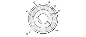
図1および2を参照すると、本発明の実施態様による物品40の一例を一部切り欠いて示した斜視図および物品の略式断面図が示されている。物品40は、電力源および使用の際、物品40と係合するヒーターを有する装置に使用するようになっている。この実施態様の物品40は、特に図5の以下で説明する装置1に使用するのに適している。
1 and 2, there is shown a cut-away perspective view and a schematic cross-sectional view of an
この実施態様の物品40は、エアロゾルを収容する多孔性の材料体44の周囲に位置する環状の喫煙材体43を含む。通常はエアロゾルを収容する多孔性の材料体44は喫煙材で形成されていない。この実施態様ではエアロゾルを収容する多孔性の材料体44は、密度が約100gsmまたは約120gsmの詰め綿またはフリースを含む。一部の実施態様ではエアロゾルを収容する多孔性の材料体44は、エアロゾル形成材料を含まない1つ以上の材料で形成される。他の実施態様ではエアロゾルを収容する多孔性の材料体44は、エアロゾル形成材料を含む1つ以上の材料で形成される。エアロゾルを収容する多孔性の材料体44を例えばエアロゾルの生成を向上させる喫煙材に含浸させてもよい。
この実施態様では喫煙材体43は、エアロゾルを収容する多孔性の材料体44と接触しているが、他の実施態様では喫煙材体43とエアロゾルを収容する多孔性の材料体44の間に別の材料層があってもよい。そのような別の材料層は物品40の剛性または頑健性を増加させ、喫煙材43と多孔性エアロゾル収容材44の相対位置を維持するのに役立ちおよび/または喫煙材43の種々の領域を保持するのに役立つ。そのような別の材料層としては再生タバコ紙の層が挙げられる。
In this embodiment the body of
この実施態様ではエアロゾルを収容する多孔性の材料体44は環状であり、物品40の空隙46の周囲に位置する。空隙46は軸を辿り、使用の際、エアロゾルを収容する多孔性の材料体44から揮発した材料を通過させて物品40から出す。この実施態様ではエアロゾルを収容する多孔性の材料体44は、物品40の内面45を画定し、エアロゾルを収容する多孔性の材料体44の半径方向内方の面45が空隙46を画定するまたは描出するようになっている。この実施態様では空隙46は物品40の一方の側から物品40の反対側へと延びた貫通孔である。しかしながら、他の実施態様では空隙46は、物品40の一方の側から物品40の反対側の方に延びただけの止まり穴であってもよい。さらに別の実施態様では空隙46はなくてもよい。いくつかのこのような別の実施態様ではエアロゾルを収容する多孔性の材料体44は、環状の喫煙材体43によって囲まれた空間を満たす。いくつかのこのような別の実施態様ではエアロゾルを収容する多孔性の材料体44は、環状ではなく円柱状であってもよく、使用の際、揮発した材料がエアロゾルを収容する多孔性の材料体44の軸方向の端部から物品40を通過して出るようにしてもよい。
In this embodiment, the porous body of
また図1および2の物品40は、喫煙材体43の周囲に位置し、これと接触する環状の伝熱材体42を含む。他の実施態様では喫煙材体43と伝熱材体42の間にさらに別の材料層があってもよい。この実施態様では伝熱材体42は、アルミニウム箔などの金属箔を含むが、他の実施態様では伝熱材体42は、箔、紙、ポリマー、プラスチック材および箔が重ねられた紙などの箔と紙を組み合わせたものからなる群から選択される1つ以上の材料を含んでもよい。そのような紙としては再生タバコ紙が挙げられる。伝熱材体42は、物品40の半径方向外側から喫煙材体43へ熱を伝えるためのものである。また伝熱材体42は、物品40の剛性または頑健性を増加し、および/または喫煙材43の種々の領域を保持するのに役立つようにする喫煙材43の基材となる。この実施態様では伝熱材体42が物品40の外面41を画定する。他の実施態様では伝熱材体42はなくてもよい。いくつかのこのような実施態様では喫煙材体43は、物品40の外面41を画定する。
The
この実施態様では喫煙材体43およびエアロゾルを収容する多孔性の材料体44のそれぞれの軸方向端部は、物品40の軸方向端部で見える。しかしながら、他の実施態様では物品40の軸方向端部の一方または両方は、喫煙材体43のおよび/またはエアロゾルを収容する多孔性の材料体44の軸方向端部を覆う端部部材(図示せず)を含んでもよい。そのまたは各端部部材は、伝熱材体42の半径方向に延びた部分によって形成してもよい。
In this embodiment the respective axial ends of the body of
図1および2の物品40は、次の方法で製造してもよい。最初に多孔性のエアロゾルを収容する材料と、喫煙材からなる層と、伝熱材料からなる層とを含む集合体を供する。この集合体において、多孔性エアロゾル収容材は、喫煙材からなる層上にあり、それと接触している。順に喫煙材からなる層は、伝熱材料からなる層上にあり、それと接触している。
それから集合体は、(a)伝熱材料からなる層が環状の伝熱材体42になり、(b)喫煙材からなる層は環状の喫煙材体43になり、(c)多孔性エアロゾル収容材が環状の多孔性エアロゾル収容材体44になるように曲げられる、または巻かれる。集合体は、集合
体の多孔性エアロゾル収容材上に置かれ、最終的に物品40の空隙46内に位置するスピンドルの周囲で巻かれるまたは曲げられる。次にスピンドルを空隙46から取り外してもよい。巻くまたは曲げに続いて、環状の伝熱材体42は、物品40の外面41を画定し、環状の多孔性エアロゾル収容材体44の半径方向内方の面が空隙46を画定する。
The assembly then comprises (a) the layer of heat transfer material becoming an annular heat
当業者は本開示から図1および2の物品40のこの製造方法を物品40の上述の変型例の1つの製造にどのようにして適合させるかを容易に理解するはずである。例えば、当業者が製造された物品が喫煙材体43とエアロゾルを収容する多孔性の材料体44との間および/または喫煙材体43と伝熱材体42の間に材料層を含むようにしたいと思った場合、当業者は、集合体において材料の層を喫煙材からなる層と多孔性エアロゾル収容材の間および/または喫煙材からなる層と伝熱材料からなる層の間に含有させる必要があることを理解するはずである。当業者は、得られる物品においてエアロゾルを収容する多孔性の材料体44が確実に環状ではなく円周状になるように集合体の多孔性エアロゾル収容材を適合させることができるはずである。物品が環状の伝熱材体42を含まないようなものである場合、集合体において喫煙材からなる層は、曲げまたは巻き手順時に曲げられるまたは巻かれ、その後喫煙材体43が物品の外面41を画定するように曲げまたは巻いた後に取り除かれる基材層上にこれと接触して位置させることも可能である。
A person skilled in the art should readily understand from this disclosure how to adapt this method of
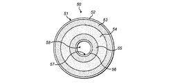
図3および4を参照すると本発明の実施態様による別の物品50の一例が一部を切り欠いて示した斜視図および略式断面図で示されている。この実施態様の物品50は、以下に説明する図6および7に示す装置2に使用するのに適している。
3 and 4, an example of another
この実施態様の物品50は、エアロゾルを収容する多孔性の材料体54の周囲に位置する環状の第1喫煙材体53を含む。通常はエアロゾルを収容する多孔性の材料体54は、喫煙材で形成されていない。この実施態様ではエアロゾルを収容する多孔性の材料体54は、密度が約100gsmまたは約120gsmの詰め綿またはフリースを含む。一部の実施態様ではエアロゾルを収容する多孔性の材料体54は、エアロゾル形成材料を含まない1つ以上の材料で形成される。他の実施態様ではエアロゾルを収容する多孔性の材料体54は、エアロゾル形成材料を含む1つ以上の材料で形成される。エアロゾルを収容する多孔性の材料体54を例えばエアロゾルの生成を向上させる喫煙材に含浸させてもよい。
この実施態様では第1喫煙材体53は、エアロゾルを収容する多孔性の材料体54と接触しているが、他の実施態様では第1喫煙材体53とエアロゾルを収容する多孔性の材料体54の間に別の材料層があってもよい。そのような別の材料層は物品50の剛性または頑健性を増加させ、第1喫煙材体53と多孔性エアロゾル収容材54の相対位置を維持するのに役立ちおよび/または第1喫煙材体53の種々の領域を保持するのに役立つ。そのような別の材料層としては再生タバコ紙の層が挙げられる。この実施態様ではエアロゾルを収容する多孔性の材料体54は、環状であり、物品50の空隙の周囲に位置するが、エアロゾルを収容する多孔性の材料体54自体は、後述するように空隙58を画定も描出もしない。
In this embodiment the first body of
図3および4の物品50もまた第1喫煙材体53の周囲に位置し、これと接触する環状の第1伝熱材体52を含む。他の実施態様では第1喫煙材体53と第1伝熱材体52の間に別の材料層があってもよい。この実施態様では第1伝熱材体52は、アルミニウム箔などの金属箔を含むが、他の実施態様では第1伝熱材体52は、図1および2の物品40の伝熱材体52について上述した材料のいずれかを含んでもよい。第1伝熱材体52は、物品50の半径方向外側から第1喫煙材体53へ熱を伝えるためのものである。第1伝熱材体52は、物品50の剛性または頑健性を増加させ、および/または喫煙材の種々の領域を保持するのに役立つようにする喫煙材53の基材となる。この実施態様では第1伝熱材体52は物品50の外面51を画定する。他の実施態様では第1伝熱材体52はなくても
よい。いくつかのこのような実施態様では第1喫煙材体53は、物品50の内面51を画定する。
The
図3および4の物品50は第2喫煙材体55も含む。環状の多孔性エアロゾル収容材体54は、第2喫煙材体55の周囲に位置し、これと接触する。他の実施態様では第2喫煙材体55とエアロゾルを収容する多孔性の材料体54の間に別の材料層があってもよい。種々の実施態様ではそのような別の材料層は、再生タバコ紙から作成することができ、および/または第1喫煙材体53とエアロゾルを収容する多孔性の材料体54の間の任意の別の層で上述した利点のいずれかを供することができる。
The
図3および4の物品では第1喫煙材体53の喫煙材は、第2喫煙材体55の喫煙材の形体および化学組成と同じ形体および化学組成を有する。しかしながら、種々の他の実施態様では第1喫煙材体53の喫煙材は、第2喫煙材体55の喫煙材の形体および化学組成と異なる形体および化学組成を有してもよい。
In the articles of FIGS. 3 and 4, the smokable material of the first body of
例えば一部の実施態様では第1および第2喫煙材体53、55の一方の喫煙材は、第1および第2喫煙材体53、55のもう一方の喫煙材より例えば喫煙材の少なくとも1つの成分を揮発させるためにより速く加熱されるような形体を有する。一部の実施態様では第1および第2喫煙材体 53、55の喫煙材は異なる平均粒子径を有してもよい。即ち、第1および第2喫煙材体53、55の一方の喫煙材は、第1の平均粒径を有する喫煙材の粒子を含んでもよく、第1および第2喫煙材体53、55のもう一方の喫煙材は、第1の平均粒径より大きい第2の平均粒径を有する喫煙材の粒子を含んでもよい。通常、小さい平均粒径を有する喫煙材の粒子は、それより大きい平均粒径を有する喫煙材の粒子より所定の熱源によって、例えば喫煙材の少なくとも1つの成分を揮発させるためにより速く加熱される。異なる喫煙材体53、55に異なる平均粒径を供することによって、物品50の喫煙材を段階的に加熱、これによりエアロゾルを段階的に発生させることができる。
For example, in some embodiments, the smokable material of one of the first and second bodies of
一部の実施態様ではこのような異なる平均粒径にすることに加えてまたはこれとは別に第1喫煙材体53の喫煙材は、第2喫煙材体55の喫煙材と異なる化学組成を有してもよい。即ち、第1喫煙材体53の1つ以上の成分は、第2喫煙材体の1つ以上の成分と異なってもよい。一部のこのような実施態様では第1および第2喫煙材体53、55の一方の喫煙材は、グリセリンなどのエアロゾル形成剤を含み、第1および第2喫煙材体53、55のもう一方の喫煙材は、エアロゾル形成剤を含まないまたは実質的に含まない。異なる喫煙材体53、56に異なる化学組成を供することによって、物品50の喫煙材を段階的に加熱、これによりエアロゾルを段階的に発生させることができる。これとは別にまたはこれに加えて、第1および第2喫煙材体53、55の一方または他方を装置1で加熱して、ユーザーがユーザーの吸入用のエアロゾルを生成するために第1および第2喫煙材体53、55のどちらを使用するか選択できるようにする。
In some embodiments, in addition to or alternatively to such different average particle sizes, the smokable material of the first body of
一部の実施態様では第1および第2喫煙材体53、55の化学組成の違いは、第1および第2喫煙材体53、55それぞれの喫煙材の総重量のパーセンテージとして第1および第2喫煙材体53、55それぞれの風味剤などの煙変性物質の重量での量の違いを含んでもよい。例えば一部の実施態様では第1および第2喫煙材体53、55の一方の喫煙材は、風味剤を含んでもよく、第1および第2喫煙材体53、55のもう一方の喫煙材は、風味剤を含まないまたは実質的に含まなくてもよい。一部の実施態様では第1および第2喫煙材体53、55の一方は、第1の風味剤を含んでもよく、第1および第2喫煙材体53、55のもう一方は第1の風味剤とは異なる第2の風味剤を含んでもよい。第1および第2喫煙材体53、55に異なる量の煙変性剤または風味剤を供することによって、一部の実施態様ではユーザーが吸入するために発生させたエアロゾルの風味を変えることができる。
In some embodiments, the difference in chemical composition of the first and second bodies of
図3および4の物品50は、環状の第2伝熱材体56をさらに含む。第2喫煙材体55は、第2伝熱材体56の周囲に位置し、これと接触する。他の実施態様では第2喫煙材体55と第2伝熱材体56の間に別の材料層があってもよい。この実施態様では第2伝熱材体56は、アルミニウム箔などの金属箔を含むが、他の実施態様では第2伝熱材体56は、図1および2の物品40の伝熱材体42について上述した材料のいずれかを含んでもよい。
第2伝熱材体56は、物品50の半径方向内側から第2喫煙材体55へ熱を伝えるためのものである。第2伝熱材体56は物品50の剛性または頑健性を増加させ、および/または喫煙材の種々の領域を保持するのに役立つようにする第2喫煙材体55の基材となる。この実施態様では第2伝熱材体56は、第2伝熱材体56の半径方向内方の面57が空隙58を画定するまたは描出するように物品50の内面57を画定する。空隙58は、軸を辿り、使用の際、装置2の第1ヒーター22を収容する。この実施態様では空隙58は物品50の一方の側から物品50の反対側へと延びた貫通孔である。しかしながら、他の実施態様では空隙58は、物品50の一方の側から物品50の反対側の方に延びただけの止まり穴であってもよい。他の実施態様では第2伝熱材体56はなくてもよい。いくつかのこのような実施態様では第2喫煙材体55の半径方向内方の面は、物品50の内面57および空隙58を画定する。
The second body of
この実施態様では第1および第2喫煙材体53、55それぞれおよびエアロゾルを収容する多孔性の材料体54の軸方向の端部は物品50の軸方向端部で目に見える。しかしながら、他の実施態様では物品50の軸方向端部の一方または両方は、第1および第2喫煙材体53、55および/またはエアロゾルを収容する多孔性の材料体54の軸方向端部を覆う端部部材(図示せず)を含んでもよい。そのまたは各端部部材は、第1伝熱材体52の半径方向に延びた部分によって形成してもよい。
In this embodiment the axial ends of the first and second bodies of
上述の物品50は、環状の別の材料体と、この材料体の周囲に位置する環状の第1喫煙材体と、環状の第2喫煙材体とをを含み、その別の材料体は、第2喫煙材体の周囲に位置する物品の実施態様である。上述の物品50の変型例では、多孔性エアロゾル収容材を必ずしも多孔性でなく、および/またはエアロゾルを収容するのに適していない別の材料に置き換えてもよい。その結果得られる物品のいくつかは、第1および/または第2伝熱材体52、56を含んでもよく、一方別のこのような物品から第1および/または第2伝熱材体52、56から除いてもよい。
The
図3および4の物品50は、次の方法で製造してもよい。最初に多孔性のエアロゾル収容材料と、喫煙材からなる第1および第2の層と、伝熱材からなる第1および第2の層とを含む集合体を設ける。この集合体において、伝熱材からなる第2の層は、喫煙材からなる第2の層上にあり、それと接触している。喫煙材からなる第2の層は、多孔性エアロゾル収容材上にあり、それと接触している。多孔性エアロゾル収容材は、喫煙材からなる第1の層上にあり、それと接触している。喫煙材からなる第1の層は、伝熱材からなる第1の層上にあり、それと接触している。
その後集合体は、(a)伝熱材からなる第1の層が環状の第1伝熱材体52になり、(b)喫煙材からなる第1の層が環状の第1喫煙材体53になり、(c)多孔性エアロゾル収容材が環状の多孔性エアロゾル収容材体54になり、(d)喫煙材からなる第2の層が環状の第2喫煙材体55になり、(e)伝熱材からなる第2の層が環状の第2伝熱材体56になるように曲げられるまたは巻かれる。集合体は集合体の伝熱材からなる第2の層上に置かれ、最終的に物品50の空隙58内に位置するスピンドルの周囲で巻かれるまたは曲げられる。次にスピンドルをは、空隙58から取り外してもよい。曲げたまたは巻いた
後、環状の第1伝熱材体52は物品50の内面51を画定し、環状の第2伝熱材体 56の半径方向内方の面が空隙58を画定する。
The assembly then becomes (a) a first annular first heat
ここでも当業者は、本開示から図3および4の物品50のこの製造方法を物品50の上述の変型例の1つの製造にどのようにして適合させるかを容易に理解するはずである。例えば、当業者には自明なように伝熱材からなる第1の層を集合体の材料の他の層と比較して大きくし、曲げまたは巻き作業後に第1伝熱材体52の突出した部分を折り曲げて、第1伝熱材体52の半径方向に延びた端部部材を形成し、この端部部材が第1および第2喫煙材体53、55および多孔性エアロゾル収容材体の軸方向端部を覆うようにしてもよい。
Again, those skilled in the art should readily understand from this disclosure how to adapt this method of
上述の実施態様のそれぞれにおいて、物品40、50は、環状の喫煙材体43、53の軸に垂直な面において円形の外周を有する。しかしながら、他の実施態様ではその外周 楕円または多角形などの円形以外の形状であってもよい。上述の実施態様のそれぞれでは物品40、50の種々の部材は、「環状」であると説明されている。上述の実施態様ではこれら部材のそれぞれは環状および円形である。しかしながら、他の実施態様ではこれらの部材の1つ以上は環状であり、それ以外は楕円または多角形などの円形以外の形状であってもよい。
In each of the above-described embodiments, the
物品40、50の上述の各実施態様では喫煙材はタバコを含む。しかしながら、他の実施態様では喫煙材は、タバコからなる、実質的にタバコだけからなる、タバコとタバコ以外の喫煙材とを含む、タバコ以外の喫煙材を含む、またはタバコを含まなくてもよい。喫煙材は、グリセリンなどのエアロゾル形成剤を含んでもよい。
In each of the above-described embodiments of
物品40、50の上述の各実施態様では多孔性エアロゾル収容材は、喫煙材を加熱することによって物品40、50に発生したエアロゾルを収容するための多孔質材料である。物品40、50の上述の各実施態様では多孔性エアロゾル収容材は、密度が約100gsmまたは約120gsmの詰め綿またはフリースを含む。他の実施態様では多孔性エアロゾル収容材の密度は異なってもよい。しかしながら、密度が高すぎると、多孔性エアロゾル収容材は、フィルターとして作用し、発生したエアロゾルを希釈してしまう。これとは別に密度が低すぎると、多孔性エアロゾル収容材が、エアロゾルを効果的に収容しない場合がある。特に多孔性エアロゾル収容材が詰め綿またはフリースを含む場合の適当な密度は、約60~約140gsmまたは約80~約120gsmである。一部の実施態様ではエアロゾル収容材は、1mm~2mmの範囲の厚さを有してもよい。
In each of the above-described embodiments of
さらに別の実施態様では多孔性エアロゾル収容材は、詰め綿、フリース、不織材、不織フリース、織り材、編み材、ナイロン、発泡体、ポリスチレン、ポリエステル、ポリエステルフィラメント、ポリプロピレンおよびポリエステルおよびポリプロピレンをブレンドしたものからなる群から選択される1つ以上の多孔質材料を含んでもよい。詰め綿またはフリース以外の材料を使用する場合、その材料は、約80~約120gsmの密度を有する詰め綿またはフリースと類似の熱的特性を有するように選択された密度を有するものになる。物品40、50の上述の各実施態様では多孔性エアロゾル収容材は喫煙材を含まない。しかしながら、必ずしもそうである必要はない。
In yet another embodiment, the porous aerosol containing material comprises wadding, fleece, nonwovens, nonwoven fleeces, wovens, knitted materials, nylons, foams, polystyrenes, polyesters, polyester filaments, polypropylenes and polyesters and polypropylenes. It may comprise one or more porous materials selected from the group consisting of blends. If a material other than wadding or fleece is used, the material will have a density selected to have similar thermal properties to wadding or fleece having a density of about 80 to about 120 gsm. In each of the above-described embodiments of
一部の実施態様ではエアロゾルを収容する多孔性の材料体は、以下に説明するように動作している間上昇する装置1の加熱装置20の予測される例えば150~300℃または170~220℃の温度範囲に少なくとも亘って耐熱性であり、そのような動作温度に曝されても劣化しない。
In some embodiments, the porous body of material containing the aerosol is raised during operation as described below to the expected temperature of the
一部の実施態様では多孔性エアロゾル収容材は、使用の際、物品40、50で発生した
揮発した材料が確実に装置1の凹部13の内面上に凝集しないようにするのに役立つ。一部の実施態様ではエアロゾルを収容する多孔性の材料体を設けることは、使用の際に物品40、50の発生したエアロゾルが形成する表面積を大きくすることに役立つ。一部の実施態様ではこのようなエアロゾルを収容する多孔性の材料体は、使用時、物品40、50で発生するまたは発せられる目に見えるエアロゾルの量を増やすのに役立ち、従って、消費者の感覚を向上させる。
In some embodiments, the porous aerosol containment material helps ensure that volatilized material generated by the
上記各実施態様では物品40、50は、消耗品である。物品40、50の喫煙材の揮発成分の全てまたは実質的に全てが消費されると、ユーザーは装置1から物品40、50を外し、物品40、50を廃棄してもよい。ユーザーは、次に別の未使用の物品40、50を装置1の接合部13に嵌め、装置1を再度使用する。しかしながら、他の各実施態様では物品40、50は、非消耗品であってもよく、物品40、50の喫煙材の揮発成分が消費されたら、装置1と物品40、50を一緒に廃棄してもよい。
In each of the above embodiments the
図5を参照すると、喫煙材を加熱して、喫煙材の少なくとも1つの成分を揮発させるための装置1の一例を一部切り欠いて示した斜視図が示されている。装置は、図1および2を参照して上述した物品40に使用するのに特に適している。使用の際、装置1は喫煙材を燃焼または燃やさずに喫煙材の少なくとも1つの成分を揮発させるために物品40の喫煙材を加熱するように構成されている。装置1は、本体10とマウスピース30とを含む。組み立てられた際の装置1の外観は、本体10とマウスピース30によって画定される。
Referring to FIG. 5, there is shown a cut-away perspective view of an exemplary apparatus 1 for heating smokable material to volatilize at least one component of the smokable material. The device is particularly suitable for use with the
本体10は、ほぼ管状であり、そして長尺であり、対向する第1および第2長手方向端部11、12を有し、物品40と協働するための接合部を画定する。この実施態様では接合部は、物品40を収容するための凹部13を含む。他の実施態様では接合部は、棚、面または突起などの異なる形体であってもよく、場合によっては物品40と協働するために物品40との機械的な噛み合いを必要とする。本体10の第1長手方向端部11は、凹部13の第1端部で凹部13内に開口した開口部14を画定する。開口部14は、以下に詳しく説明するようにユーザーが物品40を凹部13内に挿入でき、および/また物品40を凹部13から取り外したりできるように物品40が開口部14を通って移動可能な形状および大きさである。本体10は、装置1の電気部品を収容する。この実施態様ではの電気部品は、電力源15と、コントローラー16と、アクチュエーター17と、加熱装置20とを含む。
この実施態様ではマウスピース30は、ほぼ管状で長尺であり、第1および第2の対向する長手方向端部31、32を有する。マウスピース30は、マウスピース30の第2長手方向端部32で入り口34と、マウスピース30の第1長手方向端部31で出口35と、入り口34を出口35に流体接続する流路36とを含む。マウスピース30の第2長手方向端部32はコネクター(図示せず)を含み、これはマウスピース30を本体10に接続するために本体10の第1長手方向端部11のコネクター(図示せず)と解除可能に係合可能である。他の実施態様ではマウスピース30および本体10はヒンジまたは可撓性部材などを介して永久的に接続されてもよい。装置1が使用中の際、マウスピース30の第1長手方向端部31は装置1の第1長手方向端部を形成し、本体10の第2長手方向端部12は装置1の第2長手方向端部を形成する。
マウスピース30は、凹部13に開口する開口部14を覆うために本体10に対して配置可能である。マウスピース30を本体10に対してそのように配置すると、マウスピース30の第1長手方向端部31は、装置1の第1長手方向端部を形成し、マウスピース30の流路36は、マウスピース30の入り口34を介して凹部13と流体連通する。一部の実施態様ではマウスピース30は、物品40が凹部13内にあるときに物品40と接触
し、物品40を凹部13内に押し込み、物品40が確実に加熱装置20に対して正しく位置するようにする特徴を含む。
A
この実施態様では加熱装置20は、凹部13を囲む管状のヒーター21を含む。ヒーター21は、ヒーター21の軸に垂直な面において環状の断面形状を有し、ヒーター21の半径方向内方の面が凹部13の半径方向の範囲を画定する。従って、凹部13は、ヒーター21と同軸である。加熱装置20は、保持器18に取り付けられ、これはヒーター21を本体10に対して所定の位置に保持するために本体10に固定されている。この実施態様ではヒーター21は、凹部13の第2端部から凹部13の第1端部へと延び、ヒーター21の軸方向端部は、凹部13に開口する開口部14を画定する。即ち、ヒーター21は、凹部13の軸方向の全長に沿って延びている。他の実施態様では凹部13は、ヒーター21によって部分的に画定され、本体10の1つ以上の他のセクションによって部分的に画定されている。一部の実施態様では凹部13に開口する開口部14は、ヒーター21以外の本体10のセクションによって画定されている。
In this embodiment the
この実施態様ではヒーター21は、導電材を含む。この実施態様では導電材は、銅であるが、他の実施態様では導電材は、金属、金属合金、鋼、ステンレススチール、銅およびニクロムの内の任意の1つ以上を含んでもよい。この実施態様では導電材は、パターン化され、導電性のトラックを設ける方法でエッチングされている。他の実施態様では導電材層はパターン化されるようにプリントしてもよく、あるいはいくつかの他の方法でパターン化してもよい。さらに別の実施態様では導電材層は、パターン化されてなくてもよい。例えば、一部のこのような実施態様では導電材は、ある程度の長さを有する単純な管状の導電材であってもよい。ヒーター21は、電流を導電材に通すことによって加熱可能である。導電材を好適にパターン化することによって、導電材の断面積および電流流れ経路の長さは、ヒーター21が所定の電流を導電材に通すことによって加熱されるように設定される。
In this
ヒーター21は、導電材を支持するための支持体も含む。この実施態様では支持体は、電気絶縁体であり、耐熱性である。より具体的には支持体は、動作している間上昇するヒーター21の予測される例えば150~300℃または170~220℃の温度範囲に少なくとも亘って耐熱性である。この実施態様では支持体が、セラミックであるが、他の実施態様では支持体は、ポリイミドなどの別の材料から作製されてもよい。本明細書の別のところで述べるようにコントローラー16が、ヒーター21がこの範囲内の温度に確実に加熱されるように一部の実施態様では配されている。従って、支持体は、器具1の使用中の導電材の加熱に耐えることができる。
この実施態様では電力源15は充電可能なバッテリーである。他の実施態様では電力源15は、充電不可のバッテリーまたはコンデンサなどの充電可能なバッテリー以外のものであってもよい。
In this
この実施態様ではコントローラー16は、印刷回路板(PCB)上に設けられた集積回路(IC)などのICを含む。他の実施態様ではコントローラー16は、これとは異なる形体であってもよい。コントローラー16は、電力源15から加熱装置20への電力の供給を制御するためのものである。コントローラー16は、この実施態様ではアクチュエーター17をユーザーが始動させることによって作動する。アクチュエーター17は、本体10の外側に位置し、押しボタンの形体である。他の実施態様ではトグルスイッチ、ダイアルなどの異なる形体のアクチュエーター17を設けてもよい。ユーザーによってアクチュエーター17を作動させることでコントローラー16が加熱装置20のヒーター21の導電材に電流を印加させるようにする。アクチュエーター17のそのような作動によりコントローラー16の電気回路を完了させる。電流がそのように導電材に印加されると、ヒ
ーターが熱くなる。この実施態様では導電材の電気抵抗は、ヒーター21の温度が上昇するにつれて変化する。コントローラー16は、加熱された導電材の電気抵抗を監視し、その後約150℃~約300℃または約170℃~約220℃の上述の温度範囲内にヒーターの温度が確実に留まるようにするために必要に応じて監視した電気抵抗を基に導電材に印加された電流の大きさを調節する。この温度範囲内で物品40の喫煙材は、喫煙材を燃焼させずに喫煙材の少なくとも1つの成分揮発させるのに充分に加熱される。従って、コントローラー16および装置1全体として喫煙材を燃焼させずに喫煙材の少なくとも1つの成分を揮発させるように喫煙材を加熱するように構成されている。他の実施態様では加熱の温度範囲はこの範囲外の範囲であってもよい。
In this embodiment,
図には示していないが本体10は、装置1の外側から装置1内に空気を入らせるための入り口を有し、保持器18は、穴を有し、その中に入り口と流体連通する凹部13が入れられる。従って、装置1を組み立てるためにマウスピース30を本体10に接続すると、装置1の外側から入り口を通り、保持器18の穴を通り、凹部13を通り、マウスピースの流路36を通って装置1の外側へと延びた全体的な流路が画定される。
Although not shown in the figures, the
この実施態様の装置1の典型的な操作をここで説明する。ユーザーは、物品40が開口部14を通って移動可能である本体10に対する位置にマウスピース30があることを確実にする。それからユーザーは、物品40を開口部14を介して凹部13内に移動させ、管状ヒーター21内に物品40を配置する。さらにユーザーは、マウスピース30が開口部14を覆う位置にマウスピース30を本体10に対して移動し、この状態でマウスピース30の第1長手方向端部31が装置1の第1長手方向端部を形成し、マウスピースの流路36がマウスピース30の入り口34を介して凹部13と流体連通する。マウスピース30は、マウスピース30のコネクターと本体10のコネクターの係合によりこの位置に保持される。
A typical operation of the device 1 of this embodiment will now be described. The user ensures that
次にユーザーがアクチュエーター17を始動させると、コントローラー16が作動し、ヒーター21の導電材に電流が流れるようにする。このように電流を流すことでヒーター21が熱くなり、物品の喫煙材体43を加熱する。これにより喫煙材を燃焼させずに喫煙材の少なくとも1つの成分を揮発させる。ユーザーはマウスピース30の出口35を介して吸い込む。これが凹部13内の圧力を減少させ、本体10の入り口および保持器18の穴の順でこれらを介して凹部13内に空気が引き込まれるようにする。通常はこれにより喫煙材43の揮発させた成分が冷却され、縮合し、エアロゾルを形成する。エアロゾルを収容する多孔性の材料体44は、発生したエアロゾルを含み、凹部13の内面でエアロゾルが凝縮するのを妨げるのに役立つ。ユーザーが吸い込み続けるとエアロゾルが凹部13からおよび/またはエアロゾルを収容する多孔性の材料体44からそしてマウスピース30の流路36を介してユーザーの口内に吸引されるようになる。空気が凹部13内に引き込まれる度にエアロゾルが生成される。これが喫煙材43の揮発成分を使い切るまで繰り返すことができる。
When the user then actuates
喫煙材体43の喫煙材の全てまたは実質的に全ての揮発成分が消費されると、ユーザーは本体10に対してマウスピース30を物品40が開口部14を通って移動可能になる位置に動かしてもよい。その後ユーザーは、開口部14を介して凹部13から物品40を取り除いてもよい。次にユーザーは、別の未使用の物品40を凹部13内に挿入することができ、上記のプロセスを繰り返すことができる。
Once all or substantially all of the volatile components of the smokable material of body of
図6を参照すると喫煙材を加熱して喫煙材の少なくとも1つの成分を揮発させるための装置2の別の例が一部切り欠いて示した斜視図で示されている。装置2は、図3および4を参照して上述した物品50に使用するのに特に適している。使用時、装置2は、喫煙材を燃焼または燃やさずに喫煙材の少なくとも1つの成分を揮発させるために物品50の喫
煙材を加熱するように構成されている。この実施態様の装置2は、加熱装置20およびコントローラー16の形体を除いて上述の図5に示した装置1と同一である。図6の装置の加熱装置20が図7により詳しく示されている。
Referring to FIG. 6, another example of a device 2 for heating smokable material to volatilize at least one component of the smokable material is shown in perspective, partially cut-away view. Device 2 is particularly suitable for use with
図6の装置2では加熱装置20は、軸に沿って延びた第1ヒーター22と、第1ヒーター22から間隔が空けられ、そして少なくとも部分的に第1ヒーター22を囲む第2ヒーター23とを含む。この実施態様では第2ヒーター23は、管状であり、凹部13の一部を囲む。この実施態様では第2ヒーター23は、軸に垂直な面において環状であり円形である断面形状を有し、第2ヒーター23の半径方向内方の面がその凹部13の部分の半径方向の範囲を定める。しかしながら、他の実施態様では第2ヒーター23の断面形状は、楕円状または多角形などの円形以外の環状であってもよく、または第2ヒーター23の断面形状は、円または半円の弧などの環状以外の形状であってもよい。この実施態様では第2ヒーター23は第1ヒーター22と同軸であるが、他の実施態様ではそうでない場合もある。この実施態様では第1ヒーター22は、凹部13内に突出し、軸に垂直な面において円形の断面形状を有する。しかしながら、他の実施態様では第1ヒーター22は、楕円または多角形などの円形以外の断面形状を有してもよい。図6の装置2は、図3および4を参照して上述した物品50に特に好適に使用される。
In the device 2 of FIG. 6, the
この実施態様では第1ヒーター22は、軸に平行な方向の第1の長さを有し、第2ヒーター23は、軸に平行な方向の第2の長さを有し、第2の長さは、第1の長さより短い。この実施態様では第1および第2の長さは軸に垂直な面から測定される。言い換えればこの実施態様では第1および第2ヒーター22、23のそれぞれは、面内にある軸方向端部を有する。しかしながら、他の実施態様では第1および第2ヒーター22、23のそれぞれは、第1および第2ヒーター22、23のもう一方の軸方向端部と同一面にない軸方向端部を有してもよい。この実施態様では加熱装置20は、本体10に固定され、第1および第2ヒーター22、23を本体10に対して所定の位置に保持する保持器18を含む。保持器18は穴を有し、それを通して本体10の入り口と流体連通する凹部13が位置する。
In this embodiment the
この実施態様では凹部13は、第2ヒーター23によって部分的に画定され、かつ、本体10の一部分によって部分的に画定されている。凹部13に開口する開口部14は、加熱装置20以外の本体10の一部によって画定されている。この実施態様では第1および第2ヒーター22、23のそれぞれは、凹部13の第2端部から凹部13の第1端部の方へと延びているが、第2ヒーター23は、開口部14まで延びず、一方第1ヒーター22は開口部14を通過して延びている。集合体1が完全に組み立てられると、保持器18から遠位にある第1ヒーター22の遠位端は、マウスピース30内に位置する。しかしながら、一部の他の実施態様では第2ヒーター23は、凹部13の軸方向の全長に沿って延びてもよいおよび/または第2ヒーター23の軸方向端部は、凹部13に開口する開口部14を画定してもよい。
In this embodiment the
この実施態様では第1および第2ヒーター22、23のそれぞれは、導電材とこの導電材を支持するための支持体とを含む。導電材および支持体は、図5の装置1のヒーター21の導電材および支持体で上述した任意の材料および形体からなるものであってもよく、従ってさらに詳しくここでは説明しない。
In this embodiment, each of the first and
図6の装置2のコントローラー16は、電力源15から加熱装置20への電力の供給を制御するためのものである。しかしながら、図5の装置1のコントローラー16とは対照的に図6の装置2のコントローラー16は、電力源15から第2ヒーター23への電力供給とは独立して電力源15から第1ヒーター22への電力の供給を制御するためのものである。従って、ユーザーがアクチュエーターを始動させると、コントローラー16は、例
えばコントローラー16に第1の電流を第1および第2ヒーター22、23の一方の導電材に流れさせ、次に第2の電流を第1および第2ヒーター22、23のもう一方の導電材に流れさせるようにする。第1電流が流されている間または第1電流を流し終えた後に第2電流を流してもよい。コントローラー16が第1および第2ヒーター22、23の導電材に電流を流れるようにする方法は、複数の可能な方法の1つでユーザーがアクチュエーター17を好適に始動させるなどによってユーザーが選択できるようにしてもよい。即ち、一部の実施態様ではアクチュエーター17は、それぞれが異なる所定の方法でコントローラー16に加熱装置20を作動させる複数の異なる方法でユーザーによって始動させてもよい。従って、一部の実施態様ではユーザーは、第1および第2ヒーター22、23のどちらが加熱されるようにするか、従って第1および第2喫煙材体53、55のどちらが加熱されるようにするかを選択できるようにしてもよい。第1および第2喫煙材体53、55が所定の熱源によって異なる速度で加熱可能である、または異なる煙変性剤または風味剤を含む実施態様では、ユーザーは、従って、エアロゾルを吸入する際に発生させたい種類のエアロゾル、従って味わいたい感覚を選択または構成することができる。
The
図5の装置1の加熱装置の場合と同様に第1および第2ヒーター22、23の導電材の電気抵抗は、第1および第2ヒーター22、23の温度が上がるにつれて変化する。コントローラー16は、ヒーターの温度が確実に約150℃~約300℃または約170℃~約220℃の上述の温度範囲内に留まるようにするために加熱された導電材の電気抵抗を監視し、その後必要に応じて監視された電気抵抗に基づいて導電材に流れる電流の度合いを調節する。この温度範囲内で物品50の喫煙材は、喫煙材を燃焼させずに喫煙材の少なくとも1つの成分揮発させるのに充分に加熱される。従って、コントローラー16および装置2全体として喫煙材を燃焼させずに喫煙材の少なくとも1つの成分を揮発させるように喫煙材を加熱するように構成されている。他の実施態様では加熱の温度範囲はこの範囲外の範囲であってもよい。
As in the heating device of the device 1 of FIG. 5, the electrical resistance of the conductive material of the first and
この実施態様の装置2の操作例を説明する。ユーザーは、第1ヒーター22を物品50の空隙58内にスライドさせ、物品50を開口部14を介して凹部13内に移動させ、物品50を管状の第2ヒーター23内に配置する。ユーザーは、それから図5の装置1について上述したようにマウスピース30が開口部14を覆う位置にマウスピース30を本体10に対して移動する。
An example of operation of the device 2 of this embodiment will now be described. The user slides
その後ユーザーがアクチュエーター17を始動させると、コントローラー16が加熱装置20の導電材に電流が流れるようにする。このように電流を流すことにより第1および/または第2ヒーター22、23を熱くし、物品50の第1および第2喫煙材体53、55を加熱する。第1ヒーター22が物品50の空隙58内にあるとき、第1ヒーター22は第1喫煙材体53より第2喫煙材体55に近くなり、第2ヒーター23は第2喫煙材体55より第1喫煙材体53に近くなる。従って、使用時、第1ヒーター22は、主に第2喫煙材体55を加熱するためのものであり、第2ヒーター23は、主に第1喫煙材体53を加熱するためのものである。第1および/または第2ヒーター22、23の加熱によって喫煙材を燃焼させずに喫煙材の少なくとも1つの成分を揮発させる。エアロゾルを収容する多孔性の材料体54は、喫煙材の成分を揮発させた後発生したエアロゾルを含み、装置2の凹部13の内面でエアロゾルが凝縮するのを妨げるのに役立つ。ユーザーは、図5の装置1について上述したようにマウスピース30の出口35で吸い込むことでエアロゾルを吸入する。
When the user subsequently actuates
第1および/または第2喫煙材体53、55の喫煙材の揮発成分の全てまたは実質的に全てを使い切ると、ユーザーは開口部14を介して凹部13から物品50を取り外し、別の未消費の物品50を凹部13内に挿入し、上記のプロセスを繰り返す。
Once all or substantially all of the volatiles of smokable material in the first and/or second body of
他の実施態様ではヒーター21、22、23の温度は、異なる方法で調節してもよい。例えば、一部の実施態様ではコントローラー16は、ヒーターの温度が確実に上述の温度範囲内に留まるようにするために導電材を流れる電流またはヒーター21、22、23の温度またはそれに近いものを感知するセンサーからの出力を監視し、その後必要に応じて監視された電流に基づいて導電材に流れる電流の度合いを調節する。ヒーター21、22、23の温度を調節する他の方法が他の実施態様では使用可能である。
In other embodiments the temperature of
一部の実施態様では上述の装置1、2のいずれか1つは、装置1、2が特に好適に使用される物品40、50とは別個に販売、供給または提供されてもよい。しかしながら、一部の実施態様では装置1、2の内の1つおよび物品40、50の内の1つ以上をキットとして設けてもよい。
In some embodiments, any one of the devices 1, 2 described above may be sold, supplied or provided separately from the
種々の問題の対処と技術の発展のため、本開示全体は種々の実施形態を例示的に示しており、これらの実施形態では特許請求された発明が実践され、優れた喫煙材を加熱して喫煙材の少なくとも1つの成分を揮発させるための装置および/またはこの装置に使用する優れた物品を提供することができる。本開示の利点および特徴は実施形態の単なる代表的な具体例であり、包括的でも排他的でもない。これらは特許請求された特徴の理解と教示の単なる補助に提供されている。当然だが、本開示の利点、実施形態、具体例、機能、特徴、構造、および/または他の側面は本開示を特許請求の範囲に規定されたとおりに限定するあるいは特許請求の範囲の均等物に限定すると考えるべきではなく、本開示の範囲および/または思想から乖離することなく他の実施形態を利用しても改変してもよいと考えるべきである。種々の実施形態は、開示された構成要素、成分、特徴、部品、工程、手段他の組合せを適切に備えても、これらで構成されても、基本的にこれらで構成されてもよい。また本開示は、現在は特許請求されていないが将来特許請求される可能性がある他の発明を含む。 To address various problems and advance technology, the entire disclosure presents exemplary embodiments in which the claimed invention may be practiced to heat superior smokable material. A device for volatilizing at least one component of smokable material and/or a superior article for use in the device can be provided. The advantages and features of this disclosure are merely representative examples of embodiments and are neither exhaustive nor exclusive. They are provided merely as an aid in understanding and teaching the claimed features. It should be understood that the advantages, embodiments, embodiments, functions, features, structures, and/or other aspects of the disclosure limit the disclosure as defined in the claims or equivalents of the claims. should not be considered as limiting, and it should be considered that other embodiments may be utilized and modified without departing from the scope and/or spirit of the present disclosure. The various embodiments may suitably comprise, consist of, or consist essentially of any combination of the disclosed elements, components, features, parts, steps, means, and so on. The present disclosure also includes other inventions that are not currently claimed but may be claimed in the future.
Claims (40)
多孔性の材料体と、
前記多孔性の材料体の周囲に配置された環状の第1喫煙材体とを含み、前記多孔性の材料体は、喫煙材で含浸されている物品。 An article for use in an apparatus for heating smokable material to volatilize at least one component of the smokable material, the article comprising:
a porous body of material;
an annular first body of smokable material disposed about said body of porous material, said body of porous material being impregnated with smokable material .
環状の材料体と、
この環状の材料体の周囲に位置する環状の第1喫煙材体と、
環状の第2喫煙材体とを含み、
前記環状の材料体は第2喫煙材体の周囲に位置し、喫煙材で含浸されている物品。 An article for use in an apparatus for heating smokable material to volatilize at least one component of the smokable material, the article comprising:
an annular body of material;
a first annular body of smoking material positioned around the annular body of material;
an annular second body of smoking material;
An article wherein said annular body of material is positioned around a second body of smokable material and is impregnated with smokable material .
喫煙材からなる第1の層上に多孔性の材料を含む集合体を供することと、
前記喫煙材からなる第1の層が前記多孔性の材料の周囲に位置する環状の第1喫煙材体になるように集合体を巻くこととを含む方法。 1. A method of manufacturing an article for use in an apparatus for heating smokable material to volatilize at least one component of the smokable material, comprising:
providing a mass comprising a porous material over the first layer of smokable material;
rolling the assembly into an annular first body of smokable material in which said first layer of smokable material is positioned around said porous material.
Priority Applications (1)
| Application Number | Priority Date | Filing Date | Title |
|---|---|---|---|
| JP2022129849A JP7577712B2 (en) | 2015-03-31 | 2022-08-17 | Apparatus for heating smoking material, article for use therein and method for manufacturing article |
Applications Claiming Priority (2)
| Application Number | Priority Date | Filing Date | Title |
|---|---|---|---|
| GB1505593.2 | 2015-03-31 | ||
| GBGB1505593.2A GB201505593D0 (en) | 2015-03-31 | 2015-03-31 | Article for use with apparatus for heating smokable material |
Related Parent Applications (1)
| Application Number | Title | Priority Date | Filing Date |
|---|---|---|---|
| JP2019124231A Division JP6921899B2 (en) | 2015-03-31 | 2019-07-03 | A device for heating smoking materials, articles used for them, and methods for manufacturing articles. |
Related Child Applications (1)
| Application Number | Title | Priority Date | Filing Date |
|---|---|---|---|
| JP2022129849A Division JP7577712B2 (en) | 2015-03-31 | 2022-08-17 | Apparatus for heating smoking material, article for use therein and method for manufacturing article |
Publications (2)
| Publication Number | Publication Date |
|---|---|
| JP2021019638A JP2021019638A (en) | 2021-02-18 |
| JP7127097B2 true JP7127097B2 (en) | 2022-08-29 |
Family
ID=53178481
Family Applications (4)
| Application Number | Title | Priority Date | Filing Date |
|---|---|---|---|
| JP2017551205A Active JP6553204B2 (en) | 2015-03-31 | 2016-03-31 | Apparatus for heating smoking material, article used therefor and method for producing article |
| JP2019124231A Active JP6921899B2 (en) | 2015-03-31 | 2019-07-03 | A device for heating smoking materials, articles used for them, and methods for manufacturing articles. |
| JP2020182331A Active JP7127097B2 (en) | 2015-03-31 | 2020-10-30 | Apparatus for heating smokable material, article for use therewith and method of making the article |
| JP2022129849A Active JP7577712B2 (en) | 2015-03-31 | 2022-08-17 | Apparatus for heating smoking material, article for use therein and method for manufacturing article |
Family Applications Before (2)
| Application Number | Title | Priority Date | Filing Date |
|---|---|---|---|
| JP2017551205A Active JP6553204B2 (en) | 2015-03-31 | 2016-03-31 | Apparatus for heating smoking material, article used therefor and method for producing article |
| JP2019124231A Active JP6921899B2 (en) | 2015-03-31 | 2019-07-03 | A device for heating smoking materials, articles used for them, and methods for manufacturing articles. |
Family Applications After (1)
| Application Number | Title | Priority Date | Filing Date |
|---|---|---|---|
| JP2022129849A Active JP7577712B2 (en) | 2015-03-31 | 2022-08-17 | Apparatus for heating smoking material, article for use therein and method for manufacturing article |
Country Status (8)
| Country | Link |
|---|---|
| US (1) | US10863766B2 (en) |
| EP (2) | EP3858157A3 (en) |
| JP (4) | JP6553204B2 (en) |
| CN (1) | CN107427088A (en) |
| GB (1) | GB201505593D0 (en) |
| HK (1) | HK1248073A1 (en) |
| RU (2) | RU2019143566A (en) |
| WO (1) | WO2016156510A2 (en) |
Families Citing this family (50)
| Publication number | Priority date | Publication date | Assignee | Title |
|---|---|---|---|---|
| GB201423317D0 (en) | 2014-12-29 | 2015-02-11 | British American Tobacco Co | Apparatus for heating smokable material |
| GB201423318D0 (en) | 2014-12-29 | 2015-02-11 | British American Tobacco Co | Cartridge for use with apparatus for heating smokable material |
| GB201423312D0 (en) * | 2014-12-29 | 2015-02-11 | British American Tobacco Co | Heating device for apparatus for heating smokable material and method of manufacture |
| GB201423316D0 (en) | 2014-12-29 | 2015-02-11 | British American Tobacco Co | Cartridge for use with apparatus for heating smokable material |
| FR3041507B1 (en) * | 2015-09-25 | 2019-08-30 | Ltr Industries | RECONSTITUTED TOBACCO FOR DEVICES HEATING TOBACCO WITHOUT BURNING IT |
| GB2598872B (en) * | 2016-02-26 | 2022-09-07 | Nerudia Ltd | An aerosol delivery system, a carrier unit and carrier cartridge |
| US11730186B2 (en) * | 2016-04-20 | 2023-08-22 | Philip Morris Products S.A. | Hybrid aerosol-generating element and method for manufacturing a hybrid aerosol-generating element |
| EP3621465B1 (en) | 2017-05-10 | 2023-12-13 | Philip Morris Products S.A. | Aerosol-generating article, device and system for use with a plurality of aerosol-forming substrates |
| WO2018235241A1 (en) * | 2017-06-22 | 2018-12-27 | 日本たばこ産業株式会社 | Flavor generation segment, and flavor generation article and flavor suction system comprising the same |
| EP3644768B1 (en) * | 2017-06-28 | 2023-06-21 | Philip Morris Products S.A. | Shisha device with air preheat without combustion |
| WO2019110747A1 (en) * | 2017-12-07 | 2019-06-13 | Philip Morris Products S.A. | Aerosol-generating article having aerosol-generating substrate with dual plugs |
| JP7358397B2 (en) | 2018-05-21 | 2023-10-10 | ジェイティー インターナショナル エスエイ | Aerosol-generating article, method for manufacturing aerosol-generating article, and aerosol-generating system |
| ES2913938T3 (en) | 2018-05-21 | 2022-06-06 | Jt Int Sa | Aerosol-generating articles and methods for manufacturing the same |
| GB201810738D0 (en) * | 2018-06-29 | 2018-08-15 | Nicoventures Trading Ltd | An aerosol generating component for a tobacco heating device and mouthpiece therefor |
| GB201812498D0 (en) * | 2018-07-31 | 2018-09-12 | Nicoventures Holdings Ltd | Aerosol generation |
| GB201812502D0 (en) | 2018-07-31 | 2018-09-12 | Nicoventures Holdings Ltd | Aerosol generation |
| GB201812500D0 (en) * | 2018-07-31 | 2018-09-12 | Nicoventures Holdings Ltd | Aerosol generation |
| US11265974B2 (en) * | 2018-08-27 | 2022-03-01 | Rai Strategic Holdings, Inc. | Aerosol delivery device with integrated thermal conductor |
| KR102899453B1 (en) * | 2018-08-30 | 2025-12-12 | 필립모리스 프로덕츠 에스.에이. | Aerosol-generating article having an absorbent carrier |
| CN110495640A (en) * | 2018-09-17 | 2019-11-26 | 苏州晶品新材料股份有限公司 | Three-dimensional mesh oil storage atomizer |
| WO2020056510A1 (en) | 2018-09-18 | 2020-03-26 | Airgraft Inc. | Methods and systems for vaporizer security and traceability management |
| EP3895561B1 (en) * | 2018-12-10 | 2024-10-09 | Japan Tobacco Inc. | Non-combustible heating-type smoking device |
| CN113260262A (en) * | 2018-12-17 | 2021-08-13 | 菲利普莫里斯生产公司 | Tubular element comprising a porous medium and a wrapper for use with an aerosol-generating article |
| US12059022B2 (en) | 2018-12-17 | 2024-08-13 | Philip Morris Products S.A. | System, apparatus and method of manufacturing a tubular element for use with an aerosol generating article |
| CN113613514B (en) * | 2018-12-17 | 2023-06-06 | 菲利普莫里斯生产公司 | Tubular element for use with an aerosol-generating article |
| EP3897235A1 (en) * | 2018-12-17 | 2021-10-27 | Philip Morris Products, S.A. | Tubular element, comprising porous medium, for use with an aerosol generating article |
| CN109645573B (en) * | 2019-01-23 | 2024-04-02 | 中国科学技术大学 | A peripheral piercing heating device for low-temperature non-burning cigarettes |
| CA3132684A1 (en) * | 2019-03-11 | 2020-09-17 | Ryan Daniel SELBY | Improved smoking article |
| JP6969031B2 (en) * | 2019-04-18 | 2021-11-24 | 日本たばこ産業株式会社 | Heat-not-burn tobacco |
| EP3957199A4 (en) * | 2019-04-18 | 2022-12-14 | Japan Tobacco Inc. | HEATED TOBACCO PRODUCT |
| JP7464574B2 (en) * | 2019-04-18 | 2024-04-09 | 日本たばこ産業株式会社 | Heated tobacco products |
| JP7313437B2 (en) * | 2019-04-18 | 2023-07-24 | 日本たばこ産業株式会社 | Non-combustion-heated tobacco products and electrically-heated tobacco products |
| GB201907702D0 (en) * | 2019-05-30 | 2019-07-17 | Nicoventures Trading Ltd | Aerosol generation |
| WO2020254569A1 (en) * | 2019-06-21 | 2020-12-24 | Jt International Sa | Aerosol-generating article comprising an aerosol-generating material supported by a carrier element |
| WO2021026660A1 (en) | 2019-08-13 | 2021-02-18 | Airgraft Inc. | Methods and systems for heating carrier material using a vaporizer |
| US20220322734A1 (en) * | 2019-09-19 | 2022-10-13 | Philip Morris Products S.A. | Hollow aerosol-generating article with tubular substrate layers |
| CA3159877A1 (en) * | 2019-11-29 | 2021-06-03 | Junior KARIBAT | Consumable comprising two different aerosol-generating materials for non-combustible aerosol provision device |
| CN111567858B (en) * | 2020-05-11 | 2022-06-14 | 贵州中烟工业有限责任公司 | A kind of manufacturing method of heat-not-burn smoking body |
| CN115669219A (en) * | 2020-05-25 | 2023-01-31 | 京瓷株式会社 | Heating device |
| KR102503840B1 (en) | 2020-06-23 | 2023-02-24 | 주식회사 케이티앤지 | Aerosol generating article, Tread filter, and Cooling article including tread filter |
| GB202012745D0 (en) * | 2020-08-14 | 2020-09-30 | Nicoventures Trading Ltd | Articles |
| WO2022167580A1 (en) * | 2021-02-08 | 2022-08-11 | Jt International S.A. | Aerosol generating article |
| WO2022239180A1 (en) * | 2021-05-13 | 2022-11-17 | 日本たばこ産業株式会社 | Non-combustion-heating flavor inhalation article and non-combustion-heating flavor inhalation system |
| EP4331391A4 (en) * | 2021-04-27 | 2025-06-04 | Japan Tobacco Inc. | TOBACCO LEAF FOR HEAT-NOT-BURN TYPE FLAVOR INHALER, HEAT-NOT-BURN TYPE FLAVOR INHALER AND HEAT-NOT-BURN TYPE FLAVOR INHALATION SYSTEM |
| EP4309525A1 (en) * | 2022-07-20 | 2024-01-24 | Ysq International Pte. Ltd. | Consumable cartridge, aerosol-generating device and method of manufacturing the consumable cartridge |
| DE102022212052B3 (en) * | 2022-11-14 | 2023-11-30 | Fraunhofer-Gesellschaft zur Förderung der angewandten Forschung eingetragener Verein | Device and method for vaporizing a liquid for an electric cigarette |
| KR20250122491A (en) * | 2022-12-15 | 2025-08-13 | 필립모리스 프로덕츠 에스.에이. | Improved aerosol-generating articles, devices, and systems |
| WO2025154261A1 (en) * | 2024-01-19 | 2025-07-24 | 日本たばこ産業株式会社 | Flavor inhalation system |
| WO2025238699A1 (en) * | 2024-05-14 | 2025-11-20 | 日本たばこ産業株式会社 | Non-combustion type flavor stick |
| WO2025238698A1 (en) * | 2024-05-14 | 2025-11-20 | 日本たばこ産業株式会社 | Non-combustion type flavor stick |
Citations (1)
| Publication number | Priority date | Publication date | Assignee | Title |
|---|---|---|---|---|
| JP3153675U (en) | 2009-06-16 | 2009-09-17 | 袈裟雄 小林 | Self-extinguishing cigarette |
Family Cites Families (117)
| Publication number | Priority date | Publication date | Assignee | Title |
|---|---|---|---|---|
| US2057353A (en) | 1936-10-13 | Vaporizing unit fob therapeutic | ||
| DE822964C (en) | 1949-10-18 | 1951-11-29 | Rudi Muencheberg | Fillings for tobacco pipes |
| US2937648A (en) | 1958-01-22 | 1960-05-24 | John K Meyer | Tobacco pellet or cartridge |
| US2991788A (en) | 1959-03-23 | 1961-07-11 | Alvin O Brost | Pipettes-tobacco packets |
| US3148996A (en) | 1962-03-26 | 1964-09-15 | Horizons Inc | Foamed ceramic |
| US3844199A (en) * | 1968-09-27 | 1974-10-29 | Hauni Werke Koerber & Co Kg | Apparatus for producing filter rods or the like |
| JPS5130900U (en) | 1974-08-29 | 1976-03-05 | ||
| US4219031A (en) * | 1979-03-05 | 1980-08-26 | Philip Morris Incorporated | Smoking product having core of fibrillar carbonized matter |
| US4846199A (en) | 1986-03-17 | 1989-07-11 | The Regents Of The University Of California | Smoking of regenerated tobacco smoke |
| US4827950A (en) | 1986-07-28 | 1989-05-09 | R. J. Reynolds Tobacco Company | Method for modifying a substrate material for use with smoking articles and product produced thereby |
| GB8819291D0 (en) | 1988-08-12 | 1988-09-14 | British American Tobacco Co | Improvements relating to smoking articles |
| US4924886A (en) * | 1988-11-21 | 1990-05-15 | Brown & Williamson Tobacco Corporation | Smoking article |
| US5129409A (en) * | 1989-06-29 | 1992-07-14 | R. J. Reynolds Tobacco Company | Extruded cigarette |
| US5144962A (en) | 1989-12-01 | 1992-09-08 | Philip Morris Incorporated | Flavor-delivery article |
| US5415186A (en) | 1990-08-15 | 1995-05-16 | R. J. Reynolds Tobacco Company | Substrates material for smoking articles |
| US5065776A (en) * | 1990-08-29 | 1991-11-19 | R. J. Reynolds Tobacco Company | Cigarette with tobacco/glass fuel wrapper |
| US5115823A (en) * | 1990-12-20 | 1992-05-26 | Philip Morris Incorporated | Flavor-enhancing smoking filter |
| EP0532194A1 (en) | 1991-09-10 | 1993-03-17 | Philip Morris Products Inc. | Thermally-regulated flavor generator |
| US5369723A (en) | 1992-09-11 | 1994-11-29 | Philip Morris Incorporated | Tobacco flavor unit for electrical smoking article comprising fibrous mat |
| US5666976A (en) | 1992-09-11 | 1997-09-16 | Philip Morris Incorporated | Cigarette and method of manufacturing cigarette for electrical smoking system |
| US5692526A (en) * | 1992-09-11 | 1997-12-02 | Philip Morris Incorporated | Cigarette for electrical smoking system |
| JP2928388B2 (en) * | 1993-05-28 | 1999-08-03 | ブラウン アンド ウイリアムソン タバコ コーポレーション | Smoking goods |
| AR002035A1 (en) | 1995-04-20 | 1998-01-07 | Philip Morris Prod | A CIGARETTE, A CIGARETTE AND LIGHTER ADAPTED TO COOPERATE WITH THEMSELVES, A METHOD TO IMPROVE THE DELIVERY OF A SPRAY OF A CIGARETTE, A CONTINUOUS MATERIAL OF TOBACCO, A WORKING CIGARETTE, A MANUFACTURING MANUFACTURING METHOD , A METHOD FOR FORMING A HEATER AND AN ELECTRICAL SYSTEM FOR SMOKING |
| JP4322936B2 (en) | 1995-04-20 | 2009-09-02 | フィリップ・モーリス・プロダクツ・インコーポレイテッド | Heater for use in smoking equipment |
| DE69724559T2 (en) | 1996-06-17 | 2004-07-15 | Japan Tobacco Inc. | FLAVORED ARTICLE |
| US6280793B1 (en) | 1996-11-20 | 2001-08-28 | Micron Technology, Inc. | Electrostatic method and apparatus for vaporizing precursors and system for using same |
| US5829435A (en) | 1997-02-24 | 1998-11-03 | Aradigm Corporation | Prefilter for prevention of clogging of a nozzle in the generation of an aerosol and prevention of administration of undesirable particles |
| DE29713866U1 (en) | 1997-08-04 | 1997-10-02 | Bäßler, Peter, 45964 Gladbeck | Electric hot air adapter for cigarettes |
| US5954060A (en) * | 1998-02-12 | 1999-09-21 | Cardarelli; Venanzio | Coaxial filter cigarette |
| DE60119306T2 (en) | 2001-08-07 | 2006-08-31 | S.C. Johnson & Son, Inc., Racine | Electric polyfunctional wall socket evaporator |
| US6532965B1 (en) | 2001-10-24 | 2003-03-18 | Brown & Williamson Tobacco Corporation | Smoking article using steam as an aerosol-generating source |
| US7007863B2 (en) | 2002-10-08 | 2006-03-07 | S.C. Johnson & Son, Inc. | Wick-based delivery system with wick made of different composite materials |
| US20050172976A1 (en) | 2002-10-31 | 2005-08-11 | Newman Deborah J. | Electrically heated cigarette including controlled-release flavoring |
| WO2005032285A1 (en) * | 2003-09-30 | 2005-04-14 | R. J. Reynolds Tobacco Company | Smokable rod for a cigarette |
| GB0404324D0 (en) | 2004-02-27 | 2004-03-31 | British American Tobacco Co | Smoking article and apparatus and process for manufacturing a smoking article |
| CN2719043Y (en) | 2004-04-14 | 2005-08-24 | 韩力 | Atomized electronic cigarette |
| US9675109B2 (en) | 2005-07-19 | 2017-06-13 | J. T. International Sa | Method and system for vaporization of a substance |
| US20070102013A1 (en) | 2005-09-30 | 2007-05-10 | Philip Morris Usa Inc. | Electrical smoking system |
| US8573230B2 (en) * | 2005-12-12 | 2013-11-05 | Philip Morris Usa Inc. | Smoking article with coaxial tobacco rod |
| WO2007078273A1 (en) | 2005-12-22 | 2007-07-12 | Augite Incorporation | No-tar electronic smoking utensils |
| DE102006004484A1 (en) | 2006-01-29 | 2007-08-09 | Karsten Schmidt | Re-usable part for smoke-free cigarette, has filament preheated by attaching filter, where filament is brought to operating temperature, when pulling on entire construction of cigarette |
| CN201067079Y (en) | 2006-05-16 | 2008-06-04 | 韩力 | Simulated aerosol inhaler |
| JP2008035742A (en) | 2006-08-03 | 2008-02-21 | British American Tobacco Pacific Corporation | Evaporating apparatus |
| WO2008029381A2 (en) | 2006-09-05 | 2008-03-13 | Oglesby & Butler Research & Development Limited | A container comprising vaporisable matter for use in a vaporising device for vaporising a vaporisable constituent thereof |
| US8042550B2 (en) | 2006-11-02 | 2011-10-25 | Vladimir Nikolaevich Urtsev | Smoke-simulating pipe |
| JP4866920B2 (en) | 2007-02-02 | 2012-02-01 | 日本たばこ産業株式会社 | Smoking equipment |
| CN201054977Y (en) | 2007-02-05 | 2008-05-07 | 天津奥陀尔科技发展有限公司 | Novel atomizing electric smoke |
| DE102007011120A1 (en) | 2007-03-07 | 2008-09-11 | Bel Air International Corp., Nashville | Electrically-rechargeable, smoke-free cigarette, includes sensor measuring airflow, with controller to time and modulate electrical heating which vaporizes nicotine |
| WO2008121610A1 (en) | 2007-03-30 | 2008-10-09 | Duke University | Device and method for delivery of a medicament |
| NZ582761A (en) | 2007-08-10 | 2013-01-25 | Philip Morris Prod | Smoking article with a metallic heat honducting element which contacts, surrounds and links a combustible heat source and an aerosol generating substrate |
| AU2008351672B2 (en) | 2008-02-29 | 2012-08-30 | Yunqiang Xiu | Electronic simulated cigarette and atomizing liquid thereof, smoking set for electronic simulated cigarette and smoking liquid capsule thereof |
| EP2113178A1 (en) | 2008-04-30 | 2009-11-04 | Philip Morris Products S.A. | An electrically heated smoking system having a liquid storage portion |
| US20090293888A1 (en) | 2008-05-30 | 2009-12-03 | Vapor For Life | Portable vaporizer for plant material |
| US20090302019A1 (en) | 2008-06-05 | 2009-12-10 | Tim Selenski | Apparatus and Method for Vaporizing Volatile Material |
| AT507187B1 (en) | 2008-10-23 | 2010-03-15 | Helmut Dr Buchberger | INHALER |
| TW201023769A (en) | 2008-10-23 | 2010-07-01 | Japan Tobacco Inc | Non-burning type flavor inhalation article |
| JP4739433B2 (en) | 2009-02-07 | 2011-08-03 | 和彦 清水 | Smokeless smoking jig |
| CN201379072Y (en) | 2009-02-11 | 2010-01-13 | 韩力 | An improved atomized electronic cigarette |
| CN201445686U (en) | 2009-06-19 | 2010-05-05 | 李文博 | High-frequency induction atomizing device |
| NZ599060A (en) | 2009-09-16 | 2014-10-31 | Philip Morris Products Sa | Improved device and method for delivery of a medicament |
| EP2319334A1 (en) | 2009-10-27 | 2011-05-11 | Philip Morris Products S.A. | A smoking system having a liquid storage portion |
| EP2327318A1 (en) | 2009-11-27 | 2011-06-01 | Philip Morris Products S.A. | An electrically heated smoking system with internal or external heater |
| JP4753395B2 (en) | 2009-12-04 | 2011-08-24 | 和彦 清水 | Smokeless smoking jig |
| EP2340729A1 (en) | 2009-12-30 | 2011-07-06 | Philip Morris Products S.A. | An improved heater for an electrically heated aerosol generating system |
| GB201003552D0 (en) | 2010-03-03 | 2010-04-21 | Kind Consumer Ltd | A simulated cigarette |
| CN101843368A (en) | 2010-04-02 | 2010-09-29 | 陈志平 | Suction nozzle of electronic atomizer |
| CN102740716B (en) | 2010-04-09 | 2016-02-03 | 惠州市吉瑞科技有限公司深圳分公司 | A kind of electronic cigarette atomization device |
| US9259035B2 (en) | 2010-05-15 | 2016-02-16 | R. J. Reynolds Tobacco Company | Solderless personal vaporizing inhaler |
| WO2011146174A2 (en) | 2010-05-15 | 2011-11-24 | Nathan Andrew Terry | Volume liquid storage reservoir in a personal vaporizing inhaler |
| CN201830900U (en) | 2010-06-09 | 2011-05-18 | 李永海 | Tobacco juice atomization device for electronic cigarette |
| EP2399636A1 (en) | 2010-06-23 | 2011-12-28 | Philip Morris Products S.A. | An improved aerosol generator and liquid storage portion for use with the aerosol generator |
| US8975764B1 (en) | 2010-11-29 | 2015-03-10 | Benyamin Abehasera | Electronic cigarette with integrated charging mechanism |
| EP2460424A1 (en) | 2010-12-03 | 2012-06-06 | Philip Morris Products S.A. | An aerosol generating system with leakage prevention |
| US8978663B2 (en) | 2010-12-06 | 2015-03-17 | Kyle D. Newton | Charger package for electronic cigarette components |
| RU103281U1 (en) | 2010-12-27 | 2011-04-10 | Общество с ограниченной ответственностью "ПромКапитал" | ELECTRONIC CIGARETTE |
| TW201225862A (en) | 2010-12-30 | 2012-07-01 | Japan Tobacco Inc | Smoking object having carbon heat source |
| AT510837B1 (en) | 2011-07-27 | 2012-07-15 | Helmut Dr Buchberger | INHALATORKOMPONENTE |
| GB201108025D0 (en) | 2011-05-13 | 2011-06-29 | British American Tobacco Co | An additive release component, a filter for a smoking article, a smoking article and a method of manufacturing |
| KR20110006928U (en) | 2011-06-10 | 2011-07-07 | 남동환 | an electronic cigarette |
| KR101081481B1 (en) | 2011-06-13 | 2011-11-08 | 김형윤 | Electronic cigarette atomizer cartridge |
| US9078473B2 (en) | 2011-08-09 | 2015-07-14 | R.J. Reynolds Tobacco Company | Smoking articles and use thereof for yielding inhalation materials |
| WO2013034454A1 (en) * | 2011-09-06 | 2013-03-14 | British American Tobacco (Investments) Limited | Heating smokeable material |
| RU115629U1 (en) | 2011-10-10 | 2012-05-10 | Сергей Павлович Кузьмин | ELECTRONIC CIGARETTE |
| GB2496105A (en) | 2011-10-25 | 2013-05-08 | British American Tobacco Co | Vapour-adding lighter |
| RU2610401C2 (en) * | 2011-11-07 | 2017-02-09 | Филип Моррис Продактс С.А. | Smoking article with movable vapour release component |
| US9693587B2 (en) | 2011-11-21 | 2017-07-04 | Philip Morris Products S.A. | Extractor for an aerosol-generating device |
| UA113744C2 (en) | 2011-12-08 | 2017-03-10 | DEVICE FOR FORMATION OF AEROSOL WITH INTERNAL HEATER | |
| KR20140119029A (en) | 2011-12-18 | 2014-10-08 | 에스아이에스 리소시즈, 엘티디. | Charging electronic cigarette |
| US9516899B2 (en) | 2011-12-30 | 2016-12-13 | Philip Morris Products S.A. | Aerosol generating device with improved temperature distribution |
| US9326547B2 (en) | 2012-01-31 | 2016-05-03 | Altria Client Services Llc | Electronic vaping article |
| WO2013138384A2 (en) | 2012-03-12 | 2013-09-19 | Uptoke Llc | Electronic vaporizing device and methods for use |
| US20130255702A1 (en) | 2012-03-28 | 2013-10-03 | R.J. Reynolds Tobacco Company | Smoking article incorporating a conductive substrate |
| US20130306085A1 (en) * | 2012-05-17 | 2013-11-21 | Loec, Inc. | Methods and articles to control the gas-particle partition of an aerosol to enhance its taste characteristics |
| TWI605764B (en) | 2012-05-31 | 2017-11-21 | 菲利浦莫里斯製品股份有限公司 | Blended rods, method of forming such a rod, aerosol-generating article, aerosol-forming substrate and system comprising an electrically-operated aerosol-generating apparatus and an aerosol-generating article |
| US10004259B2 (en) * | 2012-06-28 | 2018-06-26 | Rai Strategic Holdings, Inc. | Reservoir and heater system for controllable delivery of multiple aerosolizable materials in an electronic smoking article |
| GB2504075A (en) | 2012-07-16 | 2014-01-22 | Nicoventures Holdings Ltd | Electronic smoking device |
| GB2504076A (en) | 2012-07-16 | 2014-01-22 | Nicoventures Holdings Ltd | Electronic smoking device |
| GB2504074A (en) | 2012-07-16 | 2014-01-22 | Nicoventures Holdings Ltd | Electronic cigarette |
| US9687025B2 (en) | 2012-09-10 | 2017-06-27 | Healthier Choices Managment Corp. | Electronic pipe |
| JP5895062B2 (en) | 2012-10-18 | 2016-03-30 | 日本たばこ産業株式会社 | Non-burning flavor inhaler |
| WO2014106093A1 (en) | 2012-12-27 | 2014-07-03 | Breiwa Iii George R | Tubular volatizing device |
| EP2939553B1 (en) | 2012-12-28 | 2017-06-28 | Japan Tobacco Inc. | Flavor source for non-combustion inhalation-type tobacco product, and non-combustion inhalation-type tobacco product |
| JP5882535B2 (en) | 2013-03-08 | 2016-03-09 | 日本たばこ産業株式会社 | Non-burning flavor inhaler |
| GB2513639A (en) | 2013-05-02 | 2014-11-05 | Nicoventures Holdings Ltd | Electronic cigarette |
| US20150103516A1 (en) | 2013-09-18 | 2015-04-16 | Anthony Maglica | Charger Cradle for Rechargeable Lighting Device |
| US20160278436A1 (en) | 2013-11-12 | 2016-09-29 | VMR Products, LLC | Vaporizer |
| GB201413036D0 (en) | 2014-02-28 | 2014-09-03 | Beyond Twenty Ltd | Beyond 9 |
| US20150258288A1 (en) | 2014-03-11 | 2015-09-17 | Voodoo Science Llc | Breathable Fluid Delivery System Including Exchangeable Fluid Permeable Cartridge |
| EP3142505B1 (en) | 2014-05-13 | 2019-01-02 | Fontem Holdings 4 B.V. | Method, system and device for controlling charging of batteries in electronic cigarettes |
| EP3143676B1 (en) | 2014-05-13 | 2019-05-01 | Fontem Holdings 4 B.V. | Method, system and device for inductively charging batteries in electronic cigarettes |
| CN203943069U (en) | 2014-05-23 | 2014-11-19 | 上海烟草集团有限责任公司 | A kind of cigarette of not burning |
| CN103974369B (en) | 2014-05-30 | 2018-01-16 | 上海斐讯数据通信技术有限公司 | A kind of channel selecting method and its system based on WLAN wireless channel scorings |
| GB2528710B (en) | 2014-07-24 | 2018-12-26 | Nicoventures Holdings Ltd | E-cigarette re-charging system |
| CN104095293B (en) * | 2014-07-28 | 2016-08-24 | 川渝中烟工业有限责任公司 | For heating the Electromagnetic Heating type aspirator of the Medicated cigarette that do not burns |
| GB2529629B (en) | 2014-08-26 | 2021-05-12 | Nicoventures Trading Ltd | Electronic aerosol provision system |
| CN204120237U (en) | 2014-09-23 | 2015-01-28 | 梅笑雨 | Electronic cigarette cartridge heater |
| US20180199618A1 (en) | 2016-09-27 | 2018-07-19 | Bond Street Manufacturing Llc | Vaporizable Tobacco Wax Compositions and Container thereof |
-
2015
- 2015-03-31 GB GBGB1505593.2A patent/GB201505593D0/en not_active Ceased
-
2016
- 2016-03-31 EP EP20205305.4A patent/EP3858157A3/en active Pending
- 2016-03-31 RU RU2019143566A patent/RU2019143566A/en unknown
- 2016-03-31 CN CN201680020844.XA patent/CN107427088A/en active Pending
- 2016-03-31 WO PCT/EP2016/057097 patent/WO2016156510A2/en not_active Ceased
- 2016-03-31 EP EP16716183.5A patent/EP3277114A2/en active Pending
- 2016-03-31 HK HK18107642.7A patent/HK1248073A1/en unknown
- 2016-03-31 JP JP2017551205A patent/JP6553204B2/en active Active
- 2016-03-31 RU RU2017133605A patent/RU2710775C2/en active
- 2016-03-31 US US15/563,065 patent/US10863766B2/en active Active
-
2019
- 2019-07-03 JP JP2019124231A patent/JP6921899B2/en active Active
-
2020
- 2020-10-30 JP JP2020182331A patent/JP7127097B2/en active Active
-
2022
- 2022-08-17 JP JP2022129849A patent/JP7577712B2/en active Active
Patent Citations (1)
| Publication number | Priority date | Publication date | Assignee | Title |
|---|---|---|---|---|
| JP3153675U (en) | 2009-06-16 | 2009-09-17 | 袈裟雄 小林 | Self-extinguishing cigarette |
Also Published As
| Publication number | Publication date |
|---|---|
| US10863766B2 (en) | 2020-12-15 |
| JP2019205439A (en) | 2019-12-05 |
| WO2016156510A2 (en) | 2016-10-06 |
| RU2710775C2 (en) | 2020-01-13 |
| EP3858157A2 (en) | 2021-08-04 |
| EP3858157A3 (en) | 2021-11-17 |
| WO2016156510A3 (en) | 2016-11-03 |
| RU2019143566A (en) | 2020-03-19 |
| JP7577712B2 (en) | 2024-11-05 |
| RU2020135864A3 (en) | 2021-04-22 |
| US20180338520A1 (en) | 2018-11-29 |
| HK1248073A1 (en) | 2018-10-12 |
| JP6553204B2 (en) | 2019-07-31 |
| JP2021019638A (en) | 2021-02-18 |
| RU2017133605A (en) | 2019-03-27 |
| JP6921899B2 (en) | 2021-08-18 |
| JP2022166201A (en) | 2022-11-01 |
| EP3277114A2 (en) | 2018-02-07 |
| CN107427088A (en) | 2017-12-01 |
| GB201505593D0 (en) | 2015-05-13 |
| JP2018512142A (en) | 2018-05-17 |
| RU2020135864A (en) | 2021-01-11 |
Similar Documents
| Publication | Publication Date | Title |
|---|---|---|
| JP7127097B2 (en) | Apparatus for heating smokable material, article for use therewith and method of making the article | |
| KR102289826B1 (en) | aerosol offerings | |
| KR102273682B1 (en) | Inhalator and cartridge thereof | |
| EP3716802B1 (en) | Apparatus for volatilising aerosolisable material | |
| RU2664351C1 (en) | Product for use with device for smoking material heating | |
| KR102340288B1 (en) | Apparatus and methods for generating receptacles, cartridges, and inhalable media | |
| RU2763680C2 (en) | Collapsible mouthpiece | |
| RU2753331C1 (en) | Device for heating aerosol-forming material | |
| JP7448676B2 (en) | Aerosol generator | |
| RU2797282C2 (en) | Apparatus for heating a smoking material, article for use with the apparatus, and method for manufacturing the article | |
| NZ752875B2 (en) | Aerosol Provision Article for use with an Aerosol Provision Device to Generate an Inhalable Medium |
Legal Events
| Date | Code | Title | Description |
|---|---|---|---|
| A521 | Request for written amendment filed |
Free format text: JAPANESE INTERMEDIATE CODE: A523 Effective date: 20201127 |
|
| A621 | Written request for application examination |
Free format text: JAPANESE INTERMEDIATE CODE: A621 Effective date: 20201127 |
|
| A521 | Request for written amendment filed |
Free format text: JAPANESE INTERMEDIATE CODE: A523 Effective date: 20201130 |
|
| A711 | Notification of change in applicant |
Free format text: JAPANESE INTERMEDIATE CODE: A711 Effective date: 20201223 |
|
| A131 | Notification of reasons for refusal |
Free format text: JAPANESE INTERMEDIATE CODE: A131 Effective date: 20210803 |
|
| A601 | Written request for extension of time |
Free format text: JAPANESE INTERMEDIATE CODE: A601 Effective date: 20211102 |
|
| A601 | Written request for extension of time |
Free format text: JAPANESE INTERMEDIATE CODE: A601 Effective date: 20211224 |
|
| A521 | Request for written amendment filed |
Free format text: JAPANESE INTERMEDIATE CODE: A523 Effective date: 20220202 |
|
| TRDD | Decision of grant or rejection written | ||
| A01 | Written decision to grant a patent or to grant a registration (utility model) |
Free format text: JAPANESE INTERMEDIATE CODE: A01 Effective date: 20220621 |
|
| A601 | Written request for extension of time |
Free format text: JAPANESE INTERMEDIATE CODE: A601 Effective date: 20220721 |
|
| A61 | First payment of annual fees (during grant procedure) |
Free format text: JAPANESE INTERMEDIATE CODE: A61 Effective date: 20220817 |
|
| R150 | Certificate of patent or registration of utility model |
Ref document number: 7127097 Country of ref document: JP Free format text: JAPANESE INTERMEDIATE CODE: R150 |
|
| R250 | Receipt of annual fees |
Free format text: JAPANESE INTERMEDIATE CODE: R250 |