CN113260262A - Tubular element comprising a porous medium and a wrapper for use with an aerosol-generating article - Google Patents
Tubular element comprising a porous medium and a wrapper for use with an aerosol-generating article Download PDFInfo
- Publication number
- CN113260262A CN113260262A CN201980079017.1A CN201980079017A CN113260262A CN 113260262 A CN113260262 A CN 113260262A CN 201980079017 A CN201980079017 A CN 201980079017A CN 113260262 A CN113260262 A CN 113260262A
- Authority
- CN
- China
- Prior art keywords
- tubular element
- aerosol
- gel
- generating article
- wrapper
- Prior art date
- Legal status (The legal status is an assumption and is not a legal conclusion. Google has not performed a legal analysis and makes no representation as to the accuracy of the status listed.)
- Pending
Links
- 239000013543 active substance Substances 0.000 claims abstract description 123
- 239000000463 material Substances 0.000 claims description 176
- 230000002209 hydrophobic effect Effects 0.000 claims description 52
- 229910052751 metal Inorganic materials 0.000 claims description 15
- 239000002184 metal Substances 0.000 claims description 15
- 229920000742 Cotton Polymers 0.000 claims description 10
- XAGFODPZIPBFFR-UHFFFAOYSA-N aluminium Chemical compound [Al] XAGFODPZIPBFFR-UHFFFAOYSA-N 0.000 claims description 8
- 239000000843 powder Substances 0.000 claims description 8
- 229910052782 aluminium Inorganic materials 0.000 claims description 7
- 238000010438 heat treatment Methods 0.000 abstract description 102
- 239000000443 aerosol Substances 0.000 abstract description 84
- 239000000499 gel Substances 0.000 description 493
- 239000012530 fluid Substances 0.000 description 403
- 238000004519 manufacturing process Methods 0.000 description 53
- 239000000123 paper Substances 0.000 description 41
- XLYOFNOQVPJJNP-UHFFFAOYSA-N water Substances O XLYOFNOQVPJJNP-UHFFFAOYSA-N 0.000 description 34
- PEDCQBHIVMGVHV-UHFFFAOYSA-N Glycerine Chemical compound OCC(O)CO PEDCQBHIVMGVHV-UHFFFAOYSA-N 0.000 description 33
- 229920002301 cellulose acetate Polymers 0.000 description 32
- 238000000034 method Methods 0.000 description 32
- 235000014113 dietary fatty acids Nutrition 0.000 description 30
- 239000000194 fatty acid Substances 0.000 description 30
- 229930195729 fatty acid Natural products 0.000 description 30
- -1 fatty acid esters Chemical class 0.000 description 27
- 239000003795 chemical substances by application Substances 0.000 description 25
- 229920001817 Agar Polymers 0.000 description 24
- 239000008272 agar Substances 0.000 description 24
- 235000010419 agar Nutrition 0.000 description 24
- 239000000796 flavoring agent Substances 0.000 description 23
- 229920002148 Gellan gum Polymers 0.000 description 22
- 235000010492 gellan gum Nutrition 0.000 description 22
- 239000000216 gellan gum Substances 0.000 description 22
- 239000002131 composite material Substances 0.000 description 21
- 239000007788 liquid Substances 0.000 description 21
- 239000003570 air Substances 0.000 description 20
- 230000004888 barrier function Effects 0.000 description 17
- 239000000203 mixture Substances 0.000 description 17
- 239000007787 solid Substances 0.000 description 17
- SNICXCGAKADSCV-JTQLQIEISA-N (-)-Nicotine Chemical compound CN1CCC[C@H]1C1=CC=CN=C1 SNICXCGAKADSCV-JTQLQIEISA-N 0.000 description 16
- 125000002252 acyl group Chemical group 0.000 description 16
- 239000003349 gelling agent Substances 0.000 description 16
- 229960002715 nicotine Drugs 0.000 description 16
- SNICXCGAKADSCV-UHFFFAOYSA-N nicotine Natural products CN1CCCC1C1=CC=CN=C1 SNICXCGAKADSCV-UHFFFAOYSA-N 0.000 description 16
- 241000196324 Embryophyta Species 0.000 description 14
- 230000008901 benefit Effects 0.000 description 14
- 235000013355 food flavoring agent Nutrition 0.000 description 14
- 230000008569 process Effects 0.000 description 14
- 241000208125 Nicotiana Species 0.000 description 13
- 235000002637 Nicotiana tabacum Nutrition 0.000 description 13
- 238000006243 chemical reaction Methods 0.000 description 13
- 230000005672 electromagnetic field Effects 0.000 description 12
- 235000011187 glycerol Nutrition 0.000 description 12
- 239000011148 porous material Substances 0.000 description 12
- 229920001285 xanthan gum Polymers 0.000 description 12
- 239000000230 xanthan gum Substances 0.000 description 12
- 235000010493 xanthan gum Nutrition 0.000 description 12
- 229940082509 xanthan gum Drugs 0.000 description 12
- 238000011144 upstream manufacturing Methods 0.000 description 11
- 239000012080 ambient air Substances 0.000 description 10
- 125000004432 carbon atom Chemical group C* 0.000 description 10
- 125000001165 hydrophobic group Chemical group 0.000 description 10
- 235000019634 flavors Nutrition 0.000 description 9
- 125000002887 hydroxy group Chemical group [H]O* 0.000 description 9
- 230000006698 induction Effects 0.000 description 9
- 239000000758 substrate Substances 0.000 description 9
- 238000012546 transfer Methods 0.000 description 9
- 235000002899 Mentha suaveolens Nutrition 0.000 description 8
- 229920001222 biopolymer Polymers 0.000 description 8
- 230000015572 biosynthetic process Effects 0.000 description 8
- 238000005755 formation reaction Methods 0.000 description 8
- 239000010410 layer Substances 0.000 description 8
- 235000010443 alginic acid Nutrition 0.000 description 7
- 229920000615 alginic acid Polymers 0.000 description 7
- 239000011111 cardboard Substances 0.000 description 7
- 150000004665 fatty acids Chemical class 0.000 description 7
- 239000000945 filler Substances 0.000 description 7
- 238000011065 in-situ storage Methods 0.000 description 7
- 238000002844 melting Methods 0.000 description 7
- 230000008018 melting Effects 0.000 description 7
- NOOLISFMXDJSKH-UTLUCORTSA-N (+)-Neomenthol Chemical compound CC(C)[C@@H]1CC[C@@H](C)C[C@@H]1O NOOLISFMXDJSKH-UTLUCORTSA-N 0.000 description 6
- JOOXCMJARBKPKM-UHFFFAOYSA-N 4-oxopentanoic acid Chemical compound CC(=O)CCC(O)=O JOOXCMJARBKPKM-UHFFFAOYSA-N 0.000 description 6
- NOOLISFMXDJSKH-UHFFFAOYSA-N DL-menthol Natural products CC(C)C1CCC(C)CC1O NOOLISFMXDJSKH-UHFFFAOYSA-N 0.000 description 6
- 244000246386 Mentha pulegium Species 0.000 description 6
- 235000016257 Mentha pulegium Nutrition 0.000 description 6
- 235000004357 Mentha x piperita Nutrition 0.000 description 6
- 229920002678 cellulose Polymers 0.000 description 6
- 239000011248 coating agent Substances 0.000 description 6
- 238000000576 coating method Methods 0.000 description 6
- 150000001875 compounds Chemical class 0.000 description 6
- 238000005520 cutting process Methods 0.000 description 6
- RRAFCDWBNXTKKO-UHFFFAOYSA-N eugenol Chemical compound COC1=CC(CC=C)=CC=C1O RRAFCDWBNXTKKO-UHFFFAOYSA-N 0.000 description 6
- 125000005313 fatty acid group Chemical group 0.000 description 6
- 230000005661 hydrophobic surface Effects 0.000 description 6
- 229940041616 menthol Drugs 0.000 description 6
- 239000011087 paperboard Substances 0.000 description 6
- 230000009467 reduction Effects 0.000 description 6
- 235000006679 Mentha X verticillata Nutrition 0.000 description 5
- 235000001636 Mentha x rotundifolia Nutrition 0.000 description 5
- 239000002253 acid Substances 0.000 description 5
- 150000001732 carboxylic acid derivatives Chemical class 0.000 description 5
- 150000001768 cations Chemical class 0.000 description 5
- 239000001913 cellulose Substances 0.000 description 5
- 239000003153 chemical reaction reagent Substances 0.000 description 5
- 238000004891 communication Methods 0.000 description 5
- 239000004020 conductor Substances 0.000 description 5
- 238000001816 cooling Methods 0.000 description 5
- 239000003205 fragrance Substances 0.000 description 5
- 235000001050 hortel pimenta Nutrition 0.000 description 5
- 230000001939 inductive effect Effects 0.000 description 5
- 238000011068 loading method Methods 0.000 description 5
- 238000002156 mixing Methods 0.000 description 5
- 230000002829 reductive effect Effects 0.000 description 5
- PUPZLCDOIYMWBV-UHFFFAOYSA-N (+/-)-1,3-Butanediol Chemical compound CC(O)CCO PUPZLCDOIYMWBV-UHFFFAOYSA-N 0.000 description 4
- 229920002907 Guar gum Polymers 0.000 description 4
- 235000014435 Mentha Nutrition 0.000 description 4
- 241001072983 Mentha Species 0.000 description 4
- 235000014749 Mentha crispa Nutrition 0.000 description 4
- 239000004696 Poly ether ether ketone Substances 0.000 description 4
- 230000007423 decrease Effects 0.000 description 4
- 230000000694 effects Effects 0.000 description 4
- 239000000835 fiber Substances 0.000 description 4
- 239000007789 gas Substances 0.000 description 4
- 239000000665 guar gum Substances 0.000 description 4
- 235000010417 guar gum Nutrition 0.000 description 4
- 229960002154 guar gum Drugs 0.000 description 4
- 230000007246 mechanism Effects 0.000 description 4
- WTBAHSZERDXKKZ-UHFFFAOYSA-N octadecanoyl chloride Chemical compound CCCCCCCCCCCCCCCCCC(Cl)=O WTBAHSZERDXKKZ-UHFFFAOYSA-N 0.000 description 4
- 230000035699 permeability Effects 0.000 description 4
- 229920002530 polyetherether ketone Polymers 0.000 description 4
- 238000007639 printing Methods 0.000 description 4
- 239000002904 solvent Substances 0.000 description 4
- 229920002994 synthetic fiber Polymers 0.000 description 4
- 239000000341 volatile oil Substances 0.000 description 4
- OKTJSMMVPCPJKN-UHFFFAOYSA-N Carbon Chemical compound [C] OKTJSMMVPCPJKN-UHFFFAOYSA-N 0.000 description 3
- NPBVQXIMTZKSBA-UHFFFAOYSA-N Chavibetol Natural products COC1=CC=C(CC=C)C=C1O NPBVQXIMTZKSBA-UHFFFAOYSA-N 0.000 description 3
- 244000223760 Cinnamomum zeylanicum Species 0.000 description 3
- 239000005770 Eugenol Substances 0.000 description 3
- 244000078639 Mentha spicata Species 0.000 description 3
- 244000182807 Mentha suaveolens Species 0.000 description 3
- UVMRYBDEERADNV-UHFFFAOYSA-N Pseudoeugenol Natural products COC1=CC(C(C)=C)=CC=C1O UVMRYBDEERADNV-UHFFFAOYSA-N 0.000 description 3
- 238000010521 absorption reaction Methods 0.000 description 3
- 239000000783 alginic acid Substances 0.000 description 3
- 229960001126 alginic acid Drugs 0.000 description 3
- 150000004781 alginic acids Chemical class 0.000 description 3
- 125000000217 alkyl group Chemical group 0.000 description 3
- 230000009286 beneficial effect Effects 0.000 description 3
- 239000000919 ceramic Substances 0.000 description 3
- 235000017803 cinnamon Nutrition 0.000 description 3
- 238000002788 crimping Methods 0.000 description 3
- 230000005670 electromagnetic radiation Effects 0.000 description 3
- 229960002217 eugenol Drugs 0.000 description 3
- 238000001125 extrusion Methods 0.000 description 3
- 239000006260 foam Substances 0.000 description 3
- ARBOVOVUTSQWSS-UHFFFAOYSA-N hexadecanoyl chloride Chemical compound CCCCCCCCCCCCCCCC(Cl)=O ARBOVOVUTSQWSS-UHFFFAOYSA-N 0.000 description 3
- 229940040102 levulinic acid Drugs 0.000 description 3
- 239000007769 metal material Substances 0.000 description 3
- 239000002245 particle Substances 0.000 description 3
- 230000035515 penetration Effects 0.000 description 3
- 239000004033 plastic Substances 0.000 description 3
- 229920003023 plastic Polymers 0.000 description 3
- 239000004014 plasticizer Substances 0.000 description 3
- 229920001282 polysaccharide Polymers 0.000 description 3
- 239000005017 polysaccharide Substances 0.000 description 3
- 150000004804 polysaccharides Chemical class 0.000 description 3
- 229920001187 thermosetting polymer Polymers 0.000 description 3
- NGNBDVOYPDDBFK-UHFFFAOYSA-N 2-[2,4-di(pentan-2-yl)phenoxy]acetyl chloride Chemical compound CCCC(C)C1=CC=C(OCC(Cl)=O)C(C(C)CCC)=C1 NGNBDVOYPDDBFK-UHFFFAOYSA-N 0.000 description 2
- 229920000936 Agarose Polymers 0.000 description 2
- 241000208173 Apiaceae Species 0.000 description 2
- VTYYLEPIZMXCLO-UHFFFAOYSA-L Calcium carbonate Chemical compound [Ca+2].[O-]C([O-])=O VTYYLEPIZMXCLO-UHFFFAOYSA-L 0.000 description 2
- BHPQYMZQTOCNFJ-UHFFFAOYSA-N Calcium cation Chemical compound [Ca+2] BHPQYMZQTOCNFJ-UHFFFAOYSA-N 0.000 description 2
- 235000005747 Carum carvi Nutrition 0.000 description 2
- 240000000467 Carum carvi Species 0.000 description 2
- 244000004281 Eucalyptus maculata Species 0.000 description 2
- 241000220485 Fabaceae Species 0.000 description 2
- 240000006927 Foeniculum vulgare Species 0.000 description 2
- 235000004204 Foeniculum vulgare Nutrition 0.000 description 2
- VEXZGXHMUGYJMC-UHFFFAOYSA-N Hydrochloric acid Chemical compound Cl VEXZGXHMUGYJMC-UHFFFAOYSA-N 0.000 description 2
- XEEYBQQBJWHFJM-UHFFFAOYSA-N Iron Chemical compound [Fe] XEEYBQQBJWHFJM-UHFFFAOYSA-N 0.000 description 2
- 241000207923 Lamiaceae Species 0.000 description 2
- 241000218195 Lauraceae Species 0.000 description 2
- 240000007707 Mentha arvensis Species 0.000 description 2
- 235000018978 Mentha arvensis Nutrition 0.000 description 2
- 244000007703 Mentha citrata Species 0.000 description 2
- 235000007421 Mentha citrata Nutrition 0.000 description 2
- 241000219926 Myrtaceae Species 0.000 description 2
- PXHVJJICTQNCMI-UHFFFAOYSA-N Nickel Chemical compound [Ni] PXHVJJICTQNCMI-UHFFFAOYSA-N 0.000 description 2
- 235000004347 Perilla Nutrition 0.000 description 2
- 244000124853 Perilla frutescens Species 0.000 description 2
- 241001093501 Rutaceae Species 0.000 description 2
- 244000269722 Thea sinensis Species 0.000 description 2
- 239000002250 absorbent Substances 0.000 description 2
- 230000002745 absorbent Effects 0.000 description 2
- 239000004480 active ingredient Substances 0.000 description 2
- 239000000654 additive Substances 0.000 description 2
- 125000001931 aliphatic group Chemical group 0.000 description 2
- 239000004411 aluminium Substances 0.000 description 2
- 125000003118 aryl group Chemical group 0.000 description 2
- 230000004323 axial length Effects 0.000 description 2
- WHGYBXFWUBPSRW-FOUAGVGXSA-N beta-cyclodextrin Chemical compound OC[C@H]([C@H]([C@@H]([C@H]1O)O)O[C@H]2O[C@@H]([C@@H](O[C@H]3O[C@H](CO)[C@H]([C@@H]([C@H]3O)O)O[C@H]3O[C@H](CO)[C@H]([C@@H]([C@H]3O)O)O[C@H]3O[C@H](CO)[C@H]([C@@H]([C@H]3O)O)O[C@H]3O[C@H](CO)[C@H]([C@@H]([C@H]3O)O)O3)[C@H](O)[C@H]2O)CO)O[C@@H]1O[C@H]1[C@H](O)[C@@H](O)[C@@H]3O[C@@H]1CO WHGYBXFWUBPSRW-FOUAGVGXSA-N 0.000 description 2
- 235000019437 butane-1,3-diol Nutrition 0.000 description 2
- 229910001424 calcium ion Inorganic materials 0.000 description 2
- 230000008859 change Effects 0.000 description 2
- 238000010276 construction Methods 0.000 description 2
- 238000013461 design Methods 0.000 description 2
- 238000009792 diffusion process Methods 0.000 description 2
- ZDJFDFNNEAPGOP-UHFFFAOYSA-N dimethyl tetradecanedioate Chemical compound COC(=O)CCCCCCCCCCCCC(=O)OC ZDJFDFNNEAPGOP-UHFFFAOYSA-N 0.000 description 2
- 238000009826 distribution Methods 0.000 description 2
- 238000005265 energy consumption Methods 0.000 description 2
- 150000002148 esters Chemical class 0.000 description 2
- 230000006870 function Effects 0.000 description 2
- 239000011521 glass Substances 0.000 description 2
- 150000004820 halides Chemical class 0.000 description 2
- 239000006049 herbal material Substances 0.000 description 2
- 230000001965 increasing effect Effects 0.000 description 2
- 125000000468 ketone group Chemical group 0.000 description 2
- CDOSHBSSFJOMGT-UHFFFAOYSA-N linalool Chemical compound CC(C)=CCCC(C)(O)C=C CDOSHBSSFJOMGT-UHFFFAOYSA-N 0.000 description 2
- 229920001684 low density polyethylene Polymers 0.000 description 2
- 239000004702 low-density polyethylene Substances 0.000 description 2
- 230000005291 magnetic effect Effects 0.000 description 2
- 239000005445 natural material Substances 0.000 description 2
- 229920000747 poly(lactic acid) Polymers 0.000 description 2
- 239000004626 polylactic acid Substances 0.000 description 2
- 239000011241 protective layer Substances 0.000 description 2
- 230000005855 radiation Effects 0.000 description 2
- 230000004044 response Effects 0.000 description 2
- 229920006395 saturated elastomer Polymers 0.000 description 2
- 230000000391 smoking effect Effects 0.000 description 2
- 239000010935 stainless steel Substances 0.000 description 2
- 229910001220 stainless steel Inorganic materials 0.000 description 2
- 238000003860 storage Methods 0.000 description 2
- 150000005846 sugar alcohols Polymers 0.000 description 2
- 235000013616 tea Nutrition 0.000 description 2
- RUVINXPYWBROJD-ONEGZZNKSA-N trans-anethole Chemical compound COC1=CC=C(\C=C\C)C=C1 RUVINXPYWBROJD-ONEGZZNKSA-N 0.000 description 2
- ZIBGPFATKBEMQZ-UHFFFAOYSA-N triethylene glycol Chemical compound OCCOCCOCCO ZIBGPFATKBEMQZ-UHFFFAOYSA-N 0.000 description 2
- 239000011800 void material Substances 0.000 description 2
- 239000001490 (3R)-3,7-dimethylocta-1,6-dien-3-ol Substances 0.000 description 1
- CDOSHBSSFJOMGT-JTQLQIEISA-N (R)-linalool Natural products CC(C)=CCC[C@@](C)(O)C=C CDOSHBSSFJOMGT-JTQLQIEISA-N 0.000 description 1
- IXPNQXFRVYWDDI-UHFFFAOYSA-N 1-methyl-2,4-dioxo-1,3-diazinane-5-carboximidamide Chemical compound CN1CC(C(N)=N)C(=O)NC1=O IXPNQXFRVYWDDI-UHFFFAOYSA-N 0.000 description 1
- 239000010965 430 stainless steel Substances 0.000 description 1
- FHVDTGUDJYJELY-UHFFFAOYSA-N 6-{[2-carboxy-4,5-dihydroxy-6-(phosphanyloxy)oxan-3-yl]oxy}-4,5-dihydroxy-3-phosphanyloxane-2-carboxylic acid Chemical compound O1C(C(O)=O)C(P)C(O)C(O)C1OC1C(C(O)=O)OC(OP)C(O)C1O FHVDTGUDJYJELY-UHFFFAOYSA-N 0.000 description 1
- QTBSBXVTEAMEQO-UHFFFAOYSA-M Acetate Chemical compound CC([O-])=O QTBSBXVTEAMEQO-UHFFFAOYSA-M 0.000 description 1
- 240000004246 Agave americana Species 0.000 description 1
- 235000001270 Allium sibiricum Nutrition 0.000 description 1
- 244000025254 Cannabis sativa Species 0.000 description 1
- 235000012766 Cannabis sativa ssp. sativa var. sativa Nutrition 0.000 description 1
- 235000012765 Cannabis sativa ssp. sativa var. spontanea Nutrition 0.000 description 1
- 229920002134 Carboxymethyl cellulose Polymers 0.000 description 1
- 235000005979 Citrus limon Nutrition 0.000 description 1
- 244000131522 Citrus pyriformis Species 0.000 description 1
- 240000007154 Coffea arabica Species 0.000 description 1
- 241000287828 Gallus gallus Species 0.000 description 1
- 241000208152 Geranium Species 0.000 description 1
- 240000004670 Glycyrrhiza echinata Species 0.000 description 1
- 235000001453 Glycyrrhiza echinata Nutrition 0.000 description 1
- 235000006200 Glycyrrhiza glabra Nutrition 0.000 description 1
- 235000017382 Glycyrrhiza lepidota Nutrition 0.000 description 1
- 241000219146 Gossypium Species 0.000 description 1
- UFHFLCQGNIYNRP-UHFFFAOYSA-N Hydrogen Chemical compound [H][H] UFHFLCQGNIYNRP-UHFFFAOYSA-N 0.000 description 1
- 244000165082 Lavanda vera Species 0.000 description 1
- 235000010663 Lavandula angustifolia Nutrition 0.000 description 1
- 235000004431 Linum usitatissimum Nutrition 0.000 description 1
- 240000006240 Linum usitatissimum Species 0.000 description 1
- 241001148717 Lygeum spartum Species 0.000 description 1
- 235000010654 Melissa officinalis Nutrition 0.000 description 1
- 244000062730 Melissa officinalis Species 0.000 description 1
- 235000014766 Mentha X piperi var citrata Nutrition 0.000 description 1
- 235000016278 Mentha canadensis Nutrition 0.000 description 1
- 244000024873 Mentha crispa Species 0.000 description 1
- 244000182802 Mentha sylvestris Species 0.000 description 1
- 235000002901 Mentha sylvestris Nutrition 0.000 description 1
- 241001479543 Mentha x piperita Species 0.000 description 1
- 235000008660 Mentha x piperita subsp citrata Nutrition 0.000 description 1
- 235000005135 Micromeria juliana Nutrition 0.000 description 1
- 235000002431 Monarda citriodora Nutrition 0.000 description 1
- 240000009023 Myrrhis odorata Species 0.000 description 1
- 235000007265 Myrrhis odorata Nutrition 0.000 description 1
- 240000005125 Myrtus communis Species 0.000 description 1
- 235000013418 Myrtus communis Nutrition 0.000 description 1
- 241000198694 Passiflora pallida Species 0.000 description 1
- 235000012550 Pimpinella anisum Nutrition 0.000 description 1
- 239000002202 Polyethylene glycol Substances 0.000 description 1
- 235000009984 Pterocarpus indicus Nutrition 0.000 description 1
- 244000086363 Pterocarpus indicus Species 0.000 description 1
- 229920001131 Pulp (paper) Polymers 0.000 description 1
- 229920000297 Rayon Polymers 0.000 description 1
- 229920001247 Reticulated foam Polymers 0.000 description 1
- 241000698291 Rugosa Species 0.000 description 1
- 235000007315 Satureja hortensis Nutrition 0.000 description 1
- 240000002114 Satureja hortensis Species 0.000 description 1
- BQCADISMDOOEFD-UHFFFAOYSA-N Silver Chemical compound [Ag] BQCADISMDOOEFD-UHFFFAOYSA-N 0.000 description 1
- VMHLLURERBWHNL-UHFFFAOYSA-M Sodium acetate Chemical compound [Na+].CC([O-])=O VMHLLURERBWHNL-UHFFFAOYSA-M 0.000 description 1
- 229910000831 Steel Inorganic materials 0.000 description 1
- 235000016639 Syzygium aromaticum Nutrition 0.000 description 1
- 244000223014 Syzygium aromaticum Species 0.000 description 1
- 235000009470 Theobroma cacao Nutrition 0.000 description 1
- 244000299461 Theobroma cacao Species 0.000 description 1
- 235000007303 Thymus vulgaris Nutrition 0.000 description 1
- 240000002657 Thymus vulgaris Species 0.000 description 1
- 235000009499 Vanilla fragrans Nutrition 0.000 description 1
- 244000263375 Vanilla tahitensis Species 0.000 description 1
- 235000012036 Vanilla tahitensis Nutrition 0.000 description 1
- 235000006886 Zingiber officinale Nutrition 0.000 description 1
- 244000273928 Zingiber officinale Species 0.000 description 1
- MUBKMWFYVHYZAI-UHFFFAOYSA-N [Al].[Cu].[Zn] Chemical compound [Al].[Cu].[Zn] MUBKMWFYVHYZAI-UHFFFAOYSA-N 0.000 description 1
- 230000002378 acidificating effect Effects 0.000 description 1
- 150000007513 acids Chemical class 0.000 description 1
- 239000008186 active pharmaceutical agent Substances 0.000 description 1
- 230000000996 additive effect Effects 0.000 description 1
- 239000000853 adhesive Substances 0.000 description 1
- 230000001070 adhesive effect Effects 0.000 description 1
- 239000003463 adsorbent Substances 0.000 description 1
- 230000002411 adverse Effects 0.000 description 1
- 238000012387 aerosolization Methods 0.000 description 1
- 238000005054 agglomeration Methods 0.000 description 1
- 230000002776 aggregation Effects 0.000 description 1
- 125000003158 alcohol group Chemical group 0.000 description 1
- 229940072056 alginate Drugs 0.000 description 1
- 150000001412 amines Chemical class 0.000 description 1
- 229940011037 anethole Drugs 0.000 description 1
- 239000012298 atmosphere Substances 0.000 description 1
- 238000005452 bending Methods 0.000 description 1
- PASDCCFISLVPSO-UHFFFAOYSA-N benzoyl chloride Chemical compound ClC(=O)C1=CC=CC=C1 PASDCCFISLVPSO-UHFFFAOYSA-N 0.000 description 1
- 239000011230 binding agent Substances 0.000 description 1
- 229910000019 calcium carbonate Inorganic materials 0.000 description 1
- 235000010216 calcium carbonate Nutrition 0.000 description 1
- MKJXYGKVIBWPFZ-UHFFFAOYSA-L calcium lactate Chemical compound [Ca+2].CC(O)C([O-])=O.CC(O)C([O-])=O MKJXYGKVIBWPFZ-UHFFFAOYSA-L 0.000 description 1
- 239000001527 calcium lactate Substances 0.000 description 1
- 229960002401 calcium lactate Drugs 0.000 description 1
- 235000011086 calcium lactate Nutrition 0.000 description 1
- 235000009120 camo Nutrition 0.000 description 1
- 229910052799 carbon Inorganic materials 0.000 description 1
- 239000001768 carboxy methyl cellulose Substances 0.000 description 1
- 235000010948 carboxy methyl cellulose Nutrition 0.000 description 1
- 239000008112 carboxymethyl-cellulose Substances 0.000 description 1
- 230000015556 catabolic process Effects 0.000 description 1
- 235000005607 chanvre indien Nutrition 0.000 description 1
- 235000019504 cigarettes Nutrition 0.000 description 1
- 235000020971 citrus fruits Nutrition 0.000 description 1
- 235000016213 coffee Nutrition 0.000 description 1
- 235000013353 coffee beverage Nutrition 0.000 description 1
- 238000000641 cold extrusion Methods 0.000 description 1
- 238000002485 combustion reaction Methods 0.000 description 1
- 239000012141 concentrate Substances 0.000 description 1
- 238000011109 contamination Methods 0.000 description 1
- 239000000110 cooling liquid Substances 0.000 description 1
- 230000003247 decreasing effect Effects 0.000 description 1
- 238000006731 degradation reaction Methods 0.000 description 1
- 238000010586 diagram Methods 0.000 description 1
- IZMOTZDBVPMOFE-UHFFFAOYSA-N dimethyl dodecanedioate Chemical compound COC(=O)CCCCCCCCCCC(=O)OC IZMOTZDBVPMOFE-UHFFFAOYSA-N 0.000 description 1
- QTHQYNCAWSGBCE-UHFFFAOYSA-N docosanoyl chloride Chemical compound CCCCCCCCCCCCCCCCCCCCCC(Cl)=O QTHQYNCAWSGBCE-UHFFFAOYSA-N 0.000 description 1
- 229940088679 drug related substance Drugs 0.000 description 1
- 230000005674 electromagnetic induction Effects 0.000 description 1
- 238000005886 esterification reaction Methods 0.000 description 1
- 239000004744 fabric Substances 0.000 description 1
- 230000005294 ferromagnetic effect Effects 0.000 description 1
- 239000003302 ferromagnetic material Substances 0.000 description 1
- 238000011049 filling Methods 0.000 description 1
- 238000001914 filtration Methods 0.000 description 1
- 238000007647 flexography Methods 0.000 description 1
- 238000009472 formulation Methods 0.000 description 1
- 235000008397 ginger Nutrition 0.000 description 1
- 239000003292 glue Substances 0.000 description 1
- PCHJSUWPFVWCPO-UHFFFAOYSA-N gold Chemical compound [Au] PCHJSUWPFVWCPO-UHFFFAOYSA-N 0.000 description 1
- 229910052737 gold Inorganic materials 0.000 description 1
- 239000010931 gold Substances 0.000 description 1
- 239000008187 granular material Substances 0.000 description 1
- 238000007646 gravure printing Methods 0.000 description 1
- 239000011487 hemp Substances 0.000 description 1
- 235000008216 herbs Nutrition 0.000 description 1
- 238000001192 hot extrusion Methods 0.000 description 1
- 239000000017 hydrogel Substances 0.000 description 1
- 229910052739 hydrogen Inorganic materials 0.000 description 1
- 239000001257 hydrogen Substances 0.000 description 1
- 238000007654 immersion Methods 0.000 description 1
- 238000002347 injection Methods 0.000 description 1
- 239000007924 injection Substances 0.000 description 1
- 238000003780 insertion Methods 0.000 description 1
- 230000037431 insertion Effects 0.000 description 1
- 239000011810 insulating material Substances 0.000 description 1
- 229910052742 iron Inorganic materials 0.000 description 1
- 230000001788 irregular Effects 0.000 description 1
- 238000005304 joining Methods 0.000 description 1
- 238000003698 laser cutting Methods 0.000 description 1
- 239000001102 lavandula vera Substances 0.000 description 1
- 235000018219 lavender Nutrition 0.000 description 1
- 235000021374 legumes Nutrition 0.000 description 1
- 229940010454 licorice Drugs 0.000 description 1
- 230000000670 limiting effect Effects 0.000 description 1
- 229930007744 linalool Natural products 0.000 description 1
- 238000003754 machining Methods 0.000 description 1
- 239000012528 membrane Substances 0.000 description 1
- 239000001771 mentha piperita Substances 0.000 description 1
- 239000001525 mentha piperita l. herb oil Substances 0.000 description 1
- 239000001683 mentha spicata herb oil Substances 0.000 description 1
- 239000011859 microparticle Substances 0.000 description 1
- 235000014569 mints Nutrition 0.000 description 1
- 229910052759 nickel Inorganic materials 0.000 description 1
- 239000003921 oil Substances 0.000 description 1
- 235000019198 oils Nutrition 0.000 description 1
- 238000005457 optimization Methods 0.000 description 1
- RUVINXPYWBROJD-UHFFFAOYSA-N para-methoxyphenyl Natural products COC1=CC=C(C=CC)C=C1 RUVINXPYWBROJD-UHFFFAOYSA-N 0.000 description 1
- 230000037361 pathway Effects 0.000 description 1
- 239000008188 pellet Substances 0.000 description 1
- 230000000149 penetrating effect Effects 0.000 description 1
- 235000019477 peppermint oil Nutrition 0.000 description 1
- 229920001223 polyethylene glycol Polymers 0.000 description 1
- 229920000642 polymer Polymers 0.000 description 1
- 229920005862 polyol Polymers 0.000 description 1
- 150000003077 polyols Chemical class 0.000 description 1
- 239000001508 potassium citrate Substances 0.000 description 1
- 229960002635 potassium citrate Drugs 0.000 description 1
- QEEAPRPFLLJWCF-UHFFFAOYSA-K potassium citrate (anhydrous) Chemical compound [K+].[K+].[K+].[O-]C(=O)CC(O)(CC([O-])=O)C([O-])=O QEEAPRPFLLJWCF-UHFFFAOYSA-K 0.000 description 1
- 235000011082 potassium citrates Nutrition 0.000 description 1
- 238000002360 preparation method Methods 0.000 description 1
- 239000011253 protective coating Substances 0.000 description 1
- 235000021251 pulses Nutrition 0.000 description 1
- 230000001846 repelling effect Effects 0.000 description 1
- 230000000284 resting effect Effects 0.000 description 1
- 230000000717 retained effect Effects 0.000 description 1
- 235000002020 sage Nutrition 0.000 description 1
- 150000004671 saturated fatty acids Chemical class 0.000 description 1
- 230000001953 sensory effect Effects 0.000 description 1
- 229910052709 silver Inorganic materials 0.000 description 1
- 239000004332 silver Substances 0.000 description 1
- 239000001632 sodium acetate Substances 0.000 description 1
- 235000017281 sodium acetate Nutrition 0.000 description 1
- 235000010413 sodium alginate Nutrition 0.000 description 1
- 239000000661 sodium alginate Substances 0.000 description 1
- 229940005550 sodium alginate Drugs 0.000 description 1
- 239000011343 solid material Substances 0.000 description 1
- 239000000243 solution Substances 0.000 description 1
- 235000019721 spearmint oil Nutrition 0.000 description 1
- 239000007921 spray Substances 0.000 description 1
- 238000005507 spraying Methods 0.000 description 1
- 238000003892 spreading Methods 0.000 description 1
- 230000007480 spreading Effects 0.000 description 1
- 238000010186 staining Methods 0.000 description 1
- 230000003068 static effect Effects 0.000 description 1
- 239000010959 steel Substances 0.000 description 1
- 239000010902 straw Substances 0.000 description 1
- 239000000126 substance Substances 0.000 description 1
- 238000012360 testing method Methods 0.000 description 1
- 125000003396 thiol group Chemical group [H]S* 0.000 description 1
- 239000001585 thymus vulgaris Substances 0.000 description 1
- 235000019505 tobacco product Nutrition 0.000 description 1
- 230000007704 transition Effects 0.000 description 1
- ILJSQTXMGCGYMG-UHFFFAOYSA-N triacetic acid Chemical compound CC(=O)CC(=O)CC(O)=O ILJSQTXMGCGYMG-UHFFFAOYSA-N 0.000 description 1
- 150000004670 unsaturated fatty acids Chemical class 0.000 description 1
- 235000021122 unsaturated fatty acids Nutrition 0.000 description 1
- 238000009423 ventilation Methods 0.000 description 1
- 238000013022 venting Methods 0.000 description 1
- 238000004078 waterproofing Methods 0.000 description 1
- 238000009736 wetting Methods 0.000 description 1
- 239000002023 wood Substances 0.000 description 1
Images


Classifications
-
- A—HUMAN NECESSITIES
- A24—TOBACCO; CIGARS; CIGARETTES; SIMULATED SMOKING DEVICES; SMOKERS' REQUISITES
- A24D—CIGARS; CIGARETTES; TOBACCO SMOKE FILTERS; MOUTHPIECES FOR CIGARS OR CIGARETTES; MANUFACTURE OF TOBACCO SMOKE FILTERS OR MOUTHPIECES
- A24D1/00—Cigars; Cigarettes
- A24D1/20—Cigarettes specially adapted for simulated smoking devices
-
- A—HUMAN NECESSITIES
- A24—TOBACCO; CIGARS; CIGARETTES; SIMULATED SMOKING DEVICES; SMOKERS' REQUISITES
- A24B—MANUFACTURE OR PREPARATION OF TOBACCO FOR SMOKING OR CHEWING; TOBACCO; SNUFF
- A24B15/00—Chemical features or treatment of tobacco; Tobacco substitutes, e.g. in liquid form
- A24B15/10—Chemical features of tobacco products or tobacco substitutes
- A24B15/16—Chemical features of tobacco products or tobacco substitutes of tobacco substitutes
-
- A—HUMAN NECESSITIES
- A24—TOBACCO; CIGARS; CIGARETTES; SIMULATED SMOKING DEVICES; SMOKERS' REQUISITES
- A24C—MACHINES FOR MAKING CIGARS OR CIGARETTES
- A24C5/00—Making cigarettes; Making tipping materials for, or attaching filters or mouthpieces to, cigars or cigarettes
- A24C5/14—Machines of the continuous-rod type
- A24C5/18—Forming the rod
- A24C5/1885—Forming the rod for cigarettes with an axial air duct
-
- A—HUMAN NECESSITIES
- A24—TOBACCO; CIGARS; CIGARETTES; SIMULATED SMOKING DEVICES; SMOKERS' REQUISITES
- A24D—CIGARS; CIGARETTES; TOBACCO SMOKE FILTERS; MOUTHPIECES FOR CIGARS OR CIGARETTES; MANUFACTURE OF TOBACCO SMOKE FILTERS OR MOUTHPIECES
- A24D1/00—Cigars; Cigarettes
- A24D1/002—Cigars; Cigarettes with additives, e.g. for flavouring
-
- A—HUMAN NECESSITIES
- A24—TOBACCO; CIGARS; CIGARETTES; SIMULATED SMOKING DEVICES; SMOKERS' REQUISITES
- A24D—CIGARS; CIGARETTES; TOBACCO SMOKE FILTERS; MOUTHPIECES FOR CIGARS OR CIGARETTES; MANUFACTURE OF TOBACCO SMOKE FILTERS OR MOUTHPIECES
- A24D1/00—Cigars; Cigarettes
- A24D1/02—Cigars; Cigarettes with special covers
-
- A—HUMAN NECESSITIES
- A24—TOBACCO; CIGARS; CIGARETTES; SIMULATED SMOKING DEVICES; SMOKERS' REQUISITES
- A24D—CIGARS; CIGARETTES; TOBACCO SMOKE FILTERS; MOUTHPIECES FOR CIGARS OR CIGARETTES; MANUFACTURE OF TOBACCO SMOKE FILTERS OR MOUTHPIECES
- A24D1/00—Cigars; Cigarettes
- A24D1/04—Cigars; Cigarettes with mouthpieces or filter-tips
-
- A—HUMAN NECESSITIES
- A24—TOBACCO; CIGARS; CIGARETTES; SIMULATED SMOKING DEVICES; SMOKERS' REQUISITES
- A24D—CIGARS; CIGARETTES; TOBACCO SMOKE FILTERS; MOUTHPIECES FOR CIGARS OR CIGARETTES; MANUFACTURE OF TOBACCO SMOKE FILTERS OR MOUTHPIECES
- A24D3/00—Tobacco smoke filters, e.g. filter-tips, filtering inserts; Filters specially adapted for simulated smoking devices; Mouthpieces for cigars or cigarettes
- A24D3/02—Manufacture of tobacco smoke filters
- A24D3/0204—Preliminary operations before the filter rod forming process, e.g. crimping, blooming
- A24D3/0212—Applying additives to filter materials
-
- A—HUMAN NECESSITIES
- A24—TOBACCO; CIGARS; CIGARETTES; SIMULATED SMOKING DEVICES; SMOKERS' REQUISITES
- A24D—CIGARS; CIGARETTES; TOBACCO SMOKE FILTERS; MOUTHPIECES FOR CIGARS OR CIGARETTES; MANUFACTURE OF TOBACCO SMOKE FILTERS OR MOUTHPIECES
- A24D3/00—Tobacco smoke filters, e.g. filter-tips, filtering inserts; Filters specially adapted for simulated smoking devices; Mouthpieces for cigars or cigarettes
- A24D3/04—Tobacco smoke filters characterised by their shape or structure
-
- A—HUMAN NECESSITIES
- A24—TOBACCO; CIGARS; CIGARETTES; SIMULATED SMOKING DEVICES; SMOKERS' REQUISITES
- A24D—CIGARS; CIGARETTES; TOBACCO SMOKE FILTERS; MOUTHPIECES FOR CIGARS OR CIGARETTES; MANUFACTURE OF TOBACCO SMOKE FILTERS OR MOUTHPIECES
- A24D3/00—Tobacco smoke filters, e.g. filter-tips, filtering inserts; Filters specially adapted for simulated smoking devices; Mouthpieces for cigars or cigarettes
- A24D3/06—Use of materials for tobacco smoke filters
- A24D3/08—Use of materials for tobacco smoke filters of organic materials as carrier or major constituent
- A24D3/10—Use of materials for tobacco smoke filters of organic materials as carrier or major constituent of cellulose or cellulose derivatives
-
- A—HUMAN NECESSITIES
- A24—TOBACCO; CIGARS; CIGARETTES; SIMULATED SMOKING DEVICES; SMOKERS' REQUISITES
- A24D—CIGARS; CIGARETTES; TOBACCO SMOKE FILTERS; MOUTHPIECES FOR CIGARS OR CIGARETTES; MANUFACTURE OF TOBACCO SMOKE FILTERS OR MOUTHPIECES
- A24D3/00—Tobacco smoke filters, e.g. filter-tips, filtering inserts; Filters specially adapted for simulated smoking devices; Mouthpieces for cigars or cigarettes
- A24D3/06—Use of materials for tobacco smoke filters
- A24D3/14—Use of materials for tobacco smoke filters of organic materials as additive
-
- A—HUMAN NECESSITIES
- A24—TOBACCO; CIGARS; CIGARETTES; SIMULATED SMOKING DEVICES; SMOKERS' REQUISITES
- A24F—SMOKERS' REQUISITES; MATCH BOXES; SIMULATED SMOKING DEVICES
- A24F40/00—Electrically operated smoking devices; Component parts thereof; Manufacture thereof; Maintenance or testing thereof; Charging means specially adapted therefor
- A24F40/40—Constructional details, e.g. connection of cartridges and battery parts
- A24F40/46—Shape or structure of electric heating means
- A24F40/465—Shape or structure of electric heating means specially adapted for induction heating
-
- B—PERFORMING OPERATIONS; TRANSPORTING
- B31—MAKING ARTICLES OF PAPER, CARDBOARD OR MATERIAL WORKED IN A MANNER ANALOGOUS TO PAPER; WORKING PAPER, CARDBOARD OR MATERIAL WORKED IN A MANNER ANALOGOUS TO PAPER
- B31F—MECHANICAL WORKING OR DEFORMATION OF PAPER, CARDBOARD OR MATERIAL WORKED IN A MANNER ANALOGOUS TO PAPER
- B31F1/00—Mechanical deformation without removing material, e.g. in combination with laminating
- B31F1/12—Crêping
-
- D—TEXTILES; PAPER
- D21—PAPER-MAKING; PRODUCTION OF CELLULOSE
- D21H—PULP COMPOSITIONS; PREPARATION THEREOF NOT COVERED BY SUBCLASSES D21C OR D21D; IMPREGNATING OR COATING OF PAPER; TREATMENT OF FINISHED PAPER NOT COVERED BY CLASS B31 OR SUBCLASS D21G; PAPER NOT OTHERWISE PROVIDED FOR
- D21H21/00—Non-fibrous material added to the pulp, characterised by its function, form or properties; Paper-impregnating or coating material, characterised by its function, form or properties
- D21H21/14—Non-fibrous material added to the pulp, characterised by its function, form or properties; Paper-impregnating or coating material, characterised by its function, form or properties characterised by function or properties in or on the paper
- D21H21/16—Sizing or water-repelling agents
-
- D—TEXTILES; PAPER
- D21—PAPER-MAKING; PRODUCTION OF CELLULOSE
- D21H—PULP COMPOSITIONS; PREPARATION THEREOF NOT COVERED BY SUBCLASSES D21C OR D21D; IMPREGNATING OR COATING OF PAPER; TREATMENT OF FINISHED PAPER NOT COVERED BY CLASS B31 OR SUBCLASS D21G; PAPER NOT OTHERWISE PROVIDED FOR
- D21H5/00—Special paper or cardboard not otherwise provided for
- D21H5/12—Special paper or cardboard not otherwise provided for characterised by the use of special fibrous materials
- D21H5/14—Special paper or cardboard not otherwise provided for characterised by the use of special fibrous materials of cellulose fibres only
- D21H5/16—Tobacco or cigarette paper
-
- H—ELECTRICITY
- H05—ELECTRIC TECHNIQUES NOT OTHERWISE PROVIDED FOR
- H05B—ELECTRIC HEATING; ELECTRIC LIGHT SOURCES NOT OTHERWISE PROVIDED FOR; CIRCUIT ARRANGEMENTS FOR ELECTRIC LIGHT SOURCES, IN GENERAL
- H05B6/00—Heating by electric, magnetic or electromagnetic fields
- H05B6/02—Induction heating
- H05B6/10—Induction heating apparatus, other than furnaces, for specific applications
- H05B6/105—Induction heating apparatus, other than furnaces, for specific applications using a susceptor
Abstract
A tubular element (500) comprising a wrapper forming a first longitudinal passage and further comprising a porous medium loaded with a gel (824) comprising an active agent, the tubular element further comprising a susceptor positioned longitudinally within the tubular element, the tubular element being for use with an aerosol-generating article, preferably for use with an aerosol-generating device. Preferably, upon heating the tubular element, the various active agents are releasable into an aerosol generated or released from the tubular element.
Description
Technical Field
The present disclosure relates to a tubular element for use with an aerosol-generating article, wherein the tubular element comprises a porous medium loaded with a gel. Preferably, the tubular element comprises a wrapper.
Background
Articles comprising nicotine for use with aerosol-generating devices are known. Typically, the article comprises a liquid, such as e-liquid, which is heated by a crimped resistance wire to release an aerosol. Manufacturing, transporting and storing such aerosol-generating articles comprising a liquid can be problematic and can result in leakage of the liquid and the liquid contents.
It would be desirable to provide a tubular element for use in aerosol-generating articles and devices, wherein the tubular element exhibits little or no leakage.
It is also desirable to provide a tubular element comprising a flow control system which is effective to deliver aerosol generated from the tubular element when heated by an aerosol-generating device.
Disclosure of Invention
According to the present invention, there is provided a tubular element comprising a first longitudinal passage and further comprising a porous medium loaded with a gel; the gel includes an active agent. In a particular embodiment, the tubular element further comprises a wrapper.
In a particular embodiment, the tubular element comprises a wrapper, wherein the wrapper comprises paper.
The present invention provides a tubular element comprising a wrapper forming a first longitudinal passageway and further comprising a porous medium loaded with a gel; the gel comprises an active agent; the tubular element further comprises a susceptor positioned longitudinally within the tubular element.
According to the present invention, there is also provided a tubular element comprising a wrapper forming a first longitudinal passageway and further comprising a porous medium loaded with a gel; the gel includes an active agent.
In some embodiments, the wrapper forming the first longitudinal passageway comprises paper.
In a particular embodiment, the porous medium loaded with the gel completely fills the tubular element within the wrapper. Alternatively, in other particular embodiments, the porous medium only partially fills the tubular element.
In a particular embodiment, the tubular element further comprises a second tubular element having longitudinal sides and proximal and distal ends, the second tubular element being positioned longitudinally within the first longitudinal passageway formed by the wrapper.
In a particular embodiment, the longitudinal sides of the second tubular element comprise paper or cardboard or cellulose acetate.
In certain embodiments, the second tubular element comprises a porous medium loaded with a gel. However, in an alternative specific embodiment, the second tubular element comprises a gel.
In some particular embodiments where there are first and second tubular elements and a wrapper as described, the porous medium loaded with the gel is positioned between the second tubular element and the wrapper forming the first longitudinal channel.
In some alternative embodiments, where there is a first tubular element and a second tubular element, the gel is positioned between the second tubular element and the wrapper forming the at least one longitudinal channel.
In combination with other features in particular embodiments, the tubular element includes a longitudinal element positioned longitudinally within the first longitudinal channel.
In combination with other features of particular embodiments, the wrapper is rigid. Alternatively or additionally, in a particular embodiment, the longitudinal sides of the second tubular element are stiff.
In combination with other features of particular embodiments, the wrapper is waterproof.
In combination with other features in certain embodiments, the tubular element further comprises a susceptor.
In particular embodiments, the gel-loaded porous medium is coiled. The porous media may be crimped before or after loading with the gel.
In particular embodiments, the gel-loaded porous medium is shredded. The porous medium may be shredded before or after loading with the gel.
According to the present invention, there is provided a method of manufacturing a tubular element according to any preceding claim,
the method comprises the following steps:
-dispensing the gel-loaded porous medium onto a web of wrapping material and dispensing a second tubular element onto the gel-loaded porous medium on the web of wrapping material;
-wrapping the web of wrapping material around the gel-loaded porous medium and the second tubular element to form a composite structure of the gel-loaded porous medium and the second tubular element.
In a particular embodiment, the method of manufacturing a tubular element further comprises the steps of: the wrapped composite structure of gel-loaded porous medium and second tubular element is cut into individual lengths.
According to the present invention, there is provided a tubular element, wherein the tubular element comprises a first longitudinal passage, and further comprises a wire loaded with a gel, wherein the gel comprises an active agent.
In a particular embodiment, there is a single line loaded with gel. However, in alternative embodiments, there are multiple wires loaded with gel. Each line loaded with gel may have the same gel or a different gel.
In a particular embodiment in combination with other features, the tubular element comprises a wire loaded with a gel, preferably a wire loaded with the same gel. Alternatively, in other particular embodiments, the tubular element comprises a different gel. In a particular embodiment, the tubular element comprises a gel-loaded wire, wherein two different wires loaded with gel are loaded with different gels. In a particular embodiment, the tubular element comprises more than one gel.
In combination with other features, the tubular element comprises a wrapper.
In combination with other features in particular embodiments, the tubular element includes a susceptor adjacent to the at least one strand loaded with the gel. The susceptor may be thin and elongated. Preferably, the susceptor is positioned longitudinally within the tubular element. Preferably, the susceptor is surrounded by a wire loaded with gel. In an alternative embodiment, the susceptor is positioned between the inner surface of the wrapper and the wire loaded with the gel. In a particular embodiment, the package comprises a susceptor. Alternatively or additionally, the susceptor may be in powder form, such as a metal powder. The powder may be in the gel or the package, or spaced between the gel and the package, or a combination thereof.
In combination with other features in certain embodiments, the tubular element further comprises a second tubular element.
According to the present invention, there is provided a method of manufacturing a tubular element according to any preceding claim,
the method comprises the following steps:
-dispensing the gel-loaded porous medium onto a web of wrapping material; and the number of the first and second groups,
-wrapping a web of wrapping material around the gel-loaded porous medium to form a wrapped strip-like structure of gel-loaded porous medium:
in a particular embodiment, the method of manufacturing a tubular element further comprises the steps of: the wrapped strip structure of gel-loaded porous media is cut into individual lengths.
According to the present invention, there is provided a method of manufacturing a tubular element,
the tubular element comprises:
a first longitudinal passageway, and the tubular element further comprises a gel-loaded wire; the gel comprises an active agent;
the method comprises the following steps:
-placing a material for the tubular element around a mandrel to form the tubular element;
-dispensing the gel-loaded wire from the catheter within the mandrel such that the gel-loaded wire is within the tubular element.
The tubular member may be cut into individual lengths. In a particular embodiment, the method of manufacturing a tubular element further comprises the steps of: the tubular member is cut into individual lengths. The desired length may vary as desired.
In a particular embodiment, the method of manufacturing a tubular element further comprises the step of extruding the material for the tubular element around a mandrel to form the tubular element.
In a particular embodiment, the method of manufacturing a tubular element further comprises the step of wrapping the tubular element with a wrapper.
According to the present invention, there is provided a method of manufacturing a tubular element,
the tubular element comprises:
a wrapper forming a first longitudinal channel and further comprising a line loaded with a gel; the gel comprises an active agent; and wherein the one or more of the one,
the method comprises the following steps:
-dispensing the gel-loaded thread onto a web of wrapping material;
-wrapping the web of wrapping material around the gel-loaded thread to form a wrapped composite structure of gel-loaded thread.
In a particular embodiment, the method of manufacturing a tubular element further comprises the steps of: the wrapped composite structure of gel-loaded strands was cut into individual lengths.
According to the present invention, there is provided a method of manufacturing a tubular element,
the tubular element comprises:
-a wrapper;
-a gel-loaded thread; the gel comprises an active agent; and
-a second tubular element;
the method comprises the following steps:
-dispensing a gel-loaded thread onto a web of wrapping material and dispensing a second tubular element onto the gel-loaded thread on the web of wrapping material;
-wrapping the web of wrapping material around the gel-loaded thread and the second tubular element to form a wrapped composite structure of the gel-loaded thread and the second tubular element.
In certain embodiments, the method of manufacturing a tubular element further comprises cutting the wrapped composite structure of gel-loaded wire and second tubular element into individual lengths.
According to the present invention, there is provided a method of manufacturing a tubular element,
the tubular element comprises:
-a thread; and
-a wrapper; and is
-further comprising a gel, wherein the gel comprises an active agent;
the method comprises the following steps:
-dispensing a thread onto a web of wrapping material;
-dispensing a gel onto a line on a web of wrapping material such that the gel impregnates or coats the line and the line is loaded with gel;
-wrapping a wrapping material around the gel-loaded thread to form a composite structure of the gel-loaded thread.
In a particular embodiment, the method of manufacturing a tubular element further comprises the steps of: the composite structure of gel-loaded strands was divided into individual lengths.
According to the present invention, there is provided a method of manufacturing a tubular element for use in an aerosol-generating article,
the tubular element comprises:
-a wrapper;
-a second tubular element extending along the length of the tubular element;
a gel-loaded wire located between the second tubular elements and extending along the hollow tubular elements, wherein an additive is dispersed in the gel; and
-a wrapper wrapped around the gel-loaded wire and the hollow tubular element,
the method comprises the following steps:
-extruding a material for a hollow tubular element through a forming die and around a mandrel, the mandrel forming a hollow core in the hollow tubular element;
-extruding a gel-loaded wire from a conduit in the forming die and around the hollow tubular element to form a composite core;
-placing the composite core along a web of wrapping material;
-wrapping the wrapping material around the composite core to form a wrapped composite structure.
In a particular embodiment, the method of manufacturing a tubular element further comprises the steps of: the composite structure is divided into lengths.
In a particular embodiment, the method of manufacturing a tubular element further comprises the step of dispensing a plurality of threads.
According to the present invention, there is provided a tubular element comprising a wrapper forming a first longitudinal passageway; the tubular element further comprises a gel; the gel includes an active agent.
In a particular embodiment, the gel completely fills the tubular element within the package.
Alternatively, in certain embodiments, the gel may partially fill the tubular element. For example, in certain embodiments, the gel is disposed as a coating on the inner surface of the tubular element. An advantage of only partially filling the tubular element is that it leaves a fluid path, for example to let aerosol flow into or out of the tubular element.
In combination with a particular embodiment, the tubular element comprises a second tubular element.
In combination with certain embodiments, the tubular element comprises a second tubular element comprising a longitudinal side and a proximal end and a distal end; and the second tubular member is positioned longitudinally within the first longitudinal passageway.
In combination with a particular embodiment, the tubular element comprises a plurality of second tubular elements.
In a particular embodiment, the tubular element comprises a plurality of second tubular elements arranged in parallel so as to extend along the longitudinal length of the tubular element. Optionally, a gel is disposed within all, some, or none of the plurality of second tubular elements. Again, depending on the particular embodiment in which the gel is present in the second tubular element, the gel completely fills each of the plurality of second tubular elements, or the gel partially fills the second tubular elements.
In a particular embodiment, the tubular element comprises a porous medium loaded with a gel.
In combination with other features in particular embodiments, one or more of the second tubular elements comprises a porous medium loaded with a gel. When the gel-loaded porous medium is present, the gel-loaded porous medium completely fills each of the plurality of second tubular elements, or the gel-loaded porous medium partially fills the second tubular elements.
In a particular embodiment, the porous medium loaded with the gel is located between the second tubular element and the wrapper.
In a particular embodiment, the longitudinal sides of the second tubular element comprise paper or cardboard or cellulose acetate.
In a particular embodiment, the second tubular element comprises a gel. Preferably, the gel is at least partially surrounded by the longitudinal sides of the second tubular element.
In a particular embodiment, the gel may be located between the second tubular element and the wrapper forming the first longitudinal passageway.
In combination with a particular embodiment, the outer diameter of the tubular element is approximately equal to the outer diameter of the aerosol-generating article.
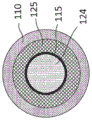
In a particular embodiment, the tubular element has an outer diameter of between 5 and 12 mm, for example between 5 and 10 mm or between 6 and 8 mm. Typically, the tubular element has an outer diameter of 7.2 mm ± 10%.
Typically, the tubular element has a length of between about 5 mm and about 15 mm. Preferably, the tubular element has a length of between 6 and 12 mm, preferably between 7 and 10 mm, preferably 8 mm.
In combination with a particular embodiment, the gel is a mixture of materials that are preferably capable of releasing volatile compounds into an aerosol passing through the tubular member while the gel is being heated. The provision of a gel may be advantageous for storage and transport or during use, as the risk of leakage from the tubular element, the aerosol-generating article or the aerosol-generating device may be reduced.
Advantageously, the gel is solid at room temperature. By "solid" in this context is meant that the gel is of a stable size and shape and does not flow. Room temperature in this context means 25 degrees celsius.
The gel may include an aerosol former. Ideally, the aerosol former is substantially resistant to thermal degradation at the operating temperature of the tubular element. Suitable aerosol-forming agents are well known in the art and include, but are not limited to: polyhydric alcohols such as triethylene glycol, 1, 3-butanediol and glycerin; esters of polyhydric alcohols, such as glycerol mono-, di-or triacetate; and fatty acid esters of mono-, di-or polycarboxylic acids, such as dimethyldodecanedioate and dimethyltetradecanedioate. The polyol or mixture thereof may be one or more of triethylene glycol, 1, 3-butanediol, and glycerol or polyethylene glycol.
Advantageously, the gel comprises, for example, a thermoreversible gel. This means that the gel becomes fluid when heated to the melting temperature and solidifies again to a gel at the gelling temperature. The gelling temperature may be at or above room temperature and atmospheric pressure. Atmospheric pressure means 1 atmosphere. The melting temperature may be higher than the gelling temperature. The melting temperature of the gel may be higher than 50 degrees celsius, or 60 degrees celsius, or 70 degrees celsius, and may be higher than 80 degrees celsius. Melting temperature in this context means the temperature at which the gel is no longer a solid and begins to flow.
Alternatively, in particular embodiments, the gel is a non-melting gel that does not melt during use of the tubular element. In these embodiments, the gel may release the active agent at least in part at a temperature at or above the operating temperature of the tubular element in use, but below the melting temperature of the gel.
Preferably, the gel has a viscosity of 50,000 to 10 pascals per second, preferably 10,000 to 1,000 pascals per second, to obtain the desired viscosity.
In combination with certain embodiments, the gel includes a gelling agent. In particular embodiments, the gel comprises agar or agarose or sodium alginate or gellan gum, or mixtures thereof.
In particular embodiments, the gel comprises water, e.g., the gel is a hydrogel. Alternatively, in particular embodiments, the gel is non-aqueous.
Preferably, the gel comprises an active agent. In combination with particular embodiments, the active agent comprises nicotine (e.g., in powder form or in liquid form) or a tobacco product or another target compound, e.g., for release in an aerosol. In a particular embodiment, the nicotine is comprised in a gel with an aerosol former. It is desirable to lock nicotine in the gel at room temperature to prevent leakage.
In particular embodiments, the gel comprises a solid tobacco material that releases the flavor compounds upon heating. Depending on the particular embodiment, the solid tobacco material is, for example, one or more of the following: a powder, granule, pellet, shred, sliver, strip, or sheet comprising one or more of: plant material, such as herbaceous plant leaves, tobacco leaves, pieces of tobacco ribs, reconstituted tobacco, homogenized tobacco, extruded tobacco and expanded tobacco.
There are embodiments where, additionally or alternatively, for example, the gel includes other flavors, such as menthol. Menthol may be added to water or to the aerosol former prior to forming the gel.
Preferably, the gel comprises a gelling agent. The gelling agent may form a solid medium in which the aerosol former may be dispersed.
The gel may comprise any suitable gelling agent. For example, the gelling agent may comprise one or more biopolymers, such as two or three biopolymers. Preferably, where the gel comprises more than one biopolymer, the biopolymers are present in substantially equal weights. The biopolymer may be formed from a polysaccharide. Biopolymers suitable as gelling agents include, for example, gellan gum (natural, low acyl gellan gum, high acyl gellan gum, preferably low acyl gellan gum), xanthan gum, alginates (alginic acid), agar, guar gum, and the like. Preferably, the gel comprises agar.
The gel can include any suitable amount of gelling agent. For example, the gel includes a gelling agent in a range from about 0.5% to about 7% by weight of the gel. Preferably, the gel comprises gellant in the range of about 1 wt.% to about 5 wt.%, for example in the range of about 1.5 wt.% to about 2.5 wt.%.
In some preferred embodiments, the gel comprises agar in the range of about 0.5% to about 7% by weight, or in the range of about 1% to about 5% by weight, or about 2% by weight.
In some preferred embodiments, the gel comprises xanthan gum in a range of about 2% to about 5% by weight, or in a range of about 2% to about 4% by weight, or about 3% by weight.
In some preferred embodiments, the gel comprises xanthan gum, gellan gum, and agar. Gels may include xanthan gum, low acyl gellan gum, and agar. The gel may comprise substantially equal amounts by weight of xanthan gum, gellan gum and agar. The gel may comprise substantially equal amounts by weight of xanthan gum, low acyl gellan gum, and agar. The gel may include xanthan gum, low acyl gellan gum and agar in a range of about 1 wt% to about 5 wt%, or in a range of about 1 wt% to about 4 wt%, or about 2 wt% (for the total weight of xanthan gum, low acyl gellan gum and agar in the gel). The gel may include xanthan gum, low acyl gellan gum, and agar in a range of about 1% to about 5% by weight, or about 2% by weight, wherein xanthan gum, gellan gum, and agar are substantially equal in weight.
The gel may include divalent cations. Preferably, the divalent cations include calcium ions, such as calcium lactate in solution. Divalent cations (e.g., calcium ions) can aid in the gel formation of compositions that include biopolymers (polysaccharides), such as gellan gum (natural, low acyl gellan gum, high acyl gellan gum), xanthan gum, alginates (alginic acid), agar, guar gum, and the like. The ionic effect may aid in gel formation. The divalent cation may be present in the gel composition in a range of about 0.1 wt.% to about 1 wt.% or about 0.5 wt.%. In some embodiments, the gel does not include divalent cations.
The gel may include a carboxylic acid. The carboxylic acid may comprise a ketone group. Preferably, the carboxylic acid comprises a ketone group having less than 10 carbon atoms. Preferably, the carboxylic acid has five carbon atoms (e.g., levulinic acid). Levulinic acid can be added to neutralize the pH of the gel. This may also aid in the gel formation of compositions comprising biopolymers (polysaccharides), such as gellan gum (low acyl gellan gum, high acyl gellan gum), xanthan gum, especially alginates (alginic acid), agar, guar gum, and the like. Levulinic acid can also enhance the organoleptic properties of the gel formulation. In some embodiments, the gel does not include a carboxylic acid.
In embodiments where agar is used as the gelling agent, the gel comprises, for example, between 0.5% and 5% by weight agar, preferably between 0.8% and 1% by weight agar. Preferably, the gel further comprises between 0.1 and 2 wt% nicotine. Preferably, the gel further comprises between 30 and 90 wt% (or between 70 and 90 wt%) glycerol. In certain embodiments, the remainder of the gel comprises water and flavoring agents.
Preferably, the gelling agent is agar, which has the property of melting at a temperature above 85 degrees celsius and changing back to a gel at about 40 degrees celsius. This property makes it suitable for use in hot environments. The gel does not melt at 50 degrees celsius, which is useful, for example, if the system is placed in a high temperature automobile in the sun. The phase transition to liquid at about 85 degrees celsius means that aerosolization can be initiated by simply heating the gel to a lower temperature, allowing for low energy consumption. It may be beneficial to use only agarose, which is one of the components of agar, rather than agar.
When gellan gum is used as the gelling agent, the gel typically comprises between 0.5 and 5 wt% gellan gum. Preferably, the gel further comprises between 0.1 and 2 wt% nicotine. Preferably, the gel further comprises between 30 and 99.4% by weight of glycerol. In certain embodiments, the remainder of the gel comprises water and flavoring agents.
In one example, the gel comprises 2% by weight nicotine, 70% by weight glycerol, 27% by weight water and 1% by weight agar.
In another example, the gel comprises 65 wt% glycerol, 20 wt% water, 14.3 wt% tobacco, and 0.7 wt% agar.
Additionally or alternatively, in certain particular embodiments, the tubular element comprises a porous medium loaded with a gel. Preferably, the porous medium loaded with gel is located between the second tubular element and the wrapper forming the first longitudinal passageway. Alternatively, in certain particular embodiments, the second tubular element comprises a porous medium loaded with a gel. These embodiments do not necessarily exclude gels, or the porous medium loaded with gels may additionally or alternatively be located elsewhere. In certain embodiments, the tubular element comprises a gel and a porous medium loaded with the gel.
In combination with certain embodiments, the tubular element includes a longitudinal element positioned longitudinally within the first longitudinal passageway. In a particular embodiment, the longitudinal element positioned longitudinally within the first longitudinal passage is a porous medium loaded with a gel. In other particular embodiments, the longitudinal element may be a longitudinal element of any material, which is able to occupy space within the tubular element, for example, or to assist or assist the passage of heat or material, or even to assist the stiffness or rigidity of the structure.
In some embodiments, the wrapper is stiff or rigid to assist in the construction of the tubular element. It is envisaged that the gels used in the present invention are semi-solid, which are capable of retaining shape, particularly in use. However, the present invention is not limited to solid gels. More fluid gels, i.e., gels having a higher viscosity than solid gels, may also be used with embodiments of the present invention. It is therefore advantageous, although not essential, to have a wrapper which is itself capable of holding the structure of the tubular element. Likewise, the longitudinal sides of the second tubular element may be rigid or stiff. Making the longitudinal sides of the wrapper or the second tubular element, or both the wrapper and the longitudinal sides of the second tubular element, stiff or practically rigid may assist in the construction of the tubular element, but may also assist in manufacturing. Preferably, the wrapper has a thickness of between about 50 microns and 150 microns.
In combination with other features of particular embodiments, the wrapper is waterproof. In a particular embodiment, the longitudinal sides of the second tubular element are waterproof. Such waterproof properties of the longitudinal sides of the wrapper or the second tubular element may be achieved by using waterproof materials, or by treating the material of the longitudinal sides of the wrapper or the second tubular element. This may be achieved by treating one or both of the longitudinal sides of the wrapper or the second tubular element. Waterproofing helps to avoid loss of structure, stiffness or rigidity. It may also help prevent leakage of gel or liquid, especially when using a gel in a fluid structure.
In combination with a particular embodiment, the tubular element comprises a susceptor. The susceptor may be any heat transfer material, for example it may be a metal wire (e.g. aluminum wire) or a wire comprising aluminum or a metal powder (e.g. aluminum powder). Typically, the susceptor is positioned longitudinally within the tubular element. The susceptor may be located within or adjacent to or near the gel, or in or adjacent to or near a porous medium loaded with the gel.
In combination with a particular embodiment, the tubular element further comprises a thread. This may be any natural or synthetic material, but is preferably cotton. The thread may be a vehicle carrying an active ingredient, such as a fragrance. An example of a suitable flavour for use in the present invention may be menthol. The wire may extend longitudinally within the tubular element. Preferably, the thread may be located within or adjacent to or near the gel, or within or adjacent to or near the porous medium loaded with the gel.
In combination with a particular embodiment, the tubular element further comprises a sheet material. In combination with certain embodiments, the gel-loaded porous medium comprises a sheet material. By providing the porous material loaded with gel as a sheet material, there may be advantages in manufacturing, for example sheet material may be easily gathered together to create a suitable structure. The gel may be loaded into the sheet material before being gathered together or after being gathered together.
According to the present invention there is provided a tubular element comprising a wrapper forming a first longitudinal channel, the tubular element further comprising a gel-loaded porous medium further comprising an active agent.
In a particular embodiment, the porous medium loaded with the gel completely fills the tubular element within the wrapper. Alternatively, in other particular embodiments, the porous medium only partially fills the tubular element.
In a particular embodiment, the tubular element further comprises a second tubular element having longitudinal sides and proximal and distal ends, the second tubular element being positioned longitudinally within the first longitudinal channel formed by the wrapper.
In a particular embodiment, the longitudinal sides of the second tubular element comprise paper or cardboard or cellulose acetate.
In certain embodiments, the second tubular element comprises a porous medium loaded with a gel.
In some particular embodiments where there is a first tubular element and a second tubular element as described, the gel-loaded porous medium is positioned between the second tubular element and the wrapper forming the first longitudinal channel.
In some alternative embodiments, where there is a first tubular element and a second tubular element, the gel is positioned between the second tubular element and the wrapper forming the first longitudinal channel.
According to the present invention, there is provided a method of manufacturing a tubular element,
the tubular element comprises:
at least one longitudinal passageway, and further comprising a gel; the gel comprises an active agent;
the method comprises the following steps:
-placing a material for the tubular element around the mandrel, the material forming the tubular element;
-extruding the gel from the catheter within the mandrel such that the gel is within the tubular element.
The method of manufacturing a tubular element may further comprise the step of extruding the material for the tubular element around a mandrel to form the tubular element.
The method of manufacturing a tubular element may further comprise the step of wrapping the tubular element with a wrapper.
According to the present invention, there is provided a method of manufacturing a tubular element,
the tubular element comprises:
-a wrapper forming a first longitudinal channel and further comprising a porous medium loaded with a gel; the gel-loaded porous medium further comprises an active agent; and wherein the one or more of the one or more,
the method comprises the following steps;
-dispensing the gel-loaded porous medium onto a web of wrapping material;
-wrapping a wrapping material around the gel-loaded porous medium.
In a particular embodiment, the method of manufacturing a tubular element further comprises the steps of: the wrapped tubular member is cut into individual lengths.
According to the present invention, there is provided a method of manufacturing a tubular element,
the tubular element comprises:
-a wrapper forming a first longitudinal channel and further comprising a porous medium loaded with a gel; the gel-loaded porous medium further comprises an active agent; and
-a second tubular element;
the method comprises the following steps:
-dispensing the gel-loaded porous medium onto a web of wrapping material; and the number of the first and second groups,
-dispensing a second tubular element onto the gel-loaded porous medium on the web of wrapping material;
-wrapping a wrapping material around the gel-loaded porous medium and the second tubular element.
In a particular embodiment, the method of manufacturing a tubular element further comprises the steps of: the wrapped tubular member is cut into individual lengths.
It is envisaged that the tubular element of the present invention is for use in an aerosol-generating article. It is also envisaged that the aerosol-generating article may be used in a device, for example an aerosol-generating device. The aerosol-generating device may be used to hold and heat the aerosol-generating article to release the material. In particular, this may be the release of material from the tubular element of the invention.
According to the present invention, there is provided an aerosol-generating article for generating an aerosol, the aerosol-generating article comprising:
-a fluid guide allowing movement of a fluid; the fluid guide having a proximal end and a distal end, the fluid guide having an inner longitudinal region and an outer longitudinal region separated by a barrier; wherein the inner longitudinal region comprises an inner longitudinal passage between the distal end and the proximal end and the outer region comprises a longitudinal passage that communicates an external fluid through at least one hole to the distal end of the fluid guide such that the external fluid can travel along the outer longitudinal passage to the distal end of the fluid guide;
-a tubular element comprising a gel; the gel comprises an active agent; the tubular element has a proximal end and a distal end, and is located on a distal side of the fluid guide.
In particular embodiments, the barrier separating the inner longitudinal passage and the outer longitudinal passage may be an impermeable barrier, e.g., a fluid impermeable barrier.
According to the present invention, there is provided an aerosol-generating article comprising:
-a fluid guide allowing movement of a fluid; the fluid guide having a proximal end and a distal end, the fluid guide having an inner longitudinal region and an outer longitudinal region separated by a barrier; wherein the inner longitudinal region comprises an inner longitudinal passage between the distal end and the proximal end; and the outer region comprises an outer longitudinal passage that communicates an external fluid through the at least one aperture to the distal end of the fluid guide such that the external fluid can travel along the outer longitudinal passage to the distal end of the fluid guide;
-a tubular element comprising a gel-loaded porous medium further comprising an active agent; the tubular element has a proximal end and a distal end and is located distal to the fluid guide.
Preferably, in some embodiments, the distal end of the tubular element comprises at least one aperture. Apertures at the distal end of the tubular element may allow fluid (e.g. air from outside the aerosol-generating article) to enter into and travel through the tubular element, thereby generating an aerosol. The fluid traveling through the tubular element can pick up the active agent or any other material in the gel and cause them to flow out of the gel in a downstream (proximal) direction.
In a particular embodiment, the aerosol-generating article may comprise a lumen positioned between the distal end of the fluid guide and the proximal end of the tubular element. Thus, the cavity may be at an upstream end of the inner longitudinal passage and at a downstream end of the tubular element. The cavity allows fluid (e.g., ambient air) to travel to the cavity via the external longitudinal passageway and come into contact with the gel in the tubular element. The fluid in contact with the tubular element may enter and pass through the tubular element before returning to the internal longitudinal passageway and to the proximal end of the fluid guide and the proximal end of the aerosol-generating article. When such a fluid (e.g. ambient air) comes into contact with the gel, the fluid may pick up the active agent or any other material in the gel or tubular element and pass them downstream along the internal longitudinal passageway to the proximal end of the aerosol-generating article. To contact the gel, ambient air may pass through the tubular member, or through the gel, or through the surface of the gel, or a combination thereof.
In a particular embodiment, the at least one aperture is located in the external passage of the fluid guide.
Having at least one external communication hole in the external passage of the fluid guide allows a distance between the tubular element and the at least one external communication hole. This may help prevent leakage of the gel and its contents, but may also provide a desired aerosol draw.
In a particular embodiment, the at least one aperture is located in the cavity between the fluid guide and the tubular element.
Having at least one aperture located in the external passageway of the fluid guide allows ambient fluid to easily reach the tubular element and easily mix in the cavity between the tubular element and the fluid guide.
In a particular embodiment, the at least one aperture is located in a sidewall of the tubular element.
Having at least one aperture in the side wall of the tubular element allows ambient fluid to travel substantially in one direction when negative pressure is applied to the proximal end of the aerosol-generating article. Having at least one aperture in the sidewall of the tubular element allows ambient fluid to easily mix with the contents of the tubular element.
In a particular embodiment, the aerosol-generating article comprises a package. The wrapper may be any suitable material, for example the wrapper may comprise paper. Preferably, the wrapper will have an aperture corresponding to the aperture of the fluid guide. The fluid guide and the corresponding aperture of the wrapper may be created by an aperture formed after wrapping the article.
In a particular embodiment, the outer longitudinal passage of the aerosol-generating article comprises one or more apertures. The aperture may be any aperture, slit, hole or passage that allows a fluid (e.g. ambient air) to pass through and into the aerosol-generating article. This allows fluid from outside the aerosol-generating article to be drawn in. In use, this may be an external fluid (e.g. air) which is first drawn through the aperture into the external longitudinal passage and into the aerosol-generating article before being drawn into the remainder of the aerosol-generating article. In particular embodiments, the apertures are evenly spaced around the circumference of the aerosol-generating article, for example there are 10 or 12 apertures. Evenly spacing the apertures helps to provide a smooth flow of fluid.
In combination with certain embodiments, the aerosol-generating article comprises a tip rod on the distal end of the tubular element, and wherein the tip rod has a high resistance to draw. The end-stick may be fluid impermeable, or may be nearly fluid impermeable. Preferably, the terminal rod is located at the most distal end of the aerosol-generating article. When a negative pressure is applied at the proximal end of the aerosol-generating article, this will advantageously bias the fluid to enter through the bore of the outer longitudinal passage, by the tip rod having a high resistance to draw. In some embodiments, the tip rod is fluid impermeable.
In some embodiments, the tubular element comprises a distal rod. Advantageously, this makes manufacture easy. The end rod of the tubular element will preferably be positioned at one end of the tubular element. Advantageously, this makes manufacture easy. In some embodiments, the tubular element comprises a tip rod, wherein the tip rod is fluid impermeable. When the tubular member comprises a fluid impermeable end rod, this prevents gels and other fluids from escaping from the tubular member through the end rod of the tubular member.
In a particular embodiment, the internal longitudinal passageway of the interior region of the fluid guide includes a restrictor. In some embodiments, the restrictor is located at or near the proximal end of the fluid guide. In some embodiments, the restrictor is located at or near the downstream end of the fluid guide. However, the restrictor (if present) may be positioned in a middle region of the inner longitudinal passage of the fluid guide, or in the outer longitudinal passage. The restrictor may also be positioned near or at the distal end of the internal longitudinal passageway. The restrictor may be positioned at or near an upstream end of the inner longitudinal passageway. More than one restrictor may be used in the inner longitudinal passage or the outer longitudinal passage of the fluid guide.
Restrictors for use with some particular embodiments of the present invention include an abrupt narrowing (as with an aperture in a surface such as a wall), or a gradual restriction. Alternatively, in other particular embodiments, the restrictor comprises a gradual or smooth restriction (e.g., an inclined wall), or a funnel shape that narrows toward the opening, or a gradually stepped restriction across the width of the passageway. There may be a gradual or abrupt widening on the downstream side (proximal side) of the restrictor. Particular embodiments include a funnel shape on one or both sides of the restrictor. Thus, in the flow of fluid from upstream to downstream (distal to proximal), there may be a gradual flow restriction as the sides of the passageway narrow toward the opening of the restrictor, followed by a gradual widening of the passageway from the opening of the restrictor. Typically, the opening of the restrictor has a restricted portion of 60 or 45 or 30% of the maximum cross-sectional area from the passageway. In the present invention, for example, in some embodiments, the restrictor may thus comprise a narrowed portion in which the cross-sectional area of the opening is only 60 or 45 or 30% of the cross-sectional area of the largest or widest portion of the internal longitudinal passageway. Typically, the cross-sectional diameter of the cylindrical passage of certain embodiments of the present invention is reduced, for example, from 4 mm to 2.5 mm, or from 4 mm to 2.5 mm. By varying the different width reduction ratios and amounts, the positioning of the restrictors, the number of restrictors, and the gradient of the reduced and widened portions, specific fluid flow characteristics may be achieved.
In combination with certain embodiments, the aerosol-generating article comprises a heating element (e.g. susceptor) such that heat can be transferred to the gel in the tubular element. Like the susceptor of the tubular element, this may be of any suitable material, preferably a metal such as aluminium, or comprising aluminium.
According to the present invention there is provided a method of manufacturing an aerosol-generating article comprising:
-a fluid guide allowing fluid transfer; the fluid guide having a proximal end and a distal end, the fluid guide having an inner longitudinal region and an outer longitudinal region separated by a barrier; wherein the inner longitudinal region comprises an inner longitudinal passage between the distal end and the proximal end and the outer region comprises an outer longitudinal passage that communicates fluid through at least one aperture to the distal end of the fluid guide such that fluid may travel along the outer longitudinal passage of the outer fluid control region to the distal end of the fluid guide;
-a tubular element comprising a gel; the gel comprises an active agent; the tubular element having a proximal end and a distal end; and the number of the first and second electrodes,
the method comprises the following steps:
-linearly arranging a tubular element comprising gel and a fluid guide on a web of wrapping material; and
-wrapping the tubular element and the fluid guide and securely positioning the wrapper around the tubular element and the fluid guide.
According to the present invention there is provided an aerosol-generating device comprising a container configured to receive a distal end of an aerosol-generating article as described herein.
The container of the device may correspond in shape and size to allow the distal end or a portion of the distal end of the aerosol-generating article to fit closely into the container and retain the aerosol-generating article in the container during normal use.
Typically, the container includes a heating element. This will enable heating of the aerosol-generating article, heating of the tubular element, or heating of a gel, preferably comprising an active agent, or heating of a porous medium loaded with a gel, or any combination, to assist directly or indirectly in generating or releasing an aerosol, or releasing a material into an aerosol. The aerosol may then be delivered to the proximal end of the aerosol-generating article. In particular embodiments, the heating is direct, or indirect via a thermal element or susceptor, or a combination of both.
The heating device may be any known heating device. Typically, the heating means may be by radiation or conduction or convection or a combination thereof.
In combination with a particular embodiment, the tubular element further comprises a thread. In particular embodiments, the thread is a natural material or a synthetic material, or the thread is a combination of natural and synthetic materials. The wire may comprise a semi-synthetic material. The thread may be made of, or comprise fibres, or partly comprise fibres. The thread may be made of, for example, cotton, cellulose acetate or paper. Composite wires may be used. The thread may facilitate the manufacture of a tubular element comprising the active agent. The thread may facilitate the introduction of the active agent into the tubular element comprising the active agent. The thread may help to stabilize the structure of the tubular element comprising the active agent.
In combination with certain embodiments, the tubular element comprises a porous medium loaded with a gel. A porous medium may be used within the tubular element to create a space within the tubular element. The porous medium is capable of holding or retaining the gel. This has the advantage of facilitating gel transfer and storage and manufacturing of the tubular element comprising the gel. The gel in the gel-loaded porous medium may further comprise an active agent; it may also hold or carry an active agent or other material.
The porous medium may be any suitable porous material capable of holding or retaining a gel. Desirably, the porous medium may allow the gel to move therein. In particular embodiments, the gel-loaded porous medium comprises a natural material, a synthetic or semi-synthetic, or a combination thereof. In particular embodiments, the gel-loaded porous media comprises a sheet material, foam, or fibers (e.g., loose fibers), or a combination thereof. In particular embodiments, the gel-loaded porous media comprises a woven, nonwoven, or extruded material, or a combination thereof. Preferably, the gel-loaded porous medium comprises, for example, cotton, paper, viscose, PLA or cellulose acetate or a combination thereof. Preferably, the gel-loaded porous medium comprises a sheet material, such as cotton or cellulose acetate. An advantage of the porous medium loaded with gel is that the gel is retained within the porous medium, and this may facilitate manufacturing, storing or transporting the gel. Which may help to maintain the desired shape of the gel, particularly during manufacture, transport or use. The porous media used in the present invention may be crimped or chopped. In particular embodiments, the porous media comprises a crimped porous media. In an alternative embodiment, the porous media comprises shredded porous media. The crimping or chopping process may be before or after loading with the gel.
Shredding imparts a high surface area to volume ratio to the media, and therefore allows for easy absorption of the gel.
In a particular embodiment, the sheet material is a composite material. Preferably, the sheet material is porous. The sheet material may assist in the manufacture of the tubular element comprising the gel. The sheet material may assist in introducing the active agent into the tubular member comprising the gel. The sheet material may help to stabilize the structure of the tubular element comprising the gel. The sheet material may assist in transporting or storing the gel. The use of sheet material enables or facilitates the addition of structure to the porous media, for example by crimping the sheet material. The crimping of the sheet material has the benefit of improving the structure to allow passage through the structure. The passage through the crimped sheet material helps to load the gel, hold the gel, and also helps to facilitate the passage of fluid through the crimped sheet material. Therefore, there is an advantage in using a curled sheet material as the porous medium.
The porous medium may be a wire. The thread may comprise cotton, paper or acetate tow, for example. The wire may also be loaded with a gel, as with any other porous medium. An advantage of using a wire as the porous medium is that it may help ease manufacturing. The wire may be pre-loaded with the gel prior to use in manufacturing the tubular element, or the wire may be loaded with the gel when assembling the tubular element.
The wire may be loaded with the gel by any known means. The wire may simply be coated with a gel, or the wire may be impregnated with a gel. In manufacture, the wire may be impregnated with a gel and stored in preparation for inclusion in the assembly of tubular elements. In other processes, the wire is subjected to a loading process in the manufacture of the gel-loaded tubular element. As with the porous media loaded with the gel or the gel alone, preferably the gel includes an active agent. The active agent is as described herein.
In the manufacture of the tubular element, the gel or porous medium or thread may be dispensed simultaneously with the dispensing of the other components, or sequentially. Preferably, the components are dispensed, but the components may be gathered or rolled, or combined or positioned in any known manner to be positioned at a desired location.
As used herein, the term "active agent" is an agent capable of being active, e.g., that produces a chemical reaction or that is capable of altering the generated aerosol. The active agent may be more than one agent.
As used herein, the term "aerosol-generating article" is used to describe an article capable of generating or releasing an aerosol.
As used herein, the term "aerosol-generating device" is a device to be used with an aerosol-generating article to enable the generation or release of an aerosol.
As used herein, the term "aerosol former" refers to any suitable known compound or mixture of compounds that, in use, promotes enhancement of an initial aerosol received, for example, into a tubular element, which may become a denser aerosol, a more stable aerosol, or both a denser aerosol and a more stable aerosol.
As used herein, the term "aerosol-generating substrate" is used to describe a substrate capable of generating or releasing an aerosol.
As used herein, the term "aperture" is used to describe any hole, slit, hole, or opening.
As used herein, the term "cavity" is used to describe any void or space that is at least partially enclosed in a structure. For example, in the present invention, the lumen is a partially enclosed space (in some embodiments) between the fluid guide and the tubular element.
As used herein, the term "chamber" is used to describe an at least partially enclosed space or cavity.
For the purposes of this disclosure, an inner longitudinal cross-sectional area that "shrinks" from a first location to a second location is used to indicate that the diameter of the inner longitudinal cross-sectional area decreases from the first location to the second location. These are commonly referred to as "limiters". Thus, as used herein, the term "restrictor" is used to describe a narrowing in a fluid passageway or a change in cross-sectional area in a fluid passageway.
As used herein, the term "crimped" means that the material has a plurality of ridges or corrugations. It also includes the process of making the coiled material.
The expression "cross-sectional area" is used to describe the cross-sectional area as measured in a plane transverse to the longitudinal direction.
For the purposes of the present disclosure, the term "diameter" or "width" as used herein is the largest transverse dimension of any of a tubular element, an aerosol-generating article or an aerosol-generating device, a portion or segment thereof, a tubular element, an aerosol-generating article or an aerosol-generating device. By way of example, "diameter" is the diameter of an object having a circular cross-section, or the length of a diagonal width of an object having a rectangular cross-section.
As used herein, the term "essential oil" is used to describe an oil having the characteristic odor and aroma of the plant from which it is obtained.
As used herein, the term "external fluid" is used to describe a fluid originating outside the aerosol-generating element, article or device, such as ambient air.
As used herein, the term "flavoring agent" is used to describe a composition that affects the sensory quality of an aerosol.
As used herein, the term "fluid guide" is used to describe a device or component that can alter fluid flow. Preferably, this is a fluid flow path that directs or guides the generated or released aerosol. The fluid guide is likely to cause mixing of the fluids. It may help accelerate the fluid as it travels through the fluid guide as the cross-section of the passageway narrows, or it may help decelerate the fluid as it travels along the passageway as the cross-section of the passageway widens.
As used herein, the term "gathered" is used to describe a sheet of material that is rolled, folded, or otherwise compressed or shrunk generally transverse to the longitudinal axis of the aerosol-generating article or tubular element.
As used herein, the term "gel" is used to describe a solid, colloidal, semi-rigid material having a three-dimensional network that is capable of holding other materials and releasing the materials into an aerosol.
The term "herbal material" is used to indicate material from herbaceous plants. "herbs" are aromatic plants in which the leaves or other parts of the plant are used for medicinal, culinary or aromatic purposes and are capable of releasing a fragrance into an aerosol produced by an aerosol-generating article.
As used herein, the term "hydrophobic" refers to a surface that exhibits the property of repelling water. Hydrophobic character can be expressed by water contact angle. The "water contact angle" is the angle through a liquid as conventionally measured when a fluid interface encounters a solid surface. It quantifies the wettability of a liquid to a solid surface by young's equation.
As used herein, the term "impermeable" is used to describe an article, such as a barrier, through which fluids do not substantially or readily pass.
As used herein, the term "induction heating" is used to describe heating an object by electromagnetic induction, wherein eddy currents (also known as foucault currents) are generated within the object to be heated and electrical resistance results in resistive heating of the object.
As used herein, the term "longitudinal passageway" is used to describe a passageway or opening along which a fluid or the like is enabled to flow. Typically, air or generated aerosol-laden material (e.g., solid particles) flows along a longitudinal path. Typically, the longitudinal passage will be longer in longitudinal length than in width, but this is not essential. The term "longitudinal passage" also includes a plurality of more than one longitudinal passage.
The term "longitudinal" is used to describe the direction between the proximal and distal ends of a tubular element, aerosol-generating article or aerosol-generating device.
As used herein, for example, a "longitudinal side" of the second tubular element is used to describe a longitudinal side or longitudinal wall of the second tubular element. In some embodiments, this is integral, for example, cellulose acetate formed into a tubular element, or a porous media loaded with a gel. In an alternative embodiment, the longitudinal sides are wrappers.
As used herein, the term "mandrel" is used to describe a shaft on which another material is forged or formed.
As used herein, the term "mint" is used to refer to mint-like plants.
The term "mouthpiece" is used herein to describe an element, component or part of an aerosol-generating article through which an aerosol exits the aerosol-generating article.
As used herein, the term "outer" with respect to the fluid guide is used to describe a portion that is more toward the longitudinal circumference of the fluid guide than the middle of the cross-sectional portion of the fluid guide. Similarly, the term "inner" is used to describe a portion of the fluid guide that is closer to the center of the cross-sectional portion (with respect to the fluid guide) than to the vicinity of the circumference of the fluid guide.
As used herein, the term "passageway" is used to describe a passageway that may allow access therebetween.
As used herein, the term "plasticizer" is used to describe a substance, typically a solvent, that is added to create or promote plasticity or flexibility and reduce brittleness.
As used herein, the term "porous medium" is used to describe any medium capable of holding, or supporting a gel. Typically, the porous medium has passages in its structure that can be filled to hold or retain a fluid or semi-solid, for example to hold a gel. Preferably, the gel is also capable of being transported or transferred along and through the passages within the porous medium. As used herein, the term "gel-loaded porous medium" is used to describe a porous medium comprising a gel. The gel-loaded porous medium is capable of holding, or supporting a quantity of gel.
As used herein, the term "rod" is used to describe a component, segment, or element for use in an aerosol-generating article. As used herein, the term "terminal rod" is used to describe the most distal component or rod of an aerosol-generating article at the distal end of the aerosol-generating article. Preferably, this end rod has a high resistance to suction (RTD).
The term "strongly acidic" refers to a group capable of donating a hydrogen or proton in a chemical reaction.
The term "container" of an aerosol-generating device, the term being used to describe a chamber of the aerosol-generating device capable of receiving a portion of an aerosol-generating article. This is typically, but not necessarily, the distal end of the article.
As used herein, the term "resistance to draw" (RTD) is used to describe the resistance of a fluid, such as a gas, to be drawn through a material. As used herein, resistance to draw is expressed in units of pressure "mmWG" or "millimeter water gauge" and is measured according to ISO 6565: 2002.
As used herein, the term "high resistance-to-draw" (RTD) is used to describe the resistance of a fluid, such as a gas, to be drawn through a material. As used herein, high resistance means greater than 200 "mm WG" or "millimeter water gauge" and is measured according to ISO 6565: 2002.
As used herein, the term "sheet material" is used to describe a generally planar, laminar element having a width and length that is substantially greater than its thickness.
As used herein, the term "seal" is a bond or "join" made, for example, by joining the edges of the package to each other or to the fluid guide. This may be by using adhesives or glues. However, the term seal also includes an interference fit joint. The seal need not create a fluid impermeable seal or barrier.
As used herein, the term "shredded" is used to describe something that is finely cut.
As used herein, the term "hard" is used to describe an article that is sufficiently rigid or hard enough to resist shape changes under normal use, or hard enough to substantially resist shape deformation. This includes that it may be resilient so that if deformed, it may return substantially to its original shape. Also, as used herein, the term "rigid" describes that the article is resistant to bending or forced deformation, generally being able to maintain its shape, particularly under normal use.
As used herein, the term "susceptor" is used to describe a heating element, any material capable of absorbing electromagnetic energy and converting it into heat. For example, in the present invention, a susceptor or heating element may help to transfer thermal energy to the gel, heating the gel to help release material from the gel.
As used herein, the term "textured sheet" means a sheet that has been curled, embossed, gravure, perforated, or otherwise deformed.
As used herein, the term "gel-loaded wire" is used to describe a wire that holds, retains, or supports a gel, including, for example, a porous medium coated or impregnated with a gel.
Throughout the literature, the term "tubular element" is used to describe a component suitable for use in an aerosol-generating article. Desirably, the longitudinal length of the tubular element may be longer than the width, but this is not necessary as it may be part of a multi-component article whose longitudinal length is desirably longer than its width. Typically, the tubular element is cylindrical, but this is not essential. For example, the tubular element may have an elliptical, polygonal such as triangular or rectangular, or irregular cross-section. The tubular element need not be hollow.
The terms "upstream" and "downstream" are used to describe the relative position with respect to the direction of the mainstream fluid as it is drawn into the tubular element, aerosol-generating article or aerosol-generating device. In some embodiments, where the fluid enters from the distal end of the aerosol-generating article and travels towards the proximal end of the article, the distal end of the aerosol-generating article may also be described as the upstream end of the aerosol-generating article and the proximal end of the aerosol-generating article may also be described as the downstream end of the aerosol-generating article. In these embodiments, the element of the aerosol-generating article located between the proximal end and the distal end may be described as being upstream of the proximal end, or alternatively downstream of the distal end. However, in other embodiments of the present invention, where the fluid enters the aerosol-generating article from the side and travels first towards the distal end, turns and then towards the proximal end of the aerosol-generating article, the distal end of the aerosol-generating article may be upstream or downstream, depending on the respective reference point.
As used herein, the term "water-resistant" is used to describe a material that does not allow water to pass easily or be easily damaged by water, such as the wrapper, or the longitudinal sides of the second tubular element. The waterproof material is resistant to water penetration.
In a particular embodiment, the tubular element comprises an active agent. In particular embodiments, the gel includes an active agent. In particular embodiments, the active agent comprises nicotine. In a particular embodiment, the gel or tubular element comprising the active agent comprises between 0.2% and 5% by weight of the active agent, such as between 1% and 2% by weight of the active agent.
Typically, in particular embodiments, the tubular element will comprise at least 150mg of gel.
In particular embodiments, the active agent includes a plasticizer.
In certain embodiments, the gel comprising the active agent comprises an aerosol former, such as glycerin. In embodiments where an aerosol former is present, typically, for example, the gel comprising the active agent comprises between 60% and 95% by weight glycerol, for example between 80% and to 90% by weight glycerol.
In particular embodiments, the gel comprising the active agent comprises a gelling agent, for example, alginate, gellan gum, guar gum, or combinations thereof. In embodiments including a gelling agent, the gel typically includes between 0.5% and 10% gelling agent by weight, such as between 1% and 3% gelling agent by weight.
In a particular embodiment, the gel comprises water. In such embodiments, the gel typically comprises between 5 and 25 wt% water, for example between 10 and 15 wt% water.
In particular embodiments, the active agent comprises a fragrance or a drug substance or a combination thereof. In a particular example, the active agent is nicotine in any form. The active agent can be active, for example, capable of producing a chemical reaction or at least altering the generated aerosol.
The active agent may be a fragrance. In certain embodiments, the active agent comprises a flavoring agent. The gel may include a flavoring agent. Alternatively or additionally, the flavoring agent may be present at one or more other locations of the article. The flavoring agent may impart a flavor to aid the mouthfeel of the fluid or aerosol generated by the article. A flavoring agent is any natural or artificial compound that affects the organoleptic qualities of an aerosol. Plants that may be used to provide flavoring agents include, but are not limited to, plants belonging to the families: lamiaceae (Lamiaceae) (e.g., peppermint), Umbelliferae (Apiaceae) (e.g., anise, fennel), Lauraceae (Lauraceae) (e.g., bay, cinnamon, rose wood), Rutaceae (Rutaceae) (e.g., citrus fruits), Myrtaceae (Myrtaceae) (e.g., fennel, myrtle), and Leguminosae (Fabaceae) (e.g., licorice). Non-limiting examples of flavor sources include mints (e.g., peppermint and spearmint), coffee, tea, cinnamon, clove, ginger, cocoa, vanilla, eucalyptus, geranium, agave and juniper berries, and combinations thereof.
Many flavoring agents are essential oils, or mixtures of one or more essential oils. Suitable essential oils include, but are not limited to, eugenol, peppermint oil, and spearmint oil. In many embodiments, the flavoring agent comprises menthol, eugenol, or a combination of menthol and eugenol. In many embodiments, the flavoring agent further comprises anethole, linalool, or a combination thereof. In certain embodiments, the flavoring agent comprises herbal material. Herbaceous material includes herbaceous plant leaves or other herbaceous plant material from herbaceous plants including, but not limited to, mint (e.g., peppermint and spearmint), lemon balm leaves, perilla, cinnamon, lemon perilla, chive (chicken), caraway, lavender, sage, tea, thyme, and caraway. Suitable types of mint leaves may be selected from plant species including, but not limited to, peppermint (Mentha piperita), field mint (Mentha arvensis), egyptian mint (Mentha nilicaa), lemon mint (Mentha citrata), spearmint (Mentha spp), rugosa (Mentha spray crispa), heart mint (Mentha cordifolia), peppermint (Mentha longifolia), pulegium (Mentha pulegium), apple mint (Mentha suaveolens), and savory (Mentha suaveolens variegata). In some embodiments, the flavoring agent may comprise a tobacco material.
In one particular example, in combination with other features, the gel comprises about 2% nicotine by weight, 70% glycerol by weight, 27% water by weight, and 1% agar by weight. In another example, the gel includes 65 wt% glycerin, 20 wt% water, 14.3 wt% solid powdered tobacco, and 0.7 wt% agar.
In the present invention, the fluid guide may have two distinct regions, for example an outer region with an outer longitudinal passage and an inner region with an inner longitudinal passage. Thus, the outer longitudinal passage extends longitudinally near the circumference of the fluid guide and the inner fluid passage extends longitudinally along the longitudinal axis near the core or center of the cross-section.
Preferably, in a particular embodiment, ambient air enters the outer longitudinal passage (of the fluid guide) through the aperture in the package and the aperture in the fluid guide towards the distal end of the aerosol-generating article and in the region of the tubular element comprising the gel comprising the active agent. Preferably, the fluid will be contacted with a gel comprising an active agent to generate or release an aerosol of mixed fluids comprising fluid from outside the aerosol-generating article and material released from the gel comprising the active agent or agent. The fluid then travels along the internal longitudinal passageway of the fluid guide toward the proximal end of the aerosol-generating article. It is foreseen that the outer longitudinal passage and the inner longitudinal passage are separated by a barrier. The barrier may be fluid impermeable or resistant to fluid passing therethrough, and thus capable of biasing fluid distally. Preferably, the outer longitudinal passage of the fluid guide comprises a hole in fluid communication with the outside of the fluid guide and preferably the outside of the article. It is also foreseen that the outer longitudinal passage is blocked at its proximal end such that, in use, fluid received from the exterior of the aerosol-generating article flows primarily towards the distal end of the fluid guide. The outer longitudinal passageway of the fluid guide has a hole at or near its proximal end, but is then open only at its distal end. In contrast, the internal longitudinal passageway of the fluid guide is open at both its proximal end and its distal end, but may have various flow restriction elements between its proximal end and its distal end. The barrier separating the inner and outer longitudinal passageways of the fluid guide forces fluid entering the outer longitudinal passageway to travel to the distal end of the outer longitudinal passageway and toward the tubular member, which preferably comprises a gel containing an active agent. This brings the fluid into contact with the tubular element, which preferably comprises a gel containing the active agent.
The outer longitudinal passage of the fluid guide may be one passage or more than one passage. The outer longitudinal passage may be within the fluid guide or may be one or more passages on an outer surface of the fluid guide, wherein the fluid guide forms a portion of a wall of the outer longitudinal passage and the wrapper forms another portion of the wall to the outer longitudinal passage. The outer longitudinal passage or the inner longitudinal passage of the fluid guide may comprise a porous material, such as a foam, in particular a reticulated foam, such that the passage traverses the porous material. In a particular embodiment, the fluid guide comprises a porous material, such as foam. The porous material may allow fluid to pass through while still maintaining its shape. These materials are easy to shape and may therefore be useful in the manufacture of aerosol-generating articles.
In some embodiments, the outer longitudinal passageway may extend substantially around the interior of the wrapper. In some embodiments, the passageway may not extend completely around the interior of the package.
Various aspects or embodiments of aerosol-generating articles for use with the aerosol-generating devices described herein may provide one or more advantages over currently available or previously described aerosol-generating articles. For example, an aerosol-generating article comprising a fluid guide and inner and outer fluid passages of the fluid guide allows for efficient transfer of an aerosol generated from a tubular element comprising a gel, which preferably comprises an active agent. Furthermore, a gel comprising an active agent is less likely to leak from the aerosol-generating article than a liquid element comprising an active agent.
The aerosol-generating article may comprise a mouth end (proximal end) and a distal end. Preferably, the distal end is received by an aerosol-generating device having a heating element configured to heat the distal end of the aerosol-generating article. A tubular element comprising a gel, preferably comprising an active agent, is preferably arranged near the distal end of the aerosol-generating article. Accordingly, the aerosol-generating device may heat a tubular element comprising a gel, preferably comprising an active agent, in the aerosol-generating article to generate an aerosol comprising the active agent.
The aerosol-generating article or part of the aerosol-generating article containing the tubular element (preferably comprising a gel comprising an active agent) may be a disposable aerosol-generating article or a multi-use aerosol-generating article. In some particular embodiments, portions of the aerosol-generating article are reusable, and portions are disposable after a single use. For example, the aerosol-generating article may comprise a reusable mouthpiece and a disposable part comprising a tubular element comprising a gel and an active agent, the active agent for example also comprising nicotine. In embodiments that include both a reusable portion and a disposable portion, the reusable portion may be removed from the disposable portion.
In combination with a particular embodiment, the aerosol-generating article comprises a package. The aerosol-generating article has an open end, a proximal end and a distal end, which may be open or closed in different particular embodiments. Preferably, a tubular element is provided near the distal end of the aerosol-generating article, the tubular element preferably comprising a gel comprising an active agent, the active agent optionally comprising nicotine. Application of negative pressure to the open proximal end causes material from the tubular member (preferably comprising a gel containing the active agent) to be released. The aerosol-generating article defines at least one aperture between the proximal end and the distal end. The at least one aperture defines at least one fluid inlet such that, on application of negative pressure to the open proximal end of the aerosol-generating article, fluid, such as air, enters the aerosol-generating article through the aperture. Preferably, fluid (e.g. ambient air) drawn into the aerosol-generating article through the aperture flows along the outer longitudinal passageway of the fluid guide towards the tubular element, which preferably comprises a gel containing the active agent, near the distal end of the aerosol-generating article. The fluid then flows from the distal end to the proximal end through the internal longitudinal passage of the fluid guide and out of the aerosol-generating article at the open proximal end.
By spacing the aperture from the distal end of the aerosol-generating article, the aperture is separated from the tubular element comprising the gel, thereby reducing the likelihood of the gel leaking through the aperture. Furthermore, by providing a passage, e.g. an external longitudinal passage, for air to flow from the aperture to the tubular element comprising the gel, fluid from the aperture may be directed towards the gel and the fluid guide may act as a further barrier between the gel and the aperture. This has the advantage of further reducing the likelihood of the tubular element leaking through the hole. In addition, the internal longitudinal passage of the fluid guide provides a path for fluid, such as air and material or vapour generated or released from the tubular element, to be drawn out of the aerosol-generating article through the open proximal end. The path provided by the inner longitudinal passage of the fluid guide may have an inner longitudinal flow cross-sectional area that varies along the length of the inner longitudinal passage to vary the flow of aerosol generated or released from the tubular element from the distal end of the aerosol-generating article to the open proximal end of the aerosol-generating article.
In combination with certain embodiments, the aerosol-generating article comprises a fluid guide. The aerosol-generating article and the fluid guide, or portions thereof, may be formed as a single part or separate parts. An advantage of integrally forming the flow guide and the aerosol-generating article as a single part is that it is easy to manufacture only one part instead of a plurality of parts and subsequently assemble these plurality of parts within the aerosol-generating article. However, if the aerosol-generating article is a multi-component structure requiring multiple components to be assembled together, it has the following advantages: the different components can be changed more easily without having to change the entire manufacturing process. Also, the fluid guide may be formed as a single part or separate parts for the same reasons-easy to manufacture if integrally manufactured as one piece, but can be more easily adapted if the components of the fluid guide are assembled. A fluid guide is disposed in the aerosol-generating article and has a proximal end, a distal end, and an internal longitudinal passage between the distal end and the proximal end.
The internal longitudinal passageway of the fluid guide has an internal cross-sectional area.
Arranging the openings or passages at an angle relative to the longitudinal direction of the aerosol-generating article has the following effect: during use, fluid is directed into the proximal lumen at an angle to the flow of the mainstream fluid. This advantageously optimizes the mixing of the fluids and creates a Resistance To Draw (RTD). Mixing may also increase turbulence of the aerosol and air flow generated through or at the proximal lumen. These effects on the flow dynamics of the mainstream generated aerosol can enhance the benefits described above. By varying the opening or the channel dynamics, for example by making the cross-sectional area of the channel smaller or larger, or by varying the angle of the walls of the channel or a combination thereof, a desired resistance to suction can be achieved. Such a passage is called a restrictor or a flow restriction element, in particular when there is a narrowing of the passage. According to the invention either or both of the outer and inner longitudinal passageways may have a restrictor, however preferably only the inner longitudinal passageway comprises a restrictor. To aid in the following description when describing the different embodiments and therefore when describing the direction of flow of the fluid and the orientation of the passages, only the internal longitudinal passages are described. However, the restrictor may equally be used in the outer longitudinal passage of the present invention, wherein the fluid flow is generally in the opposite direction to the inner longitudinal fluid flow path. The general flow path in the outer longitudinal passage is proximal to distal, whereas in the inner longitudinal passage the general flow direction in use is distal to proximal. The ventilation fluid passing through the apertures enters the aerosol-generating article and flows in a distal direction along the outer longitudinal passage. The fluid is contacted with the tubular element, which preferably comprises a gel comprising an active agent, and preferably generates or releases an aerosol containing the active agent or other contents of the tubular element.
Limiters have been provided in smoking articles and aerosol generating articles to compensate for low RTD (resistance to draw). The limiter may for example be embedded in a rod or tube of filter material. In addition, the filter segment including the restrictor may be combined with other filter segments, which may optionally include other additives, such as adsorbents or flavorants.
Preferably, in the cross-sectional area of the restrictor, each passageway extends along a radius of the cross-sectional area or along a line offset from the radius by an angle beta (β). "radius" refers to any line extending from the center of the cross-sectional area to the edge of the cross-sectional area. The angle beta (β) is measured as the smallest angle at which the radius intersects the central axis of the passageway. Where the passageway is not straight, an angle may be measured between the longitudinal axis of the filter and the longitudinal axis of the outlet of the passageway.
The angle beta (β) may point in a clockwise or counterclockwise direction relative to the radius when viewing the cross-sectional area from the downstream direction (from the distal end to the proximal end for the inner longitudinal passage).
Where the passageway is offset from a radius, the angle beta (β) is preferably less than 60 degrees, more preferably less than 45 degrees, and most preferably less than 15 degrees, in either the clockwise or counterclockwise direction. In the case where the angle beta (β) is offset from the radius, mixing of any fluid produced from the article and the venting fluid may be enhanced. In some cases, all of the passages may be directed in a clockwise or counterclockwise direction, or some of the passages may be directed in a clockwise direction and some of the passages may be directed in a counterclockwise direction.
The size of the opening or passage in the fluid guide is preferably provided between 1.0 and 4.0 square millimeters (mm)2) More preferably between 1.5 and 3.5 square millimeters (mm)2) The total open area in between. Preferably, the opening or passage of the internal longitudinal passage of the fluid guide is substantially circular, but other shapes of the cross-section are possible. An advantage of the inner longitudinal passage of the fluid guide being circular in cross-section is that a more uniform fluid flow is possible than with a passage of non-circular cross-section. Changing the shape of the passageway allows the desired flow to be achieved.
A single opening or passageway may be provided in the fluid guide. Alternatively, two or more spaced apart openings or passages may be provided in the fluid guide. For example, in some embodiments, a pair of substantially opposing passageways are provided. It is advantageous to have more than one passage to allow increased control of fluid flow through the passages. Having one passage is advantageous for ease of manufacture.
With respect to the inner longitudinal passage and the outer longitudinal passage in which there are two or more openings or passages, the openings or passages may have the same opening area or different opening areas from each other. It is advantageous for all of the same regions of two or more passageways to have equal open areas so that fluid can flow uniformly through all of the passageways. However, it is advantageous to have two or more passages with different opening areas to create turbulence of the fluid as it passes through the two or more passages.
The two or more passageways may be disposed at the same or different angles to the longitudinal axis. It is advantageous to have two or more passageways at the same angle to the longitudinal axis so that fluid can flow through all of the passageways uniformly. In general, uniform flow of fluid is more predictable and programmable. It is advantageous to have two or more passages at different angles to the longitudinal axis to create turbulence of the fluid as it passes through the two or more passages. In general, turbulent gas flow may improve agglomeration of particles to form aerosol droplets.
The two or more passageways may be disposed at the same or different angles to the radius of the cross-section of the fluid guide. It is advantageous to have two or more passages at the same angle to the radius of the cross-section of the fluid guide area so that the fluid can flow through all the passages evenly. It is advantageous to have two or more passages at different angles to the radius of the cross-section of the fluid guide to create turbulence of the fluid as it passes through the two or more passages.
With respect to the inner and outer longitudinal passageways where there are two or more passageways, the passageways may be positioned at substantially the same location along the length of the fluid guide or at different longitudinal locations from one another. It is advantageous to have two or more passageways at the same location along the length of the fluid guide so that fluid can flow evenly through all of the passageways. It is advantageous to have two or more passages at different longitudinal positions from each other to create turbulence of the fluid as it passes through the two or more passages.
In embodiments in which the aperture is provided upstream of the cavity, the external longitudinal passage between the aperture and the cavity allows fluid to pass in a distal direction from the exterior of the aerosol-generating article to the cavity and the tubular element outside the cavity. The cavity may be partially surrounded by a package of aerosol-generating article. In such embodiments, mixing of the fluid, e.g., ambient air, with the generated or released aerosol may occur or partially occur before the aerosol passes through the restrictor.
Where the fluid guide comprises two or more restrictors having cross-sectional areas of different sizes, it is preferred that the first upstream restrictor has the smallest cross-sectional area. Preferably, the first restrictor has a reduced outer diameter compared to the overall diameter of the internal longitudinal passageway so as to form an annular passageway between the distal and proximal ends.
In a particular embodiment, the restrictor is substantially spherical. However, alternative shapes are also possible. The restrictor element may for example be substantially cylindrical or provided as a membrane. For example, the limiter may be provided as a film extending in a plane perpendicular to the longitudinal axis of the article.
In an alternative design, the restrictor may be a polymer of small particles (e.g., microparticles immobilized by a binder).
In combination with certain embodiments, the cross-sectional area of the internal longitudinal passageway of the fluid guide is substantially constant from the distal end to the proximal end. This achieves smooth flow of the fluid. The internal diameter of the internal longitudinal passage of the fluid guide is typically in the range 1 to 5 mm, typically about 2 mm. The internal longitudinal passageway typically has an internal longitudinal cross-sectional area that is less than the cross-sectional area of the lumen at the distal end of the fluid guide. Thus, the fluid guide exhibits a constricted inner longitudinal cross-sectional area for accelerating air entering the inner longitudinal passage at the distal end.
In combination with certain embodiments, the cross-sectional area of the internal longitudinal passageway varies from the distal end to the proximal end. This forces the fluids to mix. For example, the cross-sectional area at the distal end of the internal longitudinal passageway may be greater than the cross-sectional area at the proximal end of the internal longitudinal passageway. Where the cross-sectional area of the internal longitudinal passageway is greater at the distal end than at the proximal end, the diameter of the internal longitudinal passageway at the proximal end is preferably between 0.5 mm and 3 mm, for example about 1 mm, and the diameter of the internal longitudinal passageway at the distal end is preferably between 1 mm and 5 mm, for example about 2 mm.
In combination with a particular embodiment, the length of the fluid guide is preferably 3 to 50 mm, preferably about 25 mm.
In combination with certain embodiments, the internal longitudinal passage of the fluid guide may have one or more portions disposed between the distal end and the proximal end adapted to vary the fluid flow through the internal longitudinal passage from the distal end to the proximal end.
The internal longitudinal passageway of the fluid guide may include a first portion between the proximal end and the distal end configured to accelerate the fluid as the fluid flows from the distal end toward the proximal end of the fluid guide. The first portion of the internal longitudinal passageway may be configured in any suitable manner to accelerate the fluid as it flows through the internal longitudinal passageway from the distal end toward the proximal end of the internal longitudinal passageway. For example, the first portion of the internal longitudinal passageway may include a restrictor defining a constricted internal longitudinal cross-sectional area that forces fluid to accelerate substantially in an axial direction from the distal end towards the proximal end. Preferably, the first portion of the internal longitudinal passageway is a first portion of the internal longitudinal passageway in a distal to proximal direction.
In combination with certain embodiments, the inner longitudinal cross-sectional area of the first portion of the inner longitudinal passage may be constricted from a position closer to the distal end of the fluid guide to a position closer to the proximal end of the fluid guide to accelerate the fluid as it flows from the distal end towards the proximal end. The internal longitudinal cross-sectional area of the first portion may taper from the distal end of the first portion to the proximal end of the first portion. Thus, the distal end of the first portion of the internal longitudinal passage (a location closer to the distal end of the fluid guide) may have a larger inner diameter than the proximal end of the first portion (a location closer to the proximal end of the fluid guide).
In combination with certain embodiments, the internal longitudinal cross-sectional area of the first portion of the internal longitudinal passageway may be constant from the distal end of the first portion to the proximal end of the first portion. In such embodiments, the constant internal longitudinal cross-sectional area of the first portion of the internal longitudinal passageway may be less than the internal longitudinal cross-sectional area at the distal end of the internal longitudinal passageway.
Where the internal longitudinal passageway of the fluid guide converges from a distal end to a proximal end, the constriction of the internal longitudinal passageway typically comprises a gradual decrease in the cross-sectional area of the internal longitudinal passageway from the distal end to the proximal end of the fluid guide. Preferably, the reduction in diameter of the internal longitudinal passage is linear from the distal end to the proximal end of the first portion, e.g. frustoconical shape. A linear reduction of the cross-sectional area, for example a frustoconical shape, is advantageous to produce a smooth flow of the fluid through the fluid guide.
Alternatively, the shrinkage is non-uniform. For example, in certain embodiments, the constriction of the internal longitudinal passageway is stepped, and the cross-sectional area of the internal longitudinal passageway decreases in discrete increments or steps from the distal end to the proximal end. The non-uniform reduction of the cross-sectional area of the inner longitudinal passage is advantageous to generate a turbulent flow of the fluid as it passes along the fluid guide.
The internal longitudinal passageway of the fluid guide may include a second portion between the proximal end and the distal end configured to decelerate the fluid as the fluid flows from the distal end toward the proximal end of the fluid guide. The second portion of the internal longitudinal passageway may be configured in any suitable manner to decelerate the fluid as it flows through the internal longitudinal passageway from the distal end toward the proximal end of the internal longitudinal passageway. For example, the first portion of the internal longitudinal passageway may include a guide defining an enlarged internal longitudinal cross-sectional area that forces the fluid to decelerate substantially in an axial direction from the distal end toward the proximal end. Preferably, the second portion of the internal longitudinal passageway is posterior to the first portion in the distal-to-proximal direction.
In combination with certain embodiments, the internal longitudinal cross-sectional area of the first portion of the internal longitudinal passageway may expand from a position closer to the distal end of the fluid guide to a position closer to the proximal end of the fluid guide such that the fluid is decelerated as it flows from the distal end towards the proximal end. The internal longitudinal cross-sectional area of the first portion may expand from a distal end of the second portion to a proximal end of the second portion of the fluid guide. Thus, the distal end of the second portion of the internal longitudinal passage (a position closer to the distal end of the fluid guide) may have a smaller inner diameter than the proximal end of the second portion (a position closer to the proximal end of the fluid guide).
In combination with certain embodiments, the cross-sectional area of the second portion of the internal longitudinal passageway may be constant from the distal end of the second portion to the proximal end of the second portion. In such embodiments, the area of the constant cross-sectional area of the second portion of the internal longitudinal passageway may be greater than the area of the cross-sectional area at the distal end of the second portion of the internal longitudinal passageway.
Where the cross-sectional area of the internal longitudinal passageway of the fluid guide expands from the distal end to the proximal end, the expansion of the cross-sectional area of the internal longitudinal passageway typically includes a gradual expansion of the cross-sectional area of the internal longitudinal passageway from the distal end of the second portion to the proximal end of the fluid guide. Preferably, the enlargement of the diameter of the internal longitudinal passage may be linear from the distal end to the proximal end of the second portion, for example a frustoconical shape. A linear reduction of the cross-sectional area, for example a frustoconical shape, is advantageous to produce a smooth flow of the fluid through the fluid guide.
Alternatively, the shrinkage is non-uniform. For example, in certain embodiments, the enlargement of the internal longitudinal passageway is stepped, and the cross-sectional area of the internal longitudinal passageway decreases in discrete increments or steps from the distal end to the proximal end. The non-uniform reduction of the cross-sectional area of the inner longitudinal passage is advantageous to generate a turbulent flow of the fluid as it passes along the fluid guide.
The proximal end of the internal longitudinal passage is typically between 0.5 mm and 3 mm in diameter, for example 0.8 mm, 1 mm or preferably 1.2 mm.
The diameter of the distal end of the internal longitudinal passage is typically between 1 mm and 5 mm, for example 1.2 mm, 2 mm or preferably 2.2 mm.
The ratio of the diameter of the proximal end of the internal longitudinal passage to the diameter of the distal end of the internal longitudinal passage is typically between 1:4 and 3:4, or between 2:5 and 3:5, or preferably 1: 2.
The distance between the proximal and distal ends of the internal longitudinal passageway may be any suitable distance. For example, the length of the internal longitudinal passage is typically 3 mm to 15 mm, such as 4 mm to 7 mm, or preferably 5.2 mm to 5.8 mm.
In particular embodiments of the invention, the fluid guide may be modular, comprising two or more segments forming the fluid guide.
In combination with a particular embodiment, the aerosol-generating article comprises at least one outer longitudinal passage communicating with the aperture of the package. In combination with a particular embodiment, the passage is at least partially formed by the wrapper in the presence of the wrapper. The passageway directs fluid (e.g., ambient air) from the bore toward the tubular element comprising the active agent. In a particular embodiment, the outer longitudinal passage is formed in an outer portion of the fluid guide, below the inner surface of the wrapper.
The aerosol-generating article may comprise more than one external longitudinal passage. In a particular embodiment, the aerosol-generating article comprises 2 to 20 outer longitudinal passages in the outer portion of the fluid guide. For example, the article may comprise from 6 to 14 external longitudinal passageways, typically from 10 to 12 passageways. The different number of passages allows for different aerosol flow dynamics.
Preferably, each external longitudinal passageway communicates with at least one aperture through the wrapper. However, the aerosol-generating article may comprise one or more external longitudinal passageways that are not in direct communication with the aperture. Preferably, each external longitudinal passage communicates with at least one aperture through an outer wall of the fluid guide. Where present, preferably the aperture through the wrapper and the aperture through the outer wall of the fluid guide are aligned with each other and with the at least one outer longitudinal passage so as to allow the fluid to flow effectively into the aerosol-generating article and along the outer longitudinal passage towards the distal end of the aerosol-generating article.
Preferably, the outer longitudinal passage and the wrapper comprise more than one aperture. For example, in combination with a particular embodiment, the outer longitudinal passage and the wrapper comprise between 2 and 20 holes. Preferably, the number of holes is equal to the number of external longitudinal passages, and each hole corresponds to a separate external longitudinal passage. Preferably, the apertures are evenly spaced circumferentially around the article to assist in the even distribution of fluid.
In combination with a particular embodiment, the side wall of the outer longitudinal passage extends between the exterior of the fluid guide and the inside of the package along at least part of the longitudinal length of the aerosol-generating article. For example, in certain embodiments, the fluid guide has longitudinal grooves that form an external longitudinal passageway in the presence of the wrapper.
In combination with a particular embodiment, the outer longitudinal passage extends completely around the interior of the package. Alternatively, the outer longitudinal passage does not extend completely around the circumference of the fluid guide, for example less than 90% around the circumference of the fluid guide, less than 70% around the circumference of the fluid guide, or less than 50% around the circumference of the fluid guide. In a particular embodiment, the outer longitudinal passage extends at least 5% around a circumference of the fluid guide.
In combination with a particular embodiment, the distal end of the outer longitudinal passage is spaced apart from the distal end of the aerosol-generating article. Alternatively, in other particular embodiments, the distal end of the outer longitudinal passageway is equal to the distal end of the fluid guide. In combination with particular embodiments, the distal end of the outer longitudinal passage may be between 2 mm and 20 mm from the distal end of the aerosol-generating article, for example between 10 mm and 12 mm from the distal end of the aerosol-generating article.
In combination with a particular embodiment, the width of the external longitudinal passage is for example between 0.5 and 2 mm, typically between 0.75 and 1.8 mm.
The distal end of the longitudinal passage may be positioned at a distance from the distal end of the aerosol-generating article such that fluid entering the bore of the outer longitudinal passage may contact the tubular element and enable the aerosol to be generated or released from the gel. The aerosol generated or released at the tubular element may reach the proximal end of the aerosol-generating article through the inner longitudinal passage of the fluid guide.
Preferably, at least 5% of the fluid flowing through the aerosol-generating article contacts the tubular element and the gel, which preferably comprises the active agent. More preferably, at least 25% of the air flowing through the article contacts the tubular member comprising the active agent.
In particular embodiments not all fluid will be in contact with the tubular element, for example at least 5% of the fluid flowing through the aerosol-generating article will not be in contact with the tubular element, but in other particular embodiments this may be at least 10% of the fluid flowing through the aerosol-generating article.
In combination with a particular embodiment, the distal end of the fluid guide is spaced apart from the distal end of the aerosol-generating article. In combination with particular embodiments, the distal end of the fluid guide may be between 2 mm and 20 mm from the distal end of the aerosol-generating article, for example between 7 mm and 17 mm, preferably between 12 mm and 16 mm from the distal end of the aerosol-generating article.
Preferably, the aerosol-generating article is substantially cylindrical. This facilitates a smooth flow of the aerosol. The aerosol-generating article may have an outer diameter of, for example, between 4 and 15 millimetres, between 5 and 10 millimetres or between 6 and 8 millimetres. The aerosol-generating article may have a length of, for example, between 10 and 60 millimetres, between 15 and 50 millimetres or between 20 and 45 millimetres.
The Resistance To Draw (RTD) of the aerosol-generating article will vary depending on the length and size of the passageway, the size of the aperture, the size of the narrowest cross-section of the internal passageway and the material used. In a particular embodiment, the RTD of the aerosol-generating article is between 50 mm/water and 140 mm/water (mm H)2O), between 60 mm/water and 120 mm/water (mm H)2O), or between 80 mm/water and 100 mm/water (mm H)2O). The RTD of the article refers to the static pressure difference between one or more orifices of the article and the mouth end of the article when the article is traversed by the internal longitudinal passageway under steady conditions at which the volumetric flow rate at the mouth end is 17.5 ml/sec. The RTD of the samples can be measured using the method specified in ISO standard 6565: 2002.
Preferably, the aerosol-generating article according to the present invention comprises apertures at positions along the outer longitudinal passage. Thus, the orifice is located at a position upstream of the restrictor. In particular embodiments, the apertures will be provided as one or more rows of apertures through the wrapper or the fluid guide or both the fluid guide and the wrapper and allow the fluid to be drawn into the aerosol-generating article. The fluid is first drawn through the aperture, then through the outer longitudinal passage, and then towards the distal end of the aerosol-generating article, before passing along the inner longitudinal passage and through the restrictor (if present in this embodiment), wherein the fluid may contact the tubular element, and preferably a gel within the tubular element, preferably the gel comprising the active agent. Preferably, the total internal path of fluid from the aperture to the proximal end of the aerosol-generating article is at least 9 mm. More preferably at least 10 mm in order to produce an optimal aerosol formation with respect to (among other things) the suction resistance and the cooling effect.
By adjusting the number and size of the apertures, the amount of fluid entering the aerosol-generating article can be adjusted upon smoking. For example, one or two rows of apertures may be formed through the wrapper to enable fluid to flow easily into the aerosol-generating article. In alternative particular embodiments, the wrapper comprises fewer apertures, such as 2 or 4. The number of apertures and the size of the apertures will affect the fluid flow into the aerosol-generating article. Different combinations of Resistance To Draw (RTD) and fluid flow into the aerosol-generating article may lead to different aerosol formations and therefore aerosol-generating articles according to the invention provide a wider range of design options.
In particular embodiments, the aerosol-generating article comprises a plastic material, a metal material, a cellulosic material (such as cellulose acetate), paper, cardboard, cotton, or a combination thereof.
In particular embodiments, the fluid guide comprises a plastic material, a metal material, a cellulosic material (such as cellulose acetate), paper, cardboard, or a combination thereof.
In combination with certain embodiments, the wrapper comprises more than one material. In particular embodiments, the package or a portion thereof comprises a metal material, a plastic material, cardboard, paper, cotton, or a combination thereof. When the wrapper comprises cardboard or paper, the aperture may be formed by laser cutting.
The wrapper provides strength and structural rigidity to the aerosol-generating article. When paper or paperboard is used for the package and a high degree of stiffness is required, it preferably has a basis weight of greater than 60 grams per square meter. One such package may provide high structural rigidity. The package may resist deformation on the exterior of the aerosol-generating article at the location where the restrictor (if present) is embedded in the aerosol-generating article or in other locations, for example in a cavity where there is less structural support (if present). In some embodiments, the tubular element wrapper comprises a metal layer. The metal layer may be used to concentrate externally applied energy to heat the tubular member, for example, the metal layer may be used as a susceptor for an electromagnetic field or to collect radiant energy provided by an external heat source. If an internal heat source is present, the metal layer may prevent heat from exiting the tubular element through the package, thereby increasing heating efficiency. It may also provide uniform heat distribution along the periphery of the tubular member.
In a particular embodiment, the aerosol-generating article comprises a seal between the exterior of the fluid guide and the interior of the package. The wrapper may then be securely attached to the fluid guide. It is not necessary to create a fluid impermeable seal.
In a particular embodiment, the aerosol-generating article comprises a mouthpiece. The mouthpiece may comprise a fluid guide or a portion thereof, and may form at least a proximal portion of the package of the aerosol-generating article. The mouthpiece may be connected to the wrapper or the distal portion of the wrapper in any suitable manner, for example by an interference fit, threaded engagement or the like. The mouthpiece may be the portion of the aerosol-generating article that may comprise the filter, or in some cases the mouthpiece may be defined by the extent of the tipping paper (if present). In other embodiments, the mouthpiece may be defined as a portion of an article that extends 40 mm from the mouth end of the aerosol-generating article, or 30 mm from the mouth end of the aerosol-generating article.
A tubular element, preferably comprising a gel comprising an active agent, may be placed in the aerosol-generating article near the distal end prior to final assembly of the aerosol-generating article.
Once fully assembled, the aerosol-generating article defines a fluid path through which fluid may flow. When a negative pressure is provided at the mouth end (proximal end) of the aerosol-generating article, fluid enters the aerosol-generating article through the apertures in the wrapper (or the fluid guide, or both) and then flows through the outer longitudinal passage towards the distal end of the aerosol-generating article. There, it may entrain an aerosol, optionally generated by heating a tubular element comprising an active agent. The fluid entrained with the aerosol may then flow through the internal longitudinal passage of the fluid guide and through the open mouth end of the aerosol-generating article.
Preferably, the aerosol-generating article is configured to be received by the aerosol-generating device such that a heating element of the aerosol-generating device can heat a section of the aerosol-generating article comprising the tubular element. For example, if a tubular element, preferably comprising a gel comprising an active agent, is provided at or near the distal end of the aerosol-generating article, the tubular element may be the distal end of the aerosol-generating article.
Preferably, the aerosol-generating article is shaped and dimensioned for use with an appropriately correspondingly shaped and dimensioned aerosol-generating device comprising a container for receiving the aerosol-generating article and a heating element configured and positioned to heat a section of the aerosol-generating article comprising a tubular element, the tubular element preferably comprising a gel comprising an active agent.
The aerosol-generating device preferably comprises control electronics operatively coupled to the heating element. The control electronics may be configured to control heating of the heating element. The control electronics may be inside the housing of the device.
The control electronics may be provided in any suitable form and may, for example, include a controller or a memory and controller. The controller may comprise one or more of: an Application Specific Integrated Circuit (ASIC) state machine, a digital signal processor, gate array, microprocessor, or equivalent discrete or integrated logic circuitry. The control electronics may include a memory containing instructions that cause one or more components of the circuit to implement functions or aspects of the control electronics. The functions attributable to the control electronics in the present disclosure may be embodied as one or more of software, firmware, and hardware.
The electronic circuit may comprise a microprocessor, which may be a programmable microprocessor. The electronic circuit may be configured to regulate the supply of power to the heating element. The power may be supplied to the heating element in the form of current pulses. The control electronics may be configured to monitor the resistance of the heating element and to control the supply of power to the heating element in dependence on the resistance of the heating element. In this way, the control electronics can regulate the temperature of the resistive element.
The aerosol-generating device may comprise a temperature sensor, such as a thermocouple, operatively coupled to the control electronics to control the temperature of the heating element. The temperature sensor may be positioned at any suitable location. For example, the temperature sensor may be in contact with or proximate to the heating element. The sensor may send a signal regarding the sensed temperature to control electronics, which may adjust the heating of the heating element to achieve the appropriate temperature at the sensor.
Regardless of whether the aerosol-generating device comprises a temperature sensor, the device may be configured to heat a tubular element, preferably comprising a gel comprising an active agent, disposed in the aerosol-generating article to a sufficient extent to generate an aerosol.
The control electronics may be operably coupled to a power source, which may be internal to the housing. The aerosol-generating device may comprise any suitable power source. For example, the power source of the aerosol-generating device may be a battery or a battery pack. The battery or power supply unit may be rechargeable, as well as removable and replaceable.
In combination with certain embodiments, the heating element comprises a resistive heating component, such as one or more resistive wires or other resistive elements. The resistive wire may be in contact with a thermally conductive material to distribute the heat generated over a wider area. Examples of suitable conductive materials include gold, aluminum, copper, zinc, nickel, silver, and combinations thereof. Preferably, if the resistive wire is in contact with the thermally conductive material, both the resistive wire and the thermally conductive material are part of the heating element.
In combination with certain embodiments, the heating element includes a cavity configured to receive and surround the distal end of the article. The heating element may comprise an elongate element configured to extend along one side of the housing of the article when the distal end of the article is received by the device.
Alternatively, to insert the heating element into the aerosol-generating article, heat may be applied externally to the tubular element using a thermal jacket thermally coupled around the wrapper of the aerosol-generating article. Preferably, the jacket is located in the portion of the aerosol-generating article comprising the tubular element.
In other particular embodiments, the heating element comprises induction heating.
In a particular embodiment, the tubular element is heated by induction heating, the tubular element preferably comprising a gel, the gel preferably comprising an active agent.
Preferably, the portion of the aerosol-generating article comprising the tubular element is positioned in the aerosol-generating device such that the one or more heating elements that generate the electromagnetic radiation for inductive heating are proximate to the portion of the aerosol-generating article comprising the tubular element. Preferably, therefore, when positioned in an aerosol-generating device, the heating element of the aerosol-generating device is proximate to the gel within the aerosol-generating article.
Preferably, in an embodiment for use with induction heating, the aerosol-generating article comprises a susceptor. Preferably, in an embodiment for use with induction heating, the tubular element comprises a susceptor. Further preferably, in a particular embodiment, the gel comprises a susceptor. Preferably, the susceptor is in contact with or in proximity to the gel. Thus, in such embodiments of the invention, heat can be readily transferred to the gel after heating the susceptor by radiation, thereby facilitating release of material, such as an active agent, from the gel.
Additionally or alternatively, in combination with other features of the invention, the gel-loaded porous medium comprises a susceptor. Thus, the susceptor may be in contact with the gel-loaded porous medium and allow for easy heating of the gel-loaded porous medium.
In certain embodiments, the gel within the tubular element may be initially separated from the aerosol received into the tubular element, and may be released for entrainment into the aerosol in response to rupture of the frangible separator. Optionally, in certain embodiments, multiple portions of the gel may each be sealed behind a respective frangible separator, and in use an appropriate number of frangible separators need to be ruptured to achieve the desired level of entrainment of the active agent into the aerosol received into the tubular element.
In combination with certain embodiments, the aerosol-generating device may be configured to receive more than one aerosol-generating article described herein. For example, the aerosol-generating device may comprise a container into which the elongate heating element extends. One aerosol-generating article may be received in the container on one side of the heating element and another aerosol-generating article may be received in the container on the other side of the heating element. Or in other particular embodiments, the aerosol-generating device comprises more than one receptacle. Thus, more than one aerosol-generating article can be received at a time.
In combination with certain embodiments of the invention, the wrapper or a portion of the wrapper is waterproof or hydrophobic, thereby imparting a degree of waterproof or moisture vapor barrier properties. This may be a package of a tubular element, or a package of an aerosol-generating article, or both a tubular element and a package of an aerosol-generating article. It may also be a wrapper of any other part of the aerosol-generating article or any other component of the aerosol-generating article, including the longitudinal sides of the second tubular element within the first tubular element. The wrapper may be naturally impermeable and thus resistant to water or moisture penetration. The wrapper may be multi-layered, having a barrier that prevents or reduces the passage of water, or at least resists water or moisture penetration. In combination with particular embodiments, the hydrophobic barrier or hydrophobic treatment of the wrapper may be over the entire area of the wrapper. Alternatively, in other particular embodiments, the hydrophobic barrier or treatment of the wrapper is directed to a portion of the wrapper, for example, this may be on one side of the wrapper (i.e., the inside or outside of the wrapper), or the treatment may be on both sides of the wrapper.
The hydrophobic region of the wrapper may be manufactured by a process comprising the steps of: a liquid composition comprising a fatty acid halide is applied to at least one surface of a package and the surface is maintained at a temperature of 120 to 180 degrees celsius for about 5 minutes. The fatty acid halide reacts in situ with the strong acid groups of the material in the package, thereby allowing the formation of fatty acid esters and thus imparting hydrophobic properties and resistance to moisture permeation.
It is contemplated that the hydrophobically treated packages may reduce and prevent the absorption of water, moisture, or liquids into or through the package. Advantageously, the hydrophobically treated wrapper does not adversely affect the mouthfeel of the product.
In a particular embodiment, the package in use generally forms an outer portion of the aerosol-generating article. In a particular embodiment, the package comprises: paper, homogenized tobacco impregnated paper, homogenized tobacco, wood pulp, hemp, flax, straw, esparto grass, eucalyptus, cotton, and the like. In particular embodiments, the substrate or paper forming the wrapper has a basis weight of the substrate or paper forming the wrapper in the range of 10 to 50 grams per square meter, for example 15 to 45 grams per square meter. In combination with particular embodiments, the thickness of the substrate or paper forming the wrapper is in the range of 10 to 100 microns, or preferably in the range of 30 to 70 microns.
In combination with certain embodiments, the hydrophobic group is covalently bonded to the inner surface of the package. In other embodiments, the hydrophobic group is covalently bonded to the outer surface of the package. It has been found that covalently bonding a hydrophobic group to only one side or surface of the package imparts a hydrophobic character to the opposite side or surface of the package. Hydrophobic packages or hydrophobically treated packages can reduce or prevent fluids (e.g., liquid flavors or liquid release components) from staining the package or being absorbed or transferred through the package.
In various particular embodiments, the wrapper and in particular the region of the wrapper adjacent the tubular element (preferably comprising a gel containing the active agent) is hydrophobic or has one or more hydrophobic regions. The hydrophobic wrapper or hydrophobically treated wrapper may have a surface area of less than 40g/m2Less than 35g/m2Less than 30g/m2Or less than 25g/m2(ii) Kobuk Water absorption (ISO535:1991) value (at 60 seconds).
In various particular embodiments, the wrapper, and in particular the area of the wrapper adjacent the tubular element (preferably including the gel comprising the active agent), has a water contact angle of at least 90 degrees, such as at least 95 degrees, at least 100 degrees, at least 110 degrees, at least 120 degrees, at least 130 degrees, at least 140 degrees, at least 150 degrees, at least 160 degrees, or at least 170 degrees. Hydrophobicity was determined by using the TAPPI T558 om-97 test, and the results are expressed as interfacial contact angle and reported in "degrees" and can range from near zero degrees to near 180 degrees. Where no contact angle is specified, and the term hydrophobic, the water contact angle is at least 90 degrees.
In combination with certain embodiments, the hydrophobic surface is present uniformly along the length of the wrapper, alternatively, in other certain embodiments, the hydrophobic surface is present non-uniformly along the length of the wrapper.
Preferably, the wrapper is formed from any suitable cellulosic material, preferably a plant-derived cellulosic material. In many embodiments, the wrapper is formed from a material having a side chain proton donating group. Preferably, the strong acid group is a reactive hydrophilic group such as, but not limited to, a hydroxyl (-OH), amine (-NH)2) Or sulfhydryl (-SH)2)。
Particularly suitable packages for accommodating the present invention will now be described by way of example. Wrappers having pendant hydroxyl groups include cellulosic materials such as paper, wood, fabrics, natural fibers, and man-made fibers. The wrapper may also include one or more filler materials, such as calcium carbonate, carboxymethyl cellulose, potassium citrate, sodium acetate, or activated carbon.
The hydrophobic surface or region of the cellulosic material forming the wrapper may be formed with any suitable hydrophobic agent or hydrophobic group. The hydrophobic agent is preferably chemically bonded to the side chain proton donating groups of the cellulosic material or the cellulosic material forming the wrapper. In many embodiments, the hydrophobic agent is covalently bonded to the cellulosic material or a side chain proton donating group of the cellulosic material. For example, hydrophobic groups are covalently bonded to pendant hydroxyl groups of the cellulosic material forming the wrapper. Covalent bonds between structural components of the cellulosic material and the hydrophobic agent can form hydrophobic groups that more strongly adhere to the paper material rather than simply disposing a coating of the hydrophobic material on the cellulosic material forming the wrapper. By chemically bonding the hydrophobic agent in situ at the molecular level rather than applying a layer of hydrophobic material entirely to cover the surface, the permeability of the cellulosic material (e.g., paper) is allowed to be better maintained because the coating tends to cover or block the pores in the cellulosic material forming the continuous sheet and reduce the permeability. Chemically bonding the hydrophobic groups in situ to the paper may also reduce the amount of material required to render the surface of the package hydrophobic. As used herein, the term "in situ" refers to the location of a chemical reaction that occurs on or near the surface of the solid material forming the package, which chemical reaction is distinguishable from a reaction in which cellulose is dissolved in a solvent. For example, the reaction occurs at or near the surface of the cellulosic material forming the wrapper, which comprises the cellulosic material in an isomeric structure. However, the term "in situ" does not require that the chemical reaction occur directly on the cellulosic material forming the hydrophobic tube region.
The hydrophobic agent may include an acyl group or a fatty acid group. The acyl or fatty acid groups or mixtures thereof may be saturated or unsaturated. The fatty acid groups (e.g., fatty acid halides) in the reagent can react with the side chain proton donating groups (e.g., hydroxyl groups) of the cellulosic material to form ester linkages that chemically bond the fatty acid to the cellulosic material. In general, these reactions with pendant hydroxyl groups can esterify the cellulosic material.
In some embodiments of the package, the acyl or fatty acid group comprises C12-C30Alkyl (alkyl having 12 to 30 carbon atoms), C14-C24Alkyl (alkyl having 14 to 24 carbon atoms) or preferably C16-C20Alkyl (alkyl having 16 to 20 carbon atoms). It will be appreciated by those skilled in the art that the term "fatty acid" as used herein refers to a long chain aliphatic, saturated or unsaturated fatty acid comprising from 12 to 30 carbon atoms, from 14 to 24 carbon atoms, from 16 to 20 carbon atoms, or having greater than 15, 16, 17, 18, 19 or 20 carbon atoms. In various embodiments, the hydrophobic agent comprises an acid halide, a fatty acid halide, for example including a fatty acid chloride such as palmitoyl chloride, stearoyl chloride, or benzoyl chloride, or mixtures thereof. In situ reaction between fatty acid chlorides and cellulosic material forming a continuous sheet produces fatty acids of celluloseEsters and hydrochloric acid.
Any suitable method may be used to chemically bond the hydrophobic agent or group to the cellulosic material forming the hydrophobic tube region. The hydrophobic groups are covalently bonded to the cellulosic material by diffusing the fatty acid halide on the surface of the cellulosic material without the use of a solvent.
As one example, an amount of a hydrophobic agent, such as an acid halide, a fatty acid chloride, palmitoyl chloride, stearoyl chloride, or behenoyl chloride, mixtures thereof, is deposited onto the surface of the wrapper in the absence of a solvent (a solventless process) at a controlled temperature, e.g., droplets of the agent form 20 micron regularly spaced rings on the surface. Control of the steam tension of the reagents may facilitate reaction propagation by diffusion as ester bonds are formed between the fatty acid and the cellulose while continuously removing unreacted acid chloride. In some cases, the esterification reaction of cellulose is based on the reaction of alcohol groups or pendant hydroxyl groups of cellulose with an acyl halide compound (e.g., an aliphatic acid chloride). The temperatures that can be used to heat the hydrophobic reagent depend on the chemistry of the reagent and, for fatty acid chlorides, range from, for example, 120 degrees celsius to 180 degrees celsius.
The hydrophobic agent can be applied to the cellulosic material of the wrapper in any useful amount or basis weight. In many embodiments, the basis weight of the hydrophobic agent is less than 3 grams per square meter, less than 2 grams per square meter, or less than 1 gram per square meter, or in the range of 0.1 to 3 grams per square meter, 0.1 to 2 grams per square meter, or 0.1 to 1 gram per square meter. The hydrophobic agent may be applied or printed onto the surface of the wrapper and define a uniform or non-uniform pattern.
Preferably, the hydrophobic tube region is formed by reacting fatty acid ester or fatty acid groups with pendant hydroxyl groups on the cellulosic material of the wrapper to form a hydrophobic surface. This reaction step can be accomplished by the application of a fatty acid halide (e.g., a fatty acid chloride) that provides fatty acid ester or fatty acid groups to chemically bond with pendant hydroxyl groups on the cellulosic material of the wrapper to form a hydrophobic surface. The applying step may be carried out by loading the fatty acid halide in liquid form onto a solid support (such as a brush, roller, or absorbent or non-absorbent pad) and then contacting the solid support with the surface of the paper. The fatty acid halide may also be applied by printing techniques (e.g. gravure, flexography, inkjet, heliography), by spraying, by wetting or by immersion in a liquid comprising the fatty acid halide. The coating step may lay down discrete islands of agent to form a uniform or non-uniform pattern of hydrophobic regions on the surface of the wrapper. The hydrophobic regions of the uniform or non-uniform pattern on the wrapper paper may be formed from at least 100 discrete hydrophobic islands, at least 500 discrete hydrophobic islands, at least 1000 discrete hydrophobic islands, or at least 5000 discrete hydrophobic islands. The discontinuous hydrophobic islands can have any useful shape, such as circular, rectangular, or polygonal. The discontinuous hydrophobic islands can have any useful average lateral dimension. In many embodiments, the discrete hydrophobic islands have an average lateral dimension in the range of 5 to 100 microns or in the range of 5 to 50 microns. To assist in spreading the applied agent over the surface, a stream of air may also be applied to the surface of the package.
In combination with certain embodiments, the hydrophobic wrapper may be made by a process comprising the steps of: applying a liquid component comprising a fatty acid halide, preferably a fatty acid halide, to at least one surface of the wrapper; optionally applying a gas stream to the surface of the wrapper to aid in the diffusion of the applied fatty acid halide; and maintaining the surface of the wrapper at a temperature of 120 to 180 degrees celsius for at least 5 minutes, wherein the fatty acid halide reacts in situ with hydroxyl groups of the cellulosic material in the wrapper, thereby forming fatty acid esters. Preferably, the wrapper is made of paper and the fatty acid halide is stearoyl chloride, palmitoyl chloride, or a mixture of fatty acid chlorides having 16 to 20 carbon atoms in the acyl group. Thus, the hydrophobic wrapper paper made by the process described above can be distinguished from materials made by coating a layer of fatty acid esters of pre-made cellulose on the surface.
The hydrophobic wrapper may be made by the following process: the liquid reagent component is applied to at least one surface of the wrapper at a rate in the range of 0.1 to 3 grams per square meter or 0.1 to 2 grams per square meter or 0.1 to 1 gram per square meter. The liquid agents applied at these rates render the surface of the wrapper hydrophobic.
In many particular embodiments, the thickness of the wrapper allows hydrophobic groups or agents applied to one surface to spread onto the opposing surface, effectively providing similar hydrophobic characteristics to both opposing surfaces. In one example, the thickness of the wrapper paper is 43 microns, and both surfaces are rendered hydrophobic by a gravure (printing) process of one surface using stearoyl chloride as a hydrophobic agent.
In some particular embodiments, the material or method that creates the hydrophobicity of the hydrophobic tube region does not substantially affect the permeability of the wrapper at other regions. Preferably, the agent or method that produces a hydrophobic tube region reduces the permeability of the wrapper at this treated region (compared to the untreated wrapper region) by less than 10% or less than 5% or less than 1%.
In many particular embodiments, the hydrophobic surface may be formed by printing the agent along the length of the cellulosic material. Any useful printing method may be utilized, such as gravure, inkjet, or the like. Gravure printing is preferred. The agent may comprise any useful hydrophobic group that may be chemically (e.g., covalently) bonded to the wrapper, specifically the cellulosic material or a side group of the cellulosic material of the wrapper.
In combination with a particular embodiment of the invention, the aerosol-generating article comprises a susceptor. In combination with a particular embodiment, the tubular element comprises a susceptor. Preferably, the susceptor is elongated and arranged longitudinally within the tubular element. Preferably, the susceptor is in thermal contact with the gel or the porous material loaded with the gel. This may help to transfer heat from the heating element in the aerosol-generating device to and through the aerosol-generating article, preferably through the tubular element to the susceptor, and thus through the gel or the porous medium loaded with the gel (if close to the susceptor). When heating is performed by induction heating, the fluctuating electromagnetic field is transferred through the aerosol-generating article, preferably through the tubular element, to the susceptor, such that the susceptor transforms the fluctuating field into thermal energy, thereby heating the nearby gel or porous material loaded with gel. Typically, the thickness of the susceptor is between 10 and 500 microns. In a preferred embodiment, the thickness of the susceptor is between 10 and 100 microns. Alternatively, the susceptor may be in the form of a powder dispersed within a gel. Generally, when used in conjunction with a particular inductor, the susceptor may be configured to consume between 1 watt and 8 watts, such as between 1.5 watts and 6 watts of energy. By configuration it is meant that the elongate susceptor may be made of a particular material and may have particular dimensions which, when used in combination with a particular conductor generating a fluctuating magnetic field of known frequency and known field strength, allow for an energy consumption of between 1 watt and 8 watts.
According to another aspect of the present invention there is provided an aerosol-generating system comprising an electrically operated aerosol-generating device having an inductor for generating an alternating or fluctuating electromagnetic field, and an aerosol-generating article comprising a susceptor as described and defined herein. The aerosol-generating article is engaged with the aerosol-generating device such that the fluctuating electromagnetic field generated by the inductor induces a current in the susceptor, causing the susceptor to heat up. Preferably, the electrically operated aerosol-generating device is capable of generating a fluctuating electromagnetic field having a magnetic field strength (hfieldstrength) of between 1 and 5 kilo-amperes per meter (kA/m), preferably between 2 and 3 kilo-amperes per meter (kA/m), for example 2.5 kilo-amperes per meter (kA/m). Preferably, the electrically operated aerosol-generating device is capable of generating a fluctuating electromagnetic field having a frequency between 1 and 30 megahertz (MHz), for example between 1 and 10 megahertz (MHz), for example between 5 and 7 megahertz (MHz).
Preferably, the elongate susceptor of the present invention is part of a consumable and therefore can only be used once. Due to the fact that a fresh susceptor is used to heat each aerosol-generating article, the flavour of a range of aerosol-generating articles may be more consistent. For devices with reusable heating elements, the requirement to clean the aerosol-generating device is significantly easier and can be achieved without damaging the heat source. Furthermore, the lack of a heating element that needs to penetrate the aerosol-forming substrate means that insertion and removal of the aerosol-generating article into and from the aerosol-generating device is less likely to result in accidental damage to the aerosol-generating article or the aerosol-generating device. Thus, the entire aerosol-generating system is more robust.
When the susceptor is located within the fluctuating electromagnetic field, eddy currents induced in the susceptor cause heating of the susceptor. Ideally, the susceptor is positioned in thermal contact with the gel or gel-loaded porous material of the tubular element, so that the gel or gel-loaded porous material, or both the gel and gel-loaded porous material, is heated by the susceptor.
In combination with certain embodiments, the aerosol-generating article is designed to engage with an electrically operated aerosol-generating device comprising an inductive heating source. An inductive heating source or inductor generates a fluctuating electromagnetic field for heating a susceptor located within the fluctuating electromagnetic field. In use, the aerosol-generating article is engaged with the aerosol-generating device such that the susceptor is located within the fluctuating electromagnetic field generated by the inductor.
Preferably, the susceptor has a length dimension greater than its width dimension or its thickness dimension, for example greater than twice its width dimension or its thickness dimension. Thus, the susceptor may be described as an elongate susceptor. The susceptor is arranged substantially longitudinally within the strip. This means that the length dimension of the elongate susceptor is arranged substantially parallel to the longitudinal direction of the aerosol-generating article, for example within plus or minus 10 degrees relative to the longitudinal axis of the longitudinal direction of the rod. In a preferred embodiment, the elongate susceptor element may be located at a radially central position within the aerosol-generating article and extend along a longitudinal axis of the aerosol-generating article.
Preferably, the susceptor is in the form of a needle, strip, sheet or sheet. Preferably, the susceptor has a length between 5 mm and 15 mm, for example between 6 mm and 12 mm or between 8 mm and 10 mm. Typically, the length of the susceptor is at least as long as the tubular element, and thus typically between 20% and 120% of the longitudinal length of the tubular element, for example between 50% and 120% of the length of the tubular element, preferably between 80% and 120% of the longitudinal length of the tubular element. Preferably, the susceptor has a width of between 1 and 5 mm and may have a thickness of between 0.01 and 2 mm, for example between 0.5 and 2 mm. The thickness of preferred embodiments may be between 10 and 500 microns, or even more preferably between 10 and 100 microns. If the susceptor has a constant cross-section, for example a circular cross-section, its preferred width or diameter is between 1 mm and 5 mm.
The susceptor may be formed from any material that is capable of being inductively heated to a temperature sufficient to generate an aerosol from the aerosol-forming substrate. In a preferred embodiment, the susceptor comprises a metal or carbon. Preferred susceptors may comprise ferromagnetic materials such as ferritic iron or ferromagnetic steel or stainless steel. In other particular embodiments, the susceptor comprises aluminum. Preferred susceptors may be made from 400 series stainless steel, such as grade 410 or grade 420 or grade 430 stainless steel. Different materials will consume different amounts of energy when positioned within an electromagnetic field having similar frequencies and field strength values. Thus, parameters of the susceptor, such as material type, length, width, and thickness, may be altered within a known electromagnetic field to provide a desired power consumption.
Preferably, the susceptor is heated to a temperature in excess of 250 degrees celsius. Preferably, however, the susceptor is heated to less than 350 degrees celsius to prevent combustion of material in contact with the susceptor. Suitable susceptors may include a non-metallic core having a metal layer disposed on the non-metallic core, such as metal traces formed on the surface of the ceramic core.
The susceptor may have an outer protective layer, for example a ceramic or glass protective layer encapsulating the elongate susceptor. The susceptor may include a protective coating formed of glass, ceramic, or inert metal formed on a core of susceptor material.
Preferably, the susceptor is arranged in thermal contact with the aerosol-forming substrate, for example within the tubular element. Thus, as the susceptor heats up, the aerosol-forming substrate heats up and material is released from the gel to form an aerosol. Preferably, the susceptor is arranged in direct physical contact with, for example, a gel comprising the active agent within the tubular element, the susceptor preferably being surrounded by the gel or a porous medium loaded with the gel.
In a particular embodiment, the aerosol-generating article or the tubular element comprises a single susceptor. Alternatively, in other particular embodiments, the tubular element or aerosol-generating article comprises more than one susceptor.
Any features described herein with respect to a particular embodiment, aspect or example of a tubular element, aerosol-generating article or aerosol-generating device may equally apply to any embodiment of a tubular element, aerosol-generating article or aerosol-generating device.
Drawings
Reference will now be made to the accompanying drawings, which depict one or more aspects described in the present disclosure. However, it should be understood that other aspects not depicted in the drawings fall within the scope of the present disclosure. Like numbers used in the figures refer to like parts, steps, etc. It should be understood, however, that the use of a number to refer to a component in a given figure is not intended to limit the component in another figure labeled with the same number. Additionally, the use of different numbers to refer to parts in different figures is not intended to indicate that the different numbered parts cannot be the same or similar to other numbered parts. The drawings are presented for purposes of illustration and not limitation. The schematic diagrams presented in the figures are not necessarily drawn to scale.
Figure 1 is a schematic cross-sectional view of an aerosol-generating device and a schematic side view of an aerosol-generating article that may be inserted into the aerosol-generating device.
Figure 2 is a schematic cross-sectional view of the aerosol-generating device depicted in figure 1 and a schematic side view of the article depicted in figure 1 inserted into the aerosol-generating device.
Figures 3-6 are schematic cross-sectional views of various embodiments of aerosol-generating articles.
Figure 7 is a schematic side view of an aerosol-generating article.
Figure 8 is a schematic perspective view of an embodiment of the aerosol-generating article depicted in figure 7 with one section of the wrapper removed for illustrative purposes.
Figure 9 is a schematic side view of an aerosol-generating article.
Figure 10 is a schematic side view of an embodiment of the aerosol-generating article depicted in figure 9 with a portion of the package removed.
Figure 11 is a schematic view of a fluid guide of a sample aerosol-generating article.
Fig. 12 is a schematic view of a sample aerosol-generating article inserted into the fluid guide depicted in fig. 11.
Figure 13 shows a cross-sectional view taken along the length of an aerosol-generating article.
Figures 14, 15 and 16 show a perspective view and two cross-sectional views of a tubular element for an aerosol-generating article.
Figure 17 shows a part of a manufacturing process for a tubular element for an aerosol-generating article.
Figure 18 shows a part of another manufacturing process for a tubular element for an aerosol-generating article.
Figure 19 shows a part of an alternative manufacturing process for a tubular element of an aerosol-generating article.
Figure 20 shows an aerosol-generating system comprising an electrically heated aerosol-generating device and an aerosol-generating article.
Figures 21, 22 and 23 show cross-sectional views of further tubular elements for aerosol-generating articles.
Figure 24 shows a cross-sectional view along the length of an aerosol-generating article.
Fig. 25-29 show schematic cross-sectional views of various tubular elements.
Fig. 30-34 show schematic cross-sectional views of various tubular elements.
Fig. 35 shows a perspective view of a schematic of a tubular element comprising a gel-loaded thread.
FIG. 36 shows a cross-sectional view (cut proximally to distally) of a schematic representation of the tubular element shown in FIG. 35.
Fig. 37 shows a cross-sectional view of the tubular element shown in fig. 35.
Fig. 38 shows a cross-sectional view of the tubular element.
Fig. 39 shows a cross-sectional view of the tubular element.
Figure 40 shows a cross-sectional view of a tubular element according to the invention.
Figures 1 and 2 show examples of aerosol-generating articles for use with aerosol-generating devices. Suitable for use with the tubular member of the present invention.
Figures 1 to 6 show longitudinal cross-sectional cut-away views of an aerosol-generating article 100. In other words, fig. 1 to 6 show views of an aerosol-generating article 100 cut in half longitudinally. In the embodiment of fig. 1 to 6, the aerosol-generating article is tubular. If the entire end face of the aerosol-generating article 100 of fig. 1 to 6 is viewed, either the proximal end 101 or the distal end 103 will be rounded. The tubular element 500 is also tubular if used or shown in the embodiment of fig. 1 to 6. The tubular element 500 is a possible tubular component of the tubular aerosol-generating article 100 of the embodiment of fig. 1 to 6. If the entire end face of the tubular element 500 used or shown in the embodiment of fig. 1 to 6 is viewed, the face of the tubular element, whether proximal or distal, will be rounded. As figures 1 to 6 are two-dimensional longitudinal cross-sectional cut-away views, the lateral curvature of the aerosol-generating article and the tubular element 600, as well as other components, cannot be seen. The figures illustrate the invention for illustrative purposes and may not be drawn to scale. The tubular element 500, if shown in fig. 1 to 6, illustrates the tubular element 500 in the aerosol-generating article 100, but the features of the aerosol-generating article 100 are optional for the illustrated embodiment of the tubular element 500 and should not be considered as essential features of the tubular element 500.
Fig. 1-2 show examples of aerosol-generating articles 100 and aerosol-generating devices 200. The aerosol-generating article 100 has a proximal or mouth end 101 and a distal end 103. In fig. 2, the distal end 103 of the aerosol-generating article 100 is received in a container 220 of the aerosol-generating device 200. The aerosol-generating device 200 comprises a package 110 defining a container 220 configured to receive the aerosol-generating article 100. The aerosol-generating device 200 further comprises a heating element 230 forming a cavity 235 configured to receive the aerosol-generating article 100, preferably by an interference fit. The heating element 230 may comprise a resistive heating element. In addition, the apparatus 200 includes a power supply 240 and control electronics 250 that cooperate to control the heating of the heating element 230.
The heating element 230 may heat the distal end 103 of the aerosol-generating article 100, which comprises a tubular element 500 (not shown). In this example, the tubular element 500 comprises a gel 124 comprising an active agent, and the active agent comprises nicotine. Heating the aerosol-generating article 100 causes the tubular element 500 comprising the gel 124 comprising the active agent to generate an active agent-containing aerosol, which can be transferred out of the aerosol-generating article 100 at the proximal end 101. The aerosol-generating device 200 comprises a housing 210.
Fig. 1-2 do not show the exact heating mechanism.
In some examples, the heating mechanism may be by conduction heating, wherein heat is transferred from the heating element 230 of the aerosol-generating device 200 to the aerosol-generating article 100. This may easily occur when the aerosol-generating article 100 is positioned in the container 220 and the distal end 103 of the aerosol-generating device 200 (which is preferably the end at which the tubular element 500 comprising the gel is located) and thus the aerosol-generating article 100 is in contact with the heating element 230 of the aerosol-generating device 200. In a particular example, the heating element comprises a heating blade protruding from the aerosol-generating device 200 and adapted for penetrating into the aerosol-generating article 100 to be in direct contact with the gel 124 of the tubular element 500.
In this example, the heating mechanism is by induction, wherein the heating element emits wireless electromagnetic radiation that is absorbed by the tubular element when the aerosol-generating article 100 is positioned in the container 220 of the aerosol-generating device 200.
Fig. 3a and 3b depict an embodiment of an aerosol-generating article 100 comprising a wrapper 110 and a fluid guide 400. Figures 3a and 3b are longitudinal cross-sectional cut-away views of an aerosol-generating article 100. In other words, the fig. 3a and 3b views are of the aerosol-generating article 100 cut in half longitudinally. In the embodiment of fig. 3a and 3b, the aerosol-generating article is tubular. If the entire end face of the aerosol-generating article 100 of fig. 3a or 3b is viewed, the proximal end 101 or the distal end 103 will be rounded. The tubular element 500 in fig. 3a or 3b is also tubular. The tubular element 500 is a tubular component of the tubular aerosol-generating article 100 of the embodiment of fig. 3a and 3 b. If the entire end face of the tubular element 500 of the embodiment of fig. 3a or 3b is viewed, the face of the tubular element, whether proximal or distal, will be rounded. Since fig. 3a and 3b are two-dimensional longitudinal cross-sectional cut-away views, the lateral curvature of the aerosol-generating article and the tubular element 600, as well as other components, cannot be seen. In fig. 3a, the proximal end of the tubular element 500 is not shown as a straight edge. Figure 3b shows the proximal end of the tubular element 500 as a straight line across the width of the aerosol-generating article. The figures illustrate the invention for illustrative purposes and may not be drawn to scale. The tubular element 500 is shown in fig. 3a and 3b to illustrate the tubular element in an aerosol-generating article, but the features of the aerosol-generating article 100 are optional for the illustrated embodiment of the tubular element and should not be taken as essential features of the tubular element 500.
The fluid guide 400 has a proximal end 401, a distal end 403, and an internal longitudinal passageway 430 from the distal end 403 to the proximal end 401. The internal longitudinal passageway 430 has a first portion 410 and a second portion 420. The first portion 410 defines a first portion of a passageway 430 that extends from a distal end 413 of the first portion 410 to a proximal end 411 of the first portion 410. The second portion 420 defines a second portion of the passageway 430 that extends from a distal end 423 of the second portion 420 to a proximal end 421 of the second portion 420. The first portion 410 of the passageway 430 has a constricted cross-sectional area moving from the distal end 413 to the proximal end 411 of the first portion 410 to accelerate fluid (e.g. air) through this first portion 410 of the inner longitudinal passageway 430 when negative pressure is applied at the proximal end 101 of the aerosol-generating article 100. The cross-sectional area of the first portion 410 of the internal longitudinal passageway 430 narrows from the distal end 413 to the proximal end 411 of the first portion 410. The second portion 420 of the internal longitudinal passageway 430 has a cross-sectional area that expands from the distal end 423 of the second portion 420 to the proximal end 421 of the fluid guide 400. In the second portion 420 of the internal longitudinal passageway 430, the fluid may decelerate.
The package 110 defines an open proximal end 101 of the aerosol-generating article 100, and a distal end 103. A tubular element 500 comprising a gel containing an active agent (not shown) is disposed in the distal end 103 of the aerosol-generating article 100. The aerosol-generating article 100 comprises a terminal rod 600 at its distal-most end 103. The tip rod 600 is located at the distal end of the tubular member 500. The tip rod 600 comprises a high resistance to draw material so that on application of negative pressure to the proximal end 101 of the aerosol-generating article 100, the biasing fluid enters the aerosol-generating article 100 through the aperture 150. An aerosol generated or released from a tubular element 500 comprising an active agent may, upon heating, enter a cavity 140 in the aerosol-generating article downstream of the tubular element 500 to be carried through the internal longitudinal passage 430.
The aperture 150 extends through the wrapper 110. The at least one aperture 150 communicates with an external longitudinal passage 440 formed between the outer surface of the fluid guide 400 and the inner surface of the wrapper 110. At a location between the aperture 150 and the proximal end 101, a seal is formed between the fluid guide 400 and the wrapper 110.
When negative pressure is applied to the proximal end 101 of the aerosol-generating article 100, fluid enters the aperture 150, flows through the outer longitudinal passage 440 into the cavity 140, and flows towards the tubular element 500 comprising the active agent-containing gel, where the fluid may entrain the aerosol when the tubular element 500 comprising the active agent-containing gel is heated. The fluid then flows through the internal longitudinal passage 430 and through the proximal end 101 of the aerosol-generating article 100. As the fluid flows through the first portion 410 of the internal longitudinal passageway 430, the fluid accelerates. As the fluid flows through the second portion of the internal longitudinal passageway 430, the fluid decelerates. In the depicted embodiment, the wrapper 110 defines a proximal cavity 130 between the proximal end 401 of the fluid guide 400 and the proximal end 101 of the article 100 that can be used to decelerate the fluid before exiting the mouth end 101.
Figure 4 depicts another embodiment of an aerosol-generating article 100 of a package 110 and a fluid guide 400.
The fluid guide 400 has a proximal end 401, a distal end 403, and an internal longitudinal passageway 430 from the distal end 403 to the proximal end 401. The interior longitudinal passage 430 has a first portion 410, a second portion 420, and a third portion 435. The first portion 410 is between the second portion 420 and the third portion 435. The first portion 410 defines a first portion of an internal longitudinal passageway 430 that extends from a distal end 413 of the first portion 410 to a proximal end 411 of the first portion 410. The second portion 420 defines a second portion of the internal longitudinal passageway 430 that extends from a distal end 423 of the second portion 420 to a proximal end 421 of the second portion 420. The third portion 435 defines a third portion of the internal longitudinal passageway 430 that extends from a distal end 433 of the third portion to a proximal end 431 of the third portion. Third portion 435 has a substantially constant inner diameter from proximal end 431 to distal end 433. The first portion 410 of the inner longitudinal passage 430 has a constricted cross-sectional area moving from the distal end 413 to the proximal end 411 of the first portion 410 to accelerate fluid through this first portion 410 of the inner longitudinal passage 430 when negative pressure is applied at the proximal end 101 of the aerosol-generating article 100. The cross-sectional area of the first portion 410 of the internal longitudinal passageway 430 narrows from the distal end 413 to the proximal end 411 of the first portion 410. The second portion 420 of the internal longitudinal passageway 430 has a cross-sectional area that expands from the distal end 423 of the second portion 420 of the internal longitudinal passageway 430 to the proximal end 421. In the second portion 420 of the internal longitudinal passageway 430, the fluid may decelerate as it travels in the distal-to-proximal direction.
Like the article 100 depicted in fig. 3, the article depicted in fig. 4 includes a wrapper 110 defining an open proximal end 101 and a distal end 103, wherein the terminal rod 600 has a high resistance to draw. A tubular element 500 comprising a gel comprising an active agent is disposed in the distal end 103 of the aerosol-generating article. The aerosol released from the gel comprising the active agent may enter the cavity 140 in the aerosol-generating article 110 when heated to be carried through the internal longitudinal passage 430.
Although not shown in fig. 4, the aerosol-generating article 100 comprises at least one aperture (e.g., the aperture 150 shown in fig. 3) that extends through the wrapper 110 and communicates with an external longitudinal passage 440 formed between an outer surface of the fluid guide 400 and an inner surface of the wrapper 110. At a location between the aperture and the proximal end 101, a seal is formed between the fluid guide 400 and the wrapper 110. Although the seal need not be fluid impermeable, it is advantageous that the seal herein does have a high resistance to aspiration or a degree of impermeability to bias fluid entering the bore 150 in the distal direction along the outer longitudinal pathway toward the tubular member 500. The third portion 435 of the fluid guide 400 extends the length of the fluid guide 400 and the outer longitudinal passage 440 to provide additional distance between the aperture (not shown in fig. 4, which may be located near the proximal end 401 of the inner longitudinal passage) and the tubular element 500 comprising the gel containing the active agent, such that the gel comprising the active agent is less likely to leak through the aperture 150.
When negative pressure is applied at the proximal end 101 of the aerosol-generating article 100 depicted in fig. 4, fluid enters the aperture 150, flows through the outer longitudinal passage 440 into the cavity 140, and flows towards the tubular element 500 comprising the gel comprising the active agent, wherein the fluid may entrain material from the heated gel comprising the active agent. The fluid may then flow through the internal longitudinal passage 430 and through the proximal end 101 of the aerosol-generating article. As the fluid flows through the inner longitudinal passage 430, the fluid flows through the third portion 435, the first portion 410, and then the second portion 420 of the aerosol-generating article 100. As the fluid flows through the first portion 410 of the internal longitudinal passageway 430, the fluid accelerates. As the fluid flows through the second portion 420 of the internal longitudinal passageway 430, the fluid decelerates. In an alternative particular embodiment, the second portion 420 and the third portion 435 of the internal longitudinal passageway 430 are optional. In the depicted embodiment, the wrapper defines a proximal cavity 130 between the proximal end 401 of the fluid guide 400 and the proximal end 101 of the article 100, which can be used to decelerate the fluid before exiting the proximal end 101.
Fig. 5 and 6 depict further embodiments of aerosol-generating articles 100 comprising a package 110, a terminal rod 600, a tubular element 500 comprising a gel containing an active agent, a proximal cavity 130, a cavity 140, and a fluid guide 400. The fluid guide 400 has a proximal end 401, a distal end 403, and an internal longitudinal passageway 430 from the distal end 403 to the proximal end 401. The interior longitudinal passage 430 has a first portion 410 and a third portion 435. The first portion 410 defines a first portion 410 of an internal longitudinal passageway 430 that extends from a distal end 413 of the first portion 410 to a proximal end 411 of the first portion 410. The third portion 435 defines a third portion of the internal longitudinal passageway 430 that extends from a distal end 433 of the third portion 435 to a proximal end 431 of the third portion 435. Third portion 435 has a substantially constant inner diameter from proximal end 433 to distal end 431.
In fig. 5, the first portion 410 of the internal longitudinal passageway 430 has a substantially constant inner diameter from the distal end 413 to the proximal end 411 of the first portion 410. The inner diameter of the inner longitudinal passageway 430 at the first portion 410 is smaller than the inner diameter of the inner longitudinal passageway 430 at the third portion 435. The restricted inner diameter of the internal longitudinal passageway 430 at the first portion 410 relative to the third portion 435 may accelerate the fluid as it flows from the third portion 435 to the first portion 410.
In fig. 6, a first portion 410 of a fluid guide 400 includes a plurality of segments 410A, 410B, 410C having a stepped inner diameter. The distal-most segment 410A has the largest inner diameter, while the proximal-most segment 410B has the smallest inner diameter. As fluid flows from the first segment 410A to the second segment 401B and from the second segment 410B to the third segment 410C through the internal longitudinal passage 430, the fluid may accelerate as the cross-sectional area of the internal longitudinal passage 430 contracts in a stepped manner.
The first portion 410 in fig. 5 and 6 provides an example of a configuration that may be beneficial when the material used to form the first portion 410 is not readily moldable. For example, the first portion 410 or segments 410A, 410B, 410C of the first portion 410 may be formed from cellulose acetate tow. In contrast, the first portion 410 of the fluid guide 400 depicted in fig. 3 and 4 provides an example of a configuration that may be beneficial when the material used to form the first portion 410 is moldable, such as when the first portion is formed of, for example, Polyetheretherketone (PEEK).
As with the aerosol-generating article 100 depicted in fig. 3 and 4, the aerosol-generating article depicted in fig. 5 and 6 comprises a wrapper 110 defining an open proximal end 101 and a distal end 103 having a terminal rod 600, the terminal rod 600 having a high resistance to draw. In these examples, a tubular element 500 comprising an active agent-containing gel 124 is disposed in the distal end 103 of the aerosol-generating article 100. The aerosol released from the tubular element 500 comprising the active agent-containing gel 124 may, upon heating, enter the cavity 140 in the aerosol-generating article 100 to be carried through the internal longitudinal passage 430.
Although not shown in fig. 5 and 6, the aerosol-generating article 100 comprises at least one aperture (e.g., the aperture 150 shown in fig. 3) extending through the wrapper 110 and communicating with an external longitudinal passage 440 formed between an outer surface of the fluid guide 400 and an inner surface of the wrapper 110. At a location between the one or more apertures 150 and the proximal end 101, a seal is formed between the fluid guide 400 and the package 110. This helps to bias fluid entering through the holes 150 along the outer longitudinal passage 440 in the distal direction or tubular element 500. The third portion 435 of the inner longitudinal passage 430 serves, inter alia, to extend the length of the fluid guide 400 and the outer longitudinal passage 440 to provide an additional distance between the aperture 150 (not shown in fig. 5 and 6, which may be located near the proximal end of the outer longitudinal passage 440) and the tubular element 500 comprising the active agent-containing gel 124, such that the active agent-containing gel 124 is less likely to leak through the aperture 150.
When negative pressure is applied at the proximal end 101 of the aerosol-generating article 100 depicted in fig. 5 and 6, fluid enters the aperture 150, flows through the outer longitudinal passage 440 into the cavity 140, flows towards the tubular element 500 comprising the active agent-containing gel 124, where the fluid may entrain material from the gel when the tubular element 500 is heated. The fluid then flows through the internal longitudinal passageway 430 and through the proximal end 101. As the fluid flows through the inner longitudinal passage 430, the fluid flows through the third portion 435 and then through the first portion 410 of the aerosol-generating article 100. As fluid flows into the first portion 410 of the inner longitudinal passage 430, the inner longitudinal passage 430 may accelerate because the inner diameter of the inner longitudinal passage 430 at the first portion 410 is smaller than the inner diameter at the third portion 435. In the aerosol-generating article 100 depicted in fig. 6, the fluid may accelerate as it passes through the segments 410A, 410B, 410C of the first portion 410.
In the embodiment depicted in fig. 4 and 5, the wrapper defines a cavity 130 between the proximal end 401 of the fluid guide 400 and the proximal end 101 of the aerosol-generating article 100 that may be used to decelerate fluid exiting the internal longitudinal passageway 430 at the proximal end 401 of the fluid guide 400 before exiting the proximal end 101.
Fig. 7-8 show embodiments of aerosol-generating articles 100. The aerosol-generating article 100 comprises a wrapper 110 and an aperture 150 through the wrapper 110. The aerosol-generating article comprises a tip rod 600 forming the distal end 103 of the aerosol-generating article 100. The end-rods have a high resistance to suction. A tubular element 500 comprising a gel comprising an active agent is disposed on the proximal side of a terminal rod 600 in the aerosol-generating article 100. When heated, the tubular element 500 may form an aerosol that enters the lumen 140 to the proximal side of the tubular element 500.
Figure 7 shows a side view of a tubular aerosol-generating article 100. If the face of the proximal end 101 or distal end 103 is viewed, the end face will be rounded. Figure 7 is a two-dimensional view and therefore the curvature of the tubular aerosol-generating article cannot be seen. Fig. 8 is a partially cut-away perspective view of the same embodiment as shown and described in fig. 7. It can be seen that the face of the distal end is rounded although partially obstructed. It can be seen that the face of the proximal end 101 is also rounded, although partially cut away. As can also be seen from fig. 8, the tubular element 500 is tubular in shape. It can also be seen from fig. 8 that for this embodiment, the end cap 600 is also tubular in shape.
At least one of the apertures 150 is in communication with at least one external longitudinal passage 440 formed between the fluid guide 400 and the wrapper 110 and between the side walls 450. The fluid guide 400 has edges 460 that press against the inner surface of the package 110 to form a seal. The seal is formed between the proximal end 101 and the bore 150.
When negative pressure is applied at the proximal end 101, fluid (e.g., air) may enter the bore 150 and flow through the outer longitudinal passage 440 to the cavity 140 and then through the tubular element 500 where material from the gel 124 is released into the fluid. The fluid then travels through the internal longitudinal passageway 430, through the fluid guide 400, into the cavity 130 defined by the package 110, and through (and out of) the proximal end 101 of the aerosol-generating article 100. The internal longitudinal passageway 430 of the fluid guide 400 may be configured in any suitable manner, such as the examples shown in fig. 3-6.
Fig. 9-10 show embodiments of aerosol-generating articles 100 comprising a mouthpiece 170 forming part of a package 110 and a fluid guide 400 of the aerosol-generating article 100. The aerosol-generating article 100 comprises a tubular element 500 which forms the distal end 103 of the aerosol-generating article 100 and is also formed by a portion of the wrapper 110. The tubular element 500 is configured to be received by the distal portion of the mouthpiece 170, such as by an interference fit. A tubular element comprising a gel 124 containing an active agent (not shown) may be disposed in the distal end 103. The aerosol-generating article 100 comprises a tip rod 600 at the distal-most end 103. The tip bar 600 has a high resistance to suction.
Figure 9 shows a portion of a cut-away side view of a tubular aerosol-generating article 100. If the entire face of the proximal end 101 or distal end 103 is viewed, the end face will be circular. Figure 9 is a two-dimensional view and therefore the curvature of the tubular aerosol-generating article cannot be seen. Figure 10 is a partially cut-away perspective view of the same partially cut-away portion of the aerosol-generating article 100 shown and described in figure 9. It can be seen that the face of the distal end is rounded although partially obstructed. It can be seen that the face of the proximal end 101 is also rounded, although partially cut away. As can also be seen from fig. 10, the tubular element 500 is tubular in shape. It can also be seen from fig. 10 that for this embodiment, the end cap 600 is also tubular in shape.
The fluid guide 400 includes an internal longitudinal passage 430 (not shown) that includes a portion that accelerates the fluid and may include a portion that decelerates the fluid. A seal is formed between the wrapper 110 and the fluid guide 400 because the wrapper 110 and the fluid guide 400 are formed from a single part. The aperture 150 is formed in the wrapper 110 and communicates with an external longitudinal passageway 640 formed at least in part by the inner surface of the wrapper 110. A portion of the outer longitudinal passage 640 is generally formed between the inner surface of the wrapper 110 and the exterior of the fluid guide 400. The outer longitudinal passage 640 extends less than the full distance around the article 100. In this embodiment, the outer longitudinal passage 640 extends a distance of about 50% around the circumference of the aerosol-generating article 100. The outer longitudinal passage 640 directs fluid, such as air, from the bore 150 to the tubular member 500 (not shown) near the distal end 103.
When negative pressure is applied at the proximal end 101, fluid (e.g., ambient air) enters the aerosol-generating article 100 through the aperture 150. The fluid flows through the outer longitudinal passage 640 towards the tubular element 500 disposed at the distal end 103, which comprises the gel 124 containing the active agent. The fluid then flows through the internal longitudinal passage 430 of the fluid guide 400 where the fluid accelerates and optionally decelerates. A fluid (e.g. air) may then exit the proximal end 101 of the aerosol-generating article 100.
Fig. 11 is an illustration of a fluid guide 400 formed of a Polyetheretherketone (PEEK) material by Computer Numerical Control (CNC) machining. The fluid guide 400 depicted in fig. 11 has a length of 25 millimeters, an outer diameter at the proximal end of 6.64 millimeters, and an outer diameter at the distal end of 6.29 millimeters. The outer diameter at the distal end is the diameter of the distal end from the base of the sidewall. The fluid guide 400 has 12 outer longitudinal passages 640 formed around the outer surface thereof, each sidewall having a substantially semicircular cross-sectional area. The outer longitudinal passage 640 has a radius of 0.75 millimeters and a length of 20 millimeters. The fluid guide 400 has an internal longitudinal passageway 430 (not shown) that includes three portions: a first portion (fluid accelerating portion), a second portion (fluid decelerating portion) downstream or proximal of the first portion, and a third portion upstream or distal of the first portion. A third portion of the internal longitudinal passage 430 of the fluid guide 400 extends from the distal end 103 of the aerosol-generating article 100 and has an inner diameter of 5.09 millimetres at the distal end which tapers to a diameter of 4.83 millimetres at the proximal end of the first portion of the internal longitudinal passage 430. The length of the first portion of the internal longitudinal passageway is 15 millimeters. A first portion of the internal longitudinal passageway 430 extends proximally from the distal end at the proximal end of the third portion. The first portion of the internal longitudinal passageway 430 has an inner diameter of 2 millimeters at its distal end, which is tapered to 1 millimeter at its proximal end. The length of the first portion of the internal longitudinal passageway is 5.5 millimeters. A second portion of the internal longitudinal passageway 430 extends from a distal end at the proximal end of the first portion to a proximal end at the proximal end of the article. The second portion of the internal longitudinal passageway 430 has an inner diameter of 1 millimeter at its distal end that is the same as the inner diameter at the proximal end of the first portion. The inner diameter of the second portion increases at a decreasing rate (in the form of a curve) towards the proximal end, which has an inner diameter of 5 mm. The length of the second portion is 4.5 mm. Thus, fluid drawn through the internal passageway of the fluid guide from the distal end to the proximal end encounters a chamber (third portion) having a substantially constant inner diameter, a constricted section (first portion) configured to accelerate the fluid, and an enlarged section (second portion) configured to decelerate the fluid. It has been found that providing such an inner longitudinal passage 430 for the aerosol released from the heated tubular element 500 (not shown) may enable control of the aerosol volume and droplet size such that a satisfactory aerosol is released. Fig. 11 is a side view of the tubular fluid guide 400. Fig. 11 is a two-dimensional view, and thus the curvature of the tubular shape of the fluid guide 400 in this embodiment cannot be seen. If the end face of the fluid guide 400 of this embodiment is viewed, the face will be circular.
Figure 12 is an illustration of an aerosol-generating article 100. The aerosol-generating article 100 comprises a wrapper 110 into which the fluid guide 400 of figure 11 is inserted. The wrapper depicted in figure 12 is a generally cylindrical paper tube having a length of 45 millimeters. One end of the wrapper 110 is distal to provide a distal end of the wrapper for holding the tubular element 500 (not shown). The proximal portion of the exterior of the fluid guide 400 above the exterior longitudinal passageway has a diameter of 6.64 millimeters. This diameter is substantially the same as the inner diameter of the wrapper such that an interference fit seal can be formed between the proximal portion of the exterior of the fluid guide 400 and the interior of the wrapper 110. The distal portion of the exterior of the fluid guide 400 that extends the length of the outer longitudinal passageway may have a diameter that is slightly smaller than the diameter of the proximal portion of the exterior of the fluid guide 400 so that the fluid guide may be easily inserted into the package 110 until the proximal portion of the exterior is interference fit. Figure 12 is a side view of an aerosol-generating article 100. Figure 12 is a two-dimensional view and therefore the curvature of the tubular shape of the aerosol-generating article 100 in this embodiment cannot be seen. If the end face of the aerosol-generating article 100 of this embodiment is viewed, the face will be circular.
Figure 13 shows an aerosol-generating article 100 manufactured with a tubular element 500 comprising a gel 124, which is further illustrated in figures 14, 15 and 16. Figure 13 is a longitudinal cross-sectional cut-away view of an aerosol-generating article 100. Fig. 13 is a two-dimensional view, and therefore the curvature of the tubular shape of the fluid guide 100 and its components, such as the tubular element 500, in this embodiment cannot be seen. If the entire end face of the aerosol-generating article 100 of this embodiment is viewed, the face will be circular. Also, if the entire end face of the tubular element 500 of this embodiment is viewed, the face will be circular.
The aerosol-generating article 100 of fig. 13 comprises four elements arranged in coaxial alignment: a tip rod 600 having a high Resistance To Draw (RTD) at the distal end 103, a tubular element 500 comprising a gel 124, a fluid guide 400, and a mouthpiece 170 at the proximal end 101. These four elements are arranged in sequence and are defined by the package 110 to form the aerosol-generating article 100. (in a similar but alternative embodiment, there is a cavity 140 between the fluid guide 400 and the tubular element 500.) the aerosol-generating article 100 has a proximal or mouth end 101, and a distal end 103 at an end of the aerosol-generating article 100 opposite the proximal end 101. Not all components of the tubular element 500 are shown or labeled in fig. 13.
In use, when negative pressure is applied at the proximal end 101, fluid (e.g. air) is drawn through the aerosol-generating article 100 via the apertures 150 (not shown, but similar to those described with respect to the examples of fig. 1 to 10).
The tip wand 600 is located at the distal-most end 103 of the aerosol-generating article 100.
In this example, the tubular element 500 is positioned immediately downstream of the end bar 600 and abuts the end bar 600.
In fig. 9, the distal portion of the outer wrapper 110 of the aerosol-generating article 100 is defined by a band of tipping paper (not shown).
As further shown in fig. 14, 15 and 16, the tubular element 500 is a cellulose acetate tube 122 containing a gel 124 in the core (e.g., the core is filled with the gel 124). In this example, the gel 124 includes active agents that are nicotine and an aerosol former. Other examples similar to this include different active agents, or no active agent. Not all of the components of the tubular element 500 of fig. 14, 15 and 16 are shown or labeled.
Fig. 14 shows a perspective view of the tubular element 500, fig. 15 shows a cross-sectional view coplanar with the central axis of the tubular element 500, and fig. 16 shows a cross-sectional view perpendicular to the central axis.
The tubular element 500 is located in the aerosol-generating article 100 (fig. 13) at the distal end 103 of the aerosol-generating article 100 such that the tubular element 500 is penetrable by a heating element of the aerosol-generating device 200, in this example the heating element (at the distal-most end 103 of the aerosol-generating article 100) penetrates the tip rod 600 to contact the tubular element 500, which comprises the gel 124. Thus, the heating element contacts the gel 124 or is in close proximity to the gel 124. Fig. 16 shows an end face of the tubular element 500.
The gel 124 includes an active agent released into a fluid (e.g., air) that flows along an external longitudinal passageway (not shown) in the fluid guide 400 from the bore 150 to the tubular member 500 adjacent the distal end 103 and then to the proximal end 101 via an internal longitudinal passageway 430 (not shown). In the example shown, the active agent is nicotine. Optionally, the gel 124 also includes a fragrance, such as menthol.
The tubular element 500 may additionally include a plasticizer.
The fluid guide 400 is positioned immediately downstream of the tubular element 500 and abuts the tubular element 500. (in a similar but alternative specific example, such as fig. 24, there is a cavity between the fluid guide 400 and the tubular element 500, so the fluid guide does not contact the tubular element). In use, material released from the tubular element 500 comprising the gel 124 passes along the fluid guide 400 towards the proximal end 101 of the aerosol-generating article 100.
In the example of fig. 13, the mouthpiece 170 is positioned immediately downstream of the fluid guide 400 and abuts the fluid guide 400. In the example of figure 13, the mouthpiece 170 comprises a conventional cellulose acetate tow filter of low filtration efficiency.
To assemble the aerosol-generating article 100, the four elements are aligned and wrapped within the outer wrapper 110. In fig. 13, the outer wrapper is conventional cigarette paper.
The tubular member 500 may be formed by an extrusion process, for example, as shown in fig. 17. The cellulose acetate 122 longitudinal side of the tubular element 500 may be formed by extruding cellulose acetate material along a die 184 and around a mandrel 180 that protrudes rearwardly relative to the direction of travel T of the extruded cellulose acetate material. The rearward projection of the mandrel 180 is shaped like a pin and is a cylindrical member having an outer diameter of 3 mm to 7 mm and a length of 55 mm to 100 mm. (not to scale in the drawings to aid in explanation).
In this example, the cellulose acetate material 122 is thermoset by exposure to steam S at a pressure greater than 1 bar.
In this example, the mandrel 180 is provided with a conduit 182 along which the gel 124 is extruded into a core of solidified cellulose acetate material 122 forming the longitudinal sides of the tubular element 500. In other examples, the cellulose acetate material 122 is thermoset prior to extruding the gel 124 into the core of the cellulose acetate material 122.
The composite cylindrical strip is cut into individual lengths to form a single tubular element 500.
In this example, the composite cylindrical strip is formed by a hot extrusion process. The composite cylindrical strip is allowed to cool or undergo a cooling process prior to being machined into individual lengths. Alternatively, in other examples, the composite cylindrical strip may be formed by a cold extrusion process.
In the illustrated tubular element 500 of this example, the cellulose acetate 122 is shown as the longitudinal side of the tubular element 500 having a core that will be filled with the gel 124. Alternatively, however, in other examples, the cellulose acetate 122 longitudinal sides may have any shape, with the core (or more than one core) for receiving the gel 124 extending generally along the tubular strip. In an alternative specific example, the core is filled with a porous medium loaded with a gel 125.
In this example, the longitudinal side of the tubular member, cellulose acetate 122, has a minimum thickness of 0.6 millimeters.
In the manufacturing process shown in fig. 17, the gel 124 is continuously extruded.
In an alternative example shown in fig. 18, the gel 124 may be extruded in batches, separated by a gap 128, as shown in fig. 18. In an alternative specific example, the porous media loaded with gel 125 is extruded in batches such that the cores of the tubular strips have spaced apart gaps.
The gel 124 may be heated above room temperature prior to injection into the mandrel 180. The mandrel 180 may be thermally conductive (e.g., a metal mandrel) and some externally applied heat (e.g., from steam S) is applied to thermoset the cellulose acetate. This can transfer thermal energy to the gel, which can reduce its viscosity and facilitate its extrusion.
In an alternative specific example as shown in fig. 19, the mandrel 180 is configured to reduce heating of the gel 124 prior to extrusion. In some of these particular examples, the mandrel 180 is formed from a substantially thermally insulating material. Alternatively or additionally, the mandrel 180 is cooled, for example, by having a liquid cooling jacket 186 (e.g., a water cooling jacket), a circulating layer of cooling liquid with a thermal barrier formed between externally applied heat (e.g., steam S) and the gel 124. Maintaining the gel 124 at a cold temperature may facilitate the formation of the gel 124 within the longitudinal sides of the cellulose acetate 122 of the tubular element 500.
In this example, the tubular element 500 is formed by severing the gaps 128 of the composite strip, which helps prevent contamination of the cutting mechanism by the gel 124, thereby improving cutting performance. In this example, the composite strip is cooled for a resting time before cutting until it reaches the appropriate temperature for cutting. After cutting, if cut in the gap 128, the cut length has a hollow end that, in some examples, is trimmed away to form a tubular element prior to assembly into the aerosol-generating article 100. In this example, the batch of gel 124 is 60 mm long and separated by a 10 mm gap. In other examples, the hollow ends are not trimmed at both ends so as to create a cavity 140 between the gel 124 and the fluid guide 400.
Alternatively, for the examples shown herein, in particular examples, the gel 124 may be extruded at room temperature. Additionally, in alternative specific examples, the cellulose acetate is replaced by other materials, such as polylactic acid.
In the embodiment of fig. 19, the mandrel has a cylindrical shape to aid in the manufacture of a tubular shaped tubular element.
Fig. 20 shows a portion of an aerosol-generating device 200 with a partially inserted aerosol-generating article 100 as described above and shown in fig. 13.
The aerosol-generating device 200 comprises a heating element 230. As shown in fig. 20, the heating element 230 is mounted within the aerosol-generating article 100 receiving chamber of the aerosol-generating device 200. In use, the aerosol-generating article 100 is inserted into the aerosol-generating article receiving chamber of the aerosol-generating device 200 such that, as shown in figure 20, the heating element 230 is inserted into the tubular element 500 of the aerosol-generating article 100 via the tip rod 600. In fig. 20, the heating element 230 of the aerosol-generating device 200 is a heating blade.
The aerosol-generating device 200 comprises a power source and electronics that allow the heating element 230 to be actuated. Such actuation may be manually operated, or may occur automatically in response to the application of negative pressure to the proximal end of an aerosol-generating article 100 inserted into an aerosol-generating article receiving chamber of the aerosol-generating device 200. A plurality of openings are provided in the aerosol-generating device to allow air to flow towards the aerosol-generating article 100; the direction of fluid (e.g. air) flow in the aerosol-generating device 200 is shown by the arrows in fig. 20. The fluid may then enter the aerosol-generating article 100 via the apertures 150, not shown.
Once the internal heating element 230 is inserted into the tubular element 500 of the aerosol-generating article 100 and actuated, the tubular element 500 comprising the gel 124 comprising the active agent is heated by the heating element 230 of the aerosol-generating device 200 to a temperature of 375 degrees celsius. At this temperature, material from the tubular element 500 generating the aerosol article 100 exits the gel. When negative pressure is applied to the proximal end 101 of the aerosol-generating article 100, such material from the tubular element 500 is drawn downstream through the aerosol-generating article 100, in particular towards the proximal end through the fluid guide 400, and out of the proximal end 101 of the aerosol-generating article 100.
As the aerosol passes downstream through the aerosol-generating article 100, the temperature of the aerosol is reduced due to the transfer of thermal energy from the aerosol to the fluid guide 400. In this example, the temperature of the aerosol is about 150 degrees celsius when the aerosol enters the fluid guide 400. Due to the cooling within the fluid guide 400, the temperature of the aerosol when leaving the fluid guide 400 is 40 degrees celsius. This results in the formation of aerosol droplets.
In the example shown in fig. 20, the tubular element 500 comprises cellulose acetate forming the longitudinal sides 122 of the cylindrical strip, with the gel 124 in the core or central portion of the tubular element 500. Alternatively, in other particular examples, the longitudinal sides of the tubular element 500 may be paperboard, crimped paper, such as crimped heat-resistant paper or crimped paperboard, or a polymeric material, such as Low Density Polyethylene (LDPE).
In fig. 14, 15, 16, the tubular element 500 has a single core provided with a single gel 124, wherein the gel 124 fills the core, said single core being surrounded by cellulose acetate along the longitudinal sides of the tubular element 500. However, in alternative specific examples, the tubular element 500 includes more than one core. In certain embodiments, the tubular element includes more than one gel 124. Not all of the components of the tubular element 500 of fig. 14, 15 and 16 are shown or labeled.
As shown in the example of fig. 21, the tubular element 500 includes a plurality of gels 524A, 524B extending along the axial length of the core of the tubular element 500, as shown in the cross-section of fig. 21. In this embodiment of fig. 21, the tubular element 500 comprises cellulose acetate longitudinal sides 522, 622, 722. Not all components of the tubular element 500 are shown or labeled in the embodiment of fig. 21.
The various gels 524A, 524B may be extruded into the cellulose acetate 522 through separate conduits in a mandrel (not shown) forming the core of the tubular element 500. The use of gels 124 having different volatilities may facilitate optimization of the delivery of the active agent.
In the example shown in fig. 22, the tubular element 500 includes cellulose acetate longitudinal sides 622, and the tubular element 500 additionally includes a plurality of cores 624A, 624B, 624C, as shown in the cross-section of fig. 22.
Not all components of the tubular element 500 are shown or labeled in this embodiment of fig. 22.
In this particular example, multiple cores are equipped with different gels 624A, 624B, 624C with different active agents, e.g., different nicotine and flavors, as shown in fig. 22. The use of gels with different volatilities may facilitate optimisation of the delivery of the active ingredient, particularly over the time of the heating cycle of the aerosol-generating device.
In other particular examples (not shown), each of the plurality of cores 624A, 624B, 624C is provided with the same gel 124 (not shown). The use of multiple wicks helps to optimize the performance of the airflow through the tubular element 500.
The plurality of cores may be formed by using a mandrel (not shown) with a corresponding plurality of projections extending rearwardly relative to the direction of travel T of the extruded cellulose acetate material. The gel may be extruded through respective conduits in the plurality of rearwardly extending mandrel projections.
In fig. 14, 15, 16, the tubular element 500 comprises longitudinal sides of cellulose acetate 122 filled with gel 124 in the core. Alternatively, however, in certain examples combined with other features, the core of the tubular element 500 is only partially filled with the gel 124 over a cross-section perpendicular to the axial length. Advantageously, this facilitates axial air flow through the length of the tubular element 500. For example, as shown in fig. 23, the gel 724 may be provided as a coating on the inner face of the longitudinal side of the tubular element 500. Not all components of the tubular element 500 are shown or labeled in the embodiment of fig. 23.
In the example shown (the embodiment of fig. 23), the tubular element 500 has a hollow conduit 726 that extends axially along its length by use of a mandrel (not shown) having a central strip that extends further downstream from where the gel 724 is extruded into the tube during manufacture to form the hollow conduit within the extruded gel 724.
Although fig. 20 shows the aerosol-generating article 100 being used with a blade-shaped heating element 230 of an aerosol-generating device 200, the tubular element 500 may alternatively be used in other aerosol-generating articles 100 that are heated differently.
For example, figure 24 shows a cut-away view of an example of an aerosol-generating article 100 adapted for inductive heating and adapted for heating with a blade-shaped heating element. Figure 24 shows an example of an aerosol-generating article 100 suitable for use with the tubular element of the present invention. Figure 24 is a cross-sectional cut-away view of a tubular aerosol-generating article and its components (e.g. the tubular element 500) and therefore does not show the curvature of the tubular shape. Not all components of the tubular element 500 are shown or labeled in this fig. 24.
In the example of fig. 24, the aerosol-generating article 100 comprises, in proximal-to-distal order, a mouthpiece 170 at a proximal end 101, a fluid guide 400, a lumen 700, a tubular element 500, and a tip rod 600. In this example, the tubular element 500 includes a gel 824 containing an active agent, and also includes a susceptor (both not shown). In this example, the susceptor is a single strip of aluminum centrally located along the longitudinal axis of the tubular element 500. The distal end 103 of the aerosol-generating article 100 is inserted into the aerosol-generating device 200 (not shown) such that the portion of the aerosol-generating article 100 comprising the tubular element 500 is positioned proximate to the inductive heating element 230 (not shown) of the aerosol-generating device 200 (not shown). The electromagnetic radiation generated by the induction heating element 230 is absorbed by the susceptor and helps heat the gel 824 in the tubular element 500, which in turn helps release material from the gel 824, for example, entrain an active agent into passing aerosol when a negative pressure is applied at the proximal end 101 of the aerosol-generating article 100. Fluid (e.g., air) enters the outer longitudinal passage 834 via the apertures 150 (not shown) to pass to the cavity 700 and then to the tubular element 500 where it mixes with the gel 824 and entrains the active agent before returning to the cavity and then passes via the inner longitudinal passage (not shown) of the fluid guide 400 before exiting at the proximal end 101. In this example, the longitudinal side 822 of the tubular element 500 comprises paper. The aerosol-generating article comprises an outer package 850. Such an aerosol-generating article 100 shown in fig. 24 and described may be used with an aerosol-generating device 200 as shown in fig. 1-2 and described. Preferably, the aerosol-generating article 100 of figure 16 is heated by induction from the aerosol-generating device 200.
The tubular element 500 may have, among other things, a variety of different combinations of gel 124, porous media loaded with gel 125, active agent, internal longitudinal elements, void spaces, filler material (preferably porous), and wrappers. The desired aerosol can be produced by a specific combination and arrangement of its components.
For example:
fig. 25 shows an example in which the tubular element 500 comprises: a wrapper 110; a second tubular element 115, the second tubular element 115 comprising a gel 124, the second tubular element 115 comprising a paper wrapper, the second tubular element being centrally located along the longitudinal axis of the tubular element 500; a porous filler material 132 located between the second tubular element 115 and the wrapper 110. The porous filler material 132 helps to keep the second tubular element centrally within the tubular element 500. In this example, the gel 124 is located within a central portion of the second tubular element 115.
Fig. 26 shows an example in which the tubular element 500 comprises: a wrapper 110; a second tubular element 115 comprising a gel 124, the second tubular element comprising a paper wrapper, the second tubular element being centrally located along the longitudinal axis of the tubular element 500; a gel 124 located between the second tubular element 115 and the wrapper 110. The gel located between the second tubular element 115 and the wrapper 110 helps to keep the second tubular element 115 centrally within the tubular element 500. In this example, the gel 124 is located within a central portion of the second tubular member 115 and between the second tubular member 115 and the wrapper 110.
Fig. 27 shows an example in which the tubular element 500 comprises: a wrapper 110; an inner longitudinal element comprising gel-loaded porous media 125, the inner longitudinal element comprising gel-loaded porous media 125 being centrally located along a longitudinal axis of tubular element 500; a gel 124 located between the inner longitudinal element comprising the porous medium 125 loaded with gel and the wrapper 110. The gel 124 may help to centrally retain the inner longitudinal element comprising the porous medium loaded with the gel 124 within the tubular element 500. In this example, the inner longitudinal element is cross-shaped in its longitudinal cross-section, and a portion of the inner longitudinal element contacts the inner surface of the package 110. Other examples may use other shapes and sizes of inner longitudinal elements and, thus, may not necessarily contact the inner surface of the wrapper 110. Other specific examples may also use inner longitudinal elements of different materials.
Fig. 28 shows an example in which the tubular element 500 comprises: a wrapper 110; a second tubular element 115 comprising a gel 124, the second tubular element 115 comprising a paper wrapper, the second tubular element being centrally located along the longitudinal axis of the tubular element 500; a porous medium loaded with a gel 124 is located between the second tubular element 115 and the wrapper 110. In this example, the porous media loaded with gel 124 helps to keep the second tubular element 115 centrally within the tubular element 500.
Fig. 29 shows an example in which the tubular element 500 comprises: a wrapper 110; a porous medium 125 loaded with a gel; and a gel 124; a porous medium 125 loaded with gel therein is located adjacent the inner surface of the wrapper 110 and surrounds the gel 124. In this example, there is both a gel 124 and a porous medium 125 loaded with the gel. Porous medium 125 loaded with gel coats the inner surface of the wrapper, but the shape of porous medium 125 loaded with gel may be formed first and then wrapped by wrapper 110. In this example, the porous medium 125 loaded with gel surrounds the gel 124, which is held centrally along the longitudinal axis of the tubular element 500. The porous media loaded with gel may help to keep the gel 125 along a central location.
Fig. 30 shows an example in which the tubular element 500 comprises: a wrapper 110; a second tubular element 115 comprising a porous medium 125 loaded with gel, the second tubular element 115 comprising a paper wrapper, the second tubular element 115 being centrally located along the longitudinal axis of the tubular element 500; a porous filler material 132 located between the second tubular element 115 and the wrapper 110. The porous filler material 132 helps to keep the second tubular element centrally within the tubular element 500. In this example, the gel-loaded porous medium 125 is located within a central portion of the second tubular element 115. In this example, the paper wrapper of the second tubular element 115 surrounds the porous medium loaded with the gel.
Fig. 31 shows an example in which the tubular element 500 comprises: a wrapper 110; a second tubular element 115 comprising a porous medium 125 loaded with gel, the second tubular element 115 being centrally located along the longitudinal axis of the tubular element 500, the second tubular element further comprising a paper wrapper; a porous medium 125 loaded with gel is located between the second tubular element 115 and the wrapper 110. In this example, the porous medium 125 loaded with gel is in two locations within the second tubular element 115 and between the second tubular element and the wrapper 110. These may have the same or different porous media, gels, or active agents.
Fig. 32 shows an example in which the tubular element 500 comprises: a wrapper 110; a second tubular element 115 comprising a porous filler material 132, the second tubular element 115 being centrally located along the longitudinal axis of the tubular element 500, the second tubular element 115 further comprising a paper wrapper; a porous medium 125 loaded with gel is located between the second tubular element 115 and the wrapper 110. The gel-loaded porous media may help to hold the second tubular element 115 centrally along the longitudinal axis of the tubular element 500. In this example, the porous medium 125 loaded with the gel is adjacent to the inner surface of the wrapper 110. The porous medium 125 loaded with gel coats the interior surface of the wrapper 110.
Fig. 33 shows an example in which the tubular element 500 comprises: a wrapper 110; a second tubular element 115 comprising a porous medium 125 loaded with gel, the second tubular element 115 being centrally located along the longitudinal axis of the tubular element 500, the second tubular element 115 further comprising a paper wrapper; a gel 124 located between the second tubular element 115 and the wrapper 110. In this example, the gel 124 may help to hold the second tubular element 115 centrally along the longitudinal axis of the tubular element 500. In this example, the gel 124 is adjacent the inner surface of the package 110. In this example, the porous medium loaded with gel 124 is centrally positioned within the second tubular element 115, surrounded by the paper wrapper of the second tubular element 115.
Fig. 34 shows an example in which the tubular element 500 comprises: a wrapper 110; an inner longitudinal element comprising the gel-loaded porous medium 125, the inner longitudinal element comprising the gel-loaded porous medium 125 being cylindrical and centrally located along the longitudinal axis of the tubular element 500; a gel 124 located between the inner longitudinal element comprising the porous medium 125 loaded with gel and the wrapper 110. The gel 124 may help to centrally retain the inner longitudinal element comprising the porous medium loaded with the gel 124 within the tubular element 500. In this example, the inner longitudinal element is cylindrical in its longitudinal cross-section and is kept separated from the inner surface of the package 110 by the gel 124. Other examples may use internal longitudinal elements of other shapes and sizes and materials.
Fig. 35, 36 and 37 show a tubular element 500 comprising a gel-loaded thread 125. In this example, the gel-loaded thread 125 extends longitudinally substantially parallel to the longitudinal axis of the tubular element 500. In this example, there is a second tubular element 304 with an inner wrapper 115 centrally positioned within the tubular element 500. The second tubular element 304 is also positioned longitudinally within the tubular element 500. The gel-loaded thread 125 is positioned between the second tubular element 304 and the inner surface of the wrapper 110. In the example shown in fig. 35, 36 and 37, the gel-loaded wire extends substantially the entire longitudinal length of the tubular element.
Fig. 38 also shows a tubular element 500 comprising a gel-loaded thread 125. In this example, there are three second tubular elements 304, and the gel-loaded thread 125 is positioned between the three second tubular elements and between the second tubular elements and the inner surface of the wrapper 110.
Fig. 39 shows a tubular element comprising a gel-loaded thread 125, wherein the tubular element 500 comprises more than one gel 124. In this example, the gel-loaded line 125 is evenly divided between the gel-loaded line 125A and the gel-loaded line 125B (one gel 124).
Fig. 40 shows a preferred embodiment of a tubular element 500 comprising a wrapper 110 defining a first longitudinal passageway comprising a porous medium 125 loaded with a gel. In this example, the gel-loaded porous medium 125 comprises a sheet material that has been rolled. The curled sheet material creates many paths as it gathers together, allowing any aerosols to pass easily. This embodiment is effective for the passage or delivery of any aerosol, while being easy to manufacture. Fig. 40 shows an embodiment of a cross-sectional view of the tubular element 500 (as if cut across the longitudinal axis).
All scientific and technical terms used herein have the meanings commonly used in the art, unless otherwise indicated. The definitions provided herein are to facilitate understanding of certain terms used frequently herein.
As used in this specification and the appended claims, the singular forms "a", "an", and "the" encompass embodiments having plural referents, unless the content clearly dictates otherwise.
As used in this specification and the appended claims, the term "or" is generally employed in its sense including "and/or" unless the content clearly dictates otherwise.
As used herein, "having," "including," "comprising," and the like are used in their open sense and generally mean "including (but not limited to)". It is understood that "consisting essentially of … …", "consisting of … …", and the like are included in the "comprising" and the like.
The words "preferred" and "preferably" refer to embodiments of the invention that may provide certain benefits under certain circumstances. However, other embodiments may also be preferred under the same or other circumstances. Furthermore, the recitation of one or more preferred embodiments does not imply that other embodiments are not useful, and is not intended to exclude other embodiments from the scope of the disclosure, including the claims.
Any directions mentioned herein, such as "top," "bottom," "left," "right," "upper," "lower," and other directions or orientations described herein for clarity and brevity, are not intended to limit the actual device or system. The devices and systems described herein can be used in a variety of directions and orientations.
The embodiments illustrated above are not limiting. Other embodiments consistent with the above-described embodiments will be apparent to those skilled in the art.
Examples
1. A tubular element comprising a wrapper forming a first longitudinal passageway and further comprising a porous medium loaded with a gel; the gel includes an active agent.
2. The tubular member of example 1, wherein the porous media is a crimped sheet material.
3. The tubular element of examples 1 or 2, wherein the tubular element comprises a second tubular element positioned longitudinally within the first longitudinal passageway.
4. The tubular element of example 3, wherein the second tubular element comprises a porous medium loaded with a gel.
5. The tubular element of any one of examples 3 or 4, wherein the gel-loaded porous medium is located between the second tubular element and a wrapper forming the first longitudinal passageway.
6. The tubular element of any one of examples 3, 4 or 5, wherein a gel is located between the second tubular element and the wrapper forming the first longitudinal passageway.
7. The tubular member of claim 1, including a longitudinal member positioned longitudinally within the first longitudinal passageway.
8. The tubular element of any preceding example, wherein the wrapper is stiff.
9. The tubular element of any preceding example, wherein the wrapper is waterproof.
10. The tubular element of any one of examples 3-9, wherein the longitudinal sides of the second tubular element are stiff.
11. The tubular element of any preceding example, further comprising a susceptor that facilitates heat transfer.
12. The tubular element of any preceding example, wherein the gel-loaded porous medium comprises cotton.
13. The tubular element of any preceding example, wherein the gel-loaded porous medium is shredded.
14. An article comprising the tubular element of any one of examples 1-13.
15. A method of manufacturing a tubular element according to any preceding example,
the method comprises the following steps:
-dispensing the gel-loaded porous medium onto a web of wrapping material; and the number of the first and second groups,
-wrapping the web of wrapping material around the gel-loaded porous medium to form a wrapped strip-shaped structure of gel-loaded porous medium.
Claims (15)
1. A tubular element comprising a wrapper forming a first longitudinal passageway and further comprising a porous medium loaded with a gel; the gel comprises an active agent; the tubular element further comprises a susceptor positioned longitudinally within the tubular element.
2. The tubular element of claim 1, wherein the wrapper comprises a further susceptor.
3. The tubular element of claim 1 or claim 2, wherein the susceptor comprises a metal.
4. The tubular element according to any one of the preceding claims, wherein the susceptor comprises aluminum.
5. The tubular element according to claim 3 or claim 4, wherein the susceptor is a metal powder.
6. A tubular element according to any preceding claim wherein the porous medium is a crimped sheet material.
7. The tubular element of any preceding claim, wherein the tubular element further comprises a longitudinal element positioned longitudinally within the first longitudinal passage.
8. The tubular element of any one of the preceding claims, wherein the wrapper comprises paper.
9. A tubular element according to any one of the preceding claims, wherein the wrapper is waterproof.
10. A tubular element according to any one of the preceding claims, wherein the wrapper is hydrophobic.
11. A tubular element according to any preceding claim, wherein the tubular element comprises a second tubular element positioned longitudinally within the first longitudinal passage.
12. The tubular element of any preceding claim, wherein the gel-loaded porous medium comprises cotton.
13. The tubular element of any preceding claim, wherein the gel-loaded porous medium is shredded.
14. The tubular element of claim 11 or claim 12, wherein the gel-loaded porous medium is coiled.
15. A tubular element according to any preceding claim wherein the tubular element further comprises an end rod at one end of the tubular element.
Applications Claiming Priority (3)
| Application Number | Priority Date | Filing Date | Title |
|---|---|---|---|
| EP18212933.8 | 2018-12-17 | ||
| EP18212933 | 2018-12-17 | ||
| PCT/EP2019/085446 WO2020127116A2 (en) | 2018-12-17 | 2019-12-16 | Tubular element, comprising porous medium and a wrapper, for use with an aerosol generating article |
Publications (1)
| Publication Number | Publication Date |
|---|---|
| CN113260262A true CN113260262A (en) | 2021-08-13 |
Family
ID=64744374
Family Applications (1)
| Application Number | Title | Priority Date | Filing Date |
|---|---|---|---|
| CN201980079017.1A Pending CN113260262A (en) | 2018-12-17 | 2019-12-16 | Tubular element comprising a porous medium and a wrapper for use with an aerosol-generating article |
Country Status (7)
| Country | Link |
|---|---|
| US (1) | US20220007710A1 (en) |
| EP (1) | EP3897237A2 (en) |
| JP (1) | JP2022511900A (en) |
| KR (1) | KR20210101213A (en) |
| CN (1) | CN113260262A (en) |
| BR (1) | BR112021009019A2 (en) |
| WO (1) | WO2020127116A2 (en) |
Families Citing this family (8)
| Publication number | Priority date | Publication date | Assignee | Title |
|---|---|---|---|---|
| KR102560715B1 (en) * | 2020-08-04 | 2023-07-27 | 주식회사 케이티앤지 | Aerosol generating article containing thermally conductive materials |
| US20220225672A1 (en) * | 2021-01-18 | 2022-07-21 | Altria Client Services Llc | Heat-not-burn (hnb) aerosol-generating devices and capsules |
| KR20230154453A (en) | 2021-03-31 | 2023-11-08 | 니뽄 다바코 산교 가부시키가이샤 | Non-combustible heated flavor aspiration product |
| JP7274055B2 (en) | 2021-03-31 | 2023-05-15 | 日本たばこ産業株式会社 | Non-combustion heating flavor inhalation article and non-combustion heating flavor inhalation product |
| GB202108816D0 (en) * | 2021-06-18 | 2021-08-04 | Nicoventures Trading Ltd | A component for an article |
| WO2023001930A1 (en) * | 2021-07-20 | 2023-01-26 | Philip Morris Products S.A. | Aerosol-generating article comprising a susceptor element and a wrapper with a metal layer |
| WO2023094254A1 (en) * | 2021-11-23 | 2023-06-01 | Philip Morris Products S.A. | Aerosol-generating article with an aerosol-generating substrate circumscribed by a high-porosity annular portion |
| GB2614895A (en) * | 2022-01-21 | 2023-07-26 | Essentra Filter Products Dev Co Pte Ltd | A sustainable smoking article element |
Citations (8)
| Publication number | Priority date | Publication date | Assignee | Title |
|---|---|---|---|---|
| US20070186945A1 (en) * | 2005-12-29 | 2007-08-16 | Philip Morris Usa Inc. | Smoking article with improved delivery profile |
| CN102883630A (en) * | 2009-09-10 | 2013-01-16 | 英美烟草(投资)有限公司 | Smoke filtration |
| JP3212228U (en) * | 2017-06-16 | 2017-08-31 | 株式会社 東亜産業 | Electronic cigarette cartridge using tobacco plant or non-tobacco plant and supporting member thereof |
| CN107427088A (en) * | 2015-03-31 | 2017-12-01 | 英美烟草(投资)有限公司 | For heating the equipment that can smoke material, the product being used therewith and the method for article of manufacture |
| US20180007974A1 (en) * | 2016-05-31 | 2018-01-11 | Michel THORENS | Consumable aerosol-generating article with liquid aerosol-forming substrate, and an aerosol-generating system |
| WO2018041924A1 (en) * | 2016-09-01 | 2018-03-08 | Philip Morris Products S.A. | Susceptor assembly and aerosol-generating article comprising the same |
| CN107920596A (en) * | 2015-09-11 | 2018-04-17 | 菲利普莫里斯生产公司 | Multistage component for aerosol generation product |
| WO2018206616A1 (en) * | 2017-05-10 | 2018-11-15 | Philip Morris Products S.A. | Aerosol-generating article, device and system for use with a plurality of aerosol-forming substrates |
Family Cites Families (8)
| Publication number | Priority date | Publication date | Assignee | Title |
|---|---|---|---|---|
| US5613505A (en) * | 1992-09-11 | 1997-03-25 | Philip Morris Incorporated | Inductive heating systems for smoking articles |
| TWI664918B (en) * | 2014-05-21 | 2019-07-11 | 瑞士商菲利浦莫里斯製品股份有限公司 | Inductively heatable tobacco product |
| CA2973880A1 (en) * | 2015-01-23 | 2016-07-28 | William Tan | Ultrasonic vaporizing element |
| RU2738700C2 (en) * | 2015-10-22 | 2020-12-15 | Филип Моррис Продактс С.А. | Aerosol-generating article and a method of making such an aerosol-generating article, an aerosol-generating device and system |
| WO2017114760A1 (en) * | 2015-12-31 | 2017-07-06 | Philip Morris Products S.A. | Breakable aerosol generating article |
| US11612185B2 (en) * | 2016-06-29 | 2023-03-28 | Nicoventures Trading Limited | Article for use with apparatus for heating smokable material |
| JP2019526232A (en) * | 2016-07-29 | 2019-09-19 | フィリップ・モーリス・プロダクツ・ソシエテ・アノニム | Aerosol generating system with gel containing cartridge and device for heating the cartridge |
| US10004265B2 (en) * | 2016-10-12 | 2018-06-26 | Altria Client Services Llc | Application of a multi-chamber cartridge |
-
2019
- 2019-12-16 KR KR1020217015720A patent/KR20210101213A/en unknown
- 2019-12-16 BR BR112021009019-3A patent/BR112021009019A2/en unknown
- 2019-12-16 EP EP19828256.8A patent/EP3897237A2/en active Pending
- 2019-12-16 JP JP2021532457A patent/JP2022511900A/en active Pending
- 2019-12-16 US US17/413,794 patent/US20220007710A1/en active Pending
- 2019-12-16 CN CN201980079017.1A patent/CN113260262A/en active Pending
- 2019-12-16 WO PCT/EP2019/085446 patent/WO2020127116A2/en unknown
Patent Citations (8)
| Publication number | Priority date | Publication date | Assignee | Title |
|---|---|---|---|---|
| US20070186945A1 (en) * | 2005-12-29 | 2007-08-16 | Philip Morris Usa Inc. | Smoking article with improved delivery profile |
| CN102883630A (en) * | 2009-09-10 | 2013-01-16 | 英美烟草(投资)有限公司 | Smoke filtration |
| CN107427088A (en) * | 2015-03-31 | 2017-12-01 | 英美烟草(投资)有限公司 | For heating the equipment that can smoke material, the product being used therewith and the method for article of manufacture |
| CN107920596A (en) * | 2015-09-11 | 2018-04-17 | 菲利普莫里斯生产公司 | Multistage component for aerosol generation product |
| US20180007974A1 (en) * | 2016-05-31 | 2018-01-11 | Michel THORENS | Consumable aerosol-generating article with liquid aerosol-forming substrate, and an aerosol-generating system |
| WO2018041924A1 (en) * | 2016-09-01 | 2018-03-08 | Philip Morris Products S.A. | Susceptor assembly and aerosol-generating article comprising the same |
| WO2018206616A1 (en) * | 2017-05-10 | 2018-11-15 | Philip Morris Products S.A. | Aerosol-generating article, device and system for use with a plurality of aerosol-forming substrates |
| JP3212228U (en) * | 2017-06-16 | 2017-08-31 | 株式会社 東亜産業 | Electronic cigarette cartridge using tobacco plant or non-tobacco plant and supporting member thereof |
Also Published As
| Publication number | Publication date |
|---|---|
| WO2020127116A3 (en) | 2020-07-23 |
| WO2020127116A2 (en) | 2020-06-25 |
| US20220007710A1 (en) | 2022-01-13 |
| KR20210101213A (en) | 2021-08-18 |
| BR112021009019A2 (en) | 2021-09-14 |
| JP2022511900A (en) | 2022-02-01 |
| EP3897237A2 (en) | 2021-10-27 |
Similar Documents
| Publication | Publication Date | Title |
|---|---|---|
| CN113518561B (en) | Aerosol-generating article for use with an aerosol-generating device | |
| CN113260262A (en) | Tubular element comprising a porous medium and a wrapper for use with an aerosol-generating article | |
| CN113490428A (en) | Tubular element comprising porous medium for use with an aerosol-generating article | |
| CN113163866A (en) | Aerosol-generating article comprising a heat source | |
| CN113163854B (en) | Tubular element with threads for use with aerosol-generating articles | |
| CN113613514B (en) | Tubular element for use with an aerosol-generating article | |
| RU2805320C2 (en) | Tubular element with threads for use with aerosol generating product | |
| RU2810159C2 (en) | Tubular element for use with aerosol-generating product, aerosol generating product containing tubular element, and method for manufacturing tubular element for use with aerosol-generating product | |
| RU2803909C2 (en) | System and method for manufacturing a tubular element for use with an aerosol-generating product (embodiments) | |
| RU2796529C2 (en) | Tubular element containing porous medium and wrapping for use with aerosol generating device | |
| RU2796278C9 (en) | Tubular element for use with aerosol generating article | |
| RU2796278C2 (en) | Tubular element for use with aerosol generating article | |
| RU2811971C2 (en) | Aerosol-generating article, method of its manufacture and aerosol-generating device containing such product | |
| CN113226086A (en) | System, apparatus and method for manufacturing a tubular element for use with an aerosol-generating article |
Legal Events
| Date | Code | Title | Description |
|---|---|---|---|
| PB01 | Publication | ||
| PB01 | Publication | ||
| SE01 | Entry into force of request for substantive examination | ||
| SE01 | Entry into force of request for substantive examination |