JP7127039B2 - Methods, systems and uses of systems for the generation and co-generation of hydrogen and electricity. - Google Patents
Methods, systems and uses of systems for the generation and co-generation of hydrogen and electricity. Download PDFInfo
- Publication number
- JP7127039B2 JP7127039B2 JP2019541091A JP2019541091A JP7127039B2 JP 7127039 B2 JP7127039 B2 JP 7127039B2 JP 2019541091 A JP2019541091 A JP 2019541091A JP 2019541091 A JP2019541091 A JP 2019541091A JP 7127039 B2 JP7127039 B2 JP 7127039B2
- Authority
- JP
- Japan
- Prior art keywords
- hydrogen
- reformer
- solid oxide
- fuel cell
- cell stack
- Prior art date
- Legal status (The legal status is an assumption and is not a legal conclusion. Google has not performed a legal analysis and makes no representation as to the accuracy of the status listed.)
- Active
Links
Images


Classifications
-
- H—ELECTRICITY
- H01—ELECTRIC ELEMENTS
- H01M—PROCESSES OR MEANS, e.g. BATTERIES, FOR THE DIRECT CONVERSION OF CHEMICAL ENERGY INTO ELECTRICAL ENERGY
- H01M8/00—Fuel cells; Manufacture thereof
- H01M8/04—Auxiliary arrangements, e.g. for control of pressure or for circulation of fluids
- H01M8/04298—Processes for controlling fuel cells or fuel cell systems
- H01M8/04694—Processes for controlling fuel cells or fuel cell systems characterised by variables to be controlled
- H01M8/04858—Electric variables
- H01M8/04925—Power, energy, capacity or load
- H01M8/0494—Power, energy, capacity or load of fuel cell stacks
-
- C—CHEMISTRY; METALLURGY
- C01—INORGANIC CHEMISTRY
- C01B—NON-METALLIC ELEMENTS; COMPOUNDS THEREOF; METALLOIDS OR COMPOUNDS THEREOF NOT COVERED BY SUBCLASS C01C
- C01B3/00—Hydrogen; Gaseous mixtures containing hydrogen; Separation of hydrogen from mixtures containing it; Purification of hydrogen; Reversible storage of hydrogen
- C01B3/02—Production of hydrogen; Production of gaseous mixtures containing hydrogen
- C01B3/32—Production of hydrogen; Production of gaseous mixtures containing hydrogen by reaction of gaseous or liquid organic compounds with gasifying agents, e.g. water, carbon dioxide or air
- C01B3/34—Production of hydrogen; Production of gaseous mixtures containing hydrogen by reaction of gaseous or liquid organic compounds with gasifying agents, e.g. water, carbon dioxide or air by reaction of hydrocarbons with gasifying agents
- C01B3/38—Production of hydrogen; Production of gaseous mixtures containing hydrogen by reaction of gaseous or liquid organic compounds with gasifying agents, e.g. water, carbon dioxide or air by reaction of hydrocarbons with gasifying agents using catalysts
- C01B3/382—Processes with two or more reaction steps, of which at least one is catalytic, e.g. steam reforming and partial oxidation
-
- C—CHEMISTRY; METALLURGY
- C01—INORGANIC CHEMISTRY
- C01B—NON-METALLIC ELEMENTS; COMPOUNDS THEREOF; METALLOIDS OR COMPOUNDS THEREOF NOT COVERED BY SUBCLASS C01C
- C01B3/00—Hydrogen; Gaseous mixtures containing hydrogen; Separation of hydrogen from mixtures containing it; Purification of hydrogen; Reversible storage of hydrogen
- C01B3/50—Separation of hydrogen or hydrogen-containing gases from gaseous mixtures, e.g. purification
-
- H—ELECTRICITY
- H01—ELECTRIC ELEMENTS
- H01M—PROCESSES OR MEANS, e.g. BATTERIES, FOR THE DIRECT CONVERSION OF CHEMICAL ENERGY INTO ELECTRICAL ENERGY
- H01M8/00—Fuel cells; Manufacture thereof
- H01M8/04—Auxiliary arrangements, e.g. for control of pressure or for circulation of fluids
- H01M8/04007—Auxiliary arrangements, e.g. for control of pressure or for circulation of fluids related to heat exchange
- H01M8/04037—Electrical heating
-
- H—ELECTRICITY
- H01—ELECTRIC ELEMENTS
- H01M—PROCESSES OR MEANS, e.g. BATTERIES, FOR THE DIRECT CONVERSION OF CHEMICAL ENERGY INTO ELECTRICAL ENERGY
- H01M8/00—Fuel cells; Manufacture thereof
- H01M8/04—Auxiliary arrangements, e.g. for control of pressure or for circulation of fluids
- H01M8/04298—Processes for controlling fuel cells or fuel cell systems
- H01M8/04694—Processes for controlling fuel cells or fuel cell systems characterised by variables to be controlled
- H01M8/04701—Temperature
- H01M8/04716—Temperature of fuel cell exhausts
-
- H—ELECTRICITY
- H01—ELECTRIC ELEMENTS
- H01M—PROCESSES OR MEANS, e.g. BATTERIES, FOR THE DIRECT CONVERSION OF CHEMICAL ENERGY INTO ELECTRICAL ENERGY
- H01M8/00—Fuel cells; Manufacture thereof
- H01M8/04—Auxiliary arrangements, e.g. for control of pressure or for circulation of fluids
- H01M8/04298—Processes for controlling fuel cells or fuel cell systems
- H01M8/04694—Processes for controlling fuel cells or fuel cell systems characterised by variables to be controlled
- H01M8/04701—Temperature
- H01M8/04738—Temperature of auxiliary devices, e.g. reformer, compressor, burner
-
- H—ELECTRICITY
- H01—ELECTRIC ELEMENTS
- H01M—PROCESSES OR MEANS, e.g. BATTERIES, FOR THE DIRECT CONVERSION OF CHEMICAL ENERGY INTO ELECTRICAL ENERGY
- H01M8/00—Fuel cells; Manufacture thereof
- H01M8/04—Auxiliary arrangements, e.g. for control of pressure or for circulation of fluids
- H01M8/04298—Processes for controlling fuel cells or fuel cell systems
- H01M8/04694—Processes for controlling fuel cells or fuel cell systems characterised by variables to be controlled
- H01M8/04746—Pressure; Flow
- H01M8/04753—Pressure; Flow of fuel cell reactants
-
- H—ELECTRICITY
- H01—ELECTRIC ELEMENTS
- H01M—PROCESSES OR MEANS, e.g. BATTERIES, FOR THE DIRECT CONVERSION OF CHEMICAL ENERGY INTO ELECTRICAL ENERGY
- H01M8/00—Fuel cells; Manufacture thereof
- H01M8/04—Auxiliary arrangements, e.g. for control of pressure or for circulation of fluids
- H01M8/04298—Processes for controlling fuel cells or fuel cell systems
- H01M8/04694—Processes for controlling fuel cells or fuel cell systems characterised by variables to be controlled
- H01M8/04746—Pressure; Flow
- H01M8/04776—Pressure; Flow at auxiliary devices, e.g. reformer, compressor, burner
-
- H—ELECTRICITY
- H01—ELECTRIC ELEMENTS
- H01M—PROCESSES OR MEANS, e.g. BATTERIES, FOR THE DIRECT CONVERSION OF CHEMICAL ENERGY INTO ELECTRICAL ENERGY
- H01M8/00—Fuel cells; Manufacture thereof
- H01M8/06—Combination of fuel cells with means for production of reactants or for treatment of residues
- H01M8/0606—Combination of fuel cells with means for production of reactants or for treatment of residues with means for production of gaseous reactants
- H01M8/0612—Combination of fuel cells with means for production of reactants or for treatment of residues with means for production of gaseous reactants from carbon-containing material
- H01M8/0618—Reforming processes, e.g. autothermal, partial oxidation or steam reforming
-
- H—ELECTRICITY
- H01—ELECTRIC ELEMENTS
- H01M—PROCESSES OR MEANS, e.g. BATTERIES, FOR THE DIRECT CONVERSION OF CHEMICAL ENERGY INTO ELECTRICAL ENERGY
- H01M8/00—Fuel cells; Manufacture thereof
- H01M8/06—Combination of fuel cells with means for production of reactants or for treatment of residues
- H01M8/0606—Combination of fuel cells with means for production of reactants or for treatment of residues with means for production of gaseous reactants
- H01M8/0612—Combination of fuel cells with means for production of reactants or for treatment of residues with means for production of gaseous reactants from carbon-containing material
- H01M8/0637—Direct internal reforming at the anode of the fuel cell
-
- H—ELECTRICITY
- H01—ELECTRIC ELEMENTS
- H01M—PROCESSES OR MEANS, e.g. BATTERIES, FOR THE DIRECT CONVERSION OF CHEMICAL ENERGY INTO ELECTRICAL ENERGY
- H01M8/00—Fuel cells; Manufacture thereof
- H01M8/06—Combination of fuel cells with means for production of reactants or for treatment of residues
- H01M8/0662—Treatment of gaseous reactants or gaseous residues, e.g. cleaning
-
- C—CHEMISTRY; METALLURGY
- C01—INORGANIC CHEMISTRY
- C01B—NON-METALLIC ELEMENTS; COMPOUNDS THEREOF; METALLOIDS OR COMPOUNDS THEREOF NOT COVERED BY SUBCLASS C01C
- C01B2203/00—Integrated processes for the production of hydrogen or synthesis gas
- C01B2203/02—Processes for making hydrogen or synthesis gas
- C01B2203/0205—Processes for making hydrogen or synthesis gas containing a reforming step
- C01B2203/0227—Processes for making hydrogen or synthesis gas containing a reforming step containing a catalytic reforming step
- C01B2203/0233—Processes for making hydrogen or synthesis gas containing a reforming step containing a catalytic reforming step the reforming step being a steam reforming step
-
- C—CHEMISTRY; METALLURGY
- C01—INORGANIC CHEMISTRY
- C01B—NON-METALLIC ELEMENTS; COMPOUNDS THEREOF; METALLOIDS OR COMPOUNDS THEREOF NOT COVERED BY SUBCLASS C01C
- C01B2203/00—Integrated processes for the production of hydrogen or synthesis gas
- C01B2203/02—Processes for making hydrogen or synthesis gas
- C01B2203/0283—Processes for making hydrogen or synthesis gas containing a CO-shift step, i.e. a water gas shift step
-
- C—CHEMISTRY; METALLURGY
- C01—INORGANIC CHEMISTRY
- C01B—NON-METALLIC ELEMENTS; COMPOUNDS THEREOF; METALLOIDS OR COMPOUNDS THEREOF NOT COVERED BY SUBCLASS C01C
- C01B2203/00—Integrated processes for the production of hydrogen or synthesis gas
- C01B2203/04—Integrated processes for the production of hydrogen or synthesis gas containing a purification step for the hydrogen or the synthesis gas
- C01B2203/0405—Purification by membrane separation
-
- C—CHEMISTRY; METALLURGY
- C01—INORGANIC CHEMISTRY
- C01B—NON-METALLIC ELEMENTS; COMPOUNDS THEREOF; METALLOIDS OR COMPOUNDS THEREOF NOT COVERED BY SUBCLASS C01C
- C01B2203/00—Integrated processes for the production of hydrogen or synthesis gas
- C01B2203/04—Integrated processes for the production of hydrogen or synthesis gas containing a purification step for the hydrogen or the synthesis gas
- C01B2203/042—Purification by adsorption on solids
- C01B2203/043—Regenerative adsorption process in two or more beds, one for adsorption, the other for regeneration
-
- C—CHEMISTRY; METALLURGY
- C01—INORGANIC CHEMISTRY
- C01B—NON-METALLIC ELEMENTS; COMPOUNDS THEREOF; METALLOIDS OR COMPOUNDS THEREOF NOT COVERED BY SUBCLASS C01C
- C01B2203/00—Integrated processes for the production of hydrogen or synthesis gas
- C01B2203/04—Integrated processes for the production of hydrogen or synthesis gas containing a purification step for the hydrogen or the synthesis gas
- C01B2203/0465—Composition of the impurity
- C01B2203/0495—Composition of the impurity the impurity being water
-
- C—CHEMISTRY; METALLURGY
- C01—INORGANIC CHEMISTRY
- C01B—NON-METALLIC ELEMENTS; COMPOUNDS THEREOF; METALLOIDS OR COMPOUNDS THEREOF NOT COVERED BY SUBCLASS C01C
- C01B2203/00—Integrated processes for the production of hydrogen or synthesis gas
- C01B2203/06—Integration with other chemical processes
- C01B2203/066—Integration with other chemical processes with fuel cells
- C01B2203/067—Integration with other chemical processes with fuel cells the reforming process taking place in the fuel cell
-
- C—CHEMISTRY; METALLURGY
- C01—INORGANIC CHEMISTRY
- C01B—NON-METALLIC ELEMENTS; COMPOUNDS THEREOF; METALLOIDS OR COMPOUNDS THEREOF NOT COVERED BY SUBCLASS C01C
- C01B2203/00—Integrated processes for the production of hydrogen or synthesis gas
- C01B2203/08—Methods of heating or cooling
- C01B2203/0805—Methods of heating the process for making hydrogen or synthesis gas
- C01B2203/0811—Methods of heating the process for making hydrogen or synthesis gas by combustion of fuel
- C01B2203/0827—Methods of heating the process for making hydrogen or synthesis gas by combustion of fuel at least part of the fuel being a recycle stream
-
- C—CHEMISTRY; METALLURGY
- C01—INORGANIC CHEMISTRY
- C01B—NON-METALLIC ELEMENTS; COMPOUNDS THEREOF; METALLOIDS OR COMPOUNDS THEREOF NOT COVERED BY SUBCLASS C01C
- C01B2203/00—Integrated processes for the production of hydrogen or synthesis gas
- C01B2203/08—Methods of heating or cooling
- C01B2203/0805—Methods of heating the process for making hydrogen or synthesis gas
- C01B2203/085—Methods of heating the process for making hydrogen or synthesis gas by electric heating
-
- C—CHEMISTRY; METALLURGY
- C01—INORGANIC CHEMISTRY
- C01B—NON-METALLIC ELEMENTS; COMPOUNDS THEREOF; METALLOIDS OR COMPOUNDS THEREOF NOT COVERED BY SUBCLASS C01C
- C01B2203/00—Integrated processes for the production of hydrogen or synthesis gas
- C01B2203/12—Feeding the process for making hydrogen or synthesis gas
- C01B2203/1205—Composition of the feed
- C01B2203/1211—Organic compounds or organic mixtures used in the process for making hydrogen or synthesis gas
- C01B2203/1235—Hydrocarbons
- C01B2203/1241—Natural gas or methane
-
- C—CHEMISTRY; METALLURGY
- C01—INORGANIC CHEMISTRY
- C01B—NON-METALLIC ELEMENTS; COMPOUNDS THEREOF; METALLOIDS OR COMPOUNDS THEREOF NOT COVERED BY SUBCLASS C01C
- C01B2203/00—Integrated processes for the production of hydrogen or synthesis gas
- C01B2203/14—Details of the flowsheet
- C01B2203/142—At least two reforming, decomposition or partial oxidation steps in series
-
- C—CHEMISTRY; METALLURGY
- C01—INORGANIC CHEMISTRY
- C01B—NON-METALLIC ELEMENTS; COMPOUNDS THEREOF; METALLOIDS OR COMPOUNDS THEREOF NOT COVERED BY SUBCLASS C01C
- C01B2203/00—Integrated processes for the production of hydrogen or synthesis gas
- C01B2203/16—Controlling the process
- C01B2203/1614—Controlling the temperature
- C01B2203/1623—Adjusting the temperature
-
- C—CHEMISTRY; METALLURGY
- C01—INORGANIC CHEMISTRY
- C01B—NON-METALLIC ELEMENTS; COMPOUNDS THEREOF; METALLOIDS OR COMPOUNDS THEREOF NOT COVERED BY SUBCLASS C01C
- C01B2203/00—Integrated processes for the production of hydrogen or synthesis gas
- C01B2203/16—Controlling the process
- C01B2203/1642—Controlling the product
- C01B2203/1647—Controlling the amount of the product
-
- C—CHEMISTRY; METALLURGY
- C01—INORGANIC CHEMISTRY
- C01B—NON-METALLIC ELEMENTS; COMPOUNDS THEREOF; METALLOIDS OR COMPOUNDS THEREOF NOT COVERED BY SUBCLASS C01C
- C01B2203/00—Integrated processes for the production of hydrogen or synthesis gas
- C01B2203/16—Controlling the process
- C01B2203/1695—Adjusting the feed of the combustion
-
- C—CHEMISTRY; METALLURGY
- C01—INORGANIC CHEMISTRY
- C01B—NON-METALLIC ELEMENTS; COMPOUNDS THEREOF; METALLOIDS OR COMPOUNDS THEREOF NOT COVERED BY SUBCLASS C01C
- C01B2203/00—Integrated processes for the production of hydrogen or synthesis gas
- C01B2203/80—Aspect of integrated processes for the production of hydrogen or synthesis gas not covered by groups C01B2203/02 - C01B2203/1695
- C01B2203/84—Energy production
-
- H—ELECTRICITY
- H01—ELECTRIC ELEMENTS
- H01M—PROCESSES OR MEANS, e.g. BATTERIES, FOR THE DIRECT CONVERSION OF CHEMICAL ENERGY INTO ELECTRICAL ENERGY
- H01M8/00—Fuel cells; Manufacture thereof
- H01M8/10—Fuel cells with solid electrolytes
- H01M8/12—Fuel cells with solid electrolytes operating at high temperature, e.g. with stabilised ZrO2 electrolyte
- H01M2008/1293—Fuel cells with solid oxide electrolytes
-
- H—ELECTRICITY
- H01—ELECTRIC ELEMENTS
- H01M—PROCESSES OR MEANS, e.g. BATTERIES, FOR THE DIRECT CONVERSION OF CHEMICAL ENERGY INTO ELECTRICAL ENERGY
- H01M2250/00—Fuel cells for particular applications; Specific features of fuel cell system
- H01M2250/10—Fuel cells in stationary systems, e.g. emergency power source in plant
-
- Y—GENERAL TAGGING OF NEW TECHNOLOGICAL DEVELOPMENTS; GENERAL TAGGING OF CROSS-SECTIONAL TECHNOLOGIES SPANNING OVER SEVERAL SECTIONS OF THE IPC; TECHNICAL SUBJECTS COVERED BY FORMER USPC CROSS-REFERENCE ART COLLECTIONS [XRACs] AND DIGESTS
- Y02—TECHNOLOGIES OR APPLICATIONS FOR MITIGATION OR ADAPTATION AGAINST CLIMATE CHANGE
- Y02E—REDUCTION OF GREENHOUSE GAS [GHG] EMISSIONS, RELATED TO ENERGY GENERATION, TRANSMISSION OR DISTRIBUTION
- Y02E60/00—Enabling technologies; Technologies with a potential or indirect contribution to GHG emissions mitigation
- Y02E60/30—Hydrogen technology
- Y02E60/50—Fuel cells
Landscapes
- Chemical & Material Sciences (AREA)
- Chemical Kinetics & Catalysis (AREA)
- Engineering & Computer Science (AREA)
- Life Sciences & Earth Sciences (AREA)
- Manufacturing & Machinery (AREA)
- Sustainable Development (AREA)
- Sustainable Energy (AREA)
- Electrochemistry (AREA)
- General Chemical & Material Sciences (AREA)
- Organic Chemistry (AREA)
- Combustion & Propulsion (AREA)
- Inorganic Chemistry (AREA)
- General Health & Medical Sciences (AREA)
- Health & Medical Sciences (AREA)
- Fuel Cell (AREA)
- Hydrogen, Water And Hydrids (AREA)
Description
本発明の分野は、固体酸化物形燃料電池ユニットを使用して、改質プロセスガス供給物から水素及び電気を生成するための方法及びシステムに関する。 The field of the invention relates to methods and systems for producing hydrogen and electricity from reformed process gas feeds using solid oxide fuel cell units.
固体酸化物形燃料電池ユニットを用いた水素と電気の併給システムは、電力、水素及び熱の同時生成を可能にする。そのようなシステムは、ポリジェネレーションシステム又は水素熱電併給システム(combined hydrogen, heat and power system)とも呼ばれ、しばしばCH2Pシステムと略される。そのようなCH2Pシステムにおいて、水素、熱及び電力の生成量を調節することができれば、すなわち電力と水素の間の比率を、例えばH2燃料補給所などの特定の必要性に応じて調整することができれば、特に興味深い。 A combined hydrogen and electricity system using solid oxide fuel cell units allows the simultaneous production of power, hydrogen and heat. Such systems are also called polygeneration systems or combined hydrogen, heat and power systems, often abbreviated as CH2P systems. If in such CH2P systems the production of hydrogen, heat and electricity can be adjusted, i.e. the ratio between electricity and hydrogen can be adjusted according to the specific needs of e.g. H2 refueling stations. Especially interesting if you can.
特許文献1は、水素、電力、又は水素と電力の両方の組み合わせを生成するために燃料電池を利用するCH2Pシステムを開示している。第1のモードでは、燃料電池は、水素含有燃料を酸素と反応させて電気、水及び熱を発生させることにより電気化学反応を行う。第2のモードでは、燃料電池は、燃料電池の電気化学反応によって放出された熱を利用して炭素質燃料を改質し、水素に富んだガスを生成する。第3のモードでは、水素及び電気の両方が燃料電池によって同時生成される。CH2Pシステムは、生成される水素の量及び/又は電力を制御することができ、また、外部電気負荷を変化させることで、及び/又はマスフローレギュレータを通る燃料供給流に働きかけることで、モード間の切り替えを行うことができる。特許文献1には、内部改質のみを行うSOFCシステムが開示されており、これは最新技術のSOFC内にニッケル(Ni)を存在させることによって可能になる。開示されているCH2Pシステムの欠点の1つは、水素と電力生産との間の調整が大きく制限されていることである。さらに、SOFCスタックを短絡近くで動作させるという選択肢は実行可能ではなく、SOFC電極の強い劣化を招くと考えられる。 US Pat. No. 5,300,009 discloses a CH2P system that utilizes fuel cells to produce hydrogen, power, or a combination of both hydrogen and power. In the first mode, the fuel cell performs an electrochemical reaction by reacting a hydrogen-containing fuel with oxygen to produce electricity, water and heat. In a second mode, the fuel cell uses the heat released by the electrochemical reaction of the fuel cell to reform carbonaceous fuel and produce a hydrogen-rich gas. In a third mode, both hydrogen and electricity are co-produced by the fuel cell. The CH2P system can control the amount of hydrogen and/or power produced and can switch between modes by varying the external electrical load and/or by acting on the fuel supply flow through the mass flow regulator. Switching can be done. US Pat. No. 5,300,001 discloses an SOFC system with internal reforming only, which is made possible by the presence of nickel (Ni) in state-of-the-art SOFCs. One of the drawbacks of the disclosed CH2P system is the severely limited coordination between hydrogen and power production. Furthermore, the option of operating the SOFC stack near a short is not viable and would lead to severe degradation of the SOFC electrodes.
特許文献2は、水素及び電力を生成するために、燃料処理及びH2分離ユニットと結合されたSOFCシステムを含むCH2Pシステムを開示している。このCH2Pシステムでは、水素と電力との間の調整は可能ではない。 US Pat. No. 5,300,002 discloses a CH2P system comprising a SOFC system coupled with a fuel processing and H2 separation unit to produce hydrogen and power. No coordination between hydrogen and power is possible in this CH2P system.
したがって、本発明の目的は、水素と電気の併給システムにおける水素と電力生産との間の調整を改善することである。本発明のさらなる目的は、水素と電気の併給システムの使用を拡大することである。 SUMMARY OF THE INVENTION It is therefore an object of the present invention to improve the coordination between hydrogen and power production in a combined hydrogen and electricity system. A further object of the invention is to extend the use of the combined hydrogen and electricity system.
上記で特定された目的は、請求項1の特徴を含む方法によって、より具体的には請求項2~13の特徴を含む方法によって解決される。上記の目的は、請求項14の特徴を備える水素と電気の併給システムによって、より具体的には請求項15~16の特徴を備えるシステムによってさらに解決される。
The object specified above is solved by a method comprising the features of
この目的は、特に、水素と電気の併給システムにおいて水素及び電力を生成する方法によって解決され、この方法は以下の工程を含む。
・炭素質燃料及び水蒸気を予備改質器に導入し、予備改質器内で、未変換の炭素質燃料が残るように炭素質燃料の一部を水蒸気改質によって水素及び一酸化炭素を含む第1の改質ガスに改質する工程、
・未変換の炭素質燃料及び第1の改質ガスを固体酸化物形燃料電池スタックのアノード側に導入する工程、
・固体酸化物形燃料電池スタックにおいて、未変換の炭素質燃料の少なくとも一部を、好ましくは未変換の炭素質燃料の全てを、水蒸気改質によって主に水素及び一酸化炭素を含む第2の改質ガスに改質する工程、
・固体酸化物形燃料電池スタックのカソード側に空気又は酸素含有ガスを導入する工程、
・固体酸化物形燃料電池スタックにおいて、酸素ならびに第1及び第2の改質ガスの水素及び一酸化炭素を電力及びアノードオフガスに変換する工程、
・アノードオフガスをH2分離ユニットに導入する工程、
・H2分離ユニットにおいてアノードオフガスを精製水素とオフガスに変換する工程、及び
・精製水素と電力との間の比率を調整可能なように、予備改質器の改質率及び固体酸化物形燃料電池スタックの燃料利用率の組み合わせ制御によって、生成される精製水素及び電力の量を調整する工程。
This object is in particular solved by a method for producing hydrogen and electricity in a combined hydrogen and electricity system, which method comprises the following steps.
introducing the carbonaceous fuel and steam into a pre-reformer in which a portion of the carbonaceous fuel is steam-reformed to contain hydrogen and carbon monoxide such that the carbonaceous fuel remains unconverted; reforming into the first reformed gas;
- introducing the unconverted carbonaceous fuel and the first reformate gas to the anode side of the solid oxide fuel cell stack;
- in a solid oxide fuel cell stack, at least part of the unconverted carbonaceous fuel, preferably all of the unconverted carbonaceous fuel, is converted by steam reforming into a second a step of reforming into a reformed gas;
- introducing air or an oxygen-containing gas to the cathode side of the solid oxide fuel cell stack;
- converting oxygen and hydrogen and carbon monoxide of the first and second reformate gases into electrical power and anode off-gas in a solid oxide fuel cell stack;
- introducing the anode off - gas into the H2 separation unit;
conversion of anode off-gas to purified hydrogen and off - gas in a H2 separation unit; Adjusting the amount of purified hydrogen and power produced by combined control of the fuel utilization of the cell stack.
上記目的は、特に、水素、電力の生成及び同時生成のための水素と電気の併給システムによってさらに解決され、このシステムは以下を含む。
・SOFC中の電流及び生成される電力を変化させるための可変電気負荷、
・炭素質燃料の流れ、水蒸気の流れに接続され、加熱源にも接続された予備改質器であって、前記予備改質器は、少なくとも水素、一酸化炭素及び未変換の炭素質燃料を含む第1の改質ガスを生成し、加熱源によって提供される熱量に応答性である予備改質器、
・可変電気負荷に結合されかつ第1の改質ガスに結合された固体酸化物形燃料電池スタック、
・ここで、生成される電力と水素の量との間の比率は、少なくとも可変電気負荷及び加熱源によって提供される熱に依存する。
The above objects are further solved, inter alia, by a combined hydrogen and electricity system for the generation and co-generation of hydrogen and electricity, which system comprises:
a variable electrical load to vary the current in the SOFC and the power produced;
- a pre-reformer connected to a carbonaceous fuel flow, a steam flow and also connected to a heating source, said pre-reformer containing at least hydrogen, carbon monoxide and unconverted carbonaceous fuel; a pre-reformer that produces a first reformed gas comprising and responsive to the amount of heat provided by the heating source;
- a solid oxide fuel cell stack coupled to a variable electrical load and coupled to a first reformate gas;
• Here, the ratio between the power produced and the amount of hydrogen depends at least on the heat provided by the variable electrical load and the heating source.
この目的は、特に、水素、電力の生成及び同時生成のための水素と電気の併給システムによってさらに解決され、このシステムは、固体酸化物形燃料電池スタック、予備改質器、電力を消費する電気負荷、水素分離ユニット、制御ユニット、炭素質燃料源、及び水蒸気源を含み、予備改質器は炭素質燃料源の流れ及び水蒸気源の流れに接続されており、前記予備改質器は少なくとも水素、一酸化炭素及び未変換の炭素質燃料を含む第1の改質ガスを生成し、固体酸化物形燃料電池スタックは、電気負荷に接続されており、第1の改質ガス及び未変換の炭素質燃料を受け取るように予備改質器に接続されており、さらに水素分離ユニットに接続されており、予備改質器は、固体改質燃料電池スタックの外側に配置されて外部改質を行い、電気負荷は制御可能な可変電気負荷であり、前記予備改質器は制御可能な加熱源に熱的に結合され、前記制御ユニットは前記可変電気負荷と加熱源によって提供される熱とを少なくとも制御することにより、生成される電力と水素の量との間の比率を制御するように適合されている。 This object is further solved, inter alia, by a combined hydrogen and electricity system for the generation and cogeneration of hydrogen and electricity, which system comprises a solid oxide fuel cell stack, a pre-reformer, a power consuming electricity a load, a hydrogen separation unit, a control unit, a carbonaceous fuel source, and a steam source, wherein a pre-reformer is connected to the carbonaceous fuel source stream and the steam source stream; , a first reformate gas comprising carbon monoxide and unconverted carbonaceous fuel, the solid oxide fuel cell stack being connected to an electrical load to produce the first reformate gas and the unconverted carbonaceous fuel; connected to a pre-reformer to receive the carbonaceous fuel and further connected to a hydrogen separation unit, the pre-reformer being located outside the solid reforming fuel cell stack for external reforming; wherein the electrical load is a controllable variable electrical load, the prereformer is thermally coupled to a controllable heating source, and the control unit controls at least the variable electrical load and the heat provided by the heating source; The control is adapted to control the ratio between the power generated and the amount of hydrogen.
本発明は、効率的で、費用効果があり、そして柔軟性のある水素及び電気の同時生成システムを提供する。
本発明による方法及び水素と電気の併給システムは、炭素質燃料から電力及び水素を生成する。それは、SOFCスタックに供給される前に、炭素質燃料を水素及び一酸化炭素に部分的に変換する燃料処理装置に対応する予備改質器を含む。本明細書においてSOFCスタックに言及するとき、そのようなSOFCスタックは、1つのSOFCスタック又は複数のSOFCスタックからなり得る。変換された炭素質燃料は、リフォーメート又は改質ガスとも呼ばれる。本発明による方法及びシステムは、予備改質器において吸熱反応を用いる。したがって、予備改質器に入る水蒸気及び炭素質燃料は、追加の空気又は酸素を含まない。好ましい燃料処理技術は水蒸気改質であり、その理由は、吸熱反応であることにより、廃熱を改質反応において活用することができ、それによってプロセス全体の効率を高めることができるためである。本発明による方法及びシステムでは、燃料の改質の一部は予備改質器内で外部改質によって行われ、燃料の改質の一部は、SOFCスタック内で、改質ガスの電力への電気化学的変換中にSOFCスタック内で発生した熱を利用した内部改質によって直接行われる。したがって、SOFCスタック内での電力生産は、内部水蒸気改質反応に熱を提供する。外部改質及び内部改質のための好ましい燃料処理技術は水蒸気改質である。
The present invention provides an efficient, cost-effective and flexible hydrogen and electricity co-generation system.
The method and combined hydrogen and electricity system according to the present invention produces electricity and hydrogen from carbonaceous fuels. It includes a pre-reformer associated with the fuel processor that partially converts the carbonaceous fuel to hydrogen and carbon monoxide before being fed to the SOFC stack. When referring to SOFC stacks herein, such SOFC stacks may consist of one SOFC stack or multiple SOFC stacks. The converted carbonaceous fuel is also called reformate or reformate gas. The method and system according to the present invention use endothermic reactions in the prereformer. Therefore, the steam and carbonaceous fuel entering the prereformer do not contain additional air or oxygen. A preferred fuel processing technique is steam reforming because, being an endothermic reaction, waste heat can be utilized in the reforming reaction, thereby increasing the efficiency of the overall process. In the method and system according to the present invention, part of the reforming of the fuel is done by external reforming in the pre-reformer and part of the reforming of the fuel is done in the SOFC stack by converting the reformate into electricity. Directly by internal reforming using the heat generated in the SOFC stack during the electrochemical conversion. Therefore, power production within the SOFC stack provides heat for the internal steam reforming reactions. A preferred fuel processing technology for external and internal reforming is steam reforming.
この文脈における「内部改質」及び「外部改質」という用語は以下の意味を有する。本明細書で用いられる場合、用語「内部改質」は、SOFCセルの本体内、SOFCスタック内、又は他の態様の燃料電池アセンブリ内で発生する燃料改質を指す。燃料電池と組み合わせて使用されることが多い外部改質は、SOFCスタックの外側に配置された別の設備で行われる。言い換えれば、前の段落で「予備改質器」と称する外部改質器の本体は、SOFCの本体又はSOFCスタックと物理的に直接接触していない。この予備改質器とSOFCスタックの熱的分離は、予備改質器とSOFCスタックの独立した熱制御を可能にし、これは電力と水素の発生を広範囲で制御するのに不可欠である。したがって、本発明による方法及びシステムは、水素及び電力の生成を広範囲で調整することを可能にし、すなわち、精製水素と電力との間の比率を必要に応じて調整することができる。このように、SOFCスタックが水素分離システムと結合されているため、残留している未変換の水素をSOFCスタックから回収することができる。電力と水素生成との間で調整を行う最新技術のSOFCシステムは、SOFCスタック内での内部改質のみを使用する。本発明による方法及びシステムは、予備改質器内での外部改質ならびにSOFCスタック内での内部改質を用いて炭素質燃料を改質するという利点を有する。最新技術に開示されている方法の欠点の1つは、電力と水素生成との間の制御が、システムのヒートバランスの要求のために、動作点の範囲を大きく制限することである。最新技術のSOFCスタックは、SOFCスタックのアノード側にNiを含み、これは、水蒸気改質反応のための優れた触媒である燃料極がメタンクラッキングも助長することを意味する。したがって、水蒸気は炭素質燃料と同時に供給されるべきである。そのため、最新技術のSOFCでは内部改質すなわち燃料極内での炭素質燃料及び水蒸気の変換が用いられている。この吸熱反応は、熱需要を補償するのに十分な熱が局所的に生成されない場合、SOFCスタックを冷却させる傾向がある。したがって、最新技術のSOFCでは、十分な局所ヒートバランス、例えば内部水蒸気改質の場合68%を超える燃料変換率を達成するために、最小の電力対水素比を満たすことが必要である。したがって、本発明による方法及びシステムは、SOFCにおける燃料変換を低下させることができ、それによって電力と水素との間の比率をより低くすることができるという利点を有する。1つの例示的な方法では、燃料の大部分又は全部が、水蒸気改質を用いた外部改質によって予備改質器で処理され、その結果、SOFCスタックに供給される未変換の炭素質燃料を最少に又は無くし、SOFCスタック内の未変換の炭素質燃料を最少にするか無くす。これは、例えば電気を使用して予備改質器を加熱することによって達成することができる。本発明による方法及びシステムは、制御の選択肢を広げ、したがって、水素及び電力生産の調整範囲内の全ての条件においてシステムの熱的持続可能性を管理するために、燃料流量、燃料利用率及び予備改質器への熱供給を調整することによる自由度を1つ加える。 The terms "internal reforming" and "external reforming" in this context have the following meanings. As used herein, the term “internal reforming” refers to fuel reforming that occurs within the body of the SOFC cell, within the SOFC stack, or within other aspects of the fuel cell assembly. External reforming, which is often used in conjunction with fuel cells, is done in a separate facility located outside the SOFC stack. In other words, the body of the external reformer, referred to as the "pre-reformer" in the previous paragraph, is not in direct physical contact with the body of the SOFC or SOFC stack. This thermal decoupling of the pre-reformer and SOFC stack allows for independent thermal control of the pre-reformer and SOFC stack, which is essential for extensive control of power and hydrogen generation. The method and system according to the present invention therefore allow the production of hydrogen and power to be adjusted over a wide range, ie the ratio between purified hydrogen and power can be adjusted as required. As such, the SOFC stack is coupled with a hydrogen separation system so that any remaining unconverted hydrogen can be recovered from the SOFC stack. State-of-the-art SOFC systems that balance between power and hydrogen production use only internal reforming within the SOFC stack. The method and system according to the present invention have the advantage of reforming carbonaceous fuel using external reforming in the prereformer and internal reforming in the SOFC stack. One of the drawbacks of the methods disclosed in the state of the art is that the control between power and hydrogen production greatly limits the range of operating points due to the heat balance requirements of the system. State-of-the-art SOFC stacks contain Ni on the anode side of the SOFC stack, which means that the anode, which is an excellent catalyst for steam reforming reactions, also promotes methane cracking. Therefore, steam should be supplied at the same time as the carbonaceous fuel. Therefore, state-of-the-art SOFCs employ internal reforming, ie, the conversion of carbonaceous fuel and steam within the anode. This endothermic reaction tends to cool the SOFC stack if sufficient heat is not produced locally to compensate for the heat demand. Therefore, state-of-the-art SOFCs need to meet a minimum power-to-hydrogen ratio in order to achieve a sufficient local heat balance, eg fuel conversion in excess of 68% for internal steam reforming. Therefore, the method and system according to the invention have the advantage that fuel conversion in SOFCs can be reduced, thereby allowing a lower ratio between electric power and hydrogen. In one exemplary method, most or all of the fuel is processed in a pre-reformer by external reforming using steam reforming, resulting in an unconverted carbonaceous fuel fed to the SOFC stack. Minimize or eliminate unconverted carbonaceous fuel in the SOFC stack. This can be achieved, for example, by using electricity to heat the pre-reformer. The method and system according to the present invention expand control options and therefore, fuel flow, fuel utilization and reserve control to manage the thermal sustainability of the system in all conditions within the tuning range of hydrogen and electricity production. Adds one degree of freedom by adjusting the heat supply to the reformer.
有利な方法では、外部からの熱、最も好ましくは、例えば抵抗器などの電気加熱要素を使用することによる電熱がSOFCスタックに提供され、その結果、SOFCスタック内で電力がほとんど又は全く生成されなかったとしても、十分な熱がSOFCスタック内で局所的に利用できるため、全ての電熱を内部改質に使用することができ、その結果、高収率の水素がもたらされる。 Advantageously, heat from outside, most preferably electric heating, for example by using an electric heating element such as a resistor, is provided to the SOFC stack so that little or no power is generated within the SOFC stack. Even so, sufficient heat is available locally within the SOFC stack so that all electric heat can be used for internal reforming, resulting in high yields of hydrogen.
本発明による方法及びシステムは、特に外部改質と内部改質とを別々に制御することによって、水素と電力生産との間の調整のための熱管理を実施する代替方法を提案する。本発明の一態様では、予備改質器とSOFCセルとが合わさって完全な水蒸気改質ユニットを形成するものと見なす。予備改質器及びSOFCセル内の水蒸気改質は独立して制御することができる。したがって、炭素質燃料の水蒸気改質反応を完結させるのに必要な熱は、炭素質燃料の一部を合成ガスに変換するために外部から予備改質器に供給され、部分的には、電気的損失によって発生する内部熱により、又は、外部熱により、好ましくは外部電気エネルギーを使用して生成された熱により、及び最も好ましくは外部過剰電気エネルギーを使用して生成された熱により、SOFCスタックによって供給される。SOFCスタックの電力生成モードでは、SOFCスタック内で大量の熱が発生する。ヒートバランスは、最大90%の内部改質をSOFCスタック内で行うことによって管理される。これは、予備改質器にほとんど熱を供給しないことにより、言い換えれば予備改質器出口温度を450℃未満に維持することにより達成される。必要であれば、SOFCスタックのカソード側への空気流を増加させることによって、SOFCスタックから過剰な熱を除去することもできる。一方、水素生成モードでは、電力生成は低いままであり、すなわちシステムの電力要求を満たすのに十分であり、したがってSOFCで発生する熱はほとんどない。よって、炭素質燃料の水蒸気改質に必要とされる熱の大部分は予備改質器に供給され、予備改質器は700℃までのより高い温度で作動するであろう。予備改質器は好ましくは可変温度で稼動され、予備改質器の予備改質率がその出口温度、好ましくは所与の出口温度によって固定されるように温度が制御される。更なる有利な実施形態では、予備改質率は他の手段、例えば炭素質燃料及び水蒸気の一部に予備改質器を迂回させることによっても制御することができる。 The method and system according to the invention offer an alternative way of implementing thermal management for coordination between hydrogen and power production, especially by controlling external and internal reforming separately. One aspect of the present invention considers the prereformer and the SOFC cell together to form a complete steam reforming unit. Steam reforming in the prereformer and SOFC cell can be controlled independently. Therefore, the heat required to complete the steam reforming reaction of the carbonaceous fuel is supplied externally to the pre-reformer to convert part of the carbonaceous fuel to syngas, SOFC stacks either by internal heat generated by thermal losses, or by external heat, preferably by heat generated using external electrical energy, and most preferably by heat generated using external excess electrical energy. powered by A large amount of heat is generated within the SOFC stack in the power generation mode of the SOFC stack. Heat balance is managed by having up to 90% internal reforming in the SOFC stack. This is achieved by supplying little heat to the prereformer, in other words by maintaining the prereformer exit temperature below 450°C. If necessary, excess heat can also be removed from the SOFC stack by increasing the airflow to the cathode side of the SOFC stack. On the other hand, in the hydrogen production mode, the power production remains low, ie sufficient to meet the power demand of the system, so little heat is generated in the SOFC. Thus, most of the heat required for steam reforming of carbonaceous fuels will be supplied to the pre-reformer, which will operate at higher temperatures up to 700°C. The prereformer is preferably operated at a variable temperature and the temperature is controlled such that the prereformation rate of the prereformer is fixed by its outlet temperature, preferably a given outlet temperature. In further advantageous embodiments, the pre-reform rate can also be controlled by other means, such as by diverting a portion of the carbonaceous fuel and steam through the pre-reformer.
有利な実施形態では、予備改質器に必要とされる熱は、H2分離ユニットを出る残留H2、CO及びCO2からなるオフガスを燃焼させることによって提供される。オフガスのカロリー値は、H2分離ユニットでのH2分離の程度を変えることによって、又は追加の炭素質燃料を補給ガスとしてバーナーに供給することによって制御することができる。 In an advantageous embodiment, the heat required for the pre - reformer is provided by burning off - gas consisting of residual H2, CO and CO2 exiting the H2 separation unit. The off - gas caloric value can be controlled by varying the degree of H2 separation in the H2 separation unit or by supplying additional carbonaceous fuel to the burner as make - up gas.
本発明による方法及びシステムの1つの利点は、稼動計画が全範囲の水素及び電力生成、すなわち水素生成のみの場合から電力生成のみの場合までを、最も効率的な方法で網羅できる点である。 One advantage of the method and system according to the present invention is that the operating plan can cover the full range of hydrogen and power generation, i.e. from hydrogen only to power only, in the most efficient manner.
さらに有利な実施形態では、水蒸気発生器及び予備改質器のうちの少なくとも一方を電気的に加熱することができ、したがって過剰な電力、特に電力網からの電力を消費することによって水素を生成することが可能になる。 In a further advantageous embodiment, at least one of the steam generator and the pre-reformer can be electrically heated, thus producing hydrogen by consuming excess power, in particular power from the power grid. becomes possible.
SOFCセルの動作中、電気化学反応は電極間に電圧を発生させ、酸化剤極から外部電気負荷を通って燃料極に電流が流れる。また、これは電気化学的法則に従って熱を発生させる。 During operation of an SOFC cell, an electrochemical reaction produces a voltage across the electrodes that causes current to flow from the oxidant electrode through an external electrical load to the anode electrode. It also generates heat according to electrochemical laws.
SOFCスタックが燃料から電気への変換を行うとき、SOFC動作パラメータを、例えば燃料利用率を上げることによって、高い電気効率を達成するように調整することができる。 When the SOFC stack performs fuel-to-electricity conversion, the SOFC operating parameters can be adjusted to achieve high electrical efficiency, such as by increasing fuel utilization.
本発明による実施形態で使用される予備改質器は、炭化水素燃料を水素に富むリフォーメートに改質する。好ましくは、水蒸気メタン改質器を使用して水素を生成する。水蒸気改質の場合、水素に富むガスは、以下の吸熱反応に従って生成される:
CH4+H2O⇔CO+3H2 ΔH=-206.16kJ/mol CH4
そのため、反応を進めるには熱を供給する必要がある。熱は、熱伝達によって、好ましくは熱交換器を介して間接的に提供される。熱伝達によって間接的に提供される熱は、導入される天然ガス供給物の一部の燃焼によって、又は、例えば水素精製システムからのパージガスなどの排ガスを燃焼させることによって、又は電力を使用して提供されてもよい。
A pre-reformer used in embodiments in accordance with the present invention reforms a hydrocarbon fuel into a hydrogen-rich reformate. Preferably, a steam methane reformer is used to produce hydrogen. In the case of steam reforming, hydrogen-rich gas is produced according to the following endothermic reactions:
CH 4 +H 2 O⇔CO+3H 2 ΔH=−206.16 kJ/mol CH 4
Therefore, heat must be supplied for the reaction to proceed. Heat is provided indirectly by heat transfer, preferably through a heat exchanger. Heat indirectly provided by heat transfer may be provided by burning a portion of the incoming natural gas feed, or by burning off-gas, such as purge gas from a hydrogen refining system, or using electrical power. may be provided.
本明細書において「改質プロセスガス供給物」という表現は、改質反応、優先的には水蒸気改質を用いて、燃料、例えば炭化水素やアルコールを、通常はより高い発熱量を有する別の燃料に変換した生産物を指す。 As used herein, the expression "reformed process gas feed" means that a reforming reaction, preferentially steam reforming, is used to convert a fuel, such as a hydrocarbon or alcohol, to another gas, usually with a higher calorific value. Refers to products converted into fuel.
水蒸気改質は、炭化水素燃料、例えば天然ガスなどの炭素質燃料から水素又は他の有用な生成物を製造するための方法である。これは、改質プロセスガス供給物が生成されるように、高温で水蒸気を燃料と反応させる改質器と呼ばれる処理装置において達成される。 Steam reforming is a process for producing hydrogen or other useful products from carbonaceous fuels such as hydrocarbon fuels, eg natural gas. This is accomplished in a processing unit called a reformer that reacts steam with fuel at high temperatures so that a reformed process gas feed is produced.
任意の炭化水素の改質は次のとおりである。
CnH2n+2+nH2O→nCO+(2n+1)H2
このような水蒸気改質は広範囲の燃料に対して実施することができるが、そのプロセス自体は全ての場合において同様である。
Optional hydrocarbon reforming is as follows.
CnH2n+ 2 + nH2O→nCO+( 2n + 1 )H2
Such steam reforming can be performed on a wide range of fuels, but the process itself is similar in all cases.
本発明は、水素、電気、又は水素及び電気の両方の組み合わせを生成するための水素及び電気の同時生成システムを提供する。具体的には、本発明は、SOFCスタックを含むSOFCシステムを使用して、水素を生成するための燃料の改質、電気を生成するための反応物の消費、及び、SOFCスタックに取り付けられている可変電気負荷などの電気負荷の状態に応じた両者の組み合わせの実施などの複数の機能を実施することを提供する。 The present invention provides a co-generation system of hydrogen and electricity to produce hydrogen, electricity, or a combination of both hydrogen and electricity. Specifically, the present invention uses an SOFC system that includes an SOFC stack to reform fuel to produce hydrogen, consume reactants to produce electricity, and It provides for performing multiple functions, such as performing a combination of both depending on the state of the electrical load, such as a variable electrical load that is on.
典型的な電力生成モードでは、SOCFスタックは、水素含有燃料を酸素と反応させて電気、水及び熱を生成することにより電気化学反応を行う。代替のすなわち改質モードでは、SOFCスタックは、好ましくは、炭化水素燃料を改質して水素を生成するためにSOFCスタックの電気化学反応によって放出される熱を利用するように適合させることができる。さらに、同時生成モードでは、水素及び電気の両方が燃料電池によって同時生成される。本発明によるシステムは、生成される水素及び/又は電気の量を制御することができ、特にシステムの電気負荷を変化させ、調整し、又は制御することによってモード間の切り替えを行うことができる。 In a typical power generation mode, a SOCF stack performs an electrochemical reaction by reacting a hydrogen-containing fuel with oxygen to produce electricity, water and heat. In an alternative or reforming mode, the SOFC stack can preferably be adapted to utilize the heat released by the electrochemical reaction of the SOFC stack to reform the hydrocarbon fuel to produce hydrogen. . Additionally, in co-generation mode, both hydrogen and electricity are co-generated by the fuel cell. A system according to the invention can control the amount of hydrogen and/or electricity produced, and in particular can switch between modes by varying, adjusting or controlling the electrical load of the system.
本発明の教示によれば、水素及び電気を生成することができる同時生成エネルギー供給システムが企図される。このシステムは、熱制御された予備改質器及びシステムのインピーダンス量を変化させるための可変電気負荷、ならびに可変電気負荷に結合されたSOFCスタックを含む。使用中、予備改質器は水素を生成し、SOFCスタックは、予備改質器に提供される熱量及び可変負荷によってシステムに導入されるインピーダンスの量に応じて、水素、電気又は両方を生成する。 In accordance with the teachings of the present invention, a co-generation energy supply system capable of producing hydrogen and electricity is contemplated. The system includes a thermally controlled pre-reformer and a variable electrical load for varying the amount of system impedance, and an SOFC stack coupled to the variable electrical load. In use, the pre-reformer produces hydrogen and the SOFC stack produces hydrogen, electricity, or both, depending on the amount of heat provided to the pre-reformer and the amount of impedance introduced into the system by the variable load. .
さらに別の態様によれば、可変電気負荷のインピーダンスは、SOFCスタックによって生成される電気と水素の相対量又は比率を変えるために変化させることができる。
別の態様によれば、システムは、SOFCスタックによって生成される水素及び電気の相対量を制御するように可変負荷のインピーダンスを変更するための構造又は手段を含むことができる。変更するための手段は、可変負荷に結合された制御装置を含み得る。制御装置は、可変負荷のインピーダンス量を変化させて、SOCFスタックによって生成される水素及び電気の相対量を制御する。さらに、制御装置は、予備改質器に供給される熱を制御することによって、又は予備改質器の出口温度を制御することによって、予備改質器の予備改質率を制御する。任意選択で、制御装置は、予備改質器及びSOFCスタックへの1つ以上の流入反応物の流れを調整する1つ以上の流体調整装置を作動させることにより、生成される水素及び/又は電気の総量を制御することができる。
According to yet another aspect, the impedance of the variable electrical load can be varied to change the relative amount or ratio of electricity and hydrogen produced by the SOFC stack.
According to another aspect, the system can include structure or means for changing the impedance of the variable load to control the relative amounts of hydrogen and electricity produced by the SOFC stack. The means for altering may include a controller coupled to the variable load. A controller varies the amount of impedance of the variable load to control the relative amounts of hydrogen and electricity produced by the SOCF stack. Additionally, the controller controls the prereformer rate of the prereformer by controlling the heat supplied to the prereformer or by controlling the exit temperature of the prereformer. Optionally, the controller controls the flow of hydrogen and/or electricity produced by operating one or more fluid regulators that regulate the flow of one or more incoming reactants to the prereformer and SOFC stack. can control the total amount of
本発明はまた、システムのインピーダンス量を変化させるための可変負荷を提供する工程と、改質ガスを生成することができる予備改質器を提供する工程と、水素及び電気の両方を生成すること、ならびに可変負荷のインピーダンスを変化させてSOFCスタックにより生成される水素及び電気の相対量を変化させることができるSOFCスタックを提供する工程とを含む、水素及び電気の同時生成方法を企図する。 The present invention also provides a variable load to change the amount of system impedance, a pre-reformer capable of producing reformate gas, and producing both hydrogen and electricity. and providing a SOFC stack that can vary the impedance of the variable load to vary the relative amounts of hydrogen and electricity produced by the SOFC stack.
一態様によれば、本方法は、可変負荷が改質器動作モードにおいて少なくとも最小インピーダンス量を導入することができるように可変負荷を構成する追加工程を含むことができ、この場合、SOFCスタックは、可変負荷が最小インピーダンス量に設定されている場合に未使用の流入燃料反応物を水素に改質するように適合されている。最小インピーダンス量はほぼゼロとすることができ、これは短絡した電気的構成に相当する。 According to one aspect, the method can include the additional step of configuring the variable load such that the variable load can introduce at least a minimum amount of impedance in the reformer mode of operation, where the SOFC stack is , adapted to reform incoming unused fuel reactant to hydrogen when the variable load is set to a minimum impedance amount. The minimum impedance quantity can be nearly zero, which corresponds to a shorted electrical configuration.
別の態様によれば、可変負荷は、SOFCスタックを横切る開回路の電気的構成に相当する最大インピーダンス量に設定されるように構成することができる。
さらに別の態様によれば、方法は、同時生成動作モードにおいて改質器が改質ガスを生成し、SOFCスタックが水素及び電気の両方を生成するように、最大インピーダンス量と最小インピーダンス量との間にあるインピーダンス量を導入することができるように可変負荷を構成する工程を含み、ここで、SOFCスタックによって生成される水素及び電気の量は可変負荷のインピーダンス量に対応する。
According to another aspect, the variable load can be configured to be set to a maximum impedance amount that corresponds to an open circuit electrical configuration across the SOFC stack.
According to yet another aspect, the method comprises combining a maximum impedance amount and a minimum impedance amount such that in a cogeneration mode of operation the reformer produces reformate gas and the SOFC stack produces both hydrogen and electricity. Configuring the variable load to introduce an impedance quantity in between, where the quantity of hydrogen and electricity produced by the SOFC stack corresponds to the impedance quantity of the variable load.
有利な実施形態では、水素及び電気を提供する反応のために熱を必要とする本発明によるシステムの少なくともいくつかの部分、好ましくは全ての部分を加熱するために電気が使用される。予備改質器、水蒸気発生器、SOFCスタック、及び炭素質原料又は酸化剤の流れなどの流動流体のうちの少なくとも1つを電気的に加熱することが有利である。最も有利には、そのようなシステム及び方法は電気から水素を生成することを可能にする。最も有利には、太陽エネルギー又は風力エネルギーのようなCO2フリー電気が、本発明によるシステムに電力を供給するために使用される。これは、低カーボンフットプリントで水素を生成することを可能にする。最も有利には、電力網内に過剰な電力があるとき、余剰CO2フリー電力がシステムで使用される。そのような余剰電力は、夏の間の非常によく晴れた日に、又は電気が風力エネルギーによって生産される場合は非常に風の強い日に生じ得る。本発明によるシステムは、そのような余剰エネルギーを使用して水素を生成することを可能にする。したがって、水素は非常に安価に製造することができ、実際、電力網からの過剰な電気エネルギーを使用するためのサービスを提供することさえ可能である。さらに、水素は短時間だけでなく長期間でも貯蔵することができる。本発明によるシステムは、水素、電気の生成及び同時生成を可能にする。したがって、生成され、その後貯蔵される水素は、後で電気を生成するために、そして最も好ましくは電力を電力網にフィードバックするために使用することができる。好ましい実施形態では、本発明によるシステムは電力網を安定させるために使用され得、この場合、余剰電力がある間は電力網からの電気が使用され、電力が不足している間は電気が電力網に供給される。 In an advantageous embodiment, electricity is used to heat at least some parts, preferably all parts, of the system according to the invention that require heat for the reactions that provide hydrogen and electricity. It is advantageous to electrically heat at least one of the pre-reformer, the steam generator, the SOFC stack, and a flowing fluid such as a carbonaceous feedstock or oxidant stream. Most advantageously, such systems and methods enable the production of hydrogen from electricity. Most advantageously, CO2 - free electricity such as solar energy or wind energy is used to power the system according to the invention. This makes it possible to produce hydrogen with a low carbon footprint. Most advantageously, surplus CO2 - free power is used in the system when there is excess power in the power grid. Such surplus power can occur on very sunny days during the summer, or on very windy days if the electricity is produced by wind energy. The system according to the invention makes it possible to use such surplus energy to produce hydrogen. Hydrogen can therefore be produced very cheaply, and in fact it is even possible to provide services for using excess electrical energy from the power grid. Moreover, hydrogen can be stored for a long time as well as a short time. The system according to the invention allows the generation and co-generation of hydrogen, electricity. Thus, the hydrogen that is produced and subsequently stored can later be used to produce electricity and most preferably feed power back into the power grid. In a preferred embodiment, the system according to the invention can be used to stabilize the power grid, where electricity from the power grid is used during surplus power and supplied to the power grid during power shortages. be done.
本発明の様々な目的、特徴、態様及び利点は、添付の図面とともに本発明の好ましい実施形態についての以下の詳細な説明からより明らかになるであろう。図面において、同じ番号は同じ構成要素を指す。 Various objects, features, aspects and advantages of the present invention will become more apparent from the following detailed description of preferred embodiments of the invention in conjunction with the accompanying drawings. In the drawings, like numbers refer to like components.
好ましい実施形態の説明
本発明は、水素、電気及び同時生成システムを提供する。本発明を、例示的な実施形態に関して以下に説明する。当業者は、本発明が多数の異なる適用形態及び実施形態において実施されてもよく、その適用において本明細書に示される特定の実施形態に特に限定されないことを理解するであろう。
DESCRIPTION OF THE PREFERRED EMBODIMENTS The present invention provides a hydrogen, electricity and cogeneration system. The invention is described below with respect to exemplary embodiments. Those skilled in the art will appreciate that this invention may be embodied in many different applications and embodiments and is not particularly limited in its application to the specific embodiments shown herein.
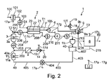
図1は、生産物として水素80、電力P、又は水素80と電力Pの両方の組み合わせを生成するのに適した水素と電気の併給システム1の概略的な実施形態を示す。システム1は送風機101、固体酸化物形燃料電池スタック2、予備改質器3、電気負荷6、水素分離ユニット8及びバーナー9を含む。予備改質器3はSOFCスタック2から分離されており、SOFCスタック2の本体と物理的に直接接触していないので、予備改質器3とSOFCスタック2との間には物理的な接触を介する直接的な熱伝達はない。これにより、予備改質器3とSOFCスタック2とを独立して熱的に制御することができる。固体酸化物形燃料電池スタック2は、カソード側21、電解質22及びアノード側23を含む。固体酸化物形燃料電池スタック2は、電力Pを消費する可変電気負荷6に結合されている。固体酸化物形燃料電池スタック2は、炭素質燃料20などの流入反応物、最も好ましくは天然ガス、及び酸化剤100、最も好ましくは空気を受け取るように適合されている。空気100は送風機101に供給され、導管102を介して固体酸化物形燃料電池スタック2のカソード側21に供給される。燃料20及び水40は水蒸気発生器11に供給され、次いで予備改質器3に供給されて、未変換炭素質燃料20aが残るように、外部改質によって水素及び一酸化炭素を含む第1の改質ガスS1が生成される。第1改質ガスS1、未変換炭素質燃料20a及び水蒸気は、導管205によって固体酸化物形燃料電池2のアノード側23に供給される。固体酸化物形燃料電池スタック2において、未変換炭素質燃料20aの少なくとも一部及び水蒸気は、内部改質によって、主に水素及び一酸化炭素を含む第2の改質ガスS2に改質される。例外的な方法ステップでは、炭素質燃料20全体を外部改質によって予備改質器3内で変換することができ、したがって予備改質器3から固体酸化物形燃料電池スタック2に供給することができる未変換炭素質燃料20aは残らない。そのような外部改質は、例えば、好ましくは風力エネルギー又は太陽エネルギーによって生成された電気などの余剰電力を使用して予備改質器3を電気的に加熱することにより、予備改質器3に十分な熱を与えることによって達成できる。
FIG. 1 shows a schematic embodiment of a combined hydrogen and
酸素減損空気流105がカソード側21からバーナー9に供給される。アノード側23から水素分離ユニット8にアノードオフガス208が供給される。水素分離ユニット8は、アノードオフガス208から水素の少なくとも一部を分離するように適合されており、また、精製水素80と、バーナー9に供給されそこで燃焼されるオフガス215とを生成するように適合されている。図2に開示された有利な実施形態では、補給ガス19もバーナー9に導入することができる。補給ガス19は、コントローラ17によってコマンドライン17f及びバルブ18を介して制御されてもよい。好ましい実施形態では、オフガス215及び/又は補給ガス19を燃焼させることによってバーナー9内で発生した熱9bは予備改質器3に伝達され、この伝達は、例えば図2に開示されているように接続された熱交換器9a及び3aを通して、又は例えば図9に開示されているように熱交換器3aのみを通して行われる。好ましい実施形態では、熱、例えばバーナー9内で発生した熱又は熱交換器9aの出口で測定された熱T3は、オフガス215及び補給ガス19の少なくとも一方を制御することによって制御することができる。予備改質器3に供給されるオフガス215及び/又は補給ガス19の熱は、熱管理を提供し、予備改質器3内の予備改質率を制御するように制御装置17によって制御されてもよい。
An oxygen-depleted
水素分離ユニット8のための適切な技術は、吸着に基づくもの、例えば圧力スイング吸着、又は膜に基づくもの、例えばパラジウムベース、又はプロトン性、又は電気化学に基づくもの、例えばプロトン伝導体ベースの電気化学ポンプとすることができる。
Suitable technologies for the
図1はまた、方法の概略図を示す。水40は、水蒸気発生器とも呼ばれる蒸発器11に入る。蒸発器11内で水蒸気が発生し、予備改質器3に入る前に炭素質燃料40と、最も好ましくは天然ガスNGと混合される。予備改質器3において、天然ガスNGは部分的に水素H2及び一酸化炭素COに改質され、残りはメタン、水蒸気及び二酸化炭素CO2である。予備改質率は、予備改質器3を出る予備改質ガスの出口温度T2によって決まる。好ましくは、出口温度は一定値に保たれる。予備改質ガスがSOFCスタック2のアノード側23に入り、そこで残りのメタンが改質される。好ましい方法では、得られた合成ガスは、SOFCスタック2内で、電力P生成を通じて部分的に水H2O及びCO2に変換される。アノードオフガス208は、H2、CO、CO2及びH2Oを含む。アノードオフガス208は水素分離ユニット8に供給され、そこでアノードオフガス208のH2の少なくとも一部が分離されて水素流80が生成される。水素分離ユニット8のオフガス215又はテールガス215は、次いで、SOFCスタック2のカソード側21を出る高温の減損空気105と共にバーナー9内で燃焼される。バーナー9によって発生した熱9bは、最も有利には、水蒸気生成及び予備改質反応に使用される。
FIG. 1 also shows a schematic representation of the method.
流入燃料反応物20は、当業者に公知の任意の適切な炭化水素燃料とすることができる。流入酸化剤反応物100は、任意の適切な酸素含有流体を含むことができる。
システム1は、電力P、精製水素80、及びそれらの組み合わせを生成及び調整するためにいくつかの選択モードで動作させることができる。本発明による方法及びシステムの主な目的は、炭素質燃料供給物からの電力P、精製水素80の形態の水素、及びそれらの組み合わせの生成である。本明細書では、システム内で生成される水素とシステムの生産物とは区別され、これらは電力P及び/又は精製水素80の形態の水素である。
The
図示されたシステム1は多機能システムである。SOFCスタック2は、従来の発電機能に加えて、水素の生成又は水素及び電気の同時生成のための改質を行うために利用することができる。従来の動作モードでは、SOFCスタック2は、流入燃料反応物と流入酸化剤反応物とを電気化学的に反応させて、電力、廃熱、及び二酸化炭素と水とを含む排気を発生させることにより電気を発生させる。代替の改質器動作モードでは、SOFCスタック2は流入燃料反応物を改質して、電気を同時に生成することなく水素排出物を生成する。排出物に含まれる可能性がある追加の反応副生成物には、一酸化炭素、二酸化炭素、及び水がある。組み合わせ又は同時生成の動作モードでは、SOFCスタック2は、水素排出物と電気の両方を同時に発生させる。排出物は、一酸化炭素、二酸化炭素及び水、対応する水蒸気などのさらなる反応種を含み得る。
The illustrated
本明細書で使用されるとき、用語「改質」及び同様のものは、予備改質器3又はSOFCスタック2によって行われる、高温で、例えば250℃超、好ましくは約400℃~約1000℃で、水蒸気の存在下かつ酸素なしで炭化水素燃料を反応させて改質物を生成する化学プロセスを指す。本発明では、予備改質器3及びSOFCスタック2は、炭化水素燃料を水と反応させることにより炭化水素燃料を改質して水素を生成する。
As used herein, the term "reforming" and the like refers to a high temperature, such as above 250°C, preferably from about 400°C to about 1000°C, performed by the
図1に開示された水素と電気の併給システム1は、炭素質燃料200の流入供給に基づき、生産物として精製水素80の形態の水素及び電力Pを生成することを可能にする。システム1は、異なる動作モードの間で切り替えを行うことで、生産物として電力Pを意味する電気、又は水素のいずれかを生成することができ、あるいは、電気コネクタ22aを介してSOFCスタック2に適用される可変負荷6を用いて負荷の量によってSOFCスタック2の燃料利用率を制御することにより、そして好ましくは同時に予備改質器3内の予備改質率を制御することにより、組み合わせモードで生成される水素対電気の比率を変化させることができる。
The combined hydrogen and
図2は、水素と電気の併給システム1の第2の実施形態をより詳細に示す。図2は、流体調整装置14、18、101、404と、改質器3に供給される燃料20、固体酸化物形燃料電池2に導入される酸化剤反応物100、改質器3に導入される水40に対応する水蒸気40a、及びバーナー9に導入される補給ガス19のうちの少なくとも1つ以上を制御するための制御信号17a~17fを提供する制御装置17とを備えるシステム1を示す。さらに、固体酸化物形燃料電池システム1内の熱交換を制御するために、熱交換器103、203、206、209、212、3a、9a、11aなどの手段、詳細には示されていないが、センサ及び接続線が設けられている。
FIG. 2 shows a second embodiment of the combined hydrogen and
図2に開示された水素と電気の併給システム1は、改質プロセスガス供給物205に変換された炭素質燃料供給物200から精製水素80及び電力Pを生成することを可能にし、特に、単位時間当たりに生成される精製水素80の量及び生成される電力出力Pを制御することを可能にする。システム1は、単位時間当たりに生成される精製水素80の量及び生成される電力出力Pを需要に応じて広い範囲で変動させることができるという利点を有する。
The combined hydrogen and
電力Pと水素生産物との間の調整は、図2に示すような制御ユニット17によって管理される。制御ユニット17は、例えば、天然ガスバルブ14、補給ガスバルブ18、送風機101、水再循環ポンプ404、水素分離ユニット8、SOFCスタック2、及び電気負荷6に作用することができる。制御装置17は、予備改質器出口温度T2、空気側のSOFCスタック出口温度T1、及びバーナー温度T3を監視する。動作点を変更するには、予備改質器3での予備改質率が制御されるように、予備改質器に熱を供給すること、及び出口温度T2を制御することによって、H2/電力P比、アノードオフガス208中の分離することが可能なH2の量をそれぞれ制御する。さらに、動作点を変更するために、SOFCスタック内の燃料利用率FUが電気負荷6によって調整され、したがって図4に開示されるように調整される。好ましくは、送風機101によって制御される空気流もまた、SOFCスタック出口温度T1の微調整に使用されるであろう。各動作点(例えば、固定H2/(H2+P))について、同じ水蒸気対炭素比を維持するように、燃料20及び水40の供給量を同時に変えることによっても、生産量を増減させることができる。
Coordination between the power P and the hydrogen product is managed by a
燃料利用率(FU)は、以下の関係を介して、総電流(I)及びセル当たりの燃料流量(f)に関係する:
FU=I/(nF*f)
ここで、nは1分子の燃料の酸化に関与する電子の数(例えば、CH4では8)であり、Fはファラデー定数(=96485C/mol)である。したがって、外部電気負荷6を変化させてSOFC内の全電流を変えることによって、又は燃料流量を変えることによって、これを変動させることができる。
Fuel utilization (FU) is related to total current (I) and fuel flow per cell (f) via the following relationship:
FU=I/(nF*f)
where n is the number of electrons involved in the oxidation of one fuel molecule (eg, 8 for CH4) and F is the Faraday constant (=96485 C/mol). Therefore, it can be varied by changing the external electrical load 6 to change the total current in the SOFC or by changing the fuel flow rate.
無毒の炭素質燃料を得るために、炭化水素燃料20、典型的にはバイオガス又は天然ガスは、制御可能バルブ14に、そして任意に燃料前処理ユニット13、典型的には脱硫ユニットに供給される。炭素質燃料供給物200は水蒸気40aと混合され、熱交換器203で予熱され、導管204を通って予備改質器3に供給されて改質プロセスガス供給物205を生成する。水蒸気40aは水蒸気発生器11内で発生する。予備改質器3には、熱交換器3aによって熱が供給される。予備改質器3における反応は、改質触媒の存在下、500~800℃の温度範囲内で行われることが好ましい。改質プロセスガス205は、熱交換器206内で加熱され、SOFCスタック2のアノード側23に供給される。SOFCスタック2を出たアノードオフガス208は、熱交換器209において例えば約300℃まで冷却され、最初に水性ガスシフト反応器4に供給され、次いで熱交換器212において冷却され、さらに水分離器15、少なくとも水40をガス流213から分離する凝縮器に供給され、したがって水減損流214がもたらされる。水40は水タンク402に貯蔵され、次いで導管403及び405及び水ポンプ404を介して水蒸気発生器11に供給することができる。水減損流214は水素分離ユニット8に供給されて、精製水素80と、分離されなかったH2及びいくらかのCOを含む二酸化炭素に富むガス流215とを生成し、これはバーナー9に供給される。
A
SOFCスタック2はまた、カソード側21と電解質22とを含む。SOFCスタック2は、酸化剤流に対応する空気流100と改質プロセスガス205とを分離した状態に保ち、それらが混合しないようにする。固体酸化物形燃料スタック2のさらなる詳細は示されていない。空気100は、送風機101内でわずかに圧縮されて圧縮冷気102となり、熱交換器103内で加熱されて予熱された空気104となり、次いで固体酸化物形燃料スタック2のカソード側21に供給される。熱交換器及びSOFCスタック2内の圧力降下を克服するためには、圧縮冷気102のわずかな過剰圧力、例えば約5.0kPa(約50ミリバール)が必要である。SOFCスタック2のカソード側21を出る高温の減損空気流105は、バーナー9に供給される。SOFCスタック2によって生成された電気は、DCからACに変換され、詳細には示されていない可変電気負荷6に送られる。電気負荷6は電力Pを消費する。
SOFC stack 2 also includes
制御装置17は、制御ライン17a~17gを通して、送風機101、H2分離ユニット8、SOFCスタック2、バルブ14、バルブ18、水ポンプ404及び電気負荷6の少なくとも1つを制御することが好ましい。さらに、好ましい実施形態では、SOFCスタック2を出る減損空気105の出口温度T1、予備改質器3を出るリフォーメート205の出口温度T2、及び熱交換器9aを出る熱の出口温度T3は、制御ユニット17によって測定される。
出口温度T1の制御は、予備改質率及びFUによって決定される任意の動作条件において、SOFCを出る高温の減損空気流105の温度を測定するセンサT1を使用してSOFCスタック2の温度を監視することができるという利点を有する。温度T1は、送風機101を介して空気流を変化させることによって調整することができ、又は微調整することができる。空気供給流を増加させると、SOFCスタックの冷却が促進され、したがってSOFCスタックの温度が低下する。
Control of outlet temperature T1 monitors the temperature of the SOFC stack 2 using sensor T1 which measures the temperature of the hot
必要な熱量9bに応じて、熱交換器9aに熱9bを供給するために補給ガス19をバーナー9に供給してしてもよく、これは熱交換器3aに熱を提供する。
図3は、図2に開示したシステム1の制御計画の一態様を示す。図3は、システム1で達成することができる一揃いの可能な動作条件を示す。システム1は、水素収量、すなわち単位時間当たりに生成される精製H280の量、及び電力P出力によって決定される特定の条件で動作させることができる。H2収量及び電力Pは任意単位[a.u.]で示される。システム1は、所与の所定量の単位時間当たりH2と所与の電力Pとを供給するように制御することができる。外部需要に応じて、H2及び電力Pの要求量はシステム1の動作中に変化する可能性がある。制御ユニット17は、必要量のH2及び電力Pが達成されるようにシステム1を制御することができる。これは、予備改質器3の予備改質率とSOFCスタック2の燃料利用率FUとを同時に変化させることによって達成される。
Depending on the amount of heat required 9b, make-up
FIG. 3 shows one aspect of the control scheme for the
予備改質率及び燃料利用率FUに加えて、燃料供給流量も制御することができる。図3の異なる線LD1、LD2、LD3、LD4、MD1、MD2、MD3、MD4は、燃料供給流の異なる量に対応しており、LD1及びMD1は100%の燃料供給に、LD2及びMD2は75%の燃料供給に、LD3及びMD3は50%の燃料供給に、LD4及びMD4は25%の燃料供給に対応する。システム1は、異なる動作点で動作することができ、それによって各動作点は、H2収量及び電力Pによって決定されるか、又はH2/(H2+P)の比及び燃料供給流量によって決定される。
In addition to pre-reform rate and fuel utilization rate FU, fuel supply flow rate can also be controlled. The different lines LD1, LD2, LD3, LD4, MD1, MD2, MD3, MD4 in FIG. 3 correspond to different amounts of fuel feed flow, with LD1 and MD1 at 100% fuel feed and LD2 and MD2 at 75% fuel feed. % fueling, with LD3 and MD3 corresponding to 50% fueling and LD4 and MD4 corresponding to 25% fueling. The
H2/(H2+P)の比において、H2は単位時間当たりにシステム1によって生成されるH2を指し、これは単位時間当たりの精製水素80を意味する。Pは、生成された電力を意味し、これは単位時間当たりの電気エネルギーを意味する。図中のH2及びPは任意単位で示されている。電力の単位はワットである。H2については、LHV(低位発熱量)基準の等価電力を用いてもよく、これは、H2=モル流量(mol/秒)×LHV(J/mol)=ワットを意味する。
In the ratio H2/(H2+P), H2 refers to H2 produced by
H2及びPの任意単位を示す図3に開示された例では、3つの動作点L1、L2、L3が、同じH2収量(0.33)に対応するが異なる電力出力で示されている。電力は、点L1では0.3、点L2では0.17、点L3では0である。点LIは、最大燃料供給(100%)及び0.52のH2/(H2+P)比で達成することができる。点L2は、部分的燃料供給(75%)及びH2/(H2+P)=0.68で達成することができる。点L3は、50%の燃料供給及びH2/(H2+P)=1で達成することができる。 In the example disclosed in FIG. 3 showing arbitrary units for H2 and P, three operating points L1, L2, L3 are shown corresponding to the same H2 yield (0.33) but with different power outputs. The power is 0.3 at point L1, 0.17 at point L2, and 0 at point L3. Point LI can be reached with maximum fueling (100%) and an H2/(H2+P) ratio of 0.52. Point L2 can be reached with partial fueling (75%) and H2/(H2+P)=0.68. Point L3 can be reached at 50% fueling and H2/(H2+P)=1.
図3において燃料供給流量及びH2/(H2+P)比によって決定される任意の可能な特定の動作点L1、L2、L3、…L100は、以下の3つの手段によって達成することができる:
1)供給流204内の正しい水蒸気対炭素比を維持し、及び正しい燃料供給流量を維持するために、燃料供給流量をバルブ14で制御し、同時に水の流れを水ポンプ404で制御する;
2)予備改質器3に供給される熱を制御することにより、予備改質器3における予備改質率を調整する;及び
3)図4に開示されるように、生成される電力Pを制御することによって、固体酸化物形燃料電池2における燃料利用率FUを調整する。
Any possible specific operating points L1, L2, L3, .
1) Control the fuel feed flow rate with the
2) adjusting the pre-reformation rate in the
特に興味深いのは、比H2/(H2+P)=0のときのシステム1の動作であり、これは精製H2が生成されず、電力Pのみが生成されることを意味する。同じく特に興味深いのは、比H2/(H2+P)=1のときのシステム1の動作であり、これは精製H2のみが生成され、電力Pが生成されないことを意味する。図3において線LD1、LD2、LD3、LD4、MD1、MD2、MD3、MD4によって示されるように、精製H2が生成されないときの電力Pの量、電力Pが生成されないときの精製H2の量は、燃料供給流量に基づいて制御され得る。
Of particular interest is the operation of
図4は、図2に開示したシステム1におけるH2/(H2+P)比と予備改質率Rと燃料利用率FUとの間の関係を示している。例えば、図3に開示された例では、動作点L1は0.52のH2/(H2+P)比を有する。動作点LIは、燃料供給流を最大量(100%)に設定し、図4に開示されているように、予備改質率を0.37に、そして燃料利用率FUを0.57に設定することによって達成することができる。同様に、図3によれば、動作点L2は0.68のH2/(H2+P)比を有する。図3によれば、動作点L2は、燃料供給流量を75%に減少させる一方で、図4によれば、予備改質率Rを0.52に、そして燃料利用率FUを0.45に変更することによって達成することができる。
FIG. 4 shows the relationship between the H2/(H2+P) ratio and the pre-reform rate R and fuel utilization rate FU in the
図5は、平衡化された予備改質器3の予備改質率Rが予備改質器出口温度T2に関係していることを示している。この関係は、図5に、水蒸気対炭素比が2のメタンの水蒸気改質の場合として示されている。0.37の予備改質率を達成するためには、予備改質器3の出口温度T2は510℃で平衡にされるべきである。同様に、0.52の予備改質率Rは565℃の平衡温度に相当する。出口温度T2は、例えば、水素分離オフガス215及び必要ならばさらに補給ガス19を燃焼させることにより、熱交換器9aによってバーナー9から熱交換器3aによって予備改質器3に伝達される熱量によって制御することができ、かつ/又は電力によって提供される熱により、例えば予備改質器3に配置された抵抗加熱素子の使用により制御することができる。
FIG. 5 shows that the
図6は、ヒートバランスを満たすためのSOFCシステム1における予備改質率R、燃料利用率FU、H2収量、電力P、及びH2/(H2+P)比の間の関係の一例を示す。図7は、図6のグラフに加えて、異なる量の燃料供給流に対応する異なる線LD1、LD2、LD3、LD4、MD1、MD2、MD3、MD4をさらに示しており、LD1及びMD1は100%の燃料供給に、LD2及びMD2は75%の燃料供給に、LD3及びMD3は50%の燃料供給に、LD4及びMD4は25%の燃料供給に対応する。
FIG. 6 shows an example of the relationship between pre-reformation rate R, fuel utilization FU, H2 yield, power P, and H2/(H2+P) ratio in
図6は特に、熱管理のためのSOFCスタック2内の予備改質率R、燃料利用率FU、各動作点についてもたらされる電力P及びH2の生産量の間の関係を示す。
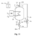
調整計画は次のとおりである。水素生成と電力生成との間の調整は、図6に示される関係に従って、SOFCスタック2内での予備改質の程度を変更し、燃料利用率FUを調整することによって達成される。予備改質の程度は、予備改質出口温度T2を制御することによって達成することができる。予備改質器出口温度T2は、例えば熱電対を用いて測定され、改質反応のために予備改質器3に供給される熱量を変えることによって調整される。この熱は、例えば水素分離ユニットオフガス215及び/又は補給ガス19を燃焼させることによって発生する。これは、特定の状況では電気加熱装置によっても生成することができる。制御のさらなる選択肢では、予備改質器の出口温度T2を一定に保つために上述のように制御及び調節し、さらに、炭素質燃料及び水蒸気を含む供給流を、例えば図11に開示されているように、調整バルブ3b、3cを用いて所望の予備改質の程度に従って2つの流れに分割する。
FIG. 6 particularly shows the relationship between the pre-reformation rate R in the SOFC stack 2 for thermal management, the fuel utilization rate FU, the yield of power P and H2 produced for each operating point.
The adjustment plan is as follows. Coordination between hydrogen production and power production is achieved by varying the degree of pre-reforming in the SOFC stack 2 and adjusting the fuel utilization FU according to the relationship shown in FIG. The degree of pre-reforming can be achieved by controlling the pre-reforming outlet temperature T2. The pre-reformer outlet temperature T2 is measured, for example, using a thermocouple and adjusted by varying the amount of heat supplied to the
予備改質率Rは、FUと合わせて、重要な制御パラメータである。図6及び図7は、水素と電気の併給システム1の動作マップを示している。出発点は、電力Pと水素H2の需要に応じて、H2/(H2+P)動作点を選択することである。それによって燃料供給流量も設定される。次いで、図7に従って予備改質率R及びFUが同時に設定される。例えば、システム1をH2/(H2+P)=0.7で動作させることにした場合、これは200kW相当のH2(LHV=低位発熱量)及び80kWの電力Pの生産に対応する。図6又は図7に従って、予備改質率は0.55に、FUは0.45に設定されるべきである。
Pre-reform ratio R, together with FU, is an important control parameter. 6 and 7 show operation maps of the hydrogen and
第1の例では、予備改質率Rは、予備改質器出口温度T2を570℃に変更し、水素分離ユニットオフガス及び/又は補給ガス19を燃焼させて予備改質器3に提供される熱を制御することにより調整することができる。第2の例では、予改質率Rは、図11に開示されているように迂回路を調整することによって調整することができる。燃料利用率FUは、一定の供給物20流量に対して固体酸化物形燃料電池スタック2の電気負荷Pを変化させることにより、又は一定の電気負荷Pで供給物流量を変化させることにより、調整することができる。
In a first example, the pre-reform rate R is provided to the
一例として、電力Pを80kWに保ったまま50kW相当のH2に動作点を変更する場合を考える。これはH2/(H2+P)が0.385になることを意味する。図6又は7に開示されているように、対応する予備改質率Rは0.25であり、燃料利用率FUは0.66である。電力出力Pは変化しないままであるので、後者は、図7に見られるように、供給流20及び40を同時に100%から50%に低下させつつ、予備改質器出口温度T2を460℃に低下させるか、又は図11に示されているように迂回路を増設することによって達成されるであろう。 As an example, consider the case of changing the operating point to H2 corresponding to 50 kW while maintaining the power P at 80 kW. This means that H2/(H2+P) becomes 0.385. As disclosed in FIG. 6 or 7, the corresponding pre-reform ratio R is 0.25 and the fuel utilization factor FU is 0.66. Since the power output P remains unchanged, the latter reduces the feed streams 20 and 40 from 100% to 50% simultaneously while reducing the pre-reformer outlet temperature T2 to 460° C., as seen in FIG. This may be achieved by lowering or adding detours as shown in FIG.
図8は、特に予備改質器3及び水蒸気発生器11のうち少なくとも一方が電気500を用いて加熱される点で、図2に開示された水素と電気の併給システム1とは区別されるさらなる水素と電気の併給システム1を示す。図7はこの動作モードをより詳細に示す。図7において、EL-SRMによって示される2つの動作点は「電気加熱水蒸気メタン改質」を指し、過剰電力が、好ましくはその使用が水素の生成にとって経済的に有利であるように、低コストで、例えば電力網又は太陽電池パネルから得られる場合に対応する。この場合、上側のEL-SRM点は100%の水素収率を指し、下側のEL-SRM点は電力Pを指す。電力はプロセス中に消費されるため、負の値(-0.55)である。電力は、特に抵抗加熱素子を介して、蒸発器11内での水蒸気の発生及び過熱、予備改質器3内での改質反応、及び改質ガス205の加熱のための熱を生成するために使用される。有利な実施形態が図8に示されている。例えば、さらなる好ましい実施形態では、SOFCスタック2も電気500で加熱することができる。そのような実施形態の利点の1つは、電気によって生成された熱のみを使用することによって、又は電気によって生成された熱の大部分を使用することによって、SOFCスタック2内で水素が生成され得ることである。さらなる利点は、SOFCスタック2が電気的に加熱されると、大部分の炭素質燃料がSOFCスタック2内で改質され、それによって予備改質器3のサイズを縮小することが可能になることである。
FIG. 8 is further distinguished from the combined hydrogen and
加えて、システム1のうち熱を必要とする他の任意の部分、例えば炭素質供給物、酸化剤流動物などの流動流体、蒸発器11、蒸気過熱、補給ガスが電気的に加熱されてもよい。
In addition, any other portion of the
さらなる有利な実施形態では、水素80は水素貯蔵容器81に貯蔵されてもよい。さらに有利な実施形態では、容器81内に貯蔵された水素80をSOFCスタック2に供給して電力を生成することができる。したがって、本発明によるシステムは、電力網から電力を取り込み、後で電力網に電力を供給するために使用することができる。有利な実施形態では、本発明によるシステムは、電気エネルギーの供給及び需要を制御するための電力網の制御に使用することができる。
In a further advantageous embodiment,
図9は、水素と電気の併給システム1のさらなる実施形態を示す。様々な流体調整装置14、18、101、404を制御し、温度又は供給流量などの様々な状態変数を測定するための制御装置17は、詳細には開示されていない。それらは図2に開示されているものと類似している。
FIG. 9 shows a further embodiment of the
制御装置17は、改質器3に供給される燃料20、固体酸化物形燃料電池2に導入される酸化剤反応物100、改質器3に導入される水40に対応する水蒸気40a、バーナー9に導入される補給ガス19、及び制御される電気負荷6の少なくとも1つ以上を制御するための制御信号17a~17gを提供する。さらに、システム1内の熱交換を制御するために、熱交換器103、203、206、209、212、3a、11aなどの手段、詳細には示されていないが、センサ及び接続線が設けられている。
The
図9に開示されたシステム1は、改質プロセスガス供給物205から精製水素80及び電力Pを生成することを可能にし、特に、単位時間当たりに生成される精製水素80の量及び生成される電力Pを制御することを可能にする。
The
制御ユニット17は、燃料バルブ14、送風機101、水再循環ポンプ404、水素分離ユニット8、電気負荷6、及びSOFCセル2に作用することができる。これは、予備改質器出口温度T2、空気側のSOFC出口温度T1、及びバーナー温度T3を監視する。動作点を変更するには、所望の予備改質器出口温度T2に達するように、H2/電力比、H2分離率をそれぞれ制御する。さらに、動作点を変更するために、SOFCスタック2内の燃料利用率(FU)が図6に従って調整され、空気流が、SOFCスタック出口温度T1の微調整に使用されるであろう。各動作点(例えば、固定H2/(H2+P))について、燃料及び水の供給量を同時に変えることによっても、生産量を増減させることができる。
無毒の炭素質燃料を得るために、炭化水素燃料20、典型的にはバイオガス又は天然ガスは、制御可能バルブ14に、そして燃料前処理ユニット13に供給される。炭素質燃料供給物200は水蒸気40aと混合され、導管204を通って予備改質器3に供給されて改質プロセスガス供給物205を生成する。水蒸気40aは水蒸気発生器11内で発生する。予備改質器3には、熱交換器3aによって熱9aが供給される。改質プロセスガス205は、熱交換器206内で加熱され、固体酸化物形燃料電池スタック2のアノード側23に供給される。固体酸化物形燃料電池スタック2を出たアノードオフガス208は、熱交換器206において冷却され、最初に水蒸気発生器11に供給され、次いで水性ガスシフト反応器4に供給され、次いで熱交換器212において冷却され、さらに水分離器15、少なくとも水40をガス流213から分離する凝縮器に供給され、したがって水減損流214がもたらされる。水40は水タンク402に貯蔵され、次いで導管403及び405及び水ポンプ404を介して水蒸気発生器11に供給することができる。水減損流214は水素分離ユニット8に供給されて、精製水素80及び二酸化炭素に富むガス流215を生成し、これはバーナー9に供給される。
A
固体酸化物形燃料電池スタック2はまた、カソード側21と電解質22とを含む。固体酸化物形燃料電池スタック2は、空気流100と改質プロセスガス205とを分離した状態に保ち、それらが混合しないようにする。空気100は、送風機101内でわずかに圧縮されて圧縮冷気102となり、熱交換器103内で加熱されて予熱された空気104となり、次いで固体酸化物形燃料電池2のカソード側21に供給される。固体酸化物形燃料電池スタック2のカソード側21を出る高温の減損空気流105は、熱交換器103に、次いでバーナー9に供給される。固体酸化物形燃料電池スタック2によって生成された電気は、DCからACに変換され、可変電気負荷6に送られる。電気負荷6は電力Pを消費する。
Solid oxide fuel cell stack 2 also includes
制御装置17は、制御ライン17a~17gを通して、送風機101、H2分離ユニット8、固体酸化物形燃料電池スタック2、バルブ14、バルブ18及び水ポンプ404の少なくとも1つを制御することが好ましい。さらに、好ましい実施形態では、固体酸化物形燃料電池スタック2を出る減損空気105の出口温度T1、予備改質器3を出るリフォーメート205の出口温度T2、及び熱交換器9aを出る熱の出口温度T3は、制御ユニット17によって測定される。
必要な熱9bに応じて、補給ガス19をバーナー9に供給してもよい。
本発明による水素と電気の併給システム1は、熱を外部使用のために供給することができるという利点も有する。例えば図9では、過剰な熱を熱交換器212から回収することができる。1つの利点は、その熱を活用することができ、それによってシステム全体の効率が向上することである。温度レベルと熱量は動作点に応じて変動する。熱は、例えば400℃から250℃の間で得られる。それは、水蒸気又は温水を生成するために利用することができ、例えば35~55℃のレベルで、例えば家庭用又は衛生用の水として、自動車の洗浄用として、あるいは吸着式チラーを用いて冷却用にさえ使用することができる。
A make-up
The combined hydrogen and
図10は、予備改質器3において予備改質の程度を制御するための、すなわち出口温度T2を制御するための第1の実施形態を示す。予備改質器3は、電源500及び熱交換器3aによって、あるいは他の任意の熱源によって加熱することができる。図10及び11において、要素3aは加熱要素である。しかしながら、図9では、要素3aは熱交換器である。制御ユニット17は、出口温度T2を制御し、出口温度T2が予備改質率を制御するための所定の温度に対応するように電源500を制御する。
FIG. 10 shows a first embodiment for controlling the degree of pre-reforming in the
図11は、予備改質の程度を制御するための第2の実施形態を示す。予備改質器3は、出口温度T2が一定に保たれるように、電源500又は他の任意の熱源によって加熱される。次いで、燃料供給物/水蒸気流204の一部が予備改質器3を迂回するように、制御バルブ3b及び3cを通る流れ3d及び3eを変化させることによって予備改質率が調整される。
FIG. 11 shows a second embodiment for controlling the degree of pre-reforming. The
Claims (21)
・炭素質燃料(20)及び水蒸気(40)を予備改質器(3)に導入し、予備改質器(3)内で、未変換の炭素質燃料(20a)が残るように炭素質燃料(20)の一部を水蒸気改質によって水素及び一酸化炭素を含む第1の改質ガス(S1)に改質する工程、
・未変換の炭素質燃料(20a)及び第1の改質ガス(S1)を固体酸化物形燃料電池スタック(2)のアノード側(23)に導入する工程、
・固体酸化物形燃料電池スタック(2)において、未変換の炭素質燃料(20a)の少なくとも一部を、内部水蒸気改質によって主に水素及び一酸化炭素を含む第2の改質ガス(S2)に改質する工程、
・固体酸化物形燃料電池スタック(2)のカソード側(21)に空気又は酸素含有ガス(100)を導入する工程、
・固体酸化物形燃料電池スタック(2)において、酸素含有ガスの酸素ならびに第1及び第2の改質ガス(S1、S2)の水素及び一酸化炭素を電力(P)及びアノードオフガス(208)に変換する工程、
・アノードオフガス(208)を水素分離ユニット(8)に導入する工程、及び
・水素分離ユニット(8)においてアノードオフガス(208)を精製水素(80)及びオフガス(215)に変換する工程
を含み、予備改質器(3)における改質は外部改質として実施され、
外部改質と内部改質を別々に制御するために予備改質器(3)及び固体酸化物形燃料電池スタック(2)の独立した熱制御を可能にするように、予備改質器(3)は固体酸化物形燃料電池スタック(2)から熱的に分離されており、
制御可能な加熱源が予備改質器(3)に熱的に結合されて、予備改質器(3)の改質率を制御するために予備改質器(3)に制御された熱を提供し、
内部改質のための熱を提供し、内部改質を制御するために、電力(P)の生成が制御され、
外部改質、内部改質、及び固体酸化物形燃料電池スタック(2)の燃料利用率(FU)を組み合わせた制御によって、生成される精製水素(80)の量及び電力(P)の量が調整されることを特徴とする方法。 A method for producing purified hydrogen (80) and electric power (P) in a hydrogen and electricity cogeneration system (1) such that the ratio between purified hydrogen (80) and electric power (P) is adjustable, comprising: ,
Introduce the carbonaceous fuel (20) and steam (40) into the pre-reformer (3), and in the pre-reformer (3) carbonaceous fuel such that unconverted carbonaceous fuel (20a) remains reforming a part of (20) into a first reformed gas (S1) containing hydrogen and carbon monoxide by steam reforming;
- introducing the unconverted carbonaceous fuel (20a) and the first reformate gas (S1) to the anode side (23) of the solid oxide fuel cell stack (2);
- In the solid oxide fuel cell stack (2), at least a portion of the unconverted carbonaceous fuel (20a) is converted by internal steam reforming into a second reformate gas (S2 ) to reform,
- introducing air or an oxygen-containing gas (100) to the cathode side (21) of the solid oxide fuel cell stack (2);
In the solid oxide fuel cell stack (2), the oxygen of the oxygen-containing gas and the hydrogen and carbon monoxide of the first and second reformed gases (S1, S2) are converted into electric power (P) and anode off-gas (208). the step of converting to
- introducing the anode off-gas (208) into the hydrogen separation unit (8); and - converting the anode off-gas (208) into purified hydrogen (80) and off-gas (215) in the hydrogen separation unit (8), the reforming in the pre-reformer (3) is carried out as external reforming ,
pre-reformer (3) to allow independent thermal control of the pre-reformer (3) and the solid oxide fuel cell stack (2) to separately control external and internal reforming; ) is thermally isolated from the solid oxide fuel cell stack (2),
A controllable heating source is thermally coupled to the prereformer (3) to provide controlled heat to the prereformer (3) to control the reforming rate of the prereformer (3). Offer to,
the generation of electrical power (P) is controlled to provide heat for and control the internal reforming;
The combined control of external reforming , internal reforming, and fuel utilization (FU ) of the solid oxide fuel cell stack (2) allows the amount of purified hydrogen (80) and electrical power (P) produced to be A method characterized by being adjusted.
・予備改質器出口温度(T2)を維持することにより外部改質率を制限する工程であって、これは第1の改質ガス(S1)及び残りの炭素質燃料(20a)の出口温度が450℃未満であることを意味し、それにより固体酸化物形燃料電池スタック(2)内で最大90%の改質が内部改質により行われて電力(P)の高生産を可能にする工程
をさらに含む、請求項6又は7に記載の方法。 - controlling the heat provided to the pre-reformer (3);
a step of limiting the external reforming rate by maintaining a pre-reformer exit temperature (T2), which is the exit temperature of the first reformate (S1) and the remaining carbonaceous fuel (20a); is less than 450° C., whereby up to 90% reforming is done by internal reforming in the solid oxide fuel cell stack (2) to enable high production of power (P) 8. The method of claim 6 or 7, further comprising the steps of:
・予備改質器出口温度(T2)を維持する工程であって、これは第1の改質ガス(S1)及び残りの炭素質燃料(20a)の出口温度が450℃~850℃であることを意味する工程、及び
・外部電気負荷(6)を制御することにより水素(80)生成量を変化させる工程
をさらに含む、請求項6又は7に記載の方法。 - controlling the heat provided to the pre-reformer (3);
a step of maintaining the pre-reformer outlet temperature (T2), which is the outlet temperature of the first reformed gas (S1) and the remaining carbonaceous fuel (20a) between 450°C and 850°C; 8. A method according to claim 6 or 7, further comprising: - varying the hydrogen (80) production by controlling the external electrical load (6).
・前記第1の部分(3e)を予備改質器(3)に供給する工程、
・前記第2の部分(3e)に予備改質器(3)を迂回させる工程、
・予備改質器(3)の下流で前記第1及び第2の部分(3d、3e)を合流させて合流水蒸気(205)にする工程、及び
・前記第1及び第2の部分(3d、3e)の量を制御することにより、合流水蒸気(205)の改質率を制御する工程
をさらに含む、請求項1~11のいずれか一項に記載の方法。 - splitting the water vapor (204) and water vapor (40) of the carbonaceous fuel (20) into a first portion (3d) and a second portion (3e);
- feeding said first portion (3e) to a pre-reformer (3);
- bypassing the pre-reformer (3) in said second part (3e);
- combining said first and second portions (3d, 3e) downstream of the pre-reformer (3) into a combined steam (205); and - said first and second portions (3d, A method according to any one of the preceding claims, further comprising controlling the reforming rate of the combined steam (205) by controlling the amount of 3e).
・固体酸化物形燃料電池スタック(2)の測定された温度に基づき、カソード側(21)に導入される酸素含有ガス(100)の量を制御することで固体酸化物形燃料電池スタック(2)を冷却すること
により、固体酸化物形燃料電池スタック(2)の改質率を制御する工程をさらに含む、請求項1~12のいずれか一項に記載の方法。 - measuring the temperature of the solid oxide fuel cell stack (2), in particular the outlet temperature (T1) at the cathode outlet (105); and - based on the measured temperature of the solid oxide fuel cell stack (2). , by controlling the amount of oxygen-containing gas (100) introduced to the cathode side (21) to cool the solid oxide fuel cell stack (2). The method of any one of claims 1-12, further comprising the step of controlling the reforming rate.
・固体酸化物形燃料電池スタック(2)、
・予備改質器(3)、
・電力(P)を消費する電気負荷(6)、
・水素分離ユニット(8)、
・制御ユニット(17)、及び
・炭素質燃料源
を含み、
・固体酸化物形燃料電池スタック(2)は電気負荷(6)に結合され、さらに水素分離ユニット(8)に結合されており、
・予備改質器(3)及び固体酸化物形燃料電池スタック(2)の独立した熱制御を可能にするように、予備改質器(3)は固体酸化物形燃料電池スタック(2)から熱的に分離されており、
・水蒸気源が水蒸気の流れを提供し、
・予備改質器(3)は炭素質燃料源の流れ及び水蒸気源の流れに接続されており、
前記予備改質器(3)は少なくとも水素、一酸化炭素及び未変換の炭素質燃料(20a)を含む第1の改質ガス(S1)を生成し、
・固体酸化物形燃料電池スタック(2)は、第1の改質ガス(S1)及び未変換の炭素質燃料(20a)を受け取るように予備改質器(3)に接続されており、
・電気負荷(6)は制御可能な可変電気負荷(6)であり、
・予備改質器(3)は制御可能な加熱源(9)に熱的に結合されており、
・制御ユニット(17)は、内部改質及び外部改質を独立して制御するために可変電気負荷(6)と加熱源(9)によって提供される熱とを少なくとも制御することにより、生成される電力(P)と水素(80)の量との間の比率を制御するように適合されていることを特徴とするシステム。 A hydrogen and electricity co-production system for producing and co-producing hydrogen (80), electricity (P), comprising:
- Solid oxide fuel cell stack (2),
- Preliminary reformer (3),
an electrical load (6) that consumes power (P),
a hydrogen separation unit (8),
a control unit (17), and
・Carbonaceous fuel source
including
- the solid oxide fuel cell stack (2) is coupled to an electrical load (6) and further coupled to a hydrogen separation unit (8),
the pre-reformer (3) from the solid oxide fuel cell stack (2) to allow independent thermal control of the pre-reformer (3) and the solid oxide fuel cell stack (2); thermally isolated and
- a water vapor source provides a flow of water vapor;
- the pre-reformer (3) is connected to the carbonaceous fuel source stream and the steam source stream;
the pre-reformer (3) produces a first reformed gas (S1) containing at least hydrogen, carbon monoxide and unconverted carbonaceous fuel (20a);
- the solid oxide fuel cell stack (2) is connected to the pre-reformer (3) to receive the first reformate gas (S1) and the unconverted carbonaceous fuel (20a) ;
- the electrical load (6) is a controllable variable electrical load (6);
- the pre-reformer (3) is thermally coupled to a controllable heating source (9);
the control unit (17) controls at least the variable electrical load (6) and the heat provided by the heating source (9) to independently control the internal reforming and the external reforming ; A system characterized in that it is adapted to control the ratio between the electric power (P) and the amount of hydrogen (80).
Applications Claiming Priority (3)
| Application Number | Priority Date | Filing Date | Title |
|---|---|---|---|
| EP17154005 | 2017-01-31 | ||
| EP17154005.7 | 2017-01-31 | ||
| PCT/EP2018/052453 WO2018141822A1 (en) | 2017-01-31 | 2018-01-31 | Method and system for producing hydrogen, electricity and co-production |
Publications (2)
| Publication Number | Publication Date |
|---|---|
| JP2020505741A JP2020505741A (en) | 2020-02-20 |
| JP7127039B2 true JP7127039B2 (en) | 2022-08-29 |
Family
ID=57956139
Family Applications (1)
| Application Number | Title | Priority Date | Filing Date |
|---|---|---|---|
| JP2019541091A Active JP7127039B2 (en) | 2017-01-31 | 2018-01-31 | Methods, systems and uses of systems for the generation and co-generation of hydrogen and electricity. |
Country Status (9)
| Country | Link |
|---|---|
| US (1) | US20190393525A1 (en) |
| EP (1) | EP3577709B1 (en) |
| JP (1) | JP7127039B2 (en) |
| KR (1) | KR102496027B1 (en) |
| CN (1) | CN110710040B (en) |
| AU (1) | AU2018214190B2 (en) |
| CA (1) | CA3049509C (en) |
| PL (1) | PL3577709T3 (en) |
| WO (1) | WO2018141822A1 (en) |
Families Citing this family (24)
| Publication number | Priority date | Publication date | Assignee | Title |
|---|---|---|---|---|
| JP7321999B2 (en) * | 2018-03-30 | 2023-08-07 | 大阪瓦斯株式会社 | FUEL CELL DEVICE AND METHOD OF OPERATION OF FUEL CELL DEVICE |
| JP7250769B2 (en) * | 2018-03-30 | 2023-04-03 | 大阪瓦斯株式会社 | Fuel cell single cell unit, fuel cell module and fuel cell device |
| KR102697272B1 (en) * | 2018-03-30 | 2024-08-20 | 오사까 가스 가부시키가이샤 | Metal-supported fuel cells and fuel cell modules |
| US11835270B1 (en) | 2018-06-22 | 2023-12-05 | Booz Allen Hamilton Inc. | Thermal management systems |
| US11486607B1 (en) | 2018-11-01 | 2022-11-01 | Booz Allen Hamilton Inc. | Thermal management systems for extended operation |
| US11384960B1 (en) | 2018-11-01 | 2022-07-12 | Booz Allen Hamilton Inc. | Thermal management systems |
| US11448434B1 (en) | 2018-11-01 | 2022-09-20 | Booz Allen Hamilton Inc. | Thermal management systems |
| US11835271B1 (en) | 2019-03-05 | 2023-12-05 | Booz Allen Hamilton Inc. | Thermal management systems |
| US11616249B2 (en) * | 2019-03-22 | 2023-03-28 | Bloom Energy Corporation | Solid oxide fuel cell system with hydrogen pumping cell with carbon monoxide tolerant anodes and integrated shift reactor |
| US11796230B1 (en) * | 2019-06-18 | 2023-10-24 | Booz Allen Hamilton Inc. | Thermal management systems |
| US11752837B1 (en) | 2019-11-15 | 2023-09-12 | Booz Allen Hamilton Inc. | Processing vapor exhausted by thermal management systems |
| JP2021103643A (en) * | 2019-12-25 | 2021-07-15 | 富士電機株式会社 | Fuel cell system and operating method |
| JP7323065B2 (en) * | 2020-05-22 | 2023-08-08 | 日産自動車株式会社 | FUEL CELL SYSTEM AND METHOD OF CONTROLLING FUEL CELL SYSTEM |
| US11561030B1 (en) | 2020-06-15 | 2023-01-24 | Booz Allen Hamilton Inc. | Thermal management systems |
| CN111725545A (en) * | 2020-06-29 | 2020-09-29 | 潍柴动力股份有限公司 | A kind of control method, device and FCU of SOFC system |
| KR102435378B1 (en) * | 2020-08-21 | 2022-08-22 | 조선대학교산학협력단 | Solar fuel production system based on plasma-matrix burner partial oxidation reformer |
| KR102491197B1 (en) * | 2021-06-18 | 2023-01-20 | 주식회사 디알엠카탈리스트 | Fuel cell system comprising steam reforming reactor and dry reforming reactor |
| KR102645544B1 (en) * | 2021-07-02 | 2024-03-08 | (주)원익머트리얼즈 | Ammonia based solid oxide fuel cells hybrid hydrogen manufacturing system |
| KR102390611B1 (en) * | 2021-10-21 | 2022-04-25 | 고등기술연구원연구조합 | Hybrid system for reforming fuel and method for reforming fuel using the same |
| DE102021212908A1 (en) * | 2021-11-17 | 2023-05-17 | Robert Bosch Gesellschaft mit beschränkter Haftung | Fuel cell device with increased service life |
| US12264068B2 (en) * | 2023-04-04 | 2025-04-01 | Iogen Corporation | Method for making low carbon intensity hydrogen |
| KR102797929B1 (en) * | 2023-09-26 | 2025-04-17 | 연세대학교 산학협력단 | Verification and design method of soec system thermal coupling and soec system |
| KR20250047420A (en) * | 2023-09-26 | 2025-04-04 | 고등기술연구원연구조합 | Biogas-based electrochemical extraction and separation system |
| CN120727883B (en) * | 2025-08-19 | 2025-11-25 | 上海中弗新能源科技股份有限公司 | Multifunctional efficient SOFC power generation management method and system for islands |
Citations (3)
| Publication number | Priority date | Publication date | Assignee | Title |
|---|---|---|---|---|
| US20040202914A1 (en) | 2003-04-09 | 2004-10-14 | Ion America Corporation | Co-production of hydrogen and electricity in a high temperature electrochemical system |
| JP2007287579A (en) | 2006-04-19 | 2007-11-01 | Central Res Inst Of Electric Power Ind | Fuel cell facilities and combined power generation facilities |
| WO2016087389A1 (en) | 2014-12-01 | 2016-06-09 | Htceramix S.A. | Sofc system and method of operating a sofc system |
Family Cites Families (12)
| Publication number | Priority date | Publication date | Assignee | Title |
|---|---|---|---|---|
| US6238815B1 (en) * | 1998-07-29 | 2001-05-29 | General Motors Corporation | Thermally integrated staged methanol reformer and method |
| JP4467929B2 (en) * | 2003-08-25 | 2010-05-26 | 日本電信電話株式会社 | Fuel cell power generation system |
| US20050112425A1 (en) | 2003-10-07 | 2005-05-26 | Ztek Corporation | Fuel cell for hydrogen production, electricity generation and co-production |
| DE102005021981B3 (en) * | 2005-05-12 | 2006-10-26 | Mtu Cfc Solutions Gmbh | Operating process for a fuel cell stack has first reformer producing excess hydrogen endothermically and second cooled reformer processing the excess exothermically |
| US8216323B2 (en) * | 2005-06-30 | 2012-07-10 | General Electric Company | System and method for hydrogen production |
| JP5150068B2 (en) * | 2006-07-06 | 2013-02-20 | Jx日鉱日石エネルギー株式会社 | Reformer and indirect internal reforming type solid oxide fuel cell |
| JP2008186759A (en) * | 2007-01-31 | 2008-08-14 | Nippon Oil Corp | Indirect internal reforming solid oxide fuel cell system and indirect internal reforming solid oxide fuel cell operating method |
| JP5102510B2 (en) * | 2007-02-13 | 2012-12-19 | Jx日鉱日石エネルギー株式会社 | Fuel cell system |
| WO2010141629A1 (en) * | 2009-06-02 | 2010-12-09 | Thermochem Recovery International, Inc. | Gasifier having integrated fuel cell power generation system |
| US20140162154A1 (en) * | 2012-12-11 | 2014-06-12 | Joseph J. Hartvigsen | Plasma-catalyzed fuel reformer system |
| US9941534B2 (en) * | 2013-03-15 | 2018-04-10 | Exxonmobil Research And Engineering Company | Integrated power generation and carbon capture using fuel cells |
| US9755258B2 (en) * | 2013-09-30 | 2017-09-05 | Exxonmobil Research And Engineering Company | Integrated power generation and chemical production using solid oxide fuel cells |
-
2018
- 2018-01-31 CA CA3049509A patent/CA3049509C/en active Active
- 2018-01-31 CN CN201880009187.8A patent/CN110710040B/en active Active
- 2018-01-31 WO PCT/EP2018/052453 patent/WO2018141822A1/en not_active Ceased
- 2018-01-31 EP EP18703941.7A patent/EP3577709B1/en active Active
- 2018-01-31 JP JP2019541091A patent/JP7127039B2/en active Active
- 2018-01-31 AU AU2018214190A patent/AU2018214190B2/en active Active
- 2018-01-31 KR KR1020197025368A patent/KR102496027B1/en active Active
- 2018-01-31 US US16/481,734 patent/US20190393525A1/en not_active Abandoned
- 2018-01-31 PL PL18703941.7T patent/PL3577709T3/en unknown
Patent Citations (3)
| Publication number | Priority date | Publication date | Assignee | Title |
|---|---|---|---|---|
| US20040202914A1 (en) | 2003-04-09 | 2004-10-14 | Ion America Corporation | Co-production of hydrogen and electricity in a high temperature electrochemical system |
| JP2007287579A (en) | 2006-04-19 | 2007-11-01 | Central Res Inst Of Electric Power Ind | Fuel cell facilities and combined power generation facilities |
| WO2016087389A1 (en) | 2014-12-01 | 2016-06-09 | Htceramix S.A. | Sofc system and method of operating a sofc system |
Also Published As
| Publication number | Publication date |
|---|---|
| PL3577709T3 (en) | 2021-03-22 |
| CN110710040A (en) | 2020-01-17 |
| AU2018214190A1 (en) | 2019-07-25 |
| JP2020505741A (en) | 2020-02-20 |
| KR20190112092A (en) | 2019-10-02 |
| KR102496027B1 (en) | 2023-02-06 |
| US20190393525A1 (en) | 2019-12-26 |
| EP3577709B1 (en) | 2020-10-21 |
| CN110710040B (en) | 2023-07-18 |
| WO2018141822A1 (en) | 2018-08-09 |
| EP3577709A1 (en) | 2019-12-11 |
| CA3049509C (en) | 2024-04-30 |
| AU2018214190B2 (en) | 2023-02-02 |
| CA3049509A1 (en) | 2018-08-09 |
Similar Documents
| Publication | Publication Date | Title |
|---|---|---|
| JP7127039B2 (en) | Methods, systems and uses of systems for the generation and co-generation of hydrogen and electricity. | |
| US20050112425A1 (en) | Fuel cell for hydrogen production, electricity generation and co-production | |
| US10320018B2 (en) | Dynamically responsive high efficiency CCHP system | |
| US10680265B2 (en) | Energy storage using an REP with an engine | |
| CN101946354A (en) | Method for generating electricity using fuel cells | |
| JP5000412B2 (en) | Operating temperature control method for solid oxide fuel cell system | |
| JP2013527555A (en) | How to operate a cogeneration facility | |
| US6818336B2 (en) | Fuel control for fuel-processor steam generation in low temperature fuel cell power plant | |
| JP2009048854A (en) | Fuel cell power generator and control method thereof | |
| JP2008254942A (en) | Hydrogen production method and hydrogen production system | |
| JP4457421B2 (en) | Fuel cell system | |
| JP7350680B2 (en) | Fuel cell system and fuel cell system operating method | |
| JP2004196611A (en) | Fuel reformer and fuel cell system | |
| JP3872006B2 (en) | Fuel cell power generation system | |
| JP2008204784A (en) | Fuel cell power generation system and fuel cell power generation method | |
| JP3886887B2 (en) | Fuel cell power generation system | |
| JP2008204783A (en) | Fuel cell power generation system and cooling method thereof | |
| EP4546472A1 (en) | Thermal management of high-temperature electrochemical devices | |
| JP2009048853A (en) | Fuel cell power generator and control method thereof | |
| JP2004210609A (en) | Fuel reformer and fuel cell system | |
| JP2851395B2 (en) | Fuel cell power generation system | |
| JP2005056775A (en) | Fuel cell power generation system | |
| JP5557260B2 (en) | Operating temperature control method for solid oxide fuel cell system | |
| KR20150052674A (en) | Fuel cell system | |
| JP2005056735A (en) | Fuel cell power generation system |
Legal Events
| Date | Code | Title | Description |
|---|---|---|---|
| A529 | Written submission of copy of amendment under article 34 pct |
Free format text: JAPANESE INTERMEDIATE CODE: A529 Effective date: 20190729 |
|
| A621 | Written request for application examination |
Free format text: JAPANESE INTERMEDIATE CODE: A621 Effective date: 20201030 |
|
| A977 | Report on retrieval |
Free format text: JAPANESE INTERMEDIATE CODE: A971007 Effective date: 20210915 |
|
| A131 | Notification of reasons for refusal |
Free format text: JAPANESE INTERMEDIATE CODE: A131 Effective date: 20211116 |
|
| A521 | Request for written amendment filed |
Free format text: JAPANESE INTERMEDIATE CODE: A523 Effective date: 20220204 |
|
| A131 | Notification of reasons for refusal |
Free format text: JAPANESE INTERMEDIATE CODE: A131 Effective date: 20220426 |
|
| A521 | Request for written amendment filed |
Free format text: JAPANESE INTERMEDIATE CODE: A523 Effective date: 20220708 |
|
| TRDD | Decision of grant or rejection written | ||
| A01 | Written decision to grant a patent or to grant a registration (utility model) |
Free format text: JAPANESE INTERMEDIATE CODE: A01 Effective date: 20220802 |
|
| A61 | First payment of annual fees (during grant procedure) |
Free format text: JAPANESE INTERMEDIATE CODE: A61 Effective date: 20220817 |
|
| R150 | Certificate of patent or registration of utility model |
Ref document number: 7127039 Country of ref document: JP Free format text: JAPANESE INTERMEDIATE CODE: R150 |
|
| S111 | Request for change of ownership or part of ownership |
Free format text: JAPANESE INTERMEDIATE CODE: R313113 |
|
| R350 | Written notification of registration of transfer |
Free format text: JAPANESE INTERMEDIATE CODE: R350 |