JP7124776B2 - engine - Google Patents
engine Download PDFInfo
- Publication number
- JP7124776B2 JP7124776B2 JP2019056394A JP2019056394A JP7124776B2 JP 7124776 B2 JP7124776 B2 JP 7124776B2 JP 2019056394 A JP2019056394 A JP 2019056394A JP 2019056394 A JP2019056394 A JP 2019056394A JP 7124776 B2 JP7124776 B2 JP 7124776B2
- Authority
- JP
- Japan
- Prior art keywords
- reforming
- engine
- reformed gas
- opening
- reformer
- Prior art date
- Legal status (The legal status is an assumption and is not a legal conclusion. Google has not performed a legal analysis and makes no representation as to the accuracy of the status listed.)
- Active
Links
Images


Classifications
-
- F—MECHANICAL ENGINEERING; LIGHTING; HEATING; WEAPONS; BLASTING
- F02—COMBUSTION ENGINES; HOT-GAS OR COMBUSTION-PRODUCT ENGINE PLANTS
- F02M—SUPPLYING COMBUSTION ENGINES IN GENERAL WITH COMBUSTIBLE MIXTURES OR CONSTITUENTS THEREOF
- F02M33/00—Other apparatus for treating combustion-air, fuel or fuel-air mixture
-
- F—MECHANICAL ENGINEERING; LIGHTING; HEATING; WEAPONS; BLASTING
- F02—COMBUSTION ENGINES; HOT-GAS OR COMBUSTION-PRODUCT ENGINE PLANTS
- F02D—CONTROLLING COMBUSTION ENGINES
- F02D33/00—Controlling delivery of fuel or combustion-air, not otherwise provided for
- F02D33/003—Controlling the feeding of liquid fuel from storage containers to carburettors or fuel-injection apparatus ; Failure or leakage prevention; Diagnosis or detection of failure; Arrangement of sensors in the fuel system; Electric wiring; Electrostatic discharge
- F02D33/006—Controlling the feeding of liquid fuel from storage containers to carburettors or fuel-injection apparatus ; Failure or leakage prevention; Diagnosis or detection of failure; Arrangement of sensors in the fuel system; Electric wiring; Electrostatic discharge depending on engine operating conditions, e.g. start, stop or ambient conditions
-
- C—CHEMISTRY; METALLURGY
- C01—INORGANIC CHEMISTRY
- C01B—NON-METALLIC ELEMENTS; COMPOUNDS THEREOF; METALLOIDS OR COMPOUNDS THEREOF NOT COVERED BY SUBCLASS C01C
- C01B3/00—Hydrogen; Gaseous mixtures containing hydrogen; Separation of hydrogen from mixtures containing it; Purification of hydrogen
- C01B3/02—Production of hydrogen or of gaseous mixtures containing a substantial proportion of hydrogen
- C01B3/04—Production of hydrogen or of gaseous mixtures containing a substantial proportion of hydrogen by decomposition of inorganic compounds, e.g. ammonia
-
- F—MECHANICAL ENGINEERING; LIGHTING; HEATING; WEAPONS; BLASTING
- F02—COMBUSTION ENGINES; HOT-GAS OR COMBUSTION-PRODUCT ENGINE PLANTS
- F02D—CONTROLLING COMBUSTION ENGINES
- F02D19/00—Controlling engines characterised by their use of non-liquid fuels, pluralities of fuels, or non-fuel substances added to the combustible mixtures
- F02D19/02—Controlling engines characterised by their use of non-liquid fuels, pluralities of fuels, or non-fuel substances added to the combustible mixtures peculiar to engines working with gaseous fuels
- F02D19/021—Control of components of the fuel supply system
- F02D19/023—Control of components of the fuel supply system to adjust the fuel mass or volume flow
-
- F—MECHANICAL ENGINEERING; LIGHTING; HEATING; WEAPONS; BLASTING
- F02—COMBUSTION ENGINES; HOT-GAS OR COMBUSTION-PRODUCT ENGINE PLANTS
- F02D—CONTROLLING COMBUSTION ENGINES
- F02D19/00—Controlling engines characterised by their use of non-liquid fuels, pluralities of fuels, or non-fuel substances added to the combustible mixtures
- F02D19/06—Controlling engines characterised by their use of non-liquid fuels, pluralities of fuels, or non-fuel substances added to the combustible mixtures peculiar to engines working with pluralities of fuels, e.g. alternatively with light and heavy fuel oil, other than engines indifferent to the fuel consumed
- F02D19/0602—Control of components of the fuel supply system
- F02D19/0607—Control of components of the fuel supply system to adjust the fuel mass or volume flow
-
- F—MECHANICAL ENGINEERING; LIGHTING; HEATING; WEAPONS; BLASTING
- F02—COMBUSTION ENGINES; HOT-GAS OR COMBUSTION-PRODUCT ENGINE PLANTS
- F02D—CONTROLLING COMBUSTION ENGINES
- F02D19/00—Controlling engines characterised by their use of non-liquid fuels, pluralities of fuels, or non-fuel substances added to the combustible mixtures
- F02D19/06—Controlling engines characterised by their use of non-liquid fuels, pluralities of fuels, or non-fuel substances added to the combustible mixtures peculiar to engines working with pluralities of fuels, e.g. alternatively with light and heavy fuel oil, other than engines indifferent to the fuel consumed
- F02D19/0639—Controlling engines characterised by their use of non-liquid fuels, pluralities of fuels, or non-fuel substances added to the combustible mixtures peculiar to engines working with pluralities of fuels, e.g. alternatively with light and heavy fuel oil, other than engines indifferent to the fuel consumed characterised by the type of fuels
- F02D19/0642—Controlling engines characterised by their use of non-liquid fuels, pluralities of fuels, or non-fuel substances added to the combustible mixtures peculiar to engines working with pluralities of fuels, e.g. alternatively with light and heavy fuel oil, other than engines indifferent to the fuel consumed characterised by the type of fuels at least one fuel being gaseous, the other fuels being gaseous or liquid at standard conditions
- F02D19/0644—Controlling engines characterised by their use of non-liquid fuels, pluralities of fuels, or non-fuel substances added to the combustible mixtures peculiar to engines working with pluralities of fuels, e.g. alternatively with light and heavy fuel oil, other than engines indifferent to the fuel consumed characterised by the type of fuels at least one fuel being gaseous, the other fuels being gaseous or liquid at standard conditions the gaseous fuel being hydrogen, ammonia or carbon monoxide
-
- F—MECHANICAL ENGINEERING; LIGHTING; HEATING; WEAPONS; BLASTING
- F02—COMBUSTION ENGINES; HOT-GAS OR COMBUSTION-PRODUCT ENGINE PLANTS
- F02D—CONTROLLING COMBUSTION ENGINES
- F02D19/00—Controlling engines characterised by their use of non-liquid fuels, pluralities of fuels, or non-fuel substances added to the combustible mixtures
- F02D19/06—Controlling engines characterised by their use of non-liquid fuels, pluralities of fuels, or non-fuel substances added to the combustible mixtures peculiar to engines working with pluralities of fuels, e.g. alternatively with light and heavy fuel oil, other than engines indifferent to the fuel consumed
- F02D19/0663—Details on the fuel supply system, e.g. tanks, valves, pipes, pumps, rails, injectors or mixers
- F02D19/0668—Treating or cleaning means; Fuel filters
- F02D19/0671—Means to generate or modify a fuel, e.g. reformers, electrolytic cells or membranes
-
- F—MECHANICAL ENGINEERING; LIGHTING; HEATING; WEAPONS; BLASTING
- F02—COMBUSTION ENGINES; HOT-GAS OR COMBUSTION-PRODUCT ENGINE PLANTS
- F02M—SUPPLYING COMBUSTION ENGINES IN GENERAL WITH COMBUSTIBLE MIXTURES OR CONSTITUENTS THEREOF
- F02M21/00—Apparatus for supplying engines with non-liquid fuels, e.g. gaseous fuels stored in liquid form
- F02M21/02—Apparatus for supplying engines with non-liquid fuels, e.g. gaseous fuels stored in liquid form for gaseous fuels
- F02M21/0203—Apparatus for supplying engines with non-liquid fuels, e.g. gaseous fuels stored in liquid form for gaseous fuels characterised by the type of gaseous fuel
- F02M21/0206—Non-hydrocarbon fuels, e.g. hydrogen, ammonia or carbon monoxide
-
- F—MECHANICAL ENGINEERING; LIGHTING; HEATING; WEAPONS; BLASTING
- F02—COMBUSTION ENGINES; HOT-GAS OR COMBUSTION-PRODUCT ENGINE PLANTS
- F02M—SUPPLYING COMBUSTION ENGINES IN GENERAL WITH COMBUSTIBLE MIXTURES OR CONSTITUENTS THEREOF
- F02M21/00—Apparatus for supplying engines with non-liquid fuels, e.g. gaseous fuels stored in liquid form
- F02M21/02—Apparatus for supplying engines with non-liquid fuels, e.g. gaseous fuels stored in liquid form for gaseous fuels
- F02M21/0218—Details on the gaseous fuel supply system, e.g. tanks, valves, pipes, pumps, rails, injectors or mixers
- F02M21/0227—Means to treat or clean gaseous fuels or fuel systems, e.g. removal of tar, cracking, reforming or enriching
-
- F—MECHANICAL ENGINEERING; LIGHTING; HEATING; WEAPONS; BLASTING
- F02—COMBUSTION ENGINES; HOT-GAS OR COMBUSTION-PRODUCT ENGINE PLANTS
- F02M—SUPPLYING COMBUSTION ENGINES IN GENERAL WITH COMBUSTIBLE MIXTURES OR CONSTITUENTS THEREOF
- F02M27/00—Apparatus for treating combustion-air, fuel, or fuel-air mixture, by catalysts, electric means, magnetism, rays, sound waves, or the like
- F02M27/02—Apparatus for treating combustion-air, fuel, or fuel-air mixture, by catalysts, electric means, magnetism, rays, sound waves, or the like by catalysts
-
- Y—GENERAL TAGGING OF NEW TECHNOLOGICAL DEVELOPMENTS; GENERAL TAGGING OF CROSS-SECTIONAL TECHNOLOGIES SPANNING OVER SEVERAL SECTIONS OF THE IPC; TECHNICAL SUBJECTS COVERED BY FORMER USPC CROSS-REFERENCE ART COLLECTIONS [XRACs] AND DIGESTS
- Y02—TECHNOLOGIES OR APPLICATIONS FOR MITIGATION OR ADAPTATION AGAINST CLIMATE CHANGE
- Y02E—REDUCTION OF GREENHOUSE GAS [GHG] EMISSIONS, RELATED TO ENERGY GENERATION, TRANSMISSION OR DISTRIBUTION
- Y02E60/00—Enabling technologies; Technologies with a potential or indirect contribution to GHG emissions mitigation
- Y02E60/30—Hydrogen technology
- Y02E60/36—Hydrogen production from non-carbon containing sources, e.g. by water electrolysis
-
- Y—GENERAL TAGGING OF NEW TECHNOLOGICAL DEVELOPMENTS; GENERAL TAGGING OF CROSS-SECTIONAL TECHNOLOGIES SPANNING OVER SEVERAL SECTIONS OF THE IPC; TECHNICAL SUBJECTS COVERED BY FORMER USPC CROSS-REFERENCE ART COLLECTIONS [XRACs] AND DIGESTS
- Y02—TECHNOLOGIES OR APPLICATIONS FOR MITIGATION OR ADAPTATION AGAINST CLIMATE CHANGE
- Y02T—CLIMATE CHANGE MITIGATION TECHNOLOGIES RELATED TO TRANSPORTATION
- Y02T10/00—Road transport of goods or passengers
- Y02T10/10—Internal combustion engine [ICE] based vehicles
- Y02T10/30—Use of alternative fuels, e.g. biofuels
Description
本発明は、燃料を改質ガスに改質する改質器を備えるエンジンに関する。 The present invention relates to an engine equipped with a reformer that reforms fuel into reformed gas.
従来、燃料を改質ガスに改質する改質器を備えるエンジンとして、吸気流路に燃料を噴射する主燃料供給部と、改質器で燃料が改質された改質ガスの流量を調整する改質ガス調整部と、を備えるエンジンが知られている(例えば特許文献1)。 Conventionally, as an engine equipped with a reformer that reforms fuel into reformed gas, the main fuel supply part that injects fuel into the intake passage and the flow rate of the reformed gas that has been reformed by the reformer are adjusted. There is known an engine provided with a reformed gas adjustment unit that performs the conversion (for example, Patent Literature 1).
上記従来技術のようなエンジンでは、例えば主燃料供給部で噴射された燃料と改質ガス調整部で流量が調整された改質ガスとがエンジンの燃焼室で燃焼される。しかしながら、例えばエンジンの始動直後においては、例えば改質器が十分に暖機されていない場合など、吸気流路に導かれる改質ガスの組成が不安定となり、エンジンの燃焼室内の混合ガスが適切な空燃比となりにくい場合がある。その結果、例えばエンジン回転数挙動の不安定又はエンジンの排気ガス性能の悪化などの性能低下が生じるおそれがある。 In the engine of the prior art, for example, the fuel injected by the main fuel supply section and the reformed gas whose flow rate is adjusted by the reformed gas adjustment section are combusted in the combustion chamber of the engine. However, immediately after the engine is started, for example, if the reformer is not sufficiently warmed up, the composition of the reformed gas led to the intake passage becomes unstable, and the mixed gas in the combustion chamber of the engine is not suitable. air-fuel ratio may be difficult to achieve. As a result, there is a risk of performance degradation such as, for example, instability of engine speed behavior or deterioration of engine exhaust gas performance.
本発明は、エンジンの始動直後に吸気流路に導かれる改質ガスの組成に起因する性能低下を抑制可能なエンジンを提供することを目的とする。 SUMMARY OF THE INVENTION An object of the present invention is to provide an engine capable of suppressing deterioration in performance caused by the composition of the reformed gas introduced into the intake passage immediately after the engine is started.
本発明の一態様に係るエンジンは、燃料を改質ガスに改質する改質器を備えるエンジンであって、エンジンの吸入空気を流通させる吸気流路と、改質器が設けられ、改質器に改質用空気を流通させると共に、改質器から吸気流路に改質ガスを流通させる改質流路と、吸気流路に設けられ、吸気流路に燃料を供給する主燃料供給部と、改質流路に設けられ、改質用空気の流量を調整する改質用空気調整部と、改質流路における改質器の上流側に設けられ、改質流路に燃料を供給する改質用燃料供給部と、改質流路に設けられ、改質ガスの流量を調整する改質ガス調整部と、エンジンを始動させるための始動信号を出力する始動信号出力部と、始動信号とエンジンのエンジン状態とに基づいて、主燃料供給部と改質用空気調整部と改質用燃料供給部と改質ガス調整部とを制御する制御部と、を備え、制御部は、始動信号が入力された場合、改質器における改質が可能となる改質可能状態となるように改質用空気調整部と改質用燃料供給部とを制御すると共に、エンジンの始動直後を少なくとも含む一定期間、改質ガス組成安定状態における改質ガス調整部の開度である通常開度よりも小さい開度となるように、改質ガス調整部を制御する。 An engine according to one aspect of the present invention is an engine that includes a reformer that reforms fuel into a reformed gas, and is provided with an intake flow path for circulating intake air of the engine and a reformer. A reforming passage that circulates reforming air through the reformer and circulates reformed gas from the reformer to the intake passage, and a main fuel supply section that is provided in the intake passage and supplies fuel to the intake passage. a reforming air adjustment unit provided in the reforming flow channel for adjusting the flow rate of the reforming air; and a reforming flow channel provided upstream of the reformer to supply fuel to the reforming flow channel. a reforming fuel supply unit for reforming, a reformed gas adjustment unit provided in the reforming flow path for adjusting the flow rate of the reformed gas, a start signal output unit for outputting a start signal for starting the engine, and a starting a control unit for controlling the main fuel supply unit, the reforming air adjustment unit, the reforming fuel supply unit, and the reformed gas adjustment unit based on the signal and the engine state of the engine, the control unit comprising: When the start signal is input, the reforming air adjustment unit and the reforming fuel supply unit are controlled so that reforming in the reformer is possible, and immediately after the engine is started. The reformed gas adjustment unit is controlled such that the opening is smaller than the normal opening, which is the opening of the reformed gas adjustment unit in the stable state of the reformed gas composition, for at least a certain period of time.
本発明の一態様に係るエンジンでは、始動信号が入力された場合、改質器における改質が可能となる改質可能状態とされると共に、エンジンの始動直後を少なくとも含む一定期間、通常開度よりも小さい開度となるように改質ガス調整部が制御される。これにより、少なくともエンジンの始動直後において、エンジンの吸気流路に導かれる改質ガスの流量が通常開度に応じた流量よりも低減される。よって、例えばエンジンの始動直後に改質ガスの組成が安定な改質ガス組成安定状態ではなかったとしても、改質ガスの組成の不安定さがエンジンの性能に及ぼす影響を抑えることができる。その結果、エンジンの始動直後に吸気流路に導かれる改質ガスの組成に起因する性能低下を抑制することが可能となる。 In the engine according to one aspect of the present invention, when a start signal is input, the reformer is brought into a reformable state in which reforming is possible, and for a certain period of time including at least immediately after the engine is started, the normal opening degree The reformed gas adjustment unit is controlled so that the opening is smaller than the opening degree. As a result, at least immediately after the engine is started, the flow rate of the reformed gas led to the intake passage of the engine is reduced below the flow rate corresponding to the normal opening. Therefore, for example, even if the reformed gas composition is not in a stable reformed gas composition state immediately after the engine is started, the influence of the unstable composition of the reformed gas on engine performance can be suppressed. As a result, it is possible to suppress the deterioration in performance due to the composition of the reformed gas introduced into the intake passage immediately after the engine is started.
本発明の一態様に係るエンジンでは、制御部は、始動信号が入力された以降において、通常開度よりも小さい初期開度から通常開度まで漸増するように、改質ガス調整部を制御してもよい。この場合、エンジンの吸気流路に導かれる改質ガスの流量が徐々に増加されるため、エンジンの燃焼室内の混合気の空燃比を徐々に変化させることができる。 In the engine according to one aspect of the present invention, the control unit controls the reformed gas adjustment unit so that the opening gradually increases from an initial opening smaller than the normal opening to the normal opening after the start signal is input. may In this case, since the flow rate of the reformed gas introduced into the intake passage of the engine is gradually increased, the air-fuel ratio of the air-fuel mixture in the combustion chamber of the engine can be gradually changed.
本発明の一態様に係るエンジンでは、一定期間は、始動信号が入力されてから所定時間が経過するまでの期間であってもよい。この場合、始動信号が入力されてからの経過時間に応じて改質ガスの組成が安定するものとして、改質ガス調整部を制御することができる。 In the engine according to one aspect of the present invention, the fixed period may be a period from when the start signal is input until a predetermined period of time elapses. In this case, the reformed gas adjustment section can be controlled assuming that the composition of the reformed gas is stabilized according to the elapsed time after the start signal is input.
本発明の一態様に係るエンジンは、改質流路に設けられ、改質用空気の流量を取得する流量取得部を更に備え、一定期間は、流量取得部で取得した流量の始動信号が入力されてからの時間積算値が所定の改質ガス置換容積に達するまでの期間であってもよい。この場合、始動信号が入力されてからの改質用空気の流量の時間積算値に応じて改質ガスの組成が安定するものとして、改質ガス調整部を制御することができる。 The engine according to one aspect of the present invention further includes a flow rate acquisition unit that is provided in the reforming flow path and acquires the flow rate of the reforming air, and for a certain period of time, the start signal for the flow rate acquired by the flow rate acquisition unit is input. It may be a period until the time integrated value after the change reaches a predetermined reformed gas replacement volume. In this case, the reformed gas adjustment section can be controlled assuming that the composition of the reformed gas is stabilized according to the time integrated value of the reforming air flow rate after the start signal is input.
本発明の一態様に係るエンジンでは、初期開度は、改質ガス調整部の全閉開度であり、通常開度は、改質ガス調整部の全開開度であってもよい。この場合、吸気流路に導かれる改質ガスの組成がエンジンの性能に及ぼす影響を、より確実に抑えることができる。 In the engine according to the aspect of the present invention, the initial opening may be the fully closed opening of the reformed gas adjustment section, and the normal opening may be the fully open opening of the reformed gas adjustment section. In this case, the influence of the composition of the reformed gas introduced into the intake passage on the performance of the engine can be suppressed more reliably.
本発明の一態様に係るエンジンは、燃料としてアンモニアを水素ガスを含む改質ガスに改質する改質器を備えるアンモニアエンジンであってもよい。この場合、例えば炭化水素を含む燃料を改質ガスに改質する改質器を備えるエンジンと比べて、改質ガスの組成の不安定さに起因する性能低下が生じ易い傾向があることから、上述の構成により得られる性能低下の抑制効果が顕著なものとなる。 An engine according to an aspect of the present invention may be an ammonia engine including a reformer that reforms ammonia as fuel into a reformed gas containing hydrogen gas. In this case, compared to, for example, an engine equipped with a reformer that reforms a fuel containing hydrocarbons into a reformed gas, there is a tendency for performance to deteriorate due to instability in the composition of the reformed gas. The effect of suppressing deterioration in performance obtained by the above-described configuration is remarkable.
本発明によれば、エンジンの始動直後に吸気流路に導かれる改質ガスの組成に起因する性能低下を抑制することが可能となる。 According to the present invention, it is possible to suppress deterioration in performance due to the composition of the reformed gas introduced into the intake passage immediately after the engine is started.
以下、本発明の実施形態について、図面を参照して詳細に説明する。なお、図面において、同一または同等の要素には同じ符号を付し、重複する説明を省略する。 BEST MODE FOR CARRYING OUT THE INVENTION Hereinafter, embodiments of the present invention will be described in detail with reference to the drawings. In the drawings, the same or equivalent elements are denoted by the same reference numerals, and overlapping descriptions are omitted.
図1は、一実施形態のエンジンの概略構成図である。図1に示されるように、本実施形態のエンジン100は、ECU[Electronic Control Unit](制御部)10と、エンジン主要部20と、改質部30と、を備えている。エンジン100は、アンモニア(NH3)を含む混合気を燃焼させる内燃機関であり、例えば4サイクルレシプロエンジンとして構成されている。エンジン100は、例えば荷役作業を行うフォークリフト等の産業車両に搭載される。エンジン100は、その他、例えば乗用車、トラック、バス等の車両に搭載されていてもよい。
FIG. 1 is a schematic configuration diagram of an engine according to one embodiment. As shown in FIG. 1 , an
エンジン主要部20は、エンジン本体21と、吸気流路22と、メインスロットル23と、メインインジェクタ(主燃料供給部)24と、排気流路25と、三元触媒26と、アンモニア吸着触媒の一例としてのSCR[Selective Catalytic Reduction]27と、を有している。
The engine
エンジン本体21は、混合気を燃焼させるためのエンジン100の主要部であり、シリンダブロック、シリンダヘッド、及びピストン等で構成されている。エンジン本体21では、シリンダブロック、シリンダヘッド、及びピストンにより燃焼室が画成されている。シリンダヘッドには、例えば点火プラグが設けられている。エンジン本体21は、エンジン100を始動させるためのスタータを有している。
The
吸気流路22は、エンジン100のエンジン本体21へ吸入空気を流通させる流路であり、例えば配管、サージタンク、インテークマニホールド、及び吸気ポート等が含まれる。吸気流路22の入口には、例えば、吸入する空気を濾過するエアクリーナ28が設けられている。
The
メインスロットル23は、エアクリーナ28を介して吸入した空気の流量を調整する弁である。メインスロットル23は、吸気流路22におけるエアクリーナ28の下流側に設けられている。メインスロットル23は、例えば電子制御スロットルバルブである。メインスロットル23は、ECU10と電気的に接続されている。メインスロットル23の動作は、ECU10によって制御される。
The
メインインジェクタ24は、吸気流路22に燃料を噴射する弁である。メインインジェクタ24は、吸気流路22におけるメインスロットル23の下流側に設けられている。メインインジェクタ24の個数は、1個でもよいし複数個であってもよい。メインインジェクタ24の個数が1個の場合、メインインジェクタ24は、例えばエンジン本体21の吸気ポートに設けられていてもよい。メインインジェクタ24の個数が複数個の場合、メインインジェクタ24は、例えばエンジン本体21のサージタンクに設けられていてもよい。なお、メインインジェクタ24は、吸気流路22におけるメインスロットル23の上流側に設けられていてもよい。あるいは、メインインジェクタ24に代えて、吸気流路22に設けられたミキサなどの燃料供給装置から燃料を供給するようにしてもよい。
The
ここでのメインインジェクタ24は、燃料として改質ガスを含まないアンモニアガスを噴射する。メインインジェクタ24は、ECU10と電気的に接続されている。メインインジェクタ24の動作は、ECU10によって制御される。メインインジェクタ24は、ECU10の制御により、吸気流路22へのアンモニアガスの供給量を調整する。メインインジェクタ24は、例えば改質器36からの改質ガスだけでは要求熱量(後述)を得られない場合に、アンモニアガスを噴射するように制御される。
The
排気流路25は、エンジン100のエンジン本体21からの排気を流通させる流路であり、例えば排気ポート、配管、後処理装置、及び消音器等が含まれる。三元触媒26及びアンモニア吸着触媒の一例としてのSCR27は、この順で排気流路25に設けられている。三元触媒26は、排気ガス中のH2を酸化して浄化すると共に、排気ガス中のNOxを還元して浄化する触媒である。SCR27は、還元反応により排気ガス中に含まれるNOxを浄化する選択還元触媒である。SCR27は、アンモニアを吸着する他の材料(例えばゼオライト系)からなる触媒であってもよい。
The
改質部30は、改質流路31と、改質用スロットル(改質用空気調整部)32と、NH3タンク33と、気化器34と、改質用インジェクタ(改質用燃料供給部)35と、改質器36と、クーラ37と、ストップバルブ(改質ガス調整部)38と、を有している。
The reforming
改質流路31は、燃料を改質ガスに改質するための流路である。改質流路31は、例えば、吸気流路22におけるメインスロットル23の上流側とメインスロットル23の下流側とを結ぶように設けられている。改質流路31は、吸気流路22におけるメインスロットル23の上流側から改質器36に改質用空気を流通させると共に、吸気流路22におけるメインスロットル23の下流側に改質器36から改質ガスを流通させる。改質用空気とは、改質器36で燃料を改質ガスに改質するために用いられる空気である。改質流路31には、改質器36が設けられている。なお、改質流路31は、例えば、吸気流路22におけるメインスロットル23の上流側に接続されずに、専用のエアクリーナを介して吸入した外気を改質用空気として改質器36に流通可能に構成されていてもよい。
The reforming
改質用スロットル32は、改質用空気の流量を調整する弁である。改質用スロットル32は、改質流路31における改質器36の上流側に設けられている。改質用スロットル32は、例えば電子制御スロットルバルブである。改質用スロットル32は、ECU10と電気的に接続されている。改質用スロットル32の動作は、ECU10によって制御される。
The reforming
NH3タンク33は、燃料としてのアンモニアを貯蔵するタンクである。NH3タンク33は、特に限定されないが、例えば一般的な鋼製のボンベを用いることができる。NH3タンク33では、例えばアンモニアが液体の状態を維持できるように加圧されている。NH3タンク33は、気化器34と接続されている。
The NH 3 tank 33 is a tank that stores ammonia as fuel. Although the NH 3 tank 33 is not particularly limited, for example, a general steel cylinder can be used. In the NH 3 tank 33, for example, ammonia is pressurized so as to maintain its liquid state. The NH 3 tank 33 is connected with the
気化器34は、NH3タンク33から導かれたアンモニアを気化させる。気化器34は、メインインジェクタ24及び改質用インジェクタ35と接続されている。気化したアンモニア(アンモニアガス)は、メインインジェクタ24及び改質用インジェクタ35のそれぞれに導かれる。気化器34とメインインジェクタ24及び改質用インジェクタ35との間には、アンモニアガスの圧力を規制するレギュレータが設けられていてもよい。
改質用インジェクタ35は、改質器36へのアンモニアガスの供給量を調整する弁である。改質用インジェクタ35は、改質流路31における改質器36の上流側に設けられている。改質用インジェクタ35は、改質流路31における改質用スロットル32と改質器36との間に設けられている。改質用インジェクタ35は、改質流路31に燃料を噴射する。改質用インジェクタ35の個数は、例えば1個である。改質用インジェクタ35は、ECU10と電気的に接続されている。改質用インジェクタ35の動作は、ECU10によって制御される。なお、改質用燃料供給部としては、インジェクタに代えてエゼクタを用いてもよい。
The reforming
改質器36は、燃料を改質して改質ガスを生成する。ここでの改質器36は、燃料としてアンモニアを水素ガス(H2)を含む改質ガスに改質する。改質器36は、改質器ヒータ36aと、燃料を改質するための改質触媒36bと、を有している。改質器ヒータ36aは、改質触媒36bの上流側に設けられ、改質触媒36bの暖機のために用いられる。改質器ヒータ36aは、例えば電気ヒータである。改質器ヒータ36aは、ECU10と電気的に接続されている。改質器ヒータ36aの動作は、ECU10によって制御される。なお、改質器ヒータ36aは、小型燃焼器であってもよい。
The
改質触媒36bは、改質用インジェクタ35で噴射されたアンモニアガスを改質用空気を用いて改質する。ここでの改質触媒36bは、ATR[Autothermal Reformer]式アンモニア改質触媒である。改質触媒36bは、改質器ヒータ36aの熱又は改質触媒36bでの反応熱を利用して、アンモニアガスを改質用空気を用いて熱解離させることで、水素ガスとアンモニアガスとを含む改質ガスを生成する。改質触媒36bは、通常、還元雰囲気(つまりNH3リッチ状態の雰囲気)で用いられる。なお、改質触媒36bに低温反応触媒を採用してもよい。
The reforming
クーラ37は、改質流路31における改質器36の下流側に設けられている。クーラ37は、改質器36からの改質ガスを冷却する。クーラ37としては、例えば、エンジン100の冷却水又は車両の走行風を低温熱源として用いた熱交換器を用いることができる。
The cooler 37 is provided downstream of the
ストップバルブ38は、改質流路31における改質器36の下流側に設けられている。ここでのストップバルブ38は、例えば、クーラ37と吸気流路22との間に設けられた電磁弁である。ストップバルブ38は、改質流路31から吸気流路22に流通する改質ガスの流量を調整する。ストップバルブ38は、ECU10と電気的に接続されている。ストップバルブ38の動作は、ECU10によって制御される。
The
ストップバルブ38は、ECU10の制御により、全閉開度と全開開度との間で連続的又は段階的に開度を変更可能とされている。ストップバルブ38の全閉開度とは、ストップバルブ38に介してのガスの流通が不可能となる開度を意味する。ストップバルブ38の全閉開度は、ストップバルブ38の最小開度であってもよいし、ストップバルブ38に介してのガスの流通が実質的に不可能である範囲内の微小開度であってもよい。ストップバルブ38の全開開度とは、ストップバルブ38の開度が最も大きいことを意味する。
The
以上のように構成されたエンジン100では、吸気行程でピストンが下死点側に移動することで吸気流路22から燃焼室にアンモニアガス及び水素ガスを含む混合気が吸気される。吸気流路22では、メインインジェクタ24から噴射されたアンモニアガスと改質器36で改質された改質ガスとが、メインスロットル23を流通した空気と混じり合うことにより、混合気が形成される。吸気された混合気は、圧縮行程でピストンが上死点側に移動することで圧縮される。圧縮された混合気は、点火プラグにより点火されて燃焼する。燃焼ガスは、燃焼行程でピストンを下死点側に押し下げ、排気行程でピストンが上死点側に移動することで排気ガスとして排気流路25に排出される。
In the
ちなみに、ここでの混合気は、吸気流路22を介してエンジン本体21が吸気する空気と燃料との混合気である。混合気中のアンモニアとしては、メインインジェクタ24から噴射されるアンモニアガス(以下、「第1アンモニアガス」ともいう)に由来するアンモニアと、改質器36からの改質ガスに由来するアンモニアガス(以下、「第2アンモニアガス」ともいう)と、が含まれる。なお、メインインジェクタ24でアンモニアガスが噴射されない場合には、混合気中のアンモニアは、第2アンモニアガスのみとなる。混合気中の水素ガスは、改質ガス中の水素ガスに由来する。
Incidentally, the air-fuel mixture here is a mixture of air and fuel that the engine
図2は、図1のエンジンの制御のための構成のブロック図である。図2に示されるように、ECU10は、エンジン回転数センサ1、アクセルセンサ2、キースイッチ(始動信号出力部)3、及び改質空気量センサ(流量取得部)4と電気的に接続されている。
2 is a block diagram of an arrangement for control of the engine of FIG. 1; FIG. As shown in FIG. 2, the
ECU10は、エンジン100を制御する電子制御ユニットである。ECU10は、CPU[Central Processing Unit]、ROM[Read Only Memory]、RAM[Random Access Memory]、通信回路等を有しているコントローラである。ECU10では、例えば、ROMに記憶されているプログラムをRAMにロードし、RAMにロードされたプログラムをCPUで実行することにより各種の機能を実現する。ECU10は、複数の電子ユニットから構成されていてもよい。
エンジン回転数センサ1は、例えばエンジン100のクランクシャフトの回転数(エンジン回転数)を検出する検出器である。エンジン回転数センサ1は、検出したエンジン回転数の検出信号をECU10に出力する。アクセルセンサ2は、例えばアクセルペダルの操作量を検出する検出器である。アクセルセンサ2は、検出したアクセルペダルの操作量に対応する検出信号をECU10に出力する。
The engine speed sensor 1 is, for example, a detector that detects the speed of the crankshaft of the engine 100 (engine speed). The engine speed sensor 1 outputs a detection signal of the detected engine speed to the
キースイッチ3は、エンジン100を始動させるための始動信号を出力するスイッチである。キースイッチ3は、例えば、その操作によりエンジン本体21のスタータを作動させるためのイグニッションスイッチである。キースイッチ3は、キーが挿し込まれると共に回転されることで、操作される。キースイッチ3は、内部に物理的な接点を含むキーシリンダを有する。キーシリンダは、キースイッチ3の操作位置に応じて複数のスイッチ状態が切り替えられる。スイッチ状態としては、OFF,ON(キースイッチオン)及びST(スタータスイッチオン)が挙げられる。キースイッチ3は、スイッチ状態に関する信号をECU10に出力する。なお、キースイッチ3に代えて、エンジン100を始動させるための始動信号を出力するボタンを用いてもよい。
キースイッチ3は、例えば、スイッチ状態がOFFの場合に車両側の運転用回路を開状態に切り替えることで、ECU10にOFF信号を出力する。キースイッチ3は、例えば、スイッチ状態がONの場合に車両側の運転用回路を閉状態に切り替えることで、ECU10にON信号を出力する。キースイッチ3は、例えば、スイッチ状態がSTの場合に車両側の始動用回路を閉状態に切り替えることで、ECU10にST信号(始動信号)を出力する。なお、キースイッチ3は、車両の運転者による操作に応じて上記各信号を出力する電子回路を用いて構成されていてもよい。
For example, when the switch state is OFF, the
改質空気量センサ4は、改質用スロットル32を流通する改質用空気の流量を検出する検出器である。改質空気量センサ4は、検出した改質用空気の流量の検出信号をECU10に送信する。
The reforming
次に、ECU10の機能的構成について説明する。ECU10は、エンジン状態取得部11と、要求熱量算出部12と、燃料比率算出部13と、メインスロットル制御部14と、改質制御部15と、メインインジェクタ制御部16と、点火制御部17と、を有している。
Next, the functional configuration of the
エンジン状態取得部11は、エンジン状態を取得する。エンジン状態取得部11は、例えば、エンジン回転数センサ1で検出されたエンジン回転数及びアクセルセンサ2で検出されたアクセルペダルの操作量を、エンジン状態として取得する。エンジン状態取得部11は、キースイッチ3からのスイッチ状態に関する信号に基づいて、上述のキースイッチ3のスイッチ状態を取得する。エンジン状態取得部11は、その他、環境補正のための環境パラメータ(例えば大気圧等)をエンジン状態として取得してもよい。
The engine
エンジン状態取得部11は、スイッチ状態に基づいて、改質ガス不安定状態であるか否かを判定する。改質ガス不安定状態は、例えば改質触媒36bが十分に暖機(活性)されていない、あるいは、改質用空気が十分に改質器36を流通していないことにより、改質器36からの改質ガスの組成が安定していない状態を意味する。なお、これとは反対に、例えば改質触媒36bが十分に暖機(活性)され且つ改質用空気が十分に改質器36を流通したことにより改質器36からの改質ガスの組成が所定の組成に安定した状態を、改質ガス安定状態と称する。改質触媒36bは、例えば床温が約200℃以上となることで、十分に暖機(活性)される。
The engine
改質ガス不安定状態は、例えば、スイッチ状態がSTとなってから改質ガスの組成が安定するまでの期間に対応する。そこで具体的には、エンジン状態取得部11は、例えば、スイッチ状態がSTとなってからの経過時間(始動信号が入力されてからの経過時間)が所定の組成安定時間以下である場合、改質ガス不安定状態であると判定する。組成安定時間は、改質器36の仕様に応じて予め設定された時間であり、例えば試験等により設定することができる。
The reformed gas unstable state corresponds to, for example, the period from when the switch state becomes ST until the composition of the reformed gas stabilizes. Therefore, specifically, the engine
エンジン状態取得部11は、スイッチ状態がSTとなってからの改質用空気の流量の時間積算値が所定の改質ガス置換容積以下である場合、改質ガス不安定状態であると判定してもよい。改質ガス置換容積は、エンジン100の始動前に改質器36の内部に残留していたガスが新たなガスにより十分に置き換えられたことを判定するための容積値である。改質ガス置換容積は、例えば改質用スロットル32以降の改質流路31の容積値とすることができる。エンジン状態取得部11は、改質空気量センサ4の検出信号に基づいて、改質用空気の流量を取得することができる。
The engine
改質ガス不安定状態には、エンジン100の始動直後が少なくとも含まれる。例えば、改質ガス不安定状態には、エンジン完爆後の点火回数が所定回以下の期間が含まれる。所定回の値は、例えばエンジン100が完爆した後に燃焼が安定してくる点火回数として予め設定された回数であってもよい。所定回は、上述の組成安定時間よりも短い。なお、完爆は、例えばエンジン回転数が所定の完爆閾値以上となったことを意味してもよい。
The reformed gas unstable state includes at least immediately after the
なお、エンジン状態取得部11は、スイッチ状態がSTの場合、エンジン100の始動状態を取得してもよい。エンジン状態取得部11は、スイッチ状態がONであって改質ガス安定状態の場合、エンジン100の通常運転状態を取得してもよい。エンジン状態取得部11は、スイッチ状態がOFFの場合に、エンジン100の運転停止状態を取得してもよい。運転停止状態は、例えばスイッチ状態がONからOFFに切り替えられた直後において、エンジン回転数が完全にゼロになるまでの惰性で回転している状態を含む。
Note that the engine
要求熱量算出部12は、エンジン状態(例えばエンジン回転数及びアクセルペダルの操作量)に基づいて、要求熱量を算出する。要求熱量は、エンジン本体21に出力することが要求される負荷に対応する熱量を意味する。要求熱量算出部12は、例えば、試験及びシミュレーション等によってエンジン回転数及びアクセルペダルの操作量と要求熱量との関係が予め設定されたマップデータに基づいて、要求熱量を算出する。要求熱量は、例えば、仕事率、図示平均有効圧、正味平均有効圧等の種々の指標で表すことができる。
The requested heat
燃料比率算出部13は、要求熱量に基づいて、燃料比率を算出する。燃料比率は、エンジン本体21に供給される混合気に含まれるアンモニアガスと水素ガスとの比率を意味し、メインインジェクタ24と改質用スロットル32と改質用インジェクタ35とを制御するための指標である。
The
燃料比率算出部13は、例えば改質ガス組成安定状態の場合、要求熱量に基づいて、通常燃料比率を算出する。通常燃料比率は、改質ガス組成安定状態における燃料比率である。通常燃料比率は、改質ガス組成安定状態における第1アンモニアガスと第2アンモニアガスと水素ガスとの比率とすることができる。燃料比率算出部13は、例えば、要求熱量及び改質マップなどに基づいて、通常燃料比率を算出する。改質マップには、例えば、改質ガス組成安定状態における改質ガスの組成を表すデータが改質触媒36bの特性等に応じて予め設定されている。
For example, when the reformed gas composition is in a stable state, the
メインスロットル制御部14は、エンジン状態と要求熱量とに基づいて、メインスロットル23を制御する。具体的には、メインスロットル制御部14は、始動状態の場合、例えば所定の始動時メイン開度となるようにメインスロットル23を制御する。なお、メインスロットル制御部14は、通常運転状態の場合、要求熱量を実現可能な流量の空気をエンジン本体21が吸気流路22を介して吸気可能な開度となるようにメインスロットル23を制御してもよい。メインスロットル制御部14は、運転停止状態の場合、所定の停止時メイン開度となるようにメインスロットル23を制御してもよい。
The main
メインスロットル制御部14は、始動状態である場合に改質器36の暖機が完了したときは、例えば所定の始動時メイン開度となるようにメインスロットル23を制御する。
The main
改質制御部15は、エンジン状態と要求熱量と燃料比率とに基づいて、改質部30を制御する。改質制御部15は、例えば通常運転状態である場合、エンジン本体21に供給される混合気に含まれるアンモニアガスと水素ガスとの比率が通常燃料比率となるように、改質用スロットル32及び改質用インジェクタ35を制御する。これにより、改質器36への改質用空気及びアンモニアガスの供給が可能となり、改質器36における改質が可能となる。この改質用スロットル32及び改質用インジェクタ35の制御状態を、改質可能状態と称する。改質制御部15は、例えば通常運転状態である場合、通常開度となるように、ストップバルブ38を制御する。通常開度は、改質ガス組成安定状態におけるストップバルブ38の開度である。通常開度は、一例として、ストップバルブ38の全開開度である。通常開度は、通常燃料比率の混合気をエンジン本体21に供給可能であれば、必ずしも全開開度でなくてもよい。ちなみに、改質用スロットル32を設けず、ストップバルブ38の開度を調整することによりエンジン本体21に供給される混合気に含まれるアンモニアガスと水素ガスとの比率が通常燃料比率となるようにしてもよい。この場合、ストップバルブ38が改質用空気調整部と改質ガス調整部とを兼ねることになる。なお、ストップバルブ38を設けず、改質用スロットル32により改質ガスの流量を調整してもよい。この場合は、改質用スロットル32が改質用空気調整部と改質ガス調整部とを兼ねることになる。
The reforming
改質制御部15は、スイッチ状態がSTの場合(始動信号が入力された場合)、改質可能状態となるように改質用スロットル32と改質用インジェクタ35とを制御する。改質制御部15は、スイッチ状態がSTの場合(始動信号が入力された場合)、改質器ヒータ36aに通電することで、改質触媒36bを暖機(活性)させる。
The reforming
改質制御部15は、エンジン100の始動直後を少なくとも含む一定期間、通常開度よりも小さい開度となるように、ストップバルブ38を制御する。改質制御部15は、例えば、上述の改質ガス不安定状態の期間、通常開度よりも小さい開度となるように、ストップバルブ38を制御する。
The reforming
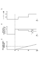
一例として、改質制御部15は、スイッチ状態がSTとなった以降(始動信号が入力された以降)において、通常開度よりも小さい初期開度から通常開度まで漸増するように、ストップバルブ38を制御する。一定期間は、スイッチ状態がSTとなってからの経過時間が組成安定時間以下の期間(始動信号が入力されてから所定時間が経過するまでの期間)であってもよい。
As an example, after the switch state becomes ST (after the start signal is input), the reforming
具体的には、ストップバルブ38の開度は、図3(a)に示されるような挙動となる。混合気中の第1アンモニアガスと改質ガスとの比率は、図3(b)に示されるような挙動となる。図3(a)及び図3(b)の例では、時刻t1においてスイッチ状態がSTとなっており、時刻t2においてエンジン完爆後の点火回数が所定回に達し、時刻t3においてスイッチ状態がSTとなってからの経過時間が組成安定時間となっている。つまり、時刻t1から時刻t3までの期間が改質ガス不安定状態の期間に該当し、時刻t3以降の期間が改質ガス安定状態の期間に該当する。
Specifically, the opening degree of the
図3(a)に示されるように、改質制御部15は、スイッチ状態がSTとなってからエンジン完爆後の点火回数が所定回以下の期間(時刻t1~t2)、通常開度よりも小さい初期開度として全閉開度で維持するように、ストップバルブ38を制御する。つまり、エンジン100の始動直後は、第1アンモニアガスのみがエンジン本体21に供給され、エンジン100が完爆した後に燃焼が安定してくるまでの期間に組成が不安定な改質ガスがエンジン本体21に供給されなくなる。これにより、組成が不安定な改質ガスが始動直後の燃焼に影響を及ぼすことを抑制できる。
As shown in FIG. 3( a ), the reforming
図3(a)において、改質制御部15は、エンジン完爆後の点火回数が所定回を超えてから、スイッチ状態がSTとなってからの経過時間が組成安定時間となるまでの期間において(時刻t2~t3)、通常開度として全開開度V1まで漸増するように、ストップバルブ38を制御する。この場合の漸増勾配は、ストップバルブ38の全開開度V1、全閉開度、及び組成安定時間に基づいて算出することができる。
In FIG. 3( a ), the reforming
その結果、図3(b)に示されるように、混合気中の第1アンモニアガスの比率R1と改質ガスの比率R2は、スイッチ状態がSTとなってからエンジン完爆後の点火回数が所定回以下の期間(時刻t1~t2)、第1アンモニアガスの比率R1が1となる。エンジン完爆後の点火回数が所定回を超えてから、スイッチ状態がSTとなってからの経過時間が組成安定時間となるまでの期間において(時刻t2~t3)、第1アンモニアガスの比率R1は1から漸減し、改質ガスの比率R2は0から漸増する。スイッチ状態がSTとなってからの経過時間が組成安定時間を超えると(時刻t3以降)、第1アンモニアガスの比率R1と改質ガスの比率R2とは、上述の通常燃料比率に対応する比率となる。このように、改質ガスを漸増させることで、改質ガスを含めた混合気の空燃比(A/F)が急激に変化することを抑制することができる。 As a result, as shown in FIG. 3(b), the ratio R1 of the first ammonia gas and the ratio R2 of the reformed gas in the air-fuel mixture are the number of ignitions after the engine complete explosion after the switch state becomes ST. The ratio R1 of the first ammonia gas is 1 for a period equal to or less than a predetermined number of times (time t1 to t2). In the period from when the number of ignitions after the engine complete explosion exceeds a predetermined number until the time elapsed after the switch state becomes ST becomes the composition stabilization time (time t2 to t3), the ratio R1 of the first ammonia gas gradually decreases from 1, and the reformed gas ratio R2 gradually increases from 0. When the elapsed time from the switch state to ST exceeds the composition stabilization time (after time t3), the ratio R1 of the first ammonia gas and the ratio R2 of the reformed gas are the ratios corresponding to the normal fuel ratio described above. becomes. By gradually increasing the amount of the reformed gas in this way, it is possible to suppress a sudden change in the air-fuel ratio (A/F) of the air-fuel mixture including the reformed gas.
他の例として、改質制御部15は、スイッチ状態がSTとなった以降(始動信号が入力された以降)において、通常開度よりも小さい初期開度で維持するように、ストップバルブ38を制御してもよい。一定期間は、改質空気量センサ4で取得した改質用空気の流量の始動信号が入力されてからの時間積算値が改質ガス置換容積に達するまでの期間であってもよい。
As another example, after the switch state becomes ST (after the start signal is input), the reforming
具体的には、ストップバルブ38の開度は、図4(a)に示されるような挙動となる。混合気中の第1アンモニアガスと改質ガスとの比率は、図4(b)に示されるような挙動となる。改質用空気の流量の時間積算値は、図4(c)に示されるような挙動となる。図4(a)~図4(c)の例では、時刻t4においてスイッチ状態がSTとなっており、時刻t5においてエンジン完爆後の点火回数が所定回に達し、時刻t6において改質用空気の流量の時間積算値が改質ガス置換容積に達している。つまり、時刻t4から時刻t6までの期間が改質ガス不安定状態の期間に該当し、時刻t6以降の期間が改質ガス安定状態の期間に該当する。
Specifically, the opening degree of the
図4(a)及び図4(c)に示されるように、改質制御部15は、スイッチ状態がSTとなってからエンジン完爆後の点火回数が所定回以下の期間(時刻t4~t5)、全閉開度で維持するように、ストップバルブ38を制御する。改質制御部15は、エンジン完爆後の点火回数が所定回を超えてから、改質用空気の流量の時間積算値が改質ガス置換容積Sに達するまでの期間において(時刻t5~t6)、通常開度よりも小さい初期開度V2で維持するように、ストップバルブ38を制御する。初期開度V2は、通常開度よりも小さく全閉開度よりも大きい所定の開度である。改質制御部15は、改質用空気の流量の時間積算値が改質ガス置換容積Sを超えた後(時刻t6~)、通常開度として全開開度V1となるように、ストップバルブ38を制御する。
As shown in FIGS. 4(a) and 4(c), the reforming
その結果、図4(b)に示されるように、混合気中の第1アンモニアガスの比率R1と改質ガスの比率R2は、スイッチ状態がSTとなってからエンジン完爆後の点火回数が所定回以下の期間(時刻t4~t5)、第1アンモニアガスの比率R1が1となる。エンジン完爆後の点火回数が所定回を超えてから、改質用空気の流量の時間積算値が改質ガス置換容積Sに達するまでの期間において(時刻t5~t6)、第1アンモニアガスの比率R1と改質ガスの比率R2とは、上述の通常燃料比率に対応する比率よりも第1アンモニアガスの比率R1が大きい比率となる。改質用空気の流量の時間積算値が改質ガス置換容積Sを超えた後(時刻t6~)、第1アンモニアガスの比率R1と改質ガスの比率R2とは、上述の通常燃料比率に対応する比率となる。 As a result, as shown in FIG. 4(b), the ratio R1 of the first ammonia gas and the ratio R2 of the reformed gas in the air-fuel mixture correspond to the number of ignitions after the engine complete explosion after the switch state becomes ST. The ratio R1 of the first ammonia gas is 1 for a period equal to or less than a predetermined number of times (time t4 to t5). During the period from when the number of ignitions after the engine complete explosion exceeds a predetermined number until the time integrated value of the reforming air flow rate reaches the reformed gas replacement volume S (time t5 to t6), the first ammonia gas The ratio R1 and the ratio R2 of the reformed gas are such that the ratio R1 of the first ammonia gas is larger than the ratio corresponding to the normal fuel ratio described above. After the time integrated value of the reforming air flow rate exceeds the reformed gas replacement volume S (from time t6), the ratio R1 of the first ammonia gas and the ratio R2 of the reformed gas are changed to the normal fuel ratio described above. corresponding ratio.
なお、図3及び図4では、説明の簡素化のため、時刻t1及び時刻t4において改質触媒36bが活性するものとする。
In addition, in FIGS. 3 and 4, for simplification of explanation, it is assumed that the reforming
メインインジェクタ制御部16は、要求熱量と燃料比率(例えば通常燃料比率)とに基づいて、メインインジェクタ24を制御する。メインインジェクタ制御部16は、例えば、改質器36からの改質ガスだけでは要求熱量を得られない場合、メインインジェクタ24から第1アンモニアガスを噴射する。メインインジェクタ制御部16は、例えば、改質器36からの改質ガスで要求熱量を賄える場合、メインインジェクタ24からアンモニアガスを噴射しなくてもよい。
The main
点火制御部17は、エンジン回転数及び要求熱量に基づいて、点火時期を算出する。点火制御部17は、例えば、試験及びシミュレーション等によってエンジン回転数及び要求熱量と点火時期との関係が予め設定されたマップデータに基づいて、点火時期を算出してもよい。
The
次に、ECU10による処理の一例について、図5及び図6を参照して説明する。図5は、ECU10の通常運転処理を示すフローチャートである。
Next, an example of processing by the
図5に示されるように、ECU10は、S01において、エンジン状態取得部11により、エンジン状態の取得を行う。エンジン状態取得部11は、エンジン回転数センサ1で検出されたエンジン回転数及びアクセルセンサ2で検出されたアクセルペダルの操作量を、エンジン状態として取得する。エンジン状態取得部11は、スイッチ状態に基づいて、改質ガス安定状態又は改質ガス不安定状態を取得する。エンジン状態取得部11は、スイッチ状態に基づいて、エンジン100の始動状態、通常運転状態、又は運転停止状態を取得する。
As shown in FIG. 5, in S01, the
ECU10は、S02において、要求熱量算出部12により、要求熱量の算出を行う。要求熱量算出部12は、例えば、試験及びシミュレーション等によってエンジン回転数及びアクセルペダルの操作量と要求熱量との関係が予め設定されたマップデータに基づいて、要求熱量を算出する。
In S<b>02 , the
ECU10は、S03において、燃料比率算出部13により、燃料比率の算出を行う。燃料比率算出部13は、改質ガス組成安定状態の場合の通常燃料比率を算出する。
In S03, the
ECU10は、S04において、メインスロットル制御部14により、メインスロットル23の制御を行う。メインスロットル制御部14は、始動状態の場合、所定の始動時メイン開度となるようにメインスロットル23を制御する。メインスロットル制御部14は、通常運転状態の場合、要求熱量を実現可能な流量の空気をエンジン本体21が吸気流路22を介して吸気可能な開度となるようにメインスロットル23を制御する。
The
ECU10は、S05において、改質制御部15により、改質用スロットル32の制御を行う。また、ECU10は、S06において、改質制御部15により、改質用インジェクタ35の制御を行う。改質制御部15は、改質可能状態となるように、改質用スロットル32及び改質用インジェクタ35を制御する。
The
ECU10は、S07において、メインインジェクタ制御部16により、メインインジェクタ24の制御を行う。メインインジェクタ制御部16は、要求熱量と通常燃料比率とに基づいて、メインインジェクタ24を制御する。その後、ECU10は、図5の処理を終了する。
The
次に、図6は、ECU10の改質ガス低減処理を示すフローチャートである。ECU10は、S11において、エンジン状態取得部11により、始動信号の入力があるか否かの判定を行う。エンジン状態取得部11により始動信号の入力がない判定された場合(S11:NO)、ECU10は、図6の処理を終了する。
Next, FIG. 6 is a flowchart showing the reformed gas reduction process of the
エンジン状態取得部11により始動信号の入力があったと判定された場合(S11:YES)、ECU10は、S12において、改質器36により、改質可能状態に制御を行う。改質制御部15は、改質可能状態となるように、改質用スロットル32及び改質用インジェクタ35を制御する。
When the engine
ECU10は、S13において、改質制御部15により、通常開度よりも小さい開度となるようにストップバルブ38の制御を行う。改質制御部15は、例えば、スイッチ状態がSTとなった以降(始動信号が入力された以降)において、通常開度よりも小さい初期開度から通常開度まで漸増するように、ストップバルブ38を制御する。あるいは、改質制御部15は、スイッチ状態がSTとなった以降(始動信号が入力された以降)において、通常開度よりも小さい初期開度で維持するように、ストップバルブ38を制御してもよい。
In S13, the
ECU10は、S14において、エンジン状態取得部11により、一定期間内か否かの判定を行う。エンジン状態取得部11は、例えば、スイッチ状態がSTとなってからの経過時間(始動信号が入力されてからの経過時間)が所定の組成安定時間以下である場合、改質ガス不安定状態であると判定する。あるいは、エンジン状態取得部11は、スイッチ状態がSTとなってからの改質用空気の流量の時間積算値が所定の改質ガス置換容積以下である場合、改質ガス不安定状態であると判定してもよい。また、エンジン状態取得部11は、改質器ヒータ36aの温度又は改質器36出口の温度を計測して改質ガス不安定状態であるか否かを判定してもよい。
In S14, the
エンジン状態取得部11により一定期間内であると判定された場合(S14:YES)、ECU10は、S13の処理を繰り返す。一方、エンジン状態取得部11により一定期間内ではないと判定された場合(S14:NO)、ECU10は、図6の処理を終了する。
When the engine
[作用及び効果]
以上説明したように、エンジン100では、始動信号が入力された場合、改質器36における改質が可能となる改質可能状態とされると共に、エンジン100の始動直後を少なくとも含む一定期間、通常開度よりも小さい開度となるようにストップバルブ38が制御される。これにより、少なくともエンジン100の始動直後において、エンジン本体21の吸気流路22に導かれる改質ガスの流量が通常開度に応じた流量よりも低減される。よって、例えばエンジン100の始動直後に改質ガスの組成が安定な改質ガス組成安定状態ではなかったとしても、改質ガスの組成の不安定さがエンジン100の性能に及ぼす影響を抑えることができる。その結果、エンジン100の始動直後に吸気流路22に導かれる改質ガスの組成に起因する性能低下を抑制することが可能となる。なお、性能低下の一例として、改質ガスの組成に起因して混合気が過度にリッチとなった場合の未燃ガスのすり抜け、あるいは混合気が過度にリーンとなった場合の失火により、排気ガスが悪化することが考えられるところ、このような性能低下を好適に抑制することができる。
[Action and effect]
As described above, in the
エンジン100では、ECU10は、始動信号が入力された以降において、通常開度よりも小さい初期開度から通常開度まで漸増するように、ストップバルブ38を制御する。これにより、エンジン本体21の吸気流路22に導かれる改質ガスの流量が徐々に増加されるため、エンジン本体21の燃焼室内の混合気の空燃比を徐々に変化させることができる。
In the
エンジン100では、一定期間は、始動信号が入力されてから組成安定時間(所定時間)が経過するまでの期間である。これにより、始動信号が入力されてからの経過時間に応じて改質ガスの組成が安定するものとして、ストップバルブ38を制御することができる。
In
エンジン100は、改質流路31に設けられ、改質用空気の流量を取得する改質空気量センサ4を備える。一定期間は、改質空気量センサ4で取得した流量の始動信号が入力されてからの時間積算値が改質ガス置換容積に達するまでの期間である。これにより、始動信号が入力されてからの改質用空気の流量の時間積算値に応じて改質ガスの組成が安定するものとして、ストップバルブ38を制御することができる。
The
エンジン100では、初期開度は、ストップバルブ38の全閉開度であり、通常開度は、ストップバルブ38の全開開度である。これにより、吸気流路22に導かれる改質ガスの組成がエンジン100の性能に及ぼす影響を、より確実に抑えることができる。
In the
エンジン100は、燃料としてアンモニアを水素ガスを含む改質ガスに改質する改質器36を備えるアンモニアエンジンである。これにより、例えば炭化水素を含む燃料を改質ガスに改質する改質器を備えるエンジンと比べて、改質ガスの組成の不安定さに起因する性能低下が生じ易い傾向があることから、上述の構成により得られる性能低下の抑制効果が顕著なものとなる。
The
[変形例]
以上、本発明に係る実施形態について説明したが、本発明は、上述した実施形態に限られるものではない。
[Modification]
Although the embodiments according to the present invention have been described above, the present invention is not limited to the above-described embodiments.
上記実施形態では、流量取得部として、改質空気量センサ4を例示したが、これに限定されない。例えば、改質用スロットル32の前後圧を検出するセンサを用いて、改質用スロットル32での改質用空気の流量を取得する構成としてもよい。
In the above-described embodiment, the reformed
上記実施形態では、改質用空気調整部として改質用スロットル32を例示したが、スロットルに代えて、例えば電磁弁等を用いてもよい。
In the above embodiment, the reforming
上記実施形態では、改質用インジェクタ35の個数は、例えば1個の場合を例示したが、複数個であってもよい。
In the above embodiment, the number of reforming
上記実施形態では、改質ガス調整部としてストップバルブ38を例示したが、電磁弁に代えて、例えばバタフライバルブ又は吸気流路22の位置に設けられた三方弁等を用いてもよい。
In the above-described embodiment, the
上記実施形態では、三元触媒26が設けられていたが、省略されてもよい。
Although the three-
上記実施形態では、一定期間内として組成安定時間を例示したが、改質触媒36bが十分に暖機(活性)され且つ改質用空気が十分に改質器36を流通するような期間となるものであれば、その他の時間であってもよい。 In the above embodiment, the composition stabilization time is exemplified as being within a certain period. Any other time may be acceptable.
上記実施形態では、一定期間として、改質用スロットル32以降の改質流路31の容積値の改質ガス置換容積としたが、少なくとも改質器36の容積以上の値であればよい。
In the above embodiment, the constant period is the reformed gas replacement volume of the reforming
上記実施形態では、一定期間内の判定として組成安定時間又は改質ガス置換容積の何れか用いる例を示したが、これらを組み合わせて用いてもよいし、他の指標と組み合わせてもよい。 In the above embodiment, either the composition stabilization time or the reformed gas replacement volume is used as the determination within a certain period of time.
上記実施形態では、改質制御部15がストップバルブ38の開度を通常開度よりも小さい開度から通常開度まで線形的に漸増させる例を示したが、例えば、非線形的に増加させてもよいし、段階的に増加させてもよい。
In the above embodiment, the reforming
上記実施形態では、改質制御部15は、エンジン完爆後の点火回数が所定回以下の期間においてストップバルブ38の開度を維持したが、必ずしもストップバルブ38の開度を維持しなくてもよい。
In the above-described embodiment, the reforming
上記実施形態では、通常開度は、ストップバルブ38の全開開度であったが、改質可能状態となる範囲であれば、全開開度よりも小さい開度であってもよい。
In the above embodiment, the normal opening is the full opening of the
上記実施形態では、エンジン100はアンモニアエンジンであったが、例えば炭化水素系燃料を改質する改質器を備えるエンジンであってもよい。
In the above embodiment, the
3…キースイッチ(始動信号出力部)、4…改質空気量センサ(流量取得部)、10…ECU(制御部)、22…吸気流路、24…メインインジェクタ(主燃料供給部)、31…改質流路、32…改質用スロットル(改質用空気調整部)、35…改質用インジェクタ(改質用燃料供給部)、36…改質器、38…ストップバルブ(改質ガス調整部)、100…エンジン。
3... Key switch (starting signal output unit) 4... Reformed air amount sensor (flow rate acquisition unit) 10... ECU (control unit) 22...
Claims (6)
前記エンジンの吸入空気を流通させる吸気流路と、
前記改質器が設けられ、前記改質器に改質用空気を流通させると共に、前記改質器から前記吸気流路に前記改質ガスを流通させる改質流路と、
前記吸気流路に設けられ、前記吸気流路に前記燃料を供給する主燃料供給部と、
前記改質流路に設けられ、前記改質用空気の流量を調整する改質用空気調整部と、
前記改質流路における前記改質器の上流側に設けられ、前記改質流路に前記燃料を供給する改質用燃料供給部と、
前記改質流路に設けられ、前記改質ガスの流量を調整する改質ガス調整部と、
前記エンジンを始動させるための始動信号を出力する始動信号出力部と、
前記始動信号と前記エンジンのエンジン状態とに基づいて、前記主燃料供給部と前記改質用空気調整部と前記改質用燃料供給部と前記改質ガス調整部とを制御する制御部と、
を備え、
前記制御部は、
前記始動信号が入力された場合、前記改質器における前記改質が可能となる改質可能状態となるように前記改質用空気調整部と前記改質用燃料供給部とを制御すると共に、
前記エンジンの始動直後を少なくとも含む一定期間、改質ガス組成安定状態となる前に、前記改質ガス組成安定状態における前記改質ガス調整部の開度である通常開度よりも小さい開度として前記改質ガスが流れるように、前記改質ガス調整部を制御する、エンジン。 An engine comprising a reformer that reforms fuel into a reformed gas,
an intake passage for circulating the intake air of the engine;
a reforming passage, provided with the reformer, for circulating the reforming air to the reformer and for circulating the reformed gas from the reformer to the intake passage;
a main fuel supply unit provided in the intake channel for supplying the fuel to the intake channel;
a reforming air adjustment unit provided in the reforming flow path for adjusting the flow rate of the reforming air;
a reforming fuel supply unit provided on the upstream side of the reformer in the reforming channel and supplying the fuel to the reforming channel;
a reformed gas adjustment unit provided in the reformed flow path for adjusting the flow rate of the reformed gas;
a starting signal output unit that outputs a starting signal for starting the engine;
a control unit that controls the main fuel supply unit, the reforming air adjustment unit, the reforming fuel supply unit, and the reformed gas adjustment unit based on the start signal and the engine state of the engine;
with
The control unit
controlling the reforming air adjustment unit and the reforming fuel supply unit so that the reforming possible state is established in the reformer when the start signal is input, and
For a certain period including at least immediately after starting the engine, before the reformed gas composition becomes stable, the opening is set to be smaller than the normal opening, which is the opening of the reformed gas adjustment unit in the reformed gas composition stable state. An engine that controls the reformed gas adjustment unit so that the reformed gas flows .
前記通常開度は、前記改質ガス調整部の全開開度である、請求項2記載のエンジン。 The initial opening is the fully closed opening of the reformed gas adjustment unit,
3. The engine according to claim 2, wherein said normal opening is a full opening of said reformed gas adjusting section.
前記一定期間は、前記流量取得部で取得した前記流量の前記始動信号が入力されてからの時間積算値が所定の改質ガス置換容積に達するまでの期間である、請求項1~4の何れか一項記載のエンジン。 further comprising a flow rate acquisition unit provided in the reforming flow path for acquiring the flow rate of the reforming air;
5. The fixed period is a period until the time integrated value of the flow rate obtained by the flow rate obtaining unit after the start signal is input reaches a predetermined reformed gas replacement volume. or an engine as described in paragraph 1 above.
Priority Applications (5)
| Application Number | Priority Date | Filing Date | Title |
|---|---|---|---|
| JP2019056394A JP7124776B2 (en) | 2019-03-25 | 2019-03-25 | engine |
| CN202080022252.8A CN113614348B (en) | 2019-03-25 | 2020-02-21 | Engine with a motor |
| PCT/JP2020/007056 WO2020195427A1 (en) | 2019-03-25 | 2020-02-21 | Engine |
| AU2020249395A AU2020249395B2 (en) | 2019-03-25 | 2020-02-21 | Engine |
| US17/441,141 US11624327B2 (en) | 2019-03-25 | 2020-02-21 | Engine |
Applications Claiming Priority (1)
| Application Number | Priority Date | Filing Date | Title |
|---|---|---|---|
| JP2019056394A JP7124776B2 (en) | 2019-03-25 | 2019-03-25 | engine |
Publications (3)
| Publication Number | Publication Date |
|---|---|
| JP2020159212A JP2020159212A (en) | 2020-10-01 |
| JP2020159212A5 JP2020159212A5 (en) | 2021-07-26 |
| JP7124776B2 true JP7124776B2 (en) | 2022-08-24 |
Family
ID=72608445
Family Applications (1)
| Application Number | Title | Priority Date | Filing Date |
|---|---|---|---|
| JP2019056394A Active JP7124776B2 (en) | 2019-03-25 | 2019-03-25 | engine |
Country Status (5)
| Country | Link |
|---|---|
| US (1) | US11624327B2 (en) |
| JP (1) | JP7124776B2 (en) |
| CN (1) | CN113614348B (en) |
| AU (1) | AU2020249395B2 (en) |
| WO (1) | WO2020195427A1 (en) |
Cited By (1)
| Publication number | Priority date | Publication date | Assignee | Title |
|---|---|---|---|---|
| US20220170415A1 (en) * | 2019-03-26 | 2022-06-02 | Kabushiki Kaisha Toyota Jidoshokki | Engine system |
Families Citing this family (8)
| Publication number | Priority date | Publication date | Assignee | Title |
|---|---|---|---|---|
| US11724245B2 (en) | 2021-08-13 | 2023-08-15 | Amogy Inc. | Integrated heat exchanger reactors for renewable fuel delivery systems |
| US20220389864A1 (en) | 2021-05-14 | 2022-12-08 | Amogy Inc. | Systems and methods for processing ammonia |
| KR20240020274A (en) | 2021-06-11 | 2024-02-14 | 아모지 인크. | Systems and methods for processing ammonia |
| US11539063B1 (en) | 2021-08-17 | 2022-12-27 | Amogy Inc. | Systems and methods for processing hydrogen |
| JP2023096372A (en) * | 2021-12-27 | 2023-07-07 | 株式会社豊田自動織機 | engine system |
| US11840447B1 (en) | 2022-10-06 | 2023-12-12 | Amogy Inc. | Systems and methods of processing ammonia |
| US11866328B1 (en) | 2022-10-21 | 2024-01-09 | Amogy Inc. | Systems and methods for processing ammonia |
| US11795055B1 (en) | 2022-10-21 | 2023-10-24 | Amogy Inc. | Systems and methods for processing ammonia |
Citations (4)
| Publication number | Priority date | Publication date | Assignee | Title |
|---|---|---|---|---|
| JP2007113421A (en) | 2005-10-18 | 2007-05-10 | Toyota Motor Corp | Control device of internal combustion engine |
| JP2009114873A (en) | 2007-11-02 | 2009-05-28 | Toyota Motor Corp | Internal combustion engine |
| WO2011145434A1 (en) | 2010-05-21 | 2011-11-24 | トヨタ自動車株式会社 | Ammonia-burning internal combustion engine |
| JP5747738B2 (en) | 2011-08-29 | 2015-07-15 | 三菱マテリアル株式会社 | Sputtering target, manufacturing method thereof, thin film using the target, thin film sheet including the thin film, and laminated sheet |
Family Cites Families (14)
| Publication number | Priority date | Publication date | Assignee | Title |
|---|---|---|---|---|
| JPS5747738U (en) * | 1980-08-30 | 1982-03-17 | ||
| JP3618312B2 (en) * | 2000-11-27 | 2005-02-09 | ヤンマー株式会社 | Gas engine |
| JP2003097306A (en) * | 2001-09-19 | 2003-04-03 | Nissan Motor Co Ltd | Reformed gas engine |
| JP2003120350A (en) * | 2001-10-19 | 2003-04-23 | Yanmar Co Ltd | Gas engine with fuel reformer |
| JP4277630B2 (en) * | 2003-09-04 | 2009-06-10 | トヨタ自動車株式会社 | Internal combustion engine and control method thereof |
| JP2006291775A (en) * | 2005-04-07 | 2006-10-26 | Toyota Motor Corp | Control device for internal combustion engine |
| JP2007278241A (en) * | 2006-04-11 | 2007-10-25 | Toyota Motor Corp | Internal combustion engine |
| JP2008031922A (en) * | 2006-07-28 | 2008-02-14 | Toyota Motor Corp | Internal combustion engine with fuel reforming device |
| JP2008063996A (en) * | 2006-09-06 | 2008-03-21 | Toyota Motor Corp | Internal combustion engine |
| JP2008163860A (en) * | 2006-12-28 | 2008-07-17 | Aisan Ind Co Ltd | Intake device of fuel injection type engine |
| US9140220B2 (en) * | 2011-06-30 | 2015-09-22 | Lg Fuel Cell Systems Inc. | Engine systems and methods of operating an engine |
| US8370049B1 (en) * | 2010-05-21 | 2013-02-05 | Toyota Jidosha Kabushiki Kaisha | Control system of internal combustion engine |
| JP5835281B2 (en) * | 2013-07-01 | 2015-12-24 | 株式会社豊田中央研究所 | Engine system |
| JP6717091B2 (en) * | 2016-07-13 | 2020-07-01 | 日産自動車株式会社 | Method of warming up exhaust purification catalyst of internal combustion engine |
-
2019
- 2019-03-25 JP JP2019056394A patent/JP7124776B2/en active Active
-
2020
- 2020-02-21 WO PCT/JP2020/007056 patent/WO2020195427A1/en active Application Filing
- 2020-02-21 US US17/441,141 patent/US11624327B2/en active Active
- 2020-02-21 AU AU2020249395A patent/AU2020249395B2/en active Active
- 2020-02-21 CN CN202080022252.8A patent/CN113614348B/en active Active
Patent Citations (4)
| Publication number | Priority date | Publication date | Assignee | Title |
|---|---|---|---|---|
| JP2007113421A (en) | 2005-10-18 | 2007-05-10 | Toyota Motor Corp | Control device of internal combustion engine |
| JP2009114873A (en) | 2007-11-02 | 2009-05-28 | Toyota Motor Corp | Internal combustion engine |
| WO2011145434A1 (en) | 2010-05-21 | 2011-11-24 | トヨタ自動車株式会社 | Ammonia-burning internal combustion engine |
| JP5747738B2 (en) | 2011-08-29 | 2015-07-15 | 三菱マテリアル株式会社 | Sputtering target, manufacturing method thereof, thin film using the target, thin film sheet including the thin film, and laminated sheet |
Cited By (2)
| Publication number | Priority date | Publication date | Assignee | Title |
|---|---|---|---|---|
| US20220170415A1 (en) * | 2019-03-26 | 2022-06-02 | Kabushiki Kaisha Toyota Jidoshokki | Engine system |
| US11713727B2 (en) * | 2019-03-26 | 2023-08-01 | Kabushiki Kaisha Toyota Jidoshokki | Engine system |
Also Published As
| Publication number | Publication date |
|---|---|
| WO2020195427A1 (en) | 2020-10-01 |
| CN113614348A (en) | 2021-11-05 |
| CN113614348B (en) | 2023-10-13 |
| US11624327B2 (en) | 2023-04-11 |
| JP2020159212A (en) | 2020-10-01 |
| AU2020249395A1 (en) | 2021-09-30 |
| US20220163002A1 (en) | 2022-05-26 |
| AU2020249395B2 (en) | 2023-05-18 |
Similar Documents
| Publication | Publication Date | Title |
|---|---|---|
| JP7124776B2 (en) | engine | |
| US8539914B2 (en) | Method for operating an engine with a fuel reformer | |
| JP4711233B2 (en) | Exhaust gas purification system for hydrogen engine | |
| WO2020195426A1 (en) | Ammonia engine | |
| RU2256083C2 (en) | Method of diagnosing condition of vehicle internal combustion engine catalyst converter, control unit and internal combustion engine | |
| US7771675B2 (en) | Fuel supply device for internal combustion and control method therefor | |
| US20020023431A1 (en) | Direct injection internal combustion engine and controlling method therefor | |
| CN101922340B (en) | Fuel control strategy for heating a catalyst | |
| JP2006342772A (en) | Sub-chamber type internal combustion engine | |
| US20150285118A1 (en) | Exhaust gas purification apparatus for an internal combustion engine | |
| KR20180054269A (en) | Reforming system and reformer operating method using temperature sensor | |
| JP2009121412A (en) | Ignition control device | |
| JP2006052662A (en) | Internal combustion engine and its operation method | |
| JP6717091B2 (en) | Method of warming up exhaust purification catalyst of internal combustion engine | |
| US8800269B2 (en) | Fuel injection system of an internal combustion engine | |
| JP2016156304A (en) | Fuel switching device of internal combustion engine | |
| JP2020172888A (en) | engine | |
| JP2012255422A (en) | Control device of internal combustion engine | |
| JP7415769B2 (en) | Control device | |
| JP2009121411A (en) | Exhaust gas recirculating device | |
| KR102417374B1 (en) | Reforming system and reformer operating method using hydrogen sensor | |
| JP2023146818A (en) | Controller of internal combustion engine | |
| WO2012168793A1 (en) | Control unit and control method for internal combustion engine | |
| JP2006291757A (en) | Control device for internal combustion engine | |
| JP2007138800A (en) | Internal combustion engine using hydrogen |
Legal Events
| Date | Code | Title | Description |
|---|---|---|---|
| A521 | Request for written amendment filed |
Free format text: JAPANESE INTERMEDIATE CODE: A523 Effective date: 20210607 |
|
| A621 | Written request for application examination |
Free format text: JAPANESE INTERMEDIATE CODE: A621 Effective date: 20210607 |
|
| TRDD | Decision of grant or rejection written | ||
| A01 | Written decision to grant a patent or to grant a registration (utility model) |
Free format text: JAPANESE INTERMEDIATE CODE: A01 Effective date: 20220712 |
|
| A61 | First payment of annual fees (during grant procedure) |
Free format text: JAPANESE INTERMEDIATE CODE: A61 Effective date: 20220725 |
|
| R151 | Written notification of patent or utility model registration |
Ref document number: 7124776 Country of ref document: JP Free format text: JAPANESE INTERMEDIATE CODE: R151 |