JP7121077B2 - game machine - Google Patents
game machine Download PDFInfo
- Publication number
- JP7121077B2 JP7121077B2 JP2020127870A JP2020127870A JP7121077B2 JP 7121077 B2 JP7121077 B2 JP 7121077B2 JP 2020127870 A JP2020127870 A JP 2020127870A JP 2020127870 A JP2020127870 A JP 2020127870A JP 7121077 B2 JP7121077 B2 JP 7121077B2
- Authority
- JP
- Japan
- Prior art keywords
- special symbol
- main control
- game
- control cpu
- time
- Prior art date
- Legal status (The legal status is an assumption and is not a legal conclusion. Google has not performed a legal analysis and makes no representation as to the accuracy of the status listed.)
- Active
Links
Images


Description
本発明は、遊技を実行する遊技機に関する。 The present invention relates to a gaming machine for executing games.
従来、この種の遊技機に関する技術として、変動開始後、所定時間経過によって先読み演出の禁止区間を設ける技術が知られている。 Conventionally, as a technique related to this type of gaming machine, a technique is known in which a look-ahead effect prohibition section is provided after a predetermined time has elapsed after the start of fluctuation.
近年では、いずれも似通った遊技機ばかりが提案されており、斬新な遊技機が望まれている。 In recent years, only similar gaming machines have been proposed, and novel gaming machines are desired.
そこで、本発明は、斬新な遊技機を提供することを課題とする。 Accordingly, an object of the present invention is to provide a novel gaming machine.
本発明は、上記の課題を解決するため以下の解決手段を採用する。なお、以下の括弧書中の文言及び解決手段はあくまで例示であり、本発明はこれに限定されるものではない。また、本発明は、以下の解決手段に示す各発明特定事項を少なくとも1つ含む発明とすることができる。さらに、以下の解決手段に示す各発明特定事項には、発明特定事項を限定する要素を追加して下位概念化することができ、発明特定事項を限定する要素を削除して上位概念化することもできる。 The present invention employs the following solutions to solve the above problems. It should be noted that the following phrases and solutions in parentheses are merely examples, and the present invention is not limited thereto. Further, the present invention can be an invention that includes at least one of the invention-specifying matters shown in the following means for solving the problem. Furthermore, each of the matters specifying the invention shown in the following solutions can be converted into a higher-level concept by adding elements that limit the matters specifying the invention, or can be made into a higher-level concept by deleting elements that limit the matters specifying the invention. .
解決手段1:本解決手段の遊技機は、閉鎖状態から開放状態に移行可能な可変入球装置と、所定の抽選で当選すると、前記可変入球装置を用いて特別遊技を実行する特別遊技実行手段と、前記特別遊技の実行中に、遊技球が前記可変入球装置に入球すると、入球を契機として特定演出を実行する特定演出実行手段とを備え、前記特定演出実行手段は、所定条件が設定された場合、前記特別遊技の実行中に、遊技球が前記可変入球装置に入球しても、前記特定演出を実行しない場合があることを特徴とする遊技機である。 Solution 1: The game machine of the present solution includes a variable ball entry device capable of shifting from a closed state to an open state, and a special game execution for executing a special game using the variable ball entry device when a predetermined lottery is won. and a specific effect execution means for executing a specific effect triggered by the ball entry when a game ball enters the variable ball entry device during execution of the special game, wherein the specific effect execution means performs a predetermined The gaming machine is characterized in that when a condition is set, even if a game ball enters the variable ball entry device during execution of the special game, the specific effect may not be executed.
本解決手段の遊技機は、以下の構成を備えている。
(1)閉鎖状態から開放状態に移行可能な可変入球装置(特別電動役物、普通電動役物)が設けられている。
(2)所定の抽選(特別図柄抽選、普通図柄抽選)で当選すると(大当り、小当り、普通図柄当りとなると)、上記(1)の可変入球装置を用いて特別遊技(大当り遊技、小当り遊技、普通電動役物開放遊技)を実行する。
The gaming machine of this solving means has the following configuration.
(1) A variable ball entry device (special electric accessory, normal electric accessory) that can shift from the closed state to the open state is provided.
(2) If you win a predetermined lottery (special pattern lottery, normal pattern lottery) (when you win a jackpot, a small win, or a normal pattern), a special game (big win game, small win) is played using the variable ball entry device in (1) above. Hit game, normal electric accessory open game) is executed.
(3)上記(2)の特別遊技の実行中に、遊技球が上記(1)の可変入球装置に入球すると、入球を契機として特定演出(カットイン演出)を実行する。特定演出は、入球と同時に実行してもよく、入球後一定時間経過後に実行してもよい。 (3) When the game ball enters the variable ball entry device of (1) above during execution of the special game of (2) above, a specific effect (cut-in effect) is executed with the entry of the ball as a trigger. The specific effect may be executed at the same time as the ball is entered, or may be executed after a certain period of time has elapsed after the ball is entered.
(4)所定条件が設定された場合(所定の時間が経過(小当り開始後70F経過、小当り開始後95F経過)している場合、1回目のカットイン演出の禁止フラグがONである場合、2回目のカットイン演出の禁止フラグがONである場合)、上記(2)の特別遊技の実行中に、遊技球が上記(1)の可変入球装置に入球しても、上記(3)の特定演出を実行しない場合がある。 (4) When a predetermined condition is set (when a predetermined time has passed (70F after the start of the small win, 95F after the start of the small win), when the prohibition flag for the first cut-in effect is ON , When the prohibition flag for the second cut-in effect is ON), even if the game ball enters the variable ball entry device of (1) during the execution of the special game of (2), the above ( There are cases where the specific effect of 3) is not executed.
本解決手段によれば、所定条件が設定された場合、特定演出を実行しない場合があるため、所定条件の設定によって特定演出の実行の可否を決定することができ、結果として、斬新な遊技機を提供することができる。これにより、例えば、特別演出の実行中の遅い段階で特定演出が実行されることを回避することができ、結果として、斬新な遊技機を提供することができる。 According to this solution means, when the predetermined condition is set, the specific performance may not be executed, so it is possible to determine whether or not to execute the specific performance by setting the predetermined condition, and as a result, the game machine is novel. can be provided. Thereby, for example, it is possible to avoid executing the specific effect at a late stage during execution of the special effect, and as a result, it is possible to provide a novel gaming machine.
解決手段2:本解決手段の遊技機は、上述したいずれかの解決手段において、前記特定演出は、第1の特定演出と第2の特定演出とを有し、前記所定条件は、前記第1の特定演出を実行しない第1の所定条件、及び、前記第2の特定演出を実行しない第2の所定条件を有し、前記第2の所定条件は、前記第1の所定条件よりも先に設定され、前記第1の所定条件と前記第2の所定条件とは同じ時期に終了することがあることを特徴とする遊技機である。 Solution 2: In any one of the above-described solution means, the gaming machine of the present solution means has a first specific effect and a second specific effect, and the predetermined condition is the first specific effect. and a second predetermined condition not to execute the second specific effect, wherein the second predetermined condition precedes the first predetermined condition The game machine is characterized in that the first predetermined condition and the second predetermined condition may end at the same time.
本解決手段では、以下の特徴が追加される。
(1)特定演出は、第1の特定演出と第2の特定演出とを有する。
(2)所定条件は、第1の特定演出を実行しない第1の所定条件、及び、第2の特定演出を実行しない第2の所定条件を有する。
(3)第2の所定条件は、第1の所定条件よりも先に設定される。
(4)第1の所定条件と第2の所定条件とは同じ時期に終了することがある。
In this solution, the following features are added.
(1) Specific effects include a first specific effect and a second specific effect.
(2) The predetermined conditions include a first predetermined condition under which the first specific effect is not executed and a second predetermined condition under which the second specific effect is not executed.
(3) The second predetermined condition is set prior to the first predetermined condition.
(4) The first predetermined condition and the second predetermined condition may end at the same time.
本解決手段によれば、2つの所定条件によって特定演出を制御するため、特定演出が複数回実行されるような状況に柔軟に対応することができ、結果として、斬新な遊技機を提供することができる。 According to this solving means, since the specific performance is controlled by two predetermined conditions, it is possible to flexibly cope with the situation in which the specific performance is executed multiple times, and as a result, to provide a novel game machine. can be done.
解決手段3:本解決手段の遊技機は、上述したいずれかの解決手段において、前記特定演出は、複数回実行される場合、所定の規則に従って実行されることを特徴とする遊技機である。 Solution 3: The game machine of the present solution means is a game machine characterized in that, in any one of the above-described solution means, the specific effect is executed according to a predetermined rule when executed a plurality of times.
本解決手段では、特定演出は、複数回実行される場合、所定の規則(左右交互に画像を表示するというルール)に従って実行される。例えば、所定条件の設定により特定演出が実行されない場合であっても、所定の規則に従って実行される(右から画像を表示する部分が実行されなくても、次回は右から画像を表示する)。 In this solution means, when the specific effect is executed a plurality of times, it is executed according to a predetermined rule (the rule that images are displayed alternately to the left and right). For example, even if a specific effect is not executed due to the setting of a prescribed condition, it is executed according to a prescribed rule (even if the part where the image is displayed from the right is not executed, the image is displayed from the right next time).
本解決手段によれば、特定演出は、所定の規則に従って実行されるため、演出の連続性を持続することができるだけでなく、遊技者に対して与える違和感を軽減することができる。 According to this solving means, the specific effect is executed according to a predetermined rule, so that not only is it possible to maintain the continuity of the effect, but also it is possible to reduce the sense of discomfort given to the player.
解決手段F1:本解決手段の遊技機は、閉鎖状態から開放状態に移行可能な可変入球装置と、所定の抽選で当選すると、前記可変入球装置を用いて特別遊技を実行する特別遊技実行手段と、前記特別遊技の実行中に、遊技球が前記可変入球装置に入球すると、入球を契機として特定演出を実行する特定演出実行手段とを備え、前記特定演出実行手段は、所定条件が設定された場合、前記特別遊技の実行中に、遊技球が前記可変入球装置に入球しても、前記特定演出を実行しない場合があり、前枠及び内枠を有する本体枠と、前記本体枠を取り付け可能な外枠とを備え、前記本体枠には、ハンドルがあり、前記ハンドルには、指掛部があり、前記ハンドルは、初期位置から最大回転位置まで回転可能であり、前記ハンドルが前記初期位置にある場合において、前記指掛部が前記本体枠の下側の縁よりも下に突出しておらず、前記ハンドルが前記最大回転位置にある場合において、前記指掛部が前記本体枠の下側の縁よりも下に突出していないことを特徴とする遊技機である。 Solution F1: The gaming machine of the present solution includes a variable ball entry device capable of shifting from a closed state to an open state, and a special game execution for executing a special game using the variable ball entry device when a predetermined lottery is won. and a specific effect execution means for executing a specific effect triggered by the ball entry when a game ball enters the variable ball entry device during execution of the special game, wherein the specific effect execution means performs a predetermined When a condition is set, even if a game ball enters the variable ball entry device during execution of the special game, the specific effect may not be executed. and an outer frame to which the body frame can be attached, the body frame having a handle, the handle having a finger hook, and the handle being rotatable from an initial position to a maximum rotation position. , when the handle is at the initial position, the finger hook does not protrude below the lower edge of the body frame, and when the handle is at the maximum rotation position, the finger hook does not protrude below the lower edge of the body frame.
本解決手段によれば、本体枠を床等に置いた場合であっても、指掛部が床等に接触せず、ハンドルが破損することはない。このため、部品が破損するリスクを低減することができる。 According to this solving means, even when the body frame is placed on the floor or the like, the finger hooking portion does not come into contact with the floor or the like, and the handle is not damaged. Therefore, it is possible to reduce the risk of component damage.
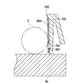
解決手段F2:本解決手段の遊技機は、閉鎖状態から開放状態に移行可能な可変入球装置と、所定の抽選で当選すると、前記可変入球装置を用いて特別遊技を実行する特別遊技実行手段と、前記特別遊技の実行中に、遊技球が前記可変入球装置に入球すると、入球を契機として特定演出を実行する特定演出実行手段とを備え、前記特定演出実行手段は、所定条件が設定された場合、前記特別遊技の実行中に、遊技球が前記可変入球装置に入球しても、前記特定演出を実行しない場合があり、上部に意匠部が形成された前枠と、左打ち領域及び右打ち領域を有する遊技領域が形成された遊技盤と、前記遊技領域の上部に配置され、外周面及び内周面を有し、遊技球を前記右打ち領域に案内する誘導通路と、前記遊技盤の盤面に対して垂直方向に延びる線のうち、前記外周面の頂上を通る線を第1基準線とし、前記第1基準線に対する鉛直線が交わり得る部分のうち、前記意匠部の下面における最も後側の部分を第1意匠部とし、前記第1基準線に対する鉛直線が交わり得る部分のうち、前記意匠部の下面における最も下側の部分を第2意匠部とすると、前記第1意匠部は、前記第1基準線よりも下方に位置するとともに、前記第1基準線からの距離が遊技球の直径以下となっており、前記第2意匠部は、前記第1基準線よりも下方に位置するとともに、前記第1基準線からの距離が遊技球の直径以上となっていることを特徴とする遊技機である。 Solution Means F2: The gaming machine of this solution means includes a variable ball entry device capable of shifting from a closed state to an open state, and a special game execution that executes a special game using the variable ball entry device when a predetermined lottery is won. and a specific effect execution means for executing a specific effect triggered by the ball entry when a game ball enters the variable ball entry device during execution of the special game, wherein the specific effect execution means performs a predetermined When a condition is set, even if a game ball enters the variable ball entry device during execution of the special game, the specific effect may not be executed, and a front frame having a design part formed on the upper part a game board on which a game area having a left-handed area and a right-handed area is formed; and a game board disposed above the game area, having an outer peripheral surface and an inner peripheral surface, and guiding a game ball to the right-handed area. Among the lines extending perpendicular to the guide path and the board surface of the game board, the line passing through the top of the outer peripheral surface is defined as a first reference line, and among the portions where the vertical lines with respect to the first reference line can intersect, The rearmost portion of the lower surface of the design portion is defined as the first design portion, and the lowermost portion of the lower surface of the design portion among the portions where the vertical lines with respect to the first reference line intersect is designated as the second design portion. Then, the first design portion is positioned below the first reference line, and the distance from the first reference line is equal to or less than the diameter of the game ball, and the second design portion is positioned below the first reference line. The gaming machine is positioned below the first reference line, and the distance from the first reference line is equal to or greater than the diameter of the game ball.
本解決手段によれば、第2意匠部は、第1基準線よりも下方に位置するとともに、第1基準線L1からの距離が遊技球の直径以上となるので、意匠部を大型化することができる。また、このように意匠部を大型化しつつも、第1基準線と第1意匠部との間隔を遊技球の直径以下としたことにより、遊技球が強く打ち出された場合(遊技球通路の上面に沿って遊技球が転がる場合)において、遊技球の視認性を確保することができる。
なお、解決手段F1、F2は、上述した解決手段1の作用効果も発揮することができる。また、解決手段F1、F2には、上述した解決手段2、3による特徴を追加することができる。
According to this solution means, the second design portion is located below the first reference line and the distance from the first reference line L1 is equal to or greater than the diameter of the game ball, so the design portion can be enlarged. can be done. In addition, while increasing the size of the design part in this way, by making the distance between the first reference line and the first design part equal to or less than the diameter of the game ball, when the game ball is hit strongly (the upper surface of the game ball passage When the game ball rolls along), the visibility of the game ball can be ensured.
In addition, the solving means F1 and F2 can exhibit the effect of the solving means 1 mentioned above. Moreover, the features of the above-described solving means 2 and 3 can be added to the solving means F1 and F2.
本発明によれば、斬新な遊技機を提供することができる。 According to the present invention, it is possible to provide a novel gaming machine.
以下、本発明の実施形態について、図面を参照しながら説明する。
図1は、パチンコ遊技機(以下、「パチンコ機」と略称する。)1の正面図である。また、図2は、パチンコ機1の背面図である。パチンコ機1は、遊技球を遊技媒体として用いるものであり、遊技者は、遊技場運営者から遊技球を借り受けてパチンコ機1による遊技を行う。なお、パチンコ機1における遊技において、遊技球はその1個1個が遊技価値を有した媒体であり、遊技の成果として遊技者が享受する特典(利益)は、例えば遊技者が獲得した遊技球の数に基づいて遊技価値に換算することができる。以下、図1及び図2を参照しつつパチンコ機1の全体構成について説明する。
BEST MODE FOR CARRYING OUT THE INVENTION Hereinafter, embodiments of the present invention will be described with reference to the drawings.
FIG. 1 is a front view of a pachinko gaming machine (hereinafter abbreviated as "pachinko machine") 1. As shown in FIG. 2 is a rear view of the
〔全体構成〕
パチンコ機1は、その本体として主に外枠ユニット2、一体扉ユニット4及び内枠アセンブリ7(プラ枠、遊技機枠)を備えている。遊技者に相対する正面からみて、その最も前面側には一体扉ユニット4が位置している。一体扉ユニット4の背面側(奥側)には内枠アセンブリ7が位置しており、内枠アセンブリ7の外側を囲むようにして外枠ユニット2が配置されている。
〔overall structure〕
The
外枠ユニット2は、木材及び金属材を縦長の矩形状に組み合わせた構造体であり、この外枠ユニット2は、遊技場内の島設備(図示されていない)に対してねじ等の締結具を用いて固定されるものである。なお、縦長矩形状の外枠ユニット2において、上下の短辺に相当する部位には木材が用いられており、左右の長辺に相当する部位には金属材が用いられている。
The
一体扉ユニット4は、その下部位置に受け皿ユニット6が一体化された構造である。一体扉ユニット4及び内枠アセンブリ7は、外枠ユニット2を介して島設備に取り付けられ、これらはそれぞれ図示しないヒンジ機構を介して開閉式に動作する。図示しないヒンジ機構の開閉軸線は、パチンコ機1の正面からみて左側端部に沿って垂直方向に延びている。
The
図1中の正面からみて内枠アセンブリ7の右側縁部(図2では左側縁部)には、その内側に統一錠ユニット9が設けられている。また、これに対応して一体扉ユニット4及び外枠ユニット2の右側縁部(裏側)にも、それぞれ図示しない施錠具が設けられている。図1に示されるように、外枠ユニット2に対して一体扉ユニット4及び内枠アセンブリ7が閉じた状態で、その裏側にある統一錠ユニット9は施錠具とともに一体扉ユニット4及び内枠アセンブリ7の開放を不能にしている。
A
また、受け皿ユニット6の右側縁部には鍵穴付きのシリンダ錠6aが設けられている。例えば、遊技場の管理者が専用キーを鍵穴に差し込んでシリンダ錠6aを時計回りに捻ると、統一錠ユニット9が作動して内枠アセンブリ7とともに一体扉ユニット4の開放が可能な状態となる。これら全体を外枠ユニット2から前面側へ開放する(扉のように動かす)と、前面側にてパチンコ機1の裏側が露出することになる。
A
一方、シリンダ錠6aを反時計回りに捻ると、内枠アセンブリ7は施錠されたままで一体扉ユニット4の施錠だけが解除され、一体扉ユニット4が開放可能となる。一体扉ユニット4を前面側へ開放すると遊技盤ユニット8が直に露出し、この状態で遊技場の管理者が盤面内での球詰まり等の障害を取り除くことができる。また、一体扉ユニット4を開放すると、受け皿ユニット6も一緒に前面側へ開放される。
On the other hand, when the
また、パチンコ機1は、遊技用ユニットとして上記の遊技盤ユニット8を備えている。遊技盤ユニット8は、一体扉ユニット4の背後(内側)で上記の内枠アセンブリ7に支持されている。遊技盤ユニット8は、例えば一体扉ユニット4を前面側へ開放した状態で内枠アセンブリ7に対して着脱可能である。一体扉ユニット4には、その中央部に縦長円形状の窓4aが形成されており、この窓4a内にガラスユニット(参照符号なし)が取り付けられている。ガラスユニットは、例えば窓4aの形状に合わせてカットされた2枚の透明板(ガラス板)を組み合わせたものである。ガラスユニットは、一体扉ユニット4の裏側に図示しない取り付け具を介して取り付けられる。遊技盤ユニット8の前面には遊技領域8a(盤面、遊技盤)が形成されており、この遊技領域8aは窓4aを通じて前面側から遊技者に視認可能である。一体扉ユニット4が閉じられると、ガラスユニットの内面と盤面との間に遊技球が流下できる空間が形成される。
Moreover, the
受け皿ユニット6は、全体的に一体扉ユニット4から前面側へ突出した形状をなしており、その上面に上皿6bが形成されている。この上皿6bには、遊技者に貸し出された遊技球(貸球)や入賞により獲得した遊技球(賞球)を貯留することができる。また、受け皿ユニット6には、上皿6bの下段位置に下皿6cが形成されている。この下皿6cには、上皿6bが満杯の状態でさらに払い出された遊技球が貯留される。なお、本実施形態のパチンコ機1はいわゆるCR機(CRユニットに接続する機種)であり、遊技者が借り受けた遊技球は、賞球とは別に裏側の払出装置ユニット172から受け皿ユニット6(上皿6b又は下皿6c)に払い出される。
The receiving
受け皿ユニット6の上面には貸出操作部14が設けられており、この貸出操作部14には、球貸ボタン10及び返却ボタン12が配置されている。図示しないCRユニットに有価媒体(例えば磁気記録媒体、記憶IC内蔵媒体等)を投入した状態で球貸ボタン10を遊技者が操作すると、予め決められた度数単位(例えば5度数)に対応する個数(例えば125個)分の遊技球が貸し出される。このため貸出操作部14の上面には度数表示部(図示されていない)が配置されており、この度数表示部には、CRユニットに投入されている有価媒体の残存度数が表示される。なお、遊技者は、返却ボタン12を操作することで、度数が残存している有価媒体の返却を受けることができる。本実施形態ではCR機を例に挙げているが、パチンコ機1はCR機とは別の現金機(CRユニットに接続されない機種)であってもよい。
A
また、受け皿ユニット6の上面には、上段位置にある上皿6bの手前に上皿球抜きボタン6dが設置されており、そして下皿6cの手前でその中央部には下皿球抜きレバー6eが設置されている。遊技者は上皿球抜きボタン6dを例えば押し込み操作することで、上皿6bに貯留された遊技球を下皿6cへ流下させることができる。また、遊技者は、下皿球抜きレバー6eを例えば左方向へスライドさせることで、下皿6cに貯留された遊技球を下方へ落下させて排出することができる。排出された遊技球は、例えば図示しない球受け箱等に受け止められる。
On the upper surface of the receiving
受け皿ユニット6の右下部には、ハンドルユニット16が設置されている。遊技者はこのハンドルユニット16を操作することで発射制御基板セット174を作動させ、遊技領域8aに向けて遊技球を発射する(打ち込む)ことができる(球発射装置)。発射された遊技球は、遊技盤ユニット8の下縁部から左側縁部に沿って上昇し、図示しない外バンドに案内されて遊技領域8a内に放り込まれる。遊技領域8a内には多数の障害釘や風車(図中参照符号なし)等が配置されており、放り込まれた遊技球は障害釘や風車により誘導・案内されながら遊技領域8a内を流下する。なお、遊技領域8a内(盤面、遊技盤)の構成については、別の図面を参照しながらさらに後述する。
A
〔枠前面の構成〕
一体扉ユニット4には、演出用の構成要素として左トップレンズユニット47及び右上電飾ユニット49が設置されている。このうち左トップレンズユニット47にはガラス枠トップランプ46及び左側のガラス枠装飾ランプ48が組み込まれており、右上電飾ユニット49には右側のガラス枠装飾ランプ50が組み込まれている。その他にも一体扉ユニット4には、左トップレンズユニット47及び右上電飾ユニット49の下方にそれぞれ連なるようにして左右のガラス枠装飾ランプ52が設置されており、これらガラス枠装飾ランプ52は、一体扉ユニット4の左右縁部から受け皿ユニット6の前面部にまで回り込むようにして延びている。一体扉ユニット4においてガラス枠トップランプ46や左右のガラス枠装飾ランプ48,50,52等は、ガラスユニットを取り巻くようにして配置されている。
[Composition of the front of the frame]
The
上述した各種ランプ46,48,50,52は、例えば内蔵するLEDの発光(点灯や点滅、輝度階調の変化、色調の変化等)により演出を実行する。また、一体扉ユニット4の上部において、左トップレンズユニット47及び右上電飾ユニット49にはそれぞれガラス枠上スピーカ54,55が組み込まれている。一方、外枠ユニット2の左下位置には外枠スピーカ56が組み込まれている。これらスピーカ54,55,56は、効果音やBGM、音声等(音響全般)を出力して演出を実行するものである。
The
また、受け皿ユニット6の中央には、上皿6bの手前位置に演出切替ボタン45が設置されている。遊技者は、この演出切替ボタン45を押し込み操作することで演出内容(例えば液晶表示器42に表示される背景画面)を切り替えたり、例えば図柄の変動中や大当りの確定表示中、あるいは大当り遊技中に何らかの演出(予告演出、確変昇格演出、大役中の昇格演出等)を発生させたりすることができる。
Also, in the center of the
さらに、演出切替ボタン45の周囲には、演出切替ボタン45を取り囲むようにジョグダイアル45aが設置されている(操作入力受付手段、回転型セレクター)。遊技者は、このジョグダイアル45aを回転させることで、例えば液晶表示器42に表示される演出内容を変化させることができる。
Furthermore, a
〔裏側の構成〕
図2に示されているように、パチンコ機1の裏側には、電源制御ユニット162や主制御基板ユニット170、払出装置ユニット172、流路ユニット173、発射制御基板セット174、払出制御基板ユニット176、裏カバーユニット178等が設置されている。この他にパチンコ機1の裏側には、パチンコ機1の電源系統や制御系統を構成する各種の電子機器類(図示しない制御コンピュータを含む)や外部端子板160、電源コード(電源プラグ)164、アース線(アース端子)166、図示しない接続配線等が設置されている。
[Composition of the back side]
As shown in FIG. 2, the back side of the
主制御基板ユニット170には、主制御装置が内蔵されており、主制御装置には、性能表示モニタ200が接続されている。
性能表示モニタ200は、パチンコ機1を裏側から見て、主制御基板ユニット170の左上の領域で視認可能なように主制御装置に配置されており、4つの7セグメントLED201~204を備えている。
The main
The performance display monitor 200 is arranged in the main controller so as to be visible in the upper left area of the main
性能表示モニタ200(ベース表示装置)は、ベースを表示する。また、性能表示モニタ200は、設定の値(設定値)を表示する。 The performance display monitor 200 (base display device) displays the base. In addition, the performance display monitor 200 displays setting values (set values).
4つの7セグメントLED201~204は、左右方向に並べて配置されており、それぞれの7セグメントLEDは、10進数のアラビア数字を表示することができる7つのセグメントと、その右下に位置するドットセグメントとによって構成されている。
性能表示モニタ200は、主制御基板ユニット170を覆っている透明ケースを通じて、視認可能である。
The four 7-
Performance display monitor 200 is visible through a transparent case covering main
また、主制御装置には、RAMクリアスイッチ304及び設定キー用鍵穴306が設けられている。RAMクリアスイッチ304は、RAMクリア(RAM76の初期化)、すなわち、主制御装置内に装備されているRAM(RWM)の初期化を行う際に用いられるスイッチである。また、設定キー用鍵穴306は、設定の変更や設定の参照を行う上で必要とされる設定キーを差し込むための鍵穴である。
The main controller is also provided with a RAM
RAMクリアスイッチ304は、主制御基板ユニット170を覆っている透明ケースに形成された貫通孔を通じて押下可能に設けられている。なお、RAMクリアスイッチ304は、透明ケース外に配置されていてもよい。また、設定キー用鍵穴306は、キーシリンダが透明ケースを貫通した状態(透明ケースがキーシリンダの周囲を囲んだ状態)で設けられている。このため、透明ケースが封止されたままの状態で設定キーを差し込み、回転させることが可能である。
The RAM
RAMクリアスイッチ304は、RAMクリアを行うためのスイッチであり、RAMクリアスイッチ304を押下した状態で電源を投入すると、RAMクリア信号が主制御装置70及び払出制御装置92に入力され、RAMクリア処理が実行される。なお、RAMクリアスイッチ304は、電源制御ユニット162に設けられていてもよい。また、RAMクリア信号を払出制御装置92には入力させず、主制御装置70がRAMクリア信号の入力を受け付けると、主制御装置70が払出制御装置92に対してRAMクリアコマンドを送信する構成としてもよい。
RAM
なお、図2に示した性能表示モニタ200やRAMクリアスイッチ304、設定キー用鍵穴306の配置位置は、あくまで一例であり、任意の位置に配置することができる。また、性能表示モニタ200やRAMクリアスイッチ304、設定キー用鍵穴306は、主制御装置の外側に設けられて主制御装置に接続される構成としてもよい。
Note that the arrangement positions of the
上記の払出装置ユニット172は、例えば賞球タンク172a及び賞球ケース(参照符号なし)を有しており、このうち賞球タンク172aは内枠アセンブリ7の上縁部(裏側)に設置された状態で、図示しない補給経路から補給された遊技球を蓄えることができる。賞球タンク172aに蓄えられた遊技球は、図示しない上側賞球樋を通じて賞球ケースに導かれる。流路ユニット173は、払出装置ユニット172から送り出された遊技球を前面側の受皿ユニット6に向けて案内する。
The
また、上記の外部端子板160は、パチンコ機1を外部の電子機器(例えばデータ表示装置、ホールコンピュータ等)に接続するためのものであり、この外部端子板160からは、パチンコ機1の遊技進行状態やメンテナンス状態等を表す各種の外部情報信号(例えば賞球情報、扉開放情報、図柄確定回数情報、大当り情報、始動口情報等)が外部の電子機器に向けて出力されるものとなっている。
The external
電源コード164は、例えば遊技場の島設備に設置された電源装置(例えばAC24V)に接続されることで、パチンコ機1の動作に必要な電源(電力)を確保するものである。また、アース線166は、同じく島設備に設置されたアース端子に接続されることで、パチンコ機1のアース(接地)を確保するものである。
The
図3は、遊技盤ユニット8を単独で示す正面図である。遊技盤ユニット8は、ベースとなる遊技板8bを備えており、この遊技板8bの前面側に遊技領域8aが形成されている。遊技板8bは、例えば透明樹脂板で構成されており、遊技盤ユニット8が内枠アセンブリ7に固定された状態で、遊技板8bの前面はガラスユニットに平行となる。遊技板8bの前面には、略円形状に設置された発射レール(参照符号なし)の内側に上記の遊技領域8aが形成されている。
FIG. 3 is a front view showing the
遊技領域8a内には、その中央位置に比較的大型の演出ユニット40が配置されており、この演出ユニット40を中心として遊技領域8aが左側部分、右側部分及び下部分に大きく分かれている。遊技領域8aの左側部分は、第1遊技状態(例えば、低確率非時間短縮状態、低確率時間短縮状態、第1可変入賞装置30が動作する大当り状態、左打ち状態等)で使用される第1遊技領域(左打ち領域)であり、遊技領域8aの右側部分は、第2遊技状態(例えば、第2可変入賞装置31が動作する大当り遊技状態、第2可変入賞装置31が動作する小当り遊技状態、高確率非時間短縮状態、右打ち状態等)で使用される第2遊技領域(右打ち領域、遊技領域)である。また、遊技領域8a内には、演出ユニット40の周辺に上始動入賞口26、右始動入賞口27(第1入賞口)、始動ゲート20、普通入賞口22、可変始動入賞装置28、第1可変入賞装置30、第2可変入賞装置31(第2入賞口)、減速通路400等が分布して設置されている。
In the
このうち、上始動入賞口26及び可変始動入賞装置28は、遊技領域8aの下部分の中央に配置されており、可変始動入賞装置28の下部には第1可変入賞装置30が配置されている。一方、右始動入賞口27、減速通路400及び第2可変入賞装置31は、遊技領域8aの右側部分に上からこの順番で配置されている。また、始動ゲート20は、遊技領域8aの左側上部に配置されており、3つの普通入賞口22は、遊技領域8aの左側下部に配置されている。
Among them, the upper
減速通路400は、右始動入賞口27と第2可変入賞装置31との間に配置され、右始動入賞口27に入球しなかった遊技球が通過する通路である。減速通路400は入口が2つあり、出口が1つあり、途中の通路は、遊技球を左右に折り返させる(左右に蛇行させる)通路となっている。
The
また、減速通路400の通路の内部には、遊技球の移動する速度を減速するための複数の突起21が配置されている。複数の突起21は、遊技盤ユニットの前後方向(奥行き方向)に対して前方側及び後方側といったように交互に配置されている。
In addition, a plurality of
例えば、前方側の突起は、遊技盤ユニットの前方側(例えば、減速通路400を構成する表側透明部材のカバーの裏側の面)に配置されており、後方側の突起は、遊技盤ユニットの後方側(例えば、減速通路400を構成する裏側透明部材のカバーの表側の面)に配置されている。 For example, the projection on the front side is arranged on the front side of the game board unit (for example, the back surface of the cover of the front transparent member constituting the deceleration passage 400), and the projection on the rear side is arranged on the rear side of the game board unit. side (for example, the surface on the front side of the cover of the back transparent member that constitutes the deceleration passage 400).
このように、複数の突起21は、遊技盤ユニット8の前後方向(奥行き方向)に対して交互に配置されているため、無作為に流下する遊技球をジグザグに進行させることができ、遊技球の減速効果を向上させることができる。
なお、複数の突起21は、減速通路400の内部以外にも、遊技球の減速を必要とする箇所(例えば、第2可変入賞装置31の開閉部材31aの上部等)に、適宜配置されている。
In this way, since the plurality of
In addition, the plurality of
遊技領域8a内に放り込まれた遊技球は、その流下の過程で始動ゲート20を通過したり、普通入賞口22、上始動入賞口26、右始動入賞口27に入球したり、開放動作時の可変始動入賞装置28や開放動作時の第1可変入賞装置30、開放動作時の第2可変入賞装置31に入球したりする。
The game ball thrown into the
遊技領域8aの左側領域を流下する遊技球は、主に始動ゲート20を通過するか、普通入賞口22に入球するか、上始動入賞口26に入球するか、開放動作時の可変始動入賞装置28に入球するか、開放動作時の第1可変入賞装置30に入球する可能性がある。一方、遊技領域8aの右側領域を流下する遊技球は、主に右始動入賞口27に入球するか、開放動作時の第2可変入賞装置31に入球する可能性がある。
The game ball flowing down the left side area of the
始動ゲート20を通過した遊技球は続けて遊技領域8a内を流下するが、上始動入賞口26、右始動入賞口27、普通入賞口22、可変始動入賞装置28、第1可変入賞装置30、第2可変入賞装置31に入球した遊技球は遊技板8b(遊技盤ユニット8を構成する合板材、透明板等)に形成された貫通孔を通じて遊技盤ユニット8の裏側へ回収される。
The game ball that has passed through the starting
可変始動入賞装置28は、所定の作動条件が満たされた場合(普通図柄が当りの態様で所定の停止表示時間にわたり停止表示された場合)に作動し、それに伴って下始動入賞口28bへの入球を可能にする(普通電動役物)。可変始動入賞装置28は、例えば左右一対の開閉部材28aを有しており、これらの開閉部材28aは、例えば図示しないソレノイドを用いたリンク機構の働きにより、盤面に沿って左右方向に往復動作する。すなわち、図示のように先端が上を向いた状態で左右の開閉部材28aは閉位置にあり、このとき下始動入賞口28bへの入球は困難(不能)な状態となっている。一方、可変始動入賞装置28が作動すると、左右の開閉部材28aはそれぞれ閉位置から開放位置に向けて変位(拡開)し、可変始動入賞装置28の開口幅を左右に拡大する。この間に下始動入賞口28bに対しては遊技球の流入が容易な状態となる。なお、可変始動入賞装置28は、開閉部材が盤面より奥に引っ込んだ位置から手前側へ突出した位置に移動する舌片型(ベロタイプ)の装置や、開閉部材の下端縁部分をヒンジとして前方へ倒れ込むように変位する装置であってもよい。
The variable starting
第1可変入賞装置30は、規定の条件が満たされた場合(特別図柄が9ラウンド通常図柄,9ラウンド確変図柄の態様で停止表示された場合)に作動し、第1大入賞口30bへの入球を可能にする(特別電動役物、第1特別入球事象発生手段)。第1可変入賞装置30は、閉鎖状態から開放状態に移行可能な可変入球装置である。
The first variable winning
第1可変入賞装置30(アタッカ)は、上始動入賞口26の下部に配置された装置であり、1つの開閉部材30aを有している。この開閉部材30aは、例えば図示しないソレノイドを用いたリンク機構の働きにより、盤面に対して前後方向に往復して開閉動作する。図示のように盤面に沿った状態で開閉部材30aは閉位置(閉鎖状態)にあり、このとき第1大入賞口30bへの入球は困難である。第1可変入賞装置30が作動すると、開閉部材30aがその下端縁部分をヒンジとして前方へ倒れ込むようにして変位し、第1大入賞口30bを開放する(開放状態)。この間に第1可変入賞装置30は遊技球の流入が困難ではない(容易又は可能な)状態となり、第1大入賞口30bへの入賞という事象を発生させることができる。なお、このとき開閉部材30aは第1大入賞口30bへの遊技球の流入を案内する部材としても機能する。
The first variable prize winning device 30 (attacker) is a device arranged below the upper starting
第2可変入賞装置31(アタッカ)は、特別な遊技状態である場合(特別図柄が16ラウンド確変図柄の態様で停止表示された場合、又は、特別図柄が小当りの態様で停止表示された場合)に作動し、第2大入賞口31bへの入球を可能にする(特別電動役物、第2特別入球事象発生手段)。第2可変入賞装置31は、閉鎖状態から開放状態に移行可能な可変入球装置である。
When the second variable winning device 31 (attacker) is in a special gaming state (when the special symbol is stopped and displayed in the form of a 16-round probability variable pattern, or when the special symbol is stopped and displayed in the form of a small hit) ) to enable the ball to enter the second big winning
第2可変入賞装置31は、減速通路400の下方に配置された装置であり、1つの開閉部材31aを有している。第2可変入賞装置31は、開閉部材31aが盤面の内部にスライドするタイプの装置である(スライド式のアタッカ)。そして、この開閉部材31aは、例えば図示しないソレノイドを用いたリンク機構の働きにより、盤面に対して前後方向に往復動作する。開閉部材31aは、盤面から遊技者側に突出した状態で閉位置(閉鎖状態)にあり、このとき遊技球は開閉部材31aの上面を転動することになるため、第2大入賞口31bへの入球は困難(第2大入賞口31bは閉塞中)である。そして、第2可変入賞装置31が作動すると、開閉部材31aが盤面の内部に引き込まれ、第2大入賞口31bを開放する(開放状態)。この間に第2可変入賞装置31は遊技球の流入が困難ではない状態となり、第2大入賞口31bへの入球という事象を発生させることができる。
The second variable winning
また、第2可変入賞装置31の内部には、第2可変入賞装置31に入球した遊技球を内部に誘導するための誘導通路31cが配置されている。誘導通路31cは、2つのルートに分岐しており、各ルートには、それぞれ第2カウントスイッチ85が配置されている。
第2可変入賞装置31に入球した遊技球は、いずれかの第2カウントスイッチ85にて入球が検出され、最終的には、排出口31fに導かれて内部に回収される。
Further, inside the second variable winning
A game ball entering the second variable
遊技盤ユニット8には、その中央位置に上記の演出ユニット40が設置されている。演出ユニット40は、その上縁部40aが遊技球の流下方向を変化させる案内部材として機能する他、その内側に各種の装飾部品等(図示しないものも含まれる)を備えている。装飾部品はその立体的な造形により遊技盤ユニット8の装飾性を高めるとともに、例えば内蔵された発光器(LED等)により透過光を発することで、演出的な動作をすることができる。また、演出ユニット40の内側には液晶表示器42(画像表示器)が設置されており、この液晶表示器42には特別図柄に対応させた演出図柄をはじめ、各種の演出画像が表示される。このように遊技盤ユニット8は、その盤面の構成や演出ユニット40の装飾性に基づいて、遊技者にパチンコ機1の特徴を印象付けている。
The
その他に演出ユニット40の内部には、演出用の可動体40fとともに駆動源(例えばモータ、ソレノイド等)が付属している。演出用の可動体40fは、液晶表示器42による画像を用いた演出や発光器による演出に加えて、有形物の動作を伴う演出を実行することができる。これら可動体40fを用いた演出により、二次元の画像を用いた演出とは別の訴求力を発揮することができる。
In addition, inside the
また、演出ユニット40の左側縁部には球案内通路40dが形成されており、その下縁部には転動ステージ40eが形成されている。球案内通路40dは遊技領域8a内にて左斜め上方に開口しており、遊技領域8a内を流下する遊技球が無作為に球案内通路40d内に流入すると、その内部を通過して転動ステージ40e上に放出される。転動ステージ40eの上面は滑らかな湾曲面を有しており、ここでは遊技球が左右方向に転動自在である。転動ステージ40e上で転動した遊技球は、やがて下方の遊技領域8a内に流下する。転動ステージ40eの中央位置には球放出路40kが形成されており、転動ステージ40eから球放出路40kに案内された遊技球は、その真下にある上始動入賞口26に流入しやすくなる。
A
その他、遊技領域8a内にはアウト口32が形成されており、各種入賞口に入球(入賞)しなかった遊技球は最終的にアウト口32を通じて遊技盤ユニット8の裏側へ回収される。また、普通入賞口22や上始動入賞口26、右始動入賞口27、下始動入賞口28b、第1可変入賞装置30、第2可変入賞装置31に入球した遊技球も含めて、遊技領域8a内に打ち込まれた全ての遊技球は遊技盤ユニット8の裏側へ回収される。回収された遊技球は、図示しないアウト通路アセンブリを通じてパチンコ機1の裏側から枠外へ排出され、さらに図示しない島設備の補給経路に合流する。
In addition, an
図4は、遊技盤ユニット8の一部(窓4a内の左下位置)を拡大して示す正面図である。すなわち遊技盤ユニット8には、例えば窓4a内の左下位置に普通図柄表示装置33及び普通図柄作動記憶ランプ33aが設けられている他、第1特別図柄表示装置34、第2特別図柄表示装置35及び遊技状態表示装置38が設けられている。
FIG. 4 is a front view showing an enlarged part of the game board unit 8 (lower left position in the
このうち普通図柄表示装置33は、例えば2つのランプ(LED)を交互に点灯させて普通図柄を変動表示し、そしてランプの点灯又は消灯により普通図柄を停止表示する。普通図柄作動記憶ランプ33aは、例えば2つのランプ(LED)の消灯又は点灯、点滅の組み合わせによって0~4個の記憶数を表示する。例えば、2つのランプをともに消灯させた表示態様では記憶数0個を表示し、1つのランプを点灯させた表示態様では記憶数1個を表示し、同じ1つのランプを点滅させた表示態様では記憶数2個を表示し、1つのランプの点滅に加えてもう1つのランプを点灯させた表示態様では記憶数3個を表示し、そして2つのランプをともに点滅させた表示態様では記憶数4個を表示する、といった具合である。なお、ここでは2つのランプ(LED)を使用することとしているが、4つのランプ(LED)を使用して普通図柄作動記憶ランプ33aを構成してもよい。この場合、点灯するランプの個数で作動記憶数を表示することができる。
Among them, the normal
普通図柄作動記憶ランプ33aは、上記の始動ゲート20を遊技球が通過すると、その都度、作動抽選の契機となる通過が発生したことを記憶する意味で1個ずつ増加後の表示態様へと変化していき(最大4個まで)、その通過を契機として普通図柄の変動が開始されるごとに1個ずつ減少後の表示態様へと変化していく。なお、本実施形態では、普通図柄作動記憶ランプ33aが未点灯(記憶数が0個)の場合、普通図柄が既に変動開始可能な状態(停止表示時)で始動ゲート20を遊技球が通過しても表示態様は変化しない。すなわち、普通図柄作動記憶ランプ33aの表示態様によって表される記憶数(最大4個)は、その時点で未だ普通図柄の変動が開始されていない通過の回数を表している。
Each time a game ball passes through the starting
また、第1特別図柄表示装置34及び第2特別図柄表示装置35は、例えばそれぞれ7セグメントLED(ドット付き)により、対応する第1特別図柄又は第2特別図柄の変動状態と停止状態とを表示することができる(第1図柄表示手段、第2図柄表示手段)。なお、第1特別図柄表示装置34や第2特別図柄表示装置35は、複数のドットLEDを幾何学的(例えば円形状)に配列した形態であってもよい。
In addition, the first special
また、第1特別図柄作動記憶ランプ34a及び第2特別図柄作動記憶ランプ35aは、例えばそれぞれ2つのランプ(LED)の消灯又は点灯、点滅の組み合わせで構成される表示態様により、それぞれ0~4個の記憶数を表示する(記憶数表示手段)。例えば、2つのランプをともに消灯させた表示態様では記憶数0個を表示し、1つのランプを点灯させた表示態様では記憶数1個を表示し、同じ1つのランプを点滅させた表示態様では記憶数2個を表示し、1つのランプの点滅に加えてもう1つのランプを点灯させた表示態様では記憶数3個を表示し、そして2つのランプをともに点滅させた表示態様では記憶数4個を表示する、といった具合である。
In addition, the first special symbol
第1特別図柄作動記憶ランプ34aは、上始動入賞口26又は可変始動入賞装置28(下始動入賞口28b)に遊技球が入球するごとに、上始動入賞口26又は可変始動入賞装置28(下始動入賞口28b)に遊技球が入球したことを記憶する意味で1個ずつ増加後の表示態様へと変化していき(最大4個まで)、その入球を契機として特別図柄の変動が開始されるごとに1個ずつ減少後の表示態様へと変化していく。また、第2特別図柄作動記憶ランプ35aは、右始動入賞口27に遊技球が入球するごとに、右始動入賞口27に遊技球が入球したことを記憶する意味で1個ずつ増加後の表示態様へと変化し(最大4個まで)、その入球を契機として特別図柄の変動が開始されるごとに1個ずつ減少後の表示態様へと変化する。なお、本実施形態では、第1特別図柄作動記憶ランプ34aが未点灯(記憶数が0個)の場合、第1特別図柄が既に変動開始可能な状態(停止表示時)で上始動入賞口26又は可変始動入賞装置28(下始動入賞口28b)に遊技球が入球しても表示態様は変化しない。また、第2特別図柄作動記憶ランプ35aが未点灯(記憶数が0個)の場合、第2特別図柄が既に変動開始可能な状態(停止表示時)で右始動入賞口27に遊技球が入球しても表示態様は変化しない。すなわち、各特別図柄作動記憶ランプ34a,35aの表示態様により表される記憶数(最大4個)は、その時点で未だ第1特別図柄又は第2特別図柄の変動が開始されていない入球の回数を表している。
The first special symbol
また、遊技状態表示装置38には、例えば大当り種別表示ランプ38a,38b、確率変動状態表示ランプ38d、時短状態表示ランプ38e、発射位置指定ランプ38fにそれぞれ対応するLEDが含まれている。なお、本実施形態では、上述した普通図柄表示装置33や普通図柄作動記憶ランプ33a、第1特別図柄表示装置34、第2特別図柄表示装置35、第1特別図柄作動記憶ランプ34a、第2特別図柄作動記憶ランプ35a及び遊技状態表示装置38が1枚の統合表示基板89に実装された状態で遊技盤ユニット8に取り付けられている。
In addition, the gaming
〔制御上の構成〕
次に、パチンコ機1の制御に関する構成について説明する。図5は、パチンコ機1に装備された各種の電子機器類を示すブロック図である。パチンコ機1は、制御動作の中枢となる主制御装置70(主制御用コンピュータ)を備えており、この主制御装置70は主に、パチンコ機1における遊技の進行を制御する機能を有している。なお、主制御装置70は、上記の主制御基板ユニット170に内蔵されている。
[Control configuration]
Next, a configuration related to control of the
また、主制御装置70には、中央演算処理装置である主制御CPU72を実装した回路基板(主制御基板)が装備されており、主制御CPU72は、図示しないCPUコアやレジスタとともにROM74、RAM(RWM)76等の半導体メモリを集積したLSIとして構成されている。また、主制御装置70には、乱数発生器75やサンプリング回路77が装備されている。このうち乱数発生器75は、特別図柄抽選の大当り判定用や普通図柄抽選の当り判定用にハードウェア乱数(例えば10進数表記で0~65535)を発生させるものであり、ここで発生された乱数は、サンプリング回路77を通じて主制御CPU72に入力される。その他にも主制御装置70には、入出力(I/O)ポート79や図示しないクロック発生回路、カウンタ/タイマ回路(CTC)等の周辺ICが装備されており、これらは主制御CPU72とともに回路基板上に実装されている。なお、回路基板上(又は内層部分)には、信号伝送経路や電源供給経路、制御用バス等が配線パターンとして形成されている。
In addition, the main control unit 70 is equipped with a circuit board (main control board) on which a
さらに、主制御装置70には、設定変更装置300、設定キースイッチ302、RAMクリアスイッチ304が設けられている。主制御装置70(主制御CPU72)は、設定変更装置300を動作させることにより設定を変更する。設定変更装置300は、設定(少なくとも特別図柄抽選の当選確率に関する設定)を切り替える装置であり、パチンコ機1に備えられたRAMクリアスイッチ304等の操作により作動する(設定変更手段)。また、設定とは、作動確率の組み合わせをいう。さらに、作動確率とは、条件装置が作動することとなる(大当り遊技が実行されることとなる)特別図柄の組み合わせが表示される確率をいう。設定キースイッチ302は、設定を切り替える上で必須となる設定キーの回転に伴い、その回転状態を示す信号(ON/OFF)を入力する入力装置である。設定の変更の手順は、様々な手法を採用することができるが、例えば、以下の手順で行うことができる。
Further, the main controller 70 is provided with a setting change device 300 , a setting
(1)まず、パチンコ機1の電源をOFFにする。
(2)ついで、専用キー(ドアキー)でパチンコ機1の扉を開ける。具体的には、専用キーをシリンダ錠6aの鍵穴に差し込んで右方向に回転し、内枠アセンブリ7とともに一体扉ユニット4を開放する。
(3)パチンコ機1には、設定キーを挿入するための設定キー用鍵穴306と、RAMクリアスイッチ304とが設けられているため、設定キー用鍵穴306に設定キーを挿入し、設定キーを右方向に回転する。
(4)そして、パチンコ機1の電源をONにする。
(1) First, the power of the
(2) Next, open the door of the
(3) Since the
(4) Then, the
(5)これにより、設定キーが変更位置に回転されたことを示す信号(ON)が設定キースイッチ302により入力され、この入力信号に基づいて設定の変更が可能な状態となる。このとき、図示しないロック機構により安全ロックが掛けられる。したがって、設定キーは、元の位置に戻されない限りは抜き取ることが不可能となる。
(5) As a result, a signal (ON) indicating that the setting key has been rotated to the change position is input by the setting
ここで、設定キーを右方向に回転した状態で、RAMクリアスイッチ304をONにしながら、電源をONにすると、設定の値が変更可能な状態となる(設定変更状態)。一方、設定キーを右方向に回転した状態で、RAMクリアスイッチ304をONにせずに、電源をONにすると、設定の値が確認可能な状態となる(設定確認状態、設定参照状態)。
When the power is turned on while the setting key is rotated rightward while the RAM
(6)設定の変更が可能な状態において、RAMクリアスイッチ304を任意の回数だけ押下することにより、例えば、6段階のうちのいずれかの段階に設定を変更することができる。
設定値は、例えば、性能表示モニタ200や、専用の7セグセグメントLED、遊技状態表示装置38(特別図柄表示装置等)に表示することができる。
(6) By pressing the RAM
The set value can be displayed on, for example, the
(7)スロット機の場合、目的の設定に達したら、レバーON処理が必要になるが、パチンコ機1にはレバーが存在しないため、レバーON処理の代わりの代替処理(例えば、設定キーを左方向に回転する処理、不図示の設定変更確定ボタンをONにする処理等)を実行したり、レバーON処理を省略したりしてもよい。本実施形態では、目的の設定に達したら、設定キーを反時計回りに回転させて元の位置に戻す。この操作により、設定キーが元の位置に戻されたことを示す信号(OFF)が設定キースイッチ302により入力され、この入力信号に基づいて設定の変更が確定する。
(7) In the case of a slot machine, when the desired setting is reached, lever ON processing is required. direction, turning on a setting change confirmation button (not shown), etc.), or the lever ON process may be omitted. In this embodiment, once the desired setting is reached, the setting key is rotated counterclockwise to return to its original position. By this operation, a signal (OFF) indicating that the setting key has been returned to its original position is input by the setting
(8)そして、設定の変更が確定すると、設定キーを設定キー用鍵穴から抜き取ることができる状態となる。この動作により、性能表示モニタ200や、専用の7セグセグメントLED、遊技状態表示装置38等に設定値を表示している場合には、その表示が消える。
(9)最後に、パチンコ機1の扉を閉める。これにより、設定の変更が完了する。設定の変更が完了すると、通常の遊技が開始される。
(8) Then, when the setting change is confirmed, the setting key can be removed from the setting key keyhole. By this operation, if the set value is displayed on the
(9) Finally, the door of the
設定が変更された場合、主制御CPU72は、変更後の設定値をRAM76の設定値バッファに記憶する。設定値バッファは、バックアップの対象となるメモリ領域とすることができる。 When the setting is changed, the main control CPU72 stores the changed setting value in the setting value buffer of the RAM76. The setting value buffer can be a memory area to be backed up.
〔設定変更の詳細〕
設定変更の詳細は、以下の通りである。
「設定キーON」、「内枠開放状態」、かつ、「RAMクリアスイッチ押下状態」で電源を投入すると、RAMクリア後、設定変更中の状態(設定変更モード)となる。
設定変更中の状態では、メイン表示器(遊技状態表示装置38に含まれる各種ランプ)の表示はなく、遊技球の発射や遊技球の賞球等は一切できない状態となる。
[Details of setting change]
The details of the setting change are as follows.
When the power is turned on with the "setting key ON", the "inner frame open state", and the "RAM clear switch depressed state", the setting is changed (setting change mode) after the RAM is cleared.
When the settings are being changed, there is no display on the main display (various lamps included in the game state display device 38), and no game balls can be shot or game balls can be won.
この場合、性能表示モニタ200の左側2つの7セグメントLED(識別セグ)に「rn.」が表示され、右側2つの7セグメントLED(比率セグ)に「-1」のように設定値が表示される。また、RAMクリアスイッチを押下すると、設定値が1~6の範囲で変化する。 In this case, the left two 7-segment LEDs (identification segments) of the performance display monitor 200 display "rn." be. Also, when the RAM clear switch is pressed, the set value changes in the range of 1-6.
そして、「設定キーOFF」にすると、設定確定となり、比率セグの表示は「空欄(非表示)1」のように「-」のセグが消灯する(非表示となる)。
この状態で、内枠閉鎖となった場合(実際には閉鎖状態が100ms継続した場合)、設定変更中の状態は終了となり、一旦、電源断前の状態に移行してから、遊技可能状態に移行する。
When the "setting key is turned off", the setting is confirmed, and the "-" segment is extinguished (not displayed), such as "blank (non-display) 1" for the display of the ratio segment.
In this state, if the inner frame is closed (actually, if the closed state continues for 100 ms), the state during setting change is terminated, and once it shifts to the state before the power is turned off, it becomes a playable state. Transition.
本実施形態では、RAMクリアスイッチ304と設定変更スイッチとを兼用している例で説明しているが、RAMクリアスイッチ304とは別に設定変更スイッチを別途設けてもよい。
In the present embodiment, an example in which the RAM
〔設定確認の詳細〕
設定確認(設定参照)の詳細は、以下の通りである。
「設定キーON」、「内枠開放状態」、かつ、「RAMクリアスイッチ押下でない状態」で電源を投入すると、設定確認中の状態(設定確認モード)となる。
設定変更中の状態と同様に、設定確認中の状態では、メイン表示器の表示はなく、遊技球の発射や遊技球の賞球等は一切できない状態となる。
[Details of setting confirmation]
The details of setting confirmation (see setting) are as follows.
When the power is turned on with the "setting key ON", the "inner frame open state", and the "RAM clear switch not depressed", the setting confirmation state (setting confirmation mode) is entered.
As in the state of changing settings, in the state of checking settings, there is no display on the main display, and no game balls can be shot or game balls can be won.
この場合、性能表示モニタの左側2つの7セグメントLED(識別セグ)に「rn.」が表示され、右側2つの7セグメントLED(比率セグ)に「空欄(非表示)1」のように設定値が表示される。また、設定確認中の状態では、RAMクリアスイッチを押下しても、設定値は変化しない。 In this case, the two 7-segment LEDs (identification segments) on the left side of the performance display monitor show "rn." is displayed. Also, while the settings are being checked, even if the RAM clear switch is pressed, the set values do not change.
この状態で、「設定キーOFF」、かつ、「内枠閉鎖状態」となった場合(実際には閉鎖状態が100ms継続した場合)、設定確認中の状態は終了となり、一旦、電源断前の状態に移行してから、遊技可能状態に移行する。
なお、本実施形態では、遊技可能状態で設定確認を行うことはできないが、遊技可能状態で設定確認を実行可能にしてもよい。
In this state, if the "setting key is OFF" and the "inner frame is closed" (actually, if the closed state continues for 100 ms), the state of checking the settings is terminated, and the After shifting to the state, it shifts to the playable state.
In this embodiment, setting confirmation cannot be performed in the playable state, but setting confirmation may be performed in the playable state.
上述した始動ゲート20には、遊技球の通過を検出するためのゲートスイッチ78が一体的に設けられている。また、遊技盤ユニット8には、上始動入賞口26、可変始動入賞装置28(下始動入賞口28b)、右始動入賞口27、第1可変入賞装置30及び第2可変入賞装置31にそれぞれ対応して上始動入賞口スイッチ80、下始動入賞口スイッチ82、右始動入賞口スイッチ83、第1カウントスイッチ84及び第2カウントスイッチ85が装備されている。各始動入賞口スイッチ80,82,83は、上始動入賞口26、可変始動入賞装置28(下始動入賞口28b)、右始動入賞口27への遊技球の入球を検出するためのものである。また、第1カウントスイッチ84は、第1可変入賞装置30(第1大入賞口)への遊技球の入球を検出し、その数をカウントするためのものである。さらに、第2カウントスイッチ85は、第2可変入賞装置31(第2大入賞口31b)への遊技球の入球を検出し、その数をカウントするためのものである。なお、2つの第2カウントスイッチ85については、共通のスイッチを用いる構成を例に挙げているが、2つのスイッチを設置して、遊技球の入球を個別に検出してもよい。
The starting
同様に遊技盤ユニット8には、普通入賞口22への遊技球の入球を検出する入賞口スイッチ86が装備されている。なお、3つの普通入賞口22については、共通の入賞口スイッチ86を用いる構成を例に挙げているが、例えば3つの入賞口スイッチを設置して、各普通入賞口22に対する遊技球の入球を個別に検出してもよい。
Similarly, the
いずれにしても、これらスイッチ類78,80,82,83,84,85,86の入賞検出信号は、図示しない入出力ドライバを介して主制御CPU72に入力される。なお、遊技盤ユニット8の構成上、本実施形態では上始動入賞口スイッチ80、下始動入賞口スイッチ82、右始動入賞口スイッチ83からの検出信号は遊技者の利益に最も直接的に影響を及ぼす信号であるため、特に中継物を介することなく主制御装置70に送信されており、その他の検出信号はパネル中継端子板87を経由して主制御装置70に送信されている。パネル中継端子板87には、それぞれの入賞検出信号を中継するための配線パターンや接続端子等が設けられている。
In any case, winning detection signals from these
また、遊技盤ユニット8には、アウトスイッチ99が設けられている。遊技盤ユニット8には、普通入賞口22、上始動入賞口26、右始動入賞口27、下始動入賞口28b、第1大入賞口30b、第2大入賞口31b、アウト口32を通過した遊技球を合流させる合流通路が形成されており、この合流通路にアウトスイッチ99が設けられている。アウトスイッチ99は、合流通路を通過する遊技球を検出するものであり、遊技球を検出するたびに検出信号が主制御装置70に入力される。主制御装置70は、アウトスイッチ99から入力される検出信号に基づいて、アウト球の数を計数する。ここで、遊技領域8aに発射された遊技球は、必ず、合流通路を通過してパチンコ機1の外部に排出されることから、アウトスイッチ99は、遊技領域8aに発射された発射球数、つまり、遊技領域8aから排出される排出数(アウト球数)を計数する。
Also, the
上述した普通図柄表示装置33や普通図柄作動記憶ランプ33a、第1特別図柄表示装置34、第2特別図柄表示装置35、第1特別図柄作動記憶ランプ34a、第2特別図柄作動記憶ランプ35a及び遊技状態表示装置38は、主制御CPU72からの制御信号に基づいて表示動作を制御されている。主制御CPU72は、遊技の進行状況に応じてこれら表示装置33,34,35,38及びランプ33a,34a,35aに対する制御信号を出力し、各LEDの点灯状態を制御している。また、これら表示装置33,34,35,38及びランプ33a,34a,35aは、上記のように1枚の統合表示基板89に実装された状態で遊技盤ユニット8に設置されており、この統合表示基板89には上記のパネル中継端子板87を中継して主制御CPU72から制御信号が送信される。
The above-described normal
また、主制御装置70には、パネル中継端子板87を介して、性能表示モニタ200が接続されている。性能表示モニタ200は、主制御CPU72からの制御信号に基づいて表示動作が制御される。主制御CPU72は、ベースの算出状況に応じて性能表示モニタ200に対する制御信号を出力し、7セグメント201~204の点灯状態を制御する。
なお、性能表示モニタ200は、パネル中継端子板87を介して主制御装置70に接続する例で説明しているが、パネル中継端子板87を介さずに主制御装置70に接続してもよく、主制御装置70の内部の構成として性能表示モニタ200を配置してもよい。
A performance display monitor 200 is connected to the main controller 70 via a panel
Although the performance display monitor 200 is connected to the main controller 70 via the panel
また、遊技盤ユニット8には、可変始動入賞装置28、第1可変入賞装置30、第2可変入賞装置31の上流にそれぞれ対応して普通電動役物ソレノイド88、第1大入賞口ソレノイド90及び第2大入賞口ソレノイド97が設けられている。これらソレノイド88,90,97は主制御CPU72からの制御信号に基づいて動作(励磁)し、それぞれ可変始動入賞装置28、第1可変入賞装置30及び第2可変入賞装置31を開閉動作(作動)させる。なお、これらソレノイド88,90,97についても上記のパネル中継端子板87を中継して主制御CPU72から制御信号が送信される。
In addition, the
その他に上記の一体扉ユニット4にはガラス枠開放スイッチ91が設置されており、また、上記の内枠アセンブリ7にはプラ枠開放スイッチ93が設置されている。一体扉ユニット4が単独で開放されると、ガラス枠開放スイッチ91からの接点信号が主制御装置70(主制御CPU72)に入力され、また、外枠ユニット2から内枠アセンブリ7が開放されると、プラ枠開放スイッチ93からの接点信号が主制御装置70(主制御CPU72)に入力される。主制御CPU72は、これら接点信号から一体扉ユニット4や内枠アセンブリ7の開放状態を検出することができる。なお、主制御CPU72は、一体扉ユニット4や内枠アセンブリ7の開放状態を検出すると、上記の外部情報信号として扉開放情報信号を生成する。
In addition, a glass frame
パチンコ機1の裏側には、払出制御装置92が装備されている。この払出制御装置92(払出制御コンピュータ)は、上述した払出装置ユニット172の動作を制御する。払出制御装置92には、払出制御CPU94を実装した回路基板(払出制御基板)が装備されており、この払出制御CPU94もまた、図示しないCPUコアとともにROM96、RAM98等の半導体メモリを集積したLSIとして構成されている。払出制御装置92(払出制御CPU94)は、主制御CPU72からの賞球指示コマンドに基づいて払出装置ユニット172の動作を制御し、要求された個数の遊技球の払出動作を実行させる。なお、主制御CPU72は賞球指示コマンドとともに、上記の外部情報信号として賞球情報信号を生成する。
A
払出装置ユニット172の図示しない賞球ケース内には、払出モータ102(例えばステッピングモータ)とともに払出装置基板100が設置されており、この払出装置基板100には払出モータ102の駆動回路が設けられている。払出装置基板100は、払出制御装置92(払出制御CPU94)からの払出数指示信号に基づいて払出モータ102の回転角度を具体的に制御し、指示された数の遊技球を賞球ケースから払い出させる。払い出された遊技球は、流路ユニット173内の払出流路を通って上記の受け皿ユニット6に送られる。
A payout motor 102 (for example, a stepping motor) and a
また、例えば賞球ケースの上流位置には払出路球切れスイッチ104が設置されている他、払出モータ102の下流位置には払出計数スイッチ106が設置されている。払出モータ102の駆動により実際に賞球が払い出されると、その都度、払出計数スイッチ106からの計数信号が払出装置基板100に入力される。また、賞球ケースの上流位置で球切れが発生すると、払出路球切れスイッチ104からの接点信号が払出装置基板100に入力される。払出装置基板100は、入力された計数信号や接点信号を払出制御装置92(払出制御CPU94)に送信する。払出制御CPU94は、払出装置基板100から受信した信号に基づき、実際の払出数や球切れ状態を検知することができる。
In addition, for example, a payout road ball disconnect switch 104 is installed at the upstream position of the prize ball case, and a payout counting switch 106 is installed at the downstream position of the
また、パチンコ機1には、例えば下皿6cの内部(パチンコ機1の正面からみて奧の位置)に満タンスイッチ161が設置されている。実際に払い出された賞球(遊技球)は上記の流路ユニット173を通じて上皿6bに放出されるが、上皿6bが遊技球で満杯になると、それ以上に払い出された遊技球は上述したように下皿6cへ流れ込む。さらに、下皿6cが遊技球で満杯になると、それによって満タンスイッチ161がONになり、満タン検出信号が払出制御装置92(払出制御CPU94)に入力される。これを受けて払出制御CPU94は、主制御CPU72から賞球指示コマンドを受信してもそれ以上の賞球動作を一旦保留とし、未払出の賞球残数をRAM98に記憶させておく。なお、RAM98の記憶は電源断時にもバックアップが可能であり、遊技中に停電(瞬間的な停電を含む)が発生しても、未払出の賞球残数情報が消失してしまうことはない。
Further, the
また、パチンコ機1の裏側には、発射制御基板108とともに発射ソレノイド110が設置されている。また、受け皿ユニット6内には球送りソレノイド111が設けられている。これら発射制御基板108、発射ソレノイド110及び球送りソレノイド111は上述した発射制御基板セット174を構成しており、このうち発射制御基板108には発射ソレノイド110及び球送りソレノイド111の駆動回路が設けられている。このうち球送りソレノイド111は、受け皿ユニット6内に蓄えられた遊技球を1個ずつ、発射機ケース内で所定の発射位置に送り出す動作を行う。また、発射ソレノイド110は、発射位置に送り出された遊技球を打撃し、上記のように遊技領域8aに向けて遊技球を1個ずつ連続的(間欠的)に打ち出す動作を行う。なお、遊技球の発射間隔は、例えば0.6秒程度の間隔(1分間で100個以内)である。
Also, on the back side of the
一方、パチンコ機1の表側に位置する上記のハンドルユニット16には、発射レバーボリューム112、タッチセンサ114及び発射停止スイッチ116が設けられている。このうち発射レバーボリューム112は、遊技者による発射ハンドルの操作量(いわゆるストローク)に比例したアナログ信号を生成する。また、タッチセンサ114は、静電容量の変化から遊技者の身体がハンドルユニット16(発射ハンドル)に触れていることを検出し、その検出信号を出力する。そして、発射停止スイッチ116は、遊技者の操作に応じて発射停止信号(接点信号)を生成する。
On the other hand, the
上記の受け皿ユニット6には発射中継端子板118が設置されており、発射レバーボリューム112やタッチセンサ114、発射停止スイッチ116からの各信号は、発射中継端子板118を経由して発射制御基板108に送信される。また、発射制御基板108からの駆動信号は、発射中継端子板118を経由して球送りソレノイド111に印加される。遊技者が発射ハンドルを操作すると、その操作量に応じて発射レバーボリューム112でアナログ信号(エンコードされたデジタル信号でもよい)が生成され、このときの信号に基づいて発射ソレノイド110が駆動される。これにより、遊技者の操作量に応じて遊技球を打ち出す強さが調整されるものとなっている。なお、発射制御基板108の駆動回路は、タッチセンサ114からの検出信号がオフ(ローレベル)の場合か、もしくは発射停止スイッチ116から発射停止信号が入力された場合は発射ソレノイド110の駆動を停止する。この他に、発射中継端子板118には遊技球等貸出装置接続端子板120が接続されており、この遊技球等貸出装置接続端子板120に上記のCRユニットが接続されていない場合、同じく発射制御基板108の駆動回路は発射ソレノイド110の駆動を停止する。
A firing
また、受け皿ユニット6には度数表示基板122及び貸出及び返却スイッチ基板123が内蔵されている。このうち度数表示基板122には、上記の度数表示部の表示器(3桁分の7セグメントLED)が設けられている。また、貸出及び返却スイッチ基板123には球貸ボタン10や返却ボタン12にそれぞれ接続されるスイッチモジュールが実装されており、球貸ボタン10又は返却ボタン12が操作されると、その操作信号が貸出及び返却スイッチ基板123から遊技球等貸出装置接続端子板120を経由してCRユニットに送信される。また、CRユニットからは、有価媒体の残り度数を表す度数信号が遊技球等貸出装置接続端子板120を経由して度数表示基板122に送信される。度数表示基板122上の図示しない表示回路は、度数信号に基づいて表示器を駆動し、有価媒体の残り度数を数値表示する。また、CRユニットに有価媒体が投入されていなかったり、あるいは投入された有価媒体の残り度数が0になったりした場合、度数表示基板122の表示回路は表示器を駆動してデモ表示(有価媒体の投入を促す表示)を行うこともできる。
Further, the
また、パチンコ機1は制御上の構成として、演出制御装置124(演出制御用コンピュータ)を備えている。この演出制御装置124は、パチンコ機1における遊技の進行に伴う演出の制御を行う。演出制御装置124にもまた、中央演算処理装置である演出制御CPU126を実装した回路基板(複合サブ制御基板)が装備されている。演出制御CPU126には、図示しないCPUコアとともにメインメモリとしてROM128やRAM130等の半導体メモリが内蔵されている。なお、演出制御装置124は、パチンコ機1の裏側で上記の裏カバーユニット178に覆われる位置に設けられている。
In addition, the
また、演出制御装置124には、図示しない入出力ドライバや各種の周辺ICが装備されている他、ランプ駆動回路132や音響駆動回路134が装備されている。演出制御CPU126は、主制御CPU72から送信される演出用のコマンドに基づいて演出の制御を行い、ランプ駆動回路132や音響駆動回路134に指令を与えて各種ランプ46~52や盤面ランプ53を発光させたり、スピーカ54,55,56から実際に効果音や音声等を出力させたりする処理を行う。
The
演出制御装置124と上記の主制御装置70とは、例えば図示しない通信用ハーネスを介して相互に接続されている。ただし、これらの間の通信は、主制御装置70から演出制御装置124への一方向のみで行われ、逆方向への通信は行われない。なお、通信用ハーネスには、主制御装置70から演出制御装置124に対して送信される各種コマンドのバス幅に応じてパラレル形式を採用してもよいし、それぞれのドライバIC(I/O)のハード構成に合わせてシリアル形式を採用してもよい。
The
ランプ駆動回路132は、例えば図示しないPWM(パルス幅変調)ICやMOSFET等のスイッチング素子を備えており、このランプ駆動回路132は、LEDを含む各種ランプに印加する駆動電圧をスイッチング(又はデューティ切替)して、その発光・点滅等の動作を管理する。なお、各種ランプには、上記のガラス枠トップランプ46やガラス枠装飾ランプ48,50,52の他に、遊技盤ユニット8に設置された装飾・演出用の盤面ランプ53が含まれる。盤面ランプ53は上記の演出ユニットに内蔵されるLEDや、可変始動入賞装置28、第1可変入賞装置30、第2可変入賞装置31等に内蔵されるLEDに相当するものである。なお、ここではガラス枠装飾ランプ52がガラス枠電飾基板136に接続されている例を挙げているが、受け皿ユニット6に受け皿電飾基板を設置し、ガラス枠装飾ランプ52については受け皿電飾基板を介してランプ駆動回路132に接続される構成であってもよい。
The
また、音響駆動回路134は、例えば図示しないサウンドROMや音響制御IC、アンプ等を内蔵したサウンドジェネレータであり、この音響駆動回路134は、スピーカ54,55,56を駆動して音響出力を行う。 The sound drive circuit 134 is a sound generator containing, for example, a sound ROM, a sound control IC, an amplifier, etc. (not shown).
本実施形態では一体扉ユニット4の内面にガラス枠電飾基板136が設置されており、ランプ駆動回路132や音響駆動回路134からの駆動信号はガラス枠電飾基板136を経由して各種ランプ46~52やスピーカ54,55,56に印加されている。また、ガラス枠電飾基板136には、上記の演出切替ボタン45が接続されており、遊技者が演出切替ボタン45を操作すると、その接点信号がガラス枠電飾基板136を通じて演出制御装置124に入力される。さらに、ガラス枠電飾基板136には、上記のジョグダイアル45aが接続されており、遊技者がジョグダイアル45aを回転させると、その回転信号がガラス枠電飾基板136を通じて演出制御装置124に入力される。なお、ここではガラス枠電飾基板136に演出切替ボタン45及びジョグダイアル45aを接続した例を挙げているが、上記の受け皿電飾基板を設置する場合、演出切替ボタン45及びジョグダイアル45aは受け皿電飾基板に接続されていてもよい。
In this embodiment, a glass-framed
その他、遊技盤ユニット8にはパネル電飾基板138が設置されており、このパネル電飾基板138には盤面ランプ53の他に可動体モータ57が接続されている。可動体モータ57は、例えば図示しないリンク機構を介して上記の可動体40fを駆動する。ランプ駆動回路132からの駆動信号は、パネル電飾基板138を経由して盤面ランプ53及び可動体モータ57にそれぞれ印加される。
In addition, a panel
上記の液晶表示器42は遊技盤ユニット8の裏側に設置されており、遊技盤ユニット8に形成された略矩形の開口を通じてその表示画面が視認可能となっている。また、遊技盤ユニット8の裏側にはインバータ基板158が設置されており、このインバータ基板158は液晶表示器42のバックライト(例えば冷陰極管)に印加される交流電源を生成している。さらに、遊技盤ユニット8の裏側には演出表示制御装置144が設置されており、液晶表示器42による表示動作は、演出表示制御装置144により制御されている。演出表示制御装置144には、汎用の中央演算処理装置である表示制御CPU146とともに、表示プロセッサであるVDP152を実装した回路基板(演出表示制御基板)が装備されている。このうち表示制御CPU146は、図示しないCPUコアとともにROM148、RAM150等の半導体メモリを集積したLSIとして構成されている。また、VDP152は、図示しないプロセッサコアとともに画像ROM154やVRAM156等の半導体メモリを集積したLSIとして構成されている。なお、VRAM156は、その記憶領域の一部をフレームバッファとして利用することができる。
The
演出制御CPU126のROM128には、演出の制御に関する基本的なプログラムが格納されており、演出制御CPU126は、このプログラムに沿って演出の制御を実行する。演出の制御には、上記のように各種ランプ46~53等やスピーカ54,55,56を用いた演出の制御が含まれる他、液晶表示器42を用いた画像表示による演出の制御が含まれる。演出制御CPU126は、表示制御CPU146に対して演出に関する基本的な情報(例えば演出番号)を送信し、これを受け取った表示制御CPU146は、基本的な情報に基づいて具体的に演出用の画像を表示する制御を行う。
The
表示制御CPU146は、VDP152に対してさらに詳細な制御信号を出力する。これを受け取ったVDP152は、制御信号に基づいて画像ROM154にアクセスし、そこから必要な画像データを読み出してVRAM156に転送する。さらに、VDP152は、VRAM156上で画像データを1フレーム(単位時間あたりの静止画像)ごとにフレームバッファに展開し、ここでバッファされた画像データに基づき液晶表示器42の各画素(フルカラー画素)を個別に駆動する。
The
その他、内枠アセンブリ7の裏側には電源制御ユニット162(電源制御手段)が装備されている。この電源制御ユニット162はスイッチング電源回路を内蔵し、電源コード164を通じて島設備から外部電力(例えばAC24V等)を取り込むと、そこから必要な電力(例えばDC+34V、+12V等)を生成することができる。電源制御ユニット162で生成された電力は、主制御装置70や払出制御装置92、演出制御装置124、インバータ基板158に分配されている。さらに、払出制御装置92を経由して発射制御基板108に電力が供給されている他、遊技球等貸出装置接続端子板120を経由してCRユニットに電力が供給されている。なお、ロジック用の低電圧電力(例えばDC+5V)は、各装置に内蔵された電源用IC(3端子レギュレータ等)で生成される。また、上記のように電源制御ユニット162は、アース線166を通じて島設備にアース(接地)されている。
In addition, a power control unit 162 (power control means) is provided on the back side of the
上記の外部端子板160は払出制御装置92に接続されており、主制御装置70(主制御CPU72)にて生成された各種の外部情報信号は、払出制御装置92を経由して外部端子板160から外部に出力されるものとなっている。主制御装置70(主制御CPU72)及び払出制御装置92(払出制御CPU94)は、外部端子板160を通じてパチンコ機1の外部に向けて外部情報信号を出力することができる。外部端子板160から出力される信号は、例えば遊技場のホールコンピュータ(図示していない)で集計される。なお、ここでは払出制御装置92を経由する構成を例に挙げているが、主制御装置70からそのまま外部情報信号が外部端子板160に出力される構成であってもよい。
以上がパチンコ機1の制御に関する構成例である。
The external
The above is an example of the configuration relating to the control of the
図6は、設定の値と特別図柄抽選の当選確率との関係を示す図である。
設定の値が「1」である場合、特別図柄抽選の当選確率(低確率状態)は、「1/319」である。
設定の値が「2」である場合、特別図柄抽選の当選確率(低確率状態)は、「1/299」である。
設定の値が「3」である場合、特別図柄抽選の当選確率(低確率状態)は、「1/279」である。
設定の値が「4」である場合、特別図柄抽選の当選確率(低確率状態)は、「1/259」である。
設定の値が「5」である場合、特別図柄抽選の当選確率(低確率状態)は、「1/239」である。
設定の値が「6」である場合、特別図柄抽選の当選確率(低確率状態)は、「1/219」である。
FIG. 6 is a diagram showing the relationship between the set value and the winning probability of the special symbol lottery.
When the setting value is "1", the probability of winning the special symbol lottery (low probability state) is "1/319".
When the set value is "2", the winning probability of the special symbol lottery (low probability state) is "1/299".
When the setting value is "3", the probability of winning the special symbol lottery (low probability state) is "1/279".
When the set value is "4", the winning probability of the special symbol lottery (low probability state) is "1/259".
When the setting value is "5", the winning probability of the special symbol lottery (low probability state) is "1/239".
When the set value is "6", the probability of winning the special symbol lottery (low probability state) is "1/219".
設定の値が「1」~「6」である場合、特別図柄抽選の当選確率(高確率状態)は、「1/100」である。 When the setting value is "1" to "6", the probability of winning the special symbol lottery (high probability state) is "1/100".
このように、設定の値が大きい値であるほど、特別図柄抽選の当選確率(低確率状態)は、大きな値となっているため、遊技者にとって有利な状況となる。 Thus, the higher the set value, the higher the probability of winning the special symbol lottery (low probability state), which is advantageous for the player.
なお、図示の例では、特別図柄抽選の当選確率は、低確率状態でのみ設定差を設ける例で説明したが、高確率状態でも設定差を設けてもよい。また、設定に関しては、大当り確率だけでなく、小当り確率に設定差を設けてもよい。さらに、その他の項目(例えば、高確率状態への移行率、時間短縮状態への移行率、確変回数、時短回数、特殊変動回数等)に設定差を設けてもよい。 In the example shown in the figure, the winning probability of the special symbol lottery has been described as an example in which the setting difference is provided only in the low probability state, but the setting difference may be provided in the high probability state. Moreover, as for the setting, not only the big hit probability but also the small hit probability may be provided with a setting difference. Furthermore, other items (for example, the rate of transition to a high probability state, the rate of transition to a time reduction state, the number of times of probability variation, the number of times of time reduction, the number of special variations, etc.) may be provided with a setting difference.
続いて、主制御装置70の主制御CPU72により実行される制御上の処理について説明する。
Next, control processing executed by the
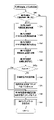
〔リセットスタート(メイン)処理〕
パチンコ機1に電源が投入されると、主制御CPU72はリセットスタート処理を開始する。リセットスタート処理は、前回の電源遮断時に保存されたバックアップ情報を元に遊技状態を復旧(いわゆる復電)したり、逆にバックアップ情報をクリアしたりすることで、パチンコ機1の初期状態を整えるための処理である。また、リセットスタート処理は、初期状態の調整後にパチンコ機1の安定した遊技動作を保証するためのメイン処理(メイン制御プログラム)として位置付けられる。
[Reset start (main) processing]
When the
図7及び図8は、リセットスタート処理の手順例を示すフローチャートである。以下、主制御CPU72が行う処理について、各手順を追って説明する。
7 and 8 are flowcharts showing an example of the procedure of reset start processing. Each procedure of the processing performed by the
ステップS101:主制御CPU72は、先ずスタックポインタにスタック領域の先頭アドレスをセットする。
Step S101: The
ステップS102:続いて主制御CPU72は、ベクタ方式の割込モード(モード2)を設定し、デフォルトであるRST方式の割込モード(モード0)を修正する。これにより、以後、主制御CPU72は任意のアドレス(ただし最下位ビットは0)を割込ベクタとして参照し、指定の割込ハンドラを実行することができる。
Step S102: Subsequently, the
ステップS103:主制御CPU72は、ここでリセット時待機処理を実行する。この処理は、リセットスタート(例えば電源投入)時にある程度の待機時間(例えば数千ms程度)を確保しておき、その間に主電源断検出信号のチェックを行うためのものである。具体的には、主制御CPU72は待機時間分のループカウンタをセットすると、ループカウンタの値をデクリメントしながら主電源断検出信号の入力ポートをビットチェックする。主電源断検出信号は、例えば周辺デバイスである電源監視ICから入力される。そして、ループカウンタが0になる前に主電源断検出信号の入力を確認すると、主制御CPU72は先頭から処理を再開する。これにより、例えば図示しない主電源スイッチの投入と切断の操作が短時間(1~2秒程度)内に繰り返し行われた場合のシステム保護を図ることができる。
Step S103: The
ステップS104:次に主制御CPU72は、RAM76のワーク領域に対するアクセスを許可する。具体的には、ワーク領域のRAMプロテクト設定値をリセット(00H)する。これにより、以後はRAM76のワーク領域に対するアクセスが許可された状態となる。
Step S104: Next, the main control CPU72 permits access to the work area of the RAM76. Specifically, the RAM protect setting value of the work area is reset (00H). As a result, access to the work area of the
ステップS105:また、主制御CPU72、割り込みマスクを設定するためにマスクレジスタの初期設定を行う。具体的には、CTC割り込みを有効にする値をマスクレジスタに格納する。
Step S105: Also, the
ステップS106:主制御CPU72は、先に退避しておいたRAMクリアスイッチからの入力信号を参照し、RAMクリアスイッチが操作(スイッチON)されたか否かを確認する。RAMクリアスイッチが操作されていなければ(No)、次にステップS107を実行する。
Step S106: The
ステップS107:次に主制御CPU72は、RAM76にバックアップ情報が保存されているか否か、つまり、バックアップ有効判定フラグがセットされているか否かを確認する。前回の電源遮断処理でバックアップが正常に終了し、バックアップ有効判定フラグ(例えば「A55AH」)がセットされていれば(Yes)、次に主制御CPU72はステップS108を実行する。
Step S107: Next, the
ステップS108:主制御CPU72は、RAM76のバックアップ情報についてサムチェックを実行する。具体的には、主制御CPU72はRAM76のワーク領域(使用禁止領域及びスタック領域を含むユーザワーク領域)のうち、バックアップ有効判定フラグ及びサムチェックバッファを除く全ての領域をサムチェックする。サムチェックの結果が正常であれば(Yes)、次に主制御CPU72はステップS109を実行する。
Step S108: The main control CPU72 performs a sum check on the backup information in the RAM76. Specifically, the
ステップS109:主制御CPU72は、バックアップ有効判定フラグをリセット(例えば「0000H」)する。
ステップS110:また、主制御CPU72は、前回の電源断発生直前に送信待ちであったコマンドをクリアする。
Step S109: The
Step S110: Also, the
ステップS111:次に主制御CPU72は、演出制御復帰処理を実行する。この処理では、主制御CPU72は演出制御装置124に対し、復帰用のコマンド(例えば機種指定コマンド、特別図柄確率状態指定コマンド、特図先判定演出コマンド、作動記憶数増加時演出コマンド、作動記憶数減少時演出コマンド、回数切りカウンタ値コマンド、特別遊技状態指定コマンド等)を送信する。これを受けて演出制御装置124は、前回の電源遮断時に実行中であった演出状態(例えば、内部確率状態、演出図柄の表示態様、作動記憶数の演出表示態様、音響出力内容、各種ランプの発光状態等)を復帰させることができる。
Step S111: Next, the
ステップS112:主制御CPU72は、状態復帰処理を実行する。この処理では、主制御CPU72はバックアップ情報を元にRAM76のワーク領域に各種の値をセットし、前回の電源遮断時に実行中であった遊技状態(例えば、特別図柄の表示態様、内部確率状態、作動記憶内容、各種フラグ状態、乱数更新状態等)を復帰させる。また、主制御CPU72は、バックアップされていたPCレジスタの値を復旧する。
Step S112: The
一方、電源投入時にRAMクリアスイッチが操作されていた場合(ステップS106:Yes)や、バックアップ有効判定フラグがセットされていなかった場合(ステップS107:No)、あるいは、バックアップ情報が正常でなかった場合(ステップS108:No)、主制御CPU72はステップS113に移行する。
On the other hand, if the RAM clear switch is operated when the power is turned on (step S106: Yes), if the backup validity determination flag is not set (step S107: No), or if the backup information is not normal (Step S108: No), the
ステップS113:主制御CPU72は、RAM76の使用禁止領域以外の記憶内容をクリアする。これにより、RAM76のワーク領域及びスタックエリアは全て初期化され、有効なバックアップ情報が保存されていても、その内容は消去される。
ステップS114:また、主制御CPU72は、RAM76の初期設定を行う。
Step S113: The
Step S114: The main control CPU72 also initializes the RAM76.
ステップS115:主制御CPU72は、演出制御出力処理を実行する。この処理では、主制御CPU72が初期設定後に演出制御装置124に送信するべきコマンド(演出制御に必要なコマンド)を出力する。
Step S115: The
ステップS116:主制御CPU72は、払出制御出力処理を実行する。この処理では、主制御CPU72は払出制御装置92に対して、賞球の払い出しを開始するための指示コマンドを出力する。
Step S116: The
ステップS117:主制御CPU72は、CTC初期設定処理を実行し、周辺デバイスであるCTC(カウンタ/タイマ回路)の初期設定を行う。この処理では、主制御CPU72は割込ベクタレジスタを設定し、また、CTCに割り込みカウント値(例えば4ms)を設定する。これにより、次にCTC割り込みが発生すると、主制御CPU72はバックアップされていたPCレジスタのプログラムアドレスから処理を続行することができる。
Step S117: The
リセットスタート処理において以上の手順を実行すると、主制御CPU72は図8に示されるメインループに移行する(接続記号A→A)。
After executing the above procedure in the reset start process, the
ステップS118,ステップS119:主制御CPU72は割込を禁止した上で、電源断発生チェック処理を実行する。この処理では、主制御CPU72は主電源断検出信号の入力ポートをビットチェックし、電源遮断の発生(駆動電圧の低下)を監視する。電源遮断が発生すると、主制御CPU72は普通電動役物ソレノイド88や第1大入賞口ソレノイド90、第2大入賞口ソレノイド97等に対応する出力ポートバッファをクリアすると、RAM76のワーク領域のうちバックアップ有効判定フラグ及びサムチェックバッファを除く全体の内容をバックアップし、サムチェックバッファにサム結果値を保存する。そして、主制御CPU72はバックアップ有効判定フラグ領域に上記の有効値(例えば「A55AH」)を格納し、RAM76のアクセスを禁止して処理を停止(NOP)する。一方、電源遮断が発生しなければ、主制御CPU72は次にステップS120を実行する。なお、このような電源断発生時の処理をマスク不能割込(NMI)処理としてCPUに実行させている公知のプログラミング例もある。
Steps S118 and S119: The
ステップS120:主制御CPU72は、初期値更新乱数更新処理を実行する。この処理では、主制御CPU72は、各種のソフトウェア乱数の初期値を更新(変更)するための乱数をインクリメントする。本実施形態では、大当り決定乱数(ハードウェア乱数)、及び普通図柄に対応する当り決定乱数(ハードウェア乱数)を除く各種の乱数(例えば、大当り図柄乱数、リーチ判定乱数、変動パターン決定乱数等)をプログラム上で発生させている。これらソフトウェア乱数は、別の割込処理(図10中のステップS201)で所定範囲内のループカウンタにより更新されているが、この処理において乱数値が1巡するごとにループカウンタの初期値(全ての乱数が対象でなくてもよい)を変更している。初期値更新用乱数は、この初期値をランダムに変更するために用いられており、ステップS120では、その初期値更新用乱数の更新を行っている。なお、ステップS118で割込を禁止した後にステップS120を実行しているのは、別の割込管理処理(図10中のステップS202)でも同様の処理を実行するため、これとの重複(競合)を防止するためである。なお、上記のように、本実施形態において大当り決定乱数及び当り決定乱数は乱数発生器75により発生されるハードウェア乱数であり、その更新周期はタイマ割込周期(例えば数ms)よりもさらに高速(例えば数μs)であるため、大当り決定乱数及び当り決定乱数の初期値を更新する必要はない。
Step S120: The
ステップS121,ステップS122:主制御CPU72は割込を許可し、その他乱数更新処理を実行する。この処理で更新される乱数は、ソフトウェア乱数のうち当選種類(当り種別)の判定に関わらない乱数(リーチ判定乱数、変動パターン決定乱数等)である。この処理は、メインループの実行中にタイマ割込が発生し、主制御CPU72が別の割込管理処理(図10)を実行した場合の残り時間で行われる。なお、割込管理処理の内容については後述する。
Steps S121, S122: The
〔電源断発生チェック処理〕
図9は、上記の電源断発生チェック処理の手順例を具体的に示すフローチャートである。
ステップS130:ここでは先ず、主制御CPU72は、電源断発生チェックのための条件を設定する。このチェック条件は、例えば主電源断検出信号が継続して出力されていることを確認するためのオンカウンタ値として設定することができる。
[Power failure check process]
FIG. 9 is a flow chart specifically showing a procedure example of the above-described power failure occurrence check process.
Step S130: Here, first, the
ステップS132:次に主制御CPU72は、主電源断検出スイッチ入力用ポートをリードし、主電源断検出信号が出力されているか否かを確認(特定のビットをチェック)する。特に図示していないが、主電源断検出スイッチは例えば主制御装置70に実装されており、この主電源断検出スイッチは、電源制御ユニット162から供給される駆動電圧を監視し、その電圧レベルが基準電圧を下回った場合に主電源断検出信号を出力する。なお、主電源断検出スイッチは電源制御ユニット162に内蔵されていてもよい。主制御CPU72は、現時点で主電源断検出信号が出力されていないことを確認すると(No)、この処理を抜けてリセットスタート処理に復帰する。一方、主電源断検出信号が出力されていることを確認した場合(Yes)、主制御CPU72は次のステップS134に進む。
Step S132: Next, the
ステップS134:主制御CPU72は、上記のチェック条件を満たすか否かを確認する。具体的には、先のステップS130で設定したオンカウンタ値を例えば1減算し、その結果が0になったか否かを確認する。現時点で未だオンカウンタ値が0でなければ(No)、主制御CPU72はステップS132に戻って主電源断検出スイッチ入力用ポートを改めて確認する。そして、ステップS134からステップS132へのループを繰り返してチェック条件が満たされると(ステップS134:Yes)、主制御CPU72は次にステップS136に進む。
Step S134: The
ステップS136:主制御CPU72は、上記のように普通電動役物ソレノイド88や第1大入賞口ソレノイド90、第2大入賞口ソレノイド97に対応する出力ポートに加え、試験信号端子やコマンド制御信号に対応する出力ポートバッファをクリアする。
Step S136: The
ステップS138,ステップS140:次に主制御CPU72は、RAM76のワーク領域のうち、バックアップ有効判定フラグ及びサムチェックバッファを除く全体の内容を1バイト単位で加算し、全領域について加算を完了するまで繰り返す。
ステップS142:全領域についてサムの算出が完了すると(ステップS140:Yes)、主制御CPU72はサムチェックバッファにサム結果値を保存する。
Steps S138, S140: Next, the
Step S142: When sum calculation is completed for all areas (step S140: Yes), the
ステップS144:次に主制御CPU72は、上記のようにバックアップ有効判定フラグ領域に有効値を格納する。
ステップS146:また、主制御CPU72は、RAM76のプロテクト値にアクセス禁止を表す「01H」を格納し、RAM76のワーク領域(使用禁止領域及びスタック領域を含む)に対するアクセスを禁止する。
ステップS148:そして、主制御CPU72は待機ループに入り、主電源断の遮断に備えて他の処理を全て停止する。主電源断の発生後は、図示しないバックアップ電源回路(例えば主制御装置70に実装された容量素子を含む回路)からバックアップ用電力が供給されるため、RAM76の記憶内容は主電源断後も消失することなく保持される。なお、バックアップ用電源回路は、例えば電源制御ユニット162に内蔵されていてもよい。
Step S144: Next, the
Step S146: In addition, the
Step S148: Then, the
以上の処理を通じて、バックアップ対象(サム加算対象)となるRAM76のワーク領域に記憶されていた情報は、全て主電源断の後もRAM76に記憶として保持されることになる。また、保持されていた記憶は、先のリセットスタート処理(図7)でチェックサムの正常を確認した上で、電源断時のバックアップ情報として復元される。
Through the above processing, all the information stored in the work area of the
〔割込管理処理(タイマ割込処理)〕
次に、割込管理処理(タイマ割込処理)について説明する。図10は、割込管理処理の手順例を示すフローチャートである。主制御CPU72は、カウンタ/タイマ回路からの割込要求信号に基づき、所定時間(例えば数ms)ごとに割込管理処理を実行する。以下、各手順を追って説明する。
[Interrupt management processing (timer interrupt processing)]
Next, interrupt management processing (timer interrupt processing) will be described. FIG. 10 is a flowchart illustrating an example of the procedure of interrupt management processing. The
ステップS200:先ず主制御CPU72は、メインループの実行中に使用していたレジスタ(アキュムレータAとフラグレジスタF、汎用レジスタB~Lの各ペア)の値をRAM76の退避領域に退避させる。値を退避させた後のレジスタ(A~L)には、割込管理処理の中で別の値を書き込むことができる。 Step S200: First, the main control CPU72 saves the values of the registers (each pair of the accumulator A and the flag register F, and the general-purpose registers B to L) used during the execution of the main loop to the saving area of the RAM76. Another value can be written to the registers (A to L) after saving the values during the interrupt management process.
ステップS201:次に主制御CPU72は、抽選乱数更新処理を実行する。この処理では、主制御CPU72は抽選用の各種乱数を発生させるためのカウンタの値を更新する。各カウンタの値は、RAM76のカウンタ領域にてインクリメントされ、それぞれ規定の範囲内でループする。各種乱数には、例えば大当り図柄乱数等が含まれる。
Step S201: Next, the
ステップS202:主制御CPU72は、ここでも初期値更新乱数更新処理を実行する。処理の内容は、先に述べたもの(図8中のステップS120)と同じである。
Step S202: The
ステップS203:主制御CPU72は、入力処理を実行する。この処理では、主制御CPU72は入出力(I/O)ポート79から各種スイッチ信号を入力する。具体的には、ゲートスイッチ78からの通過検出信号や、上始動入賞口スイッチ80、下始動入賞口スイッチ82、右始動入賞口スイッチ83、第1カウントスイッチ84、第2カウントスイッチ85、入賞口スイッチ86からの入賞検出信号の入力状態(ON/OFF)をリードする。
Step S203: The
ステップS204:次に主制御CPU72は、スイッチ入力イベント処理を実行する。この処理では、先の入力処理で入力したスイッチ信号のうち、ゲートスイッチ78、上始動入賞口スイッチ80、下始動入賞口スイッチ82、右始動入賞口スイッチ83からの入賞検出信号に基づいて遊技中に発生した事象の判定を行い、それぞれ発生した事象に応じて、さらに別の処理を実行する。なお、スイッチ入力イベント処理の具体的な内容については、さらに別のフローチャートを用いて後述する。
Step S204: Next, the
本実施形態では、上始動入賞口スイッチ80、下始動入賞口スイッチ82又は右始動入賞口スイッチ83から入賞検出信号(ON)が入力されると、主制御CPU72はそれぞれ第1特別図柄又は第2特別図柄に対応した内部抽選の契機(抽選契機)となる事象が発生したと判定する。また、ゲートスイッチ78から通過検出信号(ON)が入力されると、主制御CPU72は普通図柄に対応した抽選契機となる事象が発生したと判定する。いずれかの事象が発生したと判定すると、主制御CPU72は、それぞれの発生事象に応じた処理を実行する。なお、上始動入賞口スイッチ80、下始動入賞口スイッチ82又は右始動入賞口スイッチ83から入賞検出信号が入力された場合に実行される処理については、さらに別のフローチャートを用いて後述する。
In this embodiment, when a winning detection signal (ON) is input from the upper starting winning
ステップS204a:主制御CPU72は、設定変更処理(設定関連処理)を実行する。この処理を実行することにより、主制御CPU72は、設定の値を変更する際に実行される設定変更処理又は設定の値を確認する際に実行される設定確認処理の少なくとも一方を含む設定関連処理を実行することができる(設定関連処理実行手段)。なお、設定変更状態や設定確認状態でない場合には(通常遊技状態である場合には)、本処理を実行しないようにすることができる。また、通常遊技状態である場合には、ベースを算出し、算出したベースを性能表示モニタ200に表示する処理を実行することができる。主制御CPU72は、遊技球が各入賞口(始動入賞口、普通入賞口、大入賞口)に入球することによって払い出される賞球数を、遊技領域に発射した遊技球の数を示すアウト数(アウトスイッチで検出された遊技球の数)で除算することによりベースを算出することができる(ベース算出手段、ベース関連処理実行手段)。
Step S204a: The
ステップS205,ステップS206a,ステップS206b:主制御CPU72は、割込管理処理中において及び普通図柄遊技処理、第1特別図柄遊技処理及び第2特別図柄遊技処理を実行する。これら処理は、パチンコ機1における遊技を具体的に進行させるためのものである。このうち普通図柄遊技処理(ステップS205)では、主制御CPU72は先に述べた普通図柄表示装置33による変動表示や停止表示を制御したり、その表示結果に応じて可変始動入賞装置28の作動を制御したりする。例えば、主制御CPU72は先のスイッチ入力イベント処理(ステップS204)の中で始動ゲート20の通過を契機として取得した乱数(普通図柄当り決定乱数)を記憶しておき、この普通図柄遊技処理の中で記憶から乱数値を読み出し、所定の当り範囲内に該当するか否かの判定を行う(作動抽選実行手段)。乱数値が当り範囲内に該当する場合、普通図柄表示装置33により普通図柄を変動表示させて所定の当り態様で普通図柄の停止表示を行った後、主制御CPU72は普通電動役物ソレノイド88を励磁して可変始動入賞装置28を作動させる。一方、乱数値が当り範囲外であれば、主制御CPU72は、変動表示の後にはずれの態様で普通図柄の停止表示を行う。
Step S205, step S206a, step S206b: The main control CPU72 executes the normal symbol game process, the first special symbol game process and the second special symbol game process during the interrupt management process. These processes are for specifically advancing the game in the
また、第1特別図柄遊技処理(ステップS206a)では、主制御CPU72は第1特別図柄に対応する内部抽選の実行を制御したり(第1抽選実行手段)、第1特別図柄表示装置34による変動表示や停止表示を制御したり、その表示結果に応じて第1可変入賞装置30及び第2可変入賞装置31の作動を制御したりする。また、第2特別図柄遊技処理(ステップS206b)では、主制御CPU72は第2特別図柄に対応する内部抽選の実行を制御したり(第2抽選実行手段)、第2特別図柄表示装置35による変動表示や停止表示を制御したり、その表示結果に応じて第2可変入賞装置31の作動を制御したりする。なお、第1特別図柄遊技処理及び第2特別図柄遊技処理の詳細については、さらに別のフローチャートを用いて後述する。
In addition, in the first special symbol game process (step S206a), the main control CPU72 controls the execution of the internal lottery corresponding to the first special symbol (first lottery executing means), and the fluctuation by the first special
ステップS207:次に主制御CPU72は、賞球払出処理を実行する。この処理では、先の入力処理(ステップS203)において各種スイッチ80,81,82,83,84,85,86から入力された入賞検出信号に基づき、払出制御装置92に対して賞球個数を指示する賞球指示コマンドを出力する。払出制御装置92(払出装置)は、大当り遊技(特別遊技)や小当り遊技(特別遊技)の実行中に、遊技球が第1可変入賞装置30や第2可変入賞装置31に入球すると、所定の賞球数に応じた遊技球を払い出す。
Step S207: Next, the
また、主制御CPU72は、賞球払出処理において、演出制御装置124に対して賞球個数の内容を伝達する賞球内容コマンドを出力する。第1可変入賞装置30又は第2可変入賞装置31に対応する第1カウントスイッチ84又は第2カウントスイッチ85から入賞検出信号が入力された場合、第1利益(遊技球15個分)に対応する賞球内容コマンドを生成する。また、普通入賞口22に対応する入賞口スイッチ86から入賞検出信号が入力された場合、第2利益(遊技球10個分)に対応する賞球内容コマンドを生成する。賞球内容コマンドは、演出制御出力処理(図10中ステップS212)において演出制御装置124に送信される。
Also, the
〔賞球数及び獲得遊技球数について〕
第1特別図柄の始動口の賞球数及び第2特別図柄の始動口の賞球数は、それぞれ1個以上の規定数に設定されている。また、第1特別図柄の始動口と第2特別図柄の始動口とでは、賞球数を異ならせてもよい。さらに、特別図柄抽選の当選確率や、総獲得遊技球数の期待値(初当りから時間短縮状態が終了するまでの一連の期間に得られる平均出球数)に基づいて、最低賞球数を設定してもよい。さらにまた、特別図柄抽選の当選確率、総獲得遊技球数の期待値、大入賞口の開放回数、大入賞口の開放時間、大入賞口の最大入賞数、大入賞口の賞球数が所定の条件を満たした場合、1回の大当りによる獲得遊技球数が最大の獲得遊技球数の1/4未満となる大当りを設定してもよい。
[Regarding the number of prize balls and the number of winning game balls]
The number of prize balls for the start opening of the first special symbol and the number of prize balls for the start opening of the second special symbol are each set to a prescribed number of one or more. Also, the number of winning balls may be different between the starting opening of the first special symbol and the starting opening of the second special symbol. In addition, the minimum number of prize balls is calculated based on the probability of winning the special symbol lottery and the expected value of the total number of game balls acquired (average number of balls obtained during a series of periods from the first hit to the end of the time reduction state). May be set. Furthermore, the probability of winning the special symbol lottery, the expected value of the total number of game balls acquired, the number of times the large winning opening is opened, the opening time of the large winning opening, the maximum winning number of the large winning opening, and the number of prize balls in the large winning opening are predetermined. If the condition of (1) is satisfied, a big win may be set in which the number of game balls acquired by one big win is less than 1/4 of the maximum number of acquired game balls.
ステップS208:次に主制御CPU72は、外部情報処理を実行する。この処理では、主制御CPU72は外部端子板160を通じて遊技場のホールコンピュータに対して上記の外部情報信号(例えば賞球情報、扉開放情報、図柄確定回数情報、大当り情報、始動口情報等)をポート出力要求バッファに格納する。ポート出力要求バッファに格納された外部情報信号は、外部端子板160を介してデータ表示装置やホールコンピュータに送信される。
Step S208: Next, the
なお、本実施形態では、各種の外部情報信号のうち、例えば大当り情報として「大当り1」~「大当り5」を外部に出力することで、パチンコ機1に接続された外部の電子機器(データ表示器やホールコンピュータ)に対して多様な大当り情報を提供することができる(外部情報信号出力手段)。すなわち、大当り情報を複数の「大当り1」~「大当り5」に分けて出力することで、これらの組み合わせから大当りの種別(当選種類)を図示しないホールコンピュータで集計・管理したり、内部的な確率状態(低確率状態又は高確率状態)や図柄変動時間の短縮状態の変化を認識したり、非当選以外であっても「大当り」に分類されない小当り(条件装置が作動しない当り)の発生を集計・管理したりすることが可能となる。また、大当り情報に基づき、例えば図示しないデータ表示装置によりパチンコ機1の台ごとに過去数営業日以内の大当り発生回数を計数及び表示したり、台ごとに現在大当り中であるか否かを認識したり、あるいは台ごとに現在図柄変動時間の短縮状態であるか否かを認識したりすることができる。この外部情報処理において、主制御CPU72は「大当り1」~「大当り5」のそれぞれの出力状態(ON又はOFFのセット)を詳細に制御する。
In this embodiment, among various external information signals, for example, "
ステップS209:また、主制御CPU72は、試験信号処理を実行する。この処理では、主制御CPU72が自己の内部状態(例えば、普通図柄遊技管理状態、特別図柄遊技管理状態、大当り中、確率変動機能作動中、変動時間短縮機能作動中)を表す各種の試験信号を生成し、これらをポート出力要求バッファに格納する。この試験信号により、例えば主制御装置70の外部で主制御CPU72の内部状態を試験することができる。
Step S209: The
ステップS210:次に主制御CPU72は、表示出力管理処理を実行する。この処理では、主制御CPU72は普通図柄表示装置33、普通図柄作動記憶ランプ33a、第1特別図柄表示装置34、第2特別図柄表示装置35、第1特別図柄作動記憶ランプ34a、第2特別図柄作動記憶ランプ35a、遊技状態表示装置38等の点灯状態を制御する。具体的には、先の普通図柄遊技処理(ステップS205)や第1特別図柄遊技処理(ステップS206a)、第2特別図柄遊技処理(ステップS206b)においてポート出力要求バッファに格納されている駆動信号をポート出力する。なお、駆動信号は、各LEDに対して印加するバイトデータとしてポート出力要求バッファに格納されている。これにより、各LEDが所定の表示態様(図柄の変動表示や停止表示、作動記憶数表示、遊技状態表示等を行う態様)で駆動されることになる。
Step S210: Next, the
ステップS211:また、主制御CPU72は、出力管理処理を実行する。この処理では、主制御CPU72は先の外部情報処理(ステップS208)でポート出力要求バッファに格納された外部情報信号(バイトデータ)をポート出力する。また、主制御CPU72は、ポート出力要求バッファに格納されている普通電動役物ソレノイド88、第1大入賞口ソレノイド90及び第2大入賞口ソレノイド97の各駆動信号、試験信号等を合わせてポート出力する。
Step S211: The
ステップS212:主制御CPU72は、演出制御出力処理を実行する。この処理では、コマンドバッファ内に主制御CPU72が演出制御装置124に送信するべきコマンド(演出制御に必要なコマンド)があるか否かを確認し、未送信コマンドがある場合は出力対象のコマンドをポート出力する。
Step S212: The
ステップS213:そして、主制御CPU72は、今回のCTC割込で格納したポート出力要求バッファをクリアする。
Step S213: Then, the
なお、本実施形態では、ステップS205~ステップS212の処理(遊技制御プログラムモジュール)をタイマ割込処理として実行する例を挙げているが、これら処理をCPUのメインループ中に組み込んで実行している公知のプログラミング例もある。 It should be noted that, in the present embodiment, an example is given in which the processing of steps S205 to S212 (game control program module) is executed as a timer interrupt processing, but these processing are executed by incorporating them into the main loop of the CPU. There are also known programming examples.
ステップS214:以上の処理を終えると、主制御CPU72は割込終了を指定する値(01H)を割込プログラムカウンタ内に格納し、CTC割込を終了する。
Step S214: After completing the above processing, the
ステップS215,ステップS216:そして、主制御CPU72は、退避しておいたレジスタ(A~L)の値を復帰し、次回のCTC割込を許可する。この後、主制御CPU72は、メインループ(スタックポインタで指示されるプログラムアドレス)に復帰する。
Steps S215, S216: Then, the
〔スイッチ入力イベント処理〕
図11は、スイッチ入力イベント処理(図10中のステップS204)の手順例を示すフローチャートである。以下、各手順を追って説明する。
[Switch input event processing]
FIG. 11 is a flow chart showing a procedure example of switch input event processing (step S204 in FIG. 10). Each procedure will be described below.
ステップS10:主制御CPU72は、普通図柄に対応するゲートスイッチ78から通過検出信号が入力されたか否かを確認する。この通過検出信号の入力が確認された場合(Yes)、主制御CPU72は次のステップS11に進んで普通図柄記憶更新処理を実行する。普通図柄記憶更新処理では、主制御CPU72は現在の普通図柄作動記憶数が上限数(例えば4個)未満であるか否かを確認し、上限数に達していなければ、普通図柄当り乱数を取得する。また、主制御CPU72は、普通図柄作動記憶数を1インクリメントする。そして、主制御CPU72は、取得した普通図柄当り乱数値をRAM76の乱数記憶領域に記憶させる。一方、通過検出信号の入力がなかった場合(No)、主制御CPU72はステップS12に進む。
Step S10: The
ステップS12:主制御CPU72は、上始動入賞口26に対応する上始動入賞口スイッチ80から入賞検出信号が入力された(抽選契機が発生した)か否かを確認する。この入賞検出信号の入力が確認された場合(Yes)、主制御CPU72は次のステップS13に進んで第1特別図柄記憶更新処理を実行する。具体的な処理の内容については、別のフローチャートを用いてさらに後述する。一方、入賞検出信号の入力がなかった場合(No)、主制御CPU72はステップS14に進む。
Step S12: The
ステップS14:主制御CPU72は、下始動入賞口28bに対応する下始動入賞口スイッチ82から入賞検出信号が入力された(抽選契機が発生した)か否かを確認する。この入賞検出信号の入力が確認された場合(Yes)、主制御CPU72は次のステップS15に進んで第1特別図柄記憶更新処理を実行する。具体的な処理の内容については、別のフローチャートを用いてさらに後述する。一方、入賞検出信号の入力がなかった場合(No)、主制御CPU72はステップS16に進む。
Step S14: The
ステップS16:主制御CPU72は、右始動入賞口27に対応する右始動入賞口スイッチ83から入賞検出信号が入力された(抽選契機が発生した)か否かを確認する。この入賞検出信号の入力が確認された場合(Yes)、主制御CPU72は次のステップS17に進んで第2特別図柄記憶更新処理を実行する。具体的な処理の内容については、別のフローチャートを用いてさらに後述する。一方、入賞検出信号の入力がなかった場合(No)、主制御CPU72はステップS18に進む。
Step S16: The
ステップS18:主制御CPU72は、第1可変入賞装置30の第1大入賞口に対応する第1カウントスイッチ84から入賞検出信号が入力されたか否かを確認する。この入賞検出信号の入力が確認された場合(Yes)、主制御CPU72は次のステップS19に進んで第1大入賞口カウント処理を実行する。第1大入賞口カウント処理では、主制御CPU72は大当り遊技中に1ラウンドごとの第1可変入賞装置30への入賞球数をカウントする。一方、入賞検出信号の入力がなかった場合(No)、主制御CPU72はステップS20に進む。
Step S18: The
ステップS20:主制御CPU72は、第2可変入賞装置31の第2大入賞口に対応する第2カウントスイッチ85から入賞検出信号が入力されたか否かを確認する。この入賞検出信号の入力が確認された場合(Yes)、主制御CPU72は次のステップS21に進んで第2大入賞口カウント処理を実行する。第2大入賞口カウント処理では、主制御CPU72は大当り遊技中に第2可変入賞装置31への入賞球数をカウントする。一方、入賞検出信号の入力がなかった場合(No)、主制御CPU72は割込管理処理(図10)に復帰する。
Step S<b>20 : The
〔第1特別図柄記憶更新処理〕
図12は、第1特別図柄記憶更新処理の手順例を示すフローチャートである。以下、第1特別図柄記憶更新処理の手順について順を追って説明する。
[First special symbol memory update process]
FIG. 12 is a flow chart showing a procedure example of the first special symbol memory updating process. Hereinafter, the procedure of the first special symbol memory updating process will be described step by step.
ステップS30:ここでは先ず、主制御CPU72は第1特別図柄作動記憶数カウンタの値を参照し、作動記憶数が最大値(例えば4とする)未満であるか否かを確認する。作動記憶数カウンタは、RAM76の乱数記憶領域に記憶されている大当り決定乱数や大当り図柄乱数等の個数(組数)を表すものである。ここで、RAM76の乱数記憶領域は、第1特別図柄用の4つのセクションと、第2特別図柄用の4つのセクション(例えば各2バイト)に分けられており、各セクションには大当り決定乱数及び大当り図柄乱数を1個ずつセット(組)で記憶可能である。このとき、第1特別図柄に対応する作動記憶数カウンタの値が最大値に達していれば(No)、主制御CPU72はスイッチ入力イベント処理(図11)に復帰する。一方、作動記憶数カウンタの値が最大値未満であれば(Yes)、主制御CPU72は次のステップS31に進む。
Step S30: Here, first, the main control CPU72 refers to the value of the first special symbol working memory number counter, and confirms whether or not the working memory number is less than the maximum value (for example, 4). The working memory number counter represents the number (number of sets) of the jackpot decision random numbers and jackpot pattern random numbers stored in the random number storage area of the
ステップS31:主制御CPU72は、第1特別図柄作動記憶数を1つ加算する。第1特別図柄作動記憶数カウンタは、例えばRAM76の作動記憶数領域に記憶されており、主制御CPU72はその値をインクリメント(+1)する。ここで加算されたカウンタの値に基づき、表示出力管理処理(図10中のステップS210)で第1特別図柄作動記憶ランプ34aの点灯状態が制御されることになる。
Step S31: The main control CPU72 adds one to the first special symbol working memory number. The first special symbol working memory number counter is stored, for example, in the working memory number area of the
ステップS32:そして、主制御CPU72は、サンプリング回路77を通じて乱数発生器75から第1特別図柄に対応する大当り決定乱数値を取得する(第1抽選要素の取得、抽選要素取得手段)。乱数値の取得は、乱数発生器75のピンアドレスを指定して行う。主制御CPU72が8ビット処理の場合、アドレスの指定は上位及び下位で1バイトずつ2回に分けて行われる。主制御CPU72は、指定したアドレスから大当り決定乱数値をリードすると、これを第1特別図柄に対応する大当り決定乱数として転送先のアドレスにセーブする。
Step S32: Then, the
ステップS33:次に主制御CPU72は、RAM76の大当り図柄乱数カウンタ領域から第1特別図柄に対応する大当り図柄乱数値を取得する。この乱数値の取得もまた、大当り図柄乱数カウンタ領域のアドレスを指定して行う。主制御CPU72は、指定したアドレスから大当り図柄乱数値をリードすると、これを第1特別図柄に対応する大当り図柄乱数として転送先のアドレスにセーブする。
Step S33: Next, the main control CPU72 acquires the jackpot symbol random number value corresponding to the first special symbol from the jackpot symbol random number counter area of the RAM76. Acquisition of this random number value is also performed by designating the address of the jackpot symbol random number counter area. When the
ステップS34:また、主制御CPU72は、RAM76の変動用乱数カウンタ領域から、第1特別図柄の変動条件に関する乱数値として、リーチ判定乱数及び変動パターン決定乱数を順番に取得する(変動パターン決定要素取得手段)。これら乱数値の取得も同様に、変動用乱数カウンタ領域のアドレスを指定して行われる。そして、主制御CPU72は、指定したアドレスからリーチ判定乱数及び変動パターン決定乱数をそれぞれ取得すると、これらを転送先のアドレスにセーブする。
Step S34: In addition, the main control CPU72 sequentially acquires the reach determination random number and the variation pattern determination random number from the variation random number counter area of the RAM76 as the random value related to the variation condition of the first special symbol (variation pattern determination element acquisition means). Acquisition of these random numbers is similarly performed by designating the address of the variable random number counter area. Then, when the
ステップS35:主制御CPU72は、セーブした大当り決定乱数、大当り図柄乱数、リーチ判定乱数及び変動パターン決定乱数をともに第1特別図柄に対応する乱数記憶領域に転送し、これら乱数を領域内の空きセクションにセットで記憶させる(記憶手段、抽選要素記憶手段)。複数のセクションには順番(例えば第1~第4)が設定されており、現段階で第1~第4の全てのセクションが空きであれば、第1セクションから順に各乱数が記憶される。あるいは、第1セクションが既に埋まっており、その他の第2~第4セクションが空きであれば、第2セクションから順に各乱数が記憶されていく。なお、乱数記憶領域の読み出しはFIFO(First In First Out)形式である。
Step S35: The
ステップS36:次に主制御CPU72は、現在の特別遊技管理ステータス(遊技状態)が大当り中であるか否かを確認する。大当り中以外であれば(No)、主制御CPU72は次以降のステップS37,S38を実行する。大当り中であれば(Yes)、主制御CPU72はステップS37,S38をスキップしてステップS38aに進む。本実施形態においてこの判断を行っているのは、大当り中に発生した入球については先読みによる演出を行わないためである。
Step S36: Next, the
ステップS37:大当り中以外の場合(ステップS36:No)、主制御CPU72は第1特別図柄に関して取得時演出判定処理を実行する。この処理は、先のステップS32~S34でそれぞれ取得した第1特別図柄の大当り決定乱数及び大当り図柄乱数に基づいて、事前(変動開始前)に内部抽選の結果を判定し、それによって演出内容を判定(いわゆる「先読み」)するためのものである。なお、具体的な処理の内容については別のフローチャートを参照しながらさらに後述する。 Step S37: In the case other than during the big hit (step S36: No), the main control CPU72 executes the effect determination process at the time of acquisition regarding the first special symbol. In this process, the result of the internal lottery is determined in advance (before the start of fluctuation) based on the jackpot determination random number and the jackpot pattern random number obtained in the previous steps S32 to S34, respectively, and the content of the effect is determined accordingly. It is for judgment (so-called "look-ahead"). The specific contents of the processing will be further described later with reference to another flowchart.
ステップS38:取得時演出判定処理から復帰すると、次に主制御CPU72は、第1特別図柄に関して特図先判定演出コマンドの上位バイト分(例えば「B8H」)をセットする。この上位バイトデータは、コマンド種別が「第1特別図柄に関する特図先判定演出用」であることを記述したものである。なお、特図先判定演出コマンドの下位バイト分は、先の取得時演出判定処理(ステップS37)においてセットされているので、ここでは下位バイトに上位バイトを合成することで例えば1ワード長のコマンドが生成されることになる。 Step S38: When returning from the effect determination process at the time of acquisition, the main control CPU72 next sets the upper byte portion of the special figure destination determination effect command (for example, "B8H") with respect to the first special symbol. This high-order byte data describes that the command type is "for the special figure destination determination production for the first special symbol". In addition, since the lower byte portion of the special figure destination determination effect command is set in the previous acquisition time effect determination process (step S37), here, by synthesizing the upper byte with the lower byte, for example, a one word length command will be generated.
ステップS38a:次に主制御CPU72は、第1特別図柄に関して作動記憶数増加時演出コマンドをセットする。具体的には、コマンドの種別を表す上位バイトの先行値(例えば「BBH」)に対し、増加後の作動記憶数(例えば「01H」~「04H」)を下位バイトに付加した1ワード長の演出コマンドを生成する。このとき下位バイトについては、デフォルトで第2の位を「0」とすることにより、その値が「作動記憶数の増加による結果(変化情報)」であることを表している。つまり、下位バイトが「01H」であれば、それは前回までの作動記憶数「00H」から1つ増加した結果、今回の作動記憶数が「01H」となったことを表している。同様に、下位バイトが「02H」~「04H」であれば、それは前回までの作動記憶数「01H」~「03H」からそれぞれ1つ増加した結果、今回の作動記憶数が「02H」~「04H」となったことを表している。なお、上記の先行値「BBH」は、今回の演出コマンドが第1特別図柄についての作動記憶数コマンドであることを表す値である。
Step S38a: Next, the
ステップS39:そして、主制御CPU72は、第1特別図柄に関して演出コマンド出力設定処理を実行する。この処理は、先のステップS38で生成した特図先判定演出コマンドや、ステップS38aで生成した作動記憶数増加時演出コマンド、始動口入賞音制御コマンドを演出制御装置124に対して送信するためのものである(記憶数通知手段)。
Step S39: Then, the
以上の手順を終えるか、もしくは第1特別図柄作動記憶数が4に達していた場合(ステップS30:No)、主制御CPU72はスイッチ入力イベント処理(図11)に復帰する。
If the above procedure is completed, or if the number of first special symbol working memories has reached 4 (step S30: No), the
〔第2特別図柄記憶更新処理〕
次に図13は、第2特別図柄記憶更新処理の手順例を示すフローチャートである。以下、第2特別図柄記憶更新処理の手順について順を追って説明する。
[Second special symbol memory update process]
Next, FIG. 13 is a flow chart showing a procedure example of the second special symbol memory updating process. Hereinafter, the procedure of the second special symbol memory updating process will be described step by step.
ステップS40:主制御CPU72は、第2特別図柄作動記憶数カウンタの値を参照し、作動記憶数が最大値未満であるか否かを確認する。第2特別図柄作動記憶数カウンタについても上記と同様に、RAM76の乱数記憶領域に記憶されている大当り決定乱数や大当り図柄乱数等の個数(組数)を表すものである。このとき第2特別図柄作動記憶数カウンタの値が最大値(例えば4とする)に達していれば(No)、主制御CPU72はスイッチ入力イベント処理(図11)に復帰する。一方、未だ第2特別図柄作動記憶数カウンタの値が最大値未満であれば(Yes)、主制御CPU72は次のステップS41以降に進む。
Step S40: The main control CPU72 refers to the value of the second special symbol working memory number counter and checks whether or not the working memory number is less than the maximum value. Similarly to the above, the second special symbol working memory number counter also indicates the number (number of sets) of the jackpot decision random numbers and jackpot pattern random numbers stored in the random number storage area of the
ステップS41:主制御CPU72は、第2特別図柄作動記憶数を1つ加算(第2特別図柄作動記憶数カウンタの値をインクリメント)する。先のステップS31(図12)と同様に、ここで加算されたカウンタの値に基づき、表示出力管理処理(図10中のステップS210)で第2特別図柄作動記憶ランプ35aの点灯状態が制御されることになる。
Step S41: The main control CPU72 adds one to the second special symbol working memory number (increments the value of the second special symbol working memory number counter). Similar to the previous step S31 (FIG. 12), based on the value of the counter added here, the lighting state of the second special symbol
ステップS42:そして、主制御CPU72は、第2特別図柄に対応する大当り決定乱数値を取得する(第2抽選要素の取得、抽選要素取得手段)。乱数値を取得する手法は、先に説明したステップS32(図12)と同様である。
Step S42: Then, the
ステップS43:次に主制御CPU72は、RAM76の大当り図柄乱数カウンタ領域から第2特別図柄に対応する大当り図柄乱数値を取得する。乱数値を取得する方法は、先に説明したステップS33(図12)と同様である。 Step S43: Next, the main control CPU72 acquires a jackpot symbol random number value corresponding to the second special symbol from the jackpot symbol random number counter area of the RAM76. The method of obtaining the random value is the same as in step S33 (FIG. 12) described above.
ステップS44:また、主制御CPU72は、RAM76の変動用乱数カウンタ領域から、第2特別図柄の変動条件に関するリーチ判定乱数及び変動パターン決定乱数を順番に取得する(変動パターン決定要素取得手段)。これら乱数値の取得もまた、先に説明したステップS34(図12)と同様に行われる。 Step S44: In addition, the main control CPU72 sequentially acquires the reach determination random number and the variation pattern determination random number regarding the variation condition of the second special symbol from the variation random number counter area of the RAM76 (variation pattern determining element acquisition means). Acquisition of these random numbers is also performed in the same manner as in step S34 (FIG. 12) described above.
ステップS45:主制御CPU72は、セーブした大当り決定乱数、大当り図柄乱数、リーチ判定乱数及び変動パターン決定乱数をともに第2特別図柄に対応する乱数記憶領域に転送し、これら乱数を領域内の空きセクションにセットで記憶させる(記憶手段)。記憶の手法は、先に説明したステップS35(図12)と同様である。
Step S45: The
ステップS45a:次に主制御CPU72は、現在の遊技管理ステータス(遊技状態)が大当り中であるか否かを確認する。そして、大当り中以外であれば(No)、主制御CPU72は次以降のステップS46,S47を実行する。逆に大当り中であれば(Yes)、主制御CPU72はステップS46,S47をスキップしてステップS48に進む。本実施形態においてこの判断を行っているのは、同じく大当り中に発生した入球については先読みによる演出を行わないためである。
Step S45a: Next, the
ステップS46:大当り中以外である場合(ステップS45a:No)、次に主制御CPU72は、第2特別図柄に関して取得時演出判定処理を実行する。この処理は、先のステップS42~S44でそれぞれ取得した第2特別図柄の大当り決定乱数及び大当り図柄乱数に基づいて、事前(変動開始前)に内部抽選の結果を判定し、それによって演出内容を判定するためのものである。なお、具体的な処理の内容は後述する。 Step S46: If it is other than during the big hit (step S45a: No), then the main control CPU72 executes the effect determination process at the time of acquisition with respect to the second special symbol. In this process, the result of the internal lottery is determined in advance (before the start of fluctuation) based on the second special symbol jackpot determination random number and the jackpot pattern random number obtained in the previous steps S42 to S44, respectively, and the effect contents are determined accordingly. It is for judging. The specific contents of the processing will be described later.
ステップS47:取得時演出判定処理から復帰すると、次に主制御CPU72は特図先判定演出コマンドの上位バイト分(例えば「B9H」)をセットする。この上位バイトデータは、コマンド種別が「第2特別図柄に関する特図先判定演出用」であることを記述したものである。ここでも同様に、特図先判定演出コマンドの下位バイト分は、先の取得時演出判定処理(ステップS46)においてセットされているので、ここでは下位バイトに上位バイトを合成することで例えば1ワード長のコマンドが生成されることになる。 Step S47: When returning from the effect determination process at the time of acquisition, the main control CPU72 next sets the upper byte portion of the special figure destination determination effect command (for example, "B9H"). This high-order byte data describes that the command type is "for the special figure destination determination effect regarding the second special symbol". Similarly here, since the lower byte portion of the special figure destination determination effect command is set in the previous acquisition time effect determination process (step S46), here, by synthesizing the upper byte with the lower byte, for example, one word A long command will be generated.
ステップS48:次に主制御CPU72は、第2特別図柄に関して作動記憶数増加時演出コマンドをセットする。ここでは、コマンドの種別を表す上位バイトの先行値(例えば「BCH」)に対し、増加後の作動記憶数(例えば「01H」~「04H」)を下位バイトに付加した1ワード長の演出コマンドを生成する。第2特別図柄についても同様に、デフォルトで下位バイトの第2の位を「0」とすることにより、その値が「作動記憶数の増加による結果(変化情報)」であることを表すことができる。なお、先行値「BCH」は、今回の演出コマンドが第2特別図柄についての作動記憶数コマンドであることを表す値である。
Step S48: Next, the
ステップS49:そして、主制御CPU72は、第2特別図柄に関して演出コマンド出力設定処理を実行する。これにより、第2特別図柄に関して特図先判定演出コマンドや作動記憶数増加時演出コマンド、始動口入賞音制御コマンド等を演出制御装置124に対して送信する準備が行われる(記憶数通知手段)。また、以上の手順を終えると、主制御CPU72はスイッチ入力イベント処理(図11)に復帰する。
Step S49: Then, the
〔取得時演出判定処理〕
図14は、取得時演出判定処理の手順例を示すフローチャートである。主制御CPU72は、先の第1特別図柄記憶更新処理及び第2特別図柄記憶更新処理(図12中のステップS37,図13中のステップS46)においてこの取得時演出判定処理を実行する(先判定実行手段)。上記のように、この処理は第1特別図柄(上始動入賞口26又は可変始動入賞装置28(下始動入賞口28b)への入球時)、第2特別図柄(右始動入賞口27への入球時)のそれぞれについて実行される。したがって以下の説明は、第1特別図柄に関する処理に該当する場合と、第2特別図柄に関する処理に該当する場合とがある。以下、各手順に沿って処理の内容を説明する。
[Production determination process when acquired]
FIG. 14 is a flow chart showing an example of the procedure of the effect determination process at the time of acquisition. The
ステップS50:主制御CPU72は、特図先判定演出コマンド(先判定情報)の下位バイト分(例えば「00H」)をセットする。なお、ここでセットしたバイトデータはコマンドの標準値(はずれ時)を表すものとなる。
Step S50: The
ステップS52:次に主制御CPU72は、先判定用乱数値として大当り決定乱数をロードする。ここでロードする乱数は、先の第1特別図柄記憶更新処理(図12中のステップS35)又は第2特別図柄記憶更新処理(図13中のステップS45)でRAM76に記憶されているものである。
Step S52: Next, the
ステップS54:そして、主制御CPU72は、ロードした乱数が当り値の範囲外(ここでは下限値以下)であるか否かを判定する(抽選結果先判定手段、事前判定手段)。具体的には、主制御CPU72は比較値(下限値)をAレジスタにセットし、この比較値からロードした乱数値を減算する。なお、比較値(下限値)は、パチンコ機1における内部抽選の当選確率に応じて予め規定されている。次に主制御CPU72は、例えばフラグレジスタの値から演算結果が0又は正の値であるか否かを判別する。その結果、ロードした乱数が当り値の範囲外であれば(Yes)、主制御CPU72はステップS80に進む。
Step S54: Then, the
ステップS80:次に主制御CPU72は、はずれ時変動パターン情報事前判定処理を実行する(変動パターン先判定手段)。この処理では、主制御CPU72は、はずれ時の変動時間について上述した変動パターン先判定コマンドを生成する。ここで生成される変動パターン先判定コマンドには、特に「変動時間短縮機能」の作動時における変動時間(又は変動パターン番号)に関する事前の判定情報が反映される。例えば、現在の状態が「変動時間短縮機能」の作動時であれば、主制御CPU72はロードしたリーチ判定乱数に基づいて、変動時間が「はずれリーチ変動(非短縮変動時間)」に対応するものであるか否かを判断する。その結果、変動時間が「はずれリーチ変動(非短縮変動時間)」に対応するものである場合、主制御CPU72は「時短中非短縮変動時間」に対応する変動パターン先判定コマンドを生成する。なお、リーチ変動の場合はさらに、リーチモード乱数から「リーチグループ(リーチの種類)」をも判断し、その結果から変動パターン先判定コマンドを生成することとしてもよい。一方、変動時間が「はずれリーチ変動(非短縮変動時間)」に対応するものでない場合、主制御CPU72は「時短中短縮変動時間」に対応する変動パターン先判定コマンドを生成する。あるいは、現在の状態が「変動時間短縮機能」の非作動時であれば、主制御CPU72はロードしたリーチ判定乱数に基づいて、変動時間が「通常はずれリーチ変動」に対応するものであるか否かを判断する。その結果、変動時間が「通常はずれリーチ変動」に対応するものである場合、主制御CPU72は「通常はずれリーチ変動時間」に対応する変動パターン先判定コマンドを生成する。一方、変動時間が「通常はずれリーチ変動」に対応するものでない場合、主制御CPU72は「通常はずれ変動時間」に対応する変動パターン先判定コマンドを生成する。また、ここで生成された変動パターン先判定コマンドは、上記のように演出コマンド出力設定処理(ステップS39,S49)で送信バッファにセットされる。なお、この処理において、主制御CPU72は、小当り時の変動パターンについて、上述したはずれ時の処理と同様に変動パターン先判定コマンドを生成してもよい。
Step S80: Next, the
以上の手順を実行すると、主制御CPU72は呼び出し元の第1特別図柄記憶更新処理(図12)又は第2特別図柄記憶更新処理(図13)に復帰する。一方、先のステップS54の判断において、ロードした乱数が当り値の範囲外でなく、範囲内であれば(ステップS54:No)、主制御CPU72は次にステップS56に進む。
When the above procedure is executed, the
ステップS56:主制御CPU72は、先判定結果による確率状態予定フラグがセットされているか否かを確認する。先判定結果による確率状態予定フラグは、未だ変動は開始されていないが、これまで記憶されている大当り決定乱数の中に当選値がある場合にセットされるものである。具体的には、これまでに記憶されている大当り決定乱数に当選値があった場合、これと組になる大当り図柄乱数が「確変図柄(9ラウンド確変図柄、16ラウンド確変図柄)」に該当するものであれば、確率状態予定フラグに例えば「A0H」がセットされる。この値は、この大当り決定乱数よりも後に取得された大当り決定乱数の事前判定(先読み判定)に際して、高確率状態になることを予定として設定するためのフラグ値を表すものである。一方、これまでに記憶されている大当り決定乱数に当選値があった場合であって、これと組になる大当り図柄乱数が「非確変(通常)図柄」に該当するものであれば、確率状態予定フラグに例えば「01H」がセットされる。この値は、この大当り決定乱数よりも後に取得された大当り決定乱数の事前判定(先読み判定)に際して、通常(低)確率状態になることを予定として設定するためのフラグ値を表すものである。なお、これまでに記憶されている大当り決定乱数に当選値が未だ存在しなければ、フラグ値はリセット(00H)されている。また、確率状態予定フラグの値は、例えばRAM76のフラグ領域に格納されている。なお、ここでは「確率状態予定フラグ」を用いて厳密に事前の当り判定を行う例を挙げているが、単純に現在の確率状態に基づいて事前の当り判定を行う場合、このステップS56と以降のステップS58,ステップS60,ステップS62,ステップS76等を省略してもよい。
Step S56: The
主制御CPU72は、未だ確率状態予定フラグがセットされていなければ(ステップS56:No)、次にステップS66を実行する。
If the probability state schedule flag has not yet been set (step S56: No), the
ステップS66:この場合、主制御CPU72は次に低確率時(通常時)用比較値をAレジスタにセットする。なお、低確率時用比較値もまた、パチンコ機1における低確率時の当選確率に応じて予め規定されている。
Step S66: In this case, the
ステップS68:次に主制御CPU72は、「現在の確率状態フラグ」をロードする。この確率状態フラグは、現在の内部状態が高確率(確変中)であるか否かを表すものであり、RAM76のフラグ領域内に記憶されているものである。現在の確率状態が高確率(確変中)であれば、状態フラグとして値「01H」がセットされており、低確率(通常中)であれば、状態フラグの値はリセットされている(「00H」)。
Step S68: Next, the main control CPU72 loads the "current probability state flag". This probability state flag indicates whether or not the current internal state is high probability (during probability change), and is stored in the flag area of the
ステップS70:そして、主制御CPU72は、ロードした現在の特別図柄確率状態フラグが高確率を表すものでない(≠01H)か否かを確認し、その結果、高確率を表すものであれば(No)、次にステップS64を実行する。 Step S70: Then, the main control CPU72 confirms whether the loaded current special symbol probability state flag does not indicate a high probability (≠01H), and as a result, if it indicates a high probability (No ), and then step S64 is executed.
ステップS64:主制御CPU72は、高確率時用比較値をセットする。これにより、先のステップS66でセットされた低確率時用比較値が書き換えられることになる。なお、高確率時用比較値は、パチンコ機1における高確率時の当選確率に応じて予め規定されている。
Step S64: The
このように、先判定結果による確率状態予定フラグが未だセットされていない場合であって、現在の内部状態が高確率の場合は、比較値を高確率時用に書き換えた上で次のステップS72を実行することになる。これに対し、先のステップS70で現在の確率状態フラグが高確率を表すものでないことを確認した場合(Yes)、主制御CPU72はステップS64をスキップして次のステップS72を実行する。 In this way, if the probability state schedule flag based on the previous determination result has not been set yet and the current internal state is high probability, the comparison value is rewritten for high probability and then the next step S72 is performed. will be executed. On the other hand, if it is confirmed in the previous step S70 that the current probability state flag does not indicate a high probability (Yes), the main control CPU72 skips step S64 and executes the next step S72.
ステップS72:主制御CPU72は、先のステップS52でロードした乱数が当り値の範囲外であるか否かを判定する(抽選結果先判定手段)。すなわち、主制御CPU72は状態別でセットした比較値から大当り決定乱数値を減算する。そして、主制御CPU72は、同様にフラグレジスタの値から演算結果が負の値(<0)であるか否かを判別し、その結果、ロードした乱数が当り値の範囲外であれば(Yes)、主制御CPU72は上記のはずれ時変動パターン情報事前判定処理(ステップS80)を実行する。これに対し、ロードした乱数が当り値の範囲外でなく、範囲内であれば(No)、主制御CPU72は次にステップS74に進む。
Step S72: The
ステップS74:主制御CPU72は、大当り図柄種別判定処理を実行する。この処理は、大当り決定乱数と組になっている大当り図柄乱数に基づいて、そのときの大当り種別(当選種類)を判定するためのものである。例えば、主制御CPU72は先の第1特別図柄記憶更新処理(図12中のステップS35)又は第2特別図柄記憶更新処理(図13中のステップS45)で記憶した図柄別の大当り図柄乱数をロードすると、上記のステップS54と同様に比較値を用いた演算を実行し、その結果から大当り種別として「通常図柄(9ラウンド通常図柄)」又は「確変図柄(9ラウンド確変図柄、16ラウンド確変図柄)」のいずれに該当するかを判別する。主制御CPU72は、このときの判別結果を特別図柄先判定値として記憶し、次のステップS76に進む。
Step S74: The main control CPU72 executes a jackpot symbol type determination process. This processing is for judging the jackpot type (winning type) at that time based on the jackpot design random number paired with the jackpot determination random number. For example, the main control CPU72 loads the jackpot symbol random number for each symbol stored in the previous first special symbol memory update process (step S35 in FIG. 12) or the second special symbol memory update process (step S45 in FIG. 13). Then, the calculation using the comparison value is executed in the same manner as in the above step S54, and from the result, "normal design (9 rounds normal design)" or "probability variation design (9 rounds probability variation design, 16 rounds probability variation design) as the jackpot type. ” is determined. The
ステップS76:そして、主制御CPU72は、先判定結果による確率状態予定フラグの値をセットする。具体的には、先のステップS74で記憶した特別図柄先判定値が「通常図柄」を表す場合、主制御CPU72は確率状態予定フラグに値「01H」をセットする。一方、特別図柄先判定値が「確変図柄」を表す場合、主制御CPU72は確率状態予定フラグに値「A0H」をセットする。これにより、次回以降の処理ではステップS56において「フラグセット済み」と判定されることになる。
Step S76: Then, the main control CPU72 sets the value of the probability state schedule flag according to the previous determination result. Specifically, when the special symbol destination determination value stored in the previous step S74 represents the "normal symbol", the main control CPU72 sets the probability state schedule flag to the value "01H". On the other hand, when the special symbol destination determination value represents "variable probability symbol", the
ステップS78:主制御CPU72は、特図先判定演出コマンドの下位バイトとして、先のステップS74で記憶した特別図柄先判定値をセットする。特別図柄先判定値は、例えば「通常図柄」に該当する場合は「01H」がセットされ、「確変図柄」に該当する場合は「A0H」がセットされる。いずれにしても、ここで下位バイト分のデータをセットすることにより、先のステップS50でセットした標準の下位バイトデータ「00H」が書き換えられることになる。 Step S78: The main control CPU72 sets the special symbol destination determination value stored in the previous step S74 as the lower byte of the special symbol destination determination effect command. For example, the special symbol destination determination value is set to "01H" when it corresponds to the "normal symbol", and is set to "A0H" when it corresponds to the "variable probability symbol". In any case, by setting the lower byte data here, the standard lower byte data "00H" set in the previous step S50 is rewritten.
ステップS79:次に主制御CPU72は、大当り時変動パターン情報事前判定処理を実行する(変動パターン先判定手段)。この処理では、主制御CPU72は大当り時の変動時間について、上述した変動パターン先判定コマンドを生成する。ここで生成される変動パターン先判定コマンドには、例えば大当り時のリーチ変動時間(又は変動パターン番号)に関する事前の判定情報が反映される。また、ここで生成された変動パターン先判定コマンドは、上記のように演出コマンド出力設定処理(ステップS39,S49)で送信バッファにセットされる。
Step S79: Next, the
以上は、先判定結果による確率状態予定フラグがセットされる前(内部初当り前)における手順である。これに対し、先のステップS76を経て確率状態予定フラグがセットされた場合、以下の手順が実行される。ただし、上記のように現在の確率状態だけで事前の当り判定を行う場合、以下のステップS56,ステップS58,ステップS60,ステップS62、及びステップS76を実行する必要はない。 The above is the procedure before the probability state schedule flag is set according to the previous determination result (before the internal first hit). On the other hand, when the probability state schedule flag is set through the previous step S76, the following procedure is executed. However, when preliminary hit determination is performed only based on the current probability state as described above, there is no need to execute the following steps S56, S58, S60, S62, and S76.
ステップS56:主制御CPU72は、既に確率状態予定フラグに値がセットされていることを確認すると(Yes)、次にステップS58を実行する。
Step S56: When the
ステップS58:主制御CPU72は、先ず低確率時(通常時)用比較値をAレジスタにセットする。
Step S58: The
ステップS60:次に主制御CPU72は、「確率状態予定フラグ」をロードする。確率状態予定フラグは、上記のように直前の先判定結果に基づきそれ以降の先判定において確率状態を予定的に設定するためのものであり、RAM76のフラグ領域内に記憶されているものである。直前の先判定結果に基づく確率状態が高確率(確変)に移行する予定であれば、上記のように確率状態予定フラグの値として「A0H」がセットされており、逆に直前の先判定結果に基づく確率状態が低確率(通常)に戻る予定であれば、確率状態予定フラグの値として「01H」がセットされている。
Step S60: Next, the main control CPU72 loads the "probability state schedule flag". As described above, the probability state schedule flag is for setting the probability state in the subsequent pre-determination based on the previous pre-determination result, and is stored in the flag area of the
ステップS62:そして、主制御CPU72は、ロードした確率状態予定フラグが高確率の予定を表すものでない(≠01H)か否かを確認し、その結果、高確率の予定を表すものであれば(No)、次にステップS64を実行し、高確率時用比較値をセットする。
Step S62: Then, the
このように、先判定結果による確率状態予定フラグが既にセットされており、その値が高確率を予定するものである場合は、比較値を高確率時用に書き換えた上で次のステップS72以降を実行することになる。これに対し、先のステップS62で確率状態予定フラグが高確率の予定を表すものでなく、通常(低)確率の予定を表すものであることを確認した場合(Yes)、主制御CPU72はステップS64をスキップして次のステップS72以降を実行する。これにより本実施形態では、先判定結果に基づくその後の内部状態の変化(通常確率状態→高確率状態、高確率状態→通常確率状態)を考慮した上で、事前の大当り判定を行うことができる。
In this way, when the probability state schedule flag based on the previous determination result has already been set and the value is for a high probability, the comparative value is rewritten for the high probability and then the next step S72 and subsequent steps is performed. will be executed. On the other hand, if it is confirmed in the previous step S62 that the probability state schedule flag does not represent a high-probability schedule but indicates a normal (low) probability schedule (Yes), the
以上の手順を終えると、主制御CPU72は第1特別図柄記憶更新処理(図12)又は第2特別図柄記憶更新処理(図13)に復帰する。
After completing the above procedure, the
〔第1特別図柄及び第2特別図柄の並行変動〕
次に、第1特別図柄遊技処理及び第2特別図柄遊技処理の詳細について説明する。本実施形態では、第1特別図柄及び第2特別図柄について、それぞれに対応する内部抽選を別個に実行することで、第1特別図柄表示装置34による第1特別図柄の変動表示と第2特別図柄表示装置35による第2特別図柄の変動表示とを並行して行うことが可能である(図柄並行変動手段)。このため、本実施形態では、第1特別図柄及び第2特別図柄のそれぞれについて、主制御CPU72による制御上で第1特別図柄遊技処理及び第2特別図柄遊技処理を別個に(1割り込み周期に1回ずつ)実行することとしている。
[Parallel variation of the first special symbol and the second special symbol]
Next, the details of the first special symbol game process and the second special symbol game process will be described. In this embodiment, by separately executing the internal lottery corresponding to the first special symbol and the second special symbol, the first special
〔第1特別図柄遊技処理〕
図15は、第1特別図柄遊技処理の手順例を示すフローチャートである。
第1特別図柄遊技処理は、はじめに内部状態フラグが「大役開始(大当り遊技中)」であるか否かを確認する手順(ステップS1000a)を有している。
[First special symbol game process]
FIG. 15 is a flow chart showing a procedure example of the first special symbol game process.
First, the first special symbol game process has a procedure (step S1000a) for confirming whether or not the internal state flag is "big win start (during big win game)".
ステップS1000a:主制御CPU72は、第2特別図柄に対応する遊技状態(内部状態)が「大役開始(大当り遊技中)」であるか否かを確認する。この確認は、第2特別図柄に関してこれまでに行われた処理の進行状況(第2特別図柄遊技管理ステータスの値)に基づいて行うことができる。本実施形態においてこの確認を行っているのは、他方の第2特別図柄に関して大当り遊技中である場合、第1特別図柄に関する遊技を進行させないこととしているからである。
Step S1000a: The
現時点で、特に第2特別図柄に関して大当り遊技中(第2特別図柄遊技管理ステータスが大当り中の値)でなければ(No)、主制御CPU72は次のステップS1000bの処理を実行する。
At this time, if the second special symbol is not in the middle of a big hit game (the second special symbol game management status is a value of a big hit) (No), the
また、第1特別図柄遊技処理は、RAM76に記憶されている変動時間計測一時停止中フラグがONであり、かつ、遊技状態が小当り中であるか否かを確認する手順(ステップS1000b)を有している。なお、変動時間計測一時停止中フラグがONである場合は変動時間の計測が一時停止中であることを意味しており、変動時間計測一時停止中フラグがOFFである場合は変動時間の計測が一時停止中でないことを意味している。
In addition, the first special symbol game process includes a procedure (step S1000b) for confirming whether or not the fluctuation time measurement temporary stop flag stored in the
ステップS1000b:主制御CPU72は、RAM76に記憶されている変動時間計測一時停止中フラグがONであり、かつ、遊技状態が小当り中であるか否かを確認する。本実施形態においてこの確認を行っているのは、他方の第2特別図柄に関して小当り遊技中であり、かつ、第1図柄が変動中である場合、第1特別図柄の変動時間の計測を一時停止させることとしているからである。
Step S1000b: The
現時点で、変動時間計測一時停止中フラグがONでない、又は、変動時間計測一時停止中フラグがONであったとしても遊技状態が小当り中でなければ(No)、主制御CPU72は次のステップS1000b1以降の処理を実行する。ステップS1000b1~ステップS6000は、それぞれ第1特別図柄遊技処理の根幹となるプログラムモジュールである。主制御CPU72はこれら根幹となるステップS1000b1~ステップS6000の処理を通じて、第1特別図柄に対応する遊技の進行状況を具体的に制御することができる。
At this time, if the variable time measurement suspended flag is not ON, or even if the variable time measurement suspended flag is ON, the game state is not a small hit (No), the
一方、変動時間計測一時停止中フラグがONであり、かつ、小当り遊技中である場合(Yes)、主制御CPU72はステップS7000の処理を実行する。
On the other hand, if the fluctuation time measurement paused flag is ON and the small hit game is in progress (Yes), the
第1特別図柄遊技処理の根幹部分には、特別遊技特別図柄判別フラグ更新処理(ステップS1000b1)、実行選択処理(ステップS1000c)、特別図柄変動前処理(ステップS2000)、特別図柄変動中処理(ステップS3000)、特別図柄停止表示中処理(ステップS4000)、大当り時可変入賞装置管理処理(ステップS5000)、小当り時可変入賞装置管理処理(ステップS6000)のサブルーチン(プログラムモジュール)群が含まれている。ここでは先ず、各処理に沿って第1特別図柄遊技処理の根幹部分に関して基本的な流れを説明する。 The core part of the first special symbol game processing includes special game special symbol discrimination flag update processing (step S1000b1), execution selection processing (step S1000c), special symbol variation pre-processing (step S2000), special symbol variation during processing (step S3000), special symbol stop display processing (step S4000), variable winning device management processing for big hit (step S5000), variable winning device management processing for small win (step S6000) subroutines (program modules) groups are included. . First, the basic flow of the first special symbol game process will be described along with each process.
ステップS1000b1:主制御CPU72は、特別遊技特別図柄判別フラグ更新処理を実行する。主制御CPU72は、この処理において、第1特別図柄及び第2特別図柄のうちいずれの特別図柄を処理の対象とするかについての処理対象図柄を決定する処理を実行する。ここで、特別遊技特別図柄判別フラグとは、処理対象図柄を特定するフラグであり、RAM76に記憶されている。具体的には、主制御CPU72は、特別遊技特別図柄判別フラグの値に第1特別図柄に対応する値(例えば「0」)を設定する処理を実行する。
Step S1000b1: The
ステップS1000c:実行選択処理において、主制御CPU72は次に実行するべき処理(ステップS2000~ステップS6000のいずれか)のジャンプ先を「ジャンプテーブル」から選択する。例えば、主制御CPU72は次に実行するべき処理のプログラムアドレスをジャンプ先のアドレスとし、戻り先のアドレスとして第1特別図柄遊技処理の末尾をスタックポインタにセットする。
Step S1000c: In the execution selection process, the
いずれの処理を次のジャンプ先として選択するかは、これまでに行われた処理の進行状況(第1特別図柄遊技管理ステータス)によって異なる。例えば、未だ第1特別図柄が変動表示を開始していない状況であれば(第1特別図柄遊技管理ステータス:00H)、主制御CPU72は次のジャンプ先として特別図柄変動前処理(ステップS2000)を選択する。また、既に特別図柄変動前処理が完了していれば(第1特別図柄遊技管理ステータス:01H)、主制御CPU72は次のジャンプ先として特別図柄変動中処理(ステップS3000)を選択し、特別図柄変動中処理まで完了していれば(第1特別図柄遊技管理ステータス:02H)、次のジャンプ先として特別図柄停止表示中処理(ステップS4000)を選択するといった具合である。なお、本実施形態ではジャンプ先のアドレスを「ジャンプテーブル」で指定して処理を選択しているが、このような選択手法とは別に、「プロセスフラグ」や「処理選択フラグ」等を用いてCPUが次に実行するべき処理を選択している公知のプログラミング例もある。このようなプログラミング例では、CPUが一通り各処理をCALLし、その先頭ステップで一々フラグを参照して条件分岐(継続/リターン)することになるが、本実施形態の選択手法では、主制御CPU72が各処理を一々呼び出す手間は不要である。
Which process is selected as the next jump destination depends on the progress of the processes performed so far (first special symbol game management status). For example, if the first special symbol has not yet started variable display (first special symbol game management status: 00H), the
ステップS2000:特別図柄変動前処理では、主制御CPU72は第1特別図柄の変動表示を開始するための条件を整える作業を行う。具体的には、ここで大当り判定(第1抽選実行手段)や変動パターンの決定を行い、大当りの場合はあわせて当選種別の判定を行う。また、当選種別の判定に伴い、主制御CPU72は「時間短縮状態」及び「高確率状態」に関する回数切りカウンタを設定したりする。なお、具体的な処理の内容は、別のフローチャートを用いて後述する。
Step S2000: In the special symbol variation preprocessing, the main control CPU72 performs the work of preparing the conditions for starting the variation display of the first special symbol. Specifically, big hit determination (first lottery executing means) and variation pattern determination are performed here, and in the case of a big hit, determination of winning type is also performed. In addition, along with the determination of the winning type, the
ステップS3000:特別図柄変動中処理では、主制御CPU72は変動タイマをカウントしつつ、第1特別図柄表示装置34の駆動制御を行う。具体的には、7セグメントLEDの各セグメント及びドット(0番~7番)に対してON又はOFFの駆動信号(1バイトデータ)を出力する。駆動信号のパターンは時間の経過に伴って変化し、それによって第1特別図柄の変動表示が行われる。
Step S3000: In the special symbol fluctuation process, the main control CPU72 performs drive control of the first special
また、この処理ではスキップ機能を作動させるか否かの判定処理も行われ、先の大当り判定において、例えば、第1特別図柄が大当りの変動中であり、かつ、第2特別図柄が非当選に該当した場合、第2特別図柄に対してスキップ機能が作動される。このスキップ機能の作動により、第2特別図柄の非当選の変動を強制的に終了させる処理が行われる。なお、具体的な処理の内容は、別のフローチャートを用いて後述する。 In addition, in this process, a determination process of whether or not to operate the skip function is also performed, and in the previous big hit determination, for example, the first special symbol is in the process of changing the big hit, and the second special symbol is not elected. If so, the skip function is activated for the second special symbol. By the operation of this skip function, the process of forcibly ending the non-winning variation of the second special symbol is performed. The specific contents of the processing will be described later using another flowchart.
ステップS4000:特別図柄停止表示中処理では、主制御CPU72は第1特別図柄表示装置34の駆動制御を行う。ここでも同様に、7セグメントLEDの各セグメント及びドットに対してON又はOFFの駆動信号を出力するが、駆動信号のパターンは一定であり、これにより第1特別図柄の停止表示が行われる。なお、具体的な処理の内容は、別のフローチャートを用いて後述する。 Step S4000: In the special symbol stop display processing, the main control CPU72 performs drive control of the first special symbol display device . Similarly here, ON or OFF drive signals are output to each segment and dot of the 7-segment LED, but the pattern of the drive signal is constant, thereby performing the stop display of the first special symbol. The specific contents of the processing will be described later using another flowchart.
ステップS5000:大当り時可変入賞装置管理処理は、先の特別図柄停止表示中処理において大当りの態様で第1特別図柄が停止表示された場合に選択される。例えば、第1特別図柄が9ラウンド通常大当り、9ラウンド確変大当り又は16ラウンド確変大当りの態様で停止表示されると、それまでの通常状態から大当り遊技状態(遊技者にとって有利な特別遊技状態)に移行する契機が発生する。第1特別図柄に関して大当り遊技中は、先の実行選択処理(ステップS1000c)においてジャンプ先が大当り時可変入賞装置管理処理にセットされ、第1特別図柄の変動表示は行われない。大当り時可変入賞装置管理処理においては、第1大入賞口ソレノイド90又は第2大入賞口ソレノイド97が一定時間(例えば29秒間又は9個の入賞をカウントするまで)、予め設定された連続作動回数(例えば9回)にわたって励磁され、これにより第1可変入賞装置30又は第2可変入賞装置31が決まったパターンで開閉動作する(特別電動役物の連続作動)。この間に第1可変入賞装置30又は第2可変入賞装置31に対して遊技球を集中的に入賞させることで、遊技者には、まとまって多くの賞球を獲得する機会が与えられる(特別遊技実行手段、開放遊技実行手段)。なお、このように大当り時に第1可変入賞装置30又は第2可変入賞装置31が開閉動作することを「ラウンド」と称し、連続作動回数が全部で9回あれば、これを「9ラウンド」と総称する。本実施形態では、大当りの種類として9ラウンド通常大当り,9ラウンド確変大当りだけでなく、その他に複数種類の16ラウンド確変大当りが設けられている。
Step S5000: The variable winning device management process at the time of the big hit is selected when the first special symbol is stopped and displayed in the form of the big win in the previous special symbol stop display process. For example, when the first special symbol is stop-displayed in the form of a 9-round normal jackpot, a 9-round probability variable jackpot, or a 16-round probability variable jackpot, the previous normal state changes to a jackpot game state (a special game state advantageous to the player). An opportunity to migrate occurs. During the big hit game with respect to the first special symbol, the jump destination is set to the variable winning device management process at the time of the big hit in the previous execution selection process (step S1000c), and the variable display of the first special symbol is not performed. In the variable winning device management process at the time of a big hit, the first big winning opening solenoid 90 or the second big winning
主制御CPU72は大当り時可変入賞装置管理処理において大入賞口開放パターン(ラウンド数と1ラウンドごとの開閉動作の回数、開放時間等)を設定すると、1ラウンド分の第1可変入賞装置30又は第2可変入賞装置31の開閉動作を終了させるごとにラウンド数カウンタの値を1インクリメントする。ラウンド数カウンタの値は、例えば初期値を0としてRAM76のカウント領域に記憶されている。また、主制御CPU72は、ラウンド数カウンタの値を表すラウンド数コマンドを生成する。ラウンド数コマンドは、演出制御出力処理において演出制御装置124に送信される。ラウンド数カウンタの値が設定した連続作動回数に達すると、主制御CPU72はそのラウンド限りで第1特別図柄に関して大当り遊技(大役)を終了する。
When the
そして、大当り遊技を終了すると、主制御CPU72は遊技状態フラグ(確率変動機能作動フラグ、変動時間短縮機能作動フラグ)に基づいて大当り遊技終了後の状態(高確率状態、時間短縮状態)を変化させる(高確率状態移行手段、時間短縮状態移行手段、低確率時間短縮状態移行手段、高確率非時間短縮状態移行手段)。「高確率状態」では確率変動機能が作動し、内部抽選での当選確率が通常よりも例えば10倍程度に高くなる。また、「時間短縮状態」では変動時間短縮機能が作動し、普通図柄の作動抽選が高確率になり、普通図柄の変動時間が短縮されるとともに可変始動入賞装置28の開放時間が延長されて開放回数が増加する(いわゆる電チューサポートが行われる)。なお、「高確率状態」及び「時間短縮状態」については、制御上でいずれか一方だけに移行する場合もあれば、これら両方に合わせて移行する場合もある。
Then, when the jackpot game is finished, the
本実施形態において、「時間短縮状態」とは、変動時間短縮機能が作動することにより、普通図柄又は特別図柄の変動時間が短縮され、普通図柄の作動抽選の当選確率が高確率になり、可変始動入賞装置28の開放時間が延長される状態(開放延長機能作動)を意味している。
In this embodiment, the "time shortening state" means that the variation time shortening function is activated, the variation time of the normal symbol or the special symbol is shortened, the winning probability of the operation lottery of the normal symbol becomes high, variable It means a state in which the opening time of the starting
また、「非時間短縮状態」とは、変動時間短縮機能が非作動となることにより、普通図柄又は特別図柄の変動時間が短縮されず、普通図柄の作動抽選の当選確率が低確率になり、可変始動入賞装置28の開放時間が延長されない状態(開放延長機能非作動)を意味している。
In addition, the "non-shortening state" means that the fluctuation time reduction function is deactivated, the fluctuation time of normal symbols or special symbols is not shortened, and the probability of winning the normal symbol operation lottery becomes low. It means a state in which the opening time of the variable starting
ステップS6000:小当り時可変入賞装置管理処理は、先の特別図柄停止表示中処理において小当りの態様で第1特別図柄が停止表示された場合に選択される。例えば、第1特別図柄が小当りの態様で停止表示されると、それまでの通常状態から小当り遊技状態に移行する契機が発生する。小当り遊技中は、先の実行選択処理(ステップS1000c)においてジャンプ先が小当り時可変入賞装置管理処理にセットされ、特別図柄の変動表示は行われない。小当り遊技では第2可変入賞装置31が所定の開放時間(例えば1.8秒)で所定回数(例えば1回)にわたり開閉動作するため、遊技者は小当り遊技中に、ある程度の出球を獲得することができる。なお、本実施形態では、第1特別図柄に対して小当りを設定していないため、この処理は実行されないが、第1特別図柄に対して小当りを設定している場合には、この処理が実行される。
Step S6000: Small hit time variable winning device management process is selected when the first special symbol is stopped and displayed in the form of a small hit in the previous special symbol stop display process. For example, when the first special symbol is stop-displayed in a small-hit mode, an opportunity is generated to shift from the previous normal state to a small-hit game state. During the small-hit game, the jump destination is set to the small-hit time variable winning device management process in the previous execution selection process (step S1000c), and the variable display of the special symbol is not performed. In the small winning game, the second variable winning
ステップS7000:変動時間計測一時停止中処理は、第1特別図柄の変動を停止させずに維持する処理である。主制御CPU72は、第2特別図柄に関して小当り遊技中であり、かつ、第1特別図柄が変動中である場合に、第1特別図柄表示装置34の駆動制御を行う。第1特別図柄表示装置34の駆動制御としては、7セグメントLEDの各セグメント及びドット(0番~7番)に対してON又はOFFの駆動信号(1バイトデータ)を出力する処理を実行し、これによって第1特別図柄が停止されない状態が維持される。なお、第1特別図柄の変動時間の計測を一時的に停止した場合、小当り遊技の終了後には、変動時間の計測が再開される。なお、主制御CPU72は、第2特別図柄に関して小当り遊技中であると判断しても、第1特別図柄が変動中でない場合には、変動時間計測一時停止中処理を実行しない。また、変動時間の計測は、一時停止ではなく、強制終了であってもよい。
Step S7000: The process of temporarily stopping the measurement of the fluctuation time is a process of maintaining the fluctuation of the first special symbol without stopping it. The
〔第2特別図柄遊技処理〕
図16は、第2特別図柄遊技処理の手順例を示すフローチャートである。
第2特別図柄遊技処理は、はじめに他方の第1特別図柄に関して大当り中であるか否かを確認する手順(ステップS1900a)を有している。
[Second special symbol game processing]
FIG. 16 is a flow chart showing a procedure example of the second special symbol game process.
The second special symbol game process first has a procedure (step S1900a) for confirming whether or not the other first special symbol is in the midst of a big hit.
ステップS1900a:主制御CPU72は、第1特別図柄に対応する遊技状態が「大当り遊技中」であるか否かを確認する。この確認もまた、上記のように第1特別図柄遊技管理ステータスの値に基づいて行うことができる。なお、この判定で「小当り遊技中」であるか否かの判定を除いているのは、第1特別図柄に小当りがないからである。
Step S1900a: The
現時点で、第1特別図柄に関して大当り遊技中(第1特別図柄遊技管理ステータスが大当り中の値)でなければ(No)、主制御CPU72は次のステップS1900a1以降の処理を実行する。ステップS1900a1~ステップS6900は、それぞれ第2特別図柄遊技処理の根幹となるプログラムモジュールである。主制御CPU72はこれら根幹となるステップS1900a1~ステップS6900の処理を通じて、第2特別図柄に対応する遊技の進行状況を具体的に制御することができる。
At this time, if the first special symbol is not in a big hit game (the value of the first special symbol game management status is a big hit) (No), the
先の第1特別図柄遊技処理において説明したように、第2特別図柄遊技処理の根幹部分についても、特別遊技特別図柄判別フラグ更新処理(ステップS1900a1)、実行選択処理(ステップS1900b)、特別図柄変動前処理(ステップS2900)、特別図柄変動中処理(ステップS3900)、特別図柄停止表示中処理(ステップS4900)、大当り時可変入賞装置管理処理(ステップS5900)、小当り時可変入賞装置管理処理(ステップS6900)のサブルーチン(プログラムモジュール)群が含まれている。なお、第1特別図柄遊技処理と同様の内容は、説明を適宜省略する。 As explained in the previous first special symbol game process, also for the core part of the second special symbol game process, special game special symbol discrimination flag update process (step S1900a1), execution selection process (step S1900b), special symbol variation Pre-processing (step S2900), processing during special symbol fluctuation (step S3900), processing during special symbol stop display (step S4900), variable winning device management processing at the time of big hit (step S5900), variable winning device management processing at the time of small hit (step S6900) subroutine (program module) group is included. In addition, description of the same content as the first special symbol game process is omitted as appropriate.
ステップS1900a1:主制御CPU72は、特別遊技特別図柄判別フラグ更新処理を実行する。主制御CPU72は、この処理において、第1特別図柄及び第2特別図柄のうちいずれの特別図柄を処理の対象とするかについての処理対象図柄を決定する処理を実行する。具体的には、主制御CPU72は、特別遊技特別図柄判別フラグの値に第2特別図柄に対応する値(例えば「1」)を設定する処理を実行する。
Step S1900a1: The
ステップS1900b:実行選択処理において、主制御CPU72は次に実行するべき処理(ステップS2900~ステップS6900のいずれか)のジャンプ先を「ジャンプテーブル」から選択する。例えば、主制御CPU72は次に実行するべき処理のプログラムアドレスをジャンプ先のアドレスとし、戻り先のアドレスとして第2特別図柄遊技処理の末尾をスタックポインタにセットする。
Step S1900b: In the execution selection process, the
ここでも同様に、いずれの処理を次のジャンプ先として選択するかは、これまでに行われた処理の進行状況(第2特別図柄遊技管理ステータス)によって異なる。例えば、未だ第2特別図柄が変動表示を開始していない状況であれば(第2特別図柄遊技管理ステータス:00H)、主制御CPU72は次のジャンプ先として特別図柄変動前処理(ステップS2900)を選択する。また、既に特別図柄変動前処理が完了していれば(第2特別図柄遊技管理ステータス:01H)、主制御CPU72は次のジャンプ先として特別図柄変動中処理(ステップS3900)を選択し、特別図柄変動中処理まで完了していれば(第2特別図柄遊技管理ステータス:02H)、次のジャンプ先として特別図柄停止表示中処理(ステップS4900)を選択する。
Here as well, which process is selected as the next jump destination differs depending on the progress of the process performed so far (second special symbol game management status). For example, if the second special symbol has not yet started variable display (second special symbol game management status: 00H), the
ステップS2900:第2特別図柄遊技処理における特別図柄変動前処理では、主制御CPU72は第2特別図柄の変動表示を開始するための条件を整える作業を行う(第2抽選実行手段)。 Step S2900: In the special symbol variation preprocessing in the second special symbol game process, the main control CPU72 performs the work of adjusting the conditions for starting the variation display of the second special symbol (second lottery executing means).
ステップS3900:また、特別図柄変動中処理では、主制御CPU72は変動タイマをカウントしつつ、第2特別図柄表示装置35の駆動制御を行う。
Step S3900: In addition, in the special symbol fluctuation processing, the main control CPU72 performs drive control of the second special
ステップS4900:第2特別図柄遊技処理における特別図柄停止表示中処理では、主制御CPU72は第2特別図柄表示装置35の駆動制御を行う。ここでも同様に、7セグメントLEDの各セグメント及びドットに対してON又はOFFの駆動信号を出力し、これにより第2特別図柄の停止表示が行われる。
Step S4900: In the special symbol stop display process in the second special symbol game process, the main control CPU72 performs drive control of the second special
ステップS5900:大当り時可変入賞装置管理処理は、先の特別図柄停止表示中処理において大当りの態様で第2特別図柄が停止表示された場合に選択される。ここでも同様に、当選種類に応じた態様で第2特別図柄の停止表示態様が決定される。また、主制御CPU72は、大当り時可変入賞装置管理処理において大入賞口開放パターン(ラウンド数と1ラウンドごとの開閉動作の回数、開放時間等)を設定すると、1ラウンド分の第2可変入賞装置31の開閉動作を終了させるごとにラウンド数カウンタの値を1インクリメントする。ラウンド数カウンタの値が設定した連続作動回数に達すると、主制御CPU72はそのラウンド限りで第2特別図柄に関して大当り遊技(大役)を終了する。
Step S5900: The variable winning device management process at the time of big hit is selected when the second special symbol is stopped and displayed in the form of a big hit in the previous special symbol stop display process. Here, similarly, the stop display mode of the second special symbol is determined in accordance with the winning type. In addition, when the
そして、第2特別図柄に関して大当り遊技を終了すると、主制御CPU72は遊技状態フラグ(確率変動機能作動フラグ、変動時間短縮機能作動フラグ)に基づいて大当り遊技終了後の状態を変化させる。
Then, when the big hit game is ended with respect to the second special symbol, the
ステップS6900:小当り時可変入賞装置管理処理は、先の特別図柄停止表示中処理において小当りの態様で第2特別図柄が停止表示された場合に選択される(特殊遊技実行手段)。例えば、第2特別図柄が小当りの態様で停止表示されると、それまでの通常状態から小当り遊技状態に移行する契機が発生する。小当り遊技中は、先の実行選択処理(ステップS1000)においてジャンプ先が小当り時可変入賞装置管理処理にセットされ、特別図柄の変動表示は行われない。小当り遊技では第2可変入賞装置31が所定の開放時間(例えば0.1~1.8秒)で所定回数(例えば1回~複数回)にわたり開閉動作するため、遊技者は小当り遊技中に、ある程度の出球を獲得することができる可能性がある。
Step S6900: Small hit variable winning device management process is selected when the second special symbol is stopped and displayed in the form of a small hit in the previous special symbol stop display process (special game executing means). For example, when the second special symbol is stop-displayed in a small-hit mode, an opportunity is generated to shift from the previous normal state to a small-hit game state. During the small-hit game, the jump destination is set to the small-hit time variable winning device management process in the previous execution selection process (step S1000), and the variable display of the special symbol is not performed. In the small winning game, the second variable winning
〔複数の当選種類〕
本実施形態では、複数の当選種類として、(1)「9ラウンド通常大当り」、(2)「9ラウンド確変大当り」及び(3)「16ラウンド確変大当り」が設けられている。なお、16ラウンド、9ラウンド以外の大当りを設定してもよい。
[Multiple winning types]
In this embodiment, as a plurality of winning types, (1) "Normal 9-round big win", (2) "9-round definite variable big win", and (3) "16-round definite variable big win" are provided. It should be noted that jackpots other than 16 rounds and 9 rounds may be set.
上記の当選種類は、当選時に停止表示される第1特別図柄又は第2特別図柄の種類に対応している。例えば、「16ラウンド確変大当り」は「16ラウンド確変図柄」の大当りに対応し、「9ラウンド通常大当り」は「9ラウンド通常図柄」の大当りに対応し、「9ラウンド確変大当り」は「9ラウンド確変図柄」の大当りに対応する。このため以下では、「当選種類」のことを「当選図柄」として適宜呼称するものとする。 The winning type corresponds to the type of the first special symbol or the second special symbol that is stop-displayed at the time of winning. For example, "16 round probability variation jackpot" corresponds to "16 round probability variation pattern" jackpot, "9 round normal jackpot" corresponds to "9 round normal pattern" jackpot, and "9 round probability variation jackpot" corresponds to "9 rounds Corresponds to the big hit of "Probable variation pattern". For this reason, hereinafter, the "winning type" is appropriately referred to as "winning design".
〔可変入賞装置の開放動作パターン〕
図17は、可変入賞装置の開放動作パターンを示す図である。各当選図柄に対応する大入賞口の開放について内容を説明する。
[Opening operation pattern of variable winning device]
FIG. 17 is a diagram showing an opening operation pattern of the variable winning device. The contents of the opening of the big winning opening corresponding to each winning pattern will be explained.
〔9ラウンド通常図柄〕
特別図柄停止表示中処理において、特別図柄が「9ラウンド通常図柄」の態様で停止表示されると、それまでの通常状態から大当り遊技状態に移行する契機が発生する(特別遊技実行手段、開放遊技実行手段)。この場合、1ラウンド目から充分に長い時間(例えば最長で29.0秒の開放時間)をかけて第1可変入賞装置30の第1大入賞口30bの開放が1回ずつ行われ、これが9ラウンド目まで継続する。このため、「9ラウンド通常図柄」の大当り遊技は、9ラウンド分の出玉(賞球)を遊技者に付与するものとなる。
[Normal design for 9 rounds]
In the special symbol stop display processing, when the special symbol is stopped and displayed in the form of "9 round normal symbol", an opportunity to shift from the previous normal state to the jackpot game state is generated (special game execution means, open game means of execution). In this case, the first big winning
また、「9ラウンド通常図柄」に該当した場合、それまでの遊技で「変動時間短縮機能」が非作動の状態であったとしても、大当り遊技の終了後に「変動時間短縮機能」を作動させることで、「時間短縮状態」に移行する。 In addition, when it corresponds to the ``9 round normal pattern'', even if the ``variation time reduction function'' has been inactive in the game up to that point, the ``variation time reduction function'' can be activated after the end of the big win game. to move to the "time reduction state".
なお、第1可変入賞装置30の第1大入賞口30bは、1ラウンド内に規定回数(例えば10回=遊技球10個)の入賞が発生すると、最長の開放時間の経過を待たずに閉鎖される。また、第2可変入賞装置31の第2大入賞口31bも同様に、1ラウンド内に規定回数(例えば10回=遊技球10個)の入賞が発生すると、最長の開放時間の経過を待たずに閉鎖される。
It should be noted that the first big winning
〔9ラウンド確変図柄〕
特別図柄停止表示中処理において、特別図柄が「9ラウンド確変図柄」の態様で停止表示されると、それまでの通常状態から大当り遊技状態に移行する契機が発生する(特別遊技実行手段、開放遊技実行手段)。この場合、1ラウンド目から充分に長い時間(例えば最長で29.0秒の開放時間)をかけて第1可変入賞装置30の第1大入賞口30bの開放が1回ずつ行われ、これが9ラウンド目まで継続する。このため、「9ラウンド確変図柄」の大当り遊技は、9ラウンド分の出玉(賞球)を遊技者に付与するものとなる。
[9 round probability variation pattern]
In the special symbol stop display processing, when the special symbol is stopped and displayed in the form of "9 round probability variable symbol", an opportunity to shift from the normal state to the jackpot game state occurs (special game execution means, open game means of execution). In this case, the first big winning
また、「9ラウンド確変図柄」に該当した場合、大当り遊技の終了後には「確率変動機能」が作動されて、「高確率状態」に移行する。 In addition, when it corresponds to the "9 round probability variable pattern", the "probability variation function" is operated after the jackpot game ends, and the state shifts to the "high probability state".
〔16ラウンド確変図柄〕
特別図柄停止表示中処理において、特別図柄が「16ラウンド確変図柄」の態様で停止表示されると、それまでの通常状態から大当り遊技状態に移行する契機が発生する(特別遊技実行手段、開放遊技実行手段)。この場合、1ラウンド目から充分に長い時間(例えば最長で29.0秒の開放時間)をかけて第2可変入賞装置31の第2大入賞口31bの開放が1回ずつ行われ、これが16ラウンド目まで継続する。このため、「16ラウンド確変図柄」の大当り遊技は、16ラウンド分の出玉(賞球)を遊技者に付与するものとなる。
[16 round probability variation pattern]
In the special symbol stop display process, when the special symbol is stopped and displayed in the form of "16 round probability variable symbol", an opportunity to shift from the previous normal state to the big hit game state is generated (special game execution means, open game means of execution). In this case, the opening of the second big winning
また、「16ラウンド確変図柄」に該当した場合、大当り遊技の終了後には「確率変動機能」が作動されて、「高確率状態」に移行する。 In addition, when it corresponds to the "16 round probability variable pattern", the "probability variation function" is operated after the jackpot game ends, and the state shifts to the "high probability state".
以上のように、当選図柄が上記の「9ラウンド通常図柄」に該当すると、大当り遊技終了後には、「確率変動機能」は作動せず、「変動時間短縮機能」が作動するため、内部状態は「低確率時間短縮状態」に移行する。 As described above, when the winning pattern corresponds to the above-mentioned "9 round normal pattern", after the jackpot game ends, the "probability fluctuation function" does not operate, and the "variation time reduction function" operates, so the internal state is Transition to "low probability time reduction state".
また、当選図柄が上記の「9ラウンド確変図柄」又は「16ラウンド確変図柄」に該当すると、大当り遊技終了後には、「確率変動機能」が作動し、「変動時間短縮機能」は作動しないため、内部状態は「高確率非時間短縮状態」に移行する。 Also, if the winning pattern corresponds to the above "9 round probability variable pattern" or "16 round probability variable pattern", after the jackpot game ends, the "probability fluctuation function" operates, and the "variation time reduction function" does not operate. The internal state shifts to "high probability non-time reduction state".
また、本テーブルに示す動作パターンにおいては、ラウンド間インターバル時間は共通の「1.5秒」となっている。なお、ラウンド間インターバル時間とは、ラウンドとラウンドとの間に設定される待機時間のことである。 Further, in the operation patterns shown in this table, the inter-round interval time is commonly "1.5 seconds". The inter-round interval time is a waiting time set between rounds.
〔小当り〕
また、本実施形態では、第2特別図柄に対して非当選以外の当選種類として小当りが設けられている。小当りに当選すると、大当り遊技とは別に小当り遊技が行われて第2可変入賞装置31が開閉動作する(特例遊技実行手段)。すなわち、先の特別図柄停止表示中処理において、第2特別図柄が小当りの態様で停止表示されると、小当り遊技(第2可変入賞装置31が作動する遊技)が実行される。小当りの当選は、特定の当選である。
[small hit]
In addition, in this embodiment, a small hit is provided as a winning type other than non-winning for the second special symbol. When a small win is won, a small win game is performed separately from the big win game, and the second variable winning
ここで、本実施形態では、第1特別図柄に対しては小当りを設定していないが、第1特別図柄に対して小当りを設定してもよい。ただし、その場合は、第2特別図柄抽選での小当りの発生率を高くするために、第1特別図柄抽選で小当り(特殊当選種類)に該当する確率よりも、第2特別図柄抽選で小当りに該当する確率を高く規定することが好ましい。小当り遊技では第2可変入賞装置31が所定の開放時間(例えば1.8秒)で所定回数(例えば1回)にわたり開閉動作するため、遊技者は小当り遊技中に、ある程度の出球を獲得することができる。
Here, in the present embodiment, a small hit is not set for the first special symbol, but a small hit may be set for the first special symbol. However, in that case, in order to increase the incidence of small hits in the second special pattern lottery, the probability of hitting a small hit (special winning type) in the first special pattern lottery is higher in the second special pattern lottery It is preferable to define a high probability of hitting a small hit. In the small winning game, the second variable winning
また、小当り遊技が終了しても、「確率変動機能」が作動することはなく、また、「変動時間短縮機能」が作動することもないので、「高確率状態」や「時間短縮状態」へ移行する特典は付与されない(そのための前提条件とはならない。)。また、「高確率状態」で小当りに当選しても、その小当り遊技終了後に「高確率状態」が終了することはないし、「時間短縮状態」で小当りに当選しても、その小当り遊技終了後に「時間短縮状態」が終了することもない(上限回数に達した場合を除く。)。 In addition, even if the small winning game ends, the "probability fluctuation function" does not operate, and the "variation time reduction function" does not operate, so the "high probability state" and "time reduction state" do not operate. No privilege to transition to (not a precondition for that). Also, even if you win a small hit in the "high probability state", the "high probability state" will not end after the small win game is over, and even if you win a small win in the "shortened time state", The "time reduction state" does not end after the winning game ends (except when the upper limit number of times is reached).
さらに、小当り時の第2可変入賞装置31の開放パターンは、1種類に限定されるものではなく、小当り図柄を複数設定し、2回開放パターン、3回開放パターン、12回開放パターン等といったように複数の開放パターンを設定してもよい。ただし、小当り遊技は、いずれの開放パターンを設定したとしても、第1時間(例えば5秒)以内には終了する。
Furthermore, the opening pattern of the second variable
〔特別図柄変動前処理〕
図18は、特別図柄変動前処理の手順例を示すフローチャートである。なお、以下に挙げる特別図柄変動前処理の内容は、第1特別図柄遊技処理(図15)及び第2特別図柄遊技処理(図16)において共通とすることができる。ただし、以下の手順を第1特別図柄遊技処理に適用する場合は制御の対象を第1特別図柄とし、第2特別図柄遊技処理に適用する場合は制御の対象を第2特別図柄とすることとする。以下、各手順に沿って説明する。
[Special symbol change preprocessing]
FIG. 18 is a flow chart showing a procedure example of special symbol variation preprocessing. In addition, the contents of the special symbol variation preprocessing described below can be common in the first special symbol game process (FIG. 15) and the second special symbol game process (FIG. 16). However, when the following procedure is applied to the first special symbol game process, the control object is the first special symbol, and when it is applied to the second special symbol game process, the control object is the second special symbol. do. Each procedure will be described below.
ステップS2090:先ず主制御CPU72は、RAM76に記憶されている変動時間計測一時停止中フラグがONであるか否かを確認する処理を実行する。
Step S2090: First, the
変動時間計測一時停止中フラグがONであると判断した場合(Yes)、主制御CPU72は、ステップS2092を実行する。
When determining that the fluctuation time measurement suspension flag is ON (Yes), the
ステップS2092:主制御CPU72は、停止図柄読出処理を実行する。この処理において、RAM76に退避している停止図柄の情報を読み出す。そして、読み出した停止図柄の情報に基づいて、主制御CPU72は、第1特別図柄表示装置34によるはずれ時の停止図柄番号データをセットする。また、主制御CPU72は、演出制御装置124に送信するための停止図柄コマンド及び抽選結果コマンド(はずれ時)を生成する。これらコマンドは、演出制御出力処理において演出制御装置124に送信される。
Step S2092: The
ステップS2094:主制御CPU72は、残変動時間読出処理を実行する。この処理において、RAM76に退避している変動タイマの値(残りの変動時間の値)を読み出す。そして、主制御CPU72は、読み出した変動タイマの値を変動タイマにセットするとともに、はずれ時の停止表示時間の値を停止図柄表示タイマにセットする。
Step S2094: The
ステップS2096:次に主制御CPU72は、特別図柄再変動開始処理を実行する。この処理では、主制御CPU72は、RAM76のフラグ領域に特別図柄の再変動開始フラグをセットする。そして、主制御CPU72は、演出制御装置124に送信する再変動開始コマンドを生成する。この再変動開始コマンドは、演出制御出力処理において演出制御装置124に送信される。
Step S2096: Next, the
ステップS2098:主制御CPU72は、RAM76に記憶されている変動時間計測一時停止中フラグをOFFにする処理を実行する。これにより、変動時間の計測が一時停止中であるという状況が解除されることになる。
そして、以上の手順を終えると、主制御CPU72は特別図柄変動中処理(ステップS3000又はステップS3900)を次のジャンプ先に設定し、特別図柄遊技処理に復帰する。
Step S2098: The
After completing the above procedure, the
一方、先のステップS2090にて、変動時間計測一時停止中フラグがONであることを確認できない場合(No)、主制御CPU72は、次にステップS2100を実行する。
On the other hand, if it is not possible to confirm that the variable time measurement paused flag is ON in the preceding step S2090 (No), the
ステップS2100:主制御CPU72は、制御対象の特別図柄作動記憶数(第1特別図柄作動記憶数又は第2特別図柄作動記憶数)が残存しているか(0より大であるか)否かを確認する。この確認は、RAM76に記憶されている作動記憶数カウンタの値を参照して行うことができる。対象図柄の作動記憶数が0であった場合(No)、主制御CPU72はステップS2150に進む。
Step S2100: The main control CPU72 confirms whether or not the special symbol working memory number (first special symbol working memory number or second special symbol working memory number) to be controlled remains (greater than 0). do. This confirmation can be performed by referring to the value of the working memory number counter stored in the
ステップS2150:主制御CPU72は、他方の特別図柄作動記憶数が0であるか否かを確認する。すなわち、制御の対象が第1特別図柄であれば、第2特別図柄作動記憶数が0であるか否かを確認し、制御の対象が第2特別図柄であれば、第1特別図柄作動記憶数が0であるか否かを確認する。この確認もまた、特別図柄作動記憶数カウンタの値を参照して行うことができる。そして、他方の特別図柄作動記憶数が0であった場合(Yes)、主制御CPU72はステップS2500のデモ設定処理を実行する。
Step S2150: The main control CPU72 confirms whether or not the other special symbol working memory number is zero. That is, if the object to be controlled is the first special symbol, it is checked whether or not the second special symbol working memory number is 0, and if the object to be controlled is the second special symbol, the first special symbol working memory. Check if the number is zero. This confirmation can also be performed by referring to the value of the special symbol working memory number counter. Then, when the other special symbol working memory number is 0 (Yes), the
ステップS2500:この処理では、主制御CPU72は、いずれの始動入賞口にも所定の時間入賞がなかったかを確認し、所定の時間入賞がなかったことを確認した場合、デモ演出用コマンドを生成する。デモ演出用コマンドは、演出制御出力処理において演出制御装置124に出力される。デモ設定処理を実行すると、主制御CPU72は第1特別図柄遊技処理(図15)又は第2特別図柄遊技処理(図16)に復帰する。なお、復帰時は、各特別図柄遊技処理の末尾アドレスに復帰する(以降も同様)。
Step S2500: In this process, the
一方、他方の特別図柄作動記憶数が0でなかった場合(ステップS2150:No)、主制御CPU72はデモ設定処理を実行することなく第1特別図柄遊技処理(図15)又は第2特別図柄遊技処理(図16)に復帰する。 On the other hand, if the other special symbol working memory number is not 0 (step S2150: No), the main control CPU72 performs the first special symbol game process (FIG. 15) or the second special symbol game without executing the demonstration setting process. Return to the process (FIG. 16).
これに対し、制御対象の特別図柄作動記憶数カウンタの値が0より大きければ(ステップS2100:Yes)、主制御CPU72は次にステップS2160を実行する。 On the other hand, if the value of the special symbol working memory number counter to be controlled is greater than 0 (step S2100: Yes), the main control CPU72 next executes step S2160.
ステップS2160:主制御CPU72は、他方の特別図柄に関して、大当りフラグ又は小当りフラグに値(01H)がセットされているか否かを確認する。大当りフラグ又は小当りフラグは、内部抽選により大当り又は小当りに該当した際にセットされるフラグであり、大当り遊技の終了の際にリセットされる。したがって、この処理における確認は、他方の特別図柄に関する内部抽選の結果が大当り又は小当りに当選しているか否かの確認である。なお、他方の特別図柄の変動表示が実行されていない場合は、大当りフラグ又は小当りフラグがセットされていないため、確認の結果は必然的にNoとなる。また、ここでは、判定内容を「大当り又は小当り」としているが、「大当り」のみ又は「小当り」のみとしてもよい。
Step S2160: The
この処理において、他方の特別図柄に関する大当りフラグ又は小当りフラグに値(01H)がセットされている場合(Yes)、主制御CPU72は次にステップS2202を実行する。これに対して、他方の特別図柄に関する大当りフラグ又は小当りフラグに値(01H)がセットされていない場合、すなわち、値が「00H」である場合(No)、主制御CPU72は次にステップS2200を実行する。
In this process, if the value (01H) is set to the big hit flag or small hit flag related to the other special symbol (Yes), the
ステップS2200:主制御CPU72は、特別図柄記憶エリアシフト処理を実行する。この処理では、主制御CPU72はRAM76の乱数記憶領域に記憶されている抽選用乱数(大当り決定乱数、大当り図柄乱数)のうち、制御対象の特別図柄に対応する方を読み出す。このとき2つ以上のセクションに乱数が記憶されていれば、主制御CPU72は先頭のセクションから順に乱数を読み出して消去(消費)した後、残った乱数を1つずつ前のセクションに移動(シフト)させる。読み出した乱数は、例えば別の一時記憶領域に保存される。一時記憶領域に保存された各乱数は、次の大当り判定処理で内部抽選に使用される。また、この処理において、主制御CPU72はRAM76に記憶されている作動記憶数カウンタ(第1特別図柄又は第2特別図柄のうち制御対象となる方)の値を1つ減算し、減算後の値を「変動開始時作動記憶数」に設定する。これにより、上記の表示出力管理処理の中で第1特別図柄作動記憶ランプ34a又は第2特別図柄作動記憶ランプ35aのうち、制御対象となる方について記憶数の表示態様が変化(1減少)する。ここまでの手順を終えると、主制御CPU72は次にステップS2300を実行する。
Step S2200: The
ステップS2300:主制御CPU72は、大当り判定処理(内部抽選)を実行する。この処理では、主制御CPU72は、先ず大当り値の範囲を設定し、この範囲内に読み出した乱数値(大当り決定乱数値)が含まれるか否かを判断する(第1抽選実行手段、第2抽選実行手段)。このとき設定される大当り値の範囲は、低確率状態と高確率状態(確率変動機能作動時)とで異なり、高確率状態では低確率状態よりも大当り値の範囲が約10倍程度に拡大される。そして、このとき読み出した乱数値が大当り値の範囲内に含まれていれば、主制御CPU72は大当りフラグに「01H」をセットする。
Step S2300: The
ステップS2302:主制御CPU72は、小当り判定処理(内部抽選)を実行する。
上記の大当りフラグをセットしない場合、主制御CPU72は、次に小当り値の範囲を設定し、この範囲内に読み出した乱数値が含まれるか否かを判断する(抽選実行手段)。ここでいう「小当り」は、非当選(はずれ)以外であるが、「大当り」とは異なる性質のものである。すなわち、「大当り」は上記の「高確率状態」又は「時間短縮状態」に移行させる契機(遊技の節目)を発生させるものであるが、「小当り」はそのような契機を発生しない。ただし「小当り」は、「大当り」と同様に第2可変入賞装置31を作動させる条件を満たすものとして位置付けられている。読み出した乱数値が小当り値の範囲内に含まれていれば、主制御CPU72は小当りフラグに「01H」をセットする。なお、第2特別図柄抽選の小当りの当選確率を「略1/1」とし、大当りに該当しない限り、略小当りに該当することにしてもよく、第2特別図柄抽選の小当りの当選確率を「1/2~1/4程度」とし、大当りに該当しなければ、小当り又ははずれに該当するようにしてもよい。
Step S2302: The
If the big hit flag is not set, the
なお、本実施形態では非当選以外に該当する当り範囲として、大当り値と小当り値の範囲が予めプログラム上で規定されているが(非当選以外規定手段)、予め状態別の大当り判定テーブル、小当り判定テーブルをそれぞれROM74に書き込んでおき、これを読み出して乱数値と対比しながら大当り判定を行ってもよい。
In addition, in this embodiment, the range of the big hit value and the small hit value is defined in advance on the program as the hit range other than non-winning (regulating means other than non-winning). A small hit determination table may be written in the
ステップS2202:主制御CPU72は、特別図柄記憶エリアシフト処理を実行する。この処理では、先のステップS2200と同様の処理が行われるため、説明は省略する。主制御CPU72は次にステップS2404を実行する。
Step S2202: The
一方、小当り判定処理が終了すると(ステップS2302)、主制御CPU72は次にステップS2400を実行する。
On the other hand, when the small hit determination process ends (step S2302), the
ステップS2400:主制御CPU72は、先の大当り判定処理で大当りフラグに値(01H)がセットされたか否かを判断する。大当りフラグに値(01H)がセットされていなければ(No)、主制御CPU72は次にステップS2402に進み、大当りフラグに値(01H)がセットされていれば(Yes)、主制御CPU72は次にステップS2410を実行する。
Step S2400: The
ステップS2402:主制御CPU72は、先の小当り判定処理で小当りフラグに値(01H)がセットされたか否かを判断する。小当りフラグに値(01H)がセットされていなければ(No)、主制御CPU72は次にステップS2404に進む。なお、主制御CPU72は大当りフラグと小当りフラグとを別々に用意せずに、共通当りフラグの値によって大当り(例えば01Hを設定)又は小当り(例えば0AHを設定)を判別してもよい。
Step S2402: The main control CPU72 determines whether or not the value (01H) has been set to the small hit flag in the previous small hit determination process. If the small hit flag is not set to the value (01H) (No), the
ステップS2404:主制御CPU72は、はずれ時停止図柄決定処理を実行する。この処理では、主制御CPU72は、第1特別図柄表示装置34又は第2特別図柄表示装置35によるはずれ時の停止図柄番号データをセットする。また、主制御CPU72は、演出制御装置124に送信するための停止図柄コマンド及び抽選結果コマンド(はずれ時)を生成する。これらコマンドは、演出制御出力処理において演出制御装置124に送信される。
Step S2404: The
なお、本実施形態では、第1特別図柄表示装置34や第2特別図柄表示装置35に7セグメントLEDを用いているため、例えば、はずれ時の停止図柄の表示態様を常に1つのセグメント(中央のバー「-」)の点灯表示だけにしておき、停止図柄番号データを1つの値(例えば64H)に固定することができる。この場合、プログラム上で使用する記憶容量を削減し、主制御CPU72の処理負荷を軽減して処理速度を向上することができる。
In addition, in this embodiment, since 7-segment LEDs are used for the first special
ステップS2405:次に主制御CPU72は、はずれ時変動パターン決定処理を実行する。この処理では、主制御CPU72は、制御の対象となる特別図柄について、はずれ時の変動パターン番号を決定する(変動パターン決定手段)。変動パターン番号は、制御対象の特別図柄の変動表示の種類(パターン)を区別したり、変動表示にかかる変動時間に対応したりするものである。変動パターンには、非リーチ変動、リーチ変動、スーパーリーチ変動等といった様々な変動パターンが含まれている(大当り時や小当り時も同様)。なお、選択された特別図柄の変動パターンに関する情報は、変動パターンコマンドとして演出制御装置に送信される。
Step S2405: Next, the
ここで、はずれ時の変動時間は、上記の「高確率状態」や「時間短縮状態」であるか否かによって異なってくるため、この処理において主制御CPU72は、遊技状態フラグをロードし、現在の状態が「高確率状態」や「時間短縮状態」であるか否かを確認する。例えば「時間短縮状態」であれば、はずれ時の変動時間は短縮された時間(例えば4~12秒程度)に設定される。 Here, the fluctuation time at the time of loss varies depending on whether it is the above-mentioned "high probability state" or "time reduction state", so in this process the main control CPU72 loads the game state flag, Check whether the state of is "high probability state" or "time reduction state". For example, in the "shortened time state", the fluctuation time at the time of deviation is set to a shortened time (for example, about 4 to 12 seconds).
また、「時間短縮状態」でなくとも、リーチ変動を行う場合を除き、はずれ時の変動時間は例えばステップS2200で設定した「変動表示開始時作動記憶数(0個~3個)」に基づいて短縮される場合がある。ただし、特殊変動パターンが選択される場合、記憶数によって変動時間は変化しない。はずれ時の図柄の停止表示時間は変動パターンに関わらず一定(例えば0.5秒程度)である。主制御CPU72は、決定した変動時間(はずれ時)の値を変動タイマにセットするとともに、はずれ時の停止表示時間の値を停止図柄表示タイマにセットする。
Also, even if it is not in the "time shortening state", except when performing reach fluctuation, the fluctuation time at the time of loss is based on the "number of working memories at the start of fluctuation display (0 to 3)" set in step S2200, for example. It may be shortened. However, when a special variation pattern is selected, the variation time does not change depending on the number of memories. The stop display time of the symbol at the time of loss is constant (for example, about 0.5 seconds) regardless of the variation pattern. The
本実施形態では、第1特別図柄による内部抽選の結果、非当選に該当した場合、演出上で例えば「リーチ演出」を発生させてはずれとしたり、「リーチ演出」を発生させずにはずれとしたりする制御を行うこととしている。そして、「はずれ時変動パターン選択テーブル」には、予め複数種類の演出、例えば「非リーチ演出」、「リーチ演出」に対応した変動パターンが規定されており、非当選に該当した場合は、その中からいずれかの変動パターンが選択されることになる。なお、リーチ演出には、ノーマルリーチ演出、ロングリーチ演出、スーパーリーチ演出、ストーリーリーチ演出等といった様々なリーチ演出が含まれる。 In this embodiment, as a result of the internal lottery with the first special symbol, when it corresponds to non-winning, for example, "reach effect" is generated on the production and it is lost, or it is lost without generating "reach effect". It is supposed to control to do. Then, in the "variation pattern selection table at the time of losing", a plurality of types of effects are defined in advance, for example, "non-reach effect", "reach effect" corresponding to the variation pattern is defined. One of the variation patterns is selected from among them. The reach production includes various reach production such as normal reach production, long reach production, super reach production, story reach production, and the like.
〔第1特別図柄はずれ時変動パターン選択テーブルの例〕
図19は、第1特別図柄はずれ時変動パターン選択テーブル(低確率非時間短縮状態)の一例を示す図である。
この選択テーブルは、第1特別図柄抽選における低確率非時間短縮状態でのはずれ時(非当選に該当した場合)に使用するテーブルである(変動パターン規定手段)。また、この選択テーブルは、例えばその先頭アドレスから順番に「比較値」、「変動パターン番号」をそれぞれ1バイトずつセットにして記憶する構造である。「比較値」には、例えば8つの段階的に異なる値「101」,「201」,「211」,「221」,「231」,「241」,「251」,「255(FFH)」が設けられており、それぞれの「比較値」に対して「変動パターン番号」の「1」~「8」が割り当てられている。
[Example of variation pattern selection table when first special symbol is lost]
FIG. 19 is a diagram showing an example of a variation pattern selection table when the first special symbol is lost (low probability non-time reduction state).
This selection table is a table used when losing in the low-probability non-time-reduction state in the first special symbol lottery (in the case of non-winning) (fluctuation pattern defining means). Also, this selection table has a structure in which, for example, a "comparison value" and a "fluctuation pattern number" are stored in sets of 1 byte each in order from the head address. The "comparison value" includes, for example, eight stepwise different values "101", "201", "211", "221", "231", "241", "251", and "255 (FFH)". A "variation pattern number" of "1" to "8" is assigned to each "comparison value".
変動パターン番号「1」~「5」は、リーチ演出が行われずに、はずれとなる変動パターンに対応しており、変動パターン番号「6」~「8」は、リーチ後にはずれとなる変動パターンに対応している。なお、変動パターン選択テーブルは、変動開始時作動記憶数に応じて異なるテーブル内容としてもよい(以下、同様)。 Variation pattern numbers "1" to "5" correspond to variation patterns that are lost without performing reach production, and variation pattern numbers "6" to "8" correspond to variation patterns that are lost after reach. Yes. Note that the fluctuation pattern selection table may have different table contents according to the number of working memories at the start of fluctuation (the same applies hereinafter).
ここで、非リーチ変動パターンとリーチ変動パターンでは、設定される変動時間の長さが大きく異なっている。すなわち、「非リーチ変動パターン」は基本的に短い変動時間(例えば作動記憶数に応じて3.0秒~12.0秒程度)に対応するものであるのに対し、「リーチ変動パターン」はその倍以上の長い変動時間(例えば30秒~150秒程度)に対応するものである。 Here, the length of the set fluctuation time differs greatly between the non-reach fluctuation pattern and the reach fluctuation pattern. That is, the "non-reach fluctuation pattern" basically corresponds to a short fluctuation time (for example, about 3.0 seconds to 12.0 seconds depending on the number of working memories), whereas the "reach fluctuation pattern" It corresponds to a long fluctuation time (for example, about 30 seconds to 150 seconds) that is more than double that.
そして、主制御CPU72は、取得した変動パターン決定乱数値を、上記の変動パターン選択テーブル中の「比較値」と順番に比較していき、乱数値が比較値以下であれば、その比較値に対応する変動パターン番号を選択する(変動パターン決定手段)。例えば、そのときの変動パターン決定乱数値が「190」であったとすると、最初の比較値「101」と比較すると、乱数値が比較値を超えているため、主制御CPU72は次の比較値「201」と乱数値を比較する。この場合、乱数値が比較値以下であるため、主制御CPU72は対応する変動パターン番号として「2」を選択する。なお、本実施形態では、第2特別図柄に非当選を設定していないため、第2特別図柄に関するはずれ時変動パターン選択テーブルはないが、第2特別図柄に非当選を設定する場合、第2特別図柄に関するはずれ時変動パターン選択テーブルを用意することができる。
Then, the main control CPU72 sequentially compares the obtained variation pattern determination random number value with the "comparison value" in the variation pattern selection table, and if the random number value is less than or equal to the comparison value, the comparison value Select the corresponding variation pattern number (variation pattern determination means). For example, if the fluctuation pattern determination random number value at that time is "190", when compared with the first comparison value "101", the random number value exceeds the comparison value, so the main control CPU72 determines the next comparison value " 201” and the random number. In this case, since the random number value is equal to or less than the comparison value, the
図20は、第1特別図柄はずれ時変動パターン選択テーブル(低確率時間短縮状態)の一例を示す図である。
この選択テーブルは、第1特別図柄抽選における低確率時間短縮状態でのはずれ時(非当選に該当した場合)に使用するテーブルである(変動パターン規定手段)。また、この選択テーブルは、例えばその先頭アドレスから順番に「比較値」、「変動パターン番号」をそれぞれ1バイトずつセットにして記憶する構造である。「比較値」には、例えば8つの段階的に異なる値「101」,「201」,「211」,「221」,「231」,「241」,「251」,「255(FFH)」が設けられており、それぞれの「比較値」に対して「変動パターン番号」の「21」~「28」が割り当てられている。
FIG. 20 is a diagram showing an example of a variation pattern selection table (low-probability time reduction state) when the first special symbol is lost.
This selection table is a table used when losing in the low-probability time-shortened state in the first special symbol lottery (in the case of non-winning) (fluctuation pattern defining means). Also, this selection table has a structure in which, for example, a "comparison value" and a "fluctuation pattern number" are stored in sets of 1 byte each in order from the head address. The "comparison value" includes, for example, eight stepwise different values "101", "201", "211", "221", "231", "241", "251", and "255 (FFH)". A "variation pattern number" of "21" to "28" is assigned to each "comparison value".
変動パターン番号「21」~「25」は、リーチ演出が行われずに、はずれとなる変動パターンに対応しており、変動パターン番号「26」~「28」は、リーチ後にはずれとなる変動パターンに対応している。 Variation pattern numbers "21" to "25" correspond to variation patterns that will be lost without performing reach production, and variation pattern numbers "26" to "28" are variation patterns that will be lost after reach. Yes.
主制御CPU72は、取得した変動パターン決定乱数値を、上記の変動パターン選択テーブル中の「比較値」と順番に比較していき、乱数値が比較値以下であれば、その比較値に対応する変動パターン番号を選択する(変動パターン決定手段)。例えば、そのときの変動パターン決定乱数値が「190」であったとすると、最初の比較値「101」と比較すると、乱数値が比較値を超えているため、主制御CPU72は次の比較値「201」と乱数値を比較する。この場合、乱数値が比較値以下であるため、主制御CPU72は対応する変動パターン番号として「22」を選択する。
The
図21は、第1特別図柄はずれ時変動パターン選択テーブル(高確率非時間短縮状態)の一例を示す図である。
この選択テーブルは、第1特別図柄における高確率非時間短縮状態でのはずれ時(非当選に該当した場合)に使用するテーブルである(変動パターン規定手段)。また、この選択テーブルは、例えばその先頭アドレスから順番に「比較値」、「変動パターン番号」をそれぞれ1バイトずつセットにして記憶する構造である。「比較値」には、例えば8つの段階的に異なる値「101」,「201」,「211」,「221」,「231」,「241」,「251」,「255(FFH)」が設けられており、それぞれの「比較値」に対して「変動パターン番号」の「41」~「48」が割り当てられている。
FIG. 21 is a diagram showing an example of a variation pattern selection table when the first special symbol is lost (high probability non-time reduction state).
This selection table is a table used when the first special symbol is lost in the high-probability non-time-reduction state (when it corresponds to non-winning) (fluctuation pattern defining means). Also, this selection table has a structure in which, for example, a "comparison value" and a "fluctuation pattern number" are stored in sets of 1 byte each in order from the head address. The "comparison value" includes, for example, eight stepwise different values "101", "201", "211", "221", "231", "241", "251", and "255 (FFH)". A "variation pattern number" of "41" to "48" is assigned to each "comparison value".
変動パターン番号「41」~「48」は、リーチ演出が行われずに、はずれとなる変動パターンに対応している。 Variation pattern numbers "41" to "48" correspond to variation patterns in which the ready-to-win effect is not performed and the player loses.
主制御CPU72は、取得した変動パターン決定乱数値を、上記の変動パターン選択テーブル中の「比較値」と順番に比較していき、乱数値が比較値以下であれば、その比較値に対応する変動パターン番号を選択する(変動パターン決定手段)。例えば、そのときの変動パターン決定乱数値が「190」であったとすると、最初の比較値「101」と比較すると、乱数値が比較値を超えているため、主制御CPU72は次の比較値「201」と乱数値を比較する。この場合、乱数値が比較値以下であるため、主制御CPU72は対応する変動パターン番号として「42」を選択する。
The
〔第2特別図柄はずれ時変動パターン選択テーブル(低確率非時間短縮・低確率時間短縮状態)〕
図22は、第2特別図柄はずれ時変動パターン選択テーブル(低確率非時間短縮・低確率時間短縮状態)を示す図である。
この選択テーブルは、第2特別図柄抽選における低確率非時間短縮又は低確率時間短縮状態でのはずれ時に使用するテーブルである(変動パターン規定手段)。
本テーブルでは、すべて同一の変動パターン(変動時間は規定時間(例えば数秒~数時間程度の時間))を設定しており、この選択テーブルでは、予め定められた1つの変動パターン(非リーチはずれ変動パターン51)を選択するテーブル構成としている(変動時間規定手段)。
[Variation pattern selection table when second special symbol is lost (low probability non-time reduction / low probability time reduction state)]
FIG. 22 is a diagram showing a variation pattern selection table when the second special symbol is lost (low-probability non-time shortening/low-probability time shortening state).
This selection table is a table used in the second special symbol lottery at the time of loss in the low-probability non-time-reduction or low-probability time-reduction state (fluctuation pattern defining means).
In this table, all the same variation patterns (variation time is specified time (for example, several seconds to several hours)) are set, and in this selection table, one predetermined variation pattern (non-reach deviation variation It has a table structure for selecting the pattern 51) (fluctuation time regulation means).
したがって、主制御CPU72は、取得した変動パターン決定乱数値がいずれの値であっても、変動パターン番号として「51」を選択する。
Therefore, the
〔第2特別図柄はずれ時変動パターン選択テーブル(高確率非時間短縮状態)〕
図23は、第2特別図柄はずれ時変動パターン選択テーブル(高確率非時間短縮状態)である。
この選択テーブルは、高確率非時間短縮状態における第2特別図柄でのはずれ時に使用するテーブルである(変動パターン規定手段)。
本テーブルでは、すべて同一の変動パターン(変動時間は例えば0.5~10.0秒程度)を設定しており、この選択テーブルでは、予め定められた1つの変動パターン(非リーチ小当り変動パターン52)を選択するテーブル構成としている。
[Variation pattern selection table when second special symbol is lost (high probability non-time reduction state)]
FIG. 23 is a variation pattern selection table when the second special symbol is lost (high probability non-time reduction state).
This selection table is a table used when the second special symbol is lost in the high-probability non-time reduction state (fluctuation pattern defining means).
In this table, all the same variation pattern (variation time is about 0.5 to 10.0 seconds) is set, and in this selection table, one predetermined variation pattern (non-reach small hit variation pattern 52) are selected.
したがって、主制御CPU72は、取得した変動パターン決定乱数値がいずれの値であっても、変動パターン番号として「52」を選択する。
Therefore, the
〔図18:特別図柄変動前処理を参照〕
以上のステップS2404,ステップS2405は、大当り判定結果がはずれ時(非当選の場合)の制御手順であるが、判定結果が大当り(ステップS2400:Yes)又は小当り(ステップS2402:Yes)の場合、主制御CPU72は以下の手順を実行する。先ず、大当りの場合について説明する。
[See Figure 18: Special symbol variation pre-processing]
The above steps S2404 and S2405 are control procedures when the big hit determination result is lost (in the case of non-winning), but the determination result is a big hit (step S2400: Yes) or a small hit (step S2402: Yes), The
ステップS2410:主制御CPU72は、大当り時停止図柄決定処理を実行する(当選種類決定手段)。この処理では、主制御CPU72は大当り図柄乱数に基づき、特別図柄別(第1特別図柄又は第2特別図柄)に今回の当選図柄の種類(大当り時停止図柄番号)を決定する。大当り図柄乱数値と当選図柄の種類との関係は、予め特別図柄判定データテーブルで規定されている(当選種類規定手段)。このため主制御CPU72は、大当り時停止図柄決定処理において大当り時停止図柄選択テーブルを参照し、その記憶内容から大当り図柄乱数に基づいて当選図柄の種類を決定することができる。
Step S2410: The
〔大当り時の当選図柄〕
本実施形態では大当り時に選択的に決定される当選図柄として、大きく分けて3種類が用意されている。3種類の内訳は、「9ラウンド通常図柄」、「9ラウンド確変図柄」及び「16ラウンド確変図柄」である。なお、3種類の当選図柄の各当選図柄は、さらに複数の当選図柄を含んでいてもよい。例えば「9ラウンド通常図柄」であれば、「9ラウンド通常図柄a」、「9ラウンド通常図柄b」、「9ラウンド通常図柄c」、・・・といった具合である。
[Winning pattern at the time of the big hit]
In this embodiment, there are roughly three types of winning symbols that are selectively determined at the time of a big hit. The breakdown of the three types is "9 round normal pattern", "9 round probability variation pattern" and "16 round probability variation pattern". Each of the winning symbols of the three types may further include a plurality of winning symbols. For example, in the case of "9 round normal pattern", "9 round normal pattern a", "9 round normal pattern b", "9 round normal pattern c", and so on.
また、本実施形態では、第1特別図柄と第2特別図柄とでは、それぞれに対応する内部抽選の大当り時に選択される当選図柄の選択比率が異なっている。このため主制御CPU72は、今回の大当りの結果が第1特別図柄に対応するものであるか、第2特別図柄に対応するものであるかによって選択する当選図柄を区別している。
Further, in the present embodiment, the selection ratio of winning symbols selected at the time of a big hit in the internal lottery corresponding to the first special symbol and the second special symbol is different. Therefore, the
〔第1特別図柄大当り時停止図柄選択テーブル〕
図24は、第1特別図柄大当り時停止図柄選択テーブルの構成例を示す図である。主制御CPU72は、今回の大当りの結果が第1特別図柄に対応する場合、この第1特別図柄大当り時停止図柄選択テーブル(当選種類規定手段)を参照して当選図柄の種類を決定する。
[Stop symbol selection table at the time of the first special symbol jackpot]
FIG. 24 is a diagram showing a configuration example of a first special symbol jackpot stop symbol selection table. When the result of this big win corresponds to the first special symbol, the
第1特別図柄大当り時停止図柄選択テーブル中、左カラムには当選図柄別の振分値が示されており、各振分値「35」,「55」,「10」は分母を100とした場合の割合に相当する。また、左から2番目のカラムには、各振分値に対応する「9ラウンド通常図柄」、「9ラウンド確変図柄」、「16ラウンド確変図柄」が示されている。すなわち、第1特別図柄に対応する大当り時には、「9ラウンド通常図柄」が選択される割合は100分の35(=35%)であり、「9ラウンド確変図柄」が選択される割合は100分の55(=55%)であり、「16ラウンド確変図柄」が選択される割合は100分の10(=10%)である。各振分値の大きさは、大当り図柄乱数を用いた当選図柄別の選択比率に相当する。 In the first special symbol jackpot stop symbol selection table, the left column shows the allocation values for each winning symbol, and each allocation value "35", "55", and "10" has a denominator of 100. It corresponds to the proportion of cases. In addition, the second column from the left shows “9 round normal symbols”, “9 round probability variable symbols”, and “16 round probability variable symbols” corresponding to each distribution value. That is, at the time of the big hit corresponding to the first special symbol, the ratio of selecting "9 round normal symbol" is 35/100 (=35%), and the ratio of selecting "9 round probability variable symbol" is 100 minutes. 55 (=55%), and the percentage of "16 round probability variation pattern" is selected is 10/100 (=10%). The magnitude of each distribution value corresponds to the selection ratio for each winning symbol using the jackpot symbol random number.
いずれにしても、今回の大当りの結果が第1特別図柄に対応する場合、主制御CPU72は大当り図柄乱数に基づいて選択抽選を行い、第1特別図柄大当り時停止図柄選択テーブルに示される選択比率で当選図柄を選択的に決定する。また、第1特別図柄大当り時停止図柄選択テーブルには、左から3番目のカラムに示されるように当選時の停止図柄コマンドとして例えば2バイトのコマンドデータが規定されている。停止図柄コマンドは、例えばMODE値-EVENT値の組み合わせで記述されており、このうち上位バイトのMODE値「B1H」は、今回の当選図柄が第1特別図柄の大当り時に選択されたものであることを表している。また、下位バイトのEVENT値「01H」,「02H」,「03H」は、それぞれ選択テーブル中で対応する当選図柄の種類を表している。このため例えば、今回の大当りの結果が第1特別図柄に対応するものであり、当選図柄として「9ラウンド通常図柄」が選択された場合、当選時の停止図柄コマンドは「B1H01H」で記述されることになる。
In any case, when the result of this big hit corresponds to the first special symbol, the
以上のように、主制御CPU72は第1特別図柄大当り時停止図柄選択テーブルから当選図柄を選択すると、そのときの停止図柄コマンドを生成する。生成した停止図柄コマンドは、例えば上記の演出制御出力処理において演出制御装置124に送信される。また、主制御CPU72は、選択した当選図柄に基づいて第1特別図柄についての大当り時停止図柄番号を決定する。
As described above, when the
〔時短回数〕
第1特別図柄大当り時停止図柄選択テーブルの右から2番目のカラムには、大当り遊技の終了後に付与される時短回数(時間短縮回数)の値が示されている。
本実施形態では、「9ラウンド通常図柄」に該当した場合、時短回数として100回が設定される。一方、「9ラウンド確変図柄」又は「16ラウンド確変図柄」に該当した場合、時短回数として0回が設定される(時短回数が設定されない)。
[Time saving number of times]
The second column from the right of the first special symbol jackpot time stop symbol selection table shows the value of the number of time reductions (number of times of time reduction) given after the end of the jackpot game.
In this embodiment, 100 times is set as the number of times of time saving when it corresponds to the "9 round normal pattern". On the other hand, when it corresponds to "9 round probability variation pattern" or "16 round probability variation pattern", 0 times is set as the number of times of time saving (the number of times of time saving is not set).
〔確変回数〕
第1特別図柄大当り時停止図柄選択テーブルの右カラムには、大当り遊技の終了後に付与される確変回数(確率変動回数、ST回数)の値が示されている。
本実施形態では、「9ラウンド通常図柄」に該当した場合、確変回数として0回が設定される(確変回数が設定されない)。一方、「9ラウンド確変図柄」又は「16ラウンド確変図柄」に該当した場合、確変回数として10000回が設定される。
[Probable number of times]
The right column of the stop symbol selection table for the first special symbol big hit shows the value of the number of probability variations (the number of probability variations, the number of ST) given after the end of the big hit game.
In this embodiment, when it corresponds to "9 rounds normal pattern", 0 times is set as the probability variation frequency (the probability variation frequency is not set). On the other hand, when it corresponds to "9 round probability variation pattern" or "16 round probability variation pattern", 10000 times are set as probability variation frequency.
〔第2特別図柄大当り時停止図柄選択テーブル〕
図25は、第2特別図柄大当り時停止図柄選択テーブルの構成例を示す図である。主制御CPU72は、今回の大当りの結果が第2特別図柄に対応する場合、この第2特別図柄大当り時停止図柄選択テーブル(当選種類規定手段)を参照して当選図柄の種類を決定する。
[Stop symbol selection table at the time of the second special symbol jackpot]
FIG. 25 is a diagram showing a configuration example of a second special symbol jackpot time stop symbol selection table. The
第2特別図柄大当り時停止図柄選択テーブルにおいても、その左カラムには当選図柄別の振分値が示されており、各振分値「35」,「5」,「60」は分母を100とした場合の割合に相当する。同様に左から2番目のカラムには、振分値に対応する「9ラウンド通常図柄」、「9ラウンド確変図柄」、「16ラウンド確変図柄」が示されている。すなわち、第2特別図柄に対応する大当り時においては、「9ラウンド通常図柄」が選択される割合は100分の35(=35%)であり、「9ラウンド確変図柄」が選択される割合は100分の5(=5%)であり、「16ラウンド確変図柄」が選択される割合は100分の60(=60%)である。 In the second special symbol jackpot stop symbol selection table, the left column shows distribution values for each winning symbol. Equivalent to the ratio when Similarly, the second column from the left shows "9-round normal symbols", "9-round probability variable symbols", and "16-round probability variable symbols" corresponding to the allocation values. That is, at the time of the big hit corresponding to the second special design, the ratio of selecting "9 round normal design" is 35/100 (=35%), and the ratio of selecting "9 round probability variation design" is It is 5/100 (=5%), and the ratio of "16 round probability variation pattern" to be selected is 60/100 (=60%).
今回の大当りの結果が第2特別図柄に対応する場合、主制御CPU72は大当り図柄乱数に基づいて選択抽選を行い、第2特別図柄大当り時停止図柄選択テーブルに示される選択比率で当選図柄を選択的に決定する。同様に第2特別図柄大当り時停止図柄選択テーブルにも、その左から3番目のカラムに示されるように当選時の停止図柄コマンドとして例えば2バイトのコマンドデータが規定されている。ここでも停止図柄コマンドは、上記のMODE値-EVENT値の組み合わせで記述されており、このうち上位バイトのMODE値「B2H」は、今回の当選図柄が第2特別図柄の大当り時に選択されたものであることを表している。また、下位バイトのEVENT値「01H」,「02H」,「03H」は、それぞれ選択テーブル中で対応する当選図柄の種類を表している。このため例えば、今回の大当りの結果が第2特別図柄に対応するものであり、当選図柄として「16ラウンド確変図柄」が選択された場合、停止図柄コマンドは「B2H03H」で記述されることになる。
When the result of the current jackpot corresponds to the second special symbol, the
以上のように、主制御CPU72は第2特別図柄大当り時停止図柄選択テーブルから当選図柄を選択すると、そのときの停止図柄コマンドを生成する。生成した停止図柄コマンドは、例えば上記の演出制御出力処理において演出制御装置124に送信される。また、主制御CPU72は、選択した当選図柄に基づいて第2特別図柄についての大当り時停止図柄番号を決定する。なお、主制御CPU72は、小当り時にも、大当り時と同様に停止図柄コマンドを生成する。
As described above, when the
〔時短回数及び確変回数〕
第2特別図柄大当り時停止図柄選択テーブルの時短回数と確変回数との値は、第1特別図柄大当り時停止図柄選択テーブルの値と同様である。
[Time saving number of times and probability variable number of times]
The values of the number of times of reduction in time and the number of probability variations in the second special symbol big hit stop symbol selection table are the same as the values of the first special symbol big hit stop symbol selection table.
〔図18:特別図柄変動前処理を参照〕
ステップS2412:次に主制御CPU72は、大当り時変動パターン決定処理を実行する。この処理では、主制御CPU72は先のステップS2200でシフトした変動パターン決定乱数に基づいて第1特別図柄又は第2特別図柄の変動パターン(変動時間と停止表示時間)を決定する。また、主制御CPU72は、決定した変動時間の値を変動タイマにセットするとともに、停止表示時間の値を停止図柄表示タイマにセットする。一般的に大当りリーチ変動の場合、はずれ時よりも長い変動時間が決定される。
[See Figure 18: Special symbol variation pre-processing]
Step S2412: Next, the
本実施形態では、内部抽選の結果、9ラウンド通常大当りや9ラウンド確変大当り、16ラウンド確変大当りに該当した場合、演出上で例えば「リーチ演出」を発生させて大当りとする制御を行っている。そして、「大当り時変動パターン選択テーブル」には、複数種類の「リーチ演出」に対応した変動パターンが規定されており、9ラウンド通常大当りや9ラウンド確変大当り、16ラウンド確変大当りに該当した場合は、その中からいずれかの変動パターンが選択されることになる。また、変動時間短縮機能が作動している状態での当選時には、長い変動時間を有する変動パターンを選択せずに、短い変動時間を有する変動パターン(リーチ演出を行わない変動パターン)を選択してもよい。 In this embodiment, when a 9-round normal jackpot, a 9-round probability variable jackpot, or a 16-round probability variable jackpot is obtained as a result of an internal lottery, control is performed to generate, for example, a "ready-to-win performance" in the performance to make a big win. Then, in the "variation pattern selection table at the time of the big hit", the variation patterns corresponding to multiple types of "reach effects" are defined, and if it corresponds to the 9 round normal jackpot, the 9 round probability variable big hit, or the 16 round probability variable big hit, , one of the fluctuation patterns is selected. Also, at the time of winning while the variable time reduction function is operating, instead of selecting a variable pattern with a long variable time, select a variable pattern with a short variable time (a variable pattern that does not perform a ready-to-win effect). good too.
〔大当り時変動パターン選択テーブルの例〕
図26は、第1特別図柄大当り時変動パターン選択テーブル(低確率非時間短縮状態)の一例を示す図である。
この選択テーブルは、第1特別図柄抽選における低確率非時間短縮状態での当選時に使用するテーブルである(変動パターン規定手段)。なお、本実施形態では、9ラウンド通常大当り、9ラウンド確変大当り、16ラウンド確変大当りで変動パターンを区別していないが、それぞれの大当りで専用の変動パターン選択テーブルを用いてもよい(以下、同様)。また、この選択テーブルは、例えばその先頭アドレスから順番に「比較値」、「変動パターン番号」をそれぞれ1バイトずつセットにして記憶する構造である。「比較値」には、例えば8つの段階的に異なる値「101」,「201」,「211」,「221」,「231」,「241」,「251」,「255(FFH)」が設けられており、それぞれの「比較値」に対して「変動パターン番号」の「61」~「68」が割り当てられている。
[Example of variation pattern selection table at the time of jackpot]
FIG. 26 is a diagram showing an example of a variation pattern selection table (low-probability non-time reduction state) at the time of the first special symbol jackpot.
This selection table is a table used at the time of winning in the low-probability non-time reduction state in the first special symbol lottery (fluctuation pattern defining means). In this embodiment, variation patterns are not distinguished between the 9-round normal jackpot, the 9-round probability variable jackpot, and the 16-round probability variable jackpot. ). Also, this selection table has a structure in which, for example, a "comparison value" and a "fluctuation pattern number" are stored in sets of 1 byte each in order from the head address. The "comparison value" includes, for example, eight stepwise different values "101", "201", "211", "221", "231", "241", "251", and "255 (FFH)". A "variation pattern number" of "61" to "68" is assigned to each "comparison value".
変動パターン番号「61」~「68」は、いずれもリーチ演出が行われて当りとなる変動パターンに対応している。 Variation pattern numbers "61" to "68" all correspond to variation patterns in which a ready-to-win effect is performed and hits.
主制御CPU72は、取得した変動パターン決定乱数値を、上記の変動パターン選択テーブル中の「比較値」と順番に比較していき、乱数値が比較値以下であれば、その比較値に対応する変動パターン番号を選択する(変動パターン決定手段)。例えば、そのときの変動パターン決定乱数値が「190」であったとすると、最初の比較値「101」と比較すると、乱数値が比較値を超えているため、主制御CPU72は次の比較値「201」と乱数値を比較する。この場合、乱数値が比較値以下であるため、主制御CPU72は対応する変動パターン番号として「62」を選択する。
The
図27は、第2特別図柄大当り時変動パターン選択テーブル(低確率非時間短縮状態)の一例を示す図である。
この選択テーブルは、第2特別図柄抽選における低確率非時間短縮状態での当選時に使用するテーブルである(変動パターン規定手段)。また、この選択テーブルは、例えばその先頭アドレスから順番に「比較値」、「変動パターン番号」をそれぞれ1バイトずつセットにして記憶する構造である。「比較値」には、例えば8つの段階的に異なる値「101」,「201」,「211」,「221」,「231」,「241」,「251」,「255(FFH)」が設けられており、それぞれの「比較値」に対して「変動パターン番号」の「71」~「78」が割り当てられている。
FIG. 27 is a diagram showing an example of a second special symbol jackpot timing variation pattern selection table (low probability non-time reduction state).
This selection table is a table used at the time of winning in the low-probability non-time reduction state in the second special symbol lottery (fluctuation pattern defining means). Also, this selection table has a structure in which, for example, a "comparison value" and a "fluctuation pattern number" are stored in sets of 1 byte each in order from the head address. The "comparison value" includes, for example, eight stepwise different values "101", "201", "211", "221", "231", "241", "251", and "255 (FFH)". A "variation pattern number" of "71" to "78" is assigned to each "comparison value".
変動パターン番号「71」~「78」は、いずれもリーチ演出が行われずに当りとなる変動パターンに対応している。 Variation pattern numbers "71" to "78" all correspond to variation patterns in which the ready-to-win effect is not performed and the player wins.
主制御CPU72は、取得した変動パターン決定乱数値を、上記の変動パターン選択テーブル中の「比較値」と順番に比較していき、乱数値が比較値以下であれば、その比較値に対応する変動パターン番号を選択する(変動パターン決定手段)。例えば、そのときの変動パターン決定乱数値が「190」であったとすると、最初の比較値「101」と比較すると、乱数値が比較値を超えているため、主制御CPU72は次の比較値「201」と乱数値を比較する。この場合、乱数値が比較値以下であるため、主制御CPU72は対応する変動パターン番号として「72」を選択する。
The
図28は、第1特別図柄大当り時変動パターン選択テーブル(低確率時間短縮状態)の一例を示す図である。
この選択テーブルは、第1特別図柄抽選における低確率時間短縮状態での当選時に使用するテーブルである(変動パターン規定手段)。また、この選択テーブルは、例えばその先頭アドレスから順番に「比較値」、「変動パターン番号」をそれぞれ1バイトずつセットにして記憶する構造である。「比較値」には、例えば8つの段階的に異なる値「101」,「201」,「211」,「221」,「231」,「241」,「251」,「255(FFH)」が設けられており、それぞれの「比較値」に対して「変動パターン番号」の「81」~「88」が割り当てられている。
FIG. 28 is a diagram showing an example of a variation pattern selection table at the time of the first special symbol jackpot (low-probability time reduction state).
This selection table is a table used at the time of winning in the low probability time shortening state in the first special symbol lottery (fluctuation pattern defining means). Also, this selection table has a structure in which, for example, a "comparison value" and a "fluctuation pattern number" are stored in sets of 1 byte each in order from the head address. The "comparison value" includes, for example, eight stepwise different values "101", "201", "211", "221", "231", "241", "251", and "255 (FFH)". 'Variation pattern number''81' to '88' are assigned to each 'comparison value'.
変動パターン番号「81」~「88」は、いずれもリーチ演出が行われて当りとなる変動パターンに対応している。 Variation pattern numbers "81" to "88" all correspond to variation patterns in which a ready-to-win effect is performed and hits.
主制御CPU72は、取得した変動パターン決定乱数値を、上記の変動パターン選択テーブル中の「比較値」と順番に比較していき、乱数値が比較値以下であれば、その比較値に対応する変動パターン番号を選択する(変動パターン決定手段)。例えば、そのときの変動パターン決定乱数値が「190」であったとすると、最初の比較値「101」と比較すると、乱数値が比較値を超えているため、主制御CPU72は次の比較値「201」と乱数値を比較する。この場合、乱数値が比較値以下であるため、主制御CPU72は対応する変動パターン番号として「82」を選択する。
The
図29は、第2特別図柄大当り時変動パターン選択テーブル(低確率時間短縮状態)の一例を示す図である。
この選択テーブルは、第2特別図柄抽選における低確率時間短縮状態での当選時に使用するテーブルである(変動パターン規定手段)。また、この選択テーブルは、例えばその先頭アドレスから順番に「比較値」、「変動パターン番号」をそれぞれ1バイトずつセットにして記憶する構造である。「比較値」には、例えば8つの段階的に異なる値「101」,「201」,「211」,「221」,「231」,「241」,「251」,「255(FFH)」が設けられており、それぞれの「比較値」に対して「変動パターン番号」の「91」~「98」が割り当てられている。
FIG. 29 is a diagram showing an example of a second special symbol jackpot timing variation pattern selection table (low-probability time reduction state).
This selection table is a table used at the time of winning in the low probability time shortening state in the second special symbol lottery (fluctuation pattern defining means). Also, this selection table has a structure in which, for example, a "comparison value" and a "fluctuation pattern number" are stored in sets of 1 byte each in order from the head address. The "comparison value" includes, for example, eight stepwise different values "101", "201", "211", "221", "231", "241", "251", and "255 (FFH)". A "variation pattern number" of "91" to "98" is assigned to each "comparison value".
変動パターン番号「91」~「98」は、いずれもリーチ演出が行われずに当りとなる変動パターンに対応している。 Variation pattern numbers "91" to "98" all correspond to variation patterns in which the ready-to-win effect is not performed and the player wins.
主制御CPU72は、取得した変動パターン決定乱数値を、上記の変動パターン選択テーブル中の「比較値」と順番に比較していき、乱数値が比較値以下であれば、その比較値に対応する変動パターン番号を選択する(変動パターン決定手段)。例えば、そのときの変動パターン決定乱数値が「190」であったとすると、最初の比較値「101」と比較すると、乱数値が比較値を超えているため、主制御CPU72は次の比較値「201」と乱数値を比較する。この場合、乱数値が比較値以下であるため、主制御CPU72は対応する変動パターン番号として「92」を選択する。
The
図30は、第1特別図柄大当り時変動パターン選択テーブル(高確率非時間短縮状態)の一例を示す図である。
この選択テーブルは、第1特別図柄抽選における高確率非時間短縮状態での当選時に使用するテーブルである(変動パターン規定手段)。
本テーブルでは、すべて同一の変動パターン(変動時間は例えば0.5~10.0秒程度)を設定しており、この選択テーブルでは、予め定められた1つの変動パターン(非リーチ当り変動パターン101)を選択するテーブル構成としている。
FIG. 30 is a diagram showing an example of a variation pattern selection table (high-probability non-time reduction state) at the time of the first special symbol jackpot.
This selection table is a table used at the time of winning in the high-probability non-time reduction state in the first special symbol lottery (fluctuation pattern defining means).
In this table, all the same variation patterns (variation time is about 0.5 to 10.0 seconds) are set, and in this selection table, one predetermined variation pattern (variation pattern per non-reach 101 ) is configured as a table.
したがって、主制御CPU72は、取得した変動パターン決定乱数値がいずれの値であっても、変動パターン番号として「101」を選択する。
Therefore, the
図31は、第2特別図柄大当り時変動パターン選択テーブル(高確率非時間短縮状態)の一例を示す図である。
この選択テーブルは、第2特別図柄抽選における高確率非時間短縮状態での当選時に使用するテーブルである(変動パターン規定手段)。
本テーブルでは、すべて同一の変動パターン(変動時間は例えば0.5~10.0秒程度)を設定しており、この選択テーブルでは、予め定められた1つの変動パターン(非リーチ当り変動パターン102)を選択するテーブル構成としている。
FIG. 31 is a diagram showing an example of a second special symbol jackpot timing variation pattern selection table (high probability non-time reduction state).
This selection table is a table used at the time of winning in the high probability non-time reduction state in the second special symbol lottery (fluctuation pattern defining means).
In this table, the same variation pattern (variation time is, for example, about 0.5 to 10.0 seconds) is set, and in this selection table, one predetermined variation pattern (variation pattern per non-reach 102 ) is configured as a table.
したがって、主制御CPU72は、取得した変動パターン決定乱数値がいずれの値であっても、変動パターン番号として「102」を選択する。
Therefore, the
〔図18:特別図柄変動前処理を参照〕
ステップS2414:次に主制御CPU72は、大当り時その他設定処理を実行する。
この処理では、先のステップS2410で決定した当選図柄の種類(大当り時停止図柄番号)が「9ラウンド確変図柄」又は「16ラウンド確変図柄」である場合、主制御CPU72は、RAM76のフラグ領域に格納されている遊技状態フラグとしての確率変動機能作動フラグに値(01H)をセットする(高確率状態移行手段、確率変動機能作動手段、有利遊技状態移行手段)。
[See Figure 18: Special symbol variation pre-processing]
Step S2414: Next, the
In this process, if the winning symbol type (jackpot stop symbol number) determined in step S2410 is "9 round probability variable symbol" or "16 round probability variable symbol", the main control CPU72 stores in the flag area of RAM76. A value (01H) is set in the probability variation function activation flag as the stored game state flag (high probability state transition means, probability variation function activation means, advantageous game state transition means).
また、この処理では、先のステップS2410で決定した当選図柄の種類(大当り時停止図柄番号)が「9ラウンド通常図柄」である場合、主制御CPU72はRAM76のフラグ領域に格納されている遊技状態フラグとしての変動時間短縮機能作動フラグに値(01H)をセットする(時間短縮状態移行手段、変動時間短縮機能作動手段)。 Also, in this process, if the winning symbol type (jackpot stop symbol number) determined in the previous step S2410 is "9-round normal symbol", the main control CPU72 determines the game state stored in the flag area of the RAM76. A value (01H) is set to a fluctuation time reduction function activation flag as a flag (time reduction state transition means, fluctuation time reduction function activation means).
また、ステップS2414の処理において、主制御CPU72は大当り時停止図柄番号に基づいて第1特別図柄表示装置34又は第2特別図柄表示装置35による停止図柄(大当り図柄)の表示態様を決定する。合わせて主制御CPU72は、上記の停止図柄コマンド(大当り時)とともに抽選結果コマンド(大当り時)を生成する。これら停止図柄コマンド及び抽選結果コマンドもまた、演出制御出力処理において演出制御装置124に送信される。
Also, in the process of step S2414, the
次に、小当り時の処理について説明する。
ステップS2407:主制御CPU72は、小当り時停止図柄決定処理を実行する。この処理では、主制御CPU72は大当り図柄乱数に基づき、小当り時の当選図柄の種類(小当り時停止図柄番号)を決定する。ここでも同様に、大当り図柄乱数値と小当り時の当選図柄の種類との関係が予め小当り時特別図柄選択テーブルで規定されている(当選種類規定手段)。なお、本実施形態では、主制御CPU72の負荷を軽減するために大当り図柄乱数を用いて小当り時の当選図柄を決定しているが、別途専用の乱数を用いてもよい。
Next, processing at the time of a small hit will be described.
Step S2407: The
〔小当り時の当選図柄〕
小当り時の当選図柄は「1回開放小当り図柄」の1種類だけとしてもよく、これ以外に例えば「2回開放小当り図柄」や「3回開放小当り図柄」等の別の種類を用意してもよい。内部抽選の結果としての「小当り」は、その後の状態が「高確率状態」や「時間短縮状態」に変化する契機とはならないため、この種のパチンコ機で必須となる「2ラウンド(2回開放)以上」の規定にとらわれることなく、「1回開放小当り図柄」を設けることができる。
[Election design at the time of small hit]
The winning pattern at the time of the small hit may be only one type of "1 time open small winning pattern", and other than this, for example, other types such as "2 times open small winning pattern" and "3 times open small winning pattern" You may prepare. The "small hit" as a result of the internal lottery does not trigger the subsequent state to change to the "high probability state" or "time reduction state", so the "2 rounds (2 It is possible to provide a “one-time open small winning pattern” without being bound by the regulation of “more than once open)”.
ステップS2408:次に主制御CPU72は、小当り時変動パターン決定処理を実行する。この処理では、主制御CPU72は先のステップS2200でシフトした変動パターン決定乱数に基づいて第1特別図柄又は第2特別図柄の変動パターン(変動時間と停止表示時間)を決定する(変動パターン選択手段)。また、主制御CPU72は、決定した変動時間の値を変動タイマにセットし、停止表示時間の値を停止図柄表示タイマにセットする。なお、本実施形態では小当りの場合にリーチ変動パターンを選択することもできるし、はずれ通常変動時と同等の変動パターンを選択することもできる。
Step S2408: Next, the
〔第2特別図柄小当り時変動パターン選択テーブル(低確率非時間短縮・低確率時間短縮状態)〕
図32は、第2特別図柄小当り時変動パターン選択テーブル(低確率非時間短縮・低確率時間短縮状態)を示す図である。
この選択テーブルは、第2特別図柄抽選における低確率非時間短縮又は低確率時間短縮状態での小当り時に使用するテーブルである(変動パターン規定手段)。
本テーブルでは、すべて同一の変動パターン(変動時間は規定時間(例えば数分~数時間程度の時間))を設定しており、この選択テーブルでは、予め定められた1つの変動パターン(非リーチ小当り変動パターン201)を選択するテーブル構成としている(変動時間規定手段)。
[Variation pattern selection table for second special symbol small hit (low probability non-time reduction/low probability time reduction state)]
FIG. 32 is a diagram showing a second special symbol small hit fluctuation pattern selection table (low-probability non-time shortening/low-probability time shortening state).
This selection table is a table used at the time of a small hit in a low-probability non-time-reduction state or a low-probability time-reduction state in the second special symbol lottery (fluctuation pattern defining means).
In this table, all the same fluctuation patterns (variation time is specified time (for example, several minutes to several hours)) are set, and in this selection table, one predetermined fluctuation pattern (non-reach small It has a table configuration for selecting the hit variation pattern 201 (variation time regulation means).
したがって、主制御CPU72は、取得した変動パターン決定乱数値がいずれの値であっても、変動パターン番号として「201」を選択する。
Therefore, the
〔第2特別図柄小当り時変動パターン選択テーブル(高確率非時間短縮状態)〕
図33は、第2特別図柄小当り時変動パターン選択テーブル(高確率非時間短縮状態)である。
この選択テーブルは、高確率非時間短縮状態における第2特別図柄での小当り時に使用するテーブルである(変動パターン規定手段)。
本テーブルでは、すべて同一の変動パターン(変動時間は例えば0.5~10.0秒程度)を設定しており、この選択テーブルでは、予め定められた1つの変動パターン(非リーチ小当り変動パターン202)を選択するテーブル構成としている。
[Variation pattern selection table at the time of second special symbol small hit (high probability non-time reduction state)]
FIG. 33 is a second special symbol small hit fluctuation pattern selection table (high probability non-time reduction state).
This selection table is a table used at the time of a small hit with the second special symbol in a high-probability non-time reduction state (fluctuation pattern defining means).
In this table, all the same variation pattern (variation time is about 0.5 to 10.0 seconds) is set, and in this selection table, one predetermined variation pattern (non-reach small hit variation pattern 202) is selected.
したがって、主制御CPU72は、取得した変動パターン決定乱数値がいずれの値であっても、変動パターン番号として「202」を選択する。
Therefore, the
〔図18:特別図柄変動前処理を参照〕
ステップS2409:次に主制御CPU72は、小当り時その他設定処理を実行する。この処理では、主制御CPU72は小当り時停止図柄番号に基づき、第1特別図柄表示装置34又は第2特別図柄表示装置35による停止図柄(小当り図柄)の表示態様を決定する。合わせて主制御CPU72は、演出制御装置124に送信する停止図柄コマンド及び抽選結果コマンド(小当り時)を生成する。これら停止図柄コマンド及び抽選結果コマンドもまた、演出制御出力処理において演出制御装置124に送信される。
[See Figure 18: Special symbol variation pre-processing]
Step S2409: Next, the
ステップS2415:次に主制御CPU72は、特別図柄変動開始処理を実行する。この処理では、主制御CPU72は変動パターン番号(はずれ時/当り時)に基づいて変動パターンデータを選択する。合わせて主制御CPU72は、RAM76のフラグ領域に特別図柄の変動開始フラグをセットする。そして、主制御CPU72は、演出制御装置124に送信する変動開始コマンドを生成する。この変動開始コマンドもまた、上記の演出制御出力処理において演出制御装置124に送信される。
Step S2415: Next, the
ステップS2416:主制御CPU72は、回数切りカウンタ値管理処理を実行する。この処理において、主制御CPU72は、回数切りカウンタ値の値を更新する処理を実行する。なお、処理の詳細は後述する。また、このような処理は、特別図柄停止表示中処理の中で実行してもよい。
Step S2416: The
以上の手順を終えると、主制御CPU72は特別図柄変動中処理(ステップS3000又はステップS3900)を次のジャンプ先に設定し、特別図柄遊技処理に復帰する。
After completing the above procedure, the
〔図15、図16:特別図柄変動中処理〕
特別図柄変動中処理(ステップS3000又はステップS3900)では、主制御CPU72は上記のようにしてセットされた変動タイマの値をレジスタからタイマカウンタにロードし、その後、時間の経過(クロックパルスのカウント数又は割込カウンタの値)に応じてタイマカウンタの値をデクリメントする。そして、主制御CPU72は、タイマカウンタの値を参照しつつ、その値が0になるまで制御の対象となる特別図柄(第1特別図柄又は第2特別図柄)の変動表示を制御する。そして、タイマカウンタの値が0になると、主制御CPU72は特別図柄停止表示中処理(ステップS4000又はステップS4900)を次のジャンプ先に設定する。
[Figs. 15 and 16: Processing during special symbol fluctuation]
In the special symbol fluctuation process (step S3000 or step S3900), the main control CPU72 loads the value of the fluctuation timer set as described above from the register to the timer counter, and then the elapsed time (clock pulse count number or the value of the interrupt counter). Then, the
また、この処理ではスキップ機能を作動させるか否かの判定処理も行われ、先の特別図柄変動前処理の大当り判定又は小当り判定において、一方の特別図柄がはずれの変動中であり、かつ、他方の特別図柄が大当り又は小当りに該当したと判断された場合に、一方の特別図柄に対してスキップ機能が作動される。このスキップ機能の作動により一方の特別図柄の変動表示が強制的に終了する。 Further, in this process, a determination process of whether or not to operate the skip function is also performed, and in the big hit determination or small hit determination of the previous special symbol variation preprocessing, one special symbol is in the process of losing, and When it is determined that the other special symbol corresponds to a big win or a small win, the skip function is activated for one special symbol. Due to the operation of this skip function, the variable display of one of the special symbols is forcibly terminated.
〔図15、図16:特別図柄停止表示中処理〕
特別図柄停止表示中処理(ステップS4000又はステップS4900)では、主制御CPU72は停止図柄決定処理(図18中のステップS2092,ステップS2404,ステップS2407,ステップS2410)で決定した停止図柄に基づいて特別図柄の停止表示を制御する。また、主制御CPU72は、演出制御装置124に送信する図柄停止コマンドを生成する。図柄停止コマンドは、上記の演出制御出力処理において演出制御装置124に送信される。特別図柄停止表示中処理の中で停止図柄を所定時間にわたり表示させると、主制御CPU72は図柄変動中フラグを消去する。
[FIGS. 15 and 16: Processing during special symbol stop display]
In the special symbol stop display process (step S4000 or step S4900), the main control CPU72 is a special symbol based on the stop symbol determined by the stop symbol determination process (step S2092, step S2404, step S2407, step S2410 in FIG. 18) to control the stop display of the . Also, the
ここで、上記の大当り判定処理(ステップS2300)と小当り判定処理(ステップS2302)の実行条件について簡単に説明する。 Here, the conditions for executing the big hit determination process (step S2300) and the small hit determination process (step S2302) will be briefly described.
〔内部抽選対応表〕
図34は、内部抽選の対応表を示す図である。
内部抽選の対応表には、該当する特別図柄が内部抽選の大当り抽選(大当り判定処理)や小当り抽選(小当り判定処理)を実行する際に、他方の特別図柄の状態に基づいて、実行するか否かが決定されることが表されている。
[Internal lottery table]
FIG. 34 is a diagram showing an internal lottery correspondence table.
In the internal lottery correspondence table, when the corresponding special symbol executes the internal lottery jackpot lottery (big hit determination process) or small hit lottery (small hit determination process), based on the state of the other special symbol It is shown that it is determined whether or not to
他方の特別図柄が「大当り変動中(大当りフラグが01Hである際の変動表示中)」である場合、当該特別図柄の内部抽選においては、大当り抽選及び小当り抽選は実行されない。したがって、当該特別図柄の内部抽選における結果は、「はずれ」が該当することになる。 When the other special symbol is "during big win fluctuation (during fluctuation display when the big win flag is 01H)", the big win lottery and the small win lottery are not executed in the internal lottery of the special symbol. Therefore, the result of the internal lottery for the special symbol corresponds to "lost".
また、同様に、他方の特別図柄が「小当り変動中(小当りフラグが01Hである際の変動表示中)」である場合、当該特別図柄の内部抽選においては、大当り抽選及び小当り抽選は実行されない。したがって、当該特別図柄の内部抽選における結果は、「はずれ」が該当することになる。なお、「小当り変動中(小当りフラグが01Hである際の変動表示中)」である場合は、大当り抽選及び小当り抽選を実行する方式を採用してもよい。 Similarly, when the other special symbol is "during small hit fluctuation (during display of fluctuation when the small hit flag is 01H)", in the internal lottery of the special design, the big hit lottery and the small lottery Not executed. Therefore, the result of the internal lottery for the special symbol corresponds to "lost". In addition, when it is "during fluctuation of the small hit (during display of fluctuation when the small hit flag is 01H)", a method of executing a big hit lottery and a small hit lottery may be adopted.
一方、他方の特別図柄が「はずれ変動中(大当りフラグや小当りフラグが00Hである際の変動表示中)」である場合、当該特別図柄の内部抽選においては、大当り抽選が先ずは実行され、そこで大当りに該当しなければ小当り抽選が実行される。したがって、当該特別図柄の内部抽選における結果は、「大当り」、「小当り」又は「はずれ」のいずれかに該当することになる。なお、はずれ変動中には、変動待ち中や停止表示が含まれる。 On the other hand, when the other special symbol is "during fluctuation (during fluctuation display when the big win flag or small win flag is 00H)", in the internal lottery of the special symbol, the big win lottery is first executed, Then, if it does not correspond to a big hit, a small prize lottery is executed. Therefore, the result of the internal lottery for the special symbol corresponds to either "big win", "minor win" or "lose". It should be noted that during the deviation fluctuation, waiting for fluctuation and stop display are included.
このように、一方の特別図柄が「大当り変動中」又は「小当り変動中」である場合、他方の特別図柄においては大当り抽選又は小当り抽選が実行されないことになり、結果として、大当り遊技や小当り遊技は実行されない。すなわち、一方の特別図柄が「大当り変動中」又は「小当り変動中」である場合、他方の特別図柄については、実質的に大当り又は小当りの無抽選状態となる。 Thus, when one of the special symbols is "during the big hit fluctuation" or "during the small hit fluctuation", the big hit lottery or the small hit lottery is not executed in the other special pattern, and as a result, the big hit game or A small winning game is not executed. That is, when one of the special symbols is "during big hit fluctuation" or "during small hit fluctuation", the other special symbol is substantially in a non-lottery state of a big hit or a small hit.
〔回数切りカウンタ値管理処理〕
図35は、回数切りカウンタ値管理処理の手順例を示すフローチャートである。以下、手順例に従って説明する。
[Number of cutting counter value management processing]
FIG. 35 is a flow chart showing an example of the procedure of the number-of-times counter value management process. An example procedure will be described below.
ステップS2420:主制御CPU72は、回数切りカウンタ値をロードする処理を実行する。「回数切りカウンタ値」は、「高確率状態」や「時間短縮状態」においてそれぞれのカウンタ値がRAM76の確変カウント領域、時短カウント領域にセットされている。本実施形態では、「高確率非時間短縮状態」に移行させる場合、高確率状態に関する回数切りカウンタは所定の数値(例えば10000回)に設定されるが、時間短縮状態に関する回数切りカウンタは設定されない。また、「低確率時間短縮状態」に移行させる場合、高確率状態に関する回数切りカウンタは設定されず、時間短縮状態に関する回数切りカウンタは所定の数値(例えば100回)に設定される。
Step S2420: The
ステップS2422:主制御CPU72は、ロードしたカウンタ値が0であるか否かを確認する。このとき、既に回数切りカウンタ値が0であれば(Yes)、主制御CPU72は特別図柄遊技処理に復帰する。一方、回数切りカウンタ値が0でなかった場合(No)、回数切りカウンタ値コマンド(時短回数指定コマンド、特殊回数指定コマンド、ST回数指定コマンド等)を生成してから、主制御CPU72は次にステップS2424を実行する。
Step S2422: The
ステップS2424:主制御CPU72は、回数切りカウンタ値をデクリメント(1減算)する。
ステップS2426:そして、主制御CPU72は、その減算結果が0であるか否かを判断する。減算の結果、回数切りカウンタの値が0である場合(Yes)、主制御CPU72はステップS2428を実行する。これに対し、回数切りカウンタの値が0でない場合(No)、主制御CPU72は特別図柄変動前処理(図18)に復帰する。
Step S2424: The
Step S2426: Then, the
ステップS2428:主制御CPU72は、回数切り機能作動時のフラグをリセットする処理を実行する。本実施形態では、「高確率非時間短縮状態」に移行される場合、高確率状態に関する回数切りカウンタが所定の数値(例えば10000回)に設定されるため、この場合にリセットされるのは、確率変動機能作動フラグだけである。また、「低確率時間短縮状態」に移行される場合、時間短縮状態に関する回数切りカウンタが所定の数値(例えば100回)に設定されるため、この場合にリセットされるのは、変動時間短縮機能作動フラグだけである。
Step S2428: The
そして、以上の処理を終えると、主制御CPU72は特別図柄変動前処理(図18)に復帰する。
When the above processing is finished, the
〔特別図柄記憶エリアシフト処理〕
図36は、上記の特別図柄記憶エリアシフト処理の手順例を示すフローチャートである。特別図柄記憶エリアシフト処理の内容は、第1特別図柄の処理と第2特別図柄の処理とにおいて共通とすることができる。ただし、以下の手順を第1特別図柄に適用する場合は制御の対象を第1特別図柄とし、第2特別図柄に適用する場合は制御の対象を第2特別図柄とすることとする。以下、各手順に沿って説明する。
[Special symbol storage area shift processing]
FIG. 36 is a flow chart showing a procedure example of the special symbol storage area shift process. The contents of the special symbol storage area shift process can be common to the first special symbol process and the second special symbol process. However, when the following procedure is applied to the first special symbol, the object of control is the first special symbol, and when the procedure is applied to the second special symbol, the object of control is the second special symbol. Each procedure will be described below.
ステップS2210:先ず主制御CPU72は、制御対象の特別図柄に対応するRAM76の乱数記憶領域をシフトする。なお、具体的な処理の内容については、先の特別図柄変動前処理において既に述べた通りである。 Step S2210: First, the main control CPU72 shifts the random number storage area of the RAM76 corresponding to the special symbol to be controlled. It should be noted that the specific contents of the processing are as already described in the previous special symbol variation preprocessing.
ステップS2212:また、主制御CPU72は、制御対象の特別図柄について作動記憶カウンタの値を減算する。例えば、制御対象の特別図柄が第1特別図柄であれば、主制御CPU72は第1特別図柄に対応する作動記憶カウンタの値を減算(-1)し、制御対象の特別図柄が第2特別図柄であれば、主制御CPU72は第2特別図柄に対応する作動記憶カウンタの値を減算(-1)する。 Step S2212: Also, the main control CPU72 subtracts the value of the working memory counter for the special symbol to be controlled. For example, if the special symbol to be controlled is the first special symbol, the main control CPU72 subtracts (-1) the value of the working memory counter corresponding to the first special symbol, and the special symbol to be controlled is the second special symbol. If so, the main control CPU72 subtracts (-1) the value of the working memory counter corresponding to the second special symbol.
ステップS2214:次に主制御CPU72は、減算後の作動記憶カウンタの値から、制御対象の特別図柄について「変動開始時作動記憶数」を設定する。
Step S2214: Next, the
ステップS2216:また、主制御CPU72は、制御対象の特別図柄に関して作動記憶数減少時演出コマンドをセットする。ここでセットされる演出コマンドもまた、1ワード長のコマンドとして生成されるが、その構成は上述した「作動記憶数増加時演出コマンド」と対照的である。すなわち、作動記憶数減少時演出コマンドは、コマンド種別を表す上位バイトの先行値(例えば「BBH」)に対して、減少後の作動記憶数を表す下位バイトの値(例えば「00H」~「03H」)を付加するとともに、下位バイトの値については、「消費に伴う作動記憶数の減少」を意味する加算値(例えば「10H」)をさらに付加(論理和)したものである。したがって下位バイトについては、加算値「10H」を論理和することでその第2の位が「1」となり、この値によって「作動記憶数の減少による結果(変化情報)」であることを表したものとなる。すなわち、コマンドの下位バイトが「13H」であれば、それは前回までの作動記憶数「4」(コマンド表記は「14H」)が1つ減少した結果、今回の作動記憶数が「3」(コマンド表記は「13H」)となったことを表している。同様に、下位バイトが「12H」~「10H」であれば、それは前回までの作動記憶数「3」~「1」(コマンド表記は「13H」~「11H」)がそれぞれ1つ減少した結果、今回の作動記憶数が「2」~「0」(コマンド表記は「12H」~「10H」)となったことを表している。なお、上記の先行値「BBH」は、今回の演出コマンドが第1特別図柄についての作動記憶数コマンドであることを表す値である。制御対象が第2特別図柄であれば、先行値は第2特別図柄についての作動記憶数コマンドであることを表す値(例えば「BCH」)となる。
Step S2216: In addition, the
ステップS2218:そして主制御CPU72は、演出コマンド出力処理を実行する。この処理は、先のステップS2216でセットした制御対象となる特別図柄についての作動記憶数減少時演出コマンドを演出制御装置124に対して送信するためのものである(記憶数通知手段)。
以上の手順を終えると、主制御CPU72は特別図柄変動前処理(図18)に復帰する。
Step S2218: The
After completing the above procedure, the
図37は、特別図柄変動中処理の手順例を示すフローチャートである。以下、各手順に沿って説明する。以下に挙げる特別図柄変動中処理の内容は、第1特別図柄遊技処理(図15)及び第2特別図柄遊技処理(図16)において共通とすることができる。すなわち、以下の手順を第1特別図柄遊技処理に適用する場合は制御の対象を第1特別図柄とし、第2特別図柄遊技処理に適用する場合は制御の対象を第2特別図柄とする。 FIG. 37 is a flow chart showing an example of the procedure of the process during special symbol fluctuation. Each procedure will be described below. The contents of the special symbol fluctuation process described below can be common in the first special symbol game process (FIG. 15) and the second special symbol game process (FIG. 16). That is, when the following procedure is applied to the first special symbol game process, the control target is the first special symbol, and when applied to the second special symbol game process, the control target is the second special symbol.
ステップS3100:主制御CPU72は、制御対象の特別図柄について変動タイマの値を減算(割込周期に対応する値をデクリメント)する。 Step S3100: The main control CPU72 subtracts the value of the variable timer for the special symbols to be controlled (decrements the value corresponding to the interrupt period).
ステップS3200:そして主制御CPU72は、今回減算した変動タイマの値に基づき、停止表示時間が終了したか否かを判断する。具体的には、変動タイマの値が0以下でなければ、主制御CPU72は未だ変動表示時間が終了していないと判断する(No)。この場合、主制御CPU72は特別図柄遊技処理に復帰し、次の割込周期においても実行選択処理(図15中のステップS1000b又は図16中のステップS1900b)からジャンプして特別図柄変動表示中処理を繰り返し実行する。
Step S3200: Then, the
これに対し、変動タイマの値が0以下であれば、主制御CPU72は変動表示時間が終了したと判断する(Yes)。この場合、主制御CPU72は次にステップS3300を実行する。
On the other hand, if the variable timer value is 0 or less, the
ステップS3300:主制御CPU72は、制御対象の特別図柄に関して、大当りフラグに値(01H)がセットされているか否かを確認する。大当りフラグに値(01H)がセットされている場合(Yes)、主制御CPU72は次にステップS3400を実行する。一方、大当りフラグに値(01H)がセットされていない場合(No)、主制御CPU72は、ステップS3600を実行する。
Step S3300: The
ステップS3400:主制御CPU72は、他方の特別図柄が変動表示中であるか否かを確認する。この確認処理は、対象の特別図柄の大当り時の変動表示が終了することに伴い、他方の特別図柄に対してスキップ機能を作動させる(他方のはずれ変動を強制的に終了させる)必要があるか否かを確認するために実行される。そして、他方の特別図柄が変動表示中であることを確認した場合(Yes)、他方の特別図柄に対してスキップ機能を作動させる必要があるとして、主制御CPU72は次にステップS3500を実行する。一方、他方の特別図柄が変動表示中であることを確認できない場合(No)、他方の特別図柄は変動表示されておらず、スキップ機能を作動させる必要がないため、主制御CPU72は次にステップS3600を実行する。
Step S3400: The main control CPU72 confirms whether or not the other special symbol is being variably displayed. In this confirmation process, with the end of the variation display at the time of the big hit of the target special symbol, whether it is necessary to operate the skip function for the other special symbol (forcibly terminate the loss variation of the other). Executed to see if Then, when it is confirmed that the other special symbol is being variably displayed (Yes), the
ステップS3500:主制御CPU72は、他方の特別図柄に対してスキップ機能を作動させる処理を実行する。すなわち、主制御CPU72は、他方の特別図柄に関する変動表示を終了させる処理を実行する。具体的には、主制御CPU72は、他方の特別図柄に関する変動タイマの値に0をセットする。
Step S3500: The main control CPU72 executes the process of activating the skip function for the other special symbol. That is, the
ステップS3600:主制御CPU72は、特別図柄変動終了処理を実行する。この処理では、制御対象の特別図柄の変動表示が終了することに伴い、RAM76のフラグ領域に特別図柄の図柄停止表示中フラグに値(01H)をセットする。また、主制御CPU72は特別図柄停止表示中処理(ステップS4000又はステップS4900)を次のジャンプ先に設定する。以上の手順を終えると、第1特別図柄遊技処理(図15)又は第2特別図柄遊技処理(図16)に復帰する。
Step S3600: The main control CPU72 executes special symbol variation end processing. In this process, a value (01H) is set to the symbol stop display flag of the special symbol in the flag area of the
ここで、本実施形態の遊技機の大当り抽選確率と小当り抽選確率は、以下のように設定されている。
例えば、遊技状態が通常状態(特別図柄抽選の当選確率が低確率状態)である際の大当り確率は319分の1程度に設定されている。また、遊技状態が有利状態(特別図柄抽選の当選確率が高確率状態)である際の大当り確率は100分の1程度に設定されている。また、小当り確率については、遊技状態に関係せずに特別図柄の種類に応じて規定されており、第1特別図柄には小当りがないため、小当り確率もない。一方、第2特別図柄の小当り確率は略1.1分の1に設定されている。このため、第1特別図柄抽選よりも第2特別図柄抽選の方が、小当りに該当しやすい設定となっている(当選種類規定手段)。
Here, the big-hit lottery probability and the small-hit lottery probability of the gaming machine of the present embodiment are set as follows.
For example, the jackpot probability is set to about 1/319 when the game state is the normal state (the winning probability of the special symbol lottery is low). Also, the jackpot probability is set to about 1/100 when the game state is in an advantageous state (high probability of winning the special symbol lottery). Further, the small winning probability is defined according to the type of special symbol regardless of the game state, and since the first special symbol has no small winning probability, there is no small winning probability. On the other hand, the small hit probability of the second special symbol is set to approximately 1/1.1. For this reason, the second special symbol lottery is set to be more likely to be a small hit than the first special symbol lottery (winning type regulating means).
〔スキップ機能及び変動時間計測一時停止機能〕
以下、第1特別図柄表示装置34又は第2特別図柄表示装置35において変動表示を途中で強制的に停止させるスキップ機能と、第1特別図柄表示装置34の変動時間の計測を一時的に停止させる機能について具体的に説明する。
[Skip function and variable time measurement pause function]
Hereinafter, the skip function to forcibly stop the variation display in the first special
図38は、第1特別図柄及び第2特別図柄の変動表示の変化を示すタイミングチャートである。
このうち図38中(A)は、「スキップ機能及び変動時間計測一時停止機能未作動例」を示しており、第2特別図柄が大当り時の変動表示中に、第1特別図柄がはずれに対応する変動表示を開始した場合に、スキップ機能及び変動時間計測一時停止機能が作動しない際の各変動表示の変化を示すタイミングチャートである。
FIG. 38 is a timing chart showing changes in the variable display of the first special symbol and the second special symbol.
Among them, (A) in FIG. 38 shows an example of "skip function and fluctuation time measurement temporary stop function non-operational example". 10 is a timing chart showing changes in each variable display when the skip function and the variable time measurement pause function do not operate when the variable display is started.
また、図38中(B)は、「変動時間計測一時停止機能作動例」を示しており、第2特別図柄が小当り時の変動表示中に、第1特別図柄がはずれに対応する変動表示を開始した場合に、変動時間計測一時停止機能が作動する際の各変動表示の変化を示すタイミングチャートである。 In addition, (B) in FIG. 38 shows "an example of operation of the variable time measurement temporary stop function", and during the variable display when the second special symbol is a small hit, the variable display corresponding to the first special symbol is lost. 10 is a timing chart showing changes in each variable display when the variable time measurement pause function is activated when .
さらに、図38中(C)は、「スキップ機能作動例」を示しており、第2特別図柄がはずれ時の変動表示中に、第1特別図柄が大当りに対応する変動表示を開始した場合に、スキップ機能が作動する各際の各変動表示の変化を示すタイミングチャートである。これら(A)~(C)のタイミングチャートを例に挙げてスキップ機能及び変動時間計測一時停止機能について説明する。 Further, (C) in FIG. 38 shows a "skip function operation example", and when the first special symbol starts the variable display corresponding to the big hit during the variable display when the second special symbol is lost. , and a timing chart showing changes in each variable display each time the skip function is activated. The skip function and the variable time measurement temporary stop function will be described with reference to these timing charts (A) to (C).
〔図38中(A):各機能未作動例〕
時刻t0におけるそれぞれの特別図柄の状態は、第1特別図柄については変動待ち状態であり、第2特別図柄については大当り時の変動表示中であることを表している。
[(A) in FIG. 38: Example of non-operation of each function]
The state of each special symbol at the time t0 indicates that the first special symbol is waiting for variation, and the second special symbol is being displayed in variation at the time of the big hit.
そして、時刻t1において、第1特別図柄に対応する始動入賞口に遊技球が入賞したことを契機に、第1特別図柄に関する内部抽選が実行され、その内部抽選の結果に基づいて第1特別図柄表示装置34において変動表示が開始される。ここで、第2特別図柄が大当り時の変動表示中であることから、第1特別図柄に関する内部抽選では大当り抽選及び小当り抽選は行われない。したがって、内部抽選の結果ははずれが該当することとなる。図示の例では、第1特別図柄に関する内部抽選の結果としてはずれ(非当選)が選択され、第1特別図柄に関する変動時間がt1~t2間に設定され、変動表示が時刻t2に終了される設定が行われている。具体的には、時刻t1~t2までの時間が第1特別図柄に関する変動タイマにセットされる。変動タイマは変動表示を実行することができる時間を表しており、変動表示を実行した時間だけ変動タイマから減算され、変動タイマが0になった時点で変動表示が終了する。
Then, at time t1, with the entry of the game ball into the starting winning hole corresponding to the first special symbol, an internal lottery for the first special symbol is executed, and the first special symbol is based on the result of the internal lottery. A variable display is started on the
次に、時刻t2において、第1特別図柄に関する変動タイマが0になったことから、第1特別図柄に関する変動表示が終了し、はずれに対応する態様で第1特別図柄が停止表示する。なお、停止表示した第1特別図柄に関する内部抽選の結果は、非当選であるため、ここでは第2特別図柄に対してスキップ機能が作動しない。したがって、第2特別図柄に関する変動表示は続行される。すなわち、第2特別図柄(大当り時)に関する変動タイマは置き換えられることはない。 Next, at time t2, since the variable timer for the first special symbol reaches 0, the variable display for the first special symbol ends, and the first special symbol is stopped and displayed in a manner corresponding to the loss. Incidentally, the result of the internal lottery for the stopped and displayed first special symbol is non-winning, so the skip function does not operate for the second special symbol here. Therefore, the variable display regarding the second special symbol is continued. That is, the variable timer relating to the second special symbol (at the time of the big hit) is never replaced.
以上のように、本実施形態では、一方の特別図柄において大当り時(小当り時でもよい)の変動表示中に、他方の特別図柄に関する始動入賞口に遊技球が入賞したとしても、他方の特別図柄に関する内部抽選のうち大当り抽選は実行していない。すなわち、一方の特別図柄が大当り時の変動表示中である場合、他方の特別図柄については無抽選状態となる。 As described above, in the present embodiment, even if a game ball wins the start winning hole related to the other special symbol during the variable display at the time of the big hit (or at the time of the small hit) in one special symbol, the other special symbol Of the internal lotteries related to the design, the jackpot lottery is not executed. That is, when one of the special symbols is displayed in fluctuation at the time of the big hit, the other special symbol is in a non-lottery state.
〔図38中(B):変動時間計測一時停止機能作動例〕
時刻t0におけるそれぞれの特別図柄の状態は、第1特別図柄については変動待ち状態であり、第2特別図柄については小当り時の変動表示中であることを表している。
[(B) in FIG. 38: Example of operation of variable time measurement temporary stop function]
The state of each special symbol at the time t0 indicates that the first special symbol is waiting for a change, and the second special symbol is being displayed in a variable display at the time of a small hit.
そして、時刻t1において、第1特別図柄に対応する始動入賞口に遊技球が入賞したことを契機に、第1特別図柄に関する内部抽選が実行され、その内部抽選の結果に基づいて第1特別図柄表示装置34において変動表示が開始される。ここで、第2特別図柄が小当り時の変動表示中であることから、第1特別図柄に関する内部抽選では大当り抽選又は小当り抽選は実行されない。したがって、内部抽選の結果ははずれが該当することとなる。図示の例では、第1特別図柄に関する内部抽選の結果としてはずれが選択され、第1特別図柄に関する変動時間がt1~t2間に設定され、変動表示が時刻t2に終了される設定が行われている。具体的には、時刻t1~t2までの時間が第1特別図柄に関する変動タイマにセットされる。変動タイマは変動表示を実行することができる時間を表しており、変動表示を実行した時間だけ変動タイマから減算され、変動タイマが0になった時点で変動表示が終了する。
Then, at time t1, with the entry of the game ball into the starting winning hole corresponding to the first special symbol, an internal lottery for the first special symbol is executed, and the first special symbol is based on the result of the internal lottery. A variable display is started on the
ただし、ここでは、時刻t1~t2の間の時刻である時刻txにて、第2特別図柄の小当り時の変動が終了したものとする。そうすると、時刻tx以降に第2特別図柄に関する小当り遊技が実行される。ここでは、仮に、時刻txから時刻t2まで小当り遊技が実行されたものとする。そうすると、変動時間計測一時停止機能が作動し、第1特別図柄の変動時間の計測が一時停止される。そして、時刻t2にて小当り遊技が終了したことを契機として、残りの変動時間の計測が再開される。 However, here, at time tx, which is the time between time t1 and time t2, it is assumed that the variation of the second special symbol at the time of the small hit ends. Then, after the time tx, a small winning game relating to the second special symbol is executed. Here, it is assumed that a small winning game is executed from time tx to time t2. Then, the variable time measurement suspension function is activated, and the measurement of the variable time of the first special symbol is suspended. Triggered by the end of the small winning game at time t2, measurement of the remaining variation time is restarted.
以上のように、本実施形態では、一方の特別図柄において小当り時の変動表示中に、他方の特別図柄に関する始動入賞口に遊技球が入賞したとしても、他方の特別図柄に関する内部抽選のうち大当り抽選及び小当り抽選は実行されない。そして、一方の特別図柄による小当り遊技が開始されると、他方の特別図柄の変動時間の計測は一時停止され、その後小当り遊技が終了した後に他方の特別図柄の変動時間の計測が再開される。なお、小当り変動中には、大当り抽選を行ってもよい。 As described above, in the present embodiment, even if the game ball wins the start winning hole for the other special symbol during the variable display at the time of the small hit in one special symbol, the internal lottery for the other special symbol The big winning lottery and the small winning lottery are not executed. Then, when the small winning game by one special symbol is started, the measurement of the variation time of the other special symbol is temporarily stopped, and then the measurement of the variation time of the other special symbol is restarted after the small winning game is finished. be. It should be noted that a big winning lottery may be performed during the small winning variation.
〔図38中(C):スキップ機能作動例〕
時刻t0におけるそれぞれの特別図柄の状態は、第1特別図柄については変動待ち状態であり、第2特別図柄についてははずれ時の変動表示中であることを表している。
[(C) in FIG. 38: Example of skip function operation]
The state of each special symbol at time t0 indicates that the first special symbol is waiting for a change, and the second special symbol is being displayed in a variable state at the time of losing.
そして、時刻t1において、第1特別図柄に対応する始動入賞口に遊技球が入賞したことを契機に、第1特別図柄に関する内部抽選が実行され、その内部抽選の結果に基づいて第1特別図柄表示装置34において変動表示が開始される。ここで、第2特別図柄がはずれ時の変動表示中であることから、第1特別図柄に関する内部抽選では大当り抽選が先ず実行され、大当りに該当しなかった場合に小当り抽選が行われる。すなわち、第1特別図柄については大当り抽選実行可能な状態であることを表している。したがって、内部抽選の結果は大当り、小当り又ははずれが該当することとなる。なお、第1特別図柄抽選で小当りが選択されない場合は、大当り又ははずれが該当する。図示の例では、第1特別図柄に関する内部抽選の結果として大当りが選択され、第1特別図柄に関する変動時間がt1~t2間に設定され、変動表示が時刻t2に終了される設定が行われている。具体的には、時刻t1~t2までの時間が第1特別図柄に関する変動タイマにセットされる。変動タイマは変動表示を実行することができる時間を表しており、変動表示を実行した時間だけ変動タイマから減算され、変動タイマが0になった時点で変動表示が終了する。
Then, at time t1, with the entry of the game ball into the starting winning hole corresponding to the first special symbol, an internal lottery for the first special symbol is executed, and the first special symbol is based on the result of the internal lottery. A variable display is started on the
次に、時刻t2において、第1特別図柄に関する変動タイマが0になったことから、第1特別図柄に関する変動表示が終了し、大当りに対応する態様で第1特別図柄が停止表示する。なお、停止表示した第1特別図柄に関する内部抽選の結果が大当りであり、さらに、第2特別図柄に関する変動表示が実行中であることから、スキップ機能が作動する。そして、このスキップ機能の作動により、第2特別図柄に関するはずれ時又は小当り時の変動表示は終了される(強制終了手段)。具体的には、第2特別図柄に関する変動タイマが0に置き換えられる。したがって、設定されていた変動時間はスキップされることになる。なお、スキップされた第2特別図柄に関するはずれ時の変動表示は、図38中(B)の動作例とは異なり、再度実行されることはない。 Next, at time t2, since the variable timer for the first special symbol reaches 0, the variable display for the first special symbol ends, and the first special symbol is stopped and displayed in a manner corresponding to a big hit. In addition, the result of the internal lottery for the stopped and displayed first special symbol is a big hit, and furthermore, since the variable display for the second special symbol is being executed, the skip function is activated. Then, by the operation of this skip function, the fluctuation display at the time of losing or the small hit regarding the second special symbol is terminated (forced termination means). Specifically, the variable timer for the second special symbol is replaced with 0. Therefore, the set variable time is skipped. It should be noted that, unlike the operation example of FIG. 38(B), the variation display for the skipped second special symbol is not executed again.
以上のように、本実施形態では、一方の特別図柄においてはずれ時の変動表示中に、他方の特別図柄に関する始動入賞口に遊技球が入賞すると、他方の特別図柄に関する内部抽選では大当り抽選又は小当り抽選が実行される。すなわち、一方の特別図柄が大当り時又は小当り時の変動表示中ではない場合、他方の特別図柄については大当り抽選又は小当り抽選が可能な状態であることを表している。例えば、上記のように第2特別図柄にはずれ時の変動表示中や第2特別図柄が変動待ち状態である際に、第1特別図柄に対応する始動入賞口に遊技球が入賞すると、第1特別図柄に関する内部抽選のうち先ず大当り抽選が実行され、次に小当り抽選が実行される。また、一方の特別図柄(第2特別図柄)に関するはずれ時又は小当り時の変動表示中に、他方の特別図柄(第1特別図柄)に関する大当り時の変動表示が開始され変動時間経過後に終了した場合、その一方の特別図柄(第2特別図柄)の変動表示はスキップされることとなり、強制的に変動表示を終了させることができる。 As described above, in the present embodiment, when a game ball enters the start winning opening related to the other special symbol during the fluctuation display at the time of loss in one special symbol, the internal lottery related to the other special symbol wins a jackpot lottery or a small lottery. A lottery will be held. That is, when one of the special symbols is not in the variable display at the time of the big win or the small win, the other special symbol is in a state where the big win lottery or the small win lottery is possible. For example, as described above, when the game ball wins the start winning hole corresponding to the first special symbol during the fluctuation display when the second special symbol is lost or when the second special symbol is waiting for variation, the first Among internal lotteries related to special symbols, a big win lottery is first executed, and then a small win lottery is executed. In addition, during the fluctuation display at the time of losing or the small hit regarding one special pattern (second special pattern), the fluctuation display at the time of the big hit regarding the other special pattern (first special pattern) was started and ended after the fluctuation time elapsed. In this case, the variable display of one of the special symbols (second special symbol) is skipped, and the variable display can be forcibly terminated.
〔特別図柄停止表示中処理〕
次に図39は、特別図柄停止表示中処理(図15中のステップS4000又は図16中のステップS4900)の手順例を示すフローチャートである。以下、各手順に沿って説明する。以下に挙げる特別図柄停止表示中処理の内容もまた、第1特別図柄遊技処理及び第2特別図柄遊技処理において共通とすることができる。すなわち、以下の手順を第1特別図柄遊技処理に適用する場合は制御の対象を第1特別図柄とし、第2特別図柄遊技処理に適用する場合は制御の対象を第2特別図柄とする。
[Processing during special symbol stop display]
Next, FIG. 39 is a flow chart showing a procedure example of special symbol stop display processing (step S4000 in FIG. 15 or step S4900 in FIG. 16). Each procedure will be described below. The contents of the special symbol stop display process described below can also be common in the first special symbol game process and the second special symbol game process. That is, when the following procedure is applied to the first special symbol game process, the control target is the first special symbol, and when applied to the second special symbol game process, the control target is the second special symbol.
ステップS4100:主制御CPU72は、制御対象の特別図柄について停止図柄表示タイマの値を減算(割込周期分だけデクリメント)する。
Step S4100: The
ステップS4200:そして、主制御CPU72は、今回減算した停止図柄表示タイマの値に基づき、停止表示時間が終了したか否かを判断する。具体的には、停止図柄表示タイマの値が0以下でなければ、主制御CPU72は未だ停止表示時間が終了していないと判断する(No)。この場合、主制御CPU72は特別図柄遊技処理に復帰し、次の割込周期においても実行選択処理(図15中のステップS1000c又は図16中のステップS1900b)からジャンプして特別図柄停止表示中処理を繰り返し実行する。
Step S4200: Then, the
これに対し、停止図柄表示タイマの値が0以下であれば、主制御CPU72は停止表示時間が終了したと判断する(Yes)。この場合、主制御CPU72は次にステップS4250を実行する。
On the other hand, if the value of the stop symbol display timer is 0 or less, the
ステップS4250:主制御CPU72は、図柄停止コマンド及び停止表示時間終了コマンドを生成する。図柄停止コマンド及び停止表示時間終了コマンドは、上記の演出制御出力処理において演出制御装置124に送信される。また、主制御CPU72は、ここで図柄変動中フラグを消去する。なお、「停止表示時間終了コマンド」とは、特別図柄の停止表示時間が終了(経過)したことを示すコマンドである。
Step S4250: The
ステップS4300:主制御CPU72は、小当りフラグの値(01H)がセットされているか否かを確認する。 Step S4300: The main control CPU72 confirms whether or not the small hit flag value (01H) is set.
ステップS4603:そして、小当りフラグの値(01H)がセットされていることを確認した場合(ステップS4300:Yes)、主制御CPU72は、他方の特別図柄が変動表示中であるか否かを確認する。この確認処理は、対象の特別図柄の小当り時の変動表示が終了することに伴い、他方の特別図柄に対して変動時間計測一時停止機能を作動させる必要があるか否かを確認するために実行される。
Step S4603: Then, when it is confirmed that the small hit flag value (01H) is set (step S4300: Yes), the
そして、他方の特別図柄が変動表示中であることを確認した場合(Yes)、他方の特別図柄に対して変動時間計測一時停止機能を作動させる必要があるとして、主制御CPU72は次にステップS4604a及びステップS4604bを実行する。一方、他方の特別図柄が変動表示中であることを確認できない場合(No)、他方の特別図柄は変動表示されておらず、変動時間計測一時停止機能を作動させる必要がないとして、主制御CPU72は次にステップS4605を実行する。
Then, when it is confirmed that the other special symbol is being displayed in a variable display (Yes), the
ステップS4604a:主制御CPU72は、他方の特別図柄に対して変動時間計測一時停止機能を作動させる処理、すなわち、他方の特別図柄の変動情報を退避する処理を実行する。具体的には、主制御CPU72は、第1特別図柄の変動時間の計測を一時的に停止するために、現時点の変動タイマの値(残りの変動時間の値)及び停止図柄の情報をRAM76に退避する処理を実行する。 Step S4604a: The main control CPU72 executes the process of activating the variable time measurement temporary stop function for the other special symbol, that is, the process of saving the variation information of the other special symbol. Specifically, the main control CPU72, in order to temporarily stop the measurement of the fluctuation time of the first special symbol, the current value of the fluctuation timer (the value of the remaining fluctuation time) and the information of the stop design to the RAM76 Execute the save process.
ステップS4604b:主制御CPU72は、RAM76に記憶されている変動時間計測一時停止中フラグをONにする処理を実行する(変動時間計測一時停止手段)。これにより、変動時間の計測が一時停止中であるという状況となる。
Step S4604b: The
ステップS4605:主制御CPU72はジャンプテーブルのジャンプ先アドレスとして小当り時可変入賞装置管理処理のアドレスをセットする。
Step S4605: The
ステップS4606:そして、主制御CPU72は、制御対象の特別図柄について制御上の内部状態フラグとして「小当り開始(小当り遊技中)」をセットする。また、主制御CPU72は、制御対象の特別図柄について小当り遊技中を表す状態コマンドを生成する。小当り遊技中を表す状態コマンドは、上記の演出制御出力処理において演出制御装置124に送信される。
Step S4606: Then, the
ステップS4600:次に主制御CPU72は、大当りフラグの値(01H)がセットされているか否かを確認する。大当りフラグの値(01H)がセットされている場合(Yes)、主制御CPU72は次にステップS4350を実行する。
Step S4600: Next, the
〔当選時〕
ステップS4350:主制御CPU72は、制御対象の特別図柄についてジャンプテーブルのジャンプ先を「大当り時可変入賞装置管理処理」に設定する。なお、主制御CPU72は、本処理にて各種機能を非作動に設定する処理を実行する。具体的には、確率変動機能を非作動とし、変動時間短縮機能を非作動とする。これにより、特別遊技(大役)が開始される前には、低確率非時間短縮状態に移行されることになる。
[When elected]
Step S4350: The
ステップS4400:そして、主制御CPU72は、制御上の内部状態フラグとして「大役開始(大当り遊技中)」をセットする。また、主制御CPU72は、大当り図柄の種類に応じて連続作動回数ステータスの値をセットする。例えば、大当り図柄の種類が「16ラウンド確変図柄」である場合、連続作動回数ステータスには「16ラウンド」に対応する値がセットされる。また、大当り図柄の種類が「9ラウンド通常図柄」又は「9ラウンド確変図柄」である場合、連続作動回数ステータスには「9ラウンド」を表す値がセットされる。また、主制御CPU72は、制御対象の特別図柄について大当り中を表す状態コマンドを生成する。大当り中を表す状態コマンドは、上記の演出制御出力処理において演出制御装置124に送信される。
Step S4400: Then, the
ステップS4500:そして、主制御CPU72は、連続作動回数コマンドを生成する。連続作動回数コマンドは、先の大当り時停止図柄決定処理(図18中のステップS2410)で決定された大当り図柄の種類(停止図柄番号)に基づいて生成することができる。例えば、大当り図柄の種類が「16ラウンド確変図柄」である場合、連続作動回数コマンドは「16ラウンド」を表す値として生成される。また、大当り図柄の種類が「9ラウンド通常図柄」又は「9ラウンド確変図柄」である場合、連続作動回数コマンドは「9ラウンド」を表す値として生成される。生成された連続作動回数コマンドは、上記の演出制御出力処理において演出制御装置124に送信される。大当り時に以上の手順を終えると、主制御CPU72は特別図柄遊技処理に復帰する。
Step S4500: Then, the
〔非当選時〕
これに対し、非当選時の場合は以下の手順が実行される。
すなわち主制御CPU72は、ステップS4300において小当りフラグの値(01H)がセットされていないと判断した場合(No)、次にステップS4600を実行する。
そして、大当りフラグの値(01H)もセットされておらず、単純にはずれである場合(No)、主制御CPU72は次にステップS4602を実行する。
[When not elected]
On the other hand, in the case of non-winning, the following procedure is executed.
That is, when the
Then, if the big hit flag value (01H) is not set and it is simply a loss (No), the
ステップS4602:主制御CPU72は、ジャンプテーブルのジャンプ先アドレスとして特別図柄変動前処理のアドレスをセットする。
Step S4602: The
そして、ステップS4500、ステップS4602又はステップS4606の処理を終えると、主制御CPU72は、特別図柄遊技処理(図15又は図16)に復帰する。 After finishing the processing of step S4500, step S4602 or step S4606, the main control CPU72 returns to the special symbol game processing (FIG. 15 or 16).
〔表示出力管理処理〕
次に図40は、割込管理処理の中で実行される表示出力管理処理(図10中のステップS210)の構成例を示すフローチャートである。表示出力管理処理は、特別図柄表示設定処理(ステップS1200)、普通図柄表示設定処理(ステップS1210)、状態表示設定処理(ステップS1220)、作動記憶表示設定処理(ステップS1230)、連続作動回数表示設定処理(ステップS1240)のサブルーチン群を含む構成である。
[Display output management processing]
Next, FIG. 40 is a flow chart showing a configuration example of the display output management process (step S210 in FIG. 10) executed in the interrupt management process. The display output management process includes a special symbol display setting process (step S1200), a normal symbol display setting process (step S1210), a state display setting process (step S1220), an operation memory display setting process (step S1230), and a continuous operation number display setting. This configuration includes a group of subroutines for processing (step S1240).
このうち特別図柄表示設定処理(ステップS1200)と普通図柄表示設定処理(ステップS1210)、作動記憶表示設定処理(ステップS1230)、については、既に述べたように第1特別図柄表示装置34、第2特別図柄表示装置35、普通図柄表示装置33、普通図柄作動記憶ランプ33a、第1特別図柄作動記憶ランプ34a及び第2特別図柄作動記憶ランプ35aの各LEDに対して印加する駆動信号を生成及び出力する処理である。
Of these, the special symbol display setting process (step S1200), the normal symbol display setting process (step S1210), and the operation memory display setting process (step S1230) are performed by the first special
状態表示設定処理(ステップS1220)及び連続作動回数表示設定処理(ステップS1240)については、遊技状態表示装置38の各LEDに対して印加する駆動信号を生成及び出力する処理である。先ず状態表示設定処理では、主制御CPU72は、確率変動機能作動フラグ又は変動時間短縮機能作動フラグの値に応じてそれぞれ確率変動状態表示ランプ38d、時短状態表示ランプ38eの点灯を制御する。例えば、パチンコ機1の電源投入時において確率変動機能作動フラグに値(01H)がセットされていれば、主制御CPU72は確率変動状態表示ランプ38dに対応するLEDに対して点灯信号を出力する。なお、確率変動状態表示ランプ38dは、特別図柄に関する大当り遊技が開始されるまで、もしくは、特別図柄の変動表示が規定回数行われた後に確率変動機能がOFFにされるまで点灯しつづけ、その後非表示に(消灯)切り替えられる。一方、変動時間短縮機能作動フラグに値(01H)がセットされていれば、特に電源投入時であるか否かに関わらず、主制御CPU72は時短状態表示ランプ38eに対応するLEDに対して点灯信号を出力する。さらに、主制御CPU72は、特別遊技管理ステータスに応じて発射位置指定ランプ38fの点灯を制御する。この場合、主制御CPU72は、遊技の進行状況(特別遊技管理ステータス等の値や内部状態)に応じて遊技球の発射方向を決定する(発射方向決定手段)。例えば、遊技状態が左打ち遊技状態(低確率非時間短縮状態である場合、低確率時間短縮状態である場合、第1可変入賞装置30を利用した大当り遊技状態である場合)には、主制御CPU72は、第1遊技領域(左打ち領域)に遊技球を発射すべきであると決定する。これに対して、遊技状態が右打ち遊技状態(高確率非時間短縮状態である場合、第2可変入賞装置31を利用した大当り遊技状態又は小当り遊技状態である場合)には、主制御CPU72は、第2遊技領域(右打ち領域)に遊技球を発射すべきであると決定する。そして、主制御CPU72は、遊技状態が右打ち遊技状態であると判断した場合、発射位置指定ランプ38fに対応するLEDに対して点灯信号を出力する。なお、この処理において、主制御CPU72は、発射位置指定コマンドを生成する処理を実行する。発射位置指定コマンドには、遊技状態が左打ち遊技状態であるか、遊技状態が右打ち遊技状態であるかを識別する情報が含まれている。生成された発射位置指定コマンドは、演出制御装置に送信される。
The state display setting process (step S1220) and the continuous operation count display setting process (step S1240) are processes for generating and outputting drive signals to be applied to the LEDs of the gaming state display device . First, in the state display setting process, the main control CPU72 controls lighting of the probability change
また、主制御CPU72は、連続作動回数表示設定処理において大当り種別表示ランプ38a,38bの点灯を制御する。具体的には、主制御CPU72は上記の連続作動回数ステータスの値に基づき、大当り種別表示ランプ38a,38bのいずれかに対する点灯信号を出力する。このとき点灯信号を出力する対象となるのは、連続作動回数ステータスの値で指定された大当り図柄に対応するいずれかの表示ランプ38a,38bである。例えば、連続作動回数ステータスの値が「16ラウンド」を指定するものであれば、主制御CPU72は「16ラウンド(16R)」を表すランプ38bに対して点灯信号を出力する。また、連続作動回数ステータスの値が「9ラウンド」を指定するものであれば、主制御CPU72は「9ラウンド(9R)」を表すランプ38aに対して点灯信号を出力する。
In addition, the
〔大当り時可変入賞装置管理処理〕
次に、大当り時可変入賞装置管理処理の詳細について説明する。図41は、大当り時可変入賞装置管理処理の構成例を示すフローチャートである。大当り時可変入賞装置管理処理は、大当り時遊技プロセス選択処理(ステップS5100)、大当り時大入賞口開放パターン設定処理(ステップS5200)、大当り時大入賞口開閉動作処理(ステップS5300)、大当り時大入賞口閉鎖処理(ステップS5400)、大当り時終了処理(ステップS5500)のサブルーチン群を含む構成である。
[Variable winning device management process at the time of big hit]
Next, the details of the variable winning device management process at the time of big hit will be described. FIG. 41 is a flow chart showing a configuration example of a variable winning device management process at the time of a big hit. The variable winning device management process at the time of the big hit includes the game process selection process at the time of the big win (step S5100), the process for opening the pattern of opening the big winning prize at the time of the big win (step S5200), the process of opening and closing the big winning prize opening at the time of the big win (step S5300), and the big win at the time of the big win. This configuration includes a group of subroutines of winning opening closing processing (step S5400) and jackpot end processing (step S5500).
ステップS5100:大当り時遊技プロセス選択処理において、主制御CPU72は次に実行するべき処理(ステップS5200~ステップS5500のいずれか)のジャンプ先を選択する。すなわち主制御CPU72は、ジャンプテーブルから次に実行するべき処理のプログラムアドレスをジャンプ先のアドレスとして選択し、また、戻り先のアドレスとして大当り時可変入賞装置管理処理の末尾をスタックポインタにセットする。いずれの処理を次のジャンプ先として選択するかは、これまでに行われた処理の進行状況によって異なる。例えば、未だ第1可変入賞装置30又は第2可変入賞装置31の作動(開閉動作)を開始していない状況であれば、主制御CPU72は次のジャンプ先として大当り時大入賞口開放パターン設定処理(ステップS5200)を選択する。一方、既に大当り時大入賞口開放パターン設定処理が完了していれば、主制御CPU72は次のジャンプ先として大当り時大入賞口開閉動作処理(ステップS5300)を選択し、大当り時大入賞口開閉動作処理まで完了していれば、次のジャンプ先として大当り時大入賞口閉鎖処理(ステップS5400)を選択する。また、設定された連続作動回数(ラウンド数)にわたって大当り時大入賞口開閉動作処理及び大当り時大入賞口閉鎖処理が繰り返し実行されると、主制御CPU72は次のジャンプ先として大当り時終了処理(ステップS5500)を選択する。以下、それぞれの処理についてさらに詳しく説明する。
Step S5100: In the jackpot game process selection process, the main control CPU72 selects the jump destination of the process to be executed next (one of steps S5200 to S5500). That is, the
主制御CPU72は、大当り遊技中である場合、演出制御装置124に対して、大当り遊技中であることを示す大当り遊技中コマンド送信することができる。
The
〔大当り時大入賞口開放パターン設定処理〕
図42は、大当り時大入賞口開放パターン設定処理の手順例を示すフローチャートである。この処理は、大当り時に第1可変入賞装置30又は第2可変入賞装置31を開閉動作する回数や各開放の時間等の条件を設定するためのものである。以下、各手順に沿って説明する。
[Big winning opening pattern setting process at the time of big hit]
FIG. 42 is a flow chart showing an example of the procedure of the big winning opening opening pattern setting process at the time of big winning. This processing is for setting conditions such as the number of opening and closing operations of the first variable winning
ステップS5204:主制御CPU72は、図柄別開放パターン選択処理を実行する。この処理では、主制御CPU72は今回の該当する当選図柄に応じて大入賞口の開放パターン(ラウンドごとの開放回数及び各開放の時間)やラウンド間のインターバル時間、1ラウンド中のカウント数(最大入賞回数)を選択する。当選図柄別の大入賞口の開放パターンやラウンド間のインターバル時間については、図17に示す大当り中の可変入賞装置の動作パターンで説明した通りである。
Step S5204: The
ステップS5206:主制御CPU72は、先の大当り時停止図柄決定処理(図18中のステップS2410)で選択した大当り時の当選図柄に基づき、今回の大当り遊技における実行ラウンド数を設定する。具体的には、当選図柄として大分類の「16ラウンド確変図柄」を選択していれば、主制御CPU72は実行ラウンド数を16回に設定する。また、当選図柄として「9ラウンド通常図柄」又は「9ラウンド確変図柄」を選択していれば、主制御CPU72は実行ラウンド数を9回に設定する。ここで設定した実行ラウンド数は、プログラム上で対応する値(9回なら「8」、16回なら「15」)として、例えばRAM76のバッファ領域に格納される。
Step S5206: The
ステップS5208:次に主制御CPU72は、先のステップS5204で設定した大入賞口開放パターン作動パターンに基づいて大当り時開放タイマを設定する。ここで設定したタイマの値は、第1可変入賞装置30又は第2可変入賞装置31の開放時間となる。なお、大当り時開放タイマの値として20.0~29.0秒程度の時間が設定されていれば、その開放時間は1回の開放中に大入賞口への入球が容易に発生する充分な時間(例えば発射制御基板セット174により遊技球が10個以上発射される時間、好ましくは6秒以上)となる。一方、大当り時開放タイマの値として0.1秒が設定されていれば、その開放時間は1回の開放中に大入賞口への入球が不能ではなくとも、ほとんど発生しない(困難となる)短時間(例えば1秒より短い時間、好ましくは発射制御基板セット174による遊技球の発射間隔よりも短い時間)となる。
Step S5208: Next, the
ステップS5210:そして、主制御CPU72は、先のステップS5204で設定した大入賞口開放パターンに基づいて大当り時インターバルタイマを設定する。ここで設定したタイマの値は、大当り中のラウンド間での待機時間となる。
Step S5210: Then, the
ステップS5212:以上の手順を終えると、主制御CPU72は次のジャンプ先を大当り時大入賞口開閉動作処理に設定し、大当り時可変入賞装置管理処理(図41)に復帰する。
Step S5212: When the above procedure is completed, the
〔大当り時大入賞口開閉動作処理〕
図43は、大当り時大入賞口開閉動作処理の手順例を示すフローチャートである。この処理は、大当り時に第1可変入賞装置30又は第2可変入賞装置31の開閉動作を制御するためのものである。以下、手順に沿って説明する。
[Big winning opening opening and closing operation processing at the time of big hit]
FIG. 43 is a flow chart showing an example of the procedure of the big winning opening opening/closing operation process at the time of a big win. This process is for controlling the opening/closing operation of the first variable winning
ステップS5301:主制御CPU72は、大入賞口インターバルタイマがカウントダウン中であるか否かを確認する。具体的には、以下のステップS5314で設定する大入賞口インターバルタイマが既に動作中であるか否かを確認することにより、大入賞口インターバルタイマがカウントダウン中であるか否かを確認することができる。
Step S5301: The
その結果、大入賞口インターバルタイマがカウントダウン中であることを確認した場合(Yes)、主制御CPU72はステップS5314を実行する。一方、大入賞口インターバルタイマがカウントダウン中であることを確認できない場合(No)、主制御CPU72はステップS5302を実行する。
As a result, when it is confirmed that the big winning opening interval timer is counting down (Yes), the
ステップS5302:主制御CPU72は、第1大入賞口30b又は第2大入賞口31bを開放させる。具体的には、図17に示す大当り中の可変入賞装置の動作パターンに基づいて、第1大入賞口ソレノイド90又は第2大入賞口ソレノイド97に対して印加する駆動信号を出力する。これにより、第1可変入賞装置30又は第2可変入賞装置31が作動して閉鎖状態から開放状態に移行する。
Step S5302: The
ステップS5303:次に主制御CPU72は、開放タイマカウントダウン処理を実行する。この処理では、先の大当り時大入賞口開放パターン設定処理(図42中のステップS5208)で設定した開放タイマのカウントダウンを実行する。
Step S5303: Next, the
ステップS5306:続いて主制御CPU72は、大入賞口開放時間が終了したか否かを確認する。具体的には、カウントダウン処理後の開放タイマの値が0以下であるか否かを確認し、未だ開放タイマの値が0以下になっていなければ(No)、主制御CPU72は次にステップS5308を実行する。
Step S5306: Subsequently, the
ステップS5308:主制御CPU72は、入賞球数カウント処理を実行する。この処理では、開放時間内に第1可変入賞装置30又は第2可変入賞装置31(開放中の第1大入賞口30b又は第2大入賞口31b)に入賞した遊技球の個数をカウントする。具体的には、主制御CPU72は開放時間内に第1カウントスイッチ84又は第2カウントスイッチ85から入力された入賞検出信号に基づいて、カウント数の値をインクリメントする。
Step S5308: The
ステップS5310:次に主制御CPU72は、現在のカウント数が所定数(10個)未満であるか否かを確認する。この所定数は、上記のように開放1回(大当り中の1ラウンド)あたりに許容する入賞球数の上限(賞球数の上限)を定めたものである。未だカウント数が所定数に達していなければ(Yes)、主制御CPU72は大当り時可変入賞装置管理処理(図41)に復帰する。そして、次に大当り時可変入賞装置管理処理を実行すると、現段階ではジャンプ先が大当り時大入賞口開閉動作処理に設定されているので、主制御CPU72は上記のステップS5301~ステップS5310の手順を繰り返し実行する。
Step S5310: Next, the
上記のステップS5306で大入賞口開放時間が終了したと判断するか(Yes)、もしくはステップS5310でカウント数が所定数に達したことを確認すると(No)、主制御CPU72は次にステップS5312を実行する。
If it is determined at step S5306 that the large winning opening opening time has ended (Yes), or if it is confirmed that the count number has reached a predetermined number at step S5310 (No), the
ステップS5312:主制御CPU72は、第1大入賞口30b又は第2大入賞口31bを閉鎖させる。具体的には、第1大入賞口ソレノイド90又は第2大入賞口ソレノイド97に印加していた駆動信号の出力を停止する。これにより、第1可変入賞装置30又は第2可変入賞装置31が開放状態から閉鎖状態に移行する。
Step S5312: The
ステップS5314:次に主制御CPU72は、インターバルタイマカウントダウン処理を実行する。この処理では、主制御CPU72は上記の大当り時大入賞口開放パターン設定処理(図42中のステップS5210)で設定した大入賞口インターバルタイマのカウントダウンを実行する。
Step S5314: Next, the
ステップS5315:主制御CPU72は、大入賞口インターバル時間が終了したか否かを確認する。具体的には、カウントダウン処理後の大入賞口インターバルタイマの値が0以下であるか否かを確認し、未だ大入賞口インターバルタイマの値が0以下になっていなければ(No)、主制御CPU72は大当り時可変入賞装置管理処理(図41)の末尾アドレスに復帰する。そして、次回の呼び出しで大当り時大入賞口開閉動作処理が実行されると、先頭のステップS5301からジャンプして直にステップS5314を実行する。一方、カウントダウン処理後の大入賞口インターバルタイマの値が0以下になったことを確認した場合(Yes)、主制御CPU72はステップS5318を実行する。
Step S5315: The
ステップS5318:主制御CPU72は、開放回数カウンタの値をインクリメントする。なお、開放回数カウンタの値は、例えば初期値を0としてRAM76のカウント領域に記憶されている。
Step S5318: The
ステップS5320:主制御CPU72は、インクリメント後の開放回数カウンタの値が現ラウンド内で設定した回数に達しているか否かを確認する。ここで、「現ラウンド内で設定した回数」を判断しているのは、例えば「大当り中の1ラウンド内で第1可変入賞装置30又は第2可変入賞装置31を複数回にわたり開放動作させる」という開放パターンに対応するためである。
本実施形態のように、1ラウンド内で複数回の開閉動作を繰り返すパターンを採用していない場合(図17参照)、各ラウンドでの「現ラウンド内で設定した回数」は、各ラウンドで1回ずつに設定される。したがって、各ラウンドでは1回の開閉動作でカウンタ値が設定した回数に達するため(Yes)、主制御CPU72は次にステップS5322を実行する。
Step S5320: The
When the pattern of repeating the opening and closing operations multiple times within one round is not adopted as in this embodiment (see FIG. 17), the "number of times set in the current round" in each round is set to 1 in each round. set each time. Therefore, in each round, the counter value reaches the set number of times in one opening/closing operation (Yes), so the
一方、1ラウンド内で複数回の開閉動作を繰り返すパターンを採用している場合、1回の開放終了時に未だカウンタ値が設定した回数に達していないことになる(No)。この場合、主制御CPU72は大当り時可変入賞装置管理処理に復帰すると、現段階ではジャンプ先が大当り時大入賞口開閉動作処理に設定されているので、上記のステップS5301~ステップS5320までの手順を繰り返し実行する。その結果、ステップS5318で開放回数カウンタのインクリメントが進み、そして、カウンタ値が設定した回数に達すると(Yes)、主制御CPU72は次にステップS5322に進むことになる。
On the other hand, if a pattern is adopted in which opening and closing operations are repeated multiple times within one round, the counter value has not yet reached the set number of times at the end of one opening operation (No). In this case, when the
ステップS5322:主制御CPU72は次のジャンプ先を大当り時大入賞口閉鎖処理に設定し、大当り時可変入賞装置管理処理(図41)に復帰する。そして、次に大当り時可変入賞装置管理処理を実行すると、主制御CPU72は次に大当り時大入賞口閉鎖処理を実行する。
Step S5322: The
〔大当り時大入賞口閉鎖処理〕
図44は、大当り時大入賞口閉鎖処理の手順例を示すフローチャートである。この大当り時大入賞口閉鎖処理は、第1可変入賞装置30又は第2可変入賞装置31の作動を継続したり、その作動を終了したりするためのものである。以下、手順に沿って説明する。
[Big winning opening closing process at the time of big hit]
FIG. 44 is a flow chart showing an example of the procedure of the big winning opening closing process at the time of a big hit. This big winning opening closing process at the time of a big hit is for continuing the operation of the first variable winning
ステップS5402:主制御CPU72は、上記のラウンド数カウンタをインクリメントする。これにより、例えば1ラウンド目が終了し、2ラウンド目に向かう段階でラウンド数カウンタの値は「1」となっている。
Step S5402: The
ステップS5404:主制御CPU72は、インクリメント後のラウンド数カウンタの値が設定した実行ラウンド数に達しているか否かを確認する。具体的には、主制御CPU72はインクリメント後のラウンド数カウンタの値(1~15)を参照し、その値が設定した実行ラウンド数(1減算後の1~15)未満であれば(No)、次にステップS5405を実行する。
Step S5404: The
ステップS5405:主制御CPU72は、現在のラウンド数カウンタの値からラウンド数コマンドを生成する。このコマンドは、上記のように演出制御出力処理において演出制御装置124に送信されるものである。演出制御装置124は、受信したラウンド数コマンドに基づいて現在のラウンド数を確認することができる。
Step S5405: The
ステップS5406:主制御CPU72は、次のジャンプ先を大当り時大入賞口開閉動作処理に設定する。
Step S5406: The
ステップS5408:そして、主制御CPU72は、入賞球数カウンタをリセットし、大当り時可変入賞装置管理処理(図41)に復帰する。
Step S5408: Then, the
主制御CPU72が次に大当り時可変入賞装置管理処理を実行すると、大当り時遊技プロセス選択処理(図41中のステップS5100)で主制御CPU72は次のジャンプ先である大当り時大入賞口開閉動作処理を実行する。そして、大当り時大入賞口開閉動作処理の実行後は大当り時大入賞口閉鎖処理の実行を経て、主制御CPU72は再び大当り時大入賞口閉鎖処理を実行し、上記のステップS5402~ステップS5408を繰り返し実行する。これにより、実際のラウンド数が設定した実行ラウンド数(9回又は16回)に達するまでの間、第1可変入賞装置30又は第2可変入賞装置31の開閉動作が連続して実行される。
When the
実際のラウンド数が設定した実行ラウンド数に達した場合(ステップS5404:Yes)、主制御CPU72は次にステップS5410を実行する。
When the actual number of rounds reaches the set number of execution rounds (step S5404: Yes), the
ステップS5410,ステップS5412:この場合、主制御CPU72はラウンド数カウンタをリセット(=0)すると、次のジャンプ先を大当り時終了処理に設定する。
Steps S5410, S5412: In this case, when the
ステップS5408:そして、主制御CPU72は、入賞球数カウンタをリセットし、大当り時可変入賞装置管理処理(図41)に復帰する。これにより、次に主制御CPU72が大当り時可変入賞装置管理処理を実行すると、今度は大当り時終了処理が選択されることになる。
Step S5408: Then, the
〔大当り時終了処理〕
図45は、大当り時終了処理の手順例を示すフローチャートである。この大当り時終了処理は、大当り時の第1可変入賞装置30又は第2可変入賞装置31の作動を終了する際の条件を整えるためのものである。以下、手順例に沿って説明する。
[End processing at the time of jackpot]
FIG. 45 is a flow chart showing an example of the procedure of end processing at the time of a big hit. This end processing at the time of the big win is for preparing conditions for ending the operation of the first variable winning
ステップS5501:主制御CPU72は、大当り時終了時間タイマカウントダウン処理を実行する。この処理では、主制御CPU72は大当り時終了時間タイマに初期値を設定し、その後、時間の経過に伴って(本モジュールの呼び出しごとに)タイマをカウントダウンする。
Step S5501: The
ステップS5502:次に主制御CPU72は、大当り時終了時間が経過したか否かを確認する。具体的には、大当り時終了時間タイマの値が未だ0になっていなければ、主制御CPU72は大当り時終了時間が経過していないと判断する(No)。この場合、主制御CPU72は本モジュールを終了して大当り時可変入賞装置管理処理(図41)に復帰する。
Step S5502: Next, the
この後、時間の経過に伴って大当り時終了時間タイマの値が0になると、主制御CPU72は大当り時終了時間が経過したと判断し(Yes)、ステップS5503以降を実行する。
After that, when the value of the jackpot end time timer becomes 0 with the passage of time, the
ステップS5503,ステップS5504:主制御CPU72は大当りフラグをリセット(00H)する。これにより、主制御CPU72の制御処理上で大当り遊技状態は終了する。また、主制御CPU72は、ここで内部状態フラグから「大当り中」を消去し、制御処理上で内部状態としての大役終了を宣言する。なお、主制御CPU72は連続作動回数ステータスの値をリセットする。
Step S5503, step S5504: The
ステップS5506:次に主制御CPU72は、確率変動機能作動フラグに値(01H)がセットされているか否かを確認する。このフラグは、先の特別図柄変動前処理中の大当り時その他設定処理(図18中のステップS2414)でセットされるものである。
Step S5506: Next, the
ステップS5508:確率変動機能作動フラグに値がセットされている場合(ステップS5506:Yes)、主制御CPU72は確変回数(例えば10000回)を設定する。設定した確変回数の値は、例えばRAM76の確変カウンタ領域に格納されて上記の回数切りカウンタ値となる。ここで設定した確変回数は、これ以降の遊技で特別図柄の変動(内部抽選)を高確率状態で行う上限回数となる。本実施形態では、高確率状態に実質的な上限を設けていないため、確変回数が0回まで減算される確率は低い。なお、確率変動機能作動フラグの値がセットされていなければ(ステップS5506:No)、主制御CPU72はステップS5508を実行しない。
Step S5508: If a value is set in the probability variation function operation flag (step S5506: Yes), the main control CPU72 sets the probability variation number of times (for example, 10000 times). The value of the set probability variation count is stored in the probability variation counter area of the
ステップS5510:次に主制御CPU72は、変動時間短縮機能作動フラグに値(01H)がセットされているか否かを確認する。このフラグは、先の特別図柄変動前処理中の大当り時その他設定処理(図18中のステップS2414)でセットされるものである。
Step S5510: Next, the
ステップS5512:そして、変動時間短縮機能作動フラグに値がセットされている場合(ステップS5510:Yes)、主制御CPU72は時短回数(例えば100回)を設定する。設定した時短回数の値は、上記のようにRAM76の時短カウント領域に格納される。ここで設定した時短回数は、これ以降の遊技で特別図柄の変動時間を短縮化する上限回数となる。なお、変動時間短縮機能作動フラグの値がセットされていなければ(ステップS5510:No)、主制御CPU72はステップS5512を実行しない。
Step S5512: And, if the variable time reduction function operation flag is set to a value (step S5510: Yes), the main control CPU72 sets the number of times of time reduction (for example, 100 times). The set value of the number of times of time saving is stored in the time saving count area of the
ステップS5514:そして、主制御CPU72は、各種のフラグに基づいて状態指定コマンドを生成する。具体的には、大当りフラグのリセット又は大役終了に伴い、遊技状態として「通常中」を表す状態指定コマンドを生成する。また、確率変動機能作動フラグがセットされていれば、内部状態として「高確率中」を表す状態指定コマンドを生成し、変動時間短縮機能作動フラグがセットされていれば、内部状態として「時間短縮中」を表す状態指定コマンドを生成する。これら状態指定コマンドは、演出制御出力処理において演出制御装置124に送信される。
Step S5514: Then, the
ステップS5516:以上の手順を経ると主制御CPU72は次のジャンプ先を大当り時大入賞口開放パターン設定処理に設定する。
Step S5516: After the above procedure, the
ステップS5518:そして、主制御CPU72は、特別図柄遊技処理の中の実行選択処理(図15中のステップS1000c,図16中のステップS1900b)でのジャンプ先を特別図柄変動前処理に設定する。以上の手順を終えると、主制御CPU72は大当り時可変入賞装置管理処理(図41)に復帰する。
Step S5518: Then, the main control CPU72 sets the jump destination in the execution selection process (step S1000c in FIG. 15, step S1900b in FIG. 16) in the special symbol game process to the special symbol variation pre-processing. After completing the above procedure, the
〔小当り時可変入賞装置管理処理〕
次に、小当り時可変入賞装置管理処理の詳細について説明する。図46は、小当り時可変入賞装置管理処理の構成例を示すフローチャートである。小当り時可変入賞装置管理処理は、小当り時遊技プロセス選択処理(ステップS6100)、小当り時大入賞口開放パターン設定処理(ステップS6200)、小当り時大入賞口開閉動作処理(ステップS6300)、小当り時大入賞口閉鎖処理(ステップS6400)、小当り時終了処理(ステップS6500)のサブルーチン群を含む構成である。
[Variable winning device management process at the time of small hit]
Next, the details of the variable winning device management process at the time of a small hit will be described. FIG. 46 is a flow chart showing a configuration example of a variable winning device management process at the time of a small hit. Small-hit time variable winning device management processing includes small-hit time game process selection processing (step S6100), small-hit time big winning opening opening pattern setting processing (step S6200), small-hit time big winning opening opening/closing operation processing (step S6300). , large winning opening closing process at the time of small hit (step S6400), and subroutine group of end process at the time of small hit (step S6500).
ステップS6100:小当り時遊技プロセス選択処理において、主制御CPU72は次に実行するべき処理(ステップS6200~ステップS6500のいずれか)のジャンプ先を選択する。すなわち主制御CPU72は、ジャンプテーブルから次に実行するべき処理のプログラムアドレスをジャンプ先のアドレスとして選択し、また、戻り先のアドレスとして小当り時可変入賞装置管理処理の末尾をスタックポインタにセットする。いずれの処理を次のジャンプ先として選択するかは、これまでに行われた処理の進行状況によって異なる。例えば、未だ第2可変入賞装置31の作動(開閉動作)を開始していない状況であれば、主制御CPU72は次のジャンプ先として小当り時大入賞口開放パターン設定処理(ステップS6200)を選択する。一方、既に小当り時大入賞口開放パターン設定処理が完了していれば、主制御CPU72は次のジャンプ先として小当り時大入賞口開閉動作処理(ステップS6300)を選択し、小当り時大入賞口開閉動作処理まで完了していれば、次のジャンプ先として小当り時大入賞口閉鎖処理(ステップS6400)を選択する。また、設定された連続作動回数にわたって小当り時大入賞口開閉動作処理及び小当り時大入賞口閉鎖処理が繰り返し実行されると、主制御CPU72は次のジャンプ先として小当り時終了処理(ステップS6500)を選択する。以下、それぞれの処理についてさらに詳しく説明する。
Step S6100: In the small hit game process selection process, the main control CPU72 selects the jump destination of the process to be executed next (one of steps S6200 to S6500). That is, the
〔小当り時大入賞口開放パターン設定処理〕
図47は、小当り時大入賞口開放パターン設定処理の手順例を示すフローチャートである。この処理は、小当り時に第2可変入賞装置31を開閉動作する回数や各開放の時間等の条件を設定するためのものである。以下、各手順に沿って説明する。
[Processing for setting the pattern of opening the big winning opening at the time of the small hit]
FIG. 47 is a flow chart showing an example of a procedure for setting a pattern for opening a big winning opening at the time of a small hit. This processing is for setting conditions such as the number of opening and closing operations of the second variable winning
ステップS6212:主制御CPU72は、「小当り時開放パターン」を設定する。本実施形態では、当選図柄に応じた「小当り時開放パターン」を設定する。例えば、1回開放が選択された場合、「0.6秒開放」の開放パターンが設定され、2回開放パターンが選択された場合、1回目と2回目とでそれぞれ「0.8秒開放」の開放パターンが設定される。なお、「小当り」については「ラウンド」という概念がないことから、「開放パターン」についても「1回目の開放」、「2回目の開放」といった表記となる。
Step S6212: The
ステップS6214:主制御CPU72は、先のステップS6212で設定した大入賞口開放パターンに基づき、大入賞口の開放回数を例えば2回に設定する。ここで設定した開放回数は、例えばRAM76のバッファ領域に格納される。
Step S6214: The
ステップS6216:次に主制御CPU72は、小当り時開放タイマを設定する。ここで設定したタイマの値は、第2可変入賞装置31を作動する際の1回あたりの開放時間となる。
Step S6216: Next, the
ステップS6218:主制御CPU72は、小当り時インターバルタイマを設定する。ここで設定したタイマの値は、小当り時に第2可変入賞装置31を複数回にわたり開閉動作させる際の1回ごとの待機時間となるが、このタイマ値は、開閉部材31aの上面に遊技球が隙間なく並ぶ程度の時間(例えば、2秒程度)に設定される。
Step S6218: The main control CPU72 sets an interval timer at the time of a small hit. The value of the timer set here is the standby time for each time when the second variable winning
ステップS6220:以上の手順を終えると、主制御CPU72は次のジャンプ先を小当り時大入賞口開閉動作処理に設定し、小当り時可変入賞装置管理処理(図46)に復帰する。そして、主制御CPU72は、次に小当り時大入賞口開閉動作処理(ステップS6300)を実行する。
Step S6220: After completing the above procedure, the
主制御CPU72は、小当り遊技の開始時に、演出制御装置124に対して、小当り遊技が開始したことを示す小当り開始コマンド送信することができる。
主制御CPU72は、小当り遊技中である場合、演出制御装置124に対して、小当り遊技中であることを示す小当り遊技中コマンド送信することができる。
主制御CPU72は、小当り遊技の終了時に、演出制御装置124に対して、小当り遊技が終了したことを示す小当り終了コマンド送信することができる。
The
When the
The
〔小当り時大入賞口開閉動作処理〕
図48は、小当り時大入賞口開閉動作処理の手順例を示すフローチャートである。この処理は、小当り時に第2可変入賞装置31の開閉動作を制御するためのものである。以下、手順に沿って説明する。
[Big winning opening opening and closing operation processing at the time of small hit]
FIG. 48 is a flow chart showing an example of the procedure of the small winning big winning opening opening/closing operation process. This processing is for controlling the opening/closing operation of the second variable
ステップS6301:主制御CPU72は、インターバルタイマがカウントダウン中であるか否かを確認する。具体的には、以下のステップS6314で設定するインターバルタイマが既に動作中であるか否かを確認することにより、インターバルタイマがカウントダウン中であるか否かを確認することができる。
Step S6301: The
その結果、インターバルタイマがカウントダウン中であることを確認した場合(Yes)、主制御CPU72はステップS6314を実行する。一方、インターバルタイマがカウントダウン中であることを確認できない場合(No)、主制御CPU72はステップS6302を実行する。
As a result, when it is confirmed that the interval timer is counting down (Yes), the
ステップS6302:主制御CPU72は、第2大入賞口31bを開放させる。具体的には、第2大入賞口ソレノイド97に対して印加する駆動信号を出力する。これにより、第2可変入賞装置31が作動して閉鎖状態から開放状態に移行する。
Step S6302: The
ステップS6304:次に主制御CPU72は、開放タイマカウントダウン処理を実行する。この処理では、先の小当り時大入賞口開放パターン設定処理(図47中のステップS6216)で設定した開放タイマのカウントダウンを実行する。
Step S6304: Next, the
ステップS6306:続いて主制御CPU72は、開放時間が終了したか否かを確認する。具体的には、カウントダウン処理後の開放タイマの値が0以下であるか否かを確認し、未だ開放タイマの値が0以下になっていなければ(No)、主制御CPU72は次にステップS6308を実行する。
Step S6306: Subsequently, the
ステップS6308:主制御CPU72は、入賞球数カウント処理を実行する。この処理では、開放時間内に第2可変入賞装置31(開放中の第2大入賞口31b)に入賞した遊技球の個数をカウントする。具体的には、主制御CPU72は開放時間内に第2カウントスイッチ85から入力された入賞検出信号に基づいて、カウント数の値をインクリメントする。
Step S6308: The
ステップS6310:次に主制御CPU72は、現在のカウント数が所定数(10個)未満であるか否かを確認する。この所定数は、上記のように開放1回(小当り時の開放1回)あたりに許容する入賞球数の上限(賞球数の上限)を定めたものである。未だカウント数が所定数に達していなければ(Yes)、主制御CPU72は小当り時可変入賞装置管理処理(図46)に復帰する。そして、次に小当り時可変入賞装置管理処理を実行すると、現段階ではジャンプ先が小当り時大入賞口開閉動作処理に設定されているので、主制御CPU72は上記のステップS6301~ステップS6310の手順を繰り返し実行する。
Step S6310: Next, the
上記のステップS6306で開放時間が終了したと判断するか(Yes)、もしくはステップS6310でカウント数が所定数に達したことを確認すると(No)、主制御CPU72は次にステップS6312を実行する。
If it is determined that the open time has ended in step S6306 (Yes), or if it is confirmed that the count number has reached a predetermined number in step S6310 (No), the
ステップS6312:主制御CPU72は、第2大入賞口31bを閉鎖させる。具体的には、第2大入賞口ソレノイド97に印加していた駆動信号の出力を停止する。これにより、第2可変入賞装置31が開放状態から閉鎖状態に復帰する。
Step S6312: The
ステップS6314:次に主制御CPU72は、インターバルタイマカウントダウン処理を実行する。この処理では、主制御CPU72は上記の小当り時大入賞口開放パターン設定処理(図47中のステップS6218)で設定したインターバルタイマのカウントダウンを実行する。
Step S6314: Next, the
ステップS6315:主制御CPU72は、インターバル時間が終了したか否かを確認する。具体的には、カウントダウン処理後のインターバルタイマの値が0以下であるか否かを確認し、未だインターバルタイマの値が0以下になっていなければ(No)、主制御CPU72は小当り時可変入賞装置管理処理(図46)の末尾アドレスに復帰する。そして、次回の呼び出しで小当り時大入賞口開閉動作処理が実行されると、先頭のステップS6301からジャンプして直にステップS6314を実行する。一方、カウントダウン処理後のインターバルタイマの値が0以下になったことを確認した場合(Yes)、主制御CPU72はステップS6316を実行する。
Step S6315: The
ステップS6316:主制御CPU72は次のジャンプ先を小当り時大入賞口閉鎖処理に設定し、小当り時可変入賞装置管理処理(図46)に復帰する。そして、次に小当り時可変入賞装置管理処理を実行すると、主制御CPU72は次に小当り時大入賞口閉鎖処理を実行する。
Step S6316: The
〔小当り時大入賞口閉鎖処理〕
図49は、小当り時大入賞口閉鎖処理の手順例を示すフローチャートである。この小当り時大入賞口閉鎖処理は、第2可変入賞装置31の作動を継続したり、その作動を終了したりするためのものである。以下、手順に沿って説明する。
[Large winning opening closing process at the time of small hit]
FIG. 49 is a flow chart showing an example of a procedure for closing the big winning opening at the time of a small hit. This small-hit big winning opening closing process is for continuing the operation of the second variable winning
ステップS6412:主制御CPU72は、開放回数カウンタの値をインクリメントする。
Step S6412: The
ステップS6414:次に主制御CPU72は、インクリメント後の開放回数カウンタの値が設定した開放回数に達したか否かを確認する。開放回数は、先の小当り時大入賞口開放パターン設定処理(図47中のステップS6214)で設定したものである。未だ開放回数カウンタの値が設定した開放回数に達していなければ(No)、主制御CPU72はステップS6416を実行する。
Step S6414: Next, the
ステップS6416:主制御CPU72は、次のジャンプ先を小当り時大入賞口開閉動作処理に設定する。
ステップS6430:そして、主制御CPU72は、入賞球数カウンタをリセットし、小当り時可変入賞装置管理処理(図46)に復帰する。
Step S6416: The
Step S6430: Then, the
主制御CPU72が次に可変入賞装置管理処理を実行すると、小当り時遊技プロセス選択処理(図46中のステップS6100)で主制御CPU72は次のジャンプ先である小当り時大入賞口開閉動作処理を実行する。そして、小当り時大入賞口開閉動作処理の実行後に、主制御CPU72は再び小当り時大入賞口閉鎖処理を実行し、実際の開放回数が設定した開放回数(2回)に達するまでの間、第2可変入賞装置31の開閉動作が繰り返し実行される。
When the
小当り時の実際の開放回数が設定した開放回数に達した場合(ステップS6414:Yes)、主制御CPU72は次にステップS6418を実行する。 When the actual number of times of opening at the time of the small hit reaches the set number of times of opening (step S6414: Yes), the main control CPU72 next executes step S6418.
ステップS6418,ステップS6420:この場合、主制御CPU72は開放回数カウンタをリセット(=0)すると、次のジャンプ先を小当り時終了処理に設定する。 Step S6418, step S6420: In this case, when the main control CPU72 resets the opening number counter (=0), the next jump destination is set to end processing at the time of a small hit.
ステップS6430:そして、主制御CPU72は、入賞球数カウンタをリセットし、小当り時可変入賞装置管理処理(図46)に復帰する。これにより、次に主制御CPU72が可変入賞装置管理処理を実行すると、今度は小当り時終了処理が選択されることになる。
Step S6430: Then, the
〔小当り時終了処理〕
図50は、小当り時終了処理の手順例を示すフローチャートである。この小当り時終了処理は、小当り時の第2可変入賞装置31の作動を終了する際の条件を整えるためのものである。以下、手順例に沿って説明する。
[End processing at the time of small hit]
FIG. 50 is a flow chart showing an example of the procedure of the end processing at the time of a small hit. This end processing at the time of a small win is for adjusting the conditions for ending the operation of the second variable winning
ステップS6502:主制御CPU72は、小当り時終了時間タイマカウントダウン処理を実行する。この処理では、主制御CPU72は小当り時終了時間タイマに初期値を設定し、その後、時間の経過に伴って(本モジュールの呼び出しごとに)タイマをカウントダウンする。
Step S6502: The main control CPU72 executes a small hit end time timer countdown process. In this process, the
ステップS6504:次に主制御CPU72は、小当り時終了時間が経過したか否かを確認する。具体的には、小当り時終了時間タイマの値が未だ0になっていなければ、主制御CPU72は小当り時終了時間が経過していないと判断する(No)。この場合、主制御CPU72は本モジュールを終了して小当り時可変入賞装置管理処理(図46)に復帰する。
Step S6504: Next, the
この後、時間の経過に伴って小当り時終了時間タイマの値が0になると、主制御CPU72は小当り時終了時間が経過したと判断し(Yes)、ステップS6506以降を実行する。
After that, when the value of the small hit end time timer becomes 0 with the passage of time, the
ステップS6506,ステップS6508:主制御CPU72は小当りフラグの値をリセット(00H)し、また、内部状態フラグから「小当り遊技中」を消去して小当り遊技を終了させる。なお、小当りの場合、特に内部的な条件装置は作動しないため、このような手順は単にフラグの消去を目的としたものである。
Steps S6506, S6508: The
ステップS6510:以上の手順を経ると主制御CPU72は次のジャンプ先を小当り時大入賞口開放パターン設定処理に設定する。
Step S6510: After the above procedure, the
ステップS6512:そして、主制御CPU72は、特別図柄遊技処理の中の実行選択処理(図15中のステップS1000c,図16中のステップS1900b)でのジャンプ先を特別図柄変動前処理に設定する。以上の手順を終えると、主制御CPU72は小当り時可変入賞装置管理処理に復帰する。
Step S6512: Then, the main control CPU72 sets the jump destination in the execution selection process (step S1000c in FIG. 15, step S1900b in FIG. 16) in the special symbol game process to the special symbol variation pre-processing. When the above procedure is completed, the
〔ゲームフロー(その1)〕
図51は、通常モードにて「9ラウンド通常図柄」又は「9ラウンド確変図柄」に該当した場合に展開されるゲームフローについて説明する図である。
[Game Flow (Part 1)]
FIG. 51 is a diagram for explaining the game flow that is developed when the normal mode corresponds to "9 round normal symbols" or "9 round probability variable symbols".
パチンコ機1で遊技を開始する場合、〔F1〕通常モードから遊技が開始される。〔F1〕「通常モード」は、特別図柄抽選の当選確率は「低確率状態」であり、かつ、普通図柄抽選の当選確率は「低確率状態」である。このように、〔F1〕通常モードは、「低確率非時間短縮状態」となるので、上始動入賞口26に遊技球を入球させることにより、第1特別図柄が変動を開始して遊技が進行していく。
When a game is started with the
〔F1〕通常モードにて、〔F2〕「9ラウンド通常図柄」の大当りに当選すると、〔F3〕9ラウンド大当り遊技(バトルボーナス)が実行され、〔F4〕大役中演出のバトルで敗北して、〔F5〕海岸モードに移行する。 [F1] In the normal mode, if you win the jackpot of [F2] "9 round normal pattern", [F3] 9 round jackpot game (battle bonus) is executed, [F4] you are defeated in the battle of the production during the big role. , [F5] Shift to coast mode.
〔F5〕海岸モードは、特別図柄抽選の当選確率は「低確率状態」であり、かつ、普通図柄抽選の当選確率は「高確率状態」である(低確率時間短縮状態)。〔F5〕海岸モードにて、当選の結果が得られずに〔F6〕特別図柄が100回変動すると、〔F1〕通常モードに移行する。
なお、〔F5〕海岸モードでは、主に第1特別図柄が変動するため、通常モードと同様の遊技の流れとなる。
[F5] In the coast mode, the winning probability of the special symbol lottery is "low probability state" and the winning probability of the normal symbol lottery is "high probability state" (low probability time reduction state). [F5] If no winning result is obtained in the coast mode and the [F6] special symbols fluctuate 100 times, the mode shifts to [F1] normal mode.
In the [F5] coast mode, mainly the first special symbol changes, so the game flow is the same as in the normal mode.
〔F1〕通常モードにて、〔F7〕「9ラウンド確変図柄」の大当りに当選すると、〔F3〕9ラウンド大当り遊技(バトルボーナス)が実行され、〔F8〕大役中演出のバトルで勝利して、〔F9〕花火ラッシュに移行する。〔F9〕花火ラッシュは、特別図柄抽選の当選確率は「高確率状態」であり、かつ、普通図柄抽選の当選確率は「低確率状態」である(高確率非時間短縮状態)。 [F1] In normal mode, [F7] If you win the "9 round probability variation pattern" jackpot, [F3] 9 round jackpot game (battle bonus) will be executed, [F8] Win the battle during the big role , [F9] Transition to fireworks rush. [F9] Fireworks Rush has a "high probability state" in the winning probability of the special symbol lottery and a "low probability state" in the normal symbol lottery (high probability non-reduced time state).
特に図示はしていないが、〔F1〕通常モードにて「16ラウンド確変図柄」の大当りに該当すると、16ラウンド大当り遊技が実行され、〔F9〕花火ラッシュに移行する。 Although not shown in the figure, [F1] If a "16-round probability variable pattern" jackpot is achieved in the normal mode, a 16-round jackpot game is executed, and [F9] a transition to a fireworks rush.
〔ゲームフロー(その2)〕
図52は、花火ラッシュにて「16ラウンド確変図柄」、「9ラウンド確変図柄」又は「9ラウンド通常図柄」に該当した場合に展開されるゲームフローについて説明する図である。
[Game Flow (Part 2)]
FIG. 52 is a diagram for explaining the game flow developed when "16 round probability variable pattern", "9 round probability variable pattern" or "9 round normal pattern" is applied in the fireworks rush.
〔F9〕花火ラッシュにて〔G1〕「16ラウンド確変図柄」の大当りに当選すると、〔G2〕16ラウンド大当り遊技(スペシャルボーナス)が実行され、大当り遊技の終了後に、〔F9〕花火ラッシュに移行する。 [F9] Fireworks Rush If you win the [G1] ``16 round probability variable pattern'' jackpot, [G2] 16 rounds jackpot game (special bonus) is executed, and after the jackpot game ends, transition to [F9] Fireworks Rush. do.
〔F9〕花火ラッシュにて〔G3〕「9ラウンド確変図柄」の大当りに当選すると、〔G4〕9ラウンド大当り遊技(ノーマルボーナス)が実行され、大当り遊技の終了後に、〔F9〕花火ラッシュに移行する。 [F9] Fireworks Rush If you win the [G3] "9 round probability variable pattern" jackpot, [G4] 9 rounds jackpot game (normal bonus) is executed, and after the jackpot game ends, transition to [F9] Fireworks Rush do.
〔F9〕花火ラッシュにて〔G5〕「9ラウンド通常図柄」の大当りに当選すると、〔G4〕9ラウンド大当り遊技(ノーマルボーナス)が実行され、大当り遊技の終了後に、〔F5〕海岸モードに移行する。 [F9] If a jackpot of [G5] ``9 round normal pattern'' is won in [F9] fireworks rush, [G4] 9 round jackpot game (normal bonus) is executed, and after the jackpot game ends, [F5] shift to coast mode. do.
なお、以上のゲームフローに関しては、代表的なゲームフローの一例を示したものであり遊技の流れをすべて網羅しているものではない。 It should be noted that the game flow described above is an example of a typical game flow, and does not cover all game flows.
〔演出画像の例〕
次に、パチンコ機1において実際に液晶表示器42に表示される演出画像について、いくつかの例を挙げて説明する。以上のように、パチンコ機1において大当りの内部抽選が行われると、主制御CPU72による制御の下で変動パターン(変動時間)を決定し、第1特別図柄や第2特別図柄による変動表示が行われる(図柄表示手段)。ただし、上記のように第1特別図柄や第2特別図柄そのものは7セグメントLEDによる点灯・点滅表示であるため、見た目上の訴求力に乏しい。そこでパチンコ機1では、演出図柄等を用いた変動表示演出を実行している。
[Example of production image]
Next, several examples of effect images actually displayed on the
演出図柄には、例えば上段演出図柄、中段演出図柄、下段演出図柄の3つが含まれており、これらは液晶表示器42の画面上で上・中・下に並んで表示される(図1参照)。各演出図柄は、例えば数字の「1」~「9」とともにキャラクターが付された絵札をデザインしたものとなっている。ここで、上段演出図柄は、数字が「9」~「1」の降順に並んだ図柄列を構成しており、中段演出図柄及び下段演出図柄は、数字が「1」~「9」の昇順に並んだ図柄列を構成している。このような図柄列は、画面上の上段領域・中段領域・下段領域でそれぞれ横方向に流れる(左方向にスクロールする)ようにして変動表示される。 The production pattern includes, for example, an upper stage production pattern, a middle stage production pattern, and a lower stage production pattern, and these are displayed side by side on the screen of the liquid crystal display 42 (see FIG. 1). ). Each of the production patterns is designed as a picture card with characters attached thereto, for example, along with the numbers "1" to "9". Here, the upper stage effect pattern constitutes a pattern row in which the numbers are arranged in descending order of "9" to "1", and the middle stage effect pattern and the lower stage effect pattern are arranged in ascending order of numbers "1" to "9". It constitutes a pattern row lined up. Such a pattern row is variably displayed so as to flow horizontally (scroll leftward) in the upper, middle, and lower areas of the screen.
また、液晶表示器42の画面上には、作動記憶数を表す記憶マーカや、図柄が変動中であることを示す当該マーカを表示したり、数字保留マーカ、上段・中段・下段演出図柄に続く「第4図柄Z1,Z2(第4演出図柄)」を表示したりすることができる。
In addition, on the screen of the
図53~図55は、花火ラッシュの第1演出例を示す連続図である。
第1演出例は、内部抽選の結果がはずれに該当し、はずれ変動が選択された場合の演出例である。
花火ラッシュは、いわゆる小当りラッシュ状態(右打ち時に小当りが頻繁に発生する状態)となっている。
53 to 55 are continuous diagrams showing a first example of the fireworks rush effect.
The first example of effect is an example of effect when the result of the internal lottery corresponds to a loss and the change of loss is selected.
The fireworks rush is in a so-called small hit rush state (a state in which small hits frequently occur when hitting right).
図53中(A):花火ラッシュでの第2特別図柄のはずれ変動が実行されている。なお、第4図柄Z2も変動中の状態である。なお、第1特別図柄は停止中の状態である。図示の例では、変動開始後0F目を表示している。1秒は、30F(フレーム)である。 In FIG. 53 (A): The deviation variation of the second special symbol in the fireworks rush is executed. Note that the fourth symbol Z2 is also in a state of being changed. In addition, the first special symbol is in a stopped state. In the illustrated example, 0F is displayed after the start of fluctuation. One second is 30F (frame).
花火ラッシュでは、右打ちによって遊技を行う。右打ちされた遊技球は、右始動入賞口27に入球することもあれば、右始動入賞口27に入球せずに減速通路400に進入することもある。そして、減速通路400を通り抜けた遊技球は、第2可変入賞装置31に向かう。ここでは、第2可変入賞装置31は、閉鎖状態であるため、遊技球は、開閉部材31aの上を転動して下流に向かう。
In the fireworks rush, the game is played by hitting to the right. A game ball hit to the right may enter the right
〔ポイント演出〕
画面内の下部中央には、大当り中又は小当りラッシュ中に、第1可変入賞装置30又は第2可変入賞装置31(第1大入賞口又は第2大入賞口)に遊技球が入球することにより払出制御装置92によって払い出された遊技球の合計数が払い出しポイントPとして表示されている。
[Point production]
In the lower center of the screen, a game ball enters the first variable winning
図示の例では、払い出しポイントPとして「1200」が表示されているため、この時点までに大入賞口(第1大入賞口及び第2大入賞口)への入球によって1200個の遊技球が払い出されたことを表している。 In the illustrated example, since "1200" is displayed as the payout point P, 1200 game balls have been generated by entering the big winning holes (the first big winning hole and the second big winning hole) by this time. It indicates that the payment has been made.
図53中(B):演出図柄は高速変動中である。図示の例では、変動開始後20F目を表示している。 (B) in FIG. 53: The production pattern is in high speed fluctuation. In the illustrated example, the 20th F after the start of fluctuation is displayed.
図54中(C):上段演出図柄(上段ライン)が停止している(「8」-「ブランク図柄」-「7」)。図示の例では、変動開始後35F目を表示している。 (C) in FIG. 54: The upper effect symbol (upper line) is stopped (“8”-“blank symbol”-“7”). In the illustrated example, the 35th F after the start of fluctuation is displayed.
図54中(D):下段演出図柄(下段ライン)が停止している(「5」-「ブランク図柄」-「6」)。図示の例では、変動開始後55F目を表示している。 (D) in FIG. 54: The lower production pattern (lower line) is stopped (“5”-“Blank pattern”-“6”). In the illustrated example, the 55th F after the start of fluctuation is displayed.
図55中(E):中段演出図柄(中段ライン)が停止している(「1」-「ブランク図柄」-「2」)。図示の例では、変動開始後75F目を表示している。そして、中段演出図柄が停止すると、演出図柄の揺れ演出が開始され、この揺れ演出は、35F間継続する。 (E) in FIG. 55: The middle stage effect symbol (middle stage line) is stopped (“1”-“Blank symbol”-“2”). In the illustrated example, the 75th F after the start of fluctuation is displayed. Then, when the middle stage performance pattern is stopped, the shaking performance of the performance pattern is started, and this shaking performance continues for 35F.
図55中(F):特別図柄の停止表示に略同期して停止表示演出が実行される。停止表示演出は、演出図柄の揺れ演出をともなわない態様により実行される。確定開始は、変動開始後105F目であり、確定時間は15F間継続し、120F目で確定終了となる。第4図柄Z2は、はずれの態様で停止表示されている。 (F) in FIG. 55: A stop display effect is executed substantially in synchronism with the stop display of the special symbols. The stop display effect is executed in a manner that does not accompany the shaking effect of the effect pattern. The fixed start is the 105th F after the start of fluctuation, the fixed time continues for 15F, and the fixed end is reached at the 120th F. The fourth pattern Z2 is stopped and displayed in a displaced manner.
はずれ変動が終了しても、第2可変入賞装置31が開放状態に移行することはないため、遊技球は、開閉部材31aの上を転動して下流に向かう。
Since the second variable
図56~図62は、花火ラッシュの第2演出例を示す連続図である。
第2演出例は、内部抽選の結果が小当りに該当し、小当り変動が選択された場合の演出例である。
なお、はずれ変動である場合も、小当り変動である場合も、中段演出図柄が停止するまでの演出の流れは同様であるため、そこまでの演出例は省略する。
以下の演出例は、図53及び図54の演出例に続けて実行される演出例である。
56 to 62 are continuous diagrams showing a second example of the fireworks rush effect.
The second example of effect is an example of effect when the result of the internal lottery corresponds to a small win and a variation of a small win is selected.
In addition, since the flow of the production until the middle stage production pattern stops is the same even when it is a loss fluctuation or when it is a small hit fluctuation, an example of production up to that point is omitted.
The following example of effect is an example of effect executed following the example of effect shown in FIGS. 53 and 54 .
図56中(A):中段演出図柄(中段ライン)が停止している(「1」-「ブランク図柄」-「2」)。図示の例では、変動開始後75F目を表示している。はずれ変動の場合、中段演出図柄が停止すると、演出図柄の揺れ演出が開始されていたが、小当り変動の場合、演出図柄の揺れ演出は実行されない。 (A) in FIG. 56: The middle stage effect symbol (middle stage line) is stopped (“1”-“Blank symbol”-“2”). In the illustrated example, the 75th F after the start of fluctuation is displayed. In the case of loss fluctuation, when the middle stage production pattern is stopped, the shaking production of the production pattern is started, but in the case of the small hit fluctuation, the shaking production of the production pattern is not executed.
図56中(B):特別図柄の停止表示に略同期して停止表示演出が実行される。停止表示演出は、演出図柄の揺れ演出をともなわない態様により実行される。例えば、確定開始は、変動開始後75F目であり、確定時間は8ms間継続し、その後、小当り遊技のオープニングが8ms間で実行され、第2可変入賞装置31が684msにわたり開放し、小当り遊技のエンディング及び小当り遊技の入球有効時間(TZ)がそれぞれ800ms間で実行される。なお、第4図柄Z2は、小当りの態様で停止表示されている。
(B) in FIG. 56: A stop display effect is executed substantially in synchronism with the stop display of the special symbols. The stop display effect is executed in a manner that does not accompany the shaking effect of the effect pattern. For example, the fixed start is the 75th F after the start of fluctuation, the fixed time continues for 8 ms, the opening of the small win game is executed for 8 ms, the second variable winning
第2特別図柄が小当りの態様で停止表示されると、小当り遊技が開始される。小当り遊技が開始されると、第2可変入賞装置31は、開閉部材31aが奥側に引き込まれることにより開放状態となる。このため、遊技球は、開閉部材31aの横を通り抜けて第2大入賞口31bに入球し、いずれは、第2カウントスイッチ85によって入球が検出される。
When the second special symbol is stop-displayed in a small-hit mode, a small-hit game is started. When the small winning game is started, the second variable winning
〔拡大演出〕
図57中(C):小当り遊技が開始されてから所定の第1フレームが経過すると、拡大演出が実行される。拡大演出は、払い出しポイントPの表示を画面中央に移動しつつ拡大して表示する演出である。所定の第1フレームは、遊技の仕様に応じて任意の値に設定することができ、例えば、小当り開始から15フレーム目とすることができる。
[Enlarged performance]
(C) in FIG. 57: When a predetermined first frame elapses after the start of the small winning game, an enlarged effect is executed. The enlargement effect is a effect of enlarging and displaying the display of the payout point P while moving it to the center of the screen. The predetermined first frame can be set to an arbitrary value according to game specifications, and can be, for example, the 15th frame from the start of the small win.
〔1回目のカットイン演出〕
図57中(D):小当り遊技中に、第2カウントスイッチ85によって1回目の入球が検出されると、1回目のカットイン演出が実行される。カットイン演出は、1回の小当り遊技中に最大で2回実行される可能性がある演出である。ここでのカットイン演出は、画面の左側から、通常パターンの第1キャラクターC1を表示する演出となっている。また、第2カウントスイッチ85によって入球が検出されると、払い出しポイントPの数字をカウントアップ(スクロール表示)するカウントアップ演出が実行されるとともに、カウントアップSEの再生が開始される。カウントアップSEの再生は、カウントアップカウンタの値が0になると、終了する(以下、同様)。カウントアップSEは、ドラムの回転を表現したサウンドとなっており、スピーカ等から出力される。
[First cut-in performance]
(D) in FIG. 57: When the first ball entry is detected by the
〔2回目のカットイン演出〕
図58中(E):小当り遊技中に、第2カウントスイッチ85によって2回目の入球が検出されると、2回目のカットイン演出が実行される。ここでのカットイン演出は、画面の右側から、通常パターンの第2キャラクターC2を表示する演出となっている。また、第2カウントスイッチ85によって入球が検出されると、払い出しポイントPの数字をカウントアップするカウントアップ演出が実行されるとともに、カウントアップSEの再生が開始される。
[Second cut-in performance]
(E) in FIG. 58: When the second ball entry is detected by the
〔縮小演出〕
図58中(F):小当り遊技が開始されてから所定の第2フレームが経過すると、縮小演出が実行される。縮小演出は、払い出しポイントPの表示を画面の下部中央に移動しつつ縮小して表示する演出(元の表示態様に戻す演出)である。払い出しポイントPの表示は、「1230」となっている。所定の第2フレームは、遊技の仕様に応じて任意の値に設定することができ、例えば、小当り開始から60フレーム目とすることができる。
[Reduced production]
(F) in FIG. 58: When a predetermined second frame elapses after the start of the small winning game, a reduction effect is executed. The reduction effect is an effect (returning to the original display mode) in which the display of the payout point P is reduced while being moved to the lower center of the screen. The display of the payout point P is "1230". The predetermined second frame can be set to an arbitrary value according to the specifications of the game, and can be, for example, the 60th frame from the start of the small win.
図59中(G):小当り遊技が終了すると、次変動が開始する。この場合、第2可変入賞装置31は閉鎖状態であるため、遊技球は、開閉部材31aの上を転動して下流に向かう。
(G) in FIG. 59: When the small winning game ends, the next variation starts. In this case, since the second variable winning
〔小当り遊技、拡大演出〕
図59中(H):第2特別図柄が小当りの態様で停止表示されると、小当り遊技が開始される。小当り遊技が開始されてから所定の第1フレームが経過すると、拡大演出が実行される。
[Small hit game, enlarged effect]
(H) in FIG. 59: When the second special symbol is stop-displayed in a small-hit mode, a small-hit game is started. When a predetermined first frame elapses after the start of the small winning game, an enlarged performance is executed.
〔1回目のカットイン演出〕
図60中(I):小当り遊技中に、第2カウントスイッチ85によって1回目の入球が検出されると、1回目のカットイン演出が実行される。ここでのカットイン演出は、画面の左側から、特別パターンの第3キャラクターC13を表示する演出となっている。また、第2カウントスイッチ85によって入球が検出されると、払い出しポイントPの数字をカウントアップするカウントアップ演出が実行されるとともに、カウントアップSEの再生が開始される。
[First cut-in performance]
(I) in FIG. 60: When the first ball entry is detected by the
〔2回目のカットイン演出の禁止〕
図60中(J):小当り遊技中に、第2カウントスイッチ85によって2回目の入球が検出されると、本来であれば2回目のカットイン演出が実行される。しかし、ここでは、特定演出禁止区間に移行しているため、2回目のカットイン演出は実行されていない。なお、特定演出禁止区間の詳細は、後述する。また、第2カウントスイッチ85によって入球が検出されると、払い出しポイントPの数字をカウントアップするカウントアップ演出が実行されるとともに、カウントアップSEの再生が開始される。
[Prohibition of second cut-in production]
(J) in FIG. 60: When the second ball entry is detected by the
〔縮小演出〕
図61中(K):小当り遊技が開始されてから所定の第2フレームが経過すると、縮小演出が実行される。縮小演出は、払い出しポイントPの表示を画面の下部中央に移動しつつ縮小して表示する演出である。払い出しポイントPの表示は、「1260」となっている。
[Reduced production]
(K) in FIG. 61: When a predetermined second frame elapses after the start of the small winning game, a reduction effect is executed. The reduction effect is a effect in which the display of the payout point P is moved to the lower center of the screen and displayed in a reduced size. The display of the payout point P is "1260".
図61中(L):小当り遊技が終了すると、次変動が開始する。この場合、第2可変入賞装置31は閉鎖状態であるため、遊技球は、開閉部材31aの上を転動して下流に向かう。
(L) in FIG. 61: When the small winning game ends, the next variation starts. In this case, since the second variable winning
〔小当り遊技、拡大演出〕
図62中(M):第2特別図柄が小当りの態様で停止表示されると、小当り遊技が開始される。また、小当り遊技が開始されてから所定の第1フレームが経過すると、拡大演出が実行される。
[Small hit game, enlarged effect]
(M) in FIG. 62: When the second special symbol is stopped and displayed in a small winning mode, a small winning game is started. Further, when a predetermined first frame elapses after the start of the small winning game, an enlarged effect is executed.
〔1回目のカットイン演出〕
図62中(N):小当り遊技中に、第2カウントスイッチ85によって1回目の入球が検出されると、1回目のカットイン演出が実行される。ここでのカットイン演出は、画面の右側から、通常パターンの第4キャラクターC4を表示する演出となっている。このように、カットイン演出が禁止されても、左右交互にキャラクターを表示するというルールは守られる。また、第2カウントスイッチ85によって入球が検出されると、払い出しポイントPの数字をカウントアップするカウントアップ演出が実行されるとともに、カウントアップSEの再生が開始される。
[First cut-in performance]
(N) in FIG. 62: When the first ball entry is detected by the
次に、以上の演出を具体的に実現するための制御手法の例について説明する。上述した各種演出は、いずれも以下の制御処理を通じて制御されている。 Next, an example of a control method for specifically realizing the above effects will be described. All of the various effects described above are controlled through the following control processing.
〔演出制御処理〕
図63は、演出制御CPU126により実行される演出制御処理の手順例を示すフローチャートである。この演出制御処理は、例えば図示しないリセットスタート(メイン)処理とは別にタイマ割込処理(割込管理処理)の中で実行される。演出制御CPU126は、リセットスタート処理の実行中に所定の割込周期(例えば数十μs~数ms周期)でタイマ割込を発生させ、タイマ割込処理を実行する。
[Production control processing]
FIG. 63 is a flow chart showing a procedure example of the effect control process executed by the
演出制御処理は、コマンド受信処理(ステップS400)、作動記憶演出管理処理(ステップS401)、演出図柄管理処理(ステップS402)、花火ラッシュ中演出管理処理(ステップS403)、表示出力処理(ステップS404)、ランプ駆動処理(ステップS406)、音響駆動処理(ステップS408)、演出乱数更新処理(ステップS410)及びその他の処理(ステップS412)のサブルーチン群を含む構成である。以下、各処理に沿って演出制御処理の基本的な流れを説明する。 Effect control processing includes command reception processing (step S400), working memory effect management processing (step S401), effect design management processing (step S402), effect management processing during fireworks rush (step S403), and display output processing (step S404). , lamp drive processing (step S406), sound drive processing (step S408), effect random number update processing (step S410), and other processing (step S412). The basic flow of the effect control process will be described below along with each process.
ステップS400:コマンド受信処理において、演出制御CPU126は主制御CPU72から送信される演出用のコマンドを受信する。また、演出制御CPU126は受信したコマンドを解析し、それらを種類別にRAM130のコマンドバッファ領域に保存する。なお、主制御CPU72から送信される演出用のコマンドには、例えば特図先判定演出コマンド、作動記憶数増加時演出コマンド、作動記憶数減少時演出コマンド、始動口入賞音制御コマンド、デモ演出用コマンド、抽選結果コマンド、変動パターンコマンド、変動開始コマンド、停止図柄コマンド、状態指定コマンド、ラウンド数コマンド、回数切りカウンタ値コマンド、変動パターン先判定コマンド、停止表示時間終了コマンド、発射位置指定コマンド、大当り遊技中コマンド、小当り遊技開始コマンド、小当り遊技中コマンド、小当り遊技終了コマンド、賞球内容コマンド等がある。
Step S400: In the command reception process, the
ステップS401:作動記憶演出管理処理では、演出制御CPU126は、作動記憶数増加時演出コマンド、作動記憶数減少時演出コマンド等を参照しながら、記憶マーカ等を用いた記憶表示演出の実行を制御する。
Step S401: In the working memory effect management process, the
ステップS402:演出図柄管理処理では、演出制御CPU126は内部抽選の結果に基づいて演出図柄や第4図柄を用いた変動表示演出や停止表示演出の内容を制御したり、第1可変入賞装置30又は第2可変入賞装置31の開閉動作時の演出内容を制御したりする(演出実行手段)。また、この処理において、演出制御CPU126は各種予告演出(リーチ発生前予告演出、リーチ発生後予告演出等)の演出パターンを選択する。
Step S402: In the effect symbol management process, the
ステップS403:花火ラッシュ中演出管理処理では、演出制御CPU126は、花火ラッシュ中に実行する演出の内容を管理する処理を実行する。なお、処理の詳細は、後述する。
Step S403: In the fireworks rush effect management process, the
ステップS404:表示出力処理では、演出制御CPU126は演出表示制御装置144(表示制御CPU146)に対して演出内容の基本的な制御情報(例えば、第1特別図柄及び第2特別図柄それぞれの作動記憶数、作動記憶演出パターン番号、先読み予告演出パターン番号、変動演出パターン番号、変動時予告演出番号、背景パターン番号等)を指示する。これにより、演出表示制御装置144(表示制御CPU146及びVDP152)は指示された演出内容に基づいて液晶表示器42による表示動作を制御する(演出実行手段)。
Step S404: In the display output process, the
ステップS406:ランプ駆動処理では、演出制御CPU126はランプ駆動回路132に対して制御信号を出力する。これを受けてランプ駆動回路132は、制御信号に基づいて各種ランプ46~52や盤面ランプ53等を駆動(点灯又は消灯、点滅、輝度階調変化等)する。
Step S<b>406 : In the lamp driving process, the
ステップS408:次の音響駆動処理では、演出制御CPU126は音響駆動回路134に対して演出内容(例えば変動表示演出中やリーチ演出中、モード移行演出中、大当り演出中のBGM、音声データ等)を指示する。これにより、スピーカ54,55,56から演出内容に応じた音が出力される。
Step S408: In the next sound driving process, the
ステップS410:演出乱数更新処理では、演出制御CPU126はRAM130のカウンタ領域において各種の演出乱数を更新する。演出乱数には、例えば予告選択に用いられる乱数や通常の背景チェンジ抽選(演出抽選)に用いられる乱数等がある。
Step S410: In effect random number update processing, the
ステップS412:その他の処理では、例えば演出制御CPU126は可動体40fの駆動用ICに対して制御信号を出力する。可動体40fは可動体モータ57を駆動源として動作し、液晶表示器42による画像の表示と同期して、又は単独で演出を行う。
Step S412: In other processes, for example, the
〔演出図柄管理処理〕
図64は、演出図柄管理処理の手順例を示すフローチャートである。演出図柄管理処理は、実行選択処理(ステップS500)、演出図柄変動前処理(ステップS502)、演出図柄変動中処理(ステップS504)、演出図柄停止表示中処理(ステップS506)及び可変入賞装置作動時処理(ステップS508)のサブルーチン群を含む構成である。以下、各処理に沿って演出図柄管理処理の基本的な流れを説明する。
[Production pattern management process]
FIG. 64 is a flow chart showing an example of the procedure of the effect symbol management process. Effect symbol management processing includes execution selection processing (step S500), effect symbol change pre-process (step S502), effect symbol change process (step S504), effect symbol stop display process (step S506), and when the variable winning device is in operation. This configuration includes a group of subroutines for processing (step S508). The basic flow of the effect symbol management process will be described below along with each process.
ステップS500:実行選択処理において、演出制御CPU126は次に実行するべき処理(ステップS502~ステップS508のいずれか)のジャンプ先を選択する。例えば、演出制御CPU126は次に実行するべき処理のプログラムアドレスをジャンプ先のアドレスとし、また、戻り先のアドレスとして演出図柄管理処理の末尾を「ジャンプテーブル」にセットする。いずれの処理を次のジャンプ先として選択するかは、これまでに行われた処理の進行状況によって異なる。例えば、未だ変動表示演出を開始していない状況であれば、演出制御CPU126は次のジャンプ先として演出図柄変動前処理(ステップS502)を選択する。一方、既に演出図柄変動前処理が完了していれば、演出制御CPU126は次のジャンプ先として演出図柄変動中処理(ステップS504)を選択し、演出図柄変動中処理まで完了していれば、次のジャンプ先として演出図柄停止表示中処理(ステップS506)を選択する。また、可変入賞装置作動時処理(ステップS508)は、主制御CPU72において大当り時可変入賞装置管理処理が選択された場合や小当り時可変入賞装置管理処理が選択された場合にジャンプ先として選択される。この場合、ステップS502~ステップS506は実行されない。
Step S500: In the execution selection process, the
ステップS502:演出図柄変動前処理では、演出制御CPU126は演出図柄を用いた変動表示演出を開始するための条件を整える作業を行う。また、この処理において、演出制御CPU126は各種の条件(抽選結果、当選種類、変動パターン等)に応じてリーチ演出の内容を選択したり、予告演出についての演出パターン(先読み予告演出パターン以外のリーチ発生前予告パターン、リーチ発生後予告パターン等)を選択したりする。その他にも演出制御CPU126は、パチンコ機1がいわゆる客待ち状態である場合のデモ演出の制御も行う。
Step S502: In the effect symbol variation pre-processing, the
ステップS504:演出図柄変動中処理では、演出制御CPU126は必要に応じて演出表示制御装置144(表示制御CPU146)に指示する制御情報を生成する。例えば、演出図柄を用いた変動表示演出を実行中に演出切替ボタン45を用いた演出を行う場合、遊技者による演出ボタンの操作の有無を演出制御CPU126が監視するとともに、その結果に応じた演出内容(ボタン演出)の制御情報を表示制御CPU146に対して指示する。
Step S504: In the effect symbol changing process, the
ステップS506:演出図柄停止表示中処理では、演出制御CPU126は内部抽選の結果に応じた態様で演出図柄や動画像を用いた停止表示演出の内容を制御する。すなわち、演出制御CPU126は演出表示制御装置144(表示制御CPU146)に対して変動表示演出の終了と停止表示演出の実行を指示する。これを受けて演出表示制御装置144(表示制御CPU146)は、実際に液晶表示器42の表示画面内でそれまで実行していた変動表示演出を終了させ、停止表示演出を実行する。これにより、特別図柄の停止表示に略同期して停止表示演出が実行され、遊技者に対して内部抽選の結果を演出的に教示(開示、告知、報知等)することができる(図柄演出実行手段)。
Step S506: In the effect symbol stop display process, the
ステップS508:可変入賞装置作動時処理では、演出制御CPU126は小当り中又は大当り中の演出内容を制御する。この処理において、演出制御CPU126は各種の条件(例えば当選種類)に応じて大役中演出の内容を選択する。例えば16ラウンド確変大当りの場合、演出制御CPU126は液晶表示器42に表示する演出内容として、16ラウンド確変大当りの大役中演出パターンを選択し、これを演出表示制御装置144(表示制御CPU146)に対して指示する。これにより、液晶表示器42の表示画面では大役中演出の画像が表示されるとともに、ラウンドの進行に伴って演出内容が変化していくことになる。
Step S508: In the processing when the variable winning device is activated, the
〔花火ラッシュ中演出管理処理〕
図65~図67は、花火ラッシュ中演出管理処理の手順例を示すフローチャートである。以下、手順例に沿って説明する。
[Production management processing during fireworks rush]
65 to 67 are flowcharts showing an example of the procedure of the fireworks rush effect management process. An example procedure will be described below.
ステップS900:演出制御CPU126は、花火ラッシュ開始時であるか否かを確認する。花火ラッシュ開始時であるか否かは、遊技状態が高確率非時間短縮状態に移行した後の1回目の本処理の実行であるか否かにより確認することができる。遊技状態は、状態指定コマンドにより確認することができる。
Step S900: The
その結果、花火ラッシュ開始時であることを確認した場合(Yes)、演出制御CPU126は、ステップS902を実行し、花火ラッシュ開始時であることを確認できない場合(No)、演出制御CPU126はステップS904を実行する。
As a result, when it is confirmed that it is time to start the fireworks rush (Yes), the
ステップS902:演出制御CPU126は、花火ラッシュ用演出選択処理を実行する。具体的には、演出制御CPU126は、花火ラッシュ用の背景画像を表示したり、ポイント演出に用いる払い出しポイントPの画像を表示したりする処理を実行する。払い出しポイントPに表示する初期値は、大当り遊技で払い出した遊技球の数を初期値として表示することが好ましい。ただし、払い出しポイントPに表示する初期値は、0であってもよい。
Step S902: The
ステップS904:演出制御CPU126は、小当り開始時であるか否かを確認する。小当り開始時であるか否かは、小当り遊技開始コマンドにより確認することができる。
Step S904: The
その結果、小当り開始時であることを確認した場合(Yes)、演出制御CPU126は、ステップS906を実行し、小当り開始時であることを確認できない場合(No)、演出制御CPU126はステップS908を実行する。
As a result, when it is confirmed that it is the start of the small hit (Yes), the
ステップS906:演出制御CPU126は、小当り用ACTを起動する処理を実行する。小当り用ACTとは、小当り遊技中の経過時間(経過フレーム)を管理するモジュールである。
Step S906: The
ステップS908:演出制御CPU126は、小当り開始から所定の第1フレームが経過したか否かを確認する処理を実行する。所定の第1フレームが経過したか否かは、小当り用ACTが管理している。
Step S908: The
その結果、小当り開始から所定の第1フレームが経過したことを確認した場合(Yes)、演出制御CPU126は、ステップS910を実行し、小当り開始から所定の第1フレームが経過したことを確認できない場合(No)、演出制御CPU126はステップS912を実行する。
As a result, when it is confirmed that the predetermined first frame has passed since the start of the small hit (Yes), the
ステップS910:演出制御CPU126は、拡大演出選択処理を実行する。具体的には、演出制御CPU126は、払い出しポイントPを拡大表示する演出パターンを選択する処理を実行する。
Step S910: The
ステップS912:演出制御CPU126は、小当り開始から所定の第2フレームが経過したか否かを確認する処理を実行する。所定の第2フレームが経過したか否かは、小当り用ACTが管理している。
Step S912: The
その結果、小当り開始から所定の第2フレームが経過したことを確認した場合(Yes)、演出制御CPU126は、ステップS914を実行し、小当り開始から所定の第2フレームが経過したことを確認できない場合(No)、演出制御CPU126はステップS916を実行する(接続記号A→A)。
As a result, when it is confirmed that the predetermined second frame has passed since the start of the small hit (Yes), the
ステップS914:演出制御CPU126は、縮小演出選択処理を実行する。具体的には、演出制御CPU126は、拡大表示している払い出しポイントPを縮小表示する(元の位置に戻す)演出パターンを選択する処理を実行する。
本処理を終えると、演出制御CPU126は、ステップS916を実行する(接続記号A→A)。
Step S914: The
After completing this process, the
ステップS916:演出制御CPU126は、小当り開始から規定の第1フレームが経過したか否かを確認する処理を実行する。規定の第1フレームが経過したか否かは、小当り用ACTが管理している。
Step S916: The
その結果、小当り開始から規定の第1フレーム(例えば70F)が経過したことを確認した場合(Yes)、演出制御CPU126は、ステップS918を実行し、小当り開始から規定の第1フレームが経過したことを確認できない場合(No)、演出制御CPU126はステップS920を実行する。
As a result, when it is confirmed that the prescribed first frame (for example, 70F) has passed since the start of the small hit (Yes), the
ステップS918:演出制御CPU126は、2回目のカットイン演出禁止フラグをONに設定する処理を実行する。2回目のカットイン演出禁止フラグをONに設定することにより、特定演出禁止区間(第2の禁止区間)が設定される。
Step S918: The
ステップS920:演出制御CPU126は、小当り開始から規定の第2フレーム(例えば95F)が経過したか否かを確認する処理を実行する。規定の第2フレームが経過したか否かは、小当り用ACTが管理している。
Step S920: The
その結果、小当り開始から規定の第2フレームが経過したことを確認した場合(Yes)、演出制御CPU126は、ステップS922を実行し、小当り開始から規定の第2フレームが経過したことを確認できない場合(No)、演出制御CPU126はステップS924を実行する。
As a result, when it is confirmed that the prescribed second frame has passed since the start of the small hit (Yes), the
ステップS922:演出制御CPU126は、1回目のカットイン演出禁止フラグをONに設定する処理を実行する。1回目のカットイン演出禁止フラグをONに設定することにより、特定演出禁止区間(第1の禁止区間)が設定される。
Step S922: The
このような処理を実行することにより、演出制御CPU126は、小当り遊技(特別遊技)の実行中に、所定の時間が経過している場合、カットイン演出(特定演出)の実行を禁止する特定演出禁止区間を設定することができる(特定演出禁止区間設定手段)。特定演出禁止区間は、カットイン演出(特定演出)の実行を禁止する区間である。
By executing such a process, the
特定演出禁止区間は、1回目の特定演出の実行を禁止する第1の禁止区間(1回目のカットイン演出の禁止フラグONにしてから小当り遊技が終了するまでの区間)、及び、2回目の特定演出の実行を禁止する第2の禁止区間(2回目のカットイン演出の禁止フラグONにしてから小当り遊技が終了するまでの区間)を有する。 The specific effect prohibition section is a first prohibition section that prohibits the execution of the first specific effect (the section from turning on the prohibition flag of the first cut-in effect until the end of the small winning game), and the second time. There is a second prohibition interval (interval from when the prohibition flag of the second cut-in effect is turned ON until the end of the small winning game) for prohibiting execution of the specific effect.
第2の禁止区間は、第1の禁止区間よりも先に設定される(2回目のカットイン演出の禁止フラグは、小当り開始70F経過でONになり、1回目のカットイン演出の禁止フラグは、小当り開始95F経過でONになる)。
第1の禁止区間は、第2の禁止区間中に設定される(1回目のカットイン演出の禁止フラグは、2回目のカットイン演出の禁止フラグがONである間に、ONとなる)。
第1の禁止区間と第2の禁止区間とは終了タイミングが同一である(小当りが終了する際に、1回目のカットイン演出の禁止フラグ及び2回目のカットイン演出の禁止フラグがOFFになる)。
The second prohibited section is set before the first prohibited section (the prohibition flag for the second cut-in effect is turned ON after 70F from the start of the small hit, and the prohibition flag for the first cut-in effect is set). turns ON after 95F from the start of the small hit).
The first prohibited section is set in the second prohibited section (the prohibition flag for the first cut-in effect is turned ON while the prohibition flag for the second cut-in effect is ON).
The end timing of the first prohibited section and the second prohibited section is the same (when the small hit ends, the prohibition flag for the first cut-in effect and the prohibition flag for the second cut-in effect are turned OFF). Become).
カットイン演出(特定演出)は、1回目のカットイン演出(第1の特定演出)と2回目のカットイン演出(第2の特定演出)とを有する。
カットイン演出を実行しないための所定条件は、1回目のカットイン演出を禁止する1回目のカットイン演出の禁止フラグがONになるという条件(第1の所定条件)、及び、2回目のカットイン演出を禁止する2回目のカットイン演出の禁止フラグがONになるという条件(第2の所定条件)を有する。
2回目のカットイン演出の禁止フラグは、1回目のカットイン演出の禁止フラグよりも先にONになる(第2の所定条件は、第1の所定条件よりも先に設定される)。
1回目のカットイン演出の禁止フラグと2回目のカットイン演出の禁止フラグとは同じ時期にOFFとなることがある(第1の所定条件と第2の所定条件とは同じ時期に終了することがある)。
The cut-in effect (specific effect) has a first cut-in effect (first specific effect) and a second cut-in effect (second specific effect).
The predetermined conditions for not executing the cut-in effect are the condition that the prohibition flag for the first cut-in effect that prohibits the first cut-in effect is turned ON (first predetermined condition), and the second cut-in effect. There is a condition (second predetermined condition) that the prohibition flag for the second cut-in effect that prohibits the in effect is turned ON.
The prohibition flag for the second cut-in effect turns ON before the prohibition flag for the first cut-in effect (the second predetermined condition is set before the first predetermined condition).
The prohibition flag for the first cut-in effect and the prohibition flag for the second cut-in effect may turn OFF at the same time (the first predetermined condition and the second predetermined condition must end at the same time). there is).
ステップS924:演出制御CPU126は、小当り遊技中において、1回目の入球が発生したか否かを確認する処理を実行する。1回目の入球が発生したか否かは、賞球内容コマンドにより確認することができる。なお、賞球コマンド以外にも、一般入賞口(普通入賞口22等)に入賞したときの賞球数や、始動口(上始動入賞口26、右始動入賞口27、下始動入賞口28b等)に入賞したときの賞球数を対象にするようにしてもよい。
Step S924: The
その結果、1回目の入球が発生したことを確認した場合(Yes)、演出制御CPU126は、ステップS926を実行し、1回目の入球が発生したことを確認できない場合(No)、演出制御CPU126はステップS936を実行する(接続記号B→B)。
As a result, when it is confirmed that the first ball entry has occurred (Yes), the
ステップS926:演出制御CPU126は、カウントアップカウンタ算出処理を実行する。カウントアップカウンタ算出処理の詳細は、後述する。
Step S926: The
ステップS928:演出制御CPU126は、カウントアップ演出選択処理を実行する。具体的には、演出制御CPU126は、払い出しポイントPの数字をカウントアップする演出パターンを選択する処理を実行する。カウントアップ演出は、所定の更新間隔で更新表示される演出である。
Step S928: The
このような処理を実行することにより、演出制御CPU126は、小当り遊技(特別遊技)の実行中に、遊技球が第2可変入賞装置31に入球すると、所定の更新間隔で更新表示されるカウントアップ演出(第1演出)を実行することができる(第1演出実行手段)。
By executing such processing, the
ステップS930:演出制御CPU126は、サウンド演出開始処理を実行する。具体的には、演出制御CPU126は、カウントアップSEの再生を開始する演出パターンを選択する処理を実行する。
Step S930: The
ステップS932:演出制御CPU126は、1回目のカットイン演出の禁止フラグがOFFであるか否かを確認する処理を実行する。
Step S932: The
その結果、1回目のカットイン演出の禁止フラグがOFFであることを確認した場合(Yes)、演出制御CPU126は、ステップS934を実行し、1回目のカットイン演出の禁止フラグがOFFであることを確認できない場合(No)、すなわち、1回目のカットイン演出の禁止フラグがONであることを確認した場合、演出制御CPU126はステップS936を実行する(接続記号B→B)。
As a result, when it is confirmed that the prohibition flag of the first cut-in effect is OFF (Yes), the
ステップS934:演出制御CPU126は、カットイン演出抽選処理を実行する。カットイン演出抽選処理の詳細は、後述する。
本処理を終えると、演出制御CPU126は、ステップS936を実行する(接続記号B→B)。
Step S934: The
After completing this process, the
このような処理を実行することにより、演出制御CPU126は、小当り遊技(特別遊技)の実行中に、遊技球が第2可変入賞装置31に入球すると、入球を契機としてカットイン演出(特定演出)を実行することができる(特定演出実行手段)。
By executing such a process, the
ステップS936:演出制御CPU126は、小当り遊技中において、2回目の入球が発生したか否かを確認する処理を実行する。2回目の入球が発生したか否かは、賞球内容コマンドにより確認することができる。
Step S936: The
その結果、2回目の入球が発生したことを確認した場合(Yes)、演出制御CPU126は、ステップS938を実行し、2回目の入球が発生したことを確認できない場合(No)、演出制御CPU126はステップS948を実行する。
As a result, when it is confirmed that the second entry has occurred (Yes), the
ステップS938:演出制御CPU126は、カウントアップカウンタ算出処理を実行する。カウントアップカウンタ算出処理の詳細は、後述する。
Step S938: The
ステップS940:演出制御CPU126は、カウントアップ演出選択処理を実行する。具体的には、演出制御CPU126は、払い出しポイントPの数字をカウントアップする演出パターンを選択する処理を実行する。カウントアップ演出は、所定の更新間隔で更新表示される演出である。
Step S940: The
このような処理を実行することにより、演出制御CPU126は、小当り遊技(特別遊技)の実行中に、遊技球が第2可変入賞装置31に入球すると、所定の更新間隔で更新表示されるカウントアップ演出(第1演出)を実行することができる(第1演出実行手段)。
By executing such processing, the
ステップS942:演出制御CPU126は、サウンド演出開始処理を実行する。具体的には、演出制御CPU126は、カウントアップSEの再生を開始する演出パターンを選択する処理を実行する。なお、1回目の入球によるカウントアップSEが再生中である場合は、カウントアップSEの再生を継続して実行する演出パターンを選択する処理を実行することができる。
Step S942: The
ステップS944:演出制御CPU126は、2回目のカットイン演出の禁止フラグがOFFであるか否かを確認する処理を実行する。
Step S944: The
その結果、2回目のカットイン演出の禁止フラグがOFFであることを確認した場合(Yes)、演出制御CPU126は、ステップS946を実行し、2回目のカットイン演出の禁止フラグがOFFであることを確認できない場合(No)、すなわち、2回目のカットイン演出の禁止フラグがONであることを確認した場合、演出制御CPU126はステップS948を実行する。
As a result, when it is confirmed that the prohibition flag for the second cut-in effect is OFF (Yes), the
ステップS946:演出制御CPU126は、カットイン演出抽選処理を実行する。カットイン演出抽選処理の詳細は、後述する。
Step S946: The
このような処理を実行することにより、演出制御CPU126は、小当り遊技(特別遊技)の実行中に、遊技球が第2可変入賞装置31に入球すると、入球を契機としてカットイン演出(特定演出)を実行することができる(特定演出実行手段)。
By executing such a process, the
ステップS948:演出制御CPU126は、カウントアップカウンタ更新処理を実行する。具体的には、演出制御CPU126は、カウントアップカウンタを減算する処理を実行する。例えば、カウントアップカウンタは、1フレーム経過で1減算する。本処理が1フレームに1回実行される場合、本処理を1回実行するたびにカウントアップカウンタを1減算する。
Step S948: The
ステップS950:演出制御CPU126は、カウントアップカウンタが0であるか否かを確認する処理を実行する。
Step S950: The
その結果、カウントアップカウンタが0であることを確認した場合(Yes)、演出制御CPU126は、ステップS952を実行し、カウントアップカウンタが0であることを確認できない場合(No)、すなわち、カウントアップカウンタが0以外の値であることを確認した場合、演出制御CPU126はステップS954を実行する。
As a result, when it is confirmed that the count-up counter is 0 (Yes), the
ステップS952:演出制御CPU126は、サウンド演出終了処理を実行する。具体的には、演出制御CPU126は、カウントアップSEの再生を終了(停止)する。
Step S952: The
このような処理を実行することにより、演出制御CPU126は、小当り遊技(特別遊技)の実行中に、遊技球が第2可変入賞装置31に入球すると、カウントアップSEの再生(第2演出)を開始し、所定の賞球数及び所定の更新間隔に基づいてカウントアップSEの再生を終了することができる(第2演出実行手段)。
By executing such processing, the
ステップS954:演出制御CPU126は、小当り終了時であるか否かを確認する。小当り終了時であるか否かは、小当り遊技終了コマンドにより確認することができる。
Step S954: The
その結果、小当り終了時であることを確認した場合(Yes)、演出制御CPU126は、ステップS956を実行し、小当り終了時であることを確認できない場合(No)、演出制御CPU126は演出制御処理(図63)に復帰する。
As a result, when it is confirmed that it is the end of the small hit (Yes), the
ステップS956:演出制御CPU126は、1回目のカットイン演出の禁止フラグをOFFに設定する。
ステップS958:演出制御CPU126は、2回目のカットイン演出の禁止フラグをOFFに設定する。
以上の処理を終えると、演出制御CPU126は演出制御処理(図63)に復帰する。
Step S956: The
Step S958: The
After finishing the above process, the
このような処理を実行することにより、演出制御CPU126は、1回目のカットイン演出の禁止フラグがONである場合(所定条件が設定された場合)や、2回目のカットイン演出の禁止フラグがONである場合(所定条件が設定された場合)、小当り遊技(特別遊技)の実行中に、遊技球が第2可変入賞装置31に入球しても、カットイン演出(特定演出)を実行しないようにすることができる(特定演出実行手段)。
By executing such a process, the
カットイン演出(特定演出)は、複数回実行される場合、「左側から表示」→「右側から表示」→「左側から表示」といったように、左右交互に表示される(所定の規則に従って実行される)。
そして、1回目のカットイン演出の禁止フラグがONである場合や、2回目のカットイン演出の禁止フラグがONである場合には、カットイン演出抽選処理自体が実行されないため、特定演出禁止区間の設定によりカットイン演出の実行が禁止された場合であっても、カットイン演出は左右交互に表示される。
When the cut-in effect (specific effect) is executed multiple times, it is displayed alternately on the left and right, such as "display from the left" → "display from the right" → "display from the left" (executed according to a predetermined rule). ).
When the prohibition flag for the first cut-in effect is ON or when the prohibition flag for the second cut-in effect is ON, the cut-in effect lottery process itself is not executed, so the specific effect prohibited section Even if the execution of the cut-in effect is prohibited by the setting of , the cut-in effect is alternately displayed on the left and right sides.
〔カウントアップカウンタ算出処理〕
図68は、カウントアップカウンタ算出処理の手順例を示すフローチャートである。以下、手順例に沿って説明する。
[Count-up counter calculation process]
FIG. 68 is a flow chart showing an example of the procedure of count-up counter calculation processing. An example procedure will be described below.
ステップS960:演出制御CPU126は、カウントアップカウンタ(特別値)を算出する処理を実行する。
カウントアップカウンタは、「カウントアップカウンタ=賞球数×更新間隔+カウントアップカウンタ」の算出式に基づいて算出することができる。カウントアップカウンタに「賞球数×更新間隔」の値を代入するだけでなく、「カウントアップカウンタ」の値を加算している理由は、現状の「カウントアップカウンタ」に0以外の値が入っている場合、その値に「賞球数×更新間隔」の値を加算するためである(カウントアップSEが再中である場合に、カウントアップSEの再生時間を延長するためである)。
Step S960: The
The count-up counter can be calculated based on the calculation formula of "count-up counter = number of prize balls x update interval + count-up counter". The reason why the value of the "count-up counter" is added in addition to assigning the value of "number of prize balls x update interval" to the count-up counter is that the current "count-up counter" contains a value other than 0. If so, the value of "number of prize balls x update interval" is added to the value (if the count-up SE is being played again, the playback time of the count-up SE is extended).
賞球数は、賞球内容コマンド(メインコマンド)により確認することができる。
更新間隔は、カウントアップ演出の更新間隔であり、遊技機の仕様等により予め定められている。
以上の処理を終えると、演出制御CPU126は、花火ラッシュ中演出管理処理(図66又は図67)に復帰する。
The number of prize balls can be confirmed by a prize content command (main command).
The update interval is the update interval of the count-up effect, and is predetermined according to the specifications of the game machine.
After completing the above processing, the
このような処理を実行することにより、演出制御CPU126は、賞球数(所定の賞球数)及び更新間隔(所定の更新間隔)を乗算することによりカウントアップカウンタの値(特別値)を算出し、算出したカウントアップカウンタの値を1フレームごとに(時間の経過とともに)更新し、更新しているカウントアップカウンタの値が0(規定値)に到達すると、カウントアップSEの再生を終了することができる(第2演出実行手段)。
By executing such processing, the
〔カットイン演出抽選処理〕
図69は、カットイン演出抽選処理の手順例を示すフローチャートである。以下、手順例に沿って説明する。
[Cut-in effect lottery process]
FIG. 69 is a flow chart showing a procedure example of cut-in effect lottery processing. An example procedure will be described below.
ステップS970:演出制御CPU126は、キャラクター抽選処理を実行する。具体的には、演出制御CPU126は、カットイン演出で表示するキャラクターを抽選により決定する処理を実行する。選択するキャラクターは、前回の表示キャラクターを除いて決定する。
Step S970: The
ステップS972:演出制御CPU126は、表示パターン抽選処理を実行する。具体的には、演出制御CPU126は、ステップS970で選択したキャラクターを通常パターンで表示するか、特別パターンで表示するかを抽選により決定する処理を実行する。
Step S972: The
ステップS974:演出制御CPU126は、登場方向抽選処理を実行する。具体的には、演出制御CPU126は、ステップS970で選択したキャラクターを左側から登場させるか、右側から登場させるかを抽選により決定する処理を実行する。
以上の処理を終えると、演出制御CPU126は、花火ラッシュ中演出管理処理(図66又は図67)に復帰する。
Step S974: The
After completing the above processing, the
図70は、カットイン演出で表示するキャラクターの一覧を示す図である。
カットイン演出で表示するキャラクターは、第1キャラクター~第6キャラクターの6人分が用意されている。
また、各キャラクターには、帽子とメガネを着用していない通常パターンのキャラクター(第1キャラクターC1~第6キャラクターC6)と、帽子とメガネを着用している特別パターンのキャラクター(第1キャラクターC11~第6キャラクターC16)とが用意されている。
FIG. 70 is a diagram showing a list of characters displayed in a cut-in effect.
Six characters, 1st to 6th characters, are prepared for the characters to be displayed in the cut-in effect.
In addition, each character has a normal pattern character (first character C1 to sixth character C6) that does not wear a hat and glasses, and a special pattern character that wears a hat and glasses (first character C11 to A sixth character C16) is prepared.
例えば、小当り時の1回目の入賞で通常パターンの第1キャラクターC1が表示された場合、小当り時の2回目の入賞では、通常パターンの第1キャラクターC1及び特別パターンの第1キャラクターC11以外のキャラクターが表示される。
なお、小当り時の1回目の入賞で通常パターンの第1キャラクターC1が表示された場合、小当り時の2回目の入賞では、通常パターンの第1キャラクターC1だけを除き、特別パターンの第1キャラクターC11は選択候補に入れるようにしてもよい。
For example, when the first character C1 of the normal pattern is displayed in the first winning of the small win, the first character C1 of the normal pattern and the first character C11 of the special pattern are displayed in the second winning of the small win. character is displayed.
In addition, when the first character C1 of the normal pattern is displayed in the first prize at the time of the small hit, in the second prize at the time of the small hit, the first character C1 of the special pattern is displayed except for the first character C1 of the normal pattern. The character C11 may be included in the selection candidates.
図71は、カウントアップ演出の更新間隔が1フレームの場合のカウントアップ演出の概要を示す図である。
図71中(A):小当り遊技が開始されている。
図71中(B):遊技球が第2可変入賞装置31に入賞(入球)すると、払い出しポイントPにおいて、カウントアップ演出が開始される。払い出しポイントPの表示は「1500」である。
図71中(C):1フレーム(1F)が経過すると、払い出しポイントPの値が1つ増加して「1501」となる。
図71中(D):1フレーム(1F)が経過すると、払い出しポイントPの値が1つ増加して「1502」となる。
賞球数が多い場合(例えば、10個以上である場合)、更新間隔を1フレームとすることにより、カウントアップ演出を素早く終了させることができる。
FIG. 71 is a diagram showing an outline of the count-up effect when the update interval of the count-up effect is 1 frame.
In FIG. 71 (A): A small winning game has been started.
(B) in FIG. 71: When the game ball wins (enters) the second variable
(C) in FIG. 71: After one frame (1F) has passed, the value of the payout point P increases by one and becomes "1501".
(D) in FIG. 71: After one frame (1F) has passed, the value of the payout point P increases by one and becomes "1502".
When the number of prize balls is large (for example, when the number is 10 or more), the count-up effect can be quickly ended by setting the update interval to 1 frame.
図72は、カウントアップ演出の更新間隔が2フレームの場合のカウントアップ演出の概要を示す図である。
図72中(A):小当り遊技が開始されている。
図72中(B):遊技球が第2可変入賞装置31に入賞すると、払い出しポイントPにおいて、カウントアップ演出が開始される。払い出しポイントPの表示は「1500」である。
図72中(C):2フレーム(2F)が経過すると、払い出しポイントPの値が1つ増加して「1501」となる。
図72中(D):2フレーム(2F)が経過すると、払い出しポイントPの値が1つ増加して「1502」となる。
賞球数が少ない場合(例えば、10個未満である場合)、更新間隔を2フレームとすることにより、カウントアップ演出をじっくりと実行することができる。
FIG. 72 is a diagram showing an outline of the count-up effect when the update interval of the count-up effect is two frames.
In FIG. 72 (A): A small winning game has been started.
(B) in FIG. 72: When the game ball wins the second variable winning
(C) in FIG. 72: When two frames (2F) have passed, the value of the payout point P increases by one and becomes "1501".
(D) in FIG. 72: When two frames (2F) have passed, the value of the payout point P increases by one and becomes "1502".
When the number of prize balls is small (for example, less than 10), the count-up effect can be executed carefully by setting the update interval to 2 frames.
図73は、賞球数9、更新間隔1FのカウントアップSE再生からカウントアップSE停止までの流れの概要を示す図である。
図73中(A):小当り遊技が開始されている。
図73中(B):遊技球が第2可変入賞装置31に入賞すると、払い出しポイントPにおいて、カウントアップ演出が開始される。払い出しポイントPの表示は「1500」である。この場合、カウントアップカウンタが設定され、カウントアップSEの再生が開始する。カウントアップカウンタには、「(賞球数9)×(更新間隔1F)」の値である9が設定される。
図73中(C):1フレーム(1F)が経過すると、払い出しポイントPの値が1つ増加して「1501」となる。1フレームが経過すると、カウントアップカウンタは減算(-1)される。
図73中(D):8フレーム(8F)が経過すると、払い出しポイントPの値が8つ増加して「1509」となる。8フレームが経過すると、カウントアップカウンタは減算(-8)される。
この場合、カウントアップカウンタが0になるため、カウントアップSEの再生は終了する(カウントアップSE停止)。
FIG. 73 is a diagram showing an overview of the flow from the count-up SE reproduction with the number of prize balls of 9 and the update interval of 1F to the count-up SE stop.
In FIG. 73 (A): A small winning game has been started.
(B) in FIG. 73: When the game ball wins the second variable winning
(C) in FIG. 73: When one frame (1F) elapses, the value of the payout point P increases by one and becomes "1501". After one frame has elapsed, the count-up counter is decremented (-1).
(D) in FIG. 73: After 8 frames (8F) have passed, the value of the payout point P increases by 8 and becomes "1509". After 8 frames have passed, the count up counter is decremented (-8).
In this case, since the count-up counter becomes 0, reproduction of the count-up SE ends (count-up SE stop).
図74は、賞球数7、更新間隔2FのカウントアップSE再生からカウントアップSE停止までの流れの概要を示す図である。
図74中(A):小当り遊技が開始されている。
図74中(B):遊技球が第2可変入賞装置31に入賞すると、払い出しポイントPにおいて、カウントアップ演出が開始される。払い出しポイントPの表示は「1500」である。この場合、カウントアップカウンタが設定され、カウントアップSEの再生が開始する。カウントアップカウンタには、「(賞球数7)×(更新間隔2F)」の値である14が設定される。
図74中(C):更新間隔2Fであるため、1フレーム(1F)が経過しても、払い出しポイントPの値は増加せず「1500」が維持される。ただし、1フレームが経過すると、カウントアップカウンタは減算(-1)される。
図74中(D):1フレーム(1F)が経過すると、払い出しポイントPの値が1つ増加して「1501」となる。1フレームが経過すると、カウントアップカウンタは減算(-1)される。
図74中(E):12フレーム(12F)が経過すると、払い出しポイントPの値が6つ増加して「1507」となる。12フレームが経過すると、カウントアップカウンタは減算(-12)される。
この場合、カウントアップカウンタが0になるため、カウントアップSEの再生は終了する(カウントアップSE停止)。
FIG. 74 is a diagram showing the outline of the flow from the count-up SE reproduction with the number of prize balls of 7 and the update interval of 2F to the count-up SE stop.
In FIG. 74 (A): A small winning game has been started.
(B) in FIG. 74: When the game ball wins the second variable winning
(C) in FIG. 74: Since the update interval is 2F, even after one frame (1F) has passed, the value of the payout point P does not increase and is maintained at "1500". However, when one frame elapses, the count-up counter is decremented (-1).
(D) in FIG. 74: After one frame (1F) has passed, the value of the payout point P increases by one and becomes "1501". After one frame has elapsed, the count-up counter is decremented (-1).
(E) in FIG. 74: After 12 frames (12F) have passed, the value of the payout point P increases by 6 and becomes "1507". After 12 frames have passed, the count-up counter is decremented (-12).
In this case, since the count-up counter becomes 0, reproduction of the count-up SE ends (count-up SE stop).
図75は、小当りラッシュ中の小当りでの入賞時のカットイン演出動作の概要を示す図である。
ここでは、小当りの入賞が1回目、2回目ともに演出可能なタイミングでの入賞時の例を示している。
図75中(A):小当り遊技が開始されている。
図75中(B):1個目の遊技球が第2可変入賞装置31に入賞すると、1回目のカットイン演出(左側からキャラクターC1を表示する演出)が実行される。
図75中(C):2個目の遊技球が第2可変入賞装置31に入賞すると、2回目のカットイン演出(右側からキャラクターC2を表示する演出)が実行される。
FIG. 75 is a diagram showing the outline of the cut-in effect operation at the time of winning a small win during the small win rush.
Here, there is shown an example of winning a prize at a timing in which both the first and second small winnings can be produced.
In FIG. 75 (A): A small winning game has been started.
(B) in FIG. 75: When the first game ball wins the second variable winning
(C) in FIG. 75: When the second game ball wins the second variable winning
図76は、2回目のカットイン演出禁止タイミング経過後の小当りでの入賞時のカットイン演出動作の概要を示す図である。
ここでは、小当りの入賞が1回目演出可能、2回目演出禁止のタイミングでの入賞時の例を示している。
図76中(A):小当り遊技が開始されている。
図76中(B):1個目の遊技球が第2可変入賞装置31に入賞すると、1回目のカットイン演出(左側からキャラクターC1を表示する演出)が実行される。払い出しポイントPのカウントアップ演出により、払い出しポイントPの表示は「1500」となっている。
図76中(C):小当り開始70F経過後に、2個目の遊技球が第2可変入賞装置31に入賞しても、2回目のカットイン演出は実行されない(カットイン2回目禁止)。実際には、カットイン演出のキャラクターは表示されず、払い出しポイントPだけが表示される状態(払い出しポイントPのカウントアップ演出は実行される状態)となる。払い出しポイントPのカウントアップ演出により、払い出しポイントPの表示は「1515」となっている。
図76中(D):そして、さらに遊技球が第2可変入賞装置31に入賞すると、カットイン演出のキャラクターは表示されないが、カウントアップ演出によって払い出しポイントPの表示は「1530」となる。
FIG. 76 is a diagram showing an outline of the cut-in effect operation at the time of winning a small prize after the second cut-in effect prohibition timing has elapsed.
Here, there is shown an example of winning a small prize at the timing when the first performance is permitted and the second performance is prohibited.
In FIG. 76 (A): A small winning game has been started.
(B) in FIG. 76: When the first game ball wins the second variable winning
(C) in FIG. 76: Even if the second game ball wins the second variable
(D) in FIG. 76: When the game ball further wins the second variable winning
図77は、1回目のカットイン演出禁止タイミング経過後の小当りでの入賞時のカットイン演出動作の概要を示す図である。
ここでは、小当りの入賞が1回目、2回目ともに演出禁止のタイミングでの入賞時の例を示している。
図77中(A):小当り遊技が開始されている。
図77中(B):小当り開始95F経過後に、1個目の遊技球が第2可変入賞装置31に入賞しても、1回目のカットイン演出は実行されない(カットイン1回目禁止)。実際には、カットイン演出のキャラクターは表示されず、払い出しポイントPだけが表示される状態(払い出しポイントPのカウントアップ演出は実行される状態)となる。払い出しポイントPのカウントアップ演出により、払い出しポイントPの表示は「1500」となっている。
図77中(C):その後、2個目の遊技球が第2可変入賞装置31に入賞しても、小当り開始70F経過後となっているため、2回目のカットイン演出は実行されない(カットイン2回目禁止)。実際には、カットイン演出のキャラクターは表示されず、払い出しポイントPだけが表示される状態(払い出しポイントPのカウントアップ演出は実行される状態)となる。払い出しポイントPのカウントアップ演出により、払い出しポイントPの表示は「1515」となっている。
図77中(D):そして、さらに遊技球が第2可変入賞装置31に入賞すると、カットイン演出のキャラクターは表示されないが、カウントアップ演出によって払い出しポイントPの表示は「1530」となる。
FIG. 77 is a diagram showing an outline of the cut-in effect operation at the time of winning a small prize after the first cut-in effect prohibition timing has elapsed.
Here, an example is shown in which the first and second small wins are won at the timing when the performance is prohibited.
In FIG. 77 (A): A small winning game has been started.
(B) in FIG. 77: Even if the first game ball wins the second variable winning
(C) in FIG. 77: After that, even if the second game ball wins the second variable winning
(D) in FIG. 77: When the game ball further wins the second variable winning
以上説明したように、本実施形態によれば、以下のような効果がある。
(1)本実施形態によれば、賞球数及び更新間隔に基づいてカウントアップSEの再生(第2演出)を終了するため、仕様変更等で賞球数や更新間隔が変更された場合であっても、同一の制御で対応することができ、結果として、斬新な遊技機を提供することができる。
As described above, according to this embodiment, there are the following effects.
(1) According to the present embodiment, the reproduction of the count-up SE (second effect) is terminated based on the number of prize balls and the update interval. Even if there is, it can be handled with the same control, and as a result, it is possible to provide a novel gaming machine.
(2)本実施形態によれば、乗算によってカウントアップカウンタの値(特別値)を算出し、そのカウントアップカウンタの値を更新してカウントアップSEの再生を終了するため、乗算や更新(減算)等の簡潔な処理によってカウントアップSEの再生を終了することができ、制御処理を簡略化することができる。 (2) According to the present embodiment, the value (special value) of the count-up counter is calculated by multiplication, and the value of the count-up counter is updated to end the reproduction of the count-up SE. ) or the like can end the reproduction of the count-up SE, and the control process can be simplified.
(3)小当りの賞球数に応じて獲得出球(払い出しポイントP)のカウントアップの更新間隔が変わるが、仕様変更等で賞球数が変わる可能性がある。その場合、賞球数の変更に応じてカウントアップ更新間隔も変える必要があり、その都度プログラムの変更をしなければならないという課題がある。 (3) The update interval for counting up the number of balls won (payout point P) changes according to the number of small prize balls, but there is a possibility that the number of prize balls will change due to changes in specifications and the like. In that case, it is necessary to change the count-up update interval according to the change in the number of prize balls, and there is a problem that the program must be changed each time.
そこで、本実施形態では、小当りラッシュ中の小当りでのアタッカ入賞でカウントアップ演出を行い、その際演出に合わせてカウントアップSEを再生し、カウントアップカウンタを用意して、アタッカ入賞時にカウンタの値を設定し、毎フレームカウンタを1ずつ減算している。そして、カウントアップカウンタの値が0になるとカウントアップSEを停止する。アタッカ入賞時には、カウントアップカウンタの値を賞球数(メインコマンド)×更新間隔(フレーム数)として設定している。これにより、仕様変更で賞球数や更新間隔が変更された場合であっても、カウントアップSEの再生から停止まで、同一の制御で対応することができる。 Therefore, in the present embodiment, a count-up production is performed when an attacker wins a small hit during a small win rush, and a count-up SE is reproduced in accordance with the production at that time, a count-up counter is prepared, and a counter is prepared when the attacker wins a prize. is set, and the counter is decremented by 1 every frame. Then, when the value of the count-up counter reaches 0, the count-up SE is stopped. When the attacker wins a prize, the value of the count-up counter is set as the number of winning balls (main command)×update interval (number of frames). As a result, even if the number of winning balls or update interval is changed due to specification change, the same control can be applied from reproduction to stop of the count-up SE.
(4)本実施形態によれば、カウントアップカウンタを用意し、カウントアップカウンタの設定値を「賞球数×カウントアップの更新間隔」とすることで、カウントアップSEの再生からカウントアップSEの停止までの制御を同一制御で対応することができる。 (4) According to the present embodiment, a count-up counter is provided, and the set value of the count-up counter is set to "the number of prize balls x the update interval of the count-up." Control up to stop can be handled by the same control.
(5)本実施形態によれば、カウントアップ演出中に再度アタッカに入賞があった場合は、現在のカウンタ値に「賞球数×カウントアップの更新間隔」を加算し、カウンタの減算を再開する(継続する)ため、カウントアップSEの再生中の入賞に対しても、同一の制御で対応することができる。 (5) According to the present embodiment, if the attacker wins again during the count-up effect, the current counter value is added to the "number of winning balls x count-up update interval", and counter subtraction is resumed. Since the game continues (continues), it is possible to deal with the winning during the reproduction of the count-up SE by the same control.
(6)本実施形態によれば、小当り遊技の実行中に、所定の時間が経過している場合、カットイン演出(特定演出)の実行を禁止する特定演出禁止区間を設定するため、小当り遊技の実行中の遅い段階でカットイン演出が実行されることを回避することができ、結果として、斬新な遊技機を提供することができる。 (6) According to the present embodiment, when a predetermined time has elapsed during execution of a small winning game, a specific effect prohibition section for prohibiting execution of a cut-in effect (specific effect) is set. It is possible to avoid execution of a cut-in performance at a late stage during execution of a winning game, and as a result, a novel game machine can be provided.
(7)本実施形態によれば、2つの禁止区間(第1の禁止区間及び第2の禁止区間)によってカットイン演出を禁止するため、カットイン演出が複数回実行されるような状況に柔軟に対応することができ、結果として、斬新な遊技機を提供することができる。 (7) According to the present embodiment, since the cut-in effect is prohibited by two prohibited sections (the first prohibited section and the second prohibited section), it is possible to flexibly adapt to situations where the cut-in effect is executed multiple times. As a result, it is possible to provide a novel gaming machine.
(8)本実施形態によれば、カットイン演出は、特定演出禁止区間の設定によりカットイン演出の実行が禁止された場合であっても、左右交互に表示されるため、演出の連続性を持続することができるだけでなく、遊技者に対して与える違和感を軽減することができる。 (8) According to the present embodiment, the cut-in effect is alternately displayed on the left and right even when the execution of the cut-in effect is prohibited by setting the specific effect prohibited section. Not only can it be sustained, but it is also possible to reduce the sense of discomfort given to the player.
(9)小当りラッシュ中の小当り遊技の入賞時に、最大2回のカットイン演出を実行するが、入賞タイミング次第では小当り遊技の終了時にカットイン演出が終了しない、あるいは、次変動の大部分に跨ってカットイン演出が継続してしまうことがあるという課題がある。 (9) At the time of winning the small winning game during the small winning rush, the cut-in effect is executed up to twice, but depending on the winning timing, the cut-in effect does not end at the end of the small winning game, or the next fluctuation is large. There is a problem that the cut-in effect may continue across parts.
そこで、本実施形態では、小当りラッシュ中の小当り開始時に小当り専用のACTを起動し、規定フレーム数到達で、1回目のカットイン演出禁止フラグ、2回目のカットイン演出禁止フラグをONにする。
そして、小当り遊技中のアタッカ入賞時には、カットイン禁止フラグを参照して、表示するキャラクターの抽選の有無を決定する。
これにより、次変動に影響を与えない又は次変動に影響を大きく与えないタイミングでのみ、カットイン演出を実行することが可能になる。
Therefore, in this embodiment, when the small win starts during the small win rush, the ACT dedicated to the small win is activated, and when the specified number of frames is reached, the first cut-in effect prohibition flag and the second cut-in effect prohibition flag are turned ON. to
Then, when an attacker wins a prize during a small winning game, the cut-in prohibition flag is referred to determine whether or not the character to be displayed is selected by lottery.
As a result, it is possible to execute the cut-in effect only at a timing that does not affect the next variation or does not greatly affect the next variation.
(10)本実施形態では、小当り開始後70フレーム経過で「2回目のカットイン禁止フラグ」をONに設定し、小当り開始後95フレーム経過で「1回目のカットイン禁止フラグ」をONに設定しているため、次変動に影響を与えない又は次変動に影響を大きく与えないタイミングでのみカットイン演出を行うことができる。 (10) In this embodiment, the "second cut-in prohibition flag" is set to ON after 70 frames have passed since the start of the small win, and the "first cut-in prohibition flag" is turned ON after 95 frames have passed since the start of the small win. , the cut-in effect can be performed only at a timing that does not affect the next variation or does not greatly affect the next variation.
本発明は上述した一実施形態に制約されることなく、種々に変形して実施することができる。一実施形態で挙げた演出の態様は例示であり、上述した演出の態様に限定されるものではない。 The present invention can be modified in various ways without being limited to the above-described embodiment. The mode of presentation given in one embodiment is an example, and is not limited to the mode of presentation described above.
上述した実施形態では、確変領域を有しない遊技機に本発明を適用する例で説明したが、確変領域を有する遊技機に本発明を適用してもよい。 In the embodiment described above, an example in which the present invention is applied to a gaming machine that does not have a probability changing region has been described, but the present invention may be applied to a gaming machine that has a probability changing region.
上述した実施形態では、いわゆる同時回し機に本発明を適用する例で説明したが、非同時回し機に本発明を適用してもよい。 In the above-described embodiment, an example in which the present invention is applied to a so-called simultaneous rotating machine has been described, but the present invention may be applied to a non-simultaneous rotating machine.
特別遊技は、小当り遊技の例で説明したが、大当り遊技であってもよく、普通電動役物開放遊技であってもよい。 Although the special game has been described as an example of a small winning game, it may be a big winning game or a normal electric accessory opening game.
第2演出は、音による演出(カウントアップSE)の例で説明したが、画像による演出であってもよく、光による演出であってもよい。また、第2演出は、音による演出、画像による演出、光による演出のそれぞれの組み合わせであってもよい。 Although the second effect has been described with the example of the sound effect (count-up SE), the effect may be an image effect or a light effect. Also, the second effect may be a combination of a sound effect, an image effect, and a light effect.
賞球数や更新間隔は、固定されている例で説明したが、遊技状態や遊技の進行状況に応じて変化するものであってもよい。
カウントアップカウンタの対象(カウントアップカウンタを算出するための賞球数の内容)を、賞球内容コマンドだけでなく、始動口への入賞に伴う賞球数も合算するようにしてもよい。
賞球内容コマンドに、賞球種別(賞球数の違い)を設け、賞球種別(賞球数の違い)によって更新間隔や表示するキャラクター、カウントアップSEを変更するようにしてもよい。
Although the example in which the number of prize balls and the update interval are fixed has been described, they may be changed according to the game state and the progress of the game.
The object of the count-up counter (contents of the number of prize balls for calculating the count-up counter) may be not only the prize ball content command but also the number of prize balls accompanying winning at the starting port.
The prize ball content command may be provided with a prize ball type (difference in the number of prize balls), and the update interval, the character to be displayed, and the count-up SE may be changed according to the prize ball type (difference in the number of prize balls).
その他の演出例であげた画像はあくまで一例であり、これらは適宜に変形することができる。また、パチンコ機1の構造や盤面構成、具体的な数値等は図示のものも含めて好ましい例示であり、これらは適宜に変形可能である。
The images given in other production examples are merely examples, and can be appropriately modified. Also, the structure and board configuration of the
図78は、他の実施形態のパチンコ機の正面図である。また、図79は、他の実施形態のパチンコ機の背面図である。なお、以下の説明では、基本的には、上述した実施形態と同様の説明は省略しているが、重複して説明している箇所もある。また、図中の符号については、上述した実施形態と同一の符号を付している部分もあれば、異なる符号を付している部分もある。上述した実施形態と他の実施形態との大きな相違点は、他の実施形態のパチンコ機の前方上部に、装飾ユニットが取り付けられている点である。以下、他の実施形態のパチンコ機について説明する。 FIG. 78 is a front view of a pachinko machine of another embodiment. Also, FIG. 79 is a rear view of the pachinko machine of another embodiment. In addition, in the following description, basically, the same description as in the above-described embodiment is omitted, but some parts are redundantly described. Further, with respect to the reference numerals in the drawings, some portions are assigned the same reference numerals as those of the above-described embodiment, and other portions are provided with different reference numerals. A major difference between the above-described embodiment and other embodiments is that a decoration unit is attached to the upper front portion of the pachinko machine of other embodiments. A pachinko machine according to another embodiment will be described below.
パチンコ機1は、遊技球を遊技媒体として用いるものであり、遊技者は、遊技場運営者から遊技球を借り受けてパチンコ機1による遊技を行う。なお、パチンコ機1における遊技において、遊技球はその1個1個が遊技価値を有した媒体であり、遊技の成果として遊技者が享受する特典(利益)は、例えば遊技者が獲得した遊技球の数に基づいて遊技価値に換算することができる。以下、パチンコ機1の全体構成について説明する。
The
ここで、本明細書では、パチンコ機1に相対するようにして着席した遊技者から見て左側を左とし、遊技者から見て右側を右とし、遊技者から見て上側を上とし、遊技者から見て下側を下とし、遊技者から見て手前側を前とし、遊技者から見て奥側を後として説明している。
Here, in this specification, the left side as viewed from the player seated facing the
〔全体構成〕
パチンコ機1は、その本体として主に外枠ユニット2、一体扉ユニット4及び内枠アセンブリ7(プラ枠、遊技機枠)を備えている。遊技者に相対する正面からみて、その最も前面側には一体扉ユニット4が位置している。一体扉ユニット4の背面側(奥側)には内枠アセンブリ7が位置しており、内枠アセンブリ7の外側を囲むようにして外枠ユニット2が配置されている。
〔overall structure〕
The
外枠ユニット2は、木材及び金属材を縦長の矩形状に組み合わせた構造体であり、この外枠ユニット2は、遊技場内の島設備(図示されていない)に対してねじ等の締結具を用いて固定されるものである。なお、縦長矩形状の外枠ユニット2において、上下の短辺に相当する部位には木材が用いられており、左右の長辺に相当する部位には金属材が用いられている。
The
一体扉ユニット4は、その下部位置に受皿ユニット6が一体化された構造である。一体扉ユニット4及び内枠アセンブリ7は、外枠ユニット2を介して島設備に取り付けられ、これらはそれぞれ図示しないヒンジ機構を介して開閉式に動作する。図示しないヒンジ機構の開閉軸線は、パチンコ機1の正面からみて左側端部に沿って垂直方向に延びている。
The
パチンコ機1の正面からみて内枠アセンブリ7の右側縁部には、その内側に統一錠ユニット9が設けられている。また、これに対応して一体扉ユニット4及び外枠ユニット2の右側縁部(裏側)にも、それぞれ図示しない施錠具が設けられている。外枠ユニット2に対して一体扉ユニット4及び内枠アセンブリ7が閉じた状態で、その裏側にある統一錠ユニット9は施錠具とともに一体扉ユニット4及び内枠アセンブリ7の開放を不能にしている。
A
また、受皿ユニット6の右側縁部には鍵穴付きのシリンダ錠6aが設けられている。例えば、遊技場の管理者が専用キーを鍵穴に差し込んでシリンダ錠6aを時計回りに捻ると、統一錠ユニット9が作動して内枠アセンブリ7とともに一体扉ユニット4の開放が可能な状態となる。これら全体を外枠ユニット2から前面側へ開放する(扉のように動かす)と、前面側にてパチンコ機1の裏側が露出することになる。
A
一方、シリンダ錠6aを反時計回りに捻ると、内枠アセンブリ7は施錠されたままで一体扉ユニット4の施錠だけが解除され、一体扉ユニット4が開放可能となる。一体扉ユニット4を前面側へ開放すると遊技盤ユニット8が直に露出し、この状態で遊技場の管理者が盤面内での球詰まり等の障害を取り除くことができる。また、一体扉ユニット4を開放すると、受皿ユニット6も一緒に前面側へ開放される。
On the other hand, when the
また、パチンコ機1は、遊技用ユニットとして遊技盤ユニット8を備えている。遊技盤ユニット8は、一体扉ユニット4の背後(内側)で内枠アセンブリ7に支持されている。遊技盤ユニット8は、例えば一体扉ユニット4を前面側へ開放した状態で内枠アセンブリ7に対して着脱可能である。一体扉ユニット4には、その中央部に縦長円形状の窓4aが形成されており、この窓4a内にガラスユニット(参照符号なし)が取り付けられている。ガラスユニットは、例えば窓4aの形状に合わせてカットされた2枚の透明板(ガラス板)を組み合わせたものである。ガラスユニットは、一体扉ユニット4の裏側に図示しない取り付け具を介して取り付けられる。遊技盤ユニット8の前面には遊技領域8a(遊技球が流下する遊技領域、盤面)が形成されており、この遊技領域8aは窓4aを通じて前面側から遊技者に視認可能である。一体扉ユニット4が閉じられると、ガラスユニットの内面と盤面との間に遊技球が流下できる空間が形成される。
The
〔球皿の構成〕
受皿ユニット6は、全体的に一体扉ユニット4から前面側へ突出した形状をなしており、その上面に上皿6bが形成されている。この上皿6bには、遊技者に貸し出された遊技球(貸球)や入賞により獲得した遊技球(賞球)を貯留することができる。また、受皿ユニット6には、上皿6bの下段位置に下皿6cが形成されている。この下皿6cには、上皿6bが満杯の状態でさらに払い出された遊技球が貯留される。なお、本実施形態のパチンコ機1はカードユニットに接続する機種であり、遊技者が借り受けた遊技球は、賞球とは別に裏側の払出装置ユニット172から受皿ユニット6(上皿6b又は下皿6c)に払い出される。
[Structure of ball plate]
The receiving
受皿ユニット6の上面には貸出操作部14が設けられており、この貸出操作部14には、球貸ボタン10及び返却ボタン12が配置されている。図示しないカードユニットに有価媒体(例えば磁気記録媒体、記憶IC内蔵媒体等)を投入した状態で球貸ボタン10を遊技者が操作すると、予め決められた度数単位(例えば5度数)に対応する個数(例えば125個)分の遊技球が貸し出される。このため貸出操作部14の上面には度数表示部(図示されていない)が配置されており、この度数表示部には、カードユニットに投入されている有価媒体の残存度数が表示される。なお、遊技者は、返却ボタン12を操作することで、度数が残存している有価媒体の返却を受けることができる。本実施形態ではカードユニットに接続する機種の例で説明しているが、パチンコ機1は現金機(カードユニットに接続しない機種)であってもよい。
A
また、受皿ユニット6の上面には、上段位置にある上皿6bの手前に上皿球抜きボタン6dが設置されており、そして下皿6cの手前でその中央部には下皿球抜きレバー6eが設置されている。遊技者は上皿球抜きボタン6dを例えば押し込み操作することで、上皿6bに貯留された遊技球を下皿6cへ流下させることができる。また、遊技者は、下皿球抜きレバー6eを後方へ押し込むことで、下皿6cに貯留された遊技球を下方へ落下させて排出することができる。排出された遊技球は、例えば図示しない球受け箱等に受け止められる。
Further, on the upper surface of the receiving
受皿ユニット6の右下部には、ハンドルユニット16が設置されている。遊技者はこのハンドルユニット16を操作することで発射制御基板セット174を作動させ、遊技領域8aに向けて遊技球を発射する(打ち込む)ことができる(球発射装置)。発射された遊技球は、遊技盤ユニット8の下縁部から左側縁部に沿って上昇し、図示しない外バンドに案内されて遊技領域8a内に放り込まれる。遊技領域8a内には多数の障害釘や風車(図中参照符号なし)等が配置されており、放り込まれた遊技球は障害釘や風車により誘導・案内されながら遊技領域8a内を流下する。なお、遊技領域8a内の構成については、別の図面を参照しながらさらに後述する。
A
〔枠前面の構成〕
一体扉ユニット4には、演出用の構成要素として左トップレンズユニット47及び右上電飾ユニット49が設置されている。このうち左トップレンズユニット47にはガラス枠トップランプ46及び左側のガラス枠装飾ランプ48が組み込まれており、右上電飾ユニット49には右側のガラス枠装飾ランプ50が組み込まれている。その他にも一体扉ユニット4には、左トップレンズユニット47及び右上電飾ユニット49の下方にそれぞれ連なるようにして左右のガラス枠装飾ランプ52が設置されており、これらガラス枠装飾ランプ52は、一体扉ユニット4の左右縁部から受皿ユニット6の上側位置にまで回り込むようにして延びている。一体扉ユニット4においてガラス枠トップランプ46や左右のガラス枠装飾ランプ48,50,52等は、ガラスユニットを取り巻くようにして配置されている。
[Composition of the front of the frame]
The
上述した各種ランプ46,48,50,52は、例えば内蔵するLEDの発光(点灯や点滅、輝度階調の変化、色調の変化等)により演出を実行する。また、一体扉ユニット4の上部において、左トップレンズユニット47及び右上電飾ユニット49にはそれぞれガラス枠上スピーカ54が組み込まれており、左右のガラス枠装飾ランプ52にはそれぞれガラス枠内スピーカ55が組み込まれている。一方、内枠アセンブリ7の右下位置(パチンコ機1の正面からみてハンドルユニット16の左上位置)には内枠スピーカ56が組み込まれており、また外枠ユニット2の左下位置には外枠スピーカ58が組み込まれている。これらスピーカ54,55,56,58は、効果音やBGM、音声等(音響全般)を出力して演出を実行するものである。
The
〔操作部材〕
また、受皿ユニット6の中央には、上皿6bから前面側上方へ突出するようにして操作ユニット60が設置されている(操作手段)。操作ユニット60は、その中央部に大きなプッシュボタン64を有しており、プッシュボタン64の左側にはハンドルレバー62を有している。操作ユニット60は、演出上で示される様々な場面で操作を受け付けることが可能である。演出上のある場面ではハンドルレバー62が遊技者によって手前側に引き込み操作されたり、別の場面ではプッシュボタン64が押し込み操作されたりする。遊技者は、各種の態様で操作ユニット60を操作することにより、演出内容(例えば液晶表示器42に表示される背景画面)を切り替えたり、例えば図柄の変動中や大当りの確定表示中、あるいは大当り遊技中に何らかの演出(予告演出、確変昇格演出、大役中の昇格演出等)を発生させたりすることができる。
[Operation member]
An operation unit 60 (operating means) is installed in the center of the
また、プッシュボタン64の周囲には、リング状部65がプッシュボタン64を取り囲むようにして設置されている。リング状部65は、ハンドルレバー62やプッシュボタン64とは異なり、装飾用として設けられた部材であり、ハンドルレバー62の引き込み操作に連動して反時計回りに回転動作する。また、リング状部65は、周方向に一定の間隔で区切られてなる複数のセルを有している。これらのセルは、遊技者による操作を受け付けることはできないが、遊技者に対し操作方法を知らせる場面で有効活用される。
A ring-shaped
遊技者に何らかの操作を要求する場合、操作ユニット60の操作方法を表す縮小版画像が液晶表示器42の画面に表示される。このとき、指定した操作を行うことが可能な時間(操作有効時間)を併せて遊技者に知らせるために、縮小版画像におけるリング状部65は各セルがあたかもランプであるかのように表現される。より具体的には、縮小版画像中のリング状部65は、操作可能な状態になると全てのセルが点灯しているように表され、残り時間の減少に伴いセルが1つずつ消灯していくように表され、残り時間がなくなると全てのセルが消灯したように表される。実際のリング状部65は光源を有しておらず、画面に表示された縮小版画像に表されたリング状部65のように点灯/消灯することはないが、縮小版画像中のリング状部65の点灯/消灯をこのようにして切り替えることにより、遊技者に対して操作の残り時間を感覚的に把握させることができる。
When the player is requested to perform some kind of operation, a reduced image representing the operation method of the
さらに、プッシュボタン64は、遊技の進行過程で所定の契機が発生すると、上方に大きく突出する構造に構成されている。プッシュボタン64の突出時には、通常時の約3倍の高さまで飛び出す。プッシュボタン64はその内部に光源を有している。プッシュボタン64は、通常時は1色(例えば青色)又は多色に発光するが、突出時にはさらにカラフルに発光して非常な存在感を発揮することができる。このようなプッシュボタン64の動作により、この場面で要求されているボタンの押し込み操作が特別に重要なものであることを遊技者に認識させることができる。
Further, the
なお、本実施形態では、ハンドルレバー62及びプッシュボタン64は同じ操作ユニット60に搭載されているが、ハンドルレバー62とプッシュボタン64とがそれぞれ独立した操作部材として設けられていてもよい。また、これらの操作部材は、近接した位置に配置されていてもよく、離れた位置に配置されていてもよい。
Although the
その他に、受皿ユニット6の上面には、貸出操作部14に隣接して方向キー66が設置されている。方向キー66は上下左右の方向を示す4つのキースイッチを十字形状に配列したものであり、各方向別のキースイッチは独立して押し込み操作可能である。遊技者は演出上の様々な場面で方向キー66を押し込み操作することで、液晶表示器の画面上に表示されるカーソル等を任意に移動させることができる。
In addition, a directional key 66 is provided on the upper surface of the
〔装飾ユニット〕
パチンコ機1の前方上部には、装飾ユニット800が取り付けられている。装飾ユニット800は、所定の取り付け部材(ネジやフック等の機械的な機構)によってパチンコ機1に着脱可能である。なお、装飾ユニット800は、パチンコ機1から取り外し不能なものであってもよい。
装飾ユニット800(装飾物)は、箱型の部材であり、光を透過する透明又は半透明の部材により構成されている。装飾ユニット800は、所定の文字情報が表示された立方体形状の部材であり、後方の一体扉ユニット4に配置されたLED(例えば左トップレンズユニット47やガラス枠トップランプ46)が発光することにより発光する。
[Decoration unit]
A
The decoration unit 800 (decoration) is a box-shaped member, and is composed of a transparent or translucent member that transmits light. The
〔裏側の構成〕
図79に示すように、パチンコ機1の裏側には、電源制御ユニット162や主制御基板ユニット170、払出装置ユニット172、流路ユニット173、発射制御基板セット174、払出制御基板ユニット176、裏カバーユニット178等が設置されている。この他にパチンコ機1の裏側には、パチンコ機1の電源系統や制御系統を構成する各種の電子機器類(図示しない制御コンピュータを含む)や外部端子板160、電源コード(電源プラグ)164、アース線(アース端子)166、図示しない接続配線等が設置されている。
[Composition of the back side]
As shown in FIG. 79, the back side of the
主制御基板ユニット170には、主制御装置が内蔵されており、主制御装置には、性能表示モニタ200が接続されている。性能表示モニタ200は、パチンコ機1を裏側から見て、主制御基板ユニット170の左上の領域に視認可能な態様で主制御装置に配置されており、4つの7セグメントLEDを備えている。4個の7セグメントLEDは左右方向に並べて配置されており、それぞれの7セグメントLEDは、10進数のアラビア数字を表示することができる7つのセグメントと、その右下に位置するドットセグメントとによって構成されている。性能表示モニタ200は、主制御基板ユニット170を覆っている透明ケースを通じて視認可能である。
The main
また、主制御装置には、RAMクリアスイッチ304及び設定キー用鍵穴306が設けられている。RAMクリアスイッチ304は、RAMクリア、すなわち主制御装置内に装備されているRAM(RWM)の初期化を行う際に用いられるスイッチであり、本実施形態においては、設定変更用のスイッチとしても兼用される。設定キー用鍵穴306は、パチンコ機1の遊技に関する設定を変更又は参照する上で必要とされる設定キーを差し込むための鍵穴である。
The main controller is also provided with a RAM
RAMクリアスイッチ304は、主制御基板ユニット170を覆っている透明ケースに形成された貫通孔を通じて押下可能に設けられている。なお、RAMクリアスイッチ304は、透明ケース外に配置されていてもよい。また、設定キー用鍵穴306は、キーシリンダが透明ケースを貫通した状態(透明ケースがキーシリンダの周囲を囲んだ状態)で設けられている。したがって、透明ケースが封止されたままの状態で設定キーを差し込み、回転させることが可能である。
The RAM
なお、性能表示モニタ200やRAMクリアスイッチ304、設定キー用鍵穴306の配設位置は、あくまで一例であり、任意の位置に配置することができる。また、性能表示モニタ200やRAMクリアスイッチ304、設定キー用鍵穴306は、主制御装置の外側に設けられて主制御装置に接続される構成としてもよい。
The positions of the
払出装置ユニット172は、例えば賞球タンク172a及び賞球ケース(参照符号なし)を有しており、このうち賞球タンク172aは内枠アセンブリ7の上縁部(裏側)に設置された状態で、図示しない補給経路から補給された遊技球を蓄えることができる。賞球タンク172aに蓄えられた遊技球は、図示しない上側賞球樋を通じて賞球ケースに導かれる。流路ユニット173は、払出装置ユニット172から送り出された遊技球を前面側の受皿ユニット6に向けて案内する。
The
また、外部端子板160は、パチンコ機1を外部の電子機器(例えばデータ表示装置、ホールコンピュータ等)に接続するためのものであり、この外部端子板160からは、パチンコ機1の遊技進行状態やメンテナンス状態等を表す各種の外部情報信号(例えば賞球情報、扉開放情報、図柄確定回数情報、大当り情報、始動口情報等)が外部の電子機器に向けて出力されるものとなっている。
The external
電源コード164は、例えば遊技場の島設備に設置された電源装置(例えばAC24V)に接続されることで、パチンコ機1の動作に必要な電源(電力)を確保するものである。また、アース線166は、同じく島設備に設置されたアース端子に接続されることで、パチンコ機1のアース(接地)を確保するものである。
The
図80は、他の実施形態の遊技盤ユニット8を単独で示す正面図である。遊技盤ユニット8は、ベースとなる遊技板8bを備えており、この遊技板8bの前面側に遊技領域8aが形成されている。遊技板8bは、例えば透明樹脂板で構成されており、遊技盤ユニット8が内枠アセンブリ7に固定された状態で、遊技板8bの前面はガラスユニットに平行となる。遊技板8bの前面には、略円形状に設置された発射レール(参照符号なし)の内側に遊技領域8aが形成されている。なお、発射レールは遊技板8bの左下隅位置から遊技板8bの右上隅位置まで時計回り方向に延びている。
FIG. 80 is a front view showing a single
遊技領域8a内には、その中央位置に比較的大型の演出ユニット40が配置されており、この演出ユニット40を中心として遊技領域8aが左側部分、右側部分及び下部分に大きく分かれている。遊技領域8aの左側部分は、通常遊技状態(低確率非時間短縮状態)で使用される第1遊技領域(左打ち領域L)であり、遊技領域8aの右側部分は、特殊遊技状態(大当り遊技状態、小当り遊技状態、低確率時間短縮状態、高確率時間短縮状態等)で使用される第2遊技領域(右打ち領域R、特定の領域)である。なお、遊技領域8aの左側部分は、高確率非時間短縮状態(有利遊技状態)においても使用される。また、遊技領域8a内には、演出ユニット40の周辺に中始動入賞口26、始動ゲート20、普通入賞口22,24、可変始動入賞装置28、第1可変入賞装置30、第2可変入賞装置31等が分布して設置されている。
In the
このうち、中始動入賞口26は、遊技領域8aの下部分の中央に配置されている。始動ゲート20、可変始動入賞装置28、第2可変入賞装置31及び第1可変入賞装置30は、遊技領域8aの右側部分に上からこの順番で配置されている。ここで、第1可変入賞装置30は、中始動入賞口26の右側に配置されており、第2可変入賞装置31は、第1可変入賞装置30の右上に配置されている。さらに、左側の3つの普通入賞口22は遊技領域8aの左側部分に配置されており、右側の1つの普通入賞口24(所定の入賞口)は第1可変入賞装置30の左下に配置されている。
Among them, the middle
遊技領域8a内に放り込まれた遊技球は、その流下の過程で中始動入賞口26、普通入賞口22,24に入球したり、始動ゲート20を通過したり、作動時の可変始動入賞装置28や開放動作時の第1可変入賞装置30、開放動作時の第2可変入賞装置31に入球したりする。ここで、遊技領域8aの左側領域を流下する遊技球は、主に中始動入賞口26に入球するか、普通入賞口22に入球する可能性がある。一方、遊技領域8aの右側領域を流下する遊技球は、主に始動ゲート20を通過するか、作動時の可変始動入賞装置28に入球するか、開放動作時の第1可変入賞装置30に入球するか、開放動作時の第2可変入賞装置31に入球するか、普通入賞口24に入球する可能性がある。始動ゲート20を通過した遊技球は続けて遊技領域8a内を流下するが、中始動入賞口26、普通入賞口22,24、可変始動入賞装置28、第1可変入賞装置30、第2可変入賞装置31に入球した遊技球は遊技板(遊技盤ユニット8を構成する合板材、透明板等)に形成された貫通孔を通じて遊技盤ユニット8の裏側へ回収される。
A game ball thrown into the
ここで、本実施形態では、遊技領域8a(盤面)の構成上、中始動入賞口26や普通入賞口22に遊技球を入球させる場合は、遊技領域8a内の左側部分の領域(左打ち領域)に遊技球を打ち込む(いわゆる「左打ち」を実行する)必要がある。
Here, in the present embodiment, due to the configuration of the
一方、可変始動入賞装置28や、第1可変入賞装置30、第2可変入賞装置31、普通入賞口24に遊技球を入球させる場合は、遊技領域8a内の右側部分の領域(右打ち領域)に遊技球を打ち込む(いわゆる「右打ち」を実行する)必要がある。
On the other hand, when the game ball is entered into the variable start-up winning
本実施形態において、可変始動入賞装置28は、所定の作動条件が満たされた場合(普通図柄が当りの態様で所定の停止表示時間にわたり停止表示された場合)に作動し、それに伴って右始動入賞口28a(所定の入球口)への入球を可能にする(普通電動役物)。可変始動入賞装置28には、舌片型(ベロタイプ)の開閉部材28bが設けられている。図示の状態にて、開閉部材28bは、盤面より奥に引っ込んだ位置(待避位置)にあり、遊技球が右始動入賞口28aに入球することを不能又は困難にしている。一方、開閉部材28bが盤面より手前側へ突出した位置(駆動位置)に移動すると、開閉部材28bは上方から流下してくる遊技球を受け止め、右始動入賞口28aに遊技球を案内する(右始動入賞口28aへの入球が可能又は容易となる)。なお、可変始動入賞装置28は、開閉部材がその下端縁部分をヒンジとして前方へ倒れ込むように変位して、右始動入賞口を開放する装置であってもよい。
In this embodiment, the variable
第1可変入賞装置30は、規定の条件が満たされた場合(特別図柄が大当り又は小当りの態様で停止表示された場合)であって所定の第1条件(例えば大当り遊技の1ラウンド目から5ラウンド目、又は、7ラウンド目から10ラウンド目であるという条件、小当り遊技の開放状態であるという条件)が満たされた場合に作動し、第1大入賞口30bへの入球を可能にする(特別電動役物、第1特別入球事象発生手段)。
The first variable winning
第1可変入賞装置30は、可変始動入賞装置28の下方に配置された装置であり(上アタッカ)、例えば1つの開閉部材30aを有している。この開閉部材30aは、例えば図示しないソレノイドを用いたリンク機構の働きにより、閉位置から開放位置に向けて変位する。図示のように先端が上を向いた状態で開閉部材30aは閉位置(閉止状態)にあり、このとき第1大入賞口30bへの入賞は不能(第1大入賞口30bは閉塞中)である。第1可変入賞装置30が作動すると、開閉部材30aがその下端縁部分をヒンジとして右側へ倒れ込むようにして変位し、第1大入賞口30bを開放する(開放状態)。この間に第1可変入賞装置30は遊技球の流入が不能ではない状態となり、第1大入賞口30bへの入賞という事象を発生させることができる。なお、このとき開閉部材30aは第1大入賞口30bへの遊技球の流入を案内する部材としても機能する。第1大入賞口30bに入賞した遊技球は、第1カウントスイッチ84を通過して入賞を検出された後、回収通路(参照符号なし)を通じて遊技盤ユニット8の裏側へ回収される。
The first variable
第2可変入賞装置31は、規定の条件が満たされた場合(特別図柄が大当りの態様で停止表示された場合)であって、所定の第2条件(例えば大当り遊技の6ラウンド目であるという条件)が満たされた場合に作動し、第2大入賞口31b(特定の入賞口)への入球を可能にする(特別電動役物、第2特別入球事象発生手段)。
The second variable winning
第2可変入賞装置31は、第1可変入賞装置30の下方に配置された装置であり(下アタッカ)、例えば1つの開閉部材31aを有している。第2可変入賞装置31は、開閉部材31aが盤面の内部にスライドするタイプの装置である(スライド式のアタッカ)。そして、この開閉部材31aは、例えば図示しないソレノイドを用いたリンク機構の働きにより、盤面に対して前後方向に往復動作する。開閉部材31aは、盤面から遊技者側に突出した状態で閉位置(閉鎖状態)にあり、このとき遊技球は開閉部材31aの上面を転動することになるため、第2大入賞口31bへの入球は不能又は困難(第2大入賞口31bは閉塞中)である。そして、第2可変入賞装置31が作動すると、開閉部材31aが盤面の内部に引き込まれ、第2大入賞口31bを開放する(開放状態)。この間に第2可変入賞装置31は遊技球の流入が不能ではない(可能又は容易な)状態となり、第2大入賞口31bへの入球という事象を発生させることができる。
The second variable winning
また、第2可変入賞装置31の内部には、第2可変入賞装置31に入球した遊技球を誘導するための誘導通路31cが配置されている。誘導通路31cは、第2大入賞口31bから左下方に延び、その先で2又に分岐している。
Further, inside the second variable winning
そして、誘導通路31cの上流には、第2カウントスイッチ85が配置されており、誘導通路31cの下方右側には、確変領域用羽根部材31d及び確変領域用孔31eが配置されており、誘導通路31cの下方左側には、排出口31f(排出領域)が配置されている。
A
第2可変入賞装置31に入球した遊技球は、最初に第2カウントスイッチ85にて入球したことが検出される。ここで、確変領域用羽根部材31dを作動させる確変領域ソレノイドがONとなっている場合には、確変領域用羽根部材31dが、盤面より奥に引っ込んだ位置(開放位置)に移動し、遊技球を確変領域用孔31eに導く。一方、確変領域用羽根部材31dを作動させる確変領域ソレノイドがOFFとなっている場合には、確変領域用羽根部材31dが、盤面より手前側へ突出した位置(閉鎖位置)に移動するため、遊技球は確変領域用羽根部材31dの上部を通り抜けて、排出口31fに導かれる。
A game ball entering the second variable winning
〔確変領域(特定領域)〕
また、確変領域用孔31eの内部には、確変領域(参照符号なし)が設けられている。確変領域は、第2可変入賞装置31が閉鎖状態である場合は遊技球が通過不能な領域であり、第2可変入賞装置31が開放状態である場合であって確変領域用羽根部材31dが作動している場合は遊技球が通過可能な領域である。
[Probable variable area (specific area)]
Further, a variable probability region (no reference numeral) is provided inside the variable
確変領域用羽根部材31dは、大当り遊技中に作動する可能性がある。確変領域用羽根部材31dの動作パターンは、ラウンドの開始と同時に短期間(例えば0.1秒)にわたり確変領域を開放し、その後に数秒(2~3秒程度)閉鎖した後に確変領域を長期間(例えば20秒程度)にわたってロング開放するロング開放パターンと、ラウンドの開始と同時に短期間(例えば0.1秒)にわたり確変領域を開放するだけのショート開放するショート開放パターンとのいずれかを適用する。いずれの動作パターンにより確変領域用羽根部材31dを動作させるかについては、当選図柄によって選択することができる。具体的には、確変図柄での当選時には確変領域をロング開放するロング開放パターンが選択され、通常図柄での当選時には確変領域をショート開放するショート開放パターンが選択される。
There is a possibility that the variable probability
なお、確変領域用羽根部材31dの動作パターンは、確変領域用羽根部材31dがロング開放するパターンのみを適用し、第1可変入賞装置30がショート開放してラウンドが終了する際には、確変領域用羽根部材31dがロング開放する機会を消滅させるようにしてもよい。また、ラウンドの開始と同時に実行される短期開放では遊技球は確変領域用羽根部材31dまで到達しないので、この作動によって遊技球が確変領域に導かれることは困難である。
In addition, the operation pattern of the probability variable
そして、大当り遊技中に遊技球が確変領域を通過した場合、大当り遊技の終了後に低確率状態から高確率状態に移行される。なお、この際、非時間短縮状態から時間短縮状態に合わせて移行させてもよい(高確率時間短縮状態)。一方、大当り遊技中に遊技球が確変領域を通過しなかった場合、大当り遊技の終了後に低確率状態に移行する。なお、この際、非時間短縮状態から時間短縮状態に合わせて移行させてもよい(低確率時間短縮状態)。 Then, when the game ball passes through the variable probability area during the big win game, the state is shifted from the low probability state to the high probability state after the big win game ends. At this time, the state may be shifted from the non-time-reduction state to the time-reduction state (high-probability time-reduction state). On the other hand, when the game ball does not pass through the variable probability area during the big win game, the state shifts to a low probability state after the big win game is over. At this time, the state may be shifted from the non-time-reduction state to the time-reduction state (low-probability time-reduction state).
遊技盤ユニット8には、その中央位置から右側部分にかけて演出ユニット40が設置されている。演出ユニット40は、その上縁部40aが遊技球の流下方向を変化させる案内部材として機能する他、その内側に各種の装飾部品40b,40cを備えている。装飾部品40b,40cはその立体的な造形により遊技盤ユニット8の装飾性を高めるとともに、例えば内蔵された発光器(LED等)により透過光を発することで、演出的な動作をすることができる。また、演出ユニット40の内側には液晶表示器42(画像表示器)が設置されており、この液晶表示器42には特別図柄に対応させた演出図柄をはじめ、各種の演出画像が表示される。このように遊技盤ユニット8は、その盤面の構成や演出ユニット40の装飾性に基づいて、遊技者にパチンコ機1の特徴を印象付けている。また、本実施形態のように遊技板8bが透明樹脂板(例えばアクリル板)である場合、前面側だけでなく遊技板8bの背後に配置された各種の装飾体(可動体や発光体を含む)による装飾性を付加することができる。液晶表示器42の前方には、リング状のロゴLEDユニット900が配置されている。
A
その他に演出ユニット40の内部には、演出用の可動体40f(例えばスペードの形状を模した装飾物)とともに駆動源(例えばモータ、ソレノイド等)が付属している。演出用の可動体40fは、液晶表示器42による画像を用いた演出や発光器による演出に加えて、有形物の動作を伴う演出を実行することができる。これら可動体40fを用いた演出により、二次元の画像を用いた演出とは別の訴求力を発揮することができる。
In addition, inside the
また、演出ユニット40の左側縁部には球案内通路40dが形成されており、その下縁部には転動ステージ40eが形成されている。球案内通路40dは遊技領域8a内にて左斜め上方に開口しており、遊技領域8a内を流下する遊技球が無作為に球案内通路40d内に流入すると、その内部を通過して転動ステージ40e上に放出される。転動ステージ40eの上面は滑らかな湾曲面を有しており、ここでは遊技球が左右方向に転動自在である。転動ステージ40e上で転動した遊技球は、やがて下方の遊技領域8a内に流下する。転動ステージ40eの中央位置には球放出路40kが形成されており、転動ステージ40eから球放出路40kに案内された遊技球は、その真下にある中始動入賞口26に流入しやすくなる。なお、球案内通路40dの入口に、図示しないソレノイドで常時可動する羽根部材を配置し、球案内通路40dの出口に、図示しないソレノイドで常時可動する振分装置(中始動入賞口26に遊技球を誘導するか否かの振り分けを行う装置)を配置してもよい。
A
その他、遊技領域8a内にはアウト口32が形成されており、各種入賞口に入球(入賞)しなかった遊技球は最終的にアウト口32を通じて遊技盤ユニット8の裏側へ回収される。また、普通入賞口22,24や中始動入賞口26、右始動入賞口28a、第1可変入賞装置30、第2可変入賞装置31に入球した遊技球も含めて、遊技領域8a内に打ち込まれた全ての遊技球は遊技盤ユニット8の裏側へ回収される。回収された遊技球は、図示しないアウト通路アセンブリを通じてパチンコ機1の裏側から枠外へ排出され、さらに図示しない島設備の補給経路に合流する。
In addition, an
〔外レールの上端部の視認性〕
図81は、図78のA-A断面図を示す概略図である。図81は、遊技領域8aの上端(頂部、外周面502(外レール)の上端)を通る上下方向及び前後方向に平行な面で切った断面を示すものである。図81に示す断面は、内周面504(内レール)の上端(頂部)及び装飾ユニット800(意匠部材)の下面852の後端の上端(頂部)も通っている。
[Visibility of the upper end of the outer rail]
81 is a schematic diagram showing a cross-sectional view along line AA of FIG. 78. FIG. FIG. 81 shows a cross section taken along a plane parallel to the vertical direction and the front-rear direction passing through the upper end of the
装飾ユニット800の下面852の後端は、遊技領域8aの上端に対応する部分(遊技領域8a上端の前方部分)において、遊技領域8aの上端よりも下方に位置している。つまり、装飾ユニット800の下面852の後端は、誘導通路500の上面840aの上端よりも下方に位置している。また、装飾ユニット800の下面852の後端は、誘導通路500の下面840bの上端よりも上方に位置している。また、装飾ユニット800の下面852の後端は、遊技領域8aの上端に位置した状態の遊技球X(誘導通路500の上面840aの上端に接した状態の遊技球)の下端よりも上方に位置している。より具体的には、当該状態の遊技球Xの中心(図81に一点鎖線Yで図示している位置)よりも上方に位置している。
The rear end of the
また、突出部856は、遊技領域8aの上端に位置した状態の遊技球Xの中心よりも下方に突出している。つまり、突出部856の下端は、当該状態の遊技球Xの中心よりも下方に位置している。より具体的には、突出部856の下端は、当該状態の遊技球Xの下端よりも下方に位置している。また、突出部856は、誘導通路500の下面840bの上端よりも下方に突出している。
In addition, the protruding
以上から明らかなように、装飾ユニット800は、前後方向(遊技盤ユニット8及びガラスユニットGに垂直な方向)において、遊技領域8aの上端に位置した状態の遊技球Xと重なり合うようになっており、当該状態の遊技球X全体を覆うようになっている。また、装飾ユニット800は、下面852の後端における遊技領域8aの上端に対応する部分(遊技領域8a上端の前方部分)が、前後方向(遊技盤ユニット8及びガラスユニットGに垂直な方向)において、遊技領域8aの上端に位置した状態の遊技球Xの少なくとも下半分と重ならないようになっており、当該状態の遊技球の少なくとも下半分を覆わないようになっている。また、下面852の後側部分は、傾斜面854となっている。このため、遊技球が遊技領域8aの上端に位置する場合であっても、遊技領域8aを転がる遊技球を遊技者が容易に視認できるようになっている。ここで、所定の位置、具体的には遊技者のアイポイントからは、遊技者が顔を上下左右に動かすことなく当該状態の遊技球の少なくとも下半分が見えるようになっていることが好ましい。遊技者のアイポイントとは、椅子に座って遊技をするときの遊技者の目の位置を意味する。具体的には、例えば、前後方向におけるガラスユニットGと遊技者の目との距離が50~90cm未満の場合に、遊技者が顔を上下左右に動かすことなく当該状態の遊技球の少なくとも一部(下半分)を視認することができるようになっているとよい。つまり、ガラスユニットGからの距離が50~90cm未満である所定点から遊技領域8aの上端に位置する遊技球X(遊技球Xの中心よりも下側の部分)までの直線上に装飾ユニット800がかからないようになっているとよい。
As is clear from the above, the
図81の構成からは、以下の特徴を導き出すことができる。括弧書きで示す以下の構成のうち、少なくとも1つの構成を備える遊技機とすることができる。
(1)上部に意匠部(トップレンズ部、装飾ユニット800)がある前枠(一体扉ユニット4)と、遊技盤(遊技盤ユニット8)がある内枠(内枠アセンブリ7)と、を備えている遊技機である。
(2)遊技盤には、遊技領域8aが形成されている。
(3)遊技領域8aの上部には、遊技球を右打ち領域に案内する誘導通路500がある。
(4)誘導通路500には、外周面(外周面502、誘導通路500の上面840a)と内周面(内周面504、誘導通路500の下面840b)がある。
(5)遊技盤面に対して垂直方向に延びる線のうち、外周面の頂上を通る線を第1基準線L1とする。
(6)第1基準線L1と交わる鉛直線のうち(第1基準線L1に対する鉛直線が交わり得る部分のうち、第1基準線L1と交わる鉛直線が意匠部と交わる部分のうち)、意匠部の下面における最も後側の部分を第1意匠部D1とする。
(7)第1基準線L1と交わる鉛直線のうち(第1基準線L1に対する鉛直線が交わり得る部分のうち、第1基準線L1と交わる鉛直線が意匠部と交わる部分のうち)、意匠部の下面における最も下側の部分を第2意匠部D2とする。
(8)第1意匠部D1は、第1基準線L1よりも下方に位置するとともに、第1基準線L1からの距離(寸法A)が遊技球の直径以下(4mm)となっている。なお、遊技球の直径は約11mmである。
(9)第2意匠部D2は、第1基準線L1よりも下方に位置するとともに、第1基準線L1からの距離(寸法B)が遊技球の直径以上(40mm)となっている。
第2意匠部D2は、第1基準線L1よりも下方に位置するとともに、第1基準線L1からの距離(寸法B)が遊技球の直径以上となるので、意匠部を大型化することができる。
また、このように意匠部を大型化しつつも、第1基準線L1と第1意匠部D1との間隔を遊技球の直径以下としたことにより、遊技球が強く打ち出された場合(遊技球通路の上面に沿って遊技球が転がる場合)において、遊技球の視認性を確保することができる。
The following features can be derived from the configuration of FIG. The gaming machine may include at least one of the following parenthesized configurations.
(1) Equipped with a front frame (integrated door unit 4) having a design part (top lens part, decorative unit 800) on the upper part and an inner frame (inner frame assembly 7) having a game board (game board unit 8). It is a game machine that has
(2) A
(3) Above the
(4) The
(5) Among the lines extending in the direction perpendicular to the game board surface, the line passing through the top of the outer peripheral surface is defined as the first reference line L1.
(6) Among the vertical lines intersecting the first reference line L1 (among the portions where the vertical lines with respect to the first reference line L1 can intersect, among the portions where the vertical line intersecting with the first reference line L1 intersects the design part), the design The rearmost part of the lower surface of the part is defined as a first design part D1.
(7) Among the vertical lines intersecting the first reference line L1 (among the portions where the vertical lines with respect to the first reference line L1 can intersect, among the portions where the vertical line intersecting with the first reference line L1 intersects the design part), the design The lowermost portion on the lower surface of the part is defined as a second design part D2.
(8) The first design portion D1 is located below the first reference line L1, and the distance (dimension A) from the first reference line L1 is equal to or less than the diameter of the game ball (4 mm). The game ball has a diameter of about 11 mm.
(9) The second design portion D2 is located below the first reference line L1, and the distance (dimension B) from the first reference line L1 is equal to or greater than the diameter of the game ball (40 mm).
The second design portion D2 is located below the first reference line L1, and the distance (dimension B) from the first reference line L1 is equal to or greater than the diameter of the game ball, so the design portion can be enlarged. can.
In addition, even though the design part is enlarged in this way, by setting the distance between the first reference line L1 and the first design part D1 to be equal to or less than the diameter of the game ball, when the game ball is hit strongly (the game ball passage ), visibility of the game ball can be ensured.
(10)遊技盤面に対して垂直方向に延びる線のうち、内周面における外周面の頂上の直下に位置する部分(B地点より右側の部分、B地点より左側の部分、B地点となる部分)を通る線を第2基準線L2とする。
(11)第2基準線L2と交わる鉛直線のうち(第2基準線L2に対する鉛直線が交わり得る部分のうち、第2基準線L2と交わる鉛直線が意匠部と交わる部分のうち)、意匠部の下面における最も後側の部分を第1意匠部D1とする。
(12)第2基準線L2と交わる鉛直線のうち(第2基準線L2に対する鉛直線が交わり得る部分のうち、第2基準線L2と交わる鉛直線が意匠部と交わる部分のうち)、意匠部の下面における最も下側の部分を第2意匠部D2とする。
(13)第1意匠部D1は、第2基準線L2よりも上方に位置するとともに、第2基準線L2からの距離(寸法C)が遊技球の半径以上(14mm)となっている。
(14)第2意匠部D2は、第2基準線L2よりも下方に位置するとともに、第2基準線L2からの距離(寸法D)が遊技球の直径以上(22mm)となっている。
第2意匠部D2は、第2基準線L2よりも下方に位置するとともに、第2基準線L2からの距離(寸法D)が遊技球の直径以上となるので、意匠部を大型化することができる。また、このように意匠部を大型化しつつも、第2基準線L2と第1意匠部D1との間隔を遊技球の半径以上としたことにより、遊技球が弱く打ち出された場合(遊技球通路の下面に沿って遊技球が転がる場合)において、遊技球の視認性を確保することができる。
そして、このような構成を採用することにより、遊技盤面の視認性を構造により確保することができる。
(10) Of the lines extending perpendicular to the game board surface, the portion located directly below the top of the outer peripheral surface on the inner peripheral surface (the portion on the right side of point B, the portion on the left side of point B, the portion that will be point B ) is defined as a second reference line L2.
(11) Among the vertical lines intersecting the second reference line L2 (among the portions where the vertical lines with respect to the second reference line L2 can intersect, among the portions where the vertical line intersecting with the second reference line L2 intersects the design part), the design The rearmost part of the lower surface of the part is defined as a first design part D1.
(12) Among the vertical lines intersecting the second reference line L2 (among the portions where the vertical lines with respect to the second reference line L2 can intersect, among the portions where the vertical line intersecting with the second reference line L2 intersects the design part), the design The lowermost portion on the lower surface of the part is defined as a second design part D2.
(13) The first design portion D1 is located above the second reference line L2, and the distance (dimension C) from the second reference line L2 is equal to or greater than the radius of the game ball (14 mm).
(14) The second design portion D2 is located below the second reference line L2, and the distance (dimension D) from the second reference line L2 is equal to or greater than the diameter of the game ball (22 mm).
The second design portion D2 is located below the second reference line L2, and the distance (dimension D) from the second reference line L2 is equal to or greater than the diameter of the game ball, so the design portion can be enlarged. can. In addition, even though the design portion is enlarged in this way, by setting the distance between the second reference line L2 and the first design portion D1 to be equal to or larger than the radius of the game ball, when the game ball is weakly launched (the game ball path When the game ball rolls along the bottom surface of the), visibility of the game ball can be ensured.
By adopting such a configuration, the visibility of the game board surface can be ensured by the structure.
〔外レールの位置決め孔の配置〕
図82は、外レールを示す図である。図83は、遊技板、外レール及びレールベースを示す図である。図84は、外レールに遊技球が接触する様子を示す図である。図85は、外レール及び遊技板を示す図である。
図82に示すように、外レール600は、湾曲可能な薄板状の横長の部材である。外レール600には、遊技盤(レールベース700)への取り付け位置を案内する所定の案内部601(孔)が複数形成されている。また、外レール600には、外レール600の加工の際に使用される孔602が複数形成されている。孔602は、案内部601よりもサイズが小さい。
[Arrangement of positioning holes for outer rail]
FIG. 82 is a diagram showing an outer rail. FIG. 83 is a diagram showing a game board, an outer rail and a rail base. FIG. 84 is a diagram showing how a game ball contacts the outer rail. FIG. 85 is a diagram showing an outer rail and a game board.
As shown in FIG. 82, the
所定の案内部601(孔)の中心から外レール600の端(図中下端)までの距離Wcは、2.7mmに設定されている。つまり、所定の案内部601は、外レール600の内側の案内面を転がる遊技球が当たることのない位置に配置されている。より具体的には、外レール600の内側の案内面を転がる遊技球が当たることのない位置に、全ての所定の案内部601が配置されている。
A distance Wc from the center of the predetermined guide portion 601 (hole) to the end of the outer rail 600 (lower end in the drawing) is set to 2.7 mm. In other words, the
図83に示すように、遊技板8bの前方には、レールベース700が配置され、レールベース700の内側の湾曲したガイド面702には、湾曲した外レール600が配置される。ガイド面702には、所定の案内部601に対応する位置に、複数の突出部701が形成されている。
As shown in FIG. 83, a
図84に示すように、レールベース700のガイド面702には、外レール600が配置される。外レール600の所定の案内部601には、レールベース700の突出部701が挿入され、これにより、外レール600がレールベース700に位置決めされる。ここで、突出部701は遊技球Xに接触しない位置に配置されている。
As shown in FIG. 84 , the
図85に示すように、外レール600は、遊技板8bの前方に配置されており、左下の外レール600の始端(PS)から、左側の外レール600の左端(PL)を通り、上側の外レール600の上端(PU)を通り、右上の外レール600の終端(PE)に到達するように湾曲して配置される。
As shown in FIG. 85, the
これらの図に示す構成からは、以下の特徴を導き出すことができる。括弧書きで示す以下の構成のうち、少なくとも1つの構成を備える遊技機とすることができる。
(1)遊技領域を形成する遊技盤(遊技盤ユニット8、遊技板8b、レールベース700)と、遊技盤に設けられた外レール600とを備えた遊技機である。
(2)外レール600には、遊技盤への取り付け位置を案内する所定の案内部601(突出部701を挿入する孔(多数)、位置決めピンを取り付ける孔、突出部701を嵌め合わせる切り欠き)が複数形成されている。また、外レール600には、外レール600の加工の際に使用される孔602が形成されている。
(3)外レール600が遊技盤に設けられた状態において、外レール600の始端(PS)から左端(PL)までの範囲を第1の範囲(H1)とし、外レール600の左端(PL)から上端(PU)までの範囲を第2の範囲(H2)とし、外レール600の上端(PU)から終端(PE)までの範囲を第3の範囲(H3)とする。
(4)所定の案内部601の数は、第1の範囲(H1)(例えば3個)の方が第2の範囲(H2)(例えば2個)より多く、第2の範囲(H2)の方が第3の範囲(H3)(例えば0個)よりも多くなっている。
The following features can be derived from the configuration shown in these figures. The gaming machine may include at least one of the following parenthesized configurations.
(1) A game machine comprising a game board (
(2) The
(3) In a state where the
(4) The number of
これにより、遊技球から受ける衝撃が大きく、かつ、外レール600の配置について特に正確さが求められる球発射装置側に所定の案内部601を多く配置し、球発射装置側の外レール600のずれや振動を確実に防止することができる。
また、遊技球から受ける衝撃が小さく、かつ、遊技に与える影響が少ない外レール600の終端側は所定の案内部601を少なく配置し、外レール600の加工やレールベース700への取り付けを容易にすることができる。
As a result, a large number of
In addition, a small number of
(5)上記(4)に代えて、所定の案内部601の数は、第1の範囲(H1)には第2の範囲(H2)以上あり、第2の範囲(H2)には第3の範囲(H3)以上ある。
(6)上記(4)に代えて、所定の案内部601の数は、第1の範囲(H1)には第3の範囲(H3)以上あり、第2の範囲(H2)には第3の範囲(H3)以上ある。
(7)上記(4)に代えて、所定の案内部601の数は、第1の範囲(H1)には第2の範囲(H2)以上あり、第1の範囲(H1)には第3の範囲(H3)以上ある。
(8)所定の案内部601は、外レール600の上頂点(PU)及び左頂点(PL)には形成されていない。
(5) In place of (4) above, the number of
(6) In place of (4) above, the number of
(7) In place of (4) above, the number of
(8)
(9)所定の案内部601は、第3の範囲(H3)には形成されていない。
(10)所定の案内部601は、遊技球が接触しない位置(例えば遊技球が接する軌道を避けた位置)に形成されている。
(11)外レール600は、レールベース700のガイド面702に沿うように支持されており、レールベース700のガイド面702は、遊技球が前方向に流れにくくなるように傾斜している。
(12)所定の案内部601は、それぞれの配置間隔が均等ではない。
(9) The
(10) The
(11) The
(12) The
(13)上記(3)(4)に代えて、外レール600が遊技盤に設けられた状態において、外レール600の始端(PS)から左端(PL)までの範囲を第4の範囲(H4)とし、外レール600の左端(PL)から終端(PE)までの範囲を第5の範囲(H5)とすると、所定の案内部601の数は、第4の範囲(H4)(例えば、3個)の方が第5の範囲(H5)(例えば、2個)より多い。
(14)上記(3)(4)に代えて、外レール600が遊技盤に設けられた状態において、外レール600の始端(PS)から上端(PU)までの範囲を第6の範囲(H6)とし、外レール600の上端(PU)から終端(PE)までの範囲を第7の範囲(H7)とすると、所定の案内部601の数は、第6の範囲(H6)(例えば5個)の方が第7の範囲(H7)(例えば0個)より多い。
(15)上記(3)(4)に代えて、外レール600が遊技盤に設けられた状態において、外レール600の始端(PS)から中間(PM)までの範囲を第8の範囲(H8)とし、外レール600の中間(PM)から終端(PE)までの範囲を第9の範囲(H9)とすると、所定の案内部601の数は、第8の範囲(H8)(例えば、4個)の方が第9の範囲(H9)(例えば、1個)より多い。
そして、このような構成を採用することにより、遊技球の軌道を安定させ、設計値通りの遊技を行うことができる。
(13) In place of the above (3) and (4), the range from the starting end (PS) to the left end (PL) of the
(14) Instead of the above (3) and (4), in the state where the
(15) Instead of the above (3) and (4), in the state where the
By adopting such a configuration, the trajectory of the game ball can be stabilized, and the game can be played according to the design value.
〔外レールの上端部の視認性〕において説明した構成を備える発明と、〔外レールの位置決め孔の配置〕において説明した構成を備える発明とを組み合わせた発明としてもよく、上記実施形態において説明した構成を備える発明と、〔外レールの上端部の視認性〕において説明した構成を備える発明と、〔外レールの位置決め孔の配置〕において説明した構成を備える発明とを組み合わせた発明としてもよい。これにより、遊技球の軌道を安定させ、設計通りの遊技が可能な遊技機を提供することができる。また、遊技球の軌道が安定することにより、装飾ユニットの下面側からの遊技球の視認性を確実に確保することができる。 The invention having the configuration described in [Visibility of the upper end of the outer rail] and the invention having the configuration described in [Arrangement of positioning holes of the outer rail] may be combined. The invention having the configuration, the invention having the configuration described in [Visibility of the upper end of the outer rail], and the invention having the configuration described in [Arrangement of positioning holes of the outer rail] may be combined. As a result, it is possible to provide a gaming machine capable of stabilizing the trajectory of the game ball and playing the game as designed. In addition, by stabilizing the trajectory of the game ball, it is possible to ensure the visibility of the game ball from the bottom side of the decoration unit.
〔ハンドルの指掛部の寸法〕
図86は、操作角が0度(最小角度)のハンドルの周辺を示す図であり、図87は、操作角が100度(最大角度)のハンドルの周辺を示す図である。
ハンドル950(発射ハンドル)は、ドーム状に形成された円形の部材である。ハンドル950は、中心に配置された円形の部材の周囲に、径方向に突出する3つの指掛部952(952a、952b、952c)を備えている。
図86に示すように、ハンドル950を操作していない状態において、ハンドル950の左側に位置する第1指掛部952aは、主に遊技者の右手の親指の右側面と接触する。また、ハンドル950を操作していない状態において、ハンドル950の上側に位置する第2指掛部952bは、主に遊技者の右手の人差し指の右側面と接触する。さらに、ハンドル950を操作していない状態において、ハンドル950の右斜め上側に位置する第3指掛部952cは、主に遊技者の右手の中指の右側面と接触する。
ハンドル950は、初期位置(図86に示す位置)から最大回転位置(図87に示す位置)まで回転可能である。
[Dimensions of the finger hook of the handle]
FIG. 86 is a diagram showing the periphery of a steering wheel with an operating angle of 0 degrees (minimum angle), and FIG. 87 is a diagram showing the periphery of a steering wheel with an operating angle of 100 degrees (maximum angle).
The handle 950 (firing handle) is a circular member shaped like a dome. The
As shown in FIG. 86, when the
The
ハンドル950の中心から第1指掛部952aの先端までの距離D1は、例えば、53.4mmである。
ハンドル950の中心から第2指掛部952bの先端までの距離D2は、例えば、45.6mmである。
ハンドル950の中心から第3指掛部952cの先端までの距離D3は、例えば、39.3mmである。
ハンドル950の中心からハンドル950の下端部までの距離Eは、例えば、34.6mmである。
ハンドル950の中心から一体扉ユニット4の下端部までの距離Fは、例えば、40.0mmである。なお、ハンドル950の中心から内枠アセンブリ7の下端部までの距離は、例えば、45.0mmである。
ハンドル950の中心から一体扉ユニット4の右端部までの距離Gは、例えば、49.1mmである。なお、ハンドル950の中心から内枠アセンブリ7の右端部までの距離は、例えば、51.1mmである。
これらの数値は、あくまで例示であり、遊技の仕様等に応じて適宜変更することができる。
A distance D1 from the center of the
A distance D2 from the center of the
A distance D3 from the center of the
A distance E from the center of the
A distance F from the center of the
A distance G from the center of the
These numerical values are merely examples, and can be appropriately changed according to game specifications and the like.
これらの図に示す構成からは、以下の特徴を導き出すことができる。括弧書きで示す以下の構成のうち、少なくとも1つの構成を備える遊技機とすることができる。
(1)前枠(前扉、一体扉ユニット4)と内枠(中扉、内枠アセンブリ7)とを有する本体枠(前扉及び中扉)と、本体枠を取り付け可能な外枠(外枠ユニット2)と、を備えた遊技機である。
(2)本体枠には、ハンドル950(発射ハンドル、ハンドルユニット16)がある。
(3)ハンドル950には、指掛部952がある。
(4)ハンドル950は、初期位置から最大回転位置まで回転可能である。
(5)ハンドル950が初期位置にある場合において、指掛部952が本体枠の下側の縁(前枠又は内枠のいずれか一方の下側の縁)よりも下に突出していない。
(6)ハンドル950が最大回転位置にある場合において、指掛部952が本体枠の下側の縁よりも下に突出していない。
The following features can be derived from the configuration shown in these figures. The gaming machine may include at least one of the following parenthesized configurations.
(1) A body frame (front door and middle door) having a front frame (front door, integrated door unit 4) and an inner frame (middle door, inner frame assembly 7), and an outer frame (outer door) to which the body frame can be attached. It is a game machine provided with a frame unit 2).
(2) The body frame has a handle 950 (firing handle, handle unit 16).
(3) The
(4) The
(5) When the
(6) When the
これにより、本体枠を床等に置いた場合であっても、指掛部952が床等に接触せず、ハンドル950が破損することはない。このため、部品が破損するリスクを低減することができる。
As a result, even when the body frame is placed on the floor or the like, the
(7)ハンドル950が如何なる回転位置であっても、指掛部952が本体枠の下側の縁よりも下に突出していないようにしてもよい。
(8)ハンドル950が初期位置にある場合において、指掛部952が本体枠の右側の縁(前枠又は内枠のいずれか一方の右側の縁)よりも右に突出していない。
(9)ハンドル950が最大回転位置にある場合において、指掛部952が本体枠の右側の縁よりも右に突出していない。
(10)ハンドル950が如何なる回転位置であっても、指掛部952が本体枠の右側の縁よりも右に突出していないようにしてもよい。
(11)突出量が最も大きい指掛部を最大指掛部(第1指掛部952a)とすると、最大回転位置において、最大指掛部の先端部(PT)が回転軌道の最下点(PB)に位置していないようにしてもよい。
(7) The
(8) When the
(9) When the
(10) The
(11) Assuming that the finger hooking portion having the largest protrusion amount is the maximum finger hooking portion (first
〔ハンドルのトルク〕
図88は、ハンドルのトルクとハンドルの可動位置との関係を示す図である(実施例1)。
実施例1のハンドルのトルク(操作トルク)は、初動に必要なトルクが6.8N・mmであり、左打ち基準位置までハンドルを回転させるのに必要なトルクが13.6N・mmであり、右打ち基準位置までハンドルを回転させるのに必要なトルクが23.8N・mmである。なお、右打ち基準位置まで移動したハンドルは、スプリングの反力で原点復帰する。
[Handle Torque]
FIG. 88 is a diagram showing the relationship between the torque of the handle and the movable position of the handle (Example 1).
The torque (operation torque) of the handle in Example 1 is 6.8 N mm required for the initial movement, and 13.6 N mm required to rotate the handle to the left-handed reference position. The torque required to rotate the handle to the right-handed reference position is 23.8 N·mm. The handle that has moved to the right-handed reference position returns to the origin by the reaction force of the spring.
また、実施例1のハンドルにおいては、初期位置(初動)から左打ち基準位置までの移動量(以下、「移動量A」と称する。)が6.8mmであり、左打ち基準位置から右打ち基準位置までの移動量(以下、「移動量B」と称する。)が10.2mmである。また、図示されていないが、左打ち基準位置までの操作角が49.0度であり、右打ち基準位置までの操作角が100.0度である。移動量に関しては、A<B(6.8<10.2)であり、かつ、2A>B(13.6>10.2)である。 In addition, in the handle of Example 1, the amount of movement from the initial position (initial movement) to the left-handed reference position (hereinafter referred to as "movement amount A") is 6.8 mm. The amount of movement to the reference position (hereinafter referred to as "movement amount B") is 10.2 mm. Although not shown, the operation angle to the left-handed reference position is 49.0 degrees, and the operation angle to the right-handed reference position is 100.0 degrees. Regarding the amount of movement, A<B (6.8<10.2) and 2A>B (13.6>10.2).
このように、実施例1のハンドルは、初動に要する操作トルクを下げつつ、移動量を最小限に抑えてトルクカーブも寝かせているため、長時間遊技を行っても疲れ難い。 As described above, the handle of Example 1 reduces the operation torque required for the initial movement, minimizes the amount of movement, and flattens the torque curve.
比較例のハンドルのトルクは、初動に必要なトルクが31N・mmであり、左打ち基準位置までハンドルを回転させるのに必要なトルクが69N・mmであり、右打ち基準位置までハンドルを回転させるのに必要なトルクが152N・mmである。 The torque of the steering wheel in the comparative example is 31 Nmm for initial movement, and 69 Nmm for rotating the steering wheel to the reference position for left-handed driving. is 152 N·mm.
また、比較例のハンドルにおいては、移動量Aが38mmであり、移動量Bが83mmである。すなわち、A<Bであるが(38<83)、2A>Bではない(76<83)。 Further, in the handle of the comparative example, the amount of movement A is 38 mm and the amount of movement B is 83 mm. That is, A<B (38<83) but not 2A>B (76<83).
このように、比較例のハンドルは、初動トルクが高い上に、トルク移動も急激なために、非常に疲れ易い。 As described above, the steering wheel of the comparative example has a high initial torque and abrupt torque transfer, so that the driver is very easily fatigued.
図89は、ハンドルのトルクとハンドルの可動位置との関係を示す図である(実施例2)。
実施例2のハンドルのトルクは、初動に必要なトルクが27.2N・mmであり、左打ち基準位置までハンドルを回転させるのに必要なトルクが54.4N・mmであり、右打ち基準位置までハンドルを回転させるのに必要なトルクが95.2N・mmである。
FIG. 89 is a diagram showing the relationship between the torque of the handle and the movable position of the handle (Example 2).
The torque of the handle in Example 2 is 27.2 Nmm for initial movement, 54.4 Nmm for rotating the handle to the reference position for right-handed hitting. The torque required to rotate the handle to is 95.2 N·mm.
また、実施例2のハンドルにおいては、移動量Aが27.2mmであり、移動量Bが40.8mmである。すなわち、A<B(27.2<40.8)であり、かつ、2A>B(54.4>40.8)である。 Further, in the handle of Example 2, the amount of movement A is 27.2 mm, and the amount of movement B is 40.8 mm. That is, A<B (27.2<40.8) and 2A>B (54.4>40.8).
このように、実施例2のハンドルは、初動に要する操作トルクが実施例1と比較するとやや大きいものの比較例よりは小さく、移動量を最小限に抑えてトルクカーブも寝かせているため、長時間遊技を行っても疲れ難い。 As described above, in the handle of Example 2, the operation torque required for the initial movement is slightly larger than that of Example 1, but smaller than that of the comparative example. It is hard to get tired even if you play games.
比較例のハンドルのトルクは、図88と同様である。 The torque of the handle of the comparative example is the same as in FIG.
これらの図に示す構成からは、以下の特徴を導き出すことができる。括弧書きで示す以下の構成のうち、少なくとも1つの構成を備える遊技機とすることができる。
(1)ハンドルの初期位置からの回転に必要な(初動に必要な)操作トルクを第1操作トルク(6.8N・mm)とする。
(2)ハンドルの初期位置から左打ち基準位置(ぶっこみ位置)までの回転に必要な操作トルクを第2操作トルク(13.6N・mm)とする。
(3)ハンドルの初期位置から最大回転位置(右打ち基準位置、フルストローク位置)までの回転に必要な操作トルクを第3操作トルク(23.8N・mm)とする。
(4)第2操作トルクが、第1操作トルクよりも大きい。
(5)第3操作トルクが、第2操作トルクよりも大きい。
(6)第3操作トルクが、第2操作トルクの2倍以下となっている。
The following features can be derived from the configuration shown in these figures. The gaming machine may include at least one of the following parenthesized configurations.
(1) A first operation torque (6.8 N·mm) is defined as an operation torque required for rotating the steering wheel from the initial position (required for initial movement).
(2) Assume that the second operation torque (13.6 N·mm) is the operation torque required to rotate the steering wheel from the initial position to the left-handed reference position (backward position).
(3) The third operation torque (23.8 N·mm) is the operation torque required for rotating the handle from the initial position to the maximum rotation position (right-handed reference position, full stroke position).
(4) The second operating torque is greater than the first operating torque.
(5) The third operating torque is greater than the second operating torque.
(6) The third operating torque is less than or equal to twice the second operating torque.
このように、第2操作トルクと第3操作トルクの差が小さくなっているため、左打ち基準位置から最大回転位置までの間に操作トルクが急激に増大せず、遊技者は第2操作トルクと第3操作トルクとの差が小さいと感じる。このため、遊技者が疲れにくくなり、遊技者の負担を軽減することができる。 In this way, since the difference between the second operation torque and the third operation torque is small, the operation torque does not increase sharply between the left-handed reference position and the maximum rotation position, and the player can apply the second operation torque. and the third operation torque is small. Therefore, the player is less likely to get tired, and the burden on the player can be reduced.
(7)さらに、第2操作トルクが、第1操作トルクの2倍以下となっている。
このように、第1操作トルクと第2操作トルクとの差が小さくなっているため、初期位置から左打ち基準位置までの間に操作トルクが急激に増大せず、遊技者は第1操作トルクと第2操作トルクとの差を小さいと感じる。このため、遊技者が疲れにくく、遊技者の負担を軽減することができる。
(7) Furthermore, the second operation torque is twice or less than the first operation torque.
In this way, since the difference between the first operation torque and the second operation torque is small, the operation torque does not increase sharply between the initial position and the left-handed reference position, and the player can apply the first operation torque. and the second operation torque is felt to be small. Therefore, the player is less likely to get tired, and the burden on the player can be reduced.
(8)ハンドルの初期位置から左打ち基準位置までの操作角度を第1操作角度(45~60度)とする。
(9)ハンドルの初期位置から最大回転位置までの操作角度を第2操作角度(100~120度)とする。
(10)第1操作角度(例えば、45度)が、第2操作角度(例えば、100度)の半分以下となっている。
(8) A first operation angle (45 to 60 degrees) is defined as an operation angle from the initial position of the handle to the left-handed reference position.
(9) A second operation angle (100 to 120 degrees) is defined as the operation angle from the initial position of the handle to the maximum rotation position.
(10) The first operating angle (eg, 45 degrees) is half or less than the second operating angle (eg, 100 degrees).
〔ハンドルのトルク〕において説明した構成を採用することにより、長時間の右打ち遊技でも疲れ難い操作トルク及びその移動(変位)を最小限に抑えたハンドルユニットを提供することができる。発射ハンドル(ハンドル操作部)は、バネにより原点復帰させる構造となっているが、遊技者は常にこのバネ反力に対して逆方向に操作して遊技をしている。この反力の初動時のトルクを下げることと、移動量(変位量)を最小限に抑えることで疲れ難いハンドルユニットを提供することができる。具体的に、上記の実施例1や実施例2では、初動トルクは原点復帰できる最小限の力に抑え、さらにトルクカーブを寝かせることで疲れ難いハンドルユニットを実現している。 By adopting the configuration described in [Handle Torque], it is possible to provide a handle unit that minimizes the operation torque and its movement (displacement) so that the player does not get tired even in long-time right-handed games. The shooting handle (handle operating portion) is structured to return to the origin by a spring, but the player always plays by operating in the direction opposite to the spring reaction force. By reducing the initial torque of this reaction force and minimizing the amount of movement (displacement), it is possible to provide a handle unit that is less tiring. Specifically, in the first and second embodiments described above, the initial torque is suppressed to the minimum force that can return to the origin, and the torque curve is flattened to realize a handle unit that does not cause fatigue.
1 パチンコ機
8 遊技盤ユニット
8a 遊技領域
20 始動ゲート
26 上始動入賞口
27 右始動入賞口
28 可変始動入賞装置
30 第1可変入賞装置
31 第2可変入賞装置
33 普通図柄表示装置
33a 普通図柄作動記憶ランプ
34 第1特別図柄表示装置
35 第2特別図柄表示装置
34a 第1特別図柄作動記憶ランプ
35a 第2特別図柄作動記憶ランプ
38 遊技状態表示装置
42 液晶表示器
45 演出切替ボタン
70 主制御装置
72 主制御CPU
74 ROM
76 RAM
124 演出制御装置
126 演出制御CPU
1
74 ROMs
76 RAM
124
Claims (1)
所定の抽選で当選すると、前記可変入球装置を用いて特別遊技を実行する特別遊技実行手段と、
前記特別遊技の実行中に、遊技球が前記可変入球装置に入球すると、入球を契機として特定演出を実行する特定演出実行手段とを備え、
前記特定演出実行手段は、
所定条件が設定された場合、前記特別遊技の実行中に、遊技球が前記可変入球装置に入球しても、前記特定演出を実行しない場合があり、
上部に意匠部が形成された前枠と、
左打ち領域及び右打ち領域を有する遊技領域が形成された遊技盤と、
前記遊技領域の上部に配置され、外周面及び内周面を有し、遊技球を前記右打ち領域に案内する誘導通路と、
前記遊技盤の盤面に対して垂直方向に延びる線のうち、前記外周面の頂上を通る線を第1基準線とし、
前記第1基準線に対する鉛直線が交わり得る部分のうち、前記意匠部の下面における最も後側の部分を第1意匠部とし、
前記第1基準線に対する鉛直線が交わり得る部分のうち、前記意匠部の下面における最も下側の部分を第2意匠部とすると、
前記第1意匠部は、前記第1基準線よりも下方に位置するとともに、前記第1基準線からの距離が遊技球の直径以下となっており、
前記第2意匠部は、前記第1基準線よりも下方に位置するとともに、前記第1基準線からの距離が遊技球の直径以上となっていることを特徴とする遊技機。 a variable ball entry device capable of transitioning from a closed state to an open state;
special game execution means for executing a special game using the variable ball entry device when a predetermined lottery is won;
a specific effect execution means for executing a specific effect triggered by the ball entry when a game ball enters the variable ball entry device during execution of the special game;
The specific effect execution means is
When a predetermined condition is set, even if a game ball enters the variable ball entry device during execution of the special game, the specific effect may not be executed,
a front frame on which a design portion is formed;
a game board on which a game area having a left-handed area and a right-handed area is formed;
a guide passage disposed above the game area, having an outer peripheral surface and an inner peripheral surface, and guiding a game ball to the right-handed area;
Among the lines extending in the direction perpendicular to the board surface of the game board, a line passing through the top of the outer peripheral surface is defined as a first reference line,
Among the portions where the vertical line with respect to the first reference line can intersect, the rearmost portion on the lower surface of the design portion is the first design portion,
Among the portions where the vertical lines with respect to the first reference line intersect, if the lowermost portion on the lower surface of the design portion is the second design portion,
The first design portion is located below the first reference line, and the distance from the first reference line is equal to or less than the diameter of the game ball,
The gaming machine, wherein the second design portion is positioned below the first reference line and is at a distance from the first reference line equal to or greater than the diameter of a game ball.
Priority Applications (1)
| Application Number | Priority Date | Filing Date | Title |
|---|---|---|---|
| JP2020127870A JP7121077B2 (en) | 2020-07-29 | 2020-07-29 | game machine |
Applications Claiming Priority (1)
| Application Number | Priority Date | Filing Date | Title |
|---|---|---|---|
| JP2020127870A JP7121077B2 (en) | 2020-07-29 | 2020-07-29 | game machine |
Publications (2)
| Publication Number | Publication Date |
|---|---|
| JP2022025198A JP2022025198A (en) | 2022-02-10 |
| JP7121077B2 true JP7121077B2 (en) | 2022-08-17 |
Family
ID=80264540
Family Applications (1)
| Application Number | Title | Priority Date | Filing Date |
|---|---|---|---|
| JP2020127870A Active JP7121077B2 (en) | 2020-07-29 | 2020-07-29 | game machine |
Country Status (1)
| Country | Link |
|---|---|
| JP (1) | JP7121077B2 (en) |
Cited By (1)
| Publication number | Priority date | Publication date | Assignee | Title |
|---|---|---|---|---|
| JP7421999B2 (en) | 2020-04-27 | 2024-01-25 | 株式会社平和 | gaming machine |
Citations (6)
| Publication number | Priority date | Publication date | Assignee | Title |
|---|---|---|---|---|
| JP2006175168A (en) | 2004-12-24 | 2006-07-06 | Sanyo Product Co Ltd | Game machine |
| JP2009028351A (en) | 2007-07-27 | 2009-02-12 | Olympia:Kk | Pinball game machine |
| JP2012045233A (en) | 2010-08-27 | 2012-03-08 | Sankyo Co Ltd | Game machine |
| JP2014076106A (en) | 2012-10-09 | 2014-05-01 | Sophia Co Ltd | Game machine |
| JP2018153203A (en) | 2017-03-15 | 2018-10-04 | 株式会社サンセイアールアンドディ | Game machine |
| JP2020018451A (en) | 2018-07-31 | 2020-02-06 | サミー株式会社 | Pachinko game machine |
-
2020
- 2020-07-29 JP JP2020127870A patent/JP7121077B2/en active Active
Patent Citations (6)
| Publication number | Priority date | Publication date | Assignee | Title |
|---|---|---|---|---|
| JP2006175168A (en) | 2004-12-24 | 2006-07-06 | Sanyo Product Co Ltd | Game machine |
| JP2009028351A (en) | 2007-07-27 | 2009-02-12 | Olympia:Kk | Pinball game machine |
| JP2012045233A (en) | 2010-08-27 | 2012-03-08 | Sankyo Co Ltd | Game machine |
| JP2014076106A (en) | 2012-10-09 | 2014-05-01 | Sophia Co Ltd | Game machine |
| JP2018153203A (en) | 2017-03-15 | 2018-10-04 | 株式会社サンセイアールアンドディ | Game machine |
| JP2020018451A (en) | 2018-07-31 | 2020-02-06 | サミー株式会社 | Pachinko game machine |
Cited By (1)
| Publication number | Priority date | Publication date | Assignee | Title |
|---|---|---|---|---|
| JP7421999B2 (en) | 2020-04-27 | 2024-01-25 | 株式会社平和 | gaming machine |
Also Published As
| Publication number | Publication date |
|---|---|
| JP2022025198A (en) | 2022-02-10 |
Similar Documents
| Publication | Publication Date | Title |
|---|---|---|
| JP7287775B2 (en) | game machine | |
| JP6002445B2 (en) | Game machine | |
| JP5995351B2 (en) | Game machine | |
| JP7231361B2 (en) | game machine | |
| JP7220177B2 (en) | game machine | |
| JP7220178B2 (en) | game machine | |
| JP7121077B2 (en) | game machine | |
| JP7459022B2 (en) | Gaming Machines | |
| JP7182388B2 (en) | game machine | |
| JP7220183B2 (en) | game machine | |
| JP7228406B2 (en) | game machine | |
| JP2023043093A (en) | game machine | |
| JP6853106B2 (en) | Game machine | |
| JP7202797B2 (en) | game machine | |
| JP7220039B2 (en) | game machine | |
| JP7311470B2 (en) | game machine | |
| JP7164369B2 (en) | game machine | |
| JP7324179B2 (en) | game machine | |
| JP7169323B2 (en) | game machine | |
| JP7241051B2 (en) | game machine | |
| JP7219742B2 (en) | game machine | |
| JP7167099B2 (en) | game machine | |
| JP7042858B2 (en) | Pachinko machine | |
| JP7376538B2 (en) | gaming machine | |
| JP7262430B2 (en) | game machine |
Legal Events
| Date | Code | Title | Description |
|---|---|---|---|
| A621 | Written request for application examination |
Free format text: JAPANESE INTERMEDIATE CODE: A621 Effective date: 20210921 |
|
| A131 | Notification of reasons for refusal |
Free format text: JAPANESE INTERMEDIATE CODE: A131 Effective date: 20220628 |
|
| A977 | Report on retrieval |
Free format text: JAPANESE INTERMEDIATE CODE: A971007 Effective date: 20220629 |
|
| TRDD | Decision of grant or rejection written | ||
| A01 | Written decision to grant a patent or to grant a registration (utility model) |
Free format text: JAPANESE INTERMEDIATE CODE: A01 Effective date: 20220802 |
|
| A61 | First payment of annual fees (during grant procedure) |
Free format text: JAPANESE INTERMEDIATE CODE: A61 Effective date: 20220804 |
|
| R150 | Certificate of patent or registration of utility model |
Ref document number: 7121077 Country of ref document: JP Free format text: JAPANESE INTERMEDIATE CODE: R150 |