JP7112185B2 - game machine - Google Patents
game machine Download PDFInfo
- Publication number
- JP7112185B2 JP7112185B2 JP2017123790A JP2017123790A JP7112185B2 JP 7112185 B2 JP7112185 B2 JP 7112185B2 JP 2017123790 A JP2017123790 A JP 2017123790A JP 2017123790 A JP2017123790 A JP 2017123790A JP 7112185 B2 JP7112185 B2 JP 7112185B2
- Authority
- JP
- Japan
- Prior art keywords
- game
- data
- area
- unit
- balls
- Prior art date
- Legal status (The legal status is an assumption and is not a legal conclusion. Google has not performed a legal analysis and makes no representation as to the accuracy of the status listed.)
- Active
Links
Images


Description
本発明は、パチンコ機等の遊技機に関するものである。 The present invention relates to a game machine such as a pachinko machine.
従来、パチンコ機等の遊技機として、遊技場管理者による設定変更操作によって、当落抽選の確率や各種演出の実行確率等の設定状態を複数のいずれかに設定する遊技機が知られている。こうした遊技機では、例えば、遊技機の裏面側に配置された所定の設定キー挿入部に設定キーを挿入し、挿入した設定キーを特定方向に回動させた上で遊技機に対する電源投入を行うことで、上述した設定状態を変更可能な設定変更許容状態に制御すること等が一般である。 2. Description of the Related Art Conventionally, as a game machine such as a pachinko machine, there is known a game machine that sets a plurality of setting states such as the probability of a win-lose lottery and the execution probability of various effects by a setting change operation by a game center manager. In such a game machine, for example, a setting key is inserted into a predetermined setting key insertion portion arranged on the back side of the game machine, and the inserted setting key is rotated in a specific direction, and then the game machine is powered on. Therefore, it is common to control the above-described setting state to a changeable setting change allowable state.
しかしながら、遊技場管理者とは別の不正行為者による操作によって、上述した設定変更許容状態に不正に制御されて遊技機の設定状態が変更されると、遊技場管理者が意図していない設定状態で遊技機が稼動することとなり、当該不正により遊技場が損失を受け、その結果、遊技機の信頼性が低下してしまう虞がある。 However, if the setting state of the gaming machine is changed by being illegally controlled to the above-described setting change allowable state by an operation by a fraudulent person other than the gaming facility manager, the setting unintended by the gaming facility manager may occur. The gaming machine will operate in this state, and the gaming facility may suffer a loss due to the fraud, resulting in a decrease in the reliability of the gaming machine.
そこで、本発明は、上記の実情に鑑み、信頼性の高い遊技機を提供することを課題とするものである。 SUMMARY OF THE INVENTION Accordingly, an object of the present invention is to provide a highly reliable gaming machine in view of the above circumstances.
本発明は、
遊技に関する制御を行う遊技制御部を具備し、遊技者による所定の発射操作部の操作により遊技領域に向けて発射された遊技球が所定の入賞口に入賞することで、遊技利益を付与する遊技機であって、
前記遊技制御部が行う当落抽選に関する設定値を表示可能な設定表示部と、
当該遊技機の電源が投入されたときに、前記設定値を設定可能な設定モードを発生させる設定モード発生手段と、
前記遊技領域を流下した遊技球が入賞口に入球した数、および、該入賞口に入球しなかった数を演算して、遊技球の流下結果に関するベース値を算出するベース値算出手段と、を有し、
前記設定モード中は、遊技を進行させない状態であり、
さらに、前記設定表示部は、当該遊技機の裏面側に設けられ、且つ、特定のエラー表示を行うことが可能な表示部と兼用されるものであり、
さらに、前記設定モードが終了すると、前記特定のエラー表示と前記設定値の何れとも異なる態様の特別表示が前記設定表示部に一時的に表示される
ことを特徴とする。
The present invention
A game provided with a game control unit for performing control related to a game, and a game ball that is shot toward a game area by a player's operation of a predetermined shooting operation unit and enters a predetermined winning hole to give a game profit. machine and
A setting display unit capable of displaying setting values related to the win-lose lottery performed by the game control unit;
setting mode generation means for generating a setting mode in which the setting value can be set when the game machine is powered on;
a base value calculation means for calculating a base value relating to the result of the game balls flowing down by calculating the number of game balls that have entered the prize winning opening and the number of the game balls that have not entered the prize winning opening; , has
The setting mode is a state in which the game is not progressed ,
Further, the setting display section is provided on the back side of the game machine and is also used as a display section capable of displaying a specific error ,
Furthermore, when the setting mode ends, a special display that is different from either the specific error display or the set value is temporarily displayed on the setting display section.
It is characterized by
本発明によれば、信頼性の高い遊技機を提供することができる。 According to the present invention, it is possible to provide a highly reliable gaming machine .
本発明の一実施形態であるパチンコ機1について、図面を参照して詳細に説明する。まず、図1乃至図9を参照して本実施形態のパチンコ機1の全体構成について説明する。図1は本発明の一実施形態であるパチンコ機の正面図である。図2はパチンコ機の右側面図であり、図3はパチンコ機の平面図であり、図4はパチンコ機の背面図である。図5はパチンコ機を前から見た斜視図であり、図6はパチンコ機を後ろから見た斜視図である。図7は本体枠から扉枠3を開放させると共に、外枠2から本体枠4を開放させた状態で前から見たパチンコ機の斜視図である。図8はパチンコ機を扉枠3、遊技盤5、本体枠4、及び外枠2に分解して前から見た分解斜視図であり、図9はパチンコ機を扉枠3、遊技盤5、本体枠4、及び外枠2に分解して後ろから見た分解斜視図である。
A
本実施形態のパチンコ機1は、遊技ホールの島設備(図示しない)に設置される枠状の外枠2と、外枠2の前面を開閉可能に閉鎖する扉枠3と、扉枠3を開閉可能に支持していると共に外枠2に開閉可能に取付けられている本体枠4と、本体枠4に前側から着脱可能に取付けられると共に扉枠3を通して遊技者側から視認可能とされ遊技者によって遊技球が打込まれる遊技領域5aを有した遊技盤5と、を備えている。
The
パチンコ機1の外枠2は、図8及び図9等に示すように、上下に離間しており左右に延びている上枠部材10及び下枠部材20と、上枠部材10及び下枠部材20の両端同士を連結しており上下に延びている左枠部材30及び右枠部材40と、を備えている。上枠部材10、下枠部材20、左枠部材30、及び右枠部材40は、前後の幅が同じ幅に形成されている。また、上枠部材10及び下枠部材20の左右の長さに対して、左枠部材30及び右枠部材40の上下の長さが、長く形成されている。
As shown in FIGS. 8 and 9, the
また、外枠2は、左枠部材30及び右枠部材40の下端同士を連結し下枠部材20の前側に取付けられる幕板部材50と、上枠部材10の正面視左端部側に取付けられている外枠側上ヒンジ部材60と、幕板部材50の正面視左端側上部と左枠部材30とに取付けられている外枠側下ヒンジ部材70と、を備えている。外枠2の外枠側上ヒンジ部材60と外枠側下ヒンジ部材70とによって、本体枠4及び扉枠3が開閉可能に取付けられている。
The
パチンコ機1の扉枠3は、正面視の外形が四角形で前後に貫通している貫通口111を有した枠状の扉枠ベースユニット100と、扉枠ベースユニット100の前面下部に取付けられ遊技球を貯留可能な上皿201及び下皿202を有した皿ユニット200と、扉枠ベースユニット100の前面上部に取付けられるトップユニット350と、扉枠ベースユニット100の前面左部に取付けられる左サイドユニット400と、扉枠ベースユニット100の前面右部に取付けられる右サイドユニット450と、扉枠ベースユニット100の前面右下部に皿ユニット200を貫通して取付けられ上皿201に貯留された遊技球を遊技盤5の遊技領域内へ打込むために遊技者が操作可能なハンドルユニット500と、扉枠ベースユニット100の後面下部に取付けられ遊技領域内へ打ち損じた遊技球を受けて皿ユニット200の下皿202へ排出するファールカバーユニット520と、扉枠ベースユニット100の後面下部に取付けられ上皿201の遊技球を球発射装置680へ送るための球送りユニット540と、扉枠ベースユニット100の後面に取付けられ貫通口111を閉鎖するガラスユニット560と、ガラスユニット560の後面下部を覆う防犯カバー580と、を備えている。
The
パチンコ機1の本体枠4は、一部が外枠2の枠内に挿入可能とされると共に遊技盤5の外周を支持可能とされた枠状の本体枠ベース600と、本体枠ベース600の正面視左側の上下両端に取付けられ外枠2の外枠側上ヒンジ部材60及び外枠側下ヒンジ部材70に夫々回転可能に取付けられると共に扉枠3の扉枠側上ヒンジ部材140及び扉枠側下ヒンジ部材150が夫々回転可能に取付けられる本体枠側上ヒンジ部材620及び本体枠側下ヒンジ部材640と、本体枠ベース600の正面視左側面に取付けられる補強フレーム660と、本体枠ベース600の前面下部に取付けられており遊技盤5の遊技領域5a内に遊技球を打込むための球発射装置680と、本体枠ベースの正面視右側面に取付けられており外枠2と本体枠4、及び扉枠3と本体枠4の間を施錠する施錠ユニット700と、本体枠ベース600の正面視上辺及び左辺に沿って後側に取付けられており遊技者側へ遊技球を払出す逆L字状の払出ユニット800と、本体枠ベース600の後面下部に取付けられている基板ユニット900と、本体枠ベース600の後側に開閉可能に取付けられ本体枠ベース600に取付けられた遊技盤5の後側を覆う裏カバー980と、を備えている。
The
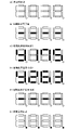
裏カバー980の内部には、パチンコ機1で行われる遊技の進行にかかる制御を行う主制御ユニット1300が設けられる。主制御ユニット1300には役物比率表示器1317が設けられる。役物比率表示器1317は、例えば、4桁の7セグメントLEDによって構成される。液晶表示装置によって役物比率表示器1317を構成してもよい。なお、役物比率表示器1317を主制御ユニット1300ではなく、払出制御基板ユニット950に設けられてもよい。
Inside the
また、役物比率を表示する表示装置を別に設けず、液晶表示装置1600、3114、244に役物比率を表示してもよい。この場合、液晶表示装置1600、3114、244のいずれかに役物比率を常時表示すると、役物比率を遊技者に報知でき、遊技者がパチンコ機の調子を確認できてよい。
Also, the character product ratio may be displayed on the liquid
役物比率は、後述するように、役物獲得球数÷総獲得球数で計算でき、例えば役物比率の数値が高い(例えば、90%)のパチンコ機は、大当たりによって多くの賞球が得られているので、調子がよいといえる。一方、役物比率の数値が低い(例えば、10%)のパチンコ機は、大当たり遊技が少なく、大当たり中の賞球が少ないので、調子が悪いといえる。したがって、遊技者は、役物比率の数値を考慮して、遊技するパチンコ機を選択できる。 As will be described later, the role ratio can be calculated by dividing the number of balls won by the total number of balls won. Since it is obtained, it can be said that it is in good condition. On the other hand, a pachinko machine with a low accessory ratio (for example, 10%) has few jackpot games and few prize balls during the jackpot, so it can be said to be in poor condition. Therefore, the player can select the pachinko machine to play in consideration of the value of the accessory ratio.
遊技者に役物比率を報知する態様として、役物比率の数値をメイン液晶表示装置1600に表示してもよい。例えば、役物比率が70%以上の場合は赤色で数値を表示し、枠ランプを赤点灯または点滅し、69%~30%の場合は緑色で数値を表示し、枠ランプを緑点灯または点滅する。役物比率の数値は、装飾図柄と間違えないような態様で表示するとよい。例えば、変動していないときの装飾図柄の表示位置と重ならない位置に表示したり、役物比率を示す数字の大きさを装飾図柄より小さくするなどの態様で表示するとよい。表示態様は何段階に分けてもよい。
As a mode for notifying the player of the role ratio, the numerical value of the role ratio may be displayed on the main liquid
また、役物比率の数値によってメイン液晶表示装置1600に表示される装飾図柄の態様を変えて、役物比率を遊技者に報知してもよい。例えば、役物比率が70%以上の場合は赤色で装飾図柄を表示し、枠ランプを赤点灯または点滅し、69%~30%の場合は緑色で装飾図柄を表示し、枠ランプを緑点灯または点滅する。表示態様は何段階に分けてもよい。
Also, the aspect of the decorative pattern displayed on the main liquid
また、扉枠3に備わる液晶表示装置244に表示してもよい。その際、上述した表示態様を変えてもよいし、役物比率だけでなく、他の情報とともに表示してもよい。他の情報とは、大当たり回数や大当たりの連続回数(所謂、連チャン回数)や持ち球数、残り残金などである。
Alternatively, the information may be displayed on the liquid
また、役物比率に限らず、後述する連続役物比率やベース値などを、前述したように態様を変化させて表示してもよい。役物比率、連続役物比率、ベース値は、各々表示態様を変えてもよい。 Further, not only the character product ratio, but also a continuous character product ratio, a base value, and the like, which will be described later, may be displayed by changing the mode as described above. The character product ratio, the continuous character product ratio, and the base value may be displayed in different ways.
主制御ユニット1300は、図13に示すように、一度閉めたら破壊せずに開けることができない構造で封印された透明の樹脂製の主制御基板ボックス1320に封入されており、プリント基板上に配置された部品を外部から見ることができる。さらに、例えば、裏カバー980が透明な樹脂で形成されている場合、パチンコ機1の裏面側から主制御ユニット1300を見ることができ、主制御ユニット1300に設けられる役物比率表示器1317をパチンコ機1の裏面側から見ることができる。役物比率表示器1317を主制御基板ボックス1320内に封入することによって、遊技機1の射幸性を低く見せるための役物比率表示器1317の不正な改造を防止でき、遊技機1の正確な射幸性を表示できる。
As shown in FIG. 13, the
なお、裏カバー980が不透明な樹脂で形成されている場合、役物比率表示器1317の位置の裏カバー980に穴を開けたり、役物比率表示器1317の位置を透明にすることによって、パチンコ機1の裏面側から役物比率表示器1317を見られるようにしてもよい。
If the
また、裏カバー980が透明な樹脂で形成されている場合でも、役物比率表示器1317の位置の裏カバー980の表面を平坦に形成したり、裏カバー980を薄く形成することによって、役物比率表示器1317をパチンコ機1の裏面側から見やすくしてもよい。
Further, even when the
パチンコ機1の裏面下方には、アウト口1111や入賞口2001、2005、2006などを経由して遊技領域5aから流出した遊技球を集合し、パチンコ機1の外部に排出する排出口が設けられている。なお、排出口から排出された遊技球は、島設備を通じて球タンク802に供給される。本実施例のパチンコ機1には、排出口から排出される遊技球を検出する排出球センサ3060を設ける。
At the bottom of the back surface of the
図13に示すように、主制御ユニット1300には役物比率表示スイッチ1318が設けられる。主制御基板ボックス1320には、役物比率表示スイッチ1318が操作可能な穴が設けられる。役物比率表示スイッチ1318の近傍のプリント基板上又は主制御基板ボックス1320に、役物比率の表示を操作するためのスイッチであることを表示(印刷、刻印、シールなど)するとよい。なお、役物比率表示スイッチ1318は、役物比率表示器1317の近くに設けることが望ましいが、主制御ユニット1300ではなくても、操作が容易な場所であれば、他の基板(例えば、演出制御基板4700、電源装置4112)や筐体4100や前面部材4200に設けてもよい。周辺制御ユニット1500や、主制御ユニット1300とは別体で設けられた中継基板や、枠側の電源基板ボックス930内の電源基板や、払出制御基板ユニット950に設けられてもよい。また、後述するように、役物比率表示スイッチ1318はRAMクリアスイッチと兼用してもよい。役物比率表示スイッチ1318を遊技者が操作できない位置に設けることで、遊技者が誤って操作することを防止できる。
As shown in FIG. 13, the
本体枠4の払出ユニット800は、本体枠ベース600の後側に取付けられる逆L字状の払出ユニットベース801と、払出ユニットベース801の上部に取付けられており上方へ開放された左右に延びた箱状で図示しない島設備から供給される遊技球を貯留する球タンク802と、球タンク802の下側で払出ユニットベース801に取付けられており球タンク802内の遊技球を正面視左方向へ誘導する左右に延びたタンクレール803と、払出ユニットベース801における正面視左側上部の後面に取付けられタンクレール803からの遊技球を蛇行状に下方へ誘導する球誘導ユニット820と、球誘導ユニット820の下側で払出ユニットベース801から着脱可能に取付けられており球誘導ユニット820により誘導された遊技球を払出制御基板ユニット950に収容された払出制御基板951(図17を参照)からの指示に基づいて一つずつ払出す払出装置830と、払出ユニットベース801の後面に取付けられ払出装置830によって払出された遊技球を下方へ誘導すると共に皿ユニット200における上皿201での遊技球の貯留状態に応じて遊技球を通常放出口又は満タン放出口の何れかから放出させる上部満タン球経路ユニット850と、払出ユニットベース801の下端に取付けられ上部満タン球経路ユニット850の通常放出口から放出された遊技球を前方へ誘導して前端から扉枠3の貫通球通路526へ誘導する通常誘導路及び満タン放出口から放出された遊技球を前方へ誘導して前端から扉枠3の満タン球受口530へ誘導する満タン誘導路を有した下部満タン球経路ユニット860と、を備えている。
The dispensing
本体枠4の基板ユニット900は、本体枠ベース600の後側に取付けられる基板ユニットベース910と、基板ユニットベース910の正面視左側で本体枠ベース600の後側に取付けられ内部に低音用のスピーカ921を有したスピーカユニット920と、基板ユニットベース910の後側で正面視右側に取付けられ内部に電源基板が収容されている電源基板ボックス930と、スピーカユニット920の後側に取付けられており内部にインターフェイス制御基板が収容されているインターフェイス制御基板ボックス940と、電源基板ボックス930及びインターフェイス制御基板ボックス940に跨って取付けられており内部に遊技球の払出しを制御する払出制御基板951が収容された払出制御基板ユニット950と、を備えている。
The
パチンコ機1の遊技盤5は、図8及び図9等に示すように、遊技球が打込まれる遊技領域5aの外周を区画し球発射装置680から発射された遊技球を遊技領域5aの上部に案内する外レール1001及び内レール1002を有した前構成部材1000と、前構成部材1000の後側に取付けられると共に遊技領域5aの後端を区画する平板状の遊技パネル1100と、遊技パネル1100の後側の下部に取付けられており上方に開放された箱状の基板ホルダ1200と、基板ホルダ1200の後側に取付けられておりパチンコ機1の遊技を制御するための主制御基板1310を有している主制御ユニット1300と、遊技パネル1100の前側で遊技領域5a内に取付けられ遊技領域5a内に打込まれた遊技球を受入可能な複数の入賞口を有した表ユニット(図示は省略)と、基板ホルダ1200の上側で遊技パネル1100の後側に取付けられている裏ユニット3000と、を備えている。
As shown in FIGS. 8 and 9, the
本実施形態のパチンコ機1は、上皿201に遊技球を貯留した状態で、遊技者がハンドルレバー504を回転操作すると、球発射装置680によってハンドルレバー504の回転角度に応じた強さで遊技球が遊技盤5の遊技領域5a内へ打込まれる。そして、遊技領域5a内に打込まれた遊技球が、図示しない入賞口に受入れられると、受入れられた入賞口に応じて、所定数の遊技球が払出装置830によって上皿201に払出される。この遊技球の払出しによって遊技者の興趣を高めることができるため、上皿201内の遊技球を遊技領域5a内へ打込ませることができ、遊技者に遊技を楽しませることができる。
In the
[2.遊技盤の全体構成]
次に、パチンコ機1の遊技盤5の全体構成について、図10乃至図16を参照して詳細に説明する。図10は、遊技盤の正面図である。図11は遊技盤を右前から見た斜視図であり、図12は遊技盤を左前から見た斜視図であり、図13は遊技盤を後ろから見た斜視図である。また、図14は遊技盤を主な構成毎に分解して前から見た分解斜視図であり、図15は遊技盤を主な構成毎に分解して後ろから見た分解斜視図である。更に、図16は、遊技盤における前構成部材及び表ユニットを遊技領域内の前後方向の略中央で切断した正面図である。
[2. Overall configuration of the game board]
Next, the overall configuration of the
本実施形態の遊技盤5は、遊技者がハンドルユニット500のハンドルレバー504を操作することで遊技球が打込まれる遊技領域5aを有している。また、遊技盤5は、遊技領域5aの外周を区画し外形が正面視略四角形状とされた前構成部材1000と、前構成部材1000の後側に取付けられており遊技領域5aの後端を区画する板状の遊技パネル1100と、遊技パネル1100の後側下部に取付けられている基板ホルダ1200と、基板ホルダ1200の後面に取付けられており遊技球を遊技領域5a内へ打込むことで行われる遊技内容を制御する主制御基板1310(図17を参照)を有している主制御ユニット1300と、を備えている。遊技パネル1100の前面において遊技領域5a内となる部位には、遊技球と当接する複数の障害釘が所定のゲージ配列で植設されている(図示は省略)。
The
また、遊技盤5は、主制御基板1310からの制御信号に基づいて遊技状況を表示し前構成部材1000の左下隅に遊技者側へ視認可能に取付けられている機能表示ユニット1400と、遊技パネル1100の後側に取付けられている周辺制御ユニット1500と、正面視において遊技領域5aの中央に配置されており所定の演出画像を表示可能なメイン液晶表示装置1600と、遊技パネル1100の前面に取付けられる表ユニット2000と、遊技パネル1100の後面に取付けられる裏ユニット3000と、を更に備えている。裏ユニット3000の後面にメイン液晶表示装置1600が取付けられていると共に、メイン液晶表示装置1600の後面に周辺制御ユニット1500が取付けられている。
The
遊技パネル1100は、外周が枠状の前構成部材1000の内周よりもやや大きく形成されていると共に透明な平板状のパネル板1110と、パネル板1110の外周を保持しており前構成部材1000の後側に取付けられると共に後面に裏ユニット3000が取付けられる枠状のパネルホルダ1120と、を備えている。
The
表ユニット2000は、遊技領域5a内に打込まれた遊技球を受入可能に常時開口している複数の一般入賞口2001と、複数の一般入賞口2001とは遊技領域5a内の異なる位置で遊技球を受入可能に常時開口している第一始動口2002と、遊技領域5a内の所定位置に取付けられており遊技球の通過を検知するゲート部2003と、遊技球がゲート部2003を通過することにより抽選される普通抽選結果に応じて遊技球の受入れが可能となる第二始動口2004と、第一始動口2002又は第二始動口2004への遊技球の受入れにより抽選される第一特別抽選結果又は第二特別抽選結果に応じて遊技球の受入れが何れかにおいて可能となる第一大入賞口2005及び第二大入賞口2006と、を備えている。第二大入賞口2006は、遊技球が流通する一つの流路に配置された第二上大入賞口2006aと第二下大入賞口2006bとの二つの大入賞口により構成されている(図16を参照)。
The
また、表ユニット2000は、遊技領域5a内の左右方向中央でアウト口1111の直上に取付けられており第一始動口2002及び第一大入賞口2005を有している始動口ユニット2100と、始動口ユニット2100の正面視左方で内レール1002に沿って取付けられており三つの一般入賞口2001を有しているサイドユニット下2200と、サイドユニット下2200の正面視左端上方に取付けられているサイドユニット上2300と、遊技領域5a内の略中央に取付けられており一つの一般入賞口2001、ゲート部2003、第二始動口2004、及び第二大入賞口2006を有している枠状のセンター役物2500と、を備えている。
In addition, the
裏ユニット3000は、パネルホルダ1120の後面に取付けられ前方が開放されている箱状で後壁に四角い開口部3010aを有している裏箱3010と、裏箱3010内の所定位置に配置されており表ユニット2000の一般入賞口2001に受入れられた遊技球を検知する複数の一般入賞口センサ3015と、裏箱3010の後面に取付けられておりメイン液晶表示装置1600を着脱可能に取付けるためのロック機構3020と、裏箱3010内の正面視右端に取付けられておりセンター役物2500の一般入賞口2001や第二始動口2004に受入れられた遊技球を排出するための右球通路ユニット3030と、裏箱3010内の正面視右下隅の前端付近に取付けられておりセンター役物2500の第二大入賞口2006や第二アウト口2543cに受入れられた遊技球を排出するための右下球通路ユニット3035と、を備えている。
The
また、裏ユニット3000は、裏箱3010の後面に取付けられている上中継基板3040と、上中継基板3040の後側を覆う上中継基板カバー3041と、裏箱3010の後面に回動可能に取付けられている箱状の演出駆動基板ボックス3042と、演出駆動基板ボックス3042内に収容されている演出駆動基板3043と、裏箱3010の後面に取付けられているパネル中継基板3044と、パネル中継基板3044の後側を覆うパネル中継基板カバー3045と、を備えている。
The
更に、裏ユニット3000は、裏箱3010内の前端で正面視左辺側の上下方向中央から上寄りに取付けられている裏左中装飾ユニット3050と、裏箱3010内における開口部3010aの下方で裏箱3010の後壁付近に取付けられている裏下後可動演出ユニット3100と、裏箱3010内における開口部3010aの上方で正面視左側に取付けられている裏上左可動演出ユニット3200と、裏箱3010内で開口部3010aの正面視左側に取付けられている裏左可動演出ユニット3300と、裏箱3010内における開口部3010aの上方で左右方向中央から正面視右端までにかけて取付けられている裏上中可動演出ユニット3400と、裏箱3010内における開口部3010aの下方で裏下後可動演出ユニット3100の前方に取付けられている裏下前可動演出ユニット3500と、を備えている。
Further, the
[2-1.前構成部材]
次に、前構成部材1000について、主に図14及び図15を参照して説明する。前構成部材1000は、正面視の外形が略正方形とされ、内形が略円形状に前後方向へ貫通しており、内形の内周によって遊技領域5aの外周を区画している。この前構成部材1000は、正面視で左右方向中央から左寄りの下端から時計回りの周方向へ沿って円弧状に延び正面視左右方向中央上端を通り過ぎて右斜め上部まで延びた外レール1001と、外レール1001に略沿って前構成部材1000の内側に配置され正面視左右方向中央下部から正面視左斜め上部まで円弧状に延びた内レール1002と、内レール1002の下端の正面視右側で遊技領域5aの最も低くなった位置に形成されており後方へ向かって低くなるように傾斜しているアウト誘導部1003と、を備えている。
[2-1. Front component]
Next, the
また、前構成部材1000は、アウト誘導部1003の正面視右端から前構成部材1000の右辺付近まで右端側が僅かに高くなるように直線状に傾斜している右下レール1004と、右下レール1004の右端から前構成部材1000の右辺に沿って外レール1001の上端の下側まで延びており上部が前構成部材1000の内側へ湾曲している右レール1005と、右レール1005の上端と外レール1001の上端とを繋いでおり外レール1001に沿って転動して来た遊技球が当接する衝止部1006と、を備えている。
In addition, the
また、前構成部材1000は、内レール1002の上端に回動可能に軸支され、外レール1001との間を閉鎖するように内レール1002の上端から上方へ延出した閉鎖位置と正面視時計回りの方向へ回動して外レール1001との間を開放した開放位置との間でのみ回動可能とされると共に閉鎖位置側へ復帰するように図示しないバネによって付勢された逆流防止部材1007を、備えている。
The front
レール1001、1002の出口付近(望ましくは、逆流防止部材1007を通過した直後)の遊技盤5の裏面側には、遊技領域5aに打ち込まれた遊技球を検出する発射球センサ1020を設ける。例えば、発射球センサ1020は、磁気センサで構成し、逆流防止部材1007を通過して遊技領域5aに流入した遊技球を検出すると、信号を出力する。なお、発射球センサ1020は、遊技領域内で遊技球が必ず通過する位置に設けてもよい。遊技盤5における発射球センサ1020の位置を固定化することによって、複数機種間で仕様を共通化でき、製造現場での検査やホールでの設置後検査が容易になる。
A
また、レール1001、1002の出口付近などの遊技領域5aの上流に設けた発射球センサ1020は、入賞口センサが遊技球の入賞を検出する前にアウト球を検出する。すなわち、アウト球、賞球の順で遊技球を検出するので、アウト球として計数されていない遊技球に起因した賞球を検出せず、正確にベース値を計算できる。
A
[2-2.遊技パネル]
次に、遊技パネル1100について、主に図14及び図15を参照して説明する。遊技パネル1100は、外周が枠状の前構成部材1000の内周よりもやや大きく形成されていると共に透明な合成樹脂で形成されている平板状のパネル板1110と、パネル板1110の外周を保持しており前構成部材1000の後側に取付けられると共に後面に裏ユニット3000が取付けられる枠状のパネルホルダ1120と、を備えている。遊技パネル1100のパネル板1110は、遊技領域5a内において最も低い位置となる部位に前後に貫通しているアウト口1111が形成されている。また、パネル板1110には、前後に貫通しており表ユニット2000を取付けるための開口部1112が複数形成されている。
[2-2. Game panel]
Next, the
遊技パネル1100のパネルホルダ1120は、パネル板1110を後側から着脱可能に保持している。また、パネルホルダ1120は、裏ユニット3000を取付けるための取付孔と、位置決め孔とが後面に複数形成されている。
The
遊技パネル1100を前構成部材1000の後側に取付けた状態では、前構成部材1000のアウト誘導部1003の後側にパネル板1110のアウト口1111が開口した状態となる。これにより、遊技領域5aの下端へ流下した遊技球が、アウト誘導部1003によって後側のアウト口1111へ誘導され、アウト口1111を通って遊技パネル1100の後側へ排出される。
When the
[2-3.基板ホルダ]
次に、基板ホルダ1200について、図11乃至図15を参照して説明する。基板ホルダ1200は、上方及び前方が開放された横長の箱状に形成されており、底面が左右方向中央へ向かって低くなるように傾斜している。この基板ホルダ1200は、遊技盤5に組立てた状態では、遊技パネル1100の後側に取付けられている裏ユニット3000の下部を下側から覆うことができる。これにより、アウト口1111を通って遊技パネル1100の後側へ排出された遊技球、及び、表ユニット2000及び裏ユニット3000から下方へ排出された遊技球、を全て受けることができ、底面に形成された排出部1201(図14を参照)から下方へ排出させることができる。
[2-3. Substrate holder]
Next, the
[2-4.主制御基板ユニット]
次に、主制御ユニット1300について、図11乃至図15、及び図17を参照して説明する。主制御ユニット1300は、基板ホルダ1200の後面に着脱可能に取付けられている。この主制御ユニット1300は、遊技内容及び遊技球の払出し等を制御する主制御基板1310と、主制御基板1310を収容しており基板ホルダ1200に取付けられる主制御基板ボックス1320と、を備えている。
[2-4. Main control board unit]
Next, the
主制御基板ボックス1320は、複数の封印機構を備えており、一つの封印機構を用いて主制御基板ボックス1320を閉じると、次に、主制御基板ボックス1320を開けるためにはその封印機構を破壊する必要があり、主制御基板ボックス1320の開閉の痕跡を残すことができる。従って、開閉の痕跡を見ることで、主制御基板ボックス1320の不正な開閉を発見することができ、主制御基板1310への不正行為に対する抑止力が高められている。
The main
[2-5.機能表示ユニット]
次に、機能表示ユニット1400について、図10乃至図12を参照して説明する。機能表示ユニット1400は、図示するように、遊技領域5aの外側で前構成部材1000の左下隅に取付けられている。この機能表示ユニット1400は、遊技盤5をパチンコ機1に組立てた状態で、扉枠3の貫通口111を通して前方(遊技者側)から視認することができる(図1を参照)。この機能表示ユニット1400は、主制御基板1310からの制御信号に基づき複数のLEDを用いて、遊技状態(遊技状況)や、普通抽選結果や特別抽選結果等を表示するものである。
[2-5. Function display unit]
Next, the
機能表示ユニット1400は、詳細な図示は省略するが、遊技状態を表示する一つのLEDからなる状態表示器と、ゲート部2003に対する遊技球の通過により抽選される普通抽選結果に基づいて二つのLEDを点滅制御することにより普通図柄を変動表示した後にこれら二つのLEDを普通抽選結果に応じた点灯態様で表示させる普通図柄表示器と、ゲート部2003に対する遊技球の通過に係る普通図柄の変動表示のうち未だ変動表示の開始条件が成立していない変動表示の個数である保留数を表示する二つのLEDからなる普通保留表示器と、第一始動口2002への遊技球の受入れ(始動入賞の発生)により抽選された第一特別抽選結果に基づいて八つのLEDを点滅制御することにより第一特別図柄を変動表示した後にこれら八つのLEDを第一特別抽選結果に応じた点灯態様で表示させる第一特別図柄表示器と、第一始動口2002への遊技球の受入れに係る第一特別図柄の変動表示のうち未だ変動表示の開始条件が成立していない変動表示の個数である保留数を表示する二つのLEDからなる第一特別保留数表示器と、第二始動口2004への遊技球の受入れ(始動入賞の発生)により抽選された第二特別抽選結果に基づいて八つのLEDを点滅制御することにより第二特別図柄を変動表示した後にこれら八つのLEDを第二特別抽選結果に応じた点灯態様で表示させる第二特別図柄表示器と、第二始動口2004への遊技球の受入れに係る第二特別図柄の変動表示のうち未だ変動表示の開始条件が成立していない変動表示の個数である保留数を表示する二つのLEDからなる第二特別保留数表示器と、第一特別抽選結果又は第二特別抽選結果が「大当り」等の時に、第一大入賞口2005や第二大入賞口2006の開閉パターンの繰返し回数(ラウンド数)を表示する二つのLEDからなるラウンド表示器と、を主に備えている。なお、機能表示ユニット1400の一部の表示器(例えば、第一特別図柄表示器)を7セグメントLEDで構成してもよい。
Although detailed illustration is omitted, the
この機能表示ユニット1400では、備えられているLEDを、適宜、点灯、消灯、及び、点滅、等させることにより、保留数や図柄等を表示することができる。
In this
[2-6.周辺制御ユニット]
次に、周辺制御ユニット1500について、図13及び図15を参照して説明する。周辺制御ユニット1500は、裏ユニット3000の裏箱3010の後面に取付けられている。周辺制御ユニット1500は、主制御基板1310からの制御信号に基づいて遊技者に提示する演出を制御する周辺制御基板1510(図17を参照)と、周辺制御基板1510を収容している周辺制御基板ボックス1520と、を備えている。周辺制御基板1510は、発光演出、サウンド演出、及び可動演出、等を制御するための周辺制御部1511と、演出画像を制御するための液晶表示制御部1512と、を備えている(図17を参照)。
[2-6. Peripheral control unit]
Next, the
[2-7.メイン液晶表示装置]
次に、メイン液晶表示装置1600について、図10乃至図16を参照して説明する。メイン液晶表示装置1600は、正面視において遊技領域5aの中央に配置されており、遊技パネル1100の後側に裏ユニット3000の裏箱3010を介して取付けられている。詳述すると、メイン液晶表示装置1600は、裏箱3010の後壁の略中央の後面に対して、着脱可能に取付けられている。このメイン液晶表示装置1600は、遊技盤5を組立てた状態で、枠状のセンター役物2500の枠内を通して、前側(遊技者側)から視認することができる。このメイン液晶表示装置1600は、白色LEDをバックライトとしたフルカラーの表示装置であり、静止画像や動画を表示することができる。
[2-7. Main liquid crystal display device]
Next, the main liquid
メイン液晶表示装置1600は、図14及び図15に示すように、正面視左側面から外方へ突出している二つの左固定片1601と、正面視右側面から外方へ突出している右固定片1602と、を備えている。このメイン液晶表示装置1600は、液晶画面を前方へ向けた状態で、後述する裏箱3010の枠状の液晶取付部内の正面視左内周面に開口している二つの固定溝3010cに、裏箱3010の斜め後方から二つの左固定片1601を挿入した上で、右固定片1602側を前方へ移動させて、右固定片1602をロック機構3020の開口部内に挿入し、ロック機構3020を下方へスライドさせることにより、裏箱3010に取付けられる。
As shown in FIGS. 14 and 15, the main liquid
[2-8.表ユニットの全体構成]
次に、表ユニット2000について、主に図10乃至図12、図14乃至図16を参照して説明する。遊技盤5の表ユニット2000は、遊技パネル1100のパネル板1110に、前方から取付けられており、前端がパネル板1110の前面よりも前方へ突出していると共に、後端が開口部1112を貫通してパネル板1110の後面よりも後方へ突出している。本実施形態の表ユニット2000は、遊技領域5a内に打込まれた遊技球を受入可能としており常時開口している複数の一般入賞口2001と、複数の一般入賞口2001とは遊技領域5a内の異なる位置で遊技球を受入可能に常時開口している第一始動口2002と、遊技領域5a内の所定位置に取付けられており遊技球の通過を検知するゲート部2003と、遊技球がゲート部2003を通過することにより抽選される普通抽選結果に応じて遊技球の受入れが可能となる第二始動口2004と、第一始動口2002又は第二始動口2004への遊技球の受入れにより抽選される第一特別抽選結果又は第二特別抽選結果に応じて何れかにおいて遊技球の受入れが可能となる第一大入賞口2005及び第二大入賞口2006と、を備えている。
[2-8. Overall configuration of table unit]
Next, the
複数(ここでは四つ)の一般入賞口2001は、三つが遊技領域5a内の下部に配置されており、残りの一つが遊技領域5a内における正面視右上付近に配置されている。第一始動口2002は、遊技領域5a内の左右方向中央でアウト口1111の直上に配置されている。ゲート部2003は、遊技領域5a内における正面視右上で衝止部1006の略直下に配置されている。第二始動口2004は、ゲート部2003の直下から正面視右寄りに配置されている。上述した複数の一般入賞口2001のうち遊技領域5a内の正面視右上付近に配置されている一般入賞口2001は、第二始動口2004の直上に配置されている。第一大入賞口2005は、第一始動口2002とアウト口1111との間に配置されている。第二大入賞口2006は、第一始動口2002の正面視右方で第一大入賞口2005よりも上方に配置されている。
Three of the plurality (here, four) of the general winning
表ユニット2000における第二大入賞口2006は、図16に示すように、遊技球が流通する一つの流路に沿って配置された第二上大入賞口2006aと第二下大入賞口2006bとにより構成されている。第二大入賞口2006は、第二上大入賞口2006aが遊技領域5a内における正面視右下付近に配置されており、第二下大入賞口2006bが第二上大入賞口2006aの正面視左側で下方に配置されている。
As shown in FIG. 16, the second large winning
また、表ユニット2000は、遊技領域5a内の左右方向中央でアウト口1111の直上に取付けられており第一始動口2002及び第一大入賞口2005を有している始動口ユニット2100と、始動口ユニット2100の正面視左方で内レール1002に沿って取付けられており三つの一般入賞口2001を有しているサイドユニット下2200と、サイドユニット下2200の正面視左端上方に取付けられているサイドユニット上2300と、遊技領域5a内の略中央に取付けられており一つの一般入賞口2001、ゲート部2003、第二始動口2004、及び第二大入賞口2006を有している枠状のセンター役物2500と、を備えている。
In addition, the
[2-8a.始動口ユニット]
次に、表ユニット2000の始動口ユニット2100について、説明する。始動口ユニット2100は、遊技領域5a内において、左右方向中央の下端部付近でアウト口1111の直上に配置されており、パネル板1110に前方から取付けられている。この始動口ユニット2100は、第一始動口2002及び第一大入賞口2005を有している。
[2-8a. starting unit]
Next,
始動口ユニット2100は、パネル板1110の前面に取付けられ左右に延びた矩形状で前後に貫通している第一大入賞口2005を有した平板状のユニットベース2101と、ユニットベース2101における第一大入賞口2005の上方で左右方向略中央の上部から前方へ突出しており第一始動口2002を形成している球受部2102と、ユニットベース2101の後側に取付けられており第一始動口2002に受入れられた遊技球を下方へ誘導する球誘導部2103と、球誘導部2103に取付けられており第一始動口2002に受入れられた遊技球を検知する第一始動口センサ2104と、第一大入賞口2005を閉鎖するようにユニットベース2101の後面に取付けられている第一アタッカユニット2110と、を備えている。
The starting
始動口ユニット2100の第一アタッカユニット2110は、第一大入賞口2005を後方から閉鎖するようにユニットベース2101の後面に取付けられ前端が第一大入賞口2005と略同じ大きさで前方に開放されている箱状のユニットケース2111と、第一大入賞口2005を開閉可能にユニットケース2111の前端で下辺が回動可能に支持されている横長矩形状で平板状の第一大入賞口扉部材2112と、ユニットケース2111内に取付けられており第一大入賞口扉部材2112を開閉駆動させる第一アタッカソレノイド2113と、ユニットケース2111内に取付けられており第一大入賞口2005に受入れられた遊技球を検知する第一大入賞口センサ2114と、ユニットケース2111の上面に取付けられており第一始動口センサ2104、第一アタッカソレノイド、及び第一大入賞口センサ2114と主制御基板1310との接続を中継する始動口ユニット中継基板2115と、ユニットケース2111の下部に取付けられており第一大入賞口2005を発光装飾させるための始動口ユニット装飾基板(図示は省略)と、を備えている。
The first attacker unit 2110 of the starting
第一始動口2002を形成している球受部2102は、遊技球を一度に一つのみ受入可能な大きさで上方に向かって開口している。ユニットベース2101を貫通している第一大入賞口2005は、遊技球を一度に複数(例えば、4個~6個)受入可能な大きさで前方に向かって開口している。
The
始動口ユニット2100は、球受部2102により形成されている第一始動口2002が上方に向かって開口しており、第一始動口2002に受入れられた遊技球を、球誘導部2103によりユニットベース2101の後側で下方へ誘導し、第一始動口センサ2104に検知させた後に、第一アタッカユニット2110を貫通して下方へ排出させることができる。本実施形態では、第一始動口センサ2104が二つ備えられており、主制御基板1310では、所定の時間範囲内で二つの第一始動口センサ2104が遊技球を検知すると、第一始動口2002に遊技球が受入れられたと判断するようになっている。これにより、第一始動口2002への不正な工具の挿入による不正行為を検知することができる。
In the starting
始動口ユニット2100では、ユニットベース2101の後面に第一アタッカユニット2110を取付けることにより、第一アタッカユニット2110の第一大入賞口扉部材2112が、ユニットベース2101に開口している第一大入賞口2005内に後方から挿入されて、第一大入賞口2005を閉鎖している。この第一大入賞口扉部材2112は、第一大入賞口2005を閉鎖している直立した状態で、下辺の左右両端部がユニットケース2111によって回動可能に取付けられており、上辺が前方且つ下方へ移動するように回動させることで第一大入賞口2005を閉状態から開状態とすることができる。
In the starting
第一アタッカユニット2110の第一大入賞口扉部材2112は、通常の状態(第一アタッカソレノイド2113が非通電の状態)では直立して、第一大入賞口2005を閉鎖している。そして、第一アタッカソレノイド2113が遊技状態に応じて通電されると、上辺が前方且つ下方へ移動するように第一大入賞口扉部材2112が回動して、上辺が下辺よりもやや上方へ位置した状態となる。つまり、第一大入賞口扉部材2112が、第一大入賞口2005の下辺から前方へ向かって高くなるように傾斜した状態となる。
The first large prize winning
この状態で第一大入賞口2005の前方を遊技球が流下して第一大入賞口扉部材2112に当接すると、第一大入賞口扉部材2112の傾斜により遊技球の流通方向が下方から後方へと変化し、第一大入賞口2005に受入れられてユニットケース2111内に進入することとなる。そして、第一大入賞口2005に受入れられた遊技球は、第一大入賞口センサ2114により検知された後に、ユニットケース2111の下面から下方へ排出される。
In this state, when the game ball flows down in front of the first big
[3.制御構成]
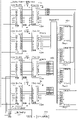
次に、パチンコ機1の各種制御を行う制御構成について、図17を参照して説明する。図17は、パチンコ機の制御構成を概略的に示すブロック図である。パチンコ機1の主な制御構成は、図示するように、遊技盤5に取付けられる主制御基板1310及び周辺制御基板1510と、本体枠4に取付けられる払出制御基板951と、から構成されており、夫々の制御が分担されている。主制御基板1310は、遊技動作(遊技の進行)を制御する。周辺制御基板1510は、主制御基板1310からのコマンドに基いて遊技中の各種演出装置を制御する周辺制御部1511と、周辺制御部1511からのコマンドに基いてメイン液晶表示装置1600や上皿液晶表示装置244等での演出画像の表示を制御する液晶表示制御部1512と、を備えている。払出制御基板951は、遊技球の払出し等を制御する払出制御部952と、ハンドルレバー504の回転操作による遊技球の発射を制御する発射制御部953と、を備えている。
[3. control configuration]
Next, a control configuration for performing various controls of the
[3-1.主制御基板]
遊技の進行を制御する主制御基板1310は、各種処理プログラムや各種コマンドを記憶するROM1313や一時的にデータを記憶するRAM1312等が内蔵されるマイクロプロセッサである主制御MPU1311と、入出力デバイス(I/Oデバイス)としての主制御I/Oポート1314と、各種検出スイッチからの検出信号が入力される主制御入力回路1315と、各種ソレノイドを駆動するための主制御ソレノイド駆動回路1316と、主制御MPU1311に内蔵されているRAMに記憶された情報を完全に消去するためのRAMクリアスイッチと、を備えている。主制御MPU1311は、その内蔵されたROMやRAMのほかに、その動作(システム)を監視するウォッチドックタイマや不正を防止するための機能等も内蔵されている。
[3-1. Main control board]
The
主制御基板1310の主制御MPU1311は、第一始動口2002に受入れられた遊技球を検出する第一始動口センサ2104、第二始動口2004に受入れられた遊技球を検出する第二始動口センサ2551、一般入賞口2001に受入れられた遊技球を検出する一般入賞口センサ3015、ゲート部2003を通過した遊技球を検知するゲートセンサ2547、第一大入賞口2005に受入れられた遊技球を検知する第一大入賞口センサ2114、第二大入賞口2006としての第二上大入賞口2006a及び第二下大入賞口2006bに受入れられた遊技球を検知する第二上大入賞口センサ2554及び第二下大入賞口センサ2557、排出球センサ3060、発射球センサ1020及び遊技領域5a内における不正な磁気を検知する磁気検出センサ、等からの検出信号が夫々主制御I/Oポート1314を介して入力される。
The
主制御MPU1311は、これらの検出信号に基づいて、主制御I/Oポート1314から主制御ソレノイド駆動回路に制御信号を出力することにより、始動口ソレノイド2550、第一アタッカソレノイド2113、第二上アタッカソレノイド2553、及び第二下アタッカソレノイド2556に駆動信号を出力したり、主制御I/Oポート1314から機能表示ユニット1400の第一特別図柄表示器、第二特別図柄表示器、第一特別図柄記憶表示器、第二特別図柄記憶表示器、普通図柄表示器、普通図柄記憶表示器、遊技状態表示器、ラウンド表示器、等に駆動信号を出力したりする。
Based on these detection signals, the
なお、本実施形態おいて、第一始動口センサ2104、第二始動口センサ2551、ゲートセンサ2547、第一大入賞口センサ2114、第二上大入賞口センサ2554、及び第二下大入賞口センサ2557には、非接触タイプの電磁式の近接スイッチを用いているのに対して、一般入賞口センサ3015には、接触タイプのON/OFF動作式のメカニカルスイッチを用いている。これは、遊技球が、第一始動口2002や第二始動口2004に頻繁に入球すると共に、ゲート部2003を頻繁に通過するため、第一始動口センサ2104、第二始動口センサ2551、及びゲートセンサ2547による遊技球の検出も頻繁に発生する。このため、第一始動口センサ2104、第二始動口センサ2551、及びゲートセンサ2547には、耐久性が高く寿命の長い近接スイッチを用いている。また、遊技者にとって有利となる有利遊技状態(「大当り」遊技、等)が発生すると、第一大入賞口2005や第二大入賞口2006が開放(又は、拡大)されて遊技球が頻繁に入球するため、第一大入賞口センサ2114、第二上大入賞口センサ2554、及び第二下大入賞口センサ2557による遊技球の検出も頻繁に発生する。このため、第一大入賞口センサ2114、第二上大入賞口センサ2554、及び第二下大入賞口センサ2557にも、耐久性が高く寿命の長い近接スイッチを用いている。これに対して、遊技球が頻繁に入球しない一般入賞口2001には、一般入賞口センサ3015による検出も頻繁に発生しない。このため、一般入賞口センサ3015には、近接スイッチより寿命が短いメカニカルスイッチを用いている。
In addition, in this embodiment, the first
また、主制御MPU1311は、遊技に関する各種情報(遊技情報)及び払出しに関する各種コマンド等を払出制御基板951に送信したり、この払出制御基板951からのパチンコ機1の状態に関する各種コマンド等を受信したりする。更に、主制御MPU1311は、メイン液晶表示装置1600等で実行される遊技演出の制御に関する各種コマンド及びパチンコ機1の状態に関する各種コマンドを、主制御I/Oポート1314を介して周辺制御基板1510の周辺制御部1511に送信したりする。なお、主制御MPU1311は、払出制御基板951からパチンコ機1の状態に関する各種コマンドを受信すると、これらの各種コマンドを整形して周辺制御部1511に送信する。
In addition, the
主制御基板1310には、電源基板ボックス930内の電源基板から各種電圧が供給されている。この主制御基板1310に各種電圧を供給する電源基板は、電源遮断時にでも所定時間、主制御基板1310に電力を供給するためのバックアップ電源としての電気二重層キャパシタ(以下、単に「キャパシタ」と記載する。)を備えている。このキャパシタにより主制御MPU1311は、電源遮断時にでも電源断時処理において各種情報をRAM1312に記憶することができる。この記憶した各種情報は、電源投入時に主制御基板1310のRAMクリアスイッチが操作されると、RAM1312から完全に消去(クリア)される。このRAMクリアスイッチの操作信号(検出信号)は、払出制御基板951にも出力される。
Various voltages are supplied to the
また、主制御基板1310には、停電監視回路が設けられている。この停電監視回路は、電源基板から供給される各種電圧の低下を監視しており、それらの電圧が停電予告電圧以下となると、停電予告として停電予告信号を出力する。この停電予告信号は、主制御I/Oポート1314を介して主制御MPU1311に入力される他に、払出制御基板951等にも出力されている。
Further, the
主制御基板1310には、パチンコ機1の裏面側から視認可能な位置に役物比率表示器1317が取り付けられる。役物比率表示器1317は、主制御MPU1311が計算した役物比率を表示する。
A
また、主制御基板1310には、役物比率表示スイッチ1318が設けられる。役物比率表示スイッチ1318は、モーメンタリ動作をする押ボタンスイッチで構成するとよいが、他の形式のスイッチでもよい。役物比率表示スイッチ1318を操作すると、役物比率表示器1317に役物比率を表示する。なお、役物比率表示器1317は常時、役物比率を表示し、役物比率表示スイッチ1318の操作によって表示内容を切り替えてもよい。
Also, the
図18は、主制御MPU1311内の構成を示す図である。
FIG. 18 is a diagram showing the internal configuration of the
主制御MPU1311は、CPU13111、RAM1312、ROM1313、乱数発生回路13112、パラレル入力ポート13113、シリアル通信回路13114、タイマ回路13115、割込コントローラ13116、外部バスインターフェイス13117、クロック回路13118、照合用ブロック13119、固有情報13120、演算回路13121及びリセット回路13122を有する。
The
CPU13111は、ROM1313に記憶されたプログラムを実行する。RAM1312は、プログラム実行時に必要なデータを記憶する。
The
主制御MPU1311には、一つ以上の乱数発生回路13112が設けられている。乱数発生回路13112は、変動表示ゲームの結果(第一特別抽選結果、第二特別抽選結果)の抽選結果や変動表示ゲームの演出内容を決定するための乱数を提供する。乱数発生回路13112は、例えば、主制御MPU1311に供給されるクロック周期(又は、該クロック周期を分周した信号)のタイミングで更新した乱数を出力する、いわゆるハード乱数生成手段である。乱数発生回路13112が生成するハード乱数は、特別図柄の当たりの抽選や、特別図柄変動表示ゲームの当たり図柄の抽選や、普通図柄の当たりの抽選に用いられる。
One or more random
パラレル入力ポート13113は、主制御入力回路1315を経由して各種検出スイッチからの検出信号が入力されるポートである。
A
シリアル通信回路13114は、主制御I/Oポート1314を介して、遊技演出の制御に関する各種コマンド及びパチンコ機1の状態に関する各種コマンドを周辺制御基板1510の周辺制御部1511と送受信する。また、シリアル通信回路13114は、主制御I/Oポート1314を介して、遊技に関する各種情報(遊技情報)及び遊技球の払い出しに関する各種コマンド等を払出制御基板951と送受信する。さらに、シリアル通信回路13114は、役物比率を表示するためのデータを役物比率表示器1317に送信する。シリアル通信回路13114の詳細な構成は、図20を参照して後述する。
The
タイマ回路13115は、タイマ割り込みや各種時間制御のためのタイマである。割込コントローラ13116は、CPU13111に対する各種の割り込み(一般割り込み、ソフトウェアでマスク不可能なNMI)を制御する。すなわち、割込コントローラ13116が割り込みを検出した場合、割り込みの種類毎に定められたベクターテーブルを参照し、ベクターテーブルに設定されたアドレスにジャンプする。
A
外部バスインターフェイス13117は、主制御MPU1311の内部バスを外部のデバイスと接続するためのインターフェイスである。外部バスインターフェイス13117からは、I/Oリクエスト(IORQ)、リード(RD)、ライト(WR)、16ビットのアドレス(A0~A15)、8ビットのデータ(D0~D7)が入出力できる。
The
クロック回路13118は、入力された外部クロック信号(例えば、32MHz)から主制御MPU1311の内部クロックを生成する。また、クロック回路13118は、入力されたクロック信号に、設定された数の分周をして、CLKO端子から外部に出力する。例えば、役物比率表示器1317のドライバ回路13171(図28参照)に供給するクロック信号を出力してもよい。
A
照合用ブロック13119は、ROM1313が不正に改造されていないかを所定のコードを用いて照合する機能ブロックである。固有情報13120は、主制御MPU1311に固有のIDであり、チップの製造時に書き換え不能に書き込まれている。
A
演算回路13121は、ROM1313に記録されたプログラムによらない演算機能を提供する。この演算機能は、チップの製造時に固定的に書き込まれている。
The
リセット回路13122は、指定外走行禁止回路、ウォッチドッグタイマ及びユーザリセット機能を有する。指定外走行禁止回路は、ROM1313の所定外のアドレスにCPU13111がアクセスした場合、不正なプログラムによるアクセスであると推定し、主制御MPU1311の動作をリセットする。ウォッチドッグタイマは、所定のタイマ時間が経過した際にタイムアウト信号を出力し、主制御MPU1311の動作をリセットする。ユーザリセット機能は、SRST端子に入力されたリセット信号によって、主制御MPU1311の動作をリセットする。
The
図19は、演算回路13121の詳細な構成を示すブロック図である。
FIG. 19 is a block diagram showing the detailed configuration of the
演算回路13121は、演算結果についてプログラムによらない演算機能を提供するものであり、乗算回路131211及び除算回路131215を有する。
The
乗算回路131211は、所定ビット数(例えば、16ビット)の二つの値を乗じて、32ビットの積を出力する演算回路であり、乗算関数によって入力値(乗数、被乗数)を積に変換して出力する変換回路として機能する。
The
主制御MPU1311のCPU13111は、乗算入力レジスタA131212及び乗算入力レジスタB131213に16ビット以下の乗数及び被乗数を格納する。乗算回路131211は、二つの16ビットの乗算入力レジスタ131212、131213に格納された値を所定のタイミングで読み出し、二つの値を乗じた結果を乗算結果レジスタ131214に格納する。CPU13111は、乗算結果レジスタ131214から乗算結果を取得する。乗算入力レジスタ131212、131213への値の書き込みから乗算結果レジスタ131214への演算結果の格納までは、所定の時間(例えば1クロック)で完了するように構成されており、CPU13111は、乗算入力レジスタ131212、131213に値を格納して、所定のクロック数が経過した後に、乗算結果レジスタ131214を参照して乗算結果を取得できる。
The
除算回路131215は、所定ビット数(例えば、32ビット)の被除数を所定ビット数(例えば、32ビット)の除数で割って、32ビットの商と32ビットの剰余を出力する演算回路であり、除算関数によって入力値(除数、被除数)を商及び剰余変換して出力する変換回路として機能する。
The
主制御MPU1311のCPU13111は、除算入力レジスタA131216に32ビット以下の被除数を格納し、除算入力レジスタB131217に32ビット以下の除数を格納する。除算回路131215は、二つの32ビットの除算入力レジスタ131216、131217の両方に値が格納されことを検出すると、格納された値を所定のタイミングで読み出し、被除数を除数で割った結果である商を除算結果レジスタA131218に格納し、剰余を除算結果レジスタB131219に格納する。また、除算回路131215は、除算入力レジスタ131216、131217に格納された値を読み込むと、読み込んだ値を消去し、当該レジスタをクリアするとよい。また、除算回路131215は、スタート命令が入力されたタイミングで、除算入力レジスタ131216、131217に格納された値を読み出し、除算結果を除算結果レジスタ131218、131219に格納してもよい。この場合、除算入力レジスタ131216、131217に格納された値を、読み込みタイミングで消去しなくてもよい。また、除算入力レジスタ131216、131217は、既に値が格納されていても(格納されている値をクリアせずに)、さらに、値を上書き可能でもよい。
The
CPU13111は、除算結果レジスタ131218、131219から除算結果を取得する。除算入力レジスタ131216、131217への値の書き込みから除算結果レジスタ131218、131219への演算結果の格納までは、所定の時間(例えば32クロック)で完了するように構成されており、CPU13111は、除算入力レジスタ131216、131217に値を格納して、所定のクロック数が経過した後に、除算結果レジスタ131218、131219をそれぞれ参照して商及び剰余を取得できる。
The
本実施例のパチンコ機1では、後述するように、ベース値を計算するために除算処理が必要であり、CPU13111がプログラムを実行する除算は複数の乗算及び減算で実行されるので相当の時間がかかるものである。このため、タイマ割込み処理毎にベース計算処理を実行するのは困難であり、遅滞ないベース値の表示は困難であった。これに対し、演算回路13121を用いて除算処理を行うことによって、ベース値の計算に必要な時間を短縮でき、一つのタイマ割込み処理において複数回ベース値を計算できる(図75、図80参照)。また、演算回路13121の除算入力レジスタ131216、131217への値の書き込みから除算結果レジスタA131218からの演算結果の読み出しまでの間、CPU13111は除算処理のために占有されないので、他の処理を実行でき、タイマ割込み処理中のベース算出処理を効率的に実行できる。
In the
図20は、シリアル通信回路13114の構成を示す図である。
FIG. 20 shows a configuration of the
シリアル通信回路13114は、四つのデータ送受信回路を有しており、各データ送受信回路が1チャネル分のデータを所定のデバイスと送受信する。なお、図20では、データ送信回路のみを図示し、データ受信回路(例えば、1チャネル分が実装)の説明は省略する。
The
本実施例の遊技機では、シリアル通信回路13114は、前述したように、周辺制御基板1510との通信に使用されるチャネル0、払出制御基板951との通信に使用されるチャネル1、役物比率表示器1317のドライバ回路13171との通信に使用されるチャネル2の三つのチャネルが使用され、チャネル3は未使用である。
In the gaming machine of the present embodiment, the
シリアル通信回路13114は、データレジスタ3141、送信データレジスタ3142、パリティ生成回路3143、送信用シフトレジスタ3144、コマンドステータスレジスタ3145、通信設定レジスタ3146、送信トリガ設定レベルレジスタ3147、ボーレートレジスタ3148及びボーレート生成回路3149を有する。
The
CPU13111から入力されたデータは、データレジスタ3141に格納された後、送信データレジスタ3142に格納される。送信データレジスタ3142は、所定の容量(例えば、64バイト)のFIFOで構成される。送信データレジスタ3142は、パリティ生成回路3143がデータの送信単位毎に生成した誤り検出符号を、送信すべきデータに付加し、送信用シフトレジスタ3144に格納する。
Data input from the
ボーレート生成回路3149は、クロック回路13118から供給されるクロック信号から、ボーレートレジスタ3148に設定されたレートでデータを送信するための送信用クロック信号を生成する。そして、送信用シフトレジスタ3144は、送信用クロック信号に従って、データを送信する。
The baud
コマンドステータスレジスタ3145は、送信状態を確認するために参照されるレジスタである。
A
通信設定レジスタ3146は、データの送信を制御するためのコマンドを格納する。送信トリガ設定レベルレジスタ3147は、送信データレジスタ3142のFIFOが割り込みを発生させるデータ量を制御するための閾値を格納する。ボーレートレジスタ3148は、データの送信レートを規定するためのボーレートの設定を格納する。通信設定レジスタ3146、送信トリガ設定レベルレジスタ3147及びボーレートレジスタ3148は、図21のステップS28において初期設定として、4チャネルの各々について設定される。
以下、これらの設定について詳しく説明する。通信設定レジスタには、各チャネルの通信フォーマットが設定される。具体的には、FIFOの使用の有無(FIFOモード、ノーマルモード)、ストップビットのビット数、パリティ(パリティを使用するか、偶数パリティか奇数パリティか)を設定する。例えば、周辺制御基板1510との通信に使用されるチャネル0及び払出制御基板951との通信に使用されるチャネル1では、FIFOモード、ストップビット=1ビット、偶数パリティを意味する1×××1010Bを設定し、役物比率表示器1317のドライバ回路13171との通信に使用されるチャネル2では、FIFOモード、ストップビット=1ビット、パリティ未使用を意味する1×××1000Bを設定する。
These settings are described in detail below. A communication format for each channel is set in the communication setting register. Specifically, whether or not to use FIFO (FIFO mode, normal mode), the number of stop bits, and parity (whether parity is used, even parity or odd parity) are set. For example, in
FIFOモードでは、送信データレジスタ3142のFIFOを使用してデータを送信する。また、遊技機はノイズが多い環境にあることから、主制御基板1310の外に高速でデータを送信する際は、パリティを設定することが望ましい。
In FIFO mode, the FIFO of transmit data register 3142 is used to transmit data. In addition, since the game machine is in a noisy environment, it is desirable to set parity when transmitting data to the outside of the
役物比率表示器1317は主制御基板1310に実装されるので、通信用の電線を経由する他の基板との通信と比較し、ノイズの影響は少ない。また、送受信するデータ量が少ないので、通信速度は低くてよく、パリティを使用する必要性は乏しい。なお、役物比率表示器1317のドライバ回路13171と主制御MPU1311との間で信号を伝達するパターンに沿って(例えば、プリント基板の表面又は内層に設けられた信号線の左右及び/又は厚み方向に隣接する層)にグランドパターンを設け、グランドパターンによるシールド効果によって、当該信号伝達パターンに重畳するノイズを低減できる。
Since the character
送信トリガ設定レベルレジスタ3147は、送信データレジスタ3142のFIFOが割り込みを発生させるデータ量を定める。具体的には、送信データレジスタ3142のFIFOに格納されている送信データの量が設定したバイト数より小さい場合、各チャンネルに対応したステータスレジスタの所定ビットがセットされる。ステータスレジスタの当該ビットを判定することによって、送信データレジスタ3142のFIFOに空きがあるか否かを確認でき、送信データレジスタ3142のFIFOに格納されたデータの送信タイミングを判定できる。
The transmission trigger
なお、送信FIFOに異常があるかを判定するために、ステータスレジスタの当該ビットを利用できる。例えば、送信データレジスタ3142のFIFOに所定の期間データが書き込まれない場合でも、ステータスレジスタの当該ビットがセットされない場合、送信データレジスタ3142のFIFOに空きが生じていないことから、送信データレジスタ3142のFIFOからデータが送信されていないと判定して、エラー処理(例えば、エラー報知)を実行してもよい。 Note that the corresponding bit of the status register can be used to determine whether there is an abnormality in the transmission FIFO. For example, even if data is not written to the FIFO of the transmission data register 3142 for a predetermined period of time, if the corresponding bit of the status register is not set, the FIFO of the transmission data register 3142 does not have an empty space. It may be determined that data has not been transmitted from the FIFO, and error processing (for example, error reporting) may be performed.
ボーレートレジスタ3148は、データ送信レートを定める。例えば、周辺制御基板1510との通信に使用されるチャネル0では19200bpsを設定し、払出制御基板951との通信に使用されるチャネル1では1200bpsを設定し、役物比率表示器1317のドライバ回路13171との通信に使用されるチャネル2では1200bpsを設定する。
このように、各チャネルで送信されるデータによって送信レートを変えている。これは、遊技機の内部は遊技球が転動しており、遊技機の電子回路はノイズの影響を受けやすい環境下にある。このため、遊技者に付与される利益に直接関係する出球を制御するためのデータは確実に送信されるように、低速で払出制御基板951にデータを送信する。一方、周辺制御基板1510は、送信されるデータ量が多く、出球に関係がないので、高いレートでデータを送信する。また、周辺制御基板1510は、受信したコマンドが異常かを検証しており、異常であると判定した場合、周辺制御基板1510を動作させない又は異常処理(例えば、通信エラー報知)を実行し、コマンドの再送を要求する。そして、再送されたコマンドが正常であると判定された場合、該正常コマンドを用いて周辺制御基板1510の状態が復旧される。このため、周辺制御基板1510との通信は、高いレートでデータを送信できる。さらに、周辺制御基板1510との通信レートを低くすると、始動口の入賞から図柄の変動開始までの遅延を遊技者が認識できるようになり、興趣を低下させる可能性がある。
In this way, the transmission rate is changed according to the data transmitted on each channel. This is because game balls are rolling inside the gaming machine, and the electronic circuits of the gaming machine are in an environment susceptible to noise. For this reason, the data for controlling the output of balls directly related to the profit given to the player is transmitted at a low speed to the
役物比率表示器1317のドライバ回路13171との通信は、高いレート(周辺制御基板1510とのデータ送信レートである19200bps)でも、低いレート(払出制御基板951とのデータ送信レートである1200bps)でもよい。また、役物比率表示器1317のドライバ回路13171との通信は、高いレート(周辺制御基板1510とのデータ送信レートである19200bps)と低いレート(払出制御基板951とのデータ送信レートである1200bps)との間のレートを採用してもよい。これは、データ送信レートを高くすると、役物比率表示器1317のドライバ回路13171のトランジスタのスイッチングノイズ等により他の回路に誤動作を起こさせる可能性がある。一方、ノイズにより送信されたデータに異常が生じても、送信データが更新されない限りタイマ割込みごとに同じデータを再送し、再送されたコマンドが正常であれは、役物比率表示器1317の表示内容は正常に戻るので、送信レートを極端に低速にする必要はないためである。
The communication with the
コマンドステータスレジスタ3145は、送信状態を確認するために参照されるレジスタであり、例えば、各ビットは以下のように定義される。
ビット7:SnTC 送信完了を示すフラグであり、0は送信中、1は送信完了を示す。ビット6:SnTDBE ノーマルモード(FIFOを使用しない通信モード)においては、送信データエンプティを示すフラグであり、0は送信用シフトレジスタに未転送、1は送信用シフトレジスタに転送済みを示す。すなわち、送信データレジスタ3142から送信用シフトレジスタ3144にデータが転送され、送信データレジスタ3142に送信データが格納されていない状態になると、セットされる。
Bit 7: SnTC This is a flag indicating completion of transmission, 0 indicating that transmission is in progress, and 1 indicating completion of transmission. Bit 6: SnTDBE In normal mode (a communication mode that does not use FIFO), this is a flag indicating that transmission data is empty. That is, it is set when data is transferred from the transmission data register 3142 to the
SnTFTL FIFOモードにおいては、送信FIFOトリガレベルを示すフラグであり、0は送信データレジスタ3142のFIFOに格納されている送信データの量がトリガレベル以上、1は送信データレジスタ3142のFIFOに格納されている送信データの量がトリガレベル未満を示す。すなわち、送信データレジスタ3142のFIFOに格納されている送信データの量が、送信トリガレベル設定レジスタに設定されたバイト数より少ないときにセットされる。このため、FIFOモードでの通信時には、当該ビットが1であることを確認した後、送信データレジスタ3142のFIFOにデータを書き込む。
ビット5~2:未使用(0固定)
ビット1:SnTCL 送信バッファ、ブレークコード送信をクリアし、送信データを空にして、又は送信FIFOトリガレベルを(SnTFL)を設定するためのビットであり、外部から書き込まれる。例えば、バッファの内容を強制的にクリアする場合、当該ビットに1をセットする。より具体的には、FIFOにコマンドを書き込んだが、なんらかの事情(例えば、異常発生)によって、書き込んだコマンドの送信を中止する場合に使用される。なお、ビット1が設定されても、送信用シフトレジスタのデータはクリアされない。
In the SnTFTL FIFO mode, the flag indicates the transmission FIFO trigger level. amount of transmitted data is below the trigger level. That is, it is set when the amount of transmission data stored in the FIFO of the transmission data register 3142 is less than the number of bytes set in the transmission trigger level setting register. Therefore, during communication in the FIFO mode, after confirming that the bit is 1, data is written in the FIFO of the
Bits 5-2: Not used (fixed to 0)
Bit 1: SnTCL Bit to clear transmit buffer, break code transmit, empty transmit data, or set transmit FIFO trigger level (SnTFL), written externally. For example, when forcibly clearing the contents of the buffer, 1 is set to the relevant bit. More specifically, it is used when a command is written to the FIFO, but transmission of the written command is canceled due to some circumstances (for example, occurrence of an abnormality). Note that even if
以上に説明した構成で、シリアル通信回路13114は、調歩同期通信(非同期通信)が可能であるが、図示しない同期通信用のクロック信号を出力する。この場合、通信相手方(役物比率表示器1317のドライバ回路13171)に供給するクロック信号は、クロック回路13118ではなく、シリアル通信回路13114から出力される。シリアル通信回路13114の各送受信回路は、少なくとも一つのチャネルが設定によって同期通信が可能でもよく、調歩同期用シリアル通信回路と同期通信用シリアル通信回路とを別に設けてもよい。
With the configuration described above, the
また、図示を省略したが、シリアル通信回路13114は、同期通信時に使用されるデータ取り込みタイミングを示す信号(LOAD)を出力する。
Although not shown, the
[3-2.払出制御基板]
図17に戻って、パチンコ機の制御構成の説明を続ける。遊技球の払出し等を制御する払出制御基板951は、詳細な図示は省略するが、払出しに関する各種制御を行う払出制御部952と、発射ソレノイド682による発射制御を行うとともに、球送りソレノイド551による球送り制御を行う発射制御部953と、パチンコ機1の状態を表示するエラーLED表示器と、エラーLED表示器に表示されているエラーを解除するためのエラー解除スイッチと、球タンク802、タンクレール803、球誘導ユニット820、及び払出装置830内の遊技球を、パチンコ機1の外部へ排出して球抜き動作を開始するための球抜きスイッチと、を備えている。
[3-2. Payout control board]
Returning to FIG. 17, the description of the control configuration of the pachinko machine is continued. Although not shown in detail, a
[3-2a.払出制御部]
払出制御基板951における払出しに関する各種制御を行う払出制御部952は、詳細な図示は省略するが、各種処理プログラムや各種コマンドを記憶するROMや一時的にデータを記憶するRAM等が内蔵されるマイクロプロセッサである払出制御MPUと、I/Oデバイスとしての払出制御I/Oポートと、払出制御MPUが正常に動作しているか否かを監視するための外部WDT(外部ウォッチドックタイマ)と、払出装置830の払出モータ834に駆動信号を出力するための払出モータ駆動回路と、払出しに関する各種検出スイッチからの検出信号が入力される払出制御入力回路と、を備えている。払出制御MPUには、その内蔵されたROMやRAMのほかに、不正を防止するため機能等も内蔵されている。
[3-2a. Payout control unit]
Although detailed illustration is omitted, the
払出制御部952の払出制御MPUは、主制御基板1310からの遊技に関する各種情報(遊技情報)及び払い出しに関する各種コマンドを払出制御I/Oポートを介してシリアル方式で受信したり、主制御基板1310からのRAMクリアスイッチの操作信号(検出信号)が払出制御I/Oポートを介して入力されたりする他に、満タン検知センサ535からの検出信号が入力されたり、球切れ検知センサ827、払出検知センサ842、及び羽根回転検知センサ840からの検出信号が入力される。
The payout control MPU of the
払出装置830の球切れ検知センサ827、払出検知センサ842、及び羽根回転検知センサ840からの検出信号は、払出制御入力回路に入力され、払出制御I/Oポートを介して払出制御MPUに入力される。
Detection signals from the out-of-
また、本体枠4に対する扉枠3の開放を検出する扉枠開放スイッチ、及び外枠2に対する本体枠4の開放を検出する本体枠開放スイッチからの検出信号は、払出制御入力回路に入力され、払出制御I/Oポートを介して払出制御MPUに入力される。
Detection signals from the door frame open switch for detecting the opening of the
また、ファールカバーユニット520の満タン検知センサ535からの検出信号は、払出制御入力回路に入力され、払出制御I/Oポートを介して払出制御MPUに入力される。
Further, the detection signal from the full
払出制御MPUは、払出モータ834を駆動するための駆動信号を、払出制御I/Oを介して払出モータ834に出力したり、パチンコ機1の状態をエラーLED表示器に表示するための信号を、払出制御I/Oポートを介してエラーLED表示器に出力したり、パチンコ機1の状態を示すためのコマンドを、払出制御I/Oポートを介して主制御基板1310にシリアル方式で送信したり、実際に払出した遊技球の球数を払出制御I/Oポートを介して外部端子板784に出力したりする。この外部端子板784は、遊技ホール側に設置されたホールコンピュータに接続されている。このホールコンピュータは、パチンコ機1が払出した遊技球の球数やパチンコ機1の遊技情報等を把握することにより遊技者の遊技を監視している。外部端子板784から出力する信号のうち主制御基板1310が生成する信号は、主制御基板1310から払出制御基板951を経由して外部端子板784から出力する。なお、主制御基板1310が生成する信号を、払出制御基板951を経由せずに外部端子板784から出力してもよい。
The payout control MPU outputs a drive signal for driving the payout motor 834 to the payout motor 834 via the payout control I/O, and outputs a signal for displaying the state of the
エラーLED表示器は、セグメント表示器であり、英数字や図形等を表示してパチンコ機1の状態を表示している。エラーLED表示器が表示して報知する内容としては、次のようなものがある。例えば、図形「-」が表示されているときには「正常」である旨を報知し、数字「0」が表示されているときには「接続異常」である旨(具体的には、主制御基板1310と払出制御基板951との基板間の電気的な接続に異常が生じている旨)を報知し、数字「1」が表示されているときには「球切れ」である旨(具体的には、球切れ検知センサ827からの検出信号に基づいて払出装置830内に遊技球がない旨)を報知し、数字「2」が表示されているときには「球がみ」である旨(具体的には、羽根回転検知センサ840からの検出信号に基づいて払出装置830の払出通路において払出羽根と遊技球とがかみ合って払出羽根が回転困難となっている旨)を報知し、数字「3」が表示されているときには「計数スイッチエラー」である旨(具体的には、払出検知センサ842からの検出信号に基づいて払出検知センサ842に不具合が生じている旨)を報知し、数字「5」が表示されているときには「リトライエラー」である旨(具体的には、払出し動作のリトライ回数が予め設定された上限値に達した旨)を報知し、数字「6」が表示されているときには「満タン」である旨(具体的には、満タン検知センサ535からの検出信号に基づいてファールカバーユニット520内に貯留された遊技球で満タンである旨)を報知し、数字「7」が表示されているときには「CR未接続」である旨(払出制御基板951からCRユニットまでに亘るいずれかにおいて電気的な接続が切断されている旨)を報知し、数字「9」が表示されているときには「ストック中」である旨(具体的には、まだ払出していない遊技球の球数が予め定めた球数に達している旨)を報知している。
The error LED indicator is a segment indicator, and displays the status of the
球貸ボタンからの遊技球の球貸要求信号、及び返却ボタンからのプリペイドカードの返却要求信号は、CRユニットに入力される。CRユニットは、球貸要求信号に従って貸し出す遊技球の球数を指定した信号を、払出制御基板951にシリアル方式で送信し、この信号が払出制御I/Oポートで受信されて払出制御MPUに入力される。またCRユニットは、貸出した遊技球の球数に応じて挿入されたプリペイドカードの残度を更新するとともに、その残度を表示部に表示するための信号を出力し、この信号が表示部に入力されて表示される。
A game ball lending request signal from the ball lending button and a prepaid card return requesting signal from the return button are input to the CR unit. The CR unit transmits a signal designating the number of game balls to be lent according to the ball lending request signal to the
[3-2b.発射制御部]
発射ソレノイド682による発射制御と、球送りソレノイド551による球送制御と、を行う発射制御部953は、詳細に図示は省略するが、発射に関する各種検出スイッチからの検出信号が入力される発射制御入力回路と、定時間毎にクロック信号を出力する発振回路と、このクロック信号に基づいて遊技球を遊技領域5aに向かって打ち出すための発射基準パルスを出力する発射タイミング制御回路と、この発射基準パルスに基づいて発射ソレノイド682に駆動信号を出力する発射ソレノイド駆動回路と、発射基準パルスに基づいて球送りソレノイド551に駆動信号を出力する球送りソレノイド駆動回路と、を備えている。発射タイミング制御回路は、発振回路からのクロック信号に基づいて、1分当たり100個の遊技球が遊技領域5aに向かって打ち出されるよう発射基準パルスを生成して発射ソレノイド駆動回路に出力するとともに、発射基準パルスを所定数倍した球送基準パルスを生成して球送りソレノイド駆動回路に出力する。
[3-2b. Launch control unit]
Although not shown in detail, a
ハンドルユニット500関係では、ハンドルレバー504に手のひらや指が触れているか否かを検出する接触検知センサ509、及び遊技者の意志によって遊技球の打ち出しを強制的に停止するか否かを検出するストップボタンからの検出信号は、発射制御入力回路に入力された後に、発射タイミング制御回路に入力される。またCRユニットとCRユニット接続端子板とが電気的に接続されると、CR接続信号として発射制御入力回路に入力され、発射タイミング制御回路に入力される。ハンドルレバー504の回転位置に応じて遊技球を遊技領域5aに向かって打ち出す強度を電気的に調節するハンドル操作センサ507からの信号は、発射ソレノイド駆動回路に入力される。
In relation to the
この発射ソレノイド駆動回路は、ハンドル操作センサ507からの信号に基づいて、ハンドルレバー504の回転位置に見合う打ち出し強度で遊技球を遊技領域5aに向かって打ち出すための駆動電流を、発射基準パルスが入力されたことを契機として、発射ソレノイド682に出力する。一方、球送りソレノイド駆動回路は、球送基準パルスが入力されたことを契機として、球送りソレノイド551に一定電流を出力することにより、皿ユニット200の上皿201に貯留された遊技球を球送りユニット540内に1球受入れ、その球送基準パルスの入力が終了したことを契機として、その一定電流の出力を停止することにより受入れた遊技球を球発射装置680側へ送る。このように、発射ソレノイド駆動回路から発射ソレノイド682に出力される駆動電流は可変に制御されるのに対して、球送りソレノイド駆動回路から球送りソレノイド551に出力される駆動電流は一定に制御されている。
This firing solenoid drive circuit receives a drive current for shooting a game ball toward the
なお、払出制御基板951に各種電圧を供給する電源基板は、電源遮断時にでも所定時間、主制御基板1310に電力を供給するためのバックアップ電源としてのキャパシタを備えている。このキャパシタにより払出制御MPUは、電源遮断時にでも電源断時処理において各種情報を払出制御基板951のRAMに記憶することができる。この記憶した各種情報は、電源投入時に主制御基板1310のRAMクリアスイッチが操作されると、払出制御基板951のRAMから完全に消去(クリア)される。
In addition, the power board that supplies various voltages to the
[3-3.周辺制御基板]
周辺制御基板1510は、図17に示すように、主制御基板1310からのコマンドに基づいて演出制御を行う周辺制御部1511と、この周辺制御部1511からの制御データに基づいてメイン液晶表示装置1600、サブ液晶表示装置3114や上皿液晶表示装置244の描画制御を行う液晶表示制御部1512と、を備えている。
[3-3. Peripheral control board]
As shown in FIG. 17, the peripheral control board 1510 includes a
[3-3a.周辺制御部]
周辺制御基板1510における演出制御を行う周辺制御部1511は、詳細な図示は省略するが、マイクロプロセッサとしての周辺制御MPUと、各種処理プログラムや各種コマンドを記憶する周辺制御ROMと、高音質の演奏を行う音源ICと、この音源ICが参照する音楽及び効果音等の音情報が記憶されている音ROMと、を備えている。
[3-3a. Peripheral control unit]
Although detailed illustration is omitted, the
周辺制御MPUは、パラレルI/Oポート、シリアルI/Oポート等を複数内蔵しており、主制御基板1310から各種コマンドを受信すると、この各種コマンドに基づいて、遊技盤5の各装飾基板に設けられたカラーLED等への点灯信号、点滅信号又は階調点灯信号を出力するための遊技盤側発光データをランプ駆動基板用シリアルI/Oポートから演出駆動基板3043に送信したり、遊技盤5に設けられた各種演出ユニットを作動させる駆動モータへの駆動信号を出力するための遊技盤側駆動データを遊技盤装飾駆動基板用シリアルI/Oポートから演出駆動基板3043に送信したり、扉枠3に設けられた加振装置242や扉右下駆動モータ272等の電気的駆動源への駆動信号を出力するための扉側駆動データと、扉枠3の各装飾基板に設けられたカラーLED等への点灯信号、点滅信号又は階調点灯信号を出力するための扉側発光データと、から構成される扉側駆動発光データを枠装飾駆動基板用シリアルI/Oポートから扉枠3側に送信したり、メイン液晶表示装置1600や上皿液晶表示装置244に表示させる画面を示す制御データ(表示コマンド)を液晶制御部用シリアルI/Oポートから液晶表示制御部1512に送信したり、するほかに、音ROMから音情報を抽出するための制御信号(音コマンド)を音源ICに出力したりする。 The peripheral control MPU has a plurality of built-in parallel I/O ports, serial I/O ports, etc. When various commands are received from the main control board 1310, based on these various commands, each decoration board of the game board 5 The game board side light emission data for outputting a lighting signal, a blinking signal or a gradation lighting signal to the provided color LED etc. is transmitted from the serial I / O port for the lamp driving board to the effect driving board 3043, or the game board The game board side drive data for outputting the drive signal to the drive motor that operates the various production units provided in 5 is transmitted from the game board decoration drive board serial I / O port to the production drive board 3043, and the door Door-side drive data for outputting a drive signal to an electric drive source such as the vibrating device 242 provided on the frame 3 and the door lower right drive motor 272; door-side drive light-emission data for outputting a lighting signal, a blinking signal, or a gradation lighting signal to an LED or the like; or to transmit control data (display command) indicating a screen to be displayed on the main liquid crystal display device 1600 or the upper tray liquid crystal display device 244 from the serial I/O port for the liquid crystal control section to the liquid crystal display control section 1512, In addition, it outputs a control signal (sound command) for extracting sound information from the sound ROM to the sound source IC.
遊技盤5に設けられた各種演出ユニットの位置を検出するための各種位置検出センサからの検出信号は、裏箱の後面に取付けられた演出駆動基板3043を介して周辺制御MPUに入力されている。また、扉枠3に設けられた演出操作ユニット220のタッチパネル246、演出ボタン押圧センサ258からの検出信号は、周辺制御MPUに入力されている。
Detection signals from various position detection sensors for detecting the positions of various effect units provided on the
また周辺制御MPUは、液晶表示制御部1512が正常に動作している旨を伝える信号(動作信号)が液晶表示制御部1512から入力されており、この動作信号に基づいて液晶表示制御部1512の動作を監視している。
Further, the peripheral control MPU receives a signal (operation signal) from the liquid crystal
音源ICは、周辺制御MPUからの制御データ(音コマンド)に基づいて音ROMから音情報を抽出し、扉枠3や本体枠4等に設けられたスピーカ921等から各種演出に合せた音楽及び効果音等が流れるように制御を行う。なお、周辺制御基板1510が収容された周辺制御基板ボックス1520から後方へ突出しているボリュームを回転操作することで、音量を調整することができるようになっている。本実施形態では、扉枠3側の複数のスピーカと本体枠4の低音用のスピーカ921とに、音情報としての音響信号(例えば、2chステレオ信号、4chステレオ信号、2.1chサラウンド信号、或いは、4.1chサラウンド信号、等)を送ることで、従来よりも臨場感のある音響効果(音響演出)を提示することができる。
The sound source IC extracts sound information from the sound ROM based on the control data (sound command) from the peripheral control MPU, and outputs music and sounds in accordance with various effects from the
なお、周辺制御部1511は、周辺制御MPUに内蔵された内蔵WDT(ウォッチドックタイマ)のほかに、図示しない、外部WDT(ウォッチドックタイマ)も備えており、周辺制御MPUは、内蔵WDTと外部WDTとを併用して自身のシステムが暴走しているか否かを診断している。
The
この周辺制御MPUから液晶表示制御部1512に出力される表示コマンドはシリアル入出力ポートにより行われ、本実施形態では、ビットレート(単位時間あたりに送信できるデータの大きさ)として19.2キロ(k)ビーピーエス(bits per second、以下、「bps」と記載する)が設定されている。一方、周辺制御MPUから裏箱の後面に取付けられた演出駆動基板3043に出力される、初期データ、扉枠側点灯点滅コマンド、遊技盤側点灯点滅コマンド、可動体駆動コマンド、表示コマンドと異なる複数のシリアル入出力ポートにより行われ、本実施形態では、ビットレートとして250kbpsが設定されている。
A display command output from the peripheral control MPU to the liquid crystal
この演出駆動基板3043は、受信した扉枠側点灯点滅コマンドに基いた点灯信号又は点滅信号を、扉枠3に備えられた各装飾基板のLEDに出力したり、受信した遊技盤側点灯点滅コマンドに基いた点灯信号又は点滅信号を遊技盤5に備えられた各装飾基板のLEDに出力したりする。
This
また、演出駆動基板3043は、受信した駆動コマンドに基いた駆動信号を、扉枠3に備えられた加振装置242及び扉右下駆動モータ272や、遊技盤5に備えられた各駆動モータ等に出力したりする。
In addition, the
[3-3b.周辺制御部の各種制御処理]
まず、周辺制御部電源投入時処理について、図60を参照して説明する。パチンコ機1に電源が投入されると、図17に示した周辺制御部1511の周辺制御MPU(図示省略)は、図60に示すように、周辺制御部電源投入時処理を行う。この周辺制御部電源投入時処理が開始されると、演出制御プログラムが周辺制御MPUの制御の下、初期設定処理を行う(ステップS1000)。この初期設定処理では、演出制御プログラムが、周辺制御MPU自身を初期化する処理と、ホットスタート/コールドスタートの判定処理と、リセット後のウェイトタイマを設定する処理等を行う。周辺制御MPUは、まず自身を初期化する処理を行うが、この周辺制御MPUを初期化する処理にかかる時間は、マイクロ秒(μs)オーダーであり、極めて短い時間で周辺制御MPUを初期化することができる。これにより、周辺制御MPUは、割り込み許可が設定された状態となることによって、例えば、後述する周辺制御部コマンド受信割り込み処理において、主制御基板1310から出力される、遊技演出の制御に関するコマンドやパチンコ機1の状態に関するコマンド等の各種コマンドを受信することができる状態となる。
[3-3b. Various control processing of the peripheral control unit]
First, the peripheral controller power-on process will be described with reference to FIG. When the power is turned on to the
ステップS1000に続いて、演出制御プログラムは現在時刻情報取得処理を行う(ステップS1002)。この現在時刻情報取得処理では、RTC制御部から、年月日を特定するカレンダー情報と時分秒を特定する時刻情報とを取得して、周辺制御RAMに、現在のカレンダー情報としてカレンダー情報記憶部にセットするとともに、現在の時刻情報として時刻情報記憶部にセットする。 Following step S1000, the effect control program performs current time information acquisition processing (step S1002). In this current time information acquisition process, calendar information specifying the year, month, day and time information specifying the hour, minute, and second are acquired from the RTC control unit and stored in the peripheral control RAM as the current calendar information in the calendar information storage unit. , and set it in the time information storage unit as the current time information.
ステップS1002に続いて、演出制御プログラムは、Vブランク信号検出フラグVB-FLGに値0をセットする(ステップS1006)。このVブランク信号検出フラグVB-FLGは、後述する周辺制御部定常処理を実行するか否かを決定するためのフラグであり、周辺制御部定常処理を実行するとき値1、周辺制御部定常処理を実行しないとき値0にそれぞれ設定される。Vブランク信号検出フラグVB-FLGは、周辺制御MPUからの画面データを受け入れることができる状態である旨を伝えるVブランク信号が入力されたことを契機として実行される後述する周辺制御部Vブランク信号割り込み処理において値1がセットされるようになっている。このステップS1006では、Vブランク信号検出フラグVB-FLGに値0をセットすることによりVブランク信号検出フラグVB-FLGを一度初期化している。
Following step S1002, the effect control program sets the
ステップS1006に続いて、演出制御プログラムは、Vブランク信号検出フラグVB-FLGが値1であるか否かを判定する(ステップS1008)。このVブランク信号検出フラグVB-FLGが値1でない(値0である)ときには、再びステップS1008に戻ってVブランク信号検出フラグVB-FLGが値1であるか否かを繰り返し判定する。このような判定を繰り返すことにより、周辺制御部定常処理を実行するまで待機する状態となる。 Following step S1006, the effect control program determines whether or not the V blank signal detection flag VB-FLG is value 1 (step S1008). When the V blank signal detection flag VB-FLG is not 1 (is 0), the process returns to step S1008 to repeatedly determine whether the V blank signal detection flag VB-FLG is 1 or not. By repeating such a determination, a standby state is established until the peripheral controller steady-state processing is executed.
ステップS1008でVブランク信号検出フラグVB-FLGが値1であるとき、つまり周辺制御部定常処理を実行するときには、まず定常処理中フラグSP-FLGに値1をセットする(ステップS1009)。この定常処理中フラグSP-FLGは、周辺制御部定常処理を実行中であるとき値1、周辺制御部定常処理を実行完了したとき値0にそれぞれセットされる。 When the V blank signal detection flag VB-FLG is 1 in step S1008, that is, when the peripheral controller steady-state processing is executed, the steady-state processing flag SP-FLG is set to 1 (step S1009). The steady-processing flag SP-FLG is set to a value of 1 when the peripheral control unit steady processing is being executed, and set to a value of 0 when the peripheral control unit steady processing is completed.
ステップS1009に続いて、演出制御プログラムは1ms割り込みタイマ起動処理を行う(ステップS1010)。この1ms割り込みタイマ起動処理では、後述する周辺制御部1msタイマ割り込み処理を実行するための1ms割り込みタイマを起動するとともに、この1ms割り込みタイマが起動して周辺制御部1msタイマ割り込み処理が実行された回数をカウントするための1msタイマ割り込み実行回数STNに値1をセットして1msタイマ割り込み実行回数STNの初期化も行う。この1msタイマ割り込み実行回数STNは周辺制御部1msタイマ割り込み処理で更新される。
Following step S1009, the effect control program performs 1 ms interrupt timer activation processing (step S1010). In this 1 ms interrupt timer start processing, a 1 ms interrupt timer for executing
ステップS1010に続いて、演出制御プログラムは、ランプデータ出力処理を行う(ステップS1012)。このランプデータ出力処理では、演出制御プログラムが図119に示したランプ駆動基板4170へのDMAシリアル連続送信を行う。ここでは、周辺制御MPUの周辺制御DMAコントローラを利用してランプ駆動基板用シリアルI/Oポート連続送信を行う。 Following step S1010, the effect control program performs lamp data output processing (step S1012). In this lamp data output process, the effect control program performs continuous DMA serial transmission to the lamp drive board 4170 shown in FIG. In this case, the peripheral control DMA controller of the peripheral control MPU is used to perform continuous transmission to the serial I/O port for the lamp driving board.
ステップS1012に続いて、演出制御プログラムは、演出操作ユニット監視処理を行う(ステップS1014)。この演出操作ユニット監視処理では、後述する周辺制御部1msタイマ割り込み処理における演出操作ユニット情報取得処理において、演出操作ユニット220に設けられた各種検出スイッチ258からの検出信号に基づいて操作ボタン220Cの操作等を取得した各種情報に基づいて、操作ボタン220Cの操作有無を監視し、操作ボタン220Cの操作の状態を遊技演出に反映するか否かを適宜決定する。
Following step S1012, the production control program performs production operation unit monitoring processing (step S1014). In this effect operation unit monitoring process, the
ステップS1014に続いて、演出制御プログラムは、表示データ出力処理を行う(ステップS1016)。この表示データ出力処理では、後述する表示データ作成処理で音源内蔵VDPの内蔵VRAM上に生成した1画面分(1フレーム分)の描画データを音源内蔵VDPが遊技盤側装飾基板3053及び扉枠側装飾基板233に出力する。これにより、遊技盤側装飾基板3053及び扉枠側装飾基板233にさまざまな画面が描画される。
Following step S1014, the effect control program performs display data output processing (step S1016). In this display data output process, drawing data for one screen (one frame) generated on the built-in VRAM of the built-in sound source VDP in the display data creation process described later is transferred to the VDP built-in sound source on the game board side
ステップS1016に続いて、演出制御プログラムは、音データ出力処理を行う(ステップS1018)。この音データ出力処理では、演出制御プログラムが、後述する音データ作成処理で音源内蔵VDPに設定された音楽及び効果音等の音データをスピーカ921に出力したり、音楽及び効果音のほかに報知音や告知音の音データをスピーカ921に出力したりする。
Following step S1016, the effect control program performs sound data output processing (step S1018). In this sound data output process, the performance control program outputs sound data such as music and sound effects set in the sound source built-in VDP in the sound data creation process to be described later to the
ステップS1018に続いて、演出制御プログラムはスケジューラ更新処理を行う(ステップS1020)。このスケジューラ更新処理では、演出制御プログラムが周辺制御RAMにセットされた各種スケジュールデータを更新する。例えば、スケジューラ更新処理では、画面生成用スケジュールデータを構成する時系列に配列された画面データのうち、先頭の画面データから何番目の画面データを音源内蔵VDPに出力するのかを指示するために、ポインタを更新する。 Following step S1018, the effect control program performs scheduler update processing (step S1020). In this scheduler update process, the performance control program updates various schedule data set in the peripheral control RAM. For example, in the scheduler update process, among the screen data arranged in time series constituting the schedule data for screen generation, in order to instruct which screen data from the first screen data is to be output to the VDP with built-in sound source, Update the pointer.
またスケジューラ更新処理では、発光態様生成用スケジュールデータを構成する時系列に配列された発光データのうち、先頭の発光データから何番目の発光データを各種LEDの発光態様とするのかを指示するために、ポインタを更新する。 Further, in the scheduler update process, among the light emission data arranged in time series constituting the light emission mode generation schedule data, the number of the light emission data from the head light emission data is to be used as the light emission mode of each LED. , to update the pointer.
またスケジューラ更新処理では、音生成用スケジュールデータを構成する時系列に配列された、音楽や効果音等の音データ、報知音や告知音の音データを指示する音指令データのうち、先頭の音指令データから何番目の音指令データを音源内蔵VDPに出力するのかを指示するために、ポインタを更新する。 In the scheduler update process, among the sound data such as music and sound effects arranged in time series, and the sound command data indicating the sound data of the notification sound and notification sound, the first sound is selected in the scheduler update process. A pointer is updated in order to indicate what number of sound command data is to be output from the command data to the tone generator built-in VDP.
またスケジューラ更新処理では、電気的駆動源スケジュールデータを構成する時系列に配列されたモータやソレノイド等の電気的駆動源の駆動データのうち、先頭の駆動データから何番目の駆動データを出力対象とするのかを指示するために、ポインタを更新する。 In the scheduler update process, among the drive data of the electric drive sources such as motors and solenoids arranged in time series that constitute the electric drive source schedule data, the drive data of which number from the top drive data is to be output. Update the pointer to indicate what to do.
ステップS1020に続いて、演出制御プログラムは、受信コマンド解析処理を行う(ステップS1022)。この受信コマンド解析処理では、演出制御プログラムが、遊技盤側装飾基板3053から送信された情報や、主制御基板1310から送信された各種コマンドであって、後述する周辺制御部コマンド受信割り込み処理(コマンド受信手段)において受信した各種コマンドの解析を行う(コマンド解析手段)。
Following step S1020, the effect control program performs received command analysis processing (step S1022). In this received command analysis process, the effect control program is information transmitted from the game board
ステップS1022に続いて、演出制御プログラムが警告処理を行う(ステップS1024)。この警告処理では、さらに、演出制御プログラムが、上述のようにステップS1022の受信コマンド解析処理で解析したコマンドに、所定の報知表示に区分される各種コマンドが含まれているときには、各種異常報知を実行するための異常表示態様に設定されている、画面生成用スケジュールデータ、発光態様生成用スケジュールデータ、音生成用スケジュールデータ、及び電気的駆動源スケジュールデータ等を、周辺制御部1511の周辺制御ROM又は周辺制御RAMから抽出して周辺制御RAMにセットする。なお、警告処理では、複数の異常が同時に発生した場合には、予め登録した優先度の高い順から異常報知から行われ、その異常が解決して残っている他の異常報知に自動的に遷移するようになっている。これにより、一の異常が発生した後であってその異常を解決する前に他の異常が発生して一の異常が発生しているという情報を失うことなく、複数の異常を同時に監視することができる。
Following step S1022, the effect control program performs warning processing (step S1024). In this warning process, furthermore, when the commands analyzed by the received command analysis process of step S1022 as described above include various commands classified into predetermined notification displays, the effect control program issues various abnormal notifications. The schedule data for screen generation, the schedule data for light emission mode generation, the schedule data for sound generation, the electric drive source schedule data, etc., which are set in the abnormal display mode for execution, are stored in the peripheral control ROM of the
またさらに、この警告処理では、電源投入時から所定時間が経過した後に、演出制御プログラムが、上述した受信コマンド解析処理(ステップS1022)において解析したコマンドが、状態表示に区分される各種コマンド、例えばエラー解除ナビコマンド(第2のエラー解除コマンド)である場合、演出動作に伴う通常の演出態様とは異なる態様に制御することにより、例えば、遊技盤側装飾基板3053(演出装置)、扉枠側装飾基板233(演出装置)、ランプ(演出装置)を用いて視覚的に外部に警告したり、スピーカを用いて聴覚的に外部に警告する(エラー報知手段)。このようにすると、悪意のある遊技者が、遊技状態であるにも拘わらず払出制御基板951の操作スイッチを操作することにより主制御基板1310にエラー解除ナビコマンドを入力しようと試行した際に、パチンコ機1が外部に警告を行う構成となっているため、遊技の進行に影響を及ぼしかねない主制御基板1310に対する不正行為が抑止されるようになる。
Furthermore, in this warning process, after a predetermined time has elapsed since the power was turned on, the command analyzed by the effect control program in the received command analysis process (step S1022) described above is classified into various commands for status display, such as In the case of the error cancellation navigation command (second error cancellation command), by controlling in a mode different from the normal presentation mode accompanying the presentation operation, for example, the game board side decoration board 3053 (drawing device), the door frame side A decorative substrate 233 (rendering device) and a lamp (rendering device) are used to visually warn the outside, and a speaker is used to audibly warn the outside (error notification means). In this way, when a malicious player tries to input an error cancellation navigation command to the
次に、上述したステップS1024に続いて、演出制御プログラムはRCT取得情報更新処理を行う(ステップS1026)。このRTC取得情報更新処理では、演出制御プログラムが、ステップS1002の現在時刻情報取得処理で取得して周辺制御RAMにセットした、カレンダー情報記憶部に記憶されたカレンダー情報と時刻情報記憶部に記憶された時刻情報とを更新する。このRCT取得情報更新処理により、時刻情報記憶部に記憶される時刻情報である時分秒が更新され、この更新される時刻情報に基づいてカレンダー情報記憶部に記憶されるカレンダー情報である年月日が更新される。 Next, following step S1024 described above, the effect control program performs RCT acquisition information update processing (step S1026). In this RTC acquisition information update process, the effect control program stores the calendar information stored in the calendar information storage unit and the time information storage unit acquired in the current time information acquisition processing of step S1002 and set in the peripheral control RAM. update the time information. By this RCT acquisition information update process, the hour, minute, and second, which are the time information stored in the time information storage unit, are updated, and based on the updated time information, the year, month, and month, which are the calendar information stored in the calendar information storage unit. date is updated.
ステップS1026に続いて、演出制御プログラムはランプデータ作成処理を行う(ステップS1028)。このランプデータ作成処理では、この演出制御プログラムが、ステップS1020のスケジューラ更新処理においてポインタが更新されて、発光態様生成用スケジュールデータを構成する時系列に配列された発光データのうち、そのポインタが指示する発光データに基づいて、遊技盤5に設けた各種装飾基板の複数のLEDへの点灯信号、点滅信号、又は階調点灯信号を出力するための遊技盤側発光データSL-DATを、周辺制御部1511の周辺制御ROM又は周辺制御RAMから抽出して作成するとともに、周辺制御RAMにセットするとともに、扉枠3に設けた各種装飾基板の複数のLEDへの点灯信号、点滅信号又は階調点灯信号を出力するための扉側発光データSTL-DATを、周辺制御部1511の周辺制御ROM又は周辺制御RAMから抽出して作成して、周辺制御RAMにセットする。
Following step S1026, the effect control program performs lamp data creation processing (step S1028). In this lamp data creation process, the effect control program updates the pointer in the scheduler update process of step S1020, and the pointer is designated among the light emission data arranged in time series constituting the light emission mode generation schedule data. Peripheral control of game board side light emission data SL-DAT for outputting a lighting signal, a blinking signal, or a gradation lighting signal to a plurality of LEDs of various decorative boards provided on the
ステップS1028に続いて、演出制御プログラムは表示データ作成処理を行う(ステップS1030)。この表示データ作成処理では、演出制御プログラムが、ステップS1020のスケジューラ更新処理においてポインタが更新されて、画面生成用スケジュールデータを構成する時系列に配列された画面データのうち、そのポインタが示す画面データを、周辺制御部1511の周辺制御ROM又は周辺制御RAMから抽出して音源内蔵VDPに出力する。音源内蔵VDPは、周辺制御MPUから画面データが入力されると、この入力された画面データに基づいて液晶及び音制御ROM1512bからキャラクタデータを抽出してスプライトデータを作成して遊技盤側装飾基板3053及び扉枠側装飾基板233に表示する1画面分(1フレーム分)の描画データを内蔵VRAM上に生成する。
Following step S1028, the effect control program performs display data creation processing (step S1030). In this display data creation process, the presentation control program updates the pointer in the scheduler update process of step S1020, and out of the screen data arranged in time series constituting the schedule data for screen generation, the screen data indicated by the pointer. is extracted from the peripheral control ROM or peripheral control RAM of the
ステップS1030に続いて、演出制御プログラムは音データ作成処理を行う(ステップS1032)。この音データ作成処理では、演出制御プログラムが、ステップS1020のスケジューラ更新処理においてポインタが更新されて、音生成用スケジュールデータを構成する時系列に配列された音指令データのうち、そのポインタが指示する音指令データを、周辺制御部1511の周辺制御ROM又は周辺制御RAMから抽出して音源内蔵VDPに出力する。音源内蔵VDPは、周辺制御MPUから音指令データが入力されると、液晶及び音制御ROMに記憶されている音楽や効果音等の音データを抽出して内蔵音源を制御することにより、音指令データに規定された、トラック番号に従って音楽及び効果音等の音データを組み込むとともに、出力チャンネル番号に従って使用する出力チャンネルを設定する。
Following step S1030, the effect control program performs sound data creation processing (step S1032). In this sound data creation process, the effect control program updates the pointer in the scheduler update process of step S1020, and the pointer points out of the sound instruction data arranged in time series constituting the schedule data for sound generation. The sound command data is extracted from the peripheral control ROM or peripheral control RAM of the
ステップS1032に続いて、演出制御プログラムはバックアップ処理を行う(ステップS1034)。このバックアップ処理では、演出制御プログラムが、周辺制御MPUと外付けされる周辺制御RAMに記憶されている内容を、バックアップ第1エリアと、バックアップ第2エリアと、にそれぞれコピーしてバックアップするとともに、周辺制御MPUと外付けされる周辺制御SRAMに記憶されている内容を、バックアップ第1エリアと、バックアップ第2エリアと、にそれぞれコピーしてバックアップする。 Following step S1032, the effect control program performs backup processing (step S1034). In this backup process, the performance control program copies and backs up the contents stored in the peripheral control MPU and the peripheral control RAM externally attached to the first backup area and the second backup area, respectively. The contents stored in the peripheral control MPU and the externally attached peripheral control SRAM are copied and backed up in the first backup area and the second backup area, respectively.
ステップS1034に続いて、WDTクリア処理を行う(ステップS1036)。このWDTクリア処理では、周辺制御内蔵WDT1511afと、周辺制御外部WDT1511eと、にクリア信号を出力して周辺制御MPUにリセットがかからないようにしている。 Following step S1034, WDT clear processing is performed (step S1036). In this WDT clearing process, a clear signal is output to the peripheral control built-in WDT 1511af and the peripheral control external WDT 1511e so that the peripheral control MPU is not reset.
ステップS1036に続いて、演出制御プログラムが、周辺制御部定常処理の実行完了として定常処理中フラグSP-FLGに値0をセットし(ステップS1038)、再びステップS1006に戻り、Vブランク信号検出フラグVB-FLGに値0をセットして初期化し、後述する周辺制御部Vブランク信号割り込み処理においてVブランク信号検出フラグVB-FLGに値1がセットされるまで、ステップS1008の判定を繰り返し行う。つまりステップS1008では、Vブランク信号検出フラグVB-FLGに値1がセットされるまで待機し、ステップS1008でVブランク信号検出フラグVB-FLGが値1であると判定されると、ステップS1009~ステップS1038の処理を行い、再びステップS1006に戻る。このように、ステップS1008でVブランク信号検出フラグVB-FLGが値1であると判定されると、ステップS1009~ステップS1038の処理を行うようになっている。ステップS1009~ステップS1038の処理を「周辺制御部定常処理」という。
Following step S1036, the effect control program sets the
この周辺制御部定常処理は、演出制御プログラムが、まずステップS1009で周辺制御部定常処理を実行中であるとして定常処理中フラグSP-FLGに値1をセットすることから開始し、ステップS1010で1ms割り込みタイマ起動処理を行い、ステップS1012、ステップS1014、・・・、そしてステップS1036の各処理を行って最後にステップS1038において周辺制御部定常処理の実行完了として定常処理中フラグSP-FLGに値0をセットすると、完了することとなる。周辺制御部定常処理は、ステップS1008でVブランク信号検出フラグVB-FLGが値1であるときに実行される。このVブランク信号検出フラグVB-FLGは、上述したように、周辺制御MPUからの画面データを受け入れることができる状態である旨を伝えるVブランク信号が音源内蔵VDPから入力されたことを契機として実行される後述する周辺制御部Vブランク信号割り込み処理において値1がセットされるようになっている。本実施形態では、遊技盤側装飾基板3053及び扉枠側装飾基板233のフレーム周波数(1秒間あたりの画面更新回数)として、上述したように、概ね秒間30fpsに設定しているため、Vブランク信号が入力される間隔は、約33.3ms(=1000ms÷30fps)となっている。つまり、周辺制御部定常処理は、約33.3msごとに繰り返し実行されるようになっている。
This peripheral control unit steady processing, effect control program, first step S1009 peripheral control unit steady processing is being executed and starts from setting the
次に、図61に示した、周辺制御部1511の周辺制御MPUからの画面データを受け入れることができる状態である旨を伝えるVブランク信号が液晶表示制御部1512の音源内蔵VDPから入力されたことを契機として実行する周辺制御部Vブランク信号割り込み処理について説明する。この周辺制御部Vブランク信号割り込み処理が開始されると、周辺制御部1511の周辺制御MPUは、図61に示すように、定常処理中フラグSP-FLGが値0であるかを判定する(ステップS1045)。この定常処理中フラグSP-FLGは、上述したように、図60の周辺制御部電源投入時処理におけるステップS1009~ステップS1038の周辺制御部定常処理を実行中であるとき値1、周辺制御部定常処理を実行完了したとき値0にそれぞれセットされる。
Next, as shown in FIG. 61, the V blank signal indicating that the screen data from the peripheral control MPU of the
ステップS1045で定常処理中フラグSP-FLGが値0でない(値1である)とき、つまり周辺制御部定常処理を実行中であるときには、そのままこのルーチンを終了する。一方、ステップS1045で定常処理中フラグSP-FLGが値0であるとき、つまり周辺制御部定常処理を実行完了したときには、Vブランク信号検出フラグVB-FLGに値1をセットし(ステップS1050)、このルーチンを終了する。このVブランク信号検出フラグVB-FLGは、上述したように、周辺制御部定常処理を実行するか否かを決定するためのフラグであり、周辺制御部定常処理を実行するとき値1、周辺制御部定常処理を実行しないとき値0にそれぞれ設定される。 When the steady-state processing flag SP-FLG is not 0 (is 1) in step S1045, that is, when the peripheral control section steady-state processing is being executed, this routine ends. On the other hand, when the steady-state processing flag SP-FLG is 0 in step S1045, that is, when the execution of the peripheral control unit steady-state processing is completed, the V blank signal detection flag VB-FLG is set to 1 (step S1050), Exit this routine. As described above, the V blank signal detection flag VB-FLG is a flag for determining whether or not to execute the peripheral control unit steady processing. They are each set to a value of 0 when no routine processing is executed.
次に、図60の周辺制御部電源投入時処理の周辺制御部定常処理におけるステップS1010で1ms割り込みタイマの起動により1ms割り込みタイマが発生するごとに繰り返し実行する周辺制御部1msタイマ割り込み処理について説明する。この周辺制御部1msタイマ割り込み処理が開始されると、周辺制御部1511の周辺制御MPUは、図62に示すように、1msタイマ割り込み実行回数STNが33回より小さいか否かを判定する(ステップS1100)。この1msタイマ割り込み実行回数STNは、上述したように、図60の周辺制御部電源投入時処理の周辺制御部定常処理におけるステップS1010の1ms割り込みタイマ起動処理で1ms割り込みタイマが起動して本ルーチンである周辺制御部1msタイマ割り込み処理が実行された回数をカウントするカウンタである。本実施形態では、遊技盤側装飾基板3053及び扉枠側装飾基板233のフレーム周波数(1秒間あたりの画面更新回数)として、上述したように、概ね秒間30fpsに設定しているため、Vブランク信号が入力される間隔は、約33.3ms(=1000ms÷30fps)となっている。つまり、周辺制御部定常処理は、約33.3msごとに繰り返し実行されるようになっているため、周辺制御部定常処理におけるステップS1010で1ms割り込みタイマを起動した後、次の周辺制御部定常処理が実行されるまでに、周辺制御部1msタイマ割り込み処理が32回だけ実行されるようになっている。具体的には、周辺制御部定常処理におけるステップS1010で1ms割り込みタイマが起動されると、まず1回目の1msタイマ割り込みが発生し、2回目、・・・、そして32回目の1msタイマ割り込みが順次発生することとなる。
Next, the
ステップS1100で1msタイマ割り込み実行回数STNが33回より小さくないとき、つまり33回目の1msタイマ割り込みが発生してこの周辺制御部1msタイマ割り込み処理が開始されたときには、そのままこのルーチンを終了する。33回目の1msタイマ割り込みの発生が次回のVブランク信号の発生よりたまたま先行した場合には、本実施形態では、割り込み処理の優先順位として、周辺制御部1msタイマ割り込み処理の方が周辺制御部Vブランク割り込み処理と比べて高く設定されているものの、この33回目の1msタイマ割り込みによる周辺制御部1msタイマ割り込み処理の開始を強制的にキャンセルするようになっている。換言すると、本実施形態では、Vブランク信号が周辺制御基板1510のシステム全体を支配する信号であるため、33回目の1msタイマ割り込みの発生が次回のVブランク信号の発生よりたまたま先行した場合には、周辺制御部Vブランク割り込み処理を実行するために33回目の1msタイマ割り込みによる周辺制御部1msタイマ割り込み処理の開始が強制的にキャンセルさせられている。そして、Vブランク信号の発生により周辺制御部定常処理におけるステップS1010で1ms割り込みタイマを再び起動した後、新たに1回目の1msタイマ割り込みの発生による周辺制御部1msタイマ割り込み処理を開始するようになっている。
When the 1ms timer interrupt execution count STN is not less than 33 times in step S1100, that is, when the 33rd 1ms timer interrupt occurs and this peripheral control unit 1ms timer interrupt processing is started, this routine ends. If the occurrence of the 33rd 1ms timer interrupt happens to precede the next occurrence of the V blank signal, in the present embodiment, the peripheral control unit 1ms timer interrupt processing is prioritized over the peripheral control unit V Although it is set higher than the blank interrupt processing, the start of the
一方、ステップS1100で1msタイマ割り込み実行回数STNが33回より小さいときには、1msタイマ割り込み実行回数STNに値1だけ足す(インクリメントする、ステップS1102)。この1msタイマ割り込み実行回数STNに値1が足されることにより、図60の周辺制御部電源投入時処理の周辺制御部定常処理におけるステップS1010の1ms割り込みタイマ起動処理で1ms割り込みタイマが起動して本ルーチンである周辺制御部1msタイマ割り込み処理が実行された回数が1回分だけ増えることとなる。
On the other hand, when the 1 ms timer interrupt execution count STN is smaller than 33 in step S1100, the
ステップS1102に続いて、モータ及びソレノイド駆動処理を行う(ステップS1104)。このモータ及びソレノイド駆動処理では、周辺制御MPUと周辺制御RAMにセットされた電気的駆動源スケジュールデータを構成する時系列に配列されたモータやソレノイド等の電気的駆動源の駆動データのうち、ポインタが指示する駆動データに従って、各種モータやソレノイド等の電気的駆動源を駆動するとともに、時系列に規定された次の駆動データにポインタを更新し、このモータ及びソレノイド駆動処理を実行するごとに、ポインタを更新する。 Following step S1102, motor and solenoid drive processing is performed (step S1104). In this motor and solenoid drive processing, pointer drives various motors, solenoids, and other electrical drive sources according to the drive data indicated by , updates the pointer to the next drive data specified in chronological order, and executes this motor and solenoid drive process each time, Update the pointer.
ステップS1104に続いて、可動体情報取得処理を行う(ステップS1106)。この可動体情報取得処理では、遊技盤5に設けた各種検出スイッチからの検出信号が入力されているか否かを判定することにより各種検出スイッチからの検出信号の履歴情報(例えば、原位置履歴情報、可動位置履歴情報など。)を作成し、周辺制御RAMにセットする。この周辺制御RAMにセットされる各種検出スイッチからの検出信号の履歴情報から遊技盤5に設けた各種可動体の原位置や可動位置等を取得することができる。
Following step S1104, movable body information acquisition processing is performed (step S1106). In this movable object information acquisition process, history information (for example, original position history information) of detection signals from various detection switches is determined by determining whether or not detection signals from various detection switches provided on the
ステップS1106に続いて、演出操作ユニット情報取得処理を行う(ステップS1108)。この演出操作ユニット情報取得処理では、演出操作ユニット220に設けられた各種検出スイッチからの検出信号が入力されているか否かを判定することにより各種検出スイッチからの検出信号の履歴情報(例えば、操作ボタン220Cの操作履歴情報など)を作成し、周辺制御RAMにセットする。この周辺制御RAMにセットされる各種検出スイッチからの検出信号の履歴情報から操作ボタン220Cの操作有無を取得することができる。
Following step S1106, effect operation unit information acquisition processing is performed (step S1108). In this production operation unit information acquisition process, history information (for example, operation operation history information of the
ステップS1108に続いて、描画状態情報取得処理を行う(ステップS1110)。この描画状態情報取得処理では、扉枠側装飾基板233の扉枠側演出用レシーバICから出力されるLOCKN信号の履歴情報を作成し、周辺制御RAMにセットする。LOCKN信号は、前述したように、扉枠側装飾基板233の扉枠側演出用レシーバICSDIC0が、周辺制御基板1510に備える扉枠側演出用トランスミッタIC1512dから受信した描画データが異常なデータであると判断すると、その旨を伝えるために出力する信号である。
Following step S1108, drawing state information acquisition processing is performed (step S1110). In this drawing state information acquisition process, the history information of the LOCKN signal output from the door frame side performance receiver IC of the door frame
ステップS1110に続いて、バックアップ処理を行い(ステップS1112)、このルーチンを終了する。このバックアップ処理では、周辺制御RAMに記憶されている内容を、バックアップ第1エリアと、バックアップ第2エリアと、にそれぞれコピーしてバックアップするとともに、周辺制御SRAMに記憶されている内容を、バックアップ第1エリアと、バックアップ第2エリアと、にそれぞれコピーしてバックアップする。 Following step S1110, backup processing is performed (step S1112), and this routine ends. In this backup process, the contents stored in the peripheral control RAM are copied to the first backup area and the second backup area for backup, and the contents stored in the peripheral control SRAM are copied to the backup second area. 1 area and the backup second area, respectively, to be backed up.
このように、周辺制御部1msタイマ割り込み処理では、1msという期間内において、演出の進行として上述したステップS1104~ステップS1108の演出に関する各種処理を実行している。これに対して、図60の周辺制御部電源投入時処理における周辺制御部定常処理では、約33.3msという期間内において、演出の進行として上述したステップS1012~ステップS1032の演出に関する各種処理を実行している。周辺制御部1msタイマ割り込み処理では、ステップS1100で1msタイマ割り込み実行回数STNが値33より小さくないとき、つまり33回目の1msタイマ割り込みが発生してこの周辺制御部1msタイマ割り込み処理が開始されたときには、そのままこのルーチンを終了するようになっているため、仮に、33回目の1msタイマ割り込みの発生が次回のVブランク信号の発生よりたまたま先行した場合でも、この33回目の1msタイマ割り込みによる周辺制御部1msタイマ割り込み処理の開始を強制的にキャンセルし、Vブランク信号の発生により周辺制御部定常処理におけるステップS1010で1ms割り込みタイマを再び起動した後、新たに1回目の1msタイマ割り込みの発生による周辺制御部1msタイマ割り込み処理を開始するようになっている。つまり、周辺制御部定常処理による演出の進行状態とタイマ割り込み制御である周辺制御部1msタイマ割り込み処理による演出の進行状態との整合性が崩れないようになっている。したがって、演出の進行状態を確実に整合させることができる。
As described above, in the peripheral control unit 1ms timer interrupt process, various processes related to the effects of steps S1104 to S1108 described above are executed within a period of 1ms as the progress of the effects. On the other hand, in the peripheral control unit steady-state processing in the peripheral control unit power-on processing of FIG. is doing. In the
また、上述したように、Vブランク信号が出力される間隔は、遊技盤側装飾基板3053及び扉枠側装飾基板233の液晶サイズによって多少変化するし、周辺制御MPUと音源内蔵VDPとが実装された周辺制御基板1510の製造ロットにおいてもVブランク信号が出力される間隔が多少変化する場合もある。本実施形態では、Vブランク信号が周辺制御基板1510のシステム全体を支配する信号であるため、33回目の1msタイマ割り込みの発生が次回のVブランク信号の発生よりたまたま先行した場合には、周辺制御部Vブランク割り込み処理を実行するために33回目の1msタイマ割り込みによる周辺制御部1msタイマ割り込み処理の開始が強制的にキャンセルさせられている。つまり本実施形態では、Vブランク信号が出力される間隔が多少変化する場合であっても、33回目の1msタイマ割り込みによる周辺制御部1msタイマ割り込み処理の開始を強制的にキャンセルすることによって、このVブランク信号が出力される間隔が多少変化することによる時間ズレを吸収することができるようになっている。
Also, as described above, the interval at which the V blank signal is output varies somewhat depending on the liquid crystal size of the game board
[3-4.液晶表示制御部]
次に、周辺制御基板1510におけるメイン液晶表示装置1600、サブ液晶表示装置3114や上皿液晶表示装置244の描画制御を行う液晶表示制御部1512は、詳細な図示は省略するが、マイクロプロセッサとしての表示制御MPUと、各種処理プログラム、各種コマンド及び各種データを記憶する表示制御ROMと、メイン液晶表示装置1600や上皿液晶表示装置244を表示制御するVDP(Video Display Processorの略)と、メイン液晶表示装置1600、サブ液晶表示装置3114や上皿液晶表示装置244に表示される画面の各種データを記憶する画像ROMと、この画像ROMに記憶されている各種データが転送されてコピーされる画像RAMと、を備えている。
[3-4. Liquid crystal display control unit]
Next, the liquid crystal
この表示制御MPUは、パラレルI/Oポート、シリアルI/Oポート等を内蔵しており、周辺制御部1511からの制御データ(表示コマンド)に基づいてVDPを制御してメイン液晶表示装置1600、サブ液晶表示装置3114や上皿液晶表示装置244の描画制御を行っている。なお、表示制御MPUは、正常に動作していると、その旨を伝える動作信号を周辺制御部1511に出力する。また表示制御MPUは、VDPから実行中信号が入力されており、この実行中信号の出力が16msごとに停止されたことを契機として、割り込み処理を行っている。
This display control MPU incorporates a parallel I/O port, a serial I/O port, etc., and controls the VDP based on control data (display commands) from the
表示制御ROMは、メイン液晶表示装置1600、サブ液晶表示装置3114や上皿液晶表示装置244に描画する画面を生成するための各種プログラムのほかに、周辺制御部1511からの制御データ(表示コマンド)と対応するスケジュールデータ、その制御データ(表示コマンド)と対応する非常駐領域転送スケジュールデータ等を複数記憶している。スケジュールデータは、画面の構成を規定する画面データが時系列に配列されて構成されており、メイン液晶表示装置1600、サブ液晶表示装置3114や上皿液晶表示装置244に描画する画面の順序が規定されている。非常駐領域転送スケジュールデータは、画像ROMに記憶されている各種データを画像RAMの非常駐領域に転送する際に、その順序を規定する非常駐領域転送データが時系列に配列されて構成されている。この非常駐領域転送データは、スケジュールデータの進行に従ってメイン液晶表示装置1600、サブ液晶表示装置3114や上皿液晶表示装置244に描画される画面データを、前もって、画像ROMから画像RAMの非常駐領域に各種データを転送する順序が規定されている。
The display control ROM stores control data (display commands) from the
表示制御MPUは、周辺制御部1511からの制御データ(表示コマンド)と対応するスケジュールデータの先頭の画面データを表示制御ROMから抽出してVDPに出力した後に、先頭の画面データに続く画面データを表示制御ROMから抽出してVDPに出力する。このように、表示制御MPUは、スケジュールデータに時系列に配列された画面データを、先頭の画面データから1つずつ表示制御ROMから抽出してVDPに出力する。
The display control MPU extracts the top screen data of the schedule data corresponding to the control data (display command) from the
VDPは、表示制御MPUから出力された画面データが入力されると、この入力された画面データに基づいて画像RAMからスプライトデータを抽出してメイン液晶表示装置1600、サブ液晶表示装置3114や上皿液晶表示装置244に表示する描画データを生成し、この生成した描画データを、メイン液晶表示装置1600、サブ液晶表示装置3114や上皿液晶表示装置244に出力する。またVDPは、メイン液晶表示装置1600、サブ液晶表示装置3114や上皿液晶表示装置244が、表示制御MPUからの画面データを受入れないときに、その旨を伝える実行中信号を表示制御MPUに出力する。なお、VDPは、ラインバッファ方式が採用されている。この「ラインバッファ方式」とは、メイン液晶表示装置1600、サブ液晶表示装置3114や上皿液晶表示装置244の左右方向を描画する1ライン分の描画データをラインバッファに保持し、このラインバッファに保持した1ライン分の描画データを、メイン液晶表示装置1600、サブ液晶表示装置3114や上皿液晶表示装置244に出力する方式である。
When the screen data output from the display control MPU is input, the VDP extracts sprite data from the image RAM based on the input screen data, and displays it on the main liquid
画像ROMには、極めて多くのスプライトデータが記憶されており、その容量が大きくなっている。画像ROMの容量が大きくなると、つまり、メイン液晶表示装置1600、サブ液晶表示装置3114や上皿液晶表示装置244に描画するスプライトの数が多くなると、画像ROMのアクセス速度が無視できなくなり、メイン液晶表示装置1600、サブ液晶表示装置3114や上皿液晶表示装置244に描画する速度に影響することとなる。そこで、本実施形態では、アクセス速度の速い画像RAMに、画像ROMに記憶されているスプライトデータを転送してコピーし、この画像RAMからスプライトデータを抽出している。なお、スプライトデータは、スプライトをビットマップ形式に展開する前のデータである基データであり、圧縮された状態で画像ROMに記憶されている。
The image ROM stores an extremely large amount of sprite data and has a large capacity. When the capacity of the image ROM increases, that is, when the number of sprites to be drawn on the main liquid
ここで、「スプライト」について説明すると、「スプライト」とは、メイン液晶表示装置1600や上皿液晶表示装置244に、纏まった単位として表示されるイメージである。例えば、メイン液晶表示装置1600、サブ液晶表示装置3114や上皿液晶表示装置244に、種々の人物(キャラクタ)を表示させる場合には、夫々の人物を描くためのデータを「スプライト」と呼ぶ。これにより、メイン液晶表示装置1600、サブ液晶表示装置3114や上皿液晶表示装置244に複数人の人物を表示させる場合には、複数のスプライトを用いることとなる。また人物のほかに、背景を構成する家、山、道路等もスプライトであり、背景全体を1つのスプライトとすることもできる。これらのスプライトは、画面に配置される位置やスプライト同士が重なる場合の上下関係(以下、「スプライトの重ね合わせの順序」と記載する。)が設定されてメイン液晶表示装置1600、サブ液晶表示装置3114や上皿液晶表示装置244に描画される。
A "sprite" is an image displayed as a unit on the main liquid
なお、スプライトは縦横それぞれ64画素の矩形領域を複数張り合わせて構成されている。この矩形領域を描くためのデータを「スプライトキャラクタ」と呼ぶ。小さなスプライトの場合には1つのスプライトキャラクタを用いて表現することができるし、人物など比較的大きいスプライトの場合には、例えば横2×縦3などで配置した合計6個のスプライトキャラクタを用いて表現することができる。背景のように更に大きいスプライトの場合には更に多数のスプライトキャラクタを用いて表現することができる。このように、スプライトキャラクタの数及び配置は、スプライトごとに任意に指定することができるようになっている。 A sprite is constructed by gluing together a plurality of rectangular areas of 64 pixels each in length and width. The data for drawing this rectangular area is called a "sprite character". A small sprite can be expressed using one sprite character, and a relatively large sprite such as a person can be expressed using a total of 6 sprite characters, for example, arranged horizontally 2 times vertically 3 times. can be expressed. Larger sprites such as backgrounds can be represented using more sprite characters. In this way, the number and arrangement of sprite characters can be arbitrarily specified for each sprite.
メイン液晶表示装置1600、サブ液晶表示装置3114や上皿液晶表示装置244は、その正面から見て左から右に向かって順次、画素に沿った一方向に画素ごとの表示状態を設定する主走査と、その一方向と交差する方向に主走査を繰り返し行う副走査と、によって駆動される。メイン液晶表示装置1600、サブ液晶表示装置3114や上皿液晶表示装置244は、液晶表示制御部1512から出力された1ライン分の描画データが入力されると、主走査としてメイン液晶表示装置1600、サブ液晶表示装置3114や上皿液晶表示装置244の正面から見て左から右に向かって順次、1ライン分の画素にそれぞれ出力する。そして1ライン分の出力が完了すると、メイン液晶表示装置1600、サブ液晶表示装置3114や上皿液晶表示装置244は、副走査として直下のラインに移行し、同様に次ライン分の描画データが入力されると、この次ライン分の描画データに基づいて主走査としてメイン液晶表示装置1600、サブ液晶表示装置3114や上皿液晶表示装置244の正面から見て左から右に向かって順次、1ライン分の画素にそれぞれ出力する。
The main liquid
[4.遊技内容]
次に、本実施形態のパチンコ機1による遊技内容について、主に図10、図16及び図17等を参照して説明する。本実施形態のパチンコ機1は、扉枠3の前面右下隅に配置されたハンドルユニット500のハンドルレバー504を遊技者が回転操作することで、皿ユニット200の上皿201に貯留された遊技球が、遊技盤5における外レール1001と内レール1002との間を通って遊技領域5a内の上部へと打ち込まれて、遊技球による遊技が開始される。遊技領域5a内の上部へ打ち込まれた遊技球は、その打込強さによってセンター役物2500の左側、或いは、右側の何れかを流下する。なお、遊技球の打込み強さは、ハンドルレバー504の回転量によって調整することができ、時計回りの方向へ回転させるほど強く打込むことができ、連続で一分間に最大100個の遊技球、つまり、0.6秒間隔で遊技球を打込むことができる。
[4. Game content]
Next, game contents by the
また、遊技領域5a内には、適宜位置に所定のゲージ配列で複数の障害釘(図示は省略)が遊技パネル1100(パネル板1110)の前面に植設されており、遊技球が障害釘に当接することで、遊技球の流下速度が抑制されると共に、遊技球に様々な動きが付与されて、その動きを楽しませられるようになっている。また、遊技領域5a内には、障害釘の他に、遊技球の当接により回転する風車(図示は省略)が適宜位置に備えられている。
In addition, in the
センター役物2500の上部へ打込まれた遊技球は、センター役物2500の前周壁部2512の外周面のうち、最も高くなった部位よりも正面視左側へ進入すると、図示しない複数の障害釘に当接しながら、センター役物2500よりも左側の領域を流下することとなる。そして、センター役物2500の左側の領域を流下する遊技球が、センター役物2500の前周壁部2512の外周面に開口しているワープ入口2520に進入すると、ワープ通路2521を通ってセンター役物2500の枠内に開口しているワープ出口2522から誘導路2523を通ってステージ2530に供給される。
When the game ball hit to the top of the
ワープ出口2522からステージ2530に供給された遊技球は、ステージ2530上を転動して左右に行ったり来たりして、左右方向中央の中央誘導部2531、又は、その左右にあるサイド誘導部2532の何れかから後方に放出される。ステージ2530の中央誘導部2531から遊技球が遊技領域5a内に放出されと、この中央誘導部2531が第一始動口2002の直上に位置していることから、中央誘導部2531から放出された遊技球は、高い確率で第一始動口2002に受入れられる。この第一始動口2002に遊技球が受入れられると、主制御基板1310及び払出制御基板951を介して払出装置830から所定数(例えば、3個)の遊技球が、上皿201に払出される。
The game ball supplied to the
ステージ2530を転動している遊技球が、サイド誘導部2532から遊技領域5a内に放出されと、始動口ユニット2100へ向かって流下する。センター役物2500のステージ2530から遊技領域5a内に放出された遊技球は、始動口ユニット2100の第一始動口2002や、開状態の第一大入賞口2005等に受入れられる可能性がある。
When the game ball rolling on the
ところで、センター役物2500の左側へ流下した遊技球が、ワープ入口2520に進入しなかった場合、サイドユニット上2300の棚部2302により左右方向中央側へ寄せられ、サイドユニット下2200の一般入賞口2001や第一始動口2002等に受入れられる可能性がある。そして、一般入賞口2001に遊技球が受入れられると、主制御基板1310及び払出制御基板951を介して払出装置830から所定数(例えば、10個)の遊技球が、上皿201に払出される。
By the way, if the game ball that has flowed down to the left side of the
一方、遊技領域5a内においてセンター役物2500の上部に打込まれた遊技球が、センター役物2500の前周壁部2512の外周面の最も高くなった部位よりも右側に進入する(打込まれる)と、右打遊技領域2540の右上流通空間2541内に進入する。この右上流通空間2541内には、図示は省略するが、複数の障害釘が植設されており、遊技球が障害釘に当接してその流下方向を様々に変化させながら流通する。この右上流通空間3541内には、上部にゲート部2003が、下部に一般入賞口2001と通常は第二始動口扉部材2549により閉鎖されている第二始動口2004が備えられている。
On the other hand, the game ball hit to the upper part of the
右上流通空間2541内を流下した遊技球は、その下流側の右流通路2542を通って右下流通空間2543内に進入する。この右下流通空間2543に進入した遊技球は、第二大入賞口2006として左右に並んだ第二上大入賞口2006aと第二下大入賞口2006bを閉鎖している第二上大入賞口扉部材2552と第二下大入賞口扉部材2555の上面が底面を形成している第二アタッカ通路2543aを通り、低くなっている正面視左側の放出板部2559の左端から遊技領域5a内に放出される。第二アタッカ通路2543aの下流端(放出板部2559)は、始動口ユニット2100の第一大入賞口2005へ遊技球が向かうように開口しており、第一大入賞口2005が開状態の時に、第二アタッカ通路2543aから遊技領域5a内に遊技球が放出されると、高い確率で遊技球が第一大入賞口2005に受入れられる。
The game ball flowing down in the upper
この右流通路2542及び右下流通空間2543を流通する遊技球は、複数の減速リブ2546により、流通速度の増加が抑制されながら流下する。なお、ごくまれに、右下流通空間2543内において、第二アタッカ通路2543aの上流端付近で分岐している排出通路2543bに進入することがあり、排出通路2543bに進入した遊技球は遊技領域5a内に戻されることなく第二アウト口2543cから遊技盤5外に排出される。
A game ball that circulates in the right circulation path 2542 and the lower
右打して右上流通空間2541内に進入した遊技球が、ゲート部2003を通過してゲートセンサ2547により検知されると、主制御基板1310において予め決められている数値範囲で更新される普通乱数の中から一の普通乱数を取得し、この取得した普通乱数を予め決められた普通当り判定テーブルと照合することで普通抽選を行う。後述する時短制御を実行していない場合にこの普通抽選の結果が「普通当り」となると第二始動口扉部材2549が1回だけ正面視反時計回りの方向に回動して第二始動口2004を開状態とし、所定時間(この例では0.5秒)の間に亘り第二始動口2004への遊技球の受入れが可能となる。一方、時短制御を実行している場合には普通抽選にて「普通当り」として「第一普通当り」、「第二普通当り」、「第三普通当り」のいずれとなったかを抽選する。そして、時短制御を実行している場合に普通抽選の普通抽選結果が「第一普通当り」、「第二普通当り」、「第三普通当り」のいずれかとなると第二始動口扉部材2549が正面視反時計回りの方向へ回動して第二始動口2004を開状態とすることで所定期間に亘って第二始動口2004への遊技球の受入れが可能な状態とした後、正面視反時計回りの方向へ回動して第二始動口2004を閉状態とすることで第二始動口2004への遊技球の受入れが不可能な状態にする開閉制御を所定回数(この例では5回)に亘って繰り返す。なお、普通抽選の普通抽選結果が「第一普通当り」となった場合には第二始動口2004が遊技球の受入れを可能な状態とされる5回夫々の期間として「0.3秒」、「0.28秒」、「0.3秒」、「0.28秒」、「0.3秒」とされ、普通抽選の普通抽選結果が「第二普通当り」となった場合には第二始動口2004が遊技球の受入れを可能な状態とされる5回夫々の期間として「0.3秒」、「0.28秒」、「1.1秒」、「0.28秒」、「0.3秒」とされ、普通抽選の普通抽選結果が「第三普通当り」となった場合には第二始動口2004が遊技球の受入れを可能な状態とされる5回夫々の期間として「0.3秒」、「0.28秒」、「0.3秒」、「0.28秒」、「1.1秒」とされ、「第二普通当り」及び「第三普通当り」では「第一普通当り」よりも遊技者に有利(第二始動口2004への遊技球の受入れが容易)な当りとなっている。また、第二始動口2004に遊技球が受入れられると、主制御基板1310及び払出制御基板951を介して払出装置830から所定数(例えば、3個)の遊技球が、上皿201に払出される。
When a game ball that hits right and enters the upper
本実施形態では、ゲート部2003を遊技球が通過したことに基づいて機能表示ユニット1400の普通図柄表示器で行われる普通図柄の変動表示において、普通図柄の変動表示を開始してから普通図柄を停止表示するまで(普通抽選結果を示唆するまで)にある程度の時間を設定している(例えば、0.01~60秒、普通変動時間とも称す)。第二始動口2004では、普通変動時間の経過後に第二始動口扉部材2549が回動して開状態となる。なお、後述する時短制御の実行中には通常(時短制御を実行していない状態)よりも普通変動時間を短縮させる制御を実行するようになっている。また、第二始動口扉部材2549を回動して第二始動口2004を開状態とする開放時間については、遊技状態に応じて変化させるようにしても良く、例えば、時短制御を実行していない場合には時短制御を実行している場合に比べて、第二始動口2004の開放時間を長い時間に変更するようにしても良い。
In this embodiment, in the variable display of the normal symbols performed by the normal symbol display device of the
また、遊技球がゲート部2003を通過してから普通図柄表示器に変動表示される普通図柄を停止表示するまで(普通抽選結果が示唆されるまで)の間に、新たな遊技球がゲート部2003を通過すると、普通図柄表示器にて新たに普通図柄の変動表示を開始することができないため、普通図柄の変動表示開始を、先の普通図柄の変動表示が終了するまで(普通抽選結果の示唆が終了するまで)保留するようにしている。具体的にはゲートセンサ2547によりゲート部2003を通過した遊技球を検知したことに基づいて主制御基板1310にて取得した普通乱数を記憶しておき、普通図柄の変動表示を開始できる状態になるまで普通図柄の変動表示開始を保留する。なお、主制御基板1310にて記憶可能な普通乱数の保留数は、4つまでを上限とし、それ以上については、ゲート部2003を遊技球が通過しても、保留せずに破棄している。これにより、保留が貯まることで遊技ホール側の負担の増加を抑制している。
In addition, after the game ball passes through the
本実施形態のパチンコ機1は、第一始動口2002に受入れられた遊技球が第一始動口センサ2104により検知されると、主制御基板1310において予め決められている数値範囲で更新される第一特別乱数の中から一の第一特別乱数を取得し、この取得した第一特別乱数を予め決められた大当り判定テーブルと照合することで遊技者に有利な有利遊技状態(例えば、「大当り」、「小当り」、等)を発生させる第一特別抽選結果の抽選が行われる。そして、抽選された第一特別抽選結果に基づいて第一特別図柄表示器の八つのLEDを所定の変動時間(例えば、0.1~360秒)に亘って点滅制御した後に第一特別抽選結果に応じた点灯態様で表示する(第一特別図柄を変動表示した後に第一特別抽選結果に応じた停止図柄を表示する)ことにより第一特別抽選結果を遊技者に示唆する。なお、第一始動口2002に遊技球が受入れられることで抽選される第一特別抽選結果には、「はずれ」、「小当り」、「2R大当り」、「8R大当り」、「10R大当り」があり、取得した第一特別乱数を大当り判定テーブルと照合することでこれらのうち何れであるかが判別され、さらには大当り遊技後に通常(低確率状態:本例では約395分の1の確率で大当りに当選する)よりも大当りに当選する確率(当選確率)を向上させる確率向上制御(高確率状態(確変状態ともいう):本例では約44分の1の確率で大当りに当選する)を実行するか否か(確変大当りか否か)と、少なくとも第一特別抽選結果がはずれの場合に通常よりも変動時間を短縮させる時短制御(時短状態)を実行するか否か(時短大当りか否か)及び時短制御を実行する期間(時短回数:特別図柄(第一特別打図柄及び第二特別図柄の変動回数))と、も判別されるようになっている。なお、「小当り」の当選確率は遊技状態に関わらず常に一定とされる(本例では約300分の1)。
In the
また、第二始動口2004に受入れられた遊技球が第二始動口センサ2551により検知されると、主制御基板1310において予め決められている数値範囲で更新される第二特別乱数の中から一の第二特別乱数を取得し、この取得した第二特別乱数を予め決められた大当り判定テーブルと照合することで遊技者に有利な有利遊技状態(例えば、「大当り」、「小当り」、等)を発生させる第二特別抽選結果の抽選が行われる。そして、抽選された第二特別抽選結果に基づいて第二特別図柄表示器の八つのLEDを所定の変動時間(例えば、0.1~360秒)に亘って点滅制御した後に第二特別抽選結果に応じた点灯態様で表示する(第二特別図柄を変動表示した後に第二特別抽選結果に応じた停止図柄を表示する)ことにより第二特別抽選結果を遊技者に示唆する。なお、第二始動口2004に遊技球が受入れられることで抽選される第二特別抽選結果には、「はずれ」、「2R大当り」、「4R大当り」、「5R大当り」、「6R大当り」、「7R大当り」、「8R大当り」、「16R大当り」があり、取得した第二特別乱数を大当り判定テーブルと照合することでこれらのうち何れであるかが判別され、さらには大当り遊技後に通常(低確率状態:本例では約395分の1の確率で大当りに当選する)よりも大当りに当選する確率(当選確率)を向上させる確率向上制御(高確率状態(確変状態ともいう):本例では約44分の1の確率で大当りに当選する)を実行するか否か(確変大当りか否か)と、少なくとも第二特別抽選結果がはずれの場合に通常よりも変動時間を短縮させる時短制御(時短状態)を実行するか否か(時短大当りか否か)及び時短制御を実行する期間(時短回数:特別図柄(第一特別打図柄及び第二特別図柄の変動回数))と、も判別されるようになっている。
In addition, when the game ball accepted in the
第一始動口2002及び第二始動口2004への遊技球の受入れにより抽選された特別抽選結果(第一特別抽選結果及び第二特別抽選結果)が、有利遊技状態を発生させる特別抽選結果の場合、所定の変動時間の経過後に特別図柄表示器(第一特別図柄表示器、第二特別図柄表示器)の8つのLEDを特別抽選結果に応じた点灯態様で表示させ、その後第一大入賞口2005及び第二大入賞口2006の何れが所定の開閉パターンで遊技球の受入れが可能な状態となる。第一大入賞口2005や第二大入賞口2006が開状態の時に、第一大入賞口2005や第二大入賞口2006に遊技球が受入れられると、主制御基板1310及び払出基板によって払出装置830から所定数(例えば、第一大入賞口2005に遊技球が受入れられた場合には11個、又は、第二大入賞口2006に遊技球が受入れられた場合には15個)の遊技球が、上皿201に払出される。従って、第一大入賞口2005や第二大入賞口2006が遊技球を受入可能としている時に、第一大入賞口2005や第二大入賞口2006に遊技球を受入れさせることで、多くの遊技球を払出させることができ、遊技者を楽しませることができる。
If the special lottery result (first special lottery result and second special lottery result) drawn by accepting the game ball into the
特別抽選結果が「小当り」や「2R大当り」の場合には、第一大入賞口2005が、所定短時間(例えば、0.2秒~0.6秒の間)の間、遊技球を受入可能な開状態となってから閉鎖する開閉パターンを複数回(例えば、2回)繰返す。一方、特別抽選結果が「4R大当り」、「5R大当り」、「6R大当り」、「7R大当り」、「8R大当り」、「10R大当り」、「16R大当り」の場合には、第一大入賞口2005又は第二大入賞口2006が、遊技球を受入可能な開状態となった後に、所定時間(例えば、約30秒)経過するか、或いは、第一大入賞口2005へ予め決められている個数(例えば、7個)の遊技球が受入れられるか又は第二大入賞口2006へ予め決められている個数(例えば、10個)の遊技球が受入れられるか、の何れかの条件が充足すると、遊技球を受入不能な閉状態とする開閉パターン(一回の開閉パターンを1ラウンドと称す)を、所定回数(所定ラウンド数)繰返す。例えば、「4R大当り」であれば4ラウンド、「5R大当り」であれば5ラウンド、「16R大当り」であれば16ラウンド、夫々繰返して、遊技者に有利な有利遊技状態を発生させる。また、特別抽選結果が「小当り」や「2R大当り」の場合に実行される開閉パターン(第一大入賞口2005が所定短時間(例えば、0.2秒~0.6秒の間)の間、遊技球を受入可能な開状態となってから閉鎖する開閉パターン)では実質的に第一大入賞口2005へ遊技球を入球させることは困難である。これに対して特別抽選結果が「4R大当り」、「5R大当り」、「6R大当り」、「7R大当り」、「8R大当り」、「10R大当り」、「16R大当り」の場合に実行される開閉パターン(第一大入賞口2005又は第二大入賞口2006が、遊技球を受入可能な開状態となった後に、所定時間(例えば、約30秒)経過するか、或いは、第一大入賞口2005へ予め決められている個数(例えば、7個)の遊技球が受入れられるか又は第二大入賞口2006へ予め決められている個数(例えば、10個)の遊技球が受入れられるか、の何れかの条件が充足すると、遊技球を受入不能な閉状態とする開閉パターン)では第一大入賞口2005又は第二大入賞口2006へ遊技球を入球させることは容易となっている。なお、特別抽選結果が「4R大当り」、「5R大当り」、「6R大当り」、「7R大当り」、「8R大当り」、「10R大当り」、「16R大当り」の場合には、上記第一大入賞口2005又は第二大入賞口2006が、遊技球を受入可能な開状態となった後に、所定時間(例えば、約30秒)経過するか、或いは、第一大入賞口2005へ予め決められている個数(例えば、7個)の遊技球が受入れられるか又は第二大入賞口2006へ予め決められている個数(例えば、10個)の遊技球が受入れられるか、の何れかの条件が充足すると、遊技球を受入不能な閉状態とする開閉パターンが実行されるラウンド数を実質的な特別抽選結果としてもよく、特別抽選結果として第一大入賞口2005へ予め決められている個数(例えば、7個)の遊技球が受入れられるか又は第二大入賞口2006へ予め決められている個数(例えば、10個)の遊技球が受入れられるか、の何れかの条件が充足すると、遊技球を受入不能な閉状態とする開閉パターンと特別抽選結果が「小当り」や「2R大当り」の場合に実行される開閉パターン(第一大入賞口2005が所定短時間(例えば、0.2秒~0.6秒の間)の間、遊技球を受入可能な開状態となってから閉鎖する開閉パターン)とを含む複数のラウンドを実行するものを設けるようにしてもよい。例えば、特別抽選結果として「実質4Rとする8R大当り」を設けて、第一大入賞口2005へ予め決められている個数(例えば、7個)の遊技球が受入れられるか又は第二大入賞口2006へ予め決められている個数(例えば、10個)の遊技球が受入れられるか、の何れかの条件が充足すると、遊技球を受入不能な閉状態とする開閉パターンを4回繰り返した後、特別抽選結果が「小当り」や「2R大当り」の場合に実行される開閉パターン(第一大入賞口2005が所定短時間(例えば、0.2秒~0.6秒の間)の間、遊技球を受入可能な開状態となってから閉鎖する開閉パターン)を4回繰り返すようにしてもよい。
When the special lottery result is a "small win" or "2R big win", the first
ところで、本実施形態では第二大入賞口2006が、左右に並んだ第二上大入賞口2006aと第二下大入賞口2006bとで構成されており、第二大入賞口2006が用いられる「大当り」の場合、例えば、初めのラウンド(1R目)は第二上大入賞口2006aが開いて遊技球を受入可能とし、受入不能とする条件の充足により閉鎖されて、次に受入可能とするまでの間(インターバルの間)、第二下大入賞口2006bを開いて遊技球を受入可能とする次のラウンド(2R目)を開始させ、第二下大入賞口2006bが受入不能となると、その間にインターバルの期間が経過しているため、第二上大入賞口2006aを再び開いて遊技球を受入可能とする。そして、第二上大入賞口2006aと第二下大入賞口2006bとを、所定ラウンド数の消化まで交互に開閉させる。これにより、第二アタッカ通路2543a内では、「大当り」中は第二上大入賞口2006a及び第二下大入賞口2006bの何れかが遊技球を受入可能な状態となっているため、この状態で右打して第二アタッカ通路2543a内に遊技球を流通させると、その遊技球が必ず第二大入賞口2006に受入れられることとなり、遊技球の取りこぼしをなくして、遊技者を楽しませることができる。
By the way, in the present embodiment, the second
また、本実施形態では上記した複数種類の大当りのうち一部の大当りでは、大当り当選時の遊技状態に応じて大当り遊技の終了後に上記時短制御を実行するか否かを異ならせている。例えば、非時短状態(時短制御を実行していない状態)で第一特別抽選結果が大当り遊技後に確率向上制御を実行しない8R通常大当りである場合には、大当り遊技後に時短制御を実行しない。一方、時短状態(時短制御を実行している状態)で第一特別抽選結果が8R通常大当りである場合には、大当り遊技後に時短制御を実行するようになっている。また、非時短状態(時短制御を実行していない状態)で第二特別抽選結果が大当り遊技後に確率向上制御を実行しない2R通常大当りである場合には、大当り遊技後に時短制御を実行しない。一方、時短状態(時短制御を実行している状態)で第二特別抽選結果が2R通常大当りである場合には、大当り遊技後に時短制御を実行するようになっている。また、低確率非時短状態(確率向上制御と時短制御との両方ともに実行していない状態:通常状態ともいう)で第一特別抽選結果及び第二特別抽選結果が大当り遊技後に確率向上制御を実行する2R確変大当りである場合には、大当り遊技後に時短制御を実行しない。一方、確率向上制御を実行しているか又は時短制御を実行している状態、即ち通常状態以外の状態で第一特別抽選結果及び第二特別抽選結果が大当り遊技後に確率向上制御を実行する2R確変大当りである場合には、大当り遊技後に時短制御を実行するようになっている。 In addition, in the present embodiment, for some of the above-described multiple types of big wins, whether or not to execute the time-saving control after the end of the big win game is differentiated according to the game state at the time of winning the big win. For example, when the result of the first special lottery is an 8R normal jackpot in which the probability improvement control is not executed after the big win game in a non-time saving state (state where the time saving control is not executed), the time saving control is not executed after the big win game. On the other hand, when the first special lottery result is the 8R normal jackpot in the time saving state (the time saving control is being executed), the time saving control is executed after the jackpot game. When the result of the second special lottery is a 2R normal jackpot in which the probability improvement control is not executed after the big win game in a non-time saving state (a state where the time saving control is not executed), the time saving control is not executed after the big win game. On the other hand, when the result of the second special lottery is the 2R normal jackpot in the time saving state (when the time saving control is being executed), the time saving control is executed after the big win game. In addition, the first special lottery result and the second special lottery result in the low probability non-time-saving state (both probability improvement control and time-saving control are not executed: normal state) Execute the probability improvement control after the big hit game In the case of the 2R probability variable jackpot, the time saving control is not executed after the jackpot game. On the other hand, 2R probability improvement control is executed after the first special lottery result and the second special lottery result are big wins in the state of executing the probability improvement control or the time reduction control, that is, in a state other than the normal state. In the case of a big hit, time saving control is executed after the big hit game.
本実施形態では、第一始動口2002への遊技球の受入れにより第一特別図柄表示器にて実行される第一特別図柄の変動表示と、第二始動口2004への遊技球の受入れにより第二特別図柄表示器にて実行される第二特別図柄の変動表示と、は同時に実行されず、いずれか一方のみを実行するようにしている。そのため、第一始動口2002への遊技球の受入れにより第一特別図柄表示器に変動表示される第一特別図柄を停止表示するまで(第一特別抽選結果が示唆されるまで)の間と第二始動口2004への遊技球の受入れにより第二特別図柄表示器に変動表示される第二特別図柄を停止表示するまで(第二特別抽選結果が示唆されるまで)の間に、第一始動口2002や第二始動口2004に新たな遊技球が受入れられると、第一特別図柄表示器や第二特別図柄表示器にて新たに第一特別図柄や第二特別図柄の変動表示を開始することができないため、特別図柄(第一特別図柄、第二特別図柄)の変動表示開始を先の特別図柄(第一特別図柄、第二特別図柄)の変動表示が終了するまで(第一特別抽選結果や第二特別抽選結果の示唆が完了するまで)保留するようにしている。具体的には、第一始動口センサ2104により第一始動口2002に受入れられた遊技球を検知したことに基づいて主制御基板1310にて取得した第一特別乱数と、第二始動口センサ2551により第二始動口2004に受入れられた遊技球を検知したことに基づいて主制御基板1310にて取得した第二特別乱数と、を記憶しておき、特別図柄(第一特別図柄、第二特別図柄)の変動表示を開始できる状態になるまで特別図柄(第一特別図柄、第二特別図柄)の変動表示開始を保留する。なお、主制御基板1310にて記憶可能な第一特別乱数及び第二特別乱数の保留数は夫々4つまでを上限とし、それ以上については、第一始動口2002及び第二始動口2004に遊技球が受入れられても保留せずに、破棄している。これにより、保留が貯まることで遊技ホール側の負担の増加を抑制している。また、主制御基板1310に記憶されている第一特別乱数及び第二特別乱数は、第二特別乱数の方を優先して消化させるようになっている。つまり、第一始動口2002及び第二始動口2004への遊技球の受入れタイミングに関わらず、第二特別乱数が記憶されて第二特別図柄の変動表示開始が保留されていれば、第一特別図柄よりも第二特別図柄の変動表示が優先して実行されるようになっている。
In this embodiment, the variation display of the first special symbol executed by the first special symbol display device by accepting the game ball to the
この特別抽選結果の示唆は、機能表示ユニット1400(第一特別図柄表示器、第二特別図柄表示器)とメイン液晶表示装置1600とで行われる(サブ液晶表示装置3114も用いても良い)。機能表示ユニット1400では、主制御基板1310によって直接制御されて特別抽選結果の示唆が行われる。機能表示ユニット1400での特別抽選結果の示唆は、特別図柄表示器(第一特別図柄表示器、第二特別図柄表示器)を構成する上記した八つのLEDを、点灯・消灯を繰返して所定時間点滅させ、その後に、所定の点灯態様で停止して、この停止時に点灯しているLEDの組み合わせによって特別抽選結果を示唆する。
This special lottery result is suggested by the function display unit 1400 (first special symbol display device, second special symbol display device) and the main liquid crystal display device 1600 (the sub liquid
一方、メイン液晶表示装置1600では、主制御基板1310からの制御信号(変動パターンコマンド、判定結果通知コマンド等)に基いて、周辺制御基板1510によって間接的に制御され、演出画像によって特別抽選結果の示唆が行われる。具体的には、メイン液晶表示装置1600において、複数の異なる図柄からなる一連の装飾図柄列が複数列(例えば、左装飾図柄・中装飾図柄・右装飾図柄の三列)表示された状態で各装飾図柄列の変動表示が開始され、その後に、順次停止表示され(本例では左装飾図柄→右装飾図柄→中装飾図柄の順に停止表示される)、最終的に全ての装飾図柄列が停止表示されると、停止表示された図柄の組合せによって抽出された特別乱数(第一特別乱数、第二特別乱数)の抽選結果が遊技者側に示唆されるようになっている。つまり、始動入賞発生時に取得した特別乱数(第一特別乱数、第二特別乱数)に基づく特別抽選結果(第一特別抽選結果、第二特別抽選結果)に応じて、複数の装飾図柄列が変動表示された後に特別抽選結果(第一特別抽選結果、第二特別抽選結果)を示唆するように停止表示される演出画像が表示されるようになっている。なお、第一特別図柄表示器に変動表示される第一特別図柄や第二特別図柄表示器に変動表示される第二特別図柄よりも、メイン液晶表示装置1600に表示される装飾図柄の方が大きく見易いため、一般的に遊技者はメイン液晶表示装置1600に表示された装飾図柄に注目することとなる。
On the other hand, the main liquid
なお、機能表示ユニット1400での特別抽選結果を示唆する時間(LEDの点滅時間(変動時間))と、メイン液晶表示装置1600での特別抽選結果を示唆する時間(図柄列が変動して確定画像が表示されるまでの時間)とは、異なっており、機能表示ユニット1400の方が短い時間に設定されている。
Note that the time indicating the special lottery result on the function display unit 1400 (blinking time of the LED (fluctuation time)) and the time indicating the special lottery result on the main liquid crystal display device 1600 (the symbol row fluctuates to indicate the final image). is displayed), and the
また、周辺制御基板1510では、メイン液晶表示装置1600による特別抽選結果を示唆するための演出画像の表示の他に、抽選された特別抽選結果に応じて、センター役物2500の装飾体、裏左中装飾ユニット3050、裏下後可動演出ユニット3100、裏上左可動演出ユニット3200、裏左可動演出ユニット3300、裏上中可動演出ユニット3400、及び裏下前可動演出ユニット3500、等を適宜用いて、発光演出、可動演出、表示演出、等を行うことが可能であり、各種の演出によっても遊技者を楽しませることができ、遊技者の遊技に対する興趣が低下するのを抑制することができる。
Further, in the peripheral control board 1510, in addition to the display of the effect image for suggesting the result of the special lottery by the main liquid
[5.主制御基板の各種制御処理]
次に、パチンコ遊技機1の遊技の進行に応じて、主制御基板1310によって実行される処理について説明する。具体的には、遊技機の電源投入時に実行されるシステム/ユーザリセット処理と、システム/ユーザリセット処理で起動されるタイマによって所定周期(本実施形態では、4ms)で実行されるタイマ割込み処理について説明する。
[5. Various control processing of the main control board]
Next, processing executed by the
[5-1.初期化処理]
図21及び図22は、本発明の実施形態における主制御基板の初期化処理の手順を示すフローチャートである。
[5-1. Initialization process]
21 and 22 are flowcharts showing the procedure of initialization processing of the main control board in the embodiment of the present invention.
パチンコ遊技機1に電源が投入されると、主制御基板1310の主制御MPU1311が主制御プログラムを実行することによって初期化処理を行う。初期化処理が開始されると、主制御MPU1311は、まず、主制御MPU1311に内蔵されたRAM1312のプロテクトを書き込み許可に設定し、RAM1312への書き込みができる状態にする(ステップS10)。具体的には、RAMプロテクトレジスタに書き込み許可を示す”00H”を出力する。
When the
続いて、主制御MPU1311は、内蔵されたウォッチドッグタイマを起動する(ステップS12)。具体的には、まず、ウォッチドッグタイマコントロールレジスタに、モード設定を示す”03H”を書き込み、さらに、ウォッチドッグタイマの起動を示す”03H”を書き込む。さらに、ウォッチドッグタイマをクリアして、リセットする(ステップS14)。
Subsequently, the
続いて、所定のウェイト時間が経過したかを判定する(ステップS16)。遊技機1の電源を投入してから所定電圧となるまでの間は電圧がすぐに上昇しないため、電源投入時から所定電圧に上がるまでの間に電圧が停電予告電圧より小さくなると、停電監視回路から停電予告信号が入力される。ウェイト処理では、所定の監視ウェイト値を設定し、ウォッチドッグタイマを起動させながら所定時間(例えば、200ミリ秒)処理を待機させる。
Subsequently, it is determined whether or not a predetermined wait time has elapsed (step S16). Since the voltage does not rise immediately after turning on the power of the
所定のウェイト時間が経過していれば、サブ基板(周辺制御基板1510など)が起動するために必要な時間が経過しているので、RAMクリアスイッチが操作されているかを判定する(ステップS18)。RAMクリアスイッチが操作されている場合、内蔵RAM1312のワークエリアにバックアップされているデータのうち役物比率算出用ワークエリア(役物比率算出用領域13128)以外の領域のデータを消去し(ステップS30)、ステップS24に進む。一方、RAMクリアスイッチが操作されていない場合、内蔵RAM1312にバックアップされているデータを消去せず、停電フラグが設定されているかを判定する(ステップS20)。停電フラグは、停電発生など、遊技機1の電源が正常な処理を経て遮断された場合にセットされるフラグである(図22のステップS56参照)。
If the predetermined wait time has passed, the time required for starting the sub-board (peripheral control board 1510, etc.) has passed, so it is determined whether the RAM clear switch has been operated (step S18). . When the RAM clear switch is operated, the data in the area other than the role product ratio calculation work area (the role product ratio calculation area 13128) among the data backed up in the work area of the built-in
その結果、停電フラグが設定されていなければ、内蔵RAM1312のワークエリアのデータは正しくない恐れがあるので、ワークエリアにバックアップされているデータ(役物比率算出用領域13128以外)を消去し(ステップS30)、ステップS24に進む。一方、停電フラグが設定されていれば、停電フラグをクリアし、前回の電源遮断時に計算されたチェックサムを用いて内蔵RAM1312のワークエリアにバックアップされているデータから算出したチェックサムとステップS48で記憶したチェックサムとを比較(検証)する(ステップS22)。
As a result, if the power failure flag is not set, the data in the work area of the built-in
その結果、バックアップデータから算出されたチェックサムとステップS48で記憶したチェックサムとが一致しなければ、内蔵RAM1312のワークエリアのデータは正しくない恐れがあるので、ワークエリアにバックアップされているデータ(役物比率算出用領域13128以外)を消去し(ステップS30)、ステップS24に進む。一方、バックアップデータから算出されたチェックサムとステップS48で記憶したチェックサムとが一致すれば、内蔵RAM1312のワークエリアのデータは正しいので、ワークエリアにバックアップされているデータを消去せず、ステップS24に進む。
As a result, if the checksum calculated from the backup data does not match the checksum stored in step S48, the data in the work area of the
続いて、チェックコードを用いて役物比率算出用ワークエリア(役物比率算出用領域13128)が正常かを判定する(ステップS24)。異常であると判定された場合、役物比率算出用ワークエリアのデータは正しくない恐れがあるので、役物比率算出用ワークエリアに格納されているデータを消去する(ステップS26)。 Subsequently, using the check code, it is determined whether or not the work area for character product ratio calculation (area for character product ratio calculation 13128) is normal (step S24). If it is determined to be abnormal, the data in the role product ratio calculation work area may not be correct, so the data stored in the role product ratio calculation work area is deleted (step S26).
なお、役物比率算出用領域13128に、1又は複数のバックアップ領域を設ける場合、最初に、チェックコードを用いてメイン領域を判定し、メイン領域が異常であると判定された場合、バックアップ領域1、2、Nの順で判定し、最初に正常であると判定されたバックアップ領域のデータをメイン領域に複製するとよい。その後、バックアップ領域のデータは消去しても、そのまま残してもよい。メイン領域が正常であると判定された場合、バックアップ領域のデータは消去しても、そのまま残してもよい。
In addition, when one or more backup areas are provided in the character product
役物比率算出用領域については、電源投入時によるチェックコードの判定結果とは別に、所定時間毎に役物比率算出用領域13128のデータを消去してもよい。また、所定の稼動量毎(例えば、所定の発射球数毎、所定の入賞球数毎、所定数の特別図柄変動表示ゲーム毎、所定数の特別図柄変動表示ゲームの大当り毎など)に役物比率算出用領域13128のデータを消去してもよい。
As for the area for calculating the role product ratio, the data in the area for calculating the
このように、本実施形態のパチンコ機では、内蔵RAM1312のワークエリアにバックアップされているデータを、データの種別毎に(遊技制御用データ13132と役物比率算出・表示用データ13136とを)異なる条件で消去する。すなわち、RAMクリアスイッチの操作によって、バックアップされた遊技制御用データ13132は消去されるが、バックアップされた役物比率算出・表示用データ13136は消去されない。RAMクリアスイッチの操作によって役物比率算出・表示用データ13136が消去できると、遊技機1が算出した役物比率を任意のタイミングで消去できる。このため、RAMクリアスイッチの操作によって、バックアップされた役物比率算出・表示用データ13136は消去されないようにして、遊技場の係員の操作による役物比率算出・表示用データ13136の消去を防止し、役物比率が異常な状態の隠蔽を防止できる。このため、役物比率が高い状態や低い状態へ改造された遊技機を容易に検出できる。
Thus, in the pachinko machine of this embodiment, the data backed up in the work area of the built-in
主制御MPU1311は、RAM作業領域の復電時設定又はRAM初期化処理が実行されると、主制御MPU1311(CPU13111)の各種設定レジスタに設定するための初期設定を実行する(ステップS28)。主制御MPU1311の初期設定では、まず、CTC(Counter/Timer Circuit)の初期設定を行い、割り込みを許可する。さらに、シリアル通信ポート及び試験信号出力ポートの初期設定を行う。ハードウェア乱数の生成回路を起動する。そして、周辺制御基板1510、払出制御基板951及び役物比率表示器1317との通信に使用するシリアル通信回路13114の設定を行う。さらに、シリアル通信回路13114の動作開始後に、役物比率表示器1317のドライバ回路13171の初期設定を行う。
The
続いて、主制御MPU1311は、周辺制御基板1510に送信するための電源投入時コマンドを設定する処理を実行する(ステップS32)。電源投入時コマンド作成処理では、遊技バックアップ情報から遊技情報を読み出して、遊技情報に応じた各種コマンドを主制御内蔵RAM1312の所定記憶領域に記憶する。電源投入時コマンドの生成は、電源投入時状態基準コマンドを基準コマンドデータとしてセットし、生成するコマンドに対応するコマンド加算データを加算する。
Subsequently, the
電源投入時のコマンドには、電源投入時状態バッファコマンドや特別図柄・電動役物動作番号コマンドが含まれる。電源投入時状態バッファコマンドは、電源断後の復帰時に遊技状態を通知するコマンドであり、特別抽選の当選確率及び普通電動役物の動作態様を通知する。一方、特別図柄・電動役物動作番号コマンドは、特別図柄の変動表示の実行状況を通知する。 The power-on command includes a power-on state buffer command and a special symbol/electric accessory operation number command. The state buffer command at power-on is a command for notifying the game state at the time of restoration after power-off, and notifies the winning probability of the special lottery and the operation mode of the normal electric accessory. On the other hand, the special symbol/electric accessary product operation number command notifies the execution status of the variable display of the special symbol.
その後、主制御MPU1311は、タイマ割込み処理をはじめとする割り込み処理の実行を許可する(ステップS34)。遊技機1の電源投入からステップS34までの処理により遊技機1の初期設定が完了する(初期設定手段)。
After that, the
続いて、主制御MPU1311は、停電予告信号を取得し(ステップS36)、停電予告信号がONであるか否かを判定する(ステップS38)。停電予告信号がONでない場合(ステップS38の結果が「No」)、すなわち、乱数更新処理を実行する(ステップS40)。ステップS46の乱数更新処理では、主として特別抽選や普通抽選において当選判定を行うための乱数以外の乱数を更新する。なお、特別抽選や普通抽選において当選判定を行うための乱数の更新処理は、後述するタイマ割込み処理で実行される。停電予告信号が検出されるまでステップS36からステップS40までの処理を実行し、これらの処理を主制御側メイン処理とする(初期設定後通常手段)。
Subsequently, the
一方、停電予告信号を検出した場合には(ステップS38の結果が「Yes」)、主制御MPU1311は、電源断時処理を実行する(電断時設定手段)。電源断時処理では、停電発生前の状態に復帰させるためのデータをバックアップする処理を実行する。具体的には、まず、割込み処理の実行を禁止する(ステップS42)。これにより後述するタイマ割り込み処理が行われなくなり、主制御内蔵RAM1312への書き込みを防ぎ、遊技情報の書き換えを保護することができる。さらに、主制御MPU1311は、出力ポートをクリアして、各ポートからの出力によって制御される機器の動作を停止する(ステップS44)。具体的には、ソレノイド・停電クリア・ACK出力ポートに停電クリア信号OFFビットデータを設定する。なお、全ての出力ポートがクリアされなくてもよく、例えば、電力消費が大きいソレノイドやモータを制御するための出力ポートをクリアすればよい。これらの出力ポートをクリアすることによって、主基板側電源断時処理が終了するまでの時間の消費電力を低減し、主基板側電源断時処理を確実に終了できるようになる。
On the other hand, when the power failure warning signal is detected (the result of step S38 is "Yes"), the
続いて、主制御MPU1311は、バックアップされるワークエリアに格納されたデータが正常に保持されたか否かを判定するためのチェックサムを計算する(ステップS46)。さらに、チェックサムの計算結果をRAM1312のチェックサムエリアに格納する(ステップS48)。このチェックサムはワークエリアにバックアップされたデータが正常かの判定に使用される。
Subsequently, the
続いて、役物比率算出用ワークエリア(役物比率算出用領域13128)のデータからチェックコード(例えば、チェックサム)算出する(ステップS50)。チェックコードが固定値である場合には、ステップS50においてチェックコードを算出する必要はない。なお、チェックコードは、主基板電源断時処理ではなく、役物比率算出・表示処理でデータの更新の都度、算出し、記憶してもよい。 Subsequently, a check code (for example, a checksum) is calculated from the data in the role product ratio calculation work area (the role product ratio calculation area 13128) (step S50). If the check code is a fixed value, there is no need to calculate the check code in step S50. It should be noted that the check code may be calculated and stored each time the data is updated in the character product ratio calculation/display process instead of the main board power-off process.
続いて、算出したチェックコード(又は、チェックコードとして用いる所定値)を役物比率算出用領域13128の所定の領域に格納する(ステップS52)。 Subsequently, the calculated check code (or a predetermined value used as the check code) is stored in a predetermined area of the character product ratio calculation area 13128 (step S52).
続いて、役物比率算出用ワーク(役物比率算出用領域13128)のメイン領域のデータを各バックアップ領域に複製する(ステップS54)。このとき、計算されたチェックコードも複製する。バックアップは、主基板側電源断時処理ではなく、役物比率算出・表示処理で適宜(例えば、データの更新の都度)、実行してもよい。 Subsequently, the data in the main area of the role product ratio calculation work (area for role product ratio calculation 13128) is copied to each backup area (step S54). At this time, the calculated check code is also duplicated. The backup may be executed as appropriate (for example, each time data is updated) in the character product ratio calculation/display process instead of the process when the power is turned off on the main board side.
このように、役物比率の算出に使用するデータを、計算された(又は、所定値の)チェックコードと共にバックアップ領域に格納することによって、電源遮断時にも役物比率算出用のデータを保持し、長期間の稼動における役物比率を算出できる。 By storing the data used for calculating the character ratio in the backup area together with the calculated (or predetermined value) check code in this way, the data for calculating the character ratio can be retained even when the power is cut off. , the function ratio in long-term operation can be calculated.
さらに、停電フラグとしてバックアップフラグエリアに正常にバックアップされたことを示す値を格納する(ステップS56)。これにより、遊技バックアップ情報の記憶が完了する。最後に、RAMプロテクトレジスタに書き込み禁止を示す”01H”を出力することでRAM1312の書き込みを禁止し(ステップS58)、停電から復旧するまでの間、待機する(無限ループ)。
Furthermore, a value indicating normal backup is stored in the backup flag area as a power failure flag (step S56). This completes the storage of the game backup information. Finally, by outputting "01H" indicating write prohibition to the RAM protect register, writing to the
[5-2.タイマ割込み処理]
次に、タイマ割込み処理について説明する。タイマ割込み処理は、図21及び図22に示した初期化処理において設定された割り込み周期(本実施形態では、4ms)ごとに繰り返し行われる。図23はタイマ割込み処理の一例を示すフローチャートである。
[5-2. Timer interrupt processing]
Next, timer interrupt processing will be described. The timer interrupt processing is repeatedly performed for each interrupt cycle (4 ms in this embodiment) set in the initialization processing shown in FIGS. 21 and 22 . FIG. 23 is a flow chart showing an example of timer interrupt processing.
タイマ割込み処理が開始されると、主制御MPU1311は、主制御プログラムを実行することによって、まず、プログラムステータスワードのRBS(レジスタバンク選択フラグ)に1を設定し、レジスタを切り替える(ステップS70)。本実施形態における主制御基板1310には、バンク0とバンク1を有しており、タイマ割込み処理が実行されるたびに切り替えて使用される。
When the timer interrupt process is started, the
次に、主制御MPU1311は、スイッチ入力処理を実行する(ステップS74)。スイッチ入力処理では、主制御MPU1311の各種入力ポートの入力端子に入力されている各種信号を読み取り、入力情報として主制御内蔵RAM1312の入力情報記憶領域に記憶する。具体的には、一般入賞口などの入賞口に入球した遊技球を検出する各種センサからの検出信号、磁石を用いた不正行為を検出する磁気検出スイッチ3024からの検出信号、賞球制御処理で送信した賞球コマンドを払出制御基板951が正常に受信した旨を伝える払出制御基板951からの払主ACK信号などをそれぞれ読み取り、入力情報として入力情報記憶領域に記憶する。また、スイッチ入力処理では、排出球センサ3060や発射球センサ1020からの検出信号を読み取って、アウト球数を計数する。
Next, the
続いて、主制御MPU1311は、タイマ更新処理を行う(ステップS76)。タイマ更新処理では、例えば、後述する特別図柄及び特別電動役物制御処理で決定される変動表示パターンに従って特別図柄表示器1185が点灯する時間、普通図柄及び普通電動役物制御処理で決定される普通図柄変動表示パターンに従って普通図柄表示器1189が点灯する時間のほかに、主制御基板1310(主制御MPU1311)が送信した各種コマンドを払出制御基板951が正常に受信した旨を伝える払主ACK信号が入力されているか否かを判定する際にその判定条件として設定されているACK信号入力判定時間等の時間管理を行う。具体的には、変動表示パターン又は普通図柄変動表示パターンの変動時間が5秒間であるときには、タイマ割り込み周期が4msに設定されているので、このタイマ減算処理を行うごとに変動時間を4msずつ減算し、その減算結果が値0になることで変動表示パターン又は普通図柄変動表示パターンの変動時間を正確に計測している。
Subsequently, the
続いて、主制御MPU1311は、乱数更新処理1を実行する(ステップS78)。乱数更新処理1では、大当り判定用乱数、大当り図柄用乱数、及び小当り図柄用乱数を更新する。またこれらの乱数に加えて、図に示したシステム/ユーザリセット処理(主制御側メイン処理)におけるステップS50の非当落乱数更新処理で更新される、大当り図柄用初期値決定用乱数、及び小当り図柄用初期値決定用乱数も更新する。
Subsequently, the
続いて、主制御MPU1311は、賞球制御処理を実行する(ステップS80)。賞球制御処理では、入力情報記憶領域から入力情報を読み出し、読み出した入力情報に基づいて払い出される遊技球(賞球)の数を計算し、主制御内蔵RAM1312に書き込む。また、賞球数の計算結果に基づいて、遊技球を払い出すための賞球コマンドを作成したり、主制御基板1310と払出制御基板951との基板間の接続状態を確認するためのセルフチェックコマンドを作成したりする。主制御MPU1311は、作成した賞球コマンドやセルフチェックコマンドを主払シリアルデータとして払出制御基板951に送信する。
Subsequently, the
続いて、主制御MPU1311は、現在の遊技状態を判定し、遊技価値として払い出される賞球数を現在の遊技状態に対応した領域に加算して、主制御内蔵RAM1312の役物比率算出用領域13128(図26参照)を更新する(ステップS81)。ステップS81の処理は、ステップS80で払い出されるべき賞球がない場合にはスキップでき、遊技機1の負荷を軽減できる。
Subsequently, the
続いて、主制御MPU1311は、枠コマンド受信処理を実行する(ステップS82)。払出制御基板951では、払出制御プログラムによって、状態表示に区分される1バイト(8ビット)の各種コマンド(例えば、枠状態1コマンド、エラー解除ナビコマンド、及び枠状態2コマンド)を送信する。一方、後述するように、払出制御プログラムによって、払出動作にエラーが発生した場合にエラー発生コマンドを出力したり、操作スイッチの検出信号に基づいてエラー解除報知コマンドを出力する。枠コマンド受信処理では、各種コマンドを払主シリアルデータとして正常に受信すると、その旨を払出制御基板951に伝える情報を、出力情報として主制御内蔵RAM1312の出力情報記憶領域に記憶する。また、主制御MPU1311は、払主シリアルデータとして正常に受信したコマンドを2バイト(16ビット)のコマンドに整形し(例えば、枠状態表示コマンド、エラー解除報知コマンドなど)、送信情報として上述した送信情報記憶領域に記憶する。また、賞球排出処理では、役物比率算出用領域13128の遊技状態により定められた記憶領域(図27参照)に賞球排出数を記録する。
Subsequently, the
役物比率算出用領域更新処理(ステップS81)は、賞球制御処理(ステップS80)の後で役物比率算出・表示処理(ステップS89)の前であれば、どの順序で実行してもよい。 The character ratio calculation area update process (step S81) may be executed in any order as long as it is after the prize ball control process (step S80) and before the character ratio calculation/display process (step S89). .
続いて、主制御MPU1311は、不正行為検出処理を実行する(ステップS84)。不正行為検出処理では、賞球に関する異常状態を確認する。例えば、上述した入力情報記憶領域から入力情報を読み出し、大当り遊技状態でない場合にカウントスイッチによって大入賞口2005,2006に遊技球が入球していると検知されたとき等には、主制御プログラムは、異常状態として報知表示に区分される入賞異常表示コマンドを作成し、送信情報として上述した送信情報記憶領域に記憶する。
Subsequently, the
続いて、主制御MPU1311は、特別図柄及び特別電動役物制御処理を実行する(ステップS86)。特別図柄及び特別電動役物制御処理では、大当り用乱数値が主制御内蔵ROMに予め記憶されている当り判定値と一致するか否かを判定する。さらに、大当り図柄乱数値に基づいて確率変動状態に移行させるか否かを判定する。そして、確変移行条件が成立している場合には、その後、確率変動状態に移行させる一方、確変移行条件が成立していない場合には当該確率変動状態以外の遊技状態に移行させる。ここで、「確率変動状態」とは、上述した特別抽選の当選確率が通常遊技状態(低確率状態)と比較して相対的に高く設定された状態(高確率状態)をいう。
Subsequently, the
続いて、主制御MPU1311は、普通図柄及び普通電動役物制御処理を実行する(ステップS88)。普通図柄及び普通電動役物制御処理では、上述した入力情報記憶領域から入力情報を読み出し、ゲートスイッチ2352からの検出信号が入力端子に入力されていたか否かを判定する。検出信号が入力端子に入力されていた場合には、普通図柄当り判定用乱数を抽出し、主制御内蔵ROMに予め記憶されている普通図柄当り判定値と一致するか否かを判定する(「普通抽選」という)。そして、普通抽選による抽選結果に応じて第二始動口扉部材2549を開閉動作させるか否かを決定する。この決定により開閉動作をさせる場合、第二始動口扉部材2549が開放(又は、拡大)状態となることで始動入賞口2004に遊技球が受け入れ可能となる遊技状態となって遊技者にとって有利な遊技状態に移行させる。
Subsequently, the
続いて、主制御MPU1311は、役物比率表示スイッチ1318が操作されているかを判定し、役物比率表示スイッチ1318が操作されていれば、役物比率算出・表示処理(図24、図25)を呼び出し、役物比率算出用領域13128に格納された賞球数を参照して役物比率を算出する。そして、算出された役物比率を役物比率表示器1317に表示する(ステップS89)。このように、タイマ割込み処理において役物比率算出・表示処理を呼び出して、役物比率を算出することによって、直近のデータによる役物比率(遊技機1の射幸性)を確認できる。
Subsequently, the
なお、役物比率表示スイッチ1318が操作されているかにかかわらず、本体枠4が外枠2から開放したことを本体枠開放スイッチ(図示省略)が検出していれば、役物比率を表示してもよい。また、本体枠4が外枠2から開放したことを本体枠開放スイッチ(図示省略)が検出中に役物比率表示スイッチ1318が操作された場合に、役物比率表示器1317に役物比率を表示してもよい。役物比率表示スイッチ1318は、遊技盤の裏面側に設けられていることから、役物比率表示スイッチ1318が表示されていれば、通常、本体枠4が開放しており、遊技の進行が停止している。このように、遊技の進行が停止したタイミングで役物比率を算出すると、遊技中に役物比率の算出のための除算や減算によってCPUリソースを消費することがなく、CPUの負荷を軽減できる。
Regardless of whether or not the role
役物比率算出・表示処理の詳細は、図24、図25において後述する。また、役物比率の表示方法の具体例は後述する。なお、役物比率表示スイッチ1318が操作されていると、全ての種類の値(役物比率、連続役物比率、累計、総累計)を計算してもよいが、役物比率表示スイッチ1318の操作毎に、表示される値のみを計算してもよい。また、役物比率表示スイッチ1318が操作されているかにかかわらず役物比率を計算し、役物比率表示スイッチ1318が操作されていれば、算出された役物比率を役物比率表示器1317に表示してもよい。
Details of the character product ratio calculation/display processing will be described later with reference to FIGS. 24 and 25 . A specific example of the display method of the character product ratio will be described later. It should be noted that when the role
なお、パチンコ機1が不正を検出して遊技を中止した場合でも、役物比率算出用領域更新処理(ステップS81)及び役物比率算出・表示処理(ステップS89)を実行する。不正が検出されたか否かにかかわらず、これらの処理を実行することによって、不正報知中でも役物比率を確認できる。
Note that even when the
続いて、主制御MPU1311は、出力データ設定処理を実行する(ステップS90)。出力データ設定処理では、主制御MPU1311の各種出力ポートの出力端子から各種信号を出力する。例えば、出力情報に基づいて主制御MPU1311の所定の出力ポートの出力端子から、払出制御基板951からの各種コマンドを正常に受信したときには主払ACK信号を払出制御基板951に出力したり、大当り遊技状態であるときには大入賞口2005、2006の開閉部材2107の開閉動作を行うアタッカソレノイド(第一アタッカソレノイド2113、第二上アタッカソレノイド2553、第二下アタッカソレノイド2556)に駆動信号を出力したり、始動口(第二始動口扉部材2549)の開閉動作を行う始動口ソレノイド2550に駆動信号を出力したりするほかに、確率変動中情報出力信号、特別図柄表示情報出力信号、普通図柄表示情報出力信号、時短中情報出力情報、始動口入賞情報出力信号等の遊技に関する各種情報(遊技情報)信号を払出制御基板951に出力したりする。
Subsequently, the
また、出力データ設定処理では、スイッチ入力処理(ステップS74)で計数されたアウト球数に対応する信号を外部端子板784から出力する。例えば、所定のアウト球数(10個など)毎に外部端子板784から所定長のパルス信号を出力してもよい。
Also, in the output data setting process, a signal corresponding to the number of out balls counted in the switch input process (step S74) is output from the external
また、出力データ設定処理では、遊技機1に接続された検査装置に出力するための試験信号の設定を行う。試験信号には、例えば、遊技状態を示す信号や普通図柄、特別図柄の停止図柄を示す信号が含まれる(情報信号出力手段)。
Also, in the output data setting process, a test signal to be output to an inspection device connected to the
続いて、主制御MPU1311は、周辺制御基板コマンド送信処理を実行する(ステップS92)。周辺制御基板コマンド送信処理では、上述した送信情報記憶領域からコマンドやデータなどの送信情報を読み出し、送信情報を主周シリアルデータとして周辺制御基板1510に送信する。送信情報には、本ルーチンであるタイマ割込み処理で作成した各種コマンドが記憶されている。主周シリアルデータは、1パケットが3バイトに構成されている。具体的には、主周シリアルデータは、1バイト(8ビット)の記憶容量を有するコマンドの種類を示すステータスと、1バイト(8ビット)の記憶容量を有する演出のバリエーションを示すモードと、ステータス及びモードを数値とみなしてその合計を算出したサム値と、から構成されており、このサム値は、送信時に作成されている。
Subsequently, the
最後に、主制御MPU1311は、ウォッチドックタイマクリアレジスタWCLに所定値(18H)をセットする(ステップS96)。ウォッチドックタイマクリアレジスタWCLに所定値がセットされることにより、ウォッチドックタイマクリアレジスタWCLがクリア設定される。また、最後に、主制御MPU1311は、レジスタバンクを切り替える(復帰する)。以上の処理が終了すると、タイマ割込み処理を終了し、割り込み前の処理に復帰する。
Finally, the
本実施例のパチンコ機1では、主制御MPU1311が、タイマ割込み処理において、役物比率や連続役物比率の計算処理を実行するが、払出制御部952の払出制御MPUが役物比率や連続役物比率の計算処理を実行してもよい。この場合、主制御基板1310から周辺制御基板1510の周辺制御部1511に役物比率や連続役物比率を表示するためのコマンドを送信してもよいし、払出制御部952から周辺制御部1511に役物比率や連続役物比率を表示するためのコマンドを送信してもよい。
In the
[5-3.役物比率算出・表示処理]
図24及び図25は、役物比率算出・表示処理の一例を示すフローチャートである。役物比率算出・表示処理は、主制御MPU1311が実行する。なお、周辺制御基板1510の周辺制御部1511が役物比率算出・表示処理を実行してもよい。周辺制御部1511が役物比率を算出する場合、算出された役物比率はメイン液晶表示装置1600に表示してもよい。例えば、算出された役物比率が所定の範囲内(又は、範囲外)である場合、遊技における演出を変えてもよい。具体的には、役物比率が所定の閾値(基準値より小さい閾値)を超えている場合に、予告演出を変えて、通常の予告演出より興趣が高まる予告演出を行ってもよい。
[5-3. Character ratio calculation/display processing]
FIGS. 24 and 25 are flowcharts showing an example of character product ratio calculation/display processing. The
まず、主制御MPU1311のRAM1312の役物比率算出用領域13128のメイン領域からチェックコードを算出し(ステップS140)、算出したチェックコードが、役物比率算出用領域13128に格納されているチェックコードと一致しているかを判定する(ステップS142)。算出したチェックコードと役物比率算出用領域13128に格納されているチェックコードとが一致していれば、メイン領域のデータは正常なので、役物比率算出処理を実行し、メイン領域のデータから役物比率及び連続役物比率を算出し、役物比率算出用領域13128に格納する(ステップS156)。具体的には、役物獲得球数÷総獲得球数で役物比率を計算し、連続役物獲得球数÷総獲得球数で連続役物比率を計算する。計算された役物比率及び連続役物比率の小数部分(小数点以下の値)は切り捨てるか、四捨五入するとよい。そして、ステップS160に進む。
First, a check code is calculated from the main area of the role product
なお、ステップS156において、役物比率算出用領域13128の役物比率及び/又は連続役物比率の更新毎に、更新された値をバックアップ領域に複製してもよい。
In step S156, each time the character product ratio and/or the continuous character product ratio in the character product
獲得球数が格納されるビット数が大きく、主制御MPU1311で演算可能なビット数が不足する場合、役物比率の演算において、獲得球数の下位ビットを省略して除算をして役物比率を算出してもよい。例えば、獲得球数の格納領域が32ビットであれば、0~42億9496万7295までの数値を記憶できる。しかし、主制御MPUが8ビットプロセッサであり、8又は16ビットの演算ができる場合、32ビットで格納された獲得球数のうち、値が1の最上位ビットから下の16ビットを取り出して演算用レジスタ(16ビット)に格納して除算するとよい。なお、獲得球数が演算に使用可能なビット数の最大値(16ビットの最大値である32767)以下である場合、下位16ビットを取り出して演算に使用すればよい。
If the number of bits in which the number of acquired balls is stored is large and the number of bits that can be calculated by the
また、総獲得球数を100で除して(小数点以下を切り捨てて)、被除数(割られる数)として用いて役物比率を計算すると、小数での計算を避けることができる。 Also, if the total number of acquired balls is divided by 100 (rounded down after the decimal point) and used as the dividend (divided number) to calculate the character ratio, calculation using decimal numbers can be avoided.
また、役物比率の上限を99に設定し、役物比率の計算結果が100以上となった場合には99としてもよい。 Also, the upper limit of the character product ratio may be set to 99, and may be set to 99 when the calculation result of the character product ratio is 100 or more.
一方、算出したチェックコードと役物比率算出用領域13128に格納されているチェックコードとが一致していなければ、メイン領域のデータは異常なので、バックアップ領域1のデータからの役物比率の算出を試みる。具体的には、役物比率算出用領域13128のバックアップ領域1からチェックコードを算出し(ステップS144)、算出したチェックコードが、役物比率算出用領域13128に格納されているチェックコードと一致しているかを判定する(ステップS146)。算出したチェックコードと役物比率算出用領域13128に格納されているチェックコードとが一致していれば、バックアップ領域1のデータは正常なので、バックアップ領域1のデータをメイン領域に複製し(ステップS148)、役物比率算出処理を実行し、メイン領域のデータから役物比率及び連続役物比率を算出する(ステップS156)。そして、ステップS160に進む。
On the other hand, if the calculated check code and the check code stored in the character product
一方、算出したチェックコードと役物比率算出用領域13128に格納されているチェックコードとが一致していなければ、バックアップ領域1のデータは異常なので、バックアップ領域2のデータからの役物比率の算出を試みる。具体的には、役物比率算出用領域13128のバックアップ領域2からチェックコードを算出し(ステップS150)、算出したチェックコードが、役物比率算出用領域13128に格納されているチェックコードと一致しているかを判定する(ステップS152)。算出したチェックコードと役物比率算出用領域13128に格納されているチェックコードとが一致していれば、バックアップ領域1のデータは正常なので、バックアップ領域2のデータをメイン領域に複製し(ステップS154)、役物比率算出処理を実行し、メイン領域のデータを読み出して役物比率及び連続役物比率を算出する(ステップS156)。そして、ステップS160に進む。
On the other hand, if the calculated check code does not match the check code stored in the character product
他にバックアップ領域があれば、同様に、当該バックアップ領域のデータが正常かを判定し、正常なバックアップ領域のデータから役物比率及び連続役物比率を算出する。 If there is another backup area, similarly, it is determined whether the data in the backup area is normal, and the character product ratio and the continuous character product ratio are calculated from the data in the normal backup area.
メイン領域及び全てのバックアップ領域のデータが異常であれば、役物比率算出用ワークエリア(役物比率算出用領域13128)を初期化し、異常を報知する(ステップS158)。 If the data in the main area and all the backup areas are abnormal, the character product ratio calculation work area (character product ratio calculation area 13128) is initialized, and the abnormality is notified (step S158).
続いて、メイン領域からチェックコードを算出し(ステップS160)、算出したチェックコードを役物比率算出用領域13128に格納する(ステップS162)。役物比率算出・表示処理でチェックコードを算出するのは、主基板側電源断時処理の途中でリセットされた場合、停電フラグやチェックサムが算出されていないために、初期化処理においてRAM1312にバックアップされたデータが初期化されるが、役物比率算出・表示処理で定期的にチェックコードを算出して記憶すれば、パチンコ機の電源が再投入されても、役物比率算出用ワークエリア(役物比率算出用領域13128)のデータは消去されずに残すことができるためである。 Subsequently, a check code is calculated from the main area (step S160), and the calculated check code is stored in the role product ratio calculation area 13128 (step S162). The reason why the check code is calculated in the character ratio calculation/display process is that if it is reset in the middle of the power failure process on the main board side, the power failure flag and checksum are not calculated. Although the backed-up data is initialized, if the check code is calculated and stored periodically in the character ratio calculation/display process, the work area for calculating the character ratio can be saved even if the pachinko machine is turned on again. This is because the data in (character product ratio calculation area 13128) can be left without being erased.
続いて、バックアップ領域振り分けカウンタ値に1を加算して更新し(ステップS164)、バックアップ領域振り分けカウンタ値が奇数かを判定する(ステップS166)。バックアップ領域振り分けカウンタ値が奇数であれば、メイン領域のデータをバックアップ領域1に複製する(ステップS168)。一方、バックアップ領域振り分けカウンタ値が偶数であれば、メイン領域のデータをバックアップ領域2に複製する(ステップS170)。バックアップ領域振り分けカウンタ値によって、メイン領域のデータの複製先を振り分けて、一部のバックアップ領域のみにデータを書き込むことによって、異常な値が複数のバックアップ領域に書き込まれることを防止できる。 Subsequently, the backup area allocation counter value is updated by adding 1 (step S164), and it is determined whether the backup area allocation counter value is an odd number (step S166). If the backup area allocation counter value is an odd number, the data in the main area is copied to the backup area 1 (step S168). On the other hand, if the backup area distribution counter value is an even number, the data in the main area is copied to the backup area 2 (step S170). It is possible to prevent an abnormal value from being written to a plurality of backup areas by distributing the copy destinations of the data in the main area according to the backup area distribution counter value and writing the data only to a part of the backup areas.
なお、3以上のバックアップ領域を設ける場合、バックアップ領域振り分けカウンタ値をバックアップ領域の数で除した余りによって、データを書き込むバックアップ領域を振り分ければよい。 When three or more backup areas are provided, the backup areas to which data is written may be allocated according to the remainder obtained by dividing the backup area allocation counter value by the number of backup areas.
続いて、算出された役物比率を役物比率表示器1317に表示する(ステップS172)。具体的には、算出した役物比率の種類と算出された値とを用いて、変換表(図示省略)を参照して、役物比率表示器1317の各桁に表示するデータを取得し、取得したデータを役物比率表示器1317のドライバ回路13171に送る。例えば、役物比率の種類が役物比率(累計)であれば、上2桁にA7を表示し、算出された役物比率が66%であれば、下2桁に66を表示する。
Subsequently, the calculated role product ratio is displayed on the role product ratio display 1317 (step S172). Specifically, using the calculated type of role product ratio and the calculated value, a conversion table (not shown) is referenced to obtain data to be displayed on each digit of the role
役物比率算出・表示処理の役物比率算出処理(ステップS156)は、役物比率算出用領域13128(すなわち、図27に示す役物比率算出用ワークエリア)から獲得球数のデータを読み出すが、役物比率算出用領域13128の獲得球数に関わる記憶領域にデータを書き込むことはできない。すなわち、後述するように、ステップS156、S172の処理を共通プログラムモジュールで構成した場合、当該共通プログラムモジュールは、役物比率算出用領域13128の獲得球数に関わる記憶領域にデータを書き込む権限がなく、算出した役物比率及び連続役物比率の記憶領域にはデータを書き込むことができる。
The role ratio calculation process (step S156) of the role ratio calculation/display process reads out the data of the number of obtained balls from the role ratio calculation area 13128 (that is, the role ratio calculation work area shown in FIG. 27). , Data cannot be written in the storage area related to the number of winning balls in the role product
以上に説明したように、役物比率算出・表示処理において役物比率を算出するためのデータをバックアップ領域に複製するので、異常リセット等により、正常な停電処理が実行されなかった場合に、役物比率を算出するためのデータを保護できる。 As described above, the data for calculating the character product ratio in the character product ratio calculation/display process is duplicated in the backup area. The data for calculating the material ratio can be protected.
なお、ステップS156、S172の処理は、遊技機の種類によらず共通であるため、一つ又は複数の共通プログラムモジュールで構成するとよい。この場合、メイン領域のチェックコード及びバックアップ領域のチェックコードが間違っていないかを判定する処理は、共通プログラムモジュールとは別に非共通側に構成するとよい。これは、データのチェック、バックアップ方法は機種ごとに異なるためである。しかし、データのチェック、バックアップ方法を機種間で共通化すれば、共通プログラムモジュールに配置してもよい。 It should be noted that the processes of steps S156 and S172 are common regardless of the type of gaming machine, and thus may be configured with one or a plurality of common program modules. In this case, the process of determining whether the check code in the main area and the check code in the backup area are correct may be configured on the non-common side separately from the common program module. This is because the data check and backup methods differ from model to model. However, if the data check and backup methods are shared among the models, they may be arranged in a common program module.
[6.記憶領域の構成]
続いて、ROM1313に格納されたプログラム及びデータの配置について説明する。図26(A)は、主制御基板1310の主制御MPU1311に内蔵されたROM1313に格納されたプログラム(コード)及びデータの配置の一例を示す図である。
[6. Storage area configuration]
Next, the arrangement of programs and data stored in the
ROM1313には、遊技制御用コード13131、遊技制御用データ13132、デバッグ(検査機能)用コード13133、デバッグ(検査機能)用データ13134、役物比率算出・表示用コード13135及び役物比率算出・表示用データ13136を格納する領域が含まれている。本実施形態のROM1313には、遊技制御用コード13131及び遊技制御用データ13132などの遊技機1に関わるプログラムやデータを格納する遊技制御領域(第一記憶領域)と、デバッグ(検査機能)コード13133及びデバッグ(検査機能)データ13134などの、遊技機1のデバッグ(検査機能)に必要な信号の出力を目的として使用されるプログラムやデータを格納するデバッグ(検査機能)領域(第二記憶領域)と、役物比率算出・表示用コード13135及び役物比率算出・表示用データ13136などの、役物比率の算出を目的として使用されるプログラムを格納する役物比率算出領域(第三記憶領域)が割り当てられている。
遊技制御用データ13132の最終アドレスと、デバッグ(検査機能)用コード13133の先頭アドレスとの間には16バイト以上の空き領域が設けられており、ダンプリスト形式で表示した場合に遊技制御領域とデバッグ(検査機能)領域とが容易に区別できるようになっている。同様に、デバッグ(検査機能)用コード13133の最終アドレスと、役物比率算出・表示用コード13135の先頭アドレスとの間には16バイト以上の空き領域が設けられており、ダンプリスト形式で表示した場合にデバッグ(検査機能)領域と役物比率算出用領域とが容易に区別できるようになっている。なお、空き領域に格納される値は、同一の値である固定値とし、かつ、遊技領域、デバック領域で設定される値とは異なる値又は頻度が低い値で設定されるとよい。このようにすると、ダンプリスト形式で表示される場合、遊技制御領域、デバック(検査機能)領域、役物比率算出領域が容易に区別できるようになる。
Between the final address of the
また、デバック(検査機能)領域と役物比率算出領域とを分けずに、デバック領域の一部に役物比率算出・表示用コード13135や役物比率算出・表示用データ13136を格納してもよい。すなわち、遊技制御領域と他の領域とが明確に区別されていればよい。このように、遊技制御領域と他の領域とを明確に区別することによって、遊技の進行の制御に直接関わらない処理である役物比率算出領域(役物比率算出・表示用コード13135や役物比率算出・表示用データ13136)を遊技制御領域と分けて配置して、役物比率算出・表示用コード13135の不具合(バグ等)が遊技制御に影響を及ぼす危険性を回避している。
Also, the
なお、デバッグ(検査機能)領域には、遊技に直接関連しない目的のプログラムやデータが格納されており、例えば、遊技機1の遊技制御以外の遊技機1のデバック時のみに使用される各種機能検査信号を出力するためのコードが格納される。これらデバック用(検査機能)コードは、デバック用(検査機能)信号を出力するためのプログラムである。また、役物比率算出領域には、遊技の進行に直接関係しない、役物比率を算出する目的のプログラムが格納される。 The debug (inspection function) area stores programs and data for purposes not directly related to the game. A code for outputting an inspection signal is stored. These debug (inspection function) codes are programs for outputting debug (inspection function) signals. Further, the role product ratio calculation area stores a program for the purpose of calculating the role product ratio, which is not directly related to the progress of the game.
また、遊技制御用コード13131は、主制御MPU1311によって実行される。また、遊技制御用コード13131は、RAM1312に対して適宜読み書きが可能であるが、遊技制御用コード13131で使用する遊技制御用領域13126に対しては、デバック(検査機能)用コードから読み出しのみが実行可能となるように構成されており、当該領域に対する書き込みが実行できないように構成されている。このように、遊技制御用領域13126は、遊技制御用コード13131のみからアクセス可能な、遊技領域を構成する。デバック(検査機能)用コードに基づく処理は、遊技制御用コード13131の実行中において、一方的に呼び出して実行することが可能であるが、デバック(検査機能)用コードから遊技制御用コード13131を呼び出して実行することができないように構成している。これにより、デバッグ(検査機能)用コード13133の独立性を高められるので、遊技制御用コード13131を変更した場合であってもデバッグ(検査機能)用コード13133の変更を最小限にとどめることができる。
Also, the
また、役物比率算出・表示用コード13135は、遊技制御用コード13131から呼び出され(例えば、タイマ割込み処理のステップS89)、主制御MPU1311によって実行される。役物比率算出・表示用コードによって計算された役物比率は、RAM1312の役物比率算出用領域13128に格納される。役物比率算出用領域13128は、図示するように、遊技制御用領域13126とは別に(遊技領域外に)設けられる。このように、役物比率算出・表示用コード13135を遊技制御用コード13131と別に設計し、別の領域に格納することによって、役物比率算出・表示用コード13135の検査と遊技制御用コード13131の検査とを別に行うことができ、遊技機1の検査の手間を減少できる。また、役物比率算出・表示用コード13135を、機種に依存せず、複数の機種で共通に使用できる。
Also, the role product ratio calculation/
図26(B)は、役物比率算出用領域13128の詳細を示す図である。役物比率算出用領域13128は、役物比率の算出結果が格納されるメイン領域の他、メイン領域に格納されたデータの複製が格納されるバックアップ領域1及びバックアップ領域2とを設けてもよい。バックアップ領域は一つでも複数でもよい。各領域には、データの誤りを検出するためのチェックコードが付加される。チェックコードは、各領域のデータのチェックサムでも予め定めた値でもよい。チェックコードは、パチンコ機1の電源投入時に初期化処理で設定したり、役物比率算出・表示処理においてメイン領域のデータが更新される毎に設定したり、主制御側電源断時処理(図22のステップS50~ステップS54)において設定してもよい。特に、チェックコードが固定値である場合、初期化処理で正常と判定した又はデータを消去した際にチェックコードを初期化し、主制御側電源断時処理(図20のステップS50)において固定値をセットしてもよい。チェックコードは、停電フラグと兼用してもよい。すなわち、メイン領域のチェックコードに所定値が設定されていれば、停電フラグが設定されていると判定してもよい。また、停電フラグに所定値が設定されていれば、各領域のチェックコードが正しい値である(すなわち、各領域のデータが正常である)と判定してもよい。
FIG. 26B is a diagram showing details of the character product
なお、メイン領域が異常であると判定された場合にバックアップ領域が正常であるかを判定し、正常であると判定されたバックアップ領域のデータをメイン領域に複製してもよい(図21のステップS24)。また、主制御側電源断時処理において、メイン領域の値を各バックアップ領域に複製してもよい(図22のステップS54)。また、役物比率算出・表示処理において、メイン領域の値が更新される毎に、更新されたデータをバックアップ領域に複製してもよい(図25のステップS168、S170)。 Incidentally, if it is determined that the main area is abnormal, it may be determined whether or not the backup area is normal, and the data in the backup area determined to be normal may be copied to the main area (step in FIG. 21). S24). Also, in the main control side power-off process, the values in the main area may be duplicated in each backup area (step S54 in FIG. 22). Also, in the role product ratio calculation/display process, every time the value in the main area is updated, the updated data may be copied to the backup area (steps S168 and S170 in FIG. 25).
メイン領域とバックアップ領域1との間、及びバックアップ領域1とバックアップ領域2との間には、未使用空間が設けられる。各領域の間に未使用空間を設けることによって、各領域のアドレスを遠ざけることができ、アドレスの上位桁で各領域を区別できる。
Unused space is provided between the main area and the
図27は、役物比率算出用領域13128における各データを格納するためのワークエリアの具体的な構造を示す図である。役物比率算出用領域13128の獲得球数のデータは、主制御MPU1311が時刻するタイマ割り込み処理(図23)において書き込まれ、役物比率算出・表示処理の役物比率算出処理(図24のステップS156)において読み出される。このように、役物比率算出・表示処理が役物比率算出用領域13128から獲得球数のデータを読み出し、タイマ割り込み処理(遊技制御プログラム)が役物比率算出用領域13128に獲得球数のデータを書き込むことによって、遊技制御プログラムと役物比率算出・表示処理を実行するプログラムとを完全に分けることができ、異なる仕様の遊技機でも役物比率算出・表示処理のためのプログラムを共通化できる。
FIG. 27 is a diagram showing a specific structure of a work area for storing each data in the character product
なお、役物比率算出・表示処理の役物比率算出処理(図24のステップS156)は、算出した役物比率及び連続役物比率を役物比率算出用領域13128の役物比率及び連続役物比率の記憶領域に書き込む。算出された役物比率及び連続役物比率のデータは、役物比率を表示する際、役物比率算出・表示処理の役物比率表示処理(図25のステップS170)において読み出される。遊技制御プログラムは、役物比率算出用領域13128の役物比率及び連続役物比率の記憶領域にアクセスしない。
Note that the character product ratio calculation processing (step S156 in FIG. 24) of the character product ratio calculation/display processing uses the calculated character product ratio and the continuous character product ratio as the character product ratio and the continuous accessory ratio in the character product
図27(A)は、最も簡単な方法のワークエリアの構造を示す。図27(A)に示すワークエリアの構造では、役物獲得球数、連続役物獲得球数、総獲得球数、役物比率及び連続役物比率を格納する。役物獲得球数は、動作中の役物(例えば、開放中の大入賞口2005、2006、第二始動口扉部材2549が開放中の第二始動口2004)への入賞による賞球数である。連続役物獲得球数は、役物が連続して動作中(例えば、大当りの連チャン中で入賞口が開放中)の役物への入賞による賞球数である。総獲得球数は、遊技者に払い出された全賞球数である。役物比率は、役物獲得球数÷総獲得球数で計算できる。連続役物比率は、連続役物獲得球数÷総獲得球数で計算できる。役物獲得球数、連続役物獲得球数、及び総獲得球数は、タイマ割込み処理のステップS81で更新され、役物比率及び連続役物比率は、タイマ割込み処理のステップS91で計算され、格納される。
FIG. 27A shows the structure of the work area of the simplest method. In the structure of the work area shown in FIG. 27(A), the number of winning ball, the number of continuous winning balls, the total number of winning balls, the ratio of the winning role, and the ratio of the continuous winning role are stored. The number of prize balls obtained is the number of prize balls obtained by winning prizes for the prizes in operation (for example, the
図27(A)に示すワークエリアの構造のうち、役物獲得球数、連続役物獲得球数及び総獲得球数は、後述する図27(B)の総累計に相当し、各々3又は4バイトの記憶領域であり、10進数で16777215又は4294967295までの数値を記憶できる。これらのデータはデータに異常が生じない限り消去されないことから、長期間のデータを格納できるように大きな記憶領域を用意している。また、役物比率及び連続役物比率は、1バイトの記憶領域であり、10進数で255までの数値を記憶できる。 Among the structure of the work area shown in FIG. It is a 4-byte storage area and can store numeric values up to 16777215 or 4294967295 in decimal. Since these data will not be erased unless an abnormality occurs in the data, a large storage area is provided so that long-term data can be stored. Also, the role product ratio and the continuous role product ratio are storage areas of 1 byte, and can store numerical values up to 255 in decimal.
図27(B)は、リングバッファを用いたワークエリアの構造を示す。図27(B)に示すワークエリアの構造では、役物獲得球数、その他獲得球数、連続役物獲得球数、合計獲得球数、役物比率及び連続役物比率を格納する。また各データの記憶領域は、所定数の賞球毎にn個の記憶領域(例えば、賞球6000個毎にn=10個の記憶領域)を持つリングバッファによって構成されており、合計獲得球数が所定数(6000個)になると全てのデータの書き込みポインタが移動して、データが更新される記憶領域が変わる。そして、n番目の記憶領域に所定数の賞球分のデータが格納された後、書き込みポインタは1番目の記憶領域に移動し、1番目の記憶領域にデータを格納する。なお、合計獲得球数以外のデータ(役物獲得球数、発射球数、入賞球数、特別図柄変動表示ゲーム数、特別図柄変動表示ゲームの大当り回数など)が所定数となった場合に、書き込みポインタを移動してもよい。 FIG. 27B shows the structure of a work area using a ring buffer. In the structure of the work area shown in FIG. 27(B), the number of winning balls, the number of other winning balls, the number of successive winning balls, the total number of winning balls, the role ratio and the continuous role ratio are stored. Each data storage area is configured by a ring buffer having n storage areas for each predetermined number of prize balls (for example, n=10 storage areas for every 6000 prize balls). When the number reaches a predetermined number (6000), the write pointers for all the data are moved, and the storage area where the data is updated changes. After the data for the predetermined number of prize balls is stored in the n-th storage area, the write pointer moves to the first storage area and stores the data in the first storage area. In addition, when the data other than the total number of acquired balls (number of acquired balls, number of fired balls, number of winning balls, number of special symbol variation display games, number of special symbol variation display games, etc.) reaches a predetermined number, You may move the write pointer.
なお、リングバッファの書き込みポインタ及び読み出しポインタは全てのデータに共通であり、所定の賞球数毎に全てのデータ列の書き込みポインタが移動する。また、書き込みポインタの移動に伴い、読み出しポインタも移動する。読み出しポインタは、書き込みポインタより一つ前の記憶領域を指す。これは、賞球6000個分の直近のデータを用いて役物比率を計算するためである。 The write pointer and read pointer of the ring buffer are common to all data, and the write pointers of all data strings are moved for each predetermined number of winning balls. Further, the read pointer also moves along with the movement of the write pointer. The read pointer points to the storage area one before the write pointer. This is for calculating the character ratio using the most recent data for 6000 prize balls.
各データの累計は、リングバッファのn個の記憶領域に格納されているデータの累計値であり、役物比率、連続役物比率の累計の値は各データの累計値から算出された値であり、リングバッファが一巡して、新たなデータを書き込むためにリングバッファの一つの記憶領域にクリアされると、当該クリアされた領域のデータを除外して累計値が計算される。各データの総累計は、過去に収集したデータの累計値であり、当該累計値から計算された役物比率、連続役物比率の総累計の値は各データの総累計値から算出された値であり、リングバッファが一巡して、新たなデータを書き込むためにリングバッファの一つの記憶領域にクリアされても、当該クリアされた領域のデータを含めて総累計値が計算される。 The cumulative total of each data is the cumulative value of the data stored in the n storage areas of the ring buffer. When the ring buffer is cycled and one storage area of the ring buffer is cleared for writing new data, the cumulative value is calculated excluding the data in the cleared area. The total cumulative value of each data is the cumulative value of the data collected in the past, and the total cumulative value of the role ratio and continuous role ratio calculated from the cumulative value is the value calculated from the total cumulative value of each data. Even if one storage area of the ring buffer is cleared in order to write new data after the ring buffer has completed one cycle, the total accumulated value is calculated including the data in the cleared area.
図27(B)に示すワークエリアの構造のうち、役物獲得球数、連続役物獲得球数、役物比率、連続役物比率は、図27(A)における説明と同じである。その他獲得球数は、役物以外(開閉しない入賞口、例えば一般入賞口2001)への入賞による賞球数である。合計獲得球数は、遊技者に払い出された全賞球数であり、この値が所定数になると書き込みポインタが移動する。役物獲得球数、その他獲得球数、連続役物獲得球数、及び合計獲得球数は、タイマ割込み処理のステップS81で書き込みポインタがある記憶領域のデータが更新され、役物比率及び連続役物比率は、タイマ割込み処理のステップS91で計算され、格納される。 Of the structure of the work area shown in FIG. 27(B), the number of winning character balls, the number of consecutive winning ball, the character ratio, and the continuous character ratio are the same as those explained in FIG. 27(A). The number of other won balls is the number of prize balls obtained by winning prizes other than accessories (a winning opening that does not open and close, for example, the general winning opening 2001). The total number of won balls is the total number of prize balls paid out to the player, and when this value reaches a predetermined number, the write pointer moves. The number of acquired balls, the number of other acquired balls, the number of continuous acquired balls, and the total number of acquired balls are updated in the storage area where the write pointer is located in step S81 of the timer interrupt processing, and the percentage of the acquired role and the number of continuous winning balls are updated. The product ratio is calculated and stored in step S91 of timer interrupt processing.
図27(C)は、リングバッファを用いたワークエリアの構造を示す。図27(C)に示すワークエリアの構造では、図27(B)に示すものより詳細なデータを取得でき、普通電動役物獲得球数、特別電動役物獲得球数、始動口獲得球数、その他入賞口獲得球数、連続役物獲得球数、合計獲得球数、役物比率及び連続役物比率を格納する。また各データの記憶領域は、所定数の賞球毎にn個の記憶領域(例えば、賞球6000個毎に10個の記憶領域)を持つリングバッファによって構成されており、合計獲得球数が所定数(6000個)になると書き込みポインタが移動して、データが更新される記憶領域が変わる。そして、n番目の記憶領域に所定数の賞球分のデータが格納された後、書き込みポインタは1番目の記憶領域に移動し、1番目の記憶領域にデータを格納する。なお、合計獲得球数以外のデータ(特別電動役物獲得球数、発射球数、入賞球数、特別図柄変動表示ゲーム数、特別図柄変動表示ゲームの大当り回数など)が所定数となった場合に、書き込みポインタを移動してもよい。 FIG. 27C shows the structure of a work area using a ring buffer. In the structure of the work area shown in FIG. 27(C), it is possible to obtain more detailed data than that shown in FIG. 27(B). , Other winning hole winning ball number, continuous role winning ball number, total winning ball number, role ratio and continuous role ratio are stored. Each data storage area is configured by a ring buffer having n storage areas for each predetermined number of prize balls (for example, 10 storage areas for every 6000 prize balls), and the total number of winning balls is When the predetermined number (6000) is reached, the write pointer moves and the storage area where the data is updated changes. After the data for the predetermined number of prize balls is stored in the n-th storage area, the write pointer moves to the first storage area and stores the data in the first storage area. In addition, when data other than the total number of acquired balls (number of special electric accessory acquired balls, number of fired balls, number of winning balls, number of special symbol variation display games, number of special symbol variation display games, etc.) reaches a predetermined number You may move the write pointer to
各データの累計は、リングバッファのn個の記憶領域に格納されているデータの累計値であり、役物比率、連続役物比率の累計の値は各データの累計値から算出された値であり、リングバッファが一巡して、新たなデータを書き込むためにリングバッファの一つの記憶領域にクリアされると、当該クリアされた領域のデータを除外して累計値が計算される。各データの総累計は、過去に収集したデータの累計値であり、役物比率、連続役物比率の累計の値は各データの累計値から算出された値であり、リングバッファが一巡して、新たなデータを書き込むためにリングバッファの一つの記憶領域にクリアされても、当該クリアされた領域のデータを含めて総累計値が計算される。 The cumulative total of each data is the cumulative value of the data stored in the n storage areas of the ring buffer. When the ring buffer is cycled and one storage area of the ring buffer is cleared for writing new data, the cumulative value is calculated excluding the data in the cleared area. The total cumulative value of each data is the cumulative value of the data collected in the past, and the cumulative value of the character ratio and the continuous component ratio is the value calculated from the cumulative value of each data. Even if one storage area of the ring buffer is cleared for writing new data, the total cumulative value is calculated including the data in the cleared area.
図27(B)(C)に示すワークエリアの構造のうち、リングバッファ内の役物獲得球数、その他獲得球数、連続役物獲得球数、合計獲得球数、普通電動役物獲得球数、特別電動役物獲得球数、始動口獲得球数、その他入賞口獲得球数は、各々2バイトの記憶領域であり、10進数で65535までの数値を記憶できる。役物獲得球数、その他獲得球数、連続役物獲得球数、合計獲得球数、普通電動役物獲得球数、特別電動役物獲得球数、始動口獲得球数及びその他入賞口獲得球数の累計は、各々3バイトの記憶領域であり、10進数で16777215までの数値を記憶できる。累計は賞球6000個×n(n=10の場合は60000個の賞球)分のデータの合計であることから、大きな記憶領域を用意している。役物獲得球数、その他獲得球数、連続役物獲得球数、合計獲得球数、役物比率、連続役物比率、普通電動役物獲得球数、特別電動役物獲得球数、始動口獲得球数及びその他入賞口獲得球数の総累計は、各々3又は4バイトの記憶領域であり、10進数で16777215又は4294967295までの数値を記憶できる。総累計はデータに異常が生じない限り消去されないことから、長期間のデータを格納できるように、さらに大きな記憶領域を用意している。また、役物比率及び連続役物比率の累計及び総累計は、各々1バイトの記憶領域であり、10進数で255までの数値を記憶できる。 Of the structure of the work area shown in FIGS. 27(B) and (C), the number of winning balls in the ring buffer, the number of other winning balls, the number of continuous winning balls, the total number of winning balls, and the normal electric winning balls Each of the number, the number of winning balls for the special electric accessory, the number of winning balls for the starting opening, and the number of winning openings is a storage area of 2 bytes, and can store numerical values up to 65,535 in decimal. Number of winning balls, number of other winning balls, number of continuous winning balls, total number of winning balls, number of normal electric winning balls, number of special electric winning balls, number of starting balls and other winning balls The cumulative total of numbers is a storage area of 3 bytes each, and can store numerical values up to 16777215 in decimal. Since the cumulative total is the sum of data for 6000 prize balls×n (60000 prize balls when n=10), a large storage area is provided. Number of acquired balls, number of other acquired balls, number of continuous acquired balls, total number of acquired balls, ratio of role, ratio of continuous roles, number of normal electric accessories acquired, number of special electric accessories acquired, starting point The number of winning balls and the total cumulative number of winning balls are each a storage area of 3 or 4 bytes, and can store numerical values up to 16,777,215 or 4,294,967,295 in decimal. Since the total cumulative total is not deleted unless an abnormality occurs in the data, a larger storage area is provided so that long-term data can be stored. Also, the sum total and total sum of the role ratio and the continuous role ratio are each a storage area of 1 byte, and can store numerical values up to 255 in decimal.
図27(C)に示すワークエリアの構造のうち、合計獲得球数、役物比率、連続役物比率は、図27(B)における説明と同じである。その他獲得球数は、役物以外(開閉しない入賞口)への入賞による賞球数である。普通電動役物獲得球数は、普通図柄による抽選の結果によって動作中の普通電動役物(第二始動口扉部材2549が開放中の第二始動口2004)への入賞により獲得される賞球数である。特別電動役物獲得球数は、特別図柄による抽選の結果によって動作中の特別電動役物(例えば、開放中の大入賞口2005、2006)への入賞による賞球数である。始動口獲得球数は、始動入賞口(第一始動口2002)への入賞により獲得される賞球数である。その他入賞口獲得球数は、役物ではなく(動作せず)、特別図柄の抽選の契機とならない入賞口(一般入賞口2001)への入賞により獲得される賞球数である。普通電動役物獲得球数、特別電動役物獲得球数、始動口獲得球数、その他入賞口獲得球数、連続役物獲得球数、及び合計獲得球数は、タイマ割込み処理のステップS81で書き込みポインタがある記憶領域のデータが更新され、役物比率及び連続役物比率は、タイマ割込み処理のステップS91で計算され、格納される。
In the structure of the work area shown in FIG. 27(C), the total acquired number of balls, the character ratio, and the continuous character ratio are the same as those explained in FIG. 27(B). The number of other winning balls is the number of prize balls obtained by winning prizes other than accessories (a winning opening that does not open and close). The number of winning balls of the normal electric accessory is the prize ball obtained by winning the normal electric accessory in operation (the
図27(A)に示すデータ構造では、格納されている値が異常であると判定された場合に、初期化処理のステップS116で役物比率算出用領域13128のデータが消去されるが、他の契機でデータは消去されない。このため、所定期間(例えば、1日、1週間、1月など)毎に役物比率算出用領域13128のデータを消去してもよい。同様に、図25(B)(C)の総累計を所定期間毎に消去してもよい。
In the data structure shown in FIG. 27A, when the stored value is determined to be abnormal, the data in the role product
また、役物比率算出用領域13128のデータや、算出された役物比率が異常値である(例えば、役物比率が100%超、役物比率の算出結果が前回の算出値から大きく変化した、役物獲得球数>総獲得球数など)場合、当該異常値を消去してもよい。当該異常値だけでなく、役物比率算出用領域13128の全データを消去してもよい。また、役物比率算出用領域13128のデータや、算出された役物比率が異常値である場合、異常であることを報知してもよい。また、チェックコードを用いてバックアップ領域のデータを検査し、正常なバックアップ領域のデータをメイン領域に複製後に、再度役物比率を計算してもよい。
Also, the data in the character product
[7.役物比率表示器の構成]
図28は、役物比率表示器1317の構成を示す図である。
[7. Configuration of character ratio indicator]
FIG. 28 is a diagram showing the configuration of the character
役物比率表示器1317は、ドライバ回路13171及び複数の7セグメントLED13172によって構成される。例えば、7セグメントLED13172は4桁で構成される。
The
ドライバ回路13171と7セグメントLED13172とは、一体として一つのパッケージに収容されるとよいが、両者が別のパッケージに収容されてもよい。
The
ドライバ回路13171と主制御MPU1311とは、3本の信号線(DATA、LOAD、CLOCK)によって接続される。
The
DATA線は、役物比率表示器1317に表示するデータや役物比率表示器1317の動作状態を設定する信号を転送し、主制御MPU1311のシリアル通信回路13114に接続される。LOAD線は、データの取り込みタイミングを示す信号を転送し、主制御MPU1311のシリアル通信回路13114に接続される。CLOCK線は、ドライバ回路13171の動作周期を規定するクロック信号を転送し、主制御MPU1311のシリアル通信回路13114に接続される。
The DATA line transfers data to be displayed on the
ドライバ回路13171と7セグメントLED13172とは、4本の桁選択信号線IDIG-0~IDIG-3と、8本のセグメント点灯信号線ISEG-a~ISEG-Dpとで接続される。セグメント点灯信号線ISEG-a~ISEG-Dpは、7セグメントLED13172の各LED素子(7セグメント及び小数点)を点灯させる信号を伝達する。桁選択信号線IDIG-0~IDIG-3は、セグメント点灯信号線ISEG-a~ISEG-Dpで伝送される信号が、7セグメントLED13172のどの桁の信号かを示す制御信号を伝達する。なお、図示した信号(電流)の向きは7セグメントLED13172がアノードコモン型かカソードコモン型かで異なるが、アノードコモン型の例を図示した。
The
ドライバ回路13171のR-EXT端子には、7セグメントLED13172の各LED素子に流す電流値を定める抵抗13174が接続される。抵抗13174の抵抗値の変更によって、7セグメントLED13172の各LED素子の発光輝度を変えることができる。
The R-EXT terminal of the
図29は、役物比率表示器1317のドライバ回路13171の構成を示す図である。
FIG. 29 is a diagram showing the configuration of the
ドライバ回路13171は、16ビットシフトレジスタ3171、16ビットデータラッチ3172、8ビットデータラッチ3173A~D、8×4データセレクタ3174、デコーダ3175、2×8データセレクタ3176、定電流ドライバ3178、ドライバ3179、ラッチセレクタ・ロードパルス分配器3180、Digit-Limit制御部3181、デューティ比制御部3182、データセレクタ制御部3183、スタンバイモード制御部3184及び発振器3185を有する。
The
16ビットシフトレジスタ3171は、DATA IN端子に入力されたシリアルデータを取り込み、16ビット分のデータを保持し、パラレルデータとして16ビットデータラッチ3172に送る。なお、D15(MSB)~D12の4ビットは、ドライバ回路13171の動作モード(図35参照)を選択するためのデータであり、D11~D8の4ビットは動作モードと対応するレジスタを選択させるデータであり(図33参照)、D7~D0(LSB)は、その詳細設定のデータである。
The 16-
16ビットデータラッチ3172は、LOAD信号のタイミングでデータをラッチし、D15~D8を各制御部(ラッチセレクタ・ロードパルス分配器3180、Digit-Limit制御部3181、デューティ比制御部3182、データセレクタ制御部3183、スタンバイモード制御部3184)に送り、D7~D0を8ビットデータラッチ3173A~Dに送る。
The 16-bit data latch 3172 latches data at the timing of the LOAD signal, and D15 to D8 are controlled by each control section (latch selector/
具体的には、図30に示すように、16ビットシフトレジスタ3171は、CLOCK信号の立ち上がりタイミングでDATA IN端子に入力されたシリアルデータを取り込み、データをシフトする。16ビットデータラッチ3172は、LOAD信号の立ち上がりタイミングで、16ビット分のデータをパラレルデータとして16ビットシフトレジスタ3171から取得し、データをラッチする。そして、D15~D8を各制御部(ラッチセレクタ・ロードパルス分配器3180、Digit-Limit制御部3181、デューティ比制御部3182、データセレクタ制御部3183、スタンバイモード制御部3184)に送る。また、16ビットデータラッチ3172は、LOAD信号の立ち下がりタイミングで、ラッチしたデータのうちD7~D0を8ビットデータラッチ3173A~Dに送る。
Specifically, as shown in FIG. 30, the 16-
LOAD信号はラッチセレクタ・ロードパルス分配器3180にも入力される。ラッチセレクタ・ロードパルス分配器3180は、D15~D8を取得し、表示データ(D7~D0の8ビット)を格納する8ビットデータラッチ3173を選択する。具体的には、ロードレジスタ選択テーブル(図33参照)に示すように、D15~D8が00100010Bであれば、ラッチセレクタ・ロードパルス分配器3180は、データレジスタ0、すなわち、Digit-Aの8ビットデータラッチ3173Aがデータを格納するように、8ビットデータラッチ3173を選択する信号を送る。
The LOAD signal is also input to the latch selector/
8ビットデータラッチ3173は、7セグメントLED13172の数(表示桁数)だけ設けられており、ラッチセレクタ・ロードパルス分配器3180からの選択信号に従って、各7セグメントLEDに表示するためのデータを取り込み、保持する。8ビットデータラッチ3173は、保持したデータを8×4データセレクタ3174に送る。
The 8-bit data latches 3173 are provided for the number of 7-segment LEDs 13172 (the number of display digits), and according to the selection signal from the latch selector/
8×4データセレクタ3174は、各8ビットデータラッチ3173A~Dから送られたデータを、予め定められた各桁の表示タイミングで選択し、デコーダ3175及び2×8データセレクタ3176に送る。
The 8×4
デコーダ3175は、キャラクタジェネレータデコードテーブル(図34参照)を用いて、入力されたデータを7セグメントLED13172に表示するキャラクタに変換し、各セグメントを点灯させるためのデータを生成する。生成されたデータは、2×8データセレクタ3176に入力される。
The
2×8データセレクタ3176は、デコード設定を参照して、デコーダを使用するモードに設定されている場合はデコーダ3175からのデータを選択し、デコーダを使用しないモードに設定されている場合は8×4データセレクタ3174からのデータを選択する。選択されたデータは、定電流ドライバ3178に入力される。
The 2×8
定電流ドライバ3178は、2×8データセレクタ3176からのデータを用いて、各セグメントを点灯させるための電流信号をデータ出力端子OUTa~OUTDpから出力する。定電流ドライバ3178から出力される電流は、前述したように、R-EXT端子に接続された抵抗の抵抗値によって制御される。
The constant
ドライバ3179は、7セグメントLED13172の各セグメントを点灯させるために定電流ドライバ3178から出力された電流のシンク電流を受け入れる。ドライバ3179が、端子DIG-0~DIG-3の電流吸い込みタイミングを制御することによって、どの7セグメントLED(桁)を表示するかが決まる。
Digit-Limit制御部3181は、ドライバ回路13171が制御する7セグメントLED13172の表示桁数を制御する。すなわち、ドライバ回路13171は、外部からの設定によって、点灯する桁数を1から4桁に制御できる。具体的には、D15~D8を00100001Bとし、D7~D0を××××0011Bとしたデータを入力することによって、Digit-Limit制御部3181の桁レジスタ(DIGITREGISTER)に4桁全てを使用する設定が書き込まれる。なお、×はH又はLのいずれのデータでもよいことを示し、入力データがHかLかは真理表には影響しない。
Digit-
デューティ比制御部3182は、7セグメントLED13172を点灯させる際のデューティ比を制御する。すなわち、ドライバ回路13171は、外部からの設定によってデューティ比を制御でき、7セグメントLED13172が点灯する明るさを制御する。デューティ比制御部3182は、定電流ドライバ3178及びドライバ3179に送るタイミング信号のうち少なくとも一方のパルス幅を制御することによって、デューティ比を制御する。具体的には、D15~D8を00100000Bとし、D3~D0に任意のデータを入力することによって、デューティ比制御部3182のデューティレジスタ(DUTY REGISTER)に0/16~15/16の16段階のデューティ比の設定が書き込まれる。
The duty
データセレクタ制御部3183は、デコーダの設定を制御する。すなわち、ドライバ回路13171は、外部からの設定によってデコーダ3175を使用するか否かを制御する。具体的には、D15~D8を00100001Bとし、D7~D0を0001××××Bとしたデータを入力することによって、デコーダを使用する設定がデコードレジスタに書き込まれ、D7~D0を0000××××Bとしたデータを入力することによって、デコーダを使用しないNO DECODERの設定が書き込まれる。データセレクタ制御部3183は、デコーダを使用する設定がされている場合、2×8データセレクタ3176がデコーダ3175からのデータを選択するように制御し、デコーダを使用しない設定がされている場合、2×8データセレクタ3176が8×4データセレクタ3174からのデータを選択するように制御する。
A data
スタンバイモード制御部3184は、スタンバイモードの設定、データクリアの設定を制御する。すなわち、ドライバ回路13171は、外部からの設定によってスタンバイモードに移行できる。具体的には、D15~D12を0100Bとし、D3~D0を0000Bとしたデータを入力することによって、スタンバイモードに設定できる。スタンバイモードでは、その時点での設定をそのまま維持し、7セグメントLED13172へ出力される電流を遮断して、ドライバ回路13171の消費電力を抑制する。
The standby
また、ドライバ回路13171は、外部からの設定によって、内部に保持された全てのデータをクリアできる。具体的には、D15~D12を0100Bとし、D3~D0を0001Bとしたデータを入力することによって、レジスタやラッチに保持された全てのデータをクリアして初期化する。
In addition, the
発振器3185は、ドライバ回路13171内で使用されるクロックを生成する。
図31は、主制御基板1310の実装例を示す図である。なお、本図において、主制御基板ボックス1320上の構成を実線で示し、主制御基板1310上の構成を点線で示す。
FIG. 31 is a diagram showing a mounting example of the
図31(A)は、実装例1の主制御基板ボックス1320を示す。主制御基板ボックス1320は、一度閉めたら破壊せずに開けることができない構造で封印可能に主制御基板1310を収容する透明の樹脂によって構成されおり、その表面には、主制御基板1310の型番表示(シール貼付、刻印、印刷など)や開封シールが貼付されている。開封シールは、主制御基板1310の封印を開封した履歴を記録するシールである。
FIG. 31(A) shows the main
図31(B)に示す実装例1は、(A)に示す主制御基板ボックス1320に主制御基板1310を収容した状態を示す。実装例1では、主制御基板1310上に主制御MPU1311が実装されている。なお、主制御基板1310の長手方向と主制御MPU1311の長手方向が同じ方向になるように、主制御MPU1311が実装されるとよい。
Mounting example 1 shown in FIG. 31(B) shows a state in which the
主制御基板1310は、主制御基板ボックス1320に封入され、主制御ユニット1300を構成している。主制御MPU1311は、不適切な改造がされていないことを外部から確認可能な位置に配置されている。また、主制御MPU1311は、その周囲に部品を配置しないことによって、不適切な改造がされていないことを外部から容易に確認できるように配置されている。
The
役物比率表示器1317は、主制御基板1310上で、外部から視認可能な位置に配置される。役物比率表示器1317に表示される数字の向きは、主制御MPU1311の型番表示や主制御基板ボックスに1320の型番表示と同一方向にするとよい。また、役物比率表示器1317の長手方向と主制御基板1310の長手方向と主制御MPU1311の長手方向が同じ方向になるように実装されるとよい。なお、主制御基板1310が横長の向きで遊技機に実装される場合には、役物比率表示器1317の長手方向や主制御MPU1311の長手方向と主制御基板1310の長手方向とが同じ向きになるように役物比率表示器1317や主制御MPU1311を実装するとよい。また、主制御基板1310が縦長の向きで遊技機に実装される場合には、役物比率表示器1317の長手方向や主制御MPU1311の長手方向と主制御基板1310の長手方向とが90度の向きになるように役物比率表示器1317や主制御MPU1311を実装するとよい。
The
また、主制御基板1310から信号線を引き出すためのコネクタCN1、CN2は、役物比率表示器1317と長手が揃う方向で、主制御基板1310の長辺に沿った端部(図では上側の長辺に沿った上端部であるが、下側の長辺に沿った下端部や、左右辺に沿った端部でもよい)に実装されるとよい。すなわち、コネクタCN1、CN2に接続される配線(ハーネス)が役物比率表示器1317と重なって、役物比率表示器1317の視認を妨げない位置に、コネクタCN1、CN2が配置されることが望ましい。
Connectors CN1 and CN2 for drawing out signal lines from the
さらに、主制御基板ボックス1320の型番表示や主制御基板ボックス1320に貼付された開封シールは、主制御MPU及び役物比率表示器1317のいずれとも重ならない位置に貼付される。
Furthermore, the model number display of the main
このように役物比率表示器1317を実装することによって、役物比率表示器1317や主制御MPU1311の型番表示が正しい向きで表示され、これらの視認性を向上し、製造過程や、遊技場に設置後の検査においても、無理な姿勢を取ることなく、役物比率や主制御MPU1311の改造の有無を確認できる。
By mounting the
図31(C)に示す別の実装例では、主制御MPU1311の型番表示と役物比率表示器1317の数字表示の向きは同じ方向となるように実装されているが、主制御MPU1311以外の回路モジュール(例えばIC)の型番表示の向きが、主制御MPU1311の型番表示や役物比率表示器1317の数字表示の向きと異なる。また、主制御MPU1311以外の回路モジュールは、主制御基板ボックス1320の型番表示や主制御基板ボックス1320に貼付された開封シールと重なる位置に配置されてもよい。これは、主制御MPU1311以外の回路モジュールは、不正な改造を検査する際の重要性が低いので、主制御基板1310上に配置される向きを同じにする意義が薄いためである。
In another implementation example shown in FIG. 31(C), the model number display of the
図32は、主制御MPU1311と役物比率表示器1317との位置関係を示す図である。
FIG. 32 is a diagram showing the positional relationship between the
図32(A)に示すように、役物比率表示器1317のドライバ回路13171と7セグメントLED13172との間の信号線13173は、ノイズによる影響で、信号が不安定になる場合がある。このため、ドライバ回路13171と7セグメントLED13172とは可能な限り近づけて配置することが望ましい。
As shown in FIG. 32A, the
例えば、図示したように、ドライバ回路13171と7セグメントLED13172との距離(配線13173の長さL2)は、主制御MPU1311と役物比率表示器1317のドライバ回路13171との距離(配線13101の長さL1)より短くなるように配置する。すなわち、L1がL2より大きくなる。
For example, as illustrated, the distance between the
また、前述したように、主制御MPU1311の周囲には、点線で示すように、不適切な改造がされていないことを外部から容易に確認するために、部品を配置しない。このため、配線長L1はある程度の長さになってしまうが、L2は可能な限り短くする。
Also, as described above, no parts are arranged around the
なお、ドライバ回路13171と7セグメントLED13172とは、一つのパッケージに収容されても、別のパッケージに収容されてもよく、いずれの場合でも、L1がL2より大きくなるように実装される。
The
図32(B)は、別の実装例において、主制御MPU1311と役物比率表示器1317との位置関係を示す図であり、図32(C)は、図32(B)に示す実装例におけるプリント基板の断面図である。
FIG. 32(B) is a diagram showing the positional relationship between the
図32(B)に示すように、主制御MPU1311と役物比率表示器1317のドライバ回路13171との間の信号線13101の両側にグランドパターン13102を設けている。さらに、プリント基板において、信号線13101の裏面及び内層には信号パターンを設けない禁止領域13106を設ける。禁止領域13106のプリント基板の裏面及び内層の少なくとも一方にガードパターンとしてのグランドパターン13107又は電源パターンを設けるとよい。
As shown in FIG. 32B,
本実装例における他の信号線の配置を説明すると、例えば、発振器から主制御MPU1311にクロック信号を供給する信号線13103は、禁止領域13106を避けて(すなわち、信号線13103と信号線13101とが交差しないように)配置される。また、主制御MPU1311に接続される信号線13104は、スルーホール13105によって裏面又は内層に抜けるように配置してもよい。この場合も、信号線13104は禁止領域13106を避けて(すなわち、信号線13104と信号線13101とが交差しないように)配置される。
To explain the arrangement of other signal lines in this implementation example, for example, the
なお、主制御基板1310は、不正な改造を防止する観点から、一般的に、表面及び裏面にパターンを有し、内層を有さない二層基板で構成されるが、前述した実装例は、内層を有する(4層、6層などの)多層基板にも適用できる。
In addition, from the viewpoint of preventing unauthorized modification, the
図33は、ドライバ回路13171のロードレジスタ選択テーブルを示す図である。
FIG. 33 shows a load register selection table of the
ロードレジスタ選択テーブルは、ドライバ回路13171に入力されたデータを格納するレジスタを決定するためのテーブルである。
A load register selection table is a table for determining a register for storing data input to the
本実施例のドライバ回路13171は、7個のレジスタを有する。デューティレジスタは、デューティ比制御部3182によって使用され、7セグメントLED13172を点灯するデューティ比が設定される。例えば、D15~D8が00100000Bである場合、D7~D0にセットされたデータは、デューティ比を設定するためのデータであり、デューティ比制御部3182のデューティレジスタに書き込まれる。
The
デコードレジスタは、データセレクタ制御部3183又はDigit-Limit制御部3181によって使用され、デコーダ3175の使用、すなわちデコードの有無及び表示桁数が設定される。デコードレジスタと桁数レジスタとを一つのレジスタとして構成してもよい。例えば、D15~D8が00100001Bである場合、D7~D0にセットされたデータは、デコードの有無を設定するためのデータ又は表示桁数を設定するためのデータであり、データセレクタ制御部3183のデコードレジスタ又はDigit-Limit制御部3181の桁レジスタに書き込まれる。
The decode register is used by the data
データレジスタは、8ビットデータラッチ3173A~Dによって使用され、7セグメントLED13172の各桁に表示するデータが設定される。例えば、D15~D8が00100010B~00100101Bである場合、D7~D0にセットされたデータは、7セグメントLEDを点灯するためのデータであり、8ビットデータラッチ3173A~D内のデータレジスタに書き込まれる。
The data registers are used by 8-bit data latches 3173A-D to set the data to be displayed on each digit of the 7-
以上に説明したレジスタに設定される、デューティ比、デコードの有無及び表示桁数は、役物比率を表示する都度設定する必要がなく、一度設定すればよいので、図21のステップS28において初期設定として設定される。なお、初期設定で1度のみ設定した場合には、初期設定後にノイズ等の影響で設定が変更される可能性があるため、所定条件(例えば、本体枠4の開放を検出するごと、切替ボタンが押下されるごと)に再設定してもよい。これにより、ノイズで設定が切り替わってしまっても、正しい表示を常に行うことができるようになる。 The duty ratio, the presence/absence of decoding, and the number of display digits, which are set in the registers described above, do not need to be set every time the character ratio is displayed. is set as Note that if the setting is made only once in the initial setting, there is a possibility that the setting will be changed due to the influence of noise after the initial setting. is pressed). As a result, correct display can always be performed even if the settings are switched due to noise.
図34は、キャラクタジェネレータデコードテーブルを示す図である。キャラクタジェネレータデコードテーブルは、デコーダ3175が、入力データを7セグメントLED13172に表示するキャラクタのデータに変換するために使用される。キャラクタジェネレータデコードテーブルを用いることによって、数字や一部のアルファベットなどの文字を、字体を考えることなく表示できる。また、数字を表示する場合、D5~D0は表示される数字と一致するので、演算結果を変換することなくドライバ回路13171に入力して、7セグメントLED13172に表示できる。
FIG. 34 is a diagram showing a character generator decode table. The character generator decode table is used by
なお、7セグメントLED13172の各桁の小数点の点灯はD6によって制御される。
The lighting of the decimal point of each digit of the 7-
図35は、ドライバ回路13171の状態遷移図であり、図36は、役物比率表示器1317の表示例を示す図である。
FIG. 35 is a state transition diagram of the
本実施例のドライバ回路13171には、五つの状態、すなわち、初期状態、データ入力済状態、LED点灯状態(0000)、LED点灯状態(入力データに応じた点灯)、LED点灯状態(全点灯)が準備されている。
The
この五つの状態を制御するために、ブランク、通常動作、レジスタ書込、全点灯、スタンバイのモード設定命令がある。ブランク命令は、定電流ドライバ3178の出力とドライバ3179の出力を遮断する。通常動作命令は、各設定の終了後に7セグメントLED13172の表示を行う。表示データを設定しないで通常動作命令を入力すると、7セグメントLED13172は全桁で数字の0を表示する。レジスタ書き込み命令は、使用桁数の設定、デューティ比の設定、デコーダの使用又は未使用の設定、表示データの入力を行う。D11~D8でデータを書き込むレジスタを選択し、D7~D0でレジスタへ設定する内容を入力する(図33参照)。全点灯命令はデータ側の定電流ドライバ3178の出力をオンにして、7セグメントLED13172の全セグメントを点灯する。スタンバイ命令には、パラメータによって二つに分かれ、スタンバイ状態に遷移するスタンバイ命令と、初期状態に遷移するクリア命令とがある。スタンバイ命令は、その時点での設定を維持し、定電流ドライバ3178及びドライバ3179の動作を停止し、7セグメントLED13172へ出力される電流を遮断して、ドライバ回路13171の消費電力を抑制する。また、クリア命令は、レジスタやラッチに保持された全てのデータをクリアして初期化し、表示も消灯する。
To control these five states, there are mode setting instructions for blank, normal operation, register write, full lighting, and standby. A blank command shuts off the output of constant
なお、ブランク命令も表示命令の一種であることから、本明細書において、「表示」は、7セグメントLEDの全点灯、一部のセグメントの点灯及び全消灯のいずれの状態も含むものである。 Note that the blank command is also a kind of display command, so in this specification, "display" includes any state of full lighting of the 7-segment LEDs, lighting of some segments, and complete extinguishing of the segments.
図36を参照して、前述した各状態における表示例を説明する。 A display example in each state described above will be described with reference to FIG.
遊技機の電源投入時は、ドライバ回路13171の初期設定が完了していない又は表示データが設定されていないため、初期状態(ALL BLANK)であり、図36(A)に示すように7セグメントLED13172の全セグメントが消灯する非点灯状態となる。また、本体枠4が閉鎖され遊技が可能な状態では、役物比率表示器1317を視認できないので、スタンバイモードに設定して、7セグメントLED13172を消灯し、遊技機の消費電力を低減するとよい。
When the game machine is powered on, the initial setting of the
そして、ドライバ回路13171に各種制御用のレジスタに制御用データを設定して初期設定が完了した後、表示データを入力すると、7セグメントLED13172に所定の表示をする。この所定の表示は、図36(B)に示すように、全桁に「-」を表示したり、全セグメントを点灯してもよい。この所定の表示によって、役物比率表示器1317の正常動作を確認できるようにするとよい。
After initial setting is completed by setting control data in various control registers in the
また、本体枠4が開放された場合には、役物比率表示器1317が正常に動作していることを確認できるように、全桁に所定の表示をするとよい。例えば、図36(B)に示すように全桁に「-」を表示したり、全セグメントを点灯してもよい。
Further, when the
そして、役物比率表示スイッチ1318が操作され表示データがドライバ回路13171に入力されると、LED点灯状態(入力データに応じた点灯)となる。具体的には、役物比率表示状態となり、7セグメントLED13172の左2桁に表示内容を示すコードを表示し、右2桁に役物比率の数値を表示する。図36(C)に示す例では、「y175」が表示されており、役物比率1が75%であることを示している。なお、表示される役物比率が規定範囲外の異常値である場合、その旨を識別できる表示をするとよい。例えば、全桁(または、数字)を点滅して表示したり、小数点を点灯又は点滅させる。
Then, when the character product
さらに役物比率表示スイッチ1318が操作され表示データがドライバ回路13171に入力されると、7セグメントLED13172の表示内容が変更される。すなわち、別な種類の役物比率を表示する。この場合も、左2桁に表示内容を示すコードを、右2桁に役物比率の数値を表示する。図36(D)に示す例では、「y263」が表示されており、役物比率2が63%であることを示している。なお、この場合も、前述と同様に、表示される役物比率が規定範囲外の異常値である旨を識別できる表示をするとよい。役物比率のより具体的な表示例は、図37を用いて後述する。
Furthermore, when the character
そして本体枠4が閉鎖されると、役物比率表示器1317の正常動作を確認できる所定の表示を行い(図36(E))、所定時間(例えば、30秒)経過後、7セグメントLED13172を消灯し、遊技機の消費電力を低減するとよい。この役物比率非表示状態は、初期設定完了後と同じ態様であるが、異なる態様でもよく、役物比率表示と区別可能な態様であればよい。
Then, when the
図36(E)は、役物比率表示器1317や主制御MPU1311に異常があり、役物比率を表示できない場合の表示例である。小数点は点灯でも点滅でも、桁毎に異なる表示でもよい。また、異常表示は、図示したものと異なる態様でもよく、役物比率表示ができない状態であることを示すために正常な役物比率表示と区別可能な態様であればよい。
FIG. 36(E) is a display example when the
また、いずれかの状態において、全点灯命令を入力すると、7セグメントLED13172の全セグメントが点灯する。また、いずれかの状態において、ブランク命令又はスタンバイ命令を入力すると、データを保持したまま、7セグメントLED13172の全セグメントが消灯する。また、いずれかの状態において、データクリア命令を入力すると、レジスタやラッチに保持された全てのデータをクリアし、7セグメントLED13172の全セグメントを点灯して、初期状態に戻る。
In addition, when an all-lighting command is input in any state, all the segments of the 7-
[8.役物比率の表示]
次に、役物比率の算出及び表示の方法を説明する。
[8. Display of character ratio]
Next, a method of calculating and displaying the character product ratio will be described.
前述したように、役物比率は、主制御基板1310に設けられた役物比率表示器1317に表示される。前述したように、役物比率表示器1317は、例えば、4桁の7セグメントLEDや、液晶表示装置によって構成され、下2桁に役物比率の数値を表示し、上2桁に数値の種類を表示する。
As described above, the character ratio is displayed on the
また、2桁の7セグメントLEDで役物比率表示器1317を構成してもよい。この場合、役物比率の数値と当該数値の種類とを交互に表示するとよい。
Also, the
役物比率の数値の表示態様は、役物比率と所定の基準値との比較結果によって異なる表示態様で表示してもよい。例えば、役物比率が所定の基準値を超えた場合に、数値を点滅させたり、色を変えたり(通常時は緑色で、基準超時は赤色など)して表示する。基準値との比較結果により表示態様を変えることによって、役物比率が異常であることを容易に認識できる。 The display mode of the numerical value of the role product ratio may be displayed in a different display mode depending on the result of comparison between the role product ratio and a predetermined reference value. For example, when the role product ratio exceeds a predetermined reference value, the numerical value is blinked or the color is changed (green when normal, red when exceeding the reference value, etc.). By changing the display mode according to the result of comparison with the reference value, it is possible to easily recognize that the character ratio is abnormal.
役物比率表示器1317を、一つ又は複数のLEDランプで構成してもよい。役物比率表示器1317を一つのLEDランプで構成した場合、役物比率と所定の基準値との比較結果を異なる態様で表示する。例えば、役物比率が基準値より小さい場合は緑色、役物比率が基準値より大きい場合は赤色で表示する。また、役物比率が基準値より小さい場合は点灯、役物比率が基準閾値より大きい場合は点滅で表示する。
The
役物比率表示器1317を複数(例えば、10個)のLEDランプで構成した場合、一つのLEDランプを10%として役物比率を表示する。例えば、役物比率が70%以上80%未満であれば、7個のLEDを点灯させる。この場合、表示内容(役物比率か連続役物比率か、直近データ表示か中期データ表示かなど)によって、異なる表示態様(表示色)で表示してもよい。
When the
また、総獲得球数が6000個より小さい場合、賞球データの収集期間が短く、役物比率の値が収束していない可能性があるため、異なる表示態様(表示色、点滅など)で表示してもよい。総獲得球数が閾値より少ない場合の表示態様と、前述した基準値を超えた場合の表示態様とは異なる態様とすることが望ましい。 In addition, if the total number of acquired balls is less than 6000, the period for collecting prize ball data is short, and the value of the character ratio may not have converged, so it is displayed in a different display mode (display color, blinking, etc.) You may It is desirable that the display mode when the total number of acquired balls is less than the threshold is different from the display mode when the total number of acquired balls exceeds the above-described reference value.
役物比率表示器1317は、直近データ表示と中期データ表示と長期データ表示とを切り替えて表示してもよい。直近データ表示は、図27(B)(C)に示すリングカウンタにおいて、現在書き込み中の一つ前のカウンタ値を用いて計算した役物比率である。中期データ表示は、図27(B)(C)に示すリングカウンタにおいて、累計を用いて計算した役物比率である。長期データ表示は、図27(B)(C)に示すリングカウンタにおいて、総累計を用いて計算した役物比率である。
The character
役物比率表示器1317を機能表示ユニット1400で兼用してもよい。機能表示ユニット1400は通常は主制御基板1310からの制御信号に基づいて遊技状況を表示するが、本体枠4が外枠2から開放したことを本体枠開放スイッチ(図示省略)が検出すると、主制御基板1310は、機能表示ユニット1400が役物比率を表示するように表示を切り替える。本体枠4の開放によって機能表示ユニット1400の表示を切り替えるが、遊技の進行は継続するとよい。遊技の進行を継続することによって、本体枠4が閉鎖すると役物比率表示から遊技状態の表示に迅速に切り替えることができる。例えば、特別図柄変動表示ゲーム中に本体枠4が開放すると役物比率が表示されるが、変動時間の経過前に本体枠4が閉鎖されると、残りの時間分の変動表示を行うことができる。機能表示ユニット1400に表示される特別図柄はメイン液晶表示装置1600に表示される装飾図柄と同期しているので、機能表示ユニット1400の特別図柄変動表示が停止するタイミングで装飾図柄が停止する。このため、機能表示ユニット1400が役物比率を表示しても、遊技者に違和感を与えないように構成できる。
The
役物比率表示器1317は、役物比率以外を表示してもよい。例えば、単位時間あたりの入賞口の種類毎の入賞数や払い出された賞球数を表示してもよい。単位時間は、1分、10分、1時間、10時間など、役物比率表示スイッチ1318の操作によって切り替えて表示するとよい。
The character
役物比率表示器1317は、ベースを表示してもよい。ベースは、特賞中(大当り中)を除いた通常時の出玉率であり、セーフ球数÷アウト球数で計算できる。発射球数(アウト球数)は、発射球センサ1020によって検出する。前述したように、発射球センサ1020は、球発射装置から遊技領域5aに遊技球を導くレール1001、1002の出口(逆流防止部材1007)付近に設ける(図10、図16参照)。また、アウト球数を、排出球センサ3060によって検出してもよい。前述したように、排出球センサ3060は、遊技領域5aから流出した遊技球をパチンコ機1の外部に排出する排出口に設ける(図4参照)。また、遊技領域5aの下部に設けられるアウト口1111を通過する遊技球を検出するアウト口通過球センサ1021(図53参照)を設け、アウト口通過球センサ1021が検出した遊技球の数と、始動口センサ2104、2551が検出した遊技球の数と、各種入賞口センサ3015、2114、2554、2557が検出した遊技球の数との合計によって、アウト球数を検出してもよい。さらに、球発射装置680へ供給される遊技球を検出する発射供給球センサ(図示省略)と、球発射装置680から打ち出されたが遊技領域5aに到達しなかった遊技球(いわゆる、ファール球)を検出するファール球センサ(図示省略)とを設け、発射供給球センサが検出した球発射装置680へ供給された遊技球の数からファール球数を減じて、アウト球数(発射球数)を検出してもよい。
The
アウト球数は、前述したいずれかの方法で計数すればよい。すなわち、図示したセンサのうち、排出球センサ3060か発射球センサ1020のいずれかが設けられれば足りる。
The number of out balls may be counted by any of the methods described above. That is, it is sufficient to provide either the discharged
また、セーフ球数は払い出した賞球数に等しい。また、ベースを、遊技状態毎(通常遊技中、電サポ中、確率変動中、時間短縮中)の出玉率と定義し、遊技状態毎のセーフ球数÷アウト球数で計算してもよい。役物比率表示器1317にベースを表示することによって、稼動中における出球性能の設計値からのズレを遊技機ごとにその場で確認できる。また、ホールコンを使用せずに出球性能を確認できるので、遊技場の立入検査時に遊技機毎の検査が容易になる。
Also, the number of safe balls is equal to the number of awarded balls. Also, the base may be defined as the ball output rate for each game state (during normal play, during power supply, during probability fluctuation, during time reduction), and calculated by the number of safe balls / the number of out balls for each game state. . By displaying the base on the
役物比率表示器1317は、ベースの他の入賞や賞球に関する情報(一般入賞口2001への入賞数や当該入賞による賞球数、始動入賞口2002への入賞数や当該入賞による賞球数、大入賞口2005、2006への入賞数や当該入賞による賞球数など)を表示してもよい。
The
役物比率表示器1317は、常に役物比率を表示しても、役物比率表示スイッチ1318の操作によって役物比率を表示してもよい。例えば、押ボタンスイッチである役物比率表示スイッチ1318を押すと、役物比率の表示を開始し、所定時間表示した後に表示を消す。なお、本体枠4が外枠2から開放したことを本体枠開放スイッチ(図示省略)が検出中に役物比率表示スイッチ1318が操作されると、役物比率表示器1317に役物比率を表示してもよい。すなわち、本体枠開放中でなければ役物比率表示スイッチ1318が操作されても、役物比率表示器1317は役物比率を表示しない。
The
また、役物比率表示スイッチ1318の操作毎に、表示内容を変えてもよい。例えば、図37に示すように、役物比率表示スイッチ1318を1回操作すると、役物比率(累計)を意味するA7を上2桁に表示し、所定数(例えば、60000個)の賞球に対する役物比率を下2桁に表示する。役物比率表示スイッチ1318を、もう1回操作すると、上2桁の表示が連続役物比率(累計)を意味するA6に切り替わり、所定数(例えば、60000個)の賞球に対する連続役物比率を下2桁に表示してもよい(図37(B))。さらに、役物比率表示スイッチ1318を1回操作すると役物比率(賞球6000個)を意味するy7を上2桁に表示し、直近のデータによる役物比率を下2桁に表示(直近データ表示)をする(図37(C))。役物比率表示スイッチ1318を、もう1回操作すると、上2桁の表示が役物比率(累計)を意味するy6に切り替わり、所定数(例えば、60000個)の賞球に対する役物比率を下2桁に表示(中期データ表示)をしてもよい(図37(D))。
In addition, the display contents may be changed for each operation of the role product
役物比率表示スイッチ1318は、独立したスイッチとして設けなくても、主制御基板1310又は周辺制御基板1510に設けられるRAMクリアスイッチと兼用してもよい。すなわち、当該スイッチは、電源投入時に操作されるとRAMクリアスイッチとして機能し、遊技機1の動作中に操作されると役物比率表示スイッチ1318として機能する。RAMクリアスイッチと役物比率表示スイッチ1318とを一つのスイッチに機能を集約することによって、遊技場の係員が操作するスイッチは一つとなり、経験が浅い係員による誤操作を減少できる。
The role item
以上のように、本実施形態によれば、稼働中の遊技機の役物比率を正確に計算でき、稼働中の遊技機の射幸性を確認できる。 As described above, according to the present embodiment, it is possible to accurately calculate the accessory ratio of the gaming machine in operation, and to check the gambling nature of the gaming machine in operation.
また、賞球数のデータを役物比率算出・表示用データ13136として蓄積し、チェックコードが異常である場合に役物比率算出・表示用データ13136を消去するので、誤った役物比率の表示を避けることができる。
In addition, since the data of the number of winning balls is accumulated as the character ratio calculation/
また、主制御MPU1311のRAM1312にバックアップされた遊技の進行に関係するデータの消去条件と別の条件で役物比率算出・表示用データ13136を消去するので、正確な賞球数のデータを保持し、正確な役物比率を計算できる。
In addition, since the
また、RAMクリアスイッチの操作によっては役物比率算出・表示用データ13136を消去しないので、遊技場の係員の操作により、誤って役物比率算出・表示用データ13136を消去することがなく、役物比率算出・表示用データがRAMクリアスイッチの操作によって消去されないので、遊技場の係員の誤操作によって、当該データが消去されないように構成されている。また、遊技場が意図的に役物比率算出・表示用データを消去できないので、表示される役物比率の信頼性が高まり、役物比率が高い状態の隠蔽を防止できる。
In addition, since the role product ratio calculation/
[9.ベースの表示]
[9-1.ベースを表示する遊技機の基本構成]
ここまで、役物比率を計算し表示するパチンコ機の実施例を説明したが、次に、ベース値を計算し表示するパチンコ機の実施例を説明する。なお、本実施例では、専ら、ベース値を計算し表示するパチンコ機を説明するが、ベース値と共に役物比率を計算し表示してもよい。
[9. Display Base]
[9-1. Basic Configuration of Game Machine Displaying Base]
So far, the embodiment of the pachinko machine that calculates and displays the character ratio has been described. Next, the embodiment of the pachinko machine that calculates and displays the base value will be described. In this embodiment, the pachinko machine that calculates and displays the base value will be described exclusively, but the character ratio may be calculated and displayed together with the base value.
以下に説明するパチンコ機では、前述したように、始動入賞口(第一始動口2002、第二始動口2004)に遊技球が入賞すると、乱数による抽選が行われ、特別図柄変動表示ゲームを実行する。特別図柄変動表示ゲームの変動パターン(変動時間)は、相対的に短い時間の変動パターン(10秒程度の通常変動パターン、保留数が多いときに選択されやすい2~5秒程度の短縮変動パターン)や、相対的に長い時間の変動パターン(1分を超えるスーパーリーチなどの変動パターン)がある。パチンコ機でベース値を計算する場合、ベース値の報知はエラーの報知より緊急性を要さないことから、特別図柄変動表示ゲームが次の変動表示ゲームに切り替わるタイミングで報知できる。しかし、変動表示時間が長い場合は、一つの特別図柄変動表示ゲームの終了を待たずに、所定の条件を満たしたときに(例えば、アウト球数(発射球数)や賞球数(払出球数)が変化した場合に)、ベース値を計算し表示を更新する方が望ましい。このため、本実施例のパチンコ機では、遊技中(例えば、特別図柄変動表示ゲーム中でも)に所定の条件を満たしたとき(例えば、アウト球数(発射球数)や賞球数(払出球数)が変化した場合)に、ベース値を計算し、表示する。次に、このような動作をするパチンコ機の具体的な構成を説明する。
In the pachinko machine described below, as described above, when a game ball wins in the starting winning opening (the
図38は、ベース値を計算し表示するパチンコ機1の主制御基板1310の周辺の構成を示すブロック図である。
FIG. 38 is a block diagram showing the configuration around the
図38に示すパチンコ機1は、図17に示すパチンコ機1とほぼ同様の構成を有するが、符号1317で表される構成が、役物比率表示器ではなくベース表示器である。本実施例のパチンコ機1のベース表示器1317は、例えば、図4や図28に示すように、4桁の7セグメントLEDを使用してもよく、他の桁数(例えば、2桁)の7セグメントLEDを使用してもよい。
The
本実施例のパチンコ機1は、主制御MPU1311が実行するタイマ割込み処理(図23)の役物比率算出用領域更新処理(ステップS81)において、賞球数やアウト球数のデータを取得し、役物比率算出・表示処理(ステップS89)において、ベース値を計算して表示する。なお、以下の説明では、図23のステップS81の「役物比率算出用領域更新処理」を「ベース算出用領域更新処理」と読み替え、ステップS89の「役物比率算出・表示処理」を「ベース算出・表示処理」と読み替えて説明する。また、図26に示す「役物比率算出用領域13128」を「ベース算出用領域13128」と読み替え、「役物比率算出・表示用コード13135」を「ベース算出・表示用コード13135」と読み替え、「役物比率算出・表示用データ13136」を「ベース算出・表示用データ13136」と読み替えて説明する。
The
図39は、ベース算出用領域更新処理(ステップS81)の一例を示すフローチャートである。ベース算出用領域更新処理は、現在の遊技状態を判定し、遊技価値として払い出される賞球数を現在の遊技状態に対応した領域に加算して、主制御内蔵RAM1312のベース算出用領域13128を更新する。特に、図39に示すベース算出用領域更新処理は、タイマ割込み周期ごとに毎回ベース値を計算するために、賞球制御処理(ステップS80)で算出された賞球数を用いて総賞球数を直接更新し(ステップS814)、アウト球数を用いて総アウト球数を直接更新する(ステップS822)。
FIG. 39 is a flow chart showing an example of base calculation region update processing (step S81). In the base calculation area update process, the current game state is determined, the number of prize balls to be paid out as game value is added to the area corresponding to the current game state, and the
まず、遊技状態が特賞中であるかを判定する(ステップS810)。遊技状態が特賞中であるとは、大入賞口2005、2006が開放しており、遊技者が多くの賞球を獲得できる時間中であるが、大当り遊技のオープニングやエンディングの時間を含めてもよい。一つの大当り中で大入賞口2005、2006が開放と閉鎖を繰り返す場合、大入賞口の閉鎖から次の開放までの間(閉鎖インターバル)の時間を含んでもよい。すなわち、ステップS810における特賞中は、条件装置作動中を意味し、例えば、特別図柄変動表示ゲームの大当たり図柄の確定からエンディング終了までである。また、右打ち指示中の全ての時間を含んでもよい。
First, it is determined whether the game state is a special prize (step S810). When the game state is during the special prize, it means that the
さらに、始動入賞口2002、2004においては、時短中、確変中(ST中)、電サポ中を特賞中に含めてもよい。さらに、時短中、確変中(ST中)、電サポ中以外の遊技状態において、始動入賞口2004の開放から閉鎖後の所定時間(例えば、始動入賞口に入賞した球がアウト球として検出されるまでに必要な数秒)までの間を特賞中に含めてもよい。
Furthermore, in the starting prize-winning
本実施例のパチンコ機1に設けられる電動作動役物は、ベース値の計算の観点から2種類に分けられる。前述したように、本実施例の遊技機における、大入賞口2005、2006に関する特賞中とは、条件装置作動中(例えば、特別図柄変動表示ゲームの大当たり図柄の確定からエンディング終了まで)であり、ベース値は特賞中以外の賞球およびアウト球数で計算されるので、大入賞口2005、2006への正常な(いわゆる大当り中の)入賞はベース値の算出に使用されない。一方、開閉部材を有する始動入賞口2004(いわゆる、電動チューリップ)は、特賞中以外(低確率時や非時短時)の入賞球および賞球がベース値の算出に使用される。つまり、電動作動役物のうち、一部の役物(大入賞口2005、2006)は、遊技状態(特賞中か否か)に関係なく、入賞球数および賞球数をベース値の計算に使用せず、他の役物(始動入賞口2004)は、入賞球数および賞球数をベース値の計算に使用するか使用しないかが、遊技状態(特賞中か否か)に応じて切り替えられることになる。入賞球数および賞球数をベース値の計算に使用しないとは、払い出された賞球をイン(ベース値の計算における被除数である特賞中以外の賞球数)に計数しないことの他、入賞信号が入力されても、当該入賞信号によって賞球を払い出すためのエッジ情報を作成しないことも含まれる。
The electrically operated accessories provided in the
また、大入賞口2005、2006は、条件装置が作動しない場合でも(いわゆる小当たりとして)開放するときがある。一般的に小当りは時短中に発生し、短時間開放のため遊技球が入賞する可能性が低いので、ベース値の計算には影響しない。しかし、特賞中以外(通常時)に小当たりを発生させ、遊技球が入賞する可能性が高くなる時間だけ開放してもよい。この場合、特賞中以外に発生した小当りにおける大入賞口2005、2006への入賞球および賞球はベース値の計算に使用してもよい。このようにすると、特賞中以外の小当たりの発生確率を制御することによって、ベース値の期待値(設計値)を変更できる。すなわち、ベース値の規格に対し柔軟に対応できるパチンコ機を提供でき、設計の自由度を向上できる。
Also, the
遊技状態が特賞中であれば、ベース値の計算に関係しない賞球であるため、賞球数やアウト球数を更新せずに、ベース算出用領域更新処理を終了する。一方、遊技状態が特賞中でなければ、賞球制御処理(ステップS80)で入力情報に基づいて算出された賞球数を取得する(ステップS811)。ベース算出用領域更新処理で取得する賞球数は、払い出しが決定した賞球数でもよい。また、作成済みの払出コマンドに対応する賞球数でもよい。また、送信済の払出コマンドに対応する賞球数でもよい。また、主制御基板1310が払出制御基板951に払出コマンドを送信し、払出制御基板951から受信確認(ACK)を受信した払出コマンドに対応する賞球数でもよい。さらに、主制御基板1310が払出制御基板951に払出コマンドを送信し、払出制御基板951から払出完了の報告を受けた賞球数(払出済み賞球数)でもよい。このバリエーションは図41から図44を用いて説明する。
If the game state is during a special prize, the prize balls are not related to the calculation of the base value, so the base calculation region updating process is terminated without updating the number of prize balls or the number of out balls. On the other hand, if the game state is not during the special prize, the number of prize balls calculated based on the input information in the prize ball control process (step S80) is obtained (step S811). The number of prize balls acquired in the base calculation region updating process may be the number of prize balls determined to be put out. Alternatively, the number of prize balls corresponding to the prepared payout command may be used. Alternatively, it may be the number of prize balls corresponding to the payout command that has already been sent. Moreover, the
そして、取得した賞球数を総賞球数に加算して、総賞球数を更新する(ステップS814)。なお、賞球があるかを判定し、賞球がなければ、総賞球数を更新する処理をスキップしてもよい。また、始動入賞口2002、2004に遊技球が入賞したが、保留が上限値であり、始動入賞口への入賞が保留されなかった場合でも賞球は払い出されるので、総賞球数が更新される。また、入賞口に遊技球が入賞しても賞球が発生しない遊技状態(例えば、特定のエラー発生時など)においては、当該入賞に起因する賞球が発生せず、取得する賞球数が0であるため、総賞球数は更新されない。総賞球数は、主制御内蔵RAM1312のベース算出用領域13128に設けられる総賞球数格納領域(図52参照)に記録される。すなわち、図39に示すベース算出用領域更新処理では、賞球数が計算される都度、ベース値の計算に用いられる総賞球数が更新される。
Then, the acquired number of prize balls is added to the total number of prize balls to update the total number of prize balls (step S814). It should be noted that it is possible to determine whether there are prize balls or not, and if there are no prize balls, the process of updating the total number of prize balls may be skipped. In addition, although the game balls entered the
その後、アウト球数を取得し(ステップS818)、取得したアウト球数を総アウト球数に加算するように、総アウト球数を更新する(ステップS822)。アウト球数は、前述したように、発射球センサ1020や排出球センサ3060などによって検出され、ステップS74のスイッチ入力処理で、これらのセンサの検出信号を読み取って、センサの検出信号があればアウト球数=1を取得する。総アウト球数は、主制御内蔵RAM1312のベース算出用領域13128に設けられる総アウト球数格納領域(図52参照)に記録される。すなわち、図39に示すベース算出用領域更新処理では、アウト球が検出される都度、ベース値の計算に用いられる総アウト球数が更新される。このように、タイマ割込み処理ごとにベース算出処理を実行して、総アウト球数を更新し、ベース算出表示処理(図40)にてベース値を計算し表示するので、ベース値を遅滞なく表示でき、ベースが正常か異常かを遅滞なく判断できる。
After that, the number of out-balls is acquired (step S818), and the total number of out-balls is updated so that the acquired number of out-balls is added to the total number of out-balls (step S822). As described above, the number of out balls is detected by the
なお、後述するベース算出用領域更新処理(図46)のステップS815からS817のように、賞球数に異常があるかを判定し、賞球数に異常があれば、異常報知コマンドを生成し、賞球異常報知用タイマをリセットしてもよい。さらに、ステップS824からS825のように、賞球異常報知用タイマがタイムアップしたかを判定し、賞球異常報知用タイマがタイムアップすると、賞球異常報知停止コマンドを生成し、賞球異常報知を停止してもよい。 As in steps S815 to S817 of the base calculation area updating process (FIG. 46), which will be described later, it is determined whether there is an abnormality in the number of prize balls, and if there is an abnormality in the number of prize balls, an abnormality notification command is generated. , You may reset the timer for prize ball abnormality notification. Further, as in steps S824 to S825, it is determined whether the timer for abnormal prize notification has timed up. may be stopped.
本実施例のパチンコ機1では、主制御MPU1311が、タイマ割込み処理においてベース値の計算処理を実行するが、払出制御部952の払出制御MPUがベース値の計算処理を実行してもよい。この場合、主制御基板1310から周辺制御基板1510の周辺制御部1511にベースを報知するためのコマンドを送信してもよいし、払出制御部952から周辺制御部1511にベースを報知するためのコマンドを送信してもよい。
In the
また、一つのタイマ割込み処理において、入賞口への入賞とアウト球との両方の情報を取得しても、賞球数を総賞球数(または、後述する実施例では賞球数バッファ)に加算し、アウト球数を総アウト球数(または、後述する実施例ではアウト球数バッファ)に加算する。また、一つのタイマ割込み処理において、複数の入賞口への入賞の情報を取得しても、複数の入賞による賞球数の合計を総賞球数(または、後述する実施例では賞球数バッファ)に加算する。このため、ベース値を正確に計算し、表示できる。例えば、賞球数が5個の入賞口の入賞口センサと賞球数が3個の入賞口の入賞口センサとへの入賞を検出した場合は、合計8個の賞球を総賞球数(または、賞球数バッファ)に加算する。 Also, in one timer interrupt process, even if the information of both the winning ball to the winning hole and the out ball is acquired, the number of prize balls is set to the total number of prize balls (or the number of prize balls buffer in the embodiment described later). The number of out-balls is added to the total number of out-balls (or the number of out-balls buffer in the embodiment described later). Also, in one timer interrupt process, even if information on winning to a plurality of winning holes is acquired, the total number of winning balls due to a plurality of winnings is calculated as the total number of winning balls (or ). Therefore, the base value can be accurately calculated and displayed. For example, if a prize-winning sensor detects a prize-winning hole with 5 prize balls and a prize-winning hole sensor with 3 prize balls, a total of 8 prize balls are detected as the total number of prize balls. (or add to the prize number buffer).
また、遊技球の発射が検出されている場合にのみ、賞球数を総賞球数(または、賞球数バッファ)に加算してもよい。すなわち、発射球センサ1020の検出から所定時間以内に検出した入賞に関する賞球数のみを総賞球数(または、賞球数バッファ)に加算してもよい。また、発射制御部953または球発射装置680の動作を検出し、発射制御部953または球発射装置680が動作している間(さらに、発射制御部953または球発射装置680が動作を停止してから所定時間(例えば、5秒)後まで)に検出した入賞に関する賞球数のみを総賞球数または賞球数バッファに加算してもよい。また、遊技者が発射ハンドルを操作している場合に、賞球数を総賞球数(または、賞球数バッファ)に加算してもよい。すなわち、ハンドルユニット500の接触検知センサ509に手のひらや指が触れていることが検出されている時間から所定時間(例えば、5秒)以内に検出した入賞に関する賞球数のみを総賞球数(または、賞球数バッファ)に加算してもよい。このようにすると、遊技球が発射されていない状態で賞球を検出する異常や不正行為による賞球のベース値への反映を防止でき、不正確なベース値の表示を防止できる。また、接触検知センサ509を用いると、遊技球の発射を検出するセンサを新たに設けなくてもよいので、パチンコ機1のコストの上昇を抑制できる。
Also, the number of prize balls may be added to the total number of prize balls (or the number of prize balls buffer) only when the shooting of game balls is detected. That is, only the number of winning balls detected within a predetermined time from the detection of the
図39に示すベース算出用領域更新処理では、特賞中の賞球数およびアウト球数を除外してベースを計算したが、特賞中でも一般入賞口及び始動入賞口への入賞による賞球数を計数し、大入賞口へ入賞した球数を除外してアウト球数を計数して、ベース値を計算してもよい。 In the base calculation area update process shown in FIG. 39, the base is calculated by excluding the number of winning balls and the number of out balls during the special prize, but the number of winning balls due to winning in the general winning opening and the starting winning opening is counted even during the special prize. However, the base value may be calculated by counting the number of out-balls, excluding the number of balls that have entered the big prize pool.
図40は、ベース算出・表示処理(ステップS89)の一例を示すフローチャートである。図40に示すベース算出・表示処理では、毎回(タイマ割込み周期ごと)にベース値を計算する。 FIG. 40 is a flowchart showing an example of base calculation/display processing (step S89). In the base calculation/display processing shown in FIG. 40, the base value is calculated each time (every timer interrupt cycle).
まず、総アウト球数が0であるかを判定する(ステップS902)。総アウト球数が0であれば、ベース値を計算できないので、ベース値を計算せず、ベース算出・表示処理を終了する。一方、総アウト球数が0でなければ、総賞球数を総アウト球数で除してベース値を計算する(ステップS903)。なお、総賞球数が0である場合はベース値として0が計算されるが、ベース値を計算しなくてもよい。さらに、異常なベース値が計算される場合(例えば、総賞球数が総アウト数より大きく、ベース値として1(100%)以上の値が計算される場合)、ベース値を計算しなくてもよい。ベース値を百分率で表す場合、総賞球数÷総アウト球数に100を乗じてベース値を計算する。具体的には、総賞球数に所定数(例えば100)を乗じて除算入力レジスタA131216に格納し、総アウト球数を除算入力レジスタB131217に格納する。 First, it is determined whether or not the total number of out balls is 0 (step S902). If the total number of out balls is 0, the base value cannot be calculated, so the base value is not calculated and the base calculation/display process is terminated. On the other hand, if the total number of out balls is not 0, the base value is calculated by dividing the total number of awarded balls by the total number of out balls (step S903). When the total number of winning balls is 0, 0 is calculated as the base value, but the base value does not have to be calculated. In addition, if an abnormal base value is calculated (e.g., if the total number of balls won is greater than the total number of outs and a value of 1 (100%) or more is calculated as the base value), the base value must not be calculated. good too. When the base value is expressed as a percentage, the base value is calculated by multiplying the total number of awarded balls divided by the total number of out balls by 100. Specifically, the total number of winning balls is multiplied by a predetermined number (for example, 100) and stored in the division input register A131216, and the total number of out balls is stored in the division input register B131217.
除算入力レジスタA131216に格納される総賞球数に乗じられる所定数は、計算されるベース値の桁数を制御する。例えば、この所定数を100とすれば、ベース値は100分率で1の位まで計算され、少数以下は計算されない。また、この所定数を10000とすれば、ベース値は100分率で小数2桁まで計算される。すなわち、演算回路から出力された商を100で除すると、小数2桁の100分率のベース値が計算できる。 The predetermined number by which the total number of balls stored in divide input register A131216 is multiplied controls the number of digits of the calculated base value. For example, if this predetermined number is 100, the base value is calculated up to the 1's place in the hundredth fraction, and the fractions below the decimal point are not calculated. Also, if this predetermined number is 10000, the base value is calculated to two decimal places in a fraction of 100. That is, by dividing the quotient output from the arithmetic circuit by 100, the base value of the fraction of 100 with two decimal places can be calculated.
そして、32クロック経過後に、除算結果レジスタA131218から商を読み出して、ベース値とする。なお、除算入力レジスタ131216、131217へのデータの書き込みから除算結果レジスタA131218からデータを読み出すまでの32クロックのウェイト時間には、主制御MPU1311は、処理を行わずに待機しても、他の処理を行ってもよい。例えば、除算入力レジスタ131216、131217へのデータの書き込みから除算結果レジスタA131218からデータを読み出すまでの間に大当たりの当落を判定する乱数を更新してもよい。より具体的には、乱数発生回路13112で生成されるハード乱数は、主制御MPU1311に供給されるクロック周期(又は、該クロック周期を分周した信号)のタイミングで更新されるので、該ウェイト時間にもハード乱数が更新される。
Then, after 32 clocks have passed, the quotient is read from the division result register A131218 and used as the base value. During the 32-clock wait time from writing data to the division input registers 131216 and 131217 to reading data from the division result register A131218, the
すなわち、本実施例の遊技機では、演算回路13121がベース演算処理を実行中においても、遊技にかかる他の処理を並行して実行可能となっている。遊技にかかる他の処理は、少なくとも、当落を判定するための乱数を更新する処理が含まれる。また、演算回路13121における演算(除算)処理中に、遊技の結果に影響を与える乱数の更新が1回以上行われる。
That is, in the gaming machine of this embodiment, even while the
また、総アウト球数が0である場合、ベース値を計算しても、演算回路13121からの返り値はエラーとなるので、ベース算出用領域13128に格納しなくてよい。この場合、ベース表示器1317に表示されるベース値は更新されない。
Also, if the total number of out balls is 0, even if the base value is calculated, the return value from the
その後、ベース報知コマンドを生成し(ステップS908)、遊技者やホール従業員にベースを報知する。ベース報知コマンドは、単にベース値を報知するものでも、ベース値の異常を報知するものでもよい。ベース値の異常とは、例えば、計算されたベース値が設計値(正常値)から所定の許容範囲を超えて大きくまたは小さくなった場合などである。なお、複数段階の許容範囲を設けてベース値の乖離の程度によって異常の程度を複数段階で判定してもよい。 Thereafter, a base notification command is generated (step S908), and the base is notified to the players and hall employees. The base notification command may simply notify the base value or may notify an abnormality of the base value. Abnormality of the base value is, for example, when the calculated base value becomes larger or smaller than the design value (normal value) beyond a predetermined allowable range. In addition, a plurality of stages of allowable ranges may be provided, and the degree of abnormality may be determined in a plurality of stages according to the degree of divergence of the base values.
ベースの報知は、様々な方法があり、以下に説明する方法の一つでも、二つ以上を組み合わせてもよい。例えば、ベース表示器(7セグメントLED)1317、液晶表示装置1600、3114、244などでベースの値を常時または所定のタイミングで報知してもよい。遊技者にベース値を報知すると、遊技者がパチンコ機の調子を確認できてよい。その際、役物比率で説明した表示態様をベース値に適用してもよい。ベースの値を報知する場合、計算されたベース値をパーセンテージ表記として、前述した表示器や表示装置に表示する。なお、小数点以下の値は切り捨て、四捨五入、切り上げのいずれでもよいし、液晶表示装置1600、3114、244など画像を表示可能な表示装置では、小数点以下第1位まで表示し、より詳細に表示してもよい。
There are various methods for base notification, and one or more of the methods described below may be used in combination. For example, the base value may be notified by the base display (7-segment LED) 1317, the liquid
7セグメントLEDで構成されるベース表示器1317にベース値を表示する場合、主制御MPU1311がベース表示器1317のドライバ回路13171に設けられた所定のレジスタに表示データを入力する。すなわち、主制御MPU1311は、ベース報知コマンドとして、ドライバ回路13171のレジスタに設定される表示データを生成する。より具体的には、主制御MPU1311は、図33、図34に示すように、D15~D8に数値を表示する桁を「データn設定」で指定し、D7~D0に表示内容を指定したデータを生成し、シフトレジスタ3171に書き込む。
When displaying a base value on the
また、液晶表示装置1600、3114、244にベース値を表示する場合、ベース値に所定の基準値(例えば、50%など)を設け、当該基準値を超えた場合は、表示態様を変更するとよい。例えば、数値を点滅させたり、色を変えたり(通常時は緑色で、基準超時は赤色など)して表示する。さらに、複数段階でベース値の表示態様を変えてもよい。具体的には、表示されるベース値が、30%以上、25%以上30%未満、20%以上25%未満、15%以上20%未満、10%以上15%未満、10%未満のように複数の段階に分けて、各段階で白、青、黄のように発光色を変えて表示してもよい。また、各段階で「調子いいね」「調子が下がってきてるよ」「やばいんじゃない」「ある意味凄いね」など、ベース値が低いときには自虐的なコメントを表示してもよい。ベース値が基準値を超えている場合、パチンコ機が想定とは異なる動作をしており、不正が行われている可能性がある。このため、赤色などの警告を示す態様による表示が望ましい。また、遊技の進行を停止しない程度の弱いエラーと同一又は同様の表示態様でもよい。ここで、同様とは、表示、ランプ、音の少なくとも一つが同じことを意味する。
In addition, when the base value is displayed on the liquid
また、各種ランプ、液晶表示装置、音などでベース値がどの範囲にあるか(ベース値が高いのか低いのか、異常値か正常値か、など)を報知してもよい。また、ベースが計算できず(ステップS902でYes)、かつ、過去に計算されたベース値がない場合、ベース報知不可を液晶表示装置に表示するためのベース報知コマンドを生成してもよい。報知コマンドを生成したサブ基板に送信することによって、サブ基板が制御する演出装置でベースの状態を報知することができるので、主基板で報知するより多種多様の報知ができ、主基板の負荷を軽減できる。また、ベース表示器1317に何も表示されていないときにベース表示不可を報知することによって、ベース表示器1317の故障と、表示するベース値がないこととを切り分けることができる。さらに、ベース値の異常を液晶表示装置に表示することによって、ベース表示器1317が設けられた遊技盤の裏面側を見ることなく、ベース値の異常を知ることができる。
In addition, various lamps, a liquid crystal display device, sound, etc. may be used to notify the range of the base value (whether the base value is high or low, whether it is an abnormal value or a normal value, etc.). Further, if the base cannot be calculated (Yes in step S902) and there is no previously calculated base value, a base notification command may be generated for displaying on the liquid crystal display that base notification is not possible. By transmitting the notification command to the generated sub-board, the effect device controlled by the sub-board can notify the state of the base. can be reduced. Further, by informing that the base display is impossible when nothing is displayed on the
機能表示ユニット1400がベース表示器1317を兼ねてもよい。この場合、機能表示ユニット1400の特定のLEDランプ(または7セグメントLED)を使用して常時報知するとよい。また、所定のタイミング(例えば、本体枠4の開放時、特別図柄変動表示ゲームが実行されていない間、特別図柄変動表示ゲームが終了したタイミング)で報知するとよい。
The
外部端子板784から遊技場に設置されたホールコンピュータにベースの情報を出力してもよい。この場合、後述するベース算出・表示処理(図47、図49など)のように、所定のタイミングで(所定の賞球数ごとに、所定のアウト球数ごとに)、ベースの情報を出力するとよい。
Base information may be output from the external
外部端子板784から出力するベースの情報は、算出されたベース値が所定の閾値に対して高いか低いかを表す2値(ハイ、ロー)の信号でもよい。また、算出されたベース値の概略を示す長さの信号を出力してもよい(例えば、ベース値が30%以上40%未満は、30ミリ秒のパルス)。また、算出されたベース値の概略を示す数の連続パルスを出力してもよい(例えば、ベース値が30%以上40%未満は、3個の連続パルス)。
The base information output from the external
なお、ベース値が更新されない場合でも、ベース報知コマンドを生成してもよく、ベース値が更新されない場合には、ベース報知コマンドを生成しなくてもよい。ベース報知コマンドを生成しなくても、ベース値の表示は継続される。 The base notification command may be generated even when the base value is not updated, and the base notification command may not be generated when the base value is not updated. The display of the base value continues even if the base notification command is not generated.
また、図56などで後述するように、計算されたベース値が異常であるかを判定し、ベース値の異常を報知するベース報知コマンドを生成し、遊技者やホール従業員にベースの異常を報知してもよい。 In addition, as will be described later with reference to FIG. 56, etc., it determines whether the calculated base value is abnormal, generates a base notification command for notifying the abnormality of the base value, and notifies the player or the hall employee of the abnormality of the base value. may be notified.
また、遊技者へのベースを報知するかを、遊技状態(遊技状況)に応じて決定してもよい。これは、ベース値を遊技者に常時報知すると、パチンコ機の本来の楽しみである特別図柄変動表示ゲームの演出に対する遊技者の注意が疎かになり、遊技者の意識が分散する可能性があるためである。 Also, whether or not to inform the player of the base may be determined according to the game state (game situation). This is because, if the base value is constantly reported to the player, the player's attention to the performance of the special symbol variation display game, which is the original enjoyment of the pachinko machine, may be neglected and the player's consciousness may be dispersed. is.
また、計算されたベース値に基づいて、実行中や今後実行される特別図柄変動表示ゲームの演出を変化させてもよい。例えば、複数の表示選択テーブルを準備し、ベース値によって異なる表示選択テーブル(図64~図68参照)から演出を選択するとよい。 Also, based on the calculated base value, the effect of the special symbol variation display game being executed or to be executed in the future may be changed. For example, it is preferable to prepare a plurality of display selection tables and select an effect from different display selection tables (see FIGS. 64 to 68) depending on the base value.
また、特別図柄変動表示ゲーム中に、ベース値が所定の閾値(例えば、30%)を越えたり下回ることもある。このため、特別図柄変動表示ゲーム中に閾値を越えたり、下回ったときに、特別図柄変動表示ゲームの演出を変化させてもよい。ベース値が所定の閾値を超えて上昇したときと下降したときで、演出を同じ態様で変化させてもよいし、演出を異なる態様で変化させてもよい。 Also, the base value may exceed or fall below a predetermined threshold value (for example, 30%) during the special symbol variation display game. Therefore, when the threshold value is exceeded or fallen below during the special symbol variation display game, the effect of the special symbol variation display game may be changed. When the base value rises above a predetermined threshold value and when it falls, the effect may be changed in the same manner, or the effect may be changed in different manners.
図41は、賞球数の更新タイミングとベース値の計算タイミングの一例を示す図である。図23に示すように、本実施例ではステップS81のベース算出用領域更新処理で賞球数を更新し、ステップS89のベース比率算出・表示処理でベース値を計算する。 FIG. 41 is a diagram showing an example of the update timing of the number of prize balls and the calculation timing of the base value. As shown in FIG. 23, in this embodiment, the number of winning balls is updated in the base calculation area update process of step S81, and the base value is calculated in the base ratio calculation/display process of step S89.
このため、主制御MPU1311は、スイッチ入力処理(ステップS74)で遊技球の入賞を検出し、賞球制御処理(ステップS80)で入賞口毎に定められた賞球数を計算し、ベース算出用領域更新処理(ステップS81)で賞球数バッファを更新する。その後、ベース比率算出・表示処理(ステップS89)でベース値を更新し、出力データ設定処理(ステップS90)で払出制御基板951に払出コマンドを送信する。
Therefore, the
払出制御基板951は、受信した払出コマンドをメモリに格納すると、払出コマンド受信確認を主制御基板1310に送信する。そして、払出制御基板951は、払出コマンドに従って賞球を払い出すと、球払出完了を主制御基板1310に通知する。なお、賞球制御処理(ステップS80)で計算された賞球数のうち未払出し賞球数は、主制御基板1310又は払出制御基板951でバックアップされる。払出制御基板951で未払出し賞球数をバックアップする場合、払出制御基板951が払出コマンド受信確認を主制御基板1310に送信する必要があるが、球払出完了を主制御基板1310に通知する必要はない。一方、主制御基板1310で未払出し賞球数をバックアップする場合、払出制御基板951が球払出完了を主制御基板1310に通知する必要があるが、払出コマンド受信確認を主制御基板1310に送信する必要はない。
After storing the received payout command in the memory, the
以上に説明した実施例にかかるパチンコ機では、遊技中にベース値が遅滞なく計算され、遊技機の状態をリアルタイムで知ることができる。このため、遊技機の異常を早期に発見できる。例えば、ベース値が所定の閾値より低いまたは高いとベースが異常であると判定する場合、一つの特別図柄変動表示ゲーム中にベース値が複数回計算され、所定の閾値を跨いで上下して異常であると判定されても遊技を止めることなく、異常の判定にかかわらずベース値の計算処理は継続して実行する。例えば、特別図柄変動表示ゲームには、通常変動などの短時間のものや、リーチ変動などの長時間のものがあり、一つの特別図柄変動表示ゲームの開始から終了までの間にベース値を計算する条件を複数回満たした場合、その都度ベース値を計算し、その都度ベース値を更新して表示するとよい。これは、特別図柄変動表示ゲーム中のベース値の計算を制限すると(例えば、変動表示終了時に1回だけベース値を計算し更新する)、ベース値の計算タイミングによっては、ベース値の変化に長時間気が付かず、ホール運営に必要な情報が適切なタイミングで出力されず、ホールが迷惑を被る可能性があるからである。 In the pachinko machine according to the embodiment described above, the base value is calculated without delay during the game, and the state of the game machine can be known in real time. Therefore, an abnormality in the gaming machine can be detected early. For example, when it is determined that the base value is abnormal when the base value is lower or higher than a predetermined threshold, the base value is calculated multiple times during one special symbol variation display game, and the predetermined threshold is exceeded. The game is not stopped even if it is determined as such, and the calculation processing of the base value is continuously executed regardless of the abnormality determination. For example, the special symbol variation display game includes short-time games such as normal variation and long-time games such as reach variation, and the base value is calculated from the start to the end of one special symbol variation display game. If the condition is met multiple times, the base value should be calculated each time, and the base value should be updated and displayed each time. This is because if the calculation of the base value during the special symbol variation display game is restricted (for example, the base value is calculated and updated only once at the end of the variation display), depending on the calculation timing of the base value, it may take a long time to change the base value. This is because there is a possibility that the information necessary for hall operation will not be output at an appropriate timing, causing inconvenience to the hall.
また、発射された遊技球が始動入賞口や一般入賞口に入賞していなければ、ベース値が低下する。この状態では、遊技者は損をしているので、例えば、液晶で行われている演出に追加演出(例えば、ベース値の変化に関連しない当落に関する演出や、ベース値の変化に伴って現出する特定の演出)を付加したり、大当りの期待度が高い予告演出(ベース値の変化に関連しない演出のうち、次回予告演出などの期待度が高い予告演出や、ベース値の変化に伴って現出する特定の演出のうち期待度が高い予告演出(例えば、ベース値をレインボー表示で表示))を行ってもよい。これによって、遊技者は、始動口および一般入賞口に入賞しないことにより感じる不快感を軽減し、遊技を継続する動機づけを与えることができる。 Also, if the launched game ball does not enter the start winning opening or the general winning opening, the base value is lowered. In this state, the player is at a loss, so for example, additional effects to the effects performed on the liquid crystal (for example, effects related to wins and losses that are not related to changes in the base value, and effects that appear with changes in the base value) (Specific effects to be added), and notice effects with high expectations for big hits (among the effects that are not related to changes in the base value, notice effects with high expectations such as the next notice effect, and changes in the base value Of the specific effects that appear, a highly anticipated advance notice effect (for example, displaying the base value in a rainbow display) may be performed. As a result, the player can be motivated to continue the game by alleviating the discomfort caused by not winning the starting slot and the general winning slot.
一方、発射された遊技球の多くが始動入賞口や一般入賞口に入賞すれば(過去の入賞数の平均値より多く入賞すれば)、ベース値が上昇する。この状態では、大当り抽選の結果がはずれでも、遊技者には通常より多くの遊技球の払い出しを受けているため、遊技者のがっかり感は軽減される。変動表示ゲームの演出を、期待度が低い演出に変えてもよい。 On the other hand, if many of the launched game balls enter the start winning hole or the general winning hole (if more than the average number of past winnings wins), the base value rises. In this state, even if the result of the jackpot lottery is a loss, the player receives more game balls than usual, so the player's disappointment is alleviated. The effect of the variable display game may be changed to a less expected effect.
[9-2.賞球数の更新タイミングとベース値の計算タイミングのバリエーション]
次に、図42から図44を用いて、賞球数の更新タイミングとベース値の計算タイミングのバリエーションを説明する。各バリエーションにおける賞球数の更新タイミング、ベース値の計算タイミングの概要は以下の通りである。
・図41:賞球数計算→賞球数更新→ベース値計算→払出コマンド送信
・図42:賞球数計算→賞球数更新→払出コマンド送信→ベース値計算
・図43:賞球数計算→払出コマンド送信→賞球数更新→ベース値計算
・図44:賞球数計算→払出コマンド送信→コマンド受信確認→賞球数更新→ベース値計算
・図45:賞球数計算→払出コマンド送信→払出完了通知→賞球数更新→ベース値計算
なお、上記図41から図44のバリエーションは、図39に示すベース算出用領域更新処理および図40に示すベース算出・表示処理だけでなく、後述するいずれのベース算出用領域更新処理およびベース算出・表示処理にも適用可能である。
[9-2. Variation of the update timing of the number of prize balls and the calculation timing of the base value]
Next, with reference to FIGS. 42 to 44, variations of the update timing of the number of prize balls and the calculation timing of the base value will be described. The outline of the update timing of the number of prize balls and the calculation timing of the base value in each variation is as follows.
・Fig. 41: Number of prize balls calculated → Number of prize balls updated → Base value calculated → Payout command sent ・Fig. 42: Number of prize balls calculated → Number of prize balls updated → Payout command sent → Base value calculated ・Fig. 43: Number of prize balls calculated → Send payout command → Update number of prize balls → Calculate base value ・Fig. 44: Calculate number of prize balls → Send payout command → Confirm command reception → Update number of prize balls → Calculate base value ・Fig. →notification of payout completion→update of the number of prize balls→calculation of the base value Note that the variations shown in FIGS. It is applicable to any base calculation area update process and base calculation/display process.
図42に示す手順では、図23に示すタイマ割込み処理の手順と異なり、ベース算出用領域更新処理(ステップS81)は図示した位置で実行し、出力データ設定処理(ステップS90)の後にベース比率算出・表示処理(ステップS89)を実行する。 In the procedure shown in FIG. 42, unlike the procedure of timer interrupt processing shown in FIG. - Execute the display process (step S89).
すなわち、主制御MPU1311は、スイッチ入力処理(ステップS74)で遊技球の入賞を検出し、賞球制御処理(ステップS80)で入賞口毎に定められた賞球数を計算し、ベース算出用領域更新処理(ステップS81)で総賞球数(または、後述する実施例では賞球数バッファ)を更新する。その後、出力データ設定処理(ステップS90)で払出制御基板951に払出コマンドを送信し、ベース比率算出・表示処理(ステップS89)でベース値を更新する。
That is, the
払出制御基板951は、受信した払出コマンドをメモリに格納すると、払出コマンド受信確認を主制御基板1310に送信する。そして、払出制御基板951は、払出コマンドに従って賞球を払い出すと、球払出完了を主制御基板1310に通知する。前述したように、賞球制御処理(ステップS80)で計算された賞球数のうち未払出し賞球数を主制御基板1310又は払出制御基板951のいずれでバックアップするかによって、払出コマンド受信確認又は球払出完了のいずれかを省略してもよい。
After storing the received payout command in the memory, the
図43に示す手順では、図23に示すタイマ割込み処理の手順と異なり、出力データ設定処理(ステップS90)の後にベース算出用領域更新処理(ステップS81)及びベース比率算出・表示処理(ステップS89)を実行する。 In the procedure shown in FIG. 43, unlike the procedure of timer interrupt processing shown in FIG. to run.
すなわち、主制御MPU1311は、スイッチ入力処理(ステップS74)で遊技球の入賞を検出し、賞球制御処理(ステップS80)で入賞口毎に定められた賞球数を計算し、出力データ設定処理(ステップS90)で払出制御基板951に払出コマンドを送信する。その後、ベース算出用領域更新処理(ステップS81)で、送信した払出コマンドに対応する賞球数で総賞球数(または、後述する実施例では賞球数バッファ)を更新し、ベース比率算出・表示処理(ステップS89)でベース値を更新する。なお、送信した払出コマンドに対応する賞球数ではなく、作成した払出コマンドに対応する賞球数で(払出コマンドが未送信であっても)賞球数バッファを更新してもよい。
That is, the
払出制御基板951は、受信した払出コマンドをメモリに格納すると、払出コマンド受信確認を主制御基板1310に送信する。そして、払出制御基板951は、払出コマンドに従って賞球を払い出すと、球払出完了を主制御基板1310に通知する。前述したように、賞球制御処理(ステップS80)で計算された賞球数のうち未払出し賞球数を主制御基板1310又は払出制御基板951のいずれでバックアップするかによって、払出コマンド受信確認又は球払出完了のいずれかを省略してもよい。
After storing the received payout command in the memory, the
なお、主制御MPU1311が、払出制御基板951からコマンド受信確認や球払出完了通知を受信するタイミングは、払出制御基板951の処理速度や払出装置830の動作速度によるので、ベース算出用領域更新処理(ステップS81)やベース比率算出・表示処理(ステップS89)との順序は問わない。
In addition, the timing at which the
図44に示す手順では、図23に示すタイマ割込み処理の手順と異なり、払出制御基板951から払出コマンド受信確認を受信した後に、ベース算出用領域更新処理(ステップS81)及びベース比率算出・表示処理(ステップS89)を実行する。 In the procedure shown in FIG. 44, unlike the procedure of the timer interrupt process shown in FIG. (Step S89) is executed.
すなわち、主制御MPU1311は、スイッチ入力処理(ステップS74)で遊技球の入賞を検出し、賞球制御処理(ステップS80)で入賞口毎に定められた賞球数を計算し、出力データ設定処理(ステップS90)で払出制御基板951に払出コマンドを送信する。
That is, the
払出制御基板951は、受信した払出コマンドをメモリに格納すると、払出コマンド受信確認を主制御基板1310に送信する。
After storing the received payout command in the memory, the
主制御MPU1311は、払出制御基板951から払出コマンド受信確認を受信すると、ベース算出用領域更新処理(ステップS81)で、コマンド受信確認を受信した払出コマンドに対応する賞球数で総賞球数(または、後述する実施例では賞球数バッファ)を更新し、ベース比率算出・表示処理(ステップS89)でベース値を更新する。
When the
そして、払出制御基板951は、払出コマンドに従って賞球を払い出すと、球払出完了を主制御基板1310に通知する。なお、図44に示す手順では、停電発生時に未払出し賞球数のデータを消失しないため、払出制御基板951で未払出し賞球数のデータバックアップしている。このため、払出制御基板951から主制御基板1310へのコマンド受信確認は必要であるが、球払出完了通知は省略してもよい。
When the
図45に示す手順では、図23に示すタイマ割込み処理の手順と異なり、払出制御基板951から球払出完了通知を受信した後に、ベース算出用領域更新処理(ステップS81)及びベース比率算出・表示処理(ステップS89)を実行する。 In the procedure shown in FIG. 45, unlike the procedure of timer interrupt processing shown in FIG. (Step S89) is executed.
すなわち、主制御MPU1311は、スイッチ入力処理(ステップS74)で遊技球の入賞を検出し、賞球制御処理(ステップS80)で入賞口毎に定められた賞球数を計算し、出力データ設定処理(ステップS90)で払出制御基板951に払出コマンドを送信する。
That is, the
払出制御基板951は、受信した払出コマンドをメモリに格納すると、払出コマンド受信確認を主制御基板1310に送信する。そして、払出制御基板951は、払出コマンドに従って賞球を払い出すと、球払出完了を主制御基板1310に通知する。
After storing the received payout command in the memory, the
主制御MPU1311は、払出制御基板951から球払出完了通知を受信すると、ベース算出用領域更新処理(ステップS81)で、払い出しが完了した賞球数で総賞球数(または、後述する実施例では賞球数バッファ)を更新し、ベース比率算出・表示処理(ステップS89)でベース値を更新する。
When the
なお、図44に示す手順では、停電発生時に未払出し賞球数のデータを消失しないため、主制御基板1310で未払出し賞球数のデータバックアップしている。このため、払出制御基板951から主制御基板1310への球払出完了通知は必要であるが、コマンド受信確認は省略してもよい。
In the procedure shown in FIG. 44, the
以上に説明したように、本実施例のパチンコ機は、所定の条件が満たされた場合に、ベース値の計算に使用するパラメータである賞球数やアウト球数を更新する。例えば、図41や図42に示す処理では、スイッチ入力処理(ステップS74)で入賞口センサが遊技球の入賞を検出すると賞球数を更新する。また、図43に示す処理では、払い出しコマンドを送信すると賞球数を更新する。また、図44に示す処理では、払い出しコマンドの受信を確認すると賞球数を更新する。また、図45に示す処理では、賞球の払い出しが完了すると賞球数を更新する。 As described above, the pachinko machine of this embodiment updates the number of winning balls and the number of out balls, which are the parameters used for calculating the base value, when a predetermined condition is satisfied. For example, in the processes shown in FIGS. 41 and 42, the number of winning balls is updated when the winning opening sensor detects winning of game balls in the switch input process (step S74). Also, in the processing shown in FIG. 43, when the payout command is transmitted, the number of prize balls is updated. Also, in the processing shown in FIG. 44, the number of prize balls is updated when the reception of the payout command is confirmed. Also, in the processing shown in FIG. 45, the number of prize balls is updated when the payout of prize balls is completed.
なお、本実施例のパチンコ機では、遊技状態が特賞中であるかの判定タイミングと賞球数の更新タイミングとのズレによって、特賞中の賞球数を正確に計数できない可能性がある。特に、入賞口への入賞から賞球数の更新までの時間が長い場合に問題が大きくなる。このため、特賞中の入賞にフラグを付し、当該入賞による賞球数、払出コマンド、受信確認および払出完了通知に当該フラグを引き継ぐ。そして、当該フラグを用いて、各段階で特賞中の賞球であるかを判定する。このようにすると、入賞口への入賞から賞球数の更新までの時間が長くても、特賞中の賞球数を正確に計数して更新できる。 In the pachinko machine of this embodiment, there is a possibility that the number of prize balls during the special prize cannot be counted accurately due to the difference between the timing of determining whether the game state is the special prize and the timing of updating the number of prize balls. In particular, the problem becomes serious when it takes a long time to update the number of prize balls after winning a prize in the prize opening. For this reason, a flag is attached to the winning prize during the special prize, and the flag is inherited to the number of winning balls, the payout command, the reception confirmation, and the payout completion notification. Then, using the flag, it is determined at each stage whether the ball is in the middle of a grand prize. In this way, even if it takes a long time to update the number of prize balls after entering the winning hole, the number of prize balls during the special prize can be accurately counted and updated.
また、本実施例のパチンコ機では、これらの契機で賞球数やアウト球数を更新して、ベース値を計算して表示する。すなわち、遊技機単体でベース値を知ることができるので、製造工程や検査工程での釘調整に必要な時間を短縮でき、効率良く遊技機を製造できる。 Further, in the pachinko machine of the present embodiment, the number of winning balls and the number of out balls are updated at these opportunities, and the base values are calculated and displayed. That is, since the base value can be known from the game machine alone, the time required for nail adjustment in the manufacturing process and the inspection process can be shortened, and the game machine can be efficiently manufactured.
また、本実施例のパチンコ機では、パチンコ機が球切れ状態で賞球を払い出せない場合、主制御基板1310又は払出制御基板951が未払出球の数を保持する。
Further, in the pachinko machine of this embodiment, when the pachinko machine is out of balls and the prize balls cannot be paid out, the
主制御基板1310が未払出球の数を保持する場合、スイッチ入力処理(ステップS74)で入賞口センサが遊技球の入賞を検出すると、入賞が検出された入賞口に対応する賞球数を未払出球数に加算する。なお、この未払出球数には、所定の上限を設けてもよいが、上限を設けなくてもよい。この場合、払い出される賞球数が計算される都度、ベース値を計算するための賞球数バッファまたは総賞球数を更新するとよい。また、主制御基板1310から払出制御基板951に払出コマンドの送信後に賞球数を更新してもよい。
When the
一方、払出制御基板951が未払出球の数を保持する場合、スイッチ入力処理(ステップS74)で入賞口センサが遊技球の入賞を検出すると、入賞が検出された入賞口に対応する賞球数の払出コマンドを払出制御基板951に送信する。パチンコ機が球切れ状態で賞球を払い出せない場合でも払出コマンドが送信され、未払出球数は払出制御基板951で保持される。この場合、払出コマンドが送信される都度、ベース値を計算するための賞球数バッファまたは総賞球数を更新するとよい。
On the other hand, when the
また、払出制御基板951が払出コマンドを受信すると、ベース値を計算するための賞球数を更新してもよい。なお、この賞球数には、所定の上限を設けてもよいが、上限を設けなくてもよい。また、実際に賞球が払い出される都度、ベース値を計算するための賞球数を更新してもよい。払出制御基板951はベース値を計算するための賞球数を主制御基板1310に送信し、主制御基板1310は、受信した賞球数を用いてベース値を計算する。
Also, when the
また、図47において後述するように、賞球数バッファ値と閾値Th1とを比較せずに、所定回数(例えば、10回)の入賞毎に、または、所定時間(例えば、5秒)毎に、ステップS891およびS892を実行してもよい。 Also, as will be described later with reference to FIG. 47, without comparing the winning balls buffer value with the threshold value Th1, every predetermined number of wins (for example, 10 times) or every predetermined time (for example, 5 seconds) , steps S891 and S892 may be performed.
以上に説明したように、ベース値を計算するための賞球数の更新は様々なタイミングで行うことができるが、賞球数を更新すると遅滞なくベース値を計算し、ベース表示器1317にリアルタイムに表示してもよいし、所定のタイミング(例えば、1分ごと)にベース値を計算し、表示してもよい。 As described above, the number of prize balls for calculating the base value can be updated at various times. Alternatively, the base value may be calculated and displayed at a predetermined timing (for example, every minute).
[9-3.賞球数の更新とベース値の計算のタイミング]
次に、図46から図51を用いて、ベース算出用領域更新処理(ステップS81)、ベース算出表示処理(ステップS89)のバリエーションを説明する。各バリエーションにおけるベース値の計算タイミングの概要は以下の通りである。
・図39及び図40:タイマ割込み周期ごとに毎回ベース値を計算
・図46及び図47:所定賞球数ごとにベース値を計算
・図48及び図49:所定アウト球数ごとにベース値を計算
・図50及び図51:賞球数及びアウト球数の一方が所定数に達したらベース値が更新
[9-3. Timing of updating the number of prize balls and calculating the base value]
Next, variations of the base calculation area update process (step S81) and the base calculation display process (step S89) will be described with reference to FIGS. 46 to 51. FIG. The outline of the calculation timing of the base value in each variation is as follows.
・Figures 39 and 40: Calculate the base value every timer interrupt cycle ・Figures 46 and 47: Calculate the base value for each predetermined number of winning balls ・Figures 48 and 49: Calculate the base value for each predetermined number of out balls Calculation ・Figure 50 and Figure 51: When either the number of awarded balls or the number of out balls reaches a predetermined number, the base value is updated.
図46は、ベース算出用領域更新処理(ステップS81)の別の一例を示すフローチャートである。図46に示すベース算出用領域更新処理は、賞球数が所定の条件を満たしたタイミングでベース値を計算するために、賞球数を賞球数バッファに記録する(ステップS813)。なお、図46において、前述したベース算出用領域更新処理(図39)と同じ部分には同じステップ番号を付し、その詳細の説明は省略する。 FIG. 46 is a flow chart showing another example of the base calculation area updating process (step S81). In the base calculation area updating process shown in FIG. 46, the number of prize balls is recorded in the number of prize balls buffer in order to calculate the base value at the timing when the number of prize balls satisfies a predetermined condition (step S813). In FIG. 46, the same step numbers are given to the same parts as in the above-described base calculation area updating process (FIG. 39), and detailed description thereof will be omitted.
まず、遊技状態が特賞中であるかを判定する(ステップS810)。特賞中であるかの判定基準は図39で説明したものと同じものを用いることができる。遊技状態が特賞中であれば、ベース値の計算に関係しない賞球であるため、賞球数やアウト球数を更新せずに、ステップS824に進む。一方、遊技状態が特賞中でなければ、賞球制御処理(ステップS80)で入力情報に基づいて算出された賞球数を取得する(ステップS811)。 First, it is determined whether the game state is a special prize (step S810). The same criteria as those described with reference to FIG. 39 can be used as the criteria for judging whether or not a special prize is being awarded. If the game state is during a special prize, the prize balls are not related to the calculation of the base value, so the process proceeds to step S824 without updating the number of prize balls or the number of out balls. On the other hand, if the game state is not during the special prize, the number of prize balls calculated based on the input information in the prize ball control process (step S80) is obtained (step S811).
そして、賞球があるか、すなわち、取得した賞球数が1以上であるかを判定する(ステップS812)。その結果、賞球がなければ、賞球数を更新せずにステップS818に進む。一方、賞球があれば、取得した賞球数を賞球数バッファに加算する(ステップS813)。なお、賞球数バッファに加算する都度、外部端子板784から遊技場に設置されたホールコンピュータに賞球数を出力してもよいし、後述する賞球数が所定の閾値Th1以上となった場合に当該閾値Th1を外部端子板784からホールコンピュータに出力してもよい。ここで賞球数バッファは、ベース値を計算するために主制御内蔵RAM1312に設けられる領域であり、遊技機1が払い出す賞球数が一時的に格納される。
Then, it is determined whether there is a prize ball, that is, whether the number of prize balls obtained is one or more (step S812). As a result, if there are no prize balls, the process proceeds to step S818 without updating the number of prize balls. On the other hand, if there are prize balls, the acquired number of prize balls is added to the number of prize balls buffer (step S813). Each time the number of prize balls is added to the number of prize balls buffer, the number of prize balls may be output from the external
そして、賞球数に異常があるかを判定する(ステップS815)。例えば、賞球数の異常とは、特賞中以外の所定時間に多くの賞球(例えば、一般入賞口や始動入賞口の賞球数から考えて、1分間に10発以上の入賞に相当する賞球)が得られている場合などである。なお、複数段階の許容範囲を設けて賞球数の基準値からの乖離の程度によって異常の程度を複数段階で判定してもよい。また、賞球数に異常がある場合、ステップS813において、取得した賞球数を賞球数バッファに加算しなくてもよく、ステップS813において賞球数バッファに加算した賞球数を減算してもよい。 Then, it is determined whether there is an abnormality in the number of prize balls (step S815). For example, an abnormality in the number of prize balls means that many prize balls are generated in a predetermined time period other than during the special prize (e.g., considering the number of prize balls in the general prize opening and the start prize opening, it corresponds to winning 10 or more prizes per minute. prize ball) is obtained. It should be noted that the degree of abnormality may be determined in a plurality of stages according to the degree of deviation from the reference value of the number of prize balls provided with a plurality of stages of allowable ranges. Also, if there is an abnormality in the number of prize balls, it is not necessary to add the number of prize balls acquired to the number of prize balls buffer in step S813. good too.
その結果、賞球数に異常があれば、異常報知コマンドを生成し(ステップS816)、遊技者やホール従業員に賞球が異常であることを報知する。異常の報知は、様々な方法があり、以下に説明する方法の一つでも、二つ以上を組み合わせてもよい。例えば、各種ランプ、液晶表示装置1600、3114、244、音などで賞球数の異常を報知してもよい。また、外部端子板784から遊技場に設置されたホールコンピュータに賞球数の異常を出力してもよい。さらに、当該異常と判定された賞球数をベース値の計算に使用しなくてもよい。この場合、遊技者に賞球を払い出してもよい。また、賞球数が異常と判定され且つ前述した報知手段(音、ランプ、LED、液晶表示装置、外部端子板784からの情報出力など)によって報知する場合、異常と判定された賞球数をベース値の計算に使用してもよい。さらに、遊技を一時的に停止してもよい。具体的には、主制御基板1310は、RAMクリアスイッチが操作されなくても、主制御内蔵RAM1312の全データを初期化し、周辺制御部1511のRAMの全データを初期化する。そして、初期状態で動作確認から遊技を開始する。遊技を停止する他の方法として、遊技を一旦停止(例えば、特別図柄の変動表示を停止)した後、エラー報知停止後に元の状態に復帰して遊技を再開する。このため、停電監視回路が電源電圧の低下を検出しなくても停電検知信号を出力し、主制御MPU1311は主制御内蔵RAM1312の全データをバックアップして、遊技を停止する。そして、エラー報知終了後に、主制御内蔵RAM1312のデータをバックアップ領域からリストアして、遊技を再開する。このとき、周辺制御部1511は、そのままの状態で、主制御基板1310からのコマンドを待つので、主制御基板1310の動作の再開によって、中断していた遊技を再開する。とはいえ、100個の遊技球(すなわち、アウト球)が遊技領域5aに発射され、全ての遊技球が一般入賞口や始動入賞口に入賞する可能性があるので、賞球数の異常を報知する態様は、通常のエラー(磁気センサエラーなど)より緊急度が低い、おとなしい態様(例えば、通常のエラー報知より小音量や低光量)が望ましい。また、表示時間も通常のエラーと同じか、短時間でもよい。場合によっては、報知時間を0秒にして報知しなくてもよい。
As a result, if there is an abnormality in the number of prize balls, an abnormality notification command is generated (step S816) to notify the player or hall employee that the number of prize balls is abnormal. There are various methods for announcing an abnormality, and one of the methods described below or a combination of two or more methods may be used. For example, various lamps, liquid
そして、賞球異常報知用タイマをリセットし(ステップS817)、賞球異常報知時間の計数を開始する。 Then, the prize ball abnormality notification timer is reset (step S817), and counting of the prize ball abnormality notification time is started.
その後、アウト球数を取得し(ステップS818)、取得したアウト球数を総アウト球数に加算するように、総アウト球数を更新する(ステップS822)。 After that, the number of out-balls is acquired (step S818), and the total number of out-balls is updated so that the acquired number of out-balls is added to the total number of out-balls (step S822).
その後、ステップS817で起動した賞球異常報知用タイマがタイムアップしたかを判定する(ステップS824)。そして、賞球異常報知用タイマがタイムアップすると、賞球異常報知停止コマンドを生成し、賞球異常報知を停止する(ステップS825)。なお、ステップS824では、所定時間だけ賞球異常を報知するためのタイマの時間によって報知の終了を判定したが、所定の発射球数だけ賞球異常を報知しするように報知の終了を判定してもよい。また、ホール従業員が確認するまで異常を報知し続けてもよい。 After that, it is determined whether the timer for announcing abnormal prize balls started in step S817 has timed up (step S824). Then, when the timer for prize ball abnormality notification times up, a prize ball abnormality notification stop command is generated, and the prize ball abnormality notification is stopped (step S825). In step S824, the end of the notification is determined by the time of the timer for notifying the abnormality of the prize ball for a predetermined time, but the end of the notification is determined so that the abnormality is notified only for the predetermined number of shot balls. may Alternatively, the anomaly may continue to be reported until a hall employee confirms it.
図46に示すベース算出用領域更新処理では、ステップS985で賞球数に異常があるかを判定したが、アウト球数を取得した後に、アウト球数との比較において賞球数に異常があるか(すなわち、ベース値に異常があるか)を判定してもよい。例えば、所定の時間においてアウト球数を超える賞球数が計数された場合や、一般入賞口や始動入賞口の賞球数から考えて、アウト球が高い割合(例えば、50%以上)で入賞している場合などである。 In the base calculation area updating process shown in FIG. 46, it is determined whether or not there is an abnormality in the number of awarded balls in step S985. (ie, whether there is an abnormality in the base value). For example, when the number of winning balls exceeds the number of out-balls in a predetermined time, or when considering the number of winning balls in the general winning opening and the starting winning opening, a high percentage of out-balls (for example, 50% or more) wins. For example, if you are
図47は、ベース算出・表示処理(ステップS89)の別の一例を示すフローチャートである。図47に示すベース算出・表示処理では、賞球数が所定の条件を満たすタイミングでベース値が更新される。なお、図47において、前述したベース算出・表示処理(図40)と同じ部分には同じステップ番号を付し、その詳細の説明は省略する。 FIG. 47 is a flow chart showing another example of the base calculation/display processing (step S89). In the base calculation/display process shown in FIG. 47, the base value is updated when the number of prize balls satisfies a predetermined condition. In FIG. 47, the same step numbers are assigned to the same parts as in the base calculation/display processing (FIG. 40) described above, and detailed description thereof will be omitted.
まず、賞球数バッファに格納されている賞球数が予め定められている閾値Th1以上であるかを判定する(ステップS890)。賞球数バッファ値が所定の閾値Th1以上であるかの判定には様々な方法がとり得る。例えば、賞球数バッファ値と閾値Th1とを比較したり、賞球数の格納領域の所定のビットの値で判定してもよい(具体的には、賞球数の格納領域を8ビットで構成し、最上位ビットが1になればアウト球数が128以上であると判定できる)。またベース算出用領域更新処理(図46)で賞球数と閾値Th1とを比較した判定結果をフラグに記録し、ベース算出・表示処理(図47)では、当該フラグによって、賞球数バッファ値が所定の閾値Th1以上であるかを判定してもよい。 First, it is determined whether or not the number of prize balls stored in the number of prize balls buffer is equal to or greater than a predetermined threshold value Th1 (step S890). Various methods can be used to determine whether the prize ball number buffer value is greater than or equal to the predetermined threshold value Th1. For example, the value of the number of prize balls buffer may be compared with the threshold value Th1, or the value of a predetermined bit in the number of prize balls storage area may be used for determination. If the most significant bit becomes 1, it can be determined that the number of out balls is 128 or more). Also, in the base calculation region update process (Fig. 46), the determination result of comparing the number of prize balls and the threshold value Th1 is recorded in a flag, and in the base calculation/display process (Fig. is greater than or equal to a predetermined threshold value Th1.
そして、賞球数バッファ値が閾値Th1より小さければ、ベース値を計算するタイミングではないので、ベース算出・表示処理を終了する。 Then, if the number-of-balls buffered value is smaller than the threshold value Th1, it is not the time to calculate the base value, so the base calculation/display process ends.
一方、賞球数バッファ値が閾値Th1以上であれば、総賞球数に閾値Th1を加算し(ステップS891)、賞球数バッファから閾値Th1を減算する(ステップS892)。すなわち、所定の起点から計数した賞球数が所定の条件を満たす(賞球数バッファに格納された賞球数が閾値Th1以上となる)遊技状況であれば、当該賞球数の端数部分を残し(賞球数バッファから閾値Th1を減算した端数を賞球数バッファに残し)、他の部分をメモリに格納して(総賞球数に閾値Th1を加算し)、ベース値の計算に使用する処理を実行する。具体的には、閾値Th1が100個である場合に、賞球数バッファ値が99個であり、一般入賞口に入賞して5個の賞球が発生すると、賞球数バッファ値は104個となるが、100個を総賞球数に移動してベース値の計算に使用し、残り4個は賞球数バッファに残す。この場合、賞球数バッファに残された4個の賞球のカウントは、次に賞球数バッファ値が閾値Th1以上となった場合にベース値の計算に使用される。また、閾値Th1=100個で説明したが、1000個など他の数値でもよい。しかし、大当たりが得られてもベースが計算されないような大きな閾値Th1を設定すると、不正の発見が遅延する可能性があるので、閾値Th1は1回の大当たりで払い出される賞球数以下(複数種類の大当たり(例えば、4ラウンドと8ラウンドの大当たり)がある場合、大当たりの賞球数の最小値以下)に設定するとよい。また、早期に不正を発見する観点から、頻繁にベース値を更新するとよい。例えば、閾値Th1が100個ではなく10個の方が、頻繁にベース値が更新される点で好ましい。 On the other hand, if the winning ball number buffer value is equal to or greater than the threshold Th1, the threshold Th1 is added to the total winning ball number (step S891), and the threshold Th1 is subtracted from the winning ball number buffer (step S892). That is, if the number of prize balls counted from a predetermined starting point satisfies a predetermined condition (the number of prize balls stored in the number of prize balls buffer is equal to or greater than the threshold Th1), the fractional portion of the number of prize balls is calculated. Retain (leave the fraction obtained by subtracting the threshold Th1 from the number of prize balls buffer in the number of prize balls buffer), store the other part in memory (add the threshold Th1 to the total number of prize balls), and use it to calculate the base value Execute the processing to be performed. Specifically, when the threshold value Th1 is 100, the buffer value for the number of prize balls is 99, and if 5 prize balls are generated by entering the general prize pool, the buffer value for the number of prize balls is 104. However, 100 are moved to the total number of balls to be used for calculating the base value, and the remaining 4 are left in the number of winning balls buffer. In this case, the count of the four prize balls left in the prize ball buffer is used to calculate the base value when the prize ball buffer value becomes equal to or greater than the threshold value Th1 next time. Also, although the threshold value Th1 has been described as 100, other numerical values such as 1000 may be used. However, if a large threshold Th1 is set so that the base is not calculated even if a big win is obtained, the detection of fraud may be delayed. If there are jackpots (e.g., 4-round and 8-round jackpots), it should be set to less than or equal to the minimum number of prize balls per jackpot. In addition, from the viewpoint of detecting fraud at an early stage, it is preferable to update the base value frequently. For example, it is preferable to set the threshold Th1 to 10 instead of 100 because the base value is updated frequently.
なお、賞球数バッファ値と閾値Th1とを比較せずに、所定回数(例えば、10回)の入賞毎に、ステップS891およびS892を実行してもよい。さらに、賞球数バッファ値と閾値Th1とを比較せずに、所定時間(例えば、5秒)毎に、ステップS891およびS892を実行してもよい。この所定時間は、主制御MPU1311で動作するタイマで計測しても、RTC(リアルタイムクロック)の出力で計測してもよい。
It should be noted that steps S891 and S892 may be executed every predetermined number of wins (for example, 10 times) without comparing the buffer value for the number of winning balls with the threshold value Th1. Furthermore, Steps S891 and S892 may be executed at predetermined time intervals (for example, 5 seconds) without comparing the winning ball number buffer value with the threshold value Th1. This predetermined time may be measured by a timer operated by the
その後、総アウト球数が0であるかを判定する(ステップS902)。総アウト球数が0であればベース値を計算できないので、ベース値を計算せず、ベース算出・表示処理を終了する。一方、総アウト球数が0でなければ、総賞球数を総アウト球数で除してベース値を計算する(ステップS903)。具体的には、総賞球数に所定数(例えば100)を乗じて除算入力レジスタA131216に格納し、総アウト球数を除算入力レジスタB131217に格納する。そして、32クロック経過後に、除算結果レジスタA131218から商を読み出して、ベース値とする。なお、総アウト球数が0である場合、ベース値を計算しても、演算回路13121からの返り値はエラー(又は、不定)となるので、ベース算出用領域13128に格納しなくてよい。この場合、ベース表示器1317に表示されるベース値は更新されない。
After that, it is determined whether or not the total number of out balls is 0 (step S902). If the total number of out balls is 0, the base value cannot be calculated, so the base value is not calculated and the base calculation/display process is terminated. On the other hand, if the total number of out balls is not 0, the base value is calculated by dividing the total number of awarded balls by the total number of out balls (step S903). Specifically, the total number of winning balls is multiplied by a predetermined number (for example, 100) and stored in the division input register A131216, and the total number of out balls is stored in the division input register B131217. Then, after 32 clocks have passed, the quotient is read from the division result register A131218 and used as the base value. Note that if the total number of out balls is 0, even if the base value is calculated, the return value from the
また、総アウト球数が0である場合の他、算出されるベース値が異常値となる場合に、ベース値を計算せず、ベース算出用領域13128を更新しなくてもよい。例えば、総アウト球数が総賞球数以下である場合、ベース値は100%以上となり、発射球数(アウト球)と同数以上の賞球が得られており、通常に遊技が行われている状態ではないので、除算入力レジスタ131216、131217に数値を格納せず、ベース値を計算しなくてもよい。また、ベース値を計算して、除算結果レジスタA131218から読み出した値が100%以上である場合、除算結果レジスタA131218から読み出した値でベース算出用領域13128を更新しなくてもよい。
In addition, when the total number of out balls is 0, or when the calculated base value is an abnormal value, the base value may not be calculated and the
また、ベース値の異常は、1500%を閾値として判定してもよい。入賞口に対する最大賞球数が15個であるパチンコ機の理論的なベース値の上限値は1500%なので、1500%を超えているベース値は、あり得ない値であり、遊技機が異常であると判定できる。この場合も、ベース値を計算しないくてもよい、又は、除算結果レジスタA131218から読み出した値でベース算出用領域13128を更新しなくてもよい。
Also, the abnormality of the base value may be determined with a threshold of 1500%. Since the theoretical upper limit of the base value of a pachinko machine in which the maximum number of prize balls per winning hole is 15 is 1500%, a base value exceeding 1500% is an impossible value and the gaming machine is abnormal. It can be determined that there is Also in this case, the base value may not be calculated, or the
また、ベース値の異常を判定する閾値は他の値でもよい。パチンコ機の通常の稼働におけるベース値の正常値(例えば、30%~50%)を定めて、当該正常値の範囲外であれば、除算結果レジスタA131218から読み出した値でベース算出用領域13128を更新せず、ベース値の表示を更新しなくてもよい。
Also, the threshold for determining whether the base value is abnormal may be another value. A normal value (for example, 30% to 50%) of the base value in normal operation of the pachinko machine is determined, and if it is outside the range of the normal value, the value read from the division result register A 131218 is used to fill the
以上にベース値を表示しない場合を説明したが、計算されたベース値が異常な値であっても、当該異常なベース値を表示してもよい。 Although the case where the base value is not displayed has been described above, even if the calculated base value is an abnormal value, the abnormal base value may be displayed.
なお、総賞球数と総アウト球数は、図52で後述するように、パチンコ機1が稼働を開始したときからの累計の数値であるが、総賞球数と総アウト球数を同じタイミングで(例えば、所定の賞球数毎、所定のアウト球数毎に)初期化してもよい。
As will be described later with reference to FIG. 52, the total number of prize balls and the total number of out balls are cumulative values from when the
その後、ベース報知コマンドを生成し(ステップS908)、遊技者やホール従業員にベースを報知する。 Thereafter, a base notification command is generated (step S908), and the base is notified to the players and hall employees.
以上に説明したように、本実施例のパチンコ機は、賞球数を取得する毎に賞球数が異常でないかを判定するので、不正行為を早期に発見できる。これは、通常の遊技中では、一般入賞口2001や始動入賞口2002、2004に、高い確率で相当数の遊技球(例えば発射球数の50%)が入賞することはない。そこで、常に開口している入賞口(一般入賞口2001や始動入賞口2002、2004)への入賞の異常を判定し、報知する。
As described above, the pachinko machine of the present embodiment determines whether the number of prize balls is abnormal each time the number of prize balls is obtained, so that fraud can be detected early. This is because during a normal game, a considerable number of game balls (for example, 50% of the number of shot balls) do not enter the
また、本実施例のパチンコ機では、賞球数が所定の条件を満たした場合にベース値を計算するので、適切なタイミングで正確なベース値を表示できる。 Further, in the pachinko machine of the present embodiment, the base value is calculated when the number of winning balls satisfies a predetermined condition, so an accurate base value can be displayed at an appropriate timing.
図46、図47に示す例では、賞球数が所定数の達したタイミングでベース値を計算するので、賞球毎にベース値を計算する場合より、ベース値の計算に要する演算量(例えば主制御MPU1311の負荷)を低減できる。なお、新たなベース値が計算されると、計算されたベース値を報知するためのベース報知コマンドが生成されて新たなベース値が報知されるが、それまでの間は従来のベース値が報知される。
In the examples shown in FIGS. 46 and 47, the base value is calculated when the number of prize balls reaches a predetermined number. load on the
図48は、ベース算出用領域更新処理(ステップS81)の別の一例を示すフローチャートである。図48に示すベース算出用領域更新処理は、アウト球数が所定の条件を満たしたタイミングでベース値を計算するために、アウト球数をアウト球数バッファに記録する(ステップS819)。なお、図48において、前述したベース算出用領域更新処理と同じ部分には同じステップ番号を付し、その詳細の説明は省略する。 FIG. 48 is a flowchart showing another example of the base calculation area updating process (step S81). In the base calculation area updating process shown in FIG. 48, the number of out balls is recorded in the number of out balls buffer in order to calculate the base value at the timing when the number of out balls satisfies a predetermined condition (step S819). In FIG. 48, the same step numbers are given to the same parts as in the above-described base calculation area updating process, and the detailed description thereof will be omitted.
まず、遊技状態が特賞中であるかを判定する(ステップS810)。特賞中であるかの判定基準は図39で説明したものと同じものを用いることができる。そして、特賞中以外の賞球数を取得し(ステップS811)、賞球があるかを判定する(ステップS812)。そして、ステップS812における判定の結果、賞球があれば、取得した賞球数を総賞球数に加算する(ステップS814)。すなわち、図48に示すベース算出用領域更新処理では、賞球数が計算される都度、ベース値の計算に用いられる総賞球数が更新される。 First, it is determined whether the game state is a special prize (step S810). The same criteria as those described with reference to FIG. 39 can be used as the criteria for judging whether or not a special prize is being awarded. Then, the number of prize balls other than the special prize is obtained (step S811), and it is determined whether there are prize balls (step S812). Then, as a result of determination in step S812, if there are prize balls, the acquired number of prize balls is added to the total number of prize balls (step S814). That is, in the base calculation region updating process shown in FIG. 48, the total number of prize balls used for calculating the base value is updated each time the number of prize balls is calculated.
そして、賞球数に異常があるかを判定し(ステップS815)、賞球数に異常があれば、異常報知コマンドを生成し(ステップS816)、賞球異常報知用タイマをリセットする(ステップS817)。 Then, it is determined whether there is an abnormality in the number of prize balls (step S815), and if there is an abnormality in the number of prize balls, an abnormality notification command is generated (step S816), and an abnormality notification timer for prize balls is reset (step S817). ).
その後、アウト球数を取得し(ステップS818)。取得したアウト球数をアウト球数バッファに加算する(ステップS819)。 After that, the number of out balls is acquired (step S818). The acquired number of out balls is added to the number of out balls buffer (step S819).
その後、賞球異常報知用タイマがタイムアップしたかを判定し(ステップS824)、賞球異常報知用タイマがタイムアップすると、賞球異常報知停止コマンドを生成し、賞球異常報知を停止する(ステップS825)。 After that, it is determined whether the timer for abnormal prize notification has timed up (step S824), and when the timer for abnormal notification of prize ball has timed up, a command to stop the abnormal notification of prize ball is generated, and the abnormal notification of prize ball is stopped ( step S825).
また、本実施例のパチンコ機では、所定の賞球数毎にベース値を計算する。このため、例えば、始動入賞口に遊技球が入賞して、先読み演出を発生させることが決定され、保留表示の表示態様を通常とは異なる態様(点滅表示や赤色保留など)で表示する場合に、遊技者は先読みされた保留に対応する特別図柄変動表示ゲームが大当りになることを期待するが、当該特別図柄変動表示ゲームがハズレであると、遊技者は落胆する。このような場合でも、本実施例のように、所定の賞球数毎にベース値を計算すると、前述したような遊技者の落胆を低減できる。これは、賞球発生タイミングよりベース値の計算が遅延するので、始動口に入賞したことによる賞球によって高くなったベース値が報知されるためである。すなわち、始動入賞口への入賞時に先読み演出を実行すると判定された場合でも、当該始動入賞口への入賞時に払い出される賞球数を加算しても上述した所定数(例えば、閾値Th1=100個)に達しない場合にはベース値は更新されない。つまり、遊技者に表示されるベース値は変化していない。しかし、賞球を得られたので、ベース値は上昇するはずである(表示桁数の関係で下位の数値しか変わらず、表示は変わらない場合がある)。このため、前述した先読み演出がはずれであっても、遊技者は、後にベース値が上昇する(すなわち、調子がよい)と思い、興趣の低下が抑制できる。換言すると、先読み演出を実行すると判定された場合でも、賞球バッファ値が所定数(閾値Th1)に達していない場合にはベース値が更新されない。また、先読み演出を実行すると判定された場合で且つ賞球バッファ値が所定数に達した場合には、次に賞球バッファ値が所定数に達するまで、ベース値の計算が遅延させてもよい。 Also, in the pachinko machine of this embodiment, the base value is calculated for each predetermined number of winning balls. For this reason, for example, when it is determined that a game ball wins in the starting winning hole to generate a look-ahead effect, and the display mode of the pending display is displayed in a mode different from usual (blinking display, red pending, etc.) , the player expects that the special symbol variation display game corresponding to the prefetched hold will be a big hit, but the player will be disappointed if the special symbol variation display game fails. Even in such a case, if the base value is calculated for each predetermined number of winning balls as in this embodiment, the disappointment of the player as described above can be reduced. This is because the calculation of the base value is delayed from the timing of generating the prize ball, so that the base value increased by the prize ball that has entered the starting hole is notified. That is, even if it is determined to execute the look-ahead effect at the time of winning to the start winning opening, even if the number of prize balls paid out at the time of winning to the starting winning opening is added, the above-mentioned predetermined number (for example, threshold value Th1 = 100) ), the base value is not updated. That is, the base value displayed to the player has not changed. However, since the prize ball was obtained, the base value should increase (in some cases, only the lower value changes due to the number of display digits, and the display does not change). Therefore, even if the above-described look-ahead effect is missed, the player thinks that the base value will rise later (that is, the player is in good shape), and the loss of interest can be suppressed. In other words, even if it is determined to execute the look-ahead effect, the base value is not updated if the prize ball buffer value has not reached the predetermined number (threshold value Th1). In addition, when it is determined to execute the look-ahead effect and when the prize ball buffer value reaches a predetermined number, the calculation of the base value may be delayed until the prize ball buffer value reaches the predetermined number next time. .
なお、ベース値の計算を遅延させるか、遅滞なく計算するかを遊技者が選択できるようにしてもよい。例えば、遊技の開始時に操作ボタン220Cによって選択できるようにする。また、抽選によって、ベース値の計算タイミングを決定してもよい。また、先読み演出を行うことが決定されると、ベース値の計算の遅延を報知可能な演出を実行するとよい。なお、特別図柄変動表示ゲームの保留記憶が上限に到達している場合、始動入賞口に入賞しても大当たり抽選は実行されない。この場合でも、始動入賞口への入賞に伴い賞球が払い出されるので、当該賞球数は計数され、ベース値の計算に使用される。なお、特定のエラー時に、始動入賞口や一般入賞口に入賞しても、入賞がなかったと取り扱われて、賞球が払い出されない場合は、賞球数は計数されず、当該入賞によってはベース値は更新されない。
It should be noted that the player may be allowed to select whether to delay the calculation of the base value or to calculate it without delay. For example, at the start of the game, the
図49は、ベース算出・表示処理(ステップS89)の別の一例を示すフローチャートである。図49に示すベース算出・表示処理では、アウト球数が所定の条件を満たすタイミングでベース値が更新される。なお、図49において、前述したベース算出・表示処理と同じ部分には同じステップ番号を付し、その詳細の説明は省略する。 FIG. 49 is a flow chart showing another example of the base calculation/display processing (step S89). In the base calculation/display processing shown in FIG. 49, the base value is updated at the timing when the number of out balls satisfies a predetermined condition. In FIG. 49, the same step numbers are assigned to the same parts as in the base calculation/display processing described above, and detailed description thereof will be omitted.
まず、アウト球数バッファに格納されているアウト球数が予め定められている閾値Th2以上であるかを判定する(ステップS895)。アウト球数バッファ値が所定の閾値Th2以上であるかの判定には様々な方法がとり得る。例えば、アウト球数と閾値Th2とを比較したり、アウト球数の格納領域の所定のビットの値で判定してもよい(具体的には、アウト球数の格納領域を8ビットで構成し、最上位ビットが1になればアウト球数が128以上であると判定できる)。またベース算出用領域更新処理(図48)でアウト球数と閾値Th2とを比較した判定結果をフラグに記録し、ベース算出・表示処理(図49)では、当該フラグによって、アウト球数が所定の閾値Th2以上であるかを判定してもよい。 First, it is determined whether or not the number of out balls stored in the number of out balls buffer is equal to or greater than a predetermined threshold value Th2 (step S895). Various methods can be used to determine whether the out-ball number buffer value is greater than or equal to the predetermined threshold value Th2. For example, the number of out-balls may be compared with the threshold value Th2, or the value of a predetermined bit in the storage area for the number of out-balls may be used for determination (specifically, the storage area for the number of out-balls is composed of 8 bits). , if the most significant bit becomes 1, it can be determined that the number of out balls is 128 or more). Also, in the base calculation area updating process (Fig. 48), the determination result of comparing the number of out balls and the threshold value Th2 is recorded in a flag, and in the base calculation/display process (Fig. 49), the number of out balls is specified by the flag. is equal to or greater than a threshold value Th2.
そして、アウト球数バッファ値が閾値Th2より小さければ、ベース値を計算するタイミングではないので、ベース算出・表示処理を終了する。 Then, if the out-ball number buffer value is smaller than the threshold Th2, it is not the timing to calculate the base value, so the base calculation/display processing ends.
一方、アウト球数バッファ値が閾値Th2以上であれば、総アウト球数に閾値Th2を加算し(ステップS899)、アウト球数バッファから閾値Th2を減算する(ステップS900)。なお、アウト球数バッファ値と閾値Th2とを比較せずに、所定時間(例えば、1分)毎に、ステップS899およびS900を実行してもよい。 On the other hand, if the out-ball number buffer value is equal to or greater than the threshold Th2, the threshold Th2 is added to the total out-ball number (step S899), and the threshold Th2 is subtracted from the out-ball number buffer (step S900). Steps S899 and S900 may be executed at predetermined time intervals (for example, one minute) without comparing the out-ball number buffer value with the threshold value Th2.
その後、総賞球数を総アウト球数で除してベース値を計算する(ステップS903)。具体的には、総賞球数に所定数(例えば100)を乗じて除算入力レジスタA131216に格納し、総アウト球数を除算入力レジスタB131217に格納する。そして、32クロック経過後に、除算結果レジスタA131218から商を読み出して、ベース値とする。なお、総アウト球数が0である場合、ベース値を計算しても、演算回路13121からの返り値はエラーとなるので、ベース算出用領域13128に格納しなくてよい。この場合、ベース表示器1317に表示されるベース値は更新されない。
Thereafter, the base value is calculated by dividing the total number of awarded balls by the total number of out balls (step S903). Specifically, the total number of winning balls is multiplied by a predetermined number (for example, 100) and stored in the division input register A131216, and the total number of out balls is stored in the division input register B131217. Then, after 32 clocks have passed, the quotient is read from the division result register A131218 and used as the base value. If the total number of out balls is 0, even if the base value is calculated, the return value from the
なお、総賞球数と総アウト球数は、パチンコ機1が稼働を開始したときからの累計の数値であるが、総賞球数と総アウト球数を同じタイミングで(例えば、所定の賞球数毎、所定のアウト球数毎に)初期化してもよい。
The total number of awarded balls and the total number of out-balls are cumulative values from when the
その後、ベース報知コマンドを生成し(ステップS908)、遊技者やホール従業員にベースを報知する。ベース報知コマンドは、単にベース値を報知するものでも、特定の演出でベース値を報知するものでも、ベース値の異常を報知するものでもよい。 Thereafter, a base notification command is generated (step S908), and the base is notified to the players and hall employees. The base notification command may simply notify the base value, may notify the base value with a specific effect, or may notify an abnormality of the base value.
以上に説明したように、本実施例のパチンコ機では、アウト球数(発射球数)が所定数に達する毎にベース値を更新し表示できる。このため、適切なタイミングでベース値を表示できる。また、面白さが追求された遊技機を提供できる。 As described above, in the pachinko machine of this embodiment, the base value can be updated and displayed each time the number of out balls (the number of shot balls) reaches a predetermined number. Therefore, the base value can be displayed at appropriate timing. Also, it is possible to provide a gaming machine that pursues amusement.
また、賞球(入賞検出、払出コマンド送信、払出コマンド到達、賞球払出完了など)の都度、賞球数を総賞球数に加算する。これは、賞球数を加算する際に所定の条件を満たしているか(例えば、賞球に対応するアウト球があるか)を確認すると、ベース値を正しく計算できないおそれがあるためである。例えば、発射が所定時間(1分程度)行われなくても、遊技領域に配設された釘に遊技球が引っ掛かって生じる玉掛り(ぶどう)状態が解消し、遅れて入賞口に遊技球が入賞する場合があるからである。このため、アウト球の有無にかかわらず賞球数を更新することが望ましい。 In addition, each time a prize ball is detected (detection of a prize, transmission of a payout command, arrival of a payout command, completion of payout of prize balls, etc.), the number of prize balls is added to the total number of prize balls. This is because there is a possibility that the base value cannot be calculated correctly if it is checked whether a predetermined condition is satisfied when adding the number of prize balls (for example, whether there is an out ball corresponding to the prize ball). For example, even if the shot is not performed for a predetermined time (about one minute), the slinging (grape) state caused by the game ball being caught on a nail arranged in the game area is resolved, and the game ball is delayed in the winning opening. This is because they may win prizes. Therefore, it is desirable to update the number of prize balls regardless of the presence or absence of out balls.
アウト球数およびアウト球数バッファ値のいずれもが閾値Th2より小さい場合、アウト球数バッファ値が閾値Th2より小さい端数であることを表示したり、アウト球数バッファ値を表示してもよい。 If both the number of out balls and the buffer value of the number of out balls are smaller than the threshold Th2, it may be displayed that the buffer value of the number of out balls is a fraction smaller than the threshold Th2, or the buffer value of the number of out balls may be displayed.
図48、図49に示す例では、アウト球数が所定数の達したタイミングでベース値を計算するので、アウト球が検出される毎にベース値を計算する場合より、ベース値の計算に要する演算量(例えば主制御MPU1311の負荷)を低減できる。なお、新たなベース値が計算されると、計算されたベース値を報知するためのベース報知コマンドが生成されて新たなベース値が報知されるが、それまでの間は従来のベース値が報知される。 In the examples shown in FIGS. 48 and 49, the base value is calculated when the number of out balls reaches a predetermined number. The amount of calculation (for example, the load of the main control MPU 1311) can be reduced. When a new base value is calculated, a base notification command for notifying the calculated base value is generated and the new base value is notified, but until then, the conventional base value is notified. be done.
図50は、ベース算出用領域更新処理(ステップS81)の別の一例を示すフローチャートである。図50に示すベース算出用領域更新処理は、賞球数とアウト球数のいずれかが所定の条件を満たしたタイミングでベース値を計算するために、賞球数を賞球数バッファに記録し、アウト球数をアウト球数バッファに記録する。なお、図50において、前述したベース算出用領域更新処理と同じ部分には同じステップ番号を付し、その詳細の説明は省略する。 FIG. 50 is a flow chart showing another example of the base calculation area updating process (step S81). The base calculation area update process shown in FIG. 50 records the number of prize balls in the number of prize balls buffer in order to calculate the base value at the timing when either the number of prize balls or the number of out balls satisfies a predetermined condition. , records the number of out pitches in the number of out pitches buffer. In FIG. 50, the same step numbers are given to the same parts as in the above-described base calculation area updating process, and detailed description thereof will be omitted.
まず、遊技状態が特賞中であるかを判定する(ステップS810)。特賞中であるかの判定基準は図39で説明したものと同じものを用いることができる。そして、特賞中以外の賞球数を取得し(ステップS811)、賞球があるかを判定する(ステップS812)。そして、賞球があれば、取得した賞球数を賞球数バッファに加算する(ステップS813)。 First, it is determined whether the game state is a special prize (step S810). The same criteria as those described with reference to FIG. 39 can be used as the criteria for judging whether or not a special prize is being awarded. Then, the number of prize balls other than the special prize is obtained (step S811), and it is determined whether there are prize balls (step S812). Then, if there are prize balls, the acquired number of prize balls is added to the number of prize balls buffer (step S813).
そして、賞球数に異常があるかを判定し(ステップS815)、賞球数に異常があれば、異常報知コマンドを生成し(ステップS816)、賞球異常報知用タイマをリセットする(ステップS817)。 Then, it is determined whether there is an abnormality in the number of prize balls (step S815), and if there is an abnormality in the number of prize balls, an abnormality notification command is generated (step S816), and an abnormality notification timer for prize balls is reset (step S817). ).
その後、アウト球数を取得し(ステップS818)、取得したアウト球数をアウト球数バッファに加算する(ステップS819)。 After that, the number of out balls is acquired (step S818), and the acquired number of out balls is added to the number of out balls buffer (step S819).
その後、賞球異常報知用タイマがタイムアップしたかを判定し(ステップS824)、賞球異常報知用タイマがタイムアップすると、賞球異常報知停止コマンドを生成し、賞球異常報知を停止する(ステップS825)。 After that, it is determined whether the timer for abnormal prize notification has timed up (step S824), and when the timer for abnormal notification of prize ball has timed up, a command to stop the abnormal notification of prize ball is generated, and the abnormal notification of prize ball is stopped ( step S825).
図51は、ベース算出・表示処理(ステップS89)の別の一例を示すフローチャートである。図51に示すベース算出・表示処理では、賞球数とアウト球数のいずれかが所定の条件を満たすタイミングでベース値が更新される。なお、図51において、前述したベース算出・表示処理と同じ部分には同じステップ番号を付し、その詳細の説明は省略する。 FIG. 51 is a flow chart showing another example of the base calculation/display processing (step S89). In the base calculation/display process shown in FIG. 51, the base value is updated when either the number of winning balls or the number of out balls satisfies a predetermined condition. In FIG. 51, the same step numbers are given to the same parts as in the base calculation/display processing described above, and the detailed description thereof will be omitted.
まず、賞球数バッファに格納されている賞球数が予め定められている閾値Th1以上であるかを判定する(ステップS890)。賞球数バッファ値が閾値Th1より小さければ、総賞球数を更新するタイミングではないので、ステップS895に進む。一方、賞球数バッファ値が閾値Th1以上であれば、総賞球数に閾値Th1を加算し(ステップS891)、賞球数バッファから閾値Th1を減算する(ステップS892)。そして、総アウト球数にアウト球数バッファ値を加算し(ステップS893)、アウト球数バッファを0にする(ステップS894)。なお、賞球数バッファ値と閾値Th1とを比較せずに、所定回数の入賞毎や所定時間毎に、ステップS891からS894を実行してもよい。 First, it is determined whether or not the number of prize balls stored in the number of prize balls buffer is equal to or greater than a predetermined threshold value Th1 (step S890). If the buffer value for the number of prize balls is smaller than the threshold value Th1, it is not time to update the total number of prize balls, so the process proceeds to step S895. On the other hand, if the winning ball number buffer value is equal to or greater than the threshold Th1, the threshold Th1 is added to the total winning ball number (step S891), and the threshold Th1 is subtracted from the winning ball number buffer (step S892). Then, the out-ball number buffer value is added to the total out-ball number (step S893), and the out-ball number buffer is set to 0 (step S894). Steps S891 to S894 may be executed every predetermined number of wins or every predetermined time without comparing the buffer value for the number of winning balls with the threshold value Th1.
その後、アウト球数バッファに格納されているアウト球数が予め定められている閾値Th2以上であるかを判定する(ステップS895)。アウト球数バッファ値が閾値Th2より小さければ、総アウト球数を更新するタイミングではないので、ステップS902に進む。一方、アウト球数バッファ値が閾値Th2以上であれば、総賞球数に賞球数バッファ値を加算し(ステップS897)、賞球数バッファを0にする(ステップS898)。そして、総アウト球数に閾値Th2を加算し(ステップS899)、アウト球数バッファから閾値Th2を減算する(ステップS900)。 After that, it is determined whether or not the number of out balls stored in the number of out balls buffer is equal to or greater than a predetermined threshold value Th2 (step S895). If the buffer value for the number of out balls is smaller than the threshold Th2, it is not time to update the total number of out balls, so the process proceeds to step S902. On the other hand, if the out ball number buffer value is equal to or greater than the threshold Th2, the prize ball number buffer value is added to the total prize ball number (step S897), and the prize ball number buffer is set to 0 (step S898). Then, the threshold Th2 is added to the total number of out balls (step S899), and the threshold Th2 is subtracted from the buffer for the number of out balls (step S900).
その後、総アウト球数が0であるかを判定する(ステップS902)。総アウト球数が0であれば、ベース値を計算できないので、ベース算出・表示処理を終了する。一方、総アウト球数が0でなければ、総賞球数を総アウト球数で除してベース値を計算する(ステップS903)。具体的には、総賞球数に所定数(例えば100)を乗じて除算入力レジスタA131216に格納し、総アウト球数を除算入力レジスタB131217に格納する。そして、32クロック経過後に、除算結果レジスタA131218から商を読み出して、ベース値とする。なお、総アウト球数が0である場合、ベース値を計算しても、演算回路13121からの返り値はエラーとなるので、ベース算出用領域13128に格納しなくてよい。この場合、ベース表示器1317に表示されるベース値は更新されない。
After that, it is determined whether or not the total number of out balls is 0 (step S902). If the total number of out balls is 0, the base value cannot be calculated, so the base calculation/display process ends. On the other hand, if the total number of out balls is not 0, the base value is calculated by dividing the total number of awarded balls by the total number of out balls (step S903). Specifically, the total number of winning balls is multiplied by a predetermined number (for example, 100) and stored in the division input register A131216, and the total number of out balls is stored in the division input register B131217. Then, after 32 clocks have passed, the quotient is read from the division result register A131218 and used as the base value. If the total number of out balls is 0, even if the base value is calculated, the return value from the
その後、ベース報知コマンドを生成し(ステップS908)、遊技者やホール従業員にベースを報知する。ベース報知コマンドは、単にベース値を報知するものでも、ベース値の異常を報知するものでもよい。なお、ベース値を計算する毎にベース報知コマンドを生成しても、ベース値を計算してもベース報知コマンドを生成しなくてもよい。 Thereafter, a base notification command is generated (step S908), and the base is notified to the players and hall employees. The base notification command may simply notify the base value or may notify an abnormality of the base value. Note that the base notification command may be generated each time the base value is calculated, or the base notification command may not be generated even if the base value is calculated.
図51に示すベース算出・表示処理では、総賞球数や総アウト球数が更新されなくても、毎回ベース値を計算している。すなわち、総賞球数および総アウト球数が更新されなければ、ベース値として同じ値が計算され、ベース値は同じ値を維持する。一方、総賞球数または総アウト球数が更新されれば、ベース値は違う値に更新される。 In the base calculation/display processing shown in FIG. 51, the base value is calculated every time even if the total number of winning balls and the total number of out balls are not updated. That is, if the total number of won balls and the total number of out balls are not updated, the same value is calculated as the base value, and the base value remains the same value. On the other hand, if the total number of awarded balls or the total number of out-balls is updated, the base value is updated to a different value.
図52は、ベース算出用領域13128における各データを格納するためのワークエリアの具体的な構造を示す図である。
FIG. 52 is a diagram showing the specific structure of the work area for storing each data in the
ベース算出用領域13128の総賞球数および総アウト球数のデータは、主制御MPU1311が実行するベース算出用領域更新処理およびベース算出・表示処理(図39、図46、図47、図48、図49、図51など)で書き込まれ、ベース算出・表示処理(図40、図47、図49、図51など)で読み出される。また、ベース算出用領域13128の賞球数バッファおよびアウト球数バッファのデータは、主制御MPU1311が実行するベース算出用領域更新処理(図46、図48、図50など)で書き込まれ、ベース算出・表示処理(図47、図49、図51など)で読み出される。このため、ベース算出用領域更新処理およびベース算出・表示処理をタイマ割込み処理(遊技制御プログラム)と分けて構成でき、異なる仕様の遊技機でも役物比率算出・表示処理のためのプログラムを共通化できる。
The data of the total number of winning balls and the total number of out balls in the
図52(A)は、最も簡単な方法のワークエリアの構造の一例を示す。図52(A)に示すワークエリアの構造では、賞球数バッファ、総賞球数、アウト球数バッファ、入賞球数バッファ、特定入賞球数バッファ、総アウト球数及びベースを格納する。賞球数バッファは、特賞中以外に遊技者に払い出された賞球数を一時的に格納し、賞球数が所定の条件を満たした場合(例えば、所定数の賞球ごと)にベースを計算するために用いられる。総賞球数は、特賞中以外に遊技者に払い出された全賞球数である。アウト球数バッファは、特賞中以外に遊技者が発射した遊技球数であり、アウト球数が所定の条件を満たした場合(例えば、所定数のアウト球ごと)にベースを計算するために用いられる。入賞球数バッファは、一般入賞口や始動入賞口に入賞した球数を一時的に格納する。特定入賞球数バッファは、特定の一般入賞口や始動入賞口に入賞した球数を一時的に格納する。入賞球数バッファは、アウト口通過球数によってアウト球数を計数する場合(図55、図56)に使用される。特定入賞球数バッファは、特定一般入賞口への入賞球数でアウト球数を補正する場合(図71、図72)に使用される。総アウト球数は、特賞中以外に遊技者が発射した全遊技球数である。ベースは、総賞球数÷総アウト球数×100で計算され、パーセンテージで表された数値であり、ベース算出・表示処理のステップS903で計算される。 FIG. 52(A) shows an example of the structure of the work area of the simplest method. In the structure of the work area shown in FIG. 52(A), winning ball number buffer, total winning ball number, out ball number buffer, winning ball number buffer, specific winning ball number buffer, total out ball number and base are stored. The number of prize balls buffer temporarily stores the number of prize balls paid out to the player other than during the special prize, and when the number of prize balls meets a predetermined condition (for example, every predetermined number of prize balls) is used to calculate The total number of prize balls is the total number of prize balls paid out to the player except during the special prize. The number of out balls buffer is the number of game balls shot by the player other than during the special prize, and is used to calculate the base when the number of out balls meets a predetermined condition (for example, every predetermined number of out balls). be done. The number-of-winning-balls buffer temporarily stores the number of balls that have won the general prize-winning opening and the starting prize-winning opening. The specific winning ball number buffer temporarily stores the number of balls that have won a specific general winning hole or starting winning hole. The winning ball number buffer is used when counting the number of out balls by the number of balls passing through the out hole (FIGS. 55 and 56). The specific winning ball number buffer is used when correcting the number of out balls with the number of winning balls into a specific general winning hole (FIGS. 71 and 72). The total number of out balls is the total number of game balls shot by the player except during the special prize. The base is calculated by dividing the total number of winning balls/total number of out balls×100, and is a numerical value expressed as a percentage, and is calculated in step S903 of the base calculation/display processing.
図52(A)に示すワークエリアの構造のうち、総賞球数及び総アウト球数は、後述する図52(B)の総累計の各領域に相当し、各々3又は4バイトの記憶領域であり、10進数で16777215又は4294967295までの数値を記憶できる。これらのデータはデータに異常が生じない限り消去されないことから、長期間のデータを格納できるように大きな記憶領域を用意する。また、ベースは、後述する図52(B)のベースの総累計に相当する1バイトの記憶領域であり、10進数で255までの数値を記憶できる。なお、ベース値が小数で記録できる容量を割り当ててもよい。 Of the structure of the work area shown in FIG. 52(A), the total number of winning balls and the total number of out balls correspond to each area of the total accumulation shown in FIG. 52(B), which will be described later. and can store values up to 16777215 or 4294967295 in decimal. Since these data will not be erased unless an abnormality occurs in the data, a large storage area is prepared so that long-term data can be stored. The base is a 1-byte storage area corresponding to the total sum of bases in FIG. 52(B), which will be described later. It should be noted that a capacity that can be recorded with a decimal base value may be allocated.
図52(B)は、リングバッファを用いたワークエリアの構造の別の一例を示す。図52(B)に示すワークエリアの構造では、賞球数バッファ、総賞球数、アウト球数バッファ、入賞球数バッファ、特定入賞球数バッファ、総アウト球数及びベースを格納する。各データ項目は、図52(A)における説明と同じである。総賞球数および総アウト球数の記憶領域は、所定数の賞球毎(または、所定数のアウト球数毎、所定時間毎)にn個の記憶領域(例えば、賞球6000個毎にn=10個の記憶領域)を持つリングバッファによって構成されており、賞球数が所定数(6000個)になると全てのデータの書き込みポインタが移動して、データが更新される記憶領域が変わる。そして、n番目の記憶領域に所定数の賞球分のデータが格納された後、書き込みポインタは1番目の記憶領域に移動し、1番目の記憶領域にデータを格納する。なお、賞球数以外のデータ(アウト球数、所定時間など)が所定数となった場合に、書き込みポインタを移動してもよい。 FIG. 52B shows another example of a work area structure using a ring buffer. In the structure of the work area shown in FIG. 52(B), winning ball number buffer, total winning ball number, out ball number buffer, winning ball number buffer, specific winning ball number buffer, total out ball number and base are stored. Each data item is the same as described in FIG. 52(A). The storage areas for the total number of prize balls and the total number of out balls are divided into n storage areas for each predetermined number of prize balls (or for each predetermined number of out balls or for each predetermined time period) (for example, every 6000 prize balls). n = 10 storage areas), and when the number of prize balls reaches a predetermined number (6000), the write pointer for all data moves and the storage area where the data is updated changes. . After the data for the predetermined number of prize balls is stored in the n-th storage area, the write pointer moves to the first storage area and stores the data in the first storage area. Note that the write pointer may be moved when data other than the number of winning balls (the number of out balls, the predetermined time, etc.) reaches a predetermined number.
なお、リングバッファの書き込みポインタ及び読み出しポインタは全てのデータに共通であり、所定の賞球数毎に全てのデータ列の書き込みポインタが移動する。また、書き込みポインタの移動に伴い、読み出しポインタも移動する。読み出しポインタは、書き込みポインタより一つ前の記憶領域を指す。これは、賞球6000個分の直近のデータを用いてベース値を計算するためである。 The write pointer and read pointer of the ring buffer are common to all data, and the write pointers of all data strings are moved for each predetermined number of winning balls. Further, the read pointer also moves along with the movement of the write pointer. The read pointer points to the storage area one before the write pointer. This is for calculating the base value using the most recent data for 6000 prize balls.
総賞球数及び総アウト球数の累計は、リングバッファのn個の記憶領域に格納されているデータの累計値であり、ベースの累計の値は総賞球数及び総アウト球数の累計値から算出された値であり、リングバッファが一巡して、新たなデータを書き込むためにリングバッファの一つの記憶領域がクリアされると、当該クリアされた領域のデータを除外して累計値が再計算される。各データの総累計は、過去に収集した全データの累計値であり、当該累計値から計算されたベースの総累計の値は各データの総累計値から算出された値であり、リングバッファが一巡して、新たなデータを書き込むためにリングバッファの一つの記憶領域がクリアされても、当該クリアされた領域の元のデータを含めて総累計値が計算される。 The total number of prize balls and the total number of out balls is the accumulated value of the data stored in the n storage areas of the ring buffer, and the base total value is the total of the total number of prize balls and the total number of out balls. is a value calculated from the values of recalculated. The total cumulative value of each data is the cumulative value of all data collected in the past, and the base total cumulative value calculated from the relevant cumulative value is the value calculated from the total cumulative value of each data, and the ring buffer is Even if one storage area of the ring buffer is cleared in order to write new data, the total cumulative value is calculated including the original data of the cleared area.
図52(B)に示すワークエリアの構造のうち、リングバッファ内の総賞球数、総アウト球数は、各々2バイトの記憶領域であり、10進数で65535までの数値を記憶できる。累計は賞球6000個×n(n=10の場合は60000個の賞球)分のデータの合計であることから、大きな記憶領域を用意する。総賞球数および総アウト球数の累計は、各々3又は4バイトの記憶領域であり、10進数で16777215又は4294967295までの数値を記憶できる。総累計はデータに異常が生じない限り消去されないことから、長期間のデータを格納できるように、さらに大きな記憶領域を用意する。また、ベースの累計及び総累計は、各々1バイトの記憶領域であり、10進数で255までの数値を記憶できる。なお、ベース値が小数で記録できる容量を割り当ててもよい。 In the structure of the work area shown in FIG. 52(B), the total number of winning balls and the total number of out balls in the ring buffer are storage areas of 2 bytes each, and can store numerical values up to 65535 in decimal. Since the cumulative total is the sum of the data for 6000 prize balls.times.n (60000 prize balls when n=10), a large storage area is prepared. The total number of winning balls and the total number of out-balls are storage areas of 3 or 4 bytes, respectively, and can store numerical values up to 16777215 or 4294967295 in decimal. Since the total sum is not deleted unless an abnormality occurs in the data, a larger storage area is prepared so that long-term data can be stored. Also, each of the base total and the total total is a 1-byte storage area, and can store numerical values up to 255 in decimal. It should be noted that a capacity that can be recorded with a decimal base value may be allocated.
図52(A)に示すデータ構造では、格納されているデータは消去されないので、所定期間(例えば、1日、1週間、1月など)毎にベース算出用領域13128のデータを消去してもよい。同様に、図52(B)の総累計を所定期間毎に消去してもよい。
In the data structure shown in FIG. 52(A), stored data is not erased, so even if the data in the
また、ベース算出用領域13128のデータや、算出されたベース値が異常値である場合、当該異常値を消去してもよい。当該異常値だけでなく、ベース算出用領域13128の全データを消去してもよい。また、ベース算出用領域13128のデータや、算出されたベース値が異常であることを報知してもよい。また、チェックコードを用いてバックアップ領域のデータを検査し、正常なバックアップ領域のデータをメイン領域に複製後に、再度ベース値を計算してもよい。
Also, if the data in the
[9-4.ベース値の表示]
前述したように計算されたベース値は、パチンコ機1の電源が投入されている間は表示し続けてもよいが、本体枠4が閉鎖され遊技が可能な状態では、ベース表示器1317を視認できないので、7セグメントLED13172を消灯し、遊技機の消費電力を低減してもよい。当然ながら、7セグメントLED13172の消灯中でも、ベース算出用領域更新処理(ステップS81)及びベース算出・表示処理(ステップS89)は実行される。
[9-4. Base value display]
The base value calculated as described above may continue to be displayed while the
また、ベース表示器1317は、ベース値を常に表示しても、表示スイッチ1318の操作によってベース値を表示してもよい。例えば、押ボタンスイッチである表示スイッチ1318を押すと、ベース値の表示を開始し、所定時間表示した後に表示を消す。なお、本体枠4が外枠2から開放したことを本体枠開放スイッチ(図示省略)が検出中に表示スイッチ1318が操作されると、ベース表示器1317にベース値を表示してもよい。すなわち、本体枠4の開放中でなければ表示スイッチ1318が操作されても、ベース表示器1317は役物比率を表示しない。
Also, the
また、本体枠4が開放された場合には、ベース表示器1317が正常に動作していることを確認できるように、全桁に所定の表示をするとよい。例えば、図36(B)に示すように全桁に「-」を表示したり、全セグメントを点灯してもよい。
Further, when the
そして本体枠4が閉鎖されると、ベース表示器1317の正常動作を確認できる所定の表示を行い(図36(E))、所定時間(例えば、30秒)経過後、7セグメントLED13172を消灯し、遊技機の消費電力を低減するとよい。このベース非表示状態は、初期設定完了後(図36(B))と同じ態様であるが、異なる態様でもよく、表示されるベース値と区別可能な態様であればよい。
Then, when the
ベース表示器1317を機能表示ユニット1400で兼用してもよい。機能表示ユニット1400は通常は主制御基板1310からの制御信号に基づいて遊技状況を表示するが、本体枠4が外枠2から開放したことを本体枠開放スイッチ(図示省略)が検出すると、主制御基板1310は、機能表示ユニット1400がベース値を表示するように表示を切り替える。本体枠4の開放によって機能表示ユニット1400の表示を切り替えても、遊技の進行は継続するとよい。遊技の進行を継続することによって、本体枠4が閉鎖するとベース表示から遊技状態の表示に迅速に切り替えることができる。例えば、特別図柄変動表示ゲーム中に本体枠4が開放するとベース値が表示されるが、変動時間の経過前に本体枠4が閉鎖されると、残りの時間分の変動表示を行うことができる。機能表示ユニット1400に表示される特別図柄はメイン液晶表示装置1600に表示される装飾図柄と同期しているので、機能表示ユニット1400の特別図柄変動表示が停止するタイミングで装飾図柄が停止する。このため、機能表示ユニット1400がベース値を表示しても、遊技者に違和感を与えないように構成できる。
The
また、本体枠4の閉鎖中でも、計算されたベース値(前述した実施例では、役物比率)をベース表示器(役物比率表示器)1317に表示してもよい。このようにすると、本体枠4を開けずにベース値(役物比率)を確認できるので、遊技機の稼働の低下を抑制できる。また、本体枠4が開放しているかの判定が不要である。また、パチンコ機が両側に設置される島設備では、片側のパチンコ機の本体枠4を開放すると、反対側に設置されたパチンコ機の裏面を見ることができる。このような遊技機において、片側のパチンコ機の本体枠4を開放することによって、背中合わせに設置された2台のパチンコ機のベース(役物比率)を確認できる。また、本体枠4の閉鎖中でもベース値を表示する場合、遊技者が認識できる形態で(例えば、特別図柄変動表示ゲームの演出を表示する表示装置や枠に取り付けられた表示装置などに)ベース値を表示するとよい。ベース値は、パチンコ機の調子を表すバロメータとして利用可能であり、遊技者が見る価値があるからである。主制御基板1310でベース値を計算する場合にはベース値を表示するための信号を主制御基板1310から周辺制御基板1510に送信すればよい。払出制御基板951でベース値を計算する場合にはベース値を表示するための信号を払出制御基板951から周辺制御基板1510に送信すればよい。また、ベース値を表示するための信号を中継基板を介して送信してもよい。
Further, even when the
また、本実施例のパチンコ機では、省エネモードに移行してもベース表示器1317の光量(輝度)を変化させない。省エネモード中にベース表示器1317の光量を低下させると、開店時間以外にパチンコ機を調整する場合にベース表示器1317によるベース値の確認が困難になるからである。
Further, the pachinko machine of this embodiment does not change the amount of light (brightness) of the
具体的には、本実施例の遊技機は、いずれの入賞口にも遊技球が入賞せず、特別図柄変動表示ゲームの保留記憶が消化された後、所定時間が経過すると、待機状態になる。待機状態において、周辺制御部1511は、いわゆる通常変動で出力するBGMを継続して出力する。さらに、待機状態で所定時間(例えば、30秒)が経過するとデモ状態に移行する。デモ状態では、遊技機のモチーフが分かる動画を再生したり、遊技機の説明が行われたりする。さらに、デモ状態で所定時間(例えば、30秒)が経過すると省エネモードに移行する(なお、デモ状態と省エネモードとを区別しなくてもよい)。省エネモードでは、電力消費を抑制するために、周辺制御部1511が制御する液晶表示装置1600、3114、244や各種ランプの光量を低減する。しかし、主制御基板1310が制御する表示装置(機能表示ユニット1400やベース表示器1317)の消費電力は、パチンコ機全体の消費電力と比べて小さいので、これらの表示装置の光量を低減しなくてもよい。また、機能表示ユニット1400の光量を低減しなければ、空き台で遊技しようとする遊技者が前回の抽選の結果を容易に視認できる。
Specifically, the gaming machine of the present embodiment enters a standby state when a predetermined time elapses after the game ball does not enter any of the winning holes and the reserved memory of the special symbol variation display game is consumed. . In the standby state, the
また、始動入賞口や一般入賞口に遊技球が入賞しなくても、遊技球が遊技領域に向けて発射されアウト球が検出されると、表示されているベース値が再計算され更新される可能性がある。遊技球が発射されアウト球数が増加しても賞球数が増えなければ、計算されるベース値は低下するが、リベンジに燃える遊技者もいる。 Also, even if the game ball does not enter the starting prize winning port or the general winning prize port, when the game ball is launched toward the game area and an out ball is detected, the displayed base value is recalculated and updated. there is a possibility. If game balls are shot and the number of out balls increases, but the number of prize balls does not increase, the calculated base value will decrease, but some players will take revenge.
このような遊技者に、ベース表示器1317を兼ねた機能表示ユニット1400で遊技の状態を報知することによって、遊技の興趣を再興できる。すなわち、デモモードや省エネモードに移行しても、ベース値が表示される表示器の表示態様をデモモードや省エネモードに移行する前の光量を維持するか、光量を上昇させて、遊技者がベース値をきちんと確認できるようにするとよい。
By informing such a player of the state of the game with the
このようにベース値が表示される表示器の光量の維持または上昇について説明したが、消費エネルギーの低減という観点を重視して、ベース値が表示される表示器の光量を下降または消灯してもよい。例えば、省エネモード中に所定の操作(発射を強制的に停止させる発射停止ボタン、現出される演出に変化を与える演出操作ボタン、RAMの内容をクリアするRAMクリアボタン、遊技機への電力の供給の有無を切り替える供給調整ボタンなどの遊技機に備わる操作手段の操作)を検出すると、ベース値が表示される表示器の光量を低減するとよい。さらに、省エネモード中に限らず、前述した所定の操作を行うと、省エネモード中に消費電力を低減するランプ等とベース値が表示される表示器との両方の光量を低減したり消灯してもよい。 In this way, maintaining or increasing the light intensity of the display that displays the base value has been explained, but from the viewpoint of reducing energy consumption, even if the light intensity of the display that displays the base value is decreased or extinguished good. For example, during the energy saving mode, predetermined operations (fire stop button to forcibly stop firing, effect operation button to change the effect that appears, RAM clear button to clear the contents of RAM, power supply to the game machine It is preferable to reduce the amount of light of the display on which the base value is displayed when detecting the operation of the operation means provided in the gaming machine, such as a supply adjustment button for switching the presence/absence of supply. Furthermore, not only during the energy saving mode, if the above-mentioned predetermined operation is performed, the light amount of both the lamp that reduces power consumption and the display that displays the base value will be reduced or turned off during the energy saving mode. good too.
ランプ等とベース値が表示される表示器との両方の光量を低減や消灯する場合、ベース値が表示される表示器より先に、省エネモード中に消費電力を低減するランプ等の光量を低減したり消灯してもよく、この場合、消費電力が大きいランプ等の光量を先に低減して消費電力を大きく減少させる効果を奏する。また、ベース値が表示される表示器をランプ等より先に、ベース値が表示される表示器の光量を低減したり消灯してもよく、この場合、省エネモード中でも遊技機の華やかさを維持する効果を奏する。また、省エネモード中に消費電力を低減するランプ等とベース値が表示される表示器とを同時に低減したり消灯してもよく、この場合、消費電力の低減量を大きくでき、省エネ効果が高い。なお、これらの説明における時間の前後(「先に」や「同時に」の意味)は、内部的な処理のタイミングの順序や、遊技者からの見た目の順序も含む。 When reducing or turning off the light intensity of both the lamp, etc. and the display that displays the base value, the light intensity of the lamp, etc. that reduces power consumption during energy saving mode is reduced before the display that displays the base value. In this case, the light amount of a lamp or the like, which consumes a large amount of power, is first reduced, thereby greatly reducing the power consumption. In addition, the light amount of the display on which the base value is displayed may be reduced or turned off prior to the lamp or the like. Effective. In addition, the lamp or the like that reduces power consumption and the display that displays the base value may be reduced or turned off at the same time during the energy saving mode. . Note that the terms before and after time (meaning "before" or "at the same time") in these descriptions include the order of internal processing timings and the order of appearance from the player's point of view.
また、ベース値の表示態様を複数段階に設定し、各段階の表示態様を変えてもよい。具体的には、表示されるベース値が、30%以上、25%以上30%未満、20%以上25%未満、15%以上20%未満、10%以上15%未満、10%未満のように複数の段階に分ける。ベース値を表示する表示器をマルチカラーLEDで構成して、各段階で白、青、黄のように発光色を変えて表示してもよい。また、ベース値を表示する表示器を液晶表示装置で構成して、各段階で「調子いいね」「調子が下がってきてるよ」「やばいんじゃない」「ある意味凄いね」など、ベース値が低いときには自虐的なコメントを表示してもよい。さらに、ベース値を表示する表示器の表示態様は変えずに、装飾図柄が表示されるメイン液晶表示装置1600に前述したようなコメントを付加する演出を実行してもよい。
Moreover, the display mode of the base value may be set in multiple stages, and the display mode of each stage may be changed. Specifically, the displayed base value is 30% or more, 25% or more and less than 30%, 20% or more and less than 25%, 15% or more and less than 20%, 10% or more and less than 15%, or less than 10%. divided into multiple stages. The indicator for displaying the base value may be composed of a multi-color LED, and may be displayed by changing the emission color such as white, blue, and yellow at each stage. In addition, the display unit that displays the base value is configured with a liquid crystal display device, and at each stage, the base value is low Occasionally it may display self-deprecating comments. Further, an effect of adding a comment as described above may be performed on the main liquid
[9-5.アウト口通過球数を用いるベース値の計算]
次に、図53から図56を用いて、ベース算出用領域更新処理(ステップS81)、ベース算出表示処理(ステップS89)のさらなるバリエーションを説明する。図54から図56で説明する処理では、入賞球数とアウト口通過球数を用いてアウト球数を計算し、ベース値を計算する。各バリエーションにおけるベース値の計算タイミングの概要は以下の通りである。
・図54及び図40:タイマ割込み周期ごとに毎回ベース値を計算
・図55及び図56:所定賞球数ごとおよび所定アウト球数ごとにベース値を計算
なお、所定賞球数ごとにベース値を計算するパターン、所定アウト球数ごとにベース値を計算するパターンの説明は省略するが、図54から図56を組み合わせることによって実現できる。
[9-5. Calculation of base value using the number of balls passing through the out mouth]
Next, further variations of the base calculation region updating process (step S81) and the base calculation display process (step S89) will be described with reference to FIGS. 53 to 56. FIG. In the processing described in FIGS. 54 to 56, the number of out balls is calculated using the number of winning balls and the number of balls passing through the out port, and the base value is calculated. The outline of the calculation timing of the base value in each variation is as follows.
・Figures 54 and 40: Base value is calculated every timer interrupt cycle ・Figure 55 and Figure 56: Base value is calculated for each predetermined number of prize balls and for each predetermined number of out balls The base value is calculated for each predetermined number of prize balls and the pattern for calculating the base value for each predetermined number of out-balls will be omitted, but they can be realized by combining FIGS.
アウト球を、アウト口1111付近に設けたアウト口通過球センサ1021で検出すると、正確なアウト球数を計数できない問題がある。これは、遊技領域5aに向けて打ち出された遊技球は、アウト口1111の他、一般入賞口2001、始動入賞口2002、大入賞口2005、2006を経由して遊技領域5aから流出する。このため、アウト口通過球センサ1021では、遊技領域5aに向けて発射された遊技球の数を正確に計数できない。そこで、本実施例のパチンコ機では、入賞球数とアウト口通過球数を用いて正確にアウト球数を計算し、ベース値を正確に計算する。
If out balls are detected by the
図53は、遊技盤の別の一例を示す正面図である。 FIG. 53 is a front view showing another example of the game board.
本実施例のパチンコ機の遊技盤は、図10に示す遊技盤と概ね同じ構造であるが、遊技領域5aの下部に設けられアウト口1111を通過して遊技領域5aから流出する遊技球(アウト口通過球数)を検出するアウト口通過球センサ1021を設ける。アウト口通過球センサ1021は、遊技者がアウト口1111を通して見える位置に設置するとよい。遊技者がアウト口1111を通して見える位置にアウト口通過球センサ1021を設置することによって、アウト球が計数されていること、すなわち、ベースが計算されていることを意識させることができる。
The game board of the pachinko machine of this embodiment has substantially the same structure as the game board shown in FIG. Out mouth passing
また、アウト口通過球センサ1021を、遊技領域5aからアウト口1111を通過して流下する遊技球が整列する集合樋など、遊技者から見ない位置に設置してもよい。遊技者が視認不可能な位置に設置すると、アウト球の計数を遊技者に意識させなくてよい。また、アウト口通過球センサ1021をアウト口1111の奥側に設けることによって、液晶表示装置や役物(可動体)を配置する場所を十分に確保でき、遊技盤5の設計の自由度を向上できる。また、遊技球の二重カウントを防止するため、アウト口通過球センサ1021を通過した遊技球が跳ね返らないように、アウト口通過球センサ1021を通過した遊技球が転動する転動面に傾斜をつけたり、曲面にするとよい。
In addition, the out-hole passing
図54は、ベース算出用領域更新処理(ステップS81)の別の一例を示すフローチャートである。図54に示すベース算出用領域更新処理は、タイマ割込み周期ごとにアウト口通過球数を用いてベース値を計算するために、賞球数、アウト口通過球数および入賞球数を取得する。なお、図54において、前述したベース算出用領域更新処理と同じ部分には同じステップ番号を付し、その詳細の説明は省略する。 FIG. 54 is a flow chart showing another example of the base calculation area updating process (step S81). The base calculation area update process shown in FIG. 54 acquires the number of prize balls, the number of balls passed through the out hole, and the number of winning balls in order to calculate the base value using the number of balls passed through the out hole at each timer interrupt cycle. In FIG. 54, the same step numbers are given to the same parts as in the above-described base calculation area updating process, and detailed description thereof will be omitted.
まず、遊技状態が特賞中であるかを判定する(ステップS810)。特賞中であるかの判定基準は図39で説明したものと同じものを用いることができる。そして、特賞中以外の賞球数を取得し(ステップS811)、取得した賞球数を総賞球数に加算する(ステップS814)。すなわち、図54に示すベース算出用領域更新処理では、賞球数が計算される都度、ベース値の計算に用いられる総賞球数が更新される。なお、賞球があるかを判定し、賞球がなければ、総賞球数を更新する処理をスキップしてもよい。 First, it is determined whether the game state is a special prize (step S810). The same criteria as those described with reference to FIG. 39 can be used as the criteria for judging whether or not a special prize is being awarded. Then, the number of prize balls other than the special prize is obtained (step S811), and the obtained number of prize balls is added to the total number of prize balls (step S814). That is, in the base calculation area updating process shown in FIG. 54, the total number of prize balls used to calculate the base value is updated each time the number of prize balls is calculated. It should be noted that it is possible to determine whether there are prize balls or not, and if there are no prize balls, the process of updating the total number of prize balls may be skipped.
その後、アウト口通過球数を取得し(ステップS818)、入賞球数を取得する(ステップS820)。そして、アウト口通過球数と入賞球数の和を総アウト球数に加算する(ステップS822)。すなわち、図54に示すベース算出用領域更新処理では、アウト球や入賞球が検出される都度、ベース値の計算に用いられる総アウト球数が更新される。 After that, the number of balls passing through the outlet is obtained (step S818), and the number of winning balls is obtained (step S820). Then, the sum of the number of balls passing through the out hole and the number of winning balls is added to the total number of out balls (step S822). That is, in the base calculation area updating process shown in FIG. 54, the total number of out balls used for calculating the base value is updated each time an out ball or winning ball is detected.
なお、前述したベース算出用領域更新処理(図46)のステップS815からS817のように、賞球数に異常があるかを判定し、賞球数に異常があれば、異常報知コマンドを生成し、賞球異常報知用タイマをリセットしてもよい。さらに、図46のステップS824からS825のように、賞球異常報知用タイマがタイムアップしたかを判定し、賞球異常報知用タイマがタイムアップすると、賞球異常報知停止コマンドを生成し、賞球異常報知を停止してもよい。 As in steps S815 to S817 of the base calculation area updating process (FIG. 46) described above, it is determined whether there is an abnormality in the number of prize balls, and if there is an abnormality in the number of prize balls, an abnormality notification command is generated. , You may reset the timer for prize ball abnormality notification. Furthermore, as in steps S824 to S825 in FIG. 46, it is determined whether the timer for abnormal prize ball notification has timed up. You may stop ball abnormality information.
図54に示すベース算出用領域更新処理で総賞球数および総アウト球数を記録した後、図40に示すベース算出・表示処理によってベース値を計算できる。 After recording the total number of winning balls and the total number of out balls in the base calculation area update process shown in FIG. 54, the base value can be calculated by the base calculation/display process shown in FIG.
図55は、ベース算出用領域更新処理(ステップS81)の別の一例を示すフローチャートである。図55に示すベース算出用領域更新処理は、賞球数とアウト球数のいずれかが所定の条件を満たしたタイミングでベース値を計算するために、賞球数を賞球数バッファに記録し、アウト口通過球数をアウト球数バッファに記録し、入賞球数を入賞球数バッファに記録する。なお、図55において、前述したベース算出用領域更新処理と同じ部分には同じステップ番号を付し、その詳細の説明は省略する。 FIG. 55 is a flow chart showing another example of the base calculation area updating process (step S81). The base calculation area update process shown in FIG. 55 records the number of prize balls in the number of prize balls buffer in order to calculate the base value at the timing when either the number of prize balls or the number of out balls satisfies a predetermined condition. , the number of balls passing through the out-hole is recorded in the out-ball number buffer, and the number of prize-winning balls is recorded in the prize-winning ball number buffer. In FIG. 55, the same step numbers are assigned to the same parts as in the above-described base calculation area updating process, and detailed description thereof will be omitted.
まず、遊技状態が特賞中であるかを判定する(ステップS810)。特賞中であるかの判定基準は図39で説明したものと同じものを用いることができる。そして、特賞中以外の賞球数を取得し(ステップS811)、賞球があるかを判定する(ステップS812)。そして、賞球があれば、取得した賞球数を賞球数バッファに加算する(ステップS813)。 First, it is determined whether the game state is a special prize (step S810). The same criteria as those described with reference to FIG. 39 can be used as the criteria for judging whether or not a special prize is being awarded. Then, the number of prize balls other than the special prize is obtained (step S811), and it is determined whether there are prize balls (step S812). Then, if there are prize balls, the acquired number of prize balls is added to the number of prize balls buffer (step S813).
そして、賞球数に異常があるかを判定し(ステップS815)、賞球数に異常があれば、異常報知コマンドを生成し(ステップS816)、賞球異常報知用タイマをリセットする(ステップS817)。 Then, it is determined whether there is an abnormality in the number of prize balls (step S815), and if there is an abnormality in the number of prize balls, an abnormality notification command is generated (step S816), and an abnormality notification timer for prize balls is reset (step S817). ).
その後、アウト口通過球数を取得し(ステップS818)、取得したアウト口通過球数をアウト球数バッファに加算する(ステップS819)。そして、入賞球数を取得し(ステップS820)、取得した入賞球数を入賞球数バッファに加算する(ステップS821)。 After that, the number of balls passing through the out hole is acquired (step S818), and the acquired number of balls passing through the out hole is added to the out ball number buffer (step S819). Then, the number of winning balls is acquired (step S820), and the acquired number of winning balls is added to the number of winning balls buffer (step S821).
その後、賞球異常報知用タイマがタイムアップしたかを判定し(ステップS824)、賞球異常報知用タイマがタイムアップすると、賞球異常報知停止コマンドを生成し、賞球異常報知を停止する(ステップS825)。 After that, it is determined whether the timer for abnormal prize notification has timed up (step S824), and when the timer for abnormal notification of prize ball has timed up, a command to stop the abnormal notification of prize ball is generated, and the abnormal notification of prize ball is stopped ( step S825).
図54に示すベース算出用領域更新処理では、取得したアウト口通過球数と入賞球数の和を一つの記憶領域(総アウト球数)に加算し、図55に示すベース算出用領域更新処理では、取得したアウト口通過球数と入賞球数を、別の記憶領域(アウト球数バッファ、入賞球数バッファ)に加算する。このように、アウト口通過球数と入賞球数を一つの記憶領域に記録しても、別の記憶領域に記録してもよい。 In the base calculation area update process shown in FIG. 54, the sum of the acquired number of balls passing through the out hole and the number of winning balls is added to one storage area (total number of out balls), and the base calculation area update process shown in FIG. Then, the obtained number of balls passing through the out-hole and the number of winning balls are added to separate storage areas (out-ball number buffer, winning ball number buffer). In this way, the number of balls passing through the outlet and the number of winning balls may be recorded in one storage area or in separate storage areas.
また、図55に示すベース算出用領域更新処理で、取得したアウト口通過球数と入賞球数を別の記憶領域に記録する場合、入賞口に入賞したときにアウト球数が1増えるので、アウト口通過球数の計数と入賞球数の計数が同時に(一つのタイマ割込み処理内で)実行されるが、アウト球数バッファと入賞球数バッファの両方を更新した後にベース値を計算する。その際、一つのタイマ割込み処理内でアウト球数バッファと入賞球数バッファの両方を更新できない場合に、アウト口通過球数を優先して計数するか、入賞球数を優先して計数するかを、適宜抽選によって決定するのではなく、予め定めておいたほうがよい。その際、賞球に関する処理を他の処理より優先すると、賞球の払出処理を迅速に実行できるが、遊技機の仕様に応じて適宜決定すればよい。 Also, in the base calculation area updating process shown in FIG. 55, if the acquired number of balls passing through the out hole and the number of winning balls are recorded in separate storage areas, the number of out balls increases by 1 when the winning hole is won. Counting the number of balls passing through the out hole and the number of winning balls are simultaneously executed (within one timer interrupt processing), but the base value is calculated after updating both the out ball number buffer and the winning ball number buffer. At that time, if both the buffer for the number of out balls and the buffer for the number of winning balls cannot be updated within one timer interrupt processing, whether the number of balls passing through the out port is preferentially counted or the number of winning balls is preferentially counted. should be determined in advance rather than being determined by lottery. In this case, if the process related to the prize balls is prioritized over other processes, the payout process of the prize balls can be executed quickly.
図56は、ベース算出・表示処理(ステップS89)の別の一例を示すフローチャートである。図56に示すベース算出・表示処理では、賞球数とアウト球数のいずれかが所定の条件を満たすタイミングでベース値が更新される。なお、図56において、前述したベース算出・表示処理と同じ部分には同じステップ番号を付し、その詳細の説明は省略する。 FIG. 56 is a flowchart showing another example of the base calculation/display processing (step S89). In the base calculation/display process shown in FIG. 56, the base value is updated when either the number of winning balls or the number of out balls satisfies a predetermined condition. In FIG. 56, the same step numbers are assigned to the same parts as in the base calculation/display processing described above, and detailed description thereof will be omitted.
まず、賞球数バッファに格納されている賞球数が予め定められている閾値Th1以上であるかを判定する(ステップS890)。賞球数バッファ値が閾値Th1より小さければ、総賞球数を更新するタイミングではないので、ステップS896に進む。一方、賞球数バッファ値が閾値Th1以上であれば、総賞球数に閾値Th1を加算し(ステップS891)、賞球数バッファから閾値Th1を減算する(ステップS892)。そして、総アウト球数にアウト球数バッファ値を加算し(ステップS893)、アウト球数バッファを0にする(ステップS894)。なお、賞球数バッファ値と閾値Th1とを比較せずに、所定回数の入賞毎や所定時間毎に、ステップS891からS894を実行してもよい。 First, it is determined whether or not the number of prize balls stored in the number of prize balls buffer is equal to or greater than a predetermined threshold value Th1 (step S890). If the buffer value for the number of prize balls is smaller than the threshold value Th1, it is not time to update the total number of prize balls, so the process proceeds to step S896. On the other hand, if the winning ball number buffer value is equal to or greater than the threshold Th1, the threshold Th1 is added to the total winning ball number (step S891), and the threshold Th1 is subtracted from the winning ball number buffer (step S892). Then, the out-ball number buffer value is added to the total out-ball number (step S893), and the out-ball number buffer is set to 0 (step S894). Steps S891 to S894 may be executed every predetermined number of wins or every predetermined time without comparing the buffer value for the number of winning balls with the threshold value Th1.
その後、アウト球数バッファに格納されているアウト口通過球数と入賞球数バッファに格納されている入賞球数との和が予め定められている閾値Th2以上であるかを判定する(ステップS896)。アウト口通過球数と入賞球数の合計が遊技領域に流入した遊技球の数でありアウト球数となる。判定の結果、計算されたアウト球数が閾値Th2より小さければ、総アウト球数を更新するタイミングではないので、ステップS902に進む。一方、計算されたアウト球数が閾値Th2以上であれば、総賞球数に賞球数バッファ値を加算し(ステップS897)、賞球数バッファを0にする(ステップS898)。そして、総アウト球数に閾値Th2を加算し(ステップS899)、入賞球数バッファを0に設定し、アウト球数バッファに入賞球数バッファ値を加算し、閾値Th2を減算する(ステップS901)。なお、アウト球数(アウト球数バッファ値+入賞球数バッファ値)と閾値Th2とを比較せずに、所定回数の入賞毎や所定時間毎に、ステップS896からS901を実行してもよい。 After that, it is determined whether or not the sum of the number of passing balls stored in the out ball number buffer and the number of winning balls stored in the winning ball number buffer is equal to or greater than a predetermined threshold value Th2 (step S896). ). The sum of the number of balls passing through the out port and the number of winning balls is the number of game balls flowing into the game area, which is the number of out balls. As a result of the determination, if the calculated number of out-balls is smaller than the threshold Th2, it is not the time to update the total number of out-balls, so the process proceeds to step S902. On the other hand, if the calculated number of out balls is equal to or greater than the threshold Th2, the number of prize balls buffer value is added to the total number of prize balls (step S897), and the number of prize balls buffer is set to 0 (step S898). Then, the threshold value Th2 is added to the total number of out balls (step S899), the winning ball number buffer is set to 0, the winning ball number buffer value is added to the out ball number buffer, and the threshold value Th2 is subtracted (step S901). . Steps S896 to S901 may be executed every predetermined number of wins or at predetermined time intervals without comparing the number of out balls (buffer value for number of out balls + buffer value for number of winning balls) with the threshold value Th2.
その後、総アウト球数が0であるかを判定する(ステップS902)。総アウト球数が0であれば、ベース値を計算できないので、ベース算出・表示処理を終了する。一方、総アウト球数が0でなければ、総賞球数を総アウト球数で除してベース値を計算する(ステップS903)。具体的には、総賞球数に所定数(例えば100)を乗じて除算入力レジスタA131216に格納し、総アウト球数を除算入力レジスタB131217に格納する。そして、32クロック経過後に、除算結果レジスタA131218から商を読み出して、ベース値とする。なお、総アウト球数が0である場合、ベース値を計算しても、演算回路13121からの返り値はエラーとなるので、ベース算出用領域13128に格納しなくてよい。この場合、ベース表示器1317に表示されるベース値は更新されない。
After that, it is determined whether or not the total number of out balls is 0 (step S902). If the total number of out balls is 0, the base value cannot be calculated, so the base calculation/display process ends. On the other hand, if the total number of out balls is not 0, the base value is calculated by dividing the total number of awarded balls by the total number of out balls (step S903). Specifically, the total number of winning balls is multiplied by a predetermined number (for example, 100) and stored in the division input register A131216, and the total number of out balls is stored in the division input register B131217. Then, after 32 clocks have passed, the quotient is read from the division result register A131218 and used as the base value. If the total number of out balls is 0, even if the base value is calculated, the return value from the
その後、ベース報知コマンドを生成し(ステップS908)、遊技者やホール従業員にベースを報知する。 Thereafter, a base notification command is generated (step S908), and the base is notified to the players and hall employees.
図56に示すベース算出・表示処理では、総賞球数や総アウト球数が更新されなくても、毎回ベース値を計算している。すなわち、総賞球数および総アウト球数が更新されなければ、ベース値として同じ値が計算され、ベース値は同じ値を維持する。一方、総賞球数または総アウト球数が更新されれば、ベース値は違う値に更新される。 In the base calculation/display processing shown in FIG. 56, the base value is calculated every time even if the total number of winning balls and the total number of out balls are not updated. That is, if the total number of won balls and the total number of out balls are not updated, the same value is calculated as the base value, and the base value remains the same value. On the other hand, if the total number of awarded balls or the total number of out-balls is updated, the base value is updated to a different value.
以上に説明したように本実施例のパチンコ機では、アウト口通過球数に入賞球数を加算してアウト球数を計算するので、アウト球数を正確に計数し、ベース値を正確に計算できる。さらに、遊技機の製造工程や検査工程において、ベース値を確認することによって、入賞口スイッチ、ベース表示器1317およびベース値を計算する処理が正常かを確認できる。
As described above, in the pachinko machine of this embodiment, the number of out balls is calculated by adding the number of winning balls passed through the out hole, so the number of out balls is counted accurately, and the base value is calculated accurately. can. Furthermore, by confirming the base value in the manufacturing process and inspection process of the gaming machine, it is possible to confirm whether the prize winning opening switch, the
[9-6.ベースの異常の報知]
以上に説明した処理は、計算されたベース値を報知するためのコマンドを生成するものであるが、次に、ベース値の異常を判定し、該異常を報知する処理を説明する。
・図57:タイマ割込み周期ごとに毎回ベース値を計算
・図58:所定賞球数ごとおよび所定アウト球数ごとにベース値を計算
なお、所定賞球数ごとにベース値を計算するパターン、所定アウト球数ごとにベース値を計算するパターンの説明は省略するが、図57と図58を組み合わせることによって実現できる。
[9-6. Base Abnormality Notification]
The processing described above is for generating a command for notifying the calculated base value. Next, the processing for determining an abnormality in the base value and notifying the abnormality will be described.
・Figure 57: Base value is calculated every timer interrupt cycle ・Figure 58: Base value is calculated for each predetermined number of prize balls and for each predetermined number of out balls Although the explanation of the pattern for calculating the base value for each number of out pitches is omitted, it can be realized by combining FIG. 57 and FIG.
図57は、ベース算出・表示処理(ステップS89)の別の一例を示すフローチャートである。図57に示すベース算出・表示処理では、毎回(タイマ割込み周期ごと)にベース値を計算する。 FIG. 57 is a flowchart showing another example of the base calculation/display processing (step S89). In the base calculation/display processing shown in FIG. 57, the base value is calculated each time (every timer interrupt cycle).
まず、総アウト球数が0であるかを判定する(ステップS902)。総アウト球数が0であれば、ベース値を計算できないので、ベース値を計算せず、ベース算出・表示処理を終了する。一方、総アウト球数が0でなければ、総賞球数を総アウト球数で除してベース値を計算する(ステップS903)。具体的には、総賞球数に所定数(例えば100)を乗じて除算入力レジスタA131216に格納し、総アウト球数を除算入力レジスタB131217に格納する。そして、32クロック経過後に、除算結果レジスタA131218から商を読み出して、ベース値とする。なお、総アウト球数が0である場合、ベース値を計算しても、演算回路13121からの返り値はエラーとなるので、ベース算出用領域13128に格納しなくてよい。この場合、ベース表示器1317に表示されるベース値は更新されない。
First, it is determined whether or not the total number of out balls is 0 (step S902). If the total number of out balls is 0, the base value cannot be calculated, so the base value is not calculated and the base calculation/display process is terminated. On the other hand, if the total number of out balls is not 0, the base value is calculated by dividing the total number of awarded balls by the total number of out balls (step S903). Specifically, the total number of winning balls is multiplied by a predetermined number (for example, 100) and stored in the division input register A131216, and the total number of out balls is stored in the division input register B131217. Then, after 32 clocks have passed, the quotient is read from the division result register A131218 and used as the base value. If the total number of out balls is 0, even if the base value is calculated, the return value from the
その後、計算されたベース値が異常であるかを判定する(ステップS907)。ベース値の異常とは、例えば、計算されたベース値が設計値(正常値)から所定の許容範囲を超えて大きくまたは小さくなった場合などである。なお、複数段階の許容範囲を設けてベース値の乖離の程度によって異常の程度を複数段階で判定してもよい。そして、ベース値が異常であれば、ベース報知コマンドを生成し(ステップS908)、遊技者やホール従業員にベースを報知する。一方、ベース値が異常でなければ、ベース算出・表示処理を終了する。ベースの異常を報知する方法は、前述したベースの報知と同じ方法を採用できる。 After that, it is determined whether the calculated base value is abnormal (step S907). Abnormality of the base value is, for example, when the calculated base value becomes larger or smaller than the design value (normal value) beyond a predetermined allowable range. In addition, a plurality of stages of allowable ranges may be provided, and the degree of abnormality may be determined in a plurality of stages according to the degree of divergence of the base values. Then, if the base value is abnormal, a base notification command is generated (step S908), and the base is notified to the player or hall employee. On the other hand, if the base value is not abnormal, the base calculation/display process is terminated. The same method as the above-described base notification can be adopted as the method of notifying the abnormality of the base.
例えば、以下に説明する方法の一つでも、二つ以上を組み合わせてもよい。具体的には、ベース表示器(7セグメントLED)1317、液晶表示装置1600、3114、244などでベース値の異常をで報知してもよい。遊技者にベース値の異常を報知すると、遊技者がパチンコ機の異常を確認できてよい。計算されたベース値をパーセンテージ表記として、前述した表示器や表示装置に表示して、ベース値の異常を報知してもよい。なお、小数点以下の値は切り捨て、四捨五入、切り上げのいずれでもよいし、液晶表示装置1600、3114、244など画像を表示可能な表示装置では、小数点以下第1位まで表示し、より詳細に表示してもよい。
For example, one or a combination of two or more of the methods described below may be used. Specifically, base display (7-segment LED) 1317, liquid
また、液晶表示装置1600、3114、244にベース値を表示する場合、ベース値が異常である場合は、表示態様を変更するとよい。例えば、数値を点滅させたり、色を変えたり(通常時は緑色で、異常時は赤色など)して表示する。さらに、複数段階でベース値の表示態様を変えてもよい。具体的には、表示されるベース値が、30%以上、25%以上30%未満、20%以上25%未満、15%以上20%未満、10%以上15%未満、10%未満のように複数の段階に分けて、各段階で白、青、黄のように発光色を変えて表示してもよい。
Further, when the base values are displayed on the liquid
また、各種ランプ、液晶表示装置、音などでベース値がどの範囲にあるか(ベース値が高いのか低いのか、異常値か正常値か、など)を報知してもよい。機能表示ユニット1400でベース値の異常を報知してもよい。また、外部端子板784から遊技場に設置されたホールコンピュータにベースの異常の情報を出力してもよい。
In addition, various lamps, a liquid crystal display device, sound, etc. may be used to notify the range of the base value (whether the base value is high or low, whether it is an abnormal value or a normal value, etc.). The
なお、図57に示すベース算出・表示処理は、例えば、図50、図55に示すような、賞球数やアウト球数が所定の条件を満たすタイミングで総賞球数や総アウト球数を更新するベース算出用領域更新処理と組み合わせて使用するとよい。 Note that the base calculation/display processing shown in FIG. 57 calculates the total number of awarded balls and the total number of out-balls at the timing when the number of awarded balls and the number of out-balls satisfy predetermined conditions as shown in FIGS. 50 and 55, for example. It is preferable to use it in combination with the base calculation region update processing to be updated.
図58は、ベース算出・表示処理(ステップS89)の別の一例を示すフローチャートである。図58に示すベース算出・表示処理では、賞球数とアウト球数のいずれかが所定の条件を満たすタイミングでベース値が更新される。なお、図58において、前述したベース算出・表示処理と同じ部分には同じステップ番号を付し、その詳細の説明は省略する。 FIG. 58 is a flow chart showing another example of the base calculation/display processing (step S89). In the base calculation/display processing shown in FIG. 58, the base value is updated at the timing when either the number of winning balls or the number of out balls satisfies a predetermined condition. In FIG. 58, the same step numbers are given to the same parts as in the base calculation/display processing described above, and the detailed description thereof will be omitted.
まず、賞球数バッファに格納されている賞球数が予め定められている閾値Th1以上であるかを判定する(ステップS890)。賞球数バッファ値が閾値Th1より小さければ、総賞球数を更新するタイミングではないので、ステップS895に進む。一方、賞球数バッファ値が閾値Th1以上であれば、総賞球数に閾値Th1を加算し(ステップS891)、賞球数バッファから閾値Th1を減算する(ステップS892)。そして、総アウト球数にアウト球数バッファ値を加算し(ステップS893)、アウト球数バッファを0にする(ステップS894)。なお、賞球数バッファ値と閾値Th1とを比較せずに、所定回数の入賞毎や所定時間毎に、ステップS891からS894を実行してもよい。 First, it is determined whether or not the number of prize balls stored in the number of prize balls buffer is equal to or greater than a predetermined threshold value Th1 (step S890). If the buffer value for the number of prize balls is smaller than the threshold value Th1, it is not time to update the total number of prize balls, so the process proceeds to step S895. On the other hand, if the winning ball number buffer value is equal to or greater than the threshold Th1, the threshold Th1 is added to the total winning ball number (step S891), and the threshold Th1 is subtracted from the winning ball number buffer (step S892). Then, the out-ball number buffer value is added to the total out-ball number (step S893), and the out-ball number buffer is set to 0 (step S894). Steps S891 to S894 may be executed every predetermined number of wins or every predetermined time without comparing the buffer value for the number of winning balls with the threshold value Th1.
その後、アウト球数バッファに格納されているアウト球数が予め定められている閾値Th2以上であるかを判定する(ステップS895)。アウト球数バッファ値が閾値Th2より小さければ、総アウト球数を更新するタイミングではないので、ステップS902に進む。一方、アウト球数バッファ値が閾値Th2以上であれば、総賞球数に賞球数バッファ値を加算し(ステップS897)、賞球数バッファを0にする(ステップS898)。そして、総アウト球数に閾値Th2を加算し(ステップS899)、アウト球数バッファから閾値Th2を減算する(ステップS900)。 After that, it is determined whether or not the number of out balls stored in the number of out balls buffer is equal to or greater than a predetermined threshold value Th2 (step S895). If the buffer value for the number of out balls is smaller than the threshold Th2, it is not time to update the total number of out balls, so the process proceeds to step S902. On the other hand, if the out ball number buffer value is equal to or greater than the threshold Th2, the prize ball number buffer value is added to the total prize ball number (step S897), and the prize ball number buffer is set to 0 (step S898). Then, the threshold Th2 is added to the total number of out balls (step S899), and the threshold Th2 is subtracted from the buffer for the number of out balls (step S900).
その後、総アウト球数が0であるかを判定する(ステップS902)。総アウト球数が0であれば、ベース値を計算できないので、ベース算出・表示処理を終了する。一方、総アウト球数が0でなければ、総賞球数を総アウト球数で除してベース値を計算する(ステップS903)。具体的には、総賞球数に所定数(例えば100)を乗じて除算入力レジスタA131216に格納し、総アウト球数を除算入力レジスタB131217に格納する。そして、32クロック経過後に、除算結果レジスタA131218から商を読み出して、ベース値とする。なお、総アウト球数が0である場合、ベース値を計算しても、演算回路13121からの返り値はエラーとなるので、ベース算出用領域13128に格納しなくてよい。この場合、ベース表示器1317に表示されるベース値は更新されない。
After that, it is determined whether or not the total number of out balls is 0 (step S902). If the total number of out balls is 0, the base value cannot be calculated, so the base calculation/display process ends. On the other hand, if the total number of out balls is not 0, the base value is calculated by dividing the total number of awarded balls by the total number of out balls (step S903). Specifically, the total number of winning balls is multiplied by a predetermined number (for example, 100) and stored in the division input register A131216, and the total number of out balls is stored in the division input register B131217. Then, after 32 clocks have passed, the quotient is read from the division result register A131218 and used as the base value. If the total number of out balls is 0, even if the base value is calculated, the return value from the
その後、計算されたベース値が異常であるかを判定する(ステップS907)。ベース値の異常とは、例えば、計算されたベース値が設計値(正常値)から所定の許容範囲を超えて大きくまたは小さくなった場合などである。なお、複数段階の許容範囲を設けてベース値の乖離の程度によって異常の程度を複数段階で判定してもよい。そして、ベース値が異常であれば、ベース報知コマンドを生成し(ステップS908)、遊技者やホール従業員にベースを報知する。一方、ベース値が異常でなければ、ベース算出・表示処理を終了する。 After that, it is determined whether the calculated base value is abnormal (step S907). Abnormality of the base value is, for example, when the calculated base value becomes larger or smaller than the design value (normal value) beyond a predetermined allowable range. In addition, a plurality of stages of allowable ranges may be provided, and the degree of abnormality may be determined in a plurality of stages according to the degree of divergence of the base values. Then, if the base value is abnormal, a base notification command is generated (step S908), and the base is notified to the player or hall employee. On the other hand, if the base value is not abnormal, the base calculation/display process is terminated.
図58に示すベース算出・表示処理では、総賞球数や総アウト球数が更新されなくても、毎回ベース値を計算している。すなわち、総賞球数および総アウト球数が更新されなければ、ベース値として同じ値が計算され、ベース値は同じ値を維持する。一方、総賞球数または総アウト球数が更新されれば、ベース値は違う値に更新される。 In the base calculation/display processing shown in FIG. 58, the base value is calculated every time even if the total number of winning balls and the total number of out balls are not updated. That is, if the total number of won balls and the total number of out balls are not updated, the same value is calculated as the base value, and the base value remains the same value. On the other hand, if the total number of awarded balls or the total number of out-balls is updated, the base value is updated to a different value.
なお、図58に示すベース算出・表示処理は、例えば、図39や図54に示すように、取得した賞球数やアウト球数を用いて直接、総賞球数や総アウト球数を更新するベース算出用領域更新処理と組み合わせて使用するとよい。 Note that the base calculation/display processing shown in FIG. 58 directly updates the total number of prize balls and total number of out balls using the acquired number of prize balls and number of out balls, as shown in, for example, FIG. 39 and FIG. It is preferable to use it in combination with the base calculation area update process.
以上に説明したように、本実施例のパチンコ機では、計算されたベース値が異常である場合に当該異常を報知するので、遊技者は遊技機の状態を知ることができ、ホール従業員は遊技機への不正な操作の可能性を知ることができる。また、従来のエラー検出では発見できない遊技機の異常を検出し報知できる。 As described above, in the pachinko machine of this embodiment, if the calculated base value is abnormal, the abnormality is notified, so that the player can know the state of the gaming machine, and the hall staff can It is possible to know the possibility of illegal operation to the game machine. In addition, it is possible to detect and report abnormalities in gaming machines that cannot be detected by conventional error detection.
[9-7.ベースの変化の報知]
次に、計算されたベース値の変化を報知する遊技機の実施例を説明する。
[9-7. Notification of base change]
Next, an embodiment of a gaming machine that reports changes in calculated base values will be described.
パチンコ機で計算されるベース値は、当然ながら上下する。ベース値は遊技機の調子を表すため、遊技中の遊技者はベース値そのものの他、ベース値の変化を気にする。このため、遊技者へのベース値の変化の報知が望まれる。ベース値の上下の目安となる表示が出現すると、遊技者は安心して遊技を行うことができる。 The base value calculated by pachinko machines naturally fluctuates. Since the base value indicates the condition of the gaming machine, the player during the game cares not only about the base value itself but also about changes in the base value. Therefore, it is desirable to inform the player of the change in the base value. The player can play the game with peace of mind when the display that serves as a reference for the upper and lower levels of the base value appears.
図59は、ベース算出・表示処理(ステップS89)の別の一例を示すフローチャートである。図59に示すベース算出・表示処理では、現在のベース値と過去のベース値の履歴とを比較するために、計算されたベース値の履歴を記録する。なお、図59において、前述したベース算出・表示処理と同じ部分には同じステップ番号を付し、その詳細の説明は省略する。 FIG. 59 is a flow chart showing another example of the base calculation/display processing (step S89). In the base calculation/display processing shown in FIG. 59, the history of calculated base values is recorded in order to compare the current base value with the history of past base values. In FIG. 59, the same step numbers are given to the same parts as in the base calculation/display processing described above, and detailed description thereof will be omitted.
まず、賞球数バッファに格納されている賞球数が予め定められている閾値Th1以上であるかを判定する(ステップS890)。賞球数バッファ値が閾値Th1より小さければ、総賞球数を更新するタイミングではないので、ステップS895に進む。一方、賞球数バッファ値が閾値Th1以上であれば、総賞球数に閾値Th1を加算し(ステップS891)、賞球数バッファから閾値Th1を減算する(ステップS892)。そして、総アウト球数にアウト球数バッファ値を加算し(ステップS893)、アウト球数バッファを0にする(ステップS894)。なお、賞球数バッファ値と閾値Th1とを比較せずに、所定回数の入賞毎や所定時間毎に、ステップS891からS894を実行してもよい。 First, it is determined whether or not the number of prize balls stored in the number of prize balls buffer is equal to or greater than a predetermined threshold value Th1 (step S890). If the buffer value for the number of prize balls is smaller than the threshold value Th1, it is not time to update the total number of prize balls, so the process proceeds to step S895. On the other hand, if the winning ball number buffer value is equal to or greater than the threshold Th1, the threshold Th1 is added to the total winning ball number (step S891), and the threshold Th1 is subtracted from the winning ball number buffer (step S892). Then, the out-ball number buffer value is added to the total out-ball number (step S893), and the out-ball number buffer is set to 0 (step S894). Steps S891 to S894 may be executed every predetermined number of wins or every predetermined time without comparing the buffer value for the number of winning balls with the threshold value Th1.
その後、アウト球数バッファに格納されているアウト球数が予め定められている閾値Th2以上であるかを判定する(ステップS895)。アウト球数バッファ値が閾値Th2より小さければ、総アウト球数を更新するタイミングではないので、ステップS902に進む。一方、アウト球数バッファ値が閾値Th2以上であれば、総賞球数に賞球数バッファ値を加算し(ステップS897)、賞球数バッファを0にする(ステップS898)。そして、総アウト球数に閾値Th2を加算し(ステップS899)、アウト球数バッファから閾値Th2を減算する(ステップS900)。 After that, it is determined whether or not the number of out balls stored in the number of out balls buffer is equal to or greater than a predetermined threshold value Th2 (step S895). If the buffer value for the number of out balls is smaller than the threshold Th2, it is not time to update the total number of out balls, so the process proceeds to step S902. On the other hand, if the out ball number buffer value is equal to or greater than the threshold Th2, the prize ball number buffer value is added to the total prize ball number (step S897), and the prize ball number buffer is set to 0 (step S898). Then, the threshold Th2 is added to the total number of out balls (step S899), and the threshold Th2 is subtracted from the buffer for the number of out balls (step S900).
その後、総アウト球数が0であるかを判定する(ステップS902)。総アウト球数が0であれば、ベース値を計算できないので、ベース算出・表示処理を終了する。一方、総アウト球数が0でなければ、総賞球数を総アウト球数で除してベース値を計算する(ステップS903)。具体的には、総賞球数に所定数(例えば100)を乗じて除算入力レジスタA131216に格納し、総アウト球数を除算入力レジスタB131217に格納する。そして、32クロック経過後に、除算結果レジスタA131218から商を読み出して、ベース値とする。なお、総アウト球数が0である場合、ベース値を計算しても、演算回路13121からの返り値はエラーとなるので、ベース算出用領域13128に格納しなくてよい。この場合、ベース表示器1317に表示されるベース値は更新されない。
After that, it is determined whether or not the total number of out balls is 0 (step S902). If the total number of out balls is 0, the base value cannot be calculated, so the base calculation/display process ends. On the other hand, if the total number of out balls is not 0, the base value is calculated by dividing the total number of awarded balls by the total number of out balls (step S903). Specifically, the total number of winning balls is multiplied by a predetermined number (for example, 100) and stored in the division input register A131216, and the total number of out balls is stored in the division input register B131217. Then, after 32 clocks have passed, the quotient is read from the division result register A131218 and used as the base value. If the total number of out balls is 0, even if the base value is calculated, the return value from the
その後、ベース値管理タイマがタイムアップしたかを判定する(ステップS904)。ベース値管理タイマがタイムアップしていなければ、ベース値をベース履歴に格納するタイミングではないので、ベース算出・表示処理を終了する。一方、ベース値管理タイマがタイムアップしていれば、ベース値をベース履歴に格納し(ステップS905)、ベース値管理タイマをリセットする(ステップS906)。 After that, it is determined whether or not the base value management timer has expired (step S904). If the base value management timer has not timed out, it is not the time to store the base value in the base history, so the base calculation/display process is terminated. On the other hand, if the base value management timer has timed out, the base value is stored in the base history (step S905), and the base value management timer is reset (step S906).
ベース値管理タイマは、所定時間(例えば、10分)毎にベース値を記録するために使用されるタイマで、ベース値管理タイマがタイムアップする毎に現在のベース値をベース履歴に格納する。ベース履歴は、ベース算出用領域13128に格納される。ベース履歴は、一つのみをベース算出用領域13128に格納しても、複数をベース算出用領域13128に格納してもよい。複数のベース履歴をベース算出用領域13128に格納する場合、ベース算出用領域13128にリングバッファを構成し、例えば所定時間×10個のベース値を格納してもよい。また、図52に示すように、ベース算出用領域13128に総賞球数と総アウト球数のリングバッファを構成し、例えば所定時間×n個の賞球数と総アウト球数を格納し、必要に応じてベース値を計算してもよい。
The base value management timer is a timer used to record a base value every predetermined time (for example, 10 minutes), and every time the base value management timer times up, the current base value is stored in the base history. The base history is stored in
その後、ベース報知コマンドを生成し(ステップS908)、遊技者やホール従業員にベースを報知する。 Thereafter, a base notification command is generated (step S908), and the base is notified to the players and hall employees.
図63は、表示選択処理の一例を示すフローチャートである。表示選択処理は、周辺制御部電源投入時処理(図60)の表示データ作成処理(ステップS1030)から呼び出される。 FIG. 63 is a flowchart illustrating an example of display selection processing. The display selection process is called from the display data creation process (step S1030) of the peripheral controller power-on process (FIG. 60).
まず、周辺制御部1511のMPUは、ベース算出用領域13128に格納された特定のベース履歴(例えば、直近の過去のベース値)を選択し、選択されたベース履歴値が現在のベース値より小さいかを判定する(ステップS10301)。その結果、選択されたベース履歴値が現在のベース値より小さければ、ベース低下継続時間計測タイマを参照し、ベース値の低下開始から所定時間(例えば、30秒)が経過しているかを判定する(ステップS10302)。そして、ベースの低下開始から所定時間が経過していなければ、ベース低下中の演出テーブルを選択する(ステップS10303)。一方、ベースの低下開始から所定時間が経過していれば、ベース低下継続中の演出テーブルを選択する(ステップS10304)。
First, the MPU of the
一方、選択されたベース履歴値が現在のベース値より小さくなければ(等しいまたは大きい)、ベース低下継続時間計測タイマをリセットし(ステップS10305)、ベース上昇中の表示選択テーブルを選択する(ステップS10306)。 On the other hand, if the selected base history value is not smaller than (equal to or larger than) the current base value, the timer for measuring the duration of base decrease is reset (step S10305), and the display selection table during base increase is selected (step S10306). ).
以上に説明した表示選択処理では、ステップS10301において、現在のベース値がベース履歴値より小さいかを判定したが、現在のベース値とベース履歴値とを比較して、大きい、等しい、小さいを判定してもよい。ベース値は除算で求まることから一般的に小数値である。このため、所定の許容範囲(例えば、3%)を考慮してベース履歴値と現在のベース値とが等しいかを判定するとよい。 In the display selection process described above, in step S10301, it is determined whether the current base value is smaller than the base history value. You may Since the base value is obtained by division, it is generally a decimal value. Therefore, it is preferable to determine whether the base historical value and the current base value are equal in consideration of a predetermined allowable range (eg, 3%).
図64から図68は、表示選択テーブルの一例を示す図である。これらの表示選択テーブルは、始動入賞口への入賞を契機として(または、特別図柄変動表示ゲームの開始前に)選択された乱数によって、特別図柄変動表示ゲームの演出を選択するために用いられる。図64から図66に示す表示選択テーブル1はベース値の上昇中またはベース値に変化がない場合に選択され、図67、図68に示す表示選択テーブル2、3は、ベース値の低下中に選択される。特に、図68に示す表示選択テーブル3は、ベース値が低下し始めてから所定時間(例えば30秒)の経過後に選択される。 64 to 68 are diagrams showing examples of display selection tables. These display selection tables are used to select the effect of the special symbol variation display game with a random number selected upon winning the start winning slot (or before the start of the special symbol variation display game). The display selection table 1 shown in FIGS. 64 to 66 is selected when the base value is increasing or when the base value does not change, and the display selection tables 2 and 3 shown in FIGS. 67 and 68 are selected during the base value decrease. selected. In particular, the display selection table 3 shown in FIG. 68 is selected after a predetermined period of time (for example, 30 seconds) has elapsed since the base value started to decrease.
各表示選択テーブルは、演出番号、演出内容、変動時間、備考、振り分けの各項目を含む。演出番号は、表示選択テーブルで選択される演出を一意に識別するための識別子である。演出内容は、当該演出の名称である。変動時間は、当該演出により特別図柄の変動が開始してから終了するまでの時間である。備考は、当該演出の概要を設計者が理解可能なように記載した情報である。振り分けは、当該演出が選択される確率であり、65536を分母とした分子で定義されている。 Each display selection table includes items of effect number, effect content, variable time, remarks, and distribution. The effect number is an identifier for uniquely identifying the effect selected in the display selection table. The effect content is the name of the effect. The variation time is the time from when the variation of the special symbol starts to when it ends due to the effect. The remarks are information describing the outline of the presentation so that the designer can understand it. Distribution is the probability that the effect is selected, and is defined by the numerator with 65536 as the denominator.
図64に示す表示選択テーブル1(はずれ)は、大当り抽選の結果がはずれであって、ベース値の上昇中または変化がない場合に選択される、図65に示す表示選択テーブル1(当たり1)は、大当り抽選の結果が確変状態を導出しない通常大当りであって、ベース値の上昇中または変化がない場合に選択される。図66に示す表示選択テーブル1(当たり2)は、大当り抽選の結果が確変状態を導出する確変大当りであって、ベース値の上昇中または変化がない場合に選択される。 The display selection table 1 (lost) shown in FIG. 64 is selected when the result of the jackpot lottery is a loss and the base value is increasing or unchanged, and the display selection table 1 (win 1) shown in FIG. 65 is selected. is selected when the result of the jackpot lottery is a normal jackpot that does not lead to a variable probability state and the base value is increasing or not changing. The display selection table 1 (win 2) shown in FIG. 66 is selected when the result of the jackpot lottery is a variable probability big win that derives a variable probability state and the base value is increasing or not changing.
図67に示す表示選択テーブル2は、ベース値の低下中に選択される。また、図68に示す表示選択テーブル3は、ベース値が低下し始めてから所定時間(例えば30秒)が経過しても、ベース値が低下している場合に選択される。 The display selection table 2 shown in FIG. 67 is selected while the base value is decreasing. Further, the display selection table 3 shown in FIG. 68 is selected when the base value has decreased even after a predetermined time (for example, 30 seconds) has elapsed since the base value started to decrease.
図示するように、表示選択テーブル2、3には、図柄が変動しない演出であるフリーズ演出1、2が含まれており、高い確率でフリーズ演出が選択される。フリーズ演出は、演出決定後所定時間(例えば5秒)が経過すると表示される。
As shown, the display selection tables 2 and 3 include
また、ベース値が低下し始めてから所定時間(例えば30秒)が経過しても、ベース値が低下している場合には、表示選択テーブル3を用いて演出を選択し、選択された演出に切り替えてもよい。 In addition, if the base value has decreased even after a predetermined time (for example, 30 seconds) has passed since the base value started to decrease, the display selection table 3 is used to select an effect, and the selected effect is displayed. You can switch.
また、ベース値の変化を報知する特定の演出を表示するかを、遊技状態(遊技状況)に応じて決定してもよい。これは、ベース値の変化を遊技者に常時報知すると、パチンコ機の本来の楽しみである特別図柄変動表示ゲームの演出に対する遊技者の注意が疎かになり、遊技者の意識が分散する可能性があるためである。 Further, whether or not to display a specific effect for notifying the change of the base value may be determined according to the game state (game situation). This is because if the player is always notified of the change in the base value, the player's attention to the performance of the special symbol variation display game, which is the original enjoyment of the pachinko machine, may be neglected and the player's consciousness may be dispersed. Because there is
例えば、特別図柄変動表示ゲームの実行中(大当たり抽選の結果が示されていない遊技状況)においては、特別図柄変動表示ゲームの演出を優先して実行し、変動中でないときは、ベース値の上昇時または下降時に特定の演出(ベース値の変化の目安となる演出)を表示するとよい。 For example, during the execution of the special symbol variation display game (game situation in which the result of the jackpot lottery is not shown), the effect of the special symbol variation display game is preferentially executed, and when the variation is not in progress, the base value is increased. It is preferable to display a specific effect (an effect that serves as a guideline for a change in the base value) at the time of hour or at the time of descent.
当該特定の演出は、特別図柄変動表示ゲームが実行されない時間が所定時間継続したタイミングで表示するとよい。こでは、当該特定の演出を特別図柄変動表示ゲーム終了後直ちに表示すると、遊技者の緊張感が持続し、疲労が蓄積されるからである。当該特定の演出が表示されている状態で、始動入賞口に遊技球が入賞すると、当該特定の演出の表示を中止して、特別図柄変動表示ゲームの演出を実行する。これは、始動入賞口への入賞を契機に、大当たり抽選が行われ、特別図柄変動表示ゲームが開始するので、遊技者を特別図柄変動表示ゲームに注視させる方がよいためである。 The specific effect may be displayed at the timing when the special symbol variation display game is not executed for a predetermined period of time. This is because if the specific effect is displayed immediately after the special symbol variation display game ends, the player's sense of tension continues and fatigue accumulates. When a game ball wins a prize in a starting winning hole while the specific effect is being displayed, the display of the specific effect is stopped and the effect of the special symbol variation display game is executed. This is because the winning of the start winning slot triggers the big winning lottery and the special symbol variation display game is started, so it is better to let the player pay attention to the special symbol variation display game.
当該特定の演出は、賞球数が所定数(閾値Th1)に達していない状況、または、アウト球数が所定数(閾値Th2)に達していない状況でも表示されるとよい。また、当該特定の演出を抽選の結果に応じて表示してもよいが、同一条件を満たせば必ず実行されるようにしてもよい。 The specific effect may be displayed even when the number of prize balls does not reach a predetermined number (threshold Th1) or when the number of out balls does not reach a predetermined number (threshold Th2). Also, the specific effect may be displayed according to the result of the lottery, or may be executed without fail if the same conditions are met.
また、当該特定の演出は、ベース値の上昇時には表示せず、ベース値の下降時にのみ表示するとよい。これは、ベース値の上昇を遊技者に報知すると、遊技者の期待が高まり、遊技者が期待する程度にベース値が上昇しなければ、期待とのギャップによって、遊技者は落胆する可能性がある。一方、ベース値の下降を遊技者に報知すると、ベース値を上昇させるべく闘争心を高める遊技者もいるためである。 Moreover, it is preferable that the specific effect is not displayed when the base value is increased, and is displayed only when the base value is decreased. This is because when a player is notified of a rise in the base value, the player's expectations rise, and if the base value does not rise to the extent that the player expects, the player may be disappointed due to the gap between expectations and expectations. be. On the other hand, if the player is notified of the decrease in the base value, some players will increase their fighting spirit in order to increase the base value.
また、本実施例では、ベース値の低下中とそれ以外(上昇中、定常中)で表示選択テーブルを変えたが、ベース値の低下中と定常中と上昇中との3状態に分けて表示選択テーブルを定義して、ベースの上昇中を遊技者に報知してもよい。この場合、所定の許容範囲(例えば、3%)を考慮してベース値が定常中か(ベース履歴値と現在のベース値とが等しいか)を判定するとよい。 In addition, in this embodiment, the display selection table is changed depending on whether the base value is decreasing or not (increasing, steady state), but the display is divided into three states: decreasing base value, steady state, and increasing base value. A selection table may be defined to inform the player that the base is rising. In this case, it is preferable to determine whether the base value is steady (whether the base history value and the current base value are equal) in consideration of a predetermined allowable range (for example, 3%).
また、当該特定の演出を特別図柄変動表示ゲーム中に表示してもよい。この場合、特別図柄変動表示ゲーム中に表示されたときより、特別図柄変動表示ゲーム中以外で表示されたときの方が、ベース値が下降するする可能性が高くなっている。 Also, the specific effect may be displayed during the special symbol variation display game. In this case, the base value is more likely to decrease when displayed outside the special symbol variation display game than when displayed during the special symbol variation display game.
なお、始動入賞口へ遊技球が入賞せず、特別図柄変動表示ゲームが行われない状態では、通常、ベース値は低下する。また、特別図柄変動表示ゲームが所定時間行われなければ、メイン液晶表示装置1600にはデモ画面が表示される。
In addition, when no game ball enters the starting winning hole and the special symbol variation display game is not performed, the base value usually decreases. Also, if the special symbol variation display game is not performed for a predetermined time, the main liquid
図69は、本実施例のパチンコ機の表示画面の一例を示す図である。 FIG. 69 is a diagram showing an example of the display screen of the pachinko machine of this embodiment.
図69(A)は、ノーマルリーチの表示例であり、左図柄と右図柄とが7で停止しており、中図柄が変動している。図69(B)は、スペシャルリーチ1の表示例であり、画面左上に表示される左図柄と右図柄とが7で停止しており、中図柄が変動している。画面中央部では、遊技者と相手がじゃんけんで対戦しており、じゃんけんの結果によって中図柄が決定される。図69(C)は、スペシャルリーチ2の表示例であり、画面左上に表示される左図柄と右図柄とが7で停止しており、中図柄が変動している。画面中央部では、遊技者と相手が対戦しており、対戦の結果によって中図柄が決定される。
FIG. 69(A) is a display example of normal reach, in which the left and right symbols are stopped at 7, and the middle symbol is fluctuating. FIG. 69(B) is a display example of
図69(D)は、フリーズ演出1の表示例であり、停止した装飾図柄が画面中央部に表示されており、装飾図柄の認識を邪魔しない位置(例えば、画面右下部)にベース値の低下を認識可能な表示をする。図69(E)は、フリーズ演出2の表示例であり、停止した装飾図柄が画面中央部に表示されており、装飾図柄の認識を邪魔しない位置(例えば、画面下部)にベース値の低下の継続を認識可能な表示をする。フリーズ演出において、ベース値の低下を示す表示は装飾図柄の認識を邪魔しない位置であれば任意の位置でよい。また、ベース値の低下を示す表示は装飾図柄と重なる位置に表示してもよい。例えば、表示画面の中央にポップアップする表示でもよい。
FIG. 69(D) is a display example of
以上にベース値の変化の程度をメイン液晶表示装置1600に表示する例を説明したが、装飾ランプの点灯態様を変更してもよい。また、ベース値の上下の傾向ではなく、ベース値の変化を数値で表示してもよい。
An example of displaying the degree of change in the base value on the main liquid
表示されるベース値の変化は、所定時間前の時間区間で計算されたベース値と現在の時間区間で計算されたベース値との比較結果でも、所定時間前に計算されたベース値の総累計と最新のベース値の総累計との比較結果でもよい。 The change in the displayed base value is the result of comparing the base value calculated in the time interval before the specified time and the base value calculated in the current time interval. and the total cumulative sum of the latest base values.
[9-8.特定の一般入賞口を考慮したベースの計算]
次に、特定の一般入賞口への入賞を考慮してベース値を正確に計算する処理を説明する。
[9-8. Calculation of Base Considering Specific General Entrances]
Next, the process of accurately calculating the base value in consideration of the winning in a specific general winning slot will be described.
パチンコ機では、遊技者は、大当たり中に遊技球が入賞しやすい状態となった特定の入賞口(例えば、開放状態となった大入賞口2005、2006)への入賞を狙って、遊技球の発射の強さを調整する。大当り中でも、いわゆる通常打ちと同じ箇所を狙って遊技球を発射させて大入賞口2005を狙ったり、発射の強さを最大まで強めた、いわゆる右打ちによって大入賞口2006を狙ったりする遊技のバリエーションがある。このようなバリエーションがある中で、大入賞口の下流に始動入賞口や一般入賞口を配置して、大入賞口からこぼれた球を拾うように遊技盤を設計することがある。
In a pachinko machine, a player shoots a game ball with the aim of winning a prize in a specific winning hole (for example, the big winning
ここで、大当り中に右打ちさせるパチンコ機における、下流(下部)について詳しく説明する。大当り中には開放した大入賞口に遊技球を入賞させるため、遊技者は右打ちを行う。遊技領域に向けて発射された遊技球の多くは開放中の大入賞口2006に入賞する。前述したように、本実施例のパチンコ機は、図10や図16に示すように、大入賞口2005の右側に一般入賞口2001が設けられており、右打ちをした遊技球が開放中の大入賞口2006に入賞しなかったときに、この一般入賞口2001に入賞する。すなわち、大入賞口2005の右側の一般入賞口2001は、右打ちをした遊技球が開放中の大入賞口2006に入賞しなかったときにのみ入賞するといえる。
Here, the downstream (lower part) of a pachinko machine that hits to the right during a big win will be described in detail. During the big win, the player hits to the right in order to win the game ball into the opened big winning hole. Most of the game balls shot toward the game area enter the
ベース値は100発の遊技球を遊技領域5aに向けて発射したときに、始動入賞口および一般入賞口への入賞によって払い出された賞球数(すなわち、100個のアウト球数に対して払い出された賞球数の割合)を示すため、遊技領域に流入したが始動口および一般入賞口に入賞する可能性が低い(大入賞口に入賞する可能性が高い)遊技球を発射球数(アウト球数)に計数すると、ベース値として計算したときに、実際のベース値と乖離することが想定される。
The base value is the number of prize balls paid out by winning the starting prize winning opening and the general winning opening when 100 game balls are fired toward the
このため、本実施例では、大入賞口2005の右側の一般入賞口2001を特定の一般入賞口と定義し、特賞中に該特定の一般入賞口に入賞した球数をアウト球数から除外してベース値を計算する。
Therefore, in this embodiment, the general winning
特定の一般入賞口を考慮してベース値を計算する遊技機の各バリエーションにおけるベース値の計算タイミングの概要は以下の通りである。
・図70及び図40:タイマ割込み周期ごとに毎回ベース値を計算
・図71及び図72:所定賞球数ごとおよび所定アウト球数ごとにベース値を計算
なお、所定賞球数ごとにベース値を計算するパターン、所定アウト球数ごとにベース値を計算するパターンの説明は省略するが、図70から図72を組み合わせることによって実現できる。
The outline of the calculation timing of the base value in each variation of the gaming machine that calculates the base value in consideration of a specific general winning hole is as follows.
・Figure 70 and Figure 40: Base value is calculated every timer interrupt cycle. ・Figure 71 and Figure 72: Base value is calculated for each predetermined number of prize balls and for each predetermined number of out balls. and the pattern for calculating the base value for each predetermined number of out-balls will be omitted, but they can be realized by combining FIGS.
図70は、ベース算出用領域更新処理(ステップS81)の別の一例を示すフローチャートである。図70に示すベース算出用領域更新処理は、タイマ割込み周期ごとに特定の一般入賞口への入賞球数で補正されたアウト球数を用いてベース値を計算するために、賞球数、アウト球数および特定入賞球数を取得する。なお、図70において、前述したベース算出用領域更新処理と同じ部分には同じステップ番号を付し、その詳細の説明は省略する。 FIG. 70 is a flow chart showing another example of the base calculation area updating process (step S81). The base calculation area updating process shown in FIG. Get the number of balls and the number of specific winning balls. In FIG. 70, the same step numbers are assigned to the same parts as in the above-described base calculation area updating process, and detailed description thereof will be omitted.
まず、遊技状態が特賞中であるかを判定する(ステップS810)。特賞中であるかの判定基準は図39で説明したものと同じものを用いることができる。そして、特賞中以外の賞球数を取得し(ステップS811)、取得した賞球数を総賞球数に加算する(ステップS814)。すなわち、図70に示すベース算出用領域更新処理では、賞球数が計算される都度、ベース値の計算に用いられる総賞球数が更新される。なお、賞球があるかを判定し、賞球がなければ、総賞球数を更新する処理をスキップしてもよい。 First, it is determined whether the game state is a special prize (step S810). The same criteria as those described with reference to FIG. 39 can be used as the criteria for judging whether or not a special prize is being awarded. Then, the number of prize balls other than the special prize is obtained (step S811), and the obtained number of prize balls is added to the total number of prize balls (step S814). That is, in the base calculation area updating process shown in FIG. 70, the total number of prize balls used to calculate the base value is updated each time the number of prize balls is calculated. It should be noted that it is possible to determine whether there are prize balls or not, and if there are no prize balls, the process of updating the total number of prize balls may be skipped.
その後、アウト球数を取得し(ステップS818)、特定の一般入賞口への入賞球数(特定入賞球数)を取得する(ステップS820)。そして、アウト球数から特定入賞球数を減じた値を総アウト球数に加算する(ステップS822)。すなわち、図70に示すベース算出用領域更新処理では、アウト球や入賞球が検出される都度、ベース値の計算に用いられる総アウト球数が更新される。 After that, the number of out balls is acquired (step S818), and the number of winning balls into a specific general winning hole (specific number of winning balls) is acquired (step S820). Then, the value obtained by subtracting the specific number of winning balls from the number of out balls is added to the total number of out balls (step S822). That is, in the base calculation area updating process shown in FIG. 70, the total number of out balls used to calculate the base value is updated each time an out ball or winning ball is detected.
なお、前述したベース算出用領域更新処理(図46)のステップS815からS817のように、賞球数に異常があるかを判定し、賞球数に異常があれば、異常報知コマンドを生成し、賞球異常報知用タイマをリセットしてもよい。さらに、図46のステップS824からS825のように、賞球異常報知用タイマがタイムアップしたかを判定し、賞球異常報知用タイマがタイムアップすると、賞球異常報知停止コマンドを生成し、賞球異常報知を停止してもよい。 As in steps S815 to S817 of the base calculation area updating process (FIG. 46) described above, it is determined whether there is an abnormality in the number of prize balls, and if there is an abnormality in the number of prize balls, an abnormality notification command is generated. , You may reset the timer for prize ball abnormality notification. Furthermore, as in steps S824 to S825 in FIG. 46, it is determined whether the timer for abnormal prize ball notification has timed up. You may stop ball abnormality information.
図70に示すベース算出用領域更新処理で総賞球数および総アウト球数を記録した後、図40に示すベース算出・表示処理によってベース値を計算できる。 After recording the total number of winning balls and the total number of out balls in the base calculation area update process shown in FIG. 70, the base value can be calculated by the base calculation/display process shown in FIG.
図71は、ベース算出用領域更新処理(ステップS81)の別の一例を示すフローチャートである。図71に示すベース算出用領域更新処理は、賞球数とアウト球数が所定の条件を満たしたタイミングでベース値を計算するために、賞球数を賞球数バッファに記録し、アウト球数をアウト球数バッファに記録する。なお、図71において、前述したベース算出用領域更新処理と同じ部分には同じステップ番号を付し、その詳細の説明は省略する。 FIG. 71 is a flow chart showing another example of the base calculation area updating process (step S81). In order to calculate the base value at the timing when the number of prize balls and the number of out balls satisfy a predetermined condition, the base calculation area update process shown in FIG. Record the number in the out pitches buffer. In FIG. 71, the same step numbers are given to the same parts as in the above-described base calculation area updating process, and detailed description thereof will be omitted.
まず、遊技状態が特賞中であるかを判定する(ステップS810)。特賞中であるかの判定基準は図39で説明したものと同じものを用いることができる。そして、特賞中以外の賞球数を取得し(ステップS811)、賞球があるかを判定する(ステップS812)。そして、賞球があれば、取得した賞球数を賞球数バッファに加算する(ステップS813)。 First, it is determined whether the game state is a special prize (step S810). The same criteria as those described with reference to FIG. 39 can be used as the criteria for judging whether or not a special prize is being awarded. Then, the number of prize balls other than the special prize is obtained (step S811), and it is determined whether there are prize balls (step S812). Then, if there are prize balls, the acquired number of prize balls is added to the number of prize balls buffer (step S813).
そして、賞球数に異常があるかを判定し(ステップS815)、賞球数に異常があれば、異常報知コマンドを生成し(ステップS816)、賞球異常報知用タイマをリセットする(ステップS817)。 Then, it is determined whether there is an abnormality in the number of prize balls (step S815), and if there is an abnormality in the number of prize balls, an abnormality notification command is generated (step S816), and an abnormality notification timer for prize balls is reset (step S817). ).
その後、アウト球数を取得し(ステップS818)、取得したアウト球数をアウト球数バッファに加算する(ステップS819)。そして、入賞球数を取得し、取得した入賞球数にかかる入賞口が特定の一般入賞口であるかを判定し、特定の一般入賞口への入賞球数を取得する(ステップS820)。そして、取得した特定の一般入賞口への入賞球数を特定入賞球数バッファに加算する(ステップS823)。 After that, the number of out balls is acquired (step S818), and the acquired number of out balls is added to the number of out balls buffer (step S819). Then, the number of winning balls is acquired, and it is determined whether the winning hole corresponding to the acquired number of winning balls is a specific general winning hole, and the number of winning balls to the specific general winning hole is acquired (step S820). Then, the acquired number of winning balls to the specific general winning hole is added to the specific winning ball number buffer (step S823).
その後、賞球異常報知用タイマがタイムアップしたかを判定し(ステップS824)、賞球異常報知用タイマがタイムアップすると、賞球異常報知停止コマンドを生成し、賞球異常報知を停止する(ステップS825)。 After that, it is determined whether the timer for abnormal prize notification has timed up (step S824), and when the timer for abnormal notification of prize ball has timed up, a command to stop the abnormal notification of prize ball is generated, and the abnormal notification of prize ball is stopped ( step S825).
図72は、ベース算出・表示処理(ステップS89)の別の一例を示すフローチャートである。図72に示すベース算出・表示処理では、特定入賞球数バッファに記録された特定入賞球数を考慮してベース値を計算する。なお、図72において、前述したベース算出・表示処理と同じ部分には同じステップ番号を付し、その詳細の説明は省略する。 FIG. 72 is a flow chart showing another example of the base calculation/display processing (step S89). In the base calculation/display processing shown in FIG. 72, the base value is calculated in consideration of the specific winning ball number recorded in the specific winning ball number buffer. In FIG. 72, the same step numbers are given to the same parts as in the above-described base calculation/display processing, and detailed description thereof will be omitted.
まず、賞球数バッファに格納されている賞球数が予め定められている閾値Th1以上であるかを判定する(ステップS890)。賞球数バッファ値が閾値Th1より小さければ、総賞球数を更新するタイミングではないので、ステップS895に進む。一方、賞球数バッファ値が閾値Th1以上であれば、総賞球数に閾値Th1を加算し(ステップS891)、賞球数バッファから閾値Th1を減算する(ステップS892)。そして、総アウト球数にアウト球数バッファ値を加算し(ステップS893)、アウト球数バッファを0にする(ステップS894)。なお、賞球数バッファ値と閾値Th1とを比較せずに、所定回数の入賞毎や所定時間毎に、ステップS891からS894を実行してもよい。 First, it is determined whether or not the number of prize balls stored in the number of prize balls buffer is equal to or greater than a predetermined threshold value Th1 (step S890). If the buffer value for the number of prize balls is smaller than the threshold value Th1, it is not time to update the total number of prize balls, so the process proceeds to step S895. On the other hand, if the winning ball number buffer value is equal to or greater than the threshold Th1, the threshold Th1 is added to the total winning ball number (step S891), and the threshold Th1 is subtracted from the winning ball number buffer (step S892). Then, the out-ball number buffer value is added to the total out-ball number (step S893), and the out-ball number buffer is set to 0 (step S894). Steps S891 to S894 may be executed every predetermined number of wins or every predetermined time without comparing the buffer value for the number of winning balls with the threshold value Th1.
その後、アウト球数バッファに格納されているアウト口通過球数と入賞球数バッファに格納されている入賞球数との和が予め定められている閾値Th2以上であるかを判定する(ステップS895)。アウト口通過球数と入賞球数の合計が遊技領域に流入した遊技球の数でありアウト球数となる。判定の結果、計算されたアウト球数が閾値Th2より小さければ、総アウト球数を更新するタイミングではないので、ステップS902に進む。一方、計算されたアウト球数が閾値Th2以上であれば、総賞球数に賞球数バッファ値を加算し(ステップS897)、賞球数バッファを0にする(ステップS898)。そして、総アウト球数から特定入賞球数を減算し、閾値Th2を加算する(ステップS899)、入賞球数バッファを0に設定し、アウト球数バッファから閾値Th2を減算する(ステップS900)。 After that, it is determined whether or not the sum of the number of passing balls stored in the out ball number buffer and the number of winning balls stored in the winning ball number buffer is equal to or greater than a predetermined threshold value Th2 (step S895). ). The sum of the number of balls passing through the out port and the number of winning balls is the number of game balls flowing into the game area, which is the number of out balls. As a result of the determination, if the calculated number of out-balls is smaller than the threshold Th2, it is not the time to update the total number of out-balls, so the process proceeds to step S902. On the other hand, if the calculated number of out balls is equal to or greater than the threshold Th2, the number of prize balls buffer value is added to the total number of prize balls (step S897), and the number of prize balls buffer is set to 0 (step S898). Then, the specific number of winning balls is subtracted from the total number of out balls and the threshold value Th2 is added (step S899), the winning ball number buffer is set to 0, and the threshold value Th2 is subtracted from the out ball number buffer (step S900).
その後、総アウト球数が0であるかを判定する(ステップS902)。総アウト球数が0であれば、ベース値を計算できないので、ベース算出・表示処理を終了する。一方、総アウト球数が0でなければ、総賞球数を総アウト球数で除してベース値を計算する(ステップS903)。具体的には、総賞球数に所定数(例えば100)を乗じて除算入力レジスタA131216に格納し、総アウト球数を除算入力レジスタB131217に格納する。そして、32クロック経過後に、除算結果レジスタA131218から商を読み出して、ベース値とする。なお、総アウト球数が0である場合、ベース値を計算しても、演算回路13121からの返り値はエラーとなるので、ベース算出用領域13128に格納しなくてよい。この場合、ベース表示器1317に表示されるベース値は更新されない。
After that, it is determined whether or not the total number of out balls is 0 (step S902). If the total number of out balls is 0, the base value cannot be calculated, so the base calculation/display process ends. On the other hand, if the total number of out balls is not 0, the base value is calculated by dividing the total number of awarded balls by the total number of out balls (step S903). Specifically, the total number of winning balls is multiplied by a predetermined number (for example, 100) and stored in the division input register A131216, and the total number of out balls is stored in the division input register B131217. Then, after 32 clocks have passed, the quotient is read from the division result register A131218 and used as the base value. If the total number of out balls is 0, even if the base value is calculated, the return value from the
その後、計算されたベース値が異常であるかを判定する(ステップS907)。ベース値の異常とは、例えば、計算されたベース値が設計値(正常値)から所定の許容範囲を超えて大きくまたは小さくなった場合などである。なお、複数段階の許容範囲を設けてベース値の乖離の程度によって異常の程度を複数段階で判定してもよい。そして、ベース値が異常であれば、ベース報知コマンドを生成し(ステップS908)、遊技者やホール従業員にベースを報知する。一方、ベース値が異常でなければ、ベース算出・表示処理を終了する。 After that, it is determined whether the calculated base value is abnormal (step S907). Abnormality of the base value is, for example, when the calculated base value becomes larger or smaller than the design value (normal value) beyond a predetermined allowable range. In addition, a plurality of stages of allowable ranges may be provided, and the degree of abnormality may be determined in a plurality of stages according to the degree of divergence of the base values. Then, if the base value is abnormal, a base notification command is generated (step S908), and the base is notified to the player or hall employee. On the other hand, if the base value is not abnormal, the base calculation/display process is terminated.
図72に示すベース算出・表示処理では、総賞球数や総アウト球数が更新されなくても、毎回ベース値を計算している。すなわち、総賞球数および総アウト球数が更新されなければ、ベース値として同じ値が計算され、ベース値は同じ値を維持し、総賞球数または総アウト球数が更新されれば、ベース値は違う値に更新される。なお、総賞球数および総アウト球数の一方が更新されたタイミングでベース値を計算してもよく、両方が更新されたタイミングでベース値を計算してもよい。 In the base calculation/display processing shown in FIG. 72, the base value is calculated every time even if the total number of winning balls and the total number of out balls are not updated. That is, if the total number of awarded balls and the total number of out balls are not updated, the same value is calculated as the base value, the base value remains the same value, and if the total number of awarded balls or the total number of out balls is updated, Base value is updated to a different value. The base value may be calculated at the timing when one of the total number of awarded balls and the total number of out-balls is updated, or at the timing when both are updated.
また、本実施例のパチンコ機では、遊技領域に流入したが始動口および一般入賞口に入賞する可能性が低い遊技球を除外してベース値を計算するので、実際のベース値との乖離が少ないベース値を正確に計算できる。 In addition, in the pachinko machine of this embodiment, since the base value is calculated by excluding game balls that have flowed into the game area but are unlikely to enter the starting hole or the general winning hole, deviation from the actual base value is calculated. A small base value can be calculated accurately.
また、大当り中に右打ちするパチンコ機で大入賞口2006の下流に一般入賞口2001がある場合を説明したが、本実施例にかかる発明は、大当り中に通常打ちで大入賞口2005を狙うパチンコ機でも、大入賞口2005の下流に始動口または一般入賞口が配設されている遊技機にも適用できる。
In addition, the pachinko machine that hits to the right during the big win has explained the case where the general winning
また、遊技領域5aには、通常は遊技球を受け入れないが、大当たり抽選結果に応じて遊技球の受け入れが可能となる大入賞口2005、2006が配置されている。この大入賞口2005、2006への入賞による賞球をベース値の計算から除外してもよい。この場合、遊技球が始動入賞口2002、2004に入賞して特別図柄変動表示ゲームが開始し、特別図柄が確定してから大入賞口2005、2006が開放するまで(大当たりオープニング)から、大入賞口2005、2006が閉鎖してから次の特別図柄変動表示ゲームが開始するまで(大当たりエンディング)の間を特賞中として、検出されたアウト球をアウト球数から除外する。このようにすれば、図39などのステップS810で特賞中であるかを判定せずに特賞中の賞球数およびアウト球数を計数できる。なお、一つの大当たりで大入賞口2005、2006が開放と閉鎖を繰り返す場合、大入賞口2005、2006の閉鎖から次の開放までの間(閉鎖インターバル)の時間を特賞中に含めてもよい。すなわち、特賞中は、条件装置作動中を意味し、例えば、特別図柄変動表示ゲームの大当たり図柄の確定からエンディング終了までである。また、右打ち指示中の全ての時間を含んでもよい。さらに、始動入賞口2002、2004においては、時短中、確変中(ST中)、電サポ中を特賞中に含めてもよい。さらに、時短中、確変中(ST中)、電サポ中以外の遊技状態において、始動入賞口2004の開放から閉鎖後の所定時間(例えば、始動入賞口に入賞した球がアウト球として検出されるまでに必要な数秒)までの間を特賞中に含めてもよい。
Also, in the
また、遊技領域5aには、通常は遊技球を受け入れないが、普通図柄の抽選結果に応じて遊技球の受け入れが可能となる第二始動口2004が配置されている。この第二始動口2004への入賞による賞球をベース値の計算から除外してもよい。この場合、遊技球がゲート部2003を通過して普通図柄の抽選が行われ、普通図柄変動表示ゲームが開始し、普通図柄が確定してから開放するまで(オープニング)から、第二始動口2004が閉鎖してから次の普通図柄変動表示ゲームが開始するまで(エンディング)の間を特賞中として、検出されたアウト球をアウト球数から除外する。なお、第二始動口2004が普通図柄の抽選結果によって開放と閉鎖を繰り返す場合、第二始動口2004の閉鎖から次の開放までの間(閉鎖インターバル)の時間を特賞中に含めてもよい。このようにすると、時短中だけでなく、第二始動口2004への全ての入賞をベース値の計算から除外できる。
Also, in the
前述のようにすれば、図39などのステップS810で特賞中であるかを判定せずに特賞中(大当たり、時短など)以外の賞球数およびアウト球数を正確に計数できる。 As described above, it is possible to accurately count the number of prize balls and the number of out balls other than those during special prizes (jackpots, short working hours, etc.) without determining in step S810 of FIG.
このようにすると、遊技者が右打ちをしている間のアウト球数、賞球数を正確に除外し、ベース値を正確に計算できる。 In this way, the number of out balls and the number of winning balls while the player is hitting right can be accurately excluded, and the base value can be calculated accurately.
また、パチンコ機によっては、大当り中でも時短中でもない状態(いわゆる通常状態)では左打ちで遊技を行い、大当り中または時短中は右打ちで遊技を行うことが推奨される。このような遊技機では、左打ち時に入賞する一般入賞口2001、第一始動口2002および右打ち時に入賞する一般入賞口2001、第二始動口2004が設けられている。このような遊技機において、遊技領域5aの左側から中央(左打ち時に遊技球が転動する領域)および遊技領域5aの右側(右打ち時に遊技球が転動する領域)における入賞口の数や配置、釘の配設位置によって、各入賞口への入球率が異なる。言い換えると左打ちのときのベース値と右打ちのときのベース値が異なる。
Also, depending on the pachinko machine, it is recommended to play the game with the left hand when neither the big win nor the time saving is in progress (so-called normal state), and to play the game with the right hand during the big win or the time saving. In such a game machine, a general
パチンコ機のベース値は、通常状態において遊技者が左打ちを行うことを想定して設定されている。ところが、前述した理由のように、左打ち時と右打ち時とでベース値が異なる場合(例えば、通常状態における右打ち時のベース値は左打ち時より低くなるように設計されている場合)、通常状態において遊技者が右打ちをすると、低いベース値が計算される。 The base value of the pachinko machine is set on the assumption that the player hits to the left in the normal state. However, if the base value differs between left-handed and right-handed for the reason described above (for example, the base value for right-handed is designed to be lower than that for left-handed in normal conditions). , a low base value is calculated when the player hits right in normal conditions.
ホールは、ベース値が低いパチンコ機は、異常があると考え点検をするか、出玉性能が悪い遊技機であると判断する。出玉性能が悪い(想定されるベースより低い)と判断されたパチンコ機においても、ホールは、遊技者が左打ちを行っていると判断するので、左打ち時のベースに作用する始動入賞口や一般入賞口の入球率を高める調整を行う。そして、異常がある釘を調整して、ベース値を高めるようにする。このように調整された遊技機で左打ちをすると、通常状態でも多くの賞球が得られる。換言すると少額で多くの抽選を受けられることになる。つまり、左打ち時のベースがホールが想定していたものと相違がなくても、ホールが勘違いして、左打ち時に入賞する始動口や一般入賞口の入球率を高める調整を行う。このような遊技者の悪意によってホールが不利益を被る可能性があることから、左打ち時のベース値と右打ち時のベース値とを正確に計算する必要がある。 A pachinko machine with a low base value is considered to be abnormal and should be inspected or judged to be a machine with poor ball output performance. Even in a pachinko machine judged to have poor ball output performance (lower than the expected base), the hall judges that the player is hitting left, so the start winning opening that acts on the base at the time of hitting left And make adjustments to increase the ball entry rate of the general winning entrance. Then, adjust the abnormal nail to increase the base value. When the game machine adjusted in this way hits to the left, many prize balls can be obtained even in the normal state. In other words, many lotteries can be received with a small amount. In other words, even if the base when hitting left-handed is not different from what the hole has assumed, the hole misunderstands and adjusts to increase the ball entry rate of the starting opening and the general winning opening that wins when hitting left-handed. Since there is a possibility that the hole may be disadvantaged by such malice of the player, it is necessary to accurately calculate the base value for hitting left and the base value for hitting right.
ところで、時短中に右打ちを行うパチンコ機は、遊技状態によって開閉する第二始動口2004と、第二始動口2004を開放させるための普通図柄抽選を行うためのゲート部2003は、右打ち時に遊技球が転動する領域に配置されている。また、通常状態に右打ちしてゲート部2003を遊技球が通過した場合、普通図柄の抽選は行っても普図当選確率を極めて低くして第二始動口2004が開かないようにしたり、普通図柄抽選に当選しても第二始動口2004の開放時間を短くして、通常状態では第二始動口2004への入賞を困難にしている。
By the way, in a pachinko machine that hits to the right during time saving, the
ここで、通常状態で右打ちした状態でベース値を高めるためには、第二始動口2004への入球率を高めることになる。しかし、一般に第一始動口2002より第二始動口2004は有利に設定されていることから、第二始動口2004への入球率を高めるとホールの利益を圧迫する。そこで、通常状態にゲート部2003を通過した遊技球を計数し、ベース値を計算する際に、ゲート部2003の通過球数を用いて補正したベース値を計算するとよい。
Here, in order to increase the base value in the normal state of hitting to the right, the rate of entry into the
具体的には、通常状態においてゲート部2003を通過した遊技球数を特定入賞球数としてアウト球数(遊技領域5aに向けて打ち込まれた遊技球数)から減算する。アウト球数の減少によって、高いベースの計算値を得ることができる。例えば、相当数の遊技球がゲート部2003を通過した場合、には極めて高いベース値が計算されることになる。なお、補正処理の程度は、遊技機の設計値(性能)に基づいて、適宜決定すればよい。
Specifically, the number of game balls passing through the
さらに、ゲート部2003の通過を監視し、遊技球がゲート部2003を通過した場合(始動口に入賞せずに所定数(例えば、3個)の遊技球がゲート部2003を通過した場合などの条件をつけてもよい)、ゲート部2003を通過した後(または、前後)の所定時間または所定発射数において計数されたアウト球数をベース値の計算に使用しなくてもよい。このようにすると、より正確にベース値を計算できる。ゲート部2003の通過を検出すると、ベース値の計算結果に反映されないことを積極的に遊技者に報知せずに、「左打ちに戻してください」などの表示や音声を出力してもよい。また、ゲート部2003の通過の検出時に、右打ちがされていることをホールに報知してもよい。例えば、特定のランプを点灯させたり、点灯態様を変えたり、外部端子板784から遊技場に設置されたホールコンピュータに右打ち中であることを出力してもよい。
Furthermore, the passage of the
以上に説明したように、遊技領域5aの右側(右打ち時に遊技球が転動する領域)に設けられたゲート部2003の通過球数をアウト球数から除外することによって、通常状態で右打ち時のベース値を大きい値へ補正できる。このため、遊技者の遊技スタイルによるベースの計算値の変動を防止できる。
As described above, by excluding the number of balls passing through the
[9-9.ベース値の初期化]
パチンコ機1の稼働状況を確認するというベース値の役割を鑑みると、算出されたベース値は長期間保持されることが望ましい。また、算出されたベース値は容易に消去できないことが望ましい。このため、主制御MPU1311のRAM1312にバックアップされた遊技の進行に関係するデータの消去条件と別の条件でベース算出・表示用データ13136を消去する。これにより、正確な賞球数のデータを保持し、正確な役物比率を計算できる。
[9-9. Initialize base value]
Considering the role of the base value of confirming the operation status of the
具体的には、RAMクリアスイッチの操作(第1の操作)によってはベース算出・表示用データ13136を消去しないが、主制御MPU1311に供給されるバックアップ電源を遮断し、かつパチンコ機1の電源の遮断する第2の操作によって、主制御MPU1311のRAM1312にバックアップされた全てのデータを消去できる。第2の操作は、この操作を実現する一つのスイッチを設けてもよいし、遊技店の従業員が主制御基板1310に供給されるバックアップ用の電源線のコネクタを抜去して、パチンコ機1の電源の遮断してもよい。
Specifically, the operation of the RAM clear switch (first operation) does not erase the base calculation/
換言すると、主制御MPU1311のRAM1312を消去するために二つの操作が準備されており、第1の操作では遊技の進行に関係するデータのみを消去するが、第2の操作では算出されたベース値や遊技の進行に関係するデータを含む全てのデータを消去する。
In other words, two operations are prepared for erasing the
このように構成することによって、遊技場の係員の誤操作によってベース算出・表示用データ13136が消去されないので、表示される役物比率の信頼性が高まり、役物比率が高い状態の隠蔽を防止できる。
By configuring in this way, the base calculation/
[9-10.入賞異常を考慮したベースの計算]
図73、図74は、入賞異常を考慮したベース算出領域更新処理のフローチャートである。
[9-10. Calculation of Base Considering Winning Abnormality]
73 and 74 are flowcharts of the base calculation area update process in consideration of the winning abnormality.
パチンコ機1においては、前述したステップS815で判定される賞球数の異常の他、入賞異常が検出される場合がある。例えば、特別図柄変動表示ゲームで大当たりが導出されたことによる大入賞口2005、2006の開放中以外に入賞が検出された場合や、普通図柄変動表示ゲームで当たりが導出されたことによる始動入賞口2004の開放中以外に入賞が検出された場合は入賞異常である。すなわち、ステップS815で判定される賞球数の異常は、賞球数から検出される異常な動作であり、主に所定時間に多くの賞球が得られている場合である。一方、入賞異常は、入賞球数から検出される異常な動作であり、主に入賞不可能な状態における入賞や、所定時間に多くの入賞が検出される場合である。
In the
この入賞異常にかかる入賞球はアウト球としてカウントされるので、この分を補正してベースを正確に計算することが望ましい。このため、入賞異常を考慮したベース算出領域更新処理では、検出した入賞異常にかかる入賞球数を減じるように総アウト球数を補正する。 Since the winning ball related to this winning abnormality is counted as an out ball, it is desirable to calculate the base accurately by correcting this amount. Therefore, in the base calculation area update process considering the winning abnormality, the total number of out balls is corrected so as to reduce the number of winning balls related to the detected winning abnormality.
なお、通常は大入賞口2005、2006や始動入賞口2004へは特賞中にのみ入賞するので、これらの入賞口への入賞球はベースを計算するためのアウト球として計数されることがなく、入賞異常を考慮する必要がない。
It should be noted that since the
図73は、ベース算出用領域更新処理(ステップS81)の一例を示すフローチャートである。ベース算出用領域更新処理は、現在の遊技状態を判定し、遊技価値として払い出される賞球数を現在の遊技状態に対応した領域に加算して、主制御内蔵RAM1312のベース算出用領域13128を更新する。特に、図73に示すベース算出用領域更新処理は、図39に示すベース算出用領域更新処理と同様に、タイマ割込み周期ごとに毎回ベース値を計算するために、賞球制御処理(ステップS80)で算出された賞球数を用いて総賞球数を直接更新し(ステップS814)、アウト球数を用いて総アウト球数を直接更新する(ステップS822)。なお、図73において、前述したベース算出用領域更新処理と同じ部分には同じステップ番号を付し、その詳細の説明は省略する。
FIG. 73 is a flow chart showing an example of base calculation area update processing (step S81). In the base calculation area update process, the current game state is determined, the number of prize balls to be paid out as game value is added to the area corresponding to the current game state, and the
まず、遊技状態が特賞中であるかを判定する(ステップS810)。特賞中であるかの判定基準は図39で説明したものと同じものを用いることができる。 First, it is determined whether the game state is a special prize (step S810). The same criteria as those described with reference to FIG. 39 can be used as the criteria for judging whether or not a special prize is being awarded.
遊技状態が特賞中であれば、ベース値の計算に関係しない賞球であるため、賞球数やアウト球数を更新せずに、ベース算出用領域更新処理を終了する。一方、遊技状態が特賞中でなければ、賞球制御処理(ステップS80)で入力情報に基づいて算出された賞球数を取得する(ステップS811)。ベース算出用領域更新処理で取得する賞球数は、払い出しが決定した賞球数でもよい。また、作成済みの払出コマンドに対応する賞球数でもよい。また、送信済の払出コマンドに対応する賞球数でもよい。また、主制御基板1310が払出制御基板951に払出コマンドを送信し、払出制御基板951から受信確認(ACK)を受信した払出コマンドに対応する賞球数でもよい。さらに、主制御基板1310が払出制御基板951に払出コマンドを送信し、払出制御基板951から払出完了の報告を受けた賞球数(払出済み賞球数)でもよい。このバリエーションは図41から図44を用いて説明済みである。
If the game state is during a special prize, the prize balls are not related to the calculation of the base value, so the base calculation region updating process is terminated without updating the number of prize balls or the number of out balls. On the other hand, if the game state is not during the special prize, the number of prize balls calculated based on the input information in the prize ball control process (step S80) is acquired (step S811). The number of prize balls acquired in the base calculation region updating process may be the number of prize balls determined to be put out. Alternatively, the number of prize balls corresponding to the prepared payout command may be used. Alternatively, it may be the number of prize balls corresponding to the payout command that has already been sent. Moreover, the
そして、取得した賞球数を総賞球数に加算して、総賞球数を更新する(ステップS814)。なお、賞球があるかを判定し、賞球がなければ、総賞球数を更新する処理をスキップしてもよい。また、始動入賞口2002、2004に遊技球が入賞したが、保留が上限値であり、始動入賞口への入賞が保留されなかった場合でも賞球は払い出されるので、総賞球数が更新される。また、入賞口に遊技球が入賞しても賞球が発生しない遊技状態(例えば、特定のエラー発生時など)においては、当該入賞に起因する賞球が発生せず、取得する賞球数が0であるため、総賞球数は更新されない。総賞球数は、主制御内蔵RAM1312のベース算出用領域13128に設けられる総賞球数格納領域(図52参照)に記録される。すなわち、図73に示すベース算出用領域更新処理では、賞球数が計算される都度、ベース値の計算に用いられる総賞球数が更新される。
Then, the acquired number of prize balls is added to the total number of prize balls to update the total number of prize balls (step S814). It should be noted that it is possible to determine whether there are prize balls or not, and if there are no prize balls, the process of updating the total number of prize balls may be skipped. In addition, although the game balls entered the
その後、アウト球数を取得する(ステップS818)。そして、入賞異常が検出されているかを判定する(ステップS826)。そして、異常と判定された入賞に対応する遊技球数を取得する(ステップS827)。具体的には、前述したように、特別図柄変動表示ゲームで大当たりが導出されたことにより生起する特賞中(条件装置作動中)以外に大入賞口2005、2006への入賞が検出された場合や、普通図柄変動表示ゲームで当たりが導出されたことによる開放中ではないのに始動入賞口2004への入賞が検出された場合は入賞異常であると判定する。
After that, the number of out balls is obtained (step S818). Then, it is determined whether or not a winning abnormality is detected (step S826). Then, the number of game balls corresponding to the winning determined to be abnormal is obtained (step S827). Specifically, as described above, when a winning to the
入賞異常にかかる入賞球が一つ検出されると入賞異常と判定してもよいし、入賞異常にかかる入賞球が所定数検出されると入賞異常と判定してもよい。また、入賞異常にかかる入賞球が連続して所定数検出されると入賞異常と判定してもよいし、入賞異常にかかる入賞球が所定の時間内に所定数検出されると入賞異常と判定してもよい。 It may be determined that the winning ball is abnormal when one winning ball related to the winning abnormality is detected, or it may be determined that the winning ball is abnormal when a predetermined number of winning balls related to the winning abnormality are detected. Further, when a predetermined number of winning balls related to the winning abnormality are continuously detected, it may be determined as a winning abnormality, and when a predetermined number of winning balls related to the winning abnormality are detected within a predetermined time, it is determined as a winning abnormality. You may
そして、取得したアウト球数を総アウト球数に加算するように、総アウト球数を更新する(ステップS822)。アウト球数は、前述したように、発射球センサ1020や排出球センサ3060などによって検出され、ステップS74のスイッチ入力処理で、これらのセンサの検出信号を読み取って、取得する。このとき、取得したアウト球数から入賞異常にかかる入賞球数を減じた値を総アウト球数に加算してもよく、また、取得したアウト球数を総アウト球数に加算した後に、入賞異常にかかる入賞球数を総アウト球数から減じてもよい。総アウト球数は、主制御内蔵RAM1312のベース算出用領域13128に設けられる総アウト球数格納領域(図52参照)に記録される。すなわち、図73に示すベース算出用領域更新処理では、アウト球が検出される都度、ベース値の計算に用いられる総アウト球数が更新される。このように、タイマ割込み処理ごとにベース算出処理を実行して、総アウト球数を更新し、ベース算出表示処理(図40)にてベース値を計算し表示するので、ベース値を遅滞なく表示でき、ベース値が正常か異常かを遅滞なく判断できる。
Then, the total number of out-balls is updated so that the acquired number of out-balls is added to the total number of out-balls (step S822). The number of out balls is detected by the
なお、後述するベース算出用領域更新処理(図74)のステップS815からS817のように、賞球数に異常があるかを判定し、賞球数に異常があれば、異常報知コマンドを生成し、賞球異常報知用タイマをリセットしてもよい。さらに、ステップS824からS825のように、賞球異常報知用タイマがタイムアップしたかを判定し、賞球異常報知用タイマがタイムアップすると、賞球異常報知停止コマンドを生成し、賞球異常報知を停止してもよい。 As in steps S815 to S817 of the base calculation area updating process (FIG. 74), which will be described later, it is determined whether there is an abnormality in the number of prize balls, and if there is an abnormality in the number of prize balls, an abnormality notification command is generated. , You may reset the timer for prize ball abnormality notification. Further, as in steps S824 to S825, it is determined whether or not the timer for abnormal prize notification has timed out, and when the timer for abnormal prize notification has timed up, a command to stop the abnormal prize notification is generated, and the abnormal prize notification is issued. may be stopped.
本実施例のパチンコ機1では、主制御MPU1311が、タイマ割込み処理においてベース値の計算処理を実行するが、払出制御部952の払出制御MPUがベース値の計算処理を実行してもよい。この場合、主制御基板1310から周辺制御基板1510の周辺制御部1511にベースを報知するためのコマンドを送信してもよいし、払出制御部952から周辺制御部1511にベースを報知するためのコマンドを送信してもよい。
In the
また、一つのタイマ割込み処理において、入賞口への入賞とアウト球との両方の情報を取得しても、賞球数を総賞球数(または、後述する実施例では賞球数バッファ)に加算し、アウト球数を総アウト球数(または、後述する実施例ではアウト球数バッファ)に加算する。また、一つのタイマ割込み処理において、複数の入賞口への入賞の情報を取得しても、複数の入賞による賞球数の合計を総賞球数(または、後述する実施例では賞球数バッファ)に加算する。このため、ベース値を正確に計算し、表示できる。例えば、賞球数が5個の入賞口の入賞口センサと賞球数が3個の入賞口の入賞口センサとへの入賞を検出した場合は、合計8個の賞球を総賞球数(または、賞球数バッファ)に加算する。 Also, in one timer interrupt process, even if the information of both the winning ball to the winning hole and the out ball is acquired, the number of prize balls is set to the total number of prize balls (or the number of prize balls buffer in the embodiment described later). The number of out-balls is added to the total number of out-balls (or the number of out-balls buffer in the embodiment described later). Also, in one timer interrupt process, even if information on winning to a plurality of winning openings is acquired, the total number of winning balls due to multiple winnings is calculated as the total number of winning balls (or ). Therefore, the base value can be accurately calculated and displayed. For example, if a prize-winning sensor detects a prize-winning hole with 5 prize balls and a prize-winning hole sensor with 3 prize balls, a total of 8 prize balls are detected as the total number of prize balls. (or add to the prize number buffer).
また、遊技球の発射が検出されている場合にのみ、賞球数を総賞球数(または、賞球数バッファ)に加算してもよい。すなわち、発射球センサ1020の検出から所定時間以内に検出した入賞に関する賞球数のみを総賞球数(または、賞球数バッファ)に加算してもよい。また、発射制御部953または球発射装置680の動作を検出し、発射制御部953または球発射装置680が動作している間(さらに、発射制御部953または球発射装置680が動作を停止してから所定時間(例えば、5秒)後まで)に検出した入賞に関する賞球数のみを総賞球数または賞球数バッファに加算してもよい。また、遊技者が発射ハンドルを操作している場合にのみ、賞球数を総賞球数(または、賞球数バッファ)に加算してもよい。すなわち、ハンドルユニット500の接触検知センサ509に手や指が触れていることが検出されている時間から所定時間(例えば、5秒)以内に検出した入賞に関する賞球数のみを総賞球数(または、賞球数バッファ)に加算してもよい。このようにすると、遊技球が発射されていない状態で賞球を検出する異常や不正行為による賞球のベース値への反映を防止でき、不正確なベース値の表示を防止できる。この場合、接触検知センサ509を用いると、遊技球の発射を検出するセンサを新たに設けなくてもよいので、パチンコ機1のコストの上昇を抑制できる。
Also, the number of prize balls may be added to the total number of prize balls (or the number of prize balls buffer) only when the shooting of game balls is detected. That is, only the number of winning balls detected within a predetermined time from the detection of the
図74は、ベース算出用領域更新処理(ステップS81)の別の一例を示すフローチャートである。図74に示すベース算出用領域更新処理は、アウト球数が所定の条件を満たしたタイミングでベース値を計算するために、アウト球数をアウト球数バッファに記録する(ステップS819)。なお、図74において、前述したベース算出用領域更新処理と同じ部分には同じステップ番号を付し、その詳細の説明は省略する。 FIG. 74 is a flowchart showing another example of the base calculation area updating process (step S81). In the base calculation area updating process shown in FIG. 74, the number of out balls is recorded in the number of out balls buffer in order to calculate the base value at the timing when the number of out balls satisfies a predetermined condition (step S819). In FIG. 74, the same step numbers are given to the same parts as in the above-described base calculation area updating process, and the detailed description thereof will be omitted.
まず、遊技状態が特賞中であるかを判定する(ステップS810)。特賞中であるかの判定基準は図39で説明したものと同じものを用いることができる。そして、特賞中以外の賞球数を取得し(ステップS811)、賞球があるかを判定する(ステップS812)。そして、ステップS812における判定の結果、賞球がなければ、賞球数を更新せずにステップS818に進む。一方、賞球があれば、賞球数に異常があるかを判定し(ステップS815)、賞球数に異常がなければ、取得した賞球数を総賞球数に加算する(ステップS814)。すなわち、図74に示すベース算出用領域更新処理では、賞球数が計算される都度、ベース値の計算に用いられる総賞球数が更新される。 First, it is determined whether the game state is a special prize (step S810). The same criteria as those described with reference to FIG. 39 can be used as the criteria for judging whether or not a special prize is being awarded. Then, the number of prize balls other than the special prize is obtained (step S811), and it is determined whether there are prize balls (step S812). If the result of determination in step S812 is that there are no prize balls, the process proceeds to step S818 without updating the number of prize balls. On the other hand, if there are prize balls, it is determined whether there is an abnormality in the number of prize balls (step S815), and if there is no abnormality in the number of prize balls, the acquired number of prize balls is added to the total number of prize balls (step S814). . That is, in the base calculation area updating process shown in FIG. 74, the total number of prize balls used for calculating the base value is updated each time the number of prize balls is calculated.
一方、賞球数に異常があれば、異常報知コマンドを生成し(ステップS816)、賞球異常報知用タイマをリセットする(ステップS817)。 On the other hand, if there is an abnormality in the number of prize balls, an abnormality notification command is generated (step S816), and the timer for prize abnormality notification is reset (step S817).
その後、アウト球数を取得し(ステップS818)。取得したアウト球数をアウト球数バッファに加算する(ステップS819)。そして、入賞異常が検出されているかを判定し(ステップS826)、異常と判定された入賞に対応する遊技球数を取得する(ステップS827)。 After that, the number of out balls is acquired (step S818). The acquired number of out balls is added to the number of out balls buffer (step S819). Then, it is determined whether or not a winning abnormality is detected (step S826), and the number of game balls corresponding to the winning determined as abnormal is acquired (step S827).
その後、賞球異常報知用タイマがタイムアップしたかを判定し(ステップS824)、賞球異常報知用タイマがタイムアップすると、賞球異常報知停止コマンドを生成し、賞球異常報知を停止する(ステップS825)。 After that, it is determined whether the timer for abnormal prize notification has timed up (step S824), and when the timer for abnormal notification of prize ball has timed up, a command to stop the abnormal notification of prize ball is generated, and the abnormal notification of prize ball is stopped ( step S825).
図73、図74に示すベース算出領域更新処理では、入賞異常にかかる全ての入賞球数分アウト球を補正したが、特定の種類の入賞異常にかかる入賞球ではアウト球を補正して、他の特定の種類の入賞異常にかかる入賞球ではアウト球を補正しなくてもよい。例えば、入賞異常にかかる入賞球の種類によっては、当該入賞球に対する賞球を払い出すことや払い出さないことがある。この入賞異常に対して賞球を払い出すかは入賞口毎に定められているとよい。この場合、賞球が払い出されない入賞異常については、入賞球を総アウト球として計数せず、ベース値の計算に使用しないとよい。一方、賞球が払い出される入賞異常については、入賞球を総アウト球として計数し、払い出される賞球も総賞球数として計数して、ベース値の計算に使用するとよい。なお、賞球が払い出される入賞異常でも、入賞球を総アウト球として計数せず、払い出される賞球も総賞球数として計数せず、ベース値の計算に使用しなくてもよい。 In the base calculation area updating process shown in FIGS. 73 and 74, the out balls are corrected for all the winning balls related to the winning abnormality. It is not necessary to correct the out ball for the winning ball related to the specific type of winning abnormality. For example, depending on the type of winning ball related to the winning abnormality, the winning ball may or may not be paid out. It is preferable that whether or not a prize ball is to be paid out in response to this prize winning abnormality is determined for each prize winning opening. In this case, in the case of a prize-winning abnormality in which no prize balls are paid out, the prize-winning balls should not be counted as total-out balls and should not be used in the calculation of the base value. On the other hand, as for the prize winning abnormality in which prize balls are paid out, the winning balls are counted as total out balls, and the paid out prize balls are also counted as the total number of prize balls, and used for calculating the base value. Note that even in the case of a prize winning abnormality in which prize balls are paid out, the winning balls may not be counted as the total out balls, the paid out prize balls may not be counted as the total number of prize balls, and may not be used in the calculation of the base value.
例えば、遊技機の故障をメンテナンス(球詰まりの解除等)した結果、ホール従業員が手で始動入賞口に遊技球を入れて、遊技者が損しないように出球を補償することがあり、この場合は当該始動入賞口への入賞に対して賞球が払い出される。この始動入賞口への入賞は入賞異常として検出されるが、賞球が払い出される。このように賞球が払い出される場合は、ベース値に反映すべきなので、入賞異常と判定しないとよい。この場合、ベース値の計算に反映する入賞口(始動入賞口2002、2004)においては賞球を払い出し、入賞異常を判定せず、他の入賞口(大入賞口2005、2006)においては賞球を払い出さずに、入賞異常を判定するとよい。入賞異常を判定する入賞口は、入賞異常を判定しない入賞口より、入賞により払い出される賞球の数が少ないものである(始動入賞口は3個賞球、大入賞口は15個賞球)。このため、大入賞口において入賞異常を判定するが、始動入賞口において異常入賞を判定しなくても、不正行為に対する防御の観点からは、大きなセキュリティホールにはならない。このように、入賞異常を判定することによって、アウト球と賞球数との不整合を防止できる。特に、賞球を発生しない入賞異常にかかる入賞球数を用いてアウト球数を補正することによって、賞球数と当該賞球の原因となるアウト球とを整合させることができる。
For example, as a result of maintenance (removal of jammed balls, etc.) for a game machine malfunction, a hall employee may manually insert a game ball into the starting prize opening to compensate for the ball output so that the player does not lose it. In this case, a prize ball is paid out for winning a prize in the starting prize opening. Winning to the start winning opening is detected as a winning abnormality, but prize balls are paid out. When prize balls are paid out in this way, it should be reflected in the base value, so it should not be determined as a prize winning abnormality. In this case, in the winning openings (starting winning
前述したように様々な入賞口で入賞異常を判定できるが、パチンコ機への具体的な実装例について説明する。 As described above, it is possible to determine a winning abnormality in various winning ports, but a specific implementation example for a pachinko machine will be described.
まず、一般入賞口2001では入賞異常を判定せず、一般入賞口2001以外の入賞口(大入賞口2005、2006、始動入賞口2002、2004)で入賞異常を判定してもよい。一般入賞口は、複数の遊技球の同時入賞が困難であることから、不正行為に対する遊技機のセキュリティ耐性を向上しつつ、開閉する電動役物である大入賞口2005、2006や始動入賞口2002(合計3個)より数多く設けられている一般入賞口2001(合計4個)への入球によって遊技者に出球を補償できる。また、一般入賞口2001は、ホールの従業員が容易に識別できることから、パチンコ機1のメンテナンスや出球補償のための操作が容易である。ホールの従業員が一般入賞口2001を容易に識別できる理由としては、一般入賞口2001は遊技領域にまとめて(分かれた領域に)配置されることが多く、また、電動役物(大入賞口2005、2006、始動入賞口2002、2004)と飾り部材(外観)が異なったりするためである。また、一般入賞口の1球の入賞に対する賞球数が少ない場合には、不正行為に対する遊技機のセキュリティ耐性が向上する効果がある。なお、特定の一般入賞口(例えば、左端)のみで入賞異常を判定せず、他の一般入賞口では入賞異常を判定してもよい。
First, the
また、賞球数が多い大入賞口2005、2006では入賞異常を判定せず、大入賞口2005、2006以外の入賞口(賞球数が少ない一般入賞口2001、始動入賞口2002、2004)で入賞異常を判定してもよい。大入賞口は、1球の入賞に対する賞球数が多いので、少ない入賞球でもベース値が大きく変化する。このため、パチンコ機の検査時にベース値の変化を容易に検査できて便利である。なお、特定の大入賞口(例えば、遊技球を手で入れやすい大入賞口2005)のみで入賞異常を判定せず、他の大入賞口(例えば、2006)では入賞異常を判定してもよい。
In addition, it does not determine the winning abnormality in the big winning
また、始動入賞口2002、2004では入賞異常を判定せず、始動入賞口2002、2004以外の入賞口(一般入賞口2001、大入賞口2005、2006)で入賞異常を判定してもよい。始動入賞口は、1球の入賞に対する賞球数が大入賞口より少ないので、ゴトに対する遊技機のセキュリティ耐性を向上しつつ、遊技者に出球を補償できる。なお、特定の始動入賞口(例えば、遊技盤の中央に設けられた始動入賞口2002は位置が分かりやすい)のみで入賞異常を判定せず、他の始動入賞口2004では入賞異常を判定してもよい。
In addition, it is also possible to determine the abnormal winning by the winning openings other than the
さらに、大入賞口や始動入賞口においては、当該入賞口の開閉部材がパチンコ機の正面から視認可能な位置にある、すなわち、ホールの従業員が開閉部材を操作容易な入賞口では入賞異常を判定せず、当該入賞口の開閉部材がパチンコ機の正面から視認できない位置にある、すなわち、ホールの従業員が開閉部材を操作困難な入賞口では入賞異常を判定してもよい。例えば、閉状態で垂直に位置する開閉部材が斜め位置に傾斜することによって、開閉部材が遊技球を拾う構造の入賞口(いわゆる、電動チューリップ)ではホールの従業員が操作容易である。一方、閉状態では平板状部材で入賞口が塞がれており、該平板状部材が奥に引っ込むことによって、入賞口への入口が開く構造の入賞口(いわゆる、ベロチュー)ではホールの従業員が操作困難である。このようにすると、遊技者への出球補償に使用される入賞口に限定してセキュリティレベルを緩和するので、ホールの従業員に分かりやすく、かつ、遊技機のセキュリティ耐性を向上できる。 Furthermore, in the case of a large winning opening or a starting winning opening, the opening/closing member of the winning opening is positioned to be visible from the front of the pachinko machine. Instead, the opening/closing member of the winning opening is located at a position that cannot be visually recognized from the front of the pachinko machine. For example, by tilting the opening and closing member that is positioned vertically in the closed state to an oblique position, it is easy for hall employees to operate a winning opening (so-called electric tulip) in which the opening and closing member picks up game balls. On the other hand, in the closed state, the winning opening is closed with a flat plate member, and when the flat member is retracted, the entrance to the winning opening opens (so-called Velochu). is difficult to operate. In this way, the security level is relaxed only for the winning holes used to compensate the player for putting out balls, so it is easy for hall employees to understand, and the security resistance of the gaming machine can be improved.
また、検出された入賞異常を報知してもよい。入賞異常の報知の方法は、前述した賞球数異常の報知の方法と同じでよい(例えば、外部端子板へのセキュリティ信号の出力、液晶等の表示装置への警告表示、遊技盤又は枠の装飾ランプの点灯や点滅、音声や効果音、警告音の出力など)が、入賞異常の報知は他の異常の報知より緩い報知にするとよい。具体的には、異常報知の時間が短かったり、異常を報知する文字が小さかったり、異常報知時にランプが点灯しなかったり、異常報知音を他の異常時の報知音の音量よりも小さく(抑制)するとよい。 Also, the detected winning abnormality may be reported. The method of notifying the abnormal prize may be the same as the method of notifying the abnormal number of prize balls described above (for example, outputting a security signal to an external terminal board, displaying a warning on a display device such as a liquid crystal, Lighting or flashing of decorative lamps, output of voice, sound effect, warning sound, etc.) should be looser than other abnormalities. Specifically, the abnormal notification time is short, the characters that notify the abnormality are small, the lamp does not light up when the abnormality is notified, and the abnormality notification sound is set to a lower volume than other abnormal notification sounds (suppressed). ).
また、入賞異常の報知では、入賞異常を検出してから所定時間の異常報知をし、当該所定時間中にさらに入賞異常を検出しても、当該所定時間を延長せずに、最初に設定された所定時間で報知を終了したり、報知の態様を変えるとよい。このように、入賞異常が所定の時間(例えば、数分間)連続して発生する場合、遊技者による不正行為ではなく、ホールが遊技機をメンテナンスしていると判断できる。このため、所定時間だけ入賞異常を報知して、その後は報知を継続しないようにすると、ホールによる遊技機のメンテナンス作業を妨害せず、作業効率を向上できる。また、所定時間後に報知の態様を変えることによって、遊技機のメンテナンス作業を妨害せず、正しく作業が継続して行われていることが分かる。具体的には、表示装置やランプによる報知は継続するが、音による報知を停止する(又は、音量を低下する)とよい。 In addition, in the notification of the winning abnormality, the abnormality is notified for a predetermined time after the detection of the winning abnormality. It is preferable to end the notification after a predetermined time or change the mode of notification. In this way, when the winning abnormality occurs continuously for a predetermined time (for example, several minutes), it can be determined that the hall is performing maintenance on the gaming machine, not the player's fraudulent act. Therefore, if the winning abnormality is notified only for a predetermined time and the notification is not continued after that, the work efficiency can be improved without interfering with the maintenance work of the game machine by the hall. In addition, by changing the mode of notification after a predetermined time, it can be seen that the maintenance work of the game machine is not hindered and the work is continued correctly. Specifically, it is preferable to stop the sound notification (or reduce the volume) while continuing the notification by the display device or the lamp.
纏めると、本実施例の遊技機は、入賞球数によってアウト球数を補正する補正手段を有し、該補正手段は、複数の入賞口を複数の種別(始動入賞口、大入賞口)に区分し、第1の種別の入賞口については、所定の条件の成立中(特賞中)以外に検出した入賞球に基づいてアウト球数を補正し、第2の種別の入賞口については、所定の条件の成立中(特賞中)以外に検出した入賞球に基づいてアウト球数を補正しない。これによって、前述したように、遊技機のメンテナンスによる遊技者への補償の際のアウト球数のズレを防止でき、アウト球数を正確に計算できる。また、遊技機の誤動作により異常なベース値が計算されることがあり、その調整(メンテナンス)としてベース値の調整が可能となる。これにより、正確なベース値を計算し、表示できる。 In summary, the gaming machine of the present embodiment has correction means for correcting the number of out balls according to the number of winning balls, and the correction means divides the plurality of winning holes into a plurality of types (starting winning hole, big winning hole). For the first type of winning openings, the number of out balls is corrected based on the winning balls detected when the predetermined conditions are not met (during the special prize), and for the second type of winning openings, the predetermined The number of out balls is not corrected based on the winning balls detected except when the condition is satisfied (during the special prize). As a result, as described above, it is possible to prevent deviation of the number of out balls when compensating the player for maintenance of the gaming machine, and to accurately calculate the number of out balls. In addition, an abnormal base value may be calculated due to a malfunction of the game machine, and the base value can be adjusted as the adjustment (maintenance). This allows an accurate base value to be calculated and displayed.
ここまで、入賞異常の検出や、入賞異常の検出の例外的な取り扱い(検出しない場合)について説明したが、入賞異常と判定される遊技球は、遊技において取得した賞球ではなく、パチンコ機のメンテナンス(ベース値の調整)に用いられる可能性が高いので、望ましくは、入賞異常を判定された入賞球はアウト球数に反映せず、ベース値の計算に使用しないとよい。 Up to this point, we have explained the detection of a winning abnormality and the exceptional handling of the detection of a winning abnormality (when it is not detected). Since there is a high possibility that the winning balls will be used for maintenance (adjustment of the base value), it is desirable that the winning balls determined to be abnormal should not be reflected in the number of out balls and should not be used in the calculation of the base value.
また、図73、図74に示すベース算出領域更新処理において検出された入賞異常を報知してもよい。例えば、タイマ割込み処理の不正行為検出処理(ステップS84)において、入賞異常を異常状態として入賞異常表示コマンドを作成し、周辺制御基板コマンド送信処理(ステップS92)において送信する。この入賞異常の報知は、入賞異常にかかる入賞球が一つ検出されると行ってもよいし、入賞異常にかかる入賞球が所定数検出されると行ってもよい。また、入賞異常にかかる入賞球が連続して所定数検出されると入賞異常の報知を行ってもよいし、入賞異常にかかる入賞球が所定の時間内に所定数検出されると入賞異常の報知を行ってもよい。 In addition, the winning abnormality detected in the base calculation area updating process shown in FIGS. 73 and 74 may be reported. For example, in the fraudulent act detection process (step S84) of the timer interrupt process, a winning abnormality display command is created with the winning abnormality as an abnormal state, and is transmitted in the peripheral control board command transmission process (step S92). The notification of the abnormal winning may be performed when one abnormal winning ball is detected, or when a predetermined number of abnormal winning balls are detected. Further, when a predetermined number of winning balls related to the abnormal winning are continuously detected, the notification of the abnormal winning may be performed, and when a predetermined number of the winning balls related to the abnormal winning are detected within a predetermined time, the abnormal winning is notified. Notification may be made.
さらに、入賞異常の報知は、所定時間の経過後に終了してもよいし、次に当該入賞口が開放した(条件装置が作動した)場合に終了してもよい。 Further, the notification of the winning abnormality may be ended after a predetermined time has elapsed, or may be ended when the winning opening is opened next time (the condition device is activated).
なお、入賞異常を報知しなくてもよい。 It should be noted that it is not necessary to report the winning abnormality.
[9-11.演算回路の特性を生かしたベース値の算出処理]
本実施例のパチンコ機1では、ベース値を計算する除算処理を演算回路13121が行うので、CPU13111がプログラムによって除算を実行するより他の処理を妨げることなくベース値を計算できる。ここまで説明したベース算出処理は、この特性を生かしたものではなかった。
[9-11. Base Value Calculation Processing Utilizing Characteristics of Arithmetic Circuit]
In the
すなわち、ベース値の計算に関連し、前述したタイマ割込み処理(図23)では、スイッチ入力処理(ステップS74)において、排出球センサ3060や発射球センサ1020からの検出信号を読み取って、アウト球数を計数し、賞球制御処理(ステップS80)において、払い出される遊技球(賞球)の数を計算する。その後、ベース算出用領域更新処理(ステップS98)において、ベース算出用領域13128の賞球数とアウト球数を更新する。
That is, in relation to the calculation of the base value, in the above-described timer interrupt processing (FIG. 23), in the switch input processing (step S74), detection signals from the ejected
その後、ベース算出・表示処理(ステップS89)において、ベース算出用領域13128に格納された賞球数とアウト球数を参照してベース値を算出し、算出されたベース値をベース表示器1317に表示する。
Thereafter, in the base calculation/display process (step S89), the base value is calculated by referring to the number of winning balls and the number of out balls stored in the
タイマ割込み処理は、所定時間毎に実行されるものであるところ、タイマ割込み毎に所定の処理が必ず終了する必要があるので、プログラムによる遅い除算処理では、時間がかかる処理をタイマ割込み処理に含める、すなわち、複数回のベース計算処理をタイマ割込み処理に含めるのは困難であった。一方、演算回路13121を用いて除算処理を行うことによって、ベース値の計算に必要な時間を短縮でき、一つのタイマ割込み処理において複数回ベース値を計算でき、遅滞なくベース値を表示できる。
Although timer interrupt processing is executed at predetermined intervals, it is necessary to complete the predetermined processing for each timer interrupt. Therefore, in the slow division processing by the program, the timer interrupt processing includes the time-consuming processing. In other words, it was difficult to include base calculation processing multiple times in timer interrupt processing. On the other hand, by performing division processing using the
また、演算回路13121の除算入力レジスタ131216、131217への値の書き込みから除算結果レジスタA131218からの演算結果の読み出しまでの間、CPU13111は除算処理のために占有されない。すなわち、被除数及び除数の入力タイミングから商の出力タイミングまでの32クロックのウェイト時間を有効に活用でき、この間に他の処理を行うことができる。換言すると、被除数及び除数の入力タイミングと商の出力タイミングとが別になるので、タイマ割込み処理におけるベース値計算処理の自由度が向上する。
In addition, the
図75は、演算回路の特性を生かしたタイマ割込み処理の一例を示すフローチャートである。図75に示すタイマ割込み処理は、ベース算出処理(ステップS97、S98)を除いて前述したタイマ割込み処理(図23)と同じなので、同一の処理の説明は省略する。 FIG. 75 is a flow chart showing an example of timer interrupt processing that takes advantage of the characteristics of the arithmetic circuit. The timer interrupt processing shown in FIG. 75 is the same as the above-described timer interrupt processing (FIG. 23) except for the base calculation processing (steps S97 and S98), so description of the same processing will be omitted.
タイマ割込み処理が開始されると、主制御MPU1311は、主制御プログラムを実行することによって、まず、レジスタを切り替える(ステップS70)。
When timer interrupt processing is started, the
次に、主制御MPU1311は、スイッチ入力処理を実行する(ステップS74)。スイッチ入力処理では、主制御MPU1311の各種入力ポートの入力端子に入力されている各種信号を読み取り、入力情報として主制御内蔵RAM1312の入力情報記憶領域に記憶する。具体的には、入賞球を検出するセンサからの検出信号や、不正行為を検出するスイッチからの検出信号や、排出球センサ3060や、発射球センサ1020からの検出信号を読み取って、アウト球数を計数する。
Next, the
続いて、主制御MPU1311は、ベース算出処理1を実行する(ステップS97)。ベース算出処理1では、ステップS74で計数されたアウト球数を用いて総アウト球数を更新し、ベース値を計算する。ベース算出処理1の詳細は、図76、図78を用いて後述する。
Subsequently, the
続いて、主制御MPU1311は、タイマ更新処理(ステップS76)と、乱数更新処理1(ステップS78)を実行する。
Subsequently, the
続いて、主制御MPU1311は、賞球制御処理を実行する(ステップS80)。賞球制御処理では、入力情報記憶領域から入力情報を読み出し、読み出した入力情報に基づいて払い出される遊技球(賞球)の数を計算し、主制御内蔵RAM1312に書き込む。また、賞球数の計算結果に基づいて、遊技球を払い出すための賞球コマンドを作成する。
Subsequently, the
続いて、主制御MPU1311は、ベース算出処理2を実行する(ステップS98)。ベース算出処理2では、ステップS80で算出された賞球数を用いて総賞球数を更新し、ベース値を計算する。ベース算出処理2の詳細は、図77、図79を用いて後述する。
Subsequently, the
続いて、主制御MPU1311は、枠コマンド受信処理(ステップS82)と、不正行為検出処理(ステップS84)と、特別図柄及び特別電動役物制御処理(ステップS86)と、普通図柄及び普通電動役物制御処理(ステップS88)とを実行する。続いて、主制御MPU1311は、出力データ設定処理(ステップS90)と、周辺制御基板コマンド送信処理(ステップS92)とを実行する。最後に、主制御MPU1311は、ウォッチドックタイマクリアレジスタWCLに所定値(18H)をセットする(ステップS96)。ウォッチドックタイマクリアレジスタWCLに所定値がセットされることにより、ウォッチドックタイマクリアレジスタWCLがクリア設定される。また、最後に、主制御MPU1311は、レジスタバンクを切り替える(復帰する)。以上の処理が終了すると、タイマ割込み処理を終了し、割り込み前の処理に復帰する。
Subsequently, the
図76は、ベース算出処理1(ステップS97)の一例を示すフローチャートである。 FIG. 76 is a flowchart showing an example of base calculation processing 1 (step S97).
まず、主制御MPU1311は、遊技状態が特賞中であるかを判定する(ステップS9701)。特賞中であるかの判定基準は図39で説明したものと同じものを用いることができる。そして、遊技状態が特賞中であれば、ベース値の計算に関係しないアウト球であるため、ベースを計算せず、ベース算出処理1を終了する。一方、遊技状態が特賞中でなければ、スイッチ入力処理(ステップS74)で検出されたアウト球数を取得し(ステップS9702)、取得したアウト球数を総アウト球数に加算するように、総アウト球数を更新する(ステップS9705)。なお、アウト球数が取得できない又は取得したアウト球数が0である場合、ベース算出処理1を直ちに終了してもよい。このようにすると、無駄にベース値を計算することなく、主制御MPU1311の負荷を低減できる。
First, the
その後、総アウト球数が0であるかを判定する(ステップS9707)。総アウト球数が0であればベース値を計算できないので、ベース値を計算せず、ベース算出処理1を終了する。一方、総アウト球数が0でなければ、総賞球数に所定数(例えば100)を乗じた値を演算回路13121の除算入力レジスタA131216に格納し、総アウト球数を除算入力レジスタB131217に格納する(ステップS9708)。そして、所定時間(32クロック)経過後に、除算結果レジスタA131218から演算結果(総賞球数÷総アウト球数)を読み出して、ベース値とする(ステップS9709)。
After that, it is determined whether or not the total number of out balls is 0 (step S9707). If the total number of out balls is 0, the base value cannot be calculated, so the base
その後、前述したステップS908と同様に、ベース報知コマンドを生成し(ステップS9710)、遊技者やホール従業員にベース(ベース値や、ベース値の異常)を報知する。ベース報知コマンドは、周辺制御部1511や液晶表示制御部1512が制御する表示装置(液晶表示装置1600、3114、244)やスピーカ921でベース値を報知する場合には、周辺制御部1511に対する表示コマンドや音出力コマンドである。また、主制御基板1310が制御するベース表示器1317や機能表示ユニット1400で報知する場合、これらの表示装置は7セグメントLEDやLEDランプで構成されていることから、ベース報知コマンドはLED素子への駆動信号である。具体的には、7セグメントLEDがドライバによって駆動される場合、ドライバ(ドライバ内のキャラクタジェネレータ)に設定された文字コードを含む駆動信号がベース報知コマンドである。また、7セグメントLEDが直接駆動される場合、各LED素子を点灯するための駆動信号がベース報知コマンドである。
After that, similarly to step S908 described above, a base notification command is generated (step S9710), and the base (base value or base value abnormality) is notified to the player or hall employee. The base notification command is a display command for the
図77は、ベース算出処理2(ステップS98)の一例を示すフローチャートである。 FIG. 77 is a flowchart showing an example of base calculation processing 2 (step S98).
まず、主制御MPU1311は、遊技状態が特賞中であるかを判定する(ステップS9801)。特賞中であるかの判定基準は図39で説明したものと同じものを用いることができる。
First, the
その結果、遊技状態が特賞中であれば、ベース値の計算に関係しない賞球であるため、ベースを計算せず、ベース算出処理2を終了する。一方、遊技状態が特賞中でなければ、賞球制御処理(ステップS80)で算出された賞球数を取得し(ステップS9802)、取得した賞球数を総賞球数に加算するように、総賞球数を更新する(ステップS9809)。なお、賞球数が取得できない又は取得した賞球数が0である場合、ベース算出処理2を直ちに終了してもよい。このようにすると、無駄にベース値を計算することなく、主制御MPU1311の負荷を低減できる。
As a result, if the game state is during the special prize, the base
その後、総アウト球数が0であるかを判定する(ステップS9810)。総アウト球数が0であればベース値を計算できないので、ベース値を計算せず、ベース算出処理2を終了する。一方、総アウト球数が0でなければ、総賞球数に所定数(例えば100)を乗じた値を演算回路13121の除算入力レジスタA131216に格納し、総アウト球数を除算入力レジスタB131217に格納する(ステップS9812)。なお、総賞球数が0である場合はベース値として0が計算されるが、ベース値を計算しなくてもよい。さらに、総賞球数が総アウト数より大きい場合はベース値として1(100%)以上の値が計算されるが、ベース値を計算しなくてもよい。そして、所定時間(32クロック)経過後に、除算結果レジスタA131218から演算結果(総賞球数÷総アウト球数)を読み出して、ベース値とする(ステップS9813)。
After that, it is determined whether or not the total number of out balls is 0 (step S9810). If the total number of out balls is 0, the base value cannot be calculated, so the base
その後、ベース報知コマンドを生成し(ステップS9814)、遊技者やホール従業員にベースを報知する。 After that, a base notification command is generated (step S9814), and the base is notified to the players and hall employees.
図76、図77に示すベース算出処理は、タイマ割込み処理毎に実行されるので、遅滞なくベース値を計算し表示できる。なお、ベース算出処理1、ベース算出処理2をタイマ割込み処理毎に実行せずに、所定時間(例えば、タイマ割込み処理より長い周期の1分)毎のタイマ割込み処理において実行してもよい。タイマ割込み処理毎にベース算出表示処理を実行しないことによって、タイマ割込み処理毎にベース値を計算する場合より、ベース値の計算に要する演算量(例えば主制御MPU1311の負荷)を低減できる。
Since the base calculation processing shown in FIGS. 76 and 77 is executed for each timer interrupt processing, the base value can be calculated and displayed without delay. Note that
次に、図78から図79を用いて、ベース算出処理(ステップS97、S98)の別な例を説明する。図78、図79に示すベース算出処理は、所定アウト球数毎、所定賞球数毎にベース値を計算する。 Next, another example of the base calculation process (steps S97 and S98) will be described with reference to FIGS. 78 and 79. FIG. The base calculation process shown in FIGS. 78 and 79 calculates a base value for each predetermined number of out balls and for each predetermined number of winning balls.
図78は、ベース算出処理1(ステップS97)の別な一例を示すフローチャートである。 FIG. 78 is a flow chart showing another example of the base calculation process 1 (step S97).
まず、主制御MPU1311は、遊技状態が特賞中であるかを判定する(ステップS9701)。特賞中であるかの判定基準は図39で説明したものと同じものを用いることができる。そして、遊技状態が特賞中であれば、ベース値の計算に関係しないアウト球であるため、ベースを計算せず、ベース算出処理1を終了する。一方、遊技状態が特賞中でなければ、スイッチ入力処理(ステップS74)で検出されたアウト球数を取得し(ステップS9702)、取得したアウト球数をアウト球数バッファに加算するように、アウト球数バッファを更新する(ステップS9703)。なお、アウト球数が取得できない又は取得したアウト球数が0である場合、ベース算出処理1を直ちに終了してもよい。このようにすると、無駄にベース値を計算することなく、主制御MPU1311の負荷を低減できる。
First, the
その後、アウト球数バッファに格納されているアウト球数が予め定められている閾値Th2以上であるかを判定する(ステップS9704)。アウト球数が所定の閾値Th2以上であるかの判定には様々な方法がとり得る。例えば、アウト球数バッファ値と閾値Th2とを比較したり、アウト球数の格納領域の所定のビットの値で判定してもよい(具体的には、アウト球数の格納領域を8ビットで構成し、最上位ビットが1になればアウト球数が128以上であると判定できる)。 After that, it is determined whether or not the number of out balls stored in the number of out balls buffer is equal to or greater than a predetermined threshold value Th2 (step S9704). Various methods can be used to determine whether the number of out balls is equal to or greater than the predetermined threshold Th2. For example, the buffer value for the number of out-balls may be compared with the threshold value Th2, or the value of a predetermined bit in the storage area for the number of out-balls may be used for determination (specifically, the storage area for the number of out-balls is 8 bits). If the most significant bit becomes 1, it can be determined that the number of out balls is 128 or more).
そして、アウト球数バッファ値が閾値Th2より小さければ、ベース値を計算するタイミングではないので、ベース算出処理1を終了する。
Then, if the out-ball number buffer value is smaller than the threshold Th2, it is not the timing to calculate the base value, so the
一方、アウト球数バッファ値が閾値Th2以上であれば、総アウト球数にアウト球数バッファ値を加算するように、総アウト球数を更新し(ステップS9705)、アウト球数バッファを0に設定する(ステップS9706)。 On the other hand, if the buffer value for the number of out balls is equal to or greater than the threshold Th2, the total number of out balls is updated so as to add the buffer value for the number of out balls to the total number of out balls (step S9705), and the buffer for the number of out balls is set to 0. set (step S9706).
その後、総アウト球数が0であるかを判定する(ステップS9707)。総アウト球数が0であればベース値を計算できないので、ベース値を計算せず、ベース算出処理1を終了する。一方、総アウト球数が0でなければ、総賞球数に所定数(例えば100)を乗じた値を演算回路13121の除算入力レジスタA131216に格納し、総アウト球数を除算入力レジスタB131217に格納する(ステップS9708)。そして、所定時間(32クロック)経過後に、除算結果レジスタA131218から演算結果(総賞球数÷総アウト球数)を読み出して、ベース値とする(ステップS9709)。
After that, it is determined whether or not the total number of out balls is 0 (step S9707). If the total number of out balls is 0, the base value cannot be calculated, so the base
その後、ベース報知コマンドを生成し(ステップS9710)、遊技者やホール従業員にベースを報知する。 After that, a base notification command is generated (step S9710), and the base is notified to the players and hall employees.
図79は、ベース算出処理2(ステップS98)の別な一例を示すフローチャートである。 FIG. 79 is a flow chart showing another example of the base calculation process 2 (step S98).
まず、主制御MPU1311は、遊技状態が特賞中であるかを判定する(ステップS9801)。特賞中であるかの判定基準は図39で説明したものと同じものを用いることができる。そして、遊技状態が特賞中であれば、ベース値の計算に関係しない賞球であるため、ベースを計算せず、ベース算出処理2を終了する。一方、遊技状態が特賞中でなければ、賞球制御処理(ステップS80)で算出された賞球数を取得し(ステップS9802)、賞球があるか、すなわち、取得した賞球数が1以上であるかを判定する(ステップS9803)。その結果、賞球がなければ、賞球数を更新せずにステップS9808に進む。一方、賞球があれば、賞球数に異常があるかを判定し(ステップS9805)、賞球数に異常がなければ、取得した賞球数を賞球数バッファに加算するように、賞球数バッファを更新する(ステップS9804)。
First, the
一方、賞球数に異常があれば、異常報知コマンドを生成し(ステップS9806)、遊技者やホール従業員に賞球が異常であることを報知する。異常の報知は、様々な方法があり、以下に説明する方法の一つでも、二つ以上を組み合わせてもよい。具体的には、図46のステップS816で説明した様々な方法をとりうる。 On the other hand, if there is an abnormality in the number of prize balls, an abnormality notification command is generated (step S9806) to notify the player or hall employee that the number of prize balls is abnormal. There are various methods for announcing an abnormality, and one of the methods described below or a combination of two or more methods may be used. Specifically, various methods described in step S816 of FIG. 46 can be used.
賞球数の異常とは、例えば、特賞中以外の所定時間に多くの賞球(例えば、一般入賞口や始動入賞口の賞球数から考えて、1分間に10発以上の入賞に相当する賞球)が得られている場合などである。なお、複数段階の許容範囲を設けて賞球数の基準値からの乖離の程度によって異常の程度を複数段階で判定してもよい。 An abnormality in the number of prize balls is, for example, a large number of prize balls in a predetermined time period other than during the special prize (for example, considering the number of prize balls in the general prize opening and the start prize opening, it corresponds to winning 10 or more prizes per minute. prize ball) is obtained. It should be noted that the degree of abnormality may be determined in a plurality of stages according to the degree of deviation from the reference value of the number of prize balls provided with a plurality of stages of allowable ranges.
そして、賞球異常報知用タイマをリセットし(ステップS9807)、賞球異常報知時間の計数を開始する。 Then, the timer for prize ball abnormality notification is reset (step S9807), and counting of the prize ball abnormality notification time is started.
そして、賞球数バッファに格納されている賞球数が予め定められている閾値Th1以上であるかを判定する(ステップS9808)。賞球数バッファ値が所定の閾値Th1以上であるかの判定には様々な方法がとり得る。例えば、賞球数バッファ値と閾値Th1とを比較したり、賞球数の格納領域の所定のビットの値で判定してもよい(具体的には、賞球数の格納領域を8ビットで構成し、最上位ビットが1になればアウト球数が128以上であると判定できる)。 Then, it is determined whether or not the number of prize balls stored in the number of prize balls buffer is equal to or greater than a predetermined threshold value Th1 (step S9808). Various methods can be used to determine whether the prize ball number buffer value is greater than or equal to the predetermined threshold value Th1. For example, the value of the number of prize balls buffer may be compared with the threshold value Th1, or the value of a predetermined bit in the number of prize balls storage area may be used for determination. If the most significant bit becomes 1, it can be determined that the number of out balls is 128 or more).
そして、賞球数バッファ値が閾値Th1より小さければ、ベース値を計算するタイミングではないので、ベースを計算せず、ベース算出処理2を終了する。
Then, if the winning ball number buffer value is smaller than the threshold value Th1, it is not the timing to calculate the base value, so the
一方、賞球数バッファ値が閾値Th1以上であれば、総賞球数に賞球数バッファ値を加算するように、総賞球数を更新し(ステップS9809)、賞球数バッファを0に設定する(ステップS9810)。 On the other hand, if the prize ball number buffer value is equal to or greater than the threshold Th1, the total prize ball number is updated so as to add the prize ball number buffer value to the total prize ball number (step S9809), and the prize ball number buffer is set to 0. Set (step S9810).
なお、賞球数バッファに加算する都度、外部端子板784から遊技場に設置されたホールコンピュータに賞球数を出力してもよいし、後述する賞球数が所定の閾値Th1以上となった場合に当該閾値Th1を外部端子板784からホールコンピュータに出力してもよい。ここで賞球数バッファは、ベース値を計算するために主制御内蔵RAM1312に設けられる領域であり、遊技機1が払い出す賞球数が一時的に格納される。
Each time the number of prize balls is added to the number of prize balls buffer, the number of prize balls may be output from the external
その後、総アウト球数が0であるかを判定する(ステップS9811)。総アウト球数が0であればベース値を計算できないので、ベース値を計算せず、ベース算出処理2を終了する。一方、総アウト球数が0でなければ、総賞球数に所定数(例えば100)を乗じた値を演算回路13121の除算入力レジスタA131216に格納し、総アウト球数を除算入力レジスタB131217に格納する(ステップS9812)。そして、所定時間(32クロック)経過後に、除算結果レジスタA131218から演算結果(総賞球数÷総アウト球数)を読み出して、ベース値とする(ステップS9813)。
After that, it is determined whether or not the total number of out balls is 0 (step S9811). If the total number of out balls is 0, the base value cannot be calculated, so the base
その後、ベース報知コマンドを生成し(ステップS9814)、遊技者やホール従業員にベースを報知する。 After that, a base notification command is generated (step S9814), and the base is notified to the players and hall employees.
その後、ステップS9807で起動した賞球異常報知用タイマがタイムアップしたかを判定する(ステップS9815)。そして、賞球異常報知用タイマがタイムアップすると、賞球異常報知停止コマンドを生成し、賞球異常報知を停止する(ステップS9816)。なお、ステップS9815では、所定時間だけ賞球異常を報知するためのタイマの時間によって報知の終了を判定したが、所定の発射球数だけ賞球異常を報知しするように報知の終了を判定してもよい。また、ホール従業員が確認するまで異常を報知し続けてもよい。 After that, it is determined whether the timer for announcing abnormal prize balls started in step S9807 has timed up (step S9815). Then, when the timer for prize ball abnormality notification times up, a prize ball abnormality notification stop command is generated, and the prize ball abnormality notification is stopped (step S9816). In step S9815, the end of the notification is determined by the time of the timer for notifying the abnormality of the prize ball for a predetermined time, but the end of the notification is determined so that the abnormality is notified only for the predetermined number of shot balls. may Alternatively, the anomaly may continue to be reported until a hall employee confirms it.
図80は、タイマ割込み処理の別な一例を示すフローチャートである。図80に示すタイマ割込み処理は、ベース算出処理(ステップS93、S94)とベース表示処理(ステップS95)を除いて前述したタイマ割込み処理(図23、図75)と同じなので、同一の処理の説明は省略する。 FIG. 80 is a flow chart showing another example of timer interrupt processing. The timer interrupt processing shown in FIG. 80 is the same as the above-described timer interrupt processing (FIGS. 23 and 75) except for the base calculation processing (steps S93 and S94) and the base display processing (step S95). are omitted.
タイマ割込み処理が開始されると、主制御MPU1311は、主制御プログラムを実行することによって、まず、レジスタを切り替える(ステップS70)。
When timer interrupt processing is started, the
次に、主制御MPU1311は、スイッチ入力処理を実行する(ステップS74)。スイッチ入力処理では、排出球センサ3060や発射球センサ1020からの検出信号を読み取って、アウト球数を計数する。
Next, the
続いて、主制御MPU1311は、ベース算出処理3を実行する(ステップS93)。ベース算出処理3では、ステップS74で計数されたアウト球数を用いて総アウト球数を更新し、ベース値を計算するためのパラメータを演算回路13121に書き込む。ベース算出処理3の詳細は、図81、図84を用いて後述する。
Subsequently, the
続いて、主制御MPU1311は、タイマ更新処理(ステップS76)と、乱数更新処理1(ステップS78)を実行する。
Subsequently, the
続いて、主制御MPU1311は、賞球制御処理を実行する(ステップS80)。賞球制御処理では、入力情報記憶領域から入力情報を読み出し、読み出した入力情報に基づいて払い出される遊技球(賞球)の数を計算し、主制御内蔵RAM1312に書き込む。また、賞球数の計算結果に基づいて、遊技球を払い出すための賞球コマンドを作成する。
Subsequently, the
続いて、主制御MPU1311は、ベース算出処理4を実行する(ステップS94)。ベース算出処理2では、ステップS80で計数された賞球数を用いて総賞球数を更新し、ベース値を計算するためのパラメータを演算回路13121に書き込む。ベース算出処理4の詳細は、図82、図85を用いて後述する。
Subsequently, the
続いて、主制御MPU1311は、枠コマンド受信処理(ステップS82)と、不正行為検出処理(ステップS84)と、特別図柄及び特別電動役物制御処理(ステップS86)と、普通図柄及び普通電動役物制御処理(ステップS88)とを実行する。
Subsequently, the
続いて、主制御MPU1311は、演算回路13121から読み出し、ベースを報知するためのコマンドを生成するベース表示処理を実行する(ステップS95)。
Subsequently, the
続いて、主制御MPU1311は、出力データ設定処理(ステップS90)と、周辺制御基板コマンド送信処理(ステップS92)とを実行する。最後に、主制御MPU1311は、ウォッチドックタイマクリアレジスタWCLに所定値(18H)をセットする(ステップS96)。ウォッチドックタイマクリアレジスタWCLに所定値がセットされることにより、ウォッチドックタイマクリアレジスタWCLがクリア設定される。また、最後に、主制御MPU1311は、レジスタバンクを切り替える(復帰する)。以上の処理が終了すると、タイマ割込み処理を終了し、割り込み前の処理に復帰する。
Subsequently, the
図81は、ベース算出処理3(ステップS93)の一例を示すフローチャートである。図81に示すベース算出処理3は、図76に示すベース算出処理1からステップS9709以後を取り除いたものである。
FIG. 81 is a flowchart showing an example of base calculation processing 3 (step S93).
まず、主制御MPU1311は、遊技状態が特賞中であるかを判定する(ステップS9701)。特賞中であるかの判定基準は図39で説明したものと同じものを用いることができる。そして、遊技状態が特賞中であれば、ベース値の計算に関係しないアウト球であるため、ベースを計算せず、ベース算出処理1を終了する。一方、遊技状態が特賞中でなければ、スイッチ入力処理(ステップS74)で検出されたアウト球数を取得し(ステップS9702)、取得したアウト球数を総アウト球数に加算するように、総アウト球数を更新する(ステップS9705)。なお、アウト球数が取得できない又は取得したアウト球数が0である場合、ベース算出処理3を直ちに終了してもよい。このようにすると、無駄にベース値を計算することなく、主制御MPU1311の負荷を低減できる。
First, the
その後、総アウト球数が0であるかを判定する(ステップS9707)。総アウト球数が0であればベース値を計算できないので、ベース値を計算せず、ベース算出処理3を終了する。一方、総アウト球数が0でなければ、演算回路13121の除算入力レジスタB131217に総アウト球数を格納する(ステップS9708)。
After that, it is determined whether or not the total number of out balls is 0 (step S9707). If the total number of out balls is 0, the base value cannot be calculated, so the base
図82は、ベース算出処理4(ステップS94)の一例を示すフローチャートである。図82に示すベース算出処理4は、図77に示すベース算出処理2からステップS9813以後を取り除いたものである。
FIG. 82 is a flowchart showing an example of base calculation processing 4 (step S94).
まず、主制御MPU1311は、遊技状態が特賞中であるかを判定する(ステップS9801)。特賞中であるかの判定基準は図39で説明したものと同じものを用いることができる。そして、遊技状態が特賞中であれば、ベース値の計算に関係しない賞球であるため、ベースを計算せず、ベース算出処理2を終了する。一方、遊技状態が特賞中でなければ、賞球制御処理(ステップS80)で算出された賞球数を取得し(ステップS9802)、取得した賞球数を総賞球数に加算するように、総賞球数を更新する(ステップS9809)。なお、賞球数が取得できない又は取得した賞球数が0である場合、ベース算出処理1を直ちに終了してもよい。このようにすると、無駄にベース値を計算することなく、主制御MPU1311の負荷を低減できる。
First, the
その後、総アウト球数が0であるかを判定する(ステップS9810)。総アウト球数が0であればベース値を計算できないので、ベース値を計算せず、ベース算出処理2を終了する。一方、総アウト球数が0でなければ、総賞球数に所定数(例えば100)を乗じた値を演算回路13121の除算入力レジスタA131216に格納する(ステップS9812)。
After that, it is determined whether or not the total number of out balls is 0 (step S9810). If the total number of out balls is 0, the base value cannot be calculated, so the base
なお、図81のステップS9708で、総アウト球数を除算入力レジスタB131217に格納せず、図82のステップS9812で、総賞球数に所定数(例えば100)を乗じた値を除算入力レジスタA131216に格納し、総アウト球数を除算入力レジスタB131217に格納してもよい。 In step S9708 of FIG. 81, the total number of out balls is not stored in the division input register B131217, and in step S9812 of FIG. , and the total number of out balls may be stored in the division input register B131217.
図83は、ベース表示処理(ステップS95)の一例を示すフローチャートである。 FIG. 83 is a flow chart showing an example of the base display process (step S95).
主制御MPU1311は、除算結果レジスタA131218から演算結果(総賞球数÷総アウト球数)を読み出して、ベース値とする(ステップS8901)。その後、ベース報知コマンドを生成し(ステップS8902)、遊技者やホール従業員にベースを報知する。
The
図81、図82に示すベース算出処理と、図83に示すベース表示処理は、タイマ割込み処理毎に実行されるので、遅滞なくベース値を計算し表示できる。なお、ベース算出処理1、ベース算出処理2をタイマ割込み処理毎に実行せずに、所定時間(例えば、1分)毎のタイマ割込み処理において実行してもよい。
Since the base calculation processing shown in FIGS. 81 and 82 and the base display processing shown in FIG. 83 are executed for each timer interrupt processing, the base value can be calculated and displayed without delay. Note that the
次に、図84から図85を用いて、ベース算出処理(ステップS97、S98)の別な例を説明する。図84、図85に示すベース算出処理は、所定アウト球数毎、所定賞球数毎にベース値を計算する。 Next, another example of the base calculation process (steps S97 and S98) will be described with reference to FIGS. 84 and 85. FIG. The base calculation process shown in FIGS. 84 and 85 calculates a base value for each predetermined number of out balls and for each predetermined number of winning balls.
図84は、ベース算出処理3(ステップS93)の別な一例を示すフローチャートである。図84に示すベース算出処理3は、図78に示すベース算出処理1からステップS9709以後を取り除いたものである。
FIG. 84 is a flow chart showing another example of the base calculation process 3 (step S93).
まず、主制御MPU1311は、遊技状態が特賞中であるかを判定する(ステップS9701)。特賞中であるかの判定基準は図39で説明したものと同じものを用いることができる。そして、遊技状態が特賞中であれば、ベース値の計算に関係しないアウト球であるため、ベースを計算せず、ベース算出処理1を終了する。一方、遊技状態が特賞中でなければ、スイッチ入力処理(ステップS74)で検出されたアウト球数を取得し(ステップS9702)、取得したアウト球数をアウト球数バッファに加算するように、アウト球数バッファを更新する(ステップS9703)。なお、アウト球数が取得できない又は取得したアウト球数が0である場合、ベース算出処理3を直ちに終了してもよい。このようにすると、無駄にベース値を計算することなく、主制御MPU1311の負荷を低減できる。
First, the
その後、アウト球数バッファに格納されているアウト球数が予め定められている閾値Th2以上であるかを判定する(ステップS9704)。アウト球数が所定の閾値Th2以上であるかの判定には様々な方法がとり得る。例えば、アウト球数バッファ値と閾値Th2とを比較したり、アウト球数の格納領域の所定のビットの値で判定してもよい(具体的には、アウト球数の格納領域を8ビットで構成し、最上位ビットが1になればアウト球数が128以上であると判定できる)。 After that, it is determined whether or not the number of out balls stored in the number of out balls buffer is equal to or greater than a predetermined threshold value Th2 (step S9704). Various methods can be used to determine whether the number of out balls is equal to or greater than the predetermined threshold Th2. For example, the buffer value for the number of out-balls may be compared with the threshold value Th2, or the value of a predetermined bit in the storage area for the number of out-balls may be used for determination (specifically, the storage area for the number of out-balls is 8 bits). If the most significant bit becomes 1, it can be determined that the number of out balls is 128 or more).
そして、アウト球数バッファ値が閾値Th2より小さければ、ベース値を計算するタイミングではないので、ベース算出処理1を終了する。
Then, if the out-ball number buffer value is smaller than the threshold Th2, it is not the timing to calculate the base value, so the
一方、アウト球数バッファ値が閾値Th2以上であれば、総アウト球数にアウト球数バッファ値を加算するように、総アウト球数を更新し(ステップS9705)、アウト球数バッファを0に設定する(ステップS9706)。 On the other hand, if the buffer value for the number of out balls is equal to or greater than the threshold Th2, the total number of out balls is updated so as to add the buffer value for the number of out balls to the total number of out balls (step S9705), and the buffer for the number of out balls is set to 0. set (step S9706).
その後、総アウト球数が0であるかを判定する(ステップS9707)。総アウト球数が0であればベース値を計算できないので、ベース値を計算せず、ベース算出処理1を終了する。一方、総アウト球数が0でなければ、演算回路13121の除算入力レジスタB131217に総アウト球数を格納する(ステップS9708)。
After that, it is determined whether or not the total number of out balls is 0 (step S9707). If the total number of out balls is 0, the base value cannot be calculated, so the base
図85は、ベース算出処理4(ステップS94)の別な一例を示すフローチャートである。図85に示すベース算出処理4は、図79に示すベース算出処理2からステップS9813以後を取り除いたものである。
FIG. 85 is a flow chart showing another example of the base calculation process 4 (step S94).
まず、主制御MPU1311は、遊技状態が特賞中であるかを判定する(ステップS9801)。特賞中であるかの判定基準は図39で説明したものと同じものを用いることができる。そして、遊技状態が特賞中であれば、ベース値の計算に関係しない賞球であるため、ベースを計算せず、ベース算出処理2を終了する。一方、遊技状態が特賞中でなければ、賞球制御処理(ステップS80)で算出された賞球数を取得し(ステップS9802)、賞球があるか、すなわち、取得した賞球数が1以上であるかを判定する(ステップS9803)。その結果、賞球がなければ、賞球数を更新せずにステップS9808に進む。一方、賞球があれば、賞球数に異常があるかを判定し(ステップS9805)、賞球数に異常がなければ、取得した賞球数を賞球数バッファに加算するように、賞球数バッファを更新する(ステップS9804)。
First, the
一方、賞球数に異常があれば、異常報知コマンドを生成し(ステップS9806)、遊技者やホール従業員に賞球が異常であることを報知する。異常の報知は、様々な方法があり、以下に説明する方法の一つでも、二つ以上を組み合わせてもよい。具体的には、図46のステップS816で説明した様々な方法をとりうる。 On the other hand, if there is an abnormality in the number of prize balls, an abnormality notification command is generated (step S9806) to notify the player or hall employee that the number of prize balls is abnormal. There are various methods for announcing an abnormality, and one of the methods described below or a combination of two or more methods may be used. Specifically, various methods described in step S816 of FIG. 46 can be used.
賞球数の異常とは、例えば、特賞中以外の所定時間に多くの賞球(例えば、一般入賞口や始動入賞口の賞球数から考えて、1分間に10発以上の入賞)が得られている場合などである。なお、複数段階の許容範囲を設けて賞球数の基準値からの乖離の程度によって異常の程度を複数段階で判定してもよい。 An abnormal number of prize balls is, for example, a large number of prize balls (for example, considering the number of prize balls in the general prize opening and the start prize opening, 10 or more prizes per minute) in a predetermined time other than during the special prize. For example, if It should be noted that the degree of abnormality may be determined in a plurality of stages according to the degree of deviation from the reference value of the number of prize balls provided with a plurality of stages of allowable ranges.
そして、賞球異常報知用タイマをリセットし(ステップS9807)、賞球異常報知時間の計数を開始する。 Then, the timer for prize ball abnormality notification is reset (step S9807), and counting of the prize ball abnormality notification time is started.
そして、賞球数バッファに格納されている賞球数が予め定められている閾値Th1以上であるかを判定する(ステップS9808)。賞球数バッファ値が所定の閾値Th1以上であるかの判定には様々な方法がとり得る。例えば、賞球数バッファ値と閾値Th1とを比較したり、賞球数の格納領域の所定のビットの値で判定してもよい(具体的には、賞球数の格納領域を8ビットで構成し、最上位ビットが1になればアウト球数が128以上であると判定できる)。 Then, it is determined whether or not the number of prize balls stored in the number of prize balls buffer is equal to or greater than a predetermined threshold value Th1 (step S9808). Various methods can be used to determine whether the prize ball number buffer value is greater than or equal to the predetermined threshold value Th1. For example, the value of the number of prize balls buffer may be compared with the threshold value Th1, or the value of a predetermined bit in the number of prize balls storage area may be used for determination. If the most significant bit becomes 1, it can be determined that the number of out balls is 128 or more).
そして、賞球数バッファ値が閾値Th1より小さければ、ベース値を計算するタイミングではないので、ベースを計算せず、ベース算出処理2を終了する。
Then, if the winning ball number buffer value is smaller than the threshold value Th1, it is not the timing to calculate the base value, so the
一方、賞球数バッファ値が閾値Th1以上であれば、総賞球数に賞球数バッファ値を加算するように、総賞球数を更新し(ステップS9809)、賞球数バッファを0に設定する(ステップS9810)。 On the other hand, if the prize ball number buffer value is equal to or greater than the threshold Th1, the total prize ball number is updated so as to add the prize ball number buffer value to the total prize ball number (step S9809), and the prize ball number buffer is set to 0. Set (step S9810).
なお、賞球数バッファに加算する都度、外部端子板784から遊技場に設置されたホールコンピュータに賞球数を出力してもよいし、後述する賞球数が所定の閾値Th1以上となった場合に当該閾値Th1を外部端子板784からホールコンピュータに出力してもよい。ここで賞球数バッファは、ベース値を計算するために主制御内蔵RAM1312に設けられる領域であり、遊技機1が払い出す賞球数が一時的に格納される。
Each time the number of prize balls is added to the number of prize balls buffer, the number of prize balls may be output from the external
その後、総アウト球数が0であるかを判定する(ステップS9811)。総アウト球数が0であればベース値を計算できないので、ベース値を計算せず、ベース算出処理2を終了する。一方、総アウト球数が0でなければ、総賞球数に所定数(例えば100)を乗じた値を演算回路13121の除算入力レジスタA131216に格納する(ステップS9812)。
After that, it is determined whether or not the total number of out balls is 0 (step S9811). If the total number of out balls is 0, the base value cannot be calculated, so the base
なお、図84のステップS9708で、総アウト球数を除算入力レジスタB131217に格納せず、図85のステップS9812で、総賞球数に所定数(例えば100)を乗じた値を除算入力レジスタA131216に格納し、総アウト球数を除算入力レジスタB131217に格納してもよい。 In step S9708 of FIG. 84, the total number of out balls is not stored in the division input register B131217, and in step S9812 of FIG. , and the total number of out balls may be stored in the division input register B131217.
図86は、ベース表示処理(ステップS95)の別な一例を示すフローチャートである。 FIG. 86 is a flow chart showing another example of the base display process (step S95).
主制御MPU1311は、除算結果レジスタA131218から演算結果(総賞球数÷総アウト球数)を読み出して、ベース値とする(ステップS8901)。その後、ベース報知コマンドを生成し(ステップS8902)、遊技者やホール従業員にベースを報知する。
The
その後、ベース算出処理4のステップS9807で起動した賞球異常報知用タイマがタイムアップしたかを判定する(ステップS8903)。そして、賞球異常報知用タイマがタイムアップすると、賞球異常報知停止コマンドを生成し、賞球異常報知を停止する(ステップS8904)。なお、ステップS8903では、所定時間だけ賞球異常を報知するためのタイマの時間によって報知の終了を判定したが、所定の発射球数だけ賞球異常を報知するように報知の終了を判定してもよい。また、ホール従業員が確認するまで異常を報知し続けてもよい。
After that, it is determined whether the timer for announcing abnormal prize balls started in step S9807 of
図75、図80に示すように、本実施例のタイマ割込み処理では、タイマ割込み処理が終了する前に(タイマ割り込み周期が経過して、次のタイマ割込み処理が開始する前に)、演算回路13121から除算結果を読み出せるタイミングで、演算回路13121への入力値(除数、被除数)を書き込む。具体的には、演算回路13121への入力値(除数、被除数)の書き込みタイミングは、タイマ割込み処理の前半であったり、乱数更新処理(ステップS78)より前であったり、特別図柄や普通図柄の制御処理(ステップS86、S88)より前がよい。
As shown in FIGS. 75 and 80, in the timer interrupt processing of this embodiment, before the timer interrupt processing ends (before the timer interrupt cycle elapses and the next timer interrupt processing starts), the arithmetic circuit Input values (divisor, dividend) to the
また、遊技者に付与する遊技媒体(賞球)の数によって、ベース値を計算する処理の実行の有無を判定してもよい。すなわち、入賞口毎に定められた賞球数の観点から、賞球数やアウト球数をベース値の計算に使用するかを切り替えてもよい。例えば、一つの入賞球に対して最大の賞球を付与する入賞口の賞球は、ベース値の計算に使用しなくてもよい。 Further, whether or not to execute the process of calculating the base value may be determined based on the number of game media (prize balls) given to the player. That is, from the viewpoint of the number of prize balls determined for each winning hole, it may be switched whether to use the number of prize balls or the number of out balls for calculating the base value. For example, the winning ball in the winning hole that gives the maximum winning ball to one winning ball may not be used in the calculation of the base value.
具体的には、遊技領域に設けられた入賞口毎に定められた遊技媒体が入賞したときに付与する賞遊技媒体(1つの入賞球に対して払い出される賞球)の数が1個、3個、5個の3種類である場合、最大である5個の賞球数及びこれに対応するアウト球数をベース値の計算に使用しなくてもよい。これは、賞球数が大きい入賞をベース値の計算に使用すると、計算されたベース値の変化が大きくなり、計算されたベース値の下位桁を加工手段によって丸めて(四捨五入、切り上げ、切り捨て等をして)表示しても、表示される値が頻繁に変化する場合が生じる。このような場合、パチンコ機が所定の性能を発揮しているか(例えば、設定した出玉率通りなのか)のホールによる判断が困難になるからである。 Specifically, the number of prize game media (prize balls paid out for one prize ball) given when a game medium determined for each prize winning port provided in the game area wins is 1, 3, or 3. In the case of three types of 1 and 5, the maximum number of 5 winning balls and the number of out balls corresponding thereto may not be used for calculation of the base value. This is because if a prize with a large number of prize balls is used to calculate the base value, the calculated base value will change greatly, and the lower digits of the calculated base value will be rounded (rounded off, rounded up, rounded down, etc.) ), the displayed value may change frequently. This is because, in such a case, it is difficult for the pachinko hall to determine whether the pachinko machine is exhibiting a predetermined performance (for example, whether the ball output rate is as set).
また、最小である1個の賞球数及びこれに対応するアウト球数をベース値の計算に使用しなくてもよい。これは、賞球数が小さい入賞によるベース値の変化は小さいことから、当該1個の賞球をベース値の計算に使用しなくても、加工手段によって計算されたベース値の下位桁を丸めて(四捨五入、切り上げ、切り捨て等をして)表示すると、表示されるベース値は変化しない場合が生じるので、表示の変化に貢献しない処理は省略してもよいからである。 Also, the minimum number of one winning ball and the corresponding number of out balls may not be used for calculating the base value. Since the change in the base value due to winning with a small number of prize balls is small, the lower digits of the base value calculated by the processing means are rounded off even if the single prize ball is not used in the calculation of the base value. This is because the displayed base value may not change if the displayed value is rounded (rounded off, rounded up, rounded down, etc.), and processing that does not contribute to the change in display may be omitted.
また、賞球数が最大の場合と最小の場合で説明したが、最大と最小の間にある中間値の賞球数をベース値の計算に使用しなくてもよい。この場合、最大と最小の賞球数はベース値の計算に使用するため、最大と最小が平均化されることによってパチンコ機全体の動作を表す賞球数やアウト球数が示され、適切なベース値を示すことができる。 In addition, although the case where the number of prize balls is the maximum and the case where the number of prize balls is the minimum have been described, it is not necessary to use an intermediate number of prize balls between the maximum and the minimum for calculation of the base value. In this case, since the maximum and minimum numbers of winning balls are used to calculate the base value, the number of winning balls and the number of out-balls representing the operation of the pachinko machine as a whole are shown by averaging the maximum and minimum values, A base value can be indicated.
なお、3種類の賞球数のパターンで説明したが、3種類に限らず、5種類や7種類など他の種類の賞球数のパターンでもよい。 Although three types of prize ball number patterns have been described, the patterns are not limited to three types, and other types of prize ball number patterns such as five types and seven types may be used.
さらに、特定の種類(前述した最小値の1個や、中間値の3個や、最大値の5個など)の賞球数の入賞をベース値の計算に使用しなかった場合、当該入賞が検出された際の遊技状態における全ての入賞はベース値の計算に使用しなくてもよい。例えば、5個の賞球を付与する入賞口への入賞をベース値の計算に使用しない場合、当該入賞口への入賞が検出された遊技状態においては、当該遊技状態の終了までは、当該入賞口や他の入賞口への入賞をベース値の計算に使用しない。また、当該遊技状態の開始以後についても、当該入賞口や他の入賞口への入賞は遡ってベース値の計算に使用しない。 In addition, if a particular type of winning ball (such as the minimum value of 1, the middle value of 3, the maximum value of 5, etc.) is not used in the calculation of the base value, such winning will be All winnings in the game state when detected need not be used in calculating the base value. For example, if the winning to a winning hole that gives five balls is not used for calculating the base value, in the game state in which the winning to the winning hole is detected, until the game state ends, the winning Winnings in mouths or other winnings should not be used to calculate base values. Moreover, even after the start of the game state, winnings in the relevant winning opening and other winning openings are not retroactively used for calculation of the base value.
また、当該入賞が検出された際の遊技状態が再び生じた場合における入賞はベース値の計算に使用しなくてもよく、当該入賞が検出された際の遊技状態が他の遊技状態に遷移するまでの入賞をベース値の計算に使用しなくてもよい。これは、計算されるベース値の変化が大きい遊技状態の賞球数とアウト球数をベース値の計算に使用しないことによって、パチンコ機が正常か(例えば、設定した出玉率通りなのか)の判断が遅延する可能性を排除するためである。 In addition, when the game state when the winning is detected occurs again, the winning may not be used for calculating the base value, and the game state when the winning is detected transitions to another game state. Winnings up to 2000 do not have to be used to calculate the base value. This is done by not using the number of winning balls and the number of out balls in the game state in which the base value to be calculated changes greatly, in calculating the base value. This is to eliminate the possibility of a delay in the judgment of
なお、遊技状態によって賞球数が変化する場合に1個の入賞球に対して最大(又は、最小、中間)となる賞球について、ベース値の計算に使用しなくてもよい。 When the number of prize balls changes depending on the game state, the maximum (or minimum or intermediate) prize ball for one winning ball may not be used for calculating the base value.
次に、前述した遊技媒体(賞球)の数によって、賞球数及びアウト球数をベース値の計算に使用しない具体的な処理を説明する。 Next, a specific process of not using the number of prize balls and the number of out balls for calculating the base value will be described, depending on the number of game media (prize balls) described above.
スイッチ入力処理(ステップS74)において、各入賞口センサからの検出信号が主制御基板1310に入力されたときに、主制御MPU1311が当該入賞をベース値の計算に使用するかを判定してもよい。そして、ベース値の計算に使用しないと判定される入賞については、ベース値を計算するための総賞球数や総アウト球数の更新をしなかったり、ベース値の計算処理を実行しなかったりする。より具体的には、例えば、図75に示すタイマ割込み処理で、ベース算出処理1(ステップS97)において、ベース値の計算から除外する入賞球数を0にしてアウト球数から除外し、ベース算出処理2(ステップS98)において、ベース値の計算から除外する賞球数を0にして総賞球数に加算しないとよい。また、検出された全ての入賞がベース値の計算に使用しない場合、図75のベース算出処理1(ステップS97)及びベース算出処理2(ステップS98)を実行しなくてもよい。
In the switch input process (step S74), when the detection signal from each winning opening sensor is input to the
また、図80に示すタイマ割込み処理では、ベース算出処理3(ステップS93)において、ベース値の計算から除外する入賞球数を0にしてアウト球数から除外し、ベース算出処理4(ステップS94)において、ベース値の計算から除外する賞球数を0にして総賞球数に加算しないとよい。また、検出された全ての入賞がベース値の計算に使用しない場合、図80のベース算出処理3(ステップS93)、ベース算出処理4(ステップS94)及びベース表示処理(ステップS95)を実行しなくてもよい。 Further, in the timer interrupt process shown in FIG. 80, in the base calculation process 3 (step S93), the number of winning balls to be excluded from the calculation of the base value is set to 0 to be excluded from the number of out balls, and the base calculation process 4 (step S94). , the number of prize balls excluded from the calculation of the base value should be set to 0 and not added to the total number of prize balls. If none of the detected prize winnings are used for calculating the base value, base calculation processing 3 (step S93), base calculation processing 4 (step S94) and base display processing (step S95) of FIG. 80 are not executed. may
ベース値の計算に使用しないと判定された入賞球数をアウト球数から除外する方法は、図73や図74で説明した異常入賞によるアウト球の補正と同様の方法を採用してもよい。 The method of excluding the number of winning balls determined not to be used in the calculation of the base value from the number of out balls may adopt the same method as the correction of out balls due to abnormal winning explained in FIGS. 73 and 74.
なお、この場合、検出された入賞をベース値の計算に使用するかを入賞球数から判定するので、ベース算出処理1(ステップS97)、ベース算出処理2(ステップS98)、ベース算出処理3(ステップS93)及びベース算出処理4(ステップS94)において、特賞中かを判定しなくてもよい。 In this case, it is determined from the number of winning balls whether the detected winning prize is to be used for calculating the base value. In step S93) and base calculation processing 4 (step S94), it is not necessary to determine whether a prize is being awarded.
このように、所定の入賞にかかるアウト球数及び入賞球数をベース値の計算から除外することによって、処理を飛ばさずに実行するので、特に開発段階において処理が正確に実行されているかを容易に確認できる。また、ベース値を計算する処理を実行せずに、ベース値を更新しないことによって、主制御MPU1311の処理が軽減され、他の処理(抽選処理や変動パターンを決定する処理など)を正確に実行できる。
In this way, by excluding the number of out balls and the number of winning balls for a predetermined prize from the calculation of the base value, the processing can be executed without skipping. can be confirmed. In addition, by not executing the processing for calculating the base value and not updating the base value, the processing of the
すなわち、有利度合いが異なる複数の賞がある中で、最大の賞は遊技者に付与されても、ベース値の計算には使用されず、当該賞の付与によってベース値は変化せずに表示される。さらに、当該最大となる賞を付与した遊技状態が少なくとも終了するまでは、計算されるベース値は変化せずに表示される。 That is, even if there are multiple prizes with different degrees of advantage, even if the largest prize is awarded to the player, it is not used for calculating the base value, and the base value is displayed without any change due to the awarding of the prize. be. Further, the calculated base value is displayed without change until at least the gaming state in which the maximum prize is given is terminated.
[9-12.ベースを表示する遊技機の別な構成]
図87は、本実施例のパチンコ機の制御構成を概略的に示すブロック図である。
[9-12. Another configuration of the game machine displaying the base]
FIG. 87 is a block diagram schematically showing the control configuration of the pachinko machine of this embodiment.
本実施例のパチンコ機1では、図17に示すパチンコ機の制御構成と異なり、排出球センサ3060として、盤側排出球センサ3060Aが遊技盤5に設けられ、枠側排出球センサ3060Bが本体枠4に設けられる。なお、盤側排出球センサ3060A及び枠側排出球センサ3060Bのいずれか一方が設けられても、両方が設けられてもよい。
In the
盤側排出球センサ3060Aは、前述したように、遊技領域5aの下部に設けられるアウト口1111を通過する遊技球を検出するアウト口通過球センサ1021である(図53参照)。盤側排出球センサ3060Aの出力信号は、図92を用いて後述するように、主制御基板1310に入力され、主制御MPU1311に入力される。この場合、アウト口通過球センサ1021が検出した遊技球の数と、始動口センサ2104、2551が検出した遊技球の数と、各種入賞口センサ3015、2114、2554、2557が検出した遊技球の数との合計をアウト球数とする。
The board-side discharged
枠側排出球センサ3060Bは、前述したように、遊技領域5aから流出した遊技球をパチンコ機1の外部に排出する排出口に設けられる(図4参照)。枠側排出球センサ3060Bの出力信号は、払出制御基板951や、本体枠4と遊技盤5とを接続するコネクタを経由して主制御基板1310に入力される。
As described above, the frame-side
盤側排出球センサ3060Aと枠側排出球センサ3060Bとの両方を設けた場合、盤側排出球センサ3060Aの計数結果と枠側排出球センサ3060Bの計数結果とを比較して、二つの計数結果に所定以上の差が生じた場合にエラーを報知してもよい。また、所定時間内の二つの計数結果に所定以上の差が生じた場合に、エラーを報知してもよい。
When both the board-side discharged
なお、本実施例のパチンコ機では、表示スイッチ1318は必須の構成ではなく、後述するように所定の時間間隔でベース表示器1317の表示内容(暫定区間表示と確定区間表示)が切り替えられるが(図99参照)、表示スイッチ1318の操作によって、ベース値を表示したり、表示内容を切り替えてもよい。
In addition, in the pachinko machine of the present embodiment, the
前述した以外の構成は、図17に示すパチンコ機の制御構成と同じである。 Configurations other than those described above are the same as the control configuration of the pachinko machine shown in FIG.
図88、図89は、枠側排出球センサ3060Bの配置を示す図である。
88 and 89 are diagrams showing the arrangement of the frame-side discharged
図88は、遊技盤の裏面側の本体枠4に設けられる球流路960においてアウト球を1条に整列させて、一つの枠側排出球センサ3060Bでアウト球を計数する機構の例を示す。遊技領域5aを転動する遊技球は、アウト口1111、一般入賞口2001、大入賞口2005、2006を経由して遊技盤5の裏面側の本体枠4に流入する。本体枠4には、排出された遊技球を正面視の右側に流下させ、1条に整列させる球流路960が設けられている。枠側排出球センサ3060Bは、1条に整列した遊技球を計数する。
FIG. 88 shows an example of a mechanism for aligning out-balls in a row in the
図89は、遊技盤の裏面に設けられる球流路960において整列させたアウト球を2条で流下させ、複数の排出球センサ3060で計数する機構の例を示す。遊技領域5aを転動する遊技球は、アウト口1111、一般入賞口2001、始動入賞口2002、2004、大入賞口2005、2006を経由して遊技盤5の裏面側の本体枠4に流入する。本体枠4には、排出された遊技球を左右から中央付近に流下させ、2条に整列させる球流路960が設けられている。二つ設けられた枠側排出球センサ3060Bの各々は、各条に整列した遊技球を計数する。
FIG. 89 shows an example of a mechanism in which out balls aligned in a
枠側排出球センサ3060Bは、図53、図88、図89に示す位置に設けられるが、球流路960と共にユニット化して、本体枠4から着脱可能に構成してもよい。また、枠側排出球センサ3060Bを本体枠4から着脱可能に構成してもよい。
The frame-side discharged
図90は、排出球センサと主制御基板との接続例を示す図である。 FIG. 90 is a diagram showing an example of connection between the ejected ball sensor and the main control board.
盤側排出球センサ3060Aの出力線は、中継基板を経由して主制御基板1310に設けられたコネクタ13101に接続され、盤側排出球センサ3060Aの出力信号が主制御MPU1311に入力される。枠側排出球センサ3060Bの出力線は、主制御基板1310に設けられたコネクタ13102に接続され、枠側排出球センサ3060Bの出力信号が主制御MPU1311に入力される。
The output line of board-side ejected
盤側排出球センサ3060Aの出力線が接続されるコネクタ13101は、主制御基板1310の上側に設けられるとよく、枠側排出球センサ3060Bの出力線が接続されるコネクタ13102は、主制御基板1310の下側に設けられるとよい。
A
盤側排出球センサ3060Aの出力線が接続されるコネクタ13101と、枠側排出球センサ3060Bの出力線が接続されるコネクタ13102とは別に設けられるが、破線で示すように、盤側排出球センサ3060Aの出力線と枠側排出球センサ3060Bの出力線とが一つのコネクタ(例えば、13102)に接続されてもよい。
A
なお、盤側排出球センサ3060Aの出力線を、中継基板を経由せずに主制御基板1310に接続してもよい。枠側排出球センサ3060Bの出力線を、直接、主制御基板1310に接続してもよい。枠側排出球センサ3060Bの出力線を払出制御基板951を経由して主制御基板1310に接続してもよい。枠側排出球センサ3060Bの出力線を中継基板(図示省略)を経由して主制御基板1310に接続してもよい。枠側排出球センサ3060Bの出力線を払出制御基板951又は中継基板に接続後、遊技盤5と本体枠4とを接続するコネクタ(例えば、フローティングコネクタ)を経由して、主制御基板1310に接続してもよい。
Note that the output line of the board-side ejected
また、本実施例のパチンコ機には複数の磁気検出センサ1030が設けられる。磁気検出センサ1030の出力信号は、図92を用いて後述するように、主制御MPU1311に入力される。
Also, the pachinko machine of this embodiment is provided with a plurality of
図91は、遊技盤5の一例を示す正面図であり、特に、遊技盤5に設けられた磁気検出センサ1030の配置を示す。
FIG. 91 is a front view showing an example of the
磁気検出センサ1030は、遊技領域5a内における不正な磁気を検知するセンサであり、各種入賞口2001、2002、2004、2005、2006への入賞を検出するセンサの近傍(図において星印の位置)に設けられる。磁気検出センサ1030の検出範囲は遊技盤5上の破線で示し、一部重複している。
The
本実施例のパチンコ機1では、アウト口1111の付近にも磁気検出センサ1030が設けられる。これは、不正なベース値の計算を防止するためである。すなわち、遊技者がアウト口1111に磁石を近づけて排出球センサ3060を動作させた場合、アウト球数が実際より多く計数され、ベース値が低下する。このため、遊技店では、ベース値を所定の規格値に戻すようにパチンコ機1のメンテナンス作業を行うことがある。実際と異なるベース値に基づいてメンテナンス作業がされたパチンコ機では通常状態の出球が増加することになり、遊技者が通常より有利な状態で遊技でき、多くの出球を獲得できる。正確なベース値を計算し、このように不正な出球の払い出しを防止するために、アウト口1111の付近に磁気検出センサ1030を設ける。なお、アウト口1111の付近以外にも排出球センサ3060が磁気によって誤動作する可能性がある箇所には磁気検出センサ1030を設けるとよい。
In the
アウト口1111付近に設けられる磁気検出センサ1030は、図示したように、他の磁気検出センサ1030より検出範囲が広い方がよい。これは、図89に示したように、複数の排出球センサ3060でアウト球を検出する場合、複数の排出球センサ3060をカバー可能な十分な範囲で磁気を検出するためである。また、アウト口1111付近に設けられる磁気検出センサ1030の磁気検出範囲は、他の入賞口(例えば、アウト口111の上部に設けられる大入賞口2005)を含んでもよい。
The
図92は、主制御入力回路1315の構成を示す図である。主制御入力回路1315は、排出球センサ3060や入賞口センサ(一般入賞口センサ3015、第一始動口センサ2104、第二始動口センサ2551、第一大入賞口センサ2114、第二上大入賞口センサ2554、第二下大入賞口センサ2557など)、磁気検出センサ1030の出力信号を受け、主制御MPU1311に入力する。
FIG. 92 shows a structure of main
主制御入力回路1315は、インターフェイス回路1331及びバッファ回路1332を含む。インターフェイス回路1331は、各種センサから入力された信号をレベル変換や整形(例えば、チャタリング除去)して出力する。バッファ回路1332は、主制御MPU1311から指示されたタイミングで、入力された信号をデータバスに出力する。
Main
具体的には、各センサからの出力信号はインターフェイス回路1331のA1~A8のいずれかの端子に入力され、インターフェイス回路1331でレベル変換や整形がされた信号がY1~Y8端子から出力され、バッファ回路1332のA1~A8のいずれかの端子に入力される。バッファ回路1332は、主制御MPU1311のチップセレクト信号CS4、CS5が入力されたタイミングで、Y1~Y8端子に入力された信号をデータバスに出力する。これによって、各センサによる検出結果が主制御MPU1311に取り込まれる。
Specifically, the output signal from each sensor is input to one of terminals A1 to A8 of the
インターフェイス回路1331は、異常検出回路及び電源監視回路を含む。インターフェイス回路1331の異常検出回路は、A1~A8端子の入力を監視しており、各端子への入力信号が所定の閾値(例えば、4V)より低いレベルや、所定の閾値(例えば、電源電圧-0.1V)より高いレベルになると、スイッチへの接続線の断線やスイッチの短絡を検出し、いずれかの端子の入力が前記所定の閾値によって定義される正常範囲を超えた場合、異常信号Eを出力するとともに、A1~A8端子の入力信号とは無関係に、各センサがOFFであるレベルの信号をY1~Y8端子から出力する。インターフェイス回路1331の電源監視回路は、電源電圧VSを監視しており、電源電圧が所定の閾値(例えば、12V-20%)より低いレベルとなり、電源の異常を検出すると、異常信号Eを出力するとともに、A1~A8端子の入力信号とは無関係に、各センサがOFFであるレベルの信号をY1~Y8端子から出力する。つまり、センサからONレベルの信号が入力されても、当該入力に対するインターフェイス回路の出力はOFFレベルとなる。このため、主制御MPU1311は、当該センサから出力された信号を有効なものとして判定しない(当該センサの出力は無効とされる)。これにより、主制御MPU1311は、スイッチの電源が低下したか否かによって、入力信号の処理を実行するか否かを判定する必要がなくなり、処理負荷を軽減できるとともに、Y1~Y8の出力信号を入力信号A1~8の状態に無関係に、各センサがOFFとなるレベルの信号を出力できる。
The
後述するように、主制御MPU1311は、異常信号を検出すると、ベース値の計算を行わない(図105参照)。インターフェイス回路1331には、ベース値の計算に使用されるセンサからの信号(排出球数、賞球数)とベース値の計算に使用されないセンサからの信号(ゲートセンサ2547など)とが入力される。インターフェイス回路1331は、いずれかの入力信号が異常となった場合に異常信号を出力する。このため、ベースの計算に関係ないセンサに異常が検出されても、ベースの計算が実行されずに、ベース表示器1317の表示内容は維持されて変化しないことになる。
As will be described later, when the
すなわち、主制御入力回路1315は、ベース値の計算に使用されるセンサからの信号とベース値の計算に使用されないセンサからの信号とを監視して、いずれかの信号が異常となった場合、ベースの計算を停止するために異常信号を出力する。
That is, the main
図93、図94、図95は、主制御基板1310の実装例を示す図である。図93(A)は、機能表示ユニット1400とベース表示器1317とが異なるドライバ回路1334に接続される例を示し、図93(B)は、機能表示ユニット1400とベース表示器1317とが一つのドライバ回路1334に接続される例を示す。図94は、主制御MPU1311とベース表示器1317と主制御基板1310上の配置を示す。図95(A)は、主制御基板ボックス1320に収容された主制御基板1310の正面図であり、図95(B)は下面図であり、図95(C)は右側面図である。
93, 94, and 95 are diagrams showing examples of mounting the
図93(A)、(B)に示すように、主制御I/Oポート1314は、ラッチ回路1333及びドライバ回路1334を含む。
As shown in FIGS. 93A and 93B, the main control I/
図93(A)に示す例において、機能表示ユニット1400の表示データとベース表示器1317の表示データとは、主制御MPU1311から出力され、異なるラッチ回路1333に取り込まれる。そして、異なるドライバ回路1334から表示データが機能表示ユニット1400及びベース表示器1317に出力される。
In the example shown in FIG. 93(A), the display data of the
図93(B)に示す例において、機能表示ユニット1400の表示データとベース表示器1317の表示データとは、主制御MPU1311から出力され、一つのラッチ回路1333に取り込まれる。そして、一つのドライバ回路1334から表示データが機能表示ユニット1400及びベース表示器1317に出力される。
In the example shown in FIG. 93(B), the display data of the
図93(A)及び(B)に示す例において、主制御MPU1311には、リセット回路1335からのリセット信号や、クロック発振器1336からのクロック信号が入力される。主制御MPU1311から機能表示ユニット1400とベース表示器1317の表示データが出力される信号線と、リセット信号やクロック信号の信号線とは交差しないように配置されるとよい。
In the examples shown in FIGS. 93A and 93B, the
コネクタ13101は、盤側排出球センサ3060Aの出力線が接続されるコネクタであり、主制御基板1310の上側に設けられるとよい。コネクタ13101には、盤側排出球センサ3060Aからの出力線だけでなく、他の入賞口センサ3015、2104等や、磁気検出センサ1030からの出力線が接続される。コネクタ13102は、枠側排出球センサ3060Bの出力線が接続されるコネクタであり、主制御基板1310の下側に設けられるとよい。コネクタ13101、13102に入力された排出球センサ3060からの信号は、インターフェイス回路1331及びバッファ回路1332を介して、主制御MPU1311に入力される。
図94は、主制御MPU1311とベース表示器1317との間に配置される部品の主制御基板1310上の配置を示す図である。図94は、主制御基板1310を構成するプリント基板を裏面側から示した図であり、実線が裏面側のパターン、破線が部品面側のパターン、点線がプリント基板の部品面に実装された部品を示す。なお、グランドパターンと電源パターンの図示は省略した。
FIG. 94 is a diagram showing the arrangement of components on the
主制御MPU1311から出力されるデータ線(D1~D8)は、ラッチ2(1333)に入力され、ドライバ2(1334)を経由してベース表示器1317の7セグメントLEDの各桁のカソード側のセグメント端子に接続される。
The data lines (D1 to D8) output from the
また、主制御MPU1311から出力されるデータ線の一部(D1~D4)は、ラッチ1(1333)に入力され、ドライバ1(1334)を経由してベース表示器1317の7セグメントLEDの各桁のアノード側のコモン端子に接続される。
In addition, some of the data lines (D1 to D4) output from the
主制御MPU1311からは、ラッチ回路1333の動作タイミングを制御するチップセレクト信号が出力されている、具体的には、ラッチ回路2(1333)は、主制御MPU1311のチップセレクト信号CS2が入力されたタイミングで、各セグメントの点滅を制御するためのデータをデータ線(D1~D8)から取り込む。また、ラッチ回路1(1333)は、主制御MPU1311のチップセレクト信号CS3が入力されたタイミングで、各桁の点滅を制御するためのデータをデータ線(D1~D4)から取り込む。
A chip select signal that controls the operation timing of the
主制御MPU1311には、リセット回路1335からのリセット信号や、クロック発振器1336からのクロック信号が入力される。また、リセット信号はリセット回路1335から各ラッチ回路1333にも入力される、ラッチ回路1333は、リセット信号によって、ラッチされたデータをクリアする。
A reset signal from a
主制御MPU1311とベース表示器1317との間のデータ線(D1~D8)と、リセット信号やクロック信号の信号線とは交差しないように配置される。同様に、図示は省略するが、主制御MPU1311と機能表示ユニット1400との間のデータ線(D1~D8)と、リセット信号やクロック信号の信号線とは交差しないように配置される。
The data lines (D1 to D8) between the
これは、本実施例のパチンコ機1では、ダイナミック点灯によってベース表示器1317を制御することから、主制御MPU1311とベース表示器1317との間のデータ線ではパルス信号が伝達され、主制御MPU1311とベース表示器1317との間のデータ線では、頻繁にレベルが変化する。特に、ドライバ回路1334とベース表示器1317との間はLED素子を駆動するために必要な大きな電流が流れる。このため、主制御MPU1311とベース表示器1317との間(特に、ドライバ回路1334とベース表示器1317との間)のデータ線はノイズの発生要因となる。そして、主制御MPU1311とベース表示器1317との間のデータ線と、リセット信号やクロック信号の信号線とが交差すると、リセット信号やクロック信号の信号線にノイズが載って、パチンコ機1が誤動作する可能性がある。この信号線の交差は、プリント基板の表面と裏面における配線パターンの交差や、内層と表面層(表面、裏面)の配線パターンの交差でも生じうる。
This is because, in the
具体的には、本来生じ得ないタイミングで主制御MPU1311にリセット信号が入力されることによって、遊技中に主制御MPU1311がリセットされ、遊技が停止したり、遊技状態が消去されることが生じ得る。なお、本来生じ得ないタイミングで遊技状態が消去されると、正常な停電処理が実行されずにリセットされるので、RAM1312に記憶されたデータがクリアされ、大当りが終了したり、変動表示ゲームが途中で終了したり、特別図柄変動表示ゲームや普通図柄変動表示ゲームの保留が消去されたりする。
Specifically, when a reset signal is input to the
主制御基板ボックス1320は、主制御基板1310に取り付けられた部品の高さや、組み付けたときの他の部材との干渉に応じて、部分的に高さが低く、他の部分の高さが高くなっている。例えば、図95に示すように、主制御MPU1311は高さが高いので、主制御MPU1311が実装される箇所は主制御基板ボックス1320の高さが高くなっており、主制御MPU1311が実装される箇所の左側の領域は主制御基板ボックス1320の高さが高くなっており、比較的背が高い電解コンデンサ等の部品が搭載される。一方、主制御MPU1311が実装される箇所の右側の領域は主制御基板ボックス1320の高さが低くなっており、背が低いIC等の部品が搭載される(背が高い部品が配置できない)。なお、主制御基板ボックス1320の高さが高く、高さが高い部品を実装可能な領域をハッチングで示す。また、コネクタ13101、13102が取り付けられる領域では、主制御基板ボックス1320は、相手方コネクタが挿抜される面と同程度以下(基板面と同じ高さとすることが望ましい)の高さに形成し、他の基板と接続するケーブル(コネクタ)の挿抜に支障が生じないようにするとよい。
The main
このように、基板上に搭載される部品の高さに合わせて主制御基板ボックス1320の高さを部分的に変えることによって、主制御基板上の不正な部品(回路)を取り付けるゴト行為を抑制できる。
In this way, by partially changing the height of the main
図95では、主制御基板1310の右上部にベース表示器1317を配置したが、メンテナンスの都合で本体枠4を所定の角度だけ開放しても、遊技者が表示内容を視認困難な位置にベース表示器1317を配置するとよい。例えば、営業中のメンテナンス(補給タンクの遊技球の有無が確認する)ために本体枠4を所定の角度だけ開放したときに、遊技者がベース表示器1317の表示内容を視認できると、遊技者はベース表示器1317の表示の読み方を正しく理解していない場合が多いことから、ベース表示器1317の表示内容について、遊技者から説明を求められることがあり、このような煩雑さを防止するために、遊技者が表示内容を視認困難な位置にベース表示器1317を配置するとよい。また、このようにベース表示器1317を配置すると、遊技者からの問い合わせを抑制できる。すなわち、ベース表示器1317は、最大でアウト球数で52000個の稼動分のベース値を表示するが、当該遊技者による短時間の遊技におけるベース値と異なるため、出球率についてクレームが生じることがある。このようにベース表示器1317を配置すると、遊技者からのクレームを抑制できる。以上のことは、前述した役物比率表示器1317でも同様であり、遊技者が表示内容を視認困難な位置に役物比率表示器1317を配置するとよい。
In FIG. 95, the
図示したように、ベース表示器(7セグメントLED)1317は高さが低いので、主制御基板ボックス1320の高さが低い領域に実装される。
As shown, the base indicator (7-segment LED) 1317 is low in height, so it is mounted in the low height area of the main
図96は、主制御I/Oポート1314の構成を示す図であり、図93(A)に示すように、機能表示ユニット1400とベース表示器1317とが異なるドライバ回路1334に接続される例の回路図である。本実施例では、機能表示ユニット1400及びベース表示器1317が発光ダイオード(LED)で構成される例を説明するが、ランプ(電球)や他の発光素子で構成されてもよい。主制御I/Oポート1314は、主制御MPU1311とベース表示器1317や機能表示ユニット1400との間に配置され、主制御MPU1311から出力された表示データをベース表示器1317や機能表示ユニット1400へ出力する。
FIG. 96 is a diagram showing the configuration of the main control I/
前述したように、主制御I/Oポート1314は、ラッチ回路1333及びドライバ回路1334を含む。
As previously mentioned, main control I/
ラッチ回路1333は、入力されたデータをクロック信号のタイミングで取り込み、次にクロック信号又はクリア信号が入力されるまで保持し、出力する。ドライバ回路1334は、入力された信号に従ってスイッチングトランジスタを動作させ、それぞれ、ドライバ回路1334のVCC端子に入力される電源電圧(+12V)を出力する。
The
具体的には、ラッチ回路1333は、クロック信号CKの立ち上がりタイミングでD1~D8端子に入力されたバスデータを取り込み、それぞれ、Q1~Q8端子からドライバ回路1334に出力する。ドライバ回路1334は、I1~I8端子に入力された信号に従ってスイッチングトランジスタを動作させ、それぞれ、O1~O8端子の電圧を変化させる。ドライバ回路1334の出力O1~O8は、ベース表示器1317を構成する7セグメントLEDのセグメント端子や機能表示ユニット1400の7セグメントLEDに接続される。
Specifically, the
例えば、ベース表示器1317の1桁目の7セグメントLED(7seg1)を点灯させるため、CS1の立ち上がりタイミングで、ラッチ2(1333)に取り込まれたバスデータD1~D8を、ドライバ2(1334)がセグメントデータ(点灯時がLOW)として出力する。また、ベース表示器1317の7セグメントLEDの駆動タイミングはコモン端子に印加される電圧のタイミングによって定まる。すなわち、CS0の立ち上がりタイミングで、ラッチ1(1333)に取り込まれたバスデータD1~D4を、ドライバ1(1334)がコモンデータ(駆動時がHIGH)として出力する。具体的には、CS0の立ち上がりタイミングで、バスデータD1がHIGHであれば、ドライバ1(1334)から出力されるCOM1がHIGHとなり、ベース表示器1317の1桁目の7セグメントLED(7seg1)が駆動される。
For example, in order to light the first digit 7-segment LED (7seg1) of the
また、機能表示ユニット1400の7セグメントLEDを点灯させるため、CS2の立ち上がりタイミングで、ラッチ3(1333)に取り込まれたバスデータD1~D8を、ドライバ3(1334)がセグメントデータ(点灯時がLOW)として出力する。また、機能表示ユニット1400の7セグメントLEDの駆動タイミングはコモン端子(LED-C1)に印加される電圧のタイミングによって定まる。すなわち、CS3の立ち上がりタイミングで、ラッチ4(1333)に取り込まれたバスデータD1~D4を、ドライバ4(1334)がコモンデータ(駆動時がHIGH)として出力する。具体的には、CS3の立ち上がりタイミングで、バスデータD1がHIGHであれば、ドライバ4(1334)のO1端子がHIGHとなり、機能表示ユニット1400の7セグメントLED(LED-C1)が駆動される。
In addition, in order to light the 7-segment LED of the
本実施例では、ベース表示器1317も機能表示ユニット1400も7セグメントLEDはアノードコモン型であるため、7セグメントLEDにはドライバ1からドライバ2への電流が流れる。このため、当該セグメントの点灯時のドライバ1、4の出力はVCC(+12V)であり、ドライバ2、3の出力はGND(0V)となる。
In this embodiment, since the 7-segment LEDs of both the
なお、コモン側のラッチ1、4(1333)は、データバスから入力されたデータをそのままQ1~Q8端子に出力するものであるが、ラッチ1、4(1333)がデコーダ機能を有しデータバスから取得した2進数データに従って、Q1~Q8のいずれかの端子から信号を出力してもよい。
The
次に、図93(A)や図96に示すように、機能表示ユニット1400とベース表示器1317とを異なるドライバ回路1334に接続した場合の信号の出力タイミングについて説明する。
Next, as shown in FIGS. 93A and 96, the signal output timing when the
ドライバ2(1334)からベース表示器1317に送られるセグメントデータと、ドライバ1(1334)からベース表示器1317に送られるコモンデータとは、同じタイマ割込み処理において出力される。また、ドライバ3(1334)から機能表示ユニット1400に送られるセグメントデータと、ドライバ4(1334)から機能表示ユニット1400に送られるコモンデータも、同じタイマ割込み処理において出力される。すなわち、コモンデータもセグメントデータも別の信号線でベース表示器1317及び機能表示ユニット1400へ送られるので、ベース表示器1317への表示データと、機能表示ユニット1400への表示データとの両方が、一つのタイマ割込み処理において出力される。
The segment data sent from the driver 2 (1334) to the
そして、次のタイマ割込み処理で、次の桁(LEDのグループ)を選択するコモンデータを出力し、コモンデータの出力と同じタイミングで各LEDの点灯を制御するセグメントデータを出力する。 Then, in the next timer interrupt process, common data for selecting the next digit (LED group) is output, and segment data for controlling lighting of each LED is output at the same timing as the output of common data.
ベース表示器1317への表示データと、機能表示ユニット1400への表示データとは、タイマ割込み処理内の別の処理で生成され、タイマ割込み処理内の別のタイミングで出力される。すなわち、主制御MPU1311が遊技制御領域外のベース算出・表示用コード13135を実行することによって、ベース表示器1317への表示データを生成し、出力する。一方、主制御MPU1311が遊技制御領域の遊技制御用コード13131を実行することによって、機能表示ユニット1400への表示データを生成し、出力する。これらのデータは、別のプログラム(コード)によって生成され、別なタイミングで出力されることになる。
The display data for the
次に、機能表示ユニット1400とベース表示器1317とを異なるドライバ回路1334に接続した場合の信号の出力タイミングの変形例について説明する。
Next, a modification of the signal output timing when the
ドライバ2(1334)からベース表示器1317に送られるセグメントデータと、ドライバ1(1334)からベース表示器1317に送られるコモンデータとは、同じタイマ割込み処理において出力される。同様に、ドライバ3(1334)から機能表示ユニット1400に送られるセグメントデータと、ドライバ4(1334)から機能表示ユニット1400に送られるコモンデータとは、同じタイマ割込み処理において出力される。ベース表示器1317に送るデータを出力するタイマ割込み処理は、機能表示ユニット1400に送るデータを出力するタイマ割込み処理と異なるタイミングで実行され、続いて実行するとよい。
The segment data sent from the driver 2 (1334) to the
機能表示ユニット1400とベース表示器1317とに信号を出力する処理は、RAM1312の異なる領域に格納されたプログラム(遊技制御用コード13131、ベース算出・表示用コード13135)に従って実行されるが、同一のタイミングでコモン信号が送信されないように、二つのコードで共通する制御用のデータを使用して、コモン信号の送信タイミングが重複しないように制御するとよい。例えば、遊技制御用コード13131とベース算出・表示用コード13135とが共通に使用するコモンカウンタを設け、例えば、コモンカウンタが0~3の場合に機能表示ユニット1400にコモン信号を出力し、コモンカウンタが4~7の場合にベース表示器1317にコモン信号を出力するように制御する。
The process of outputting signals to the
コモン信号を出力する処理とセグメント信号を出力する処理とを別個又は一つのサブルーチンで構成してもよい。機能表示ユニット1400に送るデータを出力する処理を実行するための遊技制御用コード13131と、ベース表示器1317に送るデータを出力する処理を実行するためのベース算出・表示用コード13135とが、各プログラムで定められたタイミングで当該サブルーチンを呼び出して、機能表示ユニット1400やベース表示器1317に信号を出力するとよい。この場合、機能表示ユニット1400に送るデータの出力と、ベース表示器1317に送るデータを出力とは、同じタイマ割込み処理内では行われない。遊技制御用コード13131及びベース算出・表示用コード13135は、一つのタイマ割込み処理内で実行されるものの、当該サブルーチンは異なるタイマ割込み処理で呼び出される。
The processing of outputting the common signal and the processing of outputting the segment signal may be configured separately or in one subroutine. A
図93(A)や図96に示すように、機能表示ユニット1400とベース表示器1317とを異なるドライバ回路1334に接続すると、主制御基板1310の外部に設けられた表示器(機能表示ユニット1400)からノイズが混入しても、主制御基板1310の内部の表示器(ベース表示器1317)や主制御基板1310の回路に及ぼす影響を抑制できる。
As shown in FIGS. 93A and 96, when the
図97は、主制御I/Oポート1314の構成を示す図であり、図93(B)に示すように、機能表示ユニット1400とベース表示器1317とがコモン側で共通するドライバ回路1334に接続される例の回路図である。主制御I/Oポート1314は、主制御MPU1311とベース表示器1317や機能表示ユニット1400との間に配置され、主制御MPU1311から出力された表示データをベース表示器1317や機能表示ユニット1400へ出力する。
FIG. 97 shows the configuration of the main control I/
前述したように、主制御I/Oポート1314は、ラッチ回路1333及びドライバ回路1334を含む。主制御I/Oポート1314に含まれる回路の構成は、前述した回路構成と同じであるため、以下では図96に示す構成例との違いを説明する。
As previously mentioned, main control I/
図97に示す例では、ベース表示器1317の7セグメントLEDを点灯させるための動作は、図96に示す例と同じであるが、機能表示ユニット1400のコモンがベース表示器1317とでコモン信号が共通である。
In the example shown in FIG. 97, the operation for lighting the 7-segment LED of the
機能表示ユニット1400の7セグメントLEDを点灯させるため、CS2の立ち上がりタイミングで、ラッチ3(1333)に取り込まれたバスデータD1~D8を、ドライバ3(1334)がセグメントデータ(点灯時がLOW)として出力する。また、機能表示ユニット1400の7セグメントLEDの駆動タイミングはコモン端子(LED-C1)に印加される電圧のタイミングによって定まる。すなわち、CS0の立ち上がりタイミングで、ラッチ1(1333)に取り込まれたバスデータD1~D4を、ドライバ1(1334)がコモンデータ(駆動時がHIGH)として出力する。
In order to light the 7-segment LED of the
このように、ベース表示器1317と機能表示ユニット1400とでドライバ回路を共通にすることによって、回路規模を削減できる。部品点数が減ることで、故障率が低下し、基板のサイズも小さくすることができ、基板ユニット(主制御基板1310と主制御基板ボックス1320を含め)を容易に小型化できる。パチンコ機において、主制御基板1310では、内層パターン(3層以上のプリント基板)を使用せず、表面と裏面にのみパターンを有する2層基板を使用する。このため、2層基板で構成した主制御基板1310上に、部品が物理的に配置が可能であっても配線パターンを引き回す領域が確保できず、3層以上の多層基板より基板が大きくならざるを得ないことから、部品点数の削減による小型化が重要となる。
Thus, by sharing the driver circuit between the
図98は、図97に示す主制御I/Oポート1314の構成例におけるタイミング図である。図98において、時間軸と垂直な点線はタイマ割込み処理の区切り(タイマ割込み処理の開始タイミング)を示す。
FIG. 98 is a timing chart for an example configuration of the main control I/
タイマ割込み処理内で、主制御MPU1311は、CS0を出力するタイミングで、桁選択データをデータバスに出力する。CS0で選択されるラッチ1(1333)は、CS0の立ち上がりタイミングで、データバスからD1~D4を取り込み、ドライバ1(1334)は、D1~D4で指示された桁に対応するコモンデータ(駆動時がHIGH)を出力する。
In the timer interrupt process, the
次に、主制御MPU1311は、CS2を出力するタイミングで、機能表示ユニット1400で点灯するセグメントのデータをデータバスに出力する。CS2で選択されるラッチ3(1333)は、CS2の立ち上がりタイミングで、データバスからD1~D8を取り込み、ドライバ3(1334)は、D1~D8で指示されたセグメントデータ(点灯時がLOW)を出力し、機能表示ユニット1400の7セグメントLEDを点灯する。
Next, the
その後、主制御MPU1311は、CS1を出力するタイミングで、ベース表示器1317で点灯するセグメントのデータをデータバスに出力する。CS1で選択されるラッチ2(1333)は、CS1の立ち上がりタイミングで、データバスからD1~D8を取り込み、ドライバ2(1334)は、D1~D8で指示されたセグメントデータ(点灯時がLOW)を出力し、ベース表示器1317の7セグメントLEDを点灯する。
After that, the
最後に、主制御MPU1311は、CS0、CS1、CS2を出力するタイミングで、データバスのデータを全て0に設定する。これによって、ラッチ1(1333)に設定された桁選択データと、ラッチ2、3(1333)に設定された表示データとが消去され、7セグメントLEDが消灯する。
Finally, the
次のタイマ割込み処理において、主制御MPU1311は、CS0を出力するタイミングで、次の桁選択データをデータバスに出力し、前述した処理を繰り返して、桁選択データ及び表示データを出力する。このようにして、ベース表示器1317と機能表示ユニット1400とでコモン側のドライバ回路を共通にして、セグメントデータを時分割して出力し、共通のコモンデータを用いて、ベース表示器1317と機能表示ユニット1400とのLED素子を点灯できる。
In the next timer interrupt processing, the
図93(B)や図97に示すように、機能表示ユニット1400とベース表示器1317とを共通のドライバ回路1334に接続するので、主制御基板1310の回路規模を小さくでき、高密度実装(例えば、多層基板の採用や部品の近接配置)が不可能な主制御基板1310における部品の実装を容易にできる。
As shown in FIGS. 93(B) and 97, the
また、一つのタイマ割込み処理において機能表示ユニット1400とベース表示器1317との両方を共通のコモンデータによって制御するために、当該コモンデータを出力している期間において、機能表示ユニット1400とベース表示器1317とに異なるタイミングでセグメントデータを出力する。このため、機能表示ユニット1400とベース表示器1317との両方を共通のコモンデータ線によって制御しつつ、機能表示ユニット1400とベース表示器1317との両方を、一つのタイマ割込み処理内で表示制御できる。
In addition, in order to control both the
図98に示す場合では、機能表示ユニット1400の表示用データを先に出力し、ベース表示器1317の表示用データを後に出力している。各表示用データは、チップセレクト(CS2、CS1)の立ち上がりタイミングでラッチされ、消去データに対応するチップセレクト(CS0)の立ち上がりタイミングで消去される。このため、図示するように、機能表示ユニット1400の表示用データを先に出力し、ベース表示器1317の表示用データを後に出力すると、機能表示ユニット1400の表示時間がベース表示器1317の表示時間より長くなる。これは、パチンコ機1の表面側に配置されている機能表示ユニット1400のLEDの1サイクルにおける点灯時間を長くし、輝度を上げることによって、ホールの照明に直接照らされることによる視認性の低下を防ぐためである。また、ベース表示器1317は、パチンコ機1の表面側より暗い裏面側に配置されているため、LEDを低輝度で発光させても、ベース表示器1317の視認性への影響が小さい。すなわち、本実施例のパチンコ機1では、主制御MPU1311で制御される第1LEDと第2LEDが設けられており、第1LEDの発光輝度を第2LEDの発光輝度より高くしている。
In the case shown in FIG. 98, the display data for the
なお、上記とは逆に、ベース表示器1317の表示用データを先に出力し、機能表示ユニット1400の表示用データを後に出力して、ベース表示器1317の表示時間を機能表示ユニット1400の表示時間より長くしてもよい。
In contrast to the above, the display data for the
図99は、ベース値の計算にかかる状態(区間)の変化を示す図である。 FIG. 99 is a diagram showing changes in states (intervals) involved in base value calculation.
本実施例のパチンコ機1のベース表示器1317には、暫定区間表示と確定区間表示とが所定時間(例えば5秒)間隔で切り替えられて表示される。暫定区間表示では、計測中の区間のベース値を表示する。具体的には、上2桁に「bA.」を表示してベース値Aを表示していることを示し、下2桁に計測中のベース値Aを2桁の百分率で表示する。なお、ベース値Aの百分率の整数部分が99である場合は「99」を表示し、100以上である場合は「99.」を表示し、0である場合は「00」を表示する。このため、ベース表示器1317の表示桁数が2桁でも、ベース値Aが0%か100%かが分かるように表示できる。
On the
また、暫定区間表示では、低確率・非時短アウト球数が所定数(例えば、6000個)未満の場合は上2桁(又は4桁全て)を点滅表示して、正確なベース値が計測できていないことを示す。一方、低確率・非時短アウト球数が所定数(例えば、6000個)以上の場合は上2桁を点灯表示して、正確なベース値が計測できていることを示す。 Also, in the provisional interval display, if the number of low-probability, non-time-saving out balls is less than a predetermined number (for example, 6000), the upper two digits (or all four digits) are displayed blinking, and an accurate base value can be measured. indicates that it is not On the other hand, when the number of low-probability non-time-saving out balls is a predetermined number (for example, 6000) or more, the upper two digits are lit and displayed to indicate that an accurate base value can be measured.
確定区間表示では、一つ前の区間のベース値を表示する。具体的には、上2桁に「bb.」を点灯表示してベース値Bを表示していることを示し、下2桁に一つ前の区間のベース値(一つ前の期間の下2桁の最終値であるベース値B)を2桁の百分率で点灯表示する。なお、ベース値Bの百分率の整数部分が99である場合は「99」を表示し、100以上である場合は「99.」を表示し、0である場合は「00」を表示する。このため、ベース表示器1317の表示桁数が2桁でも、ベース値Bが0%か100%かが分かるように表示できる。
In the fixed interval display, the base value of the previous interval is displayed. Specifically, the upper two digits indicate that the base value B is displayed by lighting up “bb.” The base value B), which is the final value of two digits, is lit and displayed as a percentage of two digits. When the integer part of the percentage of the base value B is 99, "99" is displayed, when it is 100 or more, "99." is displayed, and when it is 0, "00" is displayed. Therefore, even if the number of display digits of the
なお、第1区間においては、一つ前の区間はテスト区間であるため、ベース値が計測されていない。このため、確定区間表示では、上2桁に「bb.」を点滅表示し、下2桁に「--」を点滅表示する。 In the first section, the base value is not measured because the previous section is the test section. For this reason, in the fixed section display, the upper two digits are indicated by blinking "bb." and the lower two digits are indicated by blinking "--".
本実施例のパチンコ機1では、初回電源投入からアウト球数が500個未満の所定数(例えば、256個)はテスト区間として、ベース値を計算しない。これは、パチンコ機1の初回電源投入から所定数の発射においては、確率分布の範囲内で出球がばらつくことがあり、ベース値が安定せず、意味のあるベース値が計測できないからである。このため、テスト区間においては、ベース表示器1317にベース値を表示しない。具体的には、暫定区間表示では、上2桁に「bA.」を表示し、下1桁に「--」を表示し、確定区間表示では、上2桁に「bb.」を表示し、下1桁に「--」を表示する。テスト区間においては、ベース表示器1317の全桁数を点滅表示して、正確なベース値が計測できていないことを示す。
In the
ここで、初回電源投入時とは、パチンコ機の1の完成後の初めての電源投入時や、ベース算出用ワークエリアの初期化(図101のS26、図108のS8013)が実行された直後の状態である。また、本明細書で一般的に用いられる電源投入時とは、初回電源投入時以外の電源投入時である。
Here, when the power is turned on for the first time, the power is turned on for the first time after the
なお、後述するベース算出用領域13128のデータの検査において、データに異常が検出され、データが消去された場合、ベース値の計算はテスト区間から再開する。
In addition, in the inspection of the data in the
テスト区間以外の各区間において、全ての遊技状態(大当たり中、通常遊技中、時短中、非時短中、高確率中、低確率中など)の全アウト球数が52000に至ると、次の区間に切り替え、新たにベース値を計測する。なお、1区間のアウト球数は52000個ではなく、予め定めた値であれば他の数でもよい。例えば、パチンコ機1の1日の稼動時間を10時間だと想定すると、1日の稼動(アウト球数)である60000個を1区間のアウト球数に採用してもよい。切りのよい数字である50000個や100000個を採用してもよい。
In each section other than the test section, when the number of all out balls reaches 52000 in all game states (during jackpot, normal game, time saving, non time saving, high probability, low probability, etc.), the next section , and measure a new base value. Note that the number of out balls in one section is not 52,000, and may be any other number as long as it is a predetermined value. For example, assuming that the
なお、1区間のアウト球数を適宜変更可能とする構成にしてもよい。例えば、主制御基板1310に設定用のスイッチ(DIPスイッチ、ロータリースイッチなど)を設け、当該スイッチの設定に応じて1区間のアウト球数が設定されるとよい。当該スイッチは、パチンコ機1の裏面側に設けられる主制御基板1310又は主制御基板1310に接続される他の基板上に設けられる。さらに、当該スイッチの設定を変更すると、RAM1312のベース算出用ワークエリア(ベース算出用領域13128)を初期化してテスト区間からベース値の計算を再開したり、現在の区間の最初から再開してもよい。パチンコ機は、新台として導入された直後は稼動が多いので、1区間のアウト球数を大きい数に設定し、営業期間が経過すると、1区間のアウト球数を小さい数に設定する。すなわち、本実施例のパチンコ機1ではベース値の計算の単位となる区間の長さを定める稼動が設定可能な設定手段を有し、初回電源投入時には、該設定手段によって設定された稼動に基づいて1区間の長さが設定される。
It should be noted that the configuration may be such that the number of out-balls in one section can be changed as appropriate. For example, a setting switch (DIP switch, rotary switch, etc.) may be provided on the
このように、ベース表示器1317に、現在計測中の区間のベース値と、直前の区間のベース値とを所定時間毎に切り替えて表示する。また、ベース表示器1317の一部に表示内容を区別可能な表示を行い、他の一部に計測されたベース値を表示する。
In this manner, the
図100は、ベース表示器1317に表示される文字の例を示す図である。
FIG. 100 is a diagram showing an example of characters displayed on the
前述したように、ベース表示器1317は、複数桁(例えば4桁)の7セグメントLEDで構成されており、各桁のセグメントを点灯又は点滅することによって、数字や文字を表示する。数字として0から9を表示でき、文字としてアルファベットのA、b、c、d、E、F、Lや-符号も表示できる。さらに、数字や文字と同時に小数点も表示できる。小数点と同時に数字の6が表示される場合と数字の9が表示される場合を図示した。
As described above, the
図101及び図102は、本実施例のパチンコ機の初期化処理の一例を示すフローチャートである。 101 and 102 are flowcharts showing an example of initialization processing of the pachinko machine of this embodiment.
図101及び図102に示す初期化処理は、図21及び図22で前述した初期化処理と比較し、チェックコード算出処理(ステップS50)及びチェックコード格納処理(ステップS52)が削除される。このため、ベース算出用領域のチェックコードの計算は、タイマ割込み処理のベース算出処理(ステップS8038)で実行される。なお、図21及び図22で前述した初期化処理と同じステップには同じ符号を付し、その詳細な説明は省略する。 The initialization processing shown in FIGS. 101 and 102 is different from the initialization processing described above with reference to FIGS. 21 and 22, except that the check code calculation processing (step S50) and the check code storage processing (step S52) are deleted. Therefore, the calculation of the check code in the base calculation area is executed in the base calculation process (step S8038) of the timer interrupt process. 21 and 22, the same steps as those of the initialization process described above are denoted by the same reference numerals, and detailed description thereof will be omitted.
パチンコ遊技機1に電源が投入されると、主制御基板1310の主制御MPU1311が主制御プログラムを実行することによって初期化処理を行う。主制御MPU1311は、まず、主制御MPU1311に内蔵されたRAM1312のプロテクトを書き込み許可に設定し、RAM1312への書き込みができる状態にする(ステップS10)。続いて、主制御MPU1311は、内蔵されたウォッチドッグタイマを起動し(ステップS12)、所定のウェイト時間(サブ基板(周辺制御基板1510など)が起動するために必要な時間)が経過したかを判定する(ステップS16)。所定のウェイト時間が経過していれば、RAMクリアスイッチが操作されているかを判定する(ステップS18)。RAMクリアスイッチが操作されている場合、内蔵RAM1312のワークエリアにバックアップされているデータのうちベース算出用ワークエリア(ベース算出用領域13128)以外の領域のデータを消去し(ステップS30)、ステップS24に進む。一方、RAMクリアスイッチが操作されていない場合、内蔵RAM1312にバックアップされているデータを消去せず、停電フラグが設定されているかを判定する(ステップS20)。
When the
その結果、停電フラグが設定されていなければ、内蔵RAM1312のワークエリアのデータは正しくない恐れがあるので、ワークエリアにバックアップされているデータ(ベース算出用領域13128以外)を消去し(ステップS30)、ステップS24に進む。一方、停電フラグが設定されていれば、停電フラグをクリアし、前回の電源遮断時に計算されたチェックサムを用いて内蔵RAM1312のワークエリアにバックアップされているデータから算出したチェックサムとステップS48で記憶したチェックサムとを比較(検証)する(ステップS22)。
As a result, if the power failure flag is not set, the data in the work area of the built-in
その結果、バックアップデータから算出されたチェックサムとステップS48で記憶したチェックサムとが一致しなければ、内蔵RAM1312のワークエリアのデータは正しくない恐れがあるので、ワークエリアにバックアップされているデータ(ベース算出用領域13128以外)を消去し(ステップS30)、ステップS24に進む。一方、バックアップデータから算出されたチェックサムとステップS48で記憶したチェックサムとが一致すれば、内蔵RAM1312のワークエリアのデータは正しいので、ワークエリアにバックアップされているデータを消去せず、ステップS24に進む。
As a result, if the checksum calculated from the backup data does not match the checksum stored in step S48, the data in the work area of the
続いて、チェックコードを用いてベース算出用ワークエリア(ベース算出用領域13128)が正常かを判定する(ステップS24)。異常であると判定された場合、ベース算出用ワークエリアのデータは正しくない恐れがあるので、ベース算出用ワークエリアに格納されているデータを消去する(ステップS26)。 Subsequently, it is determined whether the base calculation work area (base calculation area 13128) is normal using the check code (step S24). If it is determined to be abnormal, the data in the base calculation work area may be incorrect, so the data stored in the base calculation work area is deleted (step S26).
本実施例のパチンコ機1では、RAM1312の少なくとも一部の領域が初期化されるケースとして、RAMクリアスイッチの操作(S18)と、停電フラグがセットされていない停電フラグ異常(S20)と、RAMのチェックサムが一致しないRAM異常(S22)と、ベース算出用ワークの異常(S24)とがある。これらのうち、図示したように、電源投入時にRAMクリアスイッチの操作が検出された場合、及び停電フラグ異常、RAM異常の場合は、遊技制御用領域13126(遊技用ワーク領域と遊技用スタック領域を含む)をクリアし、ベース算出用領域13128(ベース算出用ワーク領域とベース算出用スタック領域を含む)はクリアしない。また、ベース算出用ワーク異常の場合、ベース算出用領域13128(遊技領域外)をクリアし、遊技制御用領域13126はクリアしない。
In the
なお、図示したものと異なり、停電フラグ異常、RAM異常、ベース算出用ワーク異常の場合は、RAM1312に格納されたデータの正当性が保証されないことから、遊技制御用領域13126及びベース算出用領域13128を含む全RAM領域をクリアしてもよい。ベース算出用ワーク異常の場合に全RAM領域をクリアすると、遊技状態を示すデータが消失して正常な処理が実行不可能になるメモリ構成である場合、ベース算出用ワーク領域とベース算出用スタック領域のみを初期化するとよい。また、電源投入時にRAMクリアスイッチの操作が検出された場合は、前述と同様に、遊技制御用領域13126(遊技用ワーク領域と遊技用スタック領域を含む)をクリアし、ベース算出用領域13128はクリアしなくてよい。
It should be noted that, unlike the illustrated one, in the case of power failure flag abnormality, RAM abnormality, base calculation work abnormality, since the validity of the data stored in the
なお、ベース算出用領域13128に、1又は複数のバックアップ領域を設ける場合、最初に、チェックコードを用いてメイン領域を判定し、メイン領域が異常であると判定された場合、バックアップ領域1、2、Nの順で判定し、最初に正常であると判定されたバックアップ領域のデータをメイン領域に複製するとよい。その後、バックアップ領域のデータは消去しても、そのまま残してもよい。メイン領域が正常であると判定された場合、バックアップ領域のデータは消去しても、そのまま残してもよい。
When one or more backup areas are provided in the
このように、本実施形態のパチンコ機1では、内蔵RAM1312のワークエリアにバックアップされているデータを、データの種別毎に(遊技制御用領域13126とベース算出用領域13128とを)異なる条件で消去する。すなわち、RAMクリアスイッチの操作によって、バックアップされた遊技制御用領域13126は消去されるが、バックアップされたベース算出用領域13128は消去されない。RAMクリアスイッチの操作によってベース算出用領域13128が消去できると、パチンコ機1が算出したベース値を任意のタイミングで消去できる。このため、RAMクリアスイッチの操作によって、バックアップされたベース算出用領域13128が消去されないようにして、遊技場の係員の操作によるベース算出用領域13128の消去を防止し、異常なベース値の隠蔽を防止できる。このため、ベース値が高い状態や低い状態へ改造された遊技機を確実に検出できる。
Thus, in the
主制御MPU1311は、RAM作業領域の復電時設定又はRAM初期化処理が実行されると、主制御MPU1311(CPU13111)の各種設定レジスタに設定するための初期設定処理(ステップS28)、周辺制御基板1510に送信するための電源投入時コマンド設定処理(ステップS32)を実行し、タイマ割込み処理をはじめとする割り込み処理の実行を許可する(ステップS34)。続いて、主制御MPU1311は、停電予告信号を取得し(ステップS36)、停電予告信号がONであるか否かを判定する(ステップS38)。停電予告信号がONでない場合(ステップS38の結果が「No」)、乱数更新処理を実行する(ステップS40)。
When the
一方、停電予告信号を検出した場合には(ステップS38の結果が「Yes」)、主制御MPU1311は、電源断時処理を実行する(電断時設定手段)。電源断時処理では、まず、割込み処理の実行を禁止し(ステップS42)、出力ポートをクリアして、各ポートからの出力によって制御される機器の動作を停止する(ステップS44)。続いて、主制御MPU1311は、バックアップされるワークエリアに格納されたデータが正常に保持されたか否かを判定するためのチェックサムを計算し(ステップS46)、チェックサムの計算結果をRAM1312のチェックサムエリアに格納する(ステップS48)。
On the other hand, when the power failure warning signal is detected (the result of step S38 is "Yes"), the
続いて、ベース算出用ワーク(ベース算出用領域13128)のメイン領域のデータを各バックアップ領域に複製する(ステップS54)。このとき、計算されたチェックコードも複製する。バックアップは、主基板側電源断時処理ではなく、ベース算出処理で適宜(例えば、データの更新の都度)、実行してもよい。このように、ベース値の算出に使用するデータを、計算された(又は、所定値の)チェックコードと共にバックアップ領域に格納することによって、電源遮断時にもベース算出用のデータや算出されたベース値を保持し、長期間の稼動におけるベース値を算出できる。 Subsequently, the data in the main area of the base calculation work (base calculation area 13128) is copied to each backup area (step S54). At this time, the calculated check code is also duplicated. The backup may be executed as appropriate (for example, each time data is updated) in the base calculation process instead of the main board side power-off process. By storing the data used to calculate the base value in the backup area together with the calculated (or predetermined value) check code in this way, the data for base calculation and the calculated base value can be saved even when the power is shut off. can be stored and the base value for long-term operation can be calculated.
なお、ステップS24でチェックされるチェックコードは、ベース算出処理のステップS8038(図106)で算出される。また、後述する変形例においては、初期化処理のステップS50(図22)で算出される。 Note that the check code checked in step S24 is calculated in step S8038 (FIG. 106) of the base calculation process. Further, in a modified example described later, it is calculated in step S50 (FIG. 22) of the initialization process.
さらに、停電フラグとしてバックアップフラグエリアに正常にバックアップされたことを示す値を格納し(ステップS56)、RAMプロテクトレジスタに書き込み禁止を示す”01H”を出力することでRAM1312の書き込みを禁止し(ステップS58)、停電から復旧するまでの間、待機する(無限ループ)。
Furthermore, a value indicating normal backup is stored in the backup flag area as a power failure flag (step S56), and writing to the
図103は、本実施例のパチンコ機1において、図26(A)に示す役物比率算出用領域が読み替えられるベース算出用領域13128の構成を示す図である。
FIG. 103 is a diagram showing the configuration of the
ベース算出用領域13128は、RAM1312の一部の領域で構成され、前述したように、遊技制御用領域13126とは別に(遊技領域外に)設けられる。
The
ベース算出用領域13128は、ベース値A、ベース値B、区間カウンタ、全アウト球数、低確率・非時短アウト球数及び低確率・非時短賞球数の格納領域を含む。
The
ベース値Aの格納領域は、1バイトで構成され、現在計測中の暫定区間のベース値を格納する。ベース値Bの格納領域は、1バイトで構成され、前記暫定区間の一つ前の区間において計測されたベース値を格納する。区間カウンタの格納領域は、1バイトで構成され、現在ベース値を測定中の区間を示す値を格納する。区間カウンタは、区間が切り替えられる毎に更新され、区間によって異なる表示内容を制御するために使用される。なお、区間カウンタは、0、1、2のいずれかの値、すなわち、2より大きくならないように制御するとよい。具体的には、テスト区間では区間カウンタ=0、第1区間では区間カウンタ=1、第2区間以後では区間カウンタ=2である。また、区間カウンタは、0から255の値として、255より大きくならないように制御してもよく、第2区間以後では区間カウンタ=2以上となる。 The base value A storage area consists of 1 byte and stores the base value of the provisional section currently being measured. The storage area for the base value B consists of 1 byte and stores the base value measured in the section immediately before the provisional section. The storage area of the section counter consists of 1 byte and stores a value indicating the section in which the base value is currently being measured. The section counter is updated each time the section is switched, and is used to control different display contents depending on the section. It should be noted that the interval counter should be controlled to be any value of 0, 1, or 2, that is, not to exceed 2. Specifically, the section counter is 0 in the test section, the section counter is 1 in the first section, and the section counter is 2 in the second and subsequent sections. Also, the section counter may be controlled to have a value from 0 to 255 so as not to exceed 255, and the section counter will be 2 or more after the second section.
全アウト球数の格納領域は、2バイトで構成され、遊技状態によらない全てのアウト球数(すなわち、遊技機の稼働を示す値)を格納する。全アウト球数は、ベースの測定単位である区間の切り替えを判定するために使用される。本実施例のパチンコ機では、概ね1日の稼働を一つの区間として、各区間におけるベース値を計測する。このため、2バイト(65536)を全アウト球数の格納領域に割り当てている。全アウト球数は、前述したように、遊技状態によらない全てのアウト球数を区間毎に計数するための記憶領域であり、前述した実施例の総アウト球数(特賞中のアウト球数のパチンコ機1の稼働開始からの合計値)とは異なるものである。 The storage area for the total number of out-balls consists of 2 bytes, and stores all the number of out-balls regardless of the gaming state (that is, a value indicating the operation of the gaming machine). Total out pitches are used to determine interval switching, which is the base unit of measure. In the pachinko machine of the present embodiment, the base value is measured for each section, with the operation of approximately one day as one section. Therefore, 2 bytes (65536) are allocated to the storage area for the number of all-out pitches. As described above, the total number of out balls is a storage area for counting all the number of out balls regardless of the game state for each section. total value from the start of operation of the pachinko machine 1).
低確率・非時短アウト球数の格納領域は、2バイト以上(望ましくは、4バイト)で構成され、ベース値を計算するためのアウト球数(特賞中以外の遊技状態のアウト球数)を格納する。低確率・非時短賞球数の格納領域は、2バイト以上(望ましくは、4バイト)で構成され、ベース値を計算するための賞球数(特賞中以外の遊技状態の賞球数)を格納する。なお、低確率・非時短アウト球数の格納領域と低確率・非時短賞球数の格納領域は2バイト以上の領域であればよいが、ベース値の計算処理を考慮すると、同じバイト数にする方が望ましい。 The storage area for the number of low-probability/non-time-saving out-balls is composed of 2 bytes or more (preferably 4 bytes), and the number of out-balls for calculating the base value (the number of out-balls in the game state other than during the special prize) Store. The storage area for the number of low-probability/non-time-saving prize balls is composed of 2 bytes or more (preferably 4 bytes), and the number of prize balls for calculating the base value (the number of prize balls in the game state other than the special prize) Store. In addition, the storage area for the number of low-probability/non-time-saving out balls and the storage area for the number of low-probability/non-time-saving prize balls may be an area of 2 bytes or more, but considering the calculation process of the base value, the same number of bytes It is preferable to
前述した各格納領域の記憶容量(バイト数)は、前述したものは一例に過ぎず、1区間のアウト球数に応じて定めるとよい。 The storage capacity (number of bytes) of each storage area described above is merely an example, and may be determined according to the number of out balls in one section.
また、ベース算出用領域13128のメイン領域とバックアップ領域とを設ける場合、同じ構成の記憶領域をRAM1312に設ける。
When providing the main area and the backup area of the
図104は、本実施例のパチンコ機のタイマ割込み処理の一例を示すフローチャートである。 FIG. 104 is a flow chart showing an example of timer interrupt processing of the pachinko machine of this embodiment.
図104に示すタイマ割込み処理は、図23で前述したタイマ割込み処理と比較し、ステップS81の役物比率算出用領域更新処理に代えてベース算出処理(ステップS801)が設けられ、ステップS89の役物比率算出・表示処理が削除される。なお、図23で前述したタイマ割込み処理と同じステップには同じ符号を付し、その詳細な説明は省略する。 The timer interrupt process shown in FIG. 104 is different from the timer interrupt process described above in FIG. Object ratio calculation/display processing is deleted. The same steps as those of the timer interrupt processing described above in FIG.
タイマ割込み処理が開始されると、主制御MPU1311は、主制御プログラムを実行することによって、まず、プログラムステータスワードのRBS(レジスタバンク選択フラグ)に1を設定し、レジスタを切り替える(ステップS70)。
When timer interrupt processing is started, the
次に、主制御MPU1311は、スイッチ入力処理(ステップS74)、タイマ更新処理(ステップS76)、乱数更新処理1(ステップS78)、賞球制御処理を実行する(ステップS80)。
Next, the
続いて、主制御MPU1311は、現在の遊技状態を参照して、遊技価値として払い出される賞球数を現在の遊技状態に対応した領域に加算して、主制御内蔵RAM1312のベース算出用領域13128(図103参照)を更新し、ベース値を計算する(ステップS801)。ベース算出処理の詳細は、図105及び図106を用いて後述する。ベース算出処理(ステップS801)は、賞球制御処理(ステップS80)の後であれば、どの順序で実行してもよいが、タイマ割込み毎に確実に実行するために、早い順序で実行するとよい。
Subsequently, the
続いて、主制御MPU1311は、枠コマンド受信処理(ステップS82)、不正行為検出処理(ステップS84)、特別図柄及び特別電動役物制御処理(ステップS86)、普通図柄及び普通電動役物制御処理(ステップS88)、出力データ設定処理(ステップS90)、周辺制御基板コマンド送信処理(ステップS92)を実行する。
Subsequently, the
最後に、主制御MPU1311は、ウォッチドックタイマクリアレジスタWCLに所定値(18H)をセットする(ステップS96)。また、最後に、主制御MPU1311は、レジスタバンクを切り替える(復帰する)。以上の処理が終了すると、タイマ割込み処理を終了し、割り込み前の処理に復帰する。
Finally, the
このように、本実施例のパチンコ機では、タイマ割込み処理でベース値を計測するので、遊技中のベース値をリアルタイムに計測できる。 As described above, in the pachinko machine of the present embodiment, the base value is measured by the timer interrupt process, so the base value during the game can be measured in real time.
図105、図106は、ベース算出処理の一例を示すフローチャートである。 105 and 106 are flowcharts showing an example of base calculation processing.
ベース算出処理(ステップS801)は、タイマ割込み処理から呼び出されて、主制御MPU1311が実行する。
The base calculation process (step S801) is called from the timer interrupt process and executed by the
主制御MPU1311は、ベース算出プログラムを実行することによって、まず、ベース値の計算にエラーがあるかを判定する(ステップS8011)。例えば、前述したように、入賞口センサ(一般入賞口センサ3015、第一始動口センサ2104、第二始動口センサ2551、第一大入賞口センサ2114、第二上大入賞口センサ2554、第二下大入賞口センサ2557など)や排出球センサ(盤側排出球センサ3060A、枠側排出球センサ3060B)に異常がある場合、インターフェイス回路1331から出力された異常信号によって、ベース値を正確に計算できないエラーがあると判定する。また、不正行為が行われていると判定された(例えば、磁気検出センサが磁気を検出した、振動検出センサが振動を検出した、電波検出センサが電波を検出した)場合も、ベース値を正確に計算できないエラーがあると判定する。このエラーがあると判定された場合、ベース表示器1317の表示を消灯してもよい。ステップS8011では、遊技停止を伴うエラー(例えば、磁気、振動、電波エラー等)については、エラーである(YES)と判定し、遊技停止を伴わないエラー(例えば、賞球異常、扉開放等)やベースに算出に直接関係しない故障(補給切れ、満タンエラー等)については、エラーではない(NO)と判定してもよい。つまり、複数種類の異常状態のうち、一部の異常があってもベース算出処理を実行して、他の異常があればベース算出処理を実行しなくてもよい。
The
次に、主制御MPU1311は、アウト球数を取得する(ステップS8014)。アウト球数は、前述したように、発射球センサ1020や排出球センサ3060などによって検出され、ステップS74のスイッチ入力処理で、これらのセンサの検出信号を読み取って、センサの検出信号があればアウト球数=1を取得する。複数の排出球センサ3060でアウト球が検出された場合、各センサで検出された数の合計値をアウト球数として取得する。すなわち、1回のタイマ割込み処理において、複数のアウト球を検出することがある。
Next, the
次に、主制御MPU1311は、賞球数を取得する(ステップS8015)。賞球数は、前述したように、ステップS80の賞球制御処理で入力情報に基づいて算出された賞球数を取得する。ベース算出処理で取得する賞球数は、払い出しが決定した賞球数でもよい。また、作成済みの払出コマンドに対応する賞球数でもよい。また、送信済の払出コマンドに対応する賞球数でもよい。また、主制御基板1310が払出制御基板951に払出コマンドを送信し、払出制御基板951から受信確認(ACK)を受信した払出コマンドに対応する賞球数でもよい。さらに、主制御基板1310が払出制御基板951に払出コマンドを送信し、払出制御基板951から払出完了の報告を受けた賞球数(払出済み賞球数)でもよい。このバリエーションは図41から図44を用いて説明した通りである。
Next, the
次に、主制御MPU1311は、ステップS8014でアウト球が検出されているかを判定する(ステップS8016)。アウト球が検出されていなければ、アウト球に関する処理を実行せずに、ステップS8022に進む。一方、アウト球が検出されていれば、ベース算出用領域13128に格納されている全アウト球数に検出されたアウト球数を加算する(ステップS8017)。
Next, the
次に、主制御MPU1311は、ベース算出用領域13128に格納されている区間カウンタを参照して、現在、テスト区間であるかを判定する(ステップS8018)。テスト区間は、パチンコ機の初回電源投入(又は、ベース算出用領域13128の初期化)からアウト球数が500個未満の所定値である区間であり、区間カウンタの値は初期値である0となっている。このため、区間カウンタ値が0であればテスト区間であると判定できる。テスト区間であれば、ベース値を計算する必要がないので、ステップS8028に進む。一方、テスト区間でなければ、現在の遊技状態が特賞中であるかを判定する(ステップS8019)。特賞中であるかの判定は、前述した図39のステップS810と同様に判定できる。遊技状態が特賞中であるとは、大当りにより大入賞口2005、2006が開放しており、遊技者が多くの賞球を獲得できる時間中であるが、大当り遊技のオープニングやエンディングの時間を含めてもよい。一つの大当り中で大入賞口2005、2006が開放と閉鎖を繰り返す場合、大入賞口の閉鎖から次の開放までの間(閉鎖インターバル)の時間を含んでもよい。すなわち、ステップS810における特賞中は、条件装置作動中を意味し、例えば、特別図柄変動表示ゲームの大当たり図柄の確定からエンディング終了までである。また、右打ち指示中の全ての時間を含んでもよい。
Next, the
さらに、始動入賞口2002、2004においては、時短中、確変中(ST中)、電サポ中を特賞中に含めてもよい。さらに、時短中、確変中(ST中)、電サポ中以外の遊技状態において、始動入賞口2004の開放から閉鎖後の所定時間(例えば、始動入賞口に入賞した球がアウト球として検出されるまでに必要な数秒)までの間を特賞中に含めてもよい。なお、高確率遊技状態であるが時短中(電サポ中)とならない所謂「潜伏遊技状態」は特賞中に含まずに、通常状態(低確率・非時短状態)と同様に、当該遊技状態における賞球数やアウト球数を使用してベース値を算出してもよい。この場合、通常遊技状態と潜伏遊技状態の各々において、別個にベース値を算出し、何れのベース表示か否かが識別可能にベース値を表示してもよい。
Furthermore, in the starting prize-winning
潜伏遊技状態は高確率であっても遊技者には高確率状態であることを認識させない遊技状態であるが、潜伏遊技状態をベース値の算出から除外すると、営業中に枠が開放された場合に、遊技者がベース表示器1317を見て、潜伏遊技状態(すなわち、高確率)であることを認識することがある。つまり、枠開放状態で、ホールの従業員が入賞口に球を手入れしたりアウト口に球を流した場合に、遊技者はベース表示が変わるかによって遊技状態を知ることができる。通常遊技状態と潜伏遊技状態とを区別せずにベース値を計算することによって、このような問題を回避できる。
The hidden game state is a game state in which even if the probability is high, the player does not recognize that it is a high probability state. In addition, the player may look at the
一方、ホールの営業上、低確率・非時短状態におけるベース値の管理が必要な場合があり、潜伏遊技状態を含めてベース値を計算すると、ホールの営業形態に応じた管理ができない場合がある。潜伏遊技状態を除外してベース値を計算することによって、このような問題を回避できる。通常遊技状態と潜伏遊技状態とで分けてベース値を計算することによって、同様の問題を回避できる。すなわち、通常遊技状態と潜伏遊技状態とは、そもそも異なる遊技状態であることから、ホールの営業形態によっては、各遊技状態で分けてベース値を管理(検査)したいと考える場合もあるためである。 On the other hand, there are cases where it is necessary to manage the base value in a low-probability/non-time-saving state for the operation of the hall. . Such problems can be avoided by calculating the base value while excluding the latent gaming state. A similar problem can be avoided by calculating the base value separately for the normal game state and the hidden game state. In other words, since the normal game state and the hidden game state are different game states in the first place, depending on the business form of the hall, it may be desired to manage (inspect) the base value separately for each game state. .
なお、通常遊技状態と潜伏遊技状態とを分けてベース値を算出する場合、各遊技状態の専用の計算処理を用いてベース値を算出しても、共通の計算処理を用いてベース値を算出してもよい。共通の計算処理を用いてベース値を算出することによって、CPUの処理負担を軽減でき、プログラム容量を軽減できる。 In addition, when calculating the base value separately for the normal game state and the hidden game state, even if the base value is calculated using the dedicated calculation process for each game state, the base value is calculated using the common calculation process. You may By calculating the base value using common calculation processing, the processing load on the CPU can be reduced, and the program capacity can be reduced.
本実施例のパチンコ機1に設けられる電動作動役物は、ベース値の計算の観点から2種類に分けられる。前述したように、本実施例の遊技機における、大入賞口2005、2006に関する特賞中とは、条件装置作動中(例えば、特別図柄変動表示ゲームの大当たり図柄の確定からエンディング終了まで)であり、ベース値は特賞中以外の賞球およびアウト球数で計算されるので、大入賞口2005、2006への正常な(いわゆる大当り中の)入賞はベース値の算出に使用されない。一方、開閉部材を有する始動入賞口2004(いわゆる、電動チューリップ)は、特賞中以外(低確率時や非時短時)の入賞球および賞球がベース値の算出に使用される。つまり、電動作動役物のうち、一部の役物(大入賞口2005、2006)は、遊技状態(特賞中か否か)に関係なく、入賞球数および賞球数をベース値の計算に使用せず、他の役物(始動入賞口2004)は、入賞球数および賞球数をベース値の計算に使用するか使用しないかが、遊技状態(特賞中か否か)に応じて切り替えられることになる。
The electrically operated accessories provided in the
また、大入賞口2005、2006は、条件装置が作動しない場合でも(いわゆる小当たりとして)開放するときがある。一般的に小当りは時短中に発生し、短時間開放のため遊技球が入賞する可能性が低いので、ベース値の計算には影響しない。しかし、特賞中以外(通常時)に小当たりを発生させ、遊技球が入賞する可能性が高くなる時間だけ開放してもよい。この場合、特賞中以外に発生した小当りにおける大入賞口2005、2006への入賞球および賞球はベース値の計算に使用してもよい。このようにすると、特賞中以外の小当たりの発生確率を制御することによって、ベース値の期待値(設計値)を変更できる。すなわち、ベース値の規格に対し柔軟に対応できるパチンコ機を提供でき、設計の自由度を向上できる。
Also, the
遊技状態が特賞中であれば、ベース値の計算に関係しないアウト球であるため、低確率・非時短アウト球数を更新せずに、ステップS8022に進む。一方、遊技状態が特賞中でなければ、ステップS8014で検出されたアウト球数はベースの計算に用いるべきものなので、ベース算出用領域13128に格納されている低確率・非時短アウト球数に検出されたアウト球数を加算する(ステップS8020)。そして、更新フラグを1に設定する(ステップS8021)。更新フラグは、ベース算出処理(タイマ割込み処理)の実行毎に特賞中以外のアウト球や賞球が検出された場合に1に設定され、ベース値を計算すべきタイミングを示す(ステップS8026からS8027参照)。 If the game state is during the special prize, the out-ball is not related to the calculation of the base value, so the process proceeds to step S8022 without updating the number of low-probability/non-time-saving out-balls. On the other hand, if the gaming state is not a special prize, the number of out-balls detected in step S8014 should be used for base calculation. The number of out-balls given is added (step S8020). Then, the update flag is set to 1 (step S8021). The update flag is set to 1 each time the base calculation process (timer interrupt process) is executed, when an out ball or a prize ball other than during a special prize is detected, and indicates the timing at which the base value should be calculated (steps S8026 to S8027). reference).
次に、主制御MPU1311は、ステップS8015で賞球が検出されているかを判定する(ステップS8022)。賞球が検出されていなければ、賞球に関する処理を実行せずに、ステップS8026に進む。一方、賞球が検出されていれば、現在の遊技状態が特賞中であるかを判定する(ステップS8023)。特賞中であるかの判定は、ステップS8019と同じでよい。
Next, the
遊技状態が特賞中であれば、ベース値の計算に関係しない賞球であるため、低確率・非時短賞球数を更新せずに、ステップS8026に進む。一方、遊技状態が特賞中でなければ、ステップS8015で検出された賞球数はベースの計算に用いるべきものなので、ベース算出用領域13128に格納されている低確率・非時短賞球数に検出された賞球数を加算する(ステップS8024)。そして、更新フラグを1に設定する(ステップS8025)。
If the game state is during the special prize, it is a prize ball that is not related to the calculation of the base value, so the process proceeds to step S8026 without updating the number of low-probability/non-time-saving prize balls. On the other hand, if the game state is not in the special prize, the number of prize balls detected in step S8015 should be used for base calculation, so it is detected as the number of low-probability/non-time-saving prize balls stored in the
次に、主制御MPU1311は、更新フラグが1であるかを判定する(ステップS8026)。更新フラグが1である場合、当該ベース算出処理(タイマ割込み処理)において特賞中以外のアウト球又は賞球が検出されているので、低確率・非時短賞球数を低確率・非時短アウト球数で除してベース値を計算し、ベース算出用領域13128のベース値Aの格納領域に格納する(ステップS8027)。
Next, the
次に、主制御MPU1311は、区間カウンタを参照して、テスト区間中であるかを判定する(ステップS8028)。そして、区間カウンタ値が0であり、テスト区間であることを示す場合、テスト区間を終了するタイミングであるかを判定する(ステップS8029)。テスト区間は、パチンコ機の初回電源投入(ベース算出用領域13128の初期化を含む)からアウト球数が500個未満の所定値である区間であり、区間カウンタがテスト区間であることを示し、全アウト球数が当該所定値以上であれば、テスト区間を終了するタイミングであると判定できる。
Next, the
その結果、テスト区間を終了するタイミングでなければ、テスト区間を継続するために、ベース算出用領域13128を更新せずに、ステップS8034に進む。一方、テスト区間中でありかつテスト区間を終了するタイミングであれば、テスト区間から第1区間に移行するため、ステップS8032に進む。具体的には、主制御MPU1311は、区間カウンタに1を加算する(ステップS8032)。区間カウンタは、テスト区間を表す0から第1区間を表す1に変化する。そして、全アウト球数、低確率・非時短アウト球数、及び低確率・非時短賞球数を0に初期化する(ステップS8033)。この処理によって、テスト区間を終了して、第1区間に移行する。
As a result, if it is not the time to end the test section, the process proceeds to step S8034 without updating the
一方、ステップS8028で、区間カウンタ値が0ではなく、テスト区間中ではないと判定された場合、主制御MPU1311は、全アウト球数が52000以上であるかを判定する(ステップS8030)。全アウト球数が52000より小さければ、現在の区間を継続するために、ステップS8034に進む。
On the other hand, if it is determined in step S8028 that the section counter value is not 0 and that the game is not in the test section, the
一方、全アウト球数が52000以上であれば、当該区間が終了し、新たな区間を開始するための処理(ステップS8031~S8033)を実行する。具体的には、主制御MPU1311は、ベース算出用領域13128において、ベース値A格納領域からベース値Aを読み出し、ベース値B格納領域に書き込む(ステップS8031)。その後、区間カウンタに1を加算する(ステップS8032)。区間カウンタは、前述したように、0、1、2のいずれかの値、すなわち、2より大きくならないように制御されるので、区間カウンタ値が2の場合に区間カウンタに1を加算しても区間カウンタ値は増加せず、2のままである。そして、全アウト球数、低確率・非時短アウト球数、及び低確率・非時短賞球数を0に初期化し(ステップS8033)、次の区間に移行する。
On the other hand, if the total number of out-balls is 52000 or more, the section ends and a process for starting a new section (steps S8031 to S8033) is executed. Specifically, the
次に、主制御MPU1311は、更新フラグが1であるかを判定する(ステップS8034)。更新フラグが1である場合、新しく算出されたベース値を表示するためのデータを生成する(ステップS8035)。ベース表示データ生成処理の詳細は、図107を用いて後述する。その後、主制御MPU1311は、更新フラグを0に設定する(ステップS8036)。
Next, the
次に、主制御MPU1311は、表示切替カウンタに1を加算する(ステップS8037)。表示切替カウンタは、図99で説明した暫定区間表示と確定区間表示とを所定時間間隔(例えば5秒)で切り替えて表示するために使用される。暫定区間表示と確定区間表示とを切り替える所定時間は、各区間における低確率・非時短アウト球数が6000個未満である場合の点滅表示(図107のステップS8051で制御される点滅表示)の周期より十分に長い時間にするとよい。これは、点滅と表示切り替えとが同程度の周期だと、点滅表示(すなわち、低確率・非時短アウト球数が6000個未満であるか)が分かりにくくなることから、点滅表示なのか表示の切り替えなのかを分かりやすくするためである。
Next, the
次に、主制御MPU1311は、ベース算出用領域13128のデータからチェックコード(例えば、チェックサム)算出する(ステップS8038)。チェックコードの算出方法は、初期化処理(図22)のステップS50でチェックコードを算出する処理と同じ算出方法を用いる。また、チェックコードを算出することなく固定値とする場合には、チェックコードの隣り合うビット同士が同値とならない複数バイトの値とするとよい(例えば、2バイトであれば、A55AH(1010010101011010B)のようにする)。また、連続したエリアに固定値を設定するのではなく、分けて配置してもよい。例えば、ベース算出用領域13128の先頭に第1固定値を格納し、中間に第2固定値を格納し、最後に第3固定値を格納する。チェックコードが固定値である場合、チェックサムの算出によるチェックデータより多いバイト数で構成して、RAM異常の判定可能性を向上するとよい。
Next, the
このように、本実施例のベース算出処理によると、タイマ割込み処理ごとにベース値を算出して、表示するので、賞球の発生毎やアウト球の発生毎のタイミングでベース値を遅滞なく(リアルタイムに)表示でき、ベース値が正常か異常かを遅滞なく判断できる。なお、ベース算出用に使用する記憶領域であるベース算出用領域13128の容量は、遊技制御用領域13126の容量と比較して極めて少ないため、ベース算出処理の実行毎に、その終了時にチェックコードを算出しても、主制御MPU1311の処理負荷に及ぼす影響は少ない。
Thus, according to the base calculation process of this embodiment, the base value is calculated and displayed for each timer interrupt process, so the base value can be calculated without delay ( can be displayed in real time), and it can be judged without delay whether the base value is normal or abnormal. In addition, the capacity of the
また、賞球について、発生した入賞信号に基づく賞球払出予定数を用いてベース値を算出・表示している場合、ベース値として算出・表示されるタイミングと、賞球が払出されるタイミングとが異なる。すなわち、払出装置に異常が生じて、賞球が払い出されない状態(補給切れ、上皿が満タン、賞球通路に設けられた払出数カウントセンサの故障、払出モータの故障などによる払出装置の停止など)になっても、ベース値は算出され、表示される。 Also, regarding the prize balls, if the base value is calculated and displayed using the number of prize balls to be paid out based on the winning signal generated, the timing of calculating and displaying the base value and the timing of the prize balls being paid out will differ. is different. In other words, a state in which an abnormality occurs in the payout device and the prize balls are not paid out (out of supply, top tray is full, failure of the payout count sensor provided in the prize ball passage, failure of the payout motor, etc.) stop, etc.), the base value is calculated and displayed.
なお、前述したベース算出処理では、タイマ割込み処理からベース算出処理が呼び出される毎に当該タイマ割込み処理で検出されたアウト球数及び計算された賞球数を用いてベース値を計算したが、排出球センサ3060がアウト球を検出する毎、及び各種入賞口センサが入賞球を検出する毎にベース値を計算してもよい。すなわち、1回のタイマ割り込み処理において、ベース値計算処理が複数回呼び出され、ベース値が複数回計算される。このようにすると、1回のベース算出処理の中で前述した区間の切り替え(アウト球数が52000個)のタイミングが到来しても、前後のいずれの区間のベース値として計算するかを区別でき、リアルタイムに正確なベース値を表示できる。
In the base calculation process described above, the base value is calculated using the number of out balls detected in the timer interrupt process and the number of prize balls calculated each time the base calculation process is called from the timer interrupt process. The base value may be calculated each time the
また、前述したベース算出用領域更新処理(図46)のステップS815からS817のように、賞球数に異常があるかを判定し、賞球数に異常があれば、異常報知コマンドを生成し、賞球異常報知用タイマをリセットしてもよい。さらに、ステップS824からS825のように、賞球異常報知用タイマがタイムアップしたかを判定し、賞球異常報知用タイマがタイムアップすると、賞球異常報知停止コマンドを生成し、賞球異常報知を停止してもよい。 Also, as in steps S815 to S817 of the base calculation area updating process (FIG. 46) described above, it is determined whether there is an abnormality in the number of prize balls, and if there is an abnormality in the number of prize balls, an abnormality notification command is generated. , You may reset the timer for prize ball abnormality notification. Further, as in steps S824 to S825, it is determined whether the timer for abnormal prize notification has timed up. may be stopped.
図107は、ベース表示データ生成処理の一例を示すフローチャートである。 FIG. 107 is a flowchart illustrating an example of base display data generation processing.
ベース表示データ生成処理は、ベース算出処理のステップS8035から呼び出されて実行される。 The base display data generation process is called from step S8035 of the base calculation process and executed.
主制御MPU1311は、ベース表示データ生成プログラムを実行することによって、まず、表示切替カウンタが1250より小さいかを判定する(ステップS8041)。前述したタイマ割込み処理は4ミリ秒ごとに実行されることから、表示切替カウンタが1250に到達すると、表示切替カウンタが0に初期化されてから5秒の時間が経過している。ステップS8053において、表示切替カウンタは、2499に到達すると0に初期化されるので、表示切替カウンタが0~1249の間はステップS8042~S8045の処理を実行し、表示切替カウンタが1250~2499の間はステップS8046~S8049の処理を実行する。このため、本実施例のベース表示データ生成処理では、5秒ごとにベース表示器1317の表示データを切り替える。
The
表示切替カウンタが1250より小さければ、ベース表示器1317の上2桁に「bA.」を表示するためのデータを生成する(ステップS8042)。その後、主制御MPU1311は、ベース算出用領域13128に格納されている区間カウンタを参照して、現在、テスト区間であるかを判定する(ステップS8043)。テスト区間ではベース値が計算されていないので、下2桁に「--」を表示するためのデータを生成する(ステップS8044)。一方、テスト区間でなければ、暫定区間において現在計測中のベース値Aを表示するためのデータを生成する(ステップS8045)。
If the display switching counter is smaller than 1250, data for displaying "bA." After that, the
ステップS8041において、表示切替カウンタが1250以上であると判定されると、ベース表示器1317の上2桁に「bb.」を表示するためのデータを生成する(ステップS8046)。その後、主制御MPU1311は、ベース算出用領域13128に格納されている区間カウンタを参照して、現在、テスト区間又は第1区間であるかを判定する(ステップS8047)。テスト区間又は第1区間では過去の確定区間でベース値が計測されていないので、下2桁に「--」を表示するためのデータを生成する(ステップS8048)。一方、テスト区間及び第1区間のいずれでもなければ、直近の確定区間において計測されたベース値Bを表示するためのデータを生成する(ステップS8049)。
If it is determined in step S8041 that the display switching counter is equal to or greater than 1250, data for displaying "bb." After that, the
次に、主制御MPU1311は、ベース算出用領域13128に格納されている低確率・非時短アウト球数を参照して、低確率・非時短アウト球数が6000より小さいかを判定する(ステップS8050)。そして、低確率・非時短アウト球数が6000より小さければ、当該区間でベース値の計測を開始した後の稼働数(アウト球数)が少ないので、ベース値が安定していないことがあり、ベース表示器1317の表示が点滅するように制御する(ステップS8051)。一方、低確率・非時短アウト球数が6000以上であれば、ベース表示器1317の表示が点滅しないで点灯するように制御する(ステップS8052)。
Next, the
次に、主制御MPU1311は、表示切替カウンタが2499以上であるかを判定する(ステップS8053)。表示切替カウンタが2499より小さければ、表示切替カウンタを初期化せず、ステップS8055に進む。一方、表示切替カウンタが2499以上であれば、一つの繰り返しが終了したので、表示切替カウンタを0に初期化する(ステップS8054)。
Next, the
最後、主制御MPU1311は、生成された表示データと点灯態様(点灯又は点滅)が指定された表示パターンを生成する(ステップS8055)。
Finally, the
このように、所定時間毎に実行されるタイマ割込み処理(ベース算出処理)において、定期的に更新される表示切替カウンタを用いてベース表示器1317への表示内容を切り替えることによって、暫定区間において現在計測中のベース値Aと確定区間において過去に計測したベース値Bとを分かりやすく表示できる。
In this way, in the timer interrupt processing (base calculation processing) that is executed at predetermined time intervals, by switching the display content on the
また、各区間においてベース値が安定しない範囲では点滅表示をするので、ベース値が安定した範囲にあるか、安定していない範囲にあるかを、ベース表示器1317の表示によって容易に確認できる。 In addition, since the blinking display is performed in the range in which the base value is not stable in each section, whether the base value is in the stable range or not can be easily confirmed by the display of the base display 1317.例文帳に追加
図108は、ベース算出処理の変形例を示すフローチャートである。図108に示す変形例では、ベース算出用ワークのチェック処理(ステップS8012、S8013)が追加された他は、図105に示すベース算出処理と同じである。なお、図108では、ベース算出処理のうちベース値Aの計算(ステップS8027)までを説明するが、ステップS8028からS8038の処理は、前述した図106と同じである。 FIG. 108 is a flowchart illustrating a modification of base calculation processing. The modified example shown in FIG. 108 is the same as the base calculation process shown in FIG. 105, except for the addition of base calculation work check processing (steps S8012 and S8013). In FIG. 108, the calculation of the base value A (step S8027) in the base calculation processing will be described, but the processing from steps S8028 to S8038 is the same as in FIG. 106 described above.
主制御MPU1311は、ベース算出プログラムを実行することによって、まず、ベース値の計算にエラーがあるかを判定する(ステップS8011)。
The
次に、主制御MPU1311は、チェックコードを用いてベース算出用ワークエリア(ベース算出用領域13128)が正常かを判定する(ステップS8012)。異常であると判定された場合、ベース算出用ワークエリアのデータは正しくない恐れがあるので、ベース算出用ワークエリアに格納されているデータを消去する(ステップS8013)。
Next, the
なお、ベース算出用領域13128に、1又は複数のバックアップ領域を設ける場合、最初に、チェックコードを用いてメイン領域を判定し、メイン領域が異常であると判定された場合、バックアップ領域1、2、Nの順で判定し、最初に正常であると判定されたバックアップ領域のデータをメイン領域に複製するとよい。その後、バックアップ領域のデータは消去しても、そのまま残してもよい。メイン領域が正常であると判定された場合、バックアップ領域のデータは消去しても、そのまま残してもよい。
When one or more backup areas are provided in the
図示した例では、ベース値の計算にエラーがあるかを判定(ステップS8011)した後に、ベース算出用領域13128が正常かを判定(ステップS8012)したが、これとは逆に、ベース算出用領域13128が正常かを判定(ステップS8012)して、判定結果に基づく必要な処理を実行した後に、ベース値の計算にエラーがあるかを判定(ステップS8011)してもよい。
In the illustrated example, after determining whether there is an error in the calculation of the base value (step S8011), it is determined whether the
以後の処理(ステップS8014~)は前述した図105及び図106と同じなので、それらの説明は省略する。 The subsequent processing (from step S8014 onwards) is the same as in FIGS. 105 and 106 described above, so description thereof will be omitted.
図108に示すベース算出処理では、タイマ割込み毎(すなわち、4ミリ秒毎)に、ベース算出用領域13128のデータが正常かを判定するので、ベース算出用領域13128の異常が早く検出でき、異常なベース値の表示を抑制できる。
In the base calculation process shown in FIG. 108, it is determined whether the data in the
次に、本実施例のパチンコ機においてベース算出用領域13128の異常判定方法を説明する。ベース値の計算に用いられる値及び計算されたベース値は、内蔵RAM1312のワークエリアのベース算出用領域13128(図26に示す「役物比率算出用領域13128」は「ベース算出用領域13128」と読み替えられる)に格納されており、所定のタイミングでデータが正常かを判定する。この正常・異常の判定ステップと、チェックコードの計算ステップとを、どの処理(タイミング)で行うかは以下のバリエーションがある。
・図101及び図106:ベース算出処理(タイマ割込み処理)で計算したチェックコードを、電源投入時に判定する。
・図21及び図22:電源遮断時に計算したチェックコードを、電源投入時(初期化処理)に判定する。
・図106及び図108:ベース算出処理(タイマ割込み処理)で計算したチェックコードを、ベース算出処理(タイマ割込み処理)で判定する。
Next, a method for judging abnormality of the
101 and 106: The check code calculated in the base calculation process (timer interrupt process) is determined when the power is turned on.
21 and 22: The check code calculated when the power is turned off is determined when the power is turned on (initialization processing).
106 and 108: The check code calculated by the base calculation process (timer interrupt process) is judged by the base calculation process (timer interrupt process).
(チェックコードをタイマ割込み毎に算出し、電源投入時に判定するケース)
まず、図101及び図106を用いて、ベース算出処理(タイマ割込み処理)で計算したチェックコードを、電源投入時に判定する処理を説明する。
(Case where the check code is calculated for each timer interrupt and judged when the power is turned on)
101 and 106, the process of judging the check code calculated in the base calculation process (timer interrupt process) when the power is turned on will be described.
初期化処理を図101、図102に示すものとし、ベース算出処理を図105、図106に示すものとした場合、ベース算出処理(図105、図106)のステップS8038で、ベース算出用領域13128のデータからチェックコード(例えば、チェックサム)算出する。 101 and 102, and the base calculation processing shown in FIGS. 105 and 106, in step S8038 of the base calculation processing (FIGS. 105 and 106), A check code (for example, a checksum) is calculated from the data.
また、初期化処理(図101、図102)のステップS24で、チェックコードを用いてベース算出用ワークエリア(ベース算出用領域13128)が正常かを判定する。その結果、異常であると判定された場合、ベース算出用ワークエリアのデータは正しくない恐れがあるので、ベース算出用ワークエリアに格納されているデータを消去する(ステップS26)。 Also, in step S24 of the initialization process (FIGS. 101 and 102), it is determined using a check code whether the base calculation work area (base calculation area 13128) is normal. As a result, if it is determined that there is an abnormality, the data stored in the base calculation work area may be incorrect, so the data stored in the base calculation work area is deleted (step S26).
ベース算出用領域13128のデータが消去された場合、ベース値の計算にかかる状態が初期化されるので、計算されたベース値はクリアされ、ベース値の計算はテスト期間から開始される。
When the data in the
なお、ベース算出用領域13128に、1又は複数のバックアップ領域を設ける場合、最初に、チェックコードを用いてメイン領域を判定し、メイン領域が異常であると判定された場合、バックアップ領域1、2、Nの順で判定し、最初に正常であると判定されたバックアップ領域のデータをメイン領域に複製して、ベース算出用領域13128のデータを復旧してもよい。その後、バックアップ領域のデータは消去しても、そのまま残してもよい。メイン領域が正常であると判定された場合、バックアップ領域のデータは消去しても、そのまま残してもよい。
When one or more backup areas are provided in the
この場合、チェックコードの判定の頻度が少なく、異常判定にかかる計算リソース(主制御MPU1311)の消費を低減できる。 In this case, the frequency of check code determination is low, and the consumption of computational resources (main control MPU 1311) required for abnormality determination can be reduced.
(チェックコードを電源遮断時に算出し、電源投入時に判定するケース)
次に、図21及び図22を用いて、電源遮断時に計算したチェックコードを、電源投入時(初期化処理)に判定する処理を説明する。
(Case where the check code is calculated when the power is turned off and judged when the power is turned on)
21 and 22, the process of determining the check code calculated when the power is turned off when the power is turned on (initialization process) will be described.
初期化処理を図21、図22に示すものとし、ベース算出処理を図105、図106に示すものとした場合、初期化処理(図21、図22)の電源断時処理のステップS50で、ベース算出用ワークエリア(ベース算出用領域13128)のデータからチェックコード(例えば、チェックサム)算出する。 Assuming that the initialization processing is shown in FIGS. 21 and 22 and the base calculation processing is shown in FIGS. A check code (eg, checksum) is calculated from the data in the base calculation work area (base calculation area 13128).
また、初期化処理(図21、図22)のステップS24で、チェックコードを用いてベース算出用ワークエリア(ベース算出用領域13128)が正常かを判定する。その結果、異常であると判定された場合、ベース算出用ワークエリアのデータは正しくない恐れがあるので、ベース算出用ワークエリアに格納されているデータを消去する(ステップS26)。 Also, in step S24 of the initialization process (FIGS. 21 and 22), it is determined using a check code whether the base calculation work area (base calculation area 13128) is normal. As a result, if it is determined that there is an abnormality, the data stored in the base calculation work area may be incorrect, so the data stored in the base calculation work area is deleted (step S26).
この場合、ベース算出処理のステップS8038でのチェックコードの算出は省略してよい。 In this case, the calculation of the check code in step S8038 of the base calculation process may be omitted.
この場合、チェックコードの計算及び判定の頻度が少なく、異常判定にかかる計算リソース(主制御MPU1311)の消費を低減できる。 In this case, the frequency of check code calculation and determination is low, and the consumption of computational resources (main control MPU 1311) required for abnormality determination can be reduced.
(チェックコードをタイマ割込み処理で算出し、判定するケース)
次に、図106及び図108を用いて、ベース算出処理(タイマ割込み処理)で計算したチェックコードを、ベース算出処理(タイマ割込み処理)で判定する処理を説明する。
(Case where the check code is calculated and judged by timer interrupt processing)
Next, with reference to FIGS. 106 and 108, the process of determining the check code calculated in the base calculation process (timer interrupt process) in the base calculation process (timer interrupt process) will be described.
ベース算出処理を図108、図106に示すものとした場合、ベース算出処理(図108、図106)のステップS8038で、ベース算出用領域13128のデータからチェックコード(例えば、チェックサム)算出する。
108 and 106, a check code (for example, checksum) is calculated from the data in the
また、ベース算出処理(図108、図106)のステップS8012で、チェックコードを用いてベース算出用ワークエリア(ベース算出用領域13128)が正常かを判定する。その結果、異常であると判定された場合、ベース算出用ワークエリアのデータは正しくない恐れがあるので、ベース算出用ワークエリアに格納されているデータを消去する(ステップS8013)。 Also, in step S8012 of the base calculation process (FIGS. 108 and 106), it is determined using a check code whether the work area for base calculation (base calculation area 13128) is normal. As a result, if it is determined to be abnormal, the data stored in the base calculation work area may be incorrect, so the data stored in the base calculation work area is deleted (step S8013).
この場合、初期化処理を図101、図102に示すものとし、ステップS24、S26のベース算出用ワークエリアが正常かの判定ステップは省略してよい。 In this case, the initialization process is shown in FIGS. 101 and 102, and the step of determining whether the base calculation work area is normal in steps S24 and S26 may be omitted.
この場合、前述した場合と比較して、ベース算出用領域13128の異常を迅速に検出できる。
In this case, abnormalities in the
なお、チェックコードにチェックサムではなく固定値を用いる場合、チェックコードの設定及び判定のタイミングは、チェックサムの算出及び判定のタイミングと同じでよい。また、チェックコードとしてチェックサムと固定値の両方を併用して判定してもよい。 If a fixed value is used instead of the checksum for the check code, the timing for setting and determining the check code may be the same as the timing for calculating and determining the checksum. Also, both the checksum and the fixed value may be used as the check code for determination.
図109は、遊技状態が切り替わるときのベース値の計算を示す図である。 FIG. 109 is a diagram showing calculation of the base value when the game state is switched.
始動入賞口2004(電動チューリップ)の開放中に一つの遊技球が入賞し、その後に所定回数の変動表示ゲームが終了して、時短状態が終了し通常状態に戻った。その後、通常状態において、さらに、開放中の始動入賞口2004に遊技球が入賞した場合を想定する。
One game ball wins a prize while the starting prize winning port 2004 (electric tulip) is open, and after that, the variable display game of a predetermined number of times ends, the time saving state ends and the normal state returns. After that, in the normal state, it is assumed that a game ball wins the
本実施例のパチンコ機1では、始動入賞口2004への入賞に従って、第二特別図柄表示器に第二特別図柄が変動表示する。すなわち、図示した、始動入賞口2004へのいずれの入賞に関連して第二特別図柄が変動表示する変動表示ゲームが行われる。
In the
また、本実施例のパチンコ機1では、特賞中のアウト球をベース計算に用いないので、始動入賞口2004への一つ目の入賞球は低確率・非時短アウト球数に加算されずに、二つ目の入賞球は低確率・非時短アウト球数に加算される。
In addition, in the
前述では、時短状態終了時について説明したが、STによる確変終了時も同様である。 In the above description, the end of the time saving state has been described, but the same applies to the end of the probability variation by ST.
前述した時短状態終了時の他、特別図柄変動表示ゲームの大当り発生時にも同様の現象が生じる。通常状態で、始動入賞口2004(電動チューリップ)の開放中に一つの遊技球が入賞し、その後に大当り状態が開始し、さらに、開放中の始動入賞口2004に遊技球が入賞した場合を想定する。
A similar phenomenon occurs when a big hit occurs in the special symbol variation display game, in addition to the end of the time-saving state described above. In a normal state, it is assumed that one game ball wins while the start prize winning port 2004 (electric tulip) is open, after that the jackpot state starts, and furthermore, the game ball wins the starting
この場合も、いずれの始動入賞口2004への入賞に関連して第二特別図柄が変動表示する変動表示ゲームが行われる。一方、特賞中のアウト球をベース計算に用いないので、始動入賞口2004への一つ目の入賞球は低確率・非時短アウト球数に加算されるが、二つ目の入賞球は低確率・非時短アウト球数に加算されない。
Also in this case, a variable display game is performed in which the second special symbol is variably displayed in relation to the winning of any of the
さらに、特定のエラー発生時にも同様の現象が生じる。通常状態で、始動入賞口2004(電動チューリップ)の開放中に一つの遊技球が入賞し、その後に特定のエラーが発生し、さらに、開放中の始動入賞口2004に遊技球が入賞した場合を想定する。前述したように、本実施例のパチンコ機1では、特定のエラー発生時(インターフェイス回路1331から出力された異常信号によって、ベース値を正確に計算できないエラーがあると判定される場合)に、アウト球をベース計算に用いない。
Furthermore, a similar phenomenon occurs when a specific error occurs. In a normal state, one game ball wins while opening the starting winning hole 2004 (electric tulip), then a specific error occurs, and furthermore, the game ball wins the
この場合も、いずれの始動入賞口2004への入賞に関連して第二特別図柄が変動表示する変動表示ゲームが行われる。一方、特定のエラー発生中のアウト球をベース計算に用いないので、始動入賞口2004への一つ目の入賞球は低確率・非時短アウト球数に加算されるが、二つ目の入賞球は低確率・非時短アウト球数に加算されない。
Also in this case, a variable display game is performed in which the second special symbol is variably displayed in relation to the winning of any of the
すなわち、本実施例のパチンコ機1では、特定の条件(時短終了時、特別図柄変動表示ゲームの大当り発生時、特定のエラー発生時など)において、電動役物作動中に入賞した複数の遊技球について、ベース値の算出に用いられる場合とベース算出に用いられない場合があり、何れの入賞においても特図の変動を開始し得るものである。
That is, in the
また、本実施例のパチンコ機1では、保留中の特別図柄変動表示ゲームの先読み演出について、始動入賞口2004へ時短状態で入賞した一つ目の入賞は先読み演出の対象とならず、通常状態で入賞した二つ目の入賞は先読み演出の対象としてもよい。これとは逆に、始動入賞口2004へ時短状態で入賞した一つ目の入賞は先読み演出の対象として、通常状態で入賞した二つ目の入賞は先読み演出の対象としなくてもよい。
In addition, in the
なお、時短状態から通常状態へ変化するタイミングについて説明したが、確変状態(ST)又は電サポ状態から通常状態へ変化するタイミングについても同様である。 In addition, although the timing of changing from the time saving state to the normal state has been described, the same applies to the timing of changing from the variable probability state (ST) or the electric sapo state to the normal state.
[10.遊技履歴の記録]
次に、遊技履歴を記録し、出力するパチンコ機の実施例を説明する。
[10. Recording game history]
Next, an embodiment of a pachinko machine that records and outputs game histories will be described.
[10-1.遊技履歴を記録する遊技機の基本構成]
本実施例のパチンコ機1では、周辺制御部1511は、主制御基板1310から送信される変動パターンコマンドに適合する演出を複数用意された演出の中から決定し、決定された演出を液晶表示装置1600に表示する。その際、周辺制御部1511は複数用意された演出のうち特定の演出(例えば、3種類のスーパーリーチのうち2種類の特定の演出)を現出することが決定すると、遊技状態の切り替わりを起点として何回の特別図柄変動表示ゲームが行われて、その特定の演出が現出されたか(換言すると、何回転目に当該演出が出現したか)を、ゲームの進行状況と共に液晶表示装置1600に表示する。
[10-1. Basic configuration of gaming machine that records gaming history]
In the
具体的には、図110に示す遊技履歴に従って、10時25分の34回転目にスーパーリーチ1が現出して、特別図柄変動表示ゲームの結果はハズレとなり、10時54分の127回転目にスーパーリーチ2が現出して、特別図柄変動表示ゲームの結果はハズレとなり、11時30分の428回転目にスーパーリーチ2が出現して、特別図柄変動表示ゲームの結果は確変大当りとなった、という内容が表示される。
Specifically, according to the game history shown in FIG. 110,
大当たり履歴の表示(例えば、15回転目に大当たり、50回転目に大当たりという履歴)は、ホールに備え付けられているデータ表示器で確認できるが、大当たりまでに現出した特定の演出は確認できない。特定の演出が現出する程度からパチンコ機1が好調か不調かを見極める遊技者もいる(例えば、大当たり終了後50回転以内にスーパーリーチ2が出現すると、短時間で大当たりに当選すると考える)。このような遊技者の期待に応えるために、演出の現出の程度を視認可能に表示する。また、遊技者が演出の現出の程度を確認しているときは遊技球を発射しないことから、複数用意されている演出の全ての現出の程度が分かる表示をすると、遊技者が演出毎の現出の程度を確認する時間がかかり、遊技台の稼働が低下する可能性がある。このため、リーチ演出のうちの特定のリーチ演出(大当たりに対する期待度が高いリーチ演出)のみを表示するとよい。また、所定の操作手段(演出操作ボタン220Cなど)の操作によって、演出毎の現出の履歴を確認できるようにしてもよい。
The display of the jackpot history (for example, the history of the jackpot on the 15th spin and the jackpot on the 50th spin) can be confirmed with a data display provided in the hall, but the specific performance that appears before the jackpot cannot be confirmed. Some players judge whether the
具体的な処理として、周辺制御部1511は、主制御基板1310から変動パターンコマンドを受信すると、変動回数と現出された演出の情報を記憶する。さらに、周辺制御部1511は、受信した変動パターンコマンドに基づいて、変動回数と現出された演出の情報を更新する。そして、所定の操作手段(演出操作ボタン220Cなど)が操作されると、現出された全ての演出ではなく、限定された特定の演出が現出するまでに要した変動回数を加算して表示する処理を行えばよい。
As a specific process, when the
また、営業中のパチンコ機1にエラーが発生した場合、パチンコ機1からエラー情報を出力しホールの従業員に報知する。この通知の形態は、図111(A)に示すエラー画面を液晶表示装置1600に表示したり、図111(B)に示す詳細エラー画面を液晶表示装置1600に表示して、エラーの原因を報知したり、警報音を出力したり、図112に示すエラー信号を外部端子板784から出力する。また、パチンコ機1における代表的なエラーは、図113、図114、図115に示すものがある。パチンコ機1に発生するエラーはホールの従業員がその原因を知ることができるように、パチンコ機1の外に報知される。例えば、エラーの種別毎に定められたコードを、機能表示ユニット1400に含まれる状態表示LEDに表示していてもよい。具体的には、主制御基板1310と払出制御基板951との間のケーブルの接続不良である場合、機能表示ユニット1400に含まれる状態表示LEDに「0」を表示し、扉右中のLEDが青色に点灯する。
Also, when an error occurs in the
しかしながら、エラーは、パチンコ機1の軽微な故障(例えば、コネクタ外れ)によるものや、部品交換が必要な重度の故障によるものや、不正行為に起因するもの等、様々な原因により発生する。 However, errors occur due to various causes, such as a minor failure of the pachinko machine 1 (for example, disconnection of a connector), a serious failure requiring part replacement, or fraudulent activity.
エラーが発生したパチンコ機1は、エラー発生原因を探り、エラーから復旧して稼動させなければならない。エラー発生原因の探求には時間やコストが必要であり、エラーによるパチンコ機1の稼働停止は、売上の低下を招く。従って、ホールは、発生したエラーの詳細な情報を知ることができれば、エラーを早期に解決でき、パチンコ機1の稼動停止時間を短縮できる。
The
より具体的には、ホールは、ホールコンピュータを用いて、外部端子板784から出力された信号によってパチンコ機1の状態を判定する。しかし、エラーの原因の探求には、外部端子板784から出力された信号に加え、望ましくは、「一般入賞口の入賞数」「大入賞口の入賞数」「ゲート通過数」「普通図柄変動数」などの遊技履歴情報が必要である。パチンコ機1の故障であれば、修理や部品交換で解決するので、それほど大きな問題はないが、不正行為によって遊技球が取得された場合、正常な遊技者が利益を得られる機会が減り、ホールの営業を妨害し、最終的には、ホールが経営難となる可能性がある。
More specifically, the hall uses the hall computer to determine the state of the
このような遊技履歴情報を外部端子板784から出力すると、外部端子板784に用いられるコネクタの端子数が増加し、パチンコ機1のコストが増大する。さらに、「一般入賞口への入賞」「大入賞口への入賞」「ゲートの通過」「普通図柄が変動」等のイベントは頻繁に生じるため、パチンコ機1から全てのデータを出力すると、データを解析するために高性能のホールコンピュータが必要となり、ホールの負担が増大する。
When such game history information is output from the external
本実施例のパチンコ機1は、前述した課題を解決するために、外部端子板748からリアルタイムな信号として出力されないデータをパチンコ機1の内部に記憶し、記憶されたデータを後に参照可能とすることによって、エラー発生までの経緯の詳細を確認できるようにした。
In the
さらに、これらエラー発生までの経過において生じたイベント(一般入賞口の入賞数、大入賞口の入賞数、ゲート通過数、普通図柄変動数など)の発生時刻が記録されるので、どれだけの時間にどれだけのイベントが発生したかを把握できる。例えば、一般入賞口の入賞数が1分間に50個だった等の異常が分かる。 In addition, since the time of occurrence of events (number of winnings in general winnings, number of winnings in big winnings, number of gates passed, number of normal symbol fluctuations, etc.) that occurred in the course of the error occurrence is recorded, how long It is possible to know how many events have occurred in For example, an abnormality such as the number of prizes won in a general prize gate being 50 per minute can be detected.
なお、イベント毎に発生日時を記録すると、エラー発生原因の探求に使用するデータ量が多くなり、エラー発生原因の探求に時間がかかる。このため、所定時間(例えば、1分間)に所定数以上のイベントが発生している場合にエラー情報として出力し、報知してもよい。 If the date and time of occurrence are recorded for each event, the amount of data used to search for the cause of the error will increase, and it will take time to search for the cause of the error. Therefore, when a predetermined number or more of events occur within a predetermined time period (for example, one minute), the error information may be output and notified.
例えば、どの遊技状態においても一般入賞口へは入賞可能なので、所定時間に所定数以上の入賞があった場合にエラー情報を出力し報知するとよいが、大入賞口へは大当たり遊技中のみで入賞するので、所定時間を大当たり遊技開始から終了までに設定し、所定時間に所定数以上の大入賞口への入賞があった場合にエラー情報を出力し報知するとよい。 For example, since it is possible to win a prize in a general prize-winning slot in any game state, it is preferable to output and notify error information when a predetermined number or more of prizes are won in a predetermined period of time. Therefore, it is preferable to set a predetermined period of time from the start to the end of the jackpot game, and output and notify error information when a predetermined number or more of prizes are won in the large winning openings within the predetermined period of time.
以下に説明するパチンコ機では、周辺制御部1511が遊技履歴を記録し、所定の形式のデータで出力する。
In the pachinko machine described below, the
図116は、本実施例の周辺制御部電源投入時処理の一例を示すフローチャートである。図116に示す周辺制御部電源投入時処理は、図60を用いて前述した周辺制御部電源投入時処理に遊技履歴記録処理(ステップS1023)が追加されている。 FIG. 116 is a flow chart showing an example of the power-on processing of the peripheral control unit according to the present embodiment. 116 is obtained by adding a game history recording process (step S1023) to the peripheral control unit power-on process described above with reference to FIG.
遊技履歴記録処理は、周辺制御部1511が、主制御基板1310から受信したコマンドの解析結果に基づいて、受信したコマンドが所定のコマンドである場合、遊技履歴をメモリに記録する。遊技履歴は、例えば、図118に示すような形式でイベントの発生日時として記録される。遊技履歴が記録されるメモリは、DRAMでもよいが、電源遮断時にも記憶内容を保持することを考慮しリフレッシュ動作が不要で消費電力が低いSRAMに記録するとよい。
In the game history recording process, the
遊技履歴記録処理(ステップS1023)は、遊技制御に関する処理(ステップS1024~S1032)より前に実行するとよい。遊技履歴記録処理を周辺制御部定常処理の早い段階で実行することによって、遊技制御に関する処理が途中で停止して、一部の演出が実行されなくても、遊技履歴を正確に記録できる。すなわち、一部の演出が実行されなくても(たとえ全ての演出が実行されなくても)、主制御基板1310で既に行われた抽選の結果は変わらず、遊技者に付与される特典も変わらないことから、演出より優先して遊技履歴を記録している。また、遊技履歴記録処理が遊技制御に関する処理に影響されないので、複数の機種のパチンコ機で遊技履歴記録処理を共通化できる。
The game history recording process (step S1023) is preferably executed before the game control process (steps S1024 to S1032). By executing the game history recording process at an early stage of the steady process of the peripheral control part, the game history can be accurately recorded even if the process related to the game control is stopped on the way and part of the performance is not executed. That is, even if some effects are not executed (even if all effects are not executed), the result of the lottery already performed by the
次に、記録される遊技履歴のメモリの容量が上限に達した場合の処理を説明する。記録される遊技履歴のデータ量がメモリの容量の上限に達している場合、遊技履歴記録処理を実行するが、メモリに記録されている遊技履歴を更新しなくてもよい。つまり、メモリに記録されている情報は変化しない。このように、遊技履歴を記録するメモリの容量に空きがなくても遊技履歴記録処理を実行することによって、遊技履歴を記録するメモリの空き状態を確認する必要がなく、周辺制御部1511の毎回の処理を軽減できる。 Next, a description will be given of the processing when the memory capacity of the game history to be recorded reaches the upper limit. When the data amount of the game history to be recorded reaches the upper limit of the capacity of the memory, the game history recording process is executed, but the game history recorded in the memory does not have to be updated. That is, the information recorded in memory does not change. In this way, by executing the game history recording process even if there is no free space in the memory for recording the game history, there is no need to check the free state of the memory for recording the game history. processing can be reduced.
また、記録される遊技履歴のメモリの容量が上限に達している場合、遊技履歴記録処理を実行し、メモリに記録されている遊技履歴を更新してもよい。この場合、複数(例えば10個)の記憶領域を有するリングバッファを周辺制御SRAM1511dの遊技履歴格納領域に設け、最古の遊技履歴を消去して最新の遊技履歴を記録してもよい。この場合でも、遊技履歴を記録するメモリの空き状態を確認する必要がなく、周辺制御部1511の毎回の処理を軽減できる。
Further, when the memory capacity of the game history to be recorded reaches the upper limit, the game history recording process may be executed to update the game history recorded in the memory. In this case, a ring buffer having a plurality of (for example, 10) storage areas may be provided in the game history storage area of the
また、記録される遊技履歴がメモリの容量の上限に達した場合に、ステップS1023をスキップして、遊技履歴記録処理を実行しなくてもよい。記録される遊技履歴がメモリの容量の上限に達した場合に遊技履歴記録処理を実行しないことによって、無駄な処理の実行を防止できるため、周辺制御部1511が行う他の処理(演出制御、ランプ制御、音制御)を確実に実行できるとともに、空いた処理時間を利用して、新たな処理(例えば、処理時間に余裕がないために複数回の周辺制御部定常処理に跨って実行される処理や、毎回実行する必要がないために何回かの周辺制御部定常処理に1回実行される処理(例えば、選択テーブルを切り替える処理))を実行してもよい。 Also, when the game history to be recorded reaches the upper limit of the memory capacity, step S1023 may be skipped and the game history recording process may not be executed. By not executing the game history recording process when the recorded game history reaches the upper limit of the memory capacity, it is possible to prevent unnecessary processing from being executed. control, sound control) can be reliably executed, and at the same time, using the spare processing time, new processing (for example, processing that is executed over multiple times of peripheral control unit steady processing due to lack of processing time) Alternatively, a process (for example, a process of switching the selection table) that is executed once in a number of peripheral control unit steady processes because it is not necessary to be executed each time may be executed.
なお、割り込みタイマ起動処理(ステップS1010)の直後に受信コマンドを解析し(ステップS1022)、遊技履歴記録処理(ステップS1023)を実行してもよい。 Note that the received command may be analyzed (step S1022) immediately after the interrupt timer activation process (step S1010), and the game history recording process (step S1023) may be executed.
図117は、遊技履歴記録条件設定テーブルの構成例を示す図である
遊技履歴記録条件設定テーブルは、周辺制御部1511が主制御基板1310から受信するコマンドのうち、遊技履歴として記録されるコマンドの種別、すなわち、遊技履歴として記録されるイベントを登録する。
FIG. 117 is a diagram showing a configuration example of a game history recording condition setting table. A type, that is, an event recorded as a game history is registered.
例えば、遊技履歴記録条件設定テーブルには、以下のコマンド種別が登録され、当該コマンドの発生条件や、遊技履歴として記録する目的は以下の通りである。 For example, the following command types are registered in the game history recording condition setting table, and the conditions for generating the commands and the purpose of recording as game history are as follows.
例えば、始動口1入賞時コマンド、始動口2入賞時コマンドは、それぞれ、始動入賞口2002、始動入賞口2004への遊技球の入賞を検出すると主制御基板1310から周辺制御部1511へコマンド送信され、周辺制御部1511が各始動入賞口への入賞球数を計数できる。また、特別図柄1図柄種別コマンド、特別図柄2図柄種別コマンドは、それぞれ、特別図柄の変動開始時に主制御基板1310から周辺制御部1511へコマンド送信され、周辺制御部1511が特別図柄1、2の変動数を計数できる。
For example, when the starting
また、電源投入コマンドは、電源投入時に主制御基板1310から周辺制御部1511へコマンド送信され、周辺制御部1511がラムクリア操作などを取得できる。変動開始時状態コマンドは、特別図柄の変動開始時に主制御基板1310から周辺制御部1511へコマンド送信され、周辺制御部1511が特別図柄の変動開始時の状態を取得できる。変動開始時状態コマンドで区別可能な状態は、低確率・時短、低確率・非時短、高確率・時短、高確率・非時短の4状態であり、状態の変化を取得でき、各状態で開始した変動の数を計数できる。ここで、低確率とは、特別図柄変動表示ゲームに伴う大当たり抽選において大当たりが導出される確率が通常の確率である状態であり、高確率とは、特別図柄変動表示ゲームに伴う大当たり抽選において大当たりが導出される確率が通常より高い状態である。時短は、前述した第二始動口扉部材2549が開放(又は、拡大)状態となる確率が非時短と比べて高確率になったり、普通図柄が変動を開始してから確定するまでの時間が短くなるなど、第二始動口扉部材2549が開放(又は、拡大)状態となる頻度が非時短状態より高い状態である。それに伴い、1回の特別図柄変動表示ゲームの時間が短い演出が選択される確率が高くなる。
Also, the power-on command is transmitted from the
大入賞口1入賞コマンド(入賞毎)、大入賞口2入賞コマンド(入賞毎)は、それぞれ、大入賞口2005、大入賞口2006へ遊技球が入賞すると主制御基板1310から周辺制御部1511へコマンド送信され、周辺制御部1511が各大入賞口への入賞球数を計数できる。
A large winning
大入賞口1入賞コマンド(規定入賞以下)、大入賞口2入賞コマンド(規定入賞以下)は、それぞれ、大入賞口2005、大入賞口2006において、ラウンド終了までに規定数以下の遊技球しか入賞しなかった場合、各大入賞口の閉鎖時から所定時間経過時(例えば、1秒後から次回の開放前まで)に主制御基板1310から周辺制御部1511へコマンド送信され、周辺制御部1511が各大入賞口への1ラウンドにおける入賞の状態を取得できる。大入賞口1入賞コマンド(規定入賞より大きい)、大入賞口2入賞コマンド(規定入賞より大きい)は、それぞれ、大入賞口2005、大入賞口2006において規定数を超える遊技球が入賞してラウンドが終了した場合、各大入賞口の閉鎖時から所定時間経過時(例えば、1秒後から次回の開放前まで)に主制御基板1310から周辺制御部1511へコマンド送信され、周辺制御部1511が各大入賞口への1ラウンドにおける入賞の状況を取得できる。なお、このコマンドが各大入賞口2005、2006の閉鎖時から所定時間経過時に送信されるのは、1回のラウンドで定める規定数(例えば、10個)の入賞球を検出して大入賞口を閉鎖した時に未検出の遊技球が大入賞口内に存在する可能性もあり、このようなオーバー入賞時にも正確に入賞の状況を把握するためである。
For the big winning
大当たりOPコマンドは、大当たり発生時(すなわち、条件装置作動時又は役物連続作動装置作動)に主制御基板1310から周辺制御部1511へコマンド送信され、周辺制御部1511が大当たり状態への変化を取得でき、大当たり回数を計数できる。大当たり動作終了時移行先コマンドは、大当たり状態の終了時に主制御基板1310から周辺制御部1511へコマンド送信され、大当たり状態の終了と、周辺制御部1511が大当たり後の状況を取得できる。
The jackpot OP command is transmitted from the
小当りOPコマンドは、大入賞口の開放が比較的短時間(例えば、1回の開放時間が1.8秒であったり、複数回の開放時間の合計が1.8秒未満)の開放であって、役物連続作動装置が作動しない当たり(いわゆる、小当たり)に、主制御基板1310から周辺制御部1511へコマンド送信され、周辺制御部1511が小当り回数を計数できる。
In the small hit OP command, the opening of the big winning opening is relatively short (for example, the opening time of one time is 1.8 seconds, or the total opening time of multiple times is less than 1.8 seconds). A command is transmitted from the
普通図柄停止コマンドは、普通図柄の停止時に主制御基板1310から周辺制御部1511へコマンド送信され、周辺制御部1511が普通図柄の停止図柄を取得でき、普通図柄の変動数を計数できる。普図ゲート通過コマンドは、遊技球がゲート部2003を通過すると主制御基板1310から周辺制御部1511へコマンド送信され、周辺制御部1511がゲート部2003を通過した遊技球数を取得できる。
The normal symbol stop command is transmitted from the
始動入賞口に入賞したりゲートを通過しても特別図柄や普通図柄の抽選が行われない場合(オーバーフローや記憶がない場合など)でも、主制御基板1310は周辺制御部1511に、始動口1入賞時コマンド、始動口2入賞時コマンドおよび普図ゲート通過コマンドを送信する。このため、周辺制御部1511は始動口への入賞球数とゲート部を通過した球数を計数できる。
Even if the lottery of special symbols or normal symbols is not performed even after winning the start winning opening or passing through the gate (overflow, no memory, etc.), the
エラー表示コマンドは、エラー発生時に主制御基板1310から周辺制御部1511へコマンド送信され、周辺制御部1511がエラーの発生タイミングを取得でき、エラー発生数を計数できる。
The error display command is transmitted from the
一般入賞口1入賞コマンド、一般入賞口2入賞コマンド、一般入賞口3入賞コマンドは、それぞれ、各一般入賞口2001へ遊技球が入賞すると主制御基板1310から周辺制御部1511へコマンド送信され、周辺制御部1511が各一般入賞口2001への入賞球数を計数できる。なお、一般入賞口入賞コマンドは、遊技領域5aに設けられる一般入賞口2001の数だけ定められるとよく、前述では三つの一般入賞口2001が設けられている場合を例示している。本実施例のパチンコ機1は図10や図16に示すように、四つの一般入賞口2001が設けられるので、一般入賞口1入賞コマンドから一般入賞口4入賞コマンドの四種類の一般入賞口入賞コマンドが定められるものである。
The general winning
図118は、メモリに記録された遊技履歴の構成例を示す図である。 FIG. 118 is a diagram showing a configuration example of game history recorded in the memory.
遊技履歴は、履歴番号、イベント、及びイベント発生日時を含み、望ましくは、イベント発生時刻順にメモリに記録される。イベント発生日時は、周辺制御部1511が主制御基板1310からコマンドを受信した時刻をイベント発生日時として記録してもよく、主制御基板1310がイベント発生を検出した時刻を周辺制御部1511に通知して、周辺制御ぶ1511は、主制御基板1310から通知されたイベント発生時刻を記録してもよい。図示した遊技履歴では、イベント発生日時は分までの粒度で記録されているが、秒まで記録してもよい。
The game history includes a history number, event, and event occurrence date and time, and is preferably recorded in the memory in order of event occurrence time. As the event occurrence date and time, the time at which the
図118に示す形態の遊技履歴の解析によって、主制御基板1310から送信されたコマンドに関連して発生したイベントの詳細(例えば、遊技状態の変化、変動表示ゲームの結果など)を知ることができる。例えば、履歴番号1の電源投入コマンドは、2016年3月15日の15時30分に発生し、コマンドの内容からRAMクリアが行われて、低確率・非時短状態で遊技が開始したことが分かる。すなわち、ホールが15時30分に営業を開始しパチンコ機1の電源を投入し、遊技者がしばらくして(例えば、煙草に火をつけた後に)打ち始めて、一般入賞口2001に入賞した経緯が分かる。また、履歴番号4の特図1変動開始イベントは、2016年3月15日の15時34分に発生し、受信した特別図柄1図柄種別コマンドの内容(停止図柄の種別)から、特別図柄変動表示ゲームの結果が分かる。履歴番号6の特図1変動開始イベントは、2016年3月15日の15時34分に発生し、受信した特別図柄1図柄種別コマンドの内容(停止図柄の種別)から、特別図柄変動表示ゲームの結果が分かる。なお、図118には特別図柄変動表示ゲームの結果を図示していないが、特別図柄の変動開始時に受信する図柄種別コマンドに含まれる変動表示ゲームの結果を示す数値によって、各特別図柄変動表示ゲームの結果を知ることができ、変動表示ゲームの結果(ハズレ、通常4ラウンド当たり、高確率4ラウンド当たり、高確率16ラウンド当たりなど)を遊技履歴として記録してもよい。
By analyzing the game history in the form shown in FIG. 118, it is possible to know the details of the events that have occurred in relation to the command transmitted from the main control board 1310 (for example, changes in the game state, results of the variable display game, etc.). . For example, the power-on command with
次に、メモリに記録された情報(遊技履歴)をホールが参照する方法を説明する。 Next, a method of referring to the information (game history) recorded in the memory by the hole will be described.
まず、周辺制御部1511からメモリに記録された情報を出力する履歴出力インターフェイス1590を設ける。そして、周辺制御部1511は、主制御基板1310から履歴参照コマンドを受信すると、メモリに記録される遊技履歴を履歴出力インターフェイス1590から出力する。
First, a history output interface 1590 for outputting information recorded in the memory from the
また、パチンコ機1にデータ収集端末を接続し、周辺制御部1511は、該データ収集端末から履歴参照コマンドを受信すると、メモリに記録される遊技履歴を履歴出力インターフェイス1590から出力する。履歴出力インターフェイス1590は、周辺制御部1511に設けた履歴出力端子で構成しても、周辺制御部1511とは別に設けてもよい。データ収集端末は、パチンコ機1のデータ管理用にホールが保有するとよい。
Also, a data collection terminal is connected to the
データ収集端末とパチンコ機1との間の接続は、履歴出力インターフェイス1590を介したケーブルによる接続でも、近距離無線(たとえば、ブルートゥース(登録商標))を介した無線接続でもよい。
The connection between the data collection terminal and the
周辺制御部1511が遊技履歴を出力するトリガとなるコマンドは、遊技履歴出力専用の履歴参照コマンドでも、パチンコ機1に電源が投入されてから通常の遊技を行っているときには送信されないコマンド(図117には定義されていないコマンド)で特別な条件(操作)が行われたときのコマンドを履歴参照コマンドとしてもよい。特別な条件(操作)は、例えば、パチンコ機1に電源が投入されている状態でRAMクリアボタンを操作するなどである。また、通常の遊技を行っているときに送信されるコマンドでも、起こりえない(または、起こりにくい)事象を条件として、履歴参照コマンドを送信してもよい。例えば、1分間に始動口や一般入賞口に50個入賞した場合などである。また、遊技制御に使用するコマンドを通常はあり得ない特殊な順序で受信した場合に遊技履歴を出力してもよい。
The command that triggers the output of the game history by the
なお、パチンコ機1の裏面側(遊技者から見えない場所)に操作パネル(キーボード)及び表示器(液晶表示装置)を設け、遊技履歴を表示してもよい。 An operation panel (keyboard) and a display (liquid crystal display device) may be provided on the back side of the pachinko machine 1 (where the player cannot see) to display the game history.
図119は、周辺制御基板及びその周辺の構成を示すブロック図である。 FIG. 119 is a block diagram showing the configuration of the peripheral control board and its periphery.
周辺制御基板1510は、主制御基板1310からの各種コマンドに基づいて演出制御を行い、かつ、枠周辺中継端子板868を介して、演出表示駆動基板4450と制御コマンドや各種情報(各種データ)をやり取りする周辺制御部1511と、遊技盤側演出表示装置1600及び扉枠側演出表示装置460の描画制御を行い、かつ、下部スピーカ921及び上部スピーカ573から流れる音楽や効果音等の音制御を行う液晶表示制御部1512と、年月日を特定するカレンダー情報と時分秒を特定する時刻情報とを保持するリアルタイムクロック(以下、「RTC」と記載する。)制御部4165とを有する。
Peripheral control board 1510 performs effect control based on various commands from
演出制御を行う周辺制御部1511は、図119に示すように、マイクロプロセッサとしての周辺制御MPU1511aと、電源投入時に実行される電源投入時処理を制御し、電源投入時から所定時間が経過した後に実行される演出動作を制御するサブ制御プログラムなどの各種制御プログラム、各種データ、各種制御データ及び各種スケジュールデータを記憶する周辺制御ROM1511bと、後述する液晶表示制御部1512の音源内蔵VDP1512aからのVブランク信号が入力されるごとに実行される周辺制御部定常処理をまたいで継続される各種情報(例えば、遊技盤側演出表示装置1600に描画する画面を規定するスケジュールデータや各種LED等の発光態様を規定するスケジュールデータなどを管理するための情報など)を記憶する周辺制御RAM1511cと、日をまたいで継続される各種情報(例えば、大当たり遊技状態が発生した履歴を管理するための情報や特別な演出フラグの管理するための情報など)を記憶する周辺制御SRAM1511dと、周辺制御MPU1511aが正常に動作しているか否かを監視するための周辺制御外部ウォッチドックタイマ1511e(以下、「周辺制御外部WDT1511e」と記載する。)とを有する。
As shown in FIG. 119, the
周辺制御RAM1511cは、電力が長時間遮断された状態(長時間の電断が発生した場合)ではその内容を失うのに対して、周辺制御SRAM1511dは、電源基板931に設けられた図示しない大容量の電解コンデンサ(以下、「SRAM用電解コンデンサ」と記載する。)によりバックアップ電源が供給されることにより、記憶された内容を50時間程度、保持することができるようになっている。電源基板931にSRAM用電解コンデンサが設けられるので、遊技盤5をパチンコ機1から取り外した場合には、周辺制御SRAM1511dにバックアップ電源が供給されなくなるため、周辺制御SRAM1511dは、記憶された内容を保持することができなくなってその内容を失う。
The
また、周辺制御SRAM1511dの一部の領域は、電源基板931から供給されるバックアップ電源と異なるバックアップ電源1513によって電源が供給される。バックアップ電源1513によって電源が供給される周辺制御SRAM1511dの領域には、遊技履歴が記録され、パチンコ機1の電源が遮断されても、記憶内容を保持できるように構成されている。バックアップ電源1513は、リチウムイオン電池などの二次電池で構成され、数週間から1か月程度の間、周辺制御SRAM1511dの少なくとも一部の領域のデータを保持可能な電源供給能力を有するとよい。
Power is supplied to a part of the
図120は、周辺制御SRAM1511dの周辺の構成を示すブロック図である。
FIG. 120 is a block diagram showing the peripheral configuration of the
周辺制御SRAM1511dのうち、遊技履歴を格納する領域は、周辺制御MPUを含む周辺制御CPUとは別のパッケージで構成されても、周辺制御MPUと共に周辺制御CPUのパッケージ内に構成されてもよい。
The area for storing the game history in the
図120(A)は、周辺制御CPUとは別のパッケージで遊技履歴を格納する領域を構成した周辺制御SRAM1511dの周辺の構成を示す。図示するように、バックアップ電源1513から電源が供給されない演出制御用領域は周辺制御CPUパッケージの外部に設けられ、バックアップ電源1513から電源が供給される遊技履歴格納領域は周辺制御CPUパッケージの外部に設けられる。
FIG. 120(A) shows the configuration of the periphery of the
RAMクリアスイッチを操作してパチンコ機1をリセットする場合、周辺制御CPU内の周辺制御SRAM(演出制御用領域)1511dのデータはクリアされるが、周辺制御CPU外の周辺制御SRAM(遊技履歴格納用領域)1511dのデータはクリアされない。
When the RAM clear switch is operated to reset the
図120(B)は、周辺制御CPUのパッケージ内に遊技履歴を格納する領域を構成した周辺制御SRAM1511dの周辺の構成を示す。図示するように、バックアップ電源1513から電源が供給されない演出制御用領域及びバックアップ電源1513から電源が供給される遊技履歴格納領域の両方が周辺制御CPUパッケージ内に設けられる。
FIG. 120(B) shows the peripheral configuration of the
図120(B)に示す構成でも、RAMクリアスイッチを操作してパチンコ機1をリセットする場合、周辺制御CPU内の周辺制御SRAM(演出制御用領域)1511dのデータはクリアされるが、周辺制御CPU外の周辺制御SRAM(遊技履歴格納用領域)1511dのデータはクリアされない。このため、周辺制御SRAM1511dの演出制御用領域と遊技履歴格納領域とは、望ましくは、物理的に分けて構成されているとよい。
Even in the configuration shown in FIG. 120(B), when the RAM clear switch is operated to reset the
なお、周辺制御SRAM1511dのうち、遊技履歴を格納する領域を、SRAMではなく、フラッシュメモリで構成してもよい。フラッシュメモリに遊技履歴を格納することによって、バックアップ電源1513を設けることなく、電源が供給されていないパチンコ機1においても遊技履歴を保持できる。
Note that the area for storing the game history in the
図120(A)、(B)いずれの形態においても、パチンコ機1は、周辺制御SRAM1511dの遊技履歴格納領域のデータを初期化する手段を有する。周辺制御SRAM1511dの遊技履歴格納領域のデータを初期化する手段は、RAMクリアスイッチを操作しながらパチンコ機1の電源を投入するという通常のデータの初期化方法とは異なる手順の方法であれば何でもよい。例えば、RAMクリアスイッチの他に履歴クリアスイッチを設け、履歴クリアスイッチを操作しながらパチンコ機1の電源を投入すると、記憶された遊技履歴を初期化する。この場合、RAMクリアスイッチと履歴クリアスイッチの両方を操作しながらパチンコ機1の電源を投入すると、記憶された遊技状態の情報と遊技履歴の両方を初期化する。履歴クリアスイッチは、周辺制御基板1510に直接接続されてもよい。
120(A) and (B), the
また、RAMクリアスイッチを操作しながらパチンコ機1の電源を投入し、電源投入後も所定時間RAMクリアスイッチを継続して操作した場合に、記憶された遊技状態の情報と遊技履歴の両方を初期化してもよい。
In addition, when the power of the
周辺制御SRAM1511dに記憶された遊技履歴を初期化する場合、主制御基板1310は、通常の電源投入コマンドと異なるコマンドを周辺制御基板1510に送信する。
When initializing the game history stored in the
また、主制御基板1310は、RAMクリアスイッチが操作されている間は、周辺制御基板1510に電源投入コマンドを送信し続け、周辺制御基板1510は、所定時間内に所定回数の電源投入コマンドを受信した場合、又は電源投入コマンドを連続して受信した場合周辺制御SRAM(遊技履歴格納用領域)1511dに記憶された遊技履歴を初期化してもよい。このように遊技履歴格納領域のデータを初期化する手段を設けることによって、例えば、遊技機が1年間ホールで稼働し続けても、最新の情報を正確に記録し、解析できる。
Further, while the RAM clear switch is being operated, the
周辺制御外部WDT1511eは、周辺制御MPU1511aのシステムが暴走していないかを監視するためのタイマであり、このタイマがタイマアップすると、ハードウェア的にリセットをかけるようになっている。つまり、周辺制御MPU1511aは、一定期間内(タイマがタイマアップするまで)に周辺制御外部WDT1511eのタイマをクリアするクリア信号を周辺制御外部WDT1511eに出力しないときには、リセットがかかることとなる。周辺制御MPU1511aは、一定期間内にクリア信号を周辺制御外部WDT1511eに出力するときには、周辺制御外部WDT1511eのタイマカウントを再スタートさせるため、リセットがかからない。
The peripheral control external WDT 1511e is a timer for monitoring whether the system of the
周辺制御MPU1511aは、パラレルI/Oポート、シリアルI/Oポート等を複数内蔵しており、主制御基板1310からの各種コマンドを受信すると、この各種コマンドに基づいて、遊技盤5の各装飾基板に設けた複数のLED等への点灯信号、点滅信号又は階調点灯信号を出力するための遊技盤側発光データをランプ駆動基板用シリアルI/Oポートから図示しない周辺制御出力回路を介してランプ駆動基板4170に送信したり、遊技盤5に設けた各種可動体を作動させるモータやソレノイド等の電気的駆動源への駆動信号を出力するための遊技盤側モータ駆動データをモータ駆動基板用シリアルI/Oポートから周辺制御出力回路を介してモータ駆動基板4180に送信したり、扉枠3に設けられた電気的駆動源への駆動信号を出力するための扉側モータ駆動データを枠装飾駆動アンプ基板モータ用シリアルI/Oポートから周辺制御出力回路、枠周辺中継端子板868を介して枠装飾駆動アンプ基板に送信したり、扉枠3の各装飾基板に設けた複数のLED等への点灯信号、点滅信号又は階調点灯信号を出力するための扉側発光データを枠装飾駆動アンプ基板LED用シリアルI/Oポートから周辺制御出力回路、枠周辺中継端子板868を介して枠装飾駆動アンプ基板に送信したりする。
The
主制御基板1310からの各種コマンドは、図示しない周辺制御入力回路を介して、周辺制御MPU1511aの主制御基板用シリアルI/Oポートに入力されている。また、演出操作ユニット400に設けられた、ダイヤル操作部401の回転(回転方向)を検出するための回転検出スイッチからの検出信号、及び押圧操作部405の操作を検出するための押圧検出スイッチからの検出信号は、枠装飾駆動アンプ基板194に設けた図示しない扉側シリアル送信回路でシリアル化され、このシリアル化された演出操作ユニット検出データが扉側シリアル送信回路から、周辺扉中継端子板882、枠周辺中継端子板868、そして周辺制御入力回路を介して、周辺制御MPU1511aの演出操作ユニット検出用シリアルI/Oポートに入力されている。
Various commands from the
遊技盤5に設けた各種可動体の原位置や可動位置等を検出するための各種検出スイッチ(例えば、フォトセンサなど。)からの検出信号は、モータ駆動基板4180に設けた図示しない遊技盤側シリアル送信回路でシリアル化され、このシリアル化された可動体検出データが遊技盤側シリアル送信回路から周辺制御入力回路を介して、周辺制御MPU1511aのモータ駆動基板用シリアルI/Oポートに入力されている。周辺制御MPU1511aは、モータ駆動基板用シリアルI/Oポートの入出力を切り替えることにより周辺制御基板1510とモータ駆動基板4180との基板間における各種データのやり取りを行うようになっている。
Detection signals from various detection switches (for example, photosensors, etc.) for detecting the original positions and movable positions of various movable bodies provided on the
以上に説明したように、本実施例の遊技機では、主制御基板1310から周辺制御基板1510へ送信されるコマンドに従って、遊技中に生じたイベントを遊技履歴として記録するので、遊技中に生じたイベントを後で(例えば、ホールの営業終了後など)解析して、遊技機の性能や故障を把握できる。また、遊技履歴は不揮発性メモリ(バックアップ電源が入力されたSRAM)に格納するので、遊技機を再起動した後でも遊技履歴を確認できる。
As described above, in the gaming machine of this embodiment, according to commands transmitted from the
本実施例のパチンコ機1では、図117、図118等に示すように、様々な情報が発生時刻とともに記録される。また、例えば、始動入賞口1に入賞した場合は、(1)始動入賞口1に入賞した事実、(2)始動入賞口1に入賞した時刻、(3)始動入賞口1に入賞する前に起きたイベントのように、図112に示す外部端子板748から出力される情報よりも多くの情報をパチンコ機1の内部に記憶している。これは、始動入賞口に入賞した場合など、必要最低限の情報(前述の(1)始動入賞口に入賞した事実を示す情報)は外部端子板784から出力し、特別な場合(例えば、エラーの原因を調査するとき)には、パチンコ機1の内部に記憶した情報を確認できるようにしたためである。これは、始動入賞口への入賞時に内部に記憶している情報の全てを外部端子板784から出力すると、パチンコ機1の稼動に関する情報の出力量が多くなり、ホールに負担となる恐れがあるからである。つまり、イベント発生時に、外部端子板784から出力される情報より多くの情報をパチンコ機1の内部に記録しておき、内部に記録される情報の一部を外部端子板784を介してパチンコ機1の外部に出力し、特別な場合にはパチンコ機1の内部に記憶した情報を確認できるようにした。
In the
[10-2.コンパクト案1]
次に、遊技履歴を記録し、出力するパチンコ機の変形例を説明する。なお、以下に説明するいくつかの変形例は、前述した実施例の一部を変更するものであって、当該実施例の一部を成すものである。
[10-2. Compact plan 1]
Next, a modified example of a pachinko machine that records and outputs game history will be described. It should be noted that some of the modified examples described below change a part of the above-described embodiment and constitute a part of the embodiment.
前述した実施例では、主制御基板1310から周辺制御基板1510へ送信されるコマンドのうち、予め定められた所定のコマンドについて、発生したイベント(コマンドの種別)及びイベント発生日時を記録した。しかし、遊技履歴を記録するSRAM1511dの容量は有限であり、遊技中に発生する膨大な量のイベントの全てを長時間にわたり記録することは困難である。このため、変形例1(コンパクト案1)では、パチンコ機1の状態の変化と、当該状態において生じた計数イベントの数を記録するものとした。
In the above-described embodiment, among the commands transmitted from the
図121は、変形例1の遊技履歴記録条件設定テーブルの構成例を示す図である。
FIG. 121 is a diagram showing a configuration example of a game history recording condition setting table of
変形例1の遊技履歴記録条件設定テーブルでは、遊技履歴として記録されるコマンドが、計数するコマンドと状態変化の契機となるコマンドとに分けて定義されており、両方の属性が設定されているコマンドもある。なお、計数可能な情報の欄と取得可能な状態変化の欄は説明の便宜上設けたものであり、遊技履歴記録条件設定テーブルがパチンコ機1に実装される場合には、コマンド種別欄だけでよい。
In the game history recording condition setting table of
周辺制御部1511は、計数する属性が設定されているコマンドを受信すると、コマンド解析の結果、コマンド発行の契機となったイベントの数を計数する。また、周辺制御部1511は、状態変化の契機となる属性が設定されているコマンドを受信すると、コマンド解析の結果、メモリに記録される遊技履歴の状態を新しくして、イベント数を計数するレコードを追加する。
When the
例えば、電源投入コマンド、変動開始時状態コマンド、大当たりOPコマンド、大当たり動作終了時移行先コマンド、エラー表示コマンドは、状態変化によって発行されるコマンドであり、それぞれ、電源投入、特別図柄変動表示開始、大当たり状態開始、大当たり状態終了、エラー状態発生の状態の切り替わりとして把握できる。 For example, the power-on command, the state command at the start of fluctuation, the jackpot OP command, the transition destination command at the end of the jackpot operation, and the error display command are commands issued by state changes, respectively, power-on, special symbol fluctuation display start, It can be grasped as switching between the start of the jackpot state, the end of the jackpot state, and the occurrence of an error state.
また、計数コマンドを用いて、計数コマンド発行の契機となったイベント数を計数する。具体的には、始動口1入賞時コマンド、始動口2入賞時コマンドでは、各始動入賞口への入賞球数を計数できる。特別図柄1図柄種別コマンド、特別図柄2図柄種別コマンドは、各特別図柄の変動数を計数できる。大入賞口1入賞コマンド(入賞毎)、大入賞口2入賞コマンド(入賞毎)は、各大入賞口への入賞球数を計数できる。大入賞口1入賞コマンド(規定入賞以下)、大入賞口2入賞コマンド(規定入賞以下)は、規定入賞数以下で終了したラウンドの数を計数できる。大入賞口1入賞コマンド(規定入賞より大きい)、大入賞口2入賞コマンド(規定入賞より大きい)は、規定入賞数を超えて(すなわち、オーバー入賞で)終了したラウンドの数を計数できる。
Also, using the count command, the number of events that triggered the issuance of the count command is counted. Specifically, the number of winning balls into each start winning opening can be counted in the start opening 1 winning time command and the starting
小当りOPコマンドは、小当り回数を計数できる。普通図柄停止コマンドは、普通図柄の変動数を計数できる。普図ゲート通過コマンドは、ゲート部を通過した遊技球数を取得できる。エラー表示コマンドは、エラー発生数を計数できる。一般入賞口1入賞コマンド、一般入賞口2入賞コマンド、一般入賞口3入賞コマンドは、各一般入賞口への入賞球数を計数できる。
The small hit OP command can count the number of small hits. The normal design stop command can normally count the number of fluctuations in the design. Ordinary figure gate passage command can acquire the number of game balls that have passed through the gate section. The error display command can count the number of error occurrences. The general winning
図122は、変形例1のメモリに記録された遊技履歴を示す図である。
122 is a diagram showing the game history recorded in the memory of
変形例1の遊技履歴は、パチンコ機1の状態変化の契機となった状態変化イベントと、当該状態変化イベント後の状態と、当該状態変化イベントが発生した時刻と、所定の起算点から当該状態の終了まで(次の状態変化イベントまで)に検出された計数イベントの累計数とを含む。遊技履歴として記録される計数イベントの数は、当該状態中(一つ前の状態変化イベントから当該状態変化イベントまでの間)に検出された計数イベントの数でもよい。所定の起算点は、周辺制御SRAM1511dの遊技履歴記憶領域の初期化時点である。計数イベントが分けて記録される状態は、低確率・非時短状態、低確率・時短状態、高確率・非時短状態、高確率・時短状態、大当たり状態の5状態を想定しているが、この状態を更に細分化してもよい。
The game history of the modified example 1 includes the state change event that triggered the state change of the
次に、変形例1における遊技履歴記録処理の詳細を説明する。図122に示す遊技履歴では、計数イベントとして、始動口1入賞数、始動口2入賞数、特別図柄1変動数、特別図柄2変動数、一般入賞口1入賞数、一般入賞口2入賞数、一般入賞口3入賞数、大入賞口1入賞数、大入賞口2入賞数、ゲート通過数、普通図柄変動数が記録される。なお、図示した以外のイベントの数を計数してもよい。
Next, details of the game history recording process in
各計数イベントの累積数の記憶領域は2バイトあれば十分である。特に、それほど頻繁に派生せず、累積数が大きくならないデータ(例えば、一般入賞口入賞数)は1バイトでもよく、それ以外は2バイトにするとよい。この場合、1バイトのデータと2バイトのデータとを混在させることなく、2バイト、1バイトの順(又は、1バイト、2バイトの順)で並べるとよい。 Two bytes are sufficient for storing the cumulative number of each counting event. In particular, data that is not derived very frequently and does not have a large cumulative number (for example, the number of general winnings) may be 1 byte, and other data may be 2 bytes. In this case, 1-byte data and 2-byte data should be arranged in the order of 2 bytes and 1 byte (or in the order of 1 byte and 2 bytes) without mixing 1-byte data and 2-byte data.
また、状態変化イベントが生じると、状態変化イベントの種別、当該イベント発生後の状態、当該イベントの発生日時が記録され、遊技履歴に新たなレコードが作られる。そして、状態変化後の計数イベントは新たなレコードに記録される。 Also, when a state change event occurs, the type of state change event, the state after the occurrence of the event, and the date and time of occurrence of the event are recorded, and a new record is created in the game history. Then, the counting event after the state change is recorded in a new record.
なお、現在の状態における計数イベントの計数結果は、周辺制御RAM1511cの作業領域に記録し、状態変化後にSRAM1511dの遊技履歴格納領域に作られた新たなレコードに格納するとよい。なお、周辺制御SRAM1511dの遊技履歴格納領域の新たなレコードは状態変化を契機として作成されるが、計数イベントが計数される期間の開始時に新たなレコードを作成してもよい。この場合、計数イベントが計数される間、作成された新たなレコードにデータは格納されていなくても、初期値として0を格納してもよい。また、計数イベントが計数される期間の終了時に新たなレコードを作成してもよい。この場合、新たなレコードを作成した直後に、当該期間の計数イベントの計数結果が新たなレコードに格納される。
The counting result of the counting event in the current state may be recorded in the work area of the
遊技状態が変化して作業領域(周辺制御RAM1511c)に記録されたデータを遊技履歴格納領域(周辺制御SRAM1511d)に格納する場合、遊技履歴格納領域からデータを読み出して、作業領域に記録された計数値を加算して、遊技履歴格納領域に格納する。一方、当該状態中(一つ前の状態変化イベントから当該状態変化イベントまでの間)に検出された計数イベントの数が遊技履歴として記録される場合、計数イベントの計数値を周辺制御SRAM1511dの遊技履歴格納領域に格納する。
When the game state changes and the data recorded in the work area (
すなわち、状態変化イベントが生じる毎に、周辺制御SRAM1511dの遊技履歴格納領域の計数値が更新される。このため、周辺制御RAM1511cの作業領域に記録されている現在の状態における計数結果は、次の状態変化イベントが発生するまで周辺制御RAM1511cに記録されており、停電発生時には記憶内容がバックアップされるが、通常のラムクリア操作によって初期化されることになる。具体的には、例えば、低確率・非時短状態において、始動入賞口1への入賞数が50個が作業領域(周辺制御RAM1511c)に記録されている遊技履歴の情報は、変形例1のパチンコ機1では遊技状態が変化した後に周辺制御SRAM1511dの遊技履歴格納領域に記録される。換言すれば、遊技状態が変化しなければ、周辺制御SRAM1511dの遊技履歴格納領域に遊技履歴が記録されない。このため、低確率・非時短状態のまま、電源を遮断してラムクリア操作すると、この50個の入賞数は初期化され0個となる。
That is, every time a state change event occurs, the count value in the game history storage area of the
また、現在の状態における計数イベントの計数結果を、周辺制御SRAM1511dの遊技履歴格納領域に書き込んでもよい。すなわち、計数イベントが生じる毎に、周辺制御SRAM1511dの遊技履歴格納領域の計数値が更新される。この場合、周辺制御SRAM1511dに記録されている現在の状態における計数結果は、通常のラムクリア操作によっては初期化されないが、前述した遊技履歴初期化操作によって初期化される。
Also, the counting result of the counting event in the current state may be written in the game history storage area of the
また、記録される遊技履歴がメモリの容量の上限に達した場合でも、遊技履歴記録処理を実行するとよい。この場合、現在の状態において遊技履歴の周辺制御RAM1511cへの記録は継続して実行し、計数イベントの累積数を状態変化時に周辺制御RAM1511cから周辺制御SRAM1511d格納しなくてもよい。また、最古の状態における遊技履歴(計数イベントの累積数)を消去して直前の状態における計数イベントの累積数を記録してもよい。この場合、周辺制御SRAM1511dの遊技履歴格納領域にリングバッファを構成するとよい。
Also, even when the game history to be recorded reaches the upper limit of the capacity of the memory, it is preferable to execute the game history recording process. In this case, the game history is continuously recorded in the
遊技履歴を記録するメモリの容量に空きがなくても遊技履歴記録処理を実行することによって、遊技履歴を記録するメモリの空き状態を確認する必要がなく、周辺制御部1511の毎回の処理を軽減できる。また、現在の状態における計数イベントの累積数は周辺制御RAM1511cに記録されているので、直近の遊技履歴を確認できる。
By executing the game history recording process even if there is no free space in the memory for recording the game history, there is no need to check the free state of the memory for recording the game history, and the processing of the
また、記録される遊技履歴がメモリの容量の上限に達した場合に、ステップS1023をスキップして、遊技履歴記録処理を実行しなくてもよい。記録される遊技履歴がメモリの容量の上限に達した場合に遊技履歴記録処理を実行しないことによって、無駄な処理の実行を防止し、周辺制御部1511の処理を軽減できる。
Also, when the game history to be recorded reaches the upper limit of the memory capacity, step S1023 may be skipped and the game history recording process may not be executed. By not executing the game history recording process when the game history to be recorded has reached the upper limit of the capacity of the memory, execution of unnecessary processes can be prevented, and the processing of the
以上に説明したように、変形例1では、パチンコ機1の状態の切り替わりを記録し、切り替わり間の各状態における計数イベント(各入賞数、変動数など)の数を記録するので、SRAM1511dの遊技履歴格納領域の容量を大きくせずに、長時間の遊技履歴が記録できる。
As described above, in
また、前述したように、変形例1のパチンコ機1では、外部端子板784から出力される情報よりも多くの情報を内部的に記録しているのも特徴である。
Further, as described above, the
さらに、前述したように、変形例1のパチンコ機1では、遊技履歴に新たなレコードが作られる条件は遊技状態の変化であり、遊技状態が変化しなければ周辺制御SRAM1511dの遊技履歴格納領域に情報(遊技履歴)が書き込まれない。つまり、遊技履歴格納領域に新たなレコードが作られない状態(同じ遊技状態の継続中)において不正が行われると、不正の発見が困難となるおそれがある。前述したように、ホールは、メモリに書き込まれた情報(遊技履歴)を解析するために、周辺制御SRAM1511dの遊技履歴格納領域に書き込まれた情報を確認できるものの、変形例1のパチンコ機1では、遊技状態が変化しないかぎり、周辺制御SRAM1511dの遊技履歴格納領域に情報が書き込まれないので、周辺制御SRAM1511dから情報を読み出しても、現在の状態の情報(遊技履歴)を確認できない。このような場合にも早期に不正を発見できるチェック機能を設けてもよい。
Furthermore, as described above, in the
具体的には、直近の状態の遊技履歴が記録された第1のレコード(周辺制御SRAM1511dの最新のレコード)と現在の状態の遊技履歴が記録された第2のレコード(周辺制御RAM1511cのレコード)との比較結果が所定の条件を満たした場合、エラーを報知してもよい。
Specifically, the first record (latest record of the
例えば、高確率・時短状態や大当たり遊技状態では遊技領域5aの右側を転動するように遊技球を発射する、いわゆる右打ちを行うパチンコ機1において、高確率・時短状態から大当たり遊技状態へ遷移し、さらに大当たり遊技状態終了後に高確率・時短状態へ遷移した場合、状態が切り替わっても、通常は右打ちを行っているため、遊技領域5aの左側にある一般入賞口に入賞する可能性は極めて低い。この場合、一般入賞口への入賞数を大当たり遊技状態とその後の高確率・時短状態とで比較して、差が検出されると、エラーを報知してもよい。状態間の一般入賞口への入賞球数の差の許容値は1個とし、2個以上の差が生じるとエラーを報知するとよい。これは、発射ハンドルから手を離すと発射勢にムラが生じ遊技領域5aの左側を遊技球が転動する可能性があるからである。
For example, in a so-called right-
エラー報知に代えて、図112に示す外部端子板784からセキュリティ信号を送信してもよい。前述した早期不正発見チェック機能は、パチンコ機1の遊技状態から、遊技を予想して(例えば、高確率・時短状態だから右打ちするだろう)エラーを検出しているので、不慣れな遊技者が想定外の打ち方をする場合にエラーを検出する可能性がある。このため、パチンコ機1においてエラーを報知せず、外部端子板784からセキュリティ信号を出力するのみとし、遊技客には知らせないようにしてもよい。このようにすれば、ホールの店員がパチンコ機1から離れた場所から、遊技者に気付かれずにエラーの可能性を確認でき、遊技客とのトラブルも防止できる。
A security signal may be transmitted from the external
このように、パチンコ機1のエラー検出機能は万全ではないため、パチンコ機1の外部で遊技履歴を解析することによって、エラーの原因をチェックできるようにした。
As described above, since the error detection function of the
[10-3.コンパクト案2]
前述した変形例1では、主制御基板1310から周辺制御基板1510へ送信されるコマンドのうち、状態変化イベントでパチンコ機1の状態の切り替わりを記録し、切り替わりの間の各状態における計数イベントの数を記録した。しかし、変化する個々の状態におけるイベントの数は重要ではない場合もあり、繰り返し発生する状態の種別毎のイベントの数が分かれば十分な場合も考えられる。このため、変形例2(コンパクト案2)では、パチンコ機1の状態と、当該状態毎の計数イベントの累計数を記録するものとした。
[10-3. Compact plan 2]
In the above-described
変形例2では、変形例1と同じ遊技履歴記録条件設定テーブル(図121)を用いて、遊技履歴を記録する。
In
図123は、変形例2のメモリに記録された遊技履歴を示す図である。
FIG. 123 is a diagram showing a game history recorded in the memory of
図123に示すように、変形例2の遊技履歴は、状態イベントの履歴と状態毎の各計数イベントの累計数とで構成される。状態イベントの履歴は、パチンコ機1の状態変化の契機となった状態変化イベントと、当該状態変化イベント後の状態と、当該状態変化イベントが発生した時刻とを含む。変形例2のパチンコ機1では、低確率・非時短状態、低確率・時短状態、高確率・非時短状態、高確率・時短状態、大当たり状態の5状態において、計数イベントの累計数が記録される。変形例2において記録される計数イベント(及び、当該イベントに関連するコマンド)は、始動口1入賞数(始動口1入賞時コマンド)、始動口2入賞数(始動口2入賞時コマンド)、特別図柄1変動数(特別図柄1図柄種別コマンド)、特別図柄2変動数(特別図柄2図柄種別コマンド)、一般入賞口1入賞数(一般入賞口1入賞コマンド)、一般入賞口2入賞数(一般入賞口2入賞コマンド)、一般入賞口3入賞数(一般入賞口3入賞コマンド)、大入賞口1入賞数(大入賞口1入賞コマンド)、大入賞口2入賞数(大入賞口2入賞コマンド)、ゲート通過数(普図ゲート通過コマンド)、普通図柄変動数(普通図柄停止コマンド)である。
As shown in FIG. 123, the game history of
なお、前述した以外の計数イベントの数を計数してもよく、計数イベントが分けて記録される状態を更に細分化してもよい。 Note that the number of count events other than those described above may be counted, and the state in which the count events are separately recorded may be further subdivided.
次に、変形例2における遊技履歴記録処理の詳細を説明する。図123に示す遊技履歴では、状態変化イベントが生じると、状態変化イベントの種別、当該イベント発生後の状態、当該イベントの発生日時が状態イベント履歴に記録される。状態変化イベントによって遊技機の状態の変化が検出されると、変化前の状態において計数された計数イベントの累計数を不揮発性メモリに記録し、変化後の状態に対応して、前述した計数イベントの累計数の記録を開始する。
Next, details of the game history recording process in
なお、現在の状態における計数イベントの計数結果は、周辺制御RAM1511cの作業領域に記録し、状態変化後にSRAM1511dの遊技履歴格納領域(当該状態の累積値)を読み出して、周辺制御RAM1511cの作業領域に記録された値を加算して、SRAM1511dの遊技履歴格納領域に格納するとよい。すなわち、状態変化イベントが生じる毎に、SRAM1511dの遊技履歴格納領域の累積値が、周辺制御RAM1511cの作業領域に記録された当該状態変化前の値を用いて更新される。このため、周辺制御RAM1511cの作業領域に記録されている現在の状態における計数結果は、停電発生時には記憶内容がバックアップされるが、通常のラムクリア操作によって初期化される。
The counting result of the counting event in the current state is recorded in the work area of the
また、現在の状態における計数イベントの計数結果を、SRAM1511dの遊技履歴格納領域に書き込んでもよい。すなわち、計数イベントが生じる毎に、SRAM1511dの遊技履歴格納領域の累積値が更新される。この場合、SRAM1511dに記録されている現在の状態における計数結果は、通常のラムクリア操作によっては初期化されないが、前述した遊技履歴初期化操作によって初期化される。
Also, the counting result of the counting event in the current state may be written in the game history storage area of the
以上に説明したように、変形例2では、パチンコ機1の状態の切り替わりを記録し、状態の種別毎の計数イベント(各入賞数、変動数など)を記録するので、SRAM1511dの遊技履歴格納領域の容量を大きくせずに、長時間の遊技履歴が記録できる。
As described above, in
[10-4.コンパクト案3]
前述した変形例2では、主制御基板1310から周辺制御基板1510へ送信されるコマンドのうち、状態変化イベントでパチンコ機1の状態変化を記録し、状態毎の計数イベントの累積数を記録した。しかし、状態が切り替わったタイミングは重要ではない場合もあり、状態の種別毎のイベントの数が分かれば十分な場合も考えられる。このため、変形例3(コンパクト案3)では、パチンコ機1の状態の切り替わりを記録せず、状態毎の計数イベントの累計数を記録するものとした。
[10-4. Compact plan 3]
In the
変形例3では、変形例1と同じ遊技履歴記録条件設定テーブル(図121)を用いて、遊技履歴を記録する。
In
変形例3では、図121に示す遊技履歴記録条件設定テーブルを用いて、変形例1で記録されるイベントと同じイベントを記録する。
In
図124は、変形例3のメモリに記録された遊技履歴を示す図である。
124 is a diagram showing the game history recorded in the memory of
図124に示すように、変形例3の遊技履歴は、各状態における計数イベントの累計数で構成される。さらに、変形例3の遊技履歴は、各状態の累積時間を含む。累積時間を含めたのは、累積時間からイベントの発生回数(例えば、大当たりの発生回数等)をホールが推測できるようにするためである。計数イベントが分けて記録される状態は、低確率・非時短状態、低確率・時短状態、高確率・非時短状態、高確率・時短状態、大当たり状態の5状態であるが、更に細分化して計数イベントを記録してもよい。
As shown in FIG. 124, the game history of
変形例3において記録される計数イベント(及び、当該イベントに関連するコマンド)は、始動口1入賞数(始動口1入賞時コマンド)、始動口2入賞数(始動口2入賞時コマンド)、特別図柄1変動数(特別図柄1図柄種別コマンド)、特別図柄2変動数(特別図柄2図柄種別コマンド)、一般入賞口1入賞数(一般入賞口1入賞コマンド)、一般入賞口2入賞数(一般入賞口2入賞コマンド)、一般入賞口3入賞数(一般入賞口3入賞コマンド)、大入賞口1入賞数(大入賞口1入賞コマンド)、大入賞口2入賞数(大入賞口2入賞コマンド)、ゲート通過数(普図ゲート通過コマンド)、普通図柄変動数(普通図柄停止コマンド)である。なお、前述した以外の計数イベントの数を計数してもよい。
The counting events (and the commands related to the event) recorded in
次に、変形例2における遊技履歴記録処理の詳細を説明する。図124に示す遊技履歴では、状態変化イベントが生じると、当該状態変化イベントによって変化した遊技機の状態に対応して、前述した計数イベントの累計数が記録される。
Next, details of the game history recording process in
なお、現在の状態における計数イベントの計数結果は、周辺制御RAM1511cの作業領域に記録し、状態変化後にSRAM1511dの遊技履歴格納領域(当該状態の累積値)を読み出して、周辺制御RAM1511cの作業領域に記録された値を加算して、SRAM1511dの遊技履歴格納領域に格納するとよい。すなわち、状態変化イベントが生じる毎に、SRAM1511dの遊技履歴格納領域の累積値が更新される。このため、周辺制御RAM1511cの作業領域に記録されている現在の状態における計数結果は、停電発生時には記憶内容がバックアップされるが、通常のラムクリア操作によって初期化される。
The counting result of the counting event in the current state is recorded in the work area of the
また、現在の状態における計数イベントの計数結果を、SRAM1511dの遊技履歴格納領域に書き込んでもよい。すなわち、計数イベントが生じる毎に、SRAM1511dの遊技履歴格納領域の累積値が更新される。この場合、SRAM1511dに記録されている現在の状態における計数結果は、通常のラムクリア操作によっては初期化されないが、前述した遊技履歴初期化操作によって初期化される。
Also, the counting result of the counting event in the current state may be written in the game history storage area of the
以上に説明したように、変形例2では、パチンコ機1の状態の切り替わりを記録し、状態の種別毎の計数イベント(各入賞数、変動数など)を記録するので、SRAM1511dの遊技履歴格納領域の容量を大きくせずに、長時間の遊技履歴が記録できる。
As described above, in
以上に説明したように、変形例1~3については、遊技履歴記録処理によってイベント発生時に一旦作業領域(周辺制御RAM1511c)に記録し、周辺制御SRAM1511dの遊技履歴格納領域に書き込む条件を満たしたときに、作業領域のデータをSRAM1511dの遊技履歴格納領域に書き込む。また、通常のラムクリア操作では、SRAM1511dの遊技履歴格納領域に書き込まれた情報は消去(初期化)しないが、作業領域(周辺制御RAM1511c)に記録した情報は消去(初期化)される。
As described above, in
ここでホールの営業について簡単に触れておく。多くの場合、ホールは営業時間が定められており、例えば開店時間が10:00で閉店時間が23:00である。このため、開店から間もない時間帯や夕方の時間帯などの、多くの遊技客がいる時間帯では、遊技客が不正な遊技をしているかの店員による監視は困難な場合がある。しかしながら、閉店時間が近づくと遊技客も減り、閉店間際において高確率・時短状態のパチンコ機があると、翌日の営業に向けて、高確率・時短状態のパチンコ機を初期化して、低確率・非時短状態にすることがある。この場合、遊技客が少ないことから、高確率・時短状態のパチンコ機を監視できるため、直近の遊技については不正されているかが分かる。つまり、直近の遊技履歴は必要ないパチンコ機もあるという状況を考慮すると、店員が直近の情報を残すかを選択可能にすることで、効率のよい遊技機を提供できる。 Here I will briefly touch on the hall business. In many cases, halls have set business hours, for example, opening at 10:00 and closing at 23:00. For this reason, it is sometimes difficult for staff to monitor whether players are playing illegal games during hours when there are many players, such as hours just after the store opens or in the evening. However, as the closing time approaches, the number of players decreases, and if there is a pachinko machine in a high-probability/short-time state just before closing time, the high-probability/short-time state pachinko machine is initialized for the next day's business, and the low-probability/ It may be in a non-working time state. In this case, since the number of players is small, it is possible to monitor pachinko machines in a high-probability/time-saving state, so it is possible to know whether or not the most recent game has been fraudulent. In other words, considering that some pachinko machines do not require the most recent game history, it is possible to provide an efficient gaming machine by enabling the store clerk to select whether or not to keep the most recent information.
具体的には、ラムクリア操作によるパチンコ機1の初期化によって、直近のイベントの後に発生したイベントに関して作業領域に格納された遊技履歴を消去し、直近のイベントの前に発生したイベントに関して遊技履歴格納領域に格納された遊技履歴は残している。つまり、パチンコ機は外部端子板784から出力されない情報を記録するものの、RAMクリア操作によって消去される作業領域に記録された情報と、RAMクリア操作によって消去されない遊技履歴格納領域に記録された情報とに分けて、遊技履歴を記録している。このようにすることで、作業領域に記録される全てのイベントの記録を残したい場合、店員がパチンコ機の状態変化を引き起こせばよく、作業領域に記録されたイベントの記録を消去したい場合、店員はラムクリア操作を行えばよい。ラムクリア操作によって、全ての遊技履歴を消去せず、直近のイベントの後に発生したイベントに関する作業領域に格納された遊技履歴のみを消去することとしたのは、前述したように、直近のイベントの前までに発生したイベントは店員は見ていない(遊技客が多いため見られない)ためである。
Specifically, by initializing the
前述したように、本実施例のパチンコ機1では、始動入賞口に入賞したという情報の記録だけでなく、抽選と関係ない一般入賞口への入賞も作業領域に一旦は記録するため、特別図柄(始動入賞口に入賞したことによって変動を開始する図柄で、この図柄の停止態様をもって当落の抽選結果が示される図柄)が変動していなくとも、遊技領域5aに遊技球が打ち出されている間は遊技履歴を収集することを特徴としている。つまり、遊技履歴記録処理は、当落の抽選を契機に実行される処理ではなく、パチンコ機に電源が供給されている間は常に実行される可能性がある処理であると言える。
As described above, in the
また、低確率・非時短状態であれば、いわゆる左打ちやちょろ打ちのように、始動入賞口2002へ遊技球が入賞するように遊技球を発射する。このような場合、始動入賞口2002や一般入賞口2001へは適度に入賞するはずである。しかし、一般入賞口2001への入賞が無い(または、極めて少ない)が、始動入賞口2002に多くの遊技球が入賞している場合や、逆に始動入賞口2002への入賞が無い(または、極めて少ない)が、一般入賞口2001に多くの遊技球が入賞している場合には、不正が行われている可能性がある。そこで、同時期に遊技球が入賞する第1の入賞口と第2の入賞口を監視対象に設定し、第1の入賞口への入賞数が第2の入賞口への入賞数の所定倍率を超えるときに、エラーを報知してもよい。
Moreover, if it is a low probability and a non-time-saving state, it shoots a game ball so that a game ball may win to the starting prize-winning
また、エラー報知に代えて、外部端子板784からセキュリティ信号を送信してもよい。前述の検出方法では、不慣れな遊技者が想定外の打ち方をする場合にエラーを検出する可能性がある。このため、パチンコ機1においてエラーを報知せず、外部端子板784からセキュリティ信号を出力するのみとし、遊技客には知らせないようにしてもよい。このようにすれば、ホールの店員がパチンコ機1から離れた場所から、遊技者に気付かれずにエラーの可能性を確認でき、遊技客とのトラブルも防止できる。
Also, a security signal may be transmitted from the external
また、本実施例のパチンコ機1は、複数ゲームで累積した情報を遊技履歴として収集していることも特徴としている。記録可能な遊技履歴のデータ量には上限があるため、1ゲーム(1変動)ごとに記録すると、多くのゲーム(長時間)の記録ができないため、より多くのゲームの記録を保持可能にしている。
The
[11.遊技性能の設定機能]
次に、設定機能を有するパチンコ機の実施例を説明する。本実施例のパチンコ機は、遊技性能として条件装置の作動割合を変更する設定機能を有する。
[11. Game performance setting function]
Next, an embodiment of a pachinko machine having a setting function will be described. The pachinko machine of this embodiment has a setting function for changing the operating ratio of the condition device as game performance.
[11-1.設定機能を有するパチンコ機の基本構成]
図125は、設定部を有するパチンコ機の制御構成を概略的に示すブロック図であり、図126は、設定部を有するパチンコ機を開扉状態で裏面側から見た斜視図であり、図127は、図126に示すパチンコ機を閉扉状態で裏面側から見た斜視図であり、図128は、図126に示すパチンコ機の設定部を示す図である。
[11-1. Basic configuration of pachinko machine with setting function]
FIG. 125 is a block diagram schematically showing the control configuration of a pachinko machine having a setting section, FIG. 126 is a perspective view of the pachinko machine having a setting section with the door open, viewed from the rear side, and FIG. 126 is a perspective view of the pachinko machine shown in FIG. 126 with the door closed and viewed from the back side, and FIG. 128 is a diagram showing the setting section of the pachinko machine shown in FIG.
図125に示すパチンコ機は、パチンコ機の遊技性能を設定するための設定基板970を有する。設定基板970は、払出制御基板951と接続されており、払出制御部952が各スイッチの操作状態を取得し、設定表示器974の表示を制御する。
The pachinko machine shown in FIG. 125 has a setting
図128(A)の正面図に示すように、設定基板970には、パチンコ機1の動作モードを設定モードに変更するための設定キー971、設定値を変更するための設定変更スイッチ972、変更された設定値を確定入力するための設定確定スイッチ973、及び、設定又は選択された設定値を表示する設定表示器974が設けられる。設定基板970は、設定変更の操作を受け付ける設定変更操作部として機能する。
As shown in the front view of FIG. 128(A), the setting
本実施例では、設定基板970上の設定キー971、設定変更スイッチ972及び設定確定スイッチ973の操作信号は、払出制御部952に取り込まれる。また、設定表示器974は、払出制御部952によって制御される。確定した設定は、払出制御部952から主制御基板1310に送信される。なお、後述するように、主制御基板1310が設定基板970上の部品を制御してもよい。
In this embodiment, operation signals of the setting
設定キー971は、鍵穴(鍵挿入部)に所定の鍵を挿入して、設定位置に鍵を回す操作によって接点の短絡又は開放状態を維持して、設定モードに変更するための契機となる信号を出力するスイッチである。なお、設定キー971を設けずに、他のスイッチで兼用してもよい。この場合、設定変更スイッチ972を所定時間(例えば5秒)以上操作すること(長押し)によって、設定モードを開始し、設定モード中における設定変更スイッチ972の長押しによって、設定モードを終了してもよい。
The setting
また、RAMクリアスイッチ954の操作によって設定モードを開始・終了してもよい。例えば、RAMクリアスイッチ954を操作しながら電源を投入し、さらにRAMクリアスイッチ954の操作を所定時間(例えば5秒)以上継続すること(長押し)によって、設定モードを開始する。また、RAMクリアスイッチ954を操作しながら電源を投入し、RAMクリアスイッチ954の継続した操作が所定時間未満であれば、RAMクリア処理を実行する。さらに、設定モード中におけるRAMクリアスイッチ954の長押しによって、設定モードを終了してもよい。
Also, the setting mode may be started/finished by operating the RAM
このようにすると、設定キー971用の鍵を保有していない従業員でも設定変更が可能なことから、ホールでのパチンコ機1の取り扱いが容易になる。また、設定変更スイッチ972の操作時間を検出することから、設定変更スイッチ972の立ち下がりで操作を検出するとよい。
By doing so, even an employee who does not have a key for the setting key 971 can change the setting, so that the
設定変更スイッチ972は、例えば押しボタンスイッチで構成され、設定値(1~6)を順に切り替えて選択するために操作される。つまり、設定変更スイッチ972が1回押されると、設定値が1増加し、設定値=6の時に設定変更スイッチ972が操作されると設定値=1となる。なお、設定変更スイッチ972を設けずに、RAMクリアスイッチ954の操作によって設定値が選択可能でもよい。なお、設定値は、6段階でなく、これより少ない段階(例えば2段階)でも、多い段階(例えば8段階)でもよい。
The setting
なお、設定値は条件装置の作動割合(つまり、特別図柄の当り確率)を変更するものであり、設定値=1が当り確率が低く、設定値=6が当り確率が高い。また、設定値によって、確変大当りの割り合い、大当り後の時短(ST)の割り合い、時短回数、大当りのラウンド数やカウント数、普図当り確率、一般入賞口や始動入賞口や大入賞口の賞球数など、遊技に関する様々なパラメータを変更して遊技者が獲得できる賞球の数を変化させてもよい。 In addition, the set value changes the operating ratio of the condition device (that is, the hit probability of the special symbol), and the set value = 1 has a low hit probability, and the set value = 6 has a high hit probability. In addition, depending on the setting value, the ratio of the probability variable jackpot, the ratio of the time saving (ST) after the jackpot, the number of times of saving time, the number of rounds and counts of the jackpot, the probability of the normal drawing, the general winning mouth, the starting winning mouth and the big winning mouth The number of prize balls that the player can obtain may be changed by changing various parameters related to the game, such as the number of prize balls.
設定確定スイッチ973は、例えばモーメンタリ型のスイッチで構成され、設定変更スイッチ972の操作によって選択された設定値を確定し、パチンコ機1に入力するためのスイッチである。設定確定スイッチ973は、モーメンタリ型のスイッチであれば、押しボタンスイッチでも、モーメンタリ型のトグルスイッチでもよい。設定変更スイッチ972と設定確定スイッチ973とは、両スイッチを間違えて操作しないように、操作方法(操作方向)や形状が異なるスイッチで構成するとよい。例えば、設定変更スイッチ972を押しボタンスイッチで構成し、設定確定スイッチ973をモーメンタリ型のトグルスイッチで構成するとよい。
The setting
なお、設定確定スイッチ973を設けずに、設定キー971を通常位置に戻す操作によって選択された設定を確定してもよい。また、パチンコ機1に設けられた他のスイッチやセンサの動作を契機に選択された設定値を確定してもよい。例えば、ハンドルユニット500のハンドルレバー504の操作や、ハンドルレバー504に触ったことによる接触検知センサ509による接触検出や、ハンドルユニット500のストップボタンの操作や、演出操作ボタン220Cの操作や、球貸ボタンの操作や、返却ボタンの操作や、始動入賞口2002、2004への遊技球の入賞検出などによって、選択された設定を確定してもよい。設定確定スイッチ973を代用する操作部は、遊技者が操作可能な(遊技に使用する)スイッチでも、遊技者が操作不可能な(パチンコ機の裏面側に設けられた)スイッチでもよい。
Alternatively, the selected setting may be confirmed by returning the setting key 971 to the normal position without providing the
つまり、図示した例では、パチンコ機1に遊技性能を設定するために、設定基板970に三つのスイッチ(設定キーも含む)を設けたが、設定基板970には、一つ又は二つのスイッチを設ければ足りる。
That is, in the illustrated example, three switches (including setting keys) are provided on the setting
さらに、設定キー971、設定変更スイッチ972及び設定確定スイッチ973のいずれも設けず、RAMクリアスイッチ954のみで設定変更操作を可能としてもよい。例えば、RAMクリアスイッチ954を操作しながら電源を投入し、さらにRAMクリアスイッチ954の操作を所定時間(例えば5秒)以上継続すること(長押し)によって、設定モードを開始する。また、RAMクリアスイッチ954を操作しながら電源を投入し、RAMクリアスイッチ954の継続した操作が所定時間未満であれば、RAMクリア処理を実行する。さらに、設定変更スイッチ972に代えて、設定モード中におけるRAMクリアスイッチ954の所定時間(例えば5秒)未満の操作によって、設定値を選択可能とし、設定確定スイッチ973に代えて、RAMクリアスイッチ954の所定時間以上の操作(長押し)によって、設定値を確定可能とする。さらに、設定確定後のRAMクリアスイッチ954の長押しによって、設定モードを終了してもよい。
Furthermore, the setting change operation may be enabled only by the RAM
設定表示器974は、例えば7セグメントLEDで構成され、設定変更スイッチ972の操作によって選択された設定値を表示し、所定の操作(例えば、設定キー971の操作)によって現在の設定値を表示する。なお、設定表示器974を7セグメントLEDではなく、設定可能な値の数のLEDによって構成してもよい。この場合、設定値に対応するLEDが点灯して、設定値を表示する。
The
本実施例のパチンコ機1では、払出制御基板951に払出エラーの種別を表示する7セグメントLEDによるエラー種別表示器が設けられているが、このエラー種別表示器と設定表示器974を兼用し、選択された設定値や現在の設定値をエラー種別表示器に表示してもよい。この場合、エラー種別の表示と設定値の表示とを区別できるように表示態様を変えるとよい。例えば、エラー種別の表示においてはドットを消灯し、設定値の表示においてはドットを点灯してもよい。また、エラー種別の表示は(点滅しない)点灯表示をし、設定値の表示は点滅表示をしてもよい。
In the
図示した例では、設定基板970が払出制御基板951と接続されているが、電源基板ボックス930内の電源基板(図示省略)と接続されてもよい。設定基板970を電源基板に併設して(又は、電源基板ボックス930の内部に)設けることによって、設定変更時に操作される設定キー971と電源スイッチ932を近隣に配置して、設定変更の操作性を向上できる。
In the illustrated example, the setting
また、後述するように、設定基板970が主制御基板1310と接続されてもよい。
Also, as will be described later, the setting
さらに別な形態として、設定基板970が独立した基板ではなく、払出制御基板951や電源基板や主制御基板1310の一部でも構成されてもよい。すなわち、払出制御基板951、電源基板又は主制御基板1310のいずれかに、設定キー971、設定変更スイッチ972、設定確定スイッチ973及び設定表示器974が搭載されてもよい。
As another form, the setting
図126に示すように、設定基板970は、パチンコ機1を構成する本体枠4の下部(つまり、遊技盤5ではなく枠側)の右側面に取り付けられており、図127に示すように、本体枠4を外枠2に収容すると設定基板970の少なくとも一部が外枠2の右枠部材40とが対向する。本体枠4が外枠2に収容された状態では、設定基板970と右枠部材40との間隔は狭いので、この状態で設定基板970上のキーやスイッチの操作は困難となっている。このように、右枠部材40は、設定キー971を隠蔽し、設定キー971の鍵穴への鍵の挿入を阻害し、設定基板970(設定変更操作部)の操作を困難にする設定変更困難化手段として機能する。本実施例のパチンコ機1では、本体枠4を外枠2に収容した状態で、設定基板970の少なくとも一部として設定キー971が外枠2の右枠部材40と狭い間隔で対向すればよいが、設定基板970の全部が外枠2の右枠部材40と狭い間隔で対向してもよい。この場合、設定基板970の幅が右枠部材40の幅を超えないように、キーやスイッチを縦に並べて配置するとよい。このように、設定基板970の全部が外枠2の右枠部材40と狭い間隔で対向すると、パチンコ機1の稼動中に(つまり、本体枠4が外枠5に収容された状態で)設定基板970の操作を困難にして、遊技者がパチンコ機1の設定を変える不正行為を抑制できる。
As shown in FIG. 126, the setting
本体枠4が外枠5に収容された状態で設定基板970と対向する部材(設定変更困難化手段)は、図示した例では、右枠部材40であるが、他の部材でもよい。例えば、外枠5に設けられるカバーが、本体枠4が外枠5に収容された状態では、設定基板970と狭い間隔で対向する位置に配置されてもよい。また、本体枠4の開閉に連動して移動するカバーを設け、本体枠4が外枠5に収容された状態では、該カバーが設定基板970と狭い間隔で対向する位置に配置されてもよい。
In the illustrated example, the member facing the setting board 970 (means for making setting change difficult) while the
設定基板970と対向して設けられる部材によって構成される設定変更困難化手段は、設定基板970を覆うカバーでもよい。この場合、設定モードを開始する契機となる設定キー971を2重のカバーで覆うとよい。例えば、設定基板970を覆う内カバーと、設定基板970を含めた各種制御基板を覆う外カバーとを設ける。また、設定キー971の鍵穴を覆う内カバーと、設定基板970を覆う外カバーとを設けてもよい。より具体的には、設定基板971は設定基板ケースに収容されており、設定基板ケースには設定キー971や各スイッチ972、973(少なくとも設定キー971)の不用意な操作を妨げる第1のカバー体(例えば、操作時に開けることができる扉状の蓋体)を設ける。さらに、設定基板970や主制御基板1310も含めた各種制御基板を覆う第2のカバー体を、外枠5に設ける。なお、第2のカバー体は、本体枠4や遊技盤2に設けて各種制御基板を覆ってもよい。このようにすると、不用意な操作による設定モードの開始を防止でき、不正な遊技者がパチンコ機1の設定を変える不正行為を抑制できる。
The setting change making member configured to face the setting
本体枠4が外枠5に収容された状態で設定基板970が右枠部材40などの部材と対向する距離は、設定キー971の鍵穴に挿入される鍵の頭部(操作時に把持するキーヘッド)の長さより短ければよい。
The distance at which the setting
設定変更時に操作される設定キー971と電源スイッチ932とが近隣に配置されるように、設定基板970を電源スイッチ932の近傍に配置するとよい。このようにすると、設定変更モードを起動する際の操作性を向上できる。
The setting
また、図127に示すように、電源基板ボックス930には、パチンコ機1に通電するための電源スイッチ932が設けられており、払出制御基板ユニット950には、パチンコ機1の遊技制御RAM1312を初期化するRAMクリアスイッチ954が設けられている。このように、パチンコ機1には、遊技中には操作されず、裏面側から操作可能な複数のスイッチが設けられているが、前述した電源スイッチ932とRAMクリアスイッチ954とは、裏面側から視認及び操作可能な位置に設けられている。一方、設定キー971は(望ましくは、設定変更スイッチ972と設定確定スイッチ973も)、パチンコ機1の稼動中には裏面側から視認及び操作困難な位置に設けられている。これは、電源スイッチ932やRAMクリアスイッチ954は、製造工程で頻繁に操作されることから、パチンコ機1の稼動中に裏面側から操作可能な位置に設けられる。一方、設定キー971は、パチンコ機1の稼動中には操作困難に隠しておくことによって、遊技中に設定基板970を操作して、パチンコ機1の設定を変える不正行為を抑制している。このように本実施例のパチンコ機1では、利便性と不正行為の抑制を両立させるように、パチンコ機1の裏面側のスイッチを配置している。
127, the power
同様に、パチンコ機1の現在の設定値は、遊技客の台の選択に重要な情報であることから、遊技客に知られないことが望ましい。このため、図127に示すように、設定キー971と同様に、設定表示器974も右枠部材40と狭い間隔で対向させて表示が見えないようにするとよい。なお、通常は、本体枠4が外枠2に収容された状態や設定キー971が操作されていない状態では、設定表示器974は消灯して、遊技者に設定値を知られないようにすることが望ましい。このように、右枠部材40は、設定表示器974の表示内容を隠蔽し、設定表示器974(設定状態表示部)の表示内容の視認を困難にする視認困難化手段として機能する。
Similarly, the current set value of the
図128(B)は、本体枠4が外枠2に収容された状態で、設定基板970を上から見た図である。この状態では、設定基板970は右枠部材40と狭い間隔で対向しているので、設定キー971の鍵穴に挿入された鍵975の頭部と右枠部材40とが干渉し、設定キー971の鍵穴に鍵975を挿入できない。
FIG. 128B is a top view of the setting
一方、本体枠4が外枠2から開放された状態では、設定キー971の鍵穴の前面に右枠部材40が位置せず、設定キー971の鍵穴に鍵975を挿入可能となる。
On the other hand, when the
また、設定表示器974の表示面は、パチンコ機1の側面を向いており、本体枠4が外枠2に収容された状態では右枠部材40と対向しているので、遊技者による正面からパチンコ機の現在の設定値の確認が困難になっている。
The display surface of the
図129は、設定基板970の変形例を示す図である。
FIG. 129 is a diagram showing a modification of the setting
本変形例でも、前述した例と同様に、設定基板970には、設定キー971、設定変更スイッチ972、設定確定スイッチ973及び設定表示器974が設けられる。しかし、本変形例では、設定キー971が設定基板970に横向きに配置されており、設定基板の側方から鍵975を挿入するようになっている。
In this modified example, a setting
このため、本変形例の設定基板970は、本体枠4の側面側ではなく裏面側に、鍵穴が側面を向くように設置する。そして、図129(B)に示すように、設定基板970を上から見ると、本体枠4が外枠2に収容された状態で、設定基板970の側面(すなわち、鍵穴)は右枠部材40と狭い間隔で対向しているので、設定キー971の鍵穴に挿入された鍵975の頭部と右枠部材40とが干渉し、設定キー971の鍵穴に鍵975を挿入できない。
For this reason, the setting
図129に示す変形例では、パチンコ機1の基板を他の基板と同じ向きに配置でき、基板配置の困難性を低くしても、パチンコ機1の稼動中に設定基板970を操作して、パチンコ機1の設定を変える不正行為を抑制できる。
In the modification shown in FIG. 129, the board of the
次に、設定部を有するパチンコ機の変形例を説明する。本変形例では、設定基板970が本体枠4ではなく遊技盤5に設けられており、主制御基板1310に接続されている。
Next, a modified example of a pachinko machine having a setting section will be described. In this modified example, the setting
図130は、本変形例のパチンコ機の制御構成を概略的に示すブロック図であり、図131は、設定部を有する遊技盤を後ろから見た斜視図であり、図132は、図131に示す遊技盤を実装したパチンコ機を後ろから見た斜視図である。 FIG. 130 is a block diagram schematically showing the control configuration of the pachinko machine of this modification, FIG. 1 is a rear perspective view of a pachinko machine mounted with a game board shown; FIG.
設定基板970は、設定キー971、設定変更スイッチ972、設定確定スイッチ973及び設定表示器974が設けられる。設定基板970は、図128(A)に示すものでも図129(A)に示すものでもよい。
A setting
図130に示すパチンコ機1では、パチンコ機の遊技性能を設定するための設定基板970は、主制御基板1310と接続されており、主制御MPU1310が各スイッチの操作状態を取得し、主制御MPU1310が設定表示器974の表示を制御する。
In the
設定基板970や、設定基板上の各部品の機能及び構成は、前述した実施例と同じであり、共通する説明は省略する。
The setting
主制御基板1310には7セグメントLEDで構成されるベース表示器1317が設けられている。このため、ベース表示器1317と設定表示器974を兼用し、選択された設定値や現在の設定値をベース表示器1317に表示してもよい。この場合、ベース値の表示と設定値の表示とを区別できるように表示態様を変えるとよい。例えば、ベース値の表示は4桁を使用するが、設定値の表示は所定の1桁のみを使用し、他の桁には「-」を表示してもよい。また、ベース表示において上2桁は表示データの種別を表し、数字が表示されることはない。このため、最上位桁を使用して設定値を表示してもよい。
The
図示した例では、設定基板970が主制御基板1310と接続されているが、設定基板970が独立した基板ではなく、主制御基板1310の一部に形成されてもよい。すなわち、主制御基板1310に、設定キー971、設定変更スイッチ972、設定確定スイッチ973及び設定表示器974が搭載されてもよい。
In the illustrated example, the setting
設定基板970は、主制御基板1310と共に主制御基板ボックス1320に封入されてもよい。設定基板970が主制御基板ボックス1320に封入される場合、主制御基板ボックス1320には、設定基板970上の設定キー971、設定変更スイッチ972及び設定確定スイッチ973を操作するための穴や切り欠きが設けられる。
The
設定基板970を主制御基板ボックス1320に封入する場合、設定基板970上の設定キー971の鍵穴の向きによって主制御基板ボックス1320の構造、つまり開閉方向が異なる。具体的には、鍵975を基板の正面から基板に垂直に挿入する場合、主制御基板ボックス1320は、設定基板970の表面と裏面とで設定基板970に垂直に分離する又は表面側箱体(又はカバー)と裏面側箱体とを1辺を蝶番として開閉可能な構造にするとよい。一方、鍵975を側方から基板が延伸する方向に挿入する場合、主制御基板ボックス1320は、設定基板970の表面側箱体(又はカバー)と裏面側箱体とで設定基板970の延伸方向(鍵975の挿入方向)にスライドして分離する構造にするとよい。
When the setting
本変形例では、設定基板970上の設定キー971、設定変更スイッチ972及び設定確定スイッチ973の操作信号は、主制御MPU1311に取り込まれる。また、設定表示器974は、主制御MPU1311によって制御される。
In this modification, operation signals of setting
図131に示すように、設定基板970は、パチンコ機1を構成する遊技盤5の右側面(図131では左側)に取り付けられており、図132に示すように、遊技盤5が取り付けられた本体枠4を外枠2に収容すると設定基板970の少なくとも一部が外枠2の右枠部材40とが対向する。本体枠4が外枠2に収容された状態では、設定基板970と右枠部材40との間隔は狭いので、本体枠4が外枠2に収容された状態では、設定基板970上のキーやスイッチの操作は困難となっている。本実施例のパチンコ機1では、本体枠4を外枠2に収容した状態で、設定基板970の少なくとも一部として設定キー971が外枠2の右枠部材40と狭い間隔で対向すればよいが、設定基板970の全部が外枠2の右枠部材40と狭い間隔で対向してもよい。この場合、設定基板970の幅が右枠部材40の幅を超えないように、キーやスイッチを縦に並べて配置するとよい。このように、設定基板970の全部が外枠2の右枠部材40と狭い間隔で対向すると、パチンコ機1の稼動中に(つまり、本体枠4が外枠5に収容された状態で)設定基板970を操作して、パチンコ機1の設定を変える不正行為を抑制できる。
As shown in FIG. 131, the setting
本体枠4が外枠5に収容された状態で設定基板970と対向する部材(設定変更困難化手段)は、図示した例では、右枠部材40であるが、他の部材でもよい。例えば、外枠5に設けられるカバーが、本体枠4が外枠5に収容された状態では、設定基板970と狭い間隔で対向する位置に配置されてもよい。また、本体枠4の開閉に連動して移動するカバーを設け、本体枠4が外枠5に収容された状態では、該カバーが設定基板970と狭い間隔で対向する位置に配置されてもよい。
In the illustrated example, the member facing the setting board 970 (means for making setting change difficult) while the
本体枠4が外枠5に収容された状態で設定基板970が右枠部材40などの部材と対向する距離は、設定キー971の鍵穴に挿入される鍵の頭部(操作時に把持するキーヘッド)の長さより短ければよい。
The distance at which the setting
また、図132に示すように、電源基板ボックス930には、パチンコ機1に通電するための電源スイッチ932が設けられており、払出制御基板ユニット950には、パチンコ機1の遊技制御RAM1312を初期化するRAMクリアスイッチ954が設けられている。このように、パチンコ機1には、遊技中には操作されず、裏面側から操作可能な複数のスイッチが設けられているが、前述した電源スイッチ932とRAMクリアスイッチ954とは、裏面側から視認及び操作可能な位置に設けられている。一方、設定キー971は(望ましくは、設定変更スイッチ972と設定確定スイッチ973も)、パチンコ機1の稼動中には裏面側から視認及び操作困難な位置に設けられている。これは、電源スイッチ932やRAMクリアスイッチ954は、製造工程で頻繁に操作されることから、パチンコ機1の稼動中に裏面側から操作可能な位置に設けられる。一方、設定キー971は、パチンコ機1の稼動中には操作困難に隠しておくことによって、遊技中に設定基板970を操作して、パチンコ機1の設定を変える不正行為を抑制している。このように本実施例のパチンコ機1では、利便性と不正行為の抑制を両立させるように、パチンコ機1の裏面側のスイッチを配置している。
132, the power
同様に、パチンコ機1の現在の設定値は、遊技客の台の選択に重要な情報であることから、遊技客に知られないことが望ましい。このため、図132に示すように、設定キー971と同様に、設定表示器974も右枠部材40と狭い間隔で対向させて表示が見えないようにするとよい。なお、通常は、本体枠4が外枠2に収容された状態や設定キー971が操作されていない状態では、設定表示器974は消灯して、遊技者に設定値を知られないようにすることが望ましい。このように、右枠部材40は、設定表示器974の表示内容を隠蔽し、設定表示器974(設定状態表示部)の表示内容の視認を困難にする視認困難化手段として機能する。
Similarly, the current set value of the
図130に示すパチンコ機1において、本体枠4が外枠2に収容された状態で、設定基板970を上から見た図は、図128(B)や図129(B)に示すとおりである。この状態では、設定基板970や設定キー971の鍵穴は右枠部材40と狭い間隔で対向しているので、設定キー971の鍵穴に挿入された鍵975の頭部と右枠部材40とが干渉し、設定キー971の鍵穴に鍵975を挿入できない。
In the
また、設定表示器974の表示面は、パチンコ機1の側面を向いており、本体枠4が外枠2に収容された状態では右枠部材40と対向しているので、遊技者による正面からパチンコ機の現在の設定値を確認できなくなっている。
The display surface of the
次に、設定変更に関する処理を説明する。 Next, processing related to setting change will be described.
図133は、初期化処理の一例を示すフローチャートである。図133に示す初期化処理は、図21で前述した初期化処理と比較し、設定キーが操作されている場合にRAMクリア処理を行う点(ステップS17、ステップS30)及びCPU初期設定処理(ステップS28)内で設定変更処理を行う点が相違する。なお、図21で前述した初期化処理と同じステップには同じ符号を付し、その詳細な説明は省略する。 FIG. 133 is a flowchart illustrating an example of initialization processing. The initialization process shown in FIG. 133 is different from the initialization process described above in FIG. The difference is that the setting change processing is performed in S28). The same steps as in the initialization process described above in FIG. 21 are denoted by the same reference numerals, and detailed description thereof will be omitted.
パチンコ遊技機1に電源が投入されると、主制御基板1310の主制御MPU1311が主制御プログラムを実行することによって初期化処理を行う。主制御MPU1311は、まず、主制御MPU1311に内蔵されたRAM1312のプロテクトを書き込み許可に設定し、RAM1312への書き込みができる状態にする(ステップS10)。続いて、主制御MPU1311は、内蔵されたウォッチドッグタイマを起動し(ステップS12)、所定のウェイト時間(サブ基板(周辺制御基板1510など)が起動するために必要な時間)が経過したかを判定する(ステップS16)。所定のウェイト時間が経過していれば、設定キー971が操作されており、その出力がオンであるかを判定する(ステップS17)。設定キー971が操作されている場合、内蔵RAM1312のワークエリアにバックアップされているデータのうち設定値のデータと遊技状態(例えば、確変状態、時短状態、特別図柄や普通図柄の保留記憶、賞球に関する情報)のデータ以外のデータを消去し(ステップS30)、ステップS24に進む。
When the
一方、設定キー971が操作されていない場合、RAMクリアスイッチが操作されているかを判定する(ステップS18)。RAMクリアスイッチが操作されている場合、内蔵RAM1312のワークエリアにバックアップされているデータのうちベース算出用ワークエリア(ベース算出用領域13128)以外の領域のデータを消去し(ステップS30)、ステップS24に進む。一方、RAMクリアスイッチが操作されていない場合、内蔵RAM1312にバックアップされているデータを消去せず、停電フラグが設定されているかを判定する(ステップS20)。
On the other hand, if the setting
その結果、停電フラグが設定されていなければ、内蔵RAM1312のワークエリアのデータは正しくない恐れがあるので、ワークエリアにバックアップされているデータ(ベース算出用領域13128以外)を消去し(ステップS30)、ステップS24に進む。一方、停電フラグが設定されていれば、停電フラグをクリアし、前回の電源遮断時に計算されたチェックサムを用いて内蔵RAM1312のワークエリアにバックアップされているデータから算出したチェックサムとステップS48で記憶したチェックサムとを比較(検証)する(ステップS22)。
As a result, if the power failure flag is not set, the data in the work area of the built-in
その結果、バックアップデータから算出されたチェックサムとステップS48で記憶したチェックサムとが一致しなければ、内蔵RAM1312のワークエリアのデータは正しくない恐れがあるので、ワークエリアにバックアップされているデータ(ベース算出用領域13128以外)を消去し(ステップS30)、ステップS24に進む。一方、バックアップデータから算出されたチェックサムとステップS48で記憶したチェックサムとが一致すれば、内蔵RAM1312のワークエリアのデータは正しいので、ワークエリアにバックアップされているデータを消去せず、ステップS24に進む。
As a result, if the checksum calculated from the backup data does not match the checksum stored in step S48, the data in the work area of the
続いて、チェックコードを用いてベース算出用ワークエリア(ベース算出用領域13128)が正常かを判定する(ステップS24)。異常であると判定された場合、ベース算出用ワークエリアのデータは正しくない恐れがあるので、ベース算出用ワークエリアに格納されているデータを消去する(ステップS26)。 Subsequently, it is determined whether the base calculation work area (base calculation area 13128) is normal using the check code (step S24). If it is determined to be abnormal, the data in the base calculation work area may be incorrect, so the data stored in the base calculation work area is deleted (step S26).
本実施例のパチンコ機1では、RAM1312の少なくとも一部の領域が初期化されるケースとして、設定キー971の操作(ステップS17)と、RAMクリアスイッチの操作(S18)と、停電フラグがセットされていない停電フラグ異常(S20)と、RAMのチェックサムが一致しないRAM異常(S22)と、ベース算出用ワークの異常(S24)とがある。これらのうち、図示したように、電源投入時に設定キー971の操作が検出された場合は、遊技制御用領域13126(遊技用ワーク領域と遊技用スタック領域を含む)のうち、設定値と遊技状態(例えば、確変状態、時短状態、特別図柄や普通図柄の保留記憶、賞球に関する情報)以外のデータをクリアし、ベース算出用領域13128(遊技領域外)はクリアしない。電源投入時にRAMクリアスイッチの操作が検出された場合、及び停電フラグ異常、RAM異常の場合は、遊技制御用領域13126(遊技用ワーク領域と遊技用スタック領域を含む)をクリアし、ベース算出用領域13128(ベース算出用ワーク領域とベース算出用スタック領域を含む)はクリアしない。また、ベース算出用ワーク異常の場合、ベース算出用領域13128(遊技領域外)をクリアし、遊技制御用領域13126はクリアしない。
In the
なお、図示したものと異なり、停電フラグ異常、RAM異常、ベース算出用ワーク異常の場合は、RAM1312に格納されたデータの正当性が保証されないことから、遊技制御用領域13126及びベース算出用領域13128を含む全RAM領域をクリアしてもよい。ベース算出用ワーク異常の場合に全RAM領域をクリアすると、遊技状態を示すデータが消失して正常な処理が実行不可能になるメモリ構成である場合、ベース算出用ワーク領域とベース算出用スタック領域のみを初期化するとよい。また、電源投入時にRAMクリアスイッチの操作が検出された場合は、前述と同様に、遊技制御用領域13126(遊技用ワーク領域と遊技用スタック領域を含む)をクリアし、ベース算出用領域13128はクリアしなくてよい。
It should be noted that, unlike the illustrated one, in the case of power failure flag abnormality, RAM abnormality, base calculation work abnormality, since the validity of the data stored in the
このように、本実施形態のパチンコ機1では、内蔵RAM1312のワークエリアにバックアップされているデータを、データの種別毎に(遊技制御用領域13126(設定値、遊技状態のデータ)、ベース算出用領域13128)異なる条件で消去する。すなわち、RAMクリアスイッチの操作によって、設定値以外のバックアップされた遊技制御用領域13126は消去され、設定値とベース算出用領域13128は消去されない。RAMクリアスイッチの操作によって設定値が消去されると、RAMクリア操作毎に設定値を再設定する必要があり、ホールのパチンコ機1のメンテナンスが煩雑になるからである。このため、RAMクリアスイッチの操作によって、設定値が消去されないようにしている。
Thus, in the
ステップS28より後の処理は、必要に応じて、図22と図102とのいずれかを採用すればよい。図22と図102との違いは、電源遮断時にベース算出用ワークエリア(ベース算出用領域13128)のデータからチェックコード算出して格納する処理(ステップS50、S52)の有無である。 Either FIG. 22 or FIG. 102 may be employed for the processing after step S28 as required. The difference between FIG. 22 and FIG. 102 is the presence or absence of processing (steps S50 and S52) for calculating and storing a check code from the data in the base calculation work area (base calculation area 13128) when the power is turned off.
図134、図135は、設定変更処理及び設定表示処理の一例を示すフローチャートであり、図134は設定基板970が払出制御基板951に接続されている(又は払出制御基板951と一体に構成されている)場合の処理を示し、図135は設定基板970が主制御基板1310に接続されている(又は主制御基板1310と一体に構成されている)場合の処理を示す。
134 and 135 are flowcharts showing an example of setting change processing and setting display processing, and FIG. 135 shows the processing when the setting
まず、図134(A)に示す主制御基板1310と払出制御基板951とが連携した設定変更処理を説明する。
First, the setting change processing in which the
パチンコ機1に電源が投入されると、(1)払出制御部952が、設定キー971がオンに操作されているか、及び、本体枠4が外枠2から開放しているかを判定する。本体枠4が外枠2から開放しているかは、本体枠開放スイッチからの検出信号によって判定できる。なお、設定キー971の配置位置から考えると、設定キー971を操作するためには、本体枠4が外枠2から開放しているので、この本体枠4の開放の判定は省略してもよい。
When the
設定キー971がオンに操作されており、かつ、本体枠4が外枠2から開放していれば、払出制御部952は設定モードを開始する。このように、払出制御部952は設定変更許容状態発生手段として機能する。前述以外の設定モードの開始条件として、ハンドルユニット500のハンドルレバー504の操作や、ハンドルレバー504に触ったことによる接触検知センサ509による検出や、CRユニットにプリペイドカードが挿入されていたり(プリペイドカードの残高がある)、現金サンドに投入された残高がある場合に設定モードを開始しなくてもよい。また、パチンコ機1が何らかの不正行為の可能性(例えば磁気エラー)を検出している場合にも、設定モードを開始しない方がよい。これらの条件の判定は、払出制御部952ではなく主制御MPU1311が、設定変更開始コマンドを受信した後に行ってもよい。このような場合、ホールによるパチンコ機1のメンテナンスではないと推定され、不正な遊技者による設定変更操作が行われようとしている可能性があるため、設定モードへ移行しない方がよいからである。
If the setting
(2)設定モードが開始すると、払出制御部952は、主制御基板1310に設定変更開始コマンドを送信する。
(2) When the setting mode starts, the
(3)主制御MPU1311は、払出制御部952から設定変更開始コマンドを受信すると、設定変更前のRAMクリア処理を実行する。この設定変更前のRAMクリア処理は、遊技制御用領域13126(遊技用ワーク領域と遊技用スタック領域を含む)のうち、遊技状態(例えば、確変状態、時短状態、特別図柄や普通図柄の保留記憶、賞球に関する情報)以外のデータをクリアし、ベース算出用領域13128(遊技領域外)はクリアしない。なお、設定値は、後に手順(6)で初期値に設定されるので、本ステップでクリアしなくてもよい。
(3) When the
(4)その後、主制御MPU1311は、周辺制御部1511に設定変更開始コマンドを送信する。
(4) After that, the
(5)周辺制御部1511は、主制御MPU1311から設定変更開始コマンドを受信すると、設定モード中であることを報知する。設定モード中の報知は、役物の初期動作を行ったり、液晶表示装置1600に所定の表示を行う。なお、周辺制御部1511は、役物の初期動作を行わなくてもよい。例えば、液晶表示装置1600に設定変更の手順や状態を表示する場合に、設定変更中に役物の初期動作を行うと、液晶表示装置1600の表示を部分的に隠すことになり、設定変更作業の邪魔をするからである。
(5) When the
また、周辺制御部1511による設定モードの報知に合わせて、主制御MPU1311も設定モードを報知してもよい。例えば、機能表示ユニット1400の表示を、通常の遊技中には表れない特殊な態様の表示(例えば、特別図柄表示用のLEDを全部消灯又は点灯)をして遊技の進行を停止してもよい。また、主制御MPU1311は、入賞球やアウト球の検出を停止して、遊技の進行を停止することによって、設定モードを報知してもよい。その結果、設定モードにおいては、ベース値が計算されない。また、主制御MPU1311は、発射許可信号の出力を停止して、発射制御装置によって制御される遊技球の発射を停止して、発射不能化手段として機能することによって、設定モードを報知してもよい。設定モード中に遊技球の発射を停止する場合、発射停止期間中の遊技球の発射をエラーとして、当該期間中にハンドルユニット500のハンドルレバー504が操作されるとエラーを検知してもよい。
In addition, the
(6)次に、主制御MPU1311は、設定値を0にリセットする。前述したように、設定値は1~6の間で選択可能で、設定値=0は設定がされていない状態であり、設定値=0では設定モードを終了できず、遊技(遊技球の発射、変動表示ゲームなど)が開始しない。
(6) Next, the
(7)その後、遊技者が設定変更スイッチ972を操作する毎に、払出制御部952は選択された設定値を設定表示器974に表示する。
(7) Thereafter, each time the player operates the setting
(8)払出制御部952は、本体枠4が外枠2から開放しているかを判定する。なお、前述した手順(1)でも本体枠4の開放を判定しているが、設定確定スイッチ973の操作を判定する前に少なくとも1回判定すればよい。このように、払出制御部952は、設定変更の確定前に設定変更の条件が整っているかを判定する設定変更許容状態発生手段として機能する。
(8) The
(9)さらに、払出制御部952は、設定確定スイッチ973が操作されているかを判定する。
(9) Furthermore, the
(10)払出制御部952は、本体枠4が外枠2から開放しており、かつ、設定確定スイッチ973が操作されていれば、選択された設定値を確定し、設定値が確定したことを設定表示器974に表示する。設定値確定表示は、設定値として選択できない値(例えば8)を表示したり、確定した設定値を所定時間点滅表示してもよい。
(10) If the
(11)その後、払出制御部952は、設定キー971のオフに操作されているかを判定する。
(11) After that, the
(12)設定キー971がオフに操作されていれば、設定モードを終了するので、払出制御部952は、主制御基板1310に設定変更終了コマンドを送信する。この設定変更終了コマンドによって、確定した設定値が主制御MPU1311に通知される。
(12) If the setting
(13)主制御MPU1311は、払出制御部952から設定変更終了コマンドを受信すると、周辺制御部1511に設定変更終了コマンドを送信する。
(13) When the
(14)周辺制御部1511は、主制御MPU1311から設定変更終了コマンドを受信すると、設定変更中の報知を終了する。これと共に、主制御MPU1311で設定変更中の報知を行っていれば、これも終了する。
(14) When the
なお、設定モードが終了すると直ちに報知(遊技停止、発射停止も含む)を解除しても、所定時間経過後に解除してもよい。手順(5)で行う報知を、単なる外部(遊技者、ホール従業員)への報知と考えれば、設定モード終了後、直ちに報知を解除するとよい。しかし、手順(5)で行う報知を不正行為の発見の観点で捕らえると、設定モードが終了して所定時間経過後に報知を解除するとよい。これは、設定変更が行われた場合、所定時間だけ所定の表示が行われたり、遊技が停止するので、不正な遊技者が営業時間中に設定を変更したことの発見が容易になるためである。 It should be noted that the notification (including game stop and shooting stop) may be canceled immediately after the setting mode ends, or may be canceled after a predetermined period of time has elapsed. If the notification performed in step (5) is considered simply to be a notification to the outside (players, pachinko hall employees), the notification should be canceled immediately after the setting mode ends. However, if the notification performed in step (5) is taken from the viewpoint of discovery of fraudulent activity, it is preferable to release the notification after a predetermined period of time has passed since the setting mode was terminated. This is because when the setting is changed, a predetermined display is performed for a predetermined period of time or the game is stopped, so that it is easy to discover that an unauthorized player has changed the setting during business hours. be.
設定モード終了後の所定期間に遊技球の発射を停止する場合、発射停止期間中の遊技球の発射をエラーとして、当該期間中にハンドルユニット500のハンドルレバー504が操作されるとエラーを検知してもよい。
When the shooting of game balls is stopped during a predetermined period after the end of the setting mode, the shooting of game balls during the suspension of shooting is treated as an error, and the error is detected when the
(15)その後、主制御MPU1311は、設定変更後のRAMクリア処理を実行する。この設定変更後のRAMクリア処理は、遊技制御用領域13126(遊技用ワーク領域と遊技用スタック領域を含む)のうち、設定値と遊技状態(例えば、確変状態、時短状態、特別図柄や普通図柄の保留記憶、賞球に関する情報)以外のデータをクリアし、ベース算出用領域13128(遊技領域外)はクリアしない。つまり、設定変更後のRAMクリア処理では、設定変更前のRAMクリア処理と異なり、設定値が初期化されない。
(15) After that, the
そして、設定モードを終了する。 Then, exit the setting mode.
このように、設定基板970が払出制御基板951に接続されており、払出制御基板951の子基板として機能している(又は、設定基板970が払出制御基板951と一体に構成されている)場合、主制御基板1310と払出制御基板951とが連携して設定変更処理を実行する。
Thus, when the setting
なお、前述した処理では、設定キー971が操作されているかを払出制御部952が判定しているが、主制御MPU1311が判定してもよい。この場合、払出制御部952から主制御基板1310への設定キー971の操作に関する信号は、シリアル通信で送信したり、所定のパルス信号(所定周波数のパルスを所定回数)を送信したり、電源電圧でもグランド電圧でもない中間電位の信号を出力してもよい。これは、設定キー971の端子を短絡して設定モードを起動する不正行為を防止するために、端子の短絡では生じ得ない信号によって設定キー971の操作に関する信号を払出制御部952から主制御基板1310に送信することが好ましいからである。
In the processing described above, the
次に、図134(B)に示す主制御基板1310と払出制御基板951とが連携した設定表示処理を説明する。
Next, the setting display processing in which the
パチンコ機1の稼働中(通電中)に設定キー971をオンに操作すると、払出制御部952は、当該設定キー971の操作を検出し、設定表示モードを開始する。
When the setting
(1)設定表示モードでは、払出制御部952は、本体枠4が外枠2から開放しているかを判定する。なお、設定キー971の配置位置から考えると、設定キー971を操作するためには、本体枠4が外枠2から開放しているので、この本体枠4の開放の判定は省略してもよい。
(1) In the setting display mode, the
(2)払出制御部952は、本体枠4が外枠2から開放していると判定されると、主制御基板1310に設定値要求コマンドを送信する。
(2) When the
(3)主制御MPU1311は、払出制御部952から設定値要求コマンドを受信すると、主制御RAM1312に記憶された設定値を読み出し、設定値通知コマンドを払出制御部952に送信する。
(3) When the
(4)払出制御部952は、主制御MPU1311から設定値通知コマンドで通知された設定値を設定表示器974に表示する。
(4) The
なお、上記では、主制御基板1310(主制御RAM1312)に格納された設定値を設定表示器974に表示したが、払出制御部952が設定値を格納しておき、払出制御部952に格納された設定値を設定表示器974に表示してもよい。
In the above description, the setting values stored in the main control board 1310 (main control RAM 1312) are displayed on the
次に、図135(A)に示す主制御基板1310による設定変更処理を説明する。
Next, setting change processing by the
パチンコ機1に電源が投入されると、(1)主制御MPU1311が、設定キー971がオンに操作されているか、及び、本体枠4が外枠2から開放しているかを判定する。このように、主制御MPU1311は設定変更許容状態発生手段として機能する。本体枠4が外枠2から開放しているかは、本体枠開放スイッチからの検出信号によって判定できる。本体枠開放スイッチの検出信号は、払出制御基板951を経由して主制御基板1310に送信される。払出制御基板951は、受信した本体枠開放検出スイッチの検出信号に基づいて、主制御基板1310に本体枠開放検出コマンドを送信してもよい。また、払出制御基板951は、受信した本体枠開放検出スイッチの検出信号をそのまま主制御基板1310に出力してもよい。なお、設定キー971の配置位置から考えると、設定キー971を操作するためには、本体枠4が外枠2から開放しているので、この本体枠4の開放の判定は省略してもよい。
When the
設定キー971がオンに操作されており、かつ、本体枠4が外枠2から開放していれば、主制御MPU1311は設定モードを開始する。前述以外の設定モードの開始条件として、ハンドルユニット500のハンドルレバー504の操作や、ハンドルレバー504に触ったことによる接触検知センサ509による検出や、CRユニットにプリペイドカードが挿入されていたり(プリペイドカードの残高がある)、現金サンドに投入された残高がある場合に設定モードを開始しなくてもよい。また、パチンコ機1が何らかの不正行為の可能性(例えば磁気エラー)を検出している場合にも、設定モードを開始しない方がよい。このような場合、ホールによるパチンコ機1のメンテナンスではないと推定され、不正な遊技者による設定変更操作が行われようとしている可能性があるため、設定モードへ移行しない方がよいからである。
If the setting
(3)設定モードが開始すると、主制御MPU1311は、払出制御部952から設定変更開始コマンドを受信すると、設定変更前のRAMクリア処理を実行する。この設定変更前のRAMクリア処理は、遊技制御用領域13126(遊技用ワーク領域と遊技用スタック領域を含む)のうち、遊技状態(例えば、確変状態、時短状態、特別図柄や普通図柄の保留記憶、賞球に関する情報)以外のデータをクリアし、ベース算出用領域13128(遊技領域外)はクリアしない。なお、設定値は、後に手順(6)で初期値に設定されるので、本ステップでクリアしなくてもよい。
(3) When the setting mode starts, the
(4)その後、主制御MPU1311は、周辺制御部1511に設定変更開始コマンドを送信する。
(4) After that, the
(5)周辺制御部1511は、主制御MPU1311から設定変更開始コマンドを受信すると、設定モード中であることを報知する。設定モード中の報知は、役物の初期動作を行ったり、液晶表示装置1600に所定の表示を行う。なお、周辺制御部1511は、役物の初期動作を行わなくてもよい。例えば、液晶表示装置1600に設定変更の手順や状態を表示する場合に、設定変更中に役物の初期動作を行うと、液晶表示装置1600の表示を部分的に隠すことになり、設定変更作業の邪魔をするからである。
(5) When the
また、周辺制御部1511による設定モードの報知に合わせて、主制御MPU1311も設定モードを報知してもよい。例えば、機能表示ユニット1400の表示を、通常の遊技中には表れない特種な態様の表示(例えば、特別図柄表示用のLEDを全部消灯又は点灯)をして遊技の進行を停止してもよい。また、主制御MPU1311は、入賞球やアウト球の検出を停止して、遊技の進行を停止することによって、設定モードを報知してもよい。その結果、設定モードにおいては、ベース値が計算されない。また、主制御MPU1311は、発射許可信号の出力を停止して、発射制御装置によって制御される遊技球の発射を停止して、発射不能化手段として機能することによって、設定モードを報知してもよい。設定モード中に遊技球の発射を停止する場合、発射停止期間中の遊技球の発射をエラーとして、当該期間中にハンドルユニット500のハンドルレバー504が操作されるとエラーを検知してもよい。
In addition, the
(6)次に、主制御MPU1311は、設定値を0にリセットする。前述したように、設定値は1~6の間で選択可能で、設定値=0は設定がされていない状態であり、設定値=0では設定モードを終了できず、遊技(遊技球の発射、変動表示ゲームなど)が開始しない。
(6) Next, the
(7)その後、遊技者が設定変更スイッチ972を操作する毎に、主制御MPU1311は選択された設定値を設定表示器974に表示する。
(7) After that, the
(8)主制御MPU1311は、本体枠4が外枠2から開放しているかを判定する。なお、前述した手順(1)でも本体枠4の開放を判定しているが、設定確定スイッチ973の操作を判定する前に少なくとも1回判定すればよい。このように、払出制御部952は、設定変更の確定前に設定変更の条件が整っているか(特に、払出制御基板951から本体枠開放スイッチの検出信号が入力されているか)を判定する設定変更許容状態発生手段として機能する。
(8) The
(9)さらに、主制御MPU1311は、設定確定スイッチ973が操作されているかを判定する。
(9) Furthermore, the
(10)主制御MPU1311は、本体枠4が外枠2から開放しており、かつ、設定確定スイッチ973が操作されていれば、選択された設定値を確定し、設定値が確定したことを設定表示器974に表示する。設定値確定表示は、設定値として選択できない値(例えば8)を表示したり、確定した設定値を所定時間点滅表示してもよい。
(10) If the
(11)その後、主制御MPU1311は、設定キー971のオフに操作されているかを判定する。
(11) After that, the
(13)設定キー971がオフに操作されていれば、設定モードを終了するので、主制御MPU1311は、周辺制御部1511に設定変更終了コマンドを送信する。
(13) If the setting
(14)周辺制御部1511は、主制御MPU1311から設定変更終了コマンドを受信すると、設定変更中の報知を終了する。これと共に、主制御MPU1311で設定変更中の報知を行っていれば、これも終了する。
(14) When the
なお、設定モードが終了すると直ちに報知(遊技停止、発射停止も含む)を解除しても、所定時間経過後に解除してもよい。手順(5)で行う報知を、単なる外部(遊技者、ホール従業員)への報知と考えれば、設定モード終了後、直ちに報知を解除するとよい。しかし、手順(5)で行う報知を不正行為の発見の観点で捕らえると、設定モードが終了して所定時間経過後に報知を解除するとよい。これは、設定変更が行われた場合、所定時間だけ所定の表示が行われたり、遊技が停止するので、不正な遊技者が営業時間中に設定を変更したことの発見が容易になるためである。 It should be noted that the notification (including game stop and shooting stop) may be canceled immediately after the setting mode ends, or may be canceled after a predetermined period of time has elapsed. If the notification performed in step (5) is considered simply to be a notification to the outside (players, pachinko hall employees), the notification should be canceled immediately after the setting mode ends. However, if the notification performed in step (5) is taken from the viewpoint of discovery of fraudulent activity, it is preferable to release the notification after a predetermined period of time has passed since the setting mode was terminated. This is because when the setting is changed, a predetermined display is performed for a predetermined period of time or the game is stopped, so that it is easy to discover that an unauthorized player has changed the setting during business hours. be.
設定モード終了後の所定期間に遊技球の発射を停止する場合、発射停止期間中の遊技球の発射をエラーとして、当該期間中にハンドルユニット500のハンドルレバー504が操作されるとエラーを検知してもよい。
When the shooting of game balls is stopped during a predetermined period after the end of the setting mode, the shooting of game balls during the suspension of shooting is treated as an error, and the error is detected when the
(15)その後、主制御MPU1311は、設定変更後のRAMクリア処理を実行する。この設定変更後のRAMクリア処理は、遊技制御用領域13126(遊技用ワーク領域と遊技用スタック領域を含む)のうち、設定値と遊技状態(例えば、確変状態、時短状態、特別図柄や普通図柄の保留記憶、賞球に関する情報)以外のデータをクリアし、ベース算出用領域13128(遊技領域外)はクリアしない。つまり、設定変更後のRAMクリア処理では、設定変更前のRAMクリア処理と異なり、設定値が初期化されない。
(15) After that, the
そして、設定モードを終了する。 Then, exit the setting mode.
このように、設定基板970が主制御基板1310に接続されており、主制御基板1310の子基板として機能している(又は、設定基板970が主制御基板1310と一体に構成されている)場合、主制御基板1310は払出制御基板951から本体枠開放スイッチの検出信号を取得するので、主制御基板1310のみでは設定変更処理を実行できず、主制御基板1310と払出制御基板951とが連携して設定変更処理を実行している。
In this way, the setting
次に、図135(B)に示す設定基板970と払出制御基板951とが連携した設定表示処理を説明する。
Next, the setting display processing in which the setting
パチンコ機1の稼働中(通電中)に設定キー971をオンに操作すると、主制御MPU1311は、当該設定キー971の操作を検出し、設定表示モードを開始する。
When the setting
設定表示モードでは、主制御MPU1311は、本体枠4が外枠2から開放しているかを判定する。なお、設定キー971の配置位置から考えると、設定キー971を操作するためには、本体枠4が外枠2から開放しているので、この本体枠4の開放の判定は省略してもよい。
In the setting display mode, the
主制御MPU1311は、本体枠4が外枠2から開放していると判定されると、主制御RAM1312に記憶された設定値を読み出し、設定表示器974に表示する。
When the
図134(A)及び図135(A)で説明した設定変更処理において、設定モード中にパチンコ機1がエラーを検出すると、設定モードを無効とし、一旦設定モードを停止するとよい。そして、パチンコ機1の電源を遮断し、再度電源を投入することによって、停止した設定モードを再開する。設定モードの再開は、エラー検出によって停止した段階から行っても、設定モードの最初(設定値が選択されていない状態の設定値=0)から行ってもよい。
134(A) and 135(A), when the
設定値の変更は、所定回数履歴を記録するとよい。具体的には、設定を確定した日時及び確定した設定値を主制御RAM1312又は周辺制御部1511のRAMに格納する。設定値の履歴を周辺制御部1511に格納する場合、周辺制御部1511内に設けられたRTC内のRAMに格納すると、パチンコ機1の電源遮断時にも記憶内容がバックアップされるので好ましい。さらに、記録された設定値の変更の履歴は出力できる。例えば、所定の操作によって、記録された設定値の変更の履歴を液晶表示装置1600に表示するとよい。
It is preferable to record a history of changes in set values for a predetermined number of times. Specifically, the date and time when the setting was confirmed and the confirmed setting value are stored in the
設定値が変更された場合にベース値の計測の区間を変えてもよい。すなわち、設定値が変更されると、現在ベース値を計測中の区間の全アウト球数が52000未満でも、当該区間を終了して、次の区間を開始する。設定値によって遊技機の遊技性能が変更されることから、設定値の変更で区間を変えることによって、異なる遊技性能が混在しないベース値を計算でき、設定値の変更によるベース値の推移を把握できる。 The interval for measuring the base value may be changed when the set value is changed. That is, when the set value is changed, even if the total number of out-balls in the section in which the base value is currently being measured is less than 52000, the section is ended and the next section is started. Since the game performance of the game machine changes depending on the setting value, by changing the interval by changing the setting value, it is possible to calculate the base value that does not mix different game performance, and it is possible to grasp the transition of the base value due to the change of the setting value. .
また、設定値が変更された場合にベース値の計測の区間を変えずに、現在ベース値を計測中の区間を継続してもよい。設定値は条件装置の作動割合を変えるものであるところ、設定値の変更によってベース値は大きく変化しない設計も可能である。このような場合には、設定値の変更によって、ベース値の計算の区間を変更する必要がないからである。 Also, when the setting value is changed, the interval in which the base value is currently being measured may be continued without changing the interval for measuring the base value. Since the set value changes the operating ratio of the conditional device, it is possible to design the base value not to change greatly by changing the set value. This is because, in such a case, it is not necessary to change the calculation interval of the base value by changing the set value.
また、電源投入時にRAMクリアスイッチ954の操作と設定キー971のオン操作との両方が検出されている場合、設定モードを起動してもよい。RAMクリアスイッチ954と設定キー971のオン操作とでは、その操作の方法や操作手段の配置から考えると、設定キー971の操作の方が誤って操作する可能性が低いので、設定モードの起動が操作者の意思だと考えられるからである。また、設定モードでは、遊技状態とベース値以外の主制御RAM1312の記憶内容がクリアされることから、RAMクリアを希望する場合でも、設定モードを起動すれば十分だと考えられるからである。
Also, if both the operation of the RAM
一方、電源投入時にRAMクリアスイッチ954の操作と設定キー971のオン操作との両方が検出されている場合に、設定モードを起動せず、RAMクリアを行ってもよい。これは、両方が操作されている場合に、操作者は少なくともRAMクリアを望んでいると考えられるからである。また、電源投入時にRAMクリアスイッチ954の操作と設定キー971のオン操作との両方が検出されている場合に、設定モードの起動もRAMクリアも行わなくてもよい。これは、誤操作に対するファイルセーフの観点からは、操作者の意思が明確ではない操作は受け付けないことが好ましいからである。
On the other hand, if both the operation of the RAM
前述した手順(3)や(15)のRAMクリアにおいて、遊技状態のデータを維持しているが、特別図柄の保留記憶は消去してもよい。設定値は条件装置の作動割合を変えるものであるところ、特別図柄抽選の乱数の判定結果が変わることがある。このため、特別図柄の保留記憶は消去して、新たに抽選を行わせる方が好ましいからである。 In the RAM clearing of the procedures (3) and (15) described above, the game state data is maintained, but the reserved memory of the special symbols may be erased. The setting value changes the operating ratio of the condition device, and the random number determination result of the special symbol lottery may change. For this reason, it is preferable to erase the reserved memory of the special symbols and make a new lottery.
一方、特別図柄の抽選(当たり乱数の抽出)は始動入賞口への遊技球の入賞時に行われるが、抽選結果の判定は変動表示ゲームの開始時に行われることから、設定値の変更後の条件で保留記憶された乱数値を判定すればよい。このため、特別図柄の保留記憶を維持してもよい。 On the other hand, the lottery for special symbols (extraction of winning random numbers) is performed when the game ball enters the start winning slot, but the determination of the lottery result is performed at the start of the variable display game, so the condition after changing the set value , the stored random value can be determined. Therefore, the reserved memory of the special symbol may be maintained.
また、前述した手順(3)や(15)のRAMクリアにおいて、RAMクリアスイッチ954の操作に起因して消去される領域と同じ領域で主制御RAM1312を初期化してもよい。すなわち、設定モード中のRAMクリア処理において、設定値以外のバックアップされた遊技制御用領域13126は消去され(遊技状態のデータも消去し)、設定値とベース算出用領域13128は消去されない。通常、設定変更は、ホールの閉店から翌日の開店までの間に行われることから、遊技状態のデータ(確変状態、時短状態、特別図柄や普通図柄の保留記憶、賞球に関する情報など)を消去せずに維持する必要はないからである。
Further, in the RAM clearing of the procedures (3) and (15) described above, the
[11-2.設定機能を有するパチンコ機における演出]
[11-2-1.特別図柄及び特別電動役物制御処理]
以下、主制御MPU1311による処理の詳細を説明する。まず、特別図柄及び特別電動役物制御処理について説明する。図136は、特別図柄及び特別電動役物制御処理の手順の一例を示すフローチャートである。特別図柄及び特別電動役物制御処理は、主制御側タイマ割り込み処理におけるステップS86の処理で実行される。以下、第一始動口2002及び第二始動口2004を総称して始動口とも呼ぶ。また、第一大入賞口2005及び第二大入賞口2006を総称して単に大入賞口とも呼ぶ。また、第一特別図柄と第二特別図柄を総称して単に特別図柄とも呼ぶ。
[11-2. Effect in pachinko machine with setting function]
[11-2-1. Special pattern and special electric accessories control process]
Details of the processing by the
特別図柄及び特別電動役物制御処理では、始動口への遊技球の受け入れ、すなわち、始動入賞を契機として(始動条件の成立)、この始動条件が成立した始動記憶情報(始動情報)ごとに大当り判定用乱数を取得し、この大当り判定用乱数が主制御内蔵ROMに予め記憶されている大当り判定値と一致するか否かを判定する(抽選手段)。そして、抽選結果に基づいて大当り遊技状態を発生させるか否かを判定し、大当り用乱数値が大当り判定値と一致している(予め定められた当選条件が成立している)場合には通常遊技状態から大当り遊技状態に移行させる。以下、図136に示したフローチャートに沿って特別図柄及び特別電動役物制御処理の手順を説明する。 In the special symbol and special electric accessory control processing, the acceptance of the game ball into the starting port, that is, the start winning prize (satisfaction of the starting condition), the big hit for each starting memory information (starting information) in which the starting condition is satisfied. A determination random number is acquired, and it is determined whether or not the big hit determination random number matches a big hit determination value preliminarily stored in a main control built-in ROM (lottery means). Then, it is determined whether or not to generate a big win game state based on the lottery result. A game state is shifted to a jackpot game state. Hereinafter, the procedure of special symbol and special electric accessary product control processing will be described along the flowchart shown in FIG.
特別図柄及び特別電動役物制御処理が開始されると、主制御MPU1311は、まず、大入賞口に遊技球Bが入賞したか否かを判定する(ステップS100)。大入賞口に遊技球Bが入賞した場合には(ステップS100の結果が「yes」)、大入賞口入賞指定コマンドをセットする(ステップS102)。
When the special symbol and special electric role product control process is started, the
続いて、主制御MPU1311は、始動口に遊技球が入賞したか否かを判定する(ステップS112)。そして、始動口に遊技球が入賞したか否かは、主制御側タイマ割り込み処理におけるスイッチ入力処理(ステップS74)で第一始動口センサ3002又は第二始動口センサ2511からの検出信号の有無を読み取って主制御内蔵RAMの入力情報記憶領域に記憶された入力情報に基づいて行われる。
Subsequently, the
主制御MPU1311は、始動口に遊技球が入賞した場合には(ステップS114の結果が「yes」)、始動口入賞時処理を実行する(ステップS116)。始動口入賞時処理では、始動口に新たに遊技球が入賞した場合に送信される始動口入賞コマンドを設定したり、大当り判定用乱数等を抽出して所定の領域に格納したり、特別図柄先読み演出を実行するための処理等を実行したりする。
The
続いて、主制御MPU1311は、遊技の進行に応じて実行される分岐処理の種類が指定された遊技進行状態変数である特別図柄・電動役物動作番号に基づいて対応する処理を実行する(ステップS124)。遊技進行状態変数は、主制御内蔵RAMの遊技進行状態記憶領域に記憶されており、遊技の進行に応じて実行された各分岐処理において更新される。ステップS124の処理では、遊技進行状態記憶領域に記憶されている遊技進行状態変数の値に基づいて指定された分岐処理に移行し、移行した分岐処理を終えると、特別図柄及び特別電動役物制御処理を終了する。なお、遊技進行状態記憶領域に記憶される遊技進行状態変数の値等は、遊技情報であるため、主制御側電源断時処理においてバックアップされる。
Subsequently, the
ステップS130の処理では、遊技進行状態変数の値に基づいて、分岐処理として、特別図柄変動待ち処理(ステップS130)、特別図柄変動中処理(ステップS132)、特別図柄大当り判定処理(ステップS134)、特別図柄はずれ停止処理(ステップS136)、特別図柄大当り停止処理(ステップS138)、大入賞口開放前インターバル処理(ステップS140)、大入賞口開放処理(ステップS142)、大入賞口閉鎖中処理(ステップS144)又は大入賞口開放終了インターバル処理(ステップS146)が実行される。 In the processing of step S130, based on the value of the game progress state variable, as branch processing, special symbol variation waiting processing (step S130), special symbol variation in-process (step S132), special symbol big hit determination processing (step S134), Special symbol deviation stop processing (step S136), special symbol jackpot stop processing (step S138), interval processing before large winning opening opening (step S140), large winning opening opening processing (step S142), large winning opening closing process (step S144) or a special winning opening end interval process (step S146) is executed.
特別図柄変動待ち処理(ステップS130)では、始動口に遊技球Bが入球したことに基づいて、特別図柄表示器における特別図柄の変動表示を開始させる処理等を行う。 In the special symbol variation waiting process (step S130), when the game ball B enters the starting hole, the special symbol display device starts to display the variation of the special symbol.
特別図柄変動中処理(ステップS132)では、特別図柄の変動表示を制御する処理等を行う。特別図柄大当り判定処理(ステップS134)では、始動口に遊技球が入球したことに基づいて、確定停止した特別図柄が大当り遊技状態を発生させるか否かの判定を行う。 In the special symbol fluctuation process (step S132), a process for controlling the variable display of the special symbol and the like are performed. In the special symbol big hit determination process (step S134), it is determined whether or not the fixed and stopped special symbol generates a big win game state based on the entry of the game ball into the starting hole.
特別図柄はずれ停止処理(ステップS136)では、大当り遊技状態を発生させない場合に特別図柄の変動表示を停止させてその旨を報知する処理等を行う。特別図柄大当り停止処理(ステップS138)では、大当り遊技状態を発生させる場合に特別図柄の変動表示を停止させてその旨を報知する処理等を行う。 In the special symbol deviation stop process (step S136), when the big hit game state is not generated, the process of stopping the variable display of the special symbol and notifying the fact is performed. In the special symbol jackpot stop processing (step S138), when a jackpot game state is to be generated, a process of stopping the variable display of the special symbols and notifying that effect is performed.
大入賞口開放前インターバル処理(ステップS140)では、大当り遊技状態を発生させて大当り動作が開始される旨を報知するための処理等を行う。大入賞口開放処理(ステップS142)では、大入賞口を開状態とすることにより各大入賞口に遊技球が入球容易とする大当り動作に関する処理等を行う。 In the interval process before opening the big winning opening (step S140), a process for generating a big win game state and notifying that a big win operation is started is performed. In the big winning opening opening process (step S142), a process related to a big winning operation for making it easier for a game ball to enter each big winning opening is performed by opening the big winning opening.
大入賞口閉鎖中処理(ステップS144)では、大入賞口を開状態から閉状態とすることにより各大入賞口に遊技球が入球困難とする大当り動作に関する処理等を行う。入賞口開放終了インターバル処理(ステップS146)では、大当り動作が終了しているときにはその旨を報知する処理等を行う。 In the big winning opening closing process (step S144), by closing the big winning opening from the open state, a process related to the big winning operation to make it difficult for the game ball to enter each big winning opening is performed. In the winning opening opening end interval process (step S146), when the jackpot operation is over, a process of notifying that effect is performed.
[11-2-2.特別図柄変動待ち処理]
続いて、特別図柄及び特別電動役物制御処理における特別図柄変動待ち処理(ステップS130)の詳細について説明する。図137は、特別図柄変動待ち処理の手順の一例を示すフローチャートである。特別図柄変動待ち処理では、特別図柄の変動表示が実行されていない状態で実行され、当該変動表示が保留されている場合には、特別図柄の変動表示を開始する準備を行う。
[11-2-2. Special symbol variation waiting process]
Subsequently, the details of the special symbol variation waiting process (step S130) in the special symbol and special electric accessary product control process will be described. FIG. 137 is a flow chart showing an example of the procedure of the special symbol variation waiting process. The special symbol variation waiting process is executed in a state where the special symbol variation display is not performed, and when the variation display is suspended, preparations are made to start the special symbol variation display.
主制御MPU1311は、まず、特別図柄の変動が保留されているか否かを判定する(ステップS420)。具体的には、特別図柄作動保留球数が0でないか否を判定する。なお、特別図柄作動保留球数は、複数の始動口が設けられている場合には始動口ごとに記憶される。特別図柄の変動が保留されていない場合には(ステップS420の結果が「no」)、特別図柄の変動表示を開始しないので本処理を終了する。
The
一方、特別図柄の変動表示が保留されている場合には(ステップS420の結果が「yes」)、主制御MPU1311は、コマンドデータとして保留球数指定コマンドをセットする(ステップS438)。
On the other hand, when the variable display of the special symbols is suspended (the result of step S420 is "yes"), the
続いて、主制御MPU1311は、特別図柄・フラグ設定処理を実行する(ステップS442)。特別図柄・フラグ設定処理では、始動口入賞時に取得された大当り判定用の乱数などに基づいて、特別抽選を実行する。
Subsequently, the
さらに、主制御MPU1311は、特別図柄変動パターン設定処理を実行する(ステップS444)。特別図柄変動パターン設定処理では、特別抽選の結果に基づいて、変動パターンを設定する。特別図柄変動パターン設定処理の詳細については、図122にて後述する。
Furthermore, the
次に、主制御MPU1311は、周辺制御基板1510に送信するための変動パターンコマンドを作成する。具体的には、まず、コマンド値として、特別図柄識別フラグに対応する特図変動パターン基準コマンドの上位バイトを設定する(ステップS452)。さらに、下位のコマンドデータとして、変動パターンエリアに格納された変動パターン値を設定する(ステップS458)。さらに、変動タイプ種別エリアから変動タイプ種別値を取得し(ステップS460)、ステップS452の処理で設定されたコマンド値に変動タイプ種別値を加算することによって変動タイプに応じた変動パターンコマンドの上位バイトを算出する(ステップS462)。このようにして作成された変動パターンコマンドのコマンドデータを所定の領域に格納する。
Next,
続いて、主制御MPU1311は、周辺制御基板1510に送信するための図柄種別コマンドを設定する(ステップS466)。さらに、変動時状態指定コマンドをコマンドバッファに設定する(ステップS474)。
Subsequently, the
以上の処理で作成された各コマンドは、コマンドバッファに設定される。コマンドバッファに設定された保留球数指定コマンドは、主制御側タイマ割り込み処理における周辺制御基板コマンド送信処理(ステップS92)によって送信される。 Each command created by the above processing is set in the command buffer. The reserved ball number designation command set in the command buffer is transmitted by the peripheral control board command transmission processing (step S92) in the main control side timer interrupt processing.
[11-2-3.特別図柄変動パターン設定処理]
続いて、特別図柄変動待ち処理における特別図柄変動パターン設定処理(ステップS444)の詳細について説明する。特別図柄変動パターン設定処理では、特別図柄の変動表示における変動パターンを設定するための処理である。図138は、特別図柄変動パターン設定処理の手順の一例を示すフローチャートである。
[11-2-3. Special symbol variation pattern setting process]
Subsequently, the details of the special symbol variation pattern setting process (step S444) in the special symbol variation waiting process will be described. The special symbol variation pattern setting process is a process for setting the variation pattern in the special symbol variation display. FIG. 138 is a flow chart showing an example of the procedure of the special symbol variation pattern setting process.
主制御MPU1311は、まず、特別図柄作動保留球数を取得する(ステップS530)。特別図柄作動保留球数は、特別図柄作動保留球数バッファに格納される。さらに、主制御MPU1311は、大当りフラグエリアから大当りフラグを設定する(ステップS538)。
The
そして、主制御MPU1311は、特別図柄作動保留球数及び大当りフラグに基づいて、特別図柄の変動パターンを選択する変動パターン選択判定処理を実行する(ステップS542)。変動パターン選択判定処理の詳細については、図139にて後述する。
Then, the
次に、主制御MPU1311は、変動パターン選択判定処理によって抽出された変動パターン値を取得する(ステップS544)。そして、特別図柄変動時間データから変動パターン値に対応するデータ(変動時間値)を検索する(ステップS546)。
Next, the
さらに、主制御MPU1311は、特別図柄の変動表示における変動パターンに定義された変動タイプを選択するための変動タイプ判定処理を実行する(ステップS548)。変動タイプ判定処理によって取得された変動タイプ種別値を設定する(ステップS550)。
Furthermore, the
続いて、主制御MPU1311は、変動時間加算値データから変動タイプ種別値に対応する変動時間加算値を検索する(ステップS552)。変動時間加算値は変動タイプに対応する加算時間であり、例えば、疑似連回数に応じた加算時間などに相当する。そして、主制御MPU1311は、ステップS546の処理で検索された基準となる変動時間値にステップS552の処理で検索された変動時間加算値を加算し、最終的な変動時間を取得する(ステップS554)。最後に、最終的な変動時間を特別図柄・電動役物動作タイマエリアに格納し(ステップS556)、特別図柄変動パターン設定処理を終了する。
Subsequently, the
[11-2-4.変動パターン選択判定処理]
続いて、変動パターン選択判定処理(ステップS542)の詳細について説明する。図139は、変動パターン選択判定処理の手順の一例を示すフローチャートである。変動パターン選択判定処理は、特別図柄の変動表示における変動パターンを選択するための処理である。
[11-2-4. Fluctuation pattern selection judgment processing]
Next, details of the variation pattern selection determination process (step S542) will be described. FIG. 139 is a flowchart showing an example of the procedure of variation pattern selection determination processing. The variation pattern selection determination process is a process for selecting a variation pattern in the variation display of special symbols.
主制御MPU1311は、まず、変動テーブル番号に基づいて変動情報源テーブルを取得する(ステップS340)。変動テーブル番号は、変動情報源アドレステーブルから変動情報源テーブルを選択(取得)するための値である。変動情報源テーブルは、遊技状態などに応じた、当り(当り変動選択情報状態テーブル)、はずれ(はずれ変動選択情報状態テーブル)、リーチ(リーチ変動選択情報状態テーブル)、リーチ確率(特別図柄リーチ確率テーブル)、変動タイプ(変動タイプ判定データテーブル)を参照するためのテーブル情報が記憶されたデータテーブルである。
The
続いて、主制御MPU1311は、特別抽選の結果を導出するための当り判定値を取得する(ステップS346)。当り判定値が大当り値と一致するか否かを判定することによって大当りに当選したか否かを判定する(ステップS350)。大当りに当選した場合には(ステップS350の結果が「yes」)、大当りフラグ及び大当り図柄種別を取得する(ステップS354)。
Subsequently, the
次に、主制御MPU1311は、大当りフラグ及び大当り図柄種別に基づいて、変動情報番号検索処理を実行する(ステップS358)。変動情報番号検索処理では、大当り変動選択情報種別テーブルから当り時変動パターン選択値データテーブルを決定するための変動情報番号を取得する。主制御MPU1311は、取得された変動情報番号に基づいて、大当り変動選択情報種別テーブルから変動パターン用乱数1を取得する(ステップS360)。
Next, the
一方、主制御MPU1311は、大当り若しくは小当りに当選していない場合には(ステップS350の結果が「no」)、始動入賞に対応する変動表示においてリーチを発生させるか否かを判定する(ステップS372)。
On the other hand, when the
主制御MPU1311は、当該変動表示においてリーチを発生させない場合には(ステップS372の結果が「no」)、保留球数に基づいてはずれ変動選択情報保留テーブルから変動パターン用乱数1を取得する(ステップS376)。
The
一方、主制御MPU1311は、当該変動表示においてリーチを発生させる場合には(ステップS372の結果が「yes」)、状態フラグに基づいて、リーチ変動選択情報状態テーブルから変動パターン用乱数1を取得する(ステップS382)。
On the other hand, the
続いて、主制御MPU1311は、ステップS360、ステップS378又はステップS382の処理で取得された変動パターン用乱数1に基づいて、変動情報番号検索処理を実行する(ステップS388)。そして、変動情報番号検索処理によって変動パターン選択値データテーブルを取得し、変動パターン選択値データテーブルから変動パターン用乱数2を取得する(ステップS392)。さらに、変動パターン用乱数2及び変動パターン選択値データテーブルに基づいて、変動情報番号検索処理を実行する(ステップS394)。変動情報番号検索処理の結果に基づいて変動パターンを選択し(ステップS396)、本処理を終了する。
Subsequently, the
本実施形態では、変動パターン用乱数1(ステップS360、S372、S378)及び変動パターン用乱数2(ステップS392)の2種類の乱数によって2段階で変動パターンが選択される。まず、変動パターン用乱数1に基づいて変動パターンの種別(○○系リーチといった変動パターン群)を選択する。さらに、変動パターン用乱数2に基づいて変動パターン用乱数1によって選択した変動パターン群から、最終的に変動表示する変動パターン(変動パターンコマンドに設定される値)が選択される。なお、2段階で抽選する方法に限定されず、3段階以上で抽選する方式でもよいし、一の変動パターン用乱数で直接変動パターンを選択するようにしてもよい。
In the present embodiment, a variation pattern is selected in two steps by two types of random numbers, variation pattern random number 1 (steps S360, S372, S378) and variation pattern random number 2 (step S392). First, based on the variation pattern
[11-3.設定機能を有するパチンコ機における演出の説明]
以下、設定機能を有するパチンコ機1における演出について説明する。具体的には、現在の設定を示唆する設定示唆演出について説明する。設定機能を有するパチンコ機1においては、例えば、設定が高いほど特別抽選の回数に対する遊技球の払い出し数が多くなる。具体的には、例えば、設定が高いほど非確変状態における大当り当選確率が高い(例えば、設定1:1/300、設定2:1/290、設定3:1/280、設定4:1/270、設定5:1/250、設定6:1/230等)。従って、遊技者はなるべく高い設定のパチンコ機1で遊技を行いたいため、設定示唆演出が搭載されることにより、遊技意欲が高まる。
[11-3. Explanation of production in pachinko machine with setting function]
The effect of the
以下、本章では、説明の便宜のため、主制御MPU1311は、ステップS542の変動パターン選択判定処理において、一の変動パターン用乱数で直接変動パターンを選択するものとする。具体的には、本章では、主制御MPU1311は、ステップS542において以下の処理を実行するものとする。
Hereinafter, in this chapter, for convenience of explanation, the
主制御MPU1311は、ステップS542において、現在の遊技状態(時短状態(時短制御が実行されている状態)であるか、時短状態以外の通常状態であるか)と、特別抽選の結果(大当りに当選したか外れであるか)と、に応じた変動パターンテーブルを選択する。主制御MPU1311は、特別抽選の結果が大当りである場合には、変動パターン用乱数を取得し、取得した変動パターン用乱数と、選択した変動パターンテーブルにおける各変動パターンの振り分けと、に基づいて、選択した変動パターンテーブルから変動パターンを選択するものとする。また、特別抽選の結果が外れである場合にはさらにリーチ発生有無を判定し、変動パターン用乱数を取得し、取得した変動パターン用乱数と、選択した変動パターンテーブルにおける各変動パターンの振り分けと、に基づいて、選択した変動パターンテーブルから変動パターンを選択するものとする。
In step S542, the
図140(A)は、遊技状態が通常状態であり、かつ特別抽選の結果が外れである場合に選択される変動パターンテーブルの一例である。図140(B)は、遊技状態が通常状態であり、かつ特別抽選の結果が大当りである場合に選択される変動パターンテーブルの一例である。 FIG. 140(A) is an example of a variation pattern table that is selected when the gaming state is the normal state and the result of the special lottery is lost. FIG. 140(B) is an example of a variation pattern table selected when the gaming state is the normal state and the result of the special lottery is a big win.
変動パターンテーブルは、例えば、主制御ROM1313に格納されている。変動パターンテーブルは、例えば、変動パターン種別欄、変動時間欄、対応する演出内容欄、及び変動パターン決定用乱数振り分け欄を含む。変動パターン種別欄は変動パターンをテーブル内で識別するための種別を特定する情報を格納する。変動時間欄は、対応する変動パターン種別における変動時間を特定する情報を格納する。対応する演出内容欄は、対応する変動パターンにおいて実行される演出内容を特定する情報を格納する。
The fluctuation pattern table is stored in the
変動パターン決定用振り分け乱数欄は、対応する変動パターンが選択される振り分けを設定ごとに格納する。なお、特別抽選結果が外れである場合に選択される変動パターンテーブル(即ち図140(A)及び後述する図145(A)の変動パターンテーブル)の変動パターン決定用振り分け乱数欄は、リーチ発生時及びリーチ非発生時のそれぞれについて、対応する変動パターンが選択される振り分けを設定ごとに格納する。 The distribution random number column for determining the variation pattern stores the distribution for selecting the corresponding variation pattern for each setting. In addition, the random number column for determining the variation pattern of the variation pattern table selected when the special lottery result is out (that is, the variation pattern table in FIG. 140 (A) and FIG. 145 (A) described later) is when reach occurs. And for each of reach non-occurrence time, the distribution in which the corresponding variation pattern is selected is stored for each setting.
[11-4.特別抽選結果の仮表示後に実行される設定示唆演出]
まず、図140(A)の変動パターンテーブルに格納された、外れ変動パターンにおける設定示唆演出について説明する。まず、外れ変動パターン24~29において実行される演出について、図141も併せて用いながら説明する。
[11-4. Setting Suggestion Effect Executed After Temporary Display of Special Lottery Result]
First, the setting suggestion effect in the deviation variation pattern stored in the variation pattern table of FIG. 140(A) will be described. First, the effect executed in the
図141は、図140(A)の変動パターンテーブルにおける外れ変動パターン20、及び24~29において実行される演出の一例を示す概要図である。外れ変動パターン20の変動では、SPリーチ1が実行された後に特別抽選結果が外れである可能性が高いことを示す仮表示を演出表示装置1600上に表示した後に、その後特別抽選結果が外れであることを示す確定表示を演出表示装置1600上に表示する。これに対し、外れ変動パターン25~29の変動では、SPリーチ1が実行された後に特別抽選結果が外れである可能性が高いことを示す仮表示を演出表示装置1600上に表示した後に、設定示唆演出を実行し、その後特別抽選結果が外れであることを示す確定表示を演出表示装置1600上に表示する。
FIG. 141 is a schematic diagram showing an example of an effect executed in the
このように、変動パターン25~29において、特別抽選結果が外れである可能性が高いことを示す仮表示を行った後に、設定示唆演出が実行されることにより、当該仮表示が実行されても遊技者は、その後の設定示唆演出の発生を期待し、期待感を維持することができる。また、外れ変動において設定示唆演出が発生した場合には、特別抽選結果が外れであっても、特別抽選の結果による遊技者の落胆を抑制し、ひいては高揚感を高めることができる。
In this way, in the
なお、外れ変動パターン24の変動では、SPリーチ1が実行された後に特別抽選結果が外れである可能性が高いことを示す仮表示を演出表示装置1600上に表示した後に、設定示唆演出の実行を示唆するガセ演出を実行するものの、設定示唆演出自体を行わずに、特別抽選結果が外れであることを示す確定表示を演出表示装置1600上に表示する。
In addition, in the variation of the
なお、SPリーチとは、特別抽選の結果が大当りである場合に選択される割合が高く、特別抽選の結果が外れである場合に選択される割合が低いリーチ演出である。つまり、SPリーチが実行される変動の大当り期待度は高い。 The SP reach is a ready-to-win effect that is highly selected when the special lottery result is a big hit and is less likely to be selected when the special lottery result is a loss. That is, the degree of expectation for a big hit of variation in which SP reach is executed is high.
以下、外れ変動パターン20、及び24~29において実行される演出について具体的に説明する。なお、各演出においては、以下に説明する内容以外にも、各種スピーカからの音出力、各種ランプからの発光、各種可動体の動作、及び/又は演出表示装置1600における表示等が同時に実行されてもよい。
Below, the effects executed in the
外れ変動パターン20、及び24~29において、まず、リーチ前演出が実行される。リーチ前演出では、演出表示装置1600において全ての装飾図柄が変動する。続いて、外れ変動パターン20、及び24~29において、ノーマルリーチ演出に発展する。ノーマルリーチ演出では、演出表示装置1600において装飾図柄がリーチ状態となる。具体的には、例えば、3つの装飾図柄(例えば、左図柄、中図柄、及び右図柄)のうち、左図柄と右図柄が同一の図柄で停止し、中図柄が変動中の状態となる。
In the
続いて、外れ変動パターン20、及び24~29において、SPリーチ1に発展し、SPリーチ1の前半演出が実行される。SPリーチ1では、例えば、演出表示装置1600において1人の主人公キャラクタと1人の敵キャラクタが表示され、じゃんけん勝負をする。外れ変動パターン20、及び24~29におけるSPリーチ1の前半演出では、演出表示装置1600において、主人公キャラクタが敵キャラクタにじゃんけん勝負で負けてしまう演出が実行される。なお、SPリーチ中において装飾図柄は、例えば、リーチ前演出時及びノーマルリーチ演出時と比較して、小さく、かつ表示装置1600の周囲に近い位置に表示されてもよい。
Subsequently, in the
続いて、外れ変動パターン20、及び24~29において、SPリーチ1の後半演出に発展する。外れ変動パターン20、及び24~29におけるSPリーチ1の後半演出では、例えば、所謂復活演出が実行され、例えば後半演出の開始時に「まだまだ!」等の主人公の声が各種スピーカから出力され、演出表示装置1600上において、再度主人公キャラクタと敵キャラクタとのじゃんけん勝負が行われる演出が実行される。外れ変動パターン24~29におけるSPリーチ1の後半演出では、演出表示装置1600において、主人公キャラクタが敵キャラクタにじゃんけん勝負で再度負けてしまう演出が実行される。
Subsequently, in the
続いて、特別抽選結果が外れである仮表示が演出表示装置1600上で実行される。具体的には、例えば、演出表示装置1600において、外れ状態の装飾図柄の1つの組み合わせ(例えば、装飾図柄の左図柄と右図柄はリーチ状態で停止した図柄と同一の図柄で、中図柄は当該同一の図柄とは異なる図柄)が、小さい幅で揺れているような態様で表示される。
Subsequently, a provisional display that the special lottery result is out is executed on the
続いて、外れ変動パターン20においては仮表示後に、他の演出が行われることなく、特別抽選結果が外れであったことを示す確定表示が演出表示装置1600に表示される。外れ変動パターン24においては仮表示後に設定示唆ガセ演出が実行され、その後特別抽選結果が外れであったことを示す確定表示が演出表示装置1600に表示される。これに対して、外れ変動パターン25~29においては仮表示後に設定示唆演出が実行され、その後特別抽選結果が外れであったことを示す確定表示が演出表示装置1600に表示される。確定表示においては、例えば、演出表示装置1600において、仮表示において表示した装飾図柄の組み合わせと同一の組み合わせが、完全に停止した態様で表示される。なお、仮表示及び確定表示においては、装飾図柄は、例えば、演出表示装置1600の中央部に、リーチ前演出及びノーマルリーチ演出時と同様の大きさで、表示される。
Subsequently, in the
外れ変動パターン24における設定示唆ガセ演出では、例えば、演出表示装置1600において、主人公キャラクタ1人が敵キャラクタ2人を発見して、当該敵キャラクタを追いかけるものの捕まえることができない演出が実行される。図140(A)における外れ変動パターン24の振り分けのように、設定示唆ガセ演出が実行される変動パターンの振り分けは、全ての設定において均等又はおおよそ均等であることが望ましい。当該振り分けが均等でない場合には、設定示唆ガセ演出が設定を示唆してしまうからである。
In the setting-suggestion fake effect in the
また、SPリーチ1が実行される変動の振り分けの合計に占める外れ変動パターン24の振り分けの割合は低い(例えば、20%以下)であることが望ましい。当該振り分けが高いと、SPリーチ1に発展した場合に頻繁に設定示唆ガセ演出が発生することになり、設定示唆演出の発生に対する遊技者の期待感を削ぐおそれがあるからである。
In addition, it is desirable that the proportion of the distribution of the
外れ変動パターン25~29における設定示唆演出では、例えば、演出表示装置1600において、主人公キャラクタ1人が敵キャラクタ2人を発見して、当該敵キャラクタを追いかけて捕まえ、その後3人でじゃんけん勝負をする演出が実行される。
In the set-suggestion effects in the
外れ変動パターン25における設定示唆演出では、3人でのじゃんけん勝負において3人ともグーを出してあいこになる演出が実行される。また、図140(A)において外れ変動パターン25は、低設定(設定1、2、及び3)においてのみ振り分けられるように定められている。即ち、外れ変動パターン25における設定示唆演出は、低設定が確定する演出である。
In the setting-suggestion effect in the
なお、図140(A)の例では、外れ変動パターン25の振り分けは、高設定(設定4、5、及び6)における外れ変動パターン26等の振り分けと同じ値であるが、低設定確定演出が発生すると、遊技者が遊技を早期に中止する可能性もあるため、外れ変動パターン25の振り分けは、他の設定における他の設定確定演出の振り分けより低く設定されていてもよいし、外れ変動パターン25自体が存在しなくてもよい。
In addition, in the example of FIG. 140 (A), the distribution of the
外れ変動パターン26における設定示唆演出では、3人でのじゃんけん勝負において3人ともチョキを出してあいこになる演出が実行される。また、図140(A)において外れ変動パターン26は高設定(設定4、5、及び6)においてのみ振り分けられるように定められている。即ち、外れ変動パターン26における設定示唆演出は、高設定が確定する演出である。
In the set-suggestion effect in the
外れ変動パターン27における設定示唆演出では、3人でのじゃんけん勝負において3人ともパーを出してあいこになる演出が実行される。また、図140(A)において外れ変動パターン27は偶数設定(設定2、4、及び6)においてのみ振り分けられるように定められている。即ち、外れ変動パターン27における設定示唆演出は、偶数設定が確定する演出である。
In the set-suggestion effect in the
外れ変動パターン28における設定示唆演出では、3人でのじゃんけん勝負において3人とも違う手を出してあいこになる演出が実行される。また、図140(A)において外れ変動パターン28は奇数設定(設定1、3、及び5)においてのみ振り分けられるように定められている。即ち、外れ変動パターン28における設定示唆演出は、奇数設定が確定する演出である。
In the set-suggestion effect in the
なお、例えば、奇数設定と偶数設定とが異なる特性を有する場合には、上述のような奇数設定確定演出又は偶数設定確定演出が搭載されることにより、遊技者の演出に対する興味を惹くことができる。 In addition, for example, when the odd number setting and the even number setting have different characteristics, the player's interest in the effect can be attracted by installing the odd number setting confirmed effect or the even number set confirmed effect as described above. .
具体的には、例えば、設定6、4、2、5、3、1の順に通常状態の大当り当選確率が高く(6が最高、1が最低)、設定5、3、1、6、4、2の順に大当り当選のうちの確変大当りの割合が高く(5が最高、2が最低)、かつ設定6、5、4、3、2、1の順に第一始動口2002及び第二始動口2004への遊技球の入賞個数に対する遊技球払い出し総数の割合が高く(6が最高、1が最低)なるように、各設定における大当り当選確率及び確変割合が定められているとする。
Specifically, for example, in order of setting 6, 4, 2, 5, 3, 1, the probability of winning the jackpot in the normal state is high (6 is the highest, 1 is the lowest), setting 5, 3, 1, 6, 4, In order of 2, the ratio of probability variable jackpots among jackpot winnings is high (5 is the highest, 2 is the lowest), and the
この場合、偶数設定は奇数設定と比較して、通常状態における大当り当選確率が高い代わりに、確変割合が低い、即ち、所謂初当りに当選するために要する遊技球の数は少なくなりやすいものの、初当りからの一度の連荘で得られる遊技球の総量も少なくなりがちである。一方、奇数設定は偶数設定と比較して、通常状態における大当り当選確率が低い代わりに、確変割合が高い、即ち、初当りに当選するために要する遊技球の数は多くなりがちだが、初当りからの一度の連荘で得られる遊技球の総量は多くなりやすい。このよう場合、ある遊技者は偶数設定の出玉傾向を好み、別の遊技者は奇数設定の出玉傾向を好む、という事態が発生する可能性があるため、奇数設定確定演出又は偶数設定確定演出への遊技者の関心が高くなる。また、偶数設定は奇数設定と比較して、通常状態における大当り当選確率が高い代わりに、ラウンド数の少ない大当りが選択されやすい等の、特徴があってもよい。 In this case, compared to the odd number setting, the even number setting has a higher jackpot winning probability in the normal state, but a lower probability variable ratio, that is, the number of game balls required to win the so-called first hit tends to be smaller. The total amount of game balls that can be obtained in one consecutive game from the beginning tends to be small. On the other hand, compared to the even number setting, the odd number setting has a low jackpot winning probability in the normal state, but a high probability variation ratio, that is, the number of game balls required to win the first win tends to be large, but the first win The total amount of game balls that can be obtained from a single consecutive residence tends to be large. In such a case, there is a possibility that one player prefers an even-numbered ball payout tendency and another player prefers an odd-numbered ball payout tendency. The player's interest in the performance increases. Also, compared to the odd number setting, the even number setting may have a feature such as a higher jackpot winning probability in the normal state, but a larger jackpot with a smaller number of rounds being more likely to be selected.
上述した外れ変動パターン25~29においては、設定示唆演出が開始するまでの演出は同一であるが、設定示唆演出の内容は異なる(3人でのじゃんけん勝負における結果が異なる)。なお、3人でのじゃんけん勝負演出は外れ変動パターン25~29のみで用いられることが望ましい。これにより3人でのじゃんけん勝負演出が開始した時点で、遊技者は設定示唆演出が開始したことを認識することができ、高揚感がより高まる。
In the
なお、例えば、外れ変動パターン25は、高設定が確定する演出が実行される変動パターンであるが、高設定の可能性が高いことを示唆する演出が実行される変動パターンであってもよい。具体的には、例えば、低設定においても変動パターン25の振り分けを有し、かつ当該振り分けが高設定における変動パターン25の振り分けよりも低ければ(例えば、50%以下)、外れ変動パターン25における演出は高設定が確定する演出ではなく、高設定の可能性が高いことを示唆する演出となる。
It should be noted that, for example, the
なお、高設定が確定する演出が実行される変動パターンに加えて上述のような高設定の可能性が高いことを示唆する演出が実行される変動パターンが定められていてもよい。上述したことは、低設定確定演出、奇数設定確定演出、偶数設定確定演出、及び最高設定確定演出等についても同様である。 In addition to the variation pattern in which the effect that the high setting is confirmed is performed, a variation pattern in which the effect suggesting that the possibility of the high setting as described above is performed may be determined. What has been described above is the same for the low setting confirmation effect, the odd setting confirmation effect, the even setting confirmation effect, the highest setting confirmation effect, and the like.
なお、図140(B)の変動パターンテーブル(通常時かつ大当り当選時の変動パターンテーブル)によれば通常状態において特別抽選結果が大当りである場合には、最高設定が確定する当り変動パターン34以外の設定示唆演出は実行されない。また、設定示唆演出が実行されない変動パターンの振り分けが、特別抽選結果が外れである場合と比較して高くなっている。これにより、設定示唆演出は、主として特別抽選結果が外れであるときに実行される演出となり、特別抽選結果が外れである場合においても遊技者は期待感を得ることができる。 According to the variation pattern table of FIG. 140(B) (variation pattern table at normal time and jackpot winning), when the special lottery result is a jackpot in the normal state, the winning variation pattern other than 34 whose maximum setting is fixed The setting suggestion effect of is not executed. In addition, the distribution of variation patterns in which the setting suggestion effect is not executed is high compared to the case where the special lottery result is a loss. As a result, the setting suggestion performance becomes a performance mainly executed when the special lottery result is a win, and the player can get a sense of expectation even when the special lottery result is a win.
[11-5.短縮変動を用いた設定示唆演出]
以下、外れ変動パターン30について図142も併せて用いて説明する。図142は、図140(A)の変動パターンテーブルにおける外れ変動パターン1、2、及び30において実行される演出の一例を示す概要図である。
[11-5. Setting Suggestion Production Using Shortened Variation]
The
外れ変動パターン1、2、及び30において、短縮変動が実行される。短縮変動とは、例えば、他の変動パターンと比較して、変動時間が短い変動であり、演出表示装置1600上で装飾図柄の変動を開始した後に、リーチ状態に発展することなく全ての装飾図柄が停止する変動である。通常の変動においては、演出表示装置1600において、装飾図柄が、例えば左図柄、右図柄、中図柄の順に停止するが、短縮変動においては全ての装飾図柄が一斉に停止してもよい。
For
続いて、外れ変動パターン1、2、及び30において、特別抽選結果が外れである可能性が高いことを示す仮表示を行った後に、特別抽選結果が外れであることを示す確定表示を行う。仮表示、及び確定表示についての説明は上述した説明と同様であるため、省略する。
Subsequently, in
外れ変動パターン30は、外れ変動パターン1、2のような短縮変動が実行される他の全ての変動パターンの変動時間と異なる変動時間を有する。図140(A)の例では、外れ変動パターン1の変動時間は2秒であり、外れ変動パターン2の変動時間は、5秒であり、外れ変動パターン30の変動時間は3.5秒である。また、図140(A)において外れ変動パターン30は最高設定(設定6)においてのみ振り分けられるように定められている。即ち、外れ変動パターン30が実行されると、最高設定が確定する。
The
また、短縮変動が実行されかつ設定を示唆する変動パターンである外れ変動パターン30の振り分けは、短縮変動が実行される他の変動パターンの振り分けと比較して、極めて低い(例えば当該他の変動パターンの最小の振り分けの10%以下である)ことが望ましい。また、短縮変動が実行される各変動パターンにおいて、仮表示及び確定表示の実行時間は同じであり、短縮変動の時間のみが異なることが望ましい。また、外れ変動パターン30の変動時間と、他の短縮変動が実行される変動パターンの変動時間と、の差は、遊技者が認識可能な程度(例えば1.5秒以上)であることが望ましい。
In addition, the distribution of the deviating
これにより、短縮変動が実行された時点で遊技者は、振り分けの多い外れ変動パターン1、2のような変動時間を想定するが、外れ変動パターン30が実行された場合には想定した変動時間と異なることを認識することができ、最高設定が確定する演出を楽しむことができる。特に、図140(A)の例では、短縮変動を含む変動パターンは、リーチなし外れ時にしか選択されないため、遊技者は短縮変動が実行されると期待感が削がれ、短縮変動に興味を持てなくなってしまう。しかし、このように短縮変動を用いた設定示唆演出が実行されることにより、遊技者は、リーチなし外れ時にしか選択されない短縮変動に対しても期待感を有することができ、興趣の低下を抑制することができる。
As a result, when the shortened variation is executed, the player assumes a variation time such as the often-distributed
また外れ変動パターン1、2、及び30では、演出表示装置1600に表示される内容は同一であるものの、短縮変動の時間だけが異なる。これにより、遊技者を、最高設定確定演出を見逃さないように演出に集中させることができる。
Also, in the
なお、外れ変動パターン30は、最高設定が確定し、かつ短縮変動が実行される変動パターンであるが、最高設定以外の各設定についても、当該設定が確定し、かつ短縮変動が実行される変動パターンが存在してもよい。この場合、例えば、当該変動パターンそれぞれの変動時間は、短縮変動が実行される他の外れ変動パターンの変動時間と異なることが望ましい。
Note that the
[11-6.特別抽選結果の仮表示前に実行される設定示唆演出]
以下、外れ変動パターン31、及び当り変動パターン34について図143も併せて用いて説明する。図143は、図140(A)の変動パターンテーブルにおける外れ変動パターン31、及び当り変動パターン34において実行される演出の一例を示す概要図である。図140において外れ変動パターン31、及び当り変動パターン34は最高設定(設定6)においてのみ振り分けられるように定められている。即ち、外れ変動パターン31及び当り変動パターン34が実行されると、最高設定が確定する。
[11-6. Setting Suggestion Effect Executed Before Temporary Display of Special Lottery Result]
The
外れ変動パターン31、及び当り変動パターン34では、例えば、変動開始と同時に、演出表示装置1600において、スペシャルムービー1が流れる。スペシャルムービー1は、外れ変動パターン31及び当り変動パターン34においてのみ発生する演出であり、つまり最高設定が確定する演出である。
In the
外れ変動パターン31においては、スペシャルムービー1の終了後、特別抽選結果が外れである可能性が高いことを示す仮表示を行った後に、特別抽選結果が外れであることを示す確定表示を行う。当り変動パターン34においては、スペシャルムービー1の終了後、特別抽選結果が当りであることを示す仮表示を行った後に、特別抽選結果が当りであることを示す確定表示を行う。
In the
外れ変動パターン31及び当り変動パターン34は、外れ変動パターン25~30等と異なり、仮表示の前に(具体的には、例えば、変動開始と同時に)設定示唆演出が開始されている。これにより、遊技者は最高設定が確定した状態で、大当り抽選結果の報知を待つ高揚感を得ることができる。また、特にスペシャルムービー1の表示時間が長い(例えば30秒以上)場合には、他の遊技者に対して当該パチンコ機1の設定が最高設定であることをアピールすることができ、ひいては遊技者は当該他の遊技者に対して優越感を感じることができ、ホールにとっても当該他の遊技者に対して最高設定を使用していることをアピールしやすくなる。
Unlike the
[11-7.大当り当選又は高設定が確定する設定示唆演出]
以下、外れ変動パターン32、及び当り変動パターン35について図144も併せて用いて説明する。図144は、図140(A)の変動パターンテーブルにおける外れ変動パターン32、及び当り変動パターン35において実行される演出の一例を示す概要図である。図140(A)において外れ変動パターン32は高設定(設定4、5、6)のみにおいて振り分けられるように定められている。即ち、外れ変動パターン32が実行されると、最高設定が確定する。
[11-7. Setting suggestion production that confirms jackpot winning or high setting]
The
外れ変動パターン32、及び当り変動パターン35では、例えば、変動開始と同時に、演出表示装置1600において、スペシャルムービー2が流れる。スペシャルムービー2は、外れ変動パターン31及び当り変動パターン34のみで発生する演出である。
In the
外れ変動パターン32においては、スペシャルムービー2の終了後、特別抽選結果が外れである可能性が高いことを示す仮表示を行った後に、特別抽選結果が外れであることを示す確定表示を行う。当り変動パターン35においては、スペシャルムービー2の終了後、特別抽選結果が当りであることを示す仮表示を行った後に、特別抽選結果が当りであることを示す確定表示を行う。
In the
従って、スペシャルムービー2が発生した場合には、高設定又は当該変動における大当りの一方が確定する。つまり、スペシャルムービー2が発生した後に特別抽選結果が外れであった場合には高設定が確定するため、遊技者は特別抽選結果が外れであったことに対する落胆を抑えることができ、ひいては高設定が確定したことにより高揚感を得ることができる。
Therefore, when the
また、特にスペシャルムービー2の表示時間が長い場合には(例えば30秒以上)、遊技者は他の遊技者に対して優越感を感じることができる上に、さらにスペシャルムービー2が発生した上で特別抽選結果が外れである場合には、他の遊技者に対しても高設定を使用していることをホールがアピールしやすくなる。
In addition, when the display time of the
[11-8.時短状態における設定示唆演出]
以下、遊技状態時短状態である場合において選択される変動パターンについて説明する。図145(A)は、遊技状態が時短状態であり、かつ特別抽選の結果が外れである場合に選択される変動パターンテーブルの一例である。図145(B)は、遊技状態が時短状態であり、かつ特別抽選の結果が大当りである場合に選択される変動パターンテーブルの一例である。
[11-8. Setting suggestion production in time saving state]
Hereinafter, the variation pattern selected in the game state time saving state will be described. FIG. 145(A) is an example of a variation pattern table that is selected when the gaming state is the time saving state and the result of the special lottery is out. FIG. 145(B) is an example of a variation pattern table selected when the gaming state is the time saving state and the result of the special lottery is a big hit.
図145(A)の例では、設定が高いほど、リーチなし外れ時における、外れ変動パターン3の振り分けが大きく、かつ外れ変動パターン2の振り分けが小さくなっている。また、外れ変動パターン2の変動時間は、外れ変動パターン3の変動時間より短い。例えば、設定が高いほど大当り当選確率が高い場合には、仮に全ての設定において各変動パターンの振り分けが同一であるとすると、設定が高いほど短時間で大当りに当選しやすくなり、単位時間あたりの遊技球の払い出し数が増加し、ホールの負担につながるおそれがある。
In the example of FIG. 145(A), the higher the setting, the larger the allocation of the
しかし図145(A)の例のように、設定が高いほど、変動時間の長い変動パターンの振り分けが多いことにより、各設定における単位時間あたりの大当りによる遊技球の払い出し数を均等にすることができる。また、設定が高いほど、短縮変動を含む変動パターンの中では変動時間が長い外れ変動パターン3、の選択率が高くなるため、外れ変動パターン3は高設定を示唆する変動パターンとしても機能することができる。
However, as shown in the example of FIG. 145(A), the higher the setting, the more variation patterns with longer variation times are distributed, so that the number of game balls paid out by the big hit per unit time in each setting can be equalized. can. In addition, the higher the setting, the higher the selection rate of the deviating
また、リーチあり外れ時においても、同様に、設定が高いほど、変動時間の長い外れ変動パターン11の振り分けが大きくなり、かつ変動時間の短い外れ変動パターン12の振り分けが小さくなっている。また、大当り当選時においても、同様に、設定が高いほど、変動時間の長い当り変動パターン2の振り分けが大きくなり、かつ変動時間の短い当り変動パターン3の振り分けが小さくなっている。
Similarly, when the reach is not reached, the higher the setting, the larger the allocation of the
上述したように、例えば、設定が高いほど大当り当選確率が高い場合には、仮に全ての設定において各変動パターンの振り分けが同一であるとすると、設定が高いほど短時間で大当りに当選しやすくなる、換言すれば、設定が低いほど大当りに当選するために長時間を要し、大当りに当選するまでに発射する遊技球の数が多くなる。例えば、設定が低いほど変動時間の長い変動パターンの振り分けが大きくなり、かつ変動時間の短い変動パターンの選択率が小さくなれば、変動中に遊技球の発射を中止する遊技者であれば、各設定における単位時間あたりの遊技球の発射数を均等にすることができる。 As described above, for example, if the higher the setting, the higher the probability of winning a big hit, and if the distribution of each variation pattern is the same for all settings, the higher the setting, the easier it is to win a big win in a short time. In other words, the lower the setting, the longer it takes to win the big win, and the more game balls are shot until the big win is won. For example, the lower the setting, the greater the distribution of variation patterns with a long variation time, and the lower the selection rate of variation patterns with a short variation time. The number of shots of game balls per unit time in setting can be made uniform.
なお、本章で述べた各種設定示唆演出において設定が示唆されるタイミングにおいて、所定の効果音が出力されたり、所定の発光演出が実行されたりしてもよい。なお、当該所定の効果音及び当該所定の発光演出は、設定示唆演出時のみに実行される専用のものであってもよい。また、特に高設定や最高設定が確定する設定示唆演出においては、当該設定示唆演出のみで実行される、所定の効果音の出力や、所定の発光演出が実行されるとよい。 It should be noted that a predetermined sound effect may be output or a predetermined light emission effect may be executed at the timing when the setting is suggested in the various setting suggestion effects described in this chapter. Note that the predetermined sound effect and the predetermined light emission effect may be dedicated ones that are executed only during the setting suggestion effect. In addition, especially in the setting suggesting effect in which the high setting or the maximum setting is determined, it is preferable that a predetermined sound effect output or a predetermined light emitting effect, which is executed only in the setting suggesting effect, is executed.
なお、高設定や最高設定が確定する、又は可能性が高いことを示唆する演出が実行される変動パターンの振り分けは、他の変動パターンの振り分けと比較して極めて低いことが望ましい。当該変動パターンの振り分けが高いと、遊技者が、少ない遊技時間しか遊技していないにも関わらず、高設定示唆演出や最高設定示唆演出が実行されないと、期待感を失い、ひいては早期に遊技を中止するおそれがあるからである。 It should be noted that it is desirable that the distribution of the variation pattern in which an effect suggesting that the high setting or the highest setting is confirmed or executed with a high possibility is extremely low compared to the distribution of other variation patterns. When the distribution of the variation pattern is high, the player loses expectations and ends up playing the game early if the high setting suggesting effect or the highest setting suggesting effect is not executed even though the player is playing for only a short playing time. This is because there is a risk of discontinuation.
また、低設定や最低設定が確定する、又は可能性が高いことを示唆する演出が実行される変動パターンの振り分けは、他の変動パターンの振り分けと比較して極めて低いことが望ましい。当該変動パターンの振り分けが高いと、低設定示唆演出や最低設定示唆演出が頻繁に実行されてしまうことにより、遊技者が期待感を失い、ひいては早期に遊技を中止するおそれがあるからである。 In addition, it is desirable that the distribution of variation patterns in which an effect suggesting that the low setting or the lowest setting is confirmed or executed with a high possibility is extremely low compared to the distribution of other variation patterns. This is because, if the distribution of the variation pattern is high, the low setting suggesting performance and the minimum setting suggesting performance are frequently executed, so that the player loses his sense of anticipation and eventually stops playing the game at an early stage.
また、高設定、低設定、最高設定、奇数設定、偶数設定等の設定のグループを示唆する設定示唆演出について説明したが、設定示唆演出における設定のグループはこれらに限られない。1以上の設定からなる任意のグループについての設定示唆演出が実行されてもよい。例えば、設定1、2を低設定、設定3、4を中間設定、設定5、6を高設定としてグループ分けされていてもよいし、設定5のみからなるグループがあってもよい。
Also, the setting suggestion effect that suggests a setting group such as high setting, low setting, maximum setting, odd setting, and even setting has been described, but the setting group in the setting suggesting effect is not limited to these. A setting suggestion effect may be executed for any group consisting of one or more settings. For example,
[12.スロットマシン]
ここまでパチンコ機のROMに記憶されるプログラム及びデータの配置について説明したが、続いて、スロットマシン(回胴式遊技機)のRAM及びROMに記憶されるプログラム及びデータの配置について説明する。なお、パチンコ機については、図26にて概略を説明したが、以降説明するスロットマシン4000の場合と同様にRAM及びROMにプログラム及びデータが配置されている。
[12. slot machine]
The arrangement of the programs and data stored in the ROM of the pachinko machine has been described so far, and the arrangement of the programs and data stored in the RAM and ROM of the slot machine (rotary game machine) will now be described. Although the outline of the pachinko machine has been described with reference to FIG. 26, programs and data are arranged in the RAM and ROM in the same manner as the
[12-1.構造]
まず、本実施形態におけるスロットマシン4000の構造について説明する。図146は、スロットマシン4000の斜視図であり、図147は、前面部材4200を開いた状態のスロットマシン4000の斜視図である。
[12-1. structure]
First, the structure of the
図146及び図147に示すように、本実施形態のスロットマシン4000は、前面が開放した箱形の筐体4100の内部に各種の機器が設けられるとともに、この筐体4100の前面に、前面部材4200が片開き形式に開閉可能に設けられている。前面部材4200の上部には、遊技の進行状況に応じて表示による演出や情報表示を行う画像表示体4500、音による演出を行うスピーカ等が設けられている。画像表示体4500は、例えば液晶表示パネルで構成され、遊技に関する演出表示のほか、様々な情報を表示する。そして、画像表示体4500における各種演出表示や履歴情報表示は、演出制御基板4700によって制御される。すなわち、画像表示体4500が、ゲームの進行に応じた演出を表示することが可能な演出表示手段をなし、演出制御基板4700が、演出表示手段の表示制御を行うことが可能な表示制御手段をなす。
As shown in FIGS. 146 and 147, the
前面部材4200の中央部には、後方を視認できないようにするとともに装飾のための絵柄等が描かれた前面パネルが配され、前面パネルの中央部には後方を視認可能な(例えば、透明の)図柄表示窓4401が形成されている。なお、前面パネルを表示装置で構成しても良く、図柄表示窓4401の部分に画像を表示しない状態ではリール4301を視認可能とし、主に図柄表示窓4401の周囲において遊技を演出する画像を表示する。この場合、図柄表示窓4401の部分に遊技を演出する画像を表示することも可能である。
At the center of the
図柄表示窓4401(窓部)を透して、筐体内に配設されたリール4301の回転により変動表示される図柄を視認可能となっている。リール4301は、円筒形の左リール4301a、中リール4301b、右リール4301cが水平方向に並設されて構成されている。これらのリール4301a,4301b,4301cの外周面には、長手方向に沿って複数の図柄が描画された短冊状のシートが巻き付けられることで、所定の配列に従って複数の図柄が配されている。
Through the symbol display window 4401 (window portion), the symbols that are variably displayed by the rotation of the
各リール4301a,4301b,4301cには、それぞれステッピングモータであるリール駆動モータ4341a,4341b,4341c(図148参照)が設けられており、各リール4301a,4301b,4301cを独立して回転駆動及び回転停止することが可能となっている。すなわち、リール駆動モータ4341a,4341b,4341cが各リール4301a,4301b,4301cの駆動源をなしている。さらに、リール駆動モータ4341a,4341b,4341cは、前述したパチンコ遊技機1の払出モータ839と同様に、2相励磁方式によって制御することにより、駆動トルクと静止トルクとを大きくしている。これにより、駆動源に小型のモータを採用することが可能となり、コストを削減することができる。
なお、以下では必要に応じて、リール4301a,4301b,4301cをそれぞれ左リール4301a,中リール4301b,右リール4301cとする。そして、これに対応するそれぞれのリール停止ボタン4211a,4211b,4211cを左リール停止ボタン4211a,中リール停止ボタン4211b,右リール停止ボタン4211cとする。さらに、各リールに対応するリール駆動モータ4341を左リール駆動モータ4341a,中リール駆動モータ4341b,右リール駆動モータ4341cとする。
In the following description, the
また、リール駆動モータ4341によりリール4301を回転させることによって、図柄表示窓4401から視認される複数種類の図柄を、例えば上から下へと循環するように変動させる(変動表示)。一方、リール4301が停止している状態では、各リール4301a,4301b,4301cについて、連続する所定数(例えば、3つ)の図柄、つまり3×3の計9つの図柄が図柄表示窓4401を介して視認可能となっている。すなわち、図柄表示窓4401を透して、ゲームの停止結果を導出表示するためのリール4301a,4301b,4301cの有効表示部を視認可能となっている。
In addition, by rotating the
図柄表示窓4401から視認される3×3の図柄行列に対しては、所定の有効化可能ラインが設定される。本実施形態では各リール4301a,4301b,4301c中段の図柄を横切るライン(中段ライン)、左リール4301a下段-中リール4301b中段-右リール4301c上段にかけて各リール4301a,4301b,4301cを斜めに横切るライン(右上がりライン)、左リール4301a上段-中リール4301b中段-右リール4301c下段にかけて各リール4301a,4301b,4301cを斜めに横切るライン(右下がりライン)が有効化可能ラインとなっている。そして、遊技者によるメダルの投入又はクレジットからの入力(以下「賭操作」という。)によって有効化可能ラインが有効化され、この有効ライン上に形成された図柄組合せ態様(出目)に基づいて入賞(役)の成立/不成立が判断される。
A predetermined activatable line is set for the 3×3 symbol matrix visually recognized from the
入賞が成立する場合には、有効ライン上に所定の図柄が3つ並ぶ場合の他、見た目上で他のラインで所定の図柄が3つ並ぶ場合もある。このようなラインとしては、各リール4301a,4301b,4301c上段の図柄を横切るライン(上段ライン)がある。なお、各リール4301a,4301b,4301c下段の図柄を横切るライン(下段ライン)や、上記以外の各リール4301a,4301b,4301cの図柄表示窓4401に臨む前面部(視認可能な部分)を横切るように位置する仮想的なラインに見た目上図柄が並ぶようにしても良い。以下、有効化可能ライン(中段、右上がり、右下がりライン)や、入賞時に見た目上図柄が整列可能なライン(上段ライン)、その他のライン(下段ライン等)をまとめて図柄停止ライン(図柄整列ライン)と称する。
When a prize is established, there are cases where three predetermined patterns are lined up on the activated line, and there are cases where three predetermined patterns are lined up on another line visually. As such a line, there is a line (upper line) that crosses the upper pattern of each
上段、中段、下段、右上がり及び右下がりラインを有効化可能ラインとして、賭数に応じて所定の有効化可能ラインを有効化し、この有効ライン上に形成された図柄組合せ態様に基づいて入賞(役)の成立/不成立を判断する。例えば、賭数1では中段ラインを有効ラインとし、賭数2では中段ラインに加え、上下段ラインを有効ラインとし、賭数3では上中下段ラインに加え、右上がり、右下がりラインを有効ラインとする。また、賭数には無関係に(賭数が1または2であっても)すべてのラインを有効としてもよいし、3枚がけ専用としてもよい。 The upper, middle, lower, right-up and right-down lines are set as activatable lines, and predetermined activatable lines are activated according to the number of bets. role) is established/not established. For example, if the number of bets is 1, the middle line is the valid line, if the number of bets is 2, in addition to the middle line, the upper and lower lines are valid lines. and Also, regardless of the number of bets (even if the number of bets is 1 or 2), all lines may be valid, or may be dedicated to 3-coin stakes.
図柄表示窓4401の周辺(例えば、下方)には、ゲームによって払い出されるメダルの枚数を表示する払出枚数表示LED4562が設けられる。スロットマシン4000内に貯留されたメダルの枚数を表示するクレジット表示器や、特賞中の残りのゲーム数を表示するカウント表示器が設けられてもよい。
Around (for example, below) the
図柄表示窓4401の下方には、前側に突出する段部が形成されており、この段部の上面は前面側下方に向かって傾斜する操作部4202となっている。操作部4202には、メダル投入口4203と、ゲームを進行させるための進行操作部としての1枚投入ボタン4205、マックスベットボタン4206が設けられている。
Below the
メダル投入口4203は、操作部4202における当該スロットマシン4000の前面側から見て右側に配設されている。遊技者がこのメダル投入口4203にメダルを投入して賭操作を行うことにより、ゲームが実行可能となる。メダル投入口4203から投入されたメダルが通過する経路には、メダルの通過を検出する投入センサ4207bが設けられており、投入センサ4207bによる検出情報をもとにメダルの投入枚数がカウントされる。
The
1枚投入ボタン4205及びマックスベットボタン4206は、操作部4202における当該スロットマシン4000の前面側から見て左側に配設されている。1枚投入ボタン4205は、押圧操作を一度行うことでクレジットから1枚ずつ入力できる。マックスベットボタン4206は、押圧操作を一度行うことでクレジットから賭数の上限数(例えば、3枚)まで入力できるが、クレジット数が上限数に満たない場合にはクレジット数を賭数として入力するようになっている。
A
操作部4202の下方には、払戻ボタン4209、始動レバー4210、返却ボタン4208、リール停止ボタン4211、鍵装置4215等が設けられている。払戻ボタン4209は、メダル投入口4203から投入されたメダルや1枚投入ボタン4205、マックスベットボタン4206により賭数として入力されたメダル(賭メダル)又は入賞が成立することにより払い出されクレジットとして記憶されているメダル(貯留メダル)をメダル用受け皿4201に返却させる指令を与える際に用いられる。なお、再遊技入賞(リプレイ入賞)の成立に基づく自動賭操作の後にメダル投入口4203からメダルが投入された場合や、クレジットとして記憶可能な所定数を超えるメダルもメダルセレクタ4207を介してメダル用受け皿4201に返却される。
Below the
始動レバー4210は、一区切りのゲームを開始させるための操作レバーである。鍵装置4215は、前面部材4200を開く際、或いは当該スロットマシン4000のエラー(例えば、ホッパーエラー)状態をリセットする際に鍵を差し込むためのものである。返却ボタン4208は、メダル投入口4203から投入されてメダルセレクタ4207の内部に詰まったメダルをメダル用受け皿4201に返却させる際に用いられる。
The
リール停止ボタン4211は、左リール4301a、中リール4301b及び右リール4301cとそれぞれ1対1で対応付けられて設けられた、左リール停止ボタン4211a、中リール停止ボタン4211b及び右リール停止ボタン4211cで構成され、停止操作に応じて対応するリール4301a,4301b,4301cの回転をそれぞれ停止させるためのものである。
The reel stop button 4211 is composed of a left
また、これらの操作ボタン類が設けられた部分の下方には、前面部材4200の下部領域を構成する装飾板(化粧パネル)が設けられている。さらに、装飾板の下方であって前面部材4200の最下部には、メダルを貯留するためのメダル用受け皿4201、メダル払出口、音声を出力するためのスピーカ4512等が設けられている。
A decorative plate (decorative panel) forming the lower region of the
筐体内部の上部には、スロットマシン4000全体を制御するメイン基板(遊技制御装置)4600(図148参照)が配設されている。メイン基板4600上には役物比率表示器1317及び役物比率表示スイッチ1318が設けられる。役物比率表示器1317は、前述したパチンコ機と同様に、例えば、4桁の7セグメントLEDによって構成される。メイン基板4600上に設けられた液晶表示装置によって役物比率表示器1317を構成してもよい。
A main board (game control device) 4600 (see FIG. 148) for controlling the
役物比率表示器1317を、メイン基板4600上に設けず、スロットマシン4000の正面に設けられた他の表示器(例えば、払出枚数表示LED4562や画像表示体4500)と兼用し、払出枚数表示LED4562や画像表示体4500に役物比率を表示してもよい。
The
役物比率表示スイッチ1318を操作すると、役物比率表示器1317に役物比率を表示する。役物比率表示スイッチ1318の近傍のプリント基板上又は筐体4100に、役物比率の表示を操作するためのスイッチであることを表示(印刷、刻印、シールなど)するとよい。なお、役物比率表示スイッチ1318は、役物比率表示器1317の付近に設けることが望ましいが、主制御ユニット1300ではなくても、操作が容易な場所であれば、他の基板(例えば、演出制御基板4700、電源装置4112)や筐体4100や前面部材4200に設けられてもよい。また、後述するように、役物比率表示スイッチ1318はRAMクリアスイッチと兼用してもよい。役物比率表示スイッチ1318を遊技者が操作できない位置に設けることで、遊技者が誤って操作することを防止できる。
When the role
また、筐体内部のほぼ中央には、図柄変動表示装置4300が設けられ、回転可能なリール4301a,4301b,4301cが載置されている。また、当該スロットマシン4000の筐体内部にはメイン基板4600から外部の装置へ信号を出力するための外部中継端子板4131が設けられている。
In addition, a pattern
さらに、筐体内部の下部には、メダル払出装置(ホッパー)4110が配設されている。メダル払出装置4110は、メダル投入口4203から投入されてメダルセレクタ4207により誘導されたメダルを受け入れて貯留するとともに、有効ライン上に所定の図柄組合せ態様が形成され入賞が成立した場合に、この入賞に対応する枚数のメダル(払出メダル)又は入賞成立に伴う加算によりクレジットの上限を超えた分のメダルをメダル用受け皿4201に払い出す。クレジット分のメダルは払戻ボタン4209を操作することによりメダル払出装置4110によってメダル用受け皿4201に払い出される。また、メダル払出装置4110の右方には、メダル払出装置4110からオーバーフローして流入してくるメダルを貯留したり、流入してきたメダルを当該スロットマシン4000が設置される設置島のメダル回収機構へ誘導したりするためのオーバーフロータンクが設けられている。
Furthermore, a medal payout device (hopper) 4110 is arranged in the lower part inside the housing. The
[12-2.スロットマシンの内部構成]
図148は、スロットマシン4000に備えられた各種の機構要素や電子機器類、操作部材等の構成を示すブロック図である。スロットマシン4000は遊技の進行を統括的に制御するためのメイン基板4600を有しており、メイン基板4600にはCPU4601をはじめ、ROM4602、RAM4603、入出力インターフェイス4604等が実装されている。
[12-2. Internal configuration of the slot machine]
FIG. 148 is a block diagram showing the configuration of various mechanical elements, electronic devices, operation members, etc. provided in the
また、前述したように、メイン基板4600には、CPU4601が計算した役物比率を表示する役物比率表示器1317及び役物比率表示器1317の表示を切り替える役物比率表示スイッチ1318が設けられる。役物比率表示スイッチ1318は、モーメンタリ動作をする押ボタンスイッチで構成するとよいが、他の形式のスイッチでもよい。役物比率表示スイッチ1318を操作すると、役物比率表示器1317に役物比率を表示してもよい。
As described above, the
前述した1枚投入ボタン4205、マックスベットボタン4206、始動レバー4210、リール停止ボタン4211a,4211b,4211c、払戻ボタン4209等はいずれもメイン基板4600に接続されており、これら操作ボタン類は図示しないセンサを用いて遊技者による操作をし、検出された操作信号をメイン基板4600に出力する。具体的には、始動レバー4210が操作されると前述した図柄変動表示装置4300を始動させる(リール4301a,4301b,4301cの回転を開始させる)操作信号がメイン基板4600に出力され、リール停止ボタン4211a,4211b,4211cが操作されると、リール4301a,4301b,4301cをそれぞれ停止させる操作信号がメイン基板4600に出力される。
All of the above-mentioned
また、スロットマシン4000にはメイン基板4600とともにその他の機器類が収容されており、これら機器類からメイン基板4600に各種の信号が入力されている。機器類には、図柄変動表示装置4300のほか、メダル払出装置4110等がある。
Further, the
図柄変動表示装置4300は、前述のように、リール4301a,4301b,4301cをそれぞれ回転させるためのリール駆動モータ4341a,4341b,4341cを備えている(左リール駆動モータ4341a、中リール駆動モータ4341b、右リール駆動モータ4341c)。リール駆動モータ4341はステッピングモータからなり、それぞれのリール4301a,4301b,4301cは独立して回転、停止することが可能となっており、その回転時には図柄表示窓4401にて複数種類の図柄が上から下へ連続的に変化しつつ表示される。
As described above, the variable
また、各リール4301a,4301b,4301cの回転に関する基準位置を検出するための位置センサ4331a,4331b,4331cを有しており、各リール4301a,4301b,4301cにはそれぞれ位置センサ4331a,4331b,4331cがリール内に対応して設けられている(左リール位置センサ4331a、中リール位置センサ4331b、右リール位置センサ4331c)。これら位置センサからの検出信号(インデックス信号)がメイン基板4600に入力されることで、メイン基板4600では各リールの停止位置情報を得ることができる。
メダルセレクタ4207内には、前述したソレノイド4207aや投入センサ4207bが設置されている。投入センサ4207bは、メダル投入口4203から投入されたメダルを検出し、メダルの検出信号をメイン基板4600に出力する。ソレノイド4207aがOFFの状態のとき、投入されたメダルは投入センサ4207bで検出される。逆にソレノイド4207aがONの状態のときは、メダルセレクタ4207内で投入センサ4207bに到達する通路がロックアウトされてメダルの投入が受け付けられなくなり、遊技者がメダルを投入しても、メダルセレクタ4207を通って返却樋に流れたメダルはメダル用受け皿4201に戻る。このとき合わせて投入センサ4207bの機能が無効化されるので、メダル投入によるベット又はメダルの貯留のいずれも行われなくなる。
Inside the
メダル払出装置4110は、払い出されたメダルを1枚ずつ検出する払出センサ4110eを放出口内に有しており、払出センサ4110eからメダル1枚ごとの払出メダル信号がメイン基板4600に入力されている。また、遊技メダル用補助収納箱にはメダル満タンセンサ4111aが設けられており、内部に貯留されたメダルの貯留数が所定数量を超えた場合、メダルが所定数量を超えた検出信号をメイン基板4600に出力する。このとき、画像表示体4500、エラーランプ4554等によりメダル貯留の異常を知らせるエラー表示が行われ、遊技者やホール従業員等に異常が発生したことが報知される。
The medal pay-out
一方、メイン基板4600からは、図柄変動表示装置4300やメダル払出装置4110に対して制御信号が出力される。すなわち、前述した各リール駆動モータ4341a,4341b,4341cの起動及び停止を制御するための駆動パルス信号がメイン基板4600から出力される。また、メダル払出装置4110には、有効ライン上に停止した図柄の組合せの種類に応じてメイン基板4600から駆動信号が入力され、これを受けてメダル払出装置4110はメダルの払い出し動作を行う。このとき、メダル払出装置4110内に払い出しに必要な枚数のメダルが不足しているか、あるいはメダルが全く無い状態であった場合、払出センサ4110eによる枚数検出が滞ることとなる。そして所定時間(例えば3秒間)が経過すると、払出センサ4110eより払い出しメダルの異常信号がメイン基板4600へ出力され、これを受けてメイン基板4600は、メダルの払い出しに異常が発生したことを知らせる内容をエラーランプ4554や画像表示体4500等に表示させて遊技者やホール従業員等に異常が発生したことを報知する。
On the other hand, the
スロットマシン4000は、メイン基板4600の他に演出制御基板4700を備えており、この演出制御基板4700にはCPU4701やROM4702、RAM4703、入出力インターフェイス4707、VDP(Video Display Processor)4704、AMP(オーディオアンプ)4705、音源IC4706等が実装されている。演出制御基板4700はメイン基板4600から各種の指令信号を受け、画像表示体4500の表示や照明装置4502等の発光(または点灯、点滅、消灯等)及びスピーカ4512の作動を制御している。
The
さらに、外部中継端子板4131を設け、スロットマシン4000は外部中継端子板4131を介して遊技場のホールコンピュータ4800に接続される。外部中継端子板4131はメイン基板4600から送信される各種信号(投入メダル信号や払出メダル信号、遊技ステータス等)をホールコンピュータ4800に中継する役割を担っている。
Furthermore, an external
電源装置4112は、島設備から供給される交流24ボルト(AC24V)の電源から、複数種類の直流電源を作成する。例えば、直流+5V(以下、「+5V」)、直流+12V(以下、「+12V」)、及び直流+24V(以下、「+24V」)の3種類の電源が作成される。電源装置4112で作成された+5V、+12V、及び+24Vの3種類の電源は、スロットマシン4000に含まれる各構成に供給され、例えば、+5V及び+12Vの2種類の電源がリール4301及びリール駆動モータ4341を備える図柄変動表示装置4300に供給される。
The
その他、電源装置4112には、設定変更キースイッチ4112tやリセットスイッチ4112u、電源スイッチ4112v等が付属している。これらスイッチ類はいずれもスロットマシン4000の外側に露出しておらず、前面部材4200を開けることではじめて操作可能となる。電源スイッチ4112vは、スロットマシン4000への電力供給をON-OFFするためのものであり、設定変更キースイッチ4112tはスロットマシン4000の設定(例えば設定1~6)を変更するためのものである。また、リセットスイッチ4112uはスロットマシン4000で発生したエラーを解除するためのものであり、更には設定変更キースイッチ4112tとともに設定を変更する際にも操作される。
In addition, the
また、メイン基板4600には、リール駆動モータ電圧切替回路4605を設けられている。リール駆動モータ4341の出力軸を回転駆動してリール4301を回転させるための駆動トルクを得る場合には、CPU4601が電圧切替信号の論理(例えば、HI)に設定してリール駆動モータ電圧切替回路4605に出力することでモータ駆動電圧として+12Vをリール駆動モータ4341に供給する制御を行う。一方、リール駆動モータ4341の出力軸を停止させた状態を維持するための静止トルクを得る場合には、CPU4601が電圧切替信号の論理(例えば、LOW)に設定してリール駆動モータ電圧切替回路4605に出力することでモータ駆動電圧として+5Vをリール駆動モータ4341に供給する制御を行うようになっている。
Further, the
以上がスロットマシン4000の構成例である。スロットマシン4000によるゲームは、遊技者がメダルの掛け数を決定した状態で始動レバー4210を操作すると各リール4301a,4301b,4301cが回転し、この後、遊技者がリール停止ボタン4211a,4211b,4211cを操作すると、対応する各リール4301a,4301b,4301cが停止制御され、そして、全てのリール4301a,4301b,4301cが停止すると、有効ライン上での図柄の組合せ態様からゲーム結果を判断し、必要に応じて該当する当選役に対応する規定数のメダルが付与される。
The configuration example of the
前述したとおり、各リール4301a,4301b,4301cには、それぞれ図柄が描かれたリール帯が付されている。そして、全てのリール4301a,4301b,4301cを停止させた際に図柄表示窓4401内に表示される表示内容(有効ライン上に表示された図柄の組合せ態様)から所定の当選役に対応する図柄の組合せ態様(図柄組合せ)が表示されたか否かが判断される。具体的には、図柄表示窓4401内で前述の有効ラインに所定の当選役に対応する図柄の組合せ態様が表示されているか否かが判断される。なお、複数の有効ラインの各々で当選役に対応する図柄組合せが表示されているか否かが判断される。その結果、複数の当選役の図柄組合せが表示されていると判断された場合には、表示された各当選役に対応する払出数を合算した数量のメダルの払い出しが行われる。
As described above, each of the
[12-3.記憶領域の構成]
続いて、メイン基板4600に備えられたROM4602及びRAM4603などによって提供される記憶領域について説明する。なお、パチンコ機の記憶領域については、図24にて概略を説明したが、図149から図152に示したスロットマシン4000の場合と同様に構成されている。図149は、本実施形態におけるスロットマシン4000の遊技制御におけるアクセス領域と、ROM4602に対応する記憶領域であるROM領域5100の詳細を示す図である。
[12-3. Storage area configuration]
Next, storage areas provided by the
本実施形態における記憶領域は、ROM4602、RAM4603などの媒体によって提供されており、”0000H”から”FFFFH”までのアドレスが付与された一のアクセス領域として提供されている。また、本実施形態のアクセス領域は、当該アクセス領域を提供する媒体に対応した所定の領域に分割されており、ROM領域5100、RAM領域5200、I/O領域5300、パラメータ情報設定領域5400が含まれている。なお、各領域は、必ずしもアクセス領域を提供する媒体に対応する必要はなく、複数の媒体で一の領域を提供してもよいし、一の媒体で複数の領域を提供してもよい。
The storage area in this embodiment is provided by media such as the
本実施形態のアクセス領域が以上のように構成されていることによって、CPU4601がアドレスを指定することで実際にアクセス領域を提供する媒体を意識せずにプログラムやデータにアクセスすることができる。以下、アクセス領域の詳細について説明する。
Since the access area of this embodiment is configured as described above, the
[12-3-1.ROM領域]
まず、ROM領域5100の構成について説明する。ROM領域5100は、ROM4602によって提供される記憶領域に対応する。ROM4602は遊技機1の電源が切断された場合であっても記憶内容が保持される不揮発性の記憶媒体であり、記憶されたデータを読み出すことは可能であるが、更新したり削除したりすることはできないようになっている。なお、ROM4602は不揮発性の記憶媒体であれば良く、ROM領域5100に記憶されるデータを更新可能としてもよい。
[12-3-1. ROM area]
First, the configuration of the
ROM領域5100は、”0000H”から”1FFFH”までのアドレスが付与されている。CPU4601がアドレス”0000H”から”1FFFH”を指定することでROM4602に記憶されたデータにアクセスすることができる。
The
ROM領域5100は、第一制御領域、第一隔離領域、第一データ領域、第二制御領域、第二隔離領域、第二データ領域、第三制御領域、第三隔離領域及び第四隔離領域が含まれる。各領域には、開始アドレスと終了アドレスが設定されている。
The
第一制御領域は、遊技制御領域であり、遊技制御を行うためのプログラムなどが記憶されている。また、第一データ領域は、遊技制御を行うために必要なデータが記憶されている遊技データ領域である。すなわち、第一制御領域に記憶されたプログラムを実行し、第一データ領域に記憶されたデータを参照しながら遊技制御を行う。なお、遊技制御に使用される領域(第一制御領域、第一データ領域)を遊技制御用領域(第一記憶領域)とする。 The first control area is a game control area, and stores programs and the like for performing game control. The first data area is a game data area in which data necessary for game control are stored. That is, the program stored in the first control area is executed, and game control is performed while referring to the data stored in the first data area. In addition, let the area|region (1st control area, 1st data area) used for game control be the area|region for game control (1st storage area).
第二制御領域は、制御プログラムのデバッグ(機能検査)を行うためのプログラムなどが記憶されている。また、第二データ領域は、デバッグ(機能検査)を行うためのデータを記憶するための領域である。なお、第二データ領域は必ずしも必要ではなく、第二制御領域にデバッグ用のデータを格納するようにしてもよい。なお、遊技制御に使用されずに遊技制御プログラムのデバッグ(機能検査)を行うためのプログラムやデータが格納される領域(第二制御領域、第二データ領域)をデバッグ(検査機能)用領域(第二記憶領域)とする。 The second control area stores a program for debugging (functional inspection) of the control program. The second data area is an area for storing data for debugging (function test). The second data area is not necessarily required, and debugging data may be stored in the second control area. In addition, the area (second control area, second data area) where the program and data for debugging (function inspection) of the game control program without being used for game control are stored is the area for debugging (inspection function) ( second storage area).
第三制御領域は、役物比率を算出及び表示するためのプログラムなどが記憶されている。第三制御領域には、役物比率算出用のデータも格納される。役物比率算出用のデータを格納する第三データ領域を設けてもよい。なお、遊技制御に使用されずに役物比率を算出するためのプログラムやデータが格納される領域(第三制御領域)を役物比率算出用領域(第三記憶領域)とする。このように、役物比率算出・表示用コード13135を遊技制御用コード13131と別に設計し、別の領域に格納することによって、役物比率算出・表示用コード13135の検査と遊技制御用コード13131の検査とを別に行うことができ、スロットマシン4000の検査の手間を減少できる。また、役物比率算出・表示用コード13135を、機種に依存せず、複数の機種で共通に使用できる。
The third control area stores a program for calculating and displaying the character product ratio. The third control area also stores data for character product ratio calculation. A third data area may be provided for storing data for character product ratio calculation. An area (third control area) in which a program and data for calculating the role product ratio without being used for game control are stored is defined as a role product ratio calculation area (third storage area). Thus, by designing the role product ratio calculation/
第一隔離領域、第二隔離領域、第三隔離領域及び第四隔離領域は、制御領域及びデータ領域の間に割り当てられた領域であり、アクセスが禁止された領域である。CPU4601による処理において、隔離領域にアクセスされた場合には、強制的にリセット処理を実行するように構成されている。第一隔離領域、第二隔離領域第三隔離領域及び第四隔離領域は、前後の領域と連続する領域であり、例えば、第一隔離領域の開始アドレスは、第一制御領域の終了アドレスの次のアドレス(”0A00H”)となり、第一隔離領域の終了アドレスは、第一データ領域の一つ前のアドレス(”0AFFH”)となる。また、第三隔離領域は、遊技制御用領域及びデバッグ(機能検査)用領域の間に配置されており、図30では遊技制御用領域として扱うようにしているが、デバッグ(機能検査)用領域として扱うようにしてもよい。同様に、第四隔離領域は、デバッグ(機能検査)用領域及び役物比率算出用領域の間に配置されており、図149ではデバッグ(機能検査)用領域として扱うようにしているが、役物比率算出用領域として扱うようにしてもよい。
The first isolation area, the second isolation area, the third isolation area, and the fourth isolation area are areas allocated between the control area and the data area, and access is prohibited. In the processing by the
[12-3-2.RAM領域]
続いて、RAM領域5200の構成について説明する。図150は、本実施形態におけるRAM領域5200の詳細を示す図である。RAM領域5200は、RAM4603によって提供される記憶領域に対応する。RAM4603は遊技機1の電源を切断すると、記憶内容が消去される揮発性の記憶媒体であり、記憶されたデータの読み書きが可能となっている。RAM領域5200は、ROM領域5100に記憶されたプログラムやデータを一時的に記憶したり、プログラムの実行によって導出されたデータを記憶する。なお、RAM4603はデータが読み書き可能であればよく、不揮発性の記憶媒体であってもよい。また、停電発生時には、バックアップ電源によってRAM4603に記憶されたデータは所定期間保持することが可能となっている。
[12-3-2. RAM area]
Next, the configuration of the
RAM領域5200は、”3000H”から”31FFH”までのアドレスが付与されている。CPU4601がアドレス”3000H”から”31FFH”を指定することでRAM4603に記憶されたデータにアクセスすることができる。
The
RAM領域5200は、遊技制御用ワーク領域、デバッグ(検査機能)用ワーク領域、退避領域及び隔離領域を含む。各領域には、開始アドレスと終了アドレスが設定されている。
The
遊技制御用ワーク領域は、遊技制御(第一制御)を実行する際に使用するワークエリア(一時領域)である。デバッグ(検査機能)用ワーク領域は、プログラムのデバッグ制御(第二制御)を実行する際に使用するワークエリアである。役物比率算出用ワーク領域は、役物比率を算出するためのデータや算出された役物比率(役物比率、連続役物比率、有利区間役物比率など)を格納する領域である。なお、デバッグ(検査機能)用ワーク領域や役物比率算出用ワーク領域は、必ずしも専用のワークエリアを確保する必要はなく、遊技制御用ワーク領域を使用するようにしてもよいし、遊技制御用ワーク領域に、デバッグ(検査機能)用ワーク領域や役物比率算出用ワーク領域を割り当ててもよい。この場合、遊技制御領域とデバッグ(検査機能)用制御領域と役物比率算出用ワーク領域との独立性は低下することになる。ただし、デバッグ(検査機能)用ワーク領域や役物比率算出用ワーク領域を使用しないようなプログラム構成とすれば必ずしもデバッグ(検査機能)用ワーク領域や役物比率算出用ワーク領域を使用しなくてもよい。 The work area for game control is a work area (temporary area) used when executing game control (first control). The debug (inspection function) work area is a work area used when executing program debug control (second control). The role product ratio calculation work area is an area for storing data for calculating the role product ratio and the calculated role product ratio (character product ratio, continuous accessory ratio, advantageous section accessory ratio, etc.). It should be noted that the work area for debugging (inspection function) and the work area for calculating the character ratio do not necessarily need to secure a dedicated work area. A work area for debugging (inspection function) or a work area for calculating the character ratio may be assigned to the work area. In this case, the independence of the game control area, the control area for debugging (inspection function), and the work area for calculating the character ratio is reduced. However, if the program configuration does not use the work area for debugging (inspection function) or the work area for calculating the character ratio, it is not necessary to use the work area for debugging (inspection function) or the work area for calculating the character ratio. good too.
退避領域は、遊技制御またはデバック(検査機能)制御または役物比率算出において使用されるデータを退避させるために一時的に記憶する領域である。例えば、割り込みが発生して所定の処理を実行する場合に、当該所定の処理を実行する前にCPUの各種レジスタ(演算用レジスタ、フラグレジスタ、スタックポインタ等)の値を退避領域にコピーし、処理終了後にコピーされた値をCPUの各種レジスタに戻す。なお、退避領域は、遊技制御とデバック(検査機能)と役物比率算出とで共通に使用してもよいが、ワーク領域と同様に、遊技制御用とデバック(検査機能)用と役物比率算出とで個別に分けてもよい。それにより、遊技制御とデバック(検査機能)制御と役物比率算出とで、より独立性を保つことができる。 The withdrawal area is an area for temporarily storing in order to save data used in game control or debug (inspection function) control or character product ratio calculation. For example, when an interrupt occurs and a predetermined process is executed, the values of various CPU registers (calculation registers, flag registers, stack pointers, etc.) are copied to a save area before executing the predetermined process, After the processing is completed, the copied values are returned to various registers of the CPU. The retreat area may be used in common for game control, debugging (inspection function), and character ratio calculation. Calculation may be divided separately. Thereby, independence can be maintained more by game control, debug (inspection function) control, and role product ratio calculation.
隔離領域は、遊技制御用ワーク領域とデバッグ(検査機能)用ワーク領域と役物比率算出用ワーク領域との間、デバッグ(検査機能)用ワーク領域と退避領域と役物比率算出用退避領域との間に割り当てられており、各領域(前後の領域)と連続する領域となっている。例えば、遊技制御用ワーク領域とデバッグ(検査機能)用ワーク領域との間の隔離領域の開始アドレスは、遊技制御用ワーク領域の終了アドレスの次のアドレス(”3076H”)となり、終了アドレスは、デバッグ(検査機能)用ワーク領域の一つ前のアドレス(”307FH”)となる。また、隔離領域は、アクセスが禁止された領域となっており、CPU4601による処理においてアクセスされた場合には、強制的にリセット処理を実行するように構成されている。
The isolated area is between the work area for game control, the work area for debugging (inspection function), and the work area for calculating the character ratio, and the work area for debugging (inspection function), the save area, and the save area for calculating the character ratio. , and is a continuous area with each area (areas before and after). For example, the start address of the isolated area between the work area for game control and the work area for debugging (inspection function) is the next address ("3076H") after the end address of the work area for game control, and the end address is It becomes the previous address ("307FH") of the work area for debugging (inspection function). The isolated area is an area to which access is prohibited, and is configured to forcibly execute reset processing when accessed during processing by the
図150は、その右側に役物比率算出用ワーク領域の詳細を示す。役物比率算出用ワーク領域は、役物比率の算出結果が格納されるメイン領域の他、メイン領域に格納されたデータの複製が格納されるバックアップ領域1及びバックアップ領域2とを設けてもよい。バックアップ領域は一つでも複数でもよい。各領域には、データの誤りを検出するためのチェックコードが付加される。チェックコードは、各領域のデータのチェックサムでも予め定めた値でもよい。チェックコードは、スロットマシン4000の電源投入時に初期化処理で設定したり、役物比率算出・表示処理においてメイン領域のデータが更新される毎に設定したり、初期化処理(図153のステップS1020)において設定してもよい。特に、チェックコードが固定値である場合、初期化処理で正常と判定した又はデータを消去した際にチェックコードを初期化し、初期化処理(図153のステップS1020)において固定値をセットしてもよい。チェックコードは、電断フラグと兼用してもよい。すなわち、メイン領域のチェックコードに所定値が設定されていれば、電断フラグが設定されていると判定してもよい。また、電断フラグに所定値が設定されていれば、各領域のチェックコードが正しい値である(すなわち、各領域のデータが正常である)と判定してもよい。
FIG. 150 shows the details of the role product ratio calculation work area on the right side thereof. The role product ratio calculation work area may include a main area for storing the calculation result of the role product ratio, and a
なお、初期化処理(図153のステップS1020)において、バックアップ領域のデータが正常か否かが判定され、正常であると判定されたバックアップ領域のデータをメイン領域に複製するとよい。また、電源遮断時に実行される電源断時処理において、メイン領域の値を各バックアップ領域に複製してもよい。 In the initialization process (step S1020 in FIG. 153), it is determined whether or not the data in the backup area is normal, and the data in the backup area determined to be normal should be copied to the main area. Also, in the power-off processing executed when the power is turned off, the values in the main area may be copied to each backup area.
メイン領域とバックアップ領域1との間、及びバックアップ領域1とバックアップ領域2との間には、未使用空間が設けられる。各領域の間に未使用空間を設けることによって、各領域のアドレスを遠ざけることができ、アドレスの上位桁で各領域を区別できる。
Unused space is provided between the main area and the
図151は、役物比率算出用ワーク領域における各データを格納するためのワークエリアの具体的な構造を示す図である。 FIG. 151 is a diagram showing a specific structure of a work area for storing each data in the role product ratio calculation work area.
図151(A)は、最も簡単な方法のワークエリアの構造を示す。図151(A)に示すワークエリアの構造では、役物払出数、連続役物払出数、総払出数、役物比率、連続役物比率、有利区間遊技数、非有利区間遊技数及び有利区間割合を格納する。役物払出数は、役物作動中(例えば、レギュラーボーナス中)に払い出されるメダルの数である。連続役物獲得球数は、連続役物作動中(例えば、ビッグボーナス中)に払い出されるメダルの数である。総払出数は、ゲームによって払い出された全てのメダルの数である。役物比率は、役物払出数÷総払出数で計算できる。連続役物比率は、連続役物払出数÷総獲払出数で計算できる。有利区間遊技数は、遊技者に有利な遊技状態(例えば、ART(アシスト・リプレイ・タイム)などの手持ちのメダルが減りにくい遊技状態)で実行されたゲーム数であり、非有利区間遊技数は、有利区間以外の遊技状態で実行されたゲーム数である。有利区間割合は、有利区間遊技数÷(有利区間遊技数+非有利区間遊技数)で計算できる。 FIG. 151(A) shows the structure of the work area of the simplest method. In the structure of the work area shown in FIG. 151(A), the number of payouts, the number of consecutive payouts, the total number of payouts, the ratio of the prizes, the ratio of consecutive prizes, the number of advantageous section games, the number of non-advantageous section games, and the advantageous section Stores a percentage. The number of prizes paid out is the number of medals paid out while the prize is in operation (for example, during a regular bonus). The number of consecutive award winning balls is the number of medals paid out during continuous award operation (for example, during big bonus). The total number of payouts is the total number of medals paid out in the game. The role ratio can be calculated by dividing the number of payouts by the total number of payouts. The continuous accessory ratio can be calculated by dividing the number of continuous accessory payouts divided by the total number of wins and payouts. The number of games played in an advantageous interval is the number of games played in a game state that is advantageous to the player (for example, a game state in which the number of medals in hand is less likely to decrease, such as ART (Assist Replay Time)), and the number of games played in a non-advantageous interval. , is the number of games executed in a game state other than the advantageous section. The advantageous section ratio can be calculated by dividing the number of games in the advantageous section by (the number of games in the advantageous section + the number of games in the non-advantageous section).
図151(A)に示すワークエリアの構造のうち、役物払出数、連続役物払出数、総払出数、有利区間遊技数及び非有利区間遊技数は、後述する図151(B)の総累計に相当し、各々3又は4バイトの記憶領域であり、10進数で16777215又は4294967295までの数値を記憶できる。これらのデータはデータに異常が生じない限り消去されないことから、長期間のデータを格納できるように大きな記憶領域を用意している。また、役物比率、連続役物比率及び有利区間割合は、1バイトの記憶領域であり、10進数で255までの数値を記憶できる。 Of the work area structure shown in FIG. It corresponds to the cumulative total and is a storage area of 3 or 4 bytes each, and can store numerical values up to 16777215 or 4294967295 in decimal. Since these data will not be erased unless an abnormality occurs in the data, a large storage area is provided so that long-term data can be stored. Also, the role product ratio, continuous role product ratio, and advantageous section ratio are storage areas of 1 byte, and can store numerical values up to 255 in decimal.
役物払出数、連続役物払出数、総払出数、有利区間遊技数、及び非有利区間遊技数は、役物比率算出用領域更新処理(図153のステップS1038)で更新され、役物比率、連続役物比率、及び有利区間割合は、役物比率算出・表示処理(図154のステップS1119)で計算され、格納される。 The number of accessory payouts, the number of continuous accessory payouts, the total number of payouts, the number of advantageous section games, and the number of non-advantageous section games are updated in the area update process for calculating the accessory ratio (step S1038 in FIG. 153), and the accessory ratio , the continuous role ratio, and the advantageous section ratio are calculated and stored in the role ratio calculation/display process (step S1119 in FIG. 154).
図151(B)は、リングバッファを用いたワークエリアの構造を示す。図151(B)に示すワークエリアの構造では、再遊技回数、入賞払出数、役物払出数、連続役物払出数、遊技回数、役物比率、連続役物比率、有利区間遊技数、非有利区間遊技数及び有利区間割合を格納する。また、各データの記憶領域は、所定数のゲーム毎にn個の記憶領域(例えば、400ゲーム毎に15個の記憶領域)を持つリングバッファによって構成されており、実行されたゲーム数が所定数(400回)になると全てのデータの書き込みポインタが移動して、データが更新される記憶領域が変わる。そして、n番目の記憶領域に所定数の遊技回数のデータが格納された後、書き込みポインタは1番目の記憶領域に移動し、1番目の記憶領域にデータを格納する。 FIG. 151B shows the structure of a work area using a ring buffer. In the structure of the work area shown in FIG. Stores the number of games played in the advantageous section and the ratio of the advantageous section. Each data storage area is configured by a ring buffer having n storage areas for each predetermined number of games (for example, 15 storage areas for every 400 games). When the number (400) is reached, the write pointers for all data are moved, and the storage area where the data is updated changes. Then, after the data of the predetermined number of games is stored in the n-th storage area, the write pointer moves to the first storage area and stores the data in the first storage area.
なお、リングバッファの書き込みポインタ及び読み出しポインタは全てのデータに共通であり、所定の賞球数毎に全てのデータの書き込みポインタが移動する。また、書き込みポインタの移動に伴い、読み出しポインタも移動する。読み出しポインタは、書き込みポインタより一つ遅れた記憶領域を指す。これは400ゲーム分のデータを用いて役物比率を計算するためである。 The write pointer and read pointer of the ring buffer are common to all data, and the write pointers for all data are moved for each predetermined number of winning balls. Further, the read pointer also moves along with the movement of the write pointer. The read pointer points to a storage area one behind the write pointer. This is for calculating the character ratio using data for 400 games.
各データの累計は、リングバッファのn個の記憶領域に格納されているデータの累計値であり、役物比率、連続役物比率の累計の値は各データの累計値から算出された値であり、リングバッファが一巡して、新たなデータを書き込むためにリングバッファの一つの記憶領域にクリアされると、当該クリアされた領域のデータを除外して累計値が計算される。各データの総累計は、過去に収集したデータの累計値であり、役物比率、連続役物比率の累計の値は各データの累計値から算出された値であり、リングバッファが一巡して、新たなデータを書き込むためにリングバッファの一つの記憶領域にクリアされても、当該クリアされた領域のデータを含めて総累計値が計算される。 The cumulative total of each data is the cumulative value of the data stored in the n storage areas of the ring buffer. When the ring buffer is cycled and one storage area of the ring buffer is cleared for writing new data, the cumulative value is calculated excluding the data in the cleared area. The total cumulative value of each data is the cumulative value of the data collected in the past, and the cumulative value of the character ratio and the continuous component ratio is the value calculated from the cumulative value of each data. Even if one storage area of the ring buffer is cleared for writing new data, the total cumulative value is calculated including the data in the cleared area.
図151(B)に示すワークエリアの構造のうち、リングバッファ内の再遊技回数、入賞払出数、役物払出数、連続役物払出数及び遊技回数は、各々2バイトの記憶領域であり、10進数で65535までの数値を記憶できる。再遊技回数、入賞払出数、役物払出数、連続役物払出数及び遊技回数の累計は、各々3バイトの記憶領域であり、10進数で16777215までの数値を記憶できる。累計は例えば400ゲーム×n(n=15の場合は6000ゲーム)分のデータの合計であることから、大きな記憶領域を用意している。再遊技回数、入賞払出数、役物払出数、連続役物払出数及び遊技回数の総累計は、各々3又は4バイトの記憶領域であり、10進数で16777215又は4294967295までの数値を記憶できる。総累計はデータに異常が生じない限り消去されないことから、長期間のデータを格納できるように、さらに大きな記憶領域を用意している。また、役物比率及び連続役物比率の累計及び総累計は、各々1バイトの記憶領域であり、10進数で255までの数値を記憶できる。有利区間遊技数及び非有利区間遊技数は、各々3バイトの記憶領域であり、10進数で16777215までの数値を記憶できる。有利区間割合は、1バイトの記憶領域であり、10進数で255までの数値を記憶できる。 Of the structure of the work area shown in FIG. 151(B), the number of replays, the number of prize payouts, the number of award payouts, the number of continuous award payouts, and the number of games in the ring buffer are each a 2-byte storage area. Numerical values up to 65535 in decimal can be stored. The number of replays, the number of winning prizes, the number of payouts, the number of consecutive payouts, and the total number of games are storage areas of 3 bytes each, and can store values up to 16,777,215 in decimal. A large storage area is provided because the cumulative total is, for example, the sum of data for 400 games×n (6000 games when n=15). The number of replays, the number of prize payouts, the number of payouts of the award, the number of consecutive payouts of the award, and the cumulative total of the number of games are each a storage area of 3 or 4 bytes, and can store numerical values up to 16777215 or 4294967295 in decimal. Since the total cumulative total is not deleted unless an abnormality occurs in the data, a larger storage area is provided so that long-term data can be stored. Also, the sum total and total sum of the role ratio and the continuous role ratio are each a storage area of 1 byte, and can store numerical values up to 255 in decimal. The number of games played in an advantageous section and the number of games played in a non-advantageous section are each a 3-byte storage area, and can store numerical values up to 16777215 in decimal. The advantageous interval ratio is a 1-byte storage area, and can store numerical values up to 255 in decimal.
なお、リングバッファを構成する各記憶領域に格納されるデータに対応するゲーム数を多くする(例えば、600ゲーム)にすることによって、時系列のデータを格納するための連続する記憶領域の数(n)を10に減らしても、累計で同じ6000ゲーム分のデータを格納できる。このため、リングバッファとして使用する記憶領域のサイズを小さくできる。 By increasing the number of games corresponding to the data stored in each storage area constituting the ring buffer (for example, 600 games), the number of continuous storage areas for storing time-series data ( Even if n) is reduced to 10, the data for the same 6000 games in total can be stored. Therefore, the size of the storage area used as the ring buffer can be reduced.
図151(B)に示すワークエリアの構造のうち、役物払出数、連続役物払出数、役物比率、連続役物比率、有利区間遊技数、非有利区間遊技数、有利区間割合は、図151(A)における説明と同じである。再遊技回数は、リプレイとなったゲームの数である。入賞払出数は、ゲームによって払い出された全てのメダルの数である。遊技回数は、実行されたゲームの回数であり、この値が所定数になると書き込みポインタが移動する。 Among the structure of the work area shown in FIG. The description is the same as in FIG. 151(A). The number of replays is the number of games that have been replayed. The winning payout number is the total number of medals paid out in the game. The number of games played is the number of games played, and when this value reaches a predetermined number, the write pointer moves.
再遊技回数、入賞払出数、役物払出数、連続役物払出数、総払出数、有利区間遊技数、及び非有利区間遊技数は、役物比率算出用領域更新処理(図153のステップS1038)で更新され、役物比率、連続役物比率、及び有利区間割合は、役物比率算出・表示処理(図154のステップS1119)で計算され、格納される。 The number of replays, the number of prize payouts, the number of accessory payouts, the number of continuous accessory payouts, the total number of payouts, the number of advantageous section games, and the number of non-advantageous section games are updated in the area update process for calculating the role ratio (step S1038 in FIG. 153). ), and the role ratio, continuous role ratio, and advantageous section ratio are calculated and stored in the role ratio calculation/display process (step S1119 in FIG. 154).
図151(A)に示すデータ構造では、格納されている値が異常であると判定された場合に、初期化処理(図153のステップS1020)で役物比率算出用ワーク領域のデータが消去されるが、他の契機でデータは消去されない。このため、所定期間(例えば、1日、1週間、1月など)毎に役物比率算出用ワーク領域のデータを消去してもよい。同様に、図151(B)の総累計を所定期間毎に消去してもよい。 In the data structure shown in FIG. 151(A), when it is determined that the stored value is abnormal, the data in the role product ratio calculation work area is deleted in the initialization process (step S1020 in FIG. 153). data is not erased by other triggers. For this reason, the data in the work area for calculating the role product ratio may be erased every predetermined period (for example, one day, one week, one month, etc.). Similarly, the total accumulation in FIG. 151(B) may be erased every predetermined period.
また、役物比率算出用ワーク領域のデータや、算出された役物比率が異常値である(例えば、役物比率が100%超、役物比率の算出結果が前回の算出値から大きく変化した、役物払出数>総払出数など)場合、当該異常値を消去してもよい。当該異常値だけでなく、役物比率算出用ワーク領域の全データを消去してもよい。また、役物比率算出用ワーク領域のデータや、算出された役物比率が異常値である場合、異常であることを報知してもよい。また、チェックコードを用いてバックアップ領域のデータを検査し、正常なバックアップ領域のデータをメイン領域に複製後に、再度役物比率を計算してもよい。 Also, the data in the work area for calculating the character ratio or the calculated character ratio is an abnormal value (for example, the character ratio is over 100%, or the calculation result of the character ratio has changed significantly from the previous calculation value. , number of payouts>total number of payouts, etc.), the abnormal value may be deleted. Not only the abnormal value but also all the data in the work area for calculating the role product ratio may be deleted. Further, if the data in the work area for calculating the role product ratio or the calculated role product ratio is an abnormal value, it may be notified that there is an abnormality. Also, the data in the backup area may be inspected using the check code, and after duplicating the normal data in the backup area to the main area, the character product ratio may be calculated again.
[12-3-3.I/O領域の構成]
続いて、I/O領域5300について説明する。I/O領域5300には入出力ポートが対応しており、CPU4601がI/O領域5300にアクセスすることによって各入出力ポートにアクセスすることができる。入出力ポートは、例えば、スイッチ等の入力に関するポートや、大入賞口ソレノイド、LED駆動信号等の出力に関するポートが該当する。入出力ポートの設定(入力設定や出力設定等の使用/未使用に関する設定)は、パラメータ情報設定領域5400の設定値に基づいて設定される。
[12-3-3. Configuration of I/O Area]
Next, the I/
[12-3-4.パラメータ情報設定領域]
続いて、パラメータ情報設定領域5400について説明する。図152は、本実施形態のパラメータ情報設定領域5400の詳細を示す図である。パラメータ情報設定領域5400は各種設定が可能な領域である。例えば、各種設定には、図152に示すように、各制御領域、データ領域の開始/終了アドレスが含まれる。なお、図152では、第三制御領域、役物比率算出用ワーク領域、役物比率算出用退避領域の各領域の開始アドレス及び終了アドレスの定義について図示を省略したが、第三制御領域開始設定及び第三制御領域終了設定は他の制御領域の開始及び終了設定と同様に定義され、役物比率算出用ワーク領域開始設定及び役物比率算出用ワーク領域終了設定は他のワーク領域の開始及び終了設定と同様に定義され、役物比率算出用退避領域開始設定及び役物比率算出用退避領域終了設定は他の退避領域の開始及び終了設定と同様に定義さる。ここで設定された領域以外の領域が未使用(未設定)領域とされる。これにより、未使用領域にCPU4601がアクセスした場合には、強制的にリセット信号がCPU4601に入力されるように構成している。なお、図152には連続した領域に設定しているが、設定領域として連続している必要はなく、例えば、パラメータをグループ化して所定間隔で配置してもよい。
[12-3-4. Parameter information setting area]
Next, the parameter
また、本実施形態では、設定領域以外の領域(ROM5100の第一~四隔離領域、RAM5200の隔離領域)にアクセスした場合には、強制的にリセットを発生させる構成となっている。そこで、意図的に隔離領域にアクセスすることによってリセットが発生することでプログラムの初期起動を行うことが可能となる。スロットマシンではシーケンシャルに処理を実行するため、最後のゲーム処理が完了した後に隔離領域にアクセスすることによって起動処理からプログラムを実行させて再度初期設定を実行することができる。これにより、遊技中に初期設定の機能がノイズ等で設定値とは異なる値に設定されたとしても初期設定が再度実行されることで正常な値を再設定することが可能となる。さらに、初期設定処理では、電断フラグによりRAMクリアを判定するようになっているが、電断フラグをセットすることなく隔離領域にアクセスさせることで強制的にRAMクリアを発生させることが可能となる。一方、前述したパチンコ機では並行して遊技が行われるため、遊技自体が初期化されてしまうと遊技を継続することができなくなってしまうが、スロットマシンの場合にはゲーム終了後に不要となったRAMの情報を初期化する必要があるため、隔離領域にアクセスさせることによってRAMの情報を初期化するための処理を不要にすることができる。
Further, in this embodiment, when an area other than the setting area (the first to fourth isolated areas of the
パラメータ情報設定領域5400に設定される値は、CPU4601の初期設定などのユーザープログラム処理で順次設定するものではなく、ROM4602にパラメータ領域のアドレスと設定値とをプログラムとは別に設定しておくことによって、CPU4601が起動時に制御プログラムを開始する前に、ROM4602に設定されたパラメータ情報をCPUの各機能設定レジスタに順次設定するようになっている。これにより、遊技機1の電源投入とともに各種パラメータを設定することができる。各種パラメータの設定値はユーザー側で管理(決定)する情報のため、遊技制御プログラムが記憶されたROM4602に設定されている。
The values set in the parameter
[12-4.遊技制御]
[12-4-1.システムリセット起動処理]
続いて、本実施形態のスロットマシンの制御について説明する。図153は、スロットマシン4000がリセットされた場合に実行されるシステムリセット起動処理の手順を説明するフローチャートである。システムリセット起動処理は、スロットマシン4000の電源投入時や停電発生時などに実行される処理であり、CPU4601にリセット信号が入力された場合に起動する処理である。
[12-4. Game control]
[12-4-1. System reset startup process]
Next, control of the slot machine of this embodiment will be described. FIG. 153 is a flow chart for explaining the procedure of system reset activation processing executed when the
CPU4601は、システムリセット起動処理が開始されると、まず、遊技の実行に必要な各種パラメータを設定するパラメータ設定処理を実行する(ステップS1010)。具体的には、記憶領域に含まれるパラメータ情報設定領域5400に格納された設定値をCPU4601の各機能設定レジスタに設定したり、アクセス領域に割り当てられた各領域のアドレスを設定値として設定する。各領域のアドレスを設定値として設定することにより、例えば、RAM領域5200にワーク領域や退避領域を使用領域として割り当て、使用領域として割り当てられていない領域(図150の隔離領域)は未使用領域として割り当てられる。また、ワーク領域及び退避領域は、それぞれ遊技制御用とデバッグ(検査機能)用(又はその他の用途)に切り分けられている。また、ROM領域5100は、RAM領域5200と同様に、プログラムやデータを格納する領域を使用領域として割り当て、使用領域として割り当てられていない領域は未使用領域として割り当てられる。
When the system reset activation process is started, the
次に、CPU4601は、セキュリティチェック処理を実行する(ステップS1012)。セキュリティチェック処理は、ROM4602に記憶されたデータが正常なデータであるか否かを判定する処理である。ROM4602に記憶されたデータが正常なデータでない場合には、例えば、ROM4602が不正なROMに交換されているおそれがあるので、スロットマシン4000の起動を中止する。さらに、CPU4601は、セキュリティチェックに要する時間が経過するまで待機する(ステップS1014)。
Next, the
なお、スロットマシンの電源投入からセキュリティチェックが終了するまでの処理(ステップS1014までの処理)は、ユーザープログラムによって定義された処理ではなく、開発者が変更できないCPU内のハードウェアで構成される処理となっている。 It should be noted that the processing from power-on of the slot machine to the end of the security check (processing up to step S1014) is not defined by the user program, but is configured by hardware inside the CPU that cannot be changed by the developer. It has become.
続いて、CPU4601は、初期化を行うためのデバイス初期化設定処理を実行する(ステップS1016)。デバイス初期化設定処理では、定期的に所定の処理を実行する定期処理(図154、タイマ割込み処理)の起動設定などの処理を実行する。本実施形態では、乱数機能の設定など遊技の抽選に関する設定をセキュリティチェック後にユーザープログラムによって書き換えることができないようにする機能などをパラメータ設定処理で実行し、これらの機能以外についてはデバイス初期化設定処理で実行している。このようにCPU4601の初期化をパラメータ設定処理とデバイス初期化設定処理とに分けることによって、遊技制御の自由度を高めるとともに遊技において不正が行われにくくしている。
Subsequently, the
さらに、CPU4601は、RAM4603の初期化を実行するか否かを判定する(ステップS1018)。ステップS1018の処理では、RAM4603を初期化するコールドスタートを行うか、バックアップされたRAM4603の内容で遊技に復帰するホットスタートを行うかを判定する。
Furthermore, the
CPU4601は、RAM4603を初期化するコールドスタートを行う場合には(ステップS1018の結果が「Yes」)、RAM4603の初期化を実行する初期化処理を実行する(ステップS1020)。コールドスタートは、遊技機1の設定変更操作した場合、RAM4603の内容に異常が発生した場合、電断フラグが設定されていない場合などに行われる。
When performing a cold start to initialize the RAM 4603 (result of step S1018 is "Yes"), the
一方、CPU4601は、RAM4603の内容に基づいて遊技に復帰させるホットスタートを行う場合には(ステップS1018の結果が「No」)、バックアップされたRAM4603の内容に基づいて遊技を復帰させる処理を実行する(ステップS1022)。このとき、復帰処理によって、電断時に中断した処理に復帰する。具体的には、後述するシステムリセット起動処理のステップS1024からステップS1042又は定期処理(図154)のステップS1110からステップS1130までのいずれかの処理で、電断時に中断した処理に復帰させる。
On the other hand, the
なお、本実施形態におけるスロットマシン4000では、停電発生時及び復帰処理実行時にRAM4603に記憶された情報に基づいてチェックサムを算出する。このとき、チェックサムの算出対象をワークとして使用(遊技制御用ワーク領域とデバッグ(検査機能)用ワーク領域)する全領域のうちデバッグ(検査機能)用ワーク領域を除いた遊技制御用ワーク領域のみとしてもよい。遊技制御用ワーク領域のみでチェックサムを算出するのは、デバッグ(検査機能)処理は遊技制御処理とは独立性を維持するように作られており、かつ、遊技の結果に影響を与えることのない処理であることから、不十分な検証により多少バグが残ることも考えられ、この場合、そのような処理を実行することで得られた情報が保持されるデバッグ(検査機能)用ワーク領域をチェックサムの算出対象とすることは、電断から正常に復帰する信頼性を損ねる可能性がある。一方、遊技制御処理は遊技に直接関わるため、バグ等が残ったまま製品に搭載されると、市場で大きなトラブルとなる。場合によっては、販売が中止され、製品の回収が必要とする可能性が考えられ、この場合には製造メーカ及びホールに対して費用面等で甚大な損害をもたらす可能性が極めて高いことから徹底的に検証が行われるために、遊技制御用ワーク領域はデバッグ(検査機能)用ワーク領域と比較して信頼性が高いためである。
Note that the
CPU4601は、初期化処理が終了すると、又は、一連のゲームが終了すると、新たにゲームを開始するために、遊技初期設定処理を実行する(ステップS1024)。遊技初期設定処理では、一連の遊技制御を行う上で不要となったRAM4603の情報を一旦初期設定状態に戻す処理を実行する。
When the initialization process ends, or when a series of games ends, the
CPU4601は、遊技初期設定処理が終了すると、遊技開始時におけるデバック(検査機能)信号を出力するための情報信号1出力処理を実行する(ステップS1026)。情報信号1出力処理では、デバック用(検査機能)信号を初期状態に設定するなどの処理を行っている。なお、情報信号出力処理は、情報信号1~N出力処理が定義されており、情報信号を出力するタイミングで必要なモジュールが呼び出される。例えば、ゲーム開始時処理内でゲーム開始にともなうデバック(検査機能)信号(リールの回転開始、スタートレバーのON、当選役に関する情報)の出力時、図柄停止処理内で各リールの停止に関するデバック(検査機能)信号(停止操作信号、停止した図柄情報等)の出力時、入賞判定処理内で確定役に関するデバック(検査機能)信号(各リール上で停止表示された確定役、確定役に伴う払出枚数情報、払出時の払出数に関する出力信号の情報(払出メダル数)等)の出力時に、当該処理に必要な「情報信号N出力処理」モジュールが適宜呼び出されて実行される。
After completing the game initial setting process, the
続いて、CPU4601は、遊技者が始動レバー4210を操作する前段階の処理を行う待機処理を実行する(ステップS1028)。始動レバー4210を操作する前段階には、例えば、再遊技(リプレイ)の実行指示がなされたか否か、メダルが投入されたか否か、メダル清算が行われたか否かなどを判定し、さらに、ゲームの設定値の確認等が行われる。
Subsequently, the
始動レバー4210が操作されると、CPU4601は、ゲームを開始させるゲーム開始処理を実行する(ステップS1030)。ゲーム開始処理では、遊技の抽選を行うための乱数値を取得し、入賞役等の判定を行うとともに、リール4301の回転を開始させる。その後、CPU4601は、リール4301が正常な回転速度に到達するまで待機するためのWait処理を実行する(ステップS1032)。
When the starting
CPU4601は、リール4301が正常な回転速度に到達すると、リール停止ボタン4211の入力を受付可能とし、すべてのリール4301が停止するまでの処理を行う図柄停止処理を実行する(ステップS1034)。
When the
さらに、すべてのリール4301が停止すると、CPU4601は、停止した図柄に基づく入賞役を判定する入賞判定処理を実行する(ステップS1036)。入賞判定処理では、入賞役を判定するとともに、入賞と判定された場合には入賞役に対応した設定を行い、入賞役に対応した払出処理を実行するための設定を行う。
Furthermore, when all the
続いて、CPU4601は、現在の遊技状態を判定し、遊技価値として払い出される賞メダルの数を現在の遊技状態に対応した領域に加算して、RAM領域5200の役物比率算出用ワーク領域(図150、図151参照)を更新する(ステップS1038)。ステップS1038の処理は、ステップS1036で払い出されるべき賞メダルがない場合にはスキップでき、CPU4601の負荷を軽減できる。
Subsequently, the
なお、スロットマシン4000が不正を検出して遊技を中止した場合でも、役物比率算出用領域更新処理(ステップS1038)を実行する。不正が検出されたか否かにかかわらず、これらの処理を実行することによって、不正報知中でも役物比率計算用のデータを収集できる。
Note that even when the
最後に、CPU4601は、ゲーム終了時の処理を行うゲーム終了処理を実行する(ステップS1042)。ゲーム終了処理では、入賞役に対応した払出処理を実行し、入賞していない場合、又は、払い出しのない入賞の場合には、当該処理をスキップする。ゲーム終了処理が終了すると、遊技初期設定処理に戻り、ステップS1024からステップS1038までのメインループ処理を実行する。
Finally, the
[12-4-2.定期処理]
続いて、システムリセット初期起動処理のメインループ処理が実行されている間に、あらかじめ定められた周期で起動される割り込み処理である定期処理について説明する。図154は、定期処理の手順を示すフローチャートである。
[12-4-2. Periodic processing]
Next, periodic processing, which is interrupt processing that is activated at predetermined intervals while the main loop processing of the system reset initial activation processing is being executed, will be described. FIG. 154 is a flowchart showing the procedure of regular processing.
CPU4601は、定期処理が実行されると、まず、全レジスタに格納されている値を退避する(ステップS1110)。このとき、退避されるデータは、図150に示した遊技制御用退避領域に格納される。前述のように、定期処理はメインループ処理が実行されている間に起動される割り込み処理であるため、メインループ処理で使用しているCPUのレジスタを退避することによって復帰後に処理を継続できるようにする必要がある。
When the regular processing is executed, the
続いて、CPU4601は、CPUに内蔵されたウォッチドッグタイマをリセットする(ステップS1112)。これにより、ウォッチドッグタイマを定期的にクリアすることができる。
Subsequently, the
次に、CPU4601は、各種スイッチからの入力信号をサンプリングするスイッチ入力処理を実行する(ステップS1114)。さらに、遊技状態チェック処理を実行する(ステップS1116)。遊技状態チェック処理では、リール4301を回転させる駆動体(ステッピングモータ)の駆動制御に関する処理を行う。具体的には、ステッピングモータのパルス出力、原点位置の検出等を行う。
Next, the
続いて、CPU4601は、遊技制御で使用される各種タイマの更新を行うタイマ計測処理を実行する(ステップS1118)。定期処理は周期的に実行されるため、設定時間は定期処理の実行間隔×設定回数となる。
Subsequently, the
続いて、CPU4601は、役物比率表示スイッチ1318が操作されているかを判定し、役物比率表示スイッチ1318が操作されていれば、役物比率算出・表示処理を呼び出し、役物比率算出用ワーク領域に格納されたメダルの払出数を参照して役物比率を算出する。そして、算出された役物比率を役物比率表示器1317に表示する(ステップS1119)。役物比率算出・表示処理は、パチンコ機1の実施例で説明した役物比率算出・表示処理(図24、図25)と同じである。また、役物比率の具体的な計算方法、及び役物比率の具体的な表示方法は、パチンコ機1の実施例で説明した方法と同じである。このように、タイマ割込み処理において役物比率算出・表示処理を呼び出して、役物比率を算出することによって、直近のデータによる役物比率(スロットマシン4000の射幸性)を確認できる。
Subsequently, the
なお、役物比率表示スイッチ1318が操作されている場合に、全ての種類の値(役物比率、連続役物比率、累計、総累計)を計算してもよいが、役物比率表示スイッチ1318の操作毎に、表示される値のみを計算してもよい。また、役物比率表示スイッチ1318が操作されているかにかかわらず役物比率を計算し、算出された役物比率を役物比率表示スイッチ1318の操作を契機に役物比率表示器1317に表示してもよい。
In addition, when the role
続いて、CPU4601は、LEDの制御を行うためのLED出力処理を実行する(ステップS1120)。制御対象のLEDはメイン基板4600で制御されるものが対象であり、例えば、払出枚数表示LED4562である。また、役物比率をLEDに表示するためのデータを出力する。
Subsequently, the
CPU4601は、外部中継端子板4131に信号を出力する情報出力処理を実行する(ステップS1122)。出力された信号は、外部中継端子板4131を介してホールコンピュータ4800に送信される。さらに、CPU4601は、コマンドバッファに記憶されたコマンドを演出制御基板4700に出力する(ステップS1124)。
CPU4601は、遊技に用いられる乱数を更新する乱数更新処理を実行する(ステップS1126)。乱数更新処理では、ソフト処理で生成するための乱数の更新を実行する。ここでは、ソフトウェアのみで生成する乱数の他に、CPUに内蔵されたソフト乱数の更新処理を実行する。CPU内蔵のソフト乱数では、カウント自体はハードウェアで実行するものの、更新の契機を本処理で決定する。このように構成することによって、乱数更新に係るプログラム処理を削減することが可能となる。
The
乱数更新処理が終了すると、CPU4601は、割り込まれた処理(メインループ処理)に復帰するための処理を行う。具体的には、ステップS1110の処理で退避したレジスタの値を復帰させる(ステップS1128)。さらに、割り込みの実行を許可する(ステップS1130)。定期処理(タイマ割込み処理)の実行中は、新たなタイマ割込みが発生したとしても、新たなタイマ割込みはペンディングされ、直前に実行されたタイマ割込み処理が正常に終了して割り込みが許可されてから実行されるようになっている。このため、定期処理(タイマ割込み処理)が多重に実行されることがないように構成されている。
When the random number update process ends, the
[12-4-3.情報信号出力処理]
続いて、システムリセット起動処理などで実行される情報信号出力処理について説明する。情報信号出力処理は、出力信号の機能毎(1~N)に応じて設けられており、複数のモジュールによって構成されている。例えば、「条件装置出力信号用(条件装置作動に係る信号出力)」「抽選判定処理(抽選に係る信号出力)」などがある。出力する信号は異なるものの、各情報出力処理の構成は基本的には同じであるため、それぞれのフローについては説明を割愛する。図155は、本実施形態の情報信号出力処理の手順を示すフローチャートである。
[12-4-3. Information signal output processing]
Next, information signal output processing executed in system reset start-up processing and the like will be described. The information signal output processing is provided according to each output signal function (1 to N), and is composed of a plurality of modules. For example, there are "conditional device output signal (signal output related to conditional device operation)" and "lottery determination processing (signal output related to lottery)". Although the signals to be output are different, the configuration of each information output process is basically the same, so the explanation of each flow is omitted. FIG. 155 is a flow chart showing the procedure of information signal output processing of this embodiment.
CPU4601は、情報信号出力処理が開始されると、まず、CPUの全レジスタの値を退避させる(ステップS1210)。これは、情報信号出力処理を実行することによってレジスタに設定された値が破壊されることを防止するため(破壊しても確実に復帰させるため)であり、全レジスタの値をスタックエリアに退避させるようになっている。また、このとき使用されるスタックエリアは、デバッグ(検査機能)用退避領域に割り当てられており、遊技制御用退避領域とは切り分けられた異なる領域に割り当てられる。
When the information signal output process is started, the
続いて、CPU4601は、出力する情報信号(デバック用(検査機能)信号)を選択(ON/OFF)するために参照する情報をRAM4603から取得する(ステップS1212)。各情報信号出力処理では、RAM4603に記憶された情報を参照するのみで、当該処理内でRAM4603にデータを書き込むことはなく、書き込みが必要な場合にはデバッグ(検査機能)用ワーク領域に情報出力専用のワークを設け、当該ワークは、情報信号出力処理以外の処理で使用(参照含む)しないように構成する。これにより、情報信号出力処理を実行するプログラムを他の遊技制御プログラムと別の場所に配置しても共通の領域を使用せずに、他の遊技制御プログラムとの独立性を担保することができる。
Subsequently, the
次に、CPU4601は、ステップS1212の処理で取得された情報に基づいて、出力する情報信号を生成し(ステップS1214)、生成した信号を対応するポートに出力する(ステップS1216)。さらに、出力した信号を維持するための時間である情報信号出力時間が経過するまで待機する(ステップS1218)。情報信号出力時間は、あらかじめ決められており、十分な時間を設定することでデバック用(検査機能)信号を送信先に確実に伝達することができる。その後、ステップS1210の処理で退避した全レジスタの値を復帰させ(ステップS1220)、本処理を終了する。
Next, the
以上のように、ステップS1210からステップS1220までの処理で情報信号(デバック用(検査機能)信号)を生成及び出力する。そして、出力するデバック用(検査機能)信号の分だけ、ステップS1210からステップS1220までの処理を実行する。出力信号の機能毎(1~N)に異なる種類及び数の信号を出力する。なお、本実施形態では、機能ごとに複数種類の情報信号出力処理が定義されているように構成されているが、機能に対応する出力信号を定義したテーブルをデバッグ(検査機能)用領域の第二データ領域に用意し、呼び出し元から指定された機能に対応する信号を選択し、出力するように構成することによって、情報信号出力処理を共通化するようにしてもよい。 As described above, the information signal (debugging (inspection function) signal) is generated and output by the processing from step S1210 to step S1220. Then, the processing from step S1210 to step S1220 is executed for the debug (inspection function) signals to be output. Different types and numbers of signals are output for each output signal function (1 to N). In this embodiment, a plurality of types of information signal output processing are defined for each function. Information signal output processing may be made common by preparing two data areas and selecting and outputting a signal corresponding to a function designated by a caller.
以上のように、本実施形態では、遊技制御プログラムを格納する領域(遊技制御用領域)とは明確に区別された領域に、情報信号出力処理などを実行するプログラム(信号出力プログラム)を格納する領域(デバッグ(検査機能)用領域)を設けることによって、遊技機1のデバッグ(検査機能)を目的とするプログラムを独立して配置することができる。信号出力プログラムは、遊技機1のデバッグ(検査機能)を目的として使用され、遊技の結果に影響を与えることのない処理であって、遊技の公正を害さないものとなっている。また、これ以外の目的(例えば、遊技制御用のプログラムや汎用的なプログラムを配置し、遊技制御用領域の容量の不足を補うため)では、デバッグ(検査機能)用領域にプログラムが配置されないようになっている。
As described above, in the present embodiment, a program (signal output program) for executing information signal output processing etc. is stored in an area clearly distinguished from the area for storing the game control program (game control area). By providing the area (debugging (inspection function) area), a program for debugging (inspection function) of the
信号出力プログラムは、遊技制御プログラムから静的に呼び出された上で実行され、この際、呼び出し先のアドレスが明示されている。さらに、信号出力プログラムは、機能ごとにモジュール化されており、呼び出された際には遊技制御用領域で利用している全レジスタを保護する。また、前述したように、遊技制御用領域のプログラム処理を実行している場合にはデバック(検査機能)用ワーク領域へのアクセスを禁止し、デバッグ(検査機能)用領域のプログラム処理を実行している場合には、遊技制御用ワーク領域の参照のみを許可し、書込を禁止するように構成されている。さらに、デバッグ(検査機能)用領域から遊技制御用領域に配置されたモジュール(サブルーチンを含む)を呼び出すことも禁止するように構成されている。信号出力プログラムを含むデバッグ(検査機能)用領域に配置されたプログラムは、必ずサブルーチン形式で呼び出され、サブルーチン終了後は復帰命令により呼び出し直後に戻る。なお、デバッグ(検査機能)用領域に格納されるモジュールは目的ごとに構成されている。このように構成することによって、信号出力プログラム(デバッグ(検査機能)用領域に配置されたプログラム)の実行により、遊技制御プログラムの実行が影響されないように構成されている。 The signal output program is executed after being statically called from the game control program, and at this time, the address of the call destination is specified. Furthermore, the signal output program is modularized for each function, and protects all registers used in the game control area when called. Also, as mentioned above, when executing the program processing of the game control area, access to the debug (inspection function) work area is prohibited, and the program processing of the debug (inspection function) area is executed. If it is, it is configured to permit only reference to the work area for game control and prohibit writing. Furthermore, it is configured to prohibit calling modules (including subroutines) placed in the game control area from the debug (inspection function) area. The program placed in the debug (inspection function) area including the signal output program is always called in the form of a subroutine, and after the subroutine ends, the return instruction returns immediately after the call. The modules stored in the debug (inspection function) area are configured for each purpose. By configuring in this way, the execution of the game control program is not affected by the execution of the signal output program (the program placed in the debug (inspection function) area).
スロットマシン4000の実施例において、RAM(遊技制御用ワーク領域、役物比率算出用ワーク領域)の消去タイミングは、パチンコ機1の実施例の図21のステップS18~S26と同様でよい。なお、スロットマシン4000は、RAMクリアスイッチを有さず、設定変更キースイッチ4112tが操作されていると、遊技状態のバックアップデータを消去する。
In the embodiment of the
以上のように、本実施形態によれば、前述したパチンコ機の実施例で説明した効果の他、稼働中のスロットマシンの役物比率を正確に計算でき、稼働中の遊技機の射幸性を確認できる。 As described above, according to the present embodiment, in addition to the effects described in the embodiment of the pachinko machine described above, it is possible to accurately calculate the role ratio of the slot machine in operation, and to enhance the gambling nature of the gaming machine in operation. I can confirm.
以上、本発明を添付の図面を参照して詳細に説明したが、本発明はこのような具体的構成に限定されるものではなく、添付した請求の範囲の趣旨内における様々な変更及び同等の構成を含むものである。 Although the present invention has been described in detail with reference to the accompanying drawings, the present invention is not limited to such specific configurations, but various modifications and equivalents within the spirit of the appended claims. including configuration.
本明細書に開示された発明のうち、特許請求の範囲に記載した以外の発明の観点の代表的なものとして、次のものがあげられる。 Among the inventions disclosed in this specification, representative aspects of the invention other than those described in the scope of claims are as follows.
(0)遊技者に遊技価値を付与する遊技機であって、
遊技の進行を制御するプログラムを実行する主制御装置と、
付与された遊技価値に関する情報を表示する役物比率表示器とを備え、
前記役物比率表示器は、表示デバイスと、前記表示デバイスを駆動するドライバ回路とを有し、
前記主制御装置は、
前記役物比率表示器に表示するためのデータをシリアル通信によって前記ドライバ回路に送信し、
電源投入後に、前記ドライバ回路とのシリアル通信のために、同期方法、通信レート、パリティを使用するか、及びストップビットを使用するかを設定することを特徴とする、前各項に記載の遊技機。
(0) A gaming machine that provides a game value to a player,
a main controller that executes a program that controls the progress of a game;
and a character ratio indicator that displays information about the given game value,
The character ratio display device has a display device and a driver circuit for driving the display device,
The main controller is
transmitting data to be displayed on the character ratio display to the driver circuit by serial communication;
The game according to any of the preceding items, characterized in that, after power-on, the synchronization method, communication rate, whether to use parity, and whether to use stop bits are set for serial communication with the driver circuit. machine.
(1)前記主制御装置と前記ドライバ回路との通信は、前記主制御装置と周辺制御装置との通信より低速であることを特徴とする、前各項に記載の遊技機。 (1) The game machine according to any of the preceding items, wherein communication between the main control device and the driver circuit is slower than communication between the main control device and the peripheral control devices.
これによって、通信中のデータ化けによる役物比率の不正確な表示を抑制できる。 As a result, inaccurate display of the character product ratio due to garbled data during communication can be suppressed.
(2)前記主制御装置は、
遊技の進行に関するデータや役物比率計算用のデータを電源遮断中も保持するワークRAMを有し、
前記ワークRAMをクリアした後に前記シリアル通信のための設定を実行することを特徴とする、前各項に記載の遊技機。
(2) the main controller,
It has a work RAM that holds data related to the progress of the game and data for calculating the character ratio even when the power is off,
The game machine according to any of the preceding items, wherein the settings for the serial communication are executed after the work RAM is cleared.
これによって、誤った内容のRAMのデータを用いて、誤った役物比率の表示を防止できる。 As a result, it is possible to prevent display of an erroneous character product ratio by using erroneous RAM data.
(3)前記主制御装置は、
FIFOバッファに蓄積されたデータをシリアル通信によって送信する機能を有し、
電源投入後に、前記FIFOバッファからデータを送出するタイミングを決定するデータ蓄積量を設定することを特徴とする、前各項に記載の遊技機。
(3) the main controller,
has a function of transmitting the data accumulated in the FIFO buffer by serial communication,
The game machine according to any one of the preceding items, wherein a data storage amount is set to determine the timing of data transmission from the FIFO buffer after power-on.
これによって、FIFOバッファから任意のビット数でデータを送信できる。 This allows data to be sent in any number of bits from the FIFO buffer.
(4)遊技者に遊技価値を付与する遊技機であって、
遊技の進行を制御するプログラムを実行する主制御装置と、
付与された遊技価値に関する情報を表示する役物比率表示器とを備え、
前記役物比率表示器は、表示デバイスと、前記表示デバイスを駆動するドライバ回路とを有し、
前記主制御装置と前記ドライバ回路とを接続する信号線の長さは、前記ドライバ回路と前記表示デバイスを接続する信号線の長さより長くなるように、前記主制御装置、前記表示デバイス及び前記ドライバ回路を配置することを特徴とする、前各項に記載の遊技機。
(4) A gaming machine that gives a game value to a player,
a main controller that executes a program that controls the progress of a game;
and a character ratio indicator that displays information about the given game value,
The character ratio display device has a display device and a driver circuit for driving the display device,
The main controller, the display device and the driver are arranged such that the length of the signal line connecting the main controller and the driver circuit is longer than the length of the signal line connecting the driver circuit and the display device. The gaming machine according to each of the preceding items, characterized by arranging a circuit.
主制御装置とドライバ回路とを接続する信号線を長くすることによって、主制御装置の周囲に部品を配置しないで、不正な改造を発見容易とし、さらに、ドライバ回路と表示デバイスを接続する信号線を主制御装置とドライバ回路とを接続する信号線より短くすることによって、ノイズの影響を低減し、より正確に役物比率を表示できる。 By lengthening the signal line that connects the main controller and the driver circuit, it is possible to easily detect illegal modifications without arranging parts around the main controller, and furthermore, the signal line that connects the driver circuit and the display device. is shorter than the signal line connecting the main controller and the driver circuit, the influence of noise can be reduced and the character-object ratio can be displayed more accurately.
(5)前記主制御装置と前記役物比率表示器とは、一つのケース内に収容されている、前各項に記載の遊技機。 (5) The gaming machine according to any of the preceding items, wherein the main controller and the character product ratio display are housed in one case.
これによって、主制御装置の周囲に他の部品を配置しないで、不正な改造を発見容易とし、さらに、ノイズの影響を低減できる。 As a result, it is possible to easily detect illegal modifications without arranging other parts around the main controller, and to reduce the influence of noise.
(6)前記主制御装置と前記役物比率表示器とは、一つのプリント基板上に配置されている、前各項に記載の遊技機。 (6) The gaming machine according to any of the preceding items, wherein the main controller and the character product ratio display are arranged on a single printed circuit board.
これによって、主制御装置の周囲のプリント基板上に他の部品を配置しないで、不正な改造を発見容易とし、さらに、ノイズの影響を低減できる。 As a result, unauthorized modification can be easily discovered without arranging other parts on the printed circuit board around the main controller, and the influence of noise can be reduced.
(7)前記役物比率表示器は、前記表示デバイスと前記ドライバ回路とを一つのパッケージに収容して構成されている、前各項に記載の遊技機。 (7) The game machine according to each of the preceding items, wherein the character product ratio display device is configured by housing the display device and the driver circuit in one package.
これによって、前記ドライバ回路と前記表示デバイスを接続する信号線に対するノイズの影響を低減できる。また、前記ドライバ回路と前記表示デバイスを接続する信号線を短くできる。 Thereby, the influence of noise on the signal line connecting the driver circuit and the display device can be reduced. Also, the signal line connecting the driver circuit and the display device can be shortened.
(8)前記主制御装置と前記ドライバ回路とを接続する信号線に沿って、ガードパターン(グランドパターン又は電源パターン)を設ける、前各項に記載の遊技機。 (8) The game machine according to any of the preceding items, wherein a guard pattern (ground pattern or power supply pattern) is provided along the signal line connecting the main controller and the driver circuit.
これによって、前記主制御装置と前記ドライバ回路とを接続する信号線に対するノイズの影響を低減できる。 As a result, the influence of noise on the signal line connecting the main controller and the driver circuit can be reduced.
(9)前記役物比率表示器の表示向きは、前記主制御装置の表面の型番の表示向きと同じ方向である、前各項に記載の遊技機。 (9) The game machine according to any of the preceding items, wherein the display orientation of the character ratio indicator is the same as the display orientation of the model number on the surface of the main control device.
これによって、主制御装置の交換の有無と、表示された役物比率を、無理な姿勢を取ることなく容易に確認できる。 As a result, it is possible to easily confirm whether or not the main control device has been replaced and the displayed accessory ratio without taking an unreasonable posture.
(10)前記ドライバ回路は、前記表示デバイスに文字及び数字を表示せず、消費電力を低減する待機モードを有し、
前記主制御装置は、遊技機の設置状態において、前記役物比率表示器が視認できない閉鎖状態である場合、前記ドライバ回路を待機状態に設定することを特徴とする、前各項に記載の遊技機。
(10) the driver circuit has a standby mode in which characters and numbers are not displayed on the display device to reduce power consumption;
The game according to any one of the preceding items, wherein the main controller sets the driver circuit to a standby state when the character product ratio display is in a closed state in which the character product ratio display is not visible in the installed state of the game machine. machine.
これによって、役物比率の表示が不要な場合に、遊技機の無駄な電力消費を防止できる。 As a result, wasteful power consumption of the game machine can be prevented when display of the character product ratio is unnecessary.
(11)遊技領域に向けて発射された遊技球の所定の入賞口への入賞によって、遊技者に遊技価値として賞球を付与する遊技機であって、
遊技の進行を制御する主制御装置と、
賞球に関する情報を表示する役物比率表示器とを備え、
前記入賞口は、遊技状態によって入口の形状が変化しない一般入賞口と、遊技状態によって入口が開き又は拡大する電動入賞口とがあり、
前記主制御装置は、遊技者に払い出される賞球の数を、少なくとも、前記一般入賞口への入賞を契機として払い出される第1の賞球の数と、前記電動入賞口への入賞を契機として払い出される第2の賞球の数とを分けて計数し、
前記役物比率表示器は、前記第1の賞球の数と前記第2の賞球の数との比率に関する情報を表示することを特徴とする、前各項に記載の遊技機。
(11) A gaming machine that gives prize balls as game value to a player by winning a prize in a predetermined winning hole of a game ball shot toward a game area,
a main control device that controls the progress of a game;
Equipped with a role ratio display that displays information about prize balls,
The winning opening includes a general winning opening whose entrance shape does not change depending on the game state, and an electric winning opening whose entrance opens or expands depending on the game state,
The main controller determines the number of prize balls to be paid out to the player, at least the number of the first prize balls to be paid out triggered by the winning in the general winning opening, and the number of winning balls in the electric winning opening triggered by counted separately from the number of second prize balls to be paid out,
The gaming machine according to any of the preceding items, wherein the character ratio display device displays information regarding a ratio between the number of the first prize balls and the number of the second prize balls.
(12)前記主制御装置は、前記計数された賞球の数をメモリに記憶し、
前記メモリは、前記記憶された賞球の数を検証するためのチェックコードを記憶し、
前記主制御装置は、前記チェックコードが正常でない場合、前記メモリに記憶された賞球の数を消去する、前各項に記載の遊技機。
(12) The main controller stores the counted number of prize balls in a memory,
the memory stores check code for verifying the stored number of prize balls;
The gaming machine according to any of the preceding items, wherein the main controller erases the number of prize balls stored in the memory when the check code is not normal.
これによって、メモリに記憶された賞球の数の異常を検出でき、誤った役物比率(第1の賞球の数と第2の賞球の数との比率)の表示を抑制できる。 As a result, an abnormality in the number of prize balls stored in the memory can be detected, and display of an erroneous role ratio (the ratio between the number of the first prize balls and the number of the second prize balls) can be suppressed.
(13)前記主制御装置は、
メモリに、電源遮断時にも記憶内容が保持される第1バックアップ領域及び第2バックアップ領域を有し、
遊技制御用のデータを前記第1バックアップ領域に記憶し、
役物比率計算用の賞球の数のデータを前記第2のバックアップ領域に記憶し、
前記第1のバックアップ領域に記憶されたデータと、前記第2のバックアップ領域に記憶されたデータとは、異なる条件で消去される、前各項に記載の遊技機。
(13) The main controller,
The memory has a first backup area and a second backup area in which stored contents are retained even when power is cut off,
Data for game control is stored in the first backup area,
storing the data of the number of prize balls for calculating the character ratio in the second backup area;
The gaming machine according to each of the preceding items, wherein the data stored in the first backup area and the data stored in the second backup area are erased under different conditions.
これによって、遊技制御用のデータと役物比率計算用の賞球数のデータとの少なくとも一方が正常である場合、異常であるデータのみを消去し、正常であるデータは残すことができる。 Thus, when at least one of the data for game control and the data on the number of winning balls for calculating the role product ratio is normal, only the abnormal data can be deleted and the normal data can be left.
(14)前記主制御装置は、
メモリに、電源遮断時にも記憶内容が保持される第1バックアップ領域及び第2バックアップ領域を有し、
遊技制御用のデータを前記第1バックアップ領域に記憶し、
役物比率計算用の賞球の数のデータを前記第2のバックアップ領域に記憶し、
遊技機の電源等投入時にRAMクリアスイッチが操作されていれば、前記第1のバックアップ領域に記憶されたデータを消去するが、前記第2のバックアップ領域に記憶されたデータは消去しない、前各項に記載の遊技機。
(14) The main controller,
The memory has a first backup area and a second backup area in which stored contents are retained even when power is cut off,
Data for game control is stored in the first backup area,
storing the data of the number of prize balls for calculating the character ratio in the second backup area;
If the RAM clear switch is operated when the game machine is turned on, the data stored in the first backup area is erased, but the data stored in the second backup area is not erased. A game machine described in the item.
RAMクリアスイッチの操作によって役物比率算出・表示用データ13136が消去できると、遊技機が算出した役物比率を任意のタイミングで消去できる。このため、RAMクリアスイッチの操作によって、バックアップされた役物比率算出・表示用データ13136は消去されないようにして、遊技場の係員の操作による役物比率算出・表示用データ13136の消去を防止し、役物比率が高い状態の隠蔽蔽を防止できる。このため、役物比率が高い状態へ改造された遊技機を容易に検出でき、役物比率が高い状態の隠蔽を防止できる。
When the role product ratio calculation/
(15A)遊技者に遊技価値を付与する遊技機であって、
遊技の進行を制御するプログラムを実行する制御手段と、
付与された遊技価値に関する情報を表示する表示手段とを備え、
前記制御手段は、所定の信号の入出力を契機として、前記表示手段に表示するための遊技価値に関する情報を更新することを特徴とする、前各項に記載の遊技機。
(15A) A gaming machine that gives a game value to a player,
a control means for executing a program for controlling the progress of a game;
a display means for displaying information about the given game value,
The gaming machine according to any of the preceding items, wherein the control means updates the information on the game value to be displayed on the display means in response to input/output of a predetermined signal.
(15B)前記遊技価値に関する情報はベースであり、
前記制御手段は、
遊技者が多くの遊技価値を獲得可能な特別遊技状態と、前記特別遊技状態以外の通常遊技状態とを切り替えて遊技の進行を制御し、
前記通常遊技状態において遊技者に払い出された賞球数を、前記通常遊技状態において遊技者が消費した消費球数(例えば、遊技領域に打ち出された遊技球数、遊技機から排出された遊技球数、アウト口を通過した遊技球数と入賞球数との和)で除することによって、前記ベースを算出することを特徴とする、前各項に記載の遊技機。
(15B) the information about the gaming value is a base;
The control means is
controlling the progress of a game by switching between a special game state in which a player can obtain a large amount of game value and a normal game state other than the special game state;
The number of prize balls paid out to the player in the normal game state is the number of balls consumed by the player in the normal game state (for example, the number of game balls launched into the game area, the number of game balls discharged from the game machine). The gaming machine according to any of the preceding items, wherein the base is calculated by dividing by the number of balls, the sum of the number of game balls passing through the outlet and the number of winning balls.
(15C)前記制御手段は、前記所定の信号として、入賞口への入賞を検出した入賞検出信号、賞球払出コマンドの受信確認信号若しくは賞球払出完了信号を受信したタイミング、又は、賞球の払い出しを指示する賞球払出コマンドを送信したタイミングで前記表示手段に表示するためのベースの算出に使用する賞球数を更新することを特徴とする、前各項に記載の遊技機。 (15C) The control means receives, as the predetermined signal, a winning detection signal for detecting a winning to a winning opening, a reception confirmation signal for a prize ball payout command or a prize ball payout completion signal, or a timing for receiving a prize ball payout completion signal. The gaming machine according to any of the preceding items, wherein the number of prize balls used to calculate the base to be displayed on the display means is updated at the timing when the prize ball payout command instructing the payout is transmitted.
(15D)前記制御手段は、
前記ベースの算出に使用する総賞球数を記憶しており、
前記通常遊技状態において、遊技領域に設けられた入賞口へ遊技球の入賞を検出した信号を受信すると、前記入賞口に対応して定められた賞球数を計算し、
前記計算された賞球数を用いて前記総賞球数を更新し、
前記更新された総賞球数を前記通常遊技状態における消費球数で除することによって、前記ベースを算出することを特徴とする、前各項に記載の遊技機。
(15D) The control means
The total number of prize balls used for calculating the base is stored,
In the normal game state, when receiving a signal that a game ball has won a prize in a winning hole provided in the game area, calculating the number of prize balls determined corresponding to the winning hole,
updating the total number of prize balls using the calculated number of prize balls;
The gaming machine according to any of the preceding items, wherein the base is calculated by dividing the updated total number of prize balls by the number of balls consumed in the normal game state.
(15E)遊技者への賞球の払い出しを制御する払出制御手段を備え、
前記制御手段は、
前記ベースの算出に使用する総賞球数を記憶しており、
前記通常遊技状態において、遊技領域に設けられた入賞口へ遊技球の入賞が検出されると、前記入賞口に対応して定められた賞球数を計算し、
前記計算された賞球数の遊技者への払い出しを前記払出制御手段に指示し、
前記払出制御手段に指示した賞球数を用いて前記総賞球数を更新し、
前記更新された総賞球数を前記通常遊技状態における消費球数で除することによって、前記ベースを算出することを特徴とする、前各項に記載の遊技機。
(15E) comprising payout control means for controlling the payout of prize balls to the player;
The control means is
The total number of prize balls used for calculating the base is stored,
In the normal game state, when the winning of game balls into a winning opening provided in the game area is detected, the number of winning balls determined corresponding to the winning opening is calculated,
instructing the payout control means to pay out the calculated number of prize balls to the player;
updating the total number of prize balls using the number of prize balls instructed to the payout control means;
The gaming machine according to any of the preceding items, wherein the base is calculated by dividing the updated total number of prize balls by the number of balls consumed in the normal game state.
(15F)遊技者への賞球の払い出しを制御する払出制御手段を備え、
前記制御手段は、
前記ベースの算出に使用する総賞球数を記憶しており、
前記通常遊技状態において、遊技領域に設けられた入賞口へ遊技球の入賞が検出されると、前記入賞口に対応して定められた賞球数を計算し、
前記計算された賞球数の遊技者への払い出しを前記払出制御手段に指示し、
前記指示の受信確認を前記払出制御手段から受信し、
前記受信確認を受信した指示に対応する賞球数を用いて前記総賞球数を更新し、
前記更新された総賞球数を前記通常遊技状態における消費球数で除することによって、前記ベースを算出することを特徴とする、前各項に記載の遊技機。
(15F) provided with a payout control means for controlling the payout of prize balls to the player;
The control means is
The total number of prize balls used for calculating the base is stored,
In the normal game state, when the winning of game balls into a winning opening provided in the game area is detected, the number of winning balls determined corresponding to the winning opening is calculated,
instructing the payout control means to pay out the calculated number of prize balls to the player;
receiving confirmation of receipt of the instruction from the payout control means;
updating the total number of prize balls using the number of prize balls corresponding to the instruction for which the receipt confirmation is received;
The gaming machine according to any of the preceding items, wherein the base is calculated by dividing the updated total number of prize balls by the number of balls consumed in the normal game state.
(15G)遊技者への賞球の払い出しを制御する払出制御手段を備え、
前記制御手段は、
前記ベースの算出に使用する総賞球数を記憶しており、
前記通常遊技状態において、遊技領域に設けられた入賞口へ遊技球の入賞が検出されると、前記入賞口に対応して定められた賞球数を計算し、
前記計算された賞球数の遊技者への払い出しを前記払出制御手段に指示し、
前記指示にかかる賞球の払い出しの完了を前記払出制御手段から受信し、
前記払い出しの完了を受信した指示に対応する賞球数を用いて前記総賞球数を更新し、
前記更新された総賞球数を前記通常遊技状態における消費球数で除することによって、前記ベースを算出することを特徴とする、前各項に記載の遊技機。
(15G) a payout control means for controlling the payout of prize balls to the player;
The control means is
The total number of prize balls used for calculating the base is stored,
In the normal game state, when the winning of game balls into a winning opening provided in the game area is detected, the number of winning balls determined corresponding to the winning opening is calculated,
instructing the payout control means to pay out the calculated number of prize balls to the player;
receiving the completion of the payout of the prize balls according to the instruction from the payout control means;
updating the total number of prize balls using the number of prize balls corresponding to the received instruction of completion of the payout;
The gaming machine according to any of the preceding items, wherein the base is calculated by dividing the updated total number of prize balls by the number of balls consumed in the normal game state.
(15H)前記制御手段は、所定の信号の入出力を契機として、前記表示手段に表示するための遊技価値に関する情報を更新する情報更新手段と、前記更新された遊技価値に関する情報を前記表示手段に表示するにあたり、前記情報を更新する際に行った演算処理の結果を加工(統計処理)して表示しうる加工表示手段とを有することを特徴とする、前各項に記載の遊技機。 (15H) The control means includes information updating means for updating information on the game value to be displayed on the display means in response to input/output of a predetermined signal, and updating the updated information on the game value on the display means. The gaming machine according to any of the preceding items, further comprising processing display means for processing (statistically processing) and displaying the results of arithmetic processing performed when updating the information.
15Aから15Hの発明によれば、遊技媒体の獲得に関する処理を正確に実行できる。 According to the inventions 15A to 15H, it is possible to accurately execute processing related to acquisition of game media.
(16A)遊技者に遊技価値を付与する遊技機であって、
遊技の進行を制御するプログラムを実行する制御手段と、
付与された遊技価値に関する情報を表示する表示手段とを備え、
前記制御手段は、遊技の状況が所定の条件を満たすことに関連して、前記表示手段に表示するための遊技価値に関する情報を更新することを特徴とする、前各項に記載の遊技機。
(16A) A gaming machine that provides a game value to a player,
a control means for executing a program for controlling the progress of a game;
a display means for displaying information about the given game value,
The gaming machine according to any of the preceding items, wherein the control means updates the information related to the game value to be displayed on the display means in relation to satisfaction of a predetermined condition in the game situation.
(16B)前記遊技価値に関する情報はベースであり、
前記制御手段は、
遊技者が多くの遊技価値を獲得可能な特別遊技状態と、前記特別遊技状態以外の通常遊技状態とを切り替えて遊技の進行を制御し、
前記通常遊技状態において遊技者に払い出された賞球数が所定数に到達したタイミングで、前記ベースを算出することを特徴とする、前各項に記載の遊技機。
(16B) the information about the gaming value is a base;
The control means is
controlling the progress of a game by switching between a special game state in which a player can obtain a large amount of game value and a normal game state other than the special game state;
The gaming machine according to any of the preceding items, wherein the base is calculated at the timing when the number of prize balls paid out to the player in the normal game state reaches a predetermined number.
(16C)前記制御手段は、
前記ベースの算出に使用する総賞球数を記憶しており、
前記通常遊技状態において、遊技領域に設けられた入賞口へ遊技球の入賞が検出されると、入賞口に対応して定められた賞球数を計算して、バッファに格納し、
所定のタイミングで前記バッファから総賞球数に前記所定数を移動し、前記総賞球数を前記通常遊技状態において遊技者が消費した消費球数(例えば、遊技領域に打ち出された遊技球数、遊技機から排出された遊技球数、アウト口通過球数と入賞球数との和)で除することによって、前記ベースを算出することを特徴とする、前各項に記載の遊技機。
(16C) The control means
The total number of prize balls used for calculating the base is stored,
In the normal game state, when a winning game ball is detected in a winning hole provided in the game area, the number of winning balls determined corresponding to the winning hole is calculated and stored in a buffer,
At a predetermined timing, the predetermined number is transferred from the buffer to the total number of prize balls, and the total number of prize balls is the number of balls consumed by the player in the normal game state (for example, the number of game balls launched into the game area). , the number of game balls discharged from the gaming machine, the sum of the number of balls passing through the outlet and the number of winning balls) to calculate the base.
(16D)前記所定のタイミングは、前記バッファの賞球数が前記所定数を超えたタイミングであって、
前記制御手段は、前記バッファの賞球数が前記所定数を超えると、前記バッファから前記所定数を減算し、前記所定数を前記総賞球数に加算することによって、前記バッファから総賞球数に前記所定数を移動することを特徴とする、前各項に記載の遊技機。
(16D) The predetermined timing is timing when the number of winning balls in the buffer exceeds the predetermined number,
When the number of prize balls in the buffer exceeds the predetermined number, the control means subtracts the predetermined number from the buffer, adds the predetermined number to the total number of prize balls, and thereby removes the total prize balls from the buffer. The gaming machine according to any of the preceding items, characterized in that the predetermined number is moved to a number.
(16E)前記制御手段は、所定の信号の入出力を契機として、前記表示手段に表示するための遊技価値に関する情報を更新する情報更新手段と、前記更新された遊技価値に関する情報を前記表示手段に表示するにあたり、前記情報を更新する際に行った演算処理の結果を加工(統計処理)して表示しうる加工表示手段とを有することを特徴とする、前各項に記載の遊技機。 (16E) The control means includes information updating means for updating information on the game value to be displayed on the display means in response to the input/output of a predetermined signal, and updating the updated information on the game value on the display means. The gaming machine according to any of the preceding items, further comprising processing display means for processing (statistically processing) and displaying the result of arithmetic processing performed when updating the information.
16Aから16Eの発明によれば、規則上の主制御装置の制約の中で、ゲーム性を維持しつつ、ゲーム性と異なる処理を正確に実行できる。 According to the inventions 16A to 16E, it is possible to accurately execute processing different from the game while maintaining the game within the regular restrictions of the main controller.
(17A)遊技者に遊技価値を付与する遊技機であって、
遊技の進行を制御するプログラムを実行する制御手段と、
付与された遊技価値に関する情報を表示する表示手段とを備え、
前記制御手段は、
遊技者が消費した消費球数を計数し、
前記計数された消費球数が所定の条件を満たすことに関連して、前記表示手段に表示するための遊技価値に関する情報を更新することを特徴とする、前各項に記載の遊技機。
(17A) A gaming machine that gives a game value to a player,
a control means for executing a program for controlling the progress of a game;
a display means for displaying information about the given game value,
The control means is
Count the number of balls consumed by the player,
The gaming machine according to any of the preceding items, wherein the game value information to be displayed on the display means is updated in relation to the fact that the counted number of balls consumed satisfies a predetermined condition.
(17B)前記制御手段は、
遊技者が多くの遊技価値を獲得可能な特別遊技状態と、前記特別遊技状態以外の通常遊技状態とを切り替えて遊技の進行を制御し、
前記通常遊技状態における消費球数が所定数に到達したタイミングで、前記遊技価値に関する情報を算出することを特徴とする、前各項に記載の遊技機。
(17B) The control means
controlling the progress of a game by switching between a special game state in which a player can obtain a large amount of game value and a normal game state other than the special game state;
The gaming machine according to any of the preceding items, wherein the information regarding the game value is calculated at the timing when the number of balls consumed in the normal game state reaches a predetermined number.
(17C)制御手段は、遊技領域に打ち出された遊技球数、遊技機から排出された遊技球数、または、アウト口を通過した遊技球数と入賞球数との和によって、前記消費球数を計数することを特徴とする、前各項に記載の遊技機。 (17C) The control means determines the number of balls to be consumed according to the number of game balls launched into the game area, the number of game balls discharged from the gaming machine, or the sum of the number of game balls passing through the out port and the number of winning balls. The gaming machine according to each of the preceding items, characterized in that it counts .
(17D)前記遊技価値に関する情報はベースであり、
前記制御手段は、
前記ベースの算出に使用する総アウト球数を記憶しており、
前記通常遊技状態における消費球数を計算して、バッファに格納し、
所定のタイミングで前記バッファから総アウト球数に所定数を移動し、前記通常遊技状態において遊技者に払い出された賞球数を前記総アウト球数で除することによって、前記ベースを算出することを特徴とする、前各項に記載の遊技機。
(17D) the information about the gaming value is a base;
The control means is
stores the total number of out balls used for calculating the base;
calculating the number of balls consumed in the normal game state and storing it in a buffer;
A predetermined number is transferred from the buffer to the total number of out balls at a predetermined timing, and the base is calculated by dividing the number of prize balls paid out to the player in the normal game state by the total number of out balls. The gaming machine according to each of the preceding items, characterized by:
(17E)前記所定のタイミングは、前記バッファの消費球数が前記所定数を超えたタイミングであって、
前記制御手段は、前記バッファの消費球数が前記所定数を超えると、前記バッファから前記所定数を減算し、前記総アウト球数に前記所定数を加算することによって、前記バッファから総アウト球数に所定数を移動することを特徴とする、前各項に記載の遊技機。
(17E) The predetermined timing is timing when the number of balls consumed in the buffer exceeds the predetermined number,
When the number of consumed balls in the buffer exceeds the predetermined number, the control means subtracts the predetermined number from the buffer and adds the predetermined number to the total number of out balls, thereby The gaming machine according to each of the preceding items, characterized in that a predetermined number is moved to a number.
(17F)前記制御手段は、
始動入賞口への入賞を契機として、前記特別遊技状態を導出する特別図柄変動表示ゲームを実行し、
前記特別図柄変動表示ゲームの保留記憶が上限値である場合、前記始動入賞口への入賞を記憶せず、前記賞球数を計数することを特徴とする、前各項に記載の遊技機。
(17F) The control means
Triggered by winning the start winning slot, a special symbol variation display game for deriving the special game state is executed,
The gaming machine according to any of the preceding items, characterized in that, when the reserved memory of the special symbol variation display game is the upper limit value, the number of winning balls is counted without storing the winning to the starting winning hole.
(17G)前記制御手段は、所定の信号の入出力を契機として、前記表示手段に表示するための遊技価値に関する情報を更新する情報更新手段と、前記更新された遊技価値に関する情報を前記表示手段に表示するにあたり、前記情報を更新する際に行った演算処理の結果を加工(統計処理)して表示しうる加工表示手段とを有することを特徴とする、前各項に記載の遊技機。 (17G) The control means includes information updating means for updating information on the game value to be displayed on the display means in response to input/output of a predetermined signal, and updating the updated information on the game value on the display means. The gaming machine according to any of the preceding items, further comprising processing display means for processing (statistically processing) and displaying the results of arithmetic processing performed when updating the information.
17Aから17Gの発明によれば、ゲーム性を維持しつつ、ゲーム性と異なる処理を正確に実行できる。 According to inventions 17A to 17G, it is possible to accurately execute processing different from the game while maintaining the game.
(18A)遊技者に遊技価値を付与する遊技機であって、
遊技の進行を制御するプログラムを実行する制御手段と、
付与された遊技価値に関する情報を表示する表示手段と、
前記遊技が行われる遊技領域を有する遊技盤が着脱可能に取り付けられる本体枠とを備え、
前記表示手段は、前記本体枠が閉鎖状態でも、前記遊技価値に関する情報を表示することを特徴とする、前各項に記載の遊技機。
(18A) A gaming machine that provides a game value to a player,
a control means for executing a program for controlling the progress of a game;
display means for displaying information about the given game value;
a main body frame to which a game board having a game area in which the game is played is detachably attached;
The gaming machine according to any of the preceding items, wherein the display means displays the information about the game value even when the body frame is closed.
(18B)前記本体枠は、遊技場の島設備に取り付けられる外枠に対して回動可能に取り付けられており、
前記表示手段は、前記本体枠を開放した場合に視認可能な前記遊技機の裏面側に設けられていることを特徴とする、前各項に記載の遊技機。
(18B) the main body frame is rotatably attached to an outer frame attached to an island facility of a playground;
The game machine according to any one of the preceding items, wherein the display means is provided on the back side of the game machine so as to be visible when the body frame is opened.
(18C)前記制御手段は、前記本体枠に取り付けられており、
前記表示手段は、前記制御手段のケース内に、前記遊技機の裏面側から視認可能に設けられることを特徴とする、前各項に記載の遊技機。
(18C) the control means is attached to the body frame;
The game machine according to any of the preceding items, wherein the display means is provided in the case of the control means so as to be visible from the back side of the game machine.
18Aから18Cの発明によれば、ホールの売り上げの減少を抑制できる。 According to the inventions 18A to 18C, it is possible to suppress the decrease in hall sales.
(19A)
遊技者に遊技価値を付与する遊技機であって、
遊技の進行を制御するプログラムを実行する制御手段と、
付与された遊技価値に関する情報を表示する表示手段とを備え、
前記制御手段は、
遊技における所定の条件を満たすことに関連して、前記表示手段に表示するための遊技価値に関する情報を更新する情報更新手段と、
始動入賞口への入賞を契機として特別図柄変動表示ゲームを行うゲーム実行手段とを有し、
前記ゲーム実行手段によって前記特別図柄変動表示ゲームが行われているときに前記所定の条件が満たされたときであっても、前記遊技価値に関する情報を更新することを特徴とする、前各項に記載の遊技機。
(19A)
A gaming machine that provides a game value to a player,
a control means for executing a program for controlling the progress of a game;
a display means for displaying information about the given game value,
The control means is
Information updating means for updating information about game value to be displayed on the display means in relation to satisfaction of a predetermined condition in the game;
a game execution means for performing a special symbol variation display game triggered by winning a prize in the starting prize opening,
wherein the game value information is updated even when the predetermined condition is satisfied while the special symbol variation display game is being played by the game execution means; The game machine described.
(19B)前記遊技価値に関する情報はベースであり、
前記制御手段は、前記所定の条件として、入賞口への入賞の検出、賞球払出コマンドの送信、賞球払出コマンドの受信確認の受信及び賞球払出完了信号の受信のいずれかのタイミングで前記表示手段に表示するためのベースの算出に使用する賞球数を更新することを特徴とする、前各項に記載の遊技機。
(19B) the information about the gaming value is a base;
The control means, as the predetermined condition, at any timing of detection of winning to the winning opening, transmission of prize ball payout command, reception of receipt confirmation of prize ball payout command, and reception of prize ball payout completion signal The gaming machine according to any of the preceding items, wherein the number of winning balls used to calculate the base to be displayed on the display means is updated.
19Aから19Bの発明によれば、変動表示ゲーム中でも不正に対する十分な対策がされた遊技機を提供できる。 According to the inventions 19A to 19B, it is possible to provide a gaming machine that has sufficient countermeasures against cheating even during a variable display game.
(20A)遊技者に遊技価値を付与する遊技機であって、
遊技の進行を制御するプログラムを実行する主制御手段と、
始動口への入賞を契機として行われる特別図柄変動表示ゲームの演出を制御する演出制御手段と、
付与された遊技価値に関する情報を表示する遊技価値情報表示手段とを備え、
前記演出制御手段は、
通常モードより前記遊技機の消費電力が低減する低電力モードへの遷移を制御し、
前記低電力モードの間、前記遊技価値情報表示手段の消費電力が低減するような表示態様の変更をしないことを特徴とする、前各項に記載の遊技機。
(20A) A gaming machine that gives a game value to a player,
a main control means for executing a program for controlling the progress of a game;
Effect control means for controlling the effect of a special symbol variation display game that is triggered by winning a prize in the starting port;
a game value information display means for displaying information about the given game value,
The production control means is
controlling the transition to a low power mode in which the power consumption of the game machine is reduced from the normal mode,
The game machine according to any one of the preceding items, wherein during the low power mode, the display mode is not changed so as to reduce the power consumption of the game value information display means.
(20B)前記特別図柄変動表示ゲームの演出を表示し、バックライトを有する液晶表示手段で構成される演出表示手段を備え、
前記演出表示手段は、前記低電力モードの間はバックライトの輝度を低減し、
前記遊技価値情報表示手段は、発光ダイオードで構成され、前記低電力モードの間でも輝度を低減しないことを特徴とする、前各項に記載の遊技機。
(20B) an effect display means for displaying the effect of the special symbol variation display game and comprising a liquid crystal display means having a backlight;
The effect display means reduces the brightness of the backlight during the low power mode,
The gaming machine according to any of the preceding items, wherein the gaming value information display means is composed of a light-emitting diode and does not reduce brightness even during the low power mode.
(20C)前記特別図柄変動表示ゲームの演出を表示する演出表示手段を備え、
前記演出表示手段は、前記特別図柄変動表示ゲームの保留記憶が消化された後、所定時間が経過すると、前記低電力モードに表示態様を制御し、
前記遊技価値情報表示手段は、前記特別図柄変動表示ゲームの保留記憶が消化された後、所定時間が経過しても、消費電力が低減するような表示態様の変更をしないことを特徴とする、前各項に記載の遊技機。
(20C) an effect display means for displaying an effect of the special symbol variation display game;
The effect display means controls the display mode to the low power mode when a predetermined time elapses after the reserved memory of the special symbol variation display game is consumed,
The game value information display means does not change the display mode so as to reduce power consumption even after a predetermined time has elapsed after the reserved memory of the special symbol variation display game is consumed. The game machine described in each of the preceding items.
20Aから20Cの発明によれば、省エネモードが充実した遊技機を提供できる。 According to the inventions 20A to 20C, it is possible to provide a gaming machine with a substantial energy saving mode.
(21A)遊技者に遊技価値を付与する遊技機であって、
遊技の進行を制御するプログラムを実行する制御手段と、
付与された遊技価値に関する情報を表示する表示手段とを備え、
前記制御手段は、
通常遊技状態と、前記通常遊技状態より遊技者に有利な複数の有利遊技状態の中でいずれかの遊技状態に制御する遊技状態制御手段を有し、
前記通常遊技状態における賞球数を前記通常遊技状態に遊技者が消費した消費球数で除することによって、前記遊技価値に関する情報を算出し、更新することを特徴とする、前各項に記載の遊技機。
(21A) A gaming machine that provides a game value to a player,
a control means for executing a program for controlling the progress of a game;
a display means for displaying information about the given game value,
The control means is
game state control means for controlling the game state to any one of a normal game state and a plurality of advantageous game states more advantageous to the player than the normal game state;
The information regarding the game value is calculated and updated by dividing the number of prize balls in the normal game state by the number of balls consumed by the player in the normal game state. game machine.
(21B)前記制御手段は、遊技領域に打ち出された遊技球数、遊技機から排出された遊技球数、および、アウト口を通過した遊技球数と入賞球数との和のいずれかによって、前記通常遊技状態の消費球数を計数することを特徴とする、前各項に記載の遊技機。 (21B) The control means controls the number of game balls launched into the game area, the number of game balls discharged from the gaming machine, or the sum of the number of game balls passing through the out port and the number of winning balls, The gaming machine according to each of the preceding items, wherein the number of balls consumed in the normal game state is counted.
(21C)前記制御手段は、
特別図柄変動表示ゲームが大当たりとなった場合、前記有利遊技状態を導出し、遊技者が多くの遊技価値を取得可能な入賞口を開放するように制御し、
前記特別図柄変動表示ゲームによる大当たり確定から次の特別図柄変動表示ゲームの開始までの間を前記有利遊技状態として、この間における賞球数および消費球数を前記遊技価値に関する情報の計算から除外することを特徴とする、前各項に記載の遊技機。
(21C) The control means
When the special symbol variation display game results in a big win, the advantageous game state is derived, and control is performed to open the winning openings from which the player can obtain a large amount of game value,
The advantageous gaming state is defined as the period from the determination of the big win in the special symbol variation display game to the start of the next special symbol variation display game, and the number of prize balls and the number of consumption balls during this period are excluded from the calculation of the information on the game value. The gaming machine according to each of the preceding items, characterized by:
(21D)前記制御手段は、
前記有利遊技状態では、遊技者が多くの遊技価値を取得可能な入賞口を開放するように制御し、
当該入賞口に入賞した遊技球数を遊技領域に打ち出された遊技球数から除外して、前記通常遊技状態の消費球数を計数することを特徴とする、前各項に記載の遊技機。
(21D) The control means
In the advantageous game state, control is performed to open the winning openings from which the player can obtain a large amount of game value,
The gaming machine according to each of the preceding items, wherein the number of game balls that have entered the winning slot is excluded from the number of game balls that have been launched into the game area, and the number of balls that have been consumed in the normal game state is counted.
21Aから21Dの発明によれば、正確な情報を遊技機外部に出力できる。 According to the inventions 21A to 21D, accurate information can be output to the outside of the gaming machine.
(22A)所定の条件を満たした場合に遊技球を付与する遊技機であって、
遊技の進行を制御するプログラムを実行する制御手段と、
付与された遊技球に関する情報を表示する表示手段とを備え、
発射された遊技球が転動する遊技領域には、多量の遊技球の獲得を容易にする特別遊技状態を導出する契機となる始動口と、当該始動口の閉状態から開状態を導出する契機となる通過口が少なくとも設けられており、
前記制御手段は、
前記始動口の開状態を導出しやすい特殊遊技状態にも制御可能とされており、
前記特別遊技状態または前記特殊遊技状態のいずれかに制御されているときにおいて付与された賞球数と遊技者が消費した消費球数を除外して、遊技者に付与された賞球数を遊技者が消費した消費球数で除することによって、前記遊技球に関する情報を算出し、更新することを特徴とする、前各項に記載の遊技機。
(22A) A gaming machine that provides a game ball when a predetermined condition is satisfied,
a control means for executing a program for controlling the progress of a game;
and display means for displaying information about the given game ball,
In the game area where the launched game balls roll, there are a start port that triggers a special game state that facilitates the acquisition of a large number of game balls, and a trigger that leads the open state from the closed state of the start port. At least a passage opening is provided,
The control means is
It is also possible to control a special game state that makes it easy to derive the open state of the start port,
The number of prize balls given to the player is played by excluding the number of prize balls given and the number of consumption balls consumed by the player while being controlled to either the special game state or the special game state. The gaming machine according to each of the preceding items, wherein the information on the game balls is calculated and updated by dividing by the number of balls consumed by the player.
(22B)前記制御手段は、遊技領域に打ち出された遊技球数、遊技機から排出された遊技球数、および、アウト口を通過した遊技球数と入賞球数との和のいずれかによって、前記通常状態の消費球数を計数することを特徴とする、前各項に記載の遊技機。 (22B) The control means selects one of the number of game balls launched into the game area, the number of game balls discharged from the gaming machine, and the sum of the number of game balls passing through the outlet and the number of winning balls, The gaming machine according to any of the preceding items, wherein the number of balls consumed in the normal state is counted.
(22C)前記制御手段は、普通図柄変動表示ゲームによる当たり確定から次の普通図柄変動表示ゲームの開始までの間を前記拡開状態として、この間における賞球数及び消費球数を前記遊技球に関する情報の計算から除外することを特徴とする、前各項に記載の遊技機。 (22C) The control means determines the number of winning balls and the number of consumed balls during the period from the determination of winning by the normal symbol variation display game to the start of the next normal symbol variation display game as the expansion state, The gaming machine according to any of the preceding items, characterized in that it is excluded from calculation of information.
(22D)前記制御手段は、遊技領域に打ち出された遊技球数から前記始動口に入賞した遊技球の数を除外して、前記通常状態の消費球数を計数することを特徴とする、前各項に記載の遊技機。 (22D) The control means counts the number of balls consumed in the normal state by excluding the number of game balls that have entered the starting hole from the number of game balls launched into the game area. A game machine described in each item.
22Aから22Dの発明によれば、正確な情報を遊技機外部に出力できる。 According to the inventions 22A to 22D, accurate information can be output to the outside of the gaming machine.
(23A)遊技者が操作可能であり、遊技領域に向けて遊技球を発射する発射装置と、
前記遊技領域に設けられた入賞口で前記遊技球が検出されると所定数の賞球を付与する賞球付与手段と、
前記入賞口のうち所定の入賞口で前記遊技球が検出された場合、遊技者に有利な有利遊技状態を付与するか否かの抽選を実行する主制御手段と、
前記主制御手段から送信された情報に基づいて、現出させる演出を決定する周辺制御手段と、を備えた遊技機であって、
前記主制御手段は、付与した遊技球に関する情報を増減いずれにも更新可能な情報更新手段を有しており、
前記情報更新手段によって前記付与した遊技球に関する情報を増減いずれにも更新可能な第1状態と、前記情報更新手段によって前記付与した遊技球に関する情報を増減いずれにも更新可能でありながらも当該第1状態に比して前記付与した遊技球に関する情報が増加へと更新される割合が抑制された第2状態とが少なくともあり、
前記周辺制御手段は、前記第1状態から前記第2状態へと移行したことが示される特別演出の現出を決定することを特徴とする、前各項に記載の遊技機。
(23A) a shooting device operable by a player for shooting game balls toward a game area;
prize ball awarding means for awarding a predetermined number of prize balls when the game balls are detected in a winning hole provided in the game area;
a main control means for executing a lottery to decide whether or not to grant an advantageous gaming state advantageous to a player when the game ball is detected in a predetermined winning opening among the winning openings;
A gaming machine comprising peripheral control means for determining an effect to appear based on information transmitted from the main control means,
The main control means has an information update means that can update information on the given game ball to increase or decrease,
A first state in which the information on the given game ball can be updated by the information updating means to increase or decrease; There is at least a second state in which the rate at which the information on the given game ball is updated to increase is suppressed compared to the first state,
The gaming machine according to any of the preceding items, wherein the peripheral control means determines the appearance of a special effect indicating that the state has shifted from the first state to the second state.
(23B)前記遊技価値に関する情報はベースであり、
前記主制御手段は、
遊技者が多くの遊技価値を獲得可能な特別遊技状態と、前記特別遊技状態以外の通常遊技状態とを切り替えて遊技の進行を制御し、
前記通常遊技状態における賞球数を前記通常遊技状態において遊技者が消費した消費球数で除することによって、前記ベースを計算し、
前記周辺制御手段は、前記ベースが低下する可能性が高いタイミングを前記第2状態として、前記逆境演出の現出を決定することを特徴とする、前各項に記載の遊技機。
(23B) the information about the gaming value is a base;
The main control means is
controlling the progress of a game by switching between a special game state in which a player can obtain a large amount of game value and a normal game state other than the special game state;
calculating the base by dividing the number of prize balls in the normal game state by the number of balls consumed by the player in the normal game state;
The gaming machine according to any of the preceding items, wherein the peripheral control means determines the appearance of the adversity effect with a timing at which the base is likely to fall as the second state.
(23C)前記主制御手段は、
所定の時間毎、所定数の賞球毎または所定の消費球数毎のいずれかのタイミングで遊技球に関する情報を記憶領域に書き込み、
前記記憶領域に書き込まれた遊技球に関する情報と、当該書き込み前に前記記憶領域に記憶されていた遊技球に関する情報とを比較して、前記遊技球に関する情報の増減を判定し、
前記周辺制御手段は、前記判定された増減に応じて、前記逆境演出の現出を決定することを特徴とする、前各項に記載の遊技機。
(23C) The main control means
Writing information about game balls into a storage area at a predetermined time, every predetermined number of prize balls, or every predetermined number of consumed balls,
comparing the information about the game ball written in the storage area with the information about the game ball stored in the storage area before the writing, and determining the increase or decrease of the information about the game ball;
The gaming machine according to any of the preceding items, wherein the peripheral control means determines appearance of the adversity effect in accordance with the determined increase/decrease.
23Aから23Cの発明によれば、変動表示ゲームが途切れた状態が長く続いても興趣の低下を抑制できる。 According to the inventions 23A to 23C, it is possible to suppress the loss of interest even if the state in which the variable display game is interrupted continues for a long time.
(24A)遊技者に遊技価値を付与する遊技機であって、
遊技の進行を制御するプログラムを繰り返し実行する制御手段と、
付与された遊技価値に関する情報を表示する表示手段と、
所定のタイミングで遊技者が獲得する賞球数を取得する賞球数取得手段と、
遊技者が消費した消費球を検出する消費球検出手段とを備え、
前記制御手段は、
前記所定のタイミングと前記消費球数検出手段による消費球の検出とが同じ繰り返し内で発生した場合、当該所定のタイミングに取得された賞球数と前記検出された消費球数とを同じ繰り返し内で計数し、
前記計数された賞球数と消費球数とを用いて、前記遊技価値に関する情報を算出することを特徴とする、前各項に記載の遊技機。
(24A) A gaming machine that gives a game value to a player,
a control means for repeatedly executing a program for controlling the progress of a game;
display means for displaying information about the given game value;
prize ball acquisition means for acquiring the number of prize balls won by the player at a predetermined timing;
Consumed ball detection means for detecting the consumed ball consumed by the player,
The control means is
When the predetermined timing and the detection of the consumed balls by the consumed balls detection means occur within the same repetition, the number of prize balls obtained at the predetermined timing and the detected number of consumed balls are detected within the same repetition. count with
The gaming machine according to any of the preceding items, wherein the information on the game value is calculated using the counted number of awarded balls and number of consumed balls.
(24B)前記遊技価値に関する情報はベースであって、
前記制御手段は、
遊技者が多くの遊技価値を獲得可能な特別遊技状態と、前記特別遊技状態以外の通常遊技状態とを切り替えて遊技の進行を制御し、
前記通常遊技状態の総賞球数と前記通常遊技状態において遊技者が消費した遊技球数とを同じ繰り返し内で計数し、
前記通常遊技状態の総賞球数を前記通常遊技状態において遊技者が消費した遊技球数で除することによって、前記遊技価値に関する情報を算出することを特徴とする、前各項に記載の遊技機。
(24B) the information about the gaming value is a base;
The control means is
controlling the progress of a game by switching between a special game state in which a player can obtain a large amount of game value and a normal game state other than the special game state;
counting the total number of prize balls in the normal game state and the number of game balls consumed by the player in the normal game state within the same repetition;
The game according to each of the preceding items, wherein the information regarding the game value is calculated by dividing the total number of prize balls in the normal game state by the number of game balls consumed by the player in the normal game state. machine.
24Aから24Bの発明によれば、遊技者が取得した遊技媒体数の情報を迅速に表示できる。 According to the inventions 24A to 24B, information on the number of game media acquired by the player can be quickly displayed.
(25A)遊技者に遊技価値を付与する遊技機であって、
遊技の進行を制御するプログラムを実行する制御手段と、
付与された遊技価値に関する情報を表示する表示手段と、
遊技領域の下部に設けられたアウト口を通過した遊技球を検出するアウト口検出手段と、
所定の入賞口への入賞球を検出する入賞球検出手段とを備え、
前記制御手段は、
通常遊技状態と、前記通常遊技状態よりも遊技者が多くの遊技価値を獲得可能な特別遊技状態とが少なくともある中でいずれかの遊技状態に制御する遊技状態制御手段を有し、
前記アウト口検出手段の出力から前記アウト口を通過した遊技球数を計数し、
前記入賞球検出手段の出力から入賞球数を計数し、
計数された前記アウト口を通過した遊技球数と前記入賞球数との和によって、遊技者が消費した消費球数を計数し、
所定のタイミングで、前記通常遊技状態において遊技者に払い出された賞球数を、前記通常遊技状態における前記消費球数で除することによって、前記遊技価値に関する情報を算出することを特徴とする、前各項に記載の遊技機。
(25A) A gaming machine that gives a game value to a player,
a control means for executing a program for controlling the progress of a game;
display means for displaying information about the given game value;
an out-port detecting means for detecting a game ball passing through an out-port provided at the bottom of the game area;
winning ball detection means for detecting a winning ball into a predetermined winning hole,
The control means is
game state control means for controlling to any one of at least a normal game state and a special game state in which a player can obtain more game value than in the normal game state;
counting the number of game balls passing through the out port from the output of the out port detecting means;
counting the number of winning balls from the output of the winning ball detection means;
counting the number of balls consumed by the player based on the sum of the counted number of game balls passing through the outlet and the number of winning balls;
Information on the game value is calculated by dividing the number of prize balls paid out to the player in the normal game state by the number of balls consumed in the normal game state at a predetermined timing. , the game machine described in the preceding items.
(25B)遊技者に遊技価値を付与する遊技機であって、
遊技の進行を制御するプログラムを実行する制御手段と、
付与された遊技価値に関する情報を表示する表示手段と、
遊技領域に打ち出された遊技球の数を計数する検出手段とを備え、
前記制御手段は、
通常遊技状態と、前記通常遊技状態よりも遊技者が多くの遊技価値を獲得可能な特別遊技状態とが少なくともある中でいずれかの遊技状態に制御する遊技状態制御手段を有し、
前記検出手段の出力から遊技領域に打ち出された遊技球の数を計数して、遊技者が消費した消費技球を計数し、
所定のタイミングで、前記通常遊技状態において遊技者に払い出された賞球数を、前記通常遊技状態における前記消費球数で除することによって、前記遊技価値に関する情報を算出することを特徴とする、前各項に記載の遊技機。
(25B) A gaming machine that provides a game value to a player,
a control means for executing a program for controlling the progress of a game;
display means for displaying information about the given game value;
a detection means for counting the number of game balls launched into the game area,
The control means is
game state control means for controlling to any one of at least a normal game state and a special game state in which a player can obtain more game value than in the normal game state;
counting the number of game balls launched into the game area from the output of the detection means, counting the consumption game balls consumed by the player;
Information on the game value is calculated by dividing the number of prize balls paid out to the player in the normal game state by the number of balls consumed in the normal game state at a predetermined timing. , the game machine described in the preceding items.
(25C)遊技者に遊技価値を付与する遊技機であって、
遊技の進行を制御するプログラムを実行する制御手段と、
付与された遊技価値に関する情報を表示する表示手段と、
遊技機から排出された遊技球の数を計数する検出手段とを備え、
前記制御手段は、
通常遊技状態と、前記通常遊技状態よりも遊技者が多くの遊技価値を獲得可能な特別遊技状態とが少なくともある中でいずれかの遊技状態に制御する遊技状態制御手段を有し、
前記検出手段の出力から遊技機から排出された遊技球の数を計数して、遊技者が消費した消費球数を計数し、
所定のタイミングで、前記通常遊技状態において遊技者に払い出された賞球数を、前記通常遊技状態における前記消費球数で除することによって、前記遊技価値に関する情報を算出することを特徴とする、前各項に記載の遊技機。
(25C) A gaming machine that provides a game value to a player,
a control means for executing a program for controlling the progress of a game;
display means for displaying information about the given game value;
a detection means for counting the number of game balls discharged from the game machine,
The control means is
game state control means for controlling to any one of at least a normal game state and a special game state in which a player can obtain more game value than in the normal game state;
counting the number of game balls discharged from the gaming machine from the output of the detection means, counting the number of consumption balls consumed by the player;
Information on the game value is calculated by dividing the number of prize balls paid out to the player in the normal game state by the number of balls consumed in the normal game state at a predetermined timing. , the game machine described in the preceding items.
25Aから25Cの発明によれば、遊技媒体の獲得に関する処理を正確に実行できる。 According to the inventions 25A to 25C, it is possible to accurately execute processing related to acquisition of game media.
(26A)遊技者に遊技価値を付与する遊技機であって、
遊技の進行を制御するプログラムを実行する制御手段と、
付与された遊技価値に関する情報を表示する表示手段とを備え、
前記制御手段は、
通常遊技状態と、前記通常遊技状態よりも遊技者が多くの遊技価値を獲得可能な特別遊技状態とが少なくともある中でいずれかの遊技状態に制御する遊技状態制御手段と、
遊技領域の右側に向かって打ち出された遊技球が入賞可能とされている入賞口に入賞したときに付与される賞球数を除外して賞球数を計数する賞球数計数手段と、
遊技領域の右側に向かって打ち出された遊技球数を除外して遊技者が消費した消費球数を計数する消費球数計数手段とを有し、
前記制御手段は、前記計数された賞球数および消費球数を用いて、前記遊技価値に関する情報を更新することを特徴とする、前各項に記載の遊技機。
(26A) A gaming machine that gives a game value to a player,
a control means for executing a program for controlling the progress of a game;
a display means for displaying information about the given game value,
The control means is
game state control means for controlling to any one of at least a normal game state and a special game state in which a player can obtain more game value than the normal game state;
a prize ball counting means for counting the number of prize balls excluding the number of prize balls awarded when a game ball hit toward the right side of the game area enters a prize winning opening;
Consumed ball number counting means for counting the number of consumed balls consumed by the player excluding the number of game balls hit toward the right side of the game area,
The gaming machine according to any of the preceding items, wherein the control means updates the information on the game value using the counted number of awarded balls and number of consumed balls.
(26B)前記遊技価値に関する情報はベースであって、
遊技領域の右側に向かって打ち出された遊技球が入賞可能とされている入賞口に入賞したときに付与される賞球数を除外して、前記通常遊技状態の賞球数を計数し、
遊技領域の右側に向かって打ち出された遊技球数を除外して前記通常遊技状態の消費球数を計数し、
前記制御手段は、計数された前記通常遊技状態の賞球数を前記通常遊技状態の消費球数で除することによって、前記遊技価値に関する情報を算出することを特徴とする、前各項に記載の遊技機。
(26B) the information about the gaming value is a base;
counting the number of prize balls in the normal game state, excluding the number of prize balls awarded when the game ball hit toward the right side of the game area enters a prize winning opening, and
excluding the number of game balls hit toward the right side of the game area and counting the number of consumption balls in the normal game state;
Any of the preceding items, wherein the control means calculates the information on the game value by dividing the counted number of prize balls in the normal game state by the number of balls consumed in the normal game state. game machine.
(26C)前記制御手段は、前記遊技領域の右側に設けられたゲート部の遊技球の通過または前記遊技領域の右側に設けられた入賞口への入賞を検出してから所定の期間は、前記賞球数および前記消費球数の計数から除外することを特徴とする、前各項に記載の遊技機。 (26C) The control means detects that the game ball has passed through the gate section provided on the right side of the game area or won a prize in the winning opening provided on the right side of the game area, and the predetermined period is The gaming machine according to any of the preceding items, wherein the number of prize balls and the number of consumed balls are excluded from counting.
(26D)前記制御手段は、最後の検出から所定時間の経過、所定数の遊技球を消費する時間、または、所定数の賞球が払い出される時間のいずれかによって、前記所定の期間を定めることを特徴とする、前各項に記載の遊技機。 (26D) The control means determines the predetermined period by any of the lapse of a predetermined time from the last detection, the time to consume a predetermined number of game balls, or the time to pay out a predetermined number of prize balls. The gaming machine according to each of the preceding items, characterized by:
(26E)前記制御手段は、前記遊技領域の右側に設けられたゲート部の通過球数および前記遊技領域の右側に設けられた入賞口への入賞球数を除外して、前記賞球数および前記消費球数を計数することを特徴とする、前各項に記載の遊技機。 (26E) The control means excludes the number of balls passing through the gate provided on the right side of the game area and the number of winning balls into the winning hole provided on the right side of the game area, The gaming machine according to any of the preceding items, wherein the number of balls consumed is counted.
26Aから26Eの発明によれば、正確な情報を遊技機外部に出力できる。 According to inventions 26A to 26E, accurate information can be output to the outside of the gaming machine.
(27A)遊技者に遊技価値を付与する遊技機であって、
遊技における当落抽選の結果によって遊技者に有利な遊技状態を導出する主制御手段と、
遊技の結果によって第1データを設定する第1データ設定手段と、
遊技の結果によらない第2データを設定する第2データ設定手段と、
遊技の結果によって第3データを設定する第3データ設定手段と、
第1データ設定手段によって設定された第1データ及び前記第2データ設定手段によって設定された第2データから第1変換データを得る第1変換手段と、
前記第1変換手段によって得られた第1変換データ及び前記第3データ設定手段によって設定された第3データから第2変換データを得る第2変換手段と、
前記第1変換データを表示せず、前記第2変換データを表示する表示手段と、を有することを特徴とする遊技機。
(27A) A gaming machine that gives a game value to a player,
main control means for deriving a game state advantageous to the player according to the result of a win-lose lottery in the game;
first data setting means for setting first data according to a game result;
second data setting means for setting second data independent of game results;
third data setting means for setting third data according to game results;
a first conversion means for obtaining first conversion data from the first data set by the first data setting means and the second data set by the second data setting means;
a second conversion means for obtaining second conversion data from the first conversion data obtained by the first conversion means and the third data set by the third data setting means;
and display means for displaying the second conversion data without displaying the first conversion data.
(27B)前記表示手段器は、前記第2変換データが所定の範囲の数値である場合、当該第2変換データを表示しないことを特徴とする、前各項に記載の遊技機。 (27B) The gaming machine according to any of the preceding items, wherein the display device does not display the second conversion data when the second conversion data is a numerical value within a predetermined range.
(27C)前記第1変換手段は、乗算手段であって、所定の条件が成立したタイミングで、前記第1データと前記第2データとを乗じて第1変換データを得ることを特徴とする、前各項に記載の遊技機。 (27C) The first conversion means is multiplication means, and multiplies the first data and the second data at the timing when a predetermined condition is established to obtain the first conversion data, The game machine described in each of the preceding items.
(27D)前記第2変換手段は、除算手段であって、所定の条件が成立したタイミングで、前記第1変換データを前記第3データで除して第2変換データを得ることを特徴とする、前各項に記載の遊技機。 (27D) The second conversion means is division means, and is characterized by dividing the first conversion data by the third data to obtain the second conversion data at the timing when a predetermined condition is established. , the game machine described in the preceding items.
(27E)前記第1データは、遊技者に付与された遊技価値(例えば賞球数)であり、
前記第3データは、遊技者が消費した遊技価値(例えばアウト球数)であり、
前記第2変換手段は、前記第1変換データを前記第3データで除して第2変換データとして、付与された遊技価値に関する情報を得て、
前記表示器は、前記第2変換手段によって得られた遊技価値に関する情報(例えばベース)を表示することを特徴とする、前各項に記載の遊技機。
(27E) the first data is a game value given to the player (for example, the number of prize balls);
The third data is the gaming value (for example, the number of out balls) consumed by the player,
The second conversion means divides the first conversion data by the third data to obtain second conversion data as information about the given game value,
The gaming machine according to any of the preceding items, wherein the display displays information (for example, base) regarding the game value obtained by the second conversion means.
27Aから27Eの発明によると、遊技の結果に関する情報を正確かつ迅速に表示できる。特に、遊技機の評価に必要なベース値をリアルタイムで正確に表示できる。また、第2変換手段(除算手段)を用いることによって、制御手段の処理負荷の増加を抑制しつつ、遊技価値に関する情報(例えばベース値)をリアルタイムで正確に表示できる。 According to the inventions 27A to 27E, information regarding game results can be displayed accurately and quickly. In particular, it is possible to accurately display in real time the base value necessary for evaluating the gaming machine. In addition, by using the second conversion means (division means), it is possible to accurately display the information (for example, base value) regarding the game value in real time while suppressing an increase in the processing load of the control means.
(28A)遊技者に遊技価値を付与する遊技機であって、
遊技の進行を制御する定期処理を実行する制御手段と、
付与された遊技価値に関する情報を表示する表示手段と、
前記遊技価値に関する情報を算出する変換手段と、を有し、
前記制御手段は、
所定のタイミングで前記変換手段に引数を渡し、前記変換手段によって当該引数に基づいて変換された結果を前記変換手段から取得し、
前記引数を渡す処理と前記変換の結果を取得する処理とを1回の定期処理内で実行可能であることを特徴とする遊技機。
(28A) A gaming machine that gives a game value to a player,
a control means for executing regular processing for controlling the progress of a game;
display means for displaying information about the given game value;
and conversion means for calculating information about the game value,
The control means is
Passing an argument to the conversion means at a predetermined timing, obtaining a result converted by the conversion means based on the argument from the conversion means,
A gaming machine characterized in that the process of passing the argument and the process of acquiring the result of the conversion can be executed within one periodical process.
(28B)前記変換手段は、
除算演算をする演算回路であり、
除数が入力される除数レジスタと、被除数が入力される被除数レジスタと、除算演算の商を出力するための結果レジスタとを有し、
前記制御手段は、
前記除数レジスタ及び前記被除数レジスタに引数を書き込み、
引数の書き込みから所定時間経過後に、前記結果レジスタから商を読み出し、
前記除数レジスタ及び前記被除数レジスタに引数を書き込む処理を、前記繰り返し実行されるプログラムの終了から前記所定時間より前に実行することを特徴とする、前各項に記載の遊技機。
(28B) The conversion means includes:
It is an arithmetic circuit that performs a division operation,
a divisor register for inputting a divisor, a dividend register for inputting a dividend, and a result register for outputting a quotient of a division operation,
The control means is
writing arguments to the divisor register and the dividend register;
reading the quotient from the result register after a predetermined time has elapsed since the argument was written;
The gaming machine according to any of the preceding items, wherein the process of writing arguments to the divisor register and the dividend register is executed before the predetermined time from the end of the repeatedly executed program.
(28C)所定の遊技状態において遊技者に付与される遊技媒体を計数する賞遊技媒体数計数手段と、
前記所定の遊技状態において遊技者が消費した遊技媒体を計数する消費遊技媒体数計数手段とを有し、
前記制御手段は、
前記賞遊技媒体数計数手段が計数した賞遊技媒体数を100倍した値を前記被除数レジスタに書き込み、
前記消費遊技媒体数計数手段が計数した消費遊技媒体数を前記除数ジスタに書き込み、
前記結果レジスタから、ベース値を読み出すことを特徴とする、前各項に記載の遊技機。
(28C) prize game medium number counting means for counting the game medium given to the player in a predetermined game state;
Consumed game media number counting means for counting the game media consumed by the player in the predetermined game state;
The control means is
writing a value obtained by multiplying the number of prize game media counted by the prize game medium count means by 100 into the dividend register;
writing the number of consumed game media counted by the consumed game media count means into the divisor register;
A gaming machine according to any of the preceding items, wherein a base value is read from the result register.
28Aから28Cの発明によると、遊技の結果に関する情報を正確かつ迅速に表示できる。特に、変換回路に引数を渡す処理と変換回路から変換の結果を取得する処理とを1回の繰り返し処理(タイマ割込み処理)内で実行するので、制御の複雑化を抑制できる。 According to inventions 28A to 28C, information on game results can be displayed accurately and quickly. In particular, since the process of passing an argument to the conversion circuit and the process of obtaining the conversion result from the conversion circuit are executed within one repetition process (timer interrupt process), complication of control can be suppressed.
(29A)遊技者に遊技価値を付与する遊技機であって、
遊技球が入賞可能な入賞口と、
遊技の進行を制御する制御手段と、
付与された遊技価値に関する情報を表示する表示手段と、
遊技者が消費した消費球を計数する消費球計数手段と、
遊技者に付与する賞球を計数する賞球計数手段と、を有し、
前記入賞口の少なくとも一つは、遊技球の入賞が容易な開状態と入賞が困難な閉状態とに切り替え可能な特定入賞口であり、
前記制御手段は、
前記計数された消費球数及び賞球数に基づいて、前記表示手段に表示するための遊技価値に関する情報を更新し、
前記特定入賞口が前記閉状態であるにもかかわらず該特定入賞口への入賞が検出された場合には入賞異常であると判定し、該判定がなされると当該入賞異常にかかる入賞球数を消費球数から除外して、前記表示手段に表示するための遊技価値に関する情報を更新することを特徴とする遊技機。
(29A) A gaming machine that gives a game value to a player,
a prize-winning opening in which a game ball can win a prize;
a control means for controlling the progress of a game;
display means for displaying information about the given game value;
Consumed ball counting means for counting the consumed balls consumed by the player;
a prize ball counting means for counting the prize balls given to the player;
At least one of the winning openings is a specific winning opening that can be switched between an open state in which game ball winning is easy and a closed state in which winning is difficult,
The control means is
updating the information on the game value to be displayed on the display means based on the counted number of consumed balls and the number of prize balls;
If winning to the specific winning opening is detected even though the specific winning opening is in the closed state, it is determined that there is a winning abnormality, and if the determination is made, the number of winning balls related to the winning abnormality. is excluded from the number of balls consumed, and the information on the game value to be displayed on the display means is updated.
(29B)前記入賞口の少なくとも一つは、多量の遊技球の獲得を容易にする特別遊技状態を導出する契機となる始動入賞口、
前記制御手段は、前記始動入賞口が閉状態において当該始動入賞口への入賞が検出された場合、入賞異常であると判定して、当該入賞にかかる入賞球数を消費球数から除外して、前記表示手段に表示するための遊技価値に関する情報を更新することを特徴とする、前各項に記載の遊技機。
(29B) At least one of the winning holes is a starting winning hole that triggers a special game state that facilitates the acquisition of a large number of game balls;
The control means determines that there is a prize winning abnormality when the starting prize winning port is in a closed state and a winning to the starting prize winning port is detected, and excludes the number of winning balls related to the winning from the number of consumed balls. , the game machine according to each of the preceding items, wherein information relating to game value to be displayed on the display means is updated.
(29C)前記入賞口の少なくとも一つは、特別遊技状態において開放される大入賞口であり、
前記制御手段は、前記大入賞口が閉状態において当該大入賞口への入賞が検出された場合、入賞異常であると判定して、当該入賞にかかる入賞球数を消費球数から除外して、前記表示手段に表示するための遊技価値に関する情報を更新することを特徴とする、前各項に記載の遊技機。
(29C) at least one of the winning openings is a big winning opening opened in a special game state;
The control means determines that there is a winning abnormality when a winning to the big winning opening is detected while the big winning opening is closed, and excludes the number of winning balls related to the winning from the number of consumed balls. , the game machine according to each of the preceding items, wherein information relating to game value to be displayed on the display means is updated.
(29D)遊技者が消費した消費球を検出する消費球検出手段を有し、
前記消費球計数手段は、前記消費球数検出手段が検出した消費球数から前記入賞異常にかかる入賞球数を減じて、遊技者が消費した消費球を計数することを特徴とする、前各項に記載の遊技機。
(29D) having consumable ball detection means for detecting consumable balls consumed by the player;
The consumable ball counting means counts the consumable balls consumed by the player by subtracting the number of winning balls related to the winning abnormality from the number of consumable balls detected by the consumable ball number detection means. A game machine described in the item.
(29E)前記制御手段は、前記遊技価値に関する情報の算出に使用する総消費球数を記憶しており、
前記消費球計数手段は、前記消費球数検出手段が検出した消費球数を前記総消費球数に加算し、前記総消費球数から前記入賞異常にかかる入賞球数を減じて、消費球を計数することを特徴とする、前各項に記載の遊技機。
(29E) the control means stores the total number of balls consumed to be used for calculating the information on the game value;
The consumed ball counting means adds the number of consumed balls detected by the consumed ball number detection means to the total number of consumed balls, subtracts the number of winning balls related to the winning abnormality from the total number of consumed balls, and calculates the number of consumed balls. The gaming machine according to each of the preceding items, characterized by counting.
(29F)前記制御手段は、前記遊技価値に関する情報の算出に使用する総消費球数を記憶しており、
前記消費球計数手段は、前記消費球数検出手段が検出した消費球数から前記入賞異常にかかる消費球数を減じた値を前記総消費球数に加算して、消費球を計数することを特徴とする、前各項に記載の遊技機。
(29F) the control means stores the total number of balls consumed to be used for calculating the information on the game value;
The consumed ball counting means counts the consumed balls by adding a value obtained by subtracting the number of consumed balls related to the winning abnormality from the number of consumed balls detected by the consumed ball number detecting means to the total number of consumed balls. A game machine according to any of the preceding paragraphs, characterized by:
(29G)前記入賞口は、遊技球の入賞が容易な開状態と入賞が困難な閉状態とに切り替え可能であって、
前記制御手段は、閉状態において前記入賞口への入賞が検出され、かつ、当該入賞に関連して賞球を払い出さない場合、入賞異常であると判定して、当該入賞にかかる入賞球数を消費球数から除外して、前記表示手段に表示するための遊技価値に関する情報を更新することを特徴とする、前各項に記載の遊技機。
(29G) The winning port can be switched between an open state in which game ball winning is easy and a closed state in which it is difficult to win,
When a winning to the winning opening is detected in the closed state and no winning balls are dispensed in relation to the winning, the control means determines that there is a winning abnormality, and reduces the number of winning balls related to the winning. The gaming machine according to any of the preceding items, wherein the game value information to be displayed on the display means is updated by excluding it from the number of balls consumed.
(29H)前記制御手段は、前記入賞口への入賞異常が所定の期間内に複数回検出された場合、当該入賞異常にかかる入賞球数を消費球数から除外して、前記表示手段に表示するための遊技価値に関する情報を更新することを特徴とする、前各項に記載の遊技機。 (29H) When the abnormal winning to the winning opening is detected multiple times within a predetermined period, the control means excludes the number of winning balls related to the abnormal winning from the number of consumed balls and displays it on the display means. The gaming machine according to each of the preceding items, characterized in that information on game value for playing is updated.
29Aから29Hの発明によると、遊技の結果に関する情報を正確かつ迅速に表示できる。特に、入賞異常にかかる入賞球数をアウト球数から除外して、遊技価値に関する情報(例えばベース値)をリアルタイムで正確に表示できる。 According to inventions 29A to 29H, information on game results can be displayed accurately and quickly. In particular, by excluding the number of winning balls related to abnormal winning from the number of out balls, the information (for example, the base value) regarding the game value can be accurately displayed in real time.
(30)遊技者に賞として遊技媒体を付与する遊技機であって、
複数の入賞口が配設された遊技領域と、
前記各入賞口において遊技媒体が検出された場合に、複数ある賞のいずれかうち予め定められている特定の賞を付与する賞付与手段と、
前記遊技領域に流入する遊技媒体の数と、前記賞付与手段によって付与された賞として付与される遊技媒体の数とを用いて所定の演算処理を実行する演算処理手段と、
前記演算処理手段により実行された演算処理の結果を加工する加工手段と、
前記加工手段によって加工された演算処理の結果を所定の表示装置に表示する表示手段と、を備え、
遊技において前記複数ある賞のうち特定の賞が発生した場合、前記賞付与手段は当該特定の賞を付与し、前記表示手段は前記演算処理の結果が変化しないように表示することを特徴とする遊技機。
(30) A gaming machine that gives a game medium as a prize to a player,
a game area in which a plurality of winning holes are arranged;
a prize granting means for granting a predetermined specific prize out of a plurality of prizes when a game medium is detected in each of the prize winning openings;
Arithmetic processing means for executing a predetermined arithmetic process using the number of game media flowing into the game area and the number of game media given as a prize given by the prize giving means;
a processing means for processing the result of the arithmetic processing executed by the arithmetic processing means;
a display means for displaying the result of arithmetic processing processed by the processing means on a predetermined display device;
When a specific prize among the plurality of prizes is generated in the game, the prize giving means gives the specific prize, and the display means displays the result of the arithmetic processing so as not to change. game machine.
30の発明によると、遊技の結果に関する情報を正確かつ迅速に表示できる。特に、特定の賞の発生に伴って賞(例えば、高価値の賞が付与される入賞口(賞球数が多い一般入賞口や大入賞口など)への入賞に伴い払い出される賞球)が付与されても、演算処理の結果(計算されたベース値)が変化しないように表示でき、遊技機が所定の性能を発揮しているか(例えば、設定した出玉率通りか)を容易に判断できる。
According to
(31A)特定の条件を満たした場合に当落に関する抽選を実行する抽選手段を含む主制御手段と、前記主制御手段からの信号に基づいて所定の演出を制御する周辺制御手段と、を備える遊技機であって、
前記周辺制御手段は、
前記主制御手段から受信した信号に基づいて情報を記憶する一時記憶手段と、
前記一時記憶手段に記憶されている情報によって更新される情報記憶手段と、
所定の条件を満たした場合に、前記情報記憶手段に記憶されている情報の少なくとも一部を外部に出力する第1情報出力手段とを備えることで、
前記遊技機の状況履歴を把握可能にしたことを特徴とする遊技機。
(31A) A game comprising main control means including a lottery means for executing a lottery related to winning and losing when a specific condition is satisfied, and peripheral control means for controlling a predetermined effect based on a signal from the main control means. machine and
The peripheral control means is
Temporary storage means for storing information based on signals received from the main control means;
information storage means updated by the information stored in the temporary storage means;
and a first information output means for outputting at least part of the information stored in the information storage means to the outside when a predetermined condition is satisfied,
A gaming machine characterized in that the status history of the gaming machine can be comprehended.
(31B)特別な遊技状態でなくても、遊技領域に打ち出された遊技球が入賞可能な一般入賞口を備え、
前記主制御手段から前記周辺制御手段へ送信される信号は、前記一般入賞口への入賞を示す信号を含み、
前記第1情報出力手段は、所定の条件を満たした場合に、前記一般入賞口への入賞に関する情報を外部に出力することを特徴とする前各項に記載の遊技機。
(31B) Even if it is not in a special game state, it has a general prize winning opening that can win a game ball launched into the game area,
The signal transmitted from the main control means to the peripheral control means includes a signal indicating winning to the general winning slot,
The gaming machine according to any of the preceding items, wherein the first information output means outputs information regarding winning to the general winning slot to the outside when a predetermined condition is satisfied.
(31C)所定の条件を満たした場合、当該所定の条件に基づいた情報を外部端子板に向けて出力する外部出力手段と、
前記所定の条件を満たした場合、前記外部端子板に向けて出力される情報より詳細な情報を記憶する情報記憶手段と、
前記情報記憶手段によって記憶された情報を提示する情報提示手段と、を備えることを特徴とする前各項に記載の遊技機。
(31C) external output means for outputting information based on a predetermined condition to an external terminal board when a predetermined condition is satisfied;
information storage means for storing information more detailed than the information output to the external terminal board when the predetermined condition is satisfied;
and information presentation means for presenting the information stored by the information storage means.
(31D)遊技機の状態を初期化する第1初期化手段を備え、
前記周辺制御手段は、
前記主制御手段から受信した信号に基づいて情報を記憶する記憶手段と、
前記第1初期化手段によって初期化された場合でも、前記記憶手段に記憶されている情報の一部を初期化しない限定初期化手段と、を有することを特徴とする前各項に記載の遊技機。
(31D) comprising first initialization means for initializing the state of the gaming machine;
The peripheral control means is
a storage means for storing information based on the signal received from the main control means;
and a limited initialization means that does not initialize a part of the information stored in the storage means even if the information is initialized by the first initialization means. machine.
(31E)遊技機の状態を初期化する第1初期化手段と、
前記情報記憶手段の記憶内容を初期化する第2初期化手段と、を備え、
前記情報記憶手段は、遊技機の電源遮断時にも記憶内容を保持可能であって、
前記第1初期化手段は、前記情報記憶手段の記憶内容を初期化せず、前記一時記憶手段の記憶内容を初期化することを特徴とする前各項に記載の遊技機。
(31E) first initialization means for initializing the state of the gaming machine;
and a second initialization means for initializing the storage contents of the information storage means,
The information storage means can retain stored contents even when power to the game machine is cut off,
The game machine according to each of the preceding items, wherein the first initialization means does not initialize the storage contents of the information storage means, but initializes the storage contents of the temporary storage means.
(31F)前記周辺制御手段は、前記主制御手段から受信した信号の種別及び当該信号を受信した時刻を前記情報記憶手段に記憶することを特徴とする前各項に記載の遊技機。 (31F) The gaming machine according to any of the preceding items, wherein the peripheral control means stores the type of signal received from the main control means and the time at which the signal is received in the information storage means.
(31G)前記主制御手段から前記周辺制御手段に送信される信号は、遊技の進行に応じて計数される計数イベントに関する信号と、遊技機の状態の変化の契機となる状態変化イベントに関する信号とを含み、
前記周辺制御手段は、
前記主制御手段から受信した信号に基づいて情報を記憶する一時記憶手段と、
前記一時記憶手段に記憶されている情報によって更新される情報記憶手段と、
所定の条件を満たした場合に、前記情報記憶手段に記憶されている情報の少なくとも一部を外部に出力する第1情報出力手段と、を有し、
前記周辺制御手段は、
前記主制御手段から受信した信号に基づいて前記計数イベントを計数して、計数結果を前記一時記憶手段に記憶し、
前記主制御手段から前記状態変化イベントに関する信号を受信すると、前記状態変化イベントを前記情報記憶手段に記憶し、前記一時記憶手段に記憶された前記計数イベントの計数結果を前記情報記憶手段に記憶することを特徴とする前各項に記載の遊技機。
(31G) The signals transmitted from the main control means to the peripheral control means include a signal relating to a counting event counted according to the progress of the game and a signal relating to a state change event that triggers a change in the state of the gaming machine. including
The peripheral control means is
Temporary storage means for storing information based on signals received from the main control means;
information storage means updated by the information stored in the temporary storage means;
a first information output means for outputting at least part of the information stored in the information storage means to the outside when a predetermined condition is satisfied;
The peripheral control means is
counting the counting events based on the signal received from the main control means and storing the counting result in the temporary storage means;
When a signal relating to the state change event is received from the main control means, the state change event is stored in the information storage means, and the counting result of the counting event stored in the temporary storage means is stored in the information storage means. The gaming machine according to each of the preceding items, characterized by:
(31H)前記主制御手段から送信される信号は、遊技機の管理のために計数される計数イベントに関する信号と、遊技機の状態の変化の契機となる状態変化イベントに関する信号とを含み、
前記情報記憶手段は、遊技機の状態毎に前記計数イベントの計数結果を記憶するものであり、
前記周辺制御手段は、
前記主制御手段から受信した前記計数イベントに関する信号を計数して、前記一時記憶手段に記憶し、
前記主制御手段から前記状態変化イベントに関する信号を受信すると、前記状態変化イベントに関する信号の種別及び当該信号を受信した時刻と前記情報記憶手段に記憶し、前記一時記憶手段に記憶された前記計数イベントの計数結果を前記情報記憶手段に記憶された計数イベントの計数結果を加算することを特徴とする前各項に記載の遊技機。
(31H) the signal transmitted from the main control means includes a signal relating to a counting event counted for management of the gaming machine and a signal relating to a state change event that triggers a change in the state of the gaming machine;
The information storage means stores the counting result of the counting event for each state of the gaming machine,
The peripheral control means is
counting signals related to the counting event received from the main control means and storing them in the temporary storage means;
When a signal related to the state change event is received from the main control means, the type of the signal related to the state change event and the time when the signal was received are stored in the information storage means, and the counting event stored in the temporary storage means. The game machine according to any of the preceding items, wherein the counting result of the counting event stored in the information storage means is added to the counting result of the above.
(31I)前記主制御手段から送信される信号は、遊技機の管理のために計数される計数イベントに関する信号と、遊技機の状態の変化の契機となる状態変化イベントに関する信号とを含み、
前記情報記憶手段は、遊技機の状態毎に前記計数イベントの計数結果を記憶するものであり、
前記周辺制御手段は、
前記主制御手段から受信した前記計数イベントに関する信号を計数して、前記一時記憶手段に記憶し、
前記主制御手段から前記状態変化イベントに関する信号を受信すると、前記一時記憶手段に記憶された前記計数イベントの計数結果を前記情報記憶手段に記憶された計数イベントの計数結果を加算することを特徴とする前各項に記載の遊技機。
(31I) the signal transmitted from the main control means includes a signal relating to a counting event counted for management of the gaming machine and a signal relating to a state change event that triggers a change in the state of the gaming machine;
The information storage means stores the counting result of the counting event for each state of the gaming machine,
The peripheral control means is
counting signals related to the counting event received from the main control means and storing them in the temporary storage means;
When a signal relating to the state change event is received from the main control means, the counting result of the counting event stored in the temporary storage means is added to the counting result of the counting event stored in the information storage means. The game machine described in the preceding items.
31Aから31Iの発明によると、出玉が推移した経緯を知ることができる。特に、31D、31Eの発明によると、遊技に関する情報を適正に記憶できる。 According to the inventions 31A to 31I, it is possible to know how the ball output has changed. In particular, according to inventions 31D and 31E, it is possible to properly store information about games.
(32)遊技者に遊技価値として賞遊技媒体を付与する遊技機であって、
遊技の進行にかかる定期処理を実行する制御手段と、
遊技者が消費した消費遊技媒体を計数する消費遊技媒体計数手段と、
遊技者に付与する賞遊技媒体を計数する賞遊技媒体計数手段と、
前記計数された消費遊技媒体数と賞遊技媒体数とを用いて、付与された遊技価値に関する情報を算出する算出手段と、
図柄の変動表示を含む遊技に関する情報を表示する複数の発光素子を含む第1の発光素子群と、
前記付与された遊技価値に関する情報を表示する複数の発光素子を含む第2の発光素子群とを有し、
前記第1の発光素子群は、その複数の発光素子の一方の端子が共通に接続される第1の端子と、当該複数の発光素子の他方の端子がそれぞれ接続される複数の第2の端子とを有し、
前記第2の発光素子群は、その複数の発光素子の一方の端子が共通に接続される第3の端子と、当該複数の発光素子の他方の端子がそれぞれ接続される複数の第4の端子とを有し、
前記第1の発光素子群の第1の端子と前記第2の発光素子群の第3の端子とは、一つの出力駆動手段に接続されており、
前記制御手段は、前記第1の端子と前記第3の端子とに共通のタイミングで選択信号を出力するものの、前記選択信号を出力している期間において、前記第1の発光素子群の少なくとも一つの発光素子を点灯させるために前記複数の第2の端子に出力する信号と前記第2の発光素子群の少なくとも一つの発光素子を点灯させるために前記複数の第4の端子に出力する信号とを異なるタイミングで出力することで、前記第1の発光素子群と前記第2の発光素子群とを1回の定期処理内で表示制御することを特徴とする遊技機。
(32) A gaming machine that gives prize game media as game value to a player,
a control means for executing regular processing related to the progress of the game;
Consumed game media counting means for counting the consumed game media consumed by the player;
prize game medium counting means for counting prize game media given to a player;
calculation means for calculating information about the given game value using the counted number of consumed game media and the number of prize game media;
a first light-emitting element group including a plurality of light-emitting elements for displaying game-related information including variable display of symbols;
a second light-emitting element group including a plurality of light-emitting elements that display information about the given gaming value;
The first light emitting element group includes a first terminal to which one terminal of the plurality of light emitting elements is commonly connected, and a plurality of second terminals to which the other terminals of the plurality of light emitting elements are respectively connected. and
The second light emitting element group includes a third terminal to which one terminals of the plurality of light emitting elements are commonly connected, and a plurality of fourth terminals to which the other terminals of the plurality of light emitting elements are respectively connected. and
the first terminal of the first light emitting element group and the third terminal of the second light emitting element group are connected to one output drive means,
Although the control means outputs a selection signal to the first terminal and the third terminal at a common timing, at least one of the first light emitting element groups is output during the period in which the selection signal is output. a signal output to the plurality of second terminals for lighting one light emitting element and a signal output to the plurality of fourth terminals for lighting at least one light emitting element in the second light emitting element group; are output at different timings to control the display of the first light emitting element group and the second light emitting element group within one periodical process.
32の発明によると、付与される遊技価値に関する情報(例えば、ベース値や役物比率)を表示するための回路をシンプルに構成でき、遊技価値に関する情報を迅速かつ正確に表示できる。
According to
(33)遊技者に遊技価値として賞遊技媒体を付与する遊技機であって、
遊技の進行にかかる定期処理を実行する制御手段と、
遊技者が消費した消費遊技媒体を計数する消費遊技媒体計数手段と、
遊技者に付与する賞遊技媒体を計数する賞遊技媒体計数手段と、
前記計数された消費遊技媒体数と賞遊技媒体数とを用いて、付与された遊技価値に関する情報を算出する算出手段と、
図柄の変動表示を含む遊技に関する情報を表示する複数の発光素子を含む第1の発光素子群と、
前記付与された遊技価値に関する情報を表示する複数の発光素子を含む第2の発光素子群とを有し、
前記第1の発光素子群は、その複数の発光素子の一方の端子が共通に接続される第1の端子と、当該複数の発光素子の他方の端子がそれぞれ接続される複数の第2の端子とを有し、
前記第2の発光素子群は、その複数の発光素子の一方の端子が共通に接続される第3の端子と、当該複数の発光素子の他方の端子がそれぞれ接続される複数の第4の端子とを有し、
前記第1の発光素子群の前記第1の端子に出力される選択信号と、前記第1の端子に出力される選択信号に対応して前記第1の発光素子群の少なくとも一つの発光素子を点灯させるために前記複数の第2の端子に出力される信号と、前記第2の発光素子群の前記第3の端子に出力される選択信号と、前記第3の端子に出力される選択信号に対応して前記第2の発光素子群の少なくとも一つの発光素子を点灯させるために前記複数の第4の端子に出力される信号とは、同一の定期処理内で出力されるものの、前記第1の端子に出力される選択信号及び該選択信号に対応する前記複数の第2の端子に出力される信号を出力する処理と、前記第3の端子に出力される選択信号及び該選択信号に対応する前記複数の第4の端子に出力される信号を出力する処理とは、同一の定期処理内の異なる処理によって、前記定期処理内で異なるタイミングで信号を出力することを特徴とする遊技機。
(33) A gaming machine that gives a prize game medium as game value to a player,
a control means for executing regular processing related to the progress of the game;
Consumed game media counting means for counting the consumed game media consumed by the player;
prize game medium counting means for counting prize game media given to a player;
calculation means for calculating information about the given game value using the counted number of consumed game media and the number of prize game media;
a first light-emitting element group including a plurality of light-emitting elements for displaying game-related information including variable display of symbols;
a second light-emitting element group including a plurality of light-emitting elements that display information about the given gaming value;
The first light emitting element group includes a first terminal to which one terminal of the plurality of light emitting elements is commonly connected, and a plurality of second terminals to which the other terminals of the plurality of light emitting elements are respectively connected. and
The second light emitting element group includes a third terminal to which one terminals of the plurality of light emitting elements are commonly connected, and a plurality of fourth terminals to which the other terminals of the plurality of light emitting elements are respectively connected. and
A selection signal output to the first terminal of the first light emitting element group, and at least one light emitting element of the first light emitting element group corresponding to the selection signal output to the first terminal. A signal output to the plurality of second terminals for lighting, a selection signal output to the third terminal of the second light emitting element group, and a selection signal output to the third terminal The signal output to the plurality of fourth terminals for lighting at least one light emitting element of the second light emitting element group in response to is output within the same periodical processing, but is output in the same periodical processing, a process of outputting a selection signal output to one terminal and a signal output to the plurality of second terminals corresponding to the selection signal; a selection signal output to the third terminal and the selection signal; The processing of outputting the signals to be output to the corresponding plurality of fourth terminals is outputting signals at different timings within the periodic processing by different processing within the same periodic processing. .
33の発明によると、付与される遊技価値に関する情報を表示するための回路をシンプルに構成できる。このため、遊技価値に関する情報を迅速かつ正確に表示できる。
According to
(34A)遊技者に遊技価値として賞遊技媒体を付与する遊技機であって、
遊技の進行を制御する制御手段と、
遊技者が消費した消費遊技媒体を計数する消費遊技媒体計数手段と、
遊技者に付与する賞遊技媒体を計数する賞遊技媒体計数手段と、
前記計数された消費遊技媒体数と賞遊技媒体数とを用いて、付与された遊技価値に関する情報を算出する算出手段と、
前記算出手段によって算出された遊技価値に関する情報を表示する算出結果表示手段とを有し、
前記制御手段は、
遊技制御のための処理を実行する制御装置と、
前記制御装置の動作タイミングを定める信号(例えば、クロック信号やリセット信号)を生成するタイミング手段と、
前記制御装置に制御され、少なくとも、前記算出結果表示手段で表示をするための制御信号を出力する出力駆動手段とを有し、
前記制御装置が実装される基板において、前記タイミング手段を前記制御装置からみて一の方向に配置し、前記出力駆動手段及び前記算出結果表示手段を前記一の方向とは異なる他の方向に、前記タイミング手段と離れて配置することを特徴とする遊技機。
(34A) A gaming machine that gives a prize game medium as a game value to a player,
a control means for controlling the progress of a game;
Consumed game media counting means for counting the consumed game media consumed by the player;
prize game medium counting means for counting prize game media given to a player;
calculation means for calculating information about the given game value using the counted number of consumed game media and the number of prize game media;
a calculation result display means for displaying information about the game value calculated by the calculation means;
The control means is
A control device that executes processing for game control,
timing means for generating a signal (e.g., a clock signal or a reset signal) that determines the operation timing of the control device;
an output drive means controlled by the control device and outputting at least a control signal for display by the calculation result display means;
In the substrate on which the control device is mounted, the timing means is arranged in one direction as viewed from the control device, and the output drive means and the calculation result display means are arranged in the other direction different from the one direction. The game machine is characterized by being arranged apart from the timing means.
(34B)前記制御装置と前記タイミング手段との間の接続線と、前記制御装置と前記出力駆動手段との間の接続線とは、互いに交差しないように前記基板上に配置されることを特徴とする前各項に記載の遊技機。 (34B) A connection line between the control device and the timing means and a connection line between the control device and the output drive means are arranged on the substrate so as not to cross each other. The game machine described in each preceding item.
(34C)前記タイミング手段は、前記制御装置に入力されるリセット信号を生成するリセット回路と、前記制御装置に入力されるクロック信号を生成する発振回路とを有し、
前記制御手段が実現されるプリント基板上において、前記リセット回路は前記プロセッサから前記発振回路と同じ方向に配置され、前記ドライバ回路及び前記表示デバイスは前記リセット回路及び前記発振回路と離れて配置されることを特徴とする前各項に記載の遊技機。
(34C) the timing means includes a reset circuit that generates a reset signal that is input to the control device; and an oscillator circuit that generates a clock signal that is input to the control device;
On a printed circuit board on which the control means is implemented, the reset circuit is arranged in the same direction from the processor as the oscillator circuit, and the driver circuit and the display device are arranged away from the reset circuit and the oscillator circuit. The gaming machine according to each of the preceding items, characterized by:
34Aから34Cの発明によれば、遊技制御に関する信号と遊技に関する情報を表示するための信号との干渉を抑制できる。このため、遊技制御への影響を抑制し、遊技価値に関する情報を迅速かつ正確に表示できる。 According to the inventions 34A to 34C, it is possible to suppress interference between the signal regarding game control and the signal for displaying information regarding the game. Therefore, the influence on the game control can be suppressed, and the information regarding the game value can be quickly and accurately displayed.
(35A)遊技者に遊技価値として賞遊技媒体を付与する遊技機であって、
遊技の進行を制御する制御手段と、
遊技者が消費した消費遊技媒体を計数する消費遊技媒体計数手段と、
遊技者に付与する賞遊技媒体を計数する賞遊技媒体計数手段と、
前記計数された消費遊技媒体数と賞遊技媒体数とを用いて、付与された遊技価値に関する情報を算出する算出手段と、
前記制御手段に制御され、前記遊技価値に関する情報を表示する表示手段とを有し、
前記制御手段は、
遊技制御のための処理を実行する制御装置と、
前記処理の実行時に前記制御装置がアクセスし、少なくとも前記遊技価値に関する情報を記憶するメモリとを有し、
前記遊技機には、前記メモリの初期化を指示するための入力手段が設けられ、
前記制御手段は、
所定のタイミングで、前記メモリに格納されたデータが正常か否かを判定し、異常であると判定された場合、前記メモリの所定の第1の領域を初期化する第1の初期化手段と、
電源投入時において、前記入力手段が操作されているか否かを判定し、操作されていると判定された場合、前記メモリの所定の第2の領域を初期化する第2の初期化手段とを有し、
前記第1の初期化手段により初期化される第1の領域と前記第2の初期化手段により初期化される第2の領域とは、前記第1の初期化手段によっても前記第2の初期化手段によっても共通して初期化される重複領域を含み、
少なくとも前記第1の領域は、前記第2の領域と重複しない領域を含み、
前記遊技価値に関する情報は、前記重複領域以外の前記第1の領域に格納されることを特徴とする遊技機。
(35A) A gaming machine that gives prize gaming media as gaming value to a player,
a control means for controlling the progress of a game;
Consumed game media counting means for counting the consumed game media consumed by the player;
prize game medium counting means for counting prize game media given to a player;
calculation means for calculating information about the given game value using the counted number of consumed game media and the number of prize game media;
display means for displaying information about the game value under the control of the control means;
The control means is
A control device that executes processing for game control,
a memory that is accessed by the control device when executing the process and stores at least information about the game value;
The game machine is provided with input means for instructing initialization of the memory,
The control means is
a first initialization means for determining whether or not the data stored in the memory is normal at a predetermined timing, and initializing a predetermined first area of the memory when it is determined to be abnormal; ,
a second initialization means for determining whether or not the input means is being operated when the power is turned on, and initializing a predetermined second area of the memory when it is determined that the input means is being operated; have
The first area initialized by the first initialization means and the second area initialized by the second initialization means are the same as the second initialization means by the first initialization means. including overlapping regions that are also commonly initialized by the initialization means;
at least the first region includes a region that does not overlap with the second region;
A gaming machine, wherein the information about the game value is stored in the first area other than the overlapping area.
(35B)前記第1の領域には、前記遊技価値に関する情報の算出に使用するデータが格納され、
前記第2の領域には、遊技の進行の制御に使用するデータが格納され、
前記制御手段は、
前記第1の領域に格納されたデータが異常であると判定された場合、前記第1の領域を初期化し、
前記第2の領域に格納されたデータが異常であると判定された場合、前記第2の領域を初期化し、
前記入力手段が操作されていると判定された場合、前記第1の領域を初期化せずに、前記第2の領域を初期化することを特徴とする前各項に記載の遊技機。
(35B) the first area stores data used for calculating information about the game value;
The second area stores data used to control the progress of the game,
The control means is
when the data stored in the first area is determined to be abnormal, initializing the first area;
when the data stored in the second area is determined to be abnormal, initializing the second area;
The gaming machine according to any of the preceding items, wherein when it is determined that the input means is operated, the second area is initialized without initializing the first area.
(35C)前記第1の領域には、前記遊技価値に関する情報の算出に使用するデータが格納され、
前記第2の領域には、遊技の進行の制御に使用するデータが格納され、
前記制御手段は、
前記第1の領域に格納されたデータが異常であると判定された場合、前記第1の領域及び前記第2の領域を初期化し、
前記第2の領域に格納されたデータが異常であると判定された場合、前記第1の領域及び前記第2の領域を初期化し、
前記入力手段が操作されていると判定された場合、前記第1の領域を初期化せずに、前記第2の領域を初期化することを特徴とする前各項に記載の遊技機。
(35C) the first area stores data used for calculating information about the game value;
The second area stores data used to control the progress of the game,
The control means is
when the data stored in the first area is determined to be abnormal, initializing the first area and the second area;
when the data stored in the second area is determined to be abnormal, initializing the first area and the second area;
The gaming machine according to any of the preceding items, wherein when it is determined that the input means is operated, the second area is initialized without initializing the first area.
(35D)前記制御手段は、所定の時間間隔で繰り返し実行される定期処理の実行毎に、前記第1の領域に格納されたデータが異常であるかを判定することを特徴とする前各項に記載の遊技機。 (35D) Each of the preceding items, wherein the control means determines whether or not the data stored in the first area is abnormal each time periodic processing is repeatedly executed at predetermined time intervals. The gaming machine described in .
(35E)前記制御手段は、前記遊技価値に関する情報を算出する毎に、前記第1の領域に格納されたデータが異常であるかを判定することを特徴とする前各項に記載の遊技機。 (35E) The gaming machine according to any of the preceding items, wherein the control means determines whether the data stored in the first area is abnormal each time the information regarding the game value is calculated. .
(35F)前記制御手段は、遊技機の電源投入時に、前記第1の領域に格納されたデータが異常であるかを判定することを特徴とする前各項に記載の遊技機。 (35F) The game machine according to any of the preceding items, wherein the control means determines whether the data stored in the first area is abnormal when the power of the game machine is turned on.
35Aから35Fの発明によると、付与される遊技価値に関する情報(ベース値や役物比率)を格納するメモリを適切に制御できる。このため、遊技に関する情報を正確かつ迅速に表示できる。 According to the inventions 35A to 35F, it is possible to appropriately control the memory that stores the information (base value and role ratio) regarding the game value to be given. Therefore, the information regarding the game can be displayed accurately and quickly.
(36A)遊技者に遊技価値として賞遊技媒体を付与する遊技機であって、
遊技の進行を制御する制御手段と、
遊技者が消費した消費遊技媒体を計数する消費遊技媒体計数手段と、
遊技者に付与する賞遊技媒体を計数する賞遊技媒体計数手段と、
前記計数された消費遊技媒体数と賞遊技媒体数とを用いて、付与された遊技価値に関する情報を算出する算出手段と、
前記遊技価値に関する情報を表示する表示手段と、
前記制御手段によって作動する電動役物とを有し、
特定の条件において、1回の当たりを契機とした電動役物の作動中に複数の遊技媒体が入賞した場合に、入賞した遊技媒体のうち、一部の遊技媒体については前記遊技価値に関する情報の算出に使用され、他の遊技媒体については前記遊技価値に関する情報の算出に使用されないものの、いずれの遊技媒体についても変動表示ゲームの契機となりうることを特徴とする遊技機。
(36A) A gaming machine that gives a prize game medium as a game value to a player,
a control means for controlling the progress of a game;
Consumed game media counting means for counting the consumed game media consumed by the player;
prize game medium counting means for counting prize game media given to a player;
calculation means for calculating information about the given game value using the counted number of consumed game media and the number of prize game media;
display means for displaying information about the game value;
and an electric accessory operated by the control means,
Under certain conditions, when a plurality of game media wins during the operation of the electric role product triggered by one winning, some of the winning game media have information about the game value. A gaming machine characterized in that any game medium can trigger a variable display game, although the game medium is used for calculation and is not used for calculation of the information relating to the game value with respect to other game media.
(36B)前記制御手段は、
所定の始動条件を満たした場合に変動表示ゲームを実行し、
前記変動表示ゲームの結果によって、遊技者に有利な第1の遊技状態(時短、高確率状態、大当りなど)と、前記第1の遊技状態より有利度が低い第2の遊技状態(通常状態)とのいずれかに制御し、
前記電動役物の1回の作動中に複数の遊技媒体が入賞した場合に、前記第2の遊技状態で入賞した遊技媒体については前記遊技価値に関する情報の算出に使用され、前記第1の遊技状態で入賞した遊技媒体については前記遊技価値に関する情報の算出に使用されないものの、いずれの遊技媒体についても変動表示ゲームの契機となりうることを特徴とする前各項に記載の遊技機。
(36B) The control means includes:
executing a variable display game when a predetermined starting condition is satisfied;
Depending on the result of the variable display game, a first game state (shorter working hours, high probability state, big hit, etc.) advantageous to the player and a second game state (normal state) lower in advantage than the first game state. and control to either
When a plurality of game media wins during one operation of the electric accessory, the game media won in the second game state are used to calculate the information on the game value, and the first game media The gaming machine according to any of the preceding items, wherein any game medium can trigger a variable display game, although the game medium won in a state is not used for calculating the information on the game value.
(36C)前記制御手段は、
遊技機に生じる複数種類のエラーを検出し、
前記電動役物の1回の作動中に複数の遊技媒体が入賞した場合に、所定の種類の前記エラーが検出されている状態で入賞した遊技媒体については前記遊技価値に関する情報の算出に使用せず、所定の種類の前記エラーが検出されていない状態で入賞した遊技媒体については前記遊技価値に関する情報の算出に使用するものの、いずれの遊技媒体についても変動表示ゲームの契機となりうることを特徴とする前各項に記載の遊技機。
(36C) The control means includes:
Detects multiple types of errors that occur in game machines,
When a plurality of game media wins during one operation of the electric accessory, the game media won while the predetermined type of error is detected are not used for calculating the information on the game value. First, game media that have won a prize in a state in which a predetermined type of error has not been detected are used to calculate information related to the game value, but any game media can be a trigger for a variable display game. The game machine described in the preceding items.
36Aから36Cの発明によると、遊技機の状態に応じて、遊技媒体を遊技価値に関する情報の算出に使用するかを切り替えるので、遊技価値に関する情報を迅速かつ正確に表示できる。 According to the inventions 36A to 36C, it is possible to quickly and accurately display the information on the game value because the use of the game medium for calculating the information on the game value is switched according to the state of the gaming machine.
1 パチンコ機(遊技機)
2 外枠
3 扉枠
4 本体枠
5 遊技盤
5a 遊技領域
930 電源基板ボックス
951 払出制御基板
1300 主制御ユニット
1310 主制御基板
1311 主制御MPU(CPU)
1312 RAM
13121 演算回路
1313 ROM
1314 主制御I/Oポート
1317 役物比率表示器(ベース表示器)
1510 周辺制御基板
1600 メイン液晶表示装置
2002 第一始動口
2004 第二始動口
4000 スロットマシン(遊技機)
4210 始動レバー
4211 リール停止ボタン
4300 図柄変動表示装置
4301 リール
4341 リール駆動モータ
4500 画像表示体
4600 メイン基板(遊技制御装置)
4601 CPU
4602 ROM
4603 RAM
4700 演出制御基板
5100 ROM領域
5200 RAM領域
5300 I/O領域
5400 パラメータ情報設定領域
1 Pachinko machine (game machine)
2
1312 RAM
13121
1314 Main control I/
1510
4210 starting lever 4211
4601 CPU
4602 ROMs
4603 RAM
4700
Claims (1)
前記遊技制御部が行う当落抽選に関する設定値を表示可能な設定表示部と、
当該遊技機の電源が投入されたときに、前記設定値を設定可能な設定モードを発生させる設定モード発生手段と、
前記遊技領域を流下した遊技球が入賞口に入球した数、および、該入賞口に入球しなかった数を演算して、遊技球の流下結果に関するベース値を算出するベース値算出手段と、を有し、
前記設定モード中は、遊技を進行させない状態であり、
さらに、前記設定表示部は、当該遊技機の裏面側に設けられ、且つ、特定のエラー表示を行うことが可能な表示部と兼用されるものであり、
さらに、前記設定モードが終了すると、前記特定のエラー表示と前記設定値の何れとも異なる態様の特別表示が前記設定表示部に一時的に表示される
ことを特徴とする遊技機。 A game provided with a game control unit for performing control related to a game, and a game ball that is shot toward a game area by a player's operation of a predetermined shooting operation unit and enters a predetermined winning hole to give a game profit. machine and
A setting display unit capable of displaying setting values related to the win-lose lottery performed by the game control unit;
setting mode generation means for generating a setting mode in which the setting value can be set when the game machine is powered on;
a base value calculation means for calculating a base value relating to the result of the game balls flowing down by calculating the number of game balls that have entered the prize winning opening and the number of the game balls that have not entered the prize winning opening; , has
The setting mode is a state in which the game is not progressed ,
Further, the setting display section is provided on the back side of the game machine and is also used as a display section capable of displaying a specific error ,
Furthermore, when the setting mode ends, a special display that is different from either the specific error display or the set value is temporarily displayed on the setting display section.
A gaming machine characterized by:
Priority Applications (2)
| Application Number | Priority Date | Filing Date | Title |
|---|---|---|---|
| JP2017123790A JP7112185B2 (en) | 2017-06-25 | 2017-06-25 | game machine |
| JP2021108149A JP2021151575A (en) | 2017-06-25 | 2021-06-29 | Game machine |
Applications Claiming Priority (1)
| Application Number | Priority Date | Filing Date | Title |
|---|---|---|---|
| JP2017123790A JP7112185B2 (en) | 2017-06-25 | 2017-06-25 | game machine |
Related Child Applications (1)
| Application Number | Title | Priority Date | Filing Date |
|---|---|---|---|
| JP2021108149A Division JP2021151575A (en) | 2017-06-25 | 2021-06-29 | Game machine |
Publications (3)
| Publication Number | Publication Date |
|---|---|
| JP2019005242A JP2019005242A (en) | 2019-01-17 |
| JP2019005242A5 JP2019005242A5 (en) | 2020-04-16 |
| JP7112185B2 true JP7112185B2 (en) | 2022-08-03 |
Family
ID=65026193
Family Applications (2)
| Application Number | Title | Priority Date | Filing Date |
|---|---|---|---|
| JP2017123790A Active JP7112185B2 (en) | 2017-06-25 | 2017-06-25 | game machine |
| JP2021108149A Pending JP2021151575A (en) | 2017-06-25 | 2021-06-29 | Game machine |
Family Applications After (1)
| Application Number | Title | Priority Date | Filing Date |
|---|---|---|---|
| JP2021108149A Pending JP2021151575A (en) | 2017-06-25 | 2021-06-29 | Game machine |
Country Status (1)
| Country | Link |
|---|---|
| JP (2) | JP7112185B2 (en) |
Families Citing this family (43)
| Publication number | Priority date | Publication date | Assignee | Title |
|---|---|---|---|---|
| JP7119296B2 (en) * | 2017-07-06 | 2022-08-17 | 株式会社三洋物産 | game machine |
| JP7119300B2 (en) * | 2017-07-06 | 2022-08-17 | 株式会社三洋物産 | game machine |
| JP6954397B2 (en) * | 2017-07-06 | 2021-10-27 | 株式会社三洋物産 | Pachinko machine |
| JP7119298B2 (en) * | 2017-07-06 | 2022-08-17 | 株式会社三洋物産 | game machine |
| JP6824119B2 (en) * | 2017-07-06 | 2021-02-03 | 株式会社三洋物産 | Game machine |
| JP2019013418A (en) * | 2017-07-06 | 2019-01-31 | 株式会社三洋物産 | Game machine |
| JP2019013416A (en) * | 2017-07-06 | 2019-01-31 | 株式会社三洋物産 | Game machine |
| JP7119299B2 (en) * | 2017-07-06 | 2022-08-17 | 株式会社三洋物産 | game machine |
| JP6954389B2 (en) * | 2017-07-06 | 2021-10-27 | 株式会社三洋物産 | Pachinko machine |
| JP7119297B2 (en) * | 2017-07-06 | 2022-08-17 | 株式会社三洋物産 | game machine |
| JP6954393B2 (en) * | 2017-07-06 | 2021-10-27 | 株式会社三洋物産 | Pachinko machine |
| JP6954388B2 (en) * | 2017-07-06 | 2021-10-27 | 株式会社三洋物産 | Pachinko machine |
| JP2019013569A (en) * | 2017-07-07 | 2019-01-31 | サミー株式会社 | Pachinko game machine |
| JP7124274B2 (en) * | 2017-07-21 | 2022-08-24 | 株式会社三洋物産 | game machine |
| JP7000722B2 (en) * | 2017-07-21 | 2022-01-19 | 株式会社三洋物産 | Pachinko machine |
| JP7124272B2 (en) * | 2017-07-21 | 2022-08-24 | 株式会社三洋物産 | game machine |
| JP7124275B2 (en) * | 2017-07-21 | 2022-08-24 | 株式会社三洋物産 | game machine |
| JP7000724B2 (en) * | 2017-07-21 | 2022-01-19 | 株式会社三洋物産 | Pachinko machine |
| JP7124273B2 (en) * | 2017-07-21 | 2022-08-24 | 株式会社三洋物産 | game machine |
| JP7000723B2 (en) * | 2017-07-21 | 2022-01-19 | 株式会社三洋物産 | Pachinko machine |
| JP7000725B2 (en) * | 2017-07-21 | 2022-01-19 | 株式会社三洋物産 | Pachinko machine |
| JP7124271B2 (en) * | 2017-07-21 | 2022-08-24 | 株式会社三洋物産 | game machine |
| JP6881125B2 (en) * | 2017-07-21 | 2021-06-02 | 株式会社三洋物産 | Pachinko machine |
| JP6737252B2 (en) * | 2017-08-12 | 2020-08-05 | 株式会社三洋物産 | Amusement machine |
| JP6737251B2 (en) * | 2017-08-12 | 2020-08-05 | 株式会社三洋物産 | Amusement machine |
| JP6737250B2 (en) * | 2017-08-12 | 2020-08-05 | 株式会社三洋物産 | Amusement machine |
| JP7313794B2 (en) * | 2017-08-18 | 2023-07-25 | 株式会社三共 | game machine |
| JP2019033930A (en) * | 2017-08-18 | 2019-03-07 | 株式会社三共 | Game machine |
| JP7313793B2 (en) * | 2017-08-18 | 2023-07-25 | 株式会社三共 | game machine |
| JP2019041945A (en) * | 2017-08-31 | 2019-03-22 | 株式会社ソフイア | Game machine |
| JP7033299B2 (en) * | 2017-11-27 | 2022-03-10 | 株式会社ソフイア | Pachinko machine |
| JP6912811B2 (en) * | 2018-02-23 | 2021-08-04 | 株式会社ソフイア | Pachinko machine |
| JP2020120755A (en) * | 2019-01-29 | 2020-08-13 | 株式会社ソフイア | Game machine |
| JP7193131B2 (en) * | 2019-02-05 | 2022-12-20 | 株式会社大一商会 | game machine |
| JP7193130B2 (en) * | 2019-02-05 | 2022-12-20 | 株式会社大一商会 | game machine |
| JP7140150B2 (en) * | 2020-02-04 | 2022-09-21 | 株式会社三洋物産 | game machine |
| JP7167951B2 (en) * | 2020-02-25 | 2022-11-09 | 株式会社三洋物産 | game machine |
| JP7167962B2 (en) * | 2020-04-28 | 2022-11-09 | 株式会社三洋物産 | game machine |
| JP7167961B2 (en) * | 2020-04-28 | 2022-11-09 | 株式会社三洋物産 | game machine |
| JP7228908B2 (en) * | 2020-07-07 | 2023-02-27 | 株式会社三洋物産 | game machine |
| JP7127668B2 (en) * | 2020-07-13 | 2022-08-30 | 株式会社三洋物産 | game machine |
| JP7242149B2 (en) * | 2020-12-21 | 2023-03-20 | 株式会社藤商事 | game machine |
| JP2021079175A (en) * | 2021-02-24 | 2021-05-27 | 株式会社ソフイア | Game machine |
Citations (3)
| Publication number | Priority date | Publication date | Assignee | Title |
|---|---|---|---|---|
| JP2010200903A (en) | 2009-03-02 | 2010-09-16 | Fujishoji Co Ltd | Pachinko game machine |
| JP2010233715A (en) | 2009-03-30 | 2010-10-21 | Sammy Corp | Game machine |
| JP5111566B2 (en) | 2010-06-16 | 2013-01-09 | テレコム・イタリア・エッセ・ピー・アー | Switched line automatic setting system and method based on traffic prediction in telecommunication network |
Family Cites Families (10)
| Publication number | Priority date | Publication date | Assignee | Title |
|---|---|---|---|---|
| JPH05111566A (en) * | 1991-10-18 | 1993-05-07 | Sophia Co Ltd | Pachinko game machine |
| JP4530777B2 (en) * | 2004-09-15 | 2010-08-25 | 株式会社大都技研 | Amusement stand |
| JP2006175001A (en) * | 2004-12-22 | 2006-07-06 | Cs Giken Kk | Game machine control system |
| JP2010200904A (en) * | 2009-03-02 | 2010-09-16 | Fujishoji Co Ltd | Pinball game machine |
| JP5659283B1 (en) * | 2013-11-02 | 2015-01-28 | 株式会社オリンピア | Game machine |
| JP6404272B2 (en) * | 2016-06-14 | 2018-10-10 | 株式会社藤商事 | Game machine |
| JP6149986B1 (en) * | 2016-07-07 | 2017-06-21 | サミー株式会社 | Slot machine |
| JP6151414B1 (en) * | 2016-07-29 | 2017-06-21 | 山佐株式会社 | Game machine |
| JP6741951B2 (en) * | 2017-06-23 | 2020-08-19 | サミー株式会社 | Pachinko machine |
| JP6730622B2 (en) * | 2017-06-23 | 2020-07-29 | サミー株式会社 | Pachinko machine |
-
2017
- 2017-06-25 JP JP2017123790A patent/JP7112185B2/en active Active
-
2021
- 2021-06-29 JP JP2021108149A patent/JP2021151575A/en active Pending
Patent Citations (3)
| Publication number | Priority date | Publication date | Assignee | Title |
|---|---|---|---|---|
| JP2010200903A (en) | 2009-03-02 | 2010-09-16 | Fujishoji Co Ltd | Pachinko game machine |
| JP2010233715A (en) | 2009-03-30 | 2010-10-21 | Sammy Corp | Game machine |
| JP5111566B2 (en) | 2010-06-16 | 2013-01-09 | テレコム・イタリア・エッセ・ピー・アー | Switched line automatic setting system and method based on traffic prediction in telecommunication network |
Also Published As
| Publication number | Publication date |
|---|---|
| JP2021151575A (en) | 2021-09-30 |
| JP2019005242A (en) | 2019-01-17 |
Similar Documents
| Publication | Publication Date | Title |
|---|---|---|
| JP7112185B2 (en) | game machine | |
| JP7418765B2 (en) | gaming machine | |
| JP6800814B2 (en) | Game machine | |
| JP7418764B2 (en) | gaming machine | |
| JP6842376B2 (en) | Game machine | |
| JP2021183215A (en) | Game machine | |
| JP7118574B2 (en) | game machine | |
| JP7075704B2 (en) | Pachinko machine | |
| JP6800094B2 (en) | Game machine | |
| JP6813435B2 (en) | Game machine | |
| JP2022060466A (en) | Game machine | |
| JP7118572B2 (en) | game machine | |
| JP6842116B2 (en) | Game machine | |
| JP6818640B2 (en) | Game machine | |
| JP6928492B2 (en) | Pachinko machine | |
| JP7168948B2 (en) | game machine | |
| JP2019005238A (en) | Game machine | |
| JP7257058B2 (en) | game machine | |
| JP7158056B2 (en) | game machine | |
| JP7166574B2 (en) | game machine | |
| JP7418763B2 (en) | gaming machine | |
| JP7264555B2 (en) | game machine | |
| JP7264550B2 (en) | game machine | |
| JP7264554B2 (en) | game machine | |
| JP7264549B2 (en) | game machine |
Legal Events
| Date | Code | Title | Description |
|---|---|---|---|
| A621 | Written request for application examination |
Free format text: JAPANESE INTERMEDIATE CODE: A621 Effective date: 20200128 |
|
| A521 | Request for written amendment filed |
Free format text: JAPANESE INTERMEDIATE CODE: A523 Effective date: 20200302 |
|
| A871 | Explanation of circumstances concerning accelerated examination |
Free format text: JAPANESE INTERMEDIATE CODE: A871 Effective date: 20200302 |
|
| A975 | Report on accelerated examination |
Free format text: JAPANESE INTERMEDIATE CODE: A971005 Effective date: 20200728 |
|
| A977 | Report on retrieval |
Free format text: JAPANESE INTERMEDIATE CODE: A971007 Effective date: 20200731 |
|
| A131 | Notification of reasons for refusal |
Free format text: JAPANESE INTERMEDIATE CODE: A131 Effective date: 20200804 |
|
| A521 | Request for written amendment filed |
Free format text: JAPANESE INTERMEDIATE CODE: A523 Effective date: 20200914 |
|
| A131 | Notification of reasons for refusal |
Free format text: JAPANESE INTERMEDIATE CODE: A131 Effective date: 20201020 |
|
| A521 | Request for written amendment filed |
Free format text: JAPANESE INTERMEDIATE CODE: A523 Effective date: 20201202 |
|
| A131 | Notification of reasons for refusal |
Free format text: JAPANESE INTERMEDIATE CODE: A131 Effective date: 20210105 |
|
| A521 | Request for written amendment filed |
Free format text: JAPANESE INTERMEDIATE CODE: A523 Effective date: 20210305 |
|
| A02 | Decision of refusal |
Free format text: JAPANESE INTERMEDIATE CODE: A02 Effective date: 20210406 |
|
| A521 | Request for written amendment filed |
Free format text: JAPANESE INTERMEDIATE CODE: A523 Effective date: 20210629 |
|
| C60 | Trial request (containing other claim documents, opposition documents) |
Free format text: JAPANESE INTERMEDIATE CODE: C60 Effective date: 20210629 |
|
| A911 | Transfer to examiner for re-examination before appeal (zenchi) |
Free format text: JAPANESE INTERMEDIATE CODE: A911 Effective date: 20210707 |
|
| C21 | Notice of transfer of a case for reconsideration by examiners before appeal proceedings |
Free format text: JAPANESE INTERMEDIATE CODE: C21 Effective date: 20210708 |
|
| A912 | Re-examination (zenchi) completed and case transferred to appeal board |
Free format text: JAPANESE INTERMEDIATE CODE: A912 Effective date: 20210806 |
|
| C211 | Notice of termination of reconsideration by examiners before appeal proceedings |
Free format text: JAPANESE INTERMEDIATE CODE: C211 Effective date: 20210811 |
|
| C22 | Notice of designation (change) of administrative judge |
Free format text: JAPANESE INTERMEDIATE CODE: C22 Effective date: 20211126 |
|
| C13 | Notice of reasons for refusal |
Free format text: JAPANESE INTERMEDIATE CODE: C13 Effective date: 20220413 |
|
| A521 | Request for written amendment filed |
Free format text: JAPANESE INTERMEDIATE CODE: A523 Effective date: 20220603 |
|
| C23 | Notice of termination of proceedings |
Free format text: JAPANESE INTERMEDIATE CODE: C23 Effective date: 20220630 |
|
| C03 | Trial/appeal decision taken |
Free format text: JAPANESE INTERMEDIATE CODE: C03 Effective date: 20220722 |
|
| C30A | Notification sent |
Free format text: JAPANESE INTERMEDIATE CODE: C3012 Effective date: 20220722 |
|
| A61 | First payment of annual fees (during grant procedure) |
Free format text: JAPANESE INTERMEDIATE CODE: A61 Effective date: 20220722 |
|
| R151 | Written notification of patent or utility model registration |
Ref document number: 7112185 Country of ref document: JP Free format text: JAPANESE INTERMEDIATE CODE: R151 |