JP7105254B2 - Aspheric lens eccentricity detector based on wavefront technology and its detection method - Google Patents
Aspheric lens eccentricity detector based on wavefront technology and its detection method Download PDFInfo
- Publication number
- JP7105254B2 JP7105254B2 JP2019565415A JP2019565415A JP7105254B2 JP 7105254 B2 JP7105254 B2 JP 7105254B2 JP 2019565415 A JP2019565415 A JP 2019565415A JP 2019565415 A JP2019565415 A JP 2019565415A JP 7105254 B2 JP7105254 B2 JP 7105254B2
- Authority
- JP
- Japan
- Prior art keywords
- lens
- image
- measured
- center position
- light source
- Prior art date
- Legal status (The legal status is an assumption and is not a legal conclusion. Google has not performed a legal analysis and makes no representation as to the accuracy of the status listed.)
- Active
Links
Images


Classifications
-
- G—PHYSICS
- G01—MEASURING; TESTING
- G01M—TESTING STATIC OR DYNAMIC BALANCE OF MACHINES OR STRUCTURES; TESTING OF STRUCTURES OR APPARATUS, NOT OTHERWISE PROVIDED FOR
- G01M11/00—Testing of optical apparatus; Testing structures by optical methods not otherwise provided for
- G01M11/02—Testing optical properties
- G01M11/0221—Testing optical properties by determining the optical axis or position of lenses
-
- G—PHYSICS
- G01—MEASURING; TESTING
- G01M—TESTING STATIC OR DYNAMIC BALANCE OF MACHINES OR STRUCTURES; TESTING OF STRUCTURES OR APPARATUS, NOT OTHERWISE PROVIDED FOR
- G01M11/00—Testing of optical apparatus; Testing structures by optical methods not otherwise provided for
- G01M11/02—Testing optical properties
- G01M11/0242—Testing optical properties by measuring geometrical properties or aberrations
- G01M11/0257—Testing optical properties by measuring geometrical properties or aberrations by analyzing the image formed by the object to be tested
-
- G—PHYSICS
- G01—MEASURING; TESTING
- G01N—INVESTIGATING OR ANALYSING MATERIALS BY DETERMINING THEIR CHEMICAL OR PHYSICAL PROPERTIES
- G01N21/00—Investigating or analysing materials by the use of optical means, i.e. using sub-millimetre waves, infrared, visible or ultraviolet light
- G01N21/17—Systems in which incident light is modified in accordance with the properties of the material investigated
- G01N2021/1765—Method using an image detector and processing of image signal
Landscapes
- Physics & Mathematics (AREA)
- Chemical & Material Sciences (AREA)
- Analytical Chemistry (AREA)
- General Physics & Mathematics (AREA)
- Geometry (AREA)
- Life Sciences & Earth Sciences (AREA)
- Health & Medical Sciences (AREA)
- Biochemistry (AREA)
- General Health & Medical Sciences (AREA)
- Immunology (AREA)
- Pathology (AREA)
- Length Measuring Devices By Optical Means (AREA)
- Testing Of Optical Devices Or Fibers (AREA)
Description
本発明は光学検出技術分野に関し、特に波面技術に基づく非球面レンズ偏心検出装置及びその検出方法に関する。 TECHNICAL FIELD The present invention relates to the field of optical detection technology, and more particularly to an aspheric lens eccentricity detection device and detection method based on wavefront technology.
非球面レンズは、優れた光学特性により光学系の設計難度を低減させ、構造を簡素化させ、視野を広げ、開口数を向上させることができ、現在、宇宙リモートセンシング光学レンズ、リソグラフィーレンズ、光学検出機器、及び撮像光学系で広く使用されている。製造中の非球面レンズの避けられない誤差、たとえばアライメント誤差や材料の不均一な冷却は、レンズの2つの湾曲した光軸の傾斜と偏心の誤差を引き起こす。傾斜誤差により、レンズが歪曲収差とコマ(コマ収差)を光学系に導入させる。偏心誤差は、追加の球面収差を導入させる。この2種類の誤差はいずれも非球面レンズの光学画質を低下させ、また、レンズの機械的特性を低下させる。 Aspheric lenses can reduce the difficulty of optical system design, simplify the structure, widen the field of view, and improve the numerical aperture due to their excellent optical properties. Widely used in detection instruments and imaging optics. Unavoidable errors of the aspheric lens during manufacturing, such as alignment errors and non-uniform cooling of the material, cause tilt and decentration errors of the two curved optical axes of the lens. Tilt error causes the lens to introduce distortion and coma (coma) into the optical system. Eccentricity errors introduce additional spherical aberration. Both of these two types of errors degrade the optical image quality of an aspheric lens and degrade the mechanical properties of the lens.
非球面レンズの偏心検出では、パナソニック株式会社のUA3P接触式検出を主流製品とする。その検出原理は、非球面レンズの表面をシングルポイントプローブでポイントごとに走査し、各表面のすべての表面データを取得できることである。この方法は精度が高いが、長い時間がかかり、効率が低下し、同時に、測定中のレンズの固定精度が非常に高く要求され、鏡面を破壊する恐れがある。 For eccentricity detection of aspherical lenses, Panasonic Corporation's UA3P contact-type detector is the mainstream product. Its detection principle is that the surface of the aspherical lens can be scanned point by point with a single point probe and all surface data of each surface can be acquired. Although this method is highly accurate, it takes a long time and has low efficiency. At the same time, it requires very high fixing accuracy of the lens during measurement, and may destroy the mirror surface.
効率を向上させるために、さまざまな非接触式偏心検出方法も普及しており、光学イメージング及び表面干渉の検出方法が使用されてもよい。光学イメージング方法は、主に焦点式望遠鏡構造を使用してレンズの表面に一致する球面波を生成し、レンズの表面から反射した点または十字線画像は回転軸の回転に従ってイメージングカメラに描かれる円によって、レンズ表面の光軸と回転軸との偏差を判断する。この方法の測定精度は、回転軸の精度に厳密に依存し、また、点光源または十字線の寸法精度に依存する。測定精度は高くなく、通常、数秒である。表面干渉法(中国特許CN101226344B、CN102944194Bなど)は、レンズ表面の干渉縞を使用して表面傾斜を測定する。そのセンタリング測定の精度は光学イメージング法よりも高く、干渉測定によって制限されるため、横方向及び縦方向の解像度が高くない。多くの場合、領域ごとに走査干渉を行い、ステッチングの方式によって非球面の表面全体の形状と偏心誤差を取得する必要がある。測定精度は載物ステージの位置制御精度とステッチングアルゴリズムの精度に依存し、効率は非球面アパーチャーの増大とともに指数関数的に低下し、精度も大幅に低下する。さらに、干渉測定方法は、大きな偏差と大きな偏差勾配の非球面検出には困難であり、干渉測定方法はより複雑であり、オペレータに対する要件が高く、実用性が低い。 Various non-contact eccentricity detection methods are also prevalent to improve efficiency, and optical imaging and surface interference detection methods may be used. Optical imaging methods mainly use a focusing telescope structure to generate a spherical wave that matches the surface of the lens, and the point or crosshair image reflected from the surface of the lens is a circle drawn on the imaging camera according to the rotation of the axis of rotation. determines the deviation between the optical axis of the lens surface and the axis of rotation. The measurement accuracy of this method strictly depends on the accuracy of the axis of rotation and also on the dimensional accuracy of the point source or crosshair. Measurement accuracy is not high, typically a few seconds. Surface interferometry (Chinese patents CN101226344B, CN102944194B, etc.) uses the interference fringes of the lens surface to measure the surface tilt. Its centering measurement accuracy is higher than optical imaging methods and is limited by interferometry, resulting in poor lateral and longitudinal resolution. In many cases, it is necessary to perform scanning interferometry region by region and obtain the shape and eccentricity error of the entire aspherical surface by means of stitching. The measurement accuracy depends on the position control accuracy of the stage and the accuracy of the stitching algorithm, and the efficiency decreases exponentially with the increase of the aspherical aperture, and the accuracy also decreases significantly. In addition, interferometric methods are difficult for aspheric surface detection with large deviations and large deviation gradients, interferometric methods are more complex, have higher operator requirements, and are less practical.
以上から分かるように、接触式及び非接触式非球面偏心検出装置及び方法は、測定精度及び測定効率の点で両方持てない。 As can be seen from the above, the contact and non-contact aspherical eccentricity detection devices and methods cannot have both in terms of measurement accuracy and measurement efficiency.
本発明が解決しようとする技術的問題は、上述した従来技術における欠点に対して、波面技術に基づく非球面レンズ偏心検出装置及びその検出方法を提供することにある。その偏心測定の精度は、他の移動や回転機構に依存せず、波面測定と瞳孔イメージングの方法により、非接触の方式で高速かつ正確な非球面レンズ偏心検出を実現することができる。 SUMMARY OF THE INVENTION The technical problem to be solved by the present invention is to provide an aspherical lens eccentricity detection device and detection method based on wavefront technology to overcome the above-mentioned drawbacks of the prior art. Its eccentricity measurement accuracy does not depend on other moving or rotating mechanisms, and the methods of wavefront measurement and pupil imaging can realize fast and accurate aspheric lens eccentricity detection in a non-contact manner.
上述した技術的問題を解決するために、本発明が用いる技術案は、波面技術に基づく非球面レンズ偏心検出装置であって、上部光ファイバー光源、上部コリメート対物レンズ、上部光源分光器、上部ビーム収縮フロントレンズ、上部ビーム収縮リアレンズ、上部イメージング検出器、上部イメージング分光器、上部波面センサー、被測定レンズ挟持機構、下部光源分光器、下部ビーム収縮フロントレンズ、下部ビーム収縮リアレンズ、下部イメージング分光器、下部波面センサー、下部イメージング検出器、下部コリメート対物レンズ及び下部光ファイバー光源を備え、
前記上部光ファイバー光源から放射された光は、前記上部コリメート対物レンズによってコリメートされ、次に前記上部光源分光器を透過した後に前記被測定レンズ挟持機構上の被測定レンズの上面に照射され、前記被測定レンズの上面の反射光は、前記上部光源分光器によって反射され、次に前記上部ビーム収縮フロントレンズと上部ビーム収縮リアレンズによって順次にアパーチャーマッチングを行った後に前記上部イメージング分光器に到達し、光は、前記上部イメージング分光器を通過した後に2つの部分に分割され、一部は、前記上部イメージング分光器によって前記上部イメージング検出器に反射され、別の部分は、前記上部イメージング分光器を透過した後に前記上部波面センサーに入り、前記上部イメージング検出器は、被測定レンズ上面の反射光によって形成された画像を収集し、この画像における可変曲率環状画像を処理することによって被測定レンズの上面の光軸中心位置を取得し、前記上部波面センサーは被測定レンズの上面の反射光の歪曲収差情報を収集し、この歪曲収差情報を処理することによって被測定レンズの上面の傾斜情報を取得し、
前記下部光ファイバー光源から放射された光は、前記下部コリメート対物レンズによってコリメートされ、次に前記下部光源分光器を透過した後に前記被測定レンズ挟持機構上の被測定レンズの下面に照射され、前記被測定レンズの下面の反射光は、前記下部光源分光器によって反射され、次に前記下部ビーム収縮フロントレンズと下部ビーム収縮リアレンズによって順次にアパーチャーマッチングを行った後に前記下部イメージング分光器に到達し、光は、前記下部イメージング分光器を通過した後に2つの部分に分割され、一部は、前記下部イメージング分光器によって前記下部イメージング検出器に反射され、別の部分は、前記下部イメージング分光器を透過した後に前記下部波面センサーに入り、前記下部イメージング検出器は、被測定レンズの下面の反射光によって形成された画像を収集し、この画像における可変曲率環状画像を処理することによって被測定レンズの下面の光軸中心位置を取得し、前記下部波面センサーは被測定レンズの下面の反射光の歪曲収差情報を収集し、この歪曲収差情報を処理することによって被測定レンズ下面の傾斜情報を取得する。
In order to solve the above technical problems, the technical solution used by the present invention is an aspheric lens eccentricity detection device based on wavefront technology, which comprises an upper optical fiber light source, an upper collimating objective lens, an upper light source spectroscope, and an upper beam contraction. Front lens, upper beam contracting rear lens, upper imaging detector, upper imaging spectroscope, upper wavefront sensor, lens clamping mechanism, lower light source spectroscope, lower beam contracting front lens, lower beam contracting rear lens, lower imaging spectroscope, lower Equipped with a wavefront sensor, a lower imaging detector, a lower collimating objective lens and a lower fiber optic light source,
The light emitted from the upper optical fiber light source is collimated by the upper collimating objective lens, then transmitted through the upper light source spectroscope, and then irradiated onto the upper surface of the lens to be measured on the lens-to-be-measured clamping mechanism. The reflected light from the upper surface of the measurement lens is reflected by the upper light source spectroscope, and then reaches the upper imaging spectroscope after successively performing aperture matching by the upper beam contraction front lens and the upper beam contraction rear lens, and the light is was split into two parts after passing through the upper imaging spectrograph, one part was reflected by the upper imaging spectrograph to the upper imaging detector and another part was transmitted through the upper imaging spectrograph. After entering the upper wavefront sensor, the upper imaging detector collects the image formed by the reflected light on the top surface of the lens under test and detects the light on the top surface of the lens under test by processing the variable curvature annular image in this image. Obtaining the axial center position, the upper wavefront sensor collects distortion aberration information of reflected light from the upper surface of the lens under measurement, and obtains inclination information of the upper surface of the lens under measurement by processing this distortion aberration information . death,
The light emitted from the lower optical fiber light source is collimated by the lower collimating objective lens, and after passing through the lower light source spectroscope, is irradiated to the lower surface of the lens to be measured on the lens-to-be-measured clamping mechanism. The reflected light from the lower surface of the measurement lens is reflected by the lower light source spectroscope, and then reaches the lower imaging spectroscope after sequentially performing aperture matching by the lower beam contraction front lens and the lower beam contraction rear lens, and the light is was split into two parts after passing through the lower imaging spectrograph, one part was reflected by the lower imaging spectrograph to the lower imaging detector and another part was transmitted through the lower imaging spectrograph. After entering the lower wavefront sensor, the lower imaging detector collects the image formed by the reflected light of the lower surface of the lens under test, and processes the variable curvature annular image in this image to obtain the image of the lower surface of the lens under test. Obtaining the center position of the optical axis, the lower wavefront sensor collects distortion aberration information of reflected light from the lower surface of the lens under measurement, and obtains tilt information of the lower surface of the lens under measurement by processing this distortion aberration information . do.
好ましくは、前記下部光ファイバー光源から放射された光は、前記下部コリメート対物レンズによってコリメートされた後に平行ビームを形成し、平行ビームは前記下部光源分光器を透過した後に前記被測定レンズ挟持機構上の被測定レンズに照射され、前記被測定レンズを通過した後に前記上部光源分光器により反射され、次に反射光は、前記上部ビーム収縮フロントレンズと上部ビーム収縮リアレンズによって順次にアパーチャーマッチングを行った後に前記上部イメージング分光器に到達し、光の一部は、前記上部イメージング分光器によって反射された後に前記上部イメージング検出器に到達し、被測定レンズ透過像を形成し、この画像における被測定レンズの外縁画像を処理してこの被測定レンズの上面の外径中心位置を取得する。 Preferably, the light emitted from the lower fiber optic light source forms a parallel beam after being collimated by the lower collimating objective lens, and the parallel beam is transmitted through the lower light source spectroscope and then onto the lens-to-be-measured clamping mechanism. The lens to be measured is irradiated, and after passing through the lens to be measured, it is reflected by the upper light source spectroscope, and then the reflected light is sequentially subjected to aperture matching by the upper beam contracting front lens and the upper beam contracting rear lens. A portion of the light reaching the upper imaging spectroscope reaches the upper imaging detector after being reflected by the upper imaging spectroscope, forming a transmission image of the lens under measurement, and the lens under measurement in this image. The outer edge image is processed to obtain the center position of the outer diameter of the upper surface of the lens to be measured.
好ましくは、前記上部光ファイバー光源から放射された光は、前記上部コリメート対物レンズによってコリメートされた後に平行ビームを形成し、平行ビームは前記上部光源分光器を透過した後に前記被測定レンズ挟持機構上の被測定レンズに照射され、前記被測定レンズを通過した後に前記下部光源分光器によって反射され、次に反射光は、前記下部ビーム収縮フロントレンズと下部ビーム収縮リアレンズによって順次にアパーチャーマッチングを行った後に前記下部イメージング分光器に到達し、光の一部は、前記下部イメージング分光器で反射され、前記下部イメージング検出器に到達し、被測定レンズ透過像を形成し、この画像における被測定レンズの外縁画像を処理してこの被測定レンズの下面の外径中心位置を取得する。 Preferably, the light emitted from the upper optical fiber light source forms a parallel beam after being collimated by the upper collimating objective lens, and the parallel beam is transmitted through the upper light source spectroscope and then onto the lens clamping mechanism to be measured. The lens to be measured is irradiated, and after passing through the lens to be measured, it is reflected by the lower light source spectroscope, and then the reflected light is sequentially subjected to aperture matching by the lower beam contracting front lens and the lower beam contracting rear lens. A portion of the light reaching the lower imaging spectrograph is reflected by the lower imaging spectrograph and reaches the lower imaging detector, forming a transmission image of the lens under test, and the outer edge of the lens under test in this image. The image is processed to obtain the outer diameter center position of the lower surface of the lens to be measured.
好ましくは、光路上の前記上部イメージング検出器と上部波面センサーの位置はいずれも被測定レンズの上面と共役であり、
光路上の前記下部イメージング検出器と下部波面センサーの位置はいずれも被測定レンズの下面と共役である。
Preferably, the positions of the upper imaging detector and the upper wavefront sensor on the optical path are both conjugate with the upper surface of the lens to be measured,
Both the positions of the lower imaging detector and the lower wavefront sensor on the optical path are conjugate with the lower surface of the lens under test.
好ましくは、前記波面センサーは、ハルトマン波面センサーまたはせん断干渉波面センサーまたは四角錐波面センサーである。 Preferably, said wavefront sensor is a Hartmann wavefront sensor or a shear interference wavefront sensor or a square pyramid wavefront sensor.
好ましくは、取得した被測定レンズの上面の光軸中心位置情報、上面の傾斜情報、上面の外径中心位置情報、下面の光軸中心位置情報、下面の外径中心位置情報、及び下面の傾斜情報に対して総合的な処理を行うことによって、最終的に被測定レンズの上下面の面別並進偏心、上下面の面別傾斜偏心、上面の外径偏心、下面の外径偏心データを取得し、それにより、被測定レンズの偏心誤差情報に対する測定を完成する。 Preferably, the optical axis center position information of the upper surface of the lens to be measured, the tilt information of the upper surface, the outer diameter center position information of the upper surface, the optical axis center position information of the lower surface, the outer diameter center position information of the lower surface, and the tilt of the lower surface that are acquired By comprehensively processing the information, we finally obtain the translation eccentricity data for each upper and lower surface of the lens to be measured, the tilt eccentricity data for each upper and lower surface, the outer diameter eccentricity data for the upper surface, and the outer diameter eccentricity data for the lower surface. and thereby complete the measurement of the decentration error information of the lens to be measured.


好ましくは、前記ステップS3は、具体的には、
上部イメージング検出器上の瞳孔画像Jpを収集するステップS31と、
瞳孔画像Jpに対して二値化を行い、二値化画像Jp2を取得し、手動で閾値を指定し、または自動閾値算出方法で二値化閾値を設定するステップS32と、
二値化画像Jp2に対してエッジ抽出を行い、画像Jp3を取得するステップS33と、
画像Jp3に対して円形ハフ変換を行い、円を取得し、円心を抽出して(Ox,Oy)と記録し、この円心は被測定レンズの上面の光軸中心位置であるステップS34と、を含む。
Preferably, step S3 specifically includes:
a step S31 of acquiring a pupil image J p on the upper imaging detector;
a step S32 of binarizing the pupil image J p to obtain a binarized image J p2 and manually specifying a threshold or setting a binarization threshold by an automatic threshold calculation method;
a step S33 of performing edge extraction on the binarized image Jp2 to obtain an image Jp3 ;
Circular Hough transform is performed on the image J p3 to obtain a circle, and the center of the circle is extracted and recorded as (O x , O y ), which is the optical axis center position of the upper surface of the lens to be measured. and step S34.
好ましくは、前記ステップS33では、ソーベル(Sobel)演算子またはラプラシアン(Laplacian)演算子またはキャニー(Canny)演算子を用いて二値化画像Jp2に対してエッジ抽出を行う。 Preferably, in step S33, edge extraction is performed on the binarized image Jp2 using a Sobel operator, a Laplacian operator, or a Canny operator.
本発明の有益な効果は以下のとおりである。 Beneficial effects of the present invention are as follows.
(1)本発明の波面技術に基づく非球面レンズ偏心検出装置は、非接触式検出であり、レンズを破壊するリスクがなく、装置において任意の運動部材がなく、システムの信頼性が高い。 (1) The aspheric lens decentration detection device based on wavefront technology of the present invention is non-contact detection, there is no risk of breaking the lens, there are no any moving parts in the device, and the reliability of the system is high.
(2)本発明は、非球面レンズの有効なアパーチャー内の様々な偏心誤差を一度に検出することができ、ステッチング検出による誤差を回避し、同時に、検出時間を大幅に低減させ、流れラインでのオンライン検査に使用できる。 (2) The present invention can detect various eccentricity errors in the effective aperture of the aspherical lens at once, avoiding the error caused by stitching detection, and at the same time greatly reducing the detection time and reducing the flow line can be used for online inspection in
(3)本発明は、波面測定技術で非球面レンズの上下面の偏心誤差の検出を実現し、測定精度がサブナノスケールに達することができる。 (3) The present invention uses wavefront measurement technology to detect the decentration error of the upper and lower surfaces of the aspherical lens, and the measurement accuracy can reach sub-nanoscale.
(4)本発明の波面技術に基づく非球面レンズ偏心検出装置システムは、構造がシンプルかつコンパクトで、複雑さが低く、算出分析を容易にし、さまざまな使用場合に便利で、大規模な普及適用に便利である。 (4) The wavefront technology-based aspherical lens eccentricity detector system of the present invention is simple and compact in structure, low in complexity, easy to calculate and analyze, convenient in various use cases, and has large-scale popular application. convenient for
上部光ファイバー光源1、上部コリメート対物レンズ2、上部光源分光器3、上部ビーム収縮フロントレンズ4、上部ビーム収縮リアレンズ5、上部イメージング検出器6、上部イメージング分光器7、上部波面センサー8、被測定レンズ挟持機構9、下部光源分光器10、下部ビーム収縮フロントレンズ11、下部ビーム収縮リアレンズ12、下部イメージング分光器13、下部波面センサー14、下部イメージング検出器15、下部コリメート対物レンズ16、下部光ファイバー光源17。 Upper optical fiber light source 1, upper collimating objective lens 2, upper light source spectrograph 3, upper beam contracting front lens 4, upper beam contracting rear lens 5, upper imaging detector 6, upper imaging spectrograph 7, upper wavefront sensor 8, lens to be measured Clamping mechanism 9 , lower light source spectrometer 10 , lower beam contracting front lens 11 , lower beam contracting rear lens 12 , lower imaging spectrograph 13 , lower wavefront sensor 14 , lower imaging detector 15 , lower collimating objective lens 16 , lower fiber optic light source 17 . .
以下、本発明は、当業者が明細書の文字を参照して実施できるように、実施例を参照しながらさらに詳細に説明される。 The present invention will now be described in more detail with reference to examples so that those skilled in the art can refer to the text of the specification to practice it.
本明細書に用いられる「有する」、「含む」及び「備える」などの用語は、1つまたは複数の他の素子またはその組み合わせの存在または追加を除去しないことを理解すべきである。 It is to be understood that terms such as "having," "including," and "comprising" as used herein do not exclude the presence or addition of one or more other elements or combinations thereof.
図1に示すように、本実施例の波面技術に基づく非球面レンズ偏心検出装置は、上部光ファイバー光源1、上部コリメート対物レンズ2、上部光源分光器3、上部ビーム収縮フロントレンズ4、上部ビーム収縮リアレンズ5、上部イメージング検出器6、上部イメージング分光器7、上部波面センサー8、被測定レンズ挟持機構9、下部光源分光器10、下部ビーム収縮フロントレンズ11、下部ビーム収縮リアレンズ12、下部イメージング分光器13、下部波面センサー14、下部イメージング検出器15、下部コリメート対物レンズ16、及び下部光ファイバー光源17を備える。 As shown in FIG. 1, the aspheric lens decentration detection device based on wavefront technology in this embodiment includes an upper optical fiber light source 1, an upper collimating objective lens 2, an upper light source splitter 3, an upper beam contraction front lens 4, an upper beam contraction Rear lens 5, upper imaging detector 6, upper imaging spectroscope 7, upper wavefront sensor 8, lens clamping mechanism 9 to be measured, lower light source spectroscope 10, lower beam contracting front lens 11, lower beam contracting rear lens 12, lower imaging spectroscope 13 , a lower wavefront sensor 14 , a lower imaging detector 15 , a lower collimating objective lens 16 and a lower fiber optic light source 17 .
前記波面センサーは、ハルトマン波面センサーまたはせん断干渉波面センサーまたは四角錐波面センサーであり、好ましくは、本実施例において、ハルトマン波面センサーを用いる。 The wavefront sensor is a Hartmann wavefront sensor, a shear interference wavefront sensor or a quadrangular pyramid wavefront sensor, and preferably a Hartmann wavefront sensor is used in this embodiment.
上部光ファイバー光源1から放射された光は、上部コリメート対物レンズ2によってコリメートされた後に平行ビームを形成し、平行ビームは上部光源分光器3を透過した後に被測定レンズ挟持機構9に到達し、被測定レンズ挟持機構9に挟持された被測定レンズの上面は、入射した平行光を反射し、反射光は、上部光源分光器3によって反射された後に上部ビーム収縮フロントレンズ4と上部ビーム収縮リアレンズ5によってアパーチャーマッチングを行った後、上部イメージング分光器7に到達する。光は、上部イメージング分光器7を通過した後に2つの部分に分割され、反射光は、上部イメージング検出器6に入り、透過光は、上部波面センサー8に入る。光路上の上部イメージング検出器6と上部波面センサー8の位置はいずれも被測定レンズの上面と共役である。上部イメージング検出器6は、被測定レンズの上面の反射光によって形成された画像を収集し、この画像における可変曲率環状画像を処理することによって被測定レンズの上面の光軸中心位置を取得し、上部波面センサー8は、被測定レンズの上面の反射光の歪曲収差情報を収集し、この歪曲収差情報を処理することによって被測定レンズの上面の傾斜情報を取得する。 The light emitted from the upper optical fiber light source 1 is collimated by the upper collimating objective lens 2 to form a parallel beam. The upper surface of the lens to be measured held by the measurement lens holding mechanism 9 reflects the incident parallel light. After performing aperture matching by , it reaches the upper imaging spectroscope 7 . The light is split into two parts after passing through the upper imaging spectrograph 7 , the reflected light entering the upper imaging detector 6 and the transmitted light entering the upper wavefront sensor 8 . Both the positions of the upper imaging detector 6 and the upper wavefront sensor 8 on the optical path are conjugate with the upper surface of the lens to be measured. the upper imaging detector 6 collects the image formed by the reflected light of the top surface of the lens under test, and obtains the optical axis center position of the top surface of the lens under test by processing the variable curvature annular image in this image; The upper wavefront sensor 8 collects distortion aberration information of reflected light from the upper surface of the lens under measurement, and obtains inclination information of the upper surface of the lens under measurement by processing this distortion aberration information .
下部光ファイバー光源17から放射された光は、下部コリメート対物レンズ16によってコリメートされた後に平行ビームを形成し、平行ビームは下部光源分光器10を透過した後に被測定レンズ挟持機構9に到達し、被測定レンズ挟持機構9に挟持された被測定レンズを通過した後に上部光源分光器3によって反射され、反射光は、上部光源分光器3によって反射された後に上部ビーム収縮フロントレンズ4と上部ビーム収縮リアレンズ5によってアパーチャーマッチングを行った後、イメージング分光器7に到達する。イメージング分光器7によって反射された光の一部は、上部イメージング検出器6により検出され、被測定レンズ透過像を形成し、この画像における被測定レンズの外縁画像を処理することによってこの被測定レンズの上面の外径中心位置を取得する。 The light emitted from the lower optical fiber light source 17 is collimated by the lower collimating objective lens 16 and then forms a parallel beam. After passing through the lens to be measured clamped by the measurement lens clamping mechanism 9, it is reflected by the upper light source spectroscope 3. The reflected light is reflected by the upper light source spectroscope 3 and then passes through the upper beam contracting front lens 4 and the upper beam contracting rear lens. After performing aperture matching by 5, it reaches the imaging spectroscope 7. FIG. A portion of the light reflected by the imaging spectrometer 7 is detected by the upper imaging detector 6 to form a transmission image of the lens under test, and the lens under test is detected by processing the outer edge image of the lens under test in this image. Get the outer diameter center position of the top surface of .
下部光ファイバー光源17から放射された光は、下部コリメート対物レンズ16によってコリメートされた後に平行ビームを形成し、平行ビームは下部光源分光器10を透過した後に被測定レンズ挟持機構9に到達し、被測定レンズ挟持機構9に挟持された被測定レンズの下面は入射した平行光を反射し、反射光は、下部光源分光器10によって反射された後に下部ビーム収縮フロントレンズ11と下部ビーム収縮リアレンズ12によってアパーチャーマッチングを行った後、下部イメージング分光器13に到達する。光は、下部イメージング分光器13を通過した後に2つの部分に分割され、反射光は、下部イメージング検出器15に入り、透過光は、下部波面センサー14に入り、光路上の下部イメージング検出器15と下部波面センサー14の位置はいずれも被測定レンズの下面と共役である。下部イメージング検出器15は、被測定レンズの下面の反射光によって形成された画像を収集し、この画像における可変曲率環状画像を処理することによって被測定レンズの下面の光軸中心位置を取得し、下部波面センサー14は被測定レンズの下面の反射光の歪曲収差情報を収集し、この歪曲収差情報を処理することによって被測定レンズの下面の傾斜情報を取得する。 The light emitted from the lower optical fiber light source 17 is collimated by the lower collimating objective lens 16 and then forms a parallel beam. The lower surface of the lens to be measured held by the measurement lens holding mechanism 9 reflects incident parallel light. After performing aperture matching, it reaches the lower imaging spectroscope 13 . The light is split into two parts after passing through the lower imaging spectrograph 13, the reflected light enters the lower imaging detector 15 and the transmitted light enters the lower wavefront sensor 14 and is on the optical path to the lower imaging detector 15. and the lower wavefront sensor 14 are conjugate with the lower surface of the lens to be measured. the lower imaging detector 15 collects the image formed by the reflected light of the lower surface of the lens under measurement, and obtains the optical axis center position of the lower surface of the lens under measurement by processing the variable curvature annular image in this image; The lower wavefront sensor 14 collects distortion aberration information of reflected light from the lower surface of the lens under measurement, and obtains inclination information of the lower surface of the lens under measurement by processing this distortion aberration information .
上部光ファイバー光源1から放射された光は、上部コリメート対物レンズ2によってコリメートされた後に平行ビームを形成し、平行ビームは上部光源分光器3を透過した後に被測定レンズ挟持機構9に到達し、被測定レンズ挟持機構9に挟持された被測定レンズを通過した後に下部光源分光器10によって反射され、反射光は、下部光源分光器10によって反射された後に下部ビーム収縮フロントレンズ11と下部ビーム収縮リアレンズ12によってアパーチャーマッチングを行った後、下部イメージング分光器13に到達する。下部イメージング分光器13によって反射された光の一部は、下部イメージング検出器15により検出され、被測定レンズ透過像を形成し、この画像における被測定レンズの外縁画像を処理することによってこの被測定レンズの下面の外径中心位置を取得する。 The light emitted from the upper optical fiber light source 1 is collimated by the upper collimating objective lens 2 to form a parallel beam. After passing through the lens to be measured clamped by the measurement lens clamping mechanism 9, it is reflected by the lower light source spectroscope 10. The reflected light is reflected by the lower light source spectroscope 10 and then passes through the lower beam contracting front lens 11 and the lower beam contracting rear lens. After performing aperture matching by 12 , it reaches the lower imaging spectrometer 13 . A portion of the light reflected by the lower imaging spectrograph 13 is detected by the lower imaging detector 15 to form a transmission image of the lens under test, which is measured by processing the outer edge image of the lens under test in this image. Get the outer diameter center position of the bottom surface of the lens.
以上に取得した被測定レンズの上面の光軸中心位置情報、上面の傾斜情報、上面の外径中心位置情報、下面の光軸中心位置情報、下面の傾斜情報及び下面の外径中心位置情報をまとめ、最終的に処理によって被測定レンズの上下面の面別並進偏心、上下面の面別傾斜偏心、上面の外径偏心、下面の外径偏心データを取得することができ、それにより、被測定レンズの偏心誤差情報に対する測定を完成する。 The optical axis center position information on the top surface of the lens to be measured, the tilt information on the top surface, the outer diameter center position information on the top surface, the optical axis center position information on the bottom surface, the tilt information on the bottom surface, and the outer diameter center position information on the bottom surface obtained above are In summary, the final process can obtain the translational eccentricity of the upper and lower surfaces of the lens to be measured, the tilt eccentricity of the upper and lower surfaces, the outer diameter eccentricity of the upper surface, and the outer diameter eccentricity of the lower surface. Complete the measurement for the decentration error information of the measuring lens.


ステップS3は、具体的には、
上部イメージング検出器6上の瞳孔画像Jpを収集するステップS31と、
瞳孔画像Jpに対して二値化を行い、二値化画像Jp2を取得し、手動で閾値を指定し、または自動閾値算出方法で二値化閾値を設定するステップS32と、
二値化画像Jp2に対してエッジ抽出を行い、画像Jp3を取得し、ソーベル(Sobel)演算子、ラプラシアン(Laplacian)演算子、キャニー(Canny)演算子などの方法を用いてもよいステップS33と、
画像Jp3に対して円形ハフ変換を行い、円を取得し、円心を抽出して(Ox,Oy)と記録し、この円心は被測定レンズの上面の光軸中心位置であるステップS34と、をさらに含む。
Specifically, step S3 is
a step S31 of acquiring a pupil image J p on the upper imaging detector 6;
a step S32 of binarizing the pupil image J p to obtain a binarized image J p2 and manually specifying a threshold or setting a binarization threshold by an automatic threshold calculation method;
performing edge extraction on the binarized image J p2 to obtain the image J p3 , which may use methods such as Sobel operator, Laplacian operator, Canny operator; S33;
Circular Hough transform is performed on the image J p3 to obtain a circle, and the center of the circle is extracted and recorded as (O x , O y ), which is the optical axis center position of the upper surface of the lens to be measured. and step S34.
さらには、一実施例において、検出の結果は以下のとおりである。ステップS2において上部波面センサー8が取得した上面傾斜波面画像が図2に示すとおりであり、図3を参照し、上部波面センサー8の処理によって取得された上面の傾斜量は(0.0019 mm,0.0065mm)であり、全体的な傾斜量は0.0068mmである。 Furthermore, in one embodiment, the results of detection are as follows. The upper surface tilt wavefront image acquired by the upper wavefront sensor 8 in step S2 is shown in FIG. 2. Referring to FIG. 0.0065 mm) and the total amount of inclination is 0.0068 mm.
図4は、ステップS3において上部イメージング検出器6が取得した上面反射瞳孔画像Jpであり、図5を参照し、上面の光軸中心位置の測定結果として、光軸中心位置の座標は(4.8767mm,2.6132 mm)であり、半径は0.9012mmである。 FIG. 4 shows the top reflection pupil image Jp acquired by the upper imaging detector 6 in step S3. Referring to FIG. 5, the coordinates of the optical axis center position are (4 .8767 mm, 2.6132 mm) with a radius of 0.9012 mm.
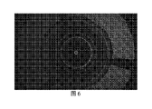
図6は、ステップS4において上部イメージング検出器6が取得した上面透過瞳孔画像Ipであり、図7を参照し、上面の外径中心位置の測定結果として、外径中心位置の座標は(4.8748mm,2.6197 mm)であり、半径は2.4651mmである。 FIG. 6 shows the top transmission pupil image Ip acquired by the upper imaging detector 6 in step S4. Referring to FIG. .8748 mm, 2.6197 mm) with a radius of 2.4651 mm.
ステップS9において、上面の外径偏心量は(-0.755度,-2.016度)である。 In step S9, the outer diameter eccentricity of the upper surface is (-0.755 degrees, -2.016 degrees).
図8は、ステップS5において下部波面センサー14が取得した下面傾斜波面画像であり、図9を参照し、処理によって得られた結果として、下面の波面傾斜量は(0.0101mm,0.0053 mm)であり、下面の全体的な傾斜量は0.0114mmである。 FIG. 8 shows the lower surface tilt wavefront image acquired by the lower wavefront sensor 14 in step S5. ), and the total amount of inclination of the lower surface is 0.0114 mm.
図10は、ステップS6において下部波面センサー14が取得した下面反射瞳孔画像Jp’であり、図11を参照し、下面の光軸中心位置座標は(4.5304mm,3.3342 mm)であり、半径は1.5171mmである。 FIG. 10 shows the lower surface reflected pupil image J p ' acquired by the lower wavefront sensor 14 in step S6. Referring to FIG. , with a radius of 1.5171 mm.
図12は、ステップS7において下部イメージング検出器15が収集した下面透過瞳孔画像I’pであり、図13を参照し、下面の外径中心位置は(4.5203mm,3.3395mm)であり、半径は2.4675mmである。 FIG. 12 is the lower surface transmission pupil image I′ p collected by the lower imaging detector 15 in step S7. Referring to FIG. The radius is 2.4675mm.
ステップS10において下面の外径偏心量は(1.73度,-3.924度)である。 In step S10, the outer diameter eccentricity of the lower surface is (1.73 degrees, -3.924 degrees).
ステップS8において、上下面の面別傾斜偏心は(0.0082mm,0.0118mm)であり、全体的な偏心は0.144mmであり、上下面の面別並進偏心は(-0.3444mm,0.7145mm)である。 In step S8, the tilt eccentricity of the upper and lower surfaces is (0.0082 mm, 0.0118 mm), the overall eccentricity is 0.144 mm, and the translational eccentricity of the upper and lower surfaces is (-0.3444 mm, 0 .7145 mm).
本発明の実施手段を上記のように開示したが、明細書及び実施形態に列挙された用途に限定されず、本発明に適した様々な分野に完全に適用可能であり、当業者であれば、別の修正を容易に実現することが可能であり、従って、本発明は、特許請求の範囲及び同等範囲によって定義される一般的な概念から脱逸することなく、特定の詳細に限定されない。 Although the means of implementation of the present invention are disclosed above, they are not limited to the uses listed in the specification and embodiments, but are fully applicable to various fields to which the present invention is suitable, and a person skilled in the art can , other modifications can be readily implemented and, therefore, the invention is not limited to specific details without departing from the general concept defined by the claims and their equivalents.
Claims (9)


上部イメージング検出器上の瞳孔画像Jpを収集するステップS31と、
瞳孔画像Jpに対して二値化を行い、二値化画像Jp2を取得し、手動で閾値を指定し、または自動閾値算出方法で二値化閾値を設定するステップS32と、
二値化画像Jp2に対してエッジ抽出を行い、画像Jp3を取得するステップS33と、
画像Jp3に対して円形ハフ変換を行い、円を取得し、円心を抽出して(Ox,Oy)と記録し、この円心は被測定レンズの上面の光軸中心位置であるステップS34と、を含むことを特徴とする請求項2に記載の波面技術に基づく非球面レンズ偏心検出方法。 Specifically, the step S3 is
a step S31 of acquiring a pupil image J p on the upper imaging detector;
a step S32 of binarizing the pupil image J p to obtain a binarized image J p2 and manually specifying a threshold or setting a binarization threshold by an automatic threshold calculation method;
a step S33 of performing edge extraction on the binarized image Jp2 to obtain an image Jp3 ;
Circular Hough transform is performed on the image J p3 to obtain a circle, and the center of the circle is extracted and recorded as (O x , O y ), which is the optical axis center position of the upper surface of the lens to be measured. 3. The wavefront technique-based aspheric lens decentration detection method of claim 2, comprising: step S34.
光路上の前記下部イメージング検出器と下部波面センサーの位置はいずれも被測定レンズの下面と共役であることを特徴とする請求項6に記載の波面技術に基づく非球面レンズ偏心検出方法。 The positions of the upper imaging detector and the upper wavefront sensor on the optical path are both conjugate with the upper surface of the lens to be measured,
7. The method of claim 6, wherein the positions of the lower imaging detector and the lower wavefront sensor on the optical path are both conjugate with the lower surface of the lens under test.
Applications Claiming Priority (3)
| Application Number | Priority Date | Filing Date | Title |
|---|---|---|---|
| CN201811399344.9A CN109580179B (en) | 2018-11-22 | 2018-11-22 | Aspheric lens eccentricity detection device based on wavefront technology and detection method thereof |
| CN201811399344.9 | 2018-11-22 | ||
| PCT/CN2018/120449 WO2020103221A1 (en) | 2018-11-22 | 2018-12-12 | Aspheric lens eccentricity detection apparatus and detection method based on wavefront technology |
Publications (3)
| Publication Number | Publication Date |
|---|---|
| JP2021510412A JP2021510412A (en) | 2021-04-22 |
| JPWO2020103221A5 JPWO2020103221A5 (en) | 2022-02-28 |
| JP7105254B2 true JP7105254B2 (en) | 2022-07-22 |
Family
ID=65923503
Family Applications (1)
| Application Number | Title | Priority Date | Filing Date |
|---|---|---|---|
| JP2019565415A Active JP7105254B2 (en) | 2018-11-22 | 2018-12-12 | Aspheric lens eccentricity detector based on wavefront technology and its detection method |
Country Status (6)
| Country | Link |
|---|---|
| US (1) | US11506567B2 (en) |
| EP (1) | EP3677893B1 (en) |
| JP (1) | JP7105254B2 (en) |
| KR (1) | KR102292329B1 (en) |
| CN (1) | CN109580179B (en) |
| WO (1) | WO2020103221A1 (en) |
Families Citing this family (8)
| Publication number | Priority date | Publication date | Assignee | Title |
|---|---|---|---|---|
| CN109990986B (en) * | 2019-05-09 | 2020-11-24 | 长春理工大学 | Calibration method and device for optical axis of single-axis optical system |
| CN110736610B (en) * | 2019-10-22 | 2021-08-20 | 歌尔光学科技有限公司 | Method and device for measuring optical center deviation, storage medium and depth camera |
| CN110793754A (en) * | 2019-11-01 | 2020-02-14 | 中国科学院光电技术研究所 | Spliced telescope system eccentricity error detection method based on phase shift modulation |
| CN111044260B (en) * | 2019-12-27 | 2021-05-18 | 中国科学院长春光学精密机械与物理研究所 | Microscope objective distortion testing device and testing method |
| CN112797961B (en) * | 2020-12-30 | 2022-03-04 | 中国工程物理研究院激光聚变研究中心 | Optical alignment system |
| CN114459395B (en) * | 2022-03-28 | 2023-09-22 | 深圳众庭联合科技有限公司 | Planar flat crystal calibrating device and calibrating method |
| CN114778079B (en) * | 2022-03-31 | 2024-01-23 | 宜宾市极米光电有限公司 | Eccentric instrument and eccentric detection method |
| CN115638741A (en) * | 2022-10-11 | 2023-01-24 | 淮安艾利光电仪器有限公司 | Aspheric lens surface type detection system |
Citations (3)
| Publication number | Priority date | Publication date | Assignee | Title |
|---|---|---|---|---|
| JP2008096233A (en) | 2006-10-11 | 2008-04-24 | Pentax Corp | Optical member inspection device |
| JP2011196954A (en) | 2010-03-23 | 2011-10-06 | Fujifilm Corp | Method and device for measuring aspherical surface object |
| JP2014115077A (en) | 2011-03-31 | 2014-06-26 | Fujifilm Corp | Lens measuring method and device for measuring surface shift and surface tilt of lens |
Family Cites Families (11)
| Publication number | Priority date | Publication date | Assignee | Title |
|---|---|---|---|---|
| TW283201B (en) * | 1993-08-13 | 1996-08-11 | Ricoh Kk | |
| JP2000193441A (en) * | 1998-12-25 | 2000-07-14 | Canon Inc | Method and device for decentering |
| JP2005201703A (en) * | 2004-01-14 | 2005-07-28 | Konica Minolta Opto Inc | Interference measuring method and system |
| CN100582715C (en) * | 2006-12-25 | 2010-01-20 | 鸿富锦精密工业(深圳)有限公司 | Lens eccentricity detection system and method |
| JP4880513B2 (en) | 2007-03-29 | 2012-02-22 | 富士フイルム株式会社 | Method and apparatus for measuring surface deviation of aspherical lens |
| JP5084327B2 (en) | 2007-04-04 | 2012-11-28 | オリンパス株式会社 | Eccentricity inspection device and eccentricity adjustment device |
| CN101226344B (en) * | 2008-01-31 | 2010-06-02 | 上海微电子装备有限公司 | Apparatus and method for measuring optical system parameter |
| JP5988643B2 (en) | 2012-03-26 | 2016-09-07 | キヤノン株式会社 | Measuring device, measuring method, and optical component manufacturing method |
| CN102944194B (en) * | 2012-11-21 | 2015-04-01 | 中国科学院光电技术研究所 | High-accuracy high-order aspherical lens eccentricity measuring system and method |
| KR101643113B1 (en) * | 2012-11-30 | 2016-08-10 | 퀘드 테크놀러지즈 인터내셔날, 인크. | Integrated wavefront sensor and profilometer |
| CN207540510U (en) * | 2017-12-13 | 2018-06-26 | 广东技术师范学院 | A kind of device for being used to detect lens centre deviation |
-
2018
- 2018-11-22 CN CN201811399344.9A patent/CN109580179B/en active Active
- 2018-12-12 US US16/616,158 patent/US11506567B2/en active Active
- 2018-12-12 EP EP18919386.5A patent/EP3677893B1/en active Active
- 2018-12-12 KR KR1020197034821A patent/KR102292329B1/en active IP Right Grant
- 2018-12-12 WO PCT/CN2018/120449 patent/WO2020103221A1/en unknown
- 2018-12-12 JP JP2019565415A patent/JP7105254B2/en active Active
Patent Citations (3)
| Publication number | Priority date | Publication date | Assignee | Title |
|---|---|---|---|---|
| JP2008096233A (en) | 2006-10-11 | 2008-04-24 | Pentax Corp | Optical member inspection device |
| JP2011196954A (en) | 2010-03-23 | 2011-10-06 | Fujifilm Corp | Method and device for measuring aspherical surface object |
| JP2014115077A (en) | 2011-03-31 | 2014-06-26 | Fujifilm Corp | Lens measuring method and device for measuring surface shift and surface tilt of lens |
Also Published As
| Publication number | Publication date |
|---|---|
| CN109580179B (en) | 2021-01-08 |
| EP3677893B1 (en) | 2021-06-30 |
| CN109580179A (en) | 2019-04-05 |
| KR102292329B1 (en) | 2021-08-25 |
| JP2021510412A (en) | 2021-04-22 |
| US20210270694A1 (en) | 2021-09-02 |
| WO2020103221A1 (en) | 2020-05-28 |
| EP3677893A4 (en) | 2020-08-19 |
| EP3677893A1 (en) | 2020-07-08 |
| KR20200063099A (en) | 2020-06-04 |
| US11506567B2 (en) | 2022-11-22 |
Similar Documents
| Publication | Publication Date | Title |
|---|---|---|
| JP7105254B2 (en) | Aspheric lens eccentricity detector based on wavefront technology and its detection method | |
| JP6542355B2 (en) | Optical evaluation of lenses and lens molds | |
| US8045181B2 (en) | Inspection system and method with multi-image phase shift analysis | |
| JP2010237189A (en) | Three-dimensional shape measuring method and device | |
| JP3206984B2 (en) | Lens inspection machine | |
| CN109186479B (en) | Method and device for measuring axial clearance of rear-mounted pupil laser differential confocal lens group | |
| CN109186477B (en) | Method and device for measuring central thickness of rear-mounted pupil laser differential confocal lens | |
| EP3177902B1 (en) | Methods and apparatus for determining geometric properties of optical fiber preforms | |
| WO2019123265A1 (en) | Method and apparatus for the determination of the index of refraction of lens material | |
| CN109540474B (en) | Rear-mounted pupil laser differential confocal focal length measuring method and device | |
| EP2986933B1 (en) | Apparatus and methods for performing wavefront-based and profile-based measurements of an aspheric surface | |
| TWI570397B (en) | Optical evaluation of lenses and lens molds | |
| CN109974603B (en) | Method for measuring center thickness of bilateral dislocation differential confocal lens | |
| JPWO2020103221A5 (en) | ||
| CN111220971B (en) | Method for measuring absolute distance with high precision without being influenced by inclination angle | |
| CN109883342B (en) | Method for measuring gap of transverse subtraction differential confocal lens group | |
| CN109883343B (en) | Axial clearance measuring method for bilateral dislocation differential confocal lens group | |
| TWI596325B (en) | Method or system for dertermining information about an object or a transparent optical element and method of forming an optical assembly | |
| CN109883340B (en) | Method for measuring central thickness of transverse subtraction differential confocal lens | |
| US20220170867A1 (en) | Testing device and method for measuring the homogeneity of an optical element | |
| EP3532829A1 (en) | Optical inspection system of objects destined to be used in a quality control system in a series manufacturing process and associated method | |
| Zhang et al. | Research on auto-centering device in surface defects evaluation system of large spherical optics | |
| Vallmitjana Rico et al. | Testing two techniques for wavefront analysis. Specific applications and comparative study | |
| MING et al. | Enlarge the dynamic range of Shack-Hartmann Wavefront sensor based on biplanar image acquisition and segmentation methods. | |
| Ge et al. | Deflectometry for Planar Surfaces with Camera Lens Entrance Pupil Calibration |
Legal Events
| Date | Code | Title | Description |
|---|---|---|---|
| A621 | Written request for application examination |
Free format text: JAPANESE INTERMEDIATE CODE: A621 Effective date: 20191125 |
|
| A521 | Request for written amendment filed |
Free format text: JAPANESE INTERMEDIATE CODE: A523 Effective date: 20210402 |
|
| A131 | Notification of reasons for refusal |
Free format text: JAPANESE INTERMEDIATE CODE: A131 Effective date: 20210511 |
|
| A521 | Request for written amendment filed |
Free format text: JAPANESE INTERMEDIATE CODE: A523 Effective date: 20210629 |
|
| A131 | Notification of reasons for refusal |
Free format text: JAPANESE INTERMEDIATE CODE: A131 Effective date: 20211207 |
|
| A524 | Written submission of copy of amendment under article 19 pct |
Free format text: JAPANESE INTERMEDIATE CODE: A524 Effective date: 20220216 |
|
| TRDD | Decision of grant or rejection written | ||
| A01 | Written decision to grant a patent or to grant a registration (utility model) |
Free format text: JAPANESE INTERMEDIATE CODE: A01 Effective date: 20220628 |
|
| A61 | First payment of annual fees (during grant procedure) |
Free format text: JAPANESE INTERMEDIATE CODE: A61 Effective date: 20220711 |
|
| R150 | Certificate of patent or registration of utility model |
Ref document number: 7105254 Country of ref document: JP Free format text: JAPANESE INTERMEDIATE CODE: R150 |