JP7100122B2 - Composite material inlays in additively manufactured structures - Google Patents
Composite material inlays in additively manufactured structures Download PDFInfo
- Publication number
- JP7100122B2 JP7100122B2 JP2020520137A JP2020520137A JP7100122B2 JP 7100122 B2 JP7100122 B2 JP 7100122B2 JP 2020520137 A JP2020520137 A JP 2020520137A JP 2020520137 A JP2020520137 A JP 2020520137A JP 7100122 B2 JP7100122 B2 JP 7100122B2
- Authority
- JP
- Japan
- Prior art keywords
- touring
- shell
- composite material
- printing
- composite
- Prior art date
- Legal status (The legal status is an assumption and is not a legal conclusion. Google has not performed a legal analysis and makes no representation as to the accuracy of the status listed.)
- Active
Links
- 239000002131 composite material Substances 0.000 title claims description 74
- 239000000463 material Substances 0.000 claims description 102
- 238000000034 method Methods 0.000 claims description 88
- 230000008569 process Effects 0.000 claims description 25
- 238000010146 3D printing Methods 0.000 claims description 21
- 229920003023 plastic Polymers 0.000 claims description 18
- 239000004033 plastic Substances 0.000 claims description 18
- 239000004918 carbon fiber reinforced polymer Substances 0.000 claims description 16
- 229920000049 Carbon (fiber) Polymers 0.000 claims description 15
- 239000004917 carbon fiber Substances 0.000 claims description 15
- 238000004519 manufacturing process Methods 0.000 claims description 14
- VNWKTOKETHGBQD-UHFFFAOYSA-N methane Chemical compound C VNWKTOKETHGBQD-UHFFFAOYSA-N 0.000 claims description 12
- 239000006260 foam Substances 0.000 claims description 10
- 238000007639 printing Methods 0.000 claims description 10
- 230000001070 adhesive effect Effects 0.000 claims description 8
- 239000000853 adhesive Substances 0.000 claims description 7
- 238000009734 composite fabrication Methods 0.000 claims description 5
- 239000000725 suspension Substances 0.000 claims description 5
- 239000002657 fibrous material Substances 0.000 claims description 4
- 239000002195 soluble material Substances 0.000 claims description 4
- 239000011159 matrix material Substances 0.000 claims description 3
- 239000012779 reinforcing material Substances 0.000 claims description 3
- 238000005304 joining Methods 0.000 claims 3
- 239000011162 core material Substances 0.000 claims 1
- 238000010586 diagram Methods 0.000 description 15
- 238000000465 moulding Methods 0.000 description 13
- 239000011347 resin Substances 0.000 description 12
- 229920005989 resin Polymers 0.000 description 12
- 238000013499 data model Methods 0.000 description 11
- 102100040287 GTP cyclohydrolase 1 feedback regulatory protein Human genes 0.000 description 10
- 101710185324 GTP cyclohydrolase 1 feedback regulatory protein Proteins 0.000 description 10
- 230000002787 reinforcement Effects 0.000 description 10
- 229910052751 metal Inorganic materials 0.000 description 8
- 239000002184 metal Substances 0.000 description 8
- 239000000835 fiber Substances 0.000 description 7
- 238000007373 indentation Methods 0.000 description 7
- 230000007246 mechanism Effects 0.000 description 7
- 239000004744 fabric Substances 0.000 description 6
- 239000004676 acrylonitrile butadiene styrene Substances 0.000 description 5
- 229910052782 aluminium Inorganic materials 0.000 description 5
- XAGFODPZIPBFFR-UHFFFAOYSA-N aluminium Chemical compound [Al] XAGFODPZIPBFFR-UHFFFAOYSA-N 0.000 description 5
- 238000001125 extrusion Methods 0.000 description 5
- 239000000203 mixture Substances 0.000 description 5
- 239000000843 powder Substances 0.000 description 5
- 229920002430 Fibre-reinforced plastic Polymers 0.000 description 4
- XECAHXYUAAWDEL-UHFFFAOYSA-N acrylonitrile butadiene styrene Chemical compound C=CC=C.C=CC#N.C=CC1=CC=CC=C1 XECAHXYUAAWDEL-UHFFFAOYSA-N 0.000 description 4
- 229920000122 acrylonitrile butadiene styrene Polymers 0.000 description 4
- 238000013461 design Methods 0.000 description 4
- 239000011151 fibre-reinforced plastic Substances 0.000 description 4
- 239000011152 fibreglass Substances 0.000 description 4
- 229910045601 alloy Inorganic materials 0.000 description 3
- 239000000956 alloy Substances 0.000 description 3
- 230000008901 benefit Effects 0.000 description 3
- 238000011960 computer-aided design Methods 0.000 description 3
- 230000008021 deposition Effects 0.000 description 3
- 238000003754 machining Methods 0.000 description 3
- 238000009877 rendering Methods 0.000 description 3
- 229920001169 thermoplastic Polymers 0.000 description 3
- 238000012546 transfer Methods 0.000 description 3
- 239000000654 additive Substances 0.000 description 2
- 230000000996 additive effect Effects 0.000 description 2
- 238000004026 adhesive bonding Methods 0.000 description 2
- 238000005516 engineering process Methods 0.000 description 2
- 239000003365 glass fiber Substances 0.000 description 2
- 238000002347 injection Methods 0.000 description 2
- 239000007924 injection Substances 0.000 description 2
- 150000002739 metals Chemical class 0.000 description 2
- 238000005457 optimization Methods 0.000 description 2
- 229920000642 polymer Polymers 0.000 description 2
- 239000000758 substrate Substances 0.000 description 2
- 238000001721 transfer moulding Methods 0.000 description 2
- 229910001374 Invar Inorganic materials 0.000 description 1
- 229920000271 Kevlar® Polymers 0.000 description 1
- 239000004697 Polyetherimide Substances 0.000 description 1
- 229920004738 ULTEM® Polymers 0.000 description 1
- 238000010521 absorption reaction Methods 0.000 description 1
- 230000001133 acceleration Effects 0.000 description 1
- 238000000149 argon plasma sintering Methods 0.000 description 1
- 230000000712 assembly Effects 0.000 description 1
- 238000000429 assembly Methods 0.000 description 1
- 230000008859 change Effects 0.000 description 1
- 239000003795 chemical substances by application Substances 0.000 description 1
- 230000009977 dual effect Effects 0.000 description 1
- 238000011049 filling Methods 0.000 description 1
- 239000012530 fluid Substances 0.000 description 1
- 239000011521 glass Substances 0.000 description 1
- 238000009787 hand lay-up Methods 0.000 description 1
- 238000003384 imaging method Methods 0.000 description 1
- 230000000977 initiatory effect Effects 0.000 description 1
- 230000010354 integration Effects 0.000 description 1
- 239000004761 kevlar Substances 0.000 description 1
- 238000011068 loading method Methods 0.000 description 1
- 239000000155 melt Substances 0.000 description 1
- 238000002844 melting Methods 0.000 description 1
- 230000008018 melting Effects 0.000 description 1
- 238000012986 modification Methods 0.000 description 1
- 230000004048 modification Effects 0.000 description 1
- 239000012768 molten material Substances 0.000 description 1
- 229920001601 polyetherimide Polymers 0.000 description 1
- 238000002360 preparation method Methods 0.000 description 1
- 230000004044 response Effects 0.000 description 1
- 239000000565 sealant Substances 0.000 description 1
- 238000007493 shaping process Methods 0.000 description 1
- 239000012815 thermoplastic material Substances 0.000 description 1
- 239000004416 thermosoftening plastic Substances 0.000 description 1
- 238000009941 weaving Methods 0.000 description 1
- 238000009756 wet lay-up Methods 0.000 description 1
Images


Classifications
-
- B—PERFORMING OPERATIONS; TRANSPORTING
- B29—WORKING OF PLASTICS; WORKING OF SUBSTANCES IN A PLASTIC STATE IN GENERAL
- B29C—SHAPING OR JOINING OF PLASTICS; SHAPING OF MATERIAL IN A PLASTIC STATE, NOT OTHERWISE PROVIDED FOR; AFTER-TREATMENT OF THE SHAPED PRODUCTS, e.g. REPAIRING
- B29C70/00—Shaping composites, i.e. plastics material comprising reinforcements, fillers or preformed parts, e.g. inserts
- B29C70/04—Shaping composites, i.e. plastics material comprising reinforcements, fillers or preformed parts, e.g. inserts comprising reinforcements only, e.g. self-reinforcing plastics
- B29C70/28—Shaping operations therefor
- B29C70/30—Shaping by lay-up, i.e. applying fibres, tape or broadsheet on a mould, former or core; Shaping by spray-up, i.e. spraying of fibres on a mould, former or core
- B29C70/34—Shaping by lay-up, i.e. applying fibres, tape or broadsheet on a mould, former or core; Shaping by spray-up, i.e. spraying of fibres on a mould, former or core and shaping or impregnating by compression, i.e. combined with compressing after the lay-up operation
- B29C70/342—Shaping by lay-up, i.e. applying fibres, tape or broadsheet on a mould, former or core; Shaping by spray-up, i.e. spraying of fibres on a mould, former or core and shaping or impregnating by compression, i.e. combined with compressing after the lay-up operation using isostatic pressure
-
- B—PERFORMING OPERATIONS; TRANSPORTING
- B29—WORKING OF PLASTICS; WORKING OF SUBSTANCES IN A PLASTIC STATE IN GENERAL
- B29C—SHAPING OR JOINING OF PLASTICS; SHAPING OF MATERIAL IN A PLASTIC STATE, NOT OTHERWISE PROVIDED FOR; AFTER-TREATMENT OF THE SHAPED PRODUCTS, e.g. REPAIRING
- B29C64/00—Additive manufacturing, i.e. manufacturing of three-dimensional [3D] objects by additive deposition, additive agglomeration or additive layering, e.g. by 3D printing, stereolithography or selective laser sintering
- B29C64/10—Processes of additive manufacturing
- B29C64/106—Processes of additive manufacturing using only liquids or viscous materials, e.g. depositing a continuous bead of viscous material
- B29C64/118—Processes of additive manufacturing using only liquids or viscous materials, e.g. depositing a continuous bead of viscous material using filamentary material being melted, e.g. fused deposition modelling [FDM]
-
- B—PERFORMING OPERATIONS; TRANSPORTING
- B29—WORKING OF PLASTICS; WORKING OF SUBSTANCES IN A PLASTIC STATE IN GENERAL
- B29C—SHAPING OR JOINING OF PLASTICS; SHAPING OF MATERIAL IN A PLASTIC STATE, NOT OTHERWISE PROVIDED FOR; AFTER-TREATMENT OF THE SHAPED PRODUCTS, e.g. REPAIRING
- B29C37/00—Component parts, details, accessories or auxiliary operations, not covered by group B29C33/00 or B29C35/00
- B29C37/0078—Measures or configurations for obtaining anchoring effects in the contact areas between layers
- B29C37/0082—Mechanical anchoring
-
- B—PERFORMING OPERATIONS; TRANSPORTING
- B29—WORKING OF PLASTICS; WORKING OF SUBSTANCES IN A PLASTIC STATE IN GENERAL
- B29C—SHAPING OR JOINING OF PLASTICS; SHAPING OF MATERIAL IN A PLASTIC STATE, NOT OTHERWISE PROVIDED FOR; AFTER-TREATMENT OF THE SHAPED PRODUCTS, e.g. REPAIRING
- B29C64/00—Additive manufacturing, i.e. manufacturing of three-dimensional [3D] objects by additive deposition, additive agglomeration or additive layering, e.g. by 3D printing, stereolithography or selective laser sintering
- B29C64/10—Processes of additive manufacturing
- B29C64/141—Processes of additive manufacturing using only solid materials
- B29C64/153—Processes of additive manufacturing using only solid materials using layers of powder being selectively joined, e.g. by selective laser sintering or melting
-
- B—PERFORMING OPERATIONS; TRANSPORTING
- B29—WORKING OF PLASTICS; WORKING OF SUBSTANCES IN A PLASTIC STATE IN GENERAL
- B29C—SHAPING OR JOINING OF PLASTICS; SHAPING OF MATERIAL IN A PLASTIC STATE, NOT OTHERWISE PROVIDED FOR; AFTER-TREATMENT OF THE SHAPED PRODUCTS, e.g. REPAIRING
- B29C64/00—Additive manufacturing, i.e. manufacturing of three-dimensional [3D] objects by additive deposition, additive agglomeration or additive layering, e.g. by 3D printing, stereolithography or selective laser sintering
- B29C64/30—Auxiliary operations or equipment
- B29C64/386—Data acquisition or data processing for additive manufacturing
-
- B—PERFORMING OPERATIONS; TRANSPORTING
- B29—WORKING OF PLASTICS; WORKING OF SUBSTANCES IN A PLASTIC STATE IN GENERAL
- B29C—SHAPING OR JOINING OF PLASTICS; SHAPING OF MATERIAL IN A PLASTIC STATE, NOT OTHERWISE PROVIDED FOR; AFTER-TREATMENT OF THE SHAPED PRODUCTS, e.g. REPAIRING
- B29C70/00—Shaping composites, i.e. plastics material comprising reinforcements, fillers or preformed parts, e.g. inserts
- B29C70/04—Shaping composites, i.e. plastics material comprising reinforcements, fillers or preformed parts, e.g. inserts comprising reinforcements only, e.g. self-reinforcing plastics
- B29C70/06—Fibrous reinforcements only
-
- B—PERFORMING OPERATIONS; TRANSPORTING
- B29—WORKING OF PLASTICS; WORKING OF SUBSTANCES IN A PLASTIC STATE IN GENERAL
- B29C—SHAPING OR JOINING OF PLASTICS; SHAPING OF MATERIAL IN A PLASTIC STATE, NOT OTHERWISE PROVIDED FOR; AFTER-TREATMENT OF THE SHAPED PRODUCTS, e.g. REPAIRING
- B29C70/00—Shaping composites, i.e. plastics material comprising reinforcements, fillers or preformed parts, e.g. inserts
- B29C70/04—Shaping composites, i.e. plastics material comprising reinforcements, fillers or preformed parts, e.g. inserts comprising reinforcements only, e.g. self-reinforcing plastics
- B29C70/28—Shaping operations therefor
- B29C70/30—Shaping by lay-up, i.e. applying fibres, tape or broadsheet on a mould, former or core; Shaping by spray-up, i.e. spraying of fibres on a mould, former or core
-
- B—PERFORMING OPERATIONS; TRANSPORTING
- B29—WORKING OF PLASTICS; WORKING OF SUBSTANCES IN A PLASTIC STATE IN GENERAL
- B29C—SHAPING OR JOINING OF PLASTICS; SHAPING OF MATERIAL IN A PLASTIC STATE, NOT OTHERWISE PROVIDED FOR; AFTER-TREATMENT OF THE SHAPED PRODUCTS, e.g. REPAIRING
- B29C70/00—Shaping composites, i.e. plastics material comprising reinforcements, fillers or preformed parts, e.g. inserts
- B29C70/68—Shaping composites, i.e. plastics material comprising reinforcements, fillers or preformed parts, e.g. inserts by incorporating or moulding on preformed parts, e.g. inserts or layers, e.g. foam blocks
- B29C70/84—Shaping composites, i.e. plastics material comprising reinforcements, fillers or preformed parts, e.g. inserts by incorporating or moulding on preformed parts, e.g. inserts or layers, e.g. foam blocks by moulding material on preformed parts to be joined
-
- B—PERFORMING OPERATIONS; TRANSPORTING
- B29—WORKING OF PLASTICS; WORKING OF SUBSTANCES IN A PLASTIC STATE IN GENERAL
- B29C—SHAPING OR JOINING OF PLASTICS; SHAPING OF MATERIAL IN A PLASTIC STATE, NOT OTHERWISE PROVIDED FOR; AFTER-TREATMENT OF THE SHAPED PRODUCTS, e.g. REPAIRING
- B29C70/00—Shaping composites, i.e. plastics material comprising reinforcements, fillers or preformed parts, e.g. inserts
- B29C70/68—Shaping composites, i.e. plastics material comprising reinforcements, fillers or preformed parts, e.g. inserts by incorporating or moulding on preformed parts, e.g. inserts or layers, e.g. foam blocks
- B29C70/86—Incorporated in coherent impregnated reinforcing layers, e.g. by winding
-
- B—PERFORMING OPERATIONS; TRANSPORTING
- B33—ADDITIVE MANUFACTURING TECHNOLOGY
- B33Y—ADDITIVE MANUFACTURING, i.e. MANUFACTURING OF THREE-DIMENSIONAL [3-D] OBJECTS BY ADDITIVE DEPOSITION, ADDITIVE AGGLOMERATION OR ADDITIVE LAYERING, e.g. BY 3-D PRINTING, STEREOLITHOGRAPHY OR SELECTIVE LASER SINTERING
- B33Y50/00—Data acquisition or data processing for additive manufacturing
-
- B—PERFORMING OPERATIONS; TRANSPORTING
- B33—ADDITIVE MANUFACTURING TECHNOLOGY
- B33Y—ADDITIVE MANUFACTURING, i.e. MANUFACTURING OF THREE-DIMENSIONAL [3-D] OBJECTS BY ADDITIVE DEPOSITION, ADDITIVE AGGLOMERATION OR ADDITIVE LAYERING, e.g. BY 3-D PRINTING, STEREOLITHOGRAPHY OR SELECTIVE LASER SINTERING
- B33Y70/00—Materials specially adapted for additive manufacturing
-
- B—PERFORMING OPERATIONS; TRANSPORTING
- B33—ADDITIVE MANUFACTURING TECHNOLOGY
- B33Y—ADDITIVE MANUFACTURING, i.e. MANUFACTURING OF THREE-DIMENSIONAL [3-D] OBJECTS BY ADDITIVE DEPOSITION, ADDITIVE AGGLOMERATION OR ADDITIVE LAYERING, e.g. BY 3-D PRINTING, STEREOLITHOGRAPHY OR SELECTIVE LASER SINTERING
- B33Y80/00—Products made by additive manufacturing
-
- B—PERFORMING OPERATIONS; TRANSPORTING
- B29—WORKING OF PLASTICS; WORKING OF SUBSTANCES IN A PLASTIC STATE IN GENERAL
- B29C—SHAPING OR JOINING OF PLASTICS; SHAPING OF MATERIAL IN A PLASTIC STATE, NOT OTHERWISE PROVIDED FOR; AFTER-TREATMENT OF THE SHAPED PRODUCTS, e.g. REPAIRING
- B29C70/00—Shaping composites, i.e. plastics material comprising reinforcements, fillers or preformed parts, e.g. inserts
- B29C70/04—Shaping composites, i.e. plastics material comprising reinforcements, fillers or preformed parts, e.g. inserts comprising reinforcements only, e.g. self-reinforcing plastics
- B29C70/28—Shaping operations therefor
- B29C70/40—Shaping or impregnating by compression not applied
- B29C70/42—Shaping or impregnating by compression not applied for producing articles of definite length, i.e. discrete articles
- B29C70/44—Shaping or impregnating by compression not applied for producing articles of definite length, i.e. discrete articles using isostatic pressure, e.g. pressure difference-moulding, vacuum bag-moulding, autoclave-moulding or expanding rubber-moulding
-
- B—PERFORMING OPERATIONS; TRANSPORTING
- B29—WORKING OF PLASTICS; WORKING OF SUBSTANCES IN A PLASTIC STATE IN GENERAL
- B29C—SHAPING OR JOINING OF PLASTICS; SHAPING OF MATERIAL IN A PLASTIC STATE, NOT OTHERWISE PROVIDED FOR; AFTER-TREATMENT OF THE SHAPED PRODUCTS, e.g. REPAIRING
- B29C70/00—Shaping composites, i.e. plastics material comprising reinforcements, fillers or preformed parts, e.g. inserts
- B29C70/04—Shaping composites, i.e. plastics material comprising reinforcements, fillers or preformed parts, e.g. inserts comprising reinforcements only, e.g. self-reinforcing plastics
- B29C70/28—Shaping operations therefor
- B29C70/54—Component parts, details or accessories; Auxiliary operations, e.g. feeding or storage of prepregs or SMC after impregnation or during ageing
- B29C70/541—Positioning reinforcements in a mould, e.g. using clamping means for the reinforcement
-
- B—PERFORMING OPERATIONS; TRANSPORTING
- B29—WORKING OF PLASTICS; WORKING OF SUBSTANCES IN A PLASTIC STATE IN GENERAL
- B29K—INDEXING SCHEME ASSOCIATED WITH SUBCLASSES B29B, B29C OR B29D, RELATING TO MOULDING MATERIALS OR TO MATERIALS FOR MOULDS, REINFORCEMENTS, FILLERS OR PREFORMED PARTS, e.g. INSERTS
- B29K2009/00—Use of rubber derived from conjugated dienes, as moulding material
- B29K2009/06—SB polymers, i.e. butadiene-styrene polymers
-
- B—PERFORMING OPERATIONS; TRANSPORTING
- B29—WORKING OF PLASTICS; WORKING OF SUBSTANCES IN A PLASTIC STATE IN GENERAL
- B29K—INDEXING SCHEME ASSOCIATED WITH SUBCLASSES B29B, B29C OR B29D, RELATING TO MOULDING MATERIALS OR TO MATERIALS FOR MOULDS, REINFORCEMENTS, FILLERS OR PREFORMED PARTS, e.g. INSERTS
- B29K2105/00—Condition, form or state of moulded material or of the material to be shaped
- B29K2105/06—Condition, form or state of moulded material or of the material to be shaped containing reinforcements, fillers or inserts
- B29K2105/20—Inserts
- B29K2105/206—Meshes, lattices or nets
-
- B—PERFORMING OPERATIONS; TRANSPORTING
- B29—WORKING OF PLASTICS; WORKING OF SUBSTANCES IN A PLASTIC STATE IN GENERAL
- B29K—INDEXING SCHEME ASSOCIATED WITH SUBCLASSES B29B, B29C OR B29D, RELATING TO MOULDING MATERIALS OR TO MATERIALS FOR MOULDS, REINFORCEMENTS, FILLERS OR PREFORMED PARTS, e.g. INSERTS
- B29K2507/00—Use of elements other than metals as filler
- B29K2507/04—Carbon
-
- B—PERFORMING OPERATIONS; TRANSPORTING
- B29—WORKING OF PLASTICS; WORKING OF SUBSTANCES IN A PLASTIC STATE IN GENERAL
- B29K—INDEXING SCHEME ASSOCIATED WITH SUBCLASSES B29B, B29C OR B29D, RELATING TO MOULDING MATERIALS OR TO MATERIALS FOR MOULDS, REINFORCEMENTS, FILLERS OR PREFORMED PARTS, e.g. INSERTS
- B29K2709/00—Use of inorganic materials not provided for in groups B29K2703/00 - B29K2707/00, for preformed parts, e.g. for inserts
-
- B—PERFORMING OPERATIONS; TRANSPORTING
- B29—WORKING OF PLASTICS; WORKING OF SUBSTANCES IN A PLASTIC STATE IN GENERAL
- B29L—INDEXING SCHEME ASSOCIATED WITH SUBCLASS B29C, RELATING TO PARTICULAR ARTICLES
- B29L2031/00—Other particular articles
- B29L2031/30—Vehicles, e.g. ships or aircraft, or body parts thereof
-
- B—PERFORMING OPERATIONS; TRANSPORTING
- B29—WORKING OF PLASTICS; WORKING OF SUBSTANCES IN A PLASTIC STATE IN GENERAL
- B29L—INDEXING SCHEME ASSOCIATED WITH SUBCLASS B29C, RELATING TO PARTICULAR ARTICLES
- B29L2031/00—Other particular articles
- B29L2031/60—Multitubular or multicompartmented articles, e.g. honeycomb
- B29L2031/608—Honeycomb structures
-
- B—PERFORMING OPERATIONS; TRANSPORTING
- B33—ADDITIVE MANUFACTURING TECHNOLOGY
- B33Y—ADDITIVE MANUFACTURING, i.e. MANUFACTURING OF THREE-DIMENSIONAL [3-D] OBJECTS BY ADDITIVE DEPOSITION, ADDITIVE AGGLOMERATION OR ADDITIVE LAYERING, e.g. BY 3-D PRINTING, STEREOLITHOGRAPHY OR SELECTIVE LASER SINTERING
- B33Y10/00—Processes of additive manufacturing
Description
関連出願の相互参照
本出願は、参照によりその全体が本明細書に明示的に組み込まれる、「COMPOSITE MATERIAL INLAY IN ADDITIVELY MANUFACTURED STRUCTURES(付加製造された構造における複合材料インレイ)」と題する、2017年10月11日出願の米国特許出願第15/730,675号の利益を主張する。
Mutual reference to related applications This application is entitled "COMPOSITE MATERIAL INLAY IN ADDITIVELY MANUFACTURED STRUCTURES", which is expressly incorporated herein by reference in its entirety, October 2017. Claims the benefit of US Patent Application No. 15 / 730,675 filed on March 11.
技術分野
本開示は、一般に、製造技術に関し、より具体的には乗り物、ボート、航空機および他の輸送構造に用いるための3D印刷されたコンポーネントに関する。
Technical Fields The present disclosure relates generally to manufacturing techniques, and more specifically to 3D printed components for use in vehicles, boats, aircraft and other transport structures.
背景技術
多くのタイプのコンポーネントが製造されて、輸送構造、例えば、乗り物、トラック、列車、オートバイ、ボート、航空機、および同様のものに用いられている。かかるコンポーネントは、輸送構造内でまたはその一部として、機能的、構造的、または審美的な目的のいずれか1つ以上に役立つことができる「オフザシェルフ(off the shelf)」およびカスタマイズコンポーネントの両方を含みうる。
Background Techniques Many types of components have been manufactured and used in transport structures such as vehicles, trucks, trains, motorcycles, boats, aircraft, and the like. Such components are both "off the shelf" and customized components that can serve one or more of the functional, structural, or aesthetic purposes within or as part of the transport structure. Can be included.
かかるコンポーネントの多くのタイプは、金属、合金、ポリマ、または別の適切な材料からなる概して堅い構造部材を構成する。構造部材は、所定の形状を有してよく、適切にモールドされた複合材料の別個の層へ接着するように製造された1つ以上の表面、インデンテーション、またはキャビティを含んでよい。例えば、乗り物におけるインテリアドアパネルの一部は、炭素繊維強化ポリマ(CRFP:carbon fiber reinforced polymer)でインレイされた(inlaid with)金属またはプラスチック構造を含んでよい。この例では、パネルに強度および耐久性を加え、一方では比較的軽く、美的で心地よいデザインを維持するためにCRFP層が含まれてよい。輸送構造のタイプならびに部品の性質および使用意図などの因子に依存して、多くの他のタイプの複合材料も用いられてよい。 Many types of such components constitute generally rigid structural members made of metals, alloys, polymers, or other suitable materials. The structural member may have a predetermined shape and may include one or more surfaces, indentations, or cavities manufactured to adhere to a separate layer of properly molded composite material. For example, a portion of the interior door panel in a vehicle may include an inlaid with metal or plastic structure with a carbon fiber reinforced polymer (CRFP). In this example, a CRFP layer may be included to add strength and durability to the panel, while maintaining a relatively light, aesthetic and pleasing design. Many other types of composites may also be used, depending on factors such as the type of transport structure and the nature and intent of use of the part.
複合材料の層をモールドするために用いられるツーリングシェルをかかる構造で用いるために所望の形状へ機械加工するステップは、大半の場合、費用がかかり、時間もかかる。従来の生産技術では、典型的に多大な労力を必要とするプロセスを用いて複合材料をモールドするためのツールが製造される。例えば、モールドの正および負のセクションの一方を各々が構成してよい一対のツーリングシェルを製造するために機械加工プロセスが用いられることがある。ある構造をそれによって成形するために、正および負のツーリングシェルセクション間のモールド中には材料および樹脂が置かれることがある。ツーリングシェルは、延いては、主題の材料をモールドする際に用いるために化学的および構造的に適した1つ以上の材料から典型的になる。しばしば、かかる構造は、所望のモールド形状へそれらが正確に食い込み、または詳細なフィーチャを形成することを難しくする特性を有する。 The step of machining the touring shell used to mold a layer of composite material into the desired shape for use in such a structure is often costly and time consuming. Traditional production techniques typically produce tools for molding composites using labor-intensive processes. For example, a machining process may be used to produce a pair of touring shells, each of which may constitute one of the positive and negative sections of the mold. Materials and resins may be placed in the mold between the positive and negative touring shell sections to form a structure thereby. The touring shell, in turn, typically consists of one or more materials that are chemically and structurally suitable for use in molding the subject material. Often, such structures have properties that make it difficult for them to accurately bite into the desired mold shape or form detailed features.
複合層のモールディングが完了した後に、ツーリングシェルは、その単一のタイプの部品を形成するための使用の範囲以外には使用が限られるか、またはそれ以上使用されないことがある。さらに、モールドされる材料がインレイされることになる構造を、無関係な技術を用いて別に製作しなければならず、潜在的に製造プロセスになおさらに費用がかかり、労力を要することもある。 After the composite layer molding is complete, the touring shell may be of limited use or no further use outside its scope of use for forming its single type of component. In addition, the structure in which the material to be molded will be inlaid must be separately manufactured using irrelevant techniques, potentially making the manufacturing process even more costly and labor intensive.
付加製造されたツーリングシェルによってインレイされた複合材料が3次元印刷技術を参照して以下により完全に記載される。 The composite material inlaid by the additively manufactured touring shell is described in full below with reference to the 3D printing technique.
輸送構造のための部品を製造する方法の一態様は、ツーリングシェルを3次元(3D)印刷し、ツーリングシェルは、ある材料に接着するように構成された表面を含む、3D印刷するステップと、モールドの一部としてツーリングシェルを用いて材料を表面へ塗布するステップと、ツーリングシェルおよびこの材料を含んだ一体化構造を形成するステップとを含み、一体化構造は、輸送構造中のコンポーネントとしての組み立て用である。 One aspect of the method of manufacturing parts for transport structures is to print the touring shell in three dimensions (3D), the touring shell is a step of 3D printing, including a surface configured to adhere to a material. The integrated structure comprises the steps of applying the material to the surface using the touring shell as part of the mold and forming the touring shell and the integrated structure containing the material, the integrated structure as a component in the transport structure. For assembly.
輸送構造用の部品を製造する方法の別の態様は、ツーリングシェルを3次元(3D)印刷するステップと、ツーリングシェルおよびツーリングシェルの表面へ塗布された材料を含んだ一体化構造を生産し、一体化構造は、輸送構造中の一部として用いるためであり、一体化構造を生産するステップは、複合材料をモールドするためにツーリングシェルを用いるステップをさらに含む、生産するステップと、複合材料をツーリングシェルへ固定するステップとを含む。 Another aspect of the method of manufacturing parts for transport structures is to produce a touring shell and an integrated structure containing the material applied to the surface of the touring shell, with the steps of printing the touring shell in three dimensions (3D). The integrated structure is to be used as part of the transport structure, and the steps to produce the integrated structure further include the step of using the touring shell to mold the composite, and the steps to produce the composite. Includes steps to secure to the touring shell.
理解されるであろうように、輸送構造用の部品を生産する方法の他の態様は、実例としていくつかの実施形態のみが示され、記載される以下の発明を実施するための形態から、当業者には直ちに明らかになるであろう。部品および部品を生産する方法は、他の異なる実施形態が可能であり、そのいくつかの詳細は、様々な他の点で修正が可能であり、すべてが本発明から逸脱しないことが当業者によって理解されるであろう。従って、図面および発明を実施するための形態は、本質的に説明的であり、制限的でないと見做されるべきである。 As will be appreciated, other aspects of the method of producing parts for transport structures, from the embodiments for carrying out the following inventions described, of which only a few embodiments are shown and described as examples. It will be immediately apparent to those skilled in the art. Parts and methods of producing parts are possible in other different embodiments, some of the details of which may be modified in various other respects and by those skilled in the art that all do not deviate from the present invention. Will be understood. Therefore, the drawings and embodiments for carrying out the invention should be considered to be descriptive in nature and not restrictive.
次に、発明を実施するための形態では付加製造されたツーリングシェルによってインレイされる複合材料が、例として、限定としてではなく、貼付図面に提示されるであろう。 Next, in the form for carrying out the invention, the composite material inlaid by the additionally manufactured touring shell will be presented, for example, in the pasted drawings, but not as a limitation.
貼付図面と関連して以下に述べられる発明を実施するための形態は、付加製造されたツーリングの上の布複合強化材のための技術の様々な例示的な実施形態の記載を提供することが意図され、本発明が実施されてよい実施形態のみを表現することは意図されない。本開示を通して用いられる用語「例示的」は、例、事例または説明としての役割を果し、それらが本開示に提示される他の実施形態より好ましいかまたは有利な実施形態であると必ずしも解釈されるべきではない。発明を実施するための形態は、本発明の範囲を当業者へ十分に伝える周到かつ完全な開示を提供するための具体的な詳細を含む。しかしながら、本発明は、これらの具体的な詳細なしに実施されてもよい。本開示を通して提示される様々なコンセプトを曖昧にするのを避けるために、いくつかの事例では、よく知られた構造およびコンポーネントは、ブロック図の形式で示されてもよく、またはまったく省略されてもよい。 The embodiments described below in connection with the pasted drawings may provide a description of various exemplary embodiments of the technique for fabric composite reinforcements on additionally manufactured touring. It is not intended to represent only embodiments in which the invention is intended and may be practiced. The term "exemplary" as used throughout the present disclosure serves as an example, case or explanation and is not necessarily construed as a preferred or advantageous embodiment over the other embodiments presented in the present disclosure. Should not be. The embodiments for carrying out the invention include specific details for providing careful and complete disclosure that fully conveys the scope of the invention to those skilled in the art. However, the present invention may be practiced without these specific details. To avoid obscuring the various concepts presented throughout this disclosure, in some cases well-known structures and components may be presented in the form of block diagrams or omitted altogether. May be good.
複合ツーリングの文脈での、3D印刷としても知られる、付加製造の使用は、機械構造および機械化組立品(mechanized assemblies)の製造業者が複雑な幾何形状をもつ部品を製造できるようにするために著しいフレキシビリティを提供する。例えば、3D印刷技術は、従来の製造プロセスでは製造することが不可能な入り組んだ内部格子構造および/またはプロファイルを有する部品を設計して造形するためのフレキシビリティを製造業者に提供する。 The use of additive manufacturing, also known as 3D printing in the context of composite touring, is significant to allow manufacturers of mechanical structures and mechanized assemblies to manufacture parts with complex geometries. Provides flexibility. For example, 3D printing technology provides manufacturers with the flexibility to design and model parts with intricate internal lattice structures and / or profiles that cannot be manufactured by conventional manufacturing processes.
図1は、3D印刷のプロセスを開始する例示的なプロセスを示すフロー図100である。印刷されることになる所望の3Dオブジェクトのデータモデルがレンダリングされる(ステップ110)。データモデルは、3Dオブジェクトの仮想設計である。従って、データモデルは、3Dオブジェクトの幾何学的および構造的フィーチャ、ならびにその材料組成を反映してよい。データモデルは、3Dスキャニング、3Dモデリングソフトウェア、写真測量ソフトウェア、およびカメラ撮像を含めて、様々な方法を用いて作り出されてよい。 FIG. 1 is a flow diagram 100 showing an exemplary process for initiating a 3D printing process. A data model of the desired 3D object to be printed is rendered (step 110). The data model is a virtual design of 3D objects. Therefore, the data model may reflect the geometric and structural features of the 3D object, as well as its material composition. Data models may be created using a variety of methods, including 3D scanning, 3D modeling software, photogrammetry software, and camera imaging.
データモデルを作り出すための3Dスキャニング方法も3Dモデルを生成するための様々な技術を用いてよい。これらの技術は、例えば、タイム・オブ・フライト(time-of-flight)、ヴォリュメトリック・スキャニング(volumetric scanning)、構造化光、変調光(structured light)、レーザ・スキャンニング、三角測量、および同様のものを含んでよい。 The 3D scanning method for creating a data model may also use various techniques for generating a 3D model. These techniques include, for example, time-of-flight, volumetric scanning, structured light, laser scanning, triangulation, and The same may be included.
3Dモデリングソフトウェアは、次には、多くの市販の3Dモデリングソフトウェアアプリケーションのうちの1つを含んでよい。データモデルは、例えば、STLフォーマットで、適切なコンピュータ支援設計(CAD:computer-aided design)パッケージを用いてレンダリングされてよい。STLファイルは、市販のCADソフトウェアと関連付けられたファイルフォーマットの一例である。CADプログラムは、3DオブジェクトのデータモデルをSTLファイルとして作り出すために用いられてよい。その結果、STLファイルは、ファイル中のエラーが識別されて解決されるプロセスを経てよい。 The 3D modeling software may then include one of many commercially available 3D modeling software applications. The data model may be rendered, for example, in STL format using a suitable computer-aided design (CAD) package. The STL file is an example of a file format associated with commercially available CAD software. CAD programs may be used to create a data model of a 3D object as an STL file. As a result, the STL file may go through a process in which errors in the file are identified and resolved.
エラー解決に続いて、データモデルは、オブジェクトを3D印刷するための命令のセットをそれによって生成するために、スライサとして知られるソフトウェアアプリケーションによって「スライスされる」(ステップ120)ことができて、これらの命令は、利用されることになる特定の3D印刷技術と適合して、それと関連付けられる。多くのスライサプログラムが市販されている。スライサプログラムは、データモデルが3D印刷される実際の表現を作り出すために、データモデルを、プリンタ固有の命令を含んだファイルと一緒に、印刷されるオブジェクトの薄いスライス(例えば、100ミクロン厚)を表す一連の個別層へ変換する。 Following error resolution, the data model can be "sliced" (step 120) by a software application known as a slicer to thereby generate a set of instructions for printing the object in 3D. The instructions are compatible with and associated with the particular 3D printing technology that will be utilized. Many slicer programs are commercially available. The slicer program strips the data model into thin slices (eg, 100 micron thick) of the object to be printed, along with a file containing printer-specific instructions, in order to produce the actual representation in which the data model is printed in 3D. Convert to a series of individual layers to represent.
この目的で用いられるファイルの共通のタイプは、オブジェクトを3D印刷するための命令を含む数値制御プログラミング言語である、Gコードファイルである。Gコードファイル、またはこれらの命令を構成する他のファイルが3Dプリンタへアップロードされる(ステップ130)。これらの命令を含んだファイルは、典型的に、固有の3D印刷プロセスで操作可能であるように構成されるため、用いられる3D印刷技術に依存して、命令ファイルの多くのフォーマットが可能であることが理解されるであろう。 A common type of file used for this purpose is a G-code file, which is a numerically controlled programming language that contains instructions for 3D printing objects. The G-code file or other files that make up these instructions are uploaded to the 3D printer (step 130). Files containing these instructions are typically configured to be operable in a unique 3D printing process, so many formats of instruction files are possible, depending on the 3D printing technique used. Will be understood.
どんなオブジェクトをどのようにレンダリングすべきかを決定づける印刷命令に加えて、オブジェクトをレンダリングする際に3Dプリンタによる使用のために必要な然るべき物理的材料が、いくつかの従来のしばしばプリンタ固有のいずれかの方法を用いて3Dプリンタ中へロードされる(ステップ140)。例えば、熱溶解積層法(FDM:fused deposition modelling)プリンタでは、材料は、1つ以上のスプール・ホルダ上に置かれた、スプール上にしばしば繊維としてロードされる。繊維は、典型的に、押出装置中へフィードされて、押出装置は、以下にさらに説明されるように、動作中に、材料を造形プレートまたは他の基板上へ吐出する前に、繊維を溶融形態へ加熱する。粉末焼結積層造形(SLS:selective laser sintering)印刷および他の方法では、造形プラットフォームへ粉末をフィードするチャンバ中へ材料が粉末としてロードされてよい。3Dプリンタに依存して、印刷材料をロードするための他の技術が用いられてもよい。 In addition to the print instructions that determine what object should be rendered and how, the appropriate physical material required for use by a 3D printer when rendering the object is one of several traditional and often printer-specific. Loaded into a 3D printer using the method (step 140). For example, in Fused Deposition Modeling (FDM) printers, the material is often loaded as fibers onto a spool placed on one or more spool holders. The fibers are typically fed into an extruder, which melts the fibers during operation, before ejecting the material onto a build plate or other substrate, as further described below. Heat to morphology. In powder-sintered additive manufacturing (SLS) printing and other methods, the material may be loaded as powder into a chamber that feeds the powder to a modeling platform. Other techniques for loading printing materials may be used, depending on the 3D printer.
3Dオブジェクトのそれぞれのデータスライスが、次に、提供された命令に基づいて材料(単数または複数)を用いて印刷される(ステップ150)。レーザ焼結を用いた3Dプリンタでは、構造が所望されるところでレーザが粉末ベッドをスキャンして粉末を一緒に溶融し、スライス・データが何も印刷されるべきではないことを示す区域をスキャンすることを避ける。所望の形状が形成されるまでこのプロセスが何千回も繰り返されてよく、その後、印刷された部品がファブリケータから取り外される。熱溶解積層法では、モデルの連続層および支持材料を基板へ塗布することによって部品が印刷される。一般に、いずれかの適切な3D印刷技術がこの開示の目的のために採用されてよい。 Each data slice of the 3D object is then printed using the material (s) based on the instructions provided (step 150). In a 3D printer with laser sintering, the laser scans the powder bed where the structure is desired, melting the powder together and scanning the area where no slice data should be printed. Avoid that. This process may be repeated thousands of times until the desired shape is formed, after which the printed part is removed from the fabricator. In Fused Deposition Modeling, parts are printed by applying a continuous layer of models and supporting materials to the substrate. In general, any suitable 3D printing technique may be employed for the purposes of this disclosure.
図2は、例示的な3Dプリンタ200のブロック図である。いくつもの3D印刷技術を適切に採用できるが、FDM技術の文脈で図2の3Dプリンタ200が考察される。3Dプリンタ200は、押出ノズル250Aおよび250Bを、順次、含むFDMヘッド210、可動造形ステージ220、ならびに造形ステージ220の上の造形プレート230を含む。
FIG. 2 is a block diagram of an
意図される構造の組成と、起こりうる重力変形、もしくは崩壊をさもなければ受けるであろう、構造の張出し要素への支持を提供するためのいずれかの支持材料の必要性とに依存して、オブジェクトを印刷するために複数の材料が用いられてよい。1つ以上の適切な繊維材料260がスプール上に巻かれて(示されない)、FDMヘッド210へフィードされてよい。(先に記載された他の技術では、材料が粉末として、または他の形態で提供されてもよい)。受信された印刷命令に基づいて、数値制御メカニズム、例えば、ステッパモータまたはサーボモータによってFDMヘッド210をX-Y方向に移動させることができる。1つの例示的な実施形態では熱可塑性ポリマを構成してよい、材料が、押出ノズル250Aおよび250Bを含むFDMヘッド210へフィードされてよい。FDMヘッド210中の押出器が繊維材料260を溶融形態へ加熱して、押出ノズル250aが溶融材料を吐出して、それを造形ステージ220の造形プレート230上へ堆積させる。
Depending on the composition of the intended structure and the need for any supporting material to provide support for the overhanging elements of the structure that would otherwise undergo possible gravitational deformation or collapse. Multiple materials may be used to print the object. One or more suitable
受信された印刷命令に応答して、FDMヘッド210は、塗布される材料のライン240を形成するために押出ノズル250Aが材料260を標的位置に滴下させるように水平(X-Y)面の周りを移動する。(ある一定の構成ではFDMヘッド210がZ方向に移動し、および/または1つ以上の軸の周りを回転するようにさらに構成されてもよい)。材料260をラインごとに堆積し、材料260が造形プレート230上に堆積されるにつれて材料の各ラインが固まることによって、ライン240を含んだ、材料260の層270が形成される。X-Y面内の然るべき位置に1つの層270が形成された後に、次の層が同様の方法で形成されてよい。
In response to the print command received, the
造形プレート230は、少なくとも垂直Z方向に移動可能な制御テーブルのコンポーネントであってよい。層270のレンダリングが完了したときに、所望の形状および組成を有する複数の断面層240が作り出されるまでプリンタが次の層の塗布を開始することなどができるように、造形ステージ220および造形プレート230は、層270の厚さに比例するある量だけ垂直(Z)方向に下降してよい。
The
簡潔にするためにこの説明図では実質的に矩形の層形状が示されるが、実際の印刷構造は、データモデルに依存して実質的にいずれの形状および組成を具現してもよい。すなわち、レンダリングされる層の実際の形状は、印刷される3Dモデルの定義された幾何形状に対応するであろう。 For the sake of brevity, this explanatory diagram shows a substantially rectangular layer shape, but the actual printed structure may embody substantially any shape and composition depending on the data model. That is, the actual shape of the layer to be rendered will correspond to the defined geometry of the 3D model to be printed.
加えて、先に示されたように、オブジェクトを印刷するために複数の異なる材料が用いられてよい。いくつかの事例では、それぞれの押出ノズル250Aおよび250Bによって2つの異なる材料260および280が同時に塗布されてよい。
In addition, as shown above, a number of different materials may be used to print the object. In some cases, two
例示的な実施形態では、輸送構造のための部品は、複合材料の1つ以上の層をモールドするために然るべく成形され、構造化されたツーリングシェルを用いて形成される。複合材料は、複合材料およびツーリングシェルの両方を含む一体化構造を形成するためにツーリングシェルの表面へ接着される。一体化構造は、乗り物などの輸送構造中のコンポーネントとして用いるために操作可能である。例示的な実施形態では、ツーリングシェルが3D印刷され、それによって、労力を要する機械加工プロセスと関連付けられた、しばしばコストがかかり、時間もかかる技術を省く。これらの実施形態では、ツーリングシェルは、複合材料をモールドすることと、輸送構造それ自体内の組み立て用のコンポーネント、例えば、車両パネル、ジョイントもしくは他のコンポーネント、航空機翼、および同様のものを形成するために、モールドされた材料とともに、有用な構造として役立つこととの2重の役割を果してよい。 In an exemplary embodiment, the component for the transport structure is appropriately molded and formed using a structured touring shell to mold one or more layers of composite material. The composite material is adhered to the surface of the touring shell to form an integrated structure that includes both the composite material and the touring shell. The integrated structure is operable for use as a component in a transport structure such as a vehicle. In an exemplary embodiment, the touring shell is 3D printed, thereby eliminating the often costly and time consuming technique associated with labor-intensive machining processes. In these embodiments, the touring shell molds the composite material and forms components for assembly within the transport structure itself, such as vehicle panels, joints or other components, aircraft wings, and the like. Therefore, together with the molded material, it may play a dual role of serving as a useful structure.
図3は、3D印刷されたツーリングシェル300の斜視図を示す。ツーリングシェルは、別の材料をモールドするために然るべきまたは適切な特性を有するいずれかの材料を含んでよい。例えば、ツーリングシェルを用いてモールドされることになる材料が炭素繊維強化ポリマ(CFRP:carbon fiber reinforced polymer)であるならば、インバール合金が、その熱膨張係数が炭素繊維のものとよく似ているため、この材料をモールドする際に用いるための適切な候補であってよい。他のケースでは、ツーリング構造は、金属、合金およびプラスチックを含めて、他の材料からなってよい。ツーリングシェル300中のインデンテーション(indentation)302は、モールドされることになる材料の然るべき量を収容するのに適した容積であってよい。別の例示的な実施形態では、硬化中に材料をシールするためにツーリングシェルの上半分が提供されてよい。さらに他の実施形態では、材料を製作するプロセスを容易にすべく樹脂材料をインデンテーション302に提供できるようにするためにツーリングシェル中に真空および流体チャンネルが一体化されてもよい。他の実施形態では、モールドに加えてツーリングシェル300も究極的に構造部として役立ってよいため、ツーリングシェル300を作製できる材料の選択も、輸送構造中に組み込まれる最終コンポーネントのための然るべき材料のタイプによって制限されることがある。
FIG. 3 shows a perspective view of the touring
一実施形態において、CRFPおよび金属3D印刷されたモールドに用いるための接着剤は、CFRPそれ自体のマトリックス材料とすることができる。 In one embodiment, the adhesive for use in CRFP and metal 3D printed molds can be the matrix material of CFRP itself.
図3にさらに含まれるのは、材料中に3D印刷された小さい表面インデンテーション304である。ツーリングシェル302およびモールドされることになる材料は、究極的に輸送構造中への組み立て用の単一のコンポーネントを形成できるため、いくつかの実施形態では、コンポーネントをツーリングシェル300の内部302へ接着させるためのメカニズムを提供することが望ましいであろう。小さい表面インデンテーション304の目的は、ツーリングシェル300の内部とツーリングシェル300中にモールドされることになる材料との間に表面接着が提供されるのを支援することである。他の実施形態では、表面接着プロセスをさらに促進するためにツーリングシェルの内側壁306上にも表面インデンテーションが形成されてよい。代わりの実施形態では、表面接着を支援するために他の手段が用いられてよい。例えば、モールドされることになる材料の挿入前に、内表面302へ樹脂が塗布されてもよい。代わりに、複合材料をツーリングシェルへ固定するためにクランプ、ねじ、ナットおよびボルト、くぎ、熱溶融結合などが用いられてもよい。
Also included in FIG. 3 is a
図4は、その中に挿入されたCFRPをもつ3D印刷されたツーリングシェル400の斜視図を示す。先述のように、ツーリングシェル400内にモールドされることになる構造の幾何形状404は、モールドがどのように構成されるかに依存して、ツーリングシェル400の内表面の形状に追随するように設計されてよい。かくして、ツーリングシェルは、以下にさらに記載されるように、コンポーネントの一部分(the a portion)へ硬化されるであろう複合材料を成形するためのモールドのセクションとしての役割を果す。
FIG. 4 shows a perspective view of a 3D printed
複合レイアップを含んだ複合生産プロセスがツーリングシェル400を用いて行われてよい。この例では、コンポーネントを生産する際の第1のステップとして炭素繊維材料(または別の適切な材料)がレイアッププロセスによってツーリングシェル400の内表面上に塗布されてよい。炭素繊維材料がツーリングシェル400の上に敷かれ、圧縮されて硬化されてよい。
A composite production process including composite layup may be performed using the touring
図5は、組み合わされた材料502およびツーリングシェル504の断面斜視図500である。材料502とツーリングシェル504との間の影付けの違いは、この特定の実施形態では2つの構造が異なる材料組成を有することを示すが、かかるフィーチャがある一定の実施形態では必ずしも必要ではない。
FIG. 5 is a cross-sectional perspective view 500 of the combined
図6は、2重組み立てコンポーネント600を用いた輸送構造中の例示的なインテリアドアパネル610の側面図を示す。この実施形態では、ドアパネルは、そのいずれもがモールドされるかまたは3D印刷されてよい、第1のコンポーネント606および第2のコンポーネント608を含む。この例示的な実施形態では、第1のコンポーネント606が、いずれかの利用可能な手段によって、図3~5に記載されるコンポーネント600の表面607へ接着される。第2のコンポーネント608は、いずれかの利用可能な手段によって、図4のコンポーネントの表面609(図4のコンポーネントの見えない底部)へ接着される。インテリアパネル610を、その結果、輸送構造中に用いることができ、炭素繊維材料604は、然るべく置かれる。コンポーネントとインテリアドアパネルとの一体化は、純粋に説明のためであり、図4のコンポーネントを輸送構造の様々な部分で数多くの実用用途に使用できることが理解されるべきである。
FIG. 6 shows a side view of an exemplary
1つの例示的な実施形態では、レイアップ(a lay up)は、予め含浸された(「prepreg(pre-impregnated)」)炭素繊維プライを用い、塗布された樹脂マトリックスをもつツーリングシェル400(図4)上へこの炭素繊維プライが送出される。prepreg技術は、効果的な樹脂押し込みを提供して、確実に樹脂が実質的に均一に分散することを支援する。ラミネート積層体を形成するためにprepregプライがツーリングシェル400上へ塗布されてよい。
In one exemplary embodiment, the layup is a touring
別の実施形態では、乾式レイアップが、乾いた織り繊維シート(woven fiber sheet)を用いる。レイアップが完了した後に、例えば、樹脂注入によって直ちに樹脂が乾いたプライへ塗布されてよい。代わりの例示的な実施形態では、湿式レイアップが用いられてもよく、各プライが樹脂でコートされて、置かれた後に圧縮されてよい。 In another embodiment, the dry layup uses a dry woven fiber sheet. After the layup is complete, the resin may be applied immediately to the dry ply, for example by resin injection. In an alternative exemplary embodiment, wet layup may be used, where each ply may be coated with resin, placed and then compressed.
先に示されたように、例えば、ツーリングシェル400(図4)の内部の幾何形状404中へ構造502(図5)をモールドする手段を提供するために、モールドのための上部シェルまたはシールが3D印刷されて、ツーリングシェル400の上に塗布されてよい。モールディングプロセスが完了すると、炭素繊維材料が、例えば、真空圧縮されて、オーブン中で指定された時間間隔にわたってベイクされてよい(baked)。
As shown above, for example, an upper shell or seal for molding is provided to provide a means of molding structure 502 (FIG. 5) into the
これらの段階中に用いられる具体的なモールディングおよび樹脂注入プロセスは、モールディング技術、設計制約条件、および所望の製造歩留りなどの変数に依存して変化してよい。一般に、3D印刷されたツーリングシェルは、例えば、樹脂トランスファーモールディング(RTM:Resin Transfer Molding)、ハンドレイアップ、prepreg、シートモールディング、および真空支援型樹脂トランスファーモールディング(VARTM:Vacuum Assisted Resin Transfer Molding)を含めて、様々な複合製造技術と関連して用いられてよい。 The specific molding and resin injection processes used during these steps may vary depending on variables such as molding techniques, design constraints, and desired manufacturing yield. In general, 3D printed touring shells include, for example, Resin Transfer Molding (RTM), Hand Layup, prepreg, Sheet Molding, and Vacuum Assisted Resin Transfer Molding (VARMM). It may be used in connection with various composite manufacturing techniques.
図7は、輸送構造中に用いるためのコンポーネントを作り出すための方法の例示的なフロー図を示す。702において、ツーリングシェルは、乗り物パネルのようなさらに別の構造内用の一体化構造の一部として、ツーリングシェルが用いられることを究極的に可能にできる幾何形状を用いて3D印刷される。ツーリングシェルは、その後に用いられることになる材料に起こりうる接着に対して設計されてよい。704において、CFRPまたは別の複合布のような、材料が塗布され、その材料をモールドして固めるために複合製作プロセスが用いられる。706において、複合製作が完了したときに、材料がツーリングシェルに接着して、硬化された材料およびツーリングシェルからなる一体化構造を含むコンポーネントが結果として形成される。708において、一体化構造は、あるコンポーネントとして輸送構造中へ組み込まれる。 FIG. 7 shows an exemplary flow diagram of a method for creating components for use in a transport structure. At 702, the touring shell is 3D printed using a geometry that ultimately allows the touring shell to be used as part of an integrated structure for use within yet another structure, such as a vehicle panel. The touring shell may be designed for possible adhesion to the material that will be used thereafter. At 704, a material is applied, such as CFRP or another composite cloth, and a composite fabrication process is used to mold and harden the material. At 706, when the composite fabrication is completed, the material adheres to the touring shell, resulting in a component containing an integrated structure consisting of the cured material and the touring shell. At 708, the integrated structure is incorporated into the transport structure as a component.
別の例示的な実施形態では、3D印刷されたプラスチックフレームが複合ツーリングのためのテンプレートとして最初に用いられる。複合材料の硬化が完了すると、結果として生じた組立品は、次に、輸送構造用のフレームまたは他のコンポーネントとして用いられてよい。図8は、付加製造されたツーリングの上の布複合強化材のオーバーレイからなる構造の説明図である。3D印刷技術の選択は、材料要件によって、および印刷プロセスの速度によって駆動されてよい。3D印刷されたプラスチックフレーム802が形成される。有利には、プラスチック印刷プロセスは、典型的に、金属印刷プロセスより25~50倍速い。付加製造されたプラスチックツーリングを用いる際のさらなる利点は、プラスチック3Dプリンタの造形チャンバが金属3Dプリンタのものより典型的にずっと大きいために、より大きい部品を得る能力である。加えて、プラスチック3Dプリンタは、多くのケースで、ずっとより滑らかな表面を印刷できる。ある実施形態では、用いられる材料は、アクリロニトリルブタジエンスチレン(ABS:Acrylonitrile Butadiene Styrene)、一般的な熱可塑性ポリマである。しかしながら、必要とされる材料の用途および特性に依存して、いくつもの適切な材料が用いられてよい。
In another exemplary embodiment, a 3D printed plastic frame is first used as a template for composite touring. Once the composite has been cured, the resulting assembly may then be used as a frame or other component for the transport structure. FIG. 8 is an explanatory diagram of a structure composed of an overlay of a cloth composite reinforcing material on an additionally manufactured touring. The choice of 3D printing technique may be driven by material requirements and by the speed of the printing process. A 3D printed
さらに、示される実施形態では、CNCフォームコア806が付加製造されて、接着剤または他の利用可能な手段を用いてプラスチックフレーム802へ結合される。一実施形態において、フレーム802およびコア806は、単一のレンダリングで共印刷される。フォームコアは、プラスチックフレーム802と同じ材料からなってよい。別の実施形態では、フォームコアの代わりにハニカムパネル構成が用いられる。多くの材料および形状が本開示のために代わりに用いられてよいので、図8に示される実施形態は、本来、例示的であることが理解されるであろう。
Further, in the embodiments shown, the
その後の複合製作プロセスでは、強度要件および他の因子に依存して、様々な繊維複合布が用いられてよい。可能な材料のいくつかの例は、ガラス繊維、炭素繊維、ケブラー、および同様のものを含む。示される実施形態では、付加製造されたツーリングの上にガラス繊維prepreg804がドレープされる(draped)。ガラス繊維prepreg層804は、1つの例示的な実施形態では、繊維強化ポリマ(FRP:fiber reinforced polymer)スキン(Eガラス)を含んでよい。炭素繊維を含めて、他の複合体も同様に用いられてよい。レイアップは、FRP上で行われる。材料が硬化された後に、フレーム802およびフォームコア806ならびにオーバーレイされたガラス繊維複合体804をもつABSツーリングからなる一体化構造が、次に、輸送構造中のコンポーネントとして用いられてよい。
In subsequent composite fabrication processes, various fiber composite fabrics may be used, depending on strength requirements and other factors. Some examples of possible materials include fiberglass, carbon fiber, Kevlar, and the like. In the embodiment shown,
付加重量の節約および/または耐荷重能力の向上のために、一体化構造の用途および使用意図に依存して、3D印刷されたツールは、最適化されたトポロジーを用いた構造を含んでよい。図9は、内部格子構造を伴って形成されたツーリングを含んだ一体化構造の説明図を示す。プラスチックツーリング902は、コンポーネントとしてそれが組み込まれたときに受けやすいであろう荷重に対して設計された格子構造を含む。フォームコアまたはハニカムパネル構造906が含められて、ガラス繊維強化ポリマ904の層がツーリング構造上にオーバーレイされる。この構造の1つの利点は、格子の使用によって達成されるプラスチック材料の節約を含む。
Depending on the application and intent of use of the integrated structure, the 3D printed tool may include a structure with an optimized topology to save additional weight and / or improve load bearing capacity. FIG. 9 shows an explanatory diagram of an integrated structure including touring formed with an internal lattice structure. The
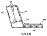
別の例示的な実施形態では、ツーリングは、フラッシュ仕上げ(flush finish)のためのポケットを伴って付加製造されてよい。図10は、トポロジー最適化によるポケットおよびツーリングを有する一体化構造の説明図である。図10に見られるように、ツーリングコンポーネント1002は、ポケット1007、1009および中空セクション1008を伴って3D印刷される。ポケット1007は、ツーリングを囲むガラス繊維材料の端部区域がフラッシュ仕上げを有することを可能にする。構造は、ハニカムまたはフォーム充填物をもつコンポーネント1006をさらに含む。加えて、機械的強化が望ましく、または必要なポケット1007、1009のうちの1つの強化を提供すべく、CFRPまたは別の複合材料がポケットに対する局所的強化を提供するために用いられてよい。これまでのように、一体化構造を生産するためにGFRP(または別の適切な複合体)のprepreg層がツーリングの上にオーバーレイされて硬化されてもよい。
In another exemplary embodiment, the touring may be additionally manufactured with pockets for a flash finish. FIG. 10 is an explanatory diagram of an integrated structure having pockets and touring by topology optimization. As seen in FIG. 10, the
いくつかの実施形態では、複合材料を所定の位置に固定するために機械的クランピングが望ましいであろう。図11は、コモールドされた(co-molded)ノードを用いた一体化構造の説明図である。前の実施形態におけるように、ツーリングシェル(tooling shell)1102は、ABSまたは別の適切な材料を用いて付加製造される。FRPまたは別の適切な材料1104がツーリングシェルの上にインレイされて硬化される。3D印刷された内側ノード1114は、ツーリングと共印刷されるか、または別に印刷されて、複合材料1104の部分1120の第1の側を固定するために加えられる。同様に、3D印刷された外側ノード1112は、複合材料の部分1120の第2の側の上に挿入される。複合材料は、それゆえに、ツーリングシェルにクランプされ、固定されて、一体化構造全体が輸送構造中のコンポーネントとして用いられてよい。1つの例示的な実施形態では、ノードが強度を確保するためにアルミニウムを用いて共印刷される。しかしながら、他の材料が同等に適切であってよい。
In some embodiments, mechanical clamping may be desirable to secure the composite in place. FIG. 11 is an explanatory diagram of an integrated structure using co-molded nodes. As in the previous embodiment, the
ある例示的な実施形態では、全体的な輸送構造と関連付けられたクラッシュレール(crush rails)のためのサスペンションピックアップポイントまたはインターフェースとしてAM金属ノードを実装できる。クラッシュレールは、乗り物が衝撃からのエネルギーを制御された仕方で有向的に吸収することを可能にするために乗り物上に実装されてよいエネルギー吸収レール構造である。レールは、乗り物サスペンションに、順次、取り付けられてよい、金属ノード間に挟み込まれてよい。かかる配置の例が図13に示される。別の実施形態では、複合レイアップを硬化させるために機械的クランピングを真空コネクタと接続して用いることができる。 In one exemplary embodiment, AM metal nodes can be implemented as suspension pickup points or interfaces for crush rails associated with the overall transport structure. Crash rails are energy absorption rail structures that may be mounted on the vehicle to allow the vehicle to absorb energy from impact in a controlled manner. The rails may be sequentially attached to the vehicle suspension and sandwiched between metal nodes. An example of such an arrangement is shown in FIG. In another embodiment, mechanical clamping can be used in connection with the vacuum connector to cure the composite layup.
図13は、ノード間に挟み込まれ、機械的クランプによって締結された複合材料を含んだ一体化構造1300の説明図である。構造1300は、付加製造されてよい、上側および下側アルミニウムノード1302a~bを含む。ノード1302bの下には、FDMまたは別の適切な技術を用いて付加製造されてよい、ツーリングシェル1308がある。ある実施形態では、ツーリングシェル1308は、ABS、またはULTEM(ポリエーテルイミド)のような熱可塑性物質からなる。
FIG. 13 is an explanatory diagram of an
ツーリングシェル1308の上に敷かれるのは、GFRPからなってよい2つの複合スキン層1306aおよび1306bである。それらの端部の近くで、GFRP層1306aおよび1306bは、ノード1302a~bと接触する。GFRP層1306aおよび1306bは、ALノード1302bおよびFDMツーリングシェル1308の両方の上で硬化されてよい。GFRP層1306a~1306bは、次に、GFRP層1306aおよび1306bの上に置かれてよいノード1302aによってクランプされてよい。
On top of the
層1306aおよび1306bのクランピングを確実にするために、機械的締結のためのフィーチャ1304が採用されてよい。この実施形態におけるフィーチャ1304は、ボルトまたは他の締結具を挿入できる大きい開口部である。締結具は、例えば、標準的なねじ付きボルト、ナット-ボルト組み合わせまたはいずれかの他の適切な機械的締結またはクランピングメカニズムによって、層1306aおよびbを固定するための力を提供できる。他の実施形態では、クランピングフィーチャがアパーチャ1304とは異なってよく、他のタイプの締結具または締結具を収容するための開口部を含んでもよい。
図13にやはり示されるのは、ノード1302bからの突出部1310である。この突出部は、FDMツーリングシェル1308からの突出部であってよい別の突出部1312中へ「スナップフィット(snap fit)」するように構成されたアパーチャを含む。ある実施形態では、突出部1312は、垂直方向に配置されて、端部により大きい突出部1312をもち、(ノード1320bによって視界から隠れされている)より長いFDM部材から突き出た緩やかな突出部である。ALノード1302bは、より長いFDM部材に接触して、それを押しつけてよい。ALノード1302bがより長いFDM部材に対して下方へ移動するにつれて、圧力または力がより大きいFDMの突出部1312を所定の位置へスナップインさせる。ある実施形態では、突出部1312が乗り物サスペンションシステムに付けられてよく、それによって、構造1300をサスペンションシステムに締結する。これらの技術は、アルミニウムクランピングメカニズムがFDMツールとインターフェースすることを可能にする。
Also shown in FIG. 13 is the
図12は、輸送構造中のコンポーネントとして用いるための一体化構造を生産すべくツーリングシェルの上に複合材料を有するコンポーネントを生産するための例示的なプロセスを示すフロー図である。1202において、プラスチックツーリングシェル、例えば、ABSシェルが適切な3Dプリンタ、例えば、FDM 3Dプリンタを用いて付加製造される。その結果、1204において、フォームコアまたはハニカムパネルが3D印刷されて、アルミニウムノードも3D印刷される。一実施形態において、集合的なステップ1202、1204において付加製造される3つの構造のうちで、2つ以上の構造が共印刷される。留意すべきは、実施形態および目的に依存して、特定された材料とは異なる材料が用いられてもよいことである。
FIG. 12 is a flow diagram illustrating an exemplary process for producing a component having a composite material on a touring shell to produce an integrated structure for use as a component in a transport structure. At 1202, a plastic touring shell, such as an ABS shell, is additionally manufactured using a suitable 3D printer, such as an FDM 3D printer. As a result, at 1204, the foam core or honeycomb panel is 3D printed and the aluminum node is also 3D printed. In one embodiment, of the three structures additionally manufactured in the
1206において、ツーリングシェルは、フォームコアと連結されるかまたは隣接される。2つのコンポーネントが単一のユニットとして付加製造されるいくつかの実施形態では、このステップが不必要であってよい。他の実施形態では、然るべき接着剤、ねじ、クランプまたは他の接続手段が用いられてよい。 At 1206, the touring shell is connected to or adjacent to the foam core. This step may not be necessary in some embodiments where the two components are additionally manufactured as a single unit. In other embodiments, appropriate adhesives, screws, clamps or other connecting means may be used.
1208において、然るべき材料、例えば、GFRPがツーリングシェルの上にインレイされて、複合製作プロセスで調製され、硬化される。いくつかの実施形態において、ツーリングシェルおよびフォームコアは、複合体に接着するための接着手段を有する。他の実施形態では、他の接着メカニズムが用いられてよい。1210において、例えば、図11に関して先に記載された仕方で複合材料をツーリングシェルへクランプするために、1204において印刷されたアルミニウムノードが用いられてよい。 At 1208, the appropriate material, eg GFRP, is inlaid onto the touring shell, prepared and cured in a composite fabrication process. In some embodiments, the touring shell and foam core have an adhesive means for adhering to the complex. In other embodiments, other bonding mechanisms may be used. At 1210, for example, the aluminum node printed at 1204 may be used to clamp the composite material to the touring shell in the manner described above with respect to FIG.
その結果、1212において、結果として生じた一体化構造が輸送構造中のコンポーネントとして用いられてよい。先に考察されたいくつかの実施形態において、構造が受けやすいであろう応力に依存して追加の支持を提供するために、この構造は、格子または他の機械的配置、例えば、CFRP層を用いてよい。必要なところに追加の強化材を置くために、ツーリングシェルを最適化し、ポケットを伴って印刷することができる。ある実施形態では、GFRPがツーリング構造でオーバーレイされるが、荷重伝達のための荷重経路を最適化するためにツーリングシェル上のポケットにはCFRPが用いられる。これらの構成は、ツーリングシェル上のポケット/フィーチャにおける一方向強化材、ならびに織り強化材(一方向は、繊維を一方向に有するが、織りは、0および90度の角度に延びる繊維を有する)の使用も可能にする。輸送構造および他の車両において、荷重伝達は、ブレーキングおよび減速を含む、縦方向および横方向加速プロセスの中に異なる車輪によって維持される荷重の変化である。他のタイプの荷重も輸送構造および機械化組立品に含まれてよい。剪断荷重は、構造要素に加えられたときに剪断応力を生じる力である。予期される剪断荷重を含めて、部品の荷重伝達力学(load the transfer mechanics)が荷重を決定づけるケースでは、複合繊維材料、格子、および他の構造を用いた強化材が必要であろう。 As a result, in 1212, the resulting integrated structure may be used as a component in the transport structure. In some of the embodiments discussed above, this structure has a grid or other mechanical arrangement, eg CFRP layer, to provide additional support depending on the stress that the structure will be susceptible to. You may use it. The touring shell can be optimized and printed with pockets to place additional reinforcement where needed. In one embodiment, GFRP is overlaid with a touring structure, but CFRP is used for pockets on the touring shell to optimize the load path for load transfer. These configurations are one-way reinforcements in pockets / features on the touring shell, as well as weaving reinforcements (one direction has fibers in one direction, but the weave has fibers extending at 0 and 90 degree angles). Can also be used. In transport structures and other vehicles, load transfer is the change in load maintained by different wheels during longitudinal and lateral acceleration processes, including braking and deceleration. Other types of loads may also be included in the transport structure and mechanized assembly. Shear load is the force that produces shear stress when applied to a structural element. In cases where the load the transfer mechanicals of the component, including the expected shear load, determine the load, composite fiber materials, grids, and reinforcements with other structures may be required.
他の実施形態では、マルチマテリアルツール(multi-material tools)が用いられてよい。例えば、ツーリングのある一定のセクションが可溶性材料で印刷されてよい。複合体が一旦オーバーレイされて硬化されると、これらのセクションは、溶解されてよい。この技術は、重量節約メカニズムにとって、かつ複合シェルのみが必要とされる設計において理想的なことがある。ある一定のセクションで複合スキンのみが必要とされるケースでは、マルチマテリアルツールが用いられてよい。ある実施形態では、複合スキンだけをもつセクションを達成すべく、複合体が硬化した後にツーリングのある一定のセクションが現れるか、または利用可能にできるようにするために離型メカニズム(離型剤、ツーリング表面調製など)が用いられてよい。 In other embodiments, multi-material tools may be used. For example, certain sections of the touring may be printed with soluble material. Once the complex is overlaid and cured, these sections may be dissolved. This technique may be ideal for weight saving mechanisms and in designs where only composite shells are required. In cases where only composite skins are needed in a given section, multi-material tools may be used. In certain embodiments, a mold release mechanism (release agent,) is used to allow certain sections of touring to appear or be available after the complex has hardened to achieve a section with only the composite skin. (Touring surface preparation, etc.) may be used.
図14A~Bは、複合スキンおよびマルチマテリアルツールを用いた一体化構造1400の例である。図14Aを参照すると、コンポーネント1404および1406を含んだマルチマテリアルツーリングシェルが付加製造されてよい。ここでは、FDMを用いてレンダリングされる通常の熱可塑性物質または他の適切な材料であってよい(あるいは、いくつかのケースでは、それが何か他のAM技術を用いてレンダリングされた金属性材料であってもよい)コンポーネント1404とは違って、コンポーネント1406は、知られた可溶性材料を構成してよい。GFRPまたはCFRPのような、スキンまたは材料1402が先に記載されたようなツーリングシェルの上にレイアップされる。最終的な一体化構造は、コンポーネント1404および1402を含むことが望まれる。しかしながら、コンポーネント1406は、材料1402を成形し、安定化させて、それが硬化することを許容すべく、単にモールディングのために用いられる。従って、材料1402が硬化された後に、コンポーネント1406は、図14bにおける最終的な一体化構造1400を生産するために、従来から知られた技術を用いて溶解除去されてよい。本明細書に開示される方法と併せてこれらのマルチマテリアルを用いて、ますます多種多様な構造が生産されてよい。
14A-B are examples of an
本開示の別の態様では、接着剤接合を改善するために、硬化された複合体の表面上にピールプライを配列できる。図15は、複合体1514、例えば、GFRP、CFRP、または同様のものを含んだ一体化構造1500の例である。前の実施形態におけるように、付加製造されたツール1516は、レイアッププロセス中に複合材料1514をモールドするため、ならびに造形された構造の一部とするために用いられる。硬化された複合体1514と3D印刷されたツール1516との間の接合を改善するために、化学的に適切な特性をもつ材料の層、例えば、ピールプライ1512をツール1516と複合体1514との間に配置できる。いくつかの実施形態では正確な結果を可能にするために、ピールプライ1512の別の層が複合体1514の上に挿入されてよい。上側ピールプライ層1512とバギングフィルム1508との間にはブリーザ1510がある。バギングフィルム1508は、陰圧を作り出すためのスルーバッグ(thru-bag)真空コネクタを含んでよい。バギングフィルム(bagging filem)1508をシールするためにシーラント1502が用いられてよく、ピールプライ1512を複合体1514へ固定するためにフラッシュテープ1504が用いられてよい。
In another aspect of the present disclosure, peel ply can be arranged on the surface of the cured composite to improve adhesive bonding. FIG. 15 is an example of an
硬化が完了すると、ピールプライ1512の性質は、硬化された複合体1514がツール1516から取り外されることを可能にする。ピールプライ1512は、硬化された複合体1514の表面上に接着剤接合の助けとなるある一定のテクスチャを残してよい。ピールプライ1512を棄てた後に、ツール1516と複合体1514との間に強い接合をそれによって形成するために、ツール-複合体界面に接着剤を塗布することができる。
Upon completion of curing, the properties of peel ply 1512 allow the cured complex 1514 to be removed from the
先の記載は、任意の当業者が本明細書に記載される様々な態様を実施することを可能にするために提供される。本開示を通して提示されるこれらの例示的な実施形態の様々な修正が当業者には直ちに明らかとなり、本明細書に開示される概念は、材料の複合インレイのための他の技術に適用されてよい。従って、請求項は、本開示を通して提示される例示的な実施形態に限定されることは意図されず、言語による請求(language claims)と矛盾しない全範囲が与えられるべきである。当業者に知られ、または後に知られることになる、本開示を通して記載される例示的な実施形態の要素のすべての構造的および機能的な均等物は、請求項によって包含されることが意図される。そのうえ、かかる開示が請求項に明示的に列挙されるかどうかに係わらず、本開示に開示されるものが公衆に提供されることは意図されない。請求要素は、語句「のための手段」を用いてその要素が明示的に列挙されない限り、または方法請求項のケースでは、語句「のためのステップ」を用いてその要素が列挙されない限り、合衆国法典第35巻(35 U.S.C)第112条(f)、または該当法域における類似した法律の規定の下で解釈されるべきではない。 The above description is provided to allow any person skilled in the art to carry out the various embodiments described herein. Various modifications of these exemplary embodiments presented through this disclosure will be immediately apparent to those of skill in the art, and the concepts disclosed herein have been applied to other techniques for composite inlays of materials. good. Therefore, the claims are not intended to be limited to the exemplary embodiments presented throughout the present disclosure and should be given the full scope consistent with language claims. All structural and functional equivalents of the elements of the exemplary embodiments described throughout this disclosure, which will be known to those of skill in the art or will be known later, are intended to be incorporated by claim. To. Moreover, it is not intended that what is disclosed in this disclosure be provided to the public, whether or not such disclosure is explicitly listed in the claims. A claim element is the United States unless the element is explicitly listed using the phrase "means for" or, in the case of a method claim, the element is listed using the phrase "step for". It should not be construed under Article 112 (f) of the Code, Vol. 35 (35 USC), or similar provisions of law in the relevant jurisdiction.
Claims (29)
ツーリングシェルを3次元(3D)印刷し、前記ツーリングシェルは、ある材料に接着するように構成された表面を備える、前記3D印刷するステップと、
モールドの一部として前記ツーリングシェルを用いて前記材料を前記表面上へ塗布するステップと、
前記塗布された材料に、少なくとも1つの付加製造されたノードを結合するステップと、
前記ツーリングシェルおよび前記材料を備える一体化構造を形成し、前記一体化構造は、前記輸送構造中のコンポーネントとしての組み立て用である、前記形成するステップと、
を含む、方法。 A method of manufacturing components for transport structures,
The 3D printing step of printing a touring shell in three dimensions (3D), wherein the touring shell comprises a surface configured to adhere to a material.
The step of applying the material onto the surface using the touring shell as part of the mold,
With the step of joining at least one additional manufactured node to the applied material,
Forming an integrated structure comprising the touring shell and the material, wherein the integrated structure is for assembly as a component in the transport structure, with the forming step.
Including the method.
前記複合材料を硬化させるステップと、
前記複合材料を硬化させるとすぐに前記1つ以上のピールプライ層を除去するステップと、
接着剤を用いて前記複合材料の少なくとも1部分を前記ツーリングシェルと接合するステップと
をさらに含む、請求項4に記載の方法。 The step of inserting one or more peel ply layers between the touring shell and the composite material,
The step of curing the composite material and
The step of removing the one or more peel ply layers as soon as the composite material is cured,
The method of claim 4, further comprising joining the tooling shell with at least one portion of the composite material using an adhesive.
表面および、可溶性材料の少なくとも1つのセクションを備えるプラスチックツーリングシェルを3次元(3D)印刷するステップと、
モールドの一部として前記プラスチックツーリングシェルを用いて前記表面上へ複合材料を塗布するステップと、
前記プラスチックツーリングシェルおよび前記材料を備える一体化構造を形成し、前記一体化構造は、前記輸送構造中のコンポーネントとしての組み立て用である、前記形成するステップと、
を含む、方法。 A method of manufacturing components for transport structures,
A step of three-dimensionally (3D) printing a plastic touring shell with a surface and at least one section of soluble material .
The step of applying the composite material onto the surface using the plastic touring shell as part of the mold,
With the forming step forming an integrated structure comprising the plastic touring shell and the material, the integrated structure is for assembly as a component in the transport structure .
Including the method.
前記複合材料を硬化させるステップと、
硬化させるとすぐにピールプライの前記1つ以上の層を除去するステップと、
接着剤を用いて、前記ツーリングシェルの前記少なくとも部分と前記複合材料とを接合するステップと、
をさらに含む、請求項23に記載の方法。 A step of inserting one or more layers of peel ply between at least a portion of the touring shell and the composite material.
The step of curing the composite material and
With the step of removing the one or more layers of peel ply as soon as it is cured,
A step of joining the at least portion of the touring shell to the composite material using an adhesive .
23. The method of claim 23 .
Priority Applications (1)
| Application Number | Priority Date | Filing Date | Title |
|---|---|---|---|
| JP2022105456A JP7434432B2 (en) | 2017-10-11 | 2022-06-30 | Composite material inlays in additively manufactured structures |
Applications Claiming Priority (3)
| Application Number | Priority Date | Filing Date | Title |
|---|---|---|---|
| US15/730,675 | 2017-10-11 | ||
| US15/730,675 US10814564B2 (en) | 2017-10-11 | 2017-10-11 | Composite material inlay in additively manufactured structures |
| PCT/US2018/054996 WO2019074916A2 (en) | 2017-10-11 | 2018-10-09 | Composite material inlay in additively manufactured structures |
Related Child Applications (1)
| Application Number | Title | Priority Date | Filing Date |
|---|---|---|---|
| JP2022105456A Division JP7434432B2 (en) | 2017-10-11 | 2022-06-30 | Composite material inlays in additively manufactured structures |
Publications (3)
| Publication Number | Publication Date |
|---|---|
| JP2020536769A JP2020536769A (en) | 2020-12-17 |
| JP2020536769A5 JP2020536769A5 (en) | 2021-11-04 |
| JP7100122B2 true JP7100122B2 (en) | 2022-07-12 |
Family
ID=65992866
Family Applications (2)
| Application Number | Title | Priority Date | Filing Date |
|---|---|---|---|
| JP2020520137A Active JP7100122B2 (en) | 2017-10-11 | 2018-10-09 | Composite material inlays in additively manufactured structures |
| JP2022105456A Active JP7434432B2 (en) | 2017-10-11 | 2022-06-30 | Composite material inlays in additively manufactured structures |
Family Applications After (1)
| Application Number | Title | Priority Date | Filing Date |
|---|---|---|---|
| JP2022105456A Active JP7434432B2 (en) | 2017-10-11 | 2022-06-30 | Composite material inlays in additively manufactured structures |
Country Status (6)
| Country | Link |
|---|---|
| US (2) | US10814564B2 (en) |
| EP (1) | EP3694701A4 (en) |
| JP (2) | JP7100122B2 (en) |
| KR (1) | KR102522931B1 (en) |
| CN (1) | CN109648843A (en) |
| WO (1) | WO2019074916A2 (en) |
Families Citing this family (7)
| Publication number | Priority date | Publication date | Assignee | Title |
|---|---|---|---|---|
| US10759090B2 (en) * | 2017-02-10 | 2020-09-01 | Divergent Technologies, Inc. | Methods for producing panels using 3D-printed tooling shells |
| US10751932B2 (en) * | 2017-07-21 | 2020-08-25 | Wisconsin Alumni Research Foundation | Joint structures |
| CN107526898B (en) * | 2017-09-13 | 2019-12-27 | 大连理工大学 | Variable-stiffness composite material plate-shell structure modeling analysis and reliability optimization design method |
| DE102018207444A1 (en) * | 2018-05-15 | 2019-11-21 | Bayerische Motoren Werke Aktiengesellschaft | Process for producing a structural component |
| DE102018006397A1 (en) * | 2018-08-15 | 2020-02-20 | DP Polar GmbH | Method for producing a three-dimensional shaped object by means of layer-by-layer application of material |
| US10836120B2 (en) * | 2018-08-27 | 2020-11-17 | Divergent Technologies, Inc . | Hybrid composite structures with integrated 3-D printed elements |
| CA3111967A1 (en) * | 2018-09-07 | 2020-03-12 | Magna Exteriors Inc. | Apparatus and method for 3d printing with smooth surface |
Citations (6)
| Publication number | Priority date | Publication date | Assignee | Title |
|---|---|---|---|---|
| US20060108058A1 (en) | 2004-11-24 | 2006-05-25 | Chapman Michael R | Composite sections for aircraft fuselages and other structures, and methods and systems for manufacturing such sections |
| JP2009029064A (en) | 2007-07-30 | 2009-02-12 | Incs Inc | Powdery molded article |
| WO2017040728A1 (en) | 2015-08-31 | 2017-03-09 | Divergent Technologies, Inc. | Systems and methods for vehicle subassembly and fabrication |
| JP2017100319A (en) | 2015-11-30 | 2017-06-08 | トヨタ自動車株式会社 | Resin body and method for manufacturing resin body |
| WO2017146284A1 (en) | 2016-02-25 | 2017-08-31 | 기술융합협동조합 | Method for making 3d printing structure using reinforcement and composite |
| CN107187020A (en) | 2017-06-06 | 2017-09-22 | 中国电子科技集团公司第三十八研究所 | A kind of fibre reinforced composites 3D printing assistant formation method |
Family Cites Families (314)
| Publication number | Priority date | Publication date | Assignee | Title |
|---|---|---|---|---|
| EP0373101B1 (en) | 1988-12-02 | 1994-01-12 | Otto Dipl.-Ing. Bay | Method and device for manufacturing, cutting and folding drawing sheets |
| US5203226A (en) | 1990-04-17 | 1993-04-20 | Toyoda Gosei Co., Ltd. | Steering wheel provided with luminous display device |
| DE29507827U1 (en) | 1995-05-16 | 1995-07-20 | Edag Eng & Design Ag | Feeding device intended for feeding welding studs to a welding gun |
| DE19518175A1 (en) | 1995-05-19 | 1996-11-21 | Edag Eng & Design Ag | Method for the automatic installation of a component of a motor vehicle body |
| DE19519643B4 (en) | 1995-05-30 | 2005-09-22 | Edag Engineering + Design Ag | Bin shifting device |
| US6252196B1 (en) | 1996-10-11 | 2001-06-26 | Technolines Llc | Laser method of scribing graphics |
| US5990444A (en) | 1995-10-30 | 1999-11-23 | Costin; Darryl J. | Laser method and system of scribing graphics |
| US5742385A (en) | 1996-07-16 | 1998-04-21 | The Boeing Company | Method of airplane interiors assembly using automated rotating laser technology |
| WO1998024958A1 (en) | 1996-12-05 | 1998-06-11 | Teijin Limited | Fiber aggregate molding method |
| US6010155A (en) | 1996-12-31 | 2000-01-04 | Dana Corporation | Vehicle frame assembly and method for manufacturing same |
| US6140602A (en) | 1997-04-29 | 2000-10-31 | Technolines Llc | Marking of fabrics and other materials using a laser |
| SE9703859L (en) | 1997-10-23 | 1998-11-30 | Ssab Hardtech Ab | Vehicle impact protection beam |
| DE19907015A1 (en) | 1999-02-18 | 2000-08-24 | Edag Eng & Design Ag | Clamping device that can be used in production lines for motor vehicles and production line with such a clamping device |
| US6391251B1 (en) | 1999-07-07 | 2002-05-21 | Optomec Design Company | Forming structures from CAD solid models |
| US6811744B2 (en) | 1999-07-07 | 2004-11-02 | Optomec Design Company | Forming structures from CAD solid models |
| US6365057B1 (en) | 1999-11-01 | 2002-04-02 | Bmc Industries, Inc. | Circuit manufacturing using etched tri-metal media |
| US6409930B1 (en) | 1999-11-01 | 2002-06-25 | Bmc Industries, Inc. | Lamination of circuit sub-elements while assuring registration |
| US6468439B1 (en) | 1999-11-01 | 2002-10-22 | Bmc Industries, Inc. | Etching of metallic composite articles |
| US6318642B1 (en) | 1999-12-22 | 2001-11-20 | Visteon Global Tech., Inc | Nozzle assembly |
| US6585151B1 (en) | 2000-05-23 | 2003-07-01 | The Regents Of The University Of Michigan | Method for producing microporous objects with fiber, wire or foil core and microporous cellular objects |
| US6919035B1 (en) | 2001-05-18 | 2005-07-19 | Ensci Inc. | Metal oxide coated polymer substrates |
| JP3889940B2 (en) | 2001-06-13 | 2007-03-07 | 株式会社東海理化電機製作所 | Mold apparatus, method of using mold apparatus, and method of sharing mold apparatus |
| JP4485196B2 (en) | 2001-08-31 | 2010-06-16 | エダック ゲーエムベーハー ウント コー. カーゲーアーアー | Roller folding head and flange folding method |
| US6926970B2 (en) | 2001-11-02 | 2005-08-09 | The Boeing Company | Apparatus and method for forming weld joints having compressive residual stress patterns |
| US6644721B1 (en) | 2002-08-30 | 2003-11-11 | Ford Global Technologies, Llc | Vehicle bed assembly |
| DE10325906B4 (en) | 2003-06-05 | 2007-03-15 | Erwin Martin Heberer | Device for shielding coherent electromagnetic radiation and laser cabin with such a device |
| DE102004014662A1 (en) | 2004-03-25 | 2005-10-13 | Audi Ag | Arrangement with a vehicle fuse and an analog / digital converter |
| US7745293B2 (en) | 2004-06-14 | 2010-06-29 | Semiconductor Energy Laboratory Co., Ltd | Method for manufacturing a thin film transistor including forming impurity regions by diagonal doping |
| DE502005001712D1 (en) | 2004-09-24 | 2007-11-29 | Edag Eng & Design Ag | Beading device and crimping process with component protection |
| US20060108783A1 (en) | 2004-11-24 | 2006-05-25 | Chi-Mou Ni | Structural assembly for vehicles and method of making same |
| DE102005004474B3 (en) | 2005-01-31 | 2006-08-31 | Edag Engineering + Design Ag | Beading device and crimping method for transferring a crimping web of a component about a crimping edge |
| DE102005030944B4 (en) | 2005-06-30 | 2007-08-02 | Edag Engineering + Design Ag | Method and device for joining joining structures, in particular in the assembly of vehicle components |
| ATE550391T1 (en) | 2005-09-28 | 2012-04-15 | Dip Tech Ltd | INK WITH AN EFFECT SIMILAR TO ETCHING FOR PRINTING ON CERAMIC SURFACES |
| US7716802B2 (en) | 2006-01-03 | 2010-05-18 | The Boeing Company | Method for machining using sacrificial supports |
| DE102006014282A1 (en) | 2006-03-28 | 2007-10-04 | Edag Engineering + Design Ag | Clamping system for sheet metal components to be joined comprises two beds which hold components and can be fastened together by couplings mounted at their ends which push them together |
| DE102006014279A1 (en) | 2006-03-28 | 2007-10-04 | Edag Engineering + Design Ag | Clamping device comprising connecting components (B1,B2), component receivers, a clamping structure, a robot structure and sub-stations |
| JP2007292048A (en) | 2006-03-29 | 2007-11-08 | Yamaha Motor Co Ltd | Exhaust apparatus for straddle-type vehicle and straddle-type vehicle |
| US8599301B2 (en) | 2006-04-17 | 2013-12-03 | Omnivision Technologies, Inc. | Arrayed imaging systems having improved alignment and associated methods |
| DE102006021755A1 (en) | 2006-05-10 | 2007-11-15 | Edag Engineering + Design Ag | Energy beam soldering or welding of components |
| JP2007317750A (en) | 2006-05-23 | 2007-12-06 | Matsushita Electric Ind Co Ltd | Imaging device |
| DE102006038795A1 (en) | 2006-08-18 | 2008-03-20 | Fft Edag Produktionssysteme Gmbh & Co. Kg | Monitoring device for a laser processing device |
| EP1900709B1 (en) | 2006-09-14 | 2010-06-09 | Ibiden Co., Ltd. | Method for manufacturing honeycomb structured body and material composition for honeycomb fired body |
| DE202006018552U1 (en) | 2006-12-08 | 2007-02-22 | Edag Engineering + Design Ag | Handheld, optionally motor-driven tool for beading sheet metal, used e.g. in automobile bodywork repair or prototyping, includes roller spring-loaded against adjustable jaw |
| US7344186B1 (en) | 2007-01-08 | 2008-03-18 | Ford Global Technologies, Llc | A-pillar structure for an automotive vehicle |
| DE102007002856B4 (en) | 2007-01-15 | 2012-02-09 | Edag Gmbh & Co. Kgaa | Device for flanging and welding or soldering of components |
| EP1949981B1 (en) | 2007-01-18 | 2015-04-29 | Toyota Motor Corporation | Composite of sheet metal parts |
| DE202007003110U1 (en) | 2007-03-02 | 2007-08-02 | Edag Engineering + Design Ag | Car for making it easy for a passenger to get out has a bodywork with side parts limiting a passenger compartment, door openings and fixed and moving roof areas |
| US7710347B2 (en) | 2007-03-13 | 2010-05-04 | Raytheon Company | Methods and apparatus for high performance structures |
| DE102007022102B4 (en) | 2007-05-11 | 2014-04-10 | Fft Edag Produktionssysteme Gmbh & Co. Kg | Beading of components in series production with short cycle times |
| DE202007007838U1 (en) | 2007-06-01 | 2007-09-13 | Edag Engineering + Design Ag | Roller flanging tool used in the production of a wheel housing, sliding roof, engine hood and mudguards comprises a support structure, arms connected to each other in a connecting section and flanging rollers |
| ES2760927T3 (en) | 2007-07-13 | 2020-05-18 | Advanced Ceramics Mfg Llc | Aggregate-based chucks for the production of composite material parts and production methods for composite material parts |
| CA2693332C (en) | 2007-07-20 | 2013-01-15 | Nippon Steel Corporation | Method for hydroforming and a hydroformed product |
| WO2009029064A1 (en) | 2007-08-24 | 2009-03-05 | Liberty Sport, Inc. | Adaptor for securing eyewear to a frame and a method of using the same |
| US9071436B2 (en) | 2007-12-21 | 2015-06-30 | The Invention Science Fund I, Llc | Security-activated robotic system |
| US8286236B2 (en) | 2007-12-21 | 2012-10-09 | The Invention Science Fund I, Llc | Manufacturing control system |
| US8429754B2 (en) | 2007-12-21 | 2013-04-23 | The Invention Science Fund I, Llc | Control technique for object production rights |
| US9818071B2 (en) | 2007-12-21 | 2017-11-14 | Invention Science Fund I, Llc | Authorization rights for operational components |
| US8752166B2 (en) | 2007-12-21 | 2014-06-10 | The Invention Science Fund I, Llc | Security-activated operational components |
| US9626487B2 (en) | 2007-12-21 | 2017-04-18 | Invention Science Fund I, Llc | Security-activated production device |
| US9128476B2 (en) | 2007-12-21 | 2015-09-08 | The Invention Science Fund I, Llc | Secure robotic operational system |
| DE102008003067B4 (en) | 2008-01-03 | 2013-05-29 | Edag Gmbh & Co. Kgaa | Method and bending tool for bending a workpiece |
| US7908922B2 (en) | 2008-01-24 | 2011-03-22 | Delphi Technologies, Inc. | Silicon integrated angular rate sensor |
| DE102008008306A1 (en) | 2008-02-07 | 2009-08-13 | Edag Gmbh & Co. Kgaa | turntable |
| DE102008013591B4 (en) | 2008-03-11 | 2010-02-18 | Edag Gmbh & Co. Kgaa | Tool, plant and method for producing a wiring harness |
| DE102008047800B4 (en) | 2008-05-09 | 2021-11-18 | Fft Produktionssysteme Gmbh & Co. Kg | Method and tool for producing a fixing connection on positively joined components |
| PL2824526T3 (en) | 2008-05-21 | 2020-11-30 | Fft Produktionssysteme Gmbh & Co. Kg | Clamping frame-less joining of components |
| US9870629B2 (en) | 2008-06-20 | 2018-01-16 | New Bis Safe Luxco S.À R.L | Methods, apparatus and systems for data visualization and related applications |
| US8383028B2 (en) | 2008-11-13 | 2013-02-26 | The Boeing Company | Method of manufacturing co-molded inserts |
| GB0905134D0 (en) | 2009-03-25 | 2009-05-06 | Airbus Uk Ltd | Height tailoring of interfacing projections |
| US8452073B2 (en) | 2009-04-08 | 2013-05-28 | The United States Of America As Represented By The Administrator Of The National Aeronautics And Space Administration | Closed-loop process control for electron beam freeform fabrication and deposition processes |
| DE102009017776B4 (en) | 2009-04-20 | 2022-03-24 | Airbus Defence and Space GmbH | Process for connecting a fiber composite material to a metallic component and its use |
| DE102009018619B4 (en) | 2009-04-27 | 2014-07-17 | Fft Edag Produktionssysteme Gmbh & Co. Kg | robot support |
| DE102009018618B4 (en) | 2009-04-27 | 2018-09-06 | Fft Produktionssysteme Gmbh & Co. Kg | Clamping device, system and method for processing of changing component types |
| DE102009024344B4 (en) | 2009-06-09 | 2011-02-24 | Edag Gmbh & Co. Kgaa | Method and tool for flanging a workpiece |
| DE202009012432U1 (en) | 2009-09-15 | 2010-01-28 | Edag Gmbh & Co. Kgaa | body component |
| US8354170B1 (en) | 2009-10-06 | 2013-01-15 | Hrl Laboratories, Llc | Elastomeric matrix composites |
| US8610761B2 (en) | 2009-11-09 | 2013-12-17 | Prohectionworks, Inc. | Systems and methods for optically projecting three-dimensional text, images and/or symbols onto three-dimensional objects |
| US8606540B2 (en) | 2009-11-10 | 2013-12-10 | Projectionworks, Inc. | Hole measurement apparatuses |
| US8755923B2 (en) | 2009-12-07 | 2014-06-17 | Engineering Technology Associates, Inc. | Optimization system |
| US8686997B2 (en) | 2009-12-18 | 2014-04-01 | Sassault Systemes | Method and system for composing an assembly |
| EP2383669B1 (en) | 2010-04-02 | 2018-07-11 | Dassault Systèmes | Design of a part modeled by parallel geodesic curves |
| DE102010015199B9 (en) * | 2010-04-16 | 2013-08-01 | Compositence Gmbh | Fiber guiding device and apparatus for constructing a three-dimensional preform |
| US8818771B2 (en) | 2010-06-21 | 2014-08-26 | Johan Gielis | Computer implemented tool box systems and methods |
| US8289352B2 (en) | 2010-07-15 | 2012-10-16 | HJ Laboratories, LLC | Providing erasable printing with nanoparticles |
| US8978535B2 (en) | 2010-08-11 | 2015-03-17 | Massachusetts Institute Of Technology | Articulating protective system for resisting mechanical loads |
| US8920697B2 (en) | 2010-09-17 | 2014-12-30 | Stratasys, Inc. | Method for building three-dimensional objects in extrusion-based additive manufacturing systems using core-shell consumable filaments |
| EP2799150B1 (en) | 2013-05-02 | 2016-04-27 | Hexagon Technology Center GmbH | Graphical application system |
| US9858604B2 (en) | 2010-09-24 | 2018-01-02 | Amazon Technologies, Inc. | Vendor interface for item delivery via 3D manufacturing on demand |
| US9672550B2 (en) | 2010-09-24 | 2017-06-06 | Amazon Technologies, Inc. | Fulfillment of orders for items using 3D manufacturing on demand |
| US9684919B2 (en) | 2010-09-24 | 2017-06-20 | Amazon Technologies, Inc. | Item delivery using 3D manufacturing on demand |
| US9898776B2 (en) | 2010-09-24 | 2018-02-20 | Amazon Technologies, Inc. | Providing services related to item delivery via 3D manufacturing on demand |
| US9690286B2 (en) | 2012-06-21 | 2017-06-27 | Massachusetts Institute Of Technology | Methods and apparatus for digital material skins |
| US9566758B2 (en) | 2010-10-19 | 2017-02-14 | Massachusetts Institute Of Technology | Digital flexural materials |
| CN103547895B (en) | 2011-02-07 | 2016-08-24 | 离子地球物理学公司 | For the method and apparatus sensing underwater signal |
| EP2495292B1 (en) | 2011-03-04 | 2013-07-24 | FFT EDAG Produktionssysteme GmbH & Co. KG | Joining surface treatment device and method |
| WO2012166552A1 (en) | 2011-06-02 | 2012-12-06 | A. Raymond Et Cie | Fasteners manufactured by three-dimensional printing |
| US9246299B2 (en) | 2011-08-04 | 2016-01-26 | Martin A. Stuart | Slab laser and amplifier |
| US9101979B2 (en) | 2011-10-31 | 2015-08-11 | California Institute Of Technology | Methods for fabricating gradient alloy articles with multi-functional properties |
| US10011089B2 (en) | 2011-12-31 | 2018-07-03 | The Boeing Company | Method of reinforcement for additive manufacturing |
| DE102012101939A1 (en) | 2012-03-08 | 2013-09-12 | Klaus Schwärzler | Method and device for the layered construction of a shaped body |
| US9566742B2 (en) | 2012-04-03 | 2017-02-14 | Massachusetts Institute Of Technology | Methods and apparatus for computer-assisted spray foam fabrication |
| US9079803B2 (en) | 2012-04-05 | 2015-07-14 | United Technologies Corporation | Additive manufacturing hybrid core |
| US20130310507A1 (en) | 2012-05-18 | 2013-11-21 | 3D Systems, Inc. | Adhesive for 3D Printing |
| US20130323473A1 (en) | 2012-05-30 | 2013-12-05 | General Electric Company | Secondary structures for aircraft engines and processes therefor |
| US8873238B2 (en) | 2012-06-11 | 2014-10-28 | The Boeing Company | Chassis system and method for holding and protecting electronic modules |
| US9533526B1 (en) | 2012-06-15 | 2017-01-03 | Joel Nevins | Game object advances for the 3D printing entertainment industry |
| US9672389B1 (en) | 2012-06-26 | 2017-06-06 | The Mathworks, Inc. | Generic human machine interface for a graphical model |
| EP2689865B1 (en) | 2012-07-27 | 2016-09-14 | FFT Produktionssysteme GmbH & Co. KG | Hemming press |
| EP2880638A1 (en) | 2012-07-30 | 2015-06-10 | Materialise N.V. | Systems and methods for forming and utilizing bending maps for object design |
| US8437513B1 (en) | 2012-08-10 | 2013-05-07 | EyeVerify LLC | Spoof detection for biometric authentication |
| US10029415B2 (en) | 2012-08-16 | 2018-07-24 | Stratasys, Inc. | Print head nozzle for use with additive manufacturing system |
| US9511543B2 (en) * | 2012-08-29 | 2016-12-06 | Cc3D Llc | Method and apparatus for continuous composite three-dimensional printing |
| JP6415447B2 (en) | 2012-12-19 | 2018-10-31 | ビーエーエスエフ ソシエタス・ヨーロピアBasf Se | Detector for optically detecting one or more objects |
| US9329020B1 (en) | 2013-01-02 | 2016-05-03 | Lockheed Martin Corporation | System, method, and computer program product to provide wireless sensing based on an aggregate magnetic field reading |
| US9244986B2 (en) | 2013-01-11 | 2016-01-26 | Buckyball Mobile, Inc. | Method and system for interactive geometric representations, configuration and control of data |
| US9609755B2 (en) | 2013-01-17 | 2017-03-28 | Hewlett-Packard Development Company, L.P. | Nanosized particles deposited on shaped surface geometries |
| US9626489B2 (en) | 2013-03-13 | 2017-04-18 | Intertrust Technologies Corporation | Object rendering systems and methods |
| US20140277669A1 (en) | 2013-03-15 | 2014-09-18 | Sikorsky Aircraft Corporation | Additive topology optimized manufacturing for multi-functional components |
| US9764415B2 (en) | 2013-03-15 | 2017-09-19 | The United States Of America As Represented By The Administrator Of Nasa | Height control and deposition measurement for the electron beam free form fabrication (EBF3) process |
| US9555580B1 (en) | 2013-03-21 | 2017-01-31 | Temper Ip, Llc. | Friction stir welding fastener |
| US9126365B1 (en) | 2013-03-22 | 2015-09-08 | Markforged, Inc. | Methods for composite filament fabrication in three dimensional printing |
| US9186848B2 (en) | 2013-03-22 | 2015-11-17 | Markforged, Inc. | Three dimensional printing of composite reinforced structures |
| US9149988B2 (en) | 2013-03-22 | 2015-10-06 | Markforged, Inc. | Three dimensional printing |
| EP3725497A1 (en) | 2013-03-22 | 2020-10-21 | Mark, Gregory Thomas | Three-dimensional printer |
| US9156205B2 (en) | 2013-03-22 | 2015-10-13 | Markforged, Inc. | Three dimensional printer with composite filament fabrication |
| EP2786921B1 (en) | 2013-04-04 | 2017-09-20 | MAGNA STEYR Engineering AG & Co KG | Adhesive joining of a first hollow profile to a second hollow profile |
| US9269022B2 (en) | 2013-04-11 | 2016-02-23 | Digimarc Corporation | Methods for object recognition and related arrangements |
| PL2989140T3 (en) | 2013-04-26 | 2017-10-31 | Dsm Ip Assets Bv | Vinyl functionalized urethane resins for powder coating compositions |
| ES2556564T3 (en) | 2013-05-22 | 2016-01-18 | Fft Produktionssysteme Gmbh & Co. Kg | Assembling a workpiece with a hidden assembly weld |
| ES2541428T3 (en) | 2013-06-07 | 2015-07-20 | Fft Produktionssysteme Gmbh & Co. Kg | Device for use in handling a load and procedure for manufacturing such a device |
| JP6400087B2 (en) | 2013-06-13 | 2018-10-03 | ビーエーエスエフ ソシエタス・ヨーロピアBasf Se | Optical detector and method of manufacturing the optical detector |
| EP2813432B1 (en) | 2013-06-13 | 2017-12-20 | Airbus Operations GmbH | Method of installing a fixture |
| JP2016529473A (en) | 2013-06-13 | 2016-09-23 | ビーエーエスエフ ソシエタス・ヨーロピアBasf Se | Detector for optically detecting at least one object |
| US9724877B2 (en) | 2013-06-23 | 2017-08-08 | Robert A. Flitsch | Methods and apparatus for mobile additive manufacturing of advanced structures and roadways |
| US9688032B2 (en) | 2013-07-01 | 2017-06-27 | GM Global Technology Operations LLC | Thermoplastic component repair |
| GB201313840D0 (en) | 2013-08-02 | 2013-09-18 | Rolls Royce Plc | Method of Manufacturing a Component |
| GB201313841D0 (en) | 2013-08-02 | 2013-09-18 | Rolls Royce Plc | Method of Manufacturing a Component |
| GB201313839D0 (en) | 2013-08-02 | 2013-09-18 | Rolls Royce Plc | Method of Manufacturing a Component |
| EP3030367B1 (en) | 2013-08-06 | 2020-02-12 | Wisys Technology Foundation, Inc. | Method of manufacture a 3-d printed casting shell |
| AU2014310703B2 (en) | 2013-08-19 | 2018-09-27 | Basf Se | Optical detector |
| EP3036558B1 (en) | 2013-08-19 | 2020-12-16 | Basf Se | Detector for determining a position of at least one object |
| US10197338B2 (en) | 2013-08-22 | 2019-02-05 | Kevin Hans Melsheimer | Building system for cascading flows of matter and energy |
| US10052820B2 (en) | 2013-09-13 | 2018-08-21 | Made In Space, Inc. | Additive manufacturing of extended structures |
| US9248611B2 (en) | 2013-10-07 | 2016-02-02 | David A. Divine | 3-D printed packaging |
| EP3055604B1 (en) | 2013-10-07 | 2021-03-31 | Raytheon Technologies Corporation | Additively grown enhanced impact resistance features for improved structure and joint protection |
| US10086568B2 (en) | 2013-10-21 | 2018-10-02 | Made In Space, Inc. | Seamless scanning and production devices and methods |
| US10705509B2 (en) | 2013-10-21 | 2020-07-07 | Made In Space, Inc. | Digital catalog for manufacturing |
| WO2015077053A1 (en) | 2013-11-21 | 2015-05-28 | Sabic Global Technologies B.V. | Reduced density article |
| SI3071651T1 (en) | 2013-11-21 | 2018-12-31 | Dsm Ip Assets B.V. | Thermosetting powder coating compositions comprising methyl-substituted benzoyl peroxide |
| US10013777B2 (en) | 2013-11-25 | 2018-07-03 | 7D Surgical Inc. | System and method for generating partial surface from volumetric data for registration to surface topology image data |
| US9555315B2 (en) | 2013-12-05 | 2017-01-31 | Aaron Benjamin Aders | Technologies for transportation |
| US9604124B2 (en) | 2013-12-05 | 2017-03-28 | Aaron Benjamin Aders | Technologies for transportation |
| EP2886448B1 (en) | 2013-12-20 | 2017-03-08 | Airbus Operations GmbH | A load bearing element and a method for manufacturing a load bearing element |
| TW201527070A (en) | 2014-01-06 | 2015-07-16 | Prior Company Ltd | Decoration film and manufacturing method thereof and manufacturing method of decorated molding article |
| JP6054553B2 (en) | 2014-01-10 | 2016-12-27 | 勝義 近藤 | Oxygen solid solution titanium material, oxygen solid solution titanium powder material, and method for producing oxygen solid solution titanium powder material |
| JP6261618B2 (en) | 2014-01-24 | 2018-01-17 | 勝義 近藤 | Method for producing titanium material and nitrogen solid solution titanium powder material |
| US9424503B2 (en) | 2014-08-11 | 2016-08-23 | Brian Kieser | Structurally encoded component and method of manufacturing structurally encoded component |
| US10204216B2 (en) | 2014-02-24 | 2019-02-12 | Singapore University Of Technology And Design | Verification methods and verification devices |
| US20150247580A1 (en) | 2014-02-28 | 2015-09-03 | University Of Washington Through Its Center For Commercialization | Assembly-Free Additively-Manufactured Fluidic Control Elements |
| US9817922B2 (en) | 2014-03-01 | 2017-11-14 | Anguleris Technologies, Llc | Method and system for creating 3D models from 2D data for building information modeling (BIM) |
| US9782936B2 (en) | 2014-03-01 | 2017-10-10 | Anguleris Technologies, Llc | Method and system for creating composite 3D models for building information modeling (BIM) |
| US9703896B2 (en) | 2014-03-11 | 2017-07-11 | Microsoft Technology Licensing, Llc | Generation of custom modular objects |
| US10006156B2 (en) | 2014-03-21 | 2018-06-26 | Goodrich Corporation | Systems and methods for calculated tow fiber angle |
| US9765226B2 (en) | 2014-03-27 | 2017-09-19 | Disney Enterprises, Inc. | Ultraviolet printing with luminosity control |
| US10294982B2 (en) | 2014-03-28 | 2019-05-21 | The Boeing Company | Systems, methods, and apparatus for supported shafts |
| US10018576B2 (en) | 2014-04-09 | 2018-07-10 | Texas Instruments Incorporated | Material detection and analysis using a dielectric waveguide |
| KR101588762B1 (en) | 2014-04-09 | 2016-01-26 | 현대자동차 주식회사 | A Front Body Member of a Vehicle |
| CN104972677A (en) * | 2014-04-14 | 2015-10-14 | 宁波华翔汽车零部件研发有限公司 | Automobile part carbon fiber composite material 3D printing process |
| US9597843B2 (en) | 2014-05-15 | 2017-03-21 | The Boeing Company | Method and apparatus for layup tooling |
| CN109094658A (en) | 2014-05-16 | 2018-12-28 | 迪根特技术公司 | Modularization for carrier chassis shapes node and its application method |
| US9643361B2 (en) | 2014-05-27 | 2017-05-09 | Jian Liu | Method and apparatus for three-dimensional additive manufacturing with a high energy high power ultrafast laser |
| US10074128B2 (en) | 2014-06-08 | 2018-09-11 | Shay C. Colson | Pre-purchase mechanism for autonomous vehicles |
| DE202014102800U1 (en) | 2014-06-17 | 2014-06-27 | Fft Produktionssysteme Gmbh & Co. Kg | Segmented component support |
| US20150367418A1 (en) | 2014-06-20 | 2015-12-24 | Velo3D, Inc. | Apparatuses, systems and methods for three-dimensional printing |
| CN111746446B (en) | 2014-07-25 | 2023-10-10 | 沙特基础工业全球技术有限公司 | Crushable polymer stringer extensions, systems, and methods of making and using the same |
| US9777889B2 (en) | 2014-08-04 | 2017-10-03 | Washington State University | Vapor cooled shielding liner for cryogenic storage in composite pressure vessels |
| US9783324B2 (en) | 2014-08-26 | 2017-10-10 | The Boeing Company | Vessel insulation assembly |
| FR3025131B1 (en) | 2014-09-03 | 2016-09-16 | Airbus Group Sas | PRE-POLYMERIZED THERMOSETTING COMPOSITE PIECE AND METHODS OF MAKING SUCH A PART |
| WO2016038692A1 (en) | 2014-09-09 | 2016-03-17 | グラフェンプラットフォーム株式会社 | Graphite-based carbon material which is used as graphene precursor, graphene dispersion and graphene composite including same, and method for producing same |
| US9696238B2 (en) | 2014-09-16 | 2017-07-04 | The Boeing Company | Systems and methods for icing flight tests |
| MX2017003309A (en) | 2014-09-24 | 2017-06-23 | Holland Lp | Grating connector and spacer apparatus, system, and methods of using the same. |
| US10285219B2 (en) | 2014-09-25 | 2019-05-07 | Aurora Flight Sciences Corporation | Electrical curing of composite structures |
| US9854828B2 (en) | 2014-09-29 | 2018-01-02 | William Langeland | Method, system and apparatus for creating 3D-printed edible objects |
| US10081140B2 (en) | 2014-10-29 | 2018-09-25 | The Boeing Company | Apparatus for and method of compaction of a prepreg |
| CA2966496C (en) * | 2014-11-03 | 2022-08-16 | Cytec Industries Inc. | Bonding of composite materials |
| US10108766B2 (en) | 2014-11-05 | 2018-10-23 | The Boeing Company | Methods and apparatus for analyzing fatigue of a structure and optimizing a characteristic of the structure based on the fatigue analysis |
| EP3018051A1 (en) | 2014-11-06 | 2016-05-11 | Airbus Operations GmbH | Structural component and method for producing a structural component |
| US10016852B2 (en) | 2014-11-13 | 2018-07-10 | The Boeing Company | Apparatuses and methods for additive manufacturing |
| US10022792B2 (en) | 2014-11-13 | 2018-07-17 | The Indian Institute of Technology | Process of dough forming of polymer-metal blend suitable for shape forming |
| EP3218248B1 (en) | 2014-11-13 | 2019-01-09 | SABIC Global Technologies B.V. | Drag reducing aerodynamic vehicle components and methods of making the same |
| US9915527B2 (en) | 2014-11-17 | 2018-03-13 | The Boeing Company | Detachable protective coverings and protection methods |
| DE102014116938A1 (en) | 2014-11-19 | 2016-05-19 | Airbus Operations Gmbh | Production of components of a vehicle using additive layer manufacturing |
| US9600929B1 (en) | 2014-12-01 | 2017-03-21 | Ngrain (Canada) Corporation | System, computer-readable medium and method for 3D-differencing of 3D voxel models |
| US9595795B2 (en) | 2014-12-09 | 2017-03-14 | Te Connectivity Corporation | Header assembly |
| DE102014225488A1 (en) | 2014-12-10 | 2016-06-16 | Fraunhofer-Gesellschaft zur Förderung der angewandten Forschung e.V. | Retarded crystallization polymer composition, crystallization behavior affecting additive composition, method of reducing the crystallization point, and use of an additive composition |
| US10160278B2 (en) | 2014-12-16 | 2018-12-25 | Aktv8 LLC | System and method for vehicle stabilization |
| US9789922B2 (en) | 2014-12-18 | 2017-10-17 | The Braun Corporation | Modified door opening of a motorized vehicle for accommodating a ramp system and method thereof |
| US9486960B2 (en) | 2014-12-19 | 2016-11-08 | Palo Alto Research Center Incorporated | System for digital fabrication of graded, hierarchical material structures |
| US9821339B2 (en) | 2014-12-19 | 2017-11-21 | Palo Alto Research Center Incorporated | System and method for digital fabrication of graded, hierarchical material structures |
| US9854227B2 (en) | 2015-01-08 | 2017-12-26 | David G Grossman | Depth sensor |
| DE102015100659B4 (en) | 2015-01-19 | 2023-01-05 | Fft Produktionssysteme Gmbh & Co. Kg | Flanging system, flanging unit and flanging process for self-sufficient flanging |
| US9718434B2 (en) | 2015-01-21 | 2017-08-01 | GM Global Technology Operations LLC | Tunable energy absorbers |
| GB2534582A (en) | 2015-01-28 | 2016-08-03 | Jaguar Land Rover Ltd | An impact energy absorbing device for a vehicle |
| US10124546B2 (en) | 2015-03-04 | 2018-11-13 | Ebert Composites Corporation | 3D thermoplastic composite pultrusion system and method |
| US10449737B2 (en) | 2015-03-04 | 2019-10-22 | Ebert Composites Corporation | 3D thermoplastic composite pultrusion system and method |
| US9616623B2 (en) | 2015-03-04 | 2017-04-11 | Ebert Composites Corporation | 3D thermoplastic composite pultrusion system and method |
| US9731773B2 (en) | 2015-03-11 | 2017-08-15 | Caterpillar Inc. | Node for a space frame |
| WO2016149400A1 (en) | 2015-03-16 | 2016-09-22 | Sabic Global Technologies B.V. | Fibrillated polymer compositions and methods of their manufacture |
| US10065367B2 (en) | 2015-03-20 | 2018-09-04 | Chevron Phillips Chemical Company Lp | Phonon generation in bulk material for manufacturing |
| US10040239B2 (en) | 2015-03-20 | 2018-08-07 | Chevron Phillips Chemical Company Lp | System and method for writing an article of manufacture into bulk material |
| US9611667B2 (en) | 2015-05-05 | 2017-04-04 | West Virginia University | Durable, fire resistant, energy absorbing and cost-effective strengthening systems for structural joints and members |
| US9809977B2 (en) | 2015-05-07 | 2017-11-07 | Massachusetts Institute Of Technology | Digital material assembly by passive means and modular isotropic lattice extruder system |
| US9725178B2 (en) | 2015-05-08 | 2017-08-08 | Raymond R M Wang | Airflow modification apparatus and method |
| US9481402B1 (en) | 2015-05-26 | 2016-11-01 | Honda Motor Co., Ltd. | Methods and apparatus for supporting vehicle components |
| US9796137B2 (en) | 2015-06-08 | 2017-10-24 | The Boeing Company | Additive manufacturing methods |
| US9963978B2 (en) | 2015-06-09 | 2018-05-08 | Ebert Composites Corporation | 3D thermoplastic composite pultrusion system and method |
| NL2015101B1 (en) * | 2015-07-07 | 2017-01-31 | Jasper Bouwmeester Holding B V | Method for preparing a fiber-reinforced article having a 3D printed surface layer. |
| US10289875B2 (en) | 2015-07-31 | 2019-05-14 | Portland State University | Embedding data on objects using surface modulation |
| US10131132B2 (en) | 2015-07-31 | 2018-11-20 | The Boeing Company | Methods for additively manufacturing composite parts |
| US10343330B2 (en) | 2015-07-31 | 2019-07-09 | The Boeing Company | Systems for additively manufacturing composite parts |
| US10201941B2 (en) | 2015-07-31 | 2019-02-12 | The Boeing Company | Systems for additively manufacturing composite parts |
| US10232550B2 (en) | 2015-07-31 | 2019-03-19 | The Boeing Company | Systems for additively manufacturing composite parts |
| US10343355B2 (en) | 2015-07-31 | 2019-07-09 | The Boeing Company | Systems for additively manufacturing composite parts |
| CA2994415A1 (en) | 2015-08-14 | 2017-02-23 | Scrape Armor, Inc. | Vehicle protection apparatus |
| EP3135442B1 (en) | 2015-08-26 | 2018-12-19 | Airbus Operations GmbH | Robot system and method of operating a robot system |
| EP3135566B1 (en) | 2015-08-28 | 2020-11-25 | EDAG Engineering GmbH | Vehicle lightweight construction structure with flexible manufacturing |
| US9957031B2 (en) | 2015-08-31 | 2018-05-01 | The Boeing Company | Systems and methods for manufacturing a tubular structure |
| US9789548B2 (en) | 2015-08-31 | 2017-10-17 | The Boeing Company | Geodesic structure forming systems and methods |
| DE202015104709U1 (en) | 2015-09-04 | 2015-10-13 | Edag Engineering Gmbh | Mobile communication device and software code as well as traffic entity |
| US9590699B1 (en) | 2015-09-11 | 2017-03-07 | Texas Instuments Incorporated | Guided near field communication for short range data communication |
| KR102539263B1 (en) | 2015-09-14 | 2023-06-05 | 트리나미엑스 게엠베하 | camera recording at least one image of at least one object |
| US9718302B2 (en) | 2015-09-22 | 2017-08-01 | The Boeing Company | Decorative laminate with non-visible light activated material and system and method for using the same |
| WO2017062454A2 (en) | 2015-10-07 | 2017-04-13 | Velez Michael D | Flow alarm |
| WO2017062784A1 (en) | 2015-10-07 | 2017-04-13 | The Regents Of The University Of California | Graphene-based multi-modal sensors |
| DE202015105595U1 (en) | 2015-10-21 | 2016-01-14 | Fft Produktionssysteme Gmbh & Co. Kg | Absolute robot-assisted positioning method |
| EP3370948A4 (en) | 2015-11-06 | 2019-07-24 | Velo3d Inc. | Adept three-dimensional printing |
| US10022912B2 (en) | 2015-11-13 | 2018-07-17 | GM Global Technology Operations LLC | Additive manufacturing of a unibody vehicle |
| US9846933B2 (en) | 2015-11-16 | 2017-12-19 | General Electric Company | Systems and methods for monitoring components |
| US10048769B2 (en) | 2015-11-18 | 2018-08-14 | Ted Selker | Three-dimensional computer-aided-design system user interface |
| US9783977B2 (en) | 2015-11-20 | 2017-10-10 | University Of South Florida | Shape-morphing space frame apparatus using unit cell bistable elements |
| EP3377314A1 (en) | 2015-11-21 | 2018-09-26 | ATS Mer, LLC | Systems and methods for forming a layer onto a surface of a solid substrate and products formed thereby |
| US10661513B2 (en) * | 2015-12-01 | 2020-05-26 | The Boeing Company | Multi-planar fiber matrix tool-less preform for resin infusion |
| US10436038B2 (en) | 2015-12-07 | 2019-10-08 | General Electric Company | Turbine engine with an airfoil having a tip shelf outlet |
| US10207454B2 (en) | 2015-12-10 | 2019-02-19 | Velo3D, Inc. | Systems for three-dimensional printing |
| CN115195104B (en) | 2015-12-22 | 2023-12-05 | 卡本有限公司 | Dual precursor resin system for additive manufacturing with dual cure resins |
| US10343331B2 (en) | 2015-12-22 | 2019-07-09 | Carbon, Inc. | Wash liquids for use in additive manufacturing with dual cure resins |
| US10289263B2 (en) | 2016-01-08 | 2019-05-14 | The Boeing Company | Data acquisition and encoding process linking physical objects with virtual data for manufacturing, inspection, maintenance and repair |
| US10294552B2 (en) | 2016-01-27 | 2019-05-21 | GM Global Technology Operations LLC | Rapidly solidified high-temperature aluminum iron silicon alloys |
| WO2017142953A1 (en) | 2016-02-16 | 2017-08-24 | Board Of Regents, University Of Texas System | Mechanisms for constructing spline surfaces to provide inter-surface continuity |
| US9919360B2 (en) | 2016-02-18 | 2018-03-20 | Velo3D, Inc. | Accurate three-dimensional printing |
| CN107150438A (en) * | 2016-03-02 | 2017-09-12 | 黑龙江鑫达企业集团有限公司 | Automobile sheet material 3D printing technique |
| US10336050B2 (en) | 2016-03-07 | 2019-07-02 | Thermwood Corporation | Apparatus and methods for fabricating components |
| US10011685B2 (en) | 2016-03-11 | 2018-07-03 | The Boeing Company | Polyarylether ketone imide adhesives |
| US9976063B2 (en) | 2016-03-11 | 2018-05-22 | The Boeing Company | Polyarylether ketone imide sulfone adhesives |
| US10234342B2 (en) | 2016-04-04 | 2019-03-19 | Xerox Corporation | 3D printed conductive compositions anticipating or indicating structural compromise |
| WO2017184778A1 (en) | 2016-04-20 | 2017-10-26 | Arconic Inc. | Fcc materials of aluminum, cobalt and nickel, and products made therefrom |
| KR20180115344A (en) | 2016-04-20 | 2018-10-22 | 아르코닉 인코포레이티드 | FCC materials made of aluminum, cobalt, iron, and nickel, and products made therefrom |
| US10393315B2 (en) | 2016-04-26 | 2019-08-27 | Ford Global Technologies, Llc | Cellular structures with twelve-cornered cells |
| ES2873503T3 (en) | 2016-05-24 | 2021-11-03 | Airbus Operations Gmbh | System and method for manipulating a component |
| CN109478053B (en) | 2016-05-24 | 2021-04-02 | 戴弗根特技术有限公司 | Systems and methods for additive manufacturing of transport structures |
| US10384393B2 (en) | 2016-05-27 | 2019-08-20 | Florida State University Research Foundation, Inc. | Polymeric ceramic precursors, apparatuses, systems, and methods |
| CN109311070A (en) | 2016-06-09 | 2019-02-05 | 戴弗根特技术有限公司 | The system and method designed and manufactured for arc-shaped workpiece and node |
| US10275564B2 (en) | 2016-06-17 | 2019-04-30 | The Boeing Company | System for analysis of a repair for a structure |
| US10252336B2 (en) | 2016-06-29 | 2019-04-09 | Velo3D, Inc. | Three-dimensional printing and three-dimensional printers |
| US10406750B2 (en) | 2016-08-04 | 2019-09-10 | The Regents Of The University Of Michigan | Fiber-reinforced 3D printing |
| US10254499B1 (en) | 2016-08-05 | 2019-04-09 | Southern Methodist University | Additive manufacturing of active devices using dielectric, conductive and magnetic materials |
| US9933092B2 (en) | 2016-08-18 | 2018-04-03 | Deflecto, LLC | Tubular structures and knurling systems and methods of manufacture and use thereof |
| US10359756B2 (en) | 2016-08-23 | 2019-07-23 | Echostar Technologies Llc | Dynamic 3D object recognition and printing |
| US10179640B2 (en) | 2016-08-24 | 2019-01-15 | The Boeing Company | Wing and method of manufacturing |
| US10392131B2 (en) | 2016-08-26 | 2019-08-27 | The Boeing Company | Additive manufactured tool assembly |
| US10220881B2 (en) | 2016-08-26 | 2019-03-05 | Ford Global Technologies, Llc | Cellular structures with fourteen-cornered cells |
| US10291193B2 (en) | 2016-09-02 | 2019-05-14 | Texas Instruments Incorporated | Combining power amplifiers at millimeter wave frequencies |
| US10429006B2 (en) | 2016-10-12 | 2019-10-01 | Ford Global Technologies, Llc | Cellular structures with twelve-cornered cells |
| US10214248B2 (en) | 2016-11-14 | 2019-02-26 | Hall Labs Llc | Tripartite support mechanism for frame-mounted vehicle components |
| US9879981B1 (en) | 2016-12-02 | 2018-01-30 | General Electric Company | Systems and methods for evaluating component strain |
| US10015908B2 (en) | 2016-12-07 | 2018-07-03 | The Boeing Company | System and method for cryogenic cooling of electromagnetic induction filter |
| US10210662B2 (en) | 2016-12-09 | 2019-02-19 | Fyusion, Inc. | Live augmented reality using tracking |
| US9996945B1 (en) | 2016-12-12 | 2018-06-12 | Fyusion, Inc. | Live augmented reality guides |
| US10017384B1 (en) | 2017-01-06 | 2018-07-10 | Nanoclear Technologies Inc. | Property control of multifunctional surfaces |
| DE102017200191A1 (en) | 2017-01-09 | 2018-07-12 | Ford Global Technologies, Llc | Smoothing a surface of an article formed from a plastic |
| US10071525B2 (en) | 2017-02-07 | 2018-09-11 | Thermwood Corporation | Apparatus and method for printing long composite thermoplastic parts on a dual gantry machine during additive manufacturing |
| US11155005B2 (en) | 2017-02-10 | 2021-10-26 | Divergent Technologies, Inc. | 3D-printed tooling and methods for producing same |
| US10392097B2 (en) | 2017-02-16 | 2019-08-27 | The Boeing Company | Efficient sub-structures |
| US20180240565A1 (en) | 2017-02-17 | 2018-08-23 | Polydrop, Llc | Conductive polymer-matrix compositions and uses thereof |
| US10337542B2 (en) | 2017-02-28 | 2019-07-02 | The Boeing Company | Curtain retention bracket |
| US10442003B2 (en) | 2017-03-02 | 2019-10-15 | Velo3D, Inc. | Three-dimensional printing of three-dimensional objects |
| US10440351B2 (en) | 2017-03-03 | 2019-10-08 | Fyusion, Inc. | Tilts as a measure of user engagement for multiview interactive digital media representations |
| US10068316B1 (en) | 2017-03-03 | 2018-09-04 | Fyusion, Inc. | Tilts as a measure of user engagement for multiview digital media representations |
| US10356395B2 (en) | 2017-03-03 | 2019-07-16 | Fyusion, Inc. | Tilts as a measure of user engagement for multiview digital media representations |
| US10343725B2 (en) | 2017-03-03 | 2019-07-09 | GM Global Technology Operations LLC | Automotive structural component and method of manufacture |
| US20180281237A1 (en) | 2017-03-28 | 2018-10-04 | Velo3D, Inc. | Material manipulation in three-dimensional printing |
| US10178800B2 (en) | 2017-03-30 | 2019-01-08 | Honeywell International Inc. | Support structure for electronics having fluid passageway for convective heat transfer |
| WO2018187611A1 (en) | 2017-04-05 | 2018-10-11 | Aerion Intellectual Property Management Corporation | Solid modeler that provides spatial gradients of 3d cad models of solid objects |
| US10313651B2 (en) | 2017-05-22 | 2019-06-04 | Fyusion, Inc. | Snapshots at predefined intervals or angles |
| US10200677B2 (en) | 2017-05-22 | 2019-02-05 | Fyusion, Inc. | Inertial measurement unit progress estimation |
| US10237477B2 (en) | 2017-05-22 | 2019-03-19 | Fyusion, Inc. | Loop closure |
| US10343724B2 (en) | 2017-06-02 | 2019-07-09 | Gm Global Technology Operations Llc. | System and method for fabricating structures |
| US10221530B2 (en) | 2017-06-12 | 2019-03-05 | Driskell Holdings, LLC | Directional surface marking safety and guidance devices and systems |
| US10391710B2 (en) | 2017-06-27 | 2019-08-27 | Arevo, Inc. | Deposition of non-uniform non-overlapping curvilinear segments of anisotropic filament to form non-uniform layers |
| US10171578B1 (en) | 2017-06-29 | 2019-01-01 | Texas Instruments Incorporated | Tapered coax launch structure for a near field communication system |
| US10389410B2 (en) | 2017-06-29 | 2019-08-20 | Texas Instruments Incorporated | Integrated artificial magnetic launch surface for near field communication system |
| US10461810B2 (en) | 2017-06-29 | 2019-10-29 | Texas Instruments Incorporated | Launch topology for field confined near field communication system |
| US10425793B2 (en) | 2017-06-29 | 2019-09-24 | Texas Instruments Incorporated | Staggered back-to-back launch topology with diagonal waveguides for field confined near field communication system |
| US10572963B1 (en) | 2017-07-14 | 2020-02-25 | Synapse Technology Corporation | Detection of items |
| DE202017104785U1 (en) | 2017-08-09 | 2017-09-07 | Edag Engineering Gmbh | Bearing for cab of a vehicle |
| DE202017105281U1 (en) | 2017-09-01 | 2017-09-11 | Fft Produktionssysteme Gmbh & Co. Kg | Trolley for transporting and positioning an aircraft component |
| DE102017120422B4 (en) | 2017-09-05 | 2020-07-23 | Edag Engineering Gmbh | Swivel joint with an additional degree of freedom |
| DE102017120384B4 (en) | 2017-09-05 | 2023-03-16 | Fft Produktionssysteme Gmbh & Co. Kg | Filling device for filling air conditioning systems with CO2 |
| DE202017105475U1 (en) | 2017-09-08 | 2018-12-12 | Edag Engineering Gmbh | Generatively manufactured battery holder |
| DE202017105474U1 (en) | 2017-09-08 | 2018-12-14 | Edag Engineering Gmbh | Material-optimized connection node |
| US10421496B2 (en) | 2017-09-15 | 2019-09-24 | Honda Motor Co., Ltd. | Panoramic roof stiffener reinforcement |
| US10356341B2 (en) | 2017-10-13 | 2019-07-16 | Fyusion, Inc. | Skeleton-based effects and background replacement |
| US10382739B1 (en) | 2018-04-26 | 2019-08-13 | Fyusion, Inc. | Visual annotation using tagging sessions |
| US10310197B1 (en) | 2018-09-17 | 2019-06-04 | Waymo Llc | Transmitter devices having bridge structures |
-
2017
- 2017-10-11 US US15/730,675 patent/US10814564B2/en active Active
-
2018
- 2018-10-09 WO PCT/US2018/054996 patent/WO2019074916A2/en unknown
- 2018-10-09 KR KR1020207012794A patent/KR102522931B1/en active IP Right Grant
- 2018-10-09 JP JP2020520137A patent/JP7100122B2/en active Active
- 2018-10-09 EP EP18866747.1A patent/EP3694701A4/en active Pending
- 2018-10-11 CN CN201811183317.8A patent/CN109648843A/en active Pending
-
2020
- 2020-09-21 US US17/027,580 patent/US11584094B2/en active Active
-
2022
- 2022-06-30 JP JP2022105456A patent/JP7434432B2/en active Active
Patent Citations (6)
| Publication number | Priority date | Publication date | Assignee | Title |
|---|---|---|---|---|
| US20060108058A1 (en) | 2004-11-24 | 2006-05-25 | Chapman Michael R | Composite sections for aircraft fuselages and other structures, and methods and systems for manufacturing such sections |
| JP2009029064A (en) | 2007-07-30 | 2009-02-12 | Incs Inc | Powdery molded article |
| WO2017040728A1 (en) | 2015-08-31 | 2017-03-09 | Divergent Technologies, Inc. | Systems and methods for vehicle subassembly and fabrication |
| JP2017100319A (en) | 2015-11-30 | 2017-06-08 | トヨタ自動車株式会社 | Resin body and method for manufacturing resin body |
| WO2017146284A1 (en) | 2016-02-25 | 2017-08-31 | 기술융합협동조합 | Method for making 3d printing structure using reinforcement and composite |
| CN107187020A (en) | 2017-06-06 | 2017-09-22 | 中国电子科技集团公司第三十八研究所 | A kind of fibre reinforced composites 3D printing assistant formation method |
Also Published As
| Publication number | Publication date |
|---|---|
| US11584094B2 (en) | 2023-02-21 |
| US10814564B2 (en) | 2020-10-27 |
| US20210001568A1 (en) | 2021-01-07 |
| EP3694701A2 (en) | 2020-08-19 |
| WO2019074916A2 (en) | 2019-04-18 |
| CN109648843A (en) | 2019-04-19 |
| US20190105852A1 (en) | 2019-04-11 |
| KR20200055794A (en) | 2020-05-21 |
| JP2020536769A (en) | 2020-12-17 |
| JP7434432B2 (en) | 2024-02-20 |
| KR102522931B1 (en) | 2023-04-17 |
| WO2019074916A3 (en) | 2019-05-23 |
| JP2022130628A (en) | 2022-09-06 |
| EP3694701A4 (en) | 2021-08-18 |
Similar Documents
| Publication | Publication Date | Title |
|---|---|---|
| JP7100122B2 (en) | Composite material inlays in additively manufactured structures | |
| US6630093B1 (en) | Method for making freeform-fabricated core composite articles | |
| JP6016814B2 (en) | Manufacturing method of composite material product, manufacturing apparatus thereof, and product manufactured by this method or apparatus | |
| EP3521002B1 (en) | Composite material structure and method for manufacturing composite material structure | |
| US11155005B2 (en) | 3D-printed tooling and methods for producing same | |
| US8088317B1 (en) | Partially automated fabrication of composite parts | |
| US10836120B2 (en) | Hybrid composite structures with integrated 3-D printed elements | |
| US7496424B2 (en) | Method of manufacturing a pressure intensifying tool and tool produced thereby | |
| US11247367B2 (en) | 3D-printed tooling shells | |
| WO2012114226A1 (en) | Process for manufacturing composite material products, as well as products manufactured with this process | |
| JP6025841B2 (en) | Masterless layup mandrel tool | |
| CN106507742B (en) | A kind of method of manufacture composite material hollow cap strip | |
| RU2575718C2 (en) | Method and system for manufacturing products of composite material, and products, manufactured by means of said method or system |
Legal Events
| Date | Code | Title | Description |
|---|---|---|---|
| A521 | Request for written amendment filed |
Free format text: JAPANESE INTERMEDIATE CODE: A523 Effective date: 20210922 |
|
| A621 | Written request for application examination |
Free format text: JAPANESE INTERMEDIATE CODE: A621 Effective date: 20210922 |
|
| A871 | Explanation of circumstances concerning accelerated examination |
Free format text: JAPANESE INTERMEDIATE CODE: A871 Effective date: 20210922 |
|
| A131 | Notification of reasons for refusal |
Free format text: JAPANESE INTERMEDIATE CODE: A131 Effective date: 20211019 |
|
| A521 | Request for written amendment filed |
Free format text: JAPANESE INTERMEDIATE CODE: A523 Effective date: 20220117 |
|
| A131 | Notification of reasons for refusal |
Free format text: JAPANESE INTERMEDIATE CODE: A131 Effective date: 20220215 |
|
| A521 | Request for written amendment filed |
Free format text: JAPANESE INTERMEDIATE CODE: A523 Effective date: 20220516 |
|
| TRDD | Decision of grant or rejection written | ||
| A01 | Written decision to grant a patent or to grant a registration (utility model) |
Free format text: JAPANESE INTERMEDIATE CODE: A01 Effective date: 20220531 |
|
| A61 | First payment of annual fees (during grant procedure) |
Free format text: JAPANESE INTERMEDIATE CODE: A61 Effective date: 20220630 |
|
| R150 | Certificate of patent or registration of utility model |
Ref document number: 7100122 Country of ref document: JP Free format text: JAPANESE INTERMEDIATE CODE: R150 |