JP7094279B2 - Blood pump - Google Patents
Blood pump Download PDFInfo
- Publication number
- JP7094279B2 JP7094279B2 JP2019520097A JP2019520097A JP7094279B2 JP 7094279 B2 JP7094279 B2 JP 7094279B2 JP 2019520097 A JP2019520097 A JP 2019520097A JP 2019520097 A JP2019520097 A JP 2019520097A JP 7094279 B2 JP7094279 B2 JP 7094279B2
- Authority
- JP
- Japan
- Prior art keywords
- impeller
- blood
- vena cava
- subject
- pump
- Prior art date
- Legal status (The legal status is an assumption and is not a legal conclusion. Google has not performed a legal analysis and makes no representation as to the accuracy of the status listed.)
- Active
Links
Images


Classifications
-
- A—HUMAN NECESSITIES
- A61—MEDICAL OR VETERINARY SCIENCE; HYGIENE
- A61M—DEVICES FOR INTRODUCING MEDIA INTO, OR ONTO, THE BODY; DEVICES FOR TRANSDUCING BODY MEDIA OR FOR TAKING MEDIA FROM THE BODY; DEVICES FOR PRODUCING OR ENDING SLEEP OR STUPOR
- A61M60/00—Blood pumps; Devices for mechanical circulatory actuation; Balloon pumps for circulatory assistance
- A61M60/80—Constructional details other than related to driving
- A61M60/802—Constructional details other than related to driving of non-positive displacement blood pumps
- A61M60/833—Occluders for preventing backflow
-
- A—HUMAN NECESSITIES
- A61—MEDICAL OR VETERINARY SCIENCE; HYGIENE
- A61M—DEVICES FOR INTRODUCING MEDIA INTO, OR ONTO, THE BODY; DEVICES FOR TRANSDUCING BODY MEDIA OR FOR TAKING MEDIA FROM THE BODY; DEVICES FOR PRODUCING OR ENDING SLEEP OR STUPOR
- A61M60/00—Blood pumps; Devices for mechanical circulatory actuation; Balloon pumps for circulatory assistance
- A61M60/10—Location thereof with respect to the patient's body
- A61M60/122—Implantable pumps or pumping devices, i.e. the blood being pumped inside the patient's body
- A61M60/126—Implantable pumps or pumping devices, i.e. the blood being pumped inside the patient's body implantable via, into, inside, in line, branching on, or around a blood vessel
- A61M60/13—Implantable pumps or pumping devices, i.e. the blood being pumped inside the patient's body implantable via, into, inside, in line, branching on, or around a blood vessel by means of a catheter allowing explantation, e.g. catheter pumps temporarily introduced via the vascular system
-
- A—HUMAN NECESSITIES
- A61—MEDICAL OR VETERINARY SCIENCE; HYGIENE
- A61M—DEVICES FOR INTRODUCING MEDIA INTO, OR ONTO, THE BODY; DEVICES FOR TRANSDUCING BODY MEDIA OR FOR TAKING MEDIA FROM THE BODY; DEVICES FOR PRODUCING OR ENDING SLEEP OR STUPOR
- A61M60/00—Blood pumps; Devices for mechanical circulatory actuation; Balloon pumps for circulatory assistance
- A61M60/10—Location thereof with respect to the patient's body
- A61M60/122—Implantable pumps or pumping devices, i.e. the blood being pumped inside the patient's body
- A61M60/126—Implantable pumps or pumping devices, i.e. the blood being pumped inside the patient's body implantable via, into, inside, in line, branching on, or around a blood vessel
- A61M60/135—Implantable pumps or pumping devices, i.e. the blood being pumped inside the patient's body implantable via, into, inside, in line, branching on, or around a blood vessel inside a blood vessel, e.g. using grafting
- A61M60/139—Implantable pumps or pumping devices, i.e. the blood being pumped inside the patient's body implantable via, into, inside, in line, branching on, or around a blood vessel inside a blood vessel, e.g. using grafting inside the aorta, e.g. intra-aortic balloon pumps
-
- A—HUMAN NECESSITIES
- A61—MEDICAL OR VETERINARY SCIENCE; HYGIENE
- A61M—DEVICES FOR INTRODUCING MEDIA INTO, OR ONTO, THE BODY; DEVICES FOR TRANSDUCING BODY MEDIA OR FOR TAKING MEDIA FROM THE BODY; DEVICES FOR PRODUCING OR ENDING SLEEP OR STUPOR
- A61M60/00—Blood pumps; Devices for mechanical circulatory actuation; Balloon pumps for circulatory assistance
- A61M60/20—Type thereof
- A61M60/205—Non-positive displacement blood pumps
- A61M60/216—Non-positive displacement blood pumps including a rotating member acting on the blood, e.g. impeller
- A61M60/237—Non-positive displacement blood pumps including a rotating member acting on the blood, e.g. impeller the blood flow through the rotating member having mainly axial components, e.g. axial flow pumps
-
- A—HUMAN NECESSITIES
- A61—MEDICAL OR VETERINARY SCIENCE; HYGIENE
- A61M—DEVICES FOR INTRODUCING MEDIA INTO, OR ONTO, THE BODY; DEVICES FOR TRANSDUCING BODY MEDIA OR FOR TAKING MEDIA FROM THE BODY; DEVICES FOR PRODUCING OR ENDING SLEEP OR STUPOR
- A61M60/00—Blood pumps; Devices for mechanical circulatory actuation; Balloon pumps for circulatory assistance
- A61M60/40—Details relating to driving
- A61M60/403—Details relating to driving for non-positive displacement blood pumps
- A61M60/408—Details relating to driving for non-positive displacement blood pumps the force acting on the blood contacting member being mechanical, e.g. transmitted by a shaft or cable
- A61M60/411—Details relating to driving for non-positive displacement blood pumps the force acting on the blood contacting member being mechanical, e.g. transmitted by a shaft or cable generated by an electromotor
- A61M60/414—Details relating to driving for non-positive displacement blood pumps the force acting on the blood contacting member being mechanical, e.g. transmitted by a shaft or cable generated by an electromotor transmitted by a rotating cable, e.g. for blood pumps mounted on a catheter
-
- A—HUMAN NECESSITIES
- A61—MEDICAL OR VETERINARY SCIENCE; HYGIENE
- A61M—DEVICES FOR INTRODUCING MEDIA INTO, OR ONTO, THE BODY; DEVICES FOR TRANSDUCING BODY MEDIA OR FOR TAKING MEDIA FROM THE BODY; DEVICES FOR PRODUCING OR ENDING SLEEP OR STUPOR
- A61M60/00—Blood pumps; Devices for mechanical circulatory actuation; Balloon pumps for circulatory assistance
- A61M60/40—Details relating to driving
- A61M60/403—Details relating to driving for non-positive displacement blood pumps
- A61M60/408—Details relating to driving for non-positive displacement blood pumps the force acting on the blood contacting member being mechanical, e.g. transmitted by a shaft or cable
- A61M60/411—Details relating to driving for non-positive displacement blood pumps the force acting on the blood contacting member being mechanical, e.g. transmitted by a shaft or cable generated by an electromotor
- A61M60/416—Details relating to driving for non-positive displacement blood pumps the force acting on the blood contacting member being mechanical, e.g. transmitted by a shaft or cable generated by an electromotor transmitted directly by the motor rotor drive shaft
-
- A—HUMAN NECESSITIES
- A61—MEDICAL OR VETERINARY SCIENCE; HYGIENE
- A61M—DEVICES FOR INTRODUCING MEDIA INTO, OR ONTO, THE BODY; DEVICES FOR TRANSDUCING BODY MEDIA OR FOR TAKING MEDIA FROM THE BODY; DEVICES FOR PRODUCING OR ENDING SLEEP OR STUPOR
- A61M60/00—Blood pumps; Devices for mechanical circulatory actuation; Balloon pumps for circulatory assistance
- A61M60/50—Details relating to control
- A61M60/508—Electronic control means, e.g. for feedback regulation
- A61M60/515—Regulation using real-time patient data
- A61M60/531—Regulation using real-time patient data using blood pressure data, e.g. from blood pressure sensors
-
- A—HUMAN NECESSITIES
- A61—MEDICAL OR VETERINARY SCIENCE; HYGIENE
- A61M—DEVICES FOR INTRODUCING MEDIA INTO, OR ONTO, THE BODY; DEVICES FOR TRANSDUCING BODY MEDIA OR FOR TAKING MEDIA FROM THE BODY; DEVICES FOR PRODUCING OR ENDING SLEEP OR STUPOR
- A61M60/00—Blood pumps; Devices for mechanical circulatory actuation; Balloon pumps for circulatory assistance
- A61M60/50—Details relating to control
- A61M60/585—User interfaces
-
- A—HUMAN NECESSITIES
- A61—MEDICAL OR VETERINARY SCIENCE; HYGIENE
- A61M—DEVICES FOR INTRODUCING MEDIA INTO, OR ONTO, THE BODY; DEVICES FOR TRANSDUCING BODY MEDIA OR FOR TAKING MEDIA FROM THE BODY; DEVICES FOR PRODUCING OR ENDING SLEEP OR STUPOR
- A61M60/00—Blood pumps; Devices for mechanical circulatory actuation; Balloon pumps for circulatory assistance
- A61M60/80—Constructional details other than related to driving
- A61M60/802—Constructional details other than related to driving of non-positive displacement blood pumps
- A61M60/804—Impellers
- A61M60/806—Vanes or blades
- A61M60/808—Vanes or blades specially adapted for deformable impellers, e.g. expandable impellers
-
- A—HUMAN NECESSITIES
- A61—MEDICAL OR VETERINARY SCIENCE; HYGIENE
- A61M—DEVICES FOR INTRODUCING MEDIA INTO, OR ONTO, THE BODY; DEVICES FOR TRANSDUCING BODY MEDIA OR FOR TAKING MEDIA FROM THE BODY; DEVICES FOR PRODUCING OR ENDING SLEEP OR STUPOR
- A61M60/00—Blood pumps; Devices for mechanical circulatory actuation; Balloon pumps for circulatory assistance
- A61M60/80—Constructional details other than related to driving
- A61M60/802—Constructional details other than related to driving of non-positive displacement blood pumps
- A61M60/818—Bearings
-
- A—HUMAN NECESSITIES
- A61—MEDICAL OR VETERINARY SCIENCE; HYGIENE
- A61M—DEVICES FOR INTRODUCING MEDIA INTO, OR ONTO, THE BODY; DEVICES FOR TRANSDUCING BODY MEDIA OR FOR TAKING MEDIA FROM THE BODY; DEVICES FOR PRODUCING OR ENDING SLEEP OR STUPOR
- A61M60/00—Blood pumps; Devices for mechanical circulatory actuation; Balloon pumps for circulatory assistance
- A61M60/80—Constructional details other than related to driving
- A61M60/855—Constructional details other than related to driving of implantable pumps or pumping devices
- A61M60/861—Connections or anchorings for connecting or anchoring pumps or pumping devices to parts of the patient's body
Description
関連出願への相互参照
本願は、参照によって本明細書に組み込まれる、「Blood pumps(血液ポンプ)」と題する2016年11月23日付け出願のTuvalへの米国仮特許出願第62/425,814号からの優先権を主張する。
Cross-reference to related applications This application is incorporated herein by reference in US provisional patent application No. 62 / 425,814 to Tuval, entitled "Blood pumps", dated 23 November 2016. Claim priority from the issue.
発明の実施形態の分野
本発明のいくつかの応用例は、概して医療装置に関する。具体的には、本発明のいくつかの応用例は、被験体の腎静脈のうちの1つ以上および/または被験体の大静脈にポンプを配置することと関連付けられた装置ならびに方法に関する。
Fields of Embodiments of the Invention Some application examples of the present invention generally relate to medical devices. Specifically, some applications of the invention relate to devices and methods associated with placing a pump in one or more of the subject's renal veins and / or the subject's vena cava.
背景
心機能不全またはうっ血性心不全が腎機能不全になり、次にうっ血性心不全症状の発症または悪化を引き起こすことが一般的である。典型的には、収縮期および/または拡張期心機能不全が、腎静脈および間質圧の増大を生じさせる全身性静脈うっ血を引き起こす。圧力の増大は、身体による体液貯留が、腎機能不全および腎神経ホルモン活性化の両方に起因して増大することを引き起こし、それらは両方とも、典型的には、腎静脈および間質圧の増大の結果として発症する。結果として生じる体液貯留は、心臓における血液量過負荷を引き起こすことおよび/または全身抵抗性を増大させることによって、うっ血性心不全が発症または悪化することを引き起こす。同様に、腎機能不全および/または腎神経ホルモン活性化が心機能不全および/またはうっ血性心不全になることが一般的である。心機能不全および/もしくはうっ血性心不全が腎機能不全および/もしくは腎神経ホルモン活性化をもたらすか、または、腎機能不全および/もしくは腎神経ホルモン活性化が心機能不全および/もしくはうっ血性心不全をもたらし、各機能不全が他方の機能不全の悪化をもたらすこの病態生理学的サイクルは、心腎症候群と呼ばれる。
Background It is common for heart failure or congestive heart failure to become renal dysfunction, which in turn causes the onset or exacerbation of congestive heart failure symptoms. Typically, systolic and / or diastolic cardiac dysfunction causes systemic venous congestion that results in increased renal vein and interstitial pressure. Increased pressure causes fluid retention by the body to increase due to both renal dysfunction and renal neurohormone activation, both of which typically increase renal vein and interstitial pressure. It develops as a result of. The resulting fluid retention causes the onset or exacerbation of congestive heart failure by causing blood volume overload in the heart and / or increasing systemic resistance. Similarly, it is common for renal dysfunction and / or renal neurohormone activation to result in cardiac dysfunction and / or congestive heart failure. Cardiac dysfunction and / or congestive heart failure results in renal dysfunction and / or renal neurohormone activation, or renal dysfunction and / or renal neurohormone activation results in cardiac dysfunction and / or congestive heart failure This pathophysiological cycle, in which each dysfunction results in exacerbation of the other dysfunction, is called cardiorenal syndrome.
増大した腎静脈圧が、高窒素血症ならびに糸球体濾過率、腎血流量、尿排出量およびナトリウム排泄量の減少を引き起こすことが実験的に示されている。血漿レニンおよびアルドステロンならびにタンパク質排泄量を増大させることもまた、示されている。静脈うっ血もまた、3つの異なる経路を介して貧血症に寄与するであろう:腎臓のエリスロポエチン産生の減少と、体液貯留による血液希釈と、減少した胃腸での鉄取込をもたらす炎症反応。 It has been experimentally shown that increased renal venous pressure causes hypernitrogenemia and decreased glomerular filtration rate, renal blood flow, urinary excretion and sodium excretion. It has also been shown to increase plasma renin and aldosterone and protein excretion. Venous congestion may also contribute to anemia via three different pathways: an inflammatory response that results in decreased renal erythropoietin production, blood dilution due to fluid retention, and decreased gastrointestinal iron uptake.
機構的に、増大した腎静脈圧は、関節包内圧を上昇させ、かつ、それに続いて間質管周囲圧を上昇させる。管周囲圧の上昇が、ボーマン嚢における圧力を上昇させることによって、尿細管機能に影響を与え(ナトリウム排泄量を減少させ)、かつ、糸球体濾過を減少させるであろう。 Mechanically, the increased renal venous pressure increases the intracapsular pressure, which in turn increases the peri-stromal pressure. An increase in peritube pressure will affect tubular function (reduce sodium excretion) and reduce glomerular filtration by increasing pressure in Bowman's capsule.
心不全患者においては、増大した腎静脈圧が、増大した中心静脈(右心房)圧からだけでなく、腎静脈に対して直圧をかける腹腔内体液貯留(腹水)から生じるかも知れない。体液の除去(例えば、穿刺および/または限外濾過を介した)による心不全患者における腹圧の低下が、血漿クレアチンレベルを減少させることが示されている。 In patients with heart failure, increased renal venous pressure may result not only from increased central venous (right atrium) pressure, but also from intra-abdominal fluid retention (ascites), which exerts direct pressure on the renal veins. Decreased abdominal pressure in patients with heart failure due to fluid removal (eg, via puncture and / or ultrafiltration) has been shown to reduce plasma creatine levels.
歩行のような身体的活動の最中の「脚筋ポンプ」の活性化から生じる増大した静脈還流量が、特に心不全患者において全身静脈圧を上昇させ、かつ、腎静脈への逆流をもたらすであろう。 Increased venous return resulting from activation of the "leg muscle pump" during physical activity such as walking may increase systemic venous pressure and result in regurgitation into the renal veins, especially in patients with heart failure. Let's go.
典型的には、急性心不全を患う患者において、高められた全身静脈圧が、腎潅流および腎機能の悪化に寄与し得る要因である、増大した腎実質圧ならびに増大した腹圧を引き起こす。さらに、高い全身静脈圧が、肺間質液のリンパ排出を妨げ、急性肺水腫に罹った患者における肺うっ血の深刻化および長期化をもたらすであろう。 Typically, in patients suffering from acute heart failure, increased systemic venous pressure causes increased renal parenchymal pressure and increased abdominal pressure, which are factors that can contribute to renal perfusion and deterioration of renal function. In addition, high systemic venous pressure will prevent lymphatic drainage of pulmonary interstitial fluid, leading to severe and prolonged pulmonary congestion in patients with acute pulmonary edema.
実施形態の概要
本発明のいくつかの応用例によれば、被験体の血管内に血液ポンプが配置され、当該血液ポンプは、(a)回転することによって血液をポンピングするように構成されたインペラ(impeller;羽根車)を含んでおり、かつ、(b)支持ケージを含んでおり、該支持ケージは、(i)狭部(narrow portion)を定める形状をしており、該狭部は、インペラの周りに配置され、かつ、血管の壁部とインペラとの間の間隔を維持するように構成されており、かつ、(ii)支持ケージの狭部に対して半径方向外側に延びる、支持ケージの狭部からの半径方向延長部を定める形状をしており、該延長部は、血管の壁部に接触することによって、インペラの長手方向軸を血管の局所的長手方向軸と整列した状態で実質的に維持するように構成されている。いくつかの応用例については、支持ケージの狭部と半径方向延長部とは、2つの別個に形成された構成要素である。代替的には、支持ケージの狭部と半径方向延長部とは、単一の一体化した構成要素の別個の部分である。各応用例によれば、半径方向延長部は、半径方向に突き出た支持アーム、ケージの狭部からの半径方向延長部を構成する球状延長部および/またはケージの狭部からの半径方向延長部を構成する円錐台状支持ケージを含んでいる。
Outline of Embodiment According to some application examples of the present invention, a blood pump is arranged in a blood vessel of a subject, and the blood pump is (a) an impeller configured to pump blood by rotation. (Impeller; impeller) is included, and (b) a support cage is included, and the support cage has a shape that defines (i) a narrow pump, and the narrow portion is formed. A support that is placed around the impeller and is configured to maintain a distance between the wall of the blood vessel and the impeller, and (ii) extends radially outward with respect to the narrow portion of the support cage. It has a shape that defines a radial extension from the narrow part of the cage, and the extension is in contact with the wall of the blood vessel so that the longitudinal axis of the impeller is aligned with the local longitudinal axis of the blood vessel. It is configured to be substantially maintained at. For some applications, the narrow portion and the radial extension of the support cage are two separately formed components. Alternatively, the narrow portion and radial extension of the support cage are separate parts of a single, integrated component. According to each application example, the radial extension is a support arm protruding radially, a spherical extension constituting the radial extension from the narrow part of the cage, and / or a radial extension from the narrow part of the cage. Includes a truncated cone-shaped support cage that constitutes.
典型的には、かかる応用例はインペラとともに用いられ、該インペラはそれが中に配置される血管に対して小型化している。かかるインペラは、例えば、いっそう大きいインペラが回転の間に実質的な量の振動を経験するような場合に用いられてもよい。代替的または追加的には、かかるインペラは、インペラと血管壁との間を分離するように構成されたケージの一部がいっそう大きければ、ケージの一部が血管の壁部によって半径方向に圧縮され、そのことが、インペラが変形すること(例えば、インペラ軸の上流および下流端が整列しなくなることによって)、および/または、インペラが血管の局所的長手方向軸と整列しなくなることをもたらすであろうリスクが存在する場合に用いられてもよい。典型的には、かかる応用例については、ケージの狭部がインペラを囲んでおり、かつ、例えば血管が狭くなる場合に血管の壁部とインペラとの間の間隔を維持するように構成されており、ケージの狭部の不存在下では、血管の壁部がインペラの上で潰れるようになっている。半径方向延長部は、典型的には、血管壁に対して半径方向外側の力をかけることによって血液ポンプを血管内に固定し、かつ、血管の壁部に接触することによって、インペラの長手方向軸を血管の局所的長手方向軸と整列した状態で実質的に維持するように構成されている。典型的には、ケージの狭部の不撓性(stiffness;剛性)が半径方向延長部のものより大きく、たとえ血管の壁部が支持ケージに対して半径方向延長部が変形することを引き起こす圧力をかけたとしても、ケージの狭部が血管の壁部とインペラとの間の間隔を維持するように構成されるようになっている。 Typically, such applications are used with an impeller, which is miniaturized with respect to the blood vessels in which it is placed. Such impellers may be used, for example, in cases where a larger impeller experiences a substantial amount of vibration during rotation. Alternatively or additionally, such impellers are configured to separate between the impeller and the vessel wall, if the portion of the cage is larger, then the portion of the cage is radially compressed by the vessel wall. And that results in the deformation of the impeller (eg, due to the upstream and downstream ends of the impeller axis being out of alignment) and / or the impeller being out of alignment with the local longitudinal axis of the blood vessel. It may be used when there is a possible risk. Typically, for such applications, the narrow portion of the cage surrounds the impeller and is configured to maintain the distance between the wall of the vessel and the impeller, for example when the vessel narrows. In the absence of the narrow part of the cage, the walls of the blood vessels collapse on the impeller. The radial extension typically secures the blood pump in the vessel by applying a radial lateral force to the vessel wall and by contacting the vessel wall in the longitudinal direction of the impeller. It is configured to substantially maintain the axis aligned with the local longitudinal axis of the blood vessel. Typically, the stiffness of the narrow part of the cage is greater than that of the radial extension, even if the walls of the vessel exert pressure that causes the radial extension to deform relative to the support cage. Even when hung, the narrow part of the cage is designed to maintain the distance between the wall of the blood vessel and the impeller.
いくつかの応用例については、材料(例えば、血液不透過性材料)が支持ケージ上に配置される。典型的には、材料は支持ケージに連結されており、血管壁に接触し、かつ、インペラを囲む血管の領域において血管を塞ぐようになっている。材料は、典型的には、インペラ付近の血管の中心領域においてそれを通る穴を定める。材料は、インペラの外側の周りの血液の逆流を塞ぐように構成されているが、インペラ付近の血管の中心領域における順方向の血流は可能にするように構成されている。 For some applications, the material (eg, blood impermeable material) is placed on the support cage. Typically, the material is attached to a support cage that contacts the vessel wall and occludes the vessel in the area of the vessel that surrounds the impeller. The material typically defines a hole through it in the central region of the blood vessel near the impeller. The material is configured to block the backflow of blood around the outside of the impeller, but to allow forward blood flow in the central region of the blood vessel near the impeller.
いくつかの応用例については、かかる血液ポンプは、例えば図13A~図13Bを参照
して本明細書に記載されるように、被験体の腎静脈内に配置され、かつ、被験体の腎静脈から被験体の大静脈の中へと血液をポンピングするように構成されている。いくつかの応用例については、かかる血液ポンプは、例えば図22Bを参照して本明細書に記載されるように、被験体の大静脈内に、大静脈と被験体の腎静脈のすべてとの接合点の上流で配置され、かつ、血液を逆(すなわち、上流)方向にポンピングするように構成されている。代替的または追加的には、かかる血液ポンプは、例えば図22Cを参照して本明細書に記載されるように、被験体の大静脈内に、大静脈と被験体の腎静脈のすべてとの接合点の下流で配置され、かつ、血液を順(すなわち、下流)方向にポンピングするように構成されている。いくつかのかかる応用例については、例えば図22Cを参照して本明細書に記載されるように、閉塞要素が、被験体の大静脈内に、大静脈と被験体の腎静脈のすべてとの接合点の上流で配置され、かつ、大静脈を部分的に塞ぐように構成されている。いくつかの応用例については、例えば図1A~図1Cを参照して本明細書に記載されるように、単一のカテーテルの上に上流および下流血液ポンプが配置される。代替的には、例えば図5A~図5B、図16および図22Cを参照して本明細書に記載されるように、単一のカテーテルの上に上流閉塞要素と下流血液ポンプとが配置される。いくつかの応用例によれば、カテーテルは、下大静脈より上にある静脈(例えば、頸静脈または鎖骨下静脈)から大静脈の中へと導入され、その場合、上流ポンプまたは閉塞要素は、図1Aおよび図3を参照して本明細書に記載されるように、カテーテル上に下流血液ポンプに対して遠位方向に配置される。代替的には、カテーテルは、大静脈と被験体の腎静脈との接合点より下にある静脈(例えば、大腿静脈)から大静脈の中へと導入され、その場合、上流ポンプまたは閉塞要素は、例えば図4を参照して本明細書に記載されるように、カテーテル上に下流血液ポンプに対して近位方向に配置される。
For some applications, such blood pumps are placed within the renal vein of the subject and, as described herein, eg, with reference to FIGS. 13A-13B, and the renal vein of the subject. It is configured to pump blood into the subject's vena cava. For some applications, such blood pumps are provided within the vena cava of the subject, with all of the vena cava and the renal vein of the subject, eg, as described herein with reference to FIG. 22B. It is located upstream of the junction and is configured to pump blood in the opposite (ie, upstream) direction. Alternatively or additionally, such blood pumps are provided within the vena cava of the subject, with all of the vena cava and the renal vein of the subject, eg, as described herein with reference to FIG. 22C. It is located downstream of the junction and is configured to pump blood forward (ie, downstream). For some such applications, for example, as described herein with reference to FIG. 22C, the obstructive element is within the vena cava of the subject, with the vena cava and all of the subject's renal veins. It is located upstream of the junction and is configured to partially block the vena cava. For some application examples, upstream and downstream blood pumps are placed on a single catheter, eg, as described herein with reference to FIGS. 1A-1C. Alternatively, an upstream occlusion element and a downstream blood pump are placed on a single catheter, eg, as described herein with reference to FIGS. 5A-5B, 16 and 22C. .. According to some applications, the catheter is introduced into the vena cava from a vein above the inferior vena cava (eg, jugular or subclavian vein), in which case the upstream pump or occlusion element As described herein with reference to FIGS. 1A and 3, it is placed distally to the downstream blood pump on the catheter. Alternatively, the catheter is introduced into the vena cava from a vein below the junction of the vena cava and the subject's renal vein (eg, the femoral vein), in which case the upstream pump or occlusion element , For example, as described herein with reference to FIG. 4, are placed on the catheter proximally to the downstream blood pump.
いくつかの応用例については、閉塞要素および/または血液ポンプが、被験体の腎臓の下の大静脈(すなわち、大静脈内であって、大静脈と被験体の腎静脈のすべてとの接合点の上流)に配置される。典型的には、閉塞要素および/または血液ポンプは、急性心不全を患う被験体の大静脈の中へと挿入される。典型的には、急性心不全を患う患者においては、高められた全身静脈圧が、腎潅流および腎機能の悪化に寄与し得る要因である、増大した腎実質圧ならびに増大した腹圧を引き起こす。さらに、高い全身静脈圧が、肺間質液のリンパ排出を妨げ、急性肺水腫に罹った患者における肺うっ血の深刻化および長期化をもたらすであろう。いくつかの応用例については、閉塞要素は、腎臓の下の大静脈の部分的閉塞を引き起こすように構成されており、および/または、血液ポンプは、腎臓の下の大静脈内で逆方向に血液をポンピングするのに用いられる。典型的には、この様式での閉塞要素および/または血液ポンプの使用は、下半身静脈貯留を引き起こすことによって心前負荷(cardiac preload)を減少させる。典型的には、心前負荷を減少させることは、肺うっ血を改善し、および/または、心負荷条件および機能を改善する。 For some applications, the obstructive element and / or blood pump is the junction of the vena cava below the subject's kidney (ie, within the vena cava and all of the vena cava and the subject's renal vein). It is located upstream of). Typically, the obstructive element and / or blood pump is inserted into the vena cava of a subject suffering from acute heart failure. Typically, in patients suffering from acute heart failure, increased systemic venous pressure causes increased renal parenchymal pressure and increased abdominal pressure, which are factors that can contribute to renal perfusion and deterioration of renal function. In addition, high systemic venous pressure will prevent lymphatic drainage of pulmonary interstitial fluid, leading to severe and prolonged pulmonary congestion in patients with acute pulmonary edema. For some applications, the obstruction element is configured to cause partial obstruction of the vena cava under the kidney, and / or the blood pump is reversely within the vena cava under the kidney. Used to pump blood. Typically, the use of obstructive elements and / or blood pumps in this manner reduces preload (cardiac preload) by causing lower body venous retention. Typically, reducing preload improves pulmonary congestion and / or improves cardiac load conditions and function.
典型的には、例えば中心静脈圧、腎静脈圧、心臓の直径および/または心臓容積を測定することによって、心前負荷の指標が測定される。さらに典型的には、例えば動脈血流量、微細流量、動脈流速および/または動脈血圧を測定することによって、心拍出量および/または動脈圧が測定される。いくつかの応用例については、制御ユニットが心前負荷の指標をモニタリングし、かつ、それに応答して、閉塞要素が腎臓の下の大静脈を塞ぐ程度および/または血液ポンプが血液をポンピングする量を調節する。いくつかの応用例については、制御ユニットは、心拍出量および/または動脈圧を所定の閾値より多く減少させることを伴うことなく到達可能である最も高い閉塞の程度または逆流する血流量を決定することによって、閉塞要素が腎臓の下の大静脈を塞ぐ程度および/または血液ポンプが血液をポンピングする量を設定する。 Typically, an index of preload is measured, for example by measuring central venous pressure, renal venous pressure, heart diameter and / or heart volume. More typically, cardiac output and / or arterial pressure are measured, for example by measuring arterial blood flow, microflow, arterial flow velocity and / or arterial blood pressure. For some applications, the control unit monitors and responds to indicators of preload, the extent to which the obstructive element occludes the vena cava under the kidney and / or the amount by which the blood pump pumps blood. To adjust. For some applications, the control unit determines the highest degree of occlusion or reflux blood flow that can be reached without reducing cardiac output and / or arterial pressure above a predetermined threshold. By doing so, the degree to which the obstructive element occludes the vena cava under the kidney and / or the amount by which the blood pump pumps blood is set.
いくつかの応用例については、大静脈と被験体の腎静脈のすべてとの接合点の下流に下流ポンプが配置され、かつ、血液を、大静脈を通して大静脈と腎静脈との接合点から離れ
るように下流方向にポンピングする。さらに、大静脈と被験体の腎静脈のすべてとの接合点の上流に閉塞要素が配置され、かつ、被験体の大静脈を、大静脈と被験体の腎静脈との接合点の上流で部分的に塞ぐように構成されている。閉塞要素は、被験体の大静脈を部分的に塞ぐように構成されており、下流血液ポンプのポンピングに応答して、被験体の下半身から被験体の心臓に向かう血流量の実質的な増大が存在しないようになっているが、閉塞要素と下流血液ポンプとの間に大静脈内における低圧の領域が作り出されるようになっており、該低圧の領域内では、血圧が被験体の中心静脈圧より低い。典型的には、低圧の領域を作り出すことによって、腎静脈から大静脈の中への血流量が増大し、そのことによって、腎血圧を低下させ、かつ、腎潅流を向上させる。いくつかの応用例については、下流ポンプと上流閉塞要素との組み合わせは、下流ポンプおよび上流閉塞要素の全体効果が、(a)中心静脈圧が下半身静脈圧に対して低下すること(例えば、上流閉塞要素による大静脈の閉塞によって引き起こされる圧力の減少を完全には補償しない下流ポンプのポンピングによって)、および(b)大静脈内の閉塞要素と下流血液ポンプとの間に作り出されている低圧の領域に起因して、腎静脈圧が下半身静脈圧および中心静脈圧に対して低下することであるように構成されている。
For some applications, a downstream pump is placed downstream of the junction of the vena cava and all of the subject's renal veins, and the blood is separated from the junction of the vena cava and the renal vein through the vena cava. Pumping in the downstream direction. In addition, an obstructive element is placed upstream of the junction of the vena cava and all of the subject's renal veins, and the subject's large vein is partially located upstream of the junction of the vena cava and the subject's renal vein. It is configured to block the veins. The obstructive element is configured to partially block the subject's large veins, resulting in a substantial increase in blood flow from the subject's lower body to the subject's heart in response to pumping of the downstream blood pump. Although not present, a low pressure area in the large vein is created between the obstructive element and the downstream blood pump, within which the blood pressure is the subject's central venous pressure. Lower. Typically, creating a low pressure area increases blood flow from the renal veins into the vena cava, thereby lowering renal blood pressure and improving renal perfusion. For some applications, the combination of the downstream pump and the upstream occlusive element results in the overall effect of the downstream pump and the upstream occluded element: (a) the central venous pressure is reduced relative to the lower body venous pressure (eg, upstream). By pumping downstream pumps that do not fully compensate for the decrease in pressure caused by the obstruction of the large vein due to the obstruction element), and (b) the low pressure created between the obstruction element in the large vein and the downstream blood pump. Due to the region, renal venous pressure is configured to decrease relative to lower body venous pressure and central venous pressure.
いくつかの応用例については、制御ユニットが、センサーによって検出されるパラメーターのうちの1つ以上に応答して、閉塞要素が大静脈を塞ぐ程度およびポンプが血液をポンピングする量を制御する。例えば、センサーによって検出されるパラメーターに基づいて、制御ユニットは、腎静脈圧と下半身体圧との間の比が第1の比であり、かつ、中心静脈圧と下半身体圧との間の比が第1の比とは異なる第2の比であるように、閉塞要素が大静脈を塞ぐ程度およびポンプが血液をポンピングする量を制御してもよい。典型的には、第1の比は、本明細書に記載の技術にしたがって被験体の腎静脈圧を減少させて、腎潅流を増大させることが好ましい程度に基づいて指定される。さらに典型的には、第2の比は、本明細書に記載の技術にしたがって被験体の心前負荷を減少させることが好ましい程度に基づいて指定される。 For some applications, the control unit responds to one or more of the parameters detected by the sensor to control how much the obstruction element occludes the vena cava and how much the pump pumps blood. For example, based on the parameters detected by the sensor, the control unit has a first ratio between renal venous pressure and lower body pressure, and a ratio between central venous pressure and lower body pressure. May control the extent to which the obstructive element occludes the large vein and the amount of pumping blood that the pump pumps so that is a second ratio that is different from the first ratio. Typically, the first ratio is specified based on the degree to which it is preferable to reduce the renal venous pressure of the subject and increase renal perfusion according to the techniques described herein. More typically, the second ratio is specified based on the degree to which it is preferable to reduce the subject's preload according to the techniques described herein.
全般的に、本願の明細書および請求の範囲においては、用語「近位」および関連用語は、デバイスまたはその一部を参照して用いられる時には、被験体の身体の中に挿入される時に、典型的にはある位置であってそれを通してデバイスが被験体の身体の中に挿入される前記位置にいっそう近いデバイスの端部またはその一部を意味すると解釈されるべきである。用語「遠位」および関連用語は、デバイスまたはその一部を参照して用いられる時には、被験体の身体の中に挿入される時に、典型的にはある位置であってそれを通してデバイスが被験体の身体の中に挿入される前記位置からいっそう遠いデバイスの端部またはその一部を意味すると解釈されるべきである。 Generally, in the specification and claims of the present application, the terms "proximal" and related terms, when used with reference to the device or a portion thereof, when inserted into the body of a subject. It should be construed to mean the end or part of the device that is typically at a position and through which the device is inserted into the subject's body closer to said position. The term "distal" and related terms, when used with reference to a device or part thereof, are typically in a position when inserted into the subject's body through which the device is the subject. It should be construed to mean the end or part of a device that is farther from said position inserted into the body of the body.
全般的に、本願の明細書および請求の範囲においては、用語「下流」および関連用語は、血管を参照するか、または、血管内部に配置されるように構成されたデバイスの一部を参照して用いられる時には、血管内の異なる位置に対して、血管を通る順方向の血流の方向に対して下流である、血管内の位置または血管内のある位置における配置が意図されるデバイスの一部を意味すると解釈されるべきである。用語「上流」および関連用語は、血管を参照するか、または、血管内部に配置されるように構成されたデバイスの一部を参照して用いられる時には、血管内の異なる位置に対して、血管を通る順方向の血流の方向に対して上流である、血管内の位置または血管内のある位置における配置が意図されるデバイスの一部を意味すると解釈されるべきである。 In general, as used herein and in the scope of claims, the terms "downstream" and related terms refer to a blood vessel or to some of the devices configured to be placed within a blood vessel. When used, one of the devices intended to be placed at a location within a blood vessel or at a location within a blood vessel that is downstream of the direction of forward blood flow through the blood vessel to different locations within the blood vessel. It should be interpreted as meaning a part. The term "upstream" and related terms refer to a blood vessel or to a different location within the blood vessel when used with reference to a portion of a device configured to be placed inside the blood vessel. It should be construed to mean a portion of a device intended for placement within a blood vessel or at a location within a blood vessel that is upstream of the direction of forward blood flow through.
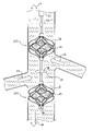
したがって、本発明のいくつかの応用例によれば、装置が提供され、当該装置は:
被験体の血管内部に配置されるように構成された血液ポンプを含んでおり、該血液ポンプは:
回転することによって血液をポンピングするように構成されたインペラを含んでおり
;かつ、
支持ケージを含んでおり、該支持ケージは:
狭部を定める形状をしており、該狭部は、インペラの周りに配置され、かつ、血管の壁部とインペラとの間の間隔を維持するように構成されており、かつ、
支持ケージの狭部に対して半径方向外側に延びる、支持ケージの狭部からの半径方向延長部を定める形状をしており、該半径方向延長部は、血管の壁部に接触することによって、インペラの長手方向軸を血管の局所的長手方向軸と整列した状態で実質的に維持するように構成されている。
Therefore, according to some application examples of the present invention, the device is provided and the device is:
It contains a blood pump configured to be placed inside a subject's blood vessel, which blood pump is:
Contains an impeller configured to pump blood by rotating; and
It contains a support cage, which is:
It has a shape that defines a narrow portion, and the narrow portion is arranged around the impeller and is configured to maintain a distance between the wall of the blood vessel and the impeller.
It has a shape that defines a radial extension from the narrow part of the support cage that extends radially outward with respect to the narrow part of the support cage, and the radial extension is by contacting the wall of the blood vessel. It is configured to substantially maintain the longitudinal axis of the impeller aligned with the local longitudinal axis of the blood vessel.
いくつかの応用例については、支持ケージの狭部と半径方向延長部とは、単一の一体化した構成要素を含んでいる。いくつかの応用例については、支持ケージの狭部と半径方向延長部とは、互いとは別個に形成されたそれぞれの構成要素を含んでいる。 For some applications, the narrow and radial extensions of the support cage include a single integrated component. For some applications, the narrow and radial extensions of the support cage include their respective components formed separately from each other.
いくつかの応用例については、半径方向延長部は、支持ケージの狭部から突き出た、複数の半径方向に突き出た支持アームを含んでいる。いくつかの応用例については、半径方向延長部は、支持ケージの狭部の周りに配置された円錐台状ケージを含んでいる。 For some applications, the radial extension includes a plurality of radial support arms protruding from the narrow portion of the support cage. For some applications, the radial extension includes a truncated cone cage placed around the narrow portion of the support cage.
いくつかの応用例では、支持ケージの狭部の不撓性が半径方向延長部の不撓性より大きく、たとえ血管の壁部が支持ケージに対して半径方向延長部が変形することを引き起こす圧力をかけても、ケージの狭部が血管の壁部とインペラとの間の間隔を維持するように構成されるようになっている。 In some applications, the inflexibility of the narrow portion of the support cage is greater than the inflexibility of the radial extension, even if the walls of the vessel exert pressure that causes the radial extension to deform relative to the support cage. However, the narrow part of the cage is designed to maintain the distance between the wall of the blood vessel and the impeller.
いくつかの応用例については、当該装置はさらに、支持ケージに連結された材料を含んでおり、該材料は、インペラ付近においてそれを通る穴を定め、該材料は、インペラの外側の周りの血液の逆流を塞ぎ、かつ、インペラ付近における順方向の血流を可能にするように構成されている。 For some applications, the device further comprises a material attached to a support cage, the material defining a hole through it in the vicinity of the impeller, the material being blood around the outside of the impeller. It is configured to block the backflow and allow forward blood flow near the impeller.
いくつかの応用例については、血液ポンプは、被験体の腎静脈内に配置され、かつ、被験体の腎静脈から被験体の大静脈の中へと血液をポンピングするように構成されている。 For some applications, the blood pump is located in the renal vein of the subject and is configured to pump blood from the renal vein of the subject into the vena cava of the subject.
いくつかの応用例については、血液ポンプは、被験体の大静脈内に、大静脈と被験体のすべての腎静脈との接合点の上流で配置されるように構成されており、該ポンプは、大静脈を通して血液を逆方向にポンピングするように構成されている。 For some applications, the blood pump is configured to be located within the vena cava of the subject, upstream of the junction of the vena cava and all of the subject's renal veins. , Is configured to pump blood in the opposite direction through the vena cava.
いくつかの応用例については、血液ポンプは、被験体の大静脈内に、大静脈と被験体のすべての腎静脈との接合点の下流で配置されるように構成されており、該ポンプは、大静脈を通して血液を順方向にポンピングするように構成されている。 For some applications, the blood pump is configured to be located within the vena cava of the subject, downstream of the junction of the vena cava and all of the subject's renal veins. , Is configured to pump blood forward through the vena cava.
いくつかの応用例については、当該装置はさらに追加の血液ポンプを含んでおり、該追加の血液ポンプは、被験体の大静脈内に、大静脈と被験体のすべての腎静脈との接合点の上流で配置されるように構成されており、該追加の血液ポンプは、大静脈を通して血液を逆方向にポンピングするように構成されている。 For some applications, the device further includes an additional blood pump, which is the junction of the vena cava with the subject's all renal veins within the subject's vena cava. It is configured to be located upstream of the vena cava, and the additional blood pump is configured to pump blood in the opposite direction through the vena cava.
いくつかの応用例については、当該装置はさらに閉塞要素を含んでおり、該閉塞要素は、被験体の大静脈内に、大静脈と被験体のすべての腎静脈との接合点の上流で配置されるように構成されており、該閉塞要素は、大静脈と被験体のすべての腎静脈との接合点の上流で大静脈を通る血流を部分的に塞ぐように構成されている。 For some applications, the device further comprises an obstructive element, which is placed within the vena cava of the subject, upstream of the junction of the vena cava and all renal veins of the subject. The obstruction element is configured to partially block the blood flow through the vena cava upstream of the junction of the vena cava and all renal veins of the subject.
いくつかの応用例については、半径方向延長部は、支持ケージの狭部から半径方向および遠位方向に延びる球状延長部を含んでいる。いくつかの応用例については、球状延長部
がその半径方向に拘束されていない構成にある時の球状延長部の最大直径が、狭部がその半径方向に拘束されていない構成にある時の支持ケージの狭部の最小直径より少なくとも1.1倍だけ大きい。
For some applications, the radial extension includes a spherical extension extending radially and distally from the narrow portion of the support cage. For some applications, the maximum diameter of the spherical extension when the spherical extension is in its radial unconstrained configuration is supported when the narrow portion is in its radial unconstrained configuration. It is at least 1.1 times larger than the minimum diameter of the narrow part of the cage.
さらに、本発明のいくつかの応用例によれば、方法が提供され、当該方法は:
被験体の血管に血液ポンプを挿入することを含んでおり、該血液ポンプは:
回転することによって血液をポンピングするように構成されたインペラを含んでおり;かつ、
支持ケージを含んでおり、該支持ケージは:
狭部を定める形状をしており、該狭部は、インペラの周りに配置され、かつ、血管の壁部とインペラとの間の間隔を維持するように構成されており、かつ、
支持ケージの狭部に対して半径方向外側に延びる、支持ケージの狭部からの半径方向延長部を定める形状をしており、該延長部は、血管の壁部に接触することによって、インペラの長手方向軸を血管の局所的長手方向軸と整列した状態で実質的に維持するように構成されており;かつ、
インペラを回転させて血液ポンプを作動させることによって、血管を通して血液をポンピングすることを含んでいる。
Further, according to some application examples of the present invention, a method is provided, wherein the method is:
It involves inserting a blood pump into a subject's blood vessel, which blood pump is:
Contains an impeller configured to pump blood by rotating; and
It contains a support cage, which is:
It has a shape that defines a narrow portion, and the narrow portion is arranged around the impeller and is configured to maintain a distance between the wall of the blood vessel and the impeller.
It has a shape that defines a radial extension from the narrow part of the support cage that extends radially outward with respect to the narrow part of the support cage, and the extension part of the impeller by contacting the wall part of the blood vessel. It is configured to substantially maintain the longitudinal axis aligned with the local longitudinal axis of the blood vessel;
It involves pumping blood through blood vessels by rotating an impeller to activate a blood pump.
さらに、本発明のいくつかの応用例によれば、方法が提供され、当該方法は:
急性心不全を患う被験体を識別することを含んでおり;
そのことに応答して、腎臓の下の位置において被験体の大静脈を部分的に塞ぐことによって、被験体の心前負荷を減少させることを含んでおり;
下半身静脈圧、中心静脈圧、中心静脈血流量、腎静脈圧、心臓の直径、心臓容積、動脈圧および動脈血流量よりなる群から選択される被験体の1つ以上の生理学的パラメーターをモニタリングすることを含んでおり;かつ、
1つ以上の生理学的パラメーターに応答して、大静脈が腎臓の下の位置において塞がれる程度を調節することを含んでいる。
Further, according to some application examples of the present invention, a method is provided, wherein the method is:
Includes identifying subjects suffering from acute heart failure;
In response, it involves reducing the subject's preload by partially occluding the subject's vena cava in a location below the kidney;
Monitoring one or more physiological parameters of a subject selected from the group consisting of lower body venous pressure, central venous pressure, central venous blood flow, renal venous pressure, heart diameter, heart volume, arterial pressure and arterial blood flow. Includes; and
It involves adjusting the degree to which the vena cava is occluded at a location below the kidney in response to one or more physiological parameters.
さらに、本発明のいくつかの応用例によれば、方法が提供され、当該方法は:
急性心不全を患う被験体を識別することを含んでおり;
そのことに応答して、被験体の大静脈内の腎臓の下の位置において血液を逆方向にポンピングすることによって、被験体の心前負荷を減少させることを含んでおり;
下半身静脈圧、中心静脈圧、中心静脈血流量、腎静脈圧、心臓の直径、心臓容積、動脈圧および動脈血流量よりなる群から選択される被験体の1つ以上の生理学的パラメーターをモニタリングすることを含んでおり;かつ、
1つ以上の生理学的パラメーターに応答して、血液が腎臓の下の位置において逆方向にポンピングされる量を調節することを含んでいる。
Further, according to some application examples of the present invention, a method is provided, wherein the method is:
Includes identifying subjects suffering from acute heart failure;
In response, it involves reducing the subject's preload by pumping blood in the reverse direction at a location below the kidney within the subject's vena cava;
Monitoring one or more physiological parameters of a subject selected from the group consisting of lower body venous pressure, central venous pressure, central venous blood flow, renal venous pressure, heart diameter, heart volume, arterial pressure and arterial blood flow. Includes; and
It involves regulating the amount of blood pumped in the opposite direction at a location below the kidney in response to one or more physiological parameters.
さらに、本発明のいくつかの応用例によれば、装置が提供され、当該装置は:
閉塞要素を含んでおり、該閉塞要素は、腎臓の下の位置において被験体の大静脈に配置されることによって被験体の心前負荷を減少させ、かつ、腎臓の下の位置において被験体の大静脈を部分的に塞ぐように構成されており;
1つ以上のセンサーを含んでおり、該1つ以上のセンサーは、下半身静脈圧、中心静脈圧、中心静脈血流量、腎静脈圧、心臓の直径、心臓容積、動脈圧および動脈血流量よりなる群から選択される被験体の1つ以上の生理学的パラメーターをモニタリングするように構成されており;かつ、
コンピュータープロセッサーを含んでおり、該コンピュータープロセッサーは、1つ以上の生理学的パラメーターに応答して、閉塞要素が腎臓の下の位置において大静脈を塞ぐ程度を調節することを含んでいる。
Further, according to some application examples of the present invention, an apparatus is provided, wherein the apparatus is:
It contains an obstructive element that reduces the subject's precardiac load by being placed in the subject's vena cava at a position below the kidney and at a position below the kidney of the subject. It is configured to partially block the vena cava;
Includes one or more sensors, the group consisting of lower body venous pressure, central venous pressure, central venous pressure, renal venous pressure, heart diameter, heart volume, arterial pressure and arterial blood pressure. It is configured to monitor one or more physiological parameters of a subject selected from; and
Includes a computer processor, which comprises adjusting the degree to which the obstructive element occludes the vena cava at a location below the kidney in response to one or more physiological parameters.
いくつかの応用例については、閉塞要素は、腎臓の下の位置において膨張するように構成されたバルーンを含んでおり、かつ、コンピュータープロセッサーは、バルーンが膨張する程度を調節することによって、閉塞要素が腎臓の下の位置において大静脈を塞ぐ程度を調節するように構成されている。 For some applications, the obstruction element comprises a balloon configured to inflate at a location below the kidney, and the computer processor adjusts the degree to which the balloon inflates to cause the obstruction element. Is configured to regulate the degree of obstruction of the vena cava in the position below the kidney.
いくつかの応用例については、閉塞要素は、拡張可能なフレームであってそれに覆われた材料を有する前記の拡張可能なフレームを含んでおり、かつ、コンピュータープロセッサーは、フレームが拡張する程度を調節することによって、閉塞要素が腎臓の下の位置において大静脈を塞ぐ程度を調節するように構成されている。 For some applications, the obstruction element comprises the expandable frame having the material covered by the expandable frame, and the computer processor adjusts the extent to which the frame expands. By doing so, the obstructive element is configured to regulate the extent to which it occludes the vena cava at a location below the kidney.
いくつかの応用例については、閉塞要素はノズルを含んでおり、かつ、コンピュータープロセッサーは、ノズルの開口部の直径を調節することによって、閉塞要素が腎臓の下の位置において大静脈を塞ぐ程度を調節するように構成されている。 For some applications, the obstruction element comprises a nozzle, and the computer processor adjusts the diameter of the nozzle opening to the extent that the obstruction element occludes the vena cava at a location below the kidney. It is configured to adjust.
いくつかの応用例については、1つ以上のセンサーは、被験体の心拍出量を示す被験体のパラメーターをモニタリングするように構成されており、かつ、コンピュータープロセッサーは、心拍出量を示すパラメーターに応答して、閉塞要素が腎臓の下の位置において大静脈を塞ぐ程度を調節するように構成されている。 For some applications, one or more sensors are configured to monitor a subject's parameters indicating the subject's cardiac output, and a computer processor indicates the cardiac output. In response to parameters, the occlusion element is configured to regulate the degree to which the vena cava is occluded below the kidney.
いくつかの応用例については、1つ以上のセンサーは、心拍出量を示すパラメーターをモニタリングするように構成されたサーモダイリューションカテーテルを含んでいる。 For some applications, one or more sensors include a thermodilution catheter configured to monitor parameters that indicate cardiac output.
いくつかの応用例については、1つ以上のセンサーはさらに、被験体の心前負荷を示す被験体のパラメーターをモニタリングするように構成されており、コンピュータープロセッサーは、心前負荷を示すパラメーターと組み合された心拍出量を示すパラメーターに応答して、閉塞要素が腎臓の下の位置において大静脈を塞ぐ程度を調節するように構成されている。 For some applications, one or more sensors are further configured to monitor the subject's parameters indicating preload, and the computer processor is paired with the subject's preload parameters. It is configured to regulate the degree to which the obstructive element occludes the vena cava at a location below the kidney in response to a parameter indicating combined cardiac output.
いくつかの応用例については、1つ以上のセンサーは、被験体の動脈血圧を示す被験体のパラメーターをモニタリングするように構成されており、かつ、コンピュータープロセッサーは、動脈血圧を示すパラメーターに応答して、閉塞要素が腎臓の下の位置において大静脈を塞ぐ程度を調節するように構成されている。 For some applications, one or more sensors are configured to monitor a subject's parameters indicating arterial blood pressure, and a computer processor responds to the subjects' parameters indicating arterial blood pressure. It is configured to regulate the degree to which the obstructive element occludes the vena cava at a location below the kidney.
いくつかの応用例については、1つ以上のセンサーはさらに、被験体の心前負荷を示す被験体のパラメーターをモニタリングするように構成されており、コンピュータープロセッサーは、心前負荷を示すパラメーターと組み合された動脈血圧を示すパラメーターに応答して、閉塞要素が腎臓の下の位置において大静脈を塞ぐ程度を調節するように構成されている。 For some applications, one or more sensors are further configured to monitor the subject's parameters indicating preload, and the computer processor is paired with the subject's preload parameters. In response to the parameters indicating the combined arterial blood pressure, the obstructive element is configured to regulate the degree of obstruction of the vena cava in the position below the kidney.
いくつかの応用例については、当該装置はさらに、大静脈と被験体のすべての腎静脈との接合点の下流である大静脈内の位置に配置されるように構成された血液ポンプを含んでおり、該血液ポンプは、該位置から大静脈を通して順方向に血液をポンピングすることによって、被験体の中心静脈圧に対して被験体の腎静脈圧を減少させるように構成されている。 For some applications, the device further includes a blood pump configured to be located within the large vein downstream of the junction of the large vein with all renal veins of the subject. The blood pump is configured to reduce a subject's renal venous pressure relative to the subject's central venous pressure by pumping blood forward from that position through a large vein.
いくつかの応用例については、コンピュータープロセッサーはさらに、1つ以上の生理学的パラメーターに応答して、血液ポンプが順方向に血液をポンピングする量を調節するように構成されている。 For some applications, the computer processor is further configured to regulate the amount of blood pumped forward by the blood pump in response to one or more physiological parameters.
いくつかの応用例については、コンピュータープロセッサーは、1つ以上の生理学的パ
ラメーターに応答して、大静脈が腎臓の下の位置において塞がれる程度を調節することとともに、1つ以上の生理学的パラメーターに応答して、血液ポンプが順方向に血液をポンピングする量を調節するように構成されており:
被験体の腎静脈圧と被験体の下半身静脈圧との間の第1の比を維持し、かつ、
被験体の中心静脈圧と被験体の下半身静脈圧との間の第2の比を維持し、
第2の比が第1の比とは異なるようになっている。
For some applications, the computer processor responds to one or more physiological parameters, adjusting the degree to which the vena cava is occluded below the kidney, as well as one or more physiological parameters. In response to, the blood pump is configured to regulate the amount of blood pumped in the forward direction:
Maintain the first ratio between the subject's renal venous pressure and the subject's lower body venous pressure, and
Maintaining a second ratio between the subject's central venous pressure and the subject's lower body venous pressure,
The second ratio is different from the first ratio.
さらに、本発明のいくつかの応用例によれば、装置が提供され、当該装置は:
被験体の大静脈内の腎臓の下の位置に配置されることおよび該位置から逆方向に血液をポンピングすることによって被験体の心前負荷を減少させるように構成された血液ポンプを含んでおり;
1つ以上のセンサーを含んでおり、該1つ以上のセンサーは、下半身静脈圧、中心静脈圧、中心静脈血流量、腎静脈圧、心臓の直径、心臓容積、動脈圧および動脈血流量よりなる群から選択される被験体の1つ以上の生理学的パラメーターをモニタリングするように構成されており;かつ、
コンピュータープロセッサーを含んでおり、該コンピュータープロセッサーは、1つ以上の生理学的パラメーターに応答して、血液ポンプが逆方向に血液をポンピングする量を調節するように構成されている。
Further, according to some application examples of the present invention, an apparatus is provided, wherein the apparatus is:
Includes a blood pump configured to be located below the kidney within the subject's vena cava and to reduce the subject's preload by pumping blood in the opposite direction from that location. ;
Includes one or more sensors, the group consisting of lower body venous pressure, central venous pressure, central venous pressure, renal venous pressure, heart diameter, heart volume, arterial pressure and arterial blood pressure. It is configured to monitor one or more physiological parameters of a subject selected from; and
Includes a computer processor, which is configured to regulate the amount of blood pumped in the reverse direction in response to one or more physiological parameters.
いくつかの応用例については、1つ以上のセンサーは、被験体の心拍出量を示す被験体のパラメーターをモニタリングするように構成されており、かつ、コンピュータープロセッサーは、心拍出量を示すパラメーターに応答して、血液ポンプが逆方向に血液をポンピングする量を調節するように構成されている。 For some applications, one or more sensors are configured to monitor a subject's parameters indicating the subject's cardiac output, and a computer processor indicates the cardiac output. In response to parameters, the blood pump is configured to regulate the amount of blood pumped in the opposite direction.
いくつかの応用例については、1つ以上のセンサーは、心拍出量を示すパラメーターをモニタリングするように構成されたサーモダイリューションカテーテルを含んでいる。 For some applications, one or more sensors include a thermodilution catheter configured to monitor parameters that indicate cardiac output.
いくつかの応用例については、1つ以上のセンサーはさらに、被験体の心前負荷を示す被験体のパラメーターをモニタリングするように構成されており、かつ、コンピュータープロセッサーは、血液がポンピングされることを調節するように構成されており、該調節は、心前負荷を示すパラメーターと組み合された心拍出量を示すパラメーターに応答して、血液ポンプが逆方向に血液をポンピングする量を調節することを含んでいる。 For some applications, one or more sensors are further configured to monitor the subject's parameters indicating the subject's preload, and the computer processor is pumped with blood. Is configured to regulate the amount by which the blood pump pumps blood in the opposite direction in response to a parameter that indicates cardiac output combined with a parameter that indicates preload. Includes doing.
いくつかの応用例については、1つ以上のセンサーは、被験体の動脈血圧を示す被験体のパラメーターをモニタリングするように構成されており、かつ、コンピュータープロセッサーは、動脈血圧を示すパラメーターに応答して、血液ポンプが逆方向に血液をポンピングする量を調節するように構成されている。 For some applications, one or more sensors are configured to monitor a subject's parameters indicating arterial blood pressure, and a computer processor responds to the subjects' parameters indicating arterial blood pressure. The blood pump is configured to regulate the amount of blood pumped in the opposite direction.
いくつかの応用例については、1つ以上のセンサーはさらに、被験体の心前負荷を示す被験体のパラメーターをモニタリングするように構成されており、かつ、コンピュータープロセッサーは、血液がポンピングされることを調節するように構成されており、該調節は、心前負荷を示すパラメーターと組み合された動脈血圧を示すパラメーターに応答して、血液ポンプが逆方向に血液をポンピングする量を調節することを含んでいる。 For some applications, one or more sensors are further configured to monitor the subject's parameters indicating the subject's preload, and the computer processor is pumped with blood. The regulation is configured to regulate the amount of blood pumping in the reverse direction in response to a parameter indicating arterial blood pressure combined with a parameter indicating preload. Includes.
いくつかの応用例については、当該装置はさらに、大静脈と被験体のすべての腎静脈との接合点の下流である大静脈内の下流位置に配置されるように構成された第2の血液ポンプを含んでおり、該第2の血液ポンプは、大静脈と被験体のすべての腎静脈との接合点の下流である位置から大静脈を通して順方向に血液をポンピングすることによって、被験体の中心静脈圧に対して被験体の腎静脈圧を減少させるように構成されている。 For some applications, the device is further configured to be located downstream within the large vein, downstream of the junction of the large vein with all renal veins of the subject. The second blood pump comprises a pump of the subject by pumping blood forward through the large vein from a location downstream of the junction of the large vein with all the renal veins of the subject. It is configured to reduce the subject's renal venous pressure relative to central venous pressure.
いくつかの応用例については、コンピュータープロセッサーはさらに、1つ以上の生理学的パラメーターに応答して、第2の血液ポンプが下流位置から順方向に血液をポンピングする量を調節するように構成されている。 For some applications, the computer processor is further configured to adjust the amount of blood pumped forward from the downstream position by the second blood pump in response to one or more physiological parameters. There is.
いくつかの応用例については、コンピュータープロセッサーは、血液が被験体の大静脈内の腎臓の下の位置において逆方向にポンピングされる量を調節することとともに、血液が下流位置から大静脈を通して順方向にポンピングされる量を調節することによって、第2の血液ポンプが1つ以上の生理学的パラメーターに応答して下流位置から順方向に血液をポンピングする量を調節するように構成されており:
被験体の腎静脈圧と被験体の下半身静脈圧との間の第1の比を維持し、かつ、
被験体の中心静脈圧と被験体の下半身静脈圧との間の第2の比を維持し、
第2の比が第1の比とは異なるようになっている。
For some applications, the computer processor regulates the amount of blood pumped in the reverse direction at a position below the kidney in the subject's vena cava, while the blood is forwarded from the downstream position through the vena cava. By adjusting the amount pumped into, the second blood pump is configured to adjust the amount of blood pumped forward from the downstream position in response to one or more physiological parameters:
Maintain the first ratio between the subject's renal venous pressure and the subject's lower body venous pressure, and
Maintaining a second ratio between the subject's central venous pressure and the subject's lower body venous pressure,
The second ratio is different from the first ratio.
本発明は、図面とともに考慮される、その実施形態の以下の詳細な説明からいっそう完全に理解されるであろう。 The present invention will be more fully understood from the following detailed description of embodiments thereof, which are considered with the drawings.
実施形態の詳細な説明
本発明のいくつかの応用例にしたがう、ガイドカテーテル23を通して被験体の大静脈22内に配置された血液ポンプカテーテル20の概略図である図1A~図1Cを参照すると、下流ポンプ24Dに対して遠位方向にはカテーテル上に上流ポンプ24Uが配置されている。典型的には、血液ポンプカテーテル20の遠位部は、カテーテルが拘束されていない状態にある時には直線状であるように構成されており、上流ポンプおよび下流ポンプの両方が大静脈内にカテーテルの軸に沿って配置されるようになっている。
Detailed description of the embodiment
With reference to FIGS. 1A-1C, which are schematic views of the
上流ポンプ24Uおよび下流ポンプ24Dはそれぞれ、典型的には、半径方向に拡張可能なインペラケージ30の内部に配置された半径方向に拡張可能なインペラ28を含んでいる。典型的には、インペラ28およびインペラケージ30は、インペラおよびケージに対して作用する任意の半径方向に拘束する力の不存在下ではその半径方向に拡張した構成をとるように設定された形状である。血液ポンプは、血液ポンプがガイドカテーテルの内部で半径方向に拘束された構成にある間に被験体の大静脈の中に挿入され、かつ、被験体の大静脈の内部でガイドカテーテルから解放されることによって実質的に半径方向に拘束
されていない構成をとるように構成されている。(いくつかの応用例については、大静脈において、血液ポンプは、大静脈の壁部が血液ポンプに半径方向の圧縮力を加えることに起因して、完全に半径方向に拘束されていない状態にはならないであろうことが注目される。)いくつかの応用例については、例えばSchwammenthalへの米国特許出願公開第2016/0022890号明細書(参照によって本明細書に組み込まれる)に記載の装置および方法にしたがい、係合機構がインペラおよびケージを互いに対して係合させ、ケージが半径方向に拘束されるようになることに応答して、インペラが半径方向に拘束されるようになるようになっている。
The
用語「インペラ」は概して、本明細書では、例えば図1A~図1Cに示されているようなブレード付きローターを示すのに用いられることが注目される。ブレード付きローターが血管(大静脈22のような)の内部に配置され、かつ、回転する時、ブレード付きローターは、血管を通る血液の流れを修正することによって、および/または、インペラの上流端と下流端との間に圧力差を作り出すことによってインペラとして機能する。 It is noted that the term "impeller" is generally used herein to refer to bladed rotors, such as those shown in FIGS. 1A-1C. When the bladed rotor is placed inside a blood vessel (such as the vena cava 22) and rotates, the bladed rotor modifies the flow of blood through the blood vessel and / or the upstream end of the impeller. It functions as an impeller by creating a pressure difference between the blood vessel and the downstream end.
参照数字24は概して、本願において血液ポンプを示すのに用いられることが注目される。上流に配置されたポンプが参照される時、参照数字24Uが用いられ、かつ、下流に配置されたポンプが参照される時、参照数字24Dが用いられる。同様に、本願においては、インペラを示すのに参照数字28が概して用いられる。上流に配置されたインペラが参照される時、参照数字28Uが用いられ、かつ、下流に配置されたインペラが参照される時、参照数字28Dが用いられる。
It is noted that
血液ポンプカテーテル20は、典型的には、被験体の大静脈22の内部に配置され、かつ、その中で作動して、心機能不全、うっ血性心不全、腎血流量の低下、腎血管抵抗の上昇、動脈性高血圧、糖尿病および/または腎機能不全を患う被験体の急性治療を提供する。例えば、血液ポンプカテーテルは、1時間より長く(例えば、1日より長く)、1週間より短い(例えば、4日より短い)期間および/または1時間~1週間の間(例えば、1日~4日の間)、被験体の大静脈の内部に配置され、かつ、その中で作動してもよい。いくつかの応用例については、血液ポンプカテーテルは、被験体の大静脈の内部に慢性的に配置されて、心機能不全、うっ血性心不全、腎血流量の低下、腎血管抵抗の上昇、動脈性高血圧、糖尿病および/または腎機能不全を患う被験体の慢性治療を提供する。いくつかの応用例については、本発明に記載の技術にしたがって、数週間、数か月または数年にわたって、被験体に対して治療のコースが適用され、その期間の最中、血液ポンプカテーテルは被験体の大静脈の内部に断続的に配置され、かつ、被験体は断続的に治療される。例えば、被験体は、数日、数週間または数か月の間隔で断続的に治療されてもよい。
The
いくつかの応用例については、血液ポンプカテーテル20は、図1Aに示されているように、被験体の鎖骨下静脈40を通して大静脈22の中に挿入される。典型的には、血液ポンプカテーテルは、蛍光透視撮像下で挿入される。代替的には、血液ポンプカテーテルは、超音波撮像下で挿入され、放射能および/または造影剤に対する被験体の曝露を減少させるようになっている。カテーテルは、上流ポンプ24Uが大静脈と被験体の腎静脈42のすべてとの接合点の上流に配置されるように、かつ、下流ポンプ24Dが大静脈と被験体の腎静脈のすべてとの接合点の下流に配置されるように大静脈の中に配置される。典型的には、上流ポンプは、腎静脈から離れるように上流方向に大静脈を通して血液をポンピングするように構成されており、かつ、下流ポンプは、腎静脈から離れるように下流方向に大静脈を通して血液をポンピングするように構成されている。
For some applications, the
ポンプ24Uおよびポンプ24Dが両方とも上記の様式で血液をポンピングすることの効果は、それらポンプ同士の間において、かつ、大静脈と腎静脈との接合点に隣接して、大静脈の低圧領域が存在し、該低圧領域内では、血圧が被験体の中心静脈圧より低いこと
である。機能上、この領域は、大静脈内のコンパートメントとして見られてもよく、該コンパートメント内では、血圧が、大静脈内のその他の場所の血圧とは無関係に制御される(ポンプ24Uおよびポンプ24Dを制御することによって)。このことは、典型的には、腎静脈から大静脈の中への血流量を増大させ、被験体の腎静脈内の圧力を低下させ、かつ、腎潅流が増大することを引き起こす。腎静脈および大静脈を通る血流に対するポンプ24Uおよびポンプ24Dの効果は、図1Bにおいて矢印44によって示されている。
The effect of both
上記されたように、血液ポンプ24Uおよび血液ポンプ24Dを作動させることの効果は、それらのポンプ間に大静脈の低圧領域が存在することである。しかしながら、典型的には、ポンプは同時に作動し、大静脈内のその他の部分内の圧力が、血液ポンプカテーテル20が作動していない時と比べて、実質的に不変であるようになっている。例えば、ポンプは典型的には同時に作動し、下流ポンプ24Dの下流の大静脈内の圧力が、血液ポンプカテーテル20が作動していない時と比べて、実質的に増大しないようになっている。同様に、ポンプは典型的には同時に作動し、上流ポンプ24Uの上流の大静脈内の圧力が、血液ポンプカテーテル20が作動していない時と比べて、実質的に増大しないようになっている。これは、ポンプが典型的には同時に作動し、2つのポンプの間の領域の外側では、上流ポンプおよび下流ポンプによるポンピングの効果が圧力に関して相殺されるようになっているからである。腎静脈から大静脈の中への血流量が増大することに起因して、下流ポンプの下流および上流ポンプの上流の大静脈内において、圧力がいくぶん増加する可能性があることが注目される。
As mentioned above, the effect of operating the
同様に、ポンプは典型的には同時に作動し、上流ポンプの上流および下流ポンプから下流の領域から大静脈への静脈還流量が、血液ポンプカテーテル20が作動していない時と比べて、実質的に不変であるようになっている。この様式では、ポンプは典型的には同時に作動し、ポンプ間の領域における圧力および流量に対しては概して相乗的な効果を有するが、該領域の外側では圧力および流量に対して拮抗効果を有し、該領域の外側では2つのポンプの効果が典型的には実質的に相殺されるようになっている。
Similarly, the pumps typically operate simultaneously, and the amount of venous return from the upstream and downstream regions of the upstream pump to the vena cava is substantially higher than when the
典型的には、血液ポンプカテーテル20は、腎静脈を通って大静脈の中に入る血流の割合は高めるが、腎静脈を通る、または腎静脈から大静脈への流れの自然な方向に対して(すなわち、血液ポンプカテーテルによるポンピングの不存在下での血流に対して)血流の方向の実質的な変化は引き起こさない様式で血液をポンピングする。すなわち、血液ポンプカテーテルは、例えば腎静脈から被験体の静脈の別の部分(大静脈内の上流位置のような)の中へと血液をポンピングするのではなく、腎静脈を通って、その後、腎静脈に隣接した大静脈の部分の中に直接入るように下流方向に血液をポンピングする。下流方向における下流ポンプのポンピングに起因して、腎静脈から腎静脈より下の大静脈の部分へのいくぶんの血流が存在する可能性があることが注目される。さらに典型的には、血液ポンプカテーテル20は、被験体の静脈系から血液ポンプの人工ルーメンのような非静脈性レセプタクルの中への血液を除去することを伴わずに腎静脈を通る血流を向上させる。
Typically, the
上記されたように、典型的には、血液ポンプカテーテル20は、心機能不全、うっ血性心不全、腎血流量の低下、腎血管抵抗の上昇、動脈性高血圧、糖尿病および/または腎機能不全を患う被験体の大静脈の内部に配置される。典型的には、例えばSchwammenthalへの米国特許出願公開第2016/0022890号明細書(参照によって本明細書に組み込まれる)の図4Bを参照して記載されるように、かかる被験体の大静脈において血液ポンプカテーテルを作動させることは、たとえ被験体の中心静脈圧が上昇したとしても、被験体の腎静脈圧プロファイルの低下および平坦化を引き起こし、かつ、追加的な効果を有する。
As mentioned above, the
典型的には、上流ポンプ24Uおよび下流ポンプ24Dはそれぞれ、インペラ28(例
えば、Schwammenthalへの米国特許出願公開第2016/0022890号明細書(参照によって本明細書に組み込まれる)に記載のインペラのうちのいずれか1つ)を含んでいる。各応用例にしたがって、インペラ28は、単一のブレードを有していてもよく、2つのブレード(例えば、Schwammenthalへの米国特許出願公開第2016/0022890号明細書(参照によって本明細書に組み込まれる)に記載されているような)を有していてもよく、3つのブレード(例えば、Schwammenthalへの米国特許出願公開第2016/0022890号明細書に記載されているような)を有していてもよく、3つより多いブレードを有していてもよい。いくつかの応用例については、血液ポンプ24Uおよび血液ポンプ24Dの一方または両方が、1つより多いインペラを含んでいる。典型的には、その他の事情が同じであれば、ポンプを用いて所定の血液の流れを作り出すために、ポンプのうちの少なくとも一方において1つより多いインペラを用いることによって、ポンプ内の各インペラに影響を与える力は、ポンプにおいて単一のインペラが用いられる場合より小さい。
Typically, the
いくつかの応用例については、ポンプの一方または両方が、半径方向に拡張可能なインペラケージ30を含んでいる。いくつかの応用例については、インペラケージ30は、大静脈の内壁を開いた状態で保持し、かつ、インペラから大静脈の内壁を分離するように構成されており、大静脈がインペラによって傷付けられないようになっている。代替的には、インペラケージは、ケージが大静脈の内壁を開いた状態で保持するのに用いられないようにサイズ決めされる(ケージの直径は、少なくとも何名かの被験体においては、大静脈のものより小さい)。かかる場合でさえ、ケージは、典型的には、例えば大静脈の壁部が少なくとも部分的に内側に潰れる場合に、インペラから大静脈の内壁を分離するように機能し、大静脈がインペラによって傷付けられないようになっている。かかる応用例は、例えば図9A~図9Bを参照して記載されている。
For some applications, one or both of the pumps include an
上記されたように、典型的には、インペラ28およびケージ30は、インペラおよび/またはケージに対して作用する任意の半径方向に拘束する力の不存在下ではその半径方向に拡張した構成をとるように設定された形状である。いくつかの応用例については、例えばSchwammenthalへの米国特許出願公開第2016/0022890号明細書(参照によって本明細書に組み込まれる)に記載の装置および方法にしたがい、係合機構がインペラおよびケージを互いに対して係合させ、ケージが半径方向に拘束されるようになることに応答して、インペラが半径方向に拘束されるようになるようになっている。いくつかの応用例については、ケージ30の不撓性は、大静脈の内壁によってケージに対してかけられる圧力がケージを変形させない程十分に大きい。ケージは、そのことによって、大静脈の内壁からの圧力によって変形することからインペラを保護する。かかる応用例は、例えば図9A~図9Bを参照して、以下に記載されている。
As mentioned above, the
ここで図1Cを参照すると、典型的には、血液ポンプカテーテル20が大静脈22の内部に配置される時、インペラ28およびインペラケージ30は、ケージに対して大静脈の壁部によってかけられる比較的小さい半径方向の力に起因して、実質的に半径方向に拘束されていない。(いくつかの応用例については、大静脈において、インペラおよび/またはインペラケージは、大静脈の壁部が血液ポンプに半径方向の圧縮力を加えることに起因して、完全に半径方向に拘束されていない状態にはならないであろうことが注目される。)いくつかの応用例については、インペラケージは、例えば図1Cに示されているように、インペラケージが大静脈の内部でその半径方向に拘束されていない構成をとる時に、大静脈の内壁と接触するように構成されている。かかる応用例については、インペラ28の全長SPが、インペラが大静脈の内部でその拘束されていない構成にある時には、14mmより大きく(例えば、16mmより大きく)、および/または、28mmより小さく(例えば、22mmより小さく)、例えば、14~28mmまたは16~22mmである。典型的には、かかる応用例については、ケージ30の直径Dが、ケージが大静脈の内部で
その拘束されていない構成にある時には、14mmより大きく(例えば、16mmより大きく)、および/または、40mmより小さく(例えば、35mmより小さく)、例えば、14~40mmまたは16~35mmである。さらに典型的には、血液ポンプカテーテル20が本明細書に記載されるように腎静脈から被験体の大静脈の中への血流を向上させるのに用いられる時、カテーテルの長手方向軸に沿って測定される上流ポンプおよび下流ポンプのインペラの中心間の長手方向距離Dlが、典型的には、3cmより大きく(例えば、6cmより大きく)、および/または、18cmより小さく(例えば、14cmより小さく)、例えば、3~18cmまたは6~14cmである。いくつかの応用例については、距離Dlは調節可能であり、かつ、被験体に対して実行される測定に基づいて設定される。
Referring here to FIG. 1C, typically when the
いくつかの応用例については、例えば図9A~図9Bを参照して下記に記載されているように、インペラ30は、その半径方向に拘束されていない構成では、ケージが少なくとも何名かの被験体においては大静脈のものより小さい直径を有するように構成されている。
For some application examples, for example, as described below with reference to FIGS. 9A-9B, the
いくつかの応用例については、上流ポンプ24Uおよび下流ポンプ24Dのインペラ28は、それぞれの回転速度で回転し、上流方向および下流方向における血液のポンピングがそれぞれの速度で実行されることを引き起こす。代替的には、インペラは、同一の回転速度で(かつ、典型的には同一方向に)回転するが、インペラは、血液が各インペラによってそれぞれ上流方向および下流方向にポンピングされる量が等しくないようにサイズ決めされ、成形され、および/または配向される。
For some applications, the
典型的には、被験体の身体の外側には、制御ユニット52およびユーザーインターフェース54が配置される。さらに典型的には、制御ユニットは、例えば図1A~図1Cに示されているように、1つ以上の圧力センサー56、58および/または60からの入力を受け取る。
Typically, the
いくつかの応用例によれば:
(a)上流血液ポンプ24Uの上流側に圧力センサー56が配置され、かつ、大静脈の低圧領域の上流の大静脈内の圧力を測定するように構成されており、該圧力は、典型的には、被験体の下半身内の静脈圧を示しており;
(b)2つの血液ポンプの間に圧力センサー58が配置され、かつ、2つの血液ポンプの間の大静脈の低圧領域内の圧力を測定するように構成されており、該圧力は、典型的には、被験体の腎静脈内の血圧を示しており;および/または、
(c)下流血液ポンプ24Dの下流側に圧力センサー60が配置され、かつ、大静脈の低圧領域の下流の大静脈内の圧力を測定するように構成されており、該圧力は、典型的には、被験体の右心近傍の被験体の中心静脈圧を示している。
According to some application examples:
(A) A
(B) A
(C) A
いくつかの応用例については、血液ポンプカテーテル20は、2つの血液ポンプの間に配置された圧力センサー58を含んでおり、かつ、2つの血液ポンプの間の大静脈の低圧領域内の圧力を測定するように構成されており、該圧力は、典型的には、被験体の腎静脈内の血圧を示しており、かつ、血液ポンプカテーテルは、圧力センサー56または圧力センサー60を含んでいない。
For some applications, the
いくつかの応用例については、制御ユニット52は、上記入力の1つ以上に応答して、例えばインペラ28の回転を制御することによって、ポンプ24Uおよびポンプ24Dを制御する。典型的には、ユーザーインターフェース54は、センサー56、センサー58および/またはセンサー60によって生成される信号に基づいて、被験体の現在の下半身静脈圧、腎静脈圧および/または中心静脈圧を表示する。典型的には、被験体の下半身静
脈圧、腎静脈圧および/または中心静脈圧の現在の値に基づいて、ユーザー(医療従事者のような)が、ユーザーインターフェースを介して被験体の腎静脈圧についての標的値を入力する。そのことに応答して、制御ユニット52は、インペラの回転の速度を制御し、インペラが、ユーザーによって示されたように標的レベルに向けて腎静脈圧を減少させるような流速で腎静脈から離れるように血液をポンピングするようになっている。いくつかの応用例については、中心静脈圧が標的腎静脈圧にあることを示すセンサー60から受け取られた信号に応答して、制御ユニットは、インペラが回転することを停止させる。いくつかの応用例については、制御ユニットは、追加のセンサー(例えばSchwammenthalへの米国特許出願公開第2016/0022890号明細書(参照によって本明細書に組み込まれる)の図22Ai~図22Ciiを参照して記載されるような、流量センサーおよび/または酸素飽和センサーおよび/または感熱式流量センサー)からの入力を受け取り、かつ、制御ユニットは、追加のセンサーからの入力に応答して、インペラの回転の速度を制御する。
For some application examples, the
制御ユニット52は、典型的には、コンピュータープロセッサーを含んでおり、該コンピュータープロセッサーは、回路を有し、かつ、本明細書に記載のアクションを実行するように構成されていることが注目される。典型的には、コンピュータープロセッサーによって実行される本明細書に記載の作動は、コンピュータープロセッサーと通信している現実の物理的な物品であるメモリーの物理的な状態を、用いられるメモリーの技術に基づいて、異なる磁極性、電荷などを有するように変化させる。制御ユニット52は、典型的には、専用コンピューターを作り出すようにというコンピュータープログラム命令でプログラミングされたハードウェアデバイスである。例えば、本明細書に記載の技術を実行するようにプログラミングされる時、制御ユニット52は、専用の、腎静脈圧調節コンピュータープロセッサーとして作用する。
It is noted that the
ユーザーインターフェース54は、典型的には、ユーザーから入力を受け取り、および/または、ユーザーに出力を提供するように構成された任意のタイプのユーザーインターフェースを含んでいることがさらに注目される。例えば、ユーザーインターフェースは、1つ以上の入力デバイス(キーボード、マウス、トラックボール、ジョイスティック、タッチスクリーンモニター、タッチパッド、音声コマンドインターフェース、スマートフォン、タブレットコンピューターおよび/もしくは本技術分野で既知のその他のタイプの入力デバイスのような)ならびに/または1つ以上の出力デバイス(モニター、音声出力デバイス、スマートフォン、タブレットコンピューターおよび/もしくは本技術分野で既知のその他のタイプの出力デバイスのような)を含んでいてもよい。
It is further noted that the
ここで図2A、図2B、図2C、図2Dおよび図2Eを参照すると、該図は、本発明のいくつかの応用例にしたがう、互いに反対方向に血液をポンピングするように構成されたインペラ28Uとインペラ28Dとの配置構成の概略図である。(説明の目的で、典型的にはインペラは上記されたようにインペラケージ30とともに用いられるが、図2A~図2Eはインペラケージの不存在下でのインペラを示している。)
Referring now to FIGS. 2A, 2B, 2C, 2D and 2E, the figure is an
典型的には、ポンプ24Uおよびポンプ24Dのインペラは、1つ以上のモーター46に連結され(図1A)、該1つ以上のモーター46は、1つ以上の回転シャフトを介してインペラに回転運動を与え、該シャフトは、血液ポンプカテーテル20の内部に収容される。各応用例によれば、モーターは、被験体の身体の外側に配置され(図示されているように)、または、被験体の身体の内部に配置される(図示せず)。
Typically, the impellers of the
ここで図2Aを参照すると、いくつかの応用例については、上流ポンプ24Uおよび下流ポンプ24Dのインペラ28は、外部基準点から見た時、互いに同一の回転方向(例えば、矢印48の方向(すなわち、時計回り)または反時計回り)に回転するが、インペラ
は、この回転の方向におけるインペラの回転が、インペラがそれぞれの反対方向に血液をポンピングすることを引き起こすようにカテーテル上に配置される。「外部基準点から見た時」のインペラの回転方向は、いずれのインペラとも同一の回転運動を経験していない任意の点から観察した時のインペラの回転運動の方向を意味するものと解釈されるべきであることが注目される。
Here, with reference to FIG. 2A, for some application examples, the
典型的には、かかる応用例については、両方のインペラを回転させるのに単一のモーターが用いられる。モーターから近位インペラへと回転運動を与えるのに、シャフト50が用いられる。シャフト50と直列である追加のシャフト51が、近位インペラを遠位インペラに連結させ、かつ、近位インペラから遠位インペラへと回転運動を与える。いくつかの応用例については、単一の直列したシャフトを用いて上流ポンプ24Uおよび下流ポンプ24Dの両方のインペラ28に回転を与えることによって、血液ポンプカテーテル20の直径は、上流インペラおよび下流インペラに回転を与えるのに並列のシャフトが用いられた場合と比べて減少する。
Typically, for such applications, a single motor is used to rotate both impellers. The
いくつかの応用例については、上流ポンプ24Uおよび下流ポンプ24Dのインペラ28のインペラブレードの角度および/または配向は、インペラがそれぞれの反対方向に血液をポンピングすることを引き起こすようなものであってもよい。いくつかの応用例については、図2Aに示されているように、各インペラは、他方の鏡像となるように成形され、および/または、配向され、反射軸は、インペラの長手方向軸に直交する。かかる応用例については、上流インペラおよび下流インペラは、互いに反対の回転方向(handedness)のものであり、インペラのうちの第1のものは左回りのインペラであり、インペラのうちの他方は右回りのインペラである。互いに平行に位置決めされた反対の回転方向のインペラは、互いに同一方向を向き、かつ、互いに反対の回転方向に回転し、互いに同一方向の流れを作り出す場合が一般的である。本発明のいくつかの応用例によれば、上流インペラおよび下流インペラは、インペラが互いに反対方向を向くようにシャフト51上に配置される。上記されたように、かかる応用例については、インペラは、外部基準点から見た時、典型的には、互いに同一の回転方向に回転する。インペラが(a)互いに反対の回転方向のものであること、および、(b)反対方向に向くことの結果は、インペラがシャフト51によって定められる軸の周りを互いに同一方向に回転する時にインペラが互いに反対方向に血液をポンピングすることである。
For some applications, even if the angle and / or orientation of the impeller blades of the
典型的には、下流インペラのブレードは、下流インペラが矢印48の方向に回転するにつれて、下流インペラが下流方向にポンピングするように配向される。上流インペラのブレードは、上流インペラが矢印48の方向に回転するにつれて、上流インペラが上流方向にポンピングするように配向される。
Typically, the blades of the downstream impeller are oriented so that the downstream impeller pumps downstream as the downstream impeller rotates in the direction of
ここで図2Bを参照すると、いくつかの応用例については、上流インペラ28Uおよび下流インペラ28Dは、外部基準点から見た時、互いに反対方向に回転し、互いに反対方向の血流を作り出す。例えば、互いに同一の回転方向のものであり、かつ、互いに同一方向を向くインペラが用いられてもよい。いくつかのかかる応用例については、両方のインペラを回転させるのに単一のモーターが用いられる。モーターから近位インペラへと回転運動を与えるのに、シャフト50が用いられる。シャフト50と直列である追加のシャフト51が、近位インペラを遠位インペラに連結させ、かつ、近位インペラから遠位インペラへと回転運動を与える。近位インペラと遠位インペラの間には、歯車機構70が配置され(例えば、図示されているようにシャフト51に沿って)、かつ、近位インペラから遠位インペラへと与えられる回転運動の方向を反対にするように構成されており、遠位インペラが近位インペラの回転の方向とは反対の回転の方向に回転するようになっている。例えば、図2Bに示されているように、下流インペラ(この場合は、近位インペラである)は矢印48の方向に回転し、一方で、上流インペラは矢印72の方向(すなわち、矢印4
8のものとは反対方向)に回転する。
Referring here to FIG. 2B, for some applications, the
Rotate in the opposite direction to that of 8.
いくつかの応用例については、下流インペラを上流インペラと同一方向に回転させる(例えば、図2Aに示されているように)のではなく、下流インペラを上流インペラとは反対方向に回転させること(例えば、図2Bに示されているように)が有利である。いくつかの応用例については、下流インペラが上流インペラと同一方向に回転すれば、その時は、下流インペラに影響を与える大静脈を通って流れる血液が、下流インペラの回転の方向の回転運動を既に少なくとも部分的に経験している(上流インペラによって血流に与えられた回転運動のおかげで)。血液が既に下流インペラと同一方向の回転運動を経験していることに起因して、血流に対する下流インペラの回転運動の効果は、血流が未だに下流インペラと同一方向の回転運動を経験していない場合または血液が下流インペラのものとは反対方向の回転運動を経験している場合より小さい。したがって、いくつかの応用例については、上流インペラおよび下流インペラは、例えば図2B、図2Dまたは図2Eのうちのいずれか1つを参照して記載される技術を用いて、互いに反対方向に回転することによって、互いに反対方向に血液をポンピングするように構成されている。 For some applications, instead of rotating the downstream impeller in the same direction as the upstream impeller (eg, as shown in FIG. 2A), the downstream impeller is rotated in the opposite direction to the upstream impeller (eg, as shown in FIG. 2A). For example, as shown in FIG. 2B) is advantageous. For some applications, if the downstream impeller rotates in the same direction as the upstream impeller, then the blood flowing through the vena cava that affects the downstream impeller will already rotate in the direction of rotation of the downstream impeller. Experienced at least partially (thanks to the rotational movement given to the bloodstream by the upstream impeller). Due to the fact that the blood has already experienced a rotational movement in the same direction as the downstream impeller, the effect of the rotational movement of the downstream impeller on the blood flow is that the blood flow is still experiencing a rotational movement in the same direction as the downstream impeller. Less than if not or if the blood is experiencing rotational movement in the opposite direction to that of the downstream impeller. Therefore, for some application examples, the upstream impeller and the downstream impeller rotate in opposite directions using, for example, the technique described with reference to any one of FIGS. 2B, 2D or 2E. By doing so, it is configured to pump blood in opposite directions.
ここで図2Cを参照すると、いくつかの応用例については、上流ポンプ24Uおよび下流ポンプ24Dのインペラ28は、外部基準点から見た時、互いに同一の回転方向(すなわち、矢印48の方向(時計回り)または反時計回り)に回転するが、インペラは、この回転の方向のインペラの回転が、インペラがそれぞれの反対方向に血液をポンピングすることを引き起こすようにカテーテル上に配置される。図2Cに示されている構成は、概して、図2Aのものと同様であり、インペラは互いに反対の回転方向のものであり、かつ、互いに反対方向を向いている。しかしながら、図2Cに示されている構成では、上流インペラおよび下流インペラの間に追加のインペラ74が配置されている。インペラ74は、積極的に回転しないように構成されている。血流の方向を示す2次元の矢印によって示されているように、上流インペラによって回転した血液がインペラ74に影響を与え、血流の回転運動が少なくとも部分的に減少することを引き起こす。血流の回転運動の減少に起因して、血流に対する下流インペラの回転の効果は、インペラ74の不存在下より大きい。
Here, with reference to FIG. 2C, for some application examples, the
ここで図2Dを参照すると、いくつかの応用例については、インペラのうちの第1のものを第1の方向に回転させるのにモーター46が用いられる。例えば、図2Dに示されているように、モーター46は、矢印48の方向(すなわち、時計回り)に下流インペラ28Dを回転させるのに用いられる。インペラのうちの第2のものを第1の方向とは反対方向に回転させるのに、第2のモーター75が用いられる。例えば、図2Dに示されているように、モーター75は、矢印72の方向(すなわち、反時計回り)に上流インペラ28Uを回転させるのに用いられる。第1のモーター46から第1のインペラへと第1の回転シャフト76が延びており、かつ、第1のインペラに第1の方向の回転運動を与える。第2のモーター75から第2のインペラへと第2の回転シャフト78が延びており、かつ、第2のインペラに第1の方向とは反対方向の回転運動を与える。典型的には、血液ポンプカテーテル20内では、第1の回転シャフト76および第2の回転シャフト78は、図示されているように互いに同軸である。いくつかのかかる応用例については、上流インペラ28Uおよび下流インペラ28Dとして、互いに同一の回転方向のものであるインペラが用いられる。
Here, with reference to FIG. 2D, for some application examples, the
ここで図2Eを参照すると、該図は、本発明のいくつかの応用例にしたがう、各カテーテル66および68上に配置された上流ポンプ24Uおよび下流ポンプ24Dの概略図である。いくつかの応用例については、被験体の大腿静脈を通して、または、被験体の下大静脈より下の別の静脈を通して挿入されたガイドカテーテル67を通して、大静脈22の中に第1のカテーテル66が挿入される。上流血液ポンプ24Uは、第1のカテーテル上
に配置され、かつ、大静脈と被験体の腎静脈のすべてとの接合点の上流の大静脈内に配置され、かつ、上記された様式で大静脈を通して血液をポンピングするように構成されている。被験体の頸静脈、鎖骨下静脈を通して、または、被験体の下大静脈より上の異なる静脈を通して挿入されたガイドカテーテル69を通して、大静脈の中に第2のカテーテル68が挿入される。下流血液ポンプ24Dは、第2のカテーテル上に配置され、かつ、大静脈と被験体の腎静脈のすべてとの接合点の下流の大静脈内に配置され、かつ、上記された様式で大静脈を通して血液をポンピングするように構成されている。
Referring here to FIG. 2E, the figure is a schematic representation of the
上流血液ポンプおよび下流血液ポンプがインペラを含んでいる応用例については、典型的には、各モーター46および75(例えば、図2Dに示されているような)は、インペラの回転を制御するのに用いられる。いくつかの応用例については、図2Dを参照して上記されたように、モーター46は下流ポンプを第1の方向(例えば、矢印48の方向)に回転させ、かつ、モーター75は上流ポンプを反対方向(例えば、矢印72の方向)に回転させる。さらに典型的には、制御ユニット52(図1A)は、両方のポンプを制御する(例えば、インペラの回転の速度を制御することによって)。いくつかの応用例については、第1のカテーテルおよび/または第2のカテーテルの上に圧力センサー56、圧力センサー58および圧力センサー60が配置され、かつ、それぞれ下半身静脈圧、腎静脈圧および中心静脈圧の指標を検出するように構成されている。制御ユニットは、上記された技術にしたがって、検出された指標に応答して上流ポンプおよび下流ポンプの作動を制御するように構成されている。
For applications where the upstream blood pump and the downstream blood pump include an impeller, typically each
いくつかの応用例については、上流ポンプおよび下流ポンプのインペラは、互いに同一方向(例えば、順方向)に血液をポンピングして、血管を通る血流を向上させるように構成されている。 For some applications, the upstream and downstream pump impellers are configured to pump blood in the same direction (eg, forward) with each other to improve blood flow through the blood vessels.
ここで図3を参照すると、該図は、本発明のいくつかの応用例にしたがう、(ガイドカテーテル23を通して)被験体の右頸静脈62を通して被験体の大静脈22の中に挿入される血液ポンプカテーテル20の概略図である。いくつかの応用例については、鎖骨下静脈を通して挿入される(例えば、図1Aに示されているように)代わりに、血液ポンプカテーテル20は、被験体の右頸静脈を通して、または、被験体の下大静脈より上の別の静脈を通して大静脈の中に挿入される。すべてのその他の態様では、血液ポンプカテーテル20およびその機能は、概して、図1A~図1Cを参照して記載されたようなものである。
Referring now to FIG. 3, the figure shows blood inserted into a subject's
ここで図4を参照すると、該図は、本発明のいくつかの応用例にしたがう、(ガイドカテーテル23を通して)被験体の大腿静脈64を通して被験体の大静脈22の中に挿入される血液ポンプカテーテル20の概略図であり、上流ポンプ24Uに対して遠位方向にはカテーテル上に下流ポンプ24Dが配置されている。いくつかの応用例については、鎖骨下静脈を通して挿入される(例えば、図1Aに示されているように)代わりに、血液ポンプカテーテル20は、被験体の大腿静脈64を通して、または、被験体の下大静脈より下の別の静脈を通して大静脈の中に挿入される。典型的には、下流血液ポンプ24Dは、上流血液ポンプ24Uに対して遠位方向に血液ポンプカテーテル20上に配置される。血液ポンプカテーテル20は、大静脈内に配置されるように構成されており、上流ポンプが大静脈と被験体の腎静脈42のすべてとの接合点の上流に配置されるようになっており、かつ、下流ポンプが大静脈と被験体の腎静脈のすべてとの接合点の下流に配置されるようになっている。血液ポンプカテーテル20に対する上流血液ポンプおよび下流血液ポンプの配置以外は、図4に示されているような血液ポンプカテーテル20およびその機能は、概して、図1A~図1Cに示されている血液カテーテル20を参照して記載されたものと同様である。
Referring now to FIG. 4, the figure is a blood pump inserted into the subject's
ここで図5A~図5Bを参照すると、該図は、本発明のいくつかの応用例にしたがう、血液ポンプカテーテル20の概略図であり、カテーテルが下流ポンプ24Dと、バルーン80(図5A)または覆われたフレーム82(図5B)のような閉塞要素とを含んでいる。いくつかの応用例(図示せず)については、例えば2017年9月28日付け出願のTuvalへの同時係属のPCT特許出願第PCT/IL2017/051092号(参照によって本明細書に組み込まれる)に記載されるように、上流閉塞要素としてノズルが用いられる。いくかの応用例については、下流ポンプは、大静脈と被験体の腎静脈のすべてとの接合点の下流の大静脈22の内部に配置される。下流ポンプは、上記された様式で、大静脈と腎静脈との接合点から離れるように下流方向に大静脈を通して血液をポンピングする。上記されたように上流ポンプを用いることの代替案として、または、上記されたように上流ポンプを用いることに加えて、閉塞要素は、大静脈と被験体の腎静脈との接合点の上流の大静脈の内部に配置される。典型的には、閉塞要素は、被験体の大静脈を、大静脈と被験体の腎静脈との接合点の上流で部分的に塞ぐように構成されている。閉塞要素は、被験体の大静脈を部分的に塞ぐように構成されており、下流血液ポンプのポンピングに応答して、被験体の下半身から被験体の心臓へと向かう血流量の実質的な増加が存在しないようになっているが、閉塞要素と下流血液ポンプとの間には大静脈内の低圧の領域が作り出されるようになっており、該領域内では、血圧が被験体の中心静脈圧より低い。典型的には、低圧の領域を作り出すことによって、腎静脈から大静脈の中への血流量が増大し、そのことによって、腎血圧を低下させ、かつ、腎潅流を向上させる。閉塞要素は、大静脈内に低圧の領域を作り出すが、大静脈を通る実質的な血液の流れを可能にするような様式で、大静脈を部分的に塞ぐが完全には塞がないように構成されていることが注目される。
Referring now to FIGS. 5A-5B, the figure is a schematic representation of a
本明細書に記載されるように、腎静脈から被験体の大静脈の中への血流を向上させるのに血液ポンプカテーテル20が用いられる時、カテーテルの長手方向軸に沿って測定される下流ポンプのインペラの長手方向中心と閉塞要素の長手方向中心との間の長手方向距離D2は、典型的には、典型的には、3cmより大きく(例えば、6cmより大きく)、および/または、18cmより小さく(例えば、14cmより小さく)、例えば、3~18cmまたは6~14cmである。
As described herein, when the
いくつかの応用例については、閉塞要素は、図5Aに示されているようにバルーン80である。代替的または追加的には、閉塞要素は、図5Bに示されているように覆われたフレーム82である。例えば、フレームは、材料(例えば、血液不透過性材料)83(例えば、ポリエステル、ポリウレタンおよび/または異なる高分子)で覆われた形状記憶要素(ニチノールのような)でできたフレーム(例えば、剛性(rigid)または半剛性(semi-rigid)のフレーム)であってもよい。
For some applications, the obstruction element is the
上記されたように、典型的には、閉塞要素は、大静脈と被験体の腎静脈との接合点の上流の大動脈を部分的に塞ぐように構成されている。いくつかの応用例については、直径であって、それに対して閉塞要素が拡張する前記直径は制御可能である。例えば、バルーンの膨張が制御可能であってもよく、フレームが拡張可能であってもよい(例えば、フレームを加熱することによって、または、フレームに電流を印加することによって)。いくつかの応用例については、閉塞要素が大静脈を塞ぐ程度は、異なるセンサー(例えばSchwammenthalへの米国特許出願公開第2016/0022890号明細書(参照によって本明細書に組み込まれる)の図22Ai~図22Ciiを参照して記載されるような、流量センサーおよび/または酸素飽和センサーおよび/または感熱式流量センサー)からの入力に応答して、および/または、ユーザーからの入力に応答して、血圧センサー56、血圧センサー58および/または血圧センサー60によって検出される血圧に応答して、制御ユニット(例えば、制御ユニット52)によって制御される。いくつかの応用例については、ポンプ24Dが腎静脈から離れるように血液をポンピングする量(例え
ば、ポンプのインペラ28が回転する速度)および/または閉塞要素が大静脈を塞ぐ程度は、異なるセンサー(例えばSchwammenthalへの米国特許出願公開第2016/0022890号明細書(参照によって本明細書に組み込まれる)の図22Ai~図22Ciiを参照して記載されるような、流量センサーおよび/または酸素飽和センサーおよび/または感熱式流量センサー)からの入力に応答して、および/または、ユーザーからの入力に応答して、血圧センサー56、血圧センサー58および/または血圧センサー60によって検出される血圧に応答して、制御ユニットによって制御される。
As mentioned above, the occlusion element is typically configured to partially occlude the aorta upstream of the junction of the vena cava and the subject's renal vein. For some applications, it is the diameter, whereas the diameter at which the obstruction element extends is controllable. For example, the expansion of the balloon may be controllable and the frame may be expandable (eg, by heating the frame or by applying an electric current to the frame). For some applications, the extent to which the obstruction element occludes the vena cava is from FIG. 22Ai of different sensors (eg, US Patent Application Publication No. 2016/0022890 to Schwammenthal (incorporated herein by reference)). Blood pressure in response to input from a flow sensor and / or oxygen saturation sensor and / or thermal flow sensor) as described with reference to FIG. 22Cii and / or in response to input from the user. It is controlled by a control unit (eg, control unit 52) in response to the blood pressure detected by the
図5Aおよび図5Bは、大静脈と被験体の腎静脈との接合点より上から(例えば、被験体の鎖骨下静脈または頸静脈を通して)大静脈の中に挿入されるカテーテル上に配置された下流血液ポンプおよび閉塞要素を示しているが、いくつかの応用例については、下流血液ポンプおよび閉塞要素は、必要な変更を加えて、大静脈と被験体の腎静脈との接合点より下から(例えば、被験体の大腿静脈を通して)大静脈の中に挿入されるカテーテル上に配置される。代替的または追加的には、閉塞要素は、大静脈と被験体の腎静脈との接合点より下から(例えば、被験体の大腿静脈を通して)大静脈の中に挿入される第1のカテーテル上に配置され、かつ、下流血液ポンプは、大静脈と被験体の腎静脈との接合点より上から(例えば、被験体の鎖骨下静脈または頸静脈を通して)大静脈の中に挿入される第2のカテーテル上に配置される。 5A and 5B were placed on a catheter inserted into the vena cava from above the junction of the vena cava and the subject's renal vein (eg, through the subject's subclavian or jugular vein). The downstream blood pump and occlusion element are shown, but for some applications, the downstream blood pump and occlusion element are modified as necessary from below the junction of the vena cava and the subject's renal vein. It is placed on a catheter that is inserted into the vena cava (eg, through the subject's femoral vein). Alternatively or additionally, the obstructive element is placed on a first catheter that is inserted into the vena cava from below the junction of the vena cava and the subject's renal vein (eg, through the subject's femoral vein). A second blood pump is inserted into the vena cava from above the junction of the vena cava and the subject's renal vein (eg, through the subject's subclavian or jugular vein). Placed on the vein of the vein.
上記されたように、いくつかの応用例については、上流ポンプおよび下流ポンプについて互いに同一方向に回転するインペラを用いることは、下流インペラに影響を与える血流が下流インペラと同一方向の回転運動を既に経験していることを引き起こし、このことは、次に、血液に対する下流インペラの回転運動の効果が、血流が下流インペラと同一方向の回転運動を経験していない場合よりも小さくなることを引き起こすであろう。いくつかの応用例については、上流インペラの代わりに、バルーン80(図5A)、覆われたフレーム82(図5B)またはノズル(図示せず、例えば2017年9月28日付け出願のTuvalへの同時係属のPCT特許出願第PCT/IL2017/051092号(参照によって本明細書に組み込まれる)に記載されるようなもの)のような閉塞要素が用いられ、下流インペラに影響を与える血流が、下流インペラと同一方向の回転運動を経験していないようになっている。 As mentioned above, for some applications, using impellers that rotate in the same direction as the upstream and downstream pumps causes the blood flow affecting the downstream impeller to rotate in the same direction as the downstream impeller. It causes what we have already experienced, which in turn means that the effect of the rotational movement of the downstream impeller on the blood is smaller than if the blood flow did not experience the rotational movement in the same direction as the downstream impeller. Will cause. For some applications, instead of the upstream impeller, a balloon 80 (FIG. 5A), a covered frame 82 (FIG. 5B) or a nozzle (not shown, eg, to Tuval, filed September 28, 2017). Occlusion elements such as those described in the co-pending PCT patent application PCT / IL2017 / 051092 (as described herein by reference) are used to allow blood flow to affect the downstream impeller. It is designed not to experience rotational movement in the same direction as the downstream impeller.
いくつかの応用例については、例えば図22Aを参照して下記でさらに詳細に記載されるように、下流血液ポンプの不存在下でさえ大静脈と腎静脈のすべてとの接合点の上流の大静脈内に閉塞要素が配置される。 For some application examples, for example, as described in more detail below with reference to FIG. 22A, the large upstream of the junction of all vena cava and renal veins, even in the absence of a downstream blood pump. An obstructive element is placed in the vein.
ここで図6を参照すると、該図は、本発明のいくつかの応用例にしたがう、被験体の大静脈22内に配置された血液ポンプカテーテル20の概略図であり、下流ポンプ24Dに対して遠位方向にはカテーテル上に上流ポンプ24Uが配置されており、かつ、上流ポンプと下流ポンプの間のカテーテル上には支持ステント160が配置されている。上記されたように、典型的にはポンプ24Uおよびポンプ24Dの作動の最中、2つのポンプの間の大静脈内に低圧の領域が作り出される。典型的には、ステント160は、低圧領域において大静脈の壁部を支持するように構成されており、大静脈が、大静脈の壁部が潰れることに起因して、低圧領域において妨げられないようになっている。例えば、上流ポンプおよび下流ポンプのポンピングに起因して、ポンプ間の領域における大静脈内の圧力が被験体の腹圧より下に低下すれば、その時は、大静脈の壁部は、支持ステント160のような支持構造体の不存在下で潰れるであろう。
Referring now to FIG. 6, the figure is a schematic representation of a
いくつかの応用例については、ステント160は、ケージ30と概して同様の形状を有する。図6は血液ポンプカテーテル上に配置されたステント160を示しており、該血液ポンプカテーテル上には下流ポンプに対して遠位方向に上流ポンプが配置されているが、
いくつかの応用例については、ステント160は、上記されたように、血液ポンプカテーテル上に配置され、該血液ポンプカテーテル上には上流ポンプに対して遠位方向に下流ポンプが配置される。同様に、図6は血液ポンプカテーテル上に配置されたステント160を示しており、該血液ポンプカテーテル上には下流ポンプに対して遠位方向に上流ポンプが配置されているが、いくつかの応用例については、ステント160は、例えば図5A~図5Bに示されているように、血液ポンプカテーテル上に配置され、該血液ポンプカテーテル上には閉塞要素と下流ポンプとが配置される。
For some applications, the
For some applications, the
ここで図7A、図7B、図7C、図7Dおよび図7Eを参照すると、該図は、本発明のいくつかの応用例にしたがう、被験体の大静脈22内に配置された血液ポンプカテーテル20の概略図であり、下流インペラ28に対して遠位方向にはカテーテル上に上流インペラ28Uが配置されており、上流インペラおよび下流インペラは、上流インペラおよび下流インペラの間の大静脈の一部の壁部を支持する支持ケージ170内に配置されている。図7A~図7Eのうちのいくつかは、血液ポンプカテーテル上に配置された支持ケージ170を示しており、該血液ポンプカテーテル上には下流ポンプに対して遠位方向に上流ポンプが配置されているが、いくつかの応用例については、支持ケージ170は、上記されたように、血液ポンプカテーテル上に配置されており、該血液カテーテル上には上流ポンプに対して遠位方向に下流ポンプが配置される。同様に、図7A~図7Eは血液ポンプカテーテル上に配置された支持170を示しており、該血液ポンプカテーテル上には下流ポンプに対して遠位方向に上流ポンプが配置されているが、いくつかの応用例については、支持ケージ170は、例えば図5A~図5Bに示されているように、血液ポンプカテーテル上に配置され、該血液ポンプカテーテル上には閉塞要素と下流要素とが配置される。
Referring now to FIGS. 7A, 7B, 7C, 7D and 7E, the figure shows a
上記されたように、典型的にはポンプ24Uおよびポンプ24Dの作動の最中、2つのポンプの間の大静脈内に低圧の領域が作り出される。典型的には、支持ケージ170は、低圧領域において大静脈の壁部を支持するように構成されており、大静脈が、大静脈の壁部が潰れることに起因して、低圧領域において妨げられないようになっている。例えば、上流ポンプおよび下流ポンプのポンピングに起因して、ポンプ間の領域における大静脈内の圧力が被験体の腹圧より下に低下すれば、その時は、大静脈の壁部は、支持ケージ170のような支持構造体の不存在下で潰れるであろう。
As mentioned above, typically during the operation of
典型的には、支持ケージは、半径方向に拡張可能であり、かつ、支持ケージに対して作用する任意の半径方向に拘束する力の不在下ではその半径方向に拡張した構成をとるように成形される。例えば、支持ケージは、形状記憶材料(例えば、形状記憶金属または形状記憶合金(ニチノールのような))でできていてもよい。典型的には、支持ケージは、第1のインペラおよび第2のインペラの間の領域の50パーセントを越える領域に沿って長手方向に延びるように構成されており、支持ケージは、そのことによって、第1のインペラおよび第2のインペラの間の領域において開いた構成で大静脈の内壁を支持するように構成されている。いくつかの応用例については、支持ケージは、少なくとも下流インペラの長手方向中心から上流インペラの長手方向中心へと延びるように構成されている。いくつかの応用例については、支持ケージの長さL1(図7B)は、ケージが大静脈の内部でその実質的に拘束されていない構成にある時には、3cmより大きく(例えば、6cmより大きく)、および/または、18cmより小さく(例えば、14cmより小さく)、例えば、3~18cmまたは6~14cmである。さらに典型的には、支持ケージ170の直径D3(図7B)は、ケージが大静脈の内部でその実質的に拘束されていない構成にある時には、14mmより大きく(例えば、16mmより大きく)、および/または、35mmより小さく(例えば、25mmより小さく)、例えば、14~35mmまたは16~25mmである。いくつかの応用例については、支持ケージは、支持ケージに対する大静脈の壁部の半径方向の圧縮に起因して。大静脈内に配置される時にいくぶん半径方向に拘束されているであろうことが注目される。 Typically, the support cage is shaped to be radially expandable and to have its radial extension in the absence of any radial constraining force acting on the support cage. Will be done. For example, the support cage may be made of shape memory material (eg, shape memory metal or shape memory alloy (such as nitinol)). Typically, the support cage is configured to extend longitudinally along more than 50 percent of the area between the first and second impellers, thereby the support cage. It is configured to support the inner wall of the vena cava in an open configuration in the region between the first impeller and the second impeller. For some applications, the support cage is configured to extend from at least the longitudinal center of the downstream impeller to the longitudinal center of the upstream impeller. For some applications, the length L1 of the support cage (FIG. 7B) is greater than 3 cm (eg, greater than 6 cm) when the cage is in its substantially unconstrained configuration within the vena cava. And / or less than 18 cm (eg, less than 14 cm), eg, 3-18 cm or 6-14 cm. More typically, the diameter D3 of the support cage 170 (FIG. 7B) is greater than 14 mm (eg, greater than 16 mm) and, when the cage is in its substantially unconstrained configuration within the vena cava. / Or less than 35 mm (eg, less than 25 mm), eg, 14-35 mm or 16-25 mm. For some applications, the support cage is due to radial compression of the wall of the vena cava relative to the support cage. It is noted that when placed in the vena cava, it will be somewhat radially constrained.
いくつかの応用例については、図7A~図7Cに示されているように、インペラは、各インペラの周りに配置される個別のケージの不存在下で支持ケージ170の内部に配置される。かかる応用例については、支持ケージは、典型的には、ケージ30に関して上記されたものと概して同様の方式で、(a)上記されたように低圧領域において大静脈の壁部を支持し、かつ(b)インペラと大静脈の内壁との間の間隔を維持するように構成されている。
For some application examples, as shown in FIGS. 7A-7C, the impellers are placed inside the
図7Aは、被験体の大静脈22の内部に配置された、記載されたような血液カテーテルを示している。図7Bは、被験体の解剖学的構造の不存在での、記載されたようなインペラおよび支持ケージ170の3次元図を示している。図7Cは、本発明のいくつかの応用例にしたがう、被験体の解剖学的構造の不存在での、記載されたようなインペラおよび支持ケージ170の3次元図を示しており、支持ケージは支持要素172を含んでいる。上記されたように、いくつかの応用例については、近位インペラおよび遠位インペラの間に軸方向シャフト51が配置され、かつ、近位インペラから遠位インペラへと回転運動を与えるように構成されている。いくつかの応用例については、支持要素172は支持ケージから延び、かつ、軸方向シャフト51に連結されて、支持ケージの長手方向軸に沿うシャフト51の配置を維持するようになっている。この様式では、軸方向シャフトの配置は、典型的には、大静脈の長手方向軸に沿って維持される。さらに典型的には、支持要素は、近位インペラの長手方向軸および遠位インペラの長手方向軸を互いに整列した状態で維持し、かつ、近位インペラの長手方向軸および遠位インペラの長手方向軸を大静脈の長手方向軸と整列した状態で維持する。
FIG. 7A shows a blood catheter as described, placed inside the subject's
いくつかの応用例については、図7D~図7Eに示されているように、インペラ28Dおよびインペラ28Uは、各インペラの周りに配置される個別のケージの存在下で支持ケージ170の内部に配置される。典型的には、個別のケージであって、その中にインペラが配置される前記の個別のケージは、上記されたようなインペラケージ30と概して同様である。
For some application examples, the
いくつかの応用例については、支持ケージ170は、図7Dに示されているように、個別のインペラケージ174を定めるように成形され、該個別のインペラケージ174のうちの1つ以上は、支持ケージとともに単一の一体化した構造体として形成される。例えば、個別のインペラケージのうちの1つ以上と支持ケージとは、図11A~図11Cを参照して以下に記載されるような技術を用いて形状記憶金属または形状記憶合金(例えば、ニチノール)の単一の部品から切り取られていてもよい。
For some applications, the
代替的には、個別のインペラケージ30は、図7Eに示されているように、支持ケージ170とは別個に形成されていてもよい。かかる応用例については、インペラは、上記されたように個別のインペラケージ30の内部に配置されていてもよく、かつ、個別のインペラケージ30は、その時、支持ケージ170の内部に配置されていてもよい。いくつかのかかる応用例については、個別のインペラケージ30は、被験体の身体の内部(例えば、被験体の大静脈の内部)で支持ケージ170の内部に配置される。代替的には、個別のインペラケージ30は、被験体の身体の外側(例えば、図1Aに示されているようなガイドカテーテル23内)で支持ケージ170の内部に配置され、かつ、個別のインペラケージは、支持ケージとともに被験体の身体の内部(例えば、被験体の大静脈の内部)に配備される。
Alternatively, the
全般的に、図6および図7A~図7Eは、血液ポンプカテーテル20の例であって、該血液ポンプカテーテルが支持構造体(例えば、ステント160または支持ケージ170)を含んでおり、該支持構造体の長手方向中心が上流血液ポンプと下流血液ポンプとの間(
例えば、上流インペラと下流インペラとの間)に配置される前記例を示している。いくつかの応用例については、支持構造体の長手方向中心は、上流血液ポンプおよび下流血液ポンプ(例えば、上流インペラおよび下流インペラ)から等距離に配置される。支持構造体は、第1のポンプおよび第2のポンプによる血液のポンピングの最中に開いた構成で大静脈の内壁を支持するように構成されている。いくつかの応用例(図示せず)については、下流ポンプと上流閉塞要素とを含む血液ポンプカテーテル(例えば、図5A~図5Bに示されているような)とともに、図6、図7A~図7Eに示されているような構造体のような支持構造体、ならびに/または、図9A~図9B、図10A~図10Dおよび/もしくは図11A~図11Cを参照して以下に記載されるような支持構造体が、必要な変更を加えて用いられる。かかる応用例については、支持構造体は、下流ポンプによる血液のポンピングの最中に開いた構成で大静脈の内壁を支持するように構成されている。
In general, FIGS. 6 and 7A-7E are examples of a
For example, the above example is shown which is arranged between the upstream impeller and the downstream impeller). For some applications, the longitudinal center of the support structure is located equidistant from the upstream and downstream blood pumps (eg, upstream and downstream impellers). The support structure is configured to support the inner wall of the vena cava in an open configuration during blood pumping by the first and second pumps. For some application examples (not shown), FIGS. 6, 7A-7A, along with a blood pump catheter containing a downstream pump and an upstream occlusion element (eg, as shown in FIGS. 5A-5B). Supporting structures such as those shown in 7E and / or as described below with reference to FIGS. 9A-9B, 10A-10D and / or 11A-11C. Support structures are used with the necessary modifications. For such applications, the support structure is configured to support the inner wall of the vena cava with an open configuration during blood pumping by a downstream pump.
ここで図8A、図8Bならびに図8Cを参照すると、該図は、本発明のいくつかの応用例にしたがう、ポンプを用いて実行された実験の最中の被験体の左腎静脈および右腎静脈のモデルにおいて記録された圧力低下を示すグラフである。 Referring now to FIGS. 8A, 8B and 8C, the figure shows the subject's left renal vein and right kidney during an experiment performed with a pump, according to some application examples of the present invention. It is a graph which shows the pressure drop recorded in the model of a vein.
実験では、大静脈および腎静脈のモデルが用いられた。該モデルは、生理食塩水で充填された可撓性シリコーンでできていた。大静脈の内部には、本明細書に記載の上流ポンプおよび下流ポンプが、それぞれ腎静脈より下および上に配置された。ポンプは、本明細書に記載の様式で大静脈を通して生理食塩水をポンピングするように作動され、かつ、左腎静脈および右腎静脈における圧力の低下は、ポンプが作動される前の左腎静脈および右腎静脈における圧力と比較して測定された。 In the experiment, models of vena cava and renal vein were used. The model was made of flexible silicone filled with saline. Inside the vena cava, the upstream and downstream pumps described herein were placed below and above the renal vein, respectively. The pump is actuated to pump physiological saline through the vena cava in the manner described herein, and the reduction in pressure in the left and right renal veins is the left renal vein before the pump is actuated. And measured in comparison to pressure in the right renal vein.
図8Aは、ポンプが上流ポンプと下流ポンプの間の支持ステント(図6に示されているような)または支持ケージもしくはスリーブ(図7A~図7E、図9A~図9B、図10A~図10Dおよび/もしくは図11A~図11Cに示されているような)のいずれもの不存在下で大静脈に配置された時についての、ポンプの毎分あたりの回転(RPM)の各速度(両方のポンプについて常に同一であった)についての左腎静脈および右腎静脈における測定された圧力減少(dP)のプロットを示している。 8A shows that the pump is a support stent (as shown in FIG. 6) or a support cage or sleeve (FIG. 7A-7E, 9A-9B, 10A-10D) between the upstream and downstream pumps. And / or each speed of pump rotation per minute (RPM) (both pumps) when placed in the large vein in the absence of any of (as shown in FIGS. 11A-11C). (Always the same) is shown for the measured pressure reduction (dP) plots in the left and right renal veins.
図8Bは、ポンプが上流ポンプと下流ポンプの間の支持ステント(図6に示されているような)の存在下で大静脈に配置された時についての、ポンプの毎分あたりの回転(RPM)の各速度(両方のポンプについて常に同一であった)についての左腎静脈および右腎静脈における測定された圧力減少(dP)のプロットを示している。 FIG. 8B shows the rotation of the pump per minute (RPM) when the pump is placed in the large vein in the presence of a supporting stent (as shown in FIG. 6) between the upstream and downstream pumps. ) Is shown as a plot of measured pressure reduction (dP) in the left and right renal veins for each rate (which was always the same for both pumps).
図8Cは、ポンプが上流ポンプと下流ポンプの間の支持ケージの存在下で大静脈に配置された時についての、ポンプの毎分あたりの回転(RPM)の各速度(両方のポンプについて常に同一であった)についての左腎静脈および右腎静脈における測定された圧力減少(dP)のプロットを示しており、該支持ケージは、図7Eに示されているように構成されている。 FIG. 8C shows each rate of rotation per minute (RPM) of the pump (always the same for both pumps) when the pump is placed in the large vein in the presence of a support cage between the upstream and downstream pumps. It shows a plot of the measured pressure reduction (dP) in the left and right renal veins (was), and the support cage is configured as shown in FIG. 7E.
図8A~図8Cにおいて観察されるように、最大圧力減少は、ポンプが、少なくとも下流インペラの長手方向中心から上流インペラの長手方向中心へと延びる支持ケージともに用いられた時に達成された(その結果は、図8Cに示されている)。さらに、左腎静脈および右腎静脈の両方の最も均一な圧力減少は、ポンプが、少なくとも下流インペラの長手方向中心から上流インペラの長手方向中心へと延びる支持ケージともに用いられた時に達成された。図6に示されている支持ステントが上流ポンプおよび下流ポンプの間に配置された時(その結果は、図8Bに示されている)、上流ポンプおよび下流ポンプが上流ポンプと下流ポンプの間の任意の支持構造体の不存在下で用いられた時(その結果は、図8Aに示されている)より大きく、かつ、均等である圧力減少が未だに存在した。 As observed in FIGS. 8A-8C, maximum pressure reduction was achieved when the pump was used with a support cage extending at least from the longitudinal center of the downstream impeller to the longitudinal center of the upstream impeller (results). Is shown in FIG. 8C). In addition, the most uniform pressure reduction in both the left and right renal veins was achieved when the pump was used with a support cage extending at least from the longitudinal center of the downstream impeller to the longitudinal center of the upstream impeller. When the support stent shown in FIG. 6 is placed between the upstream and downstream pumps (results are shown in FIG. 8B), the upstream and downstream pumps are between the upstream and downstream pumps. There was still a greater and more uniform pressure reduction than when used in the absence of any support structure (results are shown in FIG. 8A).
したがって、図8A~図8Cに示されている結果は、本明細書に記載の上流ポンプおよび下流ポンプを用いて大静脈を通して血液をポンピングすることによって腎静脈圧を減少させることの効果が、本明細書に記載の技術にしたがって、上流ポンプと下流ポンプとの間の大静脈の内部に支持構造体を配置することによって改善されるであろうことを示している。さらに、該結果は、上述の技術の効果が、少なくとも下流ポンプの長手方向中心(例えば、下流ポンプのインペラの長手方向中心)から上流ポンプの長手方向中心(例えば、上流ポンプのインペラの長手方向中心)へと延びる支持ケージを大静脈の内部に配置することによって改善されるであろうことを示している。したがって、本発明のいくつかの応用例については、図6A、図7A~図7E、図9A~図9B、図10A~図10Dおよび/または図11A~図11Cに記載の装置および方法が用いられる。 Therefore, the results shown in FIGS. 8A-8C show the effect of reducing renal venous pressure by pumping blood through the vena cava using the upstream and downstream pumps described herein. It is shown that according to the technique described herein, it will be improved by placing a support structure inside the vena cava between the upstream and downstream pumps. Further, the result is that the effect of the above technique is at least from the longitudinal center of the downstream pump (eg, the longitudinal center of the impeller of the downstream pump) to the longitudinal center of the upstream pump (eg, the longitudinal center of the impeller of the upstream pump). ) Is shown to be improved by placing a support cage inside the large vein. Therefore, for some application examples of the present invention, the devices and methods described in FIGS. 6A, 7A-7E, 9A-9B, 10A-10D and / or 11A-11C are used. ..
ここで図9A~図9Bを参照すると、該図は、本発明のいくつかの応用例にしたがう、被験体の大静脈22内に配置するための血液ポンプカテーテル20の概略図であり、下流インペラ28Dに対して近位方向にはカテーテル上に上流インペラ28Uが配置されており、上流ポンプおよび下流ポンプは、上流インペラと下流インペラの間の大静脈の一部の壁部を支持する支持ケージ180内に配置されている。支持ケージ180は、典型的には、以下に記載の相違点を除いて、上記された支持ケージ170と概して同様である。
Referring here to FIGS. 9A-9B, the figure is a schematic representation of a
いくつかの応用例については、図9A~図9Bに示されているように、インペラ28は、各インペラケージ30の内部に配置され、かつ、インペラケージは、通常の条件下では大静脈の内壁を開いた状態で保持するようにはサイズ決めされず、ケージの直径は、大静脈のものより小さい。かかる場合でさえ、インペラケージ30は、典型的には、インペラから大静脈の内壁を分離するように機能し、例えば大静脈に対して腹圧がかけられて大静脈がインペラケージにぶつかって潰れるような場合に、大静脈がインペラによって傷付けられないようになっている。典型的には、かかる応用例については、ケージ30の不撓性は、大静脈の内壁によってケージに対してかけられる圧力がケージを変形させない程十分に大きい。ケージは、そのことによって、インペラが大静脈の内壁からの圧力によって変形することを防止する。
For some application examples, as shown in FIGS. 9A-9B, the
典型的には、支持ケージ180は、例えば支持ケージ170を参照して上記されたように、第1のインペラおよび第2のインペラの間の領域の50パーセントを越える領域に沿って長手方向に延びるように構成されており、支持ケージは、そのことによって、第1のインペラおよび第2のインペラの間の領域において開いた構成で大静脈の内壁を支持するように構成されている。いくつかの応用例については、支持ケージは、少なくとも下流インペラの長手方向中心から上流インペラの長手方向中心へと延びる。いくつかの応用例については、支持ケージは、上流インペラケージの上流端から下流インペラケージの下流端へと延びる。
Typically, the
典型的には、支持ケージ180の寸法は、支持ケージ170を参照して上記されたものと概して同様である。さらに典型的には、支持ケージがその拘束されていない構成にある時の支持ケージの最大直径(すなわち、支持ケージの直径がその最大にある長手方向位置における支持ケージの直径)は、インペラケージがその拘束されていない構成にある時の各インペラケージ30の最大直径(すなわち、各インペラケージの直径がその最大にある長手方向位置における各インペラケージの直径)より少なくとも1.1倍(かつ、いくつかの応用例については、少なくとも1.3倍)だけ大きい。いくつかの応用例については、支持ケージの最大直径は約30mm(例えば、30mm±3mm)であり、かつ、各インペラケージの最大直径は約20mm(例えば、20mm±3mm)である。
Typically, the dimensions of the
典型的には、図9A~図9Bに示されている応用例については、各インペラケージの不
撓性は、支持ケージの不撓性より少なくとも1.5倍だけ大きい。上記されたように、インペラケージは、インペラケージの直径が大静脈のものより小さくなるように設定された形状である。したがって、ケージは、大静脈壁部からの圧力によって変形しないように十分な不撓性のものであるように構成されている。対照的に、支持ケージは、典型的には、少なくとも何名かの被験体においては、支持ケージの直径が大静脈の直径より大きくなるように設定された形状である。したがって、支持ケージは、典型的には、その拘束されていない構成における支持ケージの直径が大静脈の直径より大きい場合に支持ケージが大静脈によって少なくとも部分的に狭くなるような不撓性を有するように構成されている。かかる応用例においてさえ、インペラケージの不撓性は、インペラケージがガイドカテーテル23の内部でクリンピングされることによって被験体の大静脈の中に挿入されることを可能にし、かつ、インペラケージがガイドカテーテルを通って前進する間にターンをナビゲートすることを可能にするように構成されていることが注目される。
Typically, for the applications shown in FIGS. 9A-9B, the inflexibility of each impeller cage is at least 1.5 times greater than the inflexibility of the support cage. As mentioned above, the impeller cage is shaped so that the diameter of the impeller cage is smaller than that of the vena cava. Therefore, the cage is configured to be sufficiently flexible so as not to be deformed by the pressure from the vena cava wall. In contrast, the support cage is typically shaped so that the diameter of the support cage is greater than the diameter of the vena cava, at least for some subjects. Therefore, the support cage typically has inflexibility such that the support cage is at least partially narrowed by the vena cava when the diameter of the support cage in its unconstrained configuration is greater than the diameter of the vena cava. It is configured in. Even in such applications, the inflexibility of the impeller cage allows the impeller cage to be inserted into the subject's vena cava by being crimped inside the
ここで図10A、図10B、図10Cおよび図10Dを参照すると、該図は、本発明のいくつかの応用例にしたがう、開口端192を有する支持スリーブ190およびそれとともに用いるためのインペラケージ30の概略図である。支持スリーブ190は、典型的には、以下に記載の相違点を除いて、上記された支持ケージ170と概して同様である。支持スリーブ190(図10Aに示されている)は、典型的には、概して本明細書に記載されているような上流インペラおよび下流インペラ28ならびにインペラケージ30(図10Bに示されている)とともに用いられる。図10Cは、支持スリーブ190内に配置されたインペラケージを示しており、かつ、図10Dは、大静脈22内で支持スリーブの内部に配置されたインペラケージを示している。典型的には、開口端192を有するおかげで、インペラケージのうちの1つおよび対応するインペラは、インペラケージおよび対応するインペラがその半径方向に拘束されていない構成にある時でさえ支持スリーブの開口端を通過し得る。さらに典型的には、支持スリーブの開口端は、支持スリーブの開口端に向かって配置されたインペラケージおよび/またはインペラにしっかりと連結されない。
Referring now to FIGS. 10A, 10B, 10C and 10D, the figure is of a
典型的には、支持スリーブ190は、例えば支持ケージ170を参照して上記されたように、インペラケージのうちの第1のものの周りに配置され、かつ、第1のインペラおよび第2のインペラの間の領域の50パーセントを越える領域に沿って長手方向に延びるように構成されており、支持スリーブは、そのことによって、第1のインペラおよび第2のインペラの間の領域において開いた構成で大静脈の内壁を支持するように構成されている。いくつかの応用例については、支持スリーブは、少なくとも下流インペラの長手方向中心から上流インペラの長手方向中心へと延びる。いくつかの応用例については、支持スリーブは、例えば図10Cおよび図10Dに示されているように、上流インペラケージの上流端から下流インペラケージの下流端へと延びる。
Typically, the
いくつかの応用例については、支持スリーブ190は、被験体の大静脈の中へと、インペラ28およびインペラケージ30が大静脈の中へと解放される前に解放される。支持スリーブが解放され、かつ、大静脈の内部で半径方向に拡張することに続いて、インペラ28およびインペラケージ30が大静脈の中へと解放される。いくつかの応用例については、支持スリーブ190は、支持スリーブの中に配置されるインペラおよびインペラケージなしでガイドカテーテル23の内部でクリンピングされる。代替的には、インペラおよびインペラケージは、支持スリーブが挿入の最中にガイドカテーテルの内部でクリンピングされる時に支持スリーブの内部に配置される。上記されたように、支持スリーブの開口端は、支持スリーブの開口端に向かって配置されたインペラケージまたはインペラにしっかりと連結されない。支持スリーブの開口端は、そのことによって、支持スリーブの開口端に向かって配置されたインペラケージおよびインペラに対して長手方向に移動し、そのことによって、支持スリーブが、支持スリーブの端部が支持スリーブの開口端に向かって配置されたインペラケージまたはインペラにしっかりと連結された場合より長手方向に延び
るようになることを可能にする(例えば、クリンピングの最中に)。
For some applications, the
ここで図11A、図11Bおよび図11Cを参照すると、該図は、本発明のいくつかの応用例にしたがう、形状記憶合金(ニチノールのような)の単一のチューブから形成されたインペラケージ30および支持スリーブ200、ならびに、インペラケージの端部のうちの1つを閉じた状態で保持するように構成されたケージ組立要素202の概略図である。支持スリーブ200は、典型的には、以下に記載の相違点を除いて、上記された支持ケージ170と概して同様である。
Referring now to FIGS. 11A, 11B and 11C, the figure is an
いくつかの応用例については、インペラケージ30と支持スリーブ200とが、インペラケージおよび支持スリーブの両方を1つの開口端を有するように切り取ることによって、形状記憶金属または形状記憶合金(ニチノールのような)の単一のチューブから形成される。チューブの切り取りに続いて、インペラケージの開口端はケージ組立要素202を用いて閉じられ、該ケージ組立要素202は、例えば図示されているような環状の締結要素であってもよく、および/または、クリップ、縫合糸、ひも、接着剤などであってもよい。
For some applications, the
いくつかの応用例については、図9A~図9Bを参照して記載されたように、支持スリーブがその拘束されていない構成にある時の支持スリーブの最大直径D4(図11B)(すなわち、支持スリーブの直径がその最大にある長手方向位置における支持スリーブの直径)は、インペラケージがその拘束されていない構成にある時の各インペラケージ30の最大直径D5(図11B)(すなわち、各インペラケージの直径がその最大にある長手方向位置における各インペラケージの直径)より少なくとも1.1倍(かつ、いくつかの応用例については、少なくとも1.3倍)だけ大きい。いくつかの応用例については、支持スリーブの最大直径は約30mm(例えば、30mm±3mm)であり、かつ、各インペラケージの最大直径は約20mm(例えば、20mm±3mm)である。 For some application examples, as described with reference to FIGS. 9A-9B, the maximum diameter of the support sleeve D4 (ie, support) when the support sleeve is in its unconstrained configuration (i.e., support). The diameter of the support sleeve in the longitudinal position where the diameter of the sleeve is at its maximum) is the maximum diameter D5 of each impeller cage 30 (ie, each impeller cage) when the impeller cage is in its unconstrained configuration. The diameter of each impeller cage at its maximum longitudinal position) is at least 1.1 times larger (and at least 1.3 times larger for some applications). For some applications, the maximum diameter of the support sleeve is about 30 mm (eg, 30 mm ± 3 mm) and the maximum diameter of each impeller cage is about 20 mm (eg, 20 mm ± 3 mm).
いくつかの応用例については、上記されたように、インペラと支持スリーブとが形状記憶合金の単一のチューブから形成されていることのおかげで、支持スリーブ200の一端において、インペラのうちの1つが支持スリーブにしっかりと連結される。いくつかの応用例については、支持スリーブの他端において、支持スリーブは開口しており、かつ、支持スリーブの開口端は、支持スリーブの開口端に向かって配置されたインペラケージまたはインペラにしっかりと連結されない。典型的には、開口端を有するおかげで、支持スリーブの開口端に向かって配置されたインペラケージとインペラとは、インペラケージとインペラとがその半径方向に拘束されていない構成にある時でさえ、支持スリーブの開口端を通過し得る。
For some applications, as mentioned above, one of the impellers at one end of the
いくつかの応用例については、支持スリーブの開口端に向かって配置されたインペラケージとインペラとは、支持スリーブがガイドカテーテルの内部でクリンピングされる時に支持スリーブの内部に配置される。上記されたように、支持スリーブの開口端は、典型的には、支持スリーブの開口端に向かって配置されたインペラケージまたはインペラにしっかりと連結されない。支持スリーブの開口端は、そのことによって、支持スリーブの開口端に向かって配置されたインペラケージおよびインペラに対して長手方向に移動し、そのことによって、支持スリーブが、支持スリーブの端部が支持スリーブの開口端に向かって配置されたインペラケージおよび/またはインペラにしっかりと連結された場合より長手方向に延びるようになることを可能にする(例えば、クリンピングの最中に)。 For some applications, the impeller cage and impeller placed towards the open end of the support sleeve are placed inside the support sleeve when the support sleeve is crimped inside the guide catheter. As mentioned above, the open end of the support sleeve is typically not tightly coupled to the impeller cage or impeller located towards the open end of the support sleeve. The open end of the support sleeve thereby moves longitudinally relative to the impeller cage and impeller located towards the open end of the support sleeve, whereby the support sleeve is supported by the end of the support sleeve. Allows it to extend more longitudinally than when tightly coupled to an impeller cage and / or impeller located towards the end of the sleeve opening (eg, during crimping).
典型的には、支持スリーブ200は、例えば支持ケージ170を参照して上記されたように、第1のインペラおよび第2のインペラの間の領域の50パーセントを越える領域に沿って第1のインペラおよびインペラケージから長手方向に延びるように構成されており
、支持スリーブは、そのことによって、第1のインペラおよび第2のインペラの間の領域において開いた構成で大静脈の内壁を支持するように構成されている。いくつかの応用例については、支持スリーブは、少なくとも下流インペラの長手方向中心から上流インペラの長手方向中心へと延びる。いくつかの応用例については、支持スリーブは、例えば図11Cに示されているように、支持スリーブが大静脈の内部で半径方向に拡張する時には、支持スリーブが第2のインペラケージへと長手方向に延びないように構成されている。
Typically, the
血液ポンプ24Uならびに血液ポンプ24D、カテーテルであって、その上に血液ポンプが配置される前記カテーテル(例えば、血液ポンプカテーテル20、カテーテル66およびカテーテル68)ならびに図5A~図5Bを参照して記載された閉塞要素ならびに本明細書に記載のその他のデバイスは、被験体の大静脈内に配置されるものとして概して記載され、上流ポンプまたは閉塞要素が大静脈と被験体の腎静脈との接合点の上流に配置され、かつ、下流ポンプが大静脈と被験体の腎静脈との接合点の下流に配置されるようになっていることが注目される。しかしながら、本発明の範囲は、必要な変更を加えて、支流をなす静脈系の上流の任意の主たる静脈に上流ポンプ24Uまたは閉塞要素を配置することと、前記の支流をなす静脈系の下流に下流ポンプ24Dを配置することと、支流から主たる静脈の中への優先的な流れを作り出すようにポンプを構成すること(例えば、ポンプのインペラの回転の方向またはポンプの配向を介して)とを含んでいることが注目される。例えば、ポンプは、必要な変更を加えて、被験体の肝静脈から被験体の大静脈の中への流れを作り出して、被験体の肝臓の潅流を増大させるのに用いられ得る。いくつかの応用例については、上流ポンプまたは閉塞要素は、主たる静脈の中への2つ以上の支流をなす静脈系の上流の主たる静脈内(例えば、腎静脈系および肝静脈系の上流の大静脈内)に配置される。下流ポンプは、2つ以上の支流をなす静脈系の下流に配置される。ポンプは、本明細書に記載の様式で、主たる静脈を通して血液をポンピングすることによって、支流をなす静脈系の両方から主たる静脈の中への優先的な流れを作り出すように構成されている。いくつかの応用例については、上流ポンプ24Uおよび下流ポンプ24Dならびに血液ポンプカテーテル20は、必要な変更を加えて、本明細書に記載の技術を用いて、鎖骨下静脈または頸静脈内に、静脈とリンパ管との接合点に配置され、かつ、リンパ管から静脈の中へのリンパ液の流量を増大させるのに用いられる。
Described with reference to
いくつかの応用例については、上流ポンプ24Uまたは閉塞要素は、支流をなす静脈系の上流で主たる静脈に配置され、かつ、下流ポンプ24Dは、前記の支流をなす静脈系の下流に配置され、かつ、ポンプは、支流から主たる静脈の中への流量を減少させるように構成されている(例えば、ポンプのインペラの回転の方向またはポンプの配向を介して)。いくつかの応用例については、下流インペラのブレードは、下流インペラが回転するにつれて、下流インペラが上流方向に(支流をなす系と主たる静脈との接合点に向けて)ポンピングするように配向される。上流インペラのブレードは、上流インペラが回転するにつれて、上流インペラが下流方向に(支流をなす系と主たる静脈との接合点に向けて)ポンピングするように配向される。
For some applications, the
いくつかの応用例については、上流ポンプ24Uならびに下流ポンプ24D、カテーテルであって、その上に血液ポンプが配置される前記カテーテル(例えば、血液ポンプカテーテル20、カテーテル66およびカテーテル68)ならびに/または図5A~図5Bを参照して記載された閉塞要素ならびに本明細書に記載のその他のデバイスは、必要な変更を加えて、主たる動脈内に、動脈と、主たる動脈から分岐し、かつ、所定の臓器に供給する1つ以上の分岐する動脈系との分岐点の上流および下流で配置される。かかる応用例については、上流ポンプは、典型的には、下流方向に(分岐点に向けて)ポンピングするように構成されており、かつ、下流ポンプは、上流方向に(分岐点に向けて)ポンピングするように構成されており、分岐する動脈系の中への血流量が増大し、そのことによって臓器の潅流を増大させるようになっている。代替的または追加的には、閉塞要素は、動脈と
1つ以上の動脈系との分岐点の下流に配置され、かつ、分岐点の下流で動脈を部分的に塞ぐように構成されている。例えば、上流ポンプは、被験体の腎動脈の上流で被験体の大動脈に配置されてもよく、かつ、下流ポンプは、被験体の腎動脈の下流で被験体の大動脈に配置されてもよく、ポンプは、腎動脈の中へ、かつ、被験体の腎臓に向けて血液をポンピングするように作用する。いくつかの応用例については、上流ポンプおよび下流ポンプならびに/または閉塞要素は、本明細書に記載の様式で、被験体の身体の動脈側および静脈側の両方に配置されて、所定の臓器または臓器のセットの潅流を増大させる。
For some application examples, the
ここで図12を参照すると、該図は、本発明のいくつかの応用例にしたがう、被験体の鎖骨下静脈40を通して被験体の左腎静脈および右腎静脈42の中に挿入されたインペラベースの血液ポンプ150の概略図である。典型的には、各血液ポンプは、半径方向に拡張可能なインペラケージ154の内部に配置された半径方向に拡張可能なインペラ152を含んでいる。典型的には、血液ポンプは、各カテーテル150を通して左腎静脈および右腎静脈の中に挿入される。代替的には(図示せず)、血液ポンプは、静脈アクセスポイントから被験体の大静脈へと走る単一のカテーテルを通して挿入される。血液ポンプは、ガイドカテーテルの内部で半径方向に拘束されている間に被験体の腎静脈の中に挿入され、かつ、被験体の腎静脈の内部でガイドカテーテルから解放されることによって、実質的に半径方向に拘束されていない構成をとるように構成されている。いくつかの応用例については、カテーテルは両方とも、図示されているように、鎖骨下静脈40を通して挿入される。代替的または追加的には、カテーテルは、異なる静脈(例えば、被験体の大腿静脈および/または被験体の頸静脈)を通して挿入される。いくつかの応用例については、血液ポンプ150は、以下に記載の相違点は別にして、Schwammenthalへの米国特許出願公開第2016/0022890号明細書(参照によって本明細書に組み込まれる)に記載の血液ポンプと概して同様である。
Referring now to FIG. 12, the figure is an impeller base inserted into a subject's left and right
血液ポンプ150は、典型的には、被験体の腎静脈42の内部に配置され、かつ、その中で作動して、心機能不全、うっ血性心不全、腎血流量の低下、腎血管抵抗の上昇、動脈性高血圧、糖尿病および/または腎機能不全を患う被験体の急性治療を提供する。腎静脈内で血液ポンプ150を作動させることの治療効果は、(a)典型的には、必要な変更を加えて、血液ポンプカテーテル20を参照して上記されたものと概して同様であり、かつ、(b)典型的には、Schwammenthalへの米国特許出願公開第2016/0022890号明細書(参照によって本明細書に組み込まれる)に記載の腎静脈血液ポンプの効果と概して同様である。
The
典型的には、血液ポンプ150のインペラは、インペラに回転運動を与えるモーター232に連結される。各応用例によれば、モーターは、被験体の身体の外側に配置され(図示されるように)、または、被験体の身体の内部に配置される(図示せず)。典型的には、被験体の身体の外側には制御ユニット234とユーザーインターフェース236とが配置される。さらに典型的には、制御ユニットは、血液ポンプの上流側および下流側に配置された圧力センサーから入力を受け取る。血液ポンプ150が腎静脈の内部に配置される時(例えば、図12に示されているように)、上流圧力センサーによって測定される圧力は、腎静脈の内部の血液ポンプの上流の血圧を示しており、かつ、下流圧力センサーによって測定される圧力は、中心静脈圧を示している。いくつかの応用例については、制御ユニットは、追加のセンサー(例えばSchwammenthalへの米国特許出願公開第2016/0022890号明細書(参照によって本明細書に組み込まれる)の図22Ai~図22Ciiを参照して記載されるような、流量センサーおよび/または酸素飽和センサーおよび/または感熱式流量センサー)からの入力を受け取り、かつ、制御ユニットは、追加のセンサーからの入力に応答して、インペラの回転の速度を制御する。
Typically, the impeller of the
いくつかの応用例については、制御ユニット234は、上記入力のうちの1つ以上に応
答して、モーター232を制御することによって、インペラ152の回転を制御する。典型的には、ユーザーインターフェース236は、センサーによって測定された圧力に基づいて、被験体の現在の腎静脈圧および中心静脈圧を表示する。典型的には、被験体の腎静脈圧および中心静脈圧の現在の値に基づいて、ユーザー(医療従事者のような)が、ユーザーインターフェースを介して被験体の腎静脈圧についての標的値を入力する。そのことに応答して、制御ユニット234は、インペラの回転の速度を制御し、インペラが、ユーザーによって示されたように標的レベルに向けて腎静脈圧を減少させるような流速で、腎静脈を通して、かつ、大静脈に向けてポンピングするようになっている。いくつかの応用例については、中心静脈圧が標的腎静脈圧にあることを示す下流圧力センサーから受け取られた信号に応答して、制御ユニットは、インペラが回転することを停止させる。全般的に、制御ユニットは、典型的には、上流圧力センサーおよび下流圧力センサーからの入力に応答してインペラの回転の速度を制御する。
For some application examples, the
制御ユニット234は、典型的には、コンピュータープロセッサーを含んでおり、該コンピュータープロセッサーは、回路を有し、かつ、本明細書に記載のアクションを実行するように構成されていることが注目される。典型的には、コンピュータープロセッサーによって実行される本明細書に記載の作動は、コンピュータープロセッサーと通信している現実の物理的な物品であるメモリーの物理的な状態を、用いられるメモリーの技術に基づいて、異なる磁極性、電荷などを有するように変化させる。制御ユニット234は、典型的には、専用コンピューターを作り出すようにというコンピュータープログラム命令でプログラミングされたハードウェアデバイスである。例えば、本明細書に記載の技術を実行するようにプログラミングされる時、制御ユニット234は、典型的には、専用の、腎静脈圧調節コンピュータープロセッサーとして作用する。
It is noted that the
ユーザーインターフェース236は、典型的には、ユーザーから入力を受け取り、および/または、ユーザーに出力を提供するように構成された任意のタイプのユーザーインターフェースを含んでいることがさらに注目される。例えば、ユーザーインターフェースは、1つ以上の入力デバイス(キーボード、マウス、トラックボール、ジョイスティック、タッチスクリーンモニター、タッチパッド、音声コマンドインターフェース、スマートフォン、タブレットコンピューターおよび/もしくは本技術分野で既知のその他のタイプの入力デバイスのような)ならびに/または1つ以上の出力デバイス(モニター、音声出力デバイス、スマートフォン、タブレットコンピューターおよび/もしくは本技術分野で既知のその他のタイプの出力デバイスのような)を含んでいてもよい。
It is further noted that the
ここで図13A~図13Bを参照すると、該図は、本発明のいくつかの応用例にしたがう、インペラケージ154の概略図であり、該ケージは、インペラ152の長手方向軸を腎静脈42の局所的長手方向軸と整列させるように構成された、半径方向に突き出た支持アーム156を含んでいる。図13Aは、被験体の腎静脈42の内部に配置されたインペラケージを示している。図示されているように、いくつかの応用例については、インペラケージは、少なくとも数名の被験体において、ケージが半径方向に拘束されていない構成にある時、ケージの最大直径(すなわち、ケージの直径がその最大にある長手方向位置におけるケージの直径)が、インペラケージが配備される腎静脈内の位置における腎静脈の直径より小さくなるようにサイズ決めされる。典型的には、腎静脈の直径は約8mm~約16mmまで変化し、かつ、例えば、インペラケージの直径は、8mmより大きくてもよく(例えば、10mmより大きくてもよく)、および/または、13mmより小さくてもよく(例えば、12mmより小さくてもよく)、例えば8~13mmまたは10~12mmであってもよい。かかる応用例については、ケージは、典型的には、腎静脈の壁部によってケージに対して圧力がかけられたとしてもケージが変形せず、かつ、ケージがそのことによってインペラが変形することを防止するような不撓性を有するように構成されている。
Here, referring to FIGS. 13A-13B, the figure is a schematic view of the
本願の発明者らは、本明細書に記載(例えば、図12を参照して)の腎静脈内への配置用のインペラケージがいくつかの被験体の腎静脈の直径より実質的に大きい直径を有するように構成されており、かつ、インペラケージが腎静脈の壁部によって半径方向に圧縮されるように構成されていれば、このことが、インペラが変形すること(例えば、インペラ軸の上流端および下流端が整列しなくなることによって)、および/または、インペラが腎静脈の局所的長手方向軸と整列しなくなることをもたらすであろうことを見出した。したがって、上記されたように、いくつかの応用例については、インペラケージは、いっそう小さい直径を有するように構成されており、インペラケージが被験体の腎静脈より大きい直径を有する場合(例えば、狭い(narrow)腎静脈を有する被験体の場合)でさえ、被験体の腎静脈によってインペラケージに対してかけられる半径方向の力がいっそう小さくなるようになっている。さらに、インペラケージは、腎静脈の壁部によってケージに対して圧力がかけられたとしてもケージが変形せず、かつ、ケージがそのことによってインペラが変形することを防止するような不撓性を有するように構成されている。かかる場合でさえ、インペラケージの不撓性は、インペラケージがガイドカテーテル155の内部でクリンピングされることによって被験体の腎静脈の中に挿入されることを可能にし、かつ、インペラケージがガイドカテーテルを通って前進する間にターンをナビゲートすることを可能にするように構成されていることが注目される。
The inventors of the present application have a diameter in which the impeller cage for placement in the renal veins described herein (eg, see FIG. 12) is substantially larger than the diameter of the renal veins of some subjects. If the impeller cage is configured to be radially compressed by the wall of the renal vein, this causes the impeller to deform (eg, upstream of the impeller axis). It has been found that (by disalignment of the ends and downstream ends) and / or will result in the impeller becoming disaligned with the local longitudinal axis of the renal vein. Thus, as mentioned above, for some applications, the impeller cage is configured to have a smaller diameter and if the impeller cage has a larger diameter than the subject's renal veins (eg, narrower). Even (in the case of a subject with a narrow renal vein), the radial force exerted by the subject's renal vein on the impeller cage is further reduced. In addition, the impeller cage has inflexibility such that the cage does not deform when pressure is applied to the cage by the wall of the renal vein, and the cage prevents the impeller from deforming due to this. It is configured as follows. Even in such cases, the inflexibility of the impeller cage allows the impeller cage to be inserted into the subject's renal vein by being crimped inside the
上記されたように、いくつかの応用例については、インペラケージ154は、ケージの最大直径が、インペラケージが配備される腎静脈内の位置における腎静脈の直径より小さくなるように構成されている。いくつかのかかる応用例については、半径方向に突き出た支持アーム156は、インペラケージからは半径方向に突き出る。半径方向に突き出た支持アーム156は、血液ポンプが被験体の腎静脈の中へと解放される際に、半径方向に拡張することによって被験体の腎静脈の内壁と接触するように構成されている。半径方向に突き出た支持アーム156は、図13Aに示されているように、そのことによって、インペラ152の長手方向軸を腎静脈42の局所的長手方向軸と整列させるように構成されている。典型的には、その他の事情が同じであれば、インペラ152による血液のポンピングの効果は、インペラの長手方向軸が腎静脈の局所的長手方向軸と整列している場合より大きい。いくつかの応用例については、半径方向に突き出た支持アームは、インペラの長手方向軸を腎静脈の局所的長手方向軸と完全に整列させないであろうことが注目される。しかしながら、典型的には、半径方向に突き出た支持アームは、その他の事情が同じであれば、支持アームの不存在下でのインペラの長手方向軸と腎静脈の局所的長手方向軸との整列に対して、インペラの長手方向軸を、腎静脈の局所的長手方向軸といっそう整列した状態で維持する。
As mentioned above, for some applications, the
いくつかの応用例については、半径方向に突き出た支持アームはそれぞれ、7mmより大きく、および/または9mmより小さく、例えば7~9mmである血液ポンプのシャフトの長手方向軸153に対する半径R1を定める。半径R1(図13Bに示されている)は、支持アームと長手方向軸153との間の最大半径方向距離の測定値である。いくつかの応用例については、半径方向に突き出た支持アームを定めるのではなく、ケージ30は球状延長部を定め、該球状延長部は、例えば、必要な変更を加えて、図16を参照して以下に記載される球状延長部84と概して同様の形状であってもよい。
For some applications, the radial overhanging support arms each define a radius R1 with respect to the
上記されたように、いくつかの応用例については、制御ユニット234(図12)は、血液ポンプの上流側および下流側に配置された圧力センサーから入力を受け取り、かつ、該入力のうちの1つ以上に応答して、モーター232を制御することによって、インペラ152の回転を制御する。図示されているように、いくつかの応用例については、インペラおよびインペラケージに対して遠位方向には、血液ポンプ150のシャフト上に上流圧力センサー158が配置される。上流圧力センサーが腎静脈の内壁と接触すれば、その時
は、上流圧力センサーは、腎静脈内の血圧を測定するのとは対照的に、腎静脈の壁部を通して伝えられる被験体の腹圧を測定するであろう。したがって、いくつかの応用例については、半径方向に突き出た支持アーム156は、腎静脈内の血液ポンプのシャフトを中央に置くことによって、腎静脈の内壁から上流圧力センサーを分離するように構成されている。例えば、半径方向に突き出た支持アームは、腎静脈の内壁から少なくとも2mmの距離において圧力センサーを維持してもよい。
As mentioned above, for some applications, the control unit 234 (FIG. 12) receives inputs from pressure sensors located upstream and downstream of the blood pump and is one of the inputs. The rotation of the
いくつかの応用例については、インペラケージは、上記されたように、ケージがその半径方向に拘束されていない構成にある時、ケージの最大直径が腎静脈の直径より小さくなるようにサイズ決めされる。いくつかの応用例については、半径方向に突き出た支持アーム156の不存在下でさえ、インペラの長手方向軸は、インペラおよびインペラケージに支持を提供するガイドカテーテル155によって腎静脈の局所的長手方向軸と実質的に整列した状態で維持される。例えば、ガイドカテーテルは、被験体の大腿静脈を通して腎静脈の中に挿入されてもよく、かつ、カテーテルは、Tuvalへの米国特許出願公開第2015/0157777号明細書(参照によって本明細書に組み込まれる)に記載されるように構成されていてもよい。かかる応用例については、ガイドカテーテルは、上記されたように、典型的には、血管の内壁から少なくとも2mmの距離において圧力センサー158を維持するように構成されている。
For some applications, the impeller cage is sized so that the maximum diameter of the cage is smaller than the diameter of the renal vein when the cage is in its radial unconstrained configuration, as described above. Ru. For some applications, even in the absence of a radially protruding
いくつかの応用例については、制御ユニット124は、腎静脈の内壁に接触し、かつ、被験体の腹圧を測定する圧力センサー158の行動を把握するように構成されている。例えば、制御ユニットは、次のアルゴリズムを実行してもよい:
A.制御ユニットは、インペラの回転速度を増大させる。
○ インペラの回転速度が増大することに応答して圧力センサーの圧力測定値が増大すれば、制御ユニットは、(a)圧力センサーからの圧力測定値を無視し、(b)圧力センサー158からの測定値が誤っていることを示す出力を生成し、かつ/もしくは、(c)圧力センサー158からの測定値が、腎血圧ではなく腹圧を示しているという指標を生成する。(これはなぜなら、インペラの回転速度が増大することに応答して、腎圧が減少することが予測されるからである。圧力の増大は、腎静脈の内壁が圧力センサーと接触し、圧力センサーが腹圧を測定するようになっていることを示している。)
○ インペラの回転速度が増大することに応答して圧力センサーの圧力測定値が減少すれば、制御ユニットは、圧力センサーからの圧力測定値を、腎血圧を示すものとして解釈し、かつ、出力を生成し、かつ/もしくは、それに応答してインペラの回転の速度をさらに調節する(例えば、図12を参照して上記された様式で)。
および/または、
B.制御ユニットは、インペラの回転速度を減少させる。
○ インペラの回転速度が減少することに応答して圧力センサー158の圧力測定値が減少すれば、制御ユニットは、(a)回転速度の減少前の圧力センサーからの圧力測定値を無視し、(b)回転速度の減少前の圧力センサー158からの測定値が誤っていたことを示す出力を生成し、かつ/もしくは、(c)回転速度の減少前の圧力センサー158からの測定値が、腎血圧ではなく腹圧を示していたという指標を生成する。(これはなぜなら、インペラの回転速度が減少することに応答して、腎圧が増大することが予測されるからである。圧力の増大は、腎静脈の内壁が圧力センサーと接触し、圧力センサーが腹圧を測定するようになるが、腎静脈の内壁が今や圧力センサーから分離されたことを示している。)
○ インペラの回転速度が減少することに応答して圧力センサーの圧力測定値が増大すれば、制御ユニットは、圧力センサーからの圧力測定値を、腎血圧を示すもの、かつ、腎血圧を示していたものとして解釈し、かつ、出力を生成し、かつ/もしくは、それに応答してインペラの回転の速度をさらに調節する(例えば、図12を参照して上記された様式で)。
For some applications, the control unit 124 is configured to contact the inner wall of the renal vein and capture the behavior of the
A. The control unit increases the rotational speed of the impeller.
○ If the pressure measurement value of the pressure sensor increases in response to the increase in the rotation speed of the impeller, the control unit ignores (a) the pressure measurement value from the pressure sensor and (b) from the
○ If the pressure measurement value of the pressure sensor decreases in response to the increase in the rotation speed of the impeller, the control unit interprets the pressure measurement value from the pressure sensor as an indicator of renal blood pressure and outputs the output. Generate and / or respond in response to further adjusting the speed of rotation of the impeller (eg, in the manner described above with reference to FIG. 12).
And / or
B. The control unit reduces the rotational speed of the impeller.
○ If the pressure measurement value of the
○ If the pressure measurement value of the pressure sensor increases in response to the decrease in the rotation speed of the impeller, the control unit indicates the pressure measurement value from the pressure sensor, which indicates the renal blood pressure, and also indicates the renal blood pressure. It is interpreted as such and / or produces an output and / or in response to further adjusting the speed of rotation of the impeller (eg, in the manner described above with reference to FIG. 12).
いくつかの応用例については、上記アルゴリズムは、必要な変更を加えて、制御ユニット52(図1)によって実行されて、被験体の大静脈および/または腎静脈内の血圧を正確に測定する。 For some applications, the algorithm is performed by the control unit 52 (FIG. 1) with the necessary modifications to accurately measure the blood pressure in the subject's vena cava and / or renal vein.
ここで図14を参照すると、該図は、本発明のいくつかの応用例にしたがう、インペラベースの血液ポンプ150のシャフト161上に配置された圧力センサー158の概略図である。図示されているように、いくつかの応用例については、シャフト161の遠位部は、その中にくぼみ163を定める。圧力センサー158は、くぼみの内部に配置される。上記されたように、圧力センサー158が腎静脈の内壁と接触すれば、その時は、圧力センサーは、腎静脈内の血圧を測定するのとは対照的に、腎静脈の壁部を通して伝えられる被験体の腹圧を測定するであろう。したがって、いくつかの応用例については、圧力センサーは、くぼみ163の内部に配置されて、圧力センサーが腎静脈の壁部と接触する可能性を減少させる。
Referring now to FIG. 14, the figure is a schematic representation of a
ここで図15を参照すると、該図は、本発明のいくつかの応用例にしたがう、被験体の右心房212から被験体の冠状静脈洞214の中へと血液をポンピングするように構成された血液ポンプ210の概略図である。いくつかの応用例については、血液ポンプ210は、上記されたポンプ150と概して同様であるインペラベースのポンプである。代替的または追加的には、血液ポンプ210は異なる構成を有していてもよい。いくつかの応用例については、血液ポンプは、例えば被験体の大腿静脈、鎖骨下静脈および/または頸静脈にある静脈アクセスポイントから被験体の大静脈を通して被験体の右心房の中に挿入される。
Referring now to FIG. 15, the figure is configured to pump blood from the subject's
血液ポンプ210は、被験体の右心房から被験体の冠状静脈洞の中へと逆方向に血液をポンピングするように構成されている。いくつかの応用例については、冠状静脈洞の中へと血液をポンピングすることによって、血液ポンプは、冠状静脈洞における血圧を増大させ、かつ、そのことによって、毛細管系(そこから血液が冠状静脈洞の中へと間接的に流れる)内の血圧を増大させるように構成されている。このことは、次に、心筋への血液供給量を増大させる。さらに、冠閉塞が存在する場合、冠閉塞に対して遠位方向にある血管床への潅流が増大する。
The
冠状静脈洞における血液の酸素化のレベル(典型的には、約40パーセントである)は、典型的には、大静脈から右心房の中に入る血液のもの(典型的には、60~70パーセントである)より低い。いくつかの応用例については、血液ポンプは、大静脈から右心房へと戻った血液を冠状静脈洞の中へとポンピングし、そのことによって、冠状静脈洞における血液の酸素化のレベルを増大させるように構成されている。このことは、次に、毛細管系(そこから血液が冠状静脈洞の中へと間接的に流れる)内の血液の酸素化のレベルを増大させる。毛細管系内の血液の酸素化のレベルを増大させる上記効果は、冠状静脈洞内の血圧を増大させるのに受動的閉塞要素(例えば、バルーン)が用いられれば(例えば、冠状静脈洞と右心房との間の接合点に配置されることによって)達成されないことが注目される。対照的に、以上の記載によれば、血液ポンプは、(a)冠状静脈洞内の血圧を増大させること、および、(b)冠状静脈洞内の血液の酸素化のレベルを増大させることの両方を行う。 The level of oxygenation of blood in the coronary sinus (typically about 40 percent) is typically that of blood entering the right atrium from the vena cava (typically 60-70). Is lower than a percentage). For some applications, the blood pump pumps blood returning from the vena cava to the right atrium into the coronary sinus, thereby increasing the level of blood oxygenation in the coronary sinus. It is configured as follows. This in turn increases the level of oxygenation of the blood in the capillary system, from which blood flows indirectly into the coronary sinus. The above effect of increasing the level of oxygenation of blood in the capillary system is that if a passive obstructive element (eg, a balloon) is used to increase blood pressure in the coronary sinus (eg, coronary sinus and right atrium). It is noted that it is not achieved (by being placed at the junction between and). In contrast, according to the above description, a blood pump can (a) increase blood pressure in the coronary sinus and (b) increase the level of oxygenation of blood in the coronary sinus. Do both.
ここで図16を参照すると、該図は、本発明のいくつかの応用例にしたがう、下流ポンプ24Dとバルーン80とを含むカテーテルの概略図である。図16に示されている装置は、以下に記載される相違点を除いて、図5Aに示されているものと概して同様である。該装置は、図示されているようにカテーテル20を含んでおり、該カテーテル20は、下流ポンプ24Dとバルーン80のような閉塞要素とを含んでいる。いくつかの応用例(図
示せず)については、例えば2017年9月28日付け出願のTuvalへの同時係属のPCT特許出願第PCT/IL2017/051092号(参照によって本明細書に組み込まれる)に記載されるように、上流閉塞要素としてノズルが用いられる。 いくつかの応用例については、下流ポンプは、大静脈22の内部に、大静脈と被験体の腎静脈のすべてとの接合点の下流で配置される。下流ポンプは、上記された様式で、大静脈と腎静脈との接合点から離れるように下流方向に大静脈を通して血液をポンピングする。いくつかの応用例については、閉塞要素は、大静脈と被験体の腎静脈との接合点の上流の大静脈の内部に配置される。典型的には、閉塞要素は、被験体の大静脈を、大静脈と被験体の腎静脈との接合点の上流で部分的に塞ぐように構成されている。閉塞要素は、被験体の大静脈を、下流血液ポンプのポンピングに応答して、被験体の下半身から被験体の心臓に向かう血流量の実質的な増大が存在しないが、閉塞要素と下流血液ポンプとの間の大静脈内に低圧の領域(その中では、血圧が被験体の中心静脈圧より低い)が作り出されるように、部分的に塞ぐように構成されている。典型的には、低圧の領域を作り出すことによって、腎静脈から大静脈の中への血流量が増大し、そのことによって、腎血圧を低下させ、かつ、腎潅流を向上させる。閉塞要素は、大静脈内に低圧の領域を作り出すが、大静脈を通る実質的な血液の流れを可能にするような様式で、大静脈を部分的に塞ぐが完全には塞がないように構成されていることが注目される。
Referring now to FIG. 16, the figure is a schematic diagram of a catheter including a
いくつかの応用例については、図17に示されているように、血液ポンプ24Dのインペラ28はインペラケージ30の内部に配置され、かつ、インペラケージは、通常の条件下では大静脈の内壁を開いた状態で保持するようにはサイズ決めされず、ケージの直径は、大静脈のものより小さい。この点、インペラケージ30は、図9A~図9Bを参照して上記されたものと概して同様である構成を有する。かかる場合でさえ、インペラケージ30は、典型的には、インペラから大静脈の内壁を分離するように機能し、例えば腹圧に起因して大静脈が内側に潰れるような場合に、大静脈がインペラによって傷付けられず、かつ、インペラが大静脈の内壁からの圧力によって変形しないようになっている。典型的には、かかる応用例については、インペラケージ30の不撓性は、大静脈の内壁によってケージに対してかけられる圧力がケージを変形させない程十分大きい。
For some application examples, as shown in FIG. 17, the
いくつかの応用例については、大静脈の内壁と接触するように構成された球状延長部84が、インペラケージ30から延びる。球状延長部84は、大静脈の内壁と接触することによって、ケージ30の長手方向軸を、次にインペラ28の長手方向軸を、大静脈の局所的長手方向軸と整列させるように構成されている。(いくつかの応用例については、球状延長部は、インペラの長手方向軸を大静脈の局所的長手方向軸と完全に整列させないであろうことが注目される。しかしながら、典型的には、球状延長部は、球状延長部の不存在下でのインペラの長手方向軸と大静脈の局所的長手方向軸との整列に対して、インペラの長手方向軸を、大静脈の局所的長手方向軸といっそう整列した状態で維持する。)典型的には、その他の事情が同じであれば、インペラ28による血液のポンピングの効果は、インペラの長手方向軸が大静脈の局所的長手方向軸と整列している場合より大きい。
For some applications, a
いくつかの応用例については、球状延長部は、図13A~図13Bを参照して上記されたのと概して同様の様式で、血液ポンプ24Dに連結された圧力センサーが大静脈の内壁と接触することを防止し、そのことによって、被験体の大静脈内の血圧を測定する代わりに被験体の腹圧を測定することを防止するように構成されている。
For some applications, the spherical extension contacts the inner wall of the vena cava with a pressure sensor connected to the
典型的には、球状延長部84の、球状延長部がその拘束されていない構成にある時の最大直径(すなわち、球状延長部の直径がその最大にある長手方向位置における、球状延長部の直径)は、インペラケージ30の、インペラケージがその拘束されていない構成にある時の最大直径(すなわち、インペラケージの直径がその最大にある長手方向位置における各インペラケージの直径)より少なくとも1.1倍(かつ、いくつかの応用例について
は、少なくとも1.3倍)だけ大きい。
Typically, the maximum diameter of the
いくつかの応用例については、球状延長部を定めるのではなく、ケージ30は半径方向に突き出た支持アームを定め、該半径方向に突き出た支持アームは、例えば、必要な変更を加えて、図13A~図13Bを参照して上記された半径方向に突き出た支持アームと概して同様である。
For some applications, instead of defining a spherical extension, the
全般的に、本発明の範囲は、少なくとも数名の被験体において、血管(その中にインペラケージが配置される)に対して小型化されたインペラケージからの任意の半径方向に突き出た延長部を用いて、半径方向に突き出た延長部の不存在下でのインペラの長手方向軸と血管の局所的長手方向軸との整列に対して、インペラ(インペラケージ内の)の長手方向軸を、血管の局所的長手方向軸といっそう整列した状態で維持することを含んでいる。半径方向に突き出た延長部は、球状延長部(例えば、図16に示されているような)であってもよく、半径方向に突き出た支持アーム(例えば、図13Aに示されているような)であってもよい。血管は、大静脈(例えば、図16に示されているような)を含んでいてもよく、腎静脈(例えば、図13Aに示されているような)を含んでいてもよい。 Overall, the scope of the invention is any radial extension from the miniaturized impeller cage to the blood vessel, in which the impeller cage is placed, in at least a few subjects. To align the longitudinal axis of the impeller with the local longitudinal axis of the blood vessel in the absence of a radially protruding extension, the longitudinal axis of the impeller (in the impeller cage), It involves keeping it more aligned with the local longitudinal axis of the blood vessel. The radial extension may be a spherical extension (eg, as shown in FIG. 16), or a radial support arm (eg, as shown in FIG. 13A). ) May be. Blood vessels may include vena cava (eg, as shown in FIG. 16) or renal vein (eg, as shown in FIG. 13A).
図16に示されているカテーテルに関し、閉塞要素80に対して遠位方向に配置された下流ポンプ24Dを含むかかるカテーテルは、大静脈と被験体の腎静脈との接合点より下の静脈(例えば、大腿静脈)から大静脈の中への配置に適していることが注目される(例えば、必要な変更を加えて、図4を参照して上記されたものと概して同様の技術を用いて)。しかしながら、本発明の範囲はカテーテルを含んでおり、該カテーテルはその上に配置されたポンプおよび閉塞要素を有するが、上流閉塞要素は下流ポンプに対して遠位方向に配置されている。かかるカテーテルは、典型的には、必要な変更を加えて、例えば図1~図3を参照して上記されたものと概して同様の技術を用いて、下大静脈より上に配置された静脈(例えば、鎖骨下静脈または頸静脈)を通して挿入される。
With respect to the catheter shown in FIG. 16, such a catheter comprising a
ここで図17を参照すると、該図は、本発明のいくつかの応用例にしたがって実行された実験に用いられた装置の概略図である。体重66kgのブタの大静脈の内部に、概して図16を参照して記載されたような血液ポンプカテーテルが配置された。ブタの左腎静脈および右腎静脈の内部に圧力センサー86Lおよび圧力センサー86Rが配置され、腎静脈圧を測定した。さらに、バルーン80と下流血液ポンプ24Dとの間の血液ポンプカテーテルのシャフト上には、圧力センサー88が配置された。下流血液ポンプの下流で、追加のバルーン90がブタの大静脈の中に挿入された。追加のバルーンは、ブタの中心静脈圧を増大させて、高中心静脈圧を患う被験体を模倣するために膨張した。
Referring now to FIG. 17, the figure is a schematic diagram of the apparatus used in an experiment performed according to some application examples of the present invention. Inside the vena cava of a pig weighing 66 kg, a blood pump catheter generally as described with reference to FIG. 16 was placed. A
ブタは、最初は、10mmHgの中心静脈圧を有していた。ブタの中心静脈圧は、バルーン90を膨張させることによって20mmHgへと上昇した。下流血液ポンプによる血液のポンピングがその後で開始され、かつ、血液ポンプ24Dのインペラの回転速度が増大する間に圧力センサー86L、圧力センサー86Rおよび圧力センサー88によって測定された静脈圧が記録された。
Pigs initially had a central venous pressure of 10 mmHg. Central venous pressure in pigs increased to 20 mmHg by inflating the
図18は、本発明のいくつかの応用例にしたがって実行された実験の結果を示すグラフである。グラフは、血液ポンプ24Dのインペラの毎分あたりの回転(RPM)に対してプロットされた、(a)左腎静脈圧センサー86L(グラフ上の凡例において「RVP-LEFT」によって示されている)、(b)右腎静脈圧センサー86R(グラフ上の凡例において「RVP-RIGHT」によって示されている)、および、(c)血液ポンプカテーテルのシャフト上に配置された圧力センサー88(グラフ上の凡例において「RVP-CENTRAL」によって示されている)によって測定された腎静脈圧のプロットを示している。図16に示されているような血液ポンプカテーテルを用いることは、3つの圧
力センサーすべてによって測定される腎静脈圧が低下することを引き起こすことが観察されるであろう。左腎静脈圧センサー86Lによって記録された圧力の低下が概して最も小さかったことが注目される。このことは、左腎静脈が右腎静脈より大きく、したがって、結果として生じる左腎静脈における圧力低下が右腎静脈におけるものより小さいからであることが仮定される。
FIG. 18 is a graph showing the results of experiments performed according to some application examples of the present invention. The graph is plotted against the rotation per minute (RPM) of the impeller of the
ここで図19Aおよび図19Bを参照すると、該図は、本発明のいくつかの応用例にしたがう、血液ポンプ24の概略図である。典型的には、図19Aおよび図19Bに示されている血液ポンプは、図16に示されているものと概して同様の様式で用いられる。すなわち、血液ポンプ24はカテーテルの遠位端に配置され、かつ、血液ポンプに対して近位方向には閉塞要素(例えば、図16に示されているようなバルーン80)が配置される。いくつかの応用例については、ポンプは、大静脈22の内部に、大静脈と被験体の腎静脈のすべてとの接合点の下流で配置される。ポンプは、上記された様式で、大静脈と腎静脈との接合点から離れるように下流方向に大静脈を通して血液をポンピングする。いくつかの応用例については、閉塞要素は、大静脈と被験体の腎静脈との接合点の上流の大静脈の内部に配置される。典型的には、閉塞要素は、被験体の大静脈を、大静脈と被験体と腎静脈との接合点の上流で部分的に塞ぐように構成されている。閉塞要素は、被験体の大静脈を部分的に塞ぐように構成されており、血液ポンプのポンピングに応答して、被験体の下半身から被験体の心臓に向かう血流量の実質的な増大は存在しないが、閉塞要素と下流血液ポンプとの間の大静脈内に低圧の領域が作り出され、該低圧の領域内では血圧が被験体の中心静脈圧より低くなるようになっている。典型的には、低圧の領域を作り出すことによって、腎静脈から大静脈の中への血流量は増大し、そのことによって腎血圧を低下させ、かつ、腎潅流を向上させる。閉塞要素は、大静脈内に低圧の領域を作り出すが、大静脈を通る実質的な血液の流れを可能にするような様式で、大静脈を部分的に塞ぐが完全には塞がないように構成されていることが注目される。
Referring here to FIGS. 19A and 19B, the figure is a schematic representation of the
図19A~図19Bに示されているカテーテルに関し、典型的には上流閉塞要素に対して遠位方向に配置されるポンプ24を含むかかるカテーテルは、大静脈と被験体の腎静脈との接合点より下の静脈(例えば、大腿静脈)から大静脈の中への配置に適していることが注目される(例えば、必要な変更を加えて、図4を参照して上記されたものと概して同様の技術を用いて)。しかしながら、本発明の範囲はカテーテルを含んでおり、該カテーテルはその上に配置されたポンプと閉塞要素とを有するが、上流閉塞要素が下流ポンプに対して遠位方向に配置されている。かかるカテーテルは、典型的には、必要な変更を加えて、例えば図1および図3を参照して上記されたものと概して同様の技術を用いて、下大静脈より上に配置された静脈(例えば、鎖骨下静脈または頸静脈)を通して挿入される。
With respect to the catheters shown in FIGS. 19A-19B, such catheters comprising a
ここでさらに図19Dを参照すると、該図は、本発明のいくつかの応用例にしたがう、血液ポンプ24のインペラ28の概略図である。いくつかの応用例については、血液ポンプ24はインペラ28を含んでおり、かつ、インペラの遠位端は遠位軸受に連結されていない。かかる応用例については、インペラの使用の最中、インペラの遠位端は、典型的には、十分に不撓性であるインペラのフレーム250のおかげで、インペラの近位端と整列した状態で実質的に維持される。典型的には、インペラのフレームは、複数のらせん形の細長い要素252を含んでおり、該複数のらせん形の細長い要素252は、その間に材料(例えば、シリコーン)のフィルム253を支持する。例えば、インペラは概して、Schwammenthalへの米国特許出願公開第2016/0022890号明細書(参照によって本明細書に組み込まれる)に記載されるようなものであってもよい。
Further referring to FIG. 19D, the figure is a schematic diagram of the
図19A~図19Bに示されているように、いくつかの応用例については、インペラ28は支持ケージ254の内部に配置され、該支持ケージは、狭い近位部256を含んでおり、該狭い近位部256の中には、インペラが血液ポンプ24の使用の最中に配置される
ように構成されている。近位部256は、典型的には、インペラから大静脈の内壁を分離するように機能し(例えば、腹圧に起因して大静脈が内側に潰れる場合に)、大静脈がインペラによって傷付けられず、かつ、インペラが大静脈の内壁からの圧力によって変形しないようになっている。典型的には、かかる応用例については、近位部256の不撓性は、大静脈の内壁によって支持ケージの近位部に対してかけられる圧力が支持ケージの近位部を変形させない程十分大きい。
As shown in FIGS. 19A-19B, for some applications, the
いくつかの応用例については、支持ケージの球状遠位延長部258が、支持ケージの近位部256から延び、かつ、大静脈の内壁と接触するように構成されている。球状遠位延長部258は、大静脈の内壁と接触することによって、支持ケージ254の長手方向軸を、次にインペラ28の長手方向軸を、大静脈の局所的長手方向軸と整列させるように構成されている。(いくつかの応用例については、球状遠位延長部は、インペラの長手方向軸を大静脈の局所的長手方向軸と完全に整列させないであろうことが注目される。しかしながら、典型的には、球状遠位延長部は、球状延長部の不存在下でのインペラの長手方向軸と大静脈の局所的長手方向軸との整列に対して、インペラの長手方向軸を、大静脈の局所的長手方向軸といっそう整列した状態で維持する。)典型的には、その他の事情が同じであれば、インペラ28による血液のポンピングの効果は、インペラの長手方向軸が大静脈の局所的長手方向軸と整列している場合より大きい。
For some applications, the spherical
いくつかの応用例については、支持ケージ254の球状遠位延長部258は、図13A~図13Bを参照して上記されたのと概して同様の様式で、血液ポンプ24に連結された圧力センサー259が大静脈の内壁と接触することを防止し、そのことによって、圧力センサーが被験体の大静脈内の血圧を測定する代わりに被験体の腹圧を測定することを防止するように構成されている。
For some applications, the spherical
典型的には、球状遠位延長部258の、球状遠位延長部がその半径方向に拘束されていない構成にある時の最大直径(すなわち、球状遠位延長部の直径がその最大にある長手方向位置における、球状遠位延長部の直径)は、支持ケージ254の近位部256の、近位部がその半径方向に拘束されていない構成にある時の最大直径(すなわち、近位部の直径がその最大にある長手方向位置における近位部の直径)より少なくとも1.1倍(かつ、いくつかの応用例については、少なくとも1.3倍)だけ大きい。
Typically, the length of the spherical
いくつかの応用例については、支持ケージ254は、材料262(例えば、血液不透過性材料(例えば、ポリエステル、ポリウレタンおよび/または異なる高分子))で少なくとも部分的に覆われた形状記憶要素(ニチノールのような)で作られたフレーム260(例えば、剛性または半剛性のフレーム)を含んでいる。典型的には、材料はフレームに連結され、血管壁と接触し、かつ、インペラを囲む血管の領域で血管壁を塞ぐようになっている。材料は、典型的には、インペラ付近の血管の中心領域においてそれを通る穴を定める。材料は、インペラの外側の周りの血液の逆流を塞ぐように構成されているが、インペラ付近の血管の中心領域における順方向の血流は可能にするようになっている。いくつかの応用例については、上記の様式における材料の使用は、インペラにより導入される乱流によって引き起こされるインペラを囲む血管の領域における逆方向の血流の可能性を減少させる。いくつかの応用例(図示せず)については、図16に示されている血液ポンプ24は材料を含んでおり、該材料は、ケージ30および/または球状延長部84に連結され、かつ、材料262を参照して記載されたものと概して同様の様式で作用するように構成されている。
For some applications, the
いくつかの応用例については、球状遠位延長部を定めるのではなく、支持ケージ254は、必要な変更を加えて、図13A~図13Bを参照して上記された半径方向に突き出た支持アームと概して同様である半径方向に突き出た支持アームを定める。
For some applications, rather than defining a spherical distal extension, the
ここで図19Cを参照すると、該図は、本発明のいくつかの応用例にしたがう、インペラ28および支持ケージ254が、インペラおよび支持ケージをクリンピングする前に配置される相対配置を示している。支持ケージ254は、典型的には、支持ケージに対して作用する任意の半径方向に拘束する力の不存在下ではその半径方向に拡張した構成をとるように設定された形状であり、該半径方向に拡張した構成は、図19A~図19Bに示されている。支持ケージは、支持ケージがガイドカテーテルの内部で半径方向に拘束された(すなわち、クリンピングされた)構成にある間に被験体の大静脈の中に挿入され、かつ、被験体の大静脈の内部でガイドカテーテルから解放されることによって、実質的に半径方向に拘束されていない構成をとるように構成されている。
Referring now to FIG. 19C, the figure shows a relative arrangement in which the
いくつかの応用例については、支持ケージ254の遠位部が材料262で覆われていない。さらに、図示されているように、その遠位端における支持ケージのフレームのストラットの間の空間は、支持ケージの近位端におけるものより大きいのが典型的な場合である。したがって、いくつかの応用例については、支持ケージの内部でインペラをクリンピングするために、インペラは、まず支持ケージの遠位部へと前進する。典型的には、このことは、インペラと支持ケージとの組み合わせが、インペラが支持ケージの近位部内に配置された場合に対して、いっそう小さい直径へとクリンピングされることを可能にする。なぜなら、インペラが、支持ケージの遠位部内に配置されることによって、材料と重複せず、かつ、支持ケージのストラットが互いに密接した支持ケージの部分と重複しないからである。さらに典型的には、このことは、インペラが支持ケージの近位部内に配置された場合に対して、材料とインペラとが、支持ケージとインペラとのクリンピングの最中に互いへの損傷を引き起こす可能性を減少させる。その後に続いて、図19Aおよび図19Bに示されているように、一旦支持ケージとインペラとが被験体の大静脈の内部で半径方向に拘束されていない構成をとり、かつ、インペラを作動させる前に、インペラは支持ケージに対して引き込まれ、インペラが支持ケージの近位部内に配置されるようになっている。
For some applications, the distal portion of the
ここでさらに図20Aおよび図20Bを参照すると、該図は、本発明のいくつかの応用例にしたがう、血液ポンプ24のインペラ28の概略図である。図19Dを参照して上記されたように、いくつかの応用例については、血液ポンプ24はインペラ28を含んでおり、かつ、インペラの遠位端は遠位軸受に連結されていない。いくつかのかかる応用例については、インペラ28は図20Aおよび図20Bに示されているようなものであり、該インペラは、複数(例えば、2つ、3つ(図示されているように)または3つより多い)のインペラブレード270を含んでおり、該インペラブレード270は、互いに直接的に接続されていない。図示されているように、いくつかの応用例については、インペラブレードは、近位軸受272から花弁のような様式で突き出る。各ブレードは、典型的には、湾曲した剛性または半剛性の細長い要素274を含んでおり、該湾曲した剛性または半剛性の細長い要素274は、ブレードの外縁を定め、かつ、近位軸受の円周の周りの第1の位置から近位部から延び、かつ、近位軸受の円周の周りの第2の位置へと戻るように湾曲する。湾曲した細長い要素274は、典型的には、材料276(例えば、シリコーン)のフィルムを支持し、湾曲した細長い要素と材料のフィルムとは、インペラブレードを定める。典型的には、図20Aおよび図20Bに示されているようなインペラ28は、インペラの質量の80パーセントより多い部分が、インペラの長さの最近位50パーセント内に集中するように構成されている。典型的には、インペラの長さの最近位50パーセント内の質量の相対的集中は、インペラの質量のいっそう多い部分がインペラの長さの最遠位50パーセント内に配置された場合に対して、インペラの使用の最中のインペラの振動を減少させる。
Further referring to FIGS. 20A and 20B, the figure is a schematic representation of the
ここで図21Aおよび図21Bを参照すると、該図は、本発明のいくつかの応用例にしたがう、血液ポンプ24の概略図であり、該血液ポンプは、インペラ28と、インペラケ
ージ30と、円錐台状支持ケージ282とを含んでいる。血液ポンプ24は、下記の相違点を除いて、図16を参照して上記されたものと概して同様である。いくつかの応用例については、大静脈の内壁に接触することによってケージ30の長手方向軸を、次にインペラ28の長手方向軸を、大静脈の局所的長手方向軸と整列させるのに、球状延長部84(図16に示されているような)の代わりに円錐台状支持ケージが用いられる。円錐台状支持ケージは、典型的には、インペラケージに対して近位方向の位置からインペラケージに対して遠位方向の長手方向位置へと延び、該ケージは、近位から遠位の方向に分岐する。いくつかの応用例については、円錐台状支持ケージは、材料286(例えば、血液不透過性材料(例えば、ポリエステル、ポリウレタンおよび/または異なる高分子))で少なくとも部分的に覆われた形状記憶要素(ニチノールのような)で作られたフレーム284(例えば、剛性または半剛性のフレーム)を含んでいる。材料286は、典型的には、図19A~図19Cを参照して上記された材料262を参照して記載されたものと概して同様の様式で作用する。
Referring now to FIGS. 21A and 21B, the figure is a schematic representation of a
円錐台状支持ケージ282は、典型的には、支持ケージに対して作用する任意の半径方向に拘束する力の不存在下ではその半径方向に拡張した構成をとるように設定された形状であり、該半径方向に拡張した構成は、図21A~図21Bに示されている。円錐台状支持ケージは、典型的には、支持ケージがガイドカテーテルの内部で半径方向に拘束された(すなわち、クリンピングされた)構成にある間に被験体の大静脈の中に挿入され、かつ、被験体の大静脈の内部でガイドカテーテルから解放されることによって、実質的に半径方向に拘束されていない構成をとるように構成されている。
The truncated
図21Aおよび図21Bを参照して上記されたように、いくつかの応用例については、ポンプ24は、カテーテル上に上流閉塞要素に対して遠位方向に配置される。かかるカテーテルは、大静脈と被験体の腎静脈との接合点より下の静脈(例えば、大腿静脈)からの大静脈の中への配置に適している(例えば、必要な変更を加えて、図4を参照して上記されたものと概して同様の技術を用いて)。本発明の範囲はカテーテルを含んでおり、該カテーテルはその上に配置されたポンプと閉塞要素とを有するが、上流閉塞要素が下流ポンプに対して遠位方向に配置されている。かかるカテーテルは、典型的には、必要な変更を加えて、例えば図1および図3を参照して上記されたものと概して同様の技術を用いて、下大静脈より上に配置された静脈(例えば、鎖骨下静脈または頸静脈)を通して挿入される。
As mentioned above with reference to FIGS. 21A and 21B, for some applications, the
図9A~図9B、図10A~図10D、図11A~図11C、図13A~図13B、図16、図19A~図19Bおよび図21A~図21Bを参照すると、本発明の範囲は、被験体の血管の内部に配置されるように構成されており、かつ、(a)回転することによって血液をポンピングするように構成されたインペラを含んでおり、かつ、(b)(i)インペラの周りに配置され、かつ、血管の壁部とインペラとの間の間隔を維持するように構成された狭部および(ii)支持ケージの狭部に対して半径方向外側に延びる支持ケージの狭部からの半径方向延長部(該延長部は、血管の壁部に接触することによって、インペラの長手方向軸を血管の局所的長手方向軸と整列した状態で実質的に維持するように構成されている)を定める形状をした支持ケージを含んでいる、任意の血液ポンプを含んでいることが注目される。いくつかの応用例については、支持ケージの狭部と半径方向延長部とは、2つの別個に形成された構成要素である。代替的には、支持ケージの狭部と半径方向延長部とは、単一の一体化した構成要素の別個の部分である。 9A-9B, 10A-10D, 11A-11C, 13A-13B, 16, 19A-19B and 21A-21B, the scope of the invention is the subject. It contains an impeller configured to be located inside the blood vessels of the blood vessel and (a) configured to pump blood by rotation, and (b) (i) around the impeller. From the narrow portion of the support cage that extends radially outward with respect to the narrow portion arranged in and configured to maintain the distance between the wall of the blood vessel and the impeller and (ii) the narrow portion of the support cage. Radial extension of the impeller, which is configured to substantially maintain the longitudinal axis of the impeller aligned with the local longitudinal axis of the blood vessel by contacting the wall of the blood vessel. It is noted that it contains any blood pump, including a support cage shaped to define). For some applications, the narrow portion and the radial extension of the support cage are two separately formed components. Alternatively, the narrow portion and radial extension of the support cage are separate parts of a single, integrated component.
典型的には、かかる応用例はインペラとともに用いられ、該インペラは、それが中に配置される血管に対して小型化している。かかるインペラは、例えば、いっそう大きいインペラが回転の間に実質的な量の振動を経験するような場合に用いられてもよい。代替的または追加的には、かかるインペラは、インペラと血管壁との間を分離するように構成され
たケージの一部がいっそう大きければ、ケージの一部が血管の壁部によって半径方向に圧縮され、そのことが、インペラが変形すること(例えば、インペラ軸の上流および下流端が整列しなくなることによって)、および/または、インペラが血管の局所的長手方向軸と整列しなくなることをもたらすであろうリスクが存在する場合に用いられてもよい。典型的には、かかる応用例については、ケージの狭部がインペラを囲んでおり、かつ、例えば血管が狭くなり、ケージの狭部の不存在下では血管の壁部がインペラの上で潰れるよう場合に、血管の壁部とインペラとの間の間隔を維持するように構成されている。半径方向延長部は、典型的には、血管壁に対して半径方向外側の力をかけることによって血液ポンプを血管内に固定し、かつ、血管の壁部に接触することによって、インペラの長手方向軸を血管の局所的長手方向軸と整列した状態で実質的に維持するように構成されている。典型的には、ケージの狭部の不撓性が半径方向延長部のものより大きく、たとえ血管の壁部が支持ケージに対して半径方向延長部が変形することを引き起こす圧力をかけたとしても、ケージの狭部が血管の壁部とインペラとの間の間隔を維持するように構成されるようになっている。
Typically, such applications are used with an impeller, which is miniaturized with respect to the blood vessels in which it is placed. Such impellers may be used, for example, in cases where a larger impeller experiences a substantial amount of vibration during rotation. Alternatively or additionally, such impellers are configured to separate between the impeller and the vessel wall, if the portion of the cage is larger, then the portion of the cage is radially compressed by the vessel wall. And that results in the deformation of the impeller (eg, due to the upstream and downstream ends of the impeller axis being out of alignment) and / or the impeller being out of alignment with the local longitudinal axis of the blood vessel. It may be used when there is a possible risk. Typically, for such applications, the narrow part of the cage surrounds the impeller and, for example, the blood vessel narrows, and in the absence of the narrow part of the cage, the wall of the blood vessel collapses on the impeller. In some cases, it is configured to maintain a distance between the wall of the blood vessel and the impeller. The radial extension typically secures the blood pump in the vessel by applying a radial lateral force to the vessel wall and by contacting the vessel wall in the longitudinal direction of the impeller. It is configured to substantially maintain the axis aligned with the local longitudinal axis of the blood vessel. Typically, the inflexibility of the narrow part of the cage is greater than that of the radial extension, even if the walls of the vessel exert pressure on the supporting cage to cause the radial extension to deform. The narrow part of the cage is configured to maintain the distance between the wall of the vessel and the impeller.
例えば、図9A~図9Bを参照すると、血液ポンプは、インペラ28と、ケージ30(支持ケージ全体のうちの狭部を構成する)と、支持ケージ180(ケージの狭部からの半径方向延長部を構成する)とを含んでいる。図10A~図10Dを参照すると、血液ポンプは、インペラ28と、ケージ30(支持ケージ全体のうちの狭部を構成する)と、支持スリーブ190(ケージの狭部からの半径方向延長部を構成する)とを含んでいる。図11A~図11Cを参照すると、血液ポンプは、インペラ28と、ケージ30(支持ケージ全体のうちの狭部を構成する)と、支持スリーブ200(ケージの狭部からの半径方向延長部を構成する)とを含んでいる。図13A~図13Bを参照すると、血液ポンプは、インペラ152と、ケージ154(支持ケージの狭部を構成する)と、半径方向に突き出た支持アーム156(ケージの狭部からの半径方向延長部を構成する)とを含んでいる。図16を参照すると、血液ポンプは、インペラ28と、ケージ30(支持ケージの狭部を構成する)と、球状延長部84(ケージの狭部からの半径方向延長部を構成する)とを含んでいる。図19A~図19Bを参照すると、血液ポンプは、インペラ28と、狭い近位部256(支持ケージ254の狭部を構成する)と、球状遠位延長部258(ケージの狭部からの半径方向延長部を構成する)とを含んでいる。図21A~図21Bを参照すると、血液ポンプは、インペラ28と、インペラケージ30(支持ケージの狭部を構成する)と、円錐台状支持ケージ282(ケージの狭部からの半径方向延長部を構成する)とを含んでいる。いくつかの応用例については、半径方向延長部は、ケージの狭部から狭部に対して遠位方向に延びる。代替的または追加的には、半径方向延長部は、ケージの狭部から狭部に対して近位方向に、および/または、狭部と水平に延びる。
For example, referring to FIGS. 9A-9B, the blood pump includes an
いくつかの応用例については、支持ケージの上に材料(例えば、血液不透過性材料)が配置される(例えば、図19A~図19Bに示されている材料262)。典型的には、材料は支持ケージに連結されており、血管壁に接触し、かつ、インペラを囲む血管の領域において血管を塞ぐようになっている。材料は、典型的には、インペラ付近の血管の中心領域においてそれを通る穴を定める。材料は、インペラの外側の周りの血液の逆流を塞ぐように構成されているが、インペラ付近の血管の中心領域における順方向の血流は可能にするようになっている。
For some application examples, a material (eg, a blood impermeable material) is placed on the support cage (eg,
いくつかの応用例については、かかる血液ポンプは、例えば図13A~図13Bを参照して上記されたように、被験体の腎静脈内に配置され、かつ、被験体の腎静脈から被験体の大静脈の中へと血液をポンピングするように構成されている。いくつかの応用例については、かかる血液ポンプは、例えば図22Bを参照して本明細書に記載されるように、被験体の大静脈内に大静脈と被験体の腎静脈のすべてとの接合点の上流で配置され、かつ、逆(すなわち、上流)方向に血液をポンピングするように構成されている。代替的または
追加的には、かかる血液ポンプは、例えば図22Cを参照して記載されるように、被験体の大静脈内に大静脈と被験体の腎静脈のすべてとの接合点の下流で配置され、かつ、順(すなわち、下流)方向に血液をポンピングするように構成されている。いくつかの応用例については、例えば図22Cを参照して本明細書に記載されるように、閉塞要素が、被験体の大静脈内に大静脈と被験体の腎静脈のすべてとの接合点の上流で配置され、かつ、大静脈を部分的に塞ぐように構成されている。いくつかの応用例については、上流血液ポンプおよび下流血液ポンプは、例えば図1A~図1Cを参照して上記されたように、単一のカテーテル上に配置される。代替的には、例えば図5A~図5B、図16および図22Cを参照して本明細書に記載されるように、上流閉塞要素と下流血液ポンプとが、単一のカテーテルの上に配置される。いくつかの応用例によれば、カテーテルは、図1Aおよび図3を参照して本明細書に記載されるように、下大静脈より上の静脈(例えば、頸静脈または鎖骨下静脈)から大静脈の中へと導入され、その場合、上流ポンプまたは閉塞要素は、カテーテル上に下流血液ポンプに対して遠位方向に配置される。代替的には、カテーテルは、図4を参照して本明細書に記載されるように、大静脈と被験体の腎静脈との接合点より下の静脈(例えば、大腿静脈)から大静脈の中へと導入され、その場合、上流ポンプまたは閉塞要素は、カテーテル上に下流血液ポンプに対して近位方向に配置される。
For some applications, such blood pumps are placed in the renal vein of the subject and from the renal vein of the subject to the subject, as described above, eg, with reference to FIGS. 13A-13B. It is configured to pump blood into the vena cava. For some applications, such blood pumps join the vena cava and all of the subject's renal veins within the subject's vena cava, eg, as described herein with reference to FIG. 22B. It is located upstream of the point and is configured to pump blood in the opposite (ie, upstream) direction. Alternatively or additionally, such blood pumps are placed within the vena cava of the subject and downstream of the junction of all of the vena cava of the subject, as described, for example, with reference to FIG. 22C. It is arranged and configured to pump blood in the forward (ie, downstream) direction. For some application examples, for example, as described herein with reference to FIG. 22C, the obstructive element is the junction of the vena cava and all of the subject's renal veins within the subject's vena cava. It is located upstream of and is configured to partially block the vena cava. For some application examples, the upstream blood pump and the downstream blood pump are placed on a single catheter, as described above with reference to, for example, FIGS. 1A-1C. Alternatively, the upstream occlusion element and the downstream blood pump are placed on a single catheter, as described herein with reference to, for example, FIGS. 5A-5B, 16 and 22C. To. According to some applications, the catheter is large from a vein above the inferior vena cava (eg, jugular or subclavian vein), as described herein with reference to FIGS. 1A and 3. It is introduced into a vein, in which case the upstream pump or occlusion element is placed distally to the downstream blood pump on the catheter. Alternatively, the catheter is from a vein below the junction of the vena cava to the subject's renal vein (eg, the femoral vein) to the vena cava, as described herein with reference to FIG. Introduced into, in which case the upstream pump or occlusion element is placed proximal to the downstream blood pump on the catheter.
ここで図22Aおよび図22Bを参照すると、該図は、本発明の各応用例にしたがう、カテーテル291の上に配置された閉塞要素290(図22A)およびカテーテル301の上に配置された血液ポンプ300(図22)の概略図であり、閉塞要素または血液ポンプは、被験体の腎臓の下の大静脈(すなわち、大静脈内であって、大静脈と被験体の腎静脈のすべてとの接合点の上流)に配置される。典型的には、閉塞要素290または血液ポンプ300は、急性心不全を患う被験体の大静脈の中に挿入される。いくつかの応用例については、閉塞要素は、下記の相違点を除いて、図5Aおよび図5Bを参照して上記されたようなものである。いくつかの応用例については、血液ポンプ300は、上記された血液ポンプと概して同様である。例えば、図22Bに示されているように、血液ポンプ300は、図19A~図19Dを参照して上記された血液ポンプ24のように概して構成されていてもよい。
Referring now to FIGS. 22A and 22B, the figure shows an occlusion element 290 (FIG. 22A) placed on the
典型的には、急性心不全を患う患者においては、高められた全身静脈圧が、腎潅流および腎機能の悪化に寄与し得る要因である、増大した腎実質圧ならびに増大した腹圧を引き起こす。さらに、高い全身静脈圧が、肺間質液のリンパ排出を妨げ、急性肺水腫に罹った患者における肺うっ血の深刻化および長期化をもたらすであろう。いくつかの応用例については、閉塞要素290は、腎臓の下の大静脈の部分的閉塞を引き起こすように構成されており、または、血液ポンプ300は、腎臓の下の大静脈内で逆方向に血液をポンピングするのに用いられる。典型的には、この様式での閉塞要素290または血液ポンプ300の使用は、下半身静脈貯留を引き起こすことによって心前負荷を減少させる。典型的には、心前負荷を減少させることは、肺うっ血を改善し、および/または、心負荷条件および機能を改善する。いくつかの応用例については、図22Bに示されている応用例について、図19A~図19Dを参照して記載されたものと概して同様である血液ポンプが用いられる。しかしながら、図22Bに示されている応用例については、血液ポンプ300は、典型的には、材料262(例えば、図19Aに示されているような)を含んでいないことが注目される。なぜなら、インペラを即座に取り囲む領域の外側の周りの大静脈を通る順方向の血流を可能にすることが望ましいからである。
Typically, in patients suffering from acute heart failure, increased systemic venous pressure causes increased renal parenchymal pressure and increased abdominal pressure, which are factors that can contribute to renal perfusion and deterioration of renal function. In addition, high systemic venous pressure will prevent lymphatic drainage of pulmonary interstitial fluid, leading to severe and prolonged pulmonary congestion in patients with acute pulmonary edema. For some applications, the
重力に起因して、腎機能および肺機能に対する閉塞要素290による腎臓の下の大静脈閉塞の効果または血液ポンプ300による腎臓の下の大静脈の逆方向の血液ポンピングの効果は、患者の姿勢に高度に依存するであろう。例えば、患者に直立姿勢をとらせることが、肺うっ血を緩和するが、腎うっ血をさらに悪化させることが知られている。さらに、心拍出量の大き過ぎる低下を引き起こすという考え得る消極的効果に対する腎血圧の低下
の効果の積極的側面のバランスをとることが重要である。このことは、心拍出量の低下を回避することが重要である、急性心不全の重病であり、かつ、弱った患者のグループにおいて特に関心となる。したがって、上記の考慮に鑑み、本発明のいくつかの応用例によれば、閉塞要素290が腎臓の下の大静脈を塞ぐ程度および/または血液ポンプ300が血液をポンピングする量は、制御ユニット310によって制御される。
Due to gravity, the effect of vena cava obstruction under the kidney by the
例えば、閉塞要素290はバルーン(図示されているような)を含んでいてもよく、かつ、バルーンの膨張は制御可能であってもよい。代替的には、閉塞要素はフレーム(例えば、図5Bに示されているような)を含んでおり、該フレームは拡張可能である(例えば、フレームを加熱することによって、または、フレームに電流を印加することによって)。さらに代替的には、閉塞要素は、例えば2017年9月28日付け出願のTuvalへの同時係属のPCT特許出願第PCT/IL2017/051092号(参照によって本明細書に組み込まれる)に記載されるように、開口部の直径が制御可能であるノズルを含んでいる。いくつかの応用例については、閉塞要素が大静脈を塞ぐ程度は、センサーによって検出されるパラメーターに応答して、制御ユニット310によって制御される。例えば、第1のセンサー292が閉塞要素の上流に配置されてもよく、かつ、第2のセンサー294が閉塞要素の下流に配置されてもよい。いくつかの応用例については、第1のセンサーおよび第2のセンサーは、それぞれ、下半身静脈血圧および中心静脈血圧を測定するように構成された血圧センサーである。代替的または追加的には、第1のセンサーおよび第2のセンサーは、流量センサー、血液速度センサー、酸素飽和センサー、温度センサーおよび/または感熱式流量センサー(例えばSchwammenthalへの米国特許出願公開第2016/0022890号明細書(参照によって本明細書に組み込まれる)の図22Ai~図22Ciiを参照して記載されるようなもの)であってもよく、第1のセンサーおよび第2のセンサーは、それぞれ、下半身静脈パラメーターおよび中心静脈パラメーターを測定するように構成されている。
For example, the
いくつかの応用例については、上流センサー292は、閉塞要素290の上流または血液ポンプ300の上流であって少なくとも1.5cm(例えば、少なくとも2.5cm)の位置においてカテーテル291またはカテーテル301の上に取り付けられ、血流が閉塞要素または血液ポンプに到達する時までに、センサーによって引き起こされる血流の方向に対するあらゆる効果が実質的に消失するようになっている。いくつかの応用例については、下流センサー294は、閉塞要素290の下流または血液ポンプ300の下流であって少なくとも1.5(例えば、少なくとも2.5mm)の位置においてカテーテル291またはカテーテル301の上に取り付けられ、血流がセンサー294に到達する時までに、閉塞要素または血液ポンプを通過したことによって作り出された流れ層が十分に再結合して、流量、圧力、速度および/または上記されたようなその他のパラメーターの正確な測定を可能にするようになっている。いくつかの応用例については、下流センサー294は、大静脈と右腎静脈との接合点の下流であって少なくとも1.5(例えば、少なくとも2.5mm)または大静脈と被験体の腎静脈のすべてとの接合点の下流であって少なくとも1.5(例えば、少なくとも2.5mm)の位置においてカテーテル291またはカテーテル301の上に取り付けられる。
For some applications, the
ここで図23を参照すると、該図は、本発明のいくつかの応用例にしたがう、図22Aの閉塞要素または図22Bの血液ポンプが用いられる時の(a)心前負荷と(b)心拍出量および/または動脈圧との間の関係を示す曲線である。典型的には、例えば中心静脈圧(例えば、センサー294を用いて)、腎静脈圧、心臓の直径および/または心臓容積を測定することによって、心前負荷の指標が測定される。さらに典型的には、例えば動脈血流量、微細流量、動脈流速および/または動脈血圧を測定することによって、心拍出量および/または動脈圧の指標が測定される。いくつかの応用例については、制御ユニット310が心前負荷の指標をモニタリングし、かつ、それに応答して、閉塞要素が腎臓の下の
大静脈を塞ぐ程度および/または血液ポンプが血液をポンピングする量を調節する。いくつかの応用例については、制御ユニットは、例えば図23に示されているように、まず(アルゴリズム的に)圧力-流量曲線を作り出すことによって、閉塞要素が腎臓の下の大静脈を塞ぐ程度および/または血液ポンプが血液をポンピングする量を調節するように構成されている。いくつかの応用例については、制御ユニットは、その後、心拍出量および/または動脈圧を所定の閾値より多く減少させることを伴うことなく到達可能である最も高い閉塞の程度または逆流する血流量を決定することによって、閉塞要素が腎臓の下の大静脈を塞ぐ程度および/または血液ポンプが血液をポンピングする量を自動的に設定する。
Referring now to FIG. 23, the figure shows (a) preload and (b) cardiac output when the obstruction element of FIG. 22A or the blood pump of FIG. 22B is used, according to some application examples of the present invention. A curve showing the relationship between stroke volume and / or arterial pressure. Typically, an index of preload is measured, for example, by measuring central venous pressure (eg, using sensor 294), renal venous pressure, heart diameter and / or heart volume. More typically, an index of cardiac output and / or arterial pressure is measured, for example by measuring arterial blood flow, fine flow, arterial flow velocity and / or arterial blood pressure. For some applications, the
例として、閉塞要素または血液ポンプが用いられる前に、中心静脈血圧と血流量とが、図23に示されている曲線上の位置1にあってもよい。閉塞要素が腎臓の下の大静脈を塞ぐ程度が増大するにつれて、または、血液ポンプが血液をポンピングする量が増大するにつれて、心前負荷ならびに心拍出量および/または動脈圧は、位置2から位置6へと曲線に沿って移動する。例えば、図23のグラフ上に示されている点を参照すると、点4が心前負荷の減少の最適レベルであろう。なぜなら、心拍出量および/または動脈圧を減少させることを伴うことなく、心前負荷の実質的な現象が存在するからである。対照的に、点5および点6においては、心拍出量および/または動脈圧の減少のレベルは、患者にとって危険であろう。
By way of example, central venous blood pressure and blood flow may be at
いくつかの応用例については、心拍出量を測定するのにサーモダイリューション(熱希釈)カテーテル(例えば、市販のサーモダイリューションカテーテル)が用いられる。代替的には、本技術分野で既知の技術にしたがって、心拍出量を測定するのに異なるタイプのセンサーが用いられる。制御ユニット310は、上記された技術にしたがって、測定された心拍出量を受け取り、かつ、測定された心拍出量を、閉塞要素が腎臓の下の大静脈を塞ぐべき程度および/または血液ポンプが血液をポンピングする量を決定するための入力信号として用いるように構成されている。代替的または追加的には、動脈血圧が測定され、かつ、制御ユニットが閉塞要素が腎臓の下の大静脈を塞ぐべき程度および/または血液ポンプが血液をポンピングする量を決定するための入力信号として用いられてもよい。例えば、制御ユニットは、中心静脈圧の減少と動脈圧の対応する減少との間の関係を検出するように構成されていてもよい。制御ユニットは、その時、上記された技術にしたがって、閉塞のレベルまたはポンピングの量を設定するように構成されていてもよく、動脈圧の減少が存在しないか、または、動脈圧の減少が閾値より下であるようになっている。
For some applications, a thermodilution catheter (eg, a commercially available thermodilution catheter) is used to measure cardiac output. Alternatively, different types of sensors are used to measure cardiac output according to techniques known in the art. The
ここで図22Cを参照すると、該図は、本発明のいくつかの応用例にしたがう、被験体の大静脈の中に配置されるカテーテル314の概略図であり、該カテーテルは、下流ポンプ320と、バルーン290のような閉塞要素とを含んでいる。いくつかの応用例については、下流ポンプは、図19A~図19Dを参照して記載されたポンプ24と概して同様である。代替的または追加的には、上記されたポンプのうちの異なるものが用いられる。いくつかの応用例については、閉塞要素は、上記された閉塞要素のいずれかと同様である。典型的には、閉塞要素が大静脈を塞ぐ程度は、例えば上記されたような技術を用いて制御され得る。
Referring now to FIG. 22C, the figure is a schematic representation of a
典型的には、下流ポンプは、大静脈と被験体の腎静脈のすべてとの接合点の下流に配置され、かつ、大静脈と腎静脈との接合点から離れるように下流方向に大静脈を通して血液をポンピングする。典型的には、閉塞要素は、大静脈と被験体の腎静脈のすべてとの接合点の上流に配置され、かつ、被験体の大静脈を、大静脈と被験体の腎静脈との接合点の上流で部分的に塞ぐように構成されている。閉塞要素は、被験体の大静脈を部分的に塞ぐように構成されており、下流血液ポンプのポンピングに応答して、被験体の下半身から被験体の心臓へと向かう血流量の実質的な増加が存在しないようになっているが、閉塞要素と下流血液ポンプとの間には大静脈内の低圧の領域が作り出されるようになっており、該領
域内では、血圧が被験体の中心静脈圧より低い。典型的には、低圧の領域を作り出すことによって、腎静脈から大静脈の中への血流量が増大し、そのことによって、腎血圧を低下させ、かつ、腎潅流を向上させる。いくつかの応用例については、下流ポンプと上流閉塞要素との組み合わせは、下流ポンプおよび上流閉塞要素の全体効果が、(a)中心静脈圧が下半身静脈圧に対して低下すること(例えば、上流閉塞要素による大静脈の閉塞によって引き起こされる圧力減少を完全には補償しない下流ポンプのポンピングによって)、および(b)大静脈内の閉塞要素と下流血液ポンプとの間に生成されている低圧の領域に起因して、腎静脈圧が下半身静脈圧および中心静脈圧に対して低下することであるように構成されている。
Typically, the downstream pump is located downstream of the junction of the vena cava and all of the subject's renal veins and through the vena cava downstream away from the junction of the vena cava and the renal vein. Pump blood. Typically, the obstructive element is located upstream of the junction of the vena cava and all of the subject's renal veins, and the subject's aorta is the junction of the vena cava and the subject's renal vein. It is configured to partially block upstream of. The obstructive element is configured to partially block the subject's large veins, resulting in a substantial increase in blood flow from the subject's lower body to the subject's heart in response to pumping of the downstream blood pump. However, a low pressure area in the large vein is created between the obstructive element and the downstream blood pump, in which the blood pressure is the subject's central venous pressure. Lower. Typically, creating a low pressure area increases blood flow from the renal veins into the vena cava, thereby lowering renal blood pressure and improving renal perfusion. For some applications, the combination of the downstream pump and the upstream occlusive element results in the overall effect of the downstream pump and the upstream occluded element: (a) the central venous pressure is reduced relative to the lower body venous pressure (eg, upstream). By pumping the downstream pump that does not completely compensate for the pressure loss caused by the occlusion of the large vein due to the obstruction element), and (b) the low pressure region created between the obstruction element in the large vein and the downstream blood pump. Due to this, renal venous pressure is configured to decrease relative to lower body venous pressure and central venous pressure.
いくつかの応用例については、センサー292は、閉塞要素の上流に配置され、かつ、下半身静脈圧を示すパラメーターを測定するように構成されており、センサー294は、血液ポンプの下流に配置され、かつ、中心静脈圧を示すパラメーターを測定するように構成されており、かつ、センサー296は、閉塞要素と血液ポンプとの間に配置され、かつ、腎静脈圧を示すパラメーターを測定するように構成されている。例えば、センサー292、センサー294および/またはセンサー296は、圧力センサー、流量センサー、血液速度センサー、酸素飽和センサー、温度センサーおよび/または感熱式流量センサーであってもよい。典型的には、制御ユニット310は、センサーによって検出されるパラメーターのうちの1つ以上に応答して、閉塞要素が大静脈を塞ぐ程度およびポンプが血液をポンピングする量を制御する。例えば、センサーによって検出されるパラメーターに基づいて、制御ユニットは、腎静脈圧と下半身体圧との間の比が第1の比であり、かつ、中心静脈圧と下半身体圧との間の比が第1の比とは異なる第2の比であるように、閉塞要素が大静脈を閉塞する程度およびポンプが血液をポンピングする量を互いと同調させて制御してもよい。典型的には、第1の比は、本明細書に記載の技術にしたがって被験体の腎静脈圧を減少させて、腎潅流を増大させることが好ましい程度に基づいて指定される。さらに典型的には、第2の比は、本明細書に記載の技術にしたがって被験体の心前負荷を下げることが好ましい程度に基づいて指定される。
For some applications, the
制御ユニット52を参照して上記で注目されたように、制御ユニット310は、典型的には、コンピュータープロセッサーを含んでおり、該コンピュータープロセッサーは、回路を有し、かつ、本明細書に記載のアクションを実行するように構成されている。典型的には、コンピュータープロセッサーによって実行される本明細書に記載の作動は、コンピュータープロセッサーと通信している現実の物理的な物品であるメモリーの物理的な状態を、用いられるメモリーの技術に基づいて、異なる磁極性、電荷などを有するように変化させる。制御ユニット310は、典型的には、専用コンピューターを作り出すようにというコンピュータープログラム命令でプログラミングされたハードウェアデバイスである。例えば、本明細書に記載の技術を実行するようにプログラミングされる時、制御ユニット312は、典型的には、専用の、前負荷調節コンピュータープロセッサーとして作用する。いくつかの応用例については、ユーザーがユーザーインターフェース312を介してコンピュータープロセッサーと相互作用し、該ユーザーインターフェース312は、典型的には、上記されたユーザーインターフェース54と概して同様である。
As noted above with reference to the
本発明のいくつかの応用例が血液ポンプを参照して記載され、該応用例によれば血液ポンプはインペラを含んでいるが、本発明の範囲は、必要な変更を加えて、本明細書に記載の様式で血液をポンピングするための任意のその他のタイプのポンプを用いることを含んでいる。例えば、ローラーポンプ、アルキメデススクリューポンプ、遠心ポンプ、空気ポンプおよび/または圧縮ポンプが用いられてもよい。 Some applications of the invention are described with reference to blood pumps, wherein the blood pump comprises an impeller, but the scope of the invention is described herein with the necessary modifications. Includes the use of any other type of pump for pumping blood in the manner described in. For example, roller pumps, Archimedes screw pumps, centrifugal pumps, air pumps and / or compression pumps may be used.
本発明の範囲は、本明細書に記載の装置および方法のいずれかと、以下の出願(すべて参照によって本明細書に組み込まれる)の1つ以上に記載の装置および方法のいずれかと
を組み合わせることを含んでいる:
The scope of the invention is to combine any of the devices and methods described herein with any of the devices and methods described in one or more of the following applications (all incorporated herein by reference). Includes:
2016年9月29日付け出願のTuvalへの米国仮特許出願第62/401,403号からの優先権を主張する、「Blood vessel tube(血管チューブ)」と題する2017年9月28日付け出願のTuvalへの国際特許出願第PCT/IL2017/051092号; Application dated September 28, 2017, entitled "Blood vessel tube", claiming priority from US Provisional Patent Application No. 62 / 401,403 to Tuval filed September 29, 2016. International Patent Application No. PCT / IL2017 / 051092 to Tuval;
「Blood pump(血液ポンプ)」と題する2015年5月18日付け出願のSchwammenthalへの米国仮特許出願第62/162,881号からの優先権を主張する、「Blood pump(血液ポンプ)」と題する2016年5月18日付け出願のSchwammenthalへの国際特許出願第PCT/IL2016/050525号(国際公開第16/185473号パンフレットとして公開); "Blood pump", which claims priority from US provisional patent application No. 62 / 162,881 to Schwammenthal, filed May 18, 2015, entitled "Blood pump". International patent application to Schwammenthal, entitled PCT / IL2016 / 050525 (published as International Publication No. 16/185473);
「Blood pump(血液ポンプ)」と題する2014年5月19日付け出願のSchwammenthalへの米国仮特許出願第62/000,192号からの優先権を主張する、「Blood pump(血液ポンプ)」と題する2015年5月19日付け出願のSchwammenthalへの国際特許出願第PCT/IL2015/050532号(国際公開第15/177793号パンフレットとして公開)の米国国内段階であるSchwammenthalへの米国特許出願公開第2017/0100527号明細書; "Blood pump", which claims priority from US provisional patent application Nos. 62 / 000, 192 to Schwammenthal, filed May 19, 2014, entitled "Blood pump". US Patent Application Publication No. 2017 to Schwammenthal, which is the US domestic stage of the international patent application No. PCT / IL2015 / 050532 (published as International Publication No. 15/177793) to Schwammenthal, which was filed on May 19, 2015. / 0100527 specification;
(a)「Renal pump(腎臓ポンプ)」と題する2013年3月13日付け出願のSchwammenthalへの米国仮特許出願第61/779,803号および(b)「Renal pump(腎臓ポンプ)」と題する2013年12月11日付け出願のSchwammenthalへの米国仮特許出願第61/914,475号からの優先権を主張する、「Renal pump(腎臓ポンプ)」と題する2014年3月13日付け出願のSchwammenthalへの国際特許出願第PCT/IL2014/050289号(国際公開第14/141284号パンフレットとして公開)の米国国内段階であるSchwammenthalへの米国特許出願公開第2016/0022890号明細書; (A) US Provisional Patent Application No. 61 / 779,803 to Schwammenthal, filed March 13, 2013, entitled "Renal pump" and (b) entitled "Renal pump". An application dated March 13, 2014 entitled "Renal pump" claiming priority from US Provisional Patent Application No. 61 / 914,475 to Schwammenthal filed December 11, 2013. US Patent Application Publication No. 2016/0022890 to Schwammenthal, which is the US domestic stage of International Patent Application No. PCT / IL2014 / 050289 (published as International Publication No. 14/141284 pamphlet) to Schwammenthal;
「Curved catheter(湾曲したカテーテル)」と題する2013年12月11日付け出願のTuvalへの米国仮特許出願第61/914,470号からの優先権を主張する、「Curved catheter(湾曲したカテーテル)」と題する2017年9月19日付け発行のTuvalへの米国特許第9,764,113号明細書;ならびに、 "Curved catheter" claiming priority from US provisional patent application No. 61 / 914,470 to Tuval, filed December 11, 2013, entitled "Curved catheter". US Pat. No. 9,746,113 to Tuval, issued September 19, 2017;
「Prosthetic renal valve(人工腎臓弁)」と題する2012年6月6日付け出願のTuvalへの米国仮特許出願第61/656,244号からの優先権を主張する、「Prosthetic renal valve(人工腎臓弁)」と題する2013年6月6日付け出願のTuvalへの国際特許出願第PCT/IL2013/050495号(国際公開第13/183060号パンフレットとして公開)の米国国内段階であるTuvalへの米国特許第9,597,205号明細書。 "Prosthetic renal valve" claiming priority from US provisional patent application No. 61 / 656,244 to Tuval, filed June 6, 2012, entitled "Prosthetic renal valve". US patent application to Tuval, which is the US domestic stage of the international patent application No. PCT / IL2013 / 050495 (published as International Publication No. 13/183060), which was filed on June 6, 2013, entitled "Valve)". No. 9,597,205.
したがって、本発明のいくつかの応用例によれば、以下の発明概念が提供される: Therefore, according to some application examples of the present invention, the following invention concepts are provided:
発明概念1。装置であって、当該装置は:
被験体の血管の内部に配置されるように構成されたカテーテルを有し;
カテーテルを通して血管の中に挿入されるように構成された第1のインペラを有し;
第1のインペラの周りに配置され、かつ、第1のインペラと血管の内壁との間の半径方
向の間隔を維持するように構成された第1のインペラケージを有し;
カテーテルを通して血管の中に挿入され、かつ、第1のインペラから長手方向に離間して血管内に配置されるように構成された第2のインペラを有し;
第2のインペラの周りに配置され、かつ、第2のインペラと血管の内壁との間の半径方向の間隔を維持するように構成された第2のインペラケージを有し;かつ、
カテーテルを通して血管の中に挿入されるように構成された支持ケージを有し、
該支持ケージは、第1のインペラおよび第2のインペラの間の領域の50パーセントを越える領域に沿って長手方向に延びるように構成されており、該支持ケージは、そのことによって、第1のインペラおよび第2のインペラの間の領域において開いた構成で血管の内壁を支持するように構成されており、
支持ケージがその拘束されていない構成にある時の支持ケージの最大直径が、第1のインペラケージおよび第2のインペラケージがその拘束されていない構成にある時の第1のインペラケージおよび第2のインペラケージのそれぞれの最大直径より少なくとも1.1倍だけ大きい、
前記装置。
Has a catheter configured to be placed inside the subject's blood vessels;
It has a first impeller configured to be inserted into a blood vessel through a catheter;
It has a first impeller cage that is placed around the first impeller and configured to maintain a radial distance between the first impeller and the inner wall of the blood vessel;
It has a second impeller that is inserted into the blood vessel through a catheter and configured to be placed in the blood vessel longitudinally away from the first impeller;
It has a second impeller cage that is placed around the second impeller and configured to maintain a radial distance between the second impeller and the inner wall of the blood vessel;
It has a support cage configured to be inserted into a blood vessel through a catheter,
The support cage is configured to extend longitudinally along a region of more than 50 percent of the region between the first impeller and the second impeller, whereby the support cage is the first. It is configured to support the inner wall of the blood vessel in an open configuration in the area between the impeller and the second impeller.
The maximum diameter of the support cage when the support cage is in its unconstrained configuration is the first impeller cage and the second impeller cage when the first impeller cage and the second impeller cage are in its unconstrained configuration. At least 1.1 times larger than the maximum diameter of each of the impeller cages,
The device.
発明概念2。支持ケージがその拘束されていない構成にある時の支持ケージの最大直径が、第1のインペラケージおよび第2のインペラケージがその拘束されていない構成にある時の第1のインペラケージおよび第2のインペラケージのそれぞれの最大直径より少なくとも1.3倍だけ大きい、発明概念1に記載の装置。
発明概念3。第1のインペラケージおよび第2のインペラケージのそれぞれの不撓性が、支持ケージの不撓性より少なくとも1.5倍だけ大きい、発明概念1に記載の装置。
発明概念4。支持ケージが、少なくとも第1のインペラの長手方向中心から第2のインペラの長手方向中心へと延びるように構成されている、発明概念1に記載の装置。
発明概念5。第1のインペラケージおよび第2のインペラケージが、支持ケージと一体的に形成される、発明概念1に記載の装置。
発明概念6。第1のインペラケージおよび第2のインペラケージが、支持ケージとは別個に形成される、発明概念1に記載の装置。
発明概念7。第1のインペラおよび第2のインペラが、第1のインペラおよび第2のインペラが外部基準点から見た時に互いに同一方向に回転することによって、互いに反対方向に流体をポンピングするように構成されている、発明概念1に記載の装置。
発明概念8。第1のインペラおよび第2のインペラが、第1のインペラおよび第2のインペラが外部基準点から見た時に互いに反対方向に回転することによって、互いに反対方向に流体をポンピングするように構成されている、発明概念1に記載の装置。
発明概念9。第1のインペラが、被験体の大静脈内に配置されるように構成されており、第1のインペラが大静脈と被験体のすべての腎静脈との接合点の下流に配置されるようになっており、かつ、第2のインペラが、被験体の大静脈内に配置されるように構成されており、第2のインペラが大静脈と被験体の腎静脈のすべてとの接合点の上流に配置されるようになっている、発明概念1~8のいずれか1つに記載の装置。
発明概念10。カテーテルが、被験体の大腿静脈を通して挿入されることによって、被験体の大静脈内に配置されるように構成されている、発明概念9に記載の装置。
発明概念11。カテーテルが、鎖骨下静脈および頸静脈よりなる群から選択される被験体の静脈を通して挿入されることによって、被験体の大静脈内に配置されるように構成されている、発明概念9に記載の装置。
Invention concept 11. 28. The concept of
発明概念12。第1のインペラおよび第2のインペラの回転を制御するように構成された制御ユニットをさらに有し、
第1のインペラおよび第2のインペラが、回転することによって、被験体の腎静脈内の圧力を低下させるように構成されており、該低下は:
第1のインペラが下流方向に大静脈を通して血液をポンピングすることによってなされ、かつ、
第2のインペラが上流方向に大静脈を通して血液をポンピングすることによってなされる、
発明概念9に記載の装置。
The first impeller and the second impeller are configured to reduce the pressure in the subject's renal veins by rotating, the reduction being:
The first impeller is made by pumping blood downstream through the vena cava, and
A second impeller is made by pumping blood upstream through the vena cava,
The apparatus according to the
発明概念13。第1のインペラおよび第2のインペラが、第1のインペラおよび第2のインペラの間の血管の領域から離れるように血液をポンピングすることによって、血管内のその他の領域より血圧が低い領域を血管内に作り出すように構成されている、発明概念1~8のいずれかに記載の装置。
Invention concept 13. Blood vessels in areas of lower blood pressure than the rest of the blood vessels by pumping blood away from the area of blood vessels between the first and second impellers of the first and second impellers. The apparatus according to any one of the
発明概念14。カテーテルが、被験体の主たる静脈であって、その中に支流をなす静脈系から血液が流れる前記の被験体の主たる静脈内に配置されるように構成されており、
第1のインペラが、支流をなす静脈系の下流で主たる静脈に配置されるように構成されており、かつ、
第2のインペラが、支流をなす静脈系の上流で主たる静脈に配置されるように構成されている、
発明概念13に記載の装置。
Invention concept 14. The catheter is configured to be placed in the subject's main vein, which is the subject's main vein through which blood flows from a tributary venous system.
The first impeller is configured to be located in the main vein downstream of the tributary venous system and
A second impeller is configured to be located in the main vein upstream of the tributary venous system.
The apparatus according to the invention concept 13.
発明概念15。装置であって、当該装置は:
被験体の血管の内部に配置されるように構成されたカテーテルを有し;
カテーテルを通して血管の中に挿入されるように構成された第1のインペラを有し;
第1のインペラの周りに配置され、かつ、第1のインペラと血管の内壁との間の半径方向の間隔を維持するように構成された第1のインペラケージを有し;
カテーテルを通して血管の中に挿入され、かつ、第1のインペラから長手方向に離間して血管内に配置されるように構成された第2のインペラを有し;
第2のインペラの周りに配置され、かつ、第2のインペラと血管の内壁との間の半径方向の間隔を維持するように構成された第2のインペラケージを有し;かつ、
カテーテルを通して血管の中に挿入されるように構成された支持スリーブを有し、
該支持スリーブは、第1のインペラおよび第2のインペラの間の領域の50パーセントを越える領域に沿って長手方向に延びるように構成されており、該支持スリーブは、そのことによって、第1のインペラおよび第2のインペラの間の領域において開いた構成で血管の内壁を支持するように構成されており、
支持スリーブの少なくとも一端が開口しており、第1のインペラケージおよび第1のインペラが、第1のインペラケージおよび第1のインペラがその半径方向に拘束されていない構成にある時でさえ、支持スリーブの開口端を通過し得るようになっている、
前記装置。
Has a catheter configured to be placed inside the subject's blood vessels;
It has a first impeller configured to be inserted into a blood vessel through a catheter;
It has a first impeller cage that is placed around the first impeller and configured to maintain a radial distance between the first impeller and the inner wall of the blood vessel;
It has a second impeller that is inserted into the blood vessel through a catheter and configured to be placed in the blood vessel longitudinally away from the first impeller;
It has a second impeller cage that is placed around the second impeller and configured to maintain a radial distance between the second impeller and the inner wall of the blood vessel;
It has a support sleeve configured to be inserted into a blood vessel through a catheter and has a support sleeve.
The support sleeve is configured to extend longitudinally along a region of more than 50 percent of the region between the first impeller and the second impeller, whereby the support sleeve is the first. It is configured to support the inner wall of the blood vessel in an open configuration in the area between the impeller and the second impeller.
Supports even when at least one end of the support sleeve is open and the first impeller cage and first impeller are in a configuration in which the first impeller cage and first impeller are not constrained in their radial direction. Allows it to pass through the open end of the sleeve,
The device.
発明概念16。第1のインペラおよび第2のインペラが、支持スリーブとは別個に形成され、かつ、支持スリーブが血管の中に挿入された後で血管の中に挿入されるように構成されている、発明概念15に記載の装置。
発明概念17。カテーテルを通した血管の中への支持スリーブの挿入の最中、支持スリーブが、支持スリーブの内部に配置された第1のインペラケージおよび第2のインペラケージならびに第1のインペラおよび第2のインペラとともにクリンピングされるように構成されており、かつ、支持スリーブの開口端が、第1のインペラまたは第1のインペラケージにしっかりと連結されないように構成されており、支持スリーブの開口端が第1のインペラおよび第1のインペラケージに対して長手方向の移動を経験し得るようになっている、発明概念15に記載の装置。
Invention concept 17. During the insertion of the support sleeve into the blood vessel through the catheter, the support sleeve is placed inside the support sleeve with a first impeller cage and a second impeller cage as well as a first impeller and a second impeller. It is configured to be crimped with and the open end of the support sleeve is configured so that it is not securely connected to the first impeller or the first impeller cage, and the open end of the support sleeve is the first. The device according to the
発明概念18。装置であって、当該装置は:
被験体の血管の内部に配置されるように構成されたカテーテルを有し;
カテーテルを通して血管の中に挿入されるように構成された第1のインペラを有し;
第1のインペラの周りに配置され、かつ、第1のインペラと血管の内壁との間の半径方向の間隔を維持するように構成された第1のインペラケージを有し;
カテーテルを通して血管の中に挿入され、かつ、第1のインペラから長手方向に離間して血管内に配置されるように構成された第2のインペラを有し;
第2のインペラの周りに配置され、かつ、第2のインペラと血管の内壁との間の半径方向の間隔を維持するように構成された第2のインペラケージを有し;かつ、
カテーテルを通して血管の中に挿入されるように構成された支持スリーブを有し、
該支持スリーブは、第1のインペラおよび第2のインペラの間の領域の50パーセントを越える領域に沿って長手方向に延びるように構成されており、該支持スリーブは、そのことによって、第1のインペラおよび第2のインペラの間の領域において開いた構成で血管の内壁を支持するように構成されており、
第1のインペラケージおよび支持スリーブが、形状記憶合金の単一の部品から切り取られ;かつ、
第1のインペラケージの端部を閉じた状態で保持するように構成されたケージ組立要素を有する、
前記装置。
Invention concept 18. It is a device, and the device is:
Has a catheter configured to be placed inside the subject's blood vessels;
It has a first impeller configured to be inserted into a blood vessel through a catheter;
It has a first impeller cage that is placed around the first impeller and configured to maintain a radial distance between the first impeller and the inner wall of the blood vessel;
It has a second impeller that is inserted into the blood vessel through a catheter and configured to be placed in the blood vessel longitudinally away from the first impeller;
It has a second impeller cage that is placed around the second impeller and configured to maintain a radial distance between the second impeller and the inner wall of the blood vessel;
It has a support sleeve configured to be inserted into a blood vessel through a catheter and has a support sleeve.
The support sleeve is configured to extend longitudinally along a region of more than 50 percent of the region between the first impeller and the second impeller, whereby the support sleeve is the first. It is configured to support the inner wall of the blood vessel in an open configuration in the area between the impeller and the second impeller.
The first impeller cage and support sleeve are cut from a single piece of shape memory alloy; and
It has a cage assembly element configured to hold the end of the first impeller cage closed.
The device.
発明概念19。ケージ組立要素が、環状の締結要素を有する、発明概念18に記載の装置。
発明概念20。装置であって、当該装置は:
被験体の大静脈内に配置されるように構成されたカテーテルを有し;
カテーテルを通して大静脈の中に挿入されるように構成された第1のインペラを有し、第1のインペラが、長手方向に、大静脈と被験体のすべての腎静脈との接合点の第1の側に配置されるようになっており;
カテーテルを通して大静脈の中に挿入されるように構成された第2のインペラを有し、第2のインペラが、長手方向に、大静脈と被験体のすべての腎静脈との接合点の第2の側に配置されるようになっており;
第1の方向の回転運動を作り出すように構成されたモーターを有し;
モーターから第1のインペラへと延び、かつ、第1のインペラに第1の方向の回転運動を与えるように構成された回転シャフトを有し;かつ、
第1のインペラおよび第2のインペラの間に配置され、かつ、第1のインペラから第2のインペラへと与えられる回転運動を方向を逆にするように構成された歯車機構を有し、第2のインペラが、第1の方向とは反対の回転の方向に回転するようになっている、
前記装置。
Has a catheter configured to be placed within the subject's vena cava;
It has a first impeller configured to be inserted into the vena cava through a catheter, the first impeller longitudinally the first at the junction of the vena cava with all renal veins of the subject. It is designed to be placed on the side of
It has a second impeller configured to be inserted into the vena cava through a catheter, the second impeller longitudinally the second at the junction of the vena cava with all renal veins of the subject. It is designed to be placed on the side of
It has a motor configured to create a rotational motion in the first direction;
It has a rotating shaft that extends from the motor to the first impeller and is configured to give the first impeller a rotational motion in the first direction;
It has a gear mechanism that is arranged between the first impeller and the second impeller and is configured to reverse the direction of the rotational movement given from the first impeller to the second impeller. The impeller of 2 is designed to rotate in the direction of rotation opposite to the first direction,
The device.
発明概念21。装置であって、当該装置は:
被験体の大静脈内に配置されるように構成されたカテーテルを有し;
カテーテルを通して大静脈の中に挿入されるように構成された第1のインペラを有し、
第1のインペラが、長手方向に、大静脈と被験体のすべての腎静脈との接合点の第1の側に配置されるようになっており;
カテーテルを通して大静脈の中に挿入されるように構成された第2のインペラを有し、第2のインペラが、長手方向に、大静脈と被験体のすべての腎静脈との接合点の第2の側に配置されるようになっており;
所定の回転の方向に第1のインペラおよび第2のインペラを回転させるように構成されたモーターを有し;
第1インペラおよび第2のインペラが、互いに反対の回転方向のものであり、かつ、インペラが互いに反対方向を向くように大静脈内に配置されるように構成されており、第1のインペラおよび第2のインペラが、第1のインペラおよび第2のインペラが所定の回転の方向に回転することによって、互いに反対方向に血液をポンピングするようになっており;かつ、
第1のインペラおよび第2のインペラの間に配置され、かつ、第1のインペラと第2のインペラとの間を流れる血液によって受動的に回転するように構成された第3のインペラを有する、
前記装置。
Has a catheter configured to be placed within the subject's vena cava;
It has a first impeller configured to be inserted into the vena cava through a catheter and has a first impeller.
The first impeller is arranged longitudinally on the first side of the junction between the vena cava and all the renal veins of the subject;
It has a second impeller configured to be inserted into the vena cava through a catheter, the second impeller longitudinally the second at the junction of the vena cava with all renal veins of the subject. It is designed to be placed on the side of
It has a motor configured to rotate the first and second impellers in a given direction of rotation;
The first impeller and the second impeller are oriented in opposite directions of rotation, and the impellers are configured to be arranged in the large vein so as to face each other in opposite directions. The second impeller is designed to pump blood in opposite directions by rotating the first impeller and the second impeller in a predetermined direction of rotation;
It has a third impeller that is located between the first and second impellers and is configured to be passively rotated by the blood flowing between the first and second impellers.
The device.
発明概念22。第3のインペラが、第1のインペラと第2のインペラとの間を流れる血液によって受動的に回転することによって、第1のインペラと第2のインペラとの間を流れる血液の回転運動を減少させるように構成されている、発明概念21に記載の装置。
発明概念23。装置であって、当該装置は:
被験体の大静脈内に配置されるように構成されたカテーテルを有し、該カテーテルはカテーテルシャフトを定め;
カテーテルを通して大静脈の中に挿入されるように構成された第1のインペラを有し、第1のインペラが、長手方向に、大静脈と被験体のすべての腎静脈との接合点の第1の側に配置されるようになっており;
カテーテルを通して大静脈の中に挿入されるように構成された第2のインペラを有し、第2のインペラが、長手方向に、大静脈と被験体のすべての腎静脈との接合点の第2の側に配置されるようになっており;
第1の方向の回転運動を作り出すように構成された第1のモーターを有し;
第1のモーターから第1のインペラへと延び、かつ、第1のインペラに第1の方向の回転運動を与えるように構成された第1の回転シャフトを有し;
第1の方向とは反対方向の回転運動を作り出すように構成された第2のモーターを有し;
第2のモーターから第2のインペラへと延び、かつ、第2のインペラに第1の方向とは反対方向の回転運動を与えるように構成された第2の回転シャフトを有し;
第1の回転シャフトおよび第2の回転シャフトは、カテーテルシャフト内で互いに同軸である、
前記装置。
It has a catheter configured to be placed within the subject's vena cava, which defines the catheter shaft;
It has a first impeller configured to be inserted into the vena cava through a catheter, the first impeller longitudinally the first at the junction of the vena cava with all renal veins of the subject. It is designed to be placed on the side of
It has a second impeller configured to be inserted into the vena cava through a catheter, the second impeller longitudinally the second at the junction of the vena cava with all renal veins of the subject. It is designed to be placed on the side of
It has a first motor configured to create a rotational motion in the first direction;
It has a first rotary shaft that extends from the first motor to the first impeller and is configured to give the first impeller a rotational motion in the first direction;
It has a second motor configured to produce rotational motion in the opposite direction of the first direction;
It has a second rotating shaft that extends from the second motor to the second impeller and is configured to give the second impeller a rotational motion in the direction opposite to the first direction;
The first rotating shaft and the second rotating shaft are coaxial with each other within the catheter shaft.
The device.
発明概念24。ガイドカテーテルとともに使用するための装置であって、当該装置は:
被験体の腎静脈の中に挿入され、かつ、腎静脈から被験体の大静脈へと血液をポンピングするように構成された血液ポンプを有し、
血液ポンプは、血液ポンプがガイドカテーテルの内部で半径方向に拘束された構成にある間にガイドカテーテルを通して腎静脈の中に挿入されるように構成されており、かつ、
血液ポンプは、被験体の腎静脈の内部でガイドカテーテルから解放されることによって、半径方向に拘束されていない構成をとるように構成されており、
血液ポンプは:
被験体の腎静脈の内部で血液ポンプの半径方向に拘束されていない構成では、回転することによって被験体の腎静脈を通して血液をポンピングするように構成されたインペラを有し;
インペラの周りに配置されたインペラケージを有し、被験体の腎静脈の内部で血液ポンプの半径方向に拘束されていない構成では、インペラがケージの内面から分離するようになっており;かつ、
ケージから半径方向に突き出ており、かつ、腎静脈の内壁に接触し、かつ、そのことによって、インペラの長手方向軸を、支持アームの不存在下でのインペラの長手方向軸と腎静脈の局所的長手方向軸との整列に対して、腎静脈の局所的長手方向軸といっそう整列した状態で維持するように構成された複数の支持アームを有する、
前記装置。
It has a blood pump that is inserted into the subject's renal vein and is configured to pump blood from the renal vein into the subject's vena cava.
The blood pump is configured to be inserted into the renal vein through the guide catheter while the blood pump is in a radially constrained configuration inside the guide catheter.
The blood pump is configured to be radially unconstrained by being released from the guide catheter inside the subject's renal veins.
The blood pump is:
In a configuration that is not radially constrained to the blood pump inside the subject's renal veins, it has an impeller configured to pump blood through the subject's renal veins by rotating;
In a configuration with an impeller cage placed around the impeller and not constrained radially inside the subject's renal veins, the impeller is designed to separate from the inner surface of the cage;
Radially protruding from the cage and in contact with the inner wall of the renal vein, thereby the longitudinal axis of the impeller, the longitudinal axis of the impeller and the local area of the renal vein in the absence of a support arm. It has multiple support arms configured to remain more aligned with the local longitudinal axis of the renal vein for alignment with the longitudinal axis.
The device.
発明概念25。血液ポンプがさらに、圧力センサーを有し、支持アームが、血管の内壁から少なくとも2mmの距離において圧力センサーを維持するように構成されている、発明概念24に記載の装置。
発明概念26。ガイドカテーテルとともに使用するための装置であって、当該装置は:
被験体の腎静脈の中に挿入され、かつ、腎静脈から被験体の大静脈へと血液をポンピングするように構成された血液ポンプを有し、
血液ポンプは、血液ポンプがガイドカテーテルの内部で半径方向に拘束された構成にある間にガイドカテーテルを通して腎静脈の中に挿入されるように構成されており、かつ、
血液ポンプは、被験体の腎静脈の内部でガイドカテーテルから解放されることによって、半径方向に拘束されていない構成をとるように構成されており、
血液ポンプは:
被験体の腎静脈の内部で血液ポンプの半径方向に拘束されていない構成では、回転することによって被験体の腎静脈を通して血液をポンピングするように構成されたインペラを有し;
インペラの周りに配置されたインペラケージを有し、被験体の腎静脈の内部で血液ポンプの半径方向に拘束されていない構成では、インペラがケージの内面から分離するようになっており、
インペラケージの不撓性が、腎静脈の内壁によってインペラケージに対してかけられる圧力がインペラケージを変形させない程十分に大きい、
前記装置。
Invention concept 26. A device for use with a guide catheter, which is:
It has a blood pump that is inserted into the subject's renal vein and is configured to pump blood from the renal vein into the subject's vena cava.
The blood pump is configured to be inserted into the renal vein through the guide catheter while the blood pump is in a radially constrained configuration inside the guide catheter.
The blood pump is configured to be radially unconstrained by being released from the guide catheter inside the subject's renal veins.
The blood pump is:
In a configuration that is not radially constrained to the blood pump inside the subject's renal veins, it has an impeller configured to pump blood through the subject's renal veins by rotating;
In a configuration with an impeller cage placed around the impeller and not constrained radially inside the subject's renal veins, the impeller is designed to separate from the inner surface of the cage.
The inflexibility of the impeller cage is large enough that the pressure exerted on the impeller cage by the inner wall of the renal vein does not deform the impeller cage.
The device.
発明概念27。インペラケージの不撓性が、インペラケージが、ガイドカテーテルの内部でクリンピングされることによって被験体の腎静脈の中に挿入されることを可能にするように構成されている、発明概念26に記載の装置。 Invention concept 27. 26. The concept of invention 26, wherein the inflexibility of the impeller cage is configured to allow the impeller cage to be inserted into the renal vein of a subject by being crimped inside a guide catheter. Device.
発明概念28。インペラケージの不撓性が、インペラケージが、ガイドカテーテルを通って前進する間にターンをナビゲートすることを可能にするように構成されている、発明概念26に記載の装置。
発明概念29。血液ポンプの半径方向に拘束されていない構成では、インペラケージの直径がその最大にあるインペラケージに沿った長手方向位置におけるインペラケージの直径が、12mmより小さい、発明概念26~28のいずれか1つに記載の装置。 Invention concept 29. In an unconstrained configuration of the blood pump, the diameter of the impeller cage in the longitudinal position along the impeller cage where the diameter of the impeller cage is maximum is less than 12 mm, any one of the concepts 26-28. The device described in one.
発明概念30。被験体の冠状動脈の血液供給量を増大させる方法であって、当該方法は:
被験体の冠状静脈洞および被験体の右心房よりなる群から選択される位置の中へと血液ポンプを挿入することを有し;かつ、
血液ポンプを作動させて、被験体の被験体の右心房から被験体の冠状静脈洞の中へと血液をポンピングすることを有する、
前記方法。
Having inserted a blood pump into a position selected from the group consisting of the subject's coronary sinus and the subject's right atrium;
Having activated a blood pump to pump blood from the subject's right atrium into the subject's coronary sinus.
The method.
本発明は、具体的に図示され、かつ、上記されたものに限定されないことが当業者によって把握されるであろう。むしろ、本発明の範囲は、上記された種々の特徴の組み合わせおよび部分的組み合わせの両方、ならびに、上記の説明を読んだ当業者が想起する先行技術にはないその変形および修正を含んでいる。 It will be appreciated by those skilled in the art that the invention is specifically illustrated and not limited to those described above. Rather, the scope of the invention includes both combinations and partial combinations of the various features described above, as well as modifications and modifications thereof not found in the prior art recalled by those skilled in the art reading the above description.
Claims (13)
被験体の血管の内部に配置されるように構成された血液ポンプを有し、該血液ポンプは:
回転することによって血液をポンピングするように構成されたインペラを有し;
支持ケージを有し、該支持ケージは、半径方向に拘束されていない構成で配置される時に:
前記インペラの周りに配置され、かつ、前記血管の壁部と前記インペラとの間の間隔を維持するように構成された狭部を定める形状をしており、かつ、
前記支持ケージの前記狭部に対して半径方向外側に延びる、前記支持ケージの前記狭部からの半径方向延長部を定める形状をしており、該半径方向延長部は、前記血管の前記壁部に接触することによって、前記インペラの長手方向軸を、前記血管の局所的長手方向軸と整列した状態で実質的に維持するように構成されており;かつ、
前記支持ケージに連結された材料を有し、該材料は、前記インペラの付近にそれを通る穴を定め、該材料は、前記インペラの外側の周りの血液の逆流を塞ぎ、かつ、前記インペラの前記付近において順方向の血流を可能にするように構成されている、
前記装置。 It is a device, and the device is:
It has a blood pump configured to be located inside a subject's blood vessels, the blood pump being:
Has an impeller configured to pump blood by rotating;
When having a support cage and the support cage is placed in a configuration that is not radially constrained:
It has a shape that is arranged around the impeller and defines a narrow portion that is configured to maintain a distance between the wall of the blood vessel and the impeller.
It has a shape that defines a radial extension from the narrow portion of the support cage that extends radially outward with respect to the narrow portion of the support cage, and the radial extension is the wall portion of the blood vessel. By contacting with, the longitudinal axis of the impeller is configured to be substantially maintained in alignment with the local longitudinal axis of the blood vessel;
Having a material coupled to the support cage, the material defines a hole through it in the vicinity of the impeller, the material blocking the backflow of blood around the outside of the impeller and of the impeller. It is configured to allow forward blood flow in the vicinity of the above,
The device.
Applications Claiming Priority (3)
| Application Number | Priority Date | Filing Date | Title |
|---|---|---|---|
| US201662425814P | 2016-11-23 | 2016-11-23 | |
| US62/425,814 | 2016-11-23 | ||
| PCT/IL2017/051273 WO2018096531A1 (en) | 2016-11-23 | 2017-11-21 | Blood pumps |
Publications (3)
| Publication Number | Publication Date |
|---|---|
| JP2019535353A JP2019535353A (en) | 2019-12-12 |
| JP2019535353A5 JP2019535353A5 (en) | 2020-12-17 |
| JP7094279B2 true JP7094279B2 (en) | 2022-07-01 |
Family
ID=60582637
Family Applications (1)
| Application Number | Title | Priority Date | Filing Date |
|---|---|---|---|
| JP2019520097A Active JP7094279B2 (en) | 2016-11-23 | 2017-11-21 | Blood pump |
Country Status (7)
| Country | Link |
|---|---|
| US (3) | US11033727B2 (en) |
| EP (2) | EP4233988A3 (en) |
| JP (1) | JP7094279B2 (en) |
| CN (1) | CN110049792B (en) |
| AU (1) | AU2017364359B2 (en) |
| CA (1) | CA3039302A1 (en) |
| WO (1) | WO2018096531A1 (en) |
Families Citing this family (48)
| Publication number | Priority date | Publication date | Assignee | Title |
|---|---|---|---|---|
| US9597205B2 (en) | 2012-06-06 | 2017-03-21 | Magenta Medical Ltd. | Prosthetic renal valve |
| US10857274B2 (en) | 2012-11-06 | 2020-12-08 | Queen Mary University Of London | Mechanical circulatory support device with centrifugal impeller designed for implantation in the descending aorta |
| US10583231B2 (en) | 2013-03-13 | 2020-03-10 | Magenta Medical Ltd. | Blood pump |
| CA3126978A1 (en) | 2013-03-13 | 2014-09-18 | Magenta Medical Ltd. | Impeller for use with an axial support member |
| US11291824B2 (en) | 2015-05-18 | 2022-04-05 | Magenta Medical Ltd. | Blood pump |
| US11524153B2 (en) | 2016-10-03 | 2022-12-13 | Queen Mary University Of London | Mechanical circulatory support device with axial flow turbomachine optimized for heart failure and cardio-renal syndrome by implantation in the descending aorta |
| JP7383476B2 (en) | 2016-10-25 | 2023-11-20 | マジェンタ・メディカル・リミテッド | ventricular assist device |
| CN110049792B (en) * | 2016-11-23 | 2022-01-18 | 马真塔医药有限公司 | Blood pump |
| EP3634528B1 (en) * | 2017-06-07 | 2023-06-07 | Shifamed Holdings, LLC | Intravascular fluid movement devices, systems, and methods of use |
| US10595874B2 (en) | 2017-09-21 | 2020-03-24 | W. L. Gore & Associates, Inc. | Multiple inflation endovascular medical device |
| CN111556763B (en) | 2017-11-13 | 2023-09-01 | 施菲姆德控股有限责任公司 | Intravascular fluid movement device and system |
| US10905808B2 (en) | 2018-01-10 | 2021-02-02 | Magenta Medical Ltd. | Drive cable for use with a blood pump |
| EP4039321A1 (en) | 2018-01-10 | 2022-08-10 | Magenta Medical Ltd. | Ventricular assist device |
| DE102018201030A1 (en) | 2018-01-24 | 2019-07-25 | Kardion Gmbh | Magnetic coupling element with magnetic bearing function |
| EP4085965A1 (en) | 2018-02-01 | 2022-11-09 | Shifamed Holdings, LLC | Intravascular blood pumps and methods of use and manufacture |
| WO2019195480A1 (en) * | 2018-04-04 | 2019-10-10 | Theodosios Korakianitis | Removable mechanical circulatory support for short term use |
| US11690997B2 (en) | 2018-04-06 | 2023-07-04 | Puzzle Medical Devices Inc. | Mammalian body conduit intralumenal device and lumen wall anchor assembly, components thereof and methods of implantation and explanation thereof |
| DE102018211327A1 (en) | 2018-07-10 | 2020-01-16 | Kardion Gmbh | Impeller for an implantable vascular support system |
| US11202900B2 (en) | 2018-07-31 | 2021-12-21 | Cardiovascular Systems, Inc. | Intravascular pump with controls and display screen on handle |
| EP3860675A4 (en) * | 2018-10-05 | 2022-07-13 | Shifamed Holdings, LLC | Intravascular blood pumps and methods of use |
| US20200138301A1 (en) * | 2018-11-02 | 2020-05-07 | Boston Scientific Limited | Blood flow meter |
| US11484698B2 (en) * | 2019-07-09 | 2022-11-01 | Boston Scientific Scimed, Inc. | Circulatory support device |
| WO2020152611A2 (en) | 2019-01-24 | 2020-07-30 | Magenta Medical Ltd | Ventricular assist device |
| US20200288988A1 (en) * | 2019-03-14 | 2020-09-17 | Abiomed, Inc. | Blood Flow Rate Measurement System |
| US20220202557A1 (en) * | 2019-04-17 | 2022-06-30 | W. L. Gore & Associates, Inc. | Method and device for acute treatment of fluid overload in patients with heart failure |
| EP3972661A1 (en) | 2019-05-23 | 2022-03-30 | Magenta Medical Ltd. | Blood pumps |
| CN114206408A (en) * | 2019-06-05 | 2022-03-18 | 施菲姆德控股有限责任公司 | Catheter blood pump and methods of use and manufacture thereof |
| CN114828942A (en) | 2019-06-28 | 2022-07-29 | 狄奥多西·亚历山大 | Removable mechanical circulation support device for short-term use |
| US11964145B2 (en) | 2019-07-12 | 2024-04-23 | Shifamed Holdings, Llc | Intravascular blood pumps and methods of manufacture and use |
| US11654275B2 (en) | 2019-07-22 | 2023-05-23 | Shifamed Holdings, Llc | Intravascular blood pumps with struts and methods of use and manufacture |
| US11724089B2 (en) | 2019-09-25 | 2023-08-15 | Shifamed Holdings, Llc | Intravascular blood pump systems and methods of use and control thereof |
| IL293625A (en) | 2019-12-03 | 2022-08-01 | Procyrion Inc | Blood pumps |
| AU2020403115A1 (en) * | 2019-12-13 | 2022-07-14 | Procyrion, Inc. | Support structures for intravascular blood pumps |
| DE102020102474A1 (en) | 2020-01-31 | 2021-08-05 | Kardion Gmbh | Pump for conveying a fluid and method for manufacturing a pump |
| US20230137473A1 (en) | 2020-04-02 | 2023-05-04 | Magenta Medical Ltd | Centrifugal and mixed-flow impellers for use with a blood pump |
| US20220226632A1 (en) | 2020-04-07 | 2022-07-21 | Magenta Medical Ltd | Ventricular assist device |
| CN111568426B (en) * | 2020-05-25 | 2023-03-24 | 易荔 | Airway stenosis section diameter and length measuring device |
| EP3915607A1 (en) * | 2020-05-26 | 2021-12-01 | Systol Dynamics | Left ventricle unloading device |
| US20210378678A1 (en) * | 2020-06-08 | 2021-12-09 | White Swell Medical Ltd | Non-thrombogenic devices for treating edema |
| EP4218900A1 (en) | 2021-03-09 | 2023-08-02 | Magenta Medical Ltd. | Ventricular assist device |
| EP4252827A3 (en) | 2021-10-11 | 2024-01-10 | Magenta Medical Ltd. | Ventricular assist device |
| WO2023091379A1 (en) * | 2021-11-16 | 2023-05-25 | Theodosios Alexander | Collapsing mechanical circulatory support device for temporary use |
| WO2023107833A1 (en) * | 2021-12-08 | 2023-06-15 | Fbr Medical, Inc. | Catheter blood pump with deployable intra-cardiac anti-migration brace |
| WO2023148555A2 (en) * | 2022-02-03 | 2023-08-10 | White Swell Medical Ltd | Fluid management console and system |
| US20230293879A1 (en) * | 2022-03-18 | 2023-09-21 | Abiomed, Inc. | Blood pump blood compatibility device |
| US11883030B2 (en) | 2022-04-29 | 2024-01-30 | inQB8 Medical Technologies, LLC | Systems, devices, and methods for controllably and selectively occluding, restricting, and diverting flow within a patient's vasculature |
| WO2024057255A2 (en) | 2022-09-14 | 2024-03-21 | Magenta Medical Ltd | Inlet guard and thrust bearing for blood pumps |
| CN116271501A (en) * | 2023-04-26 | 2023-06-23 | 苏州心擎医疗技术有限公司 | Catheter pump |
Citations (4)
| Publication number | Priority date | Publication date | Assignee | Title |
|---|---|---|---|---|
| US20120172654A1 (en) | 2010-12-30 | 2012-07-05 | Cook Incorporated | Ventricular assist device |
| WO2015177793A2 (en) | 2014-05-19 | 2015-11-26 | Magenta Medical Ltd. | Blood pump |
| JP2016509950A (en) | 2013-03-13 | 2016-04-04 | マジェンタ・メディカル・リミテッド | Kidney pump |
| JP2017522147A (en) | 2014-05-29 | 2017-08-10 | セントビンセンツ ホスピタル シドニー リミテッド | Method and apparatus for ventricular assist device |
Family Cites Families (228)
| Publication number | Priority date | Publication date | Assignee | Title |
|---|---|---|---|---|
| DE1033690B (en) | 1955-04-26 | 1958-07-10 | Caterpillar Tractor Co | Method and device for quenching a heated steel workpiece of any cross-section by means of a flowing quenching agent |
| US4822345A (en) | 1986-08-14 | 1989-04-18 | Danforth John W | Controllable flexibility catheter |
| US4886506A (en) | 1986-12-23 | 1989-12-12 | Baxter Travenol Laboratories, Inc. | Soft tip catheter |
| US5066282A (en) | 1987-09-23 | 1991-11-19 | Leocor, Inc. | Positive displacement piston driven blood pump |
| US4919647A (en) | 1988-10-13 | 1990-04-24 | Kensey Nash Corporation | Aortically located blood pumping catheter and method of use |
| US4954055A (en) | 1989-06-22 | 1990-09-04 | Baxter International, Inc. | Variable roller pump tubing |
| US5300112A (en) | 1992-07-14 | 1994-04-05 | Aai Corporation | Articulated heart pump |
| SE501215C2 (en) | 1992-09-02 | 1994-12-12 | Oeyvind Reitan | catheter Pump |
| US5713730A (en) | 1992-09-04 | 1998-02-03 | Kyocera Corporation | Ceramic pivot bearing arrangement for a sealless blood pump |
| US5957672A (en) | 1993-11-10 | 1999-09-28 | The United States Of America As Represented By The Administrator Of The National Aeronautics And Space Administration | Blood pump bearing system |
| US5613935A (en) | 1994-12-16 | 1997-03-25 | Jarvik; Robert | High reliability cardiac assist system |
| US5772693A (en) | 1996-02-09 | 1998-06-30 | Cardiac Control Systems, Inc. | Single preformed catheter configuration for a dual-chamber pacemaker system |
| DE19613564C1 (en) | 1996-04-04 | 1998-01-08 | Guenter Prof Dr Rau | Intravascular blood pump |
| IL118352A0 (en) | 1996-05-21 | 1996-09-12 | Sudai Amnon | Apparatus and methods for revascularization |
| JP3563540B2 (en) | 1996-09-13 | 2004-09-08 | テルモ株式会社 | catheter |
| US5964694A (en) | 1997-04-02 | 1999-10-12 | Guidant Corporation | Method and apparatus for cardiac blood flow assistance |
| WO1999034847A2 (en) | 1998-01-12 | 1999-07-15 | Klein Enrique J | Improved sealless blood pump |
| JPH11244376A (en) | 1998-02-27 | 1999-09-14 | Kyocera Corp | Blood pump |
| DE29804046U1 (en) | 1998-03-07 | 1998-04-30 | Schmitz Rode Thomas Dipl Ing D | Percutaneously implantable, self-expanding axial pump for temporary heart support |
| US6086527A (en) | 1998-04-02 | 2000-07-11 | Scimed Life Systems, Inc. | System for treating congestive heart failure |
| US6749598B1 (en) | 1999-01-11 | 2004-06-15 | Flowmedica, Inc. | Apparatus and methods for treating congestive heart disease |
| US7780628B1 (en) | 1999-01-11 | 2010-08-24 | Angiodynamics, Inc. | Apparatus and methods for treating congestive heart disease |
| US20050165269A9 (en) | 1999-06-18 | 2005-07-28 | Aboul-Hosn Walid N. | Cannulation system and related methods |
| US6247892B1 (en) | 1999-07-26 | 2001-06-19 | Impsa International Inc. | Continuous flow rotary pump |
| WO2001007787A1 (en) | 1999-07-26 | 2001-02-01 | Impsa International Inc. | Continuous flow rotary pump |
| US6136025A (en) | 1999-07-27 | 2000-10-24 | Barbut; Denise R. | Endoscopic arterial pumps for treatment of cardiac insufficiency and venous pumps for right-sided cardiac support |
| US8257428B2 (en) * | 1999-08-09 | 2012-09-04 | Cardiokinetix, Inc. | System for improving cardiac function |
| US7655016B2 (en) | 1999-09-17 | 2010-02-02 | Covidien | Mechanical pump for removal of fragmented matter and methods of manufacture and use |
| US6585758B1 (en) | 1999-11-16 | 2003-07-01 | Scimed Life Systems, Inc. | Multi-section filamentary endoluminal stent |
| DE29921352U1 (en) | 1999-12-04 | 2001-04-12 | Impella Cardiotech Ag | Intravascular blood pump |
| US6592567B1 (en) | 1999-12-07 | 2003-07-15 | Chf Solutions, Inc. | Kidney perfusion catheter |
| US6551344B2 (en) * | 2000-04-26 | 2003-04-22 | Ev3 Inc. | Septal defect occluder |
| DE10040403A1 (en) | 2000-08-18 | 2002-02-28 | Impella Cardiotech Ag | Intracardiac blood pump |
| US6616624B1 (en) | 2000-10-30 | 2003-09-09 | Cvrx, Inc. | Systems and method for controlling renovascular perfusion |
| WO2002038085A1 (en) | 2000-11-13 | 2002-05-16 | Kensey Kenneth R | Device and method for reducing blood pressure |
| US6482228B1 (en) | 2000-11-14 | 2002-11-19 | Troy R. Norred | Percutaneous aortic valve replacement |
| DE10060275A1 (en) | 2000-12-05 | 2002-06-13 | Impella Cardiotech Ag | Method for calibrating a pressure sensor or a flow sensor on a rotary pump |
| US8038708B2 (en) | 2001-02-05 | 2011-10-18 | Cook Medical Technologies Llc | Implantable device with remodelable material and covering material |
| US20020107536A1 (en) | 2001-02-07 | 2002-08-08 | Hussein Hany M. | Device and method for preventing kidney failure |
| WO2002070039A2 (en) | 2001-03-01 | 2002-09-12 | Three Arch Partners | Intravascular device for treatment of hypertension |
| US8091556B2 (en) | 2001-04-20 | 2012-01-10 | V-Wave Ltd. | Methods and apparatus for reducing localized circulatory system pressure |
| US20040210236A1 (en) | 2001-07-09 | 2004-10-21 | Mats Allers | Flow path control catheter with funnel-shaped expandable structure at proximal part and tubular-shaped structure at distal part and perfusion system with such a catheter |
| US20030055486A1 (en) | 2001-09-19 | 2003-03-20 | Adams John M. | Vascular reinforcement device and method |
| AU2002337598A1 (en) | 2001-10-04 | 2003-04-14 | Neovasc Medical Ltd. | Flow reducing implant |
| US20050119682A1 (en) | 2001-10-30 | 2005-06-02 | Eric Nguyen | Vascular exclusion catheter |
| AU2003236497A1 (en) | 2002-06-11 | 2003-12-22 | Walid Aboul-Hosn | Expandable blood pump and related methods |
| US6884210B2 (en) | 2002-06-12 | 2005-04-26 | Miwatec Incorporated | Blood pump |
| US20060106449A1 (en) | 2002-08-08 | 2006-05-18 | Neovasc Medical Ltd. | Flow reducing implant |
| US20050197624A1 (en) | 2004-03-04 | 2005-09-08 | Flowmedica, Inc. | Sheath for use in peripheral interventions |
| WO2004030718A2 (en) | 2002-09-20 | 2004-04-15 | Flowmedica, Inc. | Method and apparatus for intra aortic substance delivery to a branch vessel |
| WO2004032791A2 (en) | 2002-09-20 | 2004-04-22 | Flowmedica, Inc. | Method and apparatus for selective material delivery via an intra-renal catheter |
| CA2506758C (en) | 2002-12-06 | 2014-03-11 | World Heart Corporation | Miniature, pulsatile implantable ventricular assist devices and methods of controlling ventricular assist devices |
| US20040111006A1 (en) | 2002-12-17 | 2004-06-10 | Scout Medical Technologies, Llc | System and method for regulating blood pressure |
| IL154531A (en) | 2003-02-19 | 2006-04-10 | Yair Tal | Device and method for regulating blood flow |
| JP2006518758A (en) | 2003-02-24 | 2006-08-17 | ピーエルシー システムズ インク. | Method and catheter system applicable to acute renal failure |
| US7004925B2 (en) | 2003-02-25 | 2006-02-28 | Cleveland Clinic Foundation | Apparatus and method for auto-retroperfusion of a coronary vein |
| US7159593B2 (en) | 2003-04-17 | 2007-01-09 | 3F Therapeutics, Inc. | Methods for reduction of pressure effects of cardiac tricuspid valve regurgitation |
| US8221492B2 (en) | 2003-04-24 | 2012-07-17 | Cook Medical Technologies | Artificial valve prosthesis with improved flow dynamics |
| US7717952B2 (en) | 2003-04-24 | 2010-05-18 | Cook Incorporated | Artificial prostheses with preferred geometries |
| JP2006526464A (en) | 2003-06-05 | 2006-11-24 | フローメディカ,インコーポレイテッド | System and method for performing bilateral intervention or diagnosis in a branched body lumen |
| US7201772B2 (en) | 2003-07-08 | 2007-04-10 | Ventor Technologies, Ltd. | Fluid flow prosthetic device |
| US20050033406A1 (en) | 2003-07-15 | 2005-02-10 | Barnhart William H. | Branch vessel stent and graft |
| DE10336902C5 (en) | 2003-08-08 | 2019-04-25 | Abiomed Europe Gmbh | Intracardiac pumping device |
| WO2005020848A2 (en) | 2003-08-28 | 2005-03-10 | Advanced Research And Technology Institute, Inc. | Cavopulmonary assist device and associated method |
| US20050049692A1 (en) | 2003-09-02 | 2005-03-03 | Numamoto Michael J. | Medical device for reduction of pressure effects of cardiac tricuspid valve regurgitation |
| US6984411B2 (en) | 2003-10-14 | 2006-01-10 | Boston Scientific Scimed, Inc. | Method for roll coating multiple stents |
| US7763011B2 (en) | 2003-12-22 | 2010-07-27 | Boston Scientific Scimed, Inc. | Variable density braid stent |
| US7811221B2 (en) | 2004-02-10 | 2010-10-12 | Yossi Gross | Extracardiac blood flow amplification device |
| US7766853B2 (en) | 2004-09-07 | 2010-08-03 | Droneon Pty Limited | Peripheral access devices and systems |
| US7393181B2 (en) | 2004-09-17 | 2008-07-01 | The Penn State Research Foundation | Expandable impeller pump |
| US20060064059A1 (en) | 2004-09-21 | 2006-03-23 | Mark Gelfand | Treatment of infarct expansion by partially occluding vena cava |
| DE102004054714A1 (en) | 2004-11-12 | 2006-05-24 | Impella Cardiosystems Gmbh | Foldable intravascular insertable blood pump |
| US7744642B2 (en) | 2004-11-19 | 2010-06-29 | Biomedical Research Associates, Inc. | Prosthetic venous valves |
| US7972122B2 (en) | 2005-04-29 | 2011-07-05 | Heartware, Inc. | Multiple rotor, wide blade, axial flow pump |
| US8419609B2 (en) | 2005-10-05 | 2013-04-16 | Heartware Inc. | Impeller for a rotary ventricular assist device |
| US7402151B2 (en) | 2004-12-17 | 2008-07-22 | Biocardia, Inc. | Steerable guide catheters and methods for their use |
| DE102005017546A1 (en) | 2005-04-16 | 2006-10-19 | Impella Cardiosystems Gmbh | Method for controlling a blood pump |
| US7569071B2 (en) | 2005-09-21 | 2009-08-04 | Boston Scientific Scimed, Inc. | Venous valve, system, and method with sinus pocket |
| AU2013257469B2 (en) | 2005-10-05 | 2016-03-17 | Heartware, Inc. | Axial flow pump with multi-grooved rotor |
| AU2013205145B2 (en) | 2005-10-05 | 2013-08-15 | Heartware, Inc. | Axial flow pump with multi-grooved rotor |
| US7758531B2 (en) | 2006-03-02 | 2010-07-20 | Vinod Patel | Method and apparatus for treatment of congestive heart disease |
| JP2009530041A (en) | 2006-03-23 | 2009-08-27 | ザ・ペン・ステート・リサーチ・ファンデーション | Cardiac assist device with expandable impeller pump |
| US9162019B2 (en) | 2006-04-26 | 2015-10-20 | The Cleveland Clinic Foundation | Two-stage rotodynamic blood pump |
| WO2007127477A2 (en) | 2006-04-27 | 2007-11-08 | Synecor, Llc | Renal blood flow augmentation for congestive heart failure treatment |
| US20080004485A1 (en) | 2006-06-30 | 2008-01-03 | Moreschi Rafael M | Trans-Septal Heart Assist Devices and Methods of Use |
| US7744527B2 (en) | 2006-07-06 | 2010-06-29 | Apaxis Medical, Inc. | Surgical coring system |
| EP2097012A4 (en) | 2006-11-07 | 2012-08-15 | David Stephen Celermajer | Devices and methods for the treatment of heart failure |
| US20080132748A1 (en) | 2006-12-01 | 2008-06-05 | Medical Value Partners, Llc | Method for Deployment of a Medical Device |
| WO2008094894A1 (en) | 2007-01-29 | 2008-08-07 | Cook Incorporated | Artificial venous valve with discrete shaping members |
| WO2008094706A2 (en) | 2007-02-01 | 2008-08-07 | Cook Incorporated | Closure device and method of closing a bodily opening |
| WO2008128070A2 (en) | 2007-04-11 | 2008-10-23 | The Cleveland Clinic Foundation | Method and apparatus for renal neuromodulation |
| US7762941B2 (en) | 2007-04-25 | 2010-07-27 | Robert Jarvik | Blood pump bearings with separated contact surfaces |
| CA2693735A1 (en) | 2007-07-13 | 2009-01-22 | Yigal Gat | Diagnosis and treatment of varicocele and prostate disorders |
| US8079948B2 (en) | 2007-08-29 | 2011-12-20 | NuCardia, Inc. | Article comprising an impeller |
| US8489190B2 (en) | 2007-10-08 | 2013-07-16 | Ais Gmbh Aachen Innovative Solutions | Catheter device |
| ATE491483T1 (en) | 2007-10-08 | 2011-01-15 | Ais Gmbh Aachen Innovative Solutions | CATHETER DEVICE |
| US8439859B2 (en) | 2007-10-08 | 2013-05-14 | Ais Gmbh Aachen Innovative Solutions | Catheter device |
| EP2047872B1 (en) | 2007-10-08 | 2010-09-08 | Ais Gmbh Aachen Innovative Solutions | Catheter device |
| US20090131785A1 (en) | 2007-11-15 | 2009-05-21 | University Of Florida Research Foundation, Inc. | Variable occlusional balloon catheter assembly |
| WO2009091965A1 (en) | 2008-01-18 | 2009-07-23 | Med Institute, Inc. | Intravascular device attachment system having tubular expandable body |
| EP3572045B1 (en) | 2008-01-24 | 2022-12-21 | Medtronic, Inc. | Stents for prosthetic heart valves |
| EP2244668A1 (en) | 2008-01-25 | 2010-11-03 | JenaValve Technology Inc. | Medical apparatus for the therapeutic treatment of an insufficient cardiac valve |
| US8538535B2 (en) | 2010-08-05 | 2013-09-17 | Rainbow Medical Ltd. | Enhancing perfusion by contraction |
| US8128686B2 (en) | 2008-04-18 | 2012-03-06 | Cook Medical Technologies Llc | Branched vessel prosthesis |
| US10245165B2 (en) | 2009-04-02 | 2019-04-02 | Q3 Medical Devices Limited | Stent |
| ES2449221T3 (en) | 2008-06-23 | 2014-03-18 | Cardiobridge Gmbh | Catheter pump for circulatory support |
| EP2346405B1 (en) | 2008-09-26 | 2019-03-13 | Vascular Dynamics Inc. | Devices and methods for control of blood pressure |
| AU2009302471B2 (en) | 2008-10-06 | 2015-03-19 | Indiana University Research And Technology Corporation | Methods and apparatus for active or passive assistance in the circulatory system |
| AT507578B1 (en) | 2008-11-27 | 2011-06-15 | Miracor Medical Systems Gmbh | IMPLANTABLE DEVICE FOR THE INTERMITTENT OCCLUSION OF A BLOOD VESSEL |
| EP2194278A1 (en) | 2008-12-05 | 2010-06-09 | ECP Entwicklungsgesellschaft mbH | Fluid pump with a rotor |
| US8923970B2 (en) | 2008-12-09 | 2014-12-30 | Nephera Ltd. | Stimulation of the urinary system |
| EP2218469B1 (en) | 2009-02-12 | 2012-10-31 | ECP Entwicklungsgesellschaft mbH | Casing for a functional element |
| EP2229965A1 (en) | 2009-03-18 | 2010-09-22 | ECP Entwicklungsgesellschaft mbH | Fluid pump with particular form of a rotor blade |
| EP2246078A1 (en) | 2009-04-29 | 2010-11-03 | ECP Entwicklungsgesellschaft mbH | Shaft assembly with a shaft which moves within a fluid-filled casing |
| EP2248544A1 (en) | 2009-05-05 | 2010-11-10 | ECP Entwicklungsgesellschaft mbH | Fluid pump with variable circumference, particularly for medical use |
| JP5641546B2 (en) | 2009-05-18 | 2014-12-17 | カーディオブリッジ ゲーエムベーハー | Catheter pump |
| CA3009244C (en) | 2009-06-23 | 2020-04-28 | Endospan Ltd. | Vascular prostheses for treating aneurysms |
| EP2266640A1 (en) | 2009-06-25 | 2010-12-29 | ECP Entwicklungsgesellschaft mbH | Compressible and expandable turbine blade for a fluid pump |
| CA2769631A1 (en) | 2009-07-01 | 2011-01-06 | The Penn State Research Foundation | Blood pump with expandable cannula |
| EP2282070B1 (en) | 2009-08-06 | 2012-10-17 | ECP Entwicklungsgesellschaft mbH | Catheter device with a coupling device for a drive device |
| US9278189B2 (en) | 2009-09-09 | 2016-03-08 | Abiomed, Inc. | Apparatus for simultaneously delivering fluid to a dual lumen catheter with a single fluid source |
| EP2298371A1 (en) | 2009-09-22 | 2011-03-23 | ECP Entwicklungsgesellschaft mbH | Function element, in particular fluid pump with a housing and a transport element |
| DK3441616T3 (en) | 2009-09-22 | 2023-05-30 | Ecp Entw Mbh | COMPRESSIBLE ROTOR FOR A FLUID PUMP |
| EP2298373A1 (en) | 2009-09-22 | 2011-03-23 | ECP Entwicklungsgesellschaft mbH | Fluid pump with at least one turbine blade and a seating device |
| EP2298372A1 (en) | 2009-09-22 | 2011-03-23 | ECP Entwicklungsgesellschaft mbH | Rotor for an axial pump for transporting a fluid |
| US9174065B2 (en) | 2009-10-12 | 2015-11-03 | Kona Medical, Inc. | Energetic modulation of nerves |
| EP2314331B1 (en) | 2009-10-23 | 2013-12-11 | ECP Entwicklungsgesellschaft mbH | Catheter pump arrangement and flexible shaft arrangement with a cable core |
| US8690749B1 (en) * | 2009-11-02 | 2014-04-08 | Anthony Nunez | Wireless compressible heart pump |
| CN102711894A (en) | 2009-11-09 | 2012-10-03 | 德尔凯斯系统公司 | Systems and methods for homeostatically treating organ disease using local delivery of therapeutic agents |
| US8734508B2 (en) | 2009-12-21 | 2014-05-27 | Boston Scientific Scimed, Inc. | Systems and methods for making and using percutaneously-delivered pumping systems for providing hemodynamic support |
| EP2338540A1 (en) | 2009-12-23 | 2011-06-29 | ECP Entwicklungsgesellschaft mbH | Delivery blade for a compressible rotor |
| EP2338541A1 (en) | 2009-12-23 | 2011-06-29 | ECP Entwicklungsgesellschaft mbH | Radial compressible and expandable rotor for a fluid pump |
| AU2011210741B2 (en) | 2010-01-29 | 2013-08-15 | Corvia Medical, Inc. | Devices and methods for reducing venous pressure |
| EP2363157A1 (en) | 2010-03-05 | 2011-09-07 | ECP Entwicklungsgesellschaft mbH | Device for exerting mechanical force on a medium, in particular fluid pump |
| AU2011224640B2 (en) | 2010-03-06 | 2015-05-07 | Nfusion Vascular Systems, Llc | Recovery catheter assembly |
| US8870863B2 (en) | 2010-04-26 | 2014-10-28 | Medtronic Ardian Luxembourg S.A.R.L. | Catheter apparatuses, systems, and methods for renal neuromodulation |
| EP2388029A1 (en) | 2010-05-17 | 2011-11-23 | ECP Entwicklungsgesellschaft mbH | Pump array |
| EP2588042A4 (en) | 2010-06-29 | 2015-03-18 | Artventive Medical Group Inc | Reducing flow through a tubular structure |
| EP2407185A1 (en) | 2010-07-15 | 2012-01-18 | ECP Entwicklungsgesellschaft mbH | Radial compressible and expandable rotor for a pump with a turbine blade |
| EP2407187A3 (en) | 2010-07-15 | 2012-06-20 | ECP Entwicklungsgesellschaft mbH | Blood pump for invasive application within the body of a patient |
| EP2407186A1 (en) | 2010-07-15 | 2012-01-18 | ECP Entwicklungsgesellschaft mbH | Rotor for a pump, produced with an initial elastic material |
| US9561094B2 (en) | 2010-07-23 | 2017-02-07 | Nfinium Vascular Technologies, Llc | Devices and methods for treating venous diseases |
| EP2600784B1 (en) | 2010-08-05 | 2021-12-29 | Medtronic Ireland Manufacturing Unlimited Company | Cryoablation apparatuses, systems, and methods for renal neuromodulation |
| WO2012040240A1 (en) | 2010-09-20 | 2012-03-29 | Altura Medical, Inc. | Stent graft delivery systems and associated methods |
| CN202665687U (en) | 2010-10-25 | 2013-01-16 | 美敦力Af卢森堡有限责任公司 | Catheter device used for treatment of human patient via renal denervation |
| JP5839042B2 (en) | 2010-12-01 | 2016-01-06 | アビオメド インコーポレイテッド | Wearing guide lumen |
| WO2012094641A2 (en) | 2011-01-06 | 2012-07-12 | Thoratec Corporation | Percutaneous heart pump |
| US20130053732A1 (en) | 2011-08-24 | 2013-02-28 | Richard R. Heuser | Devices and methods for treating hypertension with energy |
| US8849398B2 (en) | 2011-08-29 | 2014-09-30 | Minnetronix, Inc. | Expandable blood pump for cardiac support |
| US8734331B2 (en) | 2011-08-29 | 2014-05-27 | Minnetronix, Inc. | Expandable blood pumps and methods of their deployment and use |
| US9162017B2 (en) | 2011-08-29 | 2015-10-20 | Minnetronix, Inc. | Expandable vascular pump |
| DE102011053988B3 (en) | 2011-09-27 | 2012-11-29 | E.S. BIO-Tech Ltd. | expansion tank |
| EP2785277B1 (en) | 2011-12-04 | 2017-04-05 | Endospan Ltd. | Branched stent-graft system |
| EP2607712B1 (en) | 2011-12-22 | 2016-07-13 | ECP Entwicklungsgesellschaft mbH | Pump housing with an interior for holding a pump rotor |
| JP2015505515A (en) | 2012-02-07 | 2015-02-23 | フリダヤ インコーポレーテッドHridaya, Inc. | Blood circulation assist device |
| DE102012202411B4 (en) | 2012-02-16 | 2018-07-05 | Abiomed Europe Gmbh | INTRAVASAL BLOOD PUMP |
| WO2013128012A1 (en) | 2012-03-01 | 2013-09-06 | Medical Device Works Nv | System for monitoring and controlling organ blood perfusion |
| CA2868853C (en) * | 2012-03-26 | 2021-02-09 | Procyrion, Inc. | Systems and methods for fluid flows and/or pressures for circulation and perfusion enhancement |
| DE102012207049A1 (en) | 2012-04-27 | 2015-08-13 | Abiomed Europe Gmbh | INTRAVASAL ROTATION BLOOD PUMP |
| DE102012207056B4 (en) | 2012-04-27 | 2021-11-11 | Abiomed Europe Gmbh | CATHETHER SYSTEM AND INTRAVASAL BLOOD PUMP WITH THIS CATHETER SYSTEM |
| DE102012207053A1 (en) | 2012-04-27 | 2013-10-31 | Abiomed Europe Gmbh | INTRAVASAL ROTATION BLOOD PUMP |
| EP2662099B1 (en) | 2012-05-09 | 2014-09-10 | Abiomed Europe GmbH | Intravascular blood pump |
| GB2504176A (en) | 2012-05-14 | 2014-01-22 | Thoratec Corp | Collapsible impeller for catheter pump |
| US8721517B2 (en) | 2012-05-14 | 2014-05-13 | Thoratec Corporation | Impeller for catheter pump |
| US9327067B2 (en) | 2012-05-14 | 2016-05-03 | Thoratec Corporation | Impeller for catheter pump |
| US9597205B2 (en) | 2012-06-06 | 2017-03-21 | Magenta Medical Ltd. | Prosthetic renal valve |
| US9358329B2 (en) | 2012-07-03 | 2016-06-07 | Thoratec Corporation | Catheter pump |
| WO2014008431A1 (en) | 2012-07-05 | 2014-01-09 | BiO2 Medical, Inc. | Multi-lumen sheath central venous catheter with vena cava filter apparatus and method of using same |
| JP6050045B2 (en) | 2012-07-20 | 2016-12-21 | テルモ株式会社 | Coronary catheter |
| EP2692369B1 (en) * | 2012-07-31 | 2015-04-15 | Rheinisch-Westfälische Technische Hochschule Aachen | Axial flow blood pump device |
| US10583231B2 (en) | 2013-03-13 | 2020-03-10 | Magenta Medical Ltd. | Blood pump |
| US8777832B1 (en) | 2013-03-14 | 2014-07-15 | The University Of Kentucky Research Foundation | Axial-centrifugal flow catheter pump for cavopulmonary assistance |
| US9144638B2 (en) | 2013-03-14 | 2015-09-29 | Thoratec Corporation | Blood pump rotor bearings |
| US9308302B2 (en) | 2013-03-15 | 2016-04-12 | Thoratec Corporation | Catheter pump assembly including a stator |
| CA3115509A1 (en) * | 2013-06-20 | 2014-12-24 | Constantinos ANAGNOSTOPOULOS | Intra-aortic balloon apparatus, and assist devices for improving flow, counterpulsation, and haemodynamics |
| US9986935B2 (en) | 2013-06-26 | 2018-06-05 | MGC Diagnostics Corporation | On-airway pulmonary function tester |
| EP2860849B1 (en) | 2013-10-11 | 2016-09-14 | ECP Entwicklungsgesellschaft mbH | Compressible motor, implanting assembly and method for positioning the motor |
| EP2868331B1 (en) | 2013-11-01 | 2016-07-13 | ECP Entwicklungsgesellschaft mbH | Pump, in particular blood pump |
| EP2868289A1 (en) | 2013-11-01 | 2015-05-06 | ECP Entwicklungsgesellschaft mbH | Flexible catheter with a drive shaft |
| US9764113B2 (en) | 2013-12-11 | 2017-09-19 | Magenta Medical Ltd | Curved catheter |
| JP6641294B2 (en) | 2014-05-13 | 2020-02-05 | アビオメド インコーポレイテッド | Cannula assembly |
| EP3821939A1 (en) | 2014-05-13 | 2021-05-19 | Abiomed, Inc. | Blood pump housing component |
| US9901722B2 (en) | 2014-06-01 | 2018-02-27 | White Swell Medical Ltd | System and method for treatment of pulmonary edema |
| US10245363B1 (en) | 2014-06-17 | 2019-04-02 | Stanton J. Rowe | Catheter-based pump for improving organ function |
| DK2962720T3 (en) | 2014-07-04 | 2020-03-16 | Abiomed Europe Gmbh | SHOPS FOR SEALED ACCESS TO A CAR |
| EP3288609B1 (en) | 2015-04-30 | 2023-03-15 | ECP Entwicklungsgesellschaft mbH | Rotor for a fluid pump |
| EP3088018A1 (en) | 2015-04-30 | 2016-11-02 | ECP Entwicklungsgesellschaft mbH | Rotor for a fluid pump and method and mould for its preparation |
| US11291824B2 (en) | 2015-05-18 | 2022-04-05 | Magenta Medical Ltd. | Blood pump |
| EP3424545B1 (en) | 2015-06-23 | 2024-04-03 | Abiomed Europe GmbH | Blood pump |
| EP3808404A1 (en) | 2015-08-04 | 2021-04-21 | Abiomed Europe GmbH | Self-flushing bearing |
| US10279152B2 (en) | 2015-08-17 | 2019-05-07 | Tufts Medical Center, Inc. | Systems and methods for treating acute and chronic heart failure |
| US9393384B1 (en) | 2015-08-17 | 2016-07-19 | Tufts Medical Center, Inc. | Systems and methods for treating acute and chronic heart failure |
| MA44837A (en) | 2015-08-25 | 2018-07-04 | Innovein Inc | VENOUS VALVE PROSTHESIS |
| US9821146B2 (en) | 2015-09-22 | 2017-11-21 | Abiomed, Inc. | Guidewire for cannula placement |
| EP3153191A1 (en) | 2015-10-09 | 2017-04-12 | ECP Entwicklungsgesellschaft mbH | Blood pump |
| EP3153190A1 (en) | 2015-10-09 | 2017-04-12 | ECP Entwicklungsgesellschaft mbH | Pump, in particular blood pump |
| WO2017081561A1 (en) | 2015-11-09 | 2017-05-18 | Revamp Medical Ltd. | Blood flow reducer for cardiovascular treatment |
| DK3407930T3 (en) | 2016-01-29 | 2021-10-18 | Abiomed Inc | THERMOFORM NEEDLE WITH VARIABLE CANNULA BODY STIFFNESS |
| EP3205360B1 (en) | 2016-02-11 | 2018-08-29 | Abiomed Europe GmbH | Blood pump |
| EP3222302B1 (en) | 2016-03-23 | 2018-05-16 | Abiomed Europe GmbH | Blood pump with filter |
| JP7015301B2 (en) | 2016-06-06 | 2022-02-02 | アビオメド インコーポレイテッド | Blood pump assembly with sensor and sensor shield |
| WO2018033920A1 (en) | 2016-08-18 | 2018-02-22 | Angioslide Ltd. | Drug delivery catheter and method of use thereof |
| DK3287154T3 (en) | 2016-08-23 | 2019-11-18 | Abiomed Europe Gmbh | VENTRICULAR ASSISTANCE |
| IL248115A0 (en) | 2016-09-28 | 2017-01-31 | Yeda Res & Dev | A thermoelectric device |
| WO2018061002A1 (en) | 2016-09-29 | 2018-04-05 | Magenta Medical Ltd. | Blood vessel tube |
| JP7383476B2 (en) | 2016-10-25 | 2023-11-20 | マジェンタ・メディカル・リミテッド | ventricular assist device |
| CA3042153A1 (en) | 2016-11-01 | 2018-05-11 | White Swell Medical Ltd | Systems and methods for treatment of fluid overload |
| US10179197B2 (en) | 2016-11-21 | 2019-01-15 | Cardiobridge Gmbh | Catheter pump with a pump head for insertion into the aorta |
| CN110049792B (en) | 2016-11-23 | 2022-01-18 | 马真塔医药有限公司 | Blood pump |
| CA3054771A1 (en) | 2017-03-02 | 2018-09-07 | White Swell Medical Ltd | Systems and methods for reducing pressure at an outflow of a duct |
| EP3600178B1 (en) | 2017-03-19 | 2024-05-01 | White Swell Medical Ltd | Devices for reducing pressure |
| US10926013B2 (en) | 2017-04-07 | 2021-02-23 | Ecp Entwicklungsgesellschaft Mbh | Methods and systems for an external drive unit for an implantable heart assist pump |
| EP3446729B1 (en) | 2017-08-22 | 2021-01-27 | ECP Entwicklungsgesellschaft mbH | External drive unit for an implantable heart assist pump |
| DK3606576T3 (en) | 2017-04-07 | 2023-05-30 | Ecp Entw Mbh | External drive unit for an implantable cardiac assist pump |
| EP3398625A1 (en) | 2017-05-04 | 2018-11-07 | Abiomed Europe GmbH | Blood pump with reinforced catheter |
| EP3398624A1 (en) | 2017-05-04 | 2018-11-07 | Abiomed Europe GmbH | Blood pump with reinforced catheter |
| EP3630007A1 (en) | 2017-06-02 | 2020-04-08 | Nephronyx Ltd. | Flow modification in body lumens |
| EP3446730B1 (en) | 2017-08-23 | 2021-10-06 | ECP Entwicklungsgesellschaft mbH | Drive shaft cover with a heat conducting part |
| US11197690B2 (en) | 2017-09-14 | 2021-12-14 | Abiomed, Inc. | Integrated expandable access for medical device introducer |
| US20190183354A1 (en) | 2017-12-18 | 2019-06-20 | Edwards Lifesciences Corporation | Monitoring blood pressure in the inferior vena cava |
| EP3508230A1 (en) | 2018-01-09 | 2019-07-10 | Abiomed Europe GmbH | Method and apparatus for calibration and use in estimating blood flow in an intravascular blood pump |
| US10905808B2 (en) | 2018-01-10 | 2021-02-02 | Magenta Medical Ltd. | Drive cable for use with a blood pump |
| EP4039321A1 (en) | 2018-01-10 | 2022-08-10 | Magenta Medical Ltd. | Ventricular assist device |
| US20200397963A1 (en) | 2018-02-13 | 2020-12-24 | White Swell Medical Ltd | Intravascular catheters |
| US11298525B2 (en) | 2018-07-19 | 2022-04-12 | Abiomed, Inc. | Systems and methods for reducing leaks from a catheter |
| US20200288988A1 (en) | 2019-03-14 | 2020-09-17 | Abiomed, Inc. | Blood Flow Rate Measurement System |
| EP3858399A1 (en) | 2020-01-31 | 2021-08-04 | ECP Entwicklungsgesellschaft mbH | Intravascular blood pump |
| EP4100103A1 (en) | 2020-02-04 | 2022-12-14 | Abiomed, Inc. | Intravascular blood pump with intake filter |
-
2017
- 2017-11-21 CN CN201780072633.5A patent/CN110049792B/en active Active
- 2017-11-21 WO PCT/IL2017/051273 patent/WO2018096531A1/en unknown
- 2017-11-21 JP JP2019520097A patent/JP7094279B2/en active Active
- 2017-11-21 CA CA3039302A patent/CA3039302A1/en active Pending
- 2017-11-21 US US16/345,389 patent/US11033727B2/en active Active
- 2017-11-21 EP EP23174906.0A patent/EP4233988A3/en active Pending
- 2017-11-21 EP EP17809394.4A patent/EP3544649B1/en active Active
- 2017-11-21 AU AU2017364359A patent/AU2017364359B2/en active Active
-
2021
- 2021-05-14 US US17/320,742 patent/US11648392B2/en active Active
-
2023
- 2023-04-04 US US18/130,698 patent/US20230233841A1/en active Pending
Patent Citations (5)
| Publication number | Priority date | Publication date | Assignee | Title |
|---|---|---|---|---|
| US20120172654A1 (en) | 2010-12-30 | 2012-07-05 | Cook Incorporated | Ventricular assist device |
| JP2016509950A (en) | 2013-03-13 | 2016-04-04 | マジェンタ・メディカル・リミテッド | Kidney pump |
| WO2015177793A2 (en) | 2014-05-19 | 2015-11-26 | Magenta Medical Ltd. | Blood pump |
| JP2017515607A (en) | 2014-05-19 | 2017-06-15 | マジェンタ・メディカル・リミテッド | Blood pump |
| JP2017522147A (en) | 2014-05-29 | 2017-08-10 | セントビンセンツ ホスピタル シドニー リミテッド | Method and apparatus for ventricular assist device |
Also Published As
| Publication number | Publication date |
|---|---|
| US20230233841A1 (en) | 2023-07-27 |
| AU2017364359A1 (en) | 2019-05-02 |
| EP4233988A2 (en) | 2023-08-30 |
| EP3544649B1 (en) | 2023-06-07 |
| JP2019535353A (en) | 2019-12-12 |
| EP4233988A3 (en) | 2023-09-20 |
| CN110049792A (en) | 2019-07-23 |
| CA3039302A1 (en) | 2018-05-31 |
| EP3544649A1 (en) | 2019-10-02 |
| CN110049792B (en) | 2022-01-18 |
| US11033727B2 (en) | 2021-06-15 |
| WO2018096531A1 (en) | 2018-05-31 |
| US20190269840A1 (en) | 2019-09-05 |
| US11648392B2 (en) | 2023-05-16 |
| US20210268261A1 (en) | 2021-09-02 |
| AU2017364359B2 (en) | 2022-12-01 |
Similar Documents
| Publication | Publication Date | Title |
|---|---|---|
| JP7094279B2 (en) | Blood pump | |
| JP6974514B2 (en) | Blood pump | |
| US11648387B2 (en) | Blood pump | |
| US11850415B2 (en) | Blood pump | |
| EP3689388B1 (en) | Ventricular assist device | |
| US20210038792A1 (en) | Impeller and frame for blood pump | |
| JP2019535353A5 (en) |
Legal Events
| Date | Code | Title | Description |
|---|---|---|---|
| A521 | Request for written amendment filed |
Free format text: JAPANESE INTERMEDIATE CODE: A821 Effective date: 20190611 |
|
| RD01 | Notification of change of attorney |
Free format text: JAPANESE INTERMEDIATE CODE: A7426 Effective date: 20190611 |
|
| A521 | Request for written amendment filed |
Free format text: JAPANESE INTERMEDIATE CODE: A523 Effective date: 20201105 |
|
| A621 | Written request for application examination |
Free format text: JAPANESE INTERMEDIATE CODE: A621 Effective date: 20201105 |
|
| A977 | Report on retrieval |
Free format text: JAPANESE INTERMEDIATE CODE: A971007 Effective date: 20211022 |
|
| A131 | Notification of reasons for refusal |
Free format text: JAPANESE INTERMEDIATE CODE: A131 Effective date: 20211026 |
|
| A521 | Request for written amendment filed |
Free format text: JAPANESE INTERMEDIATE CODE: A523 Effective date: 20220125 |
|
| TRDD | Decision of grant or rejection written | ||
| A01 | Written decision to grant a patent or to grant a registration (utility model) |
Free format text: JAPANESE INTERMEDIATE CODE: A01 Effective date: 20220524 |
|
| A61 | First payment of annual fees (during grant procedure) |
Free format text: JAPANESE INTERMEDIATE CODE: A61 Effective date: 20220621 |
|
| R150 | Certificate of patent or registration of utility model |
Ref document number: 7094279 Country of ref document: JP Free format text: JAPANESE INTERMEDIATE CODE: R150 |