JP7089732B2 - Pachinko machine - Google Patents
Pachinko machine Download PDFInfo
- Publication number
- JP7089732B2 JP7089732B2 JP2017186234A JP2017186234A JP7089732B2 JP 7089732 B2 JP7089732 B2 JP 7089732B2 JP 2017186234 A JP2017186234 A JP 2017186234A JP 2017186234 A JP2017186234 A JP 2017186234A JP 7089732 B2 JP7089732 B2 JP 7089732B2
- Authority
- JP
- Japan
- Prior art keywords
- movable
- relay
- lever
- gaming machine
- base
- Prior art date
- Legal status (The legal status is an assumption and is not a legal conclusion. Google has not performed a legal analysis and makes no representation as to the accuracy of the status listed.)
- Active
Links
Images


Description
本発明は、可動演出部材を有する遊技機に関する。 The present invention relates to a gaming machine having a movable staging member.
特許文献1には、上下方向に移動する可動演出部材を備えた遊技機が示されている。
特許文献1の遊技機では、可動演出部材の動きが単調であるという問題があった。
The gaming machine of
本発明は、可動演出部材の動きの多様化が図られる遊技機の提供を目的とする。 An object of the present invention is to provide a gaming machine capable of diversifying the movement of a movable staging member.
第1の手段は、第1方向に移動しながら回動可能な可動演出部材を有する遊技機であって、前記第1方向に沿って延びかつ前記第1方向の位置の違いによって前記第1方向と交差する第2方向での互いの間隔が相違する1対のガイド部と、一方の前記ガイド部にスライド可能に係合するスライド係合部を有し、駆動源から動力を受けて前記一方のガイド部に沿って移動する移動ベースと、前記移動ベースに支持された平行リンク機構の一部をなして前記第2方向に平行移動可能に支持されると共に、他方の前記ガイド部にスライド可能に係合するスライド係合部を有し、前記移動ベースに追従して前記他方のガイド部に沿って移動しかつ前記1対のガイド部同士の間隔の変化に追従して前記第2方向に移動する第1中継部材と、前記平行リンク機構の一部をなして、前記第1中継部材の移動に伴って回動する第2中継部材と、を備え、前記可動演出部材は、前記第2中継部材と一体に回動する遊技機である。 The first means is a gaming machine having a movable effect member that can rotate while moving in the first direction, and extends along the first direction and is in the first direction due to a difference in position in the first direction. It has a pair of guide portions having different distances from each other in the second direction intersecting with the guide portion, and a slide engaging portion that slidably engages with the guide portion, and receives power from a drive source to receive the power from the guide portion. A moving base that moves along the guide portion of the above, and a part of the parallel link mechanism supported by the moving base are supported so as to be movable in parallel in the second direction, and slide to the other guide portion. It has a slide engaging portion that can engage with each other, moves along the other guide portion following the moving base, and follows a change in the distance between the pair of guide portions in the second direction. The movable effecting member comprises a first relay member that moves to, and a second relay member that forms a part of the parallel link mechanism and rotates with the movement of the first relay member . 2 A gaming machine that rotates integrally with a relay member .
本発明によれば、可動演出部材の動きの多様化が図られる。 According to the present invention, the movement of the movable staging member can be diversified.
[第1実施形態]
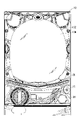
図1に示されるように、本実施形態の遊技機10は、パチンコ遊技機であって、前側が前面枠10Zにて覆われており、その前面枠10Zに形成されたガラス窓10Wを通して図2に示される遊技盤11の遊技領域R1が視認可能になっている。なお、以下の説明において、特記しない限り「右」及び「左」とは、遊技機10を前方から見た場合の「右」及び「左」を指すものとする。
[First Embodiment]
As shown in FIG. 1, the
図1に示されるように、前面枠10Zのうちガラス窓10Wより下方には、上皿26と下皿27が上下2段にして設けられ、下皿27の右側には発射用ハンドル28が設けられている。発射用ハンドル28を回動操作すると、上皿26に収容された遊技球が遊技領域R1に向けて弾き出される。
As shown in FIG. 1, an
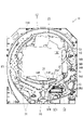
図2に示されるように、遊技領域R1は全体が略円形状となっていて、ガイドレール12により囲まれている。遊技盤11のうち遊技領域R1の中央には、表示開口11Hが貫通形成され、この表示開口11Hを通して、表示装置13の表示画面13Gが視認可能となっている。
As shown in FIG. 2, the game area R1 has a substantially circular shape as a whole and is surrounded by the
表示開口11Hの開口縁には、表示装飾枠23が取り付けられている。表示装飾枠23は、遊技盤11の前面側から表示開口11Hに嵌め込まれ、遊技盤11の前面から突出して遊技領域R1を流下する遊技球が表示装飾枠23の内側に進入することを規制している。
A display
遊技領域R1のうち表示装飾枠23の下方における左右方向の中央部には、センター始動入賞口14A及びアウト口16が、上から順に並べて設けられている。センター始動入賞口14Aは、ポケット構造をなし、その上面の開口部に遊技球が入球すると特別図柄当否判定が行われて、その特別図柄当否判定の結果が表示画面13Gにて表示される。
A center start winning opening 14A and an out opening 16 are provided side by side in order from the top in the central portion in the left-right direction below the display
表示装飾枠23の右側には、始動ゲート18が設けられると共に、表示装飾枠23の右辺部のうち始動ゲート18より下方位置には、サイド始動入賞口14Bが形成されている。始動ゲート18は、遊技球が潜って通過可能な門形構造をなし、遊技球が始動ゲート18を通過すると普通図柄当否判定が行われる。また、サイド始動入賞口14Bは、右側に開口し、可動片14Hによって開閉される。具体的には、可動片14Hは、通常は、鉛直に起立した閉位置に配置され、上述の普通図柄当否判定の結果が当りとなったことを条件にして、下端部を中心に回動し、横倒しとなった開位置(図2に示される位置)に配置される。開位置に配置された可動片14Hは、上方から流下する遊技球を受け止めてサイド始動入賞口14Bへと案内する。センター始動入賞口14Aと同様に、サイド始動入賞口14Bに遊技球が入球したときも、特別図柄当否判定が行われ、その結果が表示画面13Gにて表示される。
A
表示装飾枠23の右下には、左下がりに傾斜し且つ複数の球落下口25Aを有した傾斜誘導部25が形成されている。傾斜誘導部25は、表示装飾枠23の右側に形成された右側流下路24Rを流下してきた遊技球を受け止めて左側へと誘導し、球落下口25Aから遊技球を落下させる。なお、本実施形態では、傾斜誘導部25は、複数の釘を列状に並べて構成される道釘と、樹脂ブロック19の上面19Jとで構成されている。
At the lower right of the display
本実施形態では、傾斜誘導部25に設けられた球落下口25Aが2つとなっている。そして、左側の球落下口25Aの下方に、第1大入賞部31の第1大入賞口31Kと第2大入賞部32の第2大入賞口32Kが上下に並べて設けられている。また、右側の球落下口25Aの下方には、遊技球を受け入れて第2大入賞口32Kより下方に流下させる迂回路25Uが設けられている。
In the present embodiment, there are two
第1大入賞口31Kは、横長矩形状をなして前方に開放し、第1開閉扉31Tによって開閉される。第1開閉扉31Tは、第1大入賞口31Kの下辺部を中心にして回動可能となっていて、通常は、略鉛直に起立した状態に保持されて、第1大入賞口31Kを閉塞している。第2大入賞口32Kは、第1大入賞口31Kより幅広な横長矩形状をなして前方に開放し、第2開閉扉32Tによって開閉される。第2開閉扉32Tは、第2大入賞口32Kの下辺部を中心にして回動可能となっていて、通常は、起立姿勢に保持されて、第2大入賞口32Kを閉塞している。なお、第1大入賞口31Kと第2大入賞口32Kとは、右辺部が揃えて配置されている。
The first large winning
第1大入賞口31Kと第2大入賞口32Kは、上述した特別図柄当否判定の結果が当りとなったことを条件にして行われる大当り遊技の実行中に開放される。具体的には、大当り遊技が実行されると、第1開閉扉31Tと第2開閉扉32Tの何れか一方が、所定期間(例えば、10秒)に亘って前方に倒れる。これにより、第1大入賞口31Kと第2大入賞口32Kの何れか一方に遊技球が入球可能となる。ここで、何れか一方の大入賞口31K,32Kを入賞可能状態(所定期間内に繰り返し行われる開閉動作も含む)としてから入賞不可状態とするまでの(開放状態から閉塞状態までの)動作を「ラウンド」と称すると、1回の大当り遊技は、所定回数(例えば、16ラウンド)のラウンドが実行されるまで継続する。1回のラウンドは、大入賞口31K,32Kの開放時間が予め設定された上限時間に達するか、又は、規定上限数(例えば、10個)の遊技球が入賞すると終了する。なお、本実施形態では、第1大入賞口31Kは、所定のラウンド(例えば、3ラウンド目)で開放される。
The first big winning opening 31K and the second big winning opening 32K are opened during the execution of the big hit game performed on condition that the result of the above-mentioned special symbol winning / failing determination is a hit. Specifically, when the jackpot game is executed, either the first opening /
図2に示されるように、遊技領域R1には、遊技球が入球可能な一般入賞口21が複数設けられている。一般入賞口21は、センター始動入賞口14Aと同様に、ポケット構造をなし、遊技球を受け入れ可能となっている。詳細には、一般入賞口21は、遊技領域R1における左下部分とサイド始動入賞口14Bの右側に配置されている。なお、センター始動入賞口14A、サイド始動入賞口14B、第1大入賞口31K、第2大入賞口32K及び一般入賞口21の何れかに遊技球が入球すると、各入賞口に対応して設定された所定数の賞球が上皿26に払い出される。また、上記の何れの入賞口にも入球しなかった遊技球は、遊技領域R1の下端に配置されたアウト口16に取り込まれる。
As shown in FIG. 2, the game area R1 is provided with a plurality of general winning
遊技盤11の裏側には、図3に示される機構枠17が備えられている。機構枠17には、サイド可動役物ユニット40を含む種々の部品が固定されている。なお、機構枠17の内側の開口部17Aは、遊技盤11の表示開口11H(図2参照)に重ねられて、表示装置13の表示画面13Gを視認可能とする。
The
図4に示されるように、サイド可動役物ユニット40は、機構枠17の上辺部に固定される固定ベース41と、固定ベース41に対して横方向に直動するスライドベース51と、スライドベース51に支持された可動装飾部61と、を備えている。
As shown in FIG. 4, the side
固定ベース41は、横長矩形板状をなす主板42と、主板42に前側から重ねて固定されるカバープレート43と、を備えている。主板42の前面には、中継ギア45と、中継ギア45からの動力を受けて回動する回動レバー46と、が取り付けられていて、カバープレート43が中継ギア45及び回動レバー46を前方から覆っている。そして、カバープレート43の前面に、中継ギア45を駆動する駆動源44が固定されている。
The
図5(A)に示されるように、回動レバー46は、主板42の上辺部に回動可能に支持され、主板42とカバープレート43の間の隙間から下方へはみ出している。回動レバー46の回動軸部46Jは、駆動源44に対して右上に配置され、回動レバー46は、回動軸部46Jから左下に延びる第1レバー位置(図5(A)参照)と、回動軸部から右下に延びる第2レバー位置(図5(C)参照)と、の間を移動する。なお、回動レバー46は、通常は、第1レバー位置に配置され、所定の演出条件が成立したときに、第2レバー位置に配置される。
As shown in FIG. 5A, the
中継ギア45の回転軸部45J(図4参照)は回動レバー46の回動軸部46Jより下側に配置されて、中継ギア45は回動レバー46に前側から重ねられる。中継ギア45には、後側に突出する係合突起45T(図5(A)参照)が設けられている。この係合突起45Tは、回動レバー46の基端寄り部分(回動軸部46Jに近い側の部分)に形成された長孔46Nに係合している。そして、駆動源44に駆動されて中継ギア45が回転すると、図5(A)→図5(B)→図5(C)に示されるように、回動レバー46が第1レバー位置から第2レバー位置へと回動する。
The
図5(A),9に示されるように、スライドベース51は、横長のスライダ52の下方に支持プレート53を備えた構造になっている。スライダ52は、固定ベース41の主板42とカバープレート43との間にはさまれていて、図8,9に示されるように、スライダ52の長手方向の両端部からは、1対の係合突部52T,52Tが後側に突出している。そして、1対の係合突部52T,52Tが、主板42を貫通して横方向に延びる直動ガイド孔42Aに係合している。なお、スライダ52の後面には、1対の係合突部52T,52Tの間に配置され、スライダ52との間に主板42を挟む押え板54が固定されている。
As shown in FIGS. 5A and 5, the
支持プレート53は、縦長の長方形状をなして、スライダ52の左側部分に連絡し、主板42とカバープレート43の間の隙間から下側にはみ出している。支持プレート53の上端寄り部分には、上下方向に延びる長孔51Nが形成されている。この長孔51Nには、回動レバー46の先端部の後面に突設された係合ピン46P(図5(A)参照)が係合している。
The
図5(A)から図5(B)への変化に示されるように、駆動源44からの動力を受けて回動レバー46が第1レバー位置から第2レバー位置へ向かって回動すると、回動レバー46の係合ピン46Pが支持プレート53の長孔51N内を下方に移動しながら支持プレート53を右側に押す。このとき、1対の係合突部52T,52Tは、直動ガイド孔42A内を右側に移動する(図9,10から図11,12への変化を参照)。なお、図5(B)では、回動レバー46が上下方向と略平行に配置され、係合ピン46Pが長孔51Nの下端寄り位置に配置されている。
As shown in the change from FIG. 5 (A) to FIG. 5 (B), when the
図5(B)から図5(C)への変化に示されるように、回動レバー46がさらに第2レバー位置へ向かって回動すると、回動レバー46の係合ピン46Pが長孔51N内を上方に移動しながら支持プレート53をさらに右側へと押す。このとき、1対の係合突部52T,52Tは、直動ガイド孔42A内をさらに右側に移動する。そして、回動レバー46が第2レバー位置に配置されると、図6に示されるように、スライドベース51が表示装飾枠23の内側に露出して表示画面13Gの中央部に前側から重ねられる。なお、スライドベース51は、通常は、図3,5(A)に示される第1スライド位置に配置され、表示装飾枠23の左辺部の後ろに隠れている。そして、上述した所定の演出条件が成立したときに、図5(C),6に示される第2スライド位置に配置され、遊技者に視認可能となる。
As shown in the change from FIG. 5 (B) to FIG. 5 (C), when the
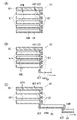
図4に示されるように、可動装飾部61は、支持プレート53の前面に固定された固定パーツ62と、固定パーツ62に対して回動可能な複数の回動パーツ63と、を備えている。固定パーツ62と回動パーツ63は共に正面視扇形状に形成され、扇の円弧が上端となるように配置されている。
As shown in FIG. 4, the movable
各回動パーツ63は、固定パーツ62に前側から重ねられた始端位置(図3参照)から下端部を中心に回動して終端位置(図6参照)に配置される。複数の回動パーツ63が始端位置に配置された状態では、図3に示されるように、固定パーツ62と複数の回動パーツ63が全て重なった状態になる。また、複数の回動パーツ63の間では、固定パーツ62に近い側(即ち、後側)に配置される回動パーツ63の終端位置までの回転角が、固定パーツ62から遠い側(即ち、前側)に配置される回動パーツ63の終端位置までの回転角よりも小さくなっている。そして、複数の回動パーツ63が全て終端位置に配置された状態では、図6に示されるように、前側に配置される回動パーツ63ほど横倒しとなり、固定パーツ62と複数の回動パーツ63が展開した状態となる。なお、以下では、図3に示される可動装飾部61の状態を収縮状態と称し、図6に示される可動装飾部61の状態を展開状態と称することにする。
Each
図4,7に示されるように、複数の回動パーツ63のうち最も前側に配置される回動パーツ63は、駆動源44からの動力を受けて回動する主動パーツ64となっていて、残りの回動パーツ63は、主動パーツ64の回動に伴って回動する従動パーツ65となっている。
As shown in FIGS. 4 and 7, the
具体的には、図7(A)に示されるように、主動パーツ64の後面には、主動パーツ64の回動中心と同心の円弧状をなす長孔64Nが形成されている。また、従動パーツ65の後面にも、従動パーツ65の回動中心と同心の円弧状をなす長孔65Nが形成されている。また、従動パーツ65の前面の右側部には、係合突起65Tが設けられている。最も前側に配置される従動パーツ65の係合突起65Tは、主動パーツ64の長孔64Nと係合している。前から2番目以降の従動パーツ65の係合突起65Tは、1つ前の従動パーツ65の長孔65Nと係合している。最も後側に配置される従動パーツ65の長孔65Nには、固定パーツ62の前面の右側部に設けられた係合突起62Tが係合している。
Specifically, as shown in FIG. 7A, a
図7(A)から図7(B)への変化に示されるように、駆動源44からの動力を受けて主動パーツ64が回動すると、1番前に配置される従動パーツ65の係合突起65Tが主動パーツ64の長孔64N内を相対的に移動し、長孔64Nの内面のうち右側を向く面と当接する。そして、係合突起65Tが長孔64Nの内面に押され、最も前側に配置される従動パーツ65が主動パーツ64と共に回動する。図7(B)から図7(C)への変化に示されるように、主動パーツ64が更に回動すると、前から2番目に配置される従動パーツ65の係合突起65Tが1番前の従動パーツ65の長孔65N内を相対的に移動し、長孔65Nの内面のうち右側を向く面と当接する。そして、前から2番目の従動パーツ65の係合突起65Tが1番前の従動パーツ65の内面に押され、前から2番目の従動パーツ65が主動パーツ64と1番前の従動パーツ65と共に回動する。そして、残りの従動パーツ65についても、1つ前の従動パーツ65に押されて回動することで、可動装飾部61が収縮状態(図3)から展開状態(図6)に変化する。なお、展開状態から収縮状態へ変化する際には、逆の手順となり、具体的には、1番前の従動パーツ65の係合突起65Tが主動パーツ64の長孔64Nの内面のうち左側を向く面に押され、残りの従動パーツ65の係合突起65Tが1つ前の従動パーツ65の長孔65Nの内面のうち左側を向く面に押される。
As shown in the change from FIG. 7A to FIG. 7B, when the
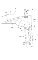
次に、駆動源44から主動パーツ64への動力伝達について説明する。この動力伝達は、図8,9に示される中継レバー71を介して行われる。中継レバー71は、上下方向に直線状に延びる帯板状をなして、スライドベース51の支持プレート53の後面に重ねられている。中継レバー71の下端部は、支持プレート53の後面の下端部に取り付けられた回転盤72に連結されている。なお、詳細には、回転盤72は、円板に左下方から三角板が連接されたティアドロップ形状をなし、中継レバー71は、三角板部分に連結されている。
Next, the power transmission from the
回転盤72は、支持プレート53の厚み方向に回転軸を有して、支持プレート53に対して自由回転可能に取り付けられている。回転盤72の回転軸部72Jは、支持プレート53と複数の従動パーツ65の下端部を貫通して、可動装飾部61の主動パーツ64(図4参照)の下端部に連絡している。そして、回転盤72と一体に主動パーツ64が回転するようになっている。
The
中継レバー71の中間部は、支持プレート53に回転自在に取り付けられた揺動レバー73に連結されている。揺動レバー73は、回転盤72の上方に配置されていて、揺動レバー73の回転中心から揺動レバー73と中継レバー71の連結部位までの距離は、回転盤72の回転中心から回転盤72と中継レバー71の連結部位までの距離と同じになっている。このように、本実施形態では、中継レバー71が上下に並べられた回転盤72と揺動レバー73に連結されるので、回転盤72及び揺動レバー73の回転に伴って上下方向に安定的に移動することが可能となる。
The intermediate portion of the
図8,9に示されるように、中継レバー71の上端部には、後側に突出した係合突部71Tが設けられている。係合突部71Tは、固定ベース41の主板42の前面に形成されたガイド溝55と係合している。ガイド溝55は、左右方向に直線状に延びる第1直線部55Aと第2直線部55Bを上下方向にずらして両端部に備えると共に、左右方向に対して交差するように延びて第1直線部55Aと第2直線部55Bを連絡する中間連絡部56を中間部に備えている。詳細には、左側に配置される第1直線部55A(図8,9では右側に示されている)は右側に配置される第2直線部55Bよりも下方に位置し、中間連絡部56は、右上がりに傾斜すると共に、下に凸となる円弧状に緩やかに湾曲している。
As shown in FIGS. 8 and 9, an engaging
さて、駆動源44からの動力を受けてスライドベース51が第1スライド位置から第2スライド位置へ移動すると、スライドベース51の支持プレート53に支持された中継レバー71もスライドベース51の移動に伴って右側へと移動する。ここで、図9,10に示されるように、スライドベース51が第1スライド位置に配置されている状態で、中継レバー71の係合突部71Tは、ガイド溝55の第1直線部55Aに受容されている。そして、スライドベース51が第2スライド位置へ向かって移動すると、図11,12に示されるように、係合突部71Tは、ガイド溝55内を右側へと移動し、中間連絡部56に受容される。ここで、中間連絡部56は、右上がりに傾斜しているので、係合突部71Tがガイド溝55の中間連絡部56の下面によって持ち上げられ、中継レバー71が上方へと移動する。すると、支持プレート53の後側から見て回転盤72が反時計方向に回転し、その回転盤72と一体に可動装飾部61の主動パーツ64が回転する。
When the
スライドベース51の第2スライド位置への移動に伴って、係合突部71Tがガイド溝55の中間連絡部56を移動する間、中継レバー71は上昇し続け、可動装飾部61の主動パーツ64は回転盤72と一体に回転し続ける。そして、係合突部71Tがガイド溝55の中間連絡部56を通過して第2直線部55Bに到達すると、中継レバー71の上昇が止まり、可動装飾部61の主動パーツ64の回転も止まる。そして、スライドベース51が第2スライド位置に配置されると、図13,14に示されるように、係合突部71Tがガイド溝55の第2直線部55Bに受容され、可動装飾部61の主動パーツ64が終端位置に配置される。このとき、可動装飾部61は展開状態(図6参照)となっている。
As the
スライドベース51が第2スライド位置から第1スライド位置へ戻るときは、スライドベース51の移動に伴って係合突部71Tがガイド溝55内を左側へと移動する。係合突部71Tが中間連絡部56を受容されているときには、係合突部71Tが中間連絡部56の上面に押し下げられて、中継レバー71が下方へと移動する。すると、支持プレート53の後側から見て回転盤72が時計方向に回転し(図13から図11への変化を参照)、その回転盤72と一体に可動装飾部61の主動パーツ64が回転する。係合突部71Tが中間連絡部56を通過して第1直線部55Aに到達すると、中継レバー71の下降が止まり、可動装飾部61の主動パーツ64の回転も止まる。そして、スライドベース51が第1スライド位置に戻ると、係合突部71Tが第1直線部55Aに受容されると共に、可動装飾部61の主動パーツ64が始端位置に配置される。このとき、可動装飾部61は収縮状態(図3参照)に戻る。
When the
遊技機10では、可動装飾部61が展開状態から収縮状態に戻るとき、主動パーツ64が重力に逆らって移動することになる。従って、可動装飾部61が収縮状態に戻るときは、可動装飾部61が展開状態に変化するときよりも、駆動源44の負荷が大きくなる。この駆動源44の負荷を低減するために、遊技機10では、主動パーツ64の重力に逆らった移動をアシストするアシストバネ75が備えられている。
In the
図8に示されるように、アシストバネ75は、中継レバー71を下方に付勢することで、主動パーツ64と一体に回転する回転盤72を後側から見て反時計方向に付勢する。具体的には、アシストバネ75は、支持プレート53の裏面の下端寄り部分と中継レバー71の中間部とに設けられたフック75Fに引っ掛けられて、中継レバー71を下方に付勢する。
As shown in FIG. 8, the
アシストバネ75は、スライドベース51が第1スライド位置(図3,8,9に示されるスライドベース51の位置)に配置されている状態で、自然長よりも長くなっていて、中継レバー71を下方へ付勢している。そして、スライドベース51が第2スライド位置(図6,13に示されるスライドベース51の位置)へ移動して、中継レバー71が上方へ移動すると、アシストバネ75の付勢力が次第に強くなる。
The
ところで、遊技機10では、可動装飾部61が展開状態のときも中継レバー71は下方に付勢されるため、駆動源44をオフにすると、中継レバー71がアシストバネ75の付勢力を受けて下方へと移動し、可動装飾部61が収縮状態に戻ることが考えられる。しかしながら、遊技機10では、可動装飾部61が展開状態になっているとき、中継レバー71の係合突部71Tは、ガイド溝55の第2直線部55Bの内面(詳細には、第2直線部55Bの内面のうち上側を向く面)と当接する。ここで、第2直線部55Bは左右方向に直線状に延びていて、係合突部71Tは第2直線部55Bと直交する方向に付勢されるので、係合突部71Tが第2直線部55Bに沿って移動することがなくなる。これにより、可動装飾部61が展開状態のときに駆動源44がオフになっても、中継レバー71が下方へ移動することがなくなり、可動装飾部61が収縮状態に戻ることが防がれる。言い換えれば、可動装飾部61を展開状態に保持するために、駆動源44をオンにしておく必要がなくなり、駆動源44の負荷が低減される。
By the way, in the
本実施形態の遊技機10の構成に関する説明は以上である。遊技機10によれば、以下の優れた効果を奏することが可能となる。
This concludes the description of the configuration of the
本実施形態の遊技機10によれば、可動装飾部61が右に移動しながら回動するので、可動装飾部61の動きの多様化が図られる。しかも、本構成では、可動装飾部61の第1方向への移動と回動とが1つの駆動源44によって達成されるので、駆動源を複数備える場合と比較して、駆動源44の制御が容易となる。
According to the
また、本実施形態の遊技機10では、スライドベース51の移動に伴って係合突部71Tがガイド溝55に沿って移動する。そして、ガイド溝55の中間部には、左右方向と上下方向の双方に対して傾斜する中間連絡部56が備えられているので、スライドベース51を左右に移動させることによって係合突部71Tが上方に移動し、中継レバー71を上方に移動させることが可能となる。このように、本実施形態の遊技機10によれば、簡易な構成によって中継レバーを上方に移動させることが可能となる。
Further, in the
また、固定ベース41には、横方向に延在する直動ガイド孔42Aが備えられると共に、スライドベース51には、直動ガイド孔42Aと係合する一対の係合突部52T,52Tが備えられているので、係合突部71Tのガイド溝55に沿った移動の安定化が図られる。
Further, the fixed
また、可動装飾部61は、遊技者から見てスライドベース51の表側に配置され、中継レバー71は、遊技者から見てスライドベース51の裏側に隠されているので、中継レバー71を遊技者に視認困難にすることが可能となる。
Further, since the movable
また、本実施形態では、可動装飾部61が表示装飾枠23の後側に隠れた状態から右に移動して視認可能となる。このとき、可動装飾部61は、収縮状態のときの左右方向に幅狭な待機姿勢から、展開状態のときの左右方向に幅広な演出姿勢へと変化するので、遊技者にインパクトを付与することが可能となる。
Further, in the present embodiment, the movable
また、本実施形態では、アシストバネ75によって下方に付勢される中継レバー71は、可動装飾部61の各回動パーツ63が終端位置に配置されたときに、第2直線部55Bによって下方への移動が規制される。そして、中継レバー71を搭載するスライドベース51が左右方向と直交する上下方向に移動可能に構成されているので、第2直線部55Bが駆動源44による駆動の妨げになることが抑制される。
Further, in the present embodiment, the
また、本実施形態では、スライドベース51を右に移動可能に支持する固定ベース41を備え、固定ベース41には、横方向に沿って延在する溝により構成されるガイド溝55が備えられると共に、中継レバー71には、ガイド溝55と係合する係合突部71Tが備えられている。そして、可動装飾部61の回動パーツ63が終端位置に配置されたときに、係合突部71Tがガイド溝55の第2直線部55Bの内面に上方から当接し、係合突部71Tと第2直線部55Bの内面とから、ロック機構が構成される。このように、本実施形態の遊技機10では、簡易な構成によってロック機構を構成することが可能となる。
Further, in the present embodiment, the fixed
また、アシストバネ75の付勢力は、可動装飾部61の回動パーツ63が終端位置に向かうにつれて大きくなるので、終端位置に配置された可動装飾部61の回動パーツ63が始端位置へ向かうときの動作の素早くすることが可能となる。
Further, since the urging force of the
また、可動装飾部61の回動パーツ63は自重に逆らって終端位置から始端位置へ移動するので、可動装飾部61の回動パーツ63の自重に逆らった移動をアシストバネ75によってアシストすることが可能となる。
Further, since the
[他の実施形態]
本発明は、上記実施形態に限定されるものではなく、例えば、以下に説明するような実施形態も本発明の技術的範囲に含まれ、さらに、下記以外にも要旨を逸脱しない範囲内で種々変更して実施することができる。
[Other embodiments]
The present invention is not limited to the above embodiments, and for example, embodiments as described below are also included in the technical scope of the present invention, and various other than the following, as long as they do not deviate from the gist. It can be changed and implemented.
(1)回動パーツ63が従動パーツ65を備えずに主動パーツ64のみから構成されてもよい。
(1) The
(2)上記実施形態では、直動ガイド孔42Aがガイド溝55よりも上方に配置されていたが、直動ガイド孔42Aがガイド溝55よりも下方に配置されてもよい。このとき、中継レバー71は、一対の係合突部52T,52Tと上下方向で重ならない位置に配置される。
(2) In the above embodiment, the linear
(3)サイド可動役物ユニット40が揺動レバー73を備えなくてもよく、中継レバー71が回転盤72のみに連結されていてもよい。
(3) The side
(4)図15に示すように、直動ガイド孔42Aの代わりに、湾曲したガイド孔42Bが固定ベース41に設けられてもよい。このとき、ガイド溝55は、ガイド孔42Bと同じ方向に延びる第1曲線部55Cと第2曲線部55Dをガイド孔42Bが延びる方向に対して垂直な方向にずらして両端部に備える共に、ガイド孔42Bが延びる方向に対して交差するように伸びて第1曲線部55Cと第2曲線部55Dとを連絡する中間連絡部56を備えている。そして、スライドベース51がガイド孔42Bに沿って移動すると共に、中継レバー71がガイド孔42Bの延びる方向に対して垂直な方向に移動して、回転盤72が回転する。
(4) As shown in FIG. 15, a curved guide hole 42B may be provided in the fixed
(5)図16に示されるように、ガイド溝55の第2直線部55Bが第1直線部55Aよりも下方に配置され、ガイド溝55の中間連絡部56が右下がり(図16では左下がり)に傾斜した形状であってもよい。このとき、回転盤72は中継レバー71よりも左側(図16では右側)に配置され、スライドベース51が第1スライド位置に配置されているときの回転盤72と中継レバー71との連結部が回転盤72の回転軸部72Jの右上(図16では左上)に配置される。また、アシストバネ75は中継レバー71を上方に付勢している。そして、スライドベース51が第1スライド位置から第2スライド位置へと移動すると、中継レバー71が下方に移動して、回転盤72が反時計回りに回転する。
(5) As shown in FIG. 16, the second
(6)ガイド溝55の中間連絡部56が、右上がりに傾斜した部分と右下がりに傾斜した部分との両方を備えていてもよい。このとき、スライドベース51が第1スライド位置から第2スライド位置へと移動する間に、可動装飾部61を一度展開状態にしてから収縮状態にすることができる。
(6) The intermediate connecting
(7)図17に示されるように、中継レバー71にガイド溝55を設けて、固定ベース41に係合突部71Tを設けてもよい。詳細には、中継プレート71Aの上部は左右方向に延びていて、ガイド溝55が設けられている。そして、固定ベース41から突出した係合突部71Tがガイド溝55と係合している。スライドベース51が第1スライド位置から第2スライド位置へと右に移動すると、中継プレート71Aも共に右に移動しつつ、係合突部71Tによって中継プレート71Aが上方に押し上げられて、回転盤72が時計回りに回転する。
(7) As shown in FIG. 17, the
(8)上記実施形態において、スライドベース51に直動ガイド孔42が設けられて、固定ベース41に1対の係合突部52T,52Tが設けられてもよい。
(8) In the above embodiment, the
(9)可動装飾部61がスライドベース51の裏側に配置されてもよく、中継レバー71がスライドベース51の表側に配置されてもよい。
(9) The movable
(10)可動装飾部61は正面視扇形状に限られず、どのような形状であってもよい。例えば、可動装飾部61が円形状であってもよく、このとき、スライドベース51が第1スライド位置から第2スライド位置へと移動して可動装飾部61が回転しても、可動装飾部61の左右方向の幅が変化しなくてもよい。
(10) The movable
(11)上記実施形態において、アシストバネ75が中継レバー71を上方に付勢していてもよい。このとき、アシストバネ75の付勢力は、スライドベース51が第1スライド位置から第2スライド位置へと向かうにつれて小さくなる。
(11) In the above embodiment, the
<付記1>
以下、上述した各実施の形態から抽出される発明群の特徴について、必要に応じて効果等を示しつつ説明する。なお、以下では、理解の容易のため、上記実施形態において対応する構成を括弧書き等で適宜示すが、この括弧書き等で示した具体的構成に限定されるものではない。
<
Hereinafter, the characteristics of the invention group extracted from each of the above-described embodiments will be described while showing the effects and the like as necessary. In the following, for the sake of easy understanding, the corresponding configurations in the above-described embodiment are appropriately shown in parentheses or the like, but the present invention is not limited to the specific configurations shown in the parentheses or the like.
<特徴A群>
以下の特徴A群は、「可動演出部材を有する」遊技機に関し、「特許文献A(特開2008-229055号公報(段落[0033]、図3))には、上下方向に移動する可動演出部材を備えた遊技機が示されている。」という背景技術について、「特許文献Aの遊技機では、可動演出部材の動きが単調であるという問題があった。」という課題をもってなされたものである。
<Characteristic A group>
The following feature A group refers to a gaming machine having a "movable effect member", and is described in "Patent Document A (Japanese Patent Laid-Open No. 2008-229055 (paragraph [0033], FIG. 3)) as a movable effect that moves in the vertical direction. Regarding the background technique of "a gaming machine provided with a member is shown", it was made with the problem of "the gaming machine of Patent Document A has a problem that the movement of the movable staging member is monotonous." be.
[特徴A1]
第1方向に移動可能な可動演出部材(可動装飾部61、特に、主動パーツ64)を有する遊技機(遊技機10)であって、
駆動源(駆動源44)により駆動されて前記第1方向に移動可能な移動ベース(スライドベース51)を有すると共に、
前記移動ベースに、前記移動ベースの移動に伴って前記第1方向と交差する第2方向に移動可能な第1中継部材(中継レバー71)と、前記第1中継部材から動力を受けて回動可能な第2中継部材(回転盤72)と、を搭載して備え、
前記可動演出部材は、前記移動ベースに搭載されて、前記第2中継部材と一体に回動するように構成されている遊技機。
[Feature A1]
A gaming machine (gaming machine 10) having a movable effect member (movable
It has a moving base (slide base 51) that is driven by a driving source (driving source 44) and can move in the first direction, and also has a moving base (slide base 51).
A first relay member (relay lever 71) that can move in a second direction intersecting the first direction with the movement of the movement base, and a rotation base that receives power from the first relay member. A second relay member (rotary board 72) that is possible is mounted and prepared.
The movable effect member is a gaming machine mounted on the moving base and configured to rotate integrally with the second relay member.
本特徴に示す構成では、可動演出部材が第1方向に移動しながら回動するので、可動演出部材の動きの多様化が図られる。しかも、本構成では、可動演出部材の第1方向への移動と回動とが1つの駆動源によって達成されるので、駆動源を複数備える場合と比較して、駆動源の制御が容易となる。 In the configuration shown in this feature, since the movable staging member rotates while moving in the first direction, the movement of the movable staging member can be diversified. Moreover, in this configuration, the movement and rotation of the movable staging member in the first direction are achieved by one drive source, so that the control of the drive source becomes easier as compared with the case where a plurality of drive sources are provided. ..
[特徴A2]
特徴A1に記載の遊技機において、
前記移動ベースを前記第1方向に移動可能に支持する支持ベース(固定ベース41)を有し、
前記支持ベースと前記第1中継部材のうち一方には、前記第1方向に沿って延在する溝又は長孔により構成される第1ガイド部(ガイド溝55)が備えられると共に、他方には、前記第1ガイド部と係合する第1係合突部(係合突部71T)が備えられ、
前記第1ガイド部には、前記第1方向の一方側に向かうにつれて前記第2方向の一方側に向かう傾斜部(中間連絡部56)が設けられている遊技機。
[Feature A2]
In the gaming machine described in feature A1,
It has a support base (fixed base 41) that movably supports the moving base in the first direction.
One of the support base and the first relay member is provided with a first guide portion (guide groove 55) formed of a groove or an elongated hole extending along the first direction, and the other is provided with a first guide portion (guide groove 55). , A first engaging protrusion (engaging
The first guide portion is provided with an inclined portion (intermediate communication portion 56) toward one side in the second direction as it goes toward one side in the first direction.
本特徴に示す構成では、移動ベースの移動に伴って第1係合突部が第1ガイド部に沿って移動する。そして、第1ガイド部に設けられた傾斜部によって第1係合突部が第2方向に移動することで、第1中継部材を第2方向に移動させることが可能となる。このように、本構成によれば、簡易な構成によって第1中継部材を第2方向に移動させることが可能となる。 In the configuration shown in this feature, the first engaging protrusion moves along the first guide portion with the movement of the movement base. Then, the first engaging protrusion is moved in the second direction by the inclined portion provided in the first guide portion, so that the first relay member can be moved in the second direction. As described above, according to this configuration, the first relay member can be moved in the second direction by a simple configuration.
[特徴A3]
特徴A2に記載の遊技機において、
前記支持ベースと前記移動ベースのうち一方には、前記第1方向に延在する溝又は長孔により構成される第2ガイド部(直動ガイド孔42A)が備えられると共に、他方には、前記第2ガイド部と係合する第2係合突部(係合突部52T)が備えられている遊技機。
[Feature A3]
In the gaming machine described in feature A2,
One of the support base and the moving base is provided with a second guide portion (linear
本特徴に示す構成によれば、第1係合突部の第1ガイド部に沿った移動の安定化が図られる。 According to the configuration shown in this feature, the movement of the first engaging protrusion along the first guide portion is stabilized.
[特徴A4]
特徴A1乃至A3のうち何れか1に記載の遊技機において、
前記移動ベースに回動可能に支持される揺動レバー(揺動レバー73)を有し、
前記第1中継部材は、前記揺動レバーに連結され、
前記揺動レバーと前記第1中継部材の連結部から前記揺動レバーの回動中心までの距離が、前記第2中継部材と前記第1中継部材の連結部から前記第2中継部材の回動中心までの距離と同じになっている遊技機。
[Feature A4]
Features In the gaming machine according to any one of A1 to A3,
The moving base has a swing lever (swing lever 73) that is rotatably supported.
The first relay member is connected to the swing lever and is connected to the swing lever.
The distance from the connecting portion between the swing lever and the first relay member to the rotation center of the swing lever is the rotation of the second relay member from the connecting portion between the second relay member and the first relay member. A gaming machine that has the same distance to the center.
本特徴に示す構成では、第1中継部材の第2方向への移動の安定化が図られる。 In the configuration shown in this feature, the movement of the first relay member in the second direction is stabilized.
[特徴A5]
特徴A1乃至A4のうち何れか1に記載の遊技機において、
前記可動演出部材は、遊技者から見て前記移動ベースの表側に配置され、
前記第1中継部材は、遊技者から見て前記移動ベースの裏側に隠れている遊技機。
[Feature A5]
Features In the gaming machine according to any one of A1 to A4,
The movable effect member is arranged on the front side of the movement base when viewed from the player.
The first relay member is a gaming machine hidden behind the moving base when viewed from the player.
本特徴に示す構成によれば、第1中継部材を遊技者に視認困難にすることが可能となる。 According to the configuration shown in this feature, it is possible to make the first relay member difficult for the player to see.
[特徴A6]
特徴A1乃至A5のうち何れか1に記載の遊技機において、
前記移動ベースは、カバー部材(表示装飾枠23)の裏側に隠れた第1ベース位置から第1方向に移動して第2ベース位置に配置されるように構成され、
前記可動演出部材は、前記移動ベースが前記第1ベース位置から前記第2ベース位置へ移動するときに、前記第1方向に幅狭な待機姿勢(図3に示される収縮状態の可動装飾部61(回動パーツ63)の姿勢)から前記第1方向に幅広な演出姿勢(図6に示される展開状態の可動装飾部61(回動パーツ63)の姿勢)へと変化するように構成されている遊技機。
[Feature A6]
Features In the gaming machine according to any one of A1 to A5,
The moving base is configured to move in the first direction from the first base position hidden behind the cover member (display decorative frame 23) and to be arranged at the second base position.
The movable staging member has a movable
本特徴に示す構成では、可動演出部材がカバー部材の後側に隠れた状態から第1方向に移動して視認可能となる。このとき、可動演出部材は、第1方向に幅狭な待機姿勢から第1方向に幅広な演出姿勢へと変化するので、遊技者にインパクトを付与することが可能となる。 In the configuration shown in this feature, the movable staging member moves from the state hidden behind the cover member to the first direction and becomes visible. At this time, since the movable staging member changes from a standby posture narrow in the first direction to a wide staging posture in the first direction, it is possible to give an impact to the player.
[特徴A7]
第1方向に移動可能な可動演出部材(可動装飾部61、特に、主動パーツ64)を有する遊技機(遊技機10)であって、
前記可動演出部材は、駆動源(駆動源44)により駆動されて前記第1方向に移動可能な移動ベース(スライドベース51)に搭載され、
前記移動ベースには、前記移動ベースの移動に伴って前記可動演出部材を回動させる連動機構(中継レバー71、回転盤72及びガイド溝55により構成される主動パーツ64の駆動機構)が備えられている遊技機。
[Feature A7]
A gaming machine (gaming machine 10) having a movable effect member (movable
The movable effect member is mounted on a movable base (slide base 51) that is driven by a drive source (drive source 44) and can move in the first direction.
The moving base is provided with an interlocking mechanism (a driving mechanism of a driving
本特徴に示す構成では、可動演出部材が第1方向に移動しながら回動するので、可動演出部材の動きの多様化が図られる。しかも、本構成では、可動演出部材の第1方向への移動と回動とが1つの駆動源によって達成されるので、駆動源を複数備える場合と比較して、駆動源の制御が容易となる。 In the configuration shown in this feature, since the movable staging member rotates while moving in the first direction, the movement of the movable staging member can be diversified. Moreover, in this configuration, the movement and rotation of the movable staging member in the first direction are achieved by one drive source, so that the control of the drive source becomes easier as compared with the case where a plurality of drive sources are provided. ..
なお、特徴A7に示す構成に、特徴A2~A6に示す構成が組み合わされてもよい。 The configuration shown in the feature A7 may be combined with the configuration shown in the features A2 to A6.
<特徴B群>
以下の特徴B群は、「第1位置と第2位置との間を移動可能な可動演出部材を有する」遊技機に関し、「特許文献B(特開2012-34746号(段落[0064]~[0065]、図8,9))には、モータの駆動によって退避位置と作動位置との間を移動可能な可動演出部材を作動位置に付勢して、可動演出部材の作動位置への駆動をアシストするアシストバネを備えた遊技機が示されている。」という背景技術について、「特許文献Bの遊技機では、可動演出部材を退避位置に保持するときに、モータに負荷がかかるという問題があった。」という課題をもってなされたものである。
<Characteristic B group>
The following feature B group relates to a gaming machine "having a movable staging member that can move between the first position and the second position", and is described in "Patent Document B (Japanese Patent Laid-Open No. 2012-34746) (paragraphs [0064] to [0064] to [ In FIGS. Regarding the background technology that "a gaming machine provided with an assist spring for assisting is shown.", "The gaming machine of Patent Document B has a problem that a load is applied to the motor when the movable staging member is held in the retracted position." It was done with the task of "There was."
[特徴B1]
駆動源(駆動源44)からの動力を受けて第1位置(図3に示される可動装飾部61(主動パーツ64)の位置)と第2位置(図6に示される可動装飾部61(主動パーツ64)の位置)との間を移動可能な可動演出部材(可動装飾部61、特に、主動パーツ64)と、
前記可動演出部材を前記第1位置に付勢する付勢手段(アシストバネ75)と、
前記可動演出部材が前記第2位置に配置された状態で前記駆動源がオフされたときに、前記可動演出部材が前記第1位置に戻ることを規制するロック機構(中継レバー71の係合突部71Tとガイド溝55の第2直線部55B)と、を有する遊技機(遊技機10)。
[Feature B1]
Upon receiving power from the drive source (drive source 44), the first position (position of the movable decorative portion 61 (main driving part 64) shown in FIG. 3) and the second position (movable decorative portion 61 (main driving) shown in FIG. 6). Movable staging member (movable
The urging means (assist spring 75) for urging the movable effect member to the first position,
A lock mechanism (engagement protrusion of the relay lever 71) that restricts the movable effect member from returning to the first position when the drive source is turned off while the movable effect member is arranged at the second position. A gaming machine (gaming machine 10) having a
本特徴に示す構成では、可動演出部材が第2位置に配置されたときに、駆動源がオフされても、ロック機構によって可動演出部材が第1位置へ戻ることが規制される。これにより、駆動源の負荷を低減することが可能となる。 In the configuration shown in this feature, when the movable effect member is arranged at the second position, even if the drive source is turned off, the lock mechanism restricts the movable effect member from returning to the first position. This makes it possible to reduce the load on the drive source.
[特徴B2]
特徴B1に記載の遊技機において、
前記駆動源により駆動されて第1方向に移動可能な移動ベース(スライドベース51)と、
前記移動ベースに搭載され、前記移動ベースの移動に伴って前記第1方向と直交する第2方向に移動可能な中継部材(中継レバー71)と、を有し、
前記可動演出部材は、前記中継部材からの動力を受けて前記第1位置と前記第2位置との間を移動可能に構成され、
前記付勢手段は、前記中継部材を前記第2方向の一方側に付勢するように構成され、
前記ロック機構は、前記可動演出部材が前記第2位置に配置されたときに、前記中継部材が前記第2方向に一方側へ移動することを規制する遊技機。
[Feature B2]
In the gaming machine described in feature B1,
A moving base (slide base 51) driven by the drive source and movable in the first direction,
It has a relay member (relay lever 71) mounted on the movement base and movable in a second direction orthogonal to the first direction as the movement base moves.
The movable staging member is configured to be movable between the first position and the second position by receiving power from the relay member.
The urging means is configured to urge the relay member to one side in the second direction.
The lock mechanism is a gaming machine that regulates the movement of the relay member to one side in the second direction when the movable effect member is arranged at the second position.
本特徴に示す構成では、付勢手段によって第2方向の一方側に付勢される中継部材は、可動演出部材が第2位置に配置されたときに、ロック機構によって第2方向の一方側への移動が規制される。そして、中継部材を搭載する移動ベースが第2方向と直交する第1方向に移動可能に構成されているので、ロック機構が駆動源による駆動の妨げになることが抑制される。 In the configuration shown in this feature, the relay member urged to one side in the second direction by the urging means is moved to one side in the second direction by the locking mechanism when the movable staging member is arranged at the second position. Movement is restricted. Further, since the moving base on which the relay member is mounted is configured to be movable in the first direction orthogonal to the second direction, it is possible to prevent the lock mechanism from interfering with the driving by the drive source.
[特徴B3]
特徴B2に記載の遊技機において、
前記移動ベースを前記第1方向に移動可能に支持する支持ベース(固定ベース41)と、
前記支持ベースと前記中継部材のうち一方には、前記第1方向に沿って延在する溝又は長孔により構成されるガイド部(ガイド溝55)が備えられると共に、他方には、前記ガイド部と係合する係合突部(中継レバー71の係合突部71T)が備えられ、
前記ガイド部には、前記可動演出部材が前記第2位置に配置されたときに前記第2方向の一方側から前記係合突部と当接する当接面(ガイド溝55の第2直線部55Bの内面のうち上側を向く面)が設けられ、
前記ロック機構は、前記係合突部と前記当接面とで構成されている遊技機。
[Feature B3]
In the gaming machine described in feature B2,
A support base (fixed base 41) that movably supports the moving base in the first direction, and
One of the support base and the relay member is provided with a guide portion (guide groove 55) formed of a groove or an elongated hole extending along the first direction, and the other is the guide portion. An engaging protrusion (
The guide portion has an abutting surface (second
The locking mechanism is a gaming machine including the engaging protrusion and the contact surface.
本特徴に示す構成によれば、簡易な構成によってロック機構を構成することが可能となる。 According to the configuration shown in this feature, the lock mechanism can be configured by a simple configuration.
[特徴B4]
特徴B3に記載の遊技機において、
前記ガイド部の中間部には、前記第1方向と前記第2方向の双方に対して傾斜する傾斜部(中間連絡部56)が備えられている遊技機。
[Feature B4]
In the gaming machine described in feature B3,
A gaming machine provided with an inclined portion (intermediate connecting portion 56) inclined with respect to both the first direction and the second direction in the intermediate portion of the guide portion.
本特徴に示す構成では、移動ベースを第1方向に駆動することによって係合突部をガイド部に沿って移動させることが可能となり、中継部材を第2方向に移動させることが可能となる。 In the configuration shown in this feature, by driving the moving base in the first direction, the engaging protrusion can be moved along the guide portion, and the relay member can be moved in the second direction.
[特徴B5]
特徴B1乃至B4のうち何れかに記載の遊技機において、
前記付勢手段の付勢力は、前記可動演出部材が前記第2位置へ向かうにつれて大きくなる遊技機。
[Feature B5]
Features In the gaming machine described in any of B1 to B4,
A gaming machine in which the urging force of the urging means increases as the movable staging member moves toward the second position.
本特徴に示す構成によれば、第2位置に配置された可動演出部材が第1位置へ向かうときの動作の素早くすることが可能となる。 According to the configuration shown in this feature, it is possible to quickly move the movable staging member arranged at the second position toward the first position.
[特徴B6]
特徴B1乃至B5のうち何れか1に記載の遊技機において、
前記可動演出部材は、自重に逆らって前記第2位置から前記第1位置へ移動するように構成されている遊技機。
[Feature B6]
Features In the gaming machine according to any one of B1 to B5,
The movable effect member is a gaming machine configured to move from the second position to the first position against its own weight.
本特徴に示す構成では、可動演出部材の自重に逆らった移動を付勢手段によってアシストすることが可能となる。 In the configuration shown in this feature, it is possible to assist the movement of the movable staging member against its own weight by the urging means.
[特徴B7]
通常は第1位置(図3に示される可動装飾部61(主動パーツ64)の位置)に付勢され、駆動源(駆動源44)からの動力を受けたときに前記第1位置から第2位置(図6に示される可動装飾部61(主動パーツ64)の位置)へ移動する可動演出部材(可動装飾部61、特に、主動パーツ64)と、
前記可動演出部材が前記第2位置に配置された状態で前記駆動源がオフされたときに、前記可動演出部材が前記第1位置に戻ることを規制するロック機構(ガイド溝55と中継レバー71の係合突部71T)と、を有する遊技機(遊技機10)。
[Feature B7]
Normally, it is urged to the first position (the position of the movable decorative portion 61 (driving part 64) shown in FIG. 3), and when it receives power from the drive source (drive source 44), it is second from the first position. A movable staging member (movable
A lock mechanism (guide
本特徴に示す構成では、可動演出部材が第2位置に配置されたときに、駆動源がオフされても、ロック機構によって可動演出部材が第1位置へ戻ることが規制される。これにより、駆動源の負荷を低減することが可能となる In the configuration shown in this feature, when the movable effect member is arranged at the second position, even if the drive source is turned off, the lock mechanism restricts the movable effect member from returning to the first position. This makes it possible to reduce the load on the drive source.
なお、特徴B7に示す構成に、特徴B2~B6に示す構成が組み合わされてもよい。 The configuration shown in the feature B7 may be combined with the configuration shown in the features B2 to B6.
10 遊技機
41 固定ベース
42N 直動ガイド孔
44 駆動源
51 スライドベース
52T 係合突部
61 可動装飾部
62 固定パーツ
63 回動パーツ
64 主動パーツ
71 中継レバー
71T 中継レバー
72 回転盤
73 揺動レバー
10
Claims (1)
前記第1方向に沿って延びかつ前記第1方向の位置の違いによって前記第1方向と交差する第2方向での互いの間隔が相違する1対のガイド部と、
一方の前記ガイド部にスライド可能に係合するスライド係合部を有し、駆動源から動力を受けて前記一方のガイド部に沿って移動する移動ベースと、
前記移動ベースに支持された平行リンク機構の一部をなして前記第2方向に平行移動可能に支持されると共に、他方の前記ガイド部にスライド可能に係合するスライド係合部を有し、前記移動ベースに追従して前記他方のガイド部に沿って移動しかつ前記1対のガイド部同士の間隔の変化に追従して前記第2方向に移動する第1中継部材と、
前記平行リンク機構の一部をなして、前記第1中継部材の移動に伴って回動する第2中継部材と、を備え、
前記可動演出部材は、前記第2中継部材と一体に回動する遊技機。 A gaming machine having a movable staging member that can rotate while moving in the first direction.
A pair of guide portions extending along the first direction and having different distances from each other in the second direction intersecting the first direction due to a difference in the position of the first direction.
A moving base having a slide engaging portion that is slidably engaged with one of the guide portions and moving along the one of the guide portions by receiving power from a drive source.
It has a slide engaging portion that is slidably engaged with the other guide portion while being slutably supported in the second direction by forming a part of the parallel link mechanism supported by the moving base. A first relay member that follows the movement base and moves along the other guide portion and moves in the second direction following a change in the distance between the pair of guide portions.
A second relay member, which forms a part of the parallel link mechanism and rotates with the movement of the first relay member, is provided.
The movable staging member is a gaming machine that rotates integrally with the second relay member .
Priority Applications (1)
| Application Number | Priority Date | Filing Date | Title |
|---|---|---|---|
| JP2017186234A JP7089732B2 (en) | 2017-09-27 | 2017-09-27 | Pachinko machine |
Applications Claiming Priority (1)
| Application Number | Priority Date | Filing Date | Title |
|---|---|---|---|
| JP2017186234A JP7089732B2 (en) | 2017-09-27 | 2017-09-27 | Pachinko machine |
Publications (3)
| Publication Number | Publication Date |
|---|---|
| JP2019058438A JP2019058438A (en) | 2019-04-18 |
| JP2019058438A5 JP2019058438A5 (en) | 2021-06-10 |
| JP7089732B2 true JP7089732B2 (en) | 2022-06-23 |
Family
ID=66175698
Family Applications (1)
| Application Number | Title | Priority Date | Filing Date |
|---|---|---|---|
| JP2017186234A Active JP7089732B2 (en) | 2017-09-27 | 2017-09-27 | Pachinko machine |
Country Status (1)
| Country | Link |
|---|---|
| JP (1) | JP7089732B2 (en) |
Citations (11)
| Publication number | Priority date | Publication date | Assignee | Title |
|---|---|---|---|---|
| JP2010214010A (en) | 2009-03-18 | 2010-09-30 | Nippon Pachinko Buhin Kk | Mobile performance device for game machine and game machine with the same |
| JP2011229702A (en) | 2010-04-28 | 2011-11-17 | Kyoraku Sangyo Kk | Pachinko game machine |
| JP2012115305A (en) | 2010-11-29 | 2012-06-21 | Kyoraku Sangyo Kk | Pachinko game machine |
| JP2013059585A (en) | 2011-09-15 | 2013-04-04 | Asama Seisakusho:Kk | Movable decorative device for game machine |
| JP2013102978A (en) | 2011-11-14 | 2013-05-30 | Newgin Co Ltd | Movable performance device of game machine |
| JP2013162987A (en) | 2012-02-13 | 2013-08-22 | Sansei R&D:Kk | Game machine |
| JP2016067745A (en) | 2014-09-30 | 2016-05-09 | 京楽産業.株式会社 | Game machine |
| JP2016087214A (en) | 2014-11-07 | 2016-05-23 | 株式会社大都技研 | Game machine |
| JP2017136278A (en) | 2016-02-05 | 2017-08-10 | 株式会社三共 | Game machine |
| JP6960666B2 (en) | 2017-09-27 | 2021-11-05 | 株式会社サンセイアールアンドディ | Pachinko machine |
| JP6974832B2 (en) | 2017-09-27 | 2021-12-01 | 株式会社サンセイアールアンドディ | Pachinko machine |
-
2017
- 2017-09-27 JP JP2017186234A patent/JP7089732B2/en active Active
Patent Citations (11)
| Publication number | Priority date | Publication date | Assignee | Title |
|---|---|---|---|---|
| JP2010214010A (en) | 2009-03-18 | 2010-09-30 | Nippon Pachinko Buhin Kk | Mobile performance device for game machine and game machine with the same |
| JP2011229702A (en) | 2010-04-28 | 2011-11-17 | Kyoraku Sangyo Kk | Pachinko game machine |
| JP2012115305A (en) | 2010-11-29 | 2012-06-21 | Kyoraku Sangyo Kk | Pachinko game machine |
| JP2013059585A (en) | 2011-09-15 | 2013-04-04 | Asama Seisakusho:Kk | Movable decorative device for game machine |
| JP2013102978A (en) | 2011-11-14 | 2013-05-30 | Newgin Co Ltd | Movable performance device of game machine |
| JP2013162987A (en) | 2012-02-13 | 2013-08-22 | Sansei R&D:Kk | Game machine |
| JP2016067745A (en) | 2014-09-30 | 2016-05-09 | 京楽産業.株式会社 | Game machine |
| JP2016087214A (en) | 2014-11-07 | 2016-05-23 | 株式会社大都技研 | Game machine |
| JP2017136278A (en) | 2016-02-05 | 2017-08-10 | 株式会社三共 | Game machine |
| JP6960666B2 (en) | 2017-09-27 | 2021-11-05 | 株式会社サンセイアールアンドディ | Pachinko machine |
| JP6974832B2 (en) | 2017-09-27 | 2021-12-01 | 株式会社サンセイアールアンドディ | Pachinko machine |
Also Published As
| Publication number | Publication date |
|---|---|
| JP2019058438A (en) | 2019-04-18 |
Similar Documents
| Publication | Publication Date | Title |
|---|---|---|
| JP6960666B2 (en) | Pachinko machine | |
| JP4887416B2 (en) | Decoration body unit, game board unit, and pachinko machine | |
| JP2019058489A (en) | Game machine | |
| JP5317770B2 (en) | Bullet ball machine | |
| JP2008113757A (en) | Performance device for game machine | |
| JP7323579B2 (en) | game machine | |
| JP6974832B2 (en) | Pachinko machine | |
| JP6152953B1 (en) | Game machine | |
| JP7089732B2 (en) | Pachinko machine | |
| JP5912737B2 (en) | Game machine | |
| JP5797410B2 (en) | Operational unit and game machine | |
| JP6976558B2 (en) | Pachinko machine | |
| JP6981646B2 (en) | Pachinko machine | |
| JP6112587B1 (en) | Game machine | |
| JP7054161B2 (en) | Pachinko machine | |
| JP2022033280A (en) | Game machine | |
| JP2019058456A (en) | Game machine | |
| JP5800615B2 (en) | Game machine | |
| JP7186992B2 (en) | game machine | |
| JP5450550B2 (en) | Bullet ball machine | |
| JP4814144B2 (en) | Amusement stand | |
| JP6112588B1 (en) | Game machine | |
| JP5961908B2 (en) | Game machine | |
| JP6995358B2 (en) | Pachinko machine | |
| JP6685490B2 (en) | Amusement machine |
Legal Events
| Date | Code | Title | Description |
|---|---|---|---|
| RD04 | Notification of resignation of power of attorney |
Free format text: JAPANESE INTERMEDIATE CODE: A7424 Effective date: 20190315 |
|
| A621 | Written request for application examination |
Free format text: JAPANESE INTERMEDIATE CODE: A621 Effective date: 20200911 |
|
| A521 | Request for written amendment filed |
Free format text: JAPANESE INTERMEDIATE CODE: A523 Effective date: 20210426 |
|
| A977 | Report on retrieval |
Free format text: JAPANESE INTERMEDIATE CODE: A971007 Effective date: 20210623 |
|
| A131 | Notification of reasons for refusal |
Free format text: JAPANESE INTERMEDIATE CODE: A131 Effective date: 20210713 |
|
| A521 | Request for written amendment filed |
Free format text: JAPANESE INTERMEDIATE CODE: A523 Effective date: 20210907 |
|
| A131 | Notification of reasons for refusal |
Free format text: JAPANESE INTERMEDIATE CODE: A131 Effective date: 20211207 |
|
| TRDD | Decision of grant or rejection written | ||
| A01 | Written decision to grant a patent or to grant a registration (utility model) |
Free format text: JAPANESE INTERMEDIATE CODE: A01 Effective date: 20220518 |
|
| A61 | First payment of annual fees (during grant procedure) |
Free format text: JAPANESE INTERMEDIATE CODE: A61 Effective date: 20220606 |
|
| R150 | Certificate of patent or registration of utility model |
Ref document number: 7089732 Country of ref document: JP Free format text: JAPANESE INTERMEDIATE CODE: R150 |