JP5961908B2 - Game machine - Google Patents
Game machine Download PDFInfo
- Publication number
- JP5961908B2 JP5961908B2 JP2014130145A JP2014130145A JP5961908B2 JP 5961908 B2 JP5961908 B2 JP 5961908B2 JP 2014130145 A JP2014130145 A JP 2014130145A JP 2014130145 A JP2014130145 A JP 2014130145A JP 5961908 B2 JP5961908 B2 JP 5961908B2
- Authority
- JP
- Japan
- Prior art keywords
- door
- door member
- lever
- lever member
- case
- Prior art date
- Legal status (The legal status is an assumption and is not a legal conclusion. Google has not performed a legal analysis and makes no representation as to the accuracy of the status listed.)
- Expired - Fee Related
Links
Images

Landscapes
- Pinball Game Machines (AREA)
Description
本発明は、パチンコ遊技機の遊技盤に配設される可変入賞装置を備えた遊技機に関するものである。 The present invention relates to a gaming machine provided with a variable winning device arranged on a gaming board of a pachinko gaming machine.
従来より、パチンコ遊技機の遊技盤に配設される各種の可変入賞装置が提案されている。
例えば、特開2001−252410号公報には、ソレノイドのオン・オフに対応して、複雑な連結機構により球誘導可動体を移動させるとともに、開閉翼片の開閉動作を行うように構成された可変入賞装置が記載されている。
Conventionally, various variable winning devices have been proposed which are arranged on a game board of a pachinko gaming machine.
For example, Japanese Patent Application Laid-Open No. 2001-252410 discloses a variable configuration in which a spherical guide movable body is moved by a complicated coupling mechanism and an opening / closing operation of an opening / closing blade piece is performed in response to on / off of a solenoid. A winning device is described.
また、特開2011−24714号公報には、ソレノイドのオン・オフに対応して、連結機構により2つの各回動片を開閉させる可変入賞装置が記載されている。 Japanese Patent Application Laid-Open No. 2011-24714 describes a variable prize winning device that opens and closes two rotating pieces by a coupling mechanism in response to solenoid on / off.
ここに、前記特許文献1及び2に記載された可変入賞装置では、ソレノイド及びソレノイドに連結された複雑な連結機構を使用し、ソレノイドの駆動力を連結機構を通じて開閉翼片・回動片(扉部材)に伝達する構成を採用している。
Here, in the variable prize winning apparatus described in
しかしながら、このような構成では、ソレノイドからの駆動力は、連結機構を介して伝達されることから、ソレノイドの駆動力が扉部材にまで伝達されるには時間がかかってしまい、ソレノイドから扉部材まで駆動力が伝達される速度が遅くなってしまう問題がある。
また、ソレノイドと扉部材との間に連結機構が存在しており、ソレノイドの駆動力を扉部材まで伝達するには、連結機構を作動させる必要があることから、大きな駆動力を発生する大型のソレノイドを使用しなければならないという問題がある。
However, in such a configuration, since the driving force from the solenoid is transmitted through the coupling mechanism, it takes time to transmit the driving force of the solenoid to the door member, and the solenoid to the door member. There is a problem that the speed at which the driving force is transmitted becomes slow.
In addition, there is a coupling mechanism between the solenoid and the door member, and in order to transmit the driving force of the solenoid to the door member, it is necessary to operate the coupling mechanism. There is a problem that a solenoid must be used.
本発明は前記従来技術の問題点を解消するためになされたものであり、複雑な連結機構を使用することなく且つ大型の駆動源を必要とすることなく、自重により下方に開放する扉部材を採用し、シンプルな構成により扉部材を開閉可能とするとともに、何らかの事情により扉部材が開放されない場合においても扉部材を開放することが可能な可変入賞装置を備えた遊技機を提供することを目的とする。 The present invention has been made to solve the above-described problems of the prior art. A door member that opens downward by its own weight without using a complicated connecting mechanism and without requiring a large drive source. An object of the present invention is to provide a gaming machine equipped with a variable prize winning device that can open and close the door member with a simple configuration and can open the door member even when the door member is not opened for some reason. And
前記目的を達成するため請求項1に係る遊技機は、ケース内に固定され駆動部材を有する駆動源と、前記駆動部材に連結された作動部材と、前記ケースに回動可能に支持され、前記駆動源への通電に基づき駆動部材が移動されることに対応して回動されるレバー部材と、前記ケースに回動可能に支持されるとともに自重によって下方に回動し、ケースに形成された遊技球の誘導口を開閉する扉部材と、前記扉部材の側部に形成された係合部材と、を備え、前記駆動源の作動によって、前記レバー部材と前記係合部材とが相互に係合することにより、前記扉部材の自重による下方への回動を禁止して扉部材を介して前記ケースの誘導口を閉鎖する第1状態と、前記駆動部材の移動に対応して前記レバー部材が回動されると共に、前記係合部材が前記レバー部材との当接状態を維持しつつ該レバー部材に追従移動し、前記係合部材の追従移動と共に前記扉部材が自重により下方に回動されて前記ケースの誘導口を開放する第2状態とに変更可能に構成され、記扉部材の側部にて前記係合部材と離間して設けられ、前記駆動源の作動に伴って前記扉部材が自重により下方に回動しない場合に、前記レバー部材と当接させることでレバー部材を介して扉部材を強制的に下方に回動させて前記第2状態に変更させるための突起部を有することを特徴とする。 In order to achieve the above-mentioned object, a gaming machine according to claim 1 is provided such that a driving source fixed in a case and having a driving member, an operating member connected to the driving member, and rotatably supported by the case, A lever member that is rotated in response to movement of the drive member based on energization of the drive source, and a case that is pivotally supported by the case and rotated downward by its own weight and formed in the case A door member that opens and closes the guide port of the game ball; and an engagement member formed on a side portion of the door member, and the lever member and the engagement member are engaged with each other by the operation of the drive source. In combination, the lever member corresponds to the first state in which the guide member of the case is closed through the door member by prohibiting the door member from rotating downward by its own weight, and the movement of the driving member. together but is rotated, the engaging member While maintaining the contact between the serial lever member follows the movement in the lever member, a second to open the induction port of the engaging member said case the door member with tracking movement is rotated downward by the weight of When the door member does not rotate downward due to its own weight in accordance with the operation of the drive source, It has a protrusion for forcibly turning the door member downward through the lever member by contacting the lever member to change to the second state.
請求項2に係る遊技機は、請求項1の遊技機において、前記駆動源の作動に伴って前記扉部材が自重により下方に回動しない状態において、前記扉部材の突起部は、前記レバー部材の回動軌跡上に存在することを特徴とする。
The gaming machine according to
請求項3に係る遊技機は、請求項1又は請求項2の遊技機において、前記作動部材に形成された支持溝と、前記作動部材に形成された長孔と、前記レバー部材に形成された支持ピンと、前記レバー部材の両側に形成された摺動ピンとを備え、前記レバー部材の支持ピンは、前記作動部材の支持溝に回動可能に支持され、前記レバー部材の両側における各摺動ピンの内一方の摺動ピンは、前記作動部材の長孔内を摺動可能に挿嵌されるとともに、レバー部材の両側における各摺動ピンは前記ケースに回動可能に支持されることを特徴とする。 A gaming machine according to a third aspect is the gaming machine according to the first or second aspect, wherein a support groove formed in the operating member, a long hole formed in the operating member, and a lever member are formed. A support pin; and a slide pin formed on both sides of the lever member. The support pin of the lever member is rotatably supported by a support groove of the operating member, and each slide pin on both sides of the lever member. One of the sliding pins is slidably fitted in the long hole of the operating member, and each sliding pin on both sides of the lever member is rotatably supported by the case. And
ここに、請求項4に記載するように、前記駆動源はソレノイドから構成されるとともに前記駆動部材はソレノイドに付設されるプランジャから構成されることが望ましい。 In this case, it is preferable that the drive source is constituted by a solenoid and the drive member is constituted by a plunger attached to the solenoid.
請求項1に係る遊技機では、駆動源の作動によって、レバー部材と係合部材とが相互に係合することにより、扉部材の自重による下方への回動を禁止して扉部材を介してケースの誘導口を閉鎖する第1状態と、駆動部材の移動に対応してレバー部材が回動されると共に、係合部材がレバー部材との当接状態を維持しつつレバー部材に追従移動し、係合部材の追従移動と共に扉部材が自重により下方に回動されてケースの誘導口を開放する第2状態とに変更可能に構成されている。 In the gaming machine according to claim 1, the lever member and the engaging member are engaged with each other by the operation of the drive source, thereby prohibiting the downward rotation due to the weight of the door member through the door member. The lever member is rotated in response to the movement of the driving member and the first state in which the guide opening of the case is closed , and the engaging member moves following the lever member while maintaining a contact state with the lever member. The door member is configured to be changed to a second state in which the door member is rotated downward by its own weight and the guide opening of the case is opened along with the follow-up movement of the engaging member .
これにより、複雑な連結機構を使用することなく且つ大型の駆動源を必要とすることなく、自重により下方に回動する扉部材を採用したことに基づき、作動部材とレバー部材からなるシンプルな構成により扉部材の開閉動作を行うことが可能となる。 As a result, a simple structure consisting of an actuating member and a lever member based on the adoption of a door member that rotates downward by its own weight without using a complicated connecting mechanism and without requiring a large drive source. Thus, the door member can be opened and closed.
また、駆動源の作動に伴って扉部材が自重により下方に回動しない場合には、レバー部材と当接させることでレバー部材を介して扉部材を強制的に下方に回動させて第2状態に変更させるため突起部を有するので、駆動源の作動時に何らかの事情により扉部材が開放されない場合においても扉部材を開放することが可能となる。 Further, when the door member does not rotate downward due to its own weight in accordance with the operation of the drive source, the door member is forcibly rotated downward via the lever member by contacting the lever member, so that the second Since the projection is provided to change the state, the door member can be opened even when the door member is not opened for some reason when the drive source is operated.
また、請求項2に係る遊技機では、駆動源の作動に伴って扉部材が自重により下方に回動しない状態において、扉部材の突起部は、レバー部材の回動軌跡上に存在するので、駆動源の作動時にレバー部材が回動されると、レバー部材は、突起部と確実に係合して強制的に突起部を跳ね上げる。これにより、駆動源の作動時に何らかの事情により扉部材が開放されない場合においても扉部材を強制的に開放することが可能となる。
Further, in the gaming machine according to
更に、請求項3に係る遊技機では、駆動源の駆動部材と扉部材とを連結する連結構造として、作動部材に形成された支持溝と、作動部材に形成された長孔と、レバー部材に形成された支持ピンと、レバー部材の両側に形成された摺動ピンとを備え、レバー部材の支持ピンは、作動部材の支持溝に回動可能に支持され、レバー部材の両側における各摺動ピンの内一方の摺動ピンは、作動部材の長孔内を摺動可能に挿嵌されるとともに、レバー部材の両側における各摺動ピンはケースに回動可能に支持される構成としたので、自重により下方に開放する扉部材を採用したこととも相まって、シンプルな構成により扉部材を開閉可能となる。
Furthermore, in the gaming machine according to
以下、本発明に係る可変入賞装置について、本発明を具体化した実施形態に基づき図面を参照しつつ説明する。
先ず、本実施形態に係る可変入賞装置が搭載されるパチンコ遊技機の基本構成について図1、図2に基づき説明する。
Hereinafter, a variable prize device according to the present invention will be described based on an embodiment of the present invention with reference to the drawings.
First, a basic configuration of a pachinko gaming machine in which the variable winning device according to this embodiment is mounted will be described with reference to FIGS.
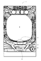
図1において、パチンコ遊技機1の中央部には、遊技盤設置領域2が設けられており、かかる遊技盤設置領域2の背後には、後述する遊技盤3が設置される。パチンコ遊技機1の遊技盤設置領域2より下方には、上皿4及び下皿5が上下2段にして設けられている。下皿5の右端部には操作ノブ6が配設されており、かかる操作ノブ6を操作することにより上皿4に貯留された遊技球が遊技盤3に向けて弾き出される。
In FIG. 1, a game
尚、上皿4の上部には、押下操作部材7が配置されている。この押下操作部材7の内部にはスイッチが内蔵されており、押下操作部材7は、ゲームの進行に伴い所定のゲームシーンで遊技者により押下操作される。
A
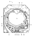
図2に示すように、遊技盤3には、ガイドレール8で囲まれたほぼ円形の遊技領域9が形成され、この遊技領域9の略中央部にはセンター役物10が配設されている。センター役物10の内側には、表示装置11が配設されている。
As shown in FIG. 2, a substantially
表示装置11の左側辺とガイドレール8との間には、風車12が設けられている。表示装置11の下方には、本実施形態に係るパチンコ遊技機1に特徴的な中央可変入賞装置Aが配設されている。中央可変入賞装置Aには、始動入賞口13、下側入賞口14等が設けられている。中央可変入賞装置Aについては、後述する。
また、中央可変入賞装置Aの斜め右上方には、大入賞口15が設けられており、更に中央可変入賞装置Aの下方位置には、外れ球受け入れ口16が設けられている。
A
Further, a large winning
遊技領域9に配設されたセンター役物10の左側には、始動ゲート17が設けられている。さらに、遊技領域9全体に亘って、図示しない複数の障害釘が起立している。
A
次に所要の各部位について詳説する。
始動ゲート17は、門形構造をなしかつ検出スイッチを内蔵し、始動ゲート17を通過した遊技球が検出スイッチにて検出される。そして、その検出信号に基づいて、表示装置11に設けられた普通図柄表示領域の図柄が変動表示される。尚、普通図柄の変動表示の結果が当たりであれば、後述するように、中央可変入賞装置Aに設けられる扉部材18が開放される。
Next, each required part will be described in detail.
The
始動入賞口13は、所謂、ポケット構造をなして上方に向かって開口しており、かかる始動入賞口13の開口幅は、遊技球が約1つ入る大きさになっている。始動入賞口13に遊技球が入賞すると、始動入賞口13内に設けた検出スイッチが遊技球を検出し、その検出信号に基づいてカウンタから乱数が取得されるとともにその取得された乱数と大当たり抽選テーブルとを参照して大当たり抽選が行われる。かかる大当たり抽選の結果に基づいて表示装置11が図柄を変動表示する。なお、表示装置11が図柄を変動表示している間に、始動入賞口13に入賞した入賞球は、例えば、4個まで累積カウントされる。
The
また同様に、遊技球が始動入賞口13に入賞した際には、別のカウンタから乱数が取得されるとともにその取得された乱数と確率変動(以下、確変と略記する)モード抽選テーブルとを参照して確変モード(高確率状態)に移行するかどうかの抽選が行われる。この抽選により確変モードへの移行を獲得すると、確変モードへの移行が確定された後に、その旨が表示装置11に表示される。
Similarly, when a game ball wins the
下側入賞口14には、下側入賞口14を開閉する扉部材18(詳細な構成については後述する)が回動可能に設けられており、かかる扉部材18は、遊技球が始動ゲート17を通過したことが検出された際に、後述の開閉機構を介して下側入賞口14を開放する。
A door member 18 (details of which will be described later) that opens and closes the lower winning
大入賞口15は、横長に形成されて、常には、可動扉19にて閉鎖されている。そして、前記のように大当たりが確定することによって、遊技盤3の裏に設けたソレノイドが駆動され、可動扉19が所定期間に亘って前側に倒れ、大当たり遊技が開始される(図2の状態)。これにより、大入賞口15が開放され、可動扉19を案内にして、大入賞口15に多くの遊技球が入賞可能になる。ここで、可動扉19が、開放してから閉じるまでの間を「ラウンド」と称すると、1つのラウンドは、可動扉19の開放時間が30秒に達したか、又は、大入賞口15に遊技球が10個入賞したか、の何れかの条件が先に満たされた場合に終了する。尚、本実施形態では、1回の「大当たり遊技」は、最大で16ラウンドまで継続して行われる。また、本実施形態では、実行可能な残りのラウンド数は、表示装置11のラウンド表示部にて表示される。
The
表示装置11は、センター役物10の後端面に、図示しない液晶モジュール(詳細には、TFT−LCDモジュール)を組み付けてなる。
表示装置11には、通常は、左、中、右の3つの特別図柄が、横並びに表示されている。これら各特別図柄は、例えば、「0」〜「11」の数字を表記した複数種類のもので構成されており、通常は、各特別図柄ごとに、所定の種類のものが、確定表示されている。そして、始動入賞口13に遊技球が入賞したときに、各特別図柄が、上下方向にスクロールして変動表示され、所定時間後に、例えば、左、中、右の順で各特別図柄が停止表示される。このとき、例えば、全ての特別図柄が同じ図柄、即ち、ぞろ目になった場合に、「大当たり遊技」が開始され、可動扉19が開かれる。
The
The
特別図柄の表示領域の左下隅には、普通図柄表示領域が設けられている。この普通図柄表示領域は、始動ゲート17内に設けた検出スイッチが遊技球の通過を検出したときに、例えば、「0」〜「9」までの数字を所定期間に亘って変動表示した後、所定の数字を確定表示する。そして、確定表示された数字が、例えば、奇数の場合に、下側入賞口14に付設された扉部材18が所定期間(例えば、0.4秒)に亘って横に倒される。また、普通図柄表示領域が変動表示している間に始動ゲート17を通過した遊技球は、例えば、4つまで累積カウントされ、例えば、図示しないLEDの点灯数で表示される。
A normal symbol display area is provided in the lower left corner of the special symbol display area. When the detection switch provided in the
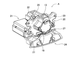
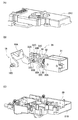
続いて、中央可変入賞装置Aの構成について、図3乃至図9に基づいて説明する。中央可変入賞装置Aは、基本的に、役物装置20及び役物装置20が取り付けられるケース21とから構成される。
役物装置20は、図3、図4に示すように、平板部22の表面側上部に形成された始動入賞受け部23と、始動入賞受け部23の下方で下側入賞口14の開閉を行う扉部材18の前面側に配置される下側入賞カバー部24とが一体に構成されてなる。
Next, the configuration of the central variable winning device A will be described with reference to FIGS. The central variable winning device A is basically composed of an
As shown in FIGS. 3 and 4, the
始動入賞受け部23の上部には、始動入賞口13が開口されており、始動入賞口13に入球した遊技球は、平板部22にて始動入賞受け部23の背面側に形成された遊技球通路25を通過した後パチンコ遊技機1の内部に案内される。
A
下側入賞カバー部24の背面側には、凹状溝26(図4参照)が形成されており、また、凹状溝26の左右両側には、遊技球案内傾斜面27、27が形成されている。凹状溝26は、扉部材18との間で遊技球の通過路を形成し、具体的に、扉部材18が下側入賞口14を閉鎖している状態において、遊技球案内傾斜面27、27を案内される遊技球は、扉部材18と凹状溝26とで形成される通過路を通過し、最終的に外れ球受け入れ口16からパチンコ遊技機1の内部に回収される。
A concave groove 26 (see FIG. 4) is formed on the back side of the lower winning
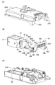
中央可変入賞装置Aを構成するケース21は、図5、図6に示すように、上ケース21Aと下ケース21Bとから構成され、上ケース21Aと下ケース21Bとの間には、扉作動機構28が収納される収納部29が形成されている。ケース21の前端部(図3、図4中右側端部)には、下側入賞口14が開口しており、かかる下側入賞口14の前面には扉部材18が配置されている。
As shown in FIGS. 5 and 6, the
次に、扉作動機構28について、図5、図6に基づき説明する。図5、図6において、扉作動機構28は、基本的に、プランジャ(摺動軸)30を有するソレノイド31、プランジャ30に連結された作動部材32、作動部材32に回動可能に支持されたレバー部材33、及び、レバー部材33との協働作用に基づき下側入賞口14の開閉を行う扉部材18とから構成されている。
Next, the
ここに、図6(B)に示すように、プランジャ30の先端には円板30Aが固設されており、また、作動部材32の基端部32Aには、円板30Aが嵌合される連結溝32Eが形成されている。このように、プランジャ30と作動部材32とは、円板30Aを連結溝32Eに嵌合することにより相互に連結される。また、作動部材32は、基端部32A及び基端部32Aから垂直に延設された板状部32Bを有している。また、板状部32Bにおいて、上端縁から下方に延びた縦溝状の支持溝32Cが形成されるとともに、支持溝32Cの下方位置には水平方向に延びる長孔32Dが形成されている。
Here, as shown in FIG. 6B, a
レバー部材33は略三角形状を有する板材から形成され、その上側頂点の一側面(図5(B)中背面側、図6(B)中正面側)からは、水平方向に支持ピン33Aが延設されており、また、その下側頂点の両面からは、摺動ピン33Bが延設されている。また、残りの頂点からは、棒状の作動部33Cが延設されている。
The
ここに、レバー部材33の支持ピン33Aは、作動部材32の支持溝32C内に回動可能に支持されている。また、各摺動ピン33Bの内、支持ピン33Aと同一側に形成された摺動ピン33Bは、作動部材32の長孔32D内に摺動可能に挿嵌されている。尚、各摺動ピン33Bの端部は、ケース21内において、レバー部材33が回動可能となるように支持されている。
Here, the
扉部材18は、扉部18A及び扉部18Aの両側から斜め方向(図5(B)中左下斜め方向、図6(B)中右斜め方向)に延設された側板部18B、18Bから構成されている。扉部18Aには装飾部18Cが形成されている。各側板部18Bからは、回動軸18Dが延設されており、各回動軸18Dは上ケース21Aの支持部21Cに回動可能に支持される。また、各側板部18Bの内、一方の側板部18B(図5(B)左側側板部)には、回動軸18Dに隣接して係合ピン18Eが水平方向に延設されており、かかる係合ピン18Eは、レバー部材33の作動部33Cとの間で、後述するように、係合及びその解除が行われる。更に一方の側板部18Bには、係合ピン18Eから離間して設けられ作動部33Cと当接可能な当接ピン18Fが設けられている。
前記のように構成される扉部材18において、図5(B)、図6(B)からも明らかなように、扉部材18の重心は、各回動軸18Dを結ぶ線分よりも扉部18A側存在しており、従って、扉部材18は、何ら規制力が作用しない状態においては、自重で各回動軸18Dの回りに回動する。
The
In the
尚、ソレノイド31のプランジャ30には、図5(B)、図6(B)に示すように、ソレノイド31の側面と作動部材32の基端部32Aの側面との間でコイルスプリング34が装着されている。かかるコイルスプリング34は、常時作動部材32の基端部32Aを一方向(図5(B)中右方向、図6(B)中左方向)に付勢している。
As shown in FIGS. 5B and 6B, a
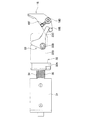
続いて、前記のように構成される扉作動機構28の動作について、図7乃至図9に基づき説明する。
先ず、ソレノイド31に通電されていない状態においては、作動部材32は、コイルスプリング34の付勢力により図7中右方向に付勢されている。これにより、レバー部材33は、支持ピン33Aと支持溝32Cとの協働により摺動ピン33Bの回りに、図7中時計方向に回動付勢され、自重により下方に回動しようとする扉部材18の当接ピン18Fに当接している。この状態で、扉部材18は、回動軸18Dの回りに図7中反時計方向に回動付勢されており、この結果、扉部材18は、下側入賞口14を閉鎖する第1状態に保持されている。
Next, the operation of the
First, when the
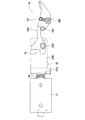
この後、遊技球が始動ゲート17を通過するとともに普通図柄の表示結果が当たりになると、扉部材18を自重で下方に回動させて下側入賞口14を開放するためソレノイド31に通電される。ソレノイド31に通電されると、プランジャ30がコイルスプリング34の付勢力に抗して図7中左方向に移動される。これと同時に、作動部材32も図7中左方向に移動される。
Thereafter, when the game ball passes through the
これにより、レバー部材33は、支持ピン33Aと支持溝32Cとの協働により摺動ピン33Bの回りに反時計方向に回動され、これに伴い作動部33Cも反時計方向に回動されていく。このとき、扉部材18の係合ピン18Eは扉部材18の自重により作動部33Cと当接しつつ上方に移動していき、これにより扉部材18は、その自重によって回動軸18Dの回りに時計方向に回動される。この結果、下側入賞口14は、扉部材18により開放される。かかる第2状態が図8に示されている。このように扉部材18が回動されて下側入賞口14が開放された状態では、遊技球は、遊技球案内傾斜面27、27及び扉部材18にて案内されて下側入賞口14を通過し、パチンコ遊技機1の内部に案内される。
Accordingly, the
前記したように、本実施形態に係るパチンコ遊技機1の遊技盤3に配設される中央可変入賞装置Aでは、ソレノイド31の非通電時には、レバー部材33の作動部33Cと扉部材18の係合ピン18Eとが相互に係合することにより、扉部材18の自重による下方への回動を禁止して扉部材18を介してケース21の下側入賞口14を閉鎖する第1状態(図7)に保持され、また、ソレノイド31の通電時には、プランジャ30の移動に対応してレバー部材33の作動部33Cと係合ピン18Eとの係合が解除されつつ、扉部材18が自重により下方に回動されてケース21の下側入賞口14を開放する第2状態に保持される(図8)。
As described above, in the central variable winning device A disposed on the
これにより、中央可変入賞装置Aによれば、複雑な連結機構を使用することなく且つ大型のソレノイドを必要とすることなく、自重により下方に回動する扉部材18を採用したことに基づき、作動部材32とレバー部材33からなるシンプルな構成により扉部材18の開閉動作を行うことが可能となる。
Thereby, according to the central variable prize-winning device A, the operation is based on adopting the
また、前記第2状態から第1状態に移行する際には前記した動作と反対の動作が行われるが、この間扉部材18が徐々に下側入賞口14を閉鎖する方向に回動する過程において遊技球が扉部材18上に落下した場合においても、扉部材18は自重により下方に回動可能であることから、扉部材18との間で所謂「球噛み」が生じることはない。
Further, when shifting from the second state to the first state, an operation opposite to the above-described operation is performed. During this time, the
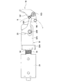
更に、扉部材18は、ソレノイド31の駆動力を利用して強制的に開閉されるものではなく、自重で下方に回動可能に構成されていることから、ソレノイド31に通電した状態においても何らかの事情で扉部材18が前記のように開放されない場合もあり得る。
かかる場合には、図9に示すように、扉部材18が自重により下方に回動しない状態、即ち、第1状態におけると同様扉部材18が下側入賞口14を閉鎖している状態にあり、また、レバー部材33は、作動部材32の左方向への移動に基づき図9中反時計方向に若干回動された状態にあるが、この状態において、扉部材18の当接ピン18Fの一部は、レバー部材33の作動部33Cの先端により描かれる回動軌跡Kの内側に存在している。
Furthermore, the
In such a case, as shown in FIG. 9, the
これにより、レバー部材33の作動部33Cは、ソレノイド31に通電されて作動部材32が若干左方向に移動されることに基づきレバー部材33が反時計方向に若干回動された時点で、当接ピン18Fに当接することとなる。この後、プランジャ30を介して作動部材32は更に左方向に移動され、これによりレバー部材33は更に回動されて当接ピン18Fを強制的に跳ね上げる。この結果、扉部材18は時計方向に回動され、図8に示す第2状態となる。
As a result, the operating
このように、ソレノイド31の通電時において、扉部材18が自重により下方に回動しない場合には、レバー部材33の作動部33Cと当接ピン18Fとを当接させるとともにレバー部材33を介して扉部材18を強制的に下方に回動させて第2状態に保持するようにしたので、ソレノイド31の通電時何らかの事情により扉部材18が開放されない場合においても扉部材18を強制的に開放することが可能となる。
As described above, when the
尚、本発明は前記実施形態に限定されることはなく、本発明の要旨を逸脱しない範囲内で種々の改良、変形が可能であることは勿論である。
例えば、前記実施形態では、扉部材18を開閉させる駆動源としてソレノイド31を使用したが、これに限らずモータ等を使用してもよい。
また、前記実施形態では、扉部材18が正常に開放される場合、レバー部材33の回動に追随して扉部材18も回動されて当接ピン18Fは作動部33Cの回動軌跡Kから外れていくので、作動部33Cが扉部材18の当接ピン18Fに当接されることはないが、かかる場合でも作動部33Cが当接ピン18Fに当接するように構成してもよい。
更に、前記実施形態では、扉部材18が前後方向に開閉するように構成されているが、扉部材18が左右方向に開閉される構成であってもよい。
In addition, this invention is not limited to the said embodiment, Of course, various improvement and deformation | transformation are possible within the range which does not deviate from the summary of this invention.
For example, in the above-described embodiment, the
In the above-described embodiment, when the
Furthermore, in the said embodiment, although the
1 パチンコ遊技機
14 下側入賞口
18 扉部材
18A 扉部
18B 側板部
18D 回動軸
18E 係合ピン
18F 当接ピン
21 ケース
26 凹状溝
28 扉作動機構
30 プランジャ
31 ソレノイド
32 作動部材
32C 支持溝
32D 長孔
33 レバー部材
33A 支持ピン
33B 摺動ピン
33C 作動部
1
Claims (4)
前記駆動部材に連結された作動部材と、
前記ケースに回動可能に支持され、前記駆動源への通電に基づき駆動部材が移動されることに対応して回動されるレバー部材と、
前記ケースに回動可能に支持されるとともに自重によって下方に回動し、ケースに形成された遊技球の誘導口を開閉する扉部材と、
前記扉部材の側部に形成された係合部材と、を備え、
前記駆動源の作動によって、前記レバー部材と前記係合部材とが相互に係合することにより、前記扉部材の自重による下方への回動を禁止して扉部材を介して前記ケースの誘導口を閉鎖する第1状態と、
前記駆動部材の移動に対応して前記レバー部材が回動されると共に、前記係合部材が前記レバー部材との当接状態を維持しつつ該レバー部材に追従移動し、前記係合部材の追従移動と共に前記扉部材が自重により下方に回動されて前記ケースの誘導口を開放する第2状態とに変更可能に構成され、
記扉部材の側部にて前記係合部材と離間して設けられ、前記駆動源の作動に伴って前記扉部材が自重により下方に回動しない場合に、前記レバー部材と当接させることでレバー部材を介して扉部材を強制的に下方に回動させて前記第2状態に変更させるための突起部を有することを特徴とする遊技機。 A driving source fixed in the case and having a driving member;
An actuating member coupled to the drive member;
A lever member that is rotatably supported by the case and is rotated in response to movement of the drive member based on energization of the drive source;
A door member that is rotatably supported by the case and rotates downward by its own weight, and opens and closes a guide port of a game ball formed in the case;
An engagement member formed on a side portion of the door member,
The lever member and the engagement member are engaged with each other by the operation of the drive source, thereby preventing the door member from rotating downward due to its own weight, and the case guide port through the door member. A first state of closing,
The lever member is rotated in response to the movement of the drive member, and the engagement member moves following the lever member while maintaining a contact state with the lever member. The door member is configured to be changed to a second state in which the door member is rotated downward by its own weight to open the guide port of the case with movement ,
By being separated from the engagement member at the side of the door member, when the door member does not rotate downward due to its own weight due to the operation of the drive source, A gaming machine comprising a protrusion for forcibly turning a door member downward through a lever member to change it to the second state.
前記作動部材に形成された長孔と、
前記レバー部材に形成された支持ピンと、
前記レバー部材の両側に形成された摺動ピンとを備え、
前記レバー部材の支持ピンは、前記作動部材の支持溝に回動可能に支持され、
前記レバー部材の両側における各摺動ピンの内一方の摺動ピンは、前記作動部材の長孔内を摺動可能に挿嵌されるとともに、レバー部材の両側における各摺動ピンは前記ケースに回動可能に支持されることを特徴とする請求項1又は請求項2に記載の遊技機。 A support groove formed in the actuating member;
A slot formed in the actuating member;
A support pin formed on the lever member;
A sliding pin formed on both sides of the lever member;
The support pin of the lever member is rotatably supported in the support groove of the operating member,
One sliding pin of each sliding pin on both sides of the lever member is slidably inserted in the long hole of the operating member, and each sliding pin on both sides of the lever member is attached to the case. The gaming machine according to claim 1 or 2, wherein the gaming machine is supported so as to be rotatable.
Priority Applications (1)
| Application Number | Priority Date | Filing Date | Title |
|---|---|---|---|
| JP2014130145A JP5961908B2 (en) | 2014-06-25 | 2014-06-25 | Game machine |
Applications Claiming Priority (1)
| Application Number | Priority Date | Filing Date | Title |
|---|---|---|---|
| JP2014130145A JP5961908B2 (en) | 2014-06-25 | 2014-06-25 | Game machine |
Publications (2)
| Publication Number | Publication Date |
|---|---|
| JP2016007408A JP2016007408A (en) | 2016-01-18 |
| JP5961908B2 true JP5961908B2 (en) | 2016-08-03 |
Family
ID=55225433
Family Applications (1)
| Application Number | Title | Priority Date | Filing Date |
|---|---|---|---|
| JP2014130145A Expired - Fee Related JP5961908B2 (en) | 2014-06-25 | 2014-06-25 | Game machine |
Country Status (1)
| Country | Link |
|---|---|
| JP (1) | JP5961908B2 (en) |
Families Citing this family (4)
| Publication number | Priority date | Publication date | Assignee | Title |
|---|---|---|---|---|
| JP6803320B2 (en) * | 2017-12-20 | 2020-12-23 | 株式会社ユニバーサルエンターテインメント | Game machine |
| JP6807825B2 (en) * | 2017-12-20 | 2021-01-06 | 株式会社ユニバーサルエンターテインメント | Game machine |
| JP6807826B2 (en) * | 2017-12-20 | 2021-01-06 | 株式会社ユニバーサルエンターテインメント | Game machine |
| JP6803319B2 (en) * | 2017-12-20 | 2020-12-23 | 株式会社ユニバーサルエンターテインメント | Game machine |
Family Cites Families (3)
| Publication number | Priority date | Publication date | Assignee | Title |
|---|---|---|---|---|
| JP5052977B2 (en) * | 2007-07-06 | 2012-10-17 | 日本ぱちんこ部品株式会社 | Variable winning device for gaming machine and gaming machine using the same |
| JP2008296058A (en) * | 2008-09-17 | 2008-12-11 | Sansei R & D:Kk | Game machine |
| JP5739924B2 (en) * | 2013-03-04 | 2015-06-24 | 京楽産業.株式会社 | Game machine |
-
2014
- 2014-06-25 JP JP2014130145A patent/JP5961908B2/en not_active Expired - Fee Related
Also Published As
| Publication number | Publication date |
|---|---|
| JP2016007408A (en) | 2016-01-18 |
Similar Documents
| Publication | Publication Date | Title |
|---|---|---|
| JP4926194B2 (en) | Game machine | |
| JP5422475B2 (en) | Game machine | |
| JP5317770B2 (en) | Bullet ball machine | |
| JP5540231B2 (en) | Movable accessory device | |
| JP2010207265A (en) | Pinball game machine | |
| JP5463171B2 (en) | Pachinko machine | |
| JP5961908B2 (en) | Game machine | |
| JP5557495B2 (en) | Game machine accessories | |
| JP6086847B2 (en) | Game machine | |
| JP5427097B2 (en) | Game machine | |
| JP4709871B2 (en) | Bullet ball machine | |
| JP4562173B2 (en) | Bullet ball machine | |
| JP2012024639A (en) | Pinball gaming machine | |
| JP6818361B2 (en) | Game machine | |
| JP4632411B2 (en) | Bullet ball machine | |
| JP2009195337A (en) | Gear attaching structure, game board and pachinko game machine | |
| JP2003340020A (en) | Game machine | |
| JP2007181484A (en) | Display device of game machine | |
| JP2011255227A (en) | Pinball game machine | |
| JP4973909B2 (en) | Pachinko machine | |
| JP2009195735A (en) | Game machine | |
| JP5930752B2 (en) | Equipment device and game machine | |
| JP2007068901A (en) | Game board unit and pinball game machine | |
| JP2005237563A (en) | Bullet ball machine | |
| JP2005081057A (en) | Game machine |
Legal Events
| Date | Code | Title | Description |
|---|---|---|---|
| A131 | Notification of reasons for refusal |
Free format text: JAPANESE INTERMEDIATE CODE: A131 Effective date: 20151104 |
|
| A521 | Request for written amendment filed |
Free format text: JAPANESE INTERMEDIATE CODE: A523 Effective date: 20151225 |
|
| TRDD | Decision of grant or rejection written | ||
| A01 | Written decision to grant a patent or to grant a registration (utility model) |
Free format text: JAPANESE INTERMEDIATE CODE: A01 Effective date: 20160517 |
|
| A61 | First payment of annual fees (during grant procedure) |
Free format text: JAPANESE INTERMEDIATE CODE: A61 Effective date: 20160610 |
|
| R150 | Certificate of patent or registration of utility model |
Ref document number: 5961908 Country of ref document: JP Free format text: JAPANESE INTERMEDIATE CODE: R150 |
|
| R250 | Receipt of annual fees |
Free format text: JAPANESE INTERMEDIATE CODE: R250 |
|
| R250 | Receipt of annual fees |
Free format text: JAPANESE INTERMEDIATE CODE: R250 |
|
| R250 | Receipt of annual fees |
Free format text: JAPANESE INTERMEDIATE CODE: R250 |
|
| R250 | Receipt of annual fees |
Free format text: JAPANESE INTERMEDIATE CODE: R250 |
|
| R250 | Receipt of annual fees |
Free format text: JAPANESE INTERMEDIATE CODE: R250 |
|
| LAPS | Cancellation because of no payment of annual fees |