JP7081355B2 - Monitoring device - Google Patents

Monitoring device Download PDF

Info

Publication number
JP7081355B2
JP7081355B2 JP2018133404A JP2018133404A JP7081355B2 JP 7081355 B2 JP7081355 B2 JP 7081355B2 JP 2018133404 A JP2018133404 A JP 2018133404A JP 2018133404 A JP2018133404 A JP 2018133404A JP 7081355 B2 JP7081355 B2 JP 7081355B2
Authority
JP
Japan
Prior art keywords
electrode terminal
wiring
protrusion
terminal
battery
Prior art date
Legal status (The legal status is an assumption and is not a legal conclusion. Google has not performed a legal analysis and makes no representation as to the accuracy of the status listed.)
Active
Application number
JP2018133404A
Other languages
Japanese (ja)
Other versions
JP2020013653A (en
Inventor
俊貴 小嶋
真和 幸田
隼 溝口
Current Assignee (The listed assignees may be inaccurate. Google has not performed a legal analysis and makes no representation or warranty as to the accuracy of the list.)
Denso Corp
Original Assignee
Denso Corp
Priority date (The priority date is an assumption and is not a legal conclusion. Google has not performed a legal analysis and makes no representation as to the accuracy of the date listed.)
Filing date
Publication date
Application filed by Denso Corp filed Critical Denso Corp
Priority to JP2018133404A priority Critical patent/JP7081355B2/en
Publication of JP2020013653A publication Critical patent/JP2020013653A/en
Application granted granted Critical
Publication of JP7081355B2 publication Critical patent/JP7081355B2/en
Active legal-status Critical Current
Anticipated expiration legal-status Critical

Links

Images

Classifications

    • YGENERAL TAGGING OF NEW TECHNOLOGICAL DEVELOPMENTS; GENERAL TAGGING OF CROSS-SECTIONAL TECHNOLOGIES SPANNING OVER SEVERAL SECTIONS OF THE IPC; TECHNICAL SUBJECTS COVERED BY FORMER USPC CROSS-REFERENCE ART COLLECTIONS [XRACs] AND DIGESTS
    • Y02TECHNOLOGIES OR APPLICATIONS FOR MITIGATION OR ADAPTATION AGAINST CLIMATE CHANGE
    • Y02EREDUCTION OF GREENHOUSE GAS [GHG] EMISSIONS, RELATED TO ENERGY GENERATION, TRANSMISSION OR DISTRIBUTION
    • Y02E60/00Enabling technologies; Technologies with a potential or indirect contribution to GHG emissions mitigation
    • Y02E60/10Energy storage using batteries

Landscapes

  • Secondary Cells (AREA)
  • Battery Mounting, Suspending (AREA)
  • Connection Of Batteries Or Terminals (AREA)

Description

本明細書の開示は、電池セルの監視装置に関するものである。 The disclosure of this specification relates to a battery cell monitoring device.

特許文献1に示されるように、複数の単電池の電圧を検出する電池配線モジュールが知られている。この電池配線モジュールは、異なる単電池間の電極端子同士を接続するバスバーと、バスバーに接続される電圧検出線を含むフレキシブル基板と、を有する。 As shown in Patent Document 1, a battery wiring module that detects the voltage of a plurality of cell cells is known. This battery wiring module has a bus bar for connecting electrode terminals between different cells and a flexible substrate including a voltage detection line connected to the bus bar.

特開2017-27831号公報Japanese Unexamined Patent Publication No. 2017-27831

特許文献1に記載の電池配線モジュールでは、複数の電圧検出線の一端に複数の接続ランドが形成されている。これら複数の接続ランドは、フレキシブル基板の1つの縁部に沿って並んでいる。この接続ランドにバスバーが接続されている。 In the battery wiring module described in Patent Document 1, a plurality of connection lands are formed at one end of a plurality of voltage detection lines. These plurality of connecting lands are lined up along one edge of the flexible substrate. A bus bar is connected to this connection land.

ところで、複数の単電池の並びや、単電池そのものが変更されると、バスバーと接続ランドの相対的な位置にズレが生じる。このズレを解消するためには、接続ランドの形成されたフレキシブル基板の形状などを設計変更しなくてはならなくなる。このように特許文献1に記載の電池配線モジュール(監視装置)は、接続対象の複数の単電池(電池スタック)の設計変更に対して、汎用性の低い構成となっている。 By the way, when the arrangement of a plurality of cells or the cells themselves are changed, the relative positions of the bus bar and the connection land are displaced. In order to eliminate this deviation, it is necessary to change the design of the flexible substrate on which the connection land is formed. As described above, the battery wiring module (monitoring device) described in Patent Document 1 has a configuration having low versatility with respect to a design change of a plurality of single batteries (battery stacks) to be connected.

そこで本明細書の開示物は、電池スタックの設計変更に対して、汎用性の高い監視装置を提供することを目的とする。 Therefore, it is an object of the disclosure of the present specification to provide a highly versatile monitoring device for a design change of a battery stack.

開示の1つは、正極端子(221)と負極端子(222)が離間する態様で形成面(220a)に形成された複数の電池セル(220)が、形成面に沿いなおかつ正極端子と負極端子の離間する離間方向に交差する所定方向に並ぶことで、正極端子と負極端子とが所定方向で交互に並ぶ第1電極端子群(211)と、第1電極端子群とは正極端子と負極端子の並びが逆の第2電極端子群(212)と、が構成され、正極端子と負極端子のうちの少なくとも一方に連結端子(223,223a~223h,224,224a,224b)が連結された電池スタック(210)に接続される監視装置(100)であって、
電池セルの電圧を監視する監視部(10)と、
連結端子と監視部とを接続する配線部(30)と、を有し、
配線部は、
複数の電池セルの形成面に対向する態様で、第1電極端子群と第2電極端子群との間に設けられる可撓基板(35)と、
可撓基板から延びた複数の突起部(36)と、
可撓基板と突起部それぞれに形成された配線パターン(34)と、を有し、
複数の突起部のうちの少なくとも1つが屈曲して所定方向と離間方向に延びることで、突起部に形成された配線パターンが連結端子に接続され
突起部には、突起部の可撓基板から延びる方向に対して交差する方向の幅を局所的に狭くする切欠き(36b)が形成されている。
One of the disclosures is that a plurality of battery cells (220) formed on the formed surface (220a) in such a manner that the positive electrode terminal (221) and the negative electrode terminal (222) are separated from each other are along the formed surface and the positive electrode terminal and the negative electrode terminal are separated from each other. The first electrode terminal group (211) in which the positive electrode terminal and the negative electrode terminal are alternately arranged in a predetermined direction by arranging in a predetermined direction intersecting the separated directions, and the first electrode terminal group are the positive electrode terminal and the negative electrode terminal. A second electrode terminal group (212) in which the arrangement is reversed, and a connecting terminal (223, 223a to 223h, 224, 224a, 224b) connected to at least one of a positive electrode terminal and a negative electrode terminal. A monitoring device (100) connected to the stack (210).
A monitoring unit (10) that monitors the voltage of the battery cell,
It has a wiring unit (30) that connects the connection terminal and the monitoring unit.
The wiring part is
A flexible substrate (35) provided between the first electrode terminal group and the second electrode terminal group in a manner facing the forming surface of a plurality of battery cells.
A plurality of protrusions (36) extending from the flexible substrate, and
It has a flexible substrate and a wiring pattern (34) formed on each of the protrusions.
By bending at least one of the plurality of protrusions and extending them in a predetermined direction and a separation direction, the wiring pattern formed on the protrusions is connected to the connecting terminal.
The protrusion is formed with a notch (36b) that locally narrows the width in the direction intersecting the direction extending from the flexible substrate of the protrusion.

このように本開示では、配線パターン(34)の形成された突起部(36)の延長方向が、屈曲することで所定方向と離間方向に変更する。そのため、電池スタック(210)の設計変更によって連結端子(223,223a~223h,224,224a,224b)と突起部(36)との相対的な位置にズレが生じたとしても、突起部(36)に形成された配線パターン(34)を連結端子(223,223a~223h,224,224a,224b)に接続することができる。監視装置(100)は電池スタック(210)の設計変更に対して汎用性が高くなっている。 As described above, in the present disclosure, the extension direction of the protrusion (36) on which the wiring pattern (34) is formed is changed to a predetermined direction and a separation direction by bending. Therefore, even if the relative positions of the connecting terminals (223, 223a to 223h, 224, 224a, 224b) and the protrusion (36) are displaced due to the design change of the battery stack (210), the protrusion (36) ) Can be connected to the connection terminals (223, 223a to 223h, 224, 224a, 224b). The monitoring device (100) is highly versatile for design changes of the battery stack (210).

なお、上記の括弧内の参照番号は、後述の実施形態に記載の構成との対応関係を示すものに過ぎず、技術的範囲を何ら制限するものではない。 It should be noted that the reference numbers in parentheses above merely indicate the correspondence with the configurations described in the embodiments described later, and do not limit the technical scope at all.

電池パックの回路図である。It is a circuit diagram of a battery pack. 電池スタックを示す上面図である。It is a top view which shows the battery stack. 表配線部と裏配線部を示す上面図である。It is a top view which shows the front wiring part and the back wiring part. 第1実施形態に係る監視装置を示す上面図である。It is a top view which shows the monitoring apparatus which concerns on 1st Embodiment. 監視装置が電池スタックに配置された状態を示す上面図である。It is a top view which shows the state which the monitoring device is arranged in the battery stack. 監視装置が電池スタックに接続された状態を示す上面図である。It is a top view which shows the state which the monitoring device is connected to the battery stack. 監視装置が電池スタックに接続された状態を示す上面図である。It is a top view which shows the state which the monitoring device is connected to the battery stack. 突起部の詳細構成を示す図表である。It is a figure which shows the detailed structure of the protrusion. 突起部の屈曲状態の固定形態を示す図表である。It is a figure which shows the fixed form of the bent state of a protrusion. 電池セルの体格が増大した場合の監視装置と電池スタックの接続構成を示す上面図である。It is a top view which shows the connection structure of a monitoring device and a battery stack when the body shape of a battery cell is increased. 電池セルの体格が減少した場合の監視装置と電池スタックの接続構成を示す上面図である。It is a top view which shows the connection structure of a monitoring device and a battery stack when the body shape of a battery cell is reduced. 電池セルの数が1つ増大した場合の監視装置と電池スタックの接続構成を示す上面図である。It is a top view which shows the connection structure of a monitoring device and a battery stack when the number of battery cells is increased by one. 電池セルの数が2つ増大した場合の監視装置と電池スタックの接続構成を示す上面図である。It is a top view which shows the connection structure of a monitoring device and a battery stack when the number of battery cells is increased by two. 裏配線部の一部を折りたたんだ監視装置を示す上面図である。It is a top view which shows the monitoring device which folded a part of the back wiring part. 第2実施形態に係る監視装置を示す上面図である。It is a top view which shows the monitoring apparatus which concerns on 2nd Embodiment. 監視装置が電池スタックに配置された状態を示す上面図である。It is a top view which shows the state which the monitoring device is arranged in the battery stack. 監視装置が電池スタックに接続された状態を示す上面図である。It is a top view which shows the state which the monitoring device is connected to the battery stack. 電池セルの数が1つ増大した場合の監視装置と電池スタックの接続構成を示す上面図である。It is a top view which shows the connection structure of a monitoring device and a battery stack when the number of battery cells is increased by one. 電池セルの数が2つ増大した場合の監視装置と電池スタックの接続構成を示す上面図である。It is a top view which shows the connection structure of a monitoring device and a battery stack when the number of battery cells is increased by two. 第3実施形態に係る監視装置を示す上面図である。It is a top view which shows the monitoring apparatus which concerns on 3rd Embodiment. 監視装置が電池スタックに配置された状態を示す上面図である。It is a top view which shows the state which the monitoring device is arranged in the battery stack. 監視装置が電池スタックに接続された状態を示す上面図である。It is a top view which shows the state which the monitoring device is connected to the battery stack. 監視装置の変形例を示す上面図である。It is a top view which shows the modification of the monitoring apparatus. 第4実施形態に係る監視装置を示す上面図である。It is a top view which shows the monitoring apparatus which concerns on 4th Embodiment. 監視装置が電池スタックに配置された状態を示す上面図である。It is a top view which shows the state which the monitoring device is arranged in the battery stack. 監視装置が電池スタックに接続された状態を示す上面図である。It is a top view which shows the state which the monitoring device is connected to the battery stack. 監視装置の変形例を示す上面図である。It is a top view which shows the modification of the monitoring apparatus. 第5実施形態における電池スタックを示す上面図である。It is a top view which shows the battery stack in 5th Embodiment. 監視装置が電池スタックに接続された状態を示す上面図である。It is a top view which shows the state which the monitoring device is connected to the battery stack. 監視装置が電池スタックに接続された状態を示す上面図である。It is a top view which shows the state which the monitoring device is connected to the battery stack. 監視装置が電池スタックに接続された状態を示す上面図である。It is a top view which shows the state which the monitoring device is connected to the battery stack. 監視装置が電池スタックに接続された状態を示す上面図である。It is a top view which shows the state which the monitoring device is connected to the battery stack.

以下、実施形態を図に基づいて説明する。 Hereinafter, embodiments will be described with reference to the drawings.

(第1実施形態)
図1~図14に基づいて本実施形態に係る電池パックの監視装置を説明する。本実施形態では、電池パックがハイブリッド自動車に適用された例を説明する。
(First Embodiment)
The battery pack monitoring device according to the present embodiment will be described with reference to FIGS. 1 to 14. In this embodiment, an example in which the battery pack is applied to a hybrid vehicle will be described.

<電池パックの概要>
電池パック400はハイブリッド自動車の電気負荷に電力供給する機能を果たす。この電気負荷には、動力供給源および発電源としての機能を果たすモータジェネレータが含まれている。例えばこのモータジェネレータが力行する場合、電池パック400は放電してモータジェネレータに電力供給する。モータジェネレータが発電する場合、電池パック400は発電によって生じた発電電力を充電する。
<Overview of battery pack>
The battery pack 400 functions to supply electric power to the electric load of the hybrid vehicle. This electrical load includes a motor generator that acts as a power source and power source. For example, when this motor generator powers up, the battery pack 400 discharges and supplies power to the motor generator. When the motor generator generates power, the battery pack 400 charges the generated power generated by the power generation.

電池パック400は電池ECU300を有する。この電池ECU300はハイブリッド自動車に搭載された各種ECU(車載ECU)と電気的に接続される。電池ECU300と車載ECUは相互に信号を送受信し、ハイブリッド自動車を協調制御する。この協調制御により、電池パック400の充電量に応じたモータジェネレータの発電と力行、および、内燃機関の出力などが制御される。 The battery pack 400 has a battery ECU 300. The battery ECU 300 is electrically connected to various ECUs (vehicle-mounted ECUs) mounted on the hybrid vehicle. The battery ECU 300 and the vehicle-mounted ECU send and receive signals to each other to coordinately control the hybrid vehicle. By this coordinated control, the power generation and power running of the motor generator according to the charge amount of the battery pack 400, the output of the internal combustion engine, and the like are controlled.

なお、ECUはelectronic control unitの略である。ECUは、少なくとも1つの演算処理装置(CPU)と、プログラムおよびデータを記憶する記憶媒体としての少なくとも1つのメモリ装置(MMR)と、を有する。ECUはコンピュータで読み取り可能な記憶媒体を備えるマイクロコンピュータによって提供される。記憶媒体はコンピュータによって読み取り可能なプログラムを非一時的に格納する非遷移的実体的記憶媒体である。記憶媒体は半導体メモリまたは磁気ディスクなどによって提供され得る。 The ECU is an abbreviation for electronic control unit. The ECU has at least one arithmetic processing unit (CPU) and at least one memory device (MMR) as a storage medium for storing programs and data. The ECU is provided by a microcomputer equipped with a computer-readable storage medium. A storage medium is a non-transitional substantive storage medium that stores a computer-readable program non-temporarily. The storage medium may be provided by a semiconductor memory, a magnetic disk, or the like.

電池パック400は電池モジュール200を有する。図2に示すように電池モジュール200は複数の電池セル220が電気的および機械的に直列接続された電池スタック210を有する。 The battery pack 400 has a battery module 200. As shown in FIG. 2, the battery module 200 has a battery stack 210 in which a plurality of battery cells 220 are electrically and mechanically connected in series.

電池パック400は監視装置100を有する。監視装置100は電池スタック210を構成する各電池セル220の電圧を検出する。監視装置100はその監視結果を電池ECU300に出力する。電池ECU300は監視装置100の監視結果に基づいて複数の電池セル220それぞれのSOCの均等化を判断する。そして電池ECU300はその判断に基づく均等化処理の指示を監視装置100に出力する。監視装置100は電池ECU300から入力された指示にしたがって、複数の電池セル220のSOCを等しくする均等化処理を行う。SOCはstate of chargeの略である。 The battery pack 400 has a monitoring device 100. The monitoring device 100 detects the voltage of each battery cell 220 constituting the battery stack 210. The monitoring device 100 outputs the monitoring result to the battery ECU 300. The battery ECU 300 determines the equalization of SOCs of each of the plurality of battery cells 220 based on the monitoring result of the monitoring device 100. Then, the battery ECU 300 outputs an instruction for equalization processing based on the determination to the monitoring device 100. The monitoring device 100 performs equalization processing for equalizing the SOCs of the plurality of battery cells 220 according to the instructions input from the battery ECU 300. SOC is an abbreviation for state of charge.

以上に示すように電池パック400は、監視装置100、電池モジュール200、および、電池ECU300を有する。図示しないが、電池パック400はこれらの他に電池モジュール200を冷却する送風ファンを有する。この送風ファンの駆動は電池ECU300によって制御される。 As shown above, the battery pack 400 includes a monitoring device 100, a battery module 200, and a battery ECU 300. Although not shown, the battery pack 400 also has a blower fan for cooling the battery module 200. The drive of this blower fan is controlled by the battery ECU 300.

電池パック400はハイブリッド自動車の例えば座席下の配置空間に設けられる。概して後部座席下のほうが前部座席下よりも広い。そのために本実施形態の電池パック400は後部座席下の配置空間に設けられる。ただし電池パック400の設置場所としてはこれに限定されない。例えば後部座席とトランクルームの間、運転席と助手席の間などに電池パック400を設置することができる。 The battery pack 400 is provided in, for example, an arrangement space under a seat of a hybrid vehicle. Generally, the area under the back seat is wider than the area under the front seat. Therefore, the battery pack 400 of the present embodiment is provided in the arrangement space under the rear seat. However, the installation location of the battery pack 400 is not limited to this. For example, the battery pack 400 can be installed between the rear seat and the trunk room, between the driver's seat and the passenger seat, and the like.

次に、電池モジュール200と監視装置100を説明する。それにあたって、以下においては互いに直交の関係にある3方向を、横方向、縦方向、および、高さ方向と示す。本実施形態では横方向はハイブリッド自動車の進退方向に沿っている。縦方向はハイブリッド自動車の左右方向に沿っている。高さ方向はハイブリッド自動車の天地方向に沿っている。 Next, the battery module 200 and the monitoring device 100 will be described. In the following, the three directions orthogonal to each other are referred to as a horizontal direction, a vertical direction, and a height direction. In the present embodiment, the lateral direction is along the advancing / retreating direction of the hybrid vehicle. The vertical direction is along the left-right direction of the hybrid vehicle. The height direction is along the top and bottom direction of the hybrid vehicle.

<電池モジュールの概要>
上記したように電池モジュール200は電池スタック210を有する。また電池モジュール200は電池スタック210を収容する電池ケース(図示略)を有する。この電池ケースは筐体と蓋部を有する。筐体はアルミダイカストで製造される。また筐体は鉄やステンレスをプレス加工することで製造することもできる。蓋部は樹脂材料、若しくは、金属材料で形成される。
<Overview of battery module>
As described above, the battery module 200 has a battery stack 210. Further, the battery module 200 has a battery case (not shown) for accommodating the battery stack 210. This battery case has a housing and a lid. The housing is made of die-cast aluminum. The housing can also be manufactured by pressing iron or stainless steel. The lid is made of a resin material or a metal material.

筐体は高さ方向に開口するとともに底を有する箱形状を成している。筐体の開口は蓋部によって覆われている。筐体と蓋部とによって電池スタック210と監視装置100を収納する収納空間が構成されている。収納空間には風の流通する流通経路が構成されている。筐体と蓋部の少なくとも一方に、外部雰囲気と流通経路とを連通するための連通孔が構成されている。 The housing has a box shape that opens in the height direction and has a bottom. The opening of the housing is covered by a lid. The housing and the lid form a storage space for accommodating the battery stack 210 and the monitoring device 100. A distribution channel through which wind flows is configured in the storage space. At least one of the housing and the lid is configured with a communication hole for communicating the external atmosphere and the distribution channel.

電池スタック210は複数の電池セル220を有する。これら複数の電池セル220は縦方向に並んでいる。複数の電池セル220は電気的および機械的に直列接続されている。そのために電池モジュール200の出力電圧は複数の電池セル220の出力電圧を総和した電圧になっている。 The battery stack 210 has a plurality of battery cells 220. These plurality of battery cells 220 are arranged in the vertical direction. The plurality of battery cells 220 are electrically and mechanically connected in series. Therefore, the output voltage of the battery module 200 is the sum of the output voltages of the plurality of battery cells 220.

<監視装置の概要>
図1に示すように監視装置100は、複数の電池セル220それぞれの電圧を監視する監視部10、および、監視部10と複数の電池セル220それぞれとを電気的に接続する配線部30を有する。
<Overview of monitoring equipment>
As shown in FIG. 1, the monitoring device 100 has a monitoring unit 10 that monitors the voltage of each of the plurality of battery cells 220, and a wiring unit 30 that electrically connects the monitoring unit 10 and each of the plurality of battery cells 220. ..

監視部10は縦方向若しくは高さ方向で電池スタック210と並ぶ態様で電池モジュール200に設けられる。配線部30は高さ方向で電池スタック210と並ぶ態様で電池モジュール200に設けられる。 The monitoring unit 10 is provided in the battery module 200 in a manner aligned with the battery stack 210 in the vertical direction or the height direction. The wiring portion 30 is provided in the battery module 200 so as to be aligned with the battery stack 210 in the height direction.

<電池スタックの構成>
上記したように電池スタック210は複数の電池セル220を有する。図2に示すように電池セル220は四角柱形状を成す。電池セル220は6面を有する。
<Battery stack configuration>
As described above, the battery stack 210 has a plurality of battery cells 220. As shown in FIG. 2, the battery cell 220 has a quadrangular prism shape. The battery cell 220 has six sides.

電池セル220は高さ方向に面する上端面220aを有する。また図示しないが、電池セル220は高さ方向に面して上端面220aと高さ方向で離間して並ぶ下端面を有する。電池セル220は横方向に面する第1側面220cと第2側面220dを有する。電池セル220は縦方向に面する第1主面220eと第2主面220fを有する。これら6面のうち第1主面220eと第2主面220fは他の4面よりも面積が大きくなっている。 The battery cell 220 has an upper end surface 220a facing in the height direction. Although not shown, the battery cell 220 has a lower end surface facing in the height direction and aligned with the upper end surface 220a in the height direction. The battery cell 220 has a first side surface 220c and a second side surface 220d facing laterally. The battery cell 220 has a first main surface 220e and a second main surface 220f facing in the vertical direction. Of these six surfaces, the first main surface 220e and the second main surface 220f have a larger area than the other four surfaces.

電池セル220は縦方向の長さが高さ方向および横方向の長さよりも短くなっている。そのために電池セル220は縦方向の長さの短い平板形状を成している。複数の電池セル220はこの縦方向に並んでいる。 The length of the battery cell 220 in the vertical direction is shorter than the length in the height direction and the horizontal direction. Therefore, the battery cell 220 has a flat plate shape having a short length in the vertical direction. The plurality of battery cells 220 are arranged in this vertical direction.

電池セル220は二次電池である。具体的には電池セル220はリチウムイオン二次電池である。リチウムイオン二次電池は化学反応によって起電圧を生成する。起電圧の生成により電池セル220に電流が流れる。これにより電池セル220はガスを発生する。電池セル220は膨張する。なお電池セル220としてはリチウムイオン二次電池に限定されない。例えば電池セル220としては、ニッケル水素二次電池、有機ラジカル電池などを採用することができる。 The battery cell 220 is a secondary battery. Specifically, the battery cell 220 is a lithium ion secondary battery. Lithium-ion secondary batteries generate electromotive voltage through a chemical reaction. A current flows through the battery cell 220 due to the generation of the electromotive voltage. As a result, the battery cell 220 generates gas. The battery cell 220 expands. The battery cell 220 is not limited to the lithium ion secondary battery. For example, as the battery cell 220, a nickel-metal hydride secondary battery, an organic radical battery, or the like can be adopted.

上記したように電池セル220の第1主面220eと第2主面220fは他の4面よりも面積が大きくなっている。そのために電池セル220では第1主面220eと第2主面220fが膨張しやすくなっている。これにより電池セル220は縦方向に膨張する。すなわち電池セル220は複数の電池セル220の並ぶ方向に膨張する。 As described above, the first main surface 220e and the second main surface 220f of the battery cell 220 have a larger area than the other four surfaces. Therefore, in the battery cell 220, the first main surface 220e and the second main surface 220f are likely to expand. As a result, the battery cell 220 expands in the vertical direction. That is, the battery cell 220 expands in the direction in which the plurality of battery cells 220 are lined up.

電池スタック210は図示しない拘束具を有する。この拘束具により、複数の電池セル220は機械的に縦方向に直列接続されている。またこの拘束具により複数の電池セル220それぞれの膨張による電池スタック210の体格の増大が抑制されている。なお、隣接する電池セル220の間には空隙が構成されている。この空隙を空気が通ることで各電池セル220の放熱が促される。 The battery stack 210 has a restraint (not shown). By this restraint, the plurality of battery cells 220 are mechanically connected in series in the vertical direction. Further, this restraint suppresses the increase in the physique of the battery stack 210 due to the expansion of each of the plurality of battery cells 220. A gap is formed between the adjacent battery cells 220. The passage of air through this gap promotes heat dissipation from each battery cell 220.

電池セル220の上端面220aに正極端子221と負極端子222が形成されている。正極端子221と負極端子222は横方向に離間して並んでいる。正極端子221は第1側面220c側に位置する。負極端子222は第2側面220d側に位置する。上端面220aが形成面に相当する。横方向が離間方向に相当する。 A positive electrode terminal 221 and a negative electrode terminal 222 are formed on the upper end surface 220a of the battery cell 220. The positive electrode terminal 221 and the negative electrode terminal 222 are arranged side by side so as to be separated from each other in the lateral direction. The positive electrode terminal 221 is located on the first side surface 220c side. The negative electrode terminal 222 is located on the second side surface 220d side. The upper end surface 220a corresponds to the forming surface. The lateral direction corresponds to the separation direction.

図2に示すように隣接して並ぶ2つの電池セル220は互いに第1主面220e同士、第2主面220f同士で対向している。隣接して並ぶ2つの電池セル220の上端面220aが縦方向に並んでいる。これにより隣接して並ぶ2つの電池セル220のうちの一方の正極端子221と他方の負極端子222とが縦方向に並んでいる。この結果、電池スタック210では、正極端子221と負極端子222とが縦方向で交互に並んでいる。縦方向が所定方向に相当する。 As shown in FIG. 2, two battery cells 220 arranged adjacent to each other face each other with the first main surface 220e facing each other and the second main surface 220f facing each other. The upper end surfaces 220a of the two battery cells 220 arranged adjacent to each other are arranged in the vertical direction. As a result, one positive electrode terminal 221 and the other negative electrode terminal 222 of the two battery cells 220 arranged adjacent to each other are vertically arranged. As a result, in the battery stack 210, the positive electrode terminals 221 and the negative electrode terminals 222 are alternately arranged in the vertical direction. The vertical direction corresponds to a predetermined direction.

電池スタック210では、縦方向に負極端子222と正極端子221とが交互に並ぶ第1電極端子群211と、縦方向に正極端子221と負極端子222とが交互に並ぶ第2電極端子群212と、が構成されている。第1電極端子群211と第2電極端子群212とでは正極端子221と負極端子222の並びが反対である。この第1電極端子群211と第2電極端子群212とが横方向に離間して並んでいる。 In the battery stack 210, the first electrode terminal group 211 in which the negative electrode terminals 222 and the positive electrode terminals 221 are alternately arranged in the vertical direction, and the second electrode terminal group 212 in which the positive electrode terminals 221 and the negative electrode terminals 222 are alternately arranged in the vertical direction. , Is configured. The arrangement of the positive electrode terminal 221 and the negative electrode terminal 222 is opposite between the first electrode terminal group 211 and the second electrode terminal group 212. The first electrode terminal group 211 and the second electrode terminal group 212 are lined up laterally apart from each other.

上記した第1電極端子群211と第2電極端子群212を構成する電極端子のうち、縦方向に並んで隣り合う1つの正極端子221と1つの負極端子222とが直列端子223を介して機械的および電気的に接続されている。これにより電池スタック210を構成する複数の電池セル220が電気的に直列接続されている。 Of the electrode terminals constituting the first electrode terminal group 211 and the second electrode terminal group 212 described above, one positive electrode terminal 221 and one negative electrode terminal 222 that are adjacent to each other in the vertical direction are mechanically arranged via a series terminal 223. Targeted and electrically connected. As a result, a plurality of battery cells 220 constituting the battery stack 210 are electrically connected in series.

本実施形態の電池スタック210は9個の電池セル220を有する。これら9個の電池セル220が直列接続されている。そのために正極端子221と負極端子222の総数は18個になっている。図1および図2に示すように、これら18個の電極端子に、最低電位から最高電位に向かうにしたがって数の大きくなる番数(No)を付与している。 The battery stack 210 of this embodiment has nine battery cells 220. These nine battery cells 220 are connected in series. Therefore, the total number of positive electrode terminals 221 and negative electrode terminals 222 is 18. As shown in FIGS. 1 and 2, these 18 electrode terminals are assigned a number (No) whose number increases from the lowest potential to the highest potential.

図2に示すようにNo.1の正極端子221とNo.2の負極端子222は縦方向で隣接して並んでいる。これら横方向で隣接して並ぶ正極端子221と負極端子222が直列端子223を介して接続される。 As shown in FIG. 2, No. 1 positive electrode terminal 221 and No. The negative electrode terminals 222 of 2 are arranged adjacent to each other in the vertical direction. The positive electrode terminals 221 and the negative electrode terminals 222 that are adjacent to each other in the lateral direction are connected via the series terminal 223.

これと同様にして、第1電極端子群211では、No.1とNo.2の電極端子、No.5とNo.6の電極端子、No.9とNo.10の電極端子、No.13とNo.14の電極端子が直列端子223を介して接続される。第2電極端子群212では、No.3とNo.4の電極端子、No.7とNo.8の電極端子、No.11とNo.12の電極端子、No.15とNo.16の電極端子が直列端子223を介して接続される。このように9個の電池セル220は計8個の直列端子223を介して直列接続されている。 In the same manner as this, in the first electrode terminal group 211, No. 1 and No. No. 2 electrode terminal, No. 5 and No. No. 6 electrode terminal, No. 9 and No. No. 10 electrode terminal, No. 13 and No. The electrode terminals of 14 are connected via the series terminal 223. In the second electrode terminal group 212, No. 3 and No. No. 4 electrode terminal, No. 7 and No. No. 8 electrode terminal, No. 11 and No. 12 electrode terminals, No. 15 and No. The 16 electrode terminals are connected via the series terminal 223. In this way, the nine battery cells 220 are connected in series via a total of eight series terminals 223.

以上に示した接続構成により、No.0の負極端子222は最低電位になる。No.17の正極端子221は最高電位になる。No.17の正極端子221は各電池セル220の出力を総和した電位になる。 According to the connection configuration shown above, No. The negative electrode terminal 222 of 0 has the lowest potential. No. The positive electrode terminal 221 of 17 has the maximum potential. No. The positive electrode terminal 221 of 17 has a potential that is the sum of the outputs of the battery cells 220.

この最低電位の負極端子222と最高電位の正極端子221に出力端子224が接続されている。この2つの出力端子224が電気負荷と電気的に接続される。この結果、最低電位と最高電位との電位差が、電池モジュール200の出力電圧として電気負荷に出力される。直列端子223と出力端子224が連結端子に相当する。 The output terminal 224 is connected to the negative electrode terminal 222 having the lowest potential and the positive electrode terminal 221 having the highest potential. The two output terminals 224 are electrically connected to the electrical load. As a result, the potential difference between the lowest potential and the highest potential is output to the electric load as the output voltage of the battery module 200. The series terminal 223 and the output terminal 224 correspond to the connecting terminal.

<監視装置の回路構成>
次に、図1および図6に基づいて監視装置100の回路構成を説明する。
<Circuit configuration of monitoring device>
Next, the circuit configuration of the monitoring device 100 will be described with reference to FIGS. 1 and 6.

図1に示すように監視部10は配線基板11、第1電子素子12、および、監視ICチップ13を有する。配線基板11に第1電子素子12と監視ICチップ13が搭載されている。第1電子素子12と監視ICチップ13は配線基板11の基板配線14を介して電気的に接続されている。 As shown in FIG. 1, the monitoring unit 10 includes a wiring board 11, a first electronic element 12, and a monitoring IC chip 13. The first electronic element 12 and the monitoring IC chip 13 are mounted on the wiring board 11. The first electronic element 12 and the monitoring IC chip 13 are electrically connected to each other via the board wiring 14 of the wiring board 11.

配線基板11に配線部30が接続される。この配線部30を介して監視部10と電池スタック210とが電気的に接続されている。 The wiring portion 30 is connected to the wiring board 11. The monitoring unit 10 and the battery stack 210 are electrically connected via the wiring unit 30.

配線基板11には図示しないコネクタが設けられている。このコネクタに図1に示すワイヤ301が接続される。このワイヤ301を介して監視部10と電池ECU300とが電気的に接続されている。 The wiring board 11 is provided with a connector (not shown). The wire 301 shown in FIG. 1 is connected to this connector. The monitoring unit 10 and the battery ECU 300 are electrically connected via the wire 301.

配線部30は表配線部31と裏配線部32を有する。表配線部31と裏配線部32それぞれは可撓性を有するフレキシブル基板33と、フレキシブル基板33に形成された複数の配線パターン34と、を有する。 The wiring unit 30 has a front wiring unit 31 and a back wiring unit 32. Each of the front wiring portion 31 and the back wiring portion 32 has a flexible substrate 33 having flexibility, and a plurality of wiring patterns 34 formed on the flexible substrate 33.

複数の配線パターン34は直列端子223と出力端子224に接続される。これら複数の配線パターン34それぞれに対応する複数の基板配線14が配線基板11に形成されている。これら複数の配線パターン34と複数の基板配線14とが電気的に接続されている。 The plurality of wiring patterns 34 are connected to the series terminal 223 and the output terminal 224. A plurality of board wirings 14 corresponding to each of the plurality of wiring patterns 34 are formed on the wiring board 11. The plurality of wiring patterns 34 and the plurality of board wirings 14 are electrically connected.

以下においては、説明を簡便とするため、互いに電気的に接続された配線パターン34と基板配線14をまとめて電圧検出配線と示す。 In the following, for the sake of simplicity, the wiring patterns 34 and the board wiring 14 electrically connected to each other are collectively referred to as voltage detection wiring.

図1に示すようにフレキシブル基板33には第2電子素子60が搭載されている。第2電子素子60はヒューズ61とインダクタ62を有する。また監視部10は第1電子素子12としてツェナーダイオード15、並列コンデンサ16、および、抵抗17を有する。これらツェナーダイオード15、並列コンデンサ16、および、抵抗17それぞれは配線基板11に搭載されている。 As shown in FIG. 1, a second electronic element 60 is mounted on the flexible substrate 33. The second electronic element 60 has a fuse 61 and an inductor 62. Further, the monitoring unit 10 has a Zener diode 15, a parallel capacitor 16, and a resistor 17 as the first electronic element 12. Each of the Zener diode 15, the parallel capacitor 16, and the resistor 17 is mounted on the wiring board 11.

図1に示すように複数の電圧検出線それぞれにヒューズ61、インダクタ62、および、抵抗17が設けられている。電池セル220から監視ICチップ13へと向かって、ヒューズ61、インダクタ62、および、抵抗17が順に直列接続されている。 As shown in FIG. 1, a fuse 61, an inductor 62, and a resistor 17 are provided for each of the plurality of voltage detection lines. A fuse 61, an inductor 62, and a resistor 17 are connected in series from the battery cell 220 to the monitoring IC chip 13.

ツェナーダイオード15と並列コンデンサ16それぞれは、電位順に並ぶ2つの電圧検出線の間で並列接続されている。詳しく言えば電圧検出線におけるインダクタ62と抵抗17との間に、ツェナーダイオード15と並列コンデンサ16が接続されている。ツェナーダイオード15のアノード電極は隣り合う2つの電圧検出線のうちの低電位側に接続されている。ツェナーダイオード15のカソード電極は隣り合う2つの電圧検出線のうちの高電位側に接続されている。 The Zener diode 15 and the parallel capacitor 16 are each connected in parallel between two voltage detection lines arranged in the order of potential. Specifically, a Zener diode 15 and a parallel capacitor 16 are connected between the inductor 62 and the resistor 17 in the voltage detection line. The anode electrode of the Zener diode 15 is connected to the low potential side of the two adjacent voltage detection lines. The cathode electrode of the Zener diode 15 is connected to the high potential side of the two adjacent voltage detection lines.

以上に示した接続構成により、抵抗17と並列コンデンサ16とによってRC回路が構成されている。このRC回路とインダクタ62は、電圧検出の際にノイズを除去するフィルタとしての機能を果たしている。 With the connection configuration shown above, the RC circuit is configured by the resistor 17 and the parallel capacitor 16. The RC circuit and the inductor 62 function as a filter for removing noise at the time of voltage detection.

なおツェナーダイオード15は、電池モジュール200から過電圧が印加された際に短絡故障(ショート故障)する構造となっている。具体的に言えば、ツェナーダイオード15は一対のリードにてPN接合型のICチップが直接狭持された構造となっている。これにより、例えばICチップとリードとがワイヤを介して間接的に接続された構成とは異なり、過電圧の印加によるワイヤの破断によってツェナーダイオード15がオープン故障することが避けられている。 The Zener diode 15 has a structure in which a short-circuit failure (short-circuit failure) occurs when an overvoltage is applied from the battery module 200. Specifically, the Zener diode 15 has a structure in which a PN junction type IC chip is directly sandwiched by a pair of leads. As a result, unlike the configuration in which the IC chip and the lead are indirectly connected via a wire, for example, the Zener diode 15 is prevented from opening failure due to the breakage of the wire due to the application of an overvoltage.

ヒューズ61は、過電圧にてツェナーダイオード15が短絡故障した際に、電圧検出配線に流れる大電流によって破断するように構成されている。ヒューズ61の定格電流は、過電圧にてツェナーダイオード15が短絡故障した際の電圧検出配線に流れる大電流を基準に設定されている。ヒューズ61の破断により監視ICチップ13に大電流が流れることが抑制される。 The fuse 61 is configured to be blown by a large current flowing through the voltage detection wiring when the Zener diode 15 is short-circuited due to an overvoltage. The rated current of the fuse 61 is set based on the large current flowing through the voltage detection wiring when the Zener diode 15 is short-circuited due to an overvoltage. A large current is suppressed from flowing through the monitoring IC chip 13 due to the blown fuse 61.

図1に示すように監視ICチップ13は、増幅などの信号処理を行うドライバ18と、複数の電池セル220それぞれに対応するスイッチ19と、を有する。このスイッチ19は電位順に並ぶ2つの電圧検出線間の電気的な接続を制御する。スイッチ19の一端は電位順に並ぶ2つの電圧検出線の一方に接続された監視ICチップ13の配線に接続される。スイッチ19の他端は電位順に並ぶ2つの電圧検出線の他方に接続された監視ICチップ13の配線に接続される。スイッチ19の開閉制御により、このスイッチ19の接続された2つの電圧検出線に電気的に接続された電池セル220の充放電が制御される。 As shown in FIG. 1, the monitoring IC chip 13 includes a driver 18 that performs signal processing such as amplification, and a switch 19 that corresponds to each of the plurality of battery cells 220. This switch 19 controls the electrical connection between two voltage detection lines arranged in the order of potential. One end of the switch 19 is connected to the wiring of the monitoring IC chip 13 connected to one of the two voltage detection lines arranged in the order of potential. The other end of the switch 19 is connected to the wiring of the monitoring IC chip 13 connected to the other of the two voltage detection lines arranged in the order of potential. The open / close control of the switch 19 controls the charging / discharging of the battery cell 220 electrically connected to the two voltage detection lines connected to the switch 19.

また監視ICチップ13は、複数の電池セル220それぞれの電圧を検出するためのコンパレータ20を有する。コンパレータ20の反転入力端子と非反転入力端子とに、電位順に並ぶ2つの電圧検出線が接続される。これによりコンパレータ20の反転入力端子と非反転入力端子とに、1つの電池セル220の正極端子221と負極端子222が接続される。コンパレータ20の出力端子は監視ICチップ13の配線に接続される。コンパレータ20の出力が、1つの電池セル220の出力電圧(起電圧)を差動増幅したものとして電池ECU300に出力される。 Further, the monitoring IC chip 13 has a comparator 20 for detecting the voltage of each of the plurality of battery cells 220. Two voltage detection lines arranged in order of potential are connected to the inverting input terminal and the non-inverting input terminal of the comparator 20. As a result, the positive electrode terminal 221 and the negative electrode terminal 222 of one battery cell 220 are connected to the inverting input terminal and the non-inverting input terminal of the comparator 20. The output terminal of the comparator 20 is connected to the wiring of the monitoring IC chip 13. The output of the comparator 20 is output to the battery ECU 300 as a differential amplification of the output voltage (electromotive voltage) of one battery cell 220.

なお、コンパレータ20の入力インピーダンスは出力インピーダンスよりもハイインピーダンスになっている。そのために電池セル220からコンパレータ20に流れる電流は微量になっている。電池セル220からコンパレータ20に流れる電流は、複数の電池セル220の直列接続された電池スタック210に流れる電流に比べて微量になっている。コンパレータ20が電圧検出回路に相当する。 The input impedance of the comparator 20 is higher than the output impedance. Therefore, the current flowing from the battery cell 220 to the comparator 20 is very small. The current flowing from the battery cell 220 to the comparator 20 is smaller than the current flowing through the battery stack 210 connected in series with the plurality of battery cells 220. The comparator 20 corresponds to a voltage detection circuit.

電池セル220の充電状態(SOC)と起電圧には相関関係がある。電池ECU300はこの相関関係を記憶している。電池ECU300は監視ICチップ13から入力された出力電圧(起電圧)と記憶している相関関係に基づいて、複数の電池セル220それぞれのSOCを検出する。 There is a correlation between the state of charge (SOC) of the battery cell 220 and the electromotive voltage. The battery ECU 300 stores this correlation. The battery ECU 300 detects the SOC of each of the plurality of battery cells 220 based on the stored correlation with the output voltage (electromotive voltage) input from the monitoring IC chip 13.

電池ECU300はこの検出したSOCに基づいて、複数の電池セル220のSOCの均等化処理を判断する。そして電池ECU300はその判断に基づく均等化処理の指示を監視ICチップ13のドライバ18に出力する。ドライバ18は均等化処理の指示にしたがって複数の電池セル220それぞれに対応するスイッチ19を開閉制御する。これにより複数の電池セル220が充放電される。複数の電池セル220のSOCが均等化される。 The battery ECU 300 determines the SOC equalization processing of the plurality of battery cells 220 based on the detected SOC. Then, the battery ECU 300 outputs an instruction for equalization processing based on the determination to the driver 18 of the monitoring IC chip 13. The driver 18 controls the opening / closing of the switch 19 corresponding to each of the plurality of battery cells 220 according to the instruction of the equalization process. As a result, the plurality of battery cells 220 are charged and discharged. The SOCs of the plurality of battery cells 220 are equalized.

また、電池ECU300は入力された電圧などに基づいて電池スタック210の充電状態も検出する。電池ECU300は検出した電池スタック210の充電状態を車載ECUに出力する。車載ECUはこの充電状態、車両に搭載された各種センサから入力されるアクセルペダルの踏み込み量やスロットルバルブ開度などの車両情報、そしてイグニッションスイッチなどに基づいて、電池ECU300に指令信号を出力する。電池ECU300はこの指令信号に基づいて電池スタック210と電気負荷との接続を制御する。 The battery ECU 300 also detects the charge state of the battery stack 210 based on the input voltage and the like. The battery ECU 300 outputs the detected charge state of the battery stack 210 to the vehicle-mounted ECU. The in-vehicle ECU outputs a command signal to the battery ECU 300 based on the charging state, vehicle information such as the amount of depression of the accelerator pedal and the throttle valve opening degree input from various sensors mounted on the vehicle, and the ignition switch. The battery ECU 300 controls the connection between the battery stack 210 and the electric load based on this command signal.

図示しないが、電池スタック210と電気負荷との間にはシステムメインリレーが設けられている。このシステムメインリレーは磁界の発生によって電池スタック210と電気負荷との電気的な接続を制御する。電池ECU300はこのシステムメインリレーの磁界の発生を制御することで、電池スタック210と電気負荷との接続を制御する。 Although not shown, a system main relay is provided between the battery stack 210 and the electrical load. This system main relay controls the electrical connection between the battery stack 210 and the electrical load by the generation of a magnetic field. The battery ECU 300 controls the connection between the battery stack 210 and the electric load by controlling the generation of the magnetic field of the system main relay.

<端子の構成>
次に、電池セル220の電極端子に接続される直列端子223と出力端子224を詳説する。それに当たって、以下においては9個の電池セル220を直列接続する8個の直列端子223に、電位が高くなるにしたがって数の大きくなる番数を付与して、第1直列端子223a~第8直列端子223hと示す。また、最低電位の負極端子222に接続される出力端子224を最低出力端子224aと示す。最高電位の正極端子221に接続される出力端子224を最高出力端子224bと示す。
<Terminal configuration>
Next, the series terminal 223 and the output terminal 224 connected to the electrode terminal of the battery cell 220 will be described in detail. In the following, in the following, the eight series terminals 223 connecting the nine battery cells 220 in series are assigned a number that increases as the potential increases, and the first series terminals 223a to the eighth series are assigned. It is shown as terminal 223h. Further, the output terminal 224 connected to the negative electrode terminal 222 having the lowest potential is referred to as the lowest output terminal 224a. The output terminal 224 connected to the positive electrode terminal 221 having the highest potential is referred to as the maximum output terminal 224b.

図2に示すように、縦方向において配線基板11から離れる方向に、第1直列端子223a、第3直列端子223c、第5直列端子223e、第7直列端子223g、および、最高出力端子224bが順に並んでいる。これら第1直列端子223a、第3直列端子223c、第5直列端子223e、第7直列端子223g、および、最高出力端子224bが、第1電極端子群211を構成する電極端子と機械的および電気的に接続される。 As shown in FIG. 2, the first series terminal 223a, the third series terminal 223c, the fifth series terminal 223e, the seventh series terminal 223g, and the maximum output terminal 224b are sequentially arranged in the direction away from the wiring board 11 in the vertical direction. They are lined up. The first series terminal 223a, the third series terminal 223c, the fifth series terminal 223e, the seventh series terminal 223g, and the maximum output terminal 224b are mechanically and electrically with the electrode terminals constituting the first electrode terminal group 211. Connected to.

同様にして、縦方向において配線基板11から離れる方向に、最低出力端子224a、第2直列端子223b、第4直列端子223d、第6直列端子223f、および、第8直列端子223hが順に並んでいる。これら最低出力端子224a、第2直列端子223b、第4直列端子223d、第6直列端子223f、および、第8直列端子223hが、第2電極端子群212を構成する電極端子と機械的および電気的に接続される。 Similarly, the lowest output terminal 224a, the second series terminal 223b, the fourth series terminal 223d, the sixth series terminal 223f, and the eighth series terminal 223h are arranged in this order in the vertical direction away from the wiring board 11. .. These minimum output terminals 224a, second series terminal 223b, fourth series terminal 223d, sixth series terminal 223f, and eighth series terminal 223h are mechanically and electrically with the electrode terminals constituting the second electrode terminal group 212. Connected to.

第1直列端子223a~第8直列端子223hそれぞれの縦方向の長さは、縦方向に隣接して並ぶ2つの電池セル220の縦方向の長さ以下になっている。これに対して最低出力端子224aと最高出力端子224bの縦方向の長さは1つの電池セル220の縦方向の長さ以下になっている。 The vertical length of each of the first series terminal 223a to the eighth series terminal 223h is equal to or less than the vertical length of the two battery cells 220 arranged adjacent to each other in the vertical direction. On the other hand, the vertical lengths of the minimum output terminal 224a and the maximum output terminal 224b are equal to or less than the vertical length of one battery cell 220.

なお、縦方向に隣接して並ぶ2つの電池セル220の縦方向の長さとは、例えば2つの電池セル220が縦方向において第1主面220e同士で対向して並んでいる場合、2つの電池セル220の第2主面220fの縦方向の離間距離に相当する。以下においては表記を簡明とするために、この離間距離を直列離間距離と示す。また、この直列離間距離の半分の長さをセル幅と示す。セル幅は、縦方向に並ぶ2つの電池セル220の間に空隙がある場合、その空隙のため、電池セル220の縦方向の長さよりも長くなっている。 The vertical length of the two battery cells 220 arranged adjacent to each other in the vertical direction means, for example, when the two battery cells 220 are arranged so as to face each other with the first main surface 220e in the vertical direction. This corresponds to the vertical separation distance of the second main surface 220f of the cell 220. In the following, for the sake of simplicity, this separation distance is referred to as a series separation distance. Further, the length of half of this series separation distance is referred to as a cell width. When there is a gap between two battery cells 220 arranged in the vertical direction, the cell width is longer than the length in the vertical direction of the battery cell 220 due to the gap.

直列端子223の縦方向の両端部のうちの一方に正極端子221が接続され、他方に負極端子222が接続される。そして後述するように、直列端子223の縦方向の中点に配線部30が電気的に接続される。以下においては、直列端子223と出力端子224それぞれにおける配線部30との接続部位を接続点CPと示す。図面では接続点CPを黒い点で示している。直列端子223の接続点CPは上記の中点と等しくなっている。 The positive electrode terminal 221 is connected to one of both ends in the vertical direction of the series terminal 223, and the negative electrode terminal 222 is connected to the other end. Then, as will be described later, the wiring portion 30 is electrically connected to the midpoint in the vertical direction of the series terminal 223. In the following, the connection portion between the series terminal 223 and the wiring portion 30 at each of the output terminals 224 is referred to as a connection point CP. In the drawing, the connection point CP is shown by a black dot. The connection point CP of the series terminal 223 is equal to the above midpoint.

接続点CPが中点と等しいため、直列端子223における接続点CPと正極端子221との接続点(第1接続点)の間の離間距離と、直列端子223における接続点CPと負極端子222との接続点(第2接続点)の間の離間距離とが等しくなっている。これにより、直列端子223における接続点CPと第1接続点の間の抵抗と、直列端子223における接続点CPと第2接続点の間の抵抗とが等しくなっている。直列端子223に電流が流れた際に、これら2つの抵抗で生じる電圧降下が等しくなっている。 Since the connection point CP is equal to the midpoint, the separation distance between the connection point CP at the series terminal 223 and the connection point (first connection point) between the positive electrode terminal 221 and the connection point CP and the negative electrode terminal 222 at the series terminal 223. The separation distance between the connection points (second connection points) of the above is equal. As a result, the resistance between the connection point CP and the first connection point at the series terminal 223 is equal to the resistance between the connection point CP and the second connection point at the series terminal 223. When a current flows through the series terminal 223, the voltage drops generated by these two resistances are equal.

また、縦方向に隣り合って並ぶ2つの直列端子223の接続点CPは、縦方向に直列離間距離だけ離れている。出力端子224の配線部30との接続点CPと、この出力端子224と縦方向で隣り合って並ぶ直列端子223の接続点CPとは、直列離間距離よりもセル幅の半分短い距離だけ離れている。 Further, the connection point CPs of the two series terminals 223 arranged adjacent to each other in the vertical direction are separated by a series separation distance in the vertical direction. The connection point CP of the output terminal 224 with the wiring portion 30 and the connection point CP of the series terminals 223 arranged adjacent to the output terminal 224 in the vertical direction are separated by a distance half shorter than the series separation distance by half the cell width. There is.

そして、電位順で並び、なおかつ横方向で離間して位置する2つの直列端子223の接続点CPは、縦方向にセル幅だけ離れている。出力端子224の接続点CPと、この出力端子224と電位順で次に並び、なおかつ横方向で離間して位置する直列端子223の接続点CPとの間の縦方向の離間距離は、セル幅の半分になっている。 The connection point CPs of the two series terminals 223, which are arranged in the order of potential and are separated from each other in the horizontal direction, are separated by the cell width in the vertical direction. The vertical separation distance between the connection point CP of the output terminal 224 and the connection point CP of the series terminal 223, which is next in the potential order with the output terminal 224 and is located at a distance in the horizontal direction, is the cell width. It is half of.

<配線部の構成>
次に図3~図9に基づいて配線部30の構成を詳説する。上記したように配線部30は表配線部31と裏配線部32を有する。表配線部31と裏配線部32はそれぞれフレキシブル基板33と複数の配線パターン34を有する。表配線部31が第1配線部に相当する。裏配線部32が第2配線部に相当する。
<Structure of wiring part>
Next, the configuration of the wiring unit 30 will be described in detail with reference to FIGS. 3 to 9. As described above, the wiring unit 30 has a front wiring unit 31 and a back wiring unit 32. The front wiring portion 31 and the back wiring portion 32 each have a flexible board 33 and a plurality of wiring patterns 34. The front wiring unit 31 corresponds to the first wiring unit. The back wiring portion 32 corresponds to the second wiring portion.

表配線部31と裏配線部32は同一構成である。したがって表配線部31の有するフレキシブル基板33および配線パターン34と、裏配線部32の有するフレキシブル基板33および配線パターン34は同一形状である。図3では、表配線部31と裏配線部32の表裏を反転しつつ、両者を横方向で離間させて図示している。 The front wiring portion 31 and the back wiring portion 32 have the same configuration. Therefore, the flexible substrate 33 and the wiring pattern 34 of the front wiring portion 31 and the flexible substrate 33 and the wiring pattern 34 of the back wiring portion 32 have the same shape. In FIG. 3, the front and back of the front wiring portion 31 and the back wiring portion 32 are reversed, and the front wiring portion 31 and the back wiring portion 32 are separated from each other in the lateral direction.

フレキシブル基板33は配線基板11よりも厚みが薄く、撓みやすい樹脂材料から成る。そのためにフレキシブル基板33は湾曲可能になっている。 The flexible substrate 33 is thinner than the wiring board 11 and is made of a flexible resin material. Therefore, the flexible substrate 33 is bendable.

フレキシブル基板33は縦方向に延びた矩形の母板35を有する。母板35の縦方向の長さは電池スタック210の縦方向の長さよりも長くなっている。なお図示しないが、大きな変形が可能なように、母板35には切欠きが形成されていたり、その一部が蛇腹構造になっていたりしてもよい。また、電池ケースによって構成される収容空間内の風の流動が妨げられるのを避けるために、母板35には高さ方向に貫通する切欠きや孔が形成されていてもよい。 The flexible substrate 33 has a rectangular base plate 35 extending in the vertical direction. The vertical length of the base plate 35 is longer than the vertical length of the battery stack 210. Although not shown, the mother plate 35 may have a notch or a part thereof having a bellows structure so that a large deformation is possible. Further, in order to avoid obstructing the flow of wind in the accommodation space formed by the battery case, the mother plate 35 may be formed with a notch or a hole penetrating in the height direction.

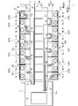
フレキシブル基板33は母板35に一体的に形成された複数の突起部36を有する。突起部36は母板35の縦方向に延びる2つの側辺のうちの1つから横方向に沿って延びている。複数の突起部36は縦方向に離間して並んでいる。縦方向に隣り合って並ぶ2つの突起部36の縦方向の離間距離は、上記の直列離間距離と等しくなっている。母板35が可撓基板に相当する。なお突起部36の母板35から延びる方向は横方向に限らない。例えば突起部36は横方向から縦方向に傾斜した斜め方向に延びてもよい。 The flexible substrate 33 has a plurality of protrusions 36 integrally formed with the mother plate 35. The protrusion 36 extends laterally from one of the two vertically extending sides of the master plate 35. The plurality of protrusions 36 are arranged vertically spaced apart from each other. The vertical separation distance of the two protrusions 36 arranged adjacent to each other in the vertical direction is equal to the above-mentioned series separation distance. The base plate 35 corresponds to a flexible substrate. The direction of the protrusion 36 extending from the mother plate 35 is not limited to the lateral direction. For example, the protrusion 36 may extend in an oblique direction inclined from the horizontal direction to the vertical direction.

フレキシブル基板33は母板35に一体的に形成された1つの出っ張り部37を有する。出っ張り部37は母板35の横方向に延びる2つの側辺のうちの1つから縦方向に沿って延びている。出っ張り部37の横方向の長さは、母板35の横方向の長さよりも短くなっている。そして出っ張り部37には、フレキシブル基板33の表面33aと裏面33bとを電気的に接続するビアが形成されている。 The flexible substrate 33 has one protruding portion 37 integrally formed with the mother plate 35. The protruding portion 37 extends along the vertical direction from one of the two laterally extending sides of the mother plate 35. The lateral length of the protruding portion 37 is shorter than the lateral length of the mother plate 35. A via is formed in the protruding portion 37 to electrically connect the front surface 33a and the back surface 33b of the flexible substrate 33.

配線パターン34は、上記の母板35、突起部36、および、出っ張り部37それぞれの表面33aに形成されている。そして配線パターン34は被覆樹脂で覆われている。配線パターン34は表面33aにおいてL字形状を成している。配線パターン34の数と突起部36の数は同数である。 The wiring pattern 34 is formed on the surface 33a of each of the mother plate 35, the protrusion 36, and the protrusion 37. The wiring pattern 34 is covered with a coating resin. The wiring pattern 34 has an L-shape on the surface 33a. The number of wiring patterns 34 and the number of protrusions 36 are the same.

配線パターン34の一端側が突起部36に形成されている。配線パターン34の中央側が母板35に形成されている。配線パターン34の他端側が出っ張り部37に形成されている。この配線パターン34の一端側の先端が直列端子223や出力端子224に溶接などによって機械的および電気的に接続される。配線パターン34の他端側の先端が上記のビアに接続されている。このビアが配線基板11の基板配線14にはんだなどによって機械的および電気的に接続される。なお、配線パターン34の一端と他端それぞれがフレキシブル基板33と被覆樹脂それぞれの外に露出された構成を採用することもできる。 One end side of the wiring pattern 34 is formed on the protrusion 36. The center side of the wiring pattern 34 is formed on the mother plate 35. The other end side of the wiring pattern 34 is formed on the protruding portion 37. The tip of the wiring pattern 34 on one end side is mechanically and electrically connected to the series terminal 223 and the output terminal 224 by welding or the like. The tip of the other end of the wiring pattern 34 is connected to the via. This via is mechanically and electrically connected to the board wiring 14 of the wiring board 11 by soldering or the like. It is also possible to adopt a configuration in which one end and the other end of the wiring pattern 34 are exposed to the outside of the flexible substrate 33 and the coating resin, respectively.

上記したように縦方向に隣り合って並ぶ2つの突起部36の縦方向の離間距離は、直列離間距離と等しくなっている。そのために縦方向で隣り合って並ぶ2つの配線パターン34の一端側の離間距離も、直列離間距離と等しくなっている。 As described above, the vertical separation distance of the two protrusions 36 arranged adjacent to each other in the vertical direction is equal to the series separation distance. Therefore, the separation distance on one end side of the two wiring patterns 34 arranged adjacent to each other in the vertical direction is also equal to the series separation distance.

突起部36は縦方向および横方向に湾曲可能である。したがって突起部36に設けられた配線パターン34の一端側も縦方向および横方向に湾曲可能である。縦方向で隣り合って並ぶ2つの配線パターン34の一端側の先端の縦方向の離間距離が可変となっている。 The protrusion 36 can be curved in the vertical direction and the horizontal direction. Therefore, one end side of the wiring pattern 34 provided on the protrusion 36 can also be curved in the vertical direction and the horizontal direction. The vertical separation distance of the tips on one end side of the two wiring patterns 34 arranged adjacent to each other in the vertical direction is variable.

<表配線部と裏配線部の接続形態>
上記にしたように表配線部31と裏配線部32は同一構成である。これら表配線部31と裏配線部32は横方向に離間して並んだ状態で配線基板11に接続される。そして表配線部31と裏配線部32は表裏反転して配線基板11に接続される。
<Connection form between front wiring and back wiring>
As described above, the front wiring portion 31 and the back wiring portion 32 have the same configuration. The front wiring portion 31 and the back wiring portion 32 are connected to the wiring board 11 in a state where they are arranged side by side so as to be separated from each other in the lateral direction. Then, the front wiring portion 31 and the back wiring portion 32 are inverted and connected to the wiring board 11.

図4に示すように表配線部31は出っ張り部37の裏面33bが配線基板11の表面11aに接続される。裏配線部32は出っ張り部37の表面33aが表面11aに接続される。 As shown in FIG. 4, in the front wiring portion 31, the back surface 33b of the protruding portion 37 is connected to the front surface 11a of the wiring board 11. In the back wiring portion 32, the surface 33a of the protruding portion 37 is connected to the surface 11a.

特に本実施形態では、表配線部31と裏配線部32とが縦方向にずれて配線基板11に接続される。表配線部31は、出っ張り部37のみが配線基板11の表面11a上に位置する態様で、配線基板11に接続される。これに対して裏配線部32は、出っ張り部37と母板35における出っ張り部37の連結部位側も表面11a上に位置する態様で、配線基板11に接続される。表配線部31と裏配線部32の配線基板11に対する縦方向の配置ズレの長さは、上記のセル幅となっている。 In particular, in the present embodiment, the front wiring portion 31 and the back wiring portion 32 are vertically displaced and connected to the wiring board 11. The front wiring portion 31 is connected to the wiring board 11 in such a manner that only the protruding portion 37 is located on the surface 11a of the wiring board 11. On the other hand, the back wiring portion 32 is connected to the wiring board 11 in such a manner that the connecting portion side of the protruding portion 37 and the protruding portion 37 in the mother plate 35 is also located on the surface 11a. The length of the vertical arrangement deviation of the front wiring portion 31 and the back wiring portion 32 with respect to the wiring board 11 is the above-mentioned cell width.

以上に示した表配線部31と裏配線部32の配線基板11に対する接続構成のため、表配線部31と裏配線部32では、突起部36の延長方向が反対になっている。表配線部31の有する突起部36は裏配線部32から離れるように横方向に延びている。裏配線部32の有する突起部36は表配線部31から離れるように横方向に延びている。そして表配線部31の有する複数の突起部36と裏配線部32の有する複数の突起部36は、縦方向にセル幅だけ配置ズレしている。 Due to the connection configuration of the front wiring portion 31 and the back wiring portion 32 to the wiring board 11 shown above, the extension directions of the protrusions 36 are opposite in the front wiring portion 31 and the back wiring portion 32. The protrusion 36 of the front wiring portion 31 extends laterally so as to be separated from the back wiring portion 32. The protrusion 36 of the back wiring portion 32 extends laterally so as to be separated from the front wiring portion 31. The plurality of protrusions 36 of the front wiring portion 31 and the plurality of protrusions 36 of the back wiring portion 32 are displaced by the cell width in the vertical direction.

<表配線部と裏配線部の搭載態様>
上記にしたように表配線部31と裏配線部32は表裏反転して配線基板11に接続されている。そのために表配線部31と裏配線部32では電池スタック210への搭載態様が異なっている。
<Mounting mode of front wiring part and back wiring part>
As described above, the front wiring portion 31 and the back wiring portion 32 are inverted and connected to the wiring board 11. Therefore, the front wiring portion 31 and the back wiring portion 32 have different mounting modes on the battery stack 210.

図5に示すように表配線部31は、フレキシブル基板33の裏面33bが電池セル220の上端面220aに対向する態様で電池スタック210に搭載される。裏配線部32は、フレキシブル基板33の表面33aが上端面220aに対向する態様で電池スタック210に搭載される。 As shown in FIG. 5, the front wiring portion 31 is mounted on the battery stack 210 in such a manner that the back surface 33b of the flexible substrate 33 faces the upper end surface 220a of the battery cell 220. The back wiring portion 32 is mounted on the battery stack 210 in such a manner that the surface 33a of the flexible substrate 33 faces the upper end surface 220a.

表配線部31と裏配線部32は、複数の電池セル220の上端面220aにおける第1電極端子群211と第2電極端子群212の間に設けられる。表配線部31は第1電極端子群211側に位置する。裏配線部32は第2電極端子群212側に位置する。 The front wiring portion 31 and the back wiring portion 32 are provided between the first electrode terminal group 211 and the second electrode terminal group 212 on the upper end surface 220a of the plurality of battery cells 220. The front wiring unit 31 is located on the side of the first electrode terminal group 211. The back wiring portion 32 is located on the second electrode terminal group 212 side.

表配線部31が複数の電池セル220の上端面220aに設けられた状態で、表配線部31の複数の突起部36は横方向に沿って第1電極端子群211側に延びている。裏配線部32が複数の電池セル220の上端面220aに設けられた状態で、裏配線部32の突起部36は横方向に沿って第2電極端子群212側に延びている。 With the front wiring portion 31 provided on the upper end surfaces 220a of the plurality of battery cells 220, the plurality of protrusions 36 of the front wiring portion 31 extend laterally toward the first electrode terminal group 211 side. With the back wiring portion 32 provided on the upper end surfaces 220a of the plurality of battery cells 220, the protrusion 36 of the back wiring portion 32 extends laterally toward the second electrode terminal group 212 side.

図6に示すように、表配線部31の突起部36に設けられた配線パターン34の一端は、第1直列端子223a、第3直列端子223c、第5直列端子223e、第7直列端子223g、および、最高出力端子224bの接続点CPに接続される。裏配線部32の突起部36に設けられた配線パターン34の一端は、最低出力端子224a、第2直列端子223b、第4直列端子223d、第6直列端子223f、および、第8直列端子223hの接続点CPに接続される。 As shown in FIG. 6, one end of the wiring pattern 34 provided on the protrusion 36 of the table wiring portion 31 includes a first series terminal 223a, a third series terminal 223c, a fifth series terminal 223e, and a seventh series terminal 223g. And, it is connected to the connection point CP of the maximum output terminal 224b. One end of the wiring pattern 34 provided on the protrusion 36 of the back wiring portion 32 is a minimum output terminal 224a, a second series terminal 223b, a fourth series terminal 223d, a sixth series terminal 223f, and an eighth series terminal 223h. Connected to the connection point CP.

以上により、配線部30と電池スタック210とは図1に示す電気的な接続構成となっている。電池スタック210を構成する全ての電池セル220の電圧が配線部30によって検出可能となっている。 As described above, the wiring portion 30 and the battery stack 210 have an electrical connection configuration shown in FIG. The voltages of all the battery cells 220 constituting the battery stack 210 can be detected by the wiring unit 30.

<突起部の構成>
次に、図5~図9に基づいて突起部36の構成を詳説する。
<Structure of protrusion>
Next, the configuration of the protrusion 36 will be described in detail with reference to FIGS. 5 to 9.

図5に明示されるように表配線部31のフレキシブル基板33には、第1電極端子群211を構成する電極端子を接続する直列端子223と出力端子224の総数以上の突起部36と配線パターン34が形成されている。同様にして裏配線部32のフレキシブル基板33には、第2電極端子群212を構成する電極端子を接続する直列端子223と出力端子224の総数以上の突起部36と配線パターン34が形成されている。具体的に言えば、表配線部31と裏配線部32のフレキシブル基板33には6本の突起部36と配線パターン34が形成されている。 As shown in FIG. 5, on the flexible substrate 33 of the table wiring portion 31, the series terminals 223 connecting the electrode terminals constituting the first electrode terminal group 211, the protrusions 36 equal to or more than the total number of the output terminals 224, and the wiring pattern 34 is formed. Similarly, on the flexible substrate 33 of the back wiring portion 32, a series terminal 223 connecting the electrode terminals constituting the second electrode terminal group 212, a protrusion 36 equal to or larger than the total number of the output terminals 224, and a wiring pattern 34 are formed. There is. Specifically, six protrusions 36 and a wiring pattern 34 are formed on the flexible substrate 33 of the front wiring portion 31 and the back wiring portion 32.

上記したように縦方向に隣り合って並ぶ2つの突起部36の離間距離は、直列離間距離と等しくなっている。表配線部31の有する複数の突起部36と裏配線部32の有する複数の突起部36は、縦方向にセル幅だけずれている。 As described above, the separation distance between the two protrusions 36 arranged adjacent to each other in the vertical direction is equal to the series separation distance. The plurality of protrusions 36 of the front wiring portion 31 and the plurality of protrusions 36 of the back wiring portion 32 are displaced by the cell width in the vertical direction.

そのため、図5に示すように表配線部31の複数の突起部36を、第1電極端子群211を構成する電極端子に接続された直列端子223の接続点CPと高さ方向で対向するように、電池スタック210に配置する。そうすると、第1電極端子群211を構成する電極端子に接続される第1直列端子223a、第3直列端子223c、第5直列端子223e、および、第7直列端子223gそれぞれの接続点CPに対して複数の突起部36が高さ方向で対向する。 Therefore, as shown in FIG. 5, the plurality of protrusions 36 of the table wiring portion 31 face each other in the height direction with the connection point CP of the series terminal 223 connected to the electrode terminals constituting the first electrode terminal group 211. It is arranged in the battery stack 210. Then, for the connection point CPs of the first series terminal 223a, the third series terminal 223c, the fifth series terminal 223e, and the seventh series terminal 223g connected to the electrode terminals constituting the first electrode terminal group 211. A plurality of protrusions 36 face each other in the height direction.

ただし、最高出力端子224bの接続点CPと、この最高出力端子224bと縦方向で隣り合って並ぶ第7直列端子223gとは、直列離間距離よりもセル幅の半分だけ短い距離だけ離れている。そのためにこの最高出力端子224bと接続される表配線部31の突起部36は、最高出力端子224bの接続点CPと縦方向にセル幅の半分だけずれている。 However, the connection point CP of the maximum output terminal 224b and the seventh series terminal 223g arranged adjacent to the maximum output terminal 224b in the vertical direction are separated by a distance that is half the cell width shorter than the series separation distance. Therefore, the protrusion 36 of the table wiring portion 31 connected to the maximum output terminal 224b is vertically deviated from the connection point CP of the maximum output terminal 224b by half the cell width.

これに対して裏配線部32の複数の突起部36は、上記した表配線部31の電池スタック210への配置によって、第2電極端子群212を構成する電極端子に接続される直列端子223の接続点CPと高さ方向で対向する。すなわち、第2直列端子223b、第4直列端子223d、第6直列端子223f、および、第8直列端子223hそれぞれの接続点CPと裏配線部32の突起部36とが高さ方向で対向する。 On the other hand, the plurality of protrusions 36 of the back wiring portion 32 are connected to the electrode terminals constituting the second electrode terminal group 212 by the arrangement of the front wiring portion 31 on the battery stack 210. It faces the connection point CP in the height direction. That is, the connection point CP of each of the second series terminal 223b, the fourth series terminal 223d, the sixth series terminal 223f, and the eighth series terminal 223h and the protrusion 36 of the back wiring portion 32 face each other in the height direction.

ただし、最低出力端子224aの接続点CPと、この最低出力端子224aと縦方向で隣り合って並ぶ第2直列端子223bとは、直列離間距離よりもセル幅の半分だけ短い距離だけ離れている。そのためにこの最低出力端子224aと接続される裏配線部32の突起部36は、最低出力端子224aの接続点CPと縦方向にセル幅の半分だけずれている。 However, the connection point CP of the minimum output terminal 224a and the second series terminal 223b arranged adjacent to the minimum output terminal 224a in the vertical direction are separated by a distance that is half the cell width shorter than the series separation distance. Therefore, the protrusion 36 of the back wiring portion 32 connected to the minimum output terminal 224a is vertically deviated from the connection point CP of the minimum output terminal 224a by half the cell width.

図5に明示するように、複数の突起部36の横方向の長さは、母板35における複数の突起部36の延長し始める側辺と、接続点CPとの間の横方向の距離(接続距離)よりも長くなっている。具体的に言えば、突起部36の横方向の長さは、接続距離よりもセル幅以上長くなっている。 As is shown in FIG. 5, the lateral length of the plurality of protrusions 36 is the lateral distance between the extension side of the plurality of protrusions 36 in the mother plate 35 and the connection point CP (the lateral length). It is longer than the connection distance). Specifically, the lateral length of the protrusion 36 is longer than the connection distance by the cell width or more.

したがって突起部36を屈曲することで、突起部36の先端の横方向の位置を接続点CPの横方向の位置にしつつ、突起部36の先端を縦方向にセル幅以上変位することが可能となっている。 Therefore, by bending the protrusion 36, it is possible to displace the tip of the protrusion 36 in the vertical direction by the cell width or more while setting the lateral position of the tip of the protrusion 36 to the lateral position of the connection point CP. It has become.

なお突起部36の横方向の長さは、接続距離よりもセル幅の半分以上長ければよい。さらに言えば、突起部36の横方向の長さは、接続距離をα、セル幅の半分をβとすると、ピタゴラスの定理にしたがって、(α+β0.5以上長ければよい。 The lateral length of the protrusion 36 may be longer than the connection distance by half or more of the cell width. Furthermore, the lateral length of the protrusion 36 may be (α 2 + β 2 ) 0.5 or more longer according to the Pythagorean theorem, where α is the connection distance and β is half the cell width.

図6に突起部36を屈曲した状態を示す。突起部36を縦方向に1回屈曲することで突起部36の延長方向を縦方向にする。その後、その屈曲部位よりも先端側を横方向に1回屈曲する。こうすることで突起部36の延長方向を再度横方向にする。こうすることで突起部36の先端の縦方向と横方向の位置が変位可能となっている。なお、突起部36を1回屈曲することで、突起部36の延長方向を、横方向から縦方向に傾斜した斜め方向にしてもよい。 FIG. 6 shows a state in which the protrusion 36 is bent. By bending the protrusion 36 once in the vertical direction, the extension direction of the protrusion 36 is changed to the vertical direction. After that, the tip side of the bent portion is bent once in the lateral direction. By doing so, the extension direction of the protrusion 36 is changed to the lateral direction again. By doing so, the positions of the tip of the protrusion 36 in the vertical direction and the horizontal direction can be displaced. By bending the protrusion 36 once, the extension direction of the protrusion 36 may be an oblique direction inclined from the horizontal direction to the vertical direction.

以上に示した屈曲により、最高出力端子224bの接続点CPと縦方向にセル幅の半分だけ離間した表配線部31の突起部36が、最高出力端子224bの接続点CPに接続される。最低出力端子224aの接続点CPと縦方向にセル幅の半分だけ離間した裏配線部32の突起部36が、最低出力端子224aの接続点CPに接続される。 Due to the bending shown above, the protrusion 36 of the table wiring portion 31 separated from the connection point CP of the maximum output terminal 224b by half the cell width in the vertical direction is connected to the connection point CP of the maximum output terminal 224b. The protrusion 36 of the back wiring portion 32, which is vertically separated from the connection point CP of the minimum output terminal 224a by half the cell width, is connected to the connection point CP of the minimum output terminal 224a.

なお、上記したように複数の突起部36の横方向の長さは、接続距離よりも長くなっている。そのため、図5に示すように、複数の突起部36の先端と、直列端子223の接続点CPの位置とが横方向で異なっている。これを調整するため、例えば図6に示すように突起部36の一部を除去することで、突起部36の先端の横方向の位置を調整してもよい。突起部36を横方向に折りたたむことで、突起部36の先端の横方向の位置を調整してもよい。若しくは、例えば図7に示すように突起部36を除去せずに、単に突起部36における接続点CPとの対向部位を、接続点CPと溶接接合してもよい。 As described above, the lateral lengths of the plurality of protrusions 36 are longer than the connection distance. Therefore, as shown in FIG. 5, the tips of the plurality of protrusions 36 and the positions of the connection point CPs of the series terminals 223 are laterally different. In order to adjust this, for example, as shown in FIG. 6, the lateral position of the tip of the protrusion 36 may be adjusted by removing a part of the protrusion 36. The lateral position of the tip of the protrusion 36 may be adjusted by folding the protrusion 36 in the lateral direction. Alternatively, for example, as shown in FIG. 7, the portion of the protrusion 36 facing the connection point CP may be welded and joined to the connection point CP without removing the protrusion 36.

また、表配線部31と裏配線部32それぞれは計6本の突起部36を有する。本実施形態の場合、これら6本の突起部36のうち、配線基板11から最も離れた1本の突起部36が電池スタック210との接続に寄与しない。そのためにこの突起部36は不要となる。 Further, each of the front wiring portion 31 and the back wiring portion 32 has a total of six protrusions 36. In the case of the present embodiment, of these six protrusions 36, one protrusion 36 farthest from the wiring board 11 does not contribute to the connection with the battery stack 210. Therefore, this protrusion 36 becomes unnecessary.

この場合、例えば図6に示すように、表配線部31の不要な突起部36を除去してもよい。裏配線部32の不要な突起部36の先端を溶接や半田などによって母板35に固定してもよい。若しくは、母板35にスリットを形成することで、そのスリットに不要な突起部36の先端を固定してもよい。更に例示すれば、例えば図7に示すように、表配線部31と裏配線部32における不要な突起部36を連結する母板35の先端部を除去してもよい。なお以下に示す図面においては、特に不要な突起部36の除去を行っていない状態の監視装置100を示す。 In this case, for example, as shown in FIG. 6, the unnecessary protrusion 36 of the front wiring portion 31 may be removed. The tip of the unnecessary protrusion 36 of the back wiring portion 32 may be fixed to the base plate 35 by welding, soldering, or the like. Alternatively, by forming a slit in the base plate 35, the tip of an unnecessary protrusion 36 may be fixed to the slit. Further, for example, as shown in FIG. 7, the tip portion of the master plate 35 connecting the unnecessary protrusions 36 in the front wiring portion 31 and the back wiring portion 32 may be removed. In the drawings shown below, the monitoring device 100 in a state where the unnecessary protrusion 36 is not removed is shown.

上記したように突起部36を屈曲するが、例えば図8の(a)欄に示すように、この屈曲を容易とするためのミシン目36aが突起部36に形成されてもよい。図8の(b)欄に示すように、屈曲を容易とするための切欠き36bが突起部36に形成されてもよい。図8においては、ミシン目36aと突起部36に形成された配線パターン34との位置関係を明りょうとするために、ミシン目36aを破線で示している。配線パターン34をハッチングで示している。 The protrusion 36 is bent as described above, but as shown in the column (a) of FIG. 8, for example, a perforation 36a for facilitating this bending may be formed in the protrusion 36. As shown in column (b) of FIG. 8, a notch 36b for facilitating bending may be formed in the protrusion 36. In FIG. 8, the perforation 36a is shown by a broken line in order to clarify the positional relationship between the perforation 36a and the wiring pattern 34 formed on the protrusion 36. The wiring pattern 34 is shown by hatching.

ミシン目36aは複数の断続的な切れ目が一直線に並んで成る。ミシン目36aは、横方向と縦方向に突起部36の延長方向を変換できるように、横方向と縦方向に対して傾斜した角度に沿う線上に形成されている。具体的に言えば、縦方向から横方向に対して±45°傾いた線上にミシン目36aが形成されている。また図8に示す変形例では、突起部36の延長方向の長さを調整できるように、縦方向に沿う直線上にミシン目36aが形成されている。これら斜め方向のミシン目36aと縦方向に沿うミシン目36aは突起部36の延長方向に等間隔で形成されている。 The perforation 36a consists of a plurality of intermittent cuts arranged in a straight line. The perforation 36a is formed on a line along an angle inclined with respect to the horizontal direction and the vertical direction so that the extension direction of the protrusion 36 can be changed in the horizontal direction and the vertical direction. Specifically, the perforations 36a are formed on a line inclined by ± 45 ° from the vertical direction to the horizontal direction. Further, in the modified example shown in FIG. 8, the perforation 36a is formed on a straight line along the vertical direction so that the length of the protrusion 36 in the extension direction can be adjusted. The perforations 36a in the diagonal direction and the perforations 36a along the vertical direction are formed at equal intervals in the extension direction of the protrusion 36.

図8に明示するように、ミシン目36aは配線パターン34を横断している。そのために配線パターン34の一部はミシン目36aの切れ目によって除去されている。ただし、配線パターン34におけるミシン目36aの形成方向の幅は、このミシン目36aを構成する複数の切れ目のうちの1つよりも長くなっている。 As is shown in FIG. 8, the perforation 36a crosses the wiring pattern 34. Therefore, a part of the wiring pattern 34 is removed by the cut of the perforation 36a. However, the width of the perforation 36a in the wiring pattern 34 in the forming direction is longer than one of the plurality of cuts constituting the perforation 36a.

図8の(b)欄に示すように切欠き36bは、横方向と縦方向に突起部36の延長方向を変換できるように、横方向と縦方向に対して傾斜した角度に形成されている。具体的に言えば、縦方向から横方向に対して±45°傾いた方向の突起部36の幅が短くなるように、切欠き36bは突起部36に形成されている。そしてこの切欠き36bは配線パターン34を挟んで2つ並んで形成されている。この2つの切欠き36bが突起部36の延長方向に等間隔で形成されている。特に、図8の(b)欄に示す構成においては、2つの切欠き36bの間に、上記の斜め方向のミシン目36aと縦方向に沿うミシン目36aが形成されている。 As shown in the column (b) of FIG. 8, the notch 36b is formed at an angle inclined with respect to the horizontal direction and the vertical direction so that the extension direction of the protrusion 36 can be changed in the horizontal direction and the vertical direction. .. Specifically, the notch 36b is formed in the protrusion 36 so that the width of the protrusion 36 in the direction inclined by ± 45 ° from the vertical direction to the horizontal direction is shortened. Two notches 36b are formed side by side with the wiring pattern 34 interposed therebetween. The two notches 36b are formed at equal intervals in the extension direction of the protrusion 36. In particular, in the configuration shown in the column (b) of FIG. 8, the perforations 36a in the diagonal direction and the perforations 36a in the vertical direction are formed between the two notches 36b.

また図9に示すように突起部36には、突起部36の屈曲状態を固定するための固定部38が形成されていてもよい。例えば図9の(a)欄に示すように、固定部38としては、突起部36に形成された切れ目を採用することができる。この切れ目に突起部36の一部を挿入することで突起部36の屈曲状態を固定してもよい。 Further, as shown in FIG. 9, the protrusion 36 may be formed with a fixing portion 38 for fixing the bent state of the protrusion 36. For example, as shown in the column (a) of FIG. 9, as the fixing portion 38, a cut formed in the protrusion 36 can be adopted. The bent state of the protrusion 36 may be fixed by inserting a part of the protrusion 36 into this cut.

図9の(b)欄に示すように、固定部38としては、突起部36に形成された金属パッドを採用することができる。この金属パッドに突起部36の一部を接触させた状態で、金属パッドを溶融する。こうすることで突起部36の屈曲状態を固定してもよい。 As shown in the column (b) of FIG. 9, as the fixing portion 38, a metal pad formed on the protrusion 36 can be adopted. The metal pad is melted in a state where a part of the protrusion 36 is in contact with the metal pad. By doing so, the bent state of the protrusion 36 may be fixed.

図9の(c)欄に示すように、固定部38としては、突起部36に形成された切れ目と孔を採用することができる。この切れ目によって形成された凸部を孔に嵌合する。これにより突起部36の屈曲状態を固定してもよい。 As shown in the column (c) of FIG. 9, as the fixing portion 38, a cut and a hole formed in the protrusion 36 can be adopted. The convex portion formed by this cut is fitted into the hole. As a result, the bent state of the protrusion 36 may be fixed.

<作用効果>
次に、監視装置100の作用効果を説明する。上記したように、配線パターン34の形成された突起部36が、屈曲することで縦方向と横方向に延びる構成となっている。そのため、電池スタック210の設計変更などによって直列端子223および出力端子224と突起部36との相対的な位置にズレが生じたとしても、突起部36に形成された配線パターン34を直列端子223と出力端子224に接続することができる。
<Action effect>
Next, the operation and effect of the monitoring device 100 will be described. As described above, the protrusion 36 on which the wiring pattern 34 is formed is bent so as to extend in the vertical direction and the horizontal direction. Therefore, even if the relative positions of the series terminal 223 and the output terminal 224 and the protrusion 36 are displaced due to a design change of the battery stack 210 or the like, the wiring pattern 34 formed on the protrusion 36 is replaced with the series terminal 223. It can be connected to the output terminal 224.

例えば図10および図11に示すように電池セル220の縦方向の体格が増減したとしても、突起部36に形成された配線パターン34を直列端子223と出力端子224に接続することができる。図12および図13に示すように電池スタック210の有する複数の電池セル220の縦方向の並び(電池セル220の数)に変更が生じたとしても、突起部36に形成された配線パターン34を直列端子223と出力端子224に接続することができる。図示しないが、電池スタック210に対する監視装置100の配置ズレが生じたとしても、突起部36に形成された配線パターン34を直列端子223と出力端子224に接続することができる。 For example, even if the vertical physique of the battery cell 220 increases or decreases as shown in FIGS. 10 and 11, the wiring pattern 34 formed on the protrusion 36 can be connected to the series terminal 223 and the output terminal 224. As shown in FIGS. 12 and 13, even if the vertical arrangement of the plurality of battery cells 220 (the number of battery cells 220) of the battery stack 210 is changed, the wiring pattern 34 formed on the protrusion 36 is provided. It can be connected to the series terminal 223 and the output terminal 224. Although not shown, the wiring pattern 34 formed on the protrusion 36 can be connected to the series terminal 223 and the output terminal 224 even if the monitoring device 100 is misaligned with respect to the battery stack 210.

このように監視装置100は電池スタック210の設計変更などに対して汎用性が高くなっている。 As described above, the monitoring device 100 is highly versatile in response to a design change of the battery stack 210 and the like.

突起部36の母板35から延びた長さは、母板35における突起部36の延長し始める側辺と、接続点CPとの間の横方向の距離(接続距離)よりもセル幅以上長くなっている。 The length of the protrusion 36 extending from the mother plate 35 is longer than the cell width (connection distance) between the side of the mother plate 35 where the protrusion 36 starts to extend and the connection point CP. It has become.

これによれば、電池スタック210の設計変更などによって直列端子223および出力端子224と突起部36との相対的な位置ズレがセル幅程度生じたとしても、突起部36に形成された配線パターン34を直列端子223と出力端子224に接続することができる。 According to this, even if the relative positional deviation between the series terminal 223 and the output terminal 224 and the protrusion 36 occurs due to a design change of the battery stack 210 or the like, the wiring pattern 34 formed on the protrusion 36 is formed. Can be connected to the series terminal 223 and the output terminal 224.

突起部36にはミシン目36aが形成されている。ミシン目36aは、横方向と縦方向に対して傾斜した角度に沿う線上に形成されている。またミシン目36aは、縦方向に沿う直線上に形成されている。 Perforations 36a are formed on the protrusions 36. The perforations 36a are formed on a line along an angle inclined with respect to the horizontal direction and the vertical direction. Further, the perforations 36a are formed on a straight line along the vertical direction.

さらに突起部36には切欠き36bが形成されている。切欠き36bは、横方向と縦方向に対して傾斜した角度の方向の突起部36の幅が局所的に狭くなるように形成されている。また切欠き36bは、配線パターン34を挟んで2つ並んで形成されている。 Further, a notch 36b is formed in the protrusion 36. The notch 36b is formed so that the width of the protrusion 36 in the direction inclined with respect to the horizontal direction and the vertical direction is locally narrowed. Further, two notches 36b are formed side by side with the wiring pattern 34 interposed therebetween.

これらミシン目36aと切欠き36bのうちの少なくとも一方によって突起部36の屈曲が容易となっている。そのために突起部36の延長方向の変換が容易となっている。突起部36の延長方向の長さ調整が容易となっている。 At least one of the perforations 36a and the notch 36b facilitates bending of the protrusion 36. Therefore, it is easy to change the extension direction of the protrusion 36. It is easy to adjust the length of the protrusion 36 in the extension direction.

配線パターン34におけるミシン目36aの形成方向の幅は、ミシン目36aを構成する複数の切れ目のうちの1つよりも長くなっている。これによりミシン目36aの形成によって配線パターン34が断線することが抑制されている。 The width of the perforations 36a in the wiring pattern 34 in the forming direction is longer than one of the plurality of cuts constituting the perforations 36a. As a result, the wiring pattern 34 is prevented from being broken due to the formation of the perforations 36a.

監視装置100は全くの同一構成の表配線部31と裏配線部32を有する。これにより監視装置100の部品点数の増大が抑制される。 The monitoring device 100 has a front wiring unit 31 and a back wiring unit 32 having exactly the same configuration. As a result, the increase in the number of parts of the monitoring device 100 is suppressed.

表配線部31と裏配線部32それぞれの複数の突起部36の離間間隔は、縦方向に隣り合って並ぶ複数の直列端子223の接続点CPの離間距離(直列離間距離)と等しくなっている。 The separation distance between the plurality of protrusions 36 of the front wiring portion 31 and the back wiring portion 32 is equal to the separation distance (series separation distance) of the connection point CPs of the plurality of series terminals 223 arranged adjacent to each other in the vertical direction. ..

また、表配線部31と裏配線部32とは、電位順で並び、なおかつ横方向で離間して位置する2つの直列端子223の接続点CPの縦方向の離間距離(セル幅)だけずれて配線基板11に接続されている。 Further, the front wiring portion 31 and the back wiring portion 32 are arranged in the order of potential and are displaced by the vertical separation distance (cell width) of the connection point CPs of the two series terminals 223 located separately in the horizontal direction. It is connected to the wiring board 11.

以上により、図5に示すように表配線部31の複数の突起部36は、第1電極端子群211を構成する電極端子に接続される複数の直列端子223それぞれの接続点CPに対して高さ方向で対向する。裏配線部32の複数の突起部36は、第2電極端子群212を構成する電極端子に接続される複数の直列端子223それぞれの接続点CPに対して高さ方向で対向する。この直列端子223と接続される突起部36の延長方向を縦方向に変換するために、突起部36を屈曲しなくともよくなる。出力端子224に接続される突起部36を屈曲するだけでよくなる。監視装置100の電池スタック210への接続配置が容易となる。 As described above, as shown in FIG. 5, the plurality of protrusions 36 of the table wiring portion 31 are higher than the connection point CP of each of the plurality of series terminals 223 connected to the electrode terminals constituting the first electrode terminal group 211. Oppose in the vertical direction. The plurality of protrusions 36 of the back wiring portion 32 face each other of the connection point CPs of the plurality of series terminals 223 connected to the electrode terminals constituting the second electrode terminal group 212 in the height direction. In order to change the extension direction of the protrusion 36 connected to the series terminal 223 to the vertical direction, it is not necessary to bend the protrusion 36. All that is required is to bend the protrusion 36 connected to the output terminal 224. The connection arrangement of the monitoring device 100 to the battery stack 210 becomes easy.

複数の直列端子223それぞれにおける突起部36に形成された配線パターン34との接続点CPは、直列端子223の中点である。そのため、複数の配線パターン34それぞれで検出される電圧に含まれる、直列端子223の抵抗と流れる電流に起因して生じる電圧降下が同程度になる。この結果、複数の電池セルの電圧の検出精度にバラツキが生じることが抑制される。 The connection point CP with the wiring pattern 34 formed on the protrusion 36 in each of the plurality of series terminals 223 is the midpoint of the series terminals 223. Therefore, the voltage drop caused by the resistance of the series terminal 223 and the flowing current included in the voltage detected in each of the plurality of wiring patterns 34 is about the same. As a result, it is possible to suppress variations in the voltage detection accuracy of the plurality of battery cells.

(第1の変形例)
本実施形態では、図4に示すよう裏配線部32は、出っ張り部37と母板35における出っ張り部37の連結部位側も表面11a上に位置する態様で、配線基板11に接続される例を示した。しかしながら図14に示すように、表配線部31と裏配線部32の先端を縦方向にセル幅ずらした状態で、裏配線部32の出っ張り部37だけが表面11a上に位置する態様で、裏配線部32を配線基板11に接続する構成を採用することもできる。図14では、裏配線部32を屈曲することで、図4において表面11a上に位置した母板35における出っ張り部37の連結部位側を、母板35における電池スタック210に設けられる部位に重ねて配置している。これによれば、配線基板11と配線部30の重なり領域の増大が抑制される。配線基板11における第1電子素子12の搭載領域の減少が抑制される。配線基板11の体格の増大が抑制される。
(First modification)
In the present embodiment, as shown in FIG. 4, the back wiring portion 32 is connected to the wiring board 11 in such a manner that the connecting portion side of the protruding portion 37 and the protruding portion 37 in the mother plate 35 is also located on the surface 11a. Indicated. However, as shown in FIG. 14, in a state where the tips of the front wiring portion 31 and the back wiring portion 32 are vertically displaced by the cell width, only the protruding portion 37 of the back wiring portion 32 is located on the surface 11a. It is also possible to adopt a configuration in which the wiring unit 32 is connected to the wiring board 11. In FIG. 14, by bending the back wiring portion 32, the connecting portion side of the protruding portion 37 in the master plate 35 located on the surface 11a in FIG. 4 is overlapped with the portion provided in the battery stack 210 in the master plate 35. It is arranged. According to this, the increase of the overlapping region of the wiring board 11 and the wiring portion 30 is suppressed. The decrease in the mounting area of the first electronic element 12 on the wiring board 11 is suppressed. The increase in the physique of the wiring board 11 is suppressed.

(第2実施形態)
次に、第2実施形態を図15~図19に基づいて説明する。以下に示す各実施形態に係る監視装置100は上記した実施形態によるものと共通点が多い。そのため以下においては共通部分の説明を省略し、異なる部分を重点的に説明する。また以下においては上記した実施形態で示した要素と同一の要素には同一の符号を付与する。
(Second Embodiment)
Next, the second embodiment will be described with reference to FIGS. 15 to 19. The monitoring device 100 according to each of the following embodiments has much in common with those according to the above-described embodiments. Therefore, in the following, the explanation of the common part will be omitted, and the different parts will be explained with emphasis. Further, in the following, the same reference numerals are given to the same elements as those shown in the above-described embodiment.

第1実施形態では、表配線部31と裏配線部32とが縦方向にセル幅ずれた状態で配線基板11に接続される例を示した。これに対して本実施形態では、表配線部31と裏配線部32とが縦方向にずれずに配線基板11に接続される。 In the first embodiment, an example is shown in which the front wiring portion 31 and the back wiring portion 32 are connected to the wiring board 11 in a state where the cell width is displaced in the vertical direction. On the other hand, in the present embodiment, the front wiring portion 31 and the back wiring portion 32 are connected to the wiring board 11 without being displaced in the vertical direction.

本構成の場合、図15に示すように表配線部31の突起部36と裏配線部32の突起部36は横方向並んだ構成となる。そのため、図16に示すように監視装置100を電池スタック210に搭載した場合、表配線部31の突起部36は接続対象の直列端子223の接続点CPと高さ方向で対向する。しかしながら裏配線部32の突起部36は接続対象の直列端子223の接続点CPとセル幅だけ縦方向にズレて位置する。 In the case of this configuration, as shown in FIG. 15, the protrusion 36 of the front wiring portion 31 and the protrusion 36 of the back wiring portion 32 are arranged side by side in the horizontal direction. Therefore, when the monitoring device 100 is mounted on the battery stack 210 as shown in FIG. 16, the protrusion 36 of the front wiring portion 31 faces the connection point CP of the series terminal 223 to be connected in the height direction. However, the protrusion 36 of the back wiring portion 32 is positioned so as to be vertically offset from the connection point CP of the series terminal 223 to be connected by the cell width.

係る構成においても、図17に示すように突起部36を屈曲することで、接続対象の直列端子223と出力端子224それぞれに突起部36の配線パターン34を接続することができる。 Also in such a configuration, by bending the protrusion 36 as shown in FIG. 17, the wiring pattern 34 of the protrusion 36 can be connected to each of the series terminal 223 and the output terminal 224 to be connected.

また、例えば図18および図19に示すように電池セル220の数が増大することで、直列端子223および出力端子224と突起部36との相対的な位置にズレが生じる場合がある。このような場合においても、突起部36を屈曲することで、突起部36に形成された配線パターン34を直列端子223と出力端子224に接続することができる。 Further, as shown in FIGS. 18 and 19, for example, as the number of battery cells 220 increases, the relative positions of the series terminal 223 and the output terminal 224 and the protrusion 36 may be displaced. Even in such a case, the wiring pattern 34 formed on the protrusion 36 can be connected to the series terminal 223 and the output terminal 224 by bending the protrusion 36.

本実施形態に係る監視装置100、および、以下に示す各種形態の監視装置100には、第1実施形態に記載の監視装置100と同等の構成要素が含まれている。そのために同等の作用効果を奏する。したがって表記が煩雑となることを避けるために、その記載を省略する。 The monitoring device 100 according to the present embodiment and the monitoring devices 100 of various forms shown below include the same components as the monitoring device 100 described in the first embodiment. Therefore, it has the same effect. Therefore, in order to avoid complicated notation, the description is omitted.

(第3実施形態)
次に、第3実施形態を図20-図22に基づいて説明する。
(Third Embodiment)
Next, the third embodiment will be described with reference to FIGS. 20-22.

第1実施形態では、表配線部31と裏配線部32とが全くの同一構成である例を示した。しかしながら図20に示すように表配線部31と裏配線部32としては異なった構成を採用することができる。 In the first embodiment, an example is shown in which the front wiring portion 31 and the back wiring portion 32 have exactly the same configuration. However, as shown in FIG. 20, different configurations can be adopted for the front wiring portion 31 and the back wiring portion 32.

本実施形態に係る表配線部31と裏配線部32の構成上の相違点は、突起部36の形成位置である。表配線部31と裏配線部32の突起部36の形成位置がセル幅ずれている。しかしながら表配線部31と裏配線部32それぞれにおける複数の突起部36の離間間隔は直列離間距離で同一となっている。 The structural difference between the front wiring portion 31 and the back wiring portion 32 according to the present embodiment is the formation position of the protrusion 36. The formation positions of the protrusions 36 of the front wiring portion 31 and the back wiring portion 32 are displaced from each other by the cell width. However, the distance between the plurality of protrusions 36 in each of the front wiring portion 31 and the back wiring portion 32 is the same as the series separation distance.

また表配線部31と裏配線部32それぞれの配線基板11との接続領域が同一となっている。すなわち表配線部31と裏配線部32それぞれの出っ張り部37だけが表面11a上に位置する態様で、表配線部31と裏配線部32が配線基板11に接続されている。 Further, the connection area between the front wiring portion 31 and the wiring board 11 of each of the back wiring portions 32 is the same. That is, the front wiring portion 31 and the back wiring portion 32 are connected to the wiring board 11 in such a manner that only the protruding portions 37 of the front wiring portion 31 and the back wiring portion 32 are located on the surface 11a.

図21に示すように監視装置100を電池スタック210に配置した場合、第1実施形態と同様にして、直列端子223の接続点CPと突起部36とが高さ方向で対向する。出力端子224の接続点CPと突起部36とは縦方向にずれて並ぶ。 When the monitoring device 100 is arranged on the battery stack 210 as shown in FIG. 21, the connection point CP of the series terminal 223 and the protrusion 36 face each other in the height direction in the same manner as in the first embodiment. The connection point CP of the output terminal 224 and the protrusion 36 are arranged so as to be offset in the vertical direction.

したがって図22に示すように、第1実施形態と同様にして、表配線部31と裏配線部32の1つの突起部36を屈曲するだけで、複数の突起部36それぞれと複数の直列端子223と2つの出力端子224とを接続することができる。 Therefore, as shown in FIG. 22, in the same manner as in the first embodiment, only by bending one protrusion 36 of the front wiring portion 31 and the back wiring portion 32, each of the plurality of protrusions 36 and the plurality of series terminals 223 are bent. And two output terminals 224 can be connected.

(第2の変形例)
本実施形態では、異なる構成の表配線部31と裏配線部32を有する例を示した。しかしながら係る構成の場合、図23に示すように表配線部31と裏配線部32とが一枚のフレキシブル基板33を共有する構成を採用することもできる。本実施形態で示したように、表配線部31と裏配線部32とに分かれた構成でなくともよい。
(Second modification)
In this embodiment, an example having a front wiring portion 31 and a back wiring portion 32 having different configurations is shown. However, in the case of such a configuration, as shown in FIG. 23, a configuration in which the front wiring portion 31 and the back wiring portion 32 share one flexible substrate 33 can be adopted. As shown in this embodiment, the configuration does not have to be divided into the front wiring portion 31 and the back wiring portion 32.

(第4実施形態)
次に、第4実施形態を図24-図26に基づいて説明する。
(Fourth Embodiment)
Next, the fourth embodiment will be described with reference to FIGS. 24-26.

第3実施形態では、表配線部31と裏配線部32の突起部36の形成位置がセル幅ずれている例を示した。これに対して本実施形態では、図24に示すように表配線部31と裏配線部32の突起部36の形成位置がセル幅の半分ずれている。 In the third embodiment, an example is shown in which the formation positions of the protrusions 36 of the front wiring portion 31 and the back wiring portion 32 are displaced by the cell width. On the other hand, in the present embodiment, as shown in FIG. 24, the forming positions of the protrusions 36 of the front wiring portion 31 and the back wiring portion 32 are deviated by half of the cell width.

図25に示すように本実施形態の監視装置100を電池スタック210に配置した場合、直列端子223の接続点CPと突起部36とが高さ方向で対向する。それだけではなく、裏配線部32の突起部36が最低出力端子224aの接続点CPと高さ方向で対向する。 As shown in FIG. 25, when the monitoring device 100 of the present embodiment is arranged on the battery stack 210, the connection point CP of the series terminal 223 and the protrusion 36 face each other in the height direction. Not only that, the protrusion 36 of the back wiring portion 32 faces the connection point CP of the minimum output terminal 224a in the height direction.

したがって図26に示すように、表配線部31の1つの突起部36だけを屈曲するだけで、複数の突起部36それぞれと複数の直列端子223と2つの出力端子224とを接続することができる。 Therefore, as shown in FIG. 26, it is possible to connect each of the plurality of protrusions 36 to the plurality of series terminals 223 and the two output terminals 224 by bending only one protrusion 36 of the table wiring portion 31. ..

(第3の変形例)
係る構成において、第2の変形例と同様にして、図27に示すように表配線部31と裏配線部32とが一枚のフレキシブル基板33を共有する構成を採用することもできる。表配線部31と裏配線部32とに分かれた構成でなくともよい。
(Third modification example)
In such a configuration, similarly to the second modification, a configuration in which the front wiring portion 31 and the back wiring portion 32 share one flexible substrate 33 can be adopted as shown in FIG. 27. It does not have to be a configuration in which the front wiring portion 31 and the back wiring portion 32 are separated.

(第5実施形態)
次に、第5実施形態を図28~図32に基づいて説明する。
(Fifth Embodiment)
Next, the fifth embodiment will be described with reference to FIGS. 28 to 32.

これまでの各実施形態では、直列端子223と出力端子224が縦方向に延びる例を示した。これに対して本実施形態では直列端子223と出力端子224の一部が横方向に延びる構成となっている。 In each embodiment so far, an example is shown in which the series terminal 223 and the output terminal 224 extend in the vertical direction. On the other hand, in the present embodiment, a part of the series terminal 223 and the output terminal 224 extends in the lateral direction.

図28に示すように直列端子223は、一体的に連結された第1連結部225と第1接続部226を有する。出力端子224は、一体的に連結された第2連結部227と第2接続部228を有する。 As shown in FIG. 28, the series terminal 223 has a first connecting portion 225 and a first connecting portion 226 that are integrally connected. The output terminal 224 has a second connecting portion 227 and a second connecting portion 228 that are integrally connected.

第1連結部225は正極端子221と負極端子222を接続する。第2連結部227は最低電位の負極端子222若しくは最高電位の正極端子221に接続される。第1接続部226と第2接続部228それぞれは突起部36に形成された配線パターン34と接続される。第1接続部226と第2接続部228は、配線パターン34、基板配線14、および、監視ICチップ13の配線を介して、入力インピーダンスの高いコンパレータ20の入力端子に接続される。 The first connecting portion 225 connects the positive electrode terminal 221 and the negative electrode terminal 222. The second connecting portion 227 is connected to the negative electrode terminal 222 having the lowest potential or the positive electrode terminal 221 having the highest potential. Each of the first connection portion 226 and the second connection portion 228 is connected to the wiring pattern 34 formed on the protrusion 36. The first connection unit 226 and the second connection unit 228 are connected to the input terminal of the comparator 20 having a high input impedance via the wiring of the wiring pattern 34, the board wiring 14, and the monitoring IC chip 13.

以上に示した接続構成のため、第1連結部225と第2連結部227には、複数の電池セル220の直列接続された電池スタック210を流れる電流が流れる。第1接続部226と第2接続部228には、第1連結部225と第2連結部227を流れる電流に比べて微量の電流が流れる。以下においては表記を簡素とするために、第1連結部225と第2連結部227に流れる電流を本電流と示す。第1接続部226と第2接続部228に流れる電流を検出電流と示す。 Due to the connection configuration shown above, a current flowing through the battery stack 210 in which a plurality of battery cells 220 are connected in series flows through the first connecting portion 225 and the second connecting portion 227. A small amount of current flows through the first connecting portion 226 and the second connecting portion 228 as compared with the current flowing through the first connecting portion 225 and the second connecting portion 227. In the following, for the sake of simplicity, the current flowing through the first connecting portion 225 and the second connecting portion 227 is referred to as the main current. The current flowing through the first connection portion 226 and the second connection portion 228 is referred to as a detection current.

第1連結部225は縦方向に延びる矩形を成している。第1連結部225の縦方向の長さは、直列離間距離以下になっている。 The first connecting portion 225 has a rectangular shape extending in the vertical direction. The length of the first connecting portion 225 in the vertical direction is equal to or less than the series separation distance.

第1接続部226は第1連結部225から横方向に延びている。第1接続部226は、第1連結部225が正極端子221と負極端子222とに接続された状態において、複数の電池セル220の上端面220aにおける正極端子221と負極端子222との間の領域と高さ方向で離間して対向している。 The first connecting portion 226 extends laterally from the first connecting portion 225. The first connecting portion 226 is a region between the positive electrode terminal 221 and the negative electrode terminal 222 on the upper end surface 220a of the plurality of battery cells 220 in a state where the first connecting portion 225 is connected to the positive electrode terminal 221 and the negative electrode terminal 222. And are separated from each other in the height direction and face each other.

第1接続部226は、第1連結部225における正極端子221との接続点(第1接続点)と負極端子222との接続点(第2接続点)との間の中点から横方向に延びている。第1接続部226における第1連結部225から延びる端部と第1接続点との離間距離と、第1接続部226の端部と第2接続点との離間距離とが等しくなっている。この構成により、第1連結部225における第1接続点と第1接続部226の端部との間の抵抗値と、第1連結部225における第2接続点と第1接続部226の端部との間の抵抗値とが相等しくなっている。第1接続点が第1接続部位に相当する。第2接続点が第2接続部位に相当する。 The first connection portion 226 is laterally arranged from the midpoint between the connection point (first connection point) with the positive electrode terminal 221 and the connection point (second connection point) with the negative electrode terminal 222 in the first connection portion 225. It is extended. The separation distance between the end portion extending from the first connection portion 225 and the first connection point in the first connection portion 226 is equal to the separation distance between the end portion of the first connection portion 226 and the second connection point. With this configuration, the resistance value between the first connection point in the first connection portion 225 and the end portion of the first connection portion 226, and the end portion of the second connection point and the first connection portion 226 in the first connection portion 225. The resistance value between and is equal to each other. The first connection point corresponds to the first connection portion. The second connection point corresponds to the second connection portion.

第2連結部227は矩形を成している。第2連結部227の縦方向の長さは、セル幅以下になっている。第2接続部228は第2連結部227から横方向に延びている。第2接続部228は、第2連結部227が負極端子222若しくは正極端子221に接続された状態において、電池セル220の上端面220aにおける正極端子221と負極端子222との間の領域と高さ方向で離間して対向している。 The second connecting portion 227 has a rectangular shape. The length of the second connecting portion 227 in the vertical direction is equal to or less than the cell width. The second connecting portion 228 extends laterally from the second connecting portion 227. The second connecting portion 228 has a region and a height between the positive electrode terminal 221 and the negative electrode terminal 222 on the upper end surface 220a of the battery cell 220 in a state where the second connecting portion 227 is connected to the negative electrode terminal 222 or the positive electrode terminal 221. They are separated from each other in the direction and face each other.

係る直列端子223と出力端子224を有する電池スタック210に、これまでの各種形態で示した監視装置100を搭載した構成を図29、図30、図31、および、図32に示す。これらに示されるように、例え接続対象の直列端子223および出力端子224と突起部36とが縦方向に離れていたとしても、その突起部36を1度屈曲して縦方向に延長させることで、監視装置100と電池スタック210とを接続することができる。このように突起部36の屈曲回数を1回に減少することができる。 29, 30, 31, and 32 show a configuration in which the monitoring device 100 shown in various forms so far is mounted on the battery stack 210 having the series terminal 223 and the output terminal 224. As shown in these, even if the series terminal 223 and the output terminal 224 to be connected and the protrusion 36 are separated in the vertical direction, the protrusion 36 is bent once and extended in the vertical direction. , The monitoring device 100 and the battery stack 210 can be connected. In this way, the number of times the protrusion 36 is bent can be reduced to one.

また、配線パターン34の接続される第1接続部226と第2接続部228に流れる検出電流は、第1連結部225と第2連結部227を流れる本電流よりも電流量が微量になっている。そのため、配線パターン34で検出される電池セル220の電圧に含まれる、第1接続部226と第2接続部228の抵抗と電流に起因して生じる電圧降下が微量となっている。 Further, the detected current flowing through the first connecting portion 226 and the second connecting portion 228 to which the wiring pattern 34 is connected has a smaller amount of current than the main current flowing through the first connecting portion 225 and the second connecting portion 227. There is. Therefore, the voltage drop caused by the resistance and current of the first connection portion 226 and the second connection portion 228 included in the voltage of the battery cell 220 detected by the wiring pattern 34 is very small.

したがって、例え配線パターン34の第1接続部226および第2接続部228に対する接続位置にズレが生じたとしても、複数の配線パターン34で検出される電池セル220の電圧の検出精度のバラツキが、この微小な電圧降下程度になる。これにより、複数の配線パターン34それぞれで検出される電池セル220の電圧の検出精度にバラツキが生じることが抑制される。 Therefore, even if the connection positions of the wiring pattern 34 with respect to the first connection portion 226 and the second connection portion 228 are displaced, the voltage detection accuracy of the battery cells 220 detected by the plurality of wiring patterns 34 varies. It becomes about this minute voltage drop. As a result, it is possible to suppress variations in the detection accuracy of the voltage of the battery cell 220 detected in each of the plurality of wiring patterns 34.

以上、本開示物の好ましい実施形態について説明したが、本開示物は上記した実施形態になんら制限されることなく、本開示物の主旨を逸脱しない範囲において、種々変形して実施することが可能である。 Although the preferred embodiments of the present disclosure have been described above, the present disclosure can be variously modified and implemented without being limited to the above-described embodiments and within a range that does not deviate from the gist of the present disclosure. Is.

(第4の変形例)
本実施形態ではフレキシブル基板33にヒューズ61とインダクタ62が設けられる例を示した。これに対して、ヒューズ61とインダクタ62の他に、例えばツェナーダイオード15、並列コンデンサ16、および、抵抗17がフレキシブル基板33に設けられる構成を採用することもできる。
(Fourth modification)
In this embodiment, an example in which the fuse 61 and the inductor 62 are provided on the flexible substrate 33 is shown. On the other hand, in addition to the fuse 61 and the inductor 62, for example, a Zener diode 15, a parallel capacitor 16, and a resistor 17 may be provided on the flexible substrate 33.

(第5の変形例)
本実施形態では配線パターン34が表面33aに形成される例を示した。しかしながら配線パターン34が裏面33bに形成された構成を採用することもできる。配線パターン34が表面33aと裏面33bの両方に形成された構成を採用することもできる。
(Fifth variant)
In this embodiment, an example in which the wiring pattern 34 is formed on the surface 33a is shown. However, it is also possible to adopt a configuration in which the wiring pattern 34 is formed on the back surface 33b. It is also possible to adopt a configuration in which the wiring pattern 34 is formed on both the front surface 33a and the back surface 33b.

(第6の変形例)
各実施形態では電池モジュール200が1つの電池スタック210を有する例を示した。しかしながら電池モジュール200は複数の電池スタック210を有してもよい。この場合、電池モジュール200の筐体には各電池スタック210に対応する収容空間が構成される。これら複数の収容空間は横方向に並んで設けられる。
(Sixth modification)
In each embodiment, an example is shown in which the battery module 200 has one battery stack 210. However, the battery module 200 may have a plurality of battery stacks 210. In this case, the housing of the battery module 200 is configured with a storage space corresponding to each battery stack 210. These plurality of accommodation spaces are provided side by side in the horizontal direction.

例えば2つの電池スタック210の電池セル220が直列接続される場合、2つの電池スタック210は偶数個の電池セル220を同数有する。2つの電池スタック210それぞれの複数の電池セルは縦方向に並んでいる。2つの電池スタック210のうちの一方の縦方向において右端に位置する電池セル220の負極端子222と、2つの電池スタック210のうちの他方の右端に位置する電池セル220の正極端子221とが、ワイヤを介して電気的に接続される。これにより2つの電池スタック210のうちの一方の縦方向において左端に位置する電池セル220の負極端子222が最低電位、他方の左端に位置する電池セル220の正極端子221が最高電位になる。最高電位の正極端子221と最低電位の負極端子222は横方向に並んで配置される。これら2つの電池スタック210それぞれに配線部30が設けられる。 For example, when the battery cells 220 of the two battery stacks 210 are connected in series, the two battery stacks 210 have the same number of even number of battery cells 220. The plurality of battery cells of each of the two battery stacks 210 are arranged vertically. The negative electrode terminal 222 of the battery cell 220 located at the right end of one of the two battery stacks 210 in the vertical direction and the positive electrode terminal 221 of the battery cell 220 located at the right end of the other of the two battery stacks 210 It is electrically connected via a wire. As a result, the negative electrode terminal 222 of the battery cell 220 located at the left end in the vertical direction of one of the two battery stacks 210 has the lowest potential, and the positive electrode terminal 221 of the battery cell 220 located at the left end of the other has the highest potential. The positive electrode terminal 221 having the highest potential and the negative electrode terminal 222 having the lowest potential are arranged side by side in the horizontal direction. A wiring unit 30 is provided in each of these two battery stacks 210.

(その他の変形例)
本実施形態では電池パック400をハイブリッド自動車に適用した例を示した。しかしながら電池パック400は例えばプラグインハイブリッド自動車や電気自動車に適用することもできる。
(Other variants)
In this embodiment, an example in which the battery pack 400 is applied to a hybrid vehicle is shown. However, the battery pack 400 can also be applied to, for example, a plug-in hybrid vehicle or an electric vehicle.

10…監視部、20…コンパレータ、30…配線部、31…表配線部、32…裏配線部、33a…表面、33b…裏面、34…配線パターン、35…母板、36…突起部、36a…切れ目、36b…切欠き、100…監視装置、200…電池モジュール、210…電池スタック、211…第1電極端子群、212…第2電極端子群、220…電池セル、220a…上端面、221…正極端子、222…負極端子、223…直列端子、224…出力端子、225…第1連結部、226…第1接続部、300…電池ECU、400…電池パック、CP…接続点 10 ... monitoring unit, 20 ... comparator, 30 ... wiring unit, 31 ... front wiring unit, 32 ... back wiring unit, 33a ... front surface, 33b ... back surface, 34 ... wiring pattern, 35 ... mother plate, 36 ... protrusion, 36a ... Cut, 36b ... Notch, 100 ... Monitoring device, 200 ... Battery module, 210 ... Battery stack, 211 ... First electrode terminal group, 212 ... Second electrode terminal group, 220 ... Battery cell, 220a ... Upper end surface, 221 ... Positive terminal, 222 ... Negative terminal, 223 ... Series terminal, 224 ... Output terminal, 225 ... First connection part, 226 ... First connection part, 300 ... Battery ECU, 400 ... Battery pack, CP ... Connection point

Claims (9)

正極端子(221)と負極端子(222)が離間する態様で形成面(220a)に形成された複数の電池セル(220)が、前記形成面に沿いなおかつ前記正極端子と前記負極端子の離間する離間方向に交差する所定方向に並ぶことで、前記正極端子と前記負極端子とが前記所定方向で交互に並ぶ第1電極端子群(211)と、前記第1電極端子群とは前記正極端子と前記負極端子の並びが逆の第2電極端子群(212)と、が構成され、前記正極端子と前記負極端子のうちの少なくとも一方に連結端子(223,223a~223h,224,224a,224b)が連結された電池スタック(210)に接続される監視装置(100)であって、
前記電池セルの電圧を監視する監視部(10)と、
前記連結端子と前記監視部とを接続する配線部(30)と、を有し、
前記配線部は、
複数の前記電池セルの前記形成面に対向する態様で、前記第1電極端子群と前記第2電極端子群との間に設けられる可撓基板(35)と、
前記可撓基板から延びた複数の突起部(36)と、
前記可撓基板と前記突起部それぞれに形成された配線パターン(34)と、を有し、
複数の前記突起部のうちの少なくとも1つが屈曲して前記所定方向と前記離間方向に延びることで、前記突起部に形成された前記配線パターンが前記連結端子に接続され
前記突起部には、前記突起部の前記可撓基板から延びる方向に対して交差する方向の幅を局所的に狭くする切欠き(36b)が形成されている監視装置。
A plurality of battery cells (220) formed on the formed surface (220a) in such a manner that the positive electrode terminal (221) and the negative electrode terminal (222) are separated from each other are along the formed surface and the positive electrode terminal and the negative electrode terminal are separated from each other. The first electrode terminal group (211) in which the positive electrode terminal and the negative electrode terminal are alternately arranged in the predetermined direction by arranging in a predetermined direction intersecting in the separation direction, and the first electrode terminal group is the positive electrode terminal. A second electrode terminal group (212) in which the arrangement of the negative electrode terminals is reversed is configured, and connecting terminals (223, 223a to 223h, 224, 224a, 224b) are connected to at least one of the positive electrode terminal and the negative electrode terminal. Is a monitoring device (100) connected to a connected battery stack (210).
A monitoring unit (10) that monitors the voltage of the battery cell,
It has a wiring unit (30) for connecting the connecting terminal and the monitoring unit, and has a wiring unit (30).
The wiring part is
A flexible substrate (35) provided between the first electrode terminal group and the second electrode terminal group in a manner facing the forming surface of the plurality of battery cells.
A plurality of protrusions (36) extending from the flexible substrate and
It has a flexible substrate and a wiring pattern (34) formed on each of the protrusions.
When at least one of the plurality of protrusions bends and extends in the predetermined direction and the separation direction, the wiring pattern formed on the protrusions is connected to the connecting terminal.
A monitoring device in which a notch (36b) is formed in the protrusion so as to locally narrow the width of the protrusion in a direction intersecting the direction extending from the flexible substrate .
前記形成面に前記可撓基板が設けられた状態における、前記可撓基板と前記連結端子における前記配線パターンとの接続点との前記離間方向の距離をα、前記電池セルの前記所定方向の長さの半分をβとすると、前記突起部の前記可撓基板から延びた長さは、(α2+β2)0.5以上長い請求項1に記載の監視装置。 The distance in the separation direction between the flexible substrate and the connection point of the wiring pattern in the connection terminal in the state where the flexible substrate is provided on the forming surface is α, and the length of the battery cell in the predetermined direction. The monitoring device according to claim 1, wherein the length of the protrusion extending from the flexible substrate is (α2 + β2) 0.5 or more longer, assuming that half of the portion is β. 前記突起部には、前記突起部の前記可撓基板から延びる方向に対して交差する方向に並ぶ、複数の断続的な切れ目(36a)が形成されている請求項1または2に記載の監視装置。 The monitoring device according to claim 1 or 2 , wherein the protrusions are formed with a plurality of intermittent cuts (36a) arranged in a direction intersecting the direction extending from the flexible substrate of the protrusions. .. 複数の断続的な前記切れ目は、前記突起部に形成された前記配線パターンを横断する態様で前記突起部に形成されており、
前記配線パターンにおける前記切れ目の形成方向に沿う長さ、1つの前記切れ目における前記形成方向に沿う長さよりも長い請求項に記載の監視装置。
The plurality of intermittent cuts are formed in the protrusion so as to cross the wiring pattern formed in the protrusion.
The monitoring device according to claim 3 , wherein the length of the wiring pattern along the formation direction of the cut is longer than the length of one of the cuts along the formation direction .
前記配線部として、前記可撓基板、前記突起部、および、前記配線パターンを備える、同一形状の第1配線部(31)と第2配線部(32)を有し、
前記第1配線部の前記可撓基板の表面(33a)の裏側の裏面(33b)が複数の前記電池セルの前記形成面に対向する態様で、前記第1配線部は前記第1電極端子群と前記第2電極端子群との間における前記第1電極端子群側に設けられ、
前記第2配線部の前記可撓基板の前記表面が複数の前記電池セルの前記形成面に対向する態様で、前記第2配線部は前記第1電極端子群と前記第2電極端子群との間における前記第2電極端子群側に設けられる請求項1~いずれか1項に記載の監視装置。
The wiring portion includes the flexible substrate, the protrusion portion, and the first wiring portion (31) and the second wiring portion (32) having the same shape and having the wiring pattern.
The back surface (33b) on the back side of the front surface (33a) of the flexible substrate of the first wiring unit faces the formation surface of the plurality of battery cells, and the first wiring unit is the first electrode terminal group. It is provided on the side of the first electrode terminal group between the second electrode terminal group and the second electrode terminal group.
The surface of the flexible substrate of the second wiring portion faces the formation surface of the plurality of battery cells, and the second wiring portion includes the first electrode terminal group and the second electrode terminal group. The monitoring device according to any one of claims 1 to 4 , which is provided on the side of the second electrode terminal group in between.
前記連結端子は、前記所定方向に隣接して並ぶ2つの前記電池セルのうちの一方の前記正極端子(221)と他方の前記負極端子(222)とを接続する直列端子(223,223a~223h)を有し、
前記突起部に形成された前記配線パターンは、前記直列端子における前記正極端子との第1接続部位と前記負極端子との第2接続部位との間の中点(CP)に接続される請求項1~いずれか1項に記載の監視装置。
The connecting terminal is a series terminal (223, 223a to 223h) that connects one of the positive electrode terminals (221) and the other negative electrode terminal (222) of the two battery cells arranged adjacent to each other in a predetermined direction. )
A claim that the wiring pattern formed on the protrusion is connected to a midpoint (CP) between a first connection portion with the positive electrode terminal and a second connection portion with the negative electrode terminal in the series terminal. The monitoring device according to any one of 1 to 5 .
前記連結端子は、前記所定方向に隣接して並ぶ2つの前記電池セルのうちの一方の前記正極端子(221)と他方の前記負極端子(222)とを接続する直列端子(223,223a~223h)を有し、
前記直列端子は、前記所定方向に延びて前記正極端子と前記負極端子とに接続される連結部(225)と、前記連結部における前記正極端子との第1接続部位と前記負極端子との第2接続部位との間の中点から延びた接続部(226)と、を有し、
前記突起部は前記接続部に接続される請求項1~いずれか1項に記載の監視装置。
The connecting terminal is a series terminal (223, 223a to 223h) that connects one of the positive electrode terminals (221) and the other negative electrode terminal (222) of the two battery cells arranged adjacent to each other in a predetermined direction. )
The series terminal has a connecting portion (225) extending in a predetermined direction and connected to the positive electrode terminal and the negative electrode terminal, a first connection portion between the positive electrode terminal and the positive electrode terminal in the connecting portion, and a first negative electrode terminal. It has a connection portion (226) extending from a midpoint between the two connection portions, and has.
The monitoring device according to any one of claims 1 to 5 , wherein the protrusion is connected to the connection.
前記接続部は、前記連結部の前記中点から前記離間方向に延びている請求項に記載の監視装置。 The monitoring device according to claim 7 , wherein the connecting portion extends from the midpoint of the connecting portion in the separating direction. 前記監視部は,前記連結端子の電圧を検出する電圧検出回路(20)を有し、
前記電圧検出回路の入力端子に前記配線パターンが接続されており、
前記電圧検出回路の入力インピーダンスは出力インピーダンスよりもハイインピーダンスとなっている請求項1~いずれか1項に記載の監視装置。
The monitoring unit has a voltage detection circuit (20) that detects the voltage of the connection terminal.
The wiring pattern is connected to the input terminal of the voltage detection circuit.
The monitoring device according to any one of claims 1 to 8 , wherein the input impedance of the voltage detection circuit has a higher impedance than the output impedance.
JP2018133404A 2018-07-13 2018-07-13 Monitoring device Active JP7081355B2 (en)

Priority Applications (1)

Application Number Priority Date Filing Date Title
JP2018133404A JP7081355B2 (en) 2018-07-13 2018-07-13 Monitoring device

Applications Claiming Priority (1)

Application Number Priority Date Filing Date Title
JP2018133404A JP7081355B2 (en) 2018-07-13 2018-07-13 Monitoring device

Publications (2)

Publication Number Publication Date
JP2020013653A JP2020013653A (en) 2020-01-23
JP7081355B2 true JP7081355B2 (en) 2022-06-07

Family

ID=69170122

Family Applications (1)

Application Number Title Priority Date Filing Date
JP2018133404A Active JP7081355B2 (en) 2018-07-13 2018-07-13 Monitoring device

Country Status (1)

Country Link
JP (1) JP7081355B2 (en)

Cited By (1)

* Cited by examiner, † Cited by third party
Publication number Priority date Publication date Assignee Title
KR101904959B1 (en) * 2016-11-10 2018-10-08 동서 피, 씨, 씨 주식회사 PC double beam-column joint structure for securing of seismic performance

Families Citing this family (8)

* Cited by examiner, † Cited by third party
Publication number Priority date Publication date Assignee Title
JP7077833B2 (en) * 2018-07-13 2022-05-31 株式会社デンソー Monitoring device
JP6975996B2 (en) * 2020-01-30 2021-12-01 株式会社大都技研 Game table
JP6975995B2 (en) * 2020-01-30 2021-12-01 株式会社大都技研 Game table
JP6975994B2 (en) * 2020-01-30 2021-12-01 株式会社大都技研 Game table
JP6975993B2 (en) * 2020-01-30 2021-12-01 株式会社大都技研 Game table
CN114583401B (en) 2020-12-02 2024-07-02 莫仕连接器(成都)有限公司 Battery connection module
WO2023162751A1 (en) * 2022-02-25 2023-08-31 ヌヴォトンテクノロジージャパン株式会社 Battery pack
JP7528161B2 (en) 2022-09-05 2024-08-05 プライムプラネットエナジー&ソリューションズ株式会社 Battery Module

Citations (10)

* Cited by examiner, † Cited by third party
Publication number Priority date Publication date Assignee Title
JP2010114025A (en) 2008-11-10 2010-05-20 Denso Corp High voltage detection module device of battery pack
JP2011040332A (en) 2009-08-18 2011-02-24 Yazaki Corp Bus bar
JP2011049158A (en) 2009-07-29 2011-03-10 Sanyo Electric Co Ltd Battery module, battery system, and electric vehicle
JP2011228216A (en) 2010-04-22 2011-11-10 Yazaki Corp Wiring material
JP2013055825A (en) 2011-09-05 2013-03-21 Sanyo Electric Co Ltd Electric power unit for vehicle and vehicle having the same
JP2013093307A (en) 2011-10-04 2013-05-16 Auto Network Gijutsu Kenkyusho:Kk Wiring module for cell
WO2015099066A1 (en) 2013-12-25 2015-07-02 矢崎総業株式会社 Battery wiring module
JP2016115544A (en) 2014-12-15 2016-06-23 矢崎総業株式会社 Manufacturing method of battery wiring module
JP2017033646A (en) 2015-07-29 2017-02-09 株式会社豊田自動織機 Method of manufacturing battery module
JP2020514976A (en) 2016-12-27 2020-05-21 ユラ・コーポレイション・カンパニー・リミテッドYura Corporation Co., Ltd. Flexible circuit board and frame assembly including the same

Patent Citations (10)

* Cited by examiner, † Cited by third party
Publication number Priority date Publication date Assignee Title
JP2010114025A (en) 2008-11-10 2010-05-20 Denso Corp High voltage detection module device of battery pack
JP2011049158A (en) 2009-07-29 2011-03-10 Sanyo Electric Co Ltd Battery module, battery system, and electric vehicle
JP2011040332A (en) 2009-08-18 2011-02-24 Yazaki Corp Bus bar
JP2011228216A (en) 2010-04-22 2011-11-10 Yazaki Corp Wiring material
JP2013055825A (en) 2011-09-05 2013-03-21 Sanyo Electric Co Ltd Electric power unit for vehicle and vehicle having the same
JP2013093307A (en) 2011-10-04 2013-05-16 Auto Network Gijutsu Kenkyusho:Kk Wiring module for cell
WO2015099066A1 (en) 2013-12-25 2015-07-02 矢崎総業株式会社 Battery wiring module
JP2016115544A (en) 2014-12-15 2016-06-23 矢崎総業株式会社 Manufacturing method of battery wiring module
JP2017033646A (en) 2015-07-29 2017-02-09 株式会社豊田自動織機 Method of manufacturing battery module
JP2020514976A (en) 2016-12-27 2020-05-21 ユラ・コーポレイション・カンパニー・リミテッドYura Corporation Co., Ltd. Flexible circuit board and frame assembly including the same

Cited By (1)

* Cited by examiner, † Cited by third party
Publication number Priority date Publication date Assignee Title
KR101904959B1 (en) * 2016-11-10 2018-10-08 동서 피, 씨, 씨 주식회사 PC double beam-column joint structure for securing of seismic performance

Also Published As

Publication number Publication date
JP2020013653A (en) 2020-01-23

Similar Documents

Publication Publication Date Title
JP7081355B2 (en) Monitoring device
JP7039995B2 (en) Monitoring device
JP6900820B2 (en) Monitoring device
US20110024205A1 (en) Battery module, battery system and electric vehicle
US20110027634A1 (en) Battery system and electric vehicle including the same
US20110104521A1 (en) Battery system and electric vehicle including the same
JP6534774B2 (en) Bus bar structure
WO2022009545A1 (en) Flexible substrate
JP2012028186A (en) Battery module, battery system, and electric vehicle
JP7006105B2 (en) Monitoring device
CN107732346B (en) Battery monitoring device
US20210151812A1 (en) Battery module and vehicle with the same
JP6874544B2 (en) Monitoring device
US11231464B2 (en) Monitoring apparatus
JP7031509B2 (en) Monitoring device
JP2023547032A (en) Battery cell contacting device and battery module comprising such battery cell contacting device
JP6859872B2 (en) Monitoring device
JP7347257B2 (en) battery pack
JP7200741B2 (en) battery module
JP7077833B2 (en) Monitoring device
JP7435402B2 (en) flexible circuit board
JP7159984B2 (en) battery module
JP2021136052A (en) Battery pack
JP7107247B2 (en) battery module

Legal Events

Date Code Title Description
A621 Written request for application examination

Free format text: JAPANESE INTERMEDIATE CODE: A621

Effective date: 20210318

A977 Report on retrieval

Free format text: JAPANESE INTERMEDIATE CODE: A971007

Effective date: 20220228

A131 Notification of reasons for refusal

Free format text: JAPANESE INTERMEDIATE CODE: A131

Effective date: 20220308

A521 Request for written amendment filed

Free format text: JAPANESE INTERMEDIATE CODE: A523

Effective date: 20220329

TRDD Decision of grant or rejection written
A01 Written decision to grant a patent or to grant a registration (utility model)

Free format text: JAPANESE INTERMEDIATE CODE: A01

Effective date: 20220426

A61 First payment of annual fees (during grant procedure)

Free format text: JAPANESE INTERMEDIATE CODE: A61

Effective date: 20220509

R151 Written notification of patent or utility model registration

Ref document number: 7081355

Country of ref document: JP

Free format text: JAPANESE INTERMEDIATE CODE: R151