WO2023162751A1 - Battery pack - Google Patents
Battery pack Download PDFInfo
- Publication number
- WO2023162751A1 WO2023162751A1 PCT/JP2023/004799 JP2023004799W WO2023162751A1 WO 2023162751 A1 WO2023162751 A1 WO 2023162751A1 JP 2023004799 W JP2023004799 W JP 2023004799W WO 2023162751 A1 WO2023162751 A1 WO 2023162751A1
- Authority
- WO
- WIPO (PCT)
- Prior art keywords
- battery
- batteries
- voltage detection
- battery pack
- current
- Prior art date
Links
Images


Classifications
-
- G—PHYSICS
- G01—MEASURING; TESTING
- G01R—MEASURING ELECTRIC VARIABLES; MEASURING MAGNETIC VARIABLES
- G01R31/00—Arrangements for testing electric properties; Arrangements for locating electric faults; Arrangements for electrical testing characterised by what is being tested not provided for elsewhere
- G01R31/36—Arrangements for testing, measuring or monitoring the electrical condition of accumulators or electric batteries, e.g. capacity or state of charge [SoC]
- G01R31/389—Measuring internal impedance, internal conductance or related variables
-
- H—ELECTRICITY
- H01—ELECTRIC ELEMENTS
- H01M—PROCESSES OR MEANS, e.g. BATTERIES, FOR THE DIRECT CONVERSION OF CHEMICAL ENERGY INTO ELECTRICAL ENERGY
- H01M10/00—Secondary cells; Manufacture thereof
- H01M10/42—Methods or arrangements for servicing or maintenance of secondary cells or secondary half-cells
- H01M10/48—Accumulators combined with arrangements for measuring, testing or indicating the condition of cells, e.g. the level or density of the electrolyte
-
- H—ELECTRICITY
- H01—ELECTRIC ELEMENTS
- H01M—PROCESSES OR MEANS, e.g. BATTERIES, FOR THE DIRECT CONVERSION OF CHEMICAL ENERGY INTO ELECTRICAL ENERGY
- H01M50/00—Constructional details or processes of manufacture of the non-active parts of electrochemical cells other than fuel cells, e.g. hybrid cells
- H01M50/20—Mountings; Secondary casings or frames; Racks, modules or packs; Suspension devices; Shock absorbers; Transport or carrying devices; Holders
- H01M50/298—Mountings; Secondary casings or frames; Racks, modules or packs; Suspension devices; Shock absorbers; Transport or carrying devices; Holders characterised by the wiring of battery packs
-
- H—ELECTRICITY
- H01—ELECTRIC ELEMENTS
- H01M—PROCESSES OR MEANS, e.g. BATTERIES, FOR THE DIRECT CONVERSION OF CHEMICAL ENERGY INTO ELECTRICAL ENERGY
- H01M50/00—Constructional details or processes of manufacture of the non-active parts of electrochemical cells other than fuel cells, e.g. hybrid cells
- H01M50/50—Current conducting connections for cells or batteries
- H01M50/569—Constructional details of current conducting connections for detecting conditions inside cells or batteries, e.g. details of voltage sensing terminals
-
- Y—GENERAL TAGGING OF NEW TECHNOLOGICAL DEVELOPMENTS; GENERAL TAGGING OF CROSS-SECTIONAL TECHNOLOGIES SPANNING OVER SEVERAL SECTIONS OF THE IPC; TECHNICAL SUBJECTS COVERED BY FORMER USPC CROSS-REFERENCE ART COLLECTIONS [XRACs] AND DIGESTS
- Y02—TECHNOLOGIES OR APPLICATIONS FOR MITIGATION OR ADAPTATION AGAINST CLIMATE CHANGE
- Y02E—REDUCTION OF GREENHOUSE GAS [GHG] EMISSIONS, RELATED TO ENERGY GENERATION, TRANSMISSION OR DISTRIBUTION
- Y02E60/00—Enabling technologies; Technologies with a potential or indirect contribution to GHG emissions mitigation
- Y02E60/10—Energy storage using batteries
Definitions
- the present disclosure relates to a battery pack including an assembled battery in which secondary batteries such as lithium ion batteries are connected in series or in parallel.
- Lithium-ion batteries are often used in such applications due to their high energy density.
- the assembled battery is required to have a large capacity so that electricity can be used for a long period of time.
- such assembled batteries are designed to have a structure in which a battery block formed by stacking a plurality of batteries in a plurality of stages is housed in an exterior case made of plastic.
- This assembled battery can increase the output voltage by connecting a plurality of batteries in series, and can extend the operating time by connecting a plurality of batteries in parallel.
- a battery monitoring device monitors the voltage, current, and temperature of all batteries in an assembled battery composed of secondary batteries, and uses these measurement data to monitor the state of each battery.
- Patent Document 1 discloses, as a high-output, high-capacity battery pack, a battery pack that has a large number of battery cells and is provided with an assembled battery formed by assembling a large number of battery cells.
- a plurality of batteries are stacked in the same direction to form an assembled battery, and a circuit board on which a battery monitoring device is mounted is arranged on an end face of the assembled battery to detect voltage. Wires connect the batteries that make up the battery block and the circuit board that is arranged on the end face of the assembled battery. Also, the voltage detection line is arranged on the terminal surface where the electrode terminal of each battery is located, and is configured to be positioned in a space outside the electrode terminal. A plurality of voltage detection lines connected to each electrode terminal are drawn out to the end of the assembled battery on the circuit board side in the longitudinal direction.
- Patent Document 2 discloses a technique for measuring the impedance of a battery as one method of monitoring the state of the battery.
- Patent Literature 2 proposes a battery monitoring device that measures internal impedance characteristics of a battery using electrochemical impedance spectroscopy (EIS) and monitors the state of the battery in real time.
- EIS electrochemical impedance spectroscopy
- this battery monitoring device measures the impedance of the battery, and refers to the correlation between the predetermined impedance and the state of charge (SOC) and the state of health (SOH) of the battery. It is also possible to estimate the SOC and SOH corresponding to the measured impedance and manage the battery state.
- SOC state of charge
- SOH state of health
- the response signal obtained from the internal impedance characteristics is an extremely weak signal, there is a problem that it is susceptible to external influences.
- an induced electromotive force is generated in an electric circuit path through which a response signal is input and output, and this induced electromotive force affects proper measurement, resulting in a problem of electromagnetic induction failure.
- Patent Document 3 proposes a battery monitoring device capable of suppressing the influence of the induced electromotive force by minimizing the area range surrounded by the electric circuit path in which the induced electromotive force is generated.
- JP 2015-185414 A Japanese Patent No. 5403437 Japanese Patent Application Laid-Open No. 2021-117221
- wiring such as voltage detection lines and bus bars that connect the battery and the battery monitoring device have a resistance value, and the impedance changes depending on the length of the wiring.
- the impedance of the battery to be measured is low, the influence of the length of the wiring becomes relatively large. In order to suppress this effect, it is necessary to shorten the wiring routed inside the battery pack as much as possible.
- a signal generator that applies alternating current is connected to each electrode terminal of the battery.
- the current applying line becomes a source of electromagnetic induction interference, affecting impedance detection.
- the present disclosure provides a battery pack that can accurately measure the internal impedance of a plurality of batteries that form an assembled battery.
- a battery pack includes an assembled battery in which a plurality of batteries are connected, a current application line for applying current to the assembled battery, a plurality of voltage detection lines for detecting voltages of the plurality of batteries, and the plurality of and a battery monitoring device for measuring the internal impedance of the battery, wherein the battery monitoring device is positioned between the positive battery terminal and the negative battery terminal of each battery constituting the assembled battery, and the plurality of The voltage detection lines are radially routed from the battery monitoring device.
- the battery pack according to one aspect of the present disclosure, it is possible to accurately measure the internal impedance of the plurality of batteries forming the assembled battery.
- FIG. 1 is a schematic configuration diagram showing an example of a battery pack according to Embodiment 1; FIG. It is a figure for demonstrating a Nyquist plot figure. It is a figure for demonstrating a Nyquist plot figure.
- FIG. 4 is a diagram for explaining the correlation between a Nyquist plot and a battery equivalent circuit; It is a perspective view showing an example of a battery.
- FIG. 2 is a plan view showing an example of an assembled battery; 1 is a plan view showing an example of a battery pack according to Embodiment 1; FIG. 1 is a perspective view showing an example of a battery pack according to Embodiment 1; FIG. It is a figure which shows the influence of the inductor component of wiring.
- FIG. 2 is a plan view showing an example of an assembled battery
- 1 is a plan view showing an example of a battery pack according to Embodiment 1
- FIG. 1 is a perspective view showing an example of a battery pack according to Embodiment 1;
- FIG. 4 is a diagram showing the influence of electromagnetic induction disturbance
- FIG. 8 is a plan view showing an example of a battery pack according to Embodiment 2
- FIG. 8 is a perspective view showing an example of a battery pack according to Embodiment 2
- FIG. 11 is a plan view showing an example of a battery pack according to Embodiment 3
- FIG. 11 is a perspective view showing an example of a battery pack according to Embodiment 3
- FIG. 11 is a diagram for explaining a first example of a shielding part according to Embodiment 4; It is a figure which shows an example of the wiring which is not covered with the shielding part.
- FIG. 11 is a diagram for explaining a second example of a shielding part according to Embodiment 4;
- FIG. 11 is a diagram for explaining a third example of a shielding portion according to Embodiment 4;
- FIG. 11 is a plan view showing an example of a battery pack according to Embodiment 5;
- FIG. 12 is a schematic configuration diagram showing an example of a battery pack according to Embodiment 6;
- FIG. 11 is a plan view showing an example of a battery pack according to Embodiment 6;
- FIG. 21 is a perspective view showing an example of a battery pack according to Embodiment 6;
- FIG. 11 is a plan view showing an example of a battery pack in another embodiment;
- a battery pack includes an assembled battery in which a plurality of batteries are connected, a current application line that applies current to the assembled battery, and a plurality of voltage detection lines that detect voltages of the plurality of batteries. and a battery monitoring device for measuring the internal impedance of the plurality of batteries, wherein the battery monitoring device is positioned between a positive battery terminal and a negative battery terminal of each battery that constitutes the assembled battery. , the plurality of voltage detection lines are routed radially from the battery monitoring device;
- the length of the plurality of voltage detection lines can be minimized. It is possible to reduce the resistance values of the plurality of voltage detection lines. Therefore, the influence of the resistance values of the plurality of voltage detection lines can be suppressed, and the internal impedances of the plurality of batteries forming the assembled battery can be accurately measured.
- the assembled battery and the battery monitoring device may be connected by the current application line, and an alternating current controlled by the battery monitoring device may be applied to the assembled battery via the current application line.
- the battery monitoring device may measure the internal AC impedance of the plurality of batteries based on the AC current applied to the assembled battery and the voltages of the plurality of batteries.
- the current application line may be laid out so as not to be parallel to the plurality of voltage detection lines, or may be laid out so as to minimize the number of parallel points with the plurality of voltage detection lines. .
- a large alternating current can be applied to the current application line, so if the current application line and the voltage detection line are arranged in parallel, the mutual inductance generated will also increase. Therefore, by wiring the current application line so as not to be parallel to the plurality of voltage detection lines, or by wiring so that the parallel portion with the plurality of voltage detection lines is minimized, the current application line and the voltage Electromagnetic induction interference due to mutual inductance with the detection line can be suppressed. Thereby, it is possible to measure the internal impedance of the plurality of batteries constituting the assembled battery with higher accuracy.
- the current application line may be positioned between the positive battery terminal and the negative battery terminal of the plurality of batteries.
- the battery monitoring device By positioning the current applying line between the positive battery terminal and the negative battery terminal of the plurality of batteries, the battery monitoring device can be connected to the assembled battery between the positive battery terminal and the negative battery terminal of the plurality of batteries. can be extended to the positive electrode side assembled battery terminal and the negative electrode side assembled battery terminal. Therefore, the current application line can be shortened, and the resistance value of the current application line can be reduced. As a result, the influence of the resistance value of the current application line can also be suppressed, and the internal impedance of the plurality of batteries forming the assembled battery can be measured with even higher accuracy.
- the current application line may be located outside between the positive battery terminals and the negative battery terminals of the plurality of batteries.
- the current application line is connected between the positive battery terminals and the negative battery terminals of the plurality of batteries. Positioning outside the gap can suppress electromagnetic induction interference due to mutual inductance between the current application line and the voltage detection line. Thereby, it is possible to measure the internal impedance of the plurality of batteries constituting the assembled battery with higher accuracy.
- the current application line may be routed so as to weaken the magnetic field generated by the current application line.
- the magnetic field generated by the current application line is weakened, it is possible to suppress electromagnetic induction interference due to mutual inductance between the current application line and the voltage detection line. Thereby, it is possible to measure the internal impedance of the plurality of batteries constituting the assembled battery with higher accuracy.
- the battery terminals of the batteries included in the plurality of batteries constitute the assembled battery by being connected to the battery terminals of adjacent batteries by bus bars, and the voltage detection lines included in the plurality of voltage detection lines are It may be connected between two of the battery terminals on the bus bar.
- the bus bar Since the positive battery terminal and the negative battery terminal of the adjacent batteries are connected by the bus bar, the bus bar has almost the same potential as the positive battery terminal and the negative battery terminal. Therefore, it is possible to detect the voltage of the adjacent batteries by connecting the voltage detection lines to the bus bar instead of connecting the voltage detection lines to the positive battery terminal and the negative battery terminal. number can be reduced. That is, since the number of voltage detection lines is reduced, it is possible to suppress the influence of the inductor component and the induced electromotive force when measuring the impedance of the battery. Thereby, it is possible to measure the internal impedance of the plurality of batteries constituting the assembled battery with higher accuracy.
- the voltage detection line may be connected to the busbar at positions equidistant from the two battery terminals.
- the effect of the resistance component of the bus bar when detecting the voltage of adjacent batteries. can be evened out for adjacent cells.
- the battery pack may include a shield that shields an electric field or magnetic field generated by the plurality of batteries or the current application line.
- the shielding part can suppress the influence of electric fields or magnetic fields generated by a plurality of batteries or current application lines.
- the shielding part may be a shield that covers the center conductor of the current application line, and shields the electric field or magnetic field generated by the current application line.
- the shield covering the current application line can suppress the influence of the electric field or magnetic field generated by the current application line.
- the shielding portion may be a sheet-like shield provided between the current application line and the plurality of voltage detection lines, and shield an electric field or magnetic field generated by the current application line.
- the sheet-like shield provided between the current application line and the plurality of voltage detection lines can suppress the influence of the electric field or magnetic field generated by the current application line.
- the shielding part is a sheet-shaped shield provided between the plurality of batteries and the current application line and the plurality of voltage detection lines, and shields the electric field or magnetic field generated by the plurality of batteries.
- the sheet-like shields provided between the batteries and the current application lines and voltage detection lines can suppress the influence of the electric field or magnetic field generated by the batteries.
- each figure is a schematic diagram and is not necessarily strictly illustrated. Moreover, in each figure, the same code
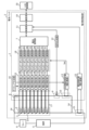
- FIG. 1 is a schematic configuration diagram showing an example of a battery pack 2 according to Embodiment 1.
- FIG. 1 In addition to the battery pack 2, FIG. 1 also shows a host controller 20, a load 5, and a relay 6.
- the battery pack 2 includes an assembled battery 4 in which a plurality of batteries 3 (for example, composed of batteries B1 to B8) are combined and connected, a battery monitoring device 1 for monitoring the batteries, and a current application line. 14 , a plurality of voltage detection lines 17 and a shunt resistor 21 .
- Battery 3 is a secondary battery such as a lithium ion battery.
- a relay 6 is provided between the assembled battery 4 and the load 5 (corresponding to the motor, inverter, and accelerator) to turn ON/OFF the connection between the assembled battery 4 and the load 5 .
- the application is operated according to ON/OFF of the connection between the assembled battery 4 and the load 5 by the relay 6 .
- the load 5 may be a charger.
- the assembled battery 4 and the battery monitoring device 1 are connected by a current application line 14 and a plurality of voltage detection lines 17 .
- the battery monitoring device 1 is a device that measures the internal impedance of a plurality of batteries 3. For example, the battery monitoring device 1 measures internal AC impedances of a plurality of batteries 3 . Also, for example, the battery monitoring device 1 measures the internal impedance (for example, internal AC impedance) of each of the plurality of batteries 3 . The battery monitoring device 1 detects the internal alternating current of the plurality of batteries 3 based on the alternating current applied to the assembled battery 4 and the voltage of the plurality of batteries 3 constituting the assembled battery 4 (for example, the voltage of each of the plurality of batteries 3). Impedance (for example, internal AC impedance of each of the plurality of batteries 3) is measured.
- the battery monitoring device 1 uses EIS to measure the internal AC impedance characteristics of the battery 3 and monitors the state of the battery 3 in real time.
- the battery monitoring device 1 includes a battery management unit 7, a load resistor 8, a switching element 9, a shunt resistor 10, a control unit 11, a signal generation unit 12, an AC current measurement unit 13, a voltage measurement unit 15, a timing generation unit 16, and an impedance calculation.
- a unit 18 , a communication unit 19 , a shunt resistor 21 and a current measurement unit 22 are provided.
- the battery management unit 7, the control unit 11, the signal generation unit 12, the alternating current measurement unit 13, the voltage measurement unit 15, the timing generation unit 16, and the impedance calculation unit 18 are connected to the assembled battery 4 (specifically, the assembled battery 4). It is a functional configuration for measuring the internal AC impedance of a plurality of batteries 3).
- the load resistor 8 , switching element 9 and shunt resistor 10 are circuits for measuring the internal AC impedance of the assembled battery 4 .
- the control unit 11 controls the signal generation unit 12 that sweeps the AC signal, so that the switching element 9 can be turned ON/OFF at a specific frequency. As a result, an alternating current with a specific frequency is output from the assembled battery 4 .
- the AC current measurement unit 13 measures the voltage generated in the shunt resistor 10 (that is, the voltage converted from the AC current output from the assembled battery 4).
- the load resistor 8 and the assembled battery 4, and the shunt resistor 10 and the assembled battery 4 are connected via current application lines 14, respectively. Since the load resistor 8 and the shunt resistor 10 are included in the battery monitoring device 1 , the battery monitoring device 1 and the assembled battery 4 are connected via the current application line 14 .
- the current application line 14 is wiring for applying an alternating current to the assembled battery 4 .
- the current application line 14 is, for example, a conducting wire.
- the voltage measurement unit 15 measures the voltages of the multiple batteries 3 that make up the assembled battery 4 .
- the voltage measurement unit 15 may measure the voltages of all the batteries 3 that make up the assembled battery 4 .
- the voltage of some (for example, at least two) batteries 3 that make up the assembled battery 4 may be measured.
- the voltage measurement unit 15 is set with measurement timings by the control unit 11 via the timing generation unit 16 in order to measure the voltages of the plurality of batteries 3 forming the assembled battery 4 at the same timing.
- the voltage measurement unit 15 is connected to the plurality of batteries 3 via the plurality of voltage detection lines 17 and measures the voltage of the plurality of batteries 3 (for example, the voltage of each of the plurality of batteries 3).
- the plurality of voltage detection lines 17 are wirings for detecting the voltages of the plurality of batteries 3 (for example, the voltages of each of the plurality of batteries 3).
- the voltage detection line 17 is connected to the positive battery terminal and the negative battery terminal of each of the plurality of batteries 3 .
- 16 voltage detection lines 17 are provided for eight batteries B1 to B8.
- the voltage detection line 17 is, for example, a conducting wire.
- the voltages V1 to V8 of the batteries B1 to B8 measured by the voltage measurement unit 15 and the current value Iac measured by the AC current measurement unit 13 and converted into voltage are converted to the impedance Z1 to B8 of the batteries B1 to B8 by the impedance calculation unit 18. Used for Z8 calculation (voltage/current). Impedances Z1-Z8 are each complex numbers, and real part ReZ and imaginary part ImZ are calculated for each of batteries B1-B8.
- the complex impedance values Z1 to Z8 of the batteries B1 to B8 are output from the impedance calculation unit 18 to the battery management unit 7, and the battery management unit 7 determines the SOC, SOH, abnormality (failure, deterioration), etc. of the batteries B1 to B8.
- the SOC, SOH, abnormality, etc. of the batteries B1 to B8 are notified to the upper control unit 20 via the control unit 11 and the communication unit 19.
- FIG. The host control unit 20 performs control according to the notified SOC, SOH, abnormality, and the like.
- the impedance calculation unit 18 calculates the ratio of the voltage measured by the voltage measurement unit 15 to the current measured by the AC current measurement unit 13 at each frequency when the alternating current is output from the assembled battery 4 at each frequency by the signal generation unit 12.
- a complex impedance of a certain battery 3 is calculated.
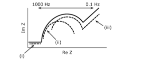
- a Nyquist plot diagram as shown in FIGS. 2A and 2B can be obtained.
- FIGS. 2A and 2B are diagrams for explaining Nyquist plot diagrams. 2A and 2B, the horizontal axis represents the real part ReZ of the complex impedance Z, and the vertical axis represents the imaginary part ImZ of the complex impedance Z.
- the horizontal axis represents the real part ReZ of the complex impedance Z
- the vertical axis represents the imaginary part ImZ of the complex impedance Z.
- the impedance components of the lithium ion battery can be analyzed by dividing them into regions (i) to (iii).
- Region (i) corresponds to the impedance of the wires and the transfer resistance in the electrolyte of the lithium-ion battery.
- the semi-circular portions of regions (ii) and (iii) correspond to the impedance of the charge transfer resistance of the lithium ion battery, region (ii) to the impedance of the negative electrode and region (iii) to the impedance of the positive electrode. .
- the linear portion rising at about 45° in the low frequency region in the ImZ ⁇ 0 region reflects the influence of the Warburg impedance of the lithium ion battery. From the Nyquist plot chart created in this way, for example, an equivalent circuit of the battery as shown in FIG. 3 can be estimated.
- FIG. 3 is a diagram for explaining the correlation between the Nyquist plot and the battery equivalent circuit.
- Fig. 3 shows an example of an equivalent circuit of the internal resistance of a lithium-ion battery.
- the resistance R0 corresponds to the transfer resistance in the electrolyte
- the resistance R1 corresponds to the charge transfer resistance of the negative electrode
- the resistance R2 corresponds to the charge transfer resistance of the positive electrode.
- the wiring is defined by a parallel circuit consisting of an inductor Li and a resistor Ri.
- Warburg resistor W0 represents diffusion and is connected in series with resistor R2.
- a circuit in which resistor R0 and a parallel circuit consisting of inductor Li and resistor Ri are connected in series corresponds to region (i) in the Nyquist plots shown in FIGS. 2A and 2B.
- the RC parallel circuit consisting of resistor R1 and capacitor C1 corresponds to region (ii) in the Nyquist plots shown in FIGS. 2A and 2B.
- An RC parallel circuit in which the series circuit of resistor R2 and Warburg resistor W0 and capacitor C2 are connected in parallel corresponds to region (iii) in the Nyquist plots shown in FIGS. 2A and 2B.
- FIG. 4 is a perspective view showing an example of the battery 3.
- the battery 3 is formed in a flat rectangular parallelepiped shape, and a housing 24 accommodates electrodes, a separator, an electrolytic solution, and the like.
- Bolt-shaped battery terminals 25 (positive battery terminal 25a and negative battery terminal 25b) connected to the electrodes are located at both ends in the longitudinal direction (X-axis direction) of the upper surface of the battery 3 .
- the positive battery terminal 25a and the negative battery terminal 25b each protrude upward (in the plus direction of the Z-axis) from the housing 24 to the same extent.
- FIG. 5 is a plan view showing an example of the assembled battery 4.
- FIG. Plan views including the figures shown below, are views of the assembled battery 4 as viewed from the upper surface side of the battery 3, that is, views viewed from the surface side on which the battery terminals 25 are provided.
- the housings 24 of the batteries 3 are arranged side by side in the lateral direction (Y-axis direction) so as to be adjacent to each other.
- Adjacent batteries 3 are arranged such that the positive battery terminal 25a and the negative battery terminal 25b are alternately arranged.
- the battery 3 adjacent to the battery 3 whose battery terminal 25 is located in the order of the positive battery terminal 25a and the negative battery terminal 25b in the positive direction of the X-axis is connected to the negative battery terminal in the positive direction of the X-axis.
- the battery terminals 25 are positioned in the order of 25b and the positive battery terminal 25a.
- the positive battery terminal 25a of the battery 3 is connected to the negative battery terminal 25b of one adjacent battery 3 via a bus bar 23 made of a conductive material so that the plurality of batteries 3 are connected in series. connected. Also, the negative battery terminal 25 b of the battery 3 is connected to the positive battery terminal 25 a of the other adjacent battery 3 via the bus bar 23 .
- a battery pack 4 is constructed by connecting a plurality of batteries 3 in series so as to achieve the target battery capacity and battery voltage. Note that the battery 3 may be composed of a plurality of batteries connected in parallel.
- the bus bar 23 is processed to have a length reaching the positive electrode battery terminal 25a and the negative electrode battery terminal 25b of the adjacent batteries 3, is formed into a thin plate, and maintains sufficient conductivity.
- the bus bar 23 is fastened to a bolt-shaped battery terminal 25 with a nut.
- a positive electrode side battery terminal 26a is connected to the positive electrode side battery terminal 25a of the battery 3 on one end side (for example, the leftmost battery 3 in FIG. 5) among the plurality of batteries 3 connected in series.
- a negative assembled battery terminal 26b is connected to the negative battery terminal 25b of the battery 3 (for example, the rightmost battery 3 in FIG. 5).
- the positive side assembled battery terminal 26 a and the negative side assembled battery terminal 26 b are provided for supplying electric power from the assembled battery 4 to the external load 5 .
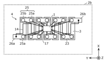
- FIG. 6 the structure of the battery pack 2 according to Embodiment 1 will be explained using FIGS. 6 and 7.
- FIG. 6 is a diagrammatic representation of the battery pack 2 according to Embodiment 1.
- FIG. 6 is a plan view showing an example of the battery pack 2 according to Embodiment 1.
- FIG. 6 is a plan view showing an example of the battery pack 2 according to Embodiment 1.
- FIG. 7 is a perspective view showing an example of the battery pack 2 according to Embodiment 1.
- FIG. 7 is a perspective view showing an example of the battery pack 2 according to Embodiment 1.
- FIGS. 6 and 7 show a battery monitoring device 1, a plurality of batteries 3 constituting an assembled battery 4, a current application line 14 connecting the assembled battery 4 and the battery monitoring device 1, and a plurality of voltage detection lines 17. shown.
- the battery monitoring device 1 is located between the positive battery terminal 25 a and the negative battery terminal 25 b of each battery 3 that constitutes the assembled battery 4 when the assembled battery 4 is viewed from above.
- one voltage detection line 17 is connected to one battery terminal 25 (positive battery terminal 25 a or negative battery terminal 25 b ), and two voltage detection lines 17 are connected to one battery 3 .
- a plurality of voltage detection lines 17 are arranged radially from the battery monitoring device 1 . As shown in FIGS.
- the battery monitoring device 1 is positioned substantially at the center of the assembled battery 4 in the longitudinal direction and substantially at the center of the assembled battery 4 in the lateral direction when the assembled battery 4 is viewed from above.
- the plurality of voltage detection lines 17 are arranged radially in all directions from the battery monitoring device 1 centering on the battery monitoring device 1 .
- the number of batteries 3 whose internal AC impedance is measured by the battery monitoring device 1 may be at least two, and the plurality of voltage detection lines 17 is at least four. For example, if four voltage detection lines 17 are routed in different directions for two batteries 3, it is assumed that the four voltage detection lines 17 are routed radially.
- the current application line 14 connects the battery monitoring device 1 and the positive side assembled battery terminal 26a, and also connects the battery monitoring device 1 and the negative side assembled battery terminal 26b. As shown in FIGS. 6 and 7 , the current application line 14 is routed so as not to be parallel to the plurality of voltage detection lines 17 . Note that if the current application line 14 and at least one voltage detection line 17 are always parallel due to the design of the battery pack 2 , the current application line 14 is not parallel to the plurality of voltage detection lines 17 Arranged to be minimal.
- the current application line 14 is located between the positive battery terminal 25a and the negative battery terminal 25b of the plurality of batteries 3 when the assembled battery 4 is viewed from above. To position.
- the voltage detection lines 17 can be provided along the shortest path between each battery terminal 25 and the battery monitoring device 1 . length can be minimized.
- Wiring such as the voltage detection line 17, the current application line 14, and the bus bar 23 has a resistance value, and the resistance value of the wiring changes depending on the material, thickness, and length of the wiring. For example, focusing on the length of the wiring, the longer the wiring, the larger the inductor component of the wiring, and the greater the influence of the inductor component of the wiring.
- FIG. 8 is a diagram showing the influence of the wiring inductor.
- the shape of the semicircular portion corresponding to the charge transfer resistance of the electrode changes greatly, and when the impedance of the battery 3 to be measured is low, the influence of the inductor component becomes relatively large. In order to suppress this effect, it is necessary to shorten the length of each wire routed in the battery pack 2 as much as possible, and the plurality of voltage detection wires 17 are routed radially.
- the current applying line 14 is positioned between the positive battery terminal 25a and the negative battery terminal 25b of the plurality of batteries 3, the positive battery terminal 25a and the negative battery terminal 25b of the plurality of batteries 3 are connected. In between, a current applying line 14 can be provided from the battery monitoring device 1 to the positive side assembled battery terminal 26 a and the negative side assembled battery terminal 26 b of the assembled battery 4 . As a result, the current application line 14 can be shortened and the resistance value of the current application line 14 can be reduced, that is, the inductor component of the current application line 14 can be reduced.
- the current application line 14 since a large alternating current can be applied to the current application line 14, the mutual inductance generated increases when the current application line 14 and the voltage detection line 17 are arranged in parallel. Therefore, the current application line 14 is wired so as not to be parallel to the plurality of voltage detection lines 17, or is wired so that the parallel portion with the plurality of voltage detection lines 17 is minimized. Electromagnetic induction interference due to mutual inductance between the line 14 and the voltage detection line 17 can be suppressed.
- FIG. 9 is a diagram showing the influence of electromagnetic induction interference.
- an AC current flows between the battery monitoring device 1 and the assembled battery 4 via the current application line 14, and a magnetic field is generated around the current application line 14. .
- the generation of this magnetic field is based on Fleming's law.
- the generated magnetic field is added to the amount of change in the impedance measurement of the nearby battery 3 and affects the measurement of the internal AC impedance of the battery 3 .
- the effect of the magnetic field is significant, and as shown in FIG. 9, the effect is significant in the high-frequency region of the Nyquist plot.
- electromagnetic induction interference the phenomenon in which the surrounding circuits are affected by the magnetic field is called electromagnetic induction interference.
- the magnetic field increases with increasing source current and with increasing mutual inductance.
- This mutual inductance is the inductance of the current loop created by wiring and the like.
- Mutual inductance increases the closer the distance between the source and the affected side and the more parallel parts the flowing currents have.
- the plurality of voltage detection lines 17 are radially routed from the battery monitoring device 1 to accurately measure the internal impedance (for example, internal AC impedance) of the plurality of batteries 3 constituting the assembled battery 4. can do.
- the assembled battery 4 by wiring the current applying line 14 so as not to be parallel to the plurality of voltage detection lines 17, or by wiring such that the parallel portion with the plurality of voltage detection lines 17 is minimized, the assembled battery 4, the internal impedance (for example, internal AC impedance) of the batteries 3 can be measured with even higher accuracy.
- the internal impedance for example, internal AC impedance
- the internal impedance (for example, internal AC impedance) of the plurality of batteries 3 constituting the assembled battery 4 ) can be measured more accurately.
- a schematic configuration diagram showing an example of the battery pack 2a according to the second embodiment is the same as the schematic configuration diagram (FIG. 1) of the battery pack 2 according to the first embodiment, so description thereof is omitted.
- the structure of the battery pack 2a according to the second embodiment will be described with reference to FIGS. 10 and 11, focusing on the differences from the battery pack 2 according to the first embodiment.
- FIG. 10 is a plan view showing an example of a battery pack 2a according to Embodiment 2.
- FIG. 10 is a plan view showing an example of a battery pack 2a according to Embodiment 2.
- FIG. 11 is a perspective view showing an example of a battery pack 2a according to Embodiment 2.
- FIG. 11 is a perspective view showing an example of a battery pack 2a according to Embodiment 2.
- the current applying line 14 connects the positive battery terminal 25a and the negative battery terminal 25b of the plurality of batteries 3 when the assembled battery 4 is viewed from above. located on the outside of the Note that the battery monitoring device 1 is positioned between the positive battery terminal 25a and the negative battery terminal 25b of the plurality of batteries 3 when the assembled battery 4 is viewed from above, and therefore is connected to the battery monitoring device 1.
- the current application line 14 includes a portion positioned between the positive battery terminal 25 a and the negative battery terminal 25 b of the plurality of batteries 3 . However, most of the current applying lines 14 are located outside between the positive battery terminals 25 a and the negative battery terminals 25 b of the plurality of batteries 3 .
- the plurality of voltage detection lines 17 are wired between the positive battery terminals 25a and the negative battery terminals 25b of the batteries 3, the current application lines 14 are connected to the positive battery terminals 25a of the batteries 3. and the negative battery terminal 25b, the distance between the voltage detection line 17 and the current application line 14 can be increased. Therefore, it is possible to suppress electromagnetic induction interference due to mutual inductance between the current application line 14 and the voltage detection line 17, and measure the internal impedance (for example, internal AC impedance) of the plurality of batteries 3 constituting the assembled battery 4 more accurately. can do.
- the internal impedance for example, internal AC impedance
- the current applying line 14 may be routed so as not to be parallel to the plurality of voltage detection lines 17, or the plurality of voltage detection lines 17 may be wired so as not to be parallel. may be routed so as to minimize the number of parallel points.
- a schematic configuration diagram showing an example of the battery pack 2b according to the third embodiment is the same as the schematic configuration diagram (FIG. 1) of the battery pack 2 according to the first embodiment, so description thereof is omitted.
- the structure of the battery pack 2b according to the third embodiment will be described with reference to FIGS. 12 and 13, focusing on the differences from the battery pack 2 according to the first embodiment.
- FIG. 12 is a plan view showing an example of a battery pack 2b according to Embodiment 3.
- FIG. 12 is a plan view showing an example of a battery pack 2b according to Embodiment 3.
- FIG. 13 is a perspective view showing an example of a battery pack 2b according to Embodiment 3.
- FIG. 13 is a perspective view showing an example of a battery pack 2b according to Embodiment 3.
- the current application line 14 is routed so as to weaken the magnetic field generated by the current application line 14 .
- the current application line 14 includes parallel opposing portions, and the current application line 14 is arranged so that the direction of the current flowing in one of the opposing portions is opposite to that of the other.
- the wire 14 may be routed, and specifically, the current applying wire 14 may be routed in a rectangular wave shape.
- the internal impedance (for example, internal AC impedance) of the plurality of batteries 3 forming the assembled battery 4 can be measured with higher accuracy.
- the current applying line 14 may be routed so as not to be parallel to the plurality of voltage detection lines 17, or the plurality of voltage detection lines 17 may be wired so as not to be parallel. It may be routed so that the parallel point with is minimized.
- the current application line 14 By arranging the current application line 14 in a rectangular wave shape, the voltage detection line 17 and the current application line 14 are not arranged in parallel, and the influence of electromagnetic induction disturbance can be suppressed.
- a schematic configuration diagram showing an example of the battery pack 2c according to Embodiment 4 is the same as the schematic configuration diagram (FIG. 1) of the battery pack 2 according to Embodiment 1, so description thereof is omitted.
- the structure of the battery pack 2c according to the fourth embodiment will be described with reference to FIGS. 14A to 16, focusing on the differences from the battery pack 2 according to the first embodiment.
- the battery pack 2c includes a shielding portion that shields the electric field or magnetic field generated by the plurality of batteries 3 or the current application lines 14.
- a shielding portion that shields the electric field or magnetic field generated by the plurality of batteries 3 or the current application lines 14.
- FIG. 14A is a diagram for explaining a first example of the shielding part according to Embodiment 4.
- FIG. 14A is a cross-sectional view of the current applying wire 14.
- FIG. 14A is a diagram for explaining a first example of the shielding part according to Embodiment 4.
- FIG. 14A is a cross-sectional view of the current applying wire 14.
- the current applying line 14 may have a shielding function against electric fields or magnetic fields.
- the shield may be a shield 30 that covers the conductor (central conductor) 27 of the current application line 14 and shields the electric field or magnetic field generated by the current application line 14 .
- the shield 30, which has a shielding function against an electric field or a magnetic field is composed of, for example, a metal tape such as copper or aluminum, or a mesh-like braided wire.
- conductor 27 is covered with shield 30
- shield 30 is covered with insulator 29
- insulator 29 is covered with jacket 28 .
- FIG. 14B shows an example of wiring that is not covered with a shield.
- the conducting wire 27 is directly covered with the jacket 28 .
- the shield 30 covering the conductor 27 of the current applying line 14 can suppress the influence of the electric field or magnetic field generated by the current applying line 14 .
- FIG. 15 is a diagram for explaining a second example of the shielding portion according to Embodiment 4.
- FIG. FIG. 15 is a plan view showing a second example of battery pack 2c according to the fourth embodiment.
- the shielding part may be a sheet-like shield 31 provided between the current application line 14 and the plurality of voltage detection lines 17, and the electric field or magnetic field generated by the current application line 14 may be may be shielded.
- the sheet-like shield 31 is made of, for example, a metal plate such as copper or aluminum that has a shielding function against electric fields or magnetic fields.
- the sheet-like shield 31 provided between the current application line 14 and the plurality of voltage detection lines 17 can suppress the influence of the electric field or magnetic field generated by the current application line 14 .
- FIG. 16 is a diagram for explaining a third example of the shielding part according to the fourth embodiment.
- FIG. 16 is a plan view showing a third example of battery pack 2c according to the fourth embodiment.
- the shielding part may be a sheet-like shield 32 provided between the plurality of batteries 3 and the current application line 14 and the plurality of voltage detection lines 17, and shields the electric field or magnetic field generated by the plurality of batteries 3. It can be shielded.
- the sheet-like shields 32 provided between the batteries 3 and the current application lines 14 and the voltage detection lines 17 prevent the multiple The influence of the electric field or magnetic field generated by the battery 3 can be suppressed.
- a schematic configuration diagram showing an example of the battery pack 2d according to Embodiment 5 is the same as the schematic configuration diagram (FIG. 1) of the battery pack 2 according to Embodiment 1, so description thereof is omitted.
- the structure of the battery pack 2d according to the fifth embodiment will be described with reference to FIG. 17, focusing on the differences from the battery pack 2 according to the first embodiment.
- FIG. 17 is a plan view showing an example of a battery pack 2d according to Embodiment 5.
- FIG. 17 is a plan view showing an example of a battery pack 2d according to Embodiment 5.
- the battery monitoring device 1 when the assembled battery 4 is viewed from the top, the battery monitoring device 1 is configured so that the end of the assembled battery 4 in the longitudinal direction (Y-axis direction) and the lateral direction (X-axis direction) of the assembled battery 4 located approximately in the center of In this way, the battery monitoring device 1 may be positioned at the end of the assembled battery 4 when viewed from above, and the plurality of voltage detection lines 17 are routed radially from the battery monitoring device 1 in a fan shape.
- FIG. 18 is a schematic configuration diagram showing an example of a battery pack 2e according to the sixth embodiment.
- the points different from the battery pack 2 according to the first embodiment will be mainly described.
- the voltage detection line 17 is connected to the positive battery terminal 25a and the negative battery terminal 25b of each of the plurality of batteries 3.
- the eight batteries B1 to An example in which 16 voltage detection lines 17 are provided for B8 has been described.
- the bus bar 23 has substantially the same potential as the positive battery terminal 25a and the negative battery terminal 25b. . Therefore, the voltage of the adjacent battery 3 can be detected even by connecting the voltage detection line 17 to the bus bar 23 without connecting the voltage detection line 17 to the positive battery terminal 25a and the negative battery terminal 25b.
- the number of voltage detection lines 17 can be set to nine for eight batteries B1 to B8 shown in FIG. 18, and the number of voltage detection lines 17 can be reduced.
- FIG. 19 the structure of the battery pack 2e according to Embodiment 6 will be described with reference to FIGS. 19 and 20.
- FIG. 19 the structure of the battery pack 2e according to Embodiment 6 will be described with reference to FIGS. 19 and 20.
- FIG. 19 is a plan view showing an example of a battery pack 2e according to Embodiment 6.
- FIG. 19 is a plan view showing an example of a battery pack 2e according to Embodiment 6.
- FIG. 20 is a perspective view showing an example of a battery pack 2e according to Embodiment 6.
- FIG. 20 is a perspective view showing an example of a battery pack 2e according to Embodiment 6.
- the battery terminals 25 of the batteries 3 included in the plurality of batteries 3 are connected to the battery terminals 25 of the adjacent batteries 3 by the bus bars 23 to form the assembled battery 4 .
- the positive electrode battery terminal 25a of the battery 3 on one end side and the negative electrode battery terminal 25b of the battery 3 on the other end side are connected to the positive electrode battery terminal 26a and the negative electrode battery terminal 26a instead of the bus bar 23, respectively.
- the side assembled battery terminal 26b is connected, and the voltage detection line 17 is connected to the positive side assembled battery terminal 26a and the negative side assembled battery terminal 26b.
- the number of voltage detection lines 17 can be reduced, and the reduced number of voltage detection lines 17 can suppress the influence of the inductor component and the induced electromotive force when measuring the impedance of the battery 3 . Therefore, it is possible to measure the internal impedance (for example, internal AC impedance) of each of the plurality of batteries 3 forming the assembled battery 4 with higher accuracy.
- the internal impedance for example, internal AC impedance
- the voltage detection line 17 (for example, each of the plurality of voltage detection lines 17) is positioned approximately in the center of the two battery terminals 25 (the positive battery terminal 25a and the negative battery terminal 25b) on the bus bar 23 (from the two battery terminals 25). equidistant positions).
- the voltage detection lines 17 (for example, each of the plurality of voltage detection lines 17) are connected to the busbar 23 at positions equidistant from the two battery terminals 25, so that the busbar 23 detects the voltage of the adjacent batteries 3. can be evenly affected by the resistance components of adjacent batteries 3 .
- equidistant includes not only the case where the two distances are completely the same, but also the case where the two distances are deviated by several percent.
- FIG. 21 is a plan view showing an example of a battery pack 2f in another embodiment.
- a circuit board 33 may be provided on the upper surface side of the assembled battery 4 so as to be electrically connected to the battery terminals 25 of the plurality of batteries 3 forming the assembled battery 4 .
- the battery monitoring device 1 may be mounted on the circuit board 33 , and the wiring pattern (conductive metal) on the circuit board 33 may form the current application line 14 and the voltage detection line 17 .
- the circuit board 33 is a PCB (printed circuit board), FPC (flexible printed circuit board), or the like.
- the battery 3 is a prismatic battery, but it may be of other shapes such as a cylindrical shape and a flat plate shape.
- battery packs are also effective for storage batteries, motorcycles, heavy machinery, ships, airplanes, power plants, and the like.
- the battery 3 may be other secondary batteries (lead storage battery, nickel-cadmium storage battery, metal lithium battery, lithium ion polymer secondary battery, sodium ion battery, solid state battery, etc.). battery, etc.).
- the present disclosure can be applied to battery packs that have a function of monitoring the state of secondary batteries such as lithium ion batteries.
Abstract
This battery pack (2) comprises: an assembled battery (4) in which a plurality of batteries (3) are connected; an electric-current-applying wire (14) for applying an electric current to the assembled battery (4); a plurality of voltage detection wires (17) for detecting the voltages of the plurality of batteries (3); and a battery-monitoring device (1) for measuring the internal impedances of the plurality of batteries (3). The battery-monitoring device (1) is positioned between a positive electrode-side battery terminal (25a) and a negative electrode-side battery terminal (25b) of each battery (3) constituting the assembled battery (4), and the plurality of voltage detection wires (17) are drawn in a radial manner from the battery-monitoring device (1).
Description
本開示は、リチウムイオン電池などの二次電池を直列、または並列に接続した組電池を備える電池パックに関する。
The present disclosure relates to a battery pack including an assembled battery in which secondary batteries such as lithium ion batteries are connected in series or in parallel.
近年、電気自動車をはじめとする環境対応車や、再生可能エネルギーを安定供給させるための蓄電池など、二次電池を使用したアプリケーションが急増している。リチウムイオン電池(LiB:Lithium-ion Battery)は、エネルギー密度が高いことから、このようなアプリケーションに採用されることが多い。
In recent years, there has been a rapid increase in applications using secondary batteries, such as electric vehicles and other eco-friendly vehicles, and storage batteries for stably supplying renewable energy. Lithium-ion batteries (LiBs) are often used in such applications due to their high energy density.
車載用電池や蓄電池の多くは、複数の電池が並べて配置され、その複数の電池が直列、または並列に接続され、組電池が構成されている。組電池は、電気を長時間にわたって使用可能とするために、容量を大きくすることが求められている。このため、このような組電池は、複数の電池を複数段に積み重ねてなる電池ブロックを、プラスチック製の外装ケースに収納する構造で設計されている。この組電池は、複数の電池を直列に接続することで出力電圧を大きくし、複数の電池を並列に接続することで使用時間を長くできる。リチウムイオン電池が使用される場合は、過充電、過放電または温度によって劣化が加速することが知られており、最悪の場合では発煙発火、さらには爆発などの危険な状態に至ることもある。そのため、通常は電池監視装置が組み込まれて適切な制御下に置かれる。
Many of the on-vehicle batteries and storage batteries have multiple batteries arranged side by side, and the multiple batteries are connected in series or in parallel to form an assembled battery. The assembled battery is required to have a large capacity so that electricity can be used for a long period of time. For this reason, such assembled batteries are designed to have a structure in which a battery block formed by stacking a plurality of batteries in a plurality of stages is housed in an exterior case made of plastic. This assembled battery can increase the output voltage by connecting a plurality of batteries in series, and can extend the operating time by connecting a plurality of batteries in parallel. When lithium-ion batteries are used, it is known that their deterioration is accelerated by overcharge, overdischarge, or temperature, and in the worst case, they can lead to dangerous situations such as smoke, fire, and even explosion. Therefore, a battery monitor is usually incorporated and placed under appropriate control.
一般的に電池監視装置は、二次電池で構成される組電池のすべての電池の電圧と電流と温度を監視し、これらの測定データを用いて、各電池の状態を監視する。
Generally, a battery monitoring device monitors the voltage, current, and temperature of all batteries in an assembled battery composed of secondary batteries, and uses these measurement data to monitor the state of each battery.
特許文献1には、高出力、高容量の電池パックとして、多数の電池セルを有し、多数の電池セルを集合化してなる組電池を備えた電池パックが開示されている。
Patent Document 1 discloses, as a high-output, high-capacity battery pack, a battery pack that has a large number of battery cells and is provided with an assembled battery formed by assembling a large number of battery cells.
特許文献1に記載された電池パックでは、複数の電池が同一方向に積層されて組電池が形成され、組電池の端面に、電池監視装置が実装された回路基板が配置されており、電圧検出線が電池ブロックを構成する電池と、組電池の端面に配置されている回路基板とを接続している。また、電圧検出線は、各電池の電極端子が位置する端子面に配置されると共に、電極端子に対して外側のスペースに位置するように構成されている。各電極端子に接続された複数の電圧検出線は、組電池の長手方向の回路基板側の端部まで引き出されている。
In the battery pack described in Patent Document 1, a plurality of batteries are stacked in the same direction to form an assembled battery, and a circuit board on which a battery monitoring device is mounted is arranged on an end face of the assembled battery to detect voltage. Wires connect the batteries that make up the battery block and the circuit board that is arranged on the end face of the assembled battery. Also, the voltage detection line is arranged on the terminal surface where the electrode terminal of each battery is located, and is configured to be positioned in a space outside the electrode terminal. A plurality of voltage detection lines connected to each electrode terminal are drawn out to the end of the assembled battery on the circuit board side in the longitudinal direction.
また、電池の状態を監視する方法の一つとして、特許文献2には、電池のインピーダンスを測定する技術が開示されている。特許文献2では、電気化学インピーダンス分光法(EIS:electrochemical impedance spectroscopy)を用いて、電池の内部インピーダンス特性を測定し、電池の状態をリアルタイムで監視できる電池監視装置が提案されている。また、この電池監視装置により、電池のインピーダンスを測定し、予め定められたインピーダンスと電池の充電状態(SOC:state of charge)や電池の劣化度(SOH:state of health)との相関関係を参照して、測定されたインピーダンスに対応するSOC、SOHを推定し、電池状態を管理することも可能である。
In addition, Patent Document 2 discloses a technique for measuring the impedance of a battery as one method of monitoring the state of the battery. Patent Literature 2 proposes a battery monitoring device that measures internal impedance characteristics of a battery using electrochemical impedance spectroscopy (EIS) and monitors the state of the battery in real time. In addition, this battery monitoring device measures the impedance of the battery, and refers to the correlation between the predetermined impedance and the state of charge (SOC) and the state of health (SOH) of the battery. It is also possible to estimate the SOC and SOH corresponding to the measured impedance and manage the battery state.
しかし、内部インピーダンス特性で得られる応答信号は、極めて微弱な信号であるため、外部の影響を受けやすいという問題がある。例えば、電池の内部インピーダンス測定時に応答信号が入出力される電気回路経路で誘導起電力が生じ、この誘導起電力の影響を受け、適正な測定ができない、電磁誘導障害といった問題がある。
However, since the response signal obtained from the internal impedance characteristics is an extremely weak signal, there is a problem that it is susceptible to external influences. For example, when measuring the internal impedance of a battery, an induced electromotive force is generated in an electric circuit path through which a response signal is input and output, and this induced electromotive force affects proper measurement, resulting in a problem of electromagnetic induction failure.
そこで、特許文献3では、誘導起電力が発生する電気回路経路で囲まれた面積範囲を最小に定め、誘電起電力の影響を抑制できる電池監視装置が提案されている。
Therefore, Patent Document 3 proposes a battery monitoring device capable of suppressing the influence of the induced electromotive force by minimizing the area range surrounded by the electric circuit path in which the induced electromotive force is generated.
複数の電池で構成される組電池において、配線由来のインピーダンスが相対的に大きいと電池由来の電極及び電解質などのインピーダンスを正確に測定することができないという問題がある。また、内部インピーダンス特性で得られる応答信号が極めて微弱な信号であるため、外部の影響を受けやすいという問題がある。
In an assembled battery composed of multiple batteries, if the wiring-derived impedance is relatively large, there is a problem that the impedance of the battery-derived electrodes and electrolyte cannot be measured accurately. Moreover, since the response signal obtained from the internal impedance characteristic is an extremely weak signal, there is a problem that it is susceptible to external influences.
また、電池と電池監視装置とを接続する電圧検出線やバスバーなどの配線は抵抗値を持ち、配線の長さなどでインピーダンスが変わる。特に、測定する電池のインピーダンスが低い場合は、相対的に配線の長さなどの影響が大きくなる。この影響を抑えるためには電池パック内に配索される配線をできるだけ短くする必要がある。
In addition, wiring such as voltage detection lines and bus bars that connect the battery and the battery monitoring device have a resistance value, and the impedance changes depending on the length of the wiring. In particular, when the impedance of the battery to be measured is low, the influence of the length of the wiring becomes relatively large. In order to suppress this effect, it is necessary to shorten the wiring routed inside the battery pack as much as possible.
また、特許文献3で開示されている電池パックでは、電池の電極端子ごとに交流電流を印加する信号生成部が接続される。そして、電池監視装置と組電池とが、組電池に交流電流を印加するための電流印加線によって接続される場合、電流印加線が電磁誘導障害の発生源となり、インピーダンスの検出に影響を与える。
In addition, in the battery pack disclosed in Patent Document 3, a signal generator that applies alternating current is connected to each electrode terminal of the battery. When the battery monitoring device and the assembled battery are connected by a current applying line for applying an alternating current to the assembled battery, the current applying line becomes a source of electromagnetic induction interference, affecting impedance detection.
そこで、本開示は、組電池を構成する複数の電池の内部インピーダンスを精度よく測定することができる電池パックを提供する。
Therefore, the present disclosure provides a battery pack that can accurately measure the internal impedance of a plurality of batteries that form an assembled battery.
本開示に係る電池パックは、複数の電池が接続された組電池と、前記組電池に電流を印加する電流印加線と、前記複数の電池の電圧を検出する複数の電圧検出線と、前記複数の電池の内部インピーダンスを測定する電池監視装置と、を備え、前記電池監視装置は、前記組電池を構成する個々の電池の正極側電池端子と負極側電池端子との間に位置し、前記複数の電圧検出線は、前記電池監視装置から放射状に配索されることを特徴とする。
A battery pack according to the present disclosure includes an assembled battery in which a plurality of batteries are connected, a current application line for applying current to the assembled battery, a plurality of voltage detection lines for detecting voltages of the plurality of batteries, and the plurality of and a battery monitoring device for measuring the internal impedance of the battery, wherein the battery monitoring device is positioned between the positive battery terminal and the negative battery terminal of each battery constituting the assembled battery, and the plurality of The voltage detection lines are radially routed from the battery monitoring device.
本開示の一態様に係る電池パックによれば、組電池を構成する複数の電池の内部インピーダンスを精度よく測定することができる。
According to the battery pack according to one aspect of the present disclosure, it is possible to accurately measure the internal impedance of the plurality of batteries forming the assembled battery.
本開示の一態様に係る電池パックは、複数の電池が接続された組電池と、前記組電池に電流を印加する電流印加線と、前記複数の電池の電圧を検出する複数の電圧検出線と、前記複数の電池の内部インピーダンスを測定する電池監視装置と、を備え、前記電池監視装置は、前記組電池を構成する個々の電池の正極側電池端子と負極側電池端子との間に位置し、前記複数の電圧検出線は、前記電池監視装置から放射状に配索される。
A battery pack according to an aspect of the present disclosure includes an assembled battery in which a plurality of batteries are connected, a current application line that applies current to the assembled battery, and a plurality of voltage detection lines that detect voltages of the plurality of batteries. and a battery monitoring device for measuring the internal impedance of the plurality of batteries, wherein the battery monitoring device is positioned between a positive battery terminal and a negative battery terminal of each battery that constitutes the assembled battery. , the plurality of voltage detection lines are routed radially from the battery monitoring device;
複数の電圧検出線が電池監視装置から複数の電池の正極側電池端子および負極側電池端子に向けて放射状に配索されるため、複数の電圧検出線の長さを最短にすることができ、複数の電圧検出線の抵抗値を小さくすることができる。このため、複数の電圧検出線の抵抗値の影響を抑制でき、組電池を構成する複数の電池の内部インピーダンスを精度よく測定することができる。
Since the plurality of voltage detection lines are radially routed from the battery monitoring device toward the positive battery terminals and the negative battery terminals of the plurality of batteries, the length of the plurality of voltage detection lines can be minimized. It is possible to reduce the resistance values of the plurality of voltage detection lines. Therefore, the influence of the resistance values of the plurality of voltage detection lines can be suppressed, and the internal impedances of the plurality of batteries forming the assembled battery can be accurately measured.
例えば、前記組電池と前記電池監視装置とは、前記電流印加線で接続され、前記電池監視装置が制御する交流電流が、前記電流印加線を介して前記組電池に印加されてもよい。例えば、前記電池監視装置は、前記組電池に印加される交流電流および前記複数の電池の電圧に基づいて、前記複数の電池の内部交流インピーダンスを測定してもよい。
For example, the assembled battery and the battery monitoring device may be connected by the current application line, and an alternating current controlled by the battery monitoring device may be applied to the assembled battery via the current application line. For example, the battery monitoring device may measure the internal AC impedance of the plurality of batteries based on the AC current applied to the assembled battery and the voltages of the plurality of batteries.
これによれば、組電池を構成する複数の電池の内部交流インピーダンスを精度よく測定することができる。
According to this, it is possible to accurately measure the internal AC impedance of a plurality of batteries constituting the assembled battery.
例えば、前記電流印加線は、前記複数の電圧検出線と平行にならないように配索されてもよい、または前記複数の電圧検出線との平行個所が最小になるように配索されてもよい。
For example, the current application line may be laid out so as not to be parallel to the plurality of voltage detection lines, or may be laid out so as to minimize the number of parallel points with the plurality of voltage detection lines. .
電流印加線には大きな交流電流が印加され得るため、電流印加線と電圧検出線とが平行になるように配置されると発生する相互インダクタンスも大きくなる。そこで、電流印加線が複数の電圧検出線と平行にならないように配索されるか、複数の電圧検出線との平行個所が最小になるように配索されることで、電流印加線と電圧検出線との相互インダクタンスによる電磁誘導障害を抑制することができる。これにより、組電池を構成する複数の電池の内部インピーダンスをさらに精度よく測定することができる。
A large alternating current can be applied to the current application line, so if the current application line and the voltage detection line are arranged in parallel, the mutual inductance generated will also increase. Therefore, by wiring the current application line so as not to be parallel to the plurality of voltage detection lines, or by wiring so that the parallel portion with the plurality of voltage detection lines is minimized, the current application line and the voltage Electromagnetic induction interference due to mutual inductance with the detection line can be suppressed. Thereby, it is possible to measure the internal impedance of the plurality of batteries constituting the assembled battery with higher accuracy.
例えば、前記電流印加線は、前記複数の電池の正極側電池端子と負極側電池端子との間に位置してもよい。
For example, the current application line may be positioned between the positive battery terminal and the negative battery terminal of the plurality of batteries.
電流印加線が複数の電池の正極側電池端子と負極側電池端子との間に位置することで、複数の電池の正極側電池端子と負極側電池端子との間において、電池監視装置から組電池の正極側組電池端子および負極側組電池端子へ電流印加線を延ばすことができる。このため、電流印加線を短くすることができ、電流印加線の抵抗値を小さくすることができる。これにより、電流印加線の抵抗値の影響も抑制でき、組電池を構成する複数の電池の内部インピーダンスをさらに精度よく測定することができる。
By positioning the current applying line between the positive battery terminal and the negative battery terminal of the plurality of batteries, the battery monitoring device can be connected to the assembled battery between the positive battery terminal and the negative battery terminal of the plurality of batteries. can be extended to the positive electrode side assembled battery terminal and the negative electrode side assembled battery terminal. Therefore, the current application line can be shortened, and the resistance value of the current application line can be reduced. As a result, the influence of the resistance value of the current application line can also be suppressed, and the internal impedance of the plurality of batteries forming the assembled battery can be measured with even higher accuracy.
例えば、前記電流印加線は、前記複数の電池の正極側電池端子と負極側電池端子との間の外側に位置してもよい。
For example, the current application line may be located outside between the positive battery terminals and the negative battery terminals of the plurality of batteries.
複数の電圧検出線が、複数の電池の正極側電池端子と負極側電池端子との間に配索されているため、電流印加線が複数の電池の正極側電池端子と負極側電池端子との間の外側に位置することで、電流印加線と電圧検出線との相互インダクタンスによる電磁誘導障害を抑制することができる。これにより、組電池を構成する複数の電池の内部インピーダンスをさらに精度よく測定することができる。
Since the plurality of voltage detection lines are routed between the positive battery terminals and the negative battery terminals of the plurality of batteries, the current application line is connected between the positive battery terminals and the negative battery terminals of the plurality of batteries. Positioning outside the gap can suppress electromagnetic induction interference due to mutual inductance between the current application line and the voltage detection line. Thereby, it is possible to measure the internal impedance of the plurality of batteries constituting the assembled battery with higher accuracy.
例えば、前記電流印加線は、前記電流印加線が発生する磁界を弱めるように配索されてもよい。
For example, the current application line may be routed so as to weaken the magnetic field generated by the current application line.
電流印加線が発生する磁界が弱められるため、電流印加線と電圧検出線との相互インダクタンスによる電磁誘導障害を抑制することができる。これにより、組電池を構成する複数の電池の内部インピーダンスをさらに精度よく測定することができる。
Since the magnetic field generated by the current application line is weakened, it is possible to suppress electromagnetic induction interference due to mutual inductance between the current application line and the voltage detection line. Thereby, it is possible to measure the internal impedance of the plurality of batteries constituting the assembled battery with higher accuracy.
例えば、前記複数の電池に含まれる電池の電池端子は、隣接する電池の電池端子とバスバーによって接続されることで前記組電池を構成し、前記複数の電圧検出線に含まれる電圧検出線は、前記バスバーにおける2つの前記電池端子の間に接続されてもよい。
For example, the battery terminals of the batteries included in the plurality of batteries constitute the assembled battery by being connected to the battery terminals of adjacent batteries by bus bars, and the voltage detection lines included in the plurality of voltage detection lines are It may be connected between two of the battery terminals on the bus bar.
隣り合う電池の正極側電池端子と負極側電池端子がバスバーによって接続されるため、バスバーは、正極側電池端子および負極側電池端子とほぼ同電位となっている。このため、正極側電池端子および負極側電池端子にそれぞれ電圧検出線を接続せずに、バスバーに電圧検出線を接続することでも、隣り合う電池の電圧を検出することができ、電圧検出線の数を減らすことができる。つまり、電圧検出線の数が減る分、電池のインピーダンス測定時のインダクタ成分と誘電起電力の影響を抑制することができる。これにより、組電池を構成する複数の電池の内部インピーダンスをさらに精度よく測定することができる。
Since the positive battery terminal and the negative battery terminal of the adjacent batteries are connected by the bus bar, the bus bar has almost the same potential as the positive battery terminal and the negative battery terminal. Therefore, it is possible to detect the voltage of the adjacent batteries by connecting the voltage detection lines to the bus bar instead of connecting the voltage detection lines to the positive battery terminal and the negative battery terminal. number can be reduced. That is, since the number of voltage detection lines is reduced, it is possible to suppress the influence of the inductor component and the induced electromotive force when measuring the impedance of the battery. Thereby, it is possible to measure the internal impedance of the plurality of batteries constituting the assembled battery with higher accuracy.
例えば、前記電圧検出線は、前記バスバーにおける2つの前記電池端子から等距離の位置に接続されてもよい。
For example, the voltage detection line may be connected to the busbar at positions equidistant from the two battery terminals.
電圧検出線が、バスバーにおける2つの電池端子(正極側電池端子および負極側電池端子)から等距離の位置に接続されることで、隣り合う電池の電圧を検出する際のバスバーの抵抗成分の影響を、隣り合う電池に対して均等にすることができる。
By connecting the voltage detection line at a position equidistant from the two battery terminals (positive battery terminal and negative battery terminal) of the bus bar, the effect of the resistance component of the bus bar when detecting the voltage of adjacent batteries. can be evened out for adjacent cells.
例えば、前記電池パックは、前記複数の電池または前記電流印加線が発生する電界または磁界を遮蔽する遮蔽部を備えていてもよい。
For example, the battery pack may include a shield that shields an electric field or magnetic field generated by the plurality of batteries or the current application line.
遮蔽部によって、複数の電池または電流印加線が発生する電界または磁界の影響を抑制することができる。
The shielding part can suppress the influence of electric fields or magnetic fields generated by a plurality of batteries or current application lines.
例えば、前記遮蔽部は、前記電流印加線の中心導体を覆うシールドであり、前記電流印加線が発生する電界または磁界を遮蔽してもよい。
For example, the shielding part may be a shield that covers the center conductor of the current application line, and shields the electric field or magnetic field generated by the current application line.
このように、電流印加線を覆うシールドによって、電流印加線が発生する電界または磁界の影響を抑制することができる。
In this way, the shield covering the current application line can suppress the influence of the electric field or magnetic field generated by the current application line.
例えば、前記遮蔽部は、前記電流印加線と前記複数の電圧検出線との間に設けられたシート状のシールドであり、前記電流印加線が発生する電界または磁界を遮蔽してもよい。
For example, the shielding portion may be a sheet-like shield provided between the current application line and the plurality of voltage detection lines, and shield an electric field or magnetic field generated by the current application line.
このように、電流印加線と複数の電圧検出線との間に設けられたシート状のシールドによって、電流印加線が発生する電界または磁界の影響を抑制することができる。
Thus, the sheet-like shield provided between the current application line and the plurality of voltage detection lines can suppress the influence of the electric field or magnetic field generated by the current application line.
例えば、前記遮蔽部は、前記複数の電池と前記電流印加線および前記複数の電圧検出線との間に設けられたシート状のシールドであり、前記複数の電池が発生する電界または磁界を遮蔽してもよい。
For example, the shielding part is a sheet-shaped shield provided between the plurality of batteries and the current application line and the plurality of voltage detection lines, and shields the electric field or magnetic field generated by the plurality of batteries. may
このように、複数の電池と電流印加線および複数の電圧検出線との間に設けられたシート状のシールドによって、複数の電池が発生する電界または磁界の影響を抑制することができる。
In this way, the sheet-like shields provided between the batteries and the current application lines and voltage detection lines can suppress the influence of the electric field or magnetic field generated by the batteries.
以下、実施の形態について、図面を参照しながら説明する。なお、以下で説明する実施の形態は、いずれも包括的または具体的な例を示すものである。以下の実施の形態で示される数値、形状、材料、構成要素、構成要素の配置位置及び接続形態などは、一例であり、本開示を限定する主旨ではない。また、以下の実施の形態における構成要素のうち、独立請求項に記載されていない構成要素については、任意の構成要素として説明される。
Hereinafter, embodiments will be described with reference to the drawings. It should be noted that the embodiments described below are all comprehensive or specific examples. Numerical values, shapes, materials, constituent elements, arrangement positions and connection forms of constituent elements, and the like shown in the following embodiments are examples, and are not intended to limit the present disclosure. Further, among the constituent elements in the following embodiments, constituent elements not described in independent claims will be described as optional constituent elements.
なお、各図は模式図であり、必ずしも厳密に図示されたものではない。また、各図において、実質的に同一の構成に対しては同一の符号を付し、重複する説明は省略または簡略化される場合がある。
It should be noted that each figure is a schematic diagram and is not necessarily strictly illustrated. Moreover, in each figure, the same code|symbol is attached|subjected with respect to substantially the same structure, and the overlapping description may be abbreviate|omitted or simplified.
(実施の形態1)
実施の形態1に係る電池パック2について説明する。 (Embodiment 1)
Abattery pack 2 according to Embodiment 1 will be described.
実施の形態1に係る電池パック2について説明する。 (Embodiment 1)
A
図1は、実施の形態1に係る電池パック2の一例を示す概略構成図である。なお、図1には、電池パック2の他に上位制御部20、負荷5およびリレー6も示している。
FIG. 1 is a schematic configuration diagram showing an example of a battery pack 2 according to Embodiment 1. FIG. In addition to the battery pack 2, FIG. 1 also shows a host controller 20, a load 5, and a relay 6.
以下では、電池パック2を車両(例えば、ハイブリッド車や電気自動車)の電源システムに適用したときの例について説明する。
An example of applying the battery pack 2 to the power supply system of a vehicle (for example, a hybrid vehicle or an electric vehicle) will be described below.
図1に示すように、電池パック2は、複数の電池3(例えば電池B1~B8で構成)が組み合わされて接続された組電池4と、電池を監視する電池監視装置1と、電流印加線14と、複数の電圧検出線17と、シャント抵抗21と、を備える。電池3は、リチウムイオン電池などの二次電池である。
As shown in FIG. 1, the battery pack 2 includes an assembled battery 4 in which a plurality of batteries 3 (for example, composed of batteries B1 to B8) are combined and connected, a battery monitoring device 1 for monitoring the batteries, and a current application line. 14 , a plurality of voltage detection lines 17 and a shunt resistor 21 . Battery 3 is a secondary battery such as a lithium ion battery.
組電池4と負荷5(モーター、インバーター、アクセルに相当)との間に、組電池4と負荷5との接続をON/OFFさせるリレー6が設けられる。リレー6による組電池4と負荷5との接続のON/OFFに応じてアプリケーションが動作される。なお、複数の電池3が蓄電池の場合には、負荷5は充電器であってもよい。組電池4と電池監視装置1とは、電流印加線14および複数の電圧検出線17によって接続される。
A relay 6 is provided between the assembled battery 4 and the load 5 (corresponding to the motor, inverter, and accelerator) to turn ON/OFF the connection between the assembled battery 4 and the load 5 . The application is operated according to ON/OFF of the connection between the assembled battery 4 and the load 5 by the relay 6 . In addition, when the plurality of batteries 3 are storage batteries, the load 5 may be a charger. The assembled battery 4 and the battery monitoring device 1 are connected by a current application line 14 and a plurality of voltage detection lines 17 .
電池監視装置1は、複数の電池3の内部インピーダンスを測定する装置である。例えば、電池監視装置1は、複数の電池3の内部交流インピーダンスを測定する。また、例えば、電池監視装置1は、複数の電池3のそれぞれの内部インピーダンス(例えば内部交流インピーダンス)を測定する。電池監視装置1は、組電池4に印加される交流電流および組電池4を構成する複数の電池3の電圧(例えば複数の電池3のそれぞれの電圧)に基づいて、複数の電池3の内部交流インピーダンス(例えば複数の電池3のそれぞれの内部交流インピーダンス)を測定する。例えば、電池監視装置1は、EISを用いて、電池3の内部交流インピーダンス特性を測定し、電池3の状態をリアルタイムで監視する。電池監視装置1は、電池管理部7、負荷抵抗8、スイッチング素子9、シャント抵抗10、制御部11、信号生成部12、交流電流測定部13、電圧測定部15、タイミング生成部16、インピーダンス演算部18、通信部19、シャント抵抗21および電流測定部22を備える。
The battery monitoring device 1 is a device that measures the internal impedance of a plurality of batteries 3. For example, the battery monitoring device 1 measures internal AC impedances of a plurality of batteries 3 . Also, for example, the battery monitoring device 1 measures the internal impedance (for example, internal AC impedance) of each of the plurality of batteries 3 . The battery monitoring device 1 detects the internal alternating current of the plurality of batteries 3 based on the alternating current applied to the assembled battery 4 and the voltage of the plurality of batteries 3 constituting the assembled battery 4 (for example, the voltage of each of the plurality of batteries 3). Impedance (for example, internal AC impedance of each of the plurality of batteries 3) is measured. For example, the battery monitoring device 1 uses EIS to measure the internal AC impedance characteristics of the battery 3 and monitors the state of the battery 3 in real time. The battery monitoring device 1 includes a battery management unit 7, a load resistor 8, a switching element 9, a shunt resistor 10, a control unit 11, a signal generation unit 12, an AC current measurement unit 13, a voltage measurement unit 15, a timing generation unit 16, and an impedance calculation. A unit 18 , a communication unit 19 , a shunt resistor 21 and a current measurement unit 22 are provided.
電池管理部7、制御部11、信号生成部12、交流電流測定部13、電圧測定部15、タイミング生成部16およびインピーダンス演算部18は、組電池4(具体的には、組電池4を構成する複数の電池3)の内部交流インピーダンスを測定するための機能構成である。
The battery management unit 7, the control unit 11, the signal generation unit 12, the alternating current measurement unit 13, the voltage measurement unit 15, the timing generation unit 16, and the impedance calculation unit 18 are connected to the assembled battery 4 (specifically, the assembled battery 4). It is a functional configuration for measuring the internal AC impedance of a plurality of batteries 3).
負荷抵抗8、スイッチング素子9およびシャント抵抗10は、組電池4の内部交流インピーダンスを測定するための回路である。
The load resistor 8 , switching element 9 and shunt resistor 10 are circuits for measuring the internal AC impedance of the assembled battery 4 .
制御部11によって、交流信号を掃引する信号生成部12を制御することで、スイッチング素子9を特定の周波数でON/OFFさせることができる。これにより、組電池4から特定の周波数の交流電流が出力される。交流電流測定部13は、シャント抵抗10に発生する電圧(すなわち組電池4から出力された交流電流から変換された電圧)を測定する。負荷抵抗8と組電池4、および、シャント抵抗10と組電池4は、それぞれ電流印加線14を介して接続されている。負荷抵抗8およびシャント抵抗10は、電池監視装置1に含まれているため、電池監視装置1と組電池4とは、電流印加線14を介して接続されている。電流印加線14は、組電池4に交流電流を印加するための配線である。電流印加線14は、例えば導線である。
The control unit 11 controls the signal generation unit 12 that sweeps the AC signal, so that the switching element 9 can be turned ON/OFF at a specific frequency. As a result, an alternating current with a specific frequency is output from the assembled battery 4 . The AC current measurement unit 13 measures the voltage generated in the shunt resistor 10 (that is, the voltage converted from the AC current output from the assembled battery 4). The load resistor 8 and the assembled battery 4, and the shunt resistor 10 and the assembled battery 4 are connected via current application lines 14, respectively. Since the load resistor 8 and the shunt resistor 10 are included in the battery monitoring device 1 , the battery monitoring device 1 and the assembled battery 4 are connected via the current application line 14 . The current application line 14 is wiring for applying an alternating current to the assembled battery 4 . The current application line 14 is, for example, a conducting wire.
電圧測定部15は、組電池4を構成する複数の電池3の電圧を測定する。電圧測定部15は、組電池4を構成する全ての電池3の電圧を測定してもよい。あるいは、組電池4を構成する一部(例えば、少なくとも2つ)の電池3の電圧を測定してもよく、つまり、組電池4には、電圧測定部15によって電圧が測定されない電池3が含まれていてもよい。また、電圧測定部15は、同じタイミングで、組電池4を構成する複数の電池3の電圧を測定するために、制御部11によってタイミング生成部16を介して測定タイミングが設定される。
The voltage measurement unit 15 measures the voltages of the multiple batteries 3 that make up the assembled battery 4 . The voltage measurement unit 15 may measure the voltages of all the batteries 3 that make up the assembled battery 4 . Alternatively, the voltage of some (for example, at least two) batteries 3 that make up the assembled battery 4 may be measured. It may be Also, the voltage measurement unit 15 is set with measurement timings by the control unit 11 via the timing generation unit 16 in order to measure the voltages of the plurality of batteries 3 forming the assembled battery 4 at the same timing.
電圧測定部15は、複数の電圧検出線17を介して複数の電池3と接続され、複数の電池3の電圧(例えば複数の電池3のそれぞれの電圧)を測定する。複数の電圧検出線17は、複数の電池3の電圧(例えば複数の電池3のそれぞれの電圧)を検出するための配線である。例えば、図1に示すように、複数の電池3のそれぞれの正極側電池端子および負極側電池端子に電圧検出線17が接続される。図1に示す例では、8つの電池B1~B8に対して、16本の電圧検出線17が設けられる。電圧検出線17は、例えば導線である。
The voltage measurement unit 15 is connected to the plurality of batteries 3 via the plurality of voltage detection lines 17 and measures the voltage of the plurality of batteries 3 (for example, the voltage of each of the plurality of batteries 3). The plurality of voltage detection lines 17 are wirings for detecting the voltages of the plurality of batteries 3 (for example, the voltages of each of the plurality of batteries 3). For example, as shown in FIG. 1, the voltage detection line 17 is connected to the positive battery terminal and the negative battery terminal of each of the plurality of batteries 3 . In the example shown in FIG. 1, 16 voltage detection lines 17 are provided for eight batteries B1 to B8. The voltage detection line 17 is, for example, a conducting wire.
電圧測定部15で測定された電池B1~B8の電圧V1~V8、および、交流電流測定部13で測定され電圧換算された電流値Iacは、インピーダンス演算部18で電池B1~B8のインピーダンスZ1~Z8の計算(電圧÷電流)に用いられる。インピーダンスZ1~Z8はそれぞれ複素数であり、電池B1~B8のそれぞれに対して実部ReZと虚部ImZが計算される。電池B1~B8の複素インピーダンス値Z1~Z8がインピーダンス演算部18から電池管理部7へ出力され、電池管理部7は、電池B1~B8のSOC、SOHおよび異常(故障、劣化)などを判断する。そして、電池B1~B8のSOC、SOHおよび異常などは、制御部11および通信部19を介して、上位制御部20へ通知される。上位制御部20は、通知されたSOC、SOHおよび異常などに応じた制御を行う。
The voltages V1 to V8 of the batteries B1 to B8 measured by the voltage measurement unit 15 and the current value Iac measured by the AC current measurement unit 13 and converted into voltage are converted to the impedance Z1 to B8 of the batteries B1 to B8 by the impedance calculation unit 18. Used for Z8 calculation (voltage/current). Impedances Z1-Z8 are each complex numbers, and real part ReZ and imaginary part ImZ are calculated for each of batteries B1-B8. The complex impedance values Z1 to Z8 of the batteries B1 to B8 are output from the impedance calculation unit 18 to the battery management unit 7, and the battery management unit 7 determines the SOC, SOH, abnormality (failure, deterioration), etc. of the batteries B1 to B8. . The SOC, SOH, abnormality, etc. of the batteries B1 to B8 are notified to the upper control unit 20 via the control unit 11 and the communication unit 19. FIG. The host control unit 20 performs control according to the notified SOC, SOH, abnormality, and the like.
インピーダンス演算部18は、信号生成部12によって各周波数で組電池4から交流電流を出力したときの、各周波数における、電圧測定部15の測定電圧と交流電流測定部13の測定電流との比である電池3の複素インピーダンスを算出する。算出された複素インピーダンスを複素平面にプロットすることにより、図2Aおよび図2Bに示すようなナイキストプロット図を得ることができる。
The impedance calculation unit 18 calculates the ratio of the voltage measured by the voltage measurement unit 15 to the current measured by the AC current measurement unit 13 at each frequency when the alternating current is output from the assembled battery 4 at each frequency by the signal generation unit 12. A complex impedance of a certain battery 3 is calculated. By plotting the calculated complex impedance on the complex plane, a Nyquist plot diagram as shown in FIGS. 2A and 2B can be obtained.
図2Aおよび図2Bは、ナイキストプロット図を説明するための図である。図2Aおよび図2Bでは、横軸に複素インピーダンスZの実部ReZ、縦軸に複素インピーダンスZの虚部ImZを示している。
FIGS. 2A and 2B are diagrams for explaining Nyquist plot diagrams. 2A and 2B, the horizontal axis represents the real part ReZ of the complex impedance Z, and the vertical axis represents the imaginary part ImZ of the complex impedance Z. In FIG.
図2Aおよび図2Bに示すようなナイキストプロット図では、例えば、領域(i)~(iii)に分けて、リチウムイオン電池のインピーダンス成分を解析することができる。領域(i)は配線およびリチウムイオン電池の電解液中の移動抵抗のインピーダンスに相当する。領域(ii)および(iii)の半円部分は、リチウムイオン電池の電荷移動抵抗のインピーダンスに相当し、領域(ii)は負極のインピーダンスに相当し、領域(iii)は正極のインピーダンスに相当する。ImZ<0の領域のうちの低周波数領域における、約45°で立ち上がる直線状の部分には、リチウムイオン電池のワールブルグインピーダンスの影響が反映されている。このようにして作成されるナイキストプロット図から、例えば、図3に示すような電池の等価回路を推定できる。
In the Nyquist plot diagrams shown in FIGS. 2A and 2B, for example, the impedance components of the lithium ion battery can be analyzed by dividing them into regions (i) to (iii). Region (i) corresponds to the impedance of the wires and the transfer resistance in the electrolyte of the lithium-ion battery. The semi-circular portions of regions (ii) and (iii) correspond to the impedance of the charge transfer resistance of the lithium ion battery, region (ii) to the impedance of the negative electrode and region (iii) to the impedance of the positive electrode. . The linear portion rising at about 45° in the low frequency region in the ImZ<0 region reflects the influence of the Warburg impedance of the lithium ion battery. From the Nyquist plot chart created in this way, for example, an equivalent circuit of the battery as shown in FIG. 3 can be estimated.
図3は、ナイキストプロットと電池等価回路との相関を説明するための図である。
FIG. 3 is a diagram for explaining the correlation between the Nyquist plot and the battery equivalent circuit.
図3には、リチウムイオン電池の内部抵抗の等価回路の一例が示されている。この例で示す等価回路において、抵抗R0は電解液中の移動抵抗に相当し、抵抗R1は負極の電荷移動抵抗に相当し、抵抗R2は正極の電荷移動抵抗に相当する。配線はインダクタLiおよび抵抗Riからなる並列回路により定義されている。また、ワールブルグ抵抗W0は拡散を示し、抵抗R2と直列接続されている。抵抗R0と、インダクタLiおよび抵抗Riからなる並列回路とが直列接続された回路は、図2Aおよび図2Bに示すナイキストプロット図における領域(i)に対応する。抵抗R1およびキャパシタC1からなるRC並列回路は、図2Aおよび図2Bに示すナイキストプロット図における領域(ii)に対応する。抵抗R2およびワールブルグ抵抗W0からなる直列回路とキャパシタC2とが並列接続されたRC並列回路は、図2Aおよび図2Bに示すナイキストプロット図における領域(iii)に対応する。
Fig. 3 shows an example of an equivalent circuit of the internal resistance of a lithium-ion battery. In the equivalent circuit shown in this example, the resistance R0 corresponds to the transfer resistance in the electrolyte, the resistance R1 corresponds to the charge transfer resistance of the negative electrode, and the resistance R2 corresponds to the charge transfer resistance of the positive electrode. The wiring is defined by a parallel circuit consisting of an inductor Li and a resistor Ri. Also, Warburg resistor W0 represents diffusion and is connected in series with resistor R2. A circuit in which resistor R0 and a parallel circuit consisting of inductor Li and resistor Ri are connected in series corresponds to region (i) in the Nyquist plots shown in FIGS. 2A and 2B. The RC parallel circuit consisting of resistor R1 and capacitor C1 corresponds to region (ii) in the Nyquist plots shown in FIGS. 2A and 2B. An RC parallel circuit in which the series circuit of resistor R2 and Warburg resistor W0 and capacitor C2 are connected in parallel corresponds to region (iii) in the Nyquist plots shown in FIGS. 2A and 2B.
次に、電池3の構造について図4を用いて説明する。
Next, the structure of the battery 3 will be explained using FIG.
図4は、電池3の一例を示す斜視図である。
4 is a perspective view showing an example of the battery 3. FIG.
図4に示すように、電池3は扁平の直方体形状に形成されており、筐体24に電極、セパレータおよび電解液などが収容されている。電池3の上面において、長手方向(X軸方向)の両端に、電極に接続されたボルト状の電池端子25(正極側電池端子25aおよび負極側電池端子25b)が位置する。正極側電池端子25aおよび負極側電池端子25bはそれぞれ、筐体24から上方(Z軸プラス方向)に同程度突出している。
As shown in FIG. 4, the battery 3 is formed in a flat rectangular parallelepiped shape, and a housing 24 accommodates electrodes, a separator, an electrolytic solution, and the like. Bolt-shaped battery terminals 25 (positive battery terminal 25a and negative battery terminal 25b) connected to the electrodes are located at both ends in the longitudinal direction (X-axis direction) of the upper surface of the battery 3 . The positive battery terminal 25a and the negative battery terminal 25b each protrude upward (in the plus direction of the Z-axis) from the housing 24 to the same extent.
次に、複数の電池3が接続された組電池4の構造について図5を用いて説明する。
Next, the structure of the assembled battery 4 in which a plurality of batteries 3 are connected will be described using FIG.
図5は、組電池4の一例を示す平面図である。以降に示す図も含めて平面図は、組電池4を電池3の上面側から見た図、すなわち電池端子25が設けられた面側から見た図である。
FIG. 5 is a plan view showing an example of the assembled battery 4. FIG. Plan views, including the figures shown below, are views of the assembled battery 4 as viewed from the upper surface side of the battery 3, that is, views viewed from the surface side on which the battery terminals 25 are provided.
組電池4において、各電池3の筐体24は、側面で隣り合うように、短手方向(Y軸方向)に並べられて配置されている。隣り合う電池3同士は、正極側電池端子25aと負極側電池端子25bとが互い違いとなるように配置されている。具体的には、X軸プラス方向へ正極側電池端子25a、負極側電池端子25bの順序で電池端子25が位置している電池3に隣接する電池3は、X軸プラス方向へ負極側電池端子25b、正極側電池端子25aの順序で電池端子25が位置している。複数の電池3が直列に接続されるように、電池3の正極側電池端子25aは、隣接する一方の電池3の負極側電池端子25bに、導電性の材料で構成されているバスバー23を介して接続されている。また、電池3の負極側電池端子25bは、隣接する他方の電池3の正極側電池端子25aにバスバー23を介して接続されている。このようにして、目的とする電池容量および電池電圧になるように電池3が複数個直列につなげられて、組電池4が構成される。なお、電池3が、並列接続された複数の電池から構成されていてもよい。
In the assembled battery 4, the housings 24 of the batteries 3 are arranged side by side in the lateral direction (Y-axis direction) so as to be adjacent to each other. Adjacent batteries 3 are arranged such that the positive battery terminal 25a and the negative battery terminal 25b are alternately arranged. Specifically, the battery 3 adjacent to the battery 3 whose battery terminal 25 is located in the order of the positive battery terminal 25a and the negative battery terminal 25b in the positive direction of the X-axis is connected to the negative battery terminal in the positive direction of the X-axis. The battery terminals 25 are positioned in the order of 25b and the positive battery terminal 25a. The positive battery terminal 25a of the battery 3 is connected to the negative battery terminal 25b of one adjacent battery 3 via a bus bar 23 made of a conductive material so that the plurality of batteries 3 are connected in series. connected. Also, the negative battery terminal 25 b of the battery 3 is connected to the positive battery terminal 25 a of the other adjacent battery 3 via the bus bar 23 . In this way, a battery pack 4 is constructed by connecting a plurality of batteries 3 in series so as to achieve the target battery capacity and battery voltage. Note that the battery 3 may be composed of a plurality of batteries connected in parallel.
バスバー23は、隣り合う電池3の正極側電池端子25aおよび負極側電池端子25bに届く長さに加工され、薄板状に形成され、十分な導電性を保持する。バスバー23は、ボルト形状の電池端子25にナットで締結されている。
The bus bar 23 is processed to have a length reaching the positive electrode battery terminal 25a and the negative electrode battery terminal 25b of the adjacent batteries 3, is formed into a thin plate, and maintains sufficient conductivity. The bus bar 23 is fastened to a bolt-shaped battery terminal 25 with a nut.
直列接続された複数の電池3のうちの一端側の電池3(例えば図5における最も左側の電池3)の正極側電池端子25aには、正極側組電池端子26aが接続され、他端側の電池3(例えば図5における最も右側の電池3)の負極側電池端子25bには、負極側組電池端子26bが接続される。正極側組電池端子26aおよび負極側組電池端子26bは、組電池4から外部の負荷5に電力を供給するために備えられている。
A positive electrode side battery terminal 26a is connected to the positive electrode side battery terminal 25a of the battery 3 on one end side (for example, the leftmost battery 3 in FIG. 5) among the plurality of batteries 3 connected in series. A negative assembled battery terminal 26b is connected to the negative battery terminal 25b of the battery 3 (for example, the rightmost battery 3 in FIG. 5). The positive side assembled battery terminal 26 a and the negative side assembled battery terminal 26 b are provided for supplying electric power from the assembled battery 4 to the external load 5 .
次に、実施の形態1に係る電池パック2の構造について、図6および図7を用いて説明する。
Next, the structure of the battery pack 2 according to Embodiment 1 will be explained using FIGS. 6 and 7. FIG.
図6は、実施の形態1に係る電池パック2の一例を示す平面図である。
FIG. 6 is a plan view showing an example of the battery pack 2 according to Embodiment 1. FIG.
図7は、実施の形態1に係る電池パック2の一例を示す斜視図である。
FIG. 7 is a perspective view showing an example of the battery pack 2 according to Embodiment 1. FIG.
図6および図7には、電池監視装置1、組電池4を構成する複数の電池3、組電池4と電池監視装置1とを接続する電流印加線14、および、複数の電圧検出線17が示される。電池監視装置1は、組電池4を平面視したときに、組電池4を構成する個々の電池3の正極側電池端子25aと負極側電池端子25bとの間に位置する。例えば、1つの電圧検出線17が、1つの電池端子25(正極側電池端子25aまたは負極側電池端子25b)に接続され、1つの電池3に対して2つの電圧検出線17が接続される。複数の電圧検出線17は、電池監視装置1から放射状に配索される。図6および図7に示すように、例えば、電池監視装置1は、組電池4を平面視したときに、組電池4の長手方向の略中央、かつ、組電池4の短手方向の略中央に位置しており、複数の電圧検出線17は、電池監視装置1を中心として電池監視装置1から四方八方へ放射状に配索される。なお、電池監視装置1によって内部交流インピーダンスが測定される電池3の数は少なくとも2つであってもよく、複数の電圧検出線17は少なくとも4本となる。例えば、2つの電池3に対して4本の電圧検出線17がそれぞれ異なる方向に配索されていれば、4本の電圧検出線17が放射状に配索されているとする。
6 and 7 show a battery monitoring device 1, a plurality of batteries 3 constituting an assembled battery 4, a current application line 14 connecting the assembled battery 4 and the battery monitoring device 1, and a plurality of voltage detection lines 17. shown. The battery monitoring device 1 is located between the positive battery terminal 25 a and the negative battery terminal 25 b of each battery 3 that constitutes the assembled battery 4 when the assembled battery 4 is viewed from above. For example, one voltage detection line 17 is connected to one battery terminal 25 (positive battery terminal 25 a or negative battery terminal 25 b ), and two voltage detection lines 17 are connected to one battery 3 . A plurality of voltage detection lines 17 are arranged radially from the battery monitoring device 1 . As shown in FIGS. 6 and 7 , for example, the battery monitoring device 1 is positioned substantially at the center of the assembled battery 4 in the longitudinal direction and substantially at the center of the assembled battery 4 in the lateral direction when the assembled battery 4 is viewed from above. , and the plurality of voltage detection lines 17 are arranged radially in all directions from the battery monitoring device 1 centering on the battery monitoring device 1 . Note that the number of batteries 3 whose internal AC impedance is measured by the battery monitoring device 1 may be at least two, and the plurality of voltage detection lines 17 is at least four. For example, if four voltage detection lines 17 are routed in different directions for two batteries 3, it is assumed that the four voltage detection lines 17 are routed radially.
電流印加線14は、電池監視装置1と正極側組電池端子26aとを接続し、また、電池監視装置1と負極側組電池端子26bとを接続する。図6および図7に示すように、電流印加線14は、複数の電圧検出線17と平行にならないように配索される。なお、電池パック2の設計上、必ず電流印加線14と少なくとも1つの電圧検出線17とが平行となってしまう場合には、電流印加線14は、複数の電圧検出線17との平行個所が最小になるように配索される。
The current application line 14 connects the battery monitoring device 1 and the positive side assembled battery terminal 26a, and also connects the battery monitoring device 1 and the negative side assembled battery terminal 26b. As shown in FIGS. 6 and 7 , the current application line 14 is routed so as not to be parallel to the plurality of voltage detection lines 17 . Note that if the current application line 14 and at least one voltage detection line 17 are always parallel due to the design of the battery pack 2 , the current application line 14 is not parallel to the plurality of voltage detection lines 17 Arranged to be minimal.
また、図6および図7に示すように、例えば、電流印加線14は、組電池4を平面視したときに、複数の電池3の正極側電池端子25aと負極側電池端子25bとの間に位置する。
As shown in FIGS. 6 and 7, for example, the current application line 14 is located between the positive battery terminal 25a and the negative battery terminal 25b of the plurality of batteries 3 when the assembled battery 4 is viewed from above. To position.
複数の電圧検出線17を放射状に配索することで、各電池端子25と電池監視装置1との最短経路上に沿って電圧検出線17を設けることができるため、複数の電圧検出線17の長さを最短にすることができる。電圧検出線17、電流印加線14およびバスバー23などの配線は抵抗値を持ち、配線の材質、太さ、長さで配線の抵抗値が変わる。例えば、配線の長さに着目すると、配線の長さが長くなるほど、配線のインダクタ成分が大きくなり、配線のインダクタ成分の影響が大きくなる。
By arranging the plurality of voltage detection lines 17 radially, the voltage detection lines 17 can be provided along the shortest path between each battery terminal 25 and the battery monitoring device 1 . length can be minimized. Wiring such as the voltage detection line 17, the current application line 14, and the bus bar 23 has a resistance value, and the resistance value of the wiring changes depending on the material, thickness, and length of the wiring. For example, focusing on the length of the wiring, the longer the wiring, the larger the inductor component of the wiring, and the greater the influence of the inductor component of the wiring.
図8は、配線のインダクタの影響を示す図である。
FIG. 8 is a diagram showing the influence of the wiring inductor.
配線のインダクタ成分が大きくなるほど、ImZ=0におけるReZの値が大きくなり、具体的には図8に示すように、インダクタ成分Lが0nH、20nH、50nH、100nHと大きくなるにつれて、ImZ=0におけるReZの値が大きくなっていくことがわかる。また、配線のインダクタ成分が大きくなるほど、電極の電荷移動抵抗に相当する半円部分の形状も大きく変化し、測定する電池3のインピーダンスが低い場合は、相対的にインダクタ成分の影響が大きくなる。この影響を抑えるためには、電池パック2内に配索される各配線の長さをできるだけ短くする必要があり、複数の電圧検出線17が放射状に配索される。
As the inductor component of the wiring increases, the value of ReZ at ImZ=0 increases. Specifically, as shown in FIG. It can be seen that the value of ReZ increases. In addition, as the inductor component of the wiring increases, the shape of the semicircular portion corresponding to the charge transfer resistance of the electrode changes greatly, and when the impedance of the battery 3 to be measured is low, the influence of the inductor component becomes relatively large. In order to suppress this effect, it is necessary to shorten the length of each wire routed in the battery pack 2 as much as possible, and the plurality of voltage detection wires 17 are routed radially.
また、電流印加線14が複数の電池3の正極側電池端子25aと負極側電池端子25bとの間に位置することで、複数の電池3の正極側電池端子25aと負極側電池端子25bとの間において、電池監視装置1から組電池4の正極側組電池端子26aおよび負極側組電池端子26bへ電流印加線14を設けることができる。これにより、電流印加線14を短くすることができ、電流印加線14の抵抗値を小さくすることができ、すなわち、電流印加線14のインダクタ成分の低減が可能となる。
In addition, since the current applying line 14 is positioned between the positive battery terminal 25a and the negative battery terminal 25b of the plurality of batteries 3, the positive battery terminal 25a and the negative battery terminal 25b of the plurality of batteries 3 are connected. In between, a current applying line 14 can be provided from the battery monitoring device 1 to the positive side assembled battery terminal 26 a and the negative side assembled battery terminal 26 b of the assembled battery 4 . As a result, the current application line 14 can be shortened and the resistance value of the current application line 14 can be reduced, that is, the inductor component of the current application line 14 can be reduced.
また、電流印加線14には大きな交流電流が印加され得るため、電流印加線14と電圧検出線17とが平行になるように配置されると発生する相互インダクタンスも大きくなる。そこで、電流印加線14が複数の電圧検出線17と平行にならないように配索されるか、複数の電圧検出線17との平行個所が最小になるように配索されることで、電流印加線14と電圧検出線17との相互インダクタンスによる電磁誘導障害を抑制することができる。
In addition, since a large alternating current can be applied to the current application line 14, the mutual inductance generated increases when the current application line 14 and the voltage detection line 17 are arranged in parallel. Therefore, the current application line 14 is wired so as not to be parallel to the plurality of voltage detection lines 17, or is wired so that the parallel portion with the plurality of voltage detection lines 17 is minimized. Electromagnetic induction interference due to mutual inductance between the line 14 and the voltage detection line 17 can be suppressed.
図9は、電磁誘導障害の影響を示す図である。
FIG. 9 is a diagram showing the influence of electromagnetic induction interference.
複数の電池3の内部交流インピーダンスを同時に測定する場合、交流電流が電流印加線14を介して、電池監視装置1と組電池4との間に流れ、電流印加線14の周りに磁界が発生する。この磁界の発生はフレミングの法則による。発生した磁界は、近傍にある電池3のインピーダンス測定の変化量に加算され、電池3の内部交流インピーダンスの測定に影響を与える。特に、高周波の交流電流が電流印加線14に印加された際には磁界の影響が大きく表れ、図9に示すように、ナイキストプロット図の高周波領域での影響が大きく表れる。
When measuring the internal AC impedance of a plurality of batteries 3 at the same time, an AC current flows between the battery monitoring device 1 and the assembled battery 4 via the current application line 14, and a magnetic field is generated around the current application line 14. . The generation of this magnetic field is based on Fleming's law. The generated magnetic field is added to the amount of change in the impedance measurement of the nearby battery 3 and affects the measurement of the internal AC impedance of the battery 3 . In particular, when a high-frequency alternating current is applied to the current application line 14, the effect of the magnetic field is significant, and as shown in FIG. 9, the effect is significant in the high-frequency region of the Nyquist plot.
このように、磁界によって周囲の回路が影響を受ける現象を電磁誘導障害と言う。磁界は、発生源の電流が大きいほど、また、相互インダクタンスが大きいほど、大きくなる。この相互インダクタンスは配線などが作る電流ループのインダクタンスである。相互インダクタンスは、発生源と影響を受ける側との間の距離が近接しているほど、また、流れる電流が平行となる部分が多いほど、大きくなる。
In this way, the phenomenon in which the surrounding circuits are affected by the magnetic field is called electromagnetic induction interference. The magnetic field increases with increasing source current and with increasing mutual inductance. This mutual inductance is the inductance of the current loop created by wiring and the like. Mutual inductance increases the closer the distance between the source and the affected side and the more parallel parts the flowing currents have.
以上説明したように、複数の電圧検出線17が電池監視装置1から放射状に配索されることで、組電池4を構成する複数の電池3の内部インピーダンス(例えば内部交流インピーダンス)を精度よく測定することができる。
As described above, the plurality of voltage detection lines 17 are radially routed from the battery monitoring device 1 to accurately measure the internal impedance (for example, internal AC impedance) of the plurality of batteries 3 constituting the assembled battery 4. can do.
また、電流印加線14が複数の電圧検出線17と平行にならないように配索される、または複数の電圧検出線17との平行個所が最小になるように配索されることで、組電池4を構成する複数の電池3の内部インピーダンス(例えば内部交流インピーダンス)をさらに精度よく測定することができる。
In addition, by wiring the current applying line 14 so as not to be parallel to the plurality of voltage detection lines 17, or by wiring such that the parallel portion with the plurality of voltage detection lines 17 is minimized, the assembled battery 4, the internal impedance (for example, internal AC impedance) of the batteries 3 can be measured with even higher accuracy.
また、電流印加線14が複数の電池3の正極側電池端子25aと負極側電池端子25bとの間に位置することで、組電池4を構成する複数の電池3の内部インピーダンス(例えば内部交流インピーダンス)をさらに精度よく測定することができる。
In addition, since the current application line 14 is positioned between the positive battery terminal 25a and the negative battery terminal 25b of the plurality of batteries 3, the internal impedance (for example, internal AC impedance) of the plurality of batteries 3 constituting the assembled battery 4 ) can be measured more accurately.
(実施の形態2)
次に、実施の形態2に係る電池パック2aについて説明する。 (Embodiment 2)
Next, abattery pack 2a according to Embodiment 2 will be described.
次に、実施の形態2に係る電池パック2aについて説明する。 (Embodiment 2)
Next, a
実施の形態2に係る電池パック2aの一例を示す概略構成図は、実施の形態1に係る電池パック2の概略構成図(図1)と同じであるため説明を省略し、以下では、実施の形態2に係る電池パック2aの構造について、実施の形態1に係る電池パック2と異なる点を中心に図10および図11を用いて説明する。
A schematic configuration diagram showing an example of the battery pack 2a according to the second embodiment is the same as the schematic configuration diagram (FIG. 1) of the battery pack 2 according to the first embodiment, so description thereof is omitted. The structure of the battery pack 2a according to the second embodiment will be described with reference to FIGS. 10 and 11, focusing on the differences from the battery pack 2 according to the first embodiment.
図10は、実施の形態2に係る電池パック2aの一例を示す平面図である。
FIG. 10 is a plan view showing an example of a battery pack 2a according to Embodiment 2. FIG.
図11は、実施の形態2に係る電池パック2aの一例を示す斜視図である。
FIG. 11 is a perspective view showing an example of a battery pack 2a according to Embodiment 2. FIG.
実施の形態2では、図10および図11に示すように、電流印加線14は、組電池4を平面視したときに、複数の電池3の正極側電池端子25aと負極側電池端子25bとの間の外側に位置する。なお、電池監視装置1は、組電池4を平面視したときに、複数の電池3の正極側電池端子25aと負極側電池端子25bとの間に位置するため、電池監視装置1と接続される電流印加線14には、複数の電池3の正極側電池端子25aと負極側電池端子25bとの間に位置する部分が含まれる。しかし、電流印加線14の大部分は、複数の電池3の正極側電池端子25aと負極側電池端子25bとの間の外側に位置する。
In the second embodiment, as shown in FIGS. 10 and 11, the current applying line 14 connects the positive battery terminal 25a and the negative battery terminal 25b of the plurality of batteries 3 when the assembled battery 4 is viewed from above. located on the outside of the Note that the battery monitoring device 1 is positioned between the positive battery terminal 25a and the negative battery terminal 25b of the plurality of batteries 3 when the assembled battery 4 is viewed from above, and therefore is connected to the battery monitoring device 1. The current application line 14 includes a portion positioned between the positive battery terminal 25 a and the negative battery terminal 25 b of the plurality of batteries 3 . However, most of the current applying lines 14 are located outside between the positive battery terminals 25 a and the negative battery terminals 25 b of the plurality of batteries 3 .
複数の電圧検出線17が、複数の電池3の正極側電池端子25aと負極側電池端子25bとの間に配索されているため、電流印加線14が複数の電池3の正極側電池端子25aと負極側電池端子25bとの間の外側に位置することで、電圧検出線17と電流印加線14との距離を離すことができる。したがって、電流印加線14と電圧検出線17との相互インダクタンスによる電磁誘導障害を抑制することができ、組電池4を構成する複数の電池3の内部インピーダンス(例えば内部交流インピーダンス)をさらに精度よく測定することができる。
Since the plurality of voltage detection lines 17 are wired between the positive battery terminals 25a and the negative battery terminals 25b of the batteries 3, the current application lines 14 are connected to the positive battery terminals 25a of the batteries 3. and the negative battery terminal 25b, the distance between the voltage detection line 17 and the current application line 14 can be increased. Therefore, it is possible to suppress electromagnetic induction interference due to mutual inductance between the current application line 14 and the voltage detection line 17, and measure the internal impedance (for example, internal AC impedance) of the plurality of batteries 3 constituting the assembled battery 4 more accurately. can do.
なお、図10および図11に示すように、実施の形態2においても、電流印加線14が複数の電圧検出線17と平行にならないように配索されてもよく、または複数の電圧検出線17の平行個所が最小になるように配索されてもよい。
As shown in FIGS. 10 and 11, also in the second embodiment, the current applying line 14 may be routed so as not to be parallel to the plurality of voltage detection lines 17, or the plurality of voltage detection lines 17 may be wired so as not to be parallel. may be routed so as to minimize the number of parallel points.
(実施の形態3)
次に、実施の形態3に係る電池パック2bについて説明する。 (Embodiment 3)
Next, abattery pack 2b according to Embodiment 3 will be described.
次に、実施の形態3に係る電池パック2bについて説明する。 (Embodiment 3)
Next, a
実施の形態3に係る電池パック2bの一例を示す概略構成図は、実施の形態1に係る電池パック2の概略構成図(図1)と同じであるため説明を省略し、以下では、実施の形態3に係る電池パック2bの構造について、実施の形態1に係る電池パック2と異なる点を中心に図12および図13を用いて説明する。
A schematic configuration diagram showing an example of the battery pack 2b according to the third embodiment is the same as the schematic configuration diagram (FIG. 1) of the battery pack 2 according to the first embodiment, so description thereof is omitted. The structure of the battery pack 2b according to the third embodiment will be described with reference to FIGS. 12 and 13, focusing on the differences from the battery pack 2 according to the first embodiment.
図12は、実施の形態3に係る電池パック2bの一例を示す平面図である。
FIG. 12 is a plan view showing an example of a battery pack 2b according to Embodiment 3. FIG.
図13は、実施の形態3に係る電池パック2bの一例を示す斜視図である。
FIG. 13 is a perspective view showing an example of a battery pack 2b according to Embodiment 3. FIG.
実施の形態3では、電流印加線14は、電流印加線14が発生する磁界を弱めるように配索される。例えば、図12および図13に示すように、電流印加線14は、平行となって対向する部分を含み、対向する部分の一方と他方とで流れる電流の向きが逆となるように、電流印加線14が配索されてもよく、具体的には、電流印加線14は、矩形波状に配索されてもよい。
In Embodiment 3, the current application line 14 is routed so as to weaken the magnetic field generated by the current application line 14 . For example, as shown in FIGS. 12 and 13, the current application line 14 includes parallel opposing portions, and the current application line 14 is arranged so that the direction of the current flowing in one of the opposing portions is opposite to that of the other. The wire 14 may be routed, and specifically, the current applying wire 14 may be routed in a rectangular wave shape.
電流印加線14が発生する磁界が弱められるため、電流印加線14と電圧検出線17との相互インダクタンスによる電磁誘導障害を抑制することができる。これにより、組電池4を構成する複数の電池3の内部インピーダンス(例えば内部交流インピーダンス)をさらに精度よく測定することができる。
Since the magnetic field generated by the current application line 14 is weakened, electromagnetic induction interference due to mutual inductance between the current application line 14 and the voltage detection line 17 can be suppressed. Thereby, the internal impedance (for example, internal AC impedance) of the plurality of batteries 3 forming the assembled battery 4 can be measured with higher accuracy.
なお、図12および図13に示すように、実施の形態3においても、電流印加線14が複数の電圧検出線17と平行にならないように配索されてもよく、または複数の電圧検出線17との平行個所が最小になるように配索されてもよい。電流印加線14が矩形波状に配索されることで、電圧検出線17と電流印加線14とが平行に並ばず、電磁誘導障害の影響を抑制することができる。
As shown in FIGS. 12 and 13, also in the third embodiment, the current applying line 14 may be routed so as not to be parallel to the plurality of voltage detection lines 17, or the plurality of voltage detection lines 17 may be wired so as not to be parallel. It may be routed so that the parallel point with is minimized. By arranging the current application line 14 in a rectangular wave shape, the voltage detection line 17 and the current application line 14 are not arranged in parallel, and the influence of electromagnetic induction disturbance can be suppressed.
また、電池3やバスバー23に流れる電流経路と電流印加線14とを同一方向に配索することで、電流ループの面積を最小限にすることができ、電磁誘導障害の影響を抑制することができる。
In addition, by wiring the current path flowing through the battery 3 and the bus bar 23 and the current application line 14 in the same direction, the area of the current loop can be minimized, and the influence of electromagnetic induction interference can be suppressed. can.
(実施の形態4)
次に、実施の形態4に係る電池パック2cについて説明する。 (Embodiment 4)
Next, abattery pack 2c according to Embodiment 4 will be described.
次に、実施の形態4に係る電池パック2cについて説明する。 (Embodiment 4)
Next, a
実施の形態4に係る電池パック2cの一例を示す概略構成図は、実施の形態1に係る電池パック2の概略構成図(図1)と同じであるため説明を省略し、以下では、実施の形態4に係る電池パック2cの構造について、実施の形態1に係る電池パック2と異なる点を中心に図14A~図16を用いて説明する。
A schematic configuration diagram showing an example of the battery pack 2c according to Embodiment 4 is the same as the schematic configuration diagram (FIG. 1) of the battery pack 2 according to Embodiment 1, so description thereof is omitted. The structure of the battery pack 2c according to the fourth embodiment will be described with reference to FIGS. 14A to 16, focusing on the differences from the battery pack 2 according to the first embodiment.
実施の形態4では、電池パック2cは、複数の電池3または電流印加線14が発生する電界または磁界を遮蔽する遮蔽部を備える。なお、遮蔽部については、いくつかの実現例があり、以下では、第一例から第三例について説明する。
In Embodiment 4, the battery pack 2c includes a shielding portion that shields the electric field or magnetic field generated by the plurality of batteries 3 or the current application lines 14. There are several implementation examples of the shielding part, and the first to third examples will be described below.
図14Aは、実施の形態4に係る遮蔽部の第一例を説明するための図である。図14Aは、電流印加線14の断面図である。
FIG. 14A is a diagram for explaining a first example of the shielding part according to Embodiment 4. FIG. 14A is a cross-sectional view of the current applying wire 14. FIG.
自動車に搭載された高容量の電池3は、そのインピーダンスが数mΩを示し、インピーダンスの測定の精度を高くするために、電流印加線14に大きな交流電流を印加することが考えられる。そのため、電流印加線14が電界または磁界に対する遮蔽機能を有していてもよい。図14Aに示すように、遮蔽部は、電流印加線14の導線(中心導体)27を覆うシールド30であってもよく、電流印加線14が発生する電界または磁界を遮蔽してもよい。電界または磁界に対する遮蔽機能を有するシールド30は、例えば、銅やアルミなどの金属テープや、メッシュ状の編み線で構成される。例えば、導線27がシールド30に覆われ、シールド30が絶縁体29に覆われ、絶縁体29がジャケット28に覆われる。
A high-capacity battery 3 mounted on an automobile has an impedance of several mΩ, and it is conceivable to apply a large alternating current to the current application line 14 in order to improve the accuracy of impedance measurement. Therefore, the current applying line 14 may have a shielding function against electric fields or magnetic fields. As shown in FIG. 14A , the shield may be a shield 30 that covers the conductor (central conductor) 27 of the current application line 14 and shields the electric field or magnetic field generated by the current application line 14 . The shield 30, which has a shielding function against an electric field or a magnetic field, is composed of, for example, a metal tape such as copper or aluminum, or a mesh-like braided wire. For example, conductor 27 is covered with shield 30 , shield 30 is covered with insulator 29 , and insulator 29 is covered with jacket 28 .
参考までに、図14Bに遮蔽部で覆われていない配線の一例を示す。このような配線では、導線27が直接ジャケット28に覆われる。
For reference, FIG. 14B shows an example of wiring that is not covered with a shield. In such wiring, the conducting wire 27 is directly covered with the jacket 28 .
このように、電流印加線14の導線27を覆うシールド30によって、電流印加線14が発生する電界または磁界の影響を抑制することができる。
Thus, the shield 30 covering the conductor 27 of the current applying line 14 can suppress the influence of the electric field or magnetic field generated by the current applying line 14 .
図15は、実施の形態4に係る遮蔽部の第二例を説明するための図である。図15は、実施の形態4に係る電池パック2cの第二例を示す平面図である。
FIG. 15 is a diagram for explaining a second example of the shielding portion according to Embodiment 4. FIG. FIG. 15 is a plan view showing a second example of battery pack 2c according to the fourth embodiment.
図15に示すように、遮蔽部は、電流印加線14と複数の電圧検出線17との間に設けられたシート状のシールド31であってもよく、電流印加線14が発生する電界または磁界を遮蔽してもよい。シート状のシールド31は、例えば、電界または磁界に対する遮蔽機能をもつ銅やアルミなどの金属板で構成される。
As shown in FIG. 15, the shielding part may be a sheet-like shield 31 provided between the current application line 14 and the plurality of voltage detection lines 17, and the electric field or magnetic field generated by the current application line 14 may be may be shielded. The sheet-like shield 31 is made of, for example, a metal plate such as copper or aluminum that has a shielding function against electric fields or magnetic fields.
このように、電流印加線14と複数の電圧検出線17との間に設けられたシート状のシールド31によって、電流印加線14が発生する電界または磁界の影響を抑制することができる。
Thus, the sheet-like shield 31 provided between the current application line 14 and the plurality of voltage detection lines 17 can suppress the influence of the electric field or magnetic field generated by the current application line 14 .
図16は、実施の形態4に係る遮蔽部の第三例を説明するための図である。図16は、実施の形態4に係る電池パック2cの第三例を示す平面図である。
FIG. 16 is a diagram for explaining a third example of the shielding part according to the fourth embodiment. FIG. 16 is a plan view showing a third example of battery pack 2c according to the fourth embodiment.
遮蔽部は、複数の電池3と、電流印加線14および複数の電圧検出線17との間に設けられたシート状のシールド32であってもよく、複数の電池3が発生する電界または磁界を遮蔽してもよい。
The shielding part may be a sheet-like shield 32 provided between the plurality of batteries 3 and the current application line 14 and the plurality of voltage detection lines 17, and shields the electric field or magnetic field generated by the plurality of batteries 3. It can be shielded.
このように、電池3が電界または磁界の発生源となる場合は、複数の電池3と電流印加線14および複数の電圧検出線17との間に設けられたシート状のシールド32によって、複数の電池3が発生する電界または磁界の影響を抑制することができる。
In this way, when the batteries 3 are the source of the electric field or the magnetic field, the sheet-like shields 32 provided between the batteries 3 and the current application lines 14 and the voltage detection lines 17 prevent the multiple The influence of the electric field or magnetic field generated by the battery 3 can be suppressed.
(実施の形態5)
次に、実施の形態5に係る電池パック2dについて説明する。 (Embodiment 5)
Next, abattery pack 2d according to Embodiment 5 will be described.
次に、実施の形態5に係る電池パック2dについて説明する。 (Embodiment 5)
Next, a
実施の形態5に係る電池パック2dの一例を示す概略構成図は、実施の形態1に係る電池パック2の概略構成図(図1)と同じであるため説明を省略し、以下では、実施の形態5に係る電池パック2dの構造について、実施の形態1に係る電池パック2と異なる点を中心に図17を用いて説明する。
A schematic configuration diagram showing an example of the battery pack 2d according to Embodiment 5 is the same as the schematic configuration diagram (FIG. 1) of the battery pack 2 according to Embodiment 1, so description thereof is omitted. The structure of the battery pack 2d according to the fifth embodiment will be described with reference to FIG. 17, focusing on the differences from the battery pack 2 according to the first embodiment.
図17は、実施の形態5に係る電池パック2dの一例を示す平面図である。
17 is a plan view showing an example of a battery pack 2d according to Embodiment 5. FIG.
実施の形態5では、電池監視装置1は、組電池4を平面視したときに、組電池4の長手方向(Y軸方向)の端、かつ、組電池4の短手方向(X軸方向)の略中央に位置している。このように、電池監視装置1が組電池4を平面視したときに組電池4の端に位置してもよく、複数の電圧検出線17が、電池監視装置1から扇状の放射状に配索されてもよい。
In Embodiment 5, when the assembled battery 4 is viewed from the top, the battery monitoring device 1 is configured so that the end of the assembled battery 4 in the longitudinal direction (Y-axis direction) and the lateral direction (X-axis direction) of the assembled battery 4 located approximately in the center of In this way, the battery monitoring device 1 may be positioned at the end of the assembled battery 4 when viewed from above, and the plurality of voltage detection lines 17 are routed radially from the battery monitoring device 1 in a fan shape. may
(実施の形態6)
次に、実施の形態6に係る電池パック2eについて説明する。 (Embodiment 6)
Next, abattery pack 2e according to Embodiment 6 will be described.
次に、実施の形態6に係る電池パック2eについて説明する。 (Embodiment 6)
Next, a
図18は、実施の形態6に係る電池パック2eの一例を示す概略構成図である。図18では、実施の形態1に係る電池パック2と異なる点を中心に説明する。
FIG. 18 is a schematic configuration diagram showing an example of a battery pack 2e according to the sixth embodiment. In FIG. 18, the points different from the battery pack 2 according to the first embodiment will be mainly described.
実施の形態1では、図1に示すように、複数の電池3のそれぞれの正極側電池端子25aおよび負極側電池端子25bに電圧検出線17が接続され、具体的には、8つの電池B1~B8に対して、16本の電圧検出線17が設けられる例について説明した。しかし、隣り合う電池3の正極側電池端子25aと負極側電池端子25bがバスバー23によって接続されるため、バスバー23は、正極側電池端子25aおよび負極側電池端子25bとほぼ同電位となっている。このため、正極側電池端子25aおよび負極側電池端子25bにそれぞれ電圧検出線17を接続せずに、バスバー23に電圧検出線17を接続することでも、隣り合う電池3の電圧を検出することができる。例えば、図18に示す8つの電池B1~B8に対して、電圧検出線17の本数を9本とすることができ、電圧検出線17の数を減らすことができる。
In Embodiment 1, as shown in FIG. 1, the voltage detection line 17 is connected to the positive battery terminal 25a and the negative battery terminal 25b of each of the plurality of batteries 3. Specifically, the eight batteries B1 to An example in which 16 voltage detection lines 17 are provided for B8 has been described. However, since the positive battery terminal 25a and the negative battery terminal 25b of the adjacent batteries 3 are connected by the bus bar 23, the bus bar 23 has substantially the same potential as the positive battery terminal 25a and the negative battery terminal 25b. . Therefore, the voltage of the adjacent battery 3 can be detected even by connecting the voltage detection line 17 to the bus bar 23 without connecting the voltage detection line 17 to the positive battery terminal 25a and the negative battery terminal 25b. can. For example, the number of voltage detection lines 17 can be set to nine for eight batteries B1 to B8 shown in FIG. 18, and the number of voltage detection lines 17 can be reduced.
次に、実施の形態6に係る電池パック2eの構造について、図19および図20を用いて説明する。
Next, the structure of the battery pack 2e according to Embodiment 6 will be described with reference to FIGS. 19 and 20. FIG.
図19は、実施の形態6に係る電池パック2eの一例を示す平面図である。
FIG. 19 is a plan view showing an example of a battery pack 2e according to Embodiment 6. FIG.
図20は、実施の形態6に係る電池パック2eの一例を示す斜視図である。
FIG. 20 is a perspective view showing an example of a battery pack 2e according to Embodiment 6. FIG.
図19および図20に示すように、複数の電池3に含まれる電池3の電池端子25は、隣接する電池3の電池端子25とバスバー23によって接続されることで組電池4を構成し、複数の電圧検出線17に含まれる電圧検出線17は、バスバー23における2つの電池端子25(正極側電池端子25aおよび負極側電池端子25b)の間に接続される。なお、直列接続された複数の電池3の一端側の電池3の正極側電池端子25aおよび他端側の電池3の負極側電池端子25bにはバスバー23の代わりに正極側組電池端子26aおよび負極側組電池端子26bが接続されており、正極側組電池端子26aおよび負極側組電池端子26bに電圧検出線17が接続される。これにより、電圧検出線17の数を減らすことができ、電圧検出線17の数が減る分、電池3のインピーダンス測定時のインダクタ成分と誘電起電力の影響を抑制することができる。したがって、組電池4を構成する複数の電池3のそれぞれの内部インピーダンス(例えば内部交流インピーダンス)をさらに精度よく測定することができる。
As shown in FIGS. 19 and 20 , the battery terminals 25 of the batteries 3 included in the plurality of batteries 3 are connected to the battery terminals 25 of the adjacent batteries 3 by the bus bars 23 to form the assembled battery 4 . is connected between the two battery terminals 25 (positive battery terminal 25a and negative battery terminal 25b) of the bus bar 23. The positive electrode battery terminal 25a of the battery 3 on one end side and the negative electrode battery terminal 25b of the battery 3 on the other end side are connected to the positive electrode battery terminal 26a and the negative electrode battery terminal 26a instead of the bus bar 23, respectively. The side assembled battery terminal 26b is connected, and the voltage detection line 17 is connected to the positive side assembled battery terminal 26a and the negative side assembled battery terminal 26b. As a result, the number of voltage detection lines 17 can be reduced, and the reduced number of voltage detection lines 17 can suppress the influence of the inductor component and the induced electromotive force when measuring the impedance of the battery 3 . Therefore, it is possible to measure the internal impedance (for example, internal AC impedance) of each of the plurality of batteries 3 forming the assembled battery 4 with higher accuracy.
なお、電圧検出線17(例えば複数の電圧検出線17のそれぞれ)は、バスバー23における2つの電池端子25(正極側電池端子25aおよび負極側電池端子25b)の略中央(2つの電池端子25から等距離の位置)に接続されてもよい。電圧検出線17(例えば複数の電圧検出線17のそれぞれ)が、バスバー23における2つの電池端子25から等距離の位置に接続されることで、隣り合う電池3の電圧を検出する際のバスバー23の抵抗成分の影響を、隣り合う電池3に対して均等にすることができる。なお、等距離は、2つの距離が完全に一致する場合だけでなく、2つの距離が数%ずれている場合も含む。
Note that the voltage detection line 17 (for example, each of the plurality of voltage detection lines 17) is positioned approximately in the center of the two battery terminals 25 (the positive battery terminal 25a and the negative battery terminal 25b) on the bus bar 23 (from the two battery terminals 25). equidistant positions). The voltage detection lines 17 (for example, each of the plurality of voltage detection lines 17) are connected to the busbar 23 at positions equidistant from the two battery terminals 25, so that the busbar 23 detects the voltage of the adjacent batteries 3. can be evenly affected by the resistance components of adjacent batteries 3 . It should be noted that equidistant includes not only the case where the two distances are completely the same, but also the case where the two distances are deviated by several percent.
(その他の実施の形態)
以上、本開示の複数の態様に係る電池パックについて、実施の形態に基づいて説明したが、本開示は、これらの実施の形態に限定されるものではない。本開示の趣旨を逸脱しない限り、当業者が思いつく各種変形を各実施の形態に施したものや、異なる実施の形態における構成要素を組み合わせて構築される形態も、本開示の複数の態様の範囲内に含まれてもよい。 (Other embodiments)
Although battery packs according to multiple aspects of the present disclosure have been described above based on the embodiments, the present disclosure is not limited to these embodiments. As long as it does not depart from the spirit of the present disclosure, various modifications that a person skilled in the art can think of are applied to each embodiment, and a form constructed by combining the components of different embodiments is also within the scope of multiple aspects of the present disclosure. may be included within
例えば、上記実施の形態では、電流印加線14および電圧検出線17が導線である例について説明したが、これに限らない。これについて図21を用いて説明する。
For example, in the above embodiment, an example in which the current application line 14 and the voltage detection line 17 are conductors has been described, but the present invention is not limited to this. This will be described with reference to FIG.
図21は、その他の実施の形態に電池パック2fの一例を示す平面図である。
FIG. 21 is a plan view showing an example of a battery pack 2f in another embodiment.
図21に示すように、組電池4を構成する複数の電池3の電池端子25と電気的に接続されるように回路基板33が組電池4の上面側に設けられてもよい。回路基板33に電池監視装置1が実装され、回路基板33上の配線パターン(導電性金属)によって電流印加線14および電圧検出線17が形成されてもよい。回路基板33は、PCB(プリント基板)またはFPC(フレキシブルプリント回路基板)などである。
As shown in FIG. 21 , a circuit board 33 may be provided on the upper surface side of the assembled battery 4 so as to be electrically connected to the battery terminals 25 of the plurality of batteries 3 forming the assembled battery 4 . The battery monitoring device 1 may be mounted on the circuit board 33 , and the wiring pattern (conductive metal) on the circuit board 33 may form the current application line 14 and the voltage detection line 17 . The circuit board 33 is a PCB (printed circuit board), FPC (flexible printed circuit board), or the like.
例えば、上記実施の形態では、電池3として角型電池である例を説明したが、円筒型、平板型などの他の形状であってもよい。
For example, in the above embodiment, the battery 3 is a prismatic battery, but it may be of other shapes such as a cylindrical shape and a flat plate shape.
例えば、上記実施の形態では、電池パックを車両の電源システムに適用したときの例について説明したが、電池パックは、蓄電池、バイク、重機、船、飛行機、発電プラントなどにも有効である。また、電池3としてリチウムイオン電池である例を説明したが、電池3は、その他の二次電池(鉛蓄電池、ニッケル・カドミウム蓄電池、金属リチウム電池、リチウムイオンポリマー二次電池、ナトリウムイオン電池、固体電池など)であってもよい。
For example, in the above embodiment, an example of applying a battery pack to a vehicle power supply system was described, but battery packs are also effective for storage batteries, motorcycles, heavy machinery, ships, airplanes, power plants, and the like. In addition, although an example in which the battery 3 is a lithium ion battery has been described, the battery 3 may be other secondary batteries (lead storage battery, nickel-cadmium storage battery, metal lithium battery, lithium ion polymer secondary battery, sodium ion battery, solid state battery, etc.). battery, etc.).
本開示は、リチウムイオン電池などの二次電池の状態を監視する機能を有する電池パックに適用できる。
The present disclosure can be applied to battery packs that have a function of monitoring the state of secondary batteries such as lithium ion batteries.
1 電池監視装置
2、2a、2b、2c、2d、2e、2f 電池パック
3 電池
4 組電池
5 負荷
6 リレー
7 電池管理部
8 負荷抵抗
9 スイッチング素子
10、21 シャント抵抗
11 制御部
12 信号生成部
13 交流電流測定部
14 電流印加線
15 電圧測定部
16 タイミング生成部
17 電圧検出線
18 インピーダンス演算部
19 通信部
20 上位制御部
22 電流測定部
23 バスバー
24 筐体
25 電池端子
25a 正極側電池端子
25b 負極側電池端子
26a 正極側組電池端子
26b 負極側組電池端子
27 導線
28 ジャケット
29 絶縁体
30 シールド
31、32 シート状のシールド
33 回路基板 1 battery monitoring device 2, 2a, 2b, 2c, 2d, 2e, 2f battery pack 3 battery 4 assembled battery 5 load 6 relay 7 battery management unit 8 load resistor 9 switching element 10, 21 shunt resistor 11 control unit 12 signal generation unit 13 AC current measurement unit 14 Current application line 15 Voltage measurement unit 16 Timing generation unit 17 Voltage detection line 18 Impedance calculation unit 19 Communication unit 20 Upper control unit 22 Current measurement unit 23 Bus bar 24 Housing 25 Battery terminal 25a Positive battery terminal 25b Negative battery terminal 26a Positive assembled battery terminal 26b Negative assembled battery terminal 27 Conductor 28 Jacket 29 Insulator 30 Shield 31, 32 Sheet-like shield 33 Circuit board
2、2a、2b、2c、2d、2e、2f 電池パック
3 電池
4 組電池
5 負荷
6 リレー
7 電池管理部
8 負荷抵抗
9 スイッチング素子
10、21 シャント抵抗
11 制御部
12 信号生成部
13 交流電流測定部
14 電流印加線
15 電圧測定部
16 タイミング生成部
17 電圧検出線
18 インピーダンス演算部
19 通信部
20 上位制御部
22 電流測定部
23 バスバー
24 筐体
25 電池端子
25a 正極側電池端子
25b 負極側電池端子
26a 正極側組電池端子
26b 負極側組電池端子
27 導線
28 ジャケット
29 絶縁体
30 シールド
31、32 シート状のシールド
33 回路基板 1
Claims (13)
- 複数の電池が接続された組電池と、
前記組電池に電流を印加する電流印加線と、
前記複数の電池の電圧を検出する複数の電圧検出線と、
前記複数の電池の内部インピーダンスを測定する電池監視装置と、を備え、
前記電池監視装置は、前記組電池を構成する個々の電池の正極側電池端子と負極側電池端子との間に位置し、
前記複数の電圧検出線は、前記電池監視装置から放射状に配索されることを特徴とする
電池パック。 an assembled battery in which a plurality of batteries are connected;
a current applying line for applying a current to the assembled battery;
a plurality of voltage detection lines for detecting voltages of the plurality of batteries;
a battery monitoring device that measures the internal impedance of the plurality of batteries,
The battery monitoring device is positioned between a positive electrode-side battery terminal and a negative electrode-side battery terminal of each battery constituting the assembled battery,
A battery pack, wherein the plurality of voltage detection lines are arranged radially from the battery monitoring device. - 前記組電池と前記電池監視装置とは、前記電流印加線で接続され、前記電池監視装置が制御する交流電流が、前記電流印加線を介して前記組電池に印加されることを特徴とする
請求項1に記載の電池パック。 The assembled battery and the battery monitoring device are connected by the current applying line, and an alternating current controlled by the battery monitoring device is applied to the assembled battery via the current applying line. Item 1. The battery pack according to item 1. - 前記電池監視装置は、前記組電池に印加される交流電流および前記複数の電池の電圧に基づいて、前記複数の電池の内部交流インピーダンスを測定することを特徴とする
請求項1または2に記載の電池パック。 3. The battery monitoring device according to claim 1, wherein the battery monitoring device measures the internal AC impedance of the plurality of batteries based on the AC current applied to the assembled battery and the voltages of the plurality of batteries. battery pack. - 前記電流印加線は、前記複数の電圧検出線と平行にならないように配索される、または前記複数の電圧検出線との平行個所が最小になるように配索されることを特徴とする
請求項1~3のいずれか1項に記載の電池パック。 The current applying line is wired so as not to be parallel to the plurality of voltage detection lines, or is wired such that parallel points with the plurality of voltage detection lines are minimized. Item 4. The battery pack according to any one of Items 1 to 3. - 前記電流印加線は、前記複数の電池の正極側電池端子と負極側電池端子との間に位置することを特徴とする
請求項1~4のいずれか1項に記載の電池パック。 The battery pack according to any one of claims 1 to 4, wherein the current applying line is positioned between positive battery terminals and negative battery terminals of the plurality of batteries. - 前記電流印加線は、前記複数の電池の正極側電池端子と負極側電池端子との間の外側に位置することを特徴とする
請求項1~4のいずれか1項に記載の電池パック。 The battery pack according to any one of claims 1 to 4, wherein the current applying line is positioned outside between positive battery terminals and negative battery terminals of the plurality of batteries. - 前記電流印加線は、前記電流印加線が発生する磁界を弱めるように配索されることを特徴とする
請求項1~6のいずれか1項に記載の電池パック。 The battery pack according to any one of claims 1 to 6, wherein the current applying wire is arranged so as to weaken a magnetic field generated by the current applying wire. - 前記複数の電池に含まれる電池の電池端子は、隣接する電池の電池端子とバスバーによって接続されることで前記組電池を構成し、
前記複数の電圧検出線に含まれる電圧検出線は、前記バスバーにおける2つの前記電池端子の間に接続されることを特徴とする
請求項1~7のいずれか1項に記載の電池パック。 The battery terminals of the batteries included in the plurality of batteries are connected to the battery terminals of adjacent batteries by bus bars to form the assembled battery,
The battery pack according to any one of claims 1 to 7, wherein a voltage detection line included in the plurality of voltage detection lines is connected between two battery terminals on the bus bar. - 前記電圧検出線は、前記バスバーにおける2つの前記電池端子から等距離の位置に接続されることを特徴とする
請求項8に記載の電池パック。 The battery pack according to claim 8, wherein the voltage detection line is connected to the busbar at positions equidistant from the two battery terminals. - 前記電池パックは、前記複数の電池または前記電流印加線が発生する電界または磁界を遮蔽する遮蔽部を備えることを特徴とする
請求項1~9のいずれか1項に記載の電池パック。 The battery pack according to any one of claims 1 to 9, further comprising a shielding portion that shields an electric field or magnetic field generated by the plurality of batteries or the current application line. - 前記遮蔽部は、前記電流印加線の中心導体を覆うシールドであり、前記電流印加線が発
生する電界または磁界を遮蔽することを特徴とする
請求項10に記載の電池パック。 11. The battery pack according to claim 10, wherein the shielding portion is a shield that covers the central conductor of the current application line, and shields an electric field or magnetic field generated by the current application line. - 前記遮蔽部は、前記電流印加線と前記複数の電圧検出線との間に設けられたシート状のシールドであり、前記電流印加線が発生する電界または磁界を遮蔽することを特徴とする
請求項10または11に記載の電池パック。 The shielding part is a sheet-like shield provided between the current applying line and the plurality of voltage detection lines, and shields an electric field or a magnetic field generated by the current applying line. 12. The battery pack according to 10 or 11. - 前記遮蔽部は、前記複数の電池と前記電流印加線および前記複数の電圧検出線との間に設けられたシート状のシールドであり、前記複数の電池が発生する電界または磁界を遮蔽することを特徴とする
請求項10~12のいずれか1項に記載の電池パック。 The shielding part is a sheet-shaped shield provided between the plurality of batteries and the current application line and the plurality of voltage detection lines, and shields the electric field or magnetic field generated by the plurality of batteries. The battery pack according to any one of claims 10-12.
Applications Claiming Priority (2)
| Application Number | Priority Date | Filing Date | Title |
|---|---|---|---|
| JP2022-028529 | 2022-02-25 | ||
| JP2022028529 | 2022-02-25 |
Publications (1)
| Publication Number | Publication Date |
|---|---|
| WO2023162751A1 true WO2023162751A1 (en) | 2023-08-31 |
Family
ID=87765720
Family Applications (1)
| Application Number | Title | Priority Date | Filing Date |
|---|---|---|---|
| PCT/JP2023/004799 WO2023162751A1 (en) | 2022-02-25 | 2023-02-13 | Battery pack |
Country Status (1)
| Country | Link |
|---|---|
| WO (1) | WO2023162751A1 (en) |
Citations (7)
| Publication number | Priority date | Publication date | Assignee | Title |
|---|---|---|---|---|
| JP2002170535A (en) * | 2000-12-04 | 2002-06-14 | Hitachi Ltd | Power supply device |
| JP2009512144A (en) * | 2005-10-11 | 2009-03-19 | デラウェア パワー システムズ コーポレーション | Universal battery module and controller for this |
| JP2013109927A (en) * | 2011-11-18 | 2013-06-06 | Sumitomo Electric Ind Ltd | Battery wiring module, method of manufacturing the same, and power supply device having battery wiring module |
| JP2013165067A (en) * | 2013-04-10 | 2013-08-22 | Toshiba Corp | Secondary battery pack |
| JP2013225457A (en) * | 2012-04-23 | 2013-10-31 | Toyota Boshoku Corp | Attachment structure of flexible printed wiring board |
| US20190391209A1 (en) * | 2018-06-20 | 2019-12-26 | Denso Corporation | Monitoring apparatus |
| JP2020013653A (en) * | 2018-07-13 | 2020-01-23 | 株式会社デンソー | Monitoring device |
-
2023
- 2023-02-13 WO PCT/JP2023/004799 patent/WO2023162751A1/en unknown
Patent Citations (7)
| Publication number | Priority date | Publication date | Assignee | Title |
|---|---|---|---|---|
| JP2002170535A (en) * | 2000-12-04 | 2002-06-14 | Hitachi Ltd | Power supply device |
| JP2009512144A (en) * | 2005-10-11 | 2009-03-19 | デラウェア パワー システムズ コーポレーション | Universal battery module and controller for this |
| JP2013109927A (en) * | 2011-11-18 | 2013-06-06 | Sumitomo Electric Ind Ltd | Battery wiring module, method of manufacturing the same, and power supply device having battery wiring module |
| JP2013225457A (en) * | 2012-04-23 | 2013-10-31 | Toyota Boshoku Corp | Attachment structure of flexible printed wiring board |
| JP2013165067A (en) * | 2013-04-10 | 2013-08-22 | Toshiba Corp | Secondary battery pack |
| US20190391209A1 (en) * | 2018-06-20 | 2019-12-26 | Denso Corporation | Monitoring apparatus |
| JP2020013653A (en) * | 2018-07-13 | 2020-01-23 | 株式会社デンソー | Monitoring device |
Similar Documents
| Publication | Publication Date | Title |
|---|---|---|
| US11313885B2 (en) | Integrated current-measuring apparatus | |
| EP2259365B1 (en) | Device for detecting abnormality in a secondary battery | |
| JP5501763B2 (en) | Equally distributed bus and medium or large battery pack using it | |
| US9748612B2 (en) | Battery pack having a plurality of electrochemical battery cells having a device for measuring a difference between two cell currents of two different battery cells | |
| US20150044511A1 (en) | Battery pack | |
| US20190245185A1 (en) | Battery wiring module | |
| US20130202928A1 (en) | Busbar including flexible circuit | |
| US20210098765A1 (en) | Battery module with flexible interconnector | |
| KR102020757B1 (en) | Electrical energy storage module and method for producing an electrical energy storage module | |
| EP2742554A2 (en) | Busbar including flexible circuit | |
| KR102511550B1 (en) | Busbar for A Battery System and Battery System Having the Same | |
| US20150303431A1 (en) | Electrical energy storage module and method for producing an electrical energy storage module | |
| CN112114180B (en) | Power conversion device | |
| WO2023162751A1 (en) | Battery pack | |
| WO2018128250A1 (en) | Battery module with thermocouple unit | |
| CN115004043A (en) | Battery measuring device | |
| EP4089790B1 (en) | Battery cell and battery system comprising a battery cell | |
| WO2024014161A1 (en) | Battery pack | |
| JP2021166429A (en) | Management device for power storage element, power storage device, and vehicle | |
| US20220029427A1 (en) | Pre-charge unit for charging a dc link capacitor and battery system including the same | |
| EP3944454A1 (en) | Pre-charge unit for charging a dc link capacitor and battery system comprising the same | |
| US11539085B2 (en) | Serviceable flex circuit for battery module | |
| JP7400831B2 (en) | Current measuring device, power storage device | |
| EP4124498A1 (en) | Relay control system and battery system | |
| CN111313119A (en) | Battery module and method for assembling unit monitoring circuit carrier to battery module |
Legal Events
| Date | Code | Title | Description |
|---|---|---|---|
| 121 | Ep: the epo has been informed by wipo that ep was designated in this application |
Ref document number: 23759754 Country of ref document: EP Kind code of ref document: A1 |