WO2023162751A1 - Bloc-batterie - Google Patents
Bloc-batterie Download PDFInfo
- Publication number
- WO2023162751A1 WO2023162751A1 PCT/JP2023/004799 JP2023004799W WO2023162751A1 WO 2023162751 A1 WO2023162751 A1 WO 2023162751A1 JP 2023004799 W JP2023004799 W JP 2023004799W WO 2023162751 A1 WO2023162751 A1 WO 2023162751A1
- Authority
- WO
- WIPO (PCT)
- Prior art keywords
- battery
- batteries
- voltage detection
- battery pack
- current
- Prior art date
Links
Images


Classifications
-
- G—PHYSICS
- G01—MEASURING; TESTING
- G01R—MEASURING ELECTRIC VARIABLES; MEASURING MAGNETIC VARIABLES
- G01R31/00—Arrangements for testing electric properties; Arrangements for locating electric faults; Arrangements for electrical testing characterised by what is being tested not provided for elsewhere
- G01R31/36—Arrangements for testing, measuring or monitoring the electrical condition of accumulators or electric batteries, e.g. capacity or state of charge [SoC]
- G01R31/389—Measuring internal impedance, internal conductance or related variables
-
- H—ELECTRICITY
- H01—ELECTRIC ELEMENTS
- H01M—PROCESSES OR MEANS, e.g. BATTERIES, FOR THE DIRECT CONVERSION OF CHEMICAL ENERGY INTO ELECTRICAL ENERGY
- H01M10/00—Secondary cells; Manufacture thereof
- H01M10/42—Methods or arrangements for servicing or maintenance of secondary cells or secondary half-cells
- H01M10/48—Accumulators combined with arrangements for measuring, testing or indicating the condition of cells, e.g. the level or density of the electrolyte
-
- H—ELECTRICITY
- H01—ELECTRIC ELEMENTS
- H01M—PROCESSES OR MEANS, e.g. BATTERIES, FOR THE DIRECT CONVERSION OF CHEMICAL ENERGY INTO ELECTRICAL ENERGY
- H01M50/00—Constructional details or processes of manufacture of the non-active parts of electrochemical cells other than fuel cells, e.g. hybrid cells
- H01M50/20—Mountings; Secondary casings or frames; Racks, modules or packs; Suspension devices; Shock absorbers; Transport or carrying devices; Holders
- H01M50/298—Mountings; Secondary casings or frames; Racks, modules or packs; Suspension devices; Shock absorbers; Transport or carrying devices; Holders characterised by the wiring of battery packs
-
- H—ELECTRICITY
- H01—ELECTRIC ELEMENTS
- H01M—PROCESSES OR MEANS, e.g. BATTERIES, FOR THE DIRECT CONVERSION OF CHEMICAL ENERGY INTO ELECTRICAL ENERGY
- H01M50/00—Constructional details or processes of manufacture of the non-active parts of electrochemical cells other than fuel cells, e.g. hybrid cells
- H01M50/50—Current conducting connections for cells or batteries
- H01M50/569—Constructional details of current conducting connections for detecting conditions inside cells or batteries, e.g. details of voltage sensing terminals
-
- Y—GENERAL TAGGING OF NEW TECHNOLOGICAL DEVELOPMENTS; GENERAL TAGGING OF CROSS-SECTIONAL TECHNOLOGIES SPANNING OVER SEVERAL SECTIONS OF THE IPC; TECHNICAL SUBJECTS COVERED BY FORMER USPC CROSS-REFERENCE ART COLLECTIONS [XRACs] AND DIGESTS
- Y02—TECHNOLOGIES OR APPLICATIONS FOR MITIGATION OR ADAPTATION AGAINST CLIMATE CHANGE
- Y02E—REDUCTION OF GREENHOUSE GAS [GHG] EMISSIONS, RELATED TO ENERGY GENERATION, TRANSMISSION OR DISTRIBUTION
- Y02E60/00—Enabling technologies; Technologies with a potential or indirect contribution to GHG emissions mitigation
- Y02E60/10—Energy storage using batteries
Definitions
- the present disclosure relates to a battery pack including an assembled battery in which secondary batteries such as lithium ion batteries are connected in series or in parallel.
- Lithium-ion batteries are often used in such applications due to their high energy density.
- the assembled battery is required to have a large capacity so that electricity can be used for a long period of time.
- such assembled batteries are designed to have a structure in which a battery block formed by stacking a plurality of batteries in a plurality of stages is housed in an exterior case made of plastic.
- This assembled battery can increase the output voltage by connecting a plurality of batteries in series, and can extend the operating time by connecting a plurality of batteries in parallel.
- a battery monitoring device monitors the voltage, current, and temperature of all batteries in an assembled battery composed of secondary batteries, and uses these measurement data to monitor the state of each battery.
- Patent Document 1 discloses, as a high-output, high-capacity battery pack, a battery pack that has a large number of battery cells and is provided with an assembled battery formed by assembling a large number of battery cells.
- a plurality of batteries are stacked in the same direction to form an assembled battery, and a circuit board on which a battery monitoring device is mounted is arranged on an end face of the assembled battery to detect voltage. Wires connect the batteries that make up the battery block and the circuit board that is arranged on the end face of the assembled battery. Also, the voltage detection line is arranged on the terminal surface where the electrode terminal of each battery is located, and is configured to be positioned in a space outside the electrode terminal. A plurality of voltage detection lines connected to each electrode terminal are drawn out to the end of the assembled battery on the circuit board side in the longitudinal direction.
- Patent Document 2 discloses a technique for measuring the impedance of a battery as one method of monitoring the state of the battery.
- Patent Literature 2 proposes a battery monitoring device that measures internal impedance characteristics of a battery using electrochemical impedance spectroscopy (EIS) and monitors the state of the battery in real time.
- EIS electrochemical impedance spectroscopy
- this battery monitoring device measures the impedance of the battery, and refers to the correlation between the predetermined impedance and the state of charge (SOC) and the state of health (SOH) of the battery. It is also possible to estimate the SOC and SOH corresponding to the measured impedance and manage the battery state.
- SOC state of charge
- SOH state of health
- the response signal obtained from the internal impedance characteristics is an extremely weak signal, there is a problem that it is susceptible to external influences.
- an induced electromotive force is generated in an electric circuit path through which a response signal is input and output, and this induced electromotive force affects proper measurement, resulting in a problem of electromagnetic induction failure.
- Patent Document 3 proposes a battery monitoring device capable of suppressing the influence of the induced electromotive force by minimizing the area range surrounded by the electric circuit path in which the induced electromotive force is generated.
- JP 2015-185414 A Japanese Patent No. 5403437 Japanese Patent Application Laid-Open No. 2021-117221
- wiring such as voltage detection lines and bus bars that connect the battery and the battery monitoring device have a resistance value, and the impedance changes depending on the length of the wiring.
- the impedance of the battery to be measured is low, the influence of the length of the wiring becomes relatively large. In order to suppress this effect, it is necessary to shorten the wiring routed inside the battery pack as much as possible.
- a signal generator that applies alternating current is connected to each electrode terminal of the battery.
- the current applying line becomes a source of electromagnetic induction interference, affecting impedance detection.
- the present disclosure provides a battery pack that can accurately measure the internal impedance of a plurality of batteries that form an assembled battery.
- a battery pack includes an assembled battery in which a plurality of batteries are connected, a current application line for applying current to the assembled battery, a plurality of voltage detection lines for detecting voltages of the plurality of batteries, and the plurality of and a battery monitoring device for measuring the internal impedance of the battery, wherein the battery monitoring device is positioned between the positive battery terminal and the negative battery terminal of each battery constituting the assembled battery, and the plurality of The voltage detection lines are radially routed from the battery monitoring device.
- the battery pack according to one aspect of the present disclosure, it is possible to accurately measure the internal impedance of the plurality of batteries forming the assembled battery.
- FIG. 1 is a schematic configuration diagram showing an example of a battery pack according to Embodiment 1; FIG. It is a figure for demonstrating a Nyquist plot figure. It is a figure for demonstrating a Nyquist plot figure.
- FIG. 4 is a diagram for explaining the correlation between a Nyquist plot and a battery equivalent circuit; It is a perspective view showing an example of a battery.
- FIG. 2 is a plan view showing an example of an assembled battery; 1 is a plan view showing an example of a battery pack according to Embodiment 1; FIG. 1 is a perspective view showing an example of a battery pack according to Embodiment 1; FIG. It is a figure which shows the influence of the inductor component of wiring.
- FIG. 2 is a plan view showing an example of an assembled battery
- 1 is a plan view showing an example of a battery pack according to Embodiment 1
- FIG. 1 is a perspective view showing an example of a battery pack according to Embodiment 1;
- FIG. 4 is a diagram showing the influence of electromagnetic induction disturbance
- FIG. 8 is a plan view showing an example of a battery pack according to Embodiment 2
- FIG. 8 is a perspective view showing an example of a battery pack according to Embodiment 2
- FIG. 11 is a plan view showing an example of a battery pack according to Embodiment 3
- FIG. 11 is a perspective view showing an example of a battery pack according to Embodiment 3
- FIG. 11 is a diagram for explaining a first example of a shielding part according to Embodiment 4; It is a figure which shows an example of the wiring which is not covered with the shielding part.
- FIG. 11 is a diagram for explaining a second example of a shielding part according to Embodiment 4;
- FIG. 11 is a diagram for explaining a third example of a shielding portion according to Embodiment 4;
- FIG. 11 is a plan view showing an example of a battery pack according to Embodiment 5;
- FIG. 12 is a schematic configuration diagram showing an example of a battery pack according to Embodiment 6;
- FIG. 11 is a plan view showing an example of a battery pack according to Embodiment 6;
- FIG. 21 is a perspective view showing an example of a battery pack according to Embodiment 6;
- FIG. 11 is a plan view showing an example of a battery pack in another embodiment;
- a battery pack includes an assembled battery in which a plurality of batteries are connected, a current application line that applies current to the assembled battery, and a plurality of voltage detection lines that detect voltages of the plurality of batteries. and a battery monitoring device for measuring the internal impedance of the plurality of batteries, wherein the battery monitoring device is positioned between a positive battery terminal and a negative battery terminal of each battery that constitutes the assembled battery. , the plurality of voltage detection lines are routed radially from the battery monitoring device;
- the length of the plurality of voltage detection lines can be minimized. It is possible to reduce the resistance values of the plurality of voltage detection lines. Therefore, the influence of the resistance values of the plurality of voltage detection lines can be suppressed, and the internal impedances of the plurality of batteries forming the assembled battery can be accurately measured.
- the assembled battery and the battery monitoring device may be connected by the current application line, and an alternating current controlled by the battery monitoring device may be applied to the assembled battery via the current application line.
- the battery monitoring device may measure the internal AC impedance of the plurality of batteries based on the AC current applied to the assembled battery and the voltages of the plurality of batteries.
- the current application line may be laid out so as not to be parallel to the plurality of voltage detection lines, or may be laid out so as to minimize the number of parallel points with the plurality of voltage detection lines. .
- a large alternating current can be applied to the current application line, so if the current application line and the voltage detection line are arranged in parallel, the mutual inductance generated will also increase. Therefore, by wiring the current application line so as not to be parallel to the plurality of voltage detection lines, or by wiring so that the parallel portion with the plurality of voltage detection lines is minimized, the current application line and the voltage Electromagnetic induction interference due to mutual inductance with the detection line can be suppressed. Thereby, it is possible to measure the internal impedance of the plurality of batteries constituting the assembled battery with higher accuracy.
- the current application line may be positioned between the positive battery terminal and the negative battery terminal of the plurality of batteries.
- the battery monitoring device By positioning the current applying line between the positive battery terminal and the negative battery terminal of the plurality of batteries, the battery monitoring device can be connected to the assembled battery between the positive battery terminal and the negative battery terminal of the plurality of batteries. can be extended to the positive electrode side assembled battery terminal and the negative electrode side assembled battery terminal. Therefore, the current application line can be shortened, and the resistance value of the current application line can be reduced. As a result, the influence of the resistance value of the current application line can also be suppressed, and the internal impedance of the plurality of batteries forming the assembled battery can be measured with even higher accuracy.
- the current application line may be located outside between the positive battery terminals and the negative battery terminals of the plurality of batteries.
- the current application line is connected between the positive battery terminals and the negative battery terminals of the plurality of batteries. Positioning outside the gap can suppress electromagnetic induction interference due to mutual inductance between the current application line and the voltage detection line. Thereby, it is possible to measure the internal impedance of the plurality of batteries constituting the assembled battery with higher accuracy.
- the current application line may be routed so as to weaken the magnetic field generated by the current application line.
- the magnetic field generated by the current application line is weakened, it is possible to suppress electromagnetic induction interference due to mutual inductance between the current application line and the voltage detection line. Thereby, it is possible to measure the internal impedance of the plurality of batteries constituting the assembled battery with higher accuracy.
- the battery terminals of the batteries included in the plurality of batteries constitute the assembled battery by being connected to the battery terminals of adjacent batteries by bus bars, and the voltage detection lines included in the plurality of voltage detection lines are It may be connected between two of the battery terminals on the bus bar.
- the bus bar Since the positive battery terminal and the negative battery terminal of the adjacent batteries are connected by the bus bar, the bus bar has almost the same potential as the positive battery terminal and the negative battery terminal. Therefore, it is possible to detect the voltage of the adjacent batteries by connecting the voltage detection lines to the bus bar instead of connecting the voltage detection lines to the positive battery terminal and the negative battery terminal. number can be reduced. That is, since the number of voltage detection lines is reduced, it is possible to suppress the influence of the inductor component and the induced electromotive force when measuring the impedance of the battery. Thereby, it is possible to measure the internal impedance of the plurality of batteries constituting the assembled battery with higher accuracy.
- the voltage detection line may be connected to the busbar at positions equidistant from the two battery terminals.
- the effect of the resistance component of the bus bar when detecting the voltage of adjacent batteries. can be evened out for adjacent cells.
- the battery pack may include a shield that shields an electric field or magnetic field generated by the plurality of batteries or the current application line.
- the shielding part can suppress the influence of electric fields or magnetic fields generated by a plurality of batteries or current application lines.
- the shielding part may be a shield that covers the center conductor of the current application line, and shields the electric field or magnetic field generated by the current application line.
- the shield covering the current application line can suppress the influence of the electric field or magnetic field generated by the current application line.
- the shielding portion may be a sheet-like shield provided between the current application line and the plurality of voltage detection lines, and shield an electric field or magnetic field generated by the current application line.
- the sheet-like shield provided between the current application line and the plurality of voltage detection lines can suppress the influence of the electric field or magnetic field generated by the current application line.
- the shielding part is a sheet-shaped shield provided between the plurality of batteries and the current application line and the plurality of voltage detection lines, and shields the electric field or magnetic field generated by the plurality of batteries.
- the sheet-like shields provided between the batteries and the current application lines and voltage detection lines can suppress the influence of the electric field or magnetic field generated by the batteries.
- each figure is a schematic diagram and is not necessarily strictly illustrated. Moreover, in each figure, the same code
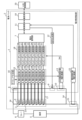
- FIG. 1 is a schematic configuration diagram showing an example of a battery pack 2 according to Embodiment 1.
- FIG. 1 In addition to the battery pack 2, FIG. 1 also shows a host controller 20, a load 5, and a relay 6.
- the battery pack 2 includes an assembled battery 4 in which a plurality of batteries 3 (for example, composed of batteries B1 to B8) are combined and connected, a battery monitoring device 1 for monitoring the batteries, and a current application line. 14 , a plurality of voltage detection lines 17 and a shunt resistor 21 .
- Battery 3 is a secondary battery such as a lithium ion battery.
- a relay 6 is provided between the assembled battery 4 and the load 5 (corresponding to the motor, inverter, and accelerator) to turn ON/OFF the connection between the assembled battery 4 and the load 5 .
- the application is operated according to ON/OFF of the connection between the assembled battery 4 and the load 5 by the relay 6 .
- the load 5 may be a charger.
- the assembled battery 4 and the battery monitoring device 1 are connected by a current application line 14 and a plurality of voltage detection lines 17 .
- the battery monitoring device 1 is a device that measures the internal impedance of a plurality of batteries 3. For example, the battery monitoring device 1 measures internal AC impedances of a plurality of batteries 3 . Also, for example, the battery monitoring device 1 measures the internal impedance (for example, internal AC impedance) of each of the plurality of batteries 3 . The battery monitoring device 1 detects the internal alternating current of the plurality of batteries 3 based on the alternating current applied to the assembled battery 4 and the voltage of the plurality of batteries 3 constituting the assembled battery 4 (for example, the voltage of each of the plurality of batteries 3). Impedance (for example, internal AC impedance of each of the plurality of batteries 3) is measured.
- the battery monitoring device 1 uses EIS to measure the internal AC impedance characteristics of the battery 3 and monitors the state of the battery 3 in real time.
- the battery monitoring device 1 includes a battery management unit 7, a load resistor 8, a switching element 9, a shunt resistor 10, a control unit 11, a signal generation unit 12, an AC current measurement unit 13, a voltage measurement unit 15, a timing generation unit 16, and an impedance calculation.
- a unit 18 , a communication unit 19 , a shunt resistor 21 and a current measurement unit 22 are provided.
- the battery management unit 7, the control unit 11, the signal generation unit 12, the alternating current measurement unit 13, the voltage measurement unit 15, the timing generation unit 16, and the impedance calculation unit 18 are connected to the assembled battery 4 (specifically, the assembled battery 4). It is a functional configuration for measuring the internal AC impedance of a plurality of batteries 3).
- the load resistor 8 , switching element 9 and shunt resistor 10 are circuits for measuring the internal AC impedance of the assembled battery 4 .
- the control unit 11 controls the signal generation unit 12 that sweeps the AC signal, so that the switching element 9 can be turned ON/OFF at a specific frequency. As a result, an alternating current with a specific frequency is output from the assembled battery 4 .
- the AC current measurement unit 13 measures the voltage generated in the shunt resistor 10 (that is, the voltage converted from the AC current output from the assembled battery 4).
- the load resistor 8 and the assembled battery 4, and the shunt resistor 10 and the assembled battery 4 are connected via current application lines 14, respectively. Since the load resistor 8 and the shunt resistor 10 are included in the battery monitoring device 1 , the battery monitoring device 1 and the assembled battery 4 are connected via the current application line 14 .
- the current application line 14 is wiring for applying an alternating current to the assembled battery 4 .
- the current application line 14 is, for example, a conducting wire.
- the voltage measurement unit 15 measures the voltages of the multiple batteries 3 that make up the assembled battery 4 .
- the voltage measurement unit 15 may measure the voltages of all the batteries 3 that make up the assembled battery 4 .
- the voltage of some (for example, at least two) batteries 3 that make up the assembled battery 4 may be measured.
- the voltage measurement unit 15 is set with measurement timings by the control unit 11 via the timing generation unit 16 in order to measure the voltages of the plurality of batteries 3 forming the assembled battery 4 at the same timing.
- the voltage measurement unit 15 is connected to the plurality of batteries 3 via the plurality of voltage detection lines 17 and measures the voltage of the plurality of batteries 3 (for example, the voltage of each of the plurality of batteries 3).
- the plurality of voltage detection lines 17 are wirings for detecting the voltages of the plurality of batteries 3 (for example, the voltages of each of the plurality of batteries 3).
- the voltage detection line 17 is connected to the positive battery terminal and the negative battery terminal of each of the plurality of batteries 3 .
- 16 voltage detection lines 17 are provided for eight batteries B1 to B8.
- the voltage detection line 17 is, for example, a conducting wire.
- the voltages V1 to V8 of the batteries B1 to B8 measured by the voltage measurement unit 15 and the current value Iac measured by the AC current measurement unit 13 and converted into voltage are converted to the impedance Z1 to B8 of the batteries B1 to B8 by the impedance calculation unit 18. Used for Z8 calculation (voltage/current). Impedances Z1-Z8 are each complex numbers, and real part ReZ and imaginary part ImZ are calculated for each of batteries B1-B8.
- the complex impedance values Z1 to Z8 of the batteries B1 to B8 are output from the impedance calculation unit 18 to the battery management unit 7, and the battery management unit 7 determines the SOC, SOH, abnormality (failure, deterioration), etc. of the batteries B1 to B8.
- the SOC, SOH, abnormality, etc. of the batteries B1 to B8 are notified to the upper control unit 20 via the control unit 11 and the communication unit 19.
- FIG. The host control unit 20 performs control according to the notified SOC, SOH, abnormality, and the like.
- the impedance calculation unit 18 calculates the ratio of the voltage measured by the voltage measurement unit 15 to the current measured by the AC current measurement unit 13 at each frequency when the alternating current is output from the assembled battery 4 at each frequency by the signal generation unit 12.
- a complex impedance of a certain battery 3 is calculated.
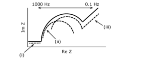
- a Nyquist plot diagram as shown in FIGS. 2A and 2B can be obtained.
- FIGS. 2A and 2B are diagrams for explaining Nyquist plot diagrams. 2A and 2B, the horizontal axis represents the real part ReZ of the complex impedance Z, and the vertical axis represents the imaginary part ImZ of the complex impedance Z.
- the horizontal axis represents the real part ReZ of the complex impedance Z
- the vertical axis represents the imaginary part ImZ of the complex impedance Z.
- the impedance components of the lithium ion battery can be analyzed by dividing them into regions (i) to (iii).
- Region (i) corresponds to the impedance of the wires and the transfer resistance in the electrolyte of the lithium-ion battery.
- the semi-circular portions of regions (ii) and (iii) correspond to the impedance of the charge transfer resistance of the lithium ion battery, region (ii) to the impedance of the negative electrode and region (iii) to the impedance of the positive electrode. .
- the linear portion rising at about 45° in the low frequency region in the ImZ ⁇ 0 region reflects the influence of the Warburg impedance of the lithium ion battery. From the Nyquist plot chart created in this way, for example, an equivalent circuit of the battery as shown in FIG. 3 can be estimated.
- FIG. 3 is a diagram for explaining the correlation between the Nyquist plot and the battery equivalent circuit.
- Fig. 3 shows an example of an equivalent circuit of the internal resistance of a lithium-ion battery.
- the resistance R0 corresponds to the transfer resistance in the electrolyte
- the resistance R1 corresponds to the charge transfer resistance of the negative electrode
- the resistance R2 corresponds to the charge transfer resistance of the positive electrode.
- the wiring is defined by a parallel circuit consisting of an inductor Li and a resistor Ri.
- Warburg resistor W0 represents diffusion and is connected in series with resistor R2.
- a circuit in which resistor R0 and a parallel circuit consisting of inductor Li and resistor Ri are connected in series corresponds to region (i) in the Nyquist plots shown in FIGS. 2A and 2B.
- the RC parallel circuit consisting of resistor R1 and capacitor C1 corresponds to region (ii) in the Nyquist plots shown in FIGS. 2A and 2B.
- An RC parallel circuit in which the series circuit of resistor R2 and Warburg resistor W0 and capacitor C2 are connected in parallel corresponds to region (iii) in the Nyquist plots shown in FIGS. 2A and 2B.
- FIG. 4 is a perspective view showing an example of the battery 3.
- the battery 3 is formed in a flat rectangular parallelepiped shape, and a housing 24 accommodates electrodes, a separator, an electrolytic solution, and the like.
- Bolt-shaped battery terminals 25 (positive battery terminal 25a and negative battery terminal 25b) connected to the electrodes are located at both ends in the longitudinal direction (X-axis direction) of the upper surface of the battery 3 .
- the positive battery terminal 25a and the negative battery terminal 25b each protrude upward (in the plus direction of the Z-axis) from the housing 24 to the same extent.
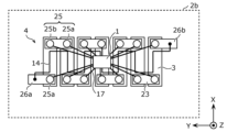
- FIG. 5 is a plan view showing an example of the assembled battery 4.
- FIG. Plan views including the figures shown below, are views of the assembled battery 4 as viewed from the upper surface side of the battery 3, that is, views viewed from the surface side on which the battery terminals 25 are provided.
- the housings 24 of the batteries 3 are arranged side by side in the lateral direction (Y-axis direction) so as to be adjacent to each other.
- Adjacent batteries 3 are arranged such that the positive battery terminal 25a and the negative battery terminal 25b are alternately arranged.
- the battery 3 adjacent to the battery 3 whose battery terminal 25 is located in the order of the positive battery terminal 25a and the negative battery terminal 25b in the positive direction of the X-axis is connected to the negative battery terminal in the positive direction of the X-axis.
- the battery terminals 25 are positioned in the order of 25b and the positive battery terminal 25a.
- the positive battery terminal 25a of the battery 3 is connected to the negative battery terminal 25b of one adjacent battery 3 via a bus bar 23 made of a conductive material so that the plurality of batteries 3 are connected in series. connected. Also, the negative battery terminal 25 b of the battery 3 is connected to the positive battery terminal 25 a of the other adjacent battery 3 via the bus bar 23 .
- a battery pack 4 is constructed by connecting a plurality of batteries 3 in series so as to achieve the target battery capacity and battery voltage. Note that the battery 3 may be composed of a plurality of batteries connected in parallel.
- the bus bar 23 is processed to have a length reaching the positive electrode battery terminal 25a and the negative electrode battery terminal 25b of the adjacent batteries 3, is formed into a thin plate, and maintains sufficient conductivity.
- the bus bar 23 is fastened to a bolt-shaped battery terminal 25 with a nut.
- a positive electrode side battery terminal 26a is connected to the positive electrode side battery terminal 25a of the battery 3 on one end side (for example, the leftmost battery 3 in FIG. 5) among the plurality of batteries 3 connected in series.
- a negative assembled battery terminal 26b is connected to the negative battery terminal 25b of the battery 3 (for example, the rightmost battery 3 in FIG. 5).
- the positive side assembled battery terminal 26 a and the negative side assembled battery terminal 26 b are provided for supplying electric power from the assembled battery 4 to the external load 5 .
- FIG. 6 the structure of the battery pack 2 according to Embodiment 1 will be explained using FIGS. 6 and 7.
- FIG. 6 is a diagrammatic representation of the battery pack 2 according to Embodiment 1.
- FIG. 6 is a plan view showing an example of the battery pack 2 according to Embodiment 1.
- FIG. 6 is a plan view showing an example of the battery pack 2 according to Embodiment 1.
- FIG. 7 is a perspective view showing an example of the battery pack 2 according to Embodiment 1.
- FIG. 7 is a perspective view showing an example of the battery pack 2 according to Embodiment 1.
- FIGS. 6 and 7 show a battery monitoring device 1, a plurality of batteries 3 constituting an assembled battery 4, a current application line 14 connecting the assembled battery 4 and the battery monitoring device 1, and a plurality of voltage detection lines 17. shown.
- the battery monitoring device 1 is located between the positive battery terminal 25 a and the negative battery terminal 25 b of each battery 3 that constitutes the assembled battery 4 when the assembled battery 4 is viewed from above.
- one voltage detection line 17 is connected to one battery terminal 25 (positive battery terminal 25 a or negative battery terminal 25 b ), and two voltage detection lines 17 are connected to one battery 3 .
- a plurality of voltage detection lines 17 are arranged radially from the battery monitoring device 1 . As shown in FIGS.
- the battery monitoring device 1 is positioned substantially at the center of the assembled battery 4 in the longitudinal direction and substantially at the center of the assembled battery 4 in the lateral direction when the assembled battery 4 is viewed from above.
- the plurality of voltage detection lines 17 are arranged radially in all directions from the battery monitoring device 1 centering on the battery monitoring device 1 .
- the number of batteries 3 whose internal AC impedance is measured by the battery monitoring device 1 may be at least two, and the plurality of voltage detection lines 17 is at least four. For example, if four voltage detection lines 17 are routed in different directions for two batteries 3, it is assumed that the four voltage detection lines 17 are routed radially.
- the current application line 14 connects the battery monitoring device 1 and the positive side assembled battery terminal 26a, and also connects the battery monitoring device 1 and the negative side assembled battery terminal 26b. As shown in FIGS. 6 and 7 , the current application line 14 is routed so as not to be parallel to the plurality of voltage detection lines 17 . Note that if the current application line 14 and at least one voltage detection line 17 are always parallel due to the design of the battery pack 2 , the current application line 14 is not parallel to the plurality of voltage detection lines 17 Arranged to be minimal.
- the current application line 14 is located between the positive battery terminal 25a and the negative battery terminal 25b of the plurality of batteries 3 when the assembled battery 4 is viewed from above. To position.
- the voltage detection lines 17 can be provided along the shortest path between each battery terminal 25 and the battery monitoring device 1 . length can be minimized.
- Wiring such as the voltage detection line 17, the current application line 14, and the bus bar 23 has a resistance value, and the resistance value of the wiring changes depending on the material, thickness, and length of the wiring. For example, focusing on the length of the wiring, the longer the wiring, the larger the inductor component of the wiring, and the greater the influence of the inductor component of the wiring.
- FIG. 8 is a diagram showing the influence of the wiring inductor.
- the shape of the semicircular portion corresponding to the charge transfer resistance of the electrode changes greatly, and when the impedance of the battery 3 to be measured is low, the influence of the inductor component becomes relatively large. In order to suppress this effect, it is necessary to shorten the length of each wire routed in the battery pack 2 as much as possible, and the plurality of voltage detection wires 17 are routed radially.
- the current applying line 14 is positioned between the positive battery terminal 25a and the negative battery terminal 25b of the plurality of batteries 3, the positive battery terminal 25a and the negative battery terminal 25b of the plurality of batteries 3 are connected. In between, a current applying line 14 can be provided from the battery monitoring device 1 to the positive side assembled battery terminal 26 a and the negative side assembled battery terminal 26 b of the assembled battery 4 . As a result, the current application line 14 can be shortened and the resistance value of the current application line 14 can be reduced, that is, the inductor component of the current application line 14 can be reduced.
- the current application line 14 since a large alternating current can be applied to the current application line 14, the mutual inductance generated increases when the current application line 14 and the voltage detection line 17 are arranged in parallel. Therefore, the current application line 14 is wired so as not to be parallel to the plurality of voltage detection lines 17, or is wired so that the parallel portion with the plurality of voltage detection lines 17 is minimized. Electromagnetic induction interference due to mutual inductance between the line 14 and the voltage detection line 17 can be suppressed.
- FIG. 9 is a diagram showing the influence of electromagnetic induction interference.
- an AC current flows between the battery monitoring device 1 and the assembled battery 4 via the current application line 14, and a magnetic field is generated around the current application line 14. .
- the generation of this magnetic field is based on Fleming's law.
- the generated magnetic field is added to the amount of change in the impedance measurement of the nearby battery 3 and affects the measurement of the internal AC impedance of the battery 3 .
- the effect of the magnetic field is significant, and as shown in FIG. 9, the effect is significant in the high-frequency region of the Nyquist plot.
- electromagnetic induction interference the phenomenon in which the surrounding circuits are affected by the magnetic field is called electromagnetic induction interference.
- the magnetic field increases with increasing source current and with increasing mutual inductance.
- This mutual inductance is the inductance of the current loop created by wiring and the like.
- Mutual inductance increases the closer the distance between the source and the affected side and the more parallel parts the flowing currents have.
- the plurality of voltage detection lines 17 are radially routed from the battery monitoring device 1 to accurately measure the internal impedance (for example, internal AC impedance) of the plurality of batteries 3 constituting the assembled battery 4. can do.
- the assembled battery 4 by wiring the current applying line 14 so as not to be parallel to the plurality of voltage detection lines 17, or by wiring such that the parallel portion with the plurality of voltage detection lines 17 is minimized, the assembled battery 4, the internal impedance (for example, internal AC impedance) of the batteries 3 can be measured with even higher accuracy.
- the internal impedance for example, internal AC impedance
- the internal impedance (for example, internal AC impedance) of the plurality of batteries 3 constituting the assembled battery 4 ) can be measured more accurately.
- a schematic configuration diagram showing an example of the battery pack 2a according to the second embodiment is the same as the schematic configuration diagram (FIG. 1) of the battery pack 2 according to the first embodiment, so description thereof is omitted.
- the structure of the battery pack 2a according to the second embodiment will be described with reference to FIGS. 10 and 11, focusing on the differences from the battery pack 2 according to the first embodiment.
- FIG. 10 is a plan view showing an example of a battery pack 2a according to Embodiment 2.
- FIG. 10 is a plan view showing an example of a battery pack 2a according to Embodiment 2.
- FIG. 11 is a perspective view showing an example of a battery pack 2a according to Embodiment 2.
- FIG. 11 is a perspective view showing an example of a battery pack 2a according to Embodiment 2.
- the current applying line 14 connects the positive battery terminal 25a and the negative battery terminal 25b of the plurality of batteries 3 when the assembled battery 4 is viewed from above. located on the outside of the Note that the battery monitoring device 1 is positioned between the positive battery terminal 25a and the negative battery terminal 25b of the plurality of batteries 3 when the assembled battery 4 is viewed from above, and therefore is connected to the battery monitoring device 1.
- the current application line 14 includes a portion positioned between the positive battery terminal 25 a and the negative battery terminal 25 b of the plurality of batteries 3 . However, most of the current applying lines 14 are located outside between the positive battery terminals 25 a and the negative battery terminals 25 b of the plurality of batteries 3 .
- the plurality of voltage detection lines 17 are wired between the positive battery terminals 25a and the negative battery terminals 25b of the batteries 3, the current application lines 14 are connected to the positive battery terminals 25a of the batteries 3. and the negative battery terminal 25b, the distance between the voltage detection line 17 and the current application line 14 can be increased. Therefore, it is possible to suppress electromagnetic induction interference due to mutual inductance between the current application line 14 and the voltage detection line 17, and measure the internal impedance (for example, internal AC impedance) of the plurality of batteries 3 constituting the assembled battery 4 more accurately. can do.
- the internal impedance for example, internal AC impedance
- the current applying line 14 may be routed so as not to be parallel to the plurality of voltage detection lines 17, or the plurality of voltage detection lines 17 may be wired so as not to be parallel. may be routed so as to minimize the number of parallel points.
- a schematic configuration diagram showing an example of the battery pack 2b according to the third embodiment is the same as the schematic configuration diagram (FIG. 1) of the battery pack 2 according to the first embodiment, so description thereof is omitted.
- the structure of the battery pack 2b according to the third embodiment will be described with reference to FIGS. 12 and 13, focusing on the differences from the battery pack 2 according to the first embodiment.
- FIG. 12 is a plan view showing an example of a battery pack 2b according to Embodiment 3.
- FIG. 12 is a plan view showing an example of a battery pack 2b according to Embodiment 3.
- FIG. 13 is a perspective view showing an example of a battery pack 2b according to Embodiment 3.
- FIG. 13 is a perspective view showing an example of a battery pack 2b according to Embodiment 3.
- the current application line 14 is routed so as to weaken the magnetic field generated by the current application line 14 .
- the current application line 14 includes parallel opposing portions, and the current application line 14 is arranged so that the direction of the current flowing in one of the opposing portions is opposite to that of the other.
- the wire 14 may be routed, and specifically, the current applying wire 14 may be routed in a rectangular wave shape.
- the internal impedance (for example, internal AC impedance) of the plurality of batteries 3 forming the assembled battery 4 can be measured with higher accuracy.
- the current applying line 14 may be routed so as not to be parallel to the plurality of voltage detection lines 17, or the plurality of voltage detection lines 17 may be wired so as not to be parallel. It may be routed so that the parallel point with is minimized.
- the current application line 14 By arranging the current application line 14 in a rectangular wave shape, the voltage detection line 17 and the current application line 14 are not arranged in parallel, and the influence of electromagnetic induction disturbance can be suppressed.
- a schematic configuration diagram showing an example of the battery pack 2c according to Embodiment 4 is the same as the schematic configuration diagram (FIG. 1) of the battery pack 2 according to Embodiment 1, so description thereof is omitted.
- the structure of the battery pack 2c according to the fourth embodiment will be described with reference to FIGS. 14A to 16, focusing on the differences from the battery pack 2 according to the first embodiment.
- the battery pack 2c includes a shielding portion that shields the electric field or magnetic field generated by the plurality of batteries 3 or the current application lines 14.
- a shielding portion that shields the electric field or magnetic field generated by the plurality of batteries 3 or the current application lines 14.
- FIG. 14A is a diagram for explaining a first example of the shielding part according to Embodiment 4.
- FIG. 14A is a cross-sectional view of the current applying wire 14.
- FIG. 14A is a diagram for explaining a first example of the shielding part according to Embodiment 4.
- FIG. 14A is a cross-sectional view of the current applying wire 14.
- the current applying line 14 may have a shielding function against electric fields or magnetic fields.
- the shield may be a shield 30 that covers the conductor (central conductor) 27 of the current application line 14 and shields the electric field or magnetic field generated by the current application line 14 .
- the shield 30, which has a shielding function against an electric field or a magnetic field is composed of, for example, a metal tape such as copper or aluminum, or a mesh-like braided wire.
- conductor 27 is covered with shield 30
- shield 30 is covered with insulator 29
- insulator 29 is covered with jacket 28 .
- FIG. 14B shows an example of wiring that is not covered with a shield.
- the conducting wire 27 is directly covered with the jacket 28 .
- the shield 30 covering the conductor 27 of the current applying line 14 can suppress the influence of the electric field or magnetic field generated by the current applying line 14 .
- FIG. 15 is a diagram for explaining a second example of the shielding portion according to Embodiment 4.
- FIG. FIG. 15 is a plan view showing a second example of battery pack 2c according to the fourth embodiment.
- the shielding part may be a sheet-like shield 31 provided between the current application line 14 and the plurality of voltage detection lines 17, and the electric field or magnetic field generated by the current application line 14 may be may be shielded.
- the sheet-like shield 31 is made of, for example, a metal plate such as copper or aluminum that has a shielding function against electric fields or magnetic fields.
- the sheet-like shield 31 provided between the current application line 14 and the plurality of voltage detection lines 17 can suppress the influence of the electric field or magnetic field generated by the current application line 14 .
- FIG. 16 is a diagram for explaining a third example of the shielding part according to the fourth embodiment.
- FIG. 16 is a plan view showing a third example of battery pack 2c according to the fourth embodiment.
- the shielding part may be a sheet-like shield 32 provided between the plurality of batteries 3 and the current application line 14 and the plurality of voltage detection lines 17, and shields the electric field or magnetic field generated by the plurality of batteries 3. It can be shielded.
- the sheet-like shields 32 provided between the batteries 3 and the current application lines 14 and the voltage detection lines 17 prevent the multiple The influence of the electric field or magnetic field generated by the battery 3 can be suppressed.
- a schematic configuration diagram showing an example of the battery pack 2d according to Embodiment 5 is the same as the schematic configuration diagram (FIG. 1) of the battery pack 2 according to Embodiment 1, so description thereof is omitted.
- the structure of the battery pack 2d according to the fifth embodiment will be described with reference to FIG. 17, focusing on the differences from the battery pack 2 according to the first embodiment.
- FIG. 17 is a plan view showing an example of a battery pack 2d according to Embodiment 5.
- FIG. 17 is a plan view showing an example of a battery pack 2d according to Embodiment 5.
- the battery monitoring device 1 when the assembled battery 4 is viewed from the top, the battery monitoring device 1 is configured so that the end of the assembled battery 4 in the longitudinal direction (Y-axis direction) and the lateral direction (X-axis direction) of the assembled battery 4 located approximately in the center of In this way, the battery monitoring device 1 may be positioned at the end of the assembled battery 4 when viewed from above, and the plurality of voltage detection lines 17 are routed radially from the battery monitoring device 1 in a fan shape.
- FIG. 18 is a schematic configuration diagram showing an example of a battery pack 2e according to the sixth embodiment.
- the points different from the battery pack 2 according to the first embodiment will be mainly described.
- the voltage detection line 17 is connected to the positive battery terminal 25a and the negative battery terminal 25b of each of the plurality of batteries 3.
- the eight batteries B1 to An example in which 16 voltage detection lines 17 are provided for B8 has been described.
- the bus bar 23 has substantially the same potential as the positive battery terminal 25a and the negative battery terminal 25b. . Therefore, the voltage of the adjacent battery 3 can be detected even by connecting the voltage detection line 17 to the bus bar 23 without connecting the voltage detection line 17 to the positive battery terminal 25a and the negative battery terminal 25b.
- the number of voltage detection lines 17 can be set to nine for eight batteries B1 to B8 shown in FIG. 18, and the number of voltage detection lines 17 can be reduced.
- FIG. 19 the structure of the battery pack 2e according to Embodiment 6 will be described with reference to FIGS. 19 and 20.
- FIG. 19 the structure of the battery pack 2e according to Embodiment 6 will be described with reference to FIGS. 19 and 20.
- FIG. 19 is a plan view showing an example of a battery pack 2e according to Embodiment 6.
- FIG. 19 is a plan view showing an example of a battery pack 2e according to Embodiment 6.
- FIG. 20 is a perspective view showing an example of a battery pack 2e according to Embodiment 6.
- FIG. 20 is a perspective view showing an example of a battery pack 2e according to Embodiment 6.
- the battery terminals 25 of the batteries 3 included in the plurality of batteries 3 are connected to the battery terminals 25 of the adjacent batteries 3 by the bus bars 23 to form the assembled battery 4 .
- the positive electrode battery terminal 25a of the battery 3 on one end side and the negative electrode battery terminal 25b of the battery 3 on the other end side are connected to the positive electrode battery terminal 26a and the negative electrode battery terminal 26a instead of the bus bar 23, respectively.
- the side assembled battery terminal 26b is connected, and the voltage detection line 17 is connected to the positive side assembled battery terminal 26a and the negative side assembled battery terminal 26b.
- the number of voltage detection lines 17 can be reduced, and the reduced number of voltage detection lines 17 can suppress the influence of the inductor component and the induced electromotive force when measuring the impedance of the battery 3 . Therefore, it is possible to measure the internal impedance (for example, internal AC impedance) of each of the plurality of batteries 3 forming the assembled battery 4 with higher accuracy.
- the internal impedance for example, internal AC impedance
- the voltage detection line 17 (for example, each of the plurality of voltage detection lines 17) is positioned approximately in the center of the two battery terminals 25 (the positive battery terminal 25a and the negative battery terminal 25b) on the bus bar 23 (from the two battery terminals 25). equidistant positions).
- the voltage detection lines 17 (for example, each of the plurality of voltage detection lines 17) are connected to the busbar 23 at positions equidistant from the two battery terminals 25, so that the busbar 23 detects the voltage of the adjacent batteries 3. can be evenly affected by the resistance components of adjacent batteries 3 .
- equidistant includes not only the case where the two distances are completely the same, but also the case where the two distances are deviated by several percent.
- FIG. 21 is a plan view showing an example of a battery pack 2f in another embodiment.
- a circuit board 33 may be provided on the upper surface side of the assembled battery 4 so as to be electrically connected to the battery terminals 25 of the plurality of batteries 3 forming the assembled battery 4 .
- the battery monitoring device 1 may be mounted on the circuit board 33 , and the wiring pattern (conductive metal) on the circuit board 33 may form the current application line 14 and the voltage detection line 17 .
- the circuit board 33 is a PCB (printed circuit board), FPC (flexible printed circuit board), or the like.
- the battery 3 is a prismatic battery, but it may be of other shapes such as a cylindrical shape and a flat plate shape.
- battery packs are also effective for storage batteries, motorcycles, heavy machinery, ships, airplanes, power plants, and the like.
- the battery 3 may be other secondary batteries (lead storage battery, nickel-cadmium storage battery, metal lithium battery, lithium ion polymer secondary battery, sodium ion battery, solid state battery, etc.). battery, etc.).
- the present disclosure can be applied to battery packs that have a function of monitoring the state of secondary batteries such as lithium ion batteries.
Landscapes
- Chemical & Material Sciences (AREA)
- Chemical Kinetics & Catalysis (AREA)
- Electrochemistry (AREA)
- General Chemical & Material Sciences (AREA)
- Physics & Mathematics (AREA)
- General Physics & Mathematics (AREA)
- Engineering & Computer Science (AREA)
- Manufacturing & Machinery (AREA)
- Battery Mounting, Suspending (AREA)
Abstract
La présente invention concerne un bloc-batterie (2) comprenant : une batterie assemblée (4) dans laquelle une pluralité de batteries (3) sont connectées ; un fil d'application de courant électrique (14) pour appliquer un courant électrique à la batterie assemblée (4) ; une pluralité de fils de détection de tension (17) pour détecter les tensions de la pluralité de batteries (3) ; et un dispositif de surveillance de batterie (1) pour mesurer les impédances internes de la pluralité de batteries (3). Le dispositif de surveillance de batterie (1) est positionné entre une borne de batterie côté électrode positive (25a) et une borne de batterie côté électrode négative (25b) de chaque batterie (3) constituant la batterie assemblée (4), et la pluralité de fils de détection de tension (17) sont tirés de manière radiale à partir du dispositif de surveillance de batterie (1).
Applications Claiming Priority (2)
| Application Number | Priority Date | Filing Date | Title |
|---|---|---|---|
| JP2022028529 | 2022-02-25 | ||
| JP2022-028529 | 2022-02-25 |
Publications (1)
| Publication Number | Publication Date |
|---|---|
| WO2023162751A1 true WO2023162751A1 (fr) | 2023-08-31 |
Family
ID=87765720
Family Applications (1)
| Application Number | Title | Priority Date | Filing Date |
|---|---|---|---|
| PCT/JP2023/004799 WO2023162751A1 (fr) | 2022-02-25 | 2023-02-13 | Bloc-batterie |
Country Status (1)
| Country | Link |
|---|---|
| WO (1) | WO2023162751A1 (fr) |
Citations (7)
| Publication number | Priority date | Publication date | Assignee | Title |
|---|---|---|---|---|
| JP2002170535A (ja) * | 2000-12-04 | 2002-06-14 | Hitachi Ltd | 電源装置 |
| JP2009512144A (ja) * | 2005-10-11 | 2009-03-19 | デラウェア パワー システムズ コーポレーション | 汎用バッテリモジュールおよびこのためのコントローラ |
| JP2013109927A (ja) * | 2011-11-18 | 2013-06-06 | Sumitomo Electric Ind Ltd | 電池配線モジュール、電池配線モジュールの製造方法、および電池配線モジュールを備えた電源装置 |
| JP2013165067A (ja) * | 2013-04-10 | 2013-08-22 | Toshiba Corp | 二次電池パック |
| JP2013225457A (ja) * | 2012-04-23 | 2013-10-31 | Toyota Boshoku Corp | フレキシブルプリント配線板の取付構造 |
| US20190391209A1 (en) * | 2018-06-20 | 2019-12-26 | Denso Corporation | Monitoring apparatus |
| JP2020013653A (ja) * | 2018-07-13 | 2020-01-23 | 株式会社デンソー | 監視装置 |
-
2023
- 2023-02-13 WO PCT/JP2023/004799 patent/WO2023162751A1/fr unknown
Patent Citations (7)
| Publication number | Priority date | Publication date | Assignee | Title |
|---|---|---|---|---|
| JP2002170535A (ja) * | 2000-12-04 | 2002-06-14 | Hitachi Ltd | 電源装置 |
| JP2009512144A (ja) * | 2005-10-11 | 2009-03-19 | デラウェア パワー システムズ コーポレーション | 汎用バッテリモジュールおよびこのためのコントローラ |
| JP2013109927A (ja) * | 2011-11-18 | 2013-06-06 | Sumitomo Electric Ind Ltd | 電池配線モジュール、電池配線モジュールの製造方法、および電池配線モジュールを備えた電源装置 |
| JP2013225457A (ja) * | 2012-04-23 | 2013-10-31 | Toyota Boshoku Corp | フレキシブルプリント配線板の取付構造 |
| JP2013165067A (ja) * | 2013-04-10 | 2013-08-22 | Toshiba Corp | 二次電池パック |
| US20190391209A1 (en) * | 2018-06-20 | 2019-12-26 | Denso Corporation | Monitoring apparatus |
| JP2020013653A (ja) * | 2018-07-13 | 2020-01-23 | 株式会社デンソー | 監視装置 |
Similar Documents
| Publication | Publication Date | Title |
|---|---|---|
| US11313885B2 (en) | Integrated current-measuring apparatus | |
| EP2259365B1 (fr) | Dispositif pour détecter les dysfonctionnements dans une batterie secondaire | |
| JP5501763B2 (ja) | 等分配型母線、及びそれを使用する中または大型バッテリーパック | |
| US9748612B2 (en) | Battery pack having a plurality of electrochemical battery cells having a device for measuring a difference between two cell currents of two different battery cells | |
| US20190245185A1 (en) | Battery wiring module | |
| US20130202928A1 (en) | Busbar including flexible circuit | |
| US20210098765A1 (en) | Battery module with flexible interconnector | |
| KR102020757B1 (ko) | 전기 에너지 저장 모듈 및 전기 에너지 저장 모듈의 제조 방법 | |
| WO2013022938A2 (fr) | Barre omnibus comprenant un circuit flexible | |
| KR102511550B1 (ko) | 전지 시스템 용 버스바 및 이를 포함하는 전지 시스템 | |
| WO2018128250A1 (fr) | Module de batterie avec unité de thermocouple | |
| US9595704B2 (en) | Electrical energy storage module and method for producing an electrical energy storage module | |
| CN112114180B (zh) | 电力转换装置 | |
| WO2023162751A1 (fr) | Bloc-batterie | |
| CN115004043A (zh) | 电池测定装置 | |
| EP4089790B1 (fr) | Cellule de batterie et système de batterie comprenant une cellule de batterie | |
| WO2024014161A1 (fr) | Bloc-batterie | |
| JP2021166429A (ja) | 蓄電素子の管理装置、蓄電装置、及び、車両 | |
| US20220029427A1 (en) | Pre-charge unit for charging a dc link capacitor and battery system including the same | |
| EP3944454A1 (fr) | Unité de pré-charge pour charger un condensateur de liaison cc et système de batterie la comprenant | |
| US11539085B2 (en) | Serviceable flex circuit for battery module | |
| JP2019133791A (ja) | 管理装置、蓄電装置 | |
| JP7400831B2 (ja) | 電流計測装置、蓄電装置 | |
| EP4124498A1 (fr) | Système de commande de relais et système de batterie | |
| CN111313119A (zh) | 电池模块以及将单元监控电路载体组装到电池模块的方法 |
Legal Events
| Date | Code | Title | Description |
|---|---|---|---|
| 121 | Ep: the epo has been informed by wipo that ep was designated in this application |
Ref document number: 23759754 Country of ref document: EP Kind code of ref document: A1 |