JP7074934B2 - Rotary crusher and rotary crushing method - Google Patents
Rotary crusher and rotary crushing method Download PDFInfo
- Publication number
- JP7074934B2 JP7074934B2 JP2021536827A JP2021536827A JP7074934B2 JP 7074934 B2 JP7074934 B2 JP 7074934B2 JP 2021536827 A JP2021536827 A JP 2021536827A JP 2021536827 A JP2021536827 A JP 2021536827A JP 7074934 B2 JP7074934 B2 JP 7074934B2
- Authority
- JP
- Japan
- Prior art keywords
- impact
- applying member
- rotary
- raw material
- rotating shaft
- Prior art date
- Legal status (The legal status is an assumption and is not a legal conclusion. Google has not performed a legal analysis and makes no representation as to the accuracy of the status listed.)
- Active
Links
Images


Classifications
-
- B—PERFORMING OPERATIONS; TRANSPORTING
- B02—CRUSHING, PULVERISING, OR DISINTEGRATING; PREPARATORY TREATMENT OF GRAIN FOR MILLING
- B02C—CRUSHING, PULVERISING, OR DISINTEGRATING IN GENERAL; MILLING GRAIN
- B02C13/00—Disintegrating by mills having rotary beater elements ; Hammer mills
- B02C13/14—Disintegrating by mills having rotary beater elements ; Hammer mills with vertical rotor shaft, e.g. combined with sifting devices
- B02C13/16—Disintegrating by mills having rotary beater elements ; Hammer mills with vertical rotor shaft, e.g. combined with sifting devices with beaters hinged to the rotor
-
- B—PERFORMING OPERATIONS; TRANSPORTING
- B02—CRUSHING, PULVERISING, OR DISINTEGRATING; PREPARATORY TREATMENT OF GRAIN FOR MILLING
- B02C—CRUSHING, PULVERISING, OR DISINTEGRATING IN GENERAL; MILLING GRAIN
- B02C13/00—Disintegrating by mills having rotary beater elements ; Hammer mills
- B02C13/26—Details
- B02C13/286—Feeding or discharge
-
- B—PERFORMING OPERATIONS; TRANSPORTING
- B02—CRUSHING, PULVERISING, OR DISINTEGRATING; PREPARATORY TREATMENT OF GRAIN FOR MILLING
- B02C—CRUSHING, PULVERISING, OR DISINTEGRATING IN GENERAL; MILLING GRAIN
- B02C13/00—Disintegrating by mills having rotary beater elements ; Hammer mills
- B02C13/26—Details
- B02C13/282—Shape or inner surface of mill-housings
-
- B—PERFORMING OPERATIONS; TRANSPORTING
- B02—CRUSHING, PULVERISING, OR DISINTEGRATING; PREPARATORY TREATMENT OF GRAIN FOR MILLING
- B02C—CRUSHING, PULVERISING, OR DISINTEGRATING IN GENERAL; MILLING GRAIN
- B02C13/00—Disintegrating by mills having rotary beater elements ; Hammer mills
- B02C13/26—Details
- B02C13/28—Shape or construction of beater elements
- B02C2013/2816—Shape or construction of beater elements of chain, rope or cable type
-
- B—PERFORMING OPERATIONS; TRANSPORTING
- B02—CRUSHING, PULVERISING, OR DISINTEGRATING; PREPARATORY TREATMENT OF GRAIN FOR MILLING
- B02C—CRUSHING, PULVERISING, OR DISINTEGRATING IN GENERAL; MILLING GRAIN
- B02C13/00—Disintegrating by mills having rotary beater elements ; Hammer mills
- B02C13/26—Details
- B02C13/286—Feeding or discharge
- B02C2013/28609—Discharge means
-
- B—PERFORMING OPERATIONS; TRANSPORTING
- B02—CRUSHING, PULVERISING, OR DISINTEGRATING; PREPARATORY TREATMENT OF GRAIN FOR MILLING
- B02C—CRUSHING, PULVERISING, OR DISINTEGRATING IN GENERAL; MILLING GRAIN
- B02C13/00—Disintegrating by mills having rotary beater elements ; Hammer mills
- B02C13/26—Details
- B02C13/286—Feeding or discharge
- B02C2013/28618—Feeding means
- B02C2013/28636—Feeding means of conveyor belt type
Description
本発明は、回転式破砕装置および回転式破砕方法に関する。 The present invention relates to a rotary crushing device and a rotary crushing method.
建設発生土などを改良して有効利用するための回転式破砕(混合)工法及びその工法に用いられる装置が知られている(例えば特許文献1等参照)。 A rotary crushing (mixing) method for improving and effectively utilizing construction-generated soil and an apparatus used for the method are known (see, for example, Patent Document 1 and the like).
回転式破砕(混合)工法は、円筒状の容器内で高速回転する衝撃付加部材(インパクト部材)を備えた処理装置を用い、インパクト部材の衝撃力により、容器内に投入された建設発生土の破砕、細粒化を行う工法であり、材料をなだらかな粒度分布にする効果を有する。また、必要に応じ、添加材として生石灰、消石灰などの石灰系固化材や、普通セメント、高炉セメントなどのセメント系固化材、あるいは高分子材料からなる土質改良材などを混合し、改良土の性状や強度などを調整することができる。なお、建設発生土は、ベルトコンベアにより回転式破砕装置の投入口に搬送されている。 The rotary crushing (mixing) method uses a processing device equipped with an impact adding member (impact member) that rotates at high speed in a cylindrical container, and the impact force of the impact member causes the soil generated from construction to be thrown into the container. It is a construction method that crushes and granulates, and has the effect of making the material a gentle particle size distribution. In addition, if necessary, lime-based solidifying materials such as quicklime and slaked lime, cement-based solidifying materials such as ordinary cement and blast furnace cement, and soil improvement materials made of polymer materials are mixed as additives to improve the properties of the improved soil. And strength can be adjusted. The soil generated from construction is conveyed to the input port of the rotary crusher by a belt conveyor.
建設発生土の破砕を行うインパクト部材については、効率的に建設発生土の破砕を行うための形状や数などの提案がなされている。しかしながら、インパクト部材にどのように建設発生土を投入するかという提案は多くなく、改善の余地があった。 Regarding impact members for crushing construction-generated soil, proposals have been made regarding the shape and number of impact members for efficiently crushing construction-generated soil. However, there were not many proposals on how to put the soil generated from construction into the impact members, and there was room for improvement.
そこで、本発明は、衝撃付加部材による破砕が効率的に行われるような回転式破砕装置ならびに回転式破砕方法を提供することを目的とする。 Therefore, an object of the present invention is to provide a rotary crushing apparatus and a rotary crushing method in which crushing by an impact applying member is efficiently performed.
第1発明の回転式破砕装置は、鉛直方向に伸びた回転軸に連結され、前記回転軸の鉛直方向回りの回転により処理対象を破砕する衝撃付加部材と、前記処理対象の搬送軸方向と、前記処理対象と接触するときの前記衝撃付加部材の移動方向とをほぼ一致させて、前記衝撃付加部材の重心位置と前記衝撃付加部材の先端側との間に対して前記処理対象を前記鉛直方向に沿って投入する投入装置と、を備えている。
第2発明の回転式破砕方法は、処理対象を破砕可能な衝撃付加部材を鉛直方向に伸びた回転軸の鉛直方向回りの回転により水平面内で回転させるステップと、前記処理対象の搬送軸方向と、前記処理対象と接触するときの前記衝撃付加部材の移動方向とをほぼ一致させて、前記衝撃付加部材の重心位置と前記衝撃付加部材の先端側との間に対して前記処理対象を前記鉛直方向に沿って投入するステップと、を含んでいる。
The rotary crushing device of the first invention is connected to a rotating shaft extending in the vertical direction, and has an impact addition member that crushes the processing target by rotation of the rotating shaft in the vertical direction, and a transport shaft direction of the processing target. The processing target is placed in the vertical direction with respect to the position of the center of gravity of the impact applying member and the tip end side of the impact applying member so as to substantially match the moving direction of the impact applying member when it comes into contact with the processing target. It is equipped with a loading device that feeds along the line.
The rotary crushing method of the second invention includes a step of rotating an impact applying member capable of crushing a processing target in a horizontal plane by rotating a rotation axis extending in the vertical direction in the vertical direction, and a transport axis direction of the processing target. The processing target is vertically aligned with the moving direction of the impact applying member when it comes into contact with the processing target, with respect to the position of the center of gravity of the impact applying member and the tip end side of the impact applying member. Includes steps to throw in along the direction.
第1発明の回転式破砕装置は、処理対象の搬送軸方向と、前記衝撃付加部材の回転軸方向とをほぼ一致させているので、衝撃付加部材による衝撃付加部材による処理対象の破砕を効率的に行うことができる。
第2発明の回転式破砕方法は、処理対象の搬送軸方向と、前記衝撃付加部材の回転軸方向とをほぼ一致させているので、衝撃付加部材による衝撃付加部材による処理対象の破砕を効率的に行うことができる。Since the rotary crushing apparatus of the first invention substantially coincides with the transport axis direction of the processing target and the rotation axis direction of the impact applying member, the impact applying member efficiently crushes the processing target by the impact applying member. Can be done.
In the rotary crushing method of the second invention, the transport axis direction of the processing target and the rotation axis direction of the impact applying member are substantially the same, so that the processing target can be efficiently crushed by the impact applying member. Can be done.
以下、一実施形態に係る回転式破砕装置について、図1~図6に基づいて詳細に説明する。
図1には、一実施形態に係る回転式破砕装置100の構成が概略的に示されている。図1においては、図示の便宜上、一部を断面して示している。また、図1では、説明の便宜上、鉛直方向をZ軸方向、水平面内において直交する二軸方向をX軸方向及びY軸方向として図示している。Hereinafter, the rotary crushing apparatus according to the embodiment will be described in detail with reference to FIGS. 1 to 6.
FIG. 1 schematically shows the configuration of the
本実施形態の回転式破砕装置100は、建設発生土などの原料土を改良して有効利用するために用いられる装置である。回転式破砕装置100は、原料土の破砕、細粒化を行い、原料土をなだらかな粒度分布にする。また、回転式破砕装置100には、必要に応じて、添加材(生石灰、消石灰などの石灰系固化材や、普通セメント、高炉セメントなどのセメント系固化材、あるいは高分子材料からなる土質改良材、天然繊維など)も投入される。添加材が投入された場合、回転式破砕装置100は、原料土と添加材を混合して改良土とすることで、改良土の性状や強度などを調整する。
The
回転式破砕装置100は、図1に示すように、架台10と、固定ドラム12と、回転ドラム14と、回転機構16と、ベルトコンベア122などを備える。
As shown in FIG. 1, the
架台10は、回転式破砕装置100の各部を保持するものであり、天板部10aと、脚部10bと、を有する。天板部10aは、例えば鉄製の板状部材であり、下面(-Z側の面)に固定される固定ドラム12の上部開口を閉塞する蓋としての機能を有している。固定ドラム12内に原料土や添加材を投入するための投入口部材20が設けられている。なお、原料土は、ベルトコンベア122により、投入口部材20に搬送される。
The
固定ドラム12は、円筒状の容器であり、天板部10aの下面(-Z側の面)に固定されている。固定ドラム12内には、投入口部材20を介して原料土や添加材が投入され、固定ドラム12の下側(-Z側)に設けられた回転ドラム14内に原料土や添加材を導く。
The
回転ドラム14は、円筒状の容器であり、円筒の中心軸回り(Z軸回り)に、不図示の回転ドラム駆動用モータにより回転(自転)する。回転ドラム14は、複数の支持ローラ24を介して架台10により支持されているため、回転ドラム駆動用モータ154の回転力を受けてスムーズに回転するようになっている。なお、回転ドラム14の回転方向と、インパクト部材34との回転方向とは、同じ回転方向でもよく逆向きの回転方向でもよい。
The
回転ドラム14の内側には、図2に示すように、掻取棒(スクレーパ)22が1又は複数設けられている(図1では不図示)。掻取棒22は、回転ドラム14の内周面に接しており、固定ドラム12に対して固定された状態となっている。したがって、回転ドラム14が回転することにより、掻取棒22が回転ドラム14の内周面に沿って相対的に移動する。これにより、回転ドラム14の内周面に原料土や添加材が付着した場合であっても、回転ドラム14が回転することで、原料土や添加材が掻取棒22によって掻き取られる。すなわち、掻取棒22と、掻取棒22に対して移動する回転ドラム14とにより、回転ドラム14の内周面に付着した原料土や添加材を掻き取る掻取部としての機能が実現されている。
As shown in FIG. 2, one or a plurality of scraping rods (scrapers) 22 are provided inside the rotating drum 14 (not shown in FIG. 1). The
図1に戻り、回転機構16は、固定ドラム12及び回転ドラム14の中心配置された鉛直方向(Z軸方向)に延びる回転軸30と、回転軸30の上端部に設けられたプーリ32と、回転軸30の下端部近傍において上下2段に設けられた2つのインパクト部材34と、を有する。なお、インパクト部材34は、チェーン40と厚板42とを有している(詳細後述)。
Returning to FIG. 1, the
回転軸30は、円柱状の部材であり、架台10の天板部10aを貫通した状態、かつ、天板部10aの上面側に設けられた2つのボールベアリング36a、36bを介して回転自在な状態で、天板部10aに保持されている。2つのボールベアリング36a、36bの間には、スペーサ38が設けられており、ボールベアリング36a、36b間には所定間隔が形成されている。回転軸30の下端部は、回転ドラム14の内部に位置しており、自由端となっている。すなわち、回転軸30は、片持ち支持されている。
The
プーリ32は、ベルトを介して不図示のモータと接続されている。不図示のモータが回転すると、プーリ32及び回転軸30が回転する。
The
ベルトコンベア122は、原料土を投入口部材20に搬送するものである。本実施形態において、ベルトコンベア122は、Y方向とZ方向とに原料土を搬送している。ベルトコンベア122は、Y方向においては紙面の奥側から紙面の手前側に向けて原料土を搬送している。また、ベルトコンベア122は、Z方向においては下方から上方に向けて原料土を搬送している。なお、添加材は、不図示の搬送機構により投入口部材20まで搬送されている。
The
図3は、回転式破砕装置100を上方から見た状態を概略的に示す図であり、図3(a)は本実施形態の投入口部材20とベルトコンベア122との配置を示しており、図3(b)は比較例の投入口部材20とベルトコンベア122との配置を示している。なお、図3ではインパクト部材34をチェーン40と厚板42とから構成しているが、インパクト部材34は、ユニバーサルジョイント40a(図4参照)と厚板42とから構成してもよく、種々の構成とすることができる。
FIG. 3 is a diagram schematically showing a state in which the
前述したように本実施形態のベルトコンベア122は、Y方向とZ方向とに原料土を搬送しているのに対して、比較例のベルトコンベア122は、X方向とZ方向とに原料土を搬送している。本実施形態のように原料土がY方向の搬送成分を持って搬送された場合には、投入口部材20からインパクト部材34に向けて落下する原料土は、図3(a)にRMで表すようにY方向に拡がってインパクト部材34の鋼製の厚板42により粉砕される。
As described above, the
ここで、回転軸30の回転により厚板42は、原料土を粉砕する際に回転成分としてY軸方向の移動成分を有している(図3(a)の矢印参照)。このため、本実施形態のベルトコンベア122の搬送軸方向と、インパクト部材34の回転軸成分とがほぼ一致する場合がある。なお、ベルトコンベア122の配置の仕方や、インパクト部材34の回転方向により、ベルトコンベア122の搬送方向(Y方向)と、インパクト部材34のY方向の回転成分とが一致する場合と、反対方向とになる場合がある。いずれの場合においても、本実施形態では、厚板42により原料土を効率的に粉砕することができる。なお、本実施形態において、原料土は主に厚板42によって粉砕されればよく、チェーン40による原料土の粉砕を排除するものではない。
Here, the
一方、比較例のように、原料土がX方向の搬送成分を持って搬送された場合には、投入口部材20からインパクト部材34に向けて落下する原料土は、図3(b)にRMで表すようにX方向に拡がってインパクト部材34のチェーン40および厚板42により粉砕される。チェーン40により原料土を破砕すると、チェーン40にダメージを与えてしまい、例えばチェーンの内周が削れてしまってチェーン40とチェーン40との間隔が伸びてしまい、インパクト部材34を回転した際にインパクト部材34がX方向に伸びてしまい、厚板42の先端が回転ドラム14の内壁と干渉してしまうという不具合が発生することがある。この不具合を防止するためにチェーン40の交換などメンテナンスが煩雑になってしまう。
On the other hand, when the raw material soil is transported with a transport component in the X direction as in the comparative example, the raw material soil that falls from the
本実施形態において、投入口部材20およびベルトコンベア122は、原料土がインパクト部材34の撃心により粉砕されるように配置されている。図4は1つのインパクト部材34の撃心について説明する図であり、図4(a)はインパクト部材34を上から見た図であり、図4(b)は、インパクト部材34を側面から見た図である。以下図4を用いてインパクト部材34の撃心について説明を続ける。なお、図4では、インパクト部材34をユニバーサルジョイント40aと厚板42とからなる簡単なモデルとして説明する。また、インパクト部材34の回転中は、ユニバーサルジョイント40aと厚板42とが一体となった多関節構造の剛体と考えることができる。ユニバーサルジョイント40aは、回転軸Jが撃力Fと垂直方向の力を緩和する効果があり、この点ではチェーン40の働きと同じである。
In the present embodiment, the
剛体であるインパクト部材34の重心をGとし、重心から撃力Fの作用線におろした垂線の足をPで表す。インパクト部材34の質量をM,撃力Fの作用線と重心Gの距離をhとする。インパクト部材34が回転運動をするとき、その回転中心となる静止点がある。回転中心は、重心Gと点Pとを結ぶ直線上で重心Gを挟んで点Pの反対側にありこの点をP’で表し、重心Gからの距離をh’で表す。また、インパクト部材34の慣性モーメントをIと表すと下式(1)が成立する
hh’=I/M ・・・(1)
重心Gから撃力Fの作用線におろした垂線の足である点Pは、打撃の中心であり撃心である。The center of gravity of the
The point P, which is the foot of the perpendicular line drawn from the center of gravity G to the line of action of the striking force F, is the center of striking and the striking center.
このように、インパクト部材34の打撃の中心である撃心は、インパクト部材34の重心よりも先端側(回転軸30とは反対側)にある。このため、本実施形態では、インパクト部材34の重心よりも先端側で原料土を破砕できるように投入口部材20およびベルトコンベア122の配置を決めている。
As described above, the center of impact of the
本発明者は、インパクト部材34の様々な位置で原料土を破砕した際の不図示のモータの負荷変動を検出したところ、インパクト部材34の撃心位置(厚板42の先端側)で原料土を破砕した際には、不図示のモータの負荷変動がほとんどないのに対してインパクト部材34の撃心位置以外で原料土を破砕した際には、不図示のモータの負荷変動が撃心位置で破砕した場合に比べて大きいことを見出した。また、本発明者は、インパクト部材34の撃心位置に対して対称な形状の原料土を破砕した場合にも不図示のモータの負荷変動がほとんどないことを見出した。これは、インパクト部材34の撃心位置で原料土を破砕したり、撃心位置に対称な形状の原料土を破砕したりすることにより、不図示のモータの消費電力を低減できることを意味する。
The present inventor detected load fluctuations of a motor (not shown) when the raw material soil was crushed at various positions of the
また、本発明者は、厚板42の様々な位置で原料土を破砕した際の厚板42に作用する反力をシミュレーションしたところ、インパクト部材34の撃心位置(厚板42の先端側)で破砕した場合の反力が、インパクト部材34の撃心位置以外で破砕した場合の反力に比べて小さいとの結果を得た。また、インパクト部材34の撃心位置(厚板42の先端側)に対して対称な形状の原料土を破砕すると、破砕の際の反力が小さいとの結果を得た。
これは、インパクト部材34の撃心位置(厚板42の先端側)で原料土を破砕したり、撃心位置に対称な形状の原料土を破砕したりすることにより、厚板42の摩耗などを低減することができ、厚板42の交換頻度を減らすことができることを意味する。Further, the present inventor simulated the reaction force acting on the
This is because the raw material soil is crushed at the impact position (tip side of the plate 42) of the
図3(a)に戻って、2段のインパクト部材34それぞれは、複数本(図3では4本)の金属製のチェーン40を有しており、各チェーン40の先端には、鋼製の厚板42が設けられている。チェーン40は、回転軸30の周りに等間隔で設けられている。
Returning to FIG. 3A, each of the two-
インパクト部材34は、回転軸30に連結され、回転軸30の回転により遠心回転し、厚板42が回転ドラム14の内周面近傍を高速移動することにより、原料土を破砕したり、原料土と添加材と混合したりする。このため、回転式破砕装置100は、回転式破砕混合装置と呼ぶこともできる。なお、インパクト部材34のチェーン40及び厚板42の数は、原料土の種類や性状、処理量、添加材の種類、量、改良土の目標品質などに応じて調整することができる。
The
本実施形態の回転式破砕装置100によると、投入口部材20を介して固定ドラム12内に投入された原料土や添加材は、回転ドラム14内においてインパクト部材34により破砕、混合され、回転ドラム14の下方に排出されるようになっている。
According to the
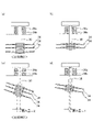
次に、図5、図6に基づいて、回転機構16として、図1のような構造(回転軸30の下端部が自由端である構造)を採用できた理由について説明する。
Next, based on FIGS. 5 and 6, the reason why the structure as shown in FIG. 1 (the structure in which the lower end portion of the
図5(a)には、比較例1に係る回転機構116が示されている。
比較例1(図5(a))においては、回転軸30が上端部近傍において1つのボールベアリング36により回転自在に保持されている。また、比較例1では、回転軸30は、下端部近傍においてボールベアリング136を介して回転自在に保持されている。なお、ボールベアリング136は、架台10に固定された支持ロッド138により保持されている。さらに、比較例1においては、インパクト部材34が3段設けられている。FIG. 5A shows the
In Comparative Example 1 (FIG. 5A), the rotating
この比較例1において、回転軸30を回転させたときの回転軸30の撓み量をシミュレーションしたところ、図5(c)に示すように撓み量はわずかであり、許容範囲であった。このように撓み量が許容範囲内に収まったのは、回転軸30が両端部近傍で保持されているためと考えられる。以下においては、説明の便宜上、比較例1における回転軸30の撓み量を「1」と表すものとする。
In Comparative Example 1, when the amount of bending of the
図5(b)には、比較例2に係る回転機構216が示されている。
比較例2の回転機構216は、回転軸30を短くするために、比較例1の回転軸30の下端部を自由端とした例である。この比較例2において、回転軸30を回転させたときの回転軸30の撓み量をシミュレーションしたところ、図5(d)に示すように、撓み量は「3」となり、許容範囲を超えるものとなった。FIG. 5B shows the
The
これらのシミュレーション結果を参考にして、本発明者は、図6(a)に示すような構成(比較例3)を検討した。比較例3は、比較例2のボールベアリング36を2つのボールベアリング36a、36bとし、ボールベアリング36a、36b間に所定間隔を設けたものである。この比較例3では、シミュレーションの結果、図6(c)に示すように回転軸30の回転時の撓み量は「2」となることが分かった。
With reference to these simulation results, the present inventor examined the configuration (Comparative Example 3) as shown in FIG. 6 (a). In Comparative Example 3, the
さらに、本発明者は、図6(b)に示すように、比較例3からインパクト部材34を1段省略して、2段とした。この構成を採用した場合、シミュレーションの結果、回転軸の長さがより短くなるため、図6(d)に示すように、回転軸30の回転時の撓み量は「1」となった。この撓み量は、比較例1と同様、許容範囲内である。
Further, as shown in FIG. 6B, the present inventor omits one step of the
このように、本発明者は、上述したような比較検討の結果、図6(b)のような構成を採用することで、回転軸30を自由端としても、撓み量を小さくすることができることを見出した。なお、本発明者は、インパクト部材34を3段から2段に減らした結果、破砕・混合性能が低下しないように、インパクト部材34の厚板42の形状等を改良し、3段の場合と同等の破砕・混合性能を維持した。
As described above, as a result of the comparative study as described above, the present inventor can reduce the amount of bending even if the
また、本発明者は、回転軸30の撓み量を低減するため、ボールベアリング36a、36b間の間隔を、回転軸30の径に応じて決定した。すなわち、回転軸30の径が小さいほど間隔を広くすることで、撓み量を低減するようにした。また、ボールベアリング36a、36bとしては、回転軸30の回転精度の向上や剛性の向上を図るため、アンギュラ玉軸受を採用することとした。さらに、回転軸30の長さは、インパクト部材34を遠心回転させたときの回転軸30の撓み量が回転軸30を支持するボールベアリング36a、36bにかかる応力の許容範囲内になるように決定した。一例を挙げると、回転軸30の撓み量は、回転軸30の長さの1/800~1/3000となる長さとした。
Further, in order to reduce the amount of bending of the
本実施形態では、上述のような回転機構16を採用することで、破砕・混合性能や、回転軸30の撓み量を小さく維持しつつ、回転軸30の長さを短くすることが可能となっている。これにより、回転式破砕装置100の高さ方向の寸法を小さくすることができる。また、回転軸30の下端部を保持するための構成(図5(a)の比較例1のような支持ロッド138やボールベアリング136)を設けなくてもよくなる。これにより、構造が簡素化し、破砕・混合後の原料土や添加材が回転式破砕装置100内に付着する箇所が少なくなるため、回転式破砕装置100内の清掃回数が減りメンテナンス性を向上することができる。また、部品点数が減るため、装置の製造コストを低減することができる。さらに、回転式破砕装置100の重量を低減することもできる。
In the present embodiment, by adopting the
なお、本実施形態の回転式破砕装置100は、自走式の処理システムに限らず、現場に設置するプラント型の処理システム、トラックの荷台に設置するオントラック型の処理システムなどにも適用することが可能である。プラント型の処理システムの場合、投入口部材20の位置まで原料土を搬送するベルトコンベアが設けられるが、回転式破砕装置100の高さが低いため、ベルトコンベアの長さを短くすることができる。これにより、処理システム全体の小型化、プラント専有面積を小さくすることができ、ひいては、処理システムの現場配置計画が容易になる。
The
以上、詳細に説明したように、回転軸30は、天板部10aを貫通した状態、かつ、天板部10aの近傍に設けられたボールベアリング36a、36bを介して回転自在な状態で保持されており、回転軸30の下端部は自由端となっている。これにより、回転軸30の長さを短くすることができるため、回転式破砕装置100を小型化することが可能である。また、回転軸30の下端部を回転自在に保持するボールベアリングなどを設けなくてもよいため、構造が簡素化し、メンテナンスがしやすくなる。
As described in detail above, the
また、本実施形態では、ボールベアリング36a、36bが天板部10aの上側に設けられているため、天板部10aの下側に設ける場合よりも、メンテナンス性を向上することができる。また、ボールベアリング36a、36bと原料土や添加材が接触することがないため、原料土や添加材がボールベアリング36a、36bに付着することがないのでボールベアリング36a、36bの長寿命化を図ることが可能である。なお、ボールベアリング36a、36bへの異物の付着を避けるために、ボールベアリング36a、36bの周囲にカバーを設けることが望ましい。
Further, in the present embodiment, since the
また、本実施形態では、回転軸30が2つのボールベアリング36a、36bにより回転自在に保持されているので、回転軸30を1つのボールベアリングで回転自在に保持する場合(図5(b)、図5(d)の比較例2)と比べ、回転軸30の撓み量を低減することができる。
Further, in the present embodiment, since the
また、本実施形態では、ボールベアリング36a、36b間の間隔を、回転軸30の径に応じて決定することとした。すなわち、回転軸30の径が小さいほど間隔を広くすることで、撓み量を低減するようにした。これにより、回転軸30の径に応じてボールベアリング36a、36b間の間隔を適切な寸法とすることができる。
Further, in the present embodiment, the distance between the
また、本実施形態では、ボールベアリング36a、36bとして、アンギュラ玉軸受を用いたため、回転軸30やインパクト部材34などのスラスト方向の荷重を受けることができるとともに、インパクト部材34の回転時のラジアル方向の荷重を受けることができる。このため、インパクト部材34の回転による回転軸の撓みを抑えることができる。
Further, in the present embodiment, since the angular contact ball bearings are used as the
なお、上記実施形態では、回転軸30の上端部近傍を保持するボールベアリングが2つである場合について説明したが、これに限らず、回転軸30の上端部近傍を保持するボールベアリングは3つ以上であってもよい。
In the above embodiment, the case where there are two ball bearings that hold the vicinity of the upper end portion of the
なお、上記実施形態では、回転軸30にインパクト部材34が2段設けられる場合について説明したが、これに限らず、回転軸30に設けられるインパクト部材34は、1段又は3段以上であってもよい。また、回転軸30を天板部10aの上側で保持するボールベアリングの数も1又は3以上であってもよい。さらに、ボールベアリング36a,36bの少なくとも一方が天板部10aの下側に配置されてもよい。
In the above embodiment, the case where the
上述した実施形態は本発明の好適な実施の例である。但し、これに限定されるものではなく、例えば、インパクト部材34が破砕するのは原料土に限られず、礫や砕石などでもよく、原料土に礫や砕石などが混ざったものでもよい。また、添加材の投入を省略してもよい。また、回転軸30の支持を片持ちではなく、両端支持としてもよい。このように、本発明の要旨を逸脱しない範囲内において種々変形実施可能である。
The embodiments described above are examples of preferred embodiments of the present invention. However, the present invention is not limited to this, and for example, the
(変形例1)
上記実施形態においては、原料土の投入範囲(図3(a)のRM)を設定する際に、ベルトコンベア122の搬送軸方向と、インパクト部材34と原料土が衝突するときのインパクト部材34の回転軸成分とがほぼ一致するように設定することとしたが、本変形例1では、原料土の投入範囲RMの位置を、上記実施形態とは別の観点に基づいて設定することとしている。(Modification 1)
In the above embodiment, when setting the input range of the raw material soil (RM in FIG. 3A), the direction of the transport axis of the
図7(a)には、上記実施形態の図4(a)で説明したモデルと同一のモデル(インパクト部材34をユニバーサルジョイント40aと厚板42とで表したモデル)を上方から見た状態が示されている。本変形例1においては、図7(a)に示すように、インパクト部材34が回転し、原料土の投入範囲RMをインパクト部材34が通過するときに、原料土の投入範囲RMの幅の中心Mが、インパクト部材34の重心Gと回転軸30の反対側の先端Tとの間を通過するように、原料土を投入するためのベルトコンベア122および投入口部材20の位置を設定している。
FIG. 7A shows a state in which the same model as the model described in FIG. 4A of the above embodiment (a model in which the
なお、原料土の投入範囲が図7(b)のような向き(ベルトコンベア122の搬送軸方向と、インパクト部材34と原料土が衝突するときのインパクト部材34の回転軸成分とが大きく異なる場合)であっても、図7(b)に示すように、原料土の投入範囲RM’の幅の中心M’が、インパクト部材34の重心Gと回転軸30の反対側の先端Tとの間を通過するように、原料土を投入するためのベルトコンベア122および投入口部材20の位置を設定すれば良い。
The direction in which the raw material soil is charged is as shown in FIG. 7B (when the transport axis direction of the
このようにすることで、原料土の大半をインパクト部材34の厚板42に当てることができるため、原料土がチェーン40に当たることによる、チェーン40のダメージを抑制することができる。
By doing so, most of the raw material soil can be applied to the
(変形例2)
本発明者は、図8に示すインパクト部材34について、インパクト部材34の全長Laに対する厚板42の長さLbの割合について、検討を行った。(Modification 2)
The present inventor examined the ratio of the length Lb of the
この検討においては、原料土とチェーン40の接触の可能性や、インパクト部材34の重量、コスト、メンテナンス性を考慮した検討を行った。その結果、インパクト部材34の全長Laに対する厚板42の長さの割合は、50~80%、より好ましくは60~80%、更に好ましくは70~80%とするのが良いことが分かった。
In this study, the possibility of contact between the raw material soil and the
インパクト部材34の全長に対する厚板42の長さを上記のような割合とすることで、インパクト部材34の長さに対するチェーン40の割合を従来(例えば、33~40%)よりも小さくすることができるので、原料土がチェーン40に接触する可能性を低くすることができる。これによりチェーン40のダメージを抑制し、チェーン40の交換頻度を低減することができる。なお、チェーン40と厚板42とが一体的に形成されている場合には、インパクト部材34の交換頻度を低減することができる。
By setting the length of the
また、上記割合とすることで、厚板42の全体に対する割合をより大きくした場合(例えば80%よりも大きくした場合)に比べ、重量を軽くすることができる。これにより、回転式破砕装置100を利用するときに必要なエネルギ(電力等)を小さくすることができるため、コスト低減を図ることができる。
Further, by setting the ratio as described above, the weight can be reduced as compared with the case where the ratio of the
また、上記割合とすることで、厚板42の全体に対する割合をより大きくした場合(例えば80%よりも大きくした場合)に比べ、チェーン40の割合が確保されているので、形状が変形しない厚板42の交換作業が容易になるため、メンテナンス性を向上することができる。
Further, by setting the above ratio, the ratio of the
10a 天板部
12 固定ドラム
14 回転ドラム
20 投入口部材
22 掻取棒
30 回転軸
34 インパクト部材(衝撃付加部材)
36a、36b ボールベアリング(軸受部材)
100 回転式破砕装置
122 ベルトコンベア
36a, 36b ball bearings (bearing members)
100
Claims (5)
前記処理対象の搬送軸方向と、前記処理対象と接触するときの前記衝撃付加部材の移動方向とをほぼ一致させて、前記衝撃付加部材の重心位置と前記衝撃付加部材の先端側との間に対して前記処理対象を前記鉛直方向に沿って投入する投入装置と、を備えた回転式破砕装置。 An impact addition member that is connected to a rotating shaft extending in the vertical direction and crushes the object to be processed by rotating the rotating shaft in the vertical direction.
The direction of the transport axis of the processing target and the moving direction of the impact applying member when it comes into contact with the processing target are substantially aligned with each other, and between the position of the center of gravity of the impact applying member and the tip end side of the impact applying member. On the other hand, a rotary crushing device including a charging device for charging the processing target along the vertical direction.
前記処理対象の搬送軸方向と、前記処理対象と接触するときの前記衝撃付加部材の移動方向とをほぼ一致させて、前記衝撃付加部材の重心位置と前記衝撃付加部材の先端側との間に対して前記処理対象を前記鉛直方向に沿って投入するステップと、を含んでいる回転式破砕方法。 A step of rotating an impact addition member capable of crushing the object to be processed in a horizontal plane by rotating the rotation axis extending in the vertical direction in the vertical direction.
The direction of the transport axis of the processing target and the moving direction of the impact applying member when it comes into contact with the processing target are substantially aligned with each other, and between the position of the center of gravity of the impact applying member and the tip end side of the impact applying member. On the other hand, a rotary crushing method including a step of charging the processing target along the vertical direction.
The charging step is between the position of the center of gravity of the impact applying member and the tip end side of the impact applying member, and is at a position determined based on the moment of inertia of the impact applying member and the mass of the impact applying member. The rotary crushing method according to claim 4 , wherein the processing target is charged.
Applications Claiming Priority (3)
| Application Number | Priority Date | Filing Date | Title |
|---|---|---|---|
| US202062971287P | 2020-02-07 | 2020-02-07 | |
| US62/971,287 | 2020-02-07 | ||
| PCT/JP2020/047400 WO2021157223A1 (en) | 2020-02-07 | 2020-12-18 | Rotary crushing device and rotary crushing method |
Publications (2)
| Publication Number | Publication Date |
|---|---|
| JPWO2021157223A1 JPWO2021157223A1 (en) | 2021-08-12 |
| JP7074934B2 true JP7074934B2 (en) | 2022-05-24 |
Family
ID=77199901
Family Applications (1)
| Application Number | Title | Priority Date | Filing Date |
|---|---|---|---|
| JP2021536827A Active JP7074934B2 (en) | 2020-02-07 | 2020-12-18 | Rotary crusher and rotary crushing method |
Country Status (4)
| Country | Link |
|---|---|
| US (1) | US20230069101A1 (en) |
| EP (1) | EP4101541A1 (en) |
| JP (1) | JP7074934B2 (en) |
| WO (1) | WO2021157223A1 (en) |
Citations (10)
| Publication number | Priority date | Publication date | Assignee | Title |
|---|---|---|---|---|
| JP2000262919A (en) | 1999-03-16 | 2000-09-26 | Soil Giken:Kk | Pulverizing machine of grain shell |
| JP2008173611A (en) | 2007-01-22 | 2008-07-31 | Jdc Corp | Soil cleaning method and crushing apparatus used therefor |
| JP2008229523A (en) | 2007-03-22 | 2008-10-02 | Jdc Corp | Treating vessel for rotary treating apparatus and the rotary treating apparatus for treating object |
| JP2009509735A (en) | 2005-09-28 | 2009-03-12 | ゲト・ハンブルク・ゲゼルシャフト・ミット・ベシュレンタク・ハフツング | Debris crusher |
| JP2012196640A (en) | 2011-03-22 | 2012-10-18 | Ohbayashi Corp | Device for crushing and mixing earth and sand |
| CN202893462U (en) | 2012-09-30 | 2013-04-24 | 广西新方向化学工业有限公司 | Crusher |
| WO2013167398A1 (en) | 2012-05-08 | 2013-11-14 | Pms Handelskontor Gmbh | Disintegrating device |
| US20140151475A1 (en) | 2012-05-18 | 2014-06-05 | Esco Corporation | Hammer for shredding machines |
| JP5873349B2 (en) | 2012-02-09 | 2016-03-01 | テルモ株式会社 | catheter |
| CN107262214A (en) | 2017-06-21 | 2017-10-20 | 广西力源宝科技有限公司 | A kind of Anti-caking chain breaker and Anti-caking method |
Family Cites Families (7)
| Publication number | Priority date | Publication date | Assignee | Title |
|---|---|---|---|---|
| JPS592842Y2 (en) * | 1981-02-24 | 1984-01-26 | 日本「ほ」道株式会社 | crushing mixer |
| JPS5873349U (en) * | 1981-11-04 | 1983-05-18 | 中村 靖 | Structure of the feed section of the crusher |
| JPS5998743A (en) * | 1983-08-16 | 1984-06-07 | 三晃技研株式会社 | Crusher |
| JP5055477B2 (en) * | 2006-08-01 | 2012-10-24 | 株式会社セフティランド | Waste fluorescent tube crusher |
| US9751087B2 (en) * | 2012-09-20 | 2017-09-05 | Gary L. Watts | Comminution mill with cable impact arms |
| WO2018224118A1 (en) * | 2017-06-04 | 2018-12-13 | TARTECH eco industries AG | Device for separating conglomerates that consist of materials of different densities |
| JP6466043B1 (en) * | 2017-07-18 | 2019-02-06 | 日本国土開発株式会社 | Production control system of improved soil using rotary crushing and mixing device |
-
2020
- 2020-12-18 US US17/793,358 patent/US20230069101A1/en active Pending
- 2020-12-18 EP EP20917494.5A patent/EP4101541A1/en active Pending
- 2020-12-18 JP JP2021536827A patent/JP7074934B2/en active Active
- 2020-12-18 WO PCT/JP2020/047400 patent/WO2021157223A1/en unknown
Patent Citations (10)
| Publication number | Priority date | Publication date | Assignee | Title |
|---|---|---|---|---|
| JP2000262919A (en) | 1999-03-16 | 2000-09-26 | Soil Giken:Kk | Pulverizing machine of grain shell |
| JP2009509735A (en) | 2005-09-28 | 2009-03-12 | ゲト・ハンブルク・ゲゼルシャフト・ミット・ベシュレンタク・ハフツング | Debris crusher |
| JP2008173611A (en) | 2007-01-22 | 2008-07-31 | Jdc Corp | Soil cleaning method and crushing apparatus used therefor |
| JP2008229523A (en) | 2007-03-22 | 2008-10-02 | Jdc Corp | Treating vessel for rotary treating apparatus and the rotary treating apparatus for treating object |
| JP2012196640A (en) | 2011-03-22 | 2012-10-18 | Ohbayashi Corp | Device for crushing and mixing earth and sand |
| JP5873349B2 (en) | 2012-02-09 | 2016-03-01 | テルモ株式会社 | catheter |
| WO2013167398A1 (en) | 2012-05-08 | 2013-11-14 | Pms Handelskontor Gmbh | Disintegrating device |
| US20140151475A1 (en) | 2012-05-18 | 2014-06-05 | Esco Corporation | Hammer for shredding machines |
| CN202893462U (en) | 2012-09-30 | 2013-04-24 | 广西新方向化学工业有限公司 | Crusher |
| CN107262214A (en) | 2017-06-21 | 2017-10-20 | 广西力源宝科技有限公司 | A kind of Anti-caking chain breaker and Anti-caking method |
Also Published As
| Publication number | Publication date |
|---|---|
| WO2021157223A1 (en) | 2021-08-12 |
| US20230069101A1 (en) | 2023-03-02 |
| JPWO2021157223A1 (en) | 2021-08-12 |
| EP4101541A1 (en) | 2022-12-14 |
Similar Documents
| Publication | Publication Date | Title |
|---|---|---|
| US20110309175A1 (en) | Milling apparatus | |
| CN107051639A (en) | A kind of mine small stones disintegrating machine | |
| WO2019016859A1 (en) | Improved soil manufacturing/management system using rotary type crushing/mixing device | |
| JP7074934B2 (en) | Rotary crusher and rotary crushing method | |
| JPWO2018134983A1 (en) | Sieve processing equipment | |
| JP2006289307A (en) | Fine granulation apparatus of earth and sand, and mud | |
| KR101670448B1 (en) | Aggregate and mineral crushing apparatus | |
| WO2021145010A1 (en) | Rotary crushing device | |
| WO2022209025A1 (en) | Construction apparatus | |
| JP2939928B2 (en) | Spraying fiber material supply device | |
| JP2013144269A (en) | Method for treating slag-mixed soil | |
| JP3681158B2 (en) | Method for producing recycled heated asphalt mixture with waste glass particles | |
| JP2012000536A (en) | Sticking earth and sand-removing device | |
| WO2023017665A1 (en) | Rotary crushing device | |
| JP2017029915A (en) | Crushing device | |
| JP2009039628A (en) | Pulverizer | |
| EA017555B1 (en) | Method for fine crushing of lump material and apparatus for realization thereof | |
| US20120267463A1 (en) | Vibratory mill | |
| KR20150069807A (en) | Crushing apparatus and method for recycling sands from concrete wastes | |
| CN206560979U (en) | A kind of improved filler screening plant | |
| CN211736399U (en) | Novel concrete spraying equipment | |
| JP2004016972A (en) | Method and apparatus for crushing lump raw material | |
| KR20160045519A (en) | Short shaft tromell | |
| KR20140041237A (en) | Processing apparatus of slag | |
| KR101750252B1 (en) | Multi-stage aggregate peeling off device |
Legal Events
| Date | Code | Title | Description |
|---|---|---|---|
| A521 | Request for written amendment filed |
Free format text: JAPANESE INTERMEDIATE CODE: A523 Effective date: 20210623 |
|
| A621 | Written request for application examination |
Free format text: JAPANESE INTERMEDIATE CODE: A621 Effective date: 20210623 |
|
| A871 | Explanation of circumstances concerning accelerated examination |
Free format text: JAPANESE INTERMEDIATE CODE: A871 Effective date: 20210623 |
|
| A131 | Notification of reasons for refusal |
Free format text: JAPANESE INTERMEDIATE CODE: A131 Effective date: 20220105 |
|
| A521 | Request for written amendment filed |
Free format text: JAPANESE INTERMEDIATE CODE: A523 Effective date: 20220303 |
|
| TRDD | Decision of grant or rejection written | ||
| A01 | Written decision to grant a patent or to grant a registration (utility model) |
Free format text: JAPANESE INTERMEDIATE CODE: A01 Effective date: 20220510 |
|
| A61 | First payment of annual fees (during grant procedure) |
Free format text: JAPANESE INTERMEDIATE CODE: A61 Effective date: 20220512 |
|
| R150 | Certificate of patent or registration of utility model |
Ref document number: 7074934 Country of ref document: JP Free format text: JAPANESE INTERMEDIATE CODE: R150 |
|
| S531 | Written request for registration of change of domicile |
Free format text: JAPANESE INTERMEDIATE CODE: R313531 |
|
| R350 | Written notification of registration of transfer |
Free format text: JAPANESE INTERMEDIATE CODE: R350 |