JP7071099B2 - Imaging device - Google Patents
Imaging device Download PDFInfo
- Publication number
- JP7071099B2 JP7071099B2 JP2017224597A JP2017224597A JP7071099B2 JP 7071099 B2 JP7071099 B2 JP 7071099B2 JP 2017224597 A JP2017224597 A JP 2017224597A JP 2017224597 A JP2017224597 A JP 2017224597A JP 7071099 B2 JP7071099 B2 JP 7071099B2
- Authority
- JP
- Japan
- Prior art keywords
- pan
- shake correction
- correction
- tilt
- image shake
- Prior art date
- Legal status (The legal status is an assumption and is not a legal conclusion. Google has not performed a legal analysis and makes no representation as to the accuracy of the status listed.)
- Active
Links
Images


Classifications
-
- H—ELECTRICITY
- H04—ELECTRIC COMMUNICATION TECHNIQUE
- H04N—PICTORIAL COMMUNICATION, e.g. TELEVISION
- H04N23/00—Cameras or camera modules comprising electronic image sensors; Control thereof
- H04N23/60—Control of cameras or camera modules
- H04N23/65—Control of camera operation in relation to power supply
- H04N23/651—Control of camera operation in relation to power supply for reducing power consumption by affecting camera operations, e.g. sleep mode, hibernation mode or power off of selective parts of the camera
-
- H—ELECTRICITY
- H04—ELECTRIC COMMUNICATION TECHNIQUE
- H04N—PICTORIAL COMMUNICATION, e.g. TELEVISION
- H04N23/00—Cameras or camera modules comprising electronic image sensors; Control thereof
- H04N23/60—Control of cameras or camera modules
- H04N23/68—Control of cameras or camera modules for stable pick-up of the scene, e.g. compensating for camera body vibrations
- H04N23/682—Vibration or motion blur correction
- H04N23/685—Vibration or motion blur correction performed by mechanical compensation
- H04N23/687—Vibration or motion blur correction performed by mechanical compensation by shifting the lens or sensor position
-
- H—ELECTRICITY
- H04—ELECTRIC COMMUNICATION TECHNIQUE
- H04N—PICTORIAL COMMUNICATION, e.g. TELEVISION
- H04N23/00—Cameras or camera modules comprising electronic image sensors; Control thereof
- H04N23/60—Control of cameras or camera modules
- H04N23/65—Control of camera operation in relation to power supply
-
- H—ELECTRICITY
- H04—ELECTRIC COMMUNICATION TECHNIQUE
- H04N—PICTORIAL COMMUNICATION, e.g. TELEVISION
- H04N23/00—Cameras or camera modules comprising electronic image sensors; Control thereof
- H04N23/60—Control of cameras or camera modules
- H04N23/68—Control of cameras or camera modules for stable pick-up of the scene, e.g. compensating for camera body vibrations
- H04N23/681—Motion detection
- H04N23/6811—Motion detection based on the image signal
-
- H—ELECTRICITY
- H04—ELECTRIC COMMUNICATION TECHNIQUE
- H04N—PICTORIAL COMMUNICATION, e.g. TELEVISION
- H04N23/00—Cameras or camera modules comprising electronic image sensors; Control thereof
- H04N23/60—Control of cameras or camera modules
- H04N23/68—Control of cameras or camera modules for stable pick-up of the scene, e.g. compensating for camera body vibrations
- H04N23/681—Motion detection
- H04N23/6812—Motion detection based on additional sensors, e.g. acceleration sensors
-
- H—ELECTRICITY
- H04—ELECTRIC COMMUNICATION TECHNIQUE
- H04N—PICTORIAL COMMUNICATION, e.g. TELEVISION
- H04N23/00—Cameras or camera modules comprising electronic image sensors; Control thereof
- H04N23/60—Control of cameras or camera modules
- H04N23/68—Control of cameras or camera modules for stable pick-up of the scene, e.g. compensating for camera body vibrations
- H04N23/682—Vibration or motion blur correction
- H04N23/683—Vibration or motion blur correction performed by a processor, e.g. controlling the readout of an image memory
-
- H—ELECTRICITY
- H04—ELECTRIC COMMUNICATION TECHNIQUE
- H04N—PICTORIAL COMMUNICATION, e.g. TELEVISION
- H04N23/00—Cameras or camera modules comprising electronic image sensors; Control thereof
- H04N23/60—Control of cameras or camera modules
- H04N23/68—Control of cameras or camera modules for stable pick-up of the scene, e.g. compensating for camera body vibrations
- H04N23/682—Vibration or motion blur correction
- H04N23/685—Vibration or motion blur correction performed by mechanical compensation
-
- H—ELECTRICITY
- H04—ELECTRIC COMMUNICATION TECHNIQUE
- H04N—PICTORIAL COMMUNICATION, e.g. TELEVISION
- H04N23/00—Cameras or camera modules comprising electronic image sensors; Control thereof
- H04N23/60—Control of cameras or camera modules
- H04N23/695—Control of camera direction for changing a field of view, e.g. pan, tilt or based on tracking of objects
Landscapes
- Engineering & Computer Science (AREA)
- Multimedia (AREA)
- Signal Processing (AREA)
- Studio Devices (AREA)
- Adjustment Of Camera Lenses (AREA)
- Accessories Of Cameras (AREA)
Description
本発明は、撮像装置に関する。 The present invention relates to an image pickup apparatus.
近年、監視カメラのような設置型の撮像装置が使用されている。設置型の撮像装置の場合、設置環境の振動により引き起こされる映像ぶれを補正する像振れ補正機構が搭載されている。像振れ補正としては、レンズを光軸に対して適切に移動させることで補正する方法や、映像またはセンサから連続する画像間のぶれ量を算出し、算出された量に応じてメモリ切り出し位置を変更することでぶれを補正する方法がある。しかし、レンズによる光学的な像振れ補正や電子的な像振れ補正では補正角が小さく、船舶や波の振幅が大きい海上での監視カメラ設置の場合、ぶれ補正効果が得られない。そこで、パンチルト機構を動かして像振れ補正を行うパンチルト像振れ補正が有効になる。 In recent years, stationary imaging devices such as surveillance cameras have been used. In the case of a stationary image pickup device, an image blur correction mechanism that corrects image blur caused by vibration of the installation environment is installed. Image shake correction is a method of correcting by moving the lens appropriately with respect to the optical axis, or calculating the amount of blur between continuous images from the image or sensor, and setting the memory cutout position according to the calculated amount. There is a way to correct the blur by changing it. However, optical image shake correction using a lens or electronic image shake correction has a small correction angle, and when a surveillance camera is installed on a ship or on the sea where the amplitude of waves is large, the blur correction effect cannot be obtained. Therefore, the pan-tilt image shake correction that moves the pan-tilt mechanism to correct the image shake becomes effective.
パンチルト機構を動かすためには4W程度の電力を消費する。設置型の撮像装置に好適なPoE(Power Over Ethernet)電源における外部機器の規格上の上限は48Vにおいて12.95Wであるため、パンチルト機構を動かすための電力は、PoE電源の電力許容量に対して高い割合を占める。特許文献1は、電動雲台に備えられた回転制御部にかかる負荷を検出し、検出された負荷に応じて電力供給量を可変にする技術を開示している。特許文献2は、雲台の駆動時と非駆動時とでモータをそれぞれ異なる通電状態に切り替えることで、消費電力を低減する技術を開示している。
It consumes about 4W of power to operate the pan-tilt mechanism. Since the standard upper limit of the external device in the PoE (Power Over Ethernet) power supply suitable for the stationary image pickup device is 12.95 W at 48 V, the power for operating the pan-tilt mechanism is the power capacity of the PoE power supply. Occupies a high percentage.
しかしながら、特許文献1では、駆動系を複数含む撮像装置が消費する総消費電力に関しては開示されていない。また、パンチルト機構の消費電力に関しても開示されていないため、総消費電力が増大してしまい他の機能を安定して動かせない恐れや、突発的に駆動させるために必要な電力が不足する恐れが生じてしまう。特許文献2でも、駆動系を複数含む撮像装置が消費する総消費電力に関しては開示されていない。また、駆動時と非駆動時でモータを停止してしまっているので、像振れ補正を行うか行わないかの選択しかすることができず、電力を低減した場合は像振れ補正の効果を得ることができない。
However,
本発明は、省電力と高精度な像振れ補正を両立するパンチルト機構を備えた撮像装置を提供することを目的とする。 An object of the present invention is to provide an image pickup apparatus provided with a pan-tilt mechanism that achieves both power saving and highly accurate image shake correction.
上記課題を解決するために、第一の態様に係る撮像装置は、撮像光学系をパン駆動およびチルト駆動する駆動手段と、前記駆動手段の駆動による像振れ補正の補正量を撮像装置の総電力が所定の値以上の場合に低下させる制御手段と、を備え、前記制御手段は、撮像装置の総電力が所定の値以上の場合であって、前記駆動手段にかかる電力が所定の値以上で且つ前記駆動手段にかかる電力のうち前記像振れ補正に使用する電力が所定の値以上の場合に、前記補正量の低下率を大きくする。
また、第二の態様に係る撮像装置は、撮像光学系をパン駆動およびチルト駆動する駆動手段と、撮像装置の振れを検出する検出手段と、前記駆動手段の駆動による像振れ補正の補正量を制御する制御手段と、を備え、前記制御手段は、前記振れの振幅が所定の振幅より小さい場合、または、シャッタ速度が所定のシャッタ速度以上である場合、前記補正量を低下させる。
In order to solve the above problems, in the image pickup apparatus according to the first aspect, the drive means for pan-driving and tilt-driving the image pickup optical system and the correction amount for image shake correction by the drive of the drive means are used as the total power of the image pickup device. The control means comprises a control means for reducing the power when the value is equal to or more than a predetermined value, and the control means is provided when the total power of the image pickup apparatus is equal to or more than a predetermined value and the power applied to the drive means is equal to or more than a predetermined value. Moreover, when the electric power used for the image shake correction is equal to or more than a predetermined value among the electric power applied to the driving means, the reduction rate of the correction amount is increased.
Further, the image pickup apparatus according to the second aspect has a drive means for pan-driving and tilt-driving the image pickup optical system, a detection means for detecting the shake of the image pickup device, and a correction amount for image shake correction by driving the drive means. The control means includes a control means for controlling, and the control means reduces the correction amount when the amplitude of the runout is smaller than the predetermined amplitude or when the shutter speed is equal to or higher than the predetermined shutter speed.
本発明によれば、省電力と高精度な像振れ補正を両立するパンチルト機構を備えた撮像装置を提供することができる。 According to the present invention, it is possible to provide an image pickup apparatus provided with a pan-tilt mechanism that achieves both power saving and highly accurate image shake correction.
図1は、撮像装置の構成例を示す図である。本実施形態の撮像装置は、例えば監視カメラなど、ネットワークを介して通信が可能なネットワークカメラである。撮像装置は、撮像部101、画像処理部102、システム制御部103、パン動作制御部104、パン動作駆動部105、チルト動作制御部106、チルト動作駆動部107、ローテーション動作制御部108およびローテーション動作駆動部109を備える。撮像装置はさらに、フォーカス制御部110、フォーカスレンズ駆動部111、ズーム制御部112、ズームレンズ駆動部113、IRIS制御部114、IRIS駆動部115、IRCF挿抜制御部116およびIRCF駆動部117を備える。また、撮像装置はさらに、ネットワークコネクタ118および外部電源コネクタ119を備える。
FIG. 1 is a diagram showing a configuration example of an image pickup device. The image pickup apparatus of this embodiment is a network camera capable of communicating via a network, such as a surveillance camera. The image pickup apparatus includes an
撮像部101は、レンズ及び撮像素子を含み、被写体を撮像して、撮像素子が有する光電変換部により電気信号への変換を行う。撮像部101において撮像・光電変換された画像信号は画像処理部102において所定の画像処理が行われ、システム制御部103に伝達される。なお、画像信号は静止画でも動画でもよい。システム制御部103は画像処理部102から伝達された画像信号をネットワーク信号に変換し、ネットワークコネクタ118を介してネットワークへ配信する。また、システム制御部103は、ネットワークを介してクライアント装置より送信された制御指令を受信する。システム制御部103は、受信した制御指令に応じてフォーカス動作、ズーム動作、IRIS制御、IRCF挿抜動作、パン動作、チルト動作、ローテーション動作の各動作を制御し、各動作制御部に動作指令を伝達する。各動作制御部は、伝達された動作指令に基づいてそれぞれ駆動部の制御を行う。
The
パン動作駆動部105は、パン駆動(パンニング動作)を行うメカ駆動系及び駆動源のモータを有し、その動作はパン動作制御部104により制御される。チルト動作駆動部107は、チルト駆動(チルティング動作)を行うメカ駆動系及び駆動源のモータを有し、その動作はチルト動作制御部106により制御される。ローテーション動作駆動部109は、ローテーション動作を行うメカ駆動系及び駆動源のモータを有し、その動作はローテーション動作制御部108により制御される。
The pan
フォーカスレンズ駆動部111は、レンズのフォーカス制御を行う駆動系及び駆動源のモータを有し、その動作はフォーカス制御部110により制御される。ズームレンズ駆動部113は、レンズのズーム制御を行う駆動系及びその駆動源のモータを有し、その動作はズーム制御部112により制御される。IRIS駆動部115は、IRIS(絞り)の開口調節を行う駆動系及び駆動源のモータを有し、その動作はIRIS制御部114により制御される。IRCF駆動部117は、IRCF(赤外線光カットフィルタ)の挿抜制御を行う駆動系及び駆動源のモータを有し、その動作はIRCF挿抜制御部116により制御される。
The focus
撮像装置は、ネットワークコネクタ118によりLAN等のネットワークに接続され、ネットワークを介して複数のクライアント装置(情報処理装置)と通信可能である。クライアント装置は、ネットワークを介して、撮像装置が撮像した撮影映像の表示および録画を行うことができる。また、クライアント装置は、撮像装置に制御指令を送信することにより、撮像装置の設定、フォーカス動作、ズーム動作、パン動作、チルト動作およびIRCF挿抜動作等の制御を行う。
The image pickup device is connected to a network such as a LAN by a
撮像装置は、ネットワークコネクタ118に接続されたLANケーブルを介してPoE(Power Over Ethernet)電源により電力供給を受けることができる。また、撮像装置は、外部電源コネクタ119を介して、ACアダプタ、汎用電源等の外部電源からも電力供給を受けることができる。PoE電源または外部電源により供給された電力は、電源制御部120において各種電圧に制御され、撮像装置の各部へ電力を供給する。
The image pickup apparatus can be powered by a PoE (Power Over Ethernet) power supply via a LAN cable connected to the
図2は、撮像装置が備える像振れ補正に関する機構の構成を示す図である。撮像装置は、振れを検出する機構と像振れを補正する機構を備えており、像振れの補正としてパンチルト像振れ補正、光学的な像振れ補正および電子的な像振れ補正を行うことが可能である。 FIG. 2 is a diagram showing a configuration of a mechanism for image shake correction included in the image pickup apparatus. The image pickup device is equipped with a mechanism for detecting shake and a mechanism for correcting image shake, and it is possible to perform pan-tilt image shake correction, optical image shake correction, and electronic image shake correction as image shake correction. be.
角速度センサ201は、撮像装置に発生した振れを角速度信号として検出する。A/D変換部202は、検出された角速度信号をデジタル信号に変換する。フィルタ処理部203は、A/D変換部202から出力されたデジタル信号をHPFやLPFを用いて所定の周波数帯域でフィルタリングする。積分処理部204は、フィルタリングされたデジタル信号に対して積分を行い、振れ量を算出する。焦点距離演算部205は、振れ量を焦点距離に応じた補正量に変換する。
The
パルス変調部206は、焦点距離演算部205から算出された補正量をPWM(Pulse Width Modulation)波形に変換して、レンズモータ駆動部207へ出力する。レンズモータ駆動部207は、パルス変調部206から出力されたPWM波形に基づいてレンズモータ208を駆動する。レンズモータ208の駆動に応じて撮像光学系219のシフトレンズ209が移動し、光束が光軸に対して適切になることで、光学的に振れが補正される。
The
また、パルス変調部206で変換されたPWM波形は、パンチルトモータ駆動部210へも出力される。パンチルトモータ駆動部210は、パルス変調部206から出力されたPWM波形に基づいてパンチルトモータ211を駆動する。パンチルトモータ211の駆動に応じてレンズとセンサを含む撮像光学系219がパンチルト方向に移動し、振れが補正される。
Further, the PWM waveform converted by the
撮像素子213上には、シフトレンズ209やその他のレンズ群を通過した光が集光される。その他のレンズ群には、被写体に対するピント合わせを行うフォーカスレンズや、画角を調整するズームレンズ等が含まれる。複数レンズ群を通してカメラ内に入ってきた光は、赤外線カットフィルタ等の光学フィルタ212を通過し、撮像素子213に入射する。
Light that has passed through the
撮像素子213で結像された映像は、撮像素子213が有する光電変換部でアナログの画像信号に変換され、画像信号の輝度の調整が行われる。A/D変換部214は、アナログの画像信号をデジタルの画像信号に変換する。画像信号処理部215は、A/D変換部214から出力された画像信号に所定の処理を施し、画素毎の輝度信号と色信号を出力する。また、画像信号処理部215は、出力用の画像を生成するとともに、絞りやピント合わせの制御で使用される各パラメータを生成する。
The image imaged by the
動きベクトル検出部216は、複数の画像信号の差分を取ることで動きベクトル量を検出する。フィルタ処理部217は、動きベクトル量に対し所定の周波数帯域でフィルタリングを行う。積分処理部218は、フィルタ処理された動きベクトル量を積分して振れ補正量を算出する。振れ補正量に基づいて切り出す画像の位置を適切に変更することで、電子的な振れ補正がおこなわれた画像が出力される。
The motion
(第1実施形態)
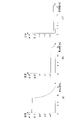
本実施形態で用いるパンチルト像振れ補正、光学的な像振れ補正および電子的な像振れ補正には、各々得意とする補正角や周波数、シーンがある。図3は、各像振れ補正方式の補正可能振幅の一例を示す図である。図3において、横軸は周波数を表し、縦軸は振幅を表している。
(First Embodiment)
The pan-tilt image shake correction, the optical image shake correction, and the electronic image shake correction used in the present embodiment have correction angles, frequencies, and scenes that are good at each. FIG. 3 is a diagram showing an example of the correctable amplitude of each image shake correction method. In FIG. 3, the horizontal axis represents frequency and the vertical axis represents amplitude.
図3(A)は、パンチルト像振れ補正により補正可能な振幅を示す図である。図3(B)は、光学的な像振れ補正により補正可能な振幅を示す図である。図3(C)は、電子的な像振れ補正により補正可能な振幅を示す図である。パンチルト像振れ補正では、光学的な像振れ補正で補正可能な振幅よりも数倍の振幅の揺れに対する補正が可能である。また、パンチルト像振れ補正では、シャッタ速度が遅い場合でも対応可能である。しかし、パンチルト像振れ補正では、高周波になるにしたがってパンチルト駆動の応答性が低下するので、振れ補正が追従できなくなり抑振性能が低下する。 FIG. 3A is a diagram showing an amplitude that can be corrected by pan-tilt image shake correction. FIG. 3B is a diagram showing an amplitude that can be corrected by optical image shake correction. FIG. 3C is a diagram showing an amplitude that can be corrected by electronic image shake correction. In the pan-tilt image shake correction, it is possible to correct a shake having an amplitude several times larger than the amplitude that can be corrected by the optical image shake correction. Further, the pan-tilt image shake correction can be applied even when the shutter speed is slow. However, in the pan-tilt image shake correction, the responsiveness of the pan-tilt drive decreases as the frequency increases, so that the shake correction cannot follow and the vibration suppression performance deteriorates.
光学的な像振れ補正では、パンチルト像振れ補正よりも高周波の揺れに対して振れ補正可能である。また、光学的な像振れ補正では、シャッタ速度の影響を受けないため、シャッタ速度が遅い場合でも対応可能である。しかし、光学的な像振れ補正では、大振幅の揺れを補正しきれない。 Optical image shake correction can correct shake for high-frequency shake rather than pan-tilt image shake correction. Further, since the optical image shake correction is not affected by the shutter speed, it can be used even when the shutter speed is slow. However, optical image shake correction cannot completely correct large-amplitude shake.
電子的な像振れ補正では、メカ機構を駆動させずに切り出し位置を変更しているので周波数の影響を受けず、光学的な像振れ補正よりもさらに高い周波数まで対応可能である。しかし、電子的な像振れ補正では、シャッタ速度が遅い場合像流れが発生してしまう。また、電子的な像振れ補正では、用いるセンササイズによっては補正可能な振幅が光学的な像振れ補正より小さくなる。このように像振れ補正方式はそれぞれ、揺れの振幅や周波数、シャッタ速度に応じた特徴を有している。そのため、本実施形態では、振幅、周波数およびシャッタ速度に応じて、使用する像振れ補正方式を切り替えている。また、振幅、周波数およびシャッタ速度に応じて、パンチルト防振の割合を変更している。なお、各像振れ補正方式は、単独で使用することもあれば、併用することもある。 In the electronic image shake correction, since the cutting position is changed without driving the mechanical mechanism, it is not affected by the frequency, and it is possible to cope with a higher frequency than the optical image shake correction. However, in electronic image shake correction, image flow occurs when the shutter speed is slow. Further, in the electronic image shake correction, the amplitude that can be corrected is smaller than the optical image shake correction depending on the sensor size used. As described above, each of the image shake correction methods has characteristics according to the amplitude, frequency, and shutter speed of the shake. Therefore, in the present embodiment, the image shake correction method to be used is switched according to the amplitude, frequency, and shutter speed. In addition, the ratio of pan-tilt vibration isolation is changed according to the amplitude, frequency, and shutter speed. It should be noted that each image shake correction method may be used alone or in combination.
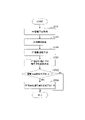
図4は、パンチルト像振れ補正の補正割合の変更処理を示すフローチャートである。図4において「PT」はパンチルトを表している。パンチルト像振れ補正は消費電力が大きいため、光学的な像振れ補正または電子的な像振れ補正で振れを高精度に補正することが可能である場合には、パンチルト像振れ補正の補正割合を下げてパンチルト像振れ補正の使用を抑制するのが望ましい。 FIG. 4 is a flowchart showing a process of changing the correction ratio of the pan-tilt image shake correction. In FIG. 4, "PT" represents pan-tilt. Since the pan-tilt image shake correction consumes a large amount of power, if it is possible to correct the shake with high accuracy by optical image shake correction or electronic image shake correction, lower the correction ratio of the pan-tilt image shake correction. It is desirable to suppress the use of pan-tilt image shake correction.
S401で、システム制御部103は、角速度センサ201で検出された振れに基づいて、撮像装置の振幅を取得する。S402で、システム制御部103は、撮像時のシャッタ速度を取得する。S403で、システム制御部103は、角速度センサ201で検出された振れに基づいて、振れの周波数を取得する。
In S401, the
S404で、システム制御部103は、S401で取得した振幅が所定の振幅以上であるか否か判定する。振幅が所定の振幅以上である場合は、S405に進む。一方、振幅が所定の振幅より小さい場合は、光学的な像振れ補正または電子的な像振れ補正で振れを高精度に補正することが可能であるので、S408に進む。
In S404, the
S405で、システム制御部103は、S402で取得したシャッタ速度が所定のシャッタ速度より低速であるか否か判定する。シャッタ速度が所定のシャッタ速度より低速である場合は、電子的な像振れ補正では画像に像振れが生じてしまうため、S406に進む。一方、シャッタ速度が所定のシャッタ速度以上である場合は、電子的な像振れ補正でも振れを高精度に補正することが可能であるので、S408に進む。
In S405, the
S406で、システム制御部103は、パンチルト像振れ補正の補正割合(補正量)を上げる。すなわち、振幅が大きく、かつ、シャッタ速度が低速である場合には、光学的な像振れ補正および電子的な像振れ補正だけでは十分な像振れ補正を行うことができないため、パンチルト像振れ補正の補正割合を上げる必要がある。
In S406, the
S406においてパンチルト像振れ補正の補正割合を上げる際に、ズーム倍率を考慮するようにしてもよい。図5は、ズーム倍率によるパンチルト像振れ補正の補正割合の変更処理を示すフローチャートである。S406においてパンチルト像振れ補正の補正割合を上げる際に、図5のフローチャートの処理を行うようにしてもよい。S501において、システム制御部103は、ズーム倍率を取得する。S502において、システム制御部103は、取得したズーム倍率が所定のズーム倍率以下であるか否か判定する。これは、ズーム倍率によって画像上での振幅が変わるためである。ズーム倍率が所定のズーム倍率以下である場合は、S503に進む。一方、ズーム倍率が所定のズーム倍率より大きい場合は、本処理を終了する。S503において、システム制御部103は、S406においてパンチルト防振の補正割合を上げる際の増加率を低下させる。
When increasing the correction ratio of the pan-tilt image shake correction in S406, the zoom magnification may be taken into consideration. FIG. 5 is a flowchart showing a process of changing the correction ratio of the pan-tilt image shake correction according to the zoom magnification. When increasing the correction ratio of the pan-tilt image shake correction in S406, the flow chart of FIG. 5 may be processed. In S501, the
S407で、システム制御部103は、S403で取得した周波数が所定の周波数以上であるか否か判定する。周波数が所定の周波数以上である場合は、パンチルト像振れ補正では高周波での応答性が低下するので、S408に進む。一方、周波数が所定の周波数より小さい場合は、パンチルト像振れ補正の補正割合をS406で上げた補正割合のままとして、本処理を終了する。
In S407, the
S408で、システム制御部103は、パンチルト像振れ補正の補正割合(補正量)を下げる。すなわち、振幅が小さい場合もしくはシャッタ速度が速い場合は、光学的な像振れ補正および電子的な像振れ補正により高精度な像振れ補正を行うことができるため、パンチルト像振れ補正の補正割合を下げることができる。また、図3(A)に示したように、高周波ではパンチルト像振れ補正の効果が低下するため、周波数が高い場合も、パンチルト像振れ補正の補正割合を下げることができる。また、振幅が光学的な像振れ補正の補正可能振幅以上で、かつ、周波数が所定以上の大振幅高周波の場合、光学的な像振れ補正で所定の振幅まで補正を行い、パンチルト像振れ補正での補正振幅を小さくしておくことで高周波での応答性低下を防ぐことができる。
In S408, the
撮像装置は、図2で示した周波数を検出可能な角速度センサ201を複数備えるようにしてもよい。図6は、低周波と高周波を含む波形例を示す図である。図6に示される大振幅の周波数を検出する角速度センサと小振幅の周波数を検出する角速度センサを備え、大振幅が低周波であればパンチルト像振れ補正で補正し、小振幅が高周波であれば光学的または電子的な像振れ補正で補正するようにしてもよい。
The image pickup apparatus may include a plurality of
以上説明したように、本実施形態によれば、パンチルト像振れ補正、光学的な像振れ補正、電子的な像振れ補正それぞれの特徴を生かすようにパンチルト像振れ補正の割合を変更して他の防振方式と併用することで、高い像振れ補正の効果を得ることができる。また、パンチルト像振れ補正の使用を抑制することにより、消費電力を低減することができる。 As described above, according to the present embodiment, the ratio of the pan-tilt image shake correction is changed so as to make the best use of the characteristics of each of the pan-tilt image shake correction, the optical image shake correction, and the electronic image shake correction. When used in combination with the anti-vibration method, a high image shake correction effect can be obtained. Further, the power consumption can be reduced by suppressing the use of the pan-tilt image runout correction.
(第2実施形態)
第1実施形態では、振動の振幅と周波数、シャッタ速度に応じてパンチルト像振れ補正の補正割合を変更した。本実施形態では、パンチルト駆動回数に応じたパンチルト像振れ補正の補正割合の変更を行う。パンチルト像振れ補正機構の耐久は光学的な像振れ補正機構と比較して短い傾向にある。そのため、駆動回数を考慮した補正割合の変更によりパンチルト像振れ補正機構の使用を抑制して使用可能期間を延ばすことで、高精度な像振れ補正を行える期間を延ばすことができる。
(Second Embodiment)
In the first embodiment, the correction ratio of the pan-tilt image shake correction is changed according to the amplitude and frequency of the vibration and the shutter speed. In the present embodiment, the correction ratio of the pan-tilt image shake correction is changed according to the number of pan-tilt drives. The durability of the pan-tilt image shake correction mechanism tends to be shorter than that of the optical image shake correction mechanism. Therefore, by suppressing the use of the pan-tilt image shake correction mechanism by changing the correction ratio in consideration of the number of drives and extending the usable period, it is possible to extend the period during which high-precision image shake correction can be performed.
本実施形態の基本フローは、第1実施形態と同様である。本実施形態では、図4の処理に加え、図7の処理を行う。図7は、パンチルト駆動回数に応じたパンチルト像振れ補正の補正割合の変更処理を示すフローチャートである。
S701で、システム制御部103は、パンチルト駆動を行った累積駆動回数を取得する。なおこの時、パン方向チルト方向別の駆動回数のみでなく駆動量や駆動時の速度を取得しておいてもよい。S702で、システム制御部103は、プリセット巡回情報を取得する。プリセット巡回は、予め登録した撮影ポジションを指定した順番、時間で順次移動して撮影する監視カメラの機能である。S703で、システム制御部103は、S702で取得したプリセット巡回情報に基づき、パンチルト駆動の予測駆動回数を算出する。パンチルト駆動の予測駆動回数は、現時点以降の所定期間内に、プリセット巡回によってパンチルト駆動をおこなう回数である。
The basic flow of this embodiment is the same as that of the first embodiment. In the present embodiment, in addition to the process of FIG. 4, the process of FIG. 7 is performed. FIG. 7 is a flowchart showing a process of changing the correction ratio of the pan-tilt image shake correction according to the number of pan-tilt drives.
In S701, the
S704で、システム制御部103は、パンチルト像振れ補正での駆動可能回数を決定する。具体的には、予め保持している現時点以降の所定期間内でのパンチルト駆動可能回数から、S701で取得した累積駆動回数とS703で算出した予測駆動回数を減算した回数を、パンチルト防振で駆動可能な回数として算出する。なお、所定期間内でのパンチルト駆動可能回数は、耐久回数を使用年数で除算した回数や年数に比例、反比例させた回数を保持しておいてもよい。
In S704, the
S705で、システム制御部103は、S704で算出した駆動可能回数が所定の駆動回数以下であるか否か判定する。駆動可能回数が所定の駆動回数以下である場合には、S706に進む。一方、駆動可能回数が所定の駆動回数より大きい場合は、駆動回数に応じた補正割合の変更を行わず、本処理を終了する。S706で、システム制御部103は、パンチルト像振れ補正の補正割合(補正量)を低下させる。
In S705, the
本フローチャートでは、駆動可能回数を算出して所定の回数との比較を行ったが、S701で取得した駆動回数と所定の回数とを比較して、駆動回数が所定の回数以上であった場合、補正割合を低下させるようにしてもよい。また、パンチルト駆動の駆動回数と光学的な像振れ補正の駆動回数を比較して、パンチルトの駆動回数がレンズ防振の駆動回数より所定以上であれば、パンチルト防振の補正割合を低下させるようにしてもよい。このように、パンチルト駆動の駆動回数に応じて、パンチルト像振れ補正の補正割合を低下させることで、パンチルト像振れ補正機構に耐久をもたせることができる。 In this flowchart, the number of times that can be driven is calculated and compared with the predetermined number of times. However, when the number of times of driving acquired in S701 is compared with the predetermined number of times and the number of times of driving is equal to or more than the predetermined number of times, The correction ratio may be lowered. Further, comparing the number of times of driving of pan-tilt drive and the number of times of driving of optical image shake correction, if the number of times of driving of pan-tilt is more than a predetermined number of times of driving of lens vibration isolation, the correction ratio of pan-tilt vibration isolation is reduced. You may do it. In this way, by reducing the correction ratio of the pan-tilt image shake correction according to the number of times the pan-tilt drive is driven, the pan-tilt image shake correction mechanism can be made durable.
第1実施形態および第2実施形態では、パンチルト像振れ補正と光学的な像振れ補正、電子的な像振れ補正を併用可能としている。パンチルト像振れ補正を行っていない場合は、振れ検出手段である角速度センサ201が検出した振れをそのまま光学的または電子的な像振れ補正に使用することができる。一方、パンチルト像振れ補正を行う場合は、振れ検出手段の位置によっては、振れ検出の際にパンチルト像振れ補正に伴って発生する振動も併せて検出されてしまう。そこで、振れ検出にパンチルト像振れ補正機構の駆動の影響が生じている場合には、検出した振れからパンチルト像振れ補正機構の振動を減算する必要がある。
In the first embodiment and the second embodiment, pan-tilt image shake correction, optical image shake correction, and electronic image shake correction can be used at the same time. When the pan-tilt image shake correction is not performed, the shake detected by the
図8は、パンチルト像振れ補正機構の振動を減算する処理を示すフローチャートである。S801で、システム制御部103は、パンチルト像振れ補正が行われているか否か、すなわち、パンチルト像振れ補正機構が駆動して振動が発生しているか否か判定する。パンチルト像振れ補正が行われている場合には、S802に進む。一方、パンチルト像振れ補正が行われていない場合には、本処理を終了する。
FIG. 8 is a flowchart showing a process of subtracting the vibration of the pan-tilt image shake correction mechanism. In S801, the
S802で、システム制御部103は、振れを検出する検出器の位置を取得する。本実施形態では、角速度センサ201の位置を取得する。S803で、システム制御部103は、S802で取得した検出器の位置とパンチルト像振れ補正機構の位置が所定の距離以下であるか否か判定する。本実施形態においてパンチルト像振れ補正機構は、図1においてはパン動作駆動部105およびチルト動作駆動部107、図2においてはパンチルトモータ駆動部210、パンチルトモータ211および撮像光学系219である。である。検出器とパンチルト像振れ補正機構の距離が所定の距離以下である場合には、S804に進む。一方、所定の距離より遠い場合には、本処理を終了する。S804で、システム制御部103は、検出器から取得した振れ成分から、パンチルト像振れ補正機構の駆動による振れ成分を減算する。光学的または電子的な像振れ補正は、減算後の値に基づいて行われる。なお、振れ成分からパンチルト像振れ補正機構の駆動による振れ成分を減算する場合に、距離に応じて減算する割合を変動するようにしてもよい。
In S802, the
以上説明したように、本実施形態によると、駆動回数を考慮した補正割合の変更によりパンチルト像振れ補正機構の使用を抑制して使用可能期間を延ばすことで、高精度な像振れ補正を行える期間を延ばすことができる。また、駆動回数を抑制することで、消費電力を抑制することができる。 As described above, according to the present embodiment, a period during which highly accurate image shake correction can be performed by suppressing the use of the pan-tilt image shake correction mechanism by changing the correction ratio in consideration of the number of drives and extending the usable period. Can be extended. Further, by suppressing the number of drives, the power consumption can be suppressed.
(第3実施形態)
第1実施形態では、振動の振幅と周波数、シャッタ速度に応じて、第2実施形態ではパンチルト駆動回数に応じてパンチルト像振れ補正の補正割合を変更した。本実施形態では、供給電力源に応じたパンチルト像振れ補正の補正割合の変更を行う。
(Third Embodiment)
In the first embodiment, the correction ratio of the pan-tilt image shake correction is changed according to the amplitude and frequency of the vibration and the shutter speed, and in the second embodiment, according to the number of pan-tilt drives. In the present embodiment, the correction ratio of the pan-tilt image shake correction is changed according to the power supply source.
図9は、供給電力源に応じたパンチルト像振れ補正の補正割合の変更処理を示すフローチャートである。S901で、システム制御部103は、パンチルト像振れ補正機構の駆動にかかる電力を取得する。パンチルト像振れ補正機構は、図1においてはパン動作駆動部105およびチルト動作駆動部107である。なお、パンチルト像振れ補正機構に、パン動作制御部104およびチルト動作制御部106を含めてもよい。
FIG. 9 is a flowchart showing a process of changing the correction ratio of the pan-tilt image shake correction according to the power supply source. In S901, the
S902で、システム制御部103は、IRIS(絞り)の駆動(開口調整)にかかる電力を取得する。ここでは、IRIS駆動部115の電力を取得する。また、IRIS制御部114の電力を含めてもよい。S903で、システム制御部103は、レンズの駆動にかかる電力を取得する。レンズの駆動には、フォーカスやズームの駆動の他、光学的な像振れ補正機構の駆動も含まれる。
In S902, the
S905で、システム制御部103は、赤外線カットフィルタ(IRCF)などの光学フィルタの駆動(挿抜)にかかる電力を取得する。ここでは、IRCF駆動部117の電力を取得する。また、IRCF挿抜制御部116の電力を含めてもよい。S906で、システム制御部103は、撮像、配信に関する電力を取得する。撮像、配信に関する電力とは、撮像・画像処理やネットワーク信号処理・映像配信における消費電力のことである。
In S905, the
パンチルト像振れ補正機構の駆動に4W、IRISの開口調整に0.5W、フォーカスやズーム、光学的な像振れ補正に用いられるレンズの駆動に2.5W、赤外線カットフィルタの挿抜に2Wであったとする。さらに、撮像、配信に関する消費電力が5Wであったとする。 It was 4W for driving the pan-tilt image shake correction mechanism, 0.5W for adjusting the aperture of IRIS, 2.5W for driving the lens used for focus, zoom, and optical image shake correction, and 2W for inserting and removing the infrared cut filter. do. Further, it is assumed that the power consumption for imaging and distribution is 5 W.
S906で、システム制御部103は、S901~S905で取得した電力に基づいて、総電力を算出する。パンチルト防振機構が継続的に駆動することを想定すると、総電力を算出した場合、パンチルト像振れ補正機構の駆動電力4Wと撮像・画像処理、ネットワーク信号処理・映像出力で消費される5Wの加算となるので9W程度となる。
In S906, the
PoEにおける外部機器の規格上の上限は48Vにおいて12.95Wであるが、実用上使用可能な電力はPoE規格の上限12.95Wに対して、機器内の電源生成のための電気的損失や種々の環境変動等の余裕を考慮し、10W程度に抑える必要がある。そこで、S907で、システム制御部103は、S906で算出された総電力量が所定の値以上であるか否かの判定を行う。総電力量が所定の値以上である場合には、S908に進む。一方、総電力量が所定の値より低い場合は、パンチルト像振れ補正を行っていても電力に余裕があるということなので、パンチルト像振れ補正の補正割合を低下させず、本処理を終了する。
The upper limit of the external device in PoE is 12.95W at 48V, but the practically usable power is the upper limit of 12.95W of the PoE standard, and the electrical loss due to the power generation in the device and various things. It is necessary to keep it to about 10W in consideration of the margin of environmental fluctuations. Therefore, in S907, the
S908で、システム制御部103は、パンチルト像振れ補正の補正割合(補正量)を低下させる。パンチルト像振れ補正の補正割合を低下させるとは、振れ角度が5°であった場合にパンチルト像振れ補正機構によって5°の振れ補正をおこなっているところを、3°までの補正に抑制ことである。補正角を抑えることにより、パン機構やチルト機構の駆動量が低減されるので、消費電力を低減することができる。消費電力を低減したことにより使用可能な電力量10Wに対して余裕が増加するので、現在駆動させていないファーカスレンズまたはIRISが突発的に駆動されても安定した駆動をおこなうことが可能である。
In S908, the
パンチルト像振れ補正機構による補正角を抑えたことにより、2°分の振れが補正されずに残ってしまうので、パンチルト像振れ補正以外の光学的または電子的な像振れ補正を併用して補正することも可能である。光学的な像振れ補正におけるレンズを駆動する際の消費電力や、電子的な像振れ補正で画像を切りだす際の消費電力は、パン機構やチルト機構を駆動する際の消費電力に比べると大幅に低い。そのため、光学的または電子的な像振れ補正を併用しても消費電力が低減されることに変わりはなく、像振れ補正の効果が低下するのを抑制することができる。 By suppressing the correction angle by the pan-tilt image shake correction mechanism, the shake of 2 ° remains uncorrected, so it is corrected by using optical or electronic image shake correction other than the pan-tilt image shake correction. It is also possible. The power consumption when driving the lens in optical image shake correction and the power consumption when cutting out an image by electronic image shake correction are significantly higher than the power consumption when driving the pan mechanism and tilt mechanism. Low to low. Therefore, even if the optical or electronic image shake correction is used in combination, the power consumption is still reduced, and it is possible to suppress the decrease in the effect of the image shake correction.
図9は、供給電力源をPoEや一種類の供給電力源を想定しておこなっているフローであるが、供給電力源としてはPoE+やその他の電力量が供給されることも考えられる。
そこで、図10では供給電力源を考慮したパンチルト像振れ補正の補正割合の変動方法について示す。図10は、供給電力源を考慮したパンチルト像振れ補正の補正割合の変更処理を示すフローチャートである。
FIG. 9 shows a flow in which the power supply source is assumed to be PoE or one type of power supply source, but PoE + or other electric power may be supplied as the power supply source.
Therefore, FIG. 10 shows a method of changing the correction ratio of the pan-tilt image runout correction in consideration of the power supply source. FIG. 10 is a flowchart showing a process of changing the correction ratio of the pan-tilt image runout correction in consideration of the power supply source.
S1001で、システム制御部103は、撮像装置につながっている供給電力源の種別を認識し、供給される電力量の取得をおこなう。S1002で、システム制御部103は、撮像装置で消費される総電力量を取得する。ここで、S1002での総電力量の取得方法は、図9のS901~S905と同様とする。
In S1001, the
S1003で、システム制御部103は、S1002で取得した総電力量が所定の値以上であるか否かを判定する。総電力量が所定の値以上である場合は、S1004に進む。一方、総電力量が所定の値より低い場合は、パンチルト像振れ補正の補正割合を変更せず本処理を終了する。
In S1003, the
S1004で、システム制御部103は、供給電力源の電力量が所定の値以上であるか否かを判定する。供給電力源の電力量が所定の値以上である場合には、S1005に進む。一方、供給電力源の電力量が所定の値より低い場合は、S1006に進み、予め設定しておいたパンチルト像振れ補正の補正割合の低下率に基づいて、パンチルト像振れ補正の補正割合(補正量)を低下させる。
In S1004, the
S1005で、システム制御部103は、パンチルト像振れ補正の補正割合の低下率を小さくする。これは、供給電力源の電力量が所定以上である場合は電力の余裕が増えるということであるので、パンチルト像振れ補正の補正割合を低下はさせるが、その低下率を小さくするという処理である。すなわち、5°の振れ量を3°までの補正に抑制することでパンチルト像振れ補正の補正割合を低下させていたところを、4°まで補正することで補正割合の低下率を小さくする。
In S1005, the
このように、供給電力源に応じて電力に余裕がある場合には、一律で補正割合を低下させないことで、抑振性能を低下させることなく安定的な駆動を維持することができる。以上説明したように、本実施形態によると、像振れ補正の性能を大幅に低下させることなく消費電力を低減することができ、電力の余裕をもつことができる。それによって他の機構の安定的な駆動を実現することができる。 As described above, when there is a margin of electric power according to the power supply source, stable driving can be maintained without deteriorating the vibration suppression performance by not uniformly lowering the correction ratio. As described above, according to the present embodiment, it is possible to reduce the power consumption without significantly deteriorating the performance of the image shake correction, and it is possible to have a margin of power. Thereby, stable driving of other mechanisms can be realized.
(第4実施形態)
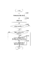
第3実施形態では、総電力および供給電源力に応じてパンチルト像振れ補正の補正割合を変更した。本実施形態では、総電力に加えパン機構およびチルト機構の駆動に応じて、パンチルト像振れ補正の補正割合を変更する。図11は、パン機構およびチルト機構の駆動に応じたパンチルト像振れ補正の補正割合の変更処理を示すフローチャートである。
(Fourth Embodiment)
In the third embodiment, the correction ratio of the pan-tilt image shake correction is changed according to the total power and the power supply power. In the present embodiment, the correction ratio of the pan-tilt image shake correction is changed according to the drive of the pan mechanism and the tilt mechanism in addition to the total power. FIG. 11 is a flowchart showing a process of changing the correction ratio of the pan / tilt image shake correction according to the drive of the pan mechanism and the tilt mechanism.
S1101で、システム制御部103は、総電力量を算出する。総電力量の算出は、第3実施形態と同様である。S1102で、システム制御部103は、S1101で算出した総電力量が所定の値以上であるか否かを判定する。総電力量が所定の値以上である場合は、S1103に進む。一方、総電力量が所定の値より低い場合は、パンチルト像振れ補正を行っても電力に余裕があるということなので、パンチルト像振れ補正の補正割合の変更は行わず、本処理を終了する。
In S1101, the
S1103で、システム制御部103は、パン動作駆動部105およびチルト動作駆動部107の駆動にかかる電力が所定の値以上であるか否かを判定する。駆動にかかる電力が所定の値以上である場合は、S1104に進む。一方、駆動にかかる電力が所定の値より低い場合は、S1106に進み、予め設定しておいた低下率に基づいてパンチルト像振れ補正の補正割合(補正量)を低下させる。
In S1103, the
S1104で、システム制御部103は、パンチルト像振れ補正に使用する電力が所定の値以上であるか否かを判定する。これは、パン動作駆動部105およびチルト動作駆動部107の駆動にかかる電力のうち、パンチルト像振れ補正に使用する電力が大きいか否かを判定するためのステップである。パン機構およびチルト機構は、像振れ補正だけでなく、ユーザ操作や定期的な設定によって像振れ補正以外にも使用される。パン機構およびチルト機構の駆動にかかる電力のうち、像振れ補正以外に使用される電力の割合が高い場合、パンチルト像振れ補正の補正割合を低下させても比較的少量の消費電力の低減にしかならず、電力抑制の効果が薄い。そこで、像振れ補正に使用される電力が大きい場合は、パンチルト像振れ補正の補正割合の低下率を大きくして、低減される電力を大きくする。
In S1104, the
パン機構およびチルト機構の消費電力をパンチルト像振れ補正に使用する電力か他に使用する電力か区別する方法としては、例えば、チルト機構が継続的に駆動している場合はパンチルト像振れ補正のために消費された電力とする方法がある。これは、設置環境の振動はチルト方向が多いためである。また、振れ検出手段としてジャイロセンサを用いている場合であれば、ジャイロ信号が所定以上になっている場合はパンチルト像振れ補正のために消費された電力とする方法でもよい。 As a method of distinguishing the power consumption of the pan mechanism and the tilt mechanism from the power used for the pan-tilt image shake correction or the power used for other purposes, for example, when the tilt mechanism is continuously driven, for the pan-tilt image shake correction. There is a way to use the power consumed by. This is because the vibration of the installation environment has many tilt directions. Further, when a gyro sensor is used as the runout detection means, if the gyro signal is equal to or higher than a predetermined value, the power consumed for the pan-tilt image runout correction may be used.
パンチルト像振れ補正に使用する電力が所定の値以上である場合は、S1105に進む。一方、パンチルト像振れ補正に使用する電力が所定の値より低い場合は、パンチルト駆動においてパンチルト像振れ補正以外のために消費されている電力が大きいと判断できるため、パンチルト像振れ補正の補正割合を変更せずに、S1106に進む。 If the electric power used for the pan-tilt image shake correction is equal to or more than a predetermined value, the process proceeds to S1105. On the other hand, when the power used for the pan-tilt image shake correction is lower than a predetermined value, it can be determined that the power consumed for other than the pan-tilt image shake correction in the pan-tilt drive is large. Proceed to S1106 without changing.
S1005で、システム制御部103は、パンチルト像振れ補正の補正割合の低下率を大きくする。すなわち、5°の振れ量を3°までの補正に抑制することでパンチルト防振機構の補正割合を低下させていたところを、さらに2°まで補正することで補正割合を低下させる低下率を大きくし、消費電力の抑制を高める。S1106で、システム制御部103は、パンチルト像振れ補正の補正割合を低下させる。
In S1005, the
以上説明したように、本実施形態によると、パンチルト像振れ補正の補正割合の低下率を一律にせず、像振れ補正に使用している電力が少ない場合には低下率を大きくする。そのため、パン機構およびチルト機構の駆動量を小さくして、消費電力を低減させることができる。 As described above, according to the present embodiment, the reduction rate of the correction ratio of the pan-tilt image shake correction is not uniform, and the reduction rate is increased when the power used for the image shake correction is small. Therefore, the driving amount of the pan mechanism and the tilt mechanism can be reduced to reduce the power consumption.
(第5実施形態)
第3実施形態では、総電力および供給電源力に応じてパンチルト像振れ補正の補正割合を変更した。本実施形態では、総電力に加え光学的な像振れ補正に使用する電力に応じて、パンチルト像振れ補正の補正割合を変更する。図12は、光学的な像振れ補正に応じたパンチルト像振れ補正の補正割合の変更処理を示すフローチャートである。
(Fifth Embodiment)
In the third embodiment, the correction ratio of the pan-tilt image shake correction is changed according to the total power and the power supply power. In the present embodiment, the correction ratio of the pan-tilt image shake correction is changed according to the power used for the optical image shake correction in addition to the total power. FIG. 12 is a flowchart showing a process of changing the correction ratio of the pan-tilt image shake correction according to the optical image shake correction.
S1201で、システム制御部103は、総電力量を算出する。S1202で、システム制御部103は、S1101で算出した総電力量が所定の値以上であるか否かを判定する。S1201およびS1202は、S1101およびS1102と同様のステップである。総電力量が所定の値以上であると判定された場合、S1203に進む。一方、総電力量が所定の値より低い場合は、パンチルト像振れ補正を行っても電力に余裕があるということなので、パンチルト像振れ補正の補正割合の変更は行わず、本処理を終了する。
In S1201, the
S1203で、システム制御部103は、パン機構およびチルト機構においてパンチルト像振れ補正のために消費される電力と、光学的な像振れ補正のために消費される電力を比較する。パンチルト像振れ補正のために消費される電力が所定の割合以上であると判定された場合は、S1204に進む。一方、パンチルト像振れ補正のために消費される電力が所定の割合より低い場合は、S1205に進む。
In S1203, the
S1204で、システム制御部103は、パンチルト像振れ補正の補正割合の低下率を大きくする。S1205で、システム制御部103は、パンチルト像振れ補正の補正割合(補正量)を低下させる。なお、上記では光学的な像振れ補正のみと比較したが、電子的な像振れ補正に使用する電力を含めて比較してもよい。
In S1204, the
以上説明したように、本実施形態によると、パンチルト像振れ補正で使用する電力が光学的な像振れ補正で使用する電力と比較して所定値より大きい場合には、パンチルト像振れ補正の補正割合の低下率を大きくして、消費電力を抑制することができる。なお、上記に記載の方法以外にも、パン機構およびチルト機構の駆動速度や駆動方向に応じて補正割合の低下率を変更するようにしてもよい。 As described above, according to the present embodiment, when the power used for the pan-tilt image shake correction is larger than a predetermined value as compared with the power used for the optical image shake correction, the correction ratio of the pan-tilt image shake correction The rate of decrease in power consumption can be increased to suppress power consumption. In addition to the method described above, the reduction rate of the correction ratio may be changed according to the driving speed and the driving direction of the pan mechanism and the tilt mechanism.
(その他の実施例)
本発明は、上述の実施形態の1以上の機能を実現するプログラムを、ネットワーク又は記憶媒体を介してシステム又は装置に供給し、そのシステム又は装置のコンピュータにおける1つ以上のプロセッサーがプログラムを読出し実行する処理でも実現可能である。また、1以上の機能を実現する回路(例えば、ASIC)によっても実現可能である。
(Other examples)
The present invention supplies a program that realizes one or more functions of the above-described embodiment to a system or device via a network or storage medium, and one or more processors in the computer of the system or device reads and executes the program. It can also be realized by the processing to be performed. It can also be realized by a circuit (for example, ASIC) that realizes one or more functions.
以上、本発明の好ましい実施形態について説明したが、本発明は、これらの実施形態に限定されず、その要旨の範囲内で種々の変形および変更が可能である。 Although the preferred embodiments of the present invention have been described above, the present invention is not limited to these embodiments, and various modifications and modifications can be made within the scope of the gist thereof.
103 システム制御部
105 パン動作駆動部
107 チルト動作駆動部
103
Claims (6)
前記駆動手段の駆動による像振れ補正の補正量を撮像装置の総電力が所定の値以上の場合に低下させる制御手段と、を備え、
前記制御手段は、撮像装置の総電力が所定の値以上の場合であって、前記駆動手段にかかる電力が所定の値以上で且つ前記駆動手段にかかる電力のうち前記像振れ補正に使用する電力が所定の値以上の場合に、前記補正量の低下率を大きくすることを特徴とする撮像装置。 A driving means for pan-driving and tilt-driving the imaging optical system,
A control means for reducing the correction amount of image shake correction by driving the drive means when the total power of the image pickup device is equal to or higher than a predetermined value is provided.
The control means is a power used for image shake correction among the powers applied to the drive means when the total power of the image pickup apparatus is equal to or more than a predetermined value and the power applied to the drive means is equal to or more than a predetermined value. An image pickup apparatus characterized in that when is greater than or equal to a predetermined value, the rate of decrease in the correction amount is increased.
撮像装置の振れを検出する検出手段と、
前記駆動手段の駆動による像振れ補正の補正量を制御する制御手段と、を備え、
前記制御手段は、前記振れの振幅が所定の振幅より小さい場合、または、シャッタ速度が所定のシャッタ速度以上である場合、前記補正量を低下させることを特徴とする撮像装置。 A driving means for pan-driving and tilt-driving the imaging optical system,
A detection means for detecting the runout of the image pickup device and
A control means for controlling the correction amount of image shake correction by driving the drive means is provided.
The control means is an image pickup apparatus characterized in that the correction amount is reduced when the amplitude of the runout is smaller than the predetermined amplitude or when the shutter speed is equal to or higher than the predetermined shutter speed .
前記制御手段は、ズーム倍率が所定の倍率より小さい場合、前記補正量を増加させる増加率を下げることを特徴とする請求項2に記載の撮像装置。 When the amplitude of the runout is equal to or greater than a predetermined amplitude, or when the shutter speed is slower than the predetermined shutter speed, the control means increases the correction amount.
The image pickup apparatus according to claim 2, wherein the control means reduces the rate of increase that increases the correction amount when the zoom magnification is smaller than a predetermined magnification.
シフトレンズの駆動により光学的な像振れ補正を行う第2の像振れ補正手段または電子的な像振れ補正を行う第3の像振れ補正手段の少なくとも1つと、をさらに備えることを特徴とする請求項1乃至5のいずれか1項に記載の撮像装置。 A first image shake correction means that corrects image shake by driving the drive means, and
A claim characterized by further comprising at least one of a second image shake correction means for performing optical image shake correction by driving a shift lens and a third image shake correction means for performing electronic image shake correction. Item 6. The image pickup apparatus according to any one of Items 1 to 5 .
Priority Applications (4)
| Application Number | Priority Date | Filing Date | Title |
|---|---|---|---|
| JP2017224597A JP7071099B2 (en) | 2017-11-22 | 2017-11-22 | Imaging device |
| EP18203044.5A EP3490243B1 (en) | 2017-11-22 | 2018-10-29 | Imaging apparatus and control method |
| US16/192,898 US10887522B2 (en) | 2017-11-22 | 2018-11-16 | Imaging apparatus and control method |
| CN201811398061.2A CN110012214B (en) | 2017-11-22 | 2018-11-22 | Image pickup apparatus and control method |
Applications Claiming Priority (1)
| Application Number | Priority Date | Filing Date | Title |
|---|---|---|---|
| JP2017224597A JP7071099B2 (en) | 2017-11-22 | 2017-11-22 | Imaging device |
Publications (2)
| Publication Number | Publication Date |
|---|---|
| JP2019095590A JP2019095590A (en) | 2019-06-20 |
| JP7071099B2 true JP7071099B2 (en) | 2022-05-18 |
Family
ID=64100583
Family Applications (1)
| Application Number | Title | Priority Date | Filing Date |
|---|---|---|---|
| JP2017224597A Active JP7071099B2 (en) | 2017-11-22 | 2017-11-22 | Imaging device |
Country Status (4)
| Country | Link |
|---|---|
| US (1) | US10887522B2 (en) |
| EP (1) | EP3490243B1 (en) |
| JP (1) | JP7071099B2 (en) |
| CN (1) | CN110012214B (en) |
Families Citing this family (10)
| Publication number | Priority date | Publication date | Assignee | Title |
|---|---|---|---|---|
| JP7398907B2 (en) * | 2019-09-10 | 2023-12-15 | キヤノン株式会社 | Image stabilization system and method, imaging device and imaging system |
| CN112567729A (en) * | 2019-11-25 | 2021-03-26 | 深圳市大疆创新科技有限公司 | Control device, imaging system, mobile body, control method, and program |
| JP6852243B1 (en) * | 2019-11-25 | 2021-03-31 | エスゼット ディージェイアイ テクノロジー カンパニー リミテッドSz Dji Technology Co.,Ltd | Control devices, imaging systems, moving objects, control methods, and programs |
| WO2021111505A1 (en) * | 2019-12-02 | 2021-06-10 | Cbc株式会社 | Lens device |
| JP7483390B2 (en) | 2020-01-29 | 2024-05-15 | キヤノン株式会社 | Imaging device and control method thereof |
| JP7520545B2 (en) * | 2020-03-25 | 2024-07-23 | キヤノン株式会社 | Imaging device, control method, and program |
| JP7649110B2 (en) * | 2020-05-15 | 2025-03-19 | キヤノン株式会社 | Image capture device, image capture device control method, and program |
| US12501129B2 (en) * | 2021-07-16 | 2025-12-16 | Samsung Electro-Mechanics Co., Ltd. | Image sensor, camera module, and electronic device including the same |
| JP2024040850A (en) * | 2022-09-13 | 2024-03-26 | キヤノン株式会社 | Control device, lens device, imaging device, camera system, control method, and program |
| WO2024090075A1 (en) * | 2022-10-28 | 2024-05-02 | ソニーグループ株式会社 | Information processing device, information processing method, and program |
Citations (9)
| Publication number | Priority date | Publication date | Assignee | Title |
|---|---|---|---|---|
| JP2002148670A (en) | 2000-08-31 | 2002-05-22 | Canon Inc | Shake correction device, control device applied to shake correction device, control method applied to shake correction device, control program applied to shake correction device, imaging device |
| JP2011145604A (en) | 2010-01-18 | 2011-07-28 | Victor Co Of Japan Ltd | Imaging apparatus and image blur correction method |
| CN102262337A (en) | 2010-05-28 | 2011-11-30 | 索尼公司 | Interchangeable lens, imaging apparatus, imaging system, method for controlling interchangeable lens |
| CN103167237A (en) | 2011-12-14 | 2013-06-19 | Jvc建伍株式会社 | Image pickup apparatus and image blur correcting method for performing image blur correction based on at least one of shutter speed and amount of image blur when taking image |
| US20130342715A1 (en) | 2012-06-22 | 2013-12-26 | Sony Corporation | Image blur correction apparatus, image blur correction method, and imaging apparatus |
| JP2015184565A (en) | 2014-03-25 | 2015-10-22 | キヤノン株式会社 | Control method and optical instrument |
| JP2015233260A (en) | 2014-06-11 | 2015-12-24 | キヤノン株式会社 | Imaging apparatus |
| CN106662793A (en) | 2015-05-27 | 2017-05-10 | 高途乐公司 | Gimbal system using a stabilization gimbal |
| JP2017134190A (en) | 2016-01-27 | 2017-08-03 | オリンパス株式会社 | Imaging device |
Family Cites Families (12)
| Publication number | Priority date | Publication date | Assignee | Title |
|---|---|---|---|---|
| JP2005258034A (en) | 2004-03-11 | 2005-09-22 | Hitachi Kokusai Electric Inc | Electric head |
| KR101329741B1 (en) * | 2007-01-11 | 2013-11-14 | 삼성전자주식회사 | Method of control of hand-shaking correction and Apparatus of control hand-shaking correction |
| US7813629B2 (en) * | 2007-07-23 | 2010-10-12 | Fujifilm Corporation | Photographing apparatus, and control method and computer program product for controlling the same |
| JP5094523B2 (en) * | 2008-04-16 | 2012-12-12 | キヤノン株式会社 | Image shake correction apparatus, imaging apparatus, and optical apparatus |
| JP2010283598A (en) | 2009-06-04 | 2010-12-16 | Canon Inc | Network camera |
| JP5553597B2 (en) * | 2009-12-25 | 2014-07-16 | キヤノン株式会社 | Imaging apparatus and control method thereof |
| JP5894371B2 (en) * | 2011-03-07 | 2016-03-30 | キヤノン株式会社 | Radiation imaging apparatus and control method thereof |
| JP5818487B2 (en) * | 2011-04-11 | 2015-11-18 | キヤノン株式会社 | Camera control device and camera control method |
| JP6004785B2 (en) * | 2012-06-29 | 2016-10-12 | キヤノン株式会社 | Imaging apparatus, optical apparatus, imaging system, and control method |
| US9832381B2 (en) * | 2014-10-31 | 2017-11-28 | Qualcomm Incorporated | Optical image stabilization for thin cameras |
| JP6614810B2 (en) * | 2015-05-29 | 2019-12-04 | キヤノン株式会社 | Blur correction device, imaging device, and blur correction method |
| EP3160125B1 (en) * | 2015-10-22 | 2017-11-29 | Axis AB | Locking device, camera, and method |
-
2017
- 2017-11-22 JP JP2017224597A patent/JP7071099B2/en active Active
-
2018
- 2018-10-29 EP EP18203044.5A patent/EP3490243B1/en active Active
- 2018-11-16 US US16/192,898 patent/US10887522B2/en active Active
- 2018-11-22 CN CN201811398061.2A patent/CN110012214B/en active Active
Patent Citations (16)
| Publication number | Priority date | Publication date | Assignee | Title |
|---|---|---|---|---|
| JP2002148670A (en) | 2000-08-31 | 2002-05-22 | Canon Inc | Shake correction device, control device applied to shake correction device, control method applied to shake correction device, control program applied to shake correction device, imaging device |
| JP2011145604A (en) | 2010-01-18 | 2011-07-28 | Victor Co Of Japan Ltd | Imaging apparatus and image blur correction method |
| CN102262337A (en) | 2010-05-28 | 2011-11-30 | 索尼公司 | Interchangeable lens, imaging apparatus, imaging system, method for controlling interchangeable lens |
| US20110292270A1 (en) | 2010-05-28 | 2011-12-01 | Sony Corporation | Interchangeable lens, imaging apparatus, imaging system, method for controlling interchangeable lens, and program |
| JP2011248164A (en) | 2010-05-28 | 2011-12-08 | Sony Corp | Interchangeable lens, imaging apparatus, imaging system, interchangeable lens control method, and program |
| CN103167237A (en) | 2011-12-14 | 2013-06-19 | Jvc建伍株式会社 | Image pickup apparatus and image blur correcting method for performing image blur correction based on at least one of shutter speed and amount of image blur when taking image |
| US20130155262A1 (en) | 2011-12-14 | 2013-06-20 | JVC Kenwood Corporation | Image pickup apparatus and image blur correcting method for performing image blur correction based on at least one of shutter speed and amount of image blur when taking image |
| JP2013126075A (en) | 2011-12-14 | 2013-06-24 | Jvc Kenwood Corp | Imaging device and image blur correcting method |
| US20130342715A1 (en) | 2012-06-22 | 2013-12-26 | Sony Corporation | Image blur correction apparatus, image blur correction method, and imaging apparatus |
| CN103513492A (en) | 2012-06-22 | 2014-01-15 | 索尼公司 | Image blur correction apparatus, image blur correction method, and imaging apparatus |
| JP2014006340A (en) | 2012-06-22 | 2014-01-16 | Sony Corp | Image blur correction device, image blur correction method and imaging device |
| JP2015184565A (en) | 2014-03-25 | 2015-10-22 | キヤノン株式会社 | Control method and optical instrument |
| JP2015233260A (en) | 2014-06-11 | 2015-12-24 | キヤノン株式会社 | Imaging apparatus |
| CN106662793A (en) | 2015-05-27 | 2017-05-10 | 高途乐公司 | Gimbal system using a stabilization gimbal |
| US20170227162A1 (en) | 2015-05-27 | 2017-08-10 | Gopro, Inc. | Camera System Using Stabilizing Gimbal |
| JP2017134190A (en) | 2016-01-27 | 2017-08-03 | オリンパス株式会社 | Imaging device |
Also Published As
| Publication number | Publication date |
|---|---|
| JP2019095590A (en) | 2019-06-20 |
| EP3490243B1 (en) | 2023-09-13 |
| CN110012214A (en) | 2019-07-12 |
| EP3490243A3 (en) | 2019-10-02 |
| US20190158748A1 (en) | 2019-05-23 |
| CN110012214B (en) | 2021-05-11 |
| US10887522B2 (en) | 2021-01-05 |
| EP3490243A2 (en) | 2019-05-29 |
Similar Documents
| Publication | Publication Date | Title |
|---|---|---|
| JP7071099B2 (en) | Imaging device | |
| JP5328307B2 (en) | Image capturing apparatus having shake correction function and control method thereof | |
| JP4717748B2 (en) | Camera body and camera system having the same | |
| JP6472176B2 (en) | Imaging apparatus, image shake correction apparatus, image pickup apparatus control method, and image shake correction method | |
| JP2714039B2 (en) | Camera device | |
| JP6910765B2 (en) | Control device, anti-vibration control method and anti-vibration control program | |
| CN105391918B (en) | Image processing apparatus and the method for controlling image processing apparatus | |
| JP6581352B2 (en) | Image blur correction apparatus and control method thereof, imaging apparatus, lens apparatus, program, and storage medium | |
| JP6932531B2 (en) | Image blur correction device, image pickup device, control method of image pickup device | |
| US11265478B2 (en) | Tracking apparatus and control method thereof, image capturing apparatus, and storage medium | |
| JP2018037772A (en) | Imaging apparatus and control method of the same | |
| US8369697B2 (en) | Optical device | |
| US8995826B2 (en) | Image capturing apparatus and control method of the image capturing apparatus | |
| US20140125826A1 (en) | Image capturing apparatus and method of controlling image capturing apparatus | |
| CN108737698A (en) | Device for image stabilization and method, picture pick-up device, camera system and storage medium | |
| US10089745B2 (en) | Image processing apparatus that enables easy tracking of a subject if the subject moves to outside a field angle and control method for same | |
| JP2024035336A (en) | Image blur correction control device and control method | |
| JP2015079158A (en) | Image capturing device and control method therefor | |
| JP7214424B2 (en) | Imaging device and its control method | |
| JP5744165B2 (en) | Imaging apparatus, blur correction apparatus, and control method thereof | |
| JP7269119B2 (en) | Image blur correction control device, camera body, lens unit, image blur correction control method, and program | |
| JP6539114B2 (en) | Imaging device, control method therefor, and program | |
| JP2025083919A (en) | CONTROL DEVICE, CONTROL METHOD AND PROGRAM THEREOF, AND IMAGING DEVICE | |
| JP6420532B2 (en) | Imaging apparatus and control method thereof | |
| JP2014128017A (en) | Imaging device, method for controlling the same, program and storage medium |
Legal Events
| Date | Code | Title | Description |
|---|---|---|---|
| A621 | Written request for application examination |
Free format text: JAPANESE INTERMEDIATE CODE: A621 Effective date: 20201119 |
|
| A977 | Report on retrieval |
Free format text: JAPANESE INTERMEDIATE CODE: A971007 Effective date: 20210823 |
|
| A131 | Notification of reasons for refusal |
Free format text: JAPANESE INTERMEDIATE CODE: A131 Effective date: 20211005 |
|
| A521 | Request for written amendment filed |
Free format text: JAPANESE INTERMEDIATE CODE: A523 Effective date: 20211203 |
|
| A131 | Notification of reasons for refusal |
Free format text: JAPANESE INTERMEDIATE CODE: A131 Effective date: 20220111 |
|
| A521 | Request for written amendment filed |
Free format text: JAPANESE INTERMEDIATE CODE: A523 Effective date: 20220311 |
|
| TRDD | Decision of grant or rejection written | ||
| A01 | Written decision to grant a patent or to grant a registration (utility model) |
Free format text: JAPANESE INTERMEDIATE CODE: A01 Effective date: 20220405 |
|
| A61 | First payment of annual fees (during grant procedure) |
Free format text: JAPANESE INTERMEDIATE CODE: A61 Effective date: 20220506 |
|
| R151 | Written notification of patent or utility model registration |
Ref document number: 7071099 Country of ref document: JP Free format text: JAPANESE INTERMEDIATE CODE: R151 |