JP5818487B2 - Camera control device and camera control method - Google Patents

Camera control device and camera control method Download PDF

Info

Publication number
JP5818487B2
JP5818487B2 JP2011087343A JP2011087343A JP5818487B2 JP 5818487 B2 JP5818487 B2 JP 5818487B2 JP 2011087343 A JP2011087343 A JP 2011087343A JP 2011087343 A JP2011087343 A JP 2011087343A JP 5818487 B2 JP5818487 B2 JP 5818487B2
Authority
JP
Japan
Prior art keywords
camera
memory
position information
output
driving unit
Prior art date
Legal status (The legal status is an assumption and is not a legal conclusion. Google has not performed a legal analysis and makes no representation as to the accuracy of the status listed.)
Active
Application number
JP2011087343A
Other languages
Japanese (ja)
Other versions
JP2012220769A5 (en
JP2012220769A (en
Inventor
聡 仲摩
聡 仲摩
Current Assignee (The listed assignees may be inaccurate. Google has not performed a legal analysis and makes no representation or warranty as to the accuracy of the list.)
Canon Inc
Original Assignee
Canon Inc
Priority date (The priority date is an assumption and is not a legal conclusion. Google has not performed a legal analysis and makes no representation as to the accuracy of the date listed.)
Filing date
Publication date
Application filed by Canon Inc filed Critical Canon Inc
Priority to JP2011087343A priority Critical patent/JP5818487B2/en
Publication of JP2012220769A publication Critical patent/JP2012220769A/en
Publication of JP2012220769A5 publication Critical patent/JP2012220769A5/ja
Application granted granted Critical
Publication of JP5818487B2 publication Critical patent/JP5818487B2/en
Active legal-status Critical Current
Anticipated expiration legal-status Critical

Links

Images

Landscapes

  • Indication In Cameras, And Counting Of Exposures (AREA)
  • Accessories Of Cameras (AREA)
  • Studio Devices (AREA)

Description

本発明は、撮像方向を変更可能なカメラの制御方法に関する。   The present invention relates to a camera control method capable of changing an imaging direction.

パン、チルト、ローテート機構のような駆動機構を持つ監視カメラにおいて、駆動機構の現在位置を把握することは、例えば、カメラ制御用のユーザーインターフェースで現在位置を表示させるために重要である。特許文献1には、例えば電源投入時や所定時間の経過ごとに、原点合わせ動作を行い、絶対回転角カウンタを校正することが記載されている。   In a surveillance camera having a drive mechanism such as a pan, tilt, and rotate mechanism, grasping the current position of the drive mechanism is important for displaying the current position on a user interface for camera control, for example. Japanese Patent Application Laid-Open No. 2004-151561 describes that an origin adjustment operation is performed to calibrate an absolute rotation angle counter when, for example, power is turned on or every elapse of a predetermined time.

特開平11−94191号公報JP-A-11-94191

しかしながら、原点合わせ動作によって、カメラの撮像方向を変更するための駆動部が劣化してしまう恐れがあった。
例えば、カメラの電源を投入するたびに、原点合わせ動作のために駆動部を駆動させてしまうと、駆動部に用いられている部品が劣化してしまう恐れがあった。
また、例えば、所定時間が経過するごとに、原点合わせを行うと、駆動部に用いられている部品が劣化してしまう恐れがあった。
本発明は、上記の問題点に鑑みてなされたものであり、その目的は、駆動部の位置情報の精度の低下を防ぎつつ、原点合わせ動作の頻度を低減することである。
However, there is a possibility that the driving unit for changing the imaging direction of the camera may be deteriorated by the origin matching operation.
For example, if the drive unit is driven for the origin adjustment operation every time the camera is turned on, there is a risk that the components used in the drive unit will deteriorate.
Further, for example, if the origin adjustment is performed every time a predetermined time elapses, there is a possibility that a component used in the drive unit is deteriorated.
The present invention has been made in view of the above-described problems, and an object of the present invention is to reduce the frequency of the origin matching operation while preventing a decrease in the accuracy of the position information of the drive unit.

上記目的を達成するために、本発明のカメラ制御装置は、例えば、以下の構成を有する。カメラの撮像方向を変更するための駆動部に対する駆動指示に従って、前記カメラの撮像方向対応する置情報を記憶するメモリから当該位置情報を取得する取得手段と、前記メモリに前記位置情報が記憶されているかどうかを判定する第1の判定手段と、前記第1の判定手段によって前記メモリに前記位置情報が記憶されていると判定された場合、前記駆動部から出力された前記駆動部の現在位置と、前記メモリから取得された位置情報に対応する位置とが異なるかどうかを判定する第2の判定手段と、前記第2の判定手段によって、前記駆動部から出力された前記駆動部の現在位置と前記メモリから取得された位置とが異なると判定された場合、前記駆動部から出力された前記駆動部の現在位置と前記メモリから取得された位置情報に対応する位置とが異なることを示す通知を出力する出力手段とを有することを特徴とするカメラ制御装置。 In order to achieve the above object, a camera control device of the present invention has, for example, the following configuration. In accordance with the driving instruction to the drive unit for changing the imaging direction of the camera, and acquisition means acquire the memory or al the position information for storing position information corresponding to the imaging direction of the camera, the position information in the memory is a first determination means for determining whether the stored, the case where the position information in the memory is determined to be stored by the first determination means, of the driver output from the driver and the current position, the a position corresponding to the position information acquired from the memory and the second determination means determines that whether different, the by the second judging means, wherein the drive unit output from the drive unit current when the position and the position obtained from the memory is determined to be different, the current position and the previous SL position information obtained from the memory of the driver output from the driver of the The camera control apparatus characterized by an output means and a position which respond to output a notification indicating different.

本発明によれば、駆動部の位置情報の精度の低下を防ぎつつ、原点合わせ動作の頻度を低減できる。   According to the present invention, it is possible to reduce the frequency of the origin matching operation while preventing a decrease in the accuracy of the position information of the drive unit.

カメラシステムの構成図Configuration diagram of the camera system カメラ200の外観図External view of camera 200 カメラ200のブロック図Block diagram of camera 200 カメラ制御装置100のユーザインタフェースの例Example of user interface of camera control apparatus 100 カメラ200のPan、Tilt、Rotateの制御処理のフローチャートFlowchart of control processing of Pan, Tilt, and Rotate of the camera 200 カメラ制御装置100のPan、Tilt、Rotateの制御処理のフローチャートFlowchart of Pan, Tilt, Rotate control process of camera control apparatus 100 映像解析の位置ずれ検出処理のフローチャートFlow chart of misalignment detection processing for video analysis カメラ200の起動時のフローチャートFlow chart when starting camera 200 カメラ制御装置100の起動時のフローチャートFlowchart at startup of camera control device 100 カメラ制御装置100のブロック図Block diagram of the camera control device 100

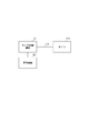
以下に、本発明の好ましい実施の形態を、添付の図面に基づいて詳細に説明する。図1は、本実施形態のカメラシステムの構成を示した図である。   Hereinafter, preferred embodiments of the present invention will be described in detail with reference to the accompanying drawings. FIG. 1 is a diagram showing the configuration of the camera system of the present embodiment.

カメラ制御装置100は、カメラ200とネットワーク400により接続される。カメラ制御装置100は、ネットワーク400を介して、カメラ200の各種制御をすると共に、カメラ200から映像、音声、設定値などの取得を行う。本形態では、ネットワーク400がローカルエリアネットワークである場合を中心に説明するが、例えばインターネットなどであっても良い。
また、カメラ制御装置100は、表示装置300と接続される。表示装置300は、カメラ200による撮像映像を表示すると共に、カメラ200の撮像方向を制御するための指示を入力するための操作画面を表示する。本実施形態のカメラ制御装置100は、カメラ200を制御するカメラ制御装置としての機能、及び、表示装置300の表示を制御する表示制御装置としての機能を有する。なお、カメラ制御装置100と表示装置300が一体であっても良い。
The camera control device 100 is connected to the camera 200 via a network 400. The camera control apparatus 100 performs various controls of the camera 200 via the network 400 and acquires video, audio, setting values, and the like from the camera 200. In the present embodiment, the case where the network 400 is a local area network will be mainly described, but it may be the Internet, for example.
In addition, the camera control device 100 is connected to the display device 300. The display device 300 displays a video image captured by the camera 200 and an operation screen for inputting an instruction for controlling the imaging direction of the camera 200. The camera control apparatus 100 of this embodiment has a function as a camera control apparatus that controls the camera 200 and a function as a display control apparatus that controls the display of the display apparatus 300. The camera control device 100 and the display device 300 may be integrated.

図2はカメラ200の外観図である。201はパン駆動部であり、パンモータの駆動によりパン方向204で示す方向へ鏡筒部203の向きを変更させる。202はチルト駆動部であり、チルトモータの駆動によりチルト方向205で示す方向へ鏡筒部203の向きを変更させる。また、レンズ含む鏡筒部203は、ローテートモータの制御により、レンズ中心位置を中心に、ローテート方向206で示す方向に回転可能である。
カメラ200は、ドーム207によって全体を覆われている。なお、本形態では、パンモータ、チルトモータ、ローテートモータの駆動可能な回数(駆動量)の上限値が予め設定されている。
FIG. 2 is an external view of the camera 200. Reference numeral 201 denotes a pan driving unit that changes the direction of the lens barrel unit 203 in the direction indicated by the pan direction 204 by driving the pan motor. A tilt drive unit 202 changes the direction of the lens barrel unit 203 in the direction indicated by the tilt direction 205 by driving the tilt motor. Further, the lens barrel portion 203 including the lens can be rotated in the direction indicated by the rotation direction 206 around the lens center position under the control of the rotation motor.
The camera 200 is entirely covered with a dome 207. In the present embodiment, the upper limit value of the number of times (drive amount) that can be driven by the pan motor, tilt motor, and rotate motor is set in advance.

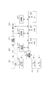
図3は、カメラ200のブロック図である。レンズ2001とCCD2002によって得られた撮像データが、信号処理部2003によって処理されて映像データが生成される。信号処理部2003で生成された映像データは、符号化部2004によって符号化される。また、解析部2005は、信号処理部2003で生成された映像データを解析する。符号化部2004により符号化された映像データや解析部2005による解析結果は、RAM2007に記憶され、通信部2014を介してカメラ制御装置100へ送信される。   FIG. 3 is a block diagram of the camera 200. Image data obtained by the lens 2001 and the CCD 2002 is processed by the signal processing unit 2003 to generate video data. The video data generated by the signal processing unit 2003 is encoded by the encoding unit 2004. The analysis unit 2005 analyzes the video data generated by the signal processing unit 2003. The video data encoded by the encoding unit 2004 and the analysis result by the analysis unit 2005 are stored in the RAM 2007 and transmitted to the camera control apparatus 100 via the communication unit 2014.

上記の各処理はCPU2006によって制御される。ただし、上記の少なくとも一部の処理を専用のハードウェアで行うようにしても良い。
また、CPU2006は、例えば、カメラ制御装置100からの制御コマンドに応じて、レンズ制御部2009を介してズームやフォーカスなどのレンズ制御を行う。また、CPU2006は、例えば、カメラ制御装置100からの制御コマンドに応じて、駆動制御部2010を介してパンモータ2011、チルトモータ2012、ローテートモータ2013を制御する。
Each process described above is controlled by the CPU 2006. However, at least a part of the processing described above may be performed by dedicated hardware.
Further, the CPU 2006 performs lens control such as zoom and focus via the lens control unit 2009 in response to a control command from the camera control device 100, for example. Further, the CPU 2006 controls the pan motor 2011, the tilt motor 2012, and the rotate motor 2013 via the drive control unit 2010 in accordance with a control command from the camera control device 100, for example.

なお、本形態の駆動制御部2010は、パンモータ2011、チルトモータ2012、ローテートモータ2013の少なくともいずれかの現在位置を取得することができる。本形態の駆動制御部2010は、パンモータ2011、チルトモータ2012、ローテートモータ2013のそれぞれの現在位置を、ロータリエンコーダを用いて取得する。ただし、例えば、パンモータ2011の現在位置のみが、ロータリエンコーダで取得できるようにしても良い。また、現在位置の取得は、ロータリエンコーダを用いた方法に限らない。
また、本形態のROM2008は、カメラ制御装置100からの制御コマンドや、追尾処理などによる駆動量に応じたパンモータ2011、チルトモータ2012、ローテートモータ2013の位置を記憶する(記憶位置)。また、ROM2008は、パンモータ2011、チルトモータ2012、ローテートモータ2013のそれぞれのこれまでの駆動回数(駆動量)に関する情報を記憶する。
Note that the drive control unit 2010 of this embodiment can acquire the current position of at least one of the pan motor 2011, the tilt motor 2012, and the rotate motor 2013. The drive control unit 2010 of this embodiment acquires the current positions of the pan motor 2011, the tilt motor 2012, and the rotate motor 2013 using a rotary encoder. However, for example, only the current position of the pan motor 2011 may be acquired by a rotary encoder. The acquisition of the current position is not limited to the method using the rotary encoder.
Further, the ROM 2008 of the present embodiment stores the positions of the pan motor 2011, the tilt motor 2012, and the rotate motor 2013 according to the control command from the camera control apparatus 100 and the driving amount by the tracking process (storage position). The ROM 2008 also stores information regarding the number of times (the amount of driving) the pan motor 2011, the tilt motor 2012, and the rotate motor 2013 have been driven so far.

図10は、カメラ制御装置100のブロック図である。
カメラ制御装置100のCPU1101は、ROM1103に記憶されている各種プログラムをRAM1102に読み出して実行することで、表示制御部1104、通信部1105を制御する。表示制御部1104は、カメラ200の撮像により取得された映像データに応じた映像を表示装置300の表示画面上に表示させると共に、カメラ200の状態等に応じて表示装置300の表示画面の表示を制御する。通信部1105は、カメラ200との間で各種メッセージやコマンドをやり取りする。
FIG. 10 is a block diagram of the camera control apparatus 100.
The CPU 1101 of the camera control apparatus 100 controls the display control unit 1104 and the communication unit 1105 by reading various programs stored in the ROM 1103 into the RAM 1102 and executing them. The display control unit 1104 displays video on the display screen of the display device 300 according to the video data acquired by the imaging of the camera 200, and displays the display screen of the display device 300 according to the state of the camera 200 and the like. Control. A communication unit 1105 exchanges various messages and commands with the camera 200.

次に、表示装置300の表示画面について説明する。表示装置300の表示画面は、カメラ制御装置100の制御により表示される。   Next, the display screen of the display device 300 will be described. The display screen of the display device 300 is displayed under the control of the camera control device 100.

図4は、表示装置300で表示されるユーザインタフェースの例である。本形態のユーザインタフェースには、映像の表示領域1002、カメラ操作領域1003、スライダバー1004、状況表示領域1005、リセットボタン1006が含まれる。
表示領域1002は、カメラ200による撮像映像を表示するための領域である。カメラ操作領域1003は、カメラ200のパン、チルト制御に関する操作を入力するための領域である。スライダバー1004は、カメラ200のローテート制御に関する操作を入力するための領域である。カメラ操作領域1003やスライダバー1004の操作に応じて、カメラ制御装置100から、カメラ200に対して制御コマンドが送信され、カメラ200の撮像方向やローテート角が変更される。この変更に応じて、表示領域1002で表示される映像がリアルタイムで変化する。なお、例えば表示領域1002上のクリック操作により、パン角度とチルト角度を同時に制御することも可能である。
FIG. 4 is an example of a user interface displayed on the display device 300. The user interface of this embodiment includes a video display area 1002, a camera operation area 1003, a slider bar 1004, a status display area 1005, and a reset button 1006.
A display area 1002 is an area for displaying an image captured by the camera 200. The camera operation area 1003 is an area for inputting operations related to pan and tilt control of the camera 200. The slider bar 1004 is an area for inputting an operation related to the rotation control of the camera 200. In response to the operation of the camera operation area 1003 and the slider bar 1004, a control command is transmitted from the camera control device 100 to the camera 200, and the imaging direction and the rotation angle of the camera 200 are changed. In accordance with this change, the video displayed in the display area 1002 changes in real time. Note that the pan angle and the tilt angle can be controlled simultaneously by, for example, a click operation on the display area 1002.

状況表示領域1005には、例えば、現在のカメラ200のパン角度、チルト角度、ローテート角度が表示される。また、リセットボタン1006は、カメラ200の原点出しに関する操作を入力するための領域である。本形態のカメラ制御装置100は、リセットボタン1006の押下に応じて、カメラ200に対して原点出しの指示コマンドを送信する。カメラ200は、カメラ制御装置100から原点出しの指示コマンドを受信すると、カメラ200の撮像方向を予め定められた方向に制御し、当該予め定められた方向に対応する位置情報(パン、チルト、ローテート角度)を、記憶位置として、ROM2008に記憶させる。記憶位置は、カメラ200の撮像方向を変更するための駆動部(パン、チルト、ローテートモータ)に対する駆動指示(制御コマンド)による駆動量に応じた位置情報である。つまり、ROM2008に記憶される記憶位置は、原点出しの後、例えば、制御コマンドに応じてパン角度が制御された場合、制御コマンドによる制御量に基づいて更新される。また、記憶位置は、例えば追尾処理によるパン角度の制御量に基づいて更新される。   In the status display area 1005, for example, the current pan angle, tilt angle, and rotate angle of the camera 200 are displayed. A reset button 1006 is an area for inputting an operation related to the origination of the camera 200. The camera control apparatus 100 according to the present embodiment transmits an origination instruction command to the camera 200 in response to pressing of the reset button 1006. When the camera 200 receives an origin point instruction command from the camera control device 100, the camera 200 controls the imaging direction of the camera 200 to a predetermined direction, and position information (pan, tilt, rotate) corresponding to the predetermined direction. Angle) is stored in the ROM 2008 as a storage position. The storage position is position information corresponding to a drive amount by a drive instruction (control command) for a drive unit (pan, tilt, rotate motor) for changing the imaging direction of the camera 200. That is, the storage position stored in the ROM 2008 is updated based on the control amount by the control command when the pan angle is controlled in accordance with the control command after the origin is set. Further, the storage position is updated based on, for example, a control amount of the pan angle by the tracking process.

次に、カメラ200によるパン、チルト、ローテート制御時の処理について、図5のフローチャートを用いて説明する。なお、カメラ200のCPU2006は、図5の処理を実行するためのプログラムをROM2008からRAM2007に読み出して実行する。
CPU2006は、パン、チルト、ローテートに関する制御コマンドをカメラ制御装置100から受信すると(S501)、制御コマンドによる指定位置が可動範囲内であるか否かを判定する(S502)。可動範囲内であると判定された場合はS504へ進み、可動範囲内でないと判定された場合、CPU2006は、エラーメッセージをカメラ制御装置100へ送信し(S503)、図5の処理を終了する。
Next, processing during pan, tilt, and rotation control by the camera 200 will be described with reference to the flowchart of FIG. Note that the CPU 2006 of the camera 200 reads a program for executing the processing of FIG. 5 from the ROM 2008 to the RAM 2007 and executes it.
When the CPU 2006 receives a control command related to pan, tilt, and rotate from the camera control apparatus 100 (S501), the CPU 2006 determines whether or not the position specified by the control command is within the movable range (S502). If it is determined that it is within the movable range, the process proceeds to S504. If it is determined that it is not within the movable range, the CPU 2006 transmits an error message to the camera control apparatus 100 (S503), and the process of FIG.

CPU2006は、S501で受信した全制御コマンドの処理を完了したか否かを判定し(S504)、完了したと判定した場合は、現在の駆動回数をカメラ制御装置100へ通知して(S505)、図5の処理を終了する。
CPU2006は、S501で受信した制御コマンドがパンモータ2011の制御に関する制御コマンドであるか否かを判定する(S510)。パンモータ2011の制御コマンドであると判定された場合、S511へ進み、CPU2006は、制御コマンドによる指定位置に到達するか、パンモータ2011の駆動回数が上限値に達するまで、パンモータ2011を駆動させる(S511〜S515)。なお、CPU2006は、パンモータ2011を所定量、駆動するごとに、パンモータ2011の駆動回数をインクリメントする(S514)。その後、CPU2006は、駆動後のパンモータ2011の位置を記憶位置としてROM2008に記憶させると共に、当該記憶位置の情報をカメラ制御装置100へ通知する(S515)。
The CPU 2006 determines whether or not the processing of all the control commands received in S501 has been completed (S504). If it is determined that the processing has been completed, the CPU 2006 notifies the camera control apparatus 100 of the current number of times of driving (S505). The process of FIG. 5 is terminated.
The CPU 2006 determines whether or not the control command received in S501 is a control command related to the control of the pan motor 2011 (S510). When it is determined that the control command is the pan motor 2011, the process proceeds to S511, and the CPU 2006 drives the pan motor 2011 until the position designated by the control command is reached or the number of times the pan motor 2011 is driven reaches the upper limit (S511 to S511). S515). The CPU 2006 increments the number of times of driving the pan motor 2011 every time the pan motor 2011 is driven by a predetermined amount (S514). Thereafter, the CPU 2006 stores the position of the pan motor 2011 after driving in the ROM 2008 as a storage position, and notifies the camera control apparatus 100 of information on the storage position (S515).

また、CPU2006は、パンモータ2011の駆動回数が上限値に達した場合、警告をカメラ制御装置100へ送信する(S516)。カメラ制御装置100は、警告に応じて、パンモータ2011が駆動できないことを示すメッセージを表示装置300に表示させる。パンモータ2011の制御に関する制御コマンドで指定された指定位置まで、パンモータ2011が駆動されたとS511で判定されると、S504に戻る。
CPU2006は、S501で受信した制御コマンドがチルトモータ2012の制御コマンドであると判定した場合、S520からS521へ進む。その後、CPU2006は、制御コマンドによる指定位置に到達するか、駆動回数が上限に達するまで、チルトモータ2012を駆動させる(S521〜S525)。なお、CPU2006は、チルトモータ2012を所定量、駆動するごとに、チルトモータ2012の駆動回数をインクリメントする(S524)。その後、CPU2006は、駆動後のチルトモータ2012の位置を記憶位置としてROM2008に記憶させると共に、当該記憶位置の情報をカメラ制御装置100へ通知する(S525)。
The CPU 2006 transmits a warning to the camera control device 100 when the number of times of driving the pan motor 2011 reaches the upper limit value (S516). In response to the warning, the camera control device 100 causes the display device 300 to display a message indicating that the pan motor 2011 cannot be driven. If it is determined in S511 that the pan motor 2011 has been driven to the designated position designated by the control command related to the control of the pan motor 2011, the process returns to S504.
If the CPU 2006 determines that the control command received in S501 is a control command for the tilt motor 2012, the process proceeds from S520 to S521. Thereafter, the CPU 2006 drives the tilt motor 2012 until the position designated by the control command is reached or the number of times of driving reaches the upper limit (S521 to S525). The CPU 2006 increments the number of times the tilt motor 2012 is driven each time the tilt motor 2012 is driven by a predetermined amount (S524). Thereafter, the CPU 2006 stores the position of the tilt motor 2012 after driving in the ROM 2008 as a storage position, and notifies the camera control apparatus 100 of information on the storage position (S525).

また、CPU2006は、チルトモータ2012の駆動回数が上限値に達した場合、警告をカメラ制御装置100へ送信する。カメラ制御装置100は警告に応じて、チルトモータ2012が駆動できないことを示すメッセージを表示装置300に表示させる。
CPU2006は、S501で受信した制御コマンドがローテートモータ2013の制御コマンドであると判定した場合、上述のパンモータ2011、チルトモータ2012の制御と同様に、ローテートモータ2013の制御を行う。
Further, the CPU 2006 transmits a warning to the camera control apparatus 100 when the number of times the tilt motor 2012 is driven reaches the upper limit value. In response to the warning, the camera control device 100 causes the display device 300 to display a message indicating that the tilt motor 2012 cannot be driven.
If the CPU 2006 determines that the control command received in S501 is a control command for the rotate motor 2013, the CPU 2006 controls the rotate motor 2013 in the same manner as the control for the pan motor 2011 and the tilt motor 2012 described above.

なお、本形態では、パンモータ2011、チルトモータ2012、ローテートモータ2013の処理を1つずつ行う形態を中心に説明したが、それぞれを同時に制御するようにしても良い。   In the present embodiment, the description has been made centering on the embodiment in which the pan motor 2011, the tilt motor 2012, and the rotate motor 2013 are performed one by one. However, these may be controlled simultaneously.

次に、カメラ制御装置100によるパン、チルト、ローテート制御時の処理について、図6のフローチャートを用いて説明する。なお、カメラ制御装置100のCPU1101は、図6の処理を実行するためのプログラムをROM1103からRAM1102に読み出して実行する。   Next, processing during panning, tilting, and rotation control by the camera control apparatus 100 will be described with reference to the flowchart of FIG. Note that the CPU 1101 of the camera control apparatus 100 reads a program for executing the processing in FIG. 6 from the ROM 1103 to the RAM 1102 and executes it.

カメラ制御装置100のCPU1101は、ユーザインタフェースのカメラ操作領域1003やスライダバー1004の操作に応じて、パン、チルト、ローテート制御のための制御コマンドをカメラ200へ送信する。そして、CPU1101は、カメラ200から制御後のパンモータ2011、チルトモータ2012、ローテートモータ2013の記憶位置の情報を受信する(S601)。また、表示制御部1104は、S601において、記憶位置の情報に基づいて、ユーザインタフェースの状況表示領域1005に表示されるパン、チルト、ローテート角度の表示を更新する。
カメラ制御装置100のCPU1101は、S601で受信した記憶位置の情報に基づいて、制御コマンドで指定した指定位置に達したか否かを判定する(S602)。CPU1101は、指定位置に達していないと判定した場合、モータの駆動回数が上限値に達したことを示す警告をカメラ200から受信したか否かを判定する(S603)。モータの駆動回数が上限値に達したことを示す警告は、図5のS516、S526、S536で送信される。カメラ制御装置100の表示制御部1104は、警告を受信したと判定した場合、表示装置300の表示画面上に警告メッセージを表示させる。また、カメラ制御装置100の表示制御部1104は、警告の受信に応じて、駆動回数が上限値に達した駆動部(例えばパンモータ)の駆動に関するリセットボタン1006、カメラ操作領域1003、スライダバー1004の表示を無効にする(S606)。一方、S603でモータの駆動回数が上限値に達したことを示す警告を受信していないと判定された場合、S601に戻る。
The CPU 1101 of the camera control apparatus 100 transmits a control command for pan, tilt, and rotate control to the camera 200 in accordance with the operation of the camera operation area 1003 and the slider bar 1004 of the user interface. Then, the CPU 1101 receives information on storage positions of the pan motor 2011, tilt motor 2012, and rotate motor 2013 after control from the camera 200 (S601). In step S <b> 601, the display control unit 1104 updates the pan, tilt, and rotation angle displays displayed in the user interface status display area 1005 based on the storage position information.
The CPU 1101 of the camera control apparatus 100 determines whether or not the designated position designated by the control command has been reached based on the storage position information received in S601 (S602). If the CPU 1101 determines that the designated position has not been reached, the CPU 1101 determines whether or not a warning indicating that the number of times of motor driving has reached the upper limit value has been received from the camera 200 (S603). A warning indicating that the motor drive count has reached the upper limit value is transmitted in S516, S526, and S536 in FIG. If the display control unit 1104 of the camera control device 100 determines that a warning has been received, it displays a warning message on the display screen of the display device 300. Further, the display control unit 1104 of the camera control device 100 receives a warning, a reset button 1006 related to driving of a driving unit (for example, a pan motor) whose number of driving has reached an upper limit value, a camera operation area 1003, and a slider bar 1004. The display is invalidated (S606). On the other hand, if it is determined in S603 that a warning indicating that the motor drive count has reached the upper limit has not been received, the process returns to S601.

S602でモータの現在位置が指定位置に達したと判定された場合、カメラ制御装置100の通信部1105は、カメラ200に指定位置を記憶位置として記憶させるための記憶制御コマンドをカメラ200に送信する(S604)。また、通信部1105は、カメラ200に記憶されている位置ずれフラグをリセットするためのリセットコマンドを送信する(S605)。本形態の位置ずれフラグは、正規の処理(例えば、制御コマンドや追尾処理)以外の方法でカメラ200の撮像方向が変更された可能性があることを示すフラグである。なお、例えば、カメラ制御装置100からのコマンドが無くてもカメラ200が管理できる場合は、S604、及びS605の処理は省略可能である。S605の処理が完了すると、図6の処理を終了する。   When it is determined in S602 that the current position of the motor has reached the specified position, the communication unit 1105 of the camera control device 100 transmits a storage control command for causing the camera 200 to store the specified position as a storage position. (S604). In addition, the communication unit 1105 transmits a reset command for resetting the misalignment flag stored in the camera 200 (S605). The misregistration flag of the present embodiment is a flag indicating that the imaging direction of the camera 200 may have been changed by a method other than regular processing (for example, control command or tracking processing). For example, when the camera 200 can be managed without a command from the camera control apparatus 100, the processes of S604 and S605 can be omitted. When the process of S605 is completed, the process of FIG.

なお、本形態では、駆動を開始してから所定時間が経過すると、駆動回数をインクリメントする例を中心に説明しているが、駆動速度に応じてインクリメントする頻度が異なるようにすることもできる。また、駆動回数は、例えば、モータギアの回転数や、駆動のためのパルス数、実際の角度に基づいて取得することも可能である。   In this embodiment, the example in which the number of times of driving is incremented when a predetermined time has elapsed after the start of driving has been mainly described. However, the frequency of incrementing may be varied depending on the driving speed. Further, the number of times of driving can be acquired based on, for example, the number of rotations of the motor gear, the number of pulses for driving, and the actual angle.

次に、カメラ200で行う映像解析について図7を用いて説明する。図7の処理は、カメラ200の起動と共に開始される。なお、本形態ではカメラ200の解析部2005で映像解析を行う例について説明するが、例えば、カメラ制御装置100で行うようにしても良い。本形態では、カメラ200の解析部2005の処理は、CPU2006により行われる。
解析部2005は、信号処理部2003により生成された1フレーム分の映像データを取得する(S701)。そして、解析部2005は、過去の映像データが記憶されているか否かを判定する(S702)。なお、本形態のカメラ200は、カメラ200の電源が落とされる前の映像データを過去の映像データとして記憶することができる。
Next, video analysis performed by the camera 200 will be described with reference to FIG. The process of FIG. 7 is started when the camera 200 is activated. In this embodiment, an example in which video analysis is performed by the analysis unit 2005 of the camera 200 will be described, but the camera control apparatus 100 may perform the video analysis, for example. In the present embodiment, the processing of the analysis unit 2005 of the camera 200 is performed by the CPU 2006.
The analysis unit 2005 acquires video data for one frame generated by the signal processing unit 2003 (S701). Then, the analysis unit 2005 determines whether past video data is stored (S702). Note that the camera 200 of this embodiment can store video data before the camera 200 is turned off as past video data.

S702で過去の映像データが記憶されていないと判定された場合、S703へ進み、解析部2005は、S701で取得された現在の映像データを過去の映像データとして記憶させる。   If it is determined in S702 that the past video data is not stored, the process proceeds to S703, and the analysis unit 2005 stores the current video data acquired in S701 as past video data.

一方、S702で過去の映像データが記憶されていると判定された場合、S704へ進み、解析部2005は、S701で取得された現在の映像データを過去の映像データとして記憶させる(S704)。また、解析部2005は、S701で取得された映像データと、S702で記憶されていると判定された映像データを比較する(S705)。本形態の解析部2005は、各映像データから、輝度成分、エッジ、及び、色情報の抽出を行い、それらを比較する。すなわち、解析部2005は、複数の映像を比較する。ただし、比較方法や、比較対象とするパラメータは、上記に限らない。   On the other hand, if it is determined in S702 that past video data is stored, the process proceeds to S704, and the analysis unit 2005 stores the current video data acquired in S701 as past video data (S704). The analysis unit 2005 compares the video data acquired in S701 with the video data determined to be stored in S702 (S705). The analysis unit 2005 of this embodiment extracts luminance components, edges, and color information from each video data, and compares them. That is, the analysis unit 2005 compares a plurality of videos. However, the comparison method and the parameters to be compared are not limited to the above.

映像データの比較により、一定の差分があると判定された場合(S706でYES)、位置ずれフラグを有効に設定する(S707)。位置ずれフラグは、正規の処理(例えば、制御コマンドや追尾処理)以外の方法でカメラ200の撮像方向が変更された可能性があることを示すフラグである。本形態のカメラ200は、カメラ200の電源が落とされる前の映像データを過去の映像データとして記憶している。従って、解析部2005は、例えば、カメラ200の電源が落とされる直前の映像データと、その後、カメラ200の電源が投入された直後の映像データとを比較することができる。
S707で位置ずれフラグを有効に設定すると、S701に戻り、解析部2005は、次の1フレーム分の映像データを取得する。一方、S706で現在の映像データと過去の映像データに一定の差分がないと判定された場合、S701に戻り、解析部2005は、次の1フレーム分の映像データを取得する。
If it is determined by the comparison of the video data that there is a certain difference (YES in S706), the misregistration flag is set valid (S707). The misregistration flag is a flag indicating that there is a possibility that the imaging direction of the camera 200 has been changed by a method other than a regular process (for example, a control command or a tracking process). The camera 200 of this embodiment stores video data before the camera 200 is turned off as past video data. Therefore, the analysis unit 2005 can compare, for example, video data immediately before the camera 200 is turned off and video data immediately after the camera 200 is turned on.
If the misregistration flag is set to be valid in S707, the process returns to S701, and the analysis unit 2005 acquires video data for the next one frame. On the other hand, when it is determined in S706 that there is no certain difference between the current video data and the past video data, the process returns to S701, and the analysis unit 2005 acquires video data for the next one frame.

次に、カメラ200の起動時の処理について図8のフローチャートを用いて説明する。なお、本形態のカメラ200は、図8のS801の初期化処理の完了と共に、図7の処理を開始する。また、カメラ200のCPU2006は、図8の処理を実行するためのプログラムをROM2008からRAM2007に読み出して実行する。本形態のカメラ200は、電源投入時、及び再起動時に、図8の処理を開始する。
CPU2006は、カメラ200のハードウェアや図3に示す各ブロックの初期化を行う(S801)。初期化が完了すると(S802でYES)、S803へ進み、CPU2006は、パン、チルト、ローテート角度の記憶位置と現在位置を取得する。
Next, processing when the camera 200 is activated will be described with reference to the flowchart of FIG. Note that the camera 200 of this embodiment starts the process of FIG. 7 upon completion of the initialization process of S801 of FIG. Further, the CPU 2006 of the camera 200 reads a program for executing the processing of FIG. 8 from the ROM 2008 to the RAM 2007 and executes it. The camera 200 of this embodiment starts the process of FIG. 8 when the power is turned on and when it is restarted.
The CPU 2006 initializes the hardware of the camera 200 and each block shown in FIG. 3 (S801). When the initialization is completed (YES in S802), the process proceeds to S803, and the CPU 2006 acquires the storage position and the current position of the pan, tilt, and rotate angles.

すなわち、S803(取得手順)において、カメラ200のCPU2006は、ROM2008に記憶された位置情報(記憶位置)を取得する。記憶位置は、カメラ200の撮像方向を変更するための駆動部(パン、チルト、ローテートモータ)に対する駆動指示(制御コマンド)の駆動量に応じた位置情報である。つまり、ROM2008に記憶される記憶位置は、原点だしの後、例えば、制御コマンドに応じてパン角度が制御された場合、制御コマンドによる制御量に基づいて更新される。また、記憶位置は、例えば追尾処理よるパン角度の制御量に基づいて更新される。なお、パン角度の制御に応じて、駆動回数の情報も更新される。   That is, in S803 (acquisition procedure), the CPU 2006 of the camera 200 acquires position information (storage position) stored in the ROM 2008. The storage position is position information according to the drive amount of a drive instruction (control command) for a drive unit (pan, tilt, rotate motor) for changing the imaging direction of the camera 200. That is, the storage position stored in the ROM 2008 is updated based on the control amount by the control command when the pan angle is controlled in accordance with the control command after the origin is set. Further, the storage position is updated based on, for example, the control amount of the pan angle by the tracking process. Note that information on the number of times of driving is also updated according to the control of the pan angle.

また、S803において、CPU2006は、駆動部の現在位置に応じた出力をする駆動制御部2010からの出力を受信する(受信手順)。本形態の駆動制御部2010は、ロータリエンコーダを用いて現在位置を取得する。
記憶位置が記憶されていない場合(S804でYES)、CPU2006は、位置ずれフラグをリセットし(S805)、記憶位置が記憶されていないことを示すメッセージをカメラ制御装置100へ送信し、図8の処理を終了する。すなわち、CPU2006は、例えば、カメラ200を初めて起動した場合、位置ずれフラグをリセットし、記憶位置が記憶されていないことをカメラ制御装置100へ通知する。記憶位置が記憶されていないことを通知されたカメラ制御装置100は、原点だし処理を実行する。すなわち、カメラ200は、撮像方向を予め定められた方向に制御し、当該予め定められた方向に対応する位置情報(パン、チルト、ローテート角度)を記憶位置として記憶させる。
In step S <b> 803, the CPU 2006 receives an output from the drive control unit 2010 that performs output according to the current position of the drive unit (reception procedure). The drive control unit 2010 of this embodiment acquires the current position using a rotary encoder.
If the storage position is not stored (YES in S804), the CPU 2006 resets the misalignment flag (S805), and transmits a message indicating that the storage position is not stored to the camera control apparatus 100, as shown in FIG. The process ends. That is, for example, when the camera 200 is activated for the first time, the CPU 2006 resets the misalignment flag and notifies the camera control apparatus 100 that the storage position is not stored. The camera control apparatus 100 that is notified that the storage position is not stored executes the origin finding process. That is, the camera 200 controls the imaging direction to a predetermined direction and stores position information (pan, tilt, rotate angle) corresponding to the predetermined direction as a storage position.

S804で記憶位置が記憶されていると判定された場合、CPU2006は、位置ずれフラグの状態を判別する(S807)。本形態の位置ずれフラグは、正規の処理(例えば、制御コマンドや追尾処理)以外の方法でカメラ200の撮像方向が変更された可能性があることを示すフラグである。なお、本形態では、カメラ200の電源が落とされる前の映像と、その後、カメラ200の電源が投入された後の映像の比較結果に応じて位置ずれフラグを有効に設定することができる。位置ずれフラグが有効であると判定された場合(S807でYES)、S808で進み、位置ずれフラグが有効でないと判定された場合(S807でNO)、図8の処理を終了する。   If it is determined in S804 that the storage position is stored, the CPU 2006 determines the state of the misalignment flag (S807). The misregistration flag of the present embodiment is a flag indicating that the imaging direction of the camera 200 may have been changed by a method other than regular processing (for example, control command or tracking processing). In this embodiment, the misalignment flag can be effectively set according to the comparison result between the video before the camera 200 is turned off and the video after the camera 200 is turned on. If it is determined that the misregistration flag is valid (YES in S807), the process proceeds to S808. If it is determined that the misregistration flag is not valid (NO in S807), the processing in FIG.

CPU2006は、位置ずれフラグが有効であると判定された場合、現在位置と記憶位置との差が所定値以上であるか否かを判定する(S808)。本形態のCPU2006は、駆動制御部2010から取得したパン、チルト、ローテート角度の現在位置と、ROM2008に記憶されているパン、チルト、ローテート角度の記憶位置との差が所定値以上であるか否かを判定する。現在位置と記憶位置との差が所定値以上であると判定された場合、S809に進み、所定値未満であると判定された場合、S810に進む。本形態では、パン、チルト、ローテート角度の少なくとも1つの差が所定値以上であると判定された場合、S809へ進む。   If the CPU 2006 determines that the position deviation flag is valid, the CPU 2006 determines whether or not the difference between the current position and the storage position is greater than or equal to a predetermined value (S808). The CPU 2006 of this embodiment determines whether the difference between the current position of the pan, tilt, and rotation angle acquired from the drive control unit 2010 and the storage position of the pan, tilt, and rotation angle stored in the ROM 2008 is greater than or equal to a predetermined value. Determine whether. If it is determined that the difference between the current position and the storage position is greater than or equal to the predetermined value, the process proceeds to S809. If it is determined that the difference is less than the predetermined value, the process proceeds to S810. In this embodiment, when it is determined that at least one difference between the pan, tilt, and rotate angles is greater than or equal to a predetermined value, the process proceeds to S809.

CPU2006は、現在位置と記憶位置の差が所定値以上であると判定された場合、ROM2008に記憶されている記憶位置を現在位置に更新すると共に、現在位置と記憶位置との差をカメラ制御装置100に通知する(S809)。カメラ制御装置100は、通知の受信に応じて、現在位置と記憶位置とが異なることを示すメッセージ、及び、現在位置と記憶位置との差を表示装置300の画面上に表示させる。すなわち、S809(出力手順)において、CPU2006は、ロータリエンコーダからの出力に応じた駆動部の現在位置と、ROM2008の記憶位置に応じた駆動部の位置とが異なることを示す通知をカメラ制御装置100へ出力する。この通知は、現在位置と記憶位置の比較結果に応じてカメラ制御装置100へ出力される。なお、カメラ制御装置100が通知の受信に応じてリセットボタン1006の表示を有効にしても良い。   When it is determined that the difference between the current position and the storage position is greater than or equal to a predetermined value, the CPU 2006 updates the storage position stored in the ROM 2008 to the current position, and the camera control device calculates the difference between the current position and the storage position. 100 is notified (S809). In response to receiving the notification, the camera control device 100 displays a message indicating that the current position and the storage position are different, and a difference between the current position and the storage position on the screen of the display device 300. That is, in S809 (output procedure), the CPU 2006 notifies the camera control device 100 of a notification indicating that the current position of the drive unit according to the output from the rotary encoder is different from the position of the drive unit according to the storage position of the ROM 2008. Output to. This notification is output to the camera control apparatus 100 according to the comparison result between the current position and the storage position. Note that the camera control device 100 may enable display of the reset button 1006 in response to reception of the notification.

S808で現在位置と記憶位置との差が所定値未満であると判定された場合、CPU2006は、現在位置が不定であることを示すメッセージをカメラ制御装置100へ送信する(S810)。カメラ制御装置100は、現在位置が不定であることを示すメッセージに応じた警告を表示装置300の画面上に表示させると共に、リセットボタン1006の表示を有効にする。そして、カメラ制御装置100は、リセットボタン1006が押下に応じて、カメラ200に原点出し処理をさせるための原点出しコマンドを送信する。ただし、S810のメッセージの受信に応じて、ユーザ指示によらずに原点だしをさせるようにしても良い。すなわち、カメラ制御装置100は、例えば、カメラ200の電源が落とされる前の映像と、カメラ200の起動後の映像との差が所定の差分以上であり、且つ、記憶位置に応じた位置と現在位置との差が所定差未満の場合、原点だし処理をさせる。   If it is determined in S808 that the difference between the current position and the storage position is less than the predetermined value, the CPU 2006 transmits a message indicating that the current position is indefinite to the camera control apparatus 100 (S810). The camera control device 100 displays a warning corresponding to a message indicating that the current position is indefinite on the screen of the display device 300 and enables the display of the reset button 1006. Then, the camera control apparatus 100 transmits an origin search command for causing the camera 200 to perform an origin search process in response to the reset button 1006 being pressed. However, in response to the reception of the message in step S810, the origin may be set regardless of the user instruction. That is, for example, the camera control apparatus 100 determines that the difference between the video before the camera 200 is turned off and the video after the camera 200 is started is greater than or equal to a predetermined difference, and the position corresponding to the storage position and the current When the difference from the position is less than the predetermined difference, the origin is processed.

なお、図8では、S805、S809、S810の処理のうちのいずれかの完了に応じて、図8の処理を終了しているが、カメラ200の稼働中は、S806〜S810の処理を継続させることも可能である。このようにすることで、カメラ200の稼働中に、例えば、いたずらにより、カメラ200の撮像方向が変更されたことを、表示装置300の画面を見たユーザが知ることができる。
また、図8の説明では、カメラ200に記憶位置が記憶されているかの判定と、位置ずれフラグが有効であるかの判定と、現在位置と記憶位置の差が所定値以上であるかの判定とをカメラ200が行う例について説明した。しかし、上記の判定の少なくとも一部をカメラ制御装置100において行うようにしても良い。
In FIG. 8, the process of FIG. 8 is terminated upon completion of any of the processes of S805, S809, and S810, but the processes of S806 to S810 are continued while the camera 200 is in operation. It is also possible. By doing in this way, during the operation of the camera 200, the user who has seen the screen of the display device 300 can know that the imaging direction of the camera 200 has been changed due to mischief, for example.
In the description of FIG. 8, it is determined whether or not the storage position is stored in the camera 200, whether or not the displacement flag is valid, and whether or not the difference between the current position and the storage position is equal to or greater than a predetermined value. The example in which the camera 200 performs the above has been described. However, at least a part of the above determination may be performed by the camera control device 100.

上記の判定をカメラ制御装置100で行う場合におけるカメラ制御装置100の起動時の処理について図9のフローチャートを用いて説明する。なお、カメラ制御装置100のCPU1101は、図9の処理を実行するためのプログラムをROM1103からRAM1102に読み出して実行する。また、本実施形態では、カメラ200の稼働中に、カメラ制御装置100が起動したときの処理を説明するが、例えば、カメラ制御装置100の稼働中に、カメラ200が起動したときに図9の処理を行うようにしても良い。
カメラ制御装置100は、カメラ200から記憶位置と現在位置と位置ずれフラグの情報を取得する(S901)。すなわち、S901(取得手順)において、カメラ制御装置100は、メモリ(カメラ200のROM2008)に記憶された位置情報(記憶位置)を取得する。記憶位置は、例えば、カメラ200の撮像方向を変更するための駆動部(パン、チルト、ローテートモータ)に対する駆動指示(制御コマンド)の駆動量に応じた位置情報である。また、S901において、カメラ制御装置100は、駆動部(パン、チルト、ローテートモータ)の現在位置に応じた出力をする駆動制御部2010からの出力を受信する(受信手順)。本形態の駆動制御部2010は、ロータリエンコーダを用いて現在位置を取得する。
Processing when the camera control device 100 is activated when the above determination is performed by the camera control device 100 will be described with reference to the flowchart of FIG. Note that the CPU 1101 of the camera control apparatus 100 reads a program for executing the processing of FIG. 9 from the ROM 1103 to the RAM 1102 and executes it. In the present embodiment, processing when the camera control apparatus 100 is activated while the camera 200 is operating will be described. For example, when the camera 200 is activated while the camera control apparatus 100 is operating, FIG. Processing may be performed.
The camera control apparatus 100 acquires information on the storage position, the current position, and the position shift flag from the camera 200 (S901). That is, in S901 (acquisition procedure), the camera control apparatus 100 acquires position information (storage position) stored in the memory (ROM 2008 of the camera 200). The storage position is, for example, position information corresponding to the drive amount of a drive instruction (control command) for a drive unit (pan, tilt, rotate motor) for changing the imaging direction of the camera 200. In step S901, the camera control apparatus 100 receives an output from the drive control unit 2010 that performs output according to the current position of the drive unit (pan, tilt, and rotate motor) (reception procedure). The drive control unit 2010 of this embodiment acquires the current position using a rotary encoder.

また、カメラ制御装置100は、カメラ200から映像データを取得し、映像データに応じた映像を表示装置300の画面上に表示させる(S902)。
また、カメラ制御装置100は、正常な記憶位置の値を取得したか否かを判定する(S903)。本形態のカメラ制御装置100は、カメラ200から取得した現在位置が空であることを示す値であった場合、正常な記憶位置の値を取得していないと判定する。正常な記憶位置の値を取得していないと判定された場合、S904に進み、カメラ制御装置100は、原点出し処理を薦めるメッセージを表示装置300の画面上に表示させる。また、カメラ制御装置100は、リセットボタン1006の表示を有効に、カメラ操作領域1003とスライダバー1004の表示を無効にする。
Further, the camera control device 100 acquires video data from the camera 200 and displays a video corresponding to the video data on the screen of the display device 300 (S902).
Further, the camera control device 100 determines whether or not a normal storage position value has been acquired (S903). When the current position acquired from the camera 200 is a value indicating that the current position is empty, the camera control apparatus 100 according to the present embodiment determines that a normal storage position value has not been acquired. If it is determined that the value of the normal storage position has not been acquired, the process advances to step S904, and the camera control apparatus 100 displays a message recommending the origin search process on the screen of the display apparatus 300. Further, the camera control device 100 enables display of the reset button 1006 and disables display of the camera operation area 1003 and the slider bar 1004.

本形態のカメラ制御装置100は、表示画面上のリセットボタン1006が押下されると、原点出しを実行させるための原点出しコマンドをカメラ200に送信する。カメラ200は、原点出しコマンドを受信すると、カメラ200の撮像方向を予め定められた方向に制御し、当該予め定められた方向に対応する位置情報(パン、チルト、ローテート角度)を記憶位置としてROM2008に記憶させる。また、カメラ200は、原点出しを実行すると、記憶位置をカメラ制御装置100へ送信する。   When the reset button 1006 on the display screen is pressed, the camera control apparatus 100 according to the present embodiment transmits an origin search command for executing origin search to the camera 200. When the camera 200 receives the origin search command, the camera 200 controls the imaging direction of the camera 200 to a predetermined direction, and the ROM 2008 uses position information (pan, tilt, rotate angle) corresponding to the predetermined direction as a storage position. Remember me. In addition, when the camera 200 performs origin search, the camera 200 transmits the storage position to the camera control device 100.

なお、本実施形態のカメラ制御装置100は、表示を無効にする表示部品(例えばカメラ操作領域1003)をグレー表示にするが、例えば、非表示にしても良い。また、本形態では、ユーザ指示に応じて原点出しコマンドが送信されるが、正常な記憶位置を取得しなかった場合、ユーザ指示によらずに原点だしを行うようにしても良い。
カメラ制御装置100は、表示画面上の状況表示領域1005を、カメラ200が初期状態であることを示す表示にする(S905)。例えば、カメラ制御装置100は、S905において、状況表示領域1005を空欄にする。その後、原点出しが完了すると、カメラ制御装置100は、予め定められた撮像方向(原点)に対応するパン、チルト、ローテート角度を状況表示領域1005に表示させる。
In addition, although the camera control apparatus 100 of this embodiment displays the display component (for example, camera operation area | region 1003) which invalidates a display in gray, you may make it non-display, for example. In this embodiment, an origin point command is transmitted in response to a user instruction. However, when a normal storage position is not acquired, the origin point may be performed without depending on the user instruction.
The camera control device 100 displays the status display area 1005 on the display screen to indicate that the camera 200 is in the initial state (S905). For example, the camera control device 100 sets the status display area 1005 blank in S905. Thereafter, when the origin search is completed, the camera control device 100 displays the pan, tilt, and rotate angles corresponding to a predetermined imaging direction (origin) in the status display area 1005.

S903で正常な記憶位置の値が取得されたと判定された場合、S906へ進み、カメラ制御装置100は、位置ずれフラグが有効であるか否かを判定する。位置ずれフラグが有効であると判定された場合、カメラ制御装置100は、現在位置と記憶位置の差を取得する(S907)。
さらに、カメラ制御装置100は、現在の駆動部(パン、チルト、ローテートモータ)の駆動回数が、上限値(所定回数)に達しているか否かを判定する(S908)。各駆動部の駆動回数の情報は、カメラ200のROM2008に記憶されている。本形態では、パン、チルト、ローテートモータのうち、少なくとも1つの駆動回数が上限値に達している(所定回数以上である)と判定されると、S911に進む。
If it is determined in S903 that the value of the normal storage position has been acquired, the process proceeds to S906, and the camera control apparatus 100 determines whether or not the positional deviation flag is valid. When it is determined that the positional deviation flag is valid, the camera control device 100 acquires the difference between the current position and the storage position (S907).
Furthermore, the camera control apparatus 100 determines whether or not the current driving unit (pan, tilt, and rotation motor) has reached the upper limit value (predetermined number) (S908). Information on the number of times each drive unit is driven is stored in the ROM 2008 of the camera 200. In the present embodiment, when it is determined that at least one of the pan, tilt, and rotate motors has reached the upper limit value (the predetermined number or more), the process proceeds to S911.

S908で駆動回数が上限値に達していないと判定された場合、S909へ進み、カメラ制御装置100は、S907で取得した差の情報を含む警告メッセージを表示画面上に表示させ、リセットボタン1006の表示を有効にする。なお、現在位置と記憶位置の差が所定値未満であると判定された場合、現在位置が不定であることを示す警告を表示装置300の画面上に表示させると共に、リセットボタン1006の表示を有効にする。   If it is determined in S908 that the number of times of driving has not reached the upper limit value, the process proceeds to S909, and the camera control device 100 displays a warning message including the difference information acquired in S907 on the display screen, and the reset button 1006 Enable display. When it is determined that the difference between the current position and the storage position is less than a predetermined value, a warning indicating that the current position is indefinite is displayed on the screen of the display device 300 and the display of the reset button 1006 is enabled. To.

警告メッセージを見たユーザが、表示画面上のリセットボタン1006を押下すると、カメラ制御装置100は、原点出しコマンドをカメラ200へ送信し、原点出し処理が行われる。すなわち、カメラ制御装置100の表示制御部1104は、S909(出力手順)において、ロータリエンコーダからの出力に応じた駆動部の現在位置と、ROM2008の記憶位置に応じた駆動部の位置とが異なることを示す通知メッセージを表示装置300へ出力する。表示装置300は、通知メッセージに応じて、警告を表示させる。また、本形態のカメラ制御装置100は、警告を表示した後のユーザ指示に応じて、原点出しコマンドをカメラ200へ送信する。ただし、ユーザ指示を待たずに原点出しコマンドを送信するようにしても良い。   When the user who sees the warning message presses the reset button 1006 on the display screen, the camera control device 100 transmits an origin search command to the camera 200, and origin search processing is performed. That is, the display control unit 1104 of the camera control apparatus 100 is different in S909 (output procedure) in that the current position of the drive unit according to the output from the rotary encoder and the position of the drive unit according to the storage position of the ROM 2008 are different. Is output to the display device 300. The display device 300 displays a warning according to the notification message. Further, the camera control apparatus 100 according to the present embodiment transmits an origin point command to the camera 200 in response to a user instruction after displaying a warning. However, the origin search command may be transmitted without waiting for a user instruction.

一方、S908で駆動回数が上限値(所定回数)に達していると判定された場合、S910へ進み、カメラ制御装置100は、表示画面上に駆動回数に関する警告を表示させる。また、カメラ制御装置100は、表示画面上のリセットボタン1006の表示を無効にすると共に、カメラ操作領域1003とスライダバー1004のうち、駆動回数が上限値に達している駆動部に対応する表示部品の表示を無効にする。駆動回数の情報は、カメラ200のROM2008に記憶されており、S908で取得される。   On the other hand, if it is determined in S908 that the number of times of driving has reached the upper limit (predetermined number), the process proceeds to S910, and the camera control device 100 displays a warning regarding the number of times of driving on the display screen. In addition, the camera control device 100 invalidates the display of the reset button 1006 on the display screen, and among the camera operation area 1003 and the slider bar 1004, the display component corresponding to the drive unit whose drive count has reached the upper limit value. Disable display of. The information on the number of times of driving is stored in the ROM 2008 of the camera 200, and is acquired in S908.

すなわち、カメラ制御装置100は、位置ずれフラグが有効で、且つ、駆動回数が上限値に達していると判定された場合、現在位置と記憶位置の差に関する警告を表示画面上に表示させる一方で、リセットボタン1006の表示を無効にする。リセットボタン1006の表示を無効にすることで、ユーザは、カメラ200の原点出しができないことがわかる。   That is, the camera control device 100 displays a warning regarding the difference between the current position and the storage position on the display screen when it is determined that the positional deviation flag is valid and the number of times of driving has reached the upper limit value. The display of the reset button 1006 is invalidated. By disabling the display of the reset button 1006, the user can see that the origin of the camera 200 cannot be obtained.

S906で位置ずれフラグが無効であると判定された場合、S913へ進み、カメラ制御装置100は、S901で取得した記憶位置に基づいてユーザインタフェース1001を表示する。すなわち、カメラ制御装置100は、正常な記憶位置の値を取得し、カメラ200の電源が落とされる前の撮像映像とカメラ200の電源が投入されたときの撮像映像との差が所定値未満であった場合、記憶位置の情報に基づいてユーザインタフェースを表示させる。具体的には、カメラ200からの記憶位置に基づいて、状況表示領域1005にカメラ200のパン角度、チルト角度、ローテート角度を表示する。   If it is determined in S906 that the misregistration flag is invalid, the process proceeds to S913, and the camera control apparatus 100 displays the user interface 1001 based on the storage position acquired in S901. That is, the camera control apparatus 100 acquires a value of a normal storage position, and the difference between the captured image before the camera 200 is turned off and the captured image when the camera 200 is turned on is less than a predetermined value. If there is, the user interface is displayed based on the storage location information. Specifically, the pan angle, tilt angle, and rotate angle of the camera 200 are displayed in the status display area 1005 based on the storage position from the camera 200.

なお、図9では、S905、S910、S912、S913の処理のいずれかの完了に応じて、図9の処理を終了しているが、カメラ制御装置100の稼働中は、S906〜S913の処理を継続させることも可能である。このようにすることで、カメラ200の稼働中に、例えば、いたずらによりカメラ200の撮像方向が変更されたことを、表示装置300の画面を見たユーザが知ることができる。   In FIG. 9, the process of FIG. 9 is terminated upon completion of any of the processes of S905, S910, S912, and S913, but the processes of S906 to S913 are performed while the camera control device 100 is in operation. It is also possible to continue. By doing in this way, during the operation of the camera 200, for example, the user who has seen the screen of the display device 300 can know that the imaging direction of the camera 200 has been changed due to mischief.

また、上記の本形態では、パンモータ2011、チルトモータ2012、ローテートモータ2013の現在位置を駆動制御部2010が取得できる構成を説明したが一部の現在位置のみを駆動制御部2010が取得できるようにしても良い。例えば、駆動制御部2010がパンモータ2011の現在位置のみを、ロータリエンコーダで取得できる構成とした場合、パンモータ2011から取得される現在位置と、パンモータ2011に関する記憶位置とが異なる場合に、原点だしをさせることができる。この原点だしによって、パンモータ2011のみならず、チルトモータ2012やローテートモータ2013の記憶位置をリセットすることができる。   Further, in the above embodiment, the configuration in which the drive control unit 2010 can acquire the current positions of the pan motor 2011, the tilt motor 2012, and the rotate motor 2013 has been described, but the drive control unit 2010 can acquire only a part of the current positions. May be. For example, when the drive control unit 2010 is configured so that only the current position of the pan motor 2011 can be acquired by the rotary encoder, the origin is determined when the current position acquired from the pan motor 2011 and the storage position related to the pan motor 2011 are different. be able to. With this origin, not only the pan motor 2011 but also the storage positions of the tilt motor 2012 and the rotate motor 2013 can be reset.

すなわち、カメラ制御装置100は、パンモータ2011の現在位置と、ROM2008から取得した位置情報に応じたパンモータ2011の位置との差が所定値以上の場合、原点だし処理を実行させるための原点だしコマンドを送信するようにしても良い。この場合、原点出しコマンドを受けたカメラ200は、パンモータ2011、チルトモータ2012を予め定められた方向に制御し、当該予め定められた方向に対応するパンモータ2011、チルトモータ2012の位置情報を記憶位置として記憶させる。このようにすれば、現在位置を出力するための部品(ロータリエンコーダ)をより少なくすることができる。また、上記の処理を、カメラ200で行うようにしても可能である。   That is, when the difference between the current position of the pan motor 2011 and the position of the pan motor 2011 corresponding to the position information acquired from the ROM 2008 is greater than or equal to a predetermined value, the camera control device 100 issues an origin command for executing origin search processing. You may make it transmit. In this case, the camera 200 that has received the origin search command controls the pan motor 2011 and the tilt motor 2012 in a predetermined direction, and stores position information of the pan motor 2011 and the tilt motor 2012 corresponding to the predetermined direction as the storage position. Remember as. In this way, it is possible to reduce the number of parts (rotary encoders) for outputting the current position. Further, the above processing can be performed by the camera 200.

また、本発明は、以下の処理を実行することによっても実現される。即ち、上述した実施形態の機能を実現するソフトウェア(プログラム)を、ネットワーク又は各種記憶媒体を介してシステム或いは装置に供給し、そのシステム或いは装置のコンピュータ(またはCPUやMPU等)がプログラムを読み出して実行する処理である。   The present invention can also be realized by executing the following processing. That is, software (program) that realizes the functions of the above-described embodiments is supplied to a system or apparatus via a network or various storage media, and a computer (or CPU, MPU, or the like) of the system or apparatus reads the program. It is a process to be executed.

Claims (12)

カメラの撮像方向を変更するための駆動部に対する駆動指示に従って、前記カメラの撮像方向対応する置情報を記憶するメモリから当該位置情報を取得する取得手段と、
前記メモリに前記位置情報が記憶されているかどうかを判定する第1の判定手段と、
前記第1の判定手段によって前記メモリに前記位置情報が記憶されていると判定された場合、前記駆動部から出力された前記駆動部の現在位置と、前記メモリから取得された位置情報に対応する位置とが異なるかどうかを判定する第2の判定手段と、
前記第2の判定手段によって、前記駆動部から出力された前記駆動部の現在位置と前記メモリから取得された位置とが異なると判定された場合、前記駆動部から出力された前記駆動部の現在位置と前記メモリから取得された位置情報に対応する位置とが異なることを示す通知を出力する出力手段とを有することを特徴とするカメラ制御装置。
In accordance with the driving instruction to the drive unit for changing the imaging direction of the camera, and acquisition means acquire the memory or al the position information for storing position information corresponding to the imaging direction of the camera,
First determination means for determining whether or not the position information is stored in the memory;
If the position information in the memory by said first determination means is determined to be stored, and the current position of the driver output from the driving unit, corresponding to the obtained positional information from the memory a second determination means for determining whether the position and location are different,
When the second determination unit determines that the current position of the drive unit output from the drive unit is different from the position acquired from the memory, the current position of the drive unit output from the drive unit position before Symbol camera control apparatus characterized by an output means and a position corresponding to the position information acquired from the memory to output a notification indicating different.
前記メモリに前記位置情報が記憶されていない場合、前記カメラの撮像方向を予め定められた撮像方向に制御し、前記メモリに前記予め定められた撮像方向に対応する位置情報を記憶させる制御手段を有することを特徴とする請求項1に記載のカメラ制御装置。   Control means for controlling the imaging direction of the camera to a predetermined imaging direction and storing the positional information corresponding to the predetermined imaging direction in the memory when the position information is not stored in the memory. The camera control device according to claim 1, further comprising: 前記制御手段は、前記駆動部から出力された前記駆動部の現在位置と前記メモリの位置情報に応じた位置との差が所定値以上の場合、前記カメラの撮像方向を前記予め定められた撮像方向に制御し、前記駆動部とは異なる方向に前記カメラの撮像方向を変更するための第2の駆動部に関する位置情報を前記メモリに記憶させることを特徴とする請求項2に記載のカメラ制御装置。 When the difference between the current position of the driving unit output from the driving unit and the position corresponding to the position information of the memory is equal to or greater than a predetermined value, the control unit determines the imaging direction of the camera as the predetermined imaging 3. The camera control according to claim 2, wherein position information related to a second driving unit for controlling in a direction and changing an imaging direction of the camera in a direction different from the driving unit is stored in the memory. apparatus. 前記制御手段は、前記差が所定値以上の場合で、かつ、前記カメラの撮像方向を前記予め定められた撮像方向にするためのユーザ指示が入力されると、前記カメラの撮像方向を前記予め定められた撮像方向にする処理を実行することを特徴とする請求項3に記載のカメラ制御装置。   When the difference is greater than or equal to a predetermined value and a user instruction for setting the imaging direction of the camera to the predetermined imaging direction is input, the control unit sets the imaging direction of the camera in advance. The camera control apparatus according to claim 3, wherein processing for setting a predetermined imaging direction is executed. 前記出力手段は、前記駆動部から出力された前記駆動部の現在位置と、前記メモリの位置情報に応じた位置との比較結果であって、前記カメラの起動に応じて実行された比較結果に応じて前記通知を出力することを特徴とする請求項1乃至4のうちいずれか1項に記載のカメラ制御装置。 The output means is a comparison result between the current position of the drive unit output from the drive unit and a position according to the position information of the memory, and the comparison result executed in response to the activation of the camera 5. The camera control apparatus according to claim 1, wherein the notification is output in response. 前記カメラによる複数の撮像映像を比較する比較手段を有し、
前記出力手段は、前記複数の撮像映像の差が所定の差分以上であり、且つ、前記駆動部から出力された前記駆動部の現在位置と、前記メモリの位置情報に応じた前記駆動部の位置との差が所定値以上の場合、前記通知を出力することを特徴とする請求項1乃至4のうちいずれか1項に記載のカメラ制御装置。
Comparing means for comparing a plurality of images captured by the camera,
The output means has a difference between the plurality of captured images equal to or greater than a predetermined difference, and the current position of the drive unit output from the drive unit and the position of the drive unit according to the position information of the memory 5. The camera control device according to claim 1, wherein the notification is output when a difference between and is greater than or equal to a predetermined value. 6.
前記メモリは、前記カメラの撮像映像を記憶し、
前記出力手段は、電源が落とされた前記カメラが起動された場合、前記電源が落とされる前に前記メモリに記憶された撮像映像と、前記起動後の撮像映像との差が前記所定の差分以上であり、且つ、前記駆動部から出力された前記駆動部の現在位置と、前記メモリの位置情報に応じた位置との差が前記所定値以上の場合、前記通知を出力することを特徴とする請求項6に記載のカメラ制御装置。
The memory stores captured images of the camera,
When the camera with the power turned off is activated, the output means is configured such that a difference between the captured image stored in the memory before the power is turned off and the captured image after the activation is equal to or greater than the predetermined difference. And when the difference between the current position of the driving unit output from the driving unit and the position corresponding to the position information of the memory is equal to or greater than the predetermined value, the notification is output. The camera control device according to claim 6.
前記カメラの電源が落とされる前の撮像映像と前記カメラの起動後の撮像映像との差が前記所定の差分以上であり、且つ、前記駆動部から出力された前記駆動部の現在位置と前記メモリの位置情報に応じた前記駆動部の位置との差が前記所定値以下の場合、前記カメラの撮像方向を予め定められた撮像方向に制御し、前記予め定められた撮像方向に対応する位置情報を前記メモリに記憶させる制御手段を有することを特徴とする請求項7に記載のカメラ制御装置。 The difference between the captured image before the camera is turned off and the captured image after the camera is activated is equal to or greater than the predetermined difference, and the current position of the drive unit output from the drive unit and the memory When the difference from the position of the drive unit according to the position information is equal to or less than the predetermined value, the image capturing direction of the camera is controlled to a predetermined image capturing direction, and the position information corresponding to the predetermined image capturing direction The camera control apparatus according to claim 7, further comprising a control unit that stores the data in the memory. 前記メモリは、前記駆動部の駆動回数を記憶し、
前記出力手段は、前記駆動部の駆動回数が前記所定回数以上の場合、前記通知を出力することを特徴とする請求項1に記載のカメラ制御装置。
The memory stores the number of driving times of the driving unit,
The camera control apparatus according to claim 1, wherein the output unit outputs the notification when the number of times the drive unit is driven is equal to or greater than the predetermined number.
カメラ制御装置が行う制御方法であって、
カメラの撮像方向を変更するための駆動部に対する駆動指示に従って、前記カメラの撮像方向対応する位置情報を記憶するメモリから当該位置情報を取得する取得工程と、
前記メモリに前記位置情報が記憶されているかどうかを判定する第1の判定工程と、
前記第1の判定工程において前記メモリに前記位置情報が記憶されていると判定された場合、前記駆動部から出力された前記駆動部の現在位置と、前記メモリから取得された前記位置情報に対応する位置とが異なるかどうかを判定する第2の判定工程と、
前記第2の判定工程において、前記駆動部から出力された前記駆動部の現在位置と前記メモリから取得された位置情報に対応する位置とが異なると判定された場合、前記駆動部から出力された前記駆動部の現在位置と前記メモリから取得された位置情報に対応する位置とが異なることを示す通知を出力する出力工程とを有することを特徴とする制御方法。
A control method performed by a camera control device,
An acquisition step of acquiring the position information from a memory that stores position information corresponding to the imaging direction of the camera, in accordance with a drive instruction to the driving unit for changing the imaging direction of the camera ;
A first determination step of determining whether or not the position information is stored in the memory;
Corresponding to the case where the position information in the memory is determined to be stored in the first determination step, the current position of the driver output from the drive unit, the position information acquired from the memory A second determination step of determining whether or not the position to be changed is different;
In the second determination step, when it is determined that the current position of the driving unit output from the driving unit is different from the position corresponding to the position information acquired from the memory, the driving unit outputs the driving unit. control method characterized by comprising an output step of a position corresponding to the position information acquired from the current position and the previous SL memory of the driving unit outputs a notification indicating different.
コンピュータに、
カメラの撮像方向を変更するための駆動部に対する駆動指示に従って、前記駆動部によって駆動される位置に関する位置情報を記憶するメモリから当該位置情報を取得する取得手順と、
前記メモリに前記位置情報が記憶されているかどうかを判定する第1の判定手順と、
前記第1の判定手順において前記メモリに前記位置情報が記憶されていると判定された場合、前記駆動部から出力された前記駆動部の現在位置と、前記メモリから取得された位置情報に対応する位置とが異なるかどうかを判定する第2の判定手順と、
前記第2の判定手順において、前記駆動部から出力された前記駆動部の現在位置と前記メモリから取得された位置情報に対応する位置とが異なると判定された場合、前記駆動部から出力された前記駆動部の現在位置と前記メモリから取得された位置情報に対応する位置とが異なることを示す通知を出力する出力手順とを実行させることを特徴とするプログラム。
On the computer,
An acquisition procedure for acquiring the position information from a memory that stores position information regarding the position driven by the drive unit , in accordance with a drive instruction to the drive unit for changing the imaging direction of the camera;
A first determination procedure for determining whether or not the position information is stored in the memory;
If the position information in the memory in the first determining step is determined to be stored, and the current position of the driver output from the driving unit, corresponding to the obtained positional information from the memory A second determination procedure for determining whether the position is different;
In the second determination procedure, when it is determined that the current position of the driving unit output from the driving unit is different from the position corresponding to the position information acquired from the memory, the driving unit outputs the driving unit. a program characterized by executing the output procedure and position corresponding to the position information acquired from the current position and the previous SL memory of the driving unit outputs a notification indicating different.
カメラと、カメラの撮像方向を制御するカメラ制御装置と、前記カメラにより撮像された映像を表示する表示装置とを含むカメラシステムであって、
前記カメラの撮像方向を変更するための駆動部に対する駆動指示に従って、前記カメラの撮像方向に対応する位置情報を記憶するメモリから当該位置情報を取得する取得手段と、
前記メモリに前記位置情報が記憶されているかどうかを判定する第1の判定手段と、
前記第1の判定手段によって前記メモリに前記位置情報が記憶されていると判定された場合、前記駆動部から出力された前記駆動部の現在位置と、前記メモリから取得された位置情報に対応する位置とが異なるかどうかを判定する第2の判定手段と、
前記第2の判定手段によって、前記駆動部から出力された前記駆動部の現在位置と前記メモリから取得された位置情報に対応する位置とが異なると判定された場合、前記駆動部から出力された前記駆動部の現在位置と前記メモリから取得された位置情報に対応する位置とが異なることを示す通知を出力する出力手段と、
を有することを特徴とするカメラシステム。
A camera system including a camera, a camera control device that controls an imaging direction of the camera, and a display device that displays an image captured by the camera,
An acquisition means for acquiring the position information from a memory that stores position information corresponding to the imaging direction of the camera, in accordance with a drive instruction to the driving unit for changing the imaging direction of the camera ;
First determination means for determining whether or not the position information is stored in the memory;
If the position information in the memory by said first determination means is determined to be stored, and the current position of the driver output from the driving unit, corresponding to the obtained positional information from the memory Second determination means for determining whether the position is different ;
When the second determination means determines that the current position of the drive unit output from the drive unit is different from the position corresponding to the position information acquired from the memory, the output is output from the drive unit. and output means and a position corresponding to the position information acquired from the current position and the previous SL memory of the driving unit outputs a notification indicating different,
A camera system comprising:
JP2011087343A 2011-04-11 2011-04-11 Camera control device and camera control method Active JP5818487B2 (en)

Priority Applications (1)

Application Number Priority Date Filing Date Title
JP2011087343A JP5818487B2 (en) 2011-04-11 2011-04-11 Camera control device and camera control method

Applications Claiming Priority (1)

Application Number Priority Date Filing Date Title
JP2011087343A JP5818487B2 (en) 2011-04-11 2011-04-11 Camera control device and camera control method

Publications (3)

Publication Number Publication Date
JP2012220769A JP2012220769A (en) 2012-11-12
JP2012220769A5 JP2012220769A5 (en) 2014-05-29
JP5818487B2 true JP5818487B2 (en) 2015-11-18

Family

ID=47272331

Family Applications (1)

Application Number Title Priority Date Filing Date
JP2011087343A Active JP5818487B2 (en) 2011-04-11 2011-04-11 Camera control device and camera control method

Country Status (1)

Country Link
JP (1) JP5818487B2 (en)

Families Citing this family (4)

* Cited by examiner, † Cited by third party
Publication number Priority date Publication date Assignee Title
WO2016038969A1 (en) * 2014-09-08 2016-03-17 富士フイルム株式会社 Camera initial position setting method, camera, and camera system
CN106327517B (en) * 2015-06-30 2019-05-28 芋头科技(杭州)有限公司 A kind of target tracker and method for tracking target
JP6463249B2 (en) * 2015-10-19 2019-01-30 キヤノン株式会社 Imaging device, control method thereof, and control program
JP7071099B2 (en) 2017-11-22 2022-05-18 キヤノン株式会社 Imaging device

Family Cites Families (5)

* Cited by examiner, † Cited by third party
Publication number Priority date Publication date Assignee Title
JPH04204705A (en) * 1990-11-30 1992-07-27 Konica Corp Video camera
JP2001100281A (en) * 1999-09-30 2001-04-13 Matsushita Electric Ind Co Ltd Monitoring camera apparatus capable of recording operation history and method for recording operation history
JP4687850B2 (en) * 2000-03-31 2011-05-25 綜合警備保障株式会社 Surveillance camera system
JP3942795B2 (en) * 2000-04-10 2007-07-11 株式会社リコー Camera mis-shooting prevention device and camera with wrong shooting prevention device
JP2011049967A (en) * 2009-08-28 2011-03-10 Sanyo Electric Co Ltd Imaging apparatus unit

Also Published As

Publication number Publication date
JP2012220769A (en) 2012-11-12

Similar Documents

Publication Publication Date Title
CN106454065B (en) Information processing apparatus and control method thereof
JP6226539B2 (en) Information processing apparatus, information processing apparatus control method, and program
JP5871485B2 (en) Image transmission apparatus, image transmission method, and program
JP7013210B2 (en) Imaging device, imaging method, display device and display method
JP2013076924A5 (en)
JP5818487B2 (en) Camera control device and camera control method
US11240446B2 (en) Imaging device, control apparatus, imaging method, and storage medium
JP2017121019A5 (en) COMMUNICATION DEVICE AND ITS CONTROL METHOD
JP6611614B2 (en) Electronic device, control method therefor, program, and storage medium
JP6774233B2 (en) Focus detector, control method and program
JP6676347B2 (en) Control device, control method, and program
EP2942945B1 (en) System and method of precision remote ptz control of ip cameras
JP5623216B2 (en) Imaging system and information processing method
JP2012065027A (en) Imaging apparatus and imaging apparatus control method
JP6343190B2 (en) Lens system and imaging system having the same
JP2015200889A (en) Lens device and photographing system having the same
EP4054174A1 (en) Image capturing control apparatus, information processing apparatus, control methods thereof, image capturing apparatus, and program
JP5072733B2 (en) IMAGING DEVICE AND IMAGING DEVICE CONTROL METHOD
JP6001140B2 (en) Information processing apparatus and information processing method
JP2020092308A (en) Imaging apparatus, control method, and program
JP2013012848A (en) Camera device and control method therefor
JP7431609B2 (en) Control device and its control method and program
JP2012019466A (en) Imaging device, control device, control method and image transmission control program
JP2023184191A (en) Imaging apparatus, imaging system, method, and program
JP2022097165A (en) Information processing device, information processing method, and program

Legal Events

Date Code Title Description
A521 Request for written amendment filed

Free format text: JAPANESE INTERMEDIATE CODE: A523

Effective date: 20140411

A621 Written request for application examination

Free format text: JAPANESE INTERMEDIATE CODE: A621

Effective date: 20140411

A977 Report on retrieval

Free format text: JAPANESE INTERMEDIATE CODE: A971007

Effective date: 20150119

A131 Notification of reasons for refusal

Free format text: JAPANESE INTERMEDIATE CODE: A131

Effective date: 20150127

A521 Request for written amendment filed

Free format text: JAPANESE INTERMEDIATE CODE: A523

Effective date: 20150330

TRDD Decision of grant or rejection written
A01 Written decision to grant a patent or to grant a registration (utility model)

Free format text: JAPANESE INTERMEDIATE CODE: A01

Effective date: 20150901

A61 First payment of annual fees (during grant procedure)

Free format text: JAPANESE INTERMEDIATE CODE: A61

Effective date: 20150929

R151 Written notification of patent or utility model registration

Ref document number: 5818487

Country of ref document: JP

Free format text: JAPANESE INTERMEDIATE CODE: R151