JP7067563B2 - Manufacturing method of steel sheet laminate and molded steel plate laminate - Google Patents
Manufacturing method of steel sheet laminate and molded steel plate laminate Download PDFInfo
- Publication number
- JP7067563B2 JP7067563B2 JP2019543435A JP2019543435A JP7067563B2 JP 7067563 B2 JP7067563 B2 JP 7067563B2 JP 2019543435 A JP2019543435 A JP 2019543435A JP 2019543435 A JP2019543435 A JP 2019543435A JP 7067563 B2 JP7067563 B2 JP 7067563B2
- Authority
- JP
- Japan
- Prior art keywords
- steel sheet
- molded
- laminate
- steel plate
- molded steel
- Prior art date
- Legal status (The legal status is an assumption and is not a legal conclusion. Google has not performed a legal analysis and makes no representation as to the accuracy of the status listed.)
- Active
Links
Images


Classifications
-
- H—ELECTRICITY
- H02—GENERATION; CONVERSION OR DISTRIBUTION OF ELECTRIC POWER
- H02K—DYNAMO-ELECTRIC MACHINES
- H02K1/00—Details of the magnetic circuit
- H02K1/06—Details of the magnetic circuit characterised by the shape, form or construction
- H02K1/12—Stationary parts of the magnetic circuit
- H02K1/18—Means for mounting or fastening magnetic stationary parts on to, or to, the stator structures
-
- H—ELECTRICITY
- H02—GENERATION; CONVERSION OR DISTRIBUTION OF ELECTRIC POWER
- H02K—DYNAMO-ELECTRIC MACHINES
- H02K15/00—Methods or apparatus specially adapted for manufacturing, assembling, maintaining or repairing of dynamo-electric machines
- H02K15/02—Methods or apparatus specially adapted for manufacturing, assembling, maintaining or repairing of dynamo-electric machines of stator or rotor bodies
Description
本発明は、モータの固定子コアなどに用いられる鋼板積層体の製造方法及び成形鋼板積層体に関する。 The present invention relates to a method for manufacturing a steel plate laminate used for a stator core of a motor and the like, and a molded steel plate laminate.
モータの固定子コアを製造する方法として、プレス装置等によって鋼板を固定子コアの形状に打ち抜いた成形鋼板を作成し、当該成形鋼板を厚み方向に複数枚積層した鋼板積層体を用いる方法が知られている。このような方法により製造された鋼板積層体としては、例えば、特許文献1(実開昭64-9437号公報)及び特許文献2(特開2016-187253号公報)などに記載されている。 As a method of manufacturing a stator core of a motor, a method of producing a molded steel plate obtained by punching a steel plate into the shape of a stator core by a pressing device or the like and using a steel plate laminate in which a plurality of the molded steel plates are laminated in the thickness direction is known. Has been done. Examples of the steel sheet laminate produced by such a method are described in Patent Document 1 (Japanese Patent Laid-Open No. 64-9437) and Patent Document 2 (Japanese Patent Laid-Open No. 2016-187253).
前記特許文献1には、所定量のスキューを付加しながら積層される回転子積層鉄心が開示されている。この特許文献1の回転子積層鉄心は、鉄心外径の1個所または複数個所に、スキュー量検知用リマークが形成されている。
前記特許文献2には、打ち抜き形成された鉄心片を積層して製造される積層鉄心が開示されている。この特許文献2の積層鉄心は、鉄心片の側部に、光の反射状況が異なる一定幅の光反射特定領域が周方向に沿って設けられている。また、前記積層鉄心において、鉄心片の側部の連続により形成される側面には、光反射特定領域により形成される縞模様が存在している。
前記特許文献2の積層鉄心では、上述の構成により、鋼板から多列取りされた鉄心片の打抜き列の確認、あるいは鉄心片の転積状況やスキューの確認を容易に行うことができる。
In the laminated iron core of
なお、前記特許文献2には、鋼板材料から鉄心片を打ち抜く際に、該鉄心片の切断部分に形成されるせん断面及び破断面の比率を変えることにより、前記光反射特定領域を形成する点が開示されている。
In
ところで、前記特許文献1のように積層体の外周部に切り欠きなどを設けると、積層体を形成する鋼板の回転対称性が損なわれる。そのため、積層体の重量のアンバランスの原因になるとともに、固定子コアの磁気特性に影響を与える可能性がある。
By the way, if a notch or the like is provided on the outer peripheral portion of the laminated body as in
また、前記特許文献2のように、鉄心片の切断部分に形成される加工面においてせん断面及び破断面の比率を変える場合でも、鉄心片の磁気特性に影響を与える可能性がある。
Further, even when the ratio of the sheared surface and the fracture surface is changed in the machined surface formed in the cut portion of the iron core piece as in
本発明の目的は、成形鋼板を厚み方向に複数枚積層することによって得られた成形鋼板積層体の性能に影響を与えることなく、前記成形鋼板積層体の積層状態を容易に確認可能な鋼板積層体の製造方法を提供することにある。 An object of the present invention is to easily confirm the laminated state of the molded steel sheet laminate without affecting the performance of the molded steel sheet laminate obtained by laminating a plurality of molded steel sheets in the thickness direction. It is to provide a method of manufacturing a body.
本発明は、上記技術的課題を解決するために、以下の鋼板積層体の製造方法を提供する。 The present invention provides the following method for manufacturing a steel sheet laminate in order to solve the above technical problems.
本発明の第1の観点からの鋼板積層体の製造方法は、鋼板を打ち抜き成形することによって、製品部と、前記製品部の外側に配置されるスクラップ部と、前記スクラップ部の外縁に配置される切り欠き部と、を有する複数の成形鋼板を成形する成形工程と、前記複数の成形鋼板を、厚み方向に積層することにより、成形鋼板積層体を得る成形鋼板積層工程と、前記成形鋼板積層体から前記スクラップ部を切断することによって鋼板積層体を得る積層体加工工程と、を有する。 In the method for manufacturing a steel sheet laminate from the first aspect of the present invention, the steel sheet is punched and formed to be arranged on the product portion, the scrap portion arranged outside the product portion, and the outer edge of the scrap portion. A molding step of forming a plurality of molded steel sheets having a notch portion, a molded steel sheet laminating step of obtaining a molded steel sheet laminate by laminating the plurality of molded steel sheets in the thickness direction, and the molded steel sheet laminating. It has a laminate processing step of obtaining a steel plate laminate by cutting the scrap portion from the body.
また、本発明の第2の観点からの成形鋼板積層体は、鋼板の打ち抜き成形によって得られた複数枚の成形鋼板が厚み方向に積層された成形鋼板積層体である。前記成形鋼板は、製品部と、前記製品部の外周側に位置するスクラップ部と、前記スクラップ部の外周縁に位置する切り欠き部とを備え、成形鋼板を中心軸周りに周方向に移動させることで、前記切り欠き部が他の成形鋼板の前記切り欠き部と異なる周方向位置に積層される。 Further, the molded steel sheet laminate from the second aspect of the present invention is a molded steel sheet laminate in which a plurality of molded steel sheets obtained by punching and forming a steel plate are laminated in the thickness direction. The molded steel sheet includes a product portion, a scrap portion located on the outer peripheral side of the product portion, and a notch portion located on the outer peripheral edge of the scrap portion, and moves the molded steel sheet in the circumferential direction around the central axis. As a result, the cutout portion is laminated at a position in the circumferential direction different from the cutout portion of the other molded steel sheet.
本発明の鋼板積層体の製造方法によれば、各成形鋼板の外周側に位置するスクラップ部に設けられた切り欠き部を、成形鋼板を積層する際の位置決め用のマークとして用いることができる。よって、鋼板積層体において、成形鋼板の周方向の位置を目視により確認することができる。 According to the method for manufacturing a steel sheet laminate of the present invention, the notch provided in the scrap portion located on the outer peripheral side of each molded steel sheet can be used as a positioning mark when laminating the molded steel sheets. Therefore, in the steel plate laminate, the position of the formed steel plate in the circumferential direction can be visually confirmed.
また、製品部の外周に設けられているスクラップ部が切り欠き部を有するため、製品の性能に影響を与えることがない。 Further, since the scrap portion provided on the outer periphery of the product portion has a notch portion, the performance of the product is not affected.
以下、図面を参照し、本発明の実施の形態を詳しく説明する。なお、図中の同一または相当部分については同一の符号を付してその説明は繰り返さない。また、各図中の構成部材の寸法は、実際の構成部材の寸法及び各構成部材の寸法比率等を忠実に表したものではない。 Hereinafter, embodiments of the present invention will be described in detail with reference to the drawings. The same or corresponding parts in the drawings are designated by the same reference numerals and the description thereof will not be repeated. Further, the dimensions of the constituent members in each drawing do not faithfully represent the dimensions of the actual constituent members and the dimensional ratio of each constituent member.
本明細書において、「鋼板積層体」とは、鋼板をプレス装置などで打ち抜いて得られた成形鋼板を厚み方向に積層した後に、外周部などを切断して製品部のみとした状態の製品を意味する。「成形鋼板積層体」とは、鋼板積層体の製造途中の中間体であり、成形鋼板を厚み方向に積層し、外周部などを切断する前の状態の積層体を意味する。 In the present specification, the "steel plate laminate" refers to a product in a state in which a molded steel plate obtained by punching a steel plate with a pressing device or the like is laminated in the thickness direction and then the outer peripheral portion or the like is cut to form only the product portion. means. The "formed steel sheet laminate" is an intermediate body in the middle of manufacturing the steel sheet laminate, and means a laminate in a state before the molded steel sheets are laminated in the thickness direction and the outer peripheral portion and the like are not cut.
本発明の実施形態にかかる鋼板積層体は、モータの固定子などに好適に用いられる。以下の実施形態では、本発明にかかる鋼板積層体を、モータの固定子コア積層体70として使用する例について説明するが、他の用途に用いられる鋼板積層体においても、同様に用いることができる。
The steel plate laminate according to the embodiment of the present invention is suitably used as a stator of a motor or the like. In the following embodiment, an example in which the steel plate laminate according to the present invention is used as the
また、以下の説明において、“固定”、“接続”及び“取り付ける”等(以下、固定等)の表現は、部材同士が直接、固定等されている場合だけでなく、他の部材を介して固定等されている場合も含む。すなわち、以下の説明において、固定等の表現には、部材同士の直接的及び間接的な固定等の意味が含まれる。 Further, in the following description, the expressions such as "fixed", "connected" and "attached" (hereinafter referred to as "fixed") are used not only when the members are directly fixed to each other but also via other members. Including the case where it is fixed. That is, in the following description, the expression such as fixing includes the meaning of direct and indirect fixing between members.
なお、以下の説明では、回転子の中心軸と平行な方向を「軸方向」、中心軸に直交する方向を「径方向」、中心軸を中心とする円弧に沿う方向を「周方向」、とそれぞれ称する。ただし、この方向の定義により、本発明に係るモータの使用時の向きを限定する意図はない。 In the following description, the direction parallel to the central axis of the rotor is "axial direction", the direction orthogonal to the central axis is "diametrical direction", and the direction along the arc centered on the central axis is "circumferential direction". Each is called. However, the definition of this direction does not intend to limit the direction when the motor according to the present invention is used.
(モータの構成) 図1に、本発明の実施形態にかかる鋼板積層体70を用いたモータ1の概略構成を示す。モータ1は、回転子2と、固定子3と、ハウジング4と、蓋板5とを備える。回転子2は、固定子3に対して、中心軸Pを中心として回転する。本実施形態では、モータ1は、筒状の固定子3内に、回転子2が中心軸Pを中心として回転可能に配置された、いわゆるインナーロータ型のモータである。
(Structure of Motor) FIG. 1 shows a schematic configuration of a
回転子2は、シャフト20と、回転子コア21と、マグネット22とを備える。回転子2は、固定子3の径方向内側に配置され、固定子3に対して回転可能である。
The
本実施形態では、回転子コア21は、中心軸Pに沿って延びる円筒状である。回転子コア21は、所定の形状に形成された電磁鋼板を、厚み方向に複数枚、積層することによって構成される。
In this embodiment, the
回転子コア21には、中心軸Pに沿って延びるシャフト20が軸方向に貫通した状態で固定される。これにより、回転子コア21は、シャフト20とともに回転する。また、本実施形態では、回転子コア21の外周面上には、周方向に所定の間隔で複数のマグネット22が配置される。なお、マグネット22は、周方向に繋がるリングマグネットであっても良い。
A
固定子3は、ハウジング4内に収容される。本実施形態では、固定子3は、筒状であり、径方向内側に回転子2が配置される。すなわち、固定子3は、回転子2に対して径方向に対向して配置される。回転子2は、固定子3の径方向内側に中心軸Pを中心として回転可能に配置される。
The
固定子3は、固定子コア31と、固定子コイル36と、ブラケット37とを備える。本実施形態では、固定子コア31は、軸方向に延びる円筒状である。固定子コア31は、所定の形状に形成され且つ厚み方向に積層された複数枚の電磁鋼板を有する。本実施形態では、電磁鋼板は、本発明の成形鋼板からスクラップ部42を切断した部材であり、固定子コア31は、本発明の鋼板積層体の一例である。
The
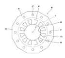
図2に示すように、固定子コア31は、筒状のヨーク31aから径方向内側に延びる複数のティース31bを有する。固定子コイル36は、固定子コア31のティース31bに装着された絶縁材料(例えば、絶縁性の樹脂材料)からなるブラケット37上に巻かれる。なお、ブラケット37は、固定子コア31の軸方向の両端面上に配置される。
As shown in FIG. 2, the
固定子コア31は、中心軸Pを中心に環状に配置された複数の分割コア32を有する。図2に示す例では、固定子コア31は、12個の分割コア32を有する。各分割コア32は、筒状のヨーク31aの一部を構成する分割ヨーク部32aと、一つのティース31bとを有する。
The
なお、固定子コア31を構成する分割コア32の数は、ティース31bの数に応じて適宜決められる。すなわち、固定子コアのティースの数が12個よりも多ければ、分割コアの数は12個よりも多い。一方、固定子コアのティースの数が12個よりも少なければ、分割コアの数は12個よりも少ない。
The number of
分割コア32は、複数枚積層された板状の分割コア片33を有する。図2に示す例では、分割コア32を構成する複数の分割コア片33は、同じ形状を有する。分割コア片33は、分割ヨーク部32aの一部を構成する分割ヨーク片33aと、ティース31bの一部を構成するティース片33bとを有する。複数の分割コア片33は、厚み方向に積層された状態で、分割ヨーク片33a及びティース片33bにそれぞれ設けられたかしめ部33cによって、互いに連結されている。
The divided
分割ヨーク部32aの周方向の端部と、該分割ヨーク部32aと周方向に隣り合う分割ヨーク部32aの周方向の端部とは、接触する。これにより、複数の分割コア32における分割ヨーク部32aによって、固定子コア31の円環状のヨーク31aが構成される。
The circumferential end of the
ハウジング4は、筒状であり、中心軸Pに沿って延びる。本実施形態では、ハウジング4は、内部に回転子2及び固定子3を収容可能な内部空間を有する円筒状である。ハウジング4は、円筒状の側壁4aと、側壁4aの軸方向の一方の端部を覆う底部4bと、を有する。ハウジング4の軸方向の他方側の開口は、蓋板5によって覆われる。ハウジング4及び蓋板5は、例えば鉄を含む材料によって構成される。有底筒状のハウジング4の開口が蓋板5によって覆われることにより、ハウジング4の内部には内部空間が形成される。特に図示しないが、蓋板5は、ハウジング4に対して、例えば、ボルト等によって固定されてもよいし、圧入や接着などの方法によって固定されてもよい。なお、ハウジング4及び蓋板5は、鉄を含む材料に限らず、アルミニウム(アルミニウム合金を含む)などの他の材料によって構成されてもよい。
The
(固定子コアの製造方法) 次に、上述のような構成を有
する固定子コア31の製造方法について説明する。 (Method for manufacturing a stator core) Next, a method for manufacturing a
図3は、固定子コア31の製造方法の一例を示すフローチャートである。図4は、鋼板打ち抜き工程において鋼板から打ち抜き鋼板40aを打ち抜く際の打ち抜き鋼板40aの配置を模式的に示す図である。図5は、分割コア片成形部49を成形する前の成形前鋼板40の平面図である。図6は、分割コア片33となる分割コア片成形部49が成形された成形鋼板50を示す平面図である。図7は、プッシュバック加工を模式的に示す図である。図8は、複数枚の成形鋼板50が厚み方向に積層された成形鋼板積層体60を示す斜視図である。図9は、成形鋼板積層体60を切断加工することによって得られた固定子コア積層体70を示す平面図である。
FIG. 3 is a flowchart showing an example of a method for manufacturing the
図4に示すように、最初に、図示しないプレス装置によって鋼板100から打ち抜き鋼板40aが打ち抜かれる。この工程が、図3に示す鋼板打抜き工程である(ステップS1)。打ち抜き鋼板40aは、後続する中央孔打抜き工程(ステップS2)及びスロット打ち抜き工程(ステップS3)において打ち抜かれる中央孔45及びスロット46を有しないが、図4においては、成形前鋼板40の構成の理解の容易のため、中央孔45及びスロット46を破線で図示する。
As shown in FIG. 4, first, the punched
本実施形態では、鋼板打抜き工程(ステップS1)によって得られた打ち抜き鋼板40aは、略正12角形である。打ち抜き鋼板40aは、後述するように、中央部分に製品部41と製品部の外側にスクラップ部42とを有する。スクラップ部42は、後述する積層工程(ステップS6)の後に続く加工工程(ステップS7)において、製品部41から切断除去される。製品部41とスクラップ部42との境界は、後述する成形鋼板積層体60を切断する際の切断位置Xであり、図4,図5及び図6及び図8において、破線で図示する。
In the present embodiment, the punched
また、鋼板打ち抜き工程で、打ち抜き鋼板40aのスクラップ部42の外周縁に、切り欠き部43が形成される。切り欠き部43がスクラップ部42の外周縁に形成されていることにより、後述の成形鋼板50の積層工程(ステップS6)時において、切り欠き部43の位置を容易に確認できる。これにより、成形鋼板50を回転させて積層する場合などにおいて、成形鋼板積層体60の特定の位置に切り欠き部43が存在するか否かによって、積層工程(ステップS6)の成形鋼板50の積層配置状態を容易に確認できる。すなわち、切り欠き部43は、成形鋼板50の積層配置の状態を確認するためのマークとして機能する。
Further, in the steel plate punching step, a
本実施形態では、切り欠き部43は、スクラップ部42の外周縁に1箇所形成されている。ただし、切り欠き部43の数は、1つに限定されるものではなく、スクラップ部42の外周縁の複数個所に配置されていてもよい。
In the present embodiment, the
なお、鋼板打ち抜き工程では、プレス装置は、図示しない上下の金型で鋼板100を挟むことによって打ち抜き鋼板40aを打ち抜く。そのため、切り欠き部43は、打ち抜き鋼板40aの厚み方向の全体にわたって形成される。
In the steel plate punching step, the press device punches the punched
上記のようにして鋼板100から打ち抜かれた打ち抜き鋼板40aに対し、中央孔打ち抜き工程(ステップS2)及びスロット打ち抜き工程(ステップS3)を行い、円形の中央孔45及びスロット46を形成することにより、成形前鋼板40が得られる。本実施形態では、最初に、打ち抜き鋼板40aに円形の中央孔45を打ち抜く中央孔打ち抜き工程(ステップS2)などの処理を行う。中央孔45の中心は、モータ1の中心軸Pと一致する。
The punched
次に、中央孔45を囲んで複数のティース片33bを形成するために、中央孔45の周りに複数のスロット46を打ち抜く。この工程が、図3に示すスロット打ち抜き工程である(ステップS3)。
Next, a plurality of
上述の中央孔打ち抜き工程(ステップS2)及びスロット打ち抜き工程(ステップS3)は、プレス加工によって行われる。中央孔打ち抜き工程及びスロット打ち抜き工程は、従来の固定子コアの製造方法と同様であるため、詳しい説明を省略する。 The above-mentioned central hole punching step (step S2) and slot punching step (step S3) are performed by press working. Since the central hole punching step and the slot punching step are the same as the conventional stator core manufacturing method, detailed description thereof will be omitted.
図5に、上述のように中央孔45及びスロット46が形成された成形前鋼板40を示す。
FIG. 5 shows the
図5に示すように、成形前鋼板40には、外周側に位置するスクラップ部42に複数の貫通穴47が打ち抜かれている。成形前鋼板40の貫通穴47の打ち抜きは、上述の中央孔打ち抜き工程(ステップS2)またはスロット打ち抜き工程(ステップS3)と同時に行ってもよいし、中央孔打ち抜き工程及びスロット打ち抜き工程の前、または後、もしくはそれらの工程の間で行ってもよい。
As shown in FIG. 5, in the
次に、図6に示すように、成形前鋼板40の中央孔45の外周側に、分割コア片33となる分割コア片成形部49a,49bを、環状に複数並んで成形し、成形鋼板50とする。分割コア片成形部49a,49bは、分割ヨーク片33aとなる分割ヨーク片成形部48及びティース片33bを有する。分割コア片成形部49を成形する工程では、分割ヨーク片成形部48を成形する。具体的には、分割コア片成形部49a,49bを成形する工程では、成形前鋼板40において、中央孔45の中心に対してティース片33bよりも外側を、分割ヨーク片33aの形状で厚み方向に打ち抜いた後、該打ち抜いた部分を元の位置に戻す、いわゆるプッシュバック加工を行う。この工程が、図3に示すプッシュバック工程である(ステップS4)。
Next, as shown in FIG. 6, a plurality of divided core
プッシュバック加工は、図7に示すように、成形前鋼板40の一部を厚み方向に挟み込む上下一対の工具を有する第1工具W1と、成形前鋼板40の一部を厚み方向に挟み込む上下一対の工具を有する第2工具W2とを用いて行われる。第1工具W1は、第2工具W2に対して、成形前鋼板40の厚み方向に移動可能である。本実施形態では、第1工具W1は、分割ヨーク片33aと同じ形状を有する。
As shown in FIG. 7, in the pushback processing, a first tool W1 having a pair of upper and lower tools for sandwiching a part of the
図7(a)に示すように、第1工具W1が第2工具W2に対して成形前鋼板40の厚み方向の一方に移動することにより、成形前鋼板40のうち第1工具W1に挟み込まれた部分と第2工具W2に挟み込まれた部分との境界では、せん断加工が行われる。なお、第2工具W2に対する第1工具W1の移動距離は、成形前鋼板40を分離させる移動距離であってもよいし、成形前鋼板40を分離させない移動距離であってもよい。
As shown in FIG. 7A, the first tool W1 moves in one direction in the thickness direction of the
その後、図7(b)に示すように、第1工具W1を第2工具W2に対して成形前鋼板40の厚み方向の他方に移動させることにより、第1工具W1を元の位置に戻す。これにより、前記境界では、成形前鋼板40のうち第1工具W1に挟み込まれた部分が第2工具W2に挟み込まれた部分に嵌め込まれる。
After that, as shown in FIG. 7B, the first tool W1 is returned to the original position by moving the first tool W1 to the other side in the thickness direction of the
分割コア片成形部49a,49bは、上述のようなプッシュバック加工が行われる押出部49aと、押し出されない非押出部49bとを有する。図5に示すように、押出部49aと非押出部49bとは、周方向に交互に位置する。
The split core
押出部49aと、プッシュバック加工によって押し出されない部分との間には、分断部49cが形成される。すなわち、押出部49aと非押出部49bとの境界、及び、押出部49aと成形前鋼板40の外周側との境界には、それぞれ、プッシュバック加工によって、分断部49cが形成される。分断部49cでは、押出部49aが、それ以外の部分に対して摩擦によって保持される。
A divided
ここで、上述のようにプッシュバック加工によって、分割コア片33となる分割コア片成形部49a,49bが環状に複数並んだ成形鋼板50を形成する工程が、プッシュバック工程(ステップS4)に対応する。
Here, the step of forming the molded
なお、鋼板100から打ち抜き鋼板40aを打ち抜く鋼板打抜き工程(ステップS1)、打ち抜き鋼板40aから中央孔45を打ち抜く中央孔打抜き工程(ステップS2)、複数のスロット46を打ち抜くスロット打ち抜き工程(ステップS3)を行うことにより成形前鋼板40を得る工程、及び、成形前鋼板40に分割コア片成形部49a,49bを成形するプッシュバック工程(ステップS4)を行なうことにより成形鋼板50を得る一連の工程が本発明の成形工程に対応する。
A steel plate punching step (step S1) for punching the punched
以上のように、プッシュバック加工によって、分割コア片成形部49a,49bを成形することにより、加工時に分割コア片成形部49a,49bが折り曲げられない。これにより、加工による残留応力及び残留ひずみの発生を抑制できる。よって、分割コア片33、すなわち固定子コア31の寸法精度を高めることができる。また、上述のように残留応力及び残留ひずみの発生を抑制することにより、分割コア片33における磁束の流れの乱れを抑制できるため、固定子コア31の磁気特性の低下を抑制できる。
As described above, by forming the divided core
上述のように、プッシュバック加工によって、成形前鋼板40に分割コア片成形部49a,49bを成形した後、分割ヨーク片成形部48及びティース片33bに、かしめ部33cを形成する。かしめ部33cは、分割ヨーク片成形部48及びティース片33bに、厚み方向の一方に突出するとともに前記厚み方向他方側の面に凹部を有する凸部を形成することにより、得られる。このかしめ部33cを形成する工程が、図3に示すかしめ部成形工程である(ステップS5)。
As described above, the split core
その後、分割コア片成形部49a,49bが形成された成形鋼板50を、厚み方向に積層して、隣り合う成形鋼板50のかしめ部33cをかしめることにより、図8に示すような成形鋼板積層体60を得る。この工程が、図3に示す積層工程である(ステップS6)。積層工程(ステップS6)は、本発明の成形鋼板積層工程に対応する。
After that, the molded
積層工程(ステップS6)では、複数の成形鋼板50を、中心軸Pの周りに所定の角度で1枚ずつ回転させ、周方向に異なる位置で積層する。このように成形鋼板50を1枚ずつ回転させて積層することにより、スクラップ部42の外周縁に設けられている切り欠き部43の位置は、それぞれ、周方向に異なる。それぞれの成形鋼板50の回転角度は、例えば、鋼板のティース片33bの数に応じて決定すればよい。本実施形態では、成形鋼板50は12個のティース片33bを有するため、成形鋼板50の回転角度は30度、もしくは30度の倍数とすることが好ましい。
In the laminating step (step S6), a plurality of molded
本実施形態では、複数の成形鋼板50を1枚ごとに30度ずつ回転させて積層しているが、複数枚の成形鋼板50の切り欠き部43が周方向で同じ位置となるように所定枚数ごとに回転させて積層してもよい。
In the present embodiment, a plurality of molded
なお、積層工程(ステップS6)において、スクラップ部42の貫通穴47は、回転角度の位置合わせに用いられる。すなわち、貫通孔47は、積層工程(ステップS6)において、軸線方向から見て貫通孔47が重なる位置に成形鋼板50を回転させて積層することで、複数の成形鋼板50を、中心軸Pがずれることなく、容易に積層できる。
In the laminating step (step S6), the through
上記のようにして作成された成形鋼板積層体60は、複数の成形鋼板50を1枚ごとに回転させて積層しているため、成形鋼板50の回転角度に応じて、側面に切り欠き部43の位置が周方向に異なった状態に配置される。これにより、成形鋼板積層体60の側面に表れた切り欠き部43の位置を確認することで、積層の状況を容易に視認することができる。
In the molded
成形鋼板積層体60は放電加工等によって、分割ヨーク片成形部48の外周側の切断位置X(図8に破線で示す位置)でスクラップ部42と製品部41とを切断される。これにより、図9に上面視で示すような固定子コア積層体70を得る。固定子コア積層体70は、本発明の鋼板積層体の一例である。この工程が、図3に示す加工工程(ステップS7)である。加工工程(ステップS7)は、本発明の積層体加工工程に対応する。成形鋼板積層体60を切断する際の切断位置Xは、分割ヨーク片成形部48の外周端よりも内周側の位置である。
The molded
上述のように成形鋼板積層体60からスクラップ部42を切断位置Xで切断した後も、固定子コア積層体70において隣り合う分割ヨーク片成形部48の間には、分断部49cが残る。これ
により、固定子コア積層体70を複数の分割コア32に分割することができる。 Even after the
以上説明したように、本実施形態にかかる鋼板積層体の製造方法によれば、各成形鋼板50の外周側に位置するスクラップ部42に設けられた切り欠き部43を、成形鋼板積層体60における成形鋼板50の位置決め用のマークとして用いることができる。よって、成形鋼板50を積層して得られた成形鋼板積層体60において、成形鋼板50の周方向の位置を目視により確認することができる。
As described above, according to the method for manufacturing a steel sheet laminate according to the present embodiment, the
また、本実施形態にかかる鋼板積層体の製造方法によれば、製品部41の外周に設けられているスクラップ部42が切り欠き部43を有するので、前記鋼板積層体である固定子コア31の磁気特性に影響を与えることがない。
Further, according to the method for manufacturing a steel plate laminate according to the present embodiment, since the
なお、本発明は上記実施形態に限定されるものではなく、その他種々の態様で実施可能である。 The present invention is not limited to the above embodiment, and can be implemented in various other embodiments.
前記実施形態では、モータ1の固定子コア31の製造方法について説明している。しかしながら、製品部の周囲にスクラップ部を有する成形鋼板を厚み方向に積層した構造を有する構造体を製造する際に、上述の実施形態の製造方法を適用してもよい。
In the above embodiment, a method of manufacturing the
前記実施形態では、モータ1の固定子コア31は、電磁鋼板を回転積層することにより得られる。しかしながら、回転積層ではない固定子コアを製造する際に、上述の実施形態の製造方法を適用してもよい。
In the above embodiment, the
前記実施形態では、モータ1の固定子コア31は、複数の分割コア32を有する。しかしながら、分割しない円板状の固定子コアを製造する際に、上述の実施形態の製造方法を適用してもよい。この場合は、分割コアを形成するためのプッシュバック加工を行う前の成形前鋼板を積層することによって、成形鋼板積層体を得ればよい。
In the embodiment, the
本発明は、板状の成形鋼板が複数枚積層された鋼板積層体の製造方法に適用可能である。 The present invention is applicable to a method for manufacturing a steel plate laminate in which a plurality of plate-shaped molded steel plates are laminated.
1 モータ 2 回転子 3 固定子 4 ハウジング 5 蓋板20 シャフト21 回転子コア22 マグネット31 固定子コア31a ヨーク31b ティース32 分割コア33 分割コア片33a 分割ヨーク片33b ティース片33c かしめ部36 固定子コイル37 ブラケット40 成形前鋼板40a 打ち抜き鋼板41 製品部42 スクラップ部43 切り欠き部45 中央孔46 スロット47 貫通孔48 分割ヨーク片成形部49a 分割コア片成形部(押出部)49b 分割コア片成形部(非押出部)49c 分断部50 成形鋼板60 成形鋼板積層体70 固定子コア積層体100 鋼板
1
Claims (7)
前記複数の成形鋼板を、厚み方向に積層することにより、成形鋼板積層体を得る成形鋼板積層工程と、
前記成形鋼板積層体から環状の切断位置に沿って前記スクラップ部を切断することによって鋼板積層体を得る積層体加工工程と、
を有する、鋼板積層体の製造方法。 A molding step of forming a plurality of molded steel sheets having a product portion, a scrap portion arranged outside the product portion, and a notch portion arranged on the outer edge of the scrap portion by punching and forming a steel plate. When,
A molded steel sheet laminating step of obtaining a molded steel sheet laminate by laminating the plurality of molded steel sheets in the thickness direction,
A laminate processing step of obtaining a steel plate laminate by cutting the scrap portion from the molded steel plate laminate along an annular cutting position .
A method for manufacturing a steel sheet laminate.
前記成形鋼板積層工程は、前記複数の成形鋼板を、前記所定の角度に応じて周方向に異なる位置で積層する、請求項1から4のいずれか1つに記載の鋼板積層体の製造方法。 The molded steel sheet is an electromagnetic steel sheet for a motor having a plurality of teeth arranged at predetermined angles in the circumferential direction.
The method for manufacturing a steel sheet laminate according to any one of claims 1 to 4, wherein the molded steel sheet laminating step is for laminating the plurality of molded steel sheets at different positions in the circumferential direction according to the predetermined angle.
前記成形鋼板は、
製品部と、
前記製品部の外周側に位置するスクラップ部と、
前記スクラップ部の外周縁に位置する切り欠き部とを備え、
前記製品部と前記スクラップ部との境界は環状の切断位置であり、
成形鋼板を中心軸周りに周方向に移動させることで、前記切り欠き部が他の成形鋼板の前記切り欠き部と異なる周方向位置に積層された、成形鋼板積層体。 In a molded steel sheet laminate in which a plurality of molded steel sheets obtained by punching and forming steel sheets are laminated in the thickness direction.
The molded steel sheet is
Product department and
The scrap part located on the outer peripheral side of the product part and
A notch located on the outer peripheral edge of the scrap portion is provided.
The boundary between the product part and the scrap part is an annular cutting position.
A molded steel sheet laminate in which the cutout portion is laminated at a position in the circumferential direction different from the cutout portion of another molded steel sheet by moving the molded steel sheet in the circumferential direction around the central axis.
Applications Claiming Priority (3)
| Application Number | Priority Date | Filing Date | Title |
|---|---|---|---|
| JP2017183311 | 2017-09-25 | ||
| JP2017183311 | 2017-09-25 | ||
| PCT/JP2018/025013 WO2019058703A1 (en) | 2017-09-25 | 2018-07-02 | Method for producing steel sheet stacked body, and moulded steel sheet stacked body |
Publications (2)
| Publication Number | Publication Date |
|---|---|
| JPWO2019058703A1 JPWO2019058703A1 (en) | 2020-10-15 |
| JP7067563B2 true JP7067563B2 (en) | 2022-05-16 |
Family
ID=65811188
Family Applications (1)
| Application Number | Title | Priority Date | Filing Date |
|---|---|---|---|
| JP2019543435A Active JP7067563B2 (en) | 2017-09-25 | 2018-07-02 | Manufacturing method of steel sheet laminate and molded steel plate laminate |
Country Status (3)
| Country | Link |
|---|---|
| JP (1) | JP7067563B2 (en) |
| CN (1) | CN111033981B (en) |
| WO (1) | WO2019058703A1 (en) |
Families Citing this family (1)
| Publication number | Priority date | Publication date | Assignee | Title |
|---|---|---|---|---|
| JP2021097493A (en) * | 2019-12-17 | 2021-06-24 | 日本電産株式会社 | Motor manufacturing line and motor manufacturing method |
Citations (2)
| Publication number | Priority date | Publication date | Assignee | Title |
|---|---|---|---|---|
| JP2012223035A (en) | 2011-04-13 | 2012-11-12 | Mitsubishi Electric Corp | Laminated core member for rotary electric machine |
| JP2012223034A (en) | 2011-04-13 | 2012-11-12 | Mitsubishi Electric Corp | Laminated core member for rotary electric machine |
Family Cites Families (9)
| Publication number | Priority date | Publication date | Assignee | Title |
|---|---|---|---|---|
| JPS6026496Y2 (en) * | 1980-01-09 | 1985-08-09 | 株式会社安川電機 | Laminated core for rotating electric machines |
| JPS5795158A (en) * | 1980-12-02 | 1982-06-12 | Toshiba Corp | Rotary electric machine |
| JP3180687B2 (en) * | 1996-10-16 | 2001-06-25 | 三菱電機株式会社 | Laminated core and method of manufacturing the laminated core |
| WO2010082465A1 (en) * | 2009-01-14 | 2010-07-22 | 三菱電機株式会社 | Method for manufacturing laminated core and tool for manufacturing same |
| CN101719705B (en) * | 2009-12-16 | 2012-06-20 | 陈石云 | Directional punching shear and processing method for iron core pieces of stator and rotor of rotary motor |
| JP5688919B2 (en) * | 2010-05-11 | 2015-03-25 | 株式会社三井ハイテック | Manufacturing method of laminated iron core |
| JP5570374B2 (en) * | 2010-09-29 | 2014-08-13 | 本田技研工業株式会社 | Laminate manufacturing method and laminate manufacturing apparatus |
| WO2017104403A1 (en) * | 2015-12-15 | 2017-06-22 | 三菱電機株式会社 | Core sheet, divided laminated core, stator, and method for manufacturing divided laminated core |
| CN107052135A (en) * | 2017-05-27 | 2017-08-18 | 宁波鸿达电机模具有限公司 | The anti-tripping waste structure of big piece groove profile cavity plate |
-
2018
- 2018-07-02 CN CN201880053785.5A patent/CN111033981B/en active Active
- 2018-07-02 WO PCT/JP2018/025013 patent/WO2019058703A1/en active Application Filing
- 2018-07-02 JP JP2019543435A patent/JP7067563B2/en active Active
Patent Citations (2)
| Publication number | Priority date | Publication date | Assignee | Title |
|---|---|---|---|---|
| JP2012223035A (en) | 2011-04-13 | 2012-11-12 | Mitsubishi Electric Corp | Laminated core member for rotary electric machine |
| JP2012223034A (en) | 2011-04-13 | 2012-11-12 | Mitsubishi Electric Corp | Laminated core member for rotary electric machine |
Also Published As
| Publication number | Publication date |
|---|---|
| CN111033981B (en) | 2022-10-28 |
| JPWO2019058703A1 (en) | 2020-10-15 |
| WO2019058703A1 (en) | 2019-03-28 |
| CN111033981A (en) | 2020-04-17 |
Similar Documents
| Publication | Publication Date | Title |
|---|---|---|
| JP5130196B2 (en) | Motor core | |
| JP7047847B2 (en) | Stator core manufacturing method, motor with stator core manufacturing method, stator core manufacturing equipment and laminated member manufacturing method | |
| JP7067563B2 (en) | Manufacturing method of steel sheet laminate and molded steel plate laminate | |
| CN110140286B (en) | Method for manufacturing rotor core, rotor, and motor | |
| JP2018074638A (en) | Stator, motor, and manufacturing method of stator | |
| JP5291774B2 (en) | Manufacturing method and manufacturing apparatus of laminated iron core | |
| JP6136477B2 (en) | Rotating electric machine and manufacturing method thereof | |
| US7197823B2 (en) | Method for manufacturing cylindrical members and method for manufacturing motors having the cylindrical member | |
| JP7067564B2 (en) | Stator core manufacturing method | |
| JP6508102B2 (en) | Rotating electrical machine and method of manufacturing split stator steel plate | |
| JP2020156295A (en) | Rotor of rotary electric machine and manufacturing method for the same | |
| JP4912088B2 (en) | Manufacturing method and manufacturing apparatus of laminated iron core | |
| JP6045638B2 (en) | Manufacturing method of laminated iron core | |
| JP2019017169A (en) | Rotary electric machine | |
| WO2020195157A1 (en) | Method for producing stator core plate, stator core plate, stator core, and die | |
| CN111742472A (en) | Method for manufacturing core component and core component | |
| JP6945955B2 (en) | Angle detector and manufacturing method of angle detector | |
| WO2023182257A1 (en) | Stator core manufacturing method, stator core, and motor | |
| WO2023182256A1 (en) | Stator core manufacturing method, stator core, and motor | |
| KR20190069972A (en) | Method for setting up motor core plate concentricity | |
| JP2003088012A (en) | Core sheet, manufacturing method therefor, stator, and motor | |
| WO2022209252A1 (en) | Method for manufacturing rotor for ipm motor and rotor for ipm motor | |
| WO2023162996A1 (en) | Stator core manufacturing method and stator core | |
| JP2022044485A (en) | Stator core and manufacturing method of stator core | |
| JPH08214510A (en) | Manufacture of stator |
Legal Events
| Date | Code | Title | Description |
|---|---|---|---|
| A621 | Written request for application examination |
Free format text: JAPANESE INTERMEDIATE CODE: A621 Effective date: 20201222 |
|
| A131 | Notification of reasons for refusal |
Free format text: JAPANESE INTERMEDIATE CODE: A131 Effective date: 20211207 |
|
| A521 | Request for written amendment filed |
Free format text: JAPANESE INTERMEDIATE CODE: A523 Effective date: 20220127 |
|
| TRDD | Decision of grant or rejection written | ||
| A01 | Written decision to grant a patent or to grant a registration (utility model) |
Free format text: JAPANESE INTERMEDIATE CODE: A01 Effective date: 20220329 |
|
| A61 | First payment of annual fees (during grant procedure) |
Free format text: JAPANESE INTERMEDIATE CODE: A61 Effective date: 20220411 |
|
| R151 | Written notification of patent or utility model registration |
Ref document number: 7067563 Country of ref document: JP Free format text: JAPANESE INTERMEDIATE CODE: R151 |