JP7067100B2 - Upper swivel - Google Patents

Upper swivel Download PDF

Info

Publication number
JP7067100B2
JP7067100B2 JP2018022180A JP2018022180A JP7067100B2 JP 7067100 B2 JP7067100 B2 JP 7067100B2 JP 2018022180 A JP2018022180 A JP 2018022180A JP 2018022180 A JP2018022180 A JP 2018022180A JP 7067100 B2 JP7067100 B2 JP 7067100B2
Authority
JP
Japan
Prior art keywords
cylinder
swivel frame
sheave
counterweight
swivel
Prior art date
Legal status (The legal status is an assumption and is not a legal conclusion. Google has not performed a legal analysis and makes no representation as to the accuracy of the status listed.)
Active
Application number
JP2018022180A
Other languages
Japanese (ja)
Other versions
JP2019137514A (en
Inventor
司 和又
大朗 松井
慎吾 栗原
Current Assignee (The listed assignees may be inaccurate. Google has not performed a legal analysis and makes no representation or warranty as to the accuracy of the list.)
Kobelco Construction Machinery Co Ltd
Original Assignee
Kobelco Construction Machinery Co Ltd
Priority date (The priority date is an assumption and is not a legal conclusion. Google has not performed a legal analysis and makes no representation as to the accuracy of the date listed.)
Filing date
Publication date
Application filed by Kobelco Construction Machinery Co Ltd filed Critical Kobelco Construction Machinery Co Ltd
Priority to JP2018022180A priority Critical patent/JP7067100B2/en
Publication of JP2019137514A publication Critical patent/JP2019137514A/en
Application granted granted Critical
Publication of JP7067100B2 publication Critical patent/JP7067100B2/en
Active legal-status Critical Current
Anticipated expiration legal-status Critical

Links

Images

Description

本発明は、旋回フレームに対してカウンタウェイトを脱着するカウンタウェイト脱着装置に関する。 The present invention relates to a counterweight attachment / detachment device that attaches / detaches a counterweight to / from a swivel frame.

例えば特許文献1などに、旋回フレームに対してカウンタウェイトを脱着(取り付けおよび取り外し)するための装置が記載されている(特許文献1の図2などを参照)。同文献に記載の技術では、シリンダが真上向きに伸びることで、シリンダが、リンク部材を介してカウンタウェイトを上げる。 For example, Patent Document 1 and the like describe a device for attaching / detaching (attaching / detaching) a counterweight to a swivel frame (see FIG. 2 of Patent Document 1 and the like). In the technique described in the same document, the cylinder extends straight up so that the cylinder raises the counterweight via the link member.

特開2006-219240号公報Japanese Unexamined Patent Publication No. 2006-219240

同文献に記載の技術では、カウンタウェイトを上げると、旋回フレームに対してシリンダの先端部が大きく上側に突出する。すると、カウンタウェイトを脱着するための装置と、この装置の上側に配置される物と、が互いに干渉するおそれがある。 In the technique described in the same document, when the counterweight is increased, the tip of the cylinder greatly protrudes upward with respect to the swivel frame. Then, the device for attaching / detaching the counterweight and the object arranged on the upper side of the device may interfere with each other.

そこで、本発明は、カウンタウェイト脱着装置の上側に配置される物と、カウンタウェイト脱着装置と、が互いに干渉することを抑制できる、カウンタウェイト脱着装置を提供することを目的とする。 Therefore, an object of the present invention is to provide a counterweight desorption device capable of suppressing interference between an object arranged above the counterweight desorption device and the counterweight desorption device.

カウンタウェイト脱着装置は、建設機械の旋回フレームに取り付けられる。カウンタウェイト脱着装置は、カウンタウェイトと、シリンダと、シーブと、張力部材と、を備える。前記カウンタウェイトは、前記旋回フレームに脱着される。前記シリンダは、前記旋回フレームに取り付けられ、伸縮可能である。前記シーブは、前記旋回フレームに回転自在に取り付けられる。前記張力部材は、前記シリンダおよび前記カウンタウェイトのそれぞれに接続され、前記シーブに掛けられ、前記シリンダから前記カウンタウェイトに張力により動力を伝える。前記シリンダは、前記シリンダの伸びる作動により前記張力部材を介して前記カウンタウェイトを上げる。前記シリンダの伸びる向きは、下向き、水平方向、または、水平方向に対して傾いた向きである。 The counterweight attachment / detachment device is attached to the swivel frame of the construction machine. The counterweight attachment / detachment device includes a counterweight, a cylinder, a sheave, and a tension member. The counterweight is attached to and detached from the swivel frame. The cylinder is attached to the swivel frame and can be expanded and contracted. The sheave is rotatably attached to the swivel frame. The tension member is connected to each of the cylinder and the counterweight, is hung on the sheave, and transmits power from the cylinder to the counterweight by tension. The cylinder raises the counterweight via the tension member by the extending operation of the cylinder. The extending direction of the cylinder is a downward direction, a horizontal direction, or a direction inclined with respect to the horizontal direction.

上記構成により、カウンタウェイト脱着装置の上側に配置される物と、カウンタウェイト脱着装置と、が互いに干渉することを抑制できる。 With the above configuration, it is possible to prevent the object placed above the counterweight desorption device and the counterweight desorption device from interfering with each other.

第1実施形態の脱着装置40を備える建設機械を横から見た図である。It is a figure which looked at the construction machine provided with the attachment / detachment device 40 of 1st Embodiment from the side. 図1に示す建設機械を上から見た図である。It is the figure which looked at the construction machine shown in FIG. 1 from the top. 図2に示すF3-F3矢視断面図である。FIG. 2 is a cross-sectional view taken along the line F3-F3 shown in FIG. 図3に示す状態よりもシリンダ60が伸びた状態を示す図3相当図である。It is a figure corresponding to FIG. 3 which shows the state which the cylinder 60 is extended more than the state shown in FIG. 図4に示すカウンタウェイト50が旋回フレーム30に接続され、図4に示す状態よりもシリンダ60が縮んだ状態を示す図4相当図である。FIG. 4 is a view corresponding to FIG. 4, showing a state in which the counterweight 50 shown in FIG. 4 is connected to the swivel frame 30 and the cylinder 60 is shrunk from the state shown in FIG. 第2実施形態の図3相当図である。FIG. 3 is a diagram corresponding to FIG. 3 of the second embodiment. 第3実施形態の図3相当図である。FIG. 3 is a diagram corresponding to FIG. 3 of the third embodiment. 第4実施形態の図3相当図である。FIG. 3 is a diagram corresponding to FIG. 3 of the fourth embodiment. 第5実施形態の図3相当図である。FIG. 3 is a diagram corresponding to FIG. 3 of the fifth embodiment. 第6実施形態の図3相当図である。FIG. 3 is a diagram corresponding to FIG. 3 of the sixth embodiment.

(第1実施形態)
図1~図5を参照して、第1実施形態の脱着装置40(カウンタウェイト脱着装置)を備える建設機械1について説明する。
(First Embodiment)
The construction machine 1 provided with the desorption device 40 (counterweight desorption device) of the first embodiment will be described with reference to FIGS. 1 to 5.

建設機械1は、図1に示すように、建設作業などの作業を行う機械であり、例えばクレーンであり、例えば移動式クレーンである。建設機械1は、下部走行体11と、上部旋回体20と、を備える。 As shown in FIG. 1, the construction machine 1 is a machine that performs work such as construction work, for example, a crane, and for example, a mobile crane. The construction machine 1 includes a lower traveling body 11 and an upper turning body 20.

下部走行体11は、建設機械1を走行させる部分である。下部走行体11は、図1に示す例ではクローラ11cを備え、例えばホイールを備えてもよい。例えば、建設機械1は、クローラクレーンでもよく、ホイールクレーンでもよい。 The lower traveling body 11 is a portion for traveling the construction machine 1. The lower traveling body 11 includes a crawler 11c in the example shown in FIG. 1, and may include, for example, a wheel. For example, the construction machine 1 may be a crawler crane or a wheel crane.

上部旋回体20は、下部走行体11よりも上側Z1に配置され、下部走行体11に対して旋回可能である。「上側Z1」などの方向の詳細は後述する。上部旋回体20は、ブーム21と、マスト23と、旋回フレーム30と、脱着装置40と、を備える。 The upper turning body 20 is arranged on the upper side Z1 of the lower running body 11 and can turn with respect to the lower running body 11. Details of the direction such as "upper Z1" will be described later. The upper swivel body 20 includes a boom 21, a mast 23, a swivel frame 30, and a detachable device 40.

ブーム21は、吊荷を吊る作業などを行う部材である。ブーム21は、旋回フレーム30に起伏可能に取り付けられる部材(起伏部材)である。例えば、ブーム21は、旋回フレーム30の前側X1端部などに取り付けられる。 The boom 21 is a member that performs work such as hanging a suspended load. The boom 21 is a member (undulating member) that is undulatingly attached to the swivel frame 30. For example, the boom 21 is attached to the front X1 end of the swivel frame 30 or the like.

マスト23は、例えばガイリンクおよびガイロープの少なくともいずれか(図示なし)を介して、ブーム21を後側X2から支持する。マスト23は、旋回フレーム30に起伏可能に取り付けられる起伏部材である。例えば、マスト23は、旋回フレーム30の前側X1部分などに取り付けられる。 The mast 23 supports the boom 21 from the rear X2, for example via at least one of a guy link and a guy rope (not shown). The mast 23 is an undulating member that is undulatingly attached to the swivel frame 30. For example, the mast 23 is attached to the front side X1 portion of the swivel frame 30 or the like.

旋回フレーム30は、上部旋回体20の本体部分である。旋回フレーム30は、ブーム21、マスト23、および脱着装置40などが取り付けられる構造物である。ここで、下部走行体11に対する上部旋回体20の旋回の回転軸の方向を上下方向Zとする。上下方向Zにおいて、下部走行体11から上部旋回体20に向かう側(向き)を上側Z1とし、その逆側を下側Z2とする。旋回フレーム30の長手方向を前後方向Xとする。前後方向Xにおいて、カウンタウェイト50(後述)から、旋回フレーム30へのブーム21の接続部に向かう側を、前側X1とし、その逆側を後側X2とする。上下方向Zおよび前後方向Xのそれぞれに直交する方向を、横方向Yとする。図2に示すように、旋回フレーム30は、上下方向Zから見て、長方形または略長方形などである。旋回フレーム30は、前板31と、後板33と、側板35と、旋回フレーム側ブラケット37(図3参照)と、を備える。 The swivel frame 30 is a main body portion of the upper swivel body 20. The swivel frame 30 is a structure to which a boom 21, a mast 23, a detachable device 40, and the like are attached. Here, the direction of the rotation axis of the rotation of the upper swivel body 20 with respect to the lower traveling body 11 is defined as the vertical direction Z. In the vertical direction Z, the side (direction) from the lower traveling body 11 toward the upper turning body 20 is the upper side Z1, and the opposite side is the lower side Z2. The longitudinal direction of the swivel frame 30 is the front-rear direction X. In the front-rear direction X, the side from the counterweight 50 (described later) toward the connection portion of the boom 21 to the turning frame 30 is the front side X1, and the opposite side is the rear side X2. The direction orthogonal to each of the vertical direction Z and the front-back direction X is defined as the horizontal direction Y. As shown in FIG. 2, the swivel frame 30 is a rectangle or a substantially rectangular shape when viewed from the vertical direction Z. The swivel frame 30 includes a front plate 31, a rear plate 33, a side plate 35, and a swivel frame side bracket 37 (see FIG. 3).

前板31は、旋回フレーム30の前側X1部分を構成する構造物であり、横方向Yに延びる。後板33は、旋回フレーム30の後側X2部分を構成する構造物であり、横方向Yに延びる。側板35・35は、旋回フレーム30の横方向Y外側の両側(左右)を構成する構造物である。側板35は、前板31と後板33とにつながれ、前後方向Xに延びる。 The front plate 31 is a structure constituting the front side X1 portion of the swivel frame 30, and extends in the lateral direction Y. The rear plate 33 is a structure constituting the rear side X2 portion of the swivel frame 30, and extends in the lateral direction Y. The side plates 35 and 35 are structures constituting both sides (left and right) on the lateral Y outer side of the swivel frame 30. The side plate 35 is connected to the front plate 31 and the rear plate 33, and extends in the front-rear direction X.

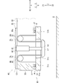
旋回フレーム側ブラケット37(図3参照)は、図1に示すカウンタウェイト50を旋回フレーム30に固定するための接続部である。なお、図1には、カウンタウェイト50が旋回フレーム30に固定されておらず、カウンタウェイト50が地面Gに置かれた状態を示す。図3に示すように、旋回フレーム側ブラケット37は、例えば、側板35から、下側Z2に突出する。旋回フレーム側ブラケット37は、ピン孔が形成されたものである。 The swivel frame side bracket 37 (see FIG. 3) is a connection portion for fixing the counterweight 50 shown in FIG. 1 to the swivel frame 30. Note that FIG. 1 shows a state in which the counterweight 50 is not fixed to the swivel frame 30 and the counterweight 50 is placed on the ground G. As shown in FIG. 3, the swivel frame side bracket 37 projects from the side plate 35 to the lower side Z2, for example. The swivel frame side bracket 37 has a pin hole formed therein.

脱着装置40(カウンタウェイト脱着装置)は、旋回フレーム30に対してカウンタウェイト50を脱着(取り付けおよび取り外し)する装置(機構)である。脱着装置40は、補助クレーンを用いなくても、旋回フレーム30にカウンタウェイト50を脱着できるようにするための装置(自力脱着装置)である。上記「補助クレーン」は、建設機械1(図1参照)の組立分解用のクレーンである。脱着装置40は、旋回フレーム30に取り付けられ、旋回フレーム30の後側X2部分に取り付けられる。図2に示すように、脱着装置40は、複数設けられ、横方向Yの両側(左右)に設けられる。2つの脱着装置40・40は、横方向Yに対称に(左右対称に)設けられる。なお、脱着装置40は、1つのみ設けられてもよく、3つ以上設けられてもよい。以下では、主に、1つの脱着装置40について説明する。図3に示すように、脱着装置40は、カウンタウェイト50と、シリンダ60と、連結部材67と、シーブ70と、ロープ80(張力部材)と、を備える。 The attachment / detachment device 40 (counterweight attachment / detachment device) is a device (mechanism) for attaching / detaching (attaching / detaching) the counterweight 50 to / from the swivel frame 30. The desorption device 40 is a device (self-desorption device) for enabling the counterweight 50 to be attached to and detached from the swivel frame 30 without using an auxiliary crane. The above-mentioned "auxiliary crane" is a crane for assembling and disassembling the construction machine 1 (see FIG. 1). The detachable device 40 is attached to the swivel frame 30 and is attached to the rear X2 portion of the swivel frame 30. As shown in FIG. 2, a plurality of attachment / detachment devices 40 are provided, and are provided on both sides (left and right) in the lateral direction Y. The two desorption devices 40 and 40 are provided symmetrically (symmetrically) in the lateral direction Y. It should be noted that only one attachment / detachment device 40 may be provided, or three or more may be provided. Hereinafter, one attachment / detachment device 40 will be mainly described. As shown in FIG. 3, the desorption device 40 includes a counterweight 50, a cylinder 60, a connecting member 67, a sheave 70, and a rope 80 (tension member).

カウンタウェイト50は、建設機械1(図1参照)のモーメントのつり合いをとるための、おもりである。カウンタウェイト50は、旋回フレーム30の後側X2部分に取り付け可能である。カウンタウェイト50は、旋回フレーム30に対して脱着される。カウンタウェイト50は、ベースウェイト51と、ウェイト53と、を備える。 The counterweight 50 is a weight for balancing the moments of the construction machine 1 (see FIG. 1). The counterweight 50 can be attached to the rear X2 portion of the swivel frame 30. The counterweight 50 is attached to and detached from the swivel frame 30. The counterweight 50 includes a base weight 51 and a weight 53.

ベースウェイト51は、カウンタウェイト50の下側Z2部分を構成する。ベースウェイト51は、旋回フレーム30の後側X2部分よりも下側Z2に配置される。図2に示すように、ベースウェイト51は、旋回フレーム30よりも右側かつ外側(横方向Y一方の外側)から左側かつ外側(横方向Y他方の外側)にわたって連続して設けられる。図3に示すように、ベースウェイト51は、略板状のベースウェイト本体部51aと、カウンタウェイト側ブラケット51bと、孔51cと、を備える。カウンタウェイト側ブラケット51bは、カウンタウェイト50を旋回フレーム30に固定するための接続部である。カウンタウェイト側ブラケット51bは、例えば、ベースウェイト本体部51aから上側Z1に突出する。ベースウェイト51は、ピン孔が形成されたものである。孔51cは、シリンダ60および連結部材67が、ベースウェイト51に干渉しないように形成される。例えば、孔51cは、シリンダ60および連結部材67が通過可能に形成される。シリンダ60および連結部材67が、ベースウェイト51に干渉しなければ、孔51cは、設けられなくてもよい。 The base weight 51 constitutes the lower Z2 portion of the counterweight 50. The base weight 51 is arranged in Z2 below the rear X2 portion of the swivel frame 30. As shown in FIG. 2, the base weight 51 is continuously provided from the right side and outside (outside of one side Y in the lateral direction) to the left side and outside (outside of one side Y in the lateral direction) of the swivel frame 30. As shown in FIG. 3, the base weight 51 includes a substantially plate-shaped base weight main body 51a, a counterweight side bracket 51b, and a hole 51c. The counterweight side bracket 51b is a connection portion for fixing the counterweight 50 to the swivel frame 30. The counterweight side bracket 51b protrudes from the base weight main body 51a to the upper side Z1, for example. The base weight 51 has a pin hole formed therein. The hole 51c is formed so that the cylinder 60 and the connecting member 67 do not interfere with the base weight 51. For example, the hole 51c is formed so that the cylinder 60 and the connecting member 67 can pass through. The hole 51c may not be provided as long as the cylinder 60 and the connecting member 67 do not interfere with the base weight 51.

ウェイト53は、略板状である。複数のウェイト53は、ベースウェイト51の上側Z1に積み上げられる。図2に示すように、ウェイト53は、旋回フレーム30よりも右側かつ外側(横方向Y一方の外側)、および、旋回フレーム30よりも左側かつ外側(横方向Y他方の外側)のそれぞれに配置される。 The weight 53 has a substantially plate shape. The plurality of weights 53 are stacked on the upper side Z1 of the base weight 51. As shown in FIG. 2, the weights 53 are arranged on the right side and outside of the swivel frame 30 (outside one of the lateral directions Y) and on the left side and outside of the swivel frame 30 (outside of the other sideways Y). Will be done.

シリンダ60は、図3および図4に示すように、伸縮(伸張および収縮)可能であり、シリンダ60の長手方向(軸方向)に伸縮可能である。図3に示すシリンダ60は、例えば油圧シリンダである。シリンダ60は、旋回フレーム30に取り付けられる。図2に示すように、例えば、シリンダ60は、旋回フレーム30の内側に配置される。上記「旋回フレーム30の内側」は、2枚の側板35・35よりも横方向Y内側、かつ、後板33よりも前側X1、かつ、前板31よりも後側X2の、旋回フレーム30に囲まれた空間(範囲)である。例えば、シリンダ60は、側板35の横方向Y内側の面に取り付けられる。例えば、シリンダ60は、後板33の前側X1の面などに取り付けられてもよい。図3に示すように、シリンダ60は、シリンダチューブ61と、シリンダロッド63と、を備える。シリンダチューブ61は、筒状の部材である。シリンダチューブ61は、旋回フレーム30に固定され、例えば側板35に固定される。シリンダロッド63は、棒状の部材である。シリンダロッド63は、シリンダチューブ61の軸方向(シリンダ60軸方向)に移動可能に、シリンダチューブ61に取り付けられる(差し込まれる)。 As shown in FIGS. 3 and 4, the cylinder 60 can be expanded and contracted (stretched and contracted), and can be expanded and contracted in the longitudinal direction (axial direction) of the cylinder 60. The cylinder 60 shown in FIG. 3 is, for example, a hydraulic cylinder. The cylinder 60 is attached to the swivel frame 30. As shown in FIG. 2, for example, the cylinder 60 is arranged inside the swivel frame 30. The "inside of the swivel frame 30" is the swivel frame 30 inside the lateral Y side of the two side plates 35 and 35, X1 on the front side of the rear plate 33, and X2 on the rear side of the front plate 31. It is an enclosed space (range). For example, the cylinder 60 is attached to the lateral Y inner surface of the side plate 35. For example, the cylinder 60 may be attached to the surface of the front side X1 of the rear plate 33 or the like. As shown in FIG. 3, the cylinder 60 includes a cylinder tube 61 and a cylinder rod 63. The cylinder tube 61 is a tubular member. The cylinder tube 61 is fixed to the swivel frame 30, for example, to the side plate 35. The cylinder rod 63 is a rod-shaped member. The cylinder rod 63 is attached (inserted) to the cylinder tube 61 so as to be movable in the axial direction of the cylinder tube 61 (cylinder 60 axial direction).

このシリンダ60が伸びるときの、シリンダチューブ61に対するシリンダロッド63の移動の向きを、「シリンダ60の伸びる向き」とする。図3および図4に示す例では、シリンダ60の伸びる向きは、真下向き(下側Z2と一致する向き)である。図3に示すシリンダ60の伸びる向きは、水平方向でもよい(図8に示すシリンダ460を参照)。上記「水平方向」は、横方向Yおよび前後方向Xの少なくともいずれかである。シリンダ60の伸びる向きは、水平方向に対して傾いた向きでもよい。水平方向に対して傾いた向きには、斜め下向き(下側Z2かつ水平方向)、および、斜め上向き(上側Z1かつ水平方向)が含まれる。シリンダ60の伸びる向きは、真上向き(上側Z1と一致する向き)ではない。 The direction of movement of the cylinder rod 63 with respect to the cylinder tube 61 when the cylinder 60 is extended is defined as the "extending direction of the cylinder 60". In the example shown in FIGS. 3 and 4, the extending direction of the cylinder 60 is directly downward (direction corresponding to the lower side Z2). The extending direction of the cylinder 60 shown in FIG. 3 may be the horizontal direction (see the cylinder 460 shown in FIG. 8). The "horizontal direction" is at least one of the horizontal direction Y and the front-back direction X. The extending direction of the cylinder 60 may be an inclination with respect to the horizontal direction. The direction inclined with respect to the horizontal direction includes an oblique downward direction (lower side Z2 and horizontal direction) and an oblique upward direction (upper side Z1 and horizontal direction). The extending direction of the cylinder 60 is not directly upward (the direction corresponding to the upper side Z1).

連結部材67は、シリンダ60軸方向に直交する方向の力がシリンダ60にかかることを抑制する。連結部材67は、シリンダロッド63に固定され、例えばシリンダロッド63の先端部に固定される。連結部材67は、シリンダロッド63と、複数本(例えば2本)のロープ80・80と、を互いに連結する。以下では、1つの脱着装置40に、2本のロープ80が設けられる場合について説明する。連結部材67は、シリンダロッド63から、シリンダ60軸方向に直交する方向に突出する。連結部材67は、図3に示す例では略直線状であり、略折れ線状でもよく、略曲線状でもよい。 The connecting member 67 suppresses the application of a force in the direction orthogonal to the cylinder 60 axis direction to the cylinder 60. The connecting member 67 is fixed to the cylinder rod 63, and is fixed to, for example, the tip end portion of the cylinder rod 63. The connecting member 67 connects the cylinder rod 63 and a plurality of (for example, two) ropes 80 and 80 to each other. Hereinafter, a case where two ropes 80 are provided in one attachment / detachment device 40 will be described. The connecting member 67 projects from the cylinder rod 63 in a direction orthogonal to the cylinder 60 axis direction. In the example shown in FIG. 3, the connecting member 67 has a substantially straight line shape, may have a substantially broken line shape, or may have a substantially curved line shape.

シーブ70は、ロープ80の力の伝わる向きを変える滑車である。シーブ70は、旋回フレーム30に回転自在に取り付けられる。シーブ70の回転軸は、旋回フレーム30に対して固定される。旋回フレーム30を基準としたとき、シーブ70は、定滑車である。例えば、シーブ70は、旋回フレーム30の内側に配置される。例えば、シーブ70は、側板35の横方向Y内側の面に取り付けられる。シーブ70は、図3に示す例では、1つの脱着装置40に2枚設けられる。シーブ70は、前側シーブ71と、後側シーブ73と、を備える(シーブ70の配置の詳細は後述)。 The sheave 70 is a pulley that changes the direction in which the force of the rope 80 is transmitted. The sheave 70 is rotatably attached to the swivel frame 30. The axis of rotation of the sheave 70 is fixed to the swivel frame 30. The sheave 70 is a constant pulley when the turning frame 30 is used as a reference. For example, the sheave 70 is arranged inside the swivel frame 30. For example, the sheave 70 is attached to the lateral Y inner surface of the side plate 35. In the example shown in FIG. 3, two sheaves 70 are provided in one desorption device 40. The sheave 70 includes a front sheave 71 and a rear sheave 73 (details of the arrangement of the sheave 70 will be described later).

ロープ80(張力部材)は、シリンダ60からカウンタウェイト50に、張力により動力を伝える部材である。ロープ80は、シリンダ60およびカウンタウェイト50のそれぞれに接続され、シーブ70に掛けられる。ロープ80は、連結部材67を介してシリンダロッド63に接続される。ロープ80は、ベースウェイト51に接続される。ロープ80は、例えばワイヤロープなどである。シリンダ60からカウンタウェイト50に、張力により動力を伝える「張力部材」は、ロープ80でなくてもよく、例えばチェーンでもよく、例えばベルトなどでもよい。ロープ80が2本設けられる場合、ロープ80は、例えば、前側ロープ81(前側張力部材)と、後側ロープ83(後側張力部材)と、を備える。 The rope 80 (tension member) is a member that transmits power from the cylinder 60 to the counterweight 50 by tension. The rope 80 is connected to each of the cylinder 60 and the counterweight 50 and hung on the sheave 70. The rope 80 is connected to the cylinder rod 63 via the connecting member 67. The rope 80 is connected to the base weight 51. The rope 80 is, for example, a wire rope. The "tension member" that transmits power from the cylinder 60 to the counterweight 50 by tension does not have to be the rope 80, and may be, for example, a chain or, for example, a belt. When two ropes 80 are provided, the rope 80 includes, for example, a front rope 81 (front tension member) and a rear rope 83 (rear tension member).

前側ロープ81は、前側シーブ71に掛けられる。例えば、前側ロープ81および前側シーブ71は、シリンダ60よりも前側X1に配置される。後側ロープ83は、後側シーブ73に掛けられる。例えば、後側ロープ83および後側シーブ73は、前側ロープ81および前側シーブ71よりも後側X2に配置され、シリンダ60よりも後側X2に配置される。 The front rope 81 is hung on the front sheave 71. For example, the front rope 81 and the front sheave 71 are arranged on the front side X1 of the cylinder 60. The rear rope 83 is hung on the rear sheave 73. For example, the rear rope 83 and the rear sheave 73 are arranged on the rear X2 of the front rope 81 and the front sheave 71, and on the rear X2 of the cylinder 60.

(シリンダ60、シーブ70、およびロープ80の配置)
シリンダ60は、シリンダ60の伸びる作動により、ロープ80を介してカウンタウェイト50を上げる(上側Z1に移動させる)。この作動が可能となるように、シリンダ60、シーブ70、およびロープ80が配置される。シリンダ60、シーブ70、およびロープ80の配置の例は次の通りである。
(Arrangement of cylinder 60, sheave 70, and rope 80)
The cylinder 60 raises the counterweight 50 (moves to the upper Z1) via the rope 80 by the extension operation of the cylinder 60. A cylinder 60, a sheave 70, and a rope 80 are arranged to allow this operation. An example of the arrangement of the cylinder 60, the sheave 70, and the rope 80 is as follows.

連結部材67とシーブ70との間のロープ80の配置の例は、次の通りである。ロープ80は、シリンダ60軸方向に直交する方向の力がシリンダ60にかかることを抑制できるように配置されることが好ましい。具体的には、連結部材67とシーブ70との間の複数本(例えば2本)のロープ80・80は、シリンダ60の中心軸に対して互いに回転対称(例えば線対称)に配置されることが好ましい。また、連結部材67とシーブ70との間の複数本(例えば2本)のロープ80・80のそれぞれは、シリンダ60軸方向(図3に示す例では上下方向Z)に延びることが好ましい。なお、連結部材67とシーブ70との間のロープ80は、シリンダ60軸方向に対して傾いた方向に延びてもよい。 An example of the arrangement of the rope 80 between the connecting member 67 and the sheave 70 is as follows. The rope 80 is preferably arranged so that a force in a direction orthogonal to the cylinder 60 axis direction can be suppressed from being applied to the cylinder 60. Specifically, a plurality of (for example, two) ropes 80 and 80 between the connecting member 67 and the sheave 70 are arranged in rotational symmetry (for example, line symmetry) with respect to the central axis of the cylinder 60. Is preferable. Further, it is preferable that each of the plurality of (for example, two) ropes 80 and 80 between the connecting member 67 and the sheave 70 extends in the cylinder 60 axial direction (vertical direction Z in the example shown in FIG. 3). The rope 80 between the connecting member 67 and the sheave 70 may extend in a direction inclined with respect to the cylinder 60 axis direction.

シーブ70とベースウェイト51との間のロープ80の配置の例は、次の通りである。図3に示す例では、シーブ70とベースウェイト51との間のロープ80は、上下方向Zに延びる。なお、シーブ70とベースウェイト51との間のロープ80は、上下方向Zに対して傾いた方向に延びてもよい。 An example of the arrangement of the rope 80 between the sheave 70 and the base weight 51 is as follows. In the example shown in FIG. 3, the rope 80 between the sheave 70 and the base weight 51 extends in the vertical direction Z. The rope 80 between the sheave 70 and the base weight 51 may extend in a direction inclined with respect to the vertical direction Z.

シーブ70の配置の例は、次の通りである。例えば、シーブ70の少なくとも一部(例えば全部)は、シリンダチューブ61の軸方向の長さ範囲L1内に配置される。長さ範囲L1は、シリンダチューブ61の軸方向における一端よりも他端側(図3では上側Z1の端よりも下側Z2)、かつ、他端よりも一端側(図3では下側Z2の端よりも上側Z1)の範囲である。この配置では、シリンダ60およびシーブ70を配置するための、シリンダ60軸方向(図3では上下方向Z)のスペースを抑制できる。 An example of the arrangement of the sheave 70 is as follows. For example, at least a portion (eg, all) of the sheave 70 is located within the axial length range L1 of the cylinder tube 61. The length range L1 is on the other end side of the cylinder tube 61 in the axial direction from one end (Z2 below the end of the upper Z1 in FIG. 3) and one end side from the other end (lower Z2 in FIG. 3). It is the range of Z1) above the edge. In this arrangement, the space in the cylinder 60 axial direction (vertical direction Z in FIG. 3) for arranging the cylinder 60 and the sheave 70 can be suppressed.

例えば、図3に示すように、シーブ70の少なくとも一部(例えば全部)は、シリンダ60および連結部材67の、長さ範囲L2内に配置される。長さ範囲L2は、シリンダ60が最も縮んだときの、シリンダ60および連結部材67の、シリンダ60軸方向における一端よりも他端側(図3では上側Z1の端よりも下側Z2)、かつ、他端よりも一端側(図3では下側Z2の端よりも上側Z1)の範囲である。この配置では、シリンダ60、連結部材67、およびシーブ70を配置するための、シリンダ60軸方向におけるスペースを抑制できる。 For example, as shown in FIG. 3, at least a portion (eg, all) of the sheave 70 is arranged within the length range L2 of the cylinder 60 and the connecting member 67. The length range L2 is the other end side of the cylinder 60 and the connecting member 67 from one end in the cylinder 60 axial direction (Z2 below the end of the upper Z1 in FIG. 3) when the cylinder 60 is most contracted. , One end side from the other end (Z1 above the end of the lower Z2 in FIG. 3). In this arrangement, the space for arranging the cylinder 60, the connecting member 67, and the sheave 70 in the cylinder 60 axial direction can be suppressed.

例えば、シーブ70の少なくとも一部(例えば全部)は、シリンダチューブ61の高さ範囲H1内に配置される。高さ範囲H1は、シリンダチューブ61の上側Z1の端よりも下側Z2、かつ、シリンダチューブ61の下側Z2の端よりも上側Z1の範囲である。この配置では、シリンダ60およびシーブ70を配置するための、上下方向Zのスペースを抑制できる。 For example, at least a portion (eg, all) of the sheave 70 is located within the height range H1 of the cylinder tube 61. The height range H1 is a range of Z2 below the end of the upper Z1 of the cylinder tube 61 and Z1 above the end of the lower Z2 of the cylinder tube 61. In this arrangement, the space in the vertical direction Z for arranging the cylinder 60 and the sheave 70 can be suppressed.

例えば、シーブ70の少なくとも一部(例えば全部)は、シリンダ60および連結部材67の、高さ範囲H2内に配置される。高さ範囲H2は、シリンダ60が最も縮んだときの、シリンダ60および連結部材67の、上側Z1の端よりも下側Z2、かつ、下側Z2の端よりも上側Z1の範囲である。この配置では、シリンダ60、連結部材67、およびシーブ70を配置するための、上下方向Zのスペースを抑制できる。なお、シリンダ60軸方向が上下方向Zと一致する場合は、長さ範囲L1と高さ範囲H1とが一致し、長さ範囲L2と高さ範囲H2とが一致する。 For example, at least a portion (eg, all) of the sheave 70 is located within the height range H2 of the cylinder 60 and the connecting member 67. The height range H2 is the range of the cylinder 60 and the connecting member 67 below the end of the upper Z1 and above the end of the lower Z2 when the cylinder 60 is most contracted. In this arrangement, the space in the vertical direction Z for arranging the cylinder 60, the connecting member 67, and the sheave 70 can be suppressed. When the cylinder 60 axis direction coincides with the vertical direction Z, the length range L1 and the height range H1 coincide with each other, and the length range L2 and the height range H2 coincide with each other.

図3に示す例では、シーブ70の少なくとも一部は、連結部材67の真上に配置される。シーブ70は、ベースウェイト51の真上に配置される。 In the example shown in FIG. 3, at least a part of the sheave 70 is arranged directly above the connecting member 67. The sheave 70 is arranged directly above the base weight 51.

(作動)
旋回フレーム30へのカウンタウェイト50の取り付けは、次のように行われる。まず、ベースウェイト51が、旋回フレーム30の真下の地面Gに置かれる。このとき、カウンタウェイト側ブラケット51bは、旋回フレーム側ブラケット37の真下に配置される。また、ウェイト53が、ベースウェイト51の上側Z1に積み上げられる。また、ロープ80が、連結部材67に接続され、シーブ70に掛けられ、ベースウェイト51に接続される。なお、ロープ80は、旋回フレーム30へのカウンタウェイト50の取り付け作業よりも前の時点(例えば輸送時など)から、連結部材67に接続されていてもよく、シーブ70に掛けられていてもよい。
(Operation)
The counterweight 50 is attached to the swivel frame 30 as follows. First, the base weight 51 is placed on the ground G directly below the swivel frame 30. At this time, the counterweight side bracket 51b is arranged directly below the swivel frame side bracket 37. Further, the weight 53 is stacked on the upper side Z1 of the base weight 51. Further, the rope 80 is connected to the connecting member 67, hung on the sheave 70, and connected to the base weight 51. The rope 80 may be connected to the connecting member 67 or hung on the sheave 70 from a time point prior to the work of attaching the counterweight 50 to the swivel frame 30 (for example, during transportation). ..

次に、図4に示すように、シリンダ60が、伸びる。シリンダ60の伸びる作動の動力は、連結部材67およびロープ80を介して、ベースウェイト51に伝わる。そして、カウンタウェイト50が、地面Gに対して持ち上げられる(上側Z1に移動する)。カウンタウェイト50が上側Z1に移動していくと、旋回フレーム側ブラケット37のピン孔とカウンタウェイト側ブラケット51bのピン孔との位置が合う。この状態で、ピンPが、各ピン孔に差し込まれる。その結果、カウンタウェイト50が、旋回フレーム30に固定される(ピン結合される)。 Next, as shown in FIG. 4, the cylinder 60 is extended. The power of the extending operation of the cylinder 60 is transmitted to the base weight 51 via the connecting member 67 and the rope 80. Then, the counterweight 50 is lifted with respect to the ground G (moves to the upper side Z1). As the counterweight 50 moves to the upper side Z1, the pin holes of the swivel frame side bracket 37 and the pin holes of the counterweight side bracket 51b are aligned with each other. In this state, the pin P is inserted into each pin hole. As a result, the counterweight 50 is fixed (pin-coupled) to the swivel frame 30.

シリンダ60が最も伸びた状態での、脱着装置40の最も上側Z1部分(最上部)の上下方向Zにおける位置を、「脱着装置40の最上位置」とする。図4に示す例では、脱着装置40の最上位置は、シリンダチューブ61の上側Z1端部の上下方向Zにおける位置である。また、旋回フレーム30の後側X2部分(脱着装置40の近傍)の上側Z1の面を、上面30aとする。脱着装置40の最上位置は、脱着装置40の上側Z1に配置される物と、脱着装置40と、が互いに干渉しないように設定される。上記「脱着装置40の上側Z1に配置される物」は、脱着装置40よりも上側Z1、かつ、脱着装置40と上下方向Zに対向する位置に配置される物である。脱着装置40の上側Z1に配置される物は、例えばマスト23(図1参照)などである。図4に示す例では、脱着装置40の最上位置は、旋回フレーム30の上面30aよりもわずかに上側Z1の位置である。この場合、脱着装置40の最上位置は、図1に示す最も伏せた(寝かせた)状態のマスト23の下側Z2の面よりも下側Z2の位置である。なお、図4に示す脱着装置40の最上位置は、上面30aの上下方向Zにおける位置と同じ位置でもよい。脱着装置40の最上位置は、上面30aよりも下側Z2の位置でもよい。 The position in the vertical direction Z of the uppermost Z1 portion (uppermost portion) of the detachable device 40 in the state where the cylinder 60 is most extended is referred to as the "uppermost position of the detachable device 40". In the example shown in FIG. 4, the uppermost position of the detachable device 40 is the position in the vertical direction Z of the upper Z1 end of the cylinder tube 61. Further, the surface of the upper side Z1 of the rear side X2 portion (near the desorption device 40) of the swivel frame 30 is referred to as the upper surface 30a. The uppermost position of the desorption device 40 is set so that the object arranged on the upper side Z1 of the desorption device 40 and the desorption device 40 do not interfere with each other. The above-mentioned "object arranged on the upper side Z1 of the desorption device 40" is an object arranged on the upper side Z1 of the desorption device 40 and at a position facing the desorption device 40 in the vertical direction Z. The object arranged on the upper side Z1 of the desorption device 40 is, for example, a mast 23 (see FIG. 1). In the example shown in FIG. 4, the uppermost position of the detachable device 40 is the position of Z1 slightly above the upper surface 30a of the swivel frame 30. In this case, the uppermost position of the desorption device 40 is the position of the lower Z2 of the mast 23 in the most prone (laid down) state shown in FIG. 1 with respect to the lower Z2 surface. The uppermost position of the detachable device 40 shown in FIG. 4 may be the same as the position of the upper surface 30a in the vertical direction Z. The uppermost position of the desorption device 40 may be the position of Z2 below the upper surface 30a.

次に、図5に示すように、シリンダ60が、縮む。シリンダ60が最も縮んだ状態での、シリンダ60および連結部材67の、最も下側Z2部分(最下部)の上下方向Zにおける位置を、「シリンダ60などの最下位置」とする。図5に示す例では、シリンダ60などの最下位置は、連結部材67の下側Z2端部の上下方向Zにおける位置である。シリンダ60などの最下位置は、図1に示す下部走行体11に対して上部旋回体20を旋回させたときに、脱着装置40と下部走行体11(例えばクローラ11c)とが互いに干渉しないように設定される。図5に示す例では、シリンダ60などの最下位置は、ベースウェイト51の底面(下側Z2の面)よりも上側Z1の位置である。なお、シリンダ60などの最下位置は、ベースウェイト51の底面の上下方向Zにおける位置と同じ位置でもよい。また、シリンダ60などの最下位置は、ベースウェイト51の底面よりも下側Z2の位置でもよい。 Next, as shown in FIG. 5, the cylinder 60 shrinks. The position of the lowermost Z2 portion (lowermost portion) of the cylinder 60 and the connecting member 67 in the vertical direction Z in the state where the cylinder 60 is most contracted is referred to as "the lowest position of the cylinder 60 or the like". In the example shown in FIG. 5, the lowest position of the cylinder 60 and the like is the position of the lower Z2 end of the connecting member 67 in the vertical direction Z. The lowest position of the cylinder 60 or the like is such that the desorption device 40 and the lower traveling body 11 (for example, the crawler 11c) do not interfere with each other when the upper rotating body 20 is swiveled with respect to the lower traveling body 11 shown in FIG. Is set to. In the example shown in FIG. 5, the lowest position of the cylinder 60 and the like is the position of Z1 above the bottom surface of the base weight 51 (the surface of the lower Z2). The lowest position of the cylinder 60 or the like may be the same as the position of the bottom surface of the base weight 51 in the vertical direction Z. Further, the lowest position of the cylinder 60 or the like may be the position of Z2 below the bottom surface of the base weight 51.

旋回フレーム30にカウンタウェイト50が固定された状態、かつ、シリンダ60が縮んだ状態(例えば最も縮んだ状態)のとき、ロープ80は、格納されてもよく、格納されなくてもよい。ロープ80は、例えば、束ねられてもよく、例えば、カウンタウェイト50や旋回フレーム30などに結び付けられてもよい。 When the counterweight 50 is fixed to the swivel frame 30 and the cylinder 60 is in the contracted state (for example, the most contracted state), the rope 80 may or may not be stored. The rope 80 may be bundled, for example, or may be tied to, for example, a counterweight 50, a swivel frame 30, or the like.

旋回フレーム30からのカウンタウェイト50の取り外しは、旋回フレーム30へのカウンタウェイト50の取り付けとは逆の手順により行われる。 The removal of the counterweight 50 from the swivel frame 30 is performed in the reverse procedure of the attachment of the counterweight 50 to the swivel frame 30.

(効果)
図3に示す脱着装置40(カウンタウェイト脱着装置)による効果は次の通りである。
(effect)
The effects of the desorption device 40 (counterweight desorption device) shown in FIG. 3 are as follows.

(第1の発明の効果)
脱着装置40は、建設機械1(図1参照)の旋回フレーム30に取り付けられる。脱着装置40は、カウンタウェイト50と、シリンダ60と、シーブ70と、ロープ80(張力部材)と、を備える。カウンタウェイト50は、旋回フレーム30に脱着される。シリンダ60は、旋回フレーム30に取り付けられ、伸縮可能である。
(Effect of the first invention)
The desorption device 40 is attached to the swivel frame 30 of the construction machine 1 (see FIG. 1). The desorption device 40 includes a counterweight 50, a cylinder 60, a sheave 70, and a rope 80 (tension member). The counterweight 50 is attached to and detached from the swivel frame 30. The cylinder 60 is attached to the swivel frame 30 and can be expanded and contracted.

[構成1-1]シーブ70は、旋回フレーム30に回転自在に取り付けられる。ロープ80は、シリンダ60およびカウンタウェイト50のそれぞれに接続され、シーブ70に掛けられ、シリンダ60からカウンタウェイト50に張力により動力を伝える。 [Structure 1-1] The sheave 70 is rotatably attached to the swivel frame 30. The rope 80 is connected to each of the cylinder 60 and the counterweight 50, is hung on the sheave 70, and transmits power from the cylinder 60 to the counterweight 50 by tension.

[構成1-2]シリンダ60は、シリンダ60の伸びる作動によりロープ80を介してカウンタウェイト50を上げる。シリンダ60の伸びる向きは、下向き、水平方向、または、水平方向に対して傾いた向きである。 [Structure 1-2] The cylinder 60 raises the counterweight 50 via the rope 80 by the extending operation of the cylinder 60. The extending direction of the cylinder 60 is a downward direction, a horizontal direction, or a direction inclined with respect to the horizontal direction.

上記[構成1-1]では、シリンダ60からカウンタウェイト50に動力を伝えるために、シーブ70およびロープ80が用いられる。よって、シーブ70およびロープ80が用いられない場合に比べ、シリンダ60の配置の自由度を高くできる。よって、脱着装置40の上側Z1に配置される物と、脱着装置40と、が互いに干渉することのないように、シリンダ60を配置しやすい。よって、脱着装置40の上側Z1に配置される物と、脱着装置40と、が互いに干渉することを抑制できる。 In the above [Structure 1-1], a sheave 70 and a rope 80 are used to transmit power from the cylinder 60 to the counterweight 50. Therefore, the degree of freedom in arranging the cylinder 60 can be increased as compared with the case where the sheave 70 and the rope 80 are not used. Therefore, it is easy to arrange the cylinder 60 so that the object arranged on the upper side Z1 of the attachment / detachment device 40 and the attachment / detachment device 40 do not interfere with each other. Therefore, it is possible to prevent the object arranged on the upper side Z1 of the desorption device 40 and the desorption device 40 from interfering with each other.

上記[構成1-2]では、シリンダ60の伸びる向きは、下向き(下側Z2)、水平方向、または、水平方向に対して傾いた向きである。よって、シリンダ60の伸びる向きが真上向きである場合に比べ、カウンタウェイト50を上げたときの、シリンダロッド63の位置を、下側Z2の位置(低い位置)にできる。その結果、脱着装置40の上側Z1に配置される物と、脱着装置40と、が互いに干渉することを抑制できる。 In the above [Structure 1-2], the extending direction of the cylinder 60 is a downward direction (lower side Z2), a horizontal direction, or a direction inclined with respect to the horizontal direction. Therefore, the position of the cylinder rod 63 when the counterweight 50 is raised can be set to the position of the lower Z2 (lower position) as compared with the case where the cylinder 60 extends in a straight upward direction. As a result, it is possible to prevent the object arranged on the upper side Z1 of the desorption device 40 and the desorption device 40 from interfering with each other.

(第2の発明の効果)
[構成2]シリンダ60の伸びる向きは、真下向き(斜め下向きを含まない下向き)である。
(Effect of the second invention)
[Structure 2] The extending direction of the cylinder 60 is directly downward (downward not including diagonally downward).

上記[構成2]により、シリンダ60の伸びる向きが水平方向または水平方向に対して傾いた方向である場合に比べ、シリンダ60を配置するための、水平方向のスペースを小さくできる。 According to the above [Structure 2], the space in the horizontal direction for arranging the cylinder 60 can be reduced as compared with the case where the extending direction of the cylinder 60 is the horizontal direction or the direction inclined with respect to the horizontal direction.

(脱着装置40の上側Z1にマスト23が配置される場合の効果)
図1に示すように、脱着装置40の真上にマスト23が配置される場合は、次の効果が得られてもよい。上記[構成1-2]により、脱着装置40でカウンタウェイト50を上げたときに、マスト23と、脱着装置40と、が互いに干渉することを抑制できる。マスト23と脱着装置40とが互いに干渉しない場合は、カウンタウェイト50を上げる際に、マスト23を最も伏せた状態よりも起こしておく必要がない。また、マスト23と脱着装置40とが互いに干渉しない場合は、マスト23の形状を特殊な形状にする必要がない。例えば、図2に示すように、マスト23の根元側(前側X1)部分から先端側(後側X2)部分にわたって、マスト23の横方向Yの幅を、一定または略一定にできる。よって、マスト23にかかるコストを低減できる。上記「特殊な形状」は、例えば、マスト23の根本側部分の横方向Yの幅に比べ、マスト23の先端側部分の横方向Yの幅が狭い形状などである。
(Effect when the mast 23 is arranged on the upper side Z1 of the desorption device 40)
As shown in FIG. 1, when the mast 23 is arranged directly above the desorption device 40, the following effects may be obtained. According to the above [Structure 1-2], it is possible to prevent the mast 23 and the desorption device 40 from interfering with each other when the counterweight 50 is raised by the desorption device 40. When the mast 23 and the attachment / detachment device 40 do not interfere with each other, it is not necessary to raise the mast 23 more than in the most prone state when raising the counterweight 50. Further, when the mast 23 and the attachment / detachment device 40 do not interfere with each other, it is not necessary to make the shape of the mast 23 a special shape. For example, as shown in FIG. 2, the width of the mast 23 in the lateral direction Y can be constant or substantially constant from the root side (front side X1) portion to the tip side (rear side X2) portion of the mast 23. Therefore, the cost of the mast 23 can be reduced. The above-mentioned "special shape" is, for example, a shape in which the width of the front end side portion of the mast 23 is narrower than the width of the lateral direction Y of the root side portion of the mast 23.

なお、本実施形態のマスト23の横方向Yの幅は、前側X1部分から後側X2部分までの間で、一定でなくてもよい。また、マスト23が伏せられた状態のときに、脱着装置40の真上にマスト23が配置されなくてもよい。 The width of the mast 23 in the lateral direction of the present embodiment does not have to be constant between the front side X1 portion and the rear side X2 portion. Further, when the mast 23 is in a prone state, the mast 23 may not be arranged directly above the desorption device 40.

(第2実施形態)
図6を参照して、第2実施形態の脱着装置240について、第1実施形態(図3などを参照)との相違点を説明する。なお、第2実施形態の脱着装置240のうち、第1実施形態との共通点については、第1実施形態と同一の符号を付すなどして、説明を省略した。共通点の説明を省略する点については、後述する他の実施形態の説明も同様である。
(Second Embodiment)
The difference between the detachable device 240 of the second embodiment and the first embodiment (see FIG. 3 and the like) will be described with reference to FIG. Of the desorption devices 240 of the second embodiment, the common points with the first embodiment are designated by the same reference numerals as those of the first embodiment, and the description thereof is omitted. The same applies to the description of other embodiments described later in that the description of the common points is omitted.

図3に示す例では、シリンダ60の伸びる向きは、真下向き(下側Z2と一致する向き)であった。一方、図6に示すように、本実施形態では、シリンダ260の伸びる向きは、斜め下向き(下側Z2向きかつ水平方向)である。シリンダ260の伸びる向きは、図6に示すように斜め下向きかつ前側X1向きでもよく、斜め下向きかつ後側X2向きでもよい。この場合、シリンダ260の伸びる向きが真下向きである場合(図3参照)に比べ、シリンダ260を配置するための上下方向Zのスペースを抑制できる。 In the example shown in FIG. 3, the extending direction of the cylinder 60 was directly downward (direction corresponding to the lower side Z2). On the other hand, as shown in FIG. 6, in the present embodiment, the extending direction of the cylinder 260 is diagonally downward (downward Z2 direction and horizontal direction). As shown in FIG. 6, the extending direction of the cylinder 260 may be diagonally downward and toward the front side X1, or diagonally downward and toward the rear side X2. In this case, the space in the vertical direction Z for arranging the cylinder 260 can be suppressed as compared with the case where the extending direction of the cylinder 260 is directly downward (see FIG. 3).

シーブ70の枚数、配置、およびロープ80の配置は、シリンダ260が伸びることでカウンタウェイト50が上がるように、適切に設定される(他の実施形態も同様)。図6に示す例では、前側ロープ81は、2枚の前側シーブ71(前側第1シーブ271a、および、前側第2シーブ271b)に掛けられる。連結部材67と前側第1シーブ271aとの間の前側ロープ81は、シリンダ60の軸方向に延び、上下方向Zに対して傾いた方向に延びる。前側第2シーブ271bとベースウェイト51との間の前側ロープ81は、上下方向Zに延びる。連結部材67と後側シーブ73との間の後側ロープ83は、シリンダ60の軸方向に延び(第1実施形態と同様)、上下方向Zに対して傾いた方向に延びる。 The number of sheaves 70, the arrangement, and the arrangement of the rope 80 are appropriately set so that the counterweight 50 is increased by extending the cylinder 260 (as in other embodiments). In the example shown in FIG. 6, the front rope 81 is hung on two front sheaves 71 (front first sheave 271a and front second sheave 271b). The front rope 81 between the connecting member 67 and the front first sheave 271a extends in the axial direction of the cylinder 60 and extends in a direction inclined with respect to the vertical direction Z. The front rope 81 between the front second sheave 271b and the base weight 51 extends in the vertical direction Z. The rear rope 83 between the connecting member 67 and the rear sheave 73 extends in the axial direction of the cylinder 60 (similar to the first embodiment) and extends in a direction inclined with respect to the vertical direction Z.

(第3実施形態)
図7を参照して、第3実施形態の脱着装置340について、第2実施形態(図6参照)との相違点を説明する。
(Third Embodiment)
With reference to FIG. 7, the difference between the detachable device 340 of the third embodiment and the second embodiment (see FIG. 6) will be described.

図6に示す例では、シリンダ260の伸びる向きは、斜め下向き(下側Z2向きかつ水平方向)であった。一方、図7に示すように、本実施形態のシリンダ360の伸びる向きは、斜め上向き(上側Z1向きかつ水平方向)である。シリンダ360の伸びる向きは、図7に示すように斜め上向きかつ後側X2向きでもよく、斜め上向きかつ前側X1向きでもよい。 In the example shown in FIG. 6, the extending direction of the cylinder 260 was diagonally downward (downward Z2 direction and horizontal direction). On the other hand, as shown in FIG. 7, the extending direction of the cylinder 360 of the present embodiment is diagonally upward (upward Z1 direction and horizontal direction). As shown in FIG. 7, the extending direction of the cylinder 360 may be diagonally upward and toward the rear side X2, or diagonally upward and toward the front side X1.

図7に示す例では、後側ロープ83は、2枚の後側シーブ73(後側第1シーブ373a、および、後側第2シーブ373b)に掛けられる。連結部材67と後側第1シーブ373aとの間の後側ロープ83は、シリンダ360の軸方向に延び、上下方向Zに対して傾いた方向に延びる。後側第2シーブ373bとベースウェイト51との間の後側ロープ83は、上下方向Zに延びる。 In the example shown in FIG. 7, the rear rope 83 is hung on two rear sheaves 73 (rear first sheave 373a and rear second sheave 373b). The rear rope 83 between the connecting member 67 and the rear first sheave 373a extends in the axial direction of the cylinder 360 and in a direction inclined with respect to the vertical direction Z. The rear rope 83 between the rear second sheave 373b and the base weight 51 extends in the vertical direction Z.

(第4実施形態)
図8を参照して、第4実施形態の脱着装置440について、第1実施形態(図4などを参照)との相違点を説明する。
(Fourth Embodiment)
The difference between the detachable device 440 of the fourth embodiment and the first embodiment (see FIG. 4 and the like) will be described with reference to FIG.

図4に示す例では、シリンダ60の伸びる向きは、真下向きであった。一方、図8に示すように、本実施形態のシリンダ460の伸びる向きは、斜め下および斜め上を除く水平方向である。シリンダ460の伸びる向きは、図8に示すように前向き(前側X1)でもよく、後ろ向き(後側X2)でもよく、横方向Y向きでもよく、前後方向Xおよび横方向Yのそれぞれに対して傾いた向きでもよい。 In the example shown in FIG. 4, the extending direction of the cylinder 60 was directly downward. On the other hand, as shown in FIG. 8, the extending direction of the cylinder 460 of the present embodiment is the horizontal direction excluding diagonally downward and diagonally upward. As shown in FIG. 8, the extending direction of the cylinder 460 may be forward (front side X1), backward (rear side X2), lateral Y direction, and tilted with respect to each of the front-rear direction X and the lateral direction Y. It may be oriented in the opposite direction.

(第5実施形態)
図9を参照して、第5実施形態の脱着装置540について、第1実施形態(図4などを参照)との相違点を説明する。相違点は、シーブ70の枚数、および、脱着装置540が動滑車590を備える点である。
(Fifth Embodiment)
With reference to FIG. 9, the difference between the detachable device 540 of the fifth embodiment and the first embodiment (see FIG. 4 and the like) will be described. The difference is the number of sheaves 70 and the attachment / detachment device 540 including the moving pulley 590.

動滑車590は、カウンタウェイト50に(ベースウェイト51に)回転自在に取り付けられる。動滑車590の回転軸は、ベースウェイト51と共に移動し、例えばベースウェイト51に対して固定される。動滑車590には、ロープ80が掛けられる。動滑車590には、前側ロープ81が掛けられる前側動滑車591と、後側ロープ83が掛けられる後側動滑車593と、がある。 The moving pulley 590 is rotatably attached to the counterweight 50 (to the baseweight 51). The rotation axis of the moving pulley 590 moves together with the base weight 51 and is fixed to, for example, the base weight 51. A rope 80 is hung on the moving pulley 590. The moving pulley 590 includes a front moving pulley 591 on which the front rope 81 is hung and a rear moving pulley 593 on which the rear rope 83 is hung.

前側シーブ71は、例えば2枚設けられ、前側第1シーブ571aと、前側第2シーブ571bと、を備える。連結部材67と前側第1シーブ571aとの間の前側ロープ81は、シリンダ60軸方向に延び、例えば上下方向Zに延びる。前側第2シーブ571bと動滑車590との間の前側ロープ81は、上下方向Zに延びる。ロープ80の両端部のうち、連結部材67に接続された側とは反対側の端部580eは、例えば旋回フレーム30に取り付けられる(固定される)。 Two front sheaves 71 are provided, for example, and include a front first sheave 571a and a front second sheave 571b. The front rope 81 between the connecting member 67 and the front first sheave 571a extends in the cylinder 60 axial direction, for example, in the vertical direction Z. The front rope 81 between the front second sheave 571b and the moving pulley 590 extends in the vertical direction Z. Of both ends of the rope 80, the end 580e on the side opposite to the side connected to the connecting member 67 is attached (fixed) to, for example, the swivel frame 30.

後側シーブ73、後側ロープ83、および後側動滑車593は、前側シーブ71、前側ロープ81、および前側動滑車591に対して、例えば前後方向Xに対称に設けられる(対称に設けられなくてもよい)。後側シーブ73は、例えば2枚設けられ、後側第1シーブ573a(前側第1シーブ571aに対応)と、後側第2シーブ573b(前側第2シーブ571bに対応)と、を備える。 The rear sheave 73, the rear rope 83, and the rear moving pulley 593 are provided symmetrically (not symmetrically) with respect to the front sheave 71, the front rope 81, and the front moving pulley 591, for example, in the anteroposterior direction X. May be). Two rear sheaves 73 are provided, for example, and include a rear first sheave 573a (corresponding to the front first sheave 571a) and a rear second sheave 573b (corresponding to the front second sheave 571b).

図9に示す脱着装置540による効果は、次の通りである。 The effects of the desorption device 540 shown in FIG. 9 are as follows.

(第3の発明の効果)
[構成3]脱着装置540は、動滑車590を備える。動滑車590は、カウンタウェイト50に回転自在に取り付けられる。動滑車590に、ロープ80が掛けられる。
(Effect of the third invention)
[Structure 3] The attachment / detachment device 540 includes a moving pulley 590. The moving pulley 590 is rotatably attached to the counterweight 50. The rope 80 is hung on the moving pulley 590.

上記[構成3]により、定滑車であるシーブ70のみを用いる場合に比べ、ロープ80にかかる張力を低減できる。よって、ロープ80に必要な強度を下げることができる。シリンダ60からカウンタウェイト50に、張力により動力を伝える「張力部材」がロープ80の場合は、ロープ80を細くでき、ロープ80を扱いやすくできる。 According to the above [Structure 3], the tension applied to the rope 80 can be reduced as compared with the case where only the sheave 70, which is a constant pulley, is used. Therefore, the strength required for the rope 80 can be lowered. When the "tension member" that transmits power from the cylinder 60 to the counterweight 50 by tension is a rope 80, the rope 80 can be made thinner and the rope 80 can be handled more easily.

(第6実施形態)
図10を参照して、第6実施形態の脱着装置640について、第5実施形態(図9参照)との相違点を説明する。相違点は、シーブ70および動滑車590それぞれの枚数、およびロープ80の掛け数である。なお、図10では、ロープ80の大部分について、中心軸(一点鎖線図参照)のみ図示した。
(Sixth Embodiment)
With reference to FIG. 10, the difference between the detachable device 640 of the sixth embodiment and the fifth embodiment (see FIG. 9) will be described. The differences are the number of each of the sheave 70 and the moving pulley 590, and the number of times the rope 80 is multiplied. In FIG. 10, most of the rope 80 is shown only on the central axis (see the alternate long and short dash line diagram).

図9に示す例では、1本のロープ80(例えば前側ロープ81)に掛けられる動滑車590(例えば前側動滑車591)は、1枚設けられた。一方、図10に示すように、本実施形態では、1本のロープ80(例えば前側ロープ81)に掛けられる動滑車590(例えば前側動滑車591)は、複数枚設けられる。そして、1本のロープ80は、動滑車590(例えば前側動滑車591)とシーブ70(例えば前側第2シーブ571b)とに交互に掛けられる(多本掛けにされる)。シーブ70は、多本掛けが可能となるように構成される。例えば、前側第2シーブ571bおよび後側第2シーブ573bのそれぞれは、複数枚設けられる。このように、動滑車590へのロープ80の掛け数を増やすことで、ロープ80にかかる張力をさらに低減できる。 In the example shown in FIG. 9, one moving pulley 590 (for example, front side moving pulley 591) hung on one rope 80 (for example, front rope 81) is provided. On the other hand, as shown in FIG. 10, in the present embodiment, a plurality of moving pulleys 590 (for example, front side moving pulleys 591) hung on one rope 80 (for example, front side rope 81) are provided. Then, one rope 80 is alternately hung on the moving pulley 590 (for example, the front side moving pulley 591) and the sheave 70 (for example, the front side second sheave 571b) (multi-rope hanging). The sheave 70 is configured so that multiple hooks can be hung. For example, a plurality of front second sheaves 571b and rear second sheaves 573b are provided. In this way, by increasing the number of times the rope 80 is hung on the moving pulley 590, the tension applied to the rope 80 can be further reduced.

(変形例)
上記実施形態は様々に変形されてもよい。例えば、互いに異なる実施形態の構成要素どうしが組み合わされてもよい。例えば、各構成要素の配置や形状が変更されてもよい。例えば、構成要素の数が変更されてもよく、構成要素の一部が設けられなくてもよい。例えば、構成要素どうしの固定や連結などは、直接的でも間接的でもよい。
(Modification example)
The above embodiment may be variously modified. For example, the components of different embodiments may be combined. For example, the arrangement and shape of each component may be changed. For example, the number of components may be changed and some of the components may not be provided. For example, fixing or connecting components may be direct or indirect.

例えば、図1に示すシリンダ60、シーブ70、ロープ80、および動滑車590(図10参照)などの配置は様々に変更されてもよい。例えば、脱着装置40の真上に、マスト23が配置されなくてもよく、マスト23以外の物が配置されてもよい。図2に示す脱着装置40は、旋回フレーム30の外側に配置されてもよい。 For example, the arrangement of the cylinder 60, the sheave 70, the rope 80, and the moving pulley 590 (see FIG. 10) shown in FIG. 1 may be variously changed. For example, the mast 23 may not be arranged directly above the desorption device 40, and an object other than the mast 23 may be arranged. The desorption device 40 shown in FIG. 2 may be arranged outside the swivel frame 30.

1 建設機械
20 上部旋回体
23 マスト(脱着装置上側配置物、脱着装置上側起伏部材)
30 旋回フレーム
40、240、340、440、540、640 脱着装置(カウンタウェイト脱着装置)
50 カウンタウェイト
60、260、360、460 シリンダ
70 シーブ
80 ロープ(張力部材)
590 動滑車
1 Construction machinery
20 Upper swivel body
23 Mast (attachment on the upper side of the desorption device, undulating member on the upper side of the desorption device)
30 Swivel frame 40, 240, 340, 440, 540, 640 Desorption device (counterweight desorption device)
50 Counterweight 60, 260, 360, 460 Cylinder 70 Sheave 80 Rope (tension member)
590 moving pulley

Claims (7)

回フレームと、
前記旋回フレームに取り付けられる脱着装置
前記脱着装置の真上に配置される脱着装置上側配置物と、
を備え、
前記脱着装置は、
前記旋回フレームに脱着されるカウンタウェイトと、
前記旋回フレームに取り付けられ、伸縮可能なシリンダと、
前記旋回フレームに回転自在に取り付けられるシーブと、
前記シリンダおよび前記カウンタウェイトのそれぞれに接続され、前記シーブに掛けられ、前記シリンダから前記カウンタウェイトに張力により動力を伝える張力部材と、
を備え、
前記シリンダは、前記シリンダの伸びる作動により前記張力部材を介して前記カウンタウェイトを上げ、
前記シリンダの伸びる向きは、下向き、水平方向、または、水平方向に対して傾いた向きであ
前記脱着装置上側配置物は、前記シリンダ、前記シーブ、および前記張力部材のそれぞれよりも上側、かつ、前記シリンダ、前記シーブ、および前記張力部材のそれぞれと上下方向に対向する位置に配置される、
上部旋回体
With a swivel frame
A detachable device attached to the swivel frame and
An arrangement on the upper side of the desorption device arranged directly above the desorption device,
Equipped with
The desorption device is
The counterweight attached to and detached from the swivel frame and
A cylinder that is attached to the swivel frame and can be expanded and contracted,
A sheave that can be rotatably attached to the swivel frame,
A tension member connected to each of the cylinder and the counterweight, hung on the sheave, and transmitting power from the cylinder to the counterweight by tension.
Equipped with
The cylinder raises the counterweight via the tension member by the extension operation of the cylinder.
The extending direction of the cylinder is a downward direction, a horizontal direction, or a direction inclined with respect to the horizontal direction.
The attachment / detachment device upper arrangement is arranged above each of the cylinder, the sheave, and the tension member, and at a position facing each of the cylinder, the sheave, and the tension member in the vertical direction.
Upper swivel body .
請求項1に記載の上部旋回体であって、The upper swivel body according to claim 1.
前記旋回フレームに起伏可能に取り付けられる脱着装置上側起伏部材を備え、A detachable device upper undulating member that can be undulated and attached to the swivel frame is provided.
最も伏せた状態の前記脱着装置上側起伏部材は、前記脱着装置上側配置物である、The undulating member on the upper side of the desorption device in the most prone state is the arrangement on the upper side of the desorption device.
上部旋回体。Upper swivel body.
請求項2に記載の上部旋回体であって、The upper swivel body according to claim 2.
前記脱着装置上側起伏部材は、マストである、The undulating member on the upper side of the desorption device is a mast.
上部旋回体。Upper swivel body.
請求項1~3のいずれか1項に記載の上部旋回体であって、The upper swivel body according to any one of claims 1 to 3.
前記旋回フレームは、The swivel frame
前記旋回フレームの前側部分を構成する前板と、The front plate constituting the front side portion of the swivel frame and
前記旋回フレームの後側部分を構成する後板と、The rear plate constituting the rear portion of the swivel frame and
前記前板と前記後板とにつながれ、前記旋回フレームの横方向両側部分を構成する左右の側板と、The left and right side plates, which are connected to the front plate and the rear plate and form both lateral portions of the swivel frame,
を備え、Equipped with
前記シリンダは、前記後板よりも前側、かつ、前記前板よりも後側、かつ、前記左右の側板よりも横方向内側の、前記旋回フレームに囲まれた範囲に配置される、The cylinder is arranged in a range surrounded by the swivel frame on the front side of the rear plate, on the rear side of the front plate, and laterally inside the left and right side plates.
上部旋回体。Upper swivel body.
請求項1~4のいずれか1項に記載の上部旋回体であって、The upper swivel body according to any one of claims 1 to 4.
前記旋回フレームは、The swivel frame
前記旋回フレームの前側部分を構成する前板と、The front plate constituting the front side portion of the swivel frame and
前記旋回フレームの後側部分を構成する後板と、The rear plate constituting the rear portion of the swivel frame and
前記前板と前記後板とにつながれ、前記旋回フレームの横方向両側部分を構成する左右の側板と、The left and right side plates, which are connected to the front plate and the rear plate and form both lateral portions of the swivel frame,
を備え、Equipped with
前記シーブは、前記後板よりも前側、かつ、前記前板よりも後側、かつ、前記左右の側板よりも横方向内側の、前記旋回フレームに囲まれた範囲に配置される、The sheave is arranged in a range surrounded by the swivel frame on the front side of the rear plate, on the rear side of the front plate, and laterally inside the left and right side plates.
上部旋回体。Upper swivel body.
請求項1~5のいずれか1項に記載の上部旋回体であって、
前記シリンダの伸びる向きは、真下向きである、
上部旋回体
The upper swivel body according to any one of claims 1 to 5 .
The extending direction of the cylinder is directly downward.
Upper swivel body .
請求項1~6のいずれか1項に記載の上部旋回体であって、
前記カウンタウェイトに回転自在に取り付けられ、前記張力部材が掛けられる動滑車を備える、
上部旋回体
The upper swivel body according to any one of claims 1 to 6 .
A moving pulley that is rotatably attached to the counterweight and to which the tension member is hung.
Upper swivel body .
JP2018022180A 2018-02-09 2018-02-09 Upper swivel Active JP7067100B2 (en)

Priority Applications (1)

Application Number Priority Date Filing Date Title
JP2018022180A JP7067100B2 (en) 2018-02-09 2018-02-09 Upper swivel

Applications Claiming Priority (1)

Application Number Priority Date Filing Date Title
JP2018022180A JP7067100B2 (en) 2018-02-09 2018-02-09 Upper swivel

Publications (2)

Publication Number Publication Date
JP2019137514A JP2019137514A (en) 2019-08-22
JP7067100B2 true JP7067100B2 (en) 2022-05-16

Family

ID=67694349

Family Applications (1)

Application Number Title Priority Date Filing Date
JP2018022180A Active JP7067100B2 (en) 2018-02-09 2018-02-09 Upper swivel

Country Status (1)

Country Link
JP (1) JP7067100B2 (en)

Families Citing this family (1)

* Cited by examiner, † Cited by third party
Publication number Priority date Publication date Assignee Title
CN111217264A (en) 2020-03-13 2020-06-02 徐工集团工程机械股份有限公司建设机械分公司 Crane with a movable crane

Citations (1)

* Cited by examiner, † Cited by third party
Publication number Priority date Publication date Assignee Title
JP2007119251A (en) 2005-10-26 2007-05-17 Liebherr Werk Ehingen Gmbh Mobile crane loading ballast

Family Cites Families (1)

* Cited by examiner, † Cited by third party
Publication number Priority date Publication date Assignee Title
DE3708458A1 (en) * 1987-03-16 1988-09-29 Krupp Gmbh Device for arranging a lowerable counterweight of a cantilever crane

Patent Citations (1)

* Cited by examiner, † Cited by third party
Publication number Priority date Publication date Assignee Title
JP2007119251A (en) 2005-10-26 2007-05-17 Liebherr Werk Ehingen Gmbh Mobile crane loading ballast

Also Published As

Publication number Publication date
JP2019137514A (en) 2019-08-22

Similar Documents

Publication Publication Date Title
JP5884247B2 (en) Movable rear balancing weight device for crawler crane
JP6627850B2 (en) Intermediate support bracket
JP6834789B2 (en) How to raise struts, and cranes
CN110775811B (en) Lifting hook device and crane
JP6468447B2 (en) Method for raising and lowering undulating member, and crane
JP7275625B2 (en) Strut backstop device
JP7067100B2 (en) Upper swivel
JP6645222B2 (en) How to attach a crane jib
WO2020026842A1 (en) Crane
JP4415643B2 (en) crane
JP6787645B1 (en) Spreader anti-vibration device
JP6870484B2 (en) Construction machinery
JP6638434B2 (en) Crane boom mounting method
JP5454308B2 (en) crane
JP7298419B2 (en) Crane assembly method and crane
JP6874747B2 (en) Upper spreader mounting device
JP6607224B2 (en) Hoisting device
WO2021020291A1 (en) Crane
WO2021053863A1 (en) Handrail device and work machine comprising same
JP7375379B2 (en) Auxiliary sheave device
CN110790151B (en) Rotary column for vehicle-mounted crane
JP7447613B2 (en) working machine
JP3950332B2 (en) How to use the counterweight attachment / detachment device
JP2022120477A (en) Derricking assist device
JP5519269B2 (en) Crane equipment

Legal Events

Date Code Title Description
A621 Written request for application examination

Free format text: JAPANESE INTERMEDIATE CODE: A621

Effective date: 20201207

A977 Report on retrieval

Free format text: JAPANESE INTERMEDIATE CODE: A971007

Effective date: 20211110

A131 Notification of reasons for refusal

Free format text: JAPANESE INTERMEDIATE CODE: A131

Effective date: 20211116

A521 Request for written amendment filed

Free format text: JAPANESE INTERMEDIATE CODE: A523

Effective date: 20220117

TRDD Decision of grant or rejection written
A01 Written decision to grant a patent or to grant a registration (utility model)

Free format text: JAPANESE INTERMEDIATE CODE: A01

Effective date: 20220329

A61 First payment of annual fees (during grant procedure)

Free format text: JAPANESE INTERMEDIATE CODE: A61

Effective date: 20220411

R150 Certificate of patent or registration of utility model

Ref document number: 7067100

Country of ref document: JP

Free format text: JAPANESE INTERMEDIATE CODE: R150