JP7066880B2 - Coiling machine, coil spring manufacturing method and coil spring - Google Patents
Coiling machine, coil spring manufacturing method and coil spring Download PDFInfo
- Publication number
- JP7066880B2 JP7066880B2 JP2020570383A JP2020570383A JP7066880B2 JP 7066880 B2 JP7066880 B2 JP 7066880B2 JP 2020570383 A JP2020570383 A JP 2020570383A JP 2020570383 A JP2020570383 A JP 2020570383A JP 7066880 B2 JP7066880 B2 JP 7066880B2
- Authority
- JP
- Japan
- Prior art keywords
- wire
- laser beam
- coil spring
- cutter
- irradiation
- Prior art date
- Legal status (The legal status is an assumption and is not a legal conclusion. Google has not performed a legal analysis and makes no representation as to the accuracy of the status listed.)
- Active
Links
Images


Classifications
-
- B—PERFORMING OPERATIONS; TRANSPORTING
- B21—MECHANICAL METAL-WORKING WITHOUT ESSENTIALLY REMOVING MATERIAL; PUNCHING METAL
- B21F—WORKING OR PROCESSING OF METAL WIRE
- B21F11/00—Cutting wire
- B21F11/005—Cutting wire springs
-
- B—PERFORMING OPERATIONS; TRANSPORTING
- B23—MACHINE TOOLS; METAL-WORKING NOT OTHERWISE PROVIDED FOR
- B23K—SOLDERING OR UNSOLDERING; WELDING; CLADDING OR PLATING BY SOLDERING OR WELDING; CUTTING BY APPLYING HEAT LOCALLY, e.g. FLAME CUTTING; WORKING BY LASER BEAM
- B23K26/00—Working by laser beam, e.g. welding, cutting or boring
- B23K26/352—Working by laser beam, e.g. welding, cutting or boring for surface treatment
- B23K26/354—Working by laser beam, e.g. welding, cutting or boring for surface treatment by melting
-
- B—PERFORMING OPERATIONS; TRANSPORTING
- B21—MECHANICAL METAL-WORKING WITHOUT ESSENTIALLY REMOVING MATERIAL; PUNCHING METAL
- B21F—WORKING OR PROCESSING OF METAL WIRE
- B21F3/00—Coiling wire into particular forms
- B21F3/02—Coiling wire into particular forms helically
- B21F3/04—Coiling wire into particular forms helically externally on a mandrel or the like
-
- B—PERFORMING OPERATIONS; TRANSPORTING
- B21—MECHANICAL METAL-WORKING WITHOUT ESSENTIALLY REMOVING MATERIAL; PUNCHING METAL
- B21F—WORKING OR PROCESSING OF METAL WIRE
- B21F35/00—Making springs from wire
-
- B—PERFORMING OPERATIONS; TRANSPORTING
- B23—MACHINE TOOLS; METAL-WORKING NOT OTHERWISE PROVIDED FOR
- B23K—SOLDERING OR UNSOLDERING; WELDING; CLADDING OR PLATING BY SOLDERING OR WELDING; CUTTING BY APPLYING HEAT LOCALLY, e.g. FLAME CUTTING; WORKING BY LASER BEAM
- B23K26/00—Working by laser beam, e.g. welding, cutting or boring
- B23K26/0093—Working by laser beam, e.g. welding, cutting or boring combined with mechanical machining or metal-working covered by other subclasses than B23K
-
- B—PERFORMING OPERATIONS; TRANSPORTING
- B23—MACHINE TOOLS; METAL-WORKING NOT OTHERWISE PROVIDED FOR
- B23K—SOLDERING OR UNSOLDERING; WELDING; CLADDING OR PLATING BY SOLDERING OR WELDING; CUTTING BY APPLYING HEAT LOCALLY, e.g. FLAME CUTTING; WORKING BY LASER BEAM
- B23K26/00—Working by laser beam, e.g. welding, cutting or boring
- B23K26/02—Positioning or observing the workpiece, e.g. with respect to the point of impact; Aligning, aiming or focusing the laser beam
- B23K26/03—Observing, e.g. monitoring, the workpiece
- B23K26/034—Observing the temperature of the workpiece
-
- B—PERFORMING OPERATIONS; TRANSPORTING
- B23—MACHINE TOOLS; METAL-WORKING NOT OTHERWISE PROVIDED FOR
- B23K—SOLDERING OR UNSOLDERING; WELDING; CLADDING OR PLATING BY SOLDERING OR WELDING; CUTTING BY APPLYING HEAT LOCALLY, e.g. FLAME CUTTING; WORKING BY LASER BEAM
- B23K26/00—Working by laser beam, e.g. welding, cutting or boring
- B23K26/08—Devices involving relative movement between laser beam and workpiece
- B23K26/083—Devices involving movement of the workpiece in at least one axial direction
-
- B—PERFORMING OPERATIONS; TRANSPORTING
- B23—MACHINE TOOLS; METAL-WORKING NOT OTHERWISE PROVIDED FOR
- B23K—SOLDERING OR UNSOLDERING; WELDING; CLADDING OR PLATING BY SOLDERING OR WELDING; CUTTING BY APPLYING HEAT LOCALLY, e.g. FLAME CUTTING; WORKING BY LASER BEAM
- B23K26/00—Working by laser beam, e.g. welding, cutting or boring
- B23K26/60—Preliminary treatment
Description
この発明は、コイルばねを製造するためのコイリングマシンと、コイルばねの製造方法と、コイルばねに関する。 The present invention relates to a coiling machine for manufacturing a coil spring, a method for manufacturing a coil spring, and a coil spring.
コイルばねを製造する装置として、例えば特許文献1に記載されているコイルばね成形機が知られている。このコイルばね成形機は、螺旋状に成形されるワイヤの長さに基づいて切断部位の位置を予め算出し、その切断部位を高周波加熱によって軟化させた状態でワイヤを切断する。
As an apparatus for manufacturing a coil spring, for example, a coil spring forming machine described in
一方、特許文献2に記載されているばね製造装置のように、螺旋状に成形されるワイヤをレーザ光により切断するコイリングマシンも知られている。
On the other hand, a coiling machine that cuts a wire formed in a spiral shape by a laser beam, such as the spring manufacturing apparatus described in
特許文献1のコイルばね成形機では、高周波加熱によって切断部位を加熱していることから、切断部位の加温の応答性が良くない。しかも、高周波加熱によって切断部位の加熱を継続している状態で切断することから、切断に用いる部材に高周波加熱の影響が及ぶことがある。さらに、高周波加熱は、切断部位の加熱の応答性が十分でないことや、ワイヤが部分的に加熱された状態でコイリングされることから、ばねの成形精度を一定に維持することが難しくなる虞がある。
In the coil spring forming machine of
一方、特許文献2のばね製造装置では、ワイヤを切断することが可能な高出力のレーザ光が必要となる。この場合、レーザ光の照射に起因したスパッタが発生し得るし、レーザ光がワイヤだけでなくばね製造装置の各部にも照射され得るため、これらの対策を講じなければならない。
On the other hand, the spring manufacturing apparatus of
本発明は、螺旋状に成形されたワイヤを容易に切断することができるコイリングマシンおよびコイルばねの製造方法を提供すること、さらには品質に優れたコイルばねを提供することを目的の一つとする。 It is one of the objects of the present invention to provide a coiling machine and a method for manufacturing a coil spring capable of easily cutting a spirally formed wire, and further to provide a coil spring having excellent quality. ..
本発明に係るコイリングマシンは、螺旋状に成形されたワイヤに対してレーザ光を照射することにより前記ワイヤの一部を加熱するレーザ加熱機と、前記レーザ光の照射が停止された後において、前記レーザ光が照射される前よりも高温になっている前記ワイヤの部位を切断する切断部品と、を備える。 The coiling machine according to the present invention is a laser heater that heats a part of the wire by irradiating the spirally formed wire with a laser beam, and after the irradiation of the laser beam is stopped. A cutting component for cutting a portion of the wire whose temperature is higher than that before the laser beam is irradiated is provided.
本発明に係るコイルばねの製造方法は、螺旋状に成形されたワイヤに対してレーザ光を照射し、前記ワイヤの一部を加熱することと、前記レーザ光の照射が停止された後において、前記レーザ光が照射される前よりも高温になっている前記ワイヤの部位を切断することと、を含む。 The method for manufacturing a coil spring according to the present invention is to irradiate a spirally formed wire with a laser beam to heat a part of the wire, and after the irradiation of the laser beam is stopped, It includes cutting a portion of the wire that is hotter than before the laser beam is applied.
本発明に係るコイルばねは、第1端末と、前記第1端末の反対側の第2端末とを有するワイヤにより形成され、前記第1端末は、レーザ光の第1照射痕を有し、前記第1照射痕は、前記ワイヤの母材よりも硬い焼入硬化部と、前記母材よりも軟らかい前記焼入硬化部の周囲の第1熱影響部と、を含み、前記第1熱影響部は、前記第1端末の端面の少なくとも一部に及んでいる。 The coil spring according to the present invention is formed of a wire having a first terminal and a second terminal on the opposite side of the first terminal, and the first terminal has a first irradiation mark of a laser beam and is described above. The first irradiation mark includes a quench-hardened portion that is harder than the base material of the wire and a first heat-affected zone around the quench-hardened portion that is softer than the base material, and the first heat-affected zone. Covers at least a part of the end face of the first terminal.
本発明によれば、螺旋状に成形されたワイヤを容易に切断することができるコイリングマシンおよびコイルばねの製造方法を提供することができる。さらに、本発明によれば、品質に優れたコイルばねを提供することができる。 INDUSTRIAL APPLICABILITY According to the present invention, it is possible to provide a coiling machine and a method for manufacturing a coil spring capable of easily cutting a wire formed in a spiral shape. Further, according to the present invention, it is possible to provide a coil spring having excellent quality.
以下、コイリングマシン、コイルばねの製造方法およびコイルばねに関するいくつかの実施形態につき、図面を参照しながら説明する。 Hereinafter, some embodiments relating to the coiling machine, the method for manufacturing the coil spring, and the coil spring will be described with reference to the drawings.
[第1実施形態]
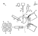
図1は、第1実施形態に係るコイリングマシン100の要部を示す概略的な斜視図である。図2は、図1のコイリングマシン100の概略的な正面図である。図1および図2に示すように、X方向、Y方向、Z方向およびθ方向を定義する。X方向、Y方向およびZ方向は、互いに直交する。X方向は、ワイヤの送り出し方向である。Z方向は、コイルばねの螺旋が形成される方向である。θ方向は、コイルばねを構成するワイヤが巻かれる方向である。[First Embodiment]
FIG. 1 is a schematic perspective view showing a main part of the
コイリングマシン100は、螺旋成形ユニット10と、加熱ユニット(レーザ加熱機20)と、切断ユニット30と、制御ユニット40とを備えている。
The
螺旋成形ユニット10は、図1および図2に示すように、コイルばねの材料であるワイヤ1を送りながら螺旋状に成形する。このような螺旋成形ユニット10は、一対の駆動ローラ11、一対の従動ローラ12、ワイヤガイド13、第1成形ローラ14、第2成形ローラ15およびピッチツール16を備えている。
As shown in FIGS. 1 and 2, the spiral forming
各駆動ローラ11と各従動ローラ12は、隙間を介して対向している。各駆動ローラ11が回転すると、ワイヤ1を介して各従動ローラ12が回転する。各駆動ローラ11と各従動ローラ12によって挟み込まれたワイヤ1は、図1および図2に示すX方向に移動する。ワイヤガイド13には、ワイヤ1が挿入されている。ワイヤガイド13は、ワイヤ1がX方向に直進するようにガイドして、ワイヤ1を第1成形ローラ14に導く。
Each
第1成形ローラ14、第2成形ローラ15およびピッチツール16は、θ方向において順に配置され、かつ、上方から見た場合にZ方向に向かってこれらの位置が異なっている。第1成形ローラ14は、X方向に移動するワイヤ1を図1に示すY方向に円弧状に湾曲させながら移動させつつ、第2成形ローラ15に導く。第2成形ローラ15は、円弧状に移動するワイヤ1をさらに円弧状に湾曲させながら、ピッチツール16に導く。ピッチツール16によってガイドされたワイヤ1は、螺旋状に成形された状態で、図1に示すZ方向に移動する。
The first forming
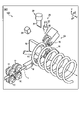
レーザ加熱機20は、図2に示すように、螺旋状に成形されたワイヤ1の一部が加熱されるようにレーザ光を照射する。このレーザ光の照射により、ワイヤ1に他の部分よりも高温の加熱部位1Vが形成される。このようなレーザ加熱機20は、レーザ発振器21、光ファイバ22およびビームスポット調整器23を備えている。
As shown in FIG. 2, the
レーザ発振器21には、例えば、レーザ光を生成する半導体レーザを用いることができる。光ファイバ22は、レーザ発振器21で生成されたレーザ光をビームスポット調整器23まで伝送する。ビームスポット調整器23は、レーザ光のビーム形状を矩形や円形に調整する。ビームスポット調整器23としては、例えば、ビームホモジナイザなどの光学素子を用いることができる。
As the
レーザ加熱機20は、加熱部位1Vの温度を測定する測定器24をさらに備えてもよい。測定器24は、例えば、ワイヤ1の加熱部位1Vの温度を検出するセンサを備えている。測定器24は、切断ユニット30との干渉を避けるために、切断ユニット30の側方に設けられてもよい。測定器24は、後述するカッタ31との干渉を避けるために、カッタ31の作動と連動して、カッタ31から離れるように移動させる構成とすることもできる。測定器24による測定結果は、例えば、切断ユニット30によるワイヤ1の切断タイミングの制御に用いることができる。
The
なお、測定器24は、必須の構成ではない。すなわち、測定器24を用いることなく、予めワイヤ1の切断に関する各種の条件を設定しておき、当該条件に基づいて切断ユニット30が加熱部位1Vを切断してもよい。
The measuring
レーザ加熱機20は、ビームスポット調整器23をワイヤ1の加熱部位1Vに接近および離間させる移動ステージをさらに備えてもよい。移動ステージは、例えば、直動ステージやロボットハンドによって構成することができる。ビームスポット調整器23の作動距離を十分に長く設定したり、切断ユニット30との干渉が回避できたりすれば、移動ステージを用いる必要はない。
The
切断ユニット30は、図2に示すように、レーザ光の照射が停止された後においてレーザ光が照射される前よりも高温になっているワイヤ1の加熱部位1Vを切断する。このような切断ユニット30は、カッタ31およびマンドレル32を備えている。
As shown in FIG. 2, the cutting
カッタ31は、第2成形ローラ15とピッチツール16との間であって、それらよりのY方向の上方に配置されている。カッタ31は、刃先がZ軸方向に沿う鋭利な切断刃を先端に有している。カッタ31は、図示せぬ直動ステージによってY方向に沿って上下に移動可能に構成されている。マンドレル32は、円弧状に配置された第1成形ローラ14、第2成形ローラ15およびピッチツール16の内側に配置されている。マンドレル32は、例えば図2に示すようにX-Y平面に沿う形状が半円状であり、Z方向に長尺に延びている。マンドレル32は、螺旋状に成形されたワイヤ1の内周面を円弧面の上方で支持する。
The
制御ユニット40は、螺旋成形ユニット10、レーザ加熱機20および切断ユニット30を制御する。このような制御ユニット40は、コントローラ41を備えている。
The
コントローラ41は、ROM(Read Only Memory)、CPU(Central Processing Unit)およびRAM(Random Access Memory)を含んでいる。ROMは、螺旋成形ユニット10、レーザ加熱機20および切断ユニット30を制御するためのコンピュータプログラムを格納している。CPUは、ROMに格納されているコンピュータプログラムを実行する。RAMは、CPUによるコンピュータプログラムの実行中に、当該コンピュータプログラムの実行に伴って発生する様々なデータを一時的に記憶する。
The
続いて、本実施形態に係るコイリングマシン100を用いたコイルばね2の製造工程を、図3から図10を参照して説明する。
Subsequently, the manufacturing process of the
図3は、コイリングマシン100の動作に関するフローチャートである。このフローチャートに示す動作は、主にコントローラ41がコンピュータプログラムを実行することにより実現される。コイリングマシン100によるコイルばね2の製造工程は、螺旋成形工程S01と、加熱工程S02と、切断工程S03とを含む。
FIG. 3 is a flowchart relating to the operation of the coiling
螺旋成形工程S01においては、ワイヤ1が螺旋状に成形される。螺旋成形工程S01が完了した後の加熱工程S02においては、ワイヤ1の一部にレーザ光が照射され、これによりワイヤ1に加熱部位1Vが形成される。加熱部位1Vは、ワイヤ1の他の部分(母材)よりも軟化した部分を含む。加熱工程S02が完了した後の切断工程S03においては、ワイヤ1の加熱部位1Vが切断される。
In the spiral forming step S01, the
図4は、螺旋成形工程S01の具体例を示すコイリングマシン100の概略的な斜視図である。螺旋成形工程S01において、螺旋成形ユニット10は、駆動ローラ11と従動ローラ12によってワイヤ1をX方向に直進させてワイヤガイド13に導く。ワイヤガイド13から導出されたワイヤ1は、第1成形ローラ14および第2成形ローラ15によって円弧状に成形される。円弧状に成形されたワイヤ1は、ピッチツール16によって所定のピッチの螺旋状に成形されるようにガイドされる。このような動作により、螺旋状のワイヤ1がZ方向に徐々に伸長する。
FIG. 4 is a schematic perspective view of the coiling
図5から図9を参照して、加熱工程S02について説明する。図5は、加熱工程S02の具体例を示すコイリングマシン100の概略的な斜視図である。加熱工程S02において、レーザ加熱機20は、例えば螺旋状に成形されたワイヤ1のうちマンドレル32の端部の上方(カッタ31の下方)に位置する部分に対して直接的にレーザ光を照射する。このレーザ光のエネルギーによってワイヤ1の母材が加熱されるとともに軟化した加熱部位1Vが形成される。
The heating step S02 will be described with reference to FIGS. 5 to 9. FIG. 5 is a schematic perspective view of the coiling
加熱工程S02の実行時には、螺旋成形ユニット10によるワイヤ1の送り出しが停止している。レーザ加熱機20は、例えば所定位置に固定的に配置されており、この位置から停止したワイヤ1の一部に向けてレーザ光を照射する。他の例として、上述の移動ステージをレーザ加熱機20が有する場合、レーザ加熱機20は、図5に示すようにビームスポット調整器23をワイヤ1に対して近づけてからレーザ光を照射してもよい。また、加熱工程S02の実行時に、螺旋成形ユニット10によるワイヤ1の送り出しを停止させず、コイリングによる切断位置の移動に追従してレーザ光の照射位置が移動するように、レーザ加熱機20の動きを制御してもよい。
When the heating step S02 is executed, the feeding of the
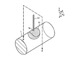
図6は、ワイヤ1の一部を加熱して軟化させる方法の第1例を示すワイヤ1の斜視図である。レーザ加熱機20は、ワイヤ1の表面にレーザ光L1を照射する。レーザ光L1は、ワイヤ1の幅方向に長尺なビームプロファイルを有している。このレーザ光L1が照射されたワイヤ1の照射領域1aやその周囲には、加熱部位1Vが形成される。
FIG. 6 is a perspective view of the
図7は、図6におけるVII-VII線に沿うワイヤ1の断面図である。加熱部位1Vは、ワイヤ1の表面における照射領域1aの周囲だけでなく、ワイヤ1の内部にも及んでいる。この図の例において、ワイヤ1の幅方向におけるレーザ光L1の幅WD1は、ワイヤ1の直径Rよりも小さい。したがって、レーザ光L1のほとんどがワイヤ1に照射される。
FIG. 7 is a cross-sectional view of the
図8は、ワイヤ1の一部を加熱して軟化させる方法の第2例を示すワイヤ1の斜視図である。レーザ加熱機20は、ワイヤ1の表面にレーザ光L2を照射する。レーザ光L2は、例えば円形のビームプロファイルを有している。このレーザ光L2が照射されたワイヤ1の照射領域1aやその周囲には、第1例と同様に加熱部位1Vが形成される。
FIG. 8 is a perspective view of the
図9は、図8におけるIX-IX線に沿うワイヤ1の断面図である。加熱部位1Vは、ワイヤ1の表面における照射領域1aの周囲だけでなく、ワイヤ1の内部にも及んでいる。例えば、レーザ光L2の幅WD2は、ワイヤ1の直径Rよりも十分に小さい。したがって、レーザ光L2のほとんどがワイヤ1に照射される。
FIG. 9 is a cross-sectional view of the
なお、図6ないし図9の例においては、Y方向と平行なレーザ光L1,L2がワイヤ1のY方向における上面に照射されているが、レーザ光L1,L2の照射方向はこれに限られない。例えば、レーザ光L1,L2は、Y方向と交差する方向からワイヤ1に照射されてもよい。また、レーザ光L1,L2は、ワイヤ1のY方向における下面に照射されてもよい。
In the examples of FIGS. 6 to 9, the laser beams L1 and L2 parallel to the Y direction are irradiated on the upper surface of the
加熱部位1Vは、図7および図9に示した例よりもワイヤ1のより内部にまで及んでもよい。レーザ加熱機20が発するレーザ光の形状は、第1例および第2例に限られない。レーザ光は、ワイヤ1の1箇所にのみ照射されてもよいし、複数個所に照射されてもよい。
The
第1例および第2例の双方において、加熱部位1Vは、ワイヤ1の母材がレーザ光のエネルギーにより溶融した溶融プールを含んでもよい。この場合において、溶融プールは、照射領域1aだけでなくその周囲に広がってもよい。
In both the first example and the second example, the
図10を参照して、切断工程S03について説明する。図10は、切断工程S03の具体例を示すコイリングマシン100の概略的な斜視図である。切断工程S03は、レーザ光の照射が停止された後に実行される。切断工程S03においては、レーザ光が照射される前よりも高温になっているワイヤ1の加熱部位1Vが切断ユニット30により切断される。これにより、コイルばね2が製造される。
The cutting step S03 will be described with reference to FIG. FIG. 10 is a schematic perspective view of the coiling
具体的には、切断工程S03では、ワイヤ1のマンドレル32によって支持されている部分の近傍に向けてカッタ31を下降させる。このときカッタ31によって与えられる衝撃により、ワイヤ1が切断される。
Specifically, in the cutting step S03, the
加熱部位1Vが溶融プールを含む場合、レーザ光の照射が停止してからカッタ31が動作するまでの間に当該溶融プールが凝固してもよい。また、カッタ31の動作後、カッタ31がワイヤ1の表面に接触した際に加熱部位1Vの熱がカッタ31により奪われることで溶融プールが凝固してもよい。このように、カッタ31の動作前あるいは動作中に溶融プールが凝固することで、溶融した金属がカッタ31に付着することを抑制できる。
When the
切断工程S03では、測定器24による加熱部位1Vの温度の測定結果に基づいてカッタ31を動作させることもできる。すなわち、レーザ光の照射の後、加熱部位1Vの温度が予め定められた目標温度まで低下した際にカッタ31が動作してもよい。上記目標温度は、例えば溶融した母材が凝固する温度であってもよい。もちろん、切断工程S03では、レーザ光の照射停止からカッタ31の動作開始までの遅延時間を予め定めておくことで、測定器24を用いることなく加熱部位1Vが切断されてもよい。
In the cutting step S03, the
切断されたコイルばね2は、第1端面51aを含む第1端末51と、第2端面52aを含む第2端末52とを有している。1つのコイルばね2が製造された後、上述の螺旋成形工程S01、加熱工程S02および切断工程S03が再度実行されて次のコイルばね2が製造される。そのため、第1端末51および第2端末52は、いずれも上述の各工程を経て切断されている。
The
ワイヤを切断するために必要なせん断力は、ワイヤを加熱して昇温させる程低下する。また、ワイヤが融点に達していない場合であってもせん断力を低下させることができる。さらに、このような傾向はワイヤの直径によらない。一例として、カッタ31によりワイヤ1を切断する際に、加熱部位1Vの少なくとも一部の温度が500℃以上であることが好ましい。
The shear force required to cut the wire decreases as the wire is heated and heated. Further, the shearing force can be reduced even when the wire has not reached the melting point. Moreover, this tendency does not depend on the diameter of the wire. As an example, when the
続いて、本実施形態に係るコイリングマシン100およびコイルばね2の製造方法の効果について説明する。本実施形態においては、螺旋状に成形されたワイヤ1の一部がレーザ光によって加熱され、レーザ光の照射が停止された後においてレーザ光が照射される前よりも高温になっている部位(加熱部位1V)が切断部品(カッタ31およびマンドレル32)により切断される。ワイヤ1が加熱されていれば切断に要するせん断力も小さくなる。したがって、本実施形態によればワイヤ1を容易に切断することができる。
Subsequently, the effect of the manufacturing method of the coiling
本実施形態のようにレーザ加熱機20を用いる場合、切断すべき部位をレーザ光によって選択的かつ急速に加熱することができる。レーザ加熱機20を用いる場合、レーザ発振器21の駆動電流の調整により、レーザ光を照射する部位に対する入熱量を任意に設定することができる。また、駆動電流の調整に速やかに追随してレーザ光の出力を上下させることができる。さらに、レーザ加熱機20によるレーザ光の照射を止めることで、加熱部位1Vを急速に自己冷却させることができる。なお、急速な自己冷却とは、冷却のための部材や装置を用いて積極的に加熱部位1Vを冷却しなくても、加熱部位1Vが急冷することを意味する。また、レーザ加熱機20は、ワイヤ1に対するレーザ光の照射角度を調整したり、レンズやミラーを用いたりすることによって、ワイヤ1におけるレーザ光の照射領域1aおよび加熱部位1Vを任意に設定することができる。したがって、レーザ加熱機20は、ワイヤ1の太さや材料および要求されているタクト等に合せて、ワイヤ1の任意の領域を高い応答性によって任意の温度に加熱することができる。
When the
また、本実施形態の構成によれば、高温で軟化している状態の加熱部位1Vを切断することから、カッタ31やマンドレル32が切断時にワイヤ1から受ける反力が低減される。このため、カッタ31およびマンドレル32の消耗や破損を抑制することができる。その結果、カッタ31およびマンドレル32の交換周期を従来よりも伸ばしてランニングコストを削減したり、カッタ31およびマンドレル32の材料に必要とされる耐摩耗性等の仕様を下げて従来よりも廉価にこれらを形成したりすることができる。また、カッタ31およびマンドレル32の交換に伴ってコイリングマシン100の稼働率が低下することを抑制できる。
Further, according to the configuration of the present embodiment, since the
また、本実施形態の構成によれば、直径が相対的に太いワイヤ1を用いる場合であっても、切断に必要な時間を過剰に増大させることなく当該ワイヤ1を切断することができる。さらに、コイリングマシン100は、直径が相対的に太いワイヤ1を用いる場合であっても、カッタ31やマンドレル32に相対的に高い切断機能を与える必要がない。したがって、相対的に太いワイヤ1を用いる場合においても、量産性を保つことができるとともに、カッタ31やマンドレル32に必要なコストを抑制することができる。
Further, according to the configuration of the present embodiment, even when the
また、本実施形態においてはレーザ光の照射のみでワイヤ1を切断するのではなく、カッタ31をさらに用いてワイヤ1を切断する。このような構成によれば、レーザ光の強度を抑制することができる。すなわち、レーザ加熱機20は、ワイヤ1を切断するためではなく軟化させるためにレーザ光を照射することから、レーザ光のみでワイヤ1を切断する場合と比較してレーザ光の強度を低くすることができる。この結果、強いレーザ光をワイヤ1に照射する場合に生じ得るスパッタやドロスを抑制することができ、さらにアシストガスの吹き付けのための設備やコストが不要となる。したがって、製造されるコイルばね2の清浄度を保って洗浄を不要としたり、コイリングマシン100自体に付着したスパッタの除去に関するメンテナンスの作業等を軽減したりして、コイリングマシン100の稼働率を上げることができる。さらに、スパッタの除去に必要な吸引装置等の設備を簡略化したり、廃止したりすることができる。
Further, in the present embodiment, the
また、本実施形態の構成によれば、ワイヤ1に対するレーザ光の照射範囲を限定することができる。すなわち、レーザ加熱機20は、ワイヤ1を切断するためではなく軟化させるためにレーザ光を照射することから、切断が予定される位置の全面にレーザ光を照射する必要はなく、例えば図6ないし図9に示すようにワイヤ1の幅方向における一部に対してレーザ光を照射できればよい。具体的には、レーザ加熱機20は、例えば、図6および図8に示したように、ワイヤ1の幅方向における両端部を避けて中央部にレーザ光を照射することができる。この場合、ワイヤ1に対してレーザ光を照射する位置がずれたとしても、ワイヤ1の両端部からレーザ光がはみ出してワイヤ1へのレーザ光の照射量が不足したり、コイリングマシン100自体に熱的な影響を及ぼしたりすることを抑制できる。
Further, according to the configuration of the present embodiment, the irradiation range of the laser beam to the
また、ワイヤ1に照射されるレーザ光がワイヤ1の反対側から漏れることも抑制できる。すなわち、レーザ加熱機20は、ワイヤ1を切断するためではなく軟化させるためにレーザ光を照射することから、ワイヤ1を貫通して分断するようにレーザ光を照射する必要がない。したがって、レーザ光によりワイヤを切断する従来のコイリングマシンと比較して、レーザ光の遮蔽のための構成を大幅に簡略化したり、廃止したりすることができる。
Further, it is possible to prevent the laser beam irradiated to the
また、本実施形態の構成によれば、特に、冷間加工によって螺旋状に成形された後のワイヤ1を加熱して切断する場合、温間加工の場合と比較して、コイルばね2の形状精度を高く保つことができる。
Further, according to the configuration of the present embodiment, in particular, when the
仮にレーザ光のみによってワイヤ1を切断する場合、レーザ光の強度を相対的に高める必要があることから、第1端面51aおよび第2端面52aを平らに形成することは難しい。また、レーザ光を用いずにカッタのみによってワイヤ1を切断する場合、強いせん断力をワイヤ1に加える必要があることから各端面51a,52aに大きな凹凸が生じやすい。これらに対し、本実施形態においてはレーザ光の照射だけでなくカッタ31を用いてワイヤ1を切断することから、レーザ光の強度を低くかつカッタ31によるせん断力を小さくできるので、各端面51a,52aを平らに形成することが可能となる。結果として、品質に優れたコイルばね2を得ることができる。
If the
上述のようにカッタ31による切断時において加熱部位1Vが少なくとも部分的に500℃以上の温度に加熱されていれば、十分に軟化している(加工抵抗が十分に低減されている)高温の固体状態においてワイヤ1を切断することができる。ワイヤ1の材料として一般的な炭素鋼は、約500℃以上に加熱することによって引張強度(TS:Tensile Strength)が常温時の約1/2以下になり、カッタ31によって容易に切断することができる。
As described above, if the
上述のように加熱部位1Vに溶融プールが形成される場合には、加熱部位1Vをワイヤ1の深部まで到達させることができる。これにより、ワイヤ1が深部まで軟化し、カッタ31による切断が一層容易になる。
以上の他にも、本実施形態からは種々の好適な効果を得ることができる。When the molten pool is formed in the
In addition to the above, various suitable effects can be obtained from the present embodiment.
[第2実施形態]
第2実施形態について説明する。本実施形態においては主に、上述のコイリングマシン100を用いてワイヤ1を切断するにあたっての好適な条件を開示する。コイリングマシン100の構成や、コイリングマシン100によるコイルばねの製造方法の流れは、第1実施形態と同様である。[Second Embodiment]
The second embodiment will be described. In the present embodiment, mainly, suitable conditions for cutting the
図11は、レーザ光が照射されたワイヤ1の概略的な断面図である。ここでは、図8に示した形状のレーザ光(L2)がワイヤ1の表面に照射され、溶融プールが形成される場合を想定する。図中のOは、ワイヤ1の外周面におけるレーザ光の照射領域の中心を示す。一例として、この照射中心Oは、レーザ光のビームプロファイルにおいて最も高強度のピーク部分が照射される位置に相当する。また、照射中心Oは、溶融プールの中心と考えることもできる。
FIG. 11 is a schematic cross-sectional view of the
上述の通り、レーザ光がワイヤ1に照射されると加熱部位1Vが形成される。レーザ光の照射中あるいは照射直後においては、照射中心Oの周囲に溶融プールが形成される。その後の冷却により、溶融プールが凝固して焼入硬化部1Cが形成される。溶融プールの周囲には、溶融はしていないがレーザ光の照射時の熱によりワイヤ1の母材から特性が変化した熱影響部1H(HAZ:Heat Affected Zone)が形成される。このように、加熱部位1Vは、焼入硬化部1Cおよび熱影響部1Hを含む。
As described above, when the
図11においては、焼入硬化部1C、熱影響部1Hおよびワイヤ1の母材のそれぞれについてビッカース硬さ[HV]を測定した結果を示している。焼入硬化部1Cは、全体的に母材に比べて大きい硬さを有している。一方、熱影響部1Hは、全体的に母材に比べて小さい硬さを有している。熱影響部1Hの硬さは、焼入硬化部1Cの近傍から母材に向けて徐々に大きくなる。
FIG. 11 shows the results of measuring the Vickers hardness [HV] for each of the quenching and hardening
このように、加熱部位1Vにおいても硬さの分布が一様でない。そのため、カッタ31およびマンドレル32の位置と、レーザ光の照射領域との関係を適切に定める必要がある。
As described above, the hardness distribution is not uniform even at the
図12は、カッタ31、マンドレル32およびレーザ光の照射領域の好適な位置関係の一例を示す断面図である。上述の螺旋成形工程S01においては、螺旋状に成形されたワイヤ1がカッタ31とマンドレル32の間に送られる。ワイヤ1の送り方向(θ方向)において、カッタ31の端部31aとマンドレル32の端部32aの間には、クリアランスGが設けられている。以下、θ方向におけるクリアランスGの中心を、クリアランス中心Cと呼ぶ。
FIG. 12 is a cross-sectional view showing an example of a suitable positional relationship between the
図12の例においては、クリアランス中心Cと照射中心Oとがθ方向にずれている。具体的には、照射中心Oは、クリアランス中心Cよりもカッタ31側(θ方向の下流側)に位置している。
In the example of FIG. 12, the clearance center C and the irradiation center O are displaced in the θ direction. Specifically, the irradiation center O is located on the
図12の例において、加熱部位1Vは、凝固後に上述の焼入硬化部1Cとなる溶融プール1Pを含む。例えば、溶融プール1Pは、クリアランス中心Cと重なっている。また、溶融プール1Pは、カッタ31の端部31aとY方向において重なっている。
In the example of FIG. 12, the
一方で、溶融プール1Pは、マンドレル32の端部32aとY方向において重なっていない。図12の例においては、マンドレル32の端部32aと、熱影響部1Hのうち溶融プール1Pよりもθ方向の上流側に位置する部分とがY方向において重なっている。
On the other hand, the
図13は、図12に示す状態からカッタ31をY方向に下降させてワイヤ1を切断した状態を示す断面図である。上述のように、カッタ31によってワイヤ1を切断する際には、既に溶融プール1Pが凝固しているか、あるいはカッタ31との接触により熱が奪われて溶融プール1Pが凝固する。したがって、切断中には焼入硬化部1Cが形成されている。なお、切断に際し、加熱部位1Vの内部に溶融プール1Pが一部残存していてもよい。
FIG. 13 is a cross-sectional view showing a state in which the
マンドレル32の端部32aから突出したワイヤ1の外周面に対してカッタ31の先端部が衝撃を与えると、加熱部位1Vとその周囲にせん断力が加わり、ワイヤ1が破断する。カッタ31は、例えば最大でワイヤ1の軸付近まで降下する。切断されたワイヤ1、すなわちコイルばね2には、カッタ31による打痕B(凹部)が形成される。図13の例においては、焼入硬化部1Cおよび熱影響部1Hが打痕Bと重なっているが、これらが互いにずれていてもよい。
When the tip of the
上述のように、熱影響部1Hは、焼入硬化部1Cおよびワイヤ1の母材よりも軟らかい。そのため、カッタ31がワイヤ1に衝撃を与えた際に、加熱部位1Vにおいては熱影響部1Hが破断しやすい。特に、図12に示したように照射中心Oがクリアランス中心Cよりもカッタ31側にずれていれば、熱影響部1Hのうち溶融プール1Pよりもθ方向の上流側に位置する部分に効果的に負荷を与え、当該部分に沿ってワイヤ1を破断させることができる。
As described above, the heat-affected
図14は、図12および図13に示した方法でワイヤ1から切断されたコイルばね2の概略的な側面図である。コイルばね2は、第1端面51aを含む第1端末51と、第2端面52aを含む第2端末52とを有している。
FIG. 14 is a schematic side view of the
第1端面51aは、図13においてワイヤ1から切り離されたコイルばね2の破断面に相当する。第1端末51は、レーザ光の第1照射痕M1と、カッタ31の打痕Bとを有している。第1照射痕M1は、焼入硬化部1Cおよび熱影響部1H(第1熱影響部)を含む。
The
第2端面52aは、このコイルばね2の前に製造されるコイルばね2を切り離した際に、マンドレル32の上方に残されたワイヤ1の破断面に相当する。第2端末52は、レーザ光の第2照射痕M2を有している。第2照射痕M2は、熱影響部1H(第2熱影響部)を含む。図13に示したようにワイヤ1が切断された場合、第2照射痕M2は焼入硬化部1Cを含まない。ただし、第2照射痕M2は、例えば第1照射痕M1よりも少量の焼入硬化部1Cを含んでもよい。
The
第1照射痕M1に含まれる熱影響部1Hは、第1端面51aの少なくとも一部に及んでいる。また、第2照射痕M2に含まれる熱影響部1Hは、第2端面52aの少なくとも一部に及んでいる。一方で、第1照射痕M1に含まれる焼入硬化部1Cは、第1端面51aに及んでいない。ただし、焼入硬化部1Cの一部が第1端面51aに及んでいてもよい。この場合、第1端面51aにおいて、焼入硬化部1Cの面積が熱影響部1Hの面積より小さいことが好ましい。
The heat-affected
続いて、第1照射痕M1、第2照射痕M2および打痕Bの位置関係につき、いくつかの態様を例示する。
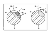
図15は、第1照射痕M1、第2照射痕M2および打痕Bの第1例であり、第1端末51および第2端末52の各々におけるコイルばね2の概略的な断面図を示している。図中左側に示す断面は、図14におけるCA-CA線に沿う第1端末51の断面に相当する。図中右側に示す断面は、図14におけるCB-CB線に沿う第2端末52の断面に相当する。第1端末51および第2端末52の各々において、図中上方の面はコイルばね2の外周面2aであり、図中下方の面はコイルばね2の内周面2bである。Subsequently, some embodiments will be exemplified with respect to the positional relationship between the first irradiation mark M1, the second irradiation mark M2, and the dent B.
FIG. 15 is a first example of the first irradiation mark M1, the second irradiation mark M2, and the dent B, and shows a schematic cross-sectional view of the
図中の破線矢印は、加熱時におけるレーザ光の照射方向D1を表す。実線矢印は、切断時におけるカッタ31の移動方向D2を表す。この図の例においては、照射方向D1および移動方向D2がいずれも図中の上方から各端末51,52に向かっている。ただし、図15に示す断面とは異なる方向から各端末51,52を見た場合に、これら方向D1,D2が交差していてもよい。
The broken line arrow in the figure indicates the irradiation direction D1 of the laser beam during heating. The solid arrow indicates the moving direction D2 of the
図中左側に示す第1端末51において、第1照射痕M1は、焼入硬化部1Cおよび熱影響部1Hを含む。また、第1照射痕M1の表面全体が打痕Bと重なっている。図中右側に示す第2端末52において、第2照射痕M2は、熱影響部1Hを含み、焼入硬化部1Cを含んでいない。また、第2端末52には打痕Bが形成されていない。第1照射痕M1、第2照射痕M2および打痕Bは、いずれも外周面2aに形成されている。
In the
図16は、第1照射痕M1、第2照射痕M2および打痕Bの第2例であり、図15と同じく第1端末51および第2端末52の各々におけるコイルばね2の概略的な断面図を示している。この図の例においては、照射方向D1と移動方向D2が鋭角(例えば40度)を成している。そのため、第1端末51においては、第1照射痕M1が打痕Bと重なる部分と打痕Bと重ならない部分を含んでいる。このような構成の場合、切断時にカッタ31が加熱部位1V以外の硬い部分(母材)にも触れるので、第1例に比べて打痕Bを小さくできる。
FIG. 16 is a second example of the first irradiation mark M1, the second irradiation mark M2, and the dent B, and is a schematic cross section of the
図17は、第1照射痕M1、第2照射痕M2および打痕Bの第3例であり、図15と同じく第1端末51および第2端末52の各々におけるコイルばね2の概略的な断面図を示している。この図の例においては、照射方向D1と移動方向D2が互いに反対方向である。第1照射痕M1および第2照射痕M2は、内周面2bに形成されている。打痕Bは、外周面2aに形成されている。第1端末51においては、第1照射痕M1の全体が打痕Bと重なっていない。このような構成の場合、切断時にカッタ31が加熱部位1Vに触れないので、第2例に比べて打痕Bをさらに小さくできる。
FIG. 17 is a third example of the first irradiation mark M1, the second irradiation mark M2, and the dent B, and is a schematic cross section of the
以上の他にも、第1照射痕M1、第2照射痕M2および打痕Bは種々の態様で形成され得る。例えば、打痕Bは、第1端末51だけでなく、第2端末52に及んでもよい。この場合において、第2端末52の打痕Bは、第1端末51の打痕Bより小さくてもよい。
In addition to the above, the first irradiation scar M1, the second irradiation scar M2, and the dent B can be formed in various embodiments. For example, the dent B may extend not only to the
なお、ここまでは図8に示した形状のレーザ光(L2)がワイヤ1に照射される場合を想定したが、図6に示した形状のレーザ光(L1)がワイヤ1に照射される場合であっても同様の構成を適用できる。
Up to this point, it has been assumed that the laser beam (L2) having the shape shown in FIG. 8 is irradiated to the
図18は、図6に示した形状のレーザ光が照射された後のワイヤ1の概略的な平面図である。レーザ光の照射中心Oは、ワイヤ1の軸方向と直交する方向に延びている。したがって、このレーザ光の照射により形成される加熱部位1Vにおいて、溶融プール1P(または凝固後の焼入硬化部1C)は、ワイヤ1の幅方向に長尺な形状を有している。同様に、焼入硬化部1Cの周囲の熱影響部1Hは、ワイヤ1の幅方向に長尺な形状を有している。図18の例においては、熱影響部1Hがワイヤ1の幅方向における一端から他端まで広がっているが、この例に限られない。
FIG. 18 is a schematic plan view of the
このような加熱部位1Vが形成されたワイヤ1の切断に際して、照射中心Oをクリアランス中心Cよりもカッタ31側(図中左側)にずらすことにより、照射中心Oとクリアランス中心Cの間に距離Dを設ける。図18の例においては、クリアランス中心Cが溶融プール1Pと重なっている。また、マンドレル32の端部32aが熱影響部1Hのうち溶融プール1Pよりもθ方向の上流側に位置する部分と重なっている。
When cutting the
このような状態でカッタ31によりワイヤ1を切断すると、図12および図13の例と同じく熱影響部1Hのうち溶融プール1Pよりもθ方向の上流側に位置する部分に効果的にせん断力を与え、当該部分を破断させることができる。
When the
以上説明したように、本実施形態においては、照射中心Oとクリアランス中心Cとをずらすことにより、他の部分に比べて軟らかい熱影響部1Hにおいてワイヤ1を破断させることができる。この場合、例えば焼入硬化部1Cでワイヤ1を破断させる場合に比べ、ワイヤ1のせん断力を小さくすることができる。
As described above, in the present embodiment, by shifting the irradiation center O and the clearance center C, the
なお、発明者らは、照射中心Oとクリアランス中心Cを一致させた場合、照射中心Oをクリアランス中心Cよりもカッタ31側にずらした場合、照射中心Oをクリアランス中心Cよりもマンドレル32側にずらした場合の各々につきワイヤ1を切断する実験を複数回にわたって行った。その結果、照射中心Oをクリアランス中心Cよりもカッタ31側にずらした場合の破断面が最も平坦となり、次いで照射中心Oとクリアランス中心Cを一致させた場合の破断面が平坦となった。この結果から、本実施形態のように照射中心Oをクリアランス中心Cよりもカッタ31側にずらすことで、より平坦な第1端面51aおよび第2端面52aを有するコイルばね2を得られることが分かる。
In addition, the inventors have shown that when the irradiation center O and the clearance center C are matched, when the irradiation center O is shifted to the
ワイヤ1を螺旋状に成形してさらにカッタ31によりワイヤ1を切断する場合、コイルばね2の第1端面51aおよび第2端面52aには一定の残留応力が発生する。このような残留応力は、各端面51a,52aの割れの原因となる。また、コイルばね2を通電により昇温させる工程を経れば残留応力を除去し得る。ただし、この手法においてはコイルばね2の端末の温度が上昇しづらいので、種々の工夫を凝らす必要がある。
When the
この点に関し、本実施形態のような条件でワイヤ1を切断して製造されたコイルばね2においては、第1端面51aおよび第2端面52aに熱影響部1Hが広範囲に及んでいる。この場合、熱影響部1Hが他の部分に比べて軟らかいことから、残留応力が低減される。また、上述のような残留応力を除去するための工程も省略することができる。
In this regard, in the
図18に示した例においては、熱影響部1Hがワイヤ1の幅方向における一端から他端まで広がっている。この場合においては、破断面のより広い範囲に熱影響部1Hが及ぶ。したがって、各端面51a,52aの割れを抑制する効果をより顕著に得ることができる。
In the example shown in FIG. 18, the heat-affected
なお本発明を実施するに当たり、コイリングマシン100が備える各要素の構成や配置等の態様を必要に応じて種々に変更して実施できることは言うまでもない。
Needless to say, in carrying out the present invention, various aspects such as the configuration and arrangement of each element included in the coiling
各実施形態においては、コイリングマシン100がカッタ31を用いてワイヤ1の加熱部位1Vを切断する構成を例示した。コイリングマシン100は、このような構成に限定されることなく、回転鋸刃を用いた切削によってワイヤ1の加熱部位1Vを切断してもよい。
In each embodiment, the configuration in which the coiling
コイリングマシン100によって製造されるコイルばね2の形態は様々であり、例えばコイル径とピッチがコイルばねの軸線方向に変化していてもよい。すなわち、コイリングマシン100によって製造されるコイルばね2は、円筒コイルばねをはじめとして、たる形コイルばね、鼓形コイルばね、テーパコイルばね、不等ピッチコイルばね、マイナスピッチの部分を有するコイルばね等など、様々な形態のコイルばねであってもよい。
The form of the
1…ワイヤ、1V…加熱部位、1P…溶融プール、1C…焼入硬化部、1H…熱影響部、2…コイルばね、10…螺旋成形ユニット、11…駆動ローラ、12…従動ローラ、13…ワイヤガイド、14…第1成形ローラ、15…第2成形ローラ、16…ピッチツール、20…レーザ加熱機、21…レーザ発振器、22…光ファイバ、23…ビームスポット調整器、24…測定器、30…切断ユニット、31…カッタ、32…マンドレル、40…制御ユニット、41…コントローラ、51…第1端末、51a…第1端面、52…第2端末、52a…第2端面、100…コイリングマシン、L1,L2…レーザ光、S01…螺旋成形工程、S02…加熱工程、S03…切断工程、M1…第1照射痕、M2…第2照射痕、B…打痕。 1 ... Wire, 1V ... Heating part, 1P ... Melted pool, 1C ... Hardened part, 1H ... Heat affected zone, 2 ... Coil spring, 10 ... Spiral forming unit, 11 ... Drive roller, 12 ... Driven roller, 13 ... Wire guide, 14 ... 1st forming roller, 15 ... 2nd forming roller, 16 ... Pitch tool, 20 ... Laser heater, 21 ... Laser oscillator, 22 ... Optical fiber, 23 ... Beam spot adjuster, 24 ... Measuring instrument, 30 ... cutting unit, 31 ... cutter, 32 ... mandrel, 40 ... control unit, 41 ... controller, 51 ... first terminal, 51a ... first end face, 52 ... second terminal, 52a ... second end face, 100 ... coiling machine , L1, L2 ... laser beam, S01 ... spiral forming process, S02 ... heating process, S03 ... cutting process, M1 ... first irradiation mark, M2 ... second irradiation mark, B ... dent.
Claims (16)
前記レーザ光の照射が停止された後において、前記レーザ光が照射される前よりも高温になっている前記ワイヤの部位を切断する切断部品と、
を備えるコイリングマシン。A laser heater that heats a part of the wire by irradiating the spirally formed wire with a laser beam, and a laser heater.
A cutting component that cuts a portion of the wire that is hotter than before the laser beam irradiation after the laser beam irradiation is stopped.
A coiling machine equipped with.
請求項1に記載のコイリングマシン。The cutting part cuts the portion of the wire heated to 500 ° C. or higher.
The coiling machine according to claim 1.
請求項1に記載のコイリングマシン。By irradiating the wire with the laser beam, the laser heater forms a molten pool and a heat-affected zone around the wire in the wire, and cuts the heat-affected zone of the wire.
The coiling machine according to claim 1.
螺旋状に成形された前記ワイヤの内周面を支持するマンドレルと、
前記マンドレルの端部から突出した前記ワイヤの外周面に対して衝撃を与えて前記ワイヤを切断するカッタと、
を備える、請求項1に記載のコイリングマシン。The cut part is
A mandrel that supports the inner peripheral surface of the spirally formed wire,
A cutter that cuts the wire by giving an impact to the outer peripheral surface of the wire protruding from the end of the mandrel.
The coiling machine according to claim 1.
前記カッタが前記ワイヤに対して衝撃を与える際に、前記クリアランスの中心と、前記ワイヤにおける前記レーザ光の照射領域の中心とが前記送り方向においてずれている、
請求項4に記載のコイリングマシン。A clearance is provided between the cutter and the end of the mandrel in the feeding direction of the wire.
When the cutter gives an impact to the wire, the center of the clearance and the center of the irradiation region of the laser beam on the wire are deviated from each other in the feed direction.
The coiling machine according to claim 4.
請求項5に記載のコイリングマシン。The center of the irradiation region is located on the cutter side of the center of the clearance in the feed direction.
The coiling machine according to claim 5.
前記カッタが前記ワイヤに対して衝撃を与える際に、前記マンドレルの前記端部と、前記熱影響部のうち前記溶融プールよりも前記送り方向の上流側に位置する部分とが前記カッタの移動方向において重なる、
請求項6に記載のコイリングマシン。By irradiating the wire with the laser beam, the laser heater forms a molten pool and a heat-affected zone around the wire on the wire.
When the cutter gives an impact to the wire, the end portion of the mandrel and the portion of the heat-affected zone located upstream of the melting pool in the feeding direction are in the moving direction of the cutter. Overlap in
The coiling machine according to claim 6.
前記レーザ光の照射が停止された後において、前記レーザ光が照射される前よりも高温になっている前記ワイヤの部位を切断することと、
を含むコイルばねの製造方法。Irradiating a spirally formed wire with a laser beam to heat a part of the wire,
After the irradiation of the laser beam is stopped, the portion of the wire whose temperature is higher than that before the irradiation of the laser beam is cut.
Manufacturing method of coil spring including.
請求項8に記載のコイルばねの製造方法。When cutting the portion of the wire, the portion is heated to 500 ° C. or higher.
The method for manufacturing a coil spring according to claim 8.
前記ワイヤの切断に際し、前記マンドレルの端部から突出した前記ワイヤの外周面に対して衝撃を与えることと、
をさらに含む、請求項8に記載のコイルばねの製造方法。Feeding the wire between the mandrel and the cutter that support the inner peripheral surface of the spirally shaped wire,
When cutting the wire, an impact is applied to the outer peripheral surface of the wire protruding from the end of the mandrel.
The method for manufacturing a coil spring according to claim 8, further comprising.
前記カッタが前記ワイヤに対して衝撃を与える際に、前記クリアランスの中心と、前記ワイヤにおける前記レーザ光の照射領域の中心とが前記送り方向においてずれている、
請求項10に記載のコイルばねの製造方法。A clearance is provided between the cutter and the end of the mandrel in the feeding direction of the wire.
When the cutter gives an impact to the wire, the center of the clearance and the center of the irradiation region of the laser beam on the wire are deviated from each other in the feed direction.
The method for manufacturing a coil spring according to claim 10.
請求項11に記載のコイルばねの製造方法。The center of the irradiation region is located on the cutter side of the center of the clearance in the feed direction.
The method for manufacturing a coil spring according to claim 11.
前記カッタが前記ワイヤに対して衝撃を与える際に、前記マンドレルの前記端部と、前記熱影響部のうち前記溶融プールよりも前記送り方向の上流側に位置する部分とが前記カッタの移動方向において重なる、
請求項12に記載のコイルばねの製造方法。By irradiating the wire with the laser beam, a molten pool and a heat-affected zone around the molten pool are formed on the wire.
When the cutter gives an impact to the wire, the end portion of the mandrel and the portion of the heat-affected zone located upstream of the melting pool in the feeding direction are in the moving direction of the cutter. Overlap in
The method for manufacturing a coil spring according to claim 12.
前記第1端末は、レーザ光の第1照射痕を有し、
前記第1照射痕は、前記ワイヤの母材よりも硬い焼入硬化部と、前記母材よりも軟らかい前記焼入硬化部の周囲の第1熱影響部と、を含み、
前記第1熱影響部は、前記第1端末の端面の少なくとも一部に及んでいる、
コイルばね。A coil spring formed by a wire having a first terminal and a second terminal on the opposite side of the first terminal.
The first terminal has a first irradiation mark of laser light, and has a first irradiation mark.
The first irradiation mark includes a quench-hardened portion harder than the base metal of the wire and a first heat-affected zone around the quench-hardened portion softer than the base metal.
The first heat-affected zone extends to at least a part of the end face of the first terminal.
Coil spring.
前記第2照射痕は、前記母材よりも軟らかい第2熱影響部を含み、
前記第2熱影響部は、前記第2端末の端面の少なくとも一部に及んでいる、
請求項14に記載のコイルばね。The second terminal has a second irradiation mark of laser light smaller than the first irradiation mark.
The second irradiation mark includes a second heat-affected zone that is softer than the base material.
The second heat-affected zone extends to at least a part of the end face of the second terminal.
The coil spring according to claim 14.
請求項14に記載のコイルばね。The first terminal has a dent on the outer peripheral surface that overlaps with the first irradiation mark.
The coil spring according to claim 14.
Priority Applications (2)
| Application Number | Priority Date | Filing Date | Title |
|---|---|---|---|
| JP2022073233A JP7225457B2 (en) | 2019-02-06 | 2022-04-27 | Coiling machine and coil spring manufacturing method |
| JP2022073234A JP2022109282A (en) | 2019-02-06 | 2022-04-27 | coil spring |
Applications Claiming Priority (3)
| Application Number | Priority Date | Filing Date | Title |
|---|---|---|---|
| JP2019019754 | 2019-02-06 | ||
| JP2019019754 | 2019-02-06 | ||
| PCT/JP2019/046219 WO2020161998A1 (en) | 2019-02-06 | 2019-11-26 | Coiling machine, method for manufacturing coil spring, and coil spring |
Related Child Applications (2)
| Application Number | Title | Priority Date | Filing Date |
|---|---|---|---|
| JP2022073233A Division JP7225457B2 (en) | 2019-02-06 | 2022-04-27 | Coiling machine and coil spring manufacturing method |
| JP2022073234A Division JP2022109282A (en) | 2019-02-06 | 2022-04-27 | coil spring |
Publications (2)
| Publication Number | Publication Date |
|---|---|
| JPWO2020161998A1 JPWO2020161998A1 (en) | 2021-11-11 |
| JP7066880B2 true JP7066880B2 (en) | 2022-05-13 |
Family
ID=71947068
Family Applications (3)
| Application Number | Title | Priority Date | Filing Date |
|---|---|---|---|
| JP2020570383A Active JP7066880B2 (en) | 2019-02-06 | 2019-11-26 | Coiling machine, coil spring manufacturing method and coil spring |
| JP2022073233A Active JP7225457B2 (en) | 2019-02-06 | 2022-04-27 | Coiling machine and coil spring manufacturing method |
| JP2022073234A Pending JP2022109282A (en) | 2019-02-06 | 2022-04-27 | coil spring |
Family Applications After (2)
| Application Number | Title | Priority Date | Filing Date |
|---|---|---|---|
| JP2022073233A Active JP7225457B2 (en) | 2019-02-06 | 2022-04-27 | Coiling machine and coil spring manufacturing method |
| JP2022073234A Pending JP2022109282A (en) | 2019-02-06 | 2022-04-27 | coil spring |
Country Status (6)
| Country | Link |
|---|---|
| US (1) | US20210362274A1 (en) |
| EP (1) | EP3922377A4 (en) |
| JP (3) | JP7066880B2 (en) |
| CN (1) | CN113365755B (en) |
| MX (1) | MX2021008990A (en) |
| WO (1) | WO2020161998A1 (en) |
Families Citing this family (4)
| Publication number | Priority date | Publication date | Assignee | Title |
|---|---|---|---|---|
| CN113857394A (en) * | 2021-09-22 | 2021-12-31 | 安徽环新集团股份有限公司 | Piston ring blank winding machine |
| CN114898947B (en) * | 2022-05-10 | 2024-02-09 | 江苏欣达通信科技股份有限公司 | Spring type jumper wire machining equipment and machining method |
| JP2024025900A (en) * | 2022-08-15 | 2024-02-28 | 日本発條株式会社 | Coiling machine and coil spring manufacturing method |
| JP2024025901A (en) * | 2022-08-15 | 2024-02-28 | 日本発條株式会社 | Coiling machine and coil spring manufacturing method |
Citations (5)
| Publication number | Priority date | Publication date | Assignee | Title |
|---|---|---|---|---|
| JP2000107827A (en) | 1998-10-07 | 2000-04-18 | Toshikazu Okuno | Heating-cutting off method in wire rod working machine and device thereof |
| JP2004330209A (en) | 2003-04-30 | 2004-11-25 | Itaya Seisakusho:Kk | Spring manufacturing device and wire cutting method using the same |
| JP2013036113A (en) | 2011-08-11 | 2013-02-21 | Nhk Spring Co Ltd | Compression coil spring and method for producing the same |
| JP2014055343A (en) | 2012-09-14 | 2014-03-27 | Nhk Spring Co Ltd | Compression coil spring and manufacturing method |
| JP2016024022A (en) | 2014-07-18 | 2016-02-08 | 日立Geニュークリア・エナジー株式会社 | Cutting device, cutting method, and disassembly system using cutting device |
Family Cites Families (12)
| Publication number | Priority date | Publication date | Assignee | Title |
|---|---|---|---|---|
| GB1374915A (en) * | 1971-03-08 | 1974-11-20 | Hattan M Green W P | Formation of nuts |
| JPS6250028A (en) | 1985-08-27 | 1987-03-04 | High Frequency Heattreat Co Ltd | Cutting method at forming cold formed coil spring of high strength and thick diameter wire |
| JPH0729164B2 (en) | 1993-01-27 | 1995-04-05 | 株式会社板屋製作所 | Spring manufacturing equipment |
| JP3324078B2 (en) * | 1996-12-19 | 2002-09-17 | 旭精機工業株式会社 | Cutting method of coil spring |
| JP4685981B2 (en) * | 2004-07-22 | 2011-05-18 | 新興機械工業株式会社 | Spring cutting machine wire rod cutting device |
| US8136379B2 (en) * | 2007-06-05 | 2012-03-20 | Kabushiki Kaisha Itaya Seisaku Sho | Helical part manufacturing apparatus and control method thereof |
| JP2009012037A (en) * | 2007-07-04 | 2009-01-22 | Nippon Bane Kogaku Kenkyusho:Kk | Laser marking apparatus for coil spring, coil spring manufacturing apparatus, and coil spring subjected to laser marking |
| DE102012204513B3 (en) * | 2012-03-21 | 2013-09-19 | Wafios Ag | Method and device for producing coil springs by spring winds |
| DE102013207028B3 (en) * | 2013-04-18 | 2014-06-26 | Wafios Ag | Spring coiling machine with adjustable cutting device |
| DE102013214161B4 (en) * | 2013-07-18 | 2015-05-07 | Wafios Ag | Method and device for producing coil springs by spring winds |
| CN103753223A (en) * | 2013-12-11 | 2014-04-30 | 广州中国科学院先进技术研究所 | Laser-assisted drilling method and device |
| CN106040920B (en) * | 2016-08-22 | 2018-03-09 | 陶胜治 | Spring steel wire automatic spring winding machine stress break process |
-
2019
- 2019-11-26 MX MX2021008990A patent/MX2021008990A/en unknown
- 2019-11-26 CN CN201980090847.4A patent/CN113365755B/en active Active
- 2019-11-26 JP JP2020570383A patent/JP7066880B2/en active Active
- 2019-11-26 EP EP19914558.2A patent/EP3922377A4/en active Pending
- 2019-11-26 WO PCT/JP2019/046219 patent/WO2020161998A1/en unknown
-
2021
- 2021-08-06 US US17/395,684 patent/US20210362274A1/en active Pending
-
2022
- 2022-04-27 JP JP2022073233A patent/JP7225457B2/en active Active
- 2022-04-27 JP JP2022073234A patent/JP2022109282A/en active Pending
Patent Citations (5)
| Publication number | Priority date | Publication date | Assignee | Title |
|---|---|---|---|---|
| JP2000107827A (en) | 1998-10-07 | 2000-04-18 | Toshikazu Okuno | Heating-cutting off method in wire rod working machine and device thereof |
| JP2004330209A (en) | 2003-04-30 | 2004-11-25 | Itaya Seisakusho:Kk | Spring manufacturing device and wire cutting method using the same |
| JP2013036113A (en) | 2011-08-11 | 2013-02-21 | Nhk Spring Co Ltd | Compression coil spring and method for producing the same |
| JP2014055343A (en) | 2012-09-14 | 2014-03-27 | Nhk Spring Co Ltd | Compression coil spring and manufacturing method |
| JP2016024022A (en) | 2014-07-18 | 2016-02-08 | 日立Geニュークリア・エナジー株式会社 | Cutting device, cutting method, and disassembly system using cutting device |
Also Published As
| Publication number | Publication date |
|---|---|
| JP2022109282A (en) | 2022-07-27 |
| MX2021008990A (en) | 2021-09-08 |
| WO2020161998A1 (en) | 2020-08-13 |
| EP3922377A1 (en) | 2021-12-15 |
| EP3922377A4 (en) | 2022-10-26 |
| CN113365755A (en) | 2021-09-07 |
| JPWO2020161998A1 (en) | 2021-11-11 |
| JP2022097584A (en) | 2022-06-30 |
| CN113365755B (en) | 2023-05-05 |
| US20210362274A1 (en) | 2021-11-25 |
| JP7225457B2 (en) | 2023-02-20 |
Similar Documents
| Publication | Publication Date | Title |
|---|---|---|
| JP7066880B2 (en) | Coiling machine, coil spring manufacturing method and coil spring | |
| EP3332904B1 (en) | Laser welding method | |
| TWI483801B (en) | Laser beam welding method and laser beam welding apparatus for steel sheet | |
| CN113646124B (en) | Method for beam machining plate-shaped or tubular workpieces | |
| US10638544B2 (en) | Heating method, heating apparatus and method of manufacturing press-molded article | |
| CN114173982B (en) | Method for beam machining a plate-shaped or tubular workpiece | |
| US20190039171A1 (en) | Machining Metal Removal Control | |
| EP3871827B1 (en) | Laser machining device and laser machining method | |
| EP3525972B1 (en) | Method of manufacturing a toothed blade and apparatus for manufacturing such a blade | |
| EP3766630B1 (en) | Laser processing machine and laser processing method | |
| KR20050045820A (en) | Method of forming fracture start portion of ductile metal part and fracture start portion forming device | |
| EP3871825B1 (en) | Laser beam machine, laser beam machining method | |
| JP6535478B2 (en) | Method for pretreatment of work by laser light and laser processing machine | |
| WO2024038669A1 (en) | Coiling machine and production method for coil springs | |
| WO2024038668A1 (en) | Coiling machine and coil spring manufacturing method | |
| JP6846273B2 (en) | Laser machining machine, bending method, and punching method | |
| JP5931341B2 (en) | Welding method | |
| WO2015136948A1 (en) | Laser processing method | |
| EP3831527B1 (en) | Laser machining device and laser machining method | |
| JPH07314163A (en) | Welding device | |
| JP7006632B2 (en) | Steel strip joining method and steel strip joining device | |
| JP2019214770A (en) | Surface hardening treatment method for metal work | |
| CN113382819A (en) | Method and system for heating an object using an energy beam |
Legal Events
| Date | Code | Title | Description |
|---|---|---|---|
| A621 | Written request for application examination |
Free format text: JAPANESE INTERMEDIATE CODE: A621 Effective date: 20210617 |
|
| TRDD | Decision of grant or rejection written | ||
| A01 | Written decision to grant a patent or to grant a registration (utility model) |
Free format text: JAPANESE INTERMEDIATE CODE: A01 Effective date: 20220329 |
|
| A61 | First payment of annual fees (during grant procedure) |
Free format text: JAPANESE INTERMEDIATE CODE: A61 Effective date: 20220427 |
|
| R150 | Certificate of patent or registration of utility model |
Ref document number: 7066880 Country of ref document: JP Free format text: JAPANESE INTERMEDIATE CODE: R150 |