JP7064850B2 - Rotor and motor - Google Patents
Rotor and motor Download PDFInfo
- Publication number
- JP7064850B2 JP7064850B2 JP2017221454A JP2017221454A JP7064850B2 JP 7064850 B2 JP7064850 B2 JP 7064850B2 JP 2017221454 A JP2017221454 A JP 2017221454A JP 2017221454 A JP2017221454 A JP 2017221454A JP 7064850 B2 JP7064850 B2 JP 7064850B2
- Authority
- JP
- Japan
- Prior art keywords
- outer peripheral
- annular
- peripheral surface
- permanent magnet
- fiber sheet
- Prior art date
- Legal status (The legal status is an assumption and is not a legal conclusion. Google has not performed a legal analysis and makes no representation as to the accuracy of the status listed.)
- Active
Links
Images


Description
本発明は、マグネットが破損した場合にその飛散を防止できるロータ、および、かかるロータを備えるモータに関する。 The present invention relates to a rotor capable of preventing scattering of a magnet when it is damaged, and a motor including such a rotor.
ロータ軸の外周側に永久磁石を備えたロータと、ロータに対して回転磁界を発生させる環状のステータと、を備えるモータは特許文献1に記載されている。同文献のモータでは、ロータは永久磁石の外周側に繊維シートを樹脂で固めてなる保護層を備える。保護層はロータが高速回転する際の遠心力によって永久磁石が破損することを抑制する。また、保護層は永久磁石が破損したときに、その飛散を防止する。
モータの製造時などにおいて、ロータの表面をクリーニングするためにウエスで保護層の外周面を周方向に拭くと、保護層に外力が加わり、保護層が永久磁石から剥離してしまうことがある。また、ロータの高速回転と停止とが繰り返されると、保護層が永久磁石から剥離する可能性がある。保護層が永久磁石から剥離すると、保護層が永久磁石に対して相対回転して永久磁石と保護層とが擦れ合う。これにより、保護層を構成している樹脂の一部が、塵埃となり、モータの性能や耐久性に影響を及ぼす場合がある。 When the outer peripheral surface of the protective layer is wiped in the circumferential direction with a waste cloth to clean the surface of the rotor at the time of manufacturing a motor or the like, an external force may be applied to the protective layer and the protective layer may be peeled off from the permanent magnet. Further, when the rotor is repeatedly rotated at high speed and stopped, the protective layer may be peeled off from the permanent magnet. When the protective layer is peeled off from the permanent magnet, the protective layer rotates relative to the permanent magnet and the permanent magnet and the protective layer rub against each other. As a result, a part of the resin constituting the protective layer becomes dust, which may affect the performance and durability of the motor.
以上の問題に鑑みて、本発明の課題は、永久磁石の外周側に設けた保護層が、永久磁石に対して相対回転することを防止或いは抑制できるロータを提供することにある。また、かかるロータを搭載するモータを提供することにある。 In view of the above problems, an object of the present invention is to provide a rotor capable of preventing or suppressing the protective layer provided on the outer peripheral side of the permanent magnet from rotating relative to the permanent magnet. Another object of the present invention is to provide a motor for mounting such a rotor.
上記課題を解決するために、本発明のロータは、ロータ軸と、前記ロータ軸の外周側に保持された永久磁石と、繊維シートを樹脂で固めてなる保護層と、を有し、前記ロータ軸は、外周側を向く環状外周面と、前記環状外周面を周方向に延びる環状溝と、を備え、前記永久磁石は、前記環状溝に挿入されており、前記環状外周面において、前記ロータ軸の軸線方向で前記環状溝の一方側に位置する第1環状外周面部分および他方側に位置する第2環状外周面部分の少なくとも一方には、凹部が設けられており、前記永久磁石は、環状であり、前記ロータ軸は、軸部材と、前記軸部材の外周側に保持された筒状部材と、前記筒状部材に固定された環状部材と、を備え、前記筒状部材は、前記軸線方向の一方側から他方側に向かって、大径筒部分、前記大径筒部分よりも外径寸法が小さい中径筒部分、および、中径筒部分よりも外径寸法が小さい小径筒部分をこの順に備え、前記環状部材は、前記軸線方向の一方側から他方側に向かって、前記中径筒部分と同一の外径寸法を備える小径環状部分と、前記小径環状部分よりも外径寸法が大きい大径環状部分と、をこの順に
備え、前記環状部材は、その中心穴に前記小径筒部分の前記中径筒部分とは反対側の端部が挿入された状態で当該筒状部材に固定されており、前記小径筒部分の外周側であって前記中径筒部分と前記小径環状部分との間に区画された凹部は、前記環状溝であり、前記中径筒部分の外周面は、前記第1環状外周面部分であり、前記小径環状部分の外周面は、前記第2環状外周面部分であり、前記保護層は、前記永久磁石、前記第1環状外周面部分および前記第2環状外周面部分の外周側を被い、前記保護層の前記樹脂は、前記凹部に嵌合する凸部を備えることを特徴とする。
In order to solve the above problems, the rotor of the present invention has a rotor shaft, a permanent magnet held on the outer peripheral side of the rotor shaft, and a protective layer formed by solidifying a fiber sheet with a resin. The shaft includes an annular outer peripheral surface facing the outer peripheral side and an annular groove extending in the circumferential direction of the annular outer peripheral surface, and the permanent magnet is inserted into the annular groove, and the rotor is formed on the annular outer peripheral surface. A recess is provided in at least one of the first annular outer peripheral surface portion located on one side of the annular groove and the second annular outer peripheral surface portion located on the other side in the axial direction of the shaft . The rotor shaft is annular, and the rotor shaft includes a shaft member, a tubular member held on the outer peripheral side of the shaft member, and an annular member fixed to the tubular member, and the tubular member is the tubular member. From one side to the other in the axial direction, a large diameter cylinder part, a medium diameter cylinder part having a smaller outer diameter than the large diameter cylinder part, and a small diameter cylinder part having a smaller outer diameter than the medium diameter cylinder part. In this order, the annular member has a small-diameter annular portion having the same outer diameter as the medium-diameter tubular portion and an outer diameter dimension larger than the small-diameter annular portion from one side to the other in the axial direction. Large diameter annular part, and in this order
The annular member is fixed to the tubular member in a state where the end portion of the small-diameter cylinder portion opposite to the medium-diameter cylinder portion is inserted into the center hole thereof, and the outer circumference of the small-diameter cylinder portion is provided. The recess on the side, which is partitioned between the medium-diameter cylinder portion and the small-diameter annular portion, is the annular groove, and the outer peripheral surface of the medium-diameter cylinder portion is the first annular outer peripheral surface portion. The outer peripheral surface of the small diameter annular portion is the second annular outer peripheral surface portion, and the protective layer covers the permanent magnet, the first annular outer peripheral surface portion, and the outer peripheral side of the second annular outer peripheral surface portion. The resin of the protective layer is characterized by having a convex portion that fits into the concave portion.
本発明では、環状の永久磁石の外周側に繊維シートを樹脂で固めてなる保護層が設けられている。従って、ロータが高速回転する際の遠心力によって永久磁石が破損することを抑制できる。また、永久磁石が破損したときに、保護層により、その飛散を防止できる。ここで、保護層は軸線方向で永久磁石の両側に位置するロータ軸の第1環状外周面部分およびロータ軸の第2環状外周面部分を被っており、保護層の樹脂は第1環状外周面部分およびロータ軸の第2環状外周面部分少なくとも一方に設けられた凹部に嵌合する凸部を備える。これにより、ロータ軸の凹部と、この凹部に嵌合した保護層の樹脂の凸部とは、保護層と永久磁石の相対回転を防止或いは抑制する回り止め機構として機能する。従って、保護層が永久磁石から剥離した場合でも、保護層と永久磁石とが相対回転することが防止或いは抑制される。よって、保護層と永久磁石とが摺れて、保護層の樹脂の一部が塵埃となることが防止或いは抑制される。また、本発明では、保護層の樹脂が備える凸部と、ロータ軸の第1環状外周面部分および第2環状外周面部分少なくとも一方に設けた凹部とによって、回り止め機構が構成されているので、永久磁石が環状であっても、保護層と永久磁石とが相対回転することが防止或いは抑制される。さらに、本発明では、筒状部材の小径筒部分の外周側に環状の永久磁石を配置し、しかる後に、小径筒部分の端部に環状部材を固定することにより、環状溝に環状の永久磁石を挿入した状態を構成できる。 In the present invention, a protective layer made by solidifying a fiber sheet with a resin is provided on the outer peripheral side of the annular permanent magnet. Therefore, it is possible to prevent the permanent magnet from being damaged by the centrifugal force when the rotor rotates at high speed. Further, when the permanent magnet is damaged, the protective layer can prevent its scattering. Here, the protective layer covers the first annular outer peripheral surface portion of the rotor shaft and the second annular outer peripheral surface portion of the rotor shaft located on both sides of the permanent magnet in the axial direction, and the resin of the protective layer covers the first annular outer peripheral surface. A convex portion that fits into a concave portion provided on at least one of the portion and the second annular outer peripheral surface portion of the rotor shaft is provided. As a result, the concave portion of the rotor shaft and the convex portion of the resin of the protective layer fitted in the concave portion function as a detent mechanism for preventing or suppressing the relative rotation between the protective layer and the permanent magnet. Therefore, even when the protective layer is peeled off from the permanent magnet, the relative rotation between the protective layer and the permanent magnet is prevented or suppressed. Therefore, it is possible to prevent or suppress that the protective layer and the permanent magnet are rubbed against each other and a part of the resin of the protective layer becomes dust. Further, in the present invention, the detent mechanism is configured by the convex portion provided by the resin of the protective layer and the concave portion provided on at least one of the first annular outer peripheral surface portion and the second annular outer peripheral surface portion of the rotor shaft. Even if the permanent magnet is annular, the relative rotation between the protective layer and the permanent magnet is prevented or suppressed. Further, in the present invention, an annular permanent magnet is arranged on the outer peripheral side of the small diameter cylinder portion of the tubular member, and then the annular member is fixed to the end portion of the small diameter cylinder portion, whereby the annular permanent magnet is formed in the annular groove. Can be configured with the inserted state.
本発明において、前記永久磁石において前記軸線が位置する側とは反対側を向く外側面と前記第1環状外周面部分との間、および、前記永久磁石の前記外側面と前記第2環状外周面部分との間には、隙間があり、前記保護層の前記樹脂は、前記隙間に浸入した浸入部を備えることが望ましい。樹脂が浸入部を備えれば、保護層の樹脂と永久磁石との接触面積が大きくなる。従って、保護層の永久磁石から剥離や、保護層が永久磁石に対して相対回転することを抑制しやすい。また、このような浸入部を備えれば、保護層が軸線方向に移動することが防止或いは抑制される。ここで、永久磁石の外側面と第1環状外周面部分との間の隙間は、例えば、永久磁石の軸線方向の一方側の端面と外側面とによって構成される環状の角部に面取り部が施されている場合などに、面取り部が第1環状外周面部分と隣り合うことによって形成されるものである。また、永久磁石の外側面と第2環状外周面部分との間の隙間は、例えば、永久磁石の軸線方向の他方側の端面と外側面とによって構成される環状の角部に面取り部が施されている場合などに、面取り部が第2環状外周面部分と隣り合うことによって形成されるものである。 In the present invention, between the outer surface of the permanent magnet facing the side opposite to the side on which the axis is located and the first annular outer peripheral surface portion, and between the outer surface of the permanent magnet and the second annular outer peripheral surface. There is a gap between the portions, and it is desirable that the resin of the protective layer includes an infiltrated portion that has penetrated into the gap. If the resin has an infiltrated portion, the contact area between the resin of the protective layer and the permanent magnet becomes large. Therefore, it is easy to prevent the protective layer from peeling off from the permanent magnet and the protective layer from rotating relative to the permanent magnet. Further, if such an intrusion portion is provided, the protective layer is prevented or suppressed from moving in the axial direction. Here, the gap between the outer surface of the permanent magnet and the first annular outer peripheral surface portion is, for example, a chamfered portion at an annular corner portion formed by one end surface and the outer surface in the axial direction of the permanent magnet. It is formed by adjoining the chamfered portion with the first annular outer peripheral surface portion, for example, when the chamfered portion is applied. Further, the gap between the outer surface of the permanent magnet and the second annular outer peripheral surface portion is, for example, a chamfered portion provided at an annular corner portion formed by the other end surface and the outer surface of the permanent magnet in the axial direction. The chamfered portion is formed so as to be adjacent to the second annular outer peripheral surface portion.
本発明において、前記凹部は、前記第1環状外周面部分および前記第2環状外周面部分の少なくとも一方において前記環状溝の側の縁に設けられた切欠きであり、前記環状溝と連通していることが望ましい。永久磁石が挿入された環状溝と凹部とが連通すれば、保護層の樹脂が、凹部から永久磁石と環状溝との間にも浸入して嵌合した状態となる。これにより、保護層の樹脂は環状溝に達する凸部を備えるものとなるので、回り止めの効果が向上する。 In the present invention, the recess is a notch provided on the side edge of the annular groove at at least one of the first annular outer peripheral surface portion and the second annular outer peripheral surface portion, and communicates with the annular groove. It is desirable to be there. When the annular groove into which the permanent magnet is inserted and the concave portion communicate with each other, the resin of the protective layer penetrates from the concave portion into the space between the permanent magnet and the annular groove and is in a fitted state. As a result, the resin of the protective layer is provided with a convex portion that reaches the annular groove, so that the effect of preventing rotation is improved.
本発明において、前記凹部は、前記第1環状外周面部分および前記第2環状外周面部分の少なくとも一方において前記軸線回りを螺旋に延びる螺旋溝とすることができる。凹部が螺旋溝であれば、切削加工によって凹部を形成しやすい。 In the present invention, the recess can be a spiral groove extending spirally around the axis in at least one of the first annular outer peripheral surface portion and the second annular outer peripheral surface portion. If the recess is a spiral groove, it is easy to form the recess by cutting.
本発明において、前記保護層は、前記繊維シートとして、前記軸線方向における前記永久磁石の幅寸法より幅の狭い第1繊維シートと、前記永久磁石の前記幅寸法よりも幅の広い第2繊維シートと、を備え、前記第1繊維シートは、当該第1繊維シート同士が幅方向で部分的に重なるように螺旋状に巻回された状態で前記永久磁石、前記第1環状外周面部分および前記第2環状外周面部分を外周側から被い、前記第2繊維シートは、前記第1の繊維シートの外周側に巻回された状態で前記永久磁石、前記第1環状外周面部分および前
記第2環状外周面部分を外周側から被うことが望ましい。このように構成すると、第1繊維シートにピンホールなどが発生している場合でも、螺旋に巻回された第1繊維シートが部分的に重なっているので、ピンホールを起点として第1繊維シートが裂けることを防止することができる。また、第1繊維シートに第2繊維シートが重ねて巻回されているので、第1繊維シートの幅方向の端部分が露出する度合いが低くなる。これにより、回転時の風圧で気体等が第1繊維シートの内側に入り込む際の入口が狭くなる。よって、保護層が永久磁石から剥離することを防止あるいは抑制できる。また、第2繊維シートの巻回によって、保護層の外周面における凹凸を無くすこともできる。
In the present invention, as the fiber sheet, the protective layer is a first fiber sheet having a width narrower than the width dimension of the permanent magnet in the axial direction and a second fiber sheet having a width wider than the width dimension of the permanent magnet. In the first fiber sheet, the permanent magnet, the first annular outer peripheral surface portion, and the said The second annular outer peripheral surface portion is covered from the outer peripheral side, and the second fiber sheet is wound around the outer peripheral side of the first fiber sheet, and the permanent magnet, the first annular outer peripheral surface portion, and the first annular surface surface portion are covered. 2 It is desirable to cover the annular outer peripheral surface portion from the outer peripheral side. With this configuration, even if a pinhole or the like is generated in the first fiber sheet, the first fiber sheet wound in a spiral partially overlaps, so that the first fiber sheet starts from the pinhole. Can be prevented from tearing. Further, since the second fiber sheet is overlapped and wound around the first fiber sheet, the degree to which the end portion in the width direction of the first fiber sheet is exposed is low. As a result, the inlet when gas or the like enters the inside of the first fiber sheet due to the wind pressure during rotation becomes narrow. Therefore, it is possible to prevent or suppress the protective layer from peeling from the permanent magnet. Further, by winding the second fiber sheet, unevenness on the outer peripheral surface of the protective layer can be eliminated.
本発明において、前記繊維シートは、前記樹脂が含浸されたプリプレグからなるものとすることができる。プリプレグを用いれば繊維シートに予め樹脂が含浸されているので、ロータ軸に繊維シートを巻回して、加熱するだけで保護層を形成することができる。また、プリプレグを用いれば、加熱により保護層を設けたときに、永久磁石などとの密着性が高い。よって、保護層が永久磁石から剥離することを抑制できる。 In the present invention, the fiber sheet can be made of a prepreg impregnated with the resin. If the prepreg is used, the fiber sheet is pre-impregnated with the resin, so that the protective layer can be formed simply by winding the fiber sheet around the rotor shaft and heating it. Further, if a prepreg is used, the adhesion to a permanent magnet or the like is high when the protective layer is provided by heating. Therefore, it is possible to prevent the protective layer from peeling from the permanent magnet.
本発明において、前記ロータ軸は、前記軸線方向で前記環状外周面の両側に、前記第1
環状外周面部分および前記第2環状外周面部分よりも外周側に突出する一対の環状の突出部を備えることが望ましい。このようにすれば、繊維シートを一対の環状の突出部の間に巻回することが容易であり、保護層を設けることが容易となる。
In the present invention, the rotor shaft is provided on both sides of the annular outer peripheral surface in the axial direction of the first.
It is desirable to provide a pair of annular protrusions that project toward the outer periphery side of the annular outer peripheral surface portion and the second annular outer peripheral surface portion. In this way, the fiber sheet can be easily wound between the pair of annular protrusions, and the protective layer can be easily provided.
次に、本発明のモータは、上記のロータと、前記ロータに対して回転磁界を発生させるステータと、を有することを特徴とする。 Next, the motor of the present invention is characterized by having the above-mentioned rotor and a stator that generates a rotating magnetic field with respect to the above-mentioned rotor.
本発明のモータでは、ロータが保護層を備えるので、ロータが高速回転する際の遠心力によって永久磁石が破損することを抑制できる。また、永久磁石が破損した場合でも、保護層により、その飛散を防止できる。さらに、保護層の樹脂は、ロータ軸の第1環状外周面部分およびロータ軸の第2環状外周面部分少なくとも一方に設けた凹部と嵌合する凸部を備えるので、保護層が永久磁石から剥離した場合でも、保護層が永久磁石に対して相対回転することが防止或いは抑制される。これにより、保護層の樹脂の一部が塵埃となることが抑制される。よって、この塵埃がモータの性能や耐久性に影響を及ぼすことを防止できる。 In the motor of the present invention, since the rotor is provided with a protective layer, it is possible to prevent the permanent magnets from being damaged by the centrifugal force when the rotor rotates at high speed. Further, even if the permanent magnet is damaged, its scattering can be prevented by the protective layer. Further, since the resin of the protective layer has a convex portion that fits with the concave portion provided in at least one of the first annular outer peripheral surface portion of the rotor shaft and the second annular outer peripheral surface portion of the rotor shaft, the protective layer is peeled from the permanent magnet. Even if this is the case, the protective layer is prevented or suppressed from rotating relative to the permanent magnet. As a result, it is possible to prevent a part of the resin of the protective layer from becoming dust. Therefore, it is possible to prevent the dust from affecting the performance and durability of the motor.
本発明では、ロータが環状の永久磁石の外周側に繊維シートを樹脂で固めてなる保護層を備えるので、ロータが高速回転する際の遠心力によって永久磁石が破損することを抑制できる。また、永久磁石が破損したときに、保護層により、その飛散を防止できる。さらに、保護層の樹脂は、ロータ軸の第1環状外周面部分およびロータ軸の第2環状外周面部分少なくとも一方に設けられた凹部に嵌合する凸部を備える。これにより、凹部と当該凹部に嵌合した樹脂の凸部とが、保護層と永久磁石の相対回転を防止或いは抑制する回り止め機構として機能する。従って、保護層が永久磁石から剥離した場合でも、保護層が永久磁石に対して相対回転することが防止或いは抑制される。また、本発明では、保護層の樹脂が備える凸部と、ロータ軸の第1環状外周面部分および第2環状外周面部分少なくとも一方に設けた凹部とによって、回り止め機構が構成されているので、永久磁石が環状であっても、保護層と永久磁石とが相対回転することが防止或いは抑制される。さらに、本発明では、筒状部材の小径筒部分の外周側に環状の永久磁石を配置し、しかる後に、小径筒部分の端部に環状部材を固定することにより、環状溝に環状の永久磁石を挿入した状態を構成できる。 In the present invention, since the rotor is provided with a protective layer in which the fiber sheet is hardened with a resin on the outer peripheral side of the annular permanent magnet, it is possible to prevent the permanent magnet from being damaged by the centrifugal force when the rotor rotates at high speed. Further, when the permanent magnet is damaged, the protective layer can prevent its scattering. Further, the resin of the protective layer includes a convex portion that fits into a concave portion provided on at least one of the first annular outer peripheral surface portion of the rotor shaft and the second annular outer peripheral surface portion of the rotor shaft. As a result, the concave portion and the convex portion of the resin fitted in the concave portion function as a detent mechanism for preventing or suppressing the relative rotation between the protective layer and the permanent magnet. Therefore, even when the protective layer is peeled off from the permanent magnet, the protective layer is prevented or suppressed from rotating relative to the permanent magnet. Further, in the present invention, the detent mechanism is configured by the convex portion provided by the resin of the protective layer and the concave portion provided on at least one of the first annular outer peripheral surface portion and the second annular outer peripheral surface portion of the rotor shaft. Even if the permanent magnet is annular, the relative rotation between the protective layer and the permanent magnet is prevented or suppressed. Further, in the present invention, an annular permanent magnet is arranged on the outer peripheral side of the small diameter cylinder portion of the tubular member, and then the annular member is fixed to the end portion of the small diameter cylinder portion, whereby the annular permanent magnet is formed in the annular groove. Can be configured with the inserted state.
以下に、図面を参照して、本発明を適用したロータおよびモータについて説明する。 Hereinafter, the rotor and the motor to which the present invention is applied will be described with reference to the drawings.
(全体構成)
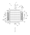
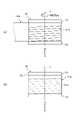
図1は本発明を適用したモータの構成図である。図1において、モータのロータは軸線と直交して永久磁石を通過する断面で示している。図1に示すように、本例のモータ1は、ロータ3と、ロータ3の外周側に配置された環状のステータ4と、ロータ3およびステータ4を収容するケース5を備える。ロータ3は、ロータ軸7と、ロータ軸7に保持された永久磁石8と、永久磁石8の外周側に設けられた保護層9を備える。ステータ4は、環状のステータコア11を備える。ステータコア11は、径方向を内側に向けて突出する6つの突極11aを備える。各突極11aの先端面は、ロータ3の永久磁石8と所定の間隙を介して対向する。6つの突極11aのそれぞれには、コイル12が巻回されている。
(overall structure)
FIG. 1 is a block diagram of a motor to which the present invention is applied. In FIG. 1, the rotor of a motor is shown in a cross section orthogonal to an axis and passing through a permanent magnet. As shown in FIG. 1, the
ステータ4は、コイル12への給電により、ロータ3に対して回転磁界を発生させる。これにより、ロータ3はロータ軸7の軸線L回りに回転する。以下の説明では、ロータ軸7の軸線L方向の一方側を第1方向L1、第1方向L1とは反対の方向を第2方向L2とする。
The
(ロータ)
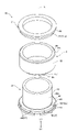
図2は図1のモータ1のロータ3の縦断面図である。図3はロータ3の斜視図である。図4はヨーク部材および永久磁石8の分解斜視図である。図3および図4では、保護層9を省略して示す。
(Rotor)
FIG. 2 is a vertical cross-sectional view of the
図2、図3に示すように、ロータ軸7は、外周側を向く環状外周面21と、環状外周面21の軸線L方向の中程を周方向に延びる環状溝22を備える。従って、環状外周面21は、ロータ軸7の軸線L方向で環状溝22の第1方向L1の側に位置する第1環状外周面部分25と、第2方向L2の側に位置する第2環状外周面部分26と、を備える。第1環状外周面部分25には、複数の凹部27が設けられている。また、ロータ軸7は、軸線L方向で環状外周面21の両側に環状外周面21よりも外周側に突出する一対の環状の突出部23を備える。
As shown in FIGS. 2 and 3, the
より具体的には、図2に示すように、ロータ軸7は、軸部材31と、磁性材料からなるヨーク部材32を備える。図2および図4に示すように、ヨーク部材32は、軸部材31の外周側に保持された筒状部材33と、筒状部材33に保持された環状部材34と、を備える。
More specifically, as shown in FIG. 2, the
図2に示すように、軸部材31は、軸線L方向の第1方向L1の側から第2方向L2の側に向かって、第1小径軸部分37、第1小径軸部分37よりも外径寸法の大きい大径軸部分38、および、第1小径軸部分37と外径寸法が同一の第2小径軸部分39をこの順に備える。第1小径軸部分37および第2小径軸部分39は、それぞれ軸受(図示せず)等で保持される。ヨーク部材32(筒状部材33)は大径軸部分38の外周側に固定されている。
As shown in FIG. 2, the
筒状部材33は、大径軸部分38の外周側に嵌合する内径寸法を備える。図4に示すように、筒状部材33は、軸線L方向の第1方向L1の側から第2方向L2の側に向かって、大径筒部分41、大径筒部分41よりも外径寸法が小さい中径筒部分42、および、中径筒部分42よりも外径寸法が小さい小径筒部分43をこの順に備える。小径筒部分43における中径筒部分42の側の端縁、すなわち、中径筒部分42と小径筒部分43との間で第2方向L2を向く環状面44と小径筒部分43の環状外周面43aとの境界部分には、幅の狭い溝45が全周に亘って設けられている。これにより、小径筒部分43と中径筒部分42との境界部分に膨らみが形成されない。
The
中径筒部分42は、その環状外周面42aの小径筒部分43の側縁に、複数の切欠き46を備える。切欠き46は、中径筒部分42の環状外周面42aと中径筒部分42と小径筒部分43との間の環状面44とが交差する角を小径筒部分43の側および外周側から切り欠いたものである。本例では、軸線L回りの等角度間隔で8つの切欠き46が設けられている。
The medium-
環状部材34は、筒状部材33の小径筒部分43の外周側に嵌合する内径寸法を備える。環状部材34は、軸線L方向の第1方向L1の側から第2方向L2の側に向かって、中径筒部分42と同一の外径寸法の環状外周面51aを備える小径環状部分51と、大径筒部分41と同一の外径寸法を備える大径環状部分52と、をこの順に備える。図2に示すように、環状部材34は、その中心穴に、筒状部材33の小径筒部分43の第2方向L2の端部分(中径筒部分42とは反対側の端部分)が挿入された状態で筒状部材33に固定されている。
The
図3に示すように、環状部材34が筒状部材33に固定された状態において、筒状部材33の小径筒部分43の外周側であって筒状部材33の中径筒部分42と環状部材34の小径環状部分51との間に区画された凹部はロータ軸7の環状溝22である。筒状部材33の中径筒部分42の環状外周面42aは第1環状外周面部分25である。中径筒部分42に設けられた複数の切欠き46は、第1環状外周面部分25に設けられた複数の凹部27であり、第1環状外周面部分25の環状溝22の側の縁に形成されている。従って、複数の凹部27は環状溝22に連通している。環状部材34の小径環状部分51の環状外周面51aは、第2環状外周面部分26である。筒状部材33の大径筒部分41および環状部材34の大径環状部分52は、ロータ軸7の環状外周面21の軸線L方向の両側に設けられた一対の環状の突出部23である。
As shown in FIG. 3, in a state where the
図4に示すように、永久磁石8は環状である。永久磁石8は筒状部材33の小径筒部分43に嵌合する内径寸法を備える。永久磁石8の径方向の厚みは、径方向における小径筒部分43の環状外周面43aと中径筒部分42の環状外周面42aとの間の距離と略等しい。永久磁石8において、軸線Lと反対側を向く外側面55は、周方向で2極に分極着磁されている。永久磁石8の第1方向L1の第1環状端面56と外側面55とにより構成される環状の角部にはアールが施されている。すなわち、永久磁石8の第1方向L1の第1環状端面56と外側面55とにより構成される環状の角部には環状の第1面取り部57が設けられている。永久磁石8の第2方向L2の第2環状端面58と外側面55とにより構成される環状の角部にはアールが施されている。すなわち、永久磁石8の第2方向L2の第2環状端面58と外側面55とにより構成される環状の角部には環状の第2面取り部59が設けられている。
As shown in FIG. 4, the
図2、図3に示すように、永久磁石8は、環状溝22に挿入され、接着剤によりロータ軸7に固定されている。永久磁石8を環状溝22に固定する際には、筒状部材33の小径筒部分43の外周面に接着剤を塗布しておき、小径筒部分43を永久磁石8の中心穴に挿入する。そして、永久磁石8における第1方向L1の第1環状端面56を、中径筒部分4
2と小径筒部分43との間の環状面44に当接した状態とする。しかる後に、筒状部材33の小径筒部分43の先端に環状部材34を固定する。これにより、永久磁石8は環状溝22に挿入された状態でロータ軸7に固定される。
As shown in FIGS. 2 and 3, the
It is in a state of being in contact with the
ここで、小径筒部分43における中径筒部分42の側の端縁には溝45が設けられており、小径筒部分43と中径筒部分42との境界部分に膨らみが形成されない。従って、永久磁石8における第1方向L1の側の第1環状端面56を、中径筒部分42と小径筒部分43との間の環状面44に当接した状態とすることが容易である。
Here, a
永久磁石8が環状溝22に固定された状態では、図3に示すように、永久磁石8の外側面55は、径方向において、第1環状外周面部分25および第2環状外周面部分26と略同一の位置にある。すなわち、永久磁石8の径方向の厚みは、環状溝22の深さ(径方向における小径筒部分43の環状外周面43aと中径筒部分42の環状外周面42aとの間の距離)と略等しい。また、永久磁石8の外側面55と第1環状外周面部分25との間、および、永久磁石8の外側面55と第2環状外周面部分26との間には、それぞれ環状の隙間70がある。これらの隙間70は、永久磁石8が第1面取り部57おより第2面取り部59を備えることにより形成された溝ということもできる。
In a state where the
図2に示すように、保護層9は、軸線L方向で一対の環状の突出部23の間に設けられている。従って、永久磁石8、ロータ軸7の第1環状外周面部分25および第2環状外周面部分26は、保護層9によって外周側から被われている。保護層9は、繊維シート61が、エポキシ樹脂やフェノール樹脂などといった熱硬化性の樹脂62で固められたものである。
As shown in FIG. 2, the
保護層9において、繊維シート61は、永久磁石8、第1環状外周面部分25および第2環状外周面部分26を外周側から被っている。保護層9の樹脂62は、第1環状外周面部分25の凹部27に嵌合する凸部62aを備える。また、保護層9の樹脂62は、永久磁石8の外側面55と第1環状外周面部分25との間、および、永久磁石8の外側面55と第2環状外周面部分26との間には環状の隙間70に浸入した浸入部62bを備える。
In the
(保護層の形成方法)
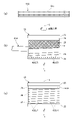
図5は保護層9の形成動作のフローチャートである。図6(a)は保護層9を形成するのに用いたプリプレグの説明図であり、図6(b)は第1繊維シート61Aをロータ軸7に巻き始めた状態を示す説明図であり、図6(c)は第1繊維シート61Aがロータ軸7に巻回された状態を示す説明図である。図6(b)、図6(c)では、軸部材31を省略して示す。図7(a)は第2繊維シート61Bをロータ軸7に巻き始めた状態を示す説明図であり、図7(b)は第2繊維シート61Bがロータ軸7に巻回された状態を示す説明図である。
(Method of forming a protective layer)
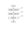
FIG. 5 is a flowchart of the forming operation of the
保護層9は、繊維シート61として、軸線L方向における永久磁石8の幅寸法より幅寸法の狭い第1繊維シート61Aと、永久磁石8の幅寸法よりも幅寸法の広い第2繊維シート61Bと、を備える。第1繊維シート61Aおよび第2繊維シート61Bは、それぞれカーボンプリプレグである。カーボンプリプレグでは炭素繊維シートに熱硬化性の樹脂62が含浸されている。図6(a)に示すように、第1繊維シート61A(炭素繊維シート)において炭素繊維61cは一方向に引き揃えている。また、第2繊維シート61B(炭素繊維シート)においても、炭素繊維は一方向に引き揃えている。なお、第1繊維シート61A、第2繊維シート61Bとして、横方向に延びた炭素繊維と縦方向に延びた炭素繊維とを織ったものが用いられていてもよい。
As the
保護層9の形成方法では、図3に示すように、ロータ軸7(ヨーク部材32)の環状外
周面21の環状溝22に永久磁石8を挿入して固定した状態とする。その後、図5に示すように、第1繊維シート61Aをロータ軸7に巻回する第1繊維シート巻回工程ST1と、第2繊維シート61Bを第1繊維シート61Aの上からロータ軸7に巻回する第2繊維シート巻回工程ST2と、第1繊維シート61Aおよび第2繊維シート61Bが巻回されたロータ軸7を加熱する熱硬化工程ST3と、を行う。
In the method of forming the
第1繊維シート巻回工程ST1では、図6(b)に示すように、軸線L方向の第1方向L1の側に位置する突出部23から、第1環状外周面部分25、永久磁石8の外側面55、および、第2環状外周面部分26に沿って、第1繊維シート61Aを螺旋状に巻回する。第1繊維シート61Aを巻回する方向は、ロータ軸7の回転方向と反対の方向とする。ここで、第1繊維シート61Aを螺旋状に巻回する際には、第1繊維シート61A同士を軸線L方向で部分的に重なった状態とする。本例では、軸線L方向に対して斜めに交差するように第1繊維シート61Aを1周巻回した後に、2周目以降を巻回する際は、新たに巻回する第1繊維シート61Aの幅方向の半分を、既に巻回してある第1繊維シート61Aの幅方向の半分に重ねた状態とする。これにより、永久磁石8の外周側では、第1繊維シート61Aは2層に巻回された状態となる。
In the first fiber sheet winding step ST1, as shown in FIG. 6B, from the protruding
そして、図6(c)に示すように、第1繊維シート61Aが第2環状外周面部分26における第2方向L2の側の突出部23の側の端まで達したら、第1繊維シート61Aを第2方向L2の側の突出部23に沿って1周巻回する。ここで、第1繊維シート61Aを巻回する方向は、ロータ軸7の回転方向と反対の方向なので、第1繊維シート61Aは、ロータ軸7の回転方向と反対方向に巻き終りの端部が向いている。
Then, as shown in FIG. 6C, when the
次に、第2繊維シート巻回工程ST2では、図7(a)に示すように、ロータ軸7に巻回された第1繊維シート61Aの外周側に、第2繊維シート61Bを所定回数、例えば、5層分巻回する。第2繊維シート61Bを巻回する方向も、第1繊維シート61Aと同様に、ロータ軸7の回転方向と反対の方向とする。ここで、第2繊維シート61Bの幅寸法は、永久磁石8の軸線L方向よりも広く、軸線L方向における一対の突出部23の間隔と略等しい。従って、第1繊維シート61Aの外周面に第2繊維シート61Bを巻回する際には、第2繊維シート61Bが軸線L方向に対して略直交するようにする。
Next, in the second fiber sheet winding step ST2, as shown in FIG. 7A, the
ここで、第2繊維シート61Bは、図7(b)に示すように、その外周面が、径方向で、一対の突出部23の環状外周面23aと同じ位置になるまで巻回される。第2繊維シート61Bを巻回する方向は、ロータ軸7の回転方向と反対の方向なので、第2繊維シート61Bは、ロータ軸7の回転方向と反対方向に巻き終りの端部が向いている。
Here, as shown in FIG. 7B, the
次に、熱硬化工程ST3では、第1繊維シート61Aおよび第2繊維シート61Bを加熱しながら、ヨーク部材32に対して真空引きを行うことにより脱気し、第1繊維シート61Aと第2繊維シート61Bとを密着させる。また、第1繊維シート61Aおよび第2繊維シート61Bに含浸されていた樹脂62を熱硬化させ、第1繊維シート61Aおよび第2繊維シート61Bを樹脂62で固める。これにより、一対の突出部23の間に保護層9が形成される。
Next, in the thermosetting step ST3, while heating the
ここで、第1繊維シート61Aおよび第2繊維シート61Bに含浸されていた樹脂62を熱硬化させる際に、第1繊維シート61Aおよび第2繊維シート61Bに含浸されていた樹脂62は溶融して、第1環状外周面部分25の凹部27に浸入した状態となる。また、溶融した樹脂62は、永久磁石8の外側面55と第1環状外周面部分25との間の隙間70、および、永久磁石8の外側面55と第2環状外周面部分26との間の隙間70に浸入した状態となる。その後、樹脂62が硬化すると、図3に示すように、保護層9の樹脂62は、凹部27に嵌合する凸部62aを備えるものとなる。また、保護層9の樹脂62
は、隙間70の形状に対応した環状の浸入部62bを備えるものとなる。
Here, when the
Is provided with an
(作用効果)
本例では、永久磁石8の外周側に繊維シート61(第1繊維シート61Aおよび第2繊維シート61B)を樹脂62で固めてなる保護層9が設けられている。また、この保護層9は、永久磁石8、ロータ軸7の第1環状外周面部分25およびロータ軸7の第2環状外周面部分26を外周側から被う。従って、ロータ3が高速回転する際の遠心力によって永久磁石8が破損することを抑制できる。また、永久磁石8が破損したときに、保護層9により、その飛散を防止できる。
(Action effect)
In this example, a
ここで、本例では、永久磁石8が環状である。従って、モータ1の製造時などに、ロータ3の表面をクリーニングするためにウエスで保護層9の外周面を周方向に拭くと、保護層9に外力が加わり、保護層9が永久磁石8から剥離しやすい。また、ロータ3の高速回転と停止とが繰り返されたときに、保護層9が永久磁石8から剥離する可能性があり、保護層9が永久磁石8に対して相対回転する可能性がある。これに対して、本例では、保護層9の樹脂62の凸部62aと、ロータ軸7の第1環状外周面部分25に設けた凹部27(切欠き46)とが回り止め機構81を構成している(図2参照)。よって、保護層9が永久磁石8から剥離した場合でも、保護層9と永久磁石8とが相対回転することが防止或いは抑制される。これにより、保護層9と永久磁石8とが摺れて保護層9の樹脂62の一部が塵埃となることが抑制される。また、保護層9と永久磁石8とが相対回転してロータ3から異音が発生することを防止或いは抑制できる。
Here, in this example, the
また、本例では、永久磁石8の外側面55と第1環状外周面部分25との間、および、永久磁石8の外側面55と第2環状外周面部分26との間には、隙間70があり、保護層9の樹脂62は、この隙間70に浸入した浸入部62bを備える。ここで、保護層9は、浸入部62bを備えることによって、樹脂62と永久磁石8との接触面積が大きくなる。従って、保護層9の永久磁石8からの剥離や、保護層9が永久磁石8に対して相対回転することを抑制しやすい。また、保護層9が浸入部62bを備えるので、保護層9が軸線L方向に移動することが防止或いは抑制される。
Further, in this example, there is a
また、本例では、第1環状外周面部分25に設けられた凹部27は、環状溝22の側の縁に設けられた切欠き46である。従って、凹部27(切欠き46)と永久磁石8が挿入された環状溝22とは連通している。これにより、保護層9の樹脂62は、凹部27から永久磁石8と環状溝22との間にも浸入して嵌合した状態となる。従って、保護層9の樹脂62は環状溝22に達する凸部62aを備えるものとなる。よって、樹脂62の凸部62aと凹部27とによる回り止めの効果が向上する。
Further, in this example, the
さらに、本例では、保護層9において、螺旋に巻回された第1繊維シート61Aが部分的に重なっている。従って、第1繊維シート61Aにピンホールなどが発生している場合でも、ピンホールを起点として第1繊維シート61Aが裂けることを防止できる。また、第1繊維シート61Aに第2繊維シート61Bが重ねて巻回されている。従って、第1繊維シート61Aの幅方向の端部分が露出する度合いが低くなる。これにより、回転時の風圧で気体等が第1繊維シータの内側に入り込む際の入口が狭くなる。よって、保護層9が永久磁石8から剥離することを防止あるいは抑制できる。また、第2繊維シート61Bの巻回によって、保護層9の外周面における凹凸を無くすこともできる。
Further, in this example, in the
また、本例では、繊維シート61(第1繊維シート61Aおよび第2繊維シート61B)は、樹脂62が含浸されたプリプレグである。プリプレグを用いれば繊維シート61に予め樹脂62が含浸されているので、繊維シート61(第1繊維シート61Aおよび第2繊維シート61B)をロータ軸7に巻回した後、加熱するだけで保護層9を形成すること
ができる。また、加熱により保護層9を設けた場合に、保護層9と永久磁石8などとの密着性が高い。よって、保護層9が永久磁石8から剥離することを抑制できる。
Further, in this example, the fiber sheet 61 (
さらに、ロータ軸7は、軸線L方向で環状外周面21の両側に、第1環状外周面部分25および第2環状外周面部分26よりも外周側に突出する一対の環状の突出部23を備える。従って、繊維シート61を一対の環状の突出部23の間に巻回することが容易であり、保護層9を設けることが容易となる。
Further, the
(変形例)
図8は変形例1のロータ3A、変形例2のロータ3Bの説明図である。図8(a)は変形例1のロータ3Aのヨーク部材32と永久磁石8を示す。図8(b)は変形例2のロータ3Bのヨーク部材32と永久磁石8を示す。図8において、左側半分は断面であり、右側半分は側面である。ロータ3Aおよびロータ3Bは、上記のロータ3に替えて、モータ1のロータとして採用可能である。
(Modification example)
FIG. 8 is an explanatory diagram of the
図8(a)に示すように、変形例1のロータ3Aでは、ロータ軸7(ヨーク部材32)に設けられた凹部27は、第1環状外周面部分25を軸線L方向に延びる溝85である。すなわち、本例の凹部27(溝85)は、第1環状外周面部分25に設けた切欠き46を、大径筒部分41まで延設したものである。このような凹部27を設けた場合、永久磁石8の外周側に設けられる保護層9の樹脂62は、軸線L方向に延びてこの溝85に嵌合するリブ状の凸部62aを備えるものとなる。
As shown in FIG. 8A, in the
図8(b)に示すように、変形例2のロータ3Bでは、ロータ軸7(ヨーク部材32)に設けられた凹部27は、第1環状外周面部分25において軸線L回りを螺旋に延びる螺旋溝86である。このような凹部27(螺旋溝86)を設けた場合、永久磁石8の外周側に設けられる保護層9の樹脂62は、この螺旋溝86に嵌合する螺旋の凸部62aを備えるものとなる。凹部27が環状溝22であれば、切削加工によって凹部27を形成しやすい。
As shown in FIG. 8B, in the
なお、凹部27は、第1環状外周面部分25の軸線L方向の途中位置に形成した穴でもよい。この場合には、保護層9の樹脂62は、この穴に嵌合する凸部62aを備えるものとなる。
The
また、上記の例では、第1環状外周面部分25に凹部27が設けられているが、第1環状外周面部分25に替えて、第2環状外周面部分26に凹部27を設けてもよい。この場合には、保護層9の樹脂62は、第2環状外周面部分26に設けた凹部27に嵌合する凸部62aを備えるものとなる。また、第1環状外周面部分25および第2環状外周面部分26の双方に凹部27を設けてもよい。この場合には、保護層9の樹脂62は、第1環状外周面部分25に設けた凹部27に嵌合する凸部62aと、第2環状外周面部分26に設けた凹部27に嵌合する凸部62aと、を備えるものとなる。
Further, in the above example, the
また、上記の例では、永久磁石8の外周側に第1繊維シート61Aを巻回した後に、第2繊維シート61Bを巻回しているが、第2繊維シート61Bを巻回した後に、第1繊維シート61Aを巻回してもよい。すなわち、第2繊維シート巻回工程ST2の後に、第1繊維シート巻回工程ST1を行ってもよい。このようにしても、保護層9を形成する熱硬
化工程ST3において、保護層9の樹脂62は、第1環状外周面部分25の凹部27に嵌合する凸部62aを備えるものとなる。
Further, in the above example, the
1…モータ、3・3A・3B…ロータ、4…ステータ、5…ケース、7…ロータ軸、8…永久磁石、9…保護層、11…ステータコア、11a…突極、12…コイル、21…環状外周面、22…環状溝、23…突出部、25…第1環状外周面部分、26…第2環状外周面部分、27…凹部、31…軸部材、32…ヨーク部材、33…筒状部材、34…環状部材、37…小径軸部分、38…大径軸部分、39…小径軸部分、41…大径筒部分、42…中径筒部分、43…小径筒部分、44…環状面、45…溝、51…小径環状部分、52…大径環状部分、55…外側面、56…第1環状端面、57…第1面取り部、58…第2環状端面、59…第2面取り部、61…繊維シート、61A…第1繊維シート、61B…第2繊維シート、62…保護層の樹脂、62a…樹脂の凸部、62b…樹脂の浸入部、61c…炭素繊維、70…隙間、81…回り止め機構、85…溝、86…螺旋溝、L…軸線、L1…第1方向、L2…第2方向 1 ... motor, 3.3A, 3B ... rotor, 4 ... stator, 5 ... case, 7 ... rotor shaft, 8 ... permanent magnet, 9 ... protective layer, 11 ... stator core, 11a ... chamfer, 12 ... coil, 21 ... Circular outer peripheral surface, 22 ... annular groove, 23 ... projecting portion, 25 ... first annular outer peripheral surface portion, 26 ... second annular outer peripheral surface portion, 27 ... recess, 31 ... shaft member, 32 ... yoke member, 33 ... tubular Member, 34 ... annular member, 37 ... small diameter shaft part, 38 ... large diameter shaft part, 39 ... small diameter shaft part, 41 ... large diameter cylinder part, 42 ... medium diameter cylinder part, 43 ... small diameter cylinder part, 44 ... annular surface , 45 ... groove, 51 ... small diameter annular portion, 52 ... large diameter annular portion, 55 ... outer surface, 56 ... first annular end face, 57 ... first chamfered portion, 58 ... second annular end face, 59 ... second chamfered portion. , 61 ... Fiber sheet, 61A ... First fiber sheet, 61B ... Second fiber sheet, 62 ... Protective layer resin, 62a ... Resin convex part, 62b ... Resin penetration part, 61c ... Carbon fiber, 70 ... Gap, 81 ... Anti-rotation mechanism, 85 ... Groove, 86 ... Spiral groove, L ... Axis line, L1 ... First direction, L2 ... Second direction
Claims (8)
前記ロータ軸の外周側に保持された永久磁石と、
繊維シートを樹脂で固めてなる保護層と、を有し、
前記ロータ軸は、外周側を向く環状外周面と、前記環状外周面を周方向に延びる環状溝と、を備え、
前記永久磁石は、前記環状溝に挿入されており、
前記環状外周面において、前記ロータ軸の軸線方向で前記環状溝の一方側に位置する第1環状外周面部分および他方側に位置する第2環状外周面部分の少なくとも一方には、凹部が設けられており、
前記永久磁石は、環状であり、
前記ロータ軸は、軸部材と、前記軸部材の外周側に保持された筒状部材と、前記筒状部材に固定された環状部材と、を備え、
前記筒状部材は、前記軸線方向の一方側から他方側に向かって、大径筒部分、前記大径筒部分よりも外径寸法が小さい中径筒部分、および、中径筒部分よりも外径寸法が小さい小径筒部分をこの順に備え、
前記環状部材は、前記軸線方向の一方側から他方側に向かって、前記中径筒部分と同一の外径寸法を備える小径環状部分と、前記小径環状部分よりも外径寸法が大きい大径環状部分と、をこの順に備え、
前記環状部材は、その中心穴に前記小径筒部分の前記中径筒部分とは反対側の端部が挿入された状態で当該筒状部材に固定されており、
前記小径筒部分の外周側であって前記中径筒部分と前記小径環状部分との間に区画された凹部は、前記環状溝であり、
前記中径筒部分の外周面は、前記第1環状外周面部分であり、
前記小径環状部分の外周面は、前記第2環状外周面部分であり、
前記保護層は、前記永久磁石、前記第1環状外周面部分および前記第2環状外周面部分の外周側を被い、
前記保護層の前記樹脂は、前記凹部に嵌合する凸部を備えることを特徴とするロータ。 With the rotor shaft,
The permanent magnet held on the outer peripheral side of the rotor shaft and
It has a protective layer made by solidifying the fiber sheet with resin,
The rotor shaft includes an annular outer peripheral surface facing the outer peripheral side and an annular groove extending in the circumferential direction on the annular outer peripheral surface.
The permanent magnet is inserted in the annular groove, and the permanent magnet is inserted into the annular groove.
On the annular outer peripheral surface, recesses are provided in at least one of the first annular outer peripheral surface portion located on one side of the annular groove and the second annular outer peripheral surface portion located on the other side in the axial direction of the rotor shaft. And
The permanent magnet is annular and has an annular shape.
The rotor shaft includes a shaft member, a tubular member held on the outer peripheral side of the shaft member, and an annular member fixed to the tubular member.
The tubular member is outward from the large-diameter cylinder portion, the medium-diameter cylinder portion having a smaller outer diameter than the large-diameter cylinder portion, and the medium-diameter cylinder portion from one side to the other side in the axial direction. Small diameter cylinders with small diameters are provided in this order.
The annular member has a small-diameter annular portion having the same outer diameter as the medium-diameter tubular portion and a large-diameter annular portion having a larger outer diameter than the small-diameter annular portion from one side to the other in the axial direction. Part and, in this order,
The annular member is fixed to the tubular member with the end of the small-diameter cylinder portion opposite to the medium-diameter cylinder portion inserted into the center hole thereof.
The recess on the outer peripheral side of the small diameter cylinder portion and partitioned between the medium diameter cylinder portion and the small diameter annular portion is the annular groove.
The outer peripheral surface of the medium-diameter cylinder portion is the first annular outer peripheral surface portion.
The outer peripheral surface of the small-diameter annular portion is the second annular outer peripheral surface portion.
The protective layer covers the permanent magnet, the first annular outer peripheral surface portion, and the outer peripheral side of the second annular outer peripheral surface portion.
The resin of the protective layer is a rotor including a convex portion fitted to the concave portion.
は、隙間があり、
前記保護層の前記樹脂は、前記隙間に浸入した浸入部を備えることを特徴とする請求項1に記載のロータ。 Between the outer surface of the permanent magnet facing away from the side where the axis is located and the first annular outer peripheral surface portion, and between the outer surface of the permanent magnet and the second annular outer peripheral surface portion. Has a gap in
The rotor according to claim 1, wherein the resin of the protective layer includes an intrusion portion that has penetrated into the gap.
前記第1繊維シートは、当該第1繊維シート同士が幅方向で部分的に重なるように螺旋状に巻回された状態で前記永久磁石、前記第1環状外周面部分および前記第2環状外周面部分を外周側から被い、
前記第2繊維シートは、前記第1の繊維シートの外周側に巻回された状態で前記永久磁石、前記第1環状外周面部分および前記第2環状外周面部分を外周側から被うことを特徴とする請求項1から4のうちの何れか一項に記載のロータ。 The protective layer includes, as the fiber sheet, a first fiber sheet having a width narrower than the width dimension of the permanent magnet in the axial direction, and a second fiber sheet having a width wider than the width dimension of the permanent magnet. ,
The first fiber sheet is a state in which the first fiber sheets are spirally wound so as to partially overlap each other in the width direction, and the permanent magnet, the first annular outer peripheral surface portion and the second annular outer peripheral surface portion are formed. Cover the part from the outer circumference side,
The second fiber sheet covers the permanent magnet, the first annular outer peripheral surface portion and the second annular outer peripheral surface portion from the outer peripheral side in a state of being wound around the outer peripheral side of the first fiber sheet. The rotor according to any one of claims 1 to 4, wherein the rotor is characterized.
前記ロータに対して回転磁界を発生させるステータと、を有することを特徴とするモータ。 The rotor according to any one of claims 1 to 7 .
A motor comprising a stator that generates a rotating magnetic field with respect to the rotor.
Priority Applications (2)
| Application Number | Priority Date | Filing Date | Title |
|---|---|---|---|
| JP2017221454A JP7064850B2 (en) | 2017-11-17 | 2017-11-17 | Rotor and motor |
| CN201811364301.7A CN109802502B (en) | 2017-11-17 | 2018-11-16 | Rotor and motor |
Applications Claiming Priority (1)
| Application Number | Priority Date | Filing Date | Title |
|---|---|---|---|
| JP2017221454A JP7064850B2 (en) | 2017-11-17 | 2017-11-17 | Rotor and motor |
Publications (3)
| Publication Number | Publication Date |
|---|---|
| JP2019092354A JP2019092354A (en) | 2019-06-13 |
| JP2019092354A5 JP2019092354A5 (en) | 2020-11-19 |
| JP7064850B2 true JP7064850B2 (en) | 2022-05-11 |
Family
ID=66556290
Family Applications (1)
| Application Number | Title | Priority Date | Filing Date |
|---|---|---|---|
| JP2017221454A Active JP7064850B2 (en) | 2017-11-17 | 2017-11-17 | Rotor and motor |
Country Status (2)
| Country | Link |
|---|---|
| JP (1) | JP7064850B2 (en) |
| CN (1) | CN109802502B (en) |
Families Citing this family (1)
| Publication number | Priority date | Publication date | Assignee | Title |
|---|---|---|---|---|
| JP2021029062A (en) * | 2019-08-09 | 2021-02-25 | 日本電産サンキョー株式会社 | Rotor and motor |
Citations (3)
| Publication number | Priority date | Publication date | Assignee | Title |
|---|---|---|---|---|
| WO2008047767A1 (en) | 2006-10-17 | 2008-04-24 | Sanyo Denki Co., Ltd. | Rotator for motor and method for manufacturing the same |
| JP2009017708A (en) | 2007-07-06 | 2009-01-22 | Nidec Sankyo Corp | Rotor, manufacturing method for rotor and motor |
| JP2011529679A (en) | 2008-07-28 | 2011-12-08 | ダイレクト、ドライヴ、システィムズ、インク | Electric machine |
Family Cites Families (10)
| Publication number | Priority date | Publication date | Assignee | Title |
|---|---|---|---|---|
| JPS612776U (en) * | 1984-06-13 | 1986-01-09 | 神鋼電機株式会社 | Permanent magnet rotor of brushless motor |
| JPS614447A (en) * | 1984-06-18 | 1986-01-10 | Aisan Ind Co Ltd | Rotor for stepping motor and manufacture thereof |
| JP2942434B2 (en) * | 1993-02-23 | 1999-08-30 | 富士電気化学株式会社 | Rotor for stepping motor and method of manufacturing the same |
| JPH10201153A (en) * | 1997-01-07 | 1998-07-31 | Oppama Kogyo Kk | Rotor for rotary machine |
| JP3484051B2 (en) * | 1997-09-10 | 2004-01-06 | 株式会社 日立インダストリイズ | Permanent magnet synchronous motor, method for manufacturing the same, and centrifugal compressor equipped with permanent magnet synchronous motor |
| CN100435456C (en) * | 2003-09-25 | 2008-11-19 | 乐金电子(天津)电器有限公司 | Rotor of variable reluctance dynamo |
| JP4143631B2 (en) * | 2005-09-01 | 2008-09-03 | トヨタ自動車株式会社 | Manufacturing method of rotor |
| CN102751801B (en) * | 2007-07-06 | 2014-10-15 | 日本电产三协株式会社 | Motor, and rotor, and manufacturing method for the rotor, and a motor provided with the rotor |
| JP6212020B2 (en) * | 2014-11-13 | 2017-10-11 | ファナック株式会社 | Manufacturing method of rotor |
| JP6571546B2 (en) * | 2016-01-21 | 2019-09-04 | ファナック株式会社 | Method for manufacturing rotor of electric motor |
-
2017
- 2017-11-17 JP JP2017221454A patent/JP7064850B2/en active Active
-
2018
- 2018-11-16 CN CN201811364301.7A patent/CN109802502B/en active Active
Patent Citations (3)
| Publication number | Priority date | Publication date | Assignee | Title |
|---|---|---|---|---|
| WO2008047767A1 (en) | 2006-10-17 | 2008-04-24 | Sanyo Denki Co., Ltd. | Rotator for motor and method for manufacturing the same |
| JP2009017708A (en) | 2007-07-06 | 2009-01-22 | Nidec Sankyo Corp | Rotor, manufacturing method for rotor and motor |
| JP2011529679A (en) | 2008-07-28 | 2011-12-08 | ダイレクト、ドライヴ、システィムズ、インク | Electric machine |
Also Published As
| Publication number | Publication date |
|---|---|
| CN109802502A (en) | 2019-05-24 |
| CN109802502B (en) | 2021-03-23 |
| JP2019092354A (en) | 2019-06-13 |
Similar Documents
| Publication | Publication Date | Title |
|---|---|---|
| JP6804642B2 (en) | Rotor, rotating machine, and method of manufacturing rotor | |
| JP4932620B2 (en) | Rotor, rotor manufacturing method, and motor | |
| JP6212020B2 (en) | Manufacturing method of rotor | |
| KR101243670B1 (en) | Rotor of motor | |
| US9472984B2 (en) | Rotor for rotating electric machine | |
| JP6274475B2 (en) | Rotor, rotating electric machine, and method of manufacturing rotor | |
| JP2015100202A (en) | Rotor, motor and method for manufacturing rotor | |
| JP2007089291A (en) | Permanent magnet type rotating electric machine | |
| JP2017163752A (en) | Rotor of permanent magnet dynamo-electric machine | |
| US20090021094A1 (en) | Motor, and rotor, and manufacturing method for the rotor, and a motor provided with the rotor | |
| JP2018078788A (en) | Motor and rotor thereof | |
| JP6148269B2 (en) | Motor rotor and motor | |
| WO2015025648A1 (en) | Dynamo-electric machine | |
| JP7064850B2 (en) | Rotor and motor | |
| WO2015049967A1 (en) | Permanent magnet embedded rotating electric machine and method for manufacturing same | |
| JP2021029067A5 (en) | ||
| JP7381304B2 (en) | A rotor with end plates arranged on the end face of the rotor core and an electric motor with the rotor | |
| JP6707392B2 (en) | Rotor manufacturing method | |
| JP7331372B2 (en) | Rotor for rotary electric machine | |
| JP5983326B2 (en) | Rotor of embedded magnet motor | |
| JP2015220950A (en) | Rotating electrical machine | |
| JP7476968B2 (en) | ROTOR, MOTOR, AND METHOD FOR MANUFACTURING ROTOR | |
| WO2023199962A1 (en) | Rotor and rotor manufacturing method | |
| WO2023190854A1 (en) | Rotor and rotor manufacturing method | |
| JP2023151123A (en) | Rotor and rotor manufacturing method |
Legal Events
| Date | Code | Title | Description |
|---|---|---|---|
| A521 | Request for written amendment filed |
Free format text: JAPANESE INTERMEDIATE CODE: A523 Effective date: 20201007 |
|
| A621 | Written request for application examination |
Free format text: JAPANESE INTERMEDIATE CODE: A621 Effective date: 20201007 |
|
| A977 | Report on retrieval |
Free format text: JAPANESE INTERMEDIATE CODE: A971007 Effective date: 20210812 |
|
| A131 | Notification of reasons for refusal |
Free format text: JAPANESE INTERMEDIATE CODE: A131 Effective date: 20211005 |
|
| A521 | Request for written amendment filed |
Free format text: JAPANESE INTERMEDIATE CODE: A523 Effective date: 20211201 |
|
| TRDD | Decision of grant or rejection written | ||
| A01 | Written decision to grant a patent or to grant a registration (utility model) |
Free format text: JAPANESE INTERMEDIATE CODE: A01 Effective date: 20220405 |
|
| A61 | First payment of annual fees (during grant procedure) |
Free format text: JAPANESE INTERMEDIATE CODE: A61 Effective date: 20220425 |
|
| R150 | Certificate of patent or registration of utility model |
Ref document number: 7064850 Country of ref document: JP Free format text: JAPANESE INTERMEDIATE CODE: R150 |