JP6571546B2 - Method for manufacturing rotor of electric motor - Google Patents
Method for manufacturing rotor of electric motor Download PDFInfo
- Publication number
- JP6571546B2 JP6571546B2 JP2016009987A JP2016009987A JP6571546B2 JP 6571546 B2 JP6571546 B2 JP 6571546B2 JP 2016009987 A JP2016009987 A JP 2016009987A JP 2016009987 A JP2016009987 A JP 2016009987A JP 6571546 B2 JP6571546 B2 JP 6571546B2
- Authority
- JP
- Japan
- Prior art keywords
- rotor core
- notch
- protective tube
- end surface
- gate
- Prior art date
- Legal status (The legal status is an assumption and is not a legal conclusion. Google has not performed a legal analysis and makes no representation as to the accuracy of the status listed.)
- Active
Links
Images


Classifications
-
- H—ELECTRICITY
- H02—GENERATION; CONVERSION OR DISTRIBUTION OF ELECTRIC POWER
- H02K—DYNAMO-ELECTRIC MACHINES
- H02K1/00—Details of the magnetic circuit
- H02K1/06—Details of the magnetic circuit characterised by the shape, form or construction
- H02K1/22—Rotating parts of the magnetic circuit
- H02K1/27—Rotor cores with permanent magnets
- H02K1/2706—Inner rotors
- H02K1/272—Inner rotors the magnetisation axis of the magnets being perpendicular to the rotor axis
- H02K1/274—Inner rotors the magnetisation axis of the magnets being perpendicular to the rotor axis the rotor consisting of two or more circumferentially positioned magnets
- H02K1/2753—Inner rotors the magnetisation axis of the magnets being perpendicular to the rotor axis the rotor consisting of two or more circumferentially positioned magnets the rotor consisting of magnets or groups of magnets arranged with alternating polarity
- H02K1/278—Surface mounted magnets; Inset magnets
-
- H—ELECTRICITY
- H02—GENERATION; CONVERSION OR DISTRIBUTION OF ELECTRIC POWER
- H02K—DYNAMO-ELECTRIC MACHINES
- H02K1/00—Details of the magnetic circuit
- H02K1/06—Details of the magnetic circuit characterised by the shape, form or construction
- H02K1/22—Rotating parts of the magnetic circuit
- H02K1/28—Means for mounting or fastening rotating magnetic parts on to, or to, the rotor structures
-
- H—ELECTRICITY
- H02—GENERATION; CONVERSION OR DISTRIBUTION OF ELECTRIC POWER
- H02K—DYNAMO-ELECTRIC MACHINES
- H02K15/00—Methods or apparatus specially adapted for manufacturing, assembling, maintaining or repairing of dynamo-electric machines
- H02K15/02—Methods or apparatus specially adapted for manufacturing, assembling, maintaining or repairing of dynamo-electric machines of stator or rotor bodies
- H02K15/03—Methods or apparatus specially adapted for manufacturing, assembling, maintaining or repairing of dynamo-electric machines of stator or rotor bodies having permanent magnets
-
- H—ELECTRICITY
- H02—GENERATION; CONVERSION OR DISTRIBUTION OF ELECTRIC POWER
- H02K—DYNAMO-ELECTRIC MACHINES
- H02K15/00—Methods or apparatus specially adapted for manufacturing, assembling, maintaining or repairing of dynamo-electric machines
- H02K15/12—Impregnating, heating or drying of windings, stators, rotors or machines
Description
本発明は、電動機のロータの製造方法に関する。
The present invention relates to a method of manufacturing a rotor of electric motive.
ロータコアと、該ロータコアの径方向外側に配置される複数の磁石と、該複数の磁石を取り囲む筒状の保護管と、ロータコアと保護管との間の隙間に充填された樹脂とを備えるロータが知られている(例えば、特許文献1)。 A rotor comprising a rotor core, a plurality of magnets arranged radially outside the rotor core, a cylindrical protective tube surrounding the plurality of magnets, and a resin filled in a gap between the rotor core and the protective tube Known (for example, Patent Document 1).
上述のようなロータを製造する場合、一般的には、ロータコアと保護管との間の隙間に樹脂を射出する。このような隙間は狭隘であり、該隙間に射出成形機のゲートを位置決めする作業が困難となっていた。また、該隙間に射出される樹脂の射出圧によって、保護管が局所的に変形してしまう場合があった。 When manufacturing a rotor as described above, generally, resin is injected into a gap between the rotor core and the protective tube. Such a gap is narrow, and it is difficult to position the gate of the injection molding machine in the gap. Moreover, the protective tube may be locally deformed by the injection pressure of the resin injected into the gap.
本発明の一態様において、電動機のロータは、ロータコアと、ロータコアの径方向外側に配置される複数の磁石と、複数の磁石を取り囲む筒状の保護管と、ロータコアと保護管との間の隙間に充填された充填物とを備える。 In one embodiment of the present invention, a rotor of an electric motor includes a rotor core, a plurality of magnets arranged radially outside the rotor core, a cylindrical protective tube surrounding the plurality of magnets, and a gap between the rotor core and the protective tube And a filled material.
ロータコアは、該ロータコアの外周面から径方向外側に突出し、該ロータコアの軸方向一方の第1端面から、ロータコアの軸方向他方の第2端面に向かって軸方向に延在する複数の突条部と、少なくとも1つの突条部の径方向外側の端面から径方向内側へ凹む切り欠きとを有する。 The rotor core protrudes radially outward from the outer peripheral surface of the rotor core, and extends in the axial direction from one axial first end surface of the rotor core toward the other axial second axial end surface of the rotor core. And a notch that is recessed radially inward from the radially outer end face of the at least one protrusion.
複数の突条部は、ロータコアの周方向に並ぶように配置される。複数の磁石の各々は、周方向に互いに隣り合う2つの突条部の間に配置される。切り欠きは、第1端面から第2端面に向かって軸方向に延びている。充填物は、樹脂であってもよい。切り欠きは、第1端面から第2端面まで延びてもよい。
本発明の他の態様において、電動機のロータを製造する方法は、ロータコアであって、該ロータコアの外周面から径方向内側へ凹む切り欠きを有し、該切り欠きは、ロータコアの軸方向一方の第1端面から、ロータコアの軸方向他方の第2端面に向かって軸方向へ延びる、ロータコアを作製することを備える。
The plurality of protrusions are arranged so as to be aligned in the circumferential direction of the rotor core. Each of the plurality of magnets is disposed between two protrusions adjacent to each other in the circumferential direction. The notch extends in the axial direction from the first end surface toward the second end surface. The filling may be a resin. The notch may extend from the first end surface to the second end surface.
In another aspect of the present invention, a method of manufacturing a rotor of an electric motor includes a rotor core having a notch that is recessed radially inward from an outer peripheral surface of the rotor core, the notch being one of the axial directions of the rotor core. Producing a rotor core extending in the axial direction from the first end surface toward the other second end surface in the axial direction of the rotor core.
また、この方法は、ロータコアの径方向外側に複数の磁石を、ロータコアの周方向に互いに隣り合う2つの磁石の間に切り欠きが位置するように、配置することと、複数の磁石を取り囲むように筒状の保護管を配置することと、切り欠きに充填物を射出して、ロータコアと保護管との間に形成された隙間に充填物を充填することとを備える。 In this method, a plurality of magnets are arranged outside the rotor core in the radial direction so that a notch is located between two magnets adjacent to each other in the circumferential direction of the rotor core, and the plurality of magnets are surrounded. Arranging a cylindrical protective tube, and injecting a filling material into the notch, and filling the filling material into a gap formed between the rotor core and the protective tube.
以下、本発明の実施の形態を図面に基づいて詳細に説明する。まず、図1〜図3を参照して、一実施形態に係るロータ10について説明する。なお、以下の説明において、軸方向とは、ロータの回転軸線Oに沿う方向を示し、径方向とは、軸線Oを中心とする円の半径方向を示し、周方向とは、該円の円周方向を示す。また、便宜上、図中の矢印Aに示す方向を軸方向前方とする。
Hereinafter, embodiments of the present invention will be described in detail with reference to the drawings. First, a
ロータ10は、電動機のステータ(図示せず)の径方向内側に回転可能に配置され、該ステータとともに電動機を構成する。ロータ10は、回転シャフト12、ロータコア14、複数の磁石16、保護管18、および充填物20を備える。回転シャフト12は、軸方向に延びる円柱部材である。
The
ロータコア14は、回転シャフト12の径方向外側に固定された筒状部材である。ロータコア14は、軸方向に積層された複数の電磁鋼板から構成され、軸線Oを中心とするように配置されている。ロータコア14の中心部には、貫通孔14aが形成されており、該貫通孔14aに、回転シャフト12が挿通されている。
The
ロータコア14は、複数の突条部22、および複数の切り欠き24を有する。突条部22の各々は、ロータコア14の外周面26から径方向外側へ突出し、ロータコア14の軸方向後方の第1端面28から軸方向前方の第2端面30まで、軸方向に延在している。本実施形態においては、計8個の突条部22が、周方向に略等間隔で並ぶように設けられている。
The
図3に示すように、突条部22の各々は、互いに対向する一対の側面40および42と、径方向外側の端面32とを有する。側面40および42は、略平面であって、外周面26から径方向外側へ向かって立ち上がり、軸方向へ延在している。端面32は、側面40と側面42との間で延在し、且つ軸方向へ延びている。
As shown in FIG. 3, each of the
切り欠き24の各々は、突条部22の径方向外側の端面32から径方向内方へ凹むように、ロータコア14に形成されている。図3に示すように、切り欠き24の各々は、互いに対面する一対の側面34および36と、側面34と側面36との間で延在する底面38とによって、画定されている。
Each of the
側面34および36は、略平面であって、周方向に予め定められた距離だけ離隔して配置され、互いに略平行となるように軸方向へ延在している。底面38は、略平面であって、外周面26よりも径方向内方に位置し、軸方向に延在している。
The
外周面26と、側面34、36、40および42と、底面38と、端面32とによって、ロータコア14の外周面44が形成されている。
An outer
磁石16の各々は、軸方向へ延びる細長い磁性部材(たとえば、ネオジムまたはフェライト)であって、周方向に互いに隣り合う2つの突条部22の間に配置され、ロータコア14の外周面26の上に固定されている。本実施形態においては、計8個の磁石16が、周方向に略等間隔で配置されている。
Each of the
保護管18は、複数の磁石16を径方向外側から取り囲む筒状部材である。保護管18は、ステンレス等の非磁性材料から作製され、軸線Oを中心とするように配置されている。
The
充填物20は、ロータコア14と保護管18との間の隙間に充填されている。より具体的には、充填物20は、磁石16の各々と保護管18との間、突条部22の各々と保護管18との間、および切り欠き24の内部に、それぞれ充填されている。一例として、充填物20は、樹脂である。
The
次に、図4〜図8を参照して、ロータ10の製造方法について説明する。ステップS1において、製造者は、ロータコア14を作製する。具体的には、製造者は、プレス加工によって複数の電磁鋼板を打ち抜き、これら電磁鋼板を軸方向に積層させて、図1および図2に示すロータコア14を作製する。
Next, a method for manufacturing the
ステップS2において、製造者は、ステップS1にて作製したロータコア14の径方向外側に、複数の磁石16を配置する。具体的には、製造者は、磁石16の各々を、周方向に互いに隣り合う2つの突条部22の間、すなわち、ロータコア14の外周面26の上に、配置する。
In step S2, the manufacturer arranges a plurality of
本実施形態においては、ロータコア14に設けられた突条部22によって、磁石16の周方向へのずれが規制されるので、製造者は、接着剤等を用いて磁石16をロータコア14の外周面26の上に接着させることなく、磁石16を外周面26の上に容易に位置決めすることができる。
In the present embodiment, the
ステップS3において、製造者は、複数の磁石16を取り囲むように、保護管18’を配置する。具体的には、製造者は、保護管18’(図5)を準備する。この保護管18’は、図1および図2に示す保護管18よりも小さい直径と、保護管18と同じ軸方向寸法とを有する筒状部材である。
In step S <b> 3, the manufacturer arranges the
次いで、製造者は、ロータコア14の外周面26に固定された磁石16を径方向外側から取り囲むように、保護管18’を嵌着する。この状態を、図5に示す。このステップS3によって、ロータコア14、磁石16、および保護管18’からなる組立体50が作製される。この組立体50においては、保護管18’の内周面は、磁石16の外面と当接している。
Next, the manufacturer fits the
ステップS4において、製造者は、ステップS3にて作製した組立体50を、射出成形機100の第1の金型102に設置する。以下、図6を参照して、一実施形態に係る射出成形機100について説明する。
In step S <b> 4, the manufacturer installs the
射出成形機100は、第1の金型102、第2の金型104、充填物供給ユニット106、スプール107、およびホットランナ108を備える。第1の金型102には、円形状のキャビティー110が形成されている。
The
第2の金型104は、第1の金型102に対して接近および離反する方向へ可動に設置されている。第2の金型104は、第1の金型102に面する加圧面104aを有する。充填物供給ユニット106は、加熱されて液状化した充填物を、スプール107内に供給する。スプール107に供給された充填物は、スプール107内を流動し、ホットランナ108に流入する。
The
ホットランナ108は、ヒータ(図示せず)を含み、スプール107から流入した充填物を、液状化した状態のまま送給する。ホットランナ108の出口端には、複数のゲート112が設けられている。
The
ゲート112の各々は、第1の金型104の加圧面104aの上で外部に開口している。ホットランナ108内に流入した充填物は、ホットランナ108内を流動して、ゲート112から外部へ射出される。
Each of the
ゲート112は、周方向に略等間隔で配列されている。これらゲート112の周方向位置は、ロータコア14に形成された切り欠き24の周方向位置にそれぞれ対応している。
The
例えば、ホットランナ108には、計8個のゲート112が設けられ、これらゲート112の周方向位置が、計8個の切り欠き24の周方向位置に、それぞれ対応している。
For example, the
このステップS4において、製造者は、ステップS3にて作製した組立体50を、第1の金型102のキャビティー110内に、該キャビティー110と同心となるように、設置する。この状態を図6に示す。図6に示す状態においては、ロータコア14の軸方向前方の端面30は、キャビティー110を画定する底面114に当接する。
In step S <b> 4, the manufacturer installs the
ステップS5において、射出成形機100は、第2の金型104を第1の金型102へ向かって移動させ、第1の金型102のキャビティー110を、第2の金型104の加圧面104aで閉鎖(いわゆる、型締め)する。
In step S <b> 5, the
この状態を図7に示す。図7に示す状態においては、ロータコア14の軸方向後方の端面28は、加圧面104aに面接触する。また、保護管18’は、キャビティー110を画定する側面116から径方向内側に離隔している。
This state is shown in FIG. In the state shown in FIG. 7, the axially rear end face 28 of the
また、ゲート112の各々は、ロータコア14に形成された切り欠き24の各々に面するように、配置される。図8に、図7に示す状態における、切り欠き24とゲート112との周方向の位置関係を概略的に示す。
Further, each of the
図8に示すように、ステップS5の終了時において、ゲート112は、切り欠き24に面して開口するように、該切り欠き24に対して位置決めされる。本実施形態においては、ゲート112は、突条部22の径方向外側の端面32よりも、底面38に近い位置に、配置される。
As shown in FIG. 8, at the end of step S <b> 5, the
ステップS6において、射出成形機100は、切り欠き24に充填物(例えば、樹脂)を射出する。具体的には、射出成形機100は、充填物供給ユニット106を駆動して、ホットランナ108内に充填物を供給し、ゲート112から切り欠き24内に充填物を射出する。
In step S <b> 6, the
切り欠き24内に射出された充填物は、該切り欠き24内を流動して、保護管18’とロータコア14との間の隙間に入り込む。射出された充填物の圧力によって、保護管18’は、径方向外側へ膨張し、キャビティー110の側面116に当接する。その結果、上述の保護管18が形成される。
The filler injected into the
また、ゲート112から射出された充填物は、磁石16の各々と保護管18との間、突条部22の各々と保護管18との間、および切り欠き部24の内部に、それぞれ充填される。その結果、上述の充填物20が形成される。
Further, the filler injected from the
この状態を、図9に示す。このステップS6によって、ロータコア14、磁石16、保護管18、および充填物20からなる組立体52が作製される。
This state is shown in FIG. By this step S <b> 6, an
ステップ7において、製造者は、回転シャフト12を固定する。具体的には、製造者は、回転シャフト12を準備し、該回転シャフト12を、ステップS6にて作製した組立体52のロータコア14の貫通孔14aに嵌め入れて固定する。
In
例えば、回転シャフト12は、ロータコア14の貫通孔14aに、焼き嵌めによって固定される。このステップS6によって、図1に示す回転子10が製造される。
For example, the rotating
上述したように、本実施形態においては、ロータコア14に切り欠き24を形成し、ステップS6にて該切り欠き24内に充填物を射出している。この構成によれば、ステップS6において保護管18’を均等に膨張させることができる。
As described above, in this embodiment, the
この作用効果について、以下に説明する。ここで、比較のために、切り欠き24が形成されていない場合について考える。この場合、ステップS6において、ゲート112は、突条部22の径方向外側の端面32と、保護管18’の内周面との間の隙間に配置されることになる。
This effect will be described below. Here, for the sake of comparison, consider the case where the
この場合、ゲート112は、図8に示す配置と比べて、保護管18’により近い位置に配置されることになる。このようにゲート112を保護管18’に近い位置に配置させて充填物を射出すると、充填物の射出圧によって、保護管18’が、ゲート112に近い領域においてより大きく変形してしまい、これにより、保護管18が’不均等に変形してしまう虞がある。
In this case, the
これに対して、本実施形態においては、切り欠き24を設けることによって、図8に示すように、ゲート112を、保護管18’から径方向内側により離れた位置に、配置させることができる。
On the other hand, in the present embodiment, by providing the
これにより、ステップS6にてゲート112から充填物を射出したときに、ゲート112に近い領域において保護管18’に掛かる射出圧を低減させ、以って、射出圧に起因して保護管18’が不均等に変形してしまうのを防止することができる。
Thereby, when the filling material is injected from the
さらには、切り欠き24が形成されていない場合、ステップS6においてゲート112を、突条部22の径方向外側の端面32と保護管18’との間の極狭い隙間に位置決めする必要がある。
Furthermore, when the
これに対して、本実施形態によれば、比較的大きな径方向寸法を有する切り欠き24に対してゲート112を容易に位置決めできるので、作業効率の向上にも繋がる。
On the other hand, according to the present embodiment, the
また、本実施形態においては、切り欠き24は、その底面38がロータコア14の外周面26よりも径方向内側に位置するように、形成されている。この構成によれば、ステップS6にてゲート112を保護管18’からより離れた位置に配置させることができるので、保護管18’が不均等に変形してしまうのを、より効果的に防止することができる。
Further, in the present embodiment, the
なお、切り欠き24には、種々の変形例が考えられ得る。一例として、切り欠き24を画定する側面34および36は、ロータコア14の軸方向後方の端面28から軸方向前方に向かうにつれて互いに接近するように軸線Oに対して傾斜するテーパ面によって、構成されてもよい。
Various modifications can be considered for the
または、切り欠き24を画定する底面38は、ロータコア14の軸方向後方の端面28から軸方向前方に向かうにつれて径方向外側へ向かうように傾斜するテーパ面によって、構成されてもよい。
Alternatively, the
これら変形例においては、切り欠き24の断面積が、ロータコア14の軸方向後方の端面28から軸方向前方に向かうにつれて徐々に小さくなる。このような場合においても、ステップS6において、充填物の射出圧を、ロータコア14の軸方向後方の端面28に近い位置において低減できるので、保護管18’の不均等な変形を防止できる。
In these modifications, the cross-sectional area of the
また、切り欠き24は、ロータコア14の軸方向後方の端面28から軸方向前方へ延びて、軸方向前方の端面30よりも軸方向後方の位置で終端するように、形成されてもよい。また、切り欠き24の底面38は、軸方向から見て、径方向内側へ向かって凹む円弧面であってもよい。
Further, the
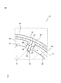
また、本発明に係るロータの製造方法は、突起部22が形成されていないロータの製造に適用することもできる。このようなロータの一例を、図10に示す。
In addition, the method for manufacturing a rotor according to the present invention can be applied to manufacture of a rotor in which the
なお、図10に示すロータ60において、上述のロータコア10と同様の要素には同じ符号を付している。ロータ60は、回転シャフト12、ロータコア62、複数の磁石16、保護管18、および充填物64を備える。
In addition, in the
ロータコア62は、円筒状の外周面66と、該外周面66から径方向内側へ凹む複数の切り欠き68とを有する。切り欠き68の各々は、ロータコア62の周方向に互いに隣り合う2つの磁石16の間に、配置されている。
The
次に、図4を参照して、図10に示すロータ60の製造方法について説明する。ステップS1において、製造者は、図10に示すロータコア62を作製する。
Next, a method for manufacturing the
ステップS2において、製造者は、複数の磁石16を、ロータコア62の径方向外側に周方向に略等間隔で整列するように、配置する。例えば、製造者は、複数の磁石16を、ロータコア62の外周面66に、接着剤等を用いて固定する。
In step S <b> 2, the manufacturer arranges the plurality of
ステップS3において、製造者は、複数の磁石16を取り囲むように、保護管18’を配置する。これにより、ロータコア62、磁石16、および保護管18’からなる組立体が作製される。
In step S <b> 3, the manufacturer arranges the
ステップS4において、製造者は、ステップS3にて作製した組立体を、上述の射出成形機100の第1の金型102に形成されたキャビティー110内に、該キャビティー110と同心となるように、設置する。
In step S4, the manufacturer makes the assembly produced in step S3 concentric with the
ステップS5において、射出成形機100は、第2の金型104を第1の金型102へ向かって移動させ、第1の金型102のキャビティー110を、第2の金型104の加圧面104aで閉鎖(いわゆる、型締め)する。このとき、ゲート112の各々は、ロータコア62に形成された切り欠き68の各々に面するように、配置される。
In step S <b> 5, the
ステップS6において、射出成形機100は、切り欠き68に充填物(例えば、樹脂)を射出する。これにより、保護管18’は、射出された充填物の圧力によって、径方向外側へ膨張し、図10に示す保護管18および充填物64が形成される。このステップS6によって、ロータコア62、磁石16、保護管18、および充填物64からなる組立体が作製される。
In step S <b> 6, the
ステップ7において、製造者は、回転シャフト12を固定する。具体的には、製造者は、回転シャフト12を、ステップS6にて作製した組立体のロータコア62の貫通孔70に嵌め入れて固定する。このステップS6によって、図10に示す回転子60が製造される。
In
本実施形態においては、上述の実施形態と同様に、切り欠き68を設けることによって、ゲート112を、保護管18’から径方向内側に離間して配置させることが可能となる。
In the present embodiment, similarly to the above-described embodiment, by providing the
これにより、ステップS6にてゲート112から充填物を射出したときに、ゲート112に近い領域において保護管18’に掛かる射出圧を低減させ、以って、保護管18’が不均等に変形してしまうのを防止することができる。
Thereby, when the filling material is injected from the
なお、切り欠き24、68の個数は、1個であってもよいし、または、N個(Nは、2以上、且つ磁石16の個数より少ない整数)であってもよい。
Note that the number of the
また、ゲート112の個数は、1個であってもよいし、またはM個(Mは、2以上、且つ切り欠き24、68の個数より少ない整数)であってもよい。この場合においても、ステップS5において、1つのゲート112は、1つの切り欠き24、68に面するように、配置される。
Further, the number of
また、ステップS6において、保護管18’を膨張させることなく、ロータコア14と保護管18’との間の隙間に充填物を充填してもよい。この場合、図11に示すようなロータ70が作製される。
In step S6, the gap may be filled in the gap between the
ロータ70は、組立体50と、該組立体50のロータコア14と保護管18’との間の隙間に充填された充填物72と、該組立体50のロータコア14の貫通孔14aに挿通された回転シャフト12とを備える。ロータ70においては、磁石16の外面と保護管18’と内周面とが面接触している。
The
また、上述のステップS2およびS3の代わりに、製造者は、まず、ロータコア14を取り囲むように保護管18’を配置させ、次いで、複数の磁石16の各々を、ロータコア14の外周面26と保護管18’との間に圧入することによって、組立体50を作製してもよい。
Further, instead of the above-described steps S2 and S3, the manufacturer first arranges the
また、ステップS3において、図1に示す保護管18を準備し、該保護管18を、ロータコア14の外周面26に固定された磁石16を径方向外側から取り囲むように配置してもよい。
Further, in step S3, the
この場合、磁石16の外面と保護管18の内周面との間には隙間が形成されることになる。次いで、ステップS6において、保護管18を膨張させることなく、ロータコア14と保護管18との間の隙間に充填物20を充填し、図1に示すロータ10を作製してもよい。
In this case, a gap is formed between the outer surface of the
以上、発明の実施形態を通じて本発明を説明したが、上述の実施形態は、特許請求の範囲に係る発明を限定するものではない。また、本発明の実施形態の中で説明されている特徴を組み合わせた形態も本発明の技術的範囲に含まれ得るが、これら特徴の組み合わせの全てが、発明の解決手段に必須であるとは限らない。さらに、上述の実施形態に、多様な変更または改良を加えることが可能であることも当業者に明らかである。 As mentioned above, although this invention was demonstrated through embodiment of invention, the above-mentioned embodiment does not limit the invention based on a claim. In addition, a combination of the features described in the embodiments of the present invention can also be included in the technical scope of the present invention, but all of these combinations of features are essential to the solution of the invention. Not exclusively. Furthermore, it will be apparent to those skilled in the art that various modifications or improvements can be added to the above-described embodiments.
また、特許請求の範囲、明細書、および図面中において示した装置、システム、プログラム、および方法における動作、手順、ステップ、工程、および段階等の各処理の実行順序は、特段「より前に」、「先立って」等と明示しておらず、また、前の処理の出力を後の処理で用いるのでない限り、任意の順序で実現しうることに留意すべきである。特許請求の範囲、明細書、および図面中の動作フローに関して、便宜上「まず、」、「次に、」、「次いで」等を用いて説明したとしても、この順で実施することが必須であることを意味するものではない。 Further, the execution order of each process such as operation, procedure, step, process, and stage in the apparatus, system, program, and method shown in the claims, the specification, and the drawings is particularly “before”. It should be noted that it may be implemented in any order unless it is explicitly stated as “prior to” or the like, and the output of the previous process is not used in the subsequent process. Even if the operation flow in the claims, the description, and the drawings is described using “first,” “next,” “next,” etc. for the sake of convenience, it is essential to implement them in this order. It doesn't mean that.
10,60,70 ロータ
12 回転シャフト
14,62 ロータコア
16 磁石
18 保護管
20,64 充填物
22 突条部
24,68 切り欠き
10, 60, 70
Claims (4)
ロータコアであって、該ロータコアの外周面から径方向内側へ凹む切り欠きを有し、該切り欠きは、前記ロータコアの軸方向一方の第1端面から、前記ロータコアの軸方向他方の第2端面に向かって軸方向へ延びる、ロータコアを作製し、
前記ロータコアの径方向外側に複数の磁石を、前記ロータコアの周方向に互いに隣り合う2つの前記磁石の間に前記切り欠きが位置するように、配置し、
前記複数の磁石を取り囲むように筒状の保護管を配置し、
充填物を射出する射出成形機のゲートを、前記切り欠きの内部空間に面するように配置し、
前記射出成形機によって前記ゲートから前記切り欠きの内部空間に充填物を射出して、前記ロータコアと前記保護管との間に形成された隙間に前記充填物を充填し、射出された該充填物の圧力によって前記保護管を径方向外側へ膨張させ、
前記ロータコアは、
該ロータコアの軸方向一方の第1端面から、前記ロータコアの軸方向他方の第2端面に向かって軸方向に延在する複数の突条部と、
少なくとも1つの前記突条部の径方向外側の端面から径方向内側へ凹む前記切り欠きと、を有し、
前記ゲートを前記切り欠きの内部空間に面するように配置するとき、該ゲートを、前記突条部の径方向外側の前記端面よりも前記切り欠きの底面に近い位置に配置する、方法。 A method for manufacturing a rotor of an electric motor, comprising:
The rotor core has a notch that is recessed radially inward from the outer peripheral surface of the rotor core, and the notch extends from one axial first end surface of the rotor core to the other axial second end surface of the rotor core. Making a rotor core that extends axially towards
A plurality of magnets are arranged on the radially outer side of the rotor core such that the notch is positioned between the two magnets adjacent to each other in the circumferential direction of the rotor core,
A cylindrical protective tube is arranged so as to surround the plurality of magnets,
The gate of the injection molding machine that injects the filling is arranged so as to face the internal space of the notch,
The filling material is injected from the gate into the interior space of the notch by the injection molding machine, the filling material is filled in the gap formed between the rotor core and the protective tube, and the injected material is injected. the pressure of the inflating said protective tube radially outward,
The rotor core is
A plurality of protrusions extending in the axial direction from one first end surface in the axial direction of the rotor core toward the other second end surface in the axial direction of the rotor core;
The notch recessed inward in the radial direction from the radially outer end face of the at least one protrusion, and
When the gate is arranged so as to face the internal space of the notch, the gate is arranged at a position closer to the bottom surface of the notch than the end face on the radially outer side of the protrusion .
キャビティーが形成された第1の金型と、
前記第1の金型に対して接近および離反する方向へ可動に設置され、前記ゲートが設けられた加圧面を有する第2の金型と、を有し、
前記ロータコア、前記複数の磁石、及び前記保護管の組立体を、前記ロータコアの前記第2端面が前記キャビティーの底面に当接するように、該キャビティーの内部に設置し、
前記第2の金型を前記第1の金型へ向かって移動させ、前記ゲートを前記切り欠きの内部空間に面するように配置させて前記加圧面を前記ロータコアの前記第1端面に接触させ、前記加圧面で前記キャビティーを閉鎖する、請求項1に記載の方法。 The injection molding machine
A first mold in which a cavity is formed;
A second mold having a pressurizing surface provided movably in a direction approaching and separating from the first mold, and having the gate provided;
An assembly of the rotor core, the plurality of magnets, and the protective tube is installed inside the cavity such that the second end surface of the rotor core is in contact with the bottom surface of the cavity;
The second mold is moved toward the first mold, the gate is disposed so as to face the inner space of the notch, and the pressing surface is brought into contact with the first end surface of the rotor core. the closing the cavity by pressurizing surface, the method according to claim 1.
Priority Applications (5)
| Application Number | Priority Date | Filing Date | Title |
|---|---|---|---|
| JP2016009987A JP6571546B2 (en) | 2016-01-21 | 2016-01-21 | Method for manufacturing rotor of electric motor |
| US15/405,471 US10439460B2 (en) | 2016-01-21 | 2017-01-13 | Rotor of electric motor and its manufacturing method |
| DE102017100681.8A DE102017100681A1 (en) | 2016-01-21 | 2017-01-16 | Rotor of an electric motor and method for its production |
| CN201720074076.8U CN206533209U (en) | 2016-01-21 | 2017-01-19 | The rotor of motor |
| CN201710044109.9A CN107046338B (en) | 2016-01-21 | 2017-01-19 | Rotor for electric motor and method of manufacturing rotor for electric motor |
Applications Claiming Priority (1)
| Application Number | Priority Date | Filing Date | Title |
|---|---|---|---|
| JP2016009987A JP6571546B2 (en) | 2016-01-21 | 2016-01-21 | Method for manufacturing rotor of electric motor |
Publications (2)
| Publication Number | Publication Date |
|---|---|
| JP2017131060A JP2017131060A (en) | 2017-07-27 |
| JP6571546B2 true JP6571546B2 (en) | 2019-09-04 |
Family
ID=59295656
Family Applications (1)
| Application Number | Title | Priority Date | Filing Date |
|---|---|---|---|
| JP2016009987A Active JP6571546B2 (en) | 2016-01-21 | 2016-01-21 | Method for manufacturing rotor of electric motor |
Country Status (4)
| Country | Link |
|---|---|
| US (1) | US10439460B2 (en) |
| JP (1) | JP6571546B2 (en) |
| CN (2) | CN206533209U (en) |
| DE (1) | DE102017100681A1 (en) |
Families Citing this family (9)
| Publication number | Priority date | Publication date | Assignee | Title |
|---|---|---|---|---|
| JP7064850B2 (en) * | 2017-11-17 | 2022-05-11 | 日本電産サンキョー株式会社 | Rotor and motor |
| JP2019161959A (en) * | 2018-03-16 | 2019-09-19 | 本田技研工業株式会社 | Rotor |
| GB201808657D0 (en) * | 2018-05-25 | 2018-07-11 | Lentus Composites Ltd | Rotor |
| PL234068B1 (en) * | 2018-06-29 | 2020-01-31 | Instytut Napedow I Masz Elektrycznych Komel | Electric machine rotor with permanent magnets |
| JP7068151B2 (en) | 2018-12-07 | 2022-05-16 | ファナック株式会社 | Rotor of a synchronous motor with a reinforcing member that presses a magnet |
| JP7079746B2 (en) * | 2019-03-08 | 2022-06-02 | 本田技研工業株式会社 | Rotating machine rotor and its manufacturing method |
| DE102020123852A1 (en) * | 2020-09-14 | 2022-03-17 | Bayerische Motoren Werke Aktiengesellschaft | Process for encapsulating or encapsulating components using transfer molding, electric machine and device for transfer molding |
| US11722025B2 (en) * | 2020-12-31 | 2023-08-08 | Trane International Inc. | Rotor for electric motors |
| CN113489197B (en) * | 2021-08-03 | 2022-07-26 | 珠海格力电器股份有限公司 | Motor rotor, motor and air conditioner |
Family Cites Families (14)
| Publication number | Priority date | Publication date | Assignee | Title |
|---|---|---|---|---|
| JP3619242B1 (en) * | 2003-10-06 | 2005-02-09 | Tdk株式会社 | Permanent magnet rotor |
| JP2007174822A (en) * | 2005-12-22 | 2007-07-05 | Fanuc Ltd | Rotor of electric motor and its manufacturing method |
| DE102007052661A1 (en) * | 2007-11-05 | 2009-05-07 | Robert Bosch Gmbh | Process for the production of micromechanical structures with relief-like sidewall profile or adjustable angle of inclination |
| JP4477072B2 (en) * | 2008-02-13 | 2010-06-09 | 三菱電機株式会社 | Rotating electric machine |
| CN101474717A (en) * | 2009-02-16 | 2009-07-08 | 中国人民解放军理工大学工程兵工程学院 | Explosive welding technique of nuclear power equipment composite pipe fitting |
| JP5310109B2 (en) * | 2009-03-03 | 2013-10-09 | 日本精工株式会社 | Brushless motor rotor, brushless motor, electric power steering apparatus, and method for manufacturing brushless motor rotor |
| JP5554527B2 (en) * | 2009-09-04 | 2014-07-23 | 株式会社三井ハイテック | Manufacturing method of rotor laminated core |
| JP5585648B2 (en) * | 2010-03-23 | 2014-09-10 | アイシン精機株式会社 | Awakening level determination device, awakening level determination method, and program |
| JP2012044789A (en) * | 2010-08-19 | 2012-03-01 | Yaskawa Electric Corp | Rotary electric machine and method for manufacturing the same |
| JP2012157143A (en) * | 2011-01-25 | 2012-08-16 | Shinano Kenshi Co Ltd | Motor |
| JP5326014B2 (en) * | 2012-02-16 | 2013-10-30 | ファナック株式会社 | Rotor for electric motor having structure for securely attaching magnet to outer peripheral surface of iron core and method for manufacturing the same |
| DE102013101956A1 (en) * | 2013-02-27 | 2014-08-28 | Wittenstein Ag | rotor |
| JP6278333B2 (en) * | 2013-09-03 | 2018-02-14 | アイシン精機株式会社 | Electric motor |
| CN107408873B (en) * | 2015-03-13 | 2019-11-26 | 黑田精工株式会社 | The resin impregnation process and resin filling device of magnet embedment shaped iron core |
-
2016
- 2016-01-21 JP JP2016009987A patent/JP6571546B2/en active Active
-
2017
- 2017-01-13 US US15/405,471 patent/US10439460B2/en active Active
- 2017-01-16 DE DE102017100681.8A patent/DE102017100681A1/en active Pending
- 2017-01-19 CN CN201720074076.8U patent/CN206533209U/en active Active
- 2017-01-19 CN CN201710044109.9A patent/CN107046338B/en active Active
Also Published As
| Publication number | Publication date |
|---|---|
| US10439460B2 (en) | 2019-10-08 |
| CN206533209U (en) | 2017-09-29 |
| CN107046338A (en) | 2017-08-15 |
| DE102017100681A1 (en) | 2017-07-27 |
| CN107046338B (en) | 2020-11-03 |
| JP2017131060A (en) | 2017-07-27 |
| US20170214282A1 (en) | 2017-07-27 |
Similar Documents
| Publication | Publication Date | Title |
|---|---|---|
| JP6571546B2 (en) | Method for manufacturing rotor of electric motor | |
| JP6557154B2 (en) | Electric motor rotor and method of manufacturing the rotor | |
| JP6221037B2 (en) | Method for molding motor and resin casing | |
| EP3395532B1 (en) | Bonded-magnet injection molding device and bonded-magnet injection molding method | |
| KR102216971B1 (en) | Rotor of an electric motor and method for producing the rotor | |
| TWI574487B (en) | Axial air gap motor and motor with bobbin | |
| JP6417470B2 (en) | Resin filling method and resin filling apparatus for core with embedded magnet | |
| CN105939068A (en) | Stator and motor | |
| JP5845224B2 (en) | Stator having bracket, electric motor having stator, and method of manufacturing electric motor | |
| EP3116103A1 (en) | Method for manufacturing a rotary electric machine rotor and rotary electric machine rotor | |
| JP2008236921A (en) | Magnetic circuit component, electric motor, fuel pump, and manufacturing methods for them | |
| JP4968928B2 (en) | Permanent magnet motor and manufacturing method thereof | |
| JP5418845B2 (en) | Rotating member made of resin injection molding | |
| JP2013176210A (en) | Rotor for rotary electric machine and method of manufacturing the same | |
| JP5900836B2 (en) | Rotor manufacturing method | |
| AU2017237623B2 (en) | Rotor and production method therefor | |
| JP7224218B2 (en) | Rotor and rotor manufacturing method | |
| JP2019193525A (en) | Magnet rotor | |
| JP2018074754A (en) | Rotor manufacturing method | |
| JP2019146329A (en) | Driving device, axial gap motor, and manufacturing method of driving unit used therefor | |
| CN109802502A (en) | Rotor and motor |
Legal Events
| Date | Code | Title | Description |
|---|---|---|---|
| A621 | Written request for application examination |
Free format text: JAPANESE INTERMEDIATE CODE: A621 Effective date: 20170216 |
|
| A977 | Report on retrieval |
Free format text: JAPANESE INTERMEDIATE CODE: A971007 Effective date: 20171115 |
|
| A131 | Notification of reasons for refusal |
Free format text: JAPANESE INTERMEDIATE CODE: A131 Effective date: 20171121 |
|
| A521 | Request for written amendment filed |
Free format text: JAPANESE INTERMEDIATE CODE: A523 Effective date: 20180119 |
|
| A131 | Notification of reasons for refusal |
Free format text: JAPANESE INTERMEDIATE CODE: A131 Effective date: 20180626 |
|
| A02 | Decision of refusal |
Free format text: JAPANESE INTERMEDIATE CODE: A02 Effective date: 20190122 |
|
| A521 | Request for written amendment filed |
Free format text: JAPANESE INTERMEDIATE CODE: A523 Effective date: 20190412 |
|
| A911 | Transfer to examiner for re-examination before appeal (zenchi) |
Free format text: JAPANESE INTERMEDIATE CODE: A911 Effective date: 20190507 |
|
| TRDD | Decision of grant or rejection written | ||
| A01 | Written decision to grant a patent or to grant a registration (utility model) |
Free format text: JAPANESE INTERMEDIATE CODE: A01 Effective date: 20190709 |
|
| A61 | First payment of annual fees (during grant procedure) |
Free format text: JAPANESE INTERMEDIATE CODE: A61 Effective date: 20190808 |
|
| R150 | Certificate of patent or registration of utility model |
Ref document number: 6571546 Country of ref document: JP Free format text: JAPANESE INTERMEDIATE CODE: R150 |