JP7064761B2 - Pachinko machine - Google Patents
Pachinko machine Download PDFInfo
- Publication number
- JP7064761B2 JP7064761B2 JP2018111037A JP2018111037A JP7064761B2 JP 7064761 B2 JP7064761 B2 JP 7064761B2 JP 2018111037 A JP2018111037 A JP 2018111037A JP 2018111037 A JP2018111037 A JP 2018111037A JP 7064761 B2 JP7064761 B2 JP 7064761B2
- Authority
- JP
- Japan
- Prior art keywords
- launch
- game ball
- game
- area
- passage
- Prior art date
- Legal status (The legal status is an assumption and is not a legal conclusion. Google has not performed a legal analysis and makes no representation as to the accuracy of the status listed.)
- Active
Links
Images


Description
本発明は、遊技機に関する。 The present invention relates to a gaming machine.
下記特許文献1等に記載されるように、遊技領域に進入した遊技球が接触する構造体を合成樹脂製とした遊技機が知られている。
As described in
本発明は、遊技球が接触することによる破損が生じにくい遊技機を提供することにある。 The present invention is to provide a gaming machine that is less likely to be damaged by contact with a gaming ball.
上記課題を解決するためになされた本発明にかかる遊技機は、発射装置により発射された遊技球が通過する発射通路と、遊技板の前側に形成された遊技領域の一部であって、前記発射通路の出口直後に形成された発射領域と、前記発射領域内における遊技球が接触可能な位置に設けられた第一構造体および当該第一構造体よりも下方に位置する第二構造体と、を備え、前記第一構造体と前記第二構造体の間には遊技球が通過可能な空間が形成されおり、前記第一構造体および第二構造体は、上下方向において当該第一構造体の左側の一部と当該第二構造体の右側の一部が重なるように配置されるとともに、上下方向における第一構造体の最下端と第二構造体の最上端との距離は、遊技球の直径未満とされることを特徴とする。 The gaming machine according to the present invention made to solve the above problems is a part of a launching passage through which a gaming ball launched by a launching device passes and a gaming area formed on the front side of the gaming board. A launch region formed immediately after the exit of the launch passage, a first structure provided in the launch region at a position where the game ball can come into contact, and a second structure located below the first structure. , A space through which a game ball can pass is formed between the first structure and the second structure, and the first structure and the second structure are the first structure in the vertical direction. A part on the left side of the body and a part on the right side of the second structure are arranged so as to overlap each other, and the distance between the lowermost end of the first structure and the uppermost end of the second structure in the vertical direction is a game. It is characterized by being smaller than the diameter of the sphere.
本発明にかかる遊技機によれば、遊技球が接触することによる破損が生じるおそれを低減することが可能である。 According to the gaming machine according to the present invention, it is possible to reduce the possibility of damage caused by contact with the gaming balls.
以下、本発明にかかる遊技機1の一実施形態について図面を参照して詳細に説明する。まず、図1および図2を参照して遊技機1の全体構成について簡単に説明する。
Hereinafter, an embodiment of the
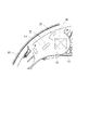
遊技機1は遊技板10を備える。遊技板10は、ほぼ正方形の合板により成形されており、発射装置60(発射ハンドル)の操作によって発射された遊技球を遊技領域11に案内する発射通路61を構成するガイドレール903が略円弧形状となるように設けられている。発射通路61は、遊技領域11の左側に沿うような略円弧状を呈する。発射装置60それ自体の構造は公知であるから説明を省略する。発射通路61の出口から飛び出る遊技球の発射強度を遊技者が適宜調節することが可能なものであればよい。
The
遊技領域11には、表示装置91、始動入賞口904、大入賞口906、アウト口907などが設けられている。かかる表示装置91の表示領域911は、遊技板10に形成された開口901を通じて視認可能となる領域である。なお、表示領域911の形状等は適宜変更可能である(開口901の形状や大きさ、表示装置91自体の形状や大きさを変更することで表示領域911の形状等を変更することができる)。
The
このような遊技機1では、発射装置60を操作することにより遊技領域11に向けて遊技球を発射する。遊技領域11を流下する遊技球が、始動入賞口904や大入賞口906等の入賞口に入賞すると、所定の数の賞球が払出装置により払い出される。
In such a
大当たりの抽選は、図示されない制御基板に設けられた当否判定手段が始動入賞口904への遊技球の入賞を契機として実行する(このような始動入賞口は複数設けられていてもよい)。具体的には、始動入賞口904への遊技球の入賞を契機として乱数源から数値(当否判定情報)が取得され、当該数値が予め定められた大当たりの数値と同じである場合には大当たりとなり、異なる場合にははずれとなる。本実施形態では、当該数値が取得された順に当否判定結果の報知が開始される(いわゆる変動が開始される)こととなるが、ある数値が取得されたときに、それより前に取得された数値に基づく当否判定結果が報知されている際には、当該ある数値に基づく当否判定結果が開始されるまで、図示されない制御基板に設けられた記憶手段に記憶される。未だ当否判定の報知が開始されていない数値(以下単に保留と称することもある)の最大の記憶数(最大保留数)は適宜設定することができる。本実施形態における記憶手段が記憶できる最大保留数は、一種の始動入賞口904につき四つである。記憶手段に上記数値(当否判定情報)が記憶されていることは、保留図柄80として表示される(図3参照)。なお、本実施形態では、当否判定の報知が開始される時点で、取得された数値が大当たりとなる数値か否かが判断されることとなるが、数値が取得されたときに当否判定を行い、当否判定結果自体を記憶させておく構成としてもよい(この場合には当否判定結果自体が、当否判定情報に相当することとなる)。また、取得された数値は、当否判定結果を報知する演出の具体的な内容を決定するための数値としても利用される。
The jackpot lottery is executed by the winning / failing determination means provided on the control board (not shown) triggered by the winning of the game ball to the starting winning opening 904 (a plurality of such starting winning openings may be provided). Specifically, a numerical value (win / fail judgment information) is acquired from a random number source triggered by the winning of a game ball to the
なお、遊技機1の枠体、遊技球を貯留する下皿や上皿など、本発明に関係のない遊技機1の構成要素は説明を省略する。これらについては公知の遊技機と同様の構造のものが適用できる。
The components of the
本実施形態では、公知の遊技機と同様に、表示装置91の表示領域911に表示される識別図柄70(図3参照)の組み合わせによって当否判定結果を遊技者に報知する。具体的には、複数種の識別図柄70を含む識別図柄群70g(左識別図柄群70gL、中識別図柄群70gC、右識別図柄群70gR)が変動を開始し、最終的に各識別図柄群70gから一の識別図柄70が選択されて停止する。大当たりに当選している場合には各識別図柄群70gから選択されて停止した識別図柄70の組み合わせは所定の組み合わせ(例えば、同じ識別図柄70の三つ揃い)となる。はずれである場合にはそれ以外(大当たりとなる組み合わせ以外)の組み合わせとなる。なお、各図においては、識別図柄70を構成する「数字(文字)」のみを図示するが、当該数字とキャラクタ等が組み合わされた図柄を識別図柄70として設定することができる。
In the present embodiment, similarly to the known gaming machine, the winning / failing determination result is notified to the player by the combination of the identification symbols 70 (see FIG. 3) displayed in the
遊技領域11には、流下する遊技球が衝突することにより遊技球の流下態様に変化を与える障害物としての遊技釘等の構造体が複数設けられている。遊技領域11を流下する遊技球は、構造体に衝突したときの条件に応じて様々な態様に変化する。
The
遊技領域11には発射領域111が含まれる。本実施形態における発射領域111は、遊技領域11の左上に位置し、発射通路61の出口直後に形成された領域である(図3参照)。通常状態(始動入賞口904に遊技球が入賞することを目指して遊技する状態)においては、当該発射領域111に遊技球が進入するよう、発射装置60を調整して遊技者は遊技することになる。おおまかに見て、発射領域111に発射された遊技球は遊技領域11の左側を流下していくため、発射領域111に遊技球が進入するような遊技は、いわゆる「左打ち」遊技ということである。
The
発射領域111には、遊技球が接触可能な構造体が設けられている。本実施形態では、第一構造体21および第二構造体22が設けられている(図3参照)。当該構造体は、合成樹脂製のブロック(塊)である。本実施形態では、遊技板10の本体部(前後方向に直交する平面に沿う板状の部分)から前方に向かって突出した突起である。本体部と構造体が一体成形されたものとしてもよいし、本体部とは別に成形された構造体が本体部に固定されたものとしてもよい。本実施形態では、遊技板10の本体部における発射領域111に面する平板状の部分(発射領域111の後側に位置する部分。以下、平面部12と称することもある)の少なくとも一部は、光透過性を有する材料で形成されている。当該平面部12の後方には、遊技領域11を装飾する装飾部材50が設けられている(図4において装飾部材50は点線で示す)。当該装飾部材50の装飾態様はどのようなものであってもよい。当該装飾部材50は、平面部12における光透過性を有する材料で形成された部分を通じて遊技者に視認されることになる。つまり、当該装飾部材50により、発射領域111が装飾されているかのようにみえる。上記構造体は、当該平面部12から前方に突出するように形成されたものであり、本実施形態では当該構造体も光透過性を有する材料で形成されたものとしている。しかし、当該構造体は平面部12に比して前後に厚いものであるため、構造体が形成されている箇所を通じて装飾部材50を視認することは困難である。すなわち、装飾部材50による装飾機能は、発射領域111における構造体が形成されていない箇所から発現されることになる。
The
発射領域111における発射通路61の出口の反対側(本実施形態では右側および下側)には、遊技球が表示装置91側に進入することを防ぐ壁部13が形成されている(図4参照)。遊技球は発射通路61の出口から飛び出すような経路を辿るところ、当該遊技球の進行方向でみて発射通路61の出口側を手前側、その反対側を奥側とすれば、発射領域111における奥側に壁部13が形成されているといえる。当該壁部13は、遊技板10の本体部から前方に突出した突状部分である。換言すれば、壁部13は、上記平面部12の右側縁および下側縁から前方に向かって立ち上がるように形成されている。本実施形態における壁部13は、厚み(壁部13が延在する方向に直交する方向の長さ)が薄い板状の部分である。発射領域111の下側の壁部13は、左にいくにつれて次第に下方に向かうような形状を呈するため、壁部13まで到達した遊技球は遊技領域11の左側を流下することになる。
On the opposite side (right side and lower side in this embodiment) of the exit of the
以下、上記構造体(第一構造体21、第二構造体22)の具体的な形状等について説明する。なお、特に明示した場合を除き、以下の説明における形状、位置等は、各構造体を正面(前方)から見たときにおけるものをいうものとする。
Hereinafter, specific shapes and the like of the above structures (
第一構造体21は第二構造体22よりも上方に設けられたものである。本実施形態では、第二構造体22の右上に第一構造体21が設けられたような(第一構造体21の左下に第二構造体22が設けられたような)位置関係にある(図4参照)。第一構造体21と第二構造体22の間には、遊技球が通過可能な空間が形成されている。つまり、第一構造体21と第二構造体22の間を遊技球が通るという事象も発生しうる(図5(b)参照)。
The
第一構造体21と第二構造体22は、上下方向において少なくとも一部が重なる。具体的には、第一構造体21の左側の一部と、第二構造体22の右側の一部が上下方向において重なる(図5(a)参照。当該「重なる部分」にはハッチングを施した)。換言すれば、第一構造体21の左側の一部の左右方向における位置と、第二構造体22の右側の一部の左右方向における位置が一致するということである。
The
また、上下方向における第一構造体21の最下端21Lと第二構造体22の最上端22Tとの距離X(上下方向に沿う直線距離)は、遊技球の直径D未満とされる(図5(b)参照)。つまり、第一構造体21と第二構造体22の間の空間は遊技球が通過可能な空間ではあるが、その空間の上下方向における最も短い部分の長さは遊技球の直径D未満とされる。したがって、仮に、水平方向(左右方向)に沿って変位しながら第一構造体21と第二構造体22の間に入り込もうとする遊技球を想定したとしても、当該遊技球は第一構造体21と第二構造体22のいずれか一方に必ず接触することになる。
Further, the distance X (straight line distance along the vertical direction) between the
第一構造体21は、その最下端21Lから発射通路61(発射通路61の出口)側に向かって次第に上方に向かうような形状を呈する(図4、図5参照)。具体的には、第一構造体21の下側の面は、右上に向かって凹となるように湾曲した形状を呈する。一方、第二構造体22は、その最上端22Tから発射通路61(発射通路61の出口)の反対側に向かって次第に下方に向かうような形状を呈する。具体的には、第二構造体22の上側の面は、右上に向かって凸となるように湾曲した形状を呈する。このような形状とすることにより、第一構造体21と第二構造体22の間の空間は、左上から右下に向かうような形状となる。つまり、第一構造体21と第二構造体22の間の空間は、左上から右下に向かうように遊技球が通過することができるものとしつつ、第一構造体21の最下端21Lと第二構造体22の最上端22Tとの間の距離Xが遊技球の直径D未満となるようにしている。
The
発射領域111において、第一構造体21および第二構造体22が設けられた箇所の奥側の領域、すなわち第一構造体21および第二構造体22と壁部13の間の領域には、壁部13に到達するまで遊技球が接触するような構造体(ここでいう構造体とは遊技球の移動方向に変化を与えるようなもの、すなわち平面部12から前方に向かって突出するような構造体をいう)は存在しない(図4参照)。したがって、第一構造体21と第二構造体22の間を通った遊技球は壁部13まで到達して壁部13に接触する。
In the
以上説明した本実施形態にかかる遊技機1によれば、次のような作用が奏される。発射領域111に設けられた第一構造体21と第二構造体22は、上下方向において少なくとも一部が重なるように配置されるとともに、上下方向における第一構造体21の最下端21Lと第二構造体22の最上端22Tとの距離Xは、遊技球の直径D未満とされているため、発射領域111に進入した遊技球が第一構造体21と第二構造体22のいずれにも接触しないことはほぼ起こり得ない。具体的に言えば、第一構造体21と第二構造体22が設けられた付近に到達した遊技球は、第一構造体21または第二構造体22に接触して手前側に跳ね返るか、両構造体の間を通るとしても少なくとも一方の構造体に接触することになるため当該接触により勢いが弱められる。したがって、発射通路61の出口から飛び出た遊技球がそのままの勢いで(他の部材に接触することなく)壁部13に接触するという事象はほとんど発生しない。そのため、継続的な遊技が行われたときに、勢いよく遊技球が壁部13に衝突することが繰り返され、壁部13が破損してしまうおそれが低減される。
According to the
また、上記の通り、第一構造体21と第二構造体22の間を遊技球が通るとしても、遊技球が第一構造体21と第二構造体22の少なくともいずれか一方に接触し、その勢いが弱められるから、第一構造体21および第二構造体22と、壁部13との間の領域に遊技球が接触可能な別の構造体を設ける必要はない。このような構造体が設けられていなければ、平面部12の少なくとも一部を通じて視認される装飾部材50の視認性が低下してしまうことが抑制される。少なくとも第一構造体21および第二構造体22と、壁部13との間の領域には別の構造体が設けられていないのであるから、平面部12における当該領域に面する部分を光透過性を有する材料で形成することで、装飾部材50が構造体に邪魔されることなく視認される(図4参照)ことになる。
Further, as described above, even if the game ball passes between the
また、第一構造体21は、その最下端21Lから発射通路61(発射通路61の出口)側に向かって次第に上方に向かうような形状を呈する。このようにすることで、第一構造体21と第二構造体22の間の空間の入口(発射通路61の出口側)が大きい印象を遊技者に与える。したがって、第一構造体21と第二構造体22の間は、遊技球を発射させるに際し「狙うべきポイント」(いわゆる「ぶっこみ」)の少なくとも一つであるかのように捉えられる。つまり、遊技者にとってみれば、発射装置60によって発射される遊技球が到達する位置として分かりやすいという利点がある。第一構造体21の最下端21Lと第二構造体22の最上端22Tの上下方向における距離Xを遊技球の直径D未満とした場合、遊技者には第一構造体21と第二構造体22が近接しているように見え、両構造体の間を狙って遊技球を発射させることを躊躇ってしまう(第一構造体21と第二構造体22の間は「狙うべきポイント」ではないと感じてしまう)おそれがあるところ、上記のような第一構造体21の形状とすることで第一構造体21と第二構造体22の間の空間の入口が大きい印象を遊技者に与えるから、遊技球を「狙うべきポイント」として分かりやすいものとすることが可能である。
Further, the
以上、本発明の実施の形態について詳細に説明したが、本発明は上記実施の形態に何ら限定されるものではなく、本発明の要旨を逸脱しない範囲で種々の改変が可能である。 Although the embodiments of the present invention have been described in detail above, the present invention is not limited to the above embodiments, and various modifications can be made without departing from the gist of the present invention.
上記実施形態における第一構造体21や第二構造体22は合成樹脂製のブロック(塊)であることを説明したが、遊技球が接触する外面の形状が上記のような形状であればよく、構造体の形成手法は上記のようなものに限られない。例えば、いわゆる遊技釘を複数用いることにより、上記のような形状が象られた構造体としてもよい。
Although it has been described that the
上記実施形態から得られる具体的手段(遊技機)を以下に列挙する。 Specific means (game machines) obtained from the above embodiments are listed below.
・手段1
発射装置により発射された遊技球が通過する発射通路と、遊技板の前側に形成された遊技領域の一部であって、前記発射通路の出口直後に形成された発射領域と、前記発射領域内における遊技球が接触可能な位置に設けられた第一構造体および当該第一構造体よりも下方に位置する第二構造体と、を備え、前記第一構造体と前記第二構造体の間には遊技球が通過可能な空間が形成されおり、前記第一構造体および第二構造体は、上下方向において少なくとも一部が重なるように配置されるとともに、上下方向における第一構造体の最下端と第二構造体の最上端との距離は、遊技球の直径未満とされることを特徴とする遊技機。
上記遊技機によれば、第一構造体と第二構造体の間を通過しようとする遊技球は、第一構造体と第二構造体の少なくともいずれか一方に接触してその勢いが弱められるから、遊技球が接触することによる破損が生じるおそれを低減することが可能である。
・ Means 1
A launch passage through which a game ball launched by a launcher passes, a launch region that is a part of a game area formed on the front side of the game board and is formed immediately after the exit of the launch passage, and a launch area. A first structure provided at a position where the game ball can be contacted in the above structure and a second structure located below the first structure, and between the first structure and the second structure. A space through which a game ball can pass is formed in, and the first structure and the second structure are arranged so that at least a part of the first structure and the second structure overlap each other in the vertical direction, and the most of the first structure in the vertical direction. A gaming machine characterized in that the distance between the lower end and the uppermost end of the second structure is less than the diameter of the gaming ball.
According to the above-mentioned gaming machine, a gaming ball that is about to pass between the first structure and the second structure comes into contact with at least one of the first structure and the second structure, and its momentum is weakened. Therefore, it is possible to reduce the possibility of damage due to contact with the game balls.
・手段2
前記第一構造体は、前記最下端から前記発射通路側に向かって次第に上方に向かうような形状を呈することを特徴とする手段1に記載の遊技機。
このようにすることで、第一構造体と第二構造体の間の空間の入口が広がるから、両構造体の間が「狙うべきポイント」であることが遊技者に分かりやすくなる。
・ Means 2
The gaming machine according to
By doing so, the entrance of the space between the first structure and the second structure is widened, so that it becomes easy for the player to understand that the space between the two structures is the “point to aim at”.
・手段3
前記発射領域における発射された遊技球の進行方向における奥側には、当該発射領域に面する壁部が設けられており、前記第一構造体および前記第二構造体と前記壁部の間には、遊技球が接触可能な構造体が設けられていないことを特徴とする手段1または手段2に記載の遊技機。
上記の通り、第一構造体と第二構造体のいずれにも接触せずに両構造体の間を遊技球が通過する事象はほとんど発生しないから、両構造体と壁部の間には遊技球の勢いを低下させるための別の構造体を設ける必要がない。つまり、別の構造体を設けなくても、勢いのついた遊技球がそのまま壁部に接触することはほとんどなく、壁部が破損するおそれを低減することが可能である。
・ Means 3
A wall portion facing the launch region is provided on the back side in the traveling direction of the launched game ball in the launch region, and between the first structure and the second structure and the wall portion. Is the gaming machine according to means 1 or means 2, wherein the structure to which the gaming ball can come into contact is not provided.
As described above, since the event that the game ball passes between the first structure and the second structure without contacting either of the first structure and the second structure rarely occurs, the game is played between the two structures and the wall portion. There is no need to provide a separate structure to reduce the momentum of the sphere. That is, even if another structure is not provided, the game ball with momentum hardly comes into contact with the wall portion as it is, and it is possible to reduce the possibility that the wall portion is damaged.
・手段4
前記遊技板における前記発射領域に面する部分の少なくとも一部は、光透過性を有する材料で形成されていることを特徴とする手段1から手段3のいずれかに記載の遊技機。
発射領域に面する部分にはあまり多くの構造体を設ける必要がなくなるから、当該部分を光透過性を有する材料で形成し、当該部分の後方に設けられた装飾等が視認されるような構造に好適に用いられる。
・ Means 4
The gaming machine according to any one of
Since it is not necessary to provide too many structures in the part facing the launch area, the part is made of a light-transmitting material so that the decorations and the like provided behind the part can be visually recognized. It is suitably used for.
1 遊技機
10 遊技板
11 遊技領域
111 発射領域
13 壁部
21 第一構造体
21L (第一構造体の)最下端
22 第二構造体
22T (第二構造体の)最上端
50 装飾部材
60 発射装置
61 発射通路
1
Claims (1)
遊技板の前側に形成された遊技領域の一部であって、前記発射通路の出口直後に形成された発射領域と、
前記発射領域内における遊技球が接触可能な位置に設けられた第一構造体および当該第一構造体よりも下方に位置する第二構造体と、
を備え、
前記第一構造体と前記第二構造体の間には、前記発射通路側に位置する入口からその反対側に位置する出口にかけて次第に下るような形状を呈する、遊技球が通過可能な通路が形成されおり、
前記第一構造体および第二構造体は、上下方向において当該第一構造体の左側の一部と当該第二構造体の右側の一部が重なるように配置されるとともに、上下方向における第一構造体の最下端と第二構造体の最上端との距離は、遊技球の直径未満とされることを特徴とする遊技機。 The launch passage through which the game ball launched by the launcher passes, and
A part of the game area formed on the front side of the game board, the launch area formed immediately after the exit of the launch passage, and the launch area.
A first structure provided at a position where the game ball can contact in the launch region, a second structure located below the first structure, and a second structure.
Equipped with
Between the first structure and the second structure , a passage through which a game ball can pass is formed, which has a shape that gradually descends from an entrance located on the launch passage side to an exit located on the opposite side. Has been done,
The first structure and the second structure are arranged so that a part on the left side of the first structure and a part on the right side of the second structure overlap each other in the vertical direction, and the first structure in the vertical direction is the first. A gaming machine characterized in that the distance between the lowermost end of the structure and the uppermost end of the second structure is less than the diameter of the gaming ball.
Priority Applications (1)
| Application Number | Priority Date | Filing Date | Title |
|---|---|---|---|
| JP2018111037A JP7064761B2 (en) | 2018-06-11 | 2018-06-11 | Pachinko machine |
Applications Claiming Priority (1)
| Application Number | Priority Date | Filing Date | Title |
|---|---|---|---|
| JP2018111037A JP7064761B2 (en) | 2018-06-11 | 2018-06-11 | Pachinko machine |
Publications (3)
| Publication Number | Publication Date |
|---|---|
| JP2019213603A JP2019213603A (en) | 2019-12-19 |
| JP2019213603A5 JP2019213603A5 (en) | 2021-07-26 |
| JP7064761B2 true JP7064761B2 (en) | 2022-05-11 |
Family
ID=68917896
Family Applications (1)
| Application Number | Title | Priority Date | Filing Date |
|---|---|---|---|
| JP2018111037A Active JP7064761B2 (en) | 2018-06-11 | 2018-06-11 | Pachinko machine |
Country Status (1)
| Country | Link |
|---|---|
| JP (1) | JP7064761B2 (en) |
Family Cites Families (1)
| Publication number | Priority date | Publication date | Assignee | Title |
|---|---|---|---|---|
| JP6354089B2 (en) * | 2013-07-30 | 2018-07-11 | 株式会社三共 | Game machine |
-
2018
- 2018-06-11 JP JP2018111037A patent/JP7064761B2/en active Active
Also Published As
| Publication number | Publication date |
|---|---|
| JP2019213603A (en) | 2019-12-19 |
Similar Documents
| Publication | Publication Date | Title |
|---|---|---|
| JP6391233B2 (en) | Game machine | |
| JP6423375B2 (en) | Game machine | |
| JP2016168291A (en) | Game machine | |
| JP7064761B2 (en) | Pachinko machine | |
| JP5975406B2 (en) | Game machine | |
| JP6804098B2 (en) | Game machine | |
| JP6903335B2 (en) | Pachinko machine | |
| JP2015221105A (en) | Game machine | |
| JP6325972B2 (en) | Game machine | |
| JP2017169633A (en) | Game machine | |
| JP7045048B2 (en) | Pachinko machine | |
| JP7026932B2 (en) | Pachinko machine | |
| JP6984872B2 (en) | Pachinko machine | |
| JP6071769B2 (en) | Game machine | |
| JP6012549B2 (en) | Game machine | |
| JP6984873B2 (en) | Pachinko machine | |
| JP7429959B2 (en) | gaming machine | |
| JP6991559B2 (en) | Pachinko machine | |
| JP6222823B2 (en) | Game machine | |
| JP7460126B2 (en) | Gaming Machines | |
| JP7026931B2 (en) | Pachinko machine | |
| JP6480999B2 (en) | Game machine | |
| JP2016182376A (en) | Game machine | |
| JP6071766B2 (en) | Game machine | |
| JP6071767B2 (en) | Game machine |
Legal Events
| Date | Code | Title | Description |
|---|---|---|---|
| A521 | Request for written amendment filed |
Free format text: JAPANESE INTERMEDIATE CODE: A523 Effective date: 20210604 |
|
| A621 | Written request for application examination |
Free format text: JAPANESE INTERMEDIATE CODE: A621 Effective date: 20210604 |
|
| TRDD | Decision of grant or rejection written | ||
| A01 | Written decision to grant a patent or to grant a registration (utility model) |
Free format text: JAPANESE INTERMEDIATE CODE: A01 Effective date: 20220329 |
|
| A61 | First payment of annual fees (during grant procedure) |
Free format text: JAPANESE INTERMEDIATE CODE: A61 Effective date: 20220418 |
|
| R150 | Certificate of patent or registration of utility model |
Ref document number: 7064761 Country of ref document: JP Free format text: JAPANESE INTERMEDIATE CODE: R150 |