[1.パチンコ機の全体構造]
本発明の一実施形態であるパチンコ機1について、図面を参照して詳細に説明する。まず、図1乃至図12を参照して本実施形態のパチンコ機1の全体構成について説明する。図1は本発明の一実施形態であるパチンコ機の正面図である。図2はパチンコ機の右側面図であり、図3はパチンコ機の左側面図であり、図4はパチンコ機の背面図である。図5はパチンコ機を右前から見た斜視図であり、図6はパチンコ機を左前から見た斜視図であり、図7はパチンコ機を後ろから見た斜視図である。図8は演出操作ユニットの押圧操作部が上昇位置の時のパチンコ機の正面図であり、図9は演出操作ユニットの押圧操作部が上昇位置の時のパチンコ機を右前から見た斜視図である。また、図10は、本体枠から扉枠を開放させると共に、外枠から本体枠を開放させた状態で前から見たパチンコ機の斜視図である。図11はパチンコ機を扉枠、遊技盤、本体枠、及び外枠に分解して前から見た分解斜視図であり、図12はパチンコ機を扉枠、遊技盤、本体枠、及び外枠に分解して後ろから見た分解斜視図である。
[1. Overall structure of pachinko machine]
The pachinko machine 1 according to the embodiment of the present invention will be described in detail with reference to the drawings. First, the overall configuration of the pachinko machine 1 of the present embodiment will be described with reference to FIGS. 1 to 12. FIG. 1 is a front view of a pachinko machine according to an embodiment of the present invention. FIG. 2 is a right side view of the pachinko machine, FIG. 3 is a left side view of the pachinko machine, and FIG. 4 is a rear view of the pachinko machine. FIG. 5 is a perspective view of the pachinko machine viewed from the front right, FIG. 6 is a perspective view of the pachinko machine viewed from the front left, and FIG. 7 is a perspective view of the pachinko machine viewed from the back. FIG. 8 is a front view of the pachinko machine when the pressing operation unit of the staging operation unit is in the raised position, and FIG. 9 is a perspective view of the pachinko machine when the pressing operation unit of the staging operation unit is in the raised position. be. Further, FIG. 10 is a perspective view of the pachinko machine viewed from the front with the door frame opened from the main body frame and the main body frame opened from the outer frame. FIG. 11 is an exploded perspective view of the pachinko machine disassembled into a door frame, a game board, a main body frame, and an outer frame, and FIG. 12 is an exploded perspective view of the pachinko machine as a door frame, a game board, a main body frame, and an outer frame. It is an exploded perspective view seen from the back after being disassembled into.
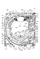
本実施形態のパチンコ機1は、遊技ホールの島設備(図示しない)に設置される枠状の外枠2と、外枠2の前面を開閉可能に閉鎖する扉枠3と、扉枠3を開閉可能に支持していると共に外枠2に開閉可能に取付けられている本体枠4と、本体枠4に前側から着脱可能に取付けられると共に扉枠3を通して遊技者側から視認可能とされ遊技者によって遊技球B(図90を参照)が打込まれる遊技領域5aを有した遊技盤5と、を備えている。
The pachinko machine 1 of the present embodiment includes a frame-shaped outer frame 2 installed in an island facility (not shown) of a game hall, a door frame 3 for opening and closing the front surface of the outer frame 2, and a door frame 3. The main body frame 4 which is openable and closable and is attached to the outer frame 2 so as to be openable and closable, and the main body frame 4 which is detachably attached from the front side and is visible from the player side through the door frame 3. It includes a game board 5 having a game area 5a into which a game ball B (see FIG. 90) is hit.
外枠2は、正面視の形状が上下に延びた四角形の枠に形成されている。外枠2は、左右に離間しており上下に延びている外枠左組立体10及び外枠右組立体20と、外枠左組立体10及び外枠右組立体20の上端同士を連結している外枠上部材30と、外枠左組立体10及び外枠右組立体20の下端同士を連結している外枠下組立体40と、外枠上部材30の上面左端に取付けられている外枠上ヒンジ組立体50と、外枠左組立体10の右側面下部と外枠下組立体40の上面左端に取付けられている外枠下ヒンジ部材60と、を備えている。
The outer frame 2 is formed in a quadrangular frame having a front view extending vertically. The outer frame 2 connects the outer frame left assembly 10 and the outer frame right assembly 20 which are separated from each other to the left and right and extend vertically, and the upper ends of the outer frame left assembly 10 and the outer frame right assembly 20. The outer frame upper member 30 is attached to the outer frame lower assembly 40 connecting the lower ends of the outer frame left assembly 10 and the outer frame right assembly 20, and the upper left end of the outer frame upper member 30. The outer frame upper hinge assembly 50 and the outer frame lower hinge member 60 attached to the lower right side of the outer frame left assembly 10 and the upper left end of the outer frame lower assembly 40 are provided.
外枠2は、パチンコ機1が設置される遊技ホールの島設備に取付けられ、外枠上ヒンジ組立体50と外枠下ヒンジ部材60とによって、本体枠4の本体枠上ヒンジ部材510と本体枠下ヒンジ組立体520とを同軸上で回転可能に支持して、本体枠4を正面視左側を中心にして前方へ開閉可能に取付けるためのものである。
The outer frame 2 is attached to the island equipment of the game hall where the pachinko machine 1 is installed, and the hinge member 510 on the main body frame of the main body frame 4 and the main body are formed by the hinge assembly 50 on the outer frame and the hinge member 60 below the outer frame. The hinge under-frame hinge assembly 520 is rotatably supported on the same axis, and the main body frame 4 is mounted so as to be openable and closable forward with the left side of the front view as the center.
また、扉枠3は、本体枠4を閉じた時に、外枠下組立体40が、本体枠4における基板ユニット620のスピーカユニット620aと協働して、本体枠スピーカ622のエンクロージャ624の一部を形成し、本体枠スピーカ622の後方へ出力されたサウンドを、位相反転させて前方へ放射することで、より重低音のサウンドを遊技者に聴かせることができるものである。
Further, in the door frame 3, when the main body frame 4 is closed, the outer frame lower assembly 40 cooperates with the speaker unit 620a of the board unit 620 in the main body frame 4 to be a part of the enclosure 624 of the main body frame speaker 622. Is formed, and the sound output to the rear of the main body frame speaker 622 is phase-inverted and radiated to the front, so that the player can hear a deeper bass sound.
扉枠3は、遊技球Bが打込まれる遊技盤5の遊技領域5aを前側から視認可能に閉鎖し、遊技領域5a内に打込むための遊技球Bを貯留すると共に、貯留している遊技球Bを遊技領域5a内へ打込むために遊技者が操作するハンドル182を備えているものである。また、扉枠3は、パチンコ機1の前面全体を装飾するものである。
The door frame 3 visibly closes the game area 5a of the game board 5 into which the game ball B is driven, stores the game ball B for driving into the game area 5a, and stores the stored game. It is provided with a handle 182 operated by a player to drive the ball B into the game area 5a. Further, the door frame 3 decorates the entire front surface of the pachinko machine 1.
また、扉枠3は、ハンドル182とは別に遊技者が操作可能な演出操作部301を備えており、遊技者参加型演出が実行された際に、遊技者が演出操作部301を操作することで遊技者が演出に参加できるようになり、遊技球Bによる遊技に加えて、演出操作部301の操作によっても遊技者を楽しませることができるようにしている。
Further, the door frame 3 is provided with an effect operation unit 301 that can be operated by the player separately from the handle 182, and the player operates the effect operation unit 301 when the player participation type effect is executed. The player can participate in the production, and the player can be entertained by operating the production operation unit 301 in addition to the game by the game ball B.
本体枠4は、後部が外枠2の枠内に挿入可能とされると共に遊技盤5の外周を支持可能とされた枠状の本体枠ベースユニット500と、本体枠4を外枠2に対して開閉可能に取付けると共に扉枠3を開閉可能に取付けるための本体枠上ヒンジ部材510及び本体枠下ヒンジ組立体520と、本体枠ベースユニット500を補強している本体枠補強フレーム530と、遊技盤5の遊技領域5a内に遊技球Bを打込むための球発射装置540と、遊技ホールの島設備から供給される遊技球Bを受取る払出ベースユニット550と、払出ベースユニット550で受取った遊技球Bを遊技者側へ払出すための払出ユニット560と、パチンコ機1の電源投入を行うことができる電源スイッチ630aを備える電源基板630のほかに払出制御基板633を有している基板ユニット620と、本体枠ベース501に取付けられた遊技盤5の後側を覆う裏カバー640と、外枠2と本体枠4、及び扉枠3と本体枠4の間を施錠する施錠ユニット650と、を備えている。
The main body frame 4 has a frame-shaped main body frame base unit 500 having a rear portion that can be inserted into the frame of the outer frame 2 and can support the outer periphery of the game board 5, and the main body frame 4 with respect to the outer frame 2. The main body frame upper hinge member 510 and the main body frame lower hinge assembly 520 for attaching the door frame 3 so as to be openable and closable, and the main body frame reinforcement frame 530 for reinforcing the main body frame base unit 500, and a game. A ball launching device 540 for driving a game ball B into the game area 5a of the board 5, a payout base unit 550 for receiving the game ball B supplied from the island equipment of the game hall, and a game received by the payout base unit 550. A board unit 620 having a payout control board 633 in addition to a payout unit 560 for paying out the ball B to the player side and a power supply board 630 provided with a power supply switch 630a capable of turning on the power of the pachinko machine 1. A back cover 640 that covers the rear side of the game board 5 attached to the main body frame base 501, and a locking unit 650 that locks between the outer frame 2 and the main body frame 4, and between the door frame 3 and the main body frame 4. I have.
本体枠4は、遊技球Bを打込むことで遊技が行われる遊技領域5aを有した遊技盤5を保持すると共に、遊技球Bを遊技者側へ払出したり、遊技に使用された遊技球Bをパチンコ機1の後方(遊技ホールの島設備側)へ排出したり、するためのものである。本体枠4は、前方が開放された箱状に形成されており、内部に前方から遊技盤5が着脱可能に収容される。また、本体枠4は、正面左辺側前端の上下において、遊技ホールの島設備に取付けられる枠状の外枠2に開閉可能に取付けられると共に、開放された前面側が閉鎖されるように扉枠3が開閉可能に取付けられる。
The main body frame 4 holds a game board 5 having a game area 5a in which a game is played by hitting the game ball B, and at the same time, pays out the game ball B to the player side or uses the game ball B for the game. Is for discharging to the rear of the pachinko machine 1 (on the island equipment side of the game hall). The main body frame 4 is formed in a box shape with an open front, and the game board 5 is detachably housed inside from the front. Further, the main body frame 4 is openably attached to the frame-shaped outer frame 2 attached to the island equipment of the game hall above and below the front end on the left side of the front side, and the door frame 3 is closed so that the opened front side is closed. Can be installed so that it can be opened and closed.
遊技盤5は、遊技者の操作によって遊技球Bが行われる遊技領域5aと、遊技領域5aの外周を区画し外形が正面視略四角形状とされた前構成部材1000と、前構成部材1000の後側に取付けられており遊技領域5aの後端を区画する板状の遊技パネル1100と、遊技パネル1100の後側下部に取付けられている基板ホルダ1200と、基板ホルダ1200の後面に取付けられており主制御基板1310及び設定変更基板1311を有している主制御ユニット1300と、主制御基板1310からの制御信号に基づいて遊技状況を表示する機能表示ユニット1400と、遊技パネル1100の後側に配置されている周辺制御ユニット1500(図12を参照)と、正面視において遊技領域5aの中央に配置されており所定の演出画像を表示可能な演出表示装置1600と、遊技パネル1100の前面に取付けられる表ユニット2000と、遊技パネル1100の後面に取付けられる裏ユニット3000と、を備えている。裏ユニット3000には、遊技状態に応じて可動演出や発光演出を行うことが可能な各種の演出ユニットを備えている。
The game board 5 includes a game area 5a in which a game ball B is performed by an operation of a player, a front component 1000 that divides the outer periphery of the game area 5a into a substantially square shape in front view, and a front component 1000. A plate-shaped game panel 1100 that is attached to the rear side and divides the rear end of the game area 5a, a board holder 1200 that is attached to the lower part of the rear side of the game panel 1100, and a board holder 1200 that is attached to the rear surface of the board holder 1200. On the rear side of the main control unit 1300 having the cage main control board 1310 and the setting change board 1311, the function display unit 1400 that displays the game status based on the control signal from the main control board 1310, and the game panel 1100. Attached to the front of the peripheral control unit 1500 (see FIG. 12), the effect display device 1600 arranged in the center of the game area 5a in front view and capable of displaying a predetermined effect image, and the game panel 1100. The front unit 2000 and the back unit 3000 attached to the rear surface of the game panel 1100 are provided. The back unit 3000 is provided with various effect units capable of performing a movable effect and a light emitting effect according to the game state.
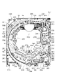
遊技盤5の遊技領域5a内には、遊技球Bと当接し所定のゲージ配列で植設されている複数の障害釘と、遊技球Bの受け入れ又は通過により遊技者に対して所定の特典(例えば、所定数の遊技球Bの払出し)を付与する一般入賞口2001、第一始動口2002、普通入賞口2003、第二始動口2004、及び大入賞口2005と、を備えている。障害釘Nは、遊技パネル1100の前面に植設されている。一般入賞口2001、第一始動口2002、普通入賞口2003、第二始動口2004、及び大入賞口2005は、表ユニット2000に備えられている。
In the game area 5a of the game board 5, a plurality of obstacle nails that are in contact with the game ball B and are planted in a predetermined gauge arrangement, and a predetermined privilege for the player by accepting or passing the game ball B ( For example, it is provided with a general winning opening 2001, a first starting opening 2002, a normal winning opening 2003, a second starting opening 2004, and a large winning opening 2005 for granting a predetermined number of game balls B). The obstacle nail N is planted in front of the game panel 1100. The general winning opening 2001, the first starting opening 2002, the normal winning opening 2003, the second starting opening 2004, and the large winning opening 2005 are provided in the table unit 2000.
遊技盤5の遊技領域5a内には、遊技者がハンドルユニット180のハンドル182を操作することで、遊技球Bを打込むことができる。これにより、遊技球Bが、遊技領域5a内の一般入賞口2001、第一始動口2002、普通入賞口2003、第二始動口2004、及び大入賞口2005等に、受け入れられたり通過したりするように、遊技者に対してハンドル182の打込操作を楽しませることができる。
A player can drive the game ball B into the game area 5a of the game board 5 by operating the handle 182 of the handle unit 180. As a result, the game ball B is accepted or passed through the general winning opening 2001, the first starting opening 2002, the normal winning opening 2003, the second starting opening 2004, the large winning opening 2005, etc. in the game area 5a. As described above, it is possible to entertain the player with the driving operation of the handle 182.
また、遊技盤5は、遊技領域5a内に遊技球Bを打込むことで変化する遊技状態に応じて、演出表示装置1600に所定の演出画像を表示させたり、導光板演出ユニット3100、裏演出ユニット3200、等により発光演出を行わせたりして、遊技者を楽しませることができる。
Further, the game board 5 causes the effect display device 1600 to display a predetermined effect image according to the game state that changes by driving the game ball B into the game area 5a, or displays the light guide plate effect unit 3100 and the back effect. It is possible to entertain the player by making the unit 3200 or the like perform a light emitting effect.
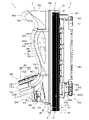
[2.外枠の全体構成]
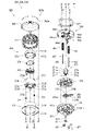
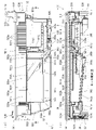
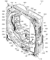
パチンコ機1の外枠2について、図13乃至図18を参照して説明する。図13はパチンコ機における外枠の正面図であり、図14は外枠の背面図であり、図15は外枠の右側面図である。また、図16は外枠を前から見た斜視図であり、図17は外枠を後ろから見た斜視図である。図18は、外枠を主な部材毎に分解して前から見た分解斜視図である。外枠2は、遊技ホール等のパチンコ機1が設置される島設備(図示は省略)に取付けられるものである。外枠2は、正面視の形状が上下に延びた四角形の枠に形成されている。
[2. Overall composition of the outer frame]
The outer frame 2 of the pachinko machine 1 will be described with reference to FIGS. 13 to 18. 13 is a front view of the outer frame of the pachinko machine, FIG. 14 is a rear view of the outer frame, and FIG. 15 is a right side view of the outer frame. Further, FIG. 16 is a perspective view of the outer frame viewed from the front, and FIG. 17 is a perspective view of the outer frame viewed from the back. FIG. 18 is an exploded perspective view of the outer frame disassembled for each main member and viewed from the front. The outer frame 2 is attached to an island facility (not shown) in which a pachinko machine 1 such as a game hall is installed. The outer frame 2 is formed in a quadrangular frame having a front view extending vertically.
外枠2は、図示するように、左右に離間しており上下に延びている外枠左組立体10及び外枠右組立体20と、外枠左組立体10及び外枠右組立体20の上端同士を連結している外枠上部材30と、外枠左組立体10及び外枠右組立体20の下端同士を連結している外枠下組立体40と、外枠上部材30の上面左端に取付けられている外枠上ヒンジ組立体50と、外枠左組立体10の右側面下部と外枠下組立体40の上面左端に取付けられている外枠下ヒンジ部材60と、を備えている。
As shown in the figure, the outer frame 2 includes an outer frame left assembly 10 and an outer frame right assembly 20 which are separated from each other to the left and right and extend vertically, and an outer frame left assembly 10 and an outer frame right assembly 20. The outer frame upper member 30 connecting the upper ends, the outer frame lower assembly 40 connecting the lower ends of the outer frame left assembly 10 and the outer frame right assembly 20, and the upper surface of the outer frame upper member 30. The outer frame upper hinge assembly 50 attached to the left end, and the outer frame lower hinge member 60 attached to the lower right side of the outer frame left assembly 10 and the upper left end of the outer frame lower assembly 40 are provided. ing.
外枠2は、本体枠4を閉じた時に、外枠下組立体40が、本体枠4における基板ユニット620のスピーカユニット620aと協働して、本体枠スピーカ622のエンクロージャ624の一部を形成していると共に、本体枠スピーカ622の後方へ出力されたサウンドを、位相反転させて前方へ放射することができるものである。
In the outer frame 2, when the main body frame 4 is closed, the outer frame lower assembly 40 cooperates with the speaker unit 620a of the board unit 620 in the main body frame 4 to form a part of the enclosure 624 of the main body frame speaker 622. At the same time, the sound output to the rear of the main body frame speaker 622 can be phase-inverted and radiated to the front.
外枠2は、外枠上ヒンジ組立体50が、本体枠4の本体枠上ヒンジ部材510を着脱可能に支持することができる。外枠2は、外枠上ヒンジ組立体50と外枠下ヒンジ部材60とによって、本体枠4の本体枠上ヒンジ部材510と本体枠下ヒンジ組立体520とを同軸上で回転可能に支持することができ、本体枠4を正面視左側を中心にして前方へ開閉可能に取付けることができる。
In the outer frame 2, the hinge assembly 50 on the outer frame can detachably support the hinge member 510 on the main body frame of the main body frame 4. The outer frame 2 coaxially and rotatably supports the main body frame upper hinge member 510 and the main body frame lower hinge assembly 520 of the main body frame 4 by the outer frame upper hinge assembly 50 and the outer frame lower hinge member 60. The main body frame 4 can be attached so as to be openable and closable forward with the left side of the front view as the center.
[2-1.外枠左組立体及び外枠右組立体]
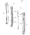
外枠2の外枠左組立体10及び外枠右組立体20について、主に図19を参照して詳細に説明する。図19は、外枠の外枠左組立体及び外枠右組立体を夫々分解して前から見た分解斜視図である。外枠2の外枠左組立体10及び外枠右組立体20は、夫々が上下に延びており、互いに左右に離間して配置されている。外枠左組立体10及び外枠右組立体20は、本体枠4の本体枠上ヒンジ部材510及び本体枠下ヒンジ組立体520を同軸上で回転可能に支持して、外枠2に対して本体枠4を開閉可能に取付けるためのものである。
[2-1. Outer frame left assembly and outer frame right assembly]
The outer frame left assembly 10 and the outer frame right assembly 20 of the outer frame 2 will be described in detail mainly with reference to FIG. FIG. 19 is an exploded perspective view of the outer frame left assembly and the outer frame right assembly of the outer frame disassembled and viewed from the front. The outer frame left assembly 10 and the outer frame right assembly 20 of the outer frame 2 extend vertically, respectively, and are arranged so as to be separated from each other on the left and right sides. The outer frame left assembly 10 and the outer frame right assembly 20 coaxially and rotatably support the main body frame upper hinge member 510 and the main body frame lower hinge assembly 520 of the main body frame 4 with respect to the outer frame 2. This is for mounting the main body frame 4 so that it can be opened and closed.
まず、外枠左組立体10は、前後方向が一定の幅(奥行)で上下に延びている外枠左部材11と、外枠左部材11の右側面上端に取付けられている左上連結部材12と、外枠左部材11の右側面下端に取付けられている左下連結部材13と、を備えている。
First, in the outer frame left assembly 10, the outer frame left member 11 extending vertically with a constant width (depth) in the front-rear direction and the upper left connecting member 12 attached to the upper end of the right side surface of the outer frame left member 11 And a lower left connecting member 13 attached to the lower end of the right side surface of the outer frame left member 11.
外枠左部材11は、一定の断面形状で上下に延びており、アルミ合金の押出型材によって形成されている。外枠左部材11は、左側面における前後方向を三等分したうちの後側の部位において平坦状に右方へ窪んでいる凹部11aと、右側面における凹部11aとは反対側の部位から右方へ膨出している膨出部11bと、膨出部11bを上下に貫通している空洞部11cと、を備えている。外枠左部材11は、凹部11aや膨出部11bによって、強度・剛性が高められていると共に、空洞部11cによって、重量が軽減されている。
The outer frame left member 11 extends vertically with a constant cross-sectional shape, and is formed of an aluminum alloy extruded mold material. The outer frame left member 11 has a concave portion 11a that is flatly recessed to the right in the rear portion of the left side surface divided into three equal parts in the front-rear direction, and a portion on the right side surface that is opposite to the concave portion 11a to the right. It includes a bulging portion 11b that bulges toward the direction and a hollow portion 11c that vertically penetrates the bulging portion 11b. The strength and rigidity of the outer frame left member 11 is increased by the concave portion 11a and the bulging portion 11b, and the weight is reduced by the hollow portion 11c.
また、外枠左部材11は、左右両側面において、上下に延びた複数の溝が形成されている。左側面の複数の溝は、V字状に形成されており、右側面の複数の溝は、半円形状に形成されている。外枠左部材11は、後述する外枠右組立体20の外枠右部材21と左右対称形状に形成されている。
Further, the outer frame left member 11 is formed with a plurality of grooves extending vertically on both the left and right sides. The plurality of grooves on the left side surface are formed in a V shape, and the plurality of grooves on the right side surface are formed in a semicircular shape. The outer frame left member 11 is formed in a symmetrical shape with the outer frame right member 21 of the outer frame right assembly 20 described later.
左上連結部材12は、外枠左部材11の上端と外枠上部材30の左端とを連結するためのものである。左上連結部材12は、水平に延びた平板状の水平固定部12aと、水平固定部12aの左辺における前後方向の中間から上方へ延出している平板状の上横固定部12bと、水平固定部12aの左辺における上横固定部12bの前後両側から下方へ延出している平板状の一対の下横固定部12cと、を備えている。左上連結部材12は、平板状の金属板を屈曲させて形成されている。
The upper left connecting member 12 is for connecting the upper end of the outer frame left member 11 and the left end of the outer frame upper member 30. The upper left connecting member 12 includes a horizontally extending flat plate-shaped horizontal fixing portion 12a, a flat plate-shaped upper-horizontal fixing portion 12b extending upward from the middle in the front-rear direction on the left side of the horizontal fixing portion 12a, and a horizontal fixing portion. It is provided with a pair of flat plate-shaped lower horizontal fixing portions 12c extending downward from both front and rear sides of the upper horizontal fixing portion 12b on the left side of 12a. The upper left connecting member 12 is formed by bending a flat metal plate.
左上連結部材12は、後側の下横固定部12cを外枠左部材11の空洞部11c内に挿入させると共に、水平固定部12aを外枠左部材11の上端に当接させ、更に、前側及び後側の下横固定部12cを外枠左部材11の右側面に当接させた状態で、外枠左部材11の左側面の外側から下横固定部12cにビスを捩じ込むことで、外枠左部材11に取付けられる。また、左上連結部材12は、水平固定部12aを外枠上部材30の左端側の下面に当接させると共に、上横固定部12bを外枠上部材30の左側面の切欠部30a内に挿入させた状態で、水平固定部12a及び上横固定部12bを通して外枠上部材30にビスを捩じ込むことで、外枠上部材30に取付けられる。
In the upper left connecting member 12, the lower horizontal fixing portion 12c on the rear side is inserted into the cavity portion 11c of the outer frame left member 11, the horizontal fixing portion 12a is brought into contact with the upper end of the outer frame left member 11, and further, the front side is further formed. In a state where the lower horizontal fixing portion 12c on the rear side is in contact with the right side surface of the outer frame left member 11, a screw is screwed into the lower horizontal fixing portion 12c from the outside of the left side surface of the outer frame left member 11. , Attached to the outer frame left member 11. Further, in the upper left connecting member 12, the horizontal fixing portion 12a is brought into contact with the lower surface on the left end side of the outer frame upper member 30, and the upper horizontal fixing portion 12b is inserted into the notch 30a on the left side surface of the outer frame upper member 30. In this state, it is attached to the outer frame upper member 30 by screwing a screw into the outer frame upper member 30 through the horizontal fixing portion 12a and the upper horizontal fixing portion 12b.
左下連結部材13は、外枠左部材11の下端と外枠下組立体40(外枠下部材41)の左端とを連結するためのものである。左下連結部材13は、水平に延びた平板状の水平固定部13aと、水平固定部13aの左辺から上方へ延出していると共に水平固定部13aよりも後方へ延出している平板状の上横固定部13bと、上横固定部13bの下辺における水平固定部よりも後側の部位から下方へ延出している平板状の下横固定部13cと、上横固定部13bの後辺から右方へ短く延出している平板状の当接部13dと、を備えている。左下連結部材13は、平板状の金属板を屈曲させて形成されている。
The lower left connecting member 13 is for connecting the lower end of the outer frame left member 11 and the left end of the outer frame lower assembly 40 (outer frame lower member 41). The lower left connecting member 13 has a horizontally extending flat plate-shaped horizontal fixing portion 13a and a flat plate-shaped upper side extending upward from the left side of the horizontal fixing portion 13a and extending rearward from the horizontal fixing portion 13a. The fixed portion 13b, the flat plate-shaped lower lateral fixing portion 13c extending downward from the portion posterior to the horizontal fixing portion on the lower side of the upper lateral fixing portion 13b, and the upper lateral fixing portion 13b to the right from the rear side. It is provided with a flat plate-shaped contact portion 13d extending shortly to. The lower left connecting member 13 is formed by bending a flat metal plate.
左下連結部材13は、当接部13dの後面を外枠左部材11の膨出部11bの前面に当接させると共に、上横固定部13bの左側面を外枠左部材11の右側面に当接させ、水平固定部13aの下面を外枠左部材11の下端と一致させた状態で、外枠左部材11の左側面の外側から上横固定部13bにビスを捩じ込むことで、外枠左部材11に取付けられる。また、左下連結部材13は、水平固定部13aを外枠下部材41の左端側の上面に当接させると共に、下横固定部13cを外枠下部材41の左側面の切欠部41aに挿入させた状態で、水平固定部13a及び下横固定部13cを通して外枠下部材にビスを捩じ込むことで、外枠下部材41に取付けられる。
In the lower left connecting member 13, the rear surface of the contact portion 13d is brought into contact with the front surface of the bulging portion 11b of the outer frame left member 11, and the left surface of the upper horizontal fixing portion 13b is in contact with the right surface of the outer frame left member 11. With the lower surface of the horizontal fixing portion 13a in contact with the lower end of the outer frame left member 11, a screw is screwed into the upper horizontal fixing portion 13b from the outside of the left side surface of the outer frame left member 11 to the outside. It is attached to the frame left member 11. Further, in the lower left connecting member 13, the horizontal fixing portion 13a is brought into contact with the upper surface on the left end side of the outer frame lower member 41, and the lower horizontal fixing portion 13c is inserted into the notch portion 41a on the left side surface of the outer frame lower member 41. In this state, it is attached to the outer frame lower member 41 by screwing a screw into the outer frame lower member through the horizontal fixing portion 13a and the lower horizontal fixing portion 13c.
次に、外枠右組立体20は、前後方向が一定の幅(奥行)で上下に延びている外枠右部材21と、外枠右部材21の左側面上端に取付けられている右上連結部材22と、外枠右部材21の左側面下端に取付けられている右下連結部材23と、外枠右部材21の左側面上部に取付けられている上鉤掛部材24と、外枠右部材21の左側面下部に取付けられている下鉤掛部材25と、を備えている。
Next, in the outer frame right assembly 20, the outer frame right member 21 extending vertically with a certain width (depth) in the front-rear direction and the upper right connecting member attached to the upper end of the left side surface of the outer frame right member 21. 22, the lower right connecting member 23 attached to the lower end of the left side surface of the outer frame right member 21, the upper hooking member 24 attached to the upper part of the left side surface of the outer frame right member 21, and the outer frame right member 21. It is provided with a lower hook member 25 attached to the lower part of the left side surface.
外枠右部材21は、一定の断面形状で上下に延びており、アルミ合金の押出型材によって形成されている。外枠右部材21は、右側面における前後方向を三等分したうちの後側の部位において平坦状に左方へ窪んでいる凹部21aと、左側面における凹部21aとは反対側の部位から左方へ膨出している膨出部21bと、膨出部21bを上下に貫通している空洞部21cと、を備えている。外枠右部材21は、凹部21aや膨出部21bによって、強度・剛性が高められていると共に、空洞部21cによって、重量が軽減されている。
The outer frame right member 21 extends vertically with a constant cross-sectional shape, and is formed of an aluminum alloy extruded mold material. The outer frame right member 21 has a concave portion 21a that is flatly recessed to the left in the rear portion of the right side surface divided into three equal parts in the front-rear direction, and a portion on the left side surface that is opposite to the concave portion 21a to the left. It includes a bulging portion 21b that bulges toward the direction and a hollow portion 21c that vertically penetrates the bulging portion 21b. The strength and rigidity of the outer frame right member 21 is increased by the concave portion 21a and the bulging portion 21b, and the weight is reduced by the hollow portion 21c.
また、外枠右部材21は、左右両側面において、上下に延びた複数の溝が形成されている。右側面の複数の溝は、V字状に形成されており、左側面の複数の溝は、半円形状に形成されている。外枠右部材21は、外枠左組立体10の外枠左部材11と左右対称形状に形成されている。
Further, the outer frame right member 21 is formed with a plurality of grooves extending vertically on both the left and right sides. The plurality of grooves on the right side surface are formed in a V shape, and the plurality of grooves on the left side surface are formed in a semicircular shape. The outer frame right member 21 is formed in a symmetrical shape with the outer frame left member 11 of the outer frame left assembly 10.
右上連結部材22は、外枠右部材21の上端と外枠上部材30の右端とを連結するためのものである。右上連結部材22は、水平に延びた平板状の水平固定部22aと、水平固定部22aの右辺における前後方向の中間から上方へ延出している平板状の上横固定部22bと、水平固定部22aの右辺における上横固定部22bの前後両側から下方へ延出している平板状の一対の下横固定部22cと、を備えている。右上連結部材22は、平板状の金属板を屈曲させて形成されている。
The upper right connecting member 22 is for connecting the upper end of the outer frame right member 21 and the right end of the outer frame upper member 30. The upper right connecting member 22 includes a horizontally extending flat plate-shaped horizontal fixing portion 22a, a flat plate-shaped upper-horizontal fixing portion 22b extending upward from the middle in the front-rear direction on the right side of the horizontal fixing portion 22a, and a horizontal fixing portion. It is provided with a pair of flat plate-shaped lower horizontal fixing portions 22c extending downward from both front and rear sides of the upper horizontal fixing portion 22b on the right side of 22a. The upper right connecting member 22 is formed by bending a flat metal plate.
右上連結部材22は、後側の下横固定部22cを外枠右部材21の空洞部21c内に挿入させると共に、水平固定部22aを外枠右部材21の上端に当接させ、更に、前側及び後側の下横固定部22cを外枠右部材21の左側面に当接させた状態で、外枠右部材21の右側面の外側から下横固定部22cにビスを捩じ込むことで、外枠右部材21に取付けられる。また、右上連結部材22は、水平固定部22aを外枠上部材30の右端側の下面に当接させると共に、上横固定部22bを外枠上部材30の右側面の切欠部30a内に挿入させた状態で、水平固定部22a及び上横固定部22bを通して外枠上部材30にビスを捩じ込むことで、外枠上部材30に取付けられる。
In the upper right connecting member 22, the lower horizontal fixing portion 22c on the rear side is inserted into the hollow portion 21c of the outer frame right member 21, the horizontal fixing portion 22a is brought into contact with the upper end of the outer frame right member 21, and further, the front side. In a state where the lower horizontal fixing portion 22c on the rear side is in contact with the left side surface of the outer frame right member 21, a screw is screwed into the lower horizontal fixing portion 22c from the outside of the right side surface of the outer frame right member 21. , Attached to the outer frame right member 21. Further, in the upper right connecting member 22, the horizontal fixing portion 22a is brought into contact with the lower surface on the right end side of the outer frame upper member 30, and the upper horizontal fixing portion 22b is inserted into the notch 30a on the right side surface of the outer frame upper member 30. In this state, it is attached to the outer frame upper member 30 by screwing a screw into the outer frame upper member 30 through the horizontal fixing portion 22a and the upper horizontal fixing portion 22b.
右下連結部材23は、外枠右部材21の下端と外枠下組立体40(外枠下部材41)の右端とを連結するためのものである。右下連結部材23は、水平に延びた平板状の水平固定部23aと、水平固定部23aの右辺から上方へ延出していると共に水平固定部23aよりも後方へ延出している平板状の上横固定部23bと、上横固定部23bの下辺における水平固定部よりも後側の部位から下方へ延出している平板状の下横固定部23cと、上横固定部23bの後辺から左方へ短く延出している平板状の当接部23dと、を備えている。右下連結部材23は、平板状の金属板を屈曲させて形成されている。
The lower right connecting member 23 is for connecting the lower end of the outer frame right member 21 and the right end of the outer frame lower assembly 40 (outer frame lower member 41). The lower right connecting member 23 has a horizontally extending flat plate-shaped horizontal fixing portion 23a and a flat plate-shaped upper portion extending upward from the right side of the horizontal fixing portion 23a and extending rearward from the horizontal fixing portion 23a. The horizontal fixing portion 23b, the flat plate-shaped lower horizontal fixing portion 23c extending downward from the portion posterior to the horizontal fixing portion on the lower side of the upper horizontal fixing portion 23b, and the left from the rear side of the upper horizontal fixing portion 23b. It is provided with a flat plate-shaped contact portion 23d that extends shortly toward the direction. The lower right connecting member 23 is formed by bending a flat metal plate.
右下連結部材23は、当接部23dの後面を外枠右部材21の膨出部21bの前面に当接させると共に、上横固定部23bの右側面を外枠右部材21の左側面に当接させ、水平固定部23aの下面を外枠右部材21の下端と一致させた状態で、外枠右部材21の右側面の外側から上横固定部23bにビスを捩じ込むことで、外枠右部材21に取付けられる。また、右下連結部材23は、水平固定部23aを外枠下部材41の右端側の上面に当接させると共に、下横固定部23cを外枠下部材41の右側面の切欠部41aに挿入させた状態で、水平固定部23a及び下横固定部23cを通して外枠下部材にビスを捩じ込むことで、外枠下部材41に取付けられる。
In the lower right connecting member 23, the rear surface of the contact portion 23d is brought into contact with the front surface of the bulging portion 21b of the outer frame right member 21, and the right surface of the upper horizontal fixing portion 23b is attached to the left surface of the outer frame right member 21. By abutting and in a state where the lower surface of the horizontal fixing portion 23a is aligned with the lower end of the outer frame right member 21, a screw is screwed into the upper horizontal fixing portion 23b from the outside of the right side surface of the outer frame right member 21. It is attached to the outer frame right member 21. Further, in the lower right connecting member 23, the horizontal fixing portion 23a is brought into contact with the upper surface on the right end side of the outer frame lower member 41, and the lower horizontal fixing portion 23c is inserted into the notch portion 41a on the right side surface of the outer frame lower member 41. In this state, it is attached to the outer frame lower member 41 by screwing a screw into the outer frame lower member through the horizontal fixing portion 23a and the lower horizontal fixing portion 23c.
上鉤掛部材24及び下鉤掛部材25は、後述する本体枠4における施錠ユニット650の外枠用鉤653が掛止されるものである。上鉤掛部材24は、前後方向に一定の幅で上下に延びており外枠右部材21の左側面に取付けられる平板状の取付部24aと、取付部24aの前辺から左方へ延出しており上側の外枠用鉤653が掛止される平板状の掛止片部24bと、を備えている。
The upper hook hook member 24 and the lower hook hook member 25 are for hooking the outer frame hook 653 of the locking unit 650 in the main body frame 4, which will be described later. The upper hook member 24 extends vertically with a certain width in the front-rear direction, and extends to the left from the front side of the flat plate-shaped mounting portion 24a mounted on the left side surface of the outer frame right member 21 and the mounting portion 24a. It is provided with a flat plate-shaped hook piece portion 24b on which the hook 653 for the outer frame on the upper side of the cage is hooked.
下鉤掛部材25は、前後方向に一定の幅で上下に延びており外枠右部材21の左側面に取付けられる平板状の取付部25aと、取付部25aの前辺から左方へ延出しており下側の外枠用鉤653が掛止される平板状の掛止片部25bと、掛止片部25bを前後に貫通しており下側の外枠用鉤653が挿通可能な挿通口25cと、を備えている。
The lower hook member 25 extends vertically with a certain width in the front-rear direction, and has a flat plate-shaped mounting portion 25a mounted on the left side surface of the outer frame right member 21 and a flat plate-shaped mounting portion 25a extending from the front side of the mounting portion 25a to the left. A flat plate-shaped hook piece portion 25b on which the lower outer frame hook 653 is hooked and an insertion through which the lower outer frame hook 653 can be inserted through the hook piece portion 25b in the front-rear direction. It has a mouth 25c and.
[2-2.外枠上部材]
外枠2の外枠上部材30について、主に図18を参照して詳細に説明する。外枠上部材30は、左右に離間している外枠左組立体10及び外枠右組立体20の上端同士を連結するためのものである。外枠上部材30は、前後方向の幅が、外枠左部材11及び外枠右部材21の前後方向と略同じ幅で、上下方向の厚さが一定で、左右方向に延びており、木材によって形成されている。外枠上部材30は、左右方向の長さが、後述する外枠下組立体40の外枠下部材41の左右方向の長さと同じに形成されている。
[2-2. Outer frame upper member]
The outer frame upper member 30 of the outer frame 2 will be described in detail mainly with reference to FIG. The outer frame upper member 30 is for connecting the upper ends of the outer frame left assembly 10 and the outer frame right assembly 20 that are separated from each other to the left and right. The width of the outer frame upper member 30 in the front-rear direction is substantially the same as the width in the front-rear direction of the outer frame left member 11 and the outer frame right member 21, the thickness in the vertical direction is constant, and the width extends in the left-right direction. Is formed by. The outer frame upper member 30 is formed so that the length in the left-right direction is the same as the length in the left-right direction of the outer frame lower member 41 of the outer frame lower assembly 40 described later.
外枠上部材30は、左右両側面における前後方向の中央において、上下に貫通した状態で左右方向中央側へ夫々窪んでいる切欠部30aを備えている。これら左右両端の切欠部30aには、左上連結部材12の上横固定部12b及び右上連結部材22の上横固定部22bが夫々挿入された状態で取付けられる。
The outer frame upper member 30 is provided with a notch 30a that is recessed toward the center side in the left-right direction in a state of penetrating up and down at the center in the front-rear direction on both left and right side surfaces. The upper lateral fixing portion 12b of the upper left connecting member 12 and the upper lateral fixing portion 22b of the upper right connecting member 22 are attached to the cutout portions 30a at both left and right ends in a state of being inserted respectively.
また、外枠上部材30は、左側端部において、上面と前面が一般面よりも窪んだ取付段部30bを備えている。この取付段部30bには、後述する外枠上ヒンジ組立体50が取付けられる。
Further, the outer frame upper member 30 includes a mounting step portion 30b whose upper surface and front surface are recessed from the general surface at the left end portion. A hinge assembly 50 on an outer frame, which will be described later, is mounted on the mounting step portion 30b.
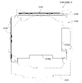
[2-3.外枠下組立体]
外枠2の外枠下組立体40について、主に図20を参照して詳細に説明する。図20は、外枠の外枠下組立体を分解して前から見た分解斜視図である。外枠下組立体40は、左右に離間している外枠左組立体10及び外枠右組立体20の下端同士を連結すると共に、パチンコ機1において扉枠3よりも下側を閉鎖して装飾するためのものである。
[2-3. Assembly under the outer frame]
The outer frame lower assembly 40 of the outer frame 2 will be described in detail mainly with reference to FIG. FIG. 20 is an exploded perspective view of the outer frame lower assembly of the outer frame as viewed from the front by disassembling. The outer frame lower assembly 40 connects the lower ends of the outer frame left assembly 10 and the outer frame right assembly 20 that are separated from each other to the left and right, and closes the lower side of the pachinko machine 1 below the door frame 3. It is for decoration.
外枠下組立体40は、左右に離間している外枠左組立体10及び外枠右組立体20の下端同士を連結しており左右に延びている外枠下部材41と、外枠下部材41の前方に配置されており外枠下部材41に沿って左右に延びていると共に後方が開放されている箱状の幕板前部材42と、幕板前部材42の後側に取付けられていると共に外枠下部材41の上面に取付けられており前方が開放されている左右に延びた箱状の幕板後部材43と、幕板後部材43の上面における左端に形成されている球噛防止機構44と、を備えている。
The outer frame lower assembly 40 has an outer frame lower member 41 that connects the lower ends of the outer frame left assembly 10 and the outer frame right assembly 20 that are separated to the left and right and extends to the left and right, and the outer frame lower assembly 40. A box-shaped front curtain plate member 42 that is arranged in front of the member 41 and extends to the left and right along the outer frame lower member 41 and is open at the rear, and is attached to the rear side of the front curtain plate member 42. A box-shaped rear curtain plate member 43 that is attached to the upper surface of the outer frame lower member 41 and has an open front, and a ball bite prevention formed on the left end of the upper surface of the curtain plate rear member 43. It is equipped with a mechanism 44.
外枠下部材41は、前後方向の幅が、外枠左部材11及び外枠右部材21の前後方向と略同じ幅で、上下方向の厚さが一定で、左右方向に延びており、木材によって形成されている。外枠下部材41は、左右方向の長さが、外枠上部材30の左右方向の長さと同じに形成されている。
The width of the outer frame lower member 41 in the front-rear direction is substantially the same as the width in the front-rear direction of the outer frame left member 11 and the outer frame right member 21, the thickness in the vertical direction is constant, and the width extends in the left-right direction. Is formed by. The outer frame lower member 41 is formed so that the length in the left-right direction is the same as the length in the left-right direction of the outer frame upper member 30.
外枠下部材41は、左右両側面における前後方向の中央において、上下に貫通した状態で左右方向中央側へ夫々窪んでいる切欠部41aを備えている。これら左右両端の切欠部41aには、左下連結部材13の下横固定部13c及び右下連結部材23の下横固定部23cが夫々挿入された状態で取付けられる。これにより、外枠左部材11及び外枠右部材21の下端同士を連結することができる。
The outer frame lower member 41 is provided with a notch 41a that is recessed toward the center side in the left-right direction in a state of penetrating up and down at the center in the front-rear direction on both left and right side surfaces. The lower lateral fixing portion 13c of the lower left connecting member 13 and the lower lateral fixing portion 23c of the lower right connecting member 23 are attached to the cutout portions 41a at both left and right ends in a state of being inserted respectively. Thereby, the lower ends of the outer frame left member 11 and the outer frame right member 21 can be connected to each other.
また、外枠下部材41は、上面から凹んでおり、幕板後部材43の下部が挿入される凹部41bを備えている。凹部41bは、左右に延びていると共に、前後方向中央の後ろ寄りの位置から前端側へ抜けている。この凹部41bにより、幕板前部材42及び幕板後部材43により形成される幕板内部空間40aの容積を可及的に広くしている。
Further, the outer frame lower member 41 is recessed from the upper surface, and has a recess 41b into which the lower portion of the curtain plate rear member 43 is inserted. The concave portion 41b extends to the left and right, and is removed from the position toward the rear in the center in the front-rear direction toward the front end side. The recess 41b makes the volume of the curtain plate internal space 40a formed by the curtain plate front member 42 and the curtain plate rear member 43 as wide as possible.
幕板前部材42は、左右方向の長さが外枠下部材41と同じ長さに延びており、高さに対して前後方向の奥行が短い横長の直方体状の箱状に形成されており、後側の全面が開放されている。幕板前部材42は、開放されている後側を、幕板後部材43によって閉鎖することで、幕板後部材43と協働して本体枠スピーカ622のエンクロージャ624の一部となる幕板内部空間40aを形成する。幕板前部材42は、右端付近の前面において、前後に貫通していると共に左右に延びている長孔状の開口部42aを備えている。
The curtain plate front member 42 has a length in the left-right direction extending to the same length as the outer frame lower member 41, and is formed in a horizontally long rectangular parallelepiped box shape having a short depth in the front-rear direction with respect to the height. The entire rear side is open. The curtain plate front member 42 is closed on the open rear side by the curtain plate rear member 43, so that the curtain plate front member 42 cooperates with the curtain plate rear member 43 to become a part of the enclosure 624 of the main body frame speaker 622. It forms a space 40a. The curtain plate front member 42 has an elongated hole-shaped opening 42a that penetrates back and forth and extends left and right on the front surface near the right end.
幕板後部材43は、左右方向の長さが外枠下部材41よりも若干短く延びており、前方が開放された箱状に形成されている。幕板後部材43は、前面に幕板前部材42を取付けることで、幕板前部材42と協働して本体枠スピーカ622のエンクロージャ624の一部となる幕板内部空間40aを形成する。幕板後部材43は、上面における左右方向中央部において、左右に延びていると共に上方へ突出しており幕板内部空間40aと連通している筒状の接続筒部43aを有している。接続筒部43aは、上端が、幕板後部材43の一般的な上面と一致している前端側から後方へ向かうほど上方へ位置するように傾斜している。本実施形態では、接続筒部43aの上端は、45度の角度で傾斜している。
The curtain plate rear member 43 has a length in the left-right direction slightly shorter than that of the outer frame lower member 41, and is formed in a box shape with an open front. By attaching the curtain plate front member 42 to the front surface of the curtain plate rear member 43, the curtain plate front member 42 cooperates with the curtain plate front member 42 to form a curtain plate internal space 40a that becomes a part of the enclosure 624 of the main body frame speaker 622. The curtain plate rear member 43 has a tubular connecting cylinder portion 43a that extends left and right and projects upward at the central portion in the left-right direction on the upper surface and communicates with the curtain plate internal space 40a. The upper end of the connecting cylinder portion 43a is inclined so as to be positioned upward from the front end side, which coincides with the general upper surface of the curtain plate rear member 43, toward the rear. In the present embodiment, the upper end of the connecting cylinder portion 43a is inclined at an angle of 45 degrees.
この接続筒部43aは、左右方向の長さが、幕板後部材43全体の約1/3の長さに形成されていると共に、前後方向の奥行が、幕板後部材43全体の奥行よりも若干短く形成されている。接続筒部43a内には、前端側と後端側とを結ぶ複数のリブ43bが備えられている。この接続筒部43aの上端には、外枠2に対して本体枠4を閉じた時に、本体枠4における基板ユニット620のスピーカユニット620aにおけるスピーカカバー621の接続部621cが接続されて、スピーカユニット620aの内部空間と連通した状態となり、エンクロージャ624を形成する。
The length of the connecting cylinder portion 43a in the left-right direction is formed to be about 1/3 of the length of the entire curtain plate rear member 43, and the depth in the front-rear direction is greater than the depth of the entire curtain plate rear member 43. Is also formed slightly shorter. A plurality of ribs 43b connecting the front end side and the rear end side are provided in the connection cylinder portion 43a. When the main body frame 4 is closed with respect to the outer frame 2, the connection portion 621c of the speaker cover 621 in the speaker unit 620a of the board unit 620 in the main body frame 4 is connected to the upper end of the connection cylinder portion 43a. It communicates with the internal space of the 620a and forms the enclosure 624.
球噛防止機構44は、幕板後部材43の上面における左端において、外枠下ヒンジ部材60の部位に遊技球Bが滞留することで、外枠2と本体枠4との間に遊技球Bが挟まれるのを防止するためのものである。
In the ball biting prevention mechanism 44, the game ball B stays at the portion of the outer frame lower hinge member 60 at the left end on the upper surface of the curtain plate rear member 43, so that the game ball B is between the outer frame 2 and the main body frame 4. Is to prevent being pinched.
球噛防止機構44は、幕板後部材43の上面における左端に形成されており、後述する外枠下ヒンジ部材60が際されるように平坦に形成された載置部44aと、載置部44aの左端において上方へ向かって開口している第一排出口44bと、載置部44aにおける第一排出口44bよりも右方で上方へ向かって開口している第二排出口44cと、載置部44aの後辺及び右辺から上方へ延出している立壁部44dと、立壁部44dの上端から前方へ突出していると共に上面が後方へ向かうに従って上方に位置するように傾斜している上端突出部44eと、を備えている。
The ball biting prevention mechanism 44 is formed at the left end on the upper surface of the curtain plate rear member 43, and is a mounting portion 44a formed flat so that the hinge member 60 under the outer frame, which will be described later, is highlighted, and a mounting portion. The first discharge port 44b that opens upward at the left end of 44a and the second discharge port 44c that opens upward to the right of the first discharge port 44b in the mounting portion 44a are mounted. A vertical wall portion 44d extending upward from the rear side and the right side of the placement portion 44a, and an upper end protrusion protruding forward from the upper end of the vertical wall portion 44d and inclined so that the upper surface is positioned upward as the upper surface moves backward. It is provided with a portion 44e.
第一排出口44bは、後述する外枠下ヒンジ部材60の排出孔60dと一致する位置に形成されている。第一排出口44b及び第二排出口44cは、遊技球Bが通過可能な大きさに形成されている。第一排出口44b及び第二排出口44cは、幕板内部空間40aとは連通しておらず、幕板後部材43の後面に開口している。従って、第一排出口44b及び第二排出口44cに進入した遊技球Bを、幕板後部材43の後方へ排出することができる。
The first discharge port 44b is formed at a position corresponding to the discharge hole 60d of the outer frame lower hinge member 60, which will be described later. The first discharge port 44b and the second discharge port 44c are formed in a size that allows the game ball B to pass through. The first discharge port 44b and the second discharge port 44c do not communicate with the curtain plate internal space 40a and are open to the rear surface of the curtain plate rear member 43. Therefore, the game ball B that has entered the first discharge port 44b and the second discharge port 44c can be discharged to the rear of the curtain plate rear member 43.
この球噛防止機構44は、球噛防止機構44は、外枠下ヒンジ部材60と後述する本体枠下ヒンジ組立体520との間の隙間を通して、ピアノ線等の不正な工具が挿入された場合、載置部44aの後端から立上っている立壁部44dにより、不正な工具の侵入を阻止することができる。仮に、不正な工具の先端が立壁部44dに当接することで、上方へ曲がったとしても、立壁部44dの上端に備えられている前方へ突出した上端突出部44eに当接し、これ以上の侵入を阻止することができる。従って、外枠下ヒンジ部材60の部位を介して、不正行為が行われるのを防止することができる。
The ball biting prevention mechanism 44 is a case where an illegal tool such as a piano wire is inserted through the gap between the outer frame lower hinge member 60 and the main body frame lower hinge assembly 520 described later. The standing wall portion 44d rising from the rear end of the mounting portion 44a can prevent an unauthorized tool from entering. Even if the tip of an illegal tool comes into contact with the standing wall portion 44d and bends upward, it comes into contact with the forward protruding upper end protruding portion 44e provided at the upper end of the standing wall portion 44d and further invades. Can be blocked. Therefore, it is possible to prevent fraudulent acts from being performed through the portion of the hinge member 60 under the outer frame.
ところで、載置部44aの後端に立壁部44dを備えた場合、外枠2に対して本体枠4を開けた時に、何らかの理由により載置部44a上に落下した遊技球Bが、立壁部44dによって外枠2の後方への移動が阻止されるため、載置部44a上に遊技球Bが滞留し易くなる。そして、載置部44a上に遊技球Bが滞留していると、外枠2に対して本体枠4を閉じる際に、外枠2と本体枠4との間に遊技球Bが挟み込まれてしまい、本体枠4を閉じることができなくなる問題が発生する。
By the way, when the standing wall portion 44d is provided at the rear end of the mounting portion 44a, the game ball B that has fallen on the mounting portion 44a for some reason when the main body frame 4 is opened with respect to the outer frame 2 is the standing wall portion. Since the movement of the outer frame 2 to the rear is prevented by the 44d, the game ball B is likely to stay on the mounting portion 44a. When the game ball B stays on the mounting portion 44a, the game ball B is sandwiched between the outer frame 2 and the main body frame 4 when the main body frame 4 is closed with respect to the outer frame 2. This causes a problem that the main body frame 4 cannot be closed.
これに対して、本実施形態の球噛防止機構44では、外枠下ヒンジ部材60上や載置部44a上に落下した遊技球Bを、外枠下ヒンジ部材60の排出孔60dと第一排出口44bを通して、又は、第二排出口44cを通して、遊技球Bを幕板後部材43の後方(外枠2の後方)へ排出することができ、外枠2と本体枠4との間に遊技球Bが挟まれるのを防止することができる。
On the other hand, in the ball biting prevention mechanism 44 of the present embodiment, the game ball B that has fallen on the outer frame lower hinge member 60 or on the mounting portion 44a is first referred to as the discharge hole 60d of the outer frame lower hinge member 60. The game ball B can be discharged to the rear of the curtain plate rear member 43 (behind the outer frame 2) through the discharge port 44b or the second discharge port 44c, and is between the outer frame 2 and the main body frame 4. It is possible to prevent the game ball B from being pinched.
外枠下組立体40は、幕板前部材42及び幕板後部材43の上面に左右に離間して配置されている一対の案内部材45と、幕板前部材42の開口部42aを後側から閉鎖している平板状のグリル部材46と、グリル部材46を挟んで開口部42aを閉鎖するように幕板前部材42の内部に取付けられており前後に延びた二つの円筒を有したポート部材47と、幕板後部材43の接続筒部43aの上端に配置される枠状のシール部材48と、を備えている。
The outer frame lower assembly 40 closes a pair of guide members 45 arranged apart from each other on the upper surfaces of the curtain plate front member 42 and the curtain plate rear member 43, and the opening 42a of the curtain plate front member 42 from the rear side. A flat plate-shaped grill member 46 and a port member 47 having two cylinders that are attached to the inside of the curtain plate front member 42 so as to close the opening 42a across the grill member 46 and extend back and forth. A frame-shaped seal member 48 arranged at the upper end of the connection cylinder portion 43a of the curtain plate rear member 43 is provided.
一対の案内部材45は、外枠2に対して本体枠4を閉じた時に、扉枠3の下端が当接するものである。案内部材45は、摩擦抵抗の低い低摩擦材料によって形成されており、本体枠4の下端を滑り易くして、開閉を容易にしている。
The pair of guide members 45 are such that the lower end of the door frame 3 comes into contact with the outer frame 2 when the main body frame 4 is closed. The guide member 45 is made of a low-friction material having low frictional resistance, and makes the lower end of the main body frame 4 slippery to facilitate opening and closing.
グリル部材46は、無数の小穴を有したパンチングメタルにより形成されている。ポート部材47は、二つの円筒により、グリル部材46を介して幕板内部空間40a(エンクロージャ624)と外枠2の前方とを連通させている。ポート部材47は、二つの円筒が、所定の内径で所定の長さに形成されており、ヘルムホルツ共鳴の原理により本体枠スピーカ622から後方(エンクロージャ624内)へ発せられた低音を共振・増幅させて、豊かな低音を外枠2の前方(遊技者側)へ放射することができる。つまり、本実施形態では、本体枠スピーカ622のエンクロージャ624がバスレフ型とされており、遊技者に対して重低音を聞かせることができる。
The grill member 46 is formed of a punching metal having innumerable small holes. The port member 47 communicates the curtain plate internal space 40a (enclosure 624) with the front of the outer frame 2 via the grill member 46 by two cylinders. The port member 47 has two cylinders formed with a predetermined inner diameter and a predetermined length, and resonates and amplifies the bass emitted from the main body frame speaker 622 to the rear (inside the enclosure 624) by the principle of Helmholtz resonance. Therefore, rich bass can be radiated to the front (player side) of the outer frame 2. That is, in the present embodiment, the enclosure 624 of the main body frame speaker 622 is a bass reflex type, and the player can hear the deep bass.
シール部材48は、外枠2に対して本体枠4を閉じた時に、接続筒部43aの上端と本体枠4におけるスピーカカバー621の接続部621cの下端との間に挟まれて圧縮されるものであり、接続筒部43aと接続部621cとの間からスピーカのエンクロージャ内の音が漏れるのを防止するものである。
The seal member 48 is sandwiched and compressed between the upper end of the connection cylinder portion 43a and the lower end of the connection portion 621c of the speaker cover 621 in the main body frame 4 when the main body frame 4 is closed with respect to the outer frame 2. This is to prevent the sound in the speaker enclosure from leaking from between the connection cylinder portion 43a and the connection portion 621c.
[2-4.外枠上ヒンジ組立体]
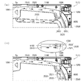
外枠2の外枠上ヒンジ組立体50について、主に図21を参照して詳細に説明する。図21(a)は外枠2の外枠上ヒンジ組立体を分解して前上から見た分解斜視図であり、(b)は(a)を前下から見た分解斜視図である。外枠上ヒンジ組立体50は、外枠左組立体10の上端と外枠上部材30の左端に取付けられるものであり、外枠2に対して本体枠4をヒンジ回転可能に取付けるためのものである。外枠上ヒンジ組立体50は、外枠左部材11の凹部11aの上端と外枠上部材30の取付段部30bとに取付けられる外枠上ヒンジ部材51と、外枠上ヒンジ部材51に取付けられているロック部材52と、ロック部材52を外枠上ヒンジ部材51に取付けている取付ビス53と、を備えている。
[2-4. Hinge assembly on outer frame]
The hinge assembly 50 on the outer frame of the outer frame 2 will be described in detail mainly with reference to FIG. 21. 21 (a) is an exploded perspective view of the outer frame upper hinge assembly of the outer frame 2 disassembled and viewed from the front upper side, and FIG. 21 (b) is an exploded perspective view of (a) viewed from the front lower surface. The outer frame upper hinge assembly 50 is attached to the upper end of the outer frame left assembly 10 and the left end of the outer frame upper member 30, and is for attaching the main body frame 4 to the outer frame 2 so that the hinge can be rotated. Is. The outer frame upper hinge assembly 50 is attached to the outer frame upper hinge member 51 attached to the upper end of the recess 11a of the outer frame left member 11 and the mounting step portion 30b of the outer frame upper member 30, and to the outer frame upper hinge member 51. The lock member 52 is provided with a locking member 52 and a mounting screw 53 for attaching the lock member 52 to the hinge member 51 on the outer frame.
外枠上ヒンジ部材51は、水平に延びた平板状で外枠上部材30の取付段部30bの上面に取付けられる上固定部51aと、上固定部51aの前辺から前方へ延出している平板状の前方延出部51bと、前方延出部51bの右辺の途中から前方へ向かうに従って前方延出部51bの左右中央へ延びており上下に貫通している軸受溝51cと、上固定部51aの左辺から下方へ延びている平板状の横固定部51dと、前方延出部51bの左辺から前辺を周って軸受溝51cが開口している部位までの端縁から下方へ延びており横固定部51dと連続している平板状の端縁壁部51eと、を備えている。外枠上ヒンジ部材51は、金属板をプレス成型により打抜き・屈曲させて形成されている。外枠上ヒンジ部材51は、軸受溝51c内において、本体枠上ヒンジ部材510の後述する本体枠上ヒンジピン512を回転可能に支持することができる。
The outer frame upper hinge member 51 has an upper fixing portion 51a that is horizontally extended and is attached to the upper surface of the mounting step portion 30b of the outer frame upper member 30, and extends forward from the front side of the upper fixing portion 51a. A flat plate-shaped front extending portion 51b, a bearing groove 51c extending vertically from the middle of the right side of the front extending portion 51b to the left and right center of the front extending portion 51b and penetrating vertically, and an upper fixing portion. The flat plate-shaped horizontal fixing portion 51d extending downward from the left side of the 51a and the end edge extending downward from the left side of the front extending portion 51b to the portion where the bearing groove 51c is opened around the front side. It is provided with a flat plate-shaped edge wall portion 51e that is continuous with the cage horizontal fixing portion 51d. The hinge member 51 on the outer frame is formed by punching and bending a metal plate by press molding. The outer frame upper hinge member 51 can rotatably support the main body frame upper hinge pin 512 described later of the main body frame upper hinge member 510 in the bearing groove 51c.
ロック部材52は、前後に延びている帯板状のロック本体52aと、ロック本体52aの後端から右方へ突出している操作片52bと、ロック本体52aの後端から左方へ延びた後に斜め左前方へ延びている弾性変形可能な棒状の弾性部52cと、ロック本体52aの後端付近で上下に貫通している取付孔52dと、を備えている。ロック部材52は、合成樹脂によって形成されている。ロック部材52は、取付ビス53によって、外枠上ヒンジ部材51における前方延出部51bの下面で、軸受溝51cよりも後側の部位に回動可能に取付けられる。
The lock member 52 has a strip-shaped lock body 52a extending back and forth, an operation piece 52b protruding to the right from the rear end of the lock body 52a, and after extending to the left from the rear end of the lock body 52a. It is provided with an elastically deformable rod-shaped elastic portion 52c extending diagonally to the left front and a mounting hole 52d penetrating vertically near the rear end of the lock body 52a. The lock member 52 is made of synthetic resin. The lock member 52 is rotatably attached to a portion of the outer frame upper hinge member 51 on the lower surface of the front extending portion 51b behind the bearing groove 51c by the mounting screw 53.
ロック部材52は、外枠上ヒンジ部材51に取付けた状態で、ロック本体52aが、平面視で軸受溝51cを遮ることができると共に、前端付近の右側面が、外枠上ヒンジ部材51の端縁壁部51eにおける軸受溝51cの開口まで延びている部位と当接可能となるように前方へ延びている。また、ロック本体52aの後端から左方へ延びている弾性部52cの先端は、外枠上ヒンジ部材51における端縁壁部51eの内周面に当接している。このロック部材52は、弾性部52cの付勢力によって取付孔52dを中心に、前端が左方へ回動する方向に付勢されている。従って、通常の状態では、ロック部材52のロック本体52aの前端付近の右側面が、端縁壁部51eに当接している。この状態では、軸受溝51cにおけるロック本体52aよりも前側の部位に、本体枠上ヒンジ部材510の本体枠上ヒンジピン512を収容可能な空間が形成される。
When the lock member 52 is attached to the hinge member 51 on the outer frame, the lock body 52a can block the bearing groove 51c in a plan view, and the right side surface near the front end is the end of the hinge member 51 on the outer frame. It extends forward so that it can come into contact with a portion of the edge wall portion 51e that extends to the opening of the bearing groove 51c. Further, the tip of the elastic portion 52c extending to the left from the rear end of the lock main body 52a is in contact with the inner peripheral surface of the end edge wall portion 51e of the hinge member 51 on the outer frame. The lock member 52 is urged by the urging force of the elastic portion 52c in a direction in which the front end rotates to the left around the mounting hole 52d. Therefore, in a normal state, the right side surface of the lock member 52 near the front end of the lock body 52a is in contact with the edge wall portion 51e. In this state, a space that can accommodate the hinge pin 512 on the main body frame of the hinge member 510 on the main body frame is formed in a portion of the bearing groove 51c on the front side of the lock main body 52a.
このロック部材52は、操作片52bを操作することで、弾性部52cの付勢力に抗してロック本体52aを回動させることができる。そして、操作片52bの操作によって、ロック本体52aを、その前端が左方へ移動する方向へ回動させることで、平面視において軸受溝51cからロック本体52aを後退させることができ、軸受溝51cが全通している状態とすることができる。これにより、軸受溝51c内に本体枠上ヒンジピン512を挿入したり、軸受溝51c内から本体枠上ヒンジピン512を外したりすることができる。
By operating the operation piece 52b, the lock member 52 can rotate the lock body 52a against the urging force of the elastic portion 52c. Then, by operating the operation piece 52b, the lock body 52a is rotated in the direction in which the front end thereof moves to the left, so that the lock body 52a can be retracted from the bearing groove 51c in a plan view, and the bearing groove 51c can be retracted. Can be in a state of being fully passed. As a result, the hinge pin 512 on the main body frame can be inserted into the bearing groove 51c, and the hinge pin 512 on the main body frame can be removed from the inside of the bearing groove 51c.
[2-5.外枠下ヒンジ部材]
外枠2の外枠下ヒンジ部材60について、主に図18を参照して詳細に説明する。外枠下ヒンジ部材60は、水平に延びた平板状の水平部60aと、水平部60aの左辺において前後方向中央よりも後側の部位から上方へ立上っている平板状の立上部60bと、水平部60aの前端付近から上方へ突出している外枠下ヒンジピン60cと、水平部60aを上下に貫通しており遊技球Bが一つのみ通過可能な大きさの排出孔60dと、を備えている。この外枠下ヒンジ部材60は、金属板をプレス成型により打抜き・屈曲させて形成されている。
[2-5. Hinge member under the outer frame]
The hinge member 60 below the outer frame of the outer frame 2 will be described in detail mainly with reference to FIG. The outer frame lower hinge member 60 includes a horizontally extending flat plate-shaped horizontal portion 60a and a flat plate-shaped rising portion 60b rising upward from a portion posterior to the center in the front-rear direction on the left side of the horizontal portion 60a. It is provided with a hinge pin 60c under the outer frame protruding upward from the vicinity of the front end of the horizontal portion 60a, and a discharge hole 60d having a size that allows only one game ball B to pass through the horizontal portion 60a up and down. ing. The outer frame lower hinge member 60 is formed by punching and bending a metal plate by press molding.
外枠下ヒンジ部材60の水平部60aは、平面視において、左辺を底辺とした台形に形成されている。外枠下ヒンジピン60cは、円柱状で、上下方向中央よりも上部が、上端が窄まった円錐台状に形成されている。この外枠下ヒンジピン60cは、水平部60aの前端付近における左寄りの位置に取付けられている。排出孔60dは、水平部60aにおいて、立上部60bの前後方向中央の部位と接し、水平部60aの左辺から右方へ逆U字状に延びるように形成されている。この排出孔60dは、外枠下組立体40における球噛防止機構44の第一排出口44bと、略同じ大きさに形成されている。
The horizontal portion 60a of the outer frame lower hinge member 60 is formed in a trapezoidal shape with the left side as the base in a plan view. The lower hinge pin 60c of the outer frame is columnar and is formed in a truncated cone shape with the upper end narrowed above the center in the vertical direction. The lower hinge pin 60c of the outer frame is attached to a position on the left side near the front end of the horizontal portion 60a. The discharge hole 60d is formed in the horizontal portion 60a so as to be in contact with the central portion in the front-rear direction of the rising portion 60b and extend from the left side of the horizontal portion 60a to the right in an inverted U shape. The discharge hole 60d is formed to have substantially the same size as the first discharge port 44b of the ball biting prevention mechanism 44 in the outer frame lower assembly 40.
外枠下ヒンジ部材60は、外枠2に組立てた状態で、水平部60aの後部が、外枠下組立体40における幕板後部材43の載置部44a上に載置され、図示しないビスによって幕板後部材43に固定されている。また、立上部60bが、外枠左部材11の右側面における膨出部11bよりも前側の部位に、図示しないビスによって取付けられている。この外枠下ヒンジ部材60は、外枠下ヒンジピン60cを、本体枠4の本体枠下ヒンジ組立体520における外枠用下ヒンジ孔521aに挿通させることで、外枠上ヒンジ部材51と協働して本体枠4を開閉可能に取付けることができる。
In the state where the outer frame lower hinge member 60 is assembled on the outer frame 2, the rear portion of the horizontal portion 60a is mounted on the mounting portion 44a of the curtain plate rear member 43 in the outer frame lower assembly 40, and a screw (not shown) is provided. It is fixed to the member 43 behind the curtain plate. Further, the rising portion 60b is attached to a portion on the right side surface of the outer frame left member 11 on the front side of the bulging portion 11b by a screw (not shown). The outer frame lower hinge member 60 cooperates with the outer frame upper hinge member 51 by inserting the outer frame lower hinge pin 60c into the outer frame lower hinge hole 521a in the main body frame lower hinge assembly 520 of the main body frame 4. Then, the main body frame 4 can be attached so as to be openable and closable.
また、外枠2を組立てた状態では、排出孔60dが、外枠下組立体40における球噛防止機構44の第一排出口44bと一致している。これにより、水平部60a上の遊技球Bを、排出孔60d及び第一排出口44bを通して、外枠2の後方へ落下(排出)させることができる。詳述すると、外枠2に対して本体枠4を閉じる時に、外枠2と本体枠4との間に落下した遊技球Bが、本体枠4が閉じられるのに従って、外枠2と本体枠4との間が徐々に狭くなることから、間隔が広い後方側へ転動とすることとなり、排出孔60dから排出させることができる。この際に、排出孔60dが、パチンコ機1に組立てた状態で、外枠2に対して本体枠4を閉じた時に、本体枠4の後端と略同じとなる位置に形成されているため、外枠2と本体枠4との間に落下した遊技球Bを、排出孔60dから排出させることで本体枠4よりも後側へ転動するのを阻止し易くすることができ、外枠下ヒンジ部材60の部位に遊技球Bが留まり難くすることができる。
Further, in the state where the outer frame 2 is assembled, the discharge hole 60d coincides with the first discharge port 44b of the ball biting prevention mechanism 44 in the outer frame lower assembly 40. As a result, the game ball B on the horizontal portion 60a can be dropped (discharged) to the rear of the outer frame 2 through the discharge hole 60d and the first discharge port 44b. More specifically, when the main body frame 4 is closed with respect to the outer frame 2, the game ball B that has fallen between the outer frame 2 and the main body frame 4 is closed, and the outer frame 2 and the main body frame 4 are closed. Since the space between the cloaca and the cloaca is gradually narrowed, the cloaca is rolled to the rear side where the distance is wide, and the cloaca can be discharged from the discharge hole 60d. At this time, since the discharge hole 60d is formed at a position substantially the same as the rear end of the main body frame 4 when the main body frame 4 is closed with respect to the outer frame 2 in the state of being assembled in the pachinko machine 1. By discharging the game ball B that has fallen between the outer frame 2 and the main body frame 4 from the discharge hole 60d, it is possible to easily prevent the game ball B from rolling to the rear side of the main body frame 4, and the outer frame can be easily prevented from rolling. The game ball B can be made difficult to stay at the portion of the lower hinge member 60.
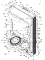
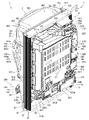
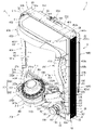
[3.扉枠の全体構成]
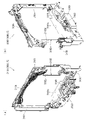
パチンコ機1の扉枠3について、主に図22乃至図30を参照して詳細に説明する。図22はパチンコ機における扉枠の表面図であり、図23は扉枠の背面図であり、図24は扉枠の左側面図であり、図25は扉枠の右側面図である。図26は扉枠を右前から見た斜視図であり、図27は扉枠を左前から見た斜視図であり、図28は扉枠を後ろから見た斜視図である。図29は扉枠を主な部材毎に分解して前から見た分解斜視図であり、図30は扉枠を主な部材毎に分解して後ろから見た分解斜視図である。
[3. Overall configuration of door frame]
The door frame 3 of the pachinko machine 1 will be described in detail mainly with reference to FIGS. 22 to 30. 22 is a front view of the door frame in the pachinko machine, FIG. 23 is a rear view of the door frame, FIG. 24 is a left side view of the door frame, and FIG. 25 is a right side view of the door frame. FIG. 26 is a perspective view of the door frame viewed from the front right, FIG. 27 is a perspective view of the door frame viewed from the front left, and FIG. 28 is a perspective view of the door frame viewed from the rear. FIG. 29 is an exploded perspective view of the door frame disassembled for each main member and viewed from the front, and FIG. 30 is an exploded perspective view of the door frame disassembled for each main member and viewed from the rear.
扉枠3は、外枠2の枠内と略同じ大きさで正面視において上下に延びた四角形に形成されており、本体枠4を介して外枠2の枠内を前側から開閉可能に取付けられている。扉枠3は、遊技球Bが打込まれる遊技盤5の遊技領域5aを前側から視認可能に閉鎖し、遊技領域5a内に打込むための遊技球Bを貯留すると共に、貯留している遊技球Bを遊技領域5a内へ打込むために遊技者が操作するハンドル182を備えているものである。また、扉枠3は、パチンコ機1の前面全体を装飾するものである。
The door frame 3 has substantially the same size as the inside of the outer frame 2 and is formed in a quadrangle extending vertically in front view, and the inside of the outer frame 2 can be opened and closed from the front side via the main body frame 4. Has been done. The door frame 3 visibly closes the game area 5a of the game board 5 into which the game ball B is driven, stores the game ball B for driving into the game area 5a, and stores the stored game. It is provided with a handle 182 operated by a player to drive the ball B into the game area 5a. Further, the door frame 3 decorates the entire front surface of the pachinko machine 1.
扉枠3は、正面視の外形が上下に延びた四角形で枠状の扉枠ベースユニット100と、扉枠ベースユニット100に着脱可能に取付けられており本体枠4に取付けられた遊技盤5の遊技領域5aを前方から視認可能に閉鎖しているガラスユニット160と、ガラスユニット160の下部を後側から覆うように扉枠ベースユニット100に取付けられている防犯カバー170と、扉枠ベースユニット100の前面右下隅に取付けられているハンドルユニット180と、扉枠ベースユニット100の前面下部に取付けられている皿ユニット200と、皿ユニット200の上側で扉枠ベースユニット100の前面左部に取付けられている扉枠左サイドユニット400と、皿ユニットの上側で扉枠ベースユニット100の前面右部に取付けられている扉枠右サイドユニット410と、扉枠左サイドユニット400及び扉枠右サイドユニット410の上側で扉枠ベースユニット100の前面上部に取付けられている扉枠トップユニット450と、を備えている。
The door frame 3 is a square and frame-shaped door frame base unit 100 having a front view extending vertically, and a game board 5 detachably attached to the door frame base unit 100 and attached to the main body frame 4. A glass unit 160 that visibly closes the game area 5a from the front, a security cover 170 that is attached to the door frame base unit 100 so as to cover the lower part of the glass unit 160 from the rear side, and a door frame base unit 100. The handle unit 180 attached to the lower right corner of the front surface of the door frame, the dish unit 200 attached to the lower part of the front surface of the door frame base unit 100, and the upper side of the dish unit 200 attached to the front left portion of the door frame base unit 100. The door frame left side unit 400, the door frame right side unit 410 attached to the front right part of the door frame base unit 100 on the upper side of the dish unit, the door frame left side unit 400, and the door frame right side unit 410. The door frame top unit 450, which is attached to the upper part of the front surface of the door frame base unit 100 on the upper side of the door frame, is provided.
扉枠ベースユニット100は、正面視の外形が上下に延びた四角形(長方形)に形成されており前後に貫通している扉窓101aを有した扉枠ベース101と、扉枠ベース101の前面右下に取付けられているハンドル取付部材102と、扉枠ベース101の後側で背面視右下隅に取付けられているスピーカダクト103と、扉枠ベース101の後側の下部における背面視右端付近に取付けられている扉枠主中継基板104と、扉枠主中継基板104の背面視左方に取付けられている扉枠副中継基板105と、扉枠副中継基板105の背面視左方に取付けられているハンドル後中継基板106と、扉枠主中継基板104と扉枠副中継基板105の一部とを後側から被覆する扉枠中継基板カバー107と、ハンドル後中継基板106を後側から被覆するハンドル後中継基板カバー108と、配線ケーブルを被覆するケーブルカバー109と、を備えている。
The door frame base unit 100 has a door frame base 101 having a door window 101a which is formed in a square shape (rectangular shape) whose outer shape extends vertically and penetrates back and forth, and a front right of the door frame base 101. The handle mounting member 102 mounted below, the speaker duct 103 mounted in the lower right corner of the rear view on the rear side of the door frame base 101, and the speaker duct 103 mounted near the right end of the rear view in the lower rear side of the door frame base 101. The door frame main relay board 104, the door frame sub-relay board 105 attached to the left side of the door frame main relay board 104, and the door frame sub-relay board 105 attached to the left side of the rear view. Covers the rear relay board 106 after the handle, the door frame relay board cover 107 that covers the door frame main relay board 104 and a part of the door frame sub relay board 105 from the rear side, and the door frame rear relay board 106 from the rear side. It includes a relay board cover 108 after the handle and a cable cover 109 that covers the wiring cable.
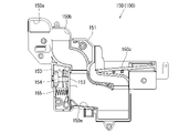
また、扉枠ベースユニット100は、扉枠ベース101の後側に取付けられている枠状の扉枠補強ユニット110と、扉枠補強ユニット110に取付けられている扉枠上ヒンジ組立体120及び扉枠下ヒンジ部材125と、扉枠補強ユニット110に取付けられている開閉用のシリンダ錠130と、扉枠ベース101の後側でハンドル後中継基板106の上方に取付けられている球送給ユニット140と、扉枠ベース101の後側の下部における背面視右側に取付けられているファールカバーユニット150と、を備えている。
Further, the door frame base unit 100 includes a frame-shaped door frame reinforcing unit 110 attached to the rear side of the door frame base 101, a hinge assembly 120 on the door frame attached to the door frame reinforcing unit 110, and a door. The hinge member 125 under the frame, the cylinder lock 130 for opening and closing attached to the door frame reinforcing unit 110, and the ball feeding unit 140 attached above the relay board 106 after the handle on the rear side of the door frame base 101. And a foul cover unit 150 attached to the right side of the rear view at the lower part of the rear side of the door frame base 101.
扉枠補強ユニット110は、扉枠ベース101の後側に取付けられることで、扉枠ベース101を補強して剛性を付与するものである。扉枠上ヒンジ組立体120及び扉枠下ヒンジ部材125は、扉枠3を本体枠4に対して開閉可能に取付けるためのものである。シリンダ錠130は、本体枠4の施錠ユニット650と協働して、扉枠3と本体枠4との開閉、及び、外枠2と本体枠4との開閉施錠に使用されるものである。
The door frame reinforcing unit 110 is attached to the rear side of the door frame base 101 to reinforce the door frame base 101 and impart rigidity. The door frame upper hinge assembly 120 and the door frame lower hinge member 125 are for attaching the door frame 3 to the main body frame 4 so as to be openable and closable. The cylinder lock 130 is used in cooperation with the locking unit 650 of the main body frame 4 to open and close the door frame 3 and the main body frame 4, and to open and close the outer frame 2 and the main body frame 4.
また、球送給ユニット140は、上皿201内の遊技球Bを一つずつ本体枠4の球発射装置540へ供給するためのものである。ファールカバーユニット150は、球発射装置540により発射されて遊技盤5の遊技領域5a内に到達しなかった遊技球B(ファール球)を、下皿202に誘導すると共に、払出装置580から払出された遊技球Bを、上皿201又は下皿202に誘導するためのものである。
Further, the ball feeding unit 140 is for supplying the game balls B in the upper plate 201 one by one to the ball launching device 540 of the main body frame 4. The foul cover unit 150 guides the game ball B (foul ball), which is launched by the ball launcher 540 and does not reach the game area 5a of the game board 5, to the lower plate 202 and is discharged from the payout device 580. This is for guiding the game ball B to the upper plate 201 or the lower plate 202.
ガラスユニット160は、透明なガラス板162を有しており扉枠ベース101の扉窓101aを閉鎖している。防犯カバー170は、ガラスユニット160の下部を後方から覆うように扉枠ベース101に取付けられている。ハンドルユニット180は、遊技者が回転操作可能なハンドル182を備えており、ハンドル182を操作することで、上皿201内の遊技球Bを、球発射装置540によって遊技盤5の遊技領域5a内に打込む遊技を行うためのものである。
The glass unit 160 has a transparent glass plate 162 and closes the door window 101a of the door frame base 101. The security cover 170 is attached to the door frame base 101 so as to cover the lower portion of the glass unit 160 from the rear. The handle unit 180 includes a handle 182 that can be rotated by a player, and by operating the handle 182, the game ball B in the upper plate 201 is moved into the game area 5a of the game board 5 by the ball launcher 540. It is for playing a game to be driven into.
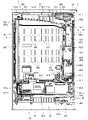
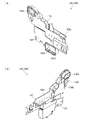
[3-1.扉枠ベースユニットの全体構成]
扉枠3の扉枠ベースユニット100について、主に図31乃至図33を参照して詳細に説明する。図31(a)は扉枠の扉枠ベースユニットを前から見た斜視図であり、(b)は扉枠ベースユニットを後ろから見た斜視図である。図32は扉枠ベースユニットを主な部材毎に分解して前から見た分解斜視図であり、図33は扉枠ベースユニットを主な部材毎に分解して後ろから見た分解斜視図である。
[3-1. Overall configuration of door frame base unit]
The door frame base unit 100 of the door frame 3 will be described in detail mainly with reference to FIGS. 31 to 33. FIG. 31 (a) is a perspective view of the door frame base unit of the door frame as viewed from the front, and FIG. 31 (b) is a perspective view of the door frame base unit as viewed from the rear. FIG. 32 is an exploded perspective view of the door frame base unit disassembled for each main member and viewed from the front, and FIG. 33 is an exploded perspective view of the door frame base unit disassembled for each main member and viewed from the rear. be.
扉枠ベースユニット100は、正面視左辺側が本体枠4に対してヒンジ回転可能に取付けられ、本体枠4の前面を開閉可能に閉鎖していると共に、本体枠4に取付けられている遊技盤の遊技領域を前方から視認可能としている。扉枠ベースユニット100は、外形が上下に延びた四角形で平板状の扉枠ベース101と、扉枠ベース101の前面右下に取付けられておりハンドルユニット180を取付けるためのハンドル取付部材102と、扉枠ベース101の後側で背面視右下隅に取付けられているスピーカダクト103と、を備えている。
The door frame base unit 100 is attached so that the left side side of the front view can be hinged with respect to the main body frame 4 so that the front surface of the main body frame 4 can be opened and closed, and the game board attached to the main body frame 4 is closed. The game area is visible from the front. The door frame base unit 100 includes a quadrangular and flat door frame base 101 having an outer shape extending vertically, a handle mounting member 102 mounted on the lower right front of the door frame base 101 for mounting the handle unit 180, and a handle mounting member 102. It is provided with a speaker duct 103 attached to the lower right corner of the rear view on the rear side of the door frame base 101.
また、扉枠ベースユニット100は、扉枠ベース101の後側の下部における背面視右端付近に取付けられている扉枠主中継基板104と、扉枠ベース101の後側の下部における扉枠主中継基板104の背面視左方に取付けられている扉枠副中継基板105と、扉枠ベース101の後側の下部における扉枠副中継基板105の背面視左方に取付けられているハンドル後中継基板106と、扉枠ベース101の後側に取付けられており扉枠主中継基板104と扉枠副中継基板105の一部とを後側から被覆する扉枠中継基板カバー107と、扉枠ベース101の後側に取付けられておりハンドル後中継基板106を後側から被覆するハンドル後中継基板カバー108と、扉枠ベース101の後側に取付けられており配線ケーブルを被覆するケーブルカバー109と、を備えている。
Further, the door frame base unit 100 includes a door frame main relay board 104 attached near the right end of the rear view at the lower rear side of the door frame base 101 and a door frame main relay at the lower rear side of the door frame base 101. The door frame sub-relay board 105 mounted on the left side of the rear view of the board 104, and the rear handle relay board mounted on the left side of the rear view of the door frame sub-relay board 105 at the lower rear side of the door frame base 101. The door frame relay board cover 107, which is attached to the rear side of the door frame base 101 and covers a part of the door frame main relay board 104 and the door frame sub relay board 105 from the rear side, and the door frame base 101. The rear relay board cover 108, which is attached to the rear side and covers the rear relay board 106 from the rear side, and the cable cover 109, which is attached to the rear side of the door frame base 101 and covers the wiring cable, are attached. I have.
更に、扉枠ベースユニット100は、扉枠ベース101の後側に取付けられている枠状の扉枠補強ユニット110と、扉枠補強ユニット110に取付けられている扉枠上ヒンジ組立体120及び扉枠下ヒンジ部材125と、扉枠補強ユニット110に取付けられている開閉用のシリンダ錠130と、扉枠ベース101の後側でハンドル後中継基板106の上方に取付けられている球送給ユニット140と、扉枠ベース101の後側の下部における背面視右側に取付けられているファールカバーユニット150と、を備えている。
Further, the door frame base unit 100 includes a frame-shaped door frame reinforcing unit 110 attached to the rear side of the door frame base 101, a hinge assembly 120 on the door frame attached to the door frame reinforcing unit 110, and a door. The hinge member 125 under the frame, the cylinder lock 130 for opening and closing attached to the door frame reinforcing unit 110, and the ball feeding unit 140 attached above the relay board 106 after the handle on the rear side of the door frame base 101. And a foul cover unit 150 attached to the right side of the rear view at the lower part of the rear side of the door frame base 101.
この扉枠ベースユニット100には、前面下隅にハンドルユニット180が、扉窓101aの下側前面に皿ユニット200が、扉窓101aの左外側前面に扉枠左サイドユニット400が、扉窓101aの右外側前面に扉枠右サイドユニット410が、扉窓101aの上外側前面に扉枠トップユニット450が、夫々取付けられるものである。
The door frame base unit 100 has a handle unit 180 in the lower front corner, a dish unit 200 in the lower front surface of the door window 101a, a door frame left side unit 400 in the left outer front surface of the door window 101a, and a door window 101a. The door frame right side unit 410 is attached to the right outer front surface, and the door frame top unit 450 is attached to the upper outer front surface of the door window 101a.
また、扉枠ベースユニット100には、扉窓101aを後方から閉鎖するようにガラスユニット160が取付けられると共に、ガラスユニット160の下部を後方から覆うように透明な防犯カバー170が取付けられるものである。
Further, a glass unit 160 is attached to the door frame base unit 100 so as to close the door window 101a from the rear, and a transparent security cover 170 is attached so as to cover the lower portion of the glass unit 160 from the rear. ..
[3-1a.扉枠ベース]
扉枠3における扉枠ベースユニット100の扉枠ベース101について、主に図31乃至図33を参照して詳細に説明する。扉枠ベース101は、正面視の外形が上下に延びた四角形(長方形)に形成されている。扉枠ベース101は、前後に貫通しており、正面視における内周形状が上下に延びた略四角形に形成された扉窓101aを備えている。扉窓101aは、内周を形成している上辺及び左右両辺が、扉枠ベース101の外周辺に夫々接近しており、内周を形成している下辺が、扉枠ベース101の下端から上下方向の約1/3の高さに位置している。このように、扉枠ベース101は、前後に貫通している扉窓101aにより全体が枠状に形成されている。この扉枠ベース101は、合成樹脂により一体成形されている。
[3-1a. Door frame base]
The door frame base 101 of the door frame base unit 100 in the door frame 3 will be described in detail mainly with reference to FIGS. 31 to 33. The door frame base 101 is formed in a quadrangle (rectangle) whose outer shape in front view extends vertically. The door frame base 101 penetrates back and forth, and includes a door window 101a formed in a substantially quadrangular shape having an inner peripheral shape extending vertically in a front view. In the door window 101a, the upper side and the left and right sides forming the inner circumference are close to the outer periphery of the door frame base 101, respectively, and the lower side forming the inner circumference is up and down from the lower end of the door frame base 101. It is located at a height of about 1/3 in the direction. As described above, the door frame base 101 is entirely formed in a frame shape by the door windows 101a penetrating the front and rear. The door frame base 101 is integrally molded with a synthetic resin.
扉枠ベース101は、前面における正面視右下隅に形成されており左端側が右端側よりも前方へやや突出するように傾斜しているハンドル取付座面101bと、ハンドル取付座面101bと扉窓101aとの間で正面視右端付近に後面から前方へ向かって窪み、扉枠補強ユニット110のシリンダ取付フレーム115が挿入される挿入凹部101cと、挿入凹部101cにおいて前後に貫通しておりシリンダ錠130のシリンダ本体131が挿通されるシリンダ挿通孔101dと、シリンダ挿通孔101d及びハンドル取付座面101bの正面視左側で前後に貫通しており球送給ユニット140の進入口141a及び球抜口141bを前方に臨ませるための球送給開口101eと、を備えている。
The door frame base 101 is formed in the lower right corner of the front view and is inclined so that the left end side slightly protrudes forward from the right end side, the handle mounting seat surface 101b, the handle mounting seat surface 101b, and the door window 101a. The cylinder lock 130 is recessed from the rear surface to the front near the right end of the front view, and penetrates back and forth between the insertion recess 101c into which the cylinder mounting frame 115 of the door frame reinforcing unit 110 is inserted and the insertion recess 101c. The cylinder insertion hole 101d through which the cylinder body 131 is inserted, the cylinder insertion hole 101d, and the handle mounting seat surface 101b penetrate the front and rear on the left side of the front view, and the entry entrance 141a and the ball outlet 141b of the ball feeding unit 140 are forward. It is equipped with a ball feeding opening 101e for facing the cylinder.
また、扉枠ベース101は、左右方向中央より左寄りで且つハンドル取付座面101bと略同じ高さで前後に貫通しておりファールカバーユニット150の球放出口150dを前方に臨ませる下皿用球通過口101fと、正面視左端付近で扉窓101aの下辺に隣接するように前後に貫通しておりファールカバーユニット150の貫通球通路150aを前方に臨ませる上皿用球通過口101gと、扉窓101aの内周に沿って後面から前方へ向かって窪み、ガラスユニット160のガラス枠161が挿入されるガラスユニット取付部101hと、を備えている。
Further, the door frame base 101 is to the left of the center in the left-right direction and penetrates back and forth at substantially the same height as the handle mounting seat surface 101b, so that the ball discharge port 150d of the foul cover unit 150 faces forward. The passage port 101f, the ball passage port 101g for the upper plate that penetrates back and forth so as to be adjacent to the lower side of the door window 101a near the left end of the front view and faces the through ball passage 150a of the foul cover unit 150 to the front, and the door. It is provided with a glass unit mounting portion 101h that is recessed from the rear surface to the front along the inner circumference of the window 101a and into which the glass frame 161 of the glass unit 160 is inserted.
また、扉枠ベース101は、正面視左下隅(上皿用球通過口101gの下方)に形成されており前後に貫通した縦長の複数のスリット101iを、備えている。複数のスリット101iの後側にスピーカダクト103が取付けられる。また、複数のスリット101iは、パチンコ機1を組立てた状態で、前方に皿ユニット200における皿ユニットベース211のスピーカ口211bが位置していると共に、後方に本体枠4のスピーカユニット620aにおける本体枠スピーカ622が位置しており、本体枠スピーカ622からの音を前方へ放射することができる。
Further, the door frame base 101 is formed in the lower left corner of the front view (below the upper plate ball passage port 101 g), and is provided with a plurality of vertically long slits 101i that penetrate the front and rear. The speaker duct 103 is attached to the rear side of the plurality of slits 101i. Further, in the plurality of slits 101i, in the state where the pachinko machine 1 is assembled, the speaker port 211b of the dish unit base 211 in the dish unit 200 is located in front, and the main body frame in the speaker unit 620a of the main body frame 4 is rearward. The speaker 622 is located, and the sound from the main body frame speaker 622 can be radiated forward.
更に、扉枠ベース101は、扉窓101aの下方でハンドル取付座面101bの上方において、前後に貫通している貫通孔101jを備えている。この貫通孔101jは、扉枠ベースユニット100側と皿ユニット200側とを接続する配線ケーブル(図示は省略)が挿通されるものであり、後述する扉枠補強ユニット110における中間補強フレーム114の貫通部114bと一致するように形成されている。
Further, the door frame base 101 is provided with a through hole 101j penetrating back and forth below the door window 101a and above the handle mounting seat surface 101b. A wiring cable (not shown) connecting the door frame base unit 100 side and the dish unit 200 side is inserted through the through hole 101j, and the intermediate reinforcing frame 114 in the door frame reinforcing unit 110 described later is penetrated. It is formed so as to coincide with the portion 114b.
[3-1b.ハンドル取付部材]
扉枠ベースユニット100のハンドル取付部材102について、主に図31乃至図33を参照して詳細に説明する。ハンドル取付部材102は、扉枠ベース101の前面にハンドルユニットを取付けるためのものであり、扉枠ベース101の前面のハンドル取付座面101bに取付けられる。
[3-1b. Handle mounting member]
The handle mounting member 102 of the door frame base unit 100 will be described in detail mainly with reference to FIGS. 31 to 33. The handle mounting member 102 is for mounting the handle unit on the front surface of the door frame base 101, and is mounted on the handle mounting seat surface 101b on the front surface of the door frame base 101.
ハンドル取付部材102は、前後方向へ延びた円筒状の筒部102aと、筒部102aの後端から筒部102aの軸に対して直角方向外方へ延びた円環状のフランジ部102bと、筒部102a内に突出していると共に筒部102aの軸方向全長に亘って延びており筒部102aの周方向に対して不等間隔に配置された複数(本例では三つ)の突条102cと、筒部102aの外周面とフランジ部102bの前面とを繋ぎ、筒部102aの周方向に対して複数配置された補強リブ102dと、を備えている。
The handle mounting member 102 includes a cylindrical tubular portion 102a extending in the front-rear direction, an annular flange portion 102b extending outward in a direction perpendicular to the axis of the tubular portion 102a from the rear end of the tubular portion 102a, and a cylinder. With a plurality of (three in this example) ridges 102c that protrude into the portion 102a and extend over the entire axial length of the cylinder portion 102a and are arranged at irregular intervals in the circumferential direction of the cylinder portion 102a. The outer peripheral surface of the tubular portion 102a and the front surface of the flange portion 102b are connected to each other, and a plurality of reinforcing ribs 102d arranged in the circumferential direction of the tubular portion 102a are provided.
ハンドル取付部材102は、フランジ部102bの後面を、扉枠ベース101におけるハンドル取付座面101bの前面に当接させた状態で、ビスによってハンドル取付座面101bに取付けられる。
The handle mounting member 102 is mounted on the handle mounting seat surface 101b with screws in a state where the rear surface of the flange portion 102b is in contact with the front surface of the handle mounting seat surface 101b of the door frame base 101.
筒部102aは、内径がハンドルユニット180におけるハンドルベース181の基部181aの外径よりも若干大きく形成されている。三つの突条102cは、一つが筒部102aの上部に備えられており、残り二つが筒部102aの下部に備えられている。これら三つの突条102cは、ハンドルベース181における三つの溝部181cと対応する位置に形成されている。従って、ハンドル取付部材102は、三つの突条102cと、ハンドルベース181の三つの溝部181cとを一致させた状態でのみ、筒部102a内にハンドルベース181の基部181aを挿入させることができ、扉枠ベース101に対してハンドルベース181(ハンドルユニット180)の回転位置を規制することができる。
The inner diameter of the tubular portion 102a is formed to be slightly larger than the outer diameter of the base portion 181a of the handle base 181 in the handle unit 180. One of the three ridges 102c is provided on the upper portion of the tubular portion 102a, and the other two are provided on the lower portion of the tubular portion 102a. These three ridges 102c are formed at positions corresponding to the three groove portions 181c in the handle base 181. Therefore, the handle mounting member 102 can insert the base portion 181a of the handle base 181 into the tubular portion 102a only when the three protrusions 102c and the three groove portions 181c of the handle base 181 are aligned with each other. The rotation position of the handle base 181 (handle unit 180) can be restricted with respect to the door frame base 101.
なお、ハンドル取付部材102は、フランジ部102bの後面に対して、筒部102aの軸線が垂直に延びていることから、扉枠ベース101の傾斜しているハンドル取付座面101bに取付けることで、筒部102aの軸線が右前方へ延びるように傾いた状態となり、ハンドルユニット180を同様に傾いた状態で扉枠ベース101に取付けることができる。
Since the axis of the tubular portion 102a extends perpendicularly to the rear surface of the flange portion 102b, the handle mounting member 102 can be attached to the inclined handle mounting seat surface 101b of the door frame base 101. The axis of the tubular portion 102a is tilted so as to extend to the front right, and the handle unit 180 can be attached to the door frame base 101 in the same tilted state.
[3-1c.スピーカダクト]
扉枠ベースユニット100のスピーカダクト103について、主に図31乃至図33を参照して詳細に説明する。このスピーカダクト103は、筒状に形成されており、扉枠ベース101の後側において複数のスリット101iが形成されている部位に取付けられる。スピーカダクト103は、パチンコ機1を組立てた状態で、筒状の部位の後端が、本体枠4の本体枠スピーカ622の前方に位置している。これにより、本体枠4の本体枠スピーカ622から放射(出力)された音(サウンド)を、拡散させることなく前方へ誘導することができ、扉枠ベース101の複数のスリット101i及び皿ユニット200の皿ユニットベース211におけるスピーカ口211bを通して、パチンコ機1の前方(遊技者側)へ良好に誘導することができる。
[3-1c. Speaker duct]
The speaker duct 103 of the door frame base unit 100 will be described in detail mainly with reference to FIGS. 31 to 33. The speaker duct 103 is formed in a cylindrical shape, and is attached to a portion where a plurality of slits 101i are formed on the rear side of the door frame base 101. In the speaker duct 103, when the pachinko machine 1 is assembled, the rear end of the cylindrical portion is located in front of the main body frame speaker 622 of the main body frame 4. As a result, the sound (sound) radiated (output) from the main body frame speaker 622 of the main body frame 4 can be guided forward without being diffused, and the plurality of slits 101i of the door frame base 101 and the dish unit 200 can be guided. It can be satisfactorily guided to the front (player side) of the pachinko machine 1 through the speaker port 211b in the dish unit base 211.
また、スピーカダクト103は、筒状の部位の下方の後面に、接続ケーブル503を保持するケーブルホルダ103aを備えている。ケーブルホルダ103aは、扉枠中継基板カバー107よりも正面視左方に配置されており、扉枠主中継基板104及び扉枠副中継基板105に接続されている接続ケーブル503を、扉枠3の左端側へ延びるように保持している。
Further, the speaker duct 103 is provided with a cable holder 103a for holding the connection cable 503 on the lower rear surface of the cylindrical portion. The cable holder 103a is arranged on the left side of the door frame relay board cover 107 when viewed from the front, and the connection cable 503 connected to the door frame main relay board 104 and the door frame sub-relay board 105 is connected to the door frame 3. It is held so as to extend to the left end side.
[3-1d.扉枠主中継基板・扉枠副中継基板・ハンドル後中継基板]
扉枠ベースユニット100の扉枠主中継基板104、扉枠副中継基板105、ハンドル後中継基板106について、主に図32及び図33等を参照して説明する。扉枠主中継基板104は、外形が上下に延びた四角形に形成されており、扉枠ベース101の後側の下部における背面視右下隅に取付けられる。扉枠主中継基板104は、ハンドル後中継基板106と本体枠4の基板ユニット620におけるインターフェイス基板635との接続を中継するためのものであり、本体枠4から延びている接続ケーブル503(図83及び図84を参照)の一部が接続される。
[3-1d. Door frame main relay board, door frame sub relay board, rear relay board after handle]
The door frame main relay board 104, the door frame sub-relay board 105, and the rear-handle relay board 106 of the door frame base unit 100 will be described mainly with reference to FIGS. 32 and 33. The door frame main relay board 104 is formed in a quadrangle whose outer shape extends vertically, and is attached to the lower right corner of the rear side of the door frame base 101 in the lower right corner of the rear view. The door frame main relay board 104 is for relaying the connection between the relay board 106 after the handle and the interface board 635 in the board unit 620 of the main body frame 4, and the connection cable 503 extending from the main body frame 4 (FIG. 83). And a part of (see FIG. 84) are connected.
扉枠副中継基板105は、外形が、上下に延びた四角形の上部の正面視右側に左右に延びた四角形が組み合された逆L字状に形成されており、上下に延びているが扉枠主中継基板104の背面視左方に隣接するように、扉枠ベース101の後側に取付けられている。扉枠副中継基板105は、ハンドルユニット180のハンドル装飾基板184、皿ユニット200の皿ユニット中継基板214、扉枠左サイドユニット400の扉枠左サイド装飾基板402、扉枠右サイドユニット410のサイド窓内装飾部装飾基板413及び扉枠右サイド装飾基板418、扉枠トップユニット450の扉枠トップ中継基板467等と、本体枠4のインターフェイス基板635との接続を中継するためのものであり、本体枠4から延びている接続ケーブル503の残りが接続される。
The door frame sub-relay board 105 is formed in an inverted L shape in which the quadrangles extending to the left and right are combined on the right side of the front view of the upper part of the quadrangles extending vertically, and the outer shape of the door frame sub-relay board 105 is formed in an inverted L shape. It is attached to the rear side of the door frame base 101 so as to be adjacent to the left side of the frame main relay board 104 when viewed from the rear. The door frame sub-relay board 105 is the handle decorative board 184 of the handle unit 180, the dish unit relay board 214 of the dish unit 200, the door frame left side decorative board 402 of the door frame left side unit 400, and the side of the door frame right side unit 410. The purpose is to relay the connection between the decorative board 413 of the decorative portion in the window, the decorative board 418 on the right side of the door frame, the door frame top relay board 467 of the door frame top unit 450, and the interface board 635 of the main body frame 4. The rest of the connection cable 503 extending from the main body frame 4 is connected.
扉枠主中継基板104及び扉枠副中継基板105は、接続端子が後方へ向かって突出するように、扉枠ベース101に取付けられる。扉枠主中継基板104及び扉枠副中継基板105は、扉枠ベースユニット100を組立てた状態で、扉枠主中継基板104と扉枠副中継基板105の上下に延びている部位とが、扉枠中継基板カバー107によって後側が被覆された状態となり、扉枠副中継基板105の残りの部位が、ファールカバーユニット150によって後側が被覆された状態となる。
The door frame main relay board 104 and the door frame sub-relay board 105 are attached to the door frame base 101 so that the connection terminals project rearward. In the door frame main relay board 104 and the door frame sub-relay board 105, the door frame main relay board 104 and the parts extending vertically of the door frame sub-relay board 105 are doors in a state where the door frame base unit 100 is assembled. The rear side is covered by the frame relay board cover 107, and the remaining portion of the door frame sub-relay board 105 is covered by the foul cover unit 150.
ハンドル後中継基板106は、外形が左右に延びた四角形に形成されており、扉枠ベース101の後側における球送給開口101eの下方でハンドル取付座面101bの後側に取付けられる。ハンドル後中継基板106は、扉枠主中継基板104とハンドルユニット180のハンドル回転検知センサ189、ハンドルタッチセンサ192、単発ボタン操作センサ194、及び球送給ユニット140の球送給ソレノイド145との接続を中継するためのものである。ハンドル後中継基板106は、扉枠ベースユニット100を組立てた状態で、ハンドル後中継基板カバー108によって後側が被覆された状態となる。
The rear handle relay board 106 is formed in a quadrangle whose outer shape extends to the left and right, and is mounted on the rear side of the handle mounting seat surface 101b below the ball feeding opening 101e on the rear side of the door frame base 101. The rear-handle relay board 106 is connected to the door frame main relay board 104, the handle rotation detection sensor 189 of the handle unit 180, the handle touch sensor 192, the single-shot button operation sensor 194, and the ball feed solenoid 145 of the ball feed unit 140. Is for relaying. The rear side of the handle rear relay board 106 is covered with the handle rear relay board cover 108 in a state where the door frame base unit 100 is assembled.
[3-1e.扉枠中継基板カバー・ハンドル後中継基板カバー・ケーブルカバー]
扉枠ベースユニット100の扉枠中継基板カバー107、ハンドル後中継基板カバー108、及びケーブルカバー109について、主に図31乃至図33を参照して説明する。扉枠中継基板カバー107は、扉枠ベース101の後側に取付けることで、扉枠主中継基板104と扉枠副中継基板の一部(逆L字状の上下に延びている部位)の後側を被覆するものである。扉枠中継基板カバー107は、前方及び正面視左方が開放された箱状に形成されている。扉枠ベースユニット100に組立てた状態では、後側を被覆している扉枠主中継基板104及び扉枠副中継基板105の接続端子が扉枠中継基板カバー107の内部に露出しており、開放されている左側から接続ケーブル503を内部に挿入して、それら端子に接続することができる。
[3-1e. Door frame relay board cover / rear relay board cover / cable cover]
The door frame relay board cover 107, the rear relay board cover 108 after the handle, and the cable cover 109 of the door frame base unit 100 will be described mainly with reference to FIGS. 31 to 33. By attaching the door frame relay board cover 107 to the rear side of the door frame base 101, the door frame main relay board 104 and a part of the door frame sub-relay board (a portion extending up and down in an inverted L shape) are rear. It covers the side. The door frame relay board cover 107 is formed in a box shape with the front side and the left side when viewed from the front open. In the state of being assembled to the door frame base unit 100, the connection terminals of the door frame main relay board 104 and the door frame sub relay board 105 covering the rear side are exposed inside the door frame relay board cover 107 and are open. The connection cable 503 can be inserted inside from the left side and connected to those terminals.
ハンドル後中継基板カバー108は、ハンドル後中継基板106の後側を被覆するように扉枠ベース101の後側に取付けられるものである。ケーブルカバー109は、扉枠補強ユニット110における中間補強フレーム114の後側に取付けられ、扉枠主中継基板104と皿ユニット200の球貸操作ユニット220とを接続する配線ケーブル(図示は省略)を被覆するためのものである。ケーブルカバー109は、左右に延びた箱状に形成されており、前面の左端付近と下面の左右方向中央に、配線ケーブルを通すための開口が形成されている。
The rear-handle relay board cover 108 is attached to the rear side of the door frame base 101 so as to cover the rear side of the rear-handle relay board 106. The cable cover 109 is attached to the rear side of the intermediate reinforcing frame 114 in the door frame reinforcing unit 110, and has a wiring cable (not shown) connecting the door frame main relay board 104 and the ball rental operation unit 220 of the dish unit 200. It is for covering. The cable cover 109 is formed in a box shape extending to the left and right, and openings for passing wiring cables are formed near the left end of the front surface and in the center of the lower surface in the left-right direction.
[3-1f.扉枠補強ユニット]
扉枠ベースユニット100の扉枠補強ユニット110について、主に図31乃至図33を参照して詳細に説明する。扉枠補強ユニット110は、扉枠ベース101の後側に取付けられることで、平板状の扉枠ベース101を補強して、扉枠ベースユニット100に剛性を付与している。扉枠補強ユニット110は、左右に離間して配置されている上下に延びた左補強フレーム111及び右補強フレーム112と、左補強フレーム111及び右補強フレーム112の上端同士を連結している左右に延びた上補強フレーム113と、左補強フレーム111の下端から上寄りの位置に左端側が取付けられており右補強フレーム112付近まで右方へ延びた中間補強フレーム114と、中間補強フレーム114の右端と右補強フレーム112とを連結しているシリンダ取付フレーム115と、右補強フレーム112の後側に上下に離間して複数取付けられており本体枠4の施錠ユニット650の扉枠用鉤652が掛止される鉤掛部材116と、を備えている。
[3-1f. Door frame reinforcement unit]
The door frame reinforcing unit 110 of the door frame base unit 100 will be described in detail mainly with reference to FIGS. 31 to 33. The door frame reinforcing unit 110 is attached to the rear side of the door frame base 101 to reinforce the flat plate-shaped door frame base 101 and impart rigidity to the door frame base unit 100. The door frame reinforcing unit 110 is provided on the left and right sides connecting the left and right reinforcing frames 111 and the right reinforcing frame 112, which are arranged apart from each other on the left and right, and the upper ends of the left reinforcing frame 111 and the right reinforcing frame 112. The extended upper reinforcing frame 113, the intermediate reinforcing frame 114 extending to the right to the vicinity of the right reinforcing frame 112 with the left end side attached at a position upward from the lower end of the left reinforcing frame 111, and the right end of the intermediate reinforcing frame 114. A cylinder mounting frame 115 connecting the right reinforcing frame 112 and a plurality of mounted cylinder mounting frames 115 vertically separated from each other on the rear side of the right reinforcing frame 112, and hooks 652 for the door frame of the locking unit 650 of the main body frame 4 are hooked. The hooking member 116 is provided.
左補強フレーム111及び右補強フレーム112は、左右方向が一定の幅で、扉枠ベース101の上下の高さと略同じ長さで上下に延びている。右補強フレーム112には、上下方向に離間しており、前後方向に貫通している複数の挿通孔が形成されている。これら挿通孔は、本体枠4に対して扉枠3を閉めた時に、施錠ユニット650の扉枠用鉤652の先端が挿通される。上補強フレーム113は、上下方向が一定の幅で、扉枠ベース101の左右の幅と略同じ長さで左右に延びている。
The left reinforcing frame 111 and the right reinforcing frame 112 have a constant width in the left-right direction, and extend vertically at substantially the same length as the vertical height of the door frame base 101. The right reinforcing frame 112 is formed with a plurality of insertion holes that are separated in the vertical direction and penetrate in the front-rear direction. The tip of the door frame hook 652 of the locking unit 650 is inserted into these insertion holes when the door frame 3 is closed with respect to the main body frame 4. The upper reinforcing frame 113 has a constant width in the vertical direction, and extends to the left and right with substantially the same length as the left and right width of the door frame base 101.
中間補強フレーム114は、上下方向が上補強フレーム113の上下の幅よりも広い幅で左右に延びている。中間補強フレーム114は、左端付近において上端から下方へ四角く切欠かれた切欠部114aと、右端付近において前後に貫通している貫通部114bと、を有している。切欠部114aは、扉枠ベース101の上皿用球通過口101gと、貫通部114bは、扉枠ベース101の貫通孔101jと、夫々一致する位置に形成されている。
The intermediate reinforcing frame 114 extends to the left and right in the vertical direction with a width wider than the vertical width of the upper reinforcing frame 113. The intermediate reinforcing frame 114 has a notch 114a which is notched downward from the upper end in the vicinity of the left end, and a penetrating portion 114b which penetrates back and forth in the vicinity of the right end. The notch 114a is formed at a position corresponding to the upper plate ball passage port 101g of the door frame base 101, and the penetrating portion 114b is formed at a position corresponding to the through hole 101j of the door frame base 101.
シリンダ取付フレーム115は、左右に離間して配置されており正面視において上下に延びた四角形の平板状に形成されている一対の後片部と、一対の後片部の対面している夫々の辺から前方へ平板状に延出している一対の側片部と、一対の前方延出部の前端の辺同士を連結している平板状の前片部と、を備えている。このシリンダ取付フレーム115は、平面視の形状が前方へ突出した凸形状に形成されている。シリンダ取付フレーム115は、左側の後片部が中間補強フレーム114の右端に取付けられ、右側の後片部が右補強フレーム112に取付けられる。このシリンダ取付フレーム115は、前片部にシリンダ錠130が取付けられる。
The cylinder mounting frame 115 is arranged so as to be separated from each other on the left and right sides, and has a pair of rear pieces that are formed in a rectangular flat plate shape that extends vertically when viewed from the front, and a pair of rear pieces that face each other. It includes a pair of side pieces extending in a flat plate shape from the side to the front, and a flat plate-shaped front piece portion connecting the front end sides of the pair of front extending portions. The cylinder mounting frame 115 is formed in a convex shape in which the shape in a plan view protrudes forward. The cylinder mounting frame 115 has a rear piece on the left side mounted on the right end of the intermediate reinforcing frame 114 and a rear piece on the right side mounted on the right reinforcing frame 112. A cylinder lock 130 is attached to the front piece of the cylinder mounting frame 115.
鉤掛部材116は、右補強フレーム112の後側において、前後に貫通している挿通孔の部位に取付けられている。これら鉤掛部材116は、施錠ユニット650の扉枠用鉤652が掛止される。
The hook member 116 is attached to the portion of the insertion hole penetrating the front and rear on the rear side of the right reinforcing frame 112. The hook 652 for the door frame of the locking unit 650 is hooked on these hook members 116.
扉枠補強ユニット110を構成している左補強フレーム111、右補強フレーム112、上補強フレーム113、中間補強フレーム114、シリンダ取付フレーム115、及び鉤掛部材116は、金属板をプレス成型によって打抜き・屈曲することで形成されている。これらは、リベットによって組立てられている。
The left reinforcing frame 111, the right reinforcing frame 112, the upper reinforcing frame 113, the intermediate reinforcing frame 114, the cylinder mounting frame 115, and the hooking member 116 constituting the door frame reinforcing unit 110 are punched out metal plates by press molding. It is formed by bending. These are assembled by rivets.
扉枠補強ユニット110は、左補強フレーム111、右補強フレーム112、及び上補強フレーム113が、扉枠ベース101の左辺、右辺、及び上辺に沿うように組立てられていると共に、中間補強フレーム114が、扉枠ベース101の扉窓101aの下方に位置するように組立てられている。
In the door frame reinforcing unit 110, the left reinforcing frame 111, the right reinforcing frame 112, and the upper reinforcing frame 113 are assembled so as to be along the left side, the right side, and the upper side of the door frame base 101, and the intermediate reinforcing frame 114 is provided. , Is assembled so as to be located below the door window 101a of the door frame base 101.
扉枠補強ユニット110は、図示しない複数のビスにより扉枠ベース101の後側に取付けられる。この扉枠補強ユニット110は、扉枠ベース101に取付けた状態で、中間補強フレーム114の切欠部114a及び貫通部114bが、扉枠ベース101の上皿用球通過口101g及び貫通孔101jと一致した状態となると共に、シリンダ取付フレーム115が、扉枠ベース101の挿入凹部101c内に挿入された状態となる。
The door frame reinforcing unit 110 is attached to the rear side of the door frame base 101 by a plurality of screws (not shown). When the door frame reinforcing unit 110 is attached to the door frame base 101, the notch 114a and the penetrating portion 114b of the intermediate reinforcing frame 114 coincide with the upper plate ball passage port 101g and the through hole 101j of the door frame base 101. The cylinder mounting frame 115 is inserted into the insertion recess 101c of the door frame base 101.
[3-1g.扉枠上ヒンジ組立体]
扉枠ベースユニット100の扉枠上ヒンジ組立体120について、主に図31乃至図33を参照して説明する。扉枠上ヒンジ組立体120は、扉枠補強ユニット110の正面視左上隅に取付けられる。扉枠上ヒンジ組立体120は、扉枠3を、扉枠下ヒンジ部材125と協働して本体枠4に対してヒンジ回転可能に取付けるためのものである。扉枠上ヒンジ組立体120は、扉枠補強ユニット110に取付けられるヒンジブラケット121と、ヒンジブラケット121に上下方向へ移動可能に取付けられる扉枠上ヒンジピン122と、扉枠上ヒンジピン122に取付けられる鍔部材123と、扉枠上ヒンジピン122を上方へ移動するように付勢しているロックバネ124と、を備えている。
[3-1 g. Hinge assembly on door frame]
The hinge assembly 120 on the door frame of the door frame base unit 100 will be described mainly with reference to FIGS. 31 to 33. The hinge assembly 120 on the door frame is attached to the upper left corner of the door frame reinforcing unit 110 when viewed from the front. The door frame upper hinge assembly 120 is for attaching the door frame 3 to the main body frame 4 in cooperation with the door frame lower hinge member 125 so that the hinge can be rotated. The door frame upper hinge assembly 120 includes a hinge bracket 121 attached to the door frame reinforcing unit 110, a door frame upper hinge pin 122 attached to the hinge bracket 121 so as to be movable in the vertical direction, and a flange attached to the door frame upper hinge pin 122. It includes a member 123 and a lock spring 124 that urges the hinge pin 122 on the door frame to move upward.
ヒンジブラケット121は、正面視四角形の平板状の取付片121aと、取付片121aの上辺及び下辺から前方へ延出している平板状の突出片121bと、を備えている。ヒンジブラケット121は、取付片121aが扉枠補強ユニット110に取付けられる。ヒンジブラケット121は、金属板を屈曲させて形成されている。
The hinge bracket 121 includes a flat plate-shaped mounting piece 121a having a rectangular front view, and a flat plate-shaped protruding piece 121b extending forward from the upper and lower sides of the mounting piece 121a. In the hinge bracket 121, the mounting piece 121a is mounted on the door frame reinforcing unit 110. The hinge bracket 121 is formed by bending a metal plate.
扉枠上ヒンジピン122は、円柱状の金属棒をL字状に屈曲させたものである。扉枠上ヒンジピン122は、扉枠上ヒンジ組立体120に組立てた状態で、上下に延びている部位が、ヒンジブラケット121における一対の突出片121bの前端付近において下方から貫通し、上端が上側の突出片121bよりも上方へ延び出していると共に、水平に延びている部位が下側の突出片121bの下面に当接している。扉枠上ヒンジピン122は、上端が本体枠4の本体枠上ヒンジ部材510における上ヒンジ本体511の扉枠用上ヒンジ孔511aに回転可能に挿通される。
The hinge pin 122 on the door frame is a columnar metal rod bent into an L shape. In the state where the hinge pin 122 on the door frame is assembled to the hinge assembly 120 on the door frame, a portion extending vertically penetrates from below near the front end of the pair of projecting pieces 121b in the hinge bracket 121, and the upper end is on the upper side. A portion extending upward from the protruding piece 121b and extending horizontally is in contact with the lower surface of the lower protruding piece 121b. The upper end of the door frame upper hinge pin 122 is rotatably inserted into the door frame upper hinge hole 511a of the upper hinge main body 511 in the main body frame upper hinge member 510 of the main body frame 4.
鍔部材123は、Eリングとされており、扉枠上ヒンジピン122における一対の突出片121bの間となる部位に取付けられている。ロックバネ124は、コイル状に形成されており、鍔部材123とヒンジブラケット121における下側の突出片121bとの間において扉枠上ヒンジピン122の上下に延びている部位の周りに被せられている。このロックバネ124により、鍔部材123を介して扉枠上ヒンジピン122が上方へ付勢されている。
The flange member 123 is an E-ring, and is attached to a portion of the hinge pin 122 on the door frame between the pair of projecting pieces 121b. The lock spring 124 is formed in a coil shape and is placed around a portion extending vertically on the hinge pin 122 on the door frame between the flange member 123 and the lower protruding piece 121b of the hinge bracket 121. The lock spring 124 urges the hinge pin 122 on the door frame upward via the flange member 123.
扉枠上ヒンジ組立体120は、扉枠上ヒンジピン122がロックバネ124により上方へ付勢された状態となっており、扉枠上ヒンジピン122における下端の水平に延びている部位が下側の突出片121bの下面に当接することで、これ以上の上方への移動が規制されている。この状態では、扉枠上ヒンジピン122の上端が、上側の突出片121bの上面よりも所定量上方に突出している。
In the door frame upper hinge assembly 120, the door frame upper hinge pin 122 is in a state of being urged upward by the lock spring 124, and the horizontally extending portion of the lower end of the door frame upper hinge pin 122 is a lower protruding piece. Further upward movement is restricted by abutting on the lower surface of 121b. In this state, the upper end of the hinge pin 122 on the door frame protrudes above the upper surface of the upper protruding piece 121b by a predetermined amount.
扉枠上ヒンジ組立体120は、扉枠上ヒンジピン122における下端の水平に延びている部位を、ロックバネ124の付勢力に抗してその部位を下方へ移動させると、扉枠上ヒンジピン122を全体的に下方へ移動させることができ、扉枠上ヒンジピン122の上端を、上側の突出片121bの上面よりも下方へ没入させることができる。従って、扉枠上ヒンジ組立体120は、扉枠上ヒンジピン122の上端を、本体枠上ヒンジ部材510の扉枠用上ヒンジ孔511aに対して下方から挿入させたり、下方へ抜いたりすることができる。これにより、扉枠上ヒンジピン122の上端を、本体枠上ヒンジ部材510の扉枠用上ヒンジ孔511aに挿入させることで、扉枠3の正面視上部左端を、本体枠4に対してヒンジ回転可能に支持させることができる。
When the horizontally extending portion of the lower end of the door frame upper hinge pin 122 is moved downward against the urging force of the lock spring 124, the door frame upper hinge assembly 120 moves the door frame upper hinge pin 122 as a whole. The upper end of the hinge pin 122 on the door frame can be immersed below the upper surface of the upper protruding piece 121b. Therefore, in the door frame upper hinge assembly 120, the upper end of the door frame upper hinge pin 122 may be inserted from below into the door frame upper hinge hole 511a of the main body frame upper hinge member 510, or may be pulled out downward. can. As a result, the upper end of the door frame upper hinge pin 122 is inserted into the door frame upper hinge hole 511a of the main body frame upper hinge member 510, so that the upper left end of the door frame 3 in front view is hinged with respect to the main body frame 4. It can be supported as much as possible.
また、扉枠上ヒンジ組立体120は、扉枠上ヒンジピン122における上下に延びている部位が、後述する扉枠下ヒンジ部材125の扉枠下ヒンジピン126と同軸上に位置している。これにより、扉枠上ヒンジピン122と扉枠下ヒンジピン126とによって、扉枠3を本体枠4に対して良好な状態でヒンジ回転させることができる。
Further, in the door frame upper hinge assembly 120, the vertically extending portion of the door frame upper hinge pin 122 is located coaxially with the door frame lower hinge pin 126 of the door frame lower hinge member 125 described later. As a result, the door frame 3 can be hinged and rotated with respect to the main body frame 4 by the door frame upper hinge pin 122 and the door frame lower hinge pin 126.
[3-1h.扉枠下ヒンジ部材]
扉枠ベースユニット100の扉枠下ヒンジ部材125について、主に図31乃至図33を参照して説明する。扉枠下ヒンジ部材125は、扉枠補強ユニット110の正面視左下隅に取付けられる。扉枠下ヒンジ部材125は、扉枠3を、扉枠上ヒンジ組立体120と協働して本体枠4に対してヒンジ回転可能に取付けるためのものである。
[3-1h. Hinge member under the door frame]
The hinge member 125 under the door frame of the door frame base unit 100 will be described mainly with reference to FIGS. 31 to 33. The door frame lower hinge member 125 is attached to the front left lower corner of the door frame reinforcing unit 110. The door frame lower hinge member 125 is for attaching the door frame 3 to the main body frame 4 in cooperation with the door frame upper hinge assembly 120 so that the hinge can be rotated.
扉枠下ヒンジ部材125は、扉枠補強ユニット110に取付けられ正面視四角形で平板状の取付片125aと、取付片125aの下辺から前方へ延出している平板状の突出片125bと、突出片125bの前端付近の下面から下方へ突出している扉枠下ヒンジピン126(図22等を参照)と、を備えている。
The door frame lower hinge member 125 is attached to the door frame reinforcing unit 110 and has a square flat plate-shaped mounting piece 125a, a flat plate-shaped projecting piece 125b extending forward from the lower side of the mounting piece 125a, and a projecting piece. The door frame lower hinge pin 126 (see FIG. 22 and the like) projecting downward from the lower surface near the front end of 125b is provided.
扉枠下ヒンジ部材125の取付片125a及び突出片125bは、金属板を屈曲させて形成されている。扉枠下ヒンジピン126は、円柱状の金属棒で、下端部の外周にテーパ状の面取りが施されている。この扉枠下ヒンジピン126は、扉枠ベースユニット100に組立てた状態で、突出片125bにおける扉枠上ヒンジ組立体120の扉枠上ヒンジピン122の上下に延びている部位と同軸上となる部位に取付けられている。
The mounting piece 125a and the protruding piece 125b of the hinge member 125 under the door frame are formed by bending a metal plate. The hinge pin 126 under the door frame is a columnar metal rod having a tapered chamfer on the outer periphery of the lower end portion. The door frame lower hinge pin 126 is located coaxially with the portion extending vertically of the door frame upper hinge pin 122 of the door frame upper hinge assembly 120 in the protruding piece 125b in a state of being assembled to the door frame base unit 100. It is installed.
この扉枠下ヒンジ部材125は、扉枠下ヒンジピン126を本体枠側下ヒンジ部材の扉枠用ヒンジ孔に挿入することで、扉枠3を本体枠4に対してヒンジ回転可能に支持することができる。
The door frame lower hinge member 125 supports the door frame 3 so as to be rotatable with respect to the main body frame 4 by inserting the door frame lower hinge pin 126 into the door frame hinge hole of the main body frame side lower hinge member. Can be done.
[3-1i.シリンダ錠]
扉枠ベースユニット100のシリンダ錠130について、主に図31乃至図33を参照して詳細に説明する。シリンダ錠130は、扉枠補強ユニット110のシリンダ取付フレーム115に取付けられ、後述する施錠ユニット650と協働して、扉枠3と本体枠4との開閉、及び、外枠2と本体枠4との開閉施錠に使用されるものである。シリンダ錠130は、前後に延びた円柱状のシリンダ本体131と、シリンダ本体131の前端面に形成されている鍵穴132と、シリンダ本体131の後側に取付けられており鍵穴132に挿入され正規の鍵を回転させると一緒に回転する回転伝達部材133と、を備えている。
[3-1i. Cylinder lock]
The cylinder lock 130 of the door frame base unit 100 will be described in detail mainly with reference to FIGS. 31 to 33. The cylinder lock 130 is attached to the cylinder mounting frame 115 of the door frame reinforcing unit 110, and cooperates with the locking unit 650 described later to open and close the door frame 3 and the main body frame 4, and the outer frame 2 and the main body frame 4. It is used for opening and closing locks. The cylinder lock 130 is a regular columnar cylinder body 131 extending back and forth, a keyhole 132 formed on the front end surface of the cylinder body 131, and a keyhole 132 attached to the rear side of the cylinder body 131 and inserted into the keyhole 132. It includes a rotation transmission member 133 that rotates with the rotation of the key.
シリンダ錠130のシリンダ本体131は、シリンダ取付フレーム115の前片部を後方から貫通して後端が前片部に取付けられている。回転伝達部材133は、後方が開放された円筒状(詳しくは、後方へ向かうに従って直径が大きくなる円錐筒状)に形成されており、中心軸を挟んで対向した位置に後端から前方へ向かって切欠かれた一対の切欠部を有している。回転伝達部材133は、本体枠4における施錠ユニット650の伝達シリンダ654が後方から挿入されるように形成されており、伝達シリンダ654の一対の突起が一対の切欠部内に挿入されることで、回転伝達部材133(鍵穴132に挿入された鍵)の回転を、伝達シリンダ654に伝達させて回転させることができる。
The cylinder body 131 of the cylinder lock 130 penetrates the front piece of the cylinder mounting frame 115 from the rear, and the rear end is attached to the front piece. The rotation transmission member 133 is formed in a cylindrical shape with an open rear (specifically, a conical cylinder whose diameter increases toward the rear), and faces forward from the rear end to positions facing each other across the central axis. It has a pair of notches that are notched. The rotation transmission member 133 is formed so that the transmission cylinder 654 of the locking unit 650 in the main body frame 4 is inserted from the rear, and the pair of protrusions of the transmission cylinder 654 is inserted into the pair of notches to rotate. The rotation of the transmission member 133 (the key inserted in the keyhole 132) can be transmitted to the transmission cylinder 654 to be rotated.
シリンダ錠130は、扉枠3に組立てた状態で、シリンダ本体131の前端が皿ユニット200における皿ユニット本体252のシリンダ挿通口252hの前端と略一致した状態となる(図22等を参照)。
When the cylinder lock 130 is assembled to the door frame 3, the front end of the cylinder body 131 is in a state of substantially coincident with the front end of the cylinder insertion port 252h of the dish unit main body 252 in the dish unit 200 (see FIG. 22 and the like).
[3-1j.球送給ユニット]
扉枠ベースユニット100の球送給ユニット140について、主に図34及び図35を参照して詳細に説明する。図34(a)は扉枠ベースユニットの球送給ユニットを前から見た斜視図であり、(b)は球送給ユニットを後ろから見た斜視図である。図35(a)は球送給ユニットを分解して前から見た分解斜視図であり、(b)は球送給ユニットの後ケースと不正防止部材を外して後から見た分解斜視図である。球送給ユニット140は、皿ユニット200の上皿201から供給される遊技球Bを一つずつ本体枠4の球発射装置540へ供給することができると共に、上皿201内に貯留された遊技球Bを、上皿球抜ボタン222の操作によって下皿202へ抜くことができるものである。
[3-1j. Ball feeding unit]
The ball feeding unit 140 of the door frame base unit 100 will be described in detail mainly with reference to FIGS. 34 and 35. FIG. 34 (a) is a perspective view of the ball feeding unit of the door frame base unit as viewed from the front, and FIG. 34 (b) is a perspective view of the ball feeding unit as viewed from the rear. FIG. 35 (a) is an exploded perspective view of the ball feeding unit disassembled and viewed from the front, and FIG. 35 (b) is an exploded perspective view of the ball feeding unit after removing the rear case and the fraud prevention member. be. The ball feeding unit 140 can supply the game balls B supplied from the upper plate 201 of the plate unit 200 one by one to the ball launching device 540 of the main body frame 4, and the game stored in the upper plate 201. The ball B can be pulled out to the lower plate 202 by operating the upper plate ball removal button 222.
球送給ユニット140は、皿ユニット200の上皿201から遊技球Bが供給され前後方向に貫通している進入口141a、及び進入口141aの下側に開口する球抜口141bを有し後方が開放された箱状の前カバー141と、前カバー141の後端を閉鎖すると共に前方が開放された箱状で、前後方向に貫通している前カバー141の進入口141aから進入した遊技球Bを球発射装置540へ供給するための打球供給口142aを有した後カバー142と、後カバー142及び前カバー141の間で前後方向へ延びた軸周りに回動可能に軸支され前カバー141の後側で進入口141aと球抜口141bとの間を仕切る仕切部143aを有した球抜部材143と、球抜部材143の仕切部143a上の遊技球Bを一つずつ後カバー142の打球供給口142aへ送り、前カバー141と後カバー142との間で上下方向へ延びた軸周りに回動可能に支持された球送給部材144と、球送給部材144を回動させる球送給ソレノイド145と、を備えている。
The ball feeding unit 140 has an entrance 141a through which the game ball B is supplied from the upper plate 201 of the plate unit 200 and penetrates in the front-rear direction, and a ball outlet 141b that opens below the entrance 141a. A game ball that has entered from the entrance 141a of the box-shaped front cover 141 that is open and the front cover 141 that is open in the front and rear while closing the rear end of the front cover 141. The front cover is rotatably supported around an axis extending in the front-rear direction between the rear cover 142 having a ball hitting supply port 142a for supplying B to the ball launcher 540, the rear cover 142, and the front cover 141. The rear cover 142 one by one a ball pulling member 143 having a partition portion 143a for partitioning between the entrance 141a and the ball pulling port 141b on the rear side of 141, and a game ball B on the partition portion 143a of the ball pulling member 143. The ball feeding member 144, which is rotatably supported around an axis extending in the vertical direction between the front cover 141 and the rear cover 142, and the ball feeding member 144 are rotated. It is equipped with a ball feeding solenoid 145.
この球送給ユニット140は、図示するように、正面視で、球送給部材144が進入口141aの右側に配置されており、球送給部材144の左側に球抜部材143が、球送給部材144の右側に球送給ソレノイド145が夫々配置されている。
As shown in the figure, in the ball feeding unit 140, the ball feeding member 144 is arranged on the right side of the entrance 141a in the front view, and the ball feeding member 143 is ball feeding on the left side of the ball feeding member 144. Ball feeding solenoids 145 are arranged on the right side of the feeding member 144, respectively.
球送給ユニット140の前カバー141は、正面視で球抜口141bの左側に、球抜部材143の回転中心に対して同心円状に形成された円弧状のスリット141cを備えており、このスリット141cから後述する球抜部材143の作動棹143cが前方へ延びだすようになっている。また、前カバー141は、進入口141aの上縁から上側が上方へ延びだしており、扉枠3を組立てた際に、上皿球抜後ユニット240における後ベース241の球送給誘導路241b及び球抜誘導路241cの上流端側の後方へ開放されている部位を後側から閉鎖するように形成されている。
The front cover 141 of the ball feeding unit 140 is provided with an arcuate slit 141c formed concentrically with respect to the rotation center of the ball pulling member 143 on the left side of the ball pulling port 141b when viewed from the front. From 141c, the operating rod 143c of the ball pulling member 143, which will be described later, extends forward. Further, the front cover 141 extends upward from the upper edge of the entrance 141a, and when the door frame 3 is assembled, the ball feeding guide path 241b of the rear base 241 in the upper plate ball removing rear unit 240 And the portion of the ball ejection taxiway 241c that is open to the rear on the upstream end side is closed from the rear side.
球抜部材143は、進入口141aよりも下側で進入口141aと球抜口141bとの間を仕切り上面が球送給部材144の方向へ向かって低くなる仕切部143aと、仕切部143aの球送給部材144とは反対側の端部から下方へ延出すると共に上下方向の中間付近から球抜口141bの下側中央へ向かってく字状に屈曲し下端が前後方向へ延びた軸周りに回動可能に支持される回動棹部143bと、回動棹部143bの上端から前方へ向かって突出する棒状の作動棹143cと、作動棹143cよりも下側で回動棹部143bの側面から仕切部143aとは反対側へ突出した錘部143dと、を備えている。球抜部材143の作動棹143cは、前カバー141に形成された円弧状のスリット141cを通して前方へ突出するように形成されている(図34(a)を参照)。作動棹143cは、扉枠ベース101の球送給開口101eを介して皿ユニット200の上皿球抜ボタン222の押圧操作によって下方へ移動する上皿球抜スライダ242の作動伝達部242bの上端(上面)と当接する。
The ball pulling member 143 has a partition portion 143a and a partition portion 143a whose upper surface is lowered toward the ball feeding member 144, which is below the entrance 141a and between the entrance 141a and the ball ejection port 141b. Around the axis that extends downward from the end opposite to the ball feeding member 144 and bends in a dogleg shape from the vicinity of the middle in the vertical direction toward the lower center of the ball ejection port 141b and the lower end extends in the front-rear direction. A rotating rod portion 143b that is rotatably supported, a rod-shaped operating rod 143c that protrudes forward from the upper end of the rotating rod portion 143b, and a rotating rod portion 143b that is below the operating rod 143c. It is provided with a weight portion 143d protruding from the side surface to the side opposite to the partition portion 143a. The actuating rod 143c of the ball pulling member 143 is formed so as to project forward through the arcuate slit 141c formed in the front cover 141 (see FIG. 34 (a)). The actuating rod 143c is the upper end of the operation transmission portion 242b of the upper plate ball removal slider 242 that moves downward by the pressing operation of the upper plate ball removal button 222 of the plate unit 200 through the ball feeding opening 101e of the door frame base 101. Contact with the upper surface).
球送給部材144は、進入口141a及び球抜部材143の仕切部143aの方を向き上下方向へ延びた回転軸芯を中心とした平面視が扇状の遮断部144aと、遮断部144aの後端から回転軸芯側へ円弧状に窪んだ球保持部144bと、球保持部144bの後端から下方へ延出する棒状の棹部144cと、を備えている。球送給部材144における遮断部144aと球保持部144bは、夫々回転軸芯を中心とした約180゜の角度範囲内に隣接して形成されている。また、球送給部材144の球保持部144bは、一つの遊技球Bを保持可能な大きさとされている。球送給部材144は、球送給ソレノイド145の駆動によって回転軸芯と偏芯した位置に配置された棹部144cが左右方向へ移動させられることで、回転軸芯周りに回動する。
The ball feeding member 144 is after the blocking portion 144a and the blocking portion 144a having a fan-shaped plan view centered on the rotation axis extending in the vertical direction toward the partition portion 143a of the entrance entrance 141a and the ball pulling member 143. It is provided with a ball holding portion 144b recessed in an arc shape from the end toward the rotation axis core side, and a rod-shaped rod-shaped rod portion 144c extending downward from the rear end of the ball holding portion 144b. The blocking portion 144a and the ball holding portion 144b of the ball feeding member 144 are formed adjacent to each other within an angle range of about 180 ° about the center of rotation axis. Further, the ball holding portion 144b of the ball feeding member 144 has a size capable of holding one game ball B. The ball feeding member 144 rotates around the rotating shaft core by driving the ball feeding solenoid 145 to move the rod portion 144c arranged at a position eccentric to the rotating shaft core in the left-right direction.
この球送給部材144は、遮断部144aが仕切部143aの方向を向くと同時に球保持部144bが打球供給口142aと連通した方向を向いた供給位置と、球保持部144bが仕切部143aの方向へ向いた保持位置との間で回動するようになっている。球送給部材144が供給位置の時には、球保持部144bに保持された遊技球Bが、打球供給口142aから球発射装置540へ供給されると共に、進入口141aから仕切部143a上に進入した遊技球Bが、遮断部144aによって球保持部144b(打球供給口142a)側への移動が遮断されて仕切部143a上に留まった状態となる。一方、球送給部材144が保持位置へ回動すると、球保持部144bが仕切部143aの方向を向くと共に、球保持部144bの棹部144c側の端部が打球供給口142aを閉鎖した状態となり、仕切部143a上の遊技球Bが一つだけ球保持部144b内に保持される。
The ball feeding member 144 has a supply position in which the blocking portion 144a faces the direction of the partition portion 143a and at the same time the ball holding portion 144b faces the direction in which the ball holding portion 144b communicates with the hit ball supply port 142a, and the ball holding portion 144b faces the partition portion 143a. It is designed to rotate between the holding position and the holding position facing in the direction. When the ball feeding member 144 is in the supply position, the game ball B held by the ball holding portion 144b is supplied to the ball launching device 540 from the hitting ball supply port 142a and enters the partition portion 143a from the entrance 141a. The game ball B is blocked from moving toward the ball holding portion 144b (striking ball supply port 142a) by the blocking portion 144a and stays on the partition portion 143a. On the other hand, when the ball feeding member 144 rotates to the holding position, the ball holding portion 144b faces the direction of the partition portion 143a, and the end portion of the ball holding portion 144b on the rod portion 144c side closes the ball hitting supply port 142a. Therefore, only one game ball B on the partition portion 143a is held in the ball holding portion 144b.
また、球送給ユニット140は、球送給ソレノイド145の駆動(通電)によって先端が上下方向へ揺動する球送給作動桿146と、球送給作動桿146における上下方向へ揺動する先端の動きによって前後方向へ延びた軸周りに回動すると共に、球送給部材144を上下方向へ延びた軸周りに回動させる球送給クランク147と、を備えている。
Further, the ball feeding unit 140 has a ball feeding operating rod 146 whose tip swings in the vertical direction by driving (energization) of the ball feeding solenoid 145 and a tip of the ball feeding operating rod 146 that swings in the vertical direction. It is provided with a ball feeding crank 147 that rotates around an axis extending in the front-rear direction and rotates a ball feeding member 144 around an axis extending in the vertical direction.
球送給作動棹146は、球送給ソレノイド145の下方の部位に鉄板146aを備えている。球送給作動棹146は、左右に延びており、球送給クランク147とは反対側の端部(右端部)が前後に延びた軸周りに回転可能に前カバー141及び後カバー142に取付けられている。球送給作動棹146は、球送給ソレノイド145が駆動されると、発生する磁力によって鉄板146aが球送給ソレノイド145の方(上方)へ引寄せられ、右端部を中心にして球送給クランク147に近い左端部側が上方へ移動するように回動する。その後、球送給ソレノイド145の駆動が解除されると、磁力が消滅することによって鉄板146aの自重が作用して、右端部を中心にして球送給クランク147に近い左端部側が下方へ移動するように回動して初めの状態に復帰する。これにより、球送給作動棹146は、球送給ソレノイド145によって、球送給クランク147に近い左端部(先端)が上下方向に揺動することとなる。
The ball feeding operation rod 146 is provided with an iron plate 146a at a portion below the ball feeding solenoid 145. The ball feeding operation rod 146 extends to the left and right, and the end (right end) opposite to the ball feeding crank 147 is rotatably attached to the front cover 141 and the rear cover 142 around the axis extending back and forth. Has been done. In the ball feeding operation rod 146, when the ball feeding solenoid 145 is driven, the iron plate 146a is attracted toward the ball feeding solenoid 145 (upward) by the generated magnetic force, and the ball feeding is centered on the right end portion. The left end side near the crank 147 rotates so as to move upward. After that, when the drive of the ball feeding solenoid 145 is released, the magnetic force disappears and the weight of the iron plate 146a acts, and the left end side close to the ball feeding crank 147 moves downward around the right end. It rotates in this way and returns to the initial state. As a result, in the ball feeding operation rod 146, the left end portion (tip) near the ball feeding crank 147 swings in the vertical direction by the ball feeding solenoid 145.
球送給クランク147は、球送給作動桿146の上下動する先端と係合可能とされ左右方向へ延びた係合部147aと、係合部147aの球送給作動桿146と係合する側とは反対側に配置され前カバー141と後カバー142との間で前後方向へ延びた軸周りに回動可能に軸支される軸部147bと、軸部147bから上方へ延出しており、球送給部材144における回動中心に対して偏芯した位置から下方へ突出する棒状の棹部144c(図35(b)を参照)と係合する伝達部147cと、を備えている。
The ball feeding crank 147 engages with the engaging portion 147a extending in the left-right direction so as to be engageable with the vertically moving tip of the ball feeding operating rod 146, and the ball feeding operating rod 146 of the engaging portion 147a. A shaft portion 147b that is arranged on the opposite side to the side and is rotatably supported around an axis extending in the front-rear direction between the front cover 141 and the rear cover 142, and extends upward from the shaft portion 147b. The ball feeding member 144 includes a transmission portion 147c that engages with a rod-shaped rod-shaped rod portion 144c (see FIG. 35 (b)) that protrudes downward from a position eccentric with respect to the center of rotation.
この球送給ユニット140は、球送給ソレノイド145の駆動により球送給作動棹146の先端(左端)を上方へ移動させることで、球送給作動棹146を介して球送給クランク147を前後に延びた軸周りに回動させることができる。
The ball feeding unit 140 moves the tip (left end) of the ball feeding operating rod 146 upward by driving the ball feeding solenoid 145, thereby moving the ball feeding crank 147 via the ball feeding operating rod 146. It can be rotated around an axis that extends back and forth.
球送給ユニット140は、球送給ソレノイド145の非駆動時(通常時)では、球送給作動桿146が球送給ソレノイド145の下端から離れて先端が下方へ位置した状態となり、この状態では球送給部材144が供給位置に位置した状態となる。また、球送給ソレノイド145の駆動時では、球送給作動桿146が球送給ソレノイド145の下端に吸引されて先端(左端)が上方へ位置した状態となり、球送給部材144が保持位置へ回動する。つまり、球送給ソレノイド145が駆動される(ONの状態)と、球送給部材144が遊技球Bを一つ受け入れ、球送給ソレノイド145の駆動が解除される(OFFの状態)と、球送給部材144が受け入れた遊技球Bを球発射装置540側へ送る(供給する)ことができる。この球送給ユニット140における球送給ソレノイド145の駆動は、払出制御基板633の発射制御部633b(図137を参照)により発射ソレノイド542の駆動制御と同期して制御される。
When the ball feeding solenoid 145 is not driven (normal time), the ball feeding unit 140 is in a state where the ball feeding operating rod 146 is separated from the lower end of the ball feeding solenoid 145 and the tip is positioned downward. Then, the ball feeding member 144 is in a state of being positioned at the supply position. Further, when the ball feeding solenoid 145 is driven, the ball feeding operating rod 146 is sucked by the lower end of the ball feeding solenoid 145 and the tip (left end) is positioned upward, and the ball feeding member 144 is in the holding position. Rotate to. That is, when the ball feeding solenoid 145 is driven (ON state), the ball feeding member 144 accepts one game ball B, and the driving of the ball feeding solenoid 145 is released (OFF state). The game ball B received by the ball feeding member 144 can be sent (supplied) to the ball launching device 540 side. The drive of the ball feed solenoid 145 in the ball feed unit 140 is controlled by the launch control unit 633b (see FIG. 137) of the payout control board 633 in synchronization with the drive control of the launch solenoid 542.
また、球送給ユニット140は、回動可能に軸支されている球抜部材143か、錘部143dによって正面視反時計周りの方向へ回転するようなモーメントがかかるようになっている。しかしながら、球抜部材143の前方へ突出している作動棹143cが、皿ユニット200の上皿球抜ボタン222の押圧操作によって動作する上皿球抜スライダ242の作動伝達部242bの上端と当接することで、その回動が規制されているため、通常の状態では、球抜部材143の仕切部143aが進入口141aと球抜口141bとの間に位置して仕切っており、球抜口141b側へ遊技球Bが侵入することはない。
Further, the ball feeding unit 140 is adapted to apply a moment such that it rotates in a counterclockwise direction when viewed from the front by a ball pulling member 143 rotatably supported by the shaft or a weight portion 143d. However, the operating rod 143c projecting forward of the ball removing member 143 comes into contact with the upper end of the operation transmitting portion 242b of the upper plate ball removing slider 242 operated by the pressing operation of the upper plate ball removing button 222 of the plate unit 200. Since the rotation is restricted, the partition portion 143a of the ball pulling member 143 is positioned and partitioned between the entrance 141a and the ball pulling port 141b under the normal state, and is on the ball pulling port 141b side. The game ball B does not invade.
そして、遊技者が、皿ユニットの上皿球抜ボタンを下方へ押圧操作すると、上皿球抜スライダが作動伝達部と共に下方へスライドし、作動伝達部の下方への移動に伴って作動棹143cも相対的に下方へ移動することとなる。作動伝達部と共に作動棹143cが下方へ移動すると、球抜部材143が正面視反時計周りの方向へ回動し、仕切部143aが進入口141aと球抜口141bとの間から移動して仕切りが解除される。これにより、進入口141aから進入した遊技球Bが、球抜口141b側へ落下し、球抜口141bから皿ユニット200における上皿球抜後ユニット240の球抜誘導路241cへと排出され、下皿球供給口211cを介して下皿202へ排出(供給)させることができる。
Then, when the player presses the upper plate ball removal button of the plate unit downward, the upper plate ball removal slider slides downward together with the operation transmission unit, and the operation rod 143c slides downward as the operation transmission unit moves downward. Will move relatively downward. When the operating rod 143c moves downward together with the operation transmitting portion, the ball pulling member 143 rotates in the counterclockwise direction when viewed from the front, and the partition portion 143a moves from between the entrance 141a and the ball pulling port 141b to partition. Is released. As a result, the game ball B that has entered from the entrance 141a falls to the ball extraction port 141b side, and is discharged from the ball extraction port 141b to the ball extraction guide path 241c of the upper plate ball extraction unit 240 in the plate unit 200. It can be discharged (supplied) to the lower plate 202 via the lower plate ball supply port 211c.
なお、球抜部材143の作動棹143cが当接する作動伝達部242bが形成されている上皿球抜スライダ242は、バネ243によって上方へ付勢されているので、仕切部143a上に遊技球Bが勢い良く供給されても、その衝撃を、作動棹143cを介してバネ243によって吸収させることができ、球抜部材143等が破損するのを防止することができると共に、遊技球Bが仕切部143aで跳ね返るのを防止することができる。
Since the upper plate ball pulling slider 242 on which the working transmission portion 242b with which the working rod 143c of the ball pulling member 143 abuts is formed is urged upward by the spring 243, the game ball B is placed on the partition portion 143a. Even if the ball is supplied vigorously, the impact can be absorbed by the spring 243 via the operating rod 143c, the ball pulling member 143 and the like can be prevented from being damaged, and the game ball B is a partition portion. It is possible to prevent it from bouncing off at 143a.
また、球送給ユニット140は、後カバー142における打球供給口142aの背面視で右上に前方へ窪んだ矩形状の取付凹部142b(図35(b)等を参照)が形成されていると共に、その取付凹部142b内に不正防止部材148が取付けられている。球送給ユニット140の不正防止部材148は、工具鋼やステンレス等の硬質の金属板により形成されており、後カバー142の取付凹部142b内に対して後側から脱着可能に取付けられている。
Further, the ball feeding unit 140 is formed with a rectangular mounting recess 142b (see FIG. 35 (b) and the like) recessed forward in the upper right corner when the ball striking port 142a in the rear cover 142 is viewed from the rear. The fraud prevention member 148 is mounted in the mounting recess 142b. The fraud prevention member 148 of the ball feeding unit 140 is formed of a hard metal plate such as tool steel or stainless steel, and is detachably attached to the inside of the mounting recess 142b of the rear cover 142 from the rear side.
不正防止部材148は、正面視の外形が左右に延びた長方形状に形成されており、右辺から左方へ所定距離の間において、上下方向略中央で上下に分離している上片部148a及び下片部148bと、上片部148a及び下片部148bの互いに対向している辺の先端側(正面視右端側)でC面取り状に夫々形成されている傾斜部148cと、を備えている。不正防止部材148の上片部148aは、不正防止部材148の一般面に対して、正面視右端が後方へ突出するように屈曲させられている。下片部148bは、不正防止部材148の一般面と同一面上に延びている。これにより、平面視において、上片部148aと下片部148bとによって、右方に向かうに従って広がるV字状の溝を形成している。
The fraud prevention member 148 is formed in a rectangular shape with the outer shape of the front view extending to the left and right, and the upper piece portion 148a and the upper piece portion 148a which are separated vertically at substantially the center in the vertical direction within a predetermined distance from the right side to the left. It is provided with a lower piece portion 148b and an inclined portion 148c formed in a C chamfer shape on the tip end side (right end side in front view) of the side facing each other of the upper piece portion 148a and the lower piece portion 148b. .. The upper piece portion 148a of the fraud prevention member 148 is bent so that the right end of the front view projects rearward with respect to the general surface of the fraud prevention member 148. The lower piece portion 148b extends on the same surface as the general surface of the fraud prevention member 148. As a result, in a plan view, the upper piece portion 148a and the lower piece portion 148b form a V-shaped groove that widens toward the right.
不正防止部材148は、後カバー142の取付凹部142bに取付けられることで、上片部148aと下片部148bとで形成されるV字状の溝が、打球供給口142a内と連通した状態となる。
The fraud prevention member 148 is attached to the mounting recess 142b of the rear cover 142 so that the V-shaped groove formed by the upper piece portion 148a and the lower piece portion 148b communicates with the inside of the ball striking supply port 142a. Become.
この不正防止部材148によれば、紐を取付けた不正な遊技球Bを、上皿から球送給ユニット140を介して球発射装置540により遊技領域5a内に打込み、不正な遊技球Bに取付けられた紐を操作して、不正な遊技球Bを第一始動口等に出し入れさせるような不正行為が行われる際に、球発射装置540により発射(打球)された不正な遊技球Bの勢いによって、不正な遊技球Bに取付けられた紐を、上片部148aと下片部148bとの間に挿入させた上で、上片部148aと下片部148bとによって形成されたV字状の狭くなった部位により切断させることができ、紐を取付けた不正な遊技球Bを用いた不正行為が行われるのを防止することができる。
According to the fraud prevention member 148, the fraudulent game ball B to which the string is attached is driven into the game area 5a by the ball launcher 540 from the upper plate via the ball feeding unit 140 and attached to the fraudulent game ball B. The momentum of the illegal game ball B launched (struck) by the ball launcher 540 when an illegal act such as operating the string to move the illegal game ball B in and out of the first starting port or the like is performed. A string attached to the illegal game ball B is inserted between the upper piece portion 148a and the lower piece portion 148b, and then a V-shape formed by the upper piece portion 148a and the lower piece portion 148b. It can be cut by the narrowed portion of the ball, and it is possible to prevent fraudulent acts using the fraudulent game ball B to which the string is attached.
[3-1k.ファールカバーユニット]
扉枠ベースユニット100のファールカバーユニット150について、主に図36及び図37を参照して詳細に説明する。図36(a)は扉枠ベースユニットのファールカバーユニットを前から見た斜視図であり、(b)はファールカバーユニットを後ろから見た斜視図である。また、図37は、蓋部材を外した状態のファールカバーユニットの正面図である。ファールカバーユニット150は、扉枠ベース101の後側の下部における背面視右側に取付けられている。ファールカバーユニット150は、球発射装置540により発射されて遊技盤5の遊技領域5a内に到達しなかった遊技球B(ファール球)を、下皿202に誘導すると共に、払出装置580から払出された遊技球Bを、上皿201又は下皿202に誘導するためのものである。ファールカバーユニット150は、図示するように、扉枠ベース101の後側に取付けられ前側が開放された浅い箱状のユニット本体151と、ユニット本体151の前面に取付けられている平板状の蓋部材152と、を備えている。
[3-1k. Foul cover unit]
The foul cover unit 150 of the door frame base unit 100 will be described in detail mainly with reference to FIGS. 36 and 37. FIG. 36A is a perspective view of the foul cover unit of the door frame base unit as viewed from the front, and FIG. 36B is a perspective view of the foul cover unit as viewed from the rear. Further, FIG. 37 is a front view of the foul cover unit with the lid member removed. The foul cover unit 150 is attached to the right side of the rear view of the lower part of the rear side of the door frame base 101. The foul cover unit 150 guides the game ball B (foul ball), which is launched by the ball launcher 540 and does not reach the game area 5a of the game board 5, to the lower plate 202 and is discharged from the payout device 580. This is for guiding the game ball B to the upper plate 201 or the lower plate 202. As shown in the figure, the foul cover unit 150 includes a shallow box-shaped unit main body 151 attached to the rear side of the door frame base 101 and the front side open, and a flat plate-shaped lid member attached to the front surface of the unit main body 151. It is equipped with 152.
ファールカバーユニット150は、正面視左上隅において前後に貫通しており本体枠4の下部満タン球経路ユニットの通常誘導路と皿ユニットの上皿球供給口とを連通させる貫通球通路150aと、貫通球通路150aの正面視右下側で後方へ向かって開口しており本体枠4の下部満タン球経路ユニットの満タン誘導路と連通可能な満タン球受口150bと、を備えている。
The foul cover unit 150 penetrates back and forth in the upper left corner of the front view, and communicates with the normal taxiway of the lower full tank path unit of the main body frame 4 and the upper dish ball supply port of the dish unit, and the through ball passage 150a. The through-ball passage 150a is provided with a full-tan ball receiving port 150b that opens rearward on the lower right side of the front view and can communicate with the full-tan taxiway of the lower full-tan ball path unit of the main body frame 4. ..
また、ファールカバーユニット150は、満タン球受口150bの正面視右側で上方へ向かって開口しており本体枠4の球発射装置により発射されにも関わらず遊技領域5a内へ到達しなかった遊技球B(ファール球)を受けるファール球受口150cと、正面視右下隅付近で前方へ向かって開口しており満タン球受口150b及びファール球受口150cに受け入れられた遊技球Bを前方へ放出すると共に皿ユニットの下皿球供給口と連通する球放出口150dと、を備えている。
Further, the foul cover unit 150 opened upward on the right side of the front view of the full tank ball receiving port 150b, and did not reach the game area 5a even though it was fired by the ball launching device of the main body frame 4. A foul ball socket 150c that receives a game ball B (foul ball), and a game ball B that is open forward near the lower right corner of the front view and is received by the full tank socket 150b and the foul ball socket 150c. It is provided with a ball discharge port 150d that discharges forward and communicates with the lower plate ball supply port of the dish unit.
更に、ファールカバーユニット150は、ユニット本体151及び蓋部材152によって、満タン球受口150b及びファール球受口150cと球放出口150dとの間に形成されており所定量の遊技球Bを貯留可能な広さを有している貯留通路150eを、備えている。
Further, the foul cover unit 150 is formed by the unit body 151 and the lid member 152 between the full tank ball receiving port 150b, the foul ball receiving port 150c, and the ball discharging port 150d, and stores a predetermined amount of the game ball B. It is provided with a storage passage 150e having a possible size.
貫通球通路150aは、ユニット本体151と蓋部材152の両方に跨って形成されている。満タン球受口150b及びファール球受口150cは、ユニット本体151に形成されている。球放出口150dは、蓋部材152に形成されている。貯留通路150eは、ユニット本体151と蓋部材152とで形成されている。
The penetrating ball passage 150a is formed so as to straddle both the unit main body 151 and the lid member 152. The full tank ball receiving port 150b and the foul ball receiving port 150c are formed in the unit main body 151. The ball discharge port 150d is formed on the lid member 152. The storage passage 150e is formed by the unit main body 151 and the lid member 152.
また、ファールカバーユニット150は、貯留通路150eの内壁の一部を構成しており下端が回動可能にユニット本体151及び蓋部材152に取付けられている平板状の可動片153と、可動片153の貯留通路150eから遠ざかる方向への回動を検知する満タン検知センサ154と、可動片153を貯留通路150e側へ付勢しているバネ155と、を備えている。
Further, the foul cover unit 150 constitutes a part of the inner wall of the storage passage 150e, and has a flat plate-shaped movable piece 153 and a movable piece 153 whose lower ends are rotatably attached to the unit main body 151 and the lid member 152. It is provided with a full tank detection sensor 154 that detects rotation in a direction away from the storage passage 150e, and a spring 155 that urges the movable piece 153 toward the storage passage 150e.
このファールカバーユニット150は、皿ユニット200の下皿202内が遊技球Bで一杯になって、球放出口150dから遊技球Bが下皿202側へ放出されなくなると、貯留通路150e内にある程度の数の遊技球Bを貯留することができる。そして、貯留通路150e内にある程度の数の遊技球Bが貯留されると、遊技球Bの重さによって可動片153の上端がバネ155の付勢力に抗して貯留通路150eから遠ざかる方向へ移動するように可動片153が回動し、その回動が満タン検知センサ154によって検知される。これにより、下皿202が遊技球Bで満タンになっていると判断することができるため、満タン検知センサ154により満タンが検知されると、これ以上の遊技球Bの払出しを停止させると共に、その旨を遊技者や遊技ホールの係員等に報知して、下皿202の満タンを解消させるように促すことができる。
In this foul cover unit 150, when the lower plate 202 of the plate unit 200 is filled with the game ball B and the game ball B is not discharged from the ball discharge port 150d to the lower plate 202 side, the storage passage 150e is filled to some extent. The number of game balls B can be stored. Then, when a certain number of game balls B are stored in the storage passage 150e, the upper end of the movable piece 153 moves in a direction away from the storage passage 150e against the urging force of the spring 155 due to the weight of the game balls B. The movable piece 153 rotates so as to do so, and the rotation is detected by the full tank detection sensor 154. As a result, it can be determined that the lower plate 202 is full with the game ball B. Therefore, when the full tank detection sensor 154 detects that the lower plate 202 is full, the payout of the game ball B is stopped. At the same time, it is possible to notify the player, the person in charge of the game hall, or the like to that effect, and urge the player to eliminate the full tank of the lower plate 202.
また、ファールカバーユニット150は、ユニット本体151の後側で貫通球通路150aの下側に取付けられており、本体枠4の後述する払出ユニット560における下部満タン球経路ユニット610の払出通路開閉扉613の作動突部613aが当接可能な扉開閉当接部150fを備えている(図91を参照)。扉開閉当接部150fは、後面が下方へ向かうに従って前方へ移動するように傾斜している。この扉開閉当接部150fに払出通路開閉扉613の作動突部613aが当接することで、払出通路開閉扉613を回動させて下部通常払出通路610a及び下部満タン払出通路610bの下流端(前側開口)を開放させることができる。
Further, the foul cover unit 150 is attached to the lower side of the penetrating ball passage 150a on the rear side of the unit main body 151, and the payout passage opening / closing door of the lower full tank path unit 610 in the payout unit 560 described later in the main body frame 4. The actuating protrusion 613a of the 613 is provided with a door opening / closing contact portion 150f that can be contacted (see FIG. 91). The door opening / closing contact portion 150f is inclined so as to move forward as the rear surface moves downward. When the actuating protrusion 613a of the payout passage opening / closing door 613 comes into contact with the door opening / closing contact portion 150f, the payout passage opening / closing door 613 is rotated to rotate the downstream end of the lower normal payout passage 610a and the lower full tank payout passage 610b. The front opening) can be opened.
[3-2.ガラスユニット]
扉枠3におけるガラスユニット160について、主に図29及び図30等を参照して詳細に説明する。ガラスユニット160は、扉枠ベースユニット100における扉枠ベース101の扉窓101aを閉鎖するように、後方からガラスユニット取付部101h内に挿入されて着脱可能に取付けられている。このガラスユニット160は、扉枠3を本体枠4に対して閉めた時に、本体枠4に取付けられている遊技盤5の遊技領域5aを遊技者側(前方)から視認可能とすると共に、遊技領域5aの前方を閉鎖するものである。
[3-2. Glass unit]
The glass unit 160 in the door frame 3 will be described in detail mainly with reference to FIGS. 29 and 30 and the like. The glass unit 160 is inserted into the glass unit mounting portion 101h from the rear so as to close the door window 101a of the door frame base 101 in the door frame base unit 100, and is detachably mounted. When the door frame 3 is closed with respect to the main body frame 4, the glass unit 160 makes the game area 5a of the game board 5 attached to the main body frame 4 visible from the player side (front), and also makes the game visible. It closes the front of the region 5a.
ガラスユニット160は、扉枠ベース101の扉窓101aの内周形状よりも大きくガラスユニット取付部101hに取付可能な枠状のガラス枠161と、ガラス枠161の枠内を閉鎖し外周がガラス枠161に取付けられている透明な二つのガラス板162と、扉枠ベースユニット100における扉枠ベース101の後側に回転可能に取付けられガラス枠161を扉枠ベース101に取付けるための一対のガラスユニット取付部材163と、を備えている。
The glass unit 160 has a frame-shaped glass frame 161 that is larger than the inner peripheral shape of the door window 101a of the door frame base 101 and can be attached to the glass unit mounting portion 101h, and the glass frame 161 is closed and the outer periphery is a glass frame. Two transparent glass plates 162 attached to 161 and a pair of glass units rotatably attached to the rear side of the door frame base 101 in the door frame base unit 100 to attach the glass frame 161 to the door frame base 101. It is provided with a mounting member 163.
ガラス枠161は、正面視左右上隅よりも下側の位置から外方へ平板状に延出している一対の取付片161aと、下端から下方へ突出していると共に下辺に沿って延びている帯板状の係止片161bと、を有している。ガラス枠161の取付片161aは、ガラスユニット取付部材163の突出部163bと当接可能とされている。係止片161bは、扉枠ベース101と扉枠補強ユニット110の中間補強フレーム114との間の空間内に挿入可能とされている(図97を参照)。二つのガラス板162は、ガラス枠161の前端側と後端側とに夫々取付けられており、互いの間に空間が形成されるように前後に離間している(図97を参照)。
The glass frame 161 is a pair of mounting pieces 161a extending outward in a flat plate shape from a position below the upper left and right corners in the front view, and a band extending downward from the lower end and extending along the lower side. It has a plate-shaped locking piece 161b and. The mounting piece 161a of the glass frame 161 can be brought into contact with the protruding portion 163b of the glass unit mounting member 163. The locking piece 161b can be inserted into the space between the door frame base 101 and the intermediate reinforcing frame 114 of the door frame reinforcing unit 110 (see FIG. 97). The two glass plates 162 are attached to the front end side and the rear end side of the glass frame 161, respectively, and are separated from each other in the front-rear direction so as to form a space between them (see FIG. 97).
ガラスユニット取付部材163は、扉枠ベース101の後側で前後に延びた軸線周りに対して回転可能に取付けられる円盤状の基部163aと、基部163aから回転軸線に対して直角方向へ棒状に突出している突出部163bと、を有している。ガラスユニット取付部材163は、扉枠ベース101の後面における扉窓101aの四隅のうち上側の二つの隅の外側に、夫々回転可能に取付けられる。
The glass unit mounting member 163 has a disk-shaped base 163a that is rotatably mounted around an axis extending back and forth on the rear side of the door frame base 101, and a rod-shaped protrusion from the base 163a in a direction perpendicular to the rotation axis. It has a protruding portion 163b and a protruding portion 163b. The glass unit mounting member 163 is rotatably mounted on the outer sides of the upper two corners of the four corners of the door window 101a on the rear surface of the door frame base 101.
ガラスユニット160を扉枠ベース101に取付けるには、まず、扉枠ベース101に取付けられているガラスユニット取付部材163を、突出部163bが基部163aよりも上方に位置するように回転させた状態とする。そして、扉枠ベース101の後側から、ガラスユニット160のガラス枠161の係止片161bを、扉枠ベース101と扉枠補強ユニット110の中間補強フレーム114との間の隙間に上方から挿入した上で、ガラス枠161の前端を扉枠ベース101のガラスユニット取付部101hの後面に当接させる。その後、ガラスユニット取付部材163を、突出部163bが基部163aよりも下方に位置するように回転させて、突出部163bをガラス枠161の取付片161aの後面と当接させる。これにより、ガラスユニット160が扉枠ベース101に取付けられる。
To mount the glass unit 160 on the door frame base 101, first, the glass unit mounting member 163 mounted on the door frame base 101 is rotated so that the protruding portion 163b is located above the base 163a. do. Then, from the rear side of the door frame base 101, the locking piece 161b of the glass frame 161 of the glass unit 160 was inserted from above into the gap between the door frame base 101 and the intermediate reinforcing frame 114 of the door frame reinforcing unit 110. Above, the front end of the glass frame 161 is brought into contact with the rear surface of the glass unit mounting portion 101h of the door frame base 101. After that, the glass unit mounting member 163 is rotated so that the protruding portion 163b is located below the base portion 163a, and the protruding portion 163b is brought into contact with the rear surface of the mounting piece 161a of the glass frame 161. As a result, the glass unit 160 is attached to the door frame base 101.
ガラスユニット160を扉枠ベース101から取外す場合は、上記と逆の手順により、取外すことができる。これにより、ガラスユニット160は、扉枠ベース101(扉枠ベースユニット100)に対して着脱可能となっている。
When the glass unit 160 is removed from the door frame base 101, it can be removed by the reverse procedure of the above. As a result, the glass unit 160 can be attached to and detached from the door frame base 101 (door frame base unit 100).
なお、ガラスユニット160では、ガラスユニット取付部材163の突出部163bが、基部163aよりも下方に位置している回転位置の時に、突出部163bによりガラス枠161の後方への移動を規制しているため、ガラスユニット取付部材163に振動等が作用しても、突出部163bが基部163aよりも上方となるように位置へ回転することはない。従って、ガラス枠161の後方への移動の規制が自然に解除されることはなく、ガラスユニット160が扉枠ベース101から自然に外れることはない。
In the glass unit 160, when the protruding portion 163b of the glass unit mounting member 163 is in the rotational position located below the base portion 163a, the protruding portion 163b restricts the movement of the glass frame 161 to the rear. Therefore, even if vibration or the like acts on the glass unit mounting member 163, the protruding portion 163b does not rotate to a position above the base portion 163a. Therefore, the restriction on the rearward movement of the glass frame 161 is not naturally lifted, and the glass unit 160 is not naturally disengaged from the door frame base 101.
[3-3.防犯カバー]
扉枠3における防犯カバー170について、主に図29及び図30等を参照して詳細に説明する。防犯カバー170は、ガラスユニット160の後面下部を覆うように扉枠ベースユニット100の後側に取付けられ、透明な合成樹脂により形成されている。防犯カバー170は、外周が所定形状に形成された平板状の本体部171と、本体部171の外周縁に沿って後方へ短く突出した平板状の後方突片172と、左右に離間して配置され本体部171よりも前方に突出し、扉枠ベース101の後側に係止可能とされている一対の係止片173と、を備えている。
[3-3. Security cover]
The security cover 170 in the door frame 3 will be described in detail mainly with reference to FIGS. 29 and 30 and the like. The security cover 170 is attached to the rear side of the door frame base unit 100 so as to cover the lower part of the rear surface of the glass unit 160, and is made of a transparent synthetic resin. The security cover 170 is arranged so as to be separated from each other to the left and right by a flat plate-shaped main body portion 171 having a predetermined outer periphery and a flat plate-shaped rear projecting piece 172 protruding rearward along the outer peripheral edge of the main body portion 171. It is provided with a pair of locking pieces 173 that project forward from the main body portion 171 and can be locked to the rear side of the door frame base 101.
防犯カバー170の本体部171は、扉枠ベースユニット100に取付けた状態で下端がガラスユニット160の下端よりも下方へ突出するように形成されている。また、本体部171は、上端が、パチンコ機1に組立てた状態で、遊技盤5における遊技領域5aの下端に沿った形状に形成されている。詳述すると、本体部171の上端は、後述する前構成部材1000の内レール1002の一部、アウト誘導部1003、右下レール1004の一部、及び右レール1005に沿った形状に形成されており、パチンコ機1に組立てた状態で遊技領域5a内に突出しないように形成されている。
The main body 171 of the security cover 170 is formed so that the lower end thereof protrudes downward from the lower end of the glass unit 160 when attached to the door frame base unit 100. Further, the upper end of the main body 171 is formed in a shape along the lower end of the game area 5a in the game board 5 in a state where the upper end is assembled to the pachinko machine 1. More specifically, the upper end of the main body portion 171 is formed in a shape along a part of the inner rail 1002 of the front component 1000, which will be described later, an out guide portion 1003, a part of the lower right rail 1004, and the right rail 1005. The rails are formed so as not to protrude into the game area 5a in a state of being assembled in the pachinko machine 1.
後方突片172は、本体部171の外周縁の略全周に亘って形成されている。従って、防犯カバー170は、本体部171と後方突片172とによって、後方へ開放された浅い箱状に形成されており、強度・剛性が高くなっている。また、後方突片172は、本体部171の外周縁とは異なる本体部171の後面の一部からも後方に突出している。この本体部171の後面の一部から後方に突出している後方突片172は、パチンコ機1に組立てた状態で遊技盤5の前構成部材1000における外レール1001の一部と沿うように形成されている。
The rear projecting piece 172 is formed over substantially the entire circumference of the outer peripheral edge of the main body portion 171. Therefore, the crime prevention cover 170 is formed in a shallow box shape that is opened rearward by the main body portion 171 and the rear projecting piece 172, and has high strength and rigidity. Further, the rear projecting piece 172 also protrudes rearward from a part of the rear surface of the main body portion 171 which is different from the outer peripheral edge of the main body portion 171. The rear projecting piece 172 projecting rearward from a part of the rear surface of the main body 171 is formed along a part of the outer rail 1001 in the front component 1000 of the game board 5 in a state of being assembled in the pachinko machine 1. ing.
なお、後方突片172は、パチンコ機1に組立てた状態で、遊技盤5における外レール1001と内レール1002との間に位置する部位には形成されていない。これにより、外レール1001と内レール1002との間を通る遊技球B(球発射装置540により発射された遊技球B)が、防犯カバー170の後方突片172に当接することはなく、遊技領域5a内への遊技球Bの打込みを阻害することはない。
The rear projecting piece 172 is not formed at a portion of the game board 5 located between the outer rail 1001 and the inner rail 1002 in a state of being assembled on the pachinko machine 1. As a result, the game ball B (game ball B launched by the ball launcher 540) passing between the outer rail 1001 and the inner rail 1002 does not come into contact with the rear projecting piece 172 of the security cover 170, and the game area. It does not hinder the driving of the game ball B into 5a.
一対の係止片173は、扉枠ベースユニット100(スピーカダクト103及びケーブルカバー109)の後側に弾性係止される。これにより、防犯カバー170は、扉枠ベースユニット100に対して容易に着脱することができる。
The pair of locking pieces 173 are elastically locked to the rear side of the door frame base unit 100 (speaker duct 103 and cable cover 109). As a result, the security cover 170 can be easily attached to and detached from the door frame base unit 100.
防犯カバー170は、パチンコ機1に組立てた状態で、本体部171の前面がガラスユニット160の後面(ガラス枠161の後端)と当接し、本体部171の下辺から後方へ突出している部位を除いた後方突片172が、前構成部材1000の防犯凹部1009内に挿入された状態となる。また、防犯カバー170は、本体部171の下辺から後方に突出している後方突片172が、前構成部材1000の下面と接するように前構成部材1000の前面よりも後方へ突出している状態となる。これにより、防犯カバー170と遊技盤5(前構成部材1000)との間が、防犯カバー170の後方突片172と前構成部材1000の防犯凹部1009とによって複雑に屈曲した状態となるため、遊技盤5の前面下方より防犯カバー170と前構成部材1000との間を通してピアノ線等の不正な工具を遊技領域5a内に侵入させようとしても、後方突片172や防犯凹部1009に阻まれることとなり、遊技領域5a内への不正な工具の侵入を阻止することができる。
When the security cover 170 is assembled in the pachinko machine 1, the front surface of the main body 171 is in contact with the rear surface of the glass unit 160 (the rear end of the glass frame 161), and the portion protruding rearward from the lower side of the main body 171 is formed. The removed rear projecting piece 172 is in a state of being inserted into the security recess 1009 of the front component 1000. Further, the security cover 170 is in a state in which the rear projecting piece 172 projecting rearward from the lower side of the main body portion 171 projects rearward from the front surface of the front component member 1000 so as to be in contact with the lower surface of the front component member 1000. .. As a result, the space between the security cover 170 and the game board 5 (front component 1000) is complicatedly bent by the rear projecting piece 172 of the security cover 170 and the security recess 1009 of the front component 1000. Even if an unauthorized tool such as a piano wire is attempted to enter the game area 5a from below the front surface of the board 5 through between the security cover 170 and the front component 1000, it will be blocked by the rear projecting piece 172 and the security recess 1009. , It is possible to prevent an unauthorized tool from entering the game area 5a.
[3-4.ハンドルユニット]
扉枠3におけるハンドルユニット180について、主に図38等を参照して詳細に説明する。図38(a)は扉枠におけるハンドルユニットを分解して前から見た分解斜視図であり、(b)はハンドルユニットを分解して後ろから見た分解斜視図である。ハンドルユニット180は、扉枠ベースユニット100のハンドル取付部材102に取付けられ、遊技者が操作することで、上皿201内の遊技球Bを遊技盤5の遊技領域5a内に打込むことができるものである。
[3-4. Handle unit]
The handle unit 180 in the door frame 3 will be described in detail mainly with reference to FIG. 38 and the like. FIG. 38 (a) is an exploded perspective view of the handle unit in the door frame disassembled and viewed from the front, and FIG. 38 (b) is an exploded perspective view of the handle unit disassembled and viewed from the rear. The handle unit 180 is attached to the handle mounting member 102 of the door frame base unit 100, and by being operated by the player, the game ball B in the upper plate 201 can be driven into the game area 5a of the game board 5. It is a thing.
ハンドルユニット180は、扉枠ベースユニット100におけるハンドル取付部材102の筒部102aに取付けられるハンドルベース181と、ハンドルベース181の前端に回転可能に取付けられるハンドル182と、ハンドル182の前端側を覆うようにハンドルベース181に取付けられる円盤状のカバー台座183と、カバー台座183の前側に取付けられており前面に複数のLEDが実装されているハンドル装飾基板184と、ハンドル装飾基板184の前側を覆うようにカバー台座183に取付けられているハンドルカバー185と、を備えている。
The handle unit 180 covers the handle base 181 attached to the tubular portion 102a of the handle mounting member 102 in the door frame base unit 100, the handle 182 rotatably attached to the front end of the handle base 181 and the front end side of the handle 182. Covers the disk-shaped cover pedestal 183 attached to the handle base 181 and the handle decorative board 184 mounted on the front side of the cover pedestal 183 and having multiple LEDs mounted on the front side, and the front side of the handle decorative board 184. The handle cover 185, which is attached to the cover pedestal 183, is provided.
また、ハンドルユニット180は、ハンドル182の後側でハンドルベース181の前面に取付けられるインナーベース186と、前端にハンドル182が取付けられると共にインナーベース186とハンドルベース181とによって回転可能に取付けられ外周に駆動ギア部187aを有している軸部材187と、軸部材187の駆動ギア部187aと噛合している伝達ギア188と、伝達ギア188と一体回転する検知軸189aを有しハンドルベース181とインナーベース186との間に挟持されているハンドル回転検知センサ189と、を備えている。
Further, the handle unit 180 has an inner base 186 attached to the front surface of the handle base 181 on the rear side of the handle 182, and a handle 182 attached to the front end thereof, and is rotatably attached to the outer periphery by the inner base 186 and the handle base 181. The handle base 181 and the inner have a shaft member 187 having a drive gear portion 187a, a transmission gear 188 meshing with the drive gear portion 187a of the shaft member 187, and a detection shaft 189a that rotates integrally with the transmission gear 188. It is equipped with a handle rotation detection sensor 189 sandwiched between the base 186 and the base 186.
更に、ハンドルユニット180は、一端側がハンドルベース181に取付けられると共に他端側がハンドル182に取付けられハンドル182を初期回転位置(正面視で反時計周りの方向への回転端)へ復帰させるように付勢しているハンドル復帰バネ190と、一端側がインナーベース186に取付けられると共に他端側が伝達ギア188に取付けられ伝達ギア188を介してハンドル回転検知センサ189の検知軸189aを正面視で時計回りの方向へ付勢している補助バネ191と、を備えている。
Further, the handle unit 180 is attached so that one end side is attached to the handle base 181 and the other end side is attached to the handle 182 so that the handle 182 is returned to the initial rotation position (rotation end in the counterclockwise direction when viewed from the front). The steering wheel return spring 190 and the other end side are attached to the inner base 186 and the other end side is attached to the transmission gear 188, and the detection shaft 189a of the handle rotation detection sensor 189 is viewed clockwise through the transmission gear 188. It is equipped with an auxiliary spring 191 that is urging in the direction.
また、ハンドルユニット180は、インナーベース186の後方でハンドルベース181に取付けられているハンドルタッチセンサ192と、先端側がハンドルベース181の前端外周面の正面視おける左側から外方に突出していると共に基端側がインナーベース186の後方でハンドルベース181に前後に延びた軸周りに回転可能に取付けられている単発ボタン193と、単発ボタン193の押圧操作を検知しハンドルベース181に取付けられている単発ボタン操作センサ194と、を備えている。
Further, the handle unit 180 has a handle touch sensor 192 attached to the handle base 181 behind the inner base 186, and the tip side of the handle unit 180 protrudes outward from the left side of the front outer peripheral surface of the handle base 181 when viewed from the front. A single-shot button 193 whose end side is rotatably attached to the handle base 181 behind the inner base 186 around an axis extending back and forth, and a single-shot button that detects the pressing operation of the single-shot button 193 and is attached to the handle base 181. It is equipped with an operation sensor 194.
ハンドルユニット180のハンドルベース181は、前後に延びた円筒状の基部181aと、基部181aの前端から半径方向へ突出している円盤状の前端部181bと、円筒状の基部181aの外周面から窪んでいると共に軸方向に延びており周方向へ不等間隔で三つ形成されている溝部181cと、を備えている。ハンドルベース181の基部181aは、外径がハンドル取付部材102の筒部102aの内径よりも若干小さく形成されている。また、三つの溝部181cは、ハンドル取付部材102における筒部102aの三つの突条102cと対応した位置に形成されている。従って、三つの溝部181cを三つの突条102cと一致させた状態で、基部181aをハンドル取付部材102の筒部102a内に挿入させることができると共に、三つの溝部181c内に夫々突条102cが挿入されることで、ハンドルベース181がハンドル取付部材102に対して相対回転不能な状態となる。
The handle base 181 of the handle unit 180 is recessed from the outer peripheral surface of the cylindrical base 181a extending in the front-rear direction, the disk-shaped front end 181b protruding radially from the front end of the base 181a, and the cylindrical base 181a. It also has three groove portions 181c that extend in the axial direction and are formed at irregular intervals in the circumferential direction. The base portion 181a of the handle base 181 is formed so that the outer diameter is slightly smaller than the inner diameter of the tubular portion 102a of the handle mounting member 102. Further, the three groove portions 181c are formed at positions corresponding to the three ridges 102c of the tubular portion 102a in the handle mounting member 102. Therefore, in a state where the three groove portions 181c are aligned with the three ridges 102c, the base portion 181a can be inserted into the tubular portion 102a of the handle mounting member 102, and the ridges 102c are respectively formed in the three groove portions 181c. By being inserted, the handle base 181 becomes in a state where it cannot rotate relative to the handle mounting member 102.
ハンドル182は、外周面から周方向に離れて外方へ突出している四つの第一突起182a、第二突起182b、第三突起182c、及び第四突起182dと、回転軸(軸部材187)を中心として円弧状に延びていると共に前後方向に貫通している二つのスリット182eと、スリット182eよりも回転中心に対して内側の位置から後方に突出しておりハンドル復帰バネ190の他端側が係止される係止突部182fと、を備えている。
The handle 182 has four first protrusions 182a, a second protrusion 182b, a third protrusion 182c, and a fourth protrusion 182d protruding outward from the outer peripheral surface in the circumferential direction, and a rotation shaft (shaft member 187). Two slits 182e extending in an arc shape as the center and penetrating in the front-rear direction, and protruding rearward from a position inside the rotation center with respect to the slit 182e, the other end side of the handle return spring 190 is locked. It is provided with a locking protrusion 182f and the like.
四つの第一突起182a、第二突起182b、第三突起182c、及び第四突起182dは、正面視において時計回りの方向に順番に備えられている。詳述すると、第一突起182aは、ハンドル182の一般外周面から最も突出した部位の正面視時計回りの方向の側面が、外側へ膨らむように膨出しており、反対側である反都決周りの方向の側面が、内側へ湾曲するように凹んでいる(抉れている)。第二突起182bは、ハンドル182の一般外周面から最も突出した部位が、第一突起182aの最も突出した部位から時計回りの方向へ約85度の回転角度で離れており、第一突起182aよりはやや低く突出している。この第二突起182bは、最も突出した部位の正面視時計回りの方向の側面が、外側へ膨らむように膨出しており、反対側である反時計周りの方向の側面が、内側へ湾曲するように凹んでおり、第一突起182aと相似した形状に形成されている。
The four first protrusions 182a, the second protrusions 182b, the third protrusions 182c, and the fourth protrusions 182d are sequentially provided in the clockwise direction in the front view. More specifically, the first protrusion 182a has a side surface in the front-view clockwise direction of the portion most protruding from the general outer peripheral surface of the handle 182, which bulges outward so as to bulge outward, and is the opposite side of the anti-city area. The side surface in the direction of is dented (cut) so as to curve inward. In the second protrusion 182b, the most protruding portion from the general outer peripheral surface of the handle 182 is separated from the most protruding portion of the first protrusion 182a in the clockwise direction at a rotation angle of about 85 degrees, and the second protrusion 182b is separated from the first protrusion 182a. It protrudes slightly low. The second protrusion 182b bulges outward so that the side surface in the front-view clockwise direction of the most protruding portion bulges outward, and the side surface in the counterclockwise direction on the opposite side curves inward. It is recessed in the shape of the first protrusion 182a and is formed in a shape similar to that of the first protrusion 182a.
第三突起182cは、ハンドル182の一般外周面から最も突出した部位が、第二突起182bの最も突出した部位から時計回りの方向へ約70度の回転角度で離れており、第一突起182aの約半分の高さで突出している。この第三突起182cは、両側の側面が略直線状に傾斜しており、時計回りの方向の側面が反対側である反時計回りの方向の側面よりもなだらかに傾斜している。第四突起182dは、ハンドル182の一般外周面から最も突出した部位が、第三突起182cの最も突出した部位から時計回りの方向へ約55度の回転角度で離れており、第一突起182aよりもやや高く突出している。この第四突起182dは、両側の側面が略直線状に傾斜しており、略二等辺三角形に形成されている。
In the third protrusion 182c, the portion most protruding from the general outer peripheral surface of the handle 182 is separated from the most protruding portion of the second protrusion 182b in the clockwise direction at a rotation angle of about 70 degrees, and the third protrusion 182a has a rotation angle of about 70 degrees. It protrudes at about half the height. The side surfaces of the third protrusion 182c are inclined substantially linearly on both sides, and the side surface in the clockwise direction is inclined more gently than the side surface in the counterclockwise direction on the opposite side. In the fourth protrusion 182d, the most protruding portion from the general outer peripheral surface of the handle 182 is separated from the most protruding portion of the third protrusion 182c in the clockwise direction at a rotation angle of about 55 degrees, and the fourth protrusion 182d is separated from the first protrusion 182a. It protrudes slightly higher. The fourth protrusion 182d has side surfaces on both sides that are inclined in a substantially straight line, and is formed into a substantially isosceles triangle.
カバー台座183は、円盤状に形成されており、後面から後方へ突出している三つの取付ボス183aを備えている。三つの取付ボス183aは、ハンドル182のスリット182eを前方から貫通してハンドルベース181の前面に取付けられる。ハンドルカバー185の取付ボス183aが、ハンドル182のスリット182eを貫通していることから、取付ボス183aがスリット182eの周方向端部に当接することとなり、ハンドル182の回転角度を規制している。本例では、ハンドル182を、約120度の回転角度の範囲内で回転させることができる。
The cover pedestal 183 is formed in a disk shape and includes three mounting bosses 183a projecting rearward from the rear surface. The three mounting bosses 183a penetrate the slit 182e of the handle 182 from the front and are mounted on the front surface of the handle base 181. Since the mounting boss 183a of the handle cover 185 penetrates the slit 182e of the handle 182, the mounting boss 183a comes into contact with the circumferential end of the slit 182e, which regulates the rotation angle of the handle 182. In this example, the handle 182 can be rotated within a rotation angle of about 120 degrees.
ハンドルカバー185は、前面が前方へ丸く膨出しており、透光性を有している。ハンドルカバー185は、内部に、透明な部材で立体的に形成されたレンズ部材が備えられている。このハンドルカバー185は、ハンドル装飾基板184の前面のLEDを適宜発光させることで、発光装飾させられる。
The front surface of the handle cover 185 is rounded forward and has translucency. The handle cover 185 is provided with a lens member three-dimensionally formed of a transparent member inside. The handle cover 185 is decorated with light emission by appropriately causing the LED on the front surface of the handle decoration substrate 184 to emit light.
このハンドルユニット180は、扉枠ベース101のハンドル取付座面101bに対して、ハンドル取付部材102を介して取付けられる。この扉枠ベース101のハンドル取付座面101bは、平面視において、右端側が左端側よりも後方に位置するように傾斜しており、外側(開放側)を向いているため、ハンドル取付部材102を介して取付けられるハンドルユニット180も平面視で外側に傾斜(換言すると、パチンコ機1の前面に直交する線に対してその先端部がパチンコ機1の外側に向かうように傾斜している。)して扉枠3に取付固定される。これにより、遊技者がハンドルユニット180のハンドル182が握り易く、違和感がなく回動操作を行わせることができる。
The handle unit 180 is attached to the handle mounting seat surface 101b of the door frame base 101 via the handle mounting member 102. The handle mounting seat surface 101b of the door frame base 101 is inclined so that the right end side is located behind the left end side in a plan view and faces the outside (open side). Therefore, the handle mounting member 102 is attached. The handle unit 180 attached via the slingshot unit 180 is also tilted outward in a plan view (in other words, its tip is tilted toward the outside of the pachinko machine 1 with respect to a line orthogonal to the front surface of the pachinko machine 1). It is attached and fixed to the door frame 3. As a result, the player can easily grip the handle 182 of the handle unit 180 and perform the rotation operation without any discomfort.
ハンドルユニット180のハンドル回転検知センサ189は、可変抵抗器とされており、ハンドル182を回転させると、軸部材187及び伝達ギア188を介してハンドル回転検知センサ189の検知軸189aが回転する。この検知軸189aの回転角度に応じてハンドル回転検知センサ189の内部抵抗が変化し、ハンドル回転検知センサ189の内部抵抗に応じて後述する球発射装置540における発射ソレノイド542の駆動力が変化して、ハンドル182の回転角度に応じた強さで遊技球Bが遊技領域5a内へ打込まれる。
The handle rotation detection sensor 189 of the handle unit 180 is a variable resistor, and when the handle 182 is rotated, the detection shaft 189a of the handle rotation detection sensor 189 rotates via the shaft member 187 and the transmission gear 188. The internal resistance of the handle rotation detection sensor 189 changes according to the rotation angle of the detection shaft 189a, and the driving force of the launch solenoid 542 in the ball launcher 540 described later changes according to the internal resistance of the handle rotation detection sensor 189. , The game ball B is driven into the game area 5a with a strength corresponding to the rotation angle of the handle 182.
ハンドルタッチセンサ192は、ハンドルユニット180に作用する静電気を検知するものであり、遊技者がハンドル182等に接触することで、遊技者から作用する静電気を検知し、遊技者のハンドル182等への接触を検出する。そして、ハンドルタッチセンサ192が遊技者の接触を検出している時に、ハンドル182を回動させると、ハンドル回転検知センサ189の検知が受付けられ、ハンドル182の回転角度に応じた強さで発射ソレノイド542の駆動が制御されて、遊技球Bを打込むことができる。つまり、遊技者がハンドル182に触れずに、何らかの方法でハンドル182を回転させて遊技球Bを遊技領域5a内に打込もうとしても、ハンドルタッチセンサ192が遊技者の接触を検知していないことから、発射ソレノイド542は駆動されず、遊技球Bを打込むことができないようになっている。これにより、遊技者が本来とは異なる方法でハンドル182を回転させて遊技が行われるのを防止することができ、パチンコ機1を設置する遊技ホールに係る負荷(負担)を軽減させることができる。
The steering wheel touch sensor 192 detects static electricity acting on the steering wheel unit 180, and when the player comes into contact with the steering wheel 182 or the like, the static electricity acting from the player is detected and the static electricity acting on the steering wheel 182 or the like of the player is detected. Detect contact. Then, when the handle 182 is rotated while the handle touch sensor 192 is detecting the contact of the player, the detection of the handle rotation detection sensor 189 is received, and the firing solenoid has a strength corresponding to the rotation angle of the handle 182. The drive of the 542 is controlled, and the game ball B can be driven. That is, even if the player tries to drive the game ball B into the game area 5a by rotating the handle 182 in some way without touching the handle 182, the handle touch sensor 192 does not detect the player's contact. Therefore, the firing solenoid 542 is not driven, and the game ball B cannot be driven. As a result, it is possible to prevent the player from rotating the handle 182 by a method different from the original method to play the game, and it is possible to reduce the load (burden) on the game hall in which the pachinko machine 1 is installed. ..
また、ハンドルユニット180は、遊技者がハンドル182を回転操作中に、単発ボタン193を押圧すると、単発ボタン操作センサ194が単発ボタン193の操作を検知し、払出制御基板633の発射制御部633bによって発射ソレノイド542の駆動が停止させられる。これにより、ハンドル182の回転操作を戻さなくても、遊技球Bの発射を一時的に停止させることができると共に、単発ボタン193の押圧操作を解除することで、単発ボタン193を操作する前の打込強さで再び遊技球Bを遊技領域5a内に打込むことができる。
Further, in the handle unit 180, when the player presses the single-shot button 193 while the player is rotating the handle 182, the single-shot button operation sensor 194 detects the operation of the single-shot button 193, and the launch control unit 633b of the payout control board 633 determines. The drive of the firing solenoid 542 is stopped. As a result, the firing of the game ball B can be temporarily stopped without returning the rotation operation of the handle 182, and by releasing the pressing operation of the single-shot button 193, before operating the single-shot button 193. The game ball B can be driven into the game area 5a again with the driving strength.
更に、ハンドルユニット180は、ハンドル182に、四つの第一突起182a、第二突起182b、第三突起182c、及び第四突起182dを備えており、ハンドル182を正面視時計回りの方向へ最も回転させて、遊技球Bを最も強く遊技領域5a内に打込むようにした(所謂、「右打ち」した)時に、第四突起182dが、ハンドル182を回転させていない時の第一突起182aの位置と、略同じ位置となるため、第四突起182dを第一突起182aとしてハンドル182を持ち替えることで、遊技者が楽な状態で「右打ち」の位置でハンドル182を維持させることができ、遊技者の疲労感を軽減させて遊技に対する興趣の低下を抑制させることができる。
Further, the handle unit 180 includes four first protrusions 182a, a second protrusion 182b, a third protrusion 182c, and a fourth protrusion 182d on the handle 182, and rotates the handle 182 most in the front-view clockwise direction. When the game ball B is driven into the game area 5a most strongly (so-called "right-handed"), the fourth protrusion 182d of the first protrusion 182a when the handle 182 is not rotated. Since the position is almost the same as the position, by changing the handle 182 with the fourth protrusion 182d as the first protrusion 182a, the player can maintain the handle 182 in the "right-handed" position in a comfortable state. It is possible to reduce the feeling of fatigue of the player and suppress the decline in the interest in the game.
[3-5.皿ユニットの全体構成]
扉枠3における皿ユニット200について、主に図39乃至図42を参照して詳細に説明する。図39は扉枠の皿ユニットを見た斜視図であり、図40は皿ユニットを後ろから見た斜視図である。図41は皿ユニットを主な部材毎に分解して前から見た分解斜視図であり、図42は皿ユニットを主な部材毎に分解して後ろから見た分解斜視図である。皿ユニット200は、扉枠ベースユニット100の扉枠ベース101の前面における扉窓101aよりも下側の部位に取付けられる。皿ユニット200は、遊技領域5a内に打込むための遊技球Bを貯留する上皿201と、上皿201の下側に配置されており上皿201やファールカバーユニット150から供給される遊技球Bを貯留可能な下皿202と、を備えている。
[3-5. Overall configuration of the dish unit]
The dish unit 200 in the door frame 3 will be described in detail mainly with reference to FIGS. 39 to 42. FIG. 39 is a perspective view of the plate unit of the door frame, and FIG. 40 is a perspective view of the plate unit as viewed from behind. FIG. 41 is an exploded perspective view of the dish unit disassembled for each main member and viewed from the front, and FIG. 42 is an exploded perspective view of the dish unit disassembled for each main member and viewed from the rear. The dish unit 200 is attached to a portion on the front surface of the door frame base 101 of the door frame base unit 100 below the door window 101a. The plate unit 200 has an upper plate 201 for storing a game ball B for driving into the game area 5a, and a game ball arranged below the upper plate 201 and supplied from the upper plate 201 and the foul cover unit 150. It is provided with a lower plate 202 capable of storing B.
皿ユニット200は、上皿201を有しており扉枠ベースユニット100の扉枠ベース101の前面に取付けられている皿ベースユニット210と、皿ベースユニット210の前面に取付けられており下皿202を有している皿装飾ユニット250と、皿装飾ユニット250及び皿ベースユニット210の前面に取付けられており遊技者が操作可能な演出操作ユニット300と、を備えている。
The plate unit 200 has an upper plate 201, a plate base unit 210 attached to the front surface of the door frame base 101 of the door frame base unit 100, and a lower plate 202 attached to the front surface of the plate base unit 210. It is provided with a plate decoration unit 250 having a plate decoration unit 250, and a production operation unit 300 attached to the front surface of the plate decoration unit 250 and the plate base unit 210 and operated by a player.
皿ベースユニット210は、左右に延びた平板状の皿ユニットベース211と、皿ユニットベース211の前面上部に取付けられ上皿201を有している上皿本体212と、上皿本体212の右方に取付けられており前方へ突出している取付ベース213と、取付ベース213の右方に取付けられている皿ユニット中継基板214と、取付ベース213の上面に取付けられている球貸操作ユニット220と、取付ベース213の下方に取付けられている上皿球抜前ユニット230と、上皿球抜前ユニット230の後方に取付けられている上皿球抜後ユニット240と、を備えている。
The plate base unit 210 includes a flat plate-shaped plate unit base 211 extending to the left and right, an upper plate main body 212 attached to the upper part of the front surface of the plate unit base 211 and having an upper plate 201, and the right side of the upper plate main body 212. The mounting base 213 mounted on the mounting base 213 and protruding forward, the dish unit relay board 214 mounted on the right side of the mounting base 213, and the ball rental operation unit 220 mounted on the upper surface of the mounting base 213. The upper plate ball removal unit 230 mounted below the mounting base 213 and the upper plate ball removal unit 240 mounted behind the upper plate ball removal unit 230 are provided.
皿装飾ユニット250は、皿ユニットベース211の前面下部に取付けられており下皿202を有している下皿本体251と、下皿本体251の外周を覆うように皿ユニットベース211の前面に取付けられる皿ユニット本体252と、下皿本体251の下面に取付けられている下皿球抜ユニット260と、皿ユニット本体252の前面上部に左右に離間して夫々取付けられている皿左上装飾ユニット270及び皿右上装飾ユニット275と、皿左上装飾ユニット270及び皿右上装飾ユニット275の夫々の下方に取付けられている皿左下装飾ユニット280及び皿右下装飾ユニット285と、を備えている。
The plate decoration unit 250 is attached to the lower part of the front surface of the plate unit base 211 and is attached to the front surface of the lower plate main body 251 having the lower plate 202 and the lower plate main body 251 so as to cover the outer periphery of the lower plate main body 251. The dish unit main body 252, the lower dish ball pulling unit 260 attached to the lower surface of the lower dish main body 251 and the dish upper left decorative unit 270 attached to the upper part of the front surface of the dish unit main body 252, respectively. It includes a plate upper right decoration unit 275, a plate upper left decoration unit 270, and a plate upper left decoration unit 280 and a plate lower right decoration unit 285 attached below each of the plate upper right decoration unit 275.
演出操作ユニット300は、遊技者が操作可能な演出操作部301として、遊技者が回転操作可能な回転操作部302と、遊技者が押圧操作可能な押圧操作部303と、を備えている。演出操作ユニット300は、皿装飾ユニット250の前面に取付けられる演出操作部カバーユニット310と、演出操作部カバーユニット310に内に収容される操作部ベース320と、操作部ベース320の上面に取付けられており回転操作部302を有している円環状の演出操作リング330と、回転操作部302を回転させる回転駆動ユニット340と、回転駆動ユニット340の回転を回転操作部302に伝達させる操作リング用伝達ギア350と、操作リング用伝達ギア350を回転可能に取付けているギア取付部材351と、を備えている。
The effect operation unit 300 includes a rotation operation unit 302 that can be rotated by the player and a pressing operation unit 303 that can be pressed by the player as the effect operation unit 301 that can be operated by the player. The effect operation unit 300 is attached to the upper surface of the effect operation unit cover unit 310 mounted on the front surface of the dish decoration unit 250, the operation unit base 320 housed in the effect operation unit cover unit 310, and the operation unit base 320. For an annular effect operation ring 330 having a rotation operation unit 302, a rotation drive unit 340 for rotating the rotation operation unit 302, and an operation ring for transmitting the rotation of the rotation drive unit 340 to the rotation operation unit 302. It includes a transmission gear 350 and a gear mounting member 351 that rotatably mounts the transmission gear 350 for an operation ring.
また、演出操作ユニット300は、演出操作リング330を発光装飾させる演出操作リング装飾基板352と、演出操作リング装飾基板352の上側を覆う装飾基板カバー353と、操作部ベース320の下面に取付けられている振動スピーカ354と、演出操作リング330の環内に臨むように操作部ベース320に取付けられている演出操作ボタンユニット360と、操作部ベース320の後面に取付けられている操作部中継基板ユニット390と、を備えている。
Further, the staging operation unit 300 is attached to the staging operation ring decorative substrate 352 that emits and decorates the staging operation ring 330, the decorative substrate cover 353 that covers the upper side of the staging operation ring decorative substrate 352, and the lower surface of the operation unit base 320. The vibration speaker 354, the staging operation button unit 360 attached to the operation unit base 320 so as to face the inside of the ring of the staging operation ring 330, and the operation unit relay board unit 390 attached to the rear surface of the operation unit base 320. And have.
皿ユニット200は、全体が前方へ膨出しており、左右方向中央において演出操作部301の上面が斜め上前方を向くように演出操作ユニット300が配置されており、上面における演出操作ユニット300の左側に上皿201が演出操作ユニット300の右側に球貸操作ユニット220が配置されていると共に、上皿201の下側で演出操作ユニット300の左側に下皿202が配置されている。
The plate unit 200 bulges forward as a whole, and the staging operation unit 300 is arranged so that the upper surface of the staging operation unit 301 faces diagonally upward and forward at the center in the left-right direction, and the left side of the staging operation unit 300 on the upper surface. The upper plate 201 has a ball lending operation unit 220 arranged on the right side of the effect operation unit 300, and the lower plate 202 is arranged on the lower side of the upper plate 201 and on the left side of the effect operation unit 300.
[3-5a.上皿]
皿ユニット200の上皿201について、主に図39乃至図42等を参照して詳細に説明する。上皿201は、皿ユニットベース211と上皿本体212とによって形成されており、正面視左右の中央より左側の方が大きく前方へ膨出し、上方へ開放された容器状に形成されている。上皿201(上皿本体212)は、扉枠3の左右方向の幅に対して左端から右方へ約1/3の部位が最も前方に膨出している。上皿201は、最も膨出した部位から正面視右方へ向かうに従って、前端が後方へ後退しており、前後方向の奥行が遊技球Bの外径よりも若干大きい誘導通路部201a(図46を参照)を有している。上皿201は、誘導通路部201aを含む底面の全体が、右端側が低くなるように傾斜しており、誘導通路部201aの正面視右端側が、球貸操作ユニット220の下方へ潜り込んでいる。
[3-5a. Upper plate]
The upper plate 201 of the plate unit 200 will be described in detail mainly with reference to FIGS. 39 to 42 and the like. The upper plate 201 is formed by the plate unit base 211 and the upper plate main body 212, and is formed in a container shape in which the left side side bulges forward more than the center of the left and right sides of the front view and is opened upward. In the upper plate 201 (upper plate main body 212), a portion of about 1/3 from the left end to the right with respect to the width in the left-right direction of the door frame 3 bulges most forward. The front end of the upper plate 201 recedes backward from the most bulging portion toward the right in the front view, and the depth in the front-rear direction is slightly larger than the outer diameter of the game ball B. Guidance passage portion 201a (FIG. 46). See). The entire bottom surface of the upper plate 201 including the guide passage portion 201a is inclined so that the right end side is lowered, and the front view right end side of the guide passage portion 201a is submerged below the ball lending operation unit 220.
上皿201は、皿ユニット200に組立てた状態で、その底面が、皿ユニットベース211の上皿球供給口211aよりも下側の位置から上皿球送給口211eの上端に対して遊技球Bの外径よりも若干下側の位置へ向かって低くなるように傾斜している。これにより、上皿球供給口211aから前方へ放出された遊技球Bが、上皿201内に受けられて貯留させることができると共に、受けられた遊技球Bを誘導通路部201aの右端側から上皿球送給口211eを通って球送給ユニット140側へ供給させることができる。
In the state where the upper plate 201 is assembled to the plate unit 200, the bottom surface of the upper plate 201 is a game ball from a position lower than the upper plate ball supply port 211a of the plate unit base 211 with respect to the upper end of the upper plate ball feeding port 211e. It is inclined so as to be slightly lower than the outer diameter of B. As a result, the game ball B discharged forward from the upper plate ball supply port 211a can be received and stored in the upper plate 201, and the received game ball B can be received from the right end side of the guide passage portion 201a. It can be supplied to the ball feeding unit 140 side through the upper plate ball feeding port 211e.
なお、誘導通路部201aには、パチンコ機1において電気的に接地(アース)されている金属製のアース金具201bが備えられており、遊技球Bが接触(転動)することで、遊技球Bに帯電した静電気を除去させることができる。
The guide passage portion 201a is provided with a metal ground fitting 201b that is electrically grounded in the pachinko machine 1, and the game ball B comes into contact with (rolls) to the game ball. The static electricity charged in B can be removed.
[3-5b.下皿]
皿ユニット200の下皿202について、主に図39乃至図42等を参照して詳細に説明する。下皿202は、上皿201の下方で、正面視おいて皿ユニット200(扉枠3)の左右方向中央よりも左側に配置されている。下皿202は、下皿本体251と皿ユニットベース211とで形成されている。下皿202は、遊技球Bを貯留可能な容器状に形成されており、底壁に上下に貫通し遊技球Bを排出可能とされた下皿球抜孔202aを備えている。下皿202の下皿球抜孔202aは、下皿球抜ユニット260によって開閉可能に閉鎖されている。
[3-5b. Lower plate]
The lower plate 202 of the plate unit 200 will be described in detail mainly with reference to FIGS. 39 to 42 and the like. The lower plate 202 is arranged below the upper plate 201 and on the left side of the center of the plate unit 200 (door frame 3) in the left-right direction when viewed from the front. The lower plate 202 is formed of a lower plate main body 251 and a plate unit base 211. The lower plate 202 is formed in a container shape capable of storing the game ball B, and is provided with a lower plate ball extraction hole 202a that penetrates vertically through the bottom wall and is capable of discharging the game ball B. The lower plate ball extraction hole 202a of the lower plate 202 is closed so as to be openable and closable by the lower plate ball extraction unit 260.
下皿202は、平面視の形状が左右に延びた略四角形に形成されており、左右方向中央より左側の前端が右側よりも前方へ突出している。下皿202は、上下に貫通している下皿球抜孔202aが、右端付近の前端付近に配置されている。この下皿202は、底面が下皿球抜孔202aへ向かって低くなるように傾斜している。下皿202の下皿球抜孔202aは、皿ユニット200に組立てた状態で、下皿球供給口211cの前方で演出操作ユニット300の下方に位置している。
The lower plate 202 is formed in a substantially quadrangular shape in which the shape in a plan view extends to the left and right, and the front end on the left side from the center in the left-right direction protrudes forward from the right side. In the lower plate 202, a lower plate ball extraction hole 202a penetrating vertically is arranged near the front end near the right end. The bottom surface of the lower plate 202 is inclined so as to be lower toward the lower plate ball extraction hole 202a. The lower plate ball extraction hole 202a of the lower plate 202 is located in front of the lower plate ball supply port 211c and below the staging operation unit 300 in a state of being assembled in the plate unit 200.
下皿202は、下皿球抜孔202aを閉鎖している状態で、下皿球供給口211cから前方へ放出された遊技球Bを貯留することができると共に、下皿球抜孔202aを開放することで貯留されている遊技球Bを皿ユニット200の下方(例えば、ドル箱)へ排出させることができる。また、下皿202の下皿球抜孔202aが開放されている状態では、下皿球抜孔202aが下皿球供給口211cの前方に配置されていることから、下皿球供給口211cから前方へ放出された遊技球Bを、最短距離の移動で速やかに下皿球抜孔202aから下方へ排出させることができる。
The lower plate 202 can store the game ball B discharged forward from the lower plate ball supply port 211c in a state where the lower plate ball extraction hole 202a is closed, and at the same time, the lower plate ball extraction hole 202a is opened. The game ball B stored in the plate unit 200 can be discharged below the plate unit 200 (for example, a dollar box). Further, in the state where the lower plate ball extraction hole 202a of the lower plate 202 is open, since the lower plate ball extraction hole 202a is arranged in front of the lower plate ball supply port 211c, the lower plate ball supply port 211c is forward. The released game ball B can be quickly discharged downward from the lower plate ball extraction hole 202a by moving the shortest distance.
[3-5c.皿ベースユニット]
皿ユニット200における皿ベースユニット210について、主に図43乃至図46を参照して詳細に説明する。図43は皿ユニットにおける皿ベースユニットを前から見た斜視図であり、図44は皿ユニットにおける皿ベースユニットを後ろから見た斜視図である。また、図45は皿ベースユニットを主な部材毎に分解して前から見た分解斜視図であり、図46は皿ベースユニットを主な部材毎に分解して後ろから見た分解斜視図である。皿ベースユニット210は、扉枠ベースユニット100の扉枠ベース101の前面における扉窓101aの下方に取付けられると共に、前面に、皿装飾ユニット250及び演出操作ユニット300が取付けられるものである。
[3-5c. Plate base unit]
The dish base unit 210 in the dish unit 200 will be described in detail mainly with reference to FIGS. 43 to 46. FIG. 43 is a perspective view of the plate base unit in the plate unit as viewed from the front, and FIG. 44 is a perspective view of the plate base unit in the plate unit as viewed from the rear. Further, FIG. 45 is an exploded perspective view of the dish base unit disassembled for each main member and viewed from the front, and FIG. 46 is an exploded perspective view of the dish base unit disassembled for each main member and viewed from the rear. be. The plate base unit 210 is attached below the door window 101a on the front surface of the door frame base 101 of the door frame base unit 100, and the plate decoration unit 250 and the staging operation unit 300 are attached to the front surface.
皿ベースユニット210は、扉枠ベースユニット100の前面下部に取付けられ左右に延びた平板状の皿ユニットベース211と、皿ユニットベース211の前面上部に取付けられ上皿201を有している上皿本体212と、皿ユニットベース211の前面上部における上皿本体212の右方に取付けられており前方へ突出している取付ベース213と、皿ユニットベース211の前面で取付ベース213の右方に取付けられている皿ユニット中継基板214と、を備えている。
The plate base unit 210 has a flat plate-shaped plate unit base 211 attached to the lower part of the front surface of the door frame base unit 100 and extending to the left and right, and an upper plate attached to the upper part of the front surface of the plate unit base 211 and having an upper plate 201. The main body 212, the mounting base 213 mounted on the right side of the upper dish main body 212 at the upper front surface of the dish unit base 211 and protruding forward, and the mounting base 213 mounted on the front side of the dish unit base 211 on the right side of the mounting base 213. The dish unit relay board 214 is provided.
また、皿ベースユニット210は、取付ベース213の上面に取付けられている球貸操作ユニット220と、取付ベース213の下方で皿ユニットベース211の前面に取付けられている上皿球抜前ユニット230と、上皿球抜前ユニット230の後方で皿ユニットベース211の後側に取付けられている上皿球抜後ユニット240と、を備えている。
Further, the plate base unit 210 includes a ball lending operation unit 220 mounted on the upper surface of the mounting base 213 and an upper plate ball pulling-out unit 230 mounted on the front surface of the dish unit base 211 below the mounting base 213. The upper plate ball removal unit 240, which is attached to the rear side of the plate unit base 211 behind the upper plate ball removal unit 230, is provided.
[3-5c-1.皿ユニットベース]
皿ベースユニット210の皿ユニットベース211について、主に図45及び図46を参照して詳細に説明する。皿ユニットベース211は、扉枠ベースユニット100の扉枠ベース101の前面における扉窓101aの下方に取付けられ、扉枠ベース101の全幅に亘って左右に延びた平板状(後方が開放された浅い箱状)に形成されている。
[3-5c-1. Dish unit base]
The dish unit base 211 of the dish base unit 210 will be described in detail mainly with reference to FIGS. 45 and 46. The dish unit base 211 is attached below the door window 101a on the front surface of the door frame base 101 of the door frame base unit 100, and has a flat plate shape (shallow with the rear open) extending to the left and right over the entire width of the door frame base 101. It is formed in a box shape).
皿ユニットベース211は、正面視左上隅付近で前後に貫通していると共に後方へ筒状に延びている上皿球供給口211aと、上皿球供給口211aの下方で前後に貫通しており前側にパンチングメタルが取付けられているスピーカ口211bと、正面視左右中央に対して左寄りの下部において前後に貫通していると共に後方へ筒状に延びている下皿球供給口211cと、下皿球供給口211cの後方へ筒状に延びている部位の右側壁において遊技球Bが通過可能な大きさに切欠かれている切欠部211dと、下皿球供給口211cの正面視右上側で前後に貫通していると共に上下に延びており上部が上皿本体212の右端に位置する上皿球送給口211eと、を備えている。
The plate unit base 211 penetrates back and forth near the upper left corner of the front view and also penetrates back and forth below the upper plate ball supply port 211a and the upper plate ball supply port 211a extending rearward in a tubular shape. The speaker port 211b to which the punching metal is attached on the front side, the lower plate ball supply port 211c that penetrates back and forth at the lower part on the left side with respect to the center of the left and right sides of the front view and extends to the rear in a tubular shape, and the lower plate. A notch 211d cut out to a size that allows the game ball B to pass through the right wall of a portion extending in a tubular shape to the rear of the ball supply port 211c, and front and rear on the upper right side of the front view of the lower plate ball supply port 211c. It is provided with an upper plate ball feeding port 211e whose upper portion is located at the right end of the upper plate main body 212.
また、皿ユニットベース211は、上皿球送給口211eの右方で前方へ突出しており取付ベースが載置される載置突部211fと、上皿球送給口211eの左方で上皿本体の下方において前後に貫通しており上皿球抜後ユニット240における上皿球抜スライダ242の作動伝達部242bが挿通されるスライダ挿通口211gと、正面視右下隅で前後に貫通しており扉枠ベースユニット100のハンドル取付部材102の筒部102aが挿通されるハンドル挿通口211hと、正面視右隅付近で前後に貫通しておりシリンダ錠130のシリンダ本体131が挿通されるシリンダ挿通口211iと、を備えている。
Further, the plate unit base 211 protrudes forward on the right side of the upper plate ball feeding port 211e, and is on the left side of the mounting protrusion 211f on which the mounting base is placed and the upper plate ball feeding port 211e. It penetrates back and forth under the plate body and penetrates back and forth at the slider insertion port 211g through which the operation transmission portion 242b of the upper plate ball removal slider 242 in the upper plate ball removal slider 242 is inserted and in the lower right corner of the front view. Cylinder insertion through which the cylinder portion 102a of the handle mounting member 102 of the cage door frame base unit 100 is inserted and the cylinder body 131 of the cylinder lock 130 which penetrates back and forth near the right corner of the front view. It is equipped with a mouth 211i.
皿ユニットベース211の上皿球供給口211aは、扉枠3に組立てた状態で、前端が上皿201の後壁に開口し、筒状の後端が扉枠ベース101の上皿用球通過口101gを前側から貫通してファールカバーユニット150の貫通球通路150aの前端と接続している。これにより、払出ユニット560の払出装置580から払出された遊技球Bが、上皿球供給口211aを通って上皿201内に供給(払出)される。
The upper plate ball supply port 211a of the plate unit base 211 is assembled in the door frame 3, the front end opens to the rear wall of the upper plate 201, and the cylindrical rear end passes through the upper plate ball of the door frame base 101. The mouth 101g is penetrated from the front side and connected to the front end of the penetrating ball passage 150a of the foul cover unit 150. As a result, the game ball B paid out from the payout device 580 of the payout unit 560 is supplied (paid out) into the upper plate 201 through the upper plate ball supply port 211a.
下皿球供給口211cは、扉枠3に組立てた状態で、前端が下皿202の後壁に開口し、筒状の後端が扉枠ベース101の下皿用球通過口101fを前側から貫通してファールカバーユニット150の球放出口150dの前端と接続している。これにより、ファールカバーユニット150の貯留通路150e内を流通する遊技球Bが、下皿球供給口211cを通って下皿202内に供給される。また、下皿球供給口211cの筒状に延びている部位に形成されている切欠部211dには、上皿球抜後ユニット240の後ベース241における球抜誘導路241cの下流端が接続されている。これにより、上皿201に貯留されている遊技球Bが、上皿球抜ボタン222の操作により、上皿球送給口211e、球送給ユニット140の進入口141a及び球抜口141b、上皿球抜後ユニット240の球送給誘導路241b及び球抜誘導路241c、及び切欠部211dを介して、下皿球供給口211cから下皿202内に排出される。
The lower plate ball supply port 211c has a front end opening to the rear wall of the lower plate 202 and a tubular rear end having a lower plate ball passage port 101f of the door frame base 101 from the front side in a state of being assembled to the door frame 3. It penetrates and is connected to the front end of the ball discharge port 150d of the foul cover unit 150. As a result, the game ball B circulating in the storage passage 150e of the foul cover unit 150 is supplied into the lower plate 202 through the lower plate ball supply port 211c. Further, the downstream end of the ball removal guide path 241c in the rear base 241 of the upper plate ball removal unit 240 is connected to the notch portion 211d formed in the cylindrically extending portion of the lower plate ball supply port 211c. ing. As a result, the game ball B stored in the upper plate 201 can be moved to the upper plate ball feeding port 211e, the entrance / entrance 141a and the ball removing port 141b of the ball feeding unit 140 by operating the upper plate ball removing button 222. After the dish ball is pulled out, the dish is discharged from the lower dish ball supply port 211c into the lower dish 202 via the ball feeding guide path 241b and the ball pulling guide path 241c of the unit 240, and the notch 211d.
上皿球送給口211eは、皿ベースユニット210に組立てた状態で、上皿球抜後ユニット240における後ベース241の球受口241aの前方に位置しており、上皿201内の遊技球Bが、上皿球抜後ユニット240の球受口241aから球送給誘導路241bへ供給される。
The upper plate ball feeding port 211e is located in front of the ball receiving port 241a of the rear base 241 in the unit 240 after removing the upper plate ball in a state of being assembled to the plate base unit 210, and is a game ball in the upper plate 201. B is supplied to the ball feeding guide path 241b from the ball receiving port 241a of the unit 240 after the upper plate ball is removed.
[3-5c-2.上皿本体]
皿ベースユニット210の上皿本体212について、主に図45及び図46等を参照して詳細に説明する。上皿本体212は、皿ユニットベース211の前面に取付けられ、皿ユニットベース211と協働して上皿201を形成するものである。上皿本体212は、上方及び後方が開放された容器状(皿状)に形成されている。上皿本体212は、左右に延びており、正面視左右の中央より左側の方が大きく前方へ膨出している。上皿本体212は、最も前方へ膨出した部位から正面視右方へ向かうに従って、前端が後方へ後退しており、前後方向の奥行が遊技球Bの外径よりも若干大きい幅に形成されている。上皿本体212の底面は、右端が最も低くなるように傾斜している。上皿本体212は、右端付近の上方が閉鎖されている。
[3-5c-2. Precision plate body]
The upper plate main body 212 of the plate base unit 210 will be described in detail mainly with reference to FIGS. 45 and 46 and the like. The upper plate main body 212 is attached to the front surface of the plate unit base 211 and cooperates with the plate unit base 211 to form the upper plate 201. The upper plate main body 212 is formed in a container shape (dish shape) with the upper and rear sides open. The upper plate main body 212 extends to the left and right, and the left side is larger and bulges forward than the center of the left and right in the front view. The front end of the upper plate main body 212 is retracted backward from the most forward bulging portion toward the right side of the front view, and the depth in the front-rear direction is formed to be slightly larger than the outer diameter of the game ball B. ing. The bottom surface of the upper plate body 212 is inclined so that the right end is the lowest. The upper part of the upper plate main body 212 is closed near the right end.
上皿本体212は、皿ユニット200に組立てた状態で、右端付近の上方が閉鎖されている部位が、球貸操作ユニット220の下方に潜り込むように取付けられている。また、上皿本体212は、上部における左右方向の中間部に、演出操作ユニット取付部212aが形成されており、この演出操作ユニット取付部212aに演出操作ユニット300の一部が取付けられる。
In the state of being assembled to the plate unit 200, the upper plate main body 212 is attached so that the portion where the upper part near the right end is closed is recessed below the ball lending operation unit 220. Further, in the upper plate main body 212, a staging operation unit mounting portion 212a is formed in an intermediate portion in the left-right direction at the upper part, and a part of the staging operation unit 300 is mounted on the staging operation unit mounting portion 212a.
[3-5c-3.取付ベース]
皿ベースユニット210の取付ベース213について、主に図45及び図46を参照して詳細に説明する。取付ベース213は、皿ユニットベース211の載置突部211fの上面に載置された状態で皿ユニットベース211の前面に取付けられると共に、上側に球貸操作ユニット220が取付けられるものである。取付ベース213は、上方が開放された浅い箱状に形成されている。取付ベース213は、左端付近において上下に貫通している挿通口213aと、後端右隅において上下に貫通している貫通口213bと、を備えている。
[3-5c-3. Mounting base]
The mounting base 213 of the dish base unit 210 will be described in detail mainly with reference to FIGS. 45 and 46. The mounting base 213 is mounted on the front surface of the dish unit base 211 in a state of being mounted on the upper surface of the mounting protrusion 211f of the dish unit base 211, and the ball lending operation unit 220 is mounted on the upper side. The mounting base 213 is formed in a shallow box shape with an open upper part. The mounting base 213 is provided with an insertion port 213a penetrating vertically near the left end and a through port 213b penetrating vertically at the right corner of the rear end.
取付ベース213の挿通口213aは、上皿球抜前ユニット230の前スライダ232が挿通されるものである。また、貫通口213bは、球貸操作ユニット220と扉枠主中継基板104とを接続するための配線ケーブルが挿通されるものである。
The front slider 232 of the upper plate ball removal unit 230 is inserted into the insertion port 213a of the mounting base 213. Further, the through port 213b is inserted with a wiring cable for connecting the ball rental operation unit 220 and the door frame main relay board 104.
[3-5c-4.皿ユニット中継基板]
皿ベースユニット210の皿ユニット中継基板214は、扉枠ベースユニット100における扉枠副中継基板105と、皿左上装飾基板273、皿右上装飾基板278、皿左下装飾基板283、皿右下装飾基板288、及び操作部中継基板392との接続を中継するためのものである。皿ユニット中継基板214は、皿ユニットベース211の前面における載置突部211fより右側に取付けられる。この皿ユニット中継基板214は、皿ユニットベース211に取付けた状態では、後面が皿ユニットベース211の後側に臨んでいる。
[3-5c-4. Dish unit relay board]
The dish unit relay board 214 of the dish base unit 210 includes the door frame sub-relay board 105 in the door frame base unit 100, the dish upper left decorative board 273, the dish upper right decorative board 278, the dish lower left decorative board 283, and the dish lower right decorative board 288. , And to relay the connection with the operation unit relay board 392. The dish unit relay board 214 is attached to the right side of the mounting protrusion 211f on the front surface of the dish unit base 211. When the dish unit relay board 214 is attached to the dish unit base 211, its rear surface faces the rear side of the dish unit base 211.
[3-5c-5.球貸操作ユニット]
皿ベースユニット210の球貸操作ユニット220について、主に図39乃至図46等を参照して詳細に説明する。球貸操作ユニット220は、取付ベース213を介して皿ユニットベース211の前面に取付けられている。この球貸操作ユニット220は、上皿201に貯留されている遊技球Bを下皿202へ排出したり、パチンコ機1に隣接して設けられた球貸機(図示は省略)に対して現金やプリペイドカードを投入した上で、所定数の遊技球Bを皿ユニット200の上皿201内へ貸出したり、球貸機に投入された現金やプリペイドカードの残量を表示したり、球貸機に投入された現金やプリペイドカードを貸出された遊技球Bの分を差し引いて返却したり、するためのものである。
[3-5c-5. Ball rental operation unit]
The ball lending operation unit 220 of the plate base unit 210 will be described in detail mainly with reference to FIGS. 39 to 46 and the like. The ball lending operation unit 220 is mounted on the front surface of the dish unit base 211 via the mounting base 213. The ball lending operation unit 220 discharges the game ball B stored in the upper plate 201 to the lower plate 202, or cashes the ball lending machine (not shown) provided adjacent to the pachinko machine 1. After inserting a prepaid card or a prepaid card, a predetermined number of game balls B can be rented into the upper plate 201 of the plate unit 200, the remaining amount of cash or prepaid card inserted in the ball lending machine can be displayed, or the ball lending machine can be used. The purpose is to deduct the amount of cash and prepaid cards that were put into the rented game ball B and return them.
球貸操作ユニット220は、取付ベース213の上側に取付けられるベース部221と、ベース部221の上面の左端付近に配置されている上皿球抜ボタン222と、ベース部221の上面における上皿球抜ボタン222の右方に配置されており透光性を有した円盤状の球貸操作ベース223と、球貸操作ベース223の前部左側に配置されている球貸ボタン224と、球貸操作ベース223の前部右側に配置されている返却ボタン225と、球貸操作ベース223の後部下方に配置されている球貸表示部(図示は省略)と、を備えている。
The ball lending operation unit 220 includes a base portion 221 mounted on the upper side of the mounting base 213, an upper plate ball removal button 222 arranged near the left end of the upper surface of the base portion 221 and an upper plate ball on the upper surface of the base portion 221. A disk-shaped ball lending operation base 223 that is arranged on the right side of the pull-out button 222 and has transparency, a ball lending button 224 that is arranged on the front left side of the ball lending operation base 223, and a ball lending operation. It includes a return button 225 arranged on the right side of the front part of the base 223, and a ball lending display unit (not shown) arranged below the rear part of the ball lending operation base 223.
上皿球抜ボタン222は、ベース部221の上面から円柱状に上方へ突出しており、遊技者が押圧操作することで下方へ移動することができる。球貸ボタン224は、円形状に形成されている。返却ボタン225は、三角形状に形成されている。球貸表示部は、三つの7セグメントLEDにより構成されており、発光している状態で透明な球貸操作ベース223を通して視認することができる。
The upper plate ball removal button 222 projects upward in a columnar shape from the upper surface of the base portion 221 and can be moved downward by a pressing operation by the player. The ball lending button 224 is formed in a circular shape. The return button 225 is formed in a triangular shape. The ball lending display unit is composed of three 7-segment LEDs, and can be visually recognized through the transparent ball lending operation base 223 in a light emitting state.
球貸操作ユニット220は、上皿球抜ボタン222を押圧操作することで、上皿201に貯留されている遊技球Bを下皿へ排出することができる。また、球貸機に現金や残金のあるプリペイドカードを投入した上で、球貸ボタン224を押圧操作すると、所定数の遊技球Bが上皿201に供給される。返却ボタン225を押圧操作すると、球貸機に投入されている現金やプリペイドカードに対して、貸出された遊技球Bの分を差し引いて返却する。球貸表示部には、球貸機に投入されている現金やプリペイドカードの残量が表示される。また、球貸表示部には、球貸機が故障した時にエラーコードが表示される。
The ball lending operation unit 220 can discharge the game ball B stored in the upper plate 201 to the lower plate by pressing the upper plate ball removal button 222. Further, when a prepaid card having cash or a balance is inserted into the ball lending machine and then the ball lending button 224 is pressed, a predetermined number of game balls B are supplied to the upper plate 201. When the return button 225 is pressed, the cash or prepaid card inserted in the ball lending machine is returned after deducting the amount of the rented game ball B. The ball lending display unit displays the remaining amount of cash and prepaid cards inserted in the ball lending machine. In addition, an error code is displayed on the ball lending display unit when the ball lending machine breaks down.
[3-5c-6.上皿球抜前ユニット及び上皿球抜後ユニット]
皿ベースユニット210における上皿球抜前ユニット230及び上皿球抜後ユニット240について、主に図45及び図46等を参照して詳細に説明する。上皿球抜前ユニット230及び上皿球抜後ユニット240は、球貸操作ユニット220の上皿球抜ボタン222が押圧操作された時に、球送給ユニット140と協働して、上皿201内に貯留されている遊技球Bを下皿202へ排出させるためのものである。
[3-5c-6. Unit before removing the upper plate ball and unit after removing the upper plate ball]
The unit 230 before removing the upper plate ball and the unit 240 after removing the upper plate ball in the plate base unit 210 will be described in detail mainly with reference to FIGS. 45 and 46 and the like. The upper plate ball removal unit 230 and the upper plate ball removal unit 240 cooperate with the ball feeding unit 140 when the upper plate ball removal button 222 of the ball lending operation unit 220 is pressed, and the upper plate 201 This is for discharging the game ball B stored in the lower plate 202 to the lower plate 202.
上皿球抜前ユニット230は、皿ユニットベース211の前面における載置突部211fの左方で球貸操作ユニット220の下方に取付けられる。上皿球抜後ユニット240は、皿ユニットベース211の後面における上皿球抜前ユニット230の後方となる部位に取付けられる。
The upper plate ball removal unit 230 is attached below the ball lending operation unit 220 on the left side of the mounting protrusion 211f on the front surface of the plate unit base 211. The upper plate ball removal unit 240 is attached to a portion on the rear surface of the plate unit base 211 behind the upper plate ball removal unit 230.
上皿球抜前ユニット230は、皿ユニットベース211の前面に取付けられており上下に延びた筒状の前ベース231と、前ベース231の筒内に上下方向へ移動可能に挿入されている前スライダ232と、を備えている。前ベース231は、皿ユニットベース211の前面における上皿球送給口211e及びスライダ挿通口211gの前方付近に取付けられている。前スライダ232は、上下に延びており、上端が上皿球抜ボタン222の下端と当接していると共に、下端が上皿球抜後ユニット240の上皿球抜スライダ242の作動受部242aの上面と当接している。
The upper plate ball removal unit 230 is attached to the front surface of the plate unit base 211 and has a vertically extending tubular front base 231 and a front that is movably inserted into the cylinder of the front base 231 in the vertical direction. The slider 232 and the like are provided. The front base 231 is attached near the front of the upper dish ball feeding port 211e and the slider insertion port 211g on the front surface of the dish unit base 211. The front slider 232 extends up and down, and the upper end is in contact with the lower end of the upper plate ball removal button 222, and the lower end is the actuating receiving portion 242a of the upper plate ball removal slider 242 of the unit 240 after the upper plate ball removal. It is in contact with the upper surface.
上皿球抜後ユニット240は、上皿球送給口211e及びスライダ挿通口211gを後方から閉鎖するように皿ユニットベース211の後面に取付けられる後ベース241と、後ベース241の前面に上下方向へスライド可能に取付けられている上皿球抜スライダ242と、上皿球抜スライダ242を上方へ付勢しているバネ243と、後ベース241の後側に取付けられている後カバー244と、を備えている。
The unit 240 after removing the upper plate ball has a rear base 241 attached to the rear surface of the plate unit base 211 so as to close the upper plate ball feeding port 211e and the slider insertion port 211g from the rear, and a vertical direction on the front surface of the rear base 241. An upper plate ball pulling slider 242 mounted slidably to, a spring 243 for urging the upper plate ball pulling slider 242 upward, and a rear cover 244 attached to the rear side of the rear base 241. It is equipped with.
後ベース241は、上皿球抜スライダ242をスライド可能に取付ける部位から上方へ突出していると共に前方へ向かって開口しており遊技球Bが通過可能な球受口241aと、球受口241aに受け入れられた遊技球Bを後ベース241の後面において下方へ誘導した後に後方へ誘導する球送給誘導路241bと、後ベース241の後面において球送給誘導路241bよりも下側の位置から遊技球Bを下方へ誘導した後に背面視右方へ誘導する球抜誘導路241cと、を備えている。
The rear base 241 protrudes upward from the portion where the upper plate ball removal slider 242 is slidably attached and is open forward, so that the ball receiving port 241a and the ball receiving port 241a through which the game ball B can pass can be used. A game from a position below the ball feeding taxiway 241b on the rear surface of the rear base 241 and a ball feeding taxiway 241b that guides the accepted game ball B downward on the rear surface of the rear base 241 and then guides it backward. It is provided with a taxiway 241c for guiding the ball B downward and then to the right in the rear view.
球受口241aは、皿ベースユニット210に組立てた状態で、上皿201の誘導通路部201a下流端(正面視右端)において、皿ユニットベース211の上皿球送給口211eを通して前方へ向かって開口する位置に形成されている。球送給誘導路241bは、扉枠3に組立てた状態で、下部の後方に球送給ユニット140の進入口141aが位置するように形成されている。これにより、上皿201に供給された遊技球Bが、球受口241a及び球送給誘導路241bを通って球送給ユニット140の進入口141aに進入するようになっている。
The ball receiving port 241a is assembled in the plate base unit 210, and at the downstream end (right end in the front view) of the guide passage portion 201a of the upper plate 201, the ball receiving port 241a is directed forward through the upper plate ball feeding port 211e of the plate unit base 211. It is formed at the opening position. The ball feeding taxiway 241b is formed so that the entrance / exit 141a of the ball feeding unit 140 is located behind the lower part in a state of being assembled to the door frame 3. As a result, the game ball B supplied to the upper plate 201 enters the entrance 141a of the ball feeding unit 140 through the ball receiving port 241a and the ball feeding guide path 241b.
球抜誘導路241cの左右に延びている部位は、上皿球抜スライダ242をスライド可能に取付けている部位よりも背面視右方へ突出していると共に、背面視右端側が低くなるように傾斜しており、背面視右側面に開口している。球抜誘導路241cの左右に延びている部位は、後側が後カバー244によって閉鎖される。球抜誘導路241cは、扉枠3に組立てた状態で、球送給誘導路241bの下方で上下に延びている部位の上部が、球送給ユニット140の球抜口141bの前方に位置すると共に、左右に延びている部位の背面視右端が皿ユニットベース211における下皿球供給口211cの切欠部211dに接続されるように形成されている。これにより、球送給ユニット140の球抜口141bから排出された遊技球Bは、球抜誘導路241c及び切欠部211dを介して下皿球供給口211cから下皿202内へ放出される。
The portion extending to the left and right of the ball removal taxiway 241c protrudes to the right of the rear view from the portion where the upper plate ball removal slider 242 is slidably attached, and is inclined so that the right end side of the rear view is lower. It is open on the right side of the rear view. The rear side of the portion extending to the left and right of the ball removal taxiway 241c is closed by the rear cover 244. In the state where the ball feeding guide path 241c is assembled to the door frame 3, the upper part of the portion extending vertically below the ball feeding guiding path 241b is located in front of the ball feeding port 141b of the ball feeding unit 140. At the same time, the right end of the portion extending to the left and right is formed so as to be connected to the cutout portion 211d of the lower plate ball supply port 211c in the plate unit base 211. As a result, the game ball B discharged from the ball ejection port 141b of the ball feeding unit 140 is discharged into the lower plate 202 from the lower plate ball supply port 211c via the ball extraction guide path 241c and the notch 211d.
上皿球抜スライダ242は、正面視の形状が四角形に形成されており、左上隅から前方へ突出している作動受部242aと、作動受部242aの後側となる後面から後方へ突出している作動伝達部242bと、を備えている。作動受部242aは、上面が平坦に形成されている。また、作動伝達部242bは、上面が後方へ向かうに従って下方へ位置するように傾斜しており、上面の後端と繋がるように下面が水平に延びている。
The upper plate ball pulling slider 242 has a quadrangular shape in front view, and protrudes rearward from the actuating receiving portion 242a projecting forward from the upper left corner and the rear surface on the rear side of the actuating receiving portion 242a. The operation transmission unit 242b and the like are provided. The upper surface of the actuating receiving portion 242a is formed flat. Further, the operation transmitting portion 242b is inclined so that the upper surface is positioned downward toward the rear, and the lower surface thereof extends horizontally so as to be connected to the rear end of the upper surface.
上皿球抜スライダ242は、扉枠3に組立てた状態で、作動受部242aが、皿ユニットベース211のスライダ挿通口211gを後側から貫通して前方へ突出していると共に、作動受部242aの上面に上皿球抜前ユニット230の前スライダ232の下端が当接している。また、上皿球抜スライダ242は、扉枠3に組立てた状態で、作動伝達部242bが、後ベース241の後方に突出していると共に、上面に球送給ユニット140の球抜部材143における作動棹143cが当接している。
In the state where the upper plate ball removing slider 242 is assembled to the door frame 3, the actuating receiving portion 242a penetrates the slider insertion port 211g of the plate unit base 211 from the rear side and protrudes forward, and the actuating receiving portion 242a. The lower end of the front slider 232 of the upper plate ball extraction unit 230 is in contact with the upper surface of the above. Further, in the state where the upper plate ball pulling slider 242 is assembled on the door frame 3, the operation transmitting portion 242b protrudes to the rear of the rear base 241 and operates on the ball feeding unit 140 on the upper surface of the ball pulling member 143. The rod 143c is in contact with it.
バネ243は、上端が後ベース241に取付けられていると共に、下端が上皿球抜スライダ242に取付けられており、上皿球抜スライダ242を上方へ付勢している。従って、上皿球抜スライダ242は、バネ243の付勢力により上方への移動端に位置しており、バネ243の付勢力に抗することで下方へ移動することができる。
The upper end of the spring 243 is attached to the rear base 241 and the lower end is attached to the upper plate ball removal slider 242 to urge the upper plate ball removal slider 242 upward. Therefore, the upper plate ball pulling slider 242 is located at the upward moving end by the urging force of the spring 243, and can move downward by resisting the urging force of the spring 243.
上皿球抜前ユニット230及び上皿球抜後ユニット240は、バネ243の付勢力により、上皿球抜スライダ242が上方への移動端に位置させていると共に、上皿球抜スライダ242の作動受部242aの上面に当接している前スライダ232を介して上皿球抜ボタン222を上方へ移動端に位置させている。また、バネ243の付勢力により、上皿球抜スライダ242が上方への移動端に位置させていることから、作動伝達部242bの上面に当接している作動棹143cの下方への移動を阻止しており、球抜部材143の仕切部143aを進入口141aと球抜口141bとの間に位置させて、両者の間を仕切っている。
In the upper plate ball removal unit 230 and the upper plate ball removal unit 240, the upper plate ball removal slider 242 is positioned at the upward moving end by the urging force of the spring 243, and the upper plate ball removal slider 242 The upper plate ball removal button 222 is positioned upward at the moving end via the front slider 232 that is in contact with the upper surface of the actuating receiving portion 242a. Further, since the countersunk ball pulling slider 242 is positioned at the upward moving end by the urging force of the spring 243, the downward movement of the operating rod 143c which is in contact with the upper surface of the operation transmitting portion 242b is prevented. The partition portion 143a of the ball pulling member 143 is positioned between the entrance 141a and the ball pulling port 141b to partition the two.
従って、上皿球抜ボタン222を押圧していない状態では、球送給ユニット140において進入口141aと球抜口141bとの間が仕切られており、上皿201から球受口241aへ送られた遊技球Bを、進入口141a及び球送給部材144を介して打球供給口142aから球発射装置540側へ送ることができる。
Therefore, when the upper plate ball ejection button 222 is not pressed, the ball feeding unit 140 is partitioned between the entrance entrance 141a and the ball ejection port 141b, and is sent from the upper plate 201 to the ball receiving port 241a. The game ball B can be sent from the hit ball supply port 142a to the ball launcher 540 side via the entrance entrance 141a and the ball feeding member 144.
一方、上皿球抜ボタン222を、バネ243の付勢力に抗して下方へ押圧すると、前スライダ232を介して上皿球抜スライダ242が下方へ移動し、上皿球抜スライダ242の作動伝達部242bの上面に当接している球抜部材143の作動棹143cが下方へ移動できるようになり、球抜部材143の錘部143dの荷重により球抜部材143が回動して仕切部143aが進入口141aと球抜口141bとの間から後退する。これにより、上皿201から球受口241a及び球送給誘導路241bを通って進入口141aに進入した遊技球Bが、進入口141aの下方に開口している球抜口141bから前方へ排出されることとなる。そして、球抜口141bから前方へ排出された遊技球Bは、球抜誘導路241cを通って切欠部211dから下皿球供給口211c内へ誘導された後に、下皿球供給口211cから下皿202内へ放出され、上皿201内の遊技球Bが下皿202内へ排出されることとなる。
On the other hand, when the upper plate ball removal button 222 is pressed downward against the urging force of the spring 243, the upper plate ball removal slider 242 moves downward via the front slider 232, and the upper plate ball removal slider 242 operates. The operating rod 143c of the ball pulling member 143 that is in contact with the upper surface of the transmission portion 242b can move downward, and the ball pulling member 143 rotates due to the load of the weight portion 143d of the ball pulling member 143 to rotate the partition portion 143a. Retreats from between the entrance 141a and the ball outlet 141b. As a result, the game ball B that has entered the entrance 141a from the upper plate 201 through the ball receiving port 241a and the ball feeding guide path 241b is discharged forward from the ball outlet 141b that is open below the entrance 141a. Will be done. Then, the game ball B discharged forward from the ball ejection port 141b is guided into the lower plate ball supply port 211c from the notch portion 211d through the ball extraction guide path 241c, and then lower from the lower plate ball supply port 211c. It is discharged into the plate 202, and the game ball B in the upper plate 201 is discharged into the lower plate 202.
上皿球抜ボタン222の下方への押圧を解除すると、バネ243の付勢力により上皿球抜スライダ242が上方へ移動し、作動受部242aと当接している前スライダ232を介して上皿球抜ボタン222が上昇すると共に、作動伝達部242bと当接している作動棹143cにより球抜部材143が回動して進入口141aと球抜口141bとの間に仕切部143aが位置して元の状態に復帰することとなる。
When the downward pressure of the upper plate ball removal button 222 is released, the upper plate ball removal slider 242 moves upward due to the urging force of the spring 243, and the upper plate is passed through the front slider 232 that is in contact with the actuating receiving portion 242a. As the ball pulling button 222 rises, the ball pulling member 143 rotates due to the working rod 143c in contact with the working transmission portion 242b, and the partition portion 143a is located between the entrance 141a and the ball pulling port 141b. It will return to the original state.
このように、上皿球抜前ユニット230及び上皿球抜後ユニット240によって、上皿201内の遊技球Bを、球送給ユニット140を介して球発射装置540側へ送給したり、下皿202側へ排出したりすることができる。
In this way, the game ball B in the upper plate 201 can be fed to the ball launching device 540 side via the ball feeding unit 140 by the upper plate ball removal unit 230 and the upper plate ball removal unit 240. It can be discharged to the lower plate 202 side.
[3-5d.皿装飾ユニット]
皿ユニット200における皿装飾ユニット250について、主に図47乃至図50等を参照して詳細に説明する。図47は皿ユニットにおける皿装飾ユニットを前から見た斜視図であり、図48は皿装飾ユニットを後ろから見た斜視図である。また、図49は皿装飾ユニットを主な部材毎に分解して前から見た分解斜視図であり、図50は皿装飾ユニットを主な部材毎に分解して後ろから見た分解斜視図である。皿装飾ユニット250は、下皿202を有しており皿ベースユニット210の前面に取付けられると共に、左右方向中央に前方から演出操作ユニット300が取付けられるものである。皿装飾ユニット250は、皿ユニット200の略全体を装飾している。
[3-5d. Dish decoration unit]
The plate decoration unit 250 in the plate unit 200 will be described in detail mainly with reference to FIGS. 47 to 50 and the like. FIG. 47 is a perspective view of the plate decoration unit in the plate unit as viewed from the front, and FIG. 48 is a perspective view of the plate decoration unit as viewed from the back. Further, FIG. 49 is an exploded perspective view of the dish decoration unit disassembled for each main member and viewed from the front, and FIG. 50 is an exploded perspective view of the dish decoration unit disassembled for each main member and viewed from the rear. be. The plate decoration unit 250 has a lower plate 202 and is attached to the front surface of the plate base unit 210, and the staging operation unit 300 is attached to the center in the left-right direction from the front. The dish decoration unit 250 decorates substantially the entire dish unit 200.
皿装飾ユニット250は、皿ユニットベース211の前面下部に取付けられ皿ユニットベース211と協働して下皿202を形成する下皿本体251と、下皿本体251の外周を覆うように皿ユニットベース211の前面に取付けられる皿ユニット本体252と、下皿本体251の下面に取付けられている下皿球抜ユニット260と、皿ユニット本体252の前面上部に左右に離間して夫々取付けられている皿左上装飾ユニット270及び皿右上装飾ユニット275と、皿ユニット本体252の全面で皿左上装飾ユニット270及び皿右上装飾ユニット275の夫々の下方に取付けられている皿左下装飾ユニット280及び皿右下装飾ユニット285と、を備えている。
The plate decoration unit 250 is attached to the lower part of the front surface of the plate unit base 211 to form the lower plate 202 in cooperation with the plate unit base 211, and the plate unit base so as to cover the outer periphery of the lower plate body 251. The plate unit main body 252 attached to the front surface of the 211, the lower plate ball removal unit 260 attached to the lower surface of the lower plate main body 251 and the plates attached to the upper part of the front surface of the plate unit main body 252, respectively, separated from each other to the left and right. The upper left decoration unit 270 and the upper right decoration unit 275 of the plate, and the lower left decoration unit 280 and the lower right decoration unit of the plate attached below the upper left decoration unit 270 and the upper right decoration unit 275 of the plate on the entire surface of the plate unit main body 252. 285 and.
[3-5d-1.下皿本体]
皿装飾ユニット250における下皿本体251について、主に図47乃至図50等を参照して詳細に説明する。下皿本体251は、皿ベースユニット210の皿ユニットベース211と協働して下皿202を形成するものである。下皿本体251は、左右に延びていると共に、上方及び後方が開放された容器状(皿状)に形成されている。この下皿本体251は、皿ユニットベース211の前面下部における左右方向中央より左側の部位に、開放されている後方が閉鎖されるように取付けられる。
[3-5d-1. Lower plate body]
The lower plate main body 251 in the plate decoration unit 250 will be described in detail mainly with reference to FIGS. 47 to 50 and the like. The lower plate main body 251 cooperates with the plate unit base 211 of the plate base unit 210 to form the lower plate 202. The lower plate body 251 extends to the left and right, and is formed in a container shape (dish shape) with the upper and rear sides open. The lower plate body 251 is attached to a portion on the left side of the center in the left-right direction in the lower part of the front surface of the plate unit base 211 so that the open rear portion is closed.
下皿本体251は、平面視の形状が左右に延びた略四角形に形成されており、左右方向中央より左側の前端が右側よりも前方へ突出している。下皿本体251には、平面視において、右端の前端付近において、上下に貫通している下皿球抜孔202aが形成されている。下皿本体251は、底面が、下皿球抜孔202aへ向かって低くなるように傾斜している。下皿球抜孔202aは、下皿球抜ユニット260の下皿球抜蓋265によって開閉可能に閉鎖される。
The lower plate main body 251 is formed in a substantially quadrangular shape in which the shape in a plan view extends to the left and right, and the front end on the left side from the center in the left-right direction protrudes forward from the right side. The lower plate main body 251 is formed with a lower plate ball extraction hole 202a penetrating up and down in the vicinity of the front end of the right end in a plan view. The bottom surface of the lower plate main body 251 is inclined so as to be lowered toward the lower plate ball extraction hole 202a. The lower plate ball extraction hole 202a is closed by the lower plate ball extraction lid 265 of the lower plate ball extraction unit 260 so as to be openable and closable.
下皿本体251は、皿装飾ユニット250に組立てた状態で、外周と下面の一部とが皿ユニット本体252に覆われた状態となる。また、下皿本体は、皿ユニット200に組立てた状態で、底面が皿ユニットベース211の下皿球供給口211cよりも下方に位置していると共に、下皿球抜孔202aが下皿球供給口211cの前方に位置している。これにより、下皿球供給口211cから前方へ放出された遊技球Bを、貯留することができる。
The lower plate main body 251 is in a state of being assembled to the plate decoration unit 250, and the outer periphery and a part of the lower surface are covered with the plate unit main body 252. Further, in the state where the lower plate body is assembled to the plate unit 200, the bottom surface is located below the lower plate ball supply port 211c of the plate unit base 211, and the lower plate ball extraction hole 202a is the lower plate ball supply port. It is located in front of 211c. As a result, the game ball B discharged forward from the lower plate ball supply port 211c can be stored.
[3-5d-2.皿ユニット本体]
皿装飾ユニット250における皿ユニット本体252について、主に図47乃至図50等を参照して詳細に説明する。皿ユニット本体252は、皿ベースユニット210における皿ユニットベース211の前面に取付けられ、皿ユニット200の前面を装飾するものである。皿ユニット本体252は、上部側では左右方向の中央が前方へ突出するように膨出しており、下部側では左右方向の左側が前方へ突出するように膨出している。また、皿ユニット本体252は、上面が、左右方向の中央が最も低くなるように湾曲している。皿ユニット本体252は、後方へ開放された箱状に形成されている。
[3-5d-2. Dish unit body]
The plate unit main body 252 in the plate decoration unit 250 will be described in detail mainly with reference to FIGS. 47 to 50 and the like. The plate unit main body 252 is attached to the front surface of the plate unit base 211 in the plate base unit 210 to decorate the front surface of the plate unit 200. The dish unit main body 252 bulges so that the center in the left-right direction protrudes forward on the upper side, and the left side in the left-right direction protrudes forward on the lower side. Further, the upper surface of the dish unit main body 252 is curved so that the center in the left-right direction is the lowest. The dish unit main body 252 is formed in a box shape that is open to the rear.
皿ユニット本体252は、上部において左右両端から左右方向中央へ向かうに従って前方へ膨出していると共に下方へ延びており左右に離間している上部サイド膨出部252aと、下部において左右方向中央より左側が下皿本体251の外周を被覆するように前方へ膨出している下部前面装飾部252bと、下部前面装飾部252bの下端から後方へ平板状に延びている底板部252cと、を備えている。
The dish unit main body 252 has an upper side bulging portion 252a that bulges forward from both left and right ends toward the center in the left-right direction and extends downward and is separated from the left and right, and a left side from the center in the left-right direction at the lower part. Includes a lower front decorative portion 252b that bulges forward so as to cover the outer periphery of the lower plate main body 251 and a bottom plate portion 252c that extends rearward from the lower end of the lower front decorative portion 252b in a flat plate shape. ..
左右の上部サイド膨出部252aは、後方が開放された箱状に形成されており、夫々の前面に皿左上装飾ユニット270及び皿左下装飾ユニット280と皿右上装飾ユニット275及び皿右下装飾ユニット285が取付けられる。左側の上部サイド膨出部252aは、下面の右端が下部前面装飾部252bと接続されている。また、右側の上部サイド膨出部252aは、下端が下部前面装飾部252bと接続されている。
The left and right upper side bulging portions 252a are formed in a box shape with the rear open, and the upper left decorative unit 270 and the lower left decorative unit 280 of the plate, the upper right decorative unit 275 of the plate, and the lower right decorative unit of the plate are formed in front of each of them. 285 is attached. The right end of the lower surface of the upper side bulging portion 252a on the left side is connected to the lower front decorative portion 252b. Further, the lower end of the upper side bulging portion 252a on the right side is connected to the lower front decorative portion 252b.
皿ユニット本体252は、左側の上部サイド膨出部252aと下部前面装飾部252bとの間で前後に貫通している下皿開口部252dが形成されている。下皿開口部252dは、遊技者の手指が挿入可能な大きさで、左方へ向かうに従って上下が広くなるように形成されている。下皿開口部252dは、下皿本体251と左側の上部サイド膨出部252aの下面とによって、前後に延びた筒状に形成されている。
The plate unit main body 252 is formed with a lower plate opening 252d that penetrates back and forth between the upper side bulging portion 252a on the left side and the lower front decorative portion 252b. The lower plate opening 252d has a size that allows the player's fingers to be inserted, and is formed so as to become wider in the vertical direction toward the left. The lower plate opening 252d is formed in a tubular shape extending back and forth by the lower plate main body 251 and the lower surface of the upper side bulging portion 252a on the left side.
また、皿ユニット本体252は、下部前面装飾部252bにおける下皿本体251の外周を被覆している部位の前面下端から上方へ切欠かれている前面切欠部252eと、底板部252cにおける下皿本体251の下方となる部位において切欠かれている底面切欠部252fと、を備えている。前面切欠部252e及び底面切欠部252fには、下皿球抜ユニット260が挿入される。
Further, the plate unit main body 252 has a front notch portion 252e cut upward from the lower front end of the portion covering the outer periphery of the lower plate main body 251 in the lower front decorative portion 252b, and the lower plate main body 251 in the bottom plate portion 252c. It is provided with a bottom surface notch 252f, which is notched in a portion below the above. The lower plate ball removing unit 260 is inserted into the front notch 252e and the bottom notch 252f.
更に、皿ユニット本体252は、下部前面装飾部252bの右下隅において前後に貫通しておりハンドル取付部材102の筒部102aが挿通されるハンドル挿通口252gと、ハンドル挿通口252gの上方で下部前面装飾部252bを前後に貫通しておりシリンダ錠130のシリンダ本体131が挿通されるシリンダ挿通口252hと、左右方向中央となる一対の上部サイド膨出部252aの間に形成されており演出操作ユニット300が取付けられる演出操作ユニット取付部252iと、を備えている。演出操作ユニット取付部252iは、皿ユニット本体252の左右方向の幅の約1/3の幅に形成されている。
Further, the dish unit main body 252 penetrates back and forth in the lower right corner of the lower front decorative portion 252b, and has a handle insertion port 252 g through which the cylinder portion 102a of the handle mounting member 102 is inserted, and a lower front surface above the handle insertion port 252 g. It is formed between the cylinder insertion port 252h, which penetrates the decorative portion 252b back and forth and into which the cylinder body 131 of the cylinder lock 130 is inserted, and the pair of upper side bulging portions 252a which are centered in the left-right direction. It is provided with a staging operation unit mounting portion 252i to which the 300 is mounted. The staging operation unit mounting portion 252i is formed to have a width of about 1/3 of the width in the left-right direction of the dish unit main body 252.
皿ユニット本体252は、皿ユニット200に組立てた状態で、皿ベースユニット210の前面を全体的に覆うように形成されており、下皿開口部252dを通してスピーカ口211bが前方へ臨んだ状態となる。また、皿装飾ユニット250に組立てた状態では、前面切欠部252eから下皿球抜ユニット260の下皿球抜ボタン263が前方へ臨むと共に、下皿球抜ユニット260の下皿球抜ベース261が底面切欠部252fを閉鎖して下面同士が同一面上の状態となる。
The plate unit main body 252 is formed so as to completely cover the front surface of the plate base unit 210 in a state of being assembled to the plate unit 200, and the speaker port 211b faces forward through the lower plate opening 252d. .. Further, in the state of being assembled to the plate decoration unit 250, the lower plate ball removal button 263 of the lower plate ball removal unit 260 faces forward from the front notch 252e, and the lower plate ball removal base 261 of the lower plate ball removal unit 260 faces forward. The bottom surface notch 252f is closed so that the bottom surfaces are on the same surface.
[3-5d-3.下皿球抜ユニット]
皿装飾ユニット250における下皿球抜ユニット260について、主に図47乃至図50等を参照して詳細に説明する。下皿球抜ユニット260は、下皿本体251の下面に取付けられ、下皿球抜孔202aを開閉させることで、下皿202に遊技球Bを貯留させたり、下皿202から遊技球Bを排出させたりするためのものである。
[3-5d-3. Lower plate ball removal unit]
The lower plate ball removing unit 260 in the plate decoration unit 250 will be described in detail mainly with reference to FIGS. 47 to 50 and the like. The lower plate ball removing unit 260 is attached to the lower surface of the lower plate main body 251 and opens and closes the lower plate ball removing hole 202a to store the game ball B in the lower plate 202 and discharge the game ball B from the lower plate 202. It is for letting you do it.
下皿球抜ユニット260は、下皿本体251の下面に取付けられており平面視右前隅に上下に貫通している貫通孔を有した平板状の下皿球抜ベース261と、下皿球抜ベース261の上面側において前後へスライド可能に取付けられているスライダ262と、スライダ262の前端に取付けられている下皿球抜ボタン263と、スライダ262を前方へ付勢しているバネ264と、スライダ262の前後方向への移動によって貫通孔を開閉する下皿球抜蓋265と、スライダ262を介して下皿球抜蓋265を開状態に保持する保持機構266と、を備えている。
The lower plate ball removal unit 260 is attached to the lower surface of the lower plate main body 251 and has a flat plate-shaped lower plate ball removal base 261 having a through hole penetrating up and down in the right front corner in a plan view, and a lower plate ball removal unit. A slider 262 that is slidably attached back and forth on the upper surface side of the base 261, a lower plate ball removal button 263 that is attached to the front end of the slider 262, and a spring 264 that urges the slider 262 forward. It is provided with a lower plate ball removing lid 265 that opens and closes a through hole by moving the slider 262 in the front-rear direction, and a holding mechanism 266 that holds the lower plate ball removing lid 265 in an open state via the slider 262.
下皿球抜ベース261は、皿ユニット本体252の底面切欠部252fを閉鎖する大きさに形成されており、下皿202(下皿本体251)の下皿球抜孔202aと一致する位置に上下に貫通している貫通孔が形成されている。下皿球抜ベース261の貫通孔は、下皿球抜孔202aと同じ大きさに形成されている。スライダ262は、前後に延びた平板状に形成されており、下皿球抜ベース261における左右方向中央から左寄りの部位に、前後へスライド可能に取付けられている。スライダ262は、上方へ円柱状に突出している突ピンを備えている。
The lower plate ball removal base 261 is formed in a size that closes the bottom notch 252f of the plate unit main body 252, and is vertically located at a position corresponding to the lower plate ball extraction hole 202a of the lower plate 202 (lower plate main body 251). A through hole is formed through. The through hole of the lower plate ball extraction base 261 is formed to have the same size as the lower plate ball extraction hole 202a. The slider 262 is formed in a flat plate shape extending in the front-rear direction, and is slidably attached to a portion of the lower plate ball removal base 261 to the left from the center in the left-right direction. The slider 262 includes a protruding pin that projects upward in a columnar shape.
下皿球抜蓋265は、左端側が、スライダ262よりも左方の位置で、上下に延びた軸周りに対して回転可能に下皿球抜ベース261に取付けられており、右端側が、スライダ262を越えて右方へ延出しており右端側が貫通孔を閉鎖可能に形成されている。下皿球抜蓋265には、スライダ262の突ピンが摺動可能に挿入される左右に延びたスリットが形成されている。
The lower plate ball removal lid 265 is attached to the lower plate ball removal base 261 so that the left end side can rotate around the axis extending vertically at a position to the left of the slider 262, and the right end side is the slider 262. It extends to the right beyond the above, and the right end side is formed so that the through hole can be closed. The lower plate ball removing lid 265 is formed with a slit extending to the left and right into which the protrusion pin of the slider 262 is slidably inserted.
下皿球抜ユニット260は、皿装飾ユニット250に組立てた状態で、下皿球抜ベース261が皿ユニット本体252の底面切欠部252fを閉鎖していると共に、下皿球抜ベース261の下面が底板部252cの下面と同一面上に位置している。また、下皿球抜ボタン263が、皿ユニット本体252の前面切欠部252eから前方に臨んでいる。下皿球抜ユニット260は、通常の状態では、スライダ262がバネ264の付勢力により前方側の移動端に位置していると共に、下皿球抜蓋265の右端側が貫通孔の直上に位置しており、貫通孔(下皿球抜孔202a)を閉鎖している。
In the state where the lower plate ball removal unit 260 is assembled to the plate decoration unit 250, the lower plate ball removal base 261 closes the bottom notch 252f of the plate unit main body 252, and the lower surface of the lower plate ball removal base 261 is It is located on the same surface as the lower surface of the bottom plate portion 252c. Further, the lower plate ball removal button 263 faces forward from the front notch 252e of the plate unit main body 252. In the lower plate ball removing unit 260, under normal conditions, the slider 262 is located at the moving end on the front side due to the urging force of the spring 264, and the right end side of the lower plate ball removing lid 265 is located directly above the through hole. The through hole (lower plate ball extraction hole 202a) is closed.
この通常の状態では、下皿球抜孔202aが下皿球抜蓋265によって閉鎖されており、下皿202に遊技球Bを貯留させることができる。また、通常の状態では、下皿球抜ボタン263の前面が、下部前面装飾部252bの前面における前面切欠部252eの周囲の前面と略一致している。
In this normal state, the lower plate ball extraction hole 202a is closed by the lower plate ball extraction lid 265, and the game ball B can be stored in the lower plate 202. Further, in a normal state, the front surface of the lower plate ball removal button 263 substantially coincides with the front surface around the front surface notch portion 252e in the front surface of the lower front surface decorative portion 252b.
通常の状態において、下皿球抜ボタン263を後方へ押圧して、バネ264の付勢力に抗して後方へ移動させると、下皿球抜ボタン263と伴にスライダ262が後方へ移動することとなる。このスライダ262が後方へ移動することで、スライダ262の突ピンがスリットを介して下皿球抜蓋265を後方へ押圧し、下皿球抜蓋265が左端側を中心にして右端側が後方へ移動する方向へ回動することとなる。そして、貫通孔の直上に位置していた下皿球抜蓋265の右端側が、貫通孔の位置から後方へ移動することで、貫通孔が開放されて下皿球抜孔202aが開いた状態となり、下皿球抜孔202aを通して下皿202内の遊技球Bを皿ユニット200の下方へ排出させることができる。
In the normal state, when the lower plate ball removal button 263 is pressed backward and moved backward against the urging force of the spring 264, the slider 262 moves backward together with the lower plate ball removal button 263. It becomes. When the slider 262 moves backward, the protruding pin of the slider 262 pushes the lower plate ball removal lid 265 backward through the slit, and the lower plate ball removal lid 265 moves backward with the left end side as the center. It will rotate in the direction of movement. Then, the right end side of the lower plate ball removal lid 265 located directly above the through hole moves rearward from the position of the through hole, so that the through hole is opened and the lower plate ball removal hole 202a is opened. The game ball B in the lower plate 202 can be discharged below the plate unit 200 through the lower plate ball extraction hole 202a.
なお、下皿球抜ボタン263の押圧によりスライダ262を後方へ移動させると、スライダ262の後端が保持機構266によって保持されるようになっており、下皿球抜ボタン263の押圧を解除しても、スライダ262がバネ264の付勢力によって前方へ移動することはない。これにより、下皿球抜蓋265の右端側が後方へ回動したままの状態となり、下皿球抜孔202aが開放されたままの状態で維持され、下皿202内の遊技球Bを連続して下方へ排出させることができる。
When the slider 262 is moved backward by pressing the lower plate ball removal button 263, the rear end of the slider 262 is held by the holding mechanism 266, and the pressing of the lower plate ball removal button 263 is released. However, the slider 262 does not move forward due to the urging force of the spring 264. As a result, the right end side of the lower plate ball removal lid 265 remains rotated backward, the lower plate ball extraction hole 202a is maintained in the open state, and the game balls B in the lower plate 202 are continuously played. It can be discharged downward.
この状態から下皿球抜孔202aを閉鎖するには、下部前面装飾部252bの前面よりも後退している下皿球抜ボタン263を後方へ押圧すると、保持機構266によるスライダ262の保持が解除される。そして、下皿球抜ボタン263の押圧を放すと、スライダ262がバネ264の付勢力により前方へ移動し、下皿球抜ボタン263の前面が下部前面装飾部252bの前面と一致した状態に復帰すると共に、下皿球抜蓋265が回動して右端側が貫通孔の直上に位置し、下皿球抜孔202aが下皿球抜蓋265により閉鎖された状態となる。これにより、下皿202内に遊技球Bを貯留させることができる。
To close the lower plate ball extraction hole 202a from this state, press the lower plate ball extraction button 263, which is recessed from the front surface of the lower front decorative portion 252b, backward, and the holding of the slider 262 by the holding mechanism 266 is released. To. Then, when the pressure of the lower plate ball removal button 263 is released, the slider 262 moves forward by the urging force of the spring 264, and the front surface of the lower plate ball removal button 263 returns to the state of matching the front surface of the lower front decorative portion 252b. At the same time, the lower plate ball removal lid 265 is rotated so that the right end side is located directly above the through hole, and the lower plate ball removal hole 202a is closed by the lower plate ball removal lid 265. As a result, the game ball B can be stored in the lower plate 202.
[3-5d-4.皿左上装飾ユニット及び皿右上装飾ユニット]
皿装飾ユニット250における皿左上装飾ユニット270及び皿右上装飾ユニット275について、主に図47乃至図50等を参照して詳細に説明する。皿左上装飾ユニット270及び皿右上装飾ユニット275は、皿ユニット本体252の上部サイド膨出部252aにおける前面の上部に取付けられる。皿左上装飾ユニット270及び皿右上装飾ユニット275は、皿ユニット200の上部で演出操作ユニット300の左右両側を装飾するものである。
[3-5d-4. Plate upper left decoration unit and plate upper right decoration unit]
The plate upper left decoration unit 270 and the plate upper right decoration unit 275 in the plate decoration unit 250 will be described in detail mainly with reference to FIGS. 47 to 50 and the like. The dish upper left decorative unit 270 and the dish upper right decorative unit 275 are attached to the upper part of the front surface of the upper side bulging portion 252a of the dish unit main body 252. The plate upper left decoration unit 270 and the plate upper right decoration unit 275 decorate both the left and right sides of the staging operation unit 300 at the upper part of the plate unit 200.
皿左上装飾ユニット270は、半円筒状で左右に延びており透光性を有している皿左上装飾体271と、皿左上装飾体271の後側に取付けられている皿左上リフレクタ272と、皿左上リフレクタ272の後側に取付けられており前面に複数のLEDが実装されている皿左上装飾基板273と、を備えている。
The dish upper left decorative unit 270 has a semi-cylindrical, left-right extending dish upper left decorative body 271 and a dish upper left reflector 272 attached to the rear side of the dish upper left decorative body 271. It is equipped with a dish upper left decorative board 273 which is attached to the rear side of the dish upper left reflector 272 and has a plurality of LEDs mounted on the front surface.
皿左上装飾体271は、左端から右端へ向かうに従って、前方へ移動すると共に下方へ移動するように曲線状に延びており、左側の上部サイド膨出部252aの上部に取付けられる。皿左上装飾体271は、前方へ膨出した半円弧が、左端では中心軸が斜め左上に延びていると共に、右端では中心軸が左右に延びており、半円筒が捩れているような形状に形成されている。この皿左上装飾体271は、乳白色に形成されている。
The dish upper left decorative body 271 extends in a curved shape so as to move forward and downward from the left end to the right end, and is attached to the upper part of the left upper side bulging portion 252a. The dish upper left decorative body 271 has a semi-circular shape that bulges forward, with the central axis extending diagonally to the upper left at the left end and the central axis extending left and right at the right end, forming a twisted semi-cylinder. It is formed. The upper left decorative body 271 of the plate is formed to be milky white.
皿左上リフレクタ272は、皿左上装飾体271の内部に後方から挿入されており、皿左上装飾基板273のLEDと対応している部位に貫通孔が形成されている。皿左上装飾基板273に実装されている複数のLEDは、フルカラーLEDとされており、発光させることで、皿左上装飾体271を発光装飾させることができる。
The dish upper left reflector 272 is inserted from the rear inside the dish upper left decorative body 271, and a through hole is formed in a portion corresponding to the LED of the dish upper left decorative substrate 273. The plurality of LEDs mounted on the plate upper left decorative substrate 273 are full-color LEDs, and by emitting light, the plate upper left decorative body 271 can be luminescently decorated.
皿左上装飾ユニット270は、扉枠3に組立てた状態で、左端が扉枠左サイドユニット400の下端と連続し、右端が演出操作ユニット300におけるユニット前カバー312の皿中央上装飾体312aの左端と連続している。皿左上装飾ユニット270は、皿左上装飾体271において長手方向の途中にリブを有していないことから、皿左上装飾基板273の複数のLEDを発光させると、皿左上装飾体271の前面全体を略均一に発光装飾させることができ、蛍光灯が埋め込まれているように見せることができる。
In the state where the plate upper left decorative unit 270 is assembled to the door frame 3, the left end is continuous with the lower end of the door frame left side unit 400, and the right end is the left end of the plate center upper decorative body 312a of the unit front cover 312 in the staging operation unit 300. Is continuous. Since the plate upper left decorative unit 270 does not have a rib in the middle of the plate upper left decorative body 271 in the longitudinal direction, when a plurality of LEDs of the plate upper left decorative substrate 273 are made to emit light, the entire front surface of the plate upper left decorative body 271 is emitted. It can be decorated with light emission almost uniformly, and it can be made to look like a fluorescent lamp is embedded.
皿右上装飾ユニット275は、半円筒状で左右に延びており透光性を有している皿右上装飾体276と、皿右上装飾体276の後側に取付けられている皿右上リフレクタ277と、皿右上リフレクタ277の後側に取付けられており前面に複数のLEDが実装されている皿右上装飾基板278と、を備えている。
The dish upper right decorative unit 275 has a semi-cylindrical, left-right extending dish upper right decorative body 276, a dish upper right decorative body 276 attached to the rear side of the dish upper right decorative body 276, and a dish upper right reflector 277. It is equipped with a dish upper right decorative board 278, which is attached to the rear side of the dish upper right reflector 277 and has a plurality of LEDs mounted on the front surface.
皿右上装飾体276は、右端から左端へ向かうに従って、前方へ移動すると共に下方へ移動するように曲線状に延びており、右側の上部サイド膨出部252aの上部に取付けられる。皿右上装飾体276は、前方へ膨出した半円弧が、右端では中心軸が斜め右上に延びていると共に、左端では中心軸が左右に延びており、半円筒が捩れているような形状に形成されている。この皿右上装飾体276は、乳白色に形成されている。
The dish upper right decorative body 276 extends in a curved shape so as to move forward and downward from the right end to the left end, and is attached to the upper part of the upper side bulging portion 252a on the right side. The dish upper right decorative body 276 has a semi-circular bulging forward, with the central axis extending diagonally to the upper right at the right end and the central axis extending left and right at the left end, forming a twisted semi-cylinder. It is formed. The upper right decorative body 276 of the plate is formed in a milky white color.
皿右上リフレクタ277は、皿右上装飾体276の内部に後方から挿入されており、皿右上装飾基板278のLEDと対応している部位に貫通孔が形成されている。皿右上装飾基板278に実装されている複数のLEDは、フルカラーLEDとされており、発光させることで、皿右上装飾体276を発光装飾させることができる。
The dish upper right reflector 277 is inserted from the rear inside the dish upper right decorative body 276, and a through hole is formed in a portion corresponding to the LED of the dish upper right decorative substrate 278. The plurality of LEDs mounted on the plate upper right decorative board 278 are full-color LEDs, and by emitting light, the plate upper right decorative body 276 can be light-emitting and decorated.
皿右上装飾ユニット275は、扉枠3に組立てた状態で、右端が扉枠右サイドユニット410の下端と連続し、左端が演出操作ユニット300におけるユニット前カバー312の皿中央上装飾体312aの右端と連続している。皿右上装飾ユニット275は、皿右上装飾体276において長手方向の途中にリブを有していないことから、皿右上装飾基板278の複数のLEDを発光させると、皿右上装飾体276の前面全体を略均一に発光装飾させることができ、蛍光灯が埋め込まれているように見せることができる。
In the state where the plate upper right decorative unit 275 is assembled to the door frame 3, the right end is continuous with the lower end of the door frame right side unit 410, and the left end is the right end of the plate center upper decorative body 312a of the unit front cover 312 in the staging operation unit 300. Is continuous. Since the plate upper right decorative unit 275 does not have a rib in the middle of the longitudinal direction in the plate upper right decorative unit 276, when a plurality of LEDs of the plate upper right decorative substrate 278 are made to emit light, the entire front surface of the plate upper right decorative body 276 is emitted. It can be decorated with light emission almost uniformly, and it can be made to look like a fluorescent lamp is embedded.
皿左上装飾ユニット270及び皿右上装飾ユニット275は、扉枠3に組立てた状態で、皿装飾ユニット250の皿ユニット本体252における上部サイド膨出部252aの前端よりも一部が上方へ突出しており、上部サイド膨出部252aとの間で皿左上装飾ユニット270及び皿右上装飾ユニット275側が高くなった段差を形成することができる。これにより、皿左上装飾ユニット270及び皿右上装飾ユニット275と上部サイド膨出部252aとの段差を利用して、遊技者が指を引掛けることができ、上皿201内の遊技球Bを均したり、後述する演出操作部301を操作したり、する際の指掛りとすることができる。また、皿左上装飾ユニット270及び皿右上装飾ユニット275と上部サイド膨出部252aとの段差により、上部サイド膨出部252a上の遊技球Bが、前方へ流出することを防止することができる。
A part of the plate upper left decoration unit 270 and the plate upper right decoration unit 275, in a state of being assembled on the door frame 3, protrudes upward from the front end of the upper side bulging portion 252a in the plate unit main body 252 of the plate decoration unit 250. It is possible to form a step in which the upper left decorative unit 270 of the plate and the decorative unit 275 on the upper right of the plate are raised from the upper side bulging portion 252a. As a result, the player can hook his finger by using the step between the plate upper left decoration unit 270 and the plate upper right decoration unit 275 and the upper side bulging portion 252a, and the game ball B in the upper plate 201 is leveled. It can be used as a finger hook when operating the effect operation unit 301, which will be described later. Further, the step between the plate upper left decorative unit 270 and the plate upper right decorative unit 275 and the upper side bulging portion 252a can prevent the game ball B on the upper side bulging portion 252a from flowing forward.
[3-5d-5.皿左下装飾ユニット及び皿右下装飾ユニット]
皿装飾ユニット250における皿左下装飾ユニット280及び皿右下装飾ユニット285について、主に図47乃至図50等を参照して詳細に説明する。皿左下装飾ユニット280及び皿右下装飾ユニット285は、皿左上装飾ユニット270及び皿右上装飾ユニット275に夫々沿って延びるように、皿ユニット本体252の上部サイド膨出部252aにおける前面の下部に取付けられる。皿左下装飾ユニット280及び皿右下装飾ユニット285は、皿左上装飾ユニット270及び皿右上装飾ユニット275と協働して、皿ユニット200の前面と演出操作ユニット300の左右両側を装飾するものである。
[3-5d-5. Lower left decorative unit of the plate and lower right decorative unit of the plate]
The lower left decorative unit 280 and the lower right decorative unit 285 of the dish decoration unit 250 will be described in detail mainly with reference to FIGS. 47 to 50 and the like. The lower left decorative unit 280 and the lower right decorative unit 285 of the plate are attached to the lower part of the front surface of the upper side bulge 252a of the plate unit main body 252 so as to extend along the upper left decorative unit 270 and the upper right decorative unit 275 of the plate, respectively. Be done. The lower left plate decoration unit 280 and the lower right plate decoration unit 285 cooperate with the upper left plate decoration unit 270 and the upper right plate decoration unit 275 to decorate the front surface of the plate unit 200 and the left and right sides of the staging operation unit 300. ..
皿左下装飾ユニット280は、半円筒状で左右に延びており透光性を有している皿左下装飾体281と、皿左下装飾体281の後側に取付けられている皿左下リフレクタ282と、皿左下リフレクタ282の後側に取付けられており前面に複数のLEDが実装されている皿左下装飾基板283と、を備えている。
The lower left dish decorative unit 280 has a semi-cylindrical shape extending to the left and right to have translucency, a lower left dish decorative body 281, and a lower left dish reflector 282 attached to the rear side of the lower left dish decorative body 281. It is equipped with a lower left decorative substrate 283 of the dish, which is attached to the rear side of the lower left reflector 282 of the dish and has a plurality of LEDs mounted on the front surface.
皿左下装飾体281は、左端から右端へ向かうに従って、前方へ移動すると共に下方へ移動するように曲線状に延びていると共に、平面視において後方に中心を有した円弧状に延びており、左側の上部サイド膨出部252aの下部に取付けられる。皿左下装飾体281は、皿左上装飾体271及び皿右上装飾体276よりも小さい半径で前方へ膨出した半円弧が、左端では中心軸がやや斜め左上後方に延びていると共に、右端では中心軸が左右に延びており、半円筒が曲げられているような形状に形成されている。皿左下装飾体281は、左端が球面状に形成されている。皿左下装飾体281は、左端側へ向かうに従って細くなるように半円弧の曲率が変化している。この皿左下装飾体281は、乳白色に形成されている。
The lower left decorative body 281 of the dish extends in a curved shape so as to move forward and downward from the left end to the right end, and also extends in an arc shape having a center in the rear in a plan view, and is on the left side. It is attached to the lower part of the upper side bulging portion 252a of the above. The lower left decorative body 281 of the plate has a semi-circular shape that bulges forward with a radius smaller than that of the upper left decorative body 271 of the plate and the upper right decorative body 276 of the plate. The shaft extends to the left and right, and is formed in a shape in which a semi-cylinder is bent. The left end of the lower left decorative body 281 of the plate is formed in a spherical shape. The curvature of the semi-arc of the lower left decorative body 281 of the plate changes so as to become thinner toward the left end side. The lower left decorative body 281 of the plate is formed in a milky white color.
皿左下リフレクタ282は、皿左下装飾体281の内部に後方から挿入されており、皿左下装飾基板283のLEDと対応している部位に貫通孔が形成されている。皿左下装飾基板283に実装されている複数のLEDは、フルカラーLEDとされており、発光させることで、皿左下装飾体281を発光装飾させることができる。
The lower left dish reflector 282 is inserted into the lower left dish decorative body 281 from the rear, and a through hole is formed in a portion corresponding to the LED of the lower left dish decorative substrate 283. The plurality of LEDs mounted on the lower left decorative substrate 283 of the plate are full-color LEDs, and the decorative body 281 on the lower left of the plate can be light-emitting and decorated by emitting light.
皿左下装飾ユニット280は、扉枠3に組立てた状態で、左端が皿左上装飾ユニット270の左端の下方に位置し、右端が演出操作ユニット300におけるユニット前カバー312の皿中央下装飾体312bの左端と連続している。皿左下装飾ユニット280は、皿左下装飾体281の左端が球面状に形成されていることから、左端が扉枠3内へ潜り込んでいるように見える。皿左下装飾ユニット280は、皿左下装飾体281において長手方向の途中にリブを有していないことから、皿左下装飾基板283の複数のLEDを発光させると、皿左下装飾体281の前面全体を略均一に発光装飾させることができ、蛍光灯が埋め込まれているように見せることができる。
The left end of the dish lower left decorative unit 280 is located below the left end of the dish upper left decorative unit 270 in the state of being assembled to the door frame 3, and the right end is the dish center lower decorative body 312b of the unit front cover 312 in the staging operation unit 300. It is continuous with the left end. Since the left end of the lower left decorative unit 281 of the plate is formed in a spherical shape, the lower left decorative unit 280 seems to have the left end sunk into the door frame 3. Since the lower left decorative unit 280 of the dish does not have a rib in the middle of the lower left decorative body 281 in the longitudinal direction, when a plurality of LEDs of the lower left decorative substrate 283 of the dish are made to emit light, the entire front surface of the lower left decorative body 281 of the dish is emitted. It can be decorated with light emission almost uniformly, and it can be made to look like a fluorescent lamp is embedded.
皿右下装飾ユニット285は、半円筒状で左右に延びており透光性を有している皿右下装飾体286と、皿右下装飾体286の後側に取付けられている皿右下リフレクタ287と、皿右下リフレクタ287の後側に取付けられており前面に複数のLEDが実装されている皿右下装飾基板288と、を備えている。
The lower right decorative unit 285 of the plate has a semi-cylindrical shape extending to the left and right and has transparency, and the lower right decorative unit 286 of the plate and the lower right of the plate attached to the rear side of the lower right decorative body 286 of the plate. It includes a reflector 287 and a decorative substrate 288 on the lower right side of the plate, which is attached to the rear side of the reflector 287 on the lower right side of the plate and has a plurality of LEDs mounted on the front surface.
皿右下装飾体286は、右端から左端へ向かうに従って、前方へ移動すると共に下方へ移動するように曲線状に延びていると共に、平面視において後方に中心を有した円弧状に延びており、右側の上部サイド膨出部252aの下部に取付けられる。皿右下装飾体286は、皿左上装飾体271及び皿右上装飾体276よりも小さい半径で前方へ膨出した半円弧が、右端では中心軸がやや斜め右上後方に延びていると共に、左端では中心軸が左右に延びており、半円筒が曲げられているような形状に形成されている。皿右下装飾体286は、右端が球面状に形成されている。皿右下装飾体286は、右端側へ向かうに従って細くなるように半円弧の曲率が変化している。この皿右下装飾体286は、乳白色に形成されている。
The lower right decorative body 286 of the dish extends in a curved shape so as to move forward and downward from the right end to the left end, and also extends in an arc shape having a center in the rear in a plan view. It is attached to the lower part of the upper side bulge 252a on the right side. The lower right decorative body 286 of the plate has a semi-circular shape that bulges forward with a radius smaller than that of the upper left decorative body 271 of the plate and the upper right decorative body 276 of the plate. The central axis extends to the left and right, and the shape is such that the semi-cylinder is bent. The right end of the lower right decorative body 286 of the plate is formed in a spherical shape. The curvature of the semi-arc of the lower right decorative body 286 of the plate changes so as to become thinner toward the right end side. The lower right decorative body 286 of the dish is formed in a milky white color.
皿右下リフレクタ287は、皿右下装飾体286の内部に後方から挿入されており、皿右下装飾基板288のLEDと対応している部位に貫通孔が形成されている。皿右下装飾基板288に実装されている複数のLEDは、フルカラーLEDとされており、発光させることで、皿右下装飾体286を発光装飾させることができる。
The lower right reflector 287 of the dish is inserted from the rear inside the lower right decorative body 286 of the dish, and a through hole is formed in a portion corresponding to the LED of the lower right decorative substrate 288 of the dish. The plurality of LEDs mounted on the lower right decorative substrate 288 of the plate are full-color LEDs, and the decorative body 286 on the lower right of the plate can be light-emitting and decorated by emitting light.
皿右下装飾ユニット285は、扉枠3に組立てた状態で、右端が皿右上装飾ユニット275の右端の下方に位置し、左端が演出操作ユニット300におけるユニット前カバー312の皿中央下装飾体312bの右端と連続している。皿右下装飾ユニット285は、皿右下装飾体286の右端が球面状に形成されていることから、右端が扉枠3内へ潜り込んでいるように見える。皿右下装飾ユニット285は、皿右下装飾体286において長手方向の途中にリブを有していないことから、皿右下装飾基板288の複数のLEDを発光させると、皿右下装飾体286の前面全体を略均一に発光装飾させることができ、蛍光灯が埋め込まれているように見せることができる。
The lower right decorative unit 285 of the plate is assembled on the door frame 3, the right end is located below the right end of the upper right decorative unit 275 of the plate, and the left end is the lower right decorative unit 312b of the unit front cover 312 of the staging operation unit 300. It is continuous with the right end of. Since the right end of the lower right decorative unit 286 of the plate is formed in a spherical shape, the lower right decorative unit 285 seems to have the right end submerged in the door frame 3. Since the lower right decorative unit 285 of the plate does not have a rib in the middle of the longitudinal direction in the lower right decorative unit 286, when a plurality of LEDs of the lower right decorative substrate 288 of the plate are made to emit light, the lower right decorative unit 286 of the plate is emitted. The entire front surface of the plate can be decorated with light emission almost uniformly, and it can be made to appear as if a fluorescent lamp is embedded.
[3-5e.演出操作ユニットの全体構成]
皿ユニット200における演出操作ユニット300の全体構成について、主に図51乃至図54等を参照して詳細に説明する。図51は、皿ユニットにおける演出操作ユニットを演出操作ボタンの進退方向から見た平面図である。図52(a)は演出操作ユニットを前から見た斜視図であり、(b)は演出操作ユニットを後ろから見た斜視図である。図53は演出操作ユニットを主な部材毎に分解して前から見た分解斜視図であり、図54は演出操作ユニットを主な部材毎に分解して後ろから見た分解斜視図である。演出操作ユニット300は、皿ユニット200における左右方向中央に備えられており、皿ユニット200を装飾していると共に、遊技者参加型演出が実行された際に遊技者が操作して演出に参加することができるものである。演出操作ユニット300は、皿ベースユニット210と皿装飾ユニット250とに取付けられている。
[3-5e. Overall configuration of the staging operation unit]
The overall configuration of the staging operation unit 300 in the dish unit 200 will be described in detail mainly with reference to FIGS. 51 to 54 and the like. FIG. 51 is a plan view of the staging operation unit in the dish unit as viewed from the advancing / retreating direction of the staging operation button. 52 (a) is a perspective view of the staging operation unit as viewed from the front, and FIG. 52 (b) is a perspective view of the staging operation unit as viewed from the back. FIG. 53 is an exploded perspective view of the staging operation unit disassembled for each main member and viewed from the front, and FIG. 54 is an exploded perspective view of the staging operation unit disassembled for each main member and viewed from the rear. The effect operation unit 300 is provided in the center of the plate unit 200 in the left-right direction, decorates the plate unit 200, and is operated by the player to participate in the effect when the player participation type effect is executed. It is something that can be done. The staging operation unit 300 is attached to the plate base unit 210 and the plate decoration unit 250.
演出操作ユニット300は、遊技者が操作可能な演出操作部301を備えている。演出操作部301は、遊技者が回転操作可能な回転操作部302と、遊技者が押圧操作可能な押圧操作部303と、から構成され、遊技者の操作を受付けたり、回転操作部302を可動したりすることができ、遊技者に対して遊技球の打込操作だけでなく、遊技中の演出にも参加することができるようにするものである。演出操作部301は、回転操作部302が、外径に対して約3/5の大きさの内径を有した円環状に形成されており、その環内に押圧操作部303が配置されている。押圧操作部303は、回転操作部302の中心に配置され、回転操作部302の内径の半分よりも若干大きい直径の中央押圧操作部303aと、中央押圧操作部303aの外周と回転操作部302の内周との間に配置されている円環状の外周押圧操作部303bとで構成されている。
The staging operation unit 300 includes a staging operation unit 301 that can be operated by the player. The effect operation unit 301 is composed of a rotation operation unit 302 capable of rotation operation by the player and a pressing operation unit 303 capable of pressing operation by the player, and accepts the operation of the player and moves the rotation operation unit 302. It is possible for the player to participate not only in the operation of driving the game ball but also in the production during the game. In the staging operation unit 301, the rotation operation unit 302 is formed in an annular shape having an inner diameter of about 3/5 of the outer diameter, and the pressing operation unit 303 is arranged in the ring. .. The pressing operation unit 303 is arranged at the center of the rotation operation unit 302, and has a central pressing operation unit 303a having a diameter slightly larger than half the inner diameter of the rotation operation unit 302, and an outer circumference of the central pressing operation unit 303a and the rotation operation unit 302. It is composed of an annular outer peripheral pressing operation unit 303b arranged between the inner circumference and the inner circumference.
演出操作ユニット300は、皿装飾ユニット250の前面に取付けられる演出操作部カバーユニット310と、演出操作部カバーユニット310に内に収容される操作部ベース320と、操作部ベース320の上面に取付けられており回転操作部302を有している円環状の演出操作リング330と、演出操作リング330の回転操作部302を回転させる回転駆動ユニット340と、回転駆動ユニット340と演出操作リング330の回転操作部302との間で回転を伝達させる操作リング用伝達ギア350と、操作リング用伝達ギア350を回転可能に操作部ベース320に取付けているギア取付部材351と、を備えている。
The effect operation unit 300 is attached to the upper surface of the effect operation unit cover unit 310 mounted on the front surface of the dish decoration unit 250, the operation unit base 320 housed in the effect operation unit cover unit 310, and the operation unit base 320. An annular effect operation ring 330 having a rotation operation unit 302, a rotation drive unit 340 for rotating the rotation operation unit 302 of the effect operation ring 330, and a rotation operation of the rotation drive unit 340 and the effect operation ring 330. It includes a transmission gear 350 for an operation ring that transmits rotation to and from the unit 302, and a gear mounting member 351 that rotatably attaches the transmission gear 350 for the operation ring to the operation unit base 320.
また、演出操作ユニット300は、演出操作リング330の下方で操作部ベース320の上面に取付けられており上面に複数のLEDが実装されている演出操作リング装飾基板352と、演出操作リング装飾基板352の上側を覆うように操作部ベース320に取付けられている装飾基板カバー353と、操作部ベース320の下面に取付けられている振動スピーカ354と、演出操作リング330の環内に臨むように操作部ベース320に取付けられている演出操作ボタンユニット360と、操作部ベース320の後面に取付けられている操作部中継基板ユニット390と、を備えている。
Further, the staging operation unit 300 is attached to the upper surface of the operation unit base 320 below the staging operation ring 330, and the staging operation ring decorative board 352 on which a plurality of LEDs are mounted on the upper surface, and the staging operation ring decorative board 352. The decorative board cover 353 attached to the operation unit base 320 so as to cover the upper side of the operation unit base 320, the vibration speaker 354 attached to the lower surface of the operation unit base 320, and the operation unit so as to face the inside of the ring of the staging operation ring 330. It includes an effect operation button unit 360 attached to the base 320, and an operation unit relay board unit 390 attached to the rear surface of the operation unit base 320.
[3-5e-1.演出操作部カバーユニット]
演出操作ユニット300の演出操作部カバーユニット310について、主に図53及び図54等を参照して詳細に説明する。演出操作部カバーユニット310は、皿装飾ユニット250の皿ユニット本体252の演出操作ユニット取付部252iに取付けられ、皿ユニット200の左右方向中央で演出操作ユニット300の前面を装飾するものである。演出操作部カバーユニット310は、上方及び後方が開放された容器状に形成されている。
[3-5e-1. Production operation unit cover unit]
The staging operation unit cover unit 310 of the staging operation unit 300 will be described in detail mainly with reference to FIGS. 53 and 54. The effect operation unit cover unit 310 is attached to the effect operation unit mounting portion 252i of the plate unit main body 252 of the plate decoration unit 250, and decorates the front surface of the effect operation unit 300 at the center in the left-right direction of the plate unit 200. The staging operation unit cover unit 310 is formed in the shape of a container with the upper and rear sides open.
演出操作部カバーユニット310は、下方へ窪んだ半球状のユニット下カバー311と、ユニット下カバー311の前側上端に取付けられており前方へ膨出した半円環状のユニット前カバー312と、ユニット前カバー312の皿中央上装飾体312a内に後方から取付けられている皿中央上リフレクタ313と、皿中央上リフレクタ313に取付けられており前方へ向かって光を照射可能な複数のLEDが実装されている皿中央上装飾基板314と、ユニット前カバー312の皿中央下装飾体312b内に後方から取付けられている皿中央下リフレクタ315と、皿中央下リフレクタ315に取付けられており前方へ向かって光を照射可能な複数のLEDが実装されている皿中央下装飾基板316と、を備えている。
The effect operation unit cover unit 310 includes a hemispherical unit lower cover 311 that is recessed downward, a semi-annular unit front cover 312 that is attached to the front upper end of the unit lower cover 311 and bulges forward, and the front of the unit. A reflector 313 on the center of the dish mounted from the rear inside the decorative body 312a on the center of the dish of the cover 312, and a plurality of LEDs mounted on the reflector 313 on the center of the dish and capable of irradiating light toward the front are mounted. The dish center upper decorative substrate 314, the dish center lower reflector 315 attached to the dish center lower decorative body 312b of the unit front cover 312 from the rear, and the dish center lower reflector 315 attached to the dish center lower reflector 315 and light toward the front. It is provided with a dish center lower decorative substrate 316 on which a plurality of LEDs capable of illuminating the plate are mounted.
ユニット下カバー311は、ユニット下カバー311は、前後方向中央後寄りから前側が、下方へ膨出した半球面状に形成されており、これより後側が、皿ユニット本体252の演出操作ユニット取付部252iに、上方から載置されるように取付けられる。ユニット下カバー311は、前部の半円弧状に延びている上端縁に形成される仮想の平面に垂直な軸線が、上方へ向かうに従って前方へ位置するように、傾斜した状態で取付けられる。本実施形態では、鉛直線に対して約18度(18.65度)の角度で傾斜している。ユニット下カバー311は、皿ユニット200に組立てた時に、最も低くなる部位に複数の排水孔311aが形成されている。
The unit lower cover 311 is formed in a hemispherical shape in which the front side of the unit lower cover 311 bulges downward from the rear side in the center in the front-rear direction, and the rear side is the staging operation unit mounting portion of the dish unit main body 252. It is attached to the 252i so as to be mounted from above. The unit lower cover 311 is attached in an inclined state so that the axis perpendicular to the virtual plane formed on the upper end edge extending in the shape of a semicircle at the front is positioned forward as it goes upward. In this embodiment, it is tilted at an angle of about 18 degrees (18.65 degrees) with respect to the vertical line. When the lower cover 311 of the unit is assembled to the dish unit 200, a plurality of drain holes 311a are formed at the lowest portion.
ユニット前カバー312は、ユニット前カバー312は、平面視の形状がユニット下カバー311の前端に沿うように前方へ膨出した半円弧状に形成されており、ユニット下カバー311の前部上端に取付けられている。ユニット前カバー312は、前方へ膨出した半円弧がユニット下カバー311の前端に沿うように半円弧状に延びている皿中央上装飾体312aと、皿中央上装飾体312aの下方で前方へ膨出した半円弧がユニット下カバー311の前端に沿うように半円弧状に延びている皿中央下装飾体312bと、を備えている。ユニット前カバー312は、皿中央下装飾体312bの下端がユニット下カバー311に取付けられている。
The unit front cover 312 is formed in a semicircular shape in which the plan view shape is bulged forward along the front end of the unit lower cover 311 and is formed on the upper end of the front portion of the unit lower cover 311. It is installed. The unit front cover 312 has a semi-circular arc extending forward along the front end of the unit lower cover 311 in a semi-circular shape, and the dish center upper decorative body 312a and the lower plate center upper decorative body 312a forward. It is provided with a dish center lower decorative body 312b in which a bulging semicircle extends in a semicircular shape along the front end of the unit lower cover 311. In the unit front cover 312, the lower end of the dish center lower decorative body 312b is attached to the unit lower cover 311.
ユニット前カバー312の皿中央上装飾体312aと皿中央下装飾体312bは、略同じ太さ(半径)の円筒を、半割にした上で割面を中心側へ向けて半円弧状に延びるように屈曲させた形状に形成されている。皿中央上装飾体312aに対して皿中央下装飾体312bは、大きい曲率で半円弧状に延びていると共に、皿中央上装飾体312aに対して皿中央下装飾体312bは、若干細い太さの半円筒状に形成されている。ユニット前カバー312は、皿ユニット200に組立てた状態で、皿中央上装飾体312aの前端が、皿中央下装飾体312bの前端よりも前方へ突出している。また、皿ユニット200に組立てた状態では、皿中央上装飾体312aの左右両端が、皿左上装飾ユニット270の右端及び皿右上装飾ユニット275の左端と夫々連続していると共に、皿中央下装飾体312bの左右両端が、皿左下装飾ユニット280の右端及び皿右下装飾ユニット285の左端と夫々連続している。ユニット前カバー312は、透光性を有し、乳白色に形成されている。
The dish center upper decorative body 312a and the dish center lower decorative body 312b of the unit front cover 312 are formed by dividing a cylinder having substantially the same thickness (radius) into half and extending the split surface toward the center in a semicircular shape. It is formed in such a bent shape. The dish center lower decoration 312b extends in a semicircular shape with a large curvature with respect to the dish center upper decoration 312a, and the dish center lower decoration 312b has a slightly thinner thickness than the dish center upper decoration 312a. It is formed in the shape of a semi-cylindrical shape. When the unit front cover 312 is assembled in the dish unit 200, the front end of the dish center upper decorative body 312a protrudes forward from the front end of the dish center lower decorative body 312b. Further, in the state of being assembled in the plate unit 200, the left and right ends of the plate center upper decoration unit 312a are continuous with the right end of the plate upper left decoration unit 270 and the left end of the plate upper right decoration unit 275, respectively, and the plate center lower decoration body. The left and right ends of the 312b are continuous with the right end of the lower left decorative unit 280 of the plate and the left end of the lower right decorative unit 285 of the plate, respectively. The unit front cover 312 has translucency and is formed in a milky white color.
また、ユニット前カバー312は、扉枠3に組立てた状態で、その前端が扉枠3の前端となっており、扉枠ベース101の前面からユニット前カバー312の前端までの距離が、扉枠ベース101の左右方向の全幅の約1/2の距離となっている。
Further, the front end of the unit front cover 312 is the front end of the door frame 3 in a state of being assembled to the door frame 3, and the distance from the front surface of the door frame base 101 to the front end of the unit front cover 312 is the door frame. The distance is about 1/2 of the total width of the base 101 in the left-right direction.
皿中央上リフレクタ313は、前方へ膨出した半円弧状に形成されており、ユニット前カバー312の皿中央上装飾体312a内に後方から挿入されて取付けられる。皿中央上リフレクタ313は、皿中央上装飾基板314に実装されているLEDからの光が、後方(内側)へ漏れるのを遮断している。皿中央上装飾基板314は、皿中央上装飾体312aに沿うように半円弧状に形成されており、上面に前方(外側)へ向かって光を照射可能な複数のLEDが実装されている。皿中央上装飾基板314の複数のLEDは、フルカラーLEDとされており、発光させることで皿中央上装飾体312aを発光装飾させることができる。
The dish center upper reflector 313 is formed in a semicircular shape that bulges forward, and is inserted and attached from the rear into the dish center upper decorative body 312a of the unit front cover 312. The reflector 313 on the center of the plate blocks the light from the LED mounted on the decorative substrate 314 on the center of the plate from leaking to the rear (inside). The decorative substrate 314 on the center of the plate is formed in a semicircular shape along the decorative body 312a on the center of the plate, and a plurality of LEDs capable of irradiating light toward the front (outside) are mounted on the upper surface. The plurality of LEDs of the decorative substrate 314 on the center of the plate are full-color LEDs, and the decorative body 312a on the center of the plate can be light-emittingly decorated by emitting light.
皿中央下リフレクタ315は、前方へ膨出した半円弧状に形成されており、ユニット前カバー312の皿中央下装飾体312b内に後方から挿入されて取付けられる。皿中央下リフレクタ315は、皿中央下装飾基板316に実装されているLEDからの光が、後方(内側)へ漏れるのを遮断している。皿中央下装飾基板316は、皿中央下装飾体312bに沿うように半円弧状に形成されており、上面に前方(外側)へ向かって光を照射可能な複数のLEDが実装されている。皿中央下装飾基板316の複数のLEDは、フルカラーLEDとされており、発光させることで皿中央下装飾体312bを発光装飾させることができる。
The dish center lower reflector 315 is formed in a semicircular shape that bulges forward, and is inserted and attached from the rear into the dish center lower decorative body 312b of the unit front cover 312. The dish center lower reflector 315 blocks the light from the LED mounted on the dish center lower decorative substrate 316 from leaking to the rear (inside). The dish center lower decorative substrate 316 is formed in a semicircular shape along the dish center lower decorative body 312b, and a plurality of LEDs capable of irradiating light toward the front (outside) are mounted on the upper surface. The plurality of LEDs of the decorative substrate 316 under the center of the plate are full-color LEDs, and the decorative body 312b under the center of the plate can be light-emittingly decorated by emitting light.
演出操作部カバーユニット310は、ユニット前カバー312の皿中央上装飾体312a及び皿中央下装飾体312bにおいて、半円弧状に延びている途中に補強用のリブを有していないことから、皿中央上装飾基板314のLED及び皿中央下装飾基板316のLEDを発光させると、夫々の全体を略均一に発光装飾させることができ、蛍光灯が埋め込まれているように見せることができる。
Since the effect operation unit cover unit 310 does not have a rib for reinforcement in the middle of extending in a semi-arc shape in the dish center upper decorative body 312a and the dish center lower decorative body 312b of the unit front cover 312, the dish When the LED of the decorative substrate 314 on the upper center and the LED of the decorative substrate 316 below the center of the plate are made to emit light, the whole of each can be luminescent and decorated substantially uniformly, and it can be made to appear as if a fluorescent lamp is embedded.
演出操作部カバーユニット310は、皿ユニット200に組立てた状態で、前端が、上皿201や下皿202よりも前方へ大きく突出している。また、演出操作部カバーユニット310は、皿中央上装飾体312aが皿左上装飾体271及び皿右上装飾体276と連続していると共に、皿中央下装飾体312bが皿左下装飾体281及び皿右下装飾体286と連続している。これにより、演出操作ユニット300を目立たせていると共に、一体的な装飾により見栄えを良くしている。
The front end of the staging operation unit cover unit 310 is greatly projected forward from the upper plate 201 and the lower plate 202 in a state of being assembled to the plate unit 200. Further, in the effect operation unit cover unit 310, the plate center upper decorative body 312a is continuous with the plate upper left decorative body 271 and the plate upper right decorative body 276, and the plate center lower decorative body 312b is the plate lower left decorative body 281 and the plate right. It is continuous with the lower decoration body 286. As a result, the staging operation unit 300 is made to stand out, and the appearance is improved by the integrated decoration.
[3-5e-2.操作部ベース]
演出操作ユニット300の操作部ベース320について、主に図53及び図54等を参照して詳細に説明する。操作部ベース320は、演出操作部カバーユニット310内に上方から挿入され、下端が演出操作部カバーユニット310に取付けられると共に、上部後端が皿ベースユニット210における上皿本体212の演出操作ユニット取付部212aに取付けられる。操作部ベース320は、上方が開放された容器状に形成されている。
[3-5e-2. Operation unit base]
The operation unit base 320 of the staging operation unit 300 will be described in detail mainly with reference to FIGS. 53 and 54. The operation unit base 320 is inserted into the effect operation unit cover unit 310 from above, the lower end is attached to the effect operation unit cover unit 310, and the upper rear end is the effect operation unit attachment of the upper plate body 212 on the plate base unit 210. It is attached to the portion 212a. The operation unit base 320 is formed in the shape of a container with an open upper part.
操作部ベース320は、外形が略立方体の箱状に形成されており上方が開放されている本体部321と、本体部321の上端から外方へ延出しており外周が円形状に形成されているフランジ部322と、本体部321の底面から下方へ突出している複数(ここでは四つ)の脚部323と、フランジ部322の後端に形成されており皿ベースユニット210に取付けられる上部取付部324と、本体部321の左外側でフランジ部322を貫通して上方に開口しており操作リング用伝達ギア350を回転可能に支持するためのギア軸受部325と、を備えている。
The operation unit base 320 has a main body portion 321 whose outer shape is formed in a substantially cubic box shape and whose upper portion is open, and a main body portion 321 which extends outward from the upper end of the main body portion 321 and has an outer periphery formed in a circular shape. The flange portion 322, the plurality of (four in this case) leg portions 323 protruding downward from the bottom surface of the main body portion 321, and the upper mounting formed at the rear end of the flange portion 322 and attached to the dish base unit 210. It is provided with a portion 324 and a gear bearing portion 325 that rotatably supports the transmission gear 350 for an operation ring, which is open upward through the flange portion 322 on the left outer side of the main body portion 321.
操作部ベース320は、本体部321が、内部に演出操作ボタンユニット360を収容可能な大きさに形成されている。本体部321は、底壁に下側から振動スピーカ354が取付けられると共に、下面における振動スピーカ354が取付けられる部位が平坦面に形成されている。本体部321の底壁は、振動スピーカ354からの振動に対して共振し易く形成されており、振動を増幅させることができると共に、振動を音声や音楽等のサウンドに変換して出力させることができる。
The operation unit base 320 is formed in such a size that the main body unit 321 can accommodate the effect operation button unit 360 inside. The main body portion 321 has a vibration speaker 354 attached to the bottom wall from below, and a portion on the lower surface to which the vibration speaker 354 is attached is formed on a flat surface. The bottom wall of the main body 321 is formed so as to easily resonate with the vibration from the vibration speaker 354, and the vibration can be amplified and the vibration can be converted into a sound such as voice or music and output. can.
本体部321の底壁の上面には、演出操作ボタンユニット360におけるボタンユニットベース361の脚部361bが取付けられる。また、本体部321は、底壁の外周縁において、本体部321内に侵入した液体を排出させる貫通孔が形成されている。本体部321は、左側壁外側に回転駆動ユニット340が取付けられると共に、後側壁外側に操作部中継基板ユニット390が取付けられる。
The leg portion 361b of the button unit base 361 in the staging operation button unit 360 is attached to the upper surface of the bottom wall of the main body portion 321. Further, the main body portion 321 is formed with a through hole on the outer peripheral edge of the bottom wall for discharging the liquid that has entered the main body portion 321. The rotation drive unit 340 is attached to the outside of the left side wall of the main body 321 and the operation unit relay board unit 390 is attached to the outside of the rear side wall.
フランジ部322は、外周がユニット前カバー312の皿中央上装飾体312aの内周と略一致する直径に形成されている。フランジ部322の上面には、演出操作リング装飾基板352及び装飾基板カバー353が取付けられると共に、演出操作リング330のリング取付ベース331が取付けられる。複数の脚部323は、下端が演出操作部カバーユニット310におけるユニット下カバー311の上面に取付けられる。
The flange portion 322 has a diameter whose outer circumference substantially coincides with the inner circumference of the decorative body 312a on the center of the dish of the unit front cover 312. The staging operation ring decorative substrate 352 and the decorative substrate cover 353 are attached to the upper surface of the flange portion 322, and the ring mounting base 331 of the staging operation ring 330 is attached. The lower ends of the plurality of legs 323 are attached to the upper surface of the unit lower cover 311 in the staging operation unit cover unit 310.
ギア軸受部325は、ギア取付部材と協働して操作リング用伝達ギアを、左右に延びた軸周りに対して回転可能に取付けることができる。ギア軸受部325に操作リング用伝達ギア350を取付けた状態では、操作リング用伝達ギア350の上部が上方へ突出した状態となると共に、操作リング用伝達ギア350の駆動側ギア部350bがフランジ部322の下方において外側に露出した状態となる。
The gear bearing portion 325 can rotatably mount the transmission gear for the operation ring around the axis extending to the left and right in cooperation with the gear mounting member. When the operation ring transmission gear 350 is attached to the gear bearing portion 325, the upper portion of the operation ring transmission gear 350 protrudes upward, and the drive side gear portion 350b of the operation ring transmission gear 350 is a flange portion. Below 322, it is exposed to the outside.
操作部ベース320は、演出操作ユニット300に組立てた状態で、フランジ部322の上面が、ユニット前カバー312の皿中央上装飾体312aの上面よりも若干下方に位置している。また、演出操作ユニット300に組立てた状態では、本体部321の下面に振動スピーカ354が接した状態で取付けられている。
When the operation unit base 320 is assembled to the staging operation unit 300, the upper surface of the flange portion 322 is located slightly below the upper surface of the dish center upper decorative body 312a of the unit front cover 312. Further, in the state of being assembled to the staging operation unit 300, the vibration speaker 354 is attached to the lower surface of the main body portion 321 in a state of being in contact with the lower surface.
[3-5e-3.演出操作リング]
演出操作ユニット300の演出操作リング330について、主に図55及び図56等を参照して詳細に説明する。図55(a)は演出操作ユニットの演出操作リングを上前から見た斜視図であり、(b)は演出操作リングを下前から見た斜視図である。図56(a)は演出操作リングを分解して上前から見た分解斜視図であり、(b)は演出操作リングを分解して下前から見た分解斜視図である。演出操作リング330は、操作部ベース320におけるフランジ部322の上面に取付けられ、遊技者が回転操作可能な回転操作部302を有している。演出操作リング330(回転操作部302)は、直径(外径)が上皿201の前後方向の寸法の約2倍の大きさとされており、内径が外径の約3/5の大きさの円環状に形成されている。本実施形態では、演出操作リング330の外径が約13cmとされている。
[3-5e-3. Direction operation ring]
The staging operation ring 330 of the staging operation unit 300 will be described in detail mainly with reference to FIGS. 55 and 56. FIG. 55 (a) is a perspective view of the staging operation ring of the staging operation unit as viewed from the top front, and FIG. 55 (b) is a perspective view of the staging operation ring as viewed from the bottom front. FIG. 56A is an exploded perspective view of the staging operation ring disassembled and viewed from above, and FIG. 56B is an exploded perspective view of the staging operation ring disassembled and viewed from below. The effect operation ring 330 is attached to the upper surface of the flange portion 322 of the operation unit base 320, and has a rotation operation unit 302 that can be rotated by the player. The diameter (outer diameter) of the effect operation ring 330 (rotation operation unit 302) is about twice the size of the upper plate 201 in the front-rear direction, and the inner diameter is about 3/5 of the outer diameter. It is formed in an annular shape. In the present embodiment, the outer diameter of the staging operation ring 330 is set to about 13 cm.
演出操作リング330は、操作部ベース320のフランジ部322の上面に取付けられる円環状のリング取付ベース331と、リング取付ベース331に回転可能に載置される円環状の回転ベース332と、回転ベース332の外周面と当接しリング取付ベース331に上下に延びた軸周りに回転可能に取付けられている複数のブッシュ333と、リング取付ベース331に取付けられており回転ベース332の上方への移動を規制しているリング抜止部材334と、を備えている。
The effect operation ring 330 includes an annular ring mounting base 331 mounted on the upper surface of the flange portion 322 of the operating portion base 320, an annular rotation base 332 rotatably mounted on the ring mounting base 331, and a rotation base. A plurality of bushes 333 that are in contact with the outer peripheral surface of the 332 and are rotatably mounted around the axis extending vertically on the ring mounting base 331, and the rotation base 332 that is mounted on the ring mounting base 331 and moves upward. It is provided with a restricting ring retaining member 334.
また、演出操作リング330は、回転ベース332の上面に取付けられており回転操作部302の一部を構成しているリング外上カバー335と、リング外上カバー335の下側に取付けられており回転操作部302の一部を構成しているリング外下カバー336と、リング外上カバー335の内周側で回転ベース332の上面に取付けられており回転操作部302の一部を構成しているリング内カバー337と、を備えている。リング外上カバー335、リング外下カバー336、及びリング内カバー337は、夫々透光性を有した円環状に形成されている。
Further, the effect operation ring 330 is attached to the upper surface of the rotation base 332 and is attached to the lower side of the ring outer upper cover 335 and the ring outer upper cover 335 which form a part of the rotation operation unit 302. The ring outer lower cover 336, which constitutes a part of the rotation operation unit 302, and the ring outer upper cover 335, which are attached to the upper surface of the rotation base 332 on the inner peripheral side, form a part of the rotation operation unit 302. It is equipped with a ring inner cover 337 and a cover. The ring outer upper cover 335, the ring outer lower cover 336, and the ring inner cover 337 are each formed in an annular shape having translucency.
リング取付ベース331は、外径が操作部ベース320のフランジ部322の外径よりも若干大きく、内径がフランジ部322の内径と略同じ大きさに形成されている。リング取付ベース331は、内周縁に沿った上面側に回転ベース332が周方向へ摺動可能に載置される載置部331aと、上面における載置部331aよりも外側で周方向へ離間して複数(ここでは四つ)の部位から上方へ円筒状に突出しておりブッシュ333を回転可能に取付けるためのボス部331bと、上面における載置部331aよりも外側で周方向へ間隔をあけて複数の部位において上下に貫通している貫通口331cと、を備えている。複数の貫通口331cは、演出操作リング装飾基板352のLEDと対応する位置に形成されている。
The ring mounting base 331 has an outer diameter slightly larger than the outer diameter of the flange portion 322 of the operation portion base 320, and the inner diameter is formed to be substantially the same as the inner diameter of the flange portion 322. The ring mounting base 331 is separated from the mounting portion 331a on which the rotary base 332 is slidably mounted on the upper surface side along the inner peripheral edge in the circumferential direction outside the mounting portion 331a on the upper surface. The boss portion 331b, which protrudes upward in a cylindrical shape from a plurality of (here, four) parts and for rotatably mounting the bush 333, and the mounting portion 331a on the upper surface are spaced outward from each other in the circumferential direction. It is provided with a through-hole 331c that penetrates up and down in a plurality of parts. The plurality of through holes 331c are formed at positions corresponding to the LEDs of the effect operation ring decorative substrate 352.
回転ベース332は、外径がリング取付ベース331の載置部331aの直径(外径)よりも若干小さく、内径がリング取付ベース331の内径よりも小さく形成されている。回転ベース332は、下面から下方へ突出していると共に周方向へ延びているリングギア332aを備えている。リングギア332aは、回転ベース332の中心側へ向かうに従って下方へ突出するように傘歯車に形成されている。リングギア332aは、リング取付ベース331の内径よりも外径が小さく形成されており、演出操作リング330に組立てた状態では、リング取付ベース331の内周側から下方へ臨んだ状態となる。このリングギア332aは、演出操作ユニット300に組立てた状態で、操作リング用伝達ギア350のリング側ギア部350aと噛合する。
The rotation base 332 is formed so that the outer diameter is slightly smaller than the diameter (outer diameter) of the mounting portion 331a of the ring mounting base 331 and the inner diameter is smaller than the inner diameter of the ring mounting base 331. The rotary base 332 includes a ring gear 332a that projects downward from the lower surface and extends in the circumferential direction. The ring gear 332a is formed on the bevel gear so as to project downward toward the center side of the rotation base 332. The ring gear 332a is formed to have an outer diameter smaller than the inner diameter of the ring mounting base 331, and when assembled to the staging operation ring 330, the ring gear 332a faces downward from the inner peripheral side of the ring mounting base 331. The ring gear 332a meshes with the ring-side gear portion 350a of the operation ring transmission gear 350 in a state of being assembled to the staging operation unit 300.
リング外上カバー335は、円形における外部且つ上部を構成している円弧が円環状に延びている外上表面部335aと、外上表面部335aに立体的に形成されており周方向へ複数配置されている装飾部335bと、外上表面部335aの内周端から下方へ延出した後に中心側へ延出しており周方向へ複数配置されている外上カバー取付部335cと、を備えている。リング外上カバー335の外上表面部335aは、円の1/4の範囲の円弧が円環状に延びた形状に形成されている。装飾部335bは、外形が六角形に形成されている。外上カバー取付部335cは、外上表面部335aの下端よりも若干下方へ延出しており、回転ベース332の上面に取付けられるものである。
The ring outer upper cover 335 is three-dimensionally formed on the outer upper surface portion 335a and the outer upper surface portion 335a in which the arcs constituting the outer and upper parts of the circle extend in an annular shape, and a plurality of rings are arranged in the circumferential direction. It is provided with a decorative portion 335b that is provided, and an outer upper cover mounting portion 335c that extends downward from the inner peripheral end of the outer upper surface portion 335a and then extends toward the center side and is arranged in a plurality of circumferential directions. There is. The outer upper surface portion 335a of the ring outer upper cover 335 is formed in a shape in which an arc in a range of 1/4 of a circle extends in an annular shape. The decorative portion 335b has a hexagonal outer shape. The outer upper cover mounting portion 335c extends slightly downward from the lower end of the outer upper surface portion 335a, and is mounted on the upper surface of the rotation base 332.
リング外下カバー336は、円形における外部且つ下部を構成している円弧が円環状に延びている外下表面部336aと、外下表面部336aの内側から上方且つ中心側へ突出しており周方向へ複数配置されている外下カバー取付部336bと、を備えている。リング外下カバー336の外下表面部336aは、円の1/8の範囲の円弧が円環状に延びた形状に形成されている。外下カバー取付部336bは、リング外上カバー335に取付けられるものである。
The outer lower cover 336 of the ring has an outer lower surface portion 336a in which an arc constituting the outer and lower parts of a circle extends in an annular shape, and the outer lower surface portion 336a projects upward and toward the center from the inside and in the circumferential direction. It is provided with an outer lower cover mounting portion 336b and a plurality of arranged portions. The outer lower surface portion 336a of the outer lower cover 336 of the ring is formed in a shape in which an arc in the range of 1/8 of the circle extends in an annular shape. The outer lower cover mounting portion 336b is attached to the ring outer upper cover 335.
リング内カバー337は、円形における内部且つ上部を構成している円弧が円環状に延びている内表面部337aと、内表面部337aの内側端部から中心軸に平行に下方へ延びている筒状の筒表面部337bと、筒表面部337bの外周に形成されており周方向へ複数配置されている内カバー取付部337cと、を備えている。リング内カバー337の内表面部337aは、円の1/8の範囲の円弧が円環状に延びた形状に形成されている。筒表面部337bは、円筒状の内径が回転ベース332の内径と同じ大きさである。内カバー取付部337cは、回転ベース332の上面に取付けられるものである。
The ring inner cover 337 is a cylinder having an inner surface portion 337a in which an arc constituting the inner and upper parts of a circle extends in an annular shape and a cylinder extending downward in parallel with the central axis from the inner end portion of the inner surface portion 337a. It is provided with a cylindrical surface portion 337b and an inner cover mounting portion 337c formed on the outer periphery of the tubular surface portion 337b and arranged in a plurality in the circumferential direction. The inner surface portion 337a of the ring inner cover 337 is formed in a shape in which an arc in the range of 1/8 of the circle extends in an annular shape. The cylindrical inner diameter of the cylinder surface portion 337b is the same as the inner diameter of the rotary base 332. The inner cover mounting portion 337c is mounted on the upper surface of the rotation base 332.
リング外上カバー335、リング外下カバー336、及びリング内カバー337は、演出操作リング330に組立てた状態で、外上表面部335a、外下表面部336a、及び内表面部337aが、連続するように形成されており、外上表面部335a、外下表面部336a、及び内表面部337aによって、円の1/2以上の範囲の部位を構成し、全体がドーナツ状となる。演出操作リング330は、演出操作リング装飾基板352によって発光装飾可能とされている。
When the ring outer upper cover 335, the ring outer lower cover 336, and the ring inner cover 337 are assembled to the staging operation ring 330, the outer upper surface portion 335a, the outer lower surface portion 336a, and the inner surface portion 337a are continuous. The outer upper surface portion 335a, the outer lower surface portion 336a, and the inner surface portion 337a form a portion in a range of 1/2 or more of the circle, and the whole is donut-shaped. The staging operation ring 330 can be light-emitting decorated by the staging operation ring decorative substrate 352.
[3-5e-4.回転駆動ユニット]
演出操作ユニット300における回転駆動ユニット340について、主に図57乃至図59等を参照して詳細に説明する。図57(a)は演出操作ユニットの回転駆動ユニットを前から見た斜視図であり、(b)は回転駆動ユニットを後ろから見た斜視図である。図58は回転駆動ユニットを分解して右前から見た分解斜視図であり、図59は回転駆動ユニットを分解して左前から見た分解斜視図である。回転駆動ユニット340は、演出操作リング330の回転操作部302を回転駆動させたり、回転操作部302の回転操作を検知したりするためのものである。回転駆動ユニット340は、操作部ベース320の本体部321における左側面の外側に取付けられる。
[3-5e-4. Rotation drive unit]
The rotation drive unit 340 in the staging operation unit 300 will be described in detail mainly with reference to FIGS. 57 to 59 and the like. FIG. 57 (a) is a perspective view of the rotary drive unit of the staging operation unit as viewed from the front, and FIG. 57 (b) is a perspective view of the rotary drive unit as viewed from the rear. FIG. 58 is an exploded perspective view of the rotary drive unit disassembled and viewed from the front right, and FIG. 59 is an exploded perspective view of the rotary drive unit disassembled and viewed from the front left. The rotation drive unit 340 is for driving the rotation operation unit 302 of the effect operation ring 330 to rotate and detecting the rotation operation of the rotation operation unit 302. The rotation drive unit 340 is attached to the outside of the left side surface of the main body portion 321 of the operation portion base 320.
回転駆動ユニット340は、操作部ベース320の本体部321に取付けられる回転駆動ベース341と、回転駆動ベース341の右側面後部に回転軸が左方へ突出するように取付けられる操作リング駆動モータ342と、操作リング駆動モータ342の回転軸に取付けられる駆動ギア343と、駆動ギア343により回転させられる変速ギア344と、変速ギア344により回転させられると共に操作リング用伝達ギア350を回転させる伝達検知ギア部材345と、変速ギア344及び伝達検知ギア部材345を回転駆動ベースを協働して回転可能に取付けていると共に駆動ギア343、変速ギア344及び伝達検知ギア部材345左方から被覆しているギアカバー346と、を備えている。
The rotation drive unit 340 includes a rotation drive base 341 attached to the main body 321 of the operation unit base 320, and an operation ring drive motor 342 attached to the rear portion of the right side surface of the rotation drive base 341 so that the rotation shaft projects to the left. , A drive gear 343 attached to the rotating shaft of the operation ring drive motor 342, a speed change gear 344 rotated by the drive gear 343, and a transmission detection gear member rotated by the speed change gear 344 and rotating the operation ring transmission gear 350. A gear cover that rotatably mounts 345, a speed change gear 344 and a transmission detection gear member 345 in cooperation with a rotary drive base, and covers the drive gear 343, a speed change gear 344 and a transmission detection gear member 345 from the left side. It is equipped with 346.
また、回転駆動ユニット340は、ギアカバー346に取付けられており伝達検知ギア部材345の回転位置を検知している第一回転検知センサ347及び第二回転検知センサ348と、第一回転検知センサ347及び第二回転検知センサ348を左方から覆うようにギアカバー346に取付けられているセンサカバー349と、を備えている。
Further, the rotation drive unit 340 includes a first rotation detection sensor 347 and a second rotation detection sensor 348, which are attached to the gear cover 346 and detect the rotation position of the transmission detection gear member 345, and a first rotation detection sensor 347. And a sensor cover 349 attached to the gear cover 346 so as to cover the second rotation detection sensor 348 from the left side.
回転駆動ベース341は、左右方向が短く前後方向へ長く延びており左方へ開放されている浅い箱状に形成されている。操作リング駆動モータ342は、ステッピングモータとされている。駆動ギア343は、平歯車とされている。変速ギア344は、駆動ギアと噛合する平歯車状の第一ギア344aと、第一ギア344aと一体回転すると共に大径に形成されている平歯車状の第二ギア344bと、から構成されている。変速ギア344の第二ギア344bは、伝達検知ギア部材345のギア部345aと噛合する。
The rotary drive base 341 is formed in a shallow box shape that is short in the left-right direction and long in the front-rear direction and is open to the left. The operation ring drive motor 342 is a stepping motor. The drive gear 343 is a spur gear. The transmission gear 344 is composed of a spur gear-shaped first gear 344a that meshes with the drive gear and a spur gear-shaped second gear 344b that rotates integrally with the first gear 344a and is formed with a large diameter. There is. The second gear 344b of the transmission gear 344 meshes with the gear portion 345a of the transmission detection gear member 345.
伝達検知ギア部材345は、変速ギア344よりも大径(第二ギア344bの直径の2倍の大きさ)のギア部345aと、ギア部345aの左側面から左方へ突出しており周方向に一定の間隔で列設されている複数の検知片345bと、を備えている。ギア部345aは、変速ギア344の第二ギア344bと噛合すると共に、操作リング用伝達ギア350の駆動側ギア部350bと噛合する。複数の検知片345bは、周方向の長さが周方向へ離間している間隔と同じ長さとされている。本実施形態では、検知片345bは、45度の回転角度の間隔で、周方向に八つ配置されている。これら検知片345bは、第一回転検知センサ347及び第二回転検知センサ348によって検知される。
The transmission detection gear member 345 has a gear portion 345a having a diameter larger than that of the transmission gear 344 (twice the diameter of the second gear 344b) and a gear portion 345a projecting to the left from the left side surface of the gear portion 345a in the circumferential direction. A plurality of detection pieces 345b, which are arranged in a row at regular intervals, are provided. The gear portion 345a meshes with the second gear 344b of the transmission gear 344 and also meshes with the drive side gear portion 350b of the transmission gear 350 for the operation ring. The plurality of detection pieces 345b have the same length as the interval in which the length in the circumferential direction is separated in the circumferential direction. In the present embodiment, eight detection pieces 345b are arranged in the circumferential direction at intervals of a rotation angle of 45 degrees. These detection pieces 345b are detected by the first rotation detection sensor 347 and the second rotation detection sensor 348.
第一回転検知センサ347及び第二回転検知センサ348は、伝達検知ギア部材345の検知片345bを検知するものである。第一回転検知センサ347及び第二回転検知センサ348は、周方向へ列設されている検知片345bの間隔に対して、整数倍とは異なる間隔で周方向へ離間して配置されている。本実施形態では、第一回転検知センサ347及び第二回転検知センサ348は、101.25度の回転角度で離間している。これにより、伝達検知ギア部材345が回転した時に、第一回転検知センサ347及び第二回転検知センサ348が同じタイミングで検知片345bを検知することはなく、一方が先に検知片345bを検知するようになっている。これにより、伝達検知ギア部材345を介して演出操作リング330における回転操作部302の回転方向や回転速度を検知することができる。
The first rotation detection sensor 347 and the second rotation detection sensor 348 detect the detection piece 345b of the transmission detection gear member 345. The first rotation detection sensor 347 and the second rotation detection sensor 348 are arranged apart from each other in the circumferential direction at intervals different from an integral multiple with respect to the spacing between the detection pieces 345b arranged in the circumferential direction. In this embodiment, the first rotation detection sensor 347 and the second rotation detection sensor 348 are separated by a rotation angle of 101.25 degrees. As a result, when the transmission detection gear member 345 rotates, the first rotation detection sensor 347 and the second rotation detection sensor 348 do not detect the detection piece 345b at the same timing, and one of them first detects the detection piece 345b. It has become like. Thereby, the rotation direction and the rotation speed of the rotation operation unit 302 in the effect operation ring 330 can be detected via the transmission detection gear member 345.
回転駆動ユニット340は、組立てた状態で、伝達検知ギア部材345のギア部345aの上部が上方へ露出しており、ギア部345aの露出した部位が操作リング用伝達ギア350の駆動側ギア部350bと噛合する。また、回転駆動ユニット340は、演出操作ユニット300に組立てた状態で、全体が演出操作部カバーユニット310内に位置している。
In the assembled state of the rotary drive unit 340, the upper portion of the gear portion 345a of the transmission detection gear member 345 is exposed upward, and the exposed portion of the gear portion 345a is the drive side gear portion 350b of the transmission gear 350 for the operation ring. To mesh with. Further, the rotation drive unit 340 is entirely located in the staging operation unit cover unit 310 in a state of being assembled in the staging operation unit 300.
回転駆動ユニット340は、操作リング駆動モータ342の駆動により、駆動ギア343、変速ギア344、伝達検知ギア部材345、及び操作リング用伝達ギアを介して、演出操作リング330の回転操作部302を任意の方向へ回転させることができる。また、回転駆動ユニット340は、操作リング駆動モータ342により駆動ギア343を、所定の回転角度の範囲で正転・逆転を繰返させることで、回転操作部302を往復回動させて振動させることができる。
The rotation drive unit 340 arbitrarily drives the rotation operation unit 302 of the effect operation ring 330 via the drive gear 343, the transmission gear 344, the transmission detection gear member 345, and the transmission gear for the operation ring by driving the operation ring drive motor 342. Can be rotated in the direction of. Further, the rotation drive unit 340 can reciprocate and vibrate the rotation operation unit 302 by repeating forward rotation and reverse rotation of the drive gear 343 by the operation ring drive motor 342 within a range of a predetermined rotation angle. can.
また、回転駆動ユニット340は、遊技者により演出操作リング330の回転操作部302が回転させられると、操作リング用伝達ギア350を介して伝達検知ギア部材345が回転し、伝達検知ギア部材345の検知片345bが第一回転検知センサ347及び第二回転検知センサ348によって検知され、回転操作部302の回転操作を検知することができる。従って、回転操作部302の回転方向に応じて遊技者参加型演出の内容を変化させることができる。
Further, in the rotation drive unit 340, when the rotation operation unit 302 of the effect operation ring 330 is rotated by the player, the transmission detection gear member 345 rotates via the operation ring transmission gear 350, and the transmission detection gear member 345 The detection piece 345b is detected by the first rotation detection sensor 347 and the second rotation detection sensor 348, and can detect the rotation operation of the rotation operation unit 302. Therefore, the content of the player participation type effect can be changed according to the rotation direction of the rotation operation unit 302.
また、回転駆動ユニット340では、第一回転検知センサ347及び第二回転検知センサ348によって回転操作部302の回転操作を検知することができるため、回転操作された回転方向と同じ方向へ操作リング駆動モータ342を駆動させることで、遊技者の回転操作をアシストすることができる。或いは、回転操作部302の回転方向とは反対の方向へ操作リング駆動モータ342を駆動させることで、遊技者の回転操作に負荷を与えることができる。従って、これらを適宜組合せることで、回転操作部302に、遊技者参加型演出の内容に応じた操作感を付与したり、クリック感を付与したりすることができる。
Further, in the rotation drive unit 340, since the rotation operation of the rotation operation unit 302 can be detected by the first rotation detection sensor 347 and the second rotation detection sensor 348, the operation ring is driven in the same direction as the rotation operation. By driving the motor 342, it is possible to assist the player in the rotation operation. Alternatively, by driving the operation ring drive motor 342 in the direction opposite to the rotation direction of the rotation operation unit 302, a load can be applied to the rotation operation of the player. Therefore, by appropriately combining these, it is possible to give the rotation operation unit 302 an operation feeling according to the content of the player participation type staging, or to give a click feeling.
[3-5e-5.操作リング用伝達ギア]
演出操作ユニット300の操作リング用伝達ギア350について、主に図53及び図54等を参照して詳細に説明する。操作リング用伝達ギア350は、回転駆動ユニット340の伝達検知ギア部材345と演出操作リング330の回転操作部302の回転ベース332との間で回転を伝達させるものであり、操作部ベース320のギア軸受部325に回転可能に取付けられるものである。
[3-5e-5. Transmission gear for operation ring]
The operation ring transmission gear 350 of the staging operation unit 300 will be described in detail mainly with reference to FIGS. 53 and 54. The transmission gear 350 for the operation ring transmits rotation between the transmission detection gear member 345 of the rotation drive unit 340 and the rotation base 332 of the rotation operation unit 302 of the effect operation ring 330, and is a gear of the operation unit base 320. It is rotatably attached to the bearing portion 325.
操作リング用伝達ギア350は、演出操作リング330の回転ベース332におけるリングギア332aと噛合する傘歯車状のリング側ギア部350aと、リング側ギア部350aと一体回転し回転駆動ユニット340の伝達検知ギア部材345におけるギア部345aと噛合する平歯車状の駆動側ギア部350bと、を備えている。リング側ギア部350aと駆動側ギア部350bは、ピッチ円が同じ直径に形成されている。傘歯車状のリング側ギア部350aは、回転ベース332の回転軸の方向へ窄まっている。
The transmission gear 350 for the operation ring rotates integrally with the ring-side gear portion 350a in the shape of a bevel gear that meshes with the ring gear 332a in the rotation base 332 of the effect operation ring 330, and the transmission detection of the rotation drive unit 340. A spur gear-shaped drive-side gear portion 350b that meshes with the gear portion 345a of the gear member 345 is provided. The ring-side gear portion 350a and the drive-side gear portion 350b have pitch circles having the same diameter. The bevel gear-shaped ring-side gear portion 350a is narrowed in the direction of the rotation axis of the rotation base 332.
操作リング用伝達ギア350は、回転軸が左右方向へ延びていると共に、演出操作リング330の回転ベース332の回転軸と交わるように、操作部ベース320に取付けられる。操作リング用伝達ギア350は、操作部ベース320のギア軸受部325に上方から挿入された上で、ギア取付部材351が操作部ベース320に取付けられることで、操作部ベース320に回転可能に取付けられる。
The operation ring transmission gear 350 is attached to the operation unit base 320 so that the rotation axis extends in the left-right direction and intersects with the rotation axis of the rotation base 332 of the staging operation ring 330. The transmission gear 350 for the operation ring is rotatably attached to the operation unit base 320 by being inserted into the gear bearing portion 325 of the operation unit base 320 from above and then the gear mounting member 351 is attached to the operation unit base 320. Be done.
操作リング用伝達ギア350は、演出操作ユニット300に組立てられた状態で、リング側ギア部350aが演出操作リング330における回転ベース332のリングギア332aと噛合していると共に、駆動側ギア部350bが回転駆動ユニット340における伝達検知ギア部材345のギア部345aと噛合している。従って、操作リング用伝達ギア350は、演出操作リング330の回転操作部302の回転操作を回転駆動ユニット340側へ伝達させることができると共に、回転駆動ユニット340の操作リング駆動モータ342の回転駆動を演出操作リング330の回転操作部302に伝達させて回転させることができる。
In the state where the operation ring transmission gear 350 is assembled to the effect operation unit 300, the ring side gear portion 350a meshes with the ring gear 332a of the rotation base 332 in the effect operation ring 330, and the drive side gear portion 350b It meshes with the gear portion 345a of the transmission detection gear member 345 in the rotation drive unit 340. Therefore, the operation ring transmission gear 350 can transmit the rotation operation of the rotation operation unit 302 of the effect operation ring 330 to the rotation drive unit 340 side, and at the same time, the rotation drive of the operation ring drive motor 342 of the rotation drive unit 340. It can be transmitted to the rotation operation unit 302 of the effect operation ring 330 and rotated.
[3-5e-6.演出操作リング装飾基板]
演出操作ユニット300における演出操作リング装飾基板352について、主に図53及び図54等を参照して説明する。演出操作リング装飾基板352は、操作部ベース320におけるフランジ部322の上面に取付けられ、上面に複数のLEDが実装されている。演出操作リング装飾基板352は、演出操作リング330の下方に取付けられており、複数のLEDを適宜発光させることで演出操作リング330(回転操作部302)を発光装飾させることができる。
[3-5e-6. Direction operation ring decorative board]
The staging operation ring decorative substrate 352 in the staging operation unit 300 will be described mainly with reference to FIGS. 53 and 54. The effect operation ring decorative substrate 352 is attached to the upper surface of the flange portion 322 of the operation portion base 320, and a plurality of LEDs are mounted on the upper surface. The staging operation ring decorative substrate 352 is attached below the staging operation ring 330, and the staging operation ring 330 (rotation operation unit 302) can be light-lit and decorated by appropriately emitting light from a plurality of LEDs.
演出操作リング装飾基板352は、円環を前後に分割したような形態に形成されており、前側の前装飾基板352aと、後側の後装飾基板352bとで構成されている。前装飾基板352a及び後装飾基板352bの上面の夫々に、複数のLEDが外周に沿って列設されている。演出操作リング装飾基板352の複数のLEDは、フルカラーLEDとされている。
The staging operation ring decorative substrate 352 is formed in a form in which an annulus is divided into front and rear parts, and is composed of a front decorative substrate 352a on the front side and a rear decorative substrate 352b on the rear side. A plurality of LEDs are arranged along the outer circumference on each of the upper surfaces of the front decorative substrate 352a and the rear decorative substrate 352b. The plurality of LEDs of the effect operation ring decorative substrate 352 are full-color LEDs.
演出操作リング装飾基板352は、演出操作ユニット300に組立てた状態で、演出操作リング330のリング取付ベース331の下方に位置している。演出操作リング装飾基板352は、上側が透明な装飾基板カバー353によって被覆されている。装飾基板カバー353は、演出操作リング装飾基板352と同様に、前後に分割された形態に形成されており、前装飾基板352aを上側から覆い操作部ベース320のフランジ部322に取付けられる前基板カバー353aと、後装飾基板352bを上側から覆い操作部ベース320のフランジ部322に取付けられる後基板カバー353bと、で構成されている。
The staging operation ring decorative substrate 352 is located below the ring mounting base 331 of the staging operation ring 330 in a state of being assembled to the staging operation unit 300. The effect operation ring decorative substrate 352 is covered with a transparent decorative substrate cover 353 on the upper side. The decorative substrate cover 353 is formed in a front and rear divided form like the staging operation ring decorative substrate 352, and covers the front decorative substrate 352a from above and is attached to the flange portion 322 of the operation portion base 320. It is composed of a rear substrate cover 353b that covers the rear decorative substrate 352b from above and is attached to the flange portion 322 of the operation unit base 320.
演出操作リング装飾基板352は、上面に実装されている複数のLEDを発光させることで、装飾基板カバー353及びリング取付ベース331の貫通口331cを通して、回転操作部302を構成しているリング外上カバー335、リング外下カバー336、及びリング内カバー337を、内部から発光装飾させることができる。従って、回転操作部302内にLEDが備えられているような発光装飾を遊技者に見せることができる。
The effect operation ring decorative substrate 352 emits light from a plurality of LEDs mounted on the upper surface, thereby passing through the decorative substrate cover 353 and the through hole 331c of the ring mounting base 331, and above the ring constituting the rotation operation unit 302. The cover 335, the outer and lower cover 336 of the ring, and the inner cover 337 of the ring can be decorated with light emission from the inside. Therefore, it is possible to show the player a light emitting decoration as if an LED is provided in the rotation operation unit 302.
[3-5e-7.振動スピーカ]
演出操作ユニット300における振動スピーカ354について、主に図53及び図54等を参照して詳細に説明する。振動スピーカ354は、操作部ベース320における本体部321の下面に出力方向を上方へ向けて取付けられており、音声や音楽等のサウンドに加えて、多彩な周波数の振動を出力することができるものである。
[3-5e-7. Vibration speaker]
The vibration speaker 354 in the staging operation unit 300 will be described in detail mainly with reference to FIGS. 53 and 54. The vibration speaker 354 is attached to the lower surface of the main body 321 of the operation unit base 320 with the output direction facing upward, and can output vibrations of various frequencies in addition to sounds such as voice and music. Is.
振動スピーカ354は、操作部ベース320の底壁を振動板として振動させることで、音声や音楽等のサウンド(音)を出力することができる。また、振動スピーカ354は、操作部ベース320を介して演出操作ユニット300全体を振動させることができる。この振動スピーカ354は、偏芯させた錘をモータで回転させる振動装置と比較して、様々な周波数の振動を発生させることができ、より多彩な演出を遊技者に提示することができる。
The vibration speaker 354 can output a sound (sound) such as voice or music by vibrating the bottom wall of the operation unit base 320 as a diaphragm. Further, the vibration speaker 354 can vibrate the entire staging operation unit 300 via the operation unit base 320. This vibration speaker 354 can generate vibrations of various frequencies as compared with a vibration device that rotates an eccentric weight with a motor, and can present a more diverse effect to the player.
[3-5e-8.演出操作ボタンユニット]
演出操作ユニット300における演出操作ボタンユニット360について、主に図60乃至図62等を参照して詳細に説明する。図60は演出操作ユニットの演出操作ボタンユニットを分解して前上から見た分解斜視図であり、図61は演出操作ボタンユニットを分解して前下から見た分解斜視図である。図62(a)は押圧操作部が下降位置の時の演出操作ボタンユニットの断面図であり、(b)押圧操作部が上昇位置の時の演出操作ボタンユニットの断面図である。演出操作ボタンユニット360は、演出操作リング330の環内に臨むように操作部ベース320に取付けられており、遊技者が押圧操作可能な押圧操作部303を有している。演出操作ボタンユニット360の押圧操作部303は、円柱状の中央押圧操作部303aと、中央押圧操作部303aの外周を覆うように形成されている円筒状の外周押圧操作部303bと、で構成されている。
[3-5e-8. Direction operation button unit]
The staging operation button unit 360 in the staging operation unit 300 will be described in detail mainly with reference to FIGS. 60 to 62 and the like. FIG. 60 is an exploded perspective view of the staging operation button unit of the staging operation unit disassembled and viewed from the front upper side, and FIG. 61 is an exploded perspective view of the staging operation button unit disassembled and viewed from the front lower side. 62 (a) is a cross-sectional view of the effect operation button unit when the pressing operation unit is in the descending position, and FIG. 62 (b) is a cross-sectional view of the effect operation button unit when the pressing operation unit is in the ascending position. The effect operation button unit 360 is attached to the operation unit base 320 so as to face the inside of the ring of the effect operation ring 330, and has a pressing operation unit 303 that can be pressed by the player. The pressing operation unit 303 of the staging operation button unit 360 is composed of a cylindrical central pressing operation unit 303a and a cylindrical outer peripheral pressing operation unit 303b formed so as to cover the outer periphery of the central pressing operation unit 303a. ing.
演出操作ボタンユニット360は、外周が略円形状に形成されており操作部ベース320の本体部321内に取付けられるボタンユニットベース361と、ボタンユニットベース361の中心軸を境にして対象に配置されており上方へ円柱状に延出している一対のガイドシャフト362と、一対のガイドシャフト362の上端同士を連結しており外周がボタンユニットベース361よりも小さい円形状に形成されている円盤状の上部ベース363と、上部ベース363とボタンユニットベース361との間において一対のガイドシャフト362によって上下方向へ移動可能に取付けられており外周がボタンユニットベース361と略同じ大きさの円形状に形成されている円盤状の昇降ベース364と、一対のガイドシャフト362が夫々挿通されており昇降ベース364を上方へ付勢している一対の昇降バネ365と、を備えている。
The effect operation button unit 360 has a substantially circular outer circumference and is arranged on the target with the button unit base 361 mounted in the main body 321 of the operation unit base 320 and the central axis of the button unit base 361 as a boundary. A disk-shaped guide shaft 362 that extends upward in a columnar shape and the upper ends of the pair of guide shafts 362 are connected to each other and the outer circumference is formed in a circular shape smaller than the button unit base 361. The upper base 363 is movably attached between the upper base 363 and the button unit base 361 by a pair of guide shafts 362 in the vertical direction, and the outer circumference is formed in a circular shape having substantially the same size as the button unit base 361. It is provided with a disk-shaped elevating base 364 and a pair of elevating springs 365 through which a pair of guide shafts 362 are inserted to urge the elevating base 364 upward.
また、演出操作ボタンユニット360は、ボタンユニットベース361の中心から上方へ円柱状に延出しており上端が上部ベース363に取付けられている中央シャフト366と、ボタンユニットベース361の下面に回転軸が上方へ突出するように取付けられている操作ボタン昇降駆動モータ367と、操作ボタン昇降駆動モータ367の回転軸に取付けられている平歯車状の昇降駆動ギア368と、昇降駆動ギア368と噛合しておりボタンユニットベース361の上側に回転可能に取付けられている平歯車状の従動ギア369と、従動ギア369により回転させられ中央シャフト366が挿通されて回転可能に取付けられている昇降カム駆動ギア部材370と、昇降カム駆動ギア部材370と下端が連結されていると共に中央シャフト366が挿通されて回転可能に取付けられており回転することで昇降ベース364を昇降させる昇降カム部材371と、昇降駆動ギア368、従動ギア369、及び昇降カム駆動ギア部材370を上方から覆うようにボタンユニットベース361の上側に取付けられている円盤状のギアカバー372と、を備えている。
Further, the effect operation button unit 360 has a central shaft 366 extending upward from the center of the button unit base 361 in a columnar shape and having an upper end attached to the upper base 363, and a rotation shaft on the lower surface of the button unit base 361. The operation button elevating drive motor 367 mounted so as to project upward, the spur gear-shaped elevating drive gear 368 attached to the rotating shaft of the operation button elevating drive motor 367, and the elevating drive gear 368 mesh with each other. A spur gear-shaped driven gear 369 rotatably mounted on the upper side of the cage button unit base 361, and an elevating cam drive gear member rotatably mounted by inserting a central shaft 366 rotated by the driven gear 369. The 370, the elevating cam drive gear member 370 and the lower end are connected, and the central shaft 366 is inserted and rotatably attached. It includes a 368, a driven gear 369, and a disk-shaped gear cover 372 attached to the upper side of the button unit base 361 so as to cover the elevating cam drive gear member 370 from above.
更に、演出操作ボタンユニット360は、内径が上部ベースよりも大径で上下に延びた有底筒状に形成されており昇降ベース364より上側で一対のガイドシャフト362によって上下方向へ移動可能に取付けられている中央ボタン本体373と、中央ボタン本体373と昇降ベース364との間に配置されており中央ボタン本体373を上方へ付勢している一対のボタンバネ374と、中央ボタン本体373と略同じ径で上端側が閉鎖された有底筒状に形成されており上部ベース363の上方を覆うように中央ボタン本体373の上端に取付けられている中央ボタンカバー375と、上部ベース363の上面に取付けられており上方へ光を照射可能な複数のLEDが実装されている中央ボタン装飾基板376と、を備えている。演出操作ボタンユニット360は、中央ボタン本体373と中央ボタンカバー375とで中央押圧操作部303aを構成している。
Further, the effect operation button unit 360 is formed in a bottomed cylindrical shape having an inner diameter larger than that of the upper base and extending vertically, and is mounted on the upper side of the elevating base 364 so as to be movable in the vertical direction by a pair of guide shafts 362. The center button body 373, the pair of button springs 374 that are arranged between the center button body 373 and the elevating base 364 and urge the center button body 373 upward, and the center button body 373 are substantially the same. The central button cover 375, which is formed in a bottomed cylinder shape with the upper end side closed by diameter and is attached to the upper end of the central button body 373 so as to cover the upper part of the upper base 363, and is attached to the upper surface of the upper base 363. It is equipped with a central button decorative substrate 376 on which a plurality of LEDs capable of irradiating light upward are mounted. In the staging operation button unit 360, the center button main body 373 and the center button cover 375 constitute a center pressing operation unit 303a.
また、演出操作ボタンユニット360は、昇降ベース364の上面における中央ボタン本体373よりも外側の部位に取付けられており上面に複数のLEDが実装されている円環状の外周ボタン装飾基板377と、外周ボタン装飾基板377の上側を覆うと共に中央ボタン本体373の外周を覆うように昇降ベース364に取付けられている外周基板カバー378と、外周基板カバー378における中央ボタン本体373の外周を覆っている部位の外周側で外周ボタン装飾基板377の上方に配置されており立体的な装飾が施された透光性を有する円筒状の外周装飾レンズ379と、外周装飾レンズ379の外周及び上面を覆うように昇降ベース364に取付けられており中央において中央ボタンカバー375が上方へ臨む透明な外周ボタンカバー380と、を備えている。演出操作ボタンユニット360は、外周基板カバー378と外周装飾レンズ379と外周ボタンカバー380とで、外周押圧操作部303bを構成している。
Further, the effect operation button unit 360 is attached to a portion of the upper surface of the elevating base 364 outside the central button body 373, and has an annular outer peripheral button decorative substrate 377 on which a plurality of LEDs are mounted on the upper surface, and an outer circumference. The outer peripheral board cover 378 attached to the elevating base 364 so as to cover the upper side of the button decorative board 377 and the outer circumference of the central button main body 373, and the portion of the outer peripheral board cover 378 that covers the outer circumference of the central button main body 373. A cylindrical outer peripheral decorative lens 379 that is arranged above the outer peripheral button decorative substrate 377 on the outer peripheral side and has a three-dimensional decoration and has translucency, and is moved up and down so as to cover the outer circumference and the upper surface of the outer peripheral decorative lens 379. It is attached to the base 364 and has a transparent outer peripheral button cover 380 in which the central button cover 375 faces upward in the center. The effect operation button unit 360 includes an outer peripheral substrate cover 378, an outer peripheral decorative lens 379, and an outer peripheral button cover 380, and constitutes an outer peripheral pressing operation unit 303b.
また、演出操作ボタンユニット360は、ボタンユニットベース361に取付けられており押圧操作部303の押圧操作を検知する押圧検知センサ381と、ボタンユニットベース361に取付けられており昇降カム駆動ギア部材370の回転位置を検知することで昇降ベース364の昇降を検知する昇降検知センサ382と、を備えている。
Further, the effect operation button unit 360 is attached to the button unit base 361 and is attached to the press detection sensor 381 to detect the pressing operation of the pressing operation unit 303, and is attached to the button unit base 361 and is attached to the elevating cam drive gear member 370. It is equipped with an elevating detection sensor 382 that detects the elevating of the elevating base 364 by detecting the rotation position.
ボタンユニットベース361は、円盤状に形成されているベース本体361aと、ベース本体361aから下方へ突出している複数の脚部361bと、を備えている。ボタンユニットベース361のベース本体361aは、外径が、操作部ベース320における本体部321の内周径よりも若干小さい大きさに形成されている。このベース本体361aは、上面に、一対のガイドシャフト362、中央シャフト366、従動ギア369、昇降カム駆動ギア部材370、及びギアカバー372が取付けられ、下面に、押圧検知センサ381及び昇降検知センサ382が取付けられる。ボタンユニットベース361は、脚部361bの下端が操作部ベース320における本体部321の底壁に取付けられる。
The button unit base 361 includes a base body 361a formed in a disk shape, and a plurality of legs 361b protruding downward from the base body 361a. The base main body 361a of the button unit base 361 is formed so that the outer diameter is slightly smaller than the inner peripheral diameter of the main body portion 321 in the operation unit base 320. A pair of guide shafts 362, a central shaft 366, a driven gear 369, an elevating cam drive gear member 370, and a gear cover 372 are attached to the upper surface of the base body 361a, and a pressure detection sensor 381 and an elevating detection sensor 382 are attached to the lower surface. Is attached. The lower end of the leg portion 361b of the button unit base 361 is attached to the bottom wall of the main body portion 321 of the operation portion base 320.
一対のガイドシャフト362は、ボタンユニットベース361のベース本体361aの上面において、中心から前方及び後方へ、ベース本体361aの直径の半分の距離の位置に夫々取付けられている。一対のガイドシャフト362及び中央シャフト366は、金属棒によって形成されている。一対のガイドシャフト362は、中央シャフト366よりも太く形成されている。
The pair of guide shafts 362 are attached to the upper surface of the base body 361a of the button unit base 361 from the center to the front and the rear at a distance of half the diameter of the base body 361a, respectively. The pair of guide shafts 362 and the center shaft 366 are formed of metal rods. The pair of guide shafts 362 are formed thicker than the central shaft 366.
上部ベース363は、外径がボタンユニットベース361のベース本体361aの外径の約1/2の大きさに形成されている。一対の昇降バネ365は、コイルスプリングとされており、下端がボタンユニットベース361のベース本体361aに当接していると共に、上端が昇降ベース364に当接している。昇降バネ365は、ボタンバネ374よりも付勢力の強いバネとされている。
The outer diameter of the upper base 363 is formed to be about ½ of the outer diameter of the base main body 361a of the button unit base 361. The pair of elevating springs 365 are coil springs, the lower end of which is in contact with the base body 361a of the button unit base 361, and the upper end of which is in contact with the elevating base 364. The elevating spring 365 is a spring having a stronger urging force than the button spring 374.
昇降ベース364は、外径がボタンユニットベース361のベース本体361aの外径と略同じ大きさに形成されている。昇降ベース364は、一対のガイドシャフト362が夫々摺動可能に挿入される一対のガイド孔364aと、中央において昇降カム部材371が通過可能な大きさで上下に貫通している中央孔364bと、中央孔364bの周縁から上方へ円筒状に突出している立壁部364cと、立壁部364cの下端付近において中央孔364bの内へ互いに対向するように突出している一対の案内ピン364dと、を備えている。一対の案内ピン364dは、同一軸芯上で互いに対向していると共に、軸芯周りに回転可能に取付けられている。
The elevating base 364 is formed so that the outer diameter is substantially the same as the outer diameter of the base body 361a of the button unit base 361. The elevating base 364 includes a pair of guide holes 364a into which a pair of guide shafts 362 are slidably inserted, and a central hole 364b in which the elevating cam member 371 is vertically penetrated in a size that allows the elevating cam member 371 to pass through. A vertical wall portion 364c projecting upward from the peripheral edge of the central hole 364b in a cylindrical shape, and a pair of guide pins 364d projecting into the central hole 364b so as to face each other near the lower end of the vertical wall portion 364c. There is. The pair of guide pins 364d face each other on the same axis and are rotatably attached around the axis.
昇降ベース364は、一対のガイド孔364aに一対のガイドシャフト362が挿通されることで、上下方向へ昇降可能に案内される。昇降ベース364は、立壁部364cの上端が上部ベース363に当接することで、上方への移動が規制されると共に、上部ベース363との間に中央ボタン本体373の底部373bが移動可能な空間を形成している。また、昇降ベース364は、一対の案内ピン364dが、昇降カム部材371のカム部371aに案内されることで、上下方向へ移動させられる。
The elevating base 364 is guided so as to be able to move up and down in the vertical direction by inserting the pair of guide shafts 362 into the pair of guide holes 364a. The elevating base 364 has a space in which the upper end of the vertical wall portion 364c abuts on the upper base 363 to restrict upward movement and the bottom portion 373b of the central button body 373 can move between the elevating base 364 and the upper base 363. Is forming. Further, the elevating base 364 is moved in the vertical direction by the pair of guide pins 364d being guided by the cam portion 371a of the elevating cam member 371.
昇降カム駆動ギア部材370は、従動ギア369と噛合する平歯車状のギア部370aと、ギア部370aから上方へ突出しており昇降カム部材371の下端が連結される連結部370bと、ギア部370aから下方へ筒状に突出していると共に対向している二箇所が切欠かれており昇降検知センサ382により検知される昇降検知片370cと、を備えている。昇降カム駆動ギア部材370は、ギア部370aの中心に中央シャフト366が挿入されることで、回転可能に取付けられる。
The elevating cam drive gear member 370 includes a spur gear-shaped gear portion 370a that meshes with the driven gear 369, a connecting portion 370b that protrudes upward from the gear portion 370a and is connected to the lower end of the elevating cam member 371, and a gear portion 370a. It is provided with an elevating detection piece 370c, which protrudes downward from the top in a cylindrical shape and has two notches facing each other and is detected by the elevating detection sensor 382. The elevating cam drive gear member 370 is rotatably attached by inserting the central shaft 366 into the center of the gear portion 370a.
昇降カム部材371は、中心に中央シャフト366が挿通されることで、回転可能に取付けられる。昇降カム部材371は、円柱状の外周面において周方向へ180度離間しており、外方へ突出している一対のカム部371aを備えている。一対のカム部371aは、昇降ベース364の案内ピン364dを案内するものである。
The elevating cam member 371 is rotatably attached by inserting the central shaft 366 in the center. The elevating cam member 371 is provided with a pair of cam portions 371a that are separated by 180 degrees in the circumferential direction on the outer peripheral surface of the columnar column and project outward. The pair of cam portions 371a guide the guide pin 364d of the elevating base 364.
カム部371aは、下端付近において軸芯に対して直角方向へ延びている第一カム371bと、第一カム371bの中間で上方へ窪んでいる係止部371cと、第一カム371bの一方の端部から軸芯と平行に上方へ延びている第二カム371dと、第一カム371bの第二カム371dとは反対側の端部から螺旋状に上方へ延びている第三カム371eと、を備えている(図62を参照)。第二カム371dと第三カム371eは、同じ高さまで上方へ延びており、隣接するカム部371a同士の間では、昇降ベース364の案内ピン364dの直径よりも小さい距離で離間している。
The cam portion 371a is one of a first cam 371b extending in a direction perpendicular to the axis near the lower end, a locking portion 371c recessed upward in the middle of the first cam 371b, and a first cam 371b. The second cam 371d extending upward from the end in parallel with the axis, and the third cam 371e spirally extending upward from the end opposite to the second cam 371d of the first cam 371b. (See FIG. 62). The second cam 371d and the third cam 371e extend upward to the same height, and are separated from each other by a distance smaller than the diameter of the guide pin 364d of the elevating base 364 between the adjacent cam portions 371a.
また、昇降カム部材371は、下端に昇降カム駆動ギア部材370の連結部370bと連結する被連結部371fを備えている。
Further, the elevating cam member 371 is provided with a connected portion 371f connected to the connecting portion 370b of the elevating cam drive gear member 370 at the lower end.
昇降カム部材371は、カム部371aにおいて、第二カム371dが、昇降カム部材371を平面視において反時計回りの方向へ回転させた時に、第一カム371bの後端側から上方へ延出するように形成されている。昇降カム部材371は、回転することで、カム部371aにより昇降ベース364の案内ピン364dを案内して昇降ベース364を昇降させることができる。
The elevating cam member 371 extends upward from the rear end side of the first cam 371b in the cam portion 371a when the second cam 371d rotates the elevating cam member 371 in the counterclockwise direction in a plan view. It is formed like this. By rotating the elevating cam member 371, the elevating base 364 can be moved up and down by guiding the guide pin 364d of the elevating base 364 by the cam portion 371a.
中央ボタン本体373は、中央ボタン本体373は、上下に延びた円筒状の筒部373aと、筒部373aの下端側を閉鎖している底部373bと、底部373bを貫通しており一対のガイドシャフト362が摺動可能に挿入される一対のガイド孔373cと、底部373bの中央において昇降ベース364の立壁部364cの外径よりも大きい径で貫通している中央口373dと、底部373bから下方へ突出しており押圧検知センサ381により検知される押圧検知片373eと、底部373bから後方へ円柱状に突出しておりボタンバネ374に挿通される一対のガイドボス373fと、を備えている。
The center button body 373 has a pair of guide shafts that penetrate the cylindrical cylinder portion 373a extending vertically, the bottom portion 373b that closes the lower end side of the cylinder portion 373a, and the bottom portion 373b. A pair of guide holes 373c into which the 362 is slidably inserted, a central opening 373d penetrating at the center of the bottom 373b with a diameter larger than the outer diameter of the vertical wall portion 364c of the elevating base 364, and downward from the bottom 373b. It includes a pressing detection piece 373e that protrudes and is detected by the pressing detection sensor 381, and a pair of guide bosses 373f that protrudes rearward from the bottom 373b in a cylindrical shape and is inserted through the button spring 374.
中央ボタン本体373は、筒部373aと底部373bとによって、有底筒状に形成されている。中央ボタン本体373は、底部373bが上部ベース363と昇降ベース364との間に配置されると共に、筒部373aの上端が上部ベース363よりも上方へ突出するように形成されている。中央口373dは、下方へ短く延びた円筒状に形成されており、下端が昇降ベース364の上面に当接することで、中央ボタン本体373の下方への移動が規制される。中央ボタン本体373の中央口373dを通って、昇降ベース364の立壁部364cの上端が上部ベース363に当接する。
The central button main body 373 is formed in a bottomed tubular shape by a cylindrical portion 373a and a bottom portion 373b. The central button body 373 is formed so that the bottom portion 373b is arranged between the upper base 363 and the elevating base 364, and the upper end of the tubular portion 373a projects upward from the upper base 363. The central opening 373d is formed in a cylindrical shape that extends downward shortly, and the lower end abuts on the upper surface of the elevating base 364 to restrict the downward movement of the central button body 373. The upper end of the vertical wall portion 364c of the elevating base 364 abuts on the upper base 363 through the central opening 373d of the central button main body 373.
中央ボタン本体373は、一対のガイドボス373fが挿通されている一対のボタンバネ374によって上方へ付勢されている。一対のガイドボス373fは、下端が昇降ベース364を貫通して下方へ延出するように形成されており、下端にワッシャが挿通されたビスが取付けられる。ガイドボス373fの下端に取付けられたワッシャが昇降ベース364の下面に当接することで、中央ボタン本体373の上方への移動が規制される。
The central button body 373 is urged upward by a pair of button springs 374 through which a pair of guide bosses 373f are inserted. The pair of guide bosses 373f are formed so that the lower end penetrates the elevating base 364 and extends downward, and a screw having a washer inserted is attached to the lower end. The washer attached to the lower end of the guide boss 373f abuts on the lower surface of the elevating base 364, thereby restricting the upward movement of the center button body 373.
中央ボタン本体373の押圧検知片373eは、一対のボタンバネ374の付勢力に抗して中央ボタン本体373の底部373b(中央口373dの下端)が昇降ベース364の上面に当接した時に、昇降ベース364を貫通して下方へ突出するように形成されている。この中央ボタン本体373は、不透明に形成されている。一対のボタンバネ374は、昇降バネ365よりも付勢力の弱いコイルバネとされている。
The press detection piece 373e of the central button main body 373 is the elevating base when the bottom portion 373b (lower end of the central opening 373d) of the central button main body 373 abuts on the upper surface of the elevating base 364 against the urging force of the pair of button springs 374. It is formed so as to penetrate 364 and project downward. The center button body 373 is formed opaquely. The pair of button springs 374 are coil springs having a weaker urging force than the elevating spring 365.
中央ボタンカバー375は、中央ボタン本体373の筒部373aと略同じ直径の円盤状の天板部375aと、天板部375aの外周から下方へ延出している筒状の周壁部375bと、を備えており、透光性を有するように形成されている。中央ボタンカバー375は、天板部375aと周壁部375bとによって有底筒状に形成されている。この中央ボタンカバー375は、周壁部375bの下端が中央ボタン本体373における筒部373aの上端に取付けられる。
The central button cover 375 includes a disk-shaped top plate portion 375a having substantially the same diameter as the cylindrical portion 373a of the central button main body 373, and a tubular peripheral wall portion 375b extending downward from the outer periphery of the top plate portion 375a. It is provided and is formed to have translucency. The central button cover 375 is formed in a bottomed cylindrical shape by a top plate portion 375a and a peripheral wall portion 375b. The lower end of the peripheral wall portion 375b of the central button cover 375 is attached to the upper end of the tubular portion 373a of the central button main body 373.
中央ボタン装飾基板376は、上面に実装されている複数のLEDがフルカラーLEDとされている。中央ボタン装飾基板376は、複数のLEDを適宜発光させることで、中央ボタンカバー375を発光装飾させることができる。外周ボタン装飾基板377は、上面に実装されている複数のLEDがフルカラーLEDとされている。外周ボタン装飾基板377は、複数のLEDを適宜発光させることで、外周装飾レンズ379及び外周ボタンカバー380を発光装飾させることができる。
In the central button decorative board 376, a plurality of LEDs mounted on the upper surface are full-color LEDs. The central button decoration substrate 376 can make the center button cover 375 emit light by appropriately emitting light from a plurality of LEDs. In the outer peripheral button decorative board 377, a plurality of LEDs mounted on the upper surface are full-color LEDs. The outer peripheral button decorative substrate 377 can illuminate and decorate the outer peripheral decorative lens 379 and the outer peripheral button cover 380 by appropriately emitting light from a plurality of LEDs.
外周基板カバー378は、外周ボタン装飾基板377の上側を覆い昇降ベース364に取付けられる円環状の基板部378aと、基板部378aの内周から上方へ筒状に延出しており中央ボタン本体373の外周を覆う円筒部378bと、を備えている。外周基板カバー378は、透明に形成されている。
The outer peripheral board cover 378 has an annular board portion 378a that covers the upper side of the outer peripheral button decorative board 377 and is attached to the elevating base 364, and the outer peripheral board portion 378 that extends upward from the inner circumference of the board portion 378a in a cylindrical shape. It is provided with a cylindrical portion 378b that covers the outer periphery. The outer peripheral substrate cover 378 is formed transparently.
外周装飾レンズ379は、上方へ向かうに従って周方向へ移動するように延びている捩れた部位が、周方向に一定の間隔で列設されている。外周装飾レンズ379は、外周基板カバー378における基板部378aの上側に取付けられている。外周ボタンカバー380は、外周装飾レンズ379の外周を覆う円筒状の筒状部380aと、筒状部380aの上端から中心側へ延出している円環状の環状部380bと、を備えている。外周ボタンカバー380は、筒状部380aの下端が昇降ベース364に取付けられる。環状部380bは、内径が外周基板カバー378の円筒部378bと略同じ大きさに形成されている。
In the outer peripheral decorative lens 379, twisted portions extending so as to move in the circumferential direction toward the upward direction are arranged in a row at regular intervals in the circumferential direction. The outer peripheral decorative lens 379 is attached to the upper side of the substrate portion 378a of the outer peripheral substrate cover 378. The outer peripheral button cover 380 includes a cylindrical tubular portion 380a that covers the outer periphery of the outer peripheral decorative lens 379, and an annular annular portion 380b that extends from the upper end of the tubular portion 380a toward the center. The lower end of the cylindrical portion 380a of the outer peripheral button cover 380 is attached to the elevating base 364. The inner diameter of the annular portion 380b is formed to be substantially the same as that of the cylindrical portion 378b of the outer peripheral substrate cover 378.
演出操作ボタンユニット360は、組立てた状態では、図62(a)に示すように、昇降ベース364が一対の昇降バネ365によって上方へ付勢された状態で、昇降ベース364の案内ピン364dが、昇降カム部材371のカム部371aにおける係止部371cに下方から挿入されている。この状態では、昇降ベース364が下方へ移動した下降位置の状態となっており、一対の昇降バネ365が圧縮されている。また、この状態では、中央ボタン本体373がボタンバネ374の付勢力により上方側への移動端に位置しており、中央ボタンカバー375の上面が、外周ボタンカバー380の上面よりも上方へ突出した状態となっている。
In the assembled state of the effect operation button unit 360, as shown in FIG. 62 (a), the guide pin 364d of the elevating base 364 is in a state where the elevating base 364 is urged upward by the pair of elevating springs 365. It is inserted from below into the locking portion 371c of the cam portion 371a of the elevating cam member 371. In this state, the elevating base 364 is in the descending position moved downward, and the pair of elevating springs 365 are compressed. Further, in this state, the central button main body 373 is located at the upward moving end due to the urging force of the button spring 374, and the upper surface of the central button cover 375 protrudes upward from the upper surface of the outer peripheral button cover 380. It has become.
従って、演出操作ユニット300に組立てた状態では、外周ボタンカバー380の上面が演出操作リング330の上面よりも僅かに上方へ突出していると共に、中央ボタンカバー375の上面が外周ボタンカバー380の上面よりも上方へ突出している(図63等を参照)。
Therefore, in the state of being assembled to the staging operation unit 300, the upper surface of the outer peripheral button cover 380 protrudes slightly upward from the upper surface of the staging operation ring 330, and the upper surface of the central button cover 375 protrudes from the upper surface of the outer peripheral button cover 380. Also protrudes upward (see FIG. 63 and the like).
この状態(図62(a)の状態)で、中央ボタンカバー375(中央押圧操作部303a)を下方へ押圧して、ボタンバネ374の付勢力に抗して下方へ移動させると、中央ボタン本体373の押圧検知片373eが押圧検知センサ381により検知され、中央押圧操作部303aの押圧操作が検知される。中央押圧操作部303aを押圧操作した状態では、中央ボタンカバー375の上面が、外周ボタンカバー380の上面と略一致した高さとなっている(図65(c)を参照)。
In this state (state of FIG. 62A), when the central button cover 375 (center pressing operation unit 303a) is pressed downward and moved downward against the urging force of the button spring 374, the center button main body 373 is moved downward. The pressing detection piece 373e is detected by the pressing detection sensor 381, and the pressing operation of the central pressing operation unit 303a is detected. In the state where the central pressing operation unit 303a is pressed, the upper surface of the central button cover 375 has a height substantially coincided with the upper surface of the outer peripheral button cover 380 (see FIG. 65 (c)).
また、この状態で、外周ボタンカバー380(外周押圧操作部303b)を下方へ押圧操作しても、外周ボタンカバー380は下方へ移動することはなく、中央ボタン本体373の押圧検知片373eが押圧検知センサ381に検知されることもない。つまり、押圧操作部303の押圧操作が検知されない。
Further, even if the outer peripheral button cover 380 (outer peripheral pressing operation unit 303b) is pressed downward in this state, the outer peripheral button cover 380 does not move downward, and the pressing detection piece 373e of the central button main body 373 presses. It is not detected by the detection sensor 381. That is, the pressing operation of the pressing operation unit 303 is not detected.
この下降位置の状態で、操作ボタン昇降駆動モータ367により昇降駆動ギア368を平面視において反時計回りの方向へ回転させると、昇降駆動ギア368と噛合している従動ギア369を介して昇降カム駆動ギア部材370が平面視反時計回りの方向へ回転し、昇降カム駆動ギア部材370と連結されている昇降カム部材371も同じ方向へ回転することとなる。この昇降カム部材371が反時計回りの方向へ回転すると、図62において正面に見えているカム部371aが右方へ移動することとなり、昇降ベース364の案内ピン364dが、係止部371cから第一カム371bにおける係止部371cの左方の部位へ転動すると共に、案内ピン364dを介して昇降ベース364が昇降バネ365の付勢力に抗して下方へ移動する。
When the elevating drive gear 368 is rotated in the counterclockwise direction in the plan view by the operation button elevating drive motor 367 in this descending position, the elevating cam is driven via the driven gear 369 meshing with the elevating drive gear 368. The gear member 370 rotates in the counterclockwise direction in a plan view, and the elevating cam member 371 connected to the elevating cam drive gear member 370 also rotates in the same direction. When the elevating cam member 371 rotates in the counterclockwise direction, the cam portion 371a seen in the front in FIG. 62 moves to the right, and the guide pin 364d of the elevating base 364 moves from the locking portion 371c to the third. One cam 371b rolls to the left portion of the locking portion 371c, and the elevating base 364 moves downward against the urging force of the elevating spring 365 via the guide pin 364d.
そして、昇降カム部材371の回転に伴って、第一カム371bに沿って相対的に左方へ転動する案内ピン364dが、第一カム371bの左端から第二カム371d側へ位置すると、第二カム371dが第一カム371bに対して垂直に上方へ延びていることから、昇降バネ365の付勢力により案内ピン364dが第二カム371dに沿って上方へ移動することとなり、案内ピン364dと一緒に昇降ベース364が上昇して上昇位置の状態となる。
Then, when the guide pin 364d that rolls relatively to the left along the first cam 371b with the rotation of the elevating cam member 371 is located from the left end of the first cam 371b to the second cam 371d side, the second cam Since the second cam 371d extends vertically upward with respect to the first cam 371b, the guide pin 364d moves upward along the second cam 371d due to the urging force of the elevating spring 365, and the guide pin 364d and the guide pin 364d. At the same time, the elevating base 364 rises and is in the ascending position.
上昇位置の状態では、図62(b)に示すように、昇降ベース364の案内ピン364dが、一方のカム部371aの第二カム371dと残りのカム部371aの第三カム371eとに接した状態となっている。この状態で、操作ボタン昇降駆動モータ367の駆動が一旦停止される。
In the raised position, as shown in FIG. 62B, the guide pin 364d of the elevating base 364 is in contact with the second cam 371d of one cam portion 371a and the third cam 371e of the remaining cam portion 371a. It is in a state. In this state, the drive of the operation button elevating drive motor 367 is temporarily stopped.
上昇位置の状態では、昇降ベース364の立壁部364cの上端が上部ベース363の下面に当接しており、昇降ベース364のこれ以上の上方への移動が規制されている。また、上昇位置の状態では、下降位置の時の中央ボタンカバー375(中央押圧操作部303a)と外周ボタンカバー380(外周押圧操作部303b)との位置関係が保持されており、中央ボタンカバー375及び外周ボタンカバー380を含む押圧操作部303全体が上方へ移動していると共に、中央ボタンカバー375の上面が外周ボタンカバー380の上面よりも上方へ突出している。
In the raised position, the upper end of the vertical wall portion 364c of the elevating base 364 is in contact with the lower surface of the upper base 363, and further upward movement of the elevating base 364 is restricted. Further, in the raised position, the positional relationship between the central button cover 375 (center pressing operation unit 303a) and the outer peripheral button cover 380 (outer peripheral pressing operation unit 303b) in the lowered position is maintained, and the central button cover 375 is maintained. The entire pressing operation unit 303 including the outer peripheral button cover 380 is moved upward, and the upper surface of the central button cover 375 projects upward from the upper surface of the outer peripheral button cover 380.
演出操作ユニット300に組立てた状態で、上昇位置へ移動させると、中央ボタンカバー375及び外周ボタンカバー380が、演出操作リング330の上面よりも大きく突出した状態となる(図65(b)等を参照)。
When the center button cover 375 and the outer peripheral button cover 380 are moved to the ascending position in the state of being assembled in the staging operation unit 300, the central button cover 375 and the outer peripheral button cover 380 are in a state of protruding more than the upper surface of the staging operation ring 330 (FIG. 65 (b) and the like). reference).
この上昇位置の状態で、中央ボタンカバー375(中央押圧操作部303a)を、ボタンバネ374の付勢力よりも強い力で下方へ押圧した場合、中央ボタンカバー375及び中央ボタン本体373がボタンバネ374の付勢力に抗して下方へ移動し、中央ボタン本体373が昇降ベース364に当接することとなる。中央ボタン本体373が昇降ベース364に当接している状態では、中央ボタン本体373の押圧検知片373eが昇降ベース364よりも下方へ突出した状態となっているが、昇降ベース364がボタンユニットベース361から離れているため、押圧検知片373eが押圧検知センサ381によって検知されることはない。
When the center button cover 375 (center pressing operation unit 303a) is pressed downward with a force stronger than the urging force of the button spring 374 in this raised position, the center button cover 375 and the center button body 373 are attached with the button spring 374. It moves downward against the force, and the center button body 373 comes into contact with the elevating base 364. In the state where the center button main body 373 is in contact with the elevating base 364, the press detection piece 373e of the central button main body 373 is in a state of protruding downward from the elevating base 364, but the elevating base 364 is the button unit base 361. The press detection piece 373e is not detected by the press detection sensor 381 because it is separated from the press detection piece 373e.
中央ボタンカバー375(中央押圧操作部303a)を、昇降バネ365の付勢力よりも強い力で下方へ押圧した場合、中央ボタンカバー375及び中央ボタン本体373がボタンバネ374の付勢力に抗して、中央ボタン本体373が昇降ベース364に当接した上で、昇降ベース364が、昇降バネ365の付勢力に抗して下方へ移動し、昇降ベース364の下端がボタンユニットベース361に当接することとなる。昇降ベース364がボタンユニットベース361に当接することで、昇降ベース364が下降位置の状態となり、昇降ベース364と共に外周ボタンカバー380(外周押圧操作部303b)も下降位置の状態となる。
When the center button cover 375 (center pressing operation unit 303a) is pressed downward with a force stronger than the urging force of the elevating spring 365, the center button cover 375 and the center button body 373 resist the urging force of the button spring 374. After the center button body 373 abuts on the elevating base 364, the elevating base 364 moves downward against the urging force of the elevating spring 365, and the lower end of the elevating base 364 abuts on the button unit base 361. Become. When the elevating base 364 comes into contact with the button unit base 361, the elevating base 364 is in the lowered position, and the outer peripheral button cover 380 (outer peripheral pressing operation unit 303b) is also in the lowered position together with the elevating base 364.
このように、中央ボタン本体373が昇降ベース364に当接した状態で、昇降ベース364がボタンユニットベース361に当接すると、昇降ベース364から下方へ突出している中央ボタン本体373の押圧検知片373eが、押圧検知センサ381に検知された状態となり、中央ボタンカバー375(中央押圧操作部303a)の押圧が検知される。
In this way, when the elevating base 364 abuts on the button unit base 361 while the center button body 373 abuts on the elevating base 364, the press detection piece 373e of the center button body 373 protruding downward from the elevating base 364e. Is detected by the press detection sensor 381, and the press of the center button cover 375 (center press operation unit 303a) is detected.
一方、上昇位置の状態で、外周ボタンカバー380(外周押圧操作部303b)を、昇降バネ365の付勢力よりも力で下方へ押圧した場合、外周ボタンカバー380を介して昇降ベース364が昇降バネ365の付勢力に抗して下方へ移動し、昇降ベース364の下端がボタンユニットベース361に当接することとなる。この状態では、昇降ベース364と共に外周ボタンカバー380が下降位置の状態となるが、中央ボタンカバー375(中央押圧操作部303a)がボタンバネ374の付勢力により上方へ突出していることから、中央ボタン本体373の押圧検知片373eが昇降ベース364から下方へ突出しておらず、押圧検知片373eが押圧検知センサ381により検知されない。
On the other hand, when the outer peripheral button cover 380 (outer peripheral pressing operation unit 303b) is pressed downward by a force higher than the urging force of the elevating spring 365 in the raised position, the elevating base 364 via the outer peripheral button cover 380 raises and lowers the spring. It moves downward against the urging force of 365, and the lower end of the elevating base 364 comes into contact with the button unit base 361. In this state, the outer peripheral button cover 380 is in the lowered position together with the elevating base 364, but since the center button cover 375 (center pressing operation unit 303a) protrudes upward due to the urging force of the button spring 374, the center button main body The press detection piece 373e of 373 does not protrude downward from the elevating base 364, and the press detection piece 373e is not detected by the press detection sensor 381.
中央ボタンカバー375及び外周ボタンカバー380を(押圧操作部303を)、上昇位置から下降位置へ戻すには、操作ボタン昇降駆動モータ367により、昇降カム部材371を平面視反時計回りの方向へ回転させると、図62(b)において、昇降ベース364の案内ピン364dの左上と当接している第三カム371eが、右方(案内ピン364dの方向)へ移動することとなるため、第三カム371eによって案内ピン364dが下方へ押圧され、案内ピン364dを介して昇降ベース364が昇降バネ365の付勢力に抗して下方へ移動することとなる。
To return the central button cover 375 and the outer peripheral button cover 380 (pressing operation unit 303) from the ascending position to the descending position, the elevating cam member 371 is rotated counterclockwise in a plan view by the operation button elevating drive motor 367. Then, in FIG. 62B, the third cam 371e, which is in contact with the upper left of the guide pin 364d of the elevating base 364, moves to the right (direction of the guide pin 364d), so that the third cam The guide pin 364d is pressed downward by the 371e, and the elevating base 364 moves downward against the urging force of the elevating spring 365 via the guide pin 364d.
そして、昇降カム部材371の回転に伴って案内ピン364dが第三カム371eの下端から第一カム371b側へ移動すると、昇降ベース364の下方への移動が停止し、案内ピン364dが第一カム371bに沿って転動する。その後、案内ピン364dが第一カム371bの途中の係止部371cの位置に到達すると、昇降バネ365の付勢力により案内ピン364dが上方へ窪んだ係止部371c内に挿入されると共に、操作ボタン昇降駆動モータ367による昇降カム部材371の回転を停止させることで、元の下降位置の状態となる。
Then, when the guide pin 364d moves from the lower end of the third cam 371e to the first cam 371b side with the rotation of the elevating cam member 371, the downward movement of the elevating base 364 stops and the guide pin 364d moves to the first cam. Roll along 371b. After that, when the guide pin 364d reaches the position of the locking portion 371c in the middle of the first cam 371b, the guide pin 364d is inserted into the locking portion 371c recessed upward by the urging force of the elevating spring 365, and the operation is performed. By stopping the rotation of the elevating cam member 371 by the button elevating drive motor 367, the original descending position is restored.
[3-5e-9.操作部中継基板ユニット]
演出操作ユニット300における操作部中継基板ユニット390について、主に図53及び図54等を参照して詳細に説明する。操作部中継基板ユニット390は、操作部ベース320の後面に取付けられている。操作部中継基板ユニット390は、操作部ベース320における本体部321の後面に取付けられる箱状の基板ボックス391と、基板ボックス391内に取付けられている操作部中継基板392と、を備えている。
[3-5e-9. Operation unit relay board unit]
The operation unit relay board unit 390 in the staging operation unit 300 will be described in detail mainly with reference to FIGS. 53 and 54. The operation unit relay board unit 390 is attached to the rear surface of the operation unit base 320. The operation unit relay board unit 390 includes a box-shaped substrate box 391 attached to the rear surface of the main body portion 321 of the operation unit base 320, and an operation unit relay board 392 installed in the substrate box 391.
基板ボックス391は、演出操作ユニット300に組立てた時に、回転駆動ユニット340の操作リング駆動モータ342を後側から覆うモータカバー部391aを有している。操作部中継基板392は、皿中央上装飾基板314、皿中央下装飾基板316、操作リング駆動モータ342、第一回転検知センサ347、第二回転検知センサ348、演出操作リング装飾基板352、振動スピーカ354、操作ボタン昇降駆動モータ367、中央ボタン装飾基板376、外周ボタン装飾基板377、押圧検知センサ381、及び昇降検知センサ382と、皿ベースユニット210の皿ユニット中継基板214との接続を中継している。
The board box 391 has a motor cover portion 391a that covers the operation ring drive motor 342 of the rotary drive unit 340 from the rear side when assembled to the staging operation unit 300. The operation unit relay board 392 includes a dish center upper decorative board 314, a dish center lower decorative board 316, an operation ring drive motor 342, a first rotation detection sensor 347, a second rotation detection sensor 348, an effect operation ring decorative board 352, and a vibration speaker. 354, operation button elevating drive motor 367, center button decorative board 376, outer peripheral button decorative board 377, press detection sensor 381, and elevating detection sensor 382, relaying the connection between the dish unit relay board 214 of the dish base unit 210. There is.
[3-5e-10.演出操作ユニットの作用]
次に、演出操作ユニット300の作用について、主に図63乃至図65等を参照して詳細に説明する。図63は、演出操作ユニットの左側面図において演出操作リングと回転駆動ユニットとの関係を示す説明図である。図64は、演出操作ユニットを押圧操作部の押圧方向から見た平面図において演出操作リングと演出操作リング装飾基板との関係を示す説明図である。図65(a)は通常の状態で示す皿ユニットの正面図であり、(b)は押圧操作部が上昇位置の時の皿ユニットの正面図であり、(c)は押圧操作部の中央押圧操作部を押圧した時の皿ユニットの正面図である。
[3-5e-10. Action of staging operation unit]
Next, the operation of the staging operation unit 300 will be described in detail mainly with reference to FIGS. 63 to 65 and the like. FIG. 63 is an explanatory diagram showing the relationship between the effect operation ring and the rotation drive unit in the left side view of the effect operation unit. FIG. 64 is an explanatory diagram showing the relationship between the staging operation ring and the staging operation ring decorative substrate in a plan view of the staging operation unit viewed from the pressing direction of the pressing operation unit. FIG. 65A is a front view of the dish unit shown in a normal state, FIG. 65B is a front view of the dish unit when the pressing operation unit is in the raised position, and FIG. 65C is a central pressing of the pressing operation unit. It is a front view of the dish unit when the operation part is pressed.
演出操作ユニット300は、上面に遊技者が操作可能な演出操作部301を備えている。演出操作部301は、大きな円環状の回転操作部302と、回転操作部302の環内に配置されている押圧操作部303とで構成されている。押圧操作部303は、回転操作部302の中心に位置する円柱状の中央押圧操作部303aと、中央押圧操作部303aと回転操作部302との間に配置されている円環状の外周押圧操作部303bとで構成されている。
The staging operation unit 300 is provided with a staging operation unit 301 on the upper surface thereof, which can be operated by the player. The effect operation unit 301 is composed of a large annular rotation operation unit 302 and a pressing operation unit 303 arranged in the ring of the rotation operation unit 302. The pressing operation unit 303 is a cylindrical central pressing operation unit 303a located at the center of the rotation operation unit 302, and an annular outer peripheral pressing operation unit arranged between the central pressing operation unit 303a and the rotation operation unit 302. It is composed of 303b.
回転操作部302は、演出操作リング330のリング外上カバー335、リング外下カバー336、及びリング内カバー337によって形成されている。中央押圧操作部303aは、演出操作ボタンユニット360の中央ボタンカバー375及び中央ボタン本体373によって形成されており、外周押圧操作部303bは、外周ボタンカバー380及び外周基板カバー378によって形成されている。
The rotation operation unit 302 is formed by a ring outer upper cover 335, a ring outer lower cover 336, and a ring inner cover 337 of the effect operation ring 330. The central pressing operation unit 303a is formed by the central button cover 375 and the central button main body 373 of the staging operation button unit 360, and the outer peripheral pressing operation unit 303b is formed by the outer peripheral button cover 380 and the outer peripheral board cover 378.
演出操作ユニット300は、円環状の回転操作部302(演出操作リング330)の上面によって形成される仮想の平面の前方側が低くなるように傾斜した状態で皿ユニット200に組立てられる。従って、回転操作部302の環内に配置されている押圧操作部303の押圧方向が、下方へ向かうに従って後方へ移動する(換言すると、上方へ向かうに従って前方へ移動する)ように傾斜している。
The effect operation unit 300 is assembled to the dish unit 200 in a state of being inclined so that the front side of the virtual plane formed by the upper surface of the annular rotation operation unit 302 (effect operation ring 330) is lowered. Therefore, the pressing direction of the pressing operation unit 303 arranged in the ring of the rotation operation unit 302 is inclined so as to move backward as it goes downward (in other words, it moves forward as it goes upward). ..
演出操作ユニット300は、通常の状態では、回転操作部302の上面よりも押圧操作部303が僅かに上方へ突出した状態となっている。詳しくは、演出操作リング330の上面よりも外周ボタンカバー380の上面が僅かに上方へ突出していると共に、外周ボタンカバー380の上面よりも中央ボタンカバー375の上面が上方へ突出した状態となっている(図63等を参照)。
In the normal state, the staging operation unit 300 is in a state in which the pressing operation unit 303 slightly protrudes upward from the upper surface of the rotation operation unit 302. Specifically, the upper surface of the outer peripheral button cover 380 slightly protrudes upward from the upper surface of the effect operation ring 330, and the upper surface of the central button cover 375 protrudes upward from the upper surface of the outer peripheral button cover 380. (See Fig. 63, etc.).
この通常の状態で、回転駆動ユニット340の操作リング駆動モータ342により、伝達検知ギア部材345を左側面視で時計回りの方向へ回転させると、操作リング用伝達ギア350を介して演出操作リング330の回転操作部302が、平面視において時計周りの方向へ回転する。一方、操作リング駆動モータ342により、伝達検知ギア部材345を左側面視で反時計周りの方向へ回転させると、演出操作リング330の回転操作部302が平面視において反時計回りの方向へ回転する。
In this normal state, when the transmission detection gear member 345 is rotated clockwise by the operation ring drive motor 342 of the rotation drive unit 340 in the left side view, the effect operation ring 330 is passed through the transmission gear 350 for the operation ring. The rotation operation unit 302 of the above rotates in the clockwise direction in a plan view. On the other hand, when the transmission detection gear member 345 is rotated in the counterclockwise direction in the left side view by the operation ring drive motor 342, the rotation operation unit 302 of the effect operation ring 330 rotates in the counterclockwise direction in the plan view. ..
操作リング駆動モータ342は、ステッピングモータとされており、所定の回転角度の範囲で正転・逆転を繰返させることで、回転操作部302を往復回動させて振動させることができる。この振動は、振動スピーカ354による振動とは異なり、回転操作部302のみが振動する。
The operation ring drive motor 342 is a stepping motor, and by repeatedly rotating forward and reverse within a predetermined rotation angle range, the rotation operation unit 302 can be reciprocally rotated and vibrated. This vibration is different from the vibration caused by the vibration speaker 354, and only the rotation operation unit 302 vibrates.
演出操作リング330の回転操作部302は、操作リング駆動モータ342により回転させられるだけでなく、遊技者によっても回転させることができる。回転操作部302を平面視において時計回りの方向へ回転させると、操作リング用伝達ギア350を介して回転駆動ユニット340の伝達検知ギア部材345が左側面視において時計回りの方向へ回転し、回転操作部302を平面視において反時計回りの方向へ回転させると、伝達検知ギア部材345が左側面視において反時計回りの方向へ回転する。この伝達検知ギア部材345は、第一回転検知センサ347と第二回転検知センサ348の二つのセンサによって回転を検知している。
The rotation operation unit 302 of the effect operation ring 330 is not only rotated by the operation ring drive motor 342, but can also be rotated by the player. When the rotation operation unit 302 is rotated in the clockwise direction in the plan view, the transmission detection gear member 345 of the rotation drive unit 340 is rotated in the clockwise direction in the left side view via the transmission gear 350 for the operation ring and rotates. When the operation unit 302 is rotated in the counterclockwise direction in the plan view, the transmission detection gear member 345 rotates in the counterclockwise direction in the left side view. The transmission detection gear member 345 detects rotation by two sensors, a first rotation detection sensor 347 and a second rotation detection sensor 348.
伝達検知ギア部材345の回転は、複数の検知片345bを第一回転検知センサ347及び第二回転検知センサ348によって検知することで、回転を検知している。詳述すると、周方向に等間隔で列設されている複数の検知片345bの間隔に対して、周方向に離間している第一回転検知センサ347と第二回転検知センサ348との間隔が、整数倍とならない間隔とされている。これにより、第一回転検知センサ347と第二回転検知センサ348とが、同じタイミングで検知片345bを検知しないように構成されている。
The rotation of the transmission detection gear member 345 is detected by detecting a plurality of detection pieces 345b by the first rotation detection sensor 347 and the second rotation detection sensor 348. More specifically, the distance between the first rotation detection sensor 347 and the second rotation detection sensor 348 separated in the circumferential direction is equal to the distance between the plurality of detection pieces 345b arranged at equal intervals in the circumferential direction. , The interval is not an integral multiple. As a result, the first rotation detection sensor 347 and the second rotation detection sensor 348 are configured so as not to detect the detection piece 345b at the same timing.
本実施形態では、伝達検知ギア部材345が左側面視において時計回りの方向へ回転すると、第二回転検知センサ348が検知片345bを検知してから第一回転検知センサ347が検知片345bを検知する。これに対して、伝達検知ギア部材345が左側面視において反時計回りの方向へ回転すると、第一回転検知センサ347が検知片345bを検知してから第二回転検知センサ348が検知片345bを検知する。従って、第一回転検知センサ347と第二回転検知センサ348とが、検知片345bを検知する順番によって、伝達検知ギア部材345(回転操作部302)の回転方向を検知することができる。また、第一回転検知センサ347及び第二回転検知センサ348における検知片345bの検知時間によって、伝達検知ギア部材345(回転操作部302)の回転速度を検知することができる。
In the present embodiment, when the transmission detection gear member 345 rotates in the clockwise direction in the left side view, the second rotation detection sensor 348 detects the detection piece 345b, and then the first rotation detection sensor 347 detects the detection piece 345b. do. On the other hand, when the transmission detection gear member 345 rotates in the counterclockwise direction in the left side view, the first rotation detection sensor 347 detects the detection piece 345b, and then the second rotation detection sensor 348 detects the detection piece 345b. Detect. Therefore, the first rotation detection sensor 347 and the second rotation detection sensor 348 can detect the rotation direction of the transmission detection gear member 345 (rotation operation unit 302) in the order of detecting the detection piece 345b. Further, the rotation speed of the transmission detection gear member 345 (rotation operation unit 302) can be detected by the detection time of the detection piece 345b in the first rotation detection sensor 347 and the second rotation detection sensor 348.
このように、回転操作部302の回転操作を検知することができるため、回転操作部302の回転方向に応じて遊技者参加型演出の内容を変化させることができる。また、回転操作部302の回転操作を検知した時に、操作リング駆動モータ342により、回転操作部302を回転操作方向と同じ方向へ回転駆動させることで、回転操作を軽くしてアシストすることができる。或いは、操作リング駆動モータ342により、回転操作部302を回転操作方向と反対方向へ回転駆動させることで、回転操作を重くしたり、クリック感を付与したりすることができる。
In this way, since the rotation operation of the rotation operation unit 302 can be detected, the content of the player participation type effect can be changed according to the rotation direction of the rotation operation unit 302. Further, when the rotation operation of the rotation operation unit 302 is detected, the rotation operation unit 302 is rotationally driven in the same direction as the rotation operation direction by the operation ring drive motor 342, so that the rotation operation can be lightened and assisted. .. Alternatively, the rotation operation unit 302 can be rotationally driven in the direction opposite to the rotation operation direction by the operation ring drive motor 342 to make the rotation operation heavier or give a click feeling.
演出操作リング330の回転操作部302は、リング外上カバー335、リング外下カバー336、及びリング内カバー337によって形成されており、円の半分以上の円弧が環状に延びている形状に形成されている。換言すると、回転操作部302がドーナツ状に形成されている。そして、回転操作部302は、図示するように、外周面、上面、及び内周面の一部、が露出した状態で取付けられているため、遊技者の手で掴み易い形状に形成されている。
The rotation operation unit 302 of the effect operation ring 330 is formed by a ring outer upper cover 335, a ring outer lower cover 336, and a ring inner cover 337, and is formed in a shape in which an arc of more than half of a circle extends in an annular shape. ing. In other words, the rotation operation unit 302 is formed in a donut shape. As shown in the figure, the rotation operation unit 302 is attached in a state where the outer peripheral surface, the upper surface, and a part of the inner peripheral surface are exposed, so that the rotation operation unit 302 is formed in a shape that can be easily grasped by the player's hand. ..
これにより、回転操作部302に対して遊技者が様々な方向から触れることができるため、遊技者のやり易い思い思いの仕方で回転操作部302を回転操作させることができ、回転操作部302の操作性が高められている。また、回転操作部302は、押圧操作部303が下降位置又は上昇位置の何れの状態の時でも、回転操作することができる。なお、回転操作部302は、下面側が操作部ベース320に取付けられているため、自動車のハンドルのように握ることはできない。
As a result, the player can touch the rotation operation unit 302 from various directions, so that the rotation operation unit 302 can be rotated in a way that is easy for the player to do, and the rotation operation unit 302 can be operated. The sex is enhanced. Further, the rotation operation unit 302 can be rotated while the pressing operation unit 303 is in either the descending position or the ascending position. Since the lower surface side of the rotation operation unit 302 is attached to the operation unit base 320, the rotation operation unit 302 cannot be gripped like a steering wheel of an automobile.
演出操作ユニット300は、図64に示すように、演出操作リング330の下方に、複数のLEDが円環状に列設されている演出操作リング装飾基板352を備えている。これにより、演出操作リング装飾基板352のLEDを発光させることで、演出操作リング330の回転操作部302を発光装飾させることができる。また、演出操作リング装飾基板352では、複数のLEDを回転操作部302に沿って環状に列設しているため、回転操作部302の回転に合わせて、列設されている複数のLEDを順次発光させることで、回転している回転操作部302の特定の部位のみを発光装飾させることができる。これにより、回転する回転操作部302内に、LED(装飾基板)が備えられているように遊技者を錯覚させることができる。
As shown in FIG. 64, the staging operation unit 300 includes a staging operation ring decorative substrate 352 in which a plurality of LEDs are arranged in an annular shape below the staging operation ring 330. As a result, the rotation operation unit 302 of the effect operation ring 330 can be light-emitting and decorated by causing the LED of the effect operation ring decoration substrate 352 to emit light. Further, in the effect operation ring decorative substrate 352, since a plurality of LEDs are arranged in a ring shape along the rotation operation unit 302, the plurality of LEDs arranged in a row are sequentially arranged according to the rotation of the rotation operation unit 302. By emitting light, it is possible to illuminate and decorate only a specific portion of the rotating rotation operation unit 302. This makes it possible for the player to have the illusion that an LED (decorative substrate) is provided in the rotating rotation operation unit 302.
演出操作ユニット300は、通常の状態では、図65(a)に示すように、回転操作部302の環内に配置されている押圧操作部303が、その上面が回転操作部302の上面よりも僅かに上方に突出した下降位置の状態となっている。この状態では、回転操作部302を回転させることができると共に、押圧操作部303における中央押圧操作部303aを押圧操作することができる。中央押圧操作部303aを下方へ押圧操作すると、中央押圧操作部303a(中央ボタンカバー375)の上面が、外周押圧操作部303b(外周ボタンカバー380)の上面と略同じ高さまで下降し、押圧検知センサ381により押圧が検知される。
In the normal state of the staging operation unit 300, as shown in FIG. 65 (a), the pressing operation unit 303 arranged in the ring of the rotation operation unit 302 has an upper surface thereof more than the upper surface of the rotation operation unit 302. It is in a descending position that protrudes slightly upward. In this state, the rotation operation unit 302 can be rotated, and the central pressing operation unit 303a in the pressing operation unit 303 can be pressed. When the central pressing operation unit 303a is pressed downward, the upper surface of the central pressing operation unit 303a (center button cover 375) descends to substantially the same height as the upper surface of the outer peripheral pressing operation unit 303b (outer peripheral button cover 380), and the pressing is detected. Pressing is detected by the sensor 381.
この通常(下降位置)の状態では、押圧操作部303における外周押圧操作部303bを下方へ押圧しても、外周押圧操作部303b(外周ボタンカバー380)が下方へ移動することはなく、押圧検知センサ381により押圧が検知されることはない。
In this normal (lowering position) state, even if the outer peripheral pressing operation unit 303b in the pressing operation unit 303 is pressed downward, the outer peripheral pressing operation unit 303b (outer peripheral button cover 380) does not move downward, and the pressing is detected. No pressing is detected by the sensor 381.
通常の状態で、操作ボタン昇降駆動モータ367により、昇降カム部材371を平面視において反時計回りの方向へ回転させると、昇降ベース364の案内ピン364dがカム部371a(第一カム371b)から外れて、一対の昇降バネ365の付勢力により、昇降ベース364と共に押圧操作部303が勢いよく上方へ突出して上昇位置の状態となる(図65(b)を参照)。この上昇位置の状態では、押圧操作部303の上面が回転操作部302の上面よりも大きく上方に位置している。換言すると、中央ボタンカバー375及び外周ボタンカバー380が、演出操作リング330の上面よりも大きく上方へ突出している。
In a normal state, when the elevating cam member 371 is rotated in the counterclockwise direction in a plan view by the operation button elevating drive motor 367, the guide pin 364d of the elevating base 364 is disengaged from the cam portion 371a (first cam 371b). Then, due to the urging force of the pair of elevating springs 365, the pressing operation unit 303 vigorously protrudes upward together with the elevating base 364 to be in the ascending position (see FIG. 65 (b)). In this raised position, the upper surface of the pressing operation unit 303 is located above the upper surface of the rotation operating unit 302. In other words, the central button cover 375 and the outer peripheral button cover 380 project significantly upward from the upper surface of the staging operation ring 330.
押圧操作部303が上昇位置の状態で、中央押圧操作部303aを下方へ押圧すると、まず、ボタンバネ374の付勢力に抗して中央押圧操作部303aが下方へ移動し、中央押圧操作部303aの上面と外周押圧操作部303bの上面とが略同じ高さの状態となる。この状態では、押圧検知センサ381が押圧を検知しない。更に、昇降バネ365の付勢力に抗して中央押圧操作部303aが外周押圧操作部303bと一緒に下方へ移動し、中央押圧操作部303a及び外周押圧操作部303bの上面が回転操作部302の上面と略同じ高さの状態となる(図65(c)を参照)。この状態では、押圧検知センサ381が押圧を検知する。
When the central pressing operation unit 303a is pressed downward while the pressing operation unit 303 is in the raised position, first, the central pressing operation unit 303a moves downward against the urging force of the button spring 374, and the central pressing operation unit 303a The upper surface and the upper surface of the outer peripheral pressing operation unit 303b are in a state of substantially the same height. In this state, the press detection sensor 381 does not detect the press. Further, the central pressing operation unit 303a moves downward together with the outer peripheral pressing operation unit 303b against the urging force of the elevating spring 365, and the upper surfaces of the central pressing operation unit 303a and the outer peripheral pressing operation unit 303b are the rotation operation unit 302. It is in a state of substantially the same height as the upper surface (see FIG. 65 (c)). In this state, the press detection sensor 381 detects the press.
また、押圧操作部303が上昇位置の状態で、外周押圧操作部303bを下方へ押圧すると、中央押圧操作部303aの上面が外周押圧操作部303bの上面よりも上方へ突出している状態のまま、外周押圧操作部303bと中央押圧操作部303aとが下方へ移動し、外周押圧操作部303bの上面が回転操作部302の上面と略同じ高さの状態となる(図65(a)を参照)。この状態では、押圧検知センサ381が押圧を検知しない。
Further, when the outer peripheral pressing operation unit 303b is pressed downward while the pressing operation unit 303 is in the raised position, the upper surface of the central pressing operation unit 303a remains projected upward from the upper surface of the outer peripheral pressing operation unit 303b. The outer peripheral pressing operation unit 303b and the central pressing operation unit 303a move downward, and the upper surface of the outer peripheral pressing operation unit 303b is in a state of substantially the same height as the upper surface of the rotation operation unit 302 (see FIG. 65 (a)). .. In this state, the press detection sensor 381 does not detect the press.
このように、本実施形態の押圧操作部303は、下降位置或いは上昇位置に関わらず、中央押圧操作部303aを、下方への移動端まで押圧しないと、押圧検知センサ381により検知されないようになっている。従って、遊技者に対して、中央押圧操作部303aをしっかりと押圧操作させることを促すことが可能となるため、遊技者参加型演出において演出操作部301の操作に注意を引付けさせることができ、遊技者参加型演出をより楽しませることができる。
As described above, the pressing operation unit 303 of the present embodiment is not detected by the pressing detection sensor 381 unless the central pressing operation unit 303a is pressed to the downward moving end regardless of the descending position or the ascending position. ing. Therefore, since it is possible to urge the player to firmly press the center pressing operation unit 303a, it is possible to draw attention to the operation of the staging operation unit 301 in the player participation type production. , Player participation type production can be more enjoyed.
なお、押圧操作部303が上昇位置の状態でも、回転操作部302を回転させることができる。従って、押圧操作部303を上昇位置の状態とした時では、遊技者によっては、押圧操作部303を手がかりにして回転操作が楽になったり、押圧操作部303が邪魔になって回転操作がし難くなったりすることから、回転操作部302の操作性を変化させることができ、より多彩な操作を楽しませることができる。
The rotation operation unit 302 can be rotated even when the pressing operation unit 303 is in the raised position. Therefore, when the pressing operation unit 303 is in the raised position, depending on the player, the pressing operation unit 303 may be used as a clue to facilitate the rotation operation, or the pressing operation unit 303 may be an obstacle to the rotation operation. The operability of the rotation operation unit 302 can be changed, and more various operations can be enjoyed.
[3-6.扉枠左サイドユニット]
扉枠3における扉枠左サイドユニット400について、主に図66乃至図68を参照して詳細に説明する。図66(a)は扉枠の扉枠左サイドユニットを前から見た斜視図であり、(b)は扉枠左サイドユニットを後ろから見た斜視図である。図67は扉枠左サイドユニットを分解して前から見た分解斜視図であり、図68は扉枠左サイドユニットを分解して後ろから見た分解斜視図である。扉枠左サイドユニット400は、皿ユニット200の上側で扉枠ベースユニット100の前面左部に取付けられており、正面視において遊技領域5aの左外側を装飾するものである。
[3-6. Door frame left side unit]
The door frame left side unit 400 in the door frame 3 will be described in detail mainly with reference to FIGS. 66 to 68. FIG. 66A is a perspective view of the door frame left side unit of the door frame as viewed from the front, and FIG. 66B is a perspective view of the door frame left side unit as viewed from the rear. FIG. 67 is an exploded perspective view of the door frame left side unit disassembled and viewed from the front, and FIG. 68 is an exploded perspective view of the door frame left side unit disassembled and viewed from the rear. The door frame left side unit 400 is attached to the front left portion of the door frame base unit 100 on the upper side of the plate unit 200, and decorates the left outer side of the game area 5a in the front view.
扉枠左サイドユニット400は、扉枠ベースユニット100の扉枠ベース101の前面における扉窓101aの左外側に取付けられる扉枠左サイドベース401と、扉枠左サイドベース401の前面に取付けられており前面に複数のLEDが実装されている扉枠左サイド装飾基板402と、扉枠左サイド装飾基板402の前側を覆うように扉枠左サイドベース401に取付けられている左サイドリフレクタ403と、左サイドリフレクタ403の前側を覆うように扉枠左サイドベース401に取付けられている扉枠左サイド装飾体404と、を備えている。
The door frame left side unit 400 is attached to the front surface of the door frame left side base 401 attached to the left outer side of the door window 101a on the front surface of the door frame base 101 of the door frame base unit 100 and the front surface of the door frame left side base 401. The door frame left side decorative board 402 on which multiple LEDs are mounted on the front of the cage, and the left side reflector 403 attached to the door frame left side base 401 so as to cover the front side of the door frame left side decorative board 402. A door frame left side decorative body 404 attached to the door frame left side base 401 so as to cover the front side of the left side reflector 403 is provided.
扉枠左サイドベース401は、上下に延びており前方へ開放された箱状に形成されている。扉枠左サイド装飾基板402は、上下に延びた帯板状に形成されており、左サイド上装飾基板402aと左サイド下装飾基板402bとで構成されている。扉枠左サイド装飾基板402は、前面に実装されている複数のLEDが、フルカラーLEDとされている。扉枠左サイド装飾基板402は、複数のLEDを適宜発光させることで、扉枠左サイド装飾体404を発光装飾させることができる。
The door frame left side base 401 extends vertically and is formed in a box shape that is open to the front. The door frame left side decorative substrate 402 is formed in the shape of a strip extending vertically, and is composed of a left side upper decorative substrate 402a and a left side lower decorative substrate 402b. In the door frame left side decorative board 402, a plurality of LEDs mounted on the front surface are full-color LEDs. The door frame left side decorative substrate 402 can illuminate and decorate the door frame left side decorative body 404 by appropriately causing a plurality of LEDs to emit light.
左サイドリフレクタ403は、扉枠左サイド装飾基板402に実装されているLEDと対応する位置に前後に貫通している貫通孔403aが形成されている。扉枠左サイド装飾体404は、透光性を有した乳白色に形成されている。扉枠左サイド装飾体404は、前方へ膨出した半円弧が上下に延びた形態に形成されている。これにより、扉枠左サイド装飾体404は、後方へ開放された半チューブ状に形成されている。
The left side reflector 403 has a through hole 403a formed in the front and rear at a position corresponding to the LED mounted on the door frame left side decorative substrate 402. The door frame left side decorative body 404 is formed in a milky white color having translucency. The door frame left side decorative body 404 is formed in a form in which a semi-arc bulging forward extends vertically. As a result, the door frame left side decorative body 404 is formed in a semi-tube shape that is open to the rear.
扉枠左サイドユニット400は、下端が皿ユニット200における皿左上装飾ユニット270の皿左上装飾体271の左端と連続するように形成されており、上端が扉枠トップユニット450扉枠トップ装飾体453の左側下端と連続するように形成されている。
The lower end of the door frame left side unit 400 is formed so as to be continuous with the left end of the dish upper left decorative unit 271 of the dish upper left decorative unit 270 in the dish unit 200, and the upper end is formed so as to be continuous with the left end of the dish upper left decorative unit 270. It is formed so as to be continuous with the lower left end of the door.
扉枠左サイドユニット400は、左右方向の幅と前後方向の奥行が、略同じ距離に形成されている。扉枠左サイドユニット400は、扉枠3に組立てた状態で、扉枠ベース101の扉窓101aの左外側を装飾しており、円柱状の蛍光灯が埋め込まれているように見せている。
The door frame left side unit 400 is formed so that the width in the left-right direction and the depth in the front-rear direction are substantially the same distance. The door frame left side unit 400, in a state of being assembled to the door frame 3, decorates the left outer side of the door window 101a of the door frame base 101, and makes it appear that a cylindrical fluorescent lamp is embedded.
[3-7.扉枠右サイドユニット]
扉枠3における扉枠右サイドユニット410について、主に図69乃至図71を参照して詳細に説明する。図69(a)は扉枠の扉枠右サイドユニットを前から見た斜視図であり、(b)は扉枠右サイドユニットを後ろから見た斜視図である。図70は扉枠右サイドユニットを分解して前から見た分解斜視図であり、図71は扉枠右サイドユニットを分解して後ろから見た分解斜視図である。扉枠右サイドユニット410は、皿ユニット200の上側で扉枠ベースユニット100の前面右部に取付けられており、正面視において遊技領域5aの右外側を装飾するものである。
[3-7. Door frame right side unit]
The door frame right side unit 410 in the door frame 3 will be described in detail mainly with reference to FIGS. 69 to 71. FIG. 69A is a perspective view of the door frame right side unit of the door frame as viewed from the front, and FIG. 69B is a perspective view of the door frame right side unit as viewed from the rear. FIG. 70 is an exploded perspective view of the door frame right side unit disassembled and viewed from the front, and FIG. 71 is an exploded perspective view of the door frame right side unit disassembled and viewed from the rear. The door frame right side unit 410 is attached to the front right portion of the door frame base unit 100 on the upper side of the dish unit 200, and decorates the right outer side of the game area 5a in the front view.
扉枠右サイドユニット410は、扉枠3の右辺から皿ユニット200の上皿201や下皿202と略同じ位置まで前方へ平板状に延出しており、左右方向へ貫通しているサイド窓410aと、サイド窓410a内に複数配置されている発光可能なサイド窓内装飾部410bと、を備えている。この扉枠右サイドユニット410は、パチンコ機1が設置された遊技ホール等において、右側に配置されているパチンコ機の遊技領域内を見え難くしたり、右側のパチンコ機で遊技している遊技者から本パチンコ機1の遊技領域5a内を見え難くしたりすることができ、遊技のプライバシーを保護するような遊技者のパーソナル空間を形成することができる。
The door frame right side unit 410 extends forward in a flat plate shape from the right side of the door frame 3 to substantially the same position as the upper plate 201 and the lower plate 202 of the plate unit 200, and the side window 410a penetrates in the left-right direction. And, a plurality of light emitting side window interior decorative portions 410b arranged in the side window 410a are provided. The door frame right side unit 410 makes it difficult to see the inside of the game area of the pachinko machine arranged on the right side in the game hall or the like where the pachinko machine 1 is installed, or a player playing a game with the pachinko machine on the right side. Therefore, it is possible to make it difficult to see the inside of the game area 5a of the pachinko machine 1, and it is possible to form a personal space for the player that protects the privacy of the game.
扉枠右サイドユニット410は、扉枠ベースユニット100の扉枠ベース101の前面における扉窓101aの右外側に取付けられ上下に延びている扉枠右サイドベース411と、扉枠右サイドベース411の前面に取付けられており前方へ円筒状に延出し上下に列設されている複数のサイド窓内装飾部410bを有するサイド窓内装飾部材412と、前面におけるサイド窓内装飾部材412の複数のサイド窓内装飾部410bと対応する部位に複数のLEDが実装されており扉枠右サイドベース411の前側に取付けられているサイド窓内装飾部装飾基板413と、サイド窓内装飾部材412の複数のサイド窓内装飾部410bの内部に夫々挿入されている内部リフレクタ414と、を備えている。
The door frame right side unit 410 is a door frame right side base 411 attached to the right outside of the door window 101a on the front surface of the door frame base 101 of the door frame base unit 100 and extending vertically, and a door frame right side base 411. A side window decoration member 412 having a plurality of side window interior decoration members 410b mounted on the front surface and extending forward in a cylindrical shape and arranged vertically, and a plurality of sides of the side window interior decoration member 412 on the front surface. A plurality of LEDs are mounted on the portion corresponding to the window decoration portion 410b, and the side window decoration portion decoration substrate 413 mounted on the front side of the door frame right side base 411 and a plurality of side window decoration members 412. It is provided with an internal reflector 414 inserted into each of the side window interior decoration portions 410b.
また、扉枠右サイドユニット410は、サイド窓内装飾部材412の前端よりも前方に配置されており上下に延びている右サイドリフレクタ415と、扉枠右サイドベース411に取付けられており扉枠右サイドベース411と右サイドリフレクタ415の右側面を被覆するように上下方向及び前後方向へ平板状に延びていると共に左右方向へ貫通しサイド窓410aを構成する貫通口416aが形成されている扉枠右サイド外パネル416と、扉枠右サイドベース411及び右サイドリフレクタ415に取付けられており扉枠右サイドベース411と右サイドリフレクタ415の左側面を被覆するように上下方向及び前後方向へ平板状に延びていると共に左右方向へ貫通しサイド窓410aを構成する貫通口417aが形成されている扉枠右サイド内パネルと417と、を備えている。
Further, the door frame right side unit 410 is attached to the right side reflector 415, which is arranged in front of the front end of the side window decorative member 412 and extends vertically, and the door frame right side base 411, and is attached to the door frame. A door that extends in a flat plate shape in the vertical and front-back directions so as to cover the right side surface of the right side base 411 and the right side reflector 415, and also has a through opening 416a that penetrates in the left-right direction and constitutes a side window 410a. It is attached to the frame right side outer panel 416, the door frame right side base 411 and the right side reflector 415, and is flat plate in the vertical and front-back directions so as to cover the left side surface of the door frame right side base 411 and the right side reflector 415. It is provided with an inner panel on the right side of the door frame and 417, which extend in a shape and penetrate in the left-right direction to form a through opening 417a forming a side window 410a.
更に、扉枠右サイドユニット410は、右サイドリフレクタ415の後面に取付けられており前面に複数のLEDが実装されている扉枠右サイド装飾基板418と、右サイドリフレクタ415の前側を覆うように右サイドリフレクタ415に取付けられている扉枠右サイド装飾体419と、を備えている。
Further, the door frame right side unit 410 is attached to the rear surface of the right side reflector 415 so as to cover the door frame right side decorative board 418 on which a plurality of LEDs are mounted on the front surface and the front side of the right side reflector 415. It is provided with a door frame right side decorative body 419 attached to the right side reflector 415.
扉枠右サイドベース411は、上下に延びており後方へ開放された箱状に形成されている。サイド窓内装飾部材412は、上下方向に列設されている複数(ここでは三つ)のサイド窓内装飾部410bの下端同士を連結している平板状の連結ベース412aを有している。サイド窓内装飾部材412のサイド窓内装飾部410bは、前端側が後端側よりも外径がやや小さくなった円錐台状の円筒に形成されていると共に、円筒の前端が半球状に形成されている。サイド窓内装飾部材412は、サイド窓内装飾部410bの前端が扉枠右サイド外パネル416に取付けられる。サイド窓内装飾部材412は、扉枠右サイドベース411の前面において、上下方向中央に対して下寄りの位置から上側の部位に取付けられる。サイド窓内装飾部材412は、透光性を有した乳白色に形成されている。
The door frame right side base 411 extends vertically and is formed in a box shape that is open to the rear. The side window interior decorative member 412 has a flat plate-shaped connecting base 412a that connects the lower ends of a plurality of (here, three) side window interior decoration members 410b arranged in a vertical direction. The side window interior decoration portion 410b of the side window interior decoration member 412 is formed into a truncated cone-shaped cylinder whose outer diameter is slightly smaller than that of the rear end side on the front end side, and the front end of the cylinder is formed in a hemispherical shape. ing. In the side window interior decoration member 412, the front end of the side window interior decoration portion 410b is attached to the door frame right side outer panel 416. The decorative member 412 in the side window is attached to a portion on the front surface of the right side base 411 of the door frame from a position lower to the center in the vertical direction to an upper portion. The decorative member 412 in the side window is formed in a milky white color having translucency.
サイド窓内装飾部装飾基板413は、扉枠右サイドベース411の前面において、サイド窓内装飾部材412の連結ベース412aの後方となる部位に取付けられる。サイド窓内装飾部装飾基板413に備えられている複数のLEDは、フルカラーLEDとされている。サイド窓内装飾部装飾基板413は、複数のサイド窓内装飾部410bの夫々の後方となる部位に、四つのLEDがサイド窓内装飾部410bの軸芯を中心として上下左右の十字状に配置されている。
The decorative substrate 413 for the decorative portion in the side window is attached to a portion on the front surface of the right side base 411 of the door frame, which is behind the connecting base 412a of the decorative member 412 in the side window. The plurality of LEDs provided on the decorative substrate 413 of the decorative portion in the side window are considered to be full-color LEDs. In the side window decorative portion decorative substrate 413, four LEDs are arranged in a cross shape up, down, left and right around the axis of the side window interior decorative portion 410b at a portion behind each of the plurality of side window interior decorative portions 410b. Has been done.
内部リフレクタ414は、正面視の形状がX状に形成されており、挿入されるサイド窓内装飾部410bの内面に沿うように前後方向に延びている。内部リフレクタ414は、サイド窓内装飾部410bの内部を、上下左右の四つに仕切っている。
The internal reflector 414 has an X-shaped front view, and extends in the front-rear direction along the inner surface of the side window interior decorative portion 410b to be inserted. The internal reflector 414 divides the inside of the side window interior decoration portion 410b into four parts, top, bottom, left, and right.
右サイドリフレクタ415は、扉枠右サイドベース411と同じ高さで上下に延びており、前後方向の形状が、上端から下端へ向かうに従って、前方へ移動した後に後方へ移動するような波状に形成されている。右サイドリフレクタ415は、前後に貫通し、扉枠右サイド装飾基板418のLEDが前方へ臨む複数の貫通孔415aが形成されている。
The right side reflector 415 extends vertically at the same height as the door frame right side base 411, and the shape in the front-rear direction is formed in a wavy shape that moves forward and then backward as it goes from the upper end to the lower end. Has been done. The right side reflector 415 penetrates back and forth, and a plurality of through holes 415a through which the LED of the door frame right side decorative substrate 418 faces forward are formed.
扉枠右サイド外パネル416は、平板状で上下及び前後に延びており、後辺が鉛直に直線状に延びていると共に、前辺が右サイドリフレクタ415に沿って波状に延びている。扉枠右サイド外パネル416は、左右方向へ貫通している貫通口416aが、上下に延びた変楕円形状に形成されていると共に、サイド窓内装飾部材412の連結ベース412aの前側と扉枠右サイド装飾基板418(右サイドリフレクタ415)の後側とを被覆可能に形成されている。扉枠右サイド外パネル416は、不透光性に形成されている。
The door frame right side outer panel 416 is flat and extends vertically and back and forth, and the rear side extends vertically and linearly, and the front side extends in a wavy shape along the right side reflector 415. In the door frame right side outer panel 416, the through hole 416a penetrating in the left-right direction is formed in a variable elliptical shape extending vertically, and the front side of the connecting base 412a of the side window interior decorative member 412 and the door frame. It is formed so as to be able to cover the rear side of the right side decorative substrate 418 (right side reflector 415). The outer panel 416 on the right side of the door frame is formed to be translucent.
扉枠右サイド内パネル417は、平板状で上下及び前後に延びており、後辺が鉛直に直線状に延びていると共に、前辺が右サイドリフレクタ415に沿って波状に延びている。扉枠右サイド内パネル417は、左右方向へ貫通している貫通口417aが、上下に延びた変楕円形状に形成されていると共に、サイド窓内装飾部材412の連結ベース412aの前側と扉枠右サイド装飾基板418(右サイドリフレクタ415)の後側とを被覆可能に形成されている。扉枠右サイド内パネル417は、不透光性に形成されている。
The inner panel 417 on the right side of the door frame is flat and extends vertically and back and forth, and the rear side extends vertically and linearly, and the front side extends in a wavy shape along the right side reflector 415. The inner panel 417 on the right side of the door frame has a through hole 417a penetrating in the left-right direction formed in a variable elliptical shape extending vertically, and the front side of the connecting base 412a of the decorative member 412 in the side window and the door frame. It is formed so as to be able to cover the rear side of the right side decorative substrate 418 (right side reflector 415). The inner panel 417 on the right side of the door frame is formed to be translucent.
扉枠右サイド装飾基板418は、上下に延びた帯板状に形成されており、右サイド上装飾基板418aと、右サイド下装飾基板418bとで構成されている。扉枠右サイド装飾基板418は、前面に実装されている複数のLEDが、フルカラーLEDとされている。扉枠右サイド装飾基板418は、複数のLEDを適宜発光させることで、扉枠右サイド装飾体419を発光装飾させることができる。
The door frame right side decorative substrate 418 is formed in the shape of a strip extending vertically, and is composed of a right side upper decorative substrate 418a and a right side lower decorative substrate 418b. In the door frame right side decorative board 418, a plurality of LEDs mounted on the front surface are full-color LEDs. The door frame right side decorative substrate 418 can illuminate and decorate the door frame right side decorative body 419 by appropriately emitting light from a plurality of LEDs.
扉枠右サイド装飾体419は、透光性を有した乳白色に形成されている。扉枠右サイド装飾体419は、前方へ膨出した半円弧が、右サイドリフレクタ415に沿うように波状に上下に延びた形態に形成されている。これにより、扉枠右サイド装飾体419は、後方へ開放された半チューブ状に形成されている。
The decorative body 419 on the right side of the door frame is formed in a milky white color having translucency. The door frame right side decorative body 419 is formed in a form in which a semi-arc bulging forward extends vertically in a wavy shape along the right side reflector 415. As a result, the door frame right side decorative body 419 is formed in a semi-tube shape that is open to the rear.
扉枠右サイドユニット410は、下端が皿ユニット200における皿右上装飾ユニット275の皿右上装飾体276の右端と連続するように形成されていると共に、上端が扉枠トップユニット450の扉枠トップ装飾体453の右側下端と連続するように形成されている。
The lower end of the door frame right side unit 410 is formed so as to be continuous with the right end of the dish upper right decorative body 276 of the dish upper right decorative unit 275 in the dish unit 200, and the upper end is the door frame top decoration of the door frame top unit 450. It is formed so as to be continuous with the lower right end of the body 453.
扉枠右サイドユニット410は、扉枠3に組立てた状態で、扉枠ベース101の扉窓101aの右外側を装飾しており、扉枠右サイド装飾体419の部位が円柱状の蛍光灯が埋め込まれているように見える。扉枠右サイドユニット410は、上から1/4の部位が最も前方へ突出するように前端(前辺)が波状に前方へ延びており、衝立状に形成されている。扉枠右サイドユニット410は、左右方向へ貫通しているサイド窓410aを有しており、サイド窓410aを通して反対側を視認することができる。
The door frame right side unit 410 decorates the right outside of the door window 101a of the door frame base 101 in a state of being assembled to the door frame 3, and the part of the door frame right side decorative body 419 is a cylindrical fluorescent lamp. Looks like it's embedded. The front end (front side) of the door frame right side unit 410 extends forward in a wavy shape so that the portion 1/4 from the top protrudes most forward, and is formed in a tsuitate shape. The door frame right side unit 410 has a side window 410a penetrating in the left-right direction, and the opposite side can be visually recognized through the side window 410a.
扉枠右サイドユニット410は、サイド窓410a内に、前後に延びた円筒状(円柱状)のサイド窓内装飾部410bを備えており、サイド窓内装飾部装飾基板413のLEDを発光させることで、サイド窓内装飾部410bを発光装飾させることができる。そして、サイド窓内装飾部410bを発光装飾させることで、サイド窓410a内を眩しくすることができ、サイド窓410aを通して反対側を見え難くすることができる。
The door frame right side unit 410 includes a cylindrical (cylindrical) side window interior decoration portion 410b extending in the front-rear direction in the side window 410a, and causes the LED of the side window interior decoration portion decoration substrate 413 to emit light. Therefore, the decorative portion 410b in the side window can be decorated by light emission. Then, by illuminating the decoration portion 410b in the side window, the inside of the side window 410a can be dazzled, and the opposite side can be made difficult to see through the side window 410a.
本実施形態の扉枠右サイドユニット410によれば、通常の状態では、複数のサイド窓内装飾部410bを発光装飾させるサイド窓内装飾部装飾基板413のLEDが消灯しているため、サイド窓410aにおける三つのサイド窓内装飾部410bの間を通して、本パチンコ機1の横(島設備の端)から遊技領域5a内を視認することができる。従って、遊技をするパチンコ機として本パチンコ機1(本遊技盤5)を探している遊技者が、島設備に沿って本パチンコ機1の前方まで移動しなくても、本パチンコ機1を簡単に見つけることができ、本パチンコ機1での遊技に対する期待感を高めさせて興趣の低下を抑制させることができる。
According to the door frame right side unit 410 of the present embodiment, in a normal state, the LED of the side window interior decoration portion decoration substrate 413 that emits and decorates the plurality of side window interior decoration portions 410b is turned off, so that the side window The inside of the game area 5a can be visually recognized from the side (the end of the island equipment) of the pachinko machine 1 through between the three side window decoration portions 410b in the 410a. Therefore, a player who is looking for the pachinko machine 1 (the game board 5) as a pachinko machine to play a game can easily use the pachinko machine 1 without having to move to the front of the pachinko machine 1 along the island equipment. It can be found in, and it is possible to raise the expectation for the game with this pachinko machine 1 and suppress the deterioration of the interest.
また、扉枠右サイドユニット410にサイド窓410aが貫通していてもサイド窓内装飾部410bを含むその他の部位によって、近隣に位置している遊技者の視線を遮ることができるため、他の遊技者から遊技領域5aの全体を見え辛くすることができ、他の遊技者から見られているような感じを受け難くすることで他の遊技者に気兼ねすることなく遊技を行わせることができる。
Further, even if the side window 410a penetrates the door frame right side unit 410, the line of sight of a player located in the vicinity can be blocked by other parts including the side window interior decoration portion 410b. It is possible to make the entire game area 5a difficult for the player to see, and to make it difficult for the player to feel as if it is being seen by another player, so that the other player can play the game without hesitation. ..
更に、サイド窓内装飾部装飾基板413のLEDにより三つのサイド窓内装飾部410bを発光させると、その光によりサイド窓410a内を眩しくすることができ、サイド窓410aを通した視認性を変化させる。この際に、三つのサイド窓内装飾部410bを、円柱状としていることから、光が帯状且つ放射状に放射されることとなるため、サイド窓内装飾部410bを眩しくさせて間から反対側を視認し難くすることができ、隣等の他の遊技者から遊技領域5a内を覗かれ難くすることができる。このように、遊技領域5a内を覗かれ難くすることができることから、他の遊技者が本パチンコ機1に注目するのを回避させることができるため、注目されることで他の遊技者が気になって遊技に専念できないことから不快感を覚えたり、ミスが誘発されることで損した気分になったりするのを防止することができ、遊技者を遊技に専念させることで遊技をより楽しませて興趣の低下を抑制させることができる。
Further, when the three side window decoration portions 410b are made to emit light by the LED of the side window interior decoration portion decoration substrate 413, the inside of the side window 410a can be dazzled by the light, and the visibility through the side window 410a is changed. Let me. At this time, since the three side window interior decoration portions 410b are columnar, light is radiated in a band-like and radial manner. It is possible to make it difficult to see, and it is possible to make it difficult for other players such as those next to each other to look into the game area 5a. In this way, since it is possible to make it difficult for the inside of the game area 5a to be seen, it is possible to prevent other players from paying attention to the pachinko machine 1, and the attention is paid to other players. It is possible to prevent the player from feeling uncomfortable because he / she cannot concentrate on the game, or feeling lost due to the induction of mistakes, and by devoting the player to the game, he / she can enjoy the game more. However, it is possible to suppress the decline in interest.
[3-8.扉枠トップユニット]
扉枠3における扉枠トップユニット450について、主に図72乃至図74等を参照して詳細に説明する。図72(a)は扉枠における扉枠トップユニットを前から見た斜視図であり、(b)は扉枠トップユニットを後ろから見た斜視図であり、(c)はトップ下カバーを外した状態で示す扉枠トップユニットの底面図である。図73は扉枠トップユニットを分解して前上から見た分解斜視図であり、図74は扉枠トップユニットを分解して前下から見た分解斜視図である。扉枠トップユニット450は、扉枠左サイドユニット400及び扉枠右サイドユニット410の上側で扉枠ベースユニット100の前面上部に取付けられるものである。
[3-8. Door frame top unit]
The door frame top unit 450 in the door frame 3 will be described in detail mainly with reference to FIGS. 72 to 74 and the like. 72 (a) is a perspective view of the door frame top unit in the door frame as viewed from the front, (b) is a perspective view of the door frame top unit as viewed from the back, and (c) is a top bottom cover removed. It is the bottom view of the door frame top unit shown in this state. FIG. 73 is an exploded perspective view of the door frame top unit disassembled and viewed from the front upper side, and FIG. 74 is an exploded perspective view of the door frame top unit disassembled and viewed from the front lower side. The door frame top unit 450 is attached to the upper part of the front surface of the door frame base unit 100 above the door frame left side unit 400 and the door frame right side unit 410.
扉枠トップユニット450は、扉枠ベースユニット100の扉枠ベース101の前面における扉窓101aよりも上側に取付けられる扉枠トップベース451と、扉枠トップベース451の左右両側と前面上部を覆うように扉枠トップベース451に取付けられているトップ上カバー452と、トップ上カバー452の前端に取付けられている扉枠トップ装飾体453と、扉枠トップ装飾体453の下端と扉枠トップベース451の下端とを連結している扉枠トップ底板454と、を添えている。
The door frame top unit 450 covers the door frame top base 451 mounted above the door window 101a on the front surface of the door frame base 101 of the door frame base unit 100, and the left and right sides and the front upper portion of the door frame top base 451. The top top cover 452 attached to the door frame top base 451, the door frame top decorative body 453 attached to the front end of the top top cover 452, the lower end of the door frame top decorative body 453, and the door frame top base 451. The door frame top bottom plate 454, which is connected to the lower end of the door frame, is attached.
また、扉枠トップユニット450は、扉枠トップ装飾体453の後方でトップ上カバー452の前面中央に取付けられており前面に複数のLEDが実装されている扉枠トップ中央装飾基板455と、扉枠トップ装飾体453の後方でトップ上カバー452の前面における扉枠トップ中央装飾基板455の左方に取付けられており前面に複数のLEDが実装されている扉枠トップ左装飾基板456と、扉枠トップ装飾体453の後方でトップ上カバー452の前面における扉枠トップ中央装飾基板455の右方に取付けられており前面に複数のLEDが実装されている扉枠トップ右装飾基板457と、を備えている。
Further, the door frame top unit 450 is attached to the center of the front surface of the top top cover 452 behind the door frame top decorative body 453, and has a door frame top central decorative board 455 on which a plurality of LEDs are mounted on the front surface, and a door. Door frame top left decorative board 456 mounted on the left side of the door frame top central decorative board 455 on the front side of the top top cover 452 behind the frame top decorative body 453 and having a plurality of LEDs mounted on the front, and a door. A door frame top right decorative board 457, which is attached to the right side of the door frame top center decorative board 455 on the front side of the top top cover 452 behind the frame top decorative body 453 and has a plurality of LEDs mounted on the front surface. I have.
また、扉枠トップユニット450は、扉枠トップ装飾体453と扉枠トップ中央装飾基板455との間に配置されトップ上カバー452の前面に取付けられているトップ中央リフレクタ458と、扉枠トップ装飾体453と扉枠トップ左装飾基板456との間に配置されトップ上カバー452の前面に取付けられているトップ左リフレクタ459と、扉枠トップ装飾体453と扉枠トップ右装飾基板457との間に配置されトップ上カバー452の前面に取付けられているトップ右リフレクタ460と、を備えている。
Further, the door frame top unit 450 has a top center reflector 458 arranged between the door frame top decorative body 453 and the door frame top central decorative substrate 455 and attached to the front surface of the top top cover 452, and the door frame top decoration. Between the top left reflector 459 arranged between the body 453 and the door frame top left decorative board 456 and attached to the front of the top top cover 452, and between the door frame top decorative body 453 and the door frame top right decorative board 457. It is provided with a top right reflector 460, which is arranged in and attached to the front surface of the top top cover 452.
更に、扉枠トップユニット450は、扉枠トップ底板454の上面中央に取付けられている中央スピーカボックス461と、中央スピーカボックス461に下方へ向けて取付けられている一対のトップ中央スピーカ462と、扉枠トップベース451の前面左右両端付近に取付けられている一対のスピーカブラケット463と、一対のスピーカブラケット463に夫々取付けられている一対のトップサイドスピーカ464と、扉枠トップ底板454を下方から覆うように扉枠トップ底板454に取付けられているトップ下カバー465と、トップ下カバー465の外周縁を下方から押圧するように扉枠トップ底板454に取付けられている下カバー枠466と、扉枠トップベース451の上部右端付近に取付けられている扉枠トップ中継基板467と、扉枠トップベース451の上方を覆うようにトップ上カバー452に取付けられている扉枠トップ天板468と、を備えている。
Further, the door frame top unit 450 includes a central speaker box 461 attached to the center of the upper surface of the door frame top bottom plate 454, a pair of top central speakers 462 attached downward to the central speaker box 461, and a door. To cover the pair of speaker brackets 463 attached to the front left and right ends of the frame top base 451, the pair of top side speakers 464 attached to the pair of speaker brackets 463, and the door frame top bottom plate 454 from below. The top lower cover 465 attached to the door frame top bottom plate 454, the lower cover frame 466 attached to the door frame top bottom plate 454 so as to press the outer peripheral edge of the top lower cover 465 from below, and the door frame top. The door frame top relay board 467 attached near the upper right end of the base 451 and the door frame top top plate 468 attached to the top top cover 452 so as to cover the upper part of the door frame top base 451 are provided. There is.
扉枠トップベース451は、扉枠ベースユニット100の扉枠ベース101の左右方向の幅と同じ長さで左右に延びている平板状の本体部451aと、本体部451aの前面における左右両端付近から前方へ突出している前方突出部451bと、を備えている。本体部451aは、下辺が、扉枠ベース101における扉窓101aの上縁と沿うように、左右方向の中央が上方へ位置するような湾曲状に形成されている。左右の前方突出部451bは、前端が下方へ向かうに従って後方へ移動するように傾斜しており、後方へ開放された箱状に形成されている。正面視右側の前方突出部451bは、上方にも開放されている。
The door frame top base 451 has a flat plate-shaped main body portion 451a extending left and right with the same length as the width in the left-right direction of the door frame base 101 of the door frame base unit 100, and from the vicinity of both left and right ends on the front surface of the main body portion 451a. It is provided with a front protruding portion 451b that protrudes forward. The main body portion 451a is formed in a curved shape so that the lower side thereof is aligned with the upper edge of the door window 101a in the door frame base 101 and the center in the left-right direction is located upward. The left and right front protrusions 451b are inclined so as to move backward as the front ends move downward, and are formed in a box shape that is open to the rear. The front protrusion 451b on the right side of the front view is also open upward.
トップ上カバー452は、正面視の形状が、扉枠トップベース451と略同じ形状に形成されている。トップ上カバー452は、扉枠トップベース451の左右の前方突出部451bの夫々の外側を覆うと共に、左右の前方突出部451bの前端上部の間を結ぶような形状に形成されている。トップ上カバー452の前端は、左右方向中央が前方へ最も突出しており、左右方向中央から左右方向両端へ向かうに従って、下方及び後方へ移動するように湾曲状に延びている。また、トップ上カバー452は、上面に後端から前方へ向かって大きく切欠かれた開口部452aを有している。この開口部452aは、扉枠トップ天板468によって閉鎖される。
The top top cover 452 is formed so that the front view shape is substantially the same as that of the door frame top base 451. The top top cover 452 is formed so as to cover the outside of each of the left and right front protrusions 451b of the door frame top base 451 and to connect between the upper front ends of the left and right front protrusions 451b. The front end of the top top cover 452 projects most forward in the center in the left-right direction, and extends in a curved shape so as to move downward and backward from the center in the left-right direction toward both ends in the left-right direction. Further, the top top cover 452 has an opening 452a on the upper surface, which is largely cut out from the rear end toward the front. The opening 452a is closed by the door frame top top plate 468.
扉枠トップ装飾体453は、透光性を有した乳白色に形成されている。扉枠トップ装飾体453は、前方へ膨出した半円弧が、左右両端から左右方向中央へ向かうに従って曲率が小さくなると共に、トップ上カバー452の前端に沿うように、左右方向へ延びた形態に形成されている。これにより、扉枠トップ装飾体453は、後方へ開放された半チューブ状に形成されている。扉枠トップ装飾体453は、左右方向の両端が下方へ延びるように向いており、扉枠左サイド装飾体404及び扉枠右サイド装飾体419の上端と夫々連続するように形成されている。
The door frame top decorative body 453 is formed in a milky white color having translucency. The door frame top decorative body 453 has a shape in which a semi-arc that bulges forward decreases in curvature toward the center in the left-right direction from both left and right ends, and extends in the left-right direction along the front end of the top cover 452. It is formed. As a result, the door frame top decorative body 453 is formed in a semi-tube shape that is open to the rear. The door frame top decorative body 453 is oriented so that both ends in the left-right direction extend downward, and is formed so as to be continuous with the upper ends of the door frame left side decorative body 404 and the door frame right side decorative body 419, respectively.
扉枠トップ底板454は、扉枠トップ装飾体453の下端と扉枠トップベース451の本体部451aの下端同士を連結するように前後方向へ延びていると共に、左右方向中央が上方へ膨出するように左右方向へ延びている。扉枠トップ底板454は、前後方向の中央が下方へ突出するように折れ曲がった形態に形成されている。扉枠トップ底板454は、左右方向へ離間しており前端と後端とを結ぶと共に上方へ平板状に延びている一対の補強リブ454aと、一対の補強リブ454aの間において上下に貫通しておりトップ中央スピーカ462が臨む一対の中央スピーカ口454bと、一対の補強リブ454aの夫々の左右方向外側において上下に貫通しておりトップサイドスピーカ464が臨む一対のサイドスピーカ口454cと、を有している。扉枠トップ底板454の上面における一対の補強リブ454aの間に中央スピーカボックス461が取付けられる。
The door frame top bottom plate 454 extends in the front-rear direction so as to connect the lower end of the door frame top decorative body 453 and the lower end of the main body portion 451a of the door frame top base 451, and the center in the left-right direction bulges upward. It extends in the left-right direction. The door frame top bottom plate 454 is formed in a bent shape so that the center in the front-rear direction protrudes downward. The door frame top bottom plate 454 penetrates vertically between the pair of reinforcing ribs 454a, which are separated in the left-right direction, connect the front end and the rear end, and extend upward in a flat plate shape, and the pair of reinforcing ribs 454a. It has a pair of central speaker openings 454b facing the top central speaker 462, and a pair of side speaker openings 454c penetrating up and down on the outer left and right sides of each of the pair of reinforcing ribs 454a and facing the top side speaker 464. ing. The central speaker box 461 is mounted between the pair of reinforcing ribs 454a on the upper surface of the door frame top bottom plate 454.
扉枠トップ中央装飾基板455は、左右に延びた帯板状に形成されている。扉枠トップ中央装飾基板455は、前面に実装されている複数のLEDが、フルカラーLEDとされている。この扉枠トップ中央装飾基板455は、複数のLEDを適宜発光させることで、扉枠トップ装飾体453の中央部分を発光装飾させることができる。
The door frame top center decorative substrate 455 is formed in the shape of a strip extending to the left and right. In the door frame top center decorative board 455, a plurality of LEDs mounted on the front surface are full-color LEDs. The door frame top central decorative substrate 455 can illuminate and decorate the central portion of the door frame top decorative body 453 by appropriately emitting light from a plurality of LEDs.
扉枠トップ左装飾基板456は、左右に延びた帯板状に形成されている。扉枠トップ左装飾基板456は、前面に実装されている複数のLEDが、フルカラーLEDとされている。この扉枠トップ左装飾基板456は、複数のLEDを適宜発光させることで、扉枠トップ装飾体453の左部分を発光装飾させることができる。
The door frame top left decorative substrate 456 is formed in the shape of a strip extending to the left and right. In the door frame top left decorative board 456, a plurality of LEDs mounted on the front surface are full-color LEDs. The door frame top left decorative substrate 456 can illuminate and decorate the left portion of the door frame top decorative body 453 by appropriately emitting a plurality of LEDs.
扉枠トップ右装飾基板457は、左右に延びた帯板状に形成されている。扉枠トップ右装飾基板457は、前面に実装されている複数のLEDが、フルカラーLEDとされている。この扉枠トップ右装飾基板457は、複数のLEDを適宜発光させることで、扉枠トップ装飾体453の右部分を発光装飾させることができる。
The door frame top right decorative substrate 457 is formed in the shape of a strip extending to the left and right. In the door frame top right decorative board 457, a plurality of LEDs mounted on the front surface are full-color LEDs. The door frame top right decorative substrate 457 can illuminate and decorate the right portion of the door frame top decorative body 453 by appropriately emitting light from a plurality of LEDs.
トップ中央リフレクタ458、トップ左リフレクタ459、及びトップ右リフレクタ460は、夫々左右方向に延びており、扉枠トップ中央装飾基板455、扉枠トップ左装飾基板456、及び扉枠トップ右装飾基板457に夫々実装されているLEDと対応する位置に前後に貫通している貫通孔が形成されている。
The top center reflector 458, the top left reflector 459, and the top right reflector 460 extend in the left-right direction, respectively, on the door frame top center decorative board 455, the door frame top left decorative board 456, and the door frame top right decorative board 457. Through holes penetrating back and forth are formed at positions corresponding to the mounted LEDs.
中央スピーカボックス461は、左右に延びた箱状に形成され、一対のトップ中央スピーカ462が下前を向くように取付けられる。この中央スピーカボックス461は、扉枠トップ底板454の上面における一対の補強リブ454aの間に取付けられる。トップ中央スピーカ462は、フルレンジスピーカとされており、広い周波数帯域で音声や音楽等のサウンドを出力するものである。
The central speaker box 461 is formed in a box shape extending to the left and right, and a pair of top center speakers 462 are attached so as to face downward and forward. The central speaker box 461 is mounted between a pair of reinforcing ribs 454a on the upper surface of the door frame top bottom plate 454. The top center speaker 462 is a full-range speaker, and outputs sounds such as voice and music in a wide frequency band.
スピーカブラケット463は、扉枠トップベース451における左右の前方突出部451bの下面に取付けられる。トップサイドスピーカ464は、ツイータとされており、音声や音楽等のサウンドの高音域を出力するものである。
The speaker bracket 463 is attached to the lower surface of the left and right front protrusions 451b in the door frame top base 451. The top-side speaker 464 is a tweeter and outputs a high frequency range of sounds such as voice and music.
トップ下カバー465は、無数の貫通孔を有した金属板からなるパンチングメタルによって形成されている。トップ下カバー465を通して、トップ中央スピーカ462やトップサイドスピーカ464から出力されたサウンドが、前方且つ下方へ向けて放射される。
The top lower cover 465 is formed of a punching metal made of a metal plate having innumerable through holes. The sound output from the top center speaker 462 and the top side speaker 464 is radiated forward and downward through the top lower cover 465.
扉枠トップ中継基板467は、扉枠トップ中央装飾基板455、扉枠トップ左装飾基板456、扉枠トップ右装飾基板457、トップ中央スピーカ462、及びトップサイドスピーカ464と、扉枠ベースユニット100の扉枠副中継基板105との接続を中継するためのものである。
The door frame top relay board 467 includes a door frame top central decorative board 455, a door frame top left decorative board 456, a door frame top right decorative board 457, a top center speaker 462, a top side speaker 464, and a door frame base unit 100. The purpose is to relay the connection with the door frame sub-relay board 105.
扉枠トップ天板468は、トップ上カバー452の開口部452aを閉鎖するものであり、前端がトップ上カバー452に係止されると共に、後端が扉枠ベースユニット100に取付けられる。
The door frame top top plate 468 closes the opening 452a of the top top cover 452, the front end is locked to the top top cover 452, and the rear end is attached to the door frame base unit 100.
扉枠トップユニット450は、扉枠3に組立てた状態で、扉枠ベース101の扉窓101aの上外側を装飾している。扉枠トップユニット450は、扉枠トップ装飾体453の左右両端が、扉枠左サイド装飾体404及び扉枠右サイド装飾体419の上端と夫々連続しており、一体的な装飾を形成している。また、扉枠トップユニット450は、一対のトップ中央スピーカ462及び一対のトップサイドスピーカ464によって、音声や音楽等のサウンドを遊技者側へ出力することができる。
The door frame top unit 450 is assembled on the door frame 3 and decorates the upper and outer sides of the door window 101a of the door frame base 101. In the door frame top unit 450, the left and right ends of the door frame top decorative body 453 are continuous with the upper ends of the door frame left side decorative body 404 and the door frame right side decorative body 419, respectively, forming an integrated decoration. There is. Further, the door frame top unit 450 can output sounds such as voice and music to the player side by the pair of top center speakers 462 and the pair of top side speakers 464.
[3-9.扉枠の装飾]
扉枠3における装飾について、主に図75等を参照して詳細に説明する。図75は、各装飾基板と共に示す扉枠の正面図である。扉枠3は、図示するように、正面視中央に、ガラスユニット160の透明なガラス板162によって閉鎖されている上下に延びた略四角形の扉窓101aを有している。扉枠3は、皿ユニット200の皿左上装飾体271、皿右上装飾体276、演出操作ユニット300の皿中央上装飾体312a、扉枠左サイドユニット400の扉枠左サイド装飾体404、扉枠右サイドユニット410の扉枠右サイド装飾体419、及び扉枠トップユニット450の扉枠トップ装飾体453によって、扉窓101aの外周が全周に亘って囲まれている。
[3-9. Door frame decoration]
The decoration of the door frame 3 will be described in detail mainly with reference to FIG. 75 and the like. FIG. 75 is a front view of the door frame shown together with each decorative substrate. As shown in the figure, the door frame 3 has a substantially quadrangular door window 101a extending vertically and closed by a transparent glass plate 162 of the glass unit 160 in the center of the front view. The door frame 3 includes a dish upper left decorative body 271 of the dish unit 200, a dish upper right decorative body 276, a dish center upper decorative body 312a of the effect operation unit 300, a door frame left side decorative body 404 of the door frame left side unit 400, and a door frame. The outer periphery of the door window 101a is surrounded by the door frame right side decorative body 419 of the right side unit 410 and the door frame top decorative body 453 of the door frame top unit 450 over the entire circumference.
扉窓101aの外周を囲っている皿左上装飾体271、皿右上装飾体276、皿中央上装飾体312a、扉枠左サイド装飾体404、扉枠右サイド装飾体419、及び扉枠トップ装飾体453は、半チューブ状に形成されているため、扉窓101aの全周が蛍光灯で囲まれているような装飾を遊技者に見せることができる。
Plate upper left decorative body 271, plate upper right decorative body 276, plate center upper decorative body 312a, door frame left side decorative body 404, door frame right side decorative body 419, and door frame top decorative body surrounding the outer periphery of the door window 101a. Since the 453 is formed in a semi-tube shape, it is possible to show the player a decoration in which the entire circumference of the door window 101a is surrounded by a fluorescent lamp.
扉枠3では、扉窓101aの外周を囲っている皿左上装飾体271、皿右上装飾体276、皿中央上装飾体312a、扉枠左サイド装飾体404、扉枠右サイド装飾体419、及び扉枠トップ装飾体453の後方に、皿左上装飾基板273、皿右上装飾基板278、皿中央上装飾基板314、扉枠左サイド装飾基板402、扉枠右サイド装飾基板418、扉枠トップ中央装飾基板455、扉枠トップ左装飾基板456、及び扉枠トップ右装飾基板457が配置されているため、それら装飾基板のLEDを適宜発光させることで、扉窓101aの外周全体を発光装飾させたり、扉窓101aの外周に沿って光が移動するように発光演出を遊技者に見せたり、することができる。
In the door frame 3, the dish upper left decorative body 271 surrounding the outer periphery of the door window 101a, the dish upper right decorative body 276, the dish center upper decorative body 312a, the door frame left side decorative body 404, the door frame right side decorative body 419, and Behind the door frame top decorative body 453, the dish upper left decorative board 273, the dish upper right decorative board 278, the dish center upper decorative board 314, the door frame left side decorative board 402, the door frame right side decorative board 418, the door frame top center decoration Since the substrate 455, the door frame top left decorative substrate 456, and the door frame top right decorative substrate 457 are arranged, the entire outer periphery of the door window 101a can be illuminated and decorated by appropriately emitting the LEDs of the decorative substrate. It is possible to show the player a light emitting effect so that the light moves along the outer periphery of the door window 101a.
扉枠3の皿ユニット200では、上面に、上皿201の前後方向の距離よりも直径が大きい円環状でドーナツ形状の回転操作部302と、回転操作部302の環内に同軸状に配置された円筒状の外周押圧操作部303bと円柱状の中央押圧操作部303aとからなる押圧操作部303とが取付けられていると共に、回転操作部302の下方に回転操作部302と同じような半円弧のドーナツ形状(半円筒状、若しくは、半チューブ状)で直径の大きな二つの皿中央上装飾体312a及び皿中央下装飾体312bが上下に二つ離間して取付けられていると共に、皿中央上装飾体312a及び皿中央下装飾体312bの両端と連続するように同じような形状の扉枠左サイドユニット400の扉枠左サイド装飾体404、扉枠右サイドユニット410の扉枠右サイド装飾体419、及び扉枠トップユニット450の扉枠トップ装飾体453が遊技領域5aの外周を囲むように扉枠ベース101の扉窓101aの外側に取付けられている。
In the plate unit 200 of the door frame 3, an annular and donut-shaped rotation operation unit 302 having a diameter larger than the distance in the front-rear direction of the upper plate 201 is arranged coaxially in the ring of the rotation operation unit 302 on the upper surface. A pressing operation unit 303 consisting of a cylindrical outer peripheral pressing operation unit 303b and a cylindrical central pressing operation unit 303a is attached, and a semi-circular arc similar to the rotation operation unit 302 is attached below the rotation operation unit 302. Two donut-shaped (semi-cylindrical or semi-tube-shaped) large-diameter upper dish center upper decorative body 312a and dish center lower decorative body 312b are attached vertically apart from each other, and above the center of the dish. Door frame left side decorative body 404 of door frame left side unit 400 and door frame right side decorative body of door frame right side unit 410 having the same shape so as to be continuous with both ends of decorative body 312a and dish center lower decorative body 312b. The 419 and the door frame top decorative body 453 of the door frame top unit 450 are attached to the outside of the door window 101a of the door frame base 101 so as to surround the outer periphery of the game area 5a.
これにより、皿ユニット200において、回転操作部302と二つの皿中央上装飾体312a及び皿中央下装飾体312bとで三つのドーナツ形状の部材が上下に並んでいると共に、回転操作部302、外周押圧操作部303b、及び中央押圧操作部303aが同心円状に並んでいるため、見た目のインパクトを高めることができ、回転操作部302や押圧操作部303を目立たせることができる。
As a result, in the plate unit 200, three donut-shaped members are vertically arranged in the rotation operation unit 302, the two plate center upper decorative bodies 312a, and the plate center lower decorative body 312b, and the rotation operation unit 302 and the outer periphery thereof. Since the pressing operation unit 303b and the central pressing operation unit 303a are arranged concentrically, the impact of appearance can be enhanced, and the rotation operation unit 302 and the pressing operation unit 303 can be made conspicuous.
また、皿左上装飾体271、皿右上装飾体276、及び皿中央上装飾体312aの下方に配置されている皿左下装飾体281、皿右下装飾体286及び皿中央下装飾体312bを、半チューブ状のチューブの太さを若干細くしていると共に、皿中央下装飾体312bの下方に半球面状のユニット下カバー311を備えている。これにより、演出操作ユニット300では下端から上方へ向かうほど大きくなっているため、上下方向に対する遠近感を強調することが可能となり、上側に配置されている遊技者が操作可能な回転操作部302や押圧操作部303を大きく見せることができ、遊技者の関心を皿ユニット200の上面の演出操作ユニット300における回転操作部302や押圧操作部303へ強く引付けさせて興趣の低下を抑制させることができる。
Further, the dish upper left decorative body 271, the dish upper right decorative body 276, and the dish lower left decorative body 281, the dish lower right decorative body 286, and the dish center lower decorative body 312b arranged below the dish central upper decorative body 312a are half. The thickness of the tubular tube is slightly reduced, and a hemispherical unit lower cover 311 is provided below the dish center lower decorative body 312b. As a result, in the staging operation unit 300, the size increases from the lower end toward the upper side, so that it is possible to emphasize the perspective in the vertical direction, and the rotation operation unit 302 arranged on the upper side can be operated by the player. The pressing operation unit 303 can be made to look large, and the player's interest can be strongly attracted to the rotation operation unit 302 and the pressing operation unit 303 in the effect operation unit 300 on the upper surface of the plate unit 200, and the deterioration of the interest can be suppressed. can.
更に、皿ユニット200の上面に、ドーナツ形状の回転操作部302を上方へ向かうに従って前方へ位置するように延びている軸周りに回転可能に取付けており、回転操作部302の上面が、前端側が低くなるように傾斜した状態となるため、回転操作部302や押圧操作部303の上面が本パチンコ機1の前方に着座した遊技者の頭(顔)の方向を向くこととなり、遊技者から回転操作部302や押圧操作部303の全容を見え易くすることができ、回転操作部302や押圧操作部303を大きく見せることができる。また、上述したように、回転操作部302や押圧操作部303の全容が判り易くなるため、遊技者に対して回転操作部302がドーナツ形状であることを認識させ易くすることができる。従って、遊技者に対して、ドーナツ形状の回転操作部302が回転操作するものであることを即座に認識させることができるため、遊技者参加型演出が実行された時に、即座に遊技者が回転操作部302を回転操作することができ、回転操作部302の操作により遊技者参加型演出を楽しませて興趣の低下を抑制させることができる。
Further, a donut-shaped rotation operation unit 302 is rotatably attached to the upper surface of the dish unit 200 around an axis extending so as to be positioned forward as it goes upward, and the upper surface of the rotation operation unit 302 has a front end side. Since the rotation operation unit 302 and the pressing operation unit 303 are tilted so as to be lowered, the upper surfaces of the rotation operation unit 302 and the pressing operation unit 303 face the direction of the player's head (face) seated in front of the pachinko machine 1, and the rotation operation unit 302 rotates from the player. The entire operation unit 302 and the pressing operation unit 303 can be easily seen, and the rotation operation unit 302 and the pressing operation unit 303 can be made to look larger. Further, as described above, since it is easy to understand the whole picture of the rotation operation unit 302 and the pressing operation unit 303, it is possible to make it easy for the player to recognize that the rotation operation unit 302 has a donut shape. Therefore, since the player can immediately recognize that the donut-shaped rotation operation unit 302 is to be rotated, the player immediately rotates when the player participation type effect is executed. The operation unit 302 can be rotated, and the operation of the rotation operation unit 302 can entertain the player-participation-type production and suppress the deterioration of the interest.
また、回転操作部302の直径を上皿201の前後方向の距離よりも大きくしていると共に、皿中央上装飾体312a及び皿中央下装飾体312bの直径を回転操作部302よりも大きくしており、パチンコ機1の皿ユニット200において、回転操作部302や皿中央上装飾体312a及び皿中央下装飾体312bの前端側が上皿201よりも前方へ大きく突出した状態となると共に、皿中央上装飾体312a及び皿中央下装飾体312bが回転操作部302の外周を装飾している状態となるため、回転操作部302や皿中央上装飾体312a及び皿中央下装飾体312bを大きく目立たせることができると同時に、皿中央上装飾体312a及び皿中央下装飾体312bによって回転操作部302周りの見栄えを良くすることができる。従って、遊技者に対して、一見して他のパチンコ機とは異なるパチンコ機1であることを認識させることができ、遊技者の関心を強く引付けさせることができると共に、遊技者に対する訴求力を高めることができ、遊技するパチンコ機として本パチンコ機1を選択させ易くすることができる。
Further, the diameter of the rotation operation unit 302 is made larger than the distance in the front-rear direction of the upper plate 201, and the diameters of the upper plate center upper decorative body 312a and the plate center lower decorative body 312b are made larger than the rotation operation unit 302. In the plate unit 200 of the pachinko machine 1, the front end side of the rotation operation unit 302, the plate center upper decorative body 312a, and the plate center lower decorative body 312b is in a state of protruding forward from the upper plate 201, and is on the plate center. Since the decorative body 312a and the plate center lower decorative body 312b are in a state of decorating the outer periphery of the rotation operation unit 302, the rotation operation unit 302, the plate center upper decorative body 312a, and the plate center lower decorative body 312b should be greatly conspicuous. At the same time, the appearance around the rotation operation unit 302 can be improved by the decorative body 312a on the center of the plate and the decorative body 312b on the lower center of the plate. Therefore, it is possible to make the player recognize that the pachinko machine 1 is different from other pachinko machines at first glance, and it is possible to strongly attract the player's interest and appeal to the player. This makes it easier to select the pachinko machine 1 as the pachinko machine to play.
[4.本体枠の全体構成]
パチンコ機1における本体枠4の全体構成について、主に図76乃至図82を参照して詳細に説明する。図76はパチンコ機における本体枠の正面図であり、図77はパチンコ機における本体枠の背面図である。図78は本体枠を右前から見た斜視図であり、図79は本体枠を左前から見た斜視図であり、図80は本体枠を後ろから見た斜視図である。図81は本体枠を主な部材毎に分解して前から見た分解斜視図であり、図82は本体枠を主な部材毎に分解して後ろから見た分解斜視図である。
[4. Overall configuration of the main body frame]
The overall configuration of the main body frame 4 in the pachinko machine 1 will be described in detail mainly with reference to FIGS. 76 to 82. FIG. 76 is a front view of the main body frame of the pachinko machine, and FIG. 77 is a rear view of the main body frame of the pachinko machine. 78 is a perspective view of the main body frame viewed from the front right, FIG. 79 is a perspective view of the main body frame viewed from the front left, and FIG. 80 is a perspective view of the main body frame viewed from the back. FIG. 81 is an exploded perspective view of the main body frame disassembled for each main member and viewed from the front, and FIG. 82 is an exploded perspective view of the main body frame disassembled for each main member and viewed from the rear.
本体枠4は、遊技球Bを打込むことで遊技が行われる遊技領域5aを有した遊技盤5を保持すると共に、遊技球Bを遊技者側へ払出したり、遊技に使用された遊技球Bをパチンコ機1の後方(遊技ホールの島設備側)へ排出したり、するためのものである。本体枠4は、図示するように、前方が開放された箱状に形成されており、内部に前方から遊技盤5が着脱可能に収容される。本体枠4は、正面左辺側前端の上下において、遊技ホールの島設備に取付けられる枠状の外枠2に開閉可能に取付けられると共に、開放された前面側が閉鎖されるように扉枠3が開閉可能に取付けられる。
The main body frame 4 holds a game board 5 having a game area 5a in which a game is played by hitting the game ball B, and at the same time, pays out the game ball B to the player side or uses the game ball B for the game. Is for discharging to the rear of the pachinko machine 1 (on the island equipment side of the game hall). As shown in the figure, the main body frame 4 is formed in a box shape with an open front, and the game board 5 is detachably housed inside from the front. The main body frame 4 is operably attached to a frame-shaped outer frame 2 attached to the island equipment of the game hall above and below the front end on the left side of the front, and the door frame 3 is opened and closed so that the opened front side is closed. Can be installed.
本体枠4は、後部が外枠2の枠内に挿入可能とされると共に遊技盤5の外周を支持可能とされた枠状の本体枠ベースユニット500と、本体枠ベースユニット500の正面視左側の上端に取付けられ外枠2の外枠上ヒンジ組立体50に回転可能に取付けられると共に扉枠3の扉枠上ヒンジ組立体120が回転可能に取付けられる本体枠上ヒンジ部材510と、本体枠ベースユニット500の正面視左側の下端に取付けられ外枠2の外枠下ヒンジ部材60に回転可能に取付けられると共に扉枠3の扉枠下ヒンジ部材125が回転可能に取付けられる本体枠下ヒンジ組立体520と、を備えている。
The main body frame 4 has a frame-shaped main body frame base unit 500 whose rear portion can be inserted into the frame of the outer frame 2 and which can support the outer periphery of the game board 5, and the left side of the main body frame base unit 500 when viewed from the front. The hinge member 510 on the main body frame, which is attached to the upper end of the outer frame 2 and is rotatably attached to the hinge assembly 50 on the outer frame of the outer frame 2, and the hinge assembly 120 on the door frame of the door frame 3 is rotatably attached, and the main body frame. Main body frame lower hinge assembly that is attached to the lower end on the left side of the front view of the base unit 500 and is rotatably attached to the outer frame lower hinge member 60 of the outer frame 2 and the door frame lower hinge member 125 of the door frame 3 is rotatably attached. It is equipped with a three-dimensional 520.
また、本体枠4は、本体枠ベースユニット500の正面視左側面に取付けられる本体枠補強フレーム530と、本体枠ベースユニット500の前面下部に取付けられており遊技盤5の遊技領域5a内に遊技球Bを打込むための球発射装置540と、本体枠ベースユニット500の後側における正面視上辺及び左辺に沿って取付けられている逆L字状の払出ベースユニット550と、払出ベースユニット550の後側に取付けられており遊技者側へ遊技球Bを払出すための払出ユニット560と、本体枠ベースユニット500の後面下部に取付けられている基板ユニット620と、本体枠ベースユニット500の後側に開閉可能に取付けられ本体枠ベース501に取付けられた遊技盤5の後側を覆う裏カバー640と、本体枠ベースユニット500の正面視右側面に取付けられており外枠2と本体枠4、及び扉枠3と本体枠4の間を施錠する施錠ユニット650と、を備えている。
Further, the main body frame 4 is attached to the main body frame reinforcing frame 530 attached to the left side surface of the main body frame base unit 500 when viewed from the front, and is attached to the lower front portion of the main body frame base unit 500, and the game is played in the game area 5a of the game board 5. A ball launcher 540 for driving the ball B, an inverted L-shaped payout base unit 550 attached along the front view upper side and the left side on the rear side of the main body frame base unit 500, and a payout base unit 550. A payout unit 560 attached to the rear side for paying out the game ball B to the player side, a board unit 620 attached to the lower part of the rear surface of the main body frame base unit 500, and the rear side of the main body frame base unit 500. The back cover 640 that covers the rear side of the game board 5 that is openable and closable and is attached to the main body frame base 501, and the outer frame 2 and the main body frame 4 that are attached to the right side surface of the main body frame base unit 500 when viewed from the front. And a locking unit 650 that locks between the door frame 3 and the main body frame 4.
本体枠ベースユニット500は、正面視の形状が上下に延びた長方形の枠状に形成されている本体枠ベース501と、扉枠3側と接続するための接続ケーブル503を案内する接続ケーブル案内部材502と、遊技盤5を着脱可能に保持するための遊技盤ロック部材505と、を備えている。
The main body frame base unit 500 is a connection cable guide member that guides the main body frame base 501, which is formed in a rectangular frame shape whose front view shape extends vertically, and the connection cable 503 for connecting to the door frame 3 side. It includes a 502 and a game board lock member 505 for holding the game board 5 detachably.
払出ベースユニット550は、本体枠ベースユニット500の本体枠ベース501の後側に取付けられる払出ベース551と、払出ベース551に取付けられており左右に延びた箱状で上方へ開放されている球タンク552と、球タンク552の左側に取付けられており上方へ開放された溝状に左方へ延びているタンクレール553と、タンクレール553の上端に取付けられている第一レールカバー554と、第一レールカバー554から正面視左方に離間してタンクレール553の上端に取付けられている第二レールカバー555と、第一レールカバー554と第二レールカバー555の間の位置でタンクレール553の上端に取付けられている球整流部材556と、タンクレール553の下流側端に取付けられている球止部材557と、を備えている。
The payout base unit 550 is a payout base 551 attached to the rear side of the main body frame base 501 of the main body frame base unit 500, and a ball tank attached to the payout base 551 and open upward in a box shape extending to the left and right. The 552, the tank rail 553 attached to the left side of the ball tank 552 and extending to the left in a groove shape open upward, the first rail cover 554 attached to the upper end of the tank rail 553, and the first rail. The second rail cover 555 attached to the upper end of the tank rail 555 separated from the rail cover 554 to the left in the front view, and the tank rail 555 at a position between the first rail cover 554 and the second rail cover 555. It includes a ball rectifying member 556 attached to the upper end and a ball stopping member 557 attached to the downstream end of the tank rail 553.
払出ユニット560は、タンクレール553からの遊技球Bを蛇行状に下方へ誘導する球誘導ユニット570と、球誘導ユニット570により誘導された遊技球Bを払出制御基板633からの指示に基づいて一つずつ払出す払出装置580と、払出装置580を通った遊技球Bを下方へ誘導する上部満タン球経路ユニット600と、上部満タン球経路ユニット600を通った遊技球Bを扉枠3側又は基板ユニット620側へ誘導する下部満タン球経路ユニット610と、を備えている。
The payout unit 560 includes a ball guide unit 570 that guides the game ball B from the tank rail 553 downward in a meandering manner, and a game ball B guided by the ball guide unit 570 based on an instruction from the payout control board 633. The payout device 580 to be paid out one by one, the upper full tank path unit 600 for guiding the game ball B passing through the payout device 580 downward, and the game ball B passing through the upper full tank path unit 600 are placed on the door frame 3 side. Alternatively, it is provided with a lower full tank path unit 610 that guides the substrate unit to the 620 side.
基板ユニット620は、本体枠ベースユニット500の本体枠ベース501に取付けられるスピーカユニット620aと、本体枠ベース501の後面に取付けられるベースユニット620bと、ベースユニット620bの後側に取付けられている電源ユニット620cと、電源ユニット620cの後側に取付けられている払出制御ユニット620dと、スピーカユニット620aの後面に取付けられているインターフェイスユニット620eと、を備えている。
The board unit 620 includes a speaker unit 620a attached to the main body frame base 501 of the main body frame base unit 500, a base unit 620b attached to the rear surface of the main body frame base 501, and a power supply unit attached to the rear side of the base unit 620b. It includes a 620c, a payout control unit 620d attached to the rear side of the power supply unit 620c, and an interface unit 620e attached to the rear surface of the speaker unit 620a.
施錠ユニット650は、本体枠ベース501に取付けられるユニットベース651と、ユニットベース651から前方へ突出しており扉枠3と係止可能な複数の扉枠用鉤652と、ユニットベース651から後方へ突出しており外枠2と係止可能な複数の外枠用鉤653と、扉枠用鉤652又は外枠用鉤653を上下方向へ移動させる伝達シリンダ654と、扉枠用鉤652を下方へ付勢していると共に外枠用鉤653を上方へ付勢している錠バネ655と、外枠用鉤653を下方へ移動させる外枠用開錠レバー656と、を備えている。
The locking unit 650 has a unit base 651 attached to the main body frame base 501, a plurality of door frame hooks 652 that project forward from the unit base 651 and can be locked to the door frame 3, and project rearward from the unit base 651. A plurality of outer frame hooks 653 that can be locked to the outer frame 2, a transmission cylinder 654 that moves the door frame hook 652 or the outer frame hook 653 in the vertical direction, and a door frame hook 652 are attached downward. It is equipped with a lock spring 655 that is urging and urging the outer frame hook 653 upward, and an outer frame unlocking lever 656 that moves the outer frame hook 653 downward.
[4-1.本体枠ベースユニット]
本体枠4における本体枠ベースユニット500について、主に図76乃至図84等を参照して詳細に説明する。図83(a)は本体枠における正面左下隅を示す拡大斜視図であり、(b)は本体枠に対して扉枠を開いた時の本体枠の正面左下隅を示す拡大斜視図である。図84は、本体枠に対する扉枠の開閉時における本体枠の接続ケーブル案内部材の動作を示す説明図である。本体枠ベースユニット500は、前方から後部が外枠2の枠内に挿入されると共に、前方から挿入された遊技盤5の外周を保持するものである。
[4-1. Body frame base unit]
The main body frame base unit 500 in the main body frame 4 will be described in detail mainly with reference to FIGS. 76 to 84 and the like. FIG. 83A is an enlarged perspective view showing a front left lower corner of the main body frame, and FIG. 83B is an enlarged perspective view showing a front left lower corner of the main body frame when the door frame is opened with respect to the main body frame. FIG. 84 is an explanatory diagram showing the operation of the connection cable guide member of the main body frame when the door frame is opened and closed with respect to the main body frame. The main body frame base unit 500 is inserted from the front to the rear into the frame of the outer frame 2, and holds the outer periphery of the game board 5 inserted from the front.
本体枠ベースユニット500は、正面視の形状が上下に延びた長方形の枠状に形成されている本体枠ベース501と、本体枠ベース501の前面における左下隅に取付けられており接続ケーブル503を案内する接続ケーブル案内部材502と、本体枠ベース501の前面下部に前後に延びた軸周りに回転可能に取付けられており遊技盤5を着脱可能に保持するための遊技盤ロック部材505と、を備えている。
The main body frame base unit 500 is attached to the main body frame base 501, which is formed in a rectangular frame shape in which the shape of the front view extends vertically, and the lower left corner on the front surface of the main body frame base 501, and guides the connection cable 503. It is provided with a connection cable guide member 502 to be connected, and a game board lock member 505 that is rotatably attached to the lower part of the front surface of the main body frame base 501 around an axis extending back and forth and for holding the game board 5 detachably. ing.
本体枠ベースユニット500の本体枠ベース501は、正面視の形状が上下に延びた長方形に形成されているベース本体501aと、ベース本体501aの上端よりやや下側の位置から全高の約3/4の高さの範囲で前後に貫通しており遊技盤5が前側から挿入される遊技盤挿入口501bと、遊技盤挿入口501bの下辺を形成しており遊技盤5が載置される遊技盤載置部501cと、遊技盤載置部501cの左右方向中央から上方へ突出しており遊技盤5の下端の左右及び後方への移動を規制する遊技盤規制部501dと、を備えている。
The main body frame base 501 of the main body frame base unit 500 has a base main body 501a whose front view shape is formed in a rectangular shape extending vertically, and about 3/4 of the total height from a position slightly below the upper end of the base main body 501a. A game board that penetrates back and forth within the height range of the game board and forms the lower side of the game board insertion port 501b into which the game board 5 is inserted from the front side and the game board insertion port 501b on which the game board 5 is placed. It includes a mounting portion 501c and a gaming board regulating section 501d that projects upward from the center in the left-right direction of the gaming board mounting section 501c and regulates the movement of the lower end of the game board 5 to the left and right and to the rear.
また、本体枠ベース501は、ベース本体501aの前面における遊技盤載置部501cの正面視右下側で後方へ窪んでおり球発射装置540を取付けるための発射装置取付部501eと、発射装置取付部501eの正面視右側で前後に貫通しており施錠ユニット650の伝達シリンダ654が挿通されるシリンダ挿通口501fと、遊技盤載置部501cの正面視左下側で前後に貫通しており基板ユニット620におけるスピーカユニット620aの本体枠スピーカ622を前方へ臨ませる円形状のスピーカ用開口部501gと、本体枠ベース501は、スピーカ用開口部501gの下方で後方へ窪んでいると共に左右に延びており接続ケーブル案内部材502が取付けられるケーブル取付凹部501hと、ケーブル取付凹部501hの正面視右端上部において前後に貫通しているケーブル挿通口501iと、を備えている。
Further, the main body frame base 501 is recessed rearward on the lower right side of the front view of the game board mounting portion 501c on the front surface of the base main body 501a, and the launcher mounting portion 501e for mounting the ball launcher 540 and the launcher mounting portion 501e. The board unit penetrates back and forth on the right side of the front view of the portion 501e and penetrates back and forth on the lower left side of the front view of the cylinder insertion port 501f through which the transmission cylinder 654 of the locking unit 650 is inserted and the game board mounting portion 501c. The circular speaker opening 501 g for the main body frame speaker 622 of the speaker unit 620a in the 620 and the main body frame base 501 are recessed rearward and extend to the left and right below the speaker opening 501 g. It is provided with a cable mounting recess 501h to which the connection cable guide member 502 is mounted, and a cable insertion port 501i penetrating back and forth at the upper right end of the cable mounting recess 501h when viewed from the front.
更に、本体枠ベース501は、ベース本体501aにおける遊技盤挿入口501bの正面視右辺から後方へ板状に延出しており、右側面に施錠ユニット650が取付けられると共に、後端に裏カバー640が回動可能に取付けられる後方延出部501jと、ベース本体501aの後面における正面視左端の上下両端部付近に形成されており、本体枠上ヒンジ部材510及び本体枠下ヒンジ組立体520を取付けるための上ヒンジ取付部501k及び下ヒンジ取付部501lと、を備えている。
Further, the main body frame base 501 extends from the right side of the game board insertion port 501b in the base main body 501a to the rear in a plate shape, the locking unit 650 is attached to the right side surface, and the back cover 640 is attached to the rear end. A rear extending portion 501j that is rotatably attached and is formed near both upper and lower ends of the left end of the front view on the rear surface of the base main body 501a to attach the hinge member 510 on the main body frame and the hinge assembly 520 below the main body frame. It includes an upper hinge mounting portion 501k and a lower hinge mounting portion 501l.
また、本体枠ベース501は、ベース本体501aの前面における施錠ユニット650の伝達シリンダ654が挿通されるシリンダ挿通口501fの下方の位置に、本体枠4に対する扉枠3の開放を検出するための扉枠開放スイッチ4aが取り付けられている。扉枠開放スイッチ4aは、本体枠4に対して扉枠3が開かれる(開放される)と、その押圧が解除されて扉枠3の開放を検出することができるようになっている。扉枠開放スイッチ4aからの検出信号は、払出制御基板633を介して、主制御基板1310へ入力されている。また、本体枠ベース501は、扉枠開放スイッチ4aが取り付けられた位置よりも下方のベース本体501aの後面において、外枠2に対する本体枠4の開放を検出するための本体枠開放スイッチ4bが取り付けられている。本体枠開放スイッチ4bは、外枠2に対して本体枠4が開かれる(開放される)と、その押圧が解除されて本体枠4の開放を検出することができるようになっている。本体枠開放スイッチ4bからの検出信号は、払出制御基板633を介して、主制御基板1310へ入力されている。
Further, the main body frame base 501 is a door for detecting the opening of the door frame 3 with respect to the main body frame 4 at a position below the cylinder insertion port 501f through which the transmission cylinder 654 of the locking unit 650 is inserted in the front surface of the base main body 501a. A frame opening switch 4a is attached. When the door frame 3 is opened (opened) with respect to the main body frame 4, the door frame opening switch 4a is released from the pressure and can detect the opening of the door frame 3. The detection signal from the door frame opening switch 4a is input to the main control board 1310 via the payout control board 633. Further, the main body frame base 501 is attached with a main body frame opening switch 4b for detecting the opening of the main body frame 4 with respect to the outer frame 2 on the rear surface of the base main body 501a below the position where the door frame opening switch 4a is attached. Has been done. When the main body frame 4 is opened (opened) with respect to the outer frame 2, the main body frame opening switch 4b releases the pressing force and can detect the opening of the main body frame 4. The detection signal from the main body frame opening switch 4b is input to the main control board 1310 via the payout control board 633.
本体枠ベース501には、前面における遊技盤載置部501cの下方でスピーカ用開口部501gの右方の位置に、遊技盤ロック部材505が前後に延びた軸周りに回転可能に取付けられる。遊技盤ロック部材505は、遊技盤挿入口501bに挿通された遊技盤5の前方への移動を規制可能とすることで、遊技盤挿入口501bに挿入された遊技盤5を着脱可能としている。
The game board lock member 505 is rotatably attached to the main body frame base 501 at a position on the right side of the speaker opening 501 g below the game board mounting portion 501c on the front surface and around an axis extending back and forth. The game board lock member 505 makes it possible to restrict the forward movement of the game board 5 inserted through the game board insertion port 501b, so that the game board 5 inserted into the game board insertion port 501b can be attached and detached.
本体枠ベース501のケーブル取付凹部501hは、下ヒンジ取付部501lの右端側からスピーカ用開口部501gよりも右方で遊技盤ロック部材505が取付けられ部位の下方の位置まで左右方向に延びている。ケーブル取付凹部501hは、接続ケーブル案内部材502を収容可能な大きさに形成されており、接続ケーブル案内部材502の右端側を上下に延びた軸周りに回転可能に取付けることができる。
The cable mounting recess 501h of the main body frame base 501 extends in the left-right direction from the right end side of the lower hinge mounting portion 501l to the right side of the speaker opening 501g to the position below the portion where the game board lock member 505 is mounted. .. The cable mounting recess 501h is formed in a size that can accommodate the connection cable guide member 502, and the right end side of the connection cable guide member 502 can be rotatably mounted around an vertically extending axis.
本体枠ベースユニット500の接続ケーブル案内部材502は、左右に延びた平板状の案内本体502aと、案内本体502aの上下両辺において夫々前方へ突出していると共に案内本体502aの右端よりも右方へ延出している帯板状の一対の枠片502bと、一対の枠片502bの右端同士を連結している円柱状の取付軸502cと、案内本体502aの上下両端において前後に貫通していると共に左右方向へ列設されている複数の貫通孔502dと、を備えている。
The connection cable guide member 502 of the main body frame base unit 500 protrudes forward on both the upper and lower sides of the flat guide main body 502a extending to the left and right and the upper and lower sides of the guide main body 502a, and extends to the right of the right end of the guide main body 502a. A pair of strip-shaped frame pieces 502b that are exposed, a columnar mounting shaft 502c that connects the right ends of the pair of frame pieces 502b, and the upper and lower ends of the guide body 502a that penetrate back and forth and are left and right. It is provided with a plurality of through holes 502d arranged in a row in the direction.
接続ケーブル案内部材502は、左右方向の長さが、本体枠ベース501のケーブル取付凹部501hの左右方向の長さよりも若干短い長さとされており、ケーブル取付凹部501h内に収容可能な大きさに形成されている。接続ケーブル案内部材502は、取付軸502cが、ケーブル取付凹部501h内における右端付近において上下に延びた軸周りに回転可能に取付けられる。これにより、接続ケーブル案内部材502は、左端側が前方へ突出するように回動(ヒンジ回転)することができる。
The length of the connection cable guide member 502 in the left-right direction is slightly shorter than the length in the left-right direction of the cable mounting recess 501h of the main body frame base 501, and has a size that can be accommodated in the cable mounting recess 501h. It is formed. The connection cable guide member 502 is rotatably mounted around a shaft whose mounting shaft 502c extends vertically near the right end in the cable mounting recess 501h. As a result, the connection cable guide member 502 can be rotated (hinge rotation) so that the left end side projects forward.
この接続ケーブル案内部材502は、接続ケーブル503を案内するためのものである。接続ケーブル503は、複数の配線コードからなり、一方の端部が基板ユニット620のインターフェイス基板635に接続されると共に、反対側の端部が扉枠3の扉枠主中継基板104及び扉枠副中継基板105に接続される。
The connection cable guide member 502 is for guiding the connection cable 503. The connection cable 503 is composed of a plurality of wiring cords, one end of which is connected to the interface board 635 of the board unit 620, and the other end of the door frame 3 is the door frame main relay board 104 and the door frame sub. It is connected to the relay board 105.
続いて、接続ケーブル案内部材502による作用効果について説明する。接続ケーブル案内部材502は、図84等に示すように、本体枠ベース501に対して、左右方向における扉枠3をヒンジ回転可能に取付ける側(左側)とは反対側の端部(右側端部)が、扉枠3のヒンジ軸と平行に延びた軸周りに回転可能に取付けられる。
Subsequently, the action and effect of the connection cable guide member 502 will be described. As shown in FIG. 84 and the like, the connection cable guide member 502 has an end portion (right end portion) opposite to the side (left side) on which the door frame 3 is rotatably attached in the left-right direction with respect to the main body frame base 501. ) Is rotatably attached around an axis extending parallel to the hinge axis of the door frame 3.
そして、本体枠4のインターフェイス基板635と扉枠3の扉枠主中継基板104及び扉枠副中継基板105とを接続する接続ケーブル503は、インターフェイス基板635に接続されている側が、接続ケーブル案内部材502の案内本体502aの右方から左方へ延びるように案内本体502aの前面に当接させた状態で、案内本体502aの上下両端側に形成されている複数の貫通孔502dのうち左右方向が同じ位置の一組の貫通孔502dに挿通した結束バンド504により、案内本体502aと一緒に締付けられることで、案内本体502aに取付けられる。
The connection cable 503 that connects the interface board 635 of the main body frame 4 to the door frame main relay board 104 and the door frame sub-relay board 105 of the door frame 3 has a connection cable guide member on the side connected to the interface board 635. The left and right directions of the plurality of through holes 502d formed on the upper and lower ends of the guide body 502a are in contact with the front surface of the guide body 502a so as to extend from the right side to the left side of the guide body 502a. It is attached to the guide body 502a by being fastened together with the guide body 502a by a binding band 504 inserted through a set of through holes 502d at the same position.
本体枠4の接続ケーブル案内部材502は、パチンコ機1に組立て扉枠3を本体枠4に対して閉じた状態で、扉枠3の扉枠主中継基板104及び扉枠副中継基板105の後方に位置している(図84(a)を参照)。この状態では、接続ケーブル503が、接続ケーブル案内部材502から左方へ延び出した後、下ヒンジ取付部501lの前方で曲げ返されて扉枠3のケーブルホルダ103aを通って扉枠中継基板カバー107内へ延出している。扉枠3のケーブルホルダ103aは、接続ケーブル案内部材502の左端よりも左方に配置されている。
The connection cable guide member 502 of the main body frame 4 is assembled in the pachinko machine 1 and the door frame 3 is closed with respect to the main body frame 4. Behind the door frame main relay board 104 and the door frame sub-relay board 105 of the door frame 3. (See FIG. 84 (a)). In this state, the connection cable 503 extends to the left from the connection cable guide member 502, is bent back in front of the lower hinge mounting portion 501l, passes through the cable holder 103a of the door frame 3, and covers the door frame relay board. It extends into 107. The cable holder 103a of the door frame 3 is arranged to the left of the left end of the connection cable guide member 502.
この状態で、扉枠3を本体枠4に対して開くようにヒンジ回転させると、接続ケーブル案内部材502の左端側が、接続ケーブル503における扉枠3に取付けられている側によって前方へ引っ張られ、接続ケーブル案内部材502が右端の取付軸502cを中心にして回動することとなる。この際に、本実施形態では、扉枠3の開角度αと、接続ケーブル案内部材502の開角度βとの関係が、 α/2≧β (望ましくは、α/3≧β) を満たすように形成されている(図84(b)を参照)。
In this state, when the door frame 3 is hinged to open with respect to the main body frame 4, the left end side of the connection cable guide member 502 is pulled forward by the side of the connection cable 503 attached to the door frame 3. The connection cable guide member 502 rotates about the mounting shaft 502c at the right end. At this time, in the present embodiment, the relationship between the opening angle α of the door frame 3 and the opening angle β of the connecting cable guide member 502 satisfies α / 2 ≧ β (preferably α / 3 ≧ β). (See FIG. 84 (b)).
接続ケーブル案内部材502の開角度βは、扉枠3が閉じている状態(扉枠3の開角度αが0度の状態)では、0度となっている。接続ケーブル案内部材502の開角度βは、扉枠3を開いて開角度αが大きくなるに従って、大きくなるが、開角度αがある程度(例えば、約90度)よりも大きくなると、増加が停止するように推移する。本実施形態では、開角度βの最大角度が、45度未満とされている。
The opening angle β of the connection cable guide member 502 is 0 degrees when the door frame 3 is closed (the opening angle α of the door frame 3 is 0 degrees). The opening angle β of the connection cable guide member 502 increases as the opening angle α increases when the door frame 3 is opened, but the increase stops when the opening angle α becomes larger than a certain level (for example, about 90 degrees). It changes like this. In the present embodiment, the maximum opening angle β is set to be less than 45 degrees.
このように、扉枠3を開けた時に、接続ケーブル案内部材502の左端側が、本体枠ベース501よりも前方へ移動するように接続ケーブル案内部材502が回動するため、接続ケーブル案内部材502に接続ケーブル503が案内されることで、扉枠3と本体枠4との間で接続ケーブル503が垂れ下がってしまうのを防止することができる。
In this way, when the door frame 3 is opened, the connection cable guide member 502 rotates so that the left end side of the connection cable guide member 502 moves forward from the main body frame base 501, so that the connection cable guide member 502 By guiding the connection cable 503, it is possible to prevent the connection cable 503 from hanging between the door frame 3 and the main body frame 4.
開いた扉枠3を閉める時には、接続ケーブル503における扉枠3に取付けられている部位が相対的に後方へ移動することとなるため、接続ケーブル503によって接続ケーブル案内部材502の左端側が後方へ押圧され、接続ケーブル案内部材502が取付軸502cを中心にして左端側が後方へ移動するように回動することとなる。この際に、接続ケーブル案内部材502が、45度未満の開角度βで開いているため、接続ケーブル案内部材502が扉枠3の閉じる方向への移動を阻害することはなく、扉枠3をスムーズに閉めることができる。また、接続ケーブル503が接続ケーブル案内部材502に案内されているため、扉枠3を閉める際に、接続ケーブル503が扉枠3と本体枠4との間に挟まれることはなく、接続ケーブル503に不具合が生じるのを防止することができる。
When the opened door frame 3 is closed, the portion of the connection cable 503 attached to the door frame 3 moves relatively rearward, so that the left end side of the connection cable guide member 502 is pressed backward by the connection cable 503. Then, the connection cable guide member 502 rotates about the mounting shaft 502c so that the left end side moves rearward. At this time, since the connection cable guide member 502 is opened at an opening angle β of less than 45 degrees, the connection cable guide member 502 does not hinder the movement of the door frame 3 in the closing direction, and the door frame 3 is opened. It can be closed smoothly. Further, since the connection cable 503 is guided by the connection cable guide member 502, the connection cable 503 is not sandwiched between the door frame 3 and the main body frame 4 when the door frame 3 is closed, and the connection cable 503 is not sandwiched between the door frame 3 and the main body frame 4. It is possible to prevent problems from occurring in the door.
また、本体枠4に対して扉枠3を閉じた時に、接続ケーブル案内部材502に案内されている接続ケーブル503を、180度折返していることから、接続ケーブル503の折返している部位に、折り癖を付けることができる。これにより、扉枠3を開くことで、接続ケーブル503の180度折返されている部位が開くように変化した時に、折り癖により接続ケーブル503に対して閉じようとする力が作用することとなるため、扉枠3を閉じる際に、その折り癖により接続ケーブル503(接続ケーブル案内部材502)が開く方向へ移動するのを阻止することができると共に、接続ケーブル503(接続ケーブル案内部材502)を閉じる方向へ誘導させることができ、扉枠3を円滑に閉じさせることができる。
Further, when the door frame 3 is closed with respect to the main body frame 4, the connection cable 503 guided by the connection cable guide member 502 is folded 180 degrees, so that the connection cable 503 is folded at the folded portion. You can make a habit. As a result, when the door frame 3 is opened and the portion of the connection cable 503 folded 180 degrees is changed to open, a force to close the connection cable 503 is exerted due to the folding habit. Therefore, when the door frame 3 is closed, it is possible to prevent the connection cable 503 (connection cable guide member 502) from moving in the opening direction due to the bending habit, and the connection cable 503 (connection cable guide member 502) can be prevented from moving. It can be guided in the closing direction, and the door frame 3 can be closed smoothly.
更に、扉枠3側において、折返されている接続ケーブル503を接続ケーブル案内部材502の先端よりも扉枠上ヒンジピン122及び扉枠下ヒンジピン126の中心軸(軸芯)に近い位置でケーブルホルダ103aによって保持していることから、本体枠4に対して扉枠3を閉じる際に、ケーブルホルダ103aによって保持されている接続ケーブル503により、接続ケーブル案内部材502の先端側を扉枠上ヒンジピン122及び扉枠下ヒンジピン126の中心軸(軸芯)側へ引寄せることができる。
Further, on the door frame 3 side, the folded connection cable 503 is placed closer to the central axis (axis core) of the hinge pin 122 above the door frame and the hinge pin 126 below the door frame than the tip of the connection cable guide member 502. When the door frame 3 is closed with respect to the main body frame 4, the connection cable 503 held by the cable holder 103a causes the tip end side of the connection cable guide member 502 to be held by the hinge pin 122 on the door frame and the hinge pin 122 on the door frame. It can be pulled toward the central axis (axis core) side of the hinge pin 126 under the door frame.
また、本実施形態では、接続ケーブル案内部材502の回転中心を通り、扉枠上ヒンジピン122及び扉枠下ヒンジピン126の中心軸(軸芯)を中心として、スピーカダクト103におけるケーブルホルダ103aよりも扉枠上ヒンジピン122及び扉枠下ヒンジピン126の中心軸(軸芯)側で後方へ突出している部位(押圧部)を通る円に接する接線と、本体枠4の前面と交差する角度が、45度以下となるように構成している。これにより、これにより、本体枠4に対して扉枠3を閉じる時に、押圧部が接続ケーブル503に当接することにより、接続ケーブル503を介して開いている接続ケーブル案内部材502の先端側を閉じる方向へ押圧することができるため、扉枠3の閉方向への移動に伴って接続ケーブル案内部材502をスムーズに閉じさせることができ、扉枠3を確実に閉じることができる。また、扉枠3の開閉に伴って回転(開閉)する接続ケーブル案内部材502の最大開角度βを、45度以下とすることができるため、扉枠3を閉じる際に、接続ケーブル案内部材502を閉じる方向へ確実に回転させることができ、上述と同様の作用効果を奏することができる。
Further, in the present embodiment, the door passes through the rotation center of the connection cable guide member 502, is centered on the central axis (axis core) of the hinge pin 122 above the door frame and the hinge pin 126 below the door frame, and is more door than the cable holder 103a in the speaker duct 103. The angle between the tangent line tangent to the circle passing through the portion (pressing portion) protruding rearward on the central axis (axis core) side of the hinge pin 122 above the frame and the hinge pin 126 below the door frame and the front surface of the main body frame 4 is 45 degrees. It is configured as follows. As a result, when the door frame 3 is closed with respect to the main body frame 4, the pressing portion abuts on the connection cable 503, thereby closing the tip end side of the connection cable guide member 502 that is open via the connection cable 503. Since it can be pressed in the direction, the connection cable guide member 502 can be smoothly closed as the door frame 3 moves in the closing direction, and the door frame 3 can be reliably closed. Further, since the maximum opening angle β of the connection cable guide member 502 that rotates (opens and closes) with the opening and closing of the door frame 3 can be set to 45 degrees or less, the connection cable guide member 502 is used when the door frame 3 is closed. Can be reliably rotated in the closing direction, and the same effects as described above can be obtained.
[4-2.本体枠上ヒンジ部材]
本体枠4における本体枠上ヒンジ部材510について、主に図81及び図82等を参照して詳細に説明する。本体枠上ヒンジ部材510は、本体枠ベースユニット500の本体枠ベース501における上ヒンジ取付部501kに取付けられ、外枠2の外枠上ヒンジ組立体50に回転可能に取付けられると共に、扉枠3の扉枠上ヒンジ組立体120を回転可能に取付けるものである。
[4-2. Hinge member on the main body frame]
The hinge member 510 on the main body frame in the main body frame 4 will be described in detail mainly with reference to FIGS. 81 and 82 and the like. The hinge member 510 on the main body frame is attached to the upper hinge mounting portion 501k in the main body frame base 501 of the main body frame base unit 500, and is rotatably attached to the outer frame upper hinge assembly 50 of the outer frame 2 and the door frame 3 is attached. The hinge assembly 120 on the door frame is rotatably attached.
本体枠上ヒンジ部材510は、水平に延びた平板状の板材の後部が下方へL字状に折り曲げられている上ヒンジ本体511と、上ヒンジ本体511の前端から上方へ円柱状に突出しており外枠上ヒンジ組立体50に軸支される本体枠上ヒンジピン512と、を備えている。上ヒンジ本体511は、水平に延びた部位における本体枠上ヒンジピン512の正面視左側で上下方向に貫通しており扉枠上ヒンジ組立体120を軸支するための扉枠用上ヒンジ孔511aを備えている。
The hinge member 510 on the main body frame has an upper hinge main body 511 in which the rear portion of a horizontally extending flat plate is bent downward in an L shape, and the upper hinge main body 511 projects upward in a columnar shape from the front end. The hinge pin 512 on the main body frame, which is pivotally supported by the hinge assembly 50 on the outer frame, is provided. The upper hinge main body 511 penetrates in the vertical direction on the left side of the front view of the main body frame upper hinge pin 512 in a horizontally extended portion, and provides a door frame upper hinge hole 511a for axially supporting the door frame upper hinge assembly 120. I have.
本体枠上ヒンジ部材510は、上ヒンジ本体511における下方へ折り曲げられて上下に延びている部位が、本体枠ベースユニット500の本体枠ベース501における上ヒンジ取付部501kに取付けられる。本体枠上ヒンジ部材510は、本体枠上ヒンジピン512が、外枠上ヒンジ組立体50における外枠上ヒンジ部材51の軸受溝51c内に挿入されて軸支される。上ヒンジ本体511の扉枠用上ヒンジ孔511aには、扉枠3の扉枠上ヒンジ組立体120における扉枠上ヒンジピン122が下方から回転可能に挿入される。
In the main body frame upper hinge member 510, a portion of the upper hinge main body 511 that is bent downward and extends vertically is attached to the upper hinge mounting portion 501k of the main body frame base 501 of the main body frame base unit 500. The main body frame upper hinge member 510 is pivotally supported by the main body frame upper hinge pin 512 inserted into the bearing groove 51c of the outer frame upper hinge member 51 in the outer frame upper hinge assembly 50. The hinge pin 122 on the door frame of the door frame upper hinge assembly 120 of the door frame 3 is rotatably inserted into the door frame upper hinge hole 511a of the upper hinge main body 511 from below.
この本体枠上ヒンジ部材510は、本体枠下ヒンジ組立体520と協働して、本体枠4を外枠2に対してヒンジ回転可能に取付けることができると共に、本体枠4に対して扉枠3をヒンジ回転可能に取付けることができる。
The main body frame upper hinge member 510 can cooperate with the main body frame lower hinge assembly 520 to rotatably attach the main body frame 4 to the outer frame 2 and the door frame to the main body frame 4. 3 can be attached so that the hinge can be rotated.
[4-3.本体枠下ヒンジ組立体]
本体枠4における本体枠下ヒンジ組立体520について、主に図81及び図82等を参照して詳細に説明する。本体枠下ヒンジ組立体520は、本体枠ベースユニット500の本体枠ベース501における下ヒンジ取付部501lに取付けられ、外枠2の外枠下ヒンジ部材60に回転可能に取付けられると共に、扉枠3の扉枠下ヒンジ部材125が回転可能に取付けられる。
[4-3. Hinge assembly under the main body frame]
The hinge assembly 520 under the main body frame in the main body frame 4 will be described in detail mainly with reference to FIGS. 81 and 82 and the like. The main body frame lower hinge assembly 520 is attached to the lower hinge mounting portion 501l of the main body frame base 501 of the main body frame base unit 500, and is rotatably attached to the outer frame lower hinge member 60 of the outer frame 2, and the door frame 3 is attached. The hinge member 125 under the door frame is rotatably attached.
本体枠下ヒンジ組立体520は、水平に延びた平板状の板材の後部が上方へL字状に折り曲げられている下ヒンジ第一本体521と、下ヒンジ第一本体521の上側に配置されており水平に延びた平板状の板材の後部が上方へL字状に折り曲げられている下ヒンジ第二本体522と、を備えている。本体枠下ヒンジ組立体520は、下ヒンジ第一本体521の水平に延びている部位から上方へ間隔をあけて下ヒンジ第二本体522の水平に延びている部位が配置されていると共に、下ヒンジ第一本体521の垂直に延びている部位の前面に、下ヒンジ第二本体522の垂直に延びている部位が当接している。
The lower hinge assembly 520 of the main body frame is arranged above the lower hinge first main body 521 and the lower hinge first main body 521 in which the rear portion of a horizontally extending flat plate is bent upward in an L shape. It is provided with a lower hinge second main body 522 in which the rear portion of a flat plate-like plate extending horizontally is bent upward in an L shape. In the lower hinge assembly 520 of the main body frame, the horizontally extending portion of the lower hinge second main body 522 is arranged at an upward interval from the horizontally extending portion of the lower hinge first main body 521, and the lower portion is arranged. The vertically extending portion of the lower hinge second main body 522 is in contact with the front surface of the vertically extending portion of the hinge first main body 521.
下ヒンジ第一本体521は、水平に延びている部位の前端付近で上下に貫通しており外枠2の外枠下ヒンジ部材60における外枠下ヒンジピン60cが下方から挿入される外枠用下ヒンジ孔521aを有している。外枠用下ヒンジ孔521aは、本体枠上ヒンジ部材510の本体枠上ヒンジピン512と同軸上に形成されている。
The lower hinge first main body 521 penetrates up and down near the front end of the horizontally extending portion, and the lower hinge pin 60c for the outer frame of the outer frame lower hinge member 60 of the outer frame 2 is inserted from below. It has a hinge hole 521a. The lower hinge hole 521a for the outer frame is formed coaxially with the hinge pin 512 on the main body frame of the hinge member 510 on the main body frame.
下ヒンジ第二本体522は、水平に延びている部位の前端付近で上下に貫通しており扉枠3の扉枠下ヒンジ部材125の扉枠下ヒンジピン126が上方から挿入される扉枠用下ヒンジ孔522aと、水平に延びている部位の左辺における扉枠用下ヒンジ孔522aよりも後側の位置から上方へ延出しており扉枠3の回動範囲を規制するための規制片522bと、を備えている。扉枠用下ヒンジ孔522aは、本体枠上ヒンジ部材510の上ヒンジ本体511における扉枠用上ヒンジ孔511aと同軸上に形成されている。
The lower hinge second main body 522 penetrates up and down near the front end of the horizontally extending portion, and the lower hinge pin 126 for the door frame lower hinge member 125 of the door frame lower hinge member 125 of the door frame 3 is inserted from above. A hinge hole 522a and a restricting piece 522b extending upward from a position behind the lower hinge hole 522a for the door frame on the left side of the horizontally extending portion to regulate the rotation range of the door frame 3. , Is equipped. The lower hinge hole 522a for the door frame is formed coaxially with the upper hinge hole 511a for the door frame in the upper hinge main body 511 of the upper hinge member 510 of the main body frame.
本体枠下ヒンジ組立体520は、下ヒンジ第一本体521と下ヒンジ第二本体522とにおける垂直に延びている部位が、本体枠ベースユニット500の本体枠ベース501における下ヒンジ取付部501lに取付けられる。本体枠下ヒンジ組立体520は、本体枠上ヒンジ部材510と協働して、本体枠4を外枠2に対してヒンジ回転可能に取付けることができると共に、本体枠4に対して扉枠3をヒンジ回転可能に取付けることができる。
In the main body frame lower hinge assembly 520, the vertically extending portions of the lower hinge first main body 521 and the lower hinge second main body 522 are attached to the lower hinge mounting portion 501l of the main body frame base 501 of the main body frame base unit 500. Be done. The main body frame lower hinge assembly 520 can cooperate with the main body frame upper hinge member 510 to attach the main body frame 4 to the outer frame 2 so that the hinge can be rotated, and the door frame 3 to the main body frame 4. Can be mounted so that the hinge can be rotated.
[4-4.本体枠補強フレーム]
本体枠4における本体枠補強フレーム530について、主に図81及び図82等を参照して詳細に説明する。本体枠補強フレーム530は、本体枠ベースユニット500における本体枠ベース501の左側面に取付けられる。本体枠補強フレーム530は、平面視の断面形状が、右側が開放されたコ字状に形成されており、一定の断面形状で上下に延びている。本実施形態では、本体枠補強フレーム530が、金属の押出型材によって形成されている。
[4-4. Body frame reinforcement frame]
The main body frame reinforcing frame 530 in the main body frame 4 will be described in detail mainly with reference to FIGS. 81 and 82 and the like. The main body frame reinforcing frame 530 is attached to the left side surface of the main body frame base 501 in the main body frame base unit 500. The main body frame reinforcing frame 530 has a cross-sectional shape in a plan view formed in a U-shape with the right side open, and extends vertically with a constant cross-sectional shape. In the present embodiment, the main body frame reinforcing frame 530 is formed of an extruded metal material.
本体枠補強フレーム530には、前端から右方へ延びている部位の後側に、本体枠ベース501の遊技盤挿入口501bに挿入された遊技盤5が前方及び上下に移動するのを規制する左位置規制部材531が、上下に離間して二つ取付けられている。
The main body frame reinforcing frame 530 restricts the game board 5 inserted into the game board insertion port 501b of the main body frame base 501 from moving forward and up and down on the rear side of the portion extending to the right from the front end. Two left position restricting members 531 are attached vertically separated from each other.
本体枠補強フレーム530は、平面視において右側が開放されたコ字状に形成されている前側に、右方へ開放されていると共に上下に延びている溝部530aを有している。この溝部530aは、本体枠4に対して扉枠3を閉じた時に、扉枠3における扉枠補強ユニット110の左補強フレーム111の後部左端が挿入されるものである。溝部530a内に左補強フレーム111が挿入されることで、平面視において、本体枠補強フレーム530と左補強フレール111との間の隙間が蛇行した状態となり、パチンコ機1の左側面から不正な工具が内部に挿入されることを防止することができる。本体枠補強フレーム530は、本体枠ベースユニット500の本体枠ベース501の左側(ヒンジ側)を補強していると共に、外枠2と本体枠4の間を通した左側からの本体枠4内(遊技盤5)への不正な工具の差し込みを防止している。
The main body frame reinforcing frame 530 has a groove portion 530a that is open to the right and extends vertically on the front side that is formed in a U shape with the right side open in a plan view. When the door frame 3 is closed with respect to the main body frame 4, the groove portion 530a is inserted into the rear left end of the left reinforcing frame 111 of the door frame reinforcing unit 110 in the door frame 3. By inserting the left reinforcing frame 111 into the groove portion 530a, the gap between the main body frame reinforcing frame 530 and the left reinforcing frail 111 becomes meandering in a plan view, and an illegal tool is used from the left side surface of the pachinko machine 1. Can be prevented from being inserted inside. The main body frame reinforcing frame 530 reinforces the left side (hinge side) of the main body frame base 501 of the main body frame base unit 500, and the inside of the main body frame 4 from the left side passing between the outer frame 2 and the main body frame 4 ( It prevents unauthorized insertion of tools into the game board 5).
[4-5.球発射装置]
本体枠4における球発射装置540について、主に図85等を参照して詳細に説明する。図85(a)は本体枠における球発射装置を前から見た斜視図であり、(b)は球発射装置を後ろから見た斜視図である。球発射装置540は、本体枠ベースユニット500の前面下部に取付けられており、扉枠3における皿ユニット200の上皿201に貯留されている遊技球Bを、本体枠4に取付けられた遊技盤5の遊技領域5a内に打込むためのものである。球発射装置540は、扉枠3の前面右下隅のハンドルユニット180のハンドル182の回動角度に応じた強さで遊技球Bを打込むことができる。
[4-5. Ball launcher]
The ball launcher 540 in the main body frame 4 will be described in detail mainly with reference to FIG. 85 and the like. FIG. 85A is a perspective view of the ball launching device in the main body frame as viewed from the front, and FIG. 85B is a perspective view of the ball launching device as viewed from the rear. The ball launcher 540 is attached to the lower part of the front surface of the main body frame base unit 500, and the game ball B stored in the upper plate 201 of the plate unit 200 in the door frame 3 is attached to the main body frame 4. It is for driving into the game area 5a of 5. The ball launcher 540 can drive the game ball B with a strength corresponding to the rotation angle of the handle 182 of the handle unit 180 at the lower right corner of the front surface of the door frame 3.
球発射装置540は、本体枠ベースユニット500における本体枠ベース501の発射装置取付部501eに取付けられる平板状の発射ベース541と、発射ベース541の正面視右部の後面に取付けられており回動軸が発射ベース541を貫通して前方へ延出しているロータリーソレノイドからなる発射ソレノイド542と、発射ソレノイド542の回転軸に基端が取付けられている打球槌543と、打球槌543の先端付近から左斜め上方へ延出するように発射ベース541の前面に取付けられており遊技球Bが転動可能な発射レール544と、を備えている。
The ball launcher 540 is attached to the flat plate-shaped launch base 541 attached to the launcher mounting portion 501e of the main body frame base 501 of the main body frame base unit 500, and the rear surface of the right portion of the launch base 541 in front view and rotates. From the launch solenoid 542, which consists of a rotary solenoid whose shaft extends forward through the launch base 541, the hitting mallet 543 whose base end is attached to the rotation shaft of the firing solenoid 542, and the vicinity of the tip of the hitting mallet 543. It is equipped with a launch rail 544 that is attached to the front surface of the launch base 541 so as to extend diagonally upward to the left and on which the game ball B can roll.
球発射装置540は、扉枠3の球送給ユニット140から遊技球Bが発射レール544の上面右端に供給されるようになっており、発射レール544の上面右端に遊技球Bが供給されている状態で、ハンドル182を回動操作すると、その回動操作角度に応じた強さで発射ソレノイド542が駆動して、打球槌543により遊技球Bを打球する。そして、打球槌543により打たれた遊技球Bは、発射レール544を通って遊技盤5の外レール1001及び内レール1002に案内されて遊技領域5a内に打込まれる。
In the ball launcher 540, the game ball B is supplied from the ball feeding unit 140 of the door frame 3 to the upper right end of the launch rail 544, and the game ball B is supplied to the upper right end of the launch rail 544. When the handle 182 is rotated in this state, the firing solenoid 542 is driven with a strength corresponding to the rotation operation angle, and the game ball B is hit by the hitting mallet 543. Then, the game ball B hit by the hitting mallet 543 is guided to the outer rail 1001 and the inner rail 1002 of the game board 5 through the launch rail 544 and is driven into the game area 5a.
なお、遊技球Bの打込強さ等の関係で、打球した遊技球Bが遊技領域5a内に到達しなかった場合は、発射レール544と遊技盤5(外レール1001及び内レール1002)との間から、下方のファールカバーユニット150のファール球受口150cへ落下し、ファールカバーユニット150内を通って下皿202に排出される。
If the hit game ball B does not reach the game area 5a due to the driving strength of the game ball B, the launch rail 544 and the game board 5 (outer rail 1001 and inner rail 1002) are used. From between, it falls to the foul ball receiving port 150c of the lower foul cover unit 150, passes through the inside of the foul cover unit 150, and is discharged to the lower plate 202.
[4-6.払出ベースユニット]
本体枠4における払出ベースユニット550について、主に図86等を参照して詳細に説明する。図86(a)は本体枠の払出ベースユニットを前から見た斜視図であり、(b)は払出ベースユニットを後ろから見た斜視図である。払出ベースユニット550は、逆L字状に形成されており、本体枠ベースユニット500の後側に取付けられる。
[4-6. Payout base unit]
The payout base unit 550 in the main body frame 4 will be described in detail mainly with reference to FIG. 86 and the like. FIG. 86A is a perspective view of the payout base unit of the main body frame as viewed from the front, and FIG. 86B is a perspective view of the payout base unit as viewed from the rear. The payout base unit 550 is formed in an inverted L shape and is attached to the rear side of the main body frame base unit 500.
払出ベースユニット550は、本体枠ベースユニット500における本体枠ベース501の後側に取付けられる払出ベース551を備えている。払出ベース551は、前後方向が略一定の幅で左右に延びている天板部551aと、天板部551aの正面視左辺から前後方向の幅が天板部と略同じ幅で下方へ長く延びている左側板部551bと、天板部551aの正面視右辺から前後方向の幅が天板部551aと略同じ幅で下方へ短く延びている右側板部551cと、天板部551aの後辺から右側板部551cの下辺と同じ位置まで下方へ延びている背板上部551dと、左側板部551bの後辺よりも前方寄りの位置から右方へ略一定の幅で下端付近まで延びている背板左部551eと、背板左部551eの右辺から後方へ左側板部551bの後辺と同じ位置まで延びている内側板部551fと、左側板部551bの下辺の前部から右方へ背板左部551eの右辺と略同じ位置まで延びている底板部551gと、底板部551gの右辺と内側板部551fの下辺とを連結している連結板部551hと、を備えている。払出ベース551は、正面視において逆L字状に形成されており、前方とL字の内方へ開放された箱状に形成されている。
The payout base unit 550 includes a payout base 551 attached to the rear side of the main body frame base 501 in the main body frame base unit 500. The payout base 551 has a top plate portion 551a extending to the left and right with a substantially constant width in the front-rear direction, and a width in the front-rear direction extending downward from the left side of the top plate portion 551a in the front-rear direction with substantially the same width as the top plate portion. The left side plate portion 551b, the right side plate portion 551c whose width in the front-rear direction from the right side of the top plate portion 551a in the front-rear direction is substantially the same as that of the top plate portion 551a, and the rear side of the top plate portion 551a. The upper part of the back plate 551d extending downward to the same position as the lower side of the right side plate portion 551c, and extending from the position closer to the front than the rear side of the left side plate portion 551b to the right with a substantially constant width to the vicinity of the lower end. The left side of the back plate 551e, the inner plate 551f extending rearward from the right side of the left side of the back plate 551e to the same position as the rear side of the left side plate 551b, and the front side of the lower side of the left side plate 551b to the right. It includes a bottom plate portion 551g extending to substantially the same position as the right side of the back plate left portion 551e, and a connecting plate portion 551h connecting the right side of the bottom plate portion 551g and the lower side of the inner plate portion 551f. The payout base 551 is formed in an inverted L shape in front view, and is formed in a box shape open to the front and inward of the L shape.
払出ベース551は、天板部551aが本体枠ベース501の遊技盤挿入口501bの左右方向の幅と略同じ長さで左右に延びていると共に、左側板部551bが遊技盤挿入口501bの上下方向の高さと略同じ長さで上下に延びている。払出ベース551は、天板部551a、左側板部551b、及び右側板部551cの前端が本体枠ベース501の後側に取付けられる。
In the payout base 551, the top plate portion 551a extends to the left and right with substantially the same length as the width in the left-right direction of the game board insertion port 501b of the main body frame base 501, and the left side plate portion 551b extends above and below the game board insertion port 501b. It extends up and down with approximately the same length as the height in the direction. In the payout base 551, the front ends of the top plate portion 551a, the left plate portion 551b, and the right side plate portion 551c are attached to the rear side of the main body frame base 501.
また、払出ベース551は、左側板部551b、背板左部551e、及び内側板部551fによって、後方へ開放されており上下に延びている浅い凹部状の部位を備えており、その部位に払出ユニット560が取付けられる。また、払出ベース551は、内側板部551fの正面視右側面の上部において右方へ突出しており、裏カバー640が取付けられる裏カバー取付部551iを有している。
Further, the payout base 551 is provided with a shallow concave portion that is opened rearward and extends vertically by the left plate portion 551b, the back plate left portion 551e, and the inner plate portion 551f, and the payout base 551 is provided at the portion. The unit 560 is mounted. Further, the payout base 551 projects to the right at the upper part of the right side surface of the inner plate portion 551f when viewed from the front, and has a back cover mounting portion 551i to which the back cover 640 is mounted.
払出ベースユニット550は、払出ベース551の天板部551aの上面に取付けられており左右に延びた箱状で上方へ開放されている球タンク552と、払出ベース551の左右に延びている部位の上側における球タンク552の左側に取付けられており上方へ開放された溝状に左方へ延びているタンクレール553と、を備えている。
The payout base unit 550 is a box-shaped ball tank 552 that is attached to the upper surface of the top plate portion 551a of the payout base 551 and is open upward in a box shape that extends to the left and right, and a portion that extends to the left and right of the payout base 551. It is provided with a tank rail 553 attached to the left side of the ball tank 552 on the upper side and extending to the left in a groove shape open upward.
また、払出ベースユニット550は、タンクレール553の上端における左右方向の途中に取付けられている第一レールカバー554と、第一レールカバー554から正面視左方に離間してタンクレール553の上端に取付けられておりタンクレール553の左端まで延びている第二レールカバー555と、第一レールカバー554と第二レールカバー555の間の位置でタンクレール553の上端に取付けられている球整流部材556と、タンクレール553の下端における正面視左端付近に取付けられている球止部材557と、を備えている。
Further, the payout base unit 550 is located at the upper end of the tank rail 553, separated from the first rail cover 554 attached in the middle of the upper end of the tank rail 555 in the left-right direction and leftward in the front view. The second rail cover 555 that is attached and extends to the left end of the tank rail 555, and the ball rectifying member 556 that is attached to the upper end of the tank rail 555 at a position between the first rail cover 554 and the second rail cover 555. And a ball stop member 557 attached near the left end of the front view at the lower end of the tank rail 553.
球タンク552は、左右方向が払出ベース551の天板部551aの左右方向の幅の約半分の長さに形成されていると共に、前後方向が天板部551aの前後方向の奥行よりも短い長さに形成されている。球タンク552は、天板部551aの上面において、左右方向の右寄りの位置に取付けられている。球タンク552の底面は、左端側が低くなるように傾斜している。球タンク552は、左端側がタンクレール553と連通している。
The ball tank 552 is formed so that the left-right direction is about half the width of the top plate portion 551a of the payout base 551 in the left-right direction, and the front-rear direction is shorter than the depth of the top plate portion 551a in the front-rear direction. It is formed in the direction. The ball tank 552 is attached to the upper surface of the top plate portion 551a at a position to the right in the left-right direction. The bottom surface of the ball tank 552 is inclined so that the left end side is low. The left end side of the ball tank 552 communicates with the tank rail 553.
タンクレール553は、払出ベース551の天板部551aの上面における左右方向中央より左側の後端付近に取付けられている。タンクレール553は、平面視の形状が、球タンク552と連通している右端から左方且つ後方へ斜めで前後方向の奥行が遊技球Bの外径の数倍の奥行から略一つ分の奥行になるように延びた後に、前後方向の奥行が遊技球Bの外径よりも若干大きい奥行で左方へ真直ぐに延びた形状に形成されている。タンクレール553は、左端側が低くなるように底面が傾斜しており、底面の左端が遊技球Bの外径よりも若干大きい大きさで下方へ向かって開口している。タンクレール553の底面の左端の開口が、払出ユニット560の球誘導ユニット570における誘導通路570aの上端開口と連通している。
The tank rail 553 is attached to the vicinity of the rear end on the left side of the center in the left-right direction on the upper surface of the top plate portion 551a of the payout base 551. The shape of the tank rail 553 in plan view is diagonal to the left and rear from the right end communicating with the ball tank 552, and the depth in the front-rear direction is about one from the depth several times the outer diameter of the game ball B. After extending to the depth, the depth in the front-rear direction is formed in a shape extending straight to the left with a depth slightly larger than the outer diameter of the game ball B. The bottom surface of the tank rail 553 is inclined so that the left end side is lower, and the left end of the bottom surface is slightly larger than the outer diameter of the game ball B and opens downward. The opening at the left end of the bottom surface of the tank rail 553 communicates with the upper end opening of the guidance passage 570a in the ball guidance unit 570 of the payout unit 560.
また、タンクレール553は、左方へ真直ぐに延びている部位の上端が、左端側の高さが遊技球Bの外径よりも若干大きい高さとなるように、底面よりも水平に対して急な角度で左端側が低くなるように傾斜している。タンクレール553は、左方へ真直ぐに延びている部位の後端が、天板部551aの後辺と略一致するように天板部551aの上面に取付けられる。また、タンクレール553は、左方へ真直ぐ延びている部位の上端に、第一レールカバー554、第二レールカバー555、球整流部材556、及び球止部材557が取付けられる。
Further, the tank rail 553 is steeper than the bottom surface so that the upper end of the portion extending straight to the left has a height slightly larger than the outer diameter of the game ball B on the left end side. It is tilted so that the left end side is low at an angle. The tank rail 553 is attached to the upper surface of the top plate portion 551a so that the rear end of the portion extending straight to the left substantially coincides with the rear side of the top plate portion 551a. Further, in the tank rail 555, the first rail cover 554, the second rail cover 555, the ball rectifying member 556, and the ball stopping member 557 are attached to the upper end of the portion extending straight to the left.
第一レールカバー554及び第二レールカバー555は、タンクレール553における左方へ真直ぐに延びている部位の上端に取付けられる。第一レールカバー554及び第二レールカバー555は、タンクレール553の上端の前後方向の奥行が、タンクレール553内の遊技球Bの圧力によって、広がったり、狭くなったりするのを防止するためのものである。
The first rail cover 554 and the second rail cover 555 are attached to the upper end of a portion of the tank rail 553 that extends straight to the left. The first rail cover 554 and the second rail cover 555 are for preventing the depth of the upper end of the tank rail 553 in the front-rear direction from expanding or narrowing due to the pressure of the game ball B in the tank rail 553. It is a thing.
球整流部材556は、タンクレール553の上端における第一レールカバー554と第二レールカバー555との間に部位において、第一レールカバー554側の端部が前後方向に延びた軸周りに対して回転可能に取付けられている。球整流部材556は、タンクレール553内へ突出し左右方向に延びている整流片556aを備えている(図92を参照)。この整流片556aによって上下二段になって流通している遊技球Bの上段側の遊技球Bの流れを遅らせて、下流側では一段となって流れるように整流することで、タンクレール553内の高さが低くなっても球詰りしないようにしている。
The ball rectifying member 556 is provided at a portion between the first rail cover 554 and the second rail cover 555 at the upper end of the tank rail 555 with respect to the axis around which the end on the first rail cover 554 side extends in the front-rear direction. It is mounted rotatably. The ball rectifying member 556 includes a rectifying piece 556a that protrudes into the tank rail 553 and extends in the left-right direction (see FIG. 92). The rectifying piece 556a delays the flow of the game ball B on the upper stage side of the game ball B that is distributed in two upper and lower stages, and rectifies the game ball B so that it flows in one stage on the downstream side. I try not to clog the ball even if the height becomes low.
球止部材557は、タンクレール553の下面における正面視左端付近において、左右方向へスライド可能に取付けられており、左方へスライドさせることで、タンクレール553の底面左端の開口を閉鎖して、タンクレール553から下流の払出ユニット側へ遊技球Bが流通しないようにすることができる。
The ball stop member 557 is slidably attached in the left-right direction near the left end of the front view on the lower surface of the tank rail 553, and by sliding it to the left, the opening at the left end of the bottom surface of the tank rail 553 is closed. It is possible to prevent the game ball B from flowing from the tank rail 553 to the payout unit side downstream.
更に、払出ベースユニット550は、払出ベース551の左右に延びている部位の上面における球タンク552の正面視左方に取付けられている外部端子板558を、更に備えている。外部端子板558は、パチンコ機1とパチンコ機1が設置される遊技ホールの島設備との間で電気的な接続を行うためのものである。外部端子板558は、図示は省略するが、本体枠ベース501の遊技盤挿入口501b側へ臨んだアース接続部を備えている。アース接続部には、遊技盤5側から延びたアース線が接続される。
Further, the payout base unit 550 further includes an external terminal board 558 attached to the left side of the front view of the ball tank 552 on the upper surface of the portion extending to the left and right of the payout base 551. The external terminal board 558 is for making an electrical connection between the pachinko machine 1 and the island equipment of the game hall where the pachinko machine 1 is installed. Although not shown, the external terminal plate 558 is provided with a ground connection portion facing the game board insertion slot 501b side of the main body frame base 501. A ground wire extending from the game board 5 side is connected to the ground connection portion.
[4-7.払出ユニットの全体構成]
本体枠4における払出ユニット560の全体構成について、主に図87及び図88等を参照して詳細に説明する。図87(a)は本体枠における払出ユニットを前から見た斜視図であり、(b)は払出ユニットを後ろから見た斜視図である。図88(a)は払出ユニットを主な構成毎に分解して前から見た分解斜視図であり、(b)は払出ユニットを主な構成毎に分解して後ろから見た分解斜視図である。払出ユニット560は、払出ベースユニット550の払出ベース551の背板左部551eの後面に取付けられるものである。
[4-7. Overall configuration of payout unit]
The overall configuration of the payout unit 560 in the main body frame 4 will be described in detail mainly with reference to FIGS. 87 and 88. FIG. 87 (a) is a perspective view of the payout unit in the main body frame as viewed from the front, and FIG. 87 (b) is a perspective view of the payout unit as viewed from the back. FIG. 88 (a) is an exploded perspective view of the payout unit disassembled for each main configuration and viewed from the front, and FIG. 88 (b) is an exploded perspective view of the payout unit disassembled for each main configuration and viewed from behind. be. The payout unit 560 is attached to the rear surface of the back plate left portion 551e of the payout base 551 of the payout base unit 550.
払出ユニット560は、タンクレール553からの遊技球Bを蛇行状に下方へ誘導する球誘導ユニット570と、球誘導ユニット570の下側に配置されており球誘導ユニット570により誘導された遊技球Bを払出制御基板633からの指示に基づいて一つずつ払出す払出装置580と、払出装置580を通った遊技球Bを下方へ誘導する上部満タン球経路ユニット600と、上部満タン球経路ユニット600を通った遊技球Bを扉枠3側又は基板ユニット620側へ誘導する下部満タン球経路ユニット610と、を備えている。
The payout unit 560 has a ball guiding unit 570 that guides the game ball B from the tank rail 553 downward in a meandering manner, and a game ball B that is arranged below the ball guiding unit 570 and is guided by the ball guiding unit 570. A payout device 580 that pays out one by one based on an instruction from the payout control board 633, an upper full tank path unit 600 that guides the game ball B that has passed through the payout device 580 downward, and an upper full tank path unit. It includes a lower full tank path unit 610 that guides the game ball B that has passed through 600 to the door frame 3 side or the board unit 620 side.
球誘導ユニット570は、タンクレール553により一列に整列された遊技球Bを、払出装置580へ供給する。払出装置580は、球誘導ユニット570から供給された遊技球Bが流通可能な払出通路580aと、払出通路580aの途中から分岐している球抜通路580bとを有しており、通常の状態では、払出制御基板633からの指示に基づいて払出通路580aから上部満タン球経路ユニット600側へ遊技球Bを放出し、球抜レバー593が操作される球抜通路580bから上部満タン球経路ユニット600側へ遊技球Bを放出するものである。
The ball guidance unit 570 supplies the game balls B arranged in a row by the tank rail 553 to the payout device 580. The payout device 580 has a payout passage 580a through which the game ball B supplied from the ball guidance unit 570 can be distributed, and a ball ejection passage 580b branching from the middle of the payout passage 580a. Based on the instruction from the payout control board 633, the game ball B is discharged from the payout passage 580a to the upper full tank path unit 600 side, and the ball pulling lever 593 is operated from the ball pulling passage 580b to the upper full tank path unit. The game ball B is released to the 600 side.
上部満タン球経路ユニット600は、払出装置580の払出通路580aから放出された遊技球Bと、球抜通路580bから放出された遊技球Bとを、分けて下方へ誘導するものである。下部満タン球経路ユニット610は、上部満タン球経路ユニット600を介して、払出装置580の払出通路580aから放出された遊技球Bを扉枠3側へ誘導し、球抜通路580bから放出された遊技球Bを基板ユニット620側へ誘導するものである。
The upper full tank path unit 600 separately guides the game ball B discharged from the payout passage 580a of the payout device 580 and the game ball B discharged from the ball ejection passage 580b downward. The lower full tank path unit 610 guides the game ball B discharged from the payout passage 580a of the payout device 580 to the door frame 3 side via the upper full tank path unit 600, and is discharged from the ball ejection passage 580b. The game ball B is guided to the substrate unit 620 side.
[4-7a.球誘導ユニット]
払出ユニット560における球誘導ユニット570について、主に図87及び図88等を参照して詳細に説明する。球誘導ユニット570は、払出ベースユニット550における払出ベース551の背板左部551eの後面上部に後方から取付けられ、タンクレール553からの遊技球Bを受取って払出装置580側へ遊技球Bを誘導するためのものである。
[4-7a. Ball guidance unit]
The ball guidance unit 570 in the payout unit 560 will be described in detail mainly with reference to FIGS. 87 and 88 and the like. The ball guidance unit 570 is attached from the rear to the upper part of the rear surface of the left side portion 551e of the back plate of the payout base 551 in the payout base unit 550, receives the game ball B from the tank rail 553, and guides the game ball B to the payout device 580 side. It is for doing.
球誘導ユニット570は、遊技球Bが流通可能な蛇行状に延びた誘導通路570aを有しており前方へ開放されている箱状の誘導ユニットベース571と、誘導ユニットベース571の前側を閉鎖している平板状の誘導通路前蓋572と、誘導通路570a内を流通する遊技球Bにより可動する可動片部材573と、可動片部材573の可動を検知することで誘導通路570a内の遊技球Bの有無を検知する球切検知センサ574と、を備えている(図92を参照)。
The ball guidance unit 570 has a meandering guidance passage 570a through which the game ball B can flow, and closes a box-shaped guidance unit base 571 that is open forward and the front side of the guidance unit base 571. The flat plate-shaped guide passage front lid 572, the movable piece member 573 that is movable by the game ball B circulating in the guide passage 570a, and the game ball B in the guide passage 570a by detecting the movement of the movable piece member 573. It is equipped with a ball-cutting detection sensor 574 that detects the presence or absence of a ball (see FIG. 92).
球誘導ユニット570は、誘導ユニットベース571及び誘導通路前蓋572の正面視の形状が、上下に延びた四角形に形成されている。誘導通路570aは、誘導ユニットベース571の上面の左端付近において上方へ開口しており、上端から誘導ユニットベース571の高さ方向中央付近まで垂直に下方へ延びた後に、右方へ屈曲し、誘導ユニットベース571の左右方向の幅の間で折返しを繰返しながら蛇行状に下方へ延びて、誘導ユニットベース571の下面の左端付近において下方へ開口している。
In the ball guidance unit 570, the shape of the guidance unit base 571 and the guidance passage front lid 572 in front view is formed in a quadrangle extending vertically. The guidance passage 570a opens upward near the left end of the upper surface of the guidance unit base 571, extends vertically downward from the upper end to the vicinity of the center in the height direction of the guidance unit base 571, and then bends to the right to guide. It extends downward in a meandering manner while repeatedly folding back between the widths of the unit base 571 in the left-right direction, and opens downward near the left end of the lower surface of the induction unit base 571.
誘導通路570aは、遊技球Bが流通する流通方向に対して、前後右方の奥行と、左右方向の幅とが、遊技球Bの外径よりも若干大きく形成されており、遊技球Bを一列で誘導することができる。
The guide passage 570a has a depth on the front-back right side and a width in the left-right direction slightly larger than the outer diameter of the game ball B with respect to the distribution direction in which the game ball B is distributed. It can be guided in a row.
球誘導ユニット570は、上部付近において、可動片部材573が誘導通路570a内へ進退可能に取付けられている。詳しくは、可動片部材573は、上部が誘導通路570aの正面視右外側の部位で前後に延びた軸周りに回転可能に取付けられており、自重により下端の一部が誘導通路570a内へ突出するように形成されている。この可動片部材573は、誘導通路570a内へ突出している部位に遊技球Bが当接することで、突出している部位が遊技球Bに押されて誘導通路570a内から後退して突出していない状態となる。
In the ball guidance unit 570, a movable piece member 573 is attached in the vicinity of the upper portion so as to be able to advance and retreat into the guidance passage 570a. Specifically, the movable piece member 573 is rotatably attached around an axis whose upper portion extends back and forth at the right outer portion of the guide passage 570a in front view, and a part of the lower end protrudes into the guide passage 570a due to its own weight. It is formed to do. The movable piece member 573 is in a state in which the game ball B abuts on the portion protruding into the guide passage 570a, so that the protruding portion is pushed by the game ball B and retracts from the inside of the guide passage 570a and does not protrude. It becomes.
球切検知センサ574は、可動片部材573の一部が誘導通路570a内へ突出している時には、可動片部材573を検知せず、可動片部材573の一部が誘導通路570a内から後退して突出していない時には、可動片部材573を検知する。従って、球切検知センサ574は、誘導通路570a内に遊技球Bが存在している時には検知の状態となり、誘導通路570a内に遊技球Bが存在していない時には非検知の状態となる。
When a part of the movable piece member 573 protrudes into the guide passage 570a, the ball cutting detection sensor 574 does not detect the movable piece member 573, and a part of the movable piece member 573 retracts from the inside of the guide passage 570a. When it is not protruding, the movable piece member 573 is detected. Therefore, the ball cut detection sensor 574 is in the detection state when the game ball B is present in the guidance passage 570a, and is in the non-detection state when the game ball B is not present in the guidance passage 570a.
球誘導ユニット570は、本体枠4に組立てた状態で、誘導通路570aの上流端が、タンクレール553の下流端と連通していると共に、誘導通路570aの下流端が、払出装置580の払出通路580aの上流端と連通している。球誘導ユニット570は、遊技球Bを誘導する誘導通路570aが蛇行状に延びていることから、球誘導ユニット570の全高によりも誘導通路570aが長く延びており、誘導通路570a内に多くの遊技球Bを貯留することができる。また、球誘導ユニット570は、球切検知センサ574によって誘導通路570a内の遊技球Bの有無を検知することができるため、誘導通路570aを介して球タンク552内の遊技球Bの有無を検知することができる。
In the state where the ball guiding unit 570 is assembled in the main body frame 4, the upstream end of the guiding passage 570a communicates with the downstream end of the tank rail 553, and the downstream end of the guiding passage 570a is the payout passage of the payout device 580. It communicates with the upstream end of 580a. In the ball guidance unit 570, since the guidance passage 570a for guiding the game ball B extends in a meandering shape, the guidance passage 570a extends longer than the total height of the ball guidance unit 570, and many games are played in the guidance passage 570a. The sphere B can be stored. Further, since the ball guidance unit 570 can detect the presence / absence of the game ball B in the guidance passage 570a by the ball cut detection sensor 574, the presence / absence of the game ball B in the ball tank 552 is detected via the guidance passage 570a. can do.
[4-7b.払出装置]
払出ユニット560における払出装置580について、主に図87乃至図90等を参照して詳細に説明する。図89は、払出ユニットの払出装置を払出羽根の前後方向中央で切断した背面断面図である。図90(a)は球抜可動片が開状態の時に払出装置を払出羽根の前後方向中央で切断した背面断面図であり、(b)は(a)におけるA-A線で切断した断面図である。払出装置580は、払出ベースユニット550の払出ベース551における背板左部551eの後面の球誘導ユニット570の下側に後方から着脱可能に取付けられる。
[4-7b. Payout device]
The payout device 580 in the payout unit 560 will be described in detail mainly with reference to FIGS. 87 to 90 and the like. FIG. 89 is a rear sectional view of the payout device of the payout unit cut at the center in the front-rear direction of the payout blade. FIG. 90 (a) is a rear sectional view of the payout device cut at the center in the front-rear direction of the payout blade when the movable ball-extracting piece is in the open state, and FIG. 90 (b) is a cross-sectional view taken along the line AA in (a). Is. The payout device 580 is detachably attached from the rear to the lower side of the ball guidance unit 570 on the rear surface of the left side portion 551e of the back plate in the payout base 551 of the payout base unit 550.
払出装置580は、後方へ開放された箱状で遊技球Bが流通可能な払出通路580a及び払出通路580aの途中から分岐している球抜通路580bを有している払出装置本体581と、払出装置本体581を後側から閉鎖している平板状の払出装置後蓋582と、払出装置本体581の前側に取付けられており後方へ開放された浅い箱状の払出装置前蓋583と、を備えている。
The payout device 580 includes a payout device main body 581 having a box-shaped payout passage 580a open to the rear and a ball ejection passage 580b branching from the middle of the payout passage 580a through which the game ball B can be distributed, and a payout device main body 581. It is provided with a flat plate-shaped payout device rear lid 582 that closes the device main body 581 from the rear side, and a shallow box-shaped payout device front lid 583 that is attached to the front side of the payout device main body 581 and is open to the rear. ing.
また、払出装置580は、払出装置本体581の後面に取付けられており回転軸が払出装置本体581と払出装置前蓋583との間に突出している払出モータ584と、払出モータ584の回転軸に取付けられている平歯車状の駆動ギア585と、駆動ギア585と噛合しており払出装置本体581と払出装置前蓋583とによって回転可能に取付けられている平歯車状の第一伝達ギア586と、第一伝達ギア586と噛合しており払出装置本体581と払出装置前蓋583とによって回転可能に取付けられている平歯車状の第二伝達ギア587と、第二伝達ギア587と噛合している平歯車状の払出ギア588a及び払出ギア588aよりも外方へ延出している複数の検知片588bを有し払出装置本体581と払出装置前蓋583との間で回転可能に取付けられている払出ギア部材588と、払出装置本体581と払出装置後蓋582との間で払出ギア部材588と一体回転し払出通路580a内に突出している複数の羽根片589aを有した払出羽根589と、払出装置本体581の後側に取付けられており払出ギア部材588の検知片588bを検知する羽根回転検知センサ590と、を備えている。
Further, the payout device 580 is attached to the payout motor 584, which is attached to the rear surface of the payout device main body 581 and whose rotary shaft projects between the payout device main body 581 and the payout device front lid 583, and the rotary shaft of the payout motor 584. A spur gear-shaped drive gear 585 that is attached, and a spur gear-shaped first transmission gear 586 that meshes with the drive gear 585 and is rotatably attached by the payout device main body 581 and the payout device front lid 583. , The spur gear-shaped second transmission gear 587, which is meshed with the first transmission gear 586 and is rotatably attached by the payout device main body 581 and the payout device front lid 583, is meshed with the second transmission gear 587. It has a spur gear-shaped payout gear 588a and a plurality of detection pieces 588b extending outward from the payout gear 588a, and is rotatably attached between the payout device main body 581 and the payout device front lid 583. The payout gear member 588, the payout blade 589 having a plurality of blade pieces 589a that rotate integrally with the payout gear member 588 between the payout device main body 581 and the payout device rear lid 582 and project into the payout passage 580a, and the payout blade 589. It is equipped with a blade rotation detection sensor 590 that is attached to the rear side of the apparatus main body 581 and detects the detection piece 588b of the payout gear member 588.
更に、払出装置580は、払出通路580aの下流端において払出装置本体581と払出装置後蓋582とによって取付けられており遊技球Bを検知する払出検知センサ591と、払出装置本体581と払出装置後蓋582とによって払出通路580aから分岐する部位で球抜通路580bを開閉可能に取付けられている球抜可動片592と、球抜可動片592が球抜通路580bを閉鎖している位置で保持可能とされており払出装置本体581と払出装置後蓋582とによって上下方向へスライド可能に取付けられている球抜レバー593と、を備えている。
Further, the payout device 580 is attached by a payout device main body 581 and a payout device rear lid 582 at the downstream end of the payout passage 580a, and has a payout detection sensor 591 for detecting the game ball B, and a payout device main body 581 and after the payout device. A ball-extracting movable piece 592 attached so that the ball-extracting passage 580b can be opened and closed at a portion branched from the payout passage 580a by the lid 582, and a ball-extracting movable piece 592 can be held at a position where the ball-extracting passage 580b is closed. It is provided with a ball pulling lever 593 that is slidably attached in the vertical direction by the payout device main body 581 and the payout device rear lid 582.
払出装置580は、平面視の形状が上下に延びた四角形に形成されている。払出装置580は、左右方向の幅が、球誘導ユニット570の左右方向の幅よりも正面視右方へ大きく形成されている。
The payout device 580 is formed in a quadrangle whose plan view shape extends vertically. The payout device 580 is formed so that the width in the left-right direction is larger to the right in the front view than the width in the left-right direction of the ball guidance unit 570.
払出装置580の払出通路580aは、図89に示すように、背面視において、上流端が左右方向の中央から左寄りの位置で上方へ開口しており、下流端が左右方向の右端付近の位置で下方へ開口している。払出通路580aは、上流端から下方へ向かうに従って少しずつ左方へ移動するように上から全高の約1/3の高さほど下方へ斜めに延び、そこから右方やや斜め下へ折れ曲がった後に、左右の幅の約1/3のところで折れ曲がって払出羽根589の中心(回転軸)へ向かうように下方へ略垂直に延びている。そして、払出羽根589の中心よりも上側において、遊技球Bの外径よりも若干大きい幅で背面視右方へ折れ曲がった後に、払出羽根589の外周との間に遊技球Bよりも若干大きい隙間が形成されるように払出羽根589と同心円の円弧状に下方へ延びた上で、払出羽根589の中心よりも背面視右方の位置で下流端まで下方へ垂直に延びている。
As shown in FIG. 89, the payout passage 580a of the payout device 580 has an upstream end opening upward from the center in the left-right direction to the left and a downstream end near the right end in the left-right direction. It opens downward. The payout passage 580a extends diagonally downward from the top to a height of about 1/3 of the total height so as to gradually move to the left from the upstream end, and then bends slightly diagonally downward to the right. It bends at about 1/3 of the width of the left and right and extends substantially vertically downward toward the center (rotation axis) of the payout blade 589. Then, on the upper side of the center of the payout blade 589, after bending to the right in the rear view with a width slightly larger than the outer diameter of the game ball B, a gap slightly larger than the game ball B is formed between the payout blade 589 and the outer circumference. It extends downward in an arc shape concentric with the payout blade 589 so as to form, and then extends vertically downward to the downstream end at a position on the right side of the rear view from the center of the payout blade 589.
払出通路580a内において、払出羽根589よりも下方で下流端の直上に払出検知センサ591が配置されている。
In the payout passage 580a, the payout detection sensor 591 is arranged below the payout blade 589 and directly above the downstream end.
球抜通路580bは、払出通路580a内における上流端から斜め下方へ延びて右方へ折れ曲がっている部位で分岐して、背面視左辺に沿って下端まで垂直に延びており、底面の背面視における左端付近で下方へ開口している。
The ball ejection passage 580b branches at a portion of the payout passage 580a that extends diagonally downward from the upstream end and bends to the right, and extends vertically to the lower end along the left side of the rear view, and is seen in the back view of the bottom surface. It opens downward near the left end.
払出装置本体581及び払出装置後蓋582は、払出通路580aと球抜通路580bとが分岐している部位における球抜可動片592が取付けられている側において、互いに対向し遊技球Bの外径よりも狭い隙間を形成するように夫々から後方及び前方へ突出していると共に、夫々が払出通路580aと球抜通路580bの背面視における左側壁と連続するように形成されている本体側ガイド壁581a及び後蓋側ガイド壁582aを備えている。本体側ガイド壁581a及び後蓋側ガイド壁582aは、払出通路580aにおける球抜通路580bと分岐して上から約1/3の高さの位置で背面視右方へ延びている部位の背面視左方の位置に形成されている。本体側ガイド壁581a及び後蓋側ガイド壁582aは、背面視において左斜め上へ窪むように湾曲しており、主に球抜通路580bの側壁を構成するように形成されている。本体側ガイド壁581aと後蓋側ガイド壁582aとの間を通って球抜可動片592が回動する。
The payout device main body 581 and the payout device rear lid 582 face each other on the side where the ball pulling movable piece 592 is attached at the portion where the payout passage 580a and the ball pulling passage 580b are branched, and the outer diameter of the game ball B is opposed to each other. Main body side guide wall 581a is formed so as to form a narrower gap from each other to the rear and front, and to be continuous with the left side wall in the rear view of the payout passage 580a and the ball ejection passage 580b, respectively. And a rear lid side guide wall 582a is provided. The guide wall 581a on the main body side and the guide wall 582a on the rear lid side branch from the ball ejection passage 580b in the payout passage 580a and extend to the right in the rear view at a height of about 1/3 from the top. It is formed in the left position. The main body side guide wall 581a and the rear lid side guide wall 582a are curved so as to be recessed diagonally upward to the left in the rear view, and are mainly formed to form a side wall of the ball ejection passage 580b. The ball pulling movable piece 592 rotates between the main body side guide wall 581a and the rear lid side guide wall 582a.
払出モータ584は、払出装置本体581における払出通路580aが上流端から斜め下方へ延びている部位の背面視右方に取付けられている。駆動ギア585、第一伝達ギア586、第二伝達ギア587、及び払出ギア部材588は、払出装置本体581の前方に配置されており、前側が払出装置前蓋583によって被覆されている。払出ギア部材588は、外方へ延出している平板状の検知片588bが、周方向へ120度の角度の間隔で三つ備えられている。
The payout motor 584 is attached to the right side of the rear view of the portion of the payout device main body 581 where the payout passage 580a extends diagonally downward from the upstream end. The drive gear 585, the first transmission gear 586, the second transmission gear 587, and the payout gear member 588 are arranged in front of the payout device main body 581, and the front side is covered with the payout device front lid 583. The payout gear member 588 is provided with three flat plate-shaped detection pieces 588b extending outward at intervals of 120 degrees in the circumferential direction.
払出羽根589は、払出装置本体581と払出装置後蓋582との間に配置されている。払出羽根589は、外方へ平板状に延出している複数の羽根片589aが、周方向へ120度の角度の間隔で三つ備えられている。羽根片589aは、払出通路580a内における上方から回転軸に向かって延びた後に背面視右方へ延びている部位において、払出通路の側壁との間が遊技球Bの外径よりも狭くなるように、払出通路580a内へ突出している。払出羽根589は、三つの羽根片589aの間に、中心側へ遊技球Bの半径よりも若大きい半径の円弧で窪んだ球収容部589bを備えている。この球収容部589bには、遊技球Bを一つのみ収容可能とされている。これにより、払出羽根589は、羽根片589aによって払出通路580a内の遊技球Bが、払出羽根589よりも下流側へ移動するのを規制することができると共に、背面視時計回りの方向へ回転することで球収容部589bに収容された遊技球Bを下流側へ移動させることができる。
The payout blade 589 is arranged between the payout device main body 581 and the payout device rear lid 582. The payout blade 589 is provided with a plurality of blade pieces 589a extending outward in a flat plate shape at intervals of 120 degrees in the circumferential direction. The blade piece 589a is narrower than the outer diameter of the game ball B at a portion of the payout passage 580a extending from above toward the rotation axis and then extending to the right in the rear view. In addition, it protrudes into the payout passage 580a. The payout blade 589 includes a ball accommodating portion 589b recessed between the three blade pieces 589a with an arc having a radius younger than the radius of the game ball B toward the center. Only one game ball B can be accommodated in the ball accommodating portion 589b. As a result, the payout blade 589 can be restricted from moving the game ball B in the payout passage 580a to the downstream side of the payout blade 589 by the blade piece 589a, and is rotated in the clockwise direction in the rear view. As a result, the game ball B accommodated in the ball accommodating portion 589b can be moved to the downstream side.
払出ギア部材588と払出羽根589は、払出装置後蓋582と払出装置前蓋583とによって同軸上で一体回転可能に取付けられている。羽根回転検知センサ590は、背面視において、払出ギア部材588の回転軸の背面視左方に配置されている。羽根回転検知センサ590は、払出羽根589と一体回転する払出ギア部材588の検知片588bを検知することで、払出羽根589の回転を検知するためのものである。
The payout gear member 588 and the payout blade 589 are coaxially and integrally rotatably attached by the payout device rear lid 582 and the payout device front lid 583. The blade rotation detection sensor 590 is arranged on the left side of the rotation shaft of the payout gear member 588 in the rear view. The blade rotation detection sensor 590 is for detecting the rotation of the payout blade 589 by detecting the detection piece 588b of the payout gear member 588 that rotates integrally with the payout blade 589.
球抜可動片592は、上端が、本体側ガイド壁581a及び後蓋側ガイド壁582aの上端において前後に延びた軸周りに回転可能に取付けられている。球抜可動片592は、く字状に屈曲しており、窪んでいる側が払出通路580a内を向くように取付けられている。球抜可動片592は、前後方向の奥行が、本体側ガイド壁581aと後蓋側ガイド壁582aとの間の隙間よりも小さく形成されており、本体側ガイド壁581a及び後蓋側ガイド壁582aの間の隙間を通って、球抜通路580b内へ突出したり球抜通路580b外へ後退したりすることができる。
The ball pulling movable piece 592 is rotatably attached around an axis extending back and forth at the upper ends of the main body side guide wall 581a and the rear lid side guide wall 582a. The ball-extracting movable piece 592 is bent in a dogleg shape, and is attached so that the recessed side faces the inside of the payout passage 580a. The ball-extracting movable piece 592 is formed so that the depth in the front-rear direction is smaller than the gap between the main body side guide wall 581a and the rear lid side guide wall 582a, and the main body side guide wall 581a and the rear lid side guide wall 582a are formed. Through the gap between them, it is possible to project into the ball pulling passage 580b or retreat to the outside of the ball pulling passage 580b.
球抜レバー593は、球抜可動片592の上端付近の背面視左方において上下方向へスライド可能に、払出装置本体581及び払出装置後蓋582に取付けられている。球抜レバー593は、一部が払出装置後蓋582を貫通して後方へ突出しており、その突出している部位を操作することで、スライドさせることができる。球抜レバー593は、下降端に位置させることで、下部が球抜可動片592と当接可能となり、球抜可動片592の背面視時計回りの方向への回動を規制することができ、球抜可動片592によって球抜通路580bを閉鎖させることができる。また、球抜レバー593は、上昇端に位置させることで、球抜可動片592を球抜通路580bの外側へ回動できるようにすることができ、球抜通路580bを開くことができる(図90を参照)。
The ball pulling lever 593 is attached to the payout device main body 581 and the payout device rear lid 582 so as to be slidable in the vertical direction on the left side of the rear view near the upper end of the ball pulling movable piece 592. A part of the ball pulling lever 593 penetrates the rear lid 582 of the payout device and protrudes rearward, and can be slid by operating the protruding portion. By locating the ball pulling lever 593 at the descending end, the lower part can come into contact with the ball pulling movable piece 592, and the rotation of the ball pulling movable piece 592 in the clockwise direction of the rear view can be restricted. The ball pulling passage 580b can be closed by the ball pulling movable piece 592. Further, by locating the ball pulling lever 593 at the rising end, the ball pulling movable piece 592 can be rotated to the outside of the ball pulling passage 580b, and the ball pulling passage 580b can be opened (FIG. FIG. See 90).
球抜レバー593を上昇させて球抜可動片592を回動可能な状態とすると、球抜可動片592の上流側で数珠繋ぎのような状態となっていた遊技球Bが、球抜可動片592を越えて球抜通路580b側へ流下することとなる。この際に、球抜通路580bが払出通路580aの上流側から真直ぐに直線状に延びているため、払出通路580aの上流から流下してきた遊技球Bが、真直ぐに球抜通路580b側へ流下すると共に、球抜通路580bの下流側が島設備側に連通していることから、払出羽根589のように遊技球Bの流れを抑制するようなものがないため、遊技球Bが払出通路580a側よりも早く流下することとなる。
When the ball pulling lever 593 is raised to make the ball pulling movable piece 592 rotatable, the game ball B, which has been in a state like a string of beads on the upstream side of the ball pulling movable piece 592, becomes a ball pulling movable piece 592. It will flow down to the ball ejection passage 580b side beyond the above. At this time, since the ball ejection passage 580b extends straight from the upstream side of the payout passage 580a, the game ball B flowing down from the upstream side of the payout passage 580a flows straight down to the ball ejection passage 580b side. At the same time, since the downstream side of the ball ejection passage 580b communicates with the island equipment side, there is no such thing as the payout blade 589 that suppresses the flow of the game ball B, so that the game ball B is from the payout passage 580a side. Will flow down soon.
このように、球抜可動片592を回動可能としている状態では、球抜通路580b内を遊技球Bが早い速度で流下することから、球抜通路580b内に突出している球抜可動片592の下端側に遊技球Bが勢い良く当接することとなるが、球抜可動片592が払出装置本体581の本体側ガイド壁581aと払出装置後蓋582の後蓋側ガイド壁582aとの間を通して球抜通路580bの内面よりも外側へ移動することができることから、その当接の力によって球抜可動片592が球抜通路580bの外側へ移動することとなるため、球抜可動片592が球抜通路580bの壁面と遊技球Bとの間に挟まれることはなく、遊技球Bにより球抜可動片592に強い力が作用しないようにすることができ、遊技球Bの衝突による球抜可動片592の耐久性の低下や破損を抑制させることができる。
In this way, in the state where the ball-extracting movable piece 592 is rotatable, the game ball B flows down in the ball-extracting passage 580b at a high speed, so that the ball-extracting movable piece 592 projecting into the ball-extracting passage 580b. The game ball B vigorously abuts on the lower end side of the ball, but the ball-extracting movable piece 592 passes between the main body side guide wall 581a of the payout device main body 581 and the rear lid side guide wall 582a of the payout device rear lid 582. Since the ball-pulling passage 580b can be moved to the outside of the inner surface, the ball-pulling movable piece 592 moves to the outside of the ball-pulling passage 580b due to the contact force, so that the ball-pulling movable piece 592 is a ball. It is not sandwiched between the wall surface of the pull-out passage 580b and the game ball B, and the game ball B can prevent a strong force from acting on the ball pull-out movable piece 592, and the ball can be pulled out by the collision of the game ball B. It is possible to suppress a decrease in durability and damage of the piece 592.
このようなことから、球抜可動片592を破損し難くすることができることから、球抜通路580bの下流側の島設備側へより多くの遊技球Bをより早く排出させることができるため、パチンコ機1の交換やメンテナンス等にかかる時間の増加を抑制させることができ、遊技ホール側の負担を軽減させることができる。
From such a thing, since it is possible to make it difficult to damage the ball pulling movable piece 592, it is possible to discharge more game balls B to the island equipment side on the downstream side of the ball pulling passage 580b more quickly, so that the pachinko machine can be used. It is possible to suppress an increase in the time required for replacement and maintenance of the machine 1, and it is possible to reduce the burden on the game hall side.
また、球抜可動片592が回動可能な状態の時に、球抜可動片592が遊技球Bよりも狭い間隔の本体側ガイド壁581aと後蓋側ガイド壁582aとの間を通して球抜通路580bの外側へ移動するため、球抜通路580b内に突出している球抜可動片592に遊技球Bが当接することで球抜可動片592が本体側ガイド壁581aと後蓋側ガイド壁582aとの間を通して外側へ移動する際に、球抜可動片592と一緒に遊技球Bが本体側ガイド壁581aと後蓋側ガイド壁582aとの間側へ移動しても、遊技球Bよりも間隔の狭い本体側ガイド壁581aと後蓋側ガイド壁582aとの間により、遊技球Bのみが外側への移動を阻止することができる。
Further, when the ball pulling movable piece 592 is in a rotatable state, the ball pulling movable piece 592 passes between the main body side guide wall 581a and the rear lid side guide wall 582a at a narrower interval than the game ball B, and the ball pulling passage 580b. In order to move to the outside of the ball pulling passage 580b, the game ball B comes into contact with the ball pulling movable piece 592 protruding into the ball pulling passage 580b, so that the ball pulling movable piece 592 comes into contact with the main body side guide wall 581a and the rear lid side guide wall 582a. Even if the game ball B moves to the side between the main body side guide wall 581a and the rear lid side guide wall 582a together with the ball pulling movable piece 592 when moving to the outside through the space, the space is larger than that of the game ball B. Only the game ball B can be prevented from moving outward due to the space between the narrow main body side guide wall 581a and the rear lid side guide wall 582a.
そして、本体側ガイド壁581aと後蓋側ガイド壁582aとの間によって遊技球Bの外側への移動が阻止されることで、球抜可動片592から遊技球Bが離れることとなり、その後の球抜可動片592の移動が慣性力によることとなるため、球抜可動片592に対して強い力が作用することはなく、球抜可動片592を破損し難くすることができると共に、本体側ガイド壁581aと後蓋側ガイド壁582aとの間から遊技球Bが球抜通路580bの外側へ飛び出すことはなく、遊技球Bを球抜通路580bの下流側へ確実に流通させることができる。
Then, the movement of the game ball B to the outside is blocked by the space between the main body side guide wall 581a and the rear lid side guide wall 582a, so that the game ball B is separated from the ball pulling movable piece 592, and the subsequent ball. Since the movement of the movable ball-pulling piece 592 is due to the inertial force, a strong force does not act on the movable ball-pulling piece 592, and the movable ball-pulling piece 592 can be made difficult to be damaged, and the guide on the main body side. The game ball B does not jump out of the ball pulling passage 580b from between the wall 581a and the rear lid side guide wall 582a, and the game ball B can be reliably distributed to the downstream side of the ball pulling passage 580b.
[4-7c.上部満タン球経路ユニット]
払出ユニット560における上部満タン球経路ユニット600について、主に図87及び図88等を参照して詳細に説明する。上部満タン球経路ユニット600は、払出ベースユニット550における払出ベース551の背板左部551eの後面下部で払出装置580の下側に後方から取付けられる。上部満タン球経路ユニット600は、払出装置580から下方へ放出され遊技球Bを、下部満タン球経路ユニット610へ誘導するためのものである。上部満タン球経路ユニット600は、正面視の形状が上下に延びた四角形に形成されている。
[4-7c. Upper full tank path unit]
The upper full tank path unit 600 in the payout unit 560 will be described in detail mainly with reference to FIGS. 87 and 88 and the like. The upper full tank path unit 600 is attached from the rear to the lower side of the payout device 580 at the lower part of the rear surface of the left side portion 551e of the back plate of the payout base 551 in the payout base unit 550. The upper full tank path unit 600 is for guiding the game ball B downwardly from the payout device 580 to the lower full tank path unit 610. The upper full tank path unit 600 is formed in a quadrangle whose front view shape extends vertically.
上部満タン球経路ユニット600は、払出ベース551に取付けられ後側が開放された箱状の上部満タンベース601と、上部満タンベース601の後側に取付けられており前側が開放された箱状の上部満タンカバー602と、上部満タンカバー602の上端付近に回転可能に取付けられており払出装置580を上方へ押圧可能な払出装置押圧部材603と、を備えている。上部満タンベース601は、正面視右辺から右方へ突出しており、裏カバーを取付けるための裏カバー取付部601aを備えている。
The upper full tank path unit 600 has a box-shaped upper full tank base 601 attached to the payout base 551 and the rear side is open, and a box shape attached to the rear side of the upper full tank base 601 and the front side is open. The upper full tank cover 602 and the payout device pressing member 603 rotatably attached near the upper end of the upper full tank cover 602 and capable of pressing the payout device 580 upward are provided. The upper full tank base 601 projects to the right from the right side of the front view, and includes a back cover mounting portion 601a for mounting the back cover.
また、上部満タン球経路ユニット600は、上面における正面視左端付近において上方へ開口しており下から全高の約2/3の高さの位置まで左辺に沿って下方へ延出している上部払出球受通路600aと、上部払出球受通路600aと連通しており正面視右方へ全幅の約3/4ほど延びていると共に下から全高の約1/6の高さまで下方へ延出している上部球貯留通路600bと、上部球貯留通路600bの左右方向中央より正面視左側から下方へ延びており下面において下方へ開口している上部通常払出通路600cと、上部通常払出通路600cと隣接し上部球貯留通路600bの左右方向中央より正面視右側から下方へ延びており下面において下方へ開口している上部満タン払出通路600dと、上面における正面視右端付近において上方へ開口して下方へ略垂直に延びた後に下面の右端付近において下方へ開口している上部球抜通路600eと、を備えている(図92を参照)。
Further, the upper full tank path unit 600 is open upward near the left end of the front view on the upper surface, and extends downward along the left side from the bottom to a position at a height of about 2/3 of the total height. It communicates with the ball receiving passage 600a and the upper payout ball receiving passage 600a, and extends to the right of the front view by about 3/4 of the total width and downwards from the bottom to a height of about 1/6 of the total height. The upper sphere storage passage 600b, the upper normal payout passage 600c extending downward from the left side in the front view from the center of the upper sphere storage passage 600b in the left-right direction and opening downward on the lower surface, and the upper normal payout passage 600c adjacent to the upper normal payout passage 600c. The upper full tank payout passage 600d extending downward from the right side of the front view from the center of the ball storage passage 600b in the left-right direction and opening downward on the lower surface, and the upper full tank payout passage 600d opening upward near the right end of the front view on the upper surface and substantially vertical downward. It is provided with an upper ball-extracting passage 600e, which is open downward near the right end of the lower surface after extending to (see FIG. 92).
上部満タン球経路ユニット600は、下面において、正面視左側から、上部通常払出通路600c、上部満タン払出通路600d、及び上部球抜通路600eが、順に並んで下方へ開口している。上部満タン球経路ユニット600は、払出ユニット560に組立てた状態で、上部払出球受通路600aの上流端が、払出装置580における払出通路580aの下流端の直下で開口しており、上部球抜通路600eの上流端が、払出装置580における球抜通路580bの下流端の直下で開口している。これにより、払出装置580の払出通路580aから放出(払出)された遊技球Bは、上部払出球受通路600a及び上部球貯留通路600bを通って、上部通常払出通路600c又は上部満タン払出通路600dの何れかから下方へ放出される。また、払出装置580の球抜通路580bから下方へ放出された遊技球Bは、上部球抜通路600eを通って下方へ放出される。
In the upper full tank path unit 600, the upper normal payout passage 600c, the upper full tank payout passage 600d, and the upper ball removal passage 600e are opened downward in order from the left side of the front view on the lower surface. In the state where the upper full tank path unit 600 is assembled in the payout unit 560, the upstream end of the upper payout ball receiving passage 600a is open just below the downstream end of the payout passage 580a in the payout device 580, and the upper ball is pulled out. The upstream end of the passage 600e is open just below the downstream end of the ball ejection passage 580b in the payout device 580. As a result, the game ball B discharged (paid out) from the payout passage 580a of the payout device 580 passes through the upper payout ball receiving passage 600a and the upper ball storage passage 600b, and passes through the upper normal payout passage 600c or the upper full tank payout passage 600d. It is released downward from any of the above. Further, the game ball B discharged downward from the ball pulling passage 580b of the payout device 580 is discharged downward through the upper ball pulling passage 600e.
[4-7d.下部満タン球経路ユニット]
払出ユニット560における下部満タン球経路ユニット610について、主に図87及び図88等を参照して詳細に説明する。下部満タン球経路ユニット610は、払出ベースユニット550における払出ベース551の底板部551gに載置されると共に、上部満タン球経路ユニット600の下部に取付けられる。下部満タン球経路ユニット610は、上部満タン球経路ユニット600から下方へ放出された遊技球Bを、扉枠3側へ誘導したり、基板ユニット620側へ誘導したりするものである。下部満タン球経路ユニット610は、前端側が低くなるように前後方向に延びていると共に、後端が上方へ延びている。
[4-7d. Lower full tank path unit]
The lower full tank path unit 610 in the payout unit 560 will be described in detail mainly with reference to FIGS. 87 and 88 and the like. The lower full tank path unit 610 is mounted on the bottom plate portion 551 g of the payout base 551 in the payout base unit 550, and is attached to the lower part of the upper full tank path unit 600. The lower full tank path unit 610 guides the game ball B discharged downward from the upper full tank path unit 600 to the door frame 3 side or to the substrate unit 620 side. The lower full tank path unit 610 extends in the front-rear direction so that the front end side is low, and the rear end extends upward.
下部満タン球経路ユニット610は、下部通常払出通路610a、下部満タン払出通路610b、及び下部球抜通路610cを有しており前後方向に延びていると共に上方へ開放されている下部満タンベース611と、下部満タンベース611の上側に取付けられている下部満タンカバー612と、下部満タンベース611の前端に前後に延びた軸周りに回動可能に取付けられており下部通常払出通路610a及び下部満タン払出通路610bの下流端開口を開閉可能としている払出通路開閉扉613と、下部通常払出通路610a及び下部満タン払出通路610bの下流端開口を閉鎖する方向へ払出通路開閉扉613を付勢している閉鎖バネ614と、を備えている。
The lower full tank path unit 610 has a lower normal payout passage 610a, a lower full tank payout passage 610b, and a lower ball removal passage 610c, and is a lower full tank base that extends in the front-rear direction and is open upward. The 611, the lower full tank cover 612 attached to the upper side of the lower full tank base 611, and the lower normal payout passage 610a and the lower normal payout passage 610a rotatably attached to the front end of the lower full tank base 611 around an axis extending back and forth. A payout passage opening / closing door 613 that can open and close the downstream end opening of the lower full tank payout passage 610b, and a payout passage opening / closing door 613 in the direction of closing the downstream end opening of the lower normal payout passage 610a and the lower full tank payout passage 610b are attached. It is equipped with a closing spring 614, which is in force.
下部満タン球経路ユニット610は、後端の上方へ延びている部位の上面に、正面視左から順に、下部通常払出通路610a、下部満タン払出通路610b、及び下部球抜通路610cが並んだ状態で、夫々の上流端が上方へ向かって開口している。下部通常払出通路610a及び下部満タン払出通路610bは、左右に並んだ状態で前方へ延びた上で、下部満タン球経路ユニット610の前端において前方へ向かって開口している。下部満タン払出通路610bは、下部通常払出通路610aよりも若干低い状態で前方へ延びている。下部球抜通路610cは、下部満タン払出通路610bの正面視右側面に沿って前方へ延びており、前後方向の途中において右方へ向かって開口している。
In the lower full tank path unit 610, the lower normal payout passage 610a, the lower full tank payout passage 610b, and the lower ball removal passage 610c are arranged in this order from the left when viewed from the front on the upper surface of the portion extending upward from the rear end. In the state, each upstream end opens upward. The lower normal payout passage 610a and the lower full tank payout passage 610b extend forward in a state of being arranged side by side, and then open forward at the front end of the lower full tank ball path unit 610. The lower full tank payout passage 610b extends forward in a state slightly lower than the lower normal payout passage 610a. The lower ball ejection passage 610c extends forward along the front right side surface of the lower full tank payout passage 610b, and opens to the right in the middle of the front-rear direction.
払出通路開閉扉613は、下部通常払出通路610aと下部満タン払出通路610bとの夫々の前端開口の間の位置で回動可能に取付けられている。この払出通路開閉扉613は、閉鎖バネ614によって正面視時計回りの方向へ付勢されており、通常の状態では、下部通常払出通路610a及び下部満タン払出通路610bの夫々の前端開口(下流端開口)を閉鎖している。払出通路開閉扉613は、前方へ突出している作動突部613aを備えている。作動突部613aは、正面視の形状が、払出通路開閉扉613の回動中心を中心とした短い円弧状に形成されており、前端面が、反時計回りの方向の端部側へ近付くに従って前方へ突出するように傾斜している。この作動突部613aは、本体枠4に対して扉枠3を閉めた時に、扉枠3におけるファールカバーユニット150の扉開閉当接部150fと当接するように形成されている。
The payout passage opening / closing door 613 is rotatably attached at a position between the front end openings of the lower normal payout passage 610a and the lower full tank payout passage 610b. The payout passage opening / closing door 613 is urged in the clockwise direction in the front view by the closing spring 614. Under normal conditions, the front end openings (downstream ends) of the lower normal payout passage 610a and the lower full tank payout passage 610b are provided. The opening) is closed. The payout passage opening / closing door 613 is provided with an actuating protrusion 613a projecting forward. The front view of the actuating protrusion 613a is formed in a short arc shape centered on the rotation center of the payout passage opening / closing door 613, and as the front end surface approaches the end side in the counterclockwise direction. It is tilted so that it protrudes forward. The actuating protrusion 613a is formed so as to come into contact with the door opening / closing contact portion 150f of the foul cover unit 150 in the door frame 3 when the door frame 3 is closed with respect to the main body frame 4.
下部満タン球経路ユニット610は、払出ユニット560に組立てた状態で、後部上端において上方へ開口している下部通常払出通路610a、下部満タン払出通路610b、下部球抜通路610cが、夫々上部満タン球経路ユニット600の上部通常払出通路600c、上部満タン払出通路600d、及び上部球抜通路600eの下流端の直下に位置している。これにより、上部通常払出通路600cから下方へ放出された遊技球Bは、下部通常払出通路610aを流通し、上部満タン払出通路600dから下方へ放出された遊技球Bは下部満タン払出通路610bを流通し、上部球抜通路600eから下方へ放出された遊技球Bは下部球抜通路610cを流通することとなる。
In the lower full tank path unit 610, the lower normal payout passage 610a, the lower full tank payout passage 610b, and the lower ball ejection passage 610c, which are open upward at the upper end of the rear portion, are in the state of being assembled to the payout unit 560, respectively. It is located directly below the downstream end of the upper normal payout passage 600c, the upper full tank payout passage 600d, and the upper ball removal passage 600e of the tongue path unit 600. As a result, the game ball B discharged downward from the upper normal payout passage 600c circulates in the lower normal payout passage 610a, and the game ball B discharged downward from the upper full tank payout passage 600d circulates in the lower full tank payout passage 610b. The game ball B discharged downward from the upper ball pulling passage 600e will circulate in the lower ball pulling passage 610c.
また、下部満タン球経路ユニット610は、パチンコ機1に組立てた状態で、下部通常払出通路610a及び下部満タン払出通路610bの前端(下流端)が、扉枠3におけるファールカバーユニット150の貫通球通路150a及び満タン球受口150bの直後で開口している。また、下部球抜通路610cの下流端は、基板ユニット620のベースユニット620bにおける左方へ開口した球抜誘導部627と対向するように開口している。
Further, in the state where the lower full tank ball path unit 610 is assembled in the pachinko machine 1, the front end (downstream end) of the lower normal payout passage 610a and the lower full tank payout passage 610b penetrates the foul cover unit 150 in the door frame 3. It opens immediately after the ball passage 150a and the full ball receiving port 150b. Further, the downstream end of the lower ball pulling passage 610c is opened so as to face the ball pulling guide portion 627 opened to the left in the base unit 620b of the substrate unit 620.
下部満タン球経路ユニット610は、通常の状態(本体枠4に対して扉枠3を閉じている状態)では、払出通路開閉扉613の作動突部613aがファールカバーユニット150の扉開閉当接部150fと当接することで、閉鎖バネ614の付勢力に抗して正面視反時計回りの方向へ回動している。これにより、下部通常払出通路610a及び下部満タン払出通路610bの夫々の下流端の開口が開いた状態となっており、ファールカバーユニット150の貫通球通路150a及び満タン球受口150bと連通した状態となっている。
In the lower full tank path unit 610, in a normal state (a state in which the door frame 3 is closed with respect to the main body frame 4), the operating protrusion 613a of the payout passage opening / closing door 613 is in contact with the door opening / closing contact of the foul cover unit 150. By abutting against the portion 150f, it rotates in the counterclockwise direction in the front view against the urging force of the closing spring 614. As a result, the openings at the downstream ends of the lower normal payout passage 610a and the lower full tank payout passage 610b are open, and communicate with the through ball passage 150a and the full tank receiving port 150b of the foul cover unit 150. It is in a state.
一方、本体枠4に対して扉枠3を開いた状態とすると、払出通路開閉扉613の作動突部613aがファールカバーユニット150の扉開閉当接部150fから離れることとなり、払出通路開閉扉613が閉鎖バネ614の付勢力によって正面視時計回りの方向へ回動し、下部通常払出通路610a及び下部満タン払出通路610bの夫々の下流端の開口が閉じられた状態となる。この状態では、下部通常払出通路610a及び下部満タン払出通路610b内の遊技球Bが、夫々の前端開口から前方へ移動することができなくなる。これにより、本体枠4に対して扉枠3を開けても、下部通常払出通路610a及び下部満タン払出通路610bから遊技球Bがこぼれることはない。
On the other hand, when the door frame 3 is opened with respect to the main body frame 4, the operating protrusion 613a of the payout passage opening / closing door 613 is separated from the door opening / closing contact portion 150f of the foul cover unit 150, and the payout passage opening / closing door 613 is separated from the door opening / closing contact portion 150f. Is rotated in the clockwise direction in the front view by the urging force of the closing spring 614, and the openings at the downstream ends of the lower normal payout passage 610a and the lower full tank payout passage 610b are closed. In this state, the game balls B in the lower normal payout passage 610a and the lower full tank payout passage 610b cannot move forward from their respective front end openings. As a result, even if the door frame 3 is opened with respect to the main body frame 4, the game ball B does not spill from the lower normal payout passage 610a and the lower full tank payout passage 610b.
[4-7e.払出ユニットにおける遊技球の流れ]
続いて、払出ユニット560における遊技球Bの流れについて、主に図92を参照して詳細に説明する。払出ユニット560は、本体枠4に組立てた状態では、払出ベース551の後面に取付けられている。通常の状態では、払出装置580の球抜レバー593が下降端に位置しており、払出通路580aから分岐している球抜通路580bを分岐部分において閉鎖している。また、下部満タン球経路ユニット610では、払出通路開閉扉613が開状態となっている。
[4-7e. Flow of game balls in payout unit]
Subsequently, the flow of the game ball B in the payout unit 560 will be described in detail mainly with reference to FIG. 92. The payout unit 560 is attached to the rear surface of the payout base 551 when assembled on the main body frame 4. In a normal state, the ball ejection lever 593 of the payout device 580 is located at the descending end, and the ball ejection passage 580b branching from the payout passage 580a is closed at the branch portion. Further, in the lower full tank path unit 610, the payout passage opening / closing door 613 is in an open state.
上方へ開放されている球タンク552には、パチンコ機1を設置している遊技ホール島設備から、例えば、球誘導ユニット570の球切検知センサ574による球切れの検知に基づいて、所定数の遊技球Bが供給される。球タンク552に供給・貯留された遊技球Bは、タンクレール553によって一列に整列された状態で、球誘導ユニット570の誘導通路570aを通って払出装置580の払出通路580a内へと送られる。払出モータ584が回転していない状態では、遊技球Bが払出羽根589よりも下流側へ移動(流下)することができず、払出羽根589よりも上流側に複数の遊技球Bが滞留した状態となる。
In the ball tank 552 opened upward, a predetermined number of balls are detected by the ball cutting detection sensor 574 of the ball guidance unit 570, for example, from the game hall island facility in which the pachinko machine 1 is installed. The game ball B is supplied. The game balls B supplied and stored in the ball tank 552 are sent to the payout passage 580a of the payout device 580 through the guide passage 570a of the ball guide unit 570 in a state of being arranged in a row by the tank rail 555. When the payout motor 584 is not rotating, the game ball B cannot move (flow down) to the downstream side of the payout blade 589, and a plurality of game balls B stay on the upstream side of the payout blade 589. Will be.
そして、球誘導ユニット570の誘導通路570a内の遊技球Bが可動片部材573を押圧し、球切検知センサ574が可動片部材573を検知することなる。これにより、少なくとも可動片部材573から払出羽根589までの間の通路内に遊技球Bが貯留されていることが判る。
Then, the game ball B in the guiding passage 570a of the ball guiding unit 570 presses the movable piece member 573, and the ball cutting detection sensor 574 detects the movable piece member 573. As a result, it can be seen that the game ball B is stored in the passage between at least the movable piece member 573 and the payout blade 589.
この状態で、払出モータ584により払出羽根589が背面視時計周りの方向へ回転すると、球収容部589bに収容された遊技球Bが背面視時計回りの方向へ移動し、払出通路580aにおける払出羽根589よりも下流側へ放出される。そして、払出羽根589(球収容部589b)から放出された遊技球Bは、払出検知センサ591に検知された後に、上部満タン球経路ユニット600の上部払出球受通路600aへと送られる。
In this state, when the payout blade 589 is rotated in the rear view clockwise direction by the payout motor 584, the game ball B housed in the ball accommodating portion 589b moves in the rear view clockwise direction, and the payout blade 580a in the payout passage 580a moves. It is released to the downstream side of 589. Then, the game ball B released from the payout blade 589 (ball accommodating portion 589b) is sent to the upper payout ball receiving passage 600a of the upper full tank ball path unit 600 after being detected by the payout detection sensor 591.
上部満タン球経路ユニット600の上部払出球受通路600aへ送られた遊技球Bは、通常の状態では、上部球貯留通路600bを通って、上部払出球受通路600aの直下に配置されている上部通常払出通路600cへと流下する。そして、上部通常払出通路600cへと流下した遊技球Bは、下部満タン球経路ユニット610の下部通常払出通路610a、扉枠3のファールカバーユニット150の貫通球通路150aを通って、皿ユニット200における皿ユニットベース211の上皿球供給口211aから上皿201内へ放出される。
The game ball B sent to the upper payout ball receiving passage 600a of the upper full tank ball path unit 600 is normally arranged through the upper ball storage passage 600b and directly below the upper payout ball receiving passage 600a. It flows down to the upper normal payout passage 600c. Then, the game ball B flowing down to the upper normal payout passage 600c passes through the lower normal payout passage 610a of the lower full tank path unit 610 and the through ball passage 150a of the foul cover unit 150 of the door frame 3, and the dish unit 200. It is discharged into the upper plate 201 from the upper plate ball supply port 211a of the plate unit base 211 in the above.
払出装置580から多くの遊技球Bが払出されて、上皿201内が遊技球Bで一杯になると、上皿球供給口211aから前方へ遊技球Bを放出することができなくなるため、払出装置580から払出された遊技球Bが、下部満タン球経路ユニット610の下部通常払出通路610a内に滞留するようになり、更に遊技球Bが払出されると、下部通常払出通路610aと上流側で連通している上部満タン球経路ユニット600の上部通常払出通路600c内にも滞留することとなる。そして、上部通常払出通路600c内が遊技球Bで一杯になった状態で、更に遊技球Bが払出されると、上部通常払出通路600cの上流側で連通している上部球貯留通路600b内に遊技球Bが滞留し始める共に、遊技球Bが上部通常払出通路600cと隣接している上部満タン払出通路600d側へ流下し初める。
When a large number of game balls B are paid out from the payout device 580 and the inside of the upper plate 201 is filled with the game balls B, the game balls B cannot be discharged forward from the upper plate ball supply port 211a, so that the payout device The game ball B paid out from the 580 stays in the lower normal payout passage 610a of the lower full tank path unit 610, and when the game ball B is further paid out, the lower normal payout passage 610a and the upstream side It will also stay in the upper normal payout passage 600c of the upper full tank path unit 600 that communicates. Then, when the game ball B is further discharged while the upper normal payout passage 600c is filled with the game ball B, the upper normal payout passage 600c is communicated with the upper ball storage passage 600b on the upstream side. As the game ball B begins to stay, the game ball B begins to flow down to the upper full tank payout passage 600d adjacent to the upper normal payout passage 600c.
そして、上部満タン払出通路600d側へ流下した遊技球Bは、下部満タン球経路ユニット610の下部満タン払出通路610bを通って、扉枠3のファールカバーユニット150における満タン球受口150bに受けられる。その後、満タン球受口150bに受けられた遊技球Bは、貯留通路150e、球放出口150d、及び皿ユニットベース211の下皿球供給口211cを通って下皿202内へ放出される。これにより、上皿201が遊技球Bで満タンになった状態で、更に遊技球Bが払出された場合、遊技球Bを自動的に下皿202へ払出させることができる。
Then, the game ball B that has flowed down to the upper full tank payout passage 600d passes through the lower full tank payout passage 610b of the lower full tank path unit 610, and passes through the lower full tank payout passage 610b, and the full tank ball receiving port 150b in the foul cover unit 150 of the door frame 3 Can be received by. After that, the game ball B received by the full tank ball receiving port 150b is discharged into the lower plate 202 through the storage passage 150e, the ball discharging port 150d, and the lower plate ball supply port 211c of the plate unit base 211. As a result, when the upper plate 201 is filled with the game ball B and the game ball B is further paid out, the game ball B can be automatically paid out to the lower plate 202.
なお、下皿202が遊技球Bで一杯になって、下皿球供給口211cから前方へ遊技球Bを放出することができなくなった状態で、更に遊技球Bが払出されると、下皿球供給口211cの上流側のファールカバーユニット150の貯留通路150e内に遊技球Bが滞留して貯留されることとなる。そして、貯留通路150e内にある程度の数の遊技球Bが貯留されると、可動片153が可動して満タン検知センサ154に検知され、上皿201及び下皿202が遊技球Bで満杯(満タン)になっていることを遊技者に音声(例えば「球を抜いてください!」等)で案内すると共に、払出装置580の払出モータ584を、満タン検知センサ154が非検知の状態となるまで一時的に停止させる。
When the lower plate 202 is filled with the game ball B and the game ball B cannot be discharged forward from the lower plate ball supply port 211c, the lower plate B is further discharged. The game ball B is retained and stored in the storage passage 150e of the foul cover unit 150 on the upstream side of the ball supply port 211c. When a certain number of game balls B are stored in the storage passage 150e, the movable piece 153 moves and is detected by the full tank detection sensor 154, and the upper plate 201 and the lower plate 202 are filled with the game balls B (the upper plate 201 and the lower plate 202 are full. The player is informed that the tank is full) by voice (for example, "Please pull out the ball!"), And the payout motor 584 of the payout device 580 is in a state where the full tank detection sensor 154 is not detected. Temporarily stop until it becomes.
パチンコ機1のメンテナンスや交換等の際に、球タンク552内に貯留されている遊技球Bをパチンコ機1から排出する場合は、払出装置580の球抜レバー593を下降端の位置から上方へスライドさせて上昇端の位置の状態とする。その後、球抜可動片592の下端側が遊技球Bに押されて、背面視時計回りの方向へ回動することとなり、球抜可動片592が本体側ガイド壁581aと後蓋側ガイド壁582aとの間を通って、球抜通路580bの外側へ押し出された状態となる。これにより、払出通路580aから分岐している球抜通路580bへ遊技球Bが進入可能となり、上流側の遊技球Bが球抜通路580bを通って下方へ放出される。
When discharging the game ball B stored in the ball tank 552 from the pachinko machine 1 during maintenance or replacement of the pachinko machine 1, move the ball pulling lever 593 of the payout device 580 upward from the position of the lower end. Slide it to the position of the rising end. After that, the lower end side of the ball-extracting movable piece 592 is pushed by the game ball B and rotates in the clockwise direction of the rear view, and the ball-extracting movable piece 592 becomes the main body side guide wall 581a and the rear lid side guide wall 582a. It is in a state of being pushed out to the outside of the ball ejection passage 580b through the space. As a result, the game ball B can enter the ball removal passage 580b branching from the payout passage 580a, and the game ball B on the upstream side is discharged downward through the ball removal passage 580b.
この際に、球抜可動片592の部位では、流下する遊技球Bが、球抜可動片592よりも本体側ガイド壁581a及び後蓋側ガイド壁582aに強く当接するため、球抜可動片592が破損し難くなっている。
At this time, at the portion of the ball-pulling movable piece 592, the flowing game ball B abuts more strongly on the main body side guide wall 581a and the rear lid side guide wall 582a than the ball-pulling movable piece 592, so that the ball-pulling movable piece 592 Is less likely to be damaged.
そして、払出装置580の球抜通路580bから下方へ放出された遊技球Bは、上部満タン球経路ユニット600の上部球抜通路600e、及び下部満タン球経路ユニット610の下部球抜通路610cを通って、下部球抜通路610cの下流端開口から基板ユニット620の球抜誘導部627へ放出された後に、排出球受部628及び球排出口629を通ってパチンコ機1の後方外部(遊技ホールの島設備側)に排出される。
Then, the gaming ball B discharged downward from the ball pulling passage 580b of the payout device 580 passes through the upper ball pulling passage 600e of the upper full tank path unit 600 and the lower ball pulling passage 610c of the lower full tank path unit 610. After being discharged from the downstream end opening of the lower ball ejection passage 610c to the ball ejection guiding portion 627 of the substrate unit 620, it passes through the ejection ball receiving portion 628 and the ball ejection port 629 to the rear outside of the pachinko machine 1 (game hole). It is discharged to the island facility side).
[4-8.基板ユニット]
本体枠4における基板ユニット620について、主に図93乃至図97等を参照して詳細に説明する。図93(a)は本体枠の基板ユニットを前から見た斜視図であり、(b)は基板ユニットを後ろから見た斜視図である。図94は、基板ユニットを後ろ下から見た斜視図である。図95は基板ユニットを主な構成毎に分解して前から見た分解斜視図であり、図96は基板ユニットを主な構成毎に分解して後ろから見た分解斜視図である。図97は、左右方向中央で切断したパチンコ機の下部を示す拡大側面断面図である。基板ユニット620は、本体枠ベースユニット500の後面下部に取付けられている。
[4-8. Board unit]
The substrate unit 620 in the main body frame 4 will be described in detail mainly with reference to FIGS. 93 to 97 and the like. FIG. 93 (a) is a perspective view of the substrate unit of the main body frame as viewed from the front, and FIG. 93 (b) is a perspective view of the substrate unit as viewed from the rear. FIG. 94 is a perspective view of the substrate unit as viewed from the lower rear. FIG. 95 is an exploded perspective view of the substrate unit disassembled for each main configuration and viewed from the front, and FIG. 96 is an exploded perspective view of the substrate unit disassembled for each main configuration and viewed from the rear. FIG. 97 is an enlarged side sectional view showing the lower part of the pachinko machine cut at the center in the left-right direction. The board unit 620 is attached to the lower part of the rear surface of the main body frame base unit 500.
基板ユニット620は、本体枠ベースユニット500における本体枠ベース501の後面における遊技盤載置部501cよりも下側に取付けられるスピーカユニット620aと、スピーカユニット620aの一部を後方から覆うように本体枠ベース501の後面に取付けられるベースユニット620bと、ベースユニット620bの後側に取付けられている電源ユニット620cと、電源ユニット620cの後側に取付けられている払出制御ユニット620dと、払出制御ユニット620dの一部を後方から覆うようにスピーカユニット620aの後面に取付けられているインターフェイスユニット620eと、を備えている。
The board unit 620 has a speaker unit 620a mounted below the game board mounting portion 501c on the rear surface of the main body frame base 501 of the main body frame base unit 500, and a main body frame so as to cover a part of the speaker unit 620a from the rear. A base unit 620b mounted on the rear surface of the base 501, a power supply unit 620c mounted on the rear side of the base unit 620b, a payout control unit 620d mounted on the rear side of the power supply unit 620c, and a payout control unit 620d. It includes an interface unit 620e attached to the rear surface of the speaker unit 620a so as to partially cover the speaker unit 620a from the rear.
スピーカユニット620aは、本体枠ベースユニット500における本体枠ベース501の後面における遊技盤載置部501cよりも下側に取付けられるスピーカカバー621と、スピーカカバー621の後面における正面視左端付近において前方へ向けて取付けられている本体枠スピーカ622と、本体枠スピーカ622の後側を覆うようにスピーカカバー621の後側に取付けられており前方へ開放された容器状のスピーカボックス623と、を備えている。
The speaker unit 620a has a speaker cover 621 mounted below the game board mounting portion 501c on the rear surface of the main body frame base 501 of the main body frame base unit 500, and the speaker cover 621 facing forward near the left end of the front view on the rear surface of the speaker cover 621. It is provided with a main body frame speaker 622 attached to the main body frame speaker 622, and a container-shaped speaker box 623 attached to the rear side of the speaker cover 621 so as to cover the rear side of the main body frame speaker 622 and opened forward. ..
スピーカカバー621は、左右方向へ延びており、正面視左端付近において前後に貫通しており上下に延びた複数のスリットにより構成されている円形状のスピーカ取付部621aと、スピーカ取付部621aの正面視右方側で後方から前方へ膨出するように窪んでいる空間用前凹部621bと、空間用前凹部621bの下面から下方へ突出していると共に左右方向へ延びており斜め下後へ向けて開口している接続部621cと、を備えている。
The speaker cover 621 extends in the left-right direction, penetrates back and forth near the left end of the front view, and is composed of a plurality of slits extending up and down. The space front recess 621b, which is recessed so as to bulge from the rear to the front on the right side of the view, and the space front recess 621b, which protrudes downward from the lower surface and extends in the left-right direction, diagonally downward and backward. It is provided with an open connection portion 621c.
スピーカカバー621のスピーカ取付部621aに、後側から本体枠スピーカ622が前方へ向けて取付けられる。また、スピーカカバー621の接続部621cは、下端が外枠2の外枠下組立体40における幕板後部材43の接続筒部43aの上端と一致するように45度の角度で傾斜している。本体枠スピーカ622は、主に低音を出力するコーン型スピーカとされている
The main body frame speaker 622 is attached to the speaker mounting portion 621a of the speaker cover 621 from the rear side toward the front. Further, the connection portion 621c of the speaker cover 621 is inclined at an angle of 45 degrees so that the lower end coincides with the upper end of the connection cylinder portion 43a of the curtain plate rear member 43 in the outer frame lower assembly 40 of the outer frame 2. .. The main body frame speaker 622 is a cone type speaker that mainly outputs bass.
スピーカボックス623は、前方へ開放された容器状に形成されており、本体枠スピーカ622の後側となる部位が後方へ最も大きく突出しており、正面視右方へ向かうに従って、階段状に後方への突出が小さくなるように形成されている。これにより、スピーカボックス623の正面視中央より右側の後方の空間を十分に確保することができ、ベースユニット620bや電源ユニット620c等が配置できるようにしている。スピーカボックス623は、スピーカカバー621の接続部621cを除いた後面の全体を被覆する(閉じる)ように形成されている。
The speaker box 623 is formed in a container shape that is open to the front, and the portion on the rear side of the main body frame speaker 622 protrudes most rearward, and as it goes to the right in the front view, it steps backward in a stepped manner. It is formed so that the protrusion of the speaker is small. As a result, a sufficient space behind the center of the front view of the speaker box 623 can be secured, and the base unit 620b, the power supply unit 620c, and the like can be arranged. The speaker box 623 is formed so as to cover (close) the entire rear surface of the speaker cover 621 except for the connection portion 621c.
スピーカユニット620aは、スピーカカバー621とスピーカボックス623とで本体枠スピーカ622から後方へ出力されるサウンドを封じ込めるエンクロージャ624の一部を形成している。このエンクロージャ624は、スピーカカバー621においてスピーカ取付部621aの正面視右方に前方へ膨出した空間用前凹部621bが形成されていることから、スピーカボックス623が右方へ向かうに従って後方への突出量が小さくなるように階段状に形成されていても、本体枠スピーカ622よりも右方の空間を充分に広く確保されている。
The speaker unit 620a forms a part of an enclosure 624 in which the speaker cover 621 and the speaker box 623 contain the sound output rearward from the main body frame speaker 622. Since the enclosure 624 has a front recess 621b for space that bulges forward to the right of the front view of the speaker mounting portion 621 in the speaker cover 621, the speaker box 623 projects rearward as it goes to the right. Even if it is formed in a stepped shape so that the amount is small, the space to the right of the main body frame speaker 622 is sufficiently widened.
スピーカユニット620aは、外枠2に対して本体枠4を閉じた状態とすると、スピーカカバー621の接続部621cがシール部材48を挟むように接続筒部43aに接続され、本体枠スピーカ622の後方の空間と、外枠2の幕板内部空間40aとが連通した状態となる。従って、本体枠スピーカ622の後側に、スピーカカバー621、スピーカボックス623、幕板前部材42、及び幕板後部材43によって、広い空間のエンクロージャ624を形成することができ、本体枠スピーカ622の後方へ出力されたサウンドを幕板前部材42の開口部42aから前方へ出力(放射)させることができる。
When the main body frame 4 of the speaker unit 620a is closed with respect to the outer frame 2, the connection portion 621c of the speaker cover 621 is connected to the connection cylinder portion 43a so as to sandwich the seal member 48, and is behind the main body frame speaker 622. The space of the above and the space 40a inside the curtain plate of the outer frame 2 are in communication with each other. Therefore, an enclosure 624 in a wide space can be formed by the speaker cover 621, the speaker box 623, the curtain plate front member 42, and the curtain plate rear member 43 on the rear side of the main body frame speaker 622, and behind the main body frame speaker 622. The sound output to can be output (radiated) forward from the opening 42a of the curtain plate front member 42.
詳述すると、上述したように、スピーカユニット620aでは、本体枠スピーカ622の後方の空間(エンクロージャ624の一部)を、比較的広い奥行で正面視右方まで延出させて、接続部621c及び接続筒部43aを介して外枠下組立体40側へ連通させていることから、本体枠スピーカ622から後方へ出力されたサウンドにおいて、特に低音域を減衰させることなく、外枠下組立体40側へ伝達させることができると共に、伝達された低音域を二つのポート部材47を通すことで共振・増幅させて幕板前部材42の開口部42aから前方へ放射することができる。
More specifically, as described above, in the speaker unit 620a, the space behind the main body frame speaker 622 (a part of the enclosure 624) is extended to the right side of the front view with a relatively wide depth, and the connection portion 621c and the connection portion 621c are extended. Since it is communicated to the outer frame lower assembly 40 side via the connection cylinder portion 43a, the outer frame lower assembly 40 does not particularly attenuate the bass range in the sound output rearward from the main body frame speaker 622. It can be transmitted to the side, and the transmitted bass range can be resonated and amplified by passing through the two port members 47 and radiated forward from the opening 42a of the curtain plate front member 42.
この際に、幕板前部材42の開口部42aから前方へ放射されるサウンドは、位相が反転された状態で、放射されるようにしているため、本体枠スピーカ622の前面から出力されて皿ユニット200のスピーカ口211bから放射されたサウンドに対して、増幅させるように共振することとなり、本体枠スピーカ622の口径が小さくても重低音が響く大きなサウンドを出力することができる。
At this time, since the sound radiated forward from the opening 42a of the curtain plate front member 42 is radiated in a state where the phase is inverted, it is output from the front surface of the main body frame speaker 622 and is a dish unit. The sound radiated from the speaker port 211b of the 200 is resonated so as to be amplified, and even if the diameter of the main body frame speaker 622 is small, it is possible to output a large sound in which deep bass sounds.
つまり、本実施形態では、本体枠スピーカ622のエンクロージャ624がバスレフ型とされており、遊技者に対して重低音を聞かせることができる。これにより、本体枠スピーカ622の前面から出力されて皿ユニット200のスピーカ口211bから放射されるサウンドと、本体枠スピーカ622の後面から出力されて外枠2のグリル部材46から放射されるサウンドとによって、豊かな低音を有したサウンドを遊技者に聴かせることができる。
That is, in the present embodiment, the enclosure 624 of the main body frame speaker 622 is a bass reflex type, and the player can hear the deep bass. As a result, the sound output from the front surface of the main body frame speaker 622 and radiated from the speaker port 211b of the dish unit 200 and the sound output from the rear surface of the main body frame speaker 622 and radiated from the grill member 46 of the outer frame 2 This makes it possible for the player to hear a sound having rich bass.
また、スピーカユニット620aは、スピーカカバー621に、スピーカ取付部621aの下部と空間用前凹部621bとの間の位置で前後方向に貫通している貫通口621dが形成されていると共に、スピーカボックス623に、貫通口621dと連通して筒状に延びており前後に貫通している貫通筒623aが形成されている。スピーカユニット620aに組立てた状態では、貫通口621dと貫通筒623aが互いに連通し、エンクロージャ624とは独立した状態となる。これら貫通口621d及び貫通筒623aには、接続ケーブル503が挿通される。
Further, the speaker unit 620a is formed with a through hole 621d penetrating in the front-rear direction at a position between the lower portion of the speaker mounting portion 621a and the front recess for space 621b in the speaker cover 621, and the speaker box 623. A through-cylinder 623a that communicates with the through-hole 621d and extends in a tubular shape and penetrates back and forth is formed. In the state of being assembled to the speaker unit 620a, the through port 621d and the through cylinder 623a communicate with each other and become independent from the enclosure 624. A connection cable 503 is inserted through the through port 621d and the through cylinder 623a.
基板ユニット620のベースユニット620bは、スピーカボックス623の一部を後方から覆うように本体枠ベース501の後面に取付けられる前ベース625と、前ベース625の後側に取付けられており後面に電源ユニット620cが取付けられる後ベース626と、を備えている。
The base unit 620b of the board unit 620 has a front base 625 mounted on the rear surface of the main body frame base 501 so as to cover a part of the speaker box 623 from the rear, and a power supply unit mounted on the rear side of the front base 625. It is equipped with a rear base 626 to which the 620c is mounted.
また、ベースユニット620bは、前ベース625と後ベース626とで協働して形成しており、下部満タン球経路ユニット610の下部球抜通路610cから放出された遊技球Bを受取って正面視右方へ誘導する球抜誘導部627と、球抜誘導部627の下流側で正面視右方において上方へ開口しており遊技盤5から下方に排出された遊技球Bを受ける排出球受部628と、球抜誘導部627及び排出球受部628を通った遊技球Bを下方へ排出する球排出口629と、を備えている。
Further, the base unit 620b is formed in cooperation with the front base 625 and the rear base 626, and receives the game ball B released from the lower ball removal passage 610c of the lower full tank path unit 610 and is viewed from the front. A ball ejection guide portion 627 that guides to the right, and a discharge ball receiving portion that is open upward on the right side of the front view on the downstream side of the ball ejection guidance portion 627 and receives the game ball B discharged downward from the game board 5. It is provided with a 628 and a ball discharge port 629 for downwardly discharging the game ball B that has passed through the ball ejection guidance unit 627 and the discharge ball receiving unit 628.
球抜誘導部627は、上流端が正面視において左側面の上部に左方へ向けて開口しており、下流端が排出球受部628の左端側に開口している。球抜誘導部627は、本体枠4に組立てた状態で、上流端の開口が、下部満タン球経路ユニット610の下部球抜通路610cの下流端開口と一致するように対向しており、下部球抜通路610cから放出された遊技球Bを受取って、排出球受部628へ誘導することができる。
The ball ejection guide portion 627 has an upstream end opening to the upper part of the left side surface toward the left in front view, and a downstream end opening to the left end side of the discharge ball receiving portion 628. In the state of being assembled to the main body frame 4, the ball pulling guide portion 627 faces the opening at the upstream end so as to coincide with the opening at the downstream end of the lower ball pulling passage 610c of the lower full tank path unit 610. The game ball B released from the ball removal passage 610c can be received and guided to the discharge ball receiving portion 628.
排出球受部628は、上方へ開放されていると共に、左右に長く延びている。排出球受部628の底面は、正面視左端が球抜誘導部627の底面と連続しており、右方へ向かうに従って低くなるように傾斜している。
The discharge ball receiving portion 628 is open upward and extends long to the left and right. The bottom surface of the discharge ball receiving portion 628 is inclined so that the left end of the front view is continuous with the bottom surface of the ball ejection guiding portion 627 and becomes lower toward the right.
ベースユニット620bは、球タンク552から抜かれた遊技球Bや、遊技盤5から排出された遊技球Bを、球抜誘導部627や排出球受部628によって正面視右方へ誘導した後に、球排出口629から下方へ排出するようにしているため、正面視において左右方向中央より左側の空間を広く確保し易くすることができる。これにより、スピーカユニット620aのエンクロージャ624の空間を広くすることができ、従来のパチンコ機よりも豊かな低音を有したサウンドを遊技者に聴かせることができる。
The base unit 620b guides the game ball B ejected from the ball tank 552 and the game ball B ejected from the game board 5 to the right in the front view by the ball ejection guiding portion 627 and the ejecting ball receiving portion 628, and then the ball. Since the space is discharged downward from the discharge port 629, it is possible to easily secure a large space on the left side of the center in the left-right direction in the front view. As a result, the space of the enclosure 624 of the speaker unit 620a can be widened, and the player can hear the sound having richer bass than the conventional pachinko machine.
基板ユニット620の電源ユニット620cは、ベースユニット620bの後ベース626の後側に取付けられている電源基板630と、電源基板630の後側を覆うように後ベース626に取付けられている電源基板カバー631と、を備えている。
The power supply unit 620c of the board unit 620 has a power supply board 630 attached to the rear side of the rear base 626 of the base unit 620b and a power supply board cover attached to the rear base 626 so as to cover the rear side of the power supply board 630. It is equipped with 631 and.
払出制御ユニット620dは、電源ユニット620cにおける電源基板カバー631の後側に着脱可能に取付けられる箱状の払出制御基板ボックス632と、払出制御基板ボックス632内に収容されている払出制御基板633(図97を参照)と、を備えている。払出制御基板633は、皿ユニット200における球貸操作ユニット220の球貸ボタン224の押圧操作や、遊技盤5の主制御基板等からの払出コマンドに応じて、払出装置580の払出モータ584を制御して、指示された数の遊技球Bを遊技者側(上皿201又は下皿202)に払出すためのものである。払出制御基板ボックス632は、開閉の痕跡が残るように形成されている。これにより、払出制御基板633に対する不正な改造を察知することができ、不正行為に対する抑止力を高めている。
The payout control unit 620d has a box-shaped payout control board box 632 detachably attached to the rear side of the power supply board cover 631 in the power supply unit 620c, and a payout control board 633 housed in the payout control board box 632 (FIG. 97) and. The payout control board 633 controls the payout motor 584 of the payout device 580 in response to the pressing operation of the ball lending button 224 of the ball lending operation unit 220 in the dish unit 200 and the payout command from the main control board of the game board 5. Then, the instructed number of game balls B is to be paid out to the player side (upper plate 201 or lower plate 202). The payout control board box 632 is formed so as to leave a trace of opening and closing. As a result, it is possible to detect an unauthorized modification of the payout control board 633, and the deterrence against the unauthorized activity is enhanced.
インターフェイスユニット620eは、スピーカユニット620aにおけるスピーカボックス623の後側に取付けられている基板ベース634と、基板ベース634の後面に取付けられているインターフェイス基板635と、インターフェイス基板635の後側を覆うように基板ベース634に取付けられているインターフェイス基板カバー636と、を備えている。
The interface unit 620e covers the board base 634 mounted on the rear side of the speaker box 623 in the speaker unit 620a, the interface board 635 mounted on the rear surface of the board base 634, and the rear side of the interface board 635. It includes an interface board cover 636 attached to the board base 634.
基板ベース634は、スピーカボックス623の後面における本体枠スピーカ622の後方となる後方へ最も突出している部位に取付けられている。インターフェイス基板635は、接続ケーブル503の一方(本体枠4側)の端部が接続されている。インターフェイス基板635は、電源基板630、払出制御基板633、主制御基板、周辺制御基板、等が接続されると共に、パチンコ機1の外部に設置されているCRユニットと接続される。インターフェイス基板カバー636は、払出制御ユニット620dの一部を覆うように基板ベース634(インターフェイス基板635)よりも正面視右方へ延出している。
The board base 634 is attached to a portion of the rear surface of the speaker box 623 that protrudes most rearward from the main body frame speaker 622. The interface board 635 is connected to one end of the connection cable 503 (main body frame 4 side). The interface board 635 is connected to a power supply board 630, a payout control board 633, a main control board, a peripheral control board, and the like, and is also connected to a CR unit installed outside the pachinko machine 1. The interface board cover 636 extends to the right of the front view from the board base 634 (interface board 635) so as to cover a part of the payout control unit 620d.
[4-9.裏カバー]
本体枠4における裏カバー640について、主に図76乃至図82を参照して詳細に説明する。裏カバー640は、本体枠ベースユニット500の本体枠ベース501の遊技盤挿入口501b内に前方から挿入されて取付けられた遊技盤5の後側を覆うものである。裏カバー640は、正面視における右辺が、本体枠ベース501の後方延出部501jの上下に延びている後端に、上下に延びた軸周りに回転可能に取付けられ、左辺が、払出ベース551の裏カバー取付部551iと上部満タン球経路ユニット600の裏カバー取付部601aとに取付けられる。
[4-9. Back cover]
The back cover 640 in the main body frame 4 will be described in detail mainly with reference to FIGS. 76 to 82. The back cover 640 covers the rear side of the game board 5 inserted and attached from the front into the game board insertion port 501b of the main body frame base 501 of the main body frame base unit 500. The back cover 640 is rotatably attached to the rear end where the right side in front view extends up and down the rear extension portion 501j of the main body frame base 501 around the axis extending up and down, and the left side is the payout base 551. It is attached to the back cover mounting portion 551i of the above and the back cover mounting portion 601a of the upper full tank ball path unit 600.
裏カバー640は、上下左右に延びた平板の正面視右辺側が前方へ折り曲げられたような形状に形成されており、本体枠4に組立てた状態で、後面が払出ベース551の背板上部551dの後面と略同一面上に位置するように形成されている。裏カバー640は、前後に貫通し上下に延びている複数のスリット641が形成されている。本実施形態では、裏カバー640は、透明な合成樹脂によって形成されており、パチンコ機1の後側から本体枠4内を視認することができる。
The back cover 640 is formed in a shape in which the right side of the flat plate extending vertically and horizontally is bent forward, and the rear surface of the back plate upper portion 551d of the payout base 551 is formed in a state of being assembled to the main body frame 4. It is formed so as to be located on substantially the same surface as the rear surface. The back cover 640 is formed with a plurality of slits 641 that penetrate back and forth and extend vertically. In the present embodiment, the back cover 640 is made of a transparent synthetic resin, and the inside of the main body frame 4 can be visually recognized from the rear side of the pachinko machine 1.
[4-10.施錠ユニット]
本体枠4における施錠ユニット650について、主に図98を参照して詳細に説明する。図98(a)は本体枠の施錠ユニットを前から見た斜視図であり、(b)は施錠ユニットを後ろから見た斜視図である。施錠ユニット650は、本体枠4の本体枠ベース501に取付けられ、本体枠4と扉枠3、本体枠4と外枠2、との間を施錠するものである。
[4-10. Locking unit]
The locking unit 650 in the main body frame 4 will be described in detail mainly with reference to FIG. 98. FIG. 98 (a) is a perspective view of the locking unit of the main body frame as viewed from the front, and FIG. 98 (b) is a perspective view of the locking unit as viewed from the rear. The locking unit 650 is attached to the main body frame base 501 of the main body frame 4 and locks between the main body frame 4 and the door frame 3, and between the main body frame 4 and the outer frame 2.
施錠ユニット650は、本体枠ベース501の後方延出部501jの右側面に取付けられ上下に延びているユニットベース651と、ユニットベース651から前方へ突出しており扉枠3と係止可能な複数の扉枠用鉤652と、ユニットベース651から後方へ突出しており外枠2と係止可能な複数の外枠用鉤653と、ユニットベース651の前端下部から前方へ突出しており回転方向によって扉枠用鉤652又は外枠用鉤653を上下方向へ移動させる伝達シリンダ654と、を備えている。
The locking unit 650 includes a unit base 651 that is attached to the right side surface of the rear extending portion 501j of the main body frame base 501 and extends vertically, and a plurality of units that project forward from the unit base 651 and can be locked to the door frame 3. Door frame hook 652, multiple outer frame hooks 653 that project rearward from the unit base 651 and can be locked to the outer frame 2, and door frame that protrudes forward from the lower part of the front end of the unit base 651 depending on the direction of rotation. It is provided with a transmission cylinder 654 for moving the hook 652 or the hook 653 for the outer frame in the vertical direction.
また、施錠ユニット650は、扉枠用鉤652を下方へ付勢していると共に外枠用鉤653を上方へ付勢している錠バネ655と、ユニットベース651の前端における伝達シリンダ654よりも上方の位置から前方へ突出しており下方へスライドさせることで、外枠用鉤653を下方へ移動させる外枠用開錠レバー656と、を備えている。
Further, the locking unit 650 is more than the lock spring 655 that urges the door frame hook 652 downward and the outer frame hook 653 upward, and the transmission cylinder 654 at the front end of the unit base 651. It is equipped with an outer frame unlocking lever 656 that projects forward from an upper position and slides downward to move the outer frame hook 653 downward.
施錠ユニット650は、本体枠4に組立てた状態で、複数(三つ)の扉枠用鉤652、伝達シリンダ654、及び外枠用開錠レバー656が、本体枠ベース501の前面よりも前方へ突出している。伝達シリンダ654は、本体枠ベース501のシリンダ挿通口501fを通って前方へ突出し、本体枠4に対して扉枠3を閉じた状態とすることで、前端が扉枠3のシリンダ錠130の回転伝達部材133と係合し、鍵穴132に挿入された鍵の回転が伝達されて回転する。
When the locking unit 650 is assembled on the main body frame 4, a plurality of (three) door frame hooks 652, a transmission cylinder 654, and an outer frame unlocking lever 656 are moved forward from the front surface of the main body frame base 501. It stands out. The transmission cylinder 654 protrudes forward through the cylinder insertion port 501f of the main body frame base 501, and the door frame 3 is closed with respect to the main body frame 4, so that the front end of the cylinder lock 130 of the door frame 3 rotates. Engages with the transmission member 133, and the rotation of the key inserted in the keyhole 132 is transmitted and rotates.
施錠ユニット650は、複数(三つ)の扉枠用鉤652が、扉枠3の扉枠ベースユニット100における扉枠補強ユニット110の鉤掛部材116に係止され、複数(二つ)の外枠用鉤653が、外枠2における外枠右組立体20の上鉤掛部材24と下鉤掛部材25とに係止される。
In the locking unit 650, a plurality of (three) door frame hooks 652 are locked to the hook member 116 of the door frame reinforcing unit 110 in the door frame base unit 100 of the door frame 3, and the outside of the plurality (two). The frame hook 653 is locked to the upper hook member 24 and the lower hook member 25 of the outer frame right assembly 20 in the outer frame 2.
施錠ユニット650は、パチンコ機1に組立てた状態で、シリンダ錠130の鍵穴132に対応している鍵を差し込んで、正面視反時計回りの方向へ回転させると、伝達シリンダ654を介して複数の扉枠用鉤652が上方へ移動し、本体枠4に対して扉枠3が開錠される。一方、鍵を正面視時計回りの方向へ回転させると、伝達シリンダ654を介して複数の外枠用鉤653が下方へ移動し、外枠2に対して本体枠4が開錠される。本体枠4に対して扉枠3を開いた状態では、外枠用開錠レバー656を下方へスライドさせると、複数の外枠用鉤653が下方へ移動し、外枠2に対して本体枠4が開錠される。このようにして、本体枠4と扉枠3との間や、本体枠4と外枠2との間の施錠を、開錠することができる。
When the lock unit 650 is assembled in the pachinko machine 1, the key corresponding to the keyhole 132 of the cylinder lock 130 is inserted and rotated in the counterclockwise direction when viewed from the front, a plurality of lock units 650 are inserted via the transmission cylinder 654. The door frame hook 652 moves upward, and the door frame 3 is unlocked with respect to the main body frame 4. On the other hand, when the key is rotated in the clockwise direction in the front view, a plurality of outer frame hooks 653 move downward via the transmission cylinder 654, and the main body frame 4 is unlocked with respect to the outer frame 2. When the door frame 3 is opened with respect to the main body frame 4, when the outer frame unlocking lever 656 is slid downward, a plurality of outer frame hooks 653 move downward, and the main body frame with respect to the outer frame 2 is moved downward. 4 is unlocked. In this way, the lock between the main body frame 4 and the door frame 3 and between the main body frame 4 and the outer frame 2 can be unlocked.
本体枠4と扉枠3との間や、本体枠4と外枠2との間を施錠する場合は、扉枠用鉤652及び外枠用鉤653の先端側が細くなるように傾斜しているため、本体枠4に対して扉枠3を閉じたり、外枠2に対して本体枠4を閉じたりすると、扉枠用鉤652や外枠用鉤653が、鉤掛部材116や上鉤掛部材24及び下鉤掛部材25を乗り越えるように下方や上方へ移動した後に、錠バネ655の付勢力によって施錠状態となる。
When locking between the main body frame 4 and the door frame 3 or between the main body frame 4 and the outer frame 2, the tip side of the door frame hook 652 and the outer frame hook 653 is inclined so as to be thin. Therefore, when the door frame 3 is closed with respect to the main body frame 4 or the main body frame 4 is closed with respect to the outer frame 2, the hook 652 for the door frame and the hook 653 for the outer frame are replaced with the hook member 116 and the upper hook member. After moving downward or upward so as to get over the 24 and the lower hook member 25, the lock is locked by the urging force of the lock spring 655.
[4-11.本体枠上部の詳細な構成]
続いて、本体枠4の上部の詳細な構成について、主に図99乃至図106を参照して詳細に説明する。図99(a)は本体枠の平面図であり、(b)は(a)におけるB-B線で切断した断面図である。図100は、本体枠を後ろから見た斜視図において上部を拡大して示す拡大図である。図101(a)は球タンクにタンクレール等を組立てた状態で前上から見た斜視図であり、(b)は(a)を前下から見た斜視図である。図102は、図101(a)を分解して前から見た分解斜視図である。図103は、本体枠上部における球タンクから溢れた遊技球が流通する領域を示す説明図である。図104は、本体枠上部における球タンクから溢れた遊技球の流れを示す説明図である。図105は、本体枠上部における迂回通路への遊技球の流れを示す説明図である。図106は、本体枠をヒンジ側の後ろから見た斜視図においてタンクレール付近を拡大して示す拡大図である。
[4-11. Detailed configuration of the upper part of the main body frame]
Subsequently, the detailed configuration of the upper part of the main body frame 4 will be described in detail mainly with reference to FIGS. 99 to 106. FIG. 99 (a) is a plan view of the main body frame, and FIG. 99 (b) is a cross-sectional view taken along the line BB in (a). FIG. 100 is an enlarged view showing an enlarged upper portion in a perspective view of the main body frame as viewed from behind. FIG. 101 (a) is a perspective view seen from the front upper side with a tank rail or the like assembled on a ball tank, and FIG. 101 (b) is a perspective view seen from the front lower side of (a). FIG. 102 is an exploded perspective view of FIG. 101 (a) as viewed from the front. FIG. 103 is an explanatory diagram showing a region in the upper part of the main body frame where game balls overflowing from the ball tank circulate. FIG. 104 is an explanatory diagram showing the flow of a game ball overflowing from the ball tank at the upper part of the main body frame. FIG. 105 is an explanatory diagram showing the flow of the game ball to the detour passage in the upper part of the main body frame. FIG. 106 is an enlarged view showing the vicinity of the tank rail in an enlarged perspective view of the main body frame as viewed from behind on the hinge side.
本体枠4は、上述したように、後部が外枠2の枠内に挿入可能とされると共に本体枠上ヒンジ部材510及び本体枠下ヒンジ組立体520により外枠2に対して着脱可能且つヒンジ回転可能に取付けられ遊技盤5の外周を支持可能とされた枠状の本体枠ベース501と、本体枠ベース501の後側における正面視上辺及び左辺に沿って取付けられている逆L字状の払出ベース551と、払出ベース551に取付けられており左右に延びた箱状(容器状)で上方へ開放されている球タンク552と、球タンク552の左側に取付けられており上方へ開放された溝状に左方へ延びているタンクレール553と、タンクレール553の上端の一部に取付けられている第一レールカバー554と、第一レールカバー554から正面視左方に離間してタンクレール553の上端に取付けられている第二レールカバー555と、第一レールカバー554と第二レールカバー555の間の位置でタンクレール553の上端に取付けられている球整流部材556と、タンクレール553の下流側端に取付けられている球止部材557と、払出ベース551の後側でタンクレール553の下流側に取付けられており遊技者側へ遊技球Bを払出すための払出装置580と、を備えている。
As described above, the main body frame 4 has a rear portion that can be inserted into the frame of the outer frame 2, and is removable and hinged to the outer frame 2 by the hinge member 510 on the main body frame and the hinge assembly 520 below the main body frame. A frame-shaped main frame base 501 that is rotatably attached and can support the outer periphery of the game board 5, and an inverted L-shaped base that is attached along the upper side and the left side of the front view on the rear side of the main body frame base 501. The payout base 551, the ball tank 552 attached to the payout base 551 and open upward in a box shape (container shape) extending to the left and right, and the ball tank 552 attached to the left side of the ball tank 552 and opened upward. The tank rail 553 extending to the left in a groove shape, the first rail cover 554 attached to a part of the upper end of the tank rail 553, and the tank rail separated from the first rail cover 554 to the left in the front view. The second rail cover 555 attached to the upper end of the 555, the ball rectifying member 556 attached to the upper end of the tank rail 555 at the position between the first rail cover 554 and the second rail cover 555, and the tank rail 555. A ball stop member 557 attached to the downstream end of the ball, and a payout device 580 attached to the downstream side of the tank rail 553 on the rear side of the payout base 551 to pay out the game ball B to the player side. It is equipped with.
球タンク552は、平面視の形状が左右方向へ延びた四角形に形成されており正面視において左側が低くなるように傾斜している底壁552aと、底壁552aの前辺及び後辺から夫々上方へ延びている前壁552b及び後壁552cと、底壁552aの左右両辺から夫々上方へ延びている左側壁552d及び右側壁552eと、を有し、上側が開放されている容器状に形成されている。球タンク552には、パチンコ機1が設置される遊技ホール等の島設備から供給される遊技球Bが貯留される。
The ball tank 552 has a bottom wall 552a which is formed in a quadrangle whose shape in a plan view extends in the left-right direction and is inclined so that the left side is lowered in a front view, and the bottom wall 552a from the front side and the rear side, respectively. It has a front wall 552b and a rear wall 552c extending upward, and a left side wall 552d and a right side wall 552e extending upward from both the left and right sides of the bottom wall 552a, respectively, and is formed in a container shape with the upper side open. Has been done. The ball tank 552 stores the game ball B supplied from the island equipment such as the game hall where the pachinko machine 1 is installed.
また、球タンク552は、前壁552bにおいて上方から切欠いて残りの外周上端縁よりも低く形成されている越流部552fを有している。この越流部552fは、前壁552bにおける左側壁552dの端部側から反対側(右側壁552e側)の端部へ向かって、前壁552bの左右方向の長さの約3/4の長さに亘って形成されている。
Further, the ball tank 552 has an overflow portion 552f which is notched from above in the front wall 552b and is formed lower than the remaining outer peripheral upper end edge. This overflow portion 552f has a length of about 3/4 of the lateral length of the front wall 552b from the end side of the left side wall 552d of the front wall 552b toward the end on the opposite side (right side wall 552e side). It is formed over the length.
タンクレール553は、正面視において右端側(上流側)が球タンク552の内部と連通していると共に、球タンク552から遠ざかるように下流側が左右方向の一方側(左方側)へ延びている。タンクレール553は、底部において上流付近から下流端まで延びており遊技球Bの流通方向に直交する幅方向が遊技球Bを一つのみ流通可能に形成されている樋状の主誘導部553aを有している。主誘導部553aは、正面視左方へ向かうほど低くなるように傾斜している。また、主誘導部553aは、平面視において、右端側から左方へ左右方向に延びた軸線に対して平行に右端から左右方向の全長の約1/10の位置まで延びた後に、左方へ向かうに従って後方へ移動するように右端から左右方向の全長の約4/10の位置まで斜めに延び、そこから左右方向に延びた軸線に対して平行に左端まで延びたクランク状に形成されている。タンクレール553は、主誘導部553aにおいて、左端から右方へ左右方向に延びた軸線に対して平行に延びている部位が、同じ幅で上端まで延びており、この部位の上端に第一レールカバー554、第二レールカバー555、及び球整流部材556が取付けられることで上側が閉鎖される。また、タンクレール553は、上側が閉鎖される部位において、遊技球Bが流通する流路の高さが下流端(左端)へ向かうに従って低くなるように形成されており、下流端では遊技球Bが一つのみ流通可能な高さ(遊技球Bの外径よりも若干高い高さ)に形成されている。
In the front view of the tank rail 553, the right end side (upstream side) communicates with the inside of the ball tank 552, and the downstream side extends to one side (left side) in the left-right direction so as to move away from the ball tank 552. .. The tank rail 553 has a gutter-shaped main guide portion 553a that extends from the vicinity of the upstream to the downstream end at the bottom and is formed so that only one game ball B can be distributed in the width direction orthogonal to the distribution direction of the game ball B. Have. The main guide portion 553a is inclined so as to be lower toward the left side of the front view. Further, in the plan view, the main guide portion 553a extends to the left from the right end to a position of about 1/10 of the total length in the left-right direction in parallel with the axis extending in the left-right direction from the right end side. It is formed in a crank shape that extends diagonally from the right end to a position of about 4/10 of the total length in the left-right direction so as to move backward as it goes toward it, and extends parallel to the axis line extending in the left-right direction to the left end. .. In the tank rail 553, a portion of the main guide portion 553a extending parallel to the axis extending from the left end to the right in the left-right direction extends to the upper end with the same width, and the first rail extends to the upper end of this portion. The upper side is closed by attaching the cover 554, the second rail cover 555, and the ball rectifying member 556. Further, the tank rail 553 is formed so that the height of the flow path through which the game ball B flows becomes lower toward the downstream end (left end) at the portion where the upper side is closed, and the game ball B is formed at the downstream end. Is formed at a height at which only one can be distributed (a height slightly higher than the outer diameter of the game ball B).
また、タンクレール553は、主誘導部553aよりも上方で上流端から上側が閉鎖される部位まで延びており、遊技球Bの流通方向に直交する幅方向へ遊技球Bが複数並ぶように主誘導部553aの幅よりも広く膨出していると共に上流端から下流側へ向かって幅方向が狭くなって主誘導部553aの幅と一致するように変化している膨出部553bを有している。この膨出部553bによって、上流側では幅方向に広がっていた複数の遊技球Bを、下流側へ向かうに従って、幅方向を遊技球B一つ分の幅となるように整列させることができる。また、膨出部553bは、上端側から下方の主誘導部553aへ向かうに従って幅方向が狭くなるように形成されている。このようなことから、タンクレール553は、膨出部553bを流通している複数の遊技球Bを、下流側及び下方側へ向かうに従って、幅方向が一列となるように整列させることができる。
Further, the tank rail 553 extends above the main guide portion 553a from the upstream end to a portion where the upper side is closed, and the game balls B are mainly arranged in the width direction orthogonal to the distribution direction of the game balls B. It has a bulging portion 553b that bulges wider than the width of the guiding portion 553a and that narrows in the width direction from the upstream end toward the downstream side and changes to match the width of the main guiding portion 553a. There is. With this bulging portion 553b, a plurality of game balls B that have spread in the width direction on the upstream side can be aligned so that the width direction becomes the width of one game ball B toward the downstream side. Further, the bulging portion 553b is formed so that the width direction becomes narrower from the upper end side toward the lower main guiding portion 553a. For this reason, the tank rail 553 can align the plurality of game balls B circulating in the bulging portion 553b so that the width directions become one line toward the downstream side and the downward side.
タンクレール553の膨出部553bは、曲率の中心が内部側に配置されており、三次元的に湾曲した形状に形成されている。膨出部553bは、湾曲している曲率の中心が、主誘導部553aよりも上方に配置されているため、タンクレール553では、主誘導部553aと膨出部553bとの境に、わずかに面取りされた角が形成されている。また、膨出部553bは、上流側よりも下流側の方が、湾曲している曲率が大きく形成されている。このようなことから、三次元的に湾曲している膨出部553bを流通する遊技球Bでは、当接する膨出部553bの位置によって、膨出部553b側からの反力が作用する向きが様々に方向へ変化することとなり、膨出部553b内において球ガミの発生を抑制させることができる。詳述すると、膨出部553bを一定に延びている形状に形成した場合、膨出部553b内を流通する遊技球Bには、膨出部553bの内面から常に一定の方向へ反力が作用することとなり、反力が分散し難くなるため、内部の遊技球Bが常に一定の方向へ押されることで、遊技球Bが逃げ難くなり、球詰り(球ガミ)が発生し易くなる。これに対して、膨出部553bを三次元的な湾曲面としていることから、遊技球Bの位置によって膨出部553bの内面から作用する反力の向きが区々となるため、内部を流通する複数の遊技球Bの押される方向が分散されることで、押された遊技球Bを逃げ易くすることができ、球詰り(球ガミ)を発生し難くすることができる。
The bulging portion 553b of the tank rail 553 has the center of curvature arranged on the inner side, and is formed in a three-dimensionally curved shape. Since the center of the curved curvature of the bulging portion 553b is arranged above the main guiding portion 553a, the tank rail 553 is slightly at the boundary between the main guiding portion 553a and the bulging portion 553b. Chamfered corners are formed. Further, the bulging portion 553b is formed to have a larger curvature on the downstream side than on the upstream side. For this reason, in the game ball B circulating through the three-dimensionally curved bulging portion 553b, the direction in which the reaction force from the bulging portion 553b side acts depends on the position of the bulging portion 553b that abuts. It changes in various directions, and it is possible to suppress the generation of ball shavings in the bulging portion 553b. More specifically, when the bulging portion 553b is formed into a shape that extends constantly, a reaction force always acts in a constant direction from the inner surface of the bulging portion 553b on the game ball B circulating in the bulging portion 553b. Since the reaction force is difficult to disperse, the internal game ball B is always pushed in a certain direction, so that the game ball B is difficult to escape and ball clogging (ball shaving) is likely to occur. On the other hand, since the bulging portion 553b has a three-dimensional curved surface, the direction of the reaction force acting from the inner surface of the bulging portion 553b varies depending on the position of the game ball B, so that the reaction force flows inside. By dispersing the pushed directions of the plurality of game balls B to be pushed, it is possible to make it easier for the pushed game balls B to escape, and it is possible to make it difficult for ball clogging (ball shavings) to occur.
また、タンクレール553は、透明な素材により形成されており、外側から内部を視認することができるように構成されている。これにより、仮に、タンクレール553内において球詰り(球ガミ)が発生しても、外側からタンクレール553内の遊技球Bの状態を見ることができるため、球詰りしている場所を素早く特定することができる。従って、タンクレール553内での球詰りを、素早く解消させることができるため、球詰りの発生による遊技の中断を可及的に短くすることができ、遊技の中断による遊技者の遊技に対する興趣の低下を抑制させることができる。また、タンクレール553を透明にしていることから、後方からタンクレール553を通して本体枠4に取付けられている遊技盤5の後側(裏ユニット3000)を視認することができるため、遊技盤5の可動演出ユニット等において可動の不具合が発生した時に、遊技盤5を本体枠4に取付けたままの状態で、駆動モータやギアやベルト等の伝達機構の状況を確認することができ、上記と同様の作用効果を奏することができる。
Further, the tank rail 553 is made of a transparent material and is configured so that the inside can be visually recognized from the outside. As a result, even if a ball jam (ball gummy) occurs in the tank rail 553, the state of the game ball B in the tank rail 553 can be seen from the outside, so that the location where the ball is jammed can be quickly identified. can do. Therefore, since the ball clogging in the tank rail 553 can be quickly cleared, the interruption of the game due to the occurrence of the ball clogging can be shortened as much as possible, and the player's interest in the game due to the interruption of the game can be achieved. The decrease can be suppressed. Further, since the tank rail 553 is made transparent, the rear side (back unit 3000) of the game board 5 attached to the main body frame 4 can be visually recognized from the rear through the tank rail 553, so that the game board 5 can be visually recognized. When a movable defect occurs in the movable staging unit or the like, the status of the transmission mechanism such as the drive motor, gears, belts, etc. can be checked with the game board 5 attached to the main body frame 4, and the same as above. It is possible to play the action effect of.
本体枠4は、球タンク552の前側に備えられ、前後方向へ延びていると共に左右方向におけるタンクレール553の下流側と同じ側(正面視において左側)が球タンク552の左側壁552dよりも外方(左方)へ延びており、球タンク552から前方へ溢れた遊技球Bを球タンク552へ戻すために後端側が越流部552fと同じ高さで前端側が高くなるように傾斜している越流面部501mと、越流面部501mの後端における球タンク552の左側壁552dの外側からタンクレール553における上側が開放されている膨出部553bの上方まで後方へ延び、後端側が低くなるように傾斜していると共に、左右方向において球タンク552から遠ざかっている側(左側)が低くなるように傾斜しており、球タンク552から越流面部501mに溢れた遊技球Bの一部を誘導する迂回通路552gと、を備えている。
The main body frame 4 is provided on the front side of the ball tank 552, extends in the front-rear direction, and the same side (left side in the front view) as the downstream side of the tank rail 553 in the left-right direction is outside the left side wall 552d of the ball tank 552. In order to return the game ball B, which extends to the left (left) and overflows forward from the ball tank 552, to the ball tank 552, the rear end side is inclined so that the rear end side is at the same height as the detour portion 552f and the front end side is higher. It extends rearward from the outside of the left side wall 552d of the ball tank 552 at the rear end of the overflow surface portion 501 m and the overflow surface portion 501 m to the upper side of the bulging portion 553b where the upper side of the tank rail 553 is open, and the rear end side is low. A part of the game ball B that overflows from the ball tank 552 to the overflow surface portion 501 m because it is tilted so that the side (left side) away from the ball tank 552 is lowered in the left-right direction. It is equipped with a detour passage 552 g for guiding the vehicle.
また、本体枠4は、迂回通路552gの左右方向両外側のうち球タンク552の左側壁552dとは反対側に備えられており、左右方向の間隔が遊技球の外径よりも広く、底面の高さがタンクレール553における上側が開放されている部位よりも低い排出部551jと、排出部551jを間にして迂回通路552gとは反対側で、越流面部501mよりも低い位置に備えられており、後方から電気配線を接続可能とされている複数の電線接続端子558aを有した外部端子板558と、複数の電線接続端子558a(外部端子板558)の上側を覆い、上面が越流面部501mよりも高い位置で水平に延びている端子カバー551kと、を備えている。
Further, the main body frame 4 is provided on the side opposite to the left side wall 552d of the ball tank 552 on both outer sides of the detour passage 552 g in the left-right direction, and the distance in the left-right direction is wider than the outer diameter of the game ball and the bottom surface. It is provided at a position lower than the overflow surface portion 501 m on the opposite side of the detour passage 552 g between the discharge portion 551j whose height is lower than the portion where the upper side of the tank rail 553 is open and the discharge portion 551j. It covers the upper side of an external terminal board 558 having a plurality of electric wire connection terminals 558a to which electrical wiring can be connected from the rear and a plurality of electric wire connection terminals 558a (external terminal board 558), and the upper surface is an overflow surface portion. It is equipped with a terminal cover 551k that extends horizontally at a position higher than 501 m.
越流面部501mは、本体枠ベース501に形成されている。越流面部501mは、正面視の形状が上下に延びた長方形に形成されているベース本体501aの後面における上辺から遊技球Bの外径の2倍~4倍の距離低い位置から後方へ平板状に延出している。越流面部501mは、左右方向の長さが、本体枠ベース501の左右方向の長さの約1/3の長さに形成されており、正面視における左端が、本体枠ベース501の左端から左右方向の全長の1/3よりも右方に位置している。越流面部501mは、前端から後端までの高さが、遊技球Bの外径の約1/2の高さに形成されている。この越流面部501mは、本体枠4を外枠2に対して閉じた状態で、外枠上部材30との間に、遊技球Bの外径の約2倍の距離の隙間が形成される。
The overflow surface portion 501m is formed on the main body frame base 501. The overflow surface portion 501 m has a flat plate shape from a position lower than the outer diameter of the game ball B by a distance of 2 to 4 times from the upper side on the rear surface of the base body 501a, which is formed in a rectangular shape with the shape of the front view extending vertically. It has been extended to. The overflow surface portion 501 m is formed so that the length in the left-right direction is about 1/3 of the length in the left-right direction of the main body frame base 501, and the left end in the front view is from the left end of the main body frame base 501. It is located to the right of 1/3 of the total length in the left-right direction. The height of the overflow surface portion 501 m from the front end to the rear end is formed to be about ½ of the outer diameter of the game ball B. In the overflow surface portion 501m, a gap having a distance of about twice the outer diameter of the game ball B is formed between the main body frame 4 and the outer frame upper member 30 in a state where the main body frame 4 is closed with respect to the outer frame 2. ..
本体枠ベース501は、越流面部501mの左右両側に配置されており、越流面部501mの前端と同じ高さで略水平に延びている平板状の左段部501n及び右段部501oと、左段部501n及び右段部501oの夫々の左右方向両外側において左段部501n及び右段部501oよりも上端が高く前後方向へ帯板状に延びており、左右方向へ遊技球Bの外径よりも狭い間隔で列設されている複数のリブ501pと、を有している。左段部501nは、前後方向の長さに対して、左右方向の長さが短く形成されている。また、左段部501nは、水平面に対して、正面視において後端右隅が僅かに低くなるように傾斜している。右段部501oは、前後方向の長さに対して、左右方向の長さが長く形成されている。また、右段部501oは、水平面に対して、正面視において後端左隅が僅かに低くなるように傾斜している。
The main body frame base 501 is arranged on both the left and right sides of the overflow surface portion 501 m, and has a flat plate-shaped left step portion 501n and a right step portion 501o extending substantially horizontally at the same height as the front end of the overflow surface portion 501 m. The upper ends of the left-stage portion 501n and the right-stage portion 501o are higher than those of the left-stage portion 501n and the right-stage portion 501o on both lateral sides in the left-right direction, and extend in a strip shape in the front-rear direction, and are outside the game ball B in the left-right direction. It has a plurality of ribs 501p, which are arranged in rows at intervals narrower than the diameter. The left-stage portion 501n is formed so that the length in the left-right direction is shorter than the length in the front-rear direction. Further, the left step portion 501n is inclined so that the right corner at the rear end is slightly lower than the horizontal plane in the front view. The right-stage portion 501o is formed to have a length in the left-right direction longer than the length in the front-rear direction. Further, the right step portion 501o is inclined so that the left corner at the rear end is slightly lower than the horizontal plane in the front view.
本体枠ベース501の複数のリブ501pは、端子カバー551kの上面よりも高く形成されており、本体枠4を外枠2に対して閉じた状態では、外枠2の外枠上部材30の下面との間の隙間が、遊技球Bの外径よりも狭くなる高さに形成されている。
The plurality of ribs 501p of the main body frame base 501 are formed higher than the upper surface of the terminal cover 551k, and when the main body frame 4 is closed with respect to the outer frame 2, the lower surface of the outer frame upper member 30 of the outer frame 2 is formed. The gap between the ball and the ball B is formed at a height that is narrower than the outer diameter of the game ball B.
本体枠ベース501は、本体枠4に組立てた状態で、正面視において、越流面部501mの右端が球タンク552における越流部552fの右端と左右方向が一致していると共に、越流面部501mの左端が迂回通路552gの左端と左右方向が度一致しており、右段部501oの右端が球タンク552の右側壁552eと左右方向が一致している。
When the main body frame base 501 is assembled to the main body frame 4, the right end of the overflow surface portion 501 m coincides with the right end of the overflow portion 552f in the ball tank 552 in the left-right direction, and the overflow surface portion 501 m. The left end of the detour passage 552g coincides with the left end of the detour passage 552g in the left-right direction, and the right end of the right step portion 501o coincides with the right end wall 552e of the ball tank 552 in the left-right direction.
迂回通路552gは、球タンク552と一体に形成されている。なお、以下では、底壁552a、前壁552b、後壁552c、左側壁552d、及び右側壁552eで囲まれた容器状の領域を、単に球タンク552とも称する。迂回通路552gは、球タンク552の左側壁552dの外側から左方へ平板状に延出しており前端が越流部552fと同じ高さで後端が低くなるように傾斜している通路面552hと、通路面552hにおける左側壁552dとは反対側の端辺から上方へ左側壁552dと同じ高さまで延出している堰部と、を有している。迂回通路552gの通路面552hの後端辺は、正面視において後端辺の左端側(堰部552i側)が、球タンク552の後壁552cと同じ位置まで後方に延びており、その左端側から右端側へ向かうに従って前方へ移動するように斜めに延びている。なお、迂回通路552gの通路面552hは、左右方向の傾斜を水平にしてもよい。
The detour passage 552 g is integrally formed with the ball tank 552. In the following, the container-shaped region surrounded by the bottom wall 552a, the front wall 552b, the rear wall 552c, the left side wall 552d, and the right side wall 552e is also simply referred to as a ball tank 552. The detour passage 552g extends from the outside of the left side wall 552d of the ball tank 552 to the left in a flat plate shape, and the front end is the same height as the overflow portion 552f and the rear end is inclined so as to be low. And a weir portion extending upward from the end side of the passage surface 552h opposite to the left side wall 552d to the same height as the left side wall 552d. As for the rear end side of the passage surface 552h of the detour passage 552g, the left end side (weir portion 552i side) of the rear end side extends rearward to the same position as the rear wall 552c of the ball tank 552 in the front view, and the left end side thereof. It extends diagonally so that it moves forward toward the right end. The passage surface 552h of the detour passage 552g may be inclined in the left-right direction horizontally.
迂回通路552gは、本体枠4に組立てた状態で、後端が、左右方向へクランク状に延びているタンクレール553において、左右方向に対して斜めに延びている部位の前端側と沿うように延びている。つまり、迂回通路552gの後端は、左右方向に対して斜めに延びている。これにより、迂回通路552gにより後方へ誘導された遊技球Bは、斜めになっている後端より、その流通方向が斜めの後端に対して垂直方向となるように変化することとなる。迂回通路552gの斜めに延びている後端は、タンクレール553の斜めに延びている部位と、略平行(タンクレール553内における遊技球Bの流通方向)に延びている。従って、迂回通路552gの後端からは、タンクレール553の流通方向(幅方向)に対して略垂直な方向へ遊技球Bが放出されるため、タンクレール553で幅の広い部位で迂回通路552gからの遊技球Bを受けることができる。また、迂回通路552gからタンクレール553内へは、遊技球Bの流通方向に対して略垂直方向(直角方向)に遊技球Bが供給されるため、迂回通路552gからの遊技球Bによるタンクレール553内での球詰りを発生し難くすることができる。
The detour passage 552g is assembled on the main body frame 4 so that the rear end of the tank rail 553 extending in a crank shape in the left-right direction is along the front end side of the portion extending diagonally in the left-right direction. It is extended. That is, the rear end of the detour passage 552 g extends diagonally in the left-right direction. As a result, the game ball B guided backward by the detour passage 552 g changes from the slanted rear end so that its distribution direction is perpendicular to the slanted rear end. The diagonally extending rear end of the detour passage 552g extends substantially parallel to the diagonally extending portion of the tank rail 553 (the distribution direction of the game ball B in the tank rail 553). Therefore, since the game ball B is discharged from the rear end of the detour passage 552g in a direction substantially perpendicular to the distribution direction (width direction) of the tank rail 553, the detour passage 552g is discharged at a wide portion of the tank rail 553. You can receive the game ball B from. Further, since the game ball B is supplied from the detour passage 552 g into the tank rail 553 in a direction substantially perpendicular (perpendicular direction) to the distribution direction of the game ball B, the tank rail by the game ball B from the detour passage 552 g. It is possible to make it difficult for ball clogging in 553 to occur.
迂回通路552gは、後端が、タンクレール553の下流側へ向かうに従って後方へ移動するように、左右方向に対して斜めに延びているため、迂回通路552gからタンクレール553側へ遊技球Bが放出される際に、斜めに延びている後端により、遊技球Bを、タンクレール553の幅が狭くなっている下流側よりも幅の広くなっている上流側へ放出することができ、幅の広い部位に放出することでタンクレール553内での球ガミの発生を抑制することができる。
Since the detour passage 552 g extends diagonally in the left-right direction so that the rear end moves rearward toward the downstream side of the tank rail 553, the game ball B moves from the detour passage 552 g to the tank rail 553 side. When released, the diagonally extending rear end allows the game ball B to be discharged to the upstream side, which is wider than the downstream side, where the width of the tank rail 553 is narrower. By releasing it to a wide area of the tank rail 553, it is possible to suppress the generation of ball shavings in the tank rail 553.
また、迂回通路552gにより遊技球Bを誘導する部位は、タンクレール553において、球タンク552の左側壁552dの後部と後壁552cの正面視左部の外側に該当している。この部位には、球タンク552内から、球タンク552の案内面部552jの下側(開口部552kの天井側)を潜った遊技球Bが流通する。このようなことから、タンクレール553における迂回通路552gの後方となる部位では、上下方向に積み重なった複数の遊技球Bの高さが、開口部552kの天井の高さ(タンクレール553の壁の高さ)を越えることはない。従って、タンクレール553における球タンク552の下流側、つまり、迂回通路552gの後端側において、上側へ遊技球Bを積み重ねることが可能なスペース(空き)を確保することができるため、迂回通路552gにより後方へ誘導された遊技球Bを、タンクレール553において確実に受取ることができ、タンクレール553から遊技球Bが後方へこぼれることはない。
Further, the portion for guiding the game ball B by the detour passage 552g corresponds to the rear portion of the left side wall 552d of the ball tank 552 and the outside of the left portion of the rear wall 552c in the front view in the tank rail 553. A game ball B that has submerged under the guide surface portion 552j of the ball tank 552 (the ceiling side of the opening 552k) is distributed from inside the ball tank 552 to this portion. For this reason, at the portion of the tank rail 553 behind the detour passage 552 g, the height of the plurality of game balls B stacked in the vertical direction is the height of the ceiling of the opening 552 k (of the wall of the tank rail 553). Height) will not be exceeded. Therefore, on the downstream side of the ball tank 552 in the tank rail 553, that is, on the rear end side of the detour passage 552 g, it is possible to secure a space (vacant space) in which the game balls B can be stacked on the upper side. The game ball B guided to the rear can be reliably received by the tank rail 553, and the game ball B does not spill backward from the tank rail 553.
球タンク552は、前壁552b、後壁552c、及び左側壁552dに囲まれた内側において、左側壁552dにおける越流部552fよりも若干低い位置から右方へ低くなるように延びている平板状の案内面部552jを有している。案内面部552jは、前後方向が前壁552bから後壁552cまで延びている。また、案内面部552jは、正面視において右端辺が、前壁552bにおける左端から前壁552bの左右方向の全長の約1/3の位置から、前壁552bにおける左端から前壁552bの左右方向の全長の約1/9で前壁552bから左側壁552dの前後方向の全長の約1/2付近の位置まで後方へ斜めに延びた後に、左側壁552dと平行に後壁552cの近傍まで延び、そこから後壁552cに平行に前後方向が一定の幅で後壁552cの左端から後壁552cの左右方向の全長の約1/3の位置まで延びた形状に形成されている。
The ball tank 552 has a flat plate shape extending to the right from a position slightly lower than the overflow portion 552f on the left side wall 552d inside surrounded by the front wall 552b, the rear wall 552c, and the left side wall 552d. It has a guide surface portion 552j. The guide surface portion 552j extends in the front-rear direction from the front wall 552b to the rear wall 552c. Further, the guide surface portion 552j has the right end side in the front view from the position of about 1/3 of the total length in the left-right direction of the front wall 552b from the left end of the front wall 552b, and the left end of the front wall 552b in the left-right direction of the front wall 552b. Approximately 1/9 of the total length extends diagonally backward from the front wall 552b to a position near about 1/2 of the total length in the anteroposterior direction of the left side wall 552d, and then extends parallel to the left side wall 552d to the vicinity of the rear wall 552c. From there, it is formed in a shape extending parallel to the rear wall 552c with a constant width in the front-rear direction from the left end of the rear wall 552c to a position of about 1/3 of the total length in the left-right direction of the rear wall 552c.
球タンク552には、平面視において、上記のような形状に形成されている案内面部552jの右端辺と、当該右端辺の前壁552b側の端と後壁552c側の端とを結んだ直線とで囲まれた領域が、上下方向に貫通するように形成された開口部552kを有している。また、球タンク552は、右側壁552eの前端側と迂回通路552gの堰部552iの前端側に、夫々前壁552bと同一面上で左右方向外方及び上下方向に延びている平板状のフランジ部552lを有している。球タンク552は、前壁552bにおける越流部552fを除いた部位の上端縁と、二つのフランジ部552lの上端縁の高さが、左側壁552dや後壁552cの上端縁(本体枠ベース501の左段部501n及び右段部501oの上面)よりも高く形成されている。
In the ball tank 552, a straight line connecting the right end side of the guide surface portion 552j formed in the above-mentioned shape in a plan view, the end of the right end side on the front wall 552b side, and the end on the rear wall 552c side. The area surrounded by and has an opening 552k formed so as to penetrate in the vertical direction. Further, the ball tank 552 is a flat plate-shaped flange extending in the lateral direction and the vertical direction on the same surface as the front wall 552b, respectively, on the front end side of the right side wall 552e and the front end side of the weir portion 552i of the detour passage 552g. It has a portion 552 liters. In the ball tank 552, the height of the upper end edge of the portion of the front wall 552b excluding the overflow portion 552f and the upper end edge of the two flange portions 552l is the upper end edge of the left side wall 552d and the rear wall 552c (main body frame base 501). It is formed higher than the left step portion 501n and the upper surface of the right step portion 501o).
球タンク552とタンクレール553は、互いに組立てた状態では、球タンク552の開口部552kに、タンクレール553の上流端(正面視において右端)が接続されている。また、平面視においてクランク状に左右方向へ延びているタンクレール553の斜めに延びている部位とその左側の左右方向へ真直ぐに延びている部位とは、球タンク552よりも後方に位置(突出)している。そして、球タンク552の左側壁552dの左側の迂回通路552gの後端辺は、クランク状に左右方向へ延びているタンクレール553の斜めに延びている部位の前端に位置している。
When the ball tank 552 and the tank rail 555 are assembled from each other, the upstream end (right end in the front view) of the tank rail 553 is connected to the opening 552k of the ball tank 552. Further, in a plan view, the diagonally extending portion of the tank rail 553 extending in the left-right direction in a crank shape and the portion extending straight in the left-right direction on the left side thereof are located rearward (protruding) from the ball tank 552. )are doing. The rear end side of the detour passage 552g on the left side of the left side wall 552d of the ball tank 552 is located at the front end of the diagonally extending portion of the tank rail 553 extending in the left-right direction in a crank shape.
排出部551jは、払出ベース551の上面に形成されている。排出部551jは、本体枠4に組立てた状態で、迂回通路552gよりも低い高さから球タンク552の底壁552aと同じ高さまで後方へ向かって階段状に低くなるように、球タンク552における正面視左側のフランジ部552lの後側からタンクレール553まで後方へ延びた後に、タンクレール553に沿って左方へタンクレール553の上端よりも高くなる位置(第二レールカバー555の左右方向中央付近の位置)まで延びた上で、後方へ向かって延びている。
The discharge portion 551j is formed on the upper surface of the payout base 551. The discharge portion 551j is in the ball tank 552 so as to be stepped rearward from a height lower than the detour passage 552 g to the same height as the bottom wall 552a of the ball tank 552 in a state of being assembled to the main body frame 4. After extending backward from the rear side of the flange portion 552l on the left side of the front view to the tank rail 553, a position higher than the upper end of the tank rail 553 to the left along the tank rail 553 (center in the left-right direction of the second rail cover 555). It extends to a nearby position) and then extends backwards.
外部端子板558は、後面に複数の電線接続端子558aが左右方向へ並んだ状態で取付けられている。この電線接続端子558aは、レバーの操作により把持部が開いて電気配線の先端を把持することができワンタッチターミナルである。外部端子板558は、本体枠4に組立てた状態で、タンクレール553における上側が第一レールカバー554、第二レールカバー555、及び球整流部材556により閉鎖される部位の前方に配置されている。外部端子板558(複数の電線接続端子558a)の上側を覆う端子カバー551kは、払出ベース551の上面に形成されている。端子カバー551kの上面は、球タンク552におけるフランジ部552lの上端と略同じ高さに形成されている。
The external terminal board 558 is attached with a plurality of electric wire connection terminals 558a arranged side by side in the left-right direction on the rear surface. The electric wire connection terminal 558a is a one-touch terminal in which the grip portion can be opened by operating the lever to grip the tip of the electric wiring. The external terminal plate 558 is arranged in front of the portion closed by the first rail cover 554, the second rail cover 555, and the ball rectifying member 556 on the upper side of the tank rail 555 in the state of being assembled on the main body frame 4. .. The terminal cover 551k that covers the upper side of the external terminal board 558 (a plurality of electric wire connection terminals 558a) is formed on the upper surface of the payout base 551. The upper surface of the terminal cover 551k is formed at substantially the same height as the upper end of the flange portion 552l in the ball tank 552.
次に、パチンコ機1における本体枠4の上部の作用効果について説明する。まず、越流面部501m、左段部501n、右段部501o、及び迂回通路552gは、図103において白抜きの矢印で示すように、越流面部501mと迂回通路552gは後端側が低くなるように傾斜しており、左段部501nは後端右隅が、右段部501oは後端左隅が、夫々低くなるように傾斜している。また、球タンク552の底壁552a及びタンクレール553(主誘導部553a)は、正面視において、夫々左端側が低くなるように傾斜している。また、球タンク552の案内面部552jは、底壁552aとは逆方向の右端側が低くなるように傾斜している。
Next, the action and effect of the upper part of the main body frame 4 in the pachinko machine 1 will be described. First, the overflow surface portion 501m, the left step portion 501n, the right step portion 501o, and the detour passage 552g are such that the overflow surface portion 501m and the detour passage 552g are lower on the rear end side as shown by the white arrows in FIG. 103. The left corner portion 501n is inclined so that the rear end right corner is lowered, and the right stage portion 501o is inclined so that the rear end left corner is lowered. Further, the bottom wall 552a and the tank rail 553 (main guide portion 553a) of the ball tank 552 are inclined so that the left end side thereof is lower in the front view. Further, the guide surface portion 552j of the ball tank 552 is inclined so that the right end side in the direction opposite to the bottom wall 552a is lower.
そして、島設備から供給されることで球タンク552内に貯留されている遊技球Bの量が増えてくると、まず初めに、外周上端縁のうち最も高さの低い越流部552fを越えて球タンク552の外側(前方)へ流出させることができ、球タンク552から溢れた遊技球Bを越流面部501mに逃すことができると共に、球タンク552から前方の越流面部501mへ流出させた遊技球Bを、越流面部501mの傾斜により球タンク552内へ戻すことができる(図104を参照)。従って、球タンク552内でのこれ以上の遊技球Bの増加を防止することができるため、球タンク552内において遊技球B同士が強く押し合うこと(球圧の増加)を抑制させることができ、球タンク552内において遊技球B同士の噛み合いによる詰り(所謂、球ガミ)の発生を防止することができる。
Then, when the amount of the game ball B stored in the ball tank 552 increases due to being supplied from the island equipment, first of all, it exceeds the overflow portion 552f, which is the lowest height among the upper edge of the outer circumference. It can be discharged to the outside (front) of the ball tank 552, and the game ball B overflowing from the ball tank 552 can be released to the overflow surface portion 501 m, and is also discharged from the ball tank 552 to the front overflow surface portion 501 m. The game ball B can be returned to the ball tank 552 by tilting the overflow surface portion 501 m (see FIG. 104). Therefore, since it is possible to prevent the game balls B from further increasing in the ball tank 552, it is possible to suppress the strong pressing of the game balls B against each other (increase in the ball pressure) in the ball tank 552. , It is possible to prevent the occurrence of clogging (so-called ball shaving) due to the engagement between the game balls B in the ball tank 552.
また、迂回通路552gを備えていることから、図105に示すように、球タンク552から越流面部501mに溢れた遊技球Bを、迂回通路552gを介してタンクレール553へ送ることができる。これにより、越流面部501mに溜った遊技球Bにより球タンク552内の遊技球Bに後方への押圧力が強く作用することを回避させることができ、球タンク552内における遊技球Bの詰りを防止することができる。また、迂回通路552gを介して遊技球Bをタンクレール553へ送ることができるため、球タンク552や越流面部501mから溢れた遊技球Bが本体枠4の外側(後側)にこぼれるのを防止することができる。従って、本体枠4の外側にこぼれた遊技球Bが、外枠2と本体枠4との間に挟まれて本体枠4が開閉できなくなるような不具合の発生を回避させることができる。
Further, since the detour passage 552 g is provided, as shown in FIG. 105, the game ball B overflowing from the ball tank 552 to the overflow surface portion 501 m can be sent to the tank rail 553 via the detour passage 552 g. As a result, it is possible to prevent the game ball B accumulated in the overflow surface portion 501 m from exerting a strong backward pressing force on the game ball B in the ball tank 552, and the game ball B in the ball tank 552 is clogged. Can be prevented. Further, since the game ball B can be sent to the tank rail 553 via the detour passage 552 g, the game ball B overflowing from the ball tank 552 and the overflow surface portion 501 m can be prevented from spilling to the outside (rear side) of the main body frame 4. Can be prevented. Therefore, it is possible to avoid the occurrence of a problem that the game ball B spilled on the outside of the main body frame 4 is sandwiched between the outer frame 2 and the main body frame 4 and the main body frame 4 cannot be opened or closed.
更に、球タンク552から越流面部501mに溢れた遊技球Bの一部を、迂回通路552gによりタンクレール553の下流側へ誘導することができると共に、球タンク552から遠ざかっている左側に沿った一定の位置から遊技球Bをタンクレール553へ送ることができるため、迂回通路552gによってタンクレール553へ送られた遊技球Bによる流れ(圧力)をタンクレール553の下流側へ向けさせることができ、タンクレール553内において遊技球B同士が強く押し合うのを抑制して遊技球Bが詰まるのを防止することができる。
Further, a part of the game ball B overflowing from the ball tank 552 to the overflow surface portion 501 m can be guided to the downstream side of the tank rail 553 by the detour passage 552 g, and along the left side away from the ball tank 552. Since the game ball B can be sent to the tank rail 553 from a fixed position, the flow (pressure) of the game ball B sent to the tank rail 553 by the detour passage 552 g can be directed to the downstream side of the tank rail 553. , It is possible to prevent the game balls B from being clogged by suppressing the strong pressing of the game balls B against each other in the tank rail 553.
また、球タンク552の外周上端縁において、越流部552f以外の残りの上端縁の高さを越流部552fよりも高くしていることから、球タンク552と迂回通路552gとの間の球タンク552における左右方向の一方側の左側壁552dの上端縁が、越流部552f、つまり、越流面部501mの後端よりも高くなっている。これにより、球タンク552から越流部552fを越えて越流面部501mに溢れた上で、越流面部501mから迂回通路552gへ流通している遊技球Bが、球タンク552の一方側の左側壁552dにより遮られることで、迂回通路552gから球タンク552側へ戻ってしまうことを防止することができ、迂回通路552g側の遊技球Bが球タンク552内の遊技球Bを押圧して球タンク552内において遊技球Bの詰りが発生することを防止することができる。
Further, since the height of the remaining upper end edges other than the overflow portion 552f is higher than that of the overflow portion 552f at the outer peripheral upper end edge of the ball tank 552, the ball between the ball tank 552 and the detour passage 552g. The upper end edge of the left side wall 552d on one side in the left-right direction of the tank 552 is higher than the overflow portion 552f, that is, the rear end of the overflow surface portion 501m. As a result, the game ball B, which overflows from the ball tank 552 beyond the overflow portion 552f to the overflow surface portion 501m and is distributed from the overflow surface portion 501m to the detour passage 552g, is on the left side of one side of the ball tank 552. By being blocked by the wall 552d, it is possible to prevent the detour passage 552g from returning to the ball tank 552 side, and the game ball B on the detour passage 552g side presses the game ball B in the ball tank 552. It is possible to prevent the game ball B from being clogged in the tank 552.
更に、上述したように、球タンク552と迂回通路552gとの間の左側壁552dの上端縁が、越流面部501mの後端(迂回通路552gにおける遊技球Bが転動する通路面552h)よりも高くなっているため、越流面部501mを介することなく遊技球Bが球タンク552から迂回通路552gへ溢れてしまうことを防止することができる。これにより、迂回通路552gに対して横(球タンク552)からの遊技球Bの流入を防止することができるため、迂回通路552gにおける遊技球Bの流れを、前端側の越流面部501mから後端側のタンクレール553へ向かう一定の方向の流れとすることができ、迂回通路552gからタンクレール553へ誘導される遊技球Bの圧力を一定方向とすることができる。従って、タンクレール553内において、遊技球Bにかかる圧力の向きがばらばらとなることで遊技球B同士が押し合って噛み込んでしまうことを防止することができ、遊技球Bの詰りの発生を防止することができる。
Further, as described above, the upper end edge of the left side wall 552d between the ball tank 552 and the detour passage 552g is from the rear end of the overflow surface portion 501m (passage surface 552h in which the game ball B in the detour passage 552g rolls). It is possible to prevent the game ball B from overflowing from the ball tank 552 to the detour passage 552 g without passing through the overflow surface portion 501 m. As a result, the inflow of the game ball B from the side (ball tank 552) to the detour passage 552 g can be prevented, so that the flow of the game ball B in the detour passage 552 g is rearward from the overflow surface portion 501 m on the front end side. The flow can be in a fixed direction toward the tank rail 553 on the end side, and the pressure of the game ball B guided from the detour passage 552 g to the tank rail 553 can be in a fixed direction. Therefore, it is possible to prevent the game balls B from pushing each other and biting each other due to the different directions of the pressure applied to the game balls B in the tank rail 553, and the game balls B are clogged. Can be prevented.
また、タンクレール553の底部に、下流端まで延びている主誘導部553aを備えていることから、タンクレール553内の遊技球Bが主誘導部553aに到達することで、左右方向へ一列に並んだ状態となるため、タンクレール553内の遊技球Bを整列させることができ、遊技球Bを下流側の払出装置580へ確実に誘導することができる。また、タンクレール553における上側が開放されている部位において、複数の遊技球Bが並ぶことが可能な幅の広い膨出部553bを備えているため、迂回通路552gの後端から放出された遊技球Bを確実に受けることができ、上述した作用効果を確実に奏することができる。
Further, since the bottom of the tank rail 553 is provided with a main guide portion 553a extending to the downstream end, the game balls B in the tank rail 553 reach the main guide portion 553a in a row in the left-right direction. Since the game balls B are arranged side by side, the game balls B in the tank rail 553 can be aligned, and the game balls B can be reliably guided to the payout device 580 on the downstream side. Further, since the tank rail 553 is provided with a wide bulging portion 553b in which a plurality of game balls B can be lined up in a portion where the upper side is open, the game released from the rear end of the detour passage 552 g. The sphere B can be reliably received, and the above-mentioned action and effect can be reliably achieved.
また、タンクレール553の膨出部553bを、上流端から上側が閉鎖されている部位まで延びるようにすると共に、上流端から下流側へ向かって幅方向が狭くなって主誘導部553aの幅と一致するように変化させるようにしているため、複数の遊技球Bが膨出部553b内において下流側へ向かうに従って、それらが幅方向に対して一列となるように整列させられることができる。また、タンクレール553における上側が閉鎖されている部位を、遊技球Bが流通する流路の高さが下流端へ向かうに従って低くなるように形成しているため、上流側(球タンク552側)において高さ方向へ複数段に積み重なっていた複数の遊技球Bを、タンクレール553における上側が閉鎖されている部位を通って下流側へ流通させることで、高さ方向の段数を少なくして一列に整列させることができる。従って、タンクレール553により、複数の遊技球Bを、一列に整列させた状態で下流側(払出装置580側)へ誘導することができる。
Further, the bulging portion 553b of the tank rail 553 is extended from the upstream end to the portion where the upper side is closed, and the width direction is narrowed from the upstream end to the downstream side to match the width of the main guiding portion 553a. Since they are changed to match, the plurality of game balls B can be aligned so as to be in a line with respect to the width direction as the plurality of game balls B are directed toward the downstream side in the bulging portion 553b. Further, since the portion of the tank rail 553 where the upper side is closed is formed so that the height of the flow path through which the game ball B flows decreases toward the downstream end, the upstream side (ball tank 552 side). By distributing a plurality of game balls B stacked in a plurality of stages in the height direction to the downstream side through a portion of the tank rail 553 where the upper side is closed, the number of stages in the height direction is reduced in a row. Can be aligned with. Therefore, the tank rail 553 can guide a plurality of game balls B to the downstream side (payout device 580 side) in a state of being aligned in a row.
更に、越流面部501m及び迂回通路552gを備えていることから、それらにおいて或る程度の数の遊技球Bを貯留することが可能となると共に、タンクレール553に膨出部553bを備えていることから、タンクレール553内の容積を大きくすることができるため、球タンク552と合わせてより多くの遊技球Bを貯留することができる。
Further, since the overflow surface portion 501 m and the detour passage 552 g are provided, it is possible to store a certain number of game balls B in them, and the tank rail 553 is provided with a bulge portion 553 b. Therefore, since the volume inside the tank rail 553 can be increased, more game balls B can be stored together with the ball tank 552.
また、迂回通路552g及び排出部551jを間にして球タンク552とは反対側に、電気配線が接続される複数の電線接続端子558aを備えた外部端子板558と、複数の電線接続端子558a(外部端子板558)の上側を覆う端子カバー551kとを備えているため、島設備から遊技球Bが供給される球タンク552に対して、電線接続端子558a及び端子カバー551kを遠くすることができるため、島設備から供給された遊技球Bが、球タンク552や越流面部501mにおいて跳ねたり勢いよく供給されたりしても、電線接続端子558a等に到達(当接)し難くすることができ、遊技球Bの当接によりショートしたり電気配線が外れたりするような不具合が発生することはない。
Further, an external terminal board 558 provided with a plurality of electric wire connection terminals 558a to which electrical wiring is connected and a plurality of electric wire connection terminals 558a on the opposite side of the ball tank 552 with the detour passage 552 g and the discharge portion 551j in between. Since the terminal cover 551k that covers the upper side of the external terminal board 558) is provided, the electric wire connection terminal 558a and the terminal cover 551k can be far from the ball tank 552 to which the game ball B is supplied from the island facility. Therefore, even if the game ball B supplied from the island facility bounces or is vigorously supplied in the ball tank 552 or the overflow surface portion 501 m, it can be difficult to reach (contact) the electric wire connection terminal 558a or the like. , There is no problem such as short circuit or disconnection of the electric wiring due to the contact of the game ball B.
また、複数の電線接続端子558aを後方へ向けると共に、端子カバー551kの上面を、越流面部501mよりも高くしているため、島設備から球タンク552に供給された遊技球Bが球タンク552や越流面部501mで跳ねても、端子カバー551kの上面に乗り難くすることができると共に、端子カバー551kの上面に遊技球Bが乗っても、後側から落下し難くすることができ上述したような不具合の発生を回避させ易くすることができる。
Further, since the plurality of electric wire connection terminals 558a are directed to the rear and the upper surface of the terminal cover 551k is higher than the overflow surface portion 501m, the game ball B supplied from the island equipment to the ball tank 552 is the ball tank 552. Even if it bounces on the overflow surface portion 501 m, it can be made difficult to get on the upper surface of the terminal cover 551k, and even if the game ball B gets on the upper surface of the terminal cover 551k, it can be made difficult to fall from the rear side. It is possible to easily avoid the occurrence of such a problem.
更に、越流面部501mから球タンク552の案内面部552jに戻された遊技球Bは、案内面部552jの傾斜により球タンク552の上流側(図104において右方向)へ送られる。これにより、案内面部552j上の遊技球Bが、球タンク552内の遊技球Bに対して下流方向へ押圧することを防止することができ、球タンク552内において遊技球Bの詰りが発生することを防止することができる。
Further, the game ball B returned from the overflow surface portion 501 m to the guide surface portion 552j of the ball tank 552 is sent to the upstream side (right direction in FIG. 104) of the ball tank 552 due to the inclination of the guide surface portion 552j. As a result, it is possible to prevent the game ball B on the guide surface portion 552j from pressing the game ball B in the ball tank 552 in the downstream direction, and the game ball B is clogged in the ball tank 552. Can be prevented.
また、島設備から球タンク552に供給された遊技球Bが、球タンク552や越流面部501mで跳ねて、越流面部501mの左右両側にある左段部501nや右段部501oに乗っても、図104に示すように、それらの傾斜により遊技球Bを越流面部501mや迂回通路552gへ誘導することができ、本体枠4の外側に遊技球Bがこぼれることで不具合が発生するのを防止することができる。
Further, the game ball B supplied from the island equipment to the ball tank 552 bounces on the ball tank 552 and the overflow surface portion 501 m, and rides on the left stage portion 501n and the right stage portion 501o on the left and right sides of the overflow surface portion 501 m. However, as shown in FIG. 104, the game ball B can be guided to the overflow surface portion 501 m and the detour passage 552 g by their inclination, and the game ball B spills on the outside of the main body frame 4, which causes a problem. Can be prevented.
また、球タンク552からタンクレール553側へ遊技球Bが流通する際に、遊技球Bが案内面部552jの下側を通る構成としているため、案内面部552jによりタンクレール553において上側に積み重なる遊技球Bの量(高さ)を、案内面部552jの下面よりも高くならないように規制することができる。従って、タンクレール553における球タンク552(案内面部552j)の下流側、つまり、迂回通路552gの後端側において、上側へ遊技球Bを積み重ねることが可能なスペース(空き)を確保することができ、迂回通路552gにより誘導された遊技球Bを確実に受取ることができる。
Further, since the game ball B is configured to pass under the guide surface portion 552j when the game ball B is distributed from the ball tank 552 to the tank rail 553 side, the game balls stacked on the upper side of the tank rail 552 by the guide surface portion 552j. The amount (height) of B can be regulated so as not to be higher than the lower surface of the guide surface portion 552j. Therefore, on the downstream side of the ball tank 552 (guide surface portion 552j) in the tank rail 553, that is, on the rear end side of the detour passage 552 g, it is possible to secure a space (vacant space) in which the game balls B can be stacked upward. , The game ball B guided by the detour passage 552 g can be reliably received.
更に、複数の電線接続端子558a及び端子カバー551kを、タンクレール553における上側が閉鎖されている部位の前方に配置しているため、端子カバー551kから後方へ遊技球Bが落下しても、その遊技球Bがタンクレール553に受入られることはなく、当該遊技球Bがタンクレール553内の遊技球Bに影響を与えて不具合が発生することを防止することができる。
Further, since the plurality of electric wire connection terminals 558a and the terminal cover 551k are arranged in front of the portion where the upper side of the tank rail 553 is closed, even if the game ball B falls backward from the terminal cover 551k, the game ball B can be dropped. The game ball B is not accepted by the tank rail 553, and it is possible to prevent the game ball B from affecting the game ball B in the tank rail 553 and causing a problem.
[5.遊技盤の全体構成]
パチンコ機1における遊技盤5の全体構成について、主に図107乃至図117を参照して詳細に説明する。図107は、パチンコ機においてセンター役物等を不透明にした遊技盤の正面図である。図108は図107の遊技盤を右前から見た斜視図であり、図109は図107の遊技盤を左前から見た斜視図であり、図110は遊技盤を後ろから見た斜視図である。図111は、主制御基板における機能表示ユニットからの配線の引き回しの概略説明図である。図112は、センター役物等を透明にした状態の遊技盤の正面図である。図113は遊技盤を主な部材毎に分解して前から見た分解斜視図であり、図114は遊技盤を主な部材毎に分解して後ろから見た分解斜視図である。図115は図107におけるC-C線で切断した断面図であり、図116は図107におけるD-D線で切断した断面図である。図117は、遊技パネルの面と平行に表ユニットを切断して遊技球が流通する遊技領域内と障害釘とを現した状態で示す遊技盤の正面図である。
[5. Overall configuration of the game board]
The overall configuration of the gaming board 5 in the pachinko machine 1 will be described in detail mainly with reference to FIGS. 107 to 117. FIG. 107 is a front view of a game board in which a center accessory or the like is made opaque in a pachinko machine. FIG. 108 is a perspective view of the game board of FIG. 107 from the front right, FIG. 109 is a perspective view of the game board of FIG. 107 from the front left, and FIG. 110 is a perspective view of the game board from the back. .. FIG. 111 is a schematic explanatory diagram of wiring routing from the function display unit on the main control board. FIG. 112 is a front view of the game board in a state where the center accessory and the like are transparent. FIG. 113 is an exploded perspective view of the game board disassembled for each main member and viewed from the front, and FIG. 114 is an exploded perspective view of the game board disassembled for each main member and viewed from the rear. FIG. 115 is a cross-sectional view taken along the line CC in FIG. 107, and FIG. 116 is a cross-sectional view taken along the line DD in FIG. 107. FIG. 117 is a front view of a game board showing a game area in which a game ball is distributed and an obstacle nail by cutting a table unit in parallel with the surface of the game panel.
パチンコ機1の遊技盤5は、遊技者がハンドルユニット180のハンドル182を操作することで遊技球Bが打込まれる遊技領域5aを有している。遊技領域5aには、遊技球Bの受け入れ又は通過により遊技者に対して所定の特典(例えば、所定数の遊技球Bの払出し)を付与する一般入賞口2001、第一始動口2002、普通入賞口2003、第二始動口2004、大入賞口2005、及び役物入賞口2006が備えられている。この遊技盤5は、遊技球Bが、遊技領域5a内の一般入賞口2001、第一始動口2002、普通入賞口2003、第二始動口2004、大入賞口2005、及び役物入賞口2006等に、受け入れられるように、ハンドル182の打込操作と遊技領域5a内での遊技球Bの流通とを楽しませる遊技を行うためのものである。
The game board 5 of the pachinko machine 1 has a game area 5a in which the game ball B is driven by the player operating the handle 182 of the handle unit 180. In the game area 5a, a general winning opening 2001, a first starting opening 2002, and a normal winning opening that grant a predetermined privilege (for example, payout of a predetermined number of game balls B) to a player by accepting or passing the game ball B are given. The opening 2003, the second starting opening 2004, the large winning opening 2005, and the accessory winning opening 2006 are provided. In this game board 5, the game ball B has a general winning opening 2001, a first starting opening 2002, a normal winning opening 2003, a second starting opening 2004, a large winning opening 2005, a bonus winning opening 2006, etc. in the game area 5a. In addition, it is for performing a game that enjoys the driving operation of the handle 182 and the distribution of the game ball B in the game area 5a so as to be accepted.
遊技盤5は、遊技領域5aの外周を区画し外形が正面視略四角形状とされた前構成部材1000と、前構成部材1000の後側に取付けられており遊技領域5aの後端を区画する板状の遊技パネル1100と、を備えている。遊技パネル1100の前面における遊技領域5a内となる部位には、遊技球Bと当接する複数の障害釘N(図117等を参照)が所定のゲージ配列で植設されている。また、遊技盤5は、遊技パネル1100の後側下部に取付けられている基板ホルダ1200と、基板ホルダ1200の後面に取付けられており遊技球Bを遊技領域5a内へ打込むことで行われる遊技内容を制御する主制御基板1310(図115及び図137等を参照)を有している主制御ユニット1300と、を備えている。
The game board 5 is attached to the rear side of the front component 1000, which divides the outer periphery of the game area 5a and has a substantially square shape in front view, and divides the rear end of the game area 5a. It is equipped with a plate-shaped game panel 1100. A plurality of obstacle nails N (see FIG. 117 and the like) that come into contact with the game ball B are planted in a predetermined gauge arrangement in a portion within the game area 5a on the front surface of the game panel 1100. Further, the game board 5 is a game played by driving the game ball B into the game area 5a, which is attached to the rear surface of the board holder 1200 attached to the lower rear side of the game panel 1100 and the board holder 1200. It comprises a main control unit 1300 having a main control board 1310 (see FIGS. 115, 137, etc.) for controlling the contents.
また、遊技盤5は、主制御基板1310からの制御信号に基づいて遊技状況を表示し前構成部材1000の左上隅に遊技者側へ視認可能に取付けられている機能表示ユニット1400と、遊技パネル1100の後側に配置されている周辺制御ユニット1500と、正面視において遊技領域5aの中央に配置されており所定の演出画像を表示可能な演出表示装置1600と、遊技パネル1100の後側に配置されており主制御基板1310と周辺制御基板1510との接続を中継しているパネル中継基板1710と、遊技パネル1100の前面に取付けられる表ユニット2000と、遊技パネル1100の後面に取付けられる裏ユニット3000と、を更に備えている。
Further, the game board 5 displays a game status based on a control signal from the main control board 1310, and has a function display unit 1400 and a game panel visibly attached to the player side in the upper left corner of the front component 1000. The peripheral control unit 1500 arranged on the rear side of the 1100, the effect display device 1600 arranged in the center of the game area 5a in front view and capable of displaying a predetermined effect image, and the effect display device 1600 arranged on the rear side of the game panel 1100. The panel relay board 1710 that relays the connection between the main control board 1310 and the peripheral control board 1510, the front unit 2000 that is mounted on the front surface of the game panel 1100, and the back unit 3000 that is mounted on the rear surface of the game panel 1100. And, further equipped.
裏ユニット3000の後面に演出表示装置1600が取付けられていると共に、演出表示装置1600の後面に周辺制御ユニット1500が取付けられている。裏ユニット3000の後面における演出表示装置1600の下方に、パネル中継基板1710が取付けられている。パネル中継基板1710は、主制御基板1310と、一般入賞口センサ3001、第一始動口センサ3002、第二始動口センサ2402、普通入賞口センサ2401、大入賞口センサ2403、役物入賞口センサ2513、第一V入賞口センサ2514、第一ハズレ口センサ2515、第二V入賞口センサ3003、第三ハズレ口センサ3004、アウト口左センサ3032、及びアウト口右センサ3033、始動口ソレノイド2412、アタッカソレノイド2414、役物入賞口ソレノイド2512、第一振分ソレノイド2532、第二振分ソレノイド2545、及び第三振分駆動モータ2555、等との接続を中継するためのものである。
The effect display device 1600 is attached to the rear surface of the back unit 3000, and the peripheral control unit 1500 is attached to the rear surface of the effect display device 1600. A panel relay board 1710 is attached below the staging display device 1600 on the rear surface of the back unit 3000. The panel relay board 1710 includes a main control board 1310, a general winning opening sensor 3001, a first starting opening sensor 3002, a second starting opening sensor 2402, a normal winning opening sensor 2401, a large winning opening sensor 2403, and an accessory winning opening sensor 2513. , 1st V winning opening sensor 2514, 1st losing opening sensor 2515, 2nd V winning opening sensor 3003, 3rd losing opening sensor 3004, out opening left sensor 3032, and out opening right sensor 3033, starting port solenoid 2412, attacker The purpose is to relay the connection with the solenoid 2414, the accessory winning opening solenoid 2512, the first distribution solenoid 2532, the second distribution solenoid 2545, the third distribution drive motor 2555, and the like.
表ユニット2000は、遊技領域5a内に打込まれた遊技球Bを受入可能に常時開口している複数(ここでは三つ)の一般入賞口2001と、複数の一般入賞口2001とは遊技領域5a内の異なる位置で遊技球Bを受入可能に常時開口している第一始動口2002と、遊技領域5a内の更に異なる位置で遊技球Bを受入可能に常時開口している普通入賞口2003と、遊技球Bが普通入賞口2003に受け入れられることにより抽選される普通抽選結果に応じて遊技球Bの受け入れが可能となる第二始動口2004と、第一始動口2002又は第二始動口2004への遊技球Bの受け入れにより抽選される第一特別抽選結果又は第二特別抽選結果に応じて遊技球Bの受け入れが可能となる大入賞口2005と、第一始動口2002又は第二始動口2004への遊技球Bの受け入れにより抽選される第一特別抽選結果又は第二特別抽選結果に応じて遊技球Bの受け入れが可能となる役物入賞口2006と、役物入賞口2006に受け入れられた遊技球Bに対して受入の機会が付与される第一V入賞口2007及び第二V入賞口2008と、遊技領域5a内において不正に作用する磁気を検知する複数の磁気センサ2010と、を備えている。
The table unit 2000 has a plurality of (here, three) general winning openings 2001 that are always open so that the game ball B driven into the gaming area 5a can be received, and the plurality of general winning openings 2001 are in the gaming area. The first starting port 2002, which is always open so that the game ball B can be received at different positions in 5a, and the normal winning opening 2003, which is always open so that the game ball B can be received at a further different position in the game area 5a. The second start port 2004, which allows the game ball B to be accepted according to the result of the normal lottery drawn by the game ball B being accepted by the normal winning opening 2003, and the first start port 2002 or the second start port. A large winning opening 2005 that allows the acceptance of the game ball B according to the result of the first special lottery or the result of the second special lottery drawn by accepting the game ball B in 2004, and the first start opening 2002 or the second start. Accepted in the character winning opening 2006 and the character winning opening 2006 in which the game ball B can be accepted according to the result of the first special lottery or the second special lottery result drawn by accepting the game ball B in the mouth 2004. The first V winning opening 2007 and the second V winning opening 2008, which are given an opportunity to accept the game ball B, and a plurality of magnetic sensors 2010 for detecting illegally acting magnetism in the game area 5a. It is equipped with.
また、表ユニット2000は、遊技領域5a内の左右方向中央で遊技領域5aの下端の直上に取付けられており第一始動口2002を有している始動口ユニット2100と、始動口ユニット2100の正面視左方で内レール1002に沿うように取付けられており三つの一般入賞口2001を有しているサイドユニット2200と、サイドユニット2200の正面視左方のやや上側に取付けられているサイド左上ユニット2300と、遊技領域5a内の正面視右下隅となる始動口ユニット2100の正面視右方に取付けられており普通入賞口2003、第二始動口2004、及び大入賞口2005を有しているアタッカユニット2400と、始動口ユニット2100及びサイドユニット2200よりも上方で、遊技領域5a内の正面視略中央やや上寄りに取付けられており役物入賞口2006、第一V入賞口2007及び第二V入賞口2008を有している枠状のセンター役物2500と、を備えている。
Further, the table unit 2000 is attached to the center of the game area 5a in the left-right direction and directly above the lower end of the game area 5a, and has a start port unit 2100 having a first start port 2002 and a front surface of the start port unit 2100. A side unit 2200 that is mounted along the inner rail 1002 on the left side of the view and has three general winning openings 2001, and a side upper left unit that is mounted slightly above the left side of the front view of the side unit 2200. An attacker that is attached to the right side of the front view of the 2300 and the start port unit 2100 that is the lower right corner of the front view in the game area 5a and has a normal winning opening 2003, a second starting opening 2004, and a large winning opening 2005. It is mounted above the unit 2400, the start port unit 2100, and the side unit 2200, slightly above the center of the front view in the game area 5a, and is attached to the accessory winning opening 2006, the first V winning opening 2007, and the second V. It is equipped with a frame-shaped center accessory 2500 having a winning opening 2008.
アタッカユニット2400には、普通入賞口2003に受け入れられた遊技球Bを検知する普通入賞口センサ2401と、第二始動口2004に受け入れられた遊技球Bを検知する第二始動口センサ2402と、大入賞口2005に受け入れられた遊技球Bを検知する大入賞口センサ2403と、を備えている。センター役物2500は、役物入賞口2006に受け入れられた遊技球Bを検知する役物入賞口センサ2513と、第一V入賞口2007に受け入れられた遊技球Bを検知する第一V入賞口センサ2514と、第一ハズレ口2535に受け入れられた遊技球Bを検知する第一ハズレ口センサ2515と、を備えている。
The attacker unit 2400 includes a normal winning opening sensor 2401 that detects the game ball B accepted in the normal winning opening 2003, a second starting opening sensor 2402 that detects the game ball B accepted in the second starting opening 2004, and the like. It is equipped with a large winning opening sensor 2403 that detects the game ball B accepted by the large winning opening 2005. The center bonus 2500 has a bonus winning slot sensor 2513 that detects the game ball B accepted by the bonus winning slot 2006, and a first V winning slot that detects the game ball B accepted by the first V winning slot 2007. It includes a sensor 2514 and a first loss opening sensor 2515 that detects a game ball B received by the first loss opening 2535.
裏ユニット3000は、パネルホルダ1120の後面に取付けられ前方が開放されている箱状で後壁に四角い開口部3010aを有している裏箱3010と、裏箱3010の後面に取付けられており演出表示装置1600を着脱可能に取付けるためのロック機構3020と、を備えている。また、裏ユニット3000は、表ユニット2000のサイドユニット2200に設けられている一般入賞口2001に受け入れられた遊技球Bを検知する一般入賞口センサ3001と、始動口ユニット2100に設けられている第一始動口2002に受け入れられた遊技球Bを検知する第一始動口センサ3002と、センター役物2500の第二V入賞口2008に受け入れられた遊技球Bを検知する第二V入賞口センサ3003と、センター役物2500の第三ハズレ口2556に受け入れられた遊技球Bを検知する第三ハズレ口センサ3004と、を備えている(図137を参照)。
The back unit 3000 is attached to the rear surface of the panel holder 1120 and is attached to the rear surface of the back box 3010 which is box-shaped and has a square opening 3010a on the rear wall and is attached to the rear surface of the back box 3010. It is provided with a lock mechanism 3020 for detachably attaching the display device 1600. Further, the back unit 3000 is provided in the general winning opening sensor 3001 for detecting the game ball B accepted in the general winning opening 2001 provided in the side unit 2200 of the front unit 2000, and the start opening unit 2100. The first starting port sensor 3002 that detects the game ball B accepted in the one starting port 2002 and the second V winning opening sensor 3003 that detects the game ball B accepted in the second V winning opening 2008 of the center accessory 2500. And a third loss opening sensor 3004 for detecting the game ball B received by the third loss opening 2556 of the center accessory 2500 (see FIG. 137).
また、裏ユニット3000は、遊技領域5a内に打込まれ、一般入賞口2001、第一始動口2002、普通入賞口2003、第二始動口2004、大入賞口2005、及び役物入賞口2006に受け入れられなかった遊技球B(特典が付与されなかった遊技球B)を検知するアウト球検知ユニット3030と、裏箱3010の前端に取付けられている導光板演出ユニット3100と、導光板演出ユニット3100の後方で裏箱3010内に取付けられている裏演出ユニット3200と、を備えている。
Further, the back unit 3000 is driven into the game area 5a and becomes the general winning opening 2001, the first starting opening 2002, the normal winning opening 2003, the second starting opening 2004, the large winning opening 2005, and the accessory winning opening 2006. An out-ball detection unit 3030 that detects an unaccepted game ball B (a game ball B for which a privilege has not been granted), a light guide plate effect unit 3100 attached to the front end of the back box 3010, and a light guide plate effect unit 3100. It is equipped with a back effect unit 3200, which is installed in the back box 3010 behind.
裏ユニット3000の導光板演出ユニット3100には、始動口ユニット2100の第一始動口2002、サイドユニット2200の三つの一般入賞口2001、及びセンター役物2500における第三振分装置2550の第二V入賞口2008や第三ハズレ口2556に、受け入れられた遊技球Bを受取って下方へ排出する裏下球排出ユニット3120と、センター役物2500における第一ハズレ口2535、及び第一V入賞口2007に受け入れられた遊技球Bを受取って下方へ排出する裏右球排出ユニット3130と、センター役物2500におけるワープ入口2501に対して不正に作用する磁気を検知する磁気センサ(図示は省略)と、を備えられている。
In the light guide plate effect unit 3100 of the back unit 3000, the first start port 2002 of the start port unit 2100, the three general winning openings 2001 of the side unit 2200, and the second V of the third distribution device 2550 in the center accessory 2500. The back lower ball discharge unit 3120 that receives the accepted game ball B and discharges it downward to the winning opening 2008 and the third losing opening 2556, the first losing opening 2535 in the center accessory 2500, and the first V winning opening 2007. The back right ball discharge unit 3130 that receives the game ball B accepted by the 2002 and discharges it downward, and a magnetic sensor (not shown) that detects magnetism that acts illegally on the warp inlet 2501 in the center accessory 2500. Is equipped.
[5-1.前構成部材]
遊技盤5における前構成部材1000について、主に図118を参照して詳細に説明する。図118(a)は遊技盤における前構成部材及び遊技パネルを前から見た斜視図であり、(b)は前構成部材及び遊技パネルを後ろから見た斜視図である。
[5-1. Front component]
The front component 1000 in the game board 5 will be described in detail mainly with reference to FIG. 118. FIG. 118 (a) is a perspective view of the front component and the game panel of the game board as viewed from the front, and FIG. 118 (b) is a perspective view of the front component and the game panel as viewed from the rear.
前構成部材1000は、全体が透明に形成されている。前構成部材1000は、正面視の外形が略正方形とされ、内形が略円形状に前後方向へ貫通しており、内形の内周によって遊技領域5aの外周を区画している。この前構成部材1000は、正面視で左右方向中央から左寄りの下端から時計回りの周方向へ沿って円弧状に延び正面視左右方向中央上端を通り過ぎて右斜め上部まで延びた外レール1001と、外レール1001に略沿って前構成部材1000の内側に配置され正面視左右方向中央下部から正面視左斜め上部まで円弧状に延びた内レール1002と、内レール1002の下端の正面視右側で遊技領域5aの最も低くなった位置に形成されており後方へ向かって低くなるように傾斜しているアウト誘導部1003と、を備えている。
The front component 1000 is entirely transparently formed. The front component 1000 has a substantially square outer shape in front view, and has a substantially circular inner shape penetrating in the front-rear direction, and the inner circumference of the inner shape divides the outer periphery of the game area 5a. The front component 1000 includes an outer rail 1001 extending in an arc shape from the lower end on the left side from the center in the left-right direction in the front view in an arc shape along the circumferential direction in the clockwise direction, passing through the upper end in the center in the left-right direction in the front view, and extending to the upper right diagonally. A game is played on the inner rail 1002, which is arranged inside the front component 1000 substantially along the outer rail 1001 and extends in an arc shape from the lower center in the left-right direction in the front view to the diagonally upper left in the front view, and the right side in the front view of the lower end of the inner rail 1002. It includes an out-guide portion 1003, which is formed at the lowest position of the region 5a and is inclined so as to be lowered toward the rear.
また、前構成部材1000は、アウト誘導部1003の正面視右端から前構成部材1000の右辺付近まで右端側が僅かに高くなるように直線状に傾斜している右下レール1004と、右下レール1004の右端から前構成部材1000の右辺に沿って外レール1001の上端の下側まで延びており上部が前構成部材1000の内側へ湾曲している右レール1005と、右レール1005の上端と外レール1001の上端とを繋いでおり外レール1001に沿って転動して来た遊技球Bが当接する衝止部1006と、を備えている。
Further, the front component 1000 has a lower right rail 1004 and a lower right rail 1004 that are linearly inclined so that the right end side is slightly higher from the right end of the front view of the out guide portion 1003 to the vicinity of the right side of the front component 1000. Right rail 1005 extending from the right end of the front component 1000 to the lower side of the upper end of the outer rail 1001 along the right side of the front component 1000, and the upper end curved inward of the front component 1000, and the upper end and outer rail of the right rail 1005. It is provided with an abutting portion 1006 that is connected to the upper end of the 1001 and is in contact with the game ball B that has rolled along the outer rail 1001.
また、前構成部材1000は、内レール1002の上端に回動可能に軸支され、外レール1001との間を閉鎖するように内レール1002の上端から上方へ延出した閉鎖位置と正面視時計回りの方向へ回動して外レール1001との間を開放した開放位置との間でのみ回動可能とされると共に閉鎖位置側へ復帰するように図示しないバネによって付勢された逆流防止部材1007を、備えている。
Further, the front component 1000 is rotatably supported on the upper end of the inner rail 1002, and has a closing position and a front view clock extending upward from the upper end of the inner rail 1002 so as to close between the front constituent member 1000 and the outer rail 1001. Backflow prevention member urged by a spring (not shown) so that it can rotate only with the open position that rotates in the circumferential direction and opens between the outer rail 1001 and returns to the closed position side. It is equipped with 1007.
更に、前構成部材1000は、枠内における正面視左右方向中央下部で、アウト誘導部1003の後端において前後に貫通しているアウト口1008を備えている。アウト誘導部1003によって後方へ誘導された遊技球Bは、アウト口1008及び後述する裏ユニット3000のアウト球検知ユニット3030を通って前構成部材1000(遊技パネル1100)の後方へ排出される。
Further, the front component 1000 includes an out port 1008 that penetrates back and forth at the rear end of the out guide portion 1003 at the lower center in the left-right direction in the front view in the frame. The game ball B guided rearward by the out guide unit 1003 is discharged to the rear of the front component 1000 (game panel 1100) through the out port 1008 and the out ball detection unit 3030 of the back unit 3000 described later.
また、前構成部材1000は、外レール1001及び内レール1002における下端から略垂直に延びた付近の部位の外側、アウト誘導部1003及び右下レール1004の下側、及び右レール1005の外側、の夫々の部位において、前端から後方へ窪んだ防犯凹部1009を備えている。この防犯凹部1009は、遊技盤5を本体枠4に取付けて、本体枠4に対して扉枠3を閉じた状態とすると、扉枠3における防犯カバー170の後方へ突出した後方突片172が挿入された状態となる。これにより、防犯カバー170と遊技盤5(前構成部材1000)との間が、防犯カバー170の後方突片172と前構成部材1000の防犯凹部1009とによって複雑に屈曲した状態となるため、遊技盤5の前面下方より防犯カバー170と前構成部材1000との間を通してピアノ線等の不正な工具を遊技領域5a内に侵入させようとしても、後方突片172や防犯凹部1009に阻まれることとなり、遊技領域5a内への不正な工具の侵入を阻止することができる。
Further, the front component 1000 is formed on the outside of a portion of the outer rail 1001 and the inner rail 1002 that extends substantially vertically from the lower end, the lower side of the out guide portion 1003 and the lower right rail 1004, and the outer side of the right rail 1005. Each part is provided with a security recess 1009 recessed from the front end to the rear. When the game board 5 is attached to the main body frame 4 and the door frame 3 is closed with respect to the main body frame 4, the security recess 1009 has a rear projection piece 172 protruding rearward of the security cover 170 in the door frame 3. It will be in the inserted state. As a result, the space between the security cover 170 and the game board 5 (front component 1000) is complicatedly bent by the rear projecting piece 172 of the security cover 170 and the security recess 1009 of the front component 1000. Even if an unauthorized tool such as a piano wire is attempted to enter the game area 5a from below the front surface of the board 5 through between the security cover 170 and the front component 1000, it will be blocked by the rear projecting piece 172 and the security recess 1009. , It is possible to prevent an unauthorized tool from entering the game area 5a.
また、前構成部材1000は、正面視左下隅において下端から上方へ切欠かれている切欠部1010を備えている。この切欠部1010は、遊技パネル1100の切欠部1103と一致しており、遊技盤5を本体枠4に取付けた時に、切欠部1010及び切欠部を貫通して下部満タン球経路ユニット610の下部通常払出通路610a及び下部満タン払出通路610bの前端開口が前方へ臨むようになっている。
Further, the front component 1000 includes a notch portion 1010 notched upward from the lower end in the lower left corner of the front view. This notch 1010 coincides with the notch 1103 of the game panel 1100, and when the game board 5 is attached to the main body frame 4, it penetrates the notch 1010 and the notch and is the lower part of the lower full tank path unit 610. The front end openings of the normal payout passage 610a and the lower full tank payout passage 610b face forward.
更に、前構成部材1000は、正面視において左上隅に形成されており、機能表示ユニット1400が取付けられる機能表示ユニット取付部1011と、左下隅に形成されている証紙貼付部1012と、を備えている。
Further, the front component 1000 is formed in the upper left corner in the front view, and includes a function display unit mounting portion 1011 to which the function display unit 1400 is mounted, and a certificate stamp attaching portion 1012 formed in the lower left corner. There is.
また、前構成部材1000は、略全体が透明に形成されており、後側に配置されている遊技パネル1100を前方から視認することができる。
Further, the front component 1000 is formed substantially entirely transparently, and the game panel 1100 arranged on the rear side can be visually recognized from the front.
[5-2.遊技パネル]
遊技盤5における遊技パネル1100について、主に図118等を参照して詳細に説明する。遊技パネル1100は、前構成部材1000の後面に取付けられており、表ユニット2000及び裏ユニット3000が取付けられるものである。遊技パネル1100の前面には、所定のゲージ配列で複数の障害釘Nが植設されている(図117等を参照)。
[5-2. Game panel]
The game panel 1100 in the game board 5 will be described in detail mainly with reference to FIG. 118 and the like. The game panel 1100 is attached to the rear surface of the front component 1000, and the front unit 2000 and the back unit 3000 are attached. A plurality of obstacle nails N are planted in a predetermined gauge arrangement on the front surface of the game panel 1100 (see FIG. 117 and the like).
遊技パネル1100は、所定厚さ(例えば、18mm~21mm)のベニヤ合板等の木質板材によって形成されており、外形が前構成部材1000の外形と略同形状に形成されている。遊技パネル1100は、遊技領域5a内において最も低い位置となり前構成部材1000のアウト口1008と対応した位置に下端から上方へ窪んだアウト凹部1101が形成されている。また、遊技パネル1100には、前後に貫通しており表ユニット2000を取付けるための開口部1102が複数形成されている。
The game panel 1100 is formed of a wood board material having a predetermined thickness (for example, 18 mm to 21 mm) such as veneer plywood, and the outer shape is formed to have substantially the same shape as the outer shape of the front component 1000. The game panel 1100 is at the lowest position in the game area 5a, and an out recess 1101 recessed upward from the lower end is formed at a position corresponding to the out port 1008 of the front component 1000. Further, the game panel 1100 is formed with a plurality of openings 1102 that penetrate the game panel 1100 in the front-rear direction and for mounting the table unit 2000.
また、遊技パネル1100は、正面視左下隅において下端から上方へ切欠かれている切欠部1103を備えている。この切欠部1103は、前構成部材1000の切欠部1010と一致するように形成されており、遊技盤5を本体枠4に取付けた時に、切欠部1010及び切欠部を貫通して貫通して下部満タン球経路ユニット610の下部通常払出通路610a及び下部満タン払出通路610bの前端開口が前方へ臨むようになっている。なお、詳細な図示は省略するが、遊技パネル1100の前面には、パチンコ機1のコンセプトに沿った絵柄や装飾が施された装飾シートが貼り付けられている。
Further, the game panel 1100 includes a cutout portion 1103 that is cut out upward from the lower end in the lower left corner of the front view. The notch 1103 is formed so as to coincide with the notch 1010 of the front component 1000, and when the game board 5 is attached to the main body frame 4, it penetrates through the notch 1010 and the notch and lowers. The front end openings of the lower normal payout passage 610a and the lower full tank payout passage 610b of the full tank path unit 610 face forward. Although detailed illustration is omitted, a decorative sheet with a pattern or decoration according to the concept of the pachinko machine 1 is attached to the front surface of the game panel 1100.
[5-3.基板ホルダ]
遊技盤5における基板ホルダ1200について、主に図113及び図114等を参照して詳細に説明する。基板ホルダ1200は、上方及び前方が開放された横長の箱状に形成されており、底面が左右方向中央へ向かって低くなるように傾斜している。基板ホルダ1200は、底面における左右方向中央において、前端から後方へ向かって切欠かれている排出部1201を有している。この基板ホルダ1200は、遊技盤5に組立てた状態で、遊技パネル1100の後側に取付けられている裏ユニット3000の下部を下側及び後側から覆っていると共に、後面に主制御ユニット1300の主制御基板ボックス1320が取付けられている。
[5-3. Board holder]
The substrate holder 1200 in the game board 5 will be described in detail mainly with reference to FIGS. 113 and 114. The substrate holder 1200 is formed in a horizontally long box shape with the upper side and the front side open, and the bottom surface is inclined so as to be lowered toward the center in the left-right direction. The substrate holder 1200 has a discharge portion 1201 notched from the front end to the rear at the center in the left-right direction on the bottom surface. The board holder 1200 covers the lower part of the back unit 3000 attached to the rear side of the game panel 1100 from the lower side and the rear side in a state of being assembled on the game board 5, and the main control unit 1300 is on the rear surface. The main control board box 1320 is attached.
基板ホルダ1200は、パチンコ機1に組立てた状態で、排出部1201が、本体枠4の基板ユニット620におけるベースユニット620bの排出球受部628の直上に位置している。これにより、アウト口1008及び裏ユニット3000のアウト球検知ユニット3030を通って遊技パネル1100の後側へ排出された遊技球B、及び、表ユニット2000及び裏ユニット3000から下方へ排出された遊技球B、を全て受けることができ、底面に形成された排出部1201から下方の排出球受部628へ排出させることができる。
When the board holder 1200 is assembled in the pachinko machine 1, the discharge unit 1201 is located directly above the discharge ball receiving unit 628 of the base unit 620b in the board unit 620 of the main body frame 4. As a result, the game ball B discharged to the rear side of the game panel 1100 through the out ball detection unit 3030 of the out port 1008 and the back unit 3000, and the game ball discharged downward from the front unit 2000 and the back unit 3000. All of B can be received, and can be discharged from the discharge unit 1201 formed on the bottom surface to the discharge ball receiving unit 628 below.
[5-4.主制御基板ユニット]
遊技盤5における主制御ユニット1300について、主に図113乃至図115を参照して詳細に説明する。主制御ユニット1300は、基板ホルダ1200の後面に着脱可能に取付けられている。主制御ユニット1300は、遊技内容及び遊技球Bの払出し等を制御する主制御基板1310(図137を参照)と、遊技性能を設定することができる設定変更基板1311(図137を参照)と、主制御基板1310と設定変更基板1311とを収容しており基板ホルダ1200に取付けられる主制御基板ボックス1320と、を備えている。
[5-4. Main control board unit]
The main control unit 1300 in the game board 5 will be described in detail mainly with reference to FIGS. 113 to 115. The main control unit 1300 is detachably attached to the rear surface of the board holder 1200. The main control unit 1300 includes a main control board 1310 (see FIG. 137) that controls the game content, payout of the game ball B, and a setting change board 1311 (see FIG. 137) that can set the game performance. It includes a main control board box 1320 that houses the main control board 1310 and the setting change board 1311 and is attached to the board holder 1200.
主制御基板ボックス1320は、カバー体とベース体とから構成されている。カバー体とベース体とは、ポリカーボネートの樹脂製であり、透明に成型されている。カバー体とベース体とにより形成される内部空間には、主制御基板1310及び設定変更基板1311を収容することができるようになっている。カバー体とベース体とがポリカーボネートの樹脂製により透明に成型されていることにより、主制御基板1310及び設定変更基板1311の表面側や裏面側の状態(不正な改変が行われているか否か、又は不正ICが実装されているか否か)を、主制御基板ボックス1320の外側から確認することができるようになっている。また、主制御基板ボックス1320は、カバー体とベース体とにそれぞれ対応するように複数の封印機構を備えており、一つの封印機構を用いて主制御基板ボックス1320を閉じると、次に、主制御基板ボックス1320を開けるためにはその封印機構を破壊する必要があり、主制御基板ボックス1320の開閉の痕跡を残すことができる。したがって、開閉の痕跡を見ることで、主制御基板ボックス1320の不正な開閉を発見することができ、主制御基板1310への不正行為に対する抑止力が高められている。
The main control board box 1320 is composed of a cover body and a base body. The cover body and the base body are made of polycarbonate resin and are transparently molded. The main control board 1310 and the setting change board 1311 can be accommodated in the internal space formed by the cover body and the base body. Since the cover body and the base body are transparently molded of polycarbonate resin, the state of the front surface side and the back surface side of the main control board 1310 and the setting change board 1311 (whether or not unauthorized modification has been performed). Or whether or not an unauthorized IC is mounted) can be confirmed from the outside of the main control board box 1320. Further, the main control board box 1320 is provided with a plurality of sealing mechanisms so as to correspond to the cover body and the base body, respectively. When the main control board box 1320 is closed by using one sealing mechanism, the main control board box 1320 is then closed. In order to open the control board box 1320, it is necessary to destroy the sealing mechanism, and it is possible to leave a trace of opening and closing of the main control board box 1320. Therefore, by looking at the traces of opening and closing, it is possible to detect unauthorized opening and closing of the main control board box 1320, and the deterrence against illegal acts on the main control board 1310 is enhanced.
主制御ユニット1300の主制御基板1310は、インターフェイス基板635、周辺制御基板1510、設定変更基板1311と、接続されている。また、主制御基板1310は、機能表示ユニット1400、一般入賞口センサ3001、第一始動口センサ3002、普通入賞口センサ2401、第二始動口センサ2402、大入賞口センサ2403、役物入賞口センサ2513、第一V入賞口センサ2514、第一ハズレ口センサ2515、第二V入賞口センサ3003、第三ハズレ口センサ3004、アウト口左センサ3032、アウト口右センサ3033、始動口ソレノイド2412、アタッカソレノイド2414、役物入賞口ソレノイド2512、第一振分ソレノイド2532、第二振分ソレノイド2545、第三振分駆動モータ2555、磁気センサ2010、アウト口左センサ3032、アウト口右センサ3033、等と接続されている。
The main control board 1310 of the main control unit 1300 is connected to the interface board 635, the peripheral control board 1510, and the setting change board 1311. Further, the main control board 1310 includes a function display unit 1400, a general winning opening sensor 3001, a first starting opening sensor 3002, a normal winning opening sensor 2401, a second starting opening sensor 2402, a large winning opening sensor 2403, and a winning accessory winning opening sensor. 2513, 1st V winning opening sensor 2514, 1st losing opening sensor 2515, 2nd V winning opening sensor 3003, 3rd losing opening sensor 3004, out opening left sensor 3032, out opening right sensor 3033, starting port solenoid 2412, attacker With solenoid 2414, accessory winning opening solenoid 2512, first distribution solenoid 2532, second distribution solenoid 2545, third distribution drive motor 2555, magnetic sensor 2010, out port left sensor 3032, out port right sensor 3033, etc. It is connected.
主制御ユニット1300の設定変更基板1311は、パチンコ機1の設定値の切り替えと設定値の確認とを行うことができる設定キースイッチ1311a、設定値を選択して切り替えることができる設定切替ボタン1311b、パチンコ機1の設定値の切り替えが許可されている状態を示す設定変更許可ランプ1311cと、を備えている。設定変更基板1311のコネクタSMCNは、主制御基板1310のコネクタMSCNとコネクタ接続(基板間接続)されている(設定変更基板1311のコネクタSMCNと主制御基板1310のコネクタMSCNとのコネクタ間を、ハーネスを介して、電気的に接続してもよい)。このコネクタ接続(基板間接続)されることにより、設定キースイッチ1311aからの信号、設定切替ボタン1311bからの信号は、主制御基板1310と電気的に接続される。設定変更基板1311は、その右辺及び左辺の上下方向の距離寸法が主制御基板1310の右辺及び左辺の上下方向の距離寸法とほぼ同一であり、その左右方向の距離寸法が主制御基板1310の左右方向の距離寸法と比べて短く、主制御基板1310の右辺と左辺とのそれぞれの中点を通る中心線と、設定変更基板1311の右辺と左辺とのそれぞれの中点を通る中心線と、が合致している。
The setting change board 1311 of the main control unit 1300 has a setting key switch 1311a capable of switching the setting value of the pachinko machine 1 and confirming the setting value, and a setting switching button 1311b capable of selecting and switching the setting value. It is equipped with a setting change permission lamp 1311c indicating a state in which switching of the setting value of the pachinko machine 1 is permitted. The connector SMCN of the setting change board 1311 is connected to the connector MSCN of the main control board 1310 (connection between boards) (the harness between the connector SMCN of the setting change board 1311 and the connector MSCN of the main control board 1310). May be electrically connected via). By this connector connection (connection between boards), the signal from the setting key switch 1311a and the signal from the setting switching button 1311b are electrically connected to the main control board 1310. The vertical distance dimension of the right side and the left side of the setting change board 1311 is almost the same as the vertical distance dimension of the right side and the left side of the main control board 1310, and the horizontal distance dimension thereof is the left and right of the main control board 1310. It is shorter than the distance dimension in the direction, and the center line passing through the center line between the right side and the left side of the main control board 1310 and the center line passing through the center line between the right side and the left side of the setting change board 1311 are It matches.
設定変更基板1311のコネクタSMCNは、設定変更基板1311の右辺に沿って、その上下方向の距離寸法の中心となる位置が中心線上に配置されているとともに、主制御基板1310のコネクタMSCNは、主制御基板1310の左辺に沿って、その上下方向の距離寸法の中心となる位置が中心線上に配置されている。設定変更基板1311の中心線より下方に設定キーが挿入されて回動操作される設定キーシリンダを有する設定キースイッチ1311aが配置され、設定変更基板1311の中心線より上方に押圧操作部を有する設定切替ボタン1311bが配置され、設定変更基板1311の中心線上であって設定キースイッチ1311aの左上方(設定切替ボタン1311bの左下方)に単色(例えば、赤色)に発光することができる設定変更許可ランプ1311cが配置されている。主制御基板1310の中心線より上方であってコネクタMSCNの近傍に小数点付き(いわゆる、ドット付き)7セグメントLED表示器単体で構成される設定表示器1310gが配置され、主制御基板1310の中心線より下方であって中央から右辺へ向かって小数点付き(いわゆる、ドット付き)7セグメントLED表示器が6つ一列に連なって構成されるベースモニタ1310hが配置され、主制御基板1310の下辺の中央寄りに押圧操作部を有するRAMクリアスイッチ1310fが配置されている。
The connector SMCN of the setting change board 1311 is arranged along the right side of the setting change board 1311 at the center of the vertical distance dimension on the center line, and the connector MSCN of the main control board 1310 is the main. Along the left side of the control board 1310, a position centered on the distance dimension in the vertical direction thereof is arranged on the center line. A setting in which a setting key switch 1311a having a setting key cylinder to be rotated by inserting a setting key below the center line of the setting change board 1311 is arranged, and a pressing operation unit is provided above the center line of the setting change board 1311. A setting change permission lamp on which the changeover button 1311b is arranged and capable of emitting a single color (for example, red) on the center line of the setting change board 1311 and on the upper left side of the setting key switch 1311a (lower left side of the setting changeover button 1311b). 1311c is arranged. A setting display 1310 g consisting of a single 7-segment LED display with a decimal point (so-called dot) is placed above the center line of the main control board 1310 and near the connector MSCN, and the center line of the main control board 1310. The base monitor 1310h, which is lower and is composed of six 7-segment LED displays with a decimal point (so-called dots) connected in a row from the center to the right side, is arranged near the center of the lower side of the main control board 1310. A RAM clear switch 1310f having a pressing operation unit is arranged therein.
本実施形態では、設定キースイッチ1311aの設定キーシリンダに形成される差し込み口に設定キーが差し込まれる準備が整っている位置(例えば、矩形状を有する差し込み口の長手方向が上下方向へ沿う位置)において、初期位置として設定キースイッチ1311aをOFFとする状態となっている。設定キーシリンダが初期位置にあるときにおいて、差し込み口に設定キーを差し込むことができるとともに、差し込み口から設定キーを抜き取ることができるようになっている。なお、本実施形態では、差し込み口に設定キーが差し込まれた状態のまま、外枠2に対して本体枠4を閉鎖したとしても、遊技ホールの島設備に背向かいで列設される他のパチンコ機の部材(又は遊技ホールの島設備の部材)と設定キーとが互いに干渉せずに損傷しないように設定キースイッチ1311aの奥行き方向の距離寸法を採用している。
In the present embodiment, a position where the setting key is ready to be inserted into the insertion port formed in the setting key cylinder of the setting key switch 1311a (for example, a position where the longitudinal direction of the insertion port having a rectangular shape is along the vertical direction). In the initial position, the setting key switch 1311a is turned off. When the setting key cylinder is in the initial position, the setting key can be inserted into the insertion slot and the setting key can be removed from the insertion slot. In addition, in this embodiment, even if the main body frame 4 is closed with respect to the outer frame 2 with the setting key inserted in the insertion slot, the other equipment is arranged in a row facing the island equipment of the game hall. The distance dimension of the setting key switch 1311a in the depth direction is adopted so that the member of the pachinko machine (or the member of the island equipment of the game hall) and the setting key do not interfere with each other and are not damaged.
設定キーシリンダが初期位置から時計方向へ向かって60度回動操作されて第1のON操作されることにより設定キースイッチ1311aを設定キーONとすることができ、この設定キーONの信号が設定変更基板1311から主制御基板1310の主制御MPU1310aへ入力される。また、設定キーシリンダが初期位置から反時計方向へ向かって60度回転操作されて第2のON操作されることにより設定キースイッチ1311aを決定キーONとすることができ、この決定キーONの信号が設定変更基板1311から主制御基板1310の主制御MPU1310aへ入力される。また、設定キースイッチ1311aを設定キーONした設定キーシリンダの回転位置から元の位置である初期位置(つまり、設定キースイッチ1311aをOFFする設定キーシリンダの回転位置)へ戻すように設定キーシリンダが反時計方向へ向かって60度回転操作されてOFF操作されることにより設定キースイッチ1311aをOFFとすることができるとともに、設定キースイッチ1311aを決定キーONした設定キーシリンダの回転位置から元の位置である初期位置(つまり、設定キースイッチ1311aをOFFする設定キーシリンダの回転位置)へ戻すように設定キーシリンダが時計方向へ向かって60度回転操作されてOFF操作されることにより設定キースイッチ1311aをOFFとすることができる。このOFFの信号が設定変更基板1311から主制御基板1310の主制御MPU1310aへ入力される。本実施形態では、設定キーONという機能と決定キーONという機能とが全く異なる2つの機能を、設定キーシリンが回動操作される方向によって、設定キースイッチ1311aという単体のみで実現することができ、設定キースイッチ1311aという単体のみによって、設定キーONとする操作と決定キーONとする操作とをまとめて行うことができる。
The setting key switch 1311a can be turned on by turning the setting key cylinder 60 degrees clockwise from the initial position and the first ON operation, and the setting key ON signal is set. It is input from the change board 1311 to the main control MPU 1310a of the main control board 1310. Further, the setting key switch 1311a can be turned on by turning the setting key cylinder 60 degrees counterclockwise from the initial position and operating the second ON operation, and the determination key ON signal can be set. Is input from the setting change board 1311 to the main control MPU 1310a of the main control board 1310. In addition, the setting key cylinder is set to return the setting key switch 1311a from the rotation position of the setting key cylinder in which the setting key is turned on to the initial position (that is, the rotation position of the setting key cylinder that turns off the setting key switch 1311a). The setting key switch 1311a can be turned off by rotating it 60 degrees counterclockwise and turning it off, and the setting key switch 1311a is turned on to the original position from the rotation position of the setting key cylinder. The setting key cylinder is rotated 60 degrees clockwise to return to the initial position (that is, the rotation position of the setting key cylinder that turns off the setting key switch 1311a), and the setting key switch 1311a is turned off. Can be turned off. This OFF signal is input from the setting change board 1311 to the main control MPU 1310a of the main control board 1310. In the present embodiment, two functions completely different from the function of turning on the setting key and the function of turning on the decision key can be realized only by a single setting key switch 1311a depending on the direction in which the setting key silin is rotated. The operation of turning on the setting key and the operation of turning on the decision key can be performed collectively by using only the setting key switch 1311a.
設定キースイッチ1311aの設定キーシリンダの前面、設定切替ボタン1311bの押圧操作部、及びRAMクリアスイッチ1310fの押圧操作部は、それぞれ対応する主制御基板ボックス1320のカバー体に形成される開口部を介して露出されているものの、設定キースイッチ1311aの設定キーシリンダの前面、設定切替ボタン1311bの押圧操作部、及びRAMクリアスイッチ1310fの押圧操作部とそれぞれ対応する開口部とに形成される「すき間」から針金などを侵入して設定変更基板1311及び主制御基板1310を改変することができないように、これらの開口部に対して針金侵入防止部がカバー体にそれぞれ成型されている構造となっている。設定表示器1310g、及びベースモニタ1310hは、カバー体とベース体とにより形成される内部空間に収容されて全く触れることができないものの、カバー体が、上述したように、透明に成型されているため、カバー体を通して、設定表示器1310gが表示する設定値と、ベースモニタ1310hが表示する球数と、を視認することができるようになっている。
The front surface of the setting key cylinder of the setting key switch 1311a, the pressing operation unit of the setting switching button 1311b, and the pressing operation unit of the RAM clear switch 1310f are via openings formed in the cover body of the corresponding main control board box 1320. Although it is exposed, there is a "gap" formed in the front surface of the setting key cylinder of the setting key switch 1311a, the pressing operation portion of the setting switching button 1311b, and the pressing operation portion of the RAM clear switch 1310f and the corresponding openings. The structure is such that a wire intrusion prevention portion is molded into the cover body for each of these openings so that the setting change board 1311 and the main control board 1310 cannot be modified by invading a wire or the like. .. Although the setting display 1310g and the base monitor 1310h are housed in the internal space formed by the cover body and the base body and cannot be touched at all, the cover body is transparently molded as described above. Through the cover body, the set value displayed by the setting display 1310g and the number of balls displayed by the base monitor 1310h can be visually recognized.
なお、不正な改変を防止するために、設定キースイッチ1311aの設定キーONの信号が伝送される配線パターンと、設定キースイッチ1311aの決定キーONの信号が伝送される配線パターンと、設定キースイッチ1311aのOFFの信号が伝送される配線パターンと、設定切替ボタン1311bからの信号が伝送される配線パターンと、の引き回しとして、設定変更基板1311において相互に近づけないように(相互に離間して)形成されるとともに、設定変更基板1311のコネクタSMCNの端子(主制御基板1310のコネクタMSCNの端子)への接続も離間して形成され、主制御基板1310においても、設定キースイッチ1311aからの各種信号が伝送される配線パターン(つまり、設定キースイッチ1311aの設定キーONの信号が伝送される配線パターン、設定キースイッチ1311aの決定キーONの信号が伝送される配線パターン、及び設定キースイッチ1311aのOFFの信号が伝送される配線パターン)と設定切替ボタン1311bからの信号が伝送される配線パターンとの引き回しも相互に近づけないように(相互に離間して)形成されているとともに、RAMクリアスイッチ1310fからの信号が伝送される配線パターンとの引き回しも相互に近づけないように(相互に離間して)形成されている。
In order to prevent unauthorized modification, a wiring pattern in which the setting key ON signal of the setting key switch 1311a is transmitted, a wiring pattern in which the determination key ON signal of the setting key switch 1311a is transmitted, and a setting key switch. As a wiring pattern in which the OFF signal of 1311a is transmitted and the wiring pattern in which the signal from the setting switching button 1311b is transmitted, the setting change board 1311 is kept away from each other (separated from each other). At the same time, the connection to the terminal of the connector SMCN of the setting change board 1311 (the terminal of the connector MSCN of the main control board 1310) is also formed separately, and various signals from the setting key switch 1311a are also formed on the main control board 1310. (That is, the wiring pattern in which the setting key ON signal of the setting key switch 1311a is transmitted, the wiring pattern in which the determination key ON signal of the setting key switch 1311a is transmitted, and the OFF of the setting key switch 1311a). The wiring pattern in which the signal of (1) is transmitted) and the wiring pattern in which the signal from the setting switching button 1311b is transmitted are also formed so as not to be close to each other (separate from each other), and the RAM clear switch 1310f is formed. The wiring pattern with which the signal from is transmitted is also formed so as not to be close to each other (separate from each other).
設定キースイッチ1311a、設定切替ボタン1311b、及び設定表示器1について簡単に説明する。ここで、まず設定値の設定変更を行う場合について簡単に説明し、現在の設定値の確認表示を行う場合について簡単に説明する。なお、設定キーは、設定値の変更のほかに、設定されている現状の設定値の確認等を行うことができる重要なキーであるため、遊技ホールの店長を含め限られた者のみ所持が許可され、2~3人に限定されている。
The setting key switch 1311a, the setting switching button 1311b, and the setting display 1 will be briefly described. Here, first, the case of changing the setting of the setting value will be briefly described, and then the case of confirming and displaying the current setting value will be briefly described. In addition to changing the set value, the setting key is an important key that allows you to check the current set value, so only a limited number of people, including the manager of the game hall, can own it. Allowed and limited to 2-3 people.
設定値の設定変更を行う場合には、パチンコ機1の電源投入時や停電(瞬間的に停電が発生する瞬停)後の電力回復時における復電時において、外枠2に対して本体枠4が開放され、かつ、設定キースイッチ1311aの設定キーシリンダの差し込み口に設定キーが差し込まれ、設定キーシリンダが時計方向へ向かって60度回動操作されて第1のON操作されることで設定キースイッチ1311aが設定キーONされているという「予め定めた設定値変更許可条件」が成立する必要がある。つまり、実際に設定値の設定変更を行う者は、まずパチンコ機1が電源投入されていない状態(パチンコ機1の電源が遮断されている状態)を確認してから、外枠2に対して本体枠4を開放する作業を行い、続いて設定キースイッチ1311aの設定キーシリンダの差し込み口に設定キーを差し込んで時計方向へ向かって60度回動操作して第1のON操作することにより設定キースイッチ1311aを設定キーONし、パチンコ機1の電源投入を行うこととなる。なお、上記した「予め定めた設定値変更許可条件」として、さらにRAMクリアスイッチ1310fの押圧操作部が操作されて操作信号が入力されていることを条件としてもよい。即ち、パチンコ機1の電源投入時や停電(瞬間的に停電が発生する瞬停)後の電力回復時における復電時において、外枠2に対して本体枠4が開放され、設定キースイッチ1311aの設定キーシリンダの差し込み口に設定キーが差し込まれ、設定キーシリンダが時計方向へ向かって60度回動操作されて第1のON操作されることで設定キースイッチ1311aが設定キーONされ、かつRAMクリアスイッチ1310fの押圧操作部が操作されているという「予め定めた設定値変更許可条件」が成立する場合に設定値の設定変更を実行可能としてもよい。
When changing the setting of the set value, the main body frame is relative to the outer frame 2 when the power of the pachinko machine 1 is turned on or when the power is restored when the power is restored after a power failure (a momentary power failure occurs). 4 is released, and the setting key is inserted into the insertion port of the setting key cylinder of the setting key switch 1311a, and the setting key cylinder is rotated 60 degrees clockwise and the first ON operation is performed. It is necessary that the "predetermined setting value change permission condition" that the setting key switch 1311a is turned on is satisfied. That is, the person who actually changes the setting of the set value first confirms the state in which the pachinko machine 1 is not turned on (the state in which the power of the pachinko machine 1 is turned off), and then the outer frame 2 is used. The work of opening the main body frame 4 is performed, and then the setting key is inserted into the insertion port of the setting key cylinder of the setting key switch 1311a and rotated 60 degrees clockwise to set by the first ON operation. The key switch 1311a is turned on and the pachinko machine 1 is turned on. In addition, as the above-mentioned "predetermined setting value change permission condition", it may be a condition that the pressing operation unit of the RAM clear switch 1310f is further operated and the operation signal is input. That is, when the power of the pachinko machine 1 is turned on or when the power is restored when the power is restored after a power failure (a momentary power failure occurs), the main body frame 4 is opened with respect to the outer frame 2 and the setting key switch 1311a is used. The setting key is inserted into the insertion port of the setting key cylinder, the setting key cylinder is rotated 60 degrees clockwise, and the first ON operation is performed, so that the setting key switch 1311a is turned ON and the setting key is turned ON. The setting change of the set value may be executed when the "predetermined setting value change permission condition" that the pressing operation unit of the RAM clear switch 1310f is operated is satisfied.
設定値の設定変更を行う者は、まずパチンコ機1が電源投入されていない状態(パチンコ機1の電源が遮断されている状態)を確認してから、外枠2に対して本体枠4を開放する作業を行い、続いて設定キースイッチ1311aの設定キーシリンダの差し込み口に設定キーを差し込み、設定キーシリンダを時計方向へ向かって60度回動操作して第1のON操作することにより設定キースイッチ1311aを設定キーONとする。続いて図7の電源スイッチ630aを操作してパチンコ機1の電源投入を行う。これにより、設定キーONの信号が設定変更基板1311から主制御基板1310の主制御MPU1310aへ入力される。主制御MPU1310aは、その内蔵されているRAMの特定領域に格納されている現状の設定値(設定キースイッチ1311aの設定キーシリンダが第1のON操作された時点における設定値1~設定値6のうち設定されている値)を設定表示器1310gに表示し、設定変更許可ランプ1311cを消灯した状態から点灯する状態へと切り替える。
A person who changes the setting of the set value first confirms that the pachinko machine 1 is not turned on (the power of the pachinko machine 1 is turned off), and then sets the main body frame 4 to the outer frame 2. Perform the opening work, then insert the setting key into the insertion port of the setting key cylinder of the setting key switch 1311a, rotate the setting key cylinder 60 degrees clockwise, and perform the first ON operation. The key switch 1311a is set to the setting key ON. Subsequently, the power switch 630a of FIG. 7 is operated to turn on the power of the pachinko machine 1. As a result, the setting key ON signal is input from the setting change board 1311 to the main control MPU 1310a of the main control board 1310. The main control MPU 1310a has the current set value stored in the specific area of the built-in RAM (the set value 1 to the set value 6 at the time when the setting key cylinder of the setting key switch 1311a is first turned on. Of these, the set value) is displayed on the setting display 1310g, and the setting change permission lamp 1311c is switched from the off state to the on state.
設定値の設定変更を行う者は、設定切替ボタン1311bの押圧操作部を押圧操作すると、設定変更基板1311の設定切替ボタン1311bからの検出信号が設定変更基板1311から主制御基板1310の主制御MPU1310aへ入力される。設定値の設定変更を行う者が設定切替ボタン1311bの押圧操作部を押圧操作するごとに、主制御MPU1310aは、設定変更基板1311の設定切替ボタン1311bからの検出信号に基づいて、現状の設定値から値1ずつ増加し、最大値である設定値6に達すると、初期値である設定値1へ戻り、再び値1ずつ増加し、設定値を設定表示器1310gに表示する制御を行う。
When a person who changes the setting of the set value presses the pressing operation unit of the setting switching button 1311b, the detection signal from the setting switching button 1311b of the setting changing board 1311 is sent from the setting changing board 1311 to the main control MPU 1310a of the main control board 1310. Is entered in. Each time the person who changes the setting of the set value presses the pressing operation unit of the setting switching button 1311b, the main control MPU 1310a sets the current setting value based on the detection signal from the setting switching button 1311b of the setting change board 1311. When the value increases by 1 from the value of 1 and reaches the maximum value of the set value of 6, the value returns to the initial value of the set value of 1, the value is increased by 1 again, and the set value is displayed on the setting display 1310 g.
設定値の設定変更を行う者は、設定値を決定する場合には、設定キーシリンダを反時計方向へ向かって120度回動操作して(つまり、設定キースイッチ1311aを設定キーONした設定キーシリンダの回転位置から元の位置である初期位置(つまり、設定キースイッチ1311aをOFFする設定キーシリンダの回転位置)へ戻すように反時計方向へ向かって60度回転操作してOFF操作し、さらに反時計方向へ向かって60度回転操作して)第2のON操作することにより設定キースイッチ1311aを決定キーONとする。この決定キーONの信号が設定変更基板1311から主制御基板1310の主制御MPU1310aへ入力される。これにより、主制御MPU1310aは、設定変更して決定した設定値を主制御MPU1310aに内蔵されているRAMの特定領域に格納する。
When determining the set value, the person who changes the setting of the set value rotates the setting key cylinder 120 degrees counterclockwise (that is, the setting key with the setting key switch 1311a turned on). Rotate 60 degrees counterclockwise to return from the rotation position of the cylinder to the original position (that is, the rotation position of the setting key cylinder that turns off the setting key switch 1311a), and then turn it off. The setting key switch 1311a is turned on by the second ON operation (rotated 60 degrees in the counterclockwise direction). The signal of this determination key ON is input from the setting change board 1311 to the main control MPU 1310a of the main control board 1310. As a result, the main control MPU 1310a stores the set value determined by changing the setting in the specific area of the RAM built in the main control MPU 1310a.
なお、設定キーシリンダを反時計方向へ向かって120度回動操作して(つまり、設定キースイッチ1311aを設定キーONした設定キーシリンダの回転位置から元の位置である初期位置(つまり、設定キースイッチ1311aをOFFする設定キーシリンダの回転位置)へ戻したときに決定キーのONの信号を設定変更基板1311から主制御基板1310の主制御MPU1310aへ入力するようにしてもよく、この場合には設定切替ボタン1311bの押圧操作部を押圧操作して設定値を設定表示器1310gに表示させた後、設定キースイッチ1311aをOFFするだけで設定値を決定してそのまま設定キーを設定キーシリンダから抜くことができるようになり、作業性が向上する。
The setting key cylinder is rotated 120 degrees counterclockwise (that is, the initial position (that is, the setting key) which is the original position from the rotation position of the setting key cylinder in which the setting key switch 1311a is turned on. The ON signal of the enter key may be input from the setting change board 1311 to the main control MPU 1310a of the main control board 1310 when the switch 1311a is returned to the setting key cylinder rotation position). After pressing the pressing operation part of the setting switching button 1311b to display the set value on the setting display 1310g, simply turn off the setting key switch 1311a to determine the setting value and remove the setting key from the setting key cylinder. It becomes possible to improve workability.
設定値の設定変更を行う者は、設定キースイッチ1311aを決定キーONした設定キーシリンダの回転位置から元の位置(つまり、設定キースイッチ1311aをOFFする設定キーシリンダの回転位置)へ戻すように設定キーシリンダが時計方向へ向かって60度回転操作してOFF操作することにより設定キースイッチ1311aをOFFとする。この設定キーOFFの信号が設定変更基板1311から主制御基板1310の主制御MPU1310aへ入力される。これにより、主制御MPU1310aは、設定表示器1310gに対して設定値を表示する状態から非表示する状態へ切り替え、設定変更許可ランプ1311cを点灯する状態から消灯する状態へ切り替える。
A person who changes the setting of the set value should return the setting key switch 1311a from the rotation position of the setting key cylinder in which the enter key is turned on to the original position (that is, the rotation position of the setting key cylinder in which the setting key switch 1311a is turned off). The setting key switch 1311a is turned off by rotating the setting key cylinder 60 degrees clockwise and turning it off. This setting key OFF signal is input from the setting change board 1311 to the main control MPU 1310a of the main control board 1310. As a result, the main control MPU 1310a switches from the state of displaying the set value to the state of not displaying the set value to the setting display 1310 g, and switches from the state of turning on the setting change permission lamp 1311c to the state of turning off the setting value.
設定値の設定変更を行う者は、設定キースイッチ1311aの設定キーシリンダの差し込み口から設定キーを抜き取り、外枠2に対して本体枠4を閉鎖する作業を行い、設定値の設定変更の作業を完了する。
A person who changes the setting of the set value pulls out the setting key from the insertion port of the setting key cylinder of the setting key switch 1311a, closes the main body frame 4 with respect to the outer frame 2, and changes the setting of the setting value. To complete.
現在設定されている設定値の確認表示を行う場合には、パチンコ機1の電源投入時や停電(瞬間的に停電が発生する瞬停)後の電力回復された復電後において、外枠2に対して本体枠4が開放され、かつ、設定キースイッチ1311aの設定キーシリンダの差し込み口に設定キーが差し込まれ、設定キーシリンダが時計方向へ向かって60度回動操作されて第1のON操作されることで設定キースイッチ1311aが設定キーONされているという「予め定めた設定値表示許可条件」が成立する必要がある。つまり、実際に現在設定されている設定値の確認表示を行う者は、まずパチンコ機1が電源投入されている状態(停電や瞬停が発生して電力が回復した状態)を確認してから、外枠2に対して本体枠4を開放する作業を行い、続いて設定キースイッチ1311aの設定キーシリンダの差し込み口に設定キーを差し込んで時計方向へ向かって60度回動操作して第1のON操作することにより設定キースイッチ1311aを設定キーONすることとなる。
When confirming the currently set value, the outer frame 2 is used when the pachinko machine 1 is turned on or after the power is restored after a power failure (a momentary power failure that causes a momentary power failure). The main body frame 4 is opened, and the setting key is inserted into the insertion port of the setting key cylinder of the setting key switch 1311a, and the setting key cylinder is rotated 60 degrees clockwise to turn the first ON. It is necessary to satisfy the "predetermined setting value display permission condition" that the setting key switch 1311a is turned on by the operation. That is, the person who actually confirms and displays the currently set value first confirms that the pachinko machine 1 is turned on (a state in which power is restored due to a power failure or a momentary power failure). , The work of opening the main body frame 4 with respect to the outer frame 2 is performed, and then the setting key is inserted into the insertion port of the setting key cylinder of the setting key switch 1311a and rotated 60 degrees clockwise to perform the first operation. By turning on the setting key switch 1311a, the setting key is turned on.
現在設定されている設定値の確認表示を行う者は、まずパチンコ機1が電源投入されている状態(停電や瞬停が発生して電力が回復した状態)を確認してから、外枠2に対して本体枠4を開放する作業を行い、続いて設定キースイッチ1311aの設定キーシリンダの差し込み口に設定キーを差し込んで時計方向へ向かって60度回動操作して第1のON操作することにより設定キースイッチ1311aを設定キーONする。この設定キーONの信号が設定変更基板1311から主制御基板1310の主制御MPU1310aへ入力される。主制御MPU1310aは、その内蔵されているRAMの特定領域に格納されている現状の設定値(設定キースイッチ1311aの設定キーシリンダが第1のON操作された時点における設定値1~設定値6のうち設定されている値)を設定表示器1310gに表示する。このとき、設定変更許可ランプ1311cを消灯した状態が維持され、また現在設定されている設定値の確認表示を行う者が設定切替ボタン1311bの押圧操作部を押圧操作しても、この押圧操作に対応して設定値が全く変更されないし、設定表示器1310gに表示された内容も変更されない。
The person who confirms and displays the currently set value first confirms that the pachinko machine 1 is turned on (a state in which power is restored due to a power failure or momentary power failure), and then the outer frame 2. Then, the main body frame 4 is opened, and then the setting key is inserted into the insertion port of the setting key cylinder of the setting key switch 1311a and rotated 60 degrees clockwise to perform the first ON operation. As a result, the setting key switch 1311a is turned on. This setting key ON signal is input from the setting change board 1311 to the main control MPU 1310a of the main control board 1310. The main control MPU 1310a has the current set value stored in the specific area of the built-in RAM (the set value 1 to the set value 6 at the time when the setting key cylinder of the setting key switch 1311a is first turned on. Of these, the set value) is displayed on the setting display 1310 g. At this time, the state in which the setting change permission lamp 1311c is turned off is maintained, and even if a person who confirms and displays the currently set setting value presses the pressing operation unit of the setting switching button 1311b, this pressing operation is performed. Correspondingly, the set value is not changed at all, and the content displayed on the setting display 1310 g is not changed either.
現在設定されている設定値の確認表示を行う者は、現在設定されている設定値の確認を完了すると、設定キースイッチ1311aを設定キーONした設定キーシリンダの回転位置から元の位置(つまり、設定キースイッチ1311aをOFFする設定キーシリンダの回転位置)へ戻すように反時計方向へ向かって60度回転操作してOFF操作する。この設定キーOFFの信号が設定変更基板1311から主制御基板1310の主制御MPU1310aへ入力される。
When the person who confirms and displays the currently set setting value completes the confirmation of the currently set setting value, the setting key switch 1311a is turned on and the setting key is turned on. Turn the setting key switch 1311a 60 degrees counterclockwise so as to return it to the rotation position of the setting key cylinder) to turn it off. This setting key OFF signal is input from the setting change board 1311 to the main control MPU 1310a of the main control board 1310.
主制御MPU1310aは、設定表示器1310gに対して設定値を表示する状態から非表示する状態へ切り替える。
The main control MPU 1310a switches from the state of displaying the set value to the state of not displaying the set value to the setting display 1310g.
現在設定されている設定値の確認表示を行う者は、設定キースイッチ1311aの設定キーシリンダの差し込み口から設定キーを抜き取り、外枠2に対して本体枠4を閉鎖する作業を行い、現在設定されている設定値の確認表示の作業を完了する。
The person who confirms and displays the currently set setting value pulls out the setting key from the insertion port of the setting key cylinder of the setting key switch 1311a, closes the main body frame 4 with respect to the outer frame 2, and currently sets the setting. Complete the work of confirming and displaying the set values.
なお、予め定めた設定値変更許可条件は、上述したように、予め定めた設定値変更許可条件は、パチンコ機1の電源投入時や停電(瞬間的に停電が発生する瞬停)後の電力回復時における復電時において、外枠2に対して本体枠4が開放され、かつ、設定キースイッチ1311aの設定キーシリンダの差し込み口に設定キーが差し込まれ、設定キーシリンダが時計方向へ向かって60度回動操作されて第1のON操作されることで設定キーON操作されていることが必要であるのに対して、予め定めた設定値表示許可条件は、上述したように、パチンコ機1の電源投入時や停電(瞬間的に停電が発生する瞬停)後の電力回復された復電後において、外枠2に対して本体枠4が開放され、かつ、設定キースイッチ1311aの設定キーシリンダの差し込み口に設定キーが差し込まれ、設定キーシリンダが時計方向へ向かって60度回動操作されて第1のON操作されることで設定キーON操作されていることが必要である。このように、予め定めた設定値変更許可条件と予め定めた設定値表示許可条件とは、外枠2に対して本体枠4が開放され、かつ、設定キースイッチ1311aの設定キーシリンダの差し込み口に設定キーが差し込まれ、設定キーシリンダが時計方向へ向かって60度回動操作されて第1のON操作されることで設定キーON操作されているという点で共通する要件があり、予め定めた設定値変更許可条件には「復電時」を要件とするのに対して、予め定めた設定値表示許可条件には「復電後」を要件とする点で相違する。
As described above, the predetermined setting value change permission condition is the power when the power of the pachinko machine 1 is turned on or after a power failure (a momentary power failure occurs). At the time of power recovery at the time of recovery, the main body frame 4 is opened with respect to the outer frame 2, the setting key is inserted into the insertion port of the setting key cylinder of the setting key switch 1311a, and the setting key cylinder is directed clockwise. While it is necessary that the setting key is turned on by the first ON operation after being rotated 60 degrees, the predetermined set value display permission condition is the pachinko machine as described above. The main body frame 4 is opened with respect to the outer frame 2 and the setting key switch 1311a is set after the power of 1 is turned on or after the power is restored after the power is restored after a power failure (a momentary power failure occurs). It is necessary that the setting key is inserted into the insertion port of the key cylinder, the setting key cylinder is rotated 60 degrees clockwise, and the first ON operation is performed to turn the setting key ON. As described above, the predetermined setting value change permission condition and the predetermined setting value display permission condition are such that the main body frame 4 is opened with respect to the outer frame 2 and the setting key cylinder insertion port of the setting key switch 1311a is inserted. There is a common requirement that the setting key is inserted into the switch, the setting key cylinder is rotated 60 degrees clockwise, and the setting key is turned on by the first ON operation. The difference is that the set value change permission condition requires "at the time of power recovery", whereas the predetermined setting value display permission condition requires "after power recovery".
ここで、設定値について簡単に説明すると、「設定値」とは、大当りか否かを抽選判定するための確率や小当りか否かを抽選判定するための確率のほかに、確変時から通常時へ移行する際に抽選判定するための確率、遊技者にとって有利となる領域への振り分け率等を変更することができるものであり、遊技者にとって有利となる(つまり、遊技者が獲得することができる遊技球の球数を増やすことができる)確率(有利度合い)が予め設定されているものである。本実施形態では、設定値として、設定値1、設定値2、設定値3、設定値4、設定値5、及び設定値6が予め用意されており、設定値1から設定値6へ向かって遊技者にとって有利となる確率(有利度合い)が予め設定されている。主制御基板1310の主制御MPU1310aは、設定値と対応付けた各種抽選判定で用いられる各種テーブル(例えば、大当りに当選したことを示す大当り判定値の割合が規定される大当り判定テーブル、大当り図柄の決定の判定値の割合が規定される大当り図柄決定テーブル、小当りに当選したことを示す小当り判定値の割合が規定される小当り判定テーブル、小当り図柄の決定の判定値の割合が規定される小当り図柄決定テーブル、確変時から通常時への移行決定の判定値の割合が規定される通常時移行判定テーブル等)を選択したり、設定値と対応付けた各種振り分け率で用いられる各種テーブル(例えば、振り分ける時間が規定される振り分けテーブル、モータやソレノイド等の電気的駆動源の駆動を管理するブロック等)を選択したりする。設定値と対応付けた各種抽選判定で用いられる各種テーブルには、各種判定値には所定の割合で割り振られている。なお、各種抽選判定で用いられる各種テーブルは、相互に少なくとも一部の値が異なるように設定され、各種振り分け率で用いられる各種テーブルは、相互に少なくとも一部の値が異なるように設定されているものもあれば、一の電気的駆動源の駆動を管理するブロックに対応するテーブルと他の電気的駆動源の駆動を管理するブロックに対応するテーブルとの関係性に基づいて値が異なるように設定されているものもある。また、上述した設定値としては、設定値1から設定値6までに亘る範囲の6つの設定値(整数)としていたが、これと比べて少ない範囲のものでもあってもよいし、多い範囲のものであってもよい。例えば、設定値1~設定値4までに亘る範囲の4つの設定値(整数)としてもよいし、設定値1~設定値8までに亘る範囲の8つの設定値(整数)としてもよい。
Here, to briefly explain the set value, the "set value" is a probability for determining whether or not it is a big hit by lottery, a probability for determining whether or not it is a small hit by lottery, and a normal probability from the time of change. It is possible to change the probability for determining the lottery when shifting to time, the distribution rate to areas that are advantageous to the player, etc., which is advantageous to the player (that is, to be acquired by the player). The probability (degree of advantage) that can increase the number of game balls that can be played is preset. In the present embodiment, a setting value 1, a setting value 2, a setting value 3, a setting value 4, a setting value 5, and a setting value 6 are prepared in advance as setting values, and the setting value 1 to the setting value 6 are prepared in advance. The probability (degree of advantage) that is advantageous to the player is preset. The main control MPU 1310a of the main control board 1310 is of various tables used in various lottery determinations associated with set values (for example, a jackpot determination table in which the ratio of jackpot determination values indicating that a jackpot has been won is defined, and a jackpot symbol. The big hit symbol determination table that defines the ratio of the judgment value of the decision, the small hit judgment table that specifies the ratio of the small hit judgment value that indicates that the small hit was won, and the ratio of the judgment value of the determination of the small hit symbol are specified. It is used to select the small hit symbol determination table, the normal time transition judgment table that defines the ratio of the judgment value of the transition decision from the probability change time to the normal time, etc.), or to use various distribution rates associated with the set value. Various tables (for example, a distribution table in which the distribution time is specified, a block that manages the drive of an electric drive source such as a motor or a solenoid, etc.) are selected. The various tables used in the various lottery determinations associated with the set values are assigned to the various determination values at a predetermined ratio. The various tables used in the various lottery determinations are set so that at least a part of the values are different from each other, and the various tables used in the various distribution rates are set so that at least a part of the values are different from each other. Some have different values based on the relationship between the table corresponding to the block that manages the drive of one electrical drive source and the table that corresponds to the block that manages the drive of another electrical drive source. Some are set to. Further, the above-mentioned setting values are six setting values (integers) in the range from the setting value 1 to the setting value 6, but the setting values may be smaller than this and may be in the larger range. It may be a thing. For example, it may be four setting values (integers) in the range from the setting value 1 to the setting value 4, or eight setting values (integers) in the range from the setting value 1 to the setting value 8.
設定表示器1310gは、上述したように、設定値の表示を行うほかに、主制御MPU1310aが復電時に自身に内蔵されているRAMの内容をチェックして異常があるか否かを判定して異常があると判定した場合、電源遮断時に主制御側電源断時処理が正常に終了していない場合には、自身に内蔵されているRAMに格納されている内容に異常がある(又は信用することができないものである)として、その旨を伝えるエラー表示を行う。本実施形態では、主制御MPU1310aがエラー表示として英字Eを設定表示器1310gに表示するようになっている。
As described above, the setting display 1310g not only displays the setting value, but also checks the contents of the RAM built in the main control MPU 1310a at the time of power recovery to determine whether or not there is an abnormality. If it is determined that there is an error, and if the main control side power off processing is not completed normally when the power is turned off, there is an error (or trust) in the contents stored in the RAM built in the unit. It is not possible to do this), and an error message is displayed to that effect. In the present embodiment, the main control MPU 1310a displays the alphabet E as an error display on the setting display 1310g.
次に、ベースモニタ1310hについて簡単に説明すると、ベースモニタ1310hは、遊技領域5aに発射された遊技球のうち、遊技盤5に区画形成される遊技領域5aに設けられるアウト口1008により回収された遊技球の球数が表示されるものである。遊技領域5aに発射された遊技球のうち、アウト口1008により回収された遊技球は、アウト口左センサ3032、及びアウト口右センサ3033のうち、いずれか一方で検出され、この検出信号がパネル中継基板1710を介して主制御MPU1310aへ入力される。
Next, the base monitor 1310h will be briefly described. The base monitor 1310h is collected by the out port 1008 provided in the game area 5a partitioned on the game board 5 among the game balls launched in the game area 5a. The number of game balls is displayed. Of the game balls fired in the game area 5a, the game ball collected by the out port 1008 is detected by either the out port left sensor 3032 or the out port right sensor 3033, and this detection signal is detected on the panel. It is input to the main control MPU 1310a via the relay board 1710.
主制御MPU1310aは、アウト口1008により回収された遊技球の球数を計数し、計数結果(総数)を、その内蔵されているRAMの特定領域に格納するとともに、ベースモニタ1310hに表示するようになっている。
The main control MPU 1310a counts the number of game balls collected by the out port 1008, stores the counting result (total number) in a specific area of its built-in RAM, and displays it on the base monitor 1310h. It has become.
なお、上述した実施形態では、設定キースイッチ1311aを設定キーONした設定キーシリンダの回転位置から元の位置である初期位置(つまり、設定キースイッチ1311aをOFFする設定キーシリンダの回転位置)へ戻すように反時計方向へ向かって60度回転操作してOFF操作し、さらに反時計方向へ向かって60度回転操作して)第2のON操作することにより設定キースイッチ1311aを決定キーONとすることができ、この決定キーONの信号が設定変更基板1311から主制御基板1310の主制御MPU1310aへ入力されるようになっていたが、この設定キースイッチ1311aを初期位置から設定キースイッチ1311aを設定キーONした設定キーシリンダの回転位置までに亘る範囲のみ回動操作することができる設定キースイッチ1311a’としてもよい。この場合、設定キースイッチ1311a’を設定キーONした設定キーシリンダの回転位置から元の位置である初期位置(つまり、設定キースイッチ1311aをOFFする設定キーシリンダの回転位置)へ戻すように反時計方向へ向かって60度回転操作してOFF操作することにより設定キースイッチ1311a’を決定キーONとすることができ、この決定キーONの信号が設定変更基板1311から主制御基板1310の主制御MPU1310aへ入力されるようにしてもよい(設定キースイッチ1311a’の態様を「決定キーの変形例(1)」と記載する場合がある)。
In the above-described embodiment, the setting key switch 1311a is returned from the rotation position of the setting key cylinder in which the setting key is turned on to the initial position (that is, the rotation position of the setting key cylinder for turning off the setting key switch 1311a). The setting key switch 1311a is turned on by the second ON operation (rotating 60 degrees counterclockwise to turn OFF, and then rotating 60 degrees counterclockwise). This decision key ON signal was input from the setting change board 1311 to the main control MPU 1310a of the main control board 1310, but this setting key switch 1311a was set from the initial position to the setting key switch 1311a. The setting key switch 1311a'which can rotate only within the range up to the rotation position of the setting key cylinder in which the key is turned on may be used. In this case, the setting key switch 1311a'is counterclockwise so as to return from the rotation position of the setting key cylinder in which the setting key is turned on to the initial position (that is, the rotation position of the setting key cylinder for turning off the setting key switch 1311a). The setting key switch 1311a'can be turned on by turning the setting key switch 1311a'by 60 degrees in the direction and turning it off, and the signal of this decision key ON is from the setting change board 1311 to the main control MPU 1310a of the main control board 1310. (The mode of the setting key switch 1311a'may be described as "variation example (1) of the determination key").
また、上述した実施形態では、設定キースイッチ1311aを設定キーONした設定キーシリンダの回転位置から元の位置である初期位置(つまり、設定キースイッチ1311aをOFFする設定キーシリンダの回転位置)へ戻すように反時計方向へ向かって60度回転操作してOFF操作し、さらに反時計方向へ向かって60度回転操作して)第2のON操作することにより設定キースイッチ1311aを決定キーONとすることができ、この決定キーONの信号が設定変更基板1311から主制御基板1310の主制御MPU1310aへ入力されるようになっていたが、これに代えて、設定変更基板1311に押圧操作部を有する決定キーボタンを設けてもよい。この場合、決定キーボタンの押圧操作部は、決定キーボタンと対応する主制御基板ボックス1320のカバー体に形成される開口部を介して露出され、決定キーボタンの押圧操作部と、これに対応する開口部と、に形成される「すき間」から針金などを侵入して設定変更基板1311及び主制御基板1310を改変することができないように、開口部に対して針金侵入防止部がカバー体に成型される構造となる。決定キーボタンの押圧操作部が押圧操作されると、この操作信号が設定変更基板1311から主制御基板1310の主制御MPU1310aへ入力される。主制御MPU1310aは、決定キーボタンからの検出信号に基づいて決定キーボタンの押圧操作部が押圧操作されているときには決定キーONであると判定することができる一方、決定キーボタンの押圧操作部が押圧操作されていないときには決定キーONでないと判定することができる。
Further, in the above-described embodiment, the setting key switch 1311a is returned from the rotation position of the setting key cylinder in which the setting key is turned on to the initial position (that is, the rotation position of the setting key cylinder for turning off the setting key switch 1311a). The setting key switch 1311a is turned on by the second ON operation (rotating 60 degrees counterclockwise to turn OFF, and then rotating 60 degrees counterclockwise). This decision key ON signal was input from the setting change board 1311 to the main control MPU 1310a of the main control board 1310, but instead of this, the setting change board 1311 has a pressing operation unit. A decision key button may be provided. In this case, the pressing operation unit of the enter key button is exposed via the opening formed in the cover body of the main control board box 1320 corresponding to the enter key button, and corresponds to the press operation portion of the enter key button. The wire intrusion prevention part covers the opening so that the setting change board 1311 and the main control board 1310 cannot be modified by invading the wire or the like through the "gap" formed in the opening. It will be a molded structure. When the pressing operation unit of the enter key button is pressed, this operation signal is input from the setting change board 1311 to the main control MPU 1310a of the main control board 1310. The main control MPU 1310a can determine that the decision key is ON when the press operation unit of the enter key button is pressed based on the detection signal from the enter key button, while the press operation unit of the enter key button is pressed. It can be determined that the enter key is not ON when the pressing operation is not performed.
なお、設定変更基板1311に決定キーボタンを配置する位置は、設定キースイッチ1311aの近傍であってもよし、設定切替ボタン1311bの近傍であってもよい。主制御基板ボックス1320のカバー体には、決定キーボタンと設定切替ボタン1311bとが混同されないように決定キーボタンと設定切替ボタン1311bとにそれぞれ対応する位置に、各ボタンの名称が印刷されたシールが貼られている(このシールに替えてカバー体に各ボタンの名称が成型されていてもよい)。また、決定キーボタンと設定切替ボタン1311bとが混同されないように、決定キーボタンと設定切替ボタン1311bとのうちいずれか一方の押圧操作部を覆うカバー付きのボタン(押圧操作部を押圧操作するためにカバーを開放する必要がある。)を採用してもよいし、押圧操作部の色を異なるものを採用してもよいし、決定キーボタンと設定切替ボタン1311bとの外形の形状又は押圧操作部の形状が異なるものを採用してもよいし、決定キーボタンとして押圧操作部を有するものでない他の種類のスイッチを採用してもよい。決定キーボタンとして押圧操作部を有するものでない他の種類のスイッチとしては、例えば、レバーを有するトグルスイッチ、スライド部を有するスライドスイッチ、回転操作部を有するロータリースイッチ、ロッカスイッチ、タッチスイッチ等の各種スイッチを挙げることができる。また、設定変更基板1311に決定キーボタンと設定切替ボタン1311bとを設ける場合には、不正な改変を防止するために、決定キーボタンへの配線パターンと設定切替ボタン1311bへの配線パターンとの引き回しとして設定変更基板1311において相互に近づけないように(相互に離間して)形成されるとともに、設定変更基板1311のコネクタSMCNの端子(主制御基板1310のコネクタMSCNの端子)への接続も離間して形成され、主制御基板1310においても、決定キーボタンからの検出信号が伝送される配線パターンと設定切替ボタン1311bからの検出信号が伝送される配線パターンとの引き回しも相互に近づけないように(相互に離間して)形成されている。また、設定変更基板1311に決定キーボタンを設ける場合には、設定キースイッチ1311aを初期位置から設定キースイッチ1311aを設定キーONした設定キーシリンダの回転位置までに亘る範囲のみ回動操作することができる設定キースイッチ1311a’としてもよい(決定キーボタンの態様(設定キースイッチ1311a’の態様を含めてもよい。)を「決定キーの変形例(2)」と記載する場合がある)。
The position where the decision key button is arranged on the setting change board 1311 may be near the setting key switch 1311a or near the setting switching button 1311b. On the cover of the main control board box 1320, a sticker on which the name of each button is printed at the position corresponding to the decision key button and the setting switching button 1311b so that the decision key button and the setting switching button 1311b are not confused. (The name of each button may be molded on the cover instead of this sticker). Further, so that the decision key button and the setting switching button 1311b are not confused, a button with a cover covering the pressing operation portion of either the enter key button or the setting switching button 1311b (to press the pressing operation portion). It is necessary to open the cover), or the color of the pressing operation unit may be different, or the outer shape of the enter key button and the setting switching button 1311b or the pressing operation may be adopted. A switch having a different shape of the portion may be adopted, or another type of switch that does not have a pressing operation portion may be adopted as the determination key button. Other types of switches that do not have a pressing operation unit as a decision key button include, for example, various types of switches such as a toggle switch having a lever, a slide switch having a slide unit, a rotary switch having a rotation operation unit, a rocker switch, and a touch switch. You can raise the switch. Further, when the decision key button and the setting switching button 1311b are provided on the setting change board 1311, the wiring pattern to the decision key button and the wiring pattern to the setting switching button 1311b are routed in order to prevent unauthorized modification. The setting change board 1311 is formed so as not to be close to each other (separate from each other), and the connection to the connector SMCN terminal of the setting change board 1311 (the terminal of the connector MSCN of the main control board 1310) is also separated. Also in the main control board 1310, the wiring pattern in which the detection signal from the enter key button is transmitted and the wiring pattern in which the detection signal from the setting switching button 1311b is transmitted should not be brought close to each other ( It is formed (separated from each other). Further, when the decision key button is provided on the setting change board 1311, the setting key switch 1311a may be rotated only in a range extending from the initial position to the rotation position of the setting key cylinder in which the setting key switch 1311a is turned on. The setting key switch 1311a'can be used (the mode of the decision key button (the mode of the setting key switch 1311a' may be included) may be described as "a modification of the decision key (2)").
また、上述した実施形態では、設定キースイッチ1311aを設定キーONした設定キーシリンダの回転位置から元の位置である初期位置(つまり、設定キースイッチ1311aをOFFする設定キーシリンダの回転位置)へ戻すように反時計方向へ向かって60度回転操作してOFF操作し、さらに反時計方向へ向かって60度回転操作して)第2のON操作することにより設定キースイッチ1311aを決定キーONとすることができ、この決定キーONの信号が設定変更基板1311から主制御基板1310の主制御MPU1310aへ入力されるようになっていたが、これに代えて、ハンドルユニット180おける、ハンドル182に手のひらや指が触れているか否かを検出するハンドルタッチセンサ192からの検出信号、及び遊技者の意志によって遊技球Bの打ち出しを強制的に停止するか否かを検出する単発ボタン操作センサ194からの検出信号が、払出制御基板633において分岐されて払出制御基板633を介して、主制御基板1310の主制御MPU1310aへ入力され、これらの検出信号に基づいて決定キーONの有無を判定してもよい。この場合、主制御MPU1310aは、ハンドルタッチセンサ192からの検出信号に基づいてハンドル182に手のひらや指が触れているときには決定キーONであると判定することができる一方、ハンドル182に手のひらや指が触れていないときには決定キーONでないと判定することができるし、及び/又は、単発ボタン操作センサ194からの検出信号に基づいて遊技球Bの打ち出しを強制的に停止しているときには決定キーONであると判定することができる一方、遊技球Bの打ち出しを強制的に停止していないときには決定キーONでないと判定することができる(ハンドルタッチセンサの態様(単発ボタン操作センサの態様を含めてもよい。)を「決定キーの変形例(3)」と記載する場合がある)。
Further, in the above-described embodiment, the setting key switch 1311a is returned from the rotation position of the setting key cylinder in which the setting key is turned on to the initial position (that is, the rotation position of the setting key cylinder for turning off the setting key switch 1311a). The setting key switch 1311a is turned on by the second ON operation (by rotating 60 degrees counterclockwise to turn it OFF, and then rotating it 60 degrees counterclockwise). This decision key ON signal was input from the setting change board 1311 to the main control MPU 1310a of the main control board 1310. Detection from the handle touch sensor 192 that detects whether or not the finger is touching, and detection from the single-shot button operation sensor 194 that detects whether or not the launch of the game ball B is forcibly stopped by the player's will. The signal may be branched at the payout control board 633 and input to the main control MPU 1310a of the main control board 1310 via the payout control board 633, and it may be determined whether or not the determination key is ON based on these detection signals. In this case, the main control MPU 1310a can determine that the determination key is ON when the palm or finger is touching the handle 182 based on the detection signal from the handle touch sensor 192, while the palm or finger is on the handle 182. When not touching, it can be determined that the decision key is not ON, and / or when the launch of the game ball B is forcibly stopped based on the detection signal from the single-shot button operation sensor 194, the decision key is ON. On the other hand, when the launch of the game ball B is not forcibly stopped, it can be determined that the decision key is not ON (even if the mode of the handle touch sensor (including the mode of the single-shot button operation sensor) is included. Good) may be described as "variation example (3) of decision key").
また、上述した実施形態では、設定キースイッチ1311aを設定キーONした設定キーシリンダの回転位置から元の位置である初期位置(つまり、設定キースイッチ1311aをOFFする設定キーシリンダの回転位置)へ戻すように反時計方向へ向かって60度回転操作してOFF操作し、さらに反時計方向へ向かって60度回転操作して)第2のON操作することにより設定キースイッチ1311aを決定キーONとすることができ、この決定キーONの信号が設定変更基板1311から主制御基板1310の主制御MPU1310aへ入力されるようになっていたが、これに代えて、後述する払出制御基板633の発射制御部633bに備える発射タイミング制御回路から発射基準パルスが払出制御基板633において分岐されて払出制御基板633を介して、主制御基板1310の主制御MPU1310aへ入力され、これらの発射基準パルスに基づいて決定キーONの有無を判定してもよい。発射基準パルスは、1分当たり100個の遊技球Bが遊技領域5aに向かって打ち出すことができる基準パルスであり、発振回路からのクロック信号に基づいて生成されるものである。この場合、主制御MPU1310aは、払出制御基板633からの発射基準パルスが入力されると、決定キーONであると判定することができる一方、発射基準パルスが入力されないと、決定キーONでないと判定することができる(発射基準パルスの態様を「決定キーの変形例(4)」と記載する場合がある)。
Further, in the above-described embodiment, the setting key switch 1311a is returned from the rotation position of the setting key cylinder in which the setting key is turned on to the initial position (that is, the rotation position of the setting key cylinder for turning off the setting key switch 1311a). The setting key switch 1311a is turned on by the second ON operation (rotating 60 degrees counterclockwise to turn OFF, and then rotating 60 degrees counterclockwise). This decision key ON signal was input from the setting change board 1311 to the main control MPU 1310a of the main control board 1310, but instead of this, the launch control unit of the payout control board 633 described later A firing reference pulse is branched from the firing timing control circuit provided in 633b at the payout control board 633 and input to the main control MPU 1310a of the main control board 1310 via the payout control board 633, and a determination key is input based on these firing reference pulses. It may be determined whether or not it is ON. The firing reference pulse is a reference pulse in which 100 game balls B can be launched toward the game area 5a per minute, and is generated based on a clock signal from the oscillation circuit. In this case, the main control MPU 1310a can determine that the determination key is ON when the emission reference pulse from the payout control board 633 is input, while it is determined that the determination key is not ON when the emission reference pulse is not input. (The mode of the emission reference pulse may be described as "variation example (4) of the determination key").
また、上述した実施形態では、設定キースイッチ1311aを設定キーONした設定キーシリンダの回転位置から元の位置である初期位置(つまり、設定キースイッチ1311aをOFFする設定キーシリンダの回転位置)へ戻すように反時計方向へ向かって60度回転操作してOFF操作し、さらに反時計方向へ向かって60度回転操作して)第2のON操作することにより設定キースイッチ1311aを決定キーONとすることができ、この決定キーONの信号が設定変更基板1311から主制御基板1310の主制御MPU1310aへ入力されるようになっていたが、パチンコ機1の対面に着座する遊技者の動作を検出することができる測距センサが遊技盤5に設けられ、この測距センサからの検出信号が中継基板を介して周辺制御基板1510へ入力されている場合には、この測距センサからの検出信号が中継基板において分岐されて中継基板を介して主制御基板1310の主制御MPU1310aへ入力され、この検出信号に基づいて決定キーONの有無を判定してもよい。測距センサは、発光部が発した光が扉枠3におけるガラスユニット160の透明なガラス板162を通過して、予め定めた距離寸法内において、遊技者の腕又は手等に反射し、この反射した光が再び透明なガラス板162を通過して受光部で受光されることにより遊技者の動作を検出することができるものである。この場合、主制御MPU1310aは、測距センサからの検出信号が中継基板を介して入力されると、この検出信号に基づいて動作の有無を判定し、動作があると判定したときには決定キーONであると判定することができる一方、動作がないと判定したときには決定キーONでないと判定することができる(測距センサの態様を「決定キーの変形例(5)」と記載する場合がある)。
Further, in the above-described embodiment, the setting key switch 1311a is returned from the rotation position of the setting key cylinder in which the setting key is turned on to the initial position (that is, the rotation position of the setting key cylinder in which the setting key switch 1311a is turned off). The setting key switch 1311a is turned on by the second ON operation (rotating 60 degrees counterclockwise to turn OFF, and then rotating 60 degrees counterclockwise) to turn the decision key ON. This decision key ON signal was input from the setting change board 1311 to the main control MPU 1310a of the main control board 1310, but the movement of the player sitting on the opposite side of the pachinko machine 1 was detected. When a range-finding sensor capable of performing is provided on the game board 5, and the detection signal from the range-finding sensor is input to the peripheral control board 1510 via the relay board, the detection signal from the range-finding sensor is input. It may be branched in the relay board and input to the main control MPU 1310a of the main control board 1310 via the relay board, and it may be determined whether or not the determination key is ON based on this detection signal. In the distance measuring sensor, the light emitted by the light emitting unit passes through the transparent glass plate 162 of the glass unit 160 in the door frame 3 and is reflected on the player's arm or hand within a predetermined distance dimension. The reflected light passes through the transparent glass plate 162 again and is received by the light receiving unit, so that the movement of the player can be detected. In this case, the main control MPU1310a determines whether or not there is an operation based on the detection signal when the detection signal from the distance measuring sensor is input via the relay board, and when it is determined that there is an operation, the determination key is turned ON. While it can be determined that there is no operation, it can be determined that the determination key is not ON (the mode of the ranging sensor may be described as "variation example (5) of the determination key"). ..
また、上述した実施形態では、設定キーシリンダが初期位置から時計方向へ向かって60度回動操作されて第1のON操作されることにより設定キースイッチ1311aを設定キーONとすることができ、この設定キーONの信号が設定変更基板1311から主制御基板1310の主制御MPU1310aへ入力され、また、設定キーシリンダが初期位置から反時計方向へ向かって60度回転操作されて第2のON操作されることにより設定キースイッチ1311aを決定キーONとすることができ、この決定キーONの信号が設定変更基板1311から主制御基板1310の主制御MPU1310aへ入力され、また、設定キースイッチ1311aを設定キーONした設定キーシリンダの回転位置から元の位置である初期位置(つまり、設定キースイッチ1311aをOFFする設定キーシリンダの回転位置)へ戻すように設定キーシリンダが反時計方向へ向かって60度回転操作されてOFF操作されることにより設定キースイッチ1311aをOFFとすることができるとともに、設定キースイッチ1311aを決定キーONした設定キーシリンダの回転位置から元の位置である初期位置(つまり、設定キースイッチ1311aをOFFする設定キーシリンダの回転位置)へ戻すように設定キーシリンダが時計方向へ向かって60度回転操作されてOFF操作されることにより設定キースイッチ1311aをOFFとすることができ、このOFFの信号が設定変更基板1311から主制御基板1310の主制御MPU1310aへ入力されるようになっていたが、設定キーON、決定キーON、及びOFFを伝える情報を、シリアル情報として、外部へシリアル出力することができるシリアル出力回路を、設定キースイッチ1311aに設けてもよい。これにより、設定キースイッチ1311aからの信号に対してセキュリティーを向上することができる。このシリアル出力回路が設けられる設定キースイッチ1311aは、設定変更基板1311に備えていたが、これに代えて、主制御基板1310に備えていてもよいし、払出制御基板633に備えていてもよい。このシリアル出力回路からシリアル出力されるシリアル情報が設定変更基板1311から主制御基板1310の主制御MPU1310aへ入力されると、主制御MPU1310aは、受信したシリアル情報から設定キーON、決定キーON、及びOFFのうち、いずれを伝えるものであるかを判別することができる(シリアル回路を有する設定キースイッチ1311aの態様を「決定キーの変形例(6)」と記載する場合がある)。
Further, in the above-described embodiment, the setting key switch 1311a can be turned ON by turning the setting key cylinder 60 degrees clockwise from the initial position and performing the first ON operation. This setting key ON signal is input from the setting change board 1311 to the main control MPU 1310a of the main control board 1310, and the setting key cylinder is rotated 60 degrees counterclockwise from the initial position to perform a second ON operation. By doing so, the setting key switch 1311a can be turned on, and the signal of this decision key ON is input from the setting change board 1311 to the main control MPU 1310a of the main control board 1310, and the setting key switch 1311a is set. The setting key cylinder is set to return from the rotation position of the setting key cylinder with the key turned on to the original position (that is, the rotation position of the setting key cylinder that turns off the setting key switch 1311a) 60 degrees counterclockwise. The setting key switch 1311a can be turned off by the rotation operation and the OFF operation, and the initial position (that is, the setting) which is the original position from the rotation position of the setting key cylinder in which the setting key switch 1311a is turned on is set. The setting key switch 1311a can be turned off by turning the key cylinder 60 degrees clockwise and turning it off so that it returns to the setting key cylinder rotation position). This OFF signal was input from the setting change board 1311 to the main control MPU 1310a of the main control board 1310, but the information for transmitting the setting key ON, the decision key ON, and OFF was sent to the outside as serial information. A serial output circuit capable of serial output may be provided in the setting key switch 1311a. This makes it possible to improve security for the signal from the setting key switch 1311a. The setting key switch 1311a provided with this serial output circuit is provided in the setting change board 1311, but may be provided in the main control board 1310 or in the payout control board 633 instead of the setting change board 1311. .. When the serial information serially output from this serial output circuit is input from the setting change board 1311 to the main control MPU 1310a of the main control board 1310, the main control MPU 1310a uses the received serial information to set the setting key ON, the enter key ON, and the main control MPU 1310a. It is possible to determine which of the OFFs is to be transmitted (the mode of the setting key switch 1311a having a serial circuit may be described as "a modification of the determination key (6)").
また、上述した実施形態では、設定キーシリンダが初期位置から時計方向へ向かって60度回動操作されて第1のON操作されることにより設定キースイッチ1311aを設定キーONとすることができ、この設定キーONの信号が設定変更基板1311から主制御基板1310の主制御MPU1310aへ入力され、また、設定キーシリンダが初期位置から反時計方向へ向かって60度回転操作されて第2のON操作されることにより設定キースイッチ1311aを決定キーONとすることができ、この決定キーONの信号が設定変更基板1311から主制御基板1310の主制御MPU1310aへ入力され、また、設定キースイッチ1311aを設定キーONした設定キーシリンダの回転位置から元の位置である初期位置(つまり、設定キースイッチ1311aをOFFする設定キーシリンダの回転位置)へ戻すように設定キーシリンダが反時計方向へ向かって60度回転操作されてOFF操作されることにより設定キースイッチ1311aをOFFとすることができるとともに、設定キースイッチ1311aを決定キーONした設定キーシリンダの回転位置から元の位置である初期位置(つまり、設定キースイッチ1311aをOFFする設定キーシリンダの回転位置)へ戻すように設定キーシリンダが時計方向へ向かって60度回転操作されてOFF操作されることにより設定キースイッチ1311aをOFFとすることができ、このOFFの信号が設定変更基板1311から主制御基板1310の主制御MPU1310aへ入力されるようになっていたが、設定キーON、決定キーON、及びOFFを伝える情報を、パルス信号として、外部へ出力することができるパルス出力回路を、設定キースイッチ1311aに設けてもよい。これにより、設定キースイッチ1311aからの信号に対してセキュリティーを向上することができる。このパルス出力回路が設けられる設定キースイッチ1311aは、設定変更基板1311に備えていたが、これに代えて、主制御基板1310に備えていてもよいし、払出制御基板633に備えていてもよい。このパルス出力回路から出力されるパルス信号は、例えば、設定キーONを伝える情報である場合にはパルス幅が1msに設定され、決定キーONを伝える情報である場合にはパルス幅が3msに設定され、OFFを伝える情報である場合にはパルス幅が5msに設定される。このパルス出力回路から出力されるパルス信号は、設定変更基板1311から主制御基板1310の主制御MPU1310aへ入力されると、主制御MPU1310aは、入力されたパルス信号から設定キーON、決定キーON、及びOFFのうち、いずれを伝える情報であるかを判別することができる(パルス出力回路を有する設定キースイッチ1311aの態様を「決定キーの変形例(7)」と記載する場合がある)。
Further, in the above-described embodiment, the setting key switch 1311a can be turned ON by turning the setting key cylinder 60 degrees clockwise from the initial position and performing the first ON operation. This setting key ON signal is input from the setting change board 1311 to the main control MPU 1310a of the main control board 1310, and the setting key cylinder is rotated 60 degrees counterclockwise from the initial position to perform a second ON operation. By doing so, the setting key switch 1311a can be turned on, and the signal of this decision key ON is input from the setting change board 1311 to the main control MPU 1310a of the main control board 1310, and the setting key switch 1311a is set. The setting key cylinder is set to return from the rotation position of the setting key cylinder with the key turned on to the original position (that is, the rotation position of the setting key cylinder that turns off the setting key switch 1311a) 60 degrees counterclockwise. The setting key switch 1311a can be turned off by the rotation operation and the OFF operation, and the initial position (that is, the setting) which is the original position from the rotation position of the setting key cylinder in which the setting key switch 1311a is turned on is set. The setting key switch 1311a can be turned off by turning the key cylinder 60 degrees clockwise and turning it off so that it returns to the setting key cylinder rotation position). This OFF signal was input from the setting change board 1311 to the main control MPU 1310a of the main control board 1310, but the information transmitting the setting key ON, the decision key ON, and OFF was sent to the outside as a pulse signal. A pulse output circuit capable of outputting may be provided in the setting key switch 1311a. This makes it possible to improve security for the signal from the setting key switch 1311a. The setting key switch 1311a provided with this pulse output circuit is provided in the setting change board 1311, but may be provided in the main control board 1310 or in the payout control board 633 instead of the setting change board 1311. .. For the pulse signal output from this pulse output circuit, for example, the pulse width is set to 1 ms when the information conveys the setting key ON, and the pulse width is set to 3 ms when the information conveys the enter key ON. If the information conveys OFF, the pulse width is set to 5 ms. When the pulse signal output from this pulse output circuit is input from the setting change board 1311 to the main control MPU 1310a of the main control board 1310, the main control MPU 1310a receives the setting key ON, the determination key ON, and the input pulse signal. It is possible to determine which of the above and OFF is the information to be transmitted (the mode of the setting key switch 1311a having the pulse output circuit may be described as "variation example (7) of the determination key").
また、上述した実施形態では、設定キーシリンダが初期位置から時計方向へ向かって60度回動操作されて第1のON操作されることにより設定キースイッチ1311aを設定キーONとすることができ、この設定キーONの信号が設定変更基板1311から主制御基板1310の主制御MPU1310aへ入力され、また、設定キーシリンダが初期位置から反時計方向へ向かって60度回転操作されて第2のON操作されることにより設定キースイッチ1311aを決定キーONとすることができ、この決定キーONの信号が設定変更基板1311から主制御基板1310の主制御MPU1310aへ入力され、また、設定キースイッチ1311aを設定キーONした設定キーシリンダの回転位置から元の位置である初期位置(つまり、設定キースイッチ1311aをOFFする設定キーシリンダの回転位置)へ戻すように設定キーシリンダが反時計方向へ向かって60度回転操作されてOFF操作されることにより設定キースイッチ1311aをOFFとすることができるとともに、設定キースイッチ1311aを決定キーONした設定キーシリンダの回転位置から元の位置である初期位置(つまり、設定キースイッチ1311aをOFFする設定キーシリンダの回転位置)へ戻すように設定キーシリンダが時計方向へ向かって60度回転操作されてOFF操作されることにより設定キースイッチ1311aをOFFとすることができ、このOFFの信号が設定変更基板1311から主制御基板1310の主制御MPU1310aへ入力されるようになっていたが、設定キーONの信号の電圧レベル、決定キーONの信号の電圧レベル、及びOFFの信号の電圧レベルを、設定変更基板1311から主制御基板1310までに亘る基板間において、中間電位(例えば、ゼロVから5Vまでのうち、2Vから3Vまでの電位)を用い、主制御基板1310においてコンパレータ回路を設けて、コンパレータ回路による比較結果が主制御MPU1310aへ入力されることで、主制御MPU1310aが設定キーONの信号のON/OFF、決定キーONの信号のON/OFF、及びOFFの信号のON/OFFを判定してもよい。これにより、設定キースイッチ1311aからの信号に対してセキュリティーを向上することができる(中間電位を用いる設定キースイッチの態様を「決定キーの変形例(8)」と記載する場合がある)。
Further, in the above-described embodiment, the setting key switch 1311a can be turned on by turning the setting key switch 1311a by turning the setting key cylinder 60 degrees clockwise from the initial position and performing the first ON operation. This setting key ON signal is input from the setting change board 1311 to the main control MPU 1310a of the main control board 1310, and the setting key cylinder is rotated 60 degrees counterclockwise from the initial position to perform a second ON operation. By doing so, the setting key switch 1311a can be turned on, and the signal of this decision key ON is input from the setting change board 1311 to the main control MPU 1310a of the main control board 1310, and the setting key switch 1311a is set. The setting key cylinder is set to return from the rotation position of the setting key cylinder with the key turned on to the original position (that is, the rotation position of the setting key cylinder that turns off the setting key switch 1311a) 60 degrees counterclockwise. The setting key switch 1311a can be turned off by the rotation operation and the OFF operation, and the initial position (that is, the setting) which is the original position from the rotation position of the setting key cylinder in which the setting key switch 1311a is turned on is set. The setting key switch 1311a can be turned off by turning the key cylinder 60 degrees clockwise and turning it off so that it returns to the setting key cylinder rotation position) that turns off the key switch 1311a. This OFF signal was input from the setting change board 1311 to the main control MPU 1310a of the main control board 1310, but the voltage level of the setting key ON signal, the voltage level of the determination key ON signal, and OFF The voltage level of the signal is set on the main control board 1310 by using an intermediate potential (for example, a potential of 2V to 3V from zero V to 5V) between the boards extending from the setting change board 1311 to the main control board 1310. By providing a comparator circuit and inputting the comparison result by the comparator circuit to the main control MPU 1310a, the main control MPU 1310a turns on / off the setting key ON signal, turns on / off the decision key ON signal, and turns off the signal. May be determined to be ON / OFF. Thereby, the security for the signal from the setting key switch 1311a can be improved (the mode of the setting key switch using the intermediate potential may be described as "a modification of the determination key (8)").
また、上述した実施形態では、設定キースイッチ1311aを設定キーONした設定キーシリンダの回転位置から元の位置である初期位置(つまり、設定キースイッチ1311aをOFFする設定キーシリンダの回転位置)へ戻すように反時計方向へ向かって60度回転操作してOFF操作し、さらに反時計方向へ向かって60度回転操作して)第2のON操作することにより設定キースイッチ1311aを決定キーONとすることができ、この決定キーONの信号が設定変更基板1311から主制御基板1310の主制御MPU1310aへ入力されるようになっていたが、これに代えて、払出制御基板633に押圧操作部を有する決定キーボタンを設けてもよい。この場合、決定キーボタンの押圧操作部は、決定キーボタンと対応する払出制御基板ボックス632のカバー体に形成される開口部を介して露出され、決定キーボタンの押圧操作部と、これに対応する開口部と、に形成される「すき間」から針金などを侵入して払出制御基板633を改変することができないように、開口部に対して針金侵入防止部がカバー体に成型される構造となる。決定キーボタンの押圧操作部が押圧操作されると、この操作信号が払出制御基板633から主制御基板1310の主制御MPU1310aへ入力される。主制御MPU1310aは、決定キーボタンからの検出信号に基づいて決定キーボタンの押圧操作部が押圧操作されているときには決定キーONであると判定することができる一方、決定キーボタンの押圧操作部が押圧操作されていないときには決定キーONでないと判定することができる。
Further, in the above-described embodiment, the setting key switch 1311a is returned from the rotation position of the setting key cylinder in which the setting key is turned on to the initial position (that is, the rotation position of the setting key cylinder for turning off the setting key switch 1311a). The setting key switch 1311a is turned on by the second ON operation (rotating 60 degrees counterclockwise to turn OFF, and then rotating 60 degrees counterclockwise). This decision key ON signal was input from the setting change board 1311 to the main control MPU 1310a of the main control board 1310, but instead of this, the payout control board 633 has a pressing operation unit. A decision key button may be provided. In this case, the pressing operation unit of the enter key button is exposed via the opening formed in the cover body of the payout control board box 632 corresponding to the enter key button, and corresponds to the press operation portion of the enter key button. With a structure in which a wire intrusion prevention portion is molded into the cover body with respect to the opening so that the payout control board 633 cannot be modified by invading the wire or the like through the "gap" formed in the opening. Become. When the pressing operation unit of the enter key button is pressed, this operation signal is input from the payout control board 633 to the main control MPU 1310a of the main control board 1310. The main control MPU 1310a can determine that the decision key is ON when the press operation unit of the enter key button is pressed based on the detection signal from the enter key button, while the press operation unit of the enter key button is pressed. It can be determined that the enter key is not ON when the pressing operation is not performed.
なお、払出制御基板633に決定キーボタンを配置する位置は、後述する押圧操作部を有するエラー解除スイッチ633dの近傍であってもよい。払出制御基板633のカバー体には、決定キーボタンとエラー解除スイッチ633dとが混同されないように決定キーボタンとエラー解除スイッチ633dとにそれぞれ対応する位置に、各ボタンの名称が印刷されたシールが貼られている(このシールに替えてカバー体に各ボタンの名称が成型されていてもよい)。また、決定キーボタンとエラー解除スイッチ633dとが混同されないように、決定キーボタンとエラー解除スイッチ633dとのうちいずれか一方の押圧操作部を覆うカバー付きのボタン(押圧操作部を押圧操作するためにカバーを開放する必要がある。)を採用してもよいし、押圧操作部の色を異なるものを採用してもよいし、決定キーボタンとエラー解除スイッチ633dとの外形の形状又は押圧操作部の形状が異なるものを採用してもよいし、決定キーボタンとして押圧操作部を有するものでない他の種類のスイッチを採用してもよい。決定キーボタンとして押圧操作部を有するものでない他の種類のスイッチとしては、例えば、レバーを有するトグルスイッチ、スライド部を有するスライドスイッチ、回転操作部を有するロータリースイッチ、ロッカスイッチ、タッチスイッチ等の各種スイッチを挙げることができる。また、払出制御基板633に決定キーボタンとエラー解除スイッチ633dとを設ける場合には、不正な改変を防止するために、決定キーボタンへの配線パターンとエラー解除スイッチ633dへの配線パターンとの引き回しとして払出制御基板633において相互に近づけないように(相互に離間して)形成されるとともに、払出制御基板633のコネクタの端子(主制御基板1310のコネクタの端子)への接続も離間して形成され、主制御基板1310においても、決定キーボタンからの検出信号が伝送される配線パターンとエラー解除スイッチ633dからの検出信号が伝送される配線パターンとの引き回しも相互に近づけないように(相互に離間して)形成されている。また、払出制御基板633に決定キーボタンを設ける場合には、設定キースイッチ1311aを初期位置から設定キースイッチ1311aを設定キーONした設定キーシリンダの回転位置までに亘る範囲のみ回動操作することができる設定キースイッチ1311a’としてもよい(決定キーボタンの態様(設定キースイッチ1311a’の態様を含めてもよい。)を「決定キーの変形例(9)」と記載する場合がある)。
The position where the decision key button is arranged on the payout control board 633 may be near the error release switch 633d having the pressing operation unit described later. On the cover body of the payout control board 633, there is a sticker on which the name of each button is printed at the position corresponding to the enter key button and the error release switch 633d so that the enter key button and the error release switch 633d are not confused. It is affixed (the name of each button may be molded on the cover instead of this sticker). Also, to avoid confusion between the enter key button and the error release switch 633d, a button with a cover that covers the press operation unit of either the enter key button or the error release switch 633d (to press the press operation unit). It is necessary to open the cover), or the color of the pressing operation unit may be different, or the external shape or pressing operation of the enter key button and the error release switch 633d may be adopted. A switch having a different shape of the portion may be adopted, or another type of switch that does not have a pressing operation portion may be adopted as the determination key button. Other types of switches that do not have a pressing operation unit as a decision key button include, for example, various types of switches such as a toggle switch having a lever, a slide switch having a slide unit, a rotary switch having a rotation operation unit, a rocker switch, and a touch switch. You can raise the switch. Further, when the decision key button and the error release switch 633d are provided on the payout control board 633, the wiring pattern to the decision key button and the wiring pattern to the error release switch 633d are routed in order to prevent unauthorized modification. The payout control board 633 is formed so as not to be close to each other (separate from each other), and the connection to the connector terminal of the payout control board 633 (the terminal of the connector of the main control board 1310) is also formed separately. Also in the main control board 1310, the wiring pattern in which the detection signal from the enter key button is transmitted and the wiring pattern in which the detection signal from the error release switch 633d is transmitted should not be close to each other (mutually). Formed (separately). Further, when the decision key button is provided on the payout control board 633, the setting key switch 1311a may be rotated only in a range extending from the initial position to the rotation position of the setting key cylinder in which the setting key switch 1311a is turned on. The setting key switch 1311a'can be used (the mode of the decision key button (the mode of the setting key switch 1311a' may be included) may be described as "a modification of the decision key (9)").
また、上述した実施形態では、設定キースイッチ1311aを設定キーONした設定キーシリンダの回転位置から元の位置である初期位置(つまり、設定キースイッチ1311aをOFFする設定キーシリンダの回転位置)へ戻すように反時計方向へ向かって60度回転操作してOFF操作し、さらに反時計方向へ向かって60度回転操作して)第2のON操作することにより設定キースイッチ1311aを決定キーONとすることができ、この決定キーONの信号が設定変更基板1311から主制御基板1310の主制御MPU1310aへ入力されるようになっていたが、これに代えて、払出制御基板633に押圧操作部を有するエラー解除スイッチ633dからの信号が、払出制御基板633において分岐されて払出制御基板633を介して、主制御基板1310の主制御MPU1310aへ入力され、この信号に基づいて決定キーONの有無を判定してもよい。エラー解除スイッチ633dは、上述したように、エラーLED表示器633cに表示されているエラーを解除するためのものであり、復電後においてパチンコ機1のシステムが起動完了し(各種制御基板の電源時投入時処理を完了して割り込み処理を行っている状態となり)、パチンコ機1の状態としてエラーが発生していない場合には、エラー解除スイッチ633dの押圧操作部を操作することが全くない。そこで、主制御MPU1310aは、エラー解除スイッチ633dからの信号に基づいてエラー解除スイッチ633dの押圧操作部が操作されているときには決定キーONであると判定することができる一方、エラー解除スイッチ633dからの信号に基づいてエラー解除スイッチ633dの押圧操作部が操作されていないときには決定キーONでないと判定することができる。これにより、決定キーONの有無に対してセキュリティーを向上することができる(エラー解除スイッチの態様を「決定キーの変形例(10)」と記載する場合がある)。
Further, in the above-described embodiment, the setting key switch 1311a is returned from the rotation position of the setting key cylinder in which the setting key is turned on to the initial position (that is, the rotation position of the setting key cylinder for turning off the setting key switch 1311a). The setting key switch 1311a is turned on by the second ON operation (rotating 60 degrees counterclockwise to turn OFF, and then rotating 60 degrees counterclockwise). This decision key ON signal was input from the setting change board 1311 to the main control MPU 1310a of the main control board 1310, but instead of this, the payout control board 633 has a pressing operation unit. The signal from the error release switch 633d is branched at the payout control board 633 and input to the main control MPU 1310a of the main control board 1310 via the payout control board 633, and it is determined whether or not the decision key is ON based on this signal. You may. As described above, the error release switch 633d is for canceling the error displayed on the error LED display 633c, and the system of the pachinko machine 1 is started up after the power is restored (power supply of various control boards). When the time-on processing is completed and the interrupt processing is being performed) and no error has occurred in the state of the pachinko machine 1, the pressing operation unit of the error release switch 633d is not operated at all. Therefore, the main control MPU 1310a can determine that the determination key is ON when the pressing operation unit of the error release switch 633d is operated based on the signal from the error release switch 633d, while the error release switch 633d is used. When the pressing operation unit of the error release switch 633d is not operated based on the signal, it can be determined that the determination key is not ON. As a result, security can be improved with respect to the presence or absence of the determination key ON (the mode of the error release switch may be described as "a modification of the determination key (10)").
また、上述した実施形態では、設定キースイッチ1311aを設定キーONした設定キーシリンダの回転位置から元の位置である初期位置(つまり、設定キースイッチ1311aをOFFする設定キーシリンダの回転位置)へ戻すように反時計方向へ向かって60度回転操作してOFF操作し、さらに反時計方向へ向かって60度回転操作して)第2のON操作することにより設定キースイッチ1311aを決定キーONとすることができ、この決定キーONの信号が設定変更基板1311から主制御基板1310の主制御MPU1310aへ入力されるようになっていたが、これに代えて、払出制御基板633に押圧操作部を有するエラー解除スイッチ633dからの信号の論理を払出制御基板633の払出制御MPU633aaが後述する払出制御部電源投入時処理のポート入力処理において監視してコマンドを作成し、後述する払出制御部電源投入時処理のコマンド送信処理において作成したコマンドを主制御基板1310へ送信し、このコマンドを受信した主制御基板1310の主制御MPU1310aが決定キーONの有無を判定してもよい。エラー解除スイッチ633dは、上述したように、エラーLED表示器633cに表示されているエラーを解除するためのものであり、復電後においてパチンコ機1のシステムが起動完了し(各種制御基板の電源時投入時処理を完了して割り込み処理を行っている状態となり)、パチンコ機1の状態としてエラーが発生していない場合には、エラー解除スイッチ633dの押圧操作部を操作することが全くない。そこで、主制御MPU1310aは、後述する主制御タイマ割り込み処理における枠コマンド受信処理において、エラー解除スイッチ633dからの信号に基づいて押圧操作部が操作されていると払出制御MPU633aaが判定してその旨を伝えるコマンドを受信したときには決定キーONであると判定することができる一方、エラー解除スイッチ633dからの信号に基づいて押圧操作部が操作されていないと払出制御MPU633aaが判定してその旨を伝えるコマンドを受信したときには決定キーONでないと判定することができる。これにより、決定キーONの有無に対してセキュリティーを向上することができる(エラー解除スイッチの態様2を「決定キーの変形例(11)」と記載する場合がある)。
Further, in the above-described embodiment, the setting key switch 1311a is returned from the rotation position of the setting key cylinder in which the setting key is turned on to the initial position (that is, the rotation position of the setting key cylinder for turning off the setting key switch 1311a). The setting key switch 1311a is turned on by the second ON operation (rotating 60 degrees counterclockwise to turn OFF, and then rotating 60 degrees counterclockwise). This decision key ON signal was input from the setting change board 1311 to the main control MPU 1310a of the main control board 1310, but instead of this, the payout control board 633 has a pressing operation unit. The logic of the signal from the error release switch 633d is monitored by the payout control MPU633aa of the payout control board 633 in the port input process of the payout control unit power-on process described later to create a command, and the payout control unit power-on process described later is performed. The command created in the command transmission process of the above may be transmitted to the main control board 1310, and the main control MPU 1310a of the main control board 1310 receiving this command may determine whether or not the determination key is ON. As described above, the error release switch 633d is for canceling the error displayed on the error LED display 633c, and the system of the pachinko machine 1 is started up after the power is restored (power supply of various control boards). When the time-on processing is completed and the interrupt processing is being performed) and no error has occurred in the state of the pachinko machine 1, the pressing operation unit of the error release switch 633d is not operated at all. Therefore, in the main control MPU 1310a, the payout control MPU 633aa determines that the pressing operation unit is operated based on the signal from the error release switch 633d in the frame command reception processing in the main control timer interrupt processing described later, and determines that fact. When the command to be transmitted is received, it can be determined that the enter key is ON, while the payout control MPU633aa determines that the pressing operation unit is not operated based on the signal from the error release switch 633d, and conveys that fact. Is received, it can be determined that the enter key is not ON. Thereby, the security can be improved with respect to the presence / absence of the determination key ON (the mode 2 of the error release switch may be described as "a modification of the determination key (11)").
また、上述した実施形態では、RAMクリアスイッチ1310fが主制御基板1310に備えられ、設定キースイッチ1311aを設定キーONした設定キーシリンダの回転位置から元の位置である初期位置(つまり、設定キースイッチ1311aをOFFする設定キーシリンダの回転位置)へ戻すように反時計方向へ向かって60度回転操作してOFF操作し、さらに反時計方向へ向かって60度回転操作して)第2のON操作することにより設定キースイッチ1311aを決定キーONとすることができ、この決定キーONの信号が設定変更基板1311から主制御基板1310の主制御MPU1310aへ入力されるようになっていたが、これに代えて、RAMクリアスイッチ1310fを払出制御基板633に備えるようにして、RAMクリアスイッチ1310fからの操作信号が払出制御基板633の払出制御MPU633aaへ入力されるとともに、払出制御基板633において分岐されて払出制御基板633を介して主制御基板1310の主制御MPU1310aへ入力され、主制御MPU1310aが入力される操作信号に基づいて決定キーONの有無を判定してもよい。RAMクリアスイッチ1310fは、後述するように、復電時に押圧操作部が操作されている場合(正確には、RAMクリアスイッチ1310fの押圧操作部を押圧操作しながらパチンコ機1の電源投入を行う場合)、設定値を変更決定することができる設定変更を行う場合(主制御MPU1310aが後述する設定変更処理を行った場合)には、主制御MPU1310aが自身に内蔵されているRAMの所定領域(RAMの全領域のうち特定領域を除く領域。)を必ずクリアする。そこで、RAMクリアスイッチ1310fの押圧操作部が押圧操作されながらパチンコ機1の電源投入が行われることで主制御MPU1310aが自身に内蔵されているRAMの所定領域を必ずクリアするため、RAMクリアスイッチ1310fを決定キーとして流用することができ、主制御MPU1310aは、払出制御基板633に備えるRAMクリアスイッチ1310fからの操作信号に基づいてRAMクリアスイッチ1310fの押圧操作部が押圧操作されているときには決定キーONであると判定することができる一方、払出制御基板633に備えるRAMクリアスイッチ1310fからの操作信号に基づいてRAMクリアスイッチ1310fの押圧操作部が押圧操作されていないときには決定キーONでないと判定することができる。これにより、決定キーONの有無に対してセキュリティーを向上することができる。
Further, in the above-described embodiment, the RAM clear switch 1310f is provided on the main control board 1310, and the initial position (that is, the setting key switch) which is the original position from the rotation position of the setting key cylinder in which the setting key switch 1311a is turned on is set. Set to turn off 1311a. Rotate 60 degrees counterclockwise to return to the rotation position of the key cylinder) to turn it off, and then rotate it 60 degrees counterclockwise.) Second ON operation. By doing so, the setting key switch 1311a can be turned on as the decision key, and the signal of this decision key ON is input from the setting change board 1311 to the main control MPU 1310a of the main control board 1310. Instead, the RAM clear switch 1310f is provided in the payout control board 633, and the operation signal from the RAM clear switch 1310f is input to the payout control MPU633aa of the payout control board 633, and is branched and paid out in the payout control board 633. The presence or absence of the determination key ON may be determined based on the operation signal input to the main control MPU 1310a of the main control board 1310 via the control board 633 and input to the main control MPU 1310a. As will be described later, when the pressing operation unit of the RAM clear switch 1310f is operated at the time of power recovery (to be exact, when the pachinko machine 1 is turned on while pressing the pressing operation unit of the RAM clear switch 1310f). ), When the setting is changed so that the setting value can be changed (when the main control MPU 1310a performs the setting change processing described later), the main control MPU 1310a has a predetermined area (RAM) of the RAM built in the main control MPU 1310a. Be sure to clear the area excluding the specific area out of all the areas of.). Therefore, when the power of the pachinko machine 1 is turned on while the pressing operation unit of the RAM clear switch 1310f is pressed, the main control MPU 1310a always clears a predetermined area of the RAM built in the RAM clear switch 1310f. Can be diverted as the determination key, and the main control MPU 1310a turns on the determination key when the pressing operation unit of the RAM clear switch 1310f is pressed based on the operation signal from the RAM clear switch 1310f provided in the payout control board 633. On the other hand, when the pressing operation unit of the RAM clear switch 1310f is not pressed based on the operation signal from the RAM clear switch 1310f provided on the payout control board 633, it is determined that the determination key is not ON. Can be done. This makes it possible to improve security with respect to the presence / absence of the determination key ON.
払出制御基板633に備えるRAMクリアスイッチ1310fの押圧操作部は、RAMクリアスイッチ1310fと対応する払出制御基板ボックス632のカバー体に形成される開口部を介して露出され、RAMクリアスイッチ1310fの押圧操作部と、これに対応する開口部と、に形成される「すき間」から針金などを侵入して払出制御基板633を改変することができないように、開口部に対して針金侵入防止部がカバー体に成型される構造となる。
The pressing operation unit of the RAM clear switch 1310f provided in the payout control board 633 is exposed through the opening formed in the cover body of the payout control board box 632 corresponding to the RAM clear switch 1310f, and the pressing operation of the RAM clear switch 1310f is performed. The wire intrusion prevention part covers the opening so that the payout control board 633 cannot be modified by invading the wire or the like through the "gap" formed in the portion and the opening corresponding to the portion. It becomes a structure that is molded into.
なお、払出制御基板633にRAMクリアスイッチ1310fを配置する位置は、後述する押圧操作部を有するエラー解除スイッチ633dの近傍であってもよい。払出制御基板633のカバー体には、RAMクリアスイッチ1310fとエラー解除スイッチ633dとが混同されないようにRAMクリアスイッチ1310fとエラー解除スイッチ633dとにそれぞれ対応する位置に、各ボタンの名称が印刷されたシールが貼られている(このシールに替えてカバー体に各ボタンの名称が成型されていてもよい)。また、RAMクリアスイッチ1310fとエラー解除スイッチ633dとが混同されないように、RAMクリアスイッチ1310fとエラー解除スイッチ633dとのうちいずれか一方の押圧操作部を覆うカバー付きのボタン(押圧操作部を押圧操作するためにカバーを開放する必要がある。)を採用してもよいし、押圧操作部の色を異なるものを採用してもよいし、RAMクリアスイッチ1310fとエラー解除スイッチ633dとの外形の形状又は押圧操作部の形状が異なるものを採用してもよいし、RAMクリアスイッチ1310fとして押圧操作部を有するものでない他の種類のスイッチを採用してもよい。RAMクリアスイッチ1310fとして押圧操作部を有するものでない他の種類のスイッチとしては、例えば、レバーを有するトグルスイッチ、スライド部を有するスライドスイッチ、回転操作部を有するロータリースイッチ、ロッカスイッチ、タッチスイッチ等の各種スイッチを挙げることができる。また、払出制御基板633にRAMクリアスイッチ1310fとエラー解除スイッチ633dとを設ける場合には、不正な改変を防止するために、RAMクリアスイッチ1310fへの配線パターンとエラー解除スイッチ633dへの配線パターンとの引き回しとして払出制御基板633において相互に近づけないように(相互に離間して)形成されるとともに、払出制御基板633のコネクタの端子(主制御基板1310のコネクタの端子)への接続も離間して形成され、主制御基板1310においても、RAMクリアスイッチ1310fからの操作信号が伝送される配線パターンとエラー解除スイッチ633dからの検出信号が伝送される配線パターンとの引き回しも相互に近づけないように(相互に離間して)形成されている。また、払出制御基板633にRAMクリアスイッチ1310fを設ける場合には、設定キースイッチ1311aを初期位置から設定キースイッチ1311aを設定キーONした設定キーシリンダの回転位置までに亘る範囲のみ回動操作することができる設定キースイッチ1311a’としてもよい(RAMクリアスイッチの態様(設定キースイッチ1311a’の態様を含めてもよい。)を「決定キーの変形例(12)」と記載する場合がある)。
The position where the RAM clear switch 1310f is arranged on the payout control board 633 may be near the error release switch 633d having the pressing operation unit described later. The name of each button is printed on the cover body of the payout control board 633 at the position corresponding to the RAM clear switch 1310f and the error release switch 633d so that the RAM clear switch 1310f and the error release switch 633d are not confused. A sticker is affixed (the name of each button may be molded on the cover instead of this sticker). Further, so that the RAM clear switch 1310f and the error release switch 633d are not confused, a button with a cover covering the pressing operation unit of either the RAM clear switch 1310f or the error release switch 633d (pressing operation of the pressing operation unit). It is necessary to open the cover in order to do so.), The color of the pressing operation unit may be different, and the outer shape of the RAM clear switch 1310f and the error release switch 633d may be adopted. Alternatively, a switch having a different shape of the pressing operation unit may be adopted, or another type of switch that does not have the pressing operation unit may be adopted as the RAM clear switch 1310f. Other types of switches that do not have a pressing operation unit as the RAM clear switch 1310f include, for example, a toggle switch having a lever, a slide switch having a slide unit, a rotary switch having a rotation operation unit, a rocker switch, a touch switch, and the like. Various switches can be mentioned. Further, when the RAM clear switch 1310f and the error release switch 633d are provided on the payout control board 633, in order to prevent unauthorized modification, a wiring pattern to the RAM clear switch 1310f and a wiring pattern to the error release switch 633d are provided. The payout control board 633 is formed so as not to be close to each other (separated from each other), and the connection to the connector terminal of the payout control board 633 (the terminal of the connector of the main control board 1310) is also separated. In the main control board 1310 as well, the wiring pattern in which the operation signal from the RAM clear switch 1310f is transmitted and the wiring pattern in which the detection signal from the error release switch 633d is transmitted should not be brought close to each other. It is formed (separated from each other). When the RAM clear switch 1310f is provided on the payout control board 633, the setting key switch 1311a is rotated only in a range extending from the initial position to the rotation position of the setting key cylinder in which the setting key switch 1311a is turned on. The setting key switch 1311a'may be used (a mode of the RAM clear switch (a mode of the setting key switch 1311a' may be included) may be described as "a modification of the determination key (12)").
また、上述した実施形態では、RAMクリアスイッチ1310fが主制御基板1310に備えられ、設定キースイッチ1311aを設定キーONした設定キーシリンダの回転位置から元の位置である初期位置(つまり、設定キースイッチ1311aをOFFする設定キーシリンダの回転位置)へ戻すように反時計方向へ向かって60度回転操作してOFF操作し、さらに反時計方向へ向かって60度回転操作して)第2のON操作することにより設定キースイッチ1311aを決定キーONとすることができ、この決定キーONの信号が設定変更基板1311から主制御基板1310の主制御MPU1310aへ入力されるようになっていたが、これに代えて、RAMクリアスイッチ1310fを払出制御基板633に備えるようにして、RAMクリアスイッチ1310fからの操作信号の論理を払出制御基板633の払出制御MPU633aaが後述する払出制御部電源投入時処理のポート入力処理において監視してコマンドを作成し、後述する払出制御部電源投入時処理のコマンド送信処理において作成したコマンドを主制御基板1310へ送信し、このコマンドを受信した主制御基板1310の主制御MPU1310aが決定キーONの有無を判定してもよい。RAMクリアスイッチ1310fは、後述するように、復電時に押圧操作部が操作されている場合(正確には、RAMクリアスイッチ1310fの押圧操作部を押圧操作しながらパチンコ機1の電源投入を行う場合)、設定値を変更決定することができる設定変更を行う場合(主制御MPU1310aが後述する設定変更処理を行った場合)には、主制御MPU1310aが自身に内蔵されているRAMの所定領域(RAMの全領域のうち特定領域を除く領域。)を必ずクリアする。そこで、RAMクリアスイッチ1310fの押圧操作部が押圧操作されながらパチンコ機1の電源投入が行われることで主制御MPU1310aが自身に内蔵されているRAMの所定領域を必ずクリアするため、RAMクリアスイッチ1310fを決定キーとして流用することができ、主制御MPU1310aは、後述する主制御タイマ割り込み処理における枠コマンド受信処理において、払出制御基板633に備えるRAMクリアスイッチ1310fからの操作信号に基づいてRAMクリアスイッチ1310fの押圧操作部が操作されていると払出制御MPU633aaが判定してその旨を伝えるコマンドを受信したときには決定キーONであると判定することができる一方、払出制御基板633に備えるRAMクリアスイッチ1310fからの操作信号に基づいてRAMクリアスイッチ1310fの押圧操作部が操作されていないと払出制御MPU633aaが判定してその旨を伝えるコマンドを受信したときには決定キーONでないと判定することができる。これにより、決定キーONの有無に対してセキュリティーを向上することができる(RAMクリアスイッチの態様2(設定キースイッチ1311a’の態様を含めてもよい。)を「決定キーの変形例(13)」と記載する場合がある)。
Further, in the above-described embodiment, the RAM clear switch 1310f is provided on the main control board 1310, and the initial position (that is, the setting key switch) which is the original position from the rotation position of the setting key cylinder in which the setting key switch 1311a is turned on is set. Set to turn off 1311a. Rotate 60 degrees counterclockwise to return to the rotation position of the key cylinder, turn OFF, and then rotate 60 degrees counterclockwise.) Second ON operation. By doing so, the setting key switch 1311a can be turned on as the decision key, and the signal of this decision key ON is input from the setting change board 1311 to the main control MPU 1310a of the main control board 1310. Instead, the RAM clear switch 1310f is provided on the payout control board 633, and the logic of the operation signal from the RAM clear switch 1310f is input to the payout control MPU633aa of the payout control board 633 as a port input for the power-on processing of the payout control unit, which will be described later. The command created in the command transmission process of the payout control unit power-on processing described later is transmitted to the main control board 1310 by monitoring in the process, and the main control MPU 1310a of the main control board 1310 receiving this command receives this command. It may be determined whether or not the determination key is ON. As will be described later, when the pressing operation unit of the RAM clear switch 1310f is operated at the time of power recovery (to be exact, when the pachinko machine 1 is turned on while pressing the pressing operation unit of the RAM clear switch 1310f). ), When the setting is changed so that the setting value can be changed (when the main control MPU 1310a performs the setting change processing described later), the main control MPU 1310a has a predetermined area (RAM) of the RAM built in the main control MPU 1310a. Be sure to clear the area excluding the specific area out of all the areas of.). Therefore, when the power of the pachinko machine 1 is turned on while the pressing operation unit of the RAM clear switch 1310f is pressed, the main control MPU 1310a always clears a predetermined area of the RAM built in the RAM clear switch 1310f. Can be diverted as a determination key, and the main control MPU 1310a is a RAM clear switch 1310f based on an operation signal from the RAM clear switch 1310f provided in the payout control board 633 in the frame command reception process in the main control timer interrupt process described later. When the payout control MPU633aa determines that the pressing operation unit is being operated and receives a command to that effect, it can be determined that the decision key is ON, while the RAM clear switch 1310f provided on the payout control board 633 can be used. When the payout control MPU633aa determines that the pressing operation unit of the RAM clear switch 1310f is not operated based on the operation signal of the above and receives a command to convey that fact, it can be determined that the determination key is not ON. Thereby, the security can be improved with respect to the presence / absence of the decision key ON (the aspect 2 of the RAM clear switch (the aspect of the setting key switch 1311a' may be included)) is described in "Modification example (13) of the decision key." May be described).
また、上述した実施形態では、アウト口左センサ3032、及びアウト口右センサ3033がパネル中継基板1710を介して主制御基板1310に入力され、設定キースイッチ1311aを設定キーONした設定キーシリンダの回転位置から元の位置である初期位置(つまり、設定キースイッチ1311aをOFFする設定キーシリンダの回転位置)へ戻すように反時計方向へ向かって60度回転操作してOFF操作し、さらに反時計方向へ向かって60度回転操作して)第2のON操作することにより設定キースイッチ1311aを決定キーONとすることができ、この決定キーONの信号が設定変更基板1311から主制御基板1310の主制御MPU1310aへ入力されるようになっていたが、これに代えて、アウト口左センサ3032、及びアウト口右センサ3033が払出制御基板633を介して(経由して)、主制御基板1310の主制御MPU1310aへ入力され、主制御MPU1310aが入力されるアウト口左センサ3032、及びアウト口右センサ3033からの検出信号に基づいて決定キーONの有無を判定してもよい。遊技盤5に区画形成される遊技領域5aに発射された遊技球は、上述したように、この遊技領域5aに設けられるアウト口1008により回収される。このアウト口1008により回収された遊技球は、上述したように、アウト口左センサ3032、及びアウト口右センサ3033のうち、いずれか一方で検出される。そこで、主制御MPU1310aは、扉枠開放スイッチ4aからの検出信号に基づいて、本体枠4に対して扉枠3が開放されている場合であって、かつ、アウト口左センサ3032、及びアウト口右センサ3033のうち、いずれか一方からの検出信号に基づいて、アウト口1008が遊技球を回収したときには決定キーONであると判定することができる一方、本体枠4に対して扉枠3が開放されていない(つまり閉鎖されている)場合、及び/又は、アウト口左センサ3032とアウト口右センサ3033との検出信号に基づいて、いずれもアウト口1008が遊技球を回収していないときには決定キーONでないと判定することができる。この場合、設定キースイッチ1311aを初期位置から設定キースイッチ1311aを設定キーONした設定キーシリンダの回転位置までに亘る範囲のみ回動操作することができる設定キースイッチ1311a’としてもよい(アウト口スイッチの態様(設定キースイッチ1311a’の態様を含めてもよい。)を「決定キーの変形例(14)」と記載する場合がある)。なお、この場合、設定値の設定変更を行う者は、決定キーONとするために、本体枠4に対して扉枠3を開放して、遊技球Bをアウト口1008へ送り込む必要がある。
Further, in the above-described embodiment, the out-port left sensor 3032 and the out-port right sensor 3033 are input to the main control board 1310 via the panel relay board 1710, and the setting key switch 1311a is turned on to rotate the setting key cylinder. Rotate 60 degrees counterclockwise to return from the position to the original position (that is, the rotation position of the setting key cylinder that turns off the setting key switch 1311a), and then turn it off, and then counterclockwise. The setting key switch 1311a can be turned on by the second ON operation (by rotating 60 degrees toward), and the signal of this decision key ON can be turned from the setting change board 1311 to the main control board 1310. Although it was supposed to be input to the control MPU 1310a, instead of this, the out port left sensor 3032 and the out port right sensor 3033 pass through (via) the payout control board 633, and the main of the main control board 1310. Whether or not the determination key is ON may be determined based on the detection signals from the out-port left sensor 3032 and the out-port right sensor 3033 that are input to the control MPU 1310a and to which the main control MPU 1310a is input. As described above, the game ball launched into the game area 5a partitioned on the game board 5 is collected by the out port 1008 provided in the game area 5a. As described above, the game ball collected by the out port 1008 is detected by either the out port left sensor 3032 or the out port right sensor 3033. Therefore, in the main control MPU 1310a, the door frame 3 is open to the main body frame 4 based on the detection signal from the door frame opening switch 4a, and the out port left sensor 3032 and the out port are out. Based on the detection signal from any one of the right sensors 3033, it can be determined that the determination key is ON when the out port 1008 collects the game ball, while the door frame 3 has the door frame 3 with respect to the main body frame 4. When it is not open (that is, it is closed) and / or when the out port 1008 is not collecting the game ball based on the detection signals of the out port left sensor 3032 and the out port right sensor 3033. It can be determined that the enter key is not ON. In this case, the setting key switch 1311a may be set as the setting key switch 1311a'that can rotate only the range from the initial position to the rotation position of the setting key cylinder in which the setting key switch 1311a is turned on (out port switch). (The aspect of the setting key switch 1311a'may be included) may be described as "a modification of the determination key (14)"). In this case, the person who changes the setting of the set value needs to open the door frame 3 with respect to the main body frame 4 and send the game ball B to the out port 1008 in order to turn on the determination key.
また、上述した実施形態では、アウト口左センサ3032、及びアウト口右センサ3033がパネル中継基板1710を介して主制御基板1310に入力され、設定キースイッチ1311aを設定キーONした設定キーシリンダの回転位置から元の位置である初期位置(つまり、設定キースイッチ1311aをOFFする設定キーシリンダの回転位置)へ戻すように反時計方向へ向かって60度回転操作してOFF操作し、さらに反時計方向へ向かって60度回転操作して)第2のON操作することにより設定キースイッチ1311aを決定キーONとすることができ、この決定キーONの信号が設定変更基板1311から主制御基板1310の主制御MPU1310aへ入力されるようになっていたが、これに代えて、アウト口左センサ3032、及びアウト口右センサ3033からの検出信号の論理を払出制御基板633の払出制御MPU633aaが後述する払出制御部電源投入時処理のポート入力処理において監視してコマンドを作成し、後述する払出制御部電源投入時処理のコマンド送信処理において作成したコマンドを主制御基板1310へ送信し、このコマンドを受信した主制御基板1310の主制御MPU1310aが決定キーONの有無を判定してもよい。遊技盤5に区画形成される遊技領域5aに発射された遊技球は、上述したように、この遊技領域5aに設けられるアウト口1008により回収される。このアウト口1008により回収された遊技球は、上述したように、アウト口左センサ3032、及びアウト口右センサ3033のうち、いずれか一方で検出される。そこで、主制御MPU1310aは、後述する主制御タイマ割り込み処理における枠コマンド受信処理において、アウト口左センサ3032、及びアウト口右センサ3033からの検出信号に基づいて、アウト口1008により遊技球が回収されたと払出制御MPU633aaが判定してその旨を伝えるコマンドを受信したときには決定キーONであると判定することができる一方、アウト口1008により遊技球が回収されていないと払出制御MPU633aaが判定してその旨を伝えるコマンドを受信したときには決定キーONでないと判定することができる。この場合、設定キースイッチ1311aを初期位置から設定キースイッチ1311aを設定キーONした設定キーシリンダの回転位置までに亘る範囲のみ回動操作することができる設定キースイッチ1311a’としてもよい(アウト口スイッチの態様2(設定キースイッチ1311a’の態様を含めてもよい。)を「決定キーの変形例(15)」と記載する場合がある)。なお、この場合、設定値の設定変更を行う者は、決定キーONとするために、本体枠4に対して扉枠3を開放して、遊技球Bをアウト口1008へ送り込む必要がある。
Further, in the above-described embodiment, the out-port left sensor 3032 and the out-port right sensor 3033 are input to the main control board 1310 via the panel relay board 1710, and the setting key switch 1311a is turned on to rotate the setting key cylinder. Rotate 60 degrees counterclockwise to return from the position to the original position (that is, the rotation position of the setting key cylinder that turns off the setting key switch 1311a), and then turn it off, and then counterclockwise. The setting key switch 1311a can be turned on by the second ON operation (by rotating 60 degrees toward), and the signal of this decision key ON can be turned from the setting change board 1311 to the main control board 1310. Although it was supposed to be input to the control MPU 1310a, instead of this, the payout control MPU633aa of the payout control board 633 transfers the logic of the detection signal from the out port left sensor 3032 and the out port right sensor 3033 to the payout control described later. A command is created by monitoring in the port input processing of the power-on processing of the unit, and the command created in the command transmission processing of the power-on processing of the payout control unit, which will be described later, is transmitted to the main control board 1310, and this command is received. The main control MPU 1310a of the control board 1310 may determine whether or not the determination key is ON. As described above, the game ball launched into the game area 5a partitioned on the game board 5 is collected by the out port 1008 provided in the game area 5a. As described above, the game ball collected by the out port 1008 is detected by either the out port left sensor 3032 or the out port right sensor 3033. Therefore, in the main control MPU 1310a, the game ball is collected by the out port 1008 based on the detection signals from the out port left sensor 3032 and the out port right sensor 3033 in the frame command reception process in the main control timer interrupt process described later. When the payout control MPU633aa determines and receives a command to convey that fact, it can be determined that the decision key is ON, while the payout control MPU633aa determines that the game ball has not been collected by the out port 1008. When a command to that effect is received, it can be determined that the enter key is not ON. In this case, the setting key switch 1311a may be set as the setting key switch 1311a'that can rotate only the range from the initial position to the rotation position of the setting key cylinder in which the setting key switch 1311a is turned on (out port switch). 2 (may include the aspect of the setting key switch 1311a') may be described as "a modification of the determination key (15)"). In this case, the person who changes the setting of the set value needs to open the door frame 3 with respect to the main body frame 4 and send the game ball B to the out port 1008 in order to turn on the determination key.
また、上述した実施形態では、設定キースイッチ1311aを設定キーONした設定キーシリンダの回転位置から元の位置である初期位置(つまり、設定キースイッチ1311aをOFFする設定キーシリンダの回転位置)へ戻すように反時計方向へ向かって60度回転操作してOFF操作し、さらに反時計方向へ向かって60度回転操作して)第2のON操作することにより設定キースイッチ1311aを決定キーONとすることができ、この決定キーONの信号が設定変更基板1311から主制御基板1310の主制御MPU1310aへ入力されるようになっていたが、これに代えて、満タン検知センサ154、球切検知センサ574、又は払出検知センサ591からの検出信号が払出制御基板633の払出制御MPU633aaへ入力されるとともに、払出制御基板633において分岐されて払出制御基板633を介して主制御基板1310の主制御MPU1310aへ入力され、これらの検出信号に基づいて主制御MPU1310aが決定キーONの有無を判定してもよいし、満タン検知センサ154、球切検知センサ574、又は払出検知センサ591からの検出信号の論理を払出制御基板633の払出制御MPU633aaが後述する払出制御部電源投入時処理のポート入力処理において監視してコマンドを作成し、後述する払出制御部電源投入時処理のコマンド送信処理において作成したコマンドを主制御基板1310へ送信し、このコマンドを受信した主制御基板1310の主制御MPU1310aが決定キーONの有無を判定してもよい。この場合、設定キースイッチ1311aを初期位置から設定キースイッチ1311aを設定キーONした設定キーシリンダの回転位置までに亘る範囲のみ回動操作することができる設定キースイッチ1311a’としてもよい(払出ユニットの態様(設定キースイッチ1311a’の態様を含めてもよい。)を「決定キーの変形例(16)」と記載する場合がある)。
Further, in the above-described embodiment, the setting key switch 1311a is returned from the rotation position of the setting key cylinder in which the setting key is turned on to the initial position (that is, the rotation position of the setting key cylinder in which the setting key switch 1311a is turned off). The setting key switch 1311a is turned on by the second ON operation (rotating 60 degrees counterclockwise to turn OFF, and then rotating 60 degrees counterclockwise) to turn the decision key ON. This decision key ON signal was input from the setting change board 1311 to the main control MPU 1310a of the main control board 1310, but instead of this, the full tank detection sensor 154 and the ball cut detection sensor The detection signal from the payout detection sensor 591 or the payout detection sensor 591 is input to the payout control MPU 633aa of the payout control board 633, and is branched at the payout control board 633 to the main control MPU 1310a of the main control board 1310 via the payout control board 633. The input may be determined by the main control MPU 1310a based on these detection signals whether or not the determination key is ON, or the logic of the detection signal from the full tank detection sensor 154, the ball cut detection sensor 574, or the payout detection sensor 591. The payout control MPU633aa of the payout control board 633 monitors and creates a command in the port input process of the payout control unit power-on process described later, and creates a command in the command transmission process of the payout control unit power-on process described later. The main control MPU 1310a of the main control board 1310 that has transmitted to the main control board 1310 and received this command may determine whether or not the determination key is ON. In this case, the setting key switch 1311a'may be set so that the setting key switch 1311a'can be rotated only in a range extending from the initial position to the rotation position of the setting key cylinder in which the setting key switch 1311a is turned on (of the payout unit). A mode (may include the mode of the setting key switch 1311a') may be described as “a modification of the decision key (16)”).
また、上述した実施形態では、設定キースイッチ1311aを設定キーONした設定キーシリンダの回転位置から元の位置である初期位置(つまり、設定キースイッチ1311aをOFFする設定キーシリンダの回転位置)へ戻すように反時計方向へ向かって60度回転操作してOFF操作し、さらに反時計方向へ向かって60度回転操作して)第2のON操作することにより設定キースイッチ1311aを決定キーONとすることができ、この決定キーONの信号が設定変更基板1311から主制御基板1310の主制御MPU1310aへ入力されるようになっていたが、これに代えて、主制御MPU1310aは、本体枠開放スイッチ4bからの検出信号に基づいて、外枠2に対して本体枠4が閉鎖されたときには決定キーONであると判定することができる一方、外枠2に対して本体枠4が開放されたままの状態が維持されているときには決定キーONでないと判定することができる。この場合、設定キースイッチ1311aを初期位置から設定キースイッチ1311aを設定キーONした設定キーシリンダの回転位置までに亘る範囲のみ回動操作することができる設定キースイッチ1311a’としてもよい(本体枠開放スイッチの態様(設定キースイッチ1311a’の態様を含めてもよい。)を「決定キーの変形例(17)」と記載する場合がある)。なお、この場合、設定値の設定変更を行う者は、決定キーONとするために、外枠2に対して本体枠4を閉鎖する必要があり、決定キーONした後に、外枠2に対して本体枠4を再び開放して、設定キースイッチ1311aの設定キーシリンダの差し込み口から設定キーを抜き取り、外枠2に対して本体枠4を再び閉鎖する必要がある。
Further, in the above-described embodiment, the setting key switch 1311a is returned from the rotation position of the setting key cylinder in which the setting key is turned on to the initial position (that is, the rotation position of the setting key cylinder for turning off the setting key switch 1311a). The setting key switch 1311a is turned on by the second ON operation (rotating 60 degrees counterclockwise to turn OFF, and then rotating 60 degrees counterclockwise). This decision key ON signal was input from the setting change board 1311 to the main control MPU 1310a of the main control board 1310, but instead of this, the main control MPU 1310a is the main body frame opening switch 4b. When the main body frame 4 is closed with respect to the outer frame 2, it can be determined that the determination key is ON, while the main body frame 4 remains open with respect to the outer frame 2. When the state is maintained, it can be determined that the enter key is not ON. In this case, the setting key switch 1311a'may be set as the setting key switch 1311a'which can rotate only the range from the initial position to the rotation position of the setting key cylinder in which the setting key switch 1311a is turned on (main body frame open). The mode of the switch (may include the mode of the setting key switch 1311a') may be described as "a modification of the decision key (17)"). In this case, the person who changes the setting of the set value needs to close the main body frame 4 with respect to the outer frame 2 in order to turn on the decision key. It is necessary to open the main body frame 4 again, remove the setting key from the insertion port of the setting key cylinder of the setting key switch 1311a, and close the main body frame 4 again with respect to the outer frame 2.
また、上述した実施形態では、設定キースイッチ1311aを設定キーONした設定キーシリンダの回転位置から元の位置である初期位置(つまり、設定キースイッチ1311aをOFFする設定キーシリンダの回転位置)へ戻すように反時計方向へ向かって60度回転操作してOFF操作し、さらに反時計方向へ向かって60度回転操作して)第2のON操作することにより設定キースイッチ1311aを決定キーONとすることができ、この決定キーONの信号が設定変更基板1311から主制御基板1310の主制御MPU1310aへ入力されるようになっていたが、これに代えて、主制御MPU1310aは、扉枠開放スイッチ4aからの検出信号に基づいて、本体枠4に対して扉枠3が開放されたときには決定キーONであると判定することができる一方、本体枠4に対して扉枠3が閉鎖されたままの状態が維持されているときには決定キーONでないと判定することができる。この場合、設定キースイッチ1311aを初期位置から設定キースイッチ1311aを設定キーONした設定キーシリンダの回転位置までに亘る範囲のみ回動操作することができる設定キースイッチ1311a’としてもよい(扉枠開放スイッチの態様(設定キースイッチ1311a’の態様を含めてもよい。)を「決定キーの変形例(17)」と記載する場合がある)。なお、この場合、設定値の設定変更を行う者は、決定キーONとするために、本体枠4に対して扉枠3を開放する必要があり、決定キーONした後に、本体枠4に対して扉枠3を再び閉鎖し、設定キースイッチ1311aの設定キーシリンダの差し込み口から設定キーを抜き取り、外枠2に対して本体枠4を閉鎖する必要がある。
Further, in the above-described embodiment, the setting key switch 1311a is returned from the rotation position of the setting key cylinder in which the setting key is turned on to the initial position (that is, the rotation position of the setting key cylinder for turning off the setting key switch 1311a). The setting key switch 1311a is turned on by the second ON operation (rotating 60 degrees counterclockwise to turn OFF, and then rotating 60 degrees counterclockwise). This decision key ON signal was input from the setting change board 1311 to the main control MPU 1310a of the main control board 1310, but instead of this, the main control MPU 1310a has the door frame opening switch 4a. When the door frame 3 is opened with respect to the main body frame 4, it can be determined that the determination key is ON, while the door frame 3 remains closed with respect to the main body frame 4. When the state is maintained, it can be determined that the enter key is not ON. In this case, the setting key switch 1311a'may be set as the setting key switch 1311a'which can rotate only the range from the initial position to the rotation position of the setting key cylinder in which the setting key switch 1311a is turned on (door frame open). The mode of the switch (may include the mode of the setting key switch 1311a') may be described as "a modification of the decision key (17)"). In this case, the person who changes the setting of the set value needs to open the door frame 3 with respect to the main body frame 4 in order to turn on the decision key. It is necessary to close the door frame 3 again, remove the setting key from the insertion port of the setting key cylinder of the setting key switch 1311a, and close the main body frame 4 with respect to the outer frame 2.
また、上述した実施形態では、設定変更基板1311に備える設定キースイッチ1311aを設定キーONした設定キーシリンダの回転位置から元の位置である初期位置(つまり、設定キースイッチ1311aをOFFする設定キーシリンダの回転位置)へ戻すように反時計方向へ向かって60度回転操作してOFF操作し、さらに反時計方向へ向かって60度回転操作して)第2のON操作することにより設定キースイッチ1311aを決定キーONとすることができ、この決定キーONの信号が設定変更基板1311から主制御基板1310の主制御MPU1310aへ入力されるようになっていたが、この設定キースイッチ1311aを主制御基板1310に備えるようにしてもよい(設定キースイッチの態様を「決定キーの変形例(18)」と記載する場合がある)。
Further, in the above-described embodiment, the initial position (that is, the setting key cylinder for turning off the setting key switch 1311a) which is the original position from the rotation position of the setting key cylinder in which the setting key switch 1311a provided on the setting change board 1311 is turned on is turned on. Rotate 60 degrees counterclockwise to return to the rotation position) to turn it off, and then rotate it 60 degrees counterclockwise) to turn it on again to set the key switch 1311a. The decision key can be turned ON, and the signal of this decision key ON is input from the setting change board 1311 to the main control MPU 1310a of the main control board 1310. However, this setting key switch 1311a is used as the main control board. It may be prepared for 1310 (the mode of the setting key switch may be described as "a modification of the determination key (18)").
また、上述した実施形態では、設定変更基板1311に備える設定キースイッチ1311aを設定キーONした設定キーシリンダの回転位置から元の位置である初期位置(つまり、設定キースイッチ1311aをOFFする設定キーシリンダの回転位置)へ戻すように反時計方向へ向かって60度回転操作してOFF操作し、さらに反時計方向へ向かって60度回転操作して)第2のON操作することにより設定キースイッチ1311aを決定キーONとすることができ、この決定キーONの信号が設定変更基板1311から主制御基板1310の主制御MPU1310aへ入力されるようになっていたが、この設定キースイッチ1311aを主制御基板1310に備えるとともに、設定キースイッチ1311aを設定キーONした設定キーシリンダの回転位置から初期位置へ回動操作されてOFF操作されることにより設定キースイッチ1311aをOFFとすることができ、このOFFの信号が主制御基板1310の主制御MPU1310aへ入力されることで、主制御MPU1310aは、OFFの信号が入力されたときには決定キーONであると判定することができる一方、OFFの信号が入力されていないときには決定キーONでないと判定することができる。この場合、設定キースイッチ1311aを初期位置から設定キースイッチ1311aを設定キーONした設定キーシリンダの回転位置までに亘る範囲のみ回動操作することができる設定キースイッチ1311a’としてもよい(設定キースイッチの態様2(設定キースイッチ1311a’の態様を含めてもよい。)を「決定キーの変形例(19)」と記載する場合がある)。
Further, in the above-described embodiment, the initial position (that is, the setting key cylinder for turning off the setting key switch 1311a) which is the original position from the rotation position of the setting key cylinder in which the setting key switch 1311a provided on the setting change board 1311 is turned on is turned on. Rotate 60 degrees counterclockwise to return to the rotation position) to turn it off, and then rotate it 60 degrees counterclockwise) to turn it on again to set the key switch 1311a. The decision key can be turned ON, and the signal of this decision key ON is input from the setting change board 1311 to the main control MPU 1310a of the main control board 1310. However, this setting key switch 1311a is used as the main control board. In addition to preparing for 1310, the setting key switch 1311a can be turned off by rotating the setting key switch 1311a from the rotation position of the setting key cylinder to the initial position and turning it off. By inputting the signal to the main control MPU 1310a of the main control board 1310, the main control MPU 1310a can determine that the determination key is ON when the OFF signal is input, while the OFF signal is input. If not, it can be determined that the enter key is not ON. In this case, the setting key switch 1311a may be set as the setting key switch 1311a'that can rotate only the range from the initial position to the rotation position of the setting key cylinder in which the setting key switch 1311a is turned on (setting key switch). 2 (may include the aspect of the setting key switch 1311a') may be described as "a modification of the determination key (19)").
また、上述した実施形態では、設定キースイッチ1311aを設定キーONした設定キーシリンダの回転位置から元の位置である初期位置(つまり、設定キースイッチ1311aをOFFする設定キーシリンダの回転位置)へ戻すように反時計方向へ向かって60度回転操作してOFF操作し、さらに反時計方向へ向かって60度回転操作して)第2のON操作することにより設定キースイッチ1311aを決定キーONとすることができ、この決定キーONの信号が設定変更基板1311から主制御基板1310の主制御MPU1310aへ入力されるようになっていたが、これに代えて、主制御基板1310に押圧操作部を有する決定キーボタンを設けてもよい。この場合、決定キーボタンの押圧操作部は、決定キーボタンと対応する主制御基板ボックス1320のカバー体に形成される開口部を介して露出され、決定キーボタンの押圧操作部と、これに対応する開口部と、に形成される「すき間」から針金などを侵入して主制御基板1310を改変することができないように、開口部に対して針金侵入防止部がカバー体に成型される構造となる。決定キーボタンの押圧操作部が押圧操作されると、この操作信号が主制御基板1310の主制御MPU1310aへ入力される。主制御MPU1310aは、決定キーボタンからの検出信号に基づいて決定キーボタンの押圧操作部が押圧操作されているときには決定キーONであると判定することができる一方、決定キーボタンの押圧操作部が押圧操作されていないときには決定キーONでないと判定することができる。
Further, in the above-described embodiment, the setting key switch 1311a is returned from the rotation position of the setting key cylinder in which the setting key is turned on to the initial position (that is, the rotation position of the setting key cylinder for turning off the setting key switch 1311a). The setting key switch 1311a is turned on by the second ON operation (rotating 60 degrees counterclockwise to turn OFF, and then rotating 60 degrees counterclockwise). This decision key ON signal was input from the setting change board 1311 to the main control MPU 1310a of the main control board 1310, but instead of this, the main control board 1310 has a pressing operation unit. A decision key button may be provided. In this case, the pressing operation unit of the enter key button is exposed via the opening formed in the cover body of the main control board box 1320 corresponding to the enter key button, and corresponds to the press operation portion of the enter key button. A structure in which a wire intrusion prevention portion is molded into the cover body with respect to the opening so that the main control board 1310 cannot be modified by invading the wire or the like through the "gap" formed in the opening. Become. When the pressing operation unit of the enter key button is pressed, this operation signal is input to the main control MPU 1310a of the main control board 1310. The main control MPU 1310a can determine that the decision key is ON when the press operation unit of the enter key button is pressed based on the detection signal from the enter key button, while the press operation unit of the enter key button is pressed. It can be determined that the enter key is not ON when the pressing operation is not performed.
なお、主制御基板1310に決定キーボタンを配置する位置は、RAMクリアスイッチ1310fの近傍であってもよい。主制御基板ボックス1320のカバー体には、決定キーボタンとRAMクリアスイッチ1310fとが混同されないように決定キーボタンとRAMクリアスイッチ1310fとにそれぞれ対応する位置に、各ボタンの名称が印刷されたシールが貼られている(このシールに替えてカバー体に各ボタンの名称が成型されていてもよい)。また、決定キーボタンとRAMクリアスイッチ1310fとが混同されないように、決定キーボタンとRAMクリアスイッチ1310fとのうちいずれか一方の押圧操作部を覆うカバー付きのボタン(押圧操作部を押圧操作するためにカバーを開放する必要がある。)を採用してもよいし、押圧操作部の色を異なるものを採用してもよいし、決定キーボタンとRAMクリアスイッチ1310fとの外形の形状又は押圧操作部の形状が異なるものを採用してもよいし、決定キーボタンとして押圧操作部を有するものでない他の種類のスイッチを採用してもよい。決定キーボタンとして押圧操作部を有するものでない他の種類のスイッチとしては、例えば、レバーを有するトグルスイッチ、スライド部を有するスライドスイッチ、回転操作部を有するロータリースイッチ、ロッカスイッチ、タッチスイッチ等の各種スイッチを挙げることができる。また、主制御基板1310に決定キーボタンとRAMクリアスイッチ1310fとを設ける場合には、不正な改変を防止するために、決定キーボタンへの配線パターンとRAMクリアスイッチ1310fへの配線パターンとの引き回しとして主制御基板1310において相互に近づけないように(相互に離間して)形成されている。また、主制御基板1310に決定キーボタンを設ける場合には、設定キースイッチ1311aを初期位置から設定キースイッチ1311aを設定キーONした設定キーシリンダの回転位置までに亘る範囲のみ回動操作することができる設定キースイッチ1311a’としてもよい(決定キーボタンの態様2(設定キースイッチ1311a’の態様を含めてもよい。)を「決定キーの変形例(20)」と記載する場合がある)。
The position where the decision key button is arranged on the main control board 1310 may be near the RAM clear switch 1310f. On the cover of the main control board box 1320, a sticker on which the name of each button is printed at the position corresponding to the enter key button and the RAM clear switch 1310f so that the enter key button and the RAM clear switch 1310f are not confused. (The name of each button may be molded on the cover instead of this sticker). Further, so that the enter key button and the RAM clear switch 1310f are not confused, a button with a cover covering the pressing operation portion of either the enter key button or the RAM clear switch 1310f (to press the pressing operation unit). It is necessary to open the cover), or the color of the pressing operation unit may be different, or the external shape or pressing operation of the enter key button and the RAM clear switch 1310f may be adopted. A switch having a different shape of the portion may be adopted, or another type of switch that does not have a pressing operation portion may be adopted as the determination key button. Other types of switches that do not have a pressing operation unit as a decision key button include, for example, various types of switches such as a toggle switch having a lever, a slide switch having a slide unit, a rotary switch having a rotation operation unit, a rocker switch, and a touch switch. You can raise the switch. Further, when the decision key button and the RAM clear switch 1310f are provided on the main control board 1310, the wiring pattern to the decision key button and the wiring pattern to the RAM clear switch 1310f are routed in order to prevent unauthorized modification. The main control board 1310 is formed so as not to approach each other (separate from each other). Further, when the decision key button is provided on the main control board 1310, the setting key switch 1311a may be rotated only in a range extending from the initial position to the rotation position of the setting key cylinder in which the setting key switch 1311a is turned on. A possible setting key switch 1311a'may be used (aspect 2 of the decision key button (aspect of the setting key switch 1311a' may be included) may be described as "a modification of the decision key (20)").
また、上述した実施形態では、設定キースイッチ1311aを設定キーONした設定キーシリンダの回転位置から元の位置である初期位置(つまり、設定キースイッチ1311aをOFFする設定キーシリンダの回転位置)へ戻すように反時計方向へ向かって60度回転操作してOFF操作し、さらに反時計方向へ向かって60度回転操作して)第2のON操作することにより設定キースイッチ1311aを決定キーONとすることができ、この決定キーONの信号が設定変更基板1311から主制御基板1310の主制御MPU1310aへ入力されるようになっていたが、これに代えて、主制御MPU1310aが入力されるRAMクリアスイッチ1310fからの操作信号に基づいて決定キーONの有無を判定してもよい。RAMクリアスイッチ1310fは、後述するように、復電時に押圧操作部が操作されている場合(正確には、RAMクリアスイッチ1310fの押圧操作部を押圧操作しながらパチンコ機1の電源投入を行う場合)、設定値を変更決定することができる設定変更を行う場合(主制御MPU1310aが後述する設定変更処理を行った場合)には、主制御MPU1310aが自身に内蔵されているRAMの所定領域(RAMの全領域のうち特定領域を除く領域。)を必ずクリアする。そこで、RAMクリアスイッチ1310fの押圧操作部が押圧操作されながらパチンコ機1の電源投入が行われることで主制御MPU1310aが自身に内蔵されているRAMの所定領域を必ずクリアするため、RAMクリアスイッチ1310fを決定キーとして流用することができ、主制御MPU1310aは、RAMクリアスイッチ1310fからの操作信号に基づいてRAMクリアスイッチ1310fの押圧操作部が押圧操作されているときには決定キーONであると判定することができる一方、払出制御基板633に備えるRAMクリアスイッチ1310fからの操作信号に基づいてRAMクリアスイッチ1310fの押圧操作部が押圧操作されていないときには決定キーONでないと判定することができる。これにより、決定キーONの有無に対してセキュリティーを向上することができる。この場合、設定キースイッチ1311aを初期位置から設定キースイッチ1311aを設定キーONした設定キーシリンダの回転位置までに亘る範囲のみ回動操作することができる設定キースイッチ1311a’としてもよい(RAMクリアスイッチの態様3(設定キースイッチ1311a’の態様を含めてもよい。)を「決定キーの変形例(21)」と記載する場合がある)。なお、RAMクリアスイッチ1310fの押圧操作部が押圧操作される期間がパチンコ機1の電源投入時と限定されるとともに、RAMクリアスイッチ1310fからの操作信号は、後述するように、払出制御基板633の払出制御MPU633aaに入力されるため、RAMクリアスイッチ1310fが後述するエラー解除スイッチ633dの機能を兼ねるように構成する場合には、払出制御基板633にエラー解除スイッチ633dが不要となる。
Further, in the above-described embodiment, the setting key switch 1311a is returned from the rotation position of the setting key cylinder in which the setting key is turned on to the initial position (that is, the rotation position of the setting key cylinder for turning off the setting key switch 1311a). The setting key switch 1311a is turned on by the second ON operation (rotating 60 degrees counterclockwise to turn OFF, and then rotating 60 degrees counterclockwise). This decision key ON signal was input from the setting change board 1311 to the main control MPU 1310a of the main control board 1310, but instead of this, the RAM clear switch to which the main control MPU 1310a is input. Whether or not the determination key is ON may be determined based on the operation signal from 1310f. As will be described later, when the pressing operation unit of the RAM clear switch 1310f is operated at the time of power recovery (to be exact, when the pachinko machine 1 is turned on while pressing the pressing operation unit of the RAM clear switch 1310f). ), When the setting is changed so that the setting value can be changed (when the main control MPU 1310a performs the setting change processing described later), the main control MPU 1310a has a predetermined area (RAM) of the RAM built in the main control MPU 1310a. Be sure to clear the area excluding the specific area out of all the areas of.). Therefore, when the power of the pachinko machine 1 is turned on while the pressing operation unit of the RAM clear switch 1310f is pressed, the main control MPU 1310a always clears a predetermined area of the RAM built in the RAM clear switch 1310f. Can be diverted as the determination key, and the main control MPU 1310a determines that the determination key is ON when the pressing operation unit of the RAM clear switch 1310f is pressed based on the operation signal from the RAM clear switch 1310f. On the other hand, when the pressing operation unit of the RAM clear switch 1310f is not pressed based on the operation signal from the RAM clear switch 1310f provided on the payout control board 633, it can be determined that the determination key is not ON. This makes it possible to improve security with respect to the presence / absence of the determination key ON. In this case, the setting key switch 1311a may be set as the setting key switch 1311a'that can rotate only the range from the initial position to the rotation position of the setting key cylinder in which the setting key switch 1311a is turned on (RAM clear switch). 3 (may include the aspect of the setting key switch 1311a') may be described as "a modification of the determination key (21)"). The period during which the pressing operation unit of the RAM clear switch 1310f is pressed is limited to when the power of the pachinko machine 1 is turned on, and the operation signal from the RAM clear switch 1310f is a payout control board 633, as will be described later. Since it is input to the payout control MPU633aa, when the RAM clear switch 1310f is configured to also have the function of the error canceling switch 633d described later, the payout control board 633 does not need the error canceling switch 633d.
また、上述した実施形態では、設定キースイッチ1311aを設定キーONした設定キーシリンダの回転位置から元の位置である初期位置(つまり、設定キースイッチ1311aをOFFする設定キーシリンダの回転位置)へ戻すように反時計方向へ向かって60度回転操作してOFF操作し、さらに反時計方向へ向かって60度回転操作して)第2のON操作することにより設定キースイッチ1311aを決定キーONとすることができ、この決定キーONの信号が設定変更基板1311から主制御基板1310の主制御MPU1310aへ入力されるようになっていたが、これに代えて、遊技盤5に設けられる、普通入賞口2003の普通入賞口センサ2401、各種入賞口の各種センサ(例えば、第二始動口センサ2402、大入賞口センサ2403、第1受入口センサ2406、一般入賞口センサ3001、第一始動口センサ3002)、アウト口1008のアウト口左センサ3032及びアウト口右センサ3033からの検出信号が入力される主制御MPU1310aがこれらの検出信号に基づいて決定キーONの有無を判定してもよい。この場合、設定キースイッチ1311aを初期位置から設定キースイッチ1311aを設定キーONした設定キーシリンダの回転位置までに亘る範囲のみ回動操作することができる設定キースイッチ1311a’としてもよい(各種センサ等の態様(設定キースイッチ1311a’の態様を含めてもよい。)を「決定キーの変形例(22)」と記載する場合がある)。なお、この場合、設定値の設定変更を行う者は、決定キーONとするために、本体枠4に対して扉枠3を開放して、普通入賞口2003へ遊技球Bを送り込んだり、各種入賞口へ遊技球Bを送り込んだり、アウト口1008へ遊技球Bを送り込んだりする必要がある。
Further, in the above-described embodiment, the setting key switch 1311a is returned from the rotation position of the setting key cylinder in which the setting key is turned on to the initial position (that is, the rotation position of the setting key cylinder for turning off the setting key switch 1311a). The setting key switch 1311a is turned on by the second ON operation (rotating 60 degrees counterclockwise to turn OFF, and then rotating 60 degrees counterclockwise) to turn the decision key ON. This decision key ON signal was input from the setting change board 1311 to the main control MPU 1310a of the main control board 1310, but instead of this, a normal winning opening provided on the game board 5 2003 ordinary winning opening sensor 2401, various winning opening sensors (for example, second starting opening sensor 2402, large winning opening sensor 2403, first entrance / receiving sensor 2406, general winning opening sensor 3001, first starting opening sensor 3002) The main control MPU1310a to which the detection signals from the out port left sensor 3032 and the out port right sensor 3033 of the out port 1008 may determine whether or not the determination key is ON based on these detection signals. In this case, the setting key switch 1311a'may be set as the setting key switch 1311a'which can rotate only the range from the initial position to the rotation position of the setting key cylinder in which the setting key switch 1311a is turned on (various sensors, etc.). (The aspect of the setting key switch 1311a'may be included) may be described as "a modification of the determination key (22)"). In this case, the person who changes the setting of the set value opens the door frame 3 with respect to the main body frame 4 and sends the game ball B to the normal winning opening 2003 in order to turn on the decision key. It is necessary to send the game ball B to the winning opening and the game ball B to the out opening 1008.
また、上述した実施形態では、設定キースイッチ1311aを設定キーONした設定キーシリンダの回転位置から元の位置である初期位置(つまり、設定キースイッチ1311aをOFFする設定キーシリンダの回転位置)へ戻すように反時計方向へ向かって60度回転操作してOFF操作し、さらに反時計方向へ向かって60度回転操作して)第2のON操作することにより設定キースイッチ1311aを決定キーONとすることができ、この決定キーONの信号が設定変更基板1311から主制御基板1310の主制御MPU1310aへ入力されるようになっていたが、これに代えて、主制御MPU1310aがステッピングモータ、DCモータ、ソレノイド等の電気的駆動源の駆動制御を行って可動体(役物)の作動を制御し、光学式センサ(フォトセンサや測距センサ等)から検出信号に基づいて可動体(役物)の原位置や作動位置等を判定する場合には、この光学式センサからの検出信号に基づいて主制御MPU1310aが決定キーONの有無を判定してもよい。この場合、設定キースイッチ1311aを初期位置から設定キースイッチ1311aを設定キーONした設定キーシリンダの回転位置までに亘る範囲のみ回動操作することができる設定キースイッチ1311a’としてもよい(光学式役物センサの態様(設定キースイッチ1311a’の態様を含めてもよい。)を「決定キーの変形例(23)」と記載する場合がある)。なお、この場合、設定値の設定変更を行う者は、決定キーONとするために、本体枠4に対して扉枠3を開放して、光学式センサが可動体(役物)の原位置や作動位置等を検知するように、可動体(役物)を移動させる必要がある。
Further, in the above-described embodiment, the setting key switch 1311a is returned from the rotation position of the setting key cylinder in which the setting key is turned on to the initial position (that is, the rotation position of the setting key cylinder for turning off the setting key switch 1311a). The setting key switch 1311a is turned on by the second ON operation (rotating 60 degrees counterclockwise to turn OFF, and then rotating 60 degrees counterclockwise) to turn the decision key ON. This decision key ON signal was input from the setting change board 1311 to the main control MPU 1310a of the main control board 1310. The operation of the movable body (feature) is controlled by controlling the drive of an electric drive source such as a solenoid, and the movable body (feature) is controlled based on the detection signal from the optical sensor (photo sensor, ranging sensor, etc.). When determining the original position, the operating position, or the like, the main control MPU 1310a may determine whether or not the determination key is ON based on the detection signal from the optical sensor. In this case, the setting key switch 1311a'may be set as the setting key switch 1311a'which can rotate only the range from the initial position to the rotation position of the setting key cylinder in which the setting key switch 1311a is turned on (optical combination). The mode of the object sensor (may include the mode of the setting key switch 1311a') may be described as "a modification of the decision key (23)"). In this case, the person who changes the setting of the set value opens the door frame 3 with respect to the main body frame 4 in order to turn on the decision key, and the optical sensor is in the original position of the movable body (role). It is necessary to move the movable body (accessory) so as to detect the operating position and the like.
また、上述した実施形態では、設定キースイッチ1311aを設定キーONした設定キーシリンダの回転位置から元の位置である初期位置(つまり、設定キースイッチ1311aをOFFする設定キーシリンダの回転位置)へ戻すように反時計方向へ向かって60度回転操作してOFF操作し、さらに反時計方向へ向かって60度回転操作して)第2のON操作することにより設定キースイッチ1311aを決定キーONとすることができ、この決定キーONの信号が設定変更基板1311から主制御基板1310の主制御MPU1310aへ入力されるようになっていたが、これに代えて、遊技領域5a内における不正な磁気を検知する磁気センサ3003からの検出信号が入力される主制御MPU1310aが磁気センサ3003からの検出信号に基づいて決定キーONの有無を判定してもよい。この場合、設定キースイッチ1311aを初期位置から設定キースイッチ1311aを設定キーONした設定キーシリンダの回転位置までに亘る範囲のみ回動操作することができる設定キースイッチ1311a’としてもよい(磁気センサの態様(設定キースイッチ1311a’の態様を含めてもよい。)を「決定キーの変形例(24)」と記載する場合がある)。なお、この場合、設定値の設定変更を行う者は、決定キーONとするために、パチンコ機1の正面から遊技盤5の前面へ向かって磁石を近づける必要がある。
Further, in the above-described embodiment, the setting key switch 1311a is returned from the rotation position of the setting key cylinder in which the setting key is turned on to the initial position (that is, the rotation position of the setting key cylinder for turning off the setting key switch 1311a). The setting key switch 1311a is turned on by the second ON operation (rotating 60 degrees counterclockwise to turn OFF, and then rotating 60 degrees counterclockwise). This decision key ON signal was input from the setting change board 1311 to the main control MPU 1310a of the main control board 1310, but instead of this, an illegal magnetism in the game area 5a was detected. The main control MPU 1310a to which the detection signal from the magnetic sensor 3003 is input may determine whether or not the determination key is ON based on the detection signal from the magnetic sensor 3003. In this case, the setting key switch 1311a'may be set so that the setting key switch 1311a'can be rotated only in a range extending from the initial position to the rotation position of the setting key cylinder in which the setting key switch 1311a is turned on (of the magnetic sensor). A mode (may include the mode of the setting key switch 1311a') may be described as “a modification of the decision key (24)”). In this case, the person who changes the setting of the set value needs to bring the magnet closer from the front of the pachinko machine 1 to the front of the game board 5 in order to turn on the determination key.
また、上述した実施形態では、設定キースイッチ1311aを設定キーONした設定キーシリンダの回転位置から元の位置である初期位置(つまり、設定キースイッチ1311aをOFFする設定キーシリンダの回転位置)へ戻すように反時計方向へ向かって60度回転操作してOFF操作し、さらに反時計方向へ向かって60度回転操作して)第2のON操作することにより設定キースイッチ1311aを決定キーONとすることができ、この決定キーONの信号が設定変更基板1311から主制御基板1310の主制御MPU1310aへ入力されるようになっていたが、これに代えて、パチンコ機1をゆすったり、叩いたりすることでパチンコ機1に振動を加えて遊技盤5に区画形成される遊技領域5aを流下する遊技球の進路を変更して遊技盤5に設けられる各種入賞口やゲート部(ゲート)に入球させる不正行為を検知する振動センサを遊技盤5に設ける場合には、主制御MPU1310aが振動センサからの検出信号に基づいて不正行為の有無を判定するとともに、振動センサからの検出信号に基づいて決定キーONの有無を判定してもよい。この場合、設定キースイッチ1311aを初期位置から設定キースイッチ1311aを設定キーONした設定キーシリンダの回転位置までに亘る範囲のみ回動操作することができる設定キースイッチ1311a’としてもよい(振動センサの態様(設定キースイッチ1311a’の態様を含めてもよい。)を「決定キーの変形例(25)」と記載する場合がある)。なお、この場合、設定値の設定変更を行う者は、決定キーONとするために、パチンコ機1をゆすったり、叩いたりする必要がある。
Further, in the above-described embodiment, the setting key switch 1311a is returned from the rotation position of the setting key cylinder in which the setting key is turned on to the initial position (that is, the rotation position of the setting key cylinder for turning off the setting key switch 1311a). The setting key switch 1311a is turned on by the second ON operation (by rotating 60 degrees counterclockwise to turn it OFF, and then rotating it 60 degrees counterclockwise). This decision key ON signal was input from the setting change board 1311 to the main control MPU 1310a of the main control board 1310, but instead of this, the pachinko machine 1 was shaken or hit. As a result, the pachinko machine 1 is vibrated to change the course of the game ball flowing down the game area 5a partitioned on the game board 5, and the ball enters various winning openings and gates provided in the game board 5. When the game board 5 is provided with a vibration sensor for detecting fraudulent activity, the main control MPU1310a determines the presence or absence of fraudulent activity based on the detection signal from the vibration sensor, and determines based on the detection signal from the vibration sensor. It may be determined whether or not the key is ON. In this case, the setting key switch 1311a'may be set so that the setting key switch 1311a'can be rotated only in a range extending from the initial position to the rotation position of the setting key cylinder in which the setting key switch 1311a is turned on (vibration sensor). A mode (may include the mode of the setting key switch 1311a') may be described as “a modification of the decision key (25)”). In this case, the person who changes the setting of the set value needs to shake or hit the pachinko machine 1 in order to turn on the determination key.
また、上述した実施形態では、設定キースイッチ1311aを設定キーONした設定キーシリンダの回転位置から元の位置である初期位置(つまり、設定キースイッチ1311aをOFFする設定キーシリンダの回転位置)へ戻すように反時計方向へ向かって60度回転操作してOFF操作し、さらに反時計方向へ向かって60度回転操作して)第2のON操作することにより設定キースイッチ1311aを決定キーONとすることができ、この決定キーONの信号が設定変更基板1311から主制御基板1310の主制御MPU1310aへ入力されるようになっていたが、これに代えて、パチンコ機1に電波を照射して遊技盤5に設けられる各種入賞口の各種センサや払出装置580に設けられる各種センサの誤動作をさせて遊技球Bを不正に獲得する不正行為を検知する電波センサを遊技盤5や払出装置580に設ける場合には、主制御MPU1310aが電波センサからの検出信号に基づいて不正行為の有無を判定するとともに、電波センサからの検出信号に基づいて決定キーONの有無を判定してもよい。この場合、設定キースイッチ1311aを初期位置から設定キースイッチ1311aを設定キーONした設定キーシリンダの回転位置までに亘る範囲のみ回動操作することができる設定キースイッチ1311a’としてもよい(電波センサの態様(設定キースイッチ1311a’の態様を含めてもよい。)を「決定キーの変形例(26)」と記載する場合がある)。なお、この場合、設定値の設定変更を行う者は、決定キーONとするために、パチンコ機1に電波を照射する必要がある。
Further, in the above-described embodiment, the setting key switch 1311a is returned from the rotation position of the setting key cylinder in which the setting key is turned on to the initial position (that is, the rotation position of the setting key cylinder for turning off the setting key switch 1311a). The setting key switch 1311a is turned on by the second ON operation (rotating 60 degrees counterclockwise to turn OFF, and then rotating 60 degrees counterclockwise) to turn the decision key ON. This decision key ON signal was input from the setting change board 1311 to the main control MPU 1310a of the main control board 1310, but instead of this, the pachinko machine 1 was irradiated with radio waves to play a game. The game board 5 and the payout device 580 are provided with radio sensors for detecting fraudulent acts of illegally acquiring the game ball B by causing the various sensors of the various winning openings provided on the board 5 and the various sensors provided on the payout device 580 to malfunction. In this case, the main control MPU 1310a may determine the presence / absence of fraudulent activity based on the detection signal from the radio wave sensor, and may determine the presence / absence of the determination key ON based on the detection signal from the radio wave sensor. In this case, the setting key switch 1311a'may be set so that the setting key switch 1311a'can be rotated only in a range extending from the initial position to the rotation position of the setting key cylinder in which the setting key switch 1311a is turned on (the radio wave sensor). A mode (may include the mode of the setting key switch 1311a') may be described as "a modification of the decision key (26)"). In this case, the person who changes the setting of the set value needs to irradiate the pachinko machine 1 with radio waves in order to turn on the determination key.
また、上述した実施形態では、設定キースイッチ1311aを設定キーONした設定キーシリンダの回転位置から元の位置である初期位置(つまり、設定キースイッチ1311aをOFFする設定キーシリンダの回転位置)へ戻すように反時計方向へ向かって60度回転操作してOFF操作し、さらに反時計方向へ向かって60度回転操作して)第2のON操作することにより設定キースイッチ1311aを決定キーONとすることができ、この決定キーONの信号が設定変更基板1311から主制御基板1310の主制御MPU1310aへ入力されるようになっていたが、これに代えて、演出操作ボタンユニット360の押圧操作部303の押圧操作を検知する押圧検知センサ381からの検出信号、演出操作ボタンユニット360の回転操作部302の回転方向を検知する第一回転検知センサ347と第二回転検知センサ348とからの検出信号が周辺制御基板1510へ入力されるとともに、周辺制御基板1510において分岐されて主制御基板1310の主制御MPU1310aへ入力され、これらの検出信号に基づいて主制御MPU1310aが決定キーONの有無を判定してもよい。この場合、設定キースイッチ1311aを初期位置から設定キースイッチ1311aを設定キーONした設定キーシリンダの回転位置までに亘る範囲のみ回動操作することができる設定キースイッチ1311a’としてもよい(演出操作ボタンユニットの態様(設定キースイッチ1311a’の態様を含めてもよい。)を「決定キーの変形例(27)」と記載する場合がある)。
Further, in the above-described embodiment, the setting key switch 1311a is returned from the rotation position of the setting key cylinder in which the setting key is turned on to the initial position (that is, the rotation position of the setting key cylinder for turning off the setting key switch 1311a). The setting key switch 1311a is turned on by the second ON operation (rotating 60 degrees counterclockwise to turn OFF, and then rotating 60 degrees counterclockwise). This decision key ON signal was input from the setting change board 1311 to the main control MPU 1310a of the main control board 1310, but instead of this, the pressing operation unit 303 of the effect operation button unit 360 was made. The detection signal from the pressure detection sensor 381 that detects the pressing operation of the above, and the detection signal from the first rotation detection sensor 347 and the second rotation detection sensor 348 that detect the rotation direction of the rotation operation unit 302 of the effect operation button unit 360. It is input to the peripheral control board 1510, branched from the peripheral control board 1510 and input to the main control MPU 1310a of the main control board 1310, and the main control MPU 1310a determines whether or not the determination key is ON based on these detection signals. May be good. In this case, the setting key switch 1311a'may be set as the setting key switch 1311a'which can rotate only the range from the initial position to the rotation position of the setting key cylinder in which the setting key switch 1311a is turned on (effect operation button). The mode of the unit (may include the mode of the setting key switch 1311a') may be described as "a modification of the decision key (27)").
また、上述した実施形態では、カバー体とベース体とから構成されている主制御基板ボックス1320の内部空間に主制御基板1310及び設定変更基板1311が収容されていたが、設定変更基板1311を別体の設定変更基板ボックスに収容して主制御基板ボックス1320の周囲又は隣接して配置してもよい。主制御基板ボックス1320は、カバー体とベース体とがカシメ部のワンウェイネジ等によりカシメられている。このカシメ部は、封印機構であり、複数備えている。一つの封印機構を用いてカバー体とベース体とがカシメ部のワンウェイネジ等によりカシメられることで主制御基板ボックス1320を閉じることができ、次に、主制御基板ボックス1320を開けるためにはその封印機構を破壊する必要がある。つまり、その封印機構を破壊しない限り、カバー体をベース体から取り外すことができない。このような主制御基板ボックス1320の構造は、設定変更基板ボックスの構造においても、適用することができる。この場合、設定キースイッチ1311aの設定キーシリンダの前面、及び決定キーボタンの押圧操作部は、それぞれと対応する主制御基板ボックス1320のカバー体に形成される開口部を介して露出されているものの、設定キースイッチ1311aの設定キーシリンダの前面、及び決定キーボタンの押圧操作部とそれぞれ対応する開口部とに形成される「すき間」から針金などを侵入して設定変更基板1311を改変することができないように、開口部に対して針金侵入防止部がカバー体に成型される構造となる。なお、設定変更基板ボックスの構造として、上述した主制御基板ボックス1320の構造と異なり、カバー体をベース体から開放又は閉鎖することができるように構成されている場合には、ベース体に対してカバー体の開放を検出することができる設定変更基板カバー体用開閉スイッチを設けてもよい。この場合、設定変更基板カバー体用開閉スイッチからの検出信号を主制御基板1310へ直接入力されるように構成してもよいし、設定変更基板1311を介して主制御基板1310へ(間接)入力されるように構成してもよい。設定変更基板カバー体用開閉スイッチからの検出信号に基づいて、カバー体をベース体から開放されている場合ことを、上述した予め定めた設定値変更許可条件に含むことができる(設定変更基板ボックスの態様を「決定キーの変形例(28)」と記載する場合がある)。
Further, in the above-described embodiment, the main control board 1310 and the setting change board 1311 are housed in the internal space of the main control board box 1320 composed of the cover body and the base body, but the setting change board 1311 is different. It may be housed in a body setting change board box and placed around or adjacent to the main control board box 1320. In the main control board box 1320, the cover body and the base body are crimped by a one-way screw or the like in the crimped portion. This caulking part is a sealing mechanism and is provided with a plurality of parts. The main control board box 1320 can be closed by caulking the cover body and the base body with a one-way screw or the like in the caulking portion using one sealing mechanism, and then, in order to open the main control board box 1320, the main control board box 1320 can be closed. The sealing mechanism needs to be destroyed. That is, the cover body cannot be removed from the base body unless the sealing mechanism is destroyed. Such a structure of the main control board box 1320 can also be applied to the structure of the setting change board box. In this case, although the front surface of the setting key cylinder of the setting key switch 1311a and the pressing operation unit of the enter key button are exposed through the openings formed in the cover body of the corresponding main control board box 1320. , The setting change board 1311 can be modified by intruding a wire or the like from the "gap" formed in the front surface of the setting key cylinder of the setting key switch 1311a and the opening corresponding to the pressing operation portion of the enter key button. The structure is such that the wire intrusion prevention portion is molded into the cover body with respect to the opening so as not to be possible. Note that, unlike the structure of the main control board box 1320 described above, the structure of the setting change board box is different from the structure of the main control board box 1320 described above, and when the cover body is configured to be open or closed from the base body, the structure of the base body is relative to the base body. A setting change board cover body open / close switch capable of detecting the opening of the cover body may be provided. In this case, the detection signal from the open / close switch for the setting change board cover may be configured to be directly input to the main control board 1310, or may be (indirectly) input to the main control board 1310 via the setting change board 1311. It may be configured to be. The case where the cover body is released from the base body based on the detection signal from the setting change board cover body open / close switch can be included in the above-mentioned predetermined setting value change permission condition (setting change board box). The embodiment may be described as “a modification of the determination key (28)”).
また、上述した実施形態では、設定変更基板1311のコネクタSMCNと主制御基板1310のコネクタMSCNの端子とが接続されるように構成され、不正な改変を防止するために、設定キースイッチ1311aの設定キーONの信号が伝送される配線パターンと、設定キースイッチ1311aの決定キーONの信号が伝送される配線パターンと、設定キースイッチ1311aのOFFの信号が伝送される配線パターンと、設定切替ボタン1311bからの信号が伝送される配線パターンと、の引き回しとして、設定変更基板1311において相互に近づけないように(相互に離間して)形成されるとともに、設定変更基板1311のコネクタSMCNの端子(主制御基板1310のコネクタMSCNの端子)への接続も離間して形成され、主制御基板1310においても、設定キースイッチ1311aからの各種信号が伝送される配線パターン(つまり、設定キースイッチ1311aの設定キーONの信号が伝送される配線パターン、設定キースイッチ1311aの決定キーONの信号が伝送される配線パターン、及び設定キースイッチ1311aのOFFの信号が伝送される配線パターン)と設定切替ボタン1311bからの信号が伝送される配線パターンとの引き回しも相互に近づけないように(相互に離間して)形成されていたが、設定キースイッチ1311aの設定キーONの信号が伝送される配線パターンと、設定キースイッチ1311aの決定キーONの信号が伝送される配線パターンと、のうち、いずれか一方の配線パターンついては、設定変更基板1311のコネクタSMCNと別体に設定変更基板1311に設けられる他のコネクタを介して、主制御基板1310のコネクタMSCNと別体に主制御基板1310に設けられる他のコネクタとコネクタ接続(基板間接続)されてもよし、この設定変更基板1311に設けられるの他のコネクタと主制御基板1310に設けられる他のコネクタとを、ハーネスを介して、電気的に接続されてもよい(配線パターンの引き回しの態様を「決定キーの変形例(29)」と記載する場合がある)。
Further, in the above-described embodiment, the connector SMCN of the setting change board 1311 and the terminal of the connector MSCN of the main control board 1310 are configured to be connected, and the setting key switch 1311a is set in order to prevent unauthorized modification. A wiring pattern in which a key ON signal is transmitted, a wiring pattern in which a determination key ON signal of the setting key switch 1311a is transmitted, a wiring pattern in which an OFF signal of the setting key switch 1311a is transmitted, and a setting switching button 1311b. As a routing with the wiring pattern in which the signal from is transmitted, the setting change board 1311 is formed so as not to be close to each other (separate from each other), and the connector SMCN terminal (main control) of the setting change board 1311 is formed. The connection to the connector MSCN terminal of the board 1310 is also formed separately, and the main control board 1310 also has a wiring pattern in which various signals from the setting key switch 1311a are transmitted (that is, the setting key ON of the setting key switch 1311a). The wiring pattern in which the signal of the setting key switch 1311a is transmitted, the wiring pattern in which the signal of the decision key ON of the setting key switch 1311a is transmitted, and the wiring pattern in which the OFF signal of the setting key switch 1311a is transmitted) and the signal from the setting switching button 1311b. Was formed so that it would not be close to each other (separated from each other) with the wiring pattern to be transmitted, but the wiring pattern in which the setting key ON signal of the setting key switch 1311a is transmitted and the setting key switch Of the wiring pattern in which the determination key ON signal of 1311a is transmitted, one of the wiring patterns is via the connector SMCN of the setting change board 1311 and the other connector provided on the setting change board 1311 separately. , The connector of the main control board 1310 may be connected to another connector provided on the main control board 1310 separately from the MSCN (connection between boards), or may be connected to the other connector provided on the setting change board 1311. Another connector provided on the board 1310 may be electrically connected via a harness (the mode of routing the wiring pattern may be described as "a modification of the determination key (29)").
また、上述した決定キーの変形例(1)~(29)のうち、適宜選択して組み合わせた態様を採用してもよい(変形例の選択組み合わせの態様を「決定キーの変形例(30)」と記載する場合がある)。
Further, from the above-mentioned modified examples (1) to (29) of the determination key, an embodiment selected and combined as appropriate may be adopted. May be described).
また、上述した設定値では、大当りか否かを抽選判定するための確率や小当りか否かを抽選判定するための確率のほかに、確変時から通常時へ移行する際に抽選判定するための確率、遊技者にとって有利となる領域への振り分け率等を変更することができるものであり、遊技者にとって有利となる(つまり、遊技者が獲得することができる遊技球の球数を増やすことができる)確率(有利度合い)が予め設定されている。本実施形態では、設定値として、設定値1、設定値2、設定値3、設定値4、設定値5、及び設定値6が予め用意されており、設定値1から設定値6へ向かって遊技者にとって有利となる確率(有利度合い)が予め設定されていた。ところで、本実施形態のパチンコ機1には、設定値1~設定値6までに亘って複数の設定値が存在するものの、他のパチンコ機には遊技者にとって有利となる確率(有利度合い)が予め設定される単一の設定値が存在するものもある。つまり、本実施形態のパチンコ機1のように遊技者にとって有利となる確率(有利度合い)が予め複数の設定値として存在して設定変更が必要な遊技仕様のものと、遊技者にとって有利となる確率(有利度合い)が予め単一の設定値のみが存在して設定変更が全く必要ない遊技仕様のものと、がある。ところが、このような遊技仕様に応じて主制御基板1310のハードウェア構成を設計変更するとともに、設定変更基板1311のハードウェア構成を設計変更又は不使用とすると、主制御基板1310及び設定変更基板1311が遊技仕様に依存されることとなるため、遊技仕様に応じてハードウェア構成が類似する又は異なる主制御基板1310及び設定変更基板1311を有することとなる。そこで、主制御基板1310及び設定変更基板1311を、遊技仕様に依存されない、つまりハードウェア構成の設計変更を伴わずに共通して使用することができるものが求められる。
Further, in the above-mentioned set values, in addition to the probability for determining whether or not a big hit is a lottery and the probability for determining whether or not a small hit is a lottery, the lottery is determined when shifting from the probability change time to the normal time. It is possible to change the probability of The probability (degree of advantage) is preset. In the present embodiment, a setting value 1, a setting value 2, a setting value 3, a setting value 4, a setting value 5, and a setting value 6 are prepared in advance as setting values, and the setting value 1 to the setting value 6 are prepared in advance. The probability (degree of advantage) that is advantageous to the player is preset. By the way, although the pachinko machine 1 of the present embodiment has a plurality of set values from the set value 1 to the set value 6, the other pachinko machines have a probability (degree of advantage) that is advantageous to the player. Some have a single preset value. That is, a game specification such as the pachinko machine 1 of the present embodiment, in which a probability (advantage) that is advantageous to the player exists as a plurality of setting values in advance and the setting needs to be changed, is advantageous to the player. There is a game specification in which the probability (degree of advantage) exists only in a single setting value in advance and the setting does not need to be changed at all. However, if the hardware configuration of the main control board 1310 is changed according to such game specifications and the hardware configuration of the setting change board 1311 is changed or not used, the main control board 1310 and the setting change board 1311 are used. Will depend on the game specifications, and therefore will have a main control board 1310 and a setting change board 1311 having similar or different hardware configurations depending on the game specifications. Therefore, it is required that the main control board 1310 and the setting change board 1311 can be used in common without depending on the game specifications, that is, without changing the design of the hardware configuration.
例えば、遊技者にとって有利となる確率(有利度合い)が予め単一の設定値のみが存在して設定変更が全く必要ない遊技仕様においては、設定値を遊技者にとって有利となる確率(有利度合い)として使用する必要が全くなくなるため、設定値1、設定値2、設定値3、設定値4、設定値5、及び設定値6を、次のような内容として割り当てるソフトウェアによる設計変更により対応することができる。
For example, in a game specification in which only a single set value exists in advance and the setting change is not necessary at all, the probability that the set value is advantageous to the player (degree of advantage) is the probability that the set value is advantageous to the player (degree of advantage). Since it is not necessary to use it at all, the setting value 1, the setting value 2, the setting value 3, the setting value 4, the setting value 5, and the setting value 6 should be assigned as the following contents by design change by the software. Can be done.
例えば、主制御MPU1310aが自身に内蔵されているRAMの所定領域(RAMの全領域のうち特定領域を除く領域。)をクリアした後に実機確認動作パターンを複数設定することができる(RAMクリア後におけるパチンコ機1の起動方法にバリエーションを持たせることができる)設定値として使用することができる。この場合には、主制御MPU1310aが制御する対象となっている可動体(役物)の動作、ランプやLED等の発光体の点灯に対して、設定値1として「全動作(可動体(役物)の動作、発光体の点灯)」を指定する実機確認動作パターン1が割り当てられ、設定値2として「可動体(役物)の動作」を指定する実機確認動作パターン2が割り当てられ、設定値3として「発光体の点灯」を指定する実機確認動作パターン3が割り当てられ、設定値4として「可動体(役物)の詳細動作(移動速度の可変、作動領域全体に亘る移動、他の構造体や他の可動体(役物)との干渉チェック、他の可動体(役物)との作動順番などの動作)」を指定する実機確認動作パターン4が割り当てられ、設定値5として「発光体1ポート単位(主制御MPU1310aの所定の出力ポート単位(つまり、1つの出力ポートごと)による発光体の点灯)の点灯」を指定する実機確認動作パターン5が割り当てられ、設定値6として「動作なし」を指定する実機確認動作パターン6が割り当てられる(RAMクリア後の実機確認動作の変更設定の態様を「共通ハードウェア構成による変形例(1)」と記載する場合がある)。なお、主制御MPU1310aは、RAMクリア後の実機確認動作を、後述する主制御側タイマ割り込み処理を繰り返し行うことにより可動体(役物)の動作、ランプやLED等の発光体の点灯を行う。主制御MPU1310aからの設定変更コマンド(図141には設定変更完了コマンドと記載)を受信する周辺制御基板1510は、設定変更コマンドに含まれる設定値に応じた内容(実機確認動作パターン)で周辺制御基板1510が制御する対象となっている可動体(役物)の動作、発光体の点灯を行うことができる。このRAMクリア後の実機確認動作の変更設定の態様により、RAMクリア後におけるパチンコ機1の起動方法にバリエーションを持たせることができる。
For example, after the main control MPU 1310a clears a predetermined area of the RAM built in the main control MPU 1310a (an area excluding a specific area among all the areas of the RAM), a plurality of actual machine confirmation operation patterns can be set (after the RAM is cleared). It can be used as a set value (which can give variation to the starting method of the pachinko machine 1). In this case, for the operation of the movable body (accessory) controlled by the main control MPU1310a and the lighting of the light emitting body such as a lamp or LED, the setting value 1 is set to "all operations (movable body (role)). The actual machine confirmation operation pattern 1 that specifies "operation of the object), lighting of the light emitter)" is assigned, and the actual machine confirmation operation pattern 2 that specifies "operation of the movable body (role)" is assigned and set as the setting value 2. The actual machine confirmation operation pattern 3 that specifies "lighting of the light emitting body" is assigned as the value 3, and the "detailed operation of the movable body (role) (variable movement speed, movement over the entire operating area, etc.) is assigned as the setting value 4. An actual machine confirmation operation pattern 4 that specifies "checking for interference with a structure or other movable body (role), operation order with other movable body (role), etc.)" is assigned, and the setting value 5 is " An actual machine confirmation operation pattern 5 for specifying "lighting of the light emitter in units of one light emitter (lighting of the light emitter in units of predetermined output ports of the main control MPU 1310a (that is, for each output port)") is assigned, and "lighting of the light emitter" is assigned as the setting value 6. The actual machine confirmation operation pattern 6 that specifies "no operation" is assigned (the mode of the change setting of the actual machine confirmation operation after clearing the RAM may be described as "variation example (1) by common hardware configuration"). The main control MPU 1310a operates a movable body (accessory) and lights a light emitting body such as a lamp or an LED by repeatedly performing an actual machine confirmation operation after clearing the RAM and a timer interrupt process on the main control side, which will be described later. The peripheral control board 1510 that receives the setting change command from the main control MPU 1310a (described as the setting change completion command in FIG. 141) controls the peripheral by the contents (actual machine confirmation operation pattern) according to the setting value included in the setting change command. It is possible to operate the movable body (accessory) controlled by the substrate 1510 and to light the light emitting body. Depending on the mode of the change setting of the actual machine confirmation operation after the RAM is cleared, the starting method of the pachinko machine 1 after the RAM is cleared can be varied.
また、例えば、図柄の変動終了後からデモンストレーション(遊技者待ち状態となって行われるデモ演出)となるまでの時間を複数設定することができる設定値として使用することができる。この場合には、設定値1として「10秒」を指定する時間設定パターン1が割り当てられ、設定値2として「15秒」を指定する時間設定パターン2が割り当てられ、設定値3として「20秒」を指定する時間設定パターン3が割り当てられ、設定値4として「25秒」を指定する時間設定パターン4が割り当てられ、設定値5として「30秒」を指定する時間設定パターン5が割り当てられ、設定値6として「35秒」を指定する時間設定パターン6が割り当てられる(図柄の変動終了後から遊技者待ち状態となるでの時間の変更設定の態様を「共通ハードウェア構成による変形例(2)」と記載する場合がある)。なお、主制御MPU1310aからの設定変更コマンドを受信する周辺制御基板1510は、設定変更コマンドに含まれる設定値に応じた時間(時間設定パターン)でデモンストレーションを開始することができる。この図柄の変動終了後から遊技者待ち状態となるでの時間の変更設定の態様により、図柄の変動終了後からデモンストレーションとなるまでの時間にバリエーションを持たせることができる。
Further, for example, it can be used as a setting value capable of setting a plurality of times from the end of the change of the symbol to the demonstration (demo effect performed in the player waiting state). In this case, the time setting pattern 1 that specifies "10 seconds" is assigned as the setting value 1, the time setting pattern 2 that specifies "15 seconds" is assigned as the setting value 2, and "20 seconds" is assigned as the setting value 3. The time setting pattern 3 that specifies "" is assigned, the time setting pattern 4 that specifies "25 seconds" is assigned as the setting value 4, and the time setting pattern 5 that specifies "30 seconds" is assigned as the setting value 5. A time setting pattern 6 that specifies "35 seconds" as the setting value 6 is assigned (a modification of the time change setting mode in which the player waits after the end of the symbol change is set to "Modification example by common hardware configuration (2)". ) ”). The peripheral control board 1510 that receives the setting change command from the main control MPU 1310a can start the demonstration at a time (time setting pattern) corresponding to the setting value included in the setting change command. Depending on the mode of setting the change of the time from the end of the change of the symbol to the state of waiting for the player, it is possible to give a variation to the time from the end of the change of the symbol to the demonstration.
また、例えば、図柄の変動終了後に行われるデモンストレーション(遊技者待ち状態となって行われるデモ演出)の内容を複数設定することができる設定値として使用することができる。この場合には、設定値1として「コミカル演出」を指定するデモ演出設定パターン1が割り当てられ、設定値2として「コミカル演出、可動体(役物)の動作演出」を指定するデモ演出設定パターン2が割り当てられ、設定値3として「シリアス演出」を指定するデモ演出設定パターン3が割り当てられ、設定値4として「シリアル演出、可動体(役物)の動作演出」を指定するデモ演出設定パターン4が割り当てられ、設定値5として「時代劇風演出」を指定するデモ演出設定パターン5が割り当てられ、設定値6として「時代劇風演出、可動体(役物)」を指定するデモ演出設定パターン6が割り当てられる(デモ演出の内容の変更設定の態様を「共通ハードウェア構成による変形例(3)」と記載する場合がある)。なお、主制御MPU1310aからの設定変更コマンドを受信する周辺制御基板1510は、設定変更コマンドに含まれる設定値に応じたデモ演出(デモ演出設定パターン)でデモンストレーションを行うことができる。このデモ演出の内容の変更設定の態様により、図柄の変動終了後に行われるデモ演出の内容にバリエーションを持たせることができる。
Further, for example, it can be used as a setting value capable of setting a plurality of contents of the demonstration (demo effect performed in the player waiting state) performed after the end of the change of the symbol. In this case, the demo effect setting pattern 1 that specifies "comical effect" is assigned as the setting value 1, and the demo effect setting pattern 1 that specifies "comical effect, motion effect of the movable body (role)" is assigned as the setting value 2. 2 is assigned, and a demo effect setting pattern 3 that specifies "serious effect" as a setting value 3 is assigned, and a demo effect setting pattern that specifies "serial effect, motion effect of a movable body (character)" as a setting value 4. 4 is assigned, and the demo effect setting pattern 5 that specifies "historical drama style effect" is assigned as the setting value 5, and the demo effect setting that specifies "historical drama style effect, movable body (character)" as the setting value 6. Pattern 6 is assigned (the mode of setting the change of the content of the demo effect may be described as "modification example (3) by common hardware configuration"). The peripheral control board 1510 that receives the setting change command from the main control MPU 1310a can perform a demonstration with a demo effect (demo effect setting pattern) according to the setting value included in the setting change command. Depending on the mode of changing the content of the demo effect, it is possible to give variation to the content of the demo effect performed after the end of the change of the symbol.
また、例えば、周辺制御基板1510に備える音量調整スイッチにより調整されるデフォルト音量を複数設定することができる設定値として使用することができる。音量調整スイッチが回転操作されることでデフォルト音量から音量を大きくしたり、小さくしたりすることができる。この場合には、設定値1として「音量1」を指定する音量設定パターン1が割り当てられ、設定値2として「音量2」を指定する音量設定パターン2が割り当てられ、設定値3として「音量3」を指定する音量設定パターン3が割り当てられ、設定値4として「音量4」を指定する音量設定パターン4が割り当てられ、設定値5として「音量5」を指定する音量設定パターン5が割り当てられ、設定値6として「音量6」を指定する音量設定パターン6が割り当てられる(デフォルト音量の変更設定の態様を「共通ハードウェア構成による変形例(4)」と記載する場合がある)。なお、設定値1から設定値6へ向かって音量が大きくなるように設定されている。主制御MPU1310aからの設定変更コマンドを受信する周辺制御基板1510は、設定変更コマンドに含まれる設定値に応じた音量(音量設定パターン)でデフォルト音量が設定される。また、設定値1に割り当てられる「音量1」のデフォルト音量は、音量調整スイッチが音量を小さくする方向へ移動され(音量を大きくする方向と反対方向へ移動され)、音量最小側末端へ移動完了されて最小側音量に調整されたときには、消音となるようにしてもよいし、パチンコ機の前面で立ち止まると、音を認識することができる音量としてもよい。また、設定値6に割り当てられる「音量6」のデフォルト音量は、音量調整スイッチが音量を大きくする方向へ移動され(音量を小さくする方向と反対方向へ移動され)、音量最大側末端へ移動完了されて最大側音量に調整されたときには、最大音量としてもよいし、最大音量の所定割合(例えば、85%)の音量としてもよい。このデフォルト音量の変更設定の態様により、周辺制御基板1510に備える音量調整スイッチにより調整されるデフォルト音量にバリエーションを持たせることができる。
Further, for example, it can be used as a setting value capable of setting a plurality of default volumes adjusted by the volume adjustment switch provided on the peripheral control board 1510. By rotating the volume control switch, you can increase or decrease the volume from the default volume. In this case, the volume setting pattern 1 that specifies "volume 1" is assigned as the setting value 1, the volume setting pattern 2 that specifies "volume 2" is assigned as the setting value 2, and the "volume 3" is assigned as the setting value 3. The volume setting pattern 3 for specifying "volume 4" is assigned, the volume setting pattern 4 for specifying "volume 4" is assigned as the setting value 4, and the volume setting pattern 5 for specifying "volume 5" is assigned as the setting value 5. A volume setting pattern 6 that specifies "volume 6" is assigned as the setting value 6 (the mode of setting the change of the default volume may be described as "variation example (4) by common hardware configuration"). The volume is set to increase from the set value 1 to the set value 6. The peripheral control board 1510 that receives the setting change command from the main control MPU 1310a is set to the default volume with a volume (volume setting pattern) corresponding to the setting value included in the setting change command. In addition, the default volume of "Volume 1" assigned to the setting value 1 is moved in the direction in which the volume adjustment switch is turned down (moved in the direction opposite to the direction in which the volume is turned up), and the movement to the minimum volume side end is completed. When the volume is adjusted to the minimum side volume, the sound may be muted, or the volume may be such that the sound can be recognized when the player stops in front of the pachinko machine. In addition, the default volume of "Volume 6" assigned to the set value 6 is moved in the direction in which the volume adjustment switch is increased (moved in the direction opposite to the direction in which the volume is decreased), and the movement to the maximum volume side end is completed. When the volume is adjusted to the maximum volume, the volume may be the maximum volume or the volume may be a predetermined ratio (for example, 85%) of the maximum volume. Depending on the mode of changing the default volume, the default volume adjusted by the volume adjustment switch provided on the peripheral control board 1510 can be varied.
また、例えば、各種の不具合、ゴト、及びエラー等のエラー報知におけるエラー報知音の音量を複数設定することができる設定値として使用することができる。各種エラー報知音は、周辺制御基板1510に備える音量調整スイッチの操作により調整することができないもの(つまり、依存されないもの)であり、最大音量とすることでエラー報知音が発するパチンコ機を遊技ホールの店員等の係員が気付きやすいものの、他のパチンコ機で遊技を行っている遊技者に対して、耳障りに感じる場合もある。そこで、各種エラー報知音の音量を調整することができるものも求められる。この場合には、設定値1として「エラー報知音量1」を指定するエラー報知音量設定パターン1が割り当てられ、設定値2として「エラー報知音量2」を指定するエラー報知音量設定パターン2が割り当てられ、設定値3として「エラー報知音量3」を指定するエラー報知音量設定パターン3が割り当てられ、設定値4として「音量4」を指定するエラー報知音量設定パターン4が割り当てられ、設定値5として「エラー報知音量5」を指定するエラー報知音量設定パターン5が割り当てられ、設定値6として「エラー報知音量6(最大音量)」を指定するエラー報知音量設定パターン6が割り当てられる(エラー報知音の音量の変更設定の態様を「共通ハードウェア構成による変形例(5)」と記載する場合がある)。なお、設定値1(消音とならない音量であって、エラー報知音を発するパチンコ機の前面で立ち止まると、そのエラー報知音を認識することができる音量)から設定値6(最大音量であって、エラー報知音を発するパチンコ機から数メートル離れてもそのエラー報知音を十分に認識することができる音量)へ向かってエラー報知音の音量が大きくなるように設定されている。主制御MPU1310aからの設定変更コマンドを受信する周辺制御基板1510は、設定変更コマンドに含まれる設定値に応じたエラー報知音の音量(エラー報知音量設定パターン)でエラー報知音を発する制御を行う。このエラー報知音の音量の変更設定の態様により、エラー報知におけるエラー報知音の音量にバリエーションを持たせることができる。
Further, for example, it can be used as a setting value capable of setting a plurality of volume of the error notification sound in error notification such as various defects, gotos, and errors. Various error notification sounds cannot be adjusted by operating the volume adjustment switch provided on the peripheral control board 1510 (that is, those that do not depend on it), and a pachinko machine that emits error notification sounds by setting the maximum volume is used in the game hall. Although it is easy for a staff member such as a clerk to notice, it may be jarring to a player who is playing a game with another pachinko machine. Therefore, a device capable of adjusting the volume of various error notification sounds is also required. In this case, the error notification volume setting pattern 1 that specifies "error notification volume 1" is assigned as the setting value 1, and the error notification volume setting pattern 2 that specifies "error notification volume 2" is assigned as the setting value 2. , The error notification volume setting pattern 3 that specifies "error notification volume 3" is assigned as the setting value 3, the error notification volume setting pattern 4 that specifies "volume 4" is assigned as the setting value 4, and "error notification volume setting pattern 4" is assigned as the setting value 5. The error notification volume setting pattern 5 that specifies "error notification volume 5" is assigned, and the error notification volume setting pattern 6 that specifies "error notification volume 6 (maximum volume)" is assigned as the setting value 6 (error notification volume volume). The mode of the change setting may be described as "variation example (5) due to common hardware configuration"). It should be noted that the set value 1 (the volume that does not mute and the volume at which the error notification sound can be recognized when stopped in front of the pachinko machine that emits the error notification sound) to the setting value 6 (the maximum volume and the maximum volume). The volume of the error notification sound is set to increase toward (the volume at which the error notification sound can be sufficiently recognized even if the distance from the pachinko machine that emits the error notification sound is several meters). The peripheral control board 1510 that receives the setting change command from the main control MPU 1310a controls to emit an error notification sound at the volume of the error notification sound (error notification volume setting pattern) according to the setting value included in the setting change command. Depending on the mode of changing the volume of the error notification sound, the volume of the error notification sound in the error notification can be varied.
また、例えば、ランプやLED等の発光体のデフォルト輝度を複数設定することができる設定値として使用することができる。主制御MPU1310aが制御する対象となっている発光体に対して、デフォルト輝度から輝度を高くしたり、低くしたりすることができる。この場合には、設定値1として「輝度1」を指定するデフォルト輝度設定パターン1が割り当てられ、設定値2として「輝度2」を指定するデフォルト輝度設定パターン2が割り当てられ、設定値3として「輝度3」を指定するデフォルト輝度設定パターン3が割り当てられ、設定値4として「輝度4」を指定するデフォルト輝度設定パターン4が割り当てられ、設定値5として「輝度5」を指定するデフォルト輝度設定パターン5が割り当てられ、設定値6として「輝度6」を指定するデフォルト輝度設定パターン6が割り当てられる(デフォルト輝度の変更設定の態様を「共通ハードウェア構成による変形例(6)」と記載する場合がある)。なお、主制御MPU1310aは、デフォルト輝度の変更設定を、後述する主制御側タイマ割り込み処理を繰り返し行うことにより発光体の輝度を調整して発光体の点灯、点滅、階調点等を行う。主制御MPU1310aからの設定変更コマンドを受信する周辺制御基板1510は、設定変更コマンドに含まれる設定値に応じたデフォルト輝度(デフォルト輝度設定パターン)に基づいて周辺制御基板1510が制御する対象となっている発光体の輝度を調整して発光体の点灯、点滅、階調点等を行うことができる。このデフォルト輝度の内容の変更設定の態様により、ランプやLED等の発光体のデフォルト輝度にバリエーションを持たせることができる。
Further, for example, it can be used as a setting value at which a plurality of default brightness of a light emitter such as a lamp or an LED can be set. The brightness can be increased or decreased from the default brightness for the light emitter to be controlled by the main control MPU 1310a. In this case, the default brightness setting pattern 1 that specifies "brightness 1" is assigned as the setting value 1, the default brightness setting pattern 2 that specifies "brightness 2" is assigned as the setting value 2, and "brightness 1" is assigned as the setting value 3. A default brightness setting pattern 3 that specifies "brightness 3" is assigned, a default brightness setting pattern 4 that specifies "brightness 4" is assigned as a setting value 4, and a default brightness setting pattern that specifies "brightness 5" as a setting value 5. 5 is assigned, and the default brightness setting pattern 6 that specifies "brightness 6" as the setting value 6 is assigned (the mode of setting the change of the default brightness may be described as "variation example (6) by common hardware configuration". be). The main control MPU 1310a adjusts the brightness of the light emitter by repeatedly performing the main control side timer interrupt process described later for changing the default brightness, and turns on, blinks, gradation points, etc. of the light emitter. The peripheral control board 1510 that receives the setting change command from the main control MPU 1310a is the target to be controlled by the peripheral control board 1510 based on the default brightness (default brightness setting pattern) according to the setting value included in the setting change command. It is possible to adjust the brightness of the light emitter to turn on, blink, and make gradation points of the light emitter. Depending on the mode of changing the content of the default brightness, the default brightness of a light emitter such as a lamp or an LED can be varied.
また、例えば、各種の不具合、ゴト、及びエラー等のエラー報知におけるランプやLED等の発光体の輝度を複数設定することができる設定値として使用することができる。主制御MPU1310aが制御する対象となっているランプに対して、設定値1として「エラー報知輝度1」を指定するエラー報知輝度設定パターン1が割り当てられ、設定値2として「エラー報知輝度2」を指定するエラー報知輝度設定パターン2が割り当てられ、設定値3として「エラー報知輝度3」を指定するエラー報知輝度設定パターン3が割り当てられ、設定値4として「エラー報知輝度4」を指定するエラー報知輝度設定パターン4が割り当てられ、設定値5として「エラー報知輝度5」を指定するエラー報知輝度設定パターン5が割り当てられ、設定値6として「エラー報知輝度6(最大輝度)」を指定するエラー報知輝度設定パターン6が割り当てられる(エラー報知における発光体の輝度の変更設定の態様を「共通ハードウェア構成による変形例(7)」と記載する場合がある)。なお、設定値1(消灯とならないものの、ランプの輝度が低く、パチンコ機の前面で立ち止まると、エラー報知を認識することができるランプの輝度)から設定値6(最大輝度)へ向かってランプの輝度が高くなるように設定されている。主制御MPU1310aは、エラー報知における発光体の輝度の変更設定を、後述する主制御側タイマ割り込み処理を繰り返し行うことにより発光体の輝度を調整して発光体の点灯、点滅、階調点等を行う。主制御MPU1310aからの設定変更コマンドを受信する周辺制御基板1510は、設定変更コマンドに含まれる設定値に応じたエラー報知輝度(エラー報知輝度設定パターン)に基づいて周辺制御基板1510が制御する対象となっている発光体の輝度を調整して発光体の点灯、点滅、階調点等を行うことができる。このエラー報知における発光体の輝度の変更設定の態様により、エラー報知におけるランプやLED等の発光体の輝度にバリエーションを持たせることができる。
Further, for example, it can be used as a setting value capable of setting a plurality of brightness of a light emitter such as a lamp or an LED in error notification such as various defects, gotos, and errors. An error notification brightness setting pattern 1 that specifies "error notification brightness 1" is assigned as the setting value 1 to the lamp controlled by the main control MPU 1310a, and "error notification brightness 2" is assigned as the setting value 2. The specified error notification brightness setting pattern 2 is assigned, the error notification brightness setting pattern 3 that specifies "error notification brightness 3" is assigned as the setting value 3, and the error notification that specifies "error notification brightness 4" as the setting value 4 is assigned. The brightness setting pattern 4 is assigned, and the error notification brightness setting pattern 5 that specifies "error notification brightness 5" is assigned as the setting value 5. The error notification that specifies "error notification brightness 6 (maximum brightness)" as the setting value 6 is assigned. The brightness setting pattern 6 is assigned (the mode of setting the change of the brightness of the light emitter in the error notification may be described as "variation example (7) by common hardware configuration"). It should be noted that the lamp changes from the set value 1 (the brightness of the lamp is not turned off, but the brightness of the lamp is low and the lamp can recognize the error notification when stopped in front of the pachinko machine) to the set value 6 (maximum brightness). The brightness is set to be high. The main control MPU 1310a adjusts the brightness of the light emitter by repeatedly performing the main control side timer interrupt process described later for setting the change of the brightness of the light emitter in the error notification, and turns on, blinks, gradation points, etc. of the light emitter. conduct. The peripheral control board 1510 that receives the setting change command from the main control MPU 1310a is the target to be controlled by the peripheral control board 1510 based on the error notification brightness (error notification brightness setting pattern) according to the setting value included in the setting change command. It is possible to adjust the brightness of the light emitter to turn on, blink, and make a gradation point of the light emitter. Depending on the mode of changing the brightness of the light emitting body in the error notification, the brightness of the light emitting body such as a lamp or an LED in the error notification can be varied.
また、上述した共通ハードウェア構成による変形例(1)~(7)に割り当てられる各種設定値は、主制御MPU1310aが行う後述する設定値確認表示処理において予め定めた設定値表示許可条件が成立したときに設定表示器1310gに表示されるようになっているが、パチンコ機1の電源投入後から電源遮断時までに亘って常に設定表示器1310gに表示されるようにしてもよい(設定値表示の態様を「共通ハードウェア構成による変形例(8)」と記載する場合がある)。
Further, for the various setting values assigned to the above-mentioned modification examples (1) to (7) due to the common hardware configuration, the setting value display permission condition predetermined in the setting value confirmation display processing described later performed by the main control MPU 1310a is satisfied. Occasionally, it is displayed on the setting display 1310g, but it may always be displayed on the setting display 1310g from the time when the power of the pachinko machine 1 is turned on to the time when the power is turned off (setting value display). The embodiment may be described as "modification example (8) due to common hardware configuration").
また、上述した共通ハードウェア構成による変形例(1)~(8)のうち、いずれか1つを適宜選択して、上述した決定キーの変形例(30)に採用してもよい。
Further, any one of the above-mentioned modification examples (1) to (8) based on the common hardware configuration may be appropriately selected and adopted in the above-mentioned modification key modification example (30).
また、上述した予め定めた設定値変更許可条件は、パチンコ機1の電源投入時や停電(瞬間的に停電が発生する瞬停)後の電力回復時における復電時において、外枠2に対して本体枠4が開放され、かつ、設定キースイッチ1311aの設定キーシリンダの差し込み口に設定キーが差し込まれ、設定キーシリンダが時計方向へ向かって60度回動操作されて第1のON操作されることで設定キーON操作されていることが必要であった。RAMクリアスイッチ1310fの押圧操作部を押圧操作しながらパチンコ機1の電源投入が行われると、主制御MPU1310aは、後述する主制御側電源投入時処理において主制御内蔵RAMの全領域のうち特定領域を除いてクリアし、その後、割り込み許可設定などを行うことで遊技を進行する。また、パチンコ機1の復電時において上述した予め定めた設定値変更許可条件が成立すると、主制御MPU1310aは、後述する主制御側電源投入時処理において設定変更処理を行って主制御内蔵RAMの全領域のうち特定領域を除いてクリアし、その後、割り込み許可設定などを行うことで遊技を進行する。つまり、RAMクリアスイッチ1310fの押圧操作部を押圧操作しながらパチンコ機1の電源投入を行う場合、パチンコ機1の復電時において上述した予め定めた設定値変更許可条件が成立する場合には、いずれにおいても、主制御MPU1310aは、後述する主制御側電源投入時処理において主制御内蔵RAMの全領域のうち特定領域を除いてクリアし、その後、割り込み許可設定などを行うことで遊技を進行することとなる。そこで、上述した予め定めた設定値変更許可条件として、パチンコ機1の電源投入時や停電(瞬間的に停電が発生する瞬停)後の電力回復時における復電時において、外枠2に対して本体枠4が開放され、かつ、設定キースイッチ1311aの設定キーシリンダの差し込み口に設定キーが差し込まれ、設定キーシリンダが時計方向へ向かって60度回動操作されて第1のON操作されることで設定キーON操作されていることに加えて、RAMクリアスイッチ1310fの押圧操作部が押圧操作されていてもよい(「予め定めた設定値変更許可条件の変形例」と記載する場合がある)。
Further, the above-mentioned predetermined setting value change permission condition is applied to the outer frame 2 when the pachinko machine 1 is turned on or when the power is restored when the power is restored after a power failure (a momentary power failure occurs). The main body frame 4 is opened, and the setting key is inserted into the insertion port of the setting key cylinder of the setting key switch 1311a, and the setting key cylinder is rotated 60 degrees clockwise to perform the first ON operation. Therefore, it was necessary that the setting key was turned on. When the power of the pachinko machine 1 is turned on while pressing the pressing operation unit of the RAM clear switch 1310f, the main control MPU 1310a is set to a specific area of the entire area of the main control built-in RAM in the main control side power-on processing described later. Clear except for, and then proceed with the game by setting interrupt permission and so on. Further, when the above-mentioned predetermined setting value change permission condition is satisfied at the time of power recovery of the pachinko machine 1, the main control MPU 1310a performs the setting change processing in the main control side power-on processing described later to perform the setting change processing of the main control built-in RAM. Clear all areas except for specific areas, and then proceed with the game by setting interrupt permission and so on. That is, when the power of the pachinko machine 1 is turned on while pressing the pressing operation unit of the RAM clear switch 1310f, the above-mentioned predetermined set value change permission condition is satisfied when the pachinko machine 1 is restored to power. In either case, the main control MPU 1310a clears all areas of the main control built-in RAM except for a specific area in the main control side power-on processing described later, and then advances the game by setting interrupt permission and the like. It will be. Therefore, as the above-mentioned predetermined setting value change permission condition, when the power of the pachinko machine 1 is turned on or when the power is restored when the power is restored after a power failure (a momentary power failure occurs), the outer frame 2 is used. The main body frame 4 is opened, the setting key is inserted into the insertion port of the setting key cylinder of the setting key switch 1311a, and the setting key cylinder is rotated 60 degrees clockwise to perform the first ON operation. By doing so, in addition to the setting key being turned on, the pressing operation unit of the RAM clear switch 1310f may be pressed (in some cases, it may be described as "a modification of a predetermined setting value change permission condition"). be).
また、上述した予め定めた設定値表示許可条件は、パチンコ機1の電源投入時や停電(瞬間的に停電が発生する瞬停)後の電力回復された復電後において、外枠2に対して本体枠4が開放され、かつ、設定キースイッチ1311aの設定キーシリンダの差し込み口に設定キーが差し込まれ、設定キーシリンダが時計方向へ向かって60度回動操作されて第1のON操作されることで設定キーON操作されていることが必要であった。主制御MPU1310aは、この予め定めた設定値表示許可条件が成立すると、後述する主制御側タイマ割り込み処理の一処理として行われる設定値確認表示処理において、設定されている現状の設定値を設定表示器1310gに表示する。また、RAMクリアスイッチ1310fは、上述したように、パチンコ機1の電源投入を行うときに押圧操作部が押圧操作されている必要があり、押圧操作される期間が限定されていた。そこで、上述した予め定めた設定値表示許可条件として、パチンコ機1の電源投入時や停電(瞬間的に停電が発生する瞬停)後の電力回復時における復電時において、外枠2に対して本体枠4が開放され、かつ、設定キースイッチ1311aの設定キーシリンダの差し込み口に設定キーが差し込まれ、設定キーシリンダが時計方向へ向かって60度回動操作されて第1のON操作されることで設定キーON操作されていることに加えて、RAMクリアスイッチ1310fの押圧操作部が押圧操作されていなくてもよい(「予め定めた設定値表示許可条件の変形例」と記載する場合がある)。この場合、主制御MPU1310aは、予め定めた設定値表示許可条件の変形例が成立すると、設定値確認表示処理を後述する主制御側タイマ割り込み処理の一処理として行わずに後述する主制御側電源投入時処理において、内蔵WDTの初期設定及び起動設定を行う前までに行い、その後、割り込み許可設定などを行うことで遊技を進行することとなる。なお、主制御MPU1310aは、予め定めた設定値表示許可条件の変形例が成立して設定値確認表示処理を行う場合には、まだ割り込み許可設定を行っていないため、主制御側タイマ割り込み処理を行わず、外枠2に対する本体枠4の開放を検出するための本体枠開放スイッチ4bからの検出信号と、設定キースイッチ1311aの設定キーシリンダの差し込み口に設定キーが差し込まれ、設定キーシリンダが初期位置(つまり、設定キースイッチ1311aをOFFする設定キーシリンダの回転位置)から時計方向へ向かって60度回動操作されて第1のON操作されることで設定キースイッチ1311aが設定キーONされ、設定キースイッチ1311aからの設定キーONの信号と、を読み取って後述する入力情報として主制御内蔵RAMの入力情報記憶領域に記憶していない。このため、主制御MPU1310aは、予め定めた設定値表示許可条件の変形例が成立して設定値確認表示処理を行う場合に、外枠2に対する本体枠4の開放を検出するための本体枠開放スイッチ4bからの検出信号と、設定キースイッチ1311aからの設定キーONの信号と、を読み取る。
Further, the above-mentioned predetermined set value display permission condition is applied to the outer frame 2 when the power of the pachinko machine 1 is turned on or after the power is restored after the power is restored after a power failure (a momentary power failure occurs). The main body frame 4 is opened, and the setting key is inserted into the insertion port of the setting key cylinder of the setting key switch 1311a, and the setting key cylinder is rotated 60 degrees clockwise to perform the first ON operation. Therefore, it was necessary that the setting key was turned on. When the predetermined set value display permission condition is satisfied, the main control MPU 1310a sets and displays the current set value set in the set value confirmation display process performed as one process of the main control side timer interrupt process described later. Display on the vessel 1310 g. Further, as described above, in the RAM clear switch 1310f, the pressing operation unit needs to be pressed when the pachinko machine 1 is turned on, and the period of the pressing operation is limited. Therefore, as the above-mentioned predetermined setting value display permission condition, when the power of the pachinko machine 1 is turned on or when the power is restored when the power is restored after a power failure (a momentary power failure occurs), the outer frame 2 is used. The main body frame 4 is opened, the setting key is inserted into the insertion port of the setting key cylinder of the setting key switch 1311a, and the setting key cylinder is rotated 60 degrees clockwise to perform the first ON operation. By doing so, in addition to the setting key being turned on, the pressing operation unit of the RAM clear switch 1310f may not be pressed (when described as "a modification of a predetermined setting value display permission condition"). There is). In this case, when the modification of the predetermined set value display permission condition is satisfied, the main control MPU 1310a does not perform the set value confirmation display process as one of the main control side timer interrupt processes described later, but the main control side power supply described later. In the on-time processing, the game is advanced by performing the initial setting and the start setting of the built-in WDT before the initial setting and the start setting, and then performing the interrupt permission setting and the like. Note that the main control MPU 1310a does not yet set the interrupt permission when the modification of the preset value display permission condition is satisfied and the set value confirmation display process is performed. Therefore, the main control side timer interrupt process is performed. Instead, the detection signal from the main body frame opening switch 4b for detecting the opening of the main body frame 4 with respect to the outer frame 2 and the setting key are inserted into the insertion port of the setting key cylinder of the setting key switch 1311a, and the setting key cylinder is inserted. The setting key switch 1311a is turned on by turning it 60 degrees clockwise from the initial position (that is, the rotation position of the setting key cylinder that turns off the setting key switch 1311a) and performing the first ON operation. , The signal of the setting key ON from the setting key switch 1311a is read and is not stored in the input information storage area of the main control built-in RAM as the input information described later. Therefore, the main control MPU 1310a opens the main body frame for detecting the opening of the main body frame 4 with respect to the outer frame 2 when a modification of the predetermined set value display permission condition is satisfied and the set value confirmation display process is performed. The detection signal from the switch 4b and the setting key ON signal from the setting key switch 1311a are read.
上述した予め定めた設定値変更許可条件の変形例と上述した予め定めた設定値表示許可条件の変形例とを共に採用することにより、パチンコ機1の電源投入時や停電(瞬間的に停電が発生する瞬停)後の電力回復時における復電時において、外枠2に対して本体枠4が開放され、かつ、設定キースイッチ1311aの設定キーシリンダの差し込み口に設定キーが差し込まれ、設定キーシリンダが時計方向へ向かって60度回動操作されて第1のON操作されることで設定キーON操作されていることを前提として、RAMクリアスイッチ1310fの押圧操作部が押圧操作されているときには、主制御MPU1310aは、後述する主制御側電源投入時処理において設定変更処理を行って主制御内蔵RAMの全領域のうち特定領域を除いてクリアし、その後、割り込み許可設定などを行うことで遊技を進行するのに対して、RAMクリアスイッチ1310fの押圧操作部が押圧操作されていないときには、主制御MPU1310aは、後述する主制御側電源投入時処理において設定値確認表示処理を行い、その後、割り込み許可設定などを行うことで遊技を進行する。この態様を採用することにより、主制御MPU1310aは、遊技の進行を開始すると、設定値確認表示処理が一度も行われない。つまり、主制御MPU1310aは、割り込み許可設定などを行うことで遊技の進行を開始すると、設定されている現状の設定値を設定表示器1310gに表示することが一度もない。主制御MPU1310aは、後述する主制御側電源投入時処理の球数計数処理において遊技盤5に区画形成される遊技領域5aに設けられるアウト口1008により回収された遊技球の球数を計数して後述する主制御側電源投入時処理のポート出力処理においてベースモニタ1310hに出力してアウト口1008により回収された遊技球の球数をベースモニタ1310hに表示する。そこで、設定表示器1310gが表示する設定されている現状の設定値を、上述したベースモニタ1310hに表示するようにしてもよい(「ベースモニタの利用方法の変形例」と記載する場合がある)。これにより、主制御MPU1310aは、ベースモニタ1310hを用いて、復電してから割り込み許可設定などを行うことで遊技の進行を開始するまでの期間において、設定されている現状の設定値を表示することができるとともに、復電してから割り込み許可設定などを行うことで遊技の進行を開始すると、アウト口1008により回収された遊技球の球数を表示することができるため、設定表示器1310gを設ける必要がなくなりコスト削減に寄与することができる。
By adopting both the above-mentioned modified example of the predetermined set value change permission condition and the above-mentioned modified example of the predetermined set value display permission condition, when the power of the pachinko machine 1 is turned on or a power failure (a momentary power failure occurs). The main body frame 4 is opened with respect to the outer frame 2 and the setting key is inserted into the insertion port of the setting key cylinder of the setting key switch 1311a at the time of power recovery at the time of power recovery after (occurrence of momentary power failure). The pressing operation unit of the RAM clear switch 1310f is pressed on the premise that the setting key is turned on by the key cylinder being rotated 60 degrees clockwise and the first ON operation. Occasionally, the main control MPU 1310a performs a setting change process in the main control side power-on processing described later to clear all areas of the main control built-in RAM except for a specific area, and then performs an interrupt enable setting or the like. While the game progresses, when the pressing operation unit of the RAM clear switch 1310f is not pressed, the main control MPU 1310a performs a set value confirmation display process in the main control side power-on processing described later, and then performs a set value confirmation display process. The game progresses by setting interrupt permission. By adopting this aspect, when the main control MPU1310a starts the progress of the game, the set value confirmation display process is never performed. That is, when the main control MPU 1310a starts the progress of the game by setting the interrupt permission or the like, the current set value set is never displayed on the setting display 1310g. The main control MPU 1310a counts the number of balls of the game balls collected by the out port 1008 provided in the game area 5a partitioned on the game board 5 in the ball number counting process of the main control side power-on processing described later. The number of game balls that are output to the base monitor 1310h and collected by the out port 1008 in the port output processing of the main control side power-on processing described later is displayed on the base monitor 1310h. Therefore, the current set value displayed by the setting display 1310g may be displayed on the above-mentioned base monitor 1310h (may be described as "a modification of how to use the base monitor"). .. As a result, the main control MPU 1310a displays the current set value set in the period from when the power is restored to when the progress of the game is started by setting the interrupt permission or the like using the base monitor 1310h. At the same time, when the progress of the game is started by setting the interrupt permission after the power is restored, the number of the game balls collected by the out port 1008 can be displayed. Therefore, the setting display 1310 g is used. It is not necessary to provide it, which can contribute to cost reduction.
また、上述した予め定めた設定値変更許可条件の変形例、上述した予め定めた設定値表示許可条件の変形例、及び上述したベースモニタの利用方法の変形例のうち、いずれか一つを適宜選択して、上述した決定キーの変形例(30)に採用してもよい。
Further, any one of the above-mentioned modified example of the predetermined set value change permission condition, the above-mentioned modified example of the predetermined set value display permission condition, and the above-mentioned modified example of the method of using the base monitor is appropriately selected. It may be selected and adopted in the above-mentioned modification key modification (30).
また、上述した予め定めた設定値変更許可条件の変形例、上述した予め定めた設定値表示許可条件の変形例、及び上述したベースモニタの利用方法の変形例のうち、いずれか一つを適宜選択して、上述した共通ハードウェア構成による変形例(1)~(8)に採用してもよい。
Further, any one of the above-mentioned modified example of the predetermined set value change permission condition, the above-mentioned modified example of the predetermined set value display permission condition, and the above-mentioned modified example of the method of using the base monitor is appropriately selected. It may be selected and adopted in the modification examples (1) to (8) by the above-mentioned common hardware configuration.
[5-5.機能表示ユニット]
遊技盤5における機能表示ユニット1400について、主に図107等を参照して詳細に説明する。機能表示ユニット1400は、遊技領域5aの外側で前構成部材1000の左上隅に取付けられている。機能表示ユニット1400は、パチンコ機1に組立てた状態で、扉枠3の扉窓101aを通して前方(遊技者側)から視認することができる。この機能表示ユニット1400は、主制御基板1310からの制御信号に基づき複数のLEDを用いて、遊技状態(遊技状況)や、普通抽選結果や特別抽選結果等を表示するものである。
[5-5. Function display unit]
The function display unit 1400 in the game board 5 will be described in detail mainly with reference to FIG. 107 and the like. The function display unit 1400 is attached to the upper left corner of the front component 1000 on the outside of the game area 5a. The function display unit 1400 can be visually recognized from the front (player side) through the door window 101a of the door frame 3 in a state of being assembled in the pachinko machine 1. The function display unit 1400 uses a plurality of LEDs based on control signals from the main control board 1310 to display a game state (game status), a normal lottery result, a special lottery result, and the like.
機能表示ユニット1400は、詳細な図示は省略するが、遊技状態を表示する三つのLEDからなる状態表示器と、普通入賞口2003への遊技球Bの受け入れにより抽選される普通抽選結果を表示する二つのLEDからなる普通図柄表示器と、普通入賞口2003への遊技球Bの受け入れに係る保留数を表示する二つのLEDからなる普通保留表示器と、を備えている。
Although detailed illustration is omitted, the function display unit 1400 displays a status display consisting of three LEDs for displaying the game status, and a normal lottery result drawn by accepting the game ball B into the normal winning opening 2003. It is provided with a normal symbol display consisting of two LEDs and a normal holding display consisting of two LEDs for displaying the number of holdings related to the acceptance of the game ball B into the normal winning opening 2003.
また、機能表示ユニット1400は、第一始動口2002への遊技球Bの受け入れにより抽選された第一特別抽選結果を表示する八つのLEDからなる第一特別図柄表示器と、第一始動口2002への遊技球Bの受け入れに係る保留数を表示する二つのLEDからなる第一特別保留数表示器と、第二始動口2004への遊技球Bの受け入れにより抽選された第二特別抽選結果を表示する八つのLEDからなる第二特別図柄表示器と、第二始動口2004への遊技球Bの受け入れに係る保留数を表示する二つのLEDからなる第二特別保留数表示器と、を備えている。
Further, the function display unit 1400 has a first special symbol display consisting of eight LEDs for displaying the result of the first special lottery drawn by accepting the game ball B to the first starting port 2002, and the first starting port 2002. The first special hold number indicator consisting of two LEDs indicating the number of holds related to the acceptance of the game ball B to the second start port 2004, and the second special lottery result drawn by the acceptance of the game ball B to the second start port 2004. It is equipped with a second special symbol display consisting of eight LEDs to display, and a second special holding number display consisting of two LEDs displaying the number of holdings related to the acceptance of the game ball B into the second starting port 2004. ing.
更に、機能表示ユニット1400は、第一特別抽選結果又は第二特別抽選結果が「当り」等の時に、大入賞口2005の開閉パターンの繰返し回数(ラウンド数)を表示する五つのLEDからなるラウンド表示器、を備えている。
Further, the function display unit 1400 is a round composed of five LEDs that displays the number of repetitions (number of rounds) of the opening / closing pattern of the large winning opening 2005 when the first special lottery result or the second special lottery result is "hit" or the like. It is equipped with a display.
この機能表示ユニット1400では、備えられているLEDを、適宜、点灯、消灯、及び、点滅、等させることにより、保留数や図柄等を表示することができる。
In this function display unit 1400, the number of holds, the design, and the like can be displayed by appropriately turning on, turning off, blinking, and the like the LED provided.
[5-6.周辺制御ユニット]
遊技盤5における周辺制御ユニット1500について、主に図110及び図114等を参照して説明する。周辺制御ユニット1500は、裏ユニット3000の裏箱3010の後面に取付けられている演出表示装置1600の後側に取付けられている。周辺制御ユニット1500は、主制御基板1310からの制御信号に基づいて遊技者に提示する演出を制御する周辺制御基板1510(図137を参照)と、周辺制御基板1510を収容している周辺制御基板ボックス1520と、を備えている。周辺制御基板1510は、発光演出、サウンド演出、及び可動演出、等を制御するための周辺制御部1511と、演出画像を制御するための演出表示制御部1512と、を備えている。
[5-6. Peripheral control unit]
The peripheral control unit 1500 in the game board 5 will be described mainly with reference to FIGS. 110 and 114. The peripheral control unit 1500 is attached to the rear side of the effect display device 1600 attached to the rear surface of the back box 3010 of the back unit 3000. The peripheral control unit 1500 includes a peripheral control board 1510 (see FIG. 137) that controls an effect presented to the player based on a control signal from the main control board 1310, and a peripheral control board that houses the peripheral control board 1510. It is equipped with a box 1520. The peripheral control board 1510 includes a peripheral control unit 1511 for controlling light emission effect, sound effect, movable effect, and the like, and an effect display control unit 1512 for controlling an effect image.
周辺制御ユニット1500の周辺制御基板1510は、主制御基板1310、演出操作ユニット300、扉枠3側の各種装飾基板、演出表示装置1600、等と接続されている。
The peripheral control board 1510 of the peripheral control unit 1500 is connected to the main control board 1310, the effect operation unit 300, various decorative boards on the door frame 3 side, the effect display device 1600, and the like.
[5-7.演出表示装置]
遊技盤5における演出表示装置1600について、主に図113及び図114等を参照して説明する。演出表示装置1600は、正面視において遊技領域5aの中央に配置されており、遊技パネル1100の後側に、裏ユニット3000の裏箱3010を介して取付けられている。演出表示装置1600は、裏箱3010の後壁の略中央の後面に対して、着脱可能に取付けられている。演出表示装置1600は、遊技盤5を組立てた状態で、枠状のセンター役物2500の枠内を通して、前側(遊技者側)から視認することができる。演出表示装置1600は、白色LEDをバックライトとした15inchのフルカラーの液晶表示装置である。演出表示装置は、周辺制御基板1510に接続されており、所定の静止画像や動画を表示することができる。
[5-7. Production display device]
The effect display device 1600 in the game board 5 will be described mainly with reference to FIGS. 113 and 114. The effect display device 1600 is arranged in the center of the game area 5a in the front view, and is attached to the rear side of the game panel 1100 via the back box 3010 of the back unit 3000. The effect display device 1600 is detachably attached to the rear surface at the substantially center of the rear wall of the back box 3010. The effect display device 1600 can be visually recognized from the front side (player side) through the frame of the frame-shaped center accessory 2500 in a state where the game board 5 is assembled. The staging display device 1600 is a 15-inch full-color liquid crystal display device backed by a white LED. The effect display device is connected to the peripheral control board 1510, and can display a predetermined still image or moving image.
演出表示装置1600は、左側面から左方へ突出している二つの左固定片1601と、右側面から右方へ突出している一つの右固定片1602と、を備えている。この演出表示装置1600は、液晶画面を前方へ向けた状態で、後述する裏箱3010の枠状の液晶取付部3010b内の左内周面に開口している二つの固定溝3010cに、裏箱3010の斜め後方から二つの左固定片1601を挿入した上で、右固定片1602側を前方へ移動させて、右固定片1602をロック機構3020の開口部内に挿入し、ロック機構3020を背面視において上方へスライドさせることにより、裏箱3010に取付けられる。
The effect display device 1600 includes two left fixed pieces 1601 protruding from the left side surface to the left and one right fixed piece 1602 protruding from the right side surface to the right. The effect display device 1600 has a back box in two fixing grooves 3010c opened on the left inner peripheral surface in the frame-shaped liquid crystal mounting portion 3010b of the back box 3010, which will be described later, with the liquid crystal screen facing forward. After inserting the two left fixed pieces 1601 diagonally from the rear of 3010, move the right fixed piece 1602 side forward, insert the right fixed piece 1602 into the opening of the lock mechanism 3020, and view the lock mechanism 3020 from the rear. It is attached to the back box 3010 by sliding it upward.
[5-8.表ユニットの全体構成]
遊技盤5における表ユニット2000について、主に図119乃至図124等を参照して詳細に説明する。図119(a)は遊技盤における表ユニットを前から見た斜視図であり、(b)は遊技盤における表ユニットを後ろから見た斜視図である。図120は表ユニットにおける右側の遊技球の流路を示す説明図である。図121(a)は案内通路群における第一案内通路を流通する遊技球の流れを示す説明図であり、(b)は案内通路群における第二案内通路を流通する遊技球の流れを示す説明図である。図122(a)は役物入賞口に受け入れられた遊技球の流れを示す説明図であり、(b)は(a)における第三振分装置の部位を平面から示す説明図であり、(c)は(a)における第二振分装置の部位を示す説明図である。
[5-8. Overall configuration of table unit]
The table unit 2000 in the game board 5 will be described in detail mainly with reference to FIGS. 119 to 124 and the like. FIG. 119 (a) is a perspective view of the front unit of the game board as viewed from the front, and FIG. 119 (b) is a perspective view of the front unit of the game board as viewed from the back. FIG. 120 is an explanatory diagram showing a flow path of the game ball on the right side in the table unit. FIG. 121 (a) is an explanatory diagram showing the flow of the game ball circulating in the first guide passage in the guide passage group, and FIG. 121 (b) is an explanation showing the flow of the game ball circulating in the second guide passage in the guide passage group. It is a figure. FIG. 122 (a) is an explanatory diagram showing the flow of the game ball accepted by the prize winning opening, and FIG. 122 (b) is an explanatory diagram showing the portion of the third distribution device in (a) from a plane. c) is an explanatory diagram showing a part of the second sorting device in (a).
また、図123は、「小当り」の種類に応じた役物入賞口と第一振分装置及び第二振分装置の動作のタイミングを示す説明図である。図124(a)はアタッカユニットにおける遊技球の流れを示す説明図であり、(a)におけるE-E線で切断した断面図である。表ユニット2000は、遊技パネル1100に、前方から取付けられており、前端が遊技パネル1100の前面よりも前方へ突出していると共に、後端の一部が遊技パネル1100の開口部1102内に突出している。
Further, FIG. 123 is an explanatory diagram showing the timing of the operation of the prize winning opening, the first distribution device, and the second distribution device according to the type of “small hit”. FIG. 124 (a) is an explanatory view showing the flow of the game ball in the attacker unit, and is a cross-sectional view taken along the line EE in (a). The front unit 2000 is attached to the game panel 1100 from the front, and the front end protrudes forward from the front surface of the game panel 1100, and a part of the rear end protrudes into the opening 1102 of the game panel 1100. There is.
表ユニット2000は、遊技領域5a内に打込まれた遊技球Bを受入可能としており常時開口している複数(ここでは三つ)の一般入賞口2001と、複数の一般入賞口2001とは遊技領域5a内の異なる位置で遊技球Bを受入可能に常時開口している第一始動口2002と、遊技領域5a内の更に異なる位置に取付けられており遊技球Bを受入可能に常時開口している普通入賞口2003と、遊技球Bが普通入賞口2003に受け入れられることにより抽選される普通抽選結果に応じて遊技球Bの受け入れが可能となる第二始動口2004と、第一始動口2002又は第二始動口2004への遊技球Bの受け入れにより抽選される第一特別抽選結果又は第二特別抽選結果に応じて遊技球Bの受け入れが可能となる大入賞口2005と、第一始動口2002又は第二始動口2004への遊技球Bの受け入れにより抽選される第一特別抽選結果又は第二特別抽選結果に応じて遊技球Bの受け入れが可能となる役物入賞口2006と、役物入賞口2006に受け入れられた遊技球Bに対して受入の機会が付与される第一V入賞口2007及び第二V入賞口2008と、を備えている。
The table unit 2000 is capable of accepting the game ball B driven into the game area 5a, and the plurality of (here, three) general winning openings 2001 that are always open and the plurality of general winning openings 2001 are games. The first start port 2002, which is always open to accept the game ball B at different positions in the area 5a, and the first start port 2002, which is attached to a further different position in the game area 5a and is always open to accept the game ball B. The normal winning opening 2003, the second starting opening 2004, and the first starting opening 2002, in which the game ball B can be accepted according to the normal lottery result drawn by the normal winning opening 2003. Alternatively, a large winning opening 2005 and a first starting opening that can accept the game ball B according to the result of the first special lottery or the result of the second special lottery drawn by accepting the game ball B to the second starting port 2004. A prize winning opening 2006 that enables acceptance of the game ball B according to the result of the first special lottery or the result of the second special lottery drawn by accepting the game ball B to the 2002 or the second starting port 2004, and the character It includes a first V winning opening 2007 and a second V winning opening 2008, which give an opportunity to accept the game ball B accepted by the winning opening 2006.
複数(ここでは三つ)の一般入賞口2001は、遊技領域5a内の上下方向中央よりも下側で、左右方向中央に対して左側に配置されている。第一始動口2002は、遊技領域5a内の左右方向中央で最下端にあるアウト口1008の直上に配置されている。普通入賞口2003は、遊技領域5a内の右端付近で、上下方向の中央に対して下寄りに配置されている。第二始動口2004は、普通入賞口2003の左下に配置されている。大入賞口2005は、第二始動口2004と第一始動口2002との間で第一始動口2002によりも若干低い高さに配置されている。役物入賞口2006は、普通入賞口2003の上方に配置されている。第一V入賞口2007は、役物入賞口2006と普通入賞口2003との間の高さに配置されている。第二V入賞口2008は、遊技領域5a内の左右方向中央で第一始動口2002の直上に配置されている。
A plurality of (here, three) general winning openings 2001 are arranged below the center in the vertical direction in the game area 5a and on the left side with respect to the center in the left-right direction. The first starting port 2002 is arranged directly above the out port 1008 at the lowermost end in the center in the left-right direction in the game area 5a. The ordinary winning opening 2003 is arranged near the right end in the game area 5a and below the center in the vertical direction. The second starting port 2004 is arranged at the lower left of the normal winning opening 2003. The large winning opening 2005 is arranged between the second starting port 2004 and the first starting port 2002 at a height slightly lower than that of the first starting port 2002. The accessory winning opening 2006 is arranged above the normal winning opening 2003. The first V winning opening 2007 is arranged at a height between the accessory winning opening 2006 and the normal winning opening 2003. The second V winning opening 2008 is arranged at the center in the left-right direction in the game area 5a and directly above the first starting opening 2002.
表ユニット2000は、遊技領域5a内の左右方向中央で遊技領域5aの下端の直上に取付けられており第一始動口2002を有している始動口ユニット2100と、始動口ユニット2100の正面視左方で内レール1002に沿うように取付けられており三つの一般入賞口2001を有しているサイドユニット2200と、サイドユニット2200の正面視左方のやや上側に取付けられているサイド左上ユニット2300と、遊技領域5a内の正面視右下隅となる始動口ユニット2100の正面視右方に取付けられており普通入賞口2003、第二始動口2004、及び大入賞口2005を有しているアタッカユニット2400と、始動口ユニット2100及びサイドユニット2200よりも上方で、遊技領域5a内の正面視略中央やや上寄りに取付けられており役物入賞口2006、第一V入賞口2007及び第二V入賞口2008を有している枠状のセンター役物2500と、を備えている。
The table unit 2000 is attached to the center of the game area 5a in the left-right direction and directly above the lower end of the game area 5a, and has a start port unit 2100 having a first start port 2002 and a front view left of the start port unit 2100. A side unit 2200 that is mounted along the inner rail 1002 and has three general winning openings 2001, and a side upper left unit 2300 that is mounted slightly above the left side of the side unit 2200 when viewed from the front. , The attacker unit 2400 which is attached to the right side of the front view of the start port unit 2100 which is the lower right corner of the front view in the game area 5a and has the normal winning opening 2003, the second starting opening 2004, and the large winning opening 2005. And, above the starting port unit 2100 and the side unit 2200, it is attached slightly above the center of the front view in the game area 5a, and is attached to the accessory winning opening 2006, the first V winning opening 2007, and the second V winning opening. It is equipped with a frame-shaped center accessory 2500 having 2008.
[5-8a.始動口ユニット]
表ユニット2000の始動口ユニット2100は、遊技領域5a内において、左右方向中央の下端部付近でアウト口1008の直上に配置されており、遊技パネル1100に前方から取付けられている。始動口ユニット2100は、遊技球Bが一つのみ受入可能な幅で上方へ向かって常時開口している第一始動口2002を有している。
[5-8a. Starting port unit]
The start port unit 2100 of the table unit 2000 is arranged in the game area 5a near the lower end portion in the center in the left-right direction and directly above the out port 1008, and is attached to the game panel 1100 from the front. The start port unit 2100 has a first start port 2002 that is always open upward with a width that allows only one game ball B to be accepted.
始動口ユニット2100は、遊技パネル1100に取付けることで、第一始動口2002が、遊技パネル1100の前面よりも前方に突出した上で、上方へ開放された状態となり、センター役物2500のステージ2503の中央の直下に位置する。従って、ステージ2503の中央放出部2503aから下方へ遊技球Bが放出されると、極めて高い確率で第一始動口2002に受け入れられる。
By attaching the start port unit 2100 to the game panel 1100, the first start port 2002 protrudes forward from the front surface of the game panel 1100 and is opened upward, so that the stage 2503 of the center accessory 2500 is in a state of being opened upward. Located just below the center of. Therefore, when the game ball B is discharged downward from the central discharge portion 2503a of the stage 2503, it is accepted by the first starting port 2002 with an extremely high probability.
始動口ユニット2100は、遊技パネル1100に取付けた状態で、第一始動口2002に受け入れられた遊技球Bを遊技パネル1100の後方へ誘導し、裏ユニット3000における導光板演出ユニット3100の裏下球排出ユニット3120に受け渡すことができる。
The start port unit 2100 guides the game ball B received by the first start port 2002 to the rear of the game panel 1100 in a state of being attached to the game panel 1100, and guides the game ball B behind the light guide plate effect unit 3100 in the back unit 3000. It can be handed over to the discharge unit 3120.
[5-8b.サイドユニット]
表ユニット2000のサイドユニット2200は、遊技領域5a内において、始動口ユニット2100の左方で内レール1002に沿うように延びており、遊技パネル1100に前方から取付けられている。サイドユニット2200は、遊技球Bを常時受入可能に開口している三つの一般入賞口2001を備えている。サイドユニット2200の三つの一般入賞口2001は、内レール1002に沿うように円弧状に列設されている。右側の二つの一般入賞口2001は上方へ向けて開口しており、左側の一般入賞口2001は左上へ向けて開口している。
[5-8b. Side unit]
The side unit 2200 of the table unit 2000 extends to the left of the starting port unit 2100 along the inner rail 1002 in the game area 5a, and is attached to the game panel 1100 from the front. The side unit 2200 includes three general winning openings 2001 that are open so that the game ball B can be accepted at all times. The three general winning openings 2001 of the side unit 2200 are arranged in an arc shape along the inner rail 1002. The two general winning openings 2001 on the right side open upward, and the general winning opening 2001 on the left side opens toward the upper left.
サイドユニット2200は、遊技盤5に組立てた状態で、三つの一般入賞口2001が遊技パネル1100の前面よりも前方に突出している。このサイドユニット2200は、一般入賞口2001に受け入れられた遊技球を、遊技パネル1100の後方に誘導し、裏ユニット3000における導光板演出ユニット3100の裏下球排出ユニット3120に受け渡すことができる。
When the side unit 2200 is assembled on the game board 5, the three general winning openings 2001 project forward from the front surface of the game panel 1100. The side unit 2200 can guide the game ball accepted in the general winning opening 2001 to the rear of the game panel 1100 and deliver it to the back lower ball discharge unit 3120 of the light guide plate effect unit 3100 in the back unit 3000.
[5-8c.サイド左上ユニット]
表ユニット2000のサイド左上ユニット2300は、遊技領域5a内において、サイドユニット2200の左方で内レール1002に接するように、遊技パネル1100に前方から取付けられている。サイド左上ユニット2300は、右方へ低くなるように傾斜した棚部2301を有している。
[5-8c. Side upper left unit]
The side upper left unit 2300 of the front unit 2000 is attached to the game panel 1100 from the front so as to be in contact with the inner rail 1002 on the left side of the side unit 2200 in the game area 5a. The side upper left unit 2300 has a shelf portion 2301 inclined so as to be lowered to the right.
サイド左上ユニット2300は、遊技盤5に組立てた状態で、棚部2301が遊技パネル1100の前面よりも前方へ突出している。サイド左上ユニット2300は、センター役物2500の左側を流下してきた遊技球Bを、棚部2301により、センター役物2500の下方となる右方側へ誘導することができる。
In the state where the side upper left unit 2300 is assembled on the game board 5, the shelf portion 2301 protrudes forward from the front surface of the game panel 1100. The side upper left unit 2300 can guide the game ball B that has flowed down the left side of the center accessory 2500 to the right side below the center accessory 2500 by the shelf portion 2301.
[5-8d.アタッカユニット]
表ユニット2000のアタッカユニット2400は、遊技領域5a内において、正面視右下隅となる始動口ユニット2100の正面視右方に配置されており、遊技パネル1100の前面に前方から取付けられている。このアタッカユニット2400は、普通入賞口2003、第二始動口2004、及び大入賞口2005を備えている(図120等を参照)。
[5-8d. Attacker unit]
The attacker unit 2400 of the front unit 2000 is arranged in the game area 5a on the right side of the front view of the start port unit 2100, which is the lower right corner of the front view, and is attached to the front surface of the game panel 1100 from the front. The attacker unit 2400 includes a normal winning opening 2003, a second starting opening 2004, and a large winning opening 2005 (see FIG. 120 and the like).
アタッカユニット2400は、正面視における外形形状が、右方へ向かうほど下辺からの高さが高くなる三角形状に形成されている。このアタッカユニット2400では、普通入賞口2003が右上隅において上方へ向かって常時開口している。第二始動口2004は、普通入賞口2003から遊技球B一つ分よりも大きく間隔をあけた左下に設けられており、前方へ向かって常時開口している。大入賞口2005は、第二始動口2004の左下の下端付近に設けられており、前方へ向かって開閉可能に開口可能としている。
The attacker unit 2400 is formed in a triangular shape in which the external shape in front view increases in height from the lower side toward the right. In this attacker unit 2400, the normal winning opening 2003 is always open upward in the upper right corner. The second starting port 2004 is provided in the lower left corner at a distance larger than one game ball B from the normal winning opening 2003, and is always open toward the front. The large winning opening 2005 is provided near the lower left lower end of the second starting opening 2004, and can be opened and closed toward the front.
アタッカユニット2400は、普通入賞口2003が遊技球Bよりも若干大きい大きさで開口している。また、アタッカユニット2400は、第二始動口2004が遊技球よりも若干大きい大きさで開口していると共に、大入賞口2005が左右方向へ遊技球の外径の約3倍~6倍の幅で開口している。
In the attacker unit 2400, the normal winning opening 2003 is opened with a size slightly larger than that of the game ball B. Further, in the attacker unit 2400, the second starting port 2004 is opened with a size slightly larger than that of the game ball, and the large winning opening 2005 is about 3 to 6 times the outer diameter of the game ball in the left-right direction. It is open at.
アタッカユニット2400は、普通入賞口2003に受け入れられた遊技球Bを検知する普通入賞口センサ2401と、第二始動口2004に受け入れられた遊技球Bを検知する第二始動口センサ2402と、大入賞口2005に受け入れられた遊技球Bを検知する大入賞口センサ2403と、不正な磁気を検知する磁気センサ2010と、を備えている(図137等を参照)。
The attacker unit 2400 has a large normal winning opening sensor 2401 that detects the game ball B accepted in the normal winning opening 2003, and a second starting opening sensor 2402 that detects the game ball B accepted in the second starting opening 2004. It is equipped with a large winning opening sensor 2403 that detects the game ball B accepted in the winning opening 2005, and a magnetic sensor 2010 that detects illegal magnetism (see FIG. 137 and the like).
アタッカユニット2400は、第二始動口2004へ遊技球Bを誘導可能な第二始動口扉2411と、第二始動口扉2411を普通入賞口2003への遊技球Bの受け入れにより抽選される普通抽選結果に応じて開閉させる始動口ソレノイド2412と、大入賞口2005を開閉可能な大入賞口扉2413と、大入賞口扉2413を第一始動口2002又は第二始動口2004への遊技球Bの受け入れにより抽選される第一特別抽選結果又は第二特別抽選結果に応じて開閉させるアタッカソレノイド2414と、を備えている。
The attacker unit 2400 is a normal lottery in which the second starting port door 2411 capable of guiding the game ball B to the second starting port 2004 and the second starting port door 2411 are drawn by accepting the game ball B to the normal winning opening 2003. A starting port solenoid 2412 that opens and closes according to the result, a large winning opening door 2413 that can open and close the large winning opening 2005, and a game ball B that opens and closes the large winning opening door 2413 to the first starting opening 2002 or the second starting opening 2004. It is provided with an attacker solenoid 2414 that opens and closes according to the result of the first special lottery or the result of the second special lottery drawn by acceptance.
アタッカユニット2400は、図120、図121、及び図124等に示すように、普通入賞口2003の左下で第二始動口2004の上方に設けられており、左方へ向かって低くなるように傾斜している第二始動口上誘導棚2421と、第二始動口上誘導棚2421の左方に設けられており上下に延びている第二始動口左立壁部2422と、第二始動口上誘導棚2421の右端から下方へ延びている第二始動口右立壁部2423と、第二始動口上誘導棚2421及び第二始動口左立壁部2422の下方で大入賞口2005よりも右方に設けられており、左方へ向かって低くなるように傾斜している大入賞口誘導棚2424と、を備えている。
As shown in FIGS. 120, 121, 124, etc., the attacker unit 2400 is provided above the second starting port 2004 at the lower left of the normal winning opening 2003, and is inclined so as to be lowered toward the left. The second starting port upper guide shelf 2421, the second starting port upper guide shelf 2422 provided on the left side of the second starting port upper guidance shelf 2421 and extending vertically, and the second starting port upper guidance shelf 2421. It is provided below the second starting port right standing wall portion 2423 extending downward from the right end, the second starting opening upper guide shelf 2421 and the second starting port left standing wall portion 2422, and to the right of the large winning opening 2005. It is equipped with a large winning opening guide shelf 2424, which is inclined so as to be lowered toward the left.
第二始動口上誘導棚2421は、第二始動口2004の右端よりも右側の部位から、第二始動口2004の左端を越えて、左右方向における第二始動口2004と大入賞口2005との中央付近まで左方へ延びている。この第二始動口上誘導棚2421により、第二始動口2004への上方からの遊技球Bの受け入れが阻止されている。
The guide shelf 2421 on the second starting port is located at the center of the second starting port 2004 and the large winning opening 2005 in the left-right direction from the portion on the right side of the right end of the second starting port 2004, beyond the left end of the second starting port 2004. It extends to the left to the vicinity. The guide shelf 2421 on the second starting port prevents the game ball B from being accepted from above into the second starting port 2004.
第二始動口左立壁部2422は、第二始動口上誘導棚2421から左方へ、遊技球Bが一つ通過可能な間隔をあけて設けられている。第二始動口左立壁部2422は、第二始動口上誘導棚2421よりも高い位置から、第二始動口上誘導棚2421よりも低く第二始動口2004の下端よりも高い位置まで垂直に上下に延びている。第二始動口左立壁部2422は、上端が右方へ屈曲されている。
The left standing wall portion 2422 of the second starting port is provided from the guidance shelf 2421 on the second starting port to the left at intervals so that one game ball B can pass through. The left standing wall portion 2422 of the second starting port extends vertically from a position higher than the guidance shelf 2421 on the second starting port to a position lower than the guidance shelf 2421 on the second starting port and higher than the lower end of the second starting port 2004. ing. The upper end of the left standing wall portion 2422 of the second starting port is bent to the right.
第二始動口右立壁部2423は、第二始動口上誘導棚2421の右端から下方へ、第二始動口2004の下端と略同じ高さまで垂直に延びている。この第二始動口右立壁部2423により、第二始動口2004への右方からの遊技球Bの受け入れが阻止されている。
The second starting port right standing wall portion 2423 extends vertically from the right end of the second starting port upper guide shelf 2421 to substantially the same height as the lower end of the second starting port 2004. The right standing wall portion 2423 of the second starting port prevents the game ball B from being accepted from the right side into the second starting port 2004.
大入賞口誘導棚2424は、第二始動口2004の下端よりも若干低い高さで、第二始動口2004の左端よりも左寄りの部位から、第二始動口2004の下端から遊技球B一つ分下方の高さで、左右方向が第二始動口左立壁部2422よりも左方で大入賞口2005の右端と略同じ部位まで、左端側が低くなるように左右方向に延びている。大入賞口誘導棚2424は、図示するように、右端側が、上方へ立上るように湾曲しており、右方へ向かうほど傾斜角度がきつくなっている。
The large winning opening guide shelf 2424 has a height slightly lower than the lower end of the second starting port 2004, from a portion to the left of the left end of the second starting port 2004, and from the lower end of the second starting port 2004, one game ball B. At a height that is slightly lower, the left-right direction extends to the left of the left standing wall portion 2422 of the second starting port to substantially the same portion as the right end of the large winning opening 2005, so that the left end side is lower. As shown in the figure, the large winning opening guide shelf 2424 is curved so that the right end side rises upward, and the inclination angle becomes steeper toward the right.
また、アタッカユニット2400は、普通入賞口2003の右側において、左方へ向かって開口しており、遊技球Bを大入賞口誘導棚2424の下方で大入賞口2005よりも低い位置へ誘導するアタッカ右通路2430を、備えている。
Further, the attacker unit 2400 opens to the left on the right side of the normal winning opening 2003, and guides the game ball B to a position lower than the large winning opening 2005 below the large winning opening guide shelf 2424. It is equipped with a right passage 2430.
アタッカ右通路2430は、普通入賞口2003の右側の上方において上下に長く左方に向けて開口している第一開口部2431と、普通入賞口2003と第二始動口上誘導棚2421との間で左上方へ向けて開口している第二開口部2432と、第二始動口2004の下側で上方に向けて開口している第三開口部2433と、大入賞口誘導棚2424の下方における大入賞口2005の右方で上下に長く左方に向けて開口している第四開口部2434と、第四開口部2434の下端と連通しており左方に向けて開口している放出口部2435と、を有している。アタッカ右通路2430は、第一開口部2431、第二開口部2432、第三開口部2433、及び第四開口部2434から、遊技球Bが内部に進入可能とされていると共に、放出口部2435からのみ遊技球Bを外部へ放出可能とされている。
The attacker right passage 2430 is between the first opening 2431 which is long vertically and opens to the left above the right side of the normal winning opening 2003, and the normal winning opening 2003 and the second starting opening upper guide shelf 2421. The second opening 2432 that opens upward to the left, the third opening 2433 that opens upward below the second starting port 2004, and the large winning opening guide shelf 2424 below. A fourth opening 2434 that is long vertically and opens to the left on the right side of the winning opening 2005, and a discharge port that communicates with the lower end of the fourth opening 2434 and opens to the left. It has 2435 and. In the attacker right passage 2430, the game ball B can enter the inside from the first opening 2431, the second opening 2432, the third opening 2433, and the fourth opening 2434, and the discharge port portion 2435. It is possible to release the game ball B to the outside only from.
アタッカ右通路2430は、左方側が下がった複数段の階段状に形成されている。詳述すると、アタッカ右通路2430は、普通入賞口2003の右側における普通入賞口2003よりも上方の部位から下方へ延びて、普通入賞口2003よりも下側の高さの部位で、左方へ屈曲して普通入賞口2003の下側へ回り込み、普通入賞口2003の下側で、第二始動口右立壁部2423を左側の壁の一部として下方へ屈曲した後に、大入賞口誘導棚2424よりも下側の高さの部位で、再び左方へ屈曲して大入賞口誘導棚2424の中央より右側の部位の下側において下方へ屈曲してアタッカユニット2400の下端まで延びている。
The attacker right passage 2430 is formed in the shape of a plurality of steps with the left side lowered. More specifically, the attacker right passage 2430 extends downward from the portion above the normal winning opening 2003 on the right side of the normal winning opening 2003, and to the left at the portion at a height below the normal winning opening 2003. After bending and wrapping around to the lower side of the normal winning opening 2003, and bending downward with the second starting port right standing wall portion 2423 as a part of the left wall at the lower side of the normal winning opening 2003, the large winning opening guide shelf 2424 At a portion lower than the center, the portion bends to the left again and bends downward below the portion on the right side of the center of the large winning opening guide shelf 2424 to extend to the lower end of the attacker unit 2400.
アタッカ右通路2430は、上下に延びている部位の前側と後側の内壁に、通路内に突出し左右に延びた複数の突条2436が、上下方向へ間隔をあけて設けられている。複数の突条2436は、前側と後側とでは、高さが互い違いとなるように設けられている。これら複数の突条2436は、遊技球Bが当接することで、遊技球Bの下方への速度の増加を抑制させながら、ジグザグ状に下方へ誘導することができる。
The attacker right passage 2430 is provided with a plurality of ridges 2436 protruding into the passage and extending to the left and right at intervals in the vertical direction on the inner walls on the front side and the rear side of the portion extending vertically. The plurality of ridges 2436 are provided so that the heights of the front side and the rear side are staggered. The plurality of ridges 2436 can be guided downward in a zigzag manner while suppressing an increase in the downward speed of the game ball B by abutting the game ball B.
アタッカ右通路2430は、大入賞口2005の右方となり上下に長く第四開口部2434が開口している部位に設けられている複数の突条2436には、第四開口部2434側の端部から更に通路内に突出している突起部2437を有している(図124等を参照)。この突起部2437の存在により、アタッカ右通路2430内の遊技球Bを、第四開口部2434から外部(左方)へ放出されることを防止することができると共に、第四開口部2434を通って外部からアタッカ右通路2430内へ遊技球Bを進入させることができる。従って、アタッカ右通路2430に進入した遊技球Bは、普通入賞口2003、第二始動口2004、及び大入賞口2005に受け入れられる機会もなく、アタッカユニット2400から遊技領域5a内に放出される。
The attacker right passage 2430 is on the right side of the large winning opening 2005, and the plurality of protrusions 2436 provided at the portion where the fourth opening 2434 is long vertically is provided with an end portion on the fourth opening 2434 side. It has a protrusion 2437 that further protrudes into the passage (see FIG. 124 and the like). The presence of the protrusion 2437 can prevent the game ball B in the attacker right passage 2430 from being discharged from the fourth opening 2434 to the outside (to the left), and at the same time, it passes through the fourth opening 2434. The game ball B can be entered into the attacker right passage 2430 from the outside. Therefore, the game ball B that has entered the attacker right passage 2430 is discharged from the attacker unit 2400 into the game area 5a without having a chance to be accepted by the normal winning opening 2003, the second starting opening 2004, and the large winning opening 2005.
また、アタッカ右通路2430は、大入賞口2005の右方を通る部位に、第四開口部2434を上下に長く開口させているため、大入賞口誘導棚2424から左方へ放出された遊技球Bが、大入賞口2005の上方に植設されている複数の障害釘Nに当接して、大入賞口2005の上方へ大入賞口2005よりも右方へ流れた遊技球Bを、第四開口部2434により受けてアタッカ右通路2430内へ進入させることができる。そして、上述したように、アタッカ右通路2430内に進入した遊技球Bは、下端の放出口部2435からしか外部へ放出されないため、大入賞口2005の上方において障害釘Nにより右方へ誘導された遊技球Bがアタッカ右通路2430の存在により大入賞口2005側へ跳ね返ることはない。
In addition, since the attacker right passage 2430 has a fourth opening 2434 opened vertically at a portion passing through the right side of the large winning opening 2005, a game ball released to the left from the large winning opening guide shelf 2424. The fourth game ball B, in which B abuts on a plurality of obstacle nails N planted above the large winning opening 2005 and flows to the right of the large winning opening 2005 above the large winning opening 2005. It can be received by the opening 2434 and entered into the attacker right passage 2430. Then, as described above, the game ball B that has entered the attacker right passage 2430 is discharged to the outside only from the discharge port portion 2435 at the lower end, and is therefore guided to the right by the obstacle nail N above the large winning opening 2005. The game ball B does not bounce back to the big winning opening 2005 side due to the presence of the attacker right passage 2430.
従って、大入賞口2005が開状態の時に、大入賞口誘導棚2424から放出された遊技球Bが、障害釘Nによって大入賞口2005よりも右方へ誘導された場合、アタッカ右通路2430に進入して大入賞口2005に受け入れられることはない。このようなことから、大入賞口2005に隣接して遊技球Bの通路(ここでは、アタッカ右通路2430)を設けても、当該通路の壁(第四開口部2434)で大入賞口2005側へ跳ね返って大入賞口2005に受け入れられることはなく、大入賞口2005への過度の遊技球Bの受け入れを抑制しつつ、大入賞口2005に隣接して遊技球Bの通路を設けることができ、これまでのパチンコ機では見られなかった通路を有するパチンコ機1とすることができる。
Therefore, when the game ball B released from the large prize opening guide shelf 2424 is guided to the right of the large prize opening 2005 by the obstacle nail N when the large prize opening 2005 is open, the attacker right passage 2430 is reached. It will not enter and be accepted by the Grand Prize 2005. For this reason, even if a passage for the game ball B (here, the attacker right passage 2430) is provided adjacent to the large winning opening 2005, the wall of the passage (fourth opening 2434) is on the large winning opening 2005 side. It is possible to provide a passage for the game ball B adjacent to the big prize opening 2005 while suppressing the excessive acceptance of the game ball B to the big prize opening 2005 without being accepted by the big prize opening 2005. The pachinko machine 1 has a passage that has not been seen in conventional pachinko machines.
第二始動口扉2411は、第二始動口2004の下側から第二始動口左立壁部2422付近まで左右に延びた板状で、始動口ソレノイド2412により前後に進退するものである。第二始動口扉2411は、左端側から右方の第二始動口2004側へ向かって低くなるように傾斜していると共に、第二始動口2004の部位では後方へ向かって低くなるように傾斜している。この第二始動口扉2411は、通常の状態(閉状態)では、後退している。そのため、第二始動口上誘導棚2421と第二始動口左立壁部2422との間に進入した遊技球Bは、第二始動口扉2411に当接することなく、大入賞口誘導棚2424上へ落下するため、第二始動口2004に進入する(受け入れられる)ことはない。
The second starting port door 2411 has a plate shape extending from the lower side of the second starting port 2004 to the vicinity of the left standing wall portion 2422 of the second starting port, and moves back and forth by the starting port solenoid 2412. The second starting port door 2411 is inclined so as to be lowered from the left end side toward the right second starting port 2004 side, and at the portion of the second starting port 2004, it is inclined so as to be lowered toward the rear. are doing. The second starting door 2411 is retracted in the normal state (closed state). Therefore, the game ball B that has entered between the second starting opening upper guide shelf 2421 and the second starting opening left standing wall portion 2422 falls onto the large winning opening guiding shelf 2424 without abutting on the second starting opening door 2411. Therefore, it does not enter (accept) the second starting port 2004.
一方、普通当りの状態(開状態)では、第二始動口扉2411は前進しているため、第二始動口上誘導棚2421と第二始動口左立壁部2422との間に進入した遊技球Bが、第二始動口扉2411に当接し、第二始動口扉2411により第二始動口2004側へ誘導されて、第二始動口2004に進入する(受け入れられる)こととなる。このように、第二始動口扉2411の進退により、第二始動口2004が開閉することとなる。第二始動口扉2411は、始動口ソレノイド2412がOFF(非通電時)の時は第二始動口2004を閉鎖し、始動口ソレノイドがON(通電時)の時は第二始動口2004を開放させる。
On the other hand, in the normal hit state (open state), since the second start opening door 2411 is advancing, the game ball B that has entered between the second start opening upper guide shelf 2421 and the second start opening left standing wall portion 2422. Is in contact with the second starting port door 2411 and is guided to the second starting port 2004 side by the second starting port door 2411 to enter (accept) the second starting port 2004. In this way, the second starting port 2004 is opened and closed by advancing and retreating the second starting port door 2411. The second starting port door 2411 closes the second starting port 2004 when the starting port solenoid 2412 is OFF (when not energized), and opens the second starting port 2004 when the starting port solenoid is ON (when energized). Let me.
大入賞口扉2413は、左右に長い長方形で、一方側の長辺を軸芯として左右方向の軸周りに回動可能に取付けられている。大入賞口扉2413は、アタッカソレノイド2414により、短辺を直立させた状態とすることで、前方へ向かって開口している大入賞口2005を閉鎖することができ、他方の長辺側が前方へ移動するように回動させることで、大入賞口2005を開放することができ、遊技球Bを受け入れることができる。この大入賞口扉2413は、アタッカソレノイド2414がOFF(非通電時)の時は大入賞口2005を閉鎖し、アタッカソレノイド2414がON(通電時)の時は大入賞口2005を開放させる。
The large prize opening door 2413 is a rectangular shape that is long to the left and right, and is rotatably attached around an axis in the left-right direction with a long side on one side as an axis. The big winning opening door 2413 can close the big winning opening 2005 that is open toward the front by making the short side upright by the attacker solenoid 2414, and the other long side is forward. By rotating it so as to move, the large winning opening 2005 can be opened and the game ball B can be accepted. The large winning opening door 2413 closes the large winning opening 2005 when the attacker solenoid 2414 is OFF (when not energized), and opens the large winning opening 2005 when the attacker solenoid 2414 is ON (when energized).
アタッカユニット2400では、普通入賞口2003に受け入れられた遊技球Bを、遊技パネル1100の後側において、普通入賞口センサ2401により検知した後に、下方の基板ホルダ1200上に排出する。また、第二始動口2004に受け入れられた遊技球Bは、遊技パネル1100の後側において、第二始動口センサ2402により検知さけた後に、下方の基板ホルダ1200上に排出される。更に、大入賞口2005に受け入れられた遊技球Bは、遊技パネル1100の後側において、大入賞口センサ2403により検知さけた後に、下方の基板ホルダ1200上に排出される。
In the attacker unit 2400, the game ball B accepted by the normal winning opening 2003 is detected by the normal winning opening sensor 2401 on the rear side of the game panel 1100, and then discharged onto the lower substrate holder 1200. Further, the game ball B received by the second starting port 2004 is discharged onto the lower substrate holder 1200 after being detected by the second starting port sensor 2402 on the rear side of the game panel 1100. Further, the game ball B received in the big winning opening 2005 is discharged onto the lower substrate holder 1200 after being detected by the big winning opening sensor 2403 on the rear side of the game panel 1100.
このアタッカユニット2400は、遊技パネル1100の前面に取付けた状態で、普通入賞口2003が、後述するセンター役物2500における右上側の案内通路群2520の二つの出口の下方でセンター役物2500のステージ2503によりも上方の高さに位置しており、第二始動口2004が普通入賞口2003の左下でセンター役物2500のステージ2503との間の高さに位置していると共に、大入賞口2005が始動口ユニット2100の第一始動口2002よりも下方に位置している。また、遊技パネル1100に取付けた状態では、普通入賞口2003、第二始動口2004(第二始動口上誘導棚2421)、及び大入賞口2005の上方の部位には、複数の障害釘Nが植設されている。
In the state where the attacker unit 2400 is attached to the front surface of the game panel 1100, the normal winning opening 2003 is below the two exits of the guide passage group 2520 on the upper right side of the center accessory 2500, which will be described later, and the stage of the center accessory 2500. It is located at a higher height than 2503, and the second starting port 2004 is located at the lower left of the normal winning opening 2003 and at the height between the center accessory 2500 and the stage 2503, and the big winning opening 2005. Is located below the first starting port 2002 of the starting port unit 2100. Further, when attached to the game panel 1100, a plurality of obstacle nails N are planted in the parts above the normal winning opening 2003, the second starting opening 2004 (second starting opening upper guide shelf 2421), and the large winning opening 2005. It is set up.
[5-8e.センター役物]
表ユニット2000のセンター役物2500は、遊技領域5a内において、始動口ユニット2100よりも上方で、正面視略中央やや上寄りに配置されており、遊技パネル1100の前面に取付けられている。センター役物2500は、枠状に形成されており、枠内を通して遊技パネル1100の後方に配置された演出表示装置1600や裏ユニット3000に備えられている各種演出ユニット等を前方から視認することができる。
[5-8e. Center role]
The center accessory 2500 of the table unit 2000 is arranged in the game area 5a above the start port unit 2100 and slightly above the center of the front view, and is attached to the front surface of the game panel 1100. The center accessory 2500 is formed in a frame shape, and various effect units provided in the effect display device 1600 and the back unit 3000 arranged behind the game panel 1100 can be visually recognized from the front through the frame. can.
枠状のセンター役物2500は、下辺を除いた全周が、遊技パネル1100の前面よりも前方へ突出しており、遊技領域5a内に打込まれた遊技球Bが、枠内に侵入できないようになっている。
The entire circumference of the frame-shaped center accessory 2500 except for the lower side protrudes forward from the front surface of the game panel 1100 so that the game ball B driven into the game area 5a cannot enter the frame. It has become.
センター役物2500は、正面視左側の外周面に、遊技領域5a内の遊技球Bが進入可能に開口しているワープ入口2501と、ワープ入口2501に進入した遊技球Bを放出可能とされ枠内に開口しているワープ出口2502と、ワープ出口2502から放出された遊技球Bを左右方向に転動させた後に遊技領域5a内へ放出可能なステージ2503と、を備えている(図117等を参照)。
The center accessory 2500 has a frame on the outer peripheral surface on the left side of the front view so that the warp entrance 2501 in which the game ball B in the game area 5a can enter and the game ball B that has entered the warp entrance 2501 can be released. It includes a warp outlet 2502 that is open inside, and a stage 2503 that can roll the game ball B discharged from the warp outlet 2502 in the left-right direction and then release it into the game area 5a (FIG. 117, etc.). See).
センター役物2500のステージ2503は、左右方向の中央側が窪んだ湾曲状で、始動口ユニット2100の第一始動口2002の直上と対応した位置、つまり、センター役物2500を遊技パネル1100に取付けた状態で左右方向の略中央の位置が、その左右両側よりも若干高くなるような波状(W字状)に形成されている。このステージ2503は、左右方向中央の左右両側よりも若干高くなっている部位(中央放出部2503a)と、その左右両側の最も低くなっている部位(サイド放出部2503b)とが、前方へ向かって低くなるように傾斜しており、それらの部位から遊技球Bを遊技領域5a内へ放出させることができる。
The stage 2503 of the center accessory 2500 has a curved shape with a concave center side in the left-right direction, and the position corresponding to directly above the first start port 2002 of the start port unit 2100, that is, the center accessory 2500 is attached to the game panel 1100. In the state, the position at the substantially center in the left-right direction is formed in a wavy shape (W-shape) so as to be slightly higher than both the left and right sides. In this stage 2503, the portion slightly higher than the left and right sides in the center in the left-right direction (central emission portion 2503a) and the lowest portion on both the left and right sides (side emission portion 2503b) are directed forward. It is inclined so as to be low, and the game ball B can be discharged into the game area 5a from those parts.
センター役物2500は、遊技盤5に組立てた状態で、ステージ2503の左右方向中央の高くなっている部位(中央放出部2503a)が、始動口ユニット2100の第一始動口2002の直上に位置している。これにより、ステージ2503の中央の中央放出部2503aから遊技球Bが放出されると、極めて高い確率で第一始動口2002に受け入れられる。
When the center accessory 2500 is assembled on the game board 5, the raised portion (central discharge portion 2503a) in the center of the stage 2503 in the left-right direction is located directly above the first start port 2002 of the start port unit 2100. ing. As a result, when the game ball B is discharged from the central discharge portion 2503a in the center of the stage 2503, it is received by the first starting port 2002 with an extremely high probability.
また、センター役物2500は、上側の外周面の一部を構成しており、左右方向の中央よりも左寄りの位置から右方へ向かって低くなるように傾斜している上右周壁部2510と、右上隅に設けられており遊技球Bが流通可能な二つの通路からなる案内通路群2520と、を備えている。上右周壁部2510は、遊技盤5に組立てた状態で、前構成部材1000の外レール1001との間に遊技球Bが流通可能な所定広さの上流空間部2505を形成するものである。案内通路群2520は、アタッカユニット2400の上方へ遊技球Bを案内するものである。
Further, the center accessory 2500 constitutes a part of the upper outer peripheral surface, and has an upper right peripheral wall portion 2510 that is inclined so as to be lower from a position on the left side of the center in the left-right direction toward the right. , A guide passage group 2520 provided in the upper right corner and composed of two passages through which the game ball B can be distributed. The upper right peripheral wall portion 2510 forms an upstream space portion 2505 having a predetermined size in which the game ball B can be distributed between the upper right peripheral wall portion 2510 and the outer rail 1001 of the front component 1000 in a state of being assembled on the game board 5. The guide passage group 2520 guides the game ball B above the attacker unit 2400.
また、センター役物2500は、案内通路群2520の一つの通路の途中に設けられており、第一始動口2002及び第二始動口2004に遊技球Bが受け入れられることで抽選される第一特別抽選結果及び第二特別抽選結果に応じて遊技球Bが受入可能となる役物入賞口2006と、役物入賞口2006に受け入れられた遊技球BをV入賞側及びハズレ側の何れかに振分ける第一振分装置2530と、第一振分装置2530によりV入賞側に振分けられた遊技球Bを第一V入賞口2007及び第二V入賞口側の何れかに振分ける第二振分装置2540と、第二振分装置2540により第二V入賞口側に振分けられた遊技球Bを第二V入賞口2008及びハズレ側の何れかに振分ける第三振分装置2550と、を備えている。
Further, the center accessory 2500 is provided in the middle of one passage of the guide passage group 2520, and the first special lottery is drawn when the game ball B is accepted in the first starting port 2002 and the second starting port 2004. Depending on the lottery result and the second special lottery result, the game ball B that can be accepted is shaken to either the V winning side or the losing side. The first distribution device 2530 to be divided and the game ball B distributed to the V winning side by the first distribution device 2530 are distributed to either the first V winning opening 2007 or the second V winning opening side. The device 2540 and the third distribution device 2550 that distributes the game ball B distributed to the second V winning opening side by the second distribution device 2540 to either the second V winning opening 2008 or the losing side are provided. ing.
また、センター役物2500は、役物入賞口2006を開閉可能な役物入賞口扉2511と、役物入賞口扉2511を第一始動口2002又は第二始動口2004への遊技球Bの受け入れにより抽選された第一特別抽選結果又は第二特別抽選結果に応じて開閉させる役物入賞口ソレノイド2512と、役物入賞口2006に受け入れられた遊技球Bを検知する役物入賞口センサ2513と、第一ハズレ口2535に受け入れられた遊技球Bを検知する第一ハズレ口センサ2515と、第二振分装置2540により振分けられて第一V入賞口2007に受け入れられた遊技球Bを検知する第一V入賞口センサ2514と、を備えている。
Further, in the center accessory 2500, the accessory winning opening door 2511 that can open and close the accessory winning opening 2006 and the accessory winning opening door 2511 are used to receive the game ball B into the first starting port 2002 or the second starting opening 2004. The bonus winning slot solenoid 2512 that opens and closes according to the first special lottery result or the second special lottery result drawn by, and the bonus winning slot sensor 2513 that detects the game ball B accepted by the bonus winning slot 2006. , The first loss opening sensor 2515 that detects the game ball B accepted by the first loss opening 2535 and the game ball B that is sorted by the second distribution device 2540 and received by the first V winning opening 2007 are detected. It is equipped with a first V winning opening sensor 2514.
案内通路群2520は、図120及び図121等に示すように、センター役物2500の枠外に設けられており、上部の入口が衝止部1006の部位に設けられている第一案内通路2521と、上部の入口が第一案内通路2521の入口の左側に隣接して設けられている第二案内通路2522と、から構成されている。案内通路群2520(第一案内通路2521及び第二案内通路2522)は、何れも無色透明な部材により形成されており、内部を流通する遊技球Bを、前方から視認することができる。
As shown in FIGS. 120 and 121, the guide passage group 2520 is provided outside the frame of the center accessory 2500, and the upper entrance is provided with the first guide passage 2521 at the portion of the abutment portion 1006. The upper entrance is composed of a second guide passage 2522 provided adjacent to the left side of the entrance of the first guide passage 2521. The guide passage group 2520 (first guide passage 2521 and second guide passage 2522) are all formed of colorless and transparent members, and the game ball B circulating inside can be visually recognized from the front.
第一案内通路2521は、前構成部材1000の衝止部1006から垂直に短く下方へ延びた後に右方へ直角に屈曲し、右レール1005に突き当ると、下方へ屈曲して右レール1005に沿って延び、遊技領域5aの高さの下から3/4の高さ付近で左方へ屈曲して、緩い角度で低くなるように左方へ延び、第二案内通路2522の入口よりも遊技球B一つ分左側の位置で下方へ屈曲して遊技領域5aの中央の高さまで延びた上で、右方へ屈曲して右レール1005付近まで延び、その後下方へ屈曲して出口が下方へ向かって開口した形状に形成されている。第一案内通路2521は、前後方向へは屈曲しておらず、遊技パネル1100の前面と略同一面上で遊技球Bを下方へ案内している。
The first guide passage 2521 extends vertically shortly downward from the abutment portion 1006 of the front component 1000 and then bends at a right angle to the right, and when it hits the right rail 1005, it bends downward to the right rail 1005. It extends along, bends to the left near the height of 3/4 from the bottom of the height of the game area 5a, extends to the left so as to be lowered at a loose angle, and is a game from the entrance of the second guide passage 2522. It bends downward at the position on the left side of the ball B and extends to the center height of the game area 5a, then bends to the right and extends to the vicinity of the right rail 1005, and then bends downward and the exit moves downward. It is formed in a shape that opens toward it. The first guide passage 2521 is not bent in the front-rear direction, and guides the game ball B downward on substantially the same surface as the front surface of the game panel 1100.
役物入賞口2006は、第一案内通路2521における左方へ延びている部位に設けられており、当該部位の左右方向の略全長に亘って左右に延びていると共に、上方へ向かって開口している。役物入賞口扉2511は、前後に延びていると共に、左端が低くなるように左右に延びた板状に形成されており、前後に進退することで上方へ開口している役物入賞口2006を開閉可能としている。役物入賞口扉2511は、前進することで役物入賞口2006を閉鎖することができ、役物入賞口2006を閉鎖している状態では、第一案内通路2521における左方へ延びている部位の底面を形成して、上流側から流通してきた遊技球Bを、第一案内通路2521の出口側へ誘導することができる。
The accessory winning opening 2006 is provided at a portion of the first guide passage 2521 extending to the left, extending left and right over substantially the entire length of the portion in the left-right direction, and opening upward. ing. The accessory winning opening door 2511 is formed in a plate shape that extends back and forth and extends to the left and right so that the left end is lowered, and the accessory winning opening 2006 that opens upward by advancing and retreating back and forth. Can be opened and closed. The accessory winning opening door 2511 can close the accessory winning opening 2006 by moving forward, and when the accessory winning opening 2006 is closed, the portion extending to the left in the first guide passage 2521. The game ball B distributed from the upstream side can be guided to the exit side of the first guide passage 2521 by forming the bottom surface of the door.
役物入賞口扉2511は、役物入賞口ソレノイド2512の駆動によって後退することで役物入賞口2006を開放して、第一案内通路2521を流通してきた遊技球Bを、役物入賞口2006に受け入れさせることができる。この役物入賞口扉2511は、役物入賞口ソレノイド2512がOFF(非通電時)の時は役物入賞口2006を閉鎖し、役物入賞口ソレノイド2512がON(通電時)の時は役物入賞口2006を開放させる。
The accessory winning opening door 2511 opens the accessory winning opening 2006 by retreating due to the drive of the accessory winning opening solenoid 2512, and the game ball B that has been distributed through the first guide passage 2521 is used as the accessory winning opening 2006. Can be accepted by. This accessory winning opening door 2511 closes the accessory winning opening 2006 when the accessory winning opening solenoid 2512 is OFF (when not energized), and serves when the accessory winning opening solenoid 2512 is ON (when energized). The prize-winning door 2006 is opened.
第二案内通路2522は、上右周壁部2510の右端側において、第一案内通路2521の入口から左方へ間隔をあけた部位に、上方へ向かって入口が開口している。第二案内通路2522は、上端の入口から略真直ぐに下方へ延び、第一案内通路2521が最初に右方へ屈曲する部位の高さよりも低い高さの位置で後方へ屈曲した上で、遊技パネル1100の前面よりも後側で下方へ屈曲して第一案内通路2521と前後方向に並んだ状態で、第一案内通路2521における役物入賞口2006よりも左側の下方へ延びている部位と左右方向が略一致するように下方へ延び、遊技領域5aの中央の高さの部位でクランク状に右方へ屈曲した上で下方へ屈曲し、そして、第一案内通路2521における下側の右方へ延びている部位よりも下方の部位で前方へ屈曲した後に、第一案内通路2521と前後方向が同一面となった状態で、第一案内通路2521における下側の右方へ延びている部位の下側に沿って延びるように右方へ屈曲し、その後、第一案内通路2521の出口の左側に隣接するように下方へ屈曲して、出口が下方へ向かって開口した形状に形成されている。
The second guide passage 2522 has an upward opening at a portion spaced left from the entrance of the first guide passage 2521 on the right end side of the upper right peripheral wall portion 2510. The second guide passage 2522 extends substantially straight down from the entrance at the upper end, bends backward at a position lower than the height of the portion where the first guide passage 2521 first bends to the right, and then the game. A part extending downward on the left side of the accessory winning opening 2006 in the first guide passage 2521 in a state of bending downward on the rear side of the front surface of the panel 1100 and lining up with the first guide passage 2521 in the front-rear direction. It extends downward so that the left-right directions are substantially aligned, bends to the right in a crank shape at a portion at the center height of the game area 5a, then bends downward, and then lower right in the first guide passage 2521. After bending forward at a part below the part extending toward the direction, it extends to the lower right side of the first guide passage 2521 in a state where the front-rear direction is flush with the first guide passage 2521. It bends to the right to extend along the underside of the site and then bends downward to adjoin the left side of the exit of the first guide passage 2521, forming the exit into a downwardly open shape. ing.
第一案内通路2521及び第二案内通路2522は、第一案内通路2521における役物入賞口2006よりも左側で上下に延びている部位に、互いに前後方向に並ぶことにより前方から重なって見える重見部2520aを有している。この重見部2520aでは、第一案内通路2521を流通している遊技球Bと、第二案内通路2522を流通している遊技球Bの何れも、前方から良好に視認することができるため、遊技者に対して、重見部2520aを流通している遊技球Bが、何れの通路を流通しているのかを判別し辛くすることができる。
The first guide passage 2521 and the second guide passage 2522 are located on the left side of the accessory winning opening 2006 in the first guide passage 2521 and extend vertically, and are arranged in the front-rear direction so as to overlap each other from the front. It has a portion 2520a. In this weighted portion 2520a, both the game ball B circulating in the first guide passage 2521 and the game ball B circulating in the second guide passage 2522 can be satisfactorily visually recognized from the front. It is possible to make it difficult for the player to determine which passage the game ball B circulating in the Shigemi portion 2520a is circulating.
案内通路群2520は、第一案内通路2521と第二案内通路2522とが、重見部2520aの上側において、上下方向の軸周りに90度ひねられており、重見部2520aの下側において、上下方向の軸周りに上側とは反対方向に90度ひねられている。第一案内通路2521及び第二案内通路2522の夫々の出口は、アタッカユニット2400における普通入賞口2003の上方で、下方へ向かって開口している。
In the guide passage group 2520, the first guide passage 2521 and the second guide passage 2522 are twisted 90 degrees around the vertical axis on the upper side of the weighted portion 2520a, and on the lower side of the weighted portion 2520a. It is twisted 90 degrees around the vertical axis in the direction opposite to the upper side. The respective exits of the first guide passage 2521 and the second guide passage 2522 open downward above the normal winning opening 2003 in the attacker unit 2400.
第一案内通路2521及び第二案内通路2522は、夫々遊技球Bの流通方向へ間隔をあけて複数の突起2520bが設けられており、遊技球Bが突起2520bに当接することで、その流通速度の増加を抑制させることができる(図112を参照)。
The first guide passage 2521 and the second guide passage 2522 are provided with a plurality of protrusions 2520b at intervals in the distribution direction of the game ball B, respectively. Can be suppressed (see FIG. 112).
第一振分装置2530は、役物入賞口2006と第一案内通路2521における下側の右方へ延びている部位との間の高さに設けられていると共に、第一案内通路2521(遊技パネル1100の前面)よりも後方に設けられている。
The first distribution device 2530 is provided at a height between the prize winning opening 2006 and the lower right portion of the first guide passage 2521, and the first guide passage 2521 (game). It is provided behind the front surface of the panel 1100).
第一振分装置2530は、遊技球Bを一つのみ収容可能な収容部2531aを外周面に有し、前後方向の軸周りに回動可能な振分回転体2531と、振分回転体2531の収容部2531aが右方を向いている状態と上方を向いている状態との間で振分回転体2531を回動させるための第一振分ソレノイド2532(図137等を参照)と、振分回転体2531の外周を覆っている円筒状の周壁部2533と、役物入賞口2006に受け入れられた遊技球Bを、周壁部2533における振分回転体2531の上側の部位を貫通して振分回転体2531の上側の外周面へ誘導する第一振分誘導路2534と、第一振分誘導路2534の下部において後方へ向かって開口しており、振分回転体2531の収容部2531aに収容されなかった遊技球Bが進入する第一ハズレ口2535と、振分回転体2531の収容部2531aに収容された球技球Bが流通し、周壁部2533における振分回転体2531の右側の部位を貫通して右方へ延びている第一アタリ通路2536と、を備えている。
The first distribution device 2530 has an accommodating portion 2531a capable of accommodating only one game ball B on the outer peripheral surface, and has a distribution rotating body 2531 that can rotate around an axis in the front-rear direction and a distribution rotating body 2531. The first distribution solenoid 2532 (see FIG. 137 etc.) for rotating the distribution rotating body 2531 between the state in which the accommodating portion 2531a is facing to the right and the state in which it is facing upward, and the shaking. The cylindrical peripheral wall portion 2533 that covers the outer periphery of the divided rotating body 2531 and the game ball B accepted by the accessory winning opening 2006 are shaken through the upper portion of the distributed rotating body 2531 in the peripheral wall portion 2533. The first distribution guide path 2534 that guides to the upper outer peripheral surface of the distribution rotating body 2531 and the lower portion of the first distribution guide path 2534 that are open rearward to accommodate the distribution rotating body 2531 in the accommodating portion 2531a. The first loss opening 2535 into which the unaccommodated game ball B enters and the ball game ball B accommodated in the accommodating portion 2531a of the distribution rotating body 2531 are distributed, and the portion on the right side of the distribution rotating body 2531 in the peripheral wall portion 2533. It is equipped with a first Atari passage 2536 that penetrates and extends to the right.
振分回転体2531は、外周面が後方へ窄まった円錐台状に形成されている。第一アタリ通路2536は、右端側が、後方へ屈曲した後に下方へ屈曲して第二振分装置2540側に連通している。
The distribution rotating body 2531 is formed in a truncated cone shape whose outer peripheral surface is narrowed rearward. The right end side of the first Atari passage 2536 bends backward and then bends downward to communicate with the second distribution device 2540 side.
第一振分装置2530は、第一振分ソレノイド2532がOFF(非通電)の状態では、振分回転体2531の収容部2531aが右方を向いている。この状態で、役物入賞口2006に受け入れられた遊技球Bが、第一振分誘導路2534を通って振分回転体2531の外周面の上部に当接すると、振分回転体2531の外周面が、後方へ窄まった円錐台状に形成されているため、外周面の傾斜により遊技球が後方へ誘導され、第一ハズレ口2535へ進入することとなる。
In the first distribution device 2530, when the first distribution solenoid 2532 is OFF (non-energized), the accommodating portion 2531a of the distribution rotating body 2531 faces to the right. In this state, when the game ball B accepted by the accessory winning opening 2006 abuts on the upper part of the outer peripheral surface of the distribution rotating body 2531 through the first distribution guiding path 2534, the outer circumference of the distribution rotating body 2531 is contacted. Since the surface is formed in the shape of a truncated cone narrowed to the rear, the game ball is guided to the rear by the inclination of the outer peripheral surface, and enters the first loss opening 2535.
一方、第一振分ソレノイド2532がON(通電)の状態では、振分回転体2531が反時計回りの方向へ回動して、収容部2531aが上方を向いている(図122(a)を参照)。この状態で、役物入賞口2006に受け入れられた遊技球Bが、第一振分誘導路2534を通ると、収容部2531aに一つのみ収容される。振分回転体2531の収容部2531aに遊技球Bが収容されている状態で、役物入賞口2006側から更に遊技球Bが第一振分誘導路2534により誘導されてくると、当該遊技球Bが収容部2531aに収容されている遊技球Bに当接した後に、後方の第一ハズレ口2535に進入することとなる。第一ハズレ口2535に進入した遊技球Bは、裏ユニット3000における導光板演出ユニット3100の裏右球排出ユニット3130に受け渡され、裏右球排出ユニット3130に設けられている第一ハズレ口センサ2515により検知された後に、基板ホルダ1200上に排出される。
On the other hand, in the state where the first distribution solenoid 2532 is ON (energized), the distribution rotating body 2531 rotates in the counterclockwise direction, and the accommodating portion 2531a faces upward (FIG. 122 (a). reference). In this state, when the game ball B accepted in the accessory winning opening 2006 passes through the first distribution taxiway 2534, only one is accommodated in the accommodating portion 2531a. When the game ball B is further guided by the first distribution guide path 2534 from the bonus winning opening 2006 side while the game ball B is housed in the accommodating portion 2531a of the distribution rotating body 2531, the game ball After B comes into contact with the game ball B accommodated in the accommodating portion 2531a, it enters the rear first loss opening 2535. The game ball B that has entered the first loss opening 2535 is handed over to the back right ball discharge unit 3130 of the light guide plate effect unit 3100 in the back unit 3000, and the first loss opening sensor provided in the back right ball discharge unit 3130. After being detected by 2515, it is discharged onto the substrate holder 1200.
収容部2531aに遊技球Bが収容されている状態で、第一振分ソレノイド2532により振分回転体2531が時計回りの方向へ回動して、収容部2531aが右方を向くと、収容部2531aに収容されている遊技球Bが、収容部2531aから右方の第一アタリ通路2536側へ転動し、第一アタリ通路2536を流通することとなる。第一アタリ通路2536を流通した遊技球Bは、次の第二振分装置2540へ送られる。
When the game ball B is accommodated in the accommodating portion 2531a, the distribution rotating body 2531 is rotated in the clockwise direction by the first distribution solenoid 2532, and the accommodating portion 2531a faces to the right. The game ball B accommodated in 2531a rolls from the accommodating portion 2531a to the right side of the first Atari passage 2536, and circulates through the first Atari passage 2536. The game ball B that has circulated through the first Atari passage 2536 is sent to the next second distribution device 2540.
このように、第一振分装置2530では、役物入賞口2006に受け入れられた遊技球Bを、第二振分装置2540側、又は、第一ハズレ口2535側の何れかに振分けることができる。
In this way, in the first distribution device 2530, the game ball B accepted in the accessory winning opening 2006 can be distributed to either the second distribution device 2540 side or the first loss opening 2535 side. can.
第二振分装置2540は、図117及び図120等に示すように、第一振分装置2530よりも下方で、案内通路群2520の出口付近の後方に設けられている。第二振分装置2540は、第一振分装置2530の第一振分誘導路2534及び第一アタリ通路2536等よりも後方に設けられている。
As shown in FIGS. 117 and 120, the second distribution device 2540 is provided below the first distribution device 2530 and behind the vicinity of the exit of the guide passage group 2520. The second distribution device 2540 is provided behind the first distribution guide path 2534, the first Atari passage 2536, etc. of the first distribution device 2530.
第二振分装置2540は、図122に示すように、第一振分装置2530において振分回転体2531の収容部2531aに収容されて第一アタリ通路2536側に振分けられた遊技球Bが流通する上下に延びた第二振分誘導路2541と、第二振分誘導路2541の下部の右側面で開口している第一V入賞口2007と、第一V入賞口2007から右方へ延びた後に下方へ延びている第一V入賞通路2542と、第一V入賞通路2542内に設けられており、第一V入賞口2007に受入らた遊技球Bを検知する第一V入賞口センサ2514と、を備えている。
As shown in FIG. 122, in the second distribution device 2540, the game ball B accommodated in the accommodating portion 2531a of the distribution rotating body 2531 in the first distribution device 2530 and distributed to the first Atari passage 2536 side is distributed. The second distribution guide path 2541 extending vertically, the first V winning opening 2007 opened on the right side surface of the lower part of the second distribution guiding path 2541, and the first V winning opening 2007 extending to the right. After that, the first V winning passage 2542 extending downward and the first V winning opening sensor provided in the first V winning passage 2542 and detecting the game ball B received in the first V winning opening 2007. 2514 and.
また、第二振分装置2540は、第二振分誘導路2541の下端において上方へ向かって開口している第二ハズレ口2543と、第二ハズレ口2543の上側に設けられており、第二ハズレ口2543を開閉可能な振分扉2544と、振分扉2544を進退させて第二ハズレ口2543を開閉させるための第二振分ソレノイド2545と、第二ハズレ口2543から左方へ延びた後に下方へ屈曲している第二ハズレ通路2546と、を備えている。振分扉2544は、前後に進退する平板状で、右側が低くなるように傾斜している。
Further, the second distribution device 2540 is provided on the second loss port 2543 that opens upward at the lower end of the second distribution guide path 2541 and on the upper side of the second loss port 2543. A distribution door 2544 that can open and close the loss port 2543, a second distribution solenoid 2545 for moving the distribution door 2544 forward and backward to open and close the second loss port 2543, and a second distribution port 2543 extending to the left. It is provided with a second loss passage 2546, which is later bent downward. The distribution door 2544 has a flat plate shape that moves back and forth, and is inclined so that the right side is lowered.
第二振分装置2540は、第二振分ソレノイド2545がOFF(非通電)の状態では、振分扉2544が後退しており、第二ハズレ口2543が上方へ向かって開放されている。この状態で、第一振分装置2530側からの遊技球Bが、第二振分誘導路2541を流下してくると、第二ハズレ口2543に進入し、第二ハズレ通路2546を通って第三振分装置2550側へ送られる。
In the second distribution device 2540, when the second distribution solenoid 2545 is OFF (non-energized), the distribution door 2544 is retracted and the second loss port 2543 is opened upward. In this state, when the game ball B from the first distribution device 2530 side flows down the second distribution guide path 2541, it enters the second loss opening 2543 and passes through the second loss passage 2546. It is sent to the strikeout device 2550 side.
一方、第二振分ソレノイド2545がON(通電)の状態では、振分扉2544が第二ハズレ口2543の上方で前進しており、、振分扉2544により第二ハズレ口2543が閉鎖されて遊技球Bの受入が不能となっている。この状態で、第一振分装置2530側からの遊技球Bが、第二振分誘導路2541を流下してくると、振分扉2544の上面に当接した上で、振分扉2544の傾斜により右方に誘導されて、第一V入賞口2007に進入する(受け入れられる)こととなる。そして、第一V入賞口2007に進入した遊技球Bは、第一V入賞通路2542を流通して第一V入賞口センサ2514により検知された上で、裏ユニット3000における導光板演出ユニット3100の裏右球排出ユニット3130を介して基板ホルダ1200上に排出される。
On the other hand, in the state where the second distribution solenoid 2545 is ON (energized), the distribution door 2544 is advanced above the second loss port 2543, and the distribution door 2544 closes the second loss port 2543. The game ball B cannot be accepted. In this state, when the game ball B from the first distribution device 2530 side flows down the second distribution guide path 2541, it comes into contact with the upper surface of the distribution door 2544 and then the distribution door 2544. It will be guided to the right by the inclination and will enter (accept) the first V winning opening 2007. Then, the game ball B that has entered the first V winning opening 2007 circulates through the first V winning passage 2542 and is detected by the first V winning opening sensor 2514, and then the light guide plate effect unit 3100 in the back unit 3000. It is discharged onto the substrate holder 1200 via the back right ball discharge unit 3130.
第一振分装置2530からの球技球Bが、第一V入賞口2007に受け入れられて第一V入賞口センサ2514により検知されると、アタッカユニット2400の大入賞口2005が所定の開閉パターンで開閉する「大当り遊技」が実行される。この第二振分装置2540は、透明な案内通路群2520を通して前方から視認することができる。
When the ball game ball B from the first distribution device 2530 is received by the first V winning opening 2007 and detected by the first V winning opening sensor 2514, the large winning opening 2005 of the attacker unit 2400 has a predetermined opening / closing pattern. A "big hit game" that opens and closes is executed. The second distribution device 2540 can be visually recognized from the front through the transparent guide passage group 2520.
このように、第二振分装置2540では、第一振分装置2530において振分回転体2531の収容部2531aに収容された遊技球Bを、第一V入賞口2007、又は、第二ハズレ口2543(第三振分装置2550)側の何れかに振分けることができる。
As described above, in the second distribution device 2540, the game ball B accommodated in the accommodating portion 2531a of the distribution rotating body 2531 in the first distribution device 2530 is inserted into the first V winning opening 2007 or the second loss opening. It can be distributed to any of the 2543 (third distribution device 2550) sides.
第三振分装置2550は、図120及び図122等に示すように、センター役物2500の枠内におけるステージ2503の上方に設けられている。第三振分装置2550は、第二振分装置2540の第二ハズレ通路2546の下端と連通しており、遊技球Bを左方へ誘導するクランク状の第三振分誘導路2551と、第三振分誘導路2551の途中に設けられており、内部を流通している遊技球Bを検知する第三振分検知センサ2552と、センター役物2500の枠内でステージ2503の上方に設けられており、下方へ窪んだ容器状で第三振分誘導路2551により誘導された遊技球Bが供給されるクルーン2553と、を備えている。
As shown in FIGS. 120 and 122, the third distribution device 2550 is provided above the stage 2503 in the frame of the center accessory 2500. The third distribution device 2550 communicates with the lower end of the second loss passage 2546 of the second distribution device 2540, and has a crank-shaped third distribution guide path 2551 that guides the game ball B to the left and a first. It is provided in the middle of the strikeout taxiway 2551, and is provided above the stage 2503 within the frame of the third distribution detection sensor 2552 that detects the game ball B circulating inside and the center accessory 2500. It is provided with a crune 2553, which is in the shape of a container recessed downward and is supplied with a game ball B guided by a third distribution taxiway 2551.
また、第三振分装置2550は、クルーンの上面の平面視中央において上下方向の軸周りに回転可能に設けられている振分回転羽根2554と、クルーン2553の下方に設けられており振分回転羽根2554を回転させる第三振分駆動モータ2555(図115を参照)と、クルーン2553の周壁の前端において開口している第二V入賞口2008と、クルーン2553の周壁における第二V入賞口2008の左右両側で開口している第三ハズレ口2556と、第二V入賞口2008及び第三ハズレ口2556に受入られた遊技球Bを、夫々区別して下方へ誘導する第三振分球排出通路2557と、を備えている。
Further, the third distribution device 2550 is provided with a distribution rotation blade 2554 rotatably provided around an axis in the vertical direction at the center of the upper surface of the crune in a plan view, and a distribution rotation device provided below the crune 2553. A third distribution drive motor 2555 (see FIG. 115) that rotates the blades 2554, a second V winning opening 2008 that is open at the front end of the peripheral wall of the Kroon 2553, and a second V winning opening 2008 on the peripheral wall of the Kroon 2553. The third distribution ball discharge passage that separately guides the third loss opening 2556, the second V winning opening 2008, and the game ball B received in the third loss opening 2556, which are open on both the left and right sides of the above, downward. It is equipped with 2557.
更に、第三振分装置2550は、図示は省略するが、クルーン2553よりも下側において振分回転羽根2554と一体回転する平歯車状の回転ギアと、回転ギアと噛合している平歯車状の従動ギアと、従動ギアの下面の周縁付近から下方へ突出している平板状の検知片と、検知片を検知する第三振分回転検知センサと、を備えている。
Further, although not shown, the third distribution device 2550 has a spur gear-like rotary gear that rotates integrally with the distribution rotary blade 2554 below the crune 2553 and a spur gear-like spur gear that meshes with the rotary gear. It is provided with a driven gear, a flat plate-shaped detection piece protruding downward from the vicinity of the peripheral edge of the lower surface of the driven gear, and a third distribution rotation detection sensor for detecting the detection piece.
第三振分誘導路2551は、第二ハズレ通路2546の下端の直下から短く下方へ延びた後に、左方へ屈曲してクルーン2553の右端付近まで延びた上で、クルーン2553内へ向かって下方へ屈曲した、クランク状に形成されている。この第三振分誘導路2551は、平面視において、クルーン2553内の右前隅に遊技球Bを放出するように形成されている。第三振分検知センサ2552は、第三振分誘導路2551の入口に設けられている。
The third distribution taxiway 2551 extends shortly downward from directly below the lower end of the second loss passage 2546, then bends to the left, extends to the vicinity of the right end of the Kroon 2553, and then descends toward the inside of the Kroon 2553. It is formed in a crank shape that is bent to. The third distribution taxiway 2551 is formed so as to discharge the game ball B to the right front corner in the crune 2553 in a plan view. The third distribution detection sensor 2552 is provided at the entrance of the third distribution guide path 2551.
クルーン2553は、中央が最も低い、横長の楕円形の皿状に形成されている。振分回転羽根2554は、回転軸に対して直角に突出している一対の突片2554a(図108等を参照)と、上部に設けられており、球体から複数の突起が突出した金平糖状の装飾部2554bと、を有している。この振分回転羽根2554は、第三振分駆動モータ2555により、一定の方向へ常時回転しており、第三振分回転検知センサにより振分回転羽根2554が回転しているか否かを監視している。振分回転羽根2554が回転している状態で、クルーン2553内の遊技球Bが突片2554aに当接すると、遊技球Bをクルーン2553の周壁側へ弾くことができる。第二V入賞口2008の左右両側に設けられている第三ハズレ口2556は、夫々第二V入賞口2008と同じ大きさに形成されている。
The Kroon 2553 is formed in the shape of a horizontally long oval dish with the lowest center. The distribution rotary blade 2554 is provided with a pair of projecting pieces 2554a (see FIG. 108 and the like) protruding at right angles to the rotation axis, and a konpeito-like decoration having a plurality of protrusions protruding from the sphere. It has a portion 2554b and. The distribution rotation blade 2554 is constantly rotated in a certain direction by the third distribution drive motor 2555, and the third distribution rotation detection sensor monitors whether or not the distribution rotation blade 2554 is rotating. ing. When the game ball B in the crune 2553 comes into contact with the projecting piece 2554a while the distribution rotation blade 2554 is rotating, the game ball B can be flipped toward the peripheral wall side of the crune 2553. The third loss openings 2556 provided on the left and right sides of the second V winning opening 2008 are each formed to have the same size as the second V winning opening 2008.
第三振分装置2550は、第三振分駆動モータ2555によりクルーン2553中央の振分回転羽根2554が常時回転している。そして、第二振分装置2540により遊技球Bが第二ハズレ口2543に振分けられると、第二ハズレ通路2546から第三振分誘導路2551を通ってクルーン2553に供給される。その際に、第三振分検知センサ2552によりクルーン2553に供給される遊技球Bが検知される。この第三振分検知センサ2552による遊技球Bの検知に基いて、クルーン2553による遊技球Bの振分けに対応した演出が実行される。
In the third distribution device 2550, the distribution rotation blade 2554 at the center of the crune 2553 is constantly rotated by the third distribution drive motor 2555. Then, when the game ball B is distributed to the second loss opening 2543 by the second distribution device 2540, it is supplied from the second loss passage 2546 to the crune 2553 through the third distribution guide path 2551. At that time, the game ball B supplied to the croon 2553 is detected by the third distribution detection sensor 2552. Based on the detection of the game ball B by the third distribution detection sensor 2552, the effect corresponding to the distribution of the game ball B by the croon 2553 is executed.
第三振分誘導路2551からクルーン2553に供給された遊技球Bは、旋回半径を狭めながらクルーン2553内を旋回(周回)し、振分回転羽根2554の突片2554aに当接すると、クルーン2553の周壁側へ弾かれる。そして、遊技球Bが振分回転羽根2554により前方へ弾かれると、第二V入賞口2008及び二つの第三ハズレ口2556の何れかに進入する(受け入れられる)こととなる。この第三振分装置2550では、1/3の確率で第二V入賞口2008へ遊技球Bが振分けられる。
The game ball B supplied from the third distribution taxiway 2551 to the crune 2553 swivels (circulates) in the crune 2553 while narrowing the turning radius, and when it comes into contact with the projecting piece 2554a of the distribution rotating blade 2554, the croon 2553 It is flipped to the peripheral wall side of. Then, when the game ball B is flipped forward by the distribution rotation blade 2554, it enters (accepts) either the second V winning opening 2008 or the two third losing openings 2556. In this third distribution device 2550, the game ball B is distributed to the second V winning opening 2008 with a probability of 1/3.
第二V入賞口2008に進入した遊技球Bは、第三振分球排出通路2557を介して裏ユニット3000における導光板演出ユニット3100の裏下球排出ユニット3120に受け渡され、裏下球排出ユニット3120に設けられている第二V入賞口センサ3003により検知された後に、基板ホルダ1200上に排出される。一方、第三ハズレ口2556に受け入れられた遊技球Bは、第三振分球排出通路2557を介して裏ユニット3000における導光板演出ユニット3100の裏下球排出ユニット3120に受け渡され、裏下球排出ユニット3120に設けられている第三ハズレ口センサ3004により検知された後に、基板ホルダ1200上に排出される。
The game ball B that has entered the second V winning opening 2008 is handed over to the back lower ball discharge unit 3120 of the light guide plate effect unit 3100 in the back unit 3000 via the third distribution ball discharge passage 2557, and the back lower ball is discharged. After being detected by the second V winning opening sensor 3003 provided in the unit 3120, it is discharged onto the substrate holder 1200. On the other hand, the game ball B received in the third loss opening 2556 is handed over to the back lower ball discharge unit 3120 of the light guide plate effect unit 3100 in the back unit 3000 via the third distribution ball discharge passage 2557, and is under the back. After being detected by the third loss opening sensor 3004 provided in the ball discharge unit 3120, the ball is discharged onto the substrate holder 1200.
このように、第三振分装置2550では、第二振分装置2540により第二ハズレ口2543に振分けられた遊技球Bを、第二V入賞口2008、又は、第三ハズレ口2556の何れかに振分けることができる。
As described above, in the third distribution device 2550, the game ball B distributed to the second loss opening 2543 by the second distribution device 2540 is either the second V winning opening 2008 or the third loss opening 2556. Can be distributed to.
[5-8f.遊技領域内での遊技球の流れ]
次に、遊技領域5a内での遊技球Bの流れについて、主に図117、図120乃至図124等を参照して詳細に説明する。遊技盤5に組立てた状態では、センター役物2500が遊技領域5aの中央に対して右上寄りに設けられている。遊技領域5a内において、センター役物2500よりも左側の部位と下側の部位、及びアタッカユニット2400とセンター役物2500との間の部位に、複数の障害釘Nが所定のゲージ配列で植設されている。また、センター役物2500の左側でサイド左上ユニット2300の上方に、遊技球Bの当接により回転する風車Wが設けられている。
[5-8f. Flow of game balls in the game area]
Next, the flow of the game ball B in the game area 5a will be described in detail mainly with reference to FIGS. 117, 120 to 124, and the like. In the state of being assembled on the game board 5, the center accessory 2500 is provided on the upper right side with respect to the center of the game area 5a. In the game area 5a, a plurality of obstacle nails N are planted in a predetermined gauge arrangement in a portion on the left side and a portion below the center accessory 2500, and a portion between the attacker unit 2400 and the center accessory 2500. Has been done. Further, a windmill W that rotates due to the contact of the game ball B is provided above the side upper left unit 2300 on the left side of the center accessory 2500.
センター役物2500の左側に植設されている複数の障害釘Nは、センター役物2500の左側に打込まれた遊技球Bを、センター役物2500のワープ入口2501、風車Wの中心よりも右側の部位、へ主に進入するように調整されていると共に、それらより低い確率で、風車Wの中心よりも左側の部位へ進入するように調整されている。
The plurality of obstacle nails N planted on the left side of the center accessory 2500 place the game ball B driven into the left side of the center accessory 2500 from the warp entrance 2501 of the center accessory 2500 and the center of the windmill W. It is adjusted to mainly enter the right part, and with a lower probability, it is adjusted to enter the part on the left side of the center of the wind turbine W.
センター役物2500における案内通路群2520の下端とアタッカユニット2400の普通入賞口2003との間に植設されている複数の障害釘Nは、案内通路群2520の第一案内通路2521を流通した遊技球Bが、アタッカ右通路2430の第一開口部2431、普通入賞口2003、普通入賞口2003の左側、の何れにも同じような確率で進入するように調整されていると共に、第二案内通路2522を流通した遊技球Bが、普通入賞口2003及び普通入賞口2003の左側へ、アタッカ右通路2430の第一開口部2431よりも高い確率で進入するように調整されている。
A plurality of obstacle nails N planted between the lower end of the guide passage group 2520 in the center accessory 2500 and the normal winning opening 2003 of the attacker unit 2400 are games that have circulated through the first guide passage 2521 of the guide passage group 2520. The ball B is adjusted to enter the first opening 2431 of the attacker right passage 2430, the normal winning opening 2003, and the left side of the normal winning opening 2003 with the same probability, and the second guide passage. The game ball B that has circulated 2522 is adjusted so as to enter the left side of the normal winning opening 2003 and the normal winning opening 2003 with a higher probability than the first opening 2431 of the attacker right passage 2430.
遊技領域5a内には、遊技球Bが、外レール1001と内レール1002とに案内されて左側から遊技領域5aの周縁に沿って上部に打込まれる。遊技領域5a内に対してセンター役物2500の左側を流通するように遊技球Bを打込んだ場合、図117に示すように、センター役物2500の左側に植設されている複数の障害釘Nにより、センター役物2500のワープ入口2501、又は、風車Wの中心よりも右側の部位、の何れかに進入するように誘導され、それらよりも低い確率で風車Wの中心よりも左側の部位に進入するように誘導される。
In the game area 5a, the game ball B is guided by the outer rail 1001 and the inner rail 1002 and driven from the left side to the upper part along the peripheral edge of the game area 5a. When the game ball B is driven so as to circulate on the left side of the center accessory 2500 in the game area 5a, as shown in FIG. 117, a plurality of obstacle nails planted on the left side of the center accessory 2500. N induces the user to enter either the warp entrance 2501 of the center accessory 2500 or the part on the right side of the center of the wind turbine W, and the part on the left side of the center of the wind turbine W with a lower probability. You will be guided to enter.
風車Wの中心よりも左側の部位に誘導された遊技球Bは、サイド左上ユニット2300の棚部2301により、右方へ誘導されてサイドユニット2200へ流下する。そして、サイドユニット2200に設けられている三つの一般入賞口2001に受け入れられる可能性がある。一般入賞口2001に受け入れられた遊技球Bは、遊技パネル1100の後方へ誘導された後に、裏ユニット3000における導光板演出ユニット3100の裏下球排出ユニット3120に受け渡されて、一般入賞口センサ3001により検知された上で基板ホルダ1200上に排出される。一般入賞口センサ3001により遊技球Bが検知されると、所定数の遊技球Bが払出される特典が付与される。風車Wの中心よりも左側の部位へ誘導された遊技球Bは、第一始動口2002に受け入れられることは殆んどない。そして、一般入賞口2001に受け入れられなかった遊技球Bは、アウト口1008から遊技領域5a外へ排出される。
The game ball B guided to a portion on the left side of the center of the wind turbine W is guided to the right by the shelf portion 2301 of the side upper left unit 2300 and flows down to the side unit 2200. Then, there is a possibility that it will be accepted by the three general winning openings 2001 provided in the side unit 2200. The game ball B accepted in the general winning opening 2001 is guided to the rear of the game panel 1100 and then handed over to the back lower ball discharging unit 3120 of the light guide plate effect unit 3100 in the back unit 3000, and the general winning opening sensor. After being detected by 3001, it is discharged onto the substrate holder 1200. When the game ball B is detected by the general winning opening sensor 3001, a privilege that a predetermined number of game balls B are paid out is given. The game ball B guided to the portion on the left side of the center of the wind turbine W is hardly accepted by the first starting port 2002. Then, the game ball B not accepted by the general winning opening 2001 is discharged from the out opening 1008 to the outside of the game area 5a.
風車Wの中心よりも右側に誘導された遊技球Bは、センター役物2500の下辺に沿って斜めに列設されている複数の障害釘Nにより、左右方向の中央(第一始動口2002)側へ誘導され、第一始動口2002に受け入れられる可能性がある。また、風車Wの中心よりも右側に誘導された遊技球Bは、斜めに列設されている複数の障害釘Nの間を通って、サイドユニット2200上へ流下することがあり、サイドユニット2200の一般入賞口2001に受け入れられる可能性がある。
The game ball B guided to the right side of the center of the wind turbine W is centered in the left-right direction (first starting port 2002) by a plurality of obstacle nails N diagonally arranged along the lower side of the center accessory 2500. It may be guided to the side and accepted by the first start port 2002. Further, the game ball B guided to the right side of the center of the wind turbine W may pass between a plurality of obstacle nails N arranged diagonally and flow down onto the side unit 2200, and the side unit 2200 may flow down. There is a possibility that it will be accepted by the general winning opening 2001.
センター役物2500のワープ入口2501に進入した(受け入れられた)遊技球Bは、ワープ出口2502からステージ2503に供給される。ステージ2503に供給された遊技球Bは、ステージ2503上を転動して左右に行ったり来たりして、左右方向中央部分から前方へ放出される。ステージ2503の中央の中央放出部2503aから遊技球Bが遊技領域5a内に放出されると、その中央放出部2503aが第一始動口2002の直上に位置していることから、高い確率で第一始動口2002に受け入れられる。中央放出部2503aの左右両側のサイド放出部2503bから遊技球Bが放出されると、或る程度の確率で第一始動口2002に受け入れられる。
The game ball B that has entered (accepted) the warp entrance 2501 of the center accessory 2500 is supplied to the stage 2503 from the warp exit 2502. The game ball B supplied to the stage 2503 rolls on the stage 2503 and moves back and forth from side to side, and is discharged forward from the central portion in the left-right direction. When the game ball B is discharged into the game area 5a from the central discharge portion 2503a in the center of the stage 2503, the central discharge portion 2503a is located directly above the first starting port 2002, so that there is a high probability that the first Accepted by the start port 2002. When the game ball B is discharged from the left and right side discharge portions 2503b of the central discharge portion 2503a, it is accepted by the first starting port 2002 with a certain probability.
第一始動口2002に受け入れられた遊技球Bは、遊技パネル1100の後方へ誘導された後に、裏ユニット3000における導光板演出ユニット3100の裏下球排出ユニット3120に受け渡されて、第一始動口センサ3002により検知された上で基板ホルダ1200上に排出される。第一始動口センサ3002により遊技球Bが検知されると、第一特別抽選結果の抽選が行われると共に所定数の遊技球Bが払出される等の特典が付与される。ステージ2503から放出されて第一始動口2002に受け入れられなかった遊技球Bは、アウト口1008から遊技領域5a外へ排出される。
The game ball B received in the first start port 2002 is guided to the rear of the game panel 1100 and then handed over to the back lower ball discharge unit 3120 of the light guide plate effect unit 3100 in the back unit 3000 for the first start. After being detected by the mouth sensor 3002, it is discharged onto the board holder 1200. When the game ball B is detected by the first start port sensor 3002, the first special lottery result is drawn and a predetermined number of game balls B are paid out. The game ball B released from the stage 2503 and not accepted by the first starting port 2002 is discharged from the out port 1008 to the outside of the game area 5a.
なお、遊技領域5a内におけるセンター役物2500の左側に遊技球Bは、普通入賞口2003や第二始動口2004に受け入れられる可能性はないと共に、まれに、開放されている大入賞口2005に受け入れられることがある。
It should be noted that the game ball B on the left side of the center accessory 2500 in the game area 5a is unlikely to be accepted by the normal winning opening 2003 or the second starting opening 2004, and is rarely opened to the large winning opening 2005. May be accepted.
本実施形態の遊技盤5では、センター役物2500の右側へ打込んだ遊技球Bが第二始動口2004に受け入れられる確率に対して、センター役物2500の左側へ打込んだ遊技球Bが第一始動口2002に受け入れられる確率の方が、高く設定されている。
In the game board 5 of the present embodiment, the game ball B driven to the left side of the center accessory 2500 has a probability of being accepted by the second starting port 2004 with respect to the probability that the game ball B driven to the right side of the center accessory 2500 is accepted. The probability of being accepted by the first starting port 2002 is set higher.
上記に対して、本実施形態の遊技盤5では、センター役物2500の上右周壁部2510の上方(上流空間部2505)に遊技球Bが進入する強さで遊技球Bを打込むと、案内通路群2520の第一案内通路2521又は第二案内通路2522の何れかを遊技球Bが流通する。
On the other hand, in the game board 5 of the present embodiment, when the game ball B is driven with the strength that the game ball B enters above the upper right peripheral wall portion 2510 (upstream space portion 2505) of the center accessory 2500, The game ball B circulates in either the first guide passage 2521 or the second guide passage 2522 of the guide passage group 2520.
具体的に詳述すると、遊技球Bを、遊技領域5aの周縁の一部を構成する外レール1001から内方へ突出している衝止部1006に当接する強さで打込む(所謂、右打ちする)と、衝止部1006に当接した遊技球Bが第一案内通路2521に進入する(図121(a)を参照)。この第一案内通路2521に進入した遊技球Bは、第一案内通路2521の途中の役物入賞口2006を閉鎖している役物入賞口扉2511の上面を転動した上で、案内通路群2520の下端の右側の出口から下方のアタッカユニット2400側へ放出される。
More specifically, the game ball B is driven with a strength that abuts on the abutment portion 1006 protruding inward from the outer rail 1001 forming a part of the peripheral edge of the game area 5a (so-called right-handed striking). Then, the game ball B in contact with the abutment portion 1006 enters the first guide passage 2521 (see FIG. 121 (a)). The game ball B that has entered the first guide passage 2521 rolls on the upper surface of the accessory winning opening door 2511 that closes the accessory winning opening 2006 in the middle of the first guide passage 2521, and then the guide passage group. It is discharged from the right exit at the lower end of the 2520 to the lower attacker unit 2400 side.
第一案内通路2521の出口から下方へ放出された遊技球Bは、アタッカユニット2400との間に植設されている複数の障害釘Nにより、アタッカ右通路2430の第一開口部2431、普通入賞口2003、及び普通入賞口2003の左側の部位、の何れかに対して、同じような確率で進入するように誘導される。
The game ball B discharged downward from the exit of the first guide passage 2521 has a first opening 2431 of the attacker right passage 2430 due to a plurality of obstacle nails N planted between the attacker unit 2400 and a normal prize. It is guided to enter either the mouth 2003 or the part on the left side of the normal winning mouth 2003 with a similar probability.
一方、上流空間部2505に打込まれた遊技球Bが第二案内通路2522の入口に進入して、第二案内通路2522を流通すると、後方へひねられて重見部2520aにおいて第一案内通路2521と前後方向に並んだ後に、前方へひねられて第一案内通路2521の出口の左側の出口から下方のアタッカユニット2400側へ放出される。
On the other hand, when the game ball B driven into the upstream space portion 2505 enters the entrance of the second guide passage 2522 and circulates through the second guide passage 2522, it is twisted backward and is twisted backward in the first guide passage 2520a. After lining up with 2521 in the front-rear direction, it is twisted forward and discharged from the exit on the left side of the exit of the first guide passage 2521 to the lower attacker unit 2400 side.
第二案内通路2522の出口から下方へ放出された遊技球Bは、アタッカユニット2400との間に植設されている複数の障害釘Nにより、普通入賞口2003又は普通入賞口2003の左側の部位の何れかに進入するように誘導され、まれに、アタッカ右通路2430の第一開口部2431に進入するように誘導される。
The game ball B discharged downward from the exit of the second guide passage 2522 is a portion on the left side of the normal winning opening 2003 or the normal winning opening 2003 due to a plurality of obstacle nails N planted between the attacker unit 2400 and the game ball B. It is guided to enter any of the above, and rarely, it is guided to enter the first opening 2431 of the attacker right passage 2430.
そして、普通入賞口2003の右側の第一開口部2431を通ってアタッカ右通路2430に進入した遊技球Bは、大入賞口2005よりも下側となる放出口部2435から右下レール1004上に放出され、アウト口1008から遊技領域5a外へ排出される。また、普通入賞口2003に進入した遊技球Bは、普通入賞口センサ2401により検知されて遊技領域5a外の基板ホルダ1200上に排出される。この普通入賞口センサ2401による遊技球Bの検知により、普通抽選が行われると共に所定数の遊技球Bが払出される等の特典が付与される。
Then, the game ball B that has entered the attacker right passage 2430 through the first opening 2431 on the right side of the normal winning opening 2003 is placed on the lower right rail 1004 from the discharging port portion 2435 that is lower than the large winning opening 2005. It is discharged and discharged from the out port 1008 to the outside of the game area 5a. Further, the game ball B that has entered the normal winning opening 2003 is detected by the normal winning opening sensor 2401 and discharged onto the board holder 1200 outside the game area 5a. By detecting the game ball B by the normal winning opening sensor 2401, a normal lottery is performed and a predetermined number of game balls B are paid out.
また、普通入賞口2003の左側の部位に進入した遊技球Bは、更に複数の障害釘Nに当接して、第二始動口上誘導棚2421上に流下する。なお、普通入賞口2003の左側の部位に進入した遊技球Bは、まれに普通入賞口2003と第二始動口上誘導棚2421との間の第二開口部2432を通って、アタッカ右通路2430に進入することがある。そして、第二始動口上誘導棚2421上に流下した遊技球Bは、第二始動口上誘導棚2421と第二始動口左立壁部2422との間を通って大入賞口誘導棚2424上へ流下する。
Further, the game ball B that has entered the portion on the left side of the normal winning opening 2003 further abuts on the plurality of obstacle nails N and flows down onto the guide shelf 2421 on the second starting opening. In rare cases, the game ball B that has entered the left side portion of the normal winning opening 2003 passes through the second opening 2432 between the normal winning opening 2003 and the guide shelf 2421 on the second starting opening, and enters the attacker right passage 2430. May enter. Then, the game ball B that has flowed down onto the second start port upper guide shelf 2421 passes between the second start port upper guide shelf 2421 and the second start port left standing wall portion 2422 and flows down onto the large winning opening guide shelf 2424. ..
この際に、普通入賞口2003に遊技球Bが受け入れられて普通抽選結果として「普通当り」が抽選されている場合、第二始動口2004が所定のパターンで開状態となるため、第二始動口上誘導棚2421と第二始動口左立壁部2422との間を通った遊技球Bが、第二始動口2004に受け入れられる可能性がある。そして、遊技球Bが第二始動口2004に受け入れられると、第二始動口センサ2402に検知された後に、遊技領域5a外となる基板ホルダ1200上に排出される。第二始動口センサ2402により遊技球Bが検知されると、第二特別抽選結果の抽選が行われると共に所定数の遊技球Bが払出される等の特典が付与される。
At this time, if the game ball B is accepted in the normal winning opening 2003 and the "normal hit" is drawn as a result of the normal lottery, the second starting opening 2004 is opened in a predetermined pattern, so that the second starting is started. The game ball B that has passed between the oral guide shelf 2421 and the left standing wall portion 2422 of the second starting port may be accepted by the second starting port 2004. Then, when the game ball B is received by the second starting port 2004, it is detected by the second starting port sensor 2402 and then discharged onto the substrate holder 1200 outside the game area 5a. When the game ball B is detected by the second start port sensor 2402, the second special lottery result is drawn and a predetermined number of game balls B are paid out.
第二始動口上誘導棚2421と第二始動口左立壁部2422との間を通って大入賞口誘導棚2424上に流下した遊技球Bは、大入賞口誘導棚2424の左端から大入賞口2005の上方の部位へ放出される。そして、大入賞口誘導棚2424から遊技球Bが放出された際に、第一始動口2002や第二始動口2004に遊技球Bが受け入れられて第一特別抽選結果や第二特別抽選結果として「大当り」が抽選されている場合、或いは、第一V入賞口2007や第二V入賞口2008に遊技球Bが受け入れられた場合、大入賞口2005が所定のパターンで開閉するため、大入賞口誘導棚2424から左方へ放出された遊技球Bが、高い確率で大入賞口2005に受け入れられることとなる。
The game ball B that has flowed down on the large winning opening guide shelf 2424 passing between the second starting opening upper guide shelf 2421 and the second starting opening left standing wall portion 2422 is the large winning opening 2005 from the left end of the large winning opening guiding shelf 2424. It is released to the part above. Then, when the game ball B is released from the large winning opening guide shelf 2424, the game ball B is accepted by the first starting port 2002 and the second starting port 2004, and as the first special lottery result or the second special lottery result. If the "big hit" is drawn, or if the game ball B is accepted in the first V winning opening 2007 or the second V winning opening 2008, the big winning opening 2005 opens and closes in a predetermined pattern, so that the big winning is won. The game ball B released to the left from the mouth guide shelf 2424 will be accepted by the big winning opening 2005 with a high probability.
大入賞口2005に受け入れられた遊技球Bは、大入賞口センサ2403により検知された上で、遊技領域5a外の基板ホルダ1200上に排出される。この大入賞口センサ2403による遊技球Bの検知により、所定数の遊技球Bが払出される特典が付与される。なお、第一案内通路2521及び第二案内通路2522を通ってアタッカユニット2400側に放出された遊技球Bが、普通入賞口2003、第二始動口2004、及び大入賞口2005の何れにも受け入れられなかった場合は、遊技領域5aの下端のアウト口1008から、遊技領域5a外となる遊技パネル1100の後方の下方へ排出される。
The game ball B received in the big winning opening 2005 is detected by the big winning opening sensor 2403 and then discharged onto the substrate holder 1200 outside the game area 5a. By detecting the game ball B by the large winning opening sensor 2403, a privilege that a predetermined number of game balls B are paid out is given. The game ball B released to the attacker unit 2400 side through the first guide passage 2521 and the second guide passage 2522 is accepted by any of the normal winning opening 2003, the second starting opening 2004, and the large winning opening 2005. If not, the game is discharged downward from the out port 1008 at the lower end of the game area 5a to the rear and lower part of the game panel 1100 which is outside the game area 5a.
なお、上記では、右打ちした場合を説明したが、上右周壁部2510の右端付近で開口している第二案内通路2522の入口を飛び越えるような強さで打込まれた遊技球Bも、第一案内通路2521に進入することとなり、上記と同様の結果となる。
Although the case of hitting to the right has been described above, the game ball B hit with a strength that jumps over the entrance of the second guide passage 2522 that is open near the right end of the upper right peripheral wall portion 2510 is also used. It will enter the first guide passage 2521, and the result will be the same as above.
上記のように、案内通路群2520とアタッカユニット2400との間に植設されている複数の障害釘Nにより、第一案内通路2521よりも第二案内通路2522を流通した遊技球Bの方が、普通入賞口2003に受け入れられる可能性が高くなっている。
As described above, due to the plurality of obstacle nails N planted between the guide passage group 2520 and the attacker unit 2400, the game ball B circulating the second guide passage 2522 is better than the first guide passage 2521. , There is a high possibility that it will be accepted by the ordinary winning opening 2003.
ところで、第一始動口2002や第二始動口2004に遊技球Bが受け入れられて第一特別抽選結果や第二抽選結果として「小当り」が抽選された場合、第一案内通路2521の途中に設けられている役物入賞口2006が所定のパターンで開閉すると共に、第一振分装置2530の振分回転体2531及び第二振分装置2540の振分扉2544が所定のパターンで動作する。従って、「小当り」が抽選された場合、役物入賞口2006が開閉することから、遊技者に対して、遊技球Bが役物入賞口2006に受け入れられるようにするために、役物入賞口2006が設けられている第一案内通路2521に遊技球Bが流通するように、「右打ち」を行わせることができる。
By the way, when the game ball B is accepted in the first starting port 2002 and the second starting port 2004 and a "small hit" is drawn as a result of the first special lottery or the second lottery, in the middle of the first guide passage 2521. The provided accessory winning opening 2006 opens and closes in a predetermined pattern, and the distribution rotating body 2531 of the first distribution device 2530 and the distribution door 2544 of the second distribution device 2540 operate in a predetermined pattern. Therefore, when the "small hit" is drawn, the character winning opening 2006 opens and closes, so that the player can receive the game ball B in the character winning opening 2006. "Right-handed" can be performed so that the game ball B is distributed in the first guide passage 2521 provided with the mouth 2006.
本実施形態では、「小当り」は、「大当り」よりも抽選される確率が高く、「小当り」として、「第一小当り」、「第二小当り」、「第三小当り」の三つのパターンが設定されており、何れのパターンも役物入賞口2006が大別して2回開閉する。
In the present embodiment, the "small hit" has a higher probability of being drawn than the "big hit", and the "small hit" includes "first small hit", "second small hit", and "third small hit". Three patterns are set, and in each pattern, the prize winning opening 2006 is roughly divided and opens and closes twice.
まず、各「小当り」における役物入賞口2006の開閉について詳述する。図123に示すように、「第一小当り」は、実行開始から一定時間(3000ms)経過した後に、役物入賞口2006が、短い時間(80ms)開状態となり、その後、閉状態となって短い時間(1252ms)経過した後に、再び短い時間(80ms)開状態となった上で閉状態となって完了する。「第二小当り」は、実行開始から一定時間(3000ms)経過した後に、役物入賞口2006が、短い時間(80ms)開状態となり、その後、閉状態となって「第一小当り」よりも長い時間(5420ms)経過した後に、長い時間(9414ms)開状態となった上で閉状態となって完了する。「第三小当り」は、実行開始から一定時間(3000ms)経過した後に、役物入賞口2006が、短い時間(80ms)開状態となり、その後、閉状態となって「第二小当り」よりも長い時間(19366ms)経過した後に、長い時間(9404ms)開状態となった上で閉状態となって完了する。
First, the opening and closing of the accessory winning opening 2006 in each "small hit" will be described in detail. As shown in FIG. 123, in the "first small hit", after a certain period of time (3000 ms) has elapsed from the start of execution, the prize winning opening 2006 is opened for a short time (80 ms) and then closed. After a short time (1252 ms) has elapsed, it is opened again for a short time (80 ms) and then closed. In the "second small hit", after a certain period of time (3000 ms) has elapsed from the start of execution, the prize winning opening 2006 is opened for a short time (80 ms), and then closed, and the "first small hit" is performed. After a long time (5420 ms) has elapsed, it is opened for a long time (9414 ms) and then closed. In the "third small hit", after a certain period of time (3000 ms) has elapsed from the start of execution, the prize winning opening 2006 is opened for a short time (80 ms), and then closed, and the "second small hit" is performed. After a long time (19366 ms) has elapsed, it will be in the open state for a long time (9404 ms) and then closed.
「第一小当り」における役物入賞口2006の2回目の開状態は、実行開始から「第一小当り」が完了する時間よりも後に開始される。また、「第三小当り」における役物入賞口2006の2回目の開状態は、実行開始から「第二小当り」が完了する時間よりも後に開始される。
The second open state of the prize winning opening 2006 in the "first small hit" is started after the time when the "first small hit" is completed from the start of execution. Further, the second open state of the prize winning opening 2006 in the "third small hit" is started after the time when the "second small hit" is completed from the start of execution.
なお、図123において、「第二小当り」及び「第三小当り」における2回目の長い時間の開状態では、8回の開状態(80ms)が一定の間隔(1252ms)で繰り返されている。つまり、役物入賞口2006は、「第一小当り」では2回、「第二小当り」及び「第三小当り」では9回、開閉する(開状態となる)。
In addition, in FIG. 123, in the second long-time open state in the "second small hit" and the "third small hit", eight open states (80 ms) are repeated at regular intervals (1252 ms). .. That is, the accessory winning opening 2006 opens and closes twice in the "first small hit" and nine times in the "second small hit" and the "third small hit" (becomes an open state).
次に、「小当り」における第一振分装置2530の振分回転体2531の動作は、実行開始と同時に反時計回りに回動して所定時間(3020ms)収容部2531aを上方へ向けた1回目の収容可能状態となり、その後、時計回りに回動して収容部2531aを右方へ向けた収容不能状態となって所定時間(4560ms)経過すると、1回目よりも長い時間(13446ms)2回目の収容可能状態となり、短時間(500ms)収容不能状態となった後に、2回目と同じ時間(13446ms)3回目の収容可能状態となった上で、収容不能状態となる。
Next, the operation of the distribution rotating body 2531 of the first distribution device 2530 in the "small hit" rotates counterclockwise at the same time as the execution starts, and the accommodating portion 2531a is directed upward for a predetermined time (3020 ms) 1. After the first accommodating state, the accommodating portion 2531a is rotated clockwise and the accommodating portion 2531a is turned to the right, and after a predetermined time (4560 ms) has elapsed, the second time is longer than the first time (13446 ms). After being in a state of being able to be accommodated for a short time (500 ms) and being in an unaccommodable state for the same time as the second time (13446 ms), the state of being able to be accommodated for the third time is achieved.
この振分回転体2531は、1回目の収容可能状態が、「小当り」における役物入賞口2006の1回目の開状態の途中で終了して収容不能状態となる。また、振分回転体2531は、実行開始から「第一小当り」が完了する時間よりも後に2回目の収容可能状態となる。従って、「第一小当り」の時には、2回目の収容可能状態となる前に、振分回転体2531の制御が終了し、2回目と3回目の収容可能状態は実行されない。この振分回転体2531は、2回目の収容可能状態が、「第二小当り」における役物入賞口2006の2回目の開状態よりも前に開始され、当該2回目の開状態が閉状態となった後で、収容不能状態となる。
The distribution rotating body 2531 ends in the first open state of the accessory winning opening 2006 in the "small hit" and becomes unaccommodable. Further, the distribution rotating body 2531 will be in the second accommodating state after the time when the "first small hit" is completed from the start of execution. Therefore, at the time of the "first small hit", the control of the distribution rotating body 2531 is completed before the second accommodating state is reached, and the second and third accommodating states are not executed. The second opening state of the distribution rotating body 2531 is started before the second open state of the accessory winning opening 2006 in the "second small hit", and the second open state is the closed state. After that, it becomes uncontainable.
また、振分回転体2531は、実行開始から「第二小当り」が完了する時間よりも後に3回目の収容可能状態となる。従って、「第二小当り」の時には、3回目の収容可能状態となる前に、振分回転体2531の制御が終了し、3回目の収容可能状態は実行されない。つまり、振分回転体2531は、「第一小当り」の時には1回、「第二小当り」の時には2回、「第三小当り」の時には3回、夫々収容可能状態となる。この振分回転体2531は、3回目の収容可能状態が、「第三小当り」における役物入賞口2006の2回目の開状態よりも前に開始され、当該2回目の開状態が終了して閉状態となった後で、収容不能状態となる。
Further, the distribution rotating body 2531 will be in the accommodating state for the third time after the time when the "second small hit" is completed from the start of execution. Therefore, at the time of the "second small hit", the control of the distribution rotating body 2531 is completed before the third accommodating state is reached, and the third accommodating state is not executed. That is, the distribution rotating body 2531 can be accommodated once for the "first small hit", twice for the "second small hit", and three times for the "third small hit". The distribution rotating body 2531 is started in the third accommodating state before the second open state of the accessory winning opening 2006 in the "third small hit", and the second open state is completed. After it is closed, it becomes uncontainable.
次に、「小当り」における第二振分装置2540の振分扉2544の動作は、実行開始と同時に前方へ突出して所定時間(3020ms)第二ハズレ口2535を閉鎖する1回目の閉状態(第一V入賞口2007へ振分可能な状態)となり、その後、後退して第二ハズレ口2535が開放された開状態(第三振分装置2550へ振分ける状態)となって所定時間(23006ms)経過すると、1回目の開状態よりも長い時間(13446ms)2回目の閉状態となった上で、開状態となる。
Next, the operation of the distribution door 2544 of the second distribution device 2540 in the "small hit" is the first closed state (3020 ms) in which the second loss port 2535 is closed by protruding forward at the same time as the execution starts. It becomes a state where it can be distributed to the first V winning opening 2007), and then it retreats and becomes an open state where the second loss opening 2535 is opened (a state where it is distributed to the third distribution device 2550) for a predetermined time (23006 ms). ) Elapses, the second closed state is set for a longer time (13446 ms) than the first open state, and then the open state is set.
この振分扉2544は、1回目の閉状態が、「小当り」における役物入賞口2006の1回目の開状態の途中で終了して開状態となる。また、第二振分装置2540は、振分扉2544の2回目の閉状態が、「第三小当り」における役物入賞口2006の2回目の開状態の途中から開始され、役物入賞口2006の2回目の開状態が閉状態となった後で、振分扉2544が閉状態から開状態となる。従って、第二振分装置2540では、「第三小当り」の時のみ、振分扉2544の2回目の閉状態が実行され、「第一小当り」や「第二小当り」の時には振分扉2544の2回目の閉状態は実行されない。
The distribution door 2544 is opened after the first closed state ends in the middle of the first open state of the accessory winning opening 2006 in the "small hit". Further, in the second distribution device 2540, the second closed state of the distribution door 2544 is started from the middle of the second open state of the accessory winning opening 2006 in the "third small hit", and the accessory winning opening is started. After the second open state of 2006 is closed, the distribution door 2544 is changed from the closed state to the open state. Therefore, in the second distribution device 2540, the second closed state of the distribution door 2544 is executed only at the time of "third small hit", and the distribution is performed at the time of "first small hit" or "second small hit". The second closed state of the branch door 2544 is not executed.
このようなことから、「第一小当り」では、役物入賞口2006の開閉が、短時間に2回、実行されるため、「右打ち」により第一案内通路2521を流通している遊技球Bが、役物入賞口2006の受け入れられる可能性は低い。また、「第二小当り」及び「第三小当り」における役物入賞口2006の1回目の開状態も、短時間であることから、遊技球Bが役物入賞口2006の受け入れられる可能性は低い。また、第一振分装置2530おける振分回転体2531の1回目の収容可能状態が、「小当り」における役物入賞口2006の1回目の開状態と重なっている時間が、役物入賞口2006の1回目の開状態の時間よりも短いため、役物入賞口2006の1回目の開状態の時に、役物入賞口2006に受け入れられた遊技球Bが、振分回転体2531の収容部2531aに収容される可能性は更に低い。そして、振分回転体2531の1回目の収容可能状態と、第二振分装置2540における振分扉2544の1回目の閉状態とが終了する時間が同じであるため、振分回転体2531の1回目の収容可能状態の時に、収容部2531aに収容された遊技球Bが、第一V入賞口2007側へ振分けられることはない。
For this reason, in the "first small hit", the opening and closing of the prize winning opening 2006 is executed twice in a short time, so that the game is distributed through the first guide passage 2521 by "right-handed". It is unlikely that the ball B will be accepted by the prize winning opening 2006. In addition, since the first open state of the accessory winning opening 2006 in the "second small hit" and the "third small hit" is also a short time, there is a possibility that the game ball B will be accepted by the accessory winning opening 2006. Is low. Further, the time during which the first accommodating state of the distribution rotating body 2531 in the first distribution device 2530 overlaps with the first open state of the accessory winning opening 2006 in the "small hit" is the accessory winning opening. Since it is shorter than the time of the first open state of 2006, the game ball B accepted by the character winning opening 2006 at the time of the first opening of the character winning opening 2006 is the accommodating portion of the distribution rotating body 2531. It is even less likely to be housed in 2531a. Then, since the time for completing the first accommodating state of the distribution rotating body 2531 and the first closing state of the distribution door 2544 in the second distribution device 2540 is the same, the distribution rotating body 2531 has the same time. The game ball B accommodated in the accommodating portion 2531a is not distributed to the first V winning opening 2007 side in the first accommodating state.
一方、「第二小当り」及び「第三小当り」における役物入賞口2006の2回目の開状態は、時間が長いため、第一案内通路2521を通って、遊技球Bが役物入賞口2006に受け入れられる可能性は高い。この際に、第一振分装置2530の振分回転体2531が、役物入賞口2006が開状態となる前に収容可能状態となった上で、役物入賞口2006が開状態から閉状態となった後に収容不能状態となるため、2回目の開状態の時の役物入賞口2006に受け入れられた遊技球Bが、振分回転体2531の収容部2531aに収容される可能性は高い。
On the other hand, since the second open state of the prize winning opening 2006 in the "second small hit" and the "third small hit" takes a long time, the game ball B wins the prize through the first guide passage 2521. It is likely to be accepted by Mouth 2006. At this time, the distribution rotating body 2531 of the first distribution device 2530 is in a state where it can be accommodated before the accessory winning opening 2006 is opened, and then the accessory winning opening 2006 is in a closed state from the open state. Since it becomes unaccommodable after the above, it is highly possible that the game ball B accepted in the accessory winning opening 2006 in the second open state is accommodated in the accommodating portion 2531a of the distribution rotating body 2531. ..
このように、本例では「第二小当り」及び「第三小当り」における役物入賞口2006の1回目の開状態において遊技球Bが役物入賞口2006の受け入れられる可能性は低いことに加えて、役物入賞口2006の1回目の開状態の時に、役物入賞口2006に受け入れられた遊技球Bが、振分回転体2531の収容部2531aに収容される可能性は更に低いにもかかわらず、小当り遊技状態の実行開始と同時に振分回転体2531を反時計回りに回動して収容部2531aを上方へ向けた収容可能状態とし、所定期間(3020ms)収容部2531aを上方へ向けた後に時計回りに回動して収容部2531aを右方へ向けた収容不能状態としている。即ち、小当り遊技状態の開始直後には振分回転体2531が遊技球Bを第一アタリ通路2536側に振り分ける可能性は低いものの、振分回転体2531が遊技球Bを第一アタリ通路2536側に振り分ける動作を実行して振分回転体2531による振り分け動作を事前に示すようになっている。
As described above, in this example, it is unlikely that the game ball B will be accepted by the bonus opening 2006 in the first open state of the bonus winning opening 2006 in the "second small hit" and the "third small hit". In addition, it is even less likely that the game ball B accepted by the accessory winning opening 2006 will be accommodated in the accommodating portion 2531a of the distribution rotating body 2531 when the accessory winning opening 2006 is opened for the first time. Nevertheless, at the same time as the execution of the small hit game state is started, the distribution rotating body 2531 is rotated counterclockwise so that the accommodating portion 2531a is in the accommodating state with the accommodating portion 2531a facing upward, and the accommodating portion 2531a is provided for a predetermined period (3020 ms). After turning upward, it rotates clockwise to make the accommodating portion 2531a in an unaccommodating state directed to the right. That is, although it is unlikely that the distribution rotating body 2531 distributes the game ball B to the first Atari passage 2536 side immediately after the start of the small hit game state, the distribution rotating body 2531 distributes the game ball B to the first Atari passage 2536. The sorting operation by the sorting rotating body 2531 is performed in advance by executing the sorting operation to the side.
同様に、小当り遊技状態の開始直後には振分回転体2531が遊技球Bを第一アタリ通路2536側に振り分ける可能性は低いものの、小当り遊技状態の実行開始と同時に第二振分装置2540の振分扉2544を前方へ突出して第二ハズレ口2535を閉鎖することで第一V入賞口2007へ振分可能な状態とし、所定時間(3020ms)経過後に後退して第二ハズレ口2535が開放することで第三振分装置2550へ振分ける状態とするようになっている。即ち、小当り遊技状態の開始直後には振分扉2544が遊技球Bを第一V入賞口2007側に振り分ける可能性は低いものの、振分扉2544が遊技球Bを第一V入賞口2007側に振り分ける動作を実行して振分扉2544による振り分け動作を事前に示すようになっている。
Similarly, although it is unlikely that the distribution rotating body 2531 distributes the game ball B to the first Atari passage 2536 side immediately after the start of the small hit game state, the second distribution device is simultaneously started to execute the small hit game state. By projecting the distribution door 2544 of 2540 forward and closing the second loss opening 2535, it is possible to distribute to the first V winning opening 2007, and after a predetermined time (3020 ms) elapses, the second loss opening 2535 is retracted. Is open so that it can be distributed to the third distribution device 2550. That is, although it is unlikely that the distribution door 2544 distributes the game ball B to the first V winning opening 2007 side immediately after the start of the small hit game state, the distribution door 2544 distributes the game ball B to the first V winning opening 2007. The sorting operation by the sorting door 2544 is performed in advance by executing the sorting operation to the side.
本例では振分回転体2531及び振分扉2544は小当り遊技状態の実行開始と同時、即ち小当り遊技状態開始時の演出(小当り遊技状態のオープニング演出であって例えば「役物入賞口2006を狙ってね」等の小当り遊技状態における遊技の説明等が行われる演出)の実行中に動作し、振分回転体2531及び振分扉2544の動作後に役物入賞口2006が1回目の開状態となる。これにより、振分回転体2531による遊技球Bの第一アタリ通路2536側への振り分けと、振分扉2544による遊技球Bの第一V入賞口2007側への振り分けと、の可能性を低くしている。なお、振分回転体2531による遊技球Bの第一アタリ通路2536側への振り分けと、振分扉2544による遊技球Bの第一V入賞口2007側への振り分けと、の可能性がない、若しくは限りなく低いものであれば、振分回転体2531及び振分扉2544の動作と同時に役物入賞口2006を1回目の開状態としてもよい。
In this example, the distribution rotating body 2531 and the distribution door 2544 are produced at the same time as the execution of the small hit game state, that is, at the start of the small hit game state (the opening effect of the small hit game state, for example, "Character winning opening". It operates during the execution of the production) in which the game is explained in the small hit game state such as "Aim for 2006", and after the distribution rotating body 2531 and the distribution door 2544 operate, the accessory winning opening 2006 is the first time. It becomes the open state of. As a result, the possibility of distributing the game ball B to the first Atari passage 2536 side by the distribution rotating body 2531 and the distribution of the game ball B to the first V winning opening 2007 side by the distribution door 2544 is low. are doing. There is no possibility that the game ball B is distributed to the first Atari passage 2536 side by the distribution rotating body 2531 and the game ball B is distributed to the first V winning opening 2007 side by the distribution door 2544. Alternatively, if it is extremely low, the accessory winning opening 2006 may be opened for the first time at the same time as the operation of the distribution rotating body 2531 and the distribution door 2544.
また、振分回転体2531と振分扉2544との一方のみを事前に動作させ、他方については事前に動作させないようにしてもよい。即ち、役物入賞口2006に入賞した遊技球の振り分けを行う複数の可動部(振分回転体2531、振分扉2544)のうち一部の可動部について事前に動作させて振り分け動作を示し、他の可動部については事前に動作させないようにしてもよい。例えば、動作することでV入賞口(この例では第一V入賞口2007)へ遊技球を進入させる可能性が高い(V入賞期待度が高い)振分扉2544については事前に動作させないようにし、振分扉2544よりもV入賞口(この例では第二V入賞口2008)へ遊技球を進入させる可能性が低い(V入賞期待度が低い)振分回転体2531についてのみ事前に動作させるようにしてもよい。これにより、可変入賞口2006に入賞した遊技球の振り分け先の一部について事前に知ることができるものの、他の振り分け先については未知の状態とすることができ、他の振り分け先が明らかになったときに振り分け先が増えたことにより遊技者を驚かせて期待感を高めさせることができると共に、振り分けられる遊技球に注目させてその動きを楽しませることができ、遊技興趣の低下を抑制することができる。
Further, only one of the distribution rotating body 2531 and the distribution door 2544 may be operated in advance, and the other may not be operated in advance. That is, some of the movable parts (distribution rotating body 2531, distribution door 2544) that distribute the game balls that have won the prize winning opening 2006 are operated in advance to show the distribution operation. Other moving parts may not be operated in advance. For example, the distribution door 2544, which has a high possibility of allowing a game ball to enter the V winning opening (first V winning opening 2007 in this example) by operating (high expectation of V winning), should not be operated in advance. , It is less likely that the game ball will enter the V winning opening (second V winning opening 2008 in this example) than the sorting door 2544 (V winning expectation is low). Only the sorting rotating body 2531 is operated in advance. You may do so. As a result, although it is possible to know in advance a part of the distribution destinations of the game balls that have won the variable winning opening 2006, it is possible to make the other distribution destinations unknown, and the other distribution destinations are clarified. By increasing the number of distribution destinations, it is possible to surprise the players and raise their expectations, and at the same time, it is possible to draw attention to the game balls to be distributed and enjoy their movements, and to suppress the decline in the interest of the game. Can be done.
また、V入賞期待度の高い可動部(振分扉2544)については事前に動作させないことでその存在を隠蔽して、第三振分装置2550へ遊技球が進入すると遊技者に思い込ませることで第三小当りが実行されたときにV入賞期待度の高い可動部(振分扉2544)が動作して遊技球をV入賞口(この例では第一V入賞口2007)に進入させることで意外性を与えると共に、予想もしていなかった振り分け先に遊技球が進入することで遊技興趣を向上させることができる。また、振り分け先として第一V入賞口2007側への振り分けが隠蔽され、第一ハズレ口2535側と第三振分装置2550側との2つだけと思い込ませることができ、第三小当りよりもV入賞期待度が低い第二小当りが実行されて第三振分装置2550側に遊技球が振り分けられても遊技者を落胆させない。
In addition, the movable part (distribution door 2544) with high expectation of V winning is concealed by not operating it in advance, and the player is made to assume that the game ball enters the third distribution device 2550. When the third small hit is executed, the movable part (distribution door 2544) with high expectation of V winning operates to allow the game ball to enter the V winning opening (first V winning opening 2007 in this example). In addition to giving unexpectedness, it is possible to improve the interest of the game by allowing the game ball to enter an unexpected distribution destination. In addition, the distribution to the first V winning opening 2007 side is concealed as the distribution destination, and it is possible to assume that there are only two, the first loss opening 2535 side and the third distribution device 2550 side, from the third small hit. Even if the second small hit with a low expectation of V winning is executed and the game ball is distributed to the third distribution device 2550 side, the player is not discouraged.
また、本例では振分回転体2531については遊技者が容易に視認できる態様で配置するのに対し、振分扉2544については遊技盤5の前後に進退する平板状とされて前面側の面積が狭いため、動作していてもその動作を気付かれにくい。ひいては、振分扉2544が前方に突出することで進入可能となる第一V入賞口2007側の通路について遊技者に気付かれにくい。そのため、第三小当りとなった場合に振分扉2544が動作して第一V入賞口2007に遊技球が進入されたときに遊技球の挙動に気付かれ難くなり、遊技球が第一V入賞口2007に進入したことに気付かせることなく、突然V入賞が発生して15R大当りが実行されたかのような感覚を遊技者に与えることができる。
Further, in this example, the distribution rotating body 2531 is arranged in such a manner that the player can easily see it, whereas the distribution door 2544 has a flat plate shape that advances and retreats to the front and back of the game board 5 and has an area on the front side. Because it is narrow, it is difficult to notice the operation even if it is operating. As a result, it is difficult for the player to notice the passage on the side of the first V winning opening 2007, which can be entered by the distribution door 2544 protruding forward. Therefore, when the third small hit occurs, the distribution door 2544 operates and when the game ball enters the first V winning opening 2007, it becomes difficult to notice the behavior of the game ball, and the game ball becomes the first V. It is possible to give the player the feeling that a V prize is suddenly generated and a 15R jackpot is executed without noticing that the player has entered the winning opening 2007.
また、小当り遊技状態のオープニング演出中に振分回転体2531が事前に動作させることで、オープニング演出における指示内容、例えば「役物入賞口2006を狙ってね」に加えて振分回転体2531の動作によっても打ち込み先、即ち小当り遊技状態中に狙うべき位置を遊技者に容易に認識させることができる。
In addition, by operating the distribution rotating body 2531 in advance during the opening effect of the small hit game state, the distribution rotating body 2531 is added to the instruction content in the opening effect, for example, "Aim for the character winning opening 2006". The player can easily recognize the driving destination, that is, the position to be aimed at during the small hit game state by the operation of.
上記のように「小当り」が抽選されることで、役物入賞口2006が開状態となった時に、第一案内通路2521を流下してきた遊技球Bが、役物入賞口2006に受け入れられると、役物入賞口センサ2513により検知された後に、第一振分装置2530の第一振分誘導路2534へ送られる。役物入賞口センサ2513により遊技球Bが検知されると、所定数の遊技球Bが払出される等の特典が付与される。
By drawing a "small hit" as described above, the game ball B that has flowed down the first taxiway 2521 is accepted by the character winning opening 2006 when the character winning opening 2006 is opened. After being detected by the accessory winning opening sensor 2513, it is sent to the first distribution guide path 2534 of the first distribution device 2530. When the game ball B is detected by the accessory winning opening sensor 2513, a privilege such as a predetermined number of game balls B being paid out is given.
「小当り」のうち、「第二小当り」では、役物入賞口2006が2回目の開状態の時に、第二振分装置2540の振分扉2544が開状態であるため、振分回転体2531が収容可能状態から収容不能状態に回動すると、収容部2531aに収容されている遊技球Bが、第一アタリ通路2536を通って第二振分装置2540の第二振分誘導路2541を流下し、下端の第二ハズレ口2543から第二ハズレ通路2546を流通して第三振分装置2550側へ送られることとなる。
Of the "small hits", in the "second small hit", when the accessory winning opening 2006 is in the second open state, the distribution door 2544 of the second distribution device 2540 is in the open state, so that the distribution rotation is performed. When the body 2531 rotates from the accommodating state to the unaccommodable state, the game ball B accommodated in the accommodating portion 2531a passes through the first atari passage 2536 and passes through the first atari passage 2536 to the second distribution guide path 2541 of the second distribution device 2540. Is circulated from the second loss port 2543 at the lower end to the second loss passage 2546 and sent to the third distribution device 2550 side.
第三振分装置2550側へ送られた遊技球Bは、第三振分検知センサ2552により検知された上で、第三振分誘導路2551を通ってクルーン2553上に供給され、クルーン2553内を旋回する。そして、第三振分駆動モータ2555により常時回転している振分回転羽根2554に弾かれることで、第二V入賞口2008及び二つの第三ハズレ口2556の何れかに受け入れられることとなる。そして、第二V入賞口2008に受け入れられた遊技球Bは、第三振分球排出通路2557を通って裏ユニット3000における導光板演出ユニット3100の裏下球排出ユニット3120に受け渡され、第二V入賞口センサ3003により検知された上で基板ホルダ1200上に排出される。一方、第三ハズレ口2556に受け入れられた遊技球Bは、第三振分球排出通路2557を通って裏ユニット3000における導光板演出ユニット3100の裏下球排出ユニット3120に受け渡され、第三ハズレ口センサ3004により検知された上で基板ホルダ1200上に排出される。第二V入賞口センサ3003により遊技球Bが検知されると、大入賞口2005が所定のパターンで開閉する特典が付与される。
The game ball B sent to the third distribution device 2550 side is detected by the third distribution detection sensor 2552 and then supplied onto the crune 2553 through the third distribution guide path 2551 and inside the croon 2553. Turn. Then, by being repelled by the distribution rotation blade 2554 that is constantly rotating by the third distribution drive motor 2555, it is accepted by either the second V winning opening 2008 or the two third loss openings 2556. Then, the game ball B received in the second V winning opening 2008 is handed over to the back lower ball discharge unit 3120 of the light guide plate effect unit 3100 in the back unit 3000 through the third distribution ball discharge passage 2557. (2) After being detected by the V winning opening sensor 3003, it is discharged onto the board holder 1200. On the other hand, the game ball B received in the third loss opening 2556 is handed over to the back lower ball discharge unit 3120 of the light guide plate effect unit 3100 in the back unit 3000 through the third distribution ball discharge passage 2557, and the third After being detected by the loss opening sensor 3004, it is discharged onto the substrate holder 1200. When the game ball B is detected by the second V winning opening sensor 3003, the privilege of opening and closing the large winning opening 2005 in a predetermined pattern is given.
これに対して、「第三小当り」では、役物入賞口2006が2回目の開状態の時に、第二振分装置2540の振分扉2544が閉状態であるため、振分回転体2531が収容可能状態から収容不能状態に回動すると、収容部2531aに収容されている遊技球Bが、第一アタリ通路2536を通って第二振分装置2540の第二振分誘導路2541を流下し、閉状態の振分扉2544の上面に当接して右方へ誘導され、第一V入賞口2007に進入する(受け入れられる)こととなる。第一V入賞口2007に進入した遊技球Bは、第一V入賞通路2542を通って第一V入賞口センサ2514により検知された後に、裏ユニット3000における導光板演出ユニット3100の裏右球排出ユニット3130を介して基板ホルダ1200上に排出される。第一V入賞口センサ2514により遊技球Bが検知されると、大入賞口2005が所定のパターンで開閉する特典が付与される。
On the other hand, in the "third small hit", when the accessory winning opening 2006 is in the second open state, the distribution door 2544 of the second distribution device 2540 is in the closed state, so that the distribution rotating body 2531 Rotates from the accommodating state to the unaccommodating state, and the game ball B accommodated in the accommodating portion 2531a flows down the second distribution guide path 2541 of the second distribution device 2540 through the first Atari passage 2536. Then, it abuts on the upper surface of the distribution door 2544 in the closed state and is guided to the right, and enters (accepts) the first V winning opening 2007. The game ball B that has entered the first V winning opening 2007 passes through the first V winning passage 2542 and is detected by the first V winning opening sensor 2514, and then the back right ball of the light guide plate effect unit 3100 in the back unit 3000 is discharged. It is discharged onto the substrate holder 1200 via the unit 3130. When the game ball B is detected by the first V winning opening sensor 2514, the privilege of opening and closing the large winning opening 2005 in a predetermined pattern is given.
このようなことから、アタッカユニット2400の大入賞口2005を開閉させるためには、第一始動口2002又は第二始動口2004に遊技球Bを受け入れさせて、「小当り」や「大当り」等の第一特別抽選結果又は第二特別抽選結果の抽選を行わせる必要がある。センター役物2500の左側を流下するように遊技球Bを打込んだ時には、第一始動口2002に受け入れられる機会があるものの、第二始動口2004に受け入れられる機会がない。
Therefore, in order to open and close the big winning opening 2005 of the attacker unit 2400, the first starting opening 2002 or the second starting opening 2004 is made to accept the game ball B, such as "small hit" or "big hit". It is necessary to have the lottery of the first special lottery result or the second special lottery result of. When the game ball B is driven so as to flow down the left side of the center accessory 2500, there is an opportunity to be accepted by the first starting port 2002, but there is no opportunity to be accepted by the second starting port 2004.
一方、センター役物2500の右側を流下するように遊技球Bを打込む場合、センター役物2500の右側には第一案内通路2521及び第二案内通路2522の二つからなる案内通路群2520が設けられており、何れも通路を通っても第二始動口2004を開閉させるための普通入賞口2003に受け入れられる機会があるものの、打込操作が容易な「右打ち」をして第一案内通路2521を流通させると、普通入賞口2003等に受入られる機会もなくアウト口1008へ送られてしまうアタッカ右通路2430へ進入する可能性があり、第二案内通路2522に遊技球Bを流通させるためには、遊技球Bの打込強さを調整する必要がある。また、第二始動口2004に遊技球Bを受け入れさせるためには、普通入賞口2003に遊技球Bを受け入れさせて、「普通当り」の普通抽選結果を導出させる必要があるため、遊技球Bの受け入れ確率が、第一始動口2002よりも第二始動口2004が低くなっている。
On the other hand, when the game ball B is driven so as to flow down the right side of the center accessory 2500, a guide passage group 2520 composed of two guide passages 2521 and a second guide passage 2522 is located on the right side of the center accessory 2500. Although it is provided, there is an opportunity to be accepted by the ordinary winning opening 2003 for opening and closing the second starting port 2004 even if it passes through the aisle, but the first guidance is made by "right-handing" which is easy to drive. If the passage 2521 is circulated, there is a possibility of entering the attacker right passage 2430, which is sent to the out opening 1008 without a chance to be accepted by the ordinary winning opening 2003, etc., and the game ball B is circulated in the second guide passage 2522. Therefore, it is necessary to adjust the driving strength of the game ball B. Further, in order for the second starting opening 2004 to accept the game ball B, it is necessary to have the normal winning opening 2003 accept the game ball B and derive the normal lottery result of "normal hit", so that the game ball B is used. The acceptance probability of the second starting port 2004 is lower than that of the first starting port 2002.
従って、通常の状態では、遊技者に対して、第一始動口2002に遊技球Bが受け入れられるように、センター役物2500の左側を遊技球Bが流下するように、遊技球Bの打込操作を行わせることができ、複数の障害釘Nにより案内される遊技球Bの動きを見せてパチンコ機1による本来の遊技を楽しませることができると共に、第一始動口2002への遊技球Bの受け入れに対する期待感を高めさせることができる。
Therefore, under the normal state, the game ball B is driven into the player so that the game ball B flows down on the left side of the center accessory 2500 so that the game ball B is accepted by the first starting port 2002. The operation can be performed, the movement of the game ball B guided by the plurality of obstacle nails N can be shown, and the original game by the pachinko machine 1 can be enjoyed, and the game ball B to the first starting port 2002 can be enjoyed. It is possible to raise expectations for acceptance of.
そして、第一始動口2002へ遊技球Bが受け入れられることで、第一特別抽選結果として「小当り」が抽選されると、役物入賞口2006が開閉するため、役物入賞口2006に遊技球Bが受け入れられるように、遊技球Bの打込操作を「右打ち」に変更して、役物入賞口2006が設けられている第一案内通路2521に遊技球Bを打込ませることができ、役物入賞口2006への遊技球Bの受け入れに対する期待感を高めさせることができる。
Then, when the game ball B is accepted into the first starting port 2002 and a "small hit" is drawn as a result of the first special lottery, the character winning opening 2006 opens and closes, so that the game is played in the character winning opening 2006. It is possible to change the driving operation of the game ball B to "right-handed" so that the ball B can be accepted, and to drive the game ball B into the first guide passage 2521 provided with the accessory winning opening 2006. It is possible to raise expectations for the acceptance of the game ball B into the prize winning opening 2006.
センター役物2500の右側に打込まれた遊技球Bは、役物入賞口2006に受け入れられなかった場合でも、下流側の普通入賞口2003に受け入れられる可能性があり、更に、普通入賞口2003への遊技球Bの受け入れにより抽選された普通抽選結果に応じて開状態となった第二始動口2004に受け入れられる可能性があると共に、第二特別抽選結果として「小当り」や「大当り」が抽選される可能性がある。
The game ball B driven to the right side of the center accessory 2500 may be accepted by the normal winning opening 2003 on the downstream side even if it is not accepted by the accessory winning opening 2006, and further, the normal winning opening 2003. There is a possibility that it will be accepted by the second starting port 2004, which has been opened according to the result of the normal lottery drawn by accepting the game ball B to, and as a result of the second special lottery, "small hit" or "big hit". May be drawn.
この第一案内通路2521に打込んだ遊技球Bが、役物入賞口2006に受け入れられると、第一振分装置2530へ送られるため、振分回転体2531の収容部2531aに遊技球Bが収容されるか否かで遊技者のハラハラ・ドキドキさせることができる。
When the game ball B driven into the first guide passage 2521 is received by the accessory winning opening 2006, it is sent to the first distribution device 2530, so that the game ball B is placed in the accommodating portion 2531a of the distribution rotating body 2531. Depending on whether or not it is accommodated, the player can be thrilled.
第一振分装置2530に送られた遊技球Bが、振分回転体2531の収容部2531aに収容されると、当該遊技球Bが次の第二振分装置2540へ送られるため、第二振分装置2540において遊技球Bが第一V入賞口2007及び第二ハズレ口2543の何れに振分けられるかで遊技者をワクワク・ドキドキさせることができる。この第二振分装置2540において、遊技球Bが第二ハズレ口2543へ振分けられても、当該遊技球Bが第二ハズレ通路2546を通って第二V入賞口2008を備えている第三振分装置2550へ送られるため、第二V入賞口2008への期待感を抱かせることができ、興趣の低下を抑制させることができる。
When the game ball B sent to the first distribution device 2530 is housed in the accommodating portion 2531a of the distribution rotating body 2531, the game ball B is sent to the next second distribution device 2540. The player can be thrilled depending on whether the game ball B is distributed to the first V winning opening 2007 or the second losing opening 2543 in the distribution device 2540. In this second distribution device 2540, even if the game ball B is distributed to the second loss opening 2543, the game ball B passes through the second loss passage 2546 and has a second V winning opening 2008. Since it is sent to the distribution device 2550, it is possible to have a sense of expectation for the second V winning opening 2008, and it is possible to suppress a decline in interest.
第二振分装置2540において第二ハズレ口2543に振分けられた遊技球Bは、第三振分装置2550のクルーン2553に供給され、クルーン2553上を旋回することとなる。そして、クルーン2553の中央の振分回転羽根2554により周壁側へ弾かれた時に、第二V入賞口2008に受け入れられるか否かによって遊技者をハラハラ・ドキドキさせることができ、遊技者を楽しませることができる。
The game ball B distributed to the second loss opening 2543 in the second distribution device 2540 is supplied to the crune 2553 of the third distribution device 2550 and turns on the crune 2553. Then, when it is flipped toward the peripheral wall side by the distribution rotary blade 2554 in the center of the Kroon 2553, the player can be thrilled and thrilled depending on whether or not it is accepted by the second V winning opening 2008, and the player is entertained. be able to.
そして、遊技球Bが、第一V入賞口2007又は第二V入賞口2008に受け入れられた場合、或いは、第一始動口2002及び第二始動口2004への遊技球Bの受け入れにより第一特別抽選結果及び第二特別抽選結果として「大当り」が抽選された場合、アタッカユニット2400の大入賞口2005が所定のパターンで開閉することで多くの遊技球Bが払出される機会が到来するため、開閉している大入賞口2005に遊技球Bが受け入れられるように、センター役物2500の右側を狙った遊技球Bの打込操作を行わせることができる。
Then, when the game ball B is accepted by the first V winning opening 2007 or the second V winning opening 2008, or by accepting the game ball B into the first starting port 2002 and the second starting port 2004, the first special When a "big hit" is drawn as a result of the lottery and the result of the second special lottery, the big winning opening 2005 of the attacker unit 2400 opens and closes in a predetermined pattern, so that a lot of game balls B are paid out. The game ball B can be driven into the right side of the center accessory 2500 so that the game ball B can be accepted by the opening and closing large winning opening 2005.
この際に、大入賞口2005に遊技球Bが到達する確率は、第一案内通路2521を流通させた方よりも、第二案内通路2522を流通させた方が高いため、遊技者に対して「右打ち」するのを控えさせて、第二案内通路2522に遊技球Bが進入するように打込強さを調整させることができ、遊技球Bの打込操作を楽しませることができる。
At this time, the probability that the game ball B will reach the grand prize opening 2005 is higher for the player than for the person who circulates the first guide passage 2521 to the person who circulates the second guide passage 2522. It is possible to refrain from "hit right" and adjust the striking strength so that the game ball B enters the second guide passage 2522, and the striking operation of the game ball B can be enjoyed.
ところで、センター役物2500の右側の案内通路群2520には、第一案内通路2521と第二案内通路2522とが前後方向に並んでいる重見部2520aを有していることから、重見部2520aを見ると、遊技球Bがどちらの通路を流通しているかが判別し辛いため、遊技者に対して第二案内通路2522に打込んだはずが第一案内通路2521に進入してしまったのではないかと思わせることができ、案内通路群2520を流通している遊技球Bに注目させることができる。また、案内通路群2520の第二案内通路2522を狙って打込んだ遊技球Bが、第二案内通路2522の出口から遊技球Bが出てくるのか否かで遊技者をドキドキさせることができ、遊技に対する期待感を高めさせることができると共に、想定外の第一案内通路2521の出口から出てくると、遊技者に意外性を付与して驚かせることができ、遊技者を楽しませて興趣の低下を抑制させることができる。
By the way, since the guide passage group 2520 on the right side of the center accessory 2500 has a weighted portion 2520a in which the first guide passage 2521 and the second guide passage 2522 are lined up in the front-rear direction, the weighted portion 2520a is provided. Looking at 2520a, it is difficult to determine which passage the game ball B is circulating in, so the player should have hit the second guide passage 2522 but entered the first guide passage 2521. It is possible to make people think that this is the case, and it is possible to draw attention to the game ball B circulating in the guide passage group 2520. In addition, the game ball B hit by aiming at the second guide passage 2522 of the guide passage group 2520 can excite the player depending on whether or not the game ball B comes out from the exit of the second guide passage 2522. , It is possible to raise the expectation for the game, and when it comes out from the unexpected exit of the first guide passage 2521, it can give the player a surprise and surprise the player, and entertain the player. It is possible to suppress the decline in interest.
[5-8g.センター役物の流通通路群の別の実施形態]
続いて、上記とは異なる実施形態のセンター役物2500の案内通路群2520について、主に図125及び図126を参照して詳細に説明する。図125(a)~(d)は図117とは異なる案内通路群の実施形態を示す説明図であり、図126(e)及び(f)は更に異なる案内通路群の実施形態を示す説明図である。なお、図125及び図126では、上記と同様の構成部分については、同一の符号を付している。
[5-8 g. Another embodiment of the distribution passage group of the center accessory]
Subsequently, the guide passage group 2520 of the center accessory 2500 of the embodiment different from the above will be described in detail mainly with reference to FIGS. 125 and 126. 125 (a) to 125 (d) are explanatory views showing an embodiment of a guide passage group different from FIG. 117, and FIGS. 126 (e) and 126 (f) are explanatory views showing an embodiment of a further different guide passage group. Is. In addition, in FIGS. 125 and 126, the same reference numerals are given to the same components as described above.
図125(a)に示す実施形態は、図117と比較して、第二案内通路2522の上端の入口を、第一案内通路2521の入口に対して左方への離隔している距離を長くしたものである。この案内通路群2520によっても上記と同様の作用効果を奏することができる。
In the embodiment shown in FIG. 125 (a), the distance at which the upper end entrance of the second guide passage 2522 is separated from the entrance of the first guide passage 2521 to the left is longer than that in FIG. 117. It was done. The guide passage group 2520 can also exert the same effect as described above.
図125(b)に示す実施形態は、前構成部材1000における衝止部1006を、当接した遊技球Bが第二案内通路2522の入口側へ跳ね返り易くなるように、衝止部1006の角度を変更していると共に、上右周壁部2510における第一案内通路2521の入口と第二案内通路2522の入口との間の部位を、第二案内通路2522側(左側)が低くなるように傾斜させたものである。これにより、第二案内通路2522側へ遊技球Bが進入し易くなることから、第二案内通路2522に遊技球Bが進入する遊技球Bの打込強さの調整範囲が広くなるため、第二案内通路2522の入口を狙った遊技球Bの打込操作を行い易いものとすることができる。
In the embodiment shown in FIG. 125 (b), the angle of the abutting portion 1006 of the front component 1000 is such that the abutting portion 1006 can easily bounce off the abutting game ball B toward the entrance side of the second guide passage 2522. Is changed, and the portion of the upper right peripheral wall portion 2510 between the entrance of the first guide passage 2521 and the entrance of the second guide passage 2522 is inclined so that the second guide passage 2522 side (left side) is lower. It was made to. As a result, the game ball B easily enters the second guide passage 2522 side, and the adjustment range of the driving strength of the game ball B into which the game ball B enters the second guide passage 2522 becomes wider. (Ii) It is possible to facilitate the driving operation of the game ball B aiming at the entrance of the guide passage 2522.
図125(c)に示す実施形態は、図117や図125(a)及び(b)の案内通路群2520では、第一案内通路2521や第二案内通路2522の夫々の入口を上方へ向けて開口させているのに対して、第一案内通路2521及び第二案内通路2522の上流側を、センター役物2500の上方の左右方向中央付近まで延び出させて、夫々の入口を上下に並んだ状態で左方へ向けて開口させるようにしたものである。
In the embodiment shown in FIG. 125 (c), in the guide passage group 2520 of FIGS. 117 and 125 (a) and (b), the entrances of the first guide passage 2521 and the second guide passage 2522 are directed upward. While the opening was made, the upstream side of the first guide passage 2521 and the second guide passage 2522 was extended to the vicinity of the center in the left-right direction above the center accessory 2500, and the respective entrances were lined up and down. It is designed to open to the left in the state.
この実施形態では、外レール1001(遊技領域5aの周縁)の一部が第一案内通路2521の一部を構成していると共に、上右周壁部2510の一部が第二案内通路2522の一部を構成している。また、この実施形態では、上右周壁部2510と外レール1001(遊技領域5aの周縁)との間の上流空間部2505の左右方向の長さが、上右周壁部2510の左端から第一案内通路2521及び第二案内通路2522の夫々の入口までの長さとなり、図117等の上記に示す上流空間部2505よりも狭くなっている。
In this embodiment, a part of the outer rail 1001 (periphery of the game area 5a) constitutes a part of the first guide passage 2521, and a part of the upper right peripheral wall portion 2510 is one of the second guide passages 2522. It constitutes a part. Further, in this embodiment, the left-right length of the upstream space portion 2505 between the upper right peripheral wall portion 2510 and the outer rail 1001 (periphery of the game area 5a) is first guided from the left end of the upper right peripheral wall portion 2510. It is the length to the entrance of each of the passage 2521 and the second guide passage 2522, and is narrower than the upstream space portion 2505 shown above in FIG. 117 and the like.
この実施形態では、遊技球Bを第二案内通路2522の入口に進入させるためには、上右周壁部2510における第二案内通路2522の入口よりも左側の狭い部位に当接する打込強さか、左方へ向かって開口している第二案内通路2522の入口に直接進入する打込強さで、遊技球Bを打込む必要があるため、図117等の実施形態と比較して、遊技球Bの打込強さの調整範囲が狭くなる。また、第一案内通路2521の入口と第二案内通路2522の入口の左方の上流空間部2505に打込まれた遊技球Bが、第一案内通路2521と第二案内通路2522とを仕切っている壁部の左端(二つの入口の間の部位)に当接した場合、跳ね返った遊技球Bの左方への勢いや角度によっては上流空間部2505から逸脱する可能性がある。つまり、上流空間部2505へ進入する強さで遊技球Bを打込んでも、上流空間部2505から左方へ逸脱して第一案内通路2521及び第二案内通路2522の何れにも進入することなくセンター役物2500の左側を流通してしまう可能性がある。このようなことから、遊技球Bの打込操作に対する難易度が高くなるため、遊技者の遊技球Bの打込操作に対する意欲を高めさせることができ、遊技者に対して遊技媒体の打込操作を楽しませて興趣の低下を抑制させることができる。
In this embodiment, in order to allow the game ball B to enter the entrance of the second guide passage 2522, is it the driving strength that abuts on a narrow portion on the left side of the entrance of the second guide passage 2522 in the upper right peripheral wall portion 2510? Since it is necessary to drive the game ball B with a driving strength that directly enters the entrance of the second guide passage 2522 that opens to the left, the game ball is compared with the embodiment of FIG. 117 or the like. The adjustment range of the driving strength of B becomes narrow. Further, the game ball B driven into the upstream space portion 2505 on the left side of the entrance of the first guide passage 2521 and the entrance of the second guide passage 2522 separates the first guide passage 2521 and the second guide passage 2522. When it comes into contact with the left end of the wall portion (the portion between the two entrances), it may deviate from the upstream space portion 2505 depending on the momentum and angle of the bouncing game ball B to the left. That is, even if the game ball B is driven with the strength to enter the upstream space portion 2505, it deviates to the left from the upstream space portion 2505 and does not enter either the first guide passage 2521 or the second guide passage 2522. There is a possibility that the left side of the center accessory 2500 will be distributed. For this reason, the difficulty level of the driving operation of the game ball B becomes high, so that the player's motivation for the driving operation of the game ball B can be increased, and the player can drive the game medium. It is possible to entertain the operation and suppress the decline in interest.
図125(d)に示す実施形態は、図125(c)の実施形態において、第一案内通路2521の途中に、第二案内通路2522と一方通行で連通している分岐部2524を設けたものである。分岐部2524は、第二案内通路2522における左右に延びている部位(上右周壁部2510)の右端から下方へ折れ曲がっている部位の直上に設けられている。この実施形態では、第一案内通路2521へ進入する強さで遊技球Bを打込んでも、その打込強さによっては(打込強さが弱いと)分岐部2524において遊技球Bが第二案内通路2522側へ分岐するため、第二案内通路2522に対する遊技球Bの流通の難易度を、図125(c)の実施形態よりも低くすることができる。
In the embodiment shown in FIG. 125 (d), in the embodiment shown in FIG. 125 (c), a branch portion 2524 that communicates with the second guide passage 2522 in a one-way manner is provided in the middle of the first guide passage 2521. Is. The branch portion 2524 is provided directly above the portion of the second guide passage 2522 that is bent downward from the right end of the portion extending to the left and right (upper right peripheral wall portion 2510). In this embodiment, even if the game ball B is driven with the strength of entering the first guide passage 2521, the game ball B is second at the branch portion 2524 (when the driving strength is weak) depending on the driving strength. Since the branch is made to the guide passage 2522 side, the difficulty level of distribution of the game ball B to the second guide passage 2522 can be made lower than that of the embodiment of FIG. 125 (c).
なお、第二案内通路2522に遊技球Bを進入させるためには、第一案内通路2521へ進入される遊技球Bの打込強さよりも弱く打込む必要があると共に、第一案内通路2521と連通している分岐部2524が、第二案内通路2522における下方へ折れ曲がっている部位の上方に設けられているため、第二案内通路2522に進入した遊技球Bが、下方へ折れ曲がっている部位で上方(分岐部2524側)へ跳ねることはなく、分岐部2524を通って第一案内通路2521側へ進入することはない。つまり、分岐部2524は、第一案内通路2521から第二案内通路2522へ一方通行で連通している。
In addition, in order to allow the game ball B to enter the second guide passage 2522, it is necessary to drive the game ball B weaker than the driving strength of the game ball B entering the first guide passage 2521, and the first guide passage 2521 and the like. Since the communicating branch portion 2524 is provided above the portion of the second guide passage 2522 that is bent downward, the game ball B that has entered the second guide passage 2522 is located at the portion that is bent downward. It does not bounce upward (branch portion 2524 side) and does not enter the first guide passage 2521 side through the branch portion 2524. That is, the branch portion 2524 communicates from the first guide passage 2521 to the second guide passage 2522 in one way.
また、この実施形態では、途中に分岐部2524を有している第一案内通路2521の入口に進入して第一案内通路2521を流通すると、分岐部2524の部位において、第一案内通路2521側又は第二案内通路2522側の何れかに分岐することとなるため、分岐部2524において遊技球Bが何れの側へ分岐するか否かにより遊技者をハラハラ・ドキドキさせることができ、第一案内通路2521内での遊技球Bの流れを楽しませて興趣の低下を抑制させることができる。
Further, in this embodiment, when the first guide passage 2521 is entered into the entrance of the first guide passage 2521 having the branch portion 2524 in the middle and the first guide passage 2521 is circulated, the first guide passage 2521 side is formed at the portion of the branch portion 2524. Alternatively, since the branch is made to either side of the second guide passage 2522, the player can be thrilled depending on which side the game ball B branches to at the branch portion 2524, and the first guide can be excited. It is possible to entertain the flow of the game ball B in the passage 2521 and suppress the deterioration of the interest.
更に、この実施形態では、遊技者が、第二案内通路2522を狙って遊技球Bを打込んだのにも関わらず、第一案内通路2521の入口に遊技球Bが進入してしまっても、第一案内通路2521の分岐部2524において、第二案内通路2522側へ分岐する可能性があるため、分岐部2524において第二案内通路2522側へ分岐するか否かで、遊技者をハラハラ・ドキドキさせることができ、遊技者を楽しませることができると共に、分岐部2524において第二案内通路2522側へ分岐すると、遊技者の打込操作のミスがカバーされて所望の第二案内通路2522を遊技球Bが流通することとなり、遊技者に対して得した気分にさせることができ、遊技者の遊技に対する興趣の低下を抑制させることができる。
Further, in this embodiment, even if the game ball B enters the entrance of the first guide passage 2521 even though the player hits the game ball B aiming at the second guide passage 2522. Since there is a possibility that the branch portion 2524 of the first guide passage 2521 branches to the second guide passage 2522 side, the player may be disturbed depending on whether or not the branch portion 2524 branches to the second guide passage 2522 side. It is possible to excite and entertain the player, and when the branch portion 2524 branches to the second guide passage 2522 side, the mistake of the player's driving operation is covered and the desired second guide passage 2522 is provided. Since the game ball B is distributed, it is possible to make the player feel as if he / she has gained, and it is possible to suppress the deterioration of the player's interest in the game.
図126(e)に示す実施形態は、第二案内通路2522に、センター役物2500の枠内を横断するバイパス部2525を有するようにしたものである。この実施形態では、第二案内通路2522の入口が、上右周壁部2510の左端よりも左方の位置で、上方へ向かって開口している。従って、上右周壁部2510の上方の上流空間部2505に打込まれた遊技球Bは全て第一案内通路2521を流通することとなる。この実施形態によれば、遊技球Bが第二案内通路2522の入口に進入してバイパス部2525を流通すると、その遊技球Bがセンター役物2500の枠内を横断することから、遊技者側から遊技球Bの流通を目立たせることができるため、遊技者に対して遊技球Bがバイパス部2525を流通すると、その後に何かよいことがあるのではないかと思わせることが可能となり、遊技者にバイパス部2525を有した第二案内通路2522の入口を狙った遊技球Bの打込操作を行わせることができ、遊技球Bの打込操作を楽しませて興趣の低下を抑制させることができる。
In the embodiment shown in FIG. 126 (e), the second guide passage 2522 is provided with a bypass portion 2525 that crosses the frame of the center accessory 2500. In this embodiment, the entrance of the second guide passage 2522 opens upward at a position to the left of the left end of the upper right peripheral wall portion 2510. Therefore, all the game balls B driven into the upstream space portion 2505 above the upper right peripheral wall portion 2510 circulate through the first guide passage 2521. According to this embodiment, when the game ball B enters the entrance of the second guide passage 2522 and circulates through the bypass portion 2525, the game ball B crosses the frame of the center accessory 2500, so that the player side. Since the distribution of the game ball B can be made conspicuous from the above, it becomes possible to make the player think that if the game ball B distributes the bypass portion 2525, there may be something good after that. It is possible to perform a driving operation of the game ball B aiming at the entrance of the second guide passage 2522 having the bypass portion 2525, and it is possible to entertain the driving operation of the game ball B and suppress the deterioration of the interest. can.
図126(f)に示す実施形態は、第一案内通路2521の後方に、第二案内通路2522の入口を設けたものであり、夫々の入口が前後方向に並んでいるものである。第一案内通路2521の入口は、遊技パネル1100の前面より前方側に設けられており、第二案内通路2522の入口は、遊技パネル1100の前面より後方側に設けられている。この実施形態では、上流空間部2505における前構成部材1000の衝止部1006の近傍において、遊技パネル1100の前面が右後方へ傾斜しており、遊技パネル1100の前面に沿って流通してきた遊技球Bを、第二案内通路2522側へ誘導するようにしている。また、前構成部材1000の衝止部1006は、第一案内通路2521の入口付近の部位が、後方へ向かうに従って右方へ移動するように傾斜しており、第一案内通路2521の入口に向かって勢い良く打込まれた遊技球Bを、第二案内通路2522の入口側へ反射させることができる。この実施形態では、第一案内通路2521の入口と、第二案内通路2522の入口とが、前後方向に並んで重なって見えるため、センター役物2500の上方の上流空間部2505に打込んだ遊技球Bが、何れの通路に進入したのかを判別し辛いものとすることができ、遊技者を注目させることができる。
In the embodiment shown in FIG. 126 (f), the entrance of the second guide passage 2522 is provided behind the first guide passage 2521, and the respective entrances are arranged in the front-rear direction. The entrance of the first guide passage 2521 is provided on the front side of the front surface of the game panel 1100, and the entrance of the second guide passage 2522 is provided on the rear side of the front surface of the game panel 1100. In this embodiment, the front surface of the game panel 1100 is inclined to the right rear in the vicinity of the abutment portion 1006 of the front component 1000 in the upstream space portion 2505, and the game ball distributed along the front surface of the game panel 1100. B is guided to the second guide passage 2522 side. Further, the abutment portion 1006 of the front component 1000 is inclined so that the portion near the entrance of the first guide passage 2521 moves to the right as it goes backward, and faces the entrance of the first guide passage 2521. The game ball B that has been hit vigorously can be reflected toward the entrance side of the second guide passage 2522. In this embodiment, since the entrance of the first guide passage 2521 and the entrance of the second guide passage 2522 appear to overlap side by side in the front-rear direction, the game is driven into the upstream space portion 2505 above the center accessory 2500. It can be difficult to determine which passage the ball B has entered, and the player can be noticed.
[5-9.裏ユニットの全体構成]
遊技盤5における裏ユニット3000の全体構成について、主に図113乃至図116等を参照して説明する。裏ユニット3000は、遊技パネル1100の後面に取付けられており、後側に周辺制御ユニット1500、及び演出表示装置1600が取付けられている。
[5-9. Overall configuration of the back unit]
The overall configuration of the back unit 3000 in the game board 5 will be described mainly with reference to FIGS. 113 to 116 and the like. The back unit 3000 is attached to the rear surface of the game panel 1100, and the peripheral control unit 1500 and the effect display device 1600 are attached to the rear side.
裏ユニット3000は、表ユニット2000のサイドユニット2200に設けられている三つの一般入賞口2001に受け入れられた遊技球Bを検知する一般入賞口センサ3001と、始動口ユニット2100に設けられている第一始動口2002に受け入れられた遊技球Bを検知する第一始動口センサ3002と、センター役物2500の第二V入賞口2008に受け入れられた遊技球Bを検知する第二V入賞口センサ3003と、センター役物2500の第三ハズレ口2556に受け入れられた遊技球Bを検知する第三ハズレ口センサ3004と、を備えている(図137を参照)。
The back unit 3000 includes a general winning opening sensor 3001 for detecting the game ball B accepted by the three general winning openings 2001 provided in the side unit 2200 of the front unit 2000, and a first opening unit 2100 provided in the starting opening unit 2100. The first starting port sensor 3002 that detects the game ball B accepted by the one starting port 2002 and the second V winning opening sensor 3003 that detects the game ball B accepted by the second V winning opening 2008 of the center accessory 2500. And a third loss opening sensor 3004 that detects the game ball B received by the third loss opening 2556 of the center accessory 2500 (see FIG. 137).
また、裏ユニット3000は、パネルホルダ1120の後面に取付けられ前方が開放されている箱状で後壁に四角い開口部3010aを有している裏箱3010と、裏箱3010の後面に取付けられており演出表示装置1600を着脱可能に取付けるためのロック機構3020と、を備えている。
Further, the back unit 3000 is attached to the back surface of the back box 3010 which is attached to the rear surface of the panel holder 1120 and has an open front surface and has a square opening 3010a in the rear wall, and the back surface of the back box 3010. It is equipped with a lock mechanism 3020 for detachably attaching the cage effect display device 1600.
また、裏ユニット3000は、遊技領域5a内に打込まれ、一般入賞口2001、第一始動口2002、普通入賞口2003、第二始動口2004、大入賞口2005、及び役物入賞口2006に受け入れられなかった遊技球B(特典が付与されなかった遊技球B)を検知するアウト球検知ユニット3030と、裏箱3010の前端に設けられている導光板演出ユニット3100と、導光板演出ユニット3100の後方で裏箱3010内に設けられている裏演出ユニット3200と、を備えている。
Further, the back unit 3000 is driven into the game area 5a and becomes the general winning opening 2001, the first starting opening 2002, the normal winning opening 2003, the second starting opening 2004, the large winning opening 2005, and the accessory winning opening 2006. An out-ball detection unit 3030 that detects an unaccepted game ball B (a game ball B for which a privilege has not been granted), a light guide plate effect unit 3100 provided at the front end of the back box 3010, and a light guide plate effect unit 3100. It is equipped with a back effect unit 3200 provided in the back box 3010 at the rear of the rear box.
裏ユニット3000の裏箱3010は、前方が開放されている箱状で後壁に四角く貫通している開口部3010aと、開口部3010aの周縁から間隔を開けて後方へ突出している平板枠状の液晶取付部3010bと、液晶取付部3010bにおける左辺において枠内の内側から左方へ向かって窪んでおり演出表示装置1600の左固定片1601が挿入される二つの固定溝3010cと、液晶取付部3010bの右辺の左右方向中央付近において後端から裏箱3010の後壁まで切欠かれロック機構3020が取付けられる切欠部3010dと、を備えている。
The back box 3010 of the back unit 3000 has a box-shaped opening 3010a having an open front and a square penetrating the rear wall, and a flat plate frame-shaped projecting rearward at a distance from the peripheral edge of the opening 3010a. The liquid crystal mounting portion 3010b, the two fixing grooves 3010c that are recessed from the inside of the frame to the left on the left side of the liquid crystal mounting portion 3010b and into which the left fixing piece 1601 of the effect display device 1600 is inserted, and the liquid crystal mounting portion 3010b. It is provided with a notch 3010d, which is cut out from the rear end to the rear wall of the back box 3010 and to which the lock mechanism 3020 is attached, in the vicinity of the center of the right side in the left-right direction.
裏箱3010の開口部3010aは、演出表示装置1600の表示画面と略同じ大きさに形成されている。また、液晶取付部3010bは、枠内に演出表示装置1600を嵌め込むことが可能な大きさに形成されている。裏箱3010は、後面における切欠部3010dの背面視左側にロック機構3020が上下にスライド可能に取付けられる。
The opening 3010a of the back box 3010 is formed to have substantially the same size as the display screen of the effect display device 1600. Further, the liquid crystal mounting portion 3010b is formed in a size capable of fitting the effect display device 1600 into the frame. In the back box 3010, the lock mechanism 3020 is slidably attached up and down on the left side of the notch 3010d on the rear surface when viewed from the rear.
また、裏箱3010は、前端から外方へ延出している平板状の固定片部3010eを備えている。この固定片部3010eは、前面が遊技パネル1100の後面に当接した状態で、遊技パネル1100に取付けられる。裏箱3010は、導光板演出ユニット3100や裏演出ユニット3200等を取付けるためのボスや取付孔等が適宜位置に形成されている。
Further, the back box 3010 includes a flat plate-shaped fixed piece portion 3010e extending outward from the front end. The fixed piece portion 3010e is attached to the game panel 1100 with the front surface in contact with the rear surface of the game panel 1100. The back box 3010 is formed with bosses, mounting holes, and the like for mounting the light guide plate effect unit 3100, the back effect unit 3200, and the like at appropriate positions.
[5-9a.アウト球検知ユニット]
次に、裏ユニット3000におけるアウト球検知ユニット3030について、主に図127乃至図131等を参照して詳細に説明する。図127(a)は裏ユニットにおけるアウト球検知ユニットの正面図であり、(b)はアウト球検知ユニットの右側面図であり、(c)はアウト球検知ユニットの背面図であり、(d)はアウト球検知ユニットを前から見た斜視図であり、(e)はアウト球検知ユニットを後ろから見た斜視図であり、(f)はアウト球検知ユニットと右前下寄りの位置から見た斜視図であり、(g)はアウト球検知ユニットを右下後方から見た斜視図である。図128(a)はアウト球検知ユニットを分解して前から見た分解斜視図であり、(b)はアウト球検知ユニットを分解して後ろから見た分解斜視図である。
[5-9a. Out ball detection unit]
Next, the out-ball detection unit 3030 in the back unit 3000 will be described in detail mainly with reference to FIGS. 127 to 131 and the like. 127 (a) is a front view of the out ball detection unit in the back unit, (b) is a right side view of the out ball detection unit, (c) is a rear view of the out ball detection unit, and (d). ) Is a perspective view of the out-ball detection unit from the front, (e) is a perspective view of the out-ball detection unit from the back, and (f) is a view from the out-ball detection unit and the lower right front position. It is a perspective view, and (g) is a perspective view of the out-ball detection unit as viewed from the lower right rear. FIG. 128 (a) is an exploded perspective view of the out sphere detection unit disassembled and viewed from the front, and FIG. 128 (b) is an exploded perspective view of the out sphere detection unit disassembled and viewed from the rear.
また、図129(a)は遊技パネルとアウト球検知ユニットとの関係を示す斜視図であり、(b)は遊技パネルにアウト球検知ユニットを当接させた状態で示す斜視図である。図130は、遊技盤に組立ててアウト口右センサの中心で上下に切断して右側から見た拡大断面図である。図131は、遊技盤に組立てた状態で前方からアウト口の付近を示す斜視図である。
Further, FIG. 129 (a) is a perspective view showing the relationship between the game panel and the out ball detection unit, and FIG. 129 (b) is a perspective view showing a state in which the out ball detection unit is in contact with the game panel. FIG. 130 is an enlarged cross-sectional view seen from the right side after being assembled on a game board and cut up and down at the center of the right sensor of the out port. FIG. 131 is a perspective view showing the vicinity of the out port from the front in a state of being assembled on the game board.
裏ユニット3000のアウト球検知ユニット3030は、遊技領域5a内に打込まれ、一般入賞口2001、第一始動口2002、普通入賞口2003、第二始動口2004、大入賞口2005、及び役物入賞口2006に受け入れられなかった遊技球B(特典が付与されなかった遊技球B、「アウト球」とも称する)を検知するためのものである。本実施形態では、アウト口1008から排出された遊技球Bを検知するものである。このアウト球検知ユニット3030は、導光板演出ユニット3100における裏下球排出ユニット3120の前面に取付けられている。
The out ball detection unit 3030 of the back unit 3000 is driven into the game area 5a, and has a general winning opening 2001, a first starting opening 2002, a normal winning opening 2003, a second starting opening 2004, a large winning opening 2005, and an accessory. The purpose is to detect a game ball B (a game ball B to which a privilege has not been given, also referred to as an "out ball") that has not been accepted by the winning opening 2006. In the present embodiment, the game ball B discharged from the out port 1008 is detected. The out ball detection unit 3030 is attached to the front surface of the back lower ball discharge unit 3120 in the light guide plate effect unit 3100.
アウト球検知ユニット3030は、遊技パネル1100におけるアウト凹部1101内に後方から挿入されると共に、導光板演出ユニット3100の前面に取付けられるユニット本体3031と、ユニット本体3031に取付けられているアウト口左センサ3032及びアウト口右センサ3033と、アウト口左センサ3032及びアウト口右センサ3033の後側を覆うようにユニット本体3031に取付けられているカバー3034と、を備えている。
The out ball detection unit 3030 is inserted into the out recess 1101 of the game panel 1100 from the rear, and the unit main body 3031 attached to the front surface of the light guide plate effect unit 3100 and the out port left sensor attached to the unit main body 3031. It includes a 3032 and an out port right sensor 3033, and a cover 3034 attached to the unit main body 3031 so as to cover the rear side of the out port left sensor 3032 and the out port right sensor 3033.
ユニット本体3031は、遊技パネル1100のアウト凹部1101内に挿入され、前後方向へ筒状に延びている筒状の筒部3031aと、筒部3031aの内部を左右に分割している仕切部3031bと、筒部3031aの後端から左右方向へ平板状に突出しているフランジ部3031cと、筒部の後端側から前方へ向かって窪んでおりアウト口左センサ3032及びアウト口右センサ3033が挿入される挿入凹部3031dと、を備えている。筒部3031aは、前端が前構成部材1000におけるアウト口1008と略同じ大きさで、左右に長く、下側の内面が後方側へ向かって低くなるように傾斜している。
The unit main body 3031 has a tubular tubular portion 3031a that is inserted into the out recess 1101 of the game panel 1100 and extends in a tubular shape in the front-rear direction, and a partition portion 3031b that divides the inside of the tubular portion 3031a into left and right. , The flange portion 3031c protruding from the rear end of the tubular portion 3031a in a flat plate shape in the left-right direction, and the out-port left sensor 3032 and the out-port right sensor 3033 recessed from the rear end side of the tubular portion toward the front are inserted. The insertion recess 3031d and the like are provided. The tubular portion 3031a has a front end having substantially the same size as the out port 1008 in the front component 1000, is long to the left and right, and is inclined so that the inner surface on the lower side is lowered toward the rear side.
仕切部3031bは、筒部3031aの後端付近に設けられており、左右両側において遊技球Bが一つ通過可能な大きさに仕切っている。仕切部3031bは、前端側が、下方へ向かうに従って前方へ突出するように湾曲しており、遊技球Bの直径よりも短く前方へ突出している。挿入凹部3031dは、前面側が、筒部3031aにおける下側の傾斜している内面と垂直になるように、上方へ向かうに従って後方へ移動するように傾斜している。
The partition portion 3031b is provided near the rear end of the tubular portion 3031a, and is partitioned to a size that allows one game ball B to pass on both the left and right sides. The partition portion 3031b is curved so that the front end side protrudes forward as it goes downward, and is shorter than the diameter of the game ball B and protrudes forward. The insertion recess 3031d is inclined so that the front surface side is perpendicular to the lower inclined inner surface of the tubular portion 3031a and moves backward as it goes upward.
アウト口左センサ3032は、ユニット本体3031の筒部3031a内における仕切部3031bの左側を流通した遊技球Bを検知するものである。アウト口右センサ3033は、ユニット本体3031の筒部3031a内における仕切部3031bの右側を流通した遊技球Bを検知するものである。アウト口左センサ3032及びアウト口右センサ3033は、非接触タイプの電磁式の近接スイッチである。
The out port left sensor 3032 detects the game ball B that has circulated on the left side of the partition portion 3031b in the tubular portion 3031a of the unit main body 3031. The out port right sensor 3033 detects the game ball B that has circulated on the right side of the partition portion 3031b in the tubular portion 3031a of the unit main body 3031. The out-port left sensor 3032 and the out-port right sensor 3033 are non-contact type electromagnetic proximity switches.
カバー3034は、アウト口左センサ3032及びアウト口右センサ3033を通過した遊技球Bを下方へ誘導するように湾曲しており、左右方向の中央に仕切板3034aを有している。
The cover 3034 is curved so as to guide the game ball B that has passed through the out-port left sensor 3032 and the out-port right sensor 3033 downward, and has a partition plate 3034a in the center in the left-right direction.
このアウト球検知ユニット3030は、ユニット本体3031のフランジ部3031cが導光板演出ユニット3100の裏下球排出ユニット3120の前面に取付けられる(図130を参照)。また、アウト球検知ユニット3030は、遊技盤5に組立てた状態で、ユニット本体3031の筒部3031aが遊技パネル1100のアウト凹部1101内に挿入されていると共に、フランジ部3031cの前面が遊技パネル1100の後面に当接している(図129及び図130を参照)。
In the out-ball detection unit 3030, the flange portion 3031c of the unit main body 3031 is attached to the front surface of the back lower ball discharge unit 3120 of the light guide plate effect unit 3100 (see FIG. 130). Further, in the out ball detection unit 3030, in a state of being assembled on the game board 5, the tubular portion 3031a of the unit main body 3031 is inserted into the out recess 1101 of the game panel 1100, and the front surface of the flange portion 3031c is the game panel 1100. It is in contact with the rear surface (see FIGS. 129 and 130).
アウト球検知ユニット3030は、遊技盤5に組立てた状態で、ユニット本体3031の筒部3031aの前端上部が、前構成部材1000のアウト誘導部1003の後端よりも前方に突出している(図130を参照)。つまり、ユニット本体3031の筒部3031a内に、アウト誘導部1003の後端が挿入されている。また、カバー3034の下端は、基板ホルダ1200の排出部1201を通って基板ホルダ1200の下面よりも下方に突出している(図130を参照)。
In the state where the out ball detection unit 3030 is assembled on the game board 5, the upper part of the front end of the tubular portion 3031a of the unit main body 3031 projects forward from the rear end of the out guide portion 1003 of the front component 1000 (FIG. 130). See). That is, the rear end of the out guide portion 1003 is inserted into the tubular portion 3031a of the unit main body 3031. Further, the lower end of the cover 3034 passes through the discharge portion 1201 of the substrate holder 1200 and protrudes below the lower surface of the substrate holder 1200 (see FIG. 130).
このアウト球検知ユニット3030は、遊技領域5a内において、前構成部材1000の内レール1002又は右下レール1004の下流端まで流下した後に、アウト誘導部1003により後方へ誘導された遊技球Bが、筒部3031a内に供給され、アウト口左センサ3032及びアウト口右センサ3033の何れかに検知された上で、カバー3034により下方へ排出される。アウト球検知ユニット3030は、遊技球Bを、基板ホルダ1200上に当接させることなく、パチンコ機1が設置されている遊技ホールの島設備側へ排出する。
In the game area 5a, the out ball detection unit 3030 has the game ball B guided backward by the out guide unit 1003 after flowing down to the downstream end of the inner rail 1002 of the front component 1000 or the lower right rail 1004. It is supplied into the cylinder portion 3031a, is detected by either the out port left sensor 3032 or the out port right sensor 3033, and is discharged downward by the cover 3034. The out-ball detection unit 3030 discharges the game ball B to the island facility side of the game hall in which the pachinko machine 1 is installed without abutting the game ball B on the board holder 1200.
本実施形態のアウト球検知ユニット3030によれば、遊技領域5a内に打込まて、一般入賞口2001、第一始動口2002、普通入賞口2003、第二始動口2004、大入賞口2005、及び役物入賞口2006の何れにも受け入れられなかった遊技球B(「アウト球」)を検知することができるため、例えば、特定の入賞口への遊技球Bの受け入れが継続的に検知されているのにも関わらず、「アウト球」が検知されないような場合、特定の入賞口に対して不正行為が行われていることとなり、不正行為が行われている旨を報知することができる。
According to the out-ball detection unit 3030 of the present embodiment, the player is driven into the game area 5a to enter the general winning opening 2001, the first starting opening 2002, the normal winning opening 2003, the second starting opening 2004, the large winning opening 2005, and the like. Since it is possible to detect the game ball B (“out ball”) that has not been accepted by any of the prize winning openings 2006, for example, the acceptance of the game ball B into a specific winning opening is continuously detected. If the "out ball" is not detected even though the ball is out, it means that the cheating is being performed on a specific winning opening, and it is possible to notify that the cheating is being carried out.
また、「アウト球」の検知により、その数をカウントすることができるため、一般入賞口2001、第一始動口2002、普通入賞口2003、第二始動口2004、大入賞口2005、及び役物入賞口2006に受け入れられた遊技球Bの検知によりカウントされた「セーフ球」の数と、「アウト球」の数とから、パチンコ機1における「セーフ球」の割合を知ることができる。
In addition, since the number can be counted by detecting the "out ball", the general winning opening 2001, the first starting opening 2002, the normal winning opening 2003, the second starting opening 2004, the large winning opening 2005, and the accessory. From the number of "safe balls" counted by the detection of the game ball B accepted in the winning opening 2006 and the number of "out balls", the ratio of "safe balls" in the pachinko machine 1 can be known.
更に、アウト球検知ユニット3030では、左右に備えられているアウト口左センサ3032及びアウト口右センサ3033の間を仕切部3031bで仕切っているため、センター役物2500の左側を流下した遊技球Bをアウト口左センサ3032側へ誘導することができると共に、センター役物2500の右側を流下してきた遊技球Bをアウト口右センサ3033側へ誘導することができ、アウト口左センサ3032によりセンター役物2500の左側を流下した遊技球Bを主に検知させることができると共に、アウト口右センサ3033によりセンター役物2500の右側を流下してきた遊技球Bを主に検知させることができる。従って、アウト口左センサ3032及びアウト口右センサ3033により時間当りに検知される遊技球Bの数により、遊技者が「左打ち」の傾向にあるのか「右打ち」の傾向にあるのかを判別することができ、その判別に基づいて、遊技状況に最適な打込操作を促して、意図した遊技を楽しませることができる。
Further, in the out ball detection unit 3030, since the partition portion 3031b partitions between the out port left sensor 3032 and the out port right sensor 3033 provided on the left and right, the game ball B flowing down the left side of the center accessory 2500. Can be guided to the out-port left sensor 3032 side, and the game ball B that has flowed down the right side of the center accessory 2500 can be guided to the out-port right sensor 3033 side. The game ball B that has flowed down the left side of the object 2500 can be mainly detected, and the game ball B that has flowed down the right side of the center accessory 2500 can be mainly detected by the out port right sensor 3033. Therefore, it is determined whether the player tends to be "left-handed" or "right-handed" based on the number of game balls B detected per hour by the out-mouth left sensor 3032 and the out-mouth right sensor 3033. Based on the determination, it is possible to promote the optimum driving operation for the game situation and entertain the intended game.
また、仕切部3031bの前方への突出を短くして遊技球Bが乗り越え易いものとしているため、時間当りに多くの遊技球Bがアウト口1008に進入した時に、仕切部3031bの比較的遊技球Bの流通量が少ない左側又は右側へ遊技球Bを逃がすことができ、アウト口1008において遊技球Bが滞ることなく排出することができる。
Further, since the protrusion of the partition portion 3031b to the front is shortened so that the game ball B can easily get over the game ball B, when a large number of game balls B enter the out opening 1008 per hour, the relatively game ball of the partition portion 3031b The game ball B can be released to the left side or the right side where the distribution amount of B is small, and the game ball B can be discharged without delay at the out port 1008.
また、カバー3034の下端を、基板ホルダ1200の排出部1201よりも下方へ突出させているため、一般入賞口2001、第一始動口2002、普通入賞口2003、第二始動口2004、大入賞口2005、及び役物入賞口2006に受け入れられて基板ホルダ1200上に排出された遊技球B(「セーフ球」)が、アウト球検知ユニット3030で逆流してアウト口左センサ3032やアウト口右センサ3033で検知されてしまうことを防止することができ、「アウト球」のみを正確に検知することができる。
Further, since the lower end of the cover 3034 is projected downward from the discharge portion 1201 of the board holder 1200, the general winning opening 2001, the first starting opening 2002, the normal winning opening 2003, the second starting opening 2004, and the large winning opening The game ball B (“safe ball”) received in 2005 and the prize winning opening 2006 and discharged onto the board holder 1200 flows backward in the out ball detection unit 3030 to the out opening left sensor 3032 and the out opening right sensor. It is possible to prevent it from being detected by 3033, and it is possible to accurately detect only the "out ball".
なお、本実施形態では、アウト球検知ユニット3030を、裏ユニット3000に取付けるものを示したが、これに限定するものではなく、アウト球検知ユニット3030を遊技パネル1100に取付けるものとしてもよい。この際に、遊技パネル1100として、アウト凹部1101を有しているものであれば、アウト球検知ユニット3030を取付けることができるため、アウト凹部1101を有した既存の遊技パネル1100に対応することができると共に、既存の遊技盤5に対して後付けすることができる。
In this embodiment, the out-ball detection unit 3030 is attached to the back unit 3000, but the present invention is not limited to this, and the out-ball detection unit 3030 may be attached to the game panel 1100. At this time, if the game panel 1100 has an out recess 1101, the out ball detection unit 3030 can be attached, so that it can correspond to the existing game panel 1100 having the out recess 1101. At the same time, it can be retrofitted to the existing game board 5.
また、遊技盤5において、遊技領域5a内に打込まれた全ての遊技球B(「全球」)を検知するようにしたり、遊技領域5a内から排出された全ての遊技球B(「全球」)を検知するようにしたりした場合、アウト球検知ユニット3030により「アウト球」のみを検知しているため、「アウト球」、「セーフ球」、及び「全球」、の夫々の数を比較することで、遊技盤5内における球詰りの発生を検知することができる。
Further, in the game board 5, all the game balls B (“global balls”) driven into the game area 5a are detected, and all the game balls B (“global balls”) discharged from the game area 5a are detected. ) Is detected, since only the "out ball" is detected by the out ball detection unit 3030, the numbers of "out ball", "safe ball", and "global ball" are compared. This makes it possible to detect the occurrence of ball clogging in the game board 5.
[5-9b.導光板演出ユニット]
続いて、裏ユニット3000の導光板演出ユニット3100について、主に図132乃至図134を参照して詳細に説明する。図132(a)は裏ユニットの導光板演出ユニットを前から見た斜視図であり、(b)は導光板演出ユニットを後ろから見た斜視図である。図133は導光板演出ユニットにおける導光板と絵柄用基板との関係を正面から示す説明図である。図134(a)は導光板の第一絵柄を発光させた状態を示す説明図であり、(b)は導光板の第二絵柄を発光させた状態を示す説明図である。
[5-9b. Light guide plate production unit]
Subsequently, the light guide plate effect unit 3100 of the back unit 3000 will be described in detail mainly with reference to FIGS. 132 to 134. FIG. 132 (a) is a perspective view of the light guide plate effect unit of the back unit as viewed from the front, and FIG. 132 (b) is a perspective view of the light guide plate effect unit as viewed from the back. FIG. 133 is an explanatory diagram showing the relationship between the light guide plate and the pattern substrate in the light guide plate effect unit from the front. FIG. 134 (a) is an explanatory diagram showing a state in which the first pattern of the light guide plate is made to emit light, and FIG. 134 (b) is an explanatory diagram showing a state in which the second pattern of the light guide plate is made to emit light.
裏ユニット3000の導光板演出ユニット3100は、裏箱3010の前端に取付けられている。導光板演出ユニット3100は、裏箱3010の前端に取付けられる四角い枠状のユニットベース3101と、ユニットベース3101に取付けられている透明平板状の導光板3102と、導光板3102の上方でユニットベース3101に取付けられており、導光板3102の上面に向かって光を照射可能な複数のLEDが実装されている第一絵柄用基板3103と、導光板3102の左方でユニットベース3101に取付けられており、導光板3102の左側面に向かって光を照射可能な複数のLEDが実装されている第二絵柄用基板3104と、を備えている。
The light guide plate effect unit 3100 of the back unit 3000 is attached to the front end of the back box 3010. The light guide plate effect unit 3100 has a square frame-shaped unit base 3101 attached to the front end of the back box 3010, a transparent flat plate-shaped light guide plate 3102 attached to the unit base 3101, and a unit base 3101 above the light guide plate 3102. It is attached to the first pattern substrate 3103 on which a plurality of LEDs capable of irradiating light toward the upper surface of the light guide plate 3102 are mounted, and to the unit base 3101 on the left side of the light guide plate 3102. , A second pattern substrate 3104 on which a plurality of LEDs capable of irradiating light toward the left side surface of the light guide plate 3102 are mounted.
また、導光板演出ユニット3100は、第一絵柄用基板3103と導光板3102との間に設けられている透明板状の拡散レンズ3105と、第一絵柄用基板3103及び拡散レンズ3105の前方を覆うようにユニットベース3101の上辺に取付けられており、前面にレリーフ状の装飾が施されている裏上装飾体3106と、第二絵柄用基板3104の前方を覆うようにユニットベース3101の左辺に取付けられている帯板状の左基板カバー3107と、を備えている。
Further, the light guide plate effect unit 3100 covers the front of the transparent plate-shaped diffuser lens 3105 provided between the first pattern substrate 3103 and the light guide plate 3102, the first pattern substrate 3103, and the diffuser lens 3105. It is attached to the upper side of the unit base 3101 as described above, and is attached to the left side of the unit base 3101 so as to cover the front of the back upper decorative body 3106 having a relief-like decoration on the front surface and the second pattern substrate 3104. It is provided with a strip-shaped left substrate cover 3107.
また、導光板演出ユニット3100は、ユニットベース3101の前面下部に取付けられており、始動口ユニット2100の第一始動口2002、サイドユニット2200の三つの一般入賞口2001、及びセンター役物2500における第三振分装置2550の第二V入賞口2008や第三ハズレ口2556に、受け入れられた遊技球Bを受取って下方へ排出する裏下球排出ユニット3120と、ユニットベース3101の右辺下部に取付けられており、センター役物2500における第一ハズレ口2535、及び第一V入賞口2007に受け入れられた遊技球Bを受取って下方へ排出する裏右球排出ユニット3130と、裏下球排出ユニット3120に取付けられており、センター役物2500の第三振分駆動モータ2555を冷却するための冷却ファン3140と、センター役物2500におけるワープ入口2501の後方となる部位に設けられており、不正に作用する磁気を検知する磁気センサ(図示は省略)と、を備えている。
Further, the light guide plate effect unit 3100 is attached to the lower part of the front surface of the unit base 3101, and is the first starting port 2002 of the starting port unit 2100, the three general winning openings 2001 of the side unit 2200, and the center accessory 2500. The lower back ball discharge unit 3120 that receives the accepted game ball B and discharges it downward to the second V winning opening 2008 and the third losing opening 2556 of the three distribution device 2550, and is attached to the lower right side of the unit base 3101. The back right ball discharge unit 3130 and the back lower ball discharge unit 3120 that receive the game ball B accepted in the first loss opening 2535 and the first V winning opening 2007 in the center accessory 2500 and discharge it downward. It is installed and is installed in the cooling fan 3140 for cooling the third distribution drive motor 2555 of the center accessory 2500 and the part behind the warp inlet 2501 in the center accessory 2500, and acts illegally. It is equipped with a magnetic sensor (not shown) that detects magnetism.
導光板3102は、上方からの光のみを前方へ反射させる凹凸状の無数の第一反射部により形成されている第一絵柄3102a(図134(a)を参照)と、左方からの光のみを前方へ反射させる凹凸状の無数の第二反射部により形成されている第二絵柄3102b(図134(b)を参照)と、を備えている。つまり、導光板演出ユニット3100は、第一絵柄用基板3103のLEDを発光させると、第一絵柄3102aを発光表示させることができ、第二絵柄用基板3104のLEDを発光させると、第二絵柄3102bを発光表示させることができる。
The light guide plate 3102 has only the first pattern 3102a (see FIG. 134 (a)) formed by innumerable uneven first reflecting portions that reflect only the light from above and the light from the left. It is provided with a second pattern 3102b (see FIG. 134 (b)) formed by a myriad of uneven second reflecting portions that reflect the light forward. That is, the light guide plate effect unit 3100 can display the first pattern 3102a by emitting light when the LED of the first pattern substrate 3103 is made to emit light, and when the LED of the second pattern substrate 3104 is made to emit light, the second pattern is emitted. The 3102b can be displayed by light emission.
導光板3102は、第一絵柄3102aを形成している無数の第一反射部や、第二絵柄3102bを形成している無数の第二反射部が、夫々の凹凸が微細に形成されており、第一絵柄用基板3103のLEDや第二絵柄用基板3104のLEDを発光させていない状態では、透明に見えて、後側に配置されている裏ユニット3000の裏演出ユッニト3200や演出表示装置1600に表示されている演出画像等を、良好な状態で視認することができる。
In the light guide plate 3102, the innumerable first reflecting portions forming the first pattern 3102a and the innumerable second reflecting portions forming the second pattern 3102b are each formed with fine irregularities. When the LED of the first picture board 3103 and the LED of the second picture board 3104 are not emitted, they look transparent, and the back effect unit 3200 and the effect display device 1600 of the back unit 3000 arranged on the rear side. The staging image or the like displayed on the screen can be visually recognized in good condition.
第一絵柄3102aは、図134(a)に示すように、パチンコ機1のコンセプトに沿った所定のキャラクタの一方の目の周りを模した絵柄である。また、第二絵柄3102bは、図134(b)に示すように、「CHANCE!」の文字からなる絵柄である。
As shown in FIG. 134 (a), the first pattern 3102a is a pattern that imitates the circumference of one eye of a predetermined character according to the concept of the pachinko machine 1. Further, the second pattern 3102b is a pattern composed of the characters "CHANGE!" As shown in FIG. 134 (b).
また、導光板3102は、下辺から上方へ切欠かれている下切欠部3102cと、右辺から左方へ切欠かれている右切欠部3102dと、を備えている。下切欠部3102cは、センター役物2500における第三振分装置2550のクルーン2553と当接しないようにするためのものであり、右切欠部3102dは、センター役物2500の案内通路群2520における後方へひねられた第二案内通路2522と当接しないようにするためのものである。
Further, the light guide plate 3102 includes a lower notch 3102c notched upward from the lower side and a right notch 3102d notched from the right side to the left. The lower notch 3102c is for preventing contact with the crune 2553 of the third distribution device 2550 in the center accessory 2500, and the right notch 3102d is the rear in the guide passage group 2520 of the center accessory 2500. The purpose is to prevent contact with the twisted second guide passage 2522.
第一絵柄用基板3103は、左右方向へ三つに分割されている。第二絵柄用基板3104は、上下方向へ二つの分割されている。なお、第一絵柄用基板3103及び第二絵柄用基板3104に実装されている複数のLEDは、フルカラーLEDである。
The first pattern substrate 3103 is divided into three in the left-right direction. The second pattern substrate 3104 is divided into two in the vertical direction. The plurality of LEDs mounted on the first pattern substrate 3103 and the second pattern substrate 3104 are full-color LEDs.
裏下球排出ユニット3120は、一般入賞口2001に受け入れられた遊技球Bを検知する一般入賞口センサ3001と、第一始動口2002に受け入れられた遊技球Bを検知する第一始動口センサ3002と、第二V入賞口2008に受け入れられた遊技球Bを検知する第二V入賞口センサ3003と、第三ハズレ口2556に受け入れられた遊技球Bを検知する第三ハズレ口センサ3004と、が設けられている。
The back lower ball discharge unit 3120 has a general winning opening sensor 3001 for detecting the game ball B accepted in the general winning opening 2001 and a first starting port sensor 3002 for detecting the game ball B accepted in the first starting opening 2002. The second V winning opening sensor 3003 that detects the game ball B accepted by the second V winning opening 2008, and the third losing opening sensor 3004 that detects the game ball B accepted by the third losing opening 2556. Is provided.
裏下球排出ユニット3120は、一般入賞口2001、第一始動口2002、第二V入賞口2008、及び第三ハズレ口2556に受け入れられた遊技球Bを、基板ホルダ1200上に排出することができる。この裏下球排出ユニット3120の前面に、アウト球検知ユニット3030が取付けられている。
The back lower ball discharge unit 3120 may discharge the game ball B accepted by the general winning opening 2001, the first starting opening 2002, the second V winning opening 2008, and the third losing opening 2556 onto the substrate holder 1200. can. An out ball detection unit 3030 is attached to the front surface of the back lower ball discharge unit 3120.
[5-9c.裏演出ユニット]
続いて、裏ユニット3000における裏演出ユニット3200について、主に図113等を参照して説明する。裏演出ユニット3200は、導光板演出ユニット3100の後方で、裏箱3010内に取付けられている。裏演出ユニット3200は、正面視において、裏箱3010の開口部3010aを囲むように、半球状の複数の装飾体を有している。これら装飾体の後方には前方へ向けて光を照射可能な複数のLEDが実装されている装飾基板が設けられている。従って、装飾基板のLEDを適宜発光させることで、複数の装飾体を発光装飾させることができ、装飾体による発光演出を遊技者に見せることができる。
[5-9c. Back production unit]
Subsequently, the back staging unit 3200 in the back unit 3000 will be described mainly with reference to FIG. 113 and the like. The back effect unit 3200 is mounted in the back box 3010 behind the light guide plate effect unit 3100. The back staging unit 3200 has a plurality of hemispherical decorative bodies so as to surround the opening 3010a of the back box 3010 in the front view. Behind these decorative bodies is provided a decorative substrate on which a plurality of LEDs capable of irradiating light toward the front are mounted. Therefore, by appropriately emitting the LED of the decorative substrate, it is possible to make a plurality of decorative bodies emit light and decorate, and it is possible to show the player the light emission effect by the decorative body.
[5-10.遊技盤における演出]
次に、遊技盤5における主な演出について、主に図135及び図136等を参照して詳細に説明する。図135は、裏ユニットの導光板演出ユニットの導光板において第二絵柄を発光装飾させた状態で示す遊技盤の正面図である。図136は、裏ユニットの導光板演出ユニットの導光板において第一絵柄を発光装飾させた状態で示す遊技盤の正面図である。遊技盤5は、第一始動口2002や第二始動口2004に遊技球Bが受け入れられることで抽選される第一特別抽選結果や第二特別抽選結果に応じて、裏ユニット3000の導光板演出ユニット3100、裏演出ユニット3200が、所定の発光演出を行う。
[5-10. Production on the game board]
Next, the main effects on the game board 5 will be described in detail mainly with reference to FIGS. 135 and 136. FIG. 135 is a front view of a game board showing a state in which the second pattern is luminescently decorated on the light guide plate of the light guide plate staging unit of the back unit. FIG. 136 is a front view of a game board showing a state in which the first pattern is luminescently decorated on the light guide plate of the light guide plate staging unit of the back unit. The game board 5 produces a light guide plate for the back unit 3000 according to the first special lottery result and the second special lottery result, which are drawn by accepting the game ball B in the first start port 2002 and the second start port 2004. The unit 3100 and the back effect unit 3200 perform a predetermined light emission effect.
具体的には、裏ユニット3000の導光板演出ユニット3100を用いた発光演出としては、例えば、図135に示すように、導光板3102の正面視左側に配置された第二絵柄用基板3104に実装されている複数のLEDを発光させて、第二絵柄3102bを発光装飾させる。これにより、演出表示装置1600の表示画面よりも前方で、「CHAHCE!」の文字が発光装飾されることで、遊技者に対してチャンスの到来を示唆させることができ、よいことがあるのではないかと思わせて遊技に対する期待感を高めさせて興趣の低下を抑制させることができる。
Specifically, as a light emitting effect using the light guide plate effect unit 3100 of the back unit 3000, for example, as shown in FIG. 135, it is mounted on the second pattern substrate 3104 arranged on the left side of the front view of the light guide plate 3102. The plurality of LEDs are made to emit light, and the second pattern 3102b is made to emit light and decorate. As a result, the characters "CHAHCE!" Are lit up in front of the display screen of the staging display device 1600, which can suggest the arrival of a chance to the player, which may be good. It is possible to raise expectations for the game and suppress the decline in interest.
また、導光板演出ユニット3100を用いた発光演出として、例えば、図136に示すように、導光板3102の上側に配置された第一絵柄用基板3103に実装されている複数のLEDを発光させて、第一絵柄3102aを発光装飾させる。これにより、演出表示装置1600の表示画面よりも前方で、パチンコ機1のコンセプトに沿った所定のキャラクタの目が発光表示されることで、遊技者を驚かせることができ、遊技者に対して強いインパクトを与えることができると共に、「大当り遊技」等の有利遊技状態が発生すると思わせることができ、遊技に対する期待感を高めさせることができる。
Further, as a light emitting effect using the light guide plate effect unit 3100, for example, as shown in FIG. 136, a plurality of LEDs mounted on the first pattern substrate 3103 arranged on the upper side of the light guide plate 3102 are made to emit light. , The first pattern 3102a is light-emittingly decorated. As a result, the eyes of a predetermined character according to the concept of the pachinko machine 1 are emitted and displayed in front of the display screen of the effect display device 1600, so that the player can be surprised and the player can be surprised. In addition to being able to give a strong impact, it is possible to make people think that an advantageous gaming state such as a "big hit game" will occur, and it is possible to raise expectations for the game.
なお、本実施形態の遊技盤5では、上記したような導光板3102による発光演出と、装飾体の発光演出とを適宜組合せることができる共に、演出表示装置1600の表示画面に表示される演出画像(表示演出)とも組合せることができる。これにより、発光演出、表示演出、等を適宜組合せることで多彩なパターンの演出を遊技者に提示することができ、遊技者を飽きさせ難くすることができると共に、各種の演出によって遊技者を楽しませることができ、遊技者の遊技に対する興趣が低下するのを抑制することができる。
In the game board 5 of the present embodiment, the light emitting effect by the light guide plate 3102 as described above and the light emitting effect of the decorative body can be appropriately combined, and the effect displayed on the display screen of the effect display device 1600. It can also be combined with an image (display effect). As a result, various patterns of effects can be presented to the player by appropriately combining light emission effects, display effects, etc., making it difficult for the player to get bored, and at the same time, various effects can be used to make the player. It can be entertained, and it is possible to suppress a decrease in the player's interest in the game.
[6.制御構成]
次に、パチンコ機1の各種制御を行う制御構成について、図137を参照して説明する。図137は、パチンコ機の制御構成を概略で示すブロック図である。パチンコ機1の主な制御構成は、図示するように、遊技盤5に取付けられる主制御基板1310及び周辺制御基板1510と、本体枠4に取付けられる払出制御基板633と、から構成されており、夫々の制御が分担されている。主制御基板1310は、遊技動作(遊技の進行)を制御する。周辺制御基板1510は、主制御基板1310からのコマンドに基づいて遊技中の各種演出を制御する周辺制御部1511と、周辺制御部1511からのコマンドに基づいて演出表示装置1600での演出画像の表示を制御する演出表示制御部1512と、を備えている。払出制御基板633は、遊技球Bの払出し等を制御する払出制御部633aと、ハンドル182の回転操作による遊技球Bの発射を制御する発射制御部633bと、を備えている。
[6. Control configuration]
Next, a control configuration for performing various controls of the pachinko machine 1 will be described with reference to FIG. 137. FIG. 137 is a block diagram schematically showing a control configuration of a pachinko machine. As shown in the figure, the main control configuration of the pachinko machine 1 is composed of a main control board 1310 and a peripheral control board 1510 attached to the game board 5, and a payout control board 633 attached to the main body frame 4. Each control is shared. The main control board 1310 controls the game operation (progress of the game). The peripheral control board 1510 displays the effect image on the effect display device 1600 based on the command from the peripheral control unit 1511 and the peripheral control unit 1511 that controls various effects during the game based on the command from the main control board 1310. It is provided with an effect display control unit 1512 for controlling the above. The payout control board 633 includes a payout control unit 633a that controls payout and the like of the game ball B, and a launch control unit 633b that controls the launch of the game ball B by the rotation operation of the handle 182.
[6-1.主制御基板]
遊技の進行を制御する主制御基板1310は、詳細な図示は省略するが、各種処理プログラムや各種コマンドを記憶するROMや一時的にデータを記憶するRAM等が内蔵されるマイクロプロセッサである主制御MPUと、入出力デバイス(I/Oデバイス)としての主制御I/Oポートと、各種検出スイッチからの検出信号が入力される主制御入力回路と、各種ソレノイドを駆動するための主制御ソレノイド駆動回路と、主制御MPUに内蔵されているRAMに記憶された情報を完全に消去するためのRAMクリアスイッチと、設定値の表示やエラー表示を行うための設定表示器1310g、遊技盤5に区画形成される遊技領域5aに設けられるアウト口1008により回収された遊技球の球数を表示するためのベースモニタ1310hと、を備えている。主制御MPUは、その内蔵されたROMやRAMのほかに、その動作(システム)を監視するウォッチドックタイマや不正を防止するための機能等も内蔵されている。
[6-1. Main control board]
Although detailed illustration is omitted, the main control board 1310 that controls the progress of the game is a main control that is a microprocessor having a built-in ROM for storing various processing programs and various commands, a RAM for temporarily storing data, and the like. MPU, main control I / O port as input / output device (I / O device), main control input circuit to input detection signals from various detection switches, and main control solenoid drive to drive various solenoids. The circuit, the RAM clear switch for completely erasing the information stored in the RAM built in the main control MPU, the setting display 1310g for displaying the set value and the error, and the game board 5 are divided. A base monitor 1310h for displaying the number of game balls collected by the out port 1008 provided in the formed game area 5a is provided. In addition to the built-in ROM and RAM, the main control MPU also has a built-in watchdog timer for monitoring its operation (system) and a function for preventing fraud.
主制御MPUには、その内蔵されているRAM(以下、「主制御内蔵RAM」と記載する。)や、その内蔵されているROM(以下、「主制御内蔵ROM」と記載する。)のほかに、その動作(システム)を監視するウォッチドックタイマ(以下、「主制御内蔵WDT」と記載する。)や不正を防止するための機能等も内蔵されている。
The main control MPU includes a built-in RAM (hereinafter referred to as "main control built-in RAM"), a built-in ROM thereof (hereinafter referred to as "main control built-in ROM"), and the like. It also has a built-in watchdog timer (hereinafter referred to as "main control built-in WDT") for monitoring its operation (system) and a function for preventing fraud.
また、主制御MPUは、不揮発性のRAMが内蔵されている。この不揮発性のRAMには、主制御MPU4100aを製造したメーカによって個体を識別するためのユニークな符号(世界で1つしか存在しない符号)が付された固有のIDコードが予め記憶されている。この一度付されたIDコードは、不揮発性のRAMに記憶されるため、外部装置を用いても書き換えることができない。主制御MPU4100aは、不揮発性のRAMからIDコードを取り出して参照することができるようになっている。
Further, the main control MPU has a built-in non-volatile RAM. In this non-volatile RAM, a unique ID code with a unique code (a code that exists only one in the world) for identifying an individual by the manufacturer of the main control MPU4100a is stored in advance. Since the ID code once attached is stored in the non-volatile RAM, it cannot be rewritten even by using an external device. The main control MPU4100a can take out an ID code from the non-volatile RAM and refer to it.
また、主制御MPUは、電気的なノイズの影響を受けると、ハードウェアによって強制的にリセットがかかる回路も内蔵されている(以下、「内蔵リセット回路」と記載する)。内蔵リセット回路は、主制御MPUの所定のレジスタの内容を監視して、つじつまの合わない内容にレジスタが変化した場合に、電気的なノイズの影響を受けたとして、主制御MPUを強制的にリセットする回路である。このような内蔵リセット回路による強制リセットは、ユーザプログラムによって制御して無効化することができない仕組みとなっている。このため、主制御MPUは、内蔵リセット回路による強制リセットがかかると、後述する主制御側電源断時処理を実行することなく、リセットがかかり、再び、後述する主制御側電源投入時処理を実行することとなる。この場合、主制御側電源断時処理が実行されていないため、後述するように、必ず主制御内蔵RAMのチェックサム(サム値)エラーとなるため、主制御内蔵RAMの内容が完全に消去(クリア)されることとなる。なお、主制御MPUが内蔵リセット回路により強制リセットがかかったとしても、主制御MPUの内蔵リセット回路から払出制御基板633に対してリセット信号を出力することがないため、主制御基板1310(主制御MPU)のみが再起動することとなり、払出制御基板633は起動した状態が維持されている。
The main control MPU also has a built-in circuit that is forcibly reset by hardware when affected by electrical noise (hereinafter referred to as "built-in reset circuit"). The built-in reset circuit monitors the contents of the predetermined registers of the main control MPU, and when the registers change to inconsistent contents, it forces the main control MPU to be affected by electrical noise. It is a circuit to reset. Such a forced reset by the built-in reset circuit cannot be invalidated by being controlled by a user program. Therefore, when the main control MPU is forcibly reset by the built-in reset circuit, the reset is performed without executing the main control side power off processing described later, and the main control side power on processing described later is executed again. Will be to be done. In this case, since the main control side power off processing is not executed, a checksum (sum value) error of the main control built-in RAM always occurs, and the contents of the main control built-in RAM are completely erased (as described later). Will be cleared). Even if the main control MPU is forcibly reset by the built-in reset circuit, the main control board 1310 (main control) does not output a reset signal to the payout control board 633 from the built-in reset circuit of the main control MPU. Only the MPU) will be restarted, and the payout control board 633 is maintained in the started state.
また、主制御MPUは、遊技に関する各種乱数のうち、大当り遊技状態を発生させるか否かの決定に用いるための大当り判定用乱数をハードウェアにより更新するハード乱数回路(以下、「主制御内蔵ハード乱数回路」と記載する。)が内蔵されている。この主制御内蔵ハード乱数回路は、予め定めた数値範囲(本実施形態では、最小値として値0~最大値として値65535という数値範囲が予め設定されている。)内において乱数を生成し、初期値として予め定めた値が固定されず(つまり、初期値が固定されず)、主制御MPUがリセットされるごとに異なる値がセットされるように回路構成されている。具体的には、主制御内蔵ハード乱数回路は、主制御MPUがリセットされると、まず、予め定めた数値範囲内における一の値を初期値として、主制御MPUに入力されるクロック信号(主制御MPUと別体に設けた図示しない水晶発振器から出力されるクロック信号)に基づいて高速に予め定めた数値範囲内における他の値を重複することなく次々に抽出し、予め定めた数値範囲内におけるすべての値を抽出し終えると、再び、予め定めた数値範囲内における一の値を抽出して、主制御MPUに入力されるクロック信号に基づいて高速に予め定めた数値範囲内における他の値を重複することなく次々に抽出する。このような高速な抽選を主制御内蔵ハード乱数回路が繰り返し行い、主制御MPUは、主制御内蔵ハード乱数回路から値を取得する時点における主制御内蔵ハード乱数回路が抽出した値を大当り判定用乱数としてセットするようになっている。
Further, the main control MPU is a hardware random number circuit that updates the big hit determination random number to be used for determining whether or not to generate a big hit game state among various random numbers related to the game by hardware (hereinafter, "hardware with built-in main control". It is described as "random number circuit".) Is built-in. This main control built-in hard random number circuit generates a random number within a predetermined numerical range (in the present embodiment, a numerical range of a value 0 to a maximum value of 65535 is preset), and an initial value is generated. The circuit is configured so that a predetermined value is not fixed as a value (that is, the initial value is not fixed), and a different value is set each time the main control MPU is reset. Specifically, in the main control built-in hard random number circuit, when the main control MPU is reset, first, a clock signal (main) input to the main control MPU with one value within a predetermined numerical range as an initial value. Based on (a clock signal output from a crystal oscillator (not shown) provided separately from the control MPU), other values within a predetermined numerical range are extracted one after another at high speed without duplication, and within the predetermined numerical range. After extracting all the values in, one value in the predetermined numerical range is extracted again, and the other values in the predetermined numerical range are extracted at high speed based on the clock signal input to the main control MPU. Extract values one after another without duplication. The main control built-in hard random number circuit repeatedly performs such a high-speed lottery, and the main control MPU uses the value extracted by the main control built-in hard random number circuit at the time of acquiring the value from the main control built-in hard random number circuit as a random number for jackpot determination. It is designed to be set as.
主制御入力回路1310bは、その各種入力端子に各種センサからの検出信号がそれぞれ入力された情報を強制的にリセットするためのリセット端子が設けられず、リセット機能を有していない。このため、主制御入力回路1310bは、図示しない主制御システムリセットからのシステムリセット信号が入力されない回路として構成されている。つまり、主制御入力回路1310bは、その各種入力端子に入力されている各種センサからの検出信号に基づく情報が主制御システムリセットによりリセットされないことによって、その情報に基づく各種信号がその各種出力端子から出力される回路として構成されている。
The main control input circuit 1310b is not provided with a reset terminal for forcibly resetting the information input by the detection signals from the various sensors to the various input terminals, and does not have a reset function. Therefore, the main control input circuit 1310b is configured as a circuit in which a system reset signal from a main control system reset (not shown) is not input. That is, in the main control input circuit 1310b, the information based on the detection signals from the various sensors input to the various input terminals is not reset by the main control system reset, so that various signals based on the information are transmitted from the various output terminals. It is configured as an output circuit.
主制御基板1310の主制御MPUは、第一始動口2002に受け入れられた遊技球Bを検出する第一始動口センサ3002、第二始動口2004に受け入れられた遊技球Bを検出する第二始動口センサ2402、一般入賞口2001に受け入れられた遊技球Bを検出する一般入賞口センサ3001、普通入賞口2003に受け入れられた遊技球Bを検知する普通入賞口センサ2401、大入賞口2005に受け入れられた遊技球Bを検知する大入賞口センサ2403、役物入賞口2006に受け入れられた遊技球Bを検知する役物入賞口センサ2513、第一V入賞口2007に受け入れられた遊技球Bを検知する第一V入賞口センサ2514、第一ハズレ口2535に受け入れられた遊技球Bを検知する第一ハズレ口センサ2515、第二V入賞口2008に受け入れられた遊技球Bを検知する第二V入賞口センサ3003、第三ハズレ口2556に受け入れられた遊技球Bを検知する第三ハズレ口センサ3004、アウト口1008に受け入れられた遊技球Bを検知するアウト口左センサ3032及びアウト口右センサ3033、及び遊技領域5a内における不正な磁気を検知する磁気センサ2010、遊技盤5に区画形成される遊技領域5aに設けられるアウト口1008により回収される遊技球Bをいずれか一方で検出するアウト口左センサ3032及びアウト口右センサ3033、等からの検出信号は、主制御入力回路1310bを介して主制御MPUの所定の入力ポートの入力端子に入力されている。
The main control MPU of the main control board 1310 has a first start port sensor 3002 that detects the game ball B received by the first start port 2002, and a second start that detects the game ball B received by the second start port 2004. The mouth sensor 2402, the general winning opening sensor 3001 for detecting the game ball B accepted in the general winning opening 2001, the normal winning opening sensor 2401 for detecting the game ball B accepted in the normal winning opening 2003, and the large winning opening 2005 The large winning opening sensor 2403 that detects the game ball B that has been used, the winning combination sensor 2513 that detects the game ball B that has been accepted by the winning feature winning opening 2006, and the game ball B that has been accepted by the first V winning opening 2007. The first V winning opening sensor 2514 to detect, the first losing opening sensor 2515 to detect the game ball B accepted by the first losing opening 2535, the second to detect the game ball B accepted by the second V winning opening 2008 V winning opening sensor 3003, third losing opening sensor 3004 that detects the game ball B accepted by the third losing opening 2556, out opening left sensor 3032 and out opening right that detects the game ball B accepted by the out opening 10008. One of the sensor 3033, the magnetic sensor 2010 for detecting illegal magnetism in the game area 5a, and the game ball B collected by the out port 1008 provided in the game area 5a partitioned on the game board 5 is detected. The detection signals from the out port left sensor 3032, the out port right sensor 3033, and the like are input to the input terminal of the predetermined input port of the main control MPU via the main control input circuit 1310b.
また、設定変更基板1311に備える設定キー1311a、設定切替ボタン1311bからのそれぞれの検出信号は、主制御入力回路1310bを介して主制御MPUの所定の入力ポートの入力端子に入力されている。
Further, the respective detection signals from the setting key 1311a and the setting switching button 1311b provided on the setting change board 1311 are input to the input terminal of the predetermined input port of the main control MPU via the main control input circuit 1310b.
また、扉枠開放スイッチ4aからの検出信号と本体枠開放スイッチ4bからの検出信号とは、払出制御基板633を介して(経由して、つまり、後述する、払出制御入力回路633ab、そして払出制御出力回路633acを介すことなく、そのまま)、主制御基板1310へそれぞれ入力されると、主制御入力回路1310bを介して、主制御MPUの所定の入力ポートの入力端子にそれぞれ入力されている。
Further, the detection signal from the door frame opening switch 4a and the detection signal from the main body frame opening switch 4b are transmitted via the payout control board 633 (via, that is, the payout control input circuit 633ab, which will be described later, and the payout control. When they are input to the main control board 1310 as they are without going through the output circuit 633ac), they are input to the input terminals of the predetermined input ports of the main control MPU via the main control input circuit 1310b.
なお、第一始動口センサ3002、及び第二始動口センサ2402からのそれぞれの検出信号は、他の基板を介すことなく、つまり直接、主制御基板1310に入力され、主制御入力回路1310bを介して主制御MPUの所定の入力ポートの入力端子に入力されている。これに対して、一般入賞口センサ3001、普通入賞口センサ2401、第1受入口センサ2406、大入賞口センサ2403、磁気センサ3003、アウト口左センサ3032、及びアウト口右センサ3033からのそれぞれの検出信号は、パネル中継基板1710を介して、つまり間接的に、主制御基板1310に入力され、主制御入力回路1310bを介して主制御MPUの所定の入力ポートの入力端子に入力されている。
The detection signals from the first start port sensor 3002 and the second start port sensor 2402 are directly input to the main control board 1310 without going through another board, and the main control input circuit 1310b is input. It is input to the input terminal of the predetermined input port of the main control MPU via. On the other hand, each of the general winning opening sensor 3001, the normal winning opening sensor 2401, the first entrance / exit sensor 2406, the large winning opening sensor 2403, the magnetic sensor 3003, the out opening left sensor 3032, and the out opening right sensor 3033. The detection signal is input to the main control board 1310 via the panel relay board 1710, that is, indirectly to the main control board 1310, and is input to the input terminal of the predetermined input port of the main control MPU via the main control input circuit 1310b.
主制御MPUは、これらの検出信号に基づいて、その所定の出力ポートの出力端子から主制御ソレノイド駆動回路に制御信号を出力することにより、主制御ソレノイド駆動回路から始動口ソレノイド2412、アタッカソレノイド2414、役物入賞口ソレノイド2512、第一振分ソレノイド2532、及び第二振分ソレノイド2545、へそれぞれの駆動信号を、パネル中継基板1710を介して、つまり間接的に、出力したり、その所定の出力ポートの出力端子から機能表示ユニット1400の状態表示器、普通図柄表示器、普通保留表示器、第一特別図柄表示器、第一特別保留数表示器、第二特別図柄表示器、第二特別保留数表示器、ラウンド表示器、へそれぞれの駆動信号を、他の基板を介すことなく、つまり直接、出力したりする。また、主制御MPUは、これらの検出信号に基づいて、その所定の出力ポートの出力端子から駆動信号を出力することにより、設定変更基板1311の設定変更許可ランプ1311cへ駆動信号を出力する。
Based on these detection signals, the main control MPU outputs a control signal from the output terminal of its predetermined output port to the main control solenoid drive circuit, whereby the start port solenoid 2412 and the attacker solenoid 2414 are output from the main control solenoid drive circuit. , Each drive signal to the accessory winning opening solenoid 2512, the first distribution solenoid 2532, and the second distribution solenoid 2545 is output via the panel relay board 1710, that is, indirectly, or a predetermined value thereof. From the output terminal of the output port, the status display of the function display unit 1400, the normal symbol display, the normal hold display, the first special symbol display, the first special hold number display, the second special symbol display, the second special Each drive signal is output to the hold number indicator and the round indicator without going through another board, that is, directly. Further, the main control MPU outputs a drive signal to the setting change permission lamp 1311c of the setting change board 1311 by outputting a drive signal from the output terminal of the predetermined output port based on these detection signals.
また、主制御MPUは、その所定の出力ポートの出力端子から遊技に関する各種情報(遊技情報)を出力することにより、払出制御基板633に対して遊技に関する各種情報(遊技情報)を出力したり、その所定の出力ポートの出力端子から信号(停電クリア信号)を出力することにより、停電監視回路1310eに対して信号(停電クリア信号)を出力したり、その所定の出力ポートの出力端子から遊技球Bの発射を許可する旨を伝える発射許可信号を出力することにより、払出制御基板633に対して遊技球Bの発射を許可する旨を伝える発射許可信号を出力したりする。この発射を許可する旨を伝える発射許可信号の論理は、発射を許可するときには発射許可論理に設定される一方、発射を許可しないときには発射許可論理を反転させた発射停止論理(発射非許可論理)に設定される。なお、発射許可信号の論理は、初期値(デフォルト)として、パチンコ機1が電源投入されてから(復電してから)後述する主制御側タイマ割り込み処理における発射許可信号設定処理が開始されるまでに亘って、発射許可論理を反転させた発射停止論理(発射非許可論理)に設定されるようにリセット機能付き主制御出力回路を含むハードウェアにより構成されている。
Further, the main control MPU outputs various information (game information) related to the game from the output terminal of the predetermined output port, thereby outputting various information (game information) related to the game to the payout control board 633. By outputting a signal (power failure clear signal) from the output terminal of the predetermined output port, a signal (power failure clear signal) can be output to the power failure monitoring circuit 1310e, or a game ball can be output from the output terminal of the predetermined output port. By outputting a launch permission signal for permitting the launch of B, a launch permission signal for permitting the launch of the game ball B is output to the payout control board 633. The logic of the launch permission signal that tells that this launch is permitted is set to the launch permission logic when launching is permitted, while the launch stop logic (launch non-permission logic) that reverses the launch permission logic when firing is not permitted. Is set to. As for the logic of the launch permission signal, as an initial value (default), the launch permission signal setting process in the timer interrupt process on the main control side, which will be described later, is started after the pachinko machine 1 is turned on (after the power is restored). It is composed of hardware including a main control output circuit with a reset function so as to be set to a launch stop logic (launch non-permitted logic) in which the launch permission logic is inverted.
なお、本実施形態おいて、第一始動口センサ3002、第二始動口センサ2402、普通入賞口センサ2401、大入賞口センサ2403、役物入賞口センサ2513、第一V入賞口センサ2514、第一ハズレ口センサ2515、第二V入賞口センサ3003、第三ハズレ口センサ3004、アウト口左センサ3032、及びアウト口右センサ3033には、非接触タイプの電磁式の近接スイッチを用いているのに対して、一般入賞口センサ3001には、接触タイプのON/OFF動作式のメカニカルスイッチを用いている。これは、遊技球Bが、第一始動口2002や第二始動口2004、普通入賞口2003には頻繁に入球するするため、第一始動口センサ3002、第二始動口センサ2402、及び普通入賞口センサ2401による遊技球Bの検出も頻繁に発生する。このため、第一始動口センサ3002、第二始動口センサ2402、及び普通入賞口センサ2401には、耐久性が高く寿命の長い近接スイッチを用いている。
In this embodiment, the first starting port sensor 3002, the second starting port sensor 2402, the normal winning opening sensor 2401, the large winning opening sensor 2403, the accessory winning opening sensor 2513, the first V winning opening sensor 2514, and the first A non-contact type electromagnetic proximity switch is used for the one loss opening sensor 2515, the second V winning opening sensor 3003, the third loss opening sensor 3004, the out opening left sensor 3032, and the out opening right sensor 3033. On the other hand, the contact type ON / OFF operation type mechanical switch is used for the general winning opening sensor 3001. This is because the game ball B frequently enters the first starting port 2002, the second starting port 2004, and the normal winning opening 2003, so that the first starting port sensor 3002, the second starting port sensor 2402, and the normal winning port 2003 are used. The detection of the game ball B by the winning opening sensor 2401 also frequently occurs. Therefore, the proximity switch having high durability and long life is used for the first starting port sensor 3002, the second starting port sensor 2402, and the ordinary winning port sensor 2401.
また、遊技者にとって有利となる有利遊技状態(「大当り」遊技、等)が発生すると、大入賞口2005が開放されて遊技球Bが頻繁に入球するため、大入賞口センサ2403による遊技球Bの検出も頻繁に発生する。このため、大入賞口センサ2403にも、耐久性が高く寿命の長い近接スイッチを用いている。また、遊技領域5aに発射された遊技球Bは、遊技盤5に区画形成される遊技領域5aに設けられるアウト口1008により多量に回収されるため、アウト口左センサ3032による遊技球Bの検出、及びアウト口右センサ3033による遊技球Bの検出も頻繁に発生する。このため、アウト口左センサ3032、及びアウト口右センサ3033に対しても、耐久性が高く寿命の長い近接スイッチを用いている。これに対して、遊技球Bが頻繁に入球しない一般入賞口2001には、一般入賞口センサ3001による検出も頻繁に発生しない。このため、一般入賞口センサ3001には、近接スイッチより寿命が短いメカニカルスイッチを用いている。なお、一般入賞口2001に遊技球Bが頻繁に入球するしないに関係なく、耐久性が高く寿命の長い近接スイッチを用いてもよい。
In addition, when an advantageous gaming state (“big hit” game, etc.) that is advantageous to the player occurs, the big winning opening 2005 is opened and the game ball B frequently enters, so that the game ball by the big winning opening sensor 2403 is used. B detection also occurs frequently. For this reason, a proximity switch with high durability and long life is also used for the large winning opening sensor 2403. Further, since the game ball B launched in the game area 5a is collected in a large amount by the out port 1008 provided in the game area 5a partitioned on the game board 5, the game ball B is detected by the out port left sensor 3032. , And the detection of the game ball B by the out-mouth right sensor 3033 also frequently occurs. Therefore, the proximity switch having high durability and long life is also used for the out port left sensor 3032 and the out port right sensor 3033. On the other hand, in the general winning opening 2001 in which the game ball B does not enter frequently, the detection by the general winning opening sensor 3001 does not occur frequently. Therefore, the general winning opening sensor 3001 uses a mechanical switch having a shorter life than the proximity switch. Regardless of whether the game ball B frequently enters the general winning opening 2001, a proximity switch having high durability and a long life may be used.
また、主制御MPUは、遊技に関する各種情報(遊技情報)及び払出しに関する各種コマンド等を払出制御基板633に送信したり、この払出制御基板633からのパチンコ機1の状態に関する各種コマンド等を受信したりする。更に、主制御MPUは、遊技演出の制御に関する各種コマンド及びパチンコ機1の状態に関する各種コマンドを、主制御I/Oポートを介して周辺制御基板1510の周辺制御部1511に送信したりする。なお、主制御MPUは、その詳細な説明は後述するが、払出制御基板633からパチンコ機1の状態に関する各種コマンドを受信すると、これらの各種コマンドを整形して周辺制御部1511に送信する。
Further, the main control MPU transmits various information related to the game (game information) and various commands related to payout to the payout control board 633, and receives various commands related to the state of the pachinko machine 1 from the payout control board 633. Or something. Further, the main control MPU transmits various commands related to the control of the game effect and various commands related to the state of the pachinko machine 1 to the peripheral control unit 1511 of the peripheral control board 1510 via the main control I / O port. Although the details of the main control MPU will be described later, when the main control MPU receives various commands related to the state of the pachinko machine 1 from the payout control board 633, these various commands are shaped and transmitted to the peripheral control unit 1511.
主制御基板1310には、詳細な説明は後述するが、基板ユニット620の電源基板630から各種電圧が供給されている。この主制御基板1310に各種電圧を供給する電源基板630は、電源遮断時にでも所定時間、主制御基板1310に電力を供給するためのバックアップ電源としての電気二重層キャパシタ(以下、単に「キャパシタ」と記載する。)を備えている。このキャパシタにより主制御MPUは、電源遮断時にでも電源断時処理において各種情報をRAMに記憶することができる。この記憶した各種情報は、電源投入時に主制御基板1310のRAMクリアスイッチが操作されると、RAMから完全に消去(クリア)される。このRAMクリアスイッチの操作信号(検出信号)は、払出制御基板633にも出力される。
Although detailed description will be described later, various voltages are supplied to the main control board 1310 from the power supply board 630 of the board unit 620. The power supply board 630 that supplies various voltages to the main control board 1310 is an electric double layer capacitor (hereinafter, simply referred to as "capacitor") as a backup power source for supplying power to the main control board 1310 for a predetermined time even when the power is cut off. It is equipped with.). With this capacitor, the main control MPU can store various information in the RAM in the power off processing even when the power is cut off. When the RAM clear switch of the main control board 1310 is operated when the power is turned on, the various stored information is completely erased (cleared) from the RAM. The operation signal (detection signal) of this RAM clear switch is also output to the payout control board 633.
また、主制御基板1310には、停電監視回路が設けられている。この停電監視回路は、電源基板630から供給される各種電圧の低下を監視しており、それらの電圧が停電予告電圧以下となると、停電予告として停電予告信号を出力する。この停電予告信号は、主制御I/Oポートを介して主制御MPUに入力される他に、払出制御基板633等にも出力されている。
Further, the main control board 1310 is provided with a power failure monitoring circuit. This power failure monitoring circuit monitors a decrease in various voltages supplied from the power supply board 630, and outputs a power failure warning signal as a power failure warning when those voltages are equal to or lower than the power failure warning voltage. This power failure warning signal is input to the main control MPU via the main control I / O port, and is also output to the payout control board 633 and the like.
[6-2.払出制御基板]
遊技球Bの払出し等を制御する払出制御基板633は、払出しに関する各種制御を行う払出制御部633aと、発射ソレノイド542による発射制御を行うとともに、球送給ソレノイド145による球送給制御を行う発射制御部633bと、パチンコ機1の状態を表示するエラーLED表示器と、エラーLED表示器に表示されているエラーを解除するための押圧操作部を有するエラー解除スイッチ633dと、メンテナンスの際に、球タンク552、タンクレール553、球誘導ユニット570、及び払出装置580内の遊技球Bを、パチンコ機1の外部(上皿201)に排出して、球抜き動作を開始するための球抜スイッチと、を備えている。
[6-2. Payout control board]
The payout control board 633 that controls the payout of the game ball B is a payout control unit 633a that controls various payouts, a launch control by the launch solenoid 542, and a launch control by the ball feed solenoid 145. A control unit 633b, an error LED display that displays the status of the pachinko machine 1, an error release switch 633d that has a pressing operation unit for canceling an error displayed on the error LED display, and an error release switch 633d during maintenance. A ball removal switch for discharging the ball tank 552, the tank rail 553, the ball guidance unit 570, and the game ball B in the payout device 580 to the outside of the pachinko machine 1 (upper plate 201) to start the ball removal operation. And have.
[6-2a.払出制御部]
払出制御基板633における払出しに関する各種制御を行う払出制御部633aは、詳細な図示は省略するが、各種処理プログラムや各種コマンドを記憶するROMや一時的にデータを記憶するRAM等が内蔵されるマイクロプロセッサである払出制御MPUと、I/Oデバイスとしての払出制御I/Oポートと、払出制御MPUが正常に動作しているか否かを監視するための外部WDT(外部ウォッチドックタイマ)と、払出装置580の払出モータ584に駆動信号を出力するための払出モータ駆動回路と、払出しに関する各種検出スイッチからの検出信号が入力される払出制御入力回路と、を備えている。払出制御MPUには、その内蔵されたROMやRAMのほかに、不正を防止するため機能等も内蔵されている。
[6-2a. Payout control unit]
Although detailed illustration is omitted, the payout control unit 633a that performs various controls related to payout on the payout control board 633 is a micro having a built-in ROM for storing various processing programs and various commands, a RAM for temporarily storing data, and the like. A payout control MPU that is a processor, a payout control I / O port as an I / O device, an external WDT (external watchdog timer) for monitoring whether the payout control MPU is operating normally, and a payout. It includes a payout motor drive circuit for outputting a drive signal to the payout motor 584 of the apparatus 580, and a payout control input circuit for inputting detection signals from various detection switches related to payout. In addition to the built-in ROM and RAM, the payout control MPU also has a built-in function to prevent fraud.
払出制御部633aの払出制御MPUは、主制御基板1310からの遊技に関する各種情報(遊技情報)及び払い出しに関する各種コマンドを払出制御I/Oポートを介してシリアル方式で受信したり、主制御基板1310からのRAMクリアスイッチの操作信号(検出信号)が払出制御I/Oポートを介して入力されたりする他に、満タン検知センサ154からの検出信号が入力されたり、球切検知センサ574、払出検知センサ591、及び羽根回転検知センサ590からの検出信号が入力される。
The payout control MPU of the payout control unit 633a receives various information (game information) related to the game from the main control board 1310 and various commands related to the payout serially via the payout control I / O port, or the main control board 1310. The operation signal (detection signal) of the RAM clear switch from is input via the payout control I / O port, the detection signal from the full tank detection sensor 154 is input, and the ball cutout detection sensor 574 is paid out. Detection signals from the detection sensor 591 and the blade rotation detection sensor 590 are input.
球誘導ユニット570の球切検知センサ574、払出装置580の払出検知センサ591及び羽根回転検知センサ590からの検出信号は、払出制御入力回路に入力され、払出制御I/Oポートを介して払出制御MPUに入力される。
The detection signals from the ball cut detection sensor 574 of the ball guidance unit 570, the payout detection sensor 591 of the payout device 580, and the blade rotation detection sensor 590 are input to the payout control input circuit, and the payout control is performed via the payout control I / O port. It is input to the MPU.
また、本体枠4に対する扉枠3の開放を検出する扉枠開放スイッチ、及び外枠2に対する本体枠4の開放を検出する本体枠開放スイッチからの検出信号は、払出制御入力回路に入力され、払出制御I/Oポートを介して払出制御MPUに入力される。
Further, the detection signals from the door frame opening switch for detecting the opening of the door frame 3 with respect to the main body frame 4 and the main body frame opening switch for detecting the opening of the main body frame 4 with respect to the outer frame 2 are input to the payout control input circuit. It is input to the payout control MPU via the payout control I / O port.
また、ファールカバーユニット150の満タン検知センサ154からの検出信号、払出装置580の羽根回転検知センサ590からの検出信号、払出装置580の払出検知センサ591からの検出信号、主制御基板1310の停電監視回路1310eからの停電予告信号、エラー解除スイッチ633dからのエラー解除信号は、払出制御入力回路を介して、払出制御MPUの所定の入力ポートへ入力されている。
Further, the detection signal from the full tank detection sensor 154 of the foul cover unit 150, the detection signal from the blade rotation detection sensor 590 of the payout device 580, the detection signal from the payout detection sensor 591 of the payout device 580, and the power failure of the main control board 1310. The power failure warning signal from the monitoring circuit 1310e and the error release signal from the error release switch 633d are input to a predetermined input port of the payout control MPU via the payout control input circuit.
払出制御MPUは、払出モータ584を駆動するための駆動信号を、払出制御I/Oを介して払出モータ584に出力したり、パチンコ機1の状態をエラーLED表示器に表示するための信号を、払出制御I/Oポートを介してエラーLED表示器に出力したり、パチンコ機1の状態を示すためのコマンドを、払出制御I/Oポートを介して主制御基板1310にシリアル方式で送信したり、実際に払出した遊技球Bの球数を払出制御I/Oポートを介して外部端子板558に出力したりする。この外部端子板558は、遊技ホール側に設置されたホールコンピュータに接続されている。このホールコンピュータは、パチンコ機1が払出した遊技球Bの球数やパチンコ機1の遊技情報等を把握することにより遊技者の遊技を監視している。
The payout control MPU outputs a drive signal for driving the payout motor 584 to the payout motor 584 via the payout control I / O, and outputs a signal for displaying the status of the pachinko machine 1 on the error LED display. , Output to the error LED display via the payout control I / O port, or send a command to indicate the status of the pachinko machine 1 to the main control board 1310 via the payout control I / O port in a serial manner. Alternatively, the number of balls of the game ball B actually paid out is output to the external terminal board 558 via the payout control I / O port. The external terminal board 558 is connected to a hall computer installed on the game hall side. This hall computer monitors the game of the player by grasping the number of balls of the game ball B paid out by the pachinko machine 1 and the game information of the pachinko machine 1.
エラーLED表示器(図示は省略)は、セグメント表示器であり、英数字や図形等を表示してパチンコ機1の状態を表示している。エラーLED表示器が表示して報知する内容としては、次のようなものがある。例えば、図形「-」が表示されているときには「正常」である旨を報知し、数字「0」が表示されているときには「接続異常」である旨(具体的には、主制御基板1310と払出制御基板633との基板間の電気的な接続に異常が生じている旨)を報知し、数字「1」が表示されているときには「球切れ」である旨(具体的には、球切検知センサ574からの検出信号に基づいて払出装置580内に遊技球Bがない旨)を報知し、数字「2」が表示されているときには「球がみ」である旨(具体的には、羽根回転検知センサ590からの検出信号に基づいて払出装置580の払出通路580aと払出羽根589との間に遊技球Bがかみ込んで払出羽根589が回転困難となっている旨)を報知し、数字「3」が表示されているときには「計数スイッチエラー」である旨(具体的には、払出検知センサ591からの検出信号に基づいて払出検知センサ591に不具合が生じている旨)を報知し、数字「5」が表示されているときには「リトライエラー」である旨(具体的には、払出し動作のリトライ回数が予め設定された上限値に達した旨)を報知し、数字「6」が表示されているときには「満タン」である旨(具体的には、満タン検知センサ154からの検出信号に基づいてファールカバーユニット150内に貯留された遊技球Bで満タンである旨)を報知し、数字「7」が表示されているときには「CR未接続」である旨(払出制御基板633からCRユニットまでに亘るいずれかにおいて電気的な接続が切断されている旨)を報知し、数字「9」が表示されているときには「ストック中」である旨(具体的には、まだ払出していない遊技球Bの球数が予め定めた球数に達している旨)を報知している。
The error LED display (not shown) is a segment display, which displays alphanumericals, figures, and the like to indicate the status of the pachinko machine 1. The contents displayed and notified by the error LED display include the following. For example, when the figure "-" is displayed, it is notified that it is "normal", and when the number "0" is displayed, it means that it is "connection abnormality" (specifically, with the main control board 1310). Notifies that there is an abnormality in the electrical connection between the payout control board 633 and the board, and when the number "1" is displayed, it means that the ball is out (specifically, the ball is out). Based on the detection signal from the detection sensor 574, it notifies that there is no game ball B in the payout device 580), and when the number "2" is displayed, it means that it is a "ball" (specifically, it is a ball. Based on the detection signal from the blade rotation detection sensor 590, the game ball B is caught between the payout passage 580a of the payout device 580 and the payout blade 589, and the payout blade 589 is difficult to rotate). When the number "3" is displayed, it is notified that a "count switch error" has occurred (specifically, a defect has occurred in the payout detection sensor 591 based on the detection signal from the payout detection sensor 591). , When the number "5" is displayed, a "retry error" is notified (specifically, the number of retries of the payout operation has reached a preset upper limit), and the number "6" is displayed. When it is displayed, it means that it is "full" (specifically, it means that the game ball B stored in the foul cover unit 150 is full based on the detection signal from the full tank detection sensor 154). When the number "7" is displayed, it notifies that "CR is not connected" (meaning that the electrical connection is disconnected in any of the areas from the payout control board 633 to the CR unit). When the number "9" is displayed, it is informed that it is "in stock" (specifically, the number of balls of the game ball B that has not been paid out has reached a predetermined number). ..
球貸ボタン224からの遊技球Bの球貸要求信号、及び返却ボタン225からのプリペイドカードの返却要求信号は、CRユニットに入力される。CRユニットは、球貸要求信号に従って貸し出す遊技球Bの球数を指定した信号を、払出制御基板633にシリアル方式で送信し、この信号が払出制御I/Oポートで受信されて払出制御MPUに入力される。またCRユニットは、貸出した遊技球Bの球数に応じて挿入されたプリペイドカードの残度を更新するとともに、その残度の表示信号を球貸操作ユニット220へ出力し、この信号が球貸操作ユニット220の球貸表示部に入力されて表示される。
The ball lending request signal of the game ball B from the ball lending button 224 and the return request signal of the prepaid card from the return button 225 are input to the CR unit. The CR unit serially transmits a signal specifying the number of balls of the game ball B to be rented according to the ball lending request signal to the payout control board 633, and this signal is received by the payout control I / O port to the payout control MPU. Entered. Further, the CR unit updates the remaining amount of the inserted prepaid card according to the number of balls of the rented game ball B, and outputs a display signal of the remaining amount to the ball lending operation unit 220, and this signal is used for ball lending. It is input to and displayed on the ball rental display unit of the operation unit 220.
[6-2b.発射制御部]
発射制御部633bは、発射ソレノイド542による発射制御と、球送給ソレノイド145による球送給制御と、を行う。発射制御部633bは、詳細に図示は省略するが、発射に関する各種検出スイッチからの検出信号が入力される発射制御入力回路と、定時間毎にクロック信号を出力する発振回路と、このクロック信号に基づいて遊技球Bを遊技領域5aに向かって打ち出すための発射基準パルスを出力する発射タイミング制御回路と、この発射基準パルスに基づいて発射ソレノイド542に駆動信号を出力する発射ソレノイド駆動回路と、発射基準パルスに基づいて球送給ソレノイド145に駆動信号を出力する球送給ソレノイド駆動回路と、を備えている。発射タイミング制御回路は、発振回路からのクロック信号に基づいて、1分当たり100個の遊技球Bが遊技領域5aに向かって打ち出されるよう発射基準パルスを生成して発射ソレノイド駆動回路に出力するとともに、発射基準パルスを所定数倍した球送基準パルスを生成して球送給ソレノイド駆動回路に出力する。
[6-2b. Launch control unit]
The launch control unit 633b performs launch control by the launch solenoid 542 and ball feed control by the ball feed solenoid 145. Although not shown in detail, the launch control unit 633b has a launch control input circuit for inputting detection signals from various detection switches related to launch, an oscillation circuit for outputting a clock signal at regular time intervals, and the clock signal. Based on this, a launch timing control circuit that outputs a launch reference pulse for launching the game ball B toward the game region 5a, a launch solenoid drive circuit that outputs a drive signal to the launch solenoid 542 based on this launch reference pulse, and a launch It is provided with a ball feed solenoid drive circuit that outputs a drive signal to the ball feed solenoid 145 based on a reference pulse. The firing timing control circuit generates a firing reference pulse so that 100 game balls B are launched toward the game region 5a per minute based on the clock signal from the oscillation circuit, and outputs the firing reference pulse to the firing solenoid drive circuit. , Generates a ball feed reference pulse obtained by multiplying the launch reference pulse by a predetermined number and outputs it to the ball feed solenoid drive circuit.
ハンドルユニット180の関係では、ハンドル182に手のひらや指が触れているか否かを検出するハンドルタッチセンサ192、及び遊技者の意志によって遊技球Bの打ち出しを強制的に停止するか否かを検出する単発ボタン操作センサ194からの検出信号は、発射制御入力回路に入力された後に、発射タイミング制御回路に入力される。またCRユニットとCRユニット接続端子板とが電気的に接続されると、CR接続信号として発射制御入力回路に入力され、発射タイミング制御回路に入力される。遊技球Bの発射を許可する旨を伝える主制御基板1310からの発射許可信号は、発射制御入力回路に入力された後に、発射タイミング制御回路に入力される。ハンドル182の回転位置に応じて遊技球Bを遊技領域5aに向かって打ち出す強度を電気的に調節するハンドル回転検知センサ189からの信号は、発射ソレノイド駆動回路に入力され。
In relation to the handle unit 180, the handle touch sensor 192 that detects whether or not the palm or finger is touching the handle 182, and whether or not the launch of the game ball B is forcibly stopped by the player's will is detected. The detection signal from the single-shot button operation sensor 194 is input to the firing control input circuit and then to the firing timing control circuit. When the CR unit and the CR unit connection terminal board are electrically connected, they are input to the firing control input circuit as a CR connection signal and input to the firing timing control circuit. The launch permission signal from the main control board 1310 that conveys that the launch of the game ball B is permitted is input to the launch control input circuit and then input to the launch timing control circuit. A signal from the handle rotation detection sensor 189, which electrically adjusts the strength of launching the game ball B toward the game area 5a according to the rotation position of the handle 182, is input to the firing solenoid drive circuit.
発射タイミング制御回路は、ハンドルタッチセンサ192からの検出信号に基づいてハンドル182に手のひらや指が触れているという発射条件1が成立し、CR接続信号に基づいてCRユニットとCRユニット接続端子板とが電気的に接続されるという発射条件2が成立し、主制御基板1310からの発射許可信号に基づいて遊技球Bの発射が許可されているという発射条件3が成立しなければ、遊技球Bを遊技領域5aに向かって打ち出すための発射基準パルスを出力しないため、例えば、発射ソレノイド駆動回路が発射ソレノイド542に駆動信号を出力せず遊技球Bを発射することができない。
In the firing timing control circuit, the firing condition 1 that the palm or finger is touching the handle 182 based on the detection signal from the handle touch sensor 192 is satisfied, and the CR unit and the CR unit connection terminal plate are connected based on the CR connection signal. If the launch condition 2 that is electrically connected is satisfied and the launch condition 3 that the launch of the game ball B is permitted based on the launch permission signal from the main control board 1310 is not satisfied, the game ball B is not satisfied. Since the firing reference pulse for launching is not output toward the game area 5a, for example, the firing solenoid drive circuit does not output a drive signal to the firing solenoid 542 and the game ball B cannot be launched.
この発射ソレノイド駆動回路は、ハンドル回転検知センサ189からの信号に基づいて、ハンドル182の回転位置に見合う打ち出し強度で遊技球Bを遊技領域5aに向かって打ち出すための駆動電流を、発射基準パルスが入力されたことを契機として、発射ソレノイド542に出力する。一方、球送給ソレノイド駆動回路は、球送基準パルスが入力されたことを契機として、球送給ソレノイド145に一定電流を出力することにより、皿ユニット200の上皿201に貯留された遊技球Bを球送給ユニット140内に1球受け入れ、その球送基準パルスの入力が終了したことを契機として、その一定電流の出力を停止することにより受け入れた遊技球Bを球発射装置540側へ送る。このように、発射ソレノイド駆動回路から発射ソレノイド542に出力される駆動電流は可変に制御されるのに対して、球送給ソレノイド駆動回路から球送給ソレノイド145に出力される駆動電流は一定に制御されている。
In this firing solenoid drive circuit, based on the signal from the handle rotation detection sensor 189, the firing reference pulse generates a driving current for launching the game ball B toward the game region 5a with a launch strength commensurate with the rotation position of the handle 182. When it is input, it is output to the firing solenoid 542. On the other hand, the ball feeding solenoid drive circuit outputs a constant current to the ball feeding solenoid 145 when the ball feeding reference pulse is input, so that the game ball stored in the upper dish 201 of the dish unit 200 is stored. One ball B is received in the ball feeding unit 140, and when the input of the ball feeding reference pulse is completed, the received game ball B is sent to the ball launching device 540 side by stopping the output of the constant current. send. In this way, the drive current output from the launch solenoid drive circuit to the launch solenoid 542 is variably controlled, while the drive current output from the ball feed solenoid drive circuit to the ball feed solenoid 145 is constant. It is controlled.
なお、本実施形態では、発射ソレノイド542による発射制御を行うと共に球送給ソレノイド145による球送給制御を行う発射制御部633bを、払出制御基板633に備えたが、電源基板630に備えるように構成してもよい。この場合、主制御基板1310からの発射許可信号は、電源基板630に直接入力されるように構成してもよいし、払出制御基板633を介して電源基板630へ入力されてもよいし、図示しない中継基板を介して電源基板630へ入力されてもよい。
In the present embodiment, the payout control board 633 is provided with the launch control unit 633b, which controls the launch by the launch solenoid 542 and the ball feed control by the ball feed solenoid 145, but the power supply board 630 is provided. It may be configured. In this case, the emission permission signal from the main control board 1310 may be configured to be directly input to the power supply board 630, may be input to the power supply board 630 via the payout control board 633, or is shown in the figure. It may be input to the power supply board 630 via a relay board that does not.
[6-3.周辺制御基板]
周辺制御基板1510は、図137に示すように、主制御基板1310からのコマンドに基づいて演出制御を行う周辺制御部1511と、この周辺制御部1511からの制御データに基づいて、演出表示装置1600の描画制御を行う演出表示制御部1512と、を備えている。
[6-3. Peripheral control board]
As shown in FIG. 137, the peripheral control board 1510 has a peripheral control unit 1511 that performs effect control based on a command from the main control board 1310, and an effect display device 1600 based on control data from the peripheral control unit 1511. It is provided with an effect display control unit 1512 that controls drawing.
[6-3a.周辺制御部]
周辺制御基板1510における演出制御を行う周辺制御部1511は、詳細な図示は省略するが、CPU、RAM、VDP、VRAM、音源、SATAコントローラ、そして各種I/Oインターフェイス等が1つの半導体チップ上に集積された周辺制御ICと、各種処理プログラムや各種コマンドを記憶する周辺制御ROMと、高音質の演奏を行う音源ICと、この音源ICが参照する音楽、音声、及び効果音等の音情報が記憶されている音ROMと、を備えている。
[6-3a. Peripheral control unit]
Although detailed illustration is omitted, the peripheral control unit 1511 that performs effect control on the peripheral control board 1510 has a CPU, RAM, VDP, VRAM, a sound source, a SATA controller, various I / O interfaces, and the like on one semiconductor chip. The integrated peripheral control IC, the peripheral control ROM that stores various processing programs and various commands, the sound source IC that plays high-quality sound, and the sound information such as music, voice, and sound effects referred to by this sound source IC. It has a stored sound ROM.
周辺制御ICには、1つの半導体チップ上にパラレルI/Oポート、シリアルI/Oポート等を複数集積されており、主制御基板1310から各種コマンドを受信すると、この各種コマンドに基づいて、周辺制御ICのCPUは遊技盤5の各装飾基板に設けられたカラーLED等への点灯信号、点滅信号又は階調点灯信号を出力するための遊技盤側発光データをランプ駆動基板用シリアルI/Oポートから遊技盤5の各装飾基板に送信したり、遊技盤5に設けられた各種演出ユニットを作動させる駆動モータへの駆動信号を出力するための遊技盤側駆動データを遊技盤装飾駆動基板用シリアルI/Oポートから遊技盤5の駆動モータ或いは駆動ソレノイドに送信したり、扉枠3に設けられた操作リング駆動モータ342、及び操作ボタン昇降駆動モータ367等への駆動信号を出力するための扉側駆動データと、扉枠3の各装飾基板に設けられたカラーLED等への点灯信号、点滅信号又は階調点灯信号を出力するための扉側発光データと、から構成される扉側駆動発光データを枠装飾駆動基板用シリアルI/Oポートから扉枠3側に送信したり、演出表示装置1600に表示させる画面を示す制御データ(表示コマンド)を表示制御部用シリアルI/Oポートから演出表示制御部1512に送信したり、するほかに、音ROMから音情報を抽出するための制御信号(音コマンド)を音源ICに出力したりする。
The peripheral control IC has a plurality of parallel I / O ports, serial I / O ports, etc. integrated on one semiconductor chip, and when various commands are received from the main control board 1310, the peripherals are based on these various commands. The CPU of the control IC outputs the game board side light emission data for outputting the lighting signal, blinking signal, or gradation lighting signal to the color LED or the like provided on each decorative board of the game board 5, serial I / O for the lamp drive board. For the game board decorative drive board, the game board side drive data for transmitting from the port to each decorative board of the game board 5 and outputting the drive signal to the drive motor for operating various effect units provided on the game board 5. To send data from the serial I / O port to the drive motor or drive solenoid of the game board 5, or to output drive signals to the operation ring drive motor 342 provided on the door frame 3, the operation button elevating drive motor 367, and the like. Door-side drive data composed of door-side drive data and door-side light emission data for outputting a lighting signal, blinking signal, or gradation lighting signal to a color LED or the like provided on each decorative substrate of the door frame 3. Control data (display command) indicating a screen for transmitting light emission data from the serial I / O port for the frame decoration drive board to the door frame 3 side or displaying on the effect display device 1600 is transmitted from the serial I / O port for the display control unit. In addition to transmitting to the effect display control unit 1512, it also outputs a control signal (sound command) for extracting sound information from the sound ROM to the sound source IC.
遊技盤5に設けられたセンター役物2500の第三振分検知センサ2552からの検知信号は、周辺制御ICに入力されている。また、扉枠3に設けられた演出操作ユニット300の押圧検知センサ381、第一回転検知センサ347及び第二回転検知センサ348からの検知信号は、周辺制御ICに入力されている。
The detection signal from the third distribution detection sensor 2552 of the center accessory 2500 provided on the game board 5 is input to the peripheral control IC. Further, the detection signals from the pressure detection sensor 381, the first rotation detection sensor 347, and the second rotation detection sensor 348 of the staging operation unit 300 provided on the door frame 3 are input to the peripheral control IC.
また周辺制御ICのCPUは、演出表示制御部1512が正常に動作している旨を伝える信号(動作信号)が演出表示制御部1512から入力されており、この動作信号に基づいて演出表示制御部1512の動作を監視している。
Further, in the CPU of the peripheral control IC, a signal (operation signal) indicating that the effect display control unit 1512 is operating normally is input from the effect display control unit 1512, and the effect display control unit is based on this operation signal. The operation of 1512 is monitored.
音源ICは、周辺制御ICのCPUからの制御データ(音コマンド)に基づいて音ROMから音情報を抽出し、扉枠3や本体枠4等に設けられた振動スピーカ354、トップ中央スピーカ462、トップサイドスピーカ464や、本体枠4の本体枠スピーカ622等から各種演出に合せた音楽及び効果音等のサウンドが流れるように制御を行う。なお、周辺制御基板1510が収容された周辺制御基板ボックスから後方へ突出している音量調整スイッチを回転操作することで、音量を調整することができるようになっている。本実施形態では、扉枠3側のトップ中央スピーカ462、トップサイドスピーカ464と、本体枠4の低音用の本体枠スピーカ622とに、音情報としての音響信号(例えば、2chステレオ信号、4chステレオ信号、2.1chサラウンド信号、或いは、4.1chサラウンド信号、等)を送ることで、従来よりも臨場感のある音響効果(音響演出)を提示することができる。
The sound source IC extracts sound information from the sound ROM based on the control data (sound command) from the CPU of the peripheral control IC, and the vibration speaker 354 and the top center speaker 462 provided on the door frame 3 and the main body frame 4 and the like. Control is performed so that sounds such as music and sound effects according to various effects are played from the top side speaker 464, the main body frame speaker 622 of the main body frame 4, and the like. The volume can be adjusted by rotating the volume adjusting switch protruding rearward from the peripheral control board box in which the peripheral control board 1510 is housed. In the present embodiment, the top center speaker 462 and the top side speaker 464 on the door frame 3 side and the main body frame speaker 622 for bass of the main body frame 4 have acoustic signals as sound information (for example, 2ch stereo signal and 4ch stereo). By sending a signal, a 2.1ch surround signal, a 4.1ch surround signal, etc.), it is possible to present a more realistic acoustic effect (acoustic effect) than before.
なお、周辺制御部1511は、周辺制御ICのCPUに内蔵された内蔵WDT(ウォッチドックタイマ)のほかに、図示しない、外部WDT(ウォッチドックタイマ)も備えており、周辺制御ICのCPUは、内蔵WDTと外部WDTとを併用して自身のシステムが暴走しているか否かを診断している。
The peripheral control unit 1511 also includes an external WDT (watchdog timer) (not shown) in addition to the built-in WDT (watchdog timer) built in the CPU of the peripheral control IC. The built-in WDT and the external WDT are used in combination to diagnose whether or not the own system is out of control.
この周辺制御ICのCPUから演出表示制御部1512に出力される表示コマンドはシリアル入出力ポートにより行われ、本実施形態では、ビットレート(単位時間あたりに送信できるデータの大きさ)として19.2キロ(k)ビーピーエス(bits per second、以下、「bps」と記載する)が設定されている。一方、周辺制御ICのCPUから遊技盤5側に出力される、初期データ、扉枠側点灯点滅コマンド、遊技盤側点灯点滅コマンド、可動体駆動コマンド等は、表示コマンドと異なる複数のシリアル入出力ポートにより行われ、本実施形態では、ビットレートとして250kbpsが設定されている。
The display command output from the CPU of the peripheral control IC to the effect display control unit 1512 is performed by the serial input / output port, and in the present embodiment, the bit rate (the size of data that can be transmitted per unit time) is 19.2. Kilo (k) BPS (bits per second, hereinafter referred to as "bps") is set. On the other hand, the initial data, the door frame side lighting / blinking command, the game board side lighting / blinking command, the movable body drive command, etc. output from the CPU of the peripheral control IC to the game board 5 side are multiple serial input / outputs different from the display commands. It is performed by the port, and in this embodiment, 250 kbps is set as the bit rate.
[6-3b.演出表示制御部]
演出表示制御部1512は、演出表示装置1600の描画制御を行うものである。演出表示制御部1512は、詳細な図示は省略するが、マイクロプロセッサとしての表示制御MPUと、各種処理プログラム、各種コマンド及び各種データを記憶する表示制御ROMと、演出表示装置1600を表示制御するVDP(Video Display Processorの略)と、演出表示装置1600に表示される画面の各種データを記憶する画像ROMと、この画像ROMに記憶されている各種データが転送されてコピーされる画像RAMと、を備えている。
[6-3b. Direction display control unit]
The staging display control unit 1512 controls drawing of the staging display device 1600. Although detailed illustration is omitted, the effect display control unit 1512 displays and controls a display control MPU as a microprocessor, a display control ROM that stores various processing programs, various commands, and various data, and a production display device 1600. (Abbreviation of Video Display Processor), an image ROM that stores various data of the screen displayed on the effect display device 1600, and an image RAM in which various data stored in the image ROM are transferred and copied. I have.
この表示制御MPUは、パラレルI/Oポート、シリアルI/Oポート等を内蔵しており、周辺制御部1511からの制御データ(表示コマンド)に基づいてVDPを制御して演出表示装置1600の描画制御を行っている。なお、表示制御MPUは、正常に動作していると、その旨を伝える動作信号を周辺制御部1511に出力する。また表示制御MPUは、VDPから実行中信号が入力されており、この実行中信号の出力が16msごとに停止されたことを契機として、割り込み処理を行っている。
This display control MPU has a built-in parallel I / O port, serial I / O port, etc., and controls VDP based on control data (display command) from the peripheral control unit 1511 to draw the effect display device 1600. It is in control. If the display control MPU is operating normally, the display control MPU outputs an operation signal to that effect to the peripheral control unit 1511. Further, the display control MPU performs interrupt processing when an executing signal is input from VDP and the output of the executing signal is stopped every 16 ms.
表示制御ROMは、演出表示装置1600に描画する画面を生成するための各種プログラムのほかに、周辺制御部1511からの制御データ(表示コマンド)と対応するスケジュールデータ、その制御データ(表示コマンド)と対応する非常駐領域転送スケジュールデータ等を複数記憶している。スケジュールデータは、画面の構成を規定する画面データが時系列に配列されて構成されており、演出表示装置1600に描画する画面の順序が規定されている。非常駐領域転送スケジュールデータは、画像ROMに記憶されている各種データを画像RAMの非常駐領域に転送する際に、その順序を規定する非常駐領域転送データが時系列に配列されて構成されている。この非常駐領域転送データは、スケジュールデータの進行に従って演出表示装置1600に描画される画面データを、前もって、画像ROMから画像RAMの非常駐領域に各種データを転送する順序が規定されている。
The display control ROM includes various programs for generating a screen to be drawn on the effect display device 1600, control data (display command) from the peripheral control unit 1511, corresponding schedule data, and control data (display command). Multiple corresponding non-residential area transfer schedule data, etc. are stored. The schedule data is configured by arranging screen data that defines the screen configuration in chronological order, and defines the order of the screens to be drawn on the effect display device 1600. The non-resident area transfer schedule data is configured by arranging the non-resident area transfer data that defines the order of various data stored in the image ROM to the non-resident area of the image RAM in chronological order. As the non-resident area transfer data, the order in which the screen data drawn on the effect display device 1600 according to the progress of the schedule data is transferred in advance from the image ROM to the non-resident area of the image RAM is defined.
表示制御MPUは、周辺制御部1511からの制御データ(表示コマンド)と対応するスケジュールデータの先頭の画面データを表示制御ROMから抽出してVDPに出力した後に、先頭の画面データに続く画面データを表示制御ROMから抽出してVDPに出力する。このように、表示制御MPUは、スケジュールデータに時系列に配列された画面データを、先頭の画面データから1つずつ表示制御ROMから抽出してVDPに出力する。
The display control MPU extracts the first screen data of the schedule data corresponding to the control data (display command) from the peripheral control unit 1511 from the display control ROM and outputs it to the VDP, and then outputs the screen data following the first screen data. It is extracted from the display control ROM and output to VDP. In this way, the display control MPU extracts the screen data arranged in time series in the schedule data from the display control ROM one by one from the first screen data and outputs the screen data to the VDP.
VDPは、表示制御MPUから出力された画面データが入力されると、この入力された画面データに基づいて画像RAMからスプライトデータを抽出して演出表示装置1600に表示する描画データを生成し、この生成した描画データを、演出表示装置1600に出力する。またVDPは、演出表示装置1600が、表示制御MPUからの画面データを受け入れないときに、その旨を伝える実行中信号を表示制御MPUに出力する。なお、VDPは、ラインバッファ方式が採用されている。この「ラインバッファ方式」とは、演出表示装置1600の左右方向を描画する1ライン分の描画データをラインバッファに保持し、このラインバッファに保持した1ライン分の描画データを、演出表示装置1600に出力する方式である。
When the screen data output from the display control MPU is input, the VDP extracts sprite data from the image RAM based on the input screen data and generates drawing data to be displayed on the effect display device 1600. The generated drawing data is output to the effect display device 1600. Further, when the effect display device 1600 does not accept the screen data from the display control MPU, the VDP outputs an executing signal to that effect to the display control MPU. The line buffer method is adopted for VDP. This "line buffer method" means that the drawing data for one line that draws the left-right direction of the effect display device 1600 is held in the line buffer, and the drawing data for one line held in the line buffer is stored in the effect display device 1600. It is a method to output to.
画像ROMには、極めて多くのスプライトデータが記憶されており、その容量が大きくなっている。画像ROMの容量が大きくなると、つまり、演出表示装置1600に描画するスプライトの数が多くなると、画像ROMのアクセス速度が無視できなくなり、演出表示装置1600に描画する速度に影響することとなる。そこで、本実施形態では、アクセス速度の速い画像RAMに、画像ROMに記憶されているスプライトデータを転送してコピーし、この画像RAMからスプライトデータを抽出している。なお、スプライトデータは、スプライトをビットマップ形式に展開する前のデータである基データであり、圧縮された状態で画像ROMに記憶されている。
An extremely large amount of sprite data is stored in the image ROM, and its capacity is large. When the capacity of the image ROM becomes large, that is, when the number of sprites drawn on the effect display device 1600 increases, the access speed of the image ROM cannot be ignored, which affects the speed of drawing on the effect display device 1600. Therefore, in the present embodiment, the sprite data stored in the image ROM is transferred and copied to the image RAM having a high access speed, and the sprite data is extracted from the image RAM. The sprite data is basic data that is data before the sprite is expanded into a bitmap format, and is stored in the image ROM in a compressed state.
ここで、「スプライト」について説明すると、「スプライト」とは、演出表示装置1600に、纏まった単位として表示されるイメージである。例えば、演出表示装置1600に、種々の人物(キャラクタ)を表示させる場合には、夫々の人物を描くためのデータを「スプライト」と呼ぶ。これにより、演出表示装置1600に複数人の人物を表示させる場合には、複数のスプライトを用いることとなる。また人物のほかに、背景を構成する家、山、道路等もスプライトであり、背景全体を1つのスプライトとすることもできる。これらのスプライトは、画面に配置される位置やスプライト同士が重なる場合の上下関係(以下、「スプライトの重ね合わせの順序」と記載する。)が設定されて演出表示装置1600に描画される。
Here, the "sprite" will be described. The "sprite" is an image displayed on the staging display device 1600 as a unit. For example, when displaying various people (characters) on the effect display device 1600, the data for drawing each person is called a "sprite". As a result, when displaying a plurality of people on the effect display device 1600, a plurality of sprites are used. In addition to people, houses, mountains, roads, etc. that make up the background are also sprites, and the entire background can be a single sprite. These sprites are drawn on the effect display device 1600 by setting the positions arranged on the screen and the vertical relationship when the sprites overlap each other (hereinafter, referred to as "the order of superimposing the sprites").
なお、スプライトは縦横それぞれ64画素の矩形領域を複数張り合わせて構成されている。この矩形領域を描くためのデータを「スプライトキャラクタ」と呼ぶ。小さなスプライトの場合には1つのスプライトキャラクタを用いて表現することができるし、人物など比較的大きいスプライトの場合には、例えば横2×縦3などで配置した合計6個のスプライトキャラクタを用いて表現することができる。背景のように更に大きいスプライトの場合には更に多数のスプライトキャラクタを用いて表現することができる。このように、スプライトキャラクタの数及び配置は、スプライトごとに任意に指定することができるようになっている。
The sprite is configured by laminating a plurality of rectangular areas of 64 pixels in each of the vertical and horizontal directions. The data for drawing this rectangular area is called a "sprite character". In the case of a small sprite, it can be expressed using one sprite character, and in the case of a relatively large sprite such as a person, for example, a total of 6 sprite characters arranged in a width of 2 x a height of 3 can be used. Can be expressed. In the case of a larger sprite such as a background, it can be expressed by using a larger number of sprite characters. In this way, the number and arrangement of sprite characters can be arbitrarily specified for each sprite.
演出表示装置1600は、その正面から見て左から右に向かって順次、画素に沿った一方向に画素ごとの表示状態を設定する主走査と、その一方向と交差する方向に主走査を繰り返し行う副走査と、によって駆動される。演出表示装置1600は、演出表示制御部1512から出力された1ライン分の描画データが入力されると、主走査として演出表示装置1600の正面から見て左から右に向かって順次、1ライン分の画素にそれぞれ出力する。そして1ライン分の出力が完了すると、演出表示装置1600は、副走査として直下のラインに移行し、同様に次ライン分の描画データが入力されると、この次ライン分の描画データに基づいて主走査として演出表示装置1600の正面から見て左から右に向かって順次、1ライン分の画素にそれぞれ出力する。
The staging display device 1600 repeats a main scan for setting a display state for each pixel in one direction along a pixel and a main scan in a direction intersecting the one direction, sequentially from left to right when viewed from the front. It is driven by a sub-scan that is performed. When the drawing data for one line output from the staging display control unit 1512 is input to the staging display device 1600, the staging display device 1600 sequentially performs one line from left to right when viewed from the front of the staging display device 1600 as the main scan. It is output to each pixel of. Then, when the output for one line is completed, the effect display device 1600 shifts to the line directly below as a sub-scan, and similarly, when the drawing data for the next line is input, the drawing data for the next line is used as the basis for the drawing data. As the main scan, outputs are sequentially output to pixels for one line from left to right when viewed from the front of the effect display device 1600.
[7.遊技内容]
本実施形態のパチンコ機1による遊技内容について、図117、図120乃至図124等を参照して説明する。本実施形態のパチンコ機1は、扉枠3の前面右下隅に配置されたハンドルユニット180のハンドル182を遊技者が回転操作することで、皿ユニット200の上皿201に貯留された遊技球Bが、遊技盤5における外レール1001と内レール1002との間を通って遊技領域5a内の上部へと打ち込まれて、遊技球Bによる遊技が開始される。遊技領域5a内の上部へ打ち込まれた遊技球Bは、その打込強さによってセンター役物2500の左側、或いは、右側の何れかを流下する。なお、遊技球Bの打込強さは、ハンドル182の回転量によって調整することができ、時計回りの方向へ回転させるほど強く打込むことができ、連続で一分間に最大100個の遊技球B、つまり、0.6秒間隔で遊技球Bを打込むことができる。
[7. Game content]
The content of the game played by the pachinko machine 1 of the present embodiment will be described with reference to FIGS. 117, 120 to 124, and the like. In the pachinko machine 1 of the present embodiment, the player rotates the handle 182 of the handle unit 180 arranged in the lower right corner of the front surface of the door frame 3, and the game ball B stored in the upper plate 201 of the plate unit 200 is operated. However, the game board 5 is driven into the upper part of the game area 5a through the space between the outer rail 1001 and the inner rail 1002, and the game by the game ball B is started. The game ball B driven into the upper part of the game area 5a flows down either the left side or the right side of the center accessory 2500 depending on the driving strength. The driving strength of the game ball B can be adjusted by the amount of rotation of the handle 182, and it can be driven strongly enough to rotate in the clockwise direction, and a maximum of 100 game balls can be continuously driven per minute. B, that is, the game ball B can be hit at intervals of 0.6 seconds.
また、遊技領域5a内には、適宜位置に所定のゲージ配列で複数の障害釘Nが遊技パネル1100の前面に植設されており、遊技球Bが障害釘Nに当接することで、遊技球Bの流下速度が抑制されると共に、遊技球Bに様々な動きが付与されて、その動きを楽しませられるようになっている。また、遊技領域5a内には、障害釘Nの他に、遊技球Bの当接により回転する風車Wがサイド左上ユニット2300の上方でセンター役物2500の左方に設けられている。
Further, in the game area 5a, a plurality of obstacle nails N are planted in front of the game panel 1100 at appropriate positions in a predetermined gauge arrangement, and the game ball B comes into contact with the obstacle nails N to cause the game ball. The flow speed of B is suppressed, and various movements are given to the game ball B so that the movements can be enjoyed. Further, in the game area 5a, in addition to the obstacle nail N, a windmill W that rotates due to the contact of the game ball B is provided above the side upper left unit 2300 and to the left of the center accessory 2500.
センター役物2500の上部へ打込まれた遊技球Bは、センター役物2500の外周面のうち、最も高くなった部位よりも正面視左側(上右周壁部2510よりも左側)へ進入すると、複数の障害釘Nに当接しながら、センター役物2500よりも左側の領域を流下することとなる。そして、センター役物2500の左側の領域を流下する遊技球Bが、センター役物2500の外周面に開口しているワープ入口2501に進入すると、ワープ出口2502からステージ2503に供給される。
When the game ball B driven into the upper part of the center accessory 2500 enters the left side of the front view (left side of the upper right peripheral wall portion 2510) from the highest portion of the outer peripheral surface of the center accessory 2500, While abutting on a plurality of obstacle nails N, the area on the left side of the center accessory 2500 will flow down. Then, when the game ball B flowing down the area on the left side of the center accessory 2500 enters the warp inlet 2501 opened on the outer peripheral surface of the center accessory 2500, it is supplied from the warp outlet 2502 to the stage 2503.
ステージ2503に供給された遊技球Bは、ステージ2503上を転動して左右に行ったり来たりして、左右方向中央部分から前方へ放出される。ステージ2503の中央の中央放出部2503aから遊技球Bが遊技領域5a内に放出されると、その中央放出部2503aが第一始動口2002の直上に位置していることから、高い確率で第一始動口2002に受け入れられる。この第一始動口2002に遊技球Bが受け入れられると、主制御基板1310及び払出制御基板633を介して払出装置580から所定数(例えば、3個)の遊技球Bが、上皿201に払出される。
The game ball B supplied to the stage 2503 rolls on the stage 2503 and moves back and forth from side to side, and is discharged forward from the central portion in the left-right direction. When the game ball B is discharged into the game area 5a from the central discharge portion 2503a in the center of the stage 2503, the central discharge portion 2503a is located directly above the first starting port 2002, so that there is a high probability that the first Accepted by the start port 2002. When the game balls B are received in the first starting port 2002, a predetermined number (for example, three) of the game balls B are paid out to the upper plate 201 from the payout device 580 via the main control board 1310 and the payout control board 633. Will be done.
センター役物2500のステージ2503から遊技領域5a内に放出された遊技球Bは、始動口ユニット2100の第一始動口2002や一般入賞口2001、開状態の大入賞口2005に受け入れられる可能性がある。
The game ball B released from the stage 2503 of the center accessory 2500 into the game area 5a may be accepted by the first starting port 2002 of the starting port unit 2100, the general winning opening 2001, and the open large winning opening 2005. be.
ところで、センター役物2500の左側へ流下した遊技球Bが、ワープ入口2501に進入しなかった場合、サイド左上ユニット2300の棚部2301や障害釘Nにより左右方向中央側へ寄せられ、サイドユニット2200の一般入賞口2001、或いは、始動口ユニット2100の第一始動口2002等、に受け入れられる可能性がある。そして、一般入賞口2001に遊技球Bが受け入れられると、主制御基板1310及び払出制御基板633を介して払出装置580から所定数(例えば、10個)の遊技球Bが、上皿201に払出される。
By the way, when the game ball B that has flowed down to the left side of the center accessory 2500 does not enter the warp entrance 2501, it is moved to the center side in the left-right direction by the shelf portion 2301 of the side upper left unit 2300 and the obstacle nail N, and the side unit 2200. There is a possibility that it will be accepted by the general winning opening 2001, the first starting port 2002 of the starting port unit 2100, or the like. Then, when the game balls B are accepted in the general winning opening 2001, a predetermined number (for example, 10) of the game balls B are paid out to the upper plate 201 from the payout device 580 via the main control board 1310 and the payout control board 633. Will be done.
一方、遊技領域5a内においてセンター役物2500の上部に打込まれた遊技球Bが、センター役物2500の外周面の最も高くなった部位よりも右側(上右周壁部2510の上方の上流空間部2505)に進入すると、センター役物2500の案内通路群2520の第一案内通路2521又は第二案内通路2522の何れかを通って、センター役物2500の普通入賞口2003の上方に放出され、普通入賞口2003の上方に植設されている複数の障害釘Nに当接した上で、ある程度の確率で普通入賞口2003に受け入れられる。
On the other hand, in the game area 5a, the game ball B driven into the upper part of the center accessory 2500 is on the right side of the highest portion of the outer peripheral surface of the center accessory 2500 (upstream space above the upper right peripheral wall portion 2510). Upon entering the section 2505), it is discharged above the normal winning opening 2003 of the center accessory 2500 through either the first guide passage 2521 or the second guide passage 2522 of the guide passage group 2520 of the center accessory 2500. After contacting a plurality of obstacle nails N planted above the normal winning opening 2003, the normal winning opening 2003 is accepted with a certain probability.
センター役物2500の案内通路群2520は、衝止部1006の近傍に入口が開口している第一案内通路2521と、第一案内通路2521の入口から左方へ間隔をあけて入口が開口している第二案内通路2522と、から構成されている。これにより、衝止部1006に当接する強さで遊技球Bを打込む(所謂、右打ちする)と、第一案内通路2521に進入し、上流空間部2505に進入し衝止部1006に当接しない強さ(右打ちよりもある程度弱い強さ)で遊技球Bを打込むと、高い確率で第二案内通路2522に進入する。つまり、上流空間部2505内に打込まれた遊技球Bは、その打込強さに応じて、第一案内通路2521又は第二案内通路2522の何れかを流通する。
In the guide passage group 2520 of the center accessory 2500, the first guide passage 2521 having an entrance opened in the vicinity of the abutment portion 1006 and the entrance of the first guide passage 2521 opened at a distance to the left. It is composed of the second guide passage 2522 and the second guide passage. As a result, when the game ball B is driven (so-called right-handed) with the strength of contacting the abutment portion 1006, the game ball B enters the first guide passage 2521, enters the upstream space portion 2505, and hits the abutment portion 1006. If the game ball B is hit with a strength that does not touch (a strength that is weaker than a right-handed hit), it will enter the second guide passage 2522 with a high probability. That is, the game ball B driven into the upstream space portion 2505 circulates in either the first guide passage 2521 or the second guide passage 2522 according to the driving strength.
本実施形態では、第一案内通路2521よりも第二案内通路2522を流通させた方が、高い確率で普通入賞口2003に受け入れられるように構成されている。
In the present embodiment, it is configured that the distribution of the second guide passage 2522 is more likely to be accepted by the ordinary winning opening 2003 than the first guide passage 2521.
この普通入賞口2003に遊技球Bが受け入れられて普通入賞口センサ2401により検知されると、主制御基板1310及び払出制御基板633を介して払出装置580から所定数(例えば、1個)の遊技球Bが、上皿201に払出されると共に、主制御基板1310において普通抽選が行われ、抽選された普通抽選結果が「普通当り」の場合、アタッカユニット2400における閉鎖されている第二始動口2004が所定時間(例えば、0.3~10秒)の間、開状態となり、第二始動口2004への遊技球Bの受け入れが可能となる。
When the game ball B is received by the ordinary winning opening 2003 and detected by the ordinary winning opening sensor 2401, a predetermined number (for example, one) of games is played from the payout device 580 via the main control board 1310 and the payout control board 633. When the ball B is paid out to the upper plate 201 and a normal lottery is performed on the main control board 1310, and the lottery normal lottery result is "normal hit", the second starting port closed in the attacker unit 2400. The 2004 is opened for a predetermined time (for example, 0.3 to 10 seconds), and the game ball B can be accepted into the second starting port 2004.
本実施形態では、普通入賞口2003に遊技球Bが受け入れられることで行われる普通抽選において、普通抽選を開始してから普通抽選結果を示唆するまでにある程度の時間を設定している(例えば、0.01~60秒、普通変動時間とも称す)。この普通抽選結果の示唆は、遊技盤5の機能表示ユニット1400に表示される。第二始動口2004では、普通変動時間の経過後に開状態となる。
In the present embodiment, in the ordinary lottery performed by accepting the game ball B in the ordinary winning opening 2003, a certain amount of time is set from the start of the ordinary lottery until the result of the ordinary lottery is suggested (for example,). 0.01 to 60 seconds, also referred to as normal fluctuation time). The suggestion of the normal lottery result is displayed on the function display unit 1400 of the game board 5. The second starting port 2004 is normally opened after the lapse of the fluctuation time.
なお、遊技球Bが普通入賞口2003に受け入れられてから普通抽選結果が示唆されるまでの間に、遊技球Bが普通入賞口2003に受け入れられると、普通抽選結果の示唆を開始することができないため、普通抽選結果の示唆の開始を、先の普通抽選結果の示唆が終了するまで保留するようにしている。また、普通抽選結果の保留数は、4つまでを上限とし、それ以上については、普通入賞口2003に遊技球Bが受け入れられても、保留せずに破棄している。これにより、保留が貯まることで遊技ホール側の負担の増加を抑制している。
If the game ball B is accepted by the ordinary winning opening 2003 between the time when the game ball B is accepted by the ordinary winning opening 2003 and the time when the ordinary lottery result is suggested, the suggestion of the ordinary lottery result may be started. Since it is not possible, the start of the suggestion of the normal lottery result is suspended until the suggestion of the previous normal lottery result is completed. In addition, the maximum number of pending lottery results is four, and even if the game ball B is accepted by the ordinary winning opening 2003, it is discarded without being reserved. As a result, the increase in the burden on the game hall side is suppressed by accumulating the hold.
普通入賞口2003の右側のアタッカ右通路2430に進入した遊技球Bは、第二始動口2004や大入賞口2005に受け入れられる機会もなく、前構成部材1000の右下レール1004上に放出され、アウト口1008から遊技領域5a外へ排出される。一方、普通入賞口2003の左側を通過した遊技球Bは、第二始動口上誘導棚2421と第二始動口左立壁部2422との間を通った上で、大入賞口誘導棚2424を介して、閉状態の大入賞口2005の前方を通過して右下レール1004上に放出される。
The game ball B that has entered the attacker right passage 2430 on the right side of the normal winning opening 2003 is released onto the lower right rail 1004 of the front component 1000 without having a chance to be accepted by the second starting opening 2004 or the large winning opening 2005. It is discharged from the out port 1008 to the outside of the game area 5a. On the other hand, the game ball B that has passed through the left side of the normal winning opening 2003 passes between the second starting opening upper guide shelf 2421 and the second starting opening left standing wall portion 2422, and then passes through the large winning opening guiding shelf 2424. , Passes in front of the closed large winning opening 2005 and is discharged onto the lower right rail 1004.
そして、遊技球Bが第二始動口上誘導棚2421と第二始動口左立壁部2422との間を通った時に、普通入賞口2003での遊技球Bの受け入れにより抽選された普通抽選結果が「普通当り」で、第二始動口扉2411が前進していると、当該遊技球Bが第二始動口扉2411により誘導されて第二始動口2004に遊技球Bが受け入れられる。この第二始動口2004に遊技球Bが受け入れられると、主制御基板1310及び払出制御基板633を介して払出装置580から所定数(例えば、4個)の遊技球Bが、上皿201に払出される。
Then, when the game ball B passes between the guide shelf 2421 on the second start opening and the left standing wall portion 2422 of the second start opening, the normal lottery result drawn by the acceptance of the game ball B at the normal winning opening 2003 is ". When the second start opening door 2411 is advancing in "normal hit", the game ball B is guided by the second start opening door 2411 and the game ball B is accepted by the second start opening 2004. When the game balls B are received in the second starting port 2004, a predetermined number (for example, four) of the game balls B are paid out to the upper plate 201 from the payout device 580 via the main control board 1310 and the payout control board 633. Will be done.
第二始動口扉2411により誘導されなかった遊技球Bは、大入賞口誘導棚2424上に落下し、大入賞口誘導棚2424の左端から閉状態の大入賞口扉2413の前方を通って右下レール1004上に放出され、アウト口1008から遊技領域5a外へ排出される。
The game ball B not guided by the second starting door 2411 falls on the big winning opening guide shelf 2424, passes in front of the closed big winning opening door 2413 from the left end of the big winning opening guide shelf 2424, and is right. It is discharged onto the lower rail 1004 and discharged from the out port 1008 to the outside of the game area 5a.
一方、第二始動口扉2411により第二始動口2004側へ誘導されたものの、途中で第二始動口扉2411が後退して第二始動口2004に受け入れられなかった遊技球Bは、第二始動口2004の下側の第三開口部2433からアタッカ右通路2430内に進入し、閉状態の大入賞口扉2413の前方を通ることなく右下レール1004上に放出されて、アウト口1008から遊技領域5a外へ排出される。
On the other hand, the game ball B, which is guided to the second starting port 2004 side by the second starting opening door 2411, but is not accepted by the second starting opening opening 2004 due to the second starting opening door 2411 retreating on the way, is the second. It enters the attacker right passage 2430 from the lower third opening 2433 of the starting port 2004, is discharged onto the lower right rail 1004 without passing in front of the closed large winning opening door 2413, and is discharged from the out opening 1004. It is discharged to the outside of the game area 5a.
なお、普通入賞口2003と第二始動口上誘導棚2421との間には、複数の障害釘Nが植設されていると共に、アタッカ右通路2430の第二開口部2432が開口しているため、普通入賞口2003の左側を通った遊技球Bが、低い確率で第二開口部2432を通ってアタッカ右通路2430に進入する。このアタッカ右通路2430に進入した遊技球Bは、大入賞口2005に関わることなくアウト口1008から遊技領域5a外に排出される。
Since a plurality of obstacle nails N are planted between the normal winning opening 2003 and the guide shelf 2421 on the second starting opening, and the second opening 2432 of the attacker right passage 2430 is open. The game ball B passing through the left side of the normal winning opening 2003 has a low probability of entering the attacker right passage 2430 through the second opening 2432. The game ball B that has entered the attacker right passage 2430 is discharged from the out port 1008 to the outside of the game area 5a without being involved in the big winning opening 2005.
上記のようなことから、第一案内通路2521を流通した遊技球Bは、普通入賞口2003にあまり受け入れられることはないため、普通入賞口2003への遊技球Bの受け入れにより第二始動口2004が開状態となる普通抽選結果が導出されることはあまりないと共に、第二始動口2004に遊技球Bがあまり受け入れられない。一方、第二案内通路2522を流通した遊技球Bは、第一案内通路2521よりも高い確率で普通入賞口2003に受け入れられるため、遊技球Bの普通入賞口2003の通過により第二始動口2004が開状態となる普通抽選結果(「普通当り」)が抽選される可能性が高いと共に、第二始動口2004に遊技球Bが受け入れられる可能性が高い。
From the above, the game ball B distributed through the first guide passage 2521 is not so accepted by the ordinary winning opening 2003. Therefore, by accepting the game ball B into the ordinary winning opening 2003, the second starting port 2004 The normal lottery result in which the game is open is rarely derived, and the game ball B is not well accepted in the second starting port 2004. On the other hand, since the game ball B distributed through the second guide passage 2522 is accepted by the normal winning opening 2003 with a higher probability than that of the first guide passage 2521, the second starting port 2004 is passed by the normal winning opening 2003 of the game ball B. There is a high possibility that the normal lottery result (“normal hit”) will be drawn, and the game ball B will be accepted in the second starting port 2004.
このようなことから、遊技者が、第二案内通路2522の入口を狙った遊技球Bの打込操作を行うようになることから、上流空間部2505に遊技球Bが進入する打込強さで、且つ、遊技球Bが第二案内通路2522に進入する打込強さで、遊技球Bが遊技領域5a内に打込まれるように、遊技球Bの打込強さを調整しなければならない。これにより、遊技球Bの打込操作に対して変化を付与させて遊技者を飽きさせ難くすることができ、遊技者に対して遊技球Bの打込操作を楽しませて興趣の低下を抑制させることができる。
For this reason, the player will perform a driving operation of the game ball B aiming at the entrance of the second guide passage 2522, so that the driving strength at which the game ball B enters the upstream space portion 2505 In addition, the driving strength of the game ball B must be adjusted so that the game ball B is driven into the game area 5a by the driving strength at which the game ball B enters the second guide passage 2522. It doesn't become. As a result, it is possible to give a change to the driving operation of the game ball B so that the player is less likely to get bored, and to entertain the player with the driving operation of the game ball B and suppress the deterioration of the interest. Can be made to.
ところで、本実施形態のパチンコ機1は、第一始動口2002及び第二始動口2004に遊技球Bが受け入れられると、主制御基板1310において、遊技者に有利な有利遊技状態(例えば、「大当り」、「小当り」、「時間短縮(時短)当り」)を発生させる特別抽選結果の抽選が行われる。そして、抽選された特別抽選結果を、所定時間(例えば、0.1~360秒、特別変動時間とも称す)かけて遊技者に示唆する。なお、第一始動口2002及び第二始動口2004に遊技球Bが受け入れられることで抽選される特別抽選結果には、「ハズレ」、「第一小当り」、「第二小当り」、「第三小当り」、「2R大当り」、「15R大当り」、等がある。本実施形態では、第一特別抽選結果よりも第二特別抽選結果の方が、「小当り」(「第一小当り」、「第二小当り」、「第三小当り」)の抽選確率が高く設定されている。
By the way, in the pachinko machine 1 of the present embodiment, when the game ball B is accepted in the first start port 2002 and the second start port 2004, the main control board 1310 is in an advantageous gaming state (for example, "big hit". , "Small hit", "Time reduction (time reduction) hit")) will be drawn. Then, the lottery special lottery result is suggested to the player over a predetermined time (for example, 0.1 to 360 seconds, also referred to as a special fluctuation time). In addition, the special lottery results drawn by accepting the game ball B in the first starting port 2002 and the second starting port 2004 include "missing", "first small hit", "second small hit", and " There are "third small hit", "2R big hit", "15R big hit", and the like. In this embodiment, the lottery probability of the "small hit" ("first small hit", "second small hit", "third small hit") is higher in the second special lottery result than in the first special lottery result. Is set high.
第一始動口2002及び第二始動口2004への遊技球Bの受け入れにより抽選された特別抽選結果(第一特別抽選結果及び第二特別抽選結果)が、「小当り」の場合、「小当り」の種類に応じて、役物入賞口2006が、所定の開閉パターンで開閉する(図123を参照)。役物入賞口2006は、センター役物2500の右側における第一案内通路2521の途中に設けられていることから、「小当り」が抽選された場合は、「右打ち」して第一案内通路2521に遊技球Bを打込む。
If the special lottery result (first special lottery result and second special lottery result) drawn by accepting the game ball B to the first starting port 2002 and the second starting port 2004 is "small hit", "small hit". The winning combination winning opening 2006 opens and closes in a predetermined opening / closing pattern according to the type (see FIG. 123). Since the accessory winning opening 2006 is provided in the middle of the first guide passage 2521 on the right side of the center accessory 2500, if a "small hit" is drawn, "right-handed" and the first guide passage. The game ball B is driven into 2521.
「小当り」が「第一小当り」の場合は、役物入賞口2006の開閉時間が短く、遊技球Bを受け入れさせることはほとんどできない。「第二小当り」や「第三小当り」の場合は、役物入賞口2006が開状態となる時間が長く、「右打ち」することで役物入賞口2006へ遊技球Bが受け入れられる可能性が高い。この役物入賞口2006に遊技球Bが受け入れられると、主制御基板1310及び払出制御基板633を介して払出装置580から所定数(例えば、4個)の遊技球Bが、上皿201に払出される。
When the "small hit" is the "first small hit", the opening and closing time of the prize winning opening 2006 is short, and it is almost impossible to accept the game ball B. In the case of "second small hit" or "third small hit", the game ball B is accepted to the character winning opening 2006 by "right-handing" because the character winning opening 2006 is open for a long time. Probability is high. When the game balls B are accepted in the prize winning opening 2006, a predetermined number (for example, 4) of the game balls B are paid out to the upper plate 201 from the payout device 580 via the main control board 1310 and the payout control board 633. Will be done.
「小当り」が「第二小当り」や「第三小当り」の時に役物入賞口2006へ遊技球Bを受け入れさせると、受け入れられた遊技球Bのうちの一つが、第一振分装置2530における振分回転体2531の収容部2531aに収容される。そして、「小当り」が「第二小当り」の場合は、振分回転体2531の収容部2531aに収容された遊技球Bが、第二振分装置2540を通って第三振分装置2550のクルーン2553上に供給される。その後、振分回転羽根2554に弾かれて、第二V入賞口2008又は第三ハズレ口2556の何れかに振分けられる。第二V入賞口2008に遊技球Bが受け入れられる(振分けられる)と、「15R大当り」が実行される。これに対して、第三ハズレ口2556に遊技球Bが受け入れられると、「15R大当り」等は実行されず、前の状態に戻る。
When the "small hit" is "second small hit" or "third small hit", when the game ball B is accepted by the prize winning opening 2006, one of the accepted game balls B is the first distribution. It is accommodated in the accommodating portion 2531a of the distribution rotating body 2531 in the apparatus 2530. When the "small hit" is the "second small hit", the game ball B accommodated in the accommodating portion 2531a of the distribution rotating body 2531 passes through the second distribution device 2540 and the third distribution device 2550. Supplied on the Kroon 2553. After that, it is repelled by the distribution rotary blade 2554 and distributed to either the second V winning opening 2008 or the third losing opening 2556. When the game ball B is accepted (distributed) in the second V winning opening 2008, the "15R jackpot" is executed. On the other hand, when the game ball B is accepted in the third loss opening 2556, the "15R jackpot" or the like is not executed and the game returns to the previous state.
一方、「小当り」が「第三小当り」の場合は、振分回転体2531の収容部2531aに収容された遊技球Bが、第二振分装置2540において第一V入賞口2007側へ振分けられ、「15R大当り」が実行される。
On the other hand, when the "small hit" is the "third small hit", the game ball B accommodated in the accommodating portion 2531a of the distribution rotating body 2531 moves to the first V winning opening 2007 side in the second distribution device 2540. It is sorted and "15R jackpot" is executed.
第一V入賞口2007や第二V入賞口2008への遊技球Bの受け入れ、第一始動口2002及び第二始動口2004への遊技球Bの受け入れにより抽選された第一特別抽選結果及び第二特別抽選結果が「2R大当り」や「15R大当り」であると、大入賞口2005が、遊技球Bを受入可能な開状態となった後に、所定時間(例えば、29秒)経過、或いは、大入賞口2005への所定個数(例えば、10個)の遊技球Bの受け入れ、の何れかの条件が充足すると、遊技球Bを受入不能な閉状態とする開閉パターン(一回の開閉パターンを1ラウンドと称す)を、所定回数(所定ラウンド数、例えば、2ラウンド、又は15ラウンド)繰返す「大当り」遊技が実行される。
The first special lottery result and the first special lottery result drawn by accepting the game ball B to the first V winning opening 2007 and the second V winning opening 2008, and accepting the game ball B to the first starting port 2002 and the second starting port 2004. (Ii) If the result of the special lottery is "2R big hit" or "15R big hit", a predetermined time (for example, 29 seconds) has elapsed or a predetermined time has passed after the big winning opening 2005 is in an open state where the game ball B can be accepted. If any of the conditions of accepting a predetermined number (for example, 10) of game balls B to the large winning opening 2005 is satisfied, the opening / closing pattern (one opening / closing pattern) that makes the game balls B unacceptable is closed. A "big hit" game is performed in which a predetermined number of times (referred to as one round) is repeated (a predetermined number of rounds, for example, two rounds or 15 rounds).
この大入賞口2005は、主にセンター役物2500の右側を流下する遊技球Bの流路上にあるため、センター役物2500の右側を狙った遊技球Bの打込操作を遊技者にさせることができる。大入賞口2005が開状態の時に、大入賞口2005に遊技球Bが受け入れられると、主制御基板1310及び払出制御基板633によって払出装置580から所定数(例えば、10個、又は、13個)の遊技球Bが、上皿201に払出される。従って、大入賞口2005が遊技球Bを受入可能としている時に、大入賞口2005に遊技球Bを受け入れさせることで、多くの遊技球Bを払出させることができ、遊技者を楽しませることができる。
Since this large winning opening 2005 is mainly on the flow path of the game ball B flowing down the right side of the center accessory 2500, the player is allowed to drive the game ball B aiming at the right side of the center accessory 2500. Can be done. When the game ball B is accepted in the large winning opening 2005 when the large winning opening 2005 is open, a predetermined number (for example, 10 or 13) is received from the payout device 580 by the main control board 1310 and the payout control board 633. The game ball B is paid out to the upper plate 201. Therefore, when the large winning opening 2005 allows the game ball B to be accepted, by having the large winning opening 2005 accept the game ball B, a large number of game balls B can be paid out, and the player can be entertained. can.
なお、センター役物2500の右側に設けられている案内通路群2520は、第一案内通路2521側の方が、第二案内通路2522側よりも打込操作を行い易い反面、第二案内通路2522側よりも大入賞口2005に受け入れられる可能性が低いため、何れの通路を狙った打込操作を行うのかを遊技者に選択させることができ、多様な遊技により遊技者を飽きさせ難くして興趣の低下を抑制させることができる。
In the guide passage group 2520 provided on the right side of the center accessory 2500, the first guide passage 2521 side is easier to perform the driving operation than the second guide passage 2522 side, but the second guide passage 2522. Since it is less likely to be accepted by the big winning opening 2005 than on the side, it is possible to let the player choose which passage to perform the driving operation, and it is difficult for the player to get bored by various games. It is possible to suppress the decline in interest.
また、「15R大当り」や時短状態中に「2R大当り」となった場合は、「大当り」遊技の終了後に、第一始動口2002及び第二始動口2004への遊技球Bの受け入れにより抽選された第一特別抽選結果及び第二特別抽選結果を遊技者に示唆するための特別図柄の変動時間を、所定の変動回数(例えば、100回)に到達するまで、通常よりも短くして、次の「当り」が抽選されるまでの時間を早くする。
In addition, in the case of "15R big hit" or "2R big hit" during the time saving state, after the end of the "big hit" game, the game ball B is accepted into the first starting port 2002 and the second starting port 2004, and a lottery is performed. The variation time of the special symbol for suggesting the first special lottery result and the second special lottery result to the player is made shorter than usual until the predetermined number of variations (for example, 100 times) is reached, and then the following The time until the "hit" is drawn is shortened.
また、大入賞口2005を狙う「大当り」遊技では、遊技球Bが大入賞口2005に至るまでの途中に、普通入賞口2003や第二始動口2004が存在するため、大入賞口2005を狙った遊技球Bが第二始動口2004に受れられる可能性が高く、「大当り」遊技中に、次の「大当り」や「小当り」が抽選されると、遊技者が有利な有利遊技状態が長く続くこととなり、遊技者をより楽しませることができる。
In addition, in the "big hit" game aiming at the big winning opening 2005, since the normal winning opening 2003 and the second starting opening 2004 exist on the way to the big winning opening 2005, the big winning opening 2005 is aimed at. There is a high possibility that the game ball B will be received by the second starting port 2004, and if the next "big hit" or "small hit" is drawn during the "big hit" game, the player is in an advantageous gaming state. Will continue for a long time, and the player can be more entertained.
本実施形態では、第一始動口2002及び第二始動口2004への遊技球Bの受け入れにより特別抽選の開始から抽選された特別抽選結果が示唆されるまでの間に、第一始動口2002及び第二始動口2004に遊技球Bが受け入れられると、特別抽選結果の示唆を開始することができないため、先に抽選された特別抽選結果の示唆が完了するまで、特別抽選結果の示唆の開始が保留される。この保留される特別抽選結果の保留数は、第一始動口2002及び第二始動口2004に対して、夫々4つまでを上限とし、それ以上については、第一始動口2002及び第二始動口2004に遊技球Bが受け入れられても特別抽選結果を保留せずに、破棄している。これにより、保留が貯まることで遊技ホール側の負担の増加を抑制している。
In the present embodiment, the first starting port 2002 and the first starting port 2002 and the period from the start of the special lottery to the suggestion of the lottery special lottery result due to the acceptance of the game ball B into the first starting port 2002 and the second starting port 2004. When the game ball B is accepted in the second starting port 2004, the suggestion of the special lottery result cannot be started. Therefore, the suggestion of the special lottery result is started until the suggestion of the special lottery result previously drawn is completed. It is put on hold. The number of reserved special lottery results is limited to four for each of the first starting port 2002 and the second starting port 2004, and for more than that, the first starting port 2002 and the second starting port 2004. Even if the game ball B is accepted in 2004, the special lottery result is not reserved and is discarded. As a result, the increase in the burden on the game hall side is suppressed by accumulating the hold.
ところで、第一始動口2002及び第二始動口2004への遊技球Bの受け入れにより抽選された特別抽選結果の示唆は、機能表示ユニット1400と演出表示装置1600とで行われる。機能表示ユニット1400では、主制御基板1310によって直接制御されて特別抽選結果の示唆が行われる。機能表示ユニット1400での特別抽選結果の示唆は、複数のLEDを、点灯・消灯を繰返して所定時間点滅させ、その後に、点灯しているLEDの組合せによって特別抽選結果を示唆する。
By the way, the suggestion of the special lottery result drawn by accepting the game ball B to the first starting port 2002 and the second starting port 2004 is performed by the function display unit 1400 and the effect display device 1600. In the function display unit 1400, the special lottery result is suggested by being directly controlled by the main control board 1310. The suggestion of the special lottery result in the function display unit 1400 suggests the special lottery result by repeatedly turning on and off a plurality of LEDs to blink for a predetermined time and then by combining the lighting LEDs.
一方、演出表示装置1600では、主制御基板1310からの制御信号に基づいて、周辺制御基板1510によって間接的に制御され演出画像として特別抽選結果の示唆が行われる。演出表示装置1600での特別抽選結果を示唆する演出画像は、複数の絵柄からなる絵柄列を、左右方向へ三つ並べて表示した状態で、各絵柄列を変動させ、変動表示されている絵柄列を順次停止表示させ、停止表示される三つの絵柄列の絵柄が、特別抽選結果と対応した組合せとなるように夫々の絵柄列が停止表示される。特別抽選結果が「ハズレ」以外の場合は、三つの絵柄列が停止して各絵柄が停止表示された後に、特別抽選結果を示唆する確定画像が演出表示装置1600に表示されて、抽選された特別抽選結果に応じた有利遊技状態(例えば、「小当り」遊技、「大当り」遊技、等)が発生する。
On the other hand, in the effect display device 1600, based on the control signal from the main control board 1310, it is indirectly controlled by the peripheral control board 1510, and the suggestion of the special lottery result is performed as the effect image. The staging image suggesting the result of the special lottery on the staging display device 1600 is a staging image in which three picture columns consisting of a plurality of pictures are displayed side by side in the left-right direction, and each pattern string is changed to display the pattern. Are stopped and displayed in sequence, and each of the three picture rows is stopped and displayed so that the patterns of the three picture rows that are stopped and displayed are in a combination corresponding to the special lottery result. When the special lottery result is other than "missing", after the three pattern rows are stopped and each pattern is stopped and displayed, a definite image suggesting the special lottery result is displayed on the effect display device 1600 and the lottery is performed. An advantageous gaming state (for example, a "small hit" game, a "big hit" game, etc.) occurs according to the result of the special lottery.
なお、機能表示ユニット1400での特別抽選結果を示唆する時間(LEDの点滅時間(変動時間))と、演出表示装置1600での特別抽選結果を示唆する時間(絵柄列が変動して確定画像が表示されるまでの時間)とは、異なっており、機能表示ユニット1400の方が長い時間に設定されている。
It should be noted that the time suggesting the special lottery result in the function display unit 1400 (LED blinking time (variable time)) and the time suggesting the special lottery result in the staging display device 1600 (the pattern sequence fluctuates and the confirmed image is displayed). It is different from the time until it is displayed), and the function display unit 1400 is set to a longer time.
また、周辺制御基板1510では、演出表示装置1600による特別抽選結果を示唆するための演出画像の表示の他に、抽選された特別抽選結果に応じて、扉枠3における演出操作ユニット300における演出操作部301の回転操作部302や押圧操作部303を操作させる遊技者参加型演出を行うことができる。遊技者参加型演出では、操作リング駆動モータ342により回転操作部302を回転させたり、振動させたり、回転操作をアシストしたり、回転操作を阻害したりすることができると共に、操作ボタン昇降駆動モータ367により押圧操作部303を上昇させて目立たせることができ、演出操作部301の操作により遊技者参加型演出を楽しませることができる。
Further, in the peripheral control board 1510, in addition to displaying the effect image for suggesting the special lottery result by the effect display device 1600, the effect operation in the effect operation unit 300 in the door frame 3 is performed according to the lottery special lottery result. It is possible to perform a player participation type effect of operating the rotation operation unit 302 and the pressing operation unit 303 of the unit 301. In the player participation type production, the rotation operation unit 302 can be rotated or vibrated by the operation ring drive motor 342, the rotation operation can be assisted, the rotation operation can be hindered, and the operation button elevating drive motor can be used. The pressing operation unit 303 can be raised to stand out by 367, and the player participation type production can be enjoyed by operating the effect operation unit 301.
また、周辺制御基板1510では、扉枠3に備えられている各装飾基板や、遊技盤5に備えられている各装飾基板、演出表示装置1600、及び裏ユニット3000の導光板演出ユニット3100、裏演出ユニット3200、等を適宜用いて、発光演出や表示演出等を行うことが可能であり、各種の演出によっても遊技者を楽しませることができ、遊技者の遊技に対する興趣が低下するのを抑制することができる。
Further, in the peripheral control board 1510, each decorative board provided in the door frame 3, each decorative board provided in the game board 5, the effect display device 1600, the light guide plate effect unit 3100 of the back unit 3000, and the back It is possible to perform light emission effect, display effect, etc. by appropriately using the effect unit 3200, etc., and the player can be entertained by various effects, and the player's interest in the game is suppressed. can do.
更に、周辺制御基板1510では、回転操作部302や押圧操作部303を操作する遊技者参加型演出において、遊技者が操作すべき操作を間違えたり、行わなかったりした時に、正しい操作を行わせるように遊技者にその旨を告知する。具体的には、例えば、中央押圧操作部303aの押圧操作が要求されている時に、外周押圧操作部303bを押圧操作したり、回転操作部302を回転操作した場合、振動スピーカ354により振動させたり演出表示装置1600にその旨を表示させたりする。
Further, in the peripheral control board 1510, in the player participation type staging in which the rotation operation unit 302 and the pressing operation unit 303 are operated, when the player makes a mistake or does not perform the operation to be operated, the correct operation is performed. Notify the player to that effect. Specifically, for example, when the pressing operation of the central pressing operation unit 303a is required, the outer peripheral pressing operation unit 303b is pressed, or when the rotation operation unit 302 is rotated, the vibration speaker 354 vibrates. The effect display device 1600 may display to that effect.
[8.本実施形態と本発明の関係]
本実施形態の表ユニット2000のセンター役物2500における案内通路群2520の第一案内通路2521及び第二案内通路2522は本発明の案内通路に、本実施形態におけるアタッカユニット2400の普通入賞口2003、第二始動口2004、及び大入賞口2005は本発明の特典付与部に、夫々相当している。
[8. Relationship between the present embodiment and the present invention]
The first guide passage 2521 and the second guide passage 2522 of the guide passage group 2520 in the center accessory 2500 of the table unit 2000 of the present invention are used in the guide passage of the present invention, and the normal winning opening 2003 of the attacker unit 2400 in the present embodiment. The second starting port 2004 and the large winning opening 2005 correspond to the privilege granting unit of the present invention, respectively.
[9.本実施形態の特徴的な作用効果]
このように、本実施形態のパチンコ機1によると、左側から周縁に沿って遊技領域5a内の上部に打込まれた遊技球Bが、センター役物2500の右側の案内通路群2520における第一案内通路2521又は第二案内通路2522の何れかを通って、下流側に設けられているアタッカユニット2400の普通入賞口2003に受け入れられると、所定の特典(所定数の遊技球Bの払出しと共に、第二始動口2004を開閉させるか否かの普通抽選)が付与されるため、遊技者に対して普通入賞口2003のあるセンター役物2500の右側を狙った遊技球Bの打込操作をさせる遊技を行わせることができる。
[9. Characteristic effects of this embodiment]
As described above, according to the pachinko machine 1 of the present embodiment, the game ball B driven into the upper part of the game area 5a from the left side along the peripheral edge is the first in the guide passage group 2520 on the right side of the center accessory 2500. When it is accepted by the ordinary winning opening 2003 of the attacker unit 2400 provided on the downstream side through either the guide passage 2521 or the second guide passage 2522, a predetermined privilege (along with the payout of a predetermined number of game balls B) is received. Since a normal lottery for whether or not to open / close the second starting port 2004) is given, the player is made to drive the game ball B aiming at the right side of the center accessory 2500 having the normal winning port 2003. You can play a game.
センター役物2500の右側の第一案内通路2521及び第二案内通路2522は、左右方向に並んでいる途中の重見部2520aにおいて、前後方向に並ぶように位置関係がひねられていることから、上部の入口側では、夫々の第一案内通路2521及び第二案内通路2522が左右方向に並んでおり、夫々の第一案内通路2521及び第二案内通路2522を明確に判別することができるため、遊技球Bの打込操作により打分けの行い易いものとすることができ、所望の第一案内通路2521又は第二案内通路2522を狙った遊技球Bの打込操作を楽しませることができる。
Since the first guide passage 2521 and the second guide passage 2522 on the right side of the center accessory 2500 are twisted so as to be lined up in the front-rear direction at the weighted portion 2520a in the middle of being lined up in the left-right direction. On the upper entrance side, the first guide passage 2521 and the second guide passage 2522 are lined up in the left-right direction, and the first guide passage 2521 and the second guide passage 2522 can be clearly distinguished from each other. The driving operation of the game ball B can be made easy to separate, and the driving operation of the game ball B aiming at the desired first guide passage 2521 or the second guide passage 2522 can be enjoyed.
一方、第一案内通路2521及び第二案内通路2522の途中では、重見部2520aにおいて前後方向に並ぶようにひねられているため、当該部位を流通している遊技球Bに対して、遊技者からは何れの案内通路を流通しているのかを判別し辛くすることができ、第一案内通路2521又は第二案内通路2522を流通している遊技球Bに対して遊技者を注目させることができる。これら第一案内通路2521及び第二案内通路2522は、案内(流通)している遊技球Bを前方から視認可能としており、第一案内通路2521及び第二案内通路2522が透明な部材により形成されていることから、前後に並んでいる重見部2520aの部位では、第一案内通路2521及び第二案内通路2522が重なって見えるため、一見しただけでは、各案内通路の経路を認識させ難くいものとすることができる。更に、第一案内通路2521及び第二案内通路2522の下部の出口側では、第一案内通路2521及び第二案内通路2522が左右方向に並ぶようにひねられていることから、出口側の夫々の第一案内通路2521及び第二案内通路2522を明確に判別することができるものの、この上流側では二回ひねられているため、入口側の第一案内通路2521及び第二案内通路2522の並びと、出口側の第一案内通路2521及び第二案内通路2522の並びとの関係が判別し辛く不明確にすることができる。
On the other hand, in the middle of the first guide passage 2521 and the second guide passage 2522, since the weighted portion 2520a is twisted so as to be lined up in the front-rear direction, the player with respect to the game ball B circulating in the portion. From this, it is possible to make it difficult to determine which guide passage is circulating, and it is possible to draw the player's attention to the game ball B circulating in the first guide passage 2521 or the second guide passage 2522. can. The first guide passage 2521 and the second guide passage 2522 make the game ball B being guided (distributed) visible from the front, and the first guide passage 2521 and the second guide passage 2522 are formed of transparent members. Therefore, it is difficult to recognize the route of each guide passage at a glance because the first guide passage 2521 and the second guide passage 2522 appear to overlap each other in the parts of the heavy viewing portions 2520a that are lined up in the front and back. Can be. Further, on the exit side of the lower part of the first guide passage 2521 and the second guide passage 2522, the first guide passage 2521 and the second guide passage 2522 are twisted so as to be lined up in the left-right direction. Although the first guide passage 2521 and the second guide passage 2522 can be clearly distinguished, since they are twisted twice on this upstream side, the arrangement of the first guide passage 2521 and the second guide passage 2522 on the entrance side , The relationship with the arrangement of the first guide passage 2521 and the second guide passage 2522 on the exit side can be difficult to determine and unclear.
従って、センター役物2500の右側では、第一案内通路2521及び第二案内通路2522の一つに遊技球Bを打込んだ(進入させた)時に、何処から出てくるのか判り難く、案内通路群2520を流通した後の遊技結果がどのようになるのか認識し辛くすることができ、第一案内通路2521及び第二案内通路2522のうち、どの案内通路に遊技球Bを打込むと普通入賞口2003に受け入れられる可能性が高いのかが判り難いため、遊技球Bを打込んだ時に、遊技球Bがどの案内通路を流通しているのかを気に掛けさせることができ、遊技者を流通している遊技球Bに注目させることができる。
Therefore, on the right side of the center accessory 2500, it is difficult to know where the game ball B comes out when the game ball B is driven (entered) into one of the first guide passage 2521 and the second guide passage 2522. It is difficult to recognize what the game result will be after the group 2520 is distributed, and if the game ball B is hit into which of the first guide passage 2521 and the second guide passage 2522, a normal prize will be won. Since it is difficult to know whether it is likely to be accepted by the mouth 2003, when the game ball B is hit, it is possible to make people care about which guide passage the game ball B is circulating, and the player is distributed. You can pay attention to the game ball B that you are playing.
また、遊技者が第一案内通路2521及び第二案内通路2522の何れかを流通している遊技球Bに注目することにより、普通入賞口2003に受け入れられる可能性の高い案内通路(第二案内通路2522)の出口から遊技球Bが出てくるのか否かで遊技者をドキドキさせることができ、遊技に対する期待感を高めさせることができると共に、想定外の出口(第一案内通路2521の出口)から出てくると、遊技者に意外性を付与して驚かせることができ、遊技者を楽しませて興趣の低下を抑制させることができる。
Further, by paying attention to the game ball B in which the player distributes either the first guide passage 2521 or the second guide passage 2522, the guide passage (second guide) that is highly likely to be accepted by the ordinary winning opening 2003. It is possible to excite the player depending on whether or not the game ball B comes out from the exit of the passage 2522), and it is possible to raise the expectation for the game, and at the same time, it is possible to raise an unexpected exit (exit of the first guide passage 2521). ), It is possible to surprise the player by giving the player a surprise, and it is possible to entertain the player and suppress the deterioration of the interest.
また、普通入賞口2003に受け入れられる可能性の高い出口を有する第二案内通路2522に遊技球Bを進入させるためには、遊技球Bの打込強さを調整する必要があるため、遊技者に対して遊技球Bの打込強さを調整させて打込ませることができる。従って、遊技球Bの打込操作に対して難易度を付与することができ、遊技球Bの打込操作の変化により遊技者を飽きさせ難くすることができると共に、遊技者に対して遊技球Bの打込操作を楽しませることができ、遊技に対する興趣の低下を抑制させることができる。
Further, in order to allow the game ball B to enter the second guide passage 2522 having an exit that is likely to be accepted by the ordinary winning opening 2003, it is necessary to adjust the driving strength of the game ball B, so that the player It is possible to adjust the driving strength of the game ball B to drive the ball B. Therefore, it is possible to give a difficulty level to the driving operation of the game ball B, it is possible to make it difficult for the player to get bored by the change in the driving operation of the game ball B, and the game ball can be given to the player. It is possible to entertain the driving operation of B and suppress a decrease in the interest in the game.
また、第一案内通路2521及び第二案内通路2522に、前後方向に並んでいる重見部2520aの部位を有するようにしていることから、当該部位では案内通路群2520の左右方向の幅を可及的に狭くすることができるため、相対的にセンター役物2500の右側にスペースを確保し易くすることができ、確保したスペースに、役物入賞口2006や第一振分装置2530等を配置したり演出装置を配置したりすることが可能となり、より遊技者を楽しませられるパチンコ機1とすることができる。
Further, since the first guide passage 2521 and the second guide passage 2522 have a portion of the weighted portion 2520a arranged in the front-rear direction, the width of the guide passage group 2520 in the left-right direction is possible in the portion. Since it can be made narrower, it is possible to relatively easily secure a space on the right side of the center accessory 2500, and the accessory winning opening 2006, the first distribution device 2530, etc. are arranged in the secured space. It is possible to make the pachinko machine 1 more entertaining to the player by making it possible to play and arrange a directing device.
[10.主制御基板の各種制御処理]
次に、パチンコ機1の遊技の進行に応じて、図137に示した主制御基板1310が行う各種制御処理について、図138~図143を参照して説明する。図138は主制御側電源投入時処理の一例を示すフローチャートであり、図139は図138の主制御側電源投入時処理のつづきを示すフローチャートであり、図140は主制御側タイマ割り込み処理の一例を示すフローチャートであり、図141は設定変更処理の一例を示すフローチャートであり、図142はエラー表示処理の一例を示すフローチャートであり、図143は設定値確認表示処理の一例を示すフローチャートである。まず、遊技制御に用いられる各種乱数について説明し、続いて初期値更新型のカウンタの動き、主制御側電源投入時処理、主制御側タイマ割り込み処理、設定変更処理、エラー表示処理、設定値確認表示処理について説明する。
[10. Various control processes on the main control board]
Next, various control processes performed by the main control board 1310 shown in FIG. 137 will be described with reference to FIGS. 138 to 143 according to the progress of the game of the pachinko machine 1. FIG. 138 is a flowchart showing an example of the main control side power-on processing, FIG. 139 is a flowchart showing the continuation of the main control-side power-on processing of FIG. 138, and FIG. 140 is an example of the main control side timer interrupt processing. 141 is a flowchart showing an example of setting change processing, FIG. 142 is a flowchart showing an example of error display processing, and FIG. 143 is a flowchart showing an example of setting value confirmation display processing. First, various random numbers used for game control will be explained, followed by the operation of the initial value update type counter, main control side power-on processing, main control side timer interrupt processing, setting change processing, error display processing, and setting value confirmation. The display process will be described.
[10-1.各種乱数]
遊技制御に用いられる各種乱数として、大当り遊技状態や小当り遊技状態を発生させるか否かの決定に用いるための特別乱数と、この特別乱数の初期値の決定に用いるための当り判定用初期値決定乱数と、大当り遊技状態を発生させないときにリーチ(リーチはずれ)を発生させるか否かの決定に用いるためのリーチ判定用乱数と、機能表示ユニット1400の第一特別図柄表示器及び第二特別図柄表示器で変動表示される特別図柄の変動表示パターンの決定に用いるための変動表示パターン用乱数と、大当り遊技状態を発生させるときに機能表示ユニット1400の第一特別図柄表示器及び第二特別図柄表示器で導出表示される大当り図柄や小当り図柄の決定(当り種別の決定)に用いるための図柄乱数と、この図柄乱数の初期値の決定に用いるための大当り図柄用初期値決定用乱数等が用意されている。またこれらの乱数に加えて、第二始動口2004の遊技球の受け入れが可能とする可動片を開閉動作させるか否かの決定に用いるための普通図柄当り判定用乱数と、この普通図柄当り判定用乱数の初期値の決定に用いるための普通図柄当り判定用初期値決定乱数と、機能表示ユニット1400の普通図柄表示器で変動表示される普通図柄の変動表示パターンの決定に用いるための普通図柄変動表示パターン用乱数等が用意されている。
[10-1. Various random numbers]
As various random numbers used for game control, a special random number for determining whether to generate a big hit game state or a small hit game state, and an initial value for hit determination to be used for determining the initial value of this special random number. A determined random number, a reach determination random number used to determine whether to generate reach (reach loss) when the jackpot game state is not generated, and a first special symbol display and a second special of the function display unit 1400. A random number for a variable display pattern used to determine a variable display pattern of a special symbol that is variablely displayed on the symbol display, and a first special symbol display and a second special of the function display unit 1400 when a big hit game state is generated. A symbol random number to be used for determining the big hit symbol and the small hit symbol (determination of the hit type) derived and displayed by the symbol display, and a random number for determining the initial value for the big hit symbol to be used for determining the initial value of this symbol random number. Etc. are prepared. Further, in addition to these random numbers, a random number for determining whether or not to open and close the movable piece that can accept the game ball of the second starting port 2004, and a random number for determining whether or not the normal symbol hit is determined. The initial value determination random number for determining the normal symbol hit to be used for determining the initial value of the random number for normal use, and the normal symbol for determining the variable display pattern of the normal symbol that is variablely displayed on the normal symbol display of the function display unit 1400. Random numbers for variable display patterns are available.
このような遊技制御に用いられる各種乱数のうち、特別乱数はハードウェアにより更新されるのに対して、他の各種乱数はソフトウェアにより更新されるようになっている。
Of the various random numbers used for such game control, the special random numbers are updated by the hardware, while the other various random numbers are updated by the software.
例えば、特別乱数は、主制御MPUに内蔵される主制御内蔵ハード乱数回路によりハードウェアにより直接更新されるようになっている。この主制御内蔵ハード乱数回路は、主制御MPUがリセットされると、まず、予め定めた数値範囲内における一の値を初期値として、主制御MPUに入力されるクロック信号に基づいて高速に予め定めた数値範囲内における他の値を次々に抽出し、予め定めた数値範囲内におけるすべての値を抽出し終えると、再び、予め定めた数値範囲内における一の値を抽出して、主制御MPUに入力されるクロック信号に基づいて高速に予め定めた数値範囲内における他の値を次々に抽出する。このような高速な抽選を主制御内蔵ハード乱数回路が繰り返し行い、主制御MPUは、主制御内蔵ハード乱数回路から値を取得する時点における主制御内蔵ハード乱数回路が抽出した値を特別乱数としてセットするようになっている。
For example, the special random number is updated directly by the hardware by the main control built-in hard random number circuit built in the main control MPU. When the main control MPU is reset, this main control built-in hard random number circuit first sets a value within a predetermined numerical range as an initial value and preliminarily at high speed based on the clock signal input to the main control MPU. When other values within the predetermined numerical range are extracted one after another and all the values within the predetermined numerical range are extracted, one value within the predetermined numerical range is extracted again and the main control is performed. Other values within a predetermined numerical range are extracted one after another at high speed based on the clock signal input to the MPU. The main control built-in hard random number circuit repeatedly performs such a high-speed lottery, and the main control MPU sets the value extracted by the main control built-in hard random number circuit at the time of acquiring the value from the main control built-in hard random number circuit as a special random number. It is designed to do.
これに対して、普通図柄当り判定用乱数を更新するカウンタは、最小値から最大値までに亘る予め定めた固定数値範囲内において更新され、この最小値から最大値までに亘る範囲を、後述する主制御側タイマ割り込み処理が行われるごとに値1ずつ加算されることでカウントアップする。このカウンタは、普通図柄当り判定用初期値決定乱数から最大値に向かってカウントアップし、続いて最小値から普通図柄当り判定用初期値決定乱数に向かってカウントアップする。普通図柄当り判定用乱数の最小値から最大値までに亘る範囲をカウンタがカウントアップし終えると、普通図柄当り判定用初期値決定乱数は更新される。このようなカウンタの更新方法を「初期値更新型のカウンタ」という。普通図柄当り判定用初期値決定乱数は、普通図柄当り判定用乱数を更新するカウンタの固定数値範囲から一の値を抽選する初期値抽選処理を実行して得ることができるようになっている。
On the other hand, the counter for updating the random number for normal symbol hit determination is updated within a predetermined fixed numerical value range from the minimum value to the maximum value, and the range from the minimum value to the maximum value will be described later. Each time the main control side timer interrupt process is performed, the value is incremented by 1 to count up. This counter counts up from the normal symbol hit determination initial value determination random number toward the maximum value, and then counts up from the minimum value toward the normal symbol hit determination initial value determination random number. When the counter finishes counting up the range from the minimum value to the maximum value of the normal symbol hit determination random number, the normal symbol hit determination initial value determination random number is updated. Such a counter update method is called an "initial value update type counter". The normal symbol hit determination initial value determination random number can be obtained by executing an initial value lottery process in which one value is drawn from a fixed numerical value range of a counter that updates the normal symbol hit determination random number.
なお、本実施形態では、主制御基板1310のRAMクリアスイッチが電源投入時に操作された場合や、後述する、主制御側電源投入時処理において主制御MPUの主制御内蔵RAMに記憶されている各種情報を数値とみなしてその合計を算出して得たチェックサムの値(サム値)が主制御側電源断時処理(電源断時)において記憶されているチェックサムの値(サム値)と一致していない場合など、主制御内蔵RAMの全領域のうち特定領域を除いてをクリアする場合には、普通図柄当り判定用初期値決定乱数は、主制御MPUがその内蔵する不揮発性のRAMからIDコードを取り出し、この取り出したIDコードに基づいて普通図柄当り判定用乱数を更新するカウンタの固定数値範囲から常に同一の固定値を導出する初期値導出処理を実行し、この導出した固定値がセットされる仕組みとなっている。つまり、普通図柄当り判定用初期値決定乱数は、初期値導出処理の実行によりIDコードに基づいて導出された同一の固定値が常に上書き更新されるようになっている。このように、普通図柄当り判定用初期値決定乱数にセットされる値は、IDコードを利用して導出されており、主制御MPUを製造したメーカによって主制御MPUに内蔵する不揮発性のRAMにIDコードを記憶させるとIDコードが外部装置を用いても書き換えられないという第1のセキュリティー対策と、主制御内蔵RAMの全領域のうち特定領域を除いてをクリアする場合に初期値導出処理を実行することによってIDコードに基づいて同一の固定値を導出するという第2のセキュリティー対策と、による2段階のセキュリティー対策が講じられることよって解析されるのを防止している。
In this embodiment, when the RAM clear switch of the main control board 1310 is operated when the power is turned on, or when the main control side power is turned on, which will be described later, various types of RAM are stored in the main control built-in RAM of the main control MPU. The checksum value (sum value) obtained by regarding the information as a numerical value and calculating the total is one with the checksum value (sum value) stored in the main control side power off processing (power off). When clearing all areas of the main control built-in RAM except for a specific area, such as when not done, the initial value determination random number for normal symbol hit judgment is from the non-volatile RAM built in the main control MPU. An initial value derivation process is executed in which the same fixed value is always derived from the fixed numerical range of the counter that extracts the ID code and updates the random number for normal symbol hit determination based on the extracted ID code. It is a mechanism to be set. That is, the same fixed value derived based on the ID code is always overwritten and updated in the initial value determination random number for normal symbol hit determination by executing the initial value derivation process. In this way, the value set in the initial value determination random number for normal symbol hit determination is derived using the ID code, and is stored in the non-volatile RAM built in the main control MPU by the manufacturer of the main control MPU. The first security measure that the ID code cannot be rewritten even if an external device is used when the ID code is stored, and the initial value derivation process when clearing all areas of the main control built-in RAM except for a specific area. It is prevented from being analyzed by taking a second security measure of deriving the same fixed value based on the ID code and a two-step security measure by the execution.
ここで、主制御MPUに内蔵する不揮発性のRAMからIDコードを取り出し、この取り出したIDコードを普通図柄当り判定用初期値決定乱数として用いる利点について説明する。例えば、賞球として払い出される遊技球を不正に獲得しようとする者が何らかの方法で遊技盤5を入手して分解し、主制御MPUに内蔵する不揮発性のRAMに予め記憶されているIDコードを不正に取得し、普通図柄当り判定用乱数を更新するカウンタの値と普通図柄当り判定値とが一致するタイミングを把握することができたとしても、そのIDコードが個体を識別するためのユニークな符号が付されたものであるため、他の遊技盤5’に備える主制御MPU’に内蔵する不揮発性のRAMに予め記憶されているIDコードとまったく異なるものとなる。つまり他の遊技盤5’においては、普通図柄当り判定用乱数を更新するカウンタの値と普通図柄当り判定値とが一致するタイミングも、入手した遊技盤5のものとまったく異なる。換言すると、入手した遊技盤5を分解して解析して得たIDコードは、他の遊技盤5’、つまり他のパチンコ機1’において、まったく役に立たないものであるため、分解して解析した得た所定間隔ごとに瞬停を発生させ、その所定間隔ごとに、普通入賞口2003に遊技球を通過させたとしても、可動片を開閉動作させて第二始動口2004へ遊技球が受入可能となる遊技状態を発生させることができない。
Here, an advantage of extracting an ID code from the non-volatile RAM built in the main control MPU and using the extracted ID code as an initial value determination random number for normal symbol hit determination will be described. For example, a person who illegally obtains a game ball to be paid out as a prize ball obtains the game board 5 by some method, disassembles it, and inputs an ID code stored in advance in the non-volatile RAM built in the main control MPU. Even if it is possible to grasp the timing at which the value of the counter that illegally acquires and updates the random value for normal symbol hit judgment and the normal symbol hit judgment value match, the ID code is unique for identifying the individual. Since the code is attached, the ID code is completely different from the ID code stored in advance in the non-volatile RAM built in the main control MPU'provided in the other game board 5'. That is, in the other game board 5', the timing at which the value of the counter for updating the random number for normal symbol hit determination and the normal symbol hit determination value match is also completely different from that of the obtained game board 5. In other words, the ID code obtained by disassembling and analyzing the obtained game board 5 is completely useless in another game board 5', that is, another pachinko machine 1', so it was disassembled and analyzed. Even if a momentary power failure is generated at each predetermined interval obtained and the game ball is passed through the normal winning opening 2003, the movable piece can be opened and closed to accept the game ball into the second starting port 2004. It is not possible to generate a gaming state that becomes.
[10-2.主制御側電源投入時処理]
まず、パチンコ機1に電源が投入されると、デフォルトとして予め定めたアドレスにスタックポインタが設定されるように主制御MPUが回路構成されている。このスタックポインタは、例えば、使用中の記憶素子(レジスタ)の内容を一時記憶するためにスタックに積んだアドレスを示したり、サブルーチンを終了して本ルーチンに復帰するときの本ルーチンの復帰アドレスを一時記憶するためにスタックに積んだアドレスを示したりするものであり、スタックが積まれるごとにスタックポインタが進む。
[10-2. Main control side power-on processing]
First, when the power is turned on to the pachinko machine 1, the main control MPU is configured so that the stack pointer is set at a predetermined address as a default. This stack pointer indicates, for example, the address stacked on the stack for temporarily storing the contents of the storage element (register) in use, or the return address of this routine when the subroutine is terminated and returned to this routine. It indicates the address stacked on the stack for temporary storage, and the stack pointer advances each time the stack is stacked.
主制御MPUによる制御の下、図138及び図139に示すように、主制御側電源投入時処理を行う。この主制御側電源投入時処理が開始されると、主制御MPUは、RAMアクセス許可の設定を行う(ステップS10)。このRAMアクセス許可の設定により主制御内蔵RAMに対する更新を行うことができる。
Under the control of the main control MPU, as shown in FIGS. 138 and 139, the main control side power-on processing is performed. When the main control side power-on processing is started, the main control MPU sets the RAM access permission (step S10). By setting this RAM access permission, the main control built-in RAM can be updated.
ステップS10に続いて、主制御MPUは、停電クリア処理を行う(ステップS12)。この停電クリア処理では、ウェイトタイマ処理を行い、停電監視回路1310eからの停電予告信号が入力されているか否かを判定する。電源投入時から所定電圧となるまでの間では電圧がすぐに上がらない。一方、停電又は瞬停(電力の供給が一時停止する現象)となるときでは電圧が下がり、停電予告電圧より小さくなると、停電監視回路1310eから停電予告として停電予告信号が入力される。電源投入時から所定電圧に上がるまでの間では同様に電圧が停電予告電圧より小さくなると、停電監視回路1310eから停電予告信号が入力される。そこで、ウェイトタイマ処理では、電源投入後、電圧が停電予告電圧より大きくなって安定するまで待つための処理であり、本実施形態では、待ち時間(ウェイトタイマ)として200ミリ秒(ms)が設定されている。
Following step S10, the main control MPU performs a power failure clearing process (step S12). In this power failure clearing process, a wait timer process is performed to determine whether or not a power failure warning signal from the power failure monitoring circuit 1310e is input. The voltage does not rise immediately from the time the power is turned on until the specified voltage is reached. On the other hand, when a power failure or a momentary power failure (a phenomenon in which the power supply is temporarily stopped) occurs, the voltage drops, and when the voltage becomes smaller than the power failure warning voltage, a power failure warning signal is input from the power failure monitoring circuit 1310e as a power failure warning signal. Similarly, when the voltage becomes smaller than the power failure warning voltage between the time when the power is turned on and the voltage rises to the predetermined voltage, the power failure warning signal is input from the power failure monitoring circuit 1310e. Therefore, the wait timer process is a process for waiting until the voltage becomes larger than the power failure warning voltage and stabilizes after the power is turned on. In the present embodiment, 200 milliseconds (ms) is set as the waiting time (wait timer). Has been done.
ステップS12に続いて、主制御MPUは、RAMクリアスイッチ1310fが操作されているか否かを判定する(ステップS14)。この判定では、主制御MPUは、RAMクリアスイッチ1310fからの操作信号(RAMクリア信号)の論理がHIであるときにはRAMクリアを行うと判断してRAMクリアスイッチ1310fが操作されていないと判定する一方、RAMクリアスイッチ1310fからの操作信号(RAMクリア信号)の論理がLOWであるときにはRAMクリアを行うと判断してRAMクリアスイッチ1310fが操作されていると判定する。なお、本ルーチンである主制御側電源投入時処理が開始されてからステップS14の判定までに亘る期間内において、極めて短時間であるため、実際には、RAMクリアスイッチ1310fの押圧操作部を押圧操作する者は、RAMクリアスイッチ1310fの押圧操作部を押圧操作しながらパチンコ機1の電源投入を行うこととなる。
Following step S12, the main control MPU determines whether or not the RAM clear switch 1310f is being operated (step S14). In this determination, the main control MPU determines that the RAM is cleared when the logic of the operation signal (RAM clear signal) from the RAM clear switch 1310f is HI, and determines that the RAM clear switch 1310f is not operated. When the logic of the operation signal (RAM clear signal) from the RAM clear switch 1310f is LOW, it is determined that the RAM is cleared, and it is determined that the RAM clear switch 1310f is operated. Since the time is extremely short within the period from the start of the main control side power-on processing, which is this routine, to the determination in step S14, the pressing operation unit of the RAM clear switch 1310f is actually pressed. The operator turns on the power of the pachinko machine 1 while pressing the pressing operation unit of the RAM clear switch 1310f.
ステップS14の判定において、主制御MPUは、RAMクリアスイッチ1310fが操作されていると判定したときには、RAMクリア報知フラグRCL-FLGに値1をセットする(ステップS16A)。一方、ステップS14の判定において、主制御MPUは、RAMクリアスイッチ1310fが操作されていないと判定したときには、RAMクリア報知フラグRCL-FLGに値0をセットする(ステップS16B)。つまり、主制御MPUは、電源投入時から所定時間に亘って、主制御MPUに内蔵されたRAM(つまり、主制御内蔵RAM)の初期化を行うRAMクリア処理を実行可能な状態とする。上述したRAMクリア報知フラグRCL-FLGは、主制御MPUの主制御内蔵RAMに記憶されている、確率変動、未払い出し賞球等の遊技に関する遊技情報、及びその他の情報(例えば、メイン賞球数情報出力判定用カウンタの値を示す情報等)を含む各種情報を消去するか否かを示すフラグであり、各種情報を消去するとき値1、各種情報を消去しないとき値0にそれぞれ設定される。なお、ステップS16A及びステップS16BでセットされたRAMクリア報知フラグRCL-FLGの値は、主制御MPUの汎用記憶素子(汎用レジスタ)に記憶される。
In the determination in step S14, when the main control MPU determines that the RAM clear switch 1310f is being operated, the main control MPU sets the value 1 in the RAM clear notification flag RCL-FLG (step S16A). On the other hand, in the determination in step S14, when the main control MPU determines that the RAM clear switch 1310f is not operated, the value 0 is set in the RAM clear notification flag RCL-FLG (step S16B). That is, the main control MPU is in a state in which the RAM clear process for initializing the RAM (that is, the main control built-in RAM) built in the main control MPU can be executed for a predetermined time from the time when the power is turned on. The RAM clear notification flag RCL-FLG described above is stored in the main control built-in RAM of the main control MPU, and is stored in the game information related to the game such as probability fluctuation and unpaid prize balls, and other information (for example, the number of main prize balls). It is a flag indicating whether to delete various information including information indicating the value of the information output judgment counter), and is set to a value of 1 when deleting various information and a value of 0 when various information is not deleted. .. The value of the RAM clear notification flag RCL-FLG set in steps S16A and S16B is stored in the general-purpose storage element (general-purpose register) of the main control MPU.
ステップS16A又はステップS16Bに続いて、本体枠4の開放及び設定キーのON操作があるか否かを判定する(ステップS18)。この判定では、主制御MPUは、外枠2に対する本体枠4の開放を検出するための本体枠開放スイッチ4bからの検出信号と、設定キースイッチ1311aの設定キーシリンダの差し込み口に設定キーが差し込まれ、設定キーシリンダが初期位置(つまり、設定キースイッチ1311aをOFFする設定キーシリンダの回転位置)から時計方向へ向かって60度回動操作されて第1のON操作されることで設定キースイッチ1311aが設定キーONされ、設定キースイッチ1311aからの設定キーONの信号と、に基づいて行う。主制御MPUは、本体枠開放スイッチ4bからの検出信号により外枠2に対して本体枠4が開放されていると判定し、かつ、設定キーONの信号により設定キースイッチ1311aが設定キーONされていると判定したことによって、予め定めた設定値変更許可条件が成立していると判定する一方、本体枠開放スイッチ4bからの検出信号により外枠2に対して本体枠4が開放されていないと判定し、及び/又は、設定キーONの信号により設定キースイッチ1311aが設定キーONされていないと判定したことによって、予め定めた設定値変更許可条件が成立していないと判定する。
Following step S16A or step S16B, it is determined whether or not there is an operation of opening the main body frame 4 and turning on the setting key (step S18). In this determination, in the main control MPU, the detection signal from the main body frame opening switch 4b for detecting the opening of the main body frame 4 with respect to the outer frame 2 and the setting key are inserted into the insertion port of the setting key cylinder of the setting key switch 1311a. Then, the setting key cylinder is rotated 60 degrees clockwise from the initial position (that is, the rotation position of the setting key cylinder that turns off the setting key switch 1311a), and the first ON operation is performed to set the setting key switch. 1311a is turned on, and the setting key is turned on based on the setting key ON signal from the setting key switch 1311a. The main control MPU determines that the main body frame 4 is open to the outer frame 2 by the detection signal from the main body frame release switch 4b, and the setting key switch 1311a is turned on by the setting key ON signal. While it is determined that the predetermined setting value change permission condition is satisfied, the main body frame 4 is not opened with respect to the outer frame 2 by the detection signal from the main body frame opening switch 4b. And / or by determining that the setting key switch 1311a is not turned on by the signal of setting key ON, it is determined that the predetermined setting value change permission condition is not satisfied.
ステップS18の判定において、主制御MPUは、予め定めた設定値変更許可条件が成立していると判定したときには、設定変更許可フラグCS-FLGに値1をセットする(ステップS20A)。一方、ステップS18の判定において、主制御MPUは、予め定めた設定値変更許可条件が成立していないと判定したときには、設定変更許可フラグCS-FLGに値0をセットする(ステップS20B)。設定変更許可フラグCS-FLGは、主制御MPUの主制御内蔵RAMの所定領域(後述する、特定領域における設定値専用領域)に格納されている現状の設定値(設定キースイッチ1311aの設定キーシリンダが第1のON操作された時点における設定値1~設定値6のうち設定されている値)の設定変更を行うことを許可するか否かを示すフラグであり、設定値の設定変更を行うことを許可するとき値1、設定値の設定変更を行うことを許可しないとき値0にそれぞれ設定される。なお、ステップS20A及びステップS20Bでセットされた設定変更許可フラグCS-FLGの値は、主制御MPUの汎用記憶素子(汎用レジスタ)に記憶される。
In the determination in step S18, when the main control MPU determines that the predetermined setting value change permission condition is satisfied, the main control MPU sets the value 1 in the setting change permission flag CS-FLG (step S20A). On the other hand, in the determination in step S18, when the main control MPU determines that the predetermined set value change permission condition is not satisfied, the main control MPU sets the value 0 in the setting change permission flag CS-FLG (step S20B). The setting change permission flag CS-FLG is the current setting value (setting key cylinder of the setting key switch 1311a) stored in a predetermined area (described later, a setting value dedicated area in a specific area) of the main control built-in RAM of the main control MPU. Is a flag indicating whether or not to allow the setting change of the setting value 1 to the setting value 6 at the time of the first ON operation), and the setting of the setting value is changed. It is set to a value of 1 when it is permitted to do so, and to a value of 0 when it is not permitted to change the setting of the set value. The value of the setting change permission flag CS-FLG set in steps S20A and S20B is stored in the general-purpose storage element (general-purpose register) of the main control MPU.
ステップS20A又はステップS20Bに続いて、主制御MPUは、ウェイト時間待機処理を行う(ステップS22)。このウェイト時間待機処理では、周辺制御基板1510の描画制御を行うシステムが起動する(ブートする)まで待っている。本実施形態では、ブートするまでの待機時間(ブートタイマ)として2.5秒(s)が設定されている。周辺制御基板1510は、主制御MPUがウェイト時間待機処理を完了する時点において、主制御基板1310(主制御MPU)からの各種コマンドを受信することができる状態となっている。なお、主制御MPUがウェイト時間待機処理を完了する時点において、払出制御基板633が周辺制御基板1510と比べて短時間でブート完了するため、払出制御基板633は、主制御基板1310(主制御MPU)からの各種コマンドを受信することができる状態となっている。
Following step S20A or step S20B, the main control MPU performs a wait time wait process (step S22). In this wait time standby process, the system that controls drawing of the peripheral control board 1510 is waiting until it starts (boots). In the present embodiment, 2.5 seconds (s) is set as the waiting time (boot timer) until booting. The peripheral control board 1510 is in a state where various commands from the main control board 1310 (main control MPU) can be received at the time when the main control MPU completes the wait time standby process. When the main control MPU completes the wait time standby process, the payout control board 633 boots in a shorter time than the peripheral control board 1510. Therefore, the payout control board 633 is the main control board 1310 (main control MPU). ) Is ready to receive various commands.
ステップS22に続いて、主制御MPUは、停電予告信号が入力されているか否かを判定する(ステップS24)。上述したように、パチンコ機1の電源を遮断したり、停電又は瞬停したりするときには、電圧が停電予告電圧以下となると、停電予告として停電予告信号が停電監視回路1310eから入力される。ステップS24の判定は、この停電予告信号に基づいて行う。ステップS24の判定において、主制御MPUは、停電予告信号の入力があると判定したときには、ステップS24の判定に再び戻り、停電予告信号の入力があり続ける限り、ステップS24の判定を繰り返し行う。なお、ステップS24の判定がステップS22のウェイト時間待機処理に続いて行われる点についての詳細な説明を後述する。
Following step S22, the main control MPU determines whether or not a power failure warning signal has been input (step S24). As described above, when the power of the pachinko machine 1 is cut off, a power failure or a momentary power failure occurs, when the voltage becomes equal to or lower than the power failure warning voltage, a power failure warning signal is input from the power failure monitoring circuit 1310e as a power failure warning. The determination in step S24 is performed based on this power failure warning signal. In the determination of step S24, when it is determined that the power failure warning signal is input, the main control MPU returns to the determination of step S24 again, and repeats the determination of step S24 as long as the power failure warning signal is continuously input. A detailed description of the point that the determination in step S24 is performed following the wait time waiting process in step S22 will be described later.
ステップS24の判定において、主制御MPUは、停電予告信号の入力がないと判定したときには、設定変更許可フラグCS-FLGが値0であるか否かを判定する(ステップS25)。設定変更許可フラグCS-FLGは、設定値の設定変更を行うことを許可するとき値1、設定値の設定変更を行うことを許可しないとき値0にそれぞれ設定される。
In the determination in step S24, when it is determined that there is no input of the power failure warning signal, the main control MPU determines whether or not the setting change permission flag CS-FLG has a value of 0 (step S25). The setting change permission flag CS-FLG is set to a value of 1 when the setting change of the setting value is permitted, and to a value of 0 when the setting change of the setting value is not permitted.
ステップS25の判定において、主制御MPUは、設定変更許可フラグCS-FLGが値0とき、つまり設定値の設定変更を行うことを許可しないときには、RAMクリア報知フラグRCL-FLGが値0である否かを判定する(ステップS26)。RAMクリア報知フラグRCL-FLGは、上述したように、各種情報を消去するとき値1、各種情報を消去しないとき値0にそれぞれ設定される。ステップS26の判定において、主制御MPUは、RAMクリア報知フラグRCL-FLGが値0であるとき、つまり各種情報を消去しないと判定したときには、チェックサムの算出を行う(ステップS28)。このチェックサムは、主制御内蔵RAMに記憶されている各種情報を数値とみなしてその合計を算出するものである。
In the determination of step S25, the main control MPU has a value of 0 when the setting change permission flag CS-FLG is 0, that is, when the setting change of the setting value is not permitted, the RAM clear notification flag RCL-FLG is a value of 0. (Step S26). As described above, the RAM clear notification flag RCL-FLG is set to a value of 1 when various information is erased and a value of 0 when various information is not erased. In the determination in step S26, the main control MPU calculates the checksum when the RAM clear notification flag RCL-FLG has a value of 0, that is, when it is determined that various information is not erased (step S28). This checksum considers various information stored in the main control built-in RAM as numerical values and calculates the total.
ステップS28に続いて、主制御MPUは、算出したチェックサムの値(サム値)が後述する主制御側電源断時処理(電源断時)において記憶されているチェックサムの値(サム値)と一致しているか否かを判定する(ステップS30)。ステップS30において、主制御MPUは、一致していると判定したときには、バックアップフラグBK-FLGが値1であるか否かを判定する(ステップS32)。このバックアップフラグBK-FLGは、各種情報、チェックサムの値(サム値)及びバックアップフラグBK-FLGの値等の遊技バックアップ情報を後述する主制御側電源断時処理において主制御内蔵RAMに記憶保持したか否かを示すフラグであり、主制御側電源断時処理を正常に終了したとき値1、主制御側電源断時処理を正常に終了していないとき値0にそれぞれ設定される。なお、主制御基板1310の製造ラインの検査工程において、検査のために製造してから最初に主制御基板1310が電源投入される際における、ステップS28のチェックサムの算出と、ステップS30の判定と、についての詳細な説明を後述する。
Following step S28, in the main control MPU, the calculated checksum value (sum value) is the checksum value (sum value) stored in the main control side power off time processing (power off) described later. It is determined whether or not they match (step S30). In step S30, when the main control MPU determines that they match, it determines whether or not the backup flag BK-FLG has a value of 1 (step S32). The backup flag BK-FLG stores various information, checksum value (sum value), game backup information such as the backup flag BK-FLG value, etc. in the main control built-in RAM in the main control side power cutoff process described later. It is a flag indicating whether or not the power is turned off, and is set to a value of 1 when the main control side power cutoff process is normally completed and a value of 0 when the main control side power cutoff process is not normally completed. In the inspection process of the production line of the main control board 1310, the checksum of step S28 is calculated and the determination of step S30 is performed when the main control board 1310 is first turned on after being manufactured for inspection. , Will be described in detail later.
ステップS30の判定において、主制御MPUは、チェックサムの値(サム値)が一致していないと判定したときには、又はステップS32の判定において、主制御MPUは、バックアップフラグBK-FLGが値1でない(値0である)とき、つまり主制御側電源断時処理を正常に終了していないと判定したときには、エラー表示処理を行い(ステップS33)、無限ループに入る。この無限ループにより、エラー表示処理が終了した状態を維持することとなり、遊技を進行することが全くできない状態となり、パチンコ機1の電源を遮断して、再び電源を投入することとなる。このエラー表示処理では、その詳細な説明を後述するが、主制御内蔵RAMの内容に異常があると判定した場合、又は、電源遮断時に主制御側電源断時処理が正常に終了していないと判定した場合には、主制御内蔵RAMに格納されている内容に異常がある(又は信用することができないものである)として、その旨を伝えるエラー表示を行う。本実施形態では、主制御MPUがエラー表示として英字Eを設定表示器1310gに表示するようになっている。
In the determination in step S30, when the main control MPU determines that the checksum values (sum values) do not match, or in the determination in step S32, the main control MPU has a backup flag BK-FLG that is not a value 1. When (value is 0), that is, when it is determined that the processing for power off on the main control side has not been normally completed, an error display processing is performed (step S33), and an infinite loop is entered. Due to this infinite loop, the state in which the error display processing is completed is maintained, the game cannot proceed at all, the power of the pachinko machine 1 is cut off, and the power is turned on again. A detailed explanation of this error display processing will be described later, but if it is determined that there is an abnormality in the contents of the main control built-in RAM, or if the main control side power off processing has not been completed normally when the power is turned off. If it is determined, the content stored in the main control built-in RAM is regarded as abnormal (or unreliable), and an error message is displayed to that effect. In the present embodiment, the main control MPU displays the alphabet E as an error display on the setting display 1310 g.
なお、パチンコ機1の電源遮断を行い、外枠2に対して本体枠4が開放し、かつ、設定キーシリンダが初期位置(つまり、設定キースイッチ1311aをOFFする設定キーシリンダの回転位置)から時計方向へ向かって60度回動操作して第1のON操作したのちに、パチンコ機1の電源投入を行うことにより、再び本ルーチンである主制御側電源投入時処理が開始される。主制御MPUは、上述したステップS18の判定において、本体枠開放スイッチ4bからの検出信号により外枠2に対して本体枠4が開放されていると判定し、かつ、設定キーONの信号により設定キースイッチ1311aが設定キーONされていると判定したことによって、予め定めた設定値変更許可条件が成立していると判定して、上述したステップS20Aにおいて、設定変更許可フラグCS-FLGに値1をセットするため、上述したステップS25の判定において、設定変更許可フラグCS-FLGが値1であるとして、つまり設定値の設定変更を行うことを許可すると判定して、後述するステップS37の設定変更処理に続いて、後述するステップS38の処理において、主制御内蔵RAMの全領域のうち特定領域を除いてクリアすることによりRAMエラーを解除して遊技を進行することができるようになっている(以下、「第1のRAMエラー解除方法」と記載する)。
The power of the pachinko machine 1 is cut off, the main body frame 4 is opened with respect to the outer frame 2, and the setting key cylinder is set from the initial position (that is, the rotation position of the setting key cylinder that turns off the setting key switch 1311a). After the first ON operation is performed by rotating the pachinko machine 60 degrees in the clockwise direction, the power of the pachinko machine 1 is turned on, so that the main control side power-on processing, which is this routine, is started again. In the determination of step S18 described above, the main control MPU determines that the main body frame 4 is open to the outer frame 2 by the detection signal from the main body frame release switch 4b, and sets by the signal of the setting key ON. By determining that the setting key 1311a is ON, it is determined that the predetermined setting value change permission condition is satisfied, and in step S20A described above, the setting change permission flag CS-FLG has a value of 1. In the determination of step S25 described above, it is determined that the setting change permission flag CS-FLG has a value of 1, that is, it is determined that the setting change of the setting value is permitted, and the setting change of step S37 described later is performed. Following the process, in the process of step S38 described later, the RAM error can be cleared and the game can proceed by clearing all the areas of the main control built-in RAM except for a specific area (the RAM error can be cleared). Hereinafter, it will be described as "first RAM error canceling method").
この第1のRAMエラー解除方法とは別の方法として、パチンコ機1の電源遮断を行い、RAMクリアスイッチ1310fの押圧操作部を押圧操作しながらパチンコ機1の電源投入を行うことにより、再び本ルーチンである主制御側電源投入時処理が開始される。主制御MPUは、上述したステップS14の判定において、RAMクリアスイッチ1310fが操作されていると判定して、上述したステップS16Aにおいて、RAMクリア報知フラグRCL-FLGに値1をセットするため、上述したステップS26の判定において、RAMクリア報知フラグRCL-FLGが値1であるとして、つまり各種情報を消去すると判定して、後述するステップS38の処理において、主制御内蔵RAMの全領域のうち特定領域を除いてクリアすることによりRAMエラーを解除して遊技を進行することができるようになっている(以下、「第2のRAMエラー解除方法」と記載する)。
As a method different from this first RAM error clearing method, the power of the pachinko machine 1 is cut off, and the power of the pachinko machine 1 is turned on again while pressing the pressing operation unit of the RAM clear switch 1310f. The routine main control side power-on processing is started. The main control MPU determines that the RAM clear switch 1310f is operated in the determination in step S14 described above, and sets the value 1 in the RAM clear notification flag RCL-FLG in step S16A described above. In the determination of step S26, it is determined that the RAM clear notification flag RCL-FLG has a value of 1, that is, it is determined that various information will be erased, and in the process of step S38 described later, a specific area of the entire area of the main control built-in RAM is used. By clearing the exceptions, the RAM error can be canceled and the game can proceed (hereinafter, referred to as "second RAM error clearing method").
このように、本実施形態では、ステップS30の判定において、主制御MPUは、チェックサムの値(サム値)が一致していないと判定したときには、又はステップS32の判定において、主制御MPUは、バックアップフラグBK-FLGが値1でない(値0である)とき、つまり主制御側電源断時処理を正常に終了していないと判定したときには、ステップS33のエラー表示を行って、主制御内蔵RAMに格納されている内容に異常がある(又は信用することができないものである)の旨を伝える場合には、第1のRAMエラー解除方法と第2のRAMエラー解除方法との2つの解除方法により行うことができるようになっている。これにより、設定値の設定変更を全く行う必要がない場合には、RAMクリアスイッチ1310fによる第2のRAMエラー解除方法を行うことによりRAMエラーを解除することができるようになっている。
As described above, in the present embodiment, when the main control MPU determines in the determination of step S30 that the checksum values (sum values) do not match, or in the determination of step S32, the main control MPU determines. When the backup flag BK-FLG is not a value 1 (value is 0), that is, when it is determined that the processing for power off on the main control side has not been completed normally, the error display in step S33 is performed and the main control built-in RAM is displayed. When telling that the content stored in is abnormal (or unreliable), there are two cancellation methods, the first RAM error cancellation method and the second RAM error cancellation method. Can be done by. As a result, when it is not necessary to change the setting of the set value at all, the RAM error can be canceled by performing the second RAM error canceling method by the RAM clear switch 1310f.
一方、ステップS32の判定において、主制御MPUは、バックアップフラグBK-FLGが値1であるとき、つまり主制御側電源断時処理を正常に終了したと判定したときには、復電時として主制御内蔵RAMの作業領域を設定する(ステップS34)。この設定は、主制御MPUに内蔵されたROM(つまり、主制御内蔵ROM)から復電時情報を読み出し、この復電時情報を主制御内蔵RAMの作業領域にセットする。これにより、遊技バックアップ情報から各種情報を読み出してこの各種情報に応じた各種コマンドを主制御内蔵RAMの所定記憶領域に記憶する。また、主制御MPUは、主制御内蔵RAMの特定領域における設定値専用領域に格納されている設定値に基づいて遊技を進行することとなる。なお、「復電」とは、電源を遮断した状態から電源を投入した状態のほかに、停電又は瞬停からその後の電力の復旧した状態、不正手段(例えば、不正行為者が腕の裾に隠した高周波出力装置)からの高周波が主制御基板1310に照射されて主制御MPU自体がリセットし、その後に復帰した状態も含める。
On the other hand, in the determination in step S32, when the backup flag BK-FLG has a value of 1, that is, when it is determined that the main control side power cutoff process has been normally completed, the main control MPU has a built-in main control as a power recovery time. The work area of the RAM is set (step S34). This setting reads the power recovery information from the ROM (that is, the main control built-in ROM) built in the main control MPU, and sets the power recovery information in the work area of the main control built-in RAM. As a result, various information is read from the game backup information, and various commands corresponding to the various information are stored in a predetermined storage area of the main control built-in RAM. Further, the main control MPU advances the game based on the set value stored in the set value dedicated area in the specific area of the main control built-in RAM. In addition to the state where the power is turned on from the state where the power is cut off, the "reset" is the state where the power is restored after the power failure or momentary power failure, and the fraudulent means (for example, the cheating person is on the hem of the arm). The state in which the main control board 1310 is irradiated with the high frequency from the hidden high frequency output device), the main control MPU itself is reset, and then the main control MPU itself is restored is also included.
ステップS34に続いて、主制御MPUは、バックアップフラグBK-FLGに値0をセットする(ステップS36)。これにより、これ以後の各種処理が行われることにより各種情報、チェックサムの値(サム値)等が変更されるため、後述する主制御側電源断時処理を正常に終了してバックアップフラグBK-FLGに値1がセットされないと、後述するように、主制御内蔵RAMの全領域のうち特定領域を除いてがクリアされることとなる。
Following step S34, the main control MPU sets the backup flag BK-FLG to a value of 0 (step S36). As a result, various information, checksum value (sum value), etc. are changed by performing various subsequent processes. Therefore, the backup flag BK-is normally terminated when the main control side power is turned off, which will be described later. If the value 1 is not set in the FLG, as will be described later, all the areas of the main control built-in RAM except the specific area will be cleared.
一方、ステップS25の判定において、主制御MPUは、設定変更許可フラグCS-FLGが値0でない(値1である)とき、つまり設定値の設定変更を行うことを許可するときには、設定変更処理を行う(ステップS37)。この設定変更処理では、その詳細な説明を後述するが、設定変更基板1311の設定切替ボタン1311bからの検出信号に基づいて、設定変更基板1311の設定切替ボタン1311bの押圧操作部が押圧操作されるごとに、設定値を変更して設定表示器1310gに表示し、設定キースイッチ1311aの設定キーシリンダが第1のON操作から第2のON操作されたことで設定キースイッチ1311aからの決定キーONの信号に基づいて、変更した設定値を決定し、主制御MPUに内蔵されているRAMの所定領域に格納する。
On the other hand, in the determination in step S25, the main control MPU performs the setting change process when the setting change permission flag CS-FLG is not a value 0 (value 1), that is, when the setting change of the setting value is permitted. (Step S37). In this setting change process, a detailed description thereof will be described later, but the pressing operation unit of the setting switching button 1311b of the setting changing board 1311 is pressed based on the detection signal from the setting switching button 1311b of the setting changing board 1311. Each time, the set value is changed and displayed on the setting display 1310g, and the setting key cylinder of the setting key switch 1311a is turned on from the first ON operation to the second ON operation. The changed setting value is determined based on the signal of, and is stored in a predetermined area of the RAM built in the main control MPU.
ステップS37の処理、又はステップS26の判定において、主制御MPUは、RAMクリア報知フラグRCL-FLGが値0でない(値1である)とき、つまり各種情報を消去すると判定したときには、主制御内蔵RAMの全領域のうち特定領域を除いてクリアする(ステップS38)。ここでは、主制御MPUは、値0を主制御内蔵RAMの所定領域(主制御内蔵RAMの全領域のうち特定領域を除く領域。)に書き込むことよって行う。本実施形態では、RAMクリア報知フラグRCL-FLGが値0でない(値1である)とき、つまり各種情報を消去すると判定したときに加えて、設定変更処理を終了すると、必ず、主制御内蔵RAMの全領域のうち特定領域を除いて(主制御内蔵RAMの所定領域(主制御内蔵RAMの全領域のうち特定領域を除く領域。)を)クリアするようになっている。ここで、「特定領域」とは、設定値が格納される設定値専用領域と、遊技盤5に区画形成される遊技領域5aに設けられるアウト口1008により回収された遊技球の球数の計数結果(総数)が格納されるアウト球計数専用領域と、から構成されている。設定値専用領域は、後述する設定変更処理において設定変更される設定値が格納され、アウト球計数専用領域は、後述する球数計数処理において計数されるアウト口1008により回収された遊技球の球数の計数結果(総数)が格納される。
In the process of step S37 or the determination of step S26, when the RAM clear notification flag RCL-FLG is not a value 0 (value 1), that is, when it is determined to erase various information, the main control built-in RAM Clear all areas except for a specific area (step S38). Here, the main control MPU is performed by writing a value 0 to a predetermined area of the main control built-in RAM (an area excluding a specific area in the entire area of the main control built-in RAM). In the present embodiment, when the RAM clear notification flag RCL-FLG is not a value 0 (value 1), that is, when it is determined that various information is to be erased, and when the setting change process is completed, the main control built-in RAM is always used. Except for a specific area among all the areas of the main control built-in RAM (a predetermined area of the main control built-in RAM (an area excluding the specific area of the total area of the main control built-in RAM)) is cleared. Here, the "specific area" is a count of the number of balls of the game ball collected by the set value dedicated area in which the set value is stored and the out port 1008 provided in the game area 5a partitioned on the game board 5. It consists of an out-ball counting area where the results (total number) are stored. The set value dedicated area stores the set value whose setting is changed in the setting change process described later, and the out ball counting area is the ball of the game ball collected by the out port 1008 counted in the ball number counting process described later. The counting result (total number) of the number is stored.
なお、主制御MPUは、初期値として主制御内蔵ROMから所定値を読み出して、セットしてもよい。また、主制御MPUは、RAMクリアスイッチ1310fからの操作信号(RAMクリア信号)の論理がRAMクリアを指示するもので各種情報を消去するとき、サム値が一致していないとき、又は主制御側電源断時処理を正常に終了していないときには、主制御MPUの不揮発性のRAMに予め記憶された固有のIDコードを取り出し、この取り出したIDコードに基づいて普通図柄当り判定用乱数を更新するカウンタの固定数値範囲から常に同一の固定値を導出する初期値導出処理を行い、この固定値を、上述した普通図柄当り判定用乱数の初期値の決定に用いるための普通図柄当り判定用初期値決定乱数にセットする。
The main control MPU may read a predetermined value from the main control built-in ROM as an initial value and set it. Further, in the main control MPU, the logic of the operation signal (RAM clear signal) from the RAM clear switch 1310f indicates RAM clear, and when various information is erased, when the sum values do not match, or on the main control side. When the power-off processing is not completed normally, the unique ID code stored in advance in the non-volatile RAM of the main control MPU is taken out, and the normal symbol hit judgment random number is updated based on the taken-out ID code. An initial value derivation process that always derives the same fixed value from the fixed numerical value range of the counter is performed, and this fixed value is used to determine the initial value of the above-mentioned normal symbol hit judgment random number. Set to the determined random number.
ステップS38に続いて、主制御MPUは、初期設定として主制御内蔵RAMの作業領域を設定する(ステップS40)。この設定は、主制御内蔵ROMから初期情報を読み出してこの初期情報を主制御内蔵RAMの作業領域にセットされることにより実施される。これにより、遊技バックアップ情報が初期化され、例えばメイン賞球数情報出力判定用カウンタの値は、初期値である値0に設定(セット)される。また、主制御MPUは、主制御内蔵RAMの特定領域における設定値専用領域に格納されている設定値に基づいて遊技を進行することとなる。
Following step S38, the main control MPU sets the work area of the main control built-in RAM as an initial setting (step S40). This setting is performed by reading the initial information from the main control built-in ROM and setting this initial information in the work area of the main control built-in RAM. As a result, the game backup information is initialized, and for example, the value of the main prize ball number information output determination counter is set (set) to the initial value 0. Further, the main control MPU advances the game based on the set value stored in the set value dedicated area in the specific area of the main control built-in RAM.
ステップS36又はステップS40に続いて、主制御MPUは、主制御内蔵WDTの初期値設定及び起動設定を行う(ステップS41)。ここでは、主制御MPUの動作(システム)が正常動作しているか否かを監視する主制御内蔵WDTに初期値を設定するために主制御MPUに内蔵されるウォッチドックタイマコントロールレジスタ(以下、「WDTコントロールレジスタ」と記載する。)にタイマ設定値を設定して主制御内蔵WDTを起動させて主制御MPUをリセットするまでの計時を開始する。主制御内蔵WDTが起動すると、主制御内蔵WDTによる計時が開始され、この計時された時間がタイマ設定値で設定された時間に達するまでに、主制御MPUに内蔵されるウォッチドックタイマクリアレジスタ(以下、「WDTクリアレジスタ」と記載する。)にタイマクリア設定値をセットしないと、主制御内蔵WDTにより主制御MPUが強制的にリセットされるようになっている。これに対して、主制御内蔵WDTが起動して計時が開始されると、この計時された時間がタイマ設定値で設定された時間に達するまでにWDTクリアレジスタにタイマクリア設定値をセットすると、主制御内蔵WDTによる計時がクリアされて、再び計時が開始されるようになっている。このように、主制御内蔵WDTによる計時をタイマ設定値で設定された時間に達するまでにクリアして再び計時を開始するという処理を繰り返し行うことにより主制御MPUの動作(システム)が正常動作しているか否かを監視することができる。
Following step S36 or step S40, the main control MPU sets the initial value and the start setting of the main control built-in WDT (step S41). Here, the watchdog timer control register built in the main control MPU to set the initial value in the main control built-in WDT that monitors whether the operation (system) of the main control MPU is operating normally (hereinafter, "" It is described as "WDT control register"), the timer setting value is set, the main control built-in WDT is started, and the time counting until the main control MPU is reset is started. When the main control built-in WDT is started, the time measurement by the main control built-in WDT is started, and the watchdog timer clear register built in the main control MPU (by the time when the time measured reaches the time set by the timer set value) ( Hereinafter, if the timer clear setting value is not set in the “WDT clear register”), the main control MPU is forcibly reset by the main control built-in WDT. On the other hand, when the WDT with built-in main control is started and the time is started, if the timer clear setting value is set in the WDT clear register before the time is reached by the time set by the timer setting value, the timer clear setting value is set. The timekeeping by the main control built-in WDT is cleared, and the timekeeping is started again. In this way, the operation (system) of the main control MPU operates normally by repeating the process of clearing the time by the WDT with built-in main control by the time set by the timer set value and starting the time again. It is possible to monitor whether or not it is.
ステップS41に続いて、主制御MPUは、割り込み初期設定を行う(ステップS42)。この設定は、後述する主制御側タイマ割り込み処理が行われるときの割り込み周期を設定するものである。本実施形態では、4ミリ秒(ms)に設定されている。
Following step S41, the main control MPU performs interrupt initial setting (step S42). This setting sets the interrupt cycle when the main control side timer interrupt process, which will be described later, is performed. In this embodiment, it is set to 4 milliseconds (ms).
ステップS42に続いて、主制御MPUは、シリアル通信初期設定を行う(ステップS44)。ここでは、主制御MPUに内蔵される各種シリアル入出力ポート(例えば、払出制御基板633に対するシリアル入出力ポート(受信チャンネル及び送信チャンネル)、周辺制御基板1510に対するシリアル入出力ポート(受信チャンネル及び送信チャンネル)に対応する、送信シリアルポートプリスケーラに通信速度の設定やパリティ有無の設定等を行うとともに、送信シリアルポートコントロールレジスタに送信回路の初期化の設定や送信許可の設定等を行う。
Following step S42, the main control MPU performs serial communication initial setting (step S44). Here, various serial input / output ports built in the main control MPU (for example, serial input / output ports (reception channel and transmission channel) for the payout control board 633, serial input / output ports (reception channel and transmission channel) for the peripheral control board 1510). ), The communication speed is set and the presence / absence of parity is set in the transmission serial port prescaler, and the initialization of the transmission circuit and the transmission permission are set in the transmission serial port control register.
ステップS44に続いて、主制御MPUは、試験信号出力ポート初期化設定を行う(ステップS46)。ここでは、遊技機の試験機関において、各種検査情報を出力するための図示しない試験信号出力ポートを、電源投入時に初期化設定(OFFデータ出力に設定)等を行う。
Following step S44, the main control MPU sets the test signal output port initialization (step S46). Here, in a gaming machine test institution, a test signal output port (not shown) for outputting various inspection information is initialized (set to OFF data output) when the power is turned on.
ステップS46に続いて、主制御MPUは、主制御内蔵ハード乱数回路の起動設定を行う(ステップS48)。ここでは、遊技に関する各種乱数のうち、大当り遊技状態を発生させるか否かの決定に用いるための特別乱数を、ハードウェアにより更新するために主制御MPUに内蔵されるハード乱数コントロールレジスタに乱数をラッチして取得するという設定等を行うとともに、ハード乱数設定レジスタに主制御内蔵ハード乱数回路の起動等を設定する。これらの設定により主制御内蔵ハード乱数回路が起動すると、主制御MPUに入力されるクロック信号に基づいて高速に予め定めた数値範囲内における他の値を重複することなく次々に抽出し、予め定めた数値範囲内におけるすべての値を抽出し終えると、再び、予め定めた数値範囲内における一の値を抽出して、主制御MPUに入力されるクロック信号に基づいて高速に予め定めた数値範囲内における他の値を重複することなく次々に抽出する。なお、主制御MPUは、主制御内蔵ハード乱数回路から乱数(乱数値)を取得するときには、主制御内蔵ハード乱数回路にラッチ信号を出力し、このラッチ信号が入力された際における主制御内蔵ハード乱数回路が抽出した乱数(乱数値)を、主制御MPUに内蔵されるハード乱数ラッチレジスタから取得するようになっている。主制御MPUは、この取得した乱数値を特別乱数としてセットする。
Following step S46, the main control MPU sets the activation of the main control built-in hard random number circuit (step S48). Here, among various random numbers related to the game, a special random number used for determining whether or not to generate a big hit game state is input to the hard random number control register built in the main control MPU in order to be updated by the hardware. In addition to making settings such as latching and acquiring, the startup of the main control built-in hard random number circuit is set in the hard random number setting register. When the main control built-in hard random number circuit is activated by these settings, other values within the predetermined numerical range are extracted one after another at high speed based on the clock signal input to the main control MPU without duplication, and are predetermined. When all the values in the numerical range have been extracted, one value in the predetermined numerical range is extracted again, and the numerical range predetermined at high speed based on the clock signal input to the main control MPU. Extract other values in one after another without duplication. When the main control MPU acquires a random number (random number value) from the main control built-in hard random number circuit, it outputs a latch signal to the main control built-in hard random number circuit, and the main control built-in hardware when this latch signal is input. The random number (random number value) extracted by the random number circuit is acquired from the hard random number latch register built in the main control MPU. The main control MPU sets the acquired random number value as a special random number.
ステップS48に続いて、主制御MPUは、電源投入時に送信するコマンドの予約設定を行う(ステップS50)。ここでは、ステップS34の主制御内蔵RAMの作業領域の設定において主制御内蔵RAMの作業領域にセットされた復電時情報に基づいて、電源投入(復電)した旨を伝えるために、電源投入に区分される電源投入時状態コマンド、電源投入時主制御復帰先コマンド、そして電源投入時メイン賞球数情報出力判定用カウンタ通知コマンドを作成して送信情報として主制御内蔵RAMの送信情報記憶領域に記憶する。主制御内蔵RAMの送信情報記憶領域には、ステップS34の主制御内蔵RAMの作業領域の設定において、遊技バックアップ情報から各種情報を読み出してこの各種情報に応じた各種コマンドが記憶されている場合もある。このような場合には、まず各種情報のうち遊技情報に応じた各種コマンドの送信完了後に、続いて電源投入時状態コマンド、電源投入時主制御復帰先コマンド、そして電源投入時メイン賞球数情報出力判定用カウンタ通知コマンドが送信されることとなる。これらのコマンドは、後述する主制御側タイマ割り込み処理において送信されるようになっている。なお、ステップS50において電源投入時に送信するコマンドの予約設定が行われる点についての詳細な説明を後述する。
Following step S48, the main control MPU sets a reservation for a command to be transmitted when the power is turned on (step S50). Here, in order to convey that the power has been turned on (recovered) based on the power recovery information set in the work area of the main control built-in RAM in the setting of the work area of the main control built-in RAM in step S34, the power is turned on. The transmission information storage area of the main control built-in RAM is created as the transmission information by creating the power-on state command, the power-on main control return destination command, and the power-on main prize ball count information output judgment counter notification command. Remember in. In the transmission information storage area of the main control built-in RAM, in the setting of the work area of the main control built-in RAM in step S34, various information may be read from the game backup information and various commands corresponding to the various information may be stored. be. In such a case, first of all the various information, after the transmission of various commands according to the game information is completed, the power-on state command, the power-on main control return destination command, and the power-on main prize ball number information The output judgment counter notification command will be sent. These commands are transmitted in the timer interrupt process on the main control side, which will be described later. A detailed description of the fact that the reservation setting of the command to be transmitted when the power is turned on is set in step S50 will be described later.
ステップS50に続いて、主制御MPUは、割り込み許可設定を行う(ステップS52)。この設定によりステップS42で設定した割り込み周期、つまり4msごとに後述する主制御側タイマ割り込み処理が繰り返し行われる。
Following step S50, the main control MPU sets interrupt enable (step S52). With this setting, the interrupt cycle set in step S42, that is, the main control side timer interrupt process described later is repeatedly performed every 4 ms.
ステップS52に続いて、主制御MPUは、停電予告信号が入力されているか否かを判定する(ステップS54)。パチンコ機1の電源を遮断したり、停電又は瞬停したりするときには、上述したように、電圧が停電予告電圧以下となると、停電予告として停電予告信号が停電監視回路1310eから主制御MPUに入力される。ステップS54の判定は、この停電予告信号に基づいて行う。
Following step S52, the main control MPU determines whether or not a power failure warning signal has been input (step S54). When the power of the pachinko machine 1 is cut off, a power failure or a momentary power failure occurs, as described above, when the voltage falls below the power failure warning voltage, a power failure warning signal is input from the power failure monitoring circuit 1310e to the main control MPU as a power failure warning. Will be done. The determination in step S54 is performed based on this power failure warning signal.
ステップS54の判定において、主制御MPUは、停電予告信号の入力がないと判定したときには、非当落乱数更新処理を行う(ステップS56)。この非当落乱数更新処理では、上述した、リーチ判定用乱数、変動表示パターン用乱数、大当り図柄用初期値決定用乱数、及び小当り図柄用初期値決定用乱数等を更新する。このように、非当落乱数更新処理では、当落判定(大当り判定)にかかわらない乱数をソフトウェアにより更新する。なお、上述した、普通図柄当り判定用乱数、普通図柄当り判定用初期値決定乱数及び普通図柄変動表示パターン用乱数等もこの非当落乱数更新処理により更新される。
In the determination in step S54, when it is determined that there is no input of the power failure warning signal, the main control MPU performs the non-winning random number update process (step S56). In this non-winning random number update process, the above-mentioned random number for reach determination, random number for variable display pattern, random number for determining initial value for big hit symbol, random number for determining initial value for small hit symbol, and the like are updated. In this way, in the non-winning random number update process, the random numbers that are not related to the winning determination (big hit determination) are updated by the software. The above-mentioned random number for determining normal symbol hit, random number for determining initial value for determining normal symbol, random number for normal symbol variation display pattern, and the like are also updated by this non-winning random number update process.
ステップS56に続いて、再びステップS54に戻り、主制御MPUは、停電予告信号の入力があるか否かを判定し、この停電予告信号の入力がなければ、ステップS56で非当落乱数更新処理を行い、ステップS54~ステップS56を繰り返し行う。なお、このステップS54~ステップS56の処理を「主制御側メイン処理」という。
Following step S56, the process returns to step S54 again, and the main control MPU determines whether or not there is a power failure warning signal input. If this power failure warning signal is not input, the non-winning random number update process is performed in step S56. Then, steps S54 to S56 are repeated. The processes of steps S54 to S56 are referred to as "main control side main process".
一方、ステップS54の判定において、主制御MPUは、停電予告信号の入力があったと判定したときには、割り込み禁止設定を行う(ステップS58)。この設定により後述する主制御側タイマ割り込み処理が行われなくなり、主制御内蔵RAMへの書き込みを防ぎ、上述した、遊技情報、及びその他の情報を含む各種情報の書き換えを保護している。
On the other hand, in the determination in step S54, when it is determined that the power failure warning signal has been input, the main control MPU sets the interrupt prohibition setting (step S58). By this setting, the timer interrupt process on the main control side, which will be described later, is not performed, writing to the main control built-in RAM is prevented, and the above-mentioned rewriting of various information including game information and other information is protected.
ステップS58に続いて、主制御MPUは、停電クリア信号を出力開始する(ステップS60)。ここでは、ステップS12の停電クリア処理において停電クリア信号を出力開始した処理と同一の処理を行う。
Following step S58, the main control MPU starts outputting a power failure clear signal (step S60). Here, the same process as the process in which the output of the power failure clear signal is started is performed in the power failure clear process in step S12.
ステップS60に続いて、主制御MPUは、例えば、機能表示ユニット1400の各種表示器、始動口ソレノイド2404、アタッカソレノイド2405、ベースモニタ1310h等に出力している駆動信号を停止する(ステップS62)。
Following step S60, the main control MPU stops the drive signal output to, for example, various indicators of the function display unit 1400, the start port solenoid 2404, the attacker solenoid 2405, the base monitor 1310h, and the like (step S62).
ステップS62に続いて、主制御MPUは、チェックサムの算出を行ってこの算出した値を記憶する(ステップS64)。このチェックサムは、上述したチェックサムの値(サム値)及びバックアップフラグBK-FLGの値の記憶領域を除く、主制御内蔵RAMの作業領域の遊技情報を数値とみなしてその合計を算出する。
Following step S62, the main control MPU calculates the checksum and stores the calculated value (step S64). This checksum calculates the total of the game information in the work area of the main control built-in RAM, excluding the storage area of the checksum value (sum value) and the backup flag BK-FLG value described above, as numerical values.
ステップS64に続いて、主制御MPUは、バックアップフラグBK-FLGに値1をセットする(ステップS66)。これにより、遊技バックアップ情報の記憶が完了する。
Following step S64, the main control MPU sets the backup flag BK-FLG to a value of 1 (step S66). This completes the storage of the game backup information.
ステップS66に続いて、主制御MPUは、RAMアクセス禁止の設定を行う(ステップS68)。このRAMアクセス禁止の設定により主制御内蔵RAMに対するアクセスが行うことができなくなることよって主制御内蔵RAMの内容の更新を防止することができる。
Following step S66, the main control MPU sets RAM access prohibition (step S68). This RAM access prohibition setting makes it impossible to access the main control built-in RAM, so that it is possible to prevent the contents of the main control built-in RAM from being updated.
ステップS68に続いて、無限ループに入る。この無限ループでは、ステップS41において起動した主制御内蔵WDTに対して主制御MPUに内蔵されるWDTクリアレジスタにタイマクリア設定値をセットし、主制御内蔵WDTによる計時をクリアして再び計時を開始させることができなくなることによって、主制御内蔵WDTにより主制御MPUが強制的にリセットされることとなる。その後、主制御MPUは、この主制御側電源投入時処理を再び行う。なお、ステップS58~ステップS68の処理及び無限ループを「主制御側電源断時処理」という。
Following step S68, an infinite loop is entered. In this infinite loop, the timer clear setting value is set in the WDT clear register built in the main control MPU for the main control built-in WDT started in step S41, the time measurement by the main control built-in WDT is cleared, and the time measurement is started again. The main control MPU is forcibly reset by the main control built-in WDT. After that, the main control MPU performs this main control side power-on processing again. The process of steps S58 to S68 and the infinite loop are referred to as "main control side power cutoff process".
主制御MPUは、上述したように、電気的なノイズの影響を受けると、内蔵リセット回路による強制リセットがかかる。この場合、主制御MPUは、ステップS54の判定を行うことができず、主制御側電源断時処理を行うことができない。このため、主制御MPUは、内蔵リセット回路による強制リセットがかかると、主制御側電源断時処理を実行することなく、リセットがかかり、再び、主制御側電源投入時処理を実行することとなる。つまり、主制御側電源断時処理が実行されないことにより、内蔵リセット回路による強制リセットがかかる直前に基づく主制御側電源断時処理におけるチェックサムの値(サム値)が記憶されていないため、前回電源遮断時において主制御側電源断時処理が実行されて記憶されたチェックサムの値(サム値)と、内蔵リセット回路による強制リセットがかかって再起動するときにステップS28で算出したチェックサムの値(サム値)と、が一致するはずがなく、必ず主制御内蔵RAMのチェックサム(サム値)エラーとなって、ステップS38の処理において主制御内蔵RAMの全領域のうち特定領域を除いて完全に消去(クリア)されることとなる。
As described above, the main control MPU is forcibly reset by the built-in reset circuit when it is affected by electrical noise. In this case, the main control MPU cannot perform the determination in step S54, and cannot perform the main control side power cutoff process. Therefore, when the main control MPU is forcibly reset by the built-in reset circuit, it is reset without executing the main control side power off processing, and the main control side power on processing is executed again. .. In other words, the checksum value (sum value) in the main control side power off processing based immediately before the forced reset by the built-in reset circuit is not executed because the main control side power off processing is not executed, so the previous time. The checksum value (sum value) stored by executing the power cutoff process on the main control side when the power is turned off, and the checksum calculated in step S28 when the system is restarted after being forcibly reset by the built-in reset circuit. The value (sum value) cannot match, and a checksum (sum value) error of the main control built-in RAM always occurs, and in the process of step S38, all areas of the main control built-in RAM except for a specific area are excluded. It will be completely erased (cleared).
パチンコ機1(主制御MPU)は、停電したとき又は瞬停したときにはリセットがかかり、その後の電力の復旧により、この主制御側電源投入時処理を行う。
The pachinko machine 1 (main control MPU) is reset when there is a power failure or when there is a momentary power failure, and when the power is restored thereafter, the main control side power-on processing is performed.
なお、ステップS30では主制御内蔵RAMに記憶されている遊技バックアップ情報が正常なものであるか否かを検査し、続いてステップS32では主制御側電源断時処理が正常に終了された否かを検査している。このように、主制御内蔵RAMに記憶されている遊技バックアップ情報を2重にチェックすることにより遊技バックアップ情報が不正行為により記憶されたものであるか否かを検査している。
In step S30, it is inspected whether or not the game backup information stored in the main control built-in RAM is normal, and then in step S32, whether or not the main control side power cutoff process is normally completed. Is inspecting. In this way, by double-checking the game backup information stored in the main control built-in RAM, it is inspected whether or not the game backup information is stored by fraudulent activity.
また、ステップS25の判定において、設定変更許可フラグCS-FLGが値0でない(値1である)とき、つまり設定値の設定変更を行うことを許可するときには、ステップS37の設定変更処理を行い、ステップS38の処理において主制御内蔵RAMの全領域のうち特定領域を除いて完全に消去(クリア)し、ステップS26の判定において、RAMクリア報知フラグRCL-FLGが値0でない(値1である)とき、つまり各種情報を消去すると判定したときには、ステップS38の処理において主制御内蔵RAMの全領域のうち特定領域を除いて完全に消去(クリア)する。このように、復電時に押圧操作部が操作されている場合(正確には、RAMクリアスイッチ1310fの押圧操作部を押圧操作しながらパチンコ機1の電源投入を行う場合)、設定値を変更決定することができる設定変更を行う場合(主制御MPUが設定変更処理を行った場合)には、主制御MPUが主制御内蔵RAMの所定領域を必ずクリアする。これは、RAMクリアスイッチ1310fの押圧操作部が押圧操作される場合には、例えば、遊技ホールの営業が終了した際に、パチンコ機1が遊技者にとって有利な状態(例えば、確率変動(確変)当りとなっている状態等)である場合には、次の営業開始までに、上述した遊技バックアップ情報を消去(クリア)する必要があるため、遊技ホールの店員等の係員は、RAMクリアスイッチ1310fの押圧操作部を押圧操作しながらパチンコ機1の電源投入する必要がある。また、設定値を変更決定する場合には、設定変更処理が行われると、(結果的に現状の設定値が維持される場合であっても、設定変更処理が行われる前の設定値により得た遊技情報等の各種情報を含む遊技バックアップ情報を主制御内蔵RAMから消去(クリア)する必要がある。設定キーは、上述したように、設定値の変更のほかに、設定されている現状の設定値の確認等を行うことができる重要なキーであるため、遊技ホールの店長を含め限られた者のみ所持が許可され、2~3人に限定されている。本実施形態では、設定値が変更決定されなくても、つまり限定された特定の者だけが所持する設定キーがなくても、遊技ホールの店員等の係員は、遊技バックアップ情報を消去(クリア)する必要があるときにRAMクリアスイッチ1310fの押圧操作部を押圧操作しながらパチンコ機1の電源投入を行うことにより、遊技バックアップ情報を主制御内蔵RAMから消去(クリア)することができるようになっている。
Further, in the determination of step S25, when the setting change permission flag CS-FLG is not a value 0 (value 1), that is, when the setting change of the set value is permitted, the setting change process of step S37 is performed. In the process of step S38, the entire area of the main control built-in RAM is completely erased (cleared) except for a specific area, and in the determination of step S26, the RAM clear notification flag RCL-FLG is not a value 0 (value 1). At that time, that is, when it is determined that various information is to be erased, in the process of step S38, all the areas of the main control built-in RAM are completely erased (cleared) except for a specific area. In this way, when the pressing operation unit is operated at the time of power recovery (to be exact, when the power of the pachinko machine 1 is turned on while pressing the pressing operation unit of the RAM clear switch 1310f), the set value is determined to be changed. When changing the settings that can be performed (when the main control MPU performs the setting change process), the main control MPU always clears the predetermined area of the main control built-in RAM. This means that when the pressing operation unit of the RAM clear switch 1310f is pressed, for example, when the game hall is closed, the pachinko machine 1 is in an advantageous state for the player (for example, probability fluctuation (probability change)). In the case of a hit state, etc.), it is necessary to erase (clear) the above-mentioned game backup information before the next business start, so the staff such as the clerk of the game hall should use the RAM clear switch 1310f. It is necessary to turn on the power of the pachinko machine 1 while pressing the pressing operation unit of. In addition, when the setting value is decided to be changed, if the setting change processing is performed (even if the current setting value is maintained as a result, the setting value before the setting change processing is performed is obtained. It is necessary to erase (clear) the game backup information including various information such as the game information from the main control built-in RAM. As described above, the setting key is currently set in addition to changing the set value. Since it is an important key that can confirm the set value, possession is permitted only to a limited number of people including the manager of the game hall, and is limited to 2 to 3 people. In this embodiment, the set value is set. Even if the change is not decided, that is, even if there is no setting key possessed only by a limited specific person, the clerk of the game hall or the like can delete (clear) the game backup information in the RAM. By turning on the power of the pachinko machine 1 while pressing the pressing operation unit of the clear switch 1310f, the game backup information can be erased (cleared) from the main control built-in RAM.
ここで、ステップS24の停電予告信号の有無の判定をステップS22のウェイト時間待機処理に続いて行う点について説明する。まず、ステップS24の停電予告信号の有無の判定がない場合における問題点について、つまりステップS22のウェイト時間待機処理の後に、ステップS26のRAMクリアフラグの値の判定を行ってその後の処理をすすめる場合における問題点について説明する。
Here, it will be described that the presence / absence of the power failure warning signal in step S24 is determined following the wait time standby process in step S22. First, regarding the problem in the case where the presence / absence of the power failure warning signal in step S24 is not determined, that is, the case where the value of the RAM clear flag in step S26 is determined after the wait time standby process in step S22 and the subsequent process is proceeded. The problem in is explained.
主制御MPUの電源端子であるVDD端子には、上述したように、停電又は瞬停が発生して遊技ホールの島設備からの電源が遮断された場合に、電解コンデンサMC2に充電された電荷が停電又は瞬停が発生してから約7ミリ秒(ms)という期間に亘って直流+5Vとして印加されるようになっている。つまり、瞬停や停電により遊技ホールの島設備からの電源が遮断された状態であっても、電解コンデンサMC2というハードウェアに充電された電荷が直流+5Vとして印加されることにより、遊技ホールの島設備からの電源が遮断されてから約7msという時間が経過するまでの期間内に、主制御側電源断時処理を完了することができるようになっている。これは、遊技者が遊技を行っている際に、つまり、主制御側メイン処理又は後述する主制御側タイマ割り込み処理を行っている際に、停電又は瞬停が発生して遊技ホールの島設備からの電源が遮断された場合において、主制御側電源断時処理を確実に完了することができるようになっている。
As described above, the photoelectric terminal MC2, which is the power supply terminal of the main control MPU, receives the electric charge charged in the electrolytic capacitor MC2 when the power supply from the island facility of the game hall is cut off due to a power failure or a momentary power failure. It is applied as DC + 5V for a period of about 7 milliseconds (ms) after a power failure or a momentary power failure occurs. That is, even if the power supply from the island equipment of the game hall is cut off due to a momentary power failure or a power failure, the electric charge charged to the hardware called the electrolytic capacitor MC2 is applied as DC + 5V, so that the island of the game hall is island. It is possible to complete the power cutoff process on the main control side within a period of about 7 ms after the power supply from the equipment is cut off. This is because a power failure or a momentary power failure occurs when the player is playing a game, that is, when the main control side main process or the main control side timer interrupt process described later is performed, and the island equipment of the game hall When the power supply from the main control side is cut off, the main control side power supply cutoff process can be reliably completed.
ところが、極めて稀な現象として、復電時にステップS22のウェイト時間待機処理において、周辺制御基板1510の描画制御を行うシステムが起動する(ブートする)までの待機時間(ブートタイマ:本実施形態では、2.5秒が設定されている。)を計時開始し、その待機時間に達する直前で、仮に瞬停又は停電が発生すると、主制御MPUの電源端子であるVDD端子に電解コンデンサMC2というハードウェアに充電された電荷が直流+5Vとして印加されるものの、約7msという期間内に、ステップS42で割り込み初期設定が行われ、その後、ステップS52で割り込み許可設定が行われることにより、後述する主制御側タイマ割り込み処理が行われて、主制御内蔵RAMの内容が更新されても、主制御側電源投入時処理における主制御側電源断時処理を完了することができなくなる場合がある。このため、主制御内蔵RAMの内容に基づく、チェックサムを算出した値が記憶されることなく再び復電時に主制御側電源投入時処理を開始することとなる。
However, as an extremely rare phenomenon, in the wait time standby process of step S22 at the time of power recovery, the waiting time until the system that controls the drawing of the peripheral control board 1510 starts (boots) (boot timer: in this embodiment). 2.5 seconds is set.) If a momentary power failure or power failure occurs just before the standby time is reached, a hardware called electrolytic capacitor MC2 is connected to the VDD terminal, which is the power supply terminal of the main control MPU. Although the charged charge is applied as DC + 5V, the interrupt initial setting is performed in step S42 within a period of about 7 ms, and then the interrupt permission setting is performed in step S52. Even if the timer interrupt processing is performed and the contents of the main control built-in RAM are updated, the main control side power off processing in the main control side power on processing may not be completed. Therefore, the value obtained by calculating the checksum based on the contents of the main control built-in RAM is not stored, and the main control side power-on processing is started again at the time of power recovery.
そうすると、今回の復電時において主制御側電源投入時処理を開始して、瞬停や停電が発生することなく、ステップS22のウェイト時間待機処理を完了し、その後、ステップS28で主制御内蔵RAMの内容に基づくチェックサムを算出した値と、瞬停又は停電が発生した直前における主制御内蔵RAMに記憶されている値と、をステップS30で比較判定すると、チェックサムの値が一致するはずがなく、ステップS38で主制御内蔵RAMの全領域のうち特定領域を除いてクリアすることなる。換言すると、復電時にRAMクリアスイッチ1310fが遊技ホールの店員等の係員により操作されてRAMクリアという遊技ホールの店員等の係員による意思表示がなくても、強制的に主制御内蔵RAMに記憶されている上述した遊技バックアップ情報を消去(クリア)することとなるという問題がある。
Then, at the time of this power recovery, the main control side power-on processing is started, the wait time standby processing in step S22 is completed without the occurrence of a momentary power failure or a power failure, and then the main control built-in RAM is completed in step S28. When the value calculated based on the contents of the above and the value stored in the main control built-in RAM immediately before the momentary power failure or power failure occurs are compared and judged in step S30, the checksum values should match. Instead, in step S38, the entire area of the main control built-in RAM is cleared except for a specific area. In other words, the RAM clear switch 1310f is forcibly stored in the main control built-in RAM even if the RAM clear switch 1310f is operated by a staff member such as a game hall clerk at the time of power recovery and there is no intention display by the game hall clerk staff member such as RAM clear. There is a problem that the above-mentioned game backup information is deleted (cleared).
そこで、本実施形態では、ステップS22のウェイト時間待機処理の直後に、停電予告信号が入力されているか否かの判定を行う処理をステップS24として設けて、停電予告信号が入力されているときには、ステップS24の判定に再び戻り、停電予告信号の入力があり続ける限り、ステップS24の判定を繰り返し行うようになっている。これにより、遊技の進行を行うことができないようになっている。ステップS22のウェイト時間待機処理を行う前に、ステップS16A又はステップS16BにおいてRAMクリア報知フラグRCL-FLGに値が設定されるものの、RAMクリア報知フラグRCL-FLGの値は、上述したように、主制御MPUの汎用記憶素子(汎用レジスタ)に記憶されるため、ステップS10でRAMアクセス許可の設定が行われていても、主制御内蔵RAMの内容(遊技情報)が全く変更されない。
Therefore, in the present embodiment, immediately after the wait time standby process in step S22, a process for determining whether or not a power failure warning signal is input is provided as step S24, and when the power failure warning signal is input, the process is provided. The determination in step S24 is returned again, and the determination in step S24 is repeated as long as the power failure warning signal is continuously input. This makes it impossible to proceed with the game. Although the value of the RAM clear notification flag RCL-FLG is set in step S16A or step S16B before the wait time standby process of step S22 is performed, the value of the RAM clear notification flag RCL-FLG is mainly set as described above. Since it is stored in the general-purpose storage element (general-purpose register) of the control MPU, the contents (game information) of the main control built-in RAM are not changed at all even if the RAM access permission is set in step S10.
このように、ステップS22のウェイト時間待機処理の直後に、停電予告信号が入力されているか否かの判定を行う処理をステップS24として設けて、停電予告信号が入力されているときには(つまり、ステップS22のウェイト時間待機処理で待機した後にパチンコ機1への電源が遮断されるとステップS24の判定により判定されたときには)、ステップS24の判定に再び戻り、停電予告信号の入力があり続ける限り、ステップS24の判定を繰り返し行うことにより、遊技の進行を行うことができず、遊技情報、及びその他の情報(例えば、メイン賞球数情報出力判定用カウンタの値を示す情報等)を含む各種情報が更新されることを防止することができ、チェックサムの算出結果に変動が生ずることがないようになっている。これにより、主制御基板1310の主制御MPUは、再起動した際に、ステップS28のチェックサムの算出結果と、ステップS64のチェックサムの算出記憶した値と、が一致していると判定することとなるため、主制御内蔵RAMに記憶保持される瞬停や停電が発生する直前の遊技情報を初期化することがない。したがって、復電時において、瞬停や停電が発生する直前の遊技情報が初期化されることを防止することができる。
In this way, immediately after the wait time standby process in step S22, a process for determining whether or not a power failure warning signal is input is provided as step S24, and when the power failure warning signal is input (that is, step). When it is determined by the determination in step S24 that the power to the pachinko machine 1 is cut off after waiting in the wait time standby process in S22), the determination in step S24 is returned again and as long as the power failure warning signal continues to be input. By repeating the determination in step S24, the game cannot be progressed, and various information including game information and other information (for example, information indicating the value of the main prize ball number information output determination counter). Can be prevented from being updated, and the check sum calculation result does not fluctuate. As a result, when the main control MPU of the main control board 1310 is restarted, it is determined that the calculation result of the checksum in step S28 and the calculated and stored value of the checksum in step S64 match. Therefore, there is no need to initialize the game information immediately before the momentary power failure or power failure that is stored and held in the main control built-in RAM. Therefore, it is possible to prevent the game information immediately before the occurrence of a momentary power failure or a power failure from being initialized at the time of power recovery.
また、ステップS22のウェイト時間待機処理の直後に、停電予告信号が入力されているか否かの判定を行う処理をステップS24として設けて、停電予告信号が入力されていないときには(つまり、ステップS22のウェイト時間待機処理で待機した後にパチンコ機1への電源が遮断されないとステップS24の判定により判別されたときには)、主制御基板1310の主制御MPUが遊技の進行を行っている際に、パチンコ機1への電源が遮断されても、主制御MPUの電源端子であるVDD端子に、電解コンデンサMC2による電源の供給により、この遊技の進行による遊技情報、及びその他の情報(例えば、メイン賞球数情報出力判定用カウンタの値を示す情報等)を含む各種情報を記憶するためのバックアップ処理であるステップS58~ステップS68の処理及び無限ループにより構成される主制御側電源断時処理を主制御基板1310の主制御MPUが完了することができるようになっているため、主制御MPUの主制御MPUは、再起動した際に、ステップS28のチェックサムの算出結果と、バックアップ処理においてチェックサムの算出結果(つまり、ステップS64のチェックサムの算出記憶した値)と、が一致していると判定することとなるため、主制御内蔵RAMに記憶保持される瞬停や停電が発生する直前の遊技情報を初期化することがない。つまり、瞬停や停電が発生する直前の遊技情報に復元されて主制御基板1310を起動することができるようになっている。
Further, immediately after the wait time standby process in step S22, a process for determining whether or not a power failure warning signal is input is provided as step S24, and when the power failure warning signal is not input (that is, in step S22). When it is determined by the determination in step S24 that the power supply to the pachinko machine 1 is not cut off after waiting in the wait time standby process), the pachinko machine is being played while the main control MPU of the main control board 1310 is proceeding with the game. Even if the power supply to 1 is cut off, the game information and other information (for example, the number of main prize balls) due to the progress of this game can be obtained by supplying power to the VDD terminal, which is the power supply terminal of the main control MPU, by the electrolytic capacitor MC2. The main control board performs the processing of steps S58 to S68, which is the backup processing for storing various information including information indicating the value of the information output determination counter, and the main control side power cutoff processing composed of an infinite loop. Since the main control MPU of 1310 can be completed, when the main control MPU of the main control MPU is restarted, the checksum calculation result of step S28 and the checksum calculation in the backup process are performed. Since it is determined that the result (that is, the value calculated and stored in the checksum of step S64) matches, the game information immediately before the momentary power failure or power failure that is stored in the main control built-in RAM is stored. Never initializes. That is, the main control board 1310 can be started by being restored to the game information immediately before the momentary power failure or the power failure occurs.
更に、ステップS22のウェイト時間待機処理の直後に、ステップS24で停電予告信号が入力されていると判定したときには主制御内蔵WDTにより主制御MPUが強制的にリセットさせることで主制御内蔵RAMの内容を全く更新することなく再び主制御側電源断時処理を開始することができる一方、ステップS22のウェイト時間待機処理の直後に、ステップS24で停電予告信号が入力されていないと判定したときにはこれまで通りハードウェアによる約7msという「瞬停又は停電時電源確保期間」以内に主制御側電源断時処理を確実に完了することができるようになっている。つまり、本実施形態では、復電時に主制御側電源投入時処理を行っている際に瞬停や停電が発生して遊技ホールの島設備からの電源が遮断された場合であって、主制御MPUの電源端子であるVDD端子に、電解コンデンサMC2に充電された電荷が停電又は瞬停が発生してから約7ミリ秒(ms)という期間に亘って直流+5Vとして印加されるようになっているため、電解コンデンサMC2というハードウェアによる約7msという「瞬停又は電源確保期間」内において主制御側電源断時処理を完了することができない場合においては、ステップS22のウェイト時間待機処理の直後におけるステップS24で停電予告信号が入力されているか否かの判定を行い、停電予告信号が入力されているときには、ステップS24の判定に再び戻り、停電予告信号の入力があり続ける限り、ステップS24の判定を繰り返し行うことにより、遊技の進行を行うことができないようになっている。
Further, immediately after the wait time standby process in step S22, when it is determined in step S24 that the power failure warning signal is input, the main control built-in WDT forcibly resets the main control MPU to contents the main control built-in RAM. While the main control side power cutoff processing can be started again without updating at all, when it is determined in step S24 that the power failure warning signal has not been input immediately after the wait time standby processing in step S22, until now. As you can see, it is possible to reliably complete the power cutoff process on the main control side within the "power supply securing period in the event of a momentary power failure or power failure" of about 7 ms by the hardware. That is, in the present embodiment, the power supply from the island facility of the game hall is cut off due to a momentary power failure or a power failure while the main control side power-on processing is being performed at the time of power recovery, and the main control is performed. The charge charged in the electrolytic capacitor MC2 is applied to the VDD terminal, which is the power supply terminal of the MPU, as DC + 5V for a period of about 7 milliseconds (ms) after a power failure or momentary power failure occurs. Therefore, if the main control side power cutoff process cannot be completed within the "instantaneous power failure or power supply securing period" of about 7 ms by the hardware of the electrolytic capacitor MC2, immediately after the wait time standby process in step S22. It is determined in step S24 whether or not the power failure warning signal is input, and when the power failure warning signal is input, the determination returns to the determination in step S24 again, and as long as the power failure warning signal continues to be input, the determination in step S24. By repeating the above steps, the game cannot be advanced.
このようなソフトウェアにより遊技の進行が行うことができないようにされることでステップS24より後のステップ(具体的には、ステップS42で割り込み初期設定を行って、その後に、ステップS52で割り込み許可を設定して後述する主制御側タイマ割り込み処理を開始するという制御フロー)への進行を阻止することで主制御内蔵RAMの内容(遊技情報、及びその他の情報(例えば、メイン賞球数情報出力判定用カウンタの値を示す情報等)を含む各種情報)が更新されることを回避することができるという仕組みを採用した。このように停電又は瞬停が発生して遊技ホールの島設備からの電源が遮断された際に、主制御内蔵RAMの内容(遊技情報、及びその他の情報(例えば、メイン賞球数情報出力判定用カウンタの値を示す情報等)を含む各種情報)が全く変更されないようにソフトウェアで賄う部分と、主制御側電源断時処理を確実に完了して主制御内蔵RAMの内容(遊技情報、及びその他の情報(例えば、メイン賞球数情報出力判定用カウンタの値を示す情報等)を含む各種情報)が全く変更されないようにハードウェアで賄う部分と、に2つに分けて構成することにより、主制御内蔵RAMの内容(遊技情報、及びその他の情報(例えば、メイン賞球数情報出力判定用カウンタの値を示す情報等)を含む各種情報)が変更されることを確実に防止することができるようになっている。
By preventing the progress of the game by such software, the steps after step S24 (specifically, the interrupt initial setting is performed in step S42, and then the interrupt enable is enabled in step S52. By blocking the progress to the main control side timer interrupt process that is set and described later, the contents of the main control built-in RAM (game information and other information (for example, main prize ball number information output determination)) We have adopted a mechanism that can prevent various information) including information indicating the value of the counter (such as information) from being updated. When the power supply from the island facility of the game hall is cut off due to a power failure or momentary power failure in this way, the contents of the main control built-in RAM (game information and other information (for example, main prize ball number information output determination)) Various information including information indicating the value of the counter) is covered by software so that it will not be changed at all, and the contents of the main control built-in RAM (game information and game information) by surely completing the main control side power outage processing. By configuring it in two parts, a part covered by hardware so that other information (for example, various information including information indicating the value of the main prize ball number information output determination counter) is not changed at all). , The contents of the main control built-in RAM (game information, and various information including other information (for example, information indicating the value of the main prize ball number information output determination counter)) are surely prevented from being changed. Can be done.
次に、ステップS50において電源投入時に送信するコマンドの予約設定が行われる点について説明する。ステップS50では、上述したように、ステップS34の主制御内蔵RAMの作業領域の設定において主制御内蔵RAMの作業領域にセットされた復電時情報に基づいて、電源投入(復電)した旨を伝えるために、電源投入に区分される電源投入時状態コマンド、電源投入時主制御復帰先コマンド、そして電源投入時メイン賞球数情報出力判定用カウンタ通知コマンドを作成して送信情報として主制御内蔵RAMの送信情報記憶領域に記憶する。この電源投入時主制御復帰先コマンドは、始動口ソレノイド2404の駆動状態を指示する情報と、アタッカソレノイド2405の駆動状態を指示する情報と、から主として構成されている。ここでは、まず電源投入時主制御復帰先コマンドに、始動口ソレノイド2404の駆動状態を指示する情報と、アタッカソレノイド2405の駆動状態を指示する情報と、が含まれていない場合における問題点、つまり、ステップS50において電源投入時主制御復帰先コマンドが電源投入時に送信するコマンドの予約設定が行われない場合における問題点について説明する。
Next, the point that the reservation setting of the command to be transmitted when the power is turned on is set in step S50 will be described. In step S50, as described above, in the setting of the work area of the main control built-in RAM in step S34, the power is turned on (recovery) based on the power recovery information set in the work area of the main control built-in RAM. In order to convey, the power-on state command, the power-on main control return destination command, and the power-on main prize ball number information output determination counter notification command are created and the main control is built-in as transmission information. Stored in the transmission information storage area of the RAM. This power-on main control return destination command is mainly composed of information indicating the drive state of the start port solenoid 2404 and information indicating the drive state of the attacker solenoid 2405. Here, first, the problem when the main control return destination command at power-on does not include the information indicating the drive state of the start port solenoid 2404 and the information indicating the drive state of the attacker solenoid 2405, that is, the problem. , The problem in the case where the reservation setting of the command to be transmitted at the time of turning on the power of the main control return destination command at the time of turning on the power is not performed in step S50 will be described.
例えば、周辺制御基板1510が大当り遊技状態の画面(例えば、大当り遊技演出の画面)を演出表示装置1600の表示領域に表示制御している際に、主制御基板1310がアタッカソレノイド2405を駆動して大入賞口2005が開閉部材により開放されているときに瞬停や停電が発生して、その後に復電すると、主制御基板1310は、ステップS34の主制御内蔵RAMの作業領域の設定において主制御内蔵RAMの作業領域にセットされた復電時情報に基づいて、瞬停又は停電が発生する直前の遊技状態に復元されることにより、アタッカソレノイド2405の駆動を開始して大入賞口2005が開閉部材により閉鎖されている状態から開放されている状態へ移行することとなる。
For example, when the peripheral control board 1510 controls the display of the big hit game state screen (for example, the big hit game effect screen) in the display area of the effect display device 1600, the main control board 1310 drives the attacker solenoid 2405. When a momentary power failure or a power failure occurs when the large winning opening 2005 is opened by the opening / closing member, and then the power is restored, the main control board 1310 is mainly controlled in the setting of the work area of the main control built-in RAM in step S34. Based on the power recovery information set in the work area of the built-in RAM, the attacker solenoid 2405 is started to be driven and the grand prize opening 2005 is opened and closed by restoring the game state immediately before the momentary power failure or power failure occurs. It will shift from the closed state to the open state by the member.
ところが、瞬停や停電が発生すると、周辺制御基板1510は、復電時において、主制御基板1310からの各種コマンドを受信して復帰するようになっているため、瞬停や停電が発生して、その後に復電すると、周辺制御基板1510は、復電時において主制御基板1310から受信した電源投入時状態コマンドが指示する確率及び時短状態に基づいて復帰することができる。しかし、主制御基板1310が遊技状態として大当り遊技状態を発生させているときに、瞬停や停電が発生して、その後に復電すると、周辺制御基板1510は、復電時において主制御基板1310から受信した電源投入時状態コマンドが指示する確率及び時短状態に基づいて、確率及び時短状態に応じて画面を演出表示装置1600の表示領域に表示して復帰することができても、大当り遊技状態のどのラウンドであるか全く表示することができない。つまり、例えば大入賞口2005に遊技球が入球して大入賞口センサ2403によって検出され、大入賞口2005に入球した遊技球の球数を伝える大入賞口1カウント表示コマンドを主制御基板1310が周辺制御基板1510に送信して周辺制御基板1510が受信したとしても、周辺制御基板1510は、確率及び時短状態に応じて画面に大入賞口2005に入球した遊技球の球数が演出表示装置1600の表示領域に表示することができても、大当り遊技状態のどのラウンド(つまり、何回目のラウンド)であるか全く表示することができない。
However, when a momentary power failure or power failure occurs, the peripheral control board 1510 receives various commands from the main control board 1310 and recovers at the time of power recovery, so that a momentary power failure or power failure occurs. After that, when the power is restored, the peripheral control board 1510 can be restored based on the probability and the time saving state indicated by the power-on state command received from the main control board 1310 at the time of power restoration. However, when a momentary power failure or a power failure occurs while the main control board 1310 is generating a big hit gaming state as a gaming state, and then power is restored, the peripheral control board 1510 will be subjected to the main control board 1310 at the time of power recovery. Even if the screen can be displayed in the display area of the effect display device 1600 and returned according to the probability and the time saving state based on the probability and the time saving state instructed by the power-on state command received from, the jackpot game state. It is not possible to display at all which round of the throat. That is, for example, a game ball enters the large winning opening 2005 and is detected by the large winning opening sensor 2403, and a large winning opening 1 count display command that conveys the number of game balls entered in the large winning opening 2005 is used as the main control board. Even if the peripheral control board 1510 transmits to the peripheral control board 1510 and receives it, the peripheral control board 1510 produces the number of game balls that have entered the large winning opening 2005 on the screen according to the probability and the time saving state. Even if it can be displayed in the display area of the display device 1600, it is not possible to display at all which round (that is, the number of rounds) of the jackpot game state.
このような状況において、主制御基板1310は、例えば大当り遊技状態の4ラウンド(4回目のラウンド)を終了するときには、アタッカソレノイド2405の駆動を停止して大入賞口2005が開閉部材により開放されている状態から閉鎖されている状態へ移行する旨(つまり、アタッカユニット2100の大入賞口2005のラウンド間の閉鎖開始)を指示する大入賞口1閉鎖表示コマンドを主制御基板1310から周辺制御基板1510に送信し、主制御基板1310が大当り遊技状態の5ラウンド(5回目のラウンド)を開始するときには、アタッカソレノイド2405の駆動を開始して大入賞口2005が開閉部材により閉鎖されている状態から開放されている状態へ移行する旨(つまり、大入賞口2005の5回目のラウンドの開放開始)を指示する大入賞口開放5回目表示コマンドを主制御基板1310から周辺制御基板1510へ送信する。これにより、周辺制御基板1510は、大当り遊技状態の5ラウンドの開始という画面を、上述した確率及び時短状態に応じた画面からようやく切り替えて演出表示装置1600の表示領域に表示することとなる。
In such a situation, for example, when the main control board 1310 finishes the fourth round (fourth round) in the big hit game state, the drive of the attacker solenoid 2405 is stopped and the big winning opening 2005 is opened by the opening / closing member. A large prize opening 1 closure display command is issued from the main control board 1310 to the peripheral control board 1510 to instruct the transition from the state of being closed to the state of being closed (that is, the start of closing between the rounds of the large winning opening 2005 of the attacker unit 2100). When the main control board 1310 starts the 5th round (fifth round) of the big hit game state, the attacker solenoid 2405 is started to be driven and the big winning opening 2005 is released from the state of being closed by the opening / closing member. A command for displaying the fifth round of opening the large winning opening is transmitted from the main control board 1310 to the peripheral control board 1510 instructing the transition to the above-mentioned state (that is, the opening of the fifth round of the large winning opening 2005 is started). As a result, the peripheral control board 1510 finally switches the screen of starting 5 rounds of the big hit game state from the screen corresponding to the above-mentioned probability and time saving state and displays it in the display area of the effect display device 1600.
また、例えば、第二始動口2004へ遊技球が受入可能となる遊技状態となって遊技者に有利な遊技状態となっている旨を伝える画面(例えば、可動片が開いている旨を遊技者に伝える画面)を周辺制御基板1510が演出表示装置1600の表示領域に表示制御している際に、主制御基板1310が始動口ソレノイド2404を駆動して可動片を開動作させて第二始動口2004を開放する状態となっているときに瞬停や停電が発生して、その後に復電すると、主制御基板1310は、ステップS34の主制御内蔵RAMの作業領域の設定において主制御内蔵RAMの作業領域にセットされた復電時情報に基づいて、瞬停又は停電が発生する直前の遊技状態に復元されることにより、始動口ソレノイド2404の駆動を開始して可動片を閉動作させて第二始動口2004を閉鎖する状態へ移行することとなる。
Further, for example, a screen telling the player that the game ball is in a game state in which the game ball can be accepted to the second start port 2004 and that the game state is advantageous to the player (for example, the player indicates that the movable piece is open). When the peripheral control board 1510 controls the display in the display area of the effect display device 1600, the main control board 1310 drives the start port solenoid 2404 to open the movable piece to open the second start port. When a momentary power failure or a power failure occurs while the 2004 is open, and then the power is restored, the main control board 1310 uses the main control built-in RAM in the setting of the work area of the main control built-in RAM in step S34. Based on the power recovery information set in the work area, the starting port solenoid 2404 is started to be driven and the movable piece is closed by restoring the gaming state immediately before the momentary power failure or power failure occurs. (Ii) The start port 2004 will be closed.
ところが、瞬停や停電が発生すると、周辺制御基板1510は、復電時において、主制御基板1310からの各種コマンドを受信して復帰するようになっているため、瞬停や停電が発生して、その後に復電すると、周辺制御基板1510は、復電時において主制御基板1310から受信した電源投入時状態コマンドに基づいて復帰することができる。しかし、主制御基板1310が遊技状態として第二始動口2004へ遊技球が受入可能となる遊技状態となって遊技者に有利な遊技状態を発生させているときに、瞬停や停電が発生して、その後に復電すると、周辺制御基板1510は、復電時において主制御基板1310から受信した電源投入時状態コマンドが指示する確率及び時短状態に基づいて、確率及び時短状態に応じて画面を演出表示装置1600の表示領域に表示して復帰することができても、第二始動口2004へ遊技球が受入可能となる遊技状態となって遊技者に有利な遊技状態となっている旨を伝える画面を周辺制御基板1510が演出表示装置1600の表示領域に全く表示することができない。このため、パチンコ機の前面に着座する遊技者は、瞬停や停電が発生したことに驚いて、復電時において、瞬停や停電が発生する直前における第二始動口2004へ遊技球が受入可能となる遊技状態であることを忘れている場合もあり、このような場合には、復電時における遊技状態として第二始動口2004へ遊技球が受入可能となる遊技状態に復帰されているにもかかわらず、復電時に演出表示装置1600の表示領域に遊技を指示する画面(つまり、第二始動口2004へ遊技球を入球させるという遊技を指示する画面)が表示されないことにより、遊技者がどのような遊技を行えば分からなくなるという問題もあった。
However, when a momentary power failure or power failure occurs, the peripheral control board 1510 receives various commands from the main control board 1310 and recovers at the time of power recovery, so that a momentary power failure or power failure occurs. After that, when the power is restored, the peripheral control board 1510 can be restored based on the power-on state command received from the main control board 1310 at the time of power restoration. However, when the main control board 1310 is in a gaming state in which the gaming ball can be accepted into the second starting port 2004 as a gaming state and a gaming state advantageous to the player is generated, a momentary power failure or a power failure occurs. After that, when the power is restored, the peripheral control board 1510 displays a screen according to the probability and the time saving state based on the probability and the time saving state indicated by the power-on state command received from the main control board 1310 at the time of power recovery. Even if it can be displayed in the display area of the effect display device 1600 and returned, the game state is such that the game ball can be accepted to the second starting port 2004, and the game state is advantageous to the player. The peripheral control board 1510 cannot display the screen to be transmitted in the display area of the effect display device 1600 at all. For this reason, the player sitting in front of the pachinko machine is surprised that a momentary power failure or power failure has occurred, and the game ball is received at the second starting port 2004 immediately before the momentary power failure or power failure occurs at the time of power restoration. In some cases, it may be forgotten that the gaming state is possible, and in such a case, the gaming state is returned to the gaming state in which the gaming ball can be accepted to the second starting port 2004 as the gaming state at the time of power recovery. Nevertheless, the game is not displayed in the display area of the effect display device 1600 at the time of power recovery (that is, the screen instructing the game to enter the game ball into the second starting port 2004). There was also the problem of not knowing what kind of game a person would play.
このように、上述した2つの例においては、瞬停又は停電直前における遊技状態に、復電後、速やかに復帰することができないという問題があった。換言すると、パチンコ機の前面に着座する遊技者は、瞬停や停電が発生して、その後に復電すると、パチンコ機のシステムがかたまった状態、いわゆるフリーズした状態に見えて故障したと勘違いするという問題があった。
As described above, in the above-mentioned two examples, there is a problem that the gaming state immediately before a momentary power failure or a power failure cannot be quickly restored after the power is restored. In other words, a player sitting in front of a pachinko machine misunderstands that the pachinko machine's system seems to be in a frozen state and has failed when a momentary power failure or power outage occurs and then the power is restored. There was a problem.
そこで、本実施形態では、主制御基板1310が電源投入時(電源投入する場合のほかに、停電や瞬停が発生して電力が回復する復電時も含む。)において、電源投入時状態コマンドと電源投入時主制御復帰先コマンドとを周辺制御基板1510に送信するために、ステップS50において、電源投入に区分される電源投入時状態コマンド、電源投入時主制御復帰先コマンド、そして電源投入時メイン賞球数情報出力判定用カウンタ通知コマンドを作成して送信情報として主制御内蔵RAMの送信情報記憶領域に記憶するようになっている。そして、これらのコマンドは、後述する主制御側タイマ割り込み処理において送信されるようになっている。
Therefore, in the present embodiment, when the main control board 1310 is turned on (including not only when the power is turned on but also when the power is restored due to a power failure or a momentary power failure), a power-on state command is used. And the power-on main control return destination command to the peripheral control board 1510, in step S50, the power-on state command classified into power-on, the power-on main control return destination command, and the power-on time. A counter notification command for determining the output of the main prize ball number information is created and stored as transmission information in the transmission information storage area of the main control built-in RAM. Then, these commands are transmitted in the timer interrupt process on the main control side, which will be described later.
これにより、周辺制御基板1510は、主制御基板1310から受信した電源投入時状態コマンドと電源投入時主制御復帰先コマンドとに基づいて、例えば、上述した例では、大当り遊技状態の4ラウンドにおいて、瞬停や停電が発して、その後に復電すると、主制御基板1310の復帰先として、アタッカソレノイド2405の駆動を開始して大入賞口2005が開閉部材により閉鎖されている状態から開放されている状態へ移行する旨を周辺制御基板1510に伝えることができるため、周辺制御基板1510は、大当り遊技状態の4ラウンドである旨を特定した画面(つまり、何回目のラウンドであるかを示す画面)を演出表示装置1600の表示領域に表示することができないものの、大当り遊技状態であってアタッカソレノイド2405の駆動を開始して大入賞口2005が開閉部材により開放されている状態である旨を伝える画面(例えば、「大当りです。大入賞口が開放されています。大入賞口に遊技球を入球させるように遊技を行ってください。」というメッセージを遊技者に伝える画面)を演出表示装置1600の表示領域に表示してパチンコ機の前面に着座する遊技者に復電後において大入賞口2005に遊技球を入球させるという遊技を指示することができるし、また例えば、上述した例では、第二始動口2004へ遊技球が受入可能となる遊技状態となって遊技者に有利な遊技状態となっている状態において、瞬停や停電が発して、その後に復電すると、主制御基板1310の復帰先として、始動口ソレノイド2404の駆動を開始して可動片を開動作させて第二始動口2004を開放させた状態となっている旨を伝える画面(例えば、「可動片が開いています。第二始動口に遊技球を入球させるように遊技を行ってください。」というメッセージを遊技者に伝える画面)を周辺制御基板1510が演出表示装置1600の表示領域に表示してパチンコ機の前面に着座する遊技者に復電後において第二始動口2004へ遊技球を入球させるという遊技を指示することができる。
As a result, the peripheral control board 1510 is based on the power-on state command and the power-on main control return destination command received from the main control board 1310, for example, in the above-mentioned example, in the four rounds of the jackpot gaming state. When a momentary power failure or power failure occurs and then the power is restored, the attacker solenoid 2405 is started to be driven as the return destination of the main control board 1310, and the large winning opening 2005 is released from the state of being closed by the opening / closing member. Since it is possible to inform the peripheral control board 1510 that the state is to be changed, the peripheral control board 1510 is a screen that specifies that it is the 4th round of the jackpot game state (that is, a screen showing how many rounds it is). Can not be displayed in the display area of the effect display device 1600, but a screen telling that the attacker solenoid 2405 is started to be driven in the big hit game state and the big winning opening 2005 is opened by the opening / closing member. (For example, a screen that conveys to the player the message "It's a big hit. The big winning opening is open. Please play the game so that the game ball enters the big winning opening.") It is possible to instruct a player who is displayed in the display area and sits on the front of the pachinko machine to enter the game ball into the large winning opening 2005 after the power is restored. (Ii) In a state where the game ball can be accepted into the starting port 2004 and the game state is favorable to the player, when a momentary power failure or a power failure occurs and then the power is restored, the main control board 1310 As a return destination, a screen telling that the drive of the start port solenoid 2404 is started to open the movable piece and the second start port 2004 is open (for example, "the movable piece is open." The peripheral control board 1510 displays the message "Please play the game so that the game ball enters the second starting port" to the player in the display area of the effect display device 1600, and the front of the pachinko machine. It is possible to instruct the player who is seated in the game to enter the game ball into the second starting port 2004 after the power is restored.
これにより、瞬停や停電が発して、その後に復電する際に、周辺制御基板1510の復帰先を主制御基板1310側で細かく指示することができる。したがって、瞬停又は停電直前における遊技状態に、復電後、速やかに復帰することができる。換言すると、パチンコ機の前面に着座する遊技者は、瞬停や停電が発生して、その後に復電すると、パチンコ機のシステムがかたまった状態、いわゆるフリーズした状態に見えて故障したと勘違いすることを防止することができる。
As a result, when a momentary power failure or a power failure occurs and the power is restored after that, the return destination of the peripheral control board 1510 can be finely instructed on the main control board 1310 side. Therefore, it is possible to quickly return to the gaming state immediately before the momentary power failure or power failure after the power is restored. In other words, a player sitting in front of a pachinko machine misunderstands that the pachinko machine's system seems to be in a frozen state and has failed when a momentary power failure or power outage occurs and then the power is restored. It can be prevented.
次に、主制御基板1310の製造ラインの検査工程である主制御基板検査工程において、検査のために製造してから最初に主制御基板1310が電源投入される際における、ステップS28のチェックサムの算出と、ステップS30の判定と、について説明する。主制御基板検査工程において、検査のために製造してから最初に主制御基板1310が電源投入されると、上述した、バックアップ処理であるステップS58~ステップS68の処理及び無限ループにより構成される主制御側電源断時処理を主制御基板1310の主制御MPUは、一度も実行していない状態であるため、ステップS28で主制御内蔵RAMの内容に基づくチェックサムを算出しても、ステップS30で比較判定において、チェックサムの値が一致するはずがなく、ステップS38で主制御内蔵RAMの全領域のうち特定領域を除いて必ずクリアすることなる。
Next, in the main control board inspection process, which is the inspection process of the production line of the main control board 1310, the checksum of step S28 when the main control board 1310 is first turned on after being manufactured for inspection. The calculation and the determination in step S30 will be described. In the main control board inspection process, when the main control board 1310 is turned on for the first time after being manufactured for inspection, the main control board is composed of the above-mentioned backup processes, steps S58 to S68, and an infinite loop. Since the main control MPU of the main control board 1310 has never executed the control side power cutoff process, even if the checksum based on the contents of the main control built-in RAM is calculated in step S28, in step S30. In the comparison determination, the checksum values cannot match, and the checksum values are always cleared in step S38 except for a specific area among all the areas of the main control built-in RAM.
これにより、ステップS50において電源投入時に送信するコマンドの予約設定が行われると、電源投入に区分される電源投入時状態コマンド、電源投入時主制御復帰先コマンド、そして電源投入時メイン賞球数情報出力判定用カウンタ通知コマンドを作成して送信情報として主制御内蔵RAMの送信情報記憶領域に記憶することにより、電源投入時状態コマンド、電源投入時主制御復帰先コマンド、そして電源投入時メイン賞球数情報出力判定用カウンタ通知コマンドという3つのコマンドのみが送信情報として主制御内蔵RAMの送信情報記憶領域に記憶される状態となる。そして、これらのコマンドは、後述する主制御側タイマ割り込み処理において、まず電源投入時状態コマンドが送信され、続いて電源投入時主制御復帰先コマンドが送信され、続いて電源投入時メイン賞球数情報出力判定用カウンタ通知コマンドが送信されるようになっている。これを利用して、主制御基板検査工程においては、検査のために製造してから最初に主制御基板1310が電源投入されると、主制御基板1310から最初のコマンドとして電源投入時状態コマンドが主制御基板検査工程の検査装置へ送信されることとなる。
As a result, when the reservation setting of the command to be transmitted at power-on is made in step S50, the power-on state command classified into power-on, the power-on main control return destination command, and the power-on main prize ball number information By creating an output judgment counter notification command and storing it as transmission information in the transmission information storage area of the main control built-in RAM, a power-on state command, a power-on main control return destination command, and a power-on main prize ball Only three commands, the counter notification command for determining the number information output, are stored in the transmission information storage area of the main control built-in RAM as transmission information. Then, in these commands, in the timer interrupt process on the main control side, which will be described later, the power-on state command is first transmitted, then the power-on main control return destination command is transmitted, and then the number of main prize balls at power-on. The information output judgment counter notification command is sent. Utilizing this, in the main control board inspection process, when the main control board 1310 is turned on for the first time after being manufactured for inspection, the power-on state command is issued as the first command from the main control board 1310. It will be transmitted to the inspection device in the main control board inspection process.
ところで、電源投入時状態コマンドは、電源投入時(電源投入する場合のほかに、停電や瞬停が発生して電力が回復する復電時も含む。)に、RAMクリアスイッチ1310fが操作されてRAMクリアを行う場合にその旨を指示する情報と、電源投入時(電源投入する場合のほかに、停電や瞬停が発生して電力が回復する復電時も含む。)に、上述した、低確率時短状態、高確率時短状態、低確率非時短状態、及び高確率非時短状態のうち、いずれの状態(確率及び時短状態)で復帰するかを指示する情報と、パチンコ機の機種コードを示す情報と、から構成されている。ここでは、電源投入時状態コマンドにパチンコ機の機種コードを示す情報が含まれていない場合における問題点について説明する。
By the way, when the power is turned on, the RAM clear switch 1310f is operated when the power is turned on (including not only when the power is turned on but also when the power is restored due to a power failure or a momentary power failure). Information to indicate that when clearing the RAM, and when the power is turned on (including not only when the power is turned on, but also when the power is restored due to a power failure or momentary power failure). Information that indicates which of the low-probability time-saving state, high-probability time-saving state, low-probability non-time-saving state, and high-probability non-time-saving state (probability and time-saving state) is to be restored, and the model code of the pachinko machine. It consists of the information shown and. Here, a problem will be described when the power-on state command does not include information indicating the model code of the pachinko machine.
パチンコ機の機種コードは、パチンコ機1(正確には、主制御基板1310)として、いわゆる、マックスタイプ、ミドルタイプ、甘デジタイプをそれぞれ作成するときに、どの作品の版権に対するものであるのか、どのような遊技仕様(例えば、確率変動が生ずると、次回大当り遊技状態が発生するまでその状態が継続されるという遊技仕様のほかに、特別図柄の変動回数が限定(例えば、30回や70回)された状態で確率変動が生ずるという遊技仕様(いわゆる、ST機)など))であるのか、を特定することができるものである。
The model code of the pachinko machine is the copyright of which work when creating the so-called max type, middle type, and amadeji type as the pachinko machine 1 (to be exact, the main control board 1310). In addition to the game specifications (for example, when a probability change occurs, the state is continued until the next big hit game state occurs), the number of times the special symbol changes is limited (for example, 30 times or 70 times). It is possible to specify whether or not the game specification (so-called ST machine), etc., in which the probability fluctuation occurs in the state of)).
パチンコ機1を製造するメーカの製造ラインにおいては、主制御基板1310を製造する際に、複数種類の作品の版権に対する主制御基板1310が混在する場合がある。そうすると、製造ラインの作業者は、複数種類の作品の版権(例えば、映画A、映画B、ドラマC、映画D、漫画E、及び漫画Fという作品の版権)のうち、どの作品の版権に対する主制御基板1310を製造するために主制御基板1310が製造ラインに流れているのか分からなくなったり、複数種類の作品の版権のうち、一の版権(例えば、映画Dという作品の版権)に対する主制御基板1310を製造するために主制御基板1310が製造ラインに流れているにもかかわらず、他の版権(例えば、漫画Fという作品の版権)に対する主制御基板1310を製造するために主制御基板1310が製造ラインに流れているという思い込みや勘違いもある。
In the production line of the manufacturer that manufactures the pachinko machine 1, when the main control board 1310 is manufactured, the main control board 1310 for the copyright of a plurality of types of works may coexist. Then, the worker of the production line is responsible for the copyright of any of the copyrights of the multiple types of works (for example, the copyrights of the works A, Movie B, Drama C, Movie D, Manga E, and Manga F). It is difficult to know whether the main control board 1310 is flowing to the production line in order to manufacture the control board 1310, or the main control board for one copyright (for example, the copyright of the movie D) among the copyrights of multiple types of works. Although the main control board 1310 is flowing to the production line to manufacture the 1310, the main control board 1310 is used to manufacture the main control board 1310 for other copyrights (for example, the copyright of the work called Manga F). There are also beliefs and misunderstandings that it is flowing to the production line.
このため、パチンコ機1を製造するメーカの製造ラインにおいて、主制御基板1310を製造する際に、複数種類の作品の版権に対する主制御基板1310が混在すると、製造ラインの作業者は、製造ラインで製造した主制御基板1310がどの作品の版権に対するものなのかを確認することができないし、同一作品の版権に対しても、どの機種タイプ(マックスタイプ、ミドルタイプ、甘デジタイプのうち、いずれのタイプ)であるのか、そしてどのような遊技仕様(確率変動が生ずると、次回大当り遊技状態が発生するまでその状態が継続されるという遊技仕様やST機)であるのかを確認することもできない。
For this reason, when the main control board 1310 is manufactured in the manufacturing line of the manufacturer that manufactures the pachinko machine 1, if the main control board 1310 for the copyright of a plurality of types of works is mixed, the worker of the manufacturing line is on the manufacturing line. It is not possible to confirm which work the manufactured main control board 1310 is for the copyright of which work, and for the copyright of the same work, any model type (max type, middle type, or Amadeji type). It is also not possible to confirm whether it is a type) and what kind of game specification (a game specification or ST machine that, when a probability fluctuation occurs, the state is continued until the next big hit game state occurs).
これにより、パチンコ機1を製造するメーカの製造ラインにおいて、主制御基板1310を製造する際に、複数種類の作品の版権に対する主制御基板1310が混在すると、複数種類の作品の版権に対する主制御基板1310が混在したまま、遊技盤5に主制御基板1310を取り付けるための遊技盤組立ラインへ送られることとなる。このため、遊技盤組立ラインの作業者は、作品の版権に対する遊技盤5と対応しない主制御基板1310を遊技盤5に取り付ける場合もあった。これにより、結果として、遊技盤5の生産効率が低下するという問題があった。
As a result, when the main control board 1310 is manufactured on the production line of the manufacturer that manufactures the pachinko machine 1, if the main control board 1310 for the copyrights of a plurality of types of works is mixed, the main control board for the copyrights of a plurality of types of works is mixed. The 1310 will be sent to the game board assembly line for mounting the main control board 1310 on the game board 5 with the 1310 mixed. Therefore, the worker of the game board assembly line may attach the main control board 1310, which does not correspond to the game board 5 for the copyright of the work, to the game board 5. As a result, there is a problem that the production efficiency of the game board 5 is lowered.
そこで、本実施形態では、主制御基板1310が電源投入時(電源投入する場合のほかに、停電や瞬停が発生して電力が回復する復電時も含む。)において、パチンコ機の機種コードを示す情報を含む電源投入時状態コマンドを周辺制御基板1510に送信するために、ステップS50において、電源投入に区分される電源投入時状態コマンド、電源投入時主制御復帰先コマンド、そして電源投入時メイン賞球数情報出力判定用カウンタ通知コマンドを作成して送信情報として主制御内蔵RAMの送信情報記憶領域に記憶するようになっている。そして、これらのコマンドは、後述する主制御側タイマ割り込み処理において送信されるようになっている。
Therefore, in the present embodiment, the model code of the pachinko machine is used when the main control board 1310 is turned on (including not only when the power is turned on but also when the power is restored due to a power failure or a momentary power failure). In order to transmit the power-on state command including the information indicating the power-on to the peripheral control board 1510, in step S50, the power-on state command classified into power-on, the power-on main control return destination command, and the power-on A counter notification command for determining the output of the main prize ball number information is created and stored as transmission information in the transmission information storage area of the main control built-in RAM. Then, these commands are transmitted in the timer interrupt process on the main control side, which will be described later.
これにより、パチンコ機1を製造するメーカの製造ラインの作業者は、製造ラインの検査工程である主制御基板検査工程において、主制御基板1310を電源投入することにより、検査装置が主制御基板1310から受信した電源投入時状態コマンドに含まれるパチンコ機の機種コードを示す情報に基づいて、つまり、パチンコ機の機種コードを示す情報を構成する、上述した、機種タイプを示すマックスタイプ、ミドルタイプ、及び甘デジタイプのうち、いずれのタイプであるかを特定するためのシリーズコードと、作品の版権を特定するための版権コードと、遊技仕様(例えば、確率変動が生ずると、次回大当り遊技状態が発生するまでその状態が継続されるという遊技仕様のほかに、特別図柄の変動回数が限定された状態で確率変動が生ずるという遊技仕様(ST機)など)を特定するための遊技仕様コードと、に基づいて、検査モニタに表示する詳細な機種情報を目視することにより、主制御基板1310がどの作品の版権に対するものなのかを判別することができるとともに、同一作品の版権に対しても、どの機種タイプ(マックスタイプ、ミドルタイプ、及び甘デジタイプのうち、いずれのタイプ)であるのか、そしてどのような遊技仕様(確率変動が生ずると、次回大当り遊技状態が発生するまでその状態が継続されるという遊技仕様やST機)であるのかを判別することもできるようになっている。
As a result, the worker of the production line of the manufacturer that manufactures the pachinko machine 1 turns on the main control board 1310 in the main control board inspection process, which is the inspection process of the production line, so that the inspection device becomes the main control board 1310. Based on the information indicating the model code of the pachinko machine included in the power-on state command received from, that is, the above-mentioned max type, middle type, indicating the model type, which constitutes the information indicating the model code of the pachinko machine. And the series code for specifying which type of Amadeji type, the copyright code for specifying the copyright of the work, and the game specifications (for example, when the probability fluctuation occurs, the next big hit game state will be In addition to the game specification that the state is continued until it occurs, the game specification code for specifying the game specification (ST machine) that the probability fluctuation occurs when the number of fluctuations of the special symbol is limited, and the game specification code. By visually observing the detailed model information displayed on the inspection monitor based on the above, it is possible to determine which work the main control board 1310 is for the copyright of which work, and which of the same work is copyrighted. What type of machine (max type, middle type, and Amadeji type), and what kind of game specifications (when probability fluctuations occur, that state will continue until the next big hit game state occurs. It is also possible to determine whether it is a game specification or ST machine).
これにより、パチンコ機1を製造するメーカの製造ラインにおいて、主制御基板1310を製造する際に、複数種類の作品の版権に対する主制御基板1310が混在しても、製造ラインの主制御基板検査工程の作業者は、検査モニタを目視して主制御基板1310の機種タイプ、作品の版権、及び遊技仕様を正確に判別することができることによって、作品の版権に対する主制御基板1310ごとに分別して後続の遊技盤組立ラインへ送ることができる。そして、遊技盤組立ラインの作業者は、作品の版権に対する遊技盤5と対応する主制御基板1310を遊技盤5に確実に取り付けることができ、作品の版権に対する遊技盤5と対応しない主制御基板1310を遊技盤5に取り付けるという作業によって生ずる遊技盤5の生産効率の低下を防止することができる。したがって、遊技盤5の生産効率の向上に寄与することができる。
As a result, when the main control board 1310 is manufactured in the manufacturing line of the manufacturer that manufactures the pachinko machine 1, even if the main control board 1310 for the copyright of a plurality of types of works is mixed, the main control board inspection process of the manufacturing line is performed. By visually observing the inspection monitor and accurately determining the model type of the main control board 1310, the copyright of the work, and the game specifications, the worker can sort each of the main control boards 1310 for the copyright of the work and succeed. It can be sent to the game board assembly line. Then, the worker of the game board assembly line can surely attach the main control board 1310 corresponding to the game board 5 to the copyright of the work to the game board 5, and the main control board not corresponding to the game board 5 to the copyright of the work. It is possible to prevent a decrease in the production efficiency of the game board 5 caused by the work of attaching the 1310 to the game board 5. Therefore, it can contribute to the improvement of the production efficiency of the game board 5.
[10-3.主制御側タイマ割り込み処理]
次に、主制御側タイマ割り込み処理について説明する。この主制御側タイマ割り込み処理は、図138及び図139に示した主制御側電源投入時処理において設定された割り込み周期(本実施形態では、4ms)ごとに繰り返し行われる。
[10-3. Main control side timer interrupt processing]
Next, the timer interrupt processing on the main control side will be described. This main control side timer interrupt process is repeatedly performed every interrupt cycle (4 ms in this embodiment) set in the main control side power-on time process shown in FIGS. 138 and 139.
主制御側タイマ割り込み処理が開始されると、主制御MPUは、図140に示すように、レジスタバンクの切替を行う(ステップS100)。主制御MPUの汎用記憶素子(汎用レジスタ)には、第1のレジスタバンクと第2のレジスタバンクとから構成される2つのレジスタバンクがある。第1のレジスタバンクは上述した主制御側電源投入時処理における主制御メイン処理において使用される一方、第2のレジスタバンクは本ルーチンである主制御側タイマ割り込み処理において使用される。ステップS100では、本ルーチンである主制御側タイマ割り込み処理において第2のレジスタバンクを使用するため、主制御側電源投入時処理における主制御メイン処理において使用されている第1のレジスタバンクから第2のレジスタタンクへのレジスタバンクの切り替えを行う。なお、本実施形態では、本ルーチンである主制御側タイマ割り込み処理が開始されるときに、各レジスタをスタックに退避する処理は必要ないようになっている。
When the main control side timer interrupt process is started, the main control MPU switches the register bank as shown in FIG. 140 (step S100). The general-purpose storage element (general-purpose register) of the main control MPU has two register banks composed of a first register bank and a second register bank. The first register bank is used in the main control main processing in the main control side power-on processing described above, while the second register bank is used in the main control side timer interrupt processing which is this routine. In step S100, since the second register bank is used in the timer interrupt process on the main control side, which is the routine, the second register bank from the first register bank used in the main control main process in the power-on process on the main control side is used. Switch the register bank to the register tank of. In this embodiment, it is not necessary to save each register on the stack when the main control side timer interrupt process, which is the routine, is started.
ステップS100に続いて、主制御MPUは、タイマ減算処理を行う(ステップS102)。このタイマ減算処理では、例えば、後述する特別図柄及び特別電動役物制御処理で決定される変動表示パターンに従って機能表示ユニット1400の第一特別図柄表示器及び第二特別図柄表示器が点灯する時間、後述する普通図柄及び普通電動役物制御処理で決定される普通図柄変動表示パターンに従って機能表示ユニット1400の普通図柄表示器が点灯する時間のほかに、主制御基板1310(主制御MPU)が送信した各種コマンドを払出制御基板633が正常に受信した旨を伝える払主ACK信号が入力されているか否かを判定する際にその判定条件として設定されているACK信号入力判定時間等の時間管理を行う。具体的には、変動表示パターン又は普通図柄変動表示パターンの変動時間が5秒間であるときには、タイマ割り込み周期が4msに設定されているので、このタイマ減算処理を行うごとに変動時間を4msずつ減算し、その減算結果が値0になることで変動表示パターン又は普通図柄変動表示パターンの変動時間を正確に計っている。
Following step S100, the main control MPU performs a timer subtraction process (step S102). In this timer subtraction process, for example, the time during which the first special symbol display and the second special symbol display of the function display unit 1400 are lit according to the fluctuation display pattern determined by the special symbol and the special electric accessory control process described later. In addition to the time when the normal symbol display of the function display unit 1400 is lit according to the normal symbol variation display pattern determined by the normal symbol and the normal electric accessory control process described later, the main control board 1310 (main control MPU) transmits. When determining whether or not a payer ACK signal indicating that the payout control board 633 has normally received various commands is input, time management such as the ACK signal input determination time set as the determination condition is performed. .. Specifically, when the fluctuation time of the fluctuation display pattern or the normal symbol fluctuation display pattern is 5 seconds, the timer interrupt cycle is set to 4 ms, so that the fluctuation time is subtracted by 4 ms each time the timer subtraction process is performed. Then, when the subtraction result becomes a value of 0, the fluctuation time of the fluctuation display pattern or the normal symbol fluctuation display pattern is accurately measured.
本実施形態では、ACK信号入力判定時間が100msに設定されている。このタイマ減算処理を行うごとにACK信号入力判定時間が4msずつ減算し、その減算結果が値0になることでACK信号入力判定時間を正確に計っている。なお、これらの各種時間及びACK信号入力判定時間は、時間管理情報として主制御内蔵RAMの時間管理情報記憶領域に記憶される。
In this embodiment, the ACK signal input determination time is set to 100 ms. Each time this timer subtraction process is performed, the ACK signal input determination time is subtracted by 4 ms, and the subtraction result becomes a value of 0, so that the ACK signal input determination time is accurately measured. These various times and the ACK signal input determination time are stored in the time management information storage area of the main control built-in RAM as time management information.
ステップS102に続いて、主制御MPUは、スイッチ入力処理を行う(ステップS104)。このスイッチ入力処理では、主制御MPUの各種入力ポートの入力端子に入力されている各種信号を読み取り、入力情報として主制御内蔵RAMの入力情報記憶領域に記憶する。具体的には、主制御MPUは、例えば、普通入賞口センサ2401からの検出信号、一般入賞口センサ3001からの検出信号、第一始動口センサ3002からの検出信号、第二始動口センサ2402からの検出信号、大入賞口センサ2403からの検出信号、役物入賞口センサ2513からの検出信号、第一V入賞口センサ2514からの検出信号、第一ハズレ口センサ2515からの検出信号、第二V入賞口センサ3003からの検出信号、第三ハズレ口センサ3004からの検出信号、アウト口左センサ3032及びアウト口右センサ3033からの検出信号、磁気センサ2010からの検出信号、RAMクリアスイッチからの操作信号(RAMクリア信号)、扉枠開放スイッチ4aからの検出信号、本体枠開放スイッチ4bからの検出信号、設定キースイッチ1311aからの信号、設定切替ボタン1311bからの信号、アウト口左センサ3032からの検出信号、アウト口右センサ3033からの検出信号、後述する賞球制御処理で送信した賞球コマンドを払出制御基板633が正常に受信した旨を伝える払出制御基板633からの払主ACK信号、をそれぞれ読み取り、入力情報として主制御内蔵RAMの入力情報記憶領域に記憶する。また、第一始動口センサ3002からの検出信号、第二始動口センサ2402からの検出信号をそれぞれ読み取ると、これと対応するその他に区分される始動口入賞コマンドを送信情報として主制御内蔵RAMの送信情報記憶領域に記憶する。つまり、第一始動口センサ3002からの検出信号があると、これと対応する始動口入賞コマンドが送信情報として主制御内蔵RAMの送信情報記憶領域に記憶されるし、第二始動口センサ2402からの検出信号があると、これと対応する始動口入賞コマンドが送信情報として主制御内蔵RAMの送信情報記憶領域に記憶されるようになっている。
Following step S102, the main control MPU performs a switch input process (step S104). In this switch input process, various signals input to the input terminals of the various input ports of the main control MPU are read and stored as input information in the input information storage area of the main control built-in RAM. Specifically, the main control MPU is, for example, a detection signal from the normal winning opening sensor 2401, a detection signal from the general winning opening sensor 3001, a detection signal from the first starting opening sensor 3002, and a second starting opening sensor 2402. Detection signal, detection signal from the large winning opening sensor 2403, detection signal from the accessory winning opening sensor 2513, detection signal from the first V winning opening sensor 2514, detection signal from the first loss opening sensor 2515, second Detection signal from V winning opening sensor 3003, detection signal from third loss opening sensor 3004, detection signal from out opening left sensor 3032 and out opening right sensor 3033, detection signal from magnetic sensor 2010, from RAM clear switch. Operation signal (RAM clear signal), detection signal from door frame opening switch 4a, detection signal from main body frame opening switch 4b, signal from setting key switch 1311a, signal from setting switching button 1311b, from out port left sensor 3032 Detection signal, detection signal from the out port right sensor 3033, payer ACK signal from the payout control board 633 that the payout control board 633 has normally received the prize ball command transmitted in the prize ball control process described later, Are read and stored as input information in the input information storage area of the main control built-in RAM. Further, when the detection signal from the first start port sensor 3002 and the detection signal from the second start port sensor 2402 are read, the start port winning command corresponding to the other is used as transmission information in the main control built-in RAM. Stored in the transmission information storage area. That is, when there is a detection signal from the first start port sensor 3002, the corresponding start port winning command is stored as transmission information in the transmission information storage area of the main control built-in RAM, and is stored from the second start port sensor 2402. When there is a detection signal of, the corresponding start opening winning command is stored in the transmission information storage area of the main control built-in RAM as transmission information.
なお、本実施形態では、主制御MPUの各種入力ポートのすべての入力端子に入力されている状態(空き端子処理が施されているものも含める。)は、このスイッチ入力処理が開始されると、まず1回目としてそれぞれ読み取られ、所定時間(例えば、10μs)経過した後、2回目としてそれぞれ再び読み取られる。そして、この2回目に読み取られた結果と、1回目に読み取られた結果と、を比較する。この比較結果のうち、同結果となっているものがあるか否かを判定する。同結果でないものについては、さらに、3回目として再び読み取られ、この3回目に読み取られた結果と、2回目に読み取られた結果と、を比較する。この比較結果のうち、同結果となっているものがあるか否かを再び判定する。同結果でないものについては、さらに、4回目として再び読み取られ、この4回目に読み取られた結果と、3回目に読み取られた結果と、を比較する。この比較結果のうち、同結果となっているものがあるか否かを再び判定する。同結果とならいものについては、遊技球の入球がないものとして、又は入力を無視するものとして扱う。
In this embodiment, when all the input terminals of the various input ports of the main control MPU are input (including those that have been subjected to empty terminal processing), this switch input processing is started. First, each is read as the first time, and after a predetermined time (for example, 10 μs) has elapsed, each is read again as the second time. Then, the result read for the second time and the result read for the first time are compared. It is determined whether or not any of the comparison results has the same result. If the result is not the same, it is read again as the third time, and the result read in the third time is compared with the result read in the second time. It is determined again whether or not any of the comparison results has the same result. If the result is not the same, it is read again as the fourth time, and the result read in the fourth time is compared with the result read in the third time. It is determined again whether or not any of the comparison results has the same result. If the result is the same, it is treated as if there is no entry of the game ball or if the input is ignored.
このように、スイッチ入力処理では、主制御MPUの各種入力ポートのすべての入力端子に入力されている状態(空き端子処理が施されているものも含める。)を、1回目~3回目に亘って比較する2度読み取りと、2回目~4回目に亘って比較する2度読み込みと、による計2回の2度読み取りを行うことによって、チャタリングやノイズ等の影響による誤検出を回避することができるようになっているため、普通入賞口センサ2401からの検出信号、一般入賞口センサ3001からの検出信号、第一始動口センサ3002からの検出信号、第二始動口センサ2402からの検出信号、大入賞口センサ2403からの検出信号、役物入賞口センサ2513からの検出信号、第一V入賞口センサ2514からの検出信号、第一ハズレ口センサ2515からの検出信号、第二V入賞口センサ3003からの検出信号、第三ハズレ口センサ3004からの検出信号、アウト口左センサ3032及びアウト口右センサ3033からの検出信号、磁気センサ2010からの検出信号、RAMクリアスイッチからの操作信号(RAMクリア信号)、扉枠開放スイッチ4aからの検出信号、本体枠開放スイッチ4bからの検出信号、設定キースイッチ1311aからの信号、設定切替ボタン1311bからの信号、アウト口左センサ3032からの検出信号、アウト口右センサ3033からの検出信号、後述する賞球制御処理で送信した賞球コマンドを払出制御基板633が正常に受信した旨を伝える払出制御基板633からの払主ACK信号の信頼性を高めることができる。
In this way, in the switch input processing, the state of being input to all the input terminals of the various input ports of the main control MPU (including the one to which the empty terminal processing is performed) is set for the first to third times. It is possible to avoid erroneous detection due to the influence of chattering, noise, etc. by performing two readings in total, two readings for comparison and two readings for comparison over the second to fourth times. Therefore, the detection signal from the normal winning opening sensor 2401, the detection signal from the general winning opening sensor 3001, the detection signal from the first starting opening sensor 3002, the detection signal from the second starting opening sensor 2402, Detection signal from the large winning opening sensor 2403, detection signal from the accessory winning opening sensor 2513, detection signal from the first V winning opening sensor 2514, detection signal from the first losing opening sensor 2515, second V winning opening sensor Detection signal from 3003, detection signal from third loss port sensor 3004, detection signal from out port left sensor 3032 and out port right sensor 3033, detection signal from magnetic sensor 2010, operation signal from RAM clear switch (RAM) Clear signal), detection signal from the door frame open switch 4a, detection signal from the main body frame open switch 4b, signal from the setting key switch 1311a, signal from the setting changeover button 1311b, detection signal from the out port left sensor 3032, Increase the reliability of the payer ACK signal from the payout control board 633 that conveys that the payout control board 633 has normally received the detection signal from the out port right sensor 3033 and the prize ball command transmitted in the prize ball control process described later. be able to.
ステップS104に続いて、主制御MPUは、入力端子不具合監視処理を行う(ステップS105)。この入力端子不具合監視処理では、主制御MPUの各種入力ポートの入力端子のうち、空き端子処理が施されているものの状態を、ステップS104のスイッチ入力処理において取得した情報に基づいて行う。具体的には、例えば、主制御MPUの入力ポートPAの入力端子PA7は、空き端子処理としてグランド(GND)に接地されているため、常に論理状態がLOWとなっている。そこで、入力端子不具合監視処理では、各種入力ポートの入力端子のうち、空き端子処理が施されている入力端子の論理状態がLOWとなっているか否かをステップS104のスイッチ入力処理において取得した情報に基づいて行う。主制御MPUは、空き端子処理が施されている入力端子の論理状態がLOWとなっていないと判定したときには、主制御MPUの周辺回路に不具合が発生している旨を伝える報知表示に区分される不具合コマンドを送信情報として主制御内蔵RAMの送信情報記憶領域に記憶する。
Following step S104, the main control MPU performs an input terminal defect monitoring process (step S105). In this input terminal defect monitoring process, among the input terminals of the various input ports of the main control MPU, the state of which the empty terminal process is performed is performed based on the information acquired in the switch input process of step S104. Specifically, for example, since the input terminal PA7 of the input port PA of the main control MPU is grounded to the ground (GND) as an empty terminal process, the logical state is always LOW. Therefore, in the input terminal defect monitoring process, information acquired in the switch input process in step S104 is performed to determine whether or not the logical state of the input terminal to which the empty terminal process is performed is LOW among the input terminals of various input ports. Do based on. When it is determined that the logical state of the input terminal to which the empty terminal processing is performed is not LOW, the main control MPU is classified into a notification display indicating that a problem has occurred in the peripheral circuit of the main control MPU. The malfunction command is stored as transmission information in the transmission information storage area of the main control built-in RAM.
ステップS105に続いて、主制御MPUは、当落乱数更新処理を行う(ステップS106)。この当落乱数更新処理では、上述した、図柄乱数を更新する。またこれらの乱数に加えて、図139に示した主制御側電源投入時処理(主制御側メイン処理)におけるステップS56の非当落乱数更新処理で更新される、大当り図柄用初期値決定用乱数、及び小当り図柄用初期値決定用乱数も更新する。これらの大当り図柄用初期値決定用乱数、及び小当り図柄用初期値決定用乱数は、主制御側メイン処理及びこの主制御側タイマ割り込み処理においてそれぞれ更新されることでランダム性をより高めている。これに対して、図柄乱数は、当落判定(当り判定)にかかわる乱数であるためこの当落乱数更新処理が行われるごとにのみ、それぞれのカウンタがカウントアップする。なお、上述した、普通図柄当り判定用乱数、普通図柄当り判定用初期値決定乱数もこの当落乱数更新処理により更新される。
Following step S105, the main control MPU performs a winning random number update process (step S106). In this winning random number update process, the symbol random number described above is updated. Further, in addition to these random numbers, the random number for determining the initial value for the jackpot symbol, which is updated by the non-winning random number update process in step S56 in the main control side power-on processing (main control side main process) shown in FIG. And the random number for determining the initial value for the small hit symbol is also updated. These random numbers for determining the initial value for the big hit symbol and the random numbers for determining the initial value for the small hit symbol are updated in the main control side main process and the main control side timer interrupt process, respectively, to further enhance the randomness. .. On the other hand, since the symbol random number is a random number related to the winning determination (winning determination), each counter counts up only every time the winning random number update process is performed. The above-mentioned random number for determining the normal symbol hit and the initial value determination random number for determining the normal symbol hit are also updated by this winning random number update process.
例えば、普通図柄当り判定用乱数を更新するカウンタは、上述したように、初期値更新型のカウンタであり、最小値から最大値までに亘る予め定めた固定数値範囲内において更新され、この最小値から最大値までに亘る範囲を、この主制御側タイマ割り込み処理が行われるごとに値1ずつ加算されることでカウントアップする。普通図柄当り判定用初期値決定乱数から最大値に向かってカウントアップし、続いて最小値から普通図柄当り判定用初期値決定乱数に向かってカウントアップする。普通図柄当り判定用乱数の最小値から最大値までに亘る範囲をカウンタがカウントアップし終えると、この当落乱数更新処理により当り判定用初期値決定乱数は更新される。普通図柄当り判定用初期値決定乱数は、普通図柄当り判定用乱数を更新するカウンタの固定数値範囲から一の値を抽選する初期値抽選処理を実行して得ることができるようになっている。
For example, as described above, the counter that updates the random number for normal symbol hit determination is an initial value update type counter, which is updated within a predetermined fixed numerical value range from the minimum value to the maximum value, and this minimum value. The range from to the maximum value is counted up by adding a value of 1 each time the main control side timer interrupt process is performed. The initial value determination random number for normal symbol hit determination is counted up from the maximum value, and then the initial value determination random number for normal symbol hit determination is counted up from the minimum value. When the counter finishes counting up the range from the minimum value to the maximum value of the normal symbol hit determination random number, the winning random number update process updates the initial value determination random number for hit determination. The normal symbol hit determination initial value determination random number can be obtained by executing an initial value lottery process in which one value is drawn from a fixed numerical value range of a counter that updates the normal symbol hit determination random number.
本実施形態では、大当り図柄用初期値決定用乱数、及び小当り図柄用初期値決定用乱数を、図139に示した主制御側電源投入時処理(主制御側メイン処理)におけるステップS56の非当落乱数更新処理、及び本ルーチンである主制御側タイマ割り込み処理におけるステップS106の当落乱数更新処理でそれぞれ更新しているが、割り込みタイマが発生するごとに本ルーチンの処理時間にムラが生じて次の割り込みタイマが発生するまでの残り時間内において主制御側メイン処理を繰り返し実行することによりステップS56の非当落乱数更新処理の実行回数がランダムとなる場合には、大当り図柄用初期値決定用乱数、及び小当り図柄用初期値決定用乱数をステップS56の非当落乱数更新処理においてのみ更新する仕組みとしてもよい。
In the present embodiment, the random number for determining the initial value for the big hit symbol and the random number for determining the initial value for the small hit symbol are not used in step S56 in the main control side power-on processing (main control side main process) shown in FIG. 139. The random number is updated in the random number update process and the random number update process in step S106 in the main control side timer interrupt process, which is the routine, but the processing time of this routine becomes uneven each time the interrupt timer occurs. If the number of executions of the non-winning random number update process in step S56 becomes random by repeatedly executing the main control side main process within the remaining time until the interrupt timer is generated, the random number for determining the initial value for the jackpot symbol , And the random number for determining the initial value for the small hit symbol may be updated only in the non-winning random number update process in step S56.
ステップS106に続いて、主制御MPUは、球数計数処理を行う(ステップS107)。この球数計数処理では、上述した入力情報記憶領域から入力情報を読み出してこの入力情報に基づいて、アウト口左センサ3032からの検出信号が入力されて遊技盤5に区画形成される遊技領域5aに設けられるアウト口1008により回収された遊技球をアウト口左センサ3032が検出した場合にはアウト口1008により回収された遊技球の球数の計数をカウントする回収球カウンタの値に値1を加算する(インクリメントする)演算を行うとともに、アウト口右センサ3033からの検出信号が入力されて遊技盤5に区画形成される遊技領域5aに設けられるアウト口1008により回収された遊技球をアウト口右センサ3033が検出した場合には、アウト口1008により回収された遊技球の球数の計数をカウントする回収球カウンタの値に値1を加算する(インクリメントする)演算を行う。つまり、球数計数処理では、アウト口左センサ3032がアウト口1008により回収された遊技球を検出し、かつ、アウト口右センサ3033がアウト口1008により回収された遊技球を検出した場合には、回収球カウンタの値に値2を加算する演算を行う。主制御MPUは、演算結果である回収球カウンタの値を、アウト口1008により回収された遊技球の球数の計数結果(総数)として、主制御内蔵RAMの特定領域におけるアウト球計数専用領域に格納するとともに、ベースモニタ1310hに表示する点灯信号の出力を設定し、出力情報として出力情報記憶領域に記憶する。また、主制御MPUは、回収球カウンタの値が値10で割り切れる場合、つまり、アウト口1008で回収される遊技球の球数が10球に達するごとに、その旨を伝える球回収コマンドを作成し、送信情報として出力情報記憶領域に記憶する。なお、主制御MPUは、演算結果である回収球カウンタの値が最大値(本実施形態では、値65535)に達して、さらに回収球カウンタの値に値1だけ加算(インクリメント)すると、回収球カウンタの値がオーバーフローして値0となり、この値0から加算する演算を行う。
Following step S106, the main control MPU performs a ball count counting process (step S107). In this ball count processing, the input information is read from the above-mentioned input information storage area, and the detection signal from the out port left sensor 3032 is input based on this input information, and the game area 5a is partitioned and formed on the game board 5. When the out port left sensor 3032 detects the game ball collected by the out port 1008 provided in, the value 1 is set to the value of the collection ball counter that counts the number of the game balls collected by the out port 1008. The game ball collected by the out port 1008 provided in the game area 5a partitioned on the game board 5 by inputting the detection signal from the out port right sensor 3033 while performing the addition (increment) calculation is taken out. When the right sensor 3033 detects it, a calculation of adding (incrementing) the value 1 to the value of the collection ball counter that counts the number of balls of the game ball collected by the out port 1008 is performed. That is, in the ball count processing, when the out-port left sensor 3032 detects the game ball collected by the out-port 1008 and the out-port right sensor 3033 detects the game ball collected by the out-port 1008, , Performs an operation of adding the value 2 to the value of the collection ball counter. The main control MPU uses the value of the collected ball counter, which is the calculation result, as the counting result (total number) of the number of game balls collected by the out port 1008 in the out ball counting dedicated area in the specific area of the main control built-in RAM. At the same time as storing, the output of the lighting signal to be displayed on the base monitor 1310h is set and stored in the output information storage area as output information. Further, the main control MPU creates a ball collection command to notify when the value of the collection ball counter is divisible by the value 10, that is, every time the number of game balls collected at the out port 1008 reaches 10. Then, it is stored in the output information storage area as transmission information. In the main control MPU, when the value of the collection ball counter, which is the calculation result, reaches the maximum value (value 65535 in this embodiment) and further adds (increments) the value by 1 to the value of the collection ball counter, the collection ball The value of the counter overflows and becomes a value 0, and the operation of adding from this value 0 is performed.
ステップS107に続いて、主制御MPUは、賞球制御処理を行う(ステップS108)。この賞球制御処理では、上述した入力情報記憶領域から入力情報を読み出してこの入力情報に基づいて遊技球を払い出すための賞球コマンドを作成したり、主制御基板1310と払出制御基板633との基板間の接続状態を確認するためのセルフチェックコマンドを作成したりする。そして作成した賞球コマンドやセルフチェックコマンドを主払シリアルデータとして払出制御基板633に送信する。例えば、大入賞口2005に遊技球が1球、入球すると、賞球として15球を払い出す賞球コマンドを作成するとともに、賞球として払い出す予定の遊技球の球数が10球に達しているため、その旨を伝えるためにメイン賞球数情報出力信号の出力を設定し、出力情報として出力情報記憶領域に記憶し、賞球コマンドを払出制御基板633に送信したり、この賞球コマンドを払出制御基板633が正常に受信完了した旨を伝える払主ACK信号が所定時間内に入力されないときには主制御基板1310と払出制御基板633との基板間の接続状態を確認するセルフチェックコマンドを作成して払出制御基板633に送信したりする。
Following step S107, the main control MPU performs a prize ball control process (step S108). In this prize ball control process, input information is read from the above-mentioned input information storage area, and a prize ball command for paying out a game ball is created based on this input information, or a main control board 1310 and a payout control board 633 are used. Create a self-check command to check the connection status between the boards. Then, the created prize ball command and self-check command are transmitted to the payout control board 633 as main payment serial data. For example, when one game ball enters the large prize opening 2005, a prize ball command is created to pay out 15 balls as a prize ball, and the number of game balls to be paid out as a prize ball reaches 10 balls. Therefore, in order to convey that fact, the output of the main prize ball number information output signal is set, stored in the output information storage area as output information, and the prize ball command is transmitted to the payout control board 633, or this prize ball. When the payer ACK signal indicating that the payout control board 633 has normally received the command is not input within the specified time, a self-check command for checking the connection status between the main control board 1310 and the payout control board 633 is issued. It is created and transmitted to the payout control board 633.
また、ステップS108の賞球制御処理では、上述した入力情報記憶領域から入力情報を読み出してこの入力情報に基づいて、賞球として払い出す予定の遊技球の球数が10球に達している場合には、その旨を伝えるためにその他に区分されるメイン賞球数情報出力コマンドを作成し、送信情報として送信情報記憶領域に記憶する。メイン賞球数情報出力コマンドは、メイン賞球数情報出力判定用カウンタの値に基づいて作成されるようになっている。このメイン賞球数情報出力判定用カウンタの値は、上述した入力情報記憶領域から入力情報を読み出してこの入力情報に基づいて、つまり遊技盤5に設けられる一般入賞口2001、普通入賞口2003、第一始動口2002、第二始動口2004、及び大入賞口2005等の各種入賞口(以下、「遊技盤5に設けられる各種入賞口」と記載する。)に入球した遊技球に基づいて、賞球として払い出す予定の遊技球の球数をカウントするものであり、ステップS108の賞球制御処理において、主制御内蔵RAMの賞球予定情報記憶領域に記憶更新されるようになっている。ステップS108の賞球制御処理では、主制御内蔵RAMの賞球予定情報記憶領域に記憶されるメイン賞球数情報出力判定用カウンタの値を読み出し、この読み出したメイン賞球数情報出力判定用カウンタの値に、上述した入力情報記憶領域から入力情報を読み出してこの入力情報に基づいて、賞球として払い出す予定の遊技球の球数を加算し、この加算した球数を示す値が値10を超えているときには(つまり、賞球として払い出す予定の遊技球の球数が10球に達しているときには)、その旨を伝えるためにメイン賞球数情報出力コマンドを作成し、送信情報として出力情報記憶領域に記憶するとともに、その超えた球数を示す値を、メイン賞球数情報出力判定用カウンタの値として、上述した主制御内蔵RAMの賞球予定情報記憶領域に記憶更新するようになっている。
Further, in the prize ball control process in step S108, when the number of game balls to be paid out as prize balls has reached 10 based on the input information read from the above-mentioned input information storage area. In order to convey that fact, a main prize ball number information output command, which is classified into other categories, is created and stored in the transmission information storage area as transmission information. The main prize ball number information output command is created based on the value of the main prize ball number information output determination counter. The value of the main prize ball number information output determination counter is based on the input information read from the above-mentioned input information storage area, that is, the general winning opening 2001, the normal winning opening 2003, provided in the game board 5. Based on the game balls that have entered various winning openings such as the first starting opening 2002, the second starting opening 2004, and the large winning opening 2005 (hereinafter, referred to as "various winning openings provided in the game board 5"). , The number of game balls to be paid out as prize balls is counted, and in the prize ball control process of step S108, the information is stored and updated in the prize ball schedule information storage area of the main control built-in RAM. .. In the prize ball control process of step S108, the value of the main prize ball number information output determination counter stored in the prize ball schedule information storage area of the main control built-in RAM is read, and the read main prize ball number information output determination counter is read. The input information is read from the above-mentioned input information storage area, and the number of game balls to be paid out as prize balls is added to the value of, and the value indicating the added number of balls is the value 10. When the number exceeds (that is, when the number of game balls to be paid out as prize balls has reached 10), a main prize ball number information output command is created to inform that fact, and as transmission information. It is stored in the output information storage area, and the value indicating the excess number of balls is stored and updated in the prize ball schedule information storage area of the above-mentioned main control built-in RAM as the value of the counter for determining the number of main prize balls. It has become.
ステップS108に続いて、主制御MPUは、枠コマンド受信処理を行う(ステップS110)。払出制御基板633は、状態表示に区分される1バイト(8ビット)の各種コマンド(例えば、枠状態1コマンド、エラー解除ナビコマンド、及び枠状態2コマンド)を送信する。枠コマンド受信処理では、各種コマンドを払主シリアルデータとして正常に受信すると、その旨を払出制御基板633に伝える情報を、出力情報として主制御内蔵RAMの出力情報記憶領域に記憶する。また、主制御MPUは、その正常に払主シリアルデータとして受信したコマンドを2バイト(16ビット)のコマンドに整形し(状態表示に区分される各種コマンド(枠状態1コマンド、エラー解除ナビコマンド、及び枠状態2コマンド))、送信情報として上述した送信情報記憶領域に記憶する。
Following step S108, the main control MPU performs frame command reception processing (step S110). The payout control board 633 transmits various 1-byte (8-bit) commands (for example, a frame state 1 command, an error release navigation command, and a frame state 2 command) classified into status displays. In the frame command reception process, when various commands are normally received as payer serial data, information to convey that fact to the payout control board 633 is stored as output information in the output information storage area of the main control built-in RAM. In addition, the main control MPU formats the command normally received as the payer serial data into a 2-byte (16-bit) command (various commands classified into status display (frame status 1 command, error cancellation navigation command, etc.). And frame state 2 command)), it is stored in the transmission information storage area described above as transmission information.
ステップS110に続いて、主制御MPUは、不正行為検出処理を行う(ステップS112)。この不正行為検出処理では、賞球に関する異常状態を確認する。電波照射による不正行為(以下、「電波照射ゴト」と記載する。)が行われていると判断すると、電波照射ゴトカウンタの値を値1だけ加算(インクリメント)する。この電波ゴトカウンタの値は、不正行為検出処理において電波照射ゴトが行われると判断されるごとに、インクリメントされるものであり、RAMクリアされると、初期値として値0(ゼロ)がセットされるようになっている。電波照射ゴトカウンタの値が上限値に達すると(本実施形態では、不正行為検出処理が主制御側タイマ割り込み処理が行われる割り込み周期である4msに基づいて、上限値として値250が設定されている。)、電波照射ゴトが行われている旨を伝える報知表示に区分される電波照射ゴト報知コマンドを作成し、送信情報として上述した送信情報記憶領域に記憶する。
Following step S110, the main control MPU performs fraud detection processing (step S112). In this fraud detection process, an abnormal state related to the prize ball is confirmed. When it is determined that a fraudulent act by radio wave irradiation (hereinafter referred to as "radio wave irradiation goto") is performed, the value of the radio wave irradiation goto counter is added (incremented) by a value of 1. The value of this radio wave goto counter is incremented each time it is determined that the radio wave irradiation goto is performed in the fraud detection process, and when the RAM is cleared, the value 0 (zero) is set as the initial value. It has become so. When the value of the radio wave irradiation goto counter reaches the upper limit value (in this embodiment, the value 250 is set as the upper limit value based on 4 ms, which is the interrupt cycle in which the fraud detection process is performed by the timer interrupt process on the main control side. ), Create a radio wave irradiation goto notification command classified into a notification display indicating that the radio wave irradiation goto is being performed, and store it in the above-mentioned transmission information storage area as transmission information.
また、ステップS112の不正行為検出処理では、上述した入力情報記憶領域から入力情報を読み出し、磁気センサ3003からの検出信号が入力されているときには、磁石を用いた不正行為(以下、「磁石ゴト」と記載する。)が行われていると判断し、磁石ゴトカウンタの値を値1だけ加算(インクリメント)する。この磁石ゴトカウンタの値は、不正行為検出処理において電波照射ゴトが行われると判断されるごとに、インクリメントされるものであり、遊技バックアップ情報に含まれるものであり、RAMクリアされると、初期値として値0(ゼロ)がセットされるようになっている。磁石ゴトカウンタの値が上限値に達すると(本実施形態では、不正行為検出処理が主制御側タイマ割り込み処理が行われる割り込み周期である4msに基づいて、上限値として値250が設定されている。)、電波照射ゴトが行われている旨を伝える報知表示に区分される磁石ゴト報知コマンドを作成し、送信情報として上述した送信情報記憶領域に記憶する。本実施形態では、このような仕組みによって磁石ゴトを確実に検出して報知することにより、遊技ホールの店員等の係員が磁石ゴトを早い段階で発見することができることに寄与することができるようになっている。
Further, in the fraudulent act detection process of step S112, the input information is read from the above-mentioned input information storage area, and when the detection signal from the magnetic sensor 3003 is input, the fraudulent act using a magnet (hereinafter, “magnet goto””. It is determined that the above is performed, and the value of the magnet goto counter is added (incremented) by the value 1. The value of this magnet goto counter is incremented each time it is determined that radio wave irradiation goto is performed in the fraud detection process, is included in the game backup information, and is initially set when the RAM is cleared. The value 0 (zero) is set as the value. When the value of the magnet goto counter reaches the upper limit value (in this embodiment, the value 250 is set as the upper limit value based on 4 ms, which is the interrupt cycle in which the fraud detection process is performed by the timer interrupt process on the main control side. ), A magnet goto notification command classified into a notification display indicating that the radio wave irradiation goto is being performed is created and stored as transmission information in the above-mentioned transmission information storage area. In the present embodiment, by reliably detecting and notifying the magnet goto by such a mechanism, it is possible to contribute to the ability of the staff such as the clerk of the game hall to find the magnet goto at an early stage. It has become.
また、ステップS112の不正行為検出処理では、例えば、上述した入力情報記憶領域から入力情報を読み出し、大当り遊技状態でない場合に大入賞口センサ2403からの検出信号が入力されているとき(大入賞口2005に遊技球が入球するとき)等の大入賞口異常入賞発生には、異常状態として報知表示に区分される入賞異常表示コマンドを作成し、送信情報として上述した送信情報記憶領域に記憶する。
Further, in the fraud detection process in step S112, for example, when the input information is read from the above-mentioned input information storage area and the detection signal from the big winning opening sensor 2403 is input when the game is not in the big hit game state (big winning opening). When a large winning opening abnormality winning is generated (when a game ball enters in 2005), a winning abnormality display command classified into a notification display as an abnormal state is created and stored in the above-mentioned transmission information storage area as transmission information. ..
なお、ステップS112の不正行為検出処理では、電波照射ゴト及び/又は、磁石ゴトを検出したときには、不正行為の検出として不正行為検出フラグFD-FLGに値1をセットする一方、電波照射ゴト及び磁石ゴトを検出していないときには、不正行為の未検出として不正行為検出フラグFD-FLGに値0をセットする。この不正行為検出フラグFD-FLGは、遊技バックアップ情報に含まれるものであり、RAMクリアされると、初期値として値0(ゼロ)がセットされるようになっている。また、大入賞口異常入賞発生を検出したときにも、不正行為の検出として、不正行為検出フラグFD-FLGに値1をセットするようにしてもよい。
In the fraud detection process of step S112, when the radio wave irradiation goto and / or the magnet goto is detected, the fraud detection flag FD-FLG is set to a value of 1 as the fraud detection, while the radio wave irradiation goto and the magnet. When the goto is not detected, the value 0 is set in the fraud detection flag FD-FLG as the fraud detection has not been detected. This fraud detection flag FD-FLG is included in the game backup information, and when the RAM is cleared, the value 0 (zero) is set as the initial value. Further, even when the occurrence of the abnormal winning of the large winning opening is detected, the value 1 may be set to the fraudulent activity detection flag FD-FLG as the detection of the fraudulent activity.
ステップS112に続いて、主制御MPUは、発射許可信号設定処理を行う(ステップS113)。この発射許可信号設定処理では、遊技球Bの発射を払出制御基板633の発射制御部633bに対して許可する旨を伝える発射許可信号の論理を設定する。具体的には、主制御MPUは、上述した不正行為検出フラグFD-FLGの値に基づいて、不正行為検出フラグFD-FLGが値0であるとき、つまり不正行為の未検出であると判定したときには発射許可信号の論理として発射許可論理に設定し、出力情報として上述した出力情報記憶領域に記憶する一方、不正行為検出フラグFD-FLGが値0でない(値1である)とき、つまり不正行為の検出であると判定したときには発射許可信号の論理として発射許可論理を反転させた発射停止論理(発射非許可論理)に設定し、出力情報として上述した出力情報記憶領域に記憶する。なお、主制御MPUは、上述した入力情報記憶領域から入力情報を読み出してこの入力情報に基づいて、扉枠開放スイッチ4aからの検出信号が入力されて本体枠4に対して扉枠3が開放されていると扉枠開放スイッチ4aが検出した場合、本体枠開放スイッチ4bからの検出信号が入力されて外枠2に対して本体枠4が開放されていると本体枠開放スイッチ4bが検出した場合には、発射許可信号の論理として発射許可論理を反転させた発射停止論理(発射非許可論理)に設定し、出力情報として上述した出力情報記憶領域に記憶する。発射許可信号の論理は、初期値(デフォルト)として、パチンコ機1が電源投入されてから(復電してから)本ルーチンである主制御側タイマ割り込み処理におけるステップS113の発射許可信号設定処理が開始されるまでに亘って、発射許可論理を反転させた発射停止論理(発射非許可論理)に設定されるようにリセット機能付き主制御出力回路を含むハードウェアにより構成されている。
Following step S112, the main control MPU performs a firing permission signal setting process (step S113). In this launch permission signal setting process, the logic of the launch permission signal for notifying the launch control unit 633b of the payout control board 633 to permit the launch of the game ball B is set. Specifically, the main control MPU determines that the fraud detection flag FD-FLG has a value of 0, that is, the fraud has not been detected, based on the value of the fraud detection flag FD-FLG described above. Occasionally, it is set in the launch permission logic as the logic of the launch permission signal and stored in the output information storage area described above as output information, while the fraud detection flag FD-FLG is not a value 0 (value 1), that is, fraudulent activity. When it is determined that the detection is, the logic of the launch permission signal is set to the launch stop logic (launch non-permission logic) in which the launch permission logic is inverted, and the output information is stored in the above-mentioned output information storage area. The main control MPU reads input information from the above-mentioned input information storage area, and based on this input information, a detection signal from the door frame opening switch 4a is input to open the door frame 3 with respect to the main body frame 4. When the door frame opening switch 4a is detected, the detection signal from the main body frame opening switch 4b is input and the main body frame opening switch 4b detects that the main body frame 4 is opened with respect to the outer frame 2. In this case, it is set in the launch stop logic (launch non-permitted logic) in which the launch permission logic is inverted as the logic of the launch permission signal, and is stored as the output information in the above-mentioned output information storage area. The logic of the firing permission signal is that, as an initial value (default), the firing permission signal setting process in step S113 in the main control side timer interrupt process, which is this routine after the power of the pachinko machine 1 is turned on (after the power is restored), is performed. Until it is started, it is composed of hardware including a main control output circuit with a reset function so that it is set to a launch stop logic (launch non-permitted logic) in which the launch permission logic is inverted.
ステップS113に続いて、主制御MPUは、特別図柄及び特別電動役物制御処理を行う(ステップS114)。この特別図柄及び特別電動役物制御処理では、主制御内蔵ハード乱数回路にラッチ信号を出力し、ラッチ信号が入力された際における主制御内蔵ハード乱数回路が抽出した乱数(乱数値)を、主制御MPUに内蔵されるハード乱数ラッチレジスタから取得し、この取得した乱数値を特別乱数としてセットする。そして特別乱数(つまり、主制御MPUに内蔵されるハード乱数ラッチレジスタから取得した乱数値)と、主制御内蔵ROMに予め記憶されている大当り判定値と、が一致するか否かを判定(大当り遊技状態を発生させるか否かを判定(「特別抽選」という。))したり、図柄乱数を更新するカウンタの値を取り出して主制御内蔵ROMに大当り種別や小当り種別に応じて予め記憶されている当り種別判定値のいずれと一致するか否かを判定(当り種別を決定)したりする。
Following step S113, the main control MPU performs a special symbol and special electric accessory control process (step S114). In this special symbol and special electric accessory control process, a latch signal is output to the main control built-in hard random number circuit, and the random number (random number value) extracted by the main control built-in hard random number circuit when the latch signal is input is mainly used. It is acquired from the hard random number latch register built in the control MPU, and the acquired random number value is set as a special random number. Then, it is determined whether or not the special random number (that is, the random number value acquired from the hard random number latch register built in the main control MPU) and the big hit judgment value stored in advance in the main control built-in ROM match (big hit). It is determined whether or not to generate a game state (referred to as "special lottery"), and the value of the counter that updates the symbol random number is taken out and stored in advance in the main control built-in ROM according to the big hit type and small hit type. Judgment (determines the hit type) whether or not it matches any of the hit type judgment values.
これらの判定結果(抽選結果)が第一始動口センサ3002によるものである場合には特図1同調演出関連の各種コマンドを作成する一方、その判定結果(抽選結果)が第二始動口センサ2402によるものである場合には特図2同調演出関連の各種コマンドを作成し、送信情報として送信情報記憶領域に記憶するとともに、特別図柄の変動表示パターンを上述した変動表示パターン用乱数に基づいて決定し、その決定した特別図柄の変動表示パターンに従って機能表示ユニット1400の第一特別図柄表示器又は第二特別図柄表示器を点灯させるよう機能表示ユニット1400の第一特別図柄表示器又は第二特別図柄表示器への点灯信号の出力を設定し、出力情報として上述した出力情報記憶領域に記憶する。また、発生させる遊技状態に応じて、例えば大当り遊技状態となるときには、大当り関連に区分される各種コマンド(大当りオープニングコマンド、大入賞口1開放N回目表示コマンド、大入賞口1閉鎖表示コマンド、大入賞口1カウント表示コマンド、大当りエンディングコマンド、及び大当り図柄表示コマンド)を作成し、送信情報として送信情報記憶領域に記憶したり、例えば、開閉部材を開閉動作させるようアタッカソレノイド2414への駆動信号の出力を設定し、出力情報として出力情報記憶領域に記憶したり、大入賞口2005が閉鎖状態から開放状態となる回数(ラウンド)が2回であるときには、機能表示ユニット1400のラウンド表示器の2ラウンド表示ランプを点灯させるよう2ラウンド表示ランプへの点灯信号の出力を設定し、出力情報として出力情報記憶領域に記憶したり、ラウンドが15回であるときには、機能表示ユニット1400のラウンド表示器の15ラウンド表示ランプを点灯させるよう15ラウンド表示ランプへの点灯信号の出力を設定し、出力情報として出力情報記憶領域に記憶したり、時短発生の有無を所定の色で点灯させるよう機能表示ユニット1400の状態表示器への点灯信号の出力を設定し、出力情報として出力情報記憶領域に記憶したりする。
When these determination results (lottery results) are based on the first start port sensor 3002, various commands related to the special figure 1 tuning effect are created, while the determination results (lottery results) are the second start port sensor 2402. In the case of, various commands related to the special figure 2 synchronization effect are created and stored in the transmission information storage area as transmission information, and the variation display pattern of the special symbol is determined based on the above-mentioned random number for the variation display pattern. Then, the first special symbol display or the second special symbol of the function display unit 1400 is turned on so as to light the first special symbol display or the second special symbol display of the function display unit 1400 according to the determined variation display pattern of the special symbol. The output of the lighting signal to the display is set and stored in the output information storage area described above as output information. In addition, depending on the game state to be generated, for example, when a big hit game state is reached, various commands classified as big hit related commands (big hit opening command, big winning opening 1 open Nth display command, big winning opening 1 closed display command, big hit opening command, big winning opening 1 closed display command, big winning opening 1 closed display command A winning opening 1 count display command, a jackpot ending command, and a jackpot symbol display command) are created and stored in the transmission information storage area as transmission information. When the output is set and stored as output information in the output information storage area, or when the number of times (round) that the big prize opening 2005 is changed from the closed state to the open state is 2 times, 2 of the round display of the function display unit 1400. Set the output of the lighting signal to the 2-round indicator lamp so that the round indicator lamp is lit, and store it in the output information storage area as output information. When the round is 15 times, the round indicator of the function display unit 1400 Function display unit 1400 that sets the output of the lighting signal to the 15-round display lamp so that the 15-round display lamp is lit, stores it in the output information storage area as output information, and lights the presence or absence of time reduction in a predetermined color. Set the output of the lighting signal to the status display of, and store it in the output information storage area as output information.
ステップS114に続いて、主制御MPUは、普通図柄及び普通電動役物制御処理を行う(ステップS116)。この普通図柄及び普通電動役物制御処理では、上述した入力情報記憶領域から入力情報を読み出してこの入力情報に基づいて普通入賞口入賞処理を行う。この普通入賞口入賞処理では、入力情報から普通入賞口センサ2401からの検出信号が入力ポートの入力端子に入力されていたか否かを判定する。この判定結果に基づいて、検出信号が入力ポートの入力端子に入力されていたときには、上述した普通図柄当り判定用乱数を更新するカウンタの値等を抽出して普通入賞口入賞情報として主制御内蔵RAMの普通入賞口入賞情報記憶領域に記憶する。
Following step S114, the main control MPU performs a normal symbol and a normal electric accessory control process (step S116). In this ordinary symbol and ordinary electric accessory control process, input information is read from the above-mentioned input information storage area, and the ordinary winning opening winning process is performed based on this input information. In this ordinary winning opening winning process, it is determined from the input information whether or not the detection signal from the ordinary winning opening sensor 2401 has been input to the input terminal of the input port. Based on this judgment result, when the detection signal is input to the input terminal of the input port, the value of the counter that updates the above-mentioned normal symbol hit judgment random number is extracted and the main control is built in as the normal winning opening winning information. It is stored in the normal winning opening winning information storage area of the RAM.
この普通入賞口入賞情報記憶領域には、第0区画~第3区画(4つの区画)が設けられており、第0区画、第1区画、第2区画、そして第3区画の順に普通入賞口入賞情報が格納されるようになっている。例えば普通入賞口入賞情報が普通入賞口入賞情報記憶の第0区画~第2区画に格納されている場合、普通入賞口センサ2401からの検出信号が入力ポートの入力端子に入力されていたときには普通入賞口入賞情報を普通入賞口入賞情報記憶の第3区画に格納する。
The normal winning opening winning information storage area is provided with a 0th to 3rd section (4 sections), and a normal winning opening is provided in the order of the 0th section, the 1st section, the 2nd section, and the 3rd section. Winning information is stored. For example, when the normal winning opening winning information is stored in the 0th to 2nd sections of the normal winning opening winning information storage, it is normal when the detection signal from the normal winning opening sensor 2401 is input to the input terminal of the input port. The winning opening winning information is stored in the third section of the normal winning opening winning information storage.
普通入賞口入賞情報は普通入賞口入賞情報記憶の第0区画に格納されているものが主制御内蔵RAMの作業領域にセットされる。この普通入賞口入賞情報がセットされると、普通入賞口入賞情報記憶の第1区画の普通入賞口入賞情報が普通入賞口入賞情報記憶の第0区画に、普通入賞口入賞情報記憶の第2区画の普通入賞口入賞情報が普通入賞口入賞情報記憶の第1区画に、普通入賞口入賞情報記憶の第3区画の普通入賞口入賞情報が普通入賞口入賞情報記憶の第2区画に、それぞれシフトされて普通入賞口入賞情報記憶の第3区画が空き領域となる。例えば、普通入賞口入賞情報記憶の第1区画~第2区画に普通入賞口入賞情報が記憶されている場合には、普通入賞口入賞情報記憶の第1区画の普通入賞口入賞情報が普通入賞口入賞情報記憶の第0区画に、普通入賞口入賞情報記憶の第2区画の普通入賞口入賞情報が普通入賞口入賞情報記憶の第1区画にそれぞれシフトされて普通入賞口入賞情報記憶の第2区画及び普通入賞口入賞情報記憶の第3区画が空き領域となる。ここで、普通入賞口入賞情報記憶の第1区画~第3区画に普通入賞口入賞情報が格納されていると、格納された普通入賞口入賞情報の総数を保留球として機能表示ユニット1400の普通保留表示器を点灯させるよう、上述した普通入賞口入賞情報に基づいて機能表示ユニット1400の普通保留表示器の点灯信号の出力を設定し、出力情報として上述した出力情報記憶領域に記憶する。
The normal winning opening winning information stored in the 0th section of the normal winning opening winning information storage is set in the work area of the main control built-in RAM. When this ordinary winning opening winning information is set, the ordinary winning opening winning information in the first section of the ordinary winning opening winning information memory is placed in the 0th section of the ordinary winning opening winning information storage, and the second section of the ordinary winning opening winning information storage. The ordinary winning opening winning information of the section is in the first section of the normal winning opening winning information storage, and the ordinary winning opening winning information in the third section of the ordinary winning opening winning information storage is in the second section of the ordinary winning opening winning information storage, respectively. It is shifted and the third section of the normal winning opening winning information storage becomes an empty area. For example, when the normal winning opening winning information is stored in the first and second sections of the normal winning opening winning information storage, the ordinary winning opening winning information in the first section of the ordinary winning opening winning information storage is the normal winning opening. The normal winning mouth winning information in the second section of the ordinary winning opening information storage is shifted to the first section of the ordinary winning opening information storage in the 0th section of the ordinary winning opening information storage, and the normal winning opening winning information storage is the first. The 2nd section and the 3rd section of the normal winning opening winning information storage will be empty areas. Here, if the normal winning opening winning information is stored in the first to third sections of the normal winning opening winning information storage, the total number of the stored normal winning opening winning information is used as a reserved ball, and the function display unit 1400 is normal. The output of the lighting signal of the normal hold display of the function display unit 1400 is set based on the above-mentioned normal winning opening winning information so as to light the hold display, and is stored in the above-mentioned output information storage area as output information.
普通入賞口入賞処理に続いて、主制御内蔵RAMの作業領域にセットされた普通入賞口入賞情報を読み出し、この読み出した普通入賞口入賞情報から普通図柄当り判定用乱数の値を取り出して主制御内蔵ROMに予め記憶されている普通図柄当り判定値と一致するか否かを判定する(「普通抽選」という)。この判定結果(普通抽選による抽選結果)により可動片を開閉動作させるか否かが決定する。この決定で開閉動作をさせる場合には、可動片が開動作した状態となることで第二始動口2004へ遊技球が受入可能となる遊技状態となって遊技者に有利な遊技状態なる。この決定と対応する普通図柄の変動表示パターンを上述した普通図柄変動表示パターン用乱数に基づいて決定し、普図同調演出関連に区分される各種コマンドを作成し、送信情報として上述した送信情報記憶領域に記憶するとともに、その決定した普通図柄の変動表示パターンに従って機能表示ユニット1400の普通図柄表示器を点灯させるよう機能表示ユニット1400の普通図柄表示器への点灯信号の出力を設定し、出力情報として上述した出力情報記憶領域に記憶する。
Following the normal winning opening winning process, the normal winning opening winning information set in the work area of the main control built-in RAM is read, and the value of the random number for determining the normal symbol hit is extracted from the read normal winning opening winning information and the main control is performed. It is determined whether or not it matches the normal symbol hit judgment value stored in advance in the built-in ROM (referred to as "normal lottery"). Whether or not to open and close the movable piece is determined based on this determination result (lottery result by ordinary lottery). When the opening / closing operation is performed by this determination, the movable piece is in the open operation state, so that the game ball can be accepted into the second starting port 2004, which is advantageous to the player. The variation display pattern of the normal symbol corresponding to this determination is determined based on the random number for the normal symbol variation display pattern described above, various commands classified to be related to the normal symbol tuning effect are created, and the transmission information storage described above is performed as transmission information. While storing in the area, the output of the lighting signal to the normal symbol display of the function display unit 1400 is set so as to light the normal symbol display of the function display unit 1400 according to the determined fluctuation display pattern of the normal symbol, and the output information. Is stored in the output information storage area described above.
また、例えばその取り出した普通図柄当り判定用乱数の値が主制御内蔵ROMに予め記憶されている普通図柄当り判定値と一致しているときには、普通電役演出関連の各種コマンドを作成し、送信情報として送信情報記憶領域に記憶するとともに、可動片を開閉動作させるよう始動口ソレノイド2412への駆動信号の出力を設定し、出力情報として上述した出力情報記憶領域に記憶する一方、その取り出した普通図柄当り判定用乱数の値が主制御内蔵ROMに予め記憶されている普通図柄当り判定値と一致していないときには、上述した普通図柄変動表示パターン用乱数に基づいて普通図柄変動表示パターンを決定し、普図同調演出関連に区分される各種コマンドを作成し、送信情報として上述した送信情報記憶領域に記憶するとともに、その決定した普通図柄変動表示パターンに従って機能表示ユニット1400の普通図柄表示器を点灯させるよう機能表示ユニット1400の普通図柄表示器への点灯信号の出力を設定し、出力情報として上述した出力情報記憶領域に記憶する。なお、本例では普通抽選の当選確率(普通当りとなる確率)は2分の1となっている。
Further, for example, when the value of the extracted normal symbol hit judgment random number matches the normal symbol hit judgment value stored in advance in the main control built-in ROM, various commands related to the normal electric service effect are created and transmitted. While storing as information in the transmission information storage area, the output of the drive signal to the start port solenoid 2412 is set so as to open and close the movable piece, and the output information is stored in the output information storage area described above, while being taken out normally. When the value of the symbol hit determination random number does not match the normal symbol hit judgment value stored in advance in the main control built-in ROM, the normal symbol variation display pattern is determined based on the above-mentioned normal symbol variation display pattern random number. , Create various commands classified in relation to the normal symbol synchronization effect, store them in the above-mentioned transmission information storage area as transmission information, and turn on the normal symbol display of the function display unit 1400 according to the determined normal symbol variation display pattern. The output of the lighting signal to the normal symbol display of the function display unit 1400 is set so as to be stored in the output information storage area described above as output information. In this example, the winning probability of the normal lottery (probability of winning the normal lottery) is halved.
ステップS116に続いて、主制御MPUは、設定値確認表示処理を行う(ステップS117)。この設定値確認表示処理では、その詳細な説明を後述するが、上述した入力情報記憶領域から入力情報を読み出してこの入力情報に基づいて、外枠2に対する本体枠4の開放を検出するための本体枠開放スイッチ4bからの検出信号と、設定キースイッチ1311aの設定キーシリンダの差し込み口に設定キーが差し込まれ、設定キーシリンダが初期位置(つまり、設定キースイッチ1311aをOFFする設定キーシリンダの回転位置)から時計方向へ向かって60度回動操作されて第1のON操作されることで設定キースイッチ1311aが設定キーONされ、設定キースイッチ1311aからの設定キーONの信号と、により、外枠2に対して本体枠4が開放されていると判定し、かつ、設定キーONの信号により設定キースイッチ1311aが設定キーONされていると判定したことによって、予め定めた設定値表示許可条件が成立していると判定する一方、本体枠開放スイッチ4bからの検出信号により外枠2に対して本体枠4が開放されていないと判定し、及び/又は、設定キーONの信号により設定キースイッチ1311aが設定キーONされていないと判定したことによって、予め定めた設定値表示許可条件が成立していないと判定する。設定値確認表示処理では、設定値表示許可条件が成立しているときには、主制御内蔵RAMの特定領域における設定値専用領域に格納されている設定値を設定表示器1310gに表示するための点灯信号の出力を設定し、出力情報として出力情報記憶領域に記憶する一方、設定値表示許可条件が成立しているときには、そのまま終了し、本ルーチンへ戻る。
Following step S116, the main control MPU performs a set value confirmation display process (step S117). In this set value confirmation display process, a detailed description thereof will be described later, but for reading input information from the above-mentioned input information storage area and detecting the opening of the main body frame 4 with respect to the outer frame 2 based on this input information. The detection signal from the main body frame opening switch 4b and the setting key are inserted into the insertion port of the setting key cylinder of the setting key switch 1311a, and the setting key cylinder is in the initial position (that is, the rotation of the setting key cylinder that turns off the setting key switch 1311a). The setting key switch 1311a is turned on by the first ON operation by rotating 60 degrees clockwise from the position), and the setting key ON signal from the setting key switch 1311a is used to turn the setting key switch 1311a out. A predetermined setting value display permission condition is determined by determining that the main body frame 4 is open with respect to the frame 2 and determining that the setting key switch 1311a is turned on by the setting key ON signal. On the other hand, it is determined that the main body frame 4 is not opened with respect to the outer frame 2 by the detection signal from the main body frame opening switch 4b, and / or the setting key is determined by the setting key ON signal. By determining that the setting key 1311a is not turned on, it is determined that the predetermined set value display permission condition is not satisfied. In the set value confirmation display process, when the set value display permission condition is satisfied, a lighting signal for displaying the set value stored in the set value dedicated area in the specific area of the main control built-in RAM on the setting display 1310 g. Is set and stored in the output information storage area as output information. On the other hand, when the set value display permission condition is satisfied, the process is terminated as it is and the process returns to this routine.
ステップS117に続いて、主制御MPUは、ポート出力処理を行う(ステップS118)。このポート出力処理では、主制御MPUの各種出力ポートの出力端子から、上述した出力情報記憶領域から出力情報を読み出してこの出力情報に基づいて各種信号を出力する。この主制御MPUは、例えば、出力情報に基づいて主制御MPUの所定の出力ポートの出力端子から、払出制御基板633からの各種コマンドを正常に受信完了したときには主払ACK信号を払出制御基板633に出力したり、大当り遊技状態であるときには大入賞口2005の開閉部材の開閉動作を行うアタッカソレノイド2414に駆動信号を出力したり、可動片の開閉動作を行う始動口ソレノイド2412に駆動信号を出力したりするほかに、15ラウンド大当り情報出力信号、2ラウンド大当り情報出力信号、小当り情報出力信号、特別図柄表示情報出力信号、普通図柄表示情報出力信号、時短中情報出力信号、始動口入賞情報出力信号等の遊技に関する各種情報(遊技情報)信号を払出制御基板633に出力したり、発射許可論理又は発射停止論理(発射非許可論理)に設定された発射許可信号を払出制御基板633に出力したり、アウト口1008により回収された遊技球の球数の計数結果(総数)を表示するベースモニタ1310hに表示信号を出力したり、主制御内蔵RAMの特定領域における設定値専用領域に格納されている設定値を設定表示器1310gに表示するための点灯信号を出力したりする。
Following step S117, the main control MPU performs port output processing (step S118). In this port output process, output information is read from the output information storage area described above from the output terminals of various output ports of the main control MPU, and various signals are output based on this output information. This main control MPU, for example, outputs a main payment ACK signal when various commands from the payout control board 633 are normally received from the output terminal of a predetermined output port of the main control MPU based on the output information. Outputs a drive signal to the attacker solenoid 2414 that opens and closes the opening and closing member of the big winning opening 2005, and outputs a drive signal to the starting port solenoid 2412 that opens and closes the movable piece when it is in the big hit game state. In addition to doing, 15 round big hit information output signal, 2 round big hit information output signal, small hit information output signal, special symbol display information output signal, normal symbol display information output signal, time saving medium information output signal, start opening winning information Various information (game information) signals related to the game such as output signals are output to the payout control board 633, and the launch permission signal set in the launch permission logic or the launch stop logic (launch non-permission logic) is output to the payout control board 633. A display signal can be output to the base monitor 1310h that displays the counting result (total number) of the number of game balls collected by the out port 1008, or stored in a set value dedicated area in a specific area of the main control built-in RAM. A lighting signal for displaying the set value on the setting display 1310g is output.
ステップS118に続いて、主制御MPUは、周辺制御基板コマンド送信処理を行う(ステップS120)。この周辺制御基板コマンド送信処理では、上述した送信情報記憶領域から送信情報を読み出してこの送信情報を主周シリアルデータとして周辺制御基板1510に送信する。この送信情報には、本ルーチンである主制御側タイマ割り込み処理で作成した、特図1同調演出関連に区分される各種コマンド、特図2同調演出関連に区分される各種コマンド、大当り関連に区分される各種コマンド(例えば、大入賞口2005に入球した遊技球を検出した際に大入賞口センサ2403からの検出信号に基づいて大入賞口カウントコマンドに相当する大入賞口1カウント表示コマンド)、電源投入に区分される各種コマンド、普図同調演出関連に区分される各種コマンド、普通電役演出関連に区分される各種コマンド、報知表示に区分される各種コマンド、状態表示に区分される各種コマンド、テスト関連に区分される各種コマンド及びその他に区分される各種コマンド(例えば、主制御基板1310が遊技盤5に設けられる各種入賞口に入球した遊技球に基づいて賞球として払い出す予定の遊技球の球数が10球に達するごとにその旨をメイン賞球数情報としてメイン賞球数情報出力信号を、外部端子板558を介して、ホールコンピュータへ伝えることを指示するメイン賞球数情報出力コマンドなど)、及び特定履歴に区分される各種コマンド(例えば、アウト口1008で回収される遊技球の球数が10球に達するごとにその旨を伝える球回収コマンド、設定値が設定変更された旨を伝える設定変更コマンド、主制御内蔵RAMに格納されている内容に異常がある(又は信用することができないものである)旨を伝えるエラー表示コマンド、主制御内蔵RAMの特定領域における後述する設定値専用領域に格納されている設定値を確認する旨を伝える設定キーのON操作コマンド等)が記憶されている。主周シリアルデータは、1パケットが3バイトに構成されている。具体的には、主周シリアルデータは、1バイト(8ビット)の記憶容量を有するコマンドの種類を示すステータスと、1バイト(8ビット)の記憶容量を有する演出のバリエーションを示すモードと、ステータス及びモードを数値とみなしてその合計を算出したサム値と、から構成されており、このサム値は、送信時に作成されている。
Following step S118, the main control MPU performs peripheral control board command transmission processing (step S120). In this peripheral control board command transmission process, transmission information is read from the transmission information storage area described above, and this transmission information is transmitted to the peripheral control board 1510 as main peripheral serial data. This transmission information is classified into various commands classified in the special figure 1 tuning effect-related, various commands classified in the special figure 2 tuning effect-related, and jackpot-related, which are created by the main control side timer interrupt processing of this routine. Various commands (for example, a large winning opening 1 count display command corresponding to a large winning opening count command based on a detection signal from the large winning opening sensor 2403 when a game ball entered in the large winning opening 2005 is detected) , Various commands classified as power-on, various commands classified as related to normal electric power production, various commands classified as normal electric service production, various commands classified as notification display, various commands classified as status display Various commands classified into commands, test-related commands, and various other commands (for example, the main control board 1310 is scheduled to be paid out as a prize ball based on the game ball entered into the various winning openings provided in the game board 5. Every time the number of game balls reaches 10, the main prize ball number information output signal is transmitted to the hall computer via the external terminal board 558 as the main prize ball number information. Numerical information output command, etc.), various commands classified into specific history (for example, ball collection command to notify every time the number of game balls collected at the out port 1008 reaches 10 balls, set value is set. A setting change command that tells that the change has been made, an error display command that tells that the contents stored in the main control built-in RAM are abnormal (or unreliable), and a specific area of the main control built-in RAM The ON operation command of the setting key that informs that the setting value stored in the setting value dedicated area, which will be described later, is confirmed) is stored. One packet of the main peripheral serial data is composed of 3 bytes. Specifically, the main peripheral serial data has a status indicating the type of a command having a storage capacity of 1 byte (8 bits), a mode indicating a variation of an effect having a storage capacity of 1 byte (8 bits), and a status. And the sum value calculated by regarding the mode as a numerical value and the sum, and this sum value is created at the time of transmission.
この周辺制御基板コマンド送信処理では、主周シリアルデータとして各種コマンドを構成する、ステータス、モード、そしてサム値という順番で周辺制御基板1510に送信する。主制御MPUの電源端子であるVDD端子には、上述したように、停電又は瞬停が発生した場合に、電解コンデンサMC2に充電された電荷が直流+5Vとして印加されるようになっているため、主制御MPUに内蔵される主周シリアル送信ポートは、少なくとも、その送信バッファレジスタにセットされたコマンドをシリアル管理部により送信シフトレジスタに転送して送信シフトレジスタから主周シリアルデータとして送信完了することができるようになっている。パチンコ機1への電源投入するときや、電源投入後に停電又は瞬停が発生して電力が回復する復電時には、図139に示した主制御側電源投入時処理におけるステップS50の電源投入時に送信するコマンドの予約設定において、復電した旨を伝えるために、電源投入に区分される電源投入時状態コマンド、電源投入時主制御復帰先コマンド、そして電源投入時メイン賞球数情報出力判定用カウンタ通知コマンドを作成して送信情報として主制御内蔵RAMの送信情報記憶領域に記憶しているため、主周シリアルデータとして、電源投入時状態コマンドを構成する、ステータス、モード、そしてサム値という順番で周辺制御基板1510に送信し、続いて電源投入時主制御復帰先コマンドを構成する、ステータス、モード、そしてサム値という順番で周辺制御基板1510に送信し、続いて電源投入時メイン賞球数情報出力判定用カウンタ通知コマンドを構成する、ステータス、モード、そしてサム値という順番で周辺制御基板1510に送信する。なお、主制御内蔵RAMの送信情報記憶領域には、主制御側電源投入時処理におけるステップS34の主制御内蔵RAMの作業領域の設定において、遊技バックアップ情報から各種情報を読み出してこの各種情報に応じた各種コマンドが記憶されている場合もある。このような場合には、まず各種情報のうち遊技情報に応じた各種コマンドの送信完了後に、続いて電源投入時状態コマンド、電源投入時主制御復帰先コマンド、そして電源投入時メイン賞球数情報出力判定用カウンタ通知コマンドが送信されることとなる。
In this peripheral control board command transmission process, various commands are transmitted to the peripheral control board 1510 in the order of status, mode, and sum value, which configure various commands as main peripheral serial data. As described above, the charge charged in the electrolytic capacitor MC2 is applied as DC + 5V to the VDD terminal, which is the power supply terminal of the main control MPU, in the event of a power failure or momentary power failure. The main-circle serial transmission port built into the main control MPU at least transfers the command set in the transmission buffer register to the transmission shift register by the serial management unit, and completes transmission from the transmission shift register as main-circle serial data. Can be done. When the power is turned on to the pachinko machine 1, or when the power is restored due to a power failure or momentary power failure after the power is turned on, transmission is performed when the power is turned on in step S50 in the main control side power-on processing shown in FIG. 139. In the reservation setting of the command to be executed, in order to notify that the power has been restored, the power-on state command, the power-on main control return destination command, and the power-on main prize ball count information output determination counter are used. Since the notification command is created and stored as transmission information in the transmission information storage area of the main control built-in RAM, the status, mode, and sum value that configure the power-on state command are stored as main peripheral serial data in that order. It is transmitted to the peripheral control board 1510, then to the peripheral control board 1510 in the order of status, mode, and sum value that configures the main control return destination command when the power is turned on, and then the main prize ball number information when the power is turned on. The output determination counter notification command is transmitted to the peripheral control board 1510 in the order of status, mode, and sum value. In the transmission information storage area of the main control built-in RAM, various information is read from the game backup information in the setting of the work area of the main control built-in RAM in step S34 in the main control side power-on processing, and the various information is accommodated. Various commands may be stored. In such a case, first of all the various information, after the transmission of various commands according to the game information is completed, the power-on state command, the power-on main control return destination command, and the power-on main prize ball number information The output judgment counter notification command will be sent.
なお、アウト口1008で回収される遊技球の球数が10球に達するごとにその旨を伝える球回収コマンドを周辺制御基板1510へ送信すると、周辺制御基板1510における周辺制御IC1510aのCPUは、受信した球回収コマンドごとに、アウト口1008で回収される遊技球の球数を計数して、図示しないリアルタイムクロックICの内蔵RAMに記憶保持される球回収情報(計数した値(つまりアウト口1008で回収される遊技球の球数の総数)と更新した日時とを対応付けた情報)を更新する。なお、球回収コマンドを受信できずに、遊技ホールの営業時間が終了してパチンコ機1が電源遮断されると、結果的に、最後に計数した値(つまりアウト口1008で回収される遊技球の球数の総数)と更新した日時とを対応付けた球回収情報が図示しないリアルタイムクロックICの内蔵RAMに記憶保持される。遊技ホールの営業を開始するときにパチンコ機1が電源投入されると、周辺制御基板1510における周辺制御IC1510aのCPUは、図示しないリアルタイムクロックICの内蔵RAMに記憶保持される球回収情報を、営業開始した日から再び球回収情報を作成するようになっており、図示しないリアルタイムクロックICの内蔵RAMに球回収情報が球回収履歴情報として記憶保持されるようになっている。なお、図示しないリアルタイムクロックICの内蔵RAMに球回収情報として記憶保持される計数した値は、その日に値0(ゼロ)から計数した値を用いてもよいし、その日に値0(ゼロ)から計数した値とこれまでの計数した値の総和との両方を用いてもよい。
When a ball collection command is transmitted to the peripheral control board 1510 every time the number of game balls collected at the out port 1008 reaches 10, the CPU of the peripheral control IC 1510a in the peripheral control board 1510 receives the command. The number of balls of the game ball collected at the out port 1008 is counted for each ball collection command, and the ball collection information stored and stored in the built-in RAM of the real-time clock IC (not shown) (counted value (that is, at the out port 1008). Information that associates the total number of collected game balls with the updated date and time) is updated. If the pachinko machine 1 is turned off after the business hours of the game hall are closed without receiving the ball collection command, as a result, the last counted value (that is, the game ball collected at the out port 1008) is used. The ball collection information associated with the total number of balls) and the updated date and time is stored and held in the built-in RAM of the real-time clock IC (not shown). When the power of the pachinko machine 1 is turned on when the game hall is opened, the CPU of the peripheral control IC 1510a on the peripheral control board 1510 sells the ball collection information stored and held in the built-in RAM of the real-time clock IC (not shown). The ball recovery information is created again from the start date, and the ball recovery information is stored and held as the ball recovery history information in the built-in RAM of the real-time clock IC (not shown). As the counted value stored and stored as ball recovery information in the built-in RAM of the real-time clock IC (not shown), the value counted from the value 0 (zero) on that day may be used, or from the value 0 (zero) on that day. Both the counted value and the sum of the counted values so far may be used.
ステップS120に続いて、主制御MPUは、主制御内蔵WDTのクリアを行い(ステップS122)、このルーチンを終了する。ステップS122の主制御内蔵WDTのクリアは、主制御MPUに内蔵されるWDTクリアレジスタにタイマクリア設定値をセットすることにより行う。これにより、主制御内蔵WDTによる計時がクリアされる。そして、主制御内蔵WDTによる計時が再び開始されることによって、主制御内蔵WDTにより主制御MPUが強制的にリセットされずに済む。
Following step S120, the main control MPU clears the main control built-in WDT (step S122) and ends this routine. The main control built-in WDT in step S122 is cleared by setting the timer clear set value in the WDT clear register built in the main control MPU. As a result, the timekeeping by the main control built-in WDT is cleared. Then, by restarting the time counting by the main control built-in WDT, the main control MPU does not have to be forcibly reset by the main control built-in WDT.
なお、主制御基板1310は、上述したように、遊技の進行を行っている際に、パチンコ機1への電源が遮断される前に、遊技の進行による遊技情報を記憶するための上述したバックアップ処理を実行して完了することができるとともに、復電時において、主制御基板1310による遊技の進行の復帰先として、バックアップ処理を実行した遊技情報に基づいて、パチンコ機1への電源が遮断される際における、本ルーチンにおけるステップS118のポート出力処理による電気的駆動源である始動口ソレノイド2412やアタッカソレノイド2414の駆動状態を指示する電源投入時主制御復帰先コマンドを周辺制御基板1510へ出力することができるようになっている。つまり、主制御基板1310は、図139に示した主制御側電源投入時処理におけるステップS50の電源投入時に送信するコマンドの予約設定において、図138に示した同処理におけるステップS34の主制御内蔵RAMの作業領域の設定において主制御内蔵RAMの作業領域にセットされた復電時情報に基づいて、電源投入(復電)した旨を伝えるために、電源投入に区分される電源投入時状態コマンド、電源投入時主制御復帰先コマンド、そして電源投入時メイン賞球数情報出力判定用カウンタ通知コマンドを作成して送信情報として主制御内蔵RAMの送信情報記憶領域に記憶し、本ルーチンにおけるステップS120の周辺制御基板コマンド送信処理において、主周シリアルデータとして、電源投入時状態コマンドを構成する、ステータス、モード、そしてサム値という順番で周辺制御基板1510に送信し、続いて電源投入時主制御復帰先コマンドを構成する、ステータス、モード、そしてサム値という順番で周辺制御基板1510に送信し、続いて電源投入時メイン賞球数情報出力判定用カウンタ通知コマンドを構成する、ステータス、モード、そしてサム値という順番で周辺制御基板1510に送信する。
As described above, the main control board 1310 is a backup for storing the game information due to the progress of the game before the power to the pachinko machine 1 is cut off during the progress of the game. The process can be executed and completed, and at the time of power recovery, the power supply to the pachinko machine 1 is cut off based on the game information in which the backup process is executed as the return destination of the game progress by the main control board 1310. When the power is turned on, the main control return destination command at power-on, which indicates the drive state of the start port solenoid 2412 and the attacker solenoid 2414, which are the electric drive sources by the port output process of step S118 in this routine, is output to the peripheral control board 1510. You can do it. That is, the main control board 1310 is set to reserve the command to be transmitted when the power is turned on in step S50 in the main control side power-on processing shown in FIG. Power-on status command, which is classified as power-on, to notify that the power has been turned on (restored) based on the power-on information set in the work area of the main control built-in RAM in the work area setting of. A command for returning to the main control when the power is turned on and a counter notification command for determining the number of main prize balls when the power is turned on are created and stored as transmission information in the transmission information storage area of the main control built-in RAM. In the peripheral control board command transmission process, the main peripheral serial data is transmitted to the peripheral control board 1510 in the order of status, mode, and sum value that configure the power-on state command, and then the main control return destination when the power is turned on. It sends commands to the peripheral control board 1510 in the order of status, mode, and sum value, and then configures the counter notification command for determining the main prize ball count information output when the power is turned on, status, mode, and sum value. It is transmitted to the peripheral control board 1510 in this order.
このため、周辺制御基板1510は、主制御基板1310からの電源投入時主制御復帰先コマンドに基づいて、復電時における主制御基板1310による遊技の進行の復帰先を演出表示装置1600の表示領域において演出表示することができる。これにより、遊技者が遊技を行っている際に、瞬停や停電が発生して、その後に復電するときに、瞬停又は停電直前における遊技状態に、復電後、速やかに復帰することができるとともに、主制御基板1310による遊技の進行の復帰先を演出表示装置1600の表示領域において演出表示して報知することができるため、パチンコ機1のシステムがかたまった状態、いわゆるフリーズした状態に遊技者に見えて故障したと勘違いされることを防止することができる。したがって、瞬停又は停電直前における遊技状態に、復電後、速やかに復帰することにより、遊技者に故障したと勘違いされることを防止することができる。
Therefore, the peripheral control board 1510 displays the display area of the effect display device 1600 as the return destination of the progress of the game by the main control board 1310 at the time of power recovery, based on the main control return destination command when the power is turned on from the main control board 1310. Can be displayed in the production. As a result, when a momentary power failure or power failure occurs while the player is playing a game, and then the power is restored, the game state immediately before the momentary power failure or power failure is restored immediately after the power is restored. In addition, the return destination of the progress of the game by the main control board 1310 can be displayed and notified in the display area of the effect display device 1600, so that the system of the pachinko machine 1 is in a solid state, that is, a so-called frozen state. It is possible to prevent the player from being mistaken for a failure. Therefore, it is possible to prevent the player from being mistaken for a failure by promptly returning to the gaming state immediately before the momentary power failure or power failure after the power is restored.
また、主制御基板1310の製造ラインの検査工程である主制御基板検査工程において、検査のために製造してから最初に主制御基板1310が電源投入されると、上述したように、図138に示した主制御側電源投入時処理におけるステップS38で主制御内蔵RAMの全領域のうち特定領域を除いて必ずクリアすることなる。これにより、図139に示した同処理におけるステップS50の電源投入時に送信するコマンドの予約設定において、電源投入時に送信するコマンドの予約設定が行われると、電源投入に区分される電源投入時状態コマンド、電源投入時主制御復帰先コマンド、そして電源投入時メイン賞球数情報出力判定用カウンタ通知コマンドを作成して送信情報として主制御内蔵RAMの送信情報記憶領域に記憶することにより、電源投入時状態コマンド、電源投入時主制御復帰先コマンド、そして電源投入時メイン賞球数情報出力判定用カウンタ通知コマンドという3つのコマンドのみが送信情報として主制御内蔵RAMの送信情報記憶領域に記憶される状態となり、本ルーチンにおけるステップS120の周辺制御基板コマンド送信処理において、主周シリアルデータとして、電源投入時状態コマンドを構成する、ステータス、モード、そしてサム値という順番で主制御基板検査工程の検査装置に送信し、続いて電源投入時主制御復帰先コマンドを構成する、ステータス、モード、そしてサム値という順番で主制御基板検査工程の検査装置に送信し、続いて電源投入時メイン賞球数情報出力判定用カウンタ通知コマンドを構成する、ステータス、モード、そしてサム値という順番で主制御基板検査工程の検査装置に送信する。主制御基板検査工程の検査装置は、主制御基板1310から受信した電源投入時状態コマンドに含まれるパチンコ機の機種コードを示す情報に基づいて、つまり、パチンコ機の機種コードを示す情報を構成する、上述した、機種タイプを示すマックスタイプ、ミドルタイプ、及び甘デジタイプのうち、いずれのタイプであるかを特定するためのシリーズコードと、作品の版権を特定するための版権コードと、遊技仕様(例えば、確率変動が生ずると、次回大当り遊技状態が発生するまでその状態が継続されるという遊技仕様のほかに、特別図柄の変動回数が限定された状態で確率変動が生ずるという遊技仕様(ST機)など)を特定するための遊技仕様コードと、に基づいて、主制御基板検査工程の検査モニタに詳細な機種情報を表示するようになっている。
Further, in the main control board inspection process, which is the inspection process of the production line of the main control board 1310, when the main control board 1310 is turned on for the first time after being manufactured for inspection, as described above, FIG. 138 shows. In step S38 in the main control side power-on processing shown, the entire area of the main control built-in RAM is always cleared except for a specific area. As a result, in the reservation setting of the command to be transmitted at power-on in step S50 in the same process shown in FIG. 139, when the reservation setting of the command to be transmitted at power-on is performed, the power-on state command classified into power-on , When the power is turned on, the main control return destination command when the power is turned on and the counter notification command for determining the main prize ball number information output when the power is turned on are created and stored as transmission information in the transmission information storage area of the main control built-in RAM. Only three commands, the status command, the main control return destination command when the power is turned on, and the counter notification command for determining the main prize ball number information output when the power is turned on, are stored in the transmission information storage area of the main control built-in RAM as transmission information. In the peripheral control board command transmission process in step S120 in this routine, the main control board inspection device is used as the main control board inspection process in the order of status, mode, and sum value that configure the power-on state command as main peripheral serial data. It sends, then sends to the inspection device of the main control board inspection process in the order of status, mode, and sum value that configures the main control return destination command when the power is turned on, and then outputs the main prize ball number information when the power is turned on. Judgment counter Sends to the inspection device in the main control board inspection process in the order of status, mode, and sum value that configure the notification command. The inspection device in the main control board inspection process constitutes information indicating the model code of the pachinko machine, that is, based on the information indicating the model code of the pachinko machine included in the power-on state command received from the main control board 1310. , The series code for specifying which of the above-mentioned max type, middle type, and Amadeji type indicating the model type, the copyright code for specifying the copyright of the work, and the game specifications. (For example, when a probability fluctuation occurs, in addition to the game specification that the state is continued until the next big hit game state occurs, the game specification that the probability fluctuation occurs in a state where the number of fluctuations of the special symbol is limited (ST). Based on the game specification code for specifying the machine), etc.), detailed model information is displayed on the inspection monitor of the main control board inspection process.
[16-4.設定変更処理]
次に、設定変更処理について説明する。この設定変更処理は、図138に示した主制御側電源投入時処理におけるステップS37において行われる処理である。
[16-4. Setting change process]
Next, the setting change process will be described. This setting change process is a process performed in step S37 in the main control side power-on time process shown in FIG. 138.
設定変更処理が開始されると、主制御MPUは、図141に示すように、現状の設置値を取得する(ステップS200)。ここでは、主制御MPUは、主制御内蔵RAMの特定領域における設定値専用領域に格納されている設定値を取得する。この設定値を取得するときには、読み出してもよいし、取り出してもよいが、設定値を取り出す場合には、取り出した設定値を所定領域にセットする。
When the setting change process is started, the main control MPU acquires the current installation value as shown in FIG. 141 (step S200). Here, the main control MPU acquires the set value stored in the set value dedicated area in the specific area of the main control built-in RAM. When acquiring this set value, it may be read out or taken out, but when the set value is taken out, the taken out set value is set in a predetermined area.
ステップS200に続いて、主制御MPUは、チェックサムの算出を行う(ステップS202)。このチェックサムは、主制御内蔵RAMに記憶されている各種情報を数値とみなしてその合計を算出するものであり、図138に示した主制御側電源投入時処理におけるステップS28において行われるチェックサムの算出と同一の処理である。
Following step S200, the main control MPU calculates the checksum (step S202). This checksum calculates the total of various information stored in the main control built-in RAM as numerical values, and is a checksum performed in step S28 in the main control side power-on processing shown in FIG. 138. It is the same process as the calculation of.
ステップS202に続いて、主制御MPUは、算出したチェックサムの値(サム値)が図139に示した主制御側電源投入時処理における主制御側電源断時処理(電源断時)において記憶されているチェックサムの値(サム値)と一致しているか否かを判定する(ステップS204)。ステップS204において、主制御MPUは、一致していると判定したときには、バックアップフラグBK-FLGが値1であるか否かを判定する(ステップS206)。ステップS204の判定、及びステップS206の判定は、図138に示した主制御側電源投入時処理におけるステップS30の判定、及びステップS32の判定とそれぞれ同一の判定である。バックアップフラグBK-FLGは、上述したように、各種情報、チェックサムの値(サム値)及びバックアップフラグBK-FLGの値等の遊技バックアップ情報を後述する主制御側電源断時処理において主制御内蔵RAMに記憶保持したか否かを示すフラグであり、主制御側電源断時処理を正常に終了したとき値1、主制御側電源断時処理を正常に終了していないとき値0にそれぞれ設定される。
Following step S202, the calculated checksum value (sum value) is stored in the main control MPU in the main control side power off processing (power off) in the main control side power on processing shown in FIG. 139. It is determined whether or not the checksum value (sum value) matches the checksum value (step S204). In step S204, when the main control MPU determines that they match, it determines whether or not the backup flag BK-FLG has a value of 1 (step S206). The determination in step S204 and the determination in step S206 are the same as the determination in step S30 and the determination in step S32 in the main control side power-on processing shown in FIG. 138. As described above, the backup flag BK-FLG has a built-in main control in the main control side power cutoff process, which will be described later, for game backup information such as various information, checksum value (sum value), and backup flag BK-FLG value. It is a flag indicating whether or not the memory is stored in the RAM, and is set to a value of 1 when the main control side power off processing is normally completed and a value of 0 when the main control side power off processing is not normally completed. Will be done.
ステップS204の判定において、主制御MPUは、チェックサムの値(サム値)が一致していないと判定したときには、又はステップS206の判定において、主制御MPUは、バックアップフラグBK-FLGが値1でない(値0である)とき、つまり主制御側電源断時処理を正常に終了していないと判定したときには、ステップS200で取得した設定値が正常範囲であるか否かを判定する(ステップS208)。ここで、「正常範囲」とは、設定値が設定変更することができる値であり、本実施形態では、設定値1、設定値2、設定値3、設定値4、設定値5、及び設定値6までの値に予め設定されている。ステップS208の判定へフローチャートがすすむことにより、主制御内蔵RAMの内容に異常があると判定した場合、又は、電源遮断時に主制御側電源断時処理が正常に終了していないと判定した場合となっているため、主制御内蔵RAMに格納されている内容に異常がある(又は信用することができないものである)。そこで、ステップS208の判定において、主制御MPUは、ステップS200で取得した、主制御内蔵RAMの特定領域における設定値専用領域に格納されている設定値が正常範囲である設定値1~設定値6のうちいずれかの値となっているか否かを判定し、正常範囲であると判定したときにはその設定値をそのまま使用する。
In the determination of step S204, when the main control MPU determines that the checksum values (sum values) do not match, or in the determination of step S206, the main control MPU has a backup flag BK-FLG that is not a value 1. When (value is 0), that is, when it is determined that the processing for power off on the main control side has not been normally completed, it is determined whether or not the set value acquired in step S200 is within the normal range (step S208). .. Here, the "normal range" is a value whose setting can be changed, and in the present embodiment, the setting value 1, the setting value 2, the setting value 3, the setting value 4, the setting value 5, and the setting. It is preset to a value up to the value 6. When it is determined that there is an abnormality in the contents of the main control built-in RAM by proceeding to the determination in step S208, or when it is determined that the main control side power cutoff process is not normally completed when the power is cut off. Therefore, there is something wrong with the contents stored in the main control built-in RAM (or it cannot be trusted). Therefore, in the determination in step S208, the main control MPU has the set value 1 to the set value 6 in which the set value stored in the set value dedicated area in the specific area of the main control built-in RAM acquired in step S200 is in the normal range. It is determined whether or not the value is one of the values, and when it is determined that the value is within the normal range, the set value is used as it is.
一方、ステップS208の判定において、主制御MPUは、正常範囲でないと判定したときにはステップS200で取得した設定値に対して初期値である設定値1を設定する(ステップS210)。なお、ステップS208の判定では、ステップS200で取得した、主制御内蔵RAMの特定領域における設定値専用領域に格納されている設定値が正常範囲である設定値1~設定値6のうちいずれかの値となっているか否かを判定しているが、このステップS208の判定を行わずに、ステップS204の判定において、主制御MPUは、チェックサムの値(サム値)が一致していないと判定したときには、又はステップS206の判定において、主制御MPUは、バックアップフラグBK-FLGが値1でない(値0である)とき、つまり主制御側電源断時処理を正常に終了していないと判定したときには、ステップS210の処理にすすみ、ステップS200で取得した設定値に対して初期値である設定値1を設定するようにしてもよい。
On the other hand, in the determination in step S208, when it is determined that the main control MPU is not in the normal range, the set value 1 which is an initial value is set with respect to the set value acquired in step S200 (step S210). In the determination of step S208, any one of the set value 1 to the set value 6 in which the set value stored in the set value dedicated area in the specific area of the main control built-in RAM acquired in step S200 is in the normal range. Although it is determined whether or not it is a value, the main control MPU determines that the checksum values (sum values) do not match in the determination in step S204 without performing the determination in step S208. When, or in the determination of step S206, the main control MPU determines that the backup flag BK-FLG is not a value 1 (value is 0), that is, the main control side power cutoff process is not normally completed. Occasionally, the process of step S210 may be proceeded, and the set value 1 which is the initial value may be set with respect to the set value acquired in step S200.
ステップS206の判定において、主制御MPUは、バックアップフラグBK-FLGが値1であるとき、つまり主制御側電源断時処理を正常に終了したと判定したときには、又はステップS208の判定において、主制御MPUは、正常範囲であると判定したときには、又はステップS210に続いて、主制御MPUは、設定変更許可ランプ1311cに点灯信号を出力して設定変更許可ランプ1311cを点灯する(ステップS212)。
In the determination of step S206, the main control MPU determines when the backup flag BK-FLG has a value of 1, that is, when it is determined that the main control side power cutoff process is normally completed, or in the determination of step S208, the main control When the MPU determines that the range is normal, or following step S210, the main control MPU outputs a lighting signal to the setting change permission lamp 1311c to light the setting change permission lamp 1311c (step S212).
ステップS212に続いて、主制御MPUは、設定値を設定表示器1310gに表示するための点灯信号を設定表示器1310gに出力して設定表示器1310gに対して設定値を表示する(ステップS214)。
Following step S212, the main control MPU outputs a lighting signal for displaying the set value on the setting display 1310g to the setting display 1310g, and displays the setting value on the setting display 1310g (step S214). ..
ステップS214に続いて、主制御MPUは、設定切替ボタン1311bが操作されているか否かを判定する(ステップS216)。この判定は、設定切替ボタン1311bからの検出信号を読み取り、設定切替ボタン1311bからの検出信号が入力されているか否かを判定する。主制御MPUは、設定切替ボタン1311bからの検出信号が入力されているときには設定切替ボタン1311bが操作されていると判定する一方、設定切替ボタン1311bからの検出信号が入力されていないときには設定切替ボタン1311bが操作されていないと判定する。
Following step S214, the main control MPU determines whether or not the setting switching button 1311b is being operated (step S216). This determination reads the detection signal from the setting switching button 1311b and determines whether or not the detection signal from the setting switching button 1311b is input. The main control MPU determines that the setting switching button 1311b is operated when the detection signal from the setting switching button 1311b is input, while the setting switching button when the detection signal from the setting switching button 1311b is not input. It is determined that 1311b is not operated.
ステップS216の判定において、主制御MPUは、設定切替ボタン1311bが操作されていると判定したときには、設定値に値1を加算する(インクリメントする)演算を行って更新する(ステップS218)。このとき、ステップS200で設定値を取得するときにおいて、主制御内蔵RAMの特定領域における設定値専用領域に格納されている設定値を取り出して所定領域にセットしている場合には、この所定領域にセットした設定値に値1を加算する(インクリメントする)こととなる。
In the determination of step S216, when it is determined that the setting switching button 1311b is being operated, the main control MPU performs an operation of adding (incrementing) the value 1 to the set value to update it (step S218). At this time, when the set value is acquired in step S200, if the set value stored in the set value dedicated area in the specific area of the main control built-in RAM is taken out and set in the predetermined area, this predetermined area is set. The value 1 is added (incremented) to the set value set in.
ステップS218に続いて、主制御MPUは、ステップS216で更新した設定値を設定表示器1310gに表示するための点灯信号を設定表示器1310gに出力して設定表示器1310gに対して更新した設定値を表示する(ステップS220)。
Following step S218, the main control MPU outputs a lighting signal for displaying the setting value updated in step S216 to the setting display 1310g to the setting display 1310g, and updates the setting value for the setting display 1310g. Is displayed (step S220).
ステップS220に続いて、又はステップS216の判定において、主制御MPUは、設定切替ボタン1311bが操作されていないと判定したときには、主制御MPUは、決定キーが操作されたか否かを判定する(ステップS222)。この判定では、主制御MPUは、設定キースイッチ1311aの設定キーシリンダの差し込み口に設定キーが差し込まれ、設定キースイッチ1311aを設定キーONした設定キーシリンダの回転位置から反時計方向へ向かって設定キーシリンダが120度回動操作されて(つまり、設定キースイッチ1311aを設定キーONした設定キーシリンダの回転位置から元の位置である初期位置(つまり、設定キースイッチ1311aをOFFする設定キーシリンダの回転位置)へ戻すように反時計方向へ向かって60度回転操作されてOFF操作し、さらに反時計方向へ向かって60度回転操作されて)第2のON操作することによりことで設定キースイッチ1311aが決定キーONされ、設定キースイッチ1311aからの決定キーONの信号に基づいて行い、設定キースイッチ1311aからの決定キーONの信号が入力されているときには決定キーが操作されたと判定する一方、設定キースイッチ1311aからの決定キーONの信号が入力されていないときには決定キーが操作されていないと判定する。
Following step S220 or in the determination of step S216, when the main control MPU determines that the setting switching button 1311b has not been operated, the main control MPU determines whether or not the determination key has been operated (step). S222). In this determination, the main control MPU is set in the counterclockwise direction from the rotation position of the setting key cylinder in which the setting key is inserted into the insertion port of the setting key cylinder of the setting key switch 1311a and the setting key switch 1311a is turned on. The key cylinder is rotated 120 degrees (that is, the initial position which is the original position from the rotation position of the setting key cylinder in which the setting key switch 1311a is turned on (that is, the setting key switch 1311a is turned off). The setting key switch is operated by rotating 60 degrees counterclockwise to return to the rotation position) and turning it off, and then rotating it 60 degrees counterclockwise (turning it 60 degrees counterclockwise) to perform the second ON operation. 1311a is turned on based on the decision key ON signal from the setting key switch 1311a, and when the decision key ON signal from the setting key switch 1311a is input, it is determined that the decision key has been operated. When the signal for turning on the decision key from the setting key switch 1311a is not input, it is determined that the decision key is not operated.
ステップS222の判定において、主制御MPUは、決定キーが操作されていないと判定したときには、ステップS216の判定に再び戻り、設定切替ボタン1311bが操作されているか否かを判定する。ステップS216の判定において、主制御MPUは、設定切替ボタン1311bが操作されていると判定したときには、ステップS218、そしてステップS220の処理を再び行い、ステップS222の判定を行い、決定キーが操作されていないと判定したときには、ステップS216の判定に再び戻り、決定キーが操作されるまで、設定切替ボタン1311bが操作されると、操作されるごとに設定値が値1ずつ加算され更新されて設定表示器1310gに表示され、設定切替ボタン1311bが操作されないと、直前に設定切替ボタン1311bが操作され更新された設定値が設定表示器1310gに表示される。なお、ステップS222の判定で決定キーが操作されたと判定されるまでに、仮に停電や瞬停が発生して復電しても、停電や瞬停が発生する直前に更新した設定値が主制御内蔵RAMの特定領域における設定値専用領域に格納されないため、破棄され、主制御内蔵RAMの特定領域における設定値専用領域に格納される設定値が変更されない。
In the determination of step S222, when the main control MPU determines that the determination key has not been operated, it returns to the determination of step S216 again and determines whether or not the setting switching button 1311b is operated. In the determination of step S216, when the main control MPU determines that the setting switching button 1311b is being operated, the processing of steps S218 and S220 is performed again, the determination of step S222 is performed, and the enter key is operated. When it is determined that there is no such condition, the determination is returned to step S216 again, and when the setting switching button 1311b is operated until the enter key is operated, the set value is incremented by 1 and updated to display the setting each time the operation is performed. It is displayed on the device 1310g, and if the setting switching button 1311b is not operated, the setting switching button 1311b is operated immediately before and the updated setting value is displayed on the setting display 1310g. Even if a power failure or momentary power failure occurs and the power is restored by the time the determination key is determined in step S222, the set value updated immediately before the power failure or momentary power failure occurs is the main control. Since it is not stored in the set value dedicated area in the specific area of the built-in RAM, it is discarded and the set value stored in the set value dedicated area in the specific area of the main control built-in RAM is not changed.
一方、ステップS222の判定において、主制御MPUは、決定キーが操作されたと判定したときには、主制御内蔵RAMの特定領域における設定値専用領域に更新した設定値を格納する(ステップS224)。このとき、ステップS200で設定値を取得するときにおいて、主制御内蔵RAMの特定領域における設定値専用領域に格納されている設定値を取り出して所定領域にセットしている場合には、この所定領域にセットした設定値に対して更新されるため、この更新された設定値を、主制御内蔵RAMの特定領域における設定値専用領域へ戻すこととなる。このステップS224の処理完了の後に、仮に停電や瞬停が発生して復電しても、停電や瞬停が発生する前に決定キーが操作されたときにおける更新した設定値が主制御内蔵RAMの特定領域における設定値専用領域に格納されている。
On the other hand, in the determination in step S222, when it is determined that the decision key has been operated, the main control MPU stores the updated set value in the set value dedicated area in the specific area of the main control built-in RAM (step S224). At this time, when the set value is acquired in step S200, if the set value stored in the set value dedicated area in the specific area of the main control built-in RAM is taken out and set in the predetermined area, this predetermined area is set. Since the updated setting value is updated with respect to the setting value set in, the updated setting value is returned to the setting value dedicated area in the specific area of the main control built-in RAM. Even if a power failure or momentary power failure occurs after the processing in step S224 is completed and the power is restored, the updated setting value when the enter key is operated before the power failure or momentary power failure occurs is the main control built-in RAM. It is stored in the area dedicated to the setting value in the specific area of.
ステップS224に続いて、主制御MPUは、設定キーのOFF操作があるか否かを判定する(ステップS226)。この判定では、主制御MPUは、設定キースイッチ1311aの設定キーシリンダの差し込み口に設定キーが差し込まれ、設定キースイッチ1311aを決定キーONした設定キーシリンダの回転位置から初期位置(つまり、設定キースイッチ1311aをOFFする設定キーシリンダの回転位置)へ戻すように設定キーシリンダが時計方向へ向かって60度回転操作されてしてOFF操作することで設定キースイッチ1311aがOFFされ、設定キースイッチ1311aからのOFFの信号に基づいて行い、設定キースイッチ1311aからのOFFの信号が入力されているときには設定キーがOFF操作されたと判定する一方、設定キースイッチ1311aからのOFFの信号が入力されていないときには設定キーがOFF操作されていないと判定する。
Following step S224, the main control MPU determines whether or not there is an OFF operation of the setting key (step S226). In this determination, the main control MPU has an initial position (that is, a setting key) from the rotation position of the setting key cylinder in which the setting key is inserted into the insertion port of the setting key cylinder of the setting key switch 1311a and the setting key switch 1311a is turned on. The setting key switch 1311a is turned off by turning the setting key cylinder 60 degrees clockwise and turning it off so that the switch 1311a is returned to the rotation position of the setting key cylinder). It is performed based on the OFF signal from the setting key switch 1311a, and when the OFF signal from the setting key switch 1311a is input, it is determined that the setting key has been turned off, but the OFF signal from the setting key switch 1311a is not input. Sometimes it is determined that the setting key has not been turned off.
ステップS226の判定において、主制御MPUは、設定キーがOFF操作されていないと判定したときには、ステップS226の判定に再び戻り、設定キーがOFF操作されるまで、ステップS226の判定を繰り返し行う。
In the determination of step S226, when the main control MPU determines that the setting key has not been turned off, it returns to the determination of step S226 again and repeats the determination of step S226 until the setting key is turned off.
一方、ステップS226の判定において、主制御MPUは、設定キーがOFF操作されたと判定したときには、更新した設定値を設定表示器1310gに表示するための点灯信号の設定表示器1310gへの出力を停止して設定表示器1310gに対して更新した設定値を非表示とする(ステップS228)。
On the other hand, in the determination in step S226, when it is determined that the setting key has been turned off, the main control MPU stops outputting the lighting signal to the setting display 1310g for displaying the updated setting value on the setting display 1310g. Then, the updated setting value is hidden for the setting display 1310g (step S228).
ステップS228に続いて、主制御MPUは、設定変更許可ランプ1311cへの点灯信号を停止して設定変更許可ランプ1311cを消灯する(ステップS230)。
Following step S228, the main control MPU stops the lighting signal to the setting change permission lamp 1311c and turns off the setting change permission lamp 1311c (step S230).
ステップS230に続いて、主制御MPUは、設定変更許可フラグCS-FLGに値0をセットする(ステップS232)。この設定変更許可フラグCS-FLGは、上述したように、主制御内蔵RAMの特定領域における設定値専用領域に格納されている現状の設定値(設定キースイッチ1311aの設定キーシリンダが第1のON操作された時点における設定値1~設定値6のうち設定されている値)の設定変更を行うことを許可するか否かを示すフラグであり、設定値の設定変更を行うことを許可するとき値1、設定値の設定変更を行うことを許可しないとき値0にそれぞれ設定される。ステップS232の処理では、設定変更許可フラグCS-FLGに値0をセットすることにより、これより以後、設定値の設定変更を行うことを許可しない。
Following step S230, the main control MPU sets the value 0 in the setting change permission flag CS-FLG (step S232). As described above, the setting change permission flag CS-FLG is the current setting value stored in the setting value dedicated area in the specific area of the main control built-in RAM (the setting key cylinder of the setting key switch 1311a is the first ON). It is a flag indicating whether or not to allow the setting change of the setting value 1 to the setting value 6 at the time of operation), and when the setting change of the setting value is permitted. The value is set to 1 and the value is set to 0 when the setting change of the set value is not permitted. In the process of step S232, by setting the value 0 in the setting change permission flag CS-FLG, it is not permitted to change the setting value after that.
ステップS232に続いて、主制御MPUは、ステップS224で格納した設定値が正常範囲であるか否かを判定する(ステップS233)。「正常範囲」とは、ステップS208の判定のものと同一であり、上述したように、本実施形態では、設定値1、設定値2、設定値3、設定値4、設定値5、及び設定値6までの値に予め設定されている。ステップS233の判定において、主制御MPUは、設定値が異常な値となっていないか再確認するために、ステップS224で主制御内蔵RAMの特定領域における設定値専用領域に格納した設定値が正常範囲である設定値1~設定値6のうちいずれかの値となっているか否かを判定し、正常範囲であると判定したときにはその設定値をそのまま使用する。
Following step S232, the main control MPU determines whether or not the set value stored in step S224 is within the normal range (step S233). The “normal range” is the same as that of the determination in step S208, and as described above, in the present embodiment, the set value 1, the set value 2, the set value 3, the set value 4, the set value 5, and the setting. It is preset to a value up to the value 6. In the determination of step S233, the main control MPU reconfirms whether the set value is an abnormal value, so that the set value stored in the set value dedicated area in the specific area of the main control built-in RAM in step S224 is normal. It is determined whether or not the value is one of the set value 1 to the set value 6 which is the range, and when it is determined that the value is within the normal range, the set value is used as it is.
ステップS233の判定において、主制御MPUは、正常範囲であると判定したときにはシリアル通信初期設定を行い(ステップS234)、続いて、設定変更コマンドを作成して送信情報を設定し(ステップS236)、続いて、ステップS236で設定した送信情報(設定変更コマンド)を主周シリアルデータとして周辺制御基板1510に送信する周辺制御基板送信コマンド送信処理を行い(ステップS238)、本ルーチンを終了する。ステップS234のシリアル通信初期設定は、図139に示した主制御側電源投入時処理におけるステップS44のシリアル通信初期設定と同一の処理であり、ステップS238の周辺制御基板送信コマンド送信処理は、図140に示した主制御側タイマ割り込み処理におけるステップS120の周辺制御基板送信コマンド送信処理と同一の処理である。ここで、ステップS234のシリアル通信初期設では、ステップS44のシリアル通信初期設より先に行って、ステップS238の周辺制御基板送信コマンド送信処理においてステップS236で設定した送信情報(設定変更コマンド)を主周シリアルデータとして周辺制御基板1510に送信しているが、これは、図139に示した主制御側電源投入時処理におけるステップS50において電源投入時に送信するコマンドの予約設定される前に、優先して、設定値が設定変更された旨を設定変更コマンドにより周辺制御基板1510へ伝えるためである。なお、設定変更コマンドは、設定変更された設定値と設定値格納完了とを伝えるコマンドである。周辺制御基板1510における周辺制御IC1510aのCPUは、設定変更コマンドを受信すると、図示しないリアルタイムクロックICの内蔵RAMに記憶保持される設定値履歴情報(設定値と日時とを対応付けた情報)を更新する。
In the determination of step S233, when the main control MPU determines that the range is normal, the serial communication initial setting is performed (step S234), and then a setting change command is created to set transmission information (step S236). Subsequently, a peripheral control board transmission command transmission process for transmitting the transmission information (setting change command) set in step S236 to the peripheral control board 1510 as main peripheral serial data is performed (step S238), and this routine is terminated. The serial communication initial setting in step S234 is the same process as the serial communication initial setting in step S44 in the main control side power-on processing shown in FIG. 139, and the peripheral control board transmission command transmission process in step S238 is FIG. 140. This is the same process as the peripheral control board transmission command transmission process in step S120 in the main control side timer interrupt process shown in 1. Here, in the serial communication initial setting in step S234, the transmission information (setting change command) set in step S236 in the peripheral control board transmission command transmission process in step S238 is mainly performed prior to the serial communication initial setting in step S44. Although it is transmitted to the peripheral control board 1510 as peripheral serial data, this is prioritized before the reservation of the command to be transmitted at power-on is set in step S50 in the main control side power-on processing shown in FIG. 139. This is to notify the peripheral control board 1510 that the setting value has been changed by the setting change command. The setting change command is a command for notifying the setting value whose setting has been changed and the setting value storage completion. When the CPU of the peripheral control IC 1510a on the peripheral control board 1510 receives the setting change command, it updates the set value history information (information corresponding to the set value and the date and time) stored and held in the built-in RAM of the real-time clock IC (not shown). do.
一方、ステップS233の判定において、主制御MPUは、正常範囲でないと判定したときにはエラー表示処理を行い(ステップS240)、無限ループに入る。この無限ループにより、エラー表示処理が終了した状態を維持することとなり、遊技を進行することが全くできない状態となり、パチンコ機1の電源を遮断して、再び電源を投入することとなる。このエラー表示処理では、その詳細な説明を後述するが、主制御内蔵RAMの内容に異常があると判定した場合、又は、電源遮断時に主制御側電源断時処理が正常に終了していないと判定した場合には、主制御内蔵RAMに格納されている内容に異常がある(又は信用することができないものである)として、その旨を伝えるエラー表示を行う。本実施形態では、主制御MPUがエラー表示として英字Eを設定表示器1310gに表示するようになっている。
On the other hand, in the determination of step S233, when it is determined that the main control MPU is not in the normal range, an error display process is performed (step S240), and an infinite loop is entered. Due to this infinite loop, the state in which the error display processing is completed is maintained, the game cannot proceed at all, the power of the pachinko machine 1 is cut off, and the power is turned on again. A detailed explanation of this error display processing will be described later, but if it is determined that there is an abnormality in the contents of the main control built-in RAM, or if the main control side power off processing has not been completed normally when the power is turned off. If it is determined, the content stored in the main control built-in RAM is regarded as abnormal (or unreliable), and an error message is displayed to that effect. In the present embodiment, the main control MPU displays the alphabet E as an error display on the setting display 1310 g.
[16-5.設定値確認表示処理]
次に、設定値確認表示処理について説明する。この設定値確認表示処理は、図140に示した主制御側タイマ割り込み処理におけるステップS117において行われる処理である。
[16-5. Setting value confirmation display processing]
Next, the setting value confirmation display process will be described. This set value confirmation display process is a process performed in step S117 in the main control side timer interrupt process shown in FIG. 140.
設定値確認表示処理が開始されると、主制御MPUは、図142に示すように、確認表示フラグDCS-FLGが値0であるか否かを判定する(ステップS350)。この確認表示フラグDCS-FLGは、主制御内蔵RAMの特定領域における設定値専用領域に格納されている設定値を確認するためのフラグであり、設定値を確認表示しているとき値1、設定値を確認表示していないとき値0にそれぞれ設定される。
When the set value confirmation display process is started, the main control MPU determines whether or not the confirmation display flag DCS-FLG has a value of 0, as shown in FIG. 142 (step S350). This confirmation display flag DCS-FLG is a flag for confirming the set value stored in the set value dedicated area in the specific area of the main control built-in RAM, and the value 1 is set when the set value is confirmed and displayed. When the value is not confirmed and displayed, the value is set to 0.
ステップS350の判定において、主制御MPUは、確認表示フラグDCS-FLGが値0であるとき、つまり設定値を確認表示していないときには、本体枠4の開放及び設定キーのON操作があるか否かを判定する(ステップS352)。この判定では、主制御MPUは、上述した入力情報記憶領域から入力情報を読み出してこの入力情報に基づいて、外枠2に対する本体枠4の開放を検出するための本体枠開放スイッチ4bからの検出信号と、設定キースイッチ1311aの設定キーシリンダの差し込み口に設定キーが差し込まれ、設定キーシリンダが初期位置(つまり、設定キースイッチ1311aをOFFする設定キーシリンダの回転位置)から時計方向へ向かって60度回動操作されて第1のON操作されることで設定キースイッチ1311aが設定キーONされ、設定キースイッチ1311aからの設定キーONの信号と、により、外枠2に対して本体枠4が開放されていると判定し、かつ、設定キーONの信号により設定キースイッチ1311aが設定キーONされていると判定したことによって、予め定めた設定値表示許可条件が成立していると判定する一方、本体枠開放スイッチ4bからの検出信号により外枠2に対して本体枠4が開放されていないと判定し、及び/又は、設定キーONの信号により設定キースイッチ1311aが設定キーONされていないと判定したことによって、予め定めた設定値表示許可条件が成立していないと判定する。
In the determination of step S350, the main control MPU opens the main body frame 4 and turns on the setting key when the confirmation display flag DCS-FLG has a value of 0, that is, when the set value is not confirmed and displayed. (Step S352). In this determination, the main control MPU reads input information from the above-mentioned input information storage area, and based on this input information, detects from the main body frame opening switch 4b for detecting the opening of the main body frame 4 with respect to the outer frame 2. The setting key is inserted into the signal and the insertion port of the setting key cylinder of the setting key switch 1311a, and the setting key cylinder moves clockwise from the initial position (that is, the rotation position of the setting key cylinder that turns off the setting key switch 1311a). The setting key switch 1311a is turned on by the first ON operation after being rotated 60 degrees, and the setting key ON signal from the setting key switch 1311a causes the main body frame 4 with respect to the outer frame 2. Is determined to be open, and it is determined that the setting key switch 1311a is turned on by the signal of setting key ON, so that the predetermined setting value display permission condition is satisfied. On the other hand, it is determined that the main body frame 4 is not opened with respect to the outer frame 2 by the detection signal from the main body frame opening switch 4b, and / or the setting key switch 1311a is turned on by the setting key ON signal. By determining that there is no such condition, it is determined that the predetermined set value display permission condition is not satisfied.
ステップS352の判定において、主制御MPUは、予め定めた設定値表示許可条件が成立していないと判定したときには、そのまま本ルーチンを終了する一方、予め定めた設定値表示許可条件が成立していると判定したときには、設定値を確認表示するとして確認表示フラグDCS-FLGに値1をセットし(ステップS354)、続いて、現状の設置値を取得する(ステップS356)。ここでは、主制御MPUは、主制御内蔵RAMの特定領域における設定値専用領域に格納されている設定値を取得する。
In the determination of step S352, when the main control MPU determines that the predetermined set value display permission condition is not satisfied, the main control MPU terminates this routine as it is, while the predetermined set value display permission condition is satisfied. When it is determined that the set value is confirmed and displayed, the value 1 is set in the confirmation display flag DCS-FLG (step S354), and then the current installed value is acquired (step S356). Here, the main control MPU acquires the set value stored in the set value dedicated area in the specific area of the main control built-in RAM.
ステップS356に続いて、主制御MPUは、ステップS356で取得した設定値が正常範囲であるか否かを判定する(ステップS357)。「正常範囲」とは、図178の設定変更処理におけるステップS208の判定、及びステップS233の判定のものと同一であり、上述したように、本実施形態では、設定値1、設定値2、設定値3、設定値4、設定値5、及び設定値6までの値に予め設定されている。ステップS357の判定において、主制御MPUは、設定値が異常な値となっていないか再確認するために、ステップS356で取得した設定値(つまり、主制御内蔵RAMの特定領域における設定値専用領域に格納されている設定値)が正常範囲である設定値1~設定値6のうちいずれかの値となっているか否かを判定し、正常範囲であると判定したときにはその設定値をそのまま使用する。
Following step S356, the main control MPU determines whether or not the set value acquired in step S356 is within the normal range (step S357). The "normal range" is the same as that of the determination in step S208 and the determination in step S233 in the setting change process of FIG. 178. As described above, in the present embodiment, the setting value 1, the setting value 2, and the setting The values up to 3, the set value 4, the set value 5, and the set value 6 are preset. In the determination of step S357, the main control MPU reconfirms whether the set value is an abnormal value, the set value acquired in step S356 (that is, the set value dedicated area in the specific area of the main control built-in RAM). It is determined whether or not the set value (set value stored in) is within the normal range from the set value 1 to the set value 6, and when it is determined that the set value is within the normal range, the set value is used as it is. do.
ステップS357の判定において、主制御MPUは、正常範囲であると判定したときにはステップS356で取得した設定値を設定表示器1310gに表示するための点灯信号を設定表示器1310gに出力して設定表示器1310gに対して設定値を表示する(ステップS358)。
In the determination of step S357, when the main control MPU determines that the range is normal, the main control MPU outputs a lighting signal for displaying the set value acquired in step S356 on the setting indicator 1310g to the setting indicator 1310g. The set value is displayed for 1310 g (step S358).
ステップS360に続いて、主制御MPUは、設定キーのON操作コマンドを作成して送信情報として主制御内蔵RAMの送信情報記憶領域に記憶し、設定キーのON操作コマンドの設定を行い(ステップS360)、本ルーチンを終了する。この設定キーのON操作コマンドは、図140に示した主制御側タイマ割り込み処理におけるステップS120の周辺制御基板コマンド送信処理において送信されるようになっている。設定キーのON操作コマンドは、本ルーチンである設定値確認表示処理が開始された旨(つまり、主制御内蔵RAMの特定領域における設定値専用領域に格納されている設定値を確認する旨)を伝えるコマンドである。
Following step S360, the main control MPU creates an ON operation command for the setting key, stores it as transmission information in the transmission information storage area of the main control built-in RAM, and sets the ON operation command for the setting key (step S360). ), End this routine. The ON operation command of this setting key is transmitted in the peripheral control board command transmission process in step S120 in the main control side timer interrupt process shown in FIG. 140. The ON operation command of the setting key indicates that the setting value confirmation display process, which is this routine, has started (that is, the setting value stored in the setting value dedicated area in the specific area of the main control built-in RAM is confirmed). It is a command to convey.
なお、周辺制御基板1510における周辺制御IC1510aのCPUは、設定キーのON操作コマンドを受信すると、図示しないリアルタイムクロックICの内蔵RAMに記憶保持される設定キーのON操作履歴情報(設定値を確認した旨と日時とを対応付けた情報)を更新する。
When the CPU of the peripheral control IC 1510a on the peripheral control board 1510 receives the ON operation command of the setting key, the ON operation history information (setting value is confirmed) of the setting key stored and held in the built-in RAM of the real-time clock IC (not shown). Information that associates the fact with the date and time) is updated.
また、周辺制御基板1510における周辺制御IC1510aのCPUは、設定キーのON操作コマンドを受信すると、上述した、球回収履歴情報、設定値履歴情報、エラー表示履歴情報、及び設定キーのON操作履歴情報等の特定履歴情報を表示許可することができるという予め定めた特定履歴情報表示許可条件が成立する状態となる。周辺制御基板1510における周辺制御IC1510aのCPUは、この予め定めた特定履歴情報表示許可条件が成立する状態において特定履歴情報を確認する者が回転操作部302の回転操作及び押圧操作部303の押圧操作を行うことにより、これまで表示していた画像から特定履歴情報を選択表示する特定履歴情報表示画像へ切り替えて演出表示装置1600の表示領域に表示する制御を行う。
Further, when the CPU of the peripheral control IC 1510a on the peripheral control board 1510 receives the ON operation command of the setting key, the ball collection history information, the set value history information, the error display history information, and the ON operation history information of the setting key described above are received. The predetermined specific history information display permission condition that the display of the specific history information such as the above can be permitted is satisfied. In the CPU of the peripheral control IC 1510a on the peripheral control board 1510, a person who confirms the specific history information in a state where the predetermined specific history information display permission condition is satisfied performs a rotation operation of the rotation operation unit 302 and a pressing operation of the pressing operation unit 303. By performing this, control is performed to switch to the specific history information display image for selecting and displaying the specific history information from the images displayed so far and to display the specific history information in the display area of the effect display device 1600.
一方、ステップS350の判定において、主制御MPUは、確認表示フラグDCS-FLGが値0でない(値1である)とき、つまり設定値を確認表示しているときには、設定キーのOFF操作があるか否かを判定する(ステップS362)。この判定では、主制御MPUは、上述した入力情報記憶領域から入力情報を読み出してこの入力情報に基づいて、設定キースイッチ1311aの設定キーシリンダの差し込み口に設定キーが差し込まれ、設定キースイッチ1311aを決定キーONした設定キーシリンダの回転位置から初期位置(つまり、設定キースイッチ1311aをOFFする設定キーシリンダの回転位置)へ戻すように設定キーシリンダが時計方向へ向かって60度回転操作されてしてOFF操作することで設定キースイッチ1311aがOFFされ、設定キースイッチ1311aからのOFFの信号により行い、設定キースイッチ1311aからのOFFの信号が入力されているときには設定キーがOFF操作されたと判定する一方、設定キースイッチ1311aからのOFFの信号が入力されていないときには設定キーがOFF操作されていないと判定する。
On the other hand, in the determination in step S350, the main control MPU has an OFF operation of the setting key when the confirmation display flag DCS-FLG is not a value 0 (value 1), that is, when the setting value is confirmed and displayed. It is determined whether or not (step S362). In this determination, the main control MPU reads input information from the above-mentioned input information storage area, and based on this input information, the setting key is inserted into the insertion port of the setting key cylinder of the setting key switch 1311a, and the setting key switch 1311a is used. The setting key cylinder is rotated 60 degrees clockwise to return to the initial position (that is, the rotation position of the setting key cylinder that turns off the setting key switch 1311a) from the rotation position of the setting key cylinder that is turned on. Then, the setting key switch 1311a is turned off by the OFF operation, and the OFF signal from the setting key switch 1311a is used. When the OFF signal from the setting key switch 1311a is input, it is determined that the setting key has been turned OFF. On the other hand, when the OFF signal from the setting key switch 1311a is not input, it is determined that the setting key has not been turned OFF.
ステップS362の判定において、主制御MPUは、設定キーがOFF操作されていないと判定したときには、そのまま本ルーチンを終了する一方、設定キーがOFF操作されたと判定したときには、設定値を確認表示しないとして確認表示フラグDCS-FLGに値0をセットし(ステップS364)、続いて、ステップS356で取得した設定値を設定表示器1310gに表示するための点灯信号の設定表示器1310gへの出力を停止して設定表示器1310gに対してその取得した設定値を非表示とし(ステップS366)、続いて、設定キーのOFF操作コマンドを作成して送信情報として主制御内蔵RAMの送信情報記憶領域に記憶し、設定キーのOFF操作コマンドの設定を行い(ステップS368)、本ルーチンを終了する。この設定キーのOFF操作コマンドは、図140に示した主制御側タイマ割り込み処理におけるステップS120の周辺制御基板コマンド送信処理において送信されるようになっている。設定キーのOFF操作コマンドは、本ルーチンである設定値確認表示処理が終了された旨(つまり、主制御内蔵RAMの特定領域における設定値専用領域に格納されている設定値を確認完了した旨)を伝えるコマンドである。
In the determination of step S362, the main control MPU terminates this routine as it is when it is determined that the setting key has not been turned off, but does not confirm and display the set value when it is determined that the setting key has been turned off. The value 0 is set in the confirmation display flag DCS-FLG (step S364), and then the output of the lighting signal for displaying the set value acquired in step S356 on the setting display 1310g is stopped. The acquired setting value is hidden from the setting display 1310g (step S366), and then an OFF operation command for the setting key is created and stored as transmission information in the transmission information storage area of the main control built-in RAM. , Set the OFF operation command of the setting key (step S368), and end this routine. The OFF operation command of this setting key is transmitted in the peripheral control board command transmission process in step S120 in the main control side timer interrupt process shown in FIG. 140. The OFF operation command of the setting key indicates that the setting value confirmation display process, which is this routine, has been completed (that is, the confirmation of the setting value stored in the setting value dedicated area in the specific area of the main control built-in RAM has been completed). It is a command to convey.
なお、周辺制御基板1510における周辺制御IC1510aのCPUは、設定キーのOFF操作コマンドを受信すると、上述した予め定めた特定履歴情報表示許可条件が成立しない状態となる。このとき、周辺制御基板1510における周辺制御IC1510aのCPUは、上述した特定履歴情報表示画像を演出表示装置1600の表示領域に表示する制御を行っていた場合には、特定履歴情報表示画像に切り替える直前まで演出表示装置1600の表示領域に表示されていた画像へ切り替えて元へ戻す制御を行う。
When the CPU of the peripheral control IC 1510a on the peripheral control board 1510 receives the OFF operation command of the setting key, the above-mentioned predetermined specific history information display permission condition is not satisfied. At this time, if the CPU of the peripheral control IC 1510a on the peripheral control board 1510 is controlling to display the above-mentioned specific history information display image in the display area of the effect display device 1600, immediately before switching to the specific history information display image. Control is performed to switch back to the original image displayed in the display area of the effect display device 1600.
一方、ステップS357の判定において、主制御MPUは、正常範囲でないと判定したときには割り込み非許可設定を行う(ステップS370)。この設定により、4msごとに繰り返し行われていた図140に示した主制御側タイマ割り込み処理が停止されることとなる。
On the other hand, in the determination in step S357, when it is determined that the main control MPU is not in the normal range, the interrupt non-permission setting is set (step S370). With this setting, the main control side timer interrupt process shown in FIG. 140, which has been repeatedly performed every 4 ms, is stopped.
ステップS370に続いて、主制御MPUは、エラー表示処理を行い(ステップS372)、続いて、主制御内蔵WDTのクリアを行い続ける無限ループに入る(ステップS374)。この無限ループにより、主制御内蔵WDTのクリアを行い続けることとなるが、これは、主制御内蔵WDTを一度起動すると停止することができないため、主制御内蔵WDTのクリアを行い続けることにより、主制御MPUに内蔵されるWDTクリアレジスタにタイマクリア設定値をセットすることで主制御内蔵WDTによる計時がクリアされ、主制御内蔵WDTによる計時が再び開始されることによって、主制御内蔵WDTにより主制御MPUが強制的にリセットされずに済む。また、この無限ループにより、エラー表示処理が終了した状態を維持することとなり、遊技を進行することが全くできない状態となり、パチンコ機1の電源を遮断して、再び電源を投入することとなる。このエラー表示処理では、その詳細な説明を後述するが、主制御内蔵RAMの内容に異常があると判定した場合、又は、電源遮断時に主制御側電源断時処理が正常に終了していないと判定した場合には、主制御内蔵RAMに格納されている内容に異常がある(又は信用することができないものである)として、その旨を伝えるエラー表示を行う。本実施形態では、主制御MPUがエラー表示として英字Eを設定表示器1310gに表示するようになっている。
Following step S370, the main control MPU performs an error display process (step S372), and then enters an infinite loop that continues to clear the main control built-in WDT (step S374). Due to this infinite loop, the main control built-in WDT will continue to be cleared, but this cannot be stopped once the main control built-in WDT is started, so by continuing to clear the main control built-in WDT, the main control built-in WDT will continue to be cleared. By setting the timer clear setting value in the WDT clear register built in the control MPU, the time by the main control built-in WDT is cleared, and by restarting the time by the main control built-in WDT, the main control is controlled by the main control built-in WDT. The MPU does not have to be forcibly reset. Further, due to this infinite loop, the state in which the error display processing is completed is maintained, the game cannot proceed at all, the power of the pachinko machine 1 is cut off, and the power is turned on again. A detailed explanation of this error display processing will be described later, but if it is determined that there is an abnormality in the contents of the main control built-in RAM, or if the main control side power off processing has not been completed normally when the power is turned off. If it is determined, the content stored in the main control built-in RAM is regarded as abnormal (or unreliable), and an error message is displayed to that effect. In the present embodiment, the main control MPU displays the alphabet E as an error display on the setting display 1310 g.
[16-6.エラー表示処理]
次に、エラー表示処理について説明する。このエラー表示処理は、図138に示した主制御側電源投入時処理におけるステップS33において行われる処理であり、図138に示した主制御側電源投入時処理におけるステップS37において行われる処理(図141に示した設定変更処理におけるステップS240において行われる処理)であり、図142に示した設定値確認表示処理におけるステップS372において行われる処理である。
[16-6. Error display processing]
Next, the error display process will be described. This error display process is a process performed in step S33 in the main control side power-on process shown in FIG. 138, and is a process performed in step S37 in the main control-side power-on process shown in FIG. 138 (FIG. 141). It is a process performed in step S240 in the setting change process shown in FIG. 142), and is a process performed in step S372 in the set value confirmation display process shown in FIG. 142.
エラー表示処理が開始されると、主制御MPUは、図143に示すように、発射許可信号の停止を行う(ステップS400)。発射許可信号は、上述したように、遊技球Bの発射を払出制御基板633の発射制御部633bに対して許可する旨を伝えるものであり、その論理が発射許可論理に設定されると、発射を許可する旨を伝えることができる一方、その論理が発射許可論理を反転させた発射停止論理(発射非許可論理)に設定されると、発射を停止(非許可)する旨を伝えることができる。
When the error display process is started, the main control MPU stops the firing permission signal as shown in FIG. 143 (step S400). As described above, the launch permission signal conveys that the launch of the game ball B is permitted to the launch control unit 633b of the payout control board 633, and when the logic is set to the launch permission logic, the launch is performed. While it is possible to tell that the launch is permitted, if the logic is set to the launch stop logic (launch non-permitted logic) that is the reverse of the launch permission logic, it is possible to convey that the launch is stopped (not permitted). ..
本ルーチンであるエラー表示処理が図138に示した主制御側電源投入時処理におけるステップS33において行われる処理又は図138に示した主制御側電源投入時処理におけるステップS37において行われる処理の一処理(具体的には、図141に示した設定変更処理におけるステップS240において行われる処理)として開始されると、主制御MPUは、図139に示した主制御側電源投入時処理におけるステップS52の割り込み許可設定を行うことができないため、図140に示した主制御側タイマ割り込み処理を行うことができず、同処理におけるステップS113の発射許可信号設定処理を行うことができない。発射許可信号は、主制御MPUの所定の出力ポートの出力端子からリセット機能付き主制御出力回路を介して払出制御基板633の発射制御部633bに出力されるため、復電時において、リセット機能付き主制御出力回路がリセットされ、その論理は、発射許可論理を反転させた発射停止論理(発射非許可論理)となっている。
The error display process of this routine is one of the processes performed in step S33 in the main control side power-on process shown in FIG. 138 or the process performed in step S37 in the main control-side power-on process shown in FIG. 138. When started as (specifically, the process performed in step S240 in the setting change process shown in FIG. 141), the main control MPU interrupts step S52 in the main control side power-on process shown in FIG. 139. Since the permission setting cannot be performed, the main control side timer interrupt process shown in FIG. 140 cannot be performed, and the firing permission signal setting process in step S113 in the same process cannot be performed. Since the emission permission signal is output from the output terminal of the predetermined output port of the main control MPU to the emission control unit 633b of the payout control board 633 via the main control output circuit with a reset function, a reset function is provided at the time of power recovery. The main control output circuit is reset, and its logic is the launch stop logic (launch non-permitted logic) that reverses the launch permission logic.
そこで、本ルーチンであるエラー表示処理が図138に示した主制御側電源投入時処理におけるステップS33において行われる処理又は図138に示した主制御側電源投入時処理におけるステップS37において行われる処理の一処理(具体的には、図141に示した設定変更処理におけるステップS240において行われる処理)として開始されると、主制御MPUは、ステップS400において、復電してから本ルーチンであるエラー表示処理が開始された後においても、遊技球Bが発射されることを確実に防止するために、発射許可信号の論理を発射停止論理(発射非許可論理)に設定して、その所定の出力ポートの出力端子からリセット機能付き主制御出力回路を介して払出制御基板633の発射制御部633bに出力する。
Therefore, the error display process of this routine is the process performed in step S33 in the main control side power-on process shown in FIG. 138 or the process performed in step S37 in the main control-side power-on process shown in FIG. 138. When started as one process (specifically, the process performed in step S240 in the setting change process shown in FIG. 141), the main control MPU recovers power in step S400 and then displays an error, which is this routine. In order to surely prevent the game ball B from being fired even after the processing is started, the logic of the firing permission signal is set to the firing stop logic (launch non-permission logic), and the predetermined output port thereof. It is output from the output terminal of the above to the launch control unit 633b of the payout control board 633 via the main control output circuit with a reset function.
本ルーチンであるエラー表示処理が図142に示した設定値確認表示処理におけるステップS372において行われる処理として開始されると、主制御MPUは、図142に示した設定値確認表示処理におけるステップS357の判定において主制御内蔵RAMの内容に異常があると判定している。主制御MPUは、図139に示した主制御側電源投入時処理におけるステップS52の割り込み許可設定をすでに行っているものの、本ルーチンであるエラー表示処理が開始される前にすでに図142に示した設定値確認表示処理におけるステップS370において割り込み非許可設定が行われているため、本ルーチンであるエラー表示処理を終了すると、上述したように、無限ループに入るため、図140に示した主制御側タイマ割り込み処理を行うことができず、同処理におけるステップS113の発射許可信号設定処理を行うことができない。
When the error display process of this routine is started as the process performed in step S372 in the set value confirmation display process shown in FIG. 142, the main control MPU is set in step S357 in the set value confirmation display process shown in FIG. 142. In the judgment, it is judged that there is an abnormality in the contents of the main control built-in RAM. Although the main control MPU has already set the interrupt permission in step S52 in the main control side power-on processing shown in FIG. 139, it has already been shown in FIG. 142 before the error display processing of this routine is started. Since the interrupt non-permission setting is performed in step S370 in the set value confirmation display process, when the error display process of this routine is terminated, an infinite loop is entered as described above. Therefore, the main control side shown in FIG. 140. The timer interrupt process cannot be performed, and the launch permission signal setting process in step S113 in the process cannot be performed.
そこで、本ルーチンであるエラー表示処理が図142に示した設定値確認表示処理におけるステップS372において行われる処理として開始されると、主制御MPUは、ステップS400において、主制御内蔵RAMの内容に異常がある状態で遊技球Bが発射されることを確実に防止するために、発射許可信号の論理を発射停止論理(発射非許可論理)に設定して、その所定の出力ポートの出力端子からリセット機能付き主制御出力回路を介して払出制御基板633の発射制御部633bに出力する。
Therefore, when the error display process of this routine is started as the process performed in step S372 in the set value confirmation display process shown in FIG. 142, the main control MPU has an abnormality in the contents of the main control built-in RAM in step S400. In order to surely prevent the game ball B from being fired in a certain state, the logic of the firing permission signal is set to the firing stop logic (launch non-permitted logic) and reset from the output terminal of the predetermined output port. It is output to the launch control unit 633b of the payout control board 633 via the main control output circuit with a function.
ステップS400に続いて、エラー表示として英字Eを設定表示器1310gに表示するための点灯信号を設定表示器1310gに出力して設定表示器1310gに対してエラー表示する(ステップS402)。
Following step S400, a lighting signal for displaying the alphabet E as an error display on the setting display 1310g is output to the setting display 1310g, and an error is displayed on the setting display 1310g (step S402).
ステップS402に続いて、主制御MPUは、機能表示ユニット1400に対してエラー表示を行う(ステップS404)。このステップS404では、機能表示ユニット1400のの各種表示器をすべて点灯するための点灯信号を機能表示ユニット1400に出力して、機能表示ユニット1400に対してエラー表示する。
Following step S402, the main control MPU displays an error to the function display unit 1400 (step S404). In this step S404, a lighting signal for lighting all the various indicators of the function display unit 1400 is output to the function display unit 1400, and an error is displayed to the function display unit 1400.
ステップS404に続いて、主制御MPUは、シリアル通信初期設定を行い(ステップS406)、続いて、エラー表示コマンドを作成して送信情報を設定し(ステップS408)、続いて、ステップS406で設定した送信情報(エラー表示コマンド)を主周シリアルデータとして周辺制御基板1510に送信する周辺制御基板送信コマンド送信処理を行い(ステップS410)、本ルーチンを終了する。
Following step S404, the main control MPU performs serial communication initial setting (step S406), then creates an error display command to set transmission information (step S408), and then sets in step S406. Peripheral control board transmission command transmission processing for transmitting transmission information (error display command) as main peripheral serial data to peripheral control board 1510 is performed (step S410), and this routine is terminated.
ステップS406のシリアル通信初期設定は、図141に示した設定変更処理におけるステップS234のシリアル通信初期設定と、図139に示した主制御側電源投入時処理におけるステップS44のシリアル通信初期設定と、同一の処理であり、ステップS410の周辺制御基板送信コマンド送信処理は、図141に示した設定変更処理におけるステップS238の周辺制御基板送信コマンド送信処理と、図140に示した主制御側タイマ割り込み処理におけるステップS120の周辺制御基板送信コマンド送信処理と同一の処理である。本ルーチンであるエラー表示処理が図138に示した主制御側電源投入時処理におけるステップS33において行われる処理、図138に示した主制御側電源投入時処理におけるステップS37において行われる処理(図141に示した設定変更処理におけるステップS240において行われる処理)、及び図142に示した設定値確認表示処理におけるステップS372において行われる処理としてそれぞれ開始されて終了すると、上述したように、無限ループに入り、この無限ループにより、エラー表示処理が終了した状態を維持することとなり、遊技を進行することが全くできない状態となる。
The serial communication initial setting in step S406 is the same as the serial communication initial setting in step S234 in the setting change process shown in FIG. 141 and the serial communication initial setting in step S44 in the main control side power-on processing shown in FIG. 139. The peripheral control board transmission command transmission process in step S410 is the peripheral control board transmission command transmission process in step S238 in the setting change process shown in FIG. 141 and the main control side timer interrupt process shown in FIG. 140. This is the same process as the peripheral control board transmission command transmission process in step S120. The error display process of this routine is performed in step S33 in the main control side power-on process shown in FIG. 138, and is performed in step S37 in the main control-side power-on process shown in FIG. 138 (FIG. 141). The process performed in step S240 in the setting change process shown in FIG. 142) and the process performed in step S372 in the setting value confirmation display process shown in FIG. 142 are started and ended, respectively, and the process enters an infinite loop as described above. Due to this infinite loop, the state in which the error display processing is completed is maintained, and the game cannot proceed at all.
そこで、本実施形態では、ステップS406のシリアル通信初期設を行って、ステップS410の周辺制御基板送信コマンド送信処理においてステップS408で設定した送信情報(エラー表示コマンド)を主周シリアルデータとして周辺制御基板1510に送信している。
Therefore, in the present embodiment, the serial communication initial setting in step S406 is performed, and the transmission information (error display command) set in step S408 in the peripheral control board transmission command transmission process in step S410 is used as the main peripheral serial data for the peripheral control board. It is being sent to 1510.
なお、エラー表示コマンドは、主制御内蔵RAMに格納されている内容に異常がある(又は信用することができないものである)旨を伝えるコマンドである。周辺制御基板1510における周辺制御IC1510aのCPUは、エラー表示コマンドを受信すると、図示しないリアルタイムクロックICの内蔵RAMに記憶保持されるエラー表示履歴情報(エラー表示コマンドと受信した日時とを対応付けた情報)を更新する。
The error display command is a command for notifying that the content stored in the main control built-in RAM is abnormal (or unreliable). When the CPU of the peripheral control IC 1510a in the peripheral control board 1510 receives the error display command, the error display history information (information corresponding to the error display command and the received date and time) stored in the built-in RAM of the real-time clock IC (not shown) is stored. ) Is updated.
また、周辺制御基板1510における周辺制御IC1510aのCPUは、エラー表示コマンドを受信すると、演出表示装置1600の表示領域に、青色の背景画像に「RAMエラーが発生しました。係員をお呼びください。」という白色の文字のメッセージ画像を表示する制御を行うとともに、「RAMエラーが発生しました。係員をお呼びください。」というアナウンスを、周辺制御基板1510に備える音量調整スイッチが回転操作されることにより調整された音量に依存されず、最大音量となるように強制的に設定して各種スピーカ(振動スピーカ354、トップ中央スピーカ462、トップサイドスピーカ464、本体枠スピーカ622等)から流す制御を行う。エラー表示コマンドによるRAMエラー報知を行う処理は、優先順位が最も高い処理であり、周辺制御基板1510における周辺制御IC1510aのCPUが他のエラーを伝えるコマンドを受信した後にエラー表示コマンドを受信すると、RAMエラー報知を最優先で行う。
When the CPU of the peripheral control IC 1510a on the peripheral control board 1510 receives the error display command, the display area of the effect display device 1600 says "RAM error has occurred. Please call the staff." In the blue background image. In addition to controlling the display of message images in white characters, the announcement "A RAM error has occurred. Please call a staff member." Is adjusted by rotating the volume control switch on the peripheral control board 1510. It is controlled to flow from various speakers (vibration speaker 354, top center speaker 462, top side speaker 464, main body frame speaker 622, etc.) by forcibly setting the maximum volume without depending on the volume. The process of notifying a RAM error by an error display command is the process having the highest priority, and when the CPU of the peripheral control IC 1510a in the peripheral control board 1510 receives a command for transmitting another error and then receives an error display command, the RAM Gives the highest priority to error notification.
[11.払出制御基板の各種制御処理]
次に、図137に示した払出制御基板633が行う各種制御処理について、図144~図147を参照して説明する。図144は払出制御部電源投入時処理の一例を示すフローチャートであり、図145は図144の払出制御部電源投入時処理のつづきを示すフローチャートであり、図146は図145に続いて払出制御部電源投入時処理のつづきを示すフローチャートであり、図147は払出制御部タイマ割り込み処理の一例を示すフローチャートである。まず、払出制御部電源投入時処理について説明し、続いて払出制御部タイマ割り込み処理について説明する。
[11. Various control processes for payout control boards]
Next, various control processes performed by the payout control board 633 shown in FIG. 137 will be described with reference to FIGS. 144 to 147. FIG. 144 is a flowchart showing an example of the payout control unit power-on process, FIG. 145 is a flowchart showing the continuation of the payout control unit power-on process of FIG. 144, and FIG. 146 is a payout control unit following FIG. 145. It is a flowchart which shows the continuation of the power-on processing, and FIG. 147 is the flowchart which shows an example of the payout control unit timer interrupt processing. First, the payout control unit power-on processing will be described, and then the payout control unit timer interrupt processing will be described.
[11-1.払出制御部電源投入時処理]
まず、パチンコ機1に電源が投入されると、払出制御基板633における払出制御部633aの払出制御MPUによる制御の下、図144~図146に示すように、払出制御部電源投入時処理を行う。この払出制御部電源投入時処理が開始されると、払出制御MPUは、割り込みモードの設定を行う(ステップS500)。この割り込みモードは、払出制御MPUの割り込みの優先順位を設定するものである。本実施形態では、後述する払出制御部タイマ割り込み処理が優先順位として最も高く設定されており、この払出制御部タイマ割り込み処理の割り込みが発生すると、優先的にその処理を行う。
[11-1. Dispensing control unit power-on processing]
First, when the power is turned on to the pachinko machine 1, the payout control unit power-on processing is performed as shown in FIGS. 144 to 146 under the control of the payout control unit 633a on the payout control board 633. .. When the payout control unit power-on processing is started, the payout control MPU sets the interrupt mode (step S500). This interrupt mode sets the priority of interrupts of the payout control MPU. In the present embodiment, the payout control unit timer interrupt process, which will be described later, is set to have the highest priority, and when an interrupt of the payout control unit timer interrupt process occurs, the process is preferentially performed.
ステップS500に続いて、払出制御MPUは、入出力設定(I/Oの入出力設定)を行う(ステップS502)。このI/Oの入出力設定では、払出制御MPUの各種入力ポート及び各種出力ポートの設定等を行う。
Following step S500, the payout control MPU performs input / output settings (I / O input / output settings) (step S502). In this I / O input / output setting, various input ports and various output ports of the payout control MPU are set.
ステップS502に続いて、払出制御MPUは、ウェイトタイマ処理1を行い(ステップS506)、停電予告信号が入力されているか否かを判定する(ステップS508)。電源投入時から所定電圧となるまでの間では電圧がすぐに上がらない。一方、停電又は瞬停(電力の供給が一時停止する現象)となるときでは電圧が下がり、停電予告電圧より小さくなると、主制御基板1310の停電監視回路から停電予告として停電予告信号が入力される。電源投入時から所定電圧に上がるまでの間では同様に電圧が停電予告電圧より小さくなると主制御基板1310の停電監視回路から停電予告信号が入力される。そこで、ステップS506のウェイトタイマ処理1は、電源投入後、電圧が停電予告電圧より大きくなって安定するまで待つための処理であり、本実施形態では、待ち時間(ウェイトタイマ)として200ミリ秒(ms)が設定されている。ステップS508の判定では、主制御基板1310の停電監視回路からの停電予告信号に基づいて行う。
Following step S502, the payout control MPU performs wait timer processing 1 (step S506) and determines whether or not a power failure warning signal has been input (step S508). The voltage does not rise immediately from the time the power is turned on until the specified voltage is reached. On the other hand, in the event of a power failure or momentary power failure (a phenomenon in which the power supply is temporarily stopped), the voltage drops, and when the voltage becomes smaller than the power failure warning voltage, a power failure warning signal is input from the power failure monitoring circuit of the main control board 1310 as a power failure warning. .. Similarly, when the voltage becomes smaller than the power failure warning voltage between the time when the power is turned on and the voltage rises to a predetermined voltage, a power failure warning signal is input from the power failure monitoring circuit of the main control board 1310. Therefore, the wait timer process 1 in step S506 is a process for waiting until the voltage becomes larger than the power failure warning voltage and stabilizes after the power is turned on. In the present embodiment, the waiting time (wait timer) is 200 milliseconds (waiting timer). ms) is set. The determination in step S508 is performed based on the power failure warning signal from the power failure monitoring circuit of the main control board 1310.
ステップS508に続いて、払出制御MPUは、主制御基板1310のRAMクリアスイッチが操作されているか否かを判定する(ステップS512)。この判定は、RAMクリアスイッチからの操作信号の論理に基づいて、RAMクリアスイッチからの操作信号(RAMクリア信号)の論理がHIであるときにはRAMクリアを行うことを指示するものではないと判断してRAMクリアスイッチが操作されていないと判定する一方、RAMクリアスイッチからの操作信号(RAMクリア信号)の論理がLOWであるときにはRAMクリアを行うことを指示するものであると判断してRAMクリアスイッチが操作されていると判定する。
Following step S508, the payout control MPU determines whether or not the RAM clear switch of the main control board 1310 is operated (step S512). This determination is based on the logic of the operation signal from the RAM clear switch, and it is determined that it does not indicate that the RAM is cleared when the logic of the operation signal (RAM clear signal) from the RAM clear switch is HI. While it is determined that the RAM clear switch is not operated, when the logic of the operation signal (RAM clear signal) from the RAM clear switch is LOW, it is determined that the RAM is cleared and the RAM is cleared. Determine that the switch is operating.
ステップS512の判定において、払出制御MPUは、RAMクリアスイッチが操作されていると判定したときには、払出RAMクリア報知フラグHRCL-FLGに値1をセットする(ステップS514)。つまり、払出制御MPUは、電源投入時から所定時間に亘って、払出制御MPUに内蔵されたRAM(つまり、払出制御内蔵RAM)の初期化を行うRAMクリア処理を実行可能な状態とする。
In the determination of step S512, when it is determined that the RAM clear switch is operated, the payout control MPU sets a value 1 in the payout RAM clear notification flag HRCL-FLG (step S514). That is, the payout control MPU is in a state in which the RAM clear process for initializing the RAM (that is, the payout control built-in RAM) built in the payout control MPU can be executed for a predetermined time from the time when the power is turned on.
一方、ステップS512の判定において、払出制御MPUは、RAMクリアスイッチが操作されていないと判定したときには、払出RAMクリア報知フラグHRCL-FLGに値0をセットする(ステップS516)。この払出RAMクリア報知フラグHRCL-FLGは、払出制御MPUの払出制御内蔵RAMに記憶されている、例えば、各種フラグ、各種情報記憶領域に記憶されている各種情報等(例えば、賞球情報記憶領域に記憶されている、賞球ストック数PBS、実球計数PB、駆動指令数DRV、不整合カウンタINCC等や、CR通信情報記憶領域に記憶されている、PRDY信号の論理の状態が設定されているPRDY信号出力設定情報等)の払い出しに関する払出情報を消去するか否かを示すフラグであり、払出情報を消去するとき値1、払出情報を消去しないとき値0にそれぞれ設定される。なお、ステップS514及びステップS516でセットされた払出RAMクリア報知フラグHRCL-FLGは、払出制御MPUの汎用記憶素子(汎用レジスタ)に記憶される。
On the other hand, in the determination in step S512, when the payout control MPU determines that the RAM clear switch is not operated, the payout RAM clear notification flag HRCL-FLG is set to a value 0 (step S516). The payout RAM clear notification flag HRCL-FLG is stored in the payout control built-in RAM of the payout control MPU, for example, various flags, various information stored in various information storage areas, and the like (for example, a prize ball information storage area). The logical state of the PRDY signal stored in the prize ball stock number PBS, actual ball count PB, drive command number DRV, mismatch counter INCC, etc. stored in the CR communication information storage area is set. It is a flag indicating whether or not to delete the payout information related to the payout information (such as the PRDY signal output setting information), and is set to a value 1 when the payout information is erased and a value 0 when the payout information is not erased. The payout RAM clear notification flag HRCL-FLG set in steps S514 and S516 is stored in the general-purpose storage element (general-purpose register) of the payout control MPU.
ステップS514又はステップS516に続いて、払出制御MPUは、払出制御内蔵RAMへのアクセスを許可する設定を行う(ステップS518)。この設定により払出制御内蔵RAMへのアクセスができ、例えば払出情報の書き込み(記憶)又は読み出しを行うことができる。
Following step S514 or step S516, the payout control MPU is set to allow access to the payout control built-in RAM (step S518). With this setting, the payout control built-in RAM can be accessed, and for example, payout information can be written (stored) or read out.
ステップS518に続いて、払出制御MPUは、スタックポインタの設定を行う(ステップS520)。スタックポインタは、例えば、使用中の記憶素子(レジスタ)の内容を一時記憶するためにスタックに積んだアドレスを示したり、サブルーチンを終了して本ルーチンに復帰するときの本ルーチンの復帰アドレスを一時記憶するためにスタックに積んだアドレスを示したりするものであり、スタックが積まれるごとにスタックポインタが進む。ステップS520では、スタックポインタに初期アドレスをセットし、この初期アドレスから、レジスタの内容、復帰アドレス等をスタックに積んで行く。そして最後に積まれたスタックから最初に積まれたスタックまで、順に読み出すことによりスタックポインタが初期アドレスに戻る。
Following step S518, the payout control MPU sets the stack pointer (step S520). The stack pointer indicates, for example, the address stacked on the stack for temporarily storing the contents of the storage element (register) in use, or temporarily returns the return address of this routine when the subroutine is terminated and returned to this routine. It indicates the address stacked on the stack for storage, and the stack pointer advances each time the stack is stacked. In step S520, the initial address is set in the stack pointer, and the contents of the register, the return address, and the like are pushed onto the stack from this initial address. Then, the stack pointer returns to the initial address by reading in order from the last stacked stack to the first stacked stack.
ステップS520に続いて、払出制御MPUは、払出RAMクリア報知フラグHRCL-FLGが値0である否かを判定する(ステップS522)。払出RAMクリア報知フラグHRCL-FLGは、上述したように、払出情報を消去するとき値1、払出情報を消去しないとき値0にそれぞれ設定される。
Following step S520, the payout control MPU determines whether or not the payout RAM clear notification flag HRCL-FLG has a value of 0 (step S522). As described above, the payout RAM clear notification flag HRCL-FLG is set to a value 1 when the payout information is erased and a value 0 when the payout information is not erased.
ステップS522の判定において、払出制御MPUは、払出RAMクリア報知フラグHRCL-FLGが値0であるとき、つまり払出情報を消去しないと判定したときには、チェックサムの算出を行う(ステップS524)。このチェックサムは、払出制御内蔵RAMに記憶されている払出情報を数値とみなしてその合計を算出するものである。
In the determination of step S522, the payout control MPU calculates the checksum when the payout RAM clear notification flag HRCL-FLG has a value of 0, that is, when it is determined that the payout information is not erased (step S524). This checksum regards the payout information stored in the payout control built-in RAM as a numerical value and calculates the total.
ステップS524に続いて、払出制御MPUは、算出したチェックサムの値が後述する払出制御部電源断時処理(電源断時)において記憶されているチェックサムの値と一致しているか否かを判定する(ステップS526)。ステップS526において、払出制御MPUは、一致していると判定したときには、払出バックアップフラグHBK-FLGが値1であるか否かを判定する(ステップS528)。この払出バックアップフラグHBK-FLGは、払出情報、チェックサムの値等の払出バックアップ情報を後述する払出制御部電源断時処理において払出制御内蔵RAMに記憶保持したか否かを示すフラグであり、払出制御部電源断時処理を正常に終了したとき値1、払出制御部電源断時処理を正常に終了していないとき値0にそれぞれ設定される。
Following step S524, the payout control MPU determines whether or not the calculated checksum value matches the checksum value stored in the payout control unit power cutoff process (when the power is turned off), which will be described later. (Step S526). In step S526, when the payout control MPU determines that they match, it determines whether or not the payout backup flag HBK-FLG has a value of 1 (step S528). The payout backup flag HBK-FLG is a flag indicating whether or not the payout backup information such as the payout information and the checksum value is stored and held in the payout control built-in RAM in the payout control unit power cutoff process described later, and is paid out. The value is set to 1 when the control unit power off processing is normally completed, and the value is set to 0 when the payout control unit power off processing is not normally completed.
ステップS528の判定において、払出制御MPUは、払出バックアップフラグHBK-FLGが値1であるとき、つまり払出制御部電源断時処理を正常に終了したと判定したときには、復電時として払出制御内蔵RAMの作業領域を設定する(ステップS530)。この設定では、払出バックアップフラグHBK-FLGに値0がセットされるほかに、払出制御MPUに内蔵されたROM(つまり、払出制御内蔵ROM)から復電時情報が読み出され、この復電時情報が払出制御内蔵RAMの作業領域にセットされる。これにより、払出制御内蔵RAMに記憶されている上述した払出バックアップ情報である、各種フラグ、各種情報記憶領域に記憶されている各種情報等(例えば、賞球情報記憶領域に記憶されている、賞球ストック数PBS、実球計数PB、駆動指令数DRV、不整合カウンタINCC等や、CR通信情報記憶領域に記憶されている、PRDY信号の論理の状態が設定されているPRDY信号出力設定情報、時間管理情報記憶領域に記憶されている不整合カウンタリセット判定時間等)の払い出しに関する払出情報に基づいて各種処理に使用する情報が設定される。なお、「復電」とは、電源を遮断した状態から電源を投入した状態のほかに、停電又は瞬停からその後の電力の復旧した状態も含める。
In the determination of step S528, when the payout backup flag HBK-FLG has a value of 1, that is, when it is determined that the payout control unit power cutoff process has been normally completed, the payout control built-in RAM is used as the time of power recovery. The work area of (step S530) is set. In this setting, the value 0 is set in the payout backup flag HBK-FLG, and the power recovery information is read from the ROM built in the payout control MPU (that is, the payout control built-in ROM). The information is set in the work area of the payout control built-in RAM. As a result, various flags, various information stored in various information storage areas, etc. (for example, prizes stored in the prize ball information storage area), which are the above-mentioned payout backup information stored in the payout control built-in RAM. Ball stock number PBS, actual ball count PB, drive command number DRV, mismatch counter INCC, etc., and PRDY signal output setting information that is stored in the CR communication information storage area and in which the logical state of the PRDY signal is set. Information used for various processes is set based on the payout information related to the payout of the inconsistency counter reset determination time stored in the time management information storage area. The term "recovery" includes not only the state in which the power is turned on from the state in which the power is cut off, but also the state in which the power is restored after the power failure or momentary power failure.
一方、ステップS522の判定において、払出制御MPUは、払出RAMクリア報知フラグHRCL-FLGが値0でない(値1である)とき、つまり払出情報を消去すると判定したときには、又はステップS526の判定において、払出制御MPUは、チェックサムの値が一致していないと判定したときには、又はステップS528の判定において、払出制御MPUは、払出バックアップフラグHBK-FLGが値1でない(値0である)とき、つまり払出制御部電源断時処理を正常に終了していないと判定したときには、払出制御内蔵RAMの全領域をクリアする(ステップS532)。これにより、払出制御内蔵RAMに記憶されている払出バックアップ情報がクリアされる。
On the other hand, in the determination in step S522, the payout control MPU determines when the payout RAM clear notification flag HRCL-FLG is not a value 0 (value 1), that is, when it is determined to erase the payout information, or in the determination in step S526. When the payout control MPU determines that the checksum values do not match, or in the determination of step S528, the payout control MPU determines that the payout backup flag HBK-FLG is not a value 1 (value 0), that is. When it is determined that the payout control unit power cutoff process has not been normally completed, the entire area of the payout control built-in RAM is cleared (step S532). As a result, the payout backup information stored in the payout control built-in RAM is cleared.
ステップS532に続いて、払出制御MPUは、初期設定として払出制御内蔵RAMの作業領域を設定する(ステップS534)。この設定は、払出制御内蔵ROMから初期情報を読み出してこの初期情報を払出制御内蔵RAMの作業領域にセットする。
Following step S532, the payout control MPU sets the work area of the payout control built-in RAM as an initial setting (step S534). This setting reads the initial information from the payout control built-in ROM and sets this initial information in the work area of the payout control built-in RAM.
ステップS530又はステップS534に続いて、払出制御MPUは、割り込み初期設定を行う(ステップS536)。この設定は、後述する払出制御部タイマ割り込み処理が行われるときの割り込み周期を設定するものである。本実施形態では、2msに設定されている。
Following step S530 or step S534, the payout control MPU performs interrupt initial setting (step S536). This setting sets the interrupt cycle when the payout control unit timer interrupt process, which will be described later, is performed. In this embodiment, it is set to 2 ms.
ステップS536に続いて、払出制御MPUは、割り込み許可設定を行う(ステップS538)。この設定によりステップS536で設定した割り込み周期、つまり2msごとに払出制御部タイマ割り込み処理が繰り返し行われる。
Following step S536, the payout control MPU sets the interrupt enable setting (step S538). With this setting, the payout control unit timer interrupt process is repeatedly performed every 2 ms, that is, the interrupt cycle set in step S536.
ステップS538に続いて、払出制御MPUは、ウォッチドックタイマクリアレジスタHWCLに値Aをセットする(ステップS539)。このウォッチドックタイマクリアレジスタHWCLに、値A、値Bそして値Cを順にセットすることによりウォッチドックタイマがクリア設定される。
Following step S538, the payout control MPU sets the value A in the watchdog timer clear register HWCL (step S539). The watchdog timer is set to clear by setting the value A, the value B, and the value C in order in the watchdog timer clear register HWCL.
ステップS539に続いて、払出制御MPUは、停電予告信号が入力されているか否かを判定する(ステップS540)。パチンコ機1の電源を遮断したり、停電又は瞬停したりするときには、上述したように、電圧が停電予告電圧以下となると、停電予告として停電予告信号が主制御基板1310の停電監視回路から入力される。ステップS540の判定は、この停電予告信号に基づいて行う。
Following step S539, the payout control MPU determines whether or not a power failure warning signal has been input (step S540). When the power of the pachinko machine 1 is cut off, a power failure or a momentary power failure occurs, as described above, when the voltage falls below the power failure warning voltage, a power failure warning signal is input from the power failure monitoring circuit of the main control board 1310 as a power failure warning. Will be done. The determination in step S540 is performed based on this power failure warning signal.
ステップS540の判定において、払出制御MPUは、停電予告信号の入力がないと判定したときには、2ms経過フラグHT-FLGが値1であるか否かを判定する(ステップS542)。この2ms経過フラグHT-FLGは、後述する、2msごとに処理される払出制御部タイマ割り込み処理で2msを計時するフラグであり、2ms経過したとき値1、2ms経過していないとき値0にそれぞれ設定される。
In the determination of step S540, the payout control MPU determines whether or not the 2 ms elapsed flag HT-FLG has a value of 1 when it is determined that there is no input of the power failure warning signal (step S542). This 2 ms elapsed flag HT-FLG is a flag for timing 2 ms by the timer interrupt process of the payout control unit, which is processed every 2 ms, which will be described later. Set.
ステップS542の判定において、払出制御MPUは、2ms経過フラグHT-FLGが値0であるとき、つまり2ms経過していないと判定したときには、ステップS540に戻り、払出制御MPUは、停電予告信号が入力されているか否かを判定する。
In the determination of step S542, when the 2 ms elapsed flag HT-FLG has a value of 0, that is, when it is determined that 2 ms has not elapsed, the payout control MPU returns to step S540, and the payout control MPU inputs a power failure warning signal. It is determined whether or not it has been done.
一方、ステップS542の判定において、払出制御MPUは、2ms経過フラグHT-FLGが値1であるとき、つまり2ms経過したと判定したときには、2ms経過フラグHT-FLGに値0をセットする(ステップS544)。
On the other hand, in the determination in step S542, the payout control MPU sets the value 0 in the 2 ms elapsed flag HT-FLG when the 2 ms elapsed flag HT-FLG has a value of 1, that is, when it is determined that 2 ms has elapsed (step S544). ).
ステップS544に続いて、払出制御MPUは、ウォッチドックタイマクリアレジスタHWCLに値Bをセットする(ステップS546)。このとき、ウォッチドックタイマクリアレジスタHWCLには、ステップS539においてセットされた値Aに続いて値Bがセットされる。
Following step S544, the payout control MPU sets the value B in the watchdog timer clear register HWCL (step S546). At this time, the value B is set in the watchdog timer clear register HWCL following the value A set in step S539.
ステップS546に続いて、払出制御MPUは、ポート出力処理を行う(ステップS548)。このポート出力処理では、払出制御内蔵RAMの出力情報記憶領域から各種情報を読み出してこの各種情報に基づいて各種信号を払出制御MPUの各種出力ポートの出力端子から出力する。出力情報記憶領域には、例えば、主制御基板1310からの払い出しに関する各種コマンド(賞球コマンドやセルフチェックコマンド)を正常に受信した旨を伝える払主ACK情報、払出モータ584への駆動制御を行う駆動情報、払出モータ584が実際に遊技球を払い出した球数の賞球数情報、エラーLED表示器に表示するLED表示情報等の各種情報が記憶されており、この出力情報に基づいて払出制御MPUの所定の出力ポートの出力端子から、主制御基板1310からの払い出しに関する各種コマンドを正常に受信したときには払主ACK信号を主制御基板1310に出力したり、払出モータ584に駆動信号を出力したり、払出モータ584が実際に遊技球を払い出した球数を賞球数情報出力信号として外部端子板558に出力したり(本実施形態では、払出モータ584が実際に10個の遊技球を払い出すごとに外部端子板558に賞球数情報出力信号を出力している。
Following step S546, the payout control MPU performs port output processing (step S548). In this port output process, various information is read from the output information storage area of the payout control built-in RAM, and various signals are output from the output terminals of various output ports of the payout control MPU based on the various information. In the output information storage area, for example, payer ACK information indicating that various commands (prize ball command and self-check command) related to payout from the main control board 1310 have been normally received, and drive control to the payout motor 584 are performed. Various information such as drive information, prize ball number information of the number of balls actually paid out by the payout motor 584, and LED display information displayed on the error LED display is stored, and payout control is performed based on this output information. When various commands related to payout from the main control board 1310 are normally received from the output terminal of the predetermined output port of the MPU, the payer ACK signal is output to the main control board 1310 or the drive signal is output to the payout motor 584. Or, the number of balls actually paid out by the payout motor 584 is output to the external terminal board 558 as a prize ball number information output signal (in the present embodiment, the payout motor 584 actually pays 10 game balls). The prize ball number information output signal is output to the external terminal board 558 each time it is output.
具体的には、賞球数情報を出力するか否かを判定するための賞球数情報出力判定用カウンタが設けられており、この賞球数情報出力判定用カウンタは、払出モータ584が実際に払い出した遊技球の球数を、後述するステップS550のポート入力処理で払出検知センサ591からの検出信号に基づいて、カウントするものであり、払出モータ584が実際に払い出した遊技球の球数を監視するための図示しない処理(プログラム)により払出制御内蔵RAMの賞球情報記憶領域に記憶更新されるようになっている。
Specifically, a counter for determining the number of prize balls information for determining whether or not to output the number of prize balls information is provided, and the payout motor 584 actually uses the counter for determining the number of prize balls information. The number of game balls paid out to is counted based on the detection signal from the payout detection sensor 591 in the port input process of step S550 described later, and the number of game balls actually paid out by the payout motor 584. Is stored and updated in the prize ball information storage area of the payout control built-in RAM by a process (program) (not shown) for monitoring.
この払出モータ584が実際に払い出した遊技球の球数を監視するための図示しない処理(プログラム)では、払出制御内蔵RAMの賞球情報記憶領域に記憶される賞球数情報出力判定用カウンタの値に、後述するステップS550のポート入力処理で払出検知センサ591からの検出信号に基づいて、払出モータ584が実際に払い出した遊技球の球数を加算して記憶更新する。
In a process (program) (not shown) for monitoring the number of game balls actually paid out by the payout motor 584, the prize ball number information output determination counter stored in the prize ball information storage area of the payout control built-in RAM Based on the detection signal from the payout detection sensor 591 in the port input process of step S550 described later, the number of game balls actually paid out by the payout motor 584 is added to the value and stored and updated.
ステップS548のポート出力処理では、この賞球情報記憶領域から賞球数情報出力判定用カウンタの値を読み出し、この読み出した賞球数情報出力判定用カウンタの値が値10を超えているときには(つまり、払出モータ584が実際に払い出した遊技球の球数が10球に達しているときには)外部端子板558に賞球数情報出力信号を出力するとともに(このとき、その超えた球数を示す値を、賞球数情報出力判定用カウンタの値として上述した払出制御内蔵RAMの賞球情報記憶領域に記憶更新する。)、エラーLED表示器に表示信号を出力する。
In the port output process of step S548, the value of the prize ball number information output determination counter is read from the prize ball information storage area, and when the value of the read prize ball number information output determination counter exceeds the value 10 ( That is, when the number of game balls actually paid out by the payout motor 584 reaches 10, the prize ball number information output signal is output to the external terminal plate 558 (at this time, the number of balls exceeding the number is shown). The value is stored and updated in the prize ball information storage area of the above-mentioned payout control built-in RAM as the value of the prize ball number information output determination counter), and the display signal is output to the error LED display.
ステップS548に続いて、払出制御MPUは、ポート入力処理を行う(ステップS550)。このポート入力処理では、払出制御MPUの各種入力ポートの入力端子に入力されている各種信号を読み取り、入力情報として払出制御内蔵RAMの入力情報記憶領域に記憶する。例えば、RAMクリアスイッチの操作信号(RAMクリア信号)、羽根回転検知センサ590からの検出信号、払出検知センサ591からの検出信号、満タン検知センサ154からの検出信号、CRユニットからのBRQ信号、BRDY信号及びCR接続信号、後述するコマンド送信処理で送信した各種コマンドを主制御基板1310が正常に受信した旨を伝える主制御基板1310からの主払ACK信号等、をそれぞれ読み取り、入力情報として入力情報記憶領域に記憶する。
Following step S548, the payout control MPU performs port input processing (step S550). In this port input process, various signals input to the input terminals of the various input ports of the payout control MPU are read and stored as input information in the input information storage area of the payout control built-in RAM. For example, an operation signal of the RAM clear switch (RAM clear signal), a detection signal from the blade rotation detection sensor 590, a detection signal from the payout detection sensor 591, a detection signal from the full tank detection sensor 154, a BRQ signal from the CR unit, The BRDY signal, CR connection signal, main payment ACK signal from the main control board 1310 that conveys that the main control board 1310 has normally received various commands transmitted in the command transmission process described later, etc. are read and input as input information. Store in the information storage area.
ステップS550に続いて、払出制御MPUは、タイマ更新処理を行う(ステップS552)。このタイマ更新処理では、払出モータ584の回転軸の回転が伝達される払出羽根589による球ガミ状態が生じているか否かの判定を行う際にその判定条件として設定されている球ガミ判定時間、払出羽根589の定位置判定を行わない際に設定されているスキップ判定時間、下皿202が貯留された遊技球で満タンであるか否かの判定を行う際にその判定条件として設定されている満タン判定時間、球切検知センサ574からの検出信号により球誘導ユニット570の誘導通路570a内に取り込まれた遊技球の球数が所定数以上となっているか否かの判定を行う際にその判定条件として設定されている球切れ判定時間等の時間管理を行うほかに、払出羽根589の球収容部589bに受け止められて払い出された遊技球の球数と、実際に払出検知センサ591で検出された球数と、の不一致によるつじつまの合わない遊技球の払い出しを、繰り返し行っているか否かを監視するための不整合カウンタINCCをリセットするか否かの判定を行う際にその判定条件と設定されている不整合カウンタリセット判定時間の時間管理を行う。例えば、球ガミ判定時間が5005msに設定されているときには、タイマ割り込み周期が2msに設定されているので、このタイマ更新処理を行うごとに球ガミ判定時間を2msずつ減算し、その減算結果が値0になることで球ガミ判定時間を正確に計っている。なお、これらの各種判定時間は、時間管理情報として払出制御内蔵RAMの時間管理情報記憶領域に記憶される。
Following step S550, the payout control MPU performs a timer update process (step S552). In this timer update process, the ball gummy determination time set as a determination condition when determining whether or not a ball gummy state is generated by the payout blade 589 to which the rotation of the rotation shaft of the payout motor 584 is transmitted is determined. The skip determination time set when the fixed position determination of the payout blade 589 is not performed is set as the determination condition when determining whether or not the game ball in which the lower plate 202 is stored is full. When determining whether or not the number of balls of the game ball taken into the guidance passage 570a of the ball guidance unit 570 is equal to or more than a predetermined number by the detection signal from the ball cut detection sensor 574 during the full tank determination time. In addition to managing the time such as the ball out judgment time set as the judgment condition, the number of game balls received and paid out by the ball accommodating portion 589b of the payout blade 589 and the actual payout detection sensor 591. Judgment when determining whether to reset the inconsistency counter INCC for monitoring whether or not the game balls that do not match due to the mismatch with the number of balls detected in Inconsistency counter set as a condition Time management of reset judgment time is performed. For example, when the ball gummy determination time is set to 5005 ms, the timer interrupt cycle is set to 2 ms. Therefore, the ball gummy determination time is subtracted by 2 ms each time the timer update process is performed, and the subtraction result is a value. When it becomes 0, the ball gadget judgment time is accurately measured. These various determination times are stored in the time management information storage area of the payout control built-in RAM as time management information.
ステップS552に続いて、払出制御MPUは、CR通信処理を行う(ステップS554)。このCR通信処理では、上述した入力情報記憶領域から入力情報を読み出してこの入力情報に基づいて、CRユニットからの各種信号(BRQ信号、BRDY信号及びCR接続信号)が入力されているか否かを判定する。CRユニットからの各種信号に基づいて、払出制御MPUは、CRユニットと各種信号のやり取りを行う。ステップS530の払出制御内蔵RAMの作業領域を設定する処理において、上述したように、払出制御内蔵RAMに記憶されている払出バックアップ情報である、各種フラグ、各種情報記憶領域に記憶されている各種情報等(例えば、賞球情報記憶領域に記憶されている、賞球ストック数PBS、実球計数PB、駆動指令数DRV、不整合カウンタINCC等や、CR通信情報記憶領域に記憶されている、PRDY信号の論理の状態が設定されているPRDY信号出力設定情報等)の払い出しに関する払出情報に基づいて各種処理に使用する情報が設定される。
Following step S552, the payout control MPU performs CR communication processing (step S554). In this CR communication process, input information is read from the above-mentioned input information storage area, and based on this input information, whether or not various signals (BRQ signal, BRDY signal, CR connection signal) from the CR unit are input is determined. judge. The payout control MPU exchanges various signals with the CR unit based on various signals from the CR unit. In the process of setting the work area of the payout control built-in RAM in step S530, as described above, various flags and various information stored in the various information storage areas, which are payout backup information stored in the payout control built-in RAM. Etc. (For example, prize ball stock number PBS, actual ball count PB, drive command number DRV, mismatch counter INCC, etc. stored in the prize ball information storage area, PRDY stored in the CR communication information storage area, etc. Information used for various processes is set based on the payout information related to the payout (PRDY signal output setting information, etc. in which the logical state of the signal is set).
この処理によって、例えば、瞬停又は停電しても、復電時における、賞球ストック数PBS、実球計数PB、駆動指令数DRV、不整合カウンタINCC等の値を、払出バックアップ情報として記憶した、瞬停又は停電する直前における、賞球ストック数PBS、実球計数PB、駆動指令数DRV、不整合カウンタINCC等の値に復元することができる。これにより、払出装置580による遊技球の払出動作を実行している際に、瞬停又は停電して払出動作を続行することができなくなっても、復電時に、その払出動作を続行することができるため、過不足なく遊技球を上皿201や下皿202に払い出すことができる。換言すれば、払出制御MPUは、CR通信処理において、CRユニットと各種信号のやり取りを行いながら、遊技球を上皿201や下皿202に払い出している際に、瞬停又は停電してCRユニットと各種信号のやり取りが遮断され、遊技球の払い出しを続行することができなくなっても、復電時における、賞球ストック数PBS、実球計数PB、駆動指令数DRV、不整合カウンタINCC等の値が、払出バックアップ情報として記憶された、瞬停又は停電する直前における、賞球ストック数PBS、実球計数PB、駆動指令数DRV、不整合カウンタINCC等の値に復元されることによって、瞬停又は停電する直前における、パチンコ機1(払出制御MPU)とCRユニットとによる各種信号のやり取りを、復電時から継続することができるとともに、遊技球の払い出しを引き続き行うことができるようになっている。
By this processing, for example, even if there is a momentary power failure or a power failure, the values of the prize ball stock number PBS, the actual ball count PB, the drive command number DRV, the mismatch counter INCC, etc. at the time of power recovery are stored as payout backup information. It can be restored to the values of the prize ball stock number PBS, the actual ball count PB, the drive command number DRV, the mismatch counter INCC, etc. immediately before the momentary power failure or power failure. As a result, even if the payout operation cannot be continued due to a momentary power failure or a power failure while the payout operation of the game ball is being executed by the payout device 580, the payout operation can be continued at the time of power recovery. Therefore, the game ball can be paid out to the upper plate 201 and the lower plate 202 without excess or deficiency. In other words, the payout control MPU momentarily stops or loses power when paying out the game ball to the upper plate 201 or the lower plate 202 while exchanging various signals with the CR unit in the CR communication process. Even if the exchange of various signals is cut off and the payout of the game ball cannot be continued, the prize ball stock number PBS, the actual ball count PB, the drive command number DRV, the mismatch counter INCC, etc. at the time of power recovery, etc. The value is restored to the value stored as the payout backup information, such as the prize ball stock number PBS, the actual ball count PB, the drive command number DRV, and the inconsistency counter INCC, immediately before the momentary power failure or power failure. Immediately before a power outage or power failure, the pachinko machine 1 (payout control MPU) and the CR unit can continue exchanging various signals from the time of power recovery, and can continue to pay out game balls. ing.
このように、パチンコ機1(払出制御MPU)とCRユニットとによる各種信号のやり取りは、瞬停又は停止しても、復電時に、瞬停又は停止する直前の状態に復元されるようになっており、瞬停又は停止による影響によってパチンコ機1(払出制御MPU)とCRユニットとによる各種信号が変化しないようになっている。したがって、パチンコ機1(払出制御MPU)とCRユニットとによる各種信号のやり取りの信頼性を高めることができる。
In this way, the exchange of various signals between the pachinko machine 1 (payout control MPU) and the CR unit is restored to the state immediately before the momentary power stop or stop even if the power is restored. Therefore, various signals by the pachinko machine 1 (payout control MPU) and the CR unit do not change due to the influence of the momentary power failure or stoppage. Therefore, it is possible to improve the reliability of the exchange of various signals between the pachinko machine 1 (payout control MPU) and the CR unit.
また、CR通信情報記憶領域に記憶される各種情報は、払出バックアップ情報に含まれている。CR通信処理では、復電時に、ステップS530の払出制御内蔵RAMの作業領域を設定する処理において設定された、払出制御内蔵RAMに記憶されているCR通信情報記憶領域からPRDY信号出力設定情報を読み出してこの読み出したPRDY信号出力設定情報が、例えば貸球を払い出すための払出動作が不可能である旨を伝えるPRDY信号の論理の状態に設定されている場合には、そのPRDY信号を払出制御MPUの所定の出力ポートの出力端子からCRユニットへ出力する。そして、主要動作設定処理の一処理として行われる、例えばリトライ動作監視処理において、払出バックアップ情報に含まれている、払出制御内蔵RAMに記憶されている賞球情報記憶領域の不整合カウンタINCCの値に基づいて、この不整合カウンタINCCの値が不整合しきい値INCTHより小さいか否かを判定し、不整合カウンタINCCの値が不整合しきい値INCTHより小さくないときには、リトライ動作が異常動作していると判断して、つまり払出装置580による遊技球の払出動作が異常状態であると判断して、リトライエラーフラグRTERR-FLGに値1をセットし、払出球ガミ動作判定設定処理において、CRユニットへのエラー状態の出力の設定として、例えばCRユニットと通信中でないときには貸球を払い出すための払出動作が不可能である旨を伝えるPRDY信号の論理の状態(LOW)をPRDY信号出力設定情報に設定してCR通信情報記憶領域に記憶する。
Further, various information stored in the CR communication information storage area is included in the payout backup information. In the CR communication process, the PRDY signal output setting information is read from the CR communication information storage area stored in the payout control built-in RAM set in the process of setting the work area of the payout control built-in RAM at the time of power recovery. When the read PRDY signal output setting information is set to the logical state of the PRDY signal that conveys, for example, that the payout operation for paying out the rental ball is impossible, the PRDY signal is paid out. Output to the CR unit from the output terminal of the specified output port of the MPU. Then, in the retry operation monitoring process, which is performed as one of the main operation setting processes, for example, the value of the mismatch counter INCC of the prize ball information storage area stored in the payout control built-in RAM included in the payout backup information. Based on, it is determined whether or not the value of the inconsistency counter INCC is smaller than the inconsistency threshold value INCTH, and when the value of the inconsistency counter INCC is not smaller than the inconsistency threshold value INCTH, the retry operation is abnormal operation. In other words, it is determined that the payout operation of the game ball by the payout device 580 is in an abnormal state, a value 1 is set in the retry error flag RTERR-FLG, and the payout ball Gami movement determination setting process is performed. As a setting of the output of the error state to the CR unit, for example, the logical state (LOW) of the PRDY signal indicating that the payout operation for paying out the rental ball is impossible when not communicating with the CR unit is output as the PRDY signal. It is set in the setting information and stored in the CR communication information storage area.
これにより、CR通信処理では、復電時から次のタイマ割り込みで、このPRDY信号の論理の状態を、CR通信情報記憶領域から読み出してそのPRDY信号を払出制御MPUの所定の出力ポートの出力端子からCRユニットへ出力する。このように、例えば、瞬停する直前において、払出装置580による遊技球の払出動作が異常状態であった場合には、復電時に、その状態が復元されるため、復電してから極めて早い段階で、貸球を払い出すための払出動作が不可能である旨を伝えるPRDY信号を払出制御MPUの所定の出力ポートの出力端子からCRユニットへ出力することができ、CRユニットに払出装置580による遊技球の払出動作が異常状態である旨を伝えることができる。これにより、復電時から極めて早い段階で、CRユニットからの無駄な貸球要求信号であるBRDYが出力されるのを防止することができる。
As a result, in the CR communication processing, the logical state of this PRDY signal is read from the CR communication information storage area by the next timer interrupt from the time of power recovery, and the PRDY signal is output from the output terminal of the predetermined output port of the payout control MPU. Outputs to the CR unit. In this way, for example, if the payout operation of the game ball by the payout device 580 is in an abnormal state immediately before the momentary power failure, that state is restored when the power is restored, so that it is extremely early after the power is restored. At the stage, a PRDY signal indicating that the payout operation for paying out the rental ball is impossible can be output to the CR unit from the output terminal of the predetermined output port of the payout control MPU, and the payout device 580 can be output to the CR unit. It is possible to convey that the payout operation of the game ball is in an abnormal state. As a result, it is possible to prevent BRDY, which is a useless ball rental request signal, from being output from the CR unit at an extremely early stage after the power is restored.
また、CR通信処理では、ステップS550のポート入力処理で、払出制御内蔵RAMの入力情報記憶領域からCR接続信号を読み出してこのCR接続信号に基づいて、その論理がHIであるとき、つまりパチンコ機1が電源投入されているときであって、払出制御基板633とCRユニットとが電気的に接続されているときには、貸球を払い出すための払出動作が可能である旨を伝えるために、PRDY信号の論理の状態をHIとして払出制御MPUの所定の出力ポートの出力端子からCRユニットへ出力する一方、その論理がLOWであるとき、つまりパチンコ機1が電源投入されているときであって、払出制御基板633とCRユニットとが電気的に接続されていないときには、貸球を払い出すための払出動作が不可能である旨を伝えるために、PRDY信号の論理の状態をLOWとして払出制御MPUの所定の出力ポートの出力端子からCRユニットへ出力する。なお、1回の払出動作を開始した旨又は終了した旨を伝えるEXS信号の論理の状態は、EXS信号出力設定情報として払出制御内蔵RAMのCR通信情報記憶領域に記憶され、払出制御基板633とCRユニットとが電気的に接続されているか否かを伝えるCR接続信号は、CR接続情報として状態情報記憶領域に記憶されるようになっている。
Further, in the CR communication process, in the port input process of step S550, the CR connection signal is read from the input information storage area of the payout control built-in RAM, and based on this CR connection signal, the logic is HI, that is, the pachinko machine. When 1 is turned on and the payout control board 633 and the CR unit are electrically connected, PRDY is used to convey that the payout operation for paying out the rental ball is possible. While the signal logic state is output as HI from the output terminal of the predetermined output port of the payout control MPU to the CR unit, when the logic is LOW, that is, when the pachinko machine 1 is turned on. When the payout control board 633 and the CR unit are not electrically connected, the payout control MPU is set to the logical state of the PRDY signal as LOW in order to convey that the payout operation for paying out the rental ball is impossible. Output to the CR unit from the output terminal of the specified output port of. The logical state of the EXS signal for notifying that one payout operation has started or ended is stored in the CR communication information storage area of the payout control built-in RAM as EXS signal output setting information, and is stored with the payout control board 633. The CR connection signal that conveys whether or not the CR unit is electrically connected is stored in the state information storage area as CR connection information.
ステップS554に続いて、払出制御MPUは、満タン及び球切れチェック処理を行う(ステップS556)。この満タン及び球切れチェック処理では、上述した入力情報記憶領域から入力情報を読み出してこの入力情報に基づいて、満タン検知センサ154からの検出信号により上述した下皿202が貯留された遊技球で満タンとなっているか否かを判定したり、球切検知センサ574からの検出信号により上述した球誘導ユニット570の誘導通路570a内に取り込まれた遊技球の球数が所定数以上となっているか否かを判定したりする。例えば、下皿202が貯留された遊技球で満タンとなっているか否かの判定は、タイマ割り込み周期2msを利用して、今回の満タン及び球切れチェック処理で満タン検知センサ154からの検出信号がON、前回(2ms前)の満タン及び球切れチェック処理で満タン検知センサ154からの検出信号がOFFとなったとき、つまり満タン検知センサ154からの検出信号がOFFからONに遷移したときには、ステップS552のタイマ更新処理で上述した満タン判定時間の計時を開始する。そしてタイマ更新処理で満タン判定時間が値0となったとき、つまり満タン判定時間となったときには、この満タン及び球切れチェック処理で満タン検知センサ154からの検出信号がONであるか否かを判定する。この判定では、満タン検知センサ154からの検出信号がONであるときには、下皿202が貯留された遊技球で満タンであるとしてその旨を伝える満タン情報を上述した状態情報記憶領域に記憶する。一方、満タン検知センサ154からの検出信号がOFFであるときには、下皿202が貯留された遊技球で満タンでないとしてその旨を伝える満タン情報を状態情報記憶領域域に記憶する。
Following step S554, the payout control MPU performs a full tank and out-of-ball check process (step S556). In this full tank and out of ball check process, the input information is read from the above-mentioned input information storage area, and based on this input information, the game ball in which the above-mentioned lower plate 202 is stored by the detection signal from the full tank detection sensor 154. The number of balls of the game ball taken into the guidance passage 570a of the ball guidance unit 570 described above by the detection signal from the ball cut detection sensor 574 becomes a predetermined number or more. It is judged whether or not it is. For example, to determine whether or not the lower plate 202 is full in the stored game ball, the full tank detection sensor 154 is used in the current full tank and out-of-ball check process using the timer interrupt cycle of 2 ms. When the detection signal is ON and the detection signal from the full tank detection sensor 154 is OFF in the previous (2 ms before) full tank and ball out check process, that is, the detection signal from the full tank detection sensor 154 is changed from OFF to ON. When the transition occurs, the time counting of the full tank determination time described above is started in the timer update process of step S552. Then, when the full tank determination time becomes 0 in the timer update process, that is, when the full tank determination time is reached, is the detection signal from the full tank detection sensor 154 ON in this full tank and out-of-ball check process? Judge whether or not. In this determination, when the detection signal from the full tank detection sensor 154 is ON, the full tank information indicating that the lower plate 202 is full in the stored game ball is stored in the above-mentioned state information storage area. do. On the other hand, when the detection signal from the full tank detection sensor 154 is OFF, the full tank information indicating that the lower plate 202 is not full in the stored game ball is stored in the state information storage area.
球誘導ユニット570の誘導通路570a内に取り込まれた遊技球の球数が所定数以上となっているか否かの判定も、タイマ割り込み周期2msを利用して、今回の満タン及び球切れチェック処理で球切れスイッチからの検出信号がON、前回(2ms前)の満タン及び球切れチェック処理で球切れスイッチからの検出信号がOFFとなったとき、つまり球切検知センサ574からの検出信号がOFFからONに遷移したときには、ステップS552のタイマ更新処理で上述した球切れ判定時間の計時を開始する。そしてタイマ更新処理で球切れ判定時間が値0となったとき、つまり球切れ判定時間となったときには、この満タン及び球切れチェック処理で球切検知センサ574からの検出信号がONであるか否かを判定する。この判定では、球切検知センサ574からの検出信号がONであるときには、球誘導ユニット570の誘導通路570a内に取り込まれた遊技球の球数が所定数以上であるとしてその旨を伝える球切れ情報を状態情報記憶領域に記憶する一方、球切検知センサ574からの検出信号がOFFであるときには、球誘導ユニット570の誘導通路570a内に取り込まれた遊技球の球数が所定数以上でないとしてその旨を伝える球切れ情報を状態情報記憶領域に記憶する。
Whether or not the number of game balls taken into the guidance passage 570a of the ball guidance unit 570 is equal to or greater than a predetermined number is also determined by using the timer interrupt cycle of 2 ms to check for full tank and out of balls this time. When the detection signal from the out-of-ball switch is turned on, and the detection signal from the out-of-ball switch is turned off in the previous (2 ms before) full tank and out-of-ball check processing, that is, the detection signal from the out-of-ball detection sensor 574 is When the transition from OFF to ON is performed, the timer update process in step S552 starts the time counting of the ball-out determination time described above. Then, when the ball-out determination time becomes 0 in the timer update process, that is, when the ball-out determination time is reached, is the detection signal from the ball-out detection sensor 574 ON in this full tank and ball-out check process? Judge whether or not. In this determination, when the detection signal from the ball cut detection sensor 574 is ON, it is assumed that the number of game balls taken into the guidance passage 570a of the ball guidance unit 570 is equal to or more than a predetermined number, and the ball breaks to that effect. While the information is stored in the state information storage area, when the detection signal from the ball cut detection sensor 574 is OFF, it is assumed that the number of balls of the game ball taken into the guidance passage 570a of the ball guidance unit 570 is not more than a predetermined number. The ball-out information that conveys that fact is stored in the state information storage area.
ステップS556に続いて、払出制御MPUは、コマンド受信処理を行う(ステップS558)。このコマンド受信処理では、主制御基板1310からの払い出しに関する各種コマンド(賞球コマンドやセルフチェックコマンド)を受信する。この各種コマンドを正常に受信したときには、その旨を伝える払主ACK情報を上述した出力情報記憶領域に記憶する。一方、各種コマンドを正常に受信できなかったときには、主制御基板1310と払出制御基板633との基板間の接続に異常が生じている(各種コマンド信号に異常が生じている)旨を伝える接続異常情報を上述した状態情報記憶領域に記憶する。
Following step S556, the payout control MPU performs command reception processing (step S558). In this command reception process, various commands (prize ball command and self-check command) related to payout from the main control board 1310 are received. When these various commands are normally received, the payer ACK information to that effect is stored in the above-mentioned output information storage area. On the other hand, when various commands cannot be received normally, a connection abnormality is transmitted to indicate that an abnormality has occurred in the connection between the main control board 1310 and the payout control board 633 (an abnormality has occurred in various command signals). Information is stored in the state information storage area described above.
ステップS558に続いて、払出制御MPUは、コマンド解析処理を行う(ステップS560)。このコマンド解析処理では、ステップS558で受信したコマンドの解析を行い、その解析したコマンドを受信コマンド情報として払出制御内蔵RAMの受信コマンド情報記憶領域に記憶する。
Following step S558, the payout control MPU performs command analysis processing (step S560). In this command analysis process, the command received in step S558 is analyzed, and the analyzed command is stored in the received command information storage area of the payout control built-in RAM as received command information.
ステップS560に続いて、払出制御MPUは、主要動作設定処理を行う(ステップS562)。この主要動作設定処理では、賞球、貸球、球抜き及び球ガミ等の動作設定を行ったり、リトライ動作の判定を行ったり、未払い出しの球数(賞球ストック数)を監視したりする。
Following step S560, the payout control MPU performs the main operation setting process (step S562). In this main motion setting process, motion settings such as prize balls, lending balls, ball removal and ball shavings are set, retry motions are determined, and the number of unpaid balls (prize ball stock number) is monitored. ..
ステップS562に続いて、払出制御MPUは、LED表示データ作成処理を行う(ステップS564)。このLED表示データ作成処理では、上述した状態情報記憶領域から各種情報を読み出し、払出制御基板633のエラーLED表示器に表示する表示データを作成してLED表示情報として上述した出力情報記憶領域に記憶する。例えば、状態情報記憶領域から上述した球切れ情報を読み出し、この球切れ情報に基づいて、球誘導ユニット570の誘導通路570a内に取り込まれた遊技球の球数が所定数以上でないときには、対応する表示データ(本実施形態では、表示値1(数字「1」))を作成してLED表示情報を出力情報記憶領域に記憶する。
Following step S562, the payout control MPU performs LED display data creation processing (step S564). In this LED display data creation process, various information is read from the above-mentioned state information storage area, display data to be displayed on the error LED display of the payout control board 633 is created, and the display data is stored in the above-mentioned output information storage area as LED display information. do. For example, when the above-mentioned ball-out information is read from the state information storage area and the number of game balls taken into the guidance passage 570a of the ball guidance unit 570 is not more than a predetermined number based on this ball-out information, the corresponding ball-out information is dealt with. Display data (in this embodiment, display value 1 (number "1")) is created and the LED display information is stored in the output information storage area.
ステップS564に続いて、払出制御MPUは、コマンド送信処理を行う(ステップS566)。このコマンド送信処理では、上述した状態情報記憶領域から各種情報を読み出し、この各種情報に基づいて状態表示に区分される各種コマンド(枠状態1コマンド、エラー解除ナビコマンド及び枠状態2コマンド)を作成して主制御基板1310に送信する。例えば、状態情報記憶領域から球切れ情報を読み出すと、この球切れ情報に基づいて、球誘導ユニット570の誘導通路570a内に取り込まれた遊技球の球数が所定数以上でないときには、枠状態1コマンドを作成して主制御基板1310に送信したりする。
Following step S564, the payout control MPU performs a command transmission process (step S566). In this command transmission process, various information is read from the above-mentioned state information storage area, and various commands (frame state 1 command, error release navigation command, and frame state 2 command) classified into status displays are created based on the various information. Then, it is transmitted to the main control board 1310. For example, when the ball-out information is read from the state information storage area, the frame state 1 is obtained when the number of game balls taken into the guidance passage 570a of the ball guidance unit 570 is not equal to or more than a predetermined number based on the ball-out information. A command is created and sent to the main control board 1310.
ステップS566に続いて、払出制御MPUは、ウォッチドックタイマクリアレジスタHWCLに値Cをセットする(ステップS568)。ステップS568でウォッチドックタイマクリアレジスタHWCLに値Cがセットされることにより、ウォッチドックタイマクリアレジスタHWCLには、ステップS546においてセットされた値Bに続いて値Cがセットされる。これにより、ウォッチドックタイマクリアレジスタHWCLには、値A、値Bそして値Cが順にセットされ、ウォッチドックタイマがクリア設定される。
Following step S566, the payout control MPU sets the value C in the watchdog timer clear register HWCL (step S568). By setting the value C in the watchdog timer clear register HWCL in step S568, the value C is set in the watchdog timer clear register HWCL following the value B set in step S546. As a result, the value A, the value B, and the value C are set in order in the watchdog timer clear register HWCL, and the watchdog timer is set to clear.
ステップS568に続いて、再びステップS539に戻り、払出制御MPUは、ウォッチドックタイマクリアレジスタHWCLに値Aをセットし、ステップS540で停電予告信号が入力されているか否かを判定し、この停電予告信号の入力がなければ、ステップS542で2ms経過フラグHT-FLGが値1であるか否かを判定し、この2ms経過フラグHT-FLGが値1であるとき、つまり2ms経過したときには、ステップS544で2ms経過フラグHT-FLGに値0をセットし、ステップS546でウォッチドックタイマクリアレジスタHWCLに値Bをセットし、ステップS548でポート出力処理を行い、ステップS550でポート入力処理を行い、ステップS552でタイマ更新処理を行い、ステップS554でCR通信処理を行い、ステップS556で満タン及び球切れチェック処理を行い、ステップS558でコマンド受信処理を行い、ステップS560でコマンド解析処理を行い、ステップS562で主要動作設定処理を行い、ステップS564でLED表示データ作成処理を行い、ステップS566でコマンド送信処理を行い、ステップS568でウォッチドックタイマクリアレジスタHWCLに値Cをセットし、ステップS539~ステップS568を繰り返し行う。なお、このステップS539~ステップS568の処理を「払出制御部メイン処理」という。
Following step S568, returning to step S539 again, the payout control MPU sets a value A in the watch dock timer clear register HWCL, determines whether or not a power failure warning signal has been input in step S540, and determines whether or not a power failure warning signal has been input, and this power failure warning. If there is no signal input, it is determined in step S542 whether or not the 2 ms elapsed flag HT-FLG has a value of 1, and when the 2 ms elapsed flag HT-FLG has a value of 1, that is, when 2 ms has elapsed, step S544 In, the value 0 is set in the 2 ms elapsed flag HT-FLG, the value B is set in the watch dock timer clear register HWCL in step S546, the port output process is performed in step S548, the port input process is performed in step S550, and step S552. Performs timer update processing in step S554, CR communication processing in step S554, full tank and ball out check processing in step S556, command reception processing in step S558, command analysis processing in step S560, and step S562. The main operation setting process is performed, the LED display data creation process is performed in step S564, the command transmission process is performed in step S566, the value C is set in the watch dock timer clear register HWCL in step S568, and steps S539 to S568 are repeated. conduct. The processing of steps S539 to S568 is referred to as "payout control unit main processing".
主制御基板1310による遊技の進行に応じて払出制御部メイン処理の処理内容が異なってくる。このため、払出制御MPUの処理に要する時間が変動することとなる。そこで、払出制御MPUは、ステップS548のポート出力処理において、主制御基板1310からの払い出しに関する各種コマンドを正常に受信した旨を伝える払主ACK信号を、優先して主制御基板1310に出力している。これにより、払出制御MPUは、変動する他の処理を十分に行えるよう、その処理時間を確保している。
The processing content of the payout control unit main processing differs depending on the progress of the game by the main control board 1310. Therefore, the time required for processing the payout control MPU varies. Therefore, in the port output process of step S548, the payout control MPU preferentially outputs a payer ACK signal indicating that various commands related to payout from the main control board 1310 have been normally received to the main control board 1310. There is. As a result, the payout control MPU secures the processing time so that other variable processing can be sufficiently performed.
一方、ステップS540の判定において、払出制御MPUは、停電予告信号の入力があったと判定したときには、割り込み禁止設定を行う(ステップS570)。この設定により後述する払出制御部タイマ割り込み処理が行われなくなり、払出制御内蔵RAMへの書き込みを防ぎ、上述した払出情報の書き換えを保護している。
On the other hand, in the determination of step S540, when it is determined that the power failure warning signal has been input, the payout control MPU sets the interrupt prohibition setting (step S570). By this setting, the timer interrupt process of the payout control unit, which will be described later, is not performed, the writing to the payout control built-in RAM is prevented, and the above-mentioned rewriting of the payout information is protected.
ステップS570に続いて、払出制御MPUは、払出モータ584への駆動信号の出力を停止する(ステップS574)。これにより、遊技球の払い出しを停止する。
Following step S570, the payout control MPU stops the output of the drive signal to the payout motor 584 (step S574). As a result, the payout of the game ball is stopped.
ステップS574に続いて、払出制御MPUは、ウォッチドックタイマのクリア設定を行う(ステップS576)。このクリア設定は、上述したように、ウォッチドックタイマクリアレジスタHWCLに値A、値Bそして値Cを順にセットすることにより行われる。
Following step S574, the payout control MPU sets the watchdog timer to clear (step S576). As described above, this clear setting is performed by setting the value A, the value B, and the value C in order in the watchdog timer clear register HWCL.
ステップS576に続いて、払出制御MPUは、チェックサムの算出を行ってこの算出した値を記憶する(ステップS578)。このチェックサムは、ステップS524で算出したチェックサムの値及び払出バックアップフラグHBK-FLGの値の記憶領域を除く、払出制御内蔵RAMの作業領域の払出情報を数値とみなしてその合計を算出する。
Following step S576, the payout control MPU calculates the checksum and stores the calculated value (step S578). For this checksum, the payout information of the work area of the payout control built-in RAM excluding the storage area of the checksum value calculated in step S524 and the value of the payout backup flag HBK-FLG is regarded as a numerical value, and the total is calculated.
ステップS578に続いて、払出制御MPUは、払出バックアップフラグHBK-FLGに値1をセットする(ステップS580)。これにより、払出バックアップ情報の記憶が完了する。
Following step S578, the payout control MPU sets the payout backup flag HBK-FLG to a value of 1 (step S580). This completes the storage of the payout backup information.
ステップS580に続いて、払出制御MPUは、払出制御内蔵RAMへのアクセスの禁止設定を行う(ステップS582)。この設定により払出制御内蔵RAMへのアクセスが禁止され書き込み及び読み出しができなくなり、払出制御内蔵RAMに記憶されている払出バックアップ情報が保護される。
Following step S580, the payout control MPU sets the prohibition of access to the payout control built-in RAM (step S582). By this setting, access to the payout control built-in RAM is prohibited, writing and reading become impossible, and the payout backup information stored in the payout control built-in RAM is protected.
ステップS582に続いて、払出制御MPUは、無限ループに入る。この無限ループでは、ウォッチドックタイマクリアレジスタHWCLに値A、値Bそして値Cを順にセットしないためウォッチドックタイマがクリア設定されなくなる。このため、払出制御MPUにリセットがかかり、その後、この払出制御部電源投入時処理を再び行う。なお、ステップS570~ステップS582の処理及び無限ループを「払出制御部電源断時処理」という。
Following step S582, the payout control MPU enters an infinite loop. In this infinite loop, the watchdog timer is not set to clear because the value A, the value B, and the value C are not set in order in the watchdog timer clear register HWCL. Therefore, the payout control MPU is reset, and then the payout control unit power-on processing is performed again. The process of steps S570 to S582 and the infinite loop are referred to as "payout control unit power cutoff process".
パチンコ機1(払出制御MPU)は、停電したとき又は瞬停したときにはリセットがかかり、その後の電力の復旧により払出制御部電源投入時処理を行う。
The pachinko machine 1 (payout control MPU) is reset when there is a power failure or when there is a momentary power failure, and when the power is restored thereafter, the payout control unit power-on processing is performed.
なお、ステップS526では払出制御内蔵RAMに記憶されている払出バックアップ情報が正常なものであるか否かを検査し、続いてステップS528では払出制御部電源断時処理が正常に終了されたか否かを検査している。このように、払出制御内蔵RAMに記憶されている払出バックアップ情報を2重にチェックすることにより払出バックアップ情報が不正行為により記憶されたものであるか否かを検査している。
In step S526, it is inspected whether or not the payout backup information stored in the payout control built-in RAM is normal, and then in step S528, whether or not the payout control unit power cutoff process is normally completed. Is inspecting. In this way, by double-checking the payout backup information stored in the payout control built-in RAM, it is inspected whether or not the payout backup information is stored by fraudulent activity.
[11-2.払出制御部タイマ割り込み処理]
次に、払出制御部タイマ割り込み処理について説明する。この払出制御部タイマ割り込み処理は、図144~図146に示した払出制御部電源投入時処理において設定された割り込み周期(本実施形態では、2ms)ごとに繰り返し行われる。
[11-2. Payout control unit timer interrupt processing]
Next, the payout control unit timer interrupt processing will be described. This payout control unit timer interrupt process is repeatedly performed every interrupt cycle (2 ms in this embodiment) set in the payout control unit power-on time process shown in FIGS. 144 to 146.
払出制御部タイマ割り込み処理が開始されると、払出制御MPUは、図147に示すように、タイマ割り込みを禁止に設定してレジスタの切替(退避)を行う(ステップS590)。ここでは、上述した払出制御部メイン処理で使用していた汎用記憶素子(汎用レジスタ)から補助レジスタに切り替える。この補助レジスタを払出制御部タイマ割り込み処理で使用することにより汎用レジスタの値が上書きされなくなる。これにより、払出制御部メイン処理で使用していた汎用レジスタの内容の破壊を防いでいる。
When the payout control unit timer interrupt process is started, the payout control MPU sets the timer interrupt to disabled and switches (saves) the register as shown in FIG. 147 (step S590). Here, the general-purpose storage element (general-purpose register) used in the above-mentioned payout control unit main processing is switched to the auxiliary register. By using this auxiliary register in the payout control unit timer interrupt processing, the value of the general-purpose register is not overwritten. This prevents the contents of the general-purpose register used in the main processing of the payout control unit from being destroyed.
ステップS590に続いて、払出制御MPUは、2ms経過フラグHT-FLGに値1をセットする(ステップS592)。この2ms経過フラグHT-FLGは、この払出制御部タイマ割り込み処理が行われるごとに、つまり2msごとに2msを計時するフラグであり、2ms経過したとき値1、2ms経過していないとき値0にそれぞれ設定される。
Following step S590, the payout control MPU sets the value 1 in the 2 ms elapsed flag HT-FLG (step S592). This 2 ms elapsed flag HT-FLG is a flag that clocks 2 ms every time the payout control unit timer interrupt process is performed, that is, every 2 ms, and becomes a value of 1 when 2 ms has elapsed and a value of 0 when 2 ms has not elapsed. Each is set.
ステップS592に続いて、払出制御MPUは、レジスタの切替(復帰)を行う(ステップS594)。この復帰は、払出制御部タイマ割り込み処理で使用していた補助レジスタから汎用記憶素子(汎用レジスタ)に切り替える。この汎用レジスタを払出制御部メイン処理で使用することにより補助レジスタの値が上書きされなくなる。これにより、払出制御部タイマ割り込み処理で使用していた補助レジスタの内容の破壊を防いでいる。
Following step S592, the payout control MPU switches (returns) the register (step S594). This return switches from the auxiliary register used in the payout control unit timer interrupt processing to the general-purpose storage element (general-purpose register). By using this general-purpose register in the payout control unit main processing, the value of the auxiliary register is not overwritten. This prevents the contents of the auxiliary register used in the payout control unit timer interrupt processing from being destroyed.
ステップS594に続いて、払出制御MPUは、割り込み許可の設定を行い(ステップS596)、このルーチンを終了する。
Following step S594, the payout control MPU sets interrupt enable (step S596) and ends this routine.
[12.周辺制御基板の各種制御処理]
次に、図137に示した、主制御基板1310(主制御MPU)から各種コマンドを受信する周辺制御基板1510の各種処理について、図148~図152を参照して説明する。図148は周辺制御部電源投入時処理の一例を示すフローチャートであり、図149は周辺制御部Vブランク割り込み処理の一例を示すフローチャートであり、図150は周辺制御部1msタイマ割り込み処理の一例を示すフローチャートであり、図151は周辺制御部コマンド受信割り込み処理の一例を示すフローチャートであり、図152は周辺制御部停電予告信号割り込み処理の一例を示すフローチャートである。まず、周辺制御部電源投入時処理について説明し、続いて周辺制御部Vブランク割り込み処理、周辺制御部1msタイマ割り込み処理、周辺制御部コマンド受信割り込み処理、周辺制御部停電予告信号割り込み処理について説明する。なお、本実施形態では、割り込み処理の優先順位として、周辺制御部停電予告信号割り込み処理が最も高く設定され、続いて周辺制御部1msタイマ割り込み処理、周辺制御部コマンド受信割り込み処理、そして周辺制御部Vブランク割り込み処理という順番に設定されている。
[12. Various control processes for peripheral control boards]
Next, various processes of the peripheral control board 1510 for receiving various commands from the main control board 1310 (main control MPU) shown in FIG. 137 will be described with reference to FIGS. 148 to 152. FIG. 148 is a flowchart showing an example of peripheral control unit power-on processing, FIG. 149 is a flowchart showing an example of peripheral control unit V blank interrupt processing, and FIG. 150 shows an example of peripheral control unit 1ms timer interrupt processing. FIG. 151 is a flowchart showing an example of peripheral control unit command reception interrupt processing, and FIG. 152 is a flowchart showing an example of peripheral control unit power failure warning signal interrupt processing. First, the peripheral control unit power-on processing will be described, and then the peripheral control unit V blank interrupt processing, the peripheral control unit 1ms timer interrupt processing, the peripheral control unit command reception interrupt processing, and the peripheral control unit power failure warning signal interrupt processing will be described. .. In the present embodiment, the peripheral control unit power failure warning signal interrupt processing is set to the highest priority as the interrupt processing, followed by the peripheral control unit 1ms timer interrupt processing, the peripheral control unit command reception interrupt processing, and the peripheral control unit. It is set in the order of V blank interrupt processing.
周辺制御基板1510の周辺制御ICは、上述したように、CPU、RAM、VDP、VRAM、音源、SATAコントローラ、そして各種I/Oインターフェイス等が1つの半導体チップ上に集積されている。
As described above, the peripheral control IC of the peripheral control board 1510 has a CPU, RAM, VDP, VRAM, a sound source, a SATA controller, various I / O interfaces, and the like integrated on one semiconductor chip.
[12-1.周辺制御部電源投入時処理]
まず、周辺制御部電源投入時処理について、図148を参照して説明する。パチンコ機1に電源が投入されると、周辺制御基板1510の周辺制御ICのCPUによる制御の下、図148に示すように、周辺制御部電源投入時処理を行う。この周辺制御部電源投入時処理が開始されると、周辺制御ICのCPUは、初期設定処理を行う(ステップS1000)。この初期設定処理では、周辺制御IC自身を初期化する処理と、ホットスタート/コールドスタートの判定処理と、リセット後のウェイトタイマを設定する処理、各種の制御情報(周辺データ)を転送する処理等を行う。周辺制御ICのCPUは、まず周辺制御IC自身を初期化する処理を行うが、周辺制御ICを初期化する処理にかかる時間は、マイクロ秒(μs)オーダーであり、極めて短い時間で周辺制御ICを初期化することができる。これにより、周辺制御ICのCPUは、割り込み許可が設定された状態となることによって、例えば、後述する周辺制御部コマンド受信割り込み処理において、主制御基板1310から出力される、遊技演出の制御に関するコマンドやパチンコ機1の状態に関するコマンド等の各種コマンドを受信することができる状態となる。
[12-1. Peripheral control unit power-on processing]
First, the peripheral control unit power-on processing will be described with reference to FIG. 148. When the power is turned on to the pachinko machine 1, the peripheral control unit power-on processing is performed as shown in FIG. 148 under the control of the CPU of the peripheral control IC of the peripheral control board 1510. When the peripheral control unit power-on processing is started, the CPU of the peripheral control IC performs the initial setting processing (step S1000). In this initial setting process, a process of initializing the peripheral control IC itself, a process of determining hot start / cold start, a process of setting a wait timer after reset, a process of transferring various control information (peripheral data), etc. I do. The CPU of the peripheral control IC first performs the process of initializing the peripheral control IC itself, but the time required for the process of initializing the peripheral control IC is on the order of microseconds (μs), and the peripheral control IC takes an extremely short time. Can be initialized. As a result, the CPU of the peripheral control IC is in a state in which interrupt permission is set, so that, for example, in the peripheral control unit command reception interrupt processing described later, a command related to control of the game effect output from the main control board 1310. And various commands such as commands related to the state of the pachinko machine 1 can be received.
ステップS1000に続いて、周辺制御ICのCPUは、現在時刻情報取得処理を行う(ステップS1002)。この現在時刻情報取得処理では、図示しないリアルタイムクロックICの内蔵RAMから、年月日を特定するカレンダー情報と時分秒を特定する時刻情報とを取得して、周辺制御ICのRAMに、現在のカレンダー情報、現在の時刻情報をセットする。
Following step S1000, the CPU of the peripheral control IC performs the current time information acquisition process (step S1002). In this current time information acquisition process, calendar information for specifying the date and time information for specifying the hour, minute, and second are acquired from the built-in RAM of the real-time clock IC (not shown), and the current time information is stored in the RAM of the peripheral control IC. Set calendar information and current time information.
本実施形態では、周辺制御ICのCPUがリアルタイムクロックICの内蔵RAMからカレンダー情報と時刻情報とを取得するのは、電源投入時の1回のみとなっている。また周辺制御ICのCPUは、この現在時刻情報取得処理を行った後に、図示しない外部WDTにクリア信号を出力して周辺制御ICのCPUにリセットがかからないようにしている。
In the present embodiment, the CPU of the peripheral control IC acquires the calendar information and the time information from the built-in RAM of the real-time clock IC only once when the power is turned on. Further, the CPU of the peripheral control IC outputs a clear signal to an external WDT (not shown) after the current time information acquisition process is performed so that the CPU of the peripheral control IC is not reset.
ステップS1002に続いて、周辺制御ICのCPUは、Vブランク信号検出フラグVB-FLGに値0をセットする(ステップS1004)。このVブランク信号検出フラグVB-FLGは、後述する周辺制御部定常処理を実行するか否かを決定するためのフラグであり、周辺制御部定常処理を実行するとき値1、周辺制御部定常処理を実行しないとき値0にそれぞれ設定される。Vブランク信号検出フラグVB-FLGは、周辺制御ICのCPUからの画面データ(画面の構成を規定する情報)を受け入れることができる状態である旨を伝えるVブランク信号が周辺制御ICのVDPから入力されたことを契機として実行される後述する周辺制御部Vブランク信号割り込み処理において値1がセットされるようになっている。このステップS1004では、Vブランク信号検出フラグVB-FLGに値0をセットすることによりVブランク信号検出フラグVB-FLGを一度初期化している。また周辺制御ICのCPUは、このVブランク信号検出フラグVB-FLGに値0をセットした後に、外部WDTにクリア信号を出力して周辺制御ICのCPUにリセットがかからないようにしている。
Following step S1002, the CPU of the peripheral control IC sets the value 0 in the V blank signal detection flag VB-FLG (step S1004). This V blank signal detection flag VB-FLG is a flag for determining whether or not to execute the peripheral control unit steady processing described later, and has a value of 1 when the peripheral control unit steady processing is executed, and the peripheral control unit steady processing. Is set to a value of 0 when is not executed. The V blank signal detection flag VB-FLG is a V blank signal input from the VDP of the peripheral control IC to indicate that the screen data (information defining the screen configuration) from the CPU of the peripheral control IC can be accepted. The value 1 is set in the peripheral control unit V blank signal interrupt processing, which will be described later, which is executed when the data is executed. In this step S1004, the V blank signal detection flag VB-FLG is initialized once by setting the value 0 to the V blank signal detection flag VB-FLG. Further, the CPU of the peripheral control IC outputs a clear signal to the external WDT after setting the value 0 in the V blank signal detection flag VB-FLG so that the CPU of the peripheral control IC is not reset.
ステップS1004に続いて、周辺制御ICのCPUは、Vブランク信号検出フラグVB-FLGが値1であるか否かを判定する(ステップS1006)。周辺制御ICのCPUは、Vブランク信号検出フラグVB-FLGが値1でない(値0である)と判定したときには、再びステップS1006に戻ってVブランク信号検出フラグVB-FLGが値1であるか否かを繰り返し判定する。このような判定を繰り返すことにより、周辺制御部定常処理を実行するまで待機する状態となる。また周辺制御ICのCPUは、このVブランク信号検出フラグVB-FLGが値1であるか否かを判定した後に、外部WDTにクリア信号を出力して周辺制御ICのCPUにリセットがかからないようにしている。
Following step S1004, the CPU of the peripheral control IC determines whether or not the V blank signal detection flag VB-FLG has a value of 1 (step S1006). When the CPU of the peripheral control IC determines that the V blank signal detection flag VB-FLG is not a value 1 (value is 0), the process returns to step S1006 again to see if the V blank signal detection flag VB-FLG has a value of 1. Whether or not it is repeatedly determined. By repeating such a determination, it becomes a state of waiting until the peripheral control unit steady processing is executed. Further, the CPU of the peripheral control IC outputs a clear signal to the external WDT after determining whether or not the V blank signal detection flag VB-FLG has a value of 1, so that the CPU of the peripheral control IC is not reset. ing.
ステップS1006の判定において、周辺制御ICのCPUは、Vブランク信号検出フラグVB-FLGが値1であるとき、つまり周辺制御部定常処理を実行すると判定したときには、まず定常処理中フラグSP-FLGに値1をセットする(ステップS1008)。この定常処理中フラグSP-FLGは、周辺制御部定常処理を実行中であるとき値1、周辺制御部定常処理を実行完了したとき値0にそれぞれセットされる。
In the determination of step S1006, when the CPU of the peripheral control IC determines that the V blank signal detection flag VB-FLG has a value of 1, that is, when it is determined to execute the peripheral control unit steady processing, the CPU of the peripheral control IC first sets the constant processing flag SP-FLG. The value 1 is set (step S1008). The steady-state processing flag SP-FLG is set to a value of 1 when the peripheral control unit steady-state processing is being executed, and to a value of 0 when the peripheral control unit steady-state processing is completed.
ステップS1008に続いて、周辺制御ICのCPUは、1ms割り込みタイマ起動処理を行う(ステップS1010)。この1ms割り込みタイマ起動処理では、後述する周辺制御部1msタイマ割り込み処理を実行するための1ms割り込みタイマを起動するとともに、この1ms割り込みタイマが起動して周辺制御部1msタイマ割り込み処理が実行された回数をカウントするための1msタイマ割り込み実行回数STNに値1をセットして1msタイマ割り込み実行回数STNの初期化も行う。この1msタイマ割り込み実行回数STNは周辺制御部1msタイマ割り込み処理で更新される。
Following step S1008, the CPU of the peripheral control IC performs a 1 ms interrupt timer activation process (step S1010). In this 1 ms interrupt timer activation process, the 1 ms interrupt timer for executing the peripheral control unit 1 ms timer interrupt process, which will be described later, is activated, and the number of times the 1 ms interrupt timer is activated and the peripheral control unit 1 ms timer interrupt process is executed. The 1ms timer interrupt execution count STN for counting is set to a value of 1, and the 1ms timer interrupt execution count STN is also initialized. The 1ms timer interrupt execution count STN is updated by the peripheral control unit 1ms timer interrupt processing.
ステップS1010に続いて、周辺制御ICのCPUは、演出操作ユニット監視処理を行う(ステップS1014)。この演出操作ユニット監視処理では、後述する周辺制御部1msタイマ割り込み処理における演出操作ユニット情報取得処理において、演出操作ユニット300に設けられた第一回転検知センサ347、第二回転検知センサ348、押圧検知センサ381、昇降検知センサ382等の各種検知センサ(以下、「演出操作ユニット300に設けられた各種センサ」と記載する。)からの検出信号に基づいて回転操作部302の回転(回転方向)及び押圧操作部303の操作等を取得した各種情報(例えば、演出操作ユニット300に設けられた各種センサからの検出信号に基づいて作成する回転操作部302の回転(回転方向)履歴情報、及び押圧操作部303の操作履歴情報など。)がセットされる周辺制御ICのRAMに基づいて、回転操作部302の回転方向や押圧操作部303の操作有無を監視し、回転操作部302の回転方向や押圧操作部303の操作の状態を遊技演出に反映するか否かを適宜決定する。具体的には、演出操作ユニット情報取得処理で音量が調節されていれば調節後の音量に応じて音生成用スケジュールデータを書き換え、輝度が調節されていれば調節後の輝度に応じて発光態様生成用スケジュールデータを書き換る。これにより、音量や輝度の調節がリアルタイムに反映されて調節後の音量や輝度で演出が進行するようになる。
Following step S1010, the CPU of the peripheral control IC performs the effect operation unit monitoring process (step S1014). In this staging operation unit monitoring process, in the staging operation unit information acquisition process in the peripheral control unit 1 ms timer interrupt process described later, the first rotation detection sensor 347, the second rotation detection sensor 348, and the pressing detection provided in the staging operation unit 300. The rotation (rotation direction) of the rotation operation unit 302 and the rotation (rotation direction) of the rotation operation unit 302 based on the detection signals from various detection sensors such as the sensor 381 and the elevation detection sensor 382 (hereinafter, referred to as "various sensors provided in the staging operation unit 300"). Various information acquired from the operation of the pressing operation unit 303 (for example, rotation (rotation direction) history information of the rotation operation unit 302 created based on detection signals from various sensors provided in the staging operation unit 300, and pressing operation. Based on the RAM of the peripheral control IC in which the operation history information of the unit 303 is set, the rotation direction of the rotation operation unit 302 and the presence / absence of operation of the pressing operation unit 303 are monitored, and the rotation direction and pressing of the rotation operation unit 302 are monitored. It is appropriately determined whether or not the operation state of the operation unit 303 is reflected in the game effect. Specifically, if the volume is adjusted by the effect operation unit information acquisition process, the schedule data for sound generation is rewritten according to the adjusted volume, and if the brightness is adjusted, the light emission mode is adjusted according to the adjusted brightness. Rewrite the schedule data for generation. As a result, the adjustment of the volume and the brightness is reflected in real time, and the production proceeds with the adjusted volume and the brightness.
なお、周辺制御ICのCPUは、演出操作ユニット監視処理の一処理としてランプパレット設定処理も行う。ランプパレット設定処理では、輝度指定値、通常パレット値、及び特殊パレット値から構成されるランプパレット設定テーブルに基づいて、直接光として用いられるLEDの輝度と、間接光として用いられるLEDの輝度と、をそれぞれ設定する。演出の進行中において、ランプパレット設定処理を実行して、遊技者(又は遊技ホールの店員等の係員)が演出操作部301(回転操作部302、押圧操作部303)を操作して、第1輝度指定値から最大輝度となる第31輝度指定値までに亘る一の輝度指定値を設定した場合には、その設定した輝度指定値となるように、周辺制御ICのRAMにセットした上述した階調情報を更新することができるようになっている。
The CPU of the peripheral control IC also performs a lamp pallet setting process as one of the staging operation unit monitoring processes. In the lamp pallet setting process, the brightness of the LED used as direct light and the brightness of the LED used as indirect light are determined based on the lamp pallet setting table composed of the specified brightness value, the normal pallet value, and the special pallet value. Are set respectively. While the production is in progress, the lamp pallet setting process is executed, and the player (or a staff member such as a clerk in the game hall) operates the production operation unit 301 (rotation operation unit 302, pressing operation unit 303) to perform the first operation. When one brightness specified value ranging from the brightness specified value to the 31st brightness specified value, which is the maximum brightness, is set, the above-mentioned floor set in the RAM of the peripheral control IC so as to be the set brightness specified value. The key information can be updated.
ここで、ランプパレット設定テーブルを構成する輝度指定値、通常パレット値、及び特殊パレット値について簡単に説明する。輝度指定値は、最小輝度(消灯)となる第0(ゼロ)輝度指定値から最大輝度となる第31輝度指定値までに亘る32段階の範囲のうち、一の輝度指定値を設定することができる値であり、第0(ゼロ)輝度指定値~第31輝度指定値と対応して後述する通常パレット値、及び特殊パレット値がそれぞれ予め設定されている。遊技者(又は遊技ホールの店員等の係員)は、操作可能な演出操作部301(回転操作部302、押圧操作部303)を操作して、第1輝度指定値から最大輝度となる第31輝度指定値までに亘る一の輝度指定値を設定することができる。
Here, the luminance specified value, the normal pallet value, and the special pallet value constituting the lamp pallet setting table will be briefly described. As the luminance designation value, one luminance designation value can be set in a range of 32 steps from the 0th (zero) luminance designation value which is the minimum luminance (off) to the 31st luminance designation value which is the maximum luminance. It is a value that can be set, and the normal palette value and the special palette value, which will be described later, are set in advance corresponding to the 0th (zero) luminance designated value to the 31st luminance designated value. The player (or a staff member such as a clerk in the game hall) operates the operable effect operation unit 301 (rotation operation unit 302, pressing operation unit 303) to obtain the 31st luminance which is the maximum luminance from the 1st luminance designated value. It is possible to set one brightness specified value up to the specified value.
例えば、遊技者(又は遊技ホールの店員等の係員)は、回転操作部302を時計回りに回転操作する場合であって現状の輝度が仮に最小輝度(消灯)となる第0(ゼロ)輝度指定値の次に輝度が高い段階となる第1輝度指定値に設定されているときには、第1輝度指定値から最大輝度である第31輝度指定値へ向かって予め定めた数式(例えば、直線的なトーンカーブ、又はスプライン曲線的なトーンカーブ)に沿って、間接光として用いられるLEDの輝度と、直接光として用いられるLEDの輝度と、を高くするように変化する一方、回転操作部302を反時計回りに回転操作する場合であって現状の輝度が最大輝度に設定されているときには、最大輝度である第31輝度指定値から第1輝度指定値へ向かって予め定めた数式(例えば、直線的なトーンカーブ、又はスプライン曲線的なトーンカーブ)に沿って、間接光として用いられるLEDの輝度と、直接光として用いられるLEDの輝度と、を低くするように変化する。遊技者(又は遊技ホールの店員等の係員)が回転操作部302を回転操作して所望の輝度を選択して押圧操作部303を押圧操作すると、選択した所望の輝度が確定する。なお、本実施形態では、演出の進行中において、遊技者(又は遊技ホールの店員等の係員)が輝度を設定できる場合が予め用意されており、このときに、遊技者(又は遊技ホールの店員等の係員)が回転操作部302、及び押圧操作部303の操作により所望の輝度に設定することができるようになっている。また、演出の進行中における演出表示装置1600の表示領域の所定位置には、遊技者(又は遊技ホールの店員等の係員)が回転操作部302を操作すると、第1輝度指定値~第31輝度指定値までの位置を示す棒状のインジケータが表示されることで、遊技者(又は遊技ホールの店員等の係員)の所望の輝度がどの程度のものであるかを画像として視覚的に示すことができるようになっている。また、本実施形態では、初期値(デフォルト)として第14輝度指定値が設定されるようになっている。
For example, a player (or a staff member such as a clerk in a game hall) specifies a 0th (zero) brightness in which the current brightness is tentatively the minimum brightness (turns off) when the rotation operation unit 302 is rotated clockwise. When it is set to the first luminance specified value, which is the next highest brightness level after the value, a predetermined formula (for example, linear) from the first luminance specified value to the 31st luminance designated value which is the maximum luminance. Along the tone curve (or spline curve tone curve), the brightness of the LED used as indirect light and the brightness of the LED used as direct light are changed so as to increase, while the rotation operation unit 302 is counteracted. When the current brightness is set to the maximum brightness in the case of rotating clockwise, a predetermined formula (for example, linear) from the 31st brightness specified value, which is the maximum brightness, to the first brightness specified value. The brightness of the LED used as indirect light and the brightness of the LED used as direct light are changed to be low along the tone curve (or a spline curve-like tone curve). When the player (or a staff member such as a clerk in the game hall) rotates the rotation operation unit 302 to select a desired brightness and presses the pressing operation unit 303, the selected desired brightness is determined. In the present embodiment, a case where the player (or a clerk of a game hall clerk or the like) can set the brightness while the production is in progress is prepared in advance, and at this time, the player (or the clerk of the game hall) can set the brightness. Etc.) can set the desired brightness by operating the rotation operation unit 302 and the pressing operation unit 303. Further, when a player (or a staff member such as a clerk in a game hall) operates the rotation operation unit 302 at a predetermined position in the display area of the effect display device 1600 while the effect is in progress, the first brightness specified value to the 31st brightness are obtained. By displaying a rod-shaped indicator showing the position up to the specified value, it is possible to visually show as an image how much the desired brightness of the player (or a clerk such as a clerk of the game hall) is. You can do it. Further, in the present embodiment, the 14th luminance designated value is set as the initial value (default).
通常パレット値は、直接光として照射される遊技盤側に設けられる各種装飾基板や扉枠側に設けられる各種装飾基板に実装される各種LEDの輝度が上述した階調情報として設定されるものである。通常パレット値は、最小値である最小パレット値(20%)から最大値である最大パレット値(100%)へ向かって5%刻みで17段階のうち、一の段階が選択され、上述した輝度指定値である第0(ゼロ)輝度指定値~第31輝度指定値までに亘る32段階の範囲のうち、一の輝度指定と対応するパレット値が予め定めた数式(例えば、直線的なトーンカーブ、又はスプライン曲線的なトーンカーブ)に沿ってそれぞれ設定されている。
The normal pallet value is set as the above-mentioned gradation information by the brightness of various LEDs mounted on various decorative boards provided on the game board side and various decorative boards provided on the door frame side, which are directly irradiated with light. be. As the normal pallet value, one of 17 steps is selected in 5% increments from the minimum pallet value (20%), which is the minimum value, to the maximum pallet value (100%), which is the maximum value. A mathematical formula (for example, a linear tone curve) in which one brightness designation and the corresponding palette value are predetermined in a range of 32 steps from the specified value of the 0th (zero) brightness designation to the 31st brightness designation value. , Or a spline curve tone curve).
最小パレット値(20%)は、上述した輝度指定値である第0(ゼロ)輝度指定値~第31輝度指定値までに亘る32段階の範囲のうち、一の輝度指定と対応する最大パレット値(100%)に対して20%の値であり、他のパレット値も同様に、括弧書きに記載される値(%)が、上述した輝度指定値である第0(ゼロ)輝度指定値~第31輝度指定値までに亘る32段階の範囲のうち、一の輝度指定と対応する最大パレット値(100%)に対しての値となる。
The minimum pallet value (20%) is the maximum pallet value corresponding to one luminance designation in the range of 32 steps from the 0th (zero) luminance designation value to the 31st luminance designation value which is the above-mentioned luminance designation value. It is a value of 20% with respect to (100%), and similarly, the value (%) described in parentheses is the 0th (zero) luminance specified value which is the above-mentioned luminance designated value in the other palette values. It is a value for the maximum palette value (100%) corresponding to one luminance designation in the range of 32 steps up to the 31st luminance designation value.
本実施形態では、通常パレット値は、直接光として照射される遊技盤側に設けられる各種装飾基板や扉枠側に設けられる各種装飾基板に対して、最大パレット値(100%)が予め選択され上述した階調情報として設定されていると共に、直接光として照射される遊技盤側に設けられる各種装飾基板のうち、図示しない特定の装飾基板(遊技者に眩しく感じられるLED)に対して、パレット値(50%)が予め選択され上述した階調情報として設定されている。
In the present embodiment, the maximum pallet value (100%) is selected in advance for the normal pallet value with respect to various decorative substrates provided on the game board side and various decorative substrates provided on the door frame side, which are irradiated with direct light. Of the various decorative boards provided on the game board side that are set as the gradation information described above and are directly irradiated as light, the palette is applied to a specific decorative board (LED that is dazzling to the player) that is not shown. A value (50%) is selected in advance and set as the gradation information described above.
特殊パレット値は、間接光として照射される導光板に利用される各種装飾基板に実装される各種LEDの輝度が上述した階調情報として設定されるものである。特殊パレット値は、通常パレット値と異なり、1段階のみ存在し、上述した輝度指定値である第0(ゼロ)輝度指定値~第31輝度指定値までに亘る32段階の範囲のうち、一の輝度指定と対応するパレット値が予め定めた数式(例えば、直線的なトーンカーブ、又はスプライン曲線的なトーンカーブ)に沿って上述した階調情報として設定されている。
The special palette value is set as the above-mentioned gradation information of the brightness of various LEDs mounted on various decorative substrates used for the light guide plate irradiated as indirect light. Unlike the normal palette value, the special palette value has only one step, and is one of the 32 steps in the range from the 0th (zero) luminance specified value to the 31st luminance specified value, which is the above-mentioned luminance specified value. The luminance designation and the corresponding palette value are set as the above-mentioned gradation information according to a predetermined mathematical formula (for example, a linear tone curve or a spline curve tone curve).
間接光として用いられるLEDの輝度は、上述したように、直接光として用いられるLEDの輝度と同一のものとすると、導光板による間接光が直接光と比べて暗くなる。そこで、本実施形態では、間接光として用いられるLEDの輝度は、直接光として用いられるLEDの輝度に対して設定される通常パレット値を用いず、特殊パレット値を用いて設定されるようになっており、最小輝度(消灯)となる第0(ゼロ)輝度指定値の次に輝度が高い段階となる第1輝度指定値を、導光板が間接光により発光している状態を視認することができる最低の輝度として、通常パレット値が最大パレット値(100%)に設定された場合における第18輝度指定値とほぼ等しい値に設定され、第1輝度指定値から第31輝度指定値までの範囲のうち、一の輝度指定値と対応するパレット値が予め定めた数式(例えば、直線的なトーンカーブ、又はスプライン曲線的なトーンカーブ)に沿って設定されるようになっている。
As described above, if the brightness of the LED used as indirect light is the same as the brightness of the LED used as direct light, the indirect light from the light guide plate becomes darker than the direct light. Therefore, in the present embodiment, the brightness of the LED used as indirect light is set by using a special palette value instead of using the normal palette value set for the brightness of the LED used as direct light. The state in which the light guide plate emits light by indirect light can be visually recognized as the first luminance specified value, which is the next highest luminance level after the 0th (zero) luminance specified value, which is the minimum luminance (off). As the lowest possible brightness, the normal palette value is set to a value almost equal to the 18th brightness specified value when the maximum palette value (100%) is set, and the range from the 1st brightness specified value to the 31st brightness specified value. Of these, one luminance designated value and a corresponding palette value are set according to a predetermined mathematical formula (for example, a linear tone curve or a spline curved tone curve).
このように、ランプパレット設定処理では、輝度指定値、通常パレット値、及び特殊パレット値から構成されるランプパレット設定テーブルに基づいて、直接光として用いられるLEDの輝度と、間接光として用いられるLEDの輝度と、をそれぞれ設定する際に、直接光として用いられるLEDの輝度に対して、遊技者(又は遊技ホールの店員等の係員)が回転操作部302、及び押圧操作部303の操作による輝度指定値と対応する通常パレット値に沿って設定される一方、間接光として用いられるLEDの輝度に対して、遊技者(又は遊技ホールの店員等の係員)が回転操作部302、及び押圧操作部303の操作による輝度指定値と対応する特殊パレット値に沿って設定されるようになっている。これにより、直接光として用いられるLEDの輝度が眩しいと感じて、その輝度を小さくするために、遊技者が回転操作部302、及び押圧操作部303を操作して設定する場合において、直接光として用いられるLEDの輝度を最も小さい輝度(つまり、最小輝度(消灯)となる第0(ゼロ)輝度指定値の次に輝度が高い段階となる第1輝度指定値)に設定し、これに連動して、間接光として用いられるLEDの輝度も最も小さい輝度(つまり、最小輝度(消灯)となる第0(ゼロ)輝度指定値の次に輝度が高い段階となる第1輝度指定値)に設定したとしても、間接光として用いられるLEDの輝度は、通常パレット値が最大パレット値(100%)に設定された場合における第18輝度指定値とほぼ等しい値に設定されるようになっているため、導光板が間接光により発光している状態を視認することができる最低の輝度が設定される。
As described above, in the lamp pallet setting process, the brightness of the LED used as direct light and the LED used as indirect light are based on the lamp pallet setting table composed of the specified brightness value, the normal pallet value, and the special pallet value. With respect to the brightness of the LED used as direct light when setting the brightness of While it is set according to the normal palette value corresponding to the specified value, the player (or a staff member such as a clerk in the game hall) determines the rotation operation unit 302 and the pressing operation unit with respect to the brightness of the LED used as indirect light. It is set according to the special palette value corresponding to the luminance specified value by the operation of 303. As a result, when the player feels that the brightness of the LED used as direct light is dazzling and the player operates and sets the rotation operation unit 302 and the pressing operation unit 303 in order to reduce the brightness, the direct light is used. The brightness of the LED used is set to the minimum brightness (that is, the first brightness specified value that is the next highest brightness level after the 0th (zero) brightness specified value that is the minimum brightness (lights out)), and is linked to this. Therefore, the brightness of the LED used as indirect light is also set to the lowest brightness (that is, the first brightness specified value at which the brightness is the next highest after the 0th (zero) brightness specified value which is the minimum brightness (turning off)). Even so, the brightness of the LED used as indirect light is set to a value substantially equal to the 18th brightness specified value when the normal palette value is set to the maximum palette value (100%). The minimum brightness is set so that the state in which the light guide plate is emitting light by indirect light can be visually recognized.
また、発光態様を設計するプログラマーは、直接光として用いられるLEDに対して、遊技盤側に設けられる各種装飾基板や扉枠側に設けられる各種装飾基板に実装される各種LEDの輝度を個別に設定しなくても、演出の流れに伴う発光態様を設定して、遊技盤側に設けられる各種装飾基板や扉枠側に設けられる各種装飾基板に実装される各種LEDの発光態様による演出の流れを見てから、眩しすぎる(又は、少し暗い輝度の方が演出効果をより発揮できる)特定の装飾基板に対して通常パレット値を小さいパレット値(例えば、50%)に設定するとともに、他の装飾基板に対して通常パレット値を最大パレット値(100%)に設定することで、全体の発光態様のバランスを極めて簡単に変更することができる。つまり、遊技者(又は遊技ホールの店員等の係員)は、操作可能な演出操作部301(回転操作部302、押圧操作部303)を操作して第1輝度指定値から最大輝度となる第31輝度指定値までに亘る一の輝度指定値を設定したとしても、特定の装飾基板に対しては一の輝度指定値と対応する小さいパレット値(例えば、50%)が設定されるのに対して、他の装飾基板に対しては一の輝度指定値と対応する最大パレット値(100%)がそれぞれ設定されるようになっているため、相互に設定された発光態様の関係(明るい、又は暗いという関係)を崩すことなく、極めて簡単に輝度調整を行うことができる。
In addition, the programmer who designs the light emission mode individually determines the brightness of the various LEDs mounted on the various decorative boards provided on the game board side and the various decorative boards provided on the door frame side with respect to the LEDs used as direct light. Even if you do not set it, you can set the light emission mode according to the flow of the effect, and the flow of the effect by the light emission mode of various LEDs mounted on the various decorative boards provided on the game board side and the various decorative boards provided on the door frame side. After seeing, set the normal palette value to a small palette value (for example, 50%) for a specific decorative substrate that is too dazzling (or a slightly darker brightness is more effective), and other By setting the normal pallet value to the maximum pallet value (100%) for the decorative substrate, the balance of the overall light emission mode can be changed extremely easily. That is, the player (or a staff member such as a clerk in the game hall) operates the operable effect operation unit 301 (rotation operation unit 302, pressing operation unit 303) to obtain the maximum brightness from the first brightness specified value. Even if one brightness designation value is set up to the brightness designation value, a small palette value (for example, 50%) corresponding to one brightness designation value is set for a specific decorative substrate. Since one brightness specified value and the corresponding maximum palette value (100%) are set for each of the other decorative substrates, the relationship between the light emission modes set mutually (bright or dark). It is possible to adjust the brightness extremely easily without breaking the relationship).
更に、導光板による間接光は、直接光と比べて輝度の調整が難しいものの、間接光として用いられるLEDに対しては、通常パレット値と異なる(つまり、通常パレット値と独立した)特殊パレット値により輝度を設定することができるようになっている。これにより、間接光として用いられるLEDの輝度は特殊パレット値により管理されるとともに、直接光として用いられるLEDの輝度は通常パレット値により管理されるようになっているため、間接光として用いられるLEDの輝度と、直接光として用いられるLEDの輝度と、を容易にそれぞれ調整することができる。
Further, although it is difficult to adjust the brightness of the indirect light by the light guide plate as compared with the direct light, the special palette value different from the normal palette value (that is, independent of the normal palette value) for the LED used as the indirect light. The brightness can be set by. As a result, the brightness of the LED used as indirect light is controlled by the special palette value, and the brightness of the LED used as direct light is controlled by the normal palette value. Therefore, the LED used as indirect light. The brightness of the LED and the brightness of the LED used as direct light can be easily adjusted.
ステップS1014に続いて、周辺制御ICのCPUは、表示データ出力処理を行う(ステップS1016)。この表示データ出力処理では、後述する表示データ作成処理において、周辺制御ICのVDPが周辺制御ICのCPUからの指示に基づいてSDRAMから画像データを読み出して周辺制御ICのVRAM上に生成した1画面分(1フレーム分)の描画データを液晶出力基板1530に出力する。これにより、演出表示装置1600にさまざまな画面(画像)が描画(表示)される。なお、表示データ出力処理では、周辺制御ICのVDPの描画能力を超える描画を行った場合には、生成した1画面分(1フレーム分)の描画データを出力することをキャンセルするようになっている。これにより、処理時間の遅れを防止することができるが、いわゆるコマ落ちが発生することとなるものの、後述する音データ出力処理による、振動スピーカ354、トップ中央スピーカ462、トップサイドスピーカ464、本体枠スピーカ622等の各種スピーカ(以下、「各種スピーカ」と記載する。)から各種演出に合わせた音楽や効果音等の演出音による演出を優先することができる仕組みとなっている。
Following step S1014, the CPU of the peripheral control IC performs display data output processing (step S1016). In this display data output process, in the display data creation process described later, one screen generated on the VRAM of the peripheral control IC by reading the image data from the SDRAM based on the instruction from the CPU of the peripheral control IC by the VDP of the peripheral control IC. Minutes (one frame) of drawing data are output to the liquid crystal output board 1530. As a result, various screens (images) are drawn (displayed) on the effect display device 1600. In the display data output process, when drawing that exceeds the drawing capacity of the VDP of the peripheral control IC is performed, the output of the generated drawing data for one screen (one frame) is canceled. There is. As a result, it is possible to prevent a delay in the processing time, but although so-called frame dropping occurs, the vibration speaker 354, the top center speaker 462, the top side speaker 464, and the main body frame by the sound data output processing described later will occur. From various speakers such as the speaker 622 (hereinafter, referred to as "various speakers"), it is possible to give priority to the production by the production sound such as music and sound effects according to the various productions.
ステップS1016に続いて、周辺制御ICのCPUは、音データ出力処理を行う(ステップS1018)。この音データ出力処理では、後述する音データ作成処理において、周辺制御ICの音源が周辺制御ICのCPUからの指示に基づいてSDRAMから音データを読み出し、設定される出力チャンネルから各種スピーカに出力する。これにより、各種スピーカから各種演出に合せた音楽及び効果音等のサウンドが流れる。
Following step S1016, the CPU of the peripheral control IC performs sound data output processing (step S1018). In this sound data output process, in the sound data creation process described later, the sound source of the peripheral control IC reads the sound data from the SDRAM based on the instruction from the CPU of the peripheral control IC, and outputs the sound data to various speakers from the set output channel. .. As a result, sounds such as music and sound effects that match various effects are played from various speakers.
ステップS1018に続いて、周辺制御ICのCPUは、スケジューラ更新処理を行う(ステップS1020)。このスケジューラ更新処理では、周辺制御ICのRAMにセットされた各種スケジュールデータを更新する。例えば、スケジューラ更新処理では、画面生成用スケジュールデータを構成する時系列に配列された画面データのうち、先頭の画面データから何番目の画面データを周辺制御ICのVDPに出力するのかを指示するために、ポインタを更新する。
Following step S1018, the CPU of the peripheral control IC performs a scheduler update process (step S1020). In this scheduler update process, various schedule data set in the RAM of the peripheral control IC are updated. For example, in the scheduler update process, in order to instruct which screen data from the first screen data is output to the VDP of the peripheral control IC among the screen data arranged in the time series constituting the screen generation schedule data. Update the pointer to.
またスケジューラ更新処理では、発光態様生成用スケジュールデータを構成する時系列に配列された発光データのうち、先頭の発光データから何番目の発光データを出力対象とするのかを指示するために、ポインタを更新する。
Further, in the scheduler update process, a pointer is set to indicate which light emission data is to be output from the first light emission data among the light emission data arranged in the time series constituting the light emission mode generation schedule data. Update.
またスケジューラ更新処理では、音生成用スケジュールデータを構成する時系列に配列された、音楽や効果音等の演出音の音データ、報知音や告知音の音データを指示する音指令データのうち、先頭の音指令データから何番目の音指令データを周辺制御ICの音源に出力するのかを指示するために、ポインタを更新する。
In the scheduler update process, among the sound data of the production sounds such as music and sound effects, and the sound command data for instructing the sound data of the notification sound and the notification sound, which are arranged in the time series constituting the schedule data for sound generation. The pointer is updated in order to indicate which sound command data is output to the sound source of the peripheral control IC from the first sound command data.
またスケジューラ更新処理では、電気的駆動源スケジュールデータを構成する時系列に配列されたモータやソレノイド等の電気的駆動源の駆動データのうち、先頭の駆動データから何番目の駆動データを出力対象とするのかを指示するために、ポインタを更新する。電気的駆動源スケジュールデータを構成する時系列に配列されたモータやソレノイド等の電気的駆動源の駆動データは、後述する、1msタイマ割り込みが発生するごとに繰り返し実行される周辺制御部1msタイマ割り込み処理におけるモータ及びソレノイド駆動処理で更新される。この1msタイマ割り込みが発生するごとに繰り返し実行されるモータ及びソレノイド駆動処理では、ポインタが指示する駆動データに従ってモータやソレノイド等の電気的駆動源を駆動するとともに、時系列に規定された次の駆動データにポインタを更新し、自身の処理を実行するごとに、ポインタを更新する。つまり、モータ及びソレノイド駆動処理において更新したポインタの指示する駆動データは、スケジューラ更新処理において強制的に更新される仕組みとなっているため、仮に、モータ及びソレノイド駆動処理においてポインタが何らかの原因で本来指示するはずの駆動データから他の駆動データを指示することとなっても、スケジューラ更新処理において本来指示するはずの駆動データに指示するように強制的に更新されるようになっている。
In the scheduler update process, the output target is the drive data from the first drive data among the drive data of the electric drive sources such as motors and solenoids arranged in the time series constituting the electrical drive source schedule data. Update the pointer to indicate if you want to. Electrical drive source The drive data of an electric drive source such as a motor or solenoid that constitutes the schedule data is the peripheral control unit 1ms timer interrupt that is repeatedly executed every time a 1ms timer interrupt occurs, which will be described later. Updated with motor and solenoid drive processing in the processing. In the motor and solenoid drive processing that is repeatedly executed each time this 1 ms timer interrupt occurs, the electric drive source such as the motor or solenoid is driven according to the drive data indicated by the pointer, and the next drive specified in time series is performed. It updates the pointer to the data and updates the pointer each time it executes its own processing. That is, since the drive data instructed by the pointer updated in the motor and solenoid drive processing is forcibly updated in the scheduler update processing, the pointer is originally instructed in the motor and solenoid drive processing for some reason. Even if another drive data is instructed from the drive data that should be instructed, the drive data that should be originally instructed in the scheduler update process is forcibly updated.
ステップS1020に続いて、周辺制御ICのCPUは、受信コマンド解析処理を行う(ステップS1022)。この受信コマンド解析処理では、主制御基板1310から送信された各種コマンドを、後述する周辺制御部コマンド受信割り込み処理において受信してその受信した各種コマンドの解析を行うとともに、演出の各種設定に用いられる乱数(例えば保留先読み関連の演出に用いられる乱数)の更新を行う。主制御基板1310からの各種コマンドは、周辺制御部コマンド受信割り込み処理で受信されて周辺制御ICのRAMに記憶されるようになっており、この受信コマンド解析処理では、周辺制御ICのRAMに記憶された各種コマンドの解析を行う。周辺制御ICのCPUは、解析した各種コマンドに基づいて、画面生成用スケジュールデータ、発光態様生成用スケジュールデータ、音生成用スケジュールデータ、及び電気的駆動源スケジュールデータ等を、周辺制御ROMから読み出して(抽出して)周辺制御ICのRAMにセットする。
Following step S1020, the CPU of the peripheral control IC performs reception command analysis processing (step S1022). In this reception command analysis process, various commands transmitted from the main control board 1310 are received in the peripheral control unit command reception interrupt process described later, and the received commands are analyzed and used for various setting of the effect. Update random numbers (for example, random numbers used for hold look-ahead related effects). Various commands from the main control board 1310 are received by the peripheral control unit command reception interrupt processing and stored in the RAM of the peripheral control IC. In this reception command analysis processing, they are stored in the RAM of the peripheral control IC. Analyze the various commands that have been issued. The CPU of the peripheral control IC reads out the screen generation schedule data, the light emission mode generation schedule data, the sound generation schedule data, the electrical drive source schedule data, and the like from the peripheral control ROM based on the various analyzed commands. (Extract) Set in the RAM of the peripheral control IC.
なお、周辺制御ICのCPUは、受信コマンド解析処理の一処理としてランプパレット設定処理も行う。ランプパレット設定処理では、上述した輝度指定値、通常パレット値、及び特殊パレット値から構成されるランプパレット設定テーブルに基づいて、直接光として用いられるLEDの輝度と、間接光として用いられるLEDの輝度と、をそれぞれ設定する。周辺制御ICは、主制御基板1310からの各種コマンドを解析し、この解析した各種コマンドに基づいて、発光態様生成用スケジュールデータを周辺制御ROMから読み出して(抽出して)、ランプパレット設定処理を実行して、遊技者(又は遊技ホールの店員等の係員)が演出操作部301(回転操作部302、押圧操作部303)を操作して、上述した、第1輝度指定値から最大輝度となる第31輝度指定値までに亘る一の輝度指定値を設定した場合には、その設定した輝度指定値となるように、上述した階調情報を更新して周辺制御ICのRAMにセットすることができるようになっている。
The CPU of the peripheral control IC also performs a lamp pallet setting process as one of the received command analysis processes. In the lamp pallet setting process, the brightness of the LED used as direct light and the brightness of the LED used as indirect light are based on the lamp pallet setting table composed of the above-mentioned brightness designation value, normal pallet value, and special pallet value. And, respectively, are set. The peripheral control IC analyzes various commands from the main control board 1310, reads (extracts) the schedule data for generating the light emission mode from the peripheral control ROM based on the analyzed various commands, and performs the lamp pallet setting process. By executing this, the player (or a staff member such as a clerk in the game hall) operates the effect operation unit 301 (rotation operation unit 302, pressing operation unit 303) to obtain the maximum brightness from the first brightness specified value described above. When one brightness specified value up to the 31st brightness specified value is set, the above-mentioned gradation information may be updated and set in the RAM of the peripheral control IC so as to be the set brightness specified value. You can do it.
また、周辺制御ICのCPUは、この周辺制御部コマンド割り込み処理で受信された主制御基板1310からのコマンドが、例えば、始動口入賞演出の開始を指示するための始動口入賞コマンド、普通図柄の保留数(0~4個)を識別するための普通図柄記憶コマンド、特別図柄の変動表示に同期して演出表示装置1600において装飾図柄の変動表示等の変動演出の開始を指示するための変動パターンコマンド、始動保留数が変化すると出力される図柄記憶コマンド、大入賞口2005に遊技球が受け入れられる度に出力された大入賞口1カウント表示コマンドであるか否かを解析し、現在、どの遊技状態であるかを認識する。
Further, in the CPU of the peripheral control IC, the command from the main control board 1310 received in the peripheral control unit command interrupt process is, for example, a start opening winning command for instructing the start of the starting opening winning effect, or a normal symbol. A normal symbol storage command for identifying the number of pending numbers (0 to 4), and a variable pattern for instructing the start of variable effects such as variable display of decorative symbols on the effect display device 1600 in synchronization with the variable display of special symbols. It analyzes whether it is a command, a symbol memory command that is output when the number of start hold changes, or a big prize opening 1 count display command that is output every time a game ball is accepted in the big winning opening 2005, and which game is currently Recognize whether it is in a state.
主制御基板1310からの各種コマンドは、周辺制御部コマンド受信割り込み処理で受信されて周辺制御ICのRAMに記憶されるようになっており、受信コマンド解析処理では、周辺制御ICのRAMに記憶された各種コマンドの解析を行う。各種コマンドには、特図1同調演出関連に区分される各種コマンド、特図2同調演出関連に区分される各種コマンド、大当り関連に区分される各種コマンド、電源投入に区分される各種コマンド、普図同調演出関連に区分される各種コマンド、普通電役演出関連に区分される各種コマンド、報知表示に区分される各種コマンド、状態表示に区分される各種コマンド、テスト関連に区分される各種コマンド及びその他に区分される各種コマンドがある。また、周辺制御基板1510は受信したコマンドに基づいて予告等に関する抽選処理を実行し、該抽選結果に基づいて画面生成用スケジュールデータ、発光態様生成用スケジュールデータ、音生成用スケジュールデータ、及び電気的駆動源スケジュールデータ等を、周辺制御ROMから読み出して(抽出して)周辺制御ICのRAMにセットする。これにより周辺制御基板1510の抽選結果に応じた演出が実行されるようになる。
Various commands from the main control board 1310 are received by the peripheral control unit command reception interrupt processing and stored in the RAM of the peripheral control IC, and are stored in the RAM of the peripheral control IC in the reception command analysis processing. Analyze various commands. Various commands include various commands classified as related to special figure 1 synchronization effect, various commands classified as related to special figure 2 synchronization effect, various commands classified as jackpot related, various commands classified as power-on, and general. Various commands classified as related to the synchronization effect, various commands classified as related to the normal electric function effect, various commands classified as the notification display, various commands classified as the status display, various commands classified as related to the test, and so on. There are various other commands that are classified. Further, the peripheral control board 1510 executes a lottery process related to a notice or the like based on a received command, and based on the lottery result, screen generation schedule data, light emission mode generation schedule data, sound generation schedule data, and electrical The drive source schedule data and the like are read (extracted) from the peripheral control ROM and set in the RAM of the peripheral control IC. As a result, the effect according to the lottery result of the peripheral control board 1510 is executed.
なお、周辺制御ROMには、周辺制御部1511、演出表示制御部1511等を制御する各種制御プログラム、各種データ、各種制御データ、及び各種スケジュールデータが予め記憶されている。各種スケジュールデータには、演出表示装置1600に描画する画面を生成する画面生成用スケジュールデータ、各種LEDの発光態様を生成する発光態様生成用スケジュールデータ、音楽や効果音等の演出音を生成する音生成用スケジュールデータ、及びモータやソレノイド等の電気的駆動源の駆動態様を生成する電気的駆動源スケジュールデータ等がある。画面生成用スケジュールデータは、画面の構成を規定する画面データが時系列に配列されて構成されており、演出表示装置1600に描画する画面の順序が規定されている。発光態様生成用スケジュールデータは、各種LEDの発光態様を規定する発光態様データが時系列に配列されて構成されている。音生成用スケジュールデータは、音指令データが時系列に配列されて構成されており、音楽や効果音が流れる順番が規定されている。この音指令データには、周辺制御ICの内蔵音源における複数の出力チャンネルのうち、どの出力チャンネルを使用するのかを指示するための出力チャンネル番号と、周辺制御ICの内蔵音源における複数のトラックのうち、どのトラックに音楽及び効果音等の音データを組み込むのかを指示するためのトラック番号と、が規定されている。電気的駆動源スケジュールデータは、モータやソレノイド等の電気的駆動源の駆動データが時系列に配列されて構成されており、モータやソレノイド等の電気的駆動源の動作が規定されている。
The peripheral control ROM stores in advance various control programs, various data, various control data, and various schedule data for controlling the peripheral control unit 1511, the effect display control unit 1511, and the like. The various schedule data include screen generation schedule data for generating a screen to be drawn on the effect display device 1600, light emission mode generation schedule data for generating light emission modes of various LEDs, and sounds for generating effect sounds such as music and sound effects. There are schedule data for generation, electrical drive source schedule data for generating drive modes of electric drive sources such as motors and solenoids, and the like. The screen generation schedule data is configured by arranging screen data that defines the screen configuration in chronological order, and defines the order of the screens to be drawn on the effect display device 1600. The light emission mode generation schedule data is configured by arranging light emission mode data defining the light emission modes of various LEDs in time series. The sound generation schedule data is composed of sound command data arranged in chronological order, and the order in which music and sound effects are played is defined. This sound command data includes an output channel number for instructing which output channel to use among a plurality of output channels in the built-in sound source of the peripheral control IC, and a plurality of tracks in the built-in sound source of the peripheral control IC. , A track number for instructing which track to incorporate sound data such as music and sound effects, is specified. The electric drive source schedule data is configured by arranging the drive data of the electric drive source such as a motor or a solenoid in a time series, and defines the operation of the electric drive source such as a motor or a solenoid.
ステップS1022に続いて、周辺制御ICのCPUは、警告処理を行う(ステップS1024)。この警告処理では、ステップS1022の受信コマンド解析処理で解析したコマンドに、報知表示に区分される各種コマンドが含まれているときには、各種異常報知を実行するための異常表示態様に設定されている、画面生成用スケジュールデータ、発光態様生成用スケジュールデータ、音生成用スケジュールデータ、及び電気的駆動源スケジュールデータ等を、周辺制御ROMから読み出して(抽出して)周辺制御ICのRAMにセットする。なお、警告処理では、複数の異常が同時に発生した場合には、予め登録した優先度の高い順から異常報知から行われ、その異常が解決して残っている他の異常報知に自動的に遷移するようになっている。これにより、一の異常が発生した後であってその異常を解決する前に他の異常が発生して一の異常が発生しているという情報を失うことなく、複数の異常を同時に監視することができる。
Following step S1022, the CPU of the peripheral control IC performs warning processing (step S1024). In this warning process, when the command analyzed in the received command analysis process in step S1022 includes various commands classified into the notification display, the abnormality display mode for executing various abnormality notifications is set. The screen generation schedule data, the light emission mode generation schedule data, the sound generation schedule data, the electrical drive source schedule data, and the like are read (extracted) from the peripheral control ROM and set in the RAM of the peripheral control IC. In the warning process, when multiple abnormalities occur at the same time, the abnormality notification is performed from the order of the highest priority registered in advance, and the abnormality is automatically resolved and the remaining abnormality notification is automatically transferred. It is designed to do. This allows multiple anomalies to be monitored simultaneously without losing information that another anomaly has occurred and one anomaly has occurred after one anomaly has occurred but before the anomaly has been resolved. Can be done.
ステップS1024に続いて、周辺制御ICのCPUは、RCT取得情報更新処理を行う(ステップS1026)。このRTC取得情報更新処理では、ステップS1002の現在時刻情報取得処理で取得して周辺制御ICのRAMに記憶されたカレンダー情報と時刻情報とを更新する。このRCT取得情報更新処理により、周辺制御ICのRAMに記憶される時刻情報である時分秒が更新され、この更新される時刻情報に基づいて周辺制御ICのRAMに記憶されるカレンダー情報である年月日が更新される。
Following step S1024, the CPU of the peripheral control IC performs RCT acquisition information update processing (step S1026). In this RTC acquisition information update process, the calendar information and the time information acquired in the current time information acquisition process of step S1002 and stored in the RAM of the peripheral control IC are updated. By this RCT acquisition information update process, the hour, minute, and second, which is the time information stored in the RAM of the peripheral control IC, is updated, and the calendar information is stored in the RAM of the peripheral control IC based on the updated time information. The date is updated.
ステップS1026に続いて、周辺制御ICのCPUは、表示データ作成処理を行う(ステップS1030)。この表示データ作成処理では、ステップS1020のスケジューラ更新処理においてポインタが更新されて、画面生成用スケジュールデータを構成する時系列に配列された画面データのうち、そのポインタが示す画面データを、周辺制御ROMから読み出して(抽出して)周辺制御ICのVDPに出力する。
Following step S1026, the CPU of the peripheral control IC performs display data creation processing (step S1030). In this display data creation process, the pointer is updated in the scheduler update process of step S1020, and among the screen data arranged in time series constituting the screen generation schedule data, the screen data indicated by the pointer is stored in the peripheral control ROM. It is read from (extracted) and output to the VDP of the peripheral control IC.
周辺制御ICのVDPは、周辺制御ICのCPUから画面データが入力されると、この入力された画面データに基づいて、SDRAMから画像データを読み出して演出表示装置1600に描画(表示)する1画面分(1フレーム分)の描画データを内蔵VRAMに生成する。
When screen data is input from the CPU of the peripheral control IC, the VDP of the peripheral control IC is one screen that reads image data from the SDRAM and draws (displays) it on the effect display device 1600 based on the input screen data. Minutes (1 frame) of drawing data are generated in the built-in VRAM.
ステップS1030に続いて、周辺制御ICのCPUは、音データ作成処理を行う(ステップS1032)。この音データ作成処理では、ステップS1020のスケジューラ更新処理においてポインタが更新されて、音生成用スケジュールデータを構成する時系列に配列された音指令データのうち、そのポインタが指示する音指令データを、周辺制御ROMから読み出して(抽出して)周辺制御ICのRAMにセットする。周辺制御ICの音源は、周辺制御ICのCPUから音指令データが入力されると、SDRAMから音データを読み出して音指令データに規定されたトラック番号に従って音楽及び効果音等の音データを組み込むとともに、出力チャンネル番号に従って使用する出力チャンネルを設定する。
Following step S1030, the CPU of the peripheral control IC performs sound data creation processing (step S1032). In this sound data creation process, the pointer is updated in the scheduler update process of step S1020, and among the sound command data arranged in time series constituting the sound generation schedule data, the sound command data instructed by the pointer is selected. Read (extract) from the peripheral control ROM and set it in the RAM of the peripheral control IC. When the sound command data is input from the CPU of the peripheral control IC, the sound source of the peripheral control IC reads the sound data from the SDRAM and incorporates the sound data such as music and sound effects according to the track number specified in the sound command data. , Set the output channel to be used according to the output channel number.
なお、音データ作成処理では、この音データ作成処理を行うごとに(つまり、周辺制御部定常処理を行うごとに)、音量調整スイッチからの音量調整操作信号に基づいて、音量調整スイッチの回転位置を特定している。周辺制御ICのCPUは、音量調整スイッチの回転位置と対応する音量となるように、周辺制御ICの音源を制御して、ステップS1018の音データ出力処理において、この音データ作成処理で設定した出力チャンネルから音データを各種スピーカに出力する。これにより、各種スピーカから各種演出に合せた音楽及び効果音等のサウンドが流れるようになっている。
In the sound data creation process, each time this sound data creation process is performed (that is, each time the peripheral control unit performs steady processing), the rotation position of the volume adjustment switch is based on the volume adjustment operation signal from the volume adjustment switch. Has been identified. The CPU of the peripheral control IC controls the sound source of the peripheral control IC so that the volume corresponds to the rotation position of the volume adjustment switch, and in the sound data output process of step S1018, the output set in this sound data creation process. Sound data is output from the channel to various speakers. As a result, sounds such as music and sound effects that match various effects are played from various speakers.
具体的には、音量調整スイッチを回動操作することにより抵抗値が可変し、音量スイッチの回転位置における抵抗値により分圧された電圧を、アナログ値からデジタル値に変換して、値0~値1023までの1024段階の値に変換している。本実施形態では、1024段階の値を7つに分割して基板ボリューム0~6として管理している。基板ボリューム0では消音、基板ボリューム6では最大音量に設定されており、基板ボリューム0から基板ボリューム6に向かって音量が大きくなるようにそれぞれ設定されている。基板ボリューム0~6に設定された音量となるように周辺制御ICの音源を制御して扉枠3側のトップ中央スピーカ462、トップサイドスピーカ464と、本体枠4の低音用の本体枠スピーカ622から音楽や効果音が流れるようになっている。このように、音量調整スイッチの回動操作に基づく音量調整により扉枠3側のトップ中央スピーカ462、トップサイドスピーカ464と、本体枠4の低音用の本体枠スピーカ622から音楽や効果音が流れるようになっている。
Specifically, the resistance value is variable by rotating the volume control switch, and the voltage divided by the resistance value at the rotation position of the volume switch is converted from an analog value to a digital value, and the value is 0 to 0. It is converted into a value of 1024 steps up to the value 1023. In this embodiment, the value of 1024 steps is divided into seven and managed as a substrate volume 0 to 6. The board volume 0 is set to mute, the board volume 6 is set to the maximum volume, and the volume is set so as to increase from the board volume 0 to the board volume 6. The sound source of the peripheral control IC is controlled so that the volume is set to the board volume 0 to 6, and the top center speaker 462 and the top side speaker 464 on the door frame 3 side and the main body frame speaker 622 for the bass of the main body frame 4 are used. Music and sound effects are played from the door. In this way, music and sound effects flow from the top center speaker 462 and the top side speaker 464 on the door frame 3 side and the main body frame speaker 622 for bass of the main body frame 4 by adjusting the volume based on the rotation operation of the volume adjustment switch. It has become like.
なお、音指令データには、音データを組み込むトラックの音量を調節するためのサブボリューム値も含まれており、周辺制御ICの内蔵音源における複数のトラックには、音楽や効果音等の演出音の音データとその音量を調節するサブボリューム値のほかに、パチンコ機1の不具合の発生やパチンコ機1に対する不正行為をホールの店員等に報知するための報知音の音データとその音量を調節するサブボリューム値が組み込まれる。
The sound command data also includes a sub-volume value for adjusting the volume of the track that incorporates the sound data, and multiple tracks in the built-in sound source of the peripheral control IC include directing sounds such as music and sound effects. In addition to the sound data of the sound data and the sub-volume value that adjusts the volume, the sound data of the notification sound and its volume are adjusted to notify the clerk of the hall of the occurrence of a malfunction of the pachinko machine 1 or an illegal act against the pachinko machine 1. Subvolume value to be included.
具体的には、演出音に対しては、上述した、音量調整スイッチが回動操作されて調節された基板ボリュームがサブボリューム値として設定され、報知音に対しては、音量調整スイッチの回動操作に基づく音量調整に全く依存されず最大音量がサブボリューム値として設定されるようになっている。演出音のサブボリューム値は、電源投入後の所定期間(具体的には周辺制御部が初期設定処理(ステップS1000)及び現在時刻設定処理(ステップS1002)を終了するまでの期間)や特別図柄表示器(第一特別図柄表示器、第二特別図柄表示器)において特別図柄(第一特別図柄、第二特別図柄)の変動表示を開始又は停止するときの一定期間(この例では周辺制御部にて変動パターンコマンドを受信してから装飾図柄の変動表示開始後に0.5秒経過するまでや、周辺制御部にて停止表示コマンドを受信してから装飾図柄の確定表示後に0.5秒経過するまで)を除き、演出操作ユニット300の回転操作部302や押圧操作部303を操作することで調節することができるようになっている。
Specifically, the substrate volume adjusted by rotating the volume adjustment switch described above is set as the sub-volume value for the effect sound, and the volume adjustment switch is rotated for the notification sound. The maximum volume is set as the sub-volume value without depending on the volume adjustment based on the operation. The sub-volume value of the effect sound is a predetermined period after the power is turned on (specifically, a period until the peripheral control unit finishes the initial setting process (step S1000) and the current time setting process (step S1002)) or a special symbol display. A certain period of time (in this example, the peripheral control unit) when the variable display of the special symbol (first special symbol, second special symbol) is started or stopped in the device (first special symbol display, second special symbol display). 0.5 seconds have passed since the change pattern command was received until 0.5 seconds have passed since the start of the change display of the decorative symbol, and 0.5 seconds have passed since the stop display command was received by the peripheral control unit. Except for (up to)), it can be adjusted by operating the rotation operation unit 302 and the pressing operation unit 303 of the effect operation unit 300.
このように、本例のパチンコ機1では電源投入後の所定期間(具体的には周辺制御部が初期設定処理(ステップS1000)及び現在時刻設定処理(ステップS1002)を終了するまでの期間)や特別図柄表示器(第一特別図柄表示器、第二特別図柄表示器)において特別図柄(第一特別図柄、第二特別図柄)の変動表示を開始又は停止するときの一定期間(この例では周辺制御部にて変動パターンコマンドを受信してから装飾図柄の変動表示開始後に0.5秒経過するまでや、周辺制御部にて停止表示コマンドを受信してから装飾図柄の確定表示後に0.5秒経過するまで)を除き、演出操作ユニット300の回転操作部302や押圧操作部303を操作することで、音データ作成処理において音量調整スイッチの回転位置における抵抗値により分圧された電圧を基板ボリューム0~6の7段階の値に変換し、さらに音量調整スイッチの回転位置における抵抗値により分圧された電圧に対して、演出操作ユニット300の回転操作部302や押圧操作部303の操作に応じて所定値を加算又は減算することによって、基板ボリュームの値を増やしたり、又は減らしたりして基板ボリュームを設定することで演出音のサブボリューム値を調節できるようになっている。
As described above, in the pachinko machine 1 of this example, a predetermined period after the power is turned on (specifically, a period until the peripheral control unit finishes the initial setting process (step S1000) and the current time setting process (step S1002)). A certain period of time (in this example, the periphery) when the variable display of the special symbol (first special symbol, second special symbol) is started or stopped on the special symbol display (first special symbol display, second special symbol display). 0.5 seconds after the variable pattern command is received by the control unit until 0.5 seconds have passed since the start of the variable display of the decorative symbol, or after the stop display command is received by the peripheral control unit and the decorative symbol is confirmed and displayed. By operating the rotation operation unit 302 and the pressing operation unit 303 of the effect operation unit 300, the voltage divided by the resistance value at the rotation position of the volume control switch in the sound data creation process is applied to the substrate except for (until the second elapses). It is converted into 7 levels of volume 0 to 6, and further, the voltage divided by the resistance value at the rotation position of the volume adjustment switch is used to operate the rotation operation unit 302 and the pressing operation unit 303 of the effect operation unit 300. The sub-volume value of the effect sound can be adjusted by setting the board volume by increasing or decreasing the value of the board volume by adding or subtracting a predetermined value accordingly.
また、音指定データには、出力するチャンネルの音量を調節するためのマスターボリューム値も含まれており、周辺制御ICの内蔵音源における複数の出力チャンネルには、周辺制御ICの内蔵音源における複数のトラックうち、使用するトラックに組み込まれた演出音の音データと、使用するトラックに組み込まれた演出音の音量を調節するサブボリューム値と、を合成して、この合成した演出音の音量を、実際に、扉枠3側のトップ中央スピーカ462、トップサイドスピーカ464と、本体枠4の低音用の本体枠スピーカ622から流れる音量となるマスターボリューム値まで増幅し、この増幅した演出音をシリアル化してオーディオデータとして出力するようになっている。
In addition, the sound designation data also includes a master volume value for adjusting the volume of the output channel, and the plurality of output channels in the built-in sound source of the peripheral control IC include a plurality of multiple output channels in the built-in sound source of the peripheral control IC. Of the tracks, the sound data of the effect sound incorporated in the track to be used and the sub-volume value for adjusting the volume of the effect sound incorporated in the track to be used are combined, and the volume of the combined effect sound is calculated. Actually, the top center speaker 462 and the top side speaker 464 on the door frame 3 side and the main body frame speaker 622 for bass of the main body frame 4 are amplified to the master volume value which is the volume to flow, and the amplified production sound is serialized. It is designed to be output as audio data.
本実施形態では、マスターボリューム値は一定値に設定されており、合成した演出音の音量が最大音量であるときに、マスターボリューム値まで増幅されることにより、扉枠3側のトップ中央スピーカ462、トップサイドスピーカ464と、本体枠4の低音用の本体枠スピーカ622から流れる音量が許容最大音量となるように設定されている。具体的には、演出音に対しては、周辺制御ICの内蔵音源における複数のトラックのうち、使用するトラックに組み込まれた演出音の音データと、使用するトラックに組み込まれた演出音の音量を調節するサブボリューム値として設定された音量調整スイッチが回動操作されて調節された基板ボリュームと、を合成して、この合成した演出音の音量を、実際に、扉枠3側のトップ中央スピーカ462、トップサイドスピーカ464と、本体枠4の低音用の本体枠スピーカ622から流れる音量となるマスターボリューム値まで増幅し、この増幅した演出音をシリアル化してオーディオデータとして出力し、報知音に対しては、使用するトラックに組み込まれた報知音の音データと、使用するトラックに組み込まれた報知音の音量を調節するサブボリューム値として設定された音量調整スイッチの回動操作に基づく音量調整に全く依存されず最大音量と、を合成して、この合成した報知音の音量を、実際に、扉枠3側のトップ中央スピーカ462、トップサイドスピーカ464と、本体枠4の低音用の本体枠スピーカ622から流れる音量となるマスターボリューム値まで増幅し、この増幅した報知音をシリアル化してオーディオデータとして出力する。
In the present embodiment, the master volume value is set to a constant value, and when the volume of the combined effect sound is the maximum volume, it is amplified to the master volume value, so that the top center speaker 462 on the door frame 3 side is used. , The volume flowing from the top side speaker 464 and the main body frame speaker 622 for bass of the main body frame 4 is set to be the allowable maximum volume. Specifically, for the effect sound, the sound data of the effect sound incorporated in the track to be used and the volume of the effect sound incorporated in the track to be used among a plurality of tracks in the built-in sound source of the peripheral control IC. The volume adjustment switch set as the sub-volume value to adjust is combined with the board volume adjusted by rotation operation, and the volume of this combined production sound is actually the top center on the door frame 3 side. The speaker 462, the top side speaker 464, and the main body frame speaker 622 for low-pitched sound of the main body frame 4 are amplified to the master volume value which is the volume to flow, and this amplified production sound is serialized and output as audio data to be used as a notification sound. On the other hand, the sound data of the notification sound incorporated in the track to be used and the volume adjustment based on the rotation operation of the volume adjustment switch set as the sub-volume value for adjusting the volume of the notification sound incorporated in the track to be used. The maximum volume, which is completely independent of It is amplified to the master volume value which is the volume flowing from the frame speaker 622, and the amplified notification sound is serialized and output as audio data.
ここで、演出音が扉枠3側のトップ中央スピーカ462、トップサイドスピーカ464と、本体枠4の低音用の本体枠スピーカ622から流れている場合に、パチンコ機1の不具合の発生やパチンコ機1に対する不正行為をホールの店員等に報知するため報知音を流す制御について簡単に説明すると、まず演出音が組み込まれているトラックのサブボリューム値を強制的に消音に設定し、この演出音が組み込まれたトラックの音データと、その消音に設定したサブボリューム値と、報知音が組み込まれたトラックの音データと、報知音の音量が最大音量に設定されたサブボリューム値と、を合成し、この合成した演出音の音量と報知音の音量とを、実際に、扉枠3側のトップ中央スピーカ462、トップサイドスピーカ464と、本体枠4の低音用の本体枠スピーカ622から流れる音量となるマスターボリューム値まで増幅し、この増幅した演出音及び報知音をシリアル化してオーディオデータとして出力する。つまり、実際に、扉枠3側のトップ中央スピーカ462、トップサイドスピーカ464と、本体枠4の低音用の本体枠スピーカ622から流れる音は、最大音量の報知音だけが流れることとなる。このとき、演出音は消音となっているため、扉枠3側のトップ中央スピーカ462、トップサイドスピーカ464と、本体枠4の低音用の本体枠スピーカ622から流れないものの、演出音は、上述した音生成用スケジュールデータに従って進行している。
Here, when the production sound is flowing from the top center speaker 462 and the top side speaker 464 on the door frame 3 side and the main body frame speaker 622 for the bass of the main body frame 4, a malfunction of the pachinko machine 1 occurs or the pachinko machine To briefly explain the control to play the notification sound in order to notify the clerk of the hall of the fraudulent act against 1, first, the sub-volume value of the track in which the production sound is incorporated is forcibly set to mute, and this production sound is set to mute. The sound data of the built-in track, the sub-volume value set to mute the sound, the sound data of the track with the built-in notification sound, and the sub-volume value set to the maximum volume of the notification sound are combined. , The volume of the combined production sound and the volume of the notification sound are actually the volume flowing from the top center speaker 462 and the top side speaker 464 on the door frame 3 side and the main body frame speaker 622 for the bass of the main body frame 4. The master volume value is amplified, and the amplified production sound and notification sound are serialized and output as audio data. That is, as for the sound actually flowing from the top center speaker 462 and the top side speaker 464 on the door frame 3 side and the main body frame speaker 622 for bass of the main body frame 4, only the maximum volume notification sound flows. At this time, since the production sound is muted, the production sound does not flow from the top center speaker 462 and the top side speaker 464 on the door frame 3 side and the main body frame speaker 622 for bass of the main body frame 4, but the production sound is described above. It is proceeding according to the schedule data for sound generation.
本実施形態では、報知音は所定期間(例えば、90秒)だけ扉枠3側のトップ中央スピーカ462、トップサイドスピーカ464と、本体枠4の低音用の本体枠スピーカ622から流れるようになっており、この所定期間経過すると、これまで消音に強制的に設定された音生成用スケジュールデータに従って進行している演出音の音量が、音量調整スイッチが回動操作されて調節された基板ボリュームがサブボリューム値として再び設定され(このとき、演出操作ユニット300の回転操作部302や押圧操作部303を操作することで演出音の音量が調節されている場合には、その調節された演出音のサブボリューム値に設定され)、扉枠3側のトップ中央スピーカ462、トップサイドスピーカ464と、本体枠4の低音用の本体枠スピーカ622から流れるようになっている。
In the present embodiment, the notification sound flows from the top center speaker 462 and the top side speaker 464 on the door frame 3 side and the main body frame speaker 622 for bass of the main body frame 4 for a predetermined period (for example, 90 seconds). After this predetermined period has elapsed, the volume of the effect sound that has been progressing according to the sound generation schedule data forcibly set to mute is subordinated to the board volume adjusted by rotating the volume adjustment switch. It is set again as a volume value (at this time, if the volume of the effect sound is adjusted by operating the rotation operation unit 302 or the pressing operation unit 303 of the effect operation unit 300, the sub of the adjusted effect sound. (Set to the volume value), the sound flows from the top center speaker 462 and the top side speaker 464 on the door frame 3 side, and the main body frame speaker 622 for bass of the main body frame 4.
このように、演出音が扉枠3側のトップ中央スピーカ462、トップサイドスピーカ464と、本体枠4の低音用の本体枠スピーカ622から流れている場合に、パチンコ機1の不具合の発生やパチンコ機1に対する不正行為をホールの店員等に報知するため報知音が流れるときには、演出音の音量が消音になって報知音が扉枠3側のトップ中央スピーカ462、トップサイドスピーカ464と、本体枠4の低音用の本体枠スピーカ622から流れるものの、この消音となった演出音は、音生成用スケジュールデータに従って進行しているため、報知音が所定期間経過して扉枠3側のトップ中央スピーカ462、トップサイドスピーカ464と、本体枠4の低音用の本体枠スピーカ622から流れなくなると、演出音は、報知音が流れ始めたところから再び流れ始めるのではなく、報知音が流れ始めて所定期間経過した時点まで音生成用スケジュールデータに従って進行したところから再び流れ始めるようになっている。
In this way, when the production sound is flowing from the top center speaker 462 and the top side speaker 464 on the door frame 3 side and the main body frame speaker 622 for the bass of the main body frame 4, a malfunction occurs in the pachinko machine 1 or pachinko. When the notification sound is played to notify the clerk of the hall of the fraudulent act against the machine 1, the volume of the production sound is muted and the notification sound is the top center speaker 462 and the top side speaker 464 on the door frame 3 side, and the main body frame. Although it flows from the main body frame speaker 622 for bass of 4, this muted production sound is proceeding according to the schedule data for sound generation, so that the notification sound has passed a predetermined period and the top center speaker on the door frame 3 side. When 462, the top side speaker 464, and the main body frame speaker 622 for bass of the main body frame 4 stop flowing, the production sound does not start to flow again from the place where the notification sound starts to flow, but the notification sound starts to flow for a predetermined period. It starts to flow again from the point where it progresses according to the schedule data for sound generation until the time has passed.
また、報知音や告知音は、音量調整スイッチの回転操作に基づく音量調整に全く依存されずに流れる仕組みとなっており、消音から最大音量までの音量をプログラムにより周辺制御ICのCPUが周辺制御ICの音源を制御して調整することができるようになっている。このプログラムにより調整される音量は、消音から最大音量までを滑らかに変化させることができるようになっている。例えば、遊技ホールの店員等の係員が音量調整スイッチを回転操作して音量を小さく設定した場合であっても、各種スピーカから流れる音楽や効果音等の演出音が小さくなるものの、パチンコ機1に不具合が発生しているときや遊技者が不正行為を行っているときには大音量(本実施形態では、最大音量)に設定した報知音を流すことができる。したがって、演出音の音量を小さくしても、報知音により遊技ホールの店員等の係員が不具合の発生や遊技者の不正行為を気付き難くなることを防止することができる。
In addition, the notification sound and notification sound flow without depending on the volume adjustment based on the rotation operation of the volume adjustment switch, and the CPU of the peripheral control IC peripherally controls the volume from mute to the maximum volume by a program. The sound source of the IC can be controlled and adjusted. The volume adjusted by this program can be smoothly changed from mute to maximum volume. For example, even when a staff member such as a clerk in a game hall rotates the volume control switch to set the volume low, the sound effects such as music and sound effects played from various speakers are reduced, but the pachinko machine 1 is used. When a problem has occurred or when the player is cheating, a notification sound set to a loud volume (maximum volume in this embodiment) can be played. Therefore, even if the volume of the staging sound is reduced, it is possible to prevent the staff such as the clerk of the game hall from becoming less likely to notice the occurrence of a problem or the fraudulent act of the player due to the notification sound.
ステップS1032に続いて、周辺制御ICのCPUは、バックアップ処理を行う(ステップS1034)。このバックアップ処理では、周辺制御ICのRAMに記憶されている内容を周辺制御ICのRAMに設けられる定常処理用バックアップ領域にコピーしてバックアップするとともに、SDRAMに記憶されている内容をSDRAMに設けられる定常処理用バックアップ領域にコピーしてバックアップする。
Following step S1032, the CPU of the peripheral control IC performs a backup process (step S1034). In this backup process, the contents stored in the RAM of the peripheral control IC are copied to the backup area for steady processing provided in the RAM of the peripheral control IC for backup, and the contents stored in the SDRAM are provided in the SDRAM. Copy to the backup area for routine processing and back up.
ステップS1034に続いて、周辺制御ICのCPUは、WDTクリア処理を行う(ステップS1036)。このWDTクリア処理では、外部WDTにクリア信号を出力して周辺制御ICのCPUにリセットがかからないようにしている。
Following step S1034, the CPU of the peripheral control IC performs the WDT clear process (step S1036). In this WDT clear process, a clear signal is output to the external WDT so that the CPU of the peripheral control IC is not reset.
ステップS1036に続いて、周辺制御ICのCPUは、周辺制御部定常処理の実行完了として定常処理中フラグSP-FLGに値0をセットし(ステップS1038)、再びステップS1004に戻り、Vブランク信号検出フラグVB-FLGに値0をセットして初期化し、後述する周辺制御部Vブランク信号割り込み処理においてVブランク信号検出フラグVB-FLGに値1がセットされるまで、ステップS1006の判定を繰り返し行う。つまりステップS1006では、Vブランク信号検出フラグVB-FLGに値1がセットされるまで待機し、ステップS1006でVブランク信号検出フラグVB-FLGが値1であると判定されると、ステップS1008~ステップS1038の処理を行い、再びステップS1004に戻る。このように、ステップS1006でVブランク信号検出フラグVB-FLGが値1であると判定されると、ステップS1008~ステップS1038の処理を行うようになっている。ステップS1008~ステップS1038の処理を「周辺制御部定常処理」という。
Following step S1036, the CPU of the peripheral control IC sets the value 0 in the steady processing flag SP-FLG as the execution of the peripheral control unit steady processing is completed (step S1038), returns to step S1004 again, and detects the V blank signal. The value 0 is set in the flag VB-FLG and initialized, and the determination in step S1006 is repeated until the value 1 is set in the V blank signal detection flag VB-FLG in the peripheral control unit V blank signal interrupt processing described later. That is, in step S1006, the process waits until the value 1 is set in the V blank signal detection flag VB-FLG, and when it is determined in step S1006 that the V blank signal detection flag VB-FLG has a value 1, steps S1008 to step S1006. The process of S1038 is performed, and the process returns to step S1004 again. As described above, when it is determined in step S1006 that the V blank signal detection flag VB-FLG has a value of 1, the processes of steps S1008 to S1038 are performed. The processing of steps S1008 to S1038 is referred to as "peripheral control unit steady processing".
この周辺制御部定常処理では、まずステップS1008で周辺制御部定常処理を実行中であるとして定常処理中フラグSP-FLGに値1をセットすることから開始し、ステップS1010で1ms割り込みタイマ起動処理を行い、ステップS1014、・・・、そしてステップS1036の各処理を行って最後にステップS1038において周辺制御部定常処理の実行完了として定常処理中フラグSP-FLGに値0をセットすると、完了することとなる。周辺制御部定常処理は、ステップS1006でVブランク信号検出フラグVB-FLGが値1であるときに実行される。このVブランク信号検出フラグVB-FLGは、上述したように、周辺制御ICのCPUからの画面データを受け入れることができる状態である旨を伝えるVブランク信号が周辺制御ICのVDPから周辺制御ICのCPUに入力されたことを契機として実行される後述する周辺制御部Vブランク信号割り込み処理において値1がセットされるようになっている。本実施形態では、演出表示装置1600のフレーム周波数(1秒間あたりの画面更新回数)として、上述したように、概ね秒間30fpsに設定しているため、Vブランク信号が入力される間隔は、約33.3ms(=1000ms÷30fps)となっている。つまり、周辺制御部定常処理は、約33.3msごとに繰り返し実行されるようになっている。
In this peripheral control unit steady processing, first, it is assumed that the peripheral control unit steady processing is being executed in step S1008, and the value 1 is set in the steady processing flag SP-FLG. In step S1010, the 1ms interrupt timer activation processing is started. Then, each process of step S1014, ..., And step S1036 is performed, and finally, when the value 0 is set in the steady processing flag SP-FLG as the execution completion of the peripheral control unit steady processing in step S1038, the process is completed. Become. Peripheral control unit steady processing is executed when the V blank signal detection flag VB-FLG has a value of 1 in step S1006. As described above, the V blank signal detection flag VB-FLG has a V blank signal indicating that the screen data from the CPU of the peripheral control IC can be accepted from the VDP of the peripheral control IC to the peripheral control IC. The value 1 is set in the peripheral control unit V blank signal interrupt processing, which will be described later, which is executed when the data is input to the CPU. In the present embodiment, as described above, the frame frequency of the effect display device 1600 (the number of screen updates per second) is set to approximately 30 fps per second, so that the interval at which the V blank signal is input is approximately 33. It is .3 ms (= 1000 ms ÷ 30 fps). That is, the peripheral control unit steady processing is repeatedly executed approximately every 33.3 ms.
[12-2.周辺制御部Vブランク信号割り込み処理]
次に、周辺制御ICのCPUからの画面データを受け入れることができる状態である旨を伝えるVブランク信号が周辺制御ICのVDPから入力されたことを契機として実行する周辺制御部Vブランク信号割り込み処理について説明する。この周辺制御部Vブランク信号割り込み処理が開始されると、周辺制御ICのCPUは、図149に示すように、定常処理中フラグSP-FLGが値0であるかを判定する(ステップS1045)。この定常処理中フラグSP-FLGは、上述したように、図148の周辺制御部電源投入時処理におけるステップS1008~ステップS1038の周辺制御部定常処理を実行中であるとき値1、周辺制御部定常処理を実行完了したとき値0にそれぞれセットされる。
[12-2. Peripheral control unit V blank signal interrupt processing]
Next, the peripheral control unit V blank signal interrupt processing is executed when a V blank signal indicating that the screen data from the CPU of the peripheral control IC can be accepted is input from the VDP of the peripheral control IC. Will be explained. When the peripheral control unit V blank signal interrupt processing is started, the CPU of the peripheral control IC determines whether the steady-state processing flag SP-FLG has a value of 0, as shown in FIG. 149 (step S1045). As described above, the steady-state processing flag SP-FLG has a value of 1 when the peripheral control unit stationary processing in steps S1008 to S1038 in the peripheral control unit power-on processing in FIG. 148 is being executed. When the execution of the process is completed, the value is set to 0.
ステップS1045の判定において、周辺制御ICのCPUは、定常処理中フラグSP-FLGが値0でない(値1である)とき、つまり周辺制御部定常処理を実行中であると判定したときには、そのままこのルーチンを終了する。一方、ステップS1045の判定において、周辺制御ICのCPUは、定常処理中フラグSP-FLGが値0であるとき、つまり周辺制御部定常処理を実行完了したと判定したときには、Vブランク信号検出フラグVB-FLGに値1をセットし(ステップS1050)、このルーチンを終了する。このVブランク信号検出フラグVB-FLGは、上述したように、周辺制御部定常処理を実行するか否かを決定するためのフラグであり、周辺制御部定常処理を実行するとき値1、周辺制御部定常処理を実行しないとき値0にそれぞれ設定される。
In the determination of step S1045, when the CPU of the peripheral control IC determines that the steady processing flag SP-FLG is not a value 0 (value 1), that is, when it is determined that the peripheral control unit steady processing is being executed, this is as it is. End the routine. On the other hand, in the determination in step S1045, when the CPU of the peripheral control IC determines that the steady processing flag SP-FLG has a value of 0, that is, when it is determined that the peripheral control unit steady processing has been executed, the V blank signal detection flag VB. -Set the value 1 to FLG (step S1050) and end this routine. As described above, this V blank signal detection flag VB-FLG is a flag for determining whether or not to execute the peripheral control unit steady processing, and has a value of 1 when the peripheral control unit steady processing is executed. The value is set to 0 when the steady processing is not executed.
本実施形態では、ステップS1045の判定で定常処理中フラグSP-FLGが値0であるか否か、つまり周辺制御部定常処理を実行完了したか否かを判定し、周辺制御部定常処理を実行完了したときにはステップS1050でVブランク信号検出フラグVB-FLGに値1をセットするようになっているが、これは、周辺制御部定常処理を実行中であるときに、Vブランク信号が入力されてVブランク信号検出フラグVB-FLGに値1をセットすると、図148の周辺制御部電源投入時処理におけるステップS1006の判定で周辺制御部定常処理を実行するものとして、現在実行中の周辺制御部定常処理を途中で強制的にキャンセルして周辺制御部定常処理を最初から実行開始するため、これを防止する目的で、図148の周辺制御部電源投入時処理(周辺制御部定常処理)におけるステップS1008で定常処理中フラグSP-FLGに値1をセットすることで周辺制御部定常処理を実行中である旨を、本ルーチンである周辺制御部Vブランク信号割り込み処理に伝えるとともに、図148の周辺制御部電源投入時処理(周辺制御部定常処理)におけるステップS1038で定常処理中フラグSP-FLGに値0をセットすることで周辺制御部定常処理を実行完了した旨を、本ルーチンである周辺制御部Vブランク信号割り込み処理に伝えることにより、本ルーチンである周辺制御部Vブランク信号割り込み処理におけるステップS1045の判定で定常処理中フラグSP-FLGが値0であるか否か、つまり周辺制御部定常処理を実行完了したか否かを判定するようになっている。換言すると、Vブランク信号が入力されて次のVブランク信号が入力されるまでに周辺制御部定常処理を実行完了することができず、いわゆる処理落ちした場合の処置である。
In the present embodiment, in the determination of step S1045, it is determined whether or not the constant processing flag SP-FLG has a value of 0, that is, whether or not the execution of the peripheral control unit stationary processing is completed, and the peripheral control unit steady processing is executed. When completed, the value 1 is set in the V blank signal detection flag VB-FLG in step S1050, but this is because the V blank signal is input while the peripheral control unit steady processing is being executed. When the value 1 is set in the V blank signal detection flag VB-FLG, the peripheral control unit steady processing currently being executed is assumed to be executed in the determination of step S1006 in the peripheral control unit power-on processing in FIG. 148. Since the processing is forcibly canceled in the middle and the peripheral control unit steady processing is started from the beginning, in order to prevent this, step S1008 in the peripheral control unit power-on processing (peripheral control unit steady processing) in FIG. 148. By setting the value 1 to the constant processing flag SP-FLG in, the peripheral control unit stationary processing is being executed, which is notified to the peripheral control unit V blank signal interrupt processing, which is this routine, and the peripheral control in FIG. 148. Peripheral control unit, which is this routine, indicates that the execution of peripheral control unit steady processing is completed by setting the value 0 to the steady processing flag SP-FLG in step S1038 in the unit power-on processing (peripheral control unit steady processing). By transmitting to the V blank signal interrupt process, whether or not the value of the steady processing flag SP-FLG is 0 in the determination of step S1045 in the peripheral control unit V blank signal interrupt process, which is the routine, that is, the peripheral control unit steady process. Is designed to determine whether or not the execution has been completed. In other words, it is a measure when the peripheral control unit steady processing cannot be completed by the time the V blank signal is input and the next V blank signal is input, so that the processing fails.
これにより、今回の周辺制御部定常処理においては、約33.3msという時間でその処理を完了できず処理落ちした場合には、図148の周辺制御部電源投入時処理におけるステップS1006の判定で次回のVブランク信号が入力されるまで待機する状態となる。つまり、処理落ちした今回の周辺制御部定常処理を実行するための時間が約66.6msとなる。通常、図148の周辺制御部電源投入時処理(周辺制御部定常処理)におけるステップS1010で1ms割り込みタイマの起動により1ms割り込みタイマが発生するごとに繰り返し実行する、後述する周辺制御部1msタイマ割り込み処理は1回の周辺制御部定常処理に対して32回だけ実行されるものの、上述した処理落ちした今回の周辺制御部定常処理が存在する場合には、周辺制御部1msタイマ割り込み処理が64回ではなく、32回だけ実行されるようになっている。つまり、周辺制御部定常処理が処理落ちした場合であっても、周辺制御部定常処理による演出の進行状態とタイマ割り込み制御である周辺制御部1msタイマ割り込み処理による演出の進行状態との整合性が崩れないようになっている。したがって、周辺制御部定常処理が処理落ちした場合であっても演出の進行状態を確実に整合させることができる。
As a result, in the peripheral control unit steady processing this time, if the processing cannot be completed in about 33.3 ms and the processing fails, the next time is determined by step S1006 in the peripheral control unit power-on processing in FIG. 148. It will be in a state of waiting until the V blank signal of is input. That is, the time for executing the current peripheral control unit steady processing that has failed the processing is about 66.6 ms. Normally, the peripheral control unit 1ms timer interrupt processing, which will be described later, is repeatedly executed every time the 1ms interrupt timer is activated by starting the 1ms interrupt timer in step S1010 in the peripheral control unit power-on processing (peripheral control unit steady processing) of FIG. 148. Is executed only 32 times for one peripheral control unit steady processing, but if the peripheral control unit steady processing of this time that the above-mentioned processing failed exists, the peripheral control unit 1ms timer interrupt processing is 64 times. It is designed to be executed only 32 times. That is, even if the peripheral control unit steady processing fails, the consistency between the progress state of the effect by the peripheral control unit steady processing and the progress state of the effect by the peripheral control unit 1ms timer interrupt processing which is the timer interrupt control is consistent. It is designed not to collapse. Therefore, even if the peripheral control unit steady processing fails, the progress state of the effect can be reliably matched.
[12-3.周辺制御部1msタイマ割り込み処理]
次に、図148の周辺制御部電源投入時処理の周辺制御部定常処理におけるステップS1010で1ms割り込みタイマの起動により1ms割り込みタイマが発生するごとに繰り返し実行する周辺制御部1msタイマ割り込み処理について説明する。この周辺制御部1msタイマ割り込み処理が開始されると、周辺制御ICのCPUは、図150に示すように、1msタイマ割り込み実行回数STNが33回より小さいか否かを判定する(ステップS1100)。この1msタイマ割り込み実行回数STNは、上述したように、図148の周辺制御部電源投入時処理の周辺制御部定常処理におけるステップS1010の1ms割り込みタイマ起動処理で1ms割り込みタイマが起動して本ルーチンである周辺制御部1msタイマ割り込み処理が実行された回数をカウントするカウンタである。本実施形態では、演出表示装置1600のフレーム周波数(1秒間あたりの画面更新回数)として、上述したように、概ね秒間30fpsに設定しているため、Vブランク信号が入力される間隔は、約33.3ms(=1000ms÷30fps)となっている。つまり、周辺制御部定常処理は、約33.3msごとに繰り返し実行されるようになっているため、周辺制御部定常処理におけるステップS1010で1ms割り込みタイマを起動した後、次の周辺制御部定常処理が実行されるまでに、周辺制御部1msタイマ割り込み処理が32回だけ実行されるようになっている。具体的には、周辺制御部定常処理におけるステップS1010で1ms割り込みタイマが起動されると、まず1回目の1msタイマ割り込みが発生し、2回目、・・・、そして32回目の1msタイマ割り込みが順次発生することとなる。
[12-3. Peripheral control unit 1ms timer interrupt processing]
Next, the peripheral control unit 1ms timer interrupt processing that is repeatedly executed every time the 1ms interrupt timer is generated by the activation of the 1ms interrupt timer in step S1010 in the peripheral control unit steady processing of the peripheral control unit power-on processing of FIG. 148 will be described. .. When the peripheral control unit 1ms timer interrupt processing is started, the CPU of the peripheral control IC determines whether or not the 1ms timer interrupt execution count STN is smaller than 33 times as shown in FIG. 150 (step S1100). As described above, the 1ms timer interrupt execution count STN is determined by the 1ms interrupt timer activation processing in step S1010 in the peripheral control unit steady processing of the peripheral control unit power-on processing in FIG. 148 in which the 1ms interrupt timer is activated in this routine. A peripheral control unit 1ms timer A counter that counts the number of times interrupt processing is executed. In the present embodiment, as described above, the frame frequency of the effect display device 1600 (the number of screen updates per second) is set to approximately 30 fps per second, so that the interval at which the V blank signal is input is approximately 33. It is .3 ms (= 1000 ms ÷ 30 fps). That is, since the peripheral control unit steady processing is repeatedly executed approximately every 33.3 ms, after the 1 ms interrupt timer is started in step S1010 in the peripheral control unit steady processing, the next peripheral control unit steady processing is performed. Is executed, the peripheral control unit 1 ms timer interrupt process is executed only 32 times. Specifically, when the 1 ms timer interrupt is activated in step S1010 in the peripheral control unit steady processing, the first 1 ms timer interrupt is generated first, the second, ..., And the 32nd 1 ms timer interrupt is sequentially performed. It will occur.
ステップS1100の判定において、周辺制御ICのCPUは、1msタイマ割り込み実行回数STNが33回より小さくないとき、つまり33回目の1msタイマ割り込みが発生してこの周辺制御部1msタイマ割り込み処理が開始されたと判定したときには、そのままこのルーチンを終了する。33回目の1msタイマ割り込みの発生が次回のVブランク信号の発生よりたまたま先行した場合には、本実施形態では、割り込み処理の優先順位として、周辺制御部1msタイマ割り込み処理の方が周辺制御部Vブランク割り込み処理と比べて高く設定されているものの、この33回目の1msタイマ割り込みによる周辺制御部1msタイマ割り込み処理の開始を強制的にキャンセルするようになっている。換言すると、本実施形態では、Vブランク信号が周辺制御基板1510のシステム全体を支配する信号であるため、33回目の1msタイマ割り込みの発生が次回のVブランク信号の発生よりたまたま先行した場合には、周辺制御部Vブランク割り込み処理を実行するために33回目の1msタイマ割り込みによる周辺制御部1msタイマ割り込み処理の開始が強制的にキャンセルさせられている。そして、Vブランク信号の発生により周辺制御部定常処理におけるステップS1010で1ms割り込みタイマを再び起動した後、新たに1回目の1msタイマ割り込みの発生による周辺制御部1msタイマ割り込み処理を開始するようになっている。
In the determination of step S1100, the CPU of the peripheral control IC determines that the 1ms timer interrupt execution count STN is not smaller than 33 times, that is, the 33rd 1ms timer interrupt occurs and the peripheral control unit 1ms timer interrupt processing is started. When it is determined, this routine is terminated as it is. When the occurrence of the 33rd 1ms timer interrupt happens to precede the generation of the next V blank signal, in the present embodiment, the peripheral control unit 1ms timer interrupt processing is the peripheral control unit V as the priority of the interrupt processing. Although it is set higher than the blank interrupt processing, the start of the peripheral control unit 1ms timer interrupt processing by the 33rd 1ms timer interrupt is forcibly canceled. In other words, in the present embodiment, since the V blank signal is the signal that controls the entire system of the peripheral control board 1510, when the occurrence of the 33rd 1 ms timer interrupt happens to precede the generation of the next V blank signal. , The start of the peripheral control unit 1ms timer interrupt processing by the 33rd 1ms timer interrupt is forcibly canceled in order to execute the peripheral control unit V blank interrupt processing. Then, after the 1ms interrupt timer is restarted in step S1010 in the peripheral control unit steady processing due to the generation of the V blank signal, the peripheral control unit 1ms timer interrupt processing due to the generation of the first 1ms timer interrupt is newly started. ing.
一方、ステップS1100の判定において、周辺制御ICのCPUは、1msタイマ割り込み実行回数STNが33回より小さいと判定したときには、1msタイマ割り込み実行回数STNに値1だけ足す(インクリメントする、ステップS1102)。この1msタイマ割り込み実行回数STNに値1が足されることにより、図148の周辺制御部電源投入時処理の周辺制御部定常処理におけるステップS1010の1ms割り込みタイマ起動処理で1ms割り込みタイマが起動して本ルーチンである周辺制御部1msタイマ割り込み処理が実行された回数が1回分だけ増えることとなる。
On the other hand, in the determination of step S1100, when the CPU of the peripheral control IC determines that the 1 ms timer interrupt execution count STN is smaller than 33, the CPU of the peripheral control IC adds a value of 1 to the 1 ms timer interrupt execution count STN (increment, step S1102). By adding the value 1 to the 1ms timer interrupt execution count STN, the 1ms interrupt timer is activated by the 1ms interrupt timer activation processing in step S1010 in the peripheral control unit steady processing of the peripheral control unit power-on processing in FIG. 148. The number of times the peripheral control unit 1ms timer interrupt processing, which is this routine, is executed is increased by one time.
ステップS1102に続いて、モータ及びソレノイド駆動処理を行う(ステップS1104)。このモータ及びソレノイド駆動処理では、周辺制御ICのRAMにセットされた電気的駆動源スケジュールデータを構成する時系列に配列されたモータやソレノイド等の電気的駆動源の駆動データのうち、ポインタが指示する駆動データに従って、モータやソレノイド等の電気的駆動源を駆動するとともに、時系列に規定された次の駆動データにポインタを更新し、このモータ及びソレノイド駆動処理を実行するごとに、ポインタを更新する。これにより、周辺制御ICのCPUが管理するモータやソレノイド等の電気的駆動源(例えば、扉枠3に設けられる電気的駆動源や遊技盤5に設けられる各種演出ユニットに備える電気的駆動源等)は、電気的駆動源スケジュールデータに従って駆動される。
Following step S1102, a motor and solenoid drive process is performed (step S1104). In this motor and solenoid drive processing, the pointer indicates among the drive data of the electric drive sources such as the motor and the solenoid arranged in time series constituting the electric drive source schedule data set in the RAM of the peripheral control IC. The pointer is updated to the next drive data specified in time series while driving an electric drive source such as a motor or a solenoid according to the drive data to be performed, and the pointer is updated each time the motor or solenoid drive process is executed. do. As a result, an electric drive source such as a motor or a solenoid managed by the CPU of the peripheral control IC (for example, an electric drive source provided in the door frame 3 or an electric drive source provided in various production units provided in the game board 5) or the like. ) Is driven according to the electrical drive source schedule data.
ステップS1104に続いて、周辺制御ICのCPUは、可動体情報取得処理を行う(ステップS1106)。この可動体情報取得処理では、遊技盤5に設けられる各種演出ユニットに備える各種センサからの検出信号が入力されているか否かを判定することにより各種センサからの検出信号の履歴情報(例えば、原位置履歴情報、可動位置履歴情報など。)を作成し、周辺制御ICのRAMにセットする。周辺制御ICのCPUは、周辺制御ICのRAMにセットされる各種センサからの検出信号の履歴情報に基づいて、遊技盤5に設けられる各種演出ユニットに備える各種可動体の原位置(待機位置)を設定したり、可動位置を取得したりすることにより、可動位置を把握する。
Following step S1104, the CPU of the peripheral control IC performs the movable body information acquisition process (step S1106). In this movable body information acquisition process, the history information of the detection signals from the various sensors (for example, the original) is determined by determining whether or not the detection signals from the various sensors provided in the various production units provided in the game board 5 are input. (Position history information, movable position history information, etc.) are created and set in the RAM of the peripheral control IC. The CPU of the peripheral control IC is the original position (standby position) of various movable bodies provided in the various staging units provided on the game board 5 based on the history information of the detection signals from the various sensors set in the RAM of the peripheral control IC. By setting or acquiring the movable position, the movable position can be grasped.
ステップS1106に続いて、周辺制御ICのCPUは、演出操作ユニット情報取得処理を行う(ステップS1108)。この演出操作ユニット情報取得処理では、演出操作ユニット300に設けられた各種センサからの検出信号が入力されているか否かを判定することにより各種センサからの検出信号の履歴情報(例えば、回転操作部302の回転(回転方向)履歴情報、及び押圧操作部303の操作履歴情報など。)を作成し、周辺制御ICのRAMにセットする。周辺制御ICのRAMにセットされる各種センサからの検出信号の履歴情報から回転操作部302の回転方向や押圧操作部303の操作有無を取得することができる。本実施形態のパチンコ機1では、演出操作部301を操作することにより、振動スピーカ354、トップ中央スピーカ462、トップサイドスピーカ464や、本体枠4の本体枠スピーカ622から出力される演出音の音量を調節したり、扉枠3や遊技盤5に備える各種装飾基板に複数実装される各種LEDの輝度を調節したりすることができるようになっている。
Following step S1106, the CPU of the peripheral control IC performs the effect operation unit information acquisition process (step S1108). In this effect operation unit information acquisition process, the history information of the detection signals from the various sensors (for example, the rotation operation unit) is determined by determining whether or not the detection signals from the various sensors provided in the effect operation unit 300 are input. The rotation (rotation direction) history information of 302, the operation history information of the pressing operation unit 303, etc.) are created and set in the RAM of the peripheral control IC. From the history information of the detection signals from various sensors set in the RAM of the peripheral control IC, the rotation direction of the rotation operation unit 302 and the operation presence / absence of the pressing operation unit 303 can be acquired. In the pachinko machine 1 of the present embodiment, the volume of the effect sound output from the vibration speaker 354, the top center speaker 462, the top side speaker 464, and the main body frame speaker 622 of the main body frame 4 by operating the effect operation unit 301. It is possible to adjust the brightness of various LEDs mounted on various decorative boards provided in the door frame 3 and the game board 5.
ステップS1108に続いて、周辺制御ICのCPUは、バックアップ処理を行い(ステップS1110)、このルーチンを終了する。このバックアップ処理では、周辺制御ICのRAMに記憶されている内容を周辺制御ICのRAMに設けられる1msタイマ割り込み処理用バックアップ領域にコピーしてバックアップするとともに、SDRAMに記憶されている内容をSDRAMに設けられる1msタイマ割り込み処理用バックアップ領域にコピーしてバックアップする。なお、本実施形態では、周辺制御ICのRAMに設けられる1msタイマ割り込み処理用バックアップ領域と、周辺制御ICのRAMに設けられる定常処理用バックアップ領域と、は異なる領域に設定されているとともに、SDRAMに設けられる1msタイマ割り込み処理用バックアップ領域と、SDRAMに設けられる定常処理用バックアップ領域と、は異なる領域に設定されている。
Following step S1108, the CPU of the peripheral control IC performs a backup process (step S1110) and ends this routine. In this backup process, the contents stored in the RAM of the peripheral control IC are copied to the backup area for 1 ms timer interrupt processing provided in the RAM of the peripheral control IC and backed up, and the contents stored in the SDRAM are transferred to the SDRAM. Copy to the backup area for 1ms timer interrupt processing provided and back up. In this embodiment, the 1 ms timer interrupt processing backup area provided in the peripheral control IC RAM and the steady processing backup area provided in the peripheral control IC RAM are set in different areas and are set to SDRAM. The backup area for 1ms timer interrupt processing provided in the DRAM and the backup area for steady processing provided in the SDRAM are set in different areas.
このように、周辺制御部1msタイマ割り込み処理では、1msという期間内において、演出の進行としてステップS1104~ステップS1108の演出に関する各種処理を実行している。これに対して、図148の周辺制御部電源投入時処理における周辺制御部定常処理では、約33.3msという期間内において、演出の進行としてステップS1014~ステップS1032の演出に関する各種処理を実行している。周辺制御部1msタイマ割り込み処理では、ステップS1100で1msタイマ割り込み実行回数STNが値33より小さくないとき、つまり33回目の1msタイマ割り込みが発生してこの周辺制御部1msタイマ割り込み処理が開始されたときには、そのままこのルーチンを終了するようになっているため、仮に、33回目の1msタイマ割り込みの発生が次回のVブランク信号の発生よりたまたま先行した場合でも、この33回目の1msタイマ割り込みによる周辺制御部1msタイマ割り込み処理の開始を強制的にキャンセルし、Vブランク信号の発生により周辺制御部定常処理におけるステップS1010で1ms割り込みタイマを再び起動した後、新たに1回目の1msタイマ割り込みの発生による周辺制御部1msタイマ割り込み処理を開始するようになっている。つまり、周辺制御部定常処理による演出の進行状態とタイマ割り込み制御である周辺制御部1msタイマ割り込み処理による演出の進行状態との整合性が崩れないようになっている。したがって、演出の進行状態を確実に整合させることができる。
As described above, in the peripheral control unit 1 ms timer interrupt process, various processes related to the effect of steps S1104 to S1108 are executed as the progress of the effect within the period of 1 ms. On the other hand, in the peripheral control unit steady processing in the peripheral control unit power-on processing of FIG. 148, various processes related to the production of steps S1014 to S1032 are executed as the progress of the production within a period of about 33.3 ms. There is. In the peripheral control unit 1ms timer interrupt processing, when the 1ms timer interrupt execution count STN is not smaller than the value 33 in step S1100, that is, when the 33rd 1ms timer interrupt occurs and the peripheral control unit 1ms timer interrupt processing is started. Since this routine is terminated as it is, even if the occurrence of the 33rd 1ms timer interrupt happens to precede the generation of the next V blank signal, the peripheral control unit due to this 33rd 1ms timer interrupt Peripheral control by forcibly canceling the start of the 1ms timer interrupt processing, restarting the 1ms interrupt timer in step S1010 in the peripheral control unit steady processing due to the generation of the V blank signal, and then newly generating the 1ms timer interrupt. Part 1ms Timer interrupt processing is started. That is, the consistency between the progress state of the effect by the peripheral control unit steady processing and the progress state of the effect by the peripheral control unit 1 ms timer interrupt process, which is the timer interrupt control, is not broken. Therefore, it is possible to surely match the progress state of the production.
また、上述したように、Vブランク信号が出力される間隔は、演出表示装置1600の液晶サイズによって多少変化するし、周辺制御ICが実装された周辺制御基板1510の製造ロットにおいてもVブランク信号が出力される間隔が多少変化する場合もある。本実施形態では、Vブランク信号が周辺制御基板1510のシステム全体を支配する信号であるため、33回目の1msタイマ割り込みの発生が次回のVブランク信号の発生よりたまたま先行した場合には、周辺制御部Vブランク割り込み処理を実行するために33回目の1msタイマ割り込みによる周辺制御部1msタイマ割り込み処理の開始が強制的にキャンセルさせられている。つまり本実施形態では、Vブランク信号が出力される間隔が多少変化する場合であっても、33回目の1msタイマ割り込みによる周辺制御部1msタイマ割り込み処理の開始を強制的にキャンセルすることによって、このVブランク信号が出力される間隔が多少変化することによる時間ズレを吸収することができるようになっている。
Further, as described above, the interval at which the V blank signal is output varies slightly depending on the liquid crystal size of the effect display device 1600, and the V blank signal is also generated in the production lot of the peripheral control board 1510 on which the peripheral control IC is mounted. The output interval may change slightly. In the present embodiment, since the V blank signal is a signal that controls the entire system of the peripheral control board 1510, if the occurrence of the 33rd 1 ms timer interrupt happens to precede the generation of the next V blank signal, peripheral control is performed. The start of the peripheral control unit 1ms timer interrupt processing by the 33rd 1ms timer interrupt is forcibly canceled in order to execute the unit V blank interrupt processing. That is, in the present embodiment, even if the interval at which the V blank signal is output changes slightly, the start of the peripheral control unit 1ms timer interrupt processing by the 33rd 1ms timer interrupt is forcibly canceled. It is possible to absorb the time lag due to a slight change in the interval at which the V-blank signal is output.
[12-4.周辺制御部コマンド受信割り込み処理]
次に、主制御基板1310からの各種コマンドを受信する周辺制御部コマンド受信割り込み処理について説明する。周辺制御ICのCPUは、主制御基板1310からの各種コマンドがシリアルデータとして送信開始されると、これを契機として、主周シリアルデータを周辺制御ICのシリアルI/Oポートで1バイト(8ビット)の情報を受信バッファに取り込み、この取り込みが完了すると、これを契機として割り込みが発生し、周辺制御部コマンド受信割り込み処理を行う。主周シリアルデータは、1パケットが3バイトに構成されており、1バイト目としてステータスが割り振られ、2バイト目としてモードが割り振られ、3バイト目としてステータスとモードとを数値とみなしてその合計を算出したサム値が割り振られている。
[12-4. Peripheral control unit command reception interrupt processing]
Next, peripheral control unit command reception interrupt processing for receiving various commands from the main control board 1310 will be described. When various commands from the main control board 1310 are started to be transmitted as serial data, the CPU of the peripheral control IC sends the main peripheral serial data to 1 byte (8 bits) at the serial I / O port of the peripheral control IC. ) Is fetched into the receive buffer, and when this fetch is completed, an interrupt is generated as a trigger, and peripheral control unit command reception interrupt processing is performed. In the main peripheral serial data, one packet is composed of 3 bytes, the status is assigned as the 1st byte, the mode is assigned as the 2nd byte, and the status and mode are regarded as numerical values as the 3rd byte, and the total thereof. The calculated sum value is assigned.
周辺制御部コマンド受信割り込み処理が開始されると、周辺制御ICのCPUは、図151に示すように、1バイト受信期間タイマがタイムアウトしたか否かを判定する(ステップS1200)。この1バイト受信期間タイマは、主制御基板1310から送信される主周シリアルデータのうち、1バイト(8ビット)の情報を受信し得る期間を設定するものである。
When the peripheral control unit command reception interrupt process is started, the CPU of the peripheral control IC determines whether or not the 1-byte reception period timer has timed out, as shown in FIG. 151 (step S1200). This 1-byte reception period timer sets a period during which 1-byte (8-bit) information of the main peripheral serial data transmitted from the main control board 1310 can be received.
ステップS1200の判定において、周辺制御ICのCPUは、1バイト受信期間タイマがタイムアウトしていないとき、つまり主制御基板1310から送信される主周シリアルデータのうち、1バイト(8ビット)の情報を受信し得る期間内であると判定したときには、周辺制御ICのシリアルI/Oポートの受信バッファから受信した1バイトの情報を取り込み(ステップS1202)、受信カウンタSRXCに値1を加える(インクリメントする、ステップS1204)。この受信カウンタSRXCは、受信バッファから取り出した回数を示すカウンタであり、主周シリアルデータの1バイト目であるステータスを受信バッファから取り出すと値1、主周シリアルデータの2バイト目であるモードを受信バッファから取り出すと値2、主周シリアルデータの3バイト目であるサム値を受信バッファから取り出すと値3となる。なお、受信カウンタSRXCは、電源投入時等に初期値0がセットされる。
In the determination of step S1200, the CPU of the peripheral control IC inputs 1 byte (8 bits) of information in the main peripheral serial data transmitted from the main control board 1310 when the 1-byte reception period timer has not timed out. When it is determined that the data is within the receivable period, the 1-byte information received from the reception buffer of the serial I / O port of the peripheral control IC is fetched (step S1202), and the value 1 is added (incremented) to the reception counter SRXC. Step S1204). This reception counter SRXC is a counter indicating the number of times the data is fetched from the receive buffer, and when the status which is the first byte of the main cycle serial data is fetched from the receive buffer, the value is 1, and the mode which is the second byte of the main cycle serial data is set. When it is taken out from the receive buffer, it becomes a value 2, and when the sum value which is the third byte of the main peripheral serial data is taken out from the receive buffer, it becomes a value 3. The initial value 0 of the reception counter SRXC is set when the power is turned on or the like.
ステップS1204に続いて、受信カウンタSRXCが値3であるか否か、つまり主周シリアルデータの3バイト目であるサム値を受信バッファから取り出したか否かを判定する(ステップS1206)。この判定では、主周シリアルデータの1バイト目であるステータスに続いて、主周シリアルデータの2バイト目であるモード、そして主周シリアルデータの3バイト目であるサム値を、順に受信バッファから取り出したか否かを判定している。
Following step S1204, it is determined whether or not the reception counter SRXC has a value of 3, that is, whether or not the sum value, which is the third byte of the main peripheral serial data, has been fetched from the receive buffer (step S1206). In this determination, following the status that is the first byte of the main circumference serial data, the mode that is the second byte of the main circumference serial data, and the sum value that is the third byte of the main circumference serial data are sequentially input from the receive buffer. It is determined whether or not it has been taken out.
ステップS1206の判定において、周辺制御ICのCPUは、受信カウンタSRXCが値3でないとき、つまり主周シリアルデータの1バイト目であるステータスに続いて、まだ主周シリアルデータの2バイト目であるモード、そして主周シリアルデータの3バイト目であるサム値を、順に受信バッファから取り出していないと判定したときには、1バイト受信期間タイマのセットを行い(ステップS1208)、このルーチンを終了する。ステップS1208で1バイト受信期間タイマがセットされることで、主周シリアルデータの2バイト目であるモード又は主周シリアルデータの3バイト目であるサム値を受信し得る期間が設定される。
In the determination of step S1206, the CPU of the peripheral control IC is in a mode in which the reception counter SRXC is not a value 3, that is, following the status of the first byte of the main cycle serial data, the CPU is still the second byte of the main cycle serial data. When it is determined that the sum value, which is the third byte of the main peripheral serial data, has not been sequentially fetched from the receive buffer, the 1-byte reception period timer is set (step S1208), and this routine is terminated. By setting the 1-byte reception period timer in step S1208, the mode in which the second byte of the main cycle serial data or the sum value which is the third byte of the main cycle serial data can be received is set.
一方、ステップS1206の判定において、周辺制御ICのCPUは、受信カウンタSRXCが値3であるとき、つまり主周シリアルデータの1バイト目であるステータスに続いて、主周シリアルデータの2バイト目であるモード、そして主周シリアルデータの3バイト目であるサム値を、順に受信バッファから取り出したと判定したときには、受信カウンタSRXCに初期値0をセットし(ステップS1210)、サム値を算出する(ステップS1212)。この算出は、ステップS1202で受信バッファからすでに取り出した、主周シリアルデータの1バイト目であるステータスと、主周シリアルデータの2バイト目であるモードと、を数値とみなしてその合計(サム値)を算出する。
On the other hand, in the determination in step S1206, the CPU of the peripheral control IC determines when the reception counter SRXC has a value of 3, that is, in the second byte of the main peripheral serial data following the status which is the first byte of the main peripheral serial data. When it is determined that the sum value, which is the third byte of the main peripheral serial data, is sequentially taken out from the receive buffer in a certain mode, the initial value 0 is set in the reception counter SRXC (step S1210), and the sum value is calculated (step). S1212). In this calculation, the status which is the first byte of the main peripheral serial data and the mode which is the second byte of the main peripheral serial data already taken out from the receive buffer in step S1202 are regarded as numerical values and the total (sum value). ) Is calculated.
ステップS1212に続いて、ステップS1202で受信バッファからすでに取り出した主周シリアルデータの3バイト目であるサム値と、ステップS1212で算出したサム値と、が一致しているか否かを判定する(ステップS1214)。ステップS1202で受信バッファからすでに取り出した主周シリアルデータの3バイト目であるサム値は、主制御基板1310からの主周シリアルデータのうち、主周シリアルデータの3バイト目として割り振られたサム値であるため、ステップS1212で算出したサム値と一致しているはずである。ところが、パチンコ機1は、遊技ホールの島設備から遊技球が供給されており、遊技球は、互いにこすれ合って帯電すると、静電放電してノイズを発生するため、パチンコ機1はノイズの影響を受けやすり環境下にある。
Following step S1212, it is determined whether or not the sum value, which is the third byte of the main peripheral serial data already fetched from the receive buffer in step S1202, and the sum value calculated in step S1212 match (step). S1214). The thumb value, which is the third byte of the main peripheral serial data already taken out from the receive buffer in step S1202, is the sum value allocated as the third byte of the main peripheral serial data among the main peripheral serial data from the main control board 1310. Therefore, it should match the sum value calculated in step S1212. However, in the pachinko machine 1, game balls are supplied from the island equipment of the game hall, and when the game balls rub against each other and are charged, they are electrostatically discharged and generate noise. Therefore, the pachinko machine 1 is affected by noise. It is in a vulnerable environment.
そこで、本実施形態では、周辺制御基板1510側において、受信した主周シリアルデータの1バイト目として割り振られたステータスと、主周シリアルデータの2バイト目として割り振られたモードと、を数値とみなしてその合計(サム値)を算出し、この算出したサム値が、主制御基板1310からの主周シリアルデータのうち、主周シリアルデータの3バイト目として割り振られたサム値と一致しているか否かを判定している。これにより、周辺制御ICのCPUは、主制御基板1310と周辺制御基板1510との基板間において、主周シリアルデータがノイズの影響を受けて正規と異なる主周シリアルデータに変化したか否かを判定することができる。
Therefore, in the present embodiment, the status allocated as the first byte of the received main peripheral serial data and the mode allocated as the second byte of the main peripheral serial data on the peripheral control board 1510 side are regarded as numerical values. The total (sum value) is calculated, and whether the calculated sum value matches the sum value allocated as the third byte of the main circumference serial data in the main circumference serial data from the main control board 1310. It is judged whether or not. As a result, the CPU of the peripheral control IC determines whether or not the main peripheral serial data has changed to the main peripheral serial data different from the normal one due to the influence of noise between the substrates of the main control board 1310 and the peripheral control board 1510. It can be determined.
ステップS1214の判定において、周辺制御ICのCPUは、ステップS1202で受信バッファからすでに取り出した主周シリアルデータの3バイト目であるサム値と、ステップS1212で算出したサム値と、が一致していると判定したときには、受信した、主周シリアルデータの1バイト目として割り振られたステータスと、主周シリアルデータの2バイト目として割り振られたモードとを、周辺制御ICのRAMに記憶し(ステップS1216)、このルーチンを終了する。
In the determination in step S1214, the CPU of the peripheral control IC matches the sum value which is the third byte of the main peripheral serial data already taken out from the receive buffer in step S1202 and the sum value calculated in step S1212. When it is determined, the received status allocated as the first byte of the main peripheral serial data and the mode allocated as the second byte of the main peripheral serial data are stored in the RAM of the peripheral control IC (step S1216). ), End this routine.
一方、ステップS1200の判定において、周辺制御ICのCPUは、1バイト受信期間タイマがタイムアウトしていないとき、つまり主制御基板1310から送信される主周シリアルデータのうち、1バイト(8ビット)の情報を受信し得る期間を超えていると判定したときには、又はステップS1214の判定において、周辺制御ICのCPUは、ステップS1202で受信バッファからすでに取り出した主周シリアルデータの3バイト目であるサム値と、ステップS1212で算出したサム値と、が一致していないと判定したときには、そのままこのルーチンを終了する。
On the other hand, in the determination in step S1200, the CPU of the peripheral control IC has 1 byte (8 bits) of the main peripheral serial data transmitted from the main control board 1310 when the 1-byte reception period timer has not timed out. When it is determined that the period during which information can be received has been exceeded, or in the determination in step S1214, the CPU of the peripheral control IC has a sum value which is the third byte of the main peripheral serial data already taken out from the receive buffer in step S1202. When it is determined that the sum value calculated in step S1212 does not match, this routine is terminated as it is.
[12-5.周辺制御部停電予告信号割り込み処理]
次に、主制御基板1310の停電監視回路からの停電予告信号が主制御基板1310から入力されたことを契機として実行する周辺制御部停電予告信号割り込み処理について説明する。この周辺制御部停電予告信号割り込み処理が開始されると周辺制御ICのCPUは、図152に示すように、まず2マイクロ秒タイマを起動し(ステップS1300)、停電予告信号が入力されているか否かを判定する(ステップS1302)。ステップS1302の判定において、周辺制御ICのCPUは、停電予告信号が入力されていないと判定したときには、そのままこのルーチンを終了する。
[12-5. Peripheral control unit power failure warning signal interrupt processing]
Next, the peripheral control unit power failure warning signal interrupt process executed when the power failure warning signal from the power failure monitoring circuit of the main control board 1310 is input from the main control board 1310 will be described. When the peripheral control unit power failure warning signal interrupt process is started, the CPU of the peripheral control IC first activates a 2-microsecond timer (step S1300) as shown in FIG. 152, and whether or not the power failure warning signal is input. (Step S1302). In the determination of step S1302, when the CPU of the peripheral control IC determines that the power failure warning signal has not been input, the CPU of the peripheral control IC ends this routine as it is.
一方、ステップS1302の判定において、周辺制御ICのCPUは、停電予告信号が入力されていると判定したときには、2マイクロ秒経過したか否かを判定する(ステップS1304)。この判定では、ステップS1300で起動したタイマが2マイクロ秒経過した否かを判定している。ステップS1304の判定において、周辺制御ICのCPUは、2マクロ秒経過していないときには、ステップS1302に戻り、停電予告信号が入力されているか否かを判定し、停電予告信号が入力されていないと判定したときにはそのままこのルーチンを終了する一方、停電予告信号が入力されていると判定したときには、再びステップS1304で2マイクロ秒経過したか否かを判定する。つまりステップS1304の判定では、本ルーチンである周辺制御部停電予告信号割り込み処理が開始されて2マイクロ秒間、停電予告信号が入力され続けているか否かを判定している。
On the other hand, in the determination in step S1302, when it is determined that the power failure warning signal is input, the CPU of the peripheral control IC determines whether or not 2 microseconds have elapsed (step S1304). In this determination, it is determined whether or not the timer started in step S1300 has elapsed 2 microseconds. In the determination of step S1304, when 2 macroseconds have not elapsed, the CPU of the peripheral control IC returns to step S1302, determines whether or not the power failure warning signal has been input, and if the power failure warning signal has not been input. When it is determined, this routine is terminated as it is, and when it is determined that the power failure warning signal is input, it is determined again in step S1304 whether or not 2 microseconds have elapsed. That is, in the determination in step S1304, it is determined whether or not the power failure warning signal is continuously input for 2 microseconds after the peripheral control unit power failure warning signal interrupt processing, which is the routine, is started.
ステップS1304の判定において、周辺制御ICのCPUは、本ルーチンである周辺制御部停電予告信号割り込み処理が開始されて2マイクロ秒間、停電予告信号が入力され続けていると判定したときには、節電処理を行う(ステップS1306)。この節電処理では、演出表示装置1600のバックライトの消灯、遊技盤5に設けられるモータやソレノイドへの励磁OFF、各種LEDの消灯等を順次実行することによりパチンコ機1のシステム全体の消費電力を抑えることによって、パチンコ機1の電力が遮断されても周辺制御ICのCPUが動作可能な時間である20ミリ秒の期間だけ安定動作を確保している。
In the determination of step S1304, when the CPU of the peripheral control IC determines that the power failure warning signal has been continuously input for 2 microseconds after the peripheral control unit power failure warning signal interrupt process, which is the routine, is started, the power saving process is performed. (Step S1306). In this power saving process, the power consumption of the entire system of the pachinko machine 1 is reduced by sequentially turning off the backlight of the effect display device 1600, turning off the excitation to the motor and solenoid provided in the game board 5, turning off various LEDs, and the like. By suppressing it, stable operation is ensured for a period of 20 milliseconds, which is the time during which the CPU of the peripheral control IC can operate even if the power of the pachinko machine 1 is cut off.
ステップS1306に続いて、周辺制御ICのCPUは、コマンド受信待機処理を行う(ステップS1308)。このコマンド受信待機処理では、主制御基板1310が送信中の各種コマンドがある場合を想定して、送信中のコマンドを周辺制御ICが受信することができるように、少なくとも、17ミリ秒の期間だけ待機するようになっている。コマンドを受信すると、上述した、周辺制御部コマンド受信割り込み処理が開始されて周辺制御ICのRAMに受信したコマンドが記憶される。
Following step S1306, the CPU of the peripheral control IC performs command reception standby processing (step S1308). In this command reception standby process, assuming that there are various commands being transmitted by the main control board 1310, the peripheral control IC can receive the commands being transmitted for a period of at least 17 milliseconds. It is supposed to wait. When the command is received, the above-mentioned peripheral control unit command reception interrupt processing is started, and the received command is stored in the RAM of the peripheral control IC.
ステップS1308に続いて、周辺制御ICのCPUは、コマンドのバックアップ処理を行う(ステップS1310)。このコマンドのバックアップ処理では、周辺制御ICのRAMに記憶されているコマンドを周辺制御ICのRAMに設けられる定常処理用バックアップ領域にコピーしてバックアップする。
Following step S1308, the CPU of the peripheral control IC performs command backup processing (step S1310). In the backup process of this command, the command stored in the RAM of the peripheral control IC is copied to the backup area for steady processing provided in the RAM of the peripheral control IC and backed up.
ステップS1310に続いて、周辺制御ICのCPUは、停電予告信号が入力されているか否かを判定する(ステップS1312)。ステップS1312の判定において、周辺制御ICのCPUは、停電予告信号が入力されていると判定したときには、WDTクリア処理を行う(ステップS1314)。このWDTクリア処理では、外部WDTにクリア信号を出力して周辺制御ICのCPUにリセットがかからないようにする。
Following step S1310, the CPU of the peripheral control IC determines whether or not a power failure warning signal has been input (step S1312). In the determination of step S1312, when it is determined that the power failure warning signal is input, the CPU of the peripheral control IC performs the WDT clear process (step S1314). In this WDT clear process, a clear signal is output to the external WDT so that the CPU of the peripheral control IC is not reset.
一方、ステップS1312の判定において、周辺制御ICのCPUは、停電予告信号が入力されていないと判定したとき、又はステップS1314に続いて、再びステップS1312に戻り、停電予告信号が入力されているか否かを判定する。つまり、停電予告信号が入力されているか否かを無限に判定し続けることとなる。このように無限に判定し続けることにより、ステップS1312の判定において、周辺制御ICのCPUは、停電予告信号が入力されていないと判定したときには、外部WDTにクリア信号を出力することができなくなり、周辺制御ICのCPUにリセットがかかる一方、ステップS1312の判定において、周辺制御ICのCPUは、停電予告信号が入力されていると判定したときには、ステップS1314でWDTクリア処理を行い、周辺制御ICのCPUにリセットがかからない。なお、周辺制御ICのCPUにリセットがかかると、図148に示した周辺制御部電源投入時処理が再び開始されることとなる。
On the other hand, in the determination of step S1312, when the CPU of the peripheral control IC determines that the power failure warning signal has not been input, or after step S1314, the CPU returns to step S1312 again to determine whether or not the power failure warning signal has been input. Is determined. That is, it is infinitely determined whether or not the power failure warning signal is input. By continuing the determination indefinitely in this way, the CPU of the peripheral control IC cannot output the clear signal to the external WDT when it is determined that the power failure warning signal has not been input in the determination in step S1312. While the CPU of the peripheral control IC is reset, when the CPU of the peripheral control IC determines in the determination of step S1312 that the power failure warning signal is input, the CPU of the peripheral control IC performs WDT clear processing in step S1314 to perform the peripheral control IC. The CPU does not reset. When the CPU of the peripheral control IC is reset, the peripheral control unit power-on processing shown in FIG. 148 is restarted.
このように、ステップS1312による判定で無限ループにおいて停電予告信号の入力が継続する場合には、ステップS1314でWDTクリア処理が実行されることによって停電状態になる直前で周辺制御ICのCPUにリセットがかからないようになっている。これに対して、ステップS1312による判定で無限ループにおいて停電予告信号の入力が継続されず解除された場合には、WDTクリア処理が実行されないため、外部WDTにクリア信号を出力が中断されるようになっている。これにより、ノイズなどで本ルーチンである周辺制御部停電予告信号割り込み処理が誤って開始され、そのノイズが2マイクロ秒の期間を超えて発生することでステップS1302の判定を通過したとしても、ステップS1312による判定で無限ループにおいて停電予告信号の入力が継続されず解除された場合には、ステップS1314のWDTクリア処理が実行されないことにより周辺制御ICのCPUにリセットがかかるようになっているため、そのようなノイズに対して自動的にリセット復帰することで対応することができるようになっている。
In this way, when the input of the power failure warning signal continues in the infinite loop according to the determination in step S1312, the WDT clear process is executed in step S1314, so that the CPU of the peripheral control IC is reset immediately before the power failure state occurs. It is designed not to take. On the other hand, if the input of the power failure warning signal is not continued and is canceled in the infinite loop by the determination in step S1312, the WDT clear processing is not executed, so that the output of the clear signal to the external WDT is interrupted. It has become. As a result, even if the peripheral control unit power failure warning signal interrupt process, which is the routine, is erroneously started due to noise or the like, and the noise occurs for more than a period of 2 microseconds, the determination in step S1302 is passed. If the input of the power failure warning signal is not continued and is canceled in the infinite loop by the determination by S1312, the WDT clear processing in step S1314 is not executed, so that the CPU of the peripheral control IC is reset. It is possible to deal with such noise by automatically resetting and returning.
[13.主制御基板の制御処理]
次に、主制御基板1310(特に主制御MPU)で実行される制御処理の例について説明する。図153は、上記特別図柄及び特別電動役物制御処理(ステップS114)についてその手順を示すフローチャートである。
[13. Main control board control process]
Next, an example of the control process executed by the main control board 1310 (particularly the main control MPU) will be described. FIG. 153 is a flowchart showing the procedure for the special symbol and the special electric accessory control process (step S114).
いま、各種の抽選処理に供される乱数が更新されたとすると(ステップS106)、同図153に示されるように、この主制御基板1310の主制御MPUはまず、上記第一始動口センサ3002による検出信号がオン状態(第一始動口2002への入球あり)にあることを条件に(ステップS231)、第一特別図柄の第一特別乱数を上記乱数カウンタから取得してこれをRAMの第一特別図柄保留記憶領域に格納するなどの第一始動口通過処理を実行する(ステップS232)。また、上記第二始動口センサ2402による検出信号がオン状態(第二始動口2004への入球あり)にあることを条件に(ステップS233)、第二特別図柄の第二特別乱数を上記乱数カウンタから取得してこれをRAMの第二特別図柄保留記憶領域に格納するなどの第二始動口通過処理を実行する(ステップS234)。
Assuming that the random numbers used for various lottery processes have been updated (step S106), as shown in FIG. 153, the main control MPU of the main control board 1310 is first driven by the first start port sensor 3002. On condition that the detection signal is in the ON state (the ball has entered the first start port 2002) (step S231), the first special random number of the first special symbol is acquired from the above random number counter and this is the first of the RAM. (I) Execute a first start port passing process such as storing in a special symbol hold storage area (step S232). Further, on condition that the detection signal by the second start port sensor 2402 is in the ON state (there is a ball entering the second start port 2004) (step S233), the second special random number of the second special symbol is the above random number. A second start port passage process such as acquiring from a counter and storing it in the second special symbol hold storage area of the RAM is executed (step S234).
次いで、大当り遊技状態に制御している旨を示す大当り実行中フラグがセットされているか否かを判別し(ステップS235)、大当り実行中フラグがセットされていれば、大当り遊技状態の制御を行う大当り制御処理(ステップS235A)を実行する。なお、大当り制御処理では、特別図柄(第一特別図柄、第二特別図柄)の変動表示停止時における表示態様についての抽選処理の結果が「15R大当り」を示唆する態様となったときに、15R大当り遊技状態に応じて大入賞口2005を開閉制御する処理を実行する。また、「2R大当り」を示唆する態様となったときに、2R大当り遊技状態に応じて大入賞口2005を開閉制御する処理を実行する。
Next, it is determined whether or not the jackpot executing flag indicating that the jackpot gaming state is controlled is set (step S235), and if the jackpot executing flag is set, the jackpot gaming state is controlled. The jackpot control process (step S235A) is executed. In the jackpot control process, when the result of the lottery process for the display mode when the variable display of the special symbol (first special symbol, second special symbol) is stopped is a mode suggesting "15R jackpot", 15R A process of opening / closing the big prize opening 2005 is executed according to the big hit game state. Further, when the mode suggesting "2R big hit" is obtained, a process of opening / closing the big winning opening 2005 is executed according to the 2R big hit gaming state.
また、大当り制御処理(ステップS235A)では、大入賞口2005の開放制御を行った後、時短フラグ、及び時短回数カウンタの各セット処理を実行する。時短フラグは、時短状態であることを示すフラグであり、時短状態中に第一特別図柄の変動停止時における抽選処理の結果が「2R大当り」を示唆する態様となったことに基づく2R大当り遊技状態を終了するとき、時短状態中及び非時短状態中に15R大当り遊技状態を終了するときにセットされる。そして、時短フラグは、次に大当りとなったとき、又は時短回数カウンタのカウンタ値が「0」になったときに後述する図164に示す第一特別図柄停止処理又は図示しない第二特別図柄停止処理でリセットされる。
Further, in the big hit control process (step S235A), after the opening control of the big winning opening 2005 is performed, each set process of the time saving flag and the time saving number counter is executed. The time saving flag is a flag indicating that the time saving state is set, and the 2R big hit game is based on the fact that the result of the lottery process when the fluctuation of the first special symbol is stopped during the time saving state is an aspect suggesting "2R big hit". It is set when the state is terminated, and when the 15R jackpot gaming state is terminated during the time-saving state and the non-time-saving state. Then, when the time saving flag becomes a big hit next time, or when the counter value of the time saving number counter becomes "0", the first special symbol stop processing shown in FIG. 164 described later or the second special symbol stop not shown is shown. It is reset by the process.
また、時短回数カウンタは、時短状態の継続回数としての特別図柄(第一特別図柄及び第二特別図柄)の変動表示の残り回数を示すカウンタであり、大当り遊技状態の終了後に時短状態に制御する場合には当該大当り遊技状態を終了するときに、その時短状態の継続回数がセットされる。そして、時短回数カウンタは、そのカウンタ値が「0」になるまで特別図柄の変動表示を実行するごとにカウントダウンされるが、カウンタ値が「0」になるよりも前に次の大当りとなったときには、後述する図164に示す第一特別図柄停止処理又は図示しない第二特別図柄停止処理でリセットされる(カウンタ値を「0」に戻す)。
Further, the time reduction counter is a counter that indicates the remaining number of times of variation display of special symbols (first special symbol and second special symbol) as the number of continuations of the time reduction state, and is controlled to the time reduction state after the end of the jackpot game state. In the case, when the jackpot game state is terminated, the number of continuations of the time saving state is set. Then, the time reduction counter is counted down every time the fluctuation display of the special symbol is executed until the counter value becomes "0", but the next big hit is made before the counter value becomes "0". Occasionally, it is reset by the first special symbol stop process shown in FIG. 164, which will be described later, or the second special symbol stop process (not shown) (the counter value is returned to "0").
また、大当り実行中フラグがセットされていなければ、第二特別図柄保留記憶領域に記憶される第二特別乱数の個数を示す第二特別保留数カウンタの値が「0」であることを条件に(ステップS237)、第一特別図柄の変動表示停止時における表示態様にかかる抽選処理を含む第一特別図柄プロセス処理を実行し(ステップS238)、第二特別図柄保留記憶領域に記憶される第二特別乱数の個数を示す第二特別保留数カウンタの値が「0」でないことを条件に(ステップS237)、第二特別図柄の変動表示停止時における表示態様にかかる抽選処理を含む第二特別図柄プロセス処理を実行する(ステップS239)。このようにこの例では、第二特別保留数カウンタの値が「0」でないときには第二特別図柄の変動表示を優先的に実行するように構成されている。
If the jackpot executing flag is not set, the value of the second special hold number counter indicating the number of second special random numbers stored in the second special symbol hold storage area is "0". (Step S237), the first special symbol process process including the lottery process related to the display mode when the variable display of the first special symbol is stopped is executed (step S238), and the second special symbol is stored in the reserved storage area. On condition that the value of the second special hold number counter indicating the number of special random numbers is not "0" (step S237), the second special symbol including the lottery process relating to the display mode when the variation display of the second special symbol is stopped. The process process is executed (step S239). As described above, in this example, when the value of the second special hold number counter is not "0", the variation display of the second special symbol is preferentially executed.
図154は、上記第一始動口通過処理(ステップS232)についてその手順を示すフローチャートである。
FIG. 154 is a flowchart showing the procedure for the first starting port passing process (step S232).
いま、上記ステップS231の処理において、上記第一始動口センサ3002がオン状態にあり、上記第一始動口2002への遊技球の入球があったと判断されたとすると、同図154に示されるように、上記主制御基板1310の主制御MPUは、ステップS241の処理として、まず、上記第一特別乱数、上記リーチ乱数、上記第一図柄乱数、上記変動乱数を上記乱数カウンタから取得する。
Now, assuming that in the process of step S231, the first start port sensor 3002 is in the ON state and it is determined that the game ball has entered the first start port 2002, as shown in FIG. 154. In addition, the main control MPU of the main control board 1310 first acquires the first special random number, the reach random number, the first symbol random number, and the variable random number from the random number counter as the process of step S241.
次いで上記主制御基板1310の主制御MPUは、第一特別図柄保留記憶領域に記憶される第一特別乱数の個数を示す第一特別保留数カウンタによるカウンタ値を主制御内蔵RAMから取得し、このカウンタ値に基づいて上記第一保留記憶数がその最大値(上限値)である「4」であるか否かの判断を行う(ステップS242)。このステップS242の処理において、上記第一保留記憶数がその最大値でないと判断された場合には、上記第一特別図柄の変動表示制御を新たに保留の状態とすべく、以下のステップS243~S245の処理を行うこととなる。すなわち、まず、上記ステップS243の処理として、上記第一特別保留数カウンタをカウントアップ(1加算)する。次いで、ステップS244の処理として、上記ステップS241で取得された各乱数を、上記主制御内蔵RAMの記憶領域のうちの上記第一特別保留数カウンタによるカウンタ値に対応する第一特別図柄保留記憶領域に格納する。
Next, the main control MPU of the main control board 1310 acquires a counter value by the first special hold number counter indicating the number of first special random numbers stored in the first special symbol hold storage area from the main control built-in RAM. Based on the counter value, it is determined whether or not the first reserved storage number is "4", which is the maximum value (upper limit value) (step S242). In the process of step S242, when it is determined that the first reserved storage number is not the maximum value, the following steps S243 to the following steps S243 to newly put the variable display control of the first special symbol into the pending state. The processing of S245 will be performed. That is, first, as the process of step S243, the first special hold number counter is counted up (added by 1). Next, as the process of step S244, each random number acquired in step S241 is stored in the first special symbol hold storage area corresponding to the counter value by the first special hold number counter in the storage area of the main control built-in RAM. Store in.
また、主制御基板1310の主制御MPUは、ステップS241で取得した上記第一特別乱数、上記リーチ乱数、上記第一図柄乱数、上記変動乱数に基づいて、第一特別図柄の変動表示の表示結果を大当りとするか否か、大当りとなる場合には大当りの種類、大当りとならない場合には演出表示装置1600で実行される遊技演出としてリーチ演出を実行するか、実行する遊技演出の態様種別(変動パターンの種別)などの事前判定情報を、当該始動入賞に応じた変動表示を開始する以前に判定する演出事前判定処理を実行した後(ステップS245)、処理を終了する。
Further, the main control MPU of the main control board 1310 is a display result of the variation display of the first special symbol based on the first special random number, the reach random number, the first symbol random number, and the variable random number acquired in step S241. Whether or not to make a big hit, if it is a big hit, the type of the big hit, if it is not a big hit, the reach effect is executed as the game effect executed by the effect display device 1600, or the mode type of the game effect to be executed ( After executing the staging pre-determination process for determining the pre-determination information (type of variation pattern) before starting the variation display according to the start winning prize (step S245), the process ends.
ただし、上記ステップS242の処理において、上記第一保留記憶数がその最大値であると判断された場合には、上記第一特別図柄の変動表示制御は新たに保留されない。すなわち、ステップS243~ステップS245の処理を実行することなく処理を終了することで、上記第一特別図柄の変動表示制御を新たに保留の状態としない。
However, in the process of step S242, when it is determined that the first reserved storage number is the maximum value, the variation display control of the first special symbol is not newly suspended. That is, by terminating the processing without executing the processing of steps S243 to S245, the fluctuation display control of the first special symbol is not newly put on hold.
また、第一始動口2002へ遊技球が入球したことに基づいて第一保留記憶数が変化すると機能表示ユニット1400における第一特別保留数表示器の二つのLEDの点灯状態を第一保留記憶数に対応するように更新するとともに、上記周辺制御基板コマンド送信処理(ステップS120)にて第一保留記憶数を指示するコマンド(第一保留数指定コマンド0~4(特別図柄1記憶コマンド0~4))をセットして周辺制御基板1510に送信するようになっている。なお、周辺制御基板1510の周辺制御ICは第一保留数指定コマンド0~4(特別図柄1記憶コマンド0~4)を受信したことに基づいて第一保留記憶数を演出表示装置1600に表示するようになっている。
Further, when the first hold storage number changes based on the game ball entering the first start port 2002, the lighting state of the two LEDs of the first special hold number indicator in the function display unit 1400 is stored in the first hold storage. A command (first hold number designation command 0 to 4 (special symbol 1 storage command 0 to 0)) for instructing the first hold storage number in the peripheral control board command transmission process (step S120) while updating to correspond to the number. 4)) is set and transmitted to the peripheral control board 1510. The peripheral control IC of the peripheral control board 1510 displays the first reserved storage number on the effect display device 1600 based on the reception of the first reserved number designation command 0 to 4 (special symbol 1 storage command 0 to 4). It has become like.
図155は、上記演出事前判定処理(ステップS245)についてその手順を示すフローチャートである。主制御基板1310の主制御MPUは、演出事前判定処理を開始すると、図示しない事前判定テーブルと上記ステップS241で取得した乱数、具体的には第一特別乱数、第一図柄乱数、リーチ乱数、変動乱数とを比較することにより大当りとなるか否か、大当りとなる場合には大当りの種類、大当りとならない場合には演出表示装置1600で実行される遊技演出としてリーチ演出を実行するか、実行する遊技演出の態様種別、を特定する(ステップS261)。
FIG. 155 is a flowchart showing the procedure for the staging pre-determination process (step S245). When the main control MPU of the main control board 1310 starts the staging pre-determination process, the pre-determination table (not shown) and the random numbers acquired in step S241, specifically, the first special random number, the first symbol random number, the reach random number, and the fluctuation. Whether or not a big hit is achieved by comparing with a random number, if it is a big hit, the type of the big hit, and if it is not a big hit, the reach effect is executed or executed as a game effect executed by the effect display device 1600. The mode type of the game effect is specified (step S261).
そして、特定した事前判定情報(大当りとなるか否か、大当りとなる場合には大当りの種類、大当りとならない場合には演出表示装置1600で実行される遊技演出としてリーチ演出を実行するか、実行する遊技演出の態様種別など)と、取得した特別乱数の種別(第一特別乱数)と、取得した特別乱数に対応して記憶される保留記憶数(保留数カウンタの値)と、に応じた事前判定コマンドをセットする。例えば、第一始動口通過処理のステップS245で実行される第一特別図柄に関する演出事前判定処理では、特定した事前判定情報と、第一特別乱数を取得したことと、第一保留記憶数(第一特別保留数カウンタの値)と、に応じた第一特別図柄事前判定コマンドをセットする(ステップS262)。
Then, the specified pre-judgment information (whether or not it is a big hit, the type of the big hit if it is a big hit, and if it is not a big hit, the reach effect is executed or executed as a game effect executed by the effect display device 1600. Depending on the type of game effect to be played (such as the type of game effect to be played), the type of the acquired special random number (first special random number), and the number of pending storages (value of the pending number counter) stored corresponding to the acquired special random number. Set the pre-judgment command. For example, in the effect pre-determination process relating to the first special symbol executed in step S245 of the first start port passage process, the specified pre-determination information, the acquisition of the first special random number, and the first reserved storage number (first hold storage number). (1) The value of the special hold number counter) and the first special symbol pre-determination command according to (step S262).
そして、上記周辺制御基板コマンド送信処理(ステップS120)で主制御基板1310から周辺制御基板1510に事前判定コマンドが送信されることにより、始動入賞が発生した第一始動口2002に対応して記憶される保留記憶数に加え、発生した始動入賞に基づく特別図柄の変動表示の表示結果を大当りとするか否か、大当りとなる場合には大当りの種類、大当りとならない場合には演出表示装置1600で実行される遊技演出としてリーチ演出を実行するか、実行する遊技演出の態様種別などの事前判定情報を、当該始動入賞に応じた変動表示を開始する以前に周辺制御基板1510に搭載される周辺制御ICが把握できるようになる。
Then, in the peripheral control board command transmission process (step S120), the pre-determination command is transmitted from the main control board 1310 to the peripheral control board 1510, so that it is stored corresponding to the first start port 2002 in which the start winning is generated. Whether or not the display result of the variable display of the special symbol based on the generated start prize is a big hit, the type of big hit if it is a big hit, and the staging display device 1600 if it is not a big hit. Peripheral control mounted on the peripheral control board 1510 before starting the variable display according to the start winning prize, such as whether to execute the reach effect as the game effect to be executed or the mode type of the game effect to be executed. You will be able to grasp the IC.
なお、周辺制御基板1510に搭載される周辺制御ICは主制御基板1310から事前判定コマンドを受信すると、受信した事前判定コマンドによって示される事前判定情報を記憶するようになっている。具体的には、周辺制御ICのRAMには、第一特別図柄の変動表示に関する事前判定情報を記憶する第一保留記憶領域が設けられている。
When the peripheral control IC mounted on the peripheral control board 1510 receives the pre-determination command from the main control board 1310, the peripheral control IC stores the pre-determination information indicated by the received pre-determination command. Specifically, the RAM of the peripheral control IC is provided with a first reserved storage area for storing prior determination information regarding the variation display of the first special symbol.
また、第一保留記憶領域は保留記憶数に対応する1~4の記憶領域を有しており、周辺制御ICは受信した事前判定コマンドによって示される事前判定情報を1番目(最先)の記憶領域から順に格納する。そして、n番目(n=1~3)の記憶領域に事前判定情報が格納されている場合に事前判定コマンドを受信するとn+1番目(n=1~3)の記憶領域に通知された事前判定情報を格納し、第一特別図柄の変動表示開始を通知する第一変動パターンコマンドを受信すると受信した第一変動パターンコマンドに応じて第一保留記憶領域の1番目の記憶領域に格納されている事前判定情報を破棄してN番目(N=2~4)の記憶領域に格納されている事前判定情報をN-1番目(N=2~4)番目の記憶領域に移動させる(保留記憶領域に格納されている事前判定情報をシフトする)。これにより、上記第一特別図柄の事前判定情報が、変動表示開始の保留が発生した順序を特定可能に記憶されるとともに最先の事前判定情報から順に破棄されるようになる。
Further, the first reserved storage area has 1 to 4 storage areas corresponding to the number of reserved storages, and the peripheral control IC stores the first (earliest) pre-determination information indicated by the received pre-determination command. Store in order from the area. Then, when the pre-judgment command is received when the pre-judgment information is stored in the n-th (n = 1 to 3) storage area, the pre-judgment information notified to the n + 1-th (n = 1 to 3) storage area is received. Is stored and is stored in the first storage area of the first reserved storage area according to the received first variation pattern command when the first variation pattern command for notifying the start of variation display of the first special symbol is received. The determination information is discarded and the pre-judgment information stored in the Nth (N = 2 to 4) storage area is moved to the N-1st (N = 2 to 4) storage area (to the reserved storage area). Shift the stored pre-judgment information). As a result, the pre-judgment information of the first special symbol is stored so as to be able to specify the order in which the hold for starting the variable display occurs, and is discarded in order from the earliest pre-judgment information.
このように変動表示制御が保留の状態とされた時点では、その変動表示制御を未実行の状態(保留状態)にて維持するにもかかわらず、その変動表示制御の大当り期待度(疑似当選確率)についてはこれを先行して、例えば、その保留表示の新規出力時や保留消化に応じた保留表示のシフト表示時などの予め定められたタイミングにて報知することが可能とされるようになる。
At the time when the fluctuation display control is put on hold in this way, the jackpot expectation degree (pseudo-winning probability) of the fluctuation display control is maintained even though the fluctuation display control is maintained in the unexecuted state (holding state). ) Will be notified in advance at a predetermined timing, for example, at the time of new output of the hold display or at the time of shift display of the hold display according to the hold digestion. ..
図156は、上記第二始動口通過処理(ステップS234)についてその手順を示すフローチャートである。
FIG. 156 is a flowchart showing the procedure for the second starting port passing process (step S234).
いま、上記ステップS233の処理において、上記第二始動口センサ2402がオン状態にあり、上記第二始動口2004への遊技球の入球があったと判断されたとすると、同図156に示されるように、上記主制御基板1310の主制御MPUは、ステップS251の処理として、まず、上記第二特別乱数、上記リーチ乱数、上記第二図柄乱数、上記変動乱数を上記乱数カウンタから取得する。
Now, assuming that in the process of step S233, the second start port sensor 2402 is in the ON state and it is determined that the game ball has entered the second start port 2004, as shown in FIG. 156. In addition, the main control MPU of the main control board 1310 first acquires the second special random number, the reach random number, the second symbol random number, and the variable random number from the random number counter as the process of step S251.
次いで上記主制御基板1310の主制御MPUは、上記第二特別保留数カウンタによるカウンタ値を主制御内蔵RAMから取得し、このカウンタ値に基づいて上記第二保留記憶数がその最大値(上限値)である「1」であるか否かの判断を行う(ステップS252)。このステップS252の処理において、上記第二保留記憶数がその最大値でないと判断された場合には、上記第二特別図柄の変動表示制御を新たに保留の状態とすべく、以下のステップS253~S254の処理を行うこととなる。すなわち、まず、上記ステップS253の処理として、上記第二特別保留数カウンタをカウントアップ(1加算)する。次いで、ステップS254の処理として、上記ステップS251で取得された各乱数を、上記主制御内蔵RAMの記憶領域のうちの上記第二特別保留数カウンタによるカウンタ値に対応する第二特別図柄保留記憶領域に格納する。
Next, the main control MPU of the main control board 1310 acquires the counter value by the second special hold number counter from the main control built-in RAM, and the second hold storage number is the maximum value (upper limit value) based on this counter value. ) Is determined (step S252). In the process of step S252, when it is determined that the second reserved storage number is not the maximum value, the following steps S253 to the following steps S253 to newly put the variable display control of the second special symbol into the pending state. The processing of S254 will be performed. That is, first, as the process of step S253, the second special hold number counter is counted up (added by 1). Next, as the process of step S254, each random number acquired in step S251 is stored in the second special symbol hold storage area corresponding to the counter value by the second special hold number counter in the storage area of the main control built-in RAM. Store in.
ただし、上記ステップS252の処理において、上記第二保留記憶数がその最大値であると判断された場合には、上記第二特別図柄の変動表示制御は新たに保留されない。すなわち、ステップS253~ステップS254の処理を実行することなく処理を終了することで、上記第二特別図柄の変動表示制御を新たに保留の状態としない。
However, in the process of step S252, when it is determined that the second reserved storage number is the maximum value, the variation display control of the second special symbol is not newly suspended. That is, by terminating the processing without executing the processing of steps S253 to S254, the fluctuation display control of the second special symbol is not newly put on hold.
また、第二始動口2004へ遊技球が入球したことに基づいて第二保留記憶数が変化すると機能表示ユニット1400における第二特別保留数表示器の二つのLEDの点灯状態を第二保留記憶数に対応するように更新するとともに、上記周辺制御基板コマンド送信処理(ステップS120)にて第二保留記憶数を指示するコマンド(第二保留数指定コマンド0~1(特別図柄2記憶コマンド0~1))をセットして周辺制御基板1510に送信するようになっている。なお、周辺制御基板1510の周辺制御ICは第二保留数指定コマンド0~1(特別図柄2記憶コマンド0~1)を受信したことに基づいて第二保留記憶数を演出表示装置1600に表示するようになっている。
Further, when the second hold storage number changes based on the game ball entering the second start port 2004, the lighting state of the two LEDs of the second special hold number indicator in the function display unit 1400 is stored in the second hold storage. A command for instructing the second hold storage number in the peripheral control board command transmission process (step S120) (second hold number designation command 0 to 1 (special symbol 2 storage command 0 to 0)) while updating to correspond to the number. 1)) is set and transmitted to the peripheral control board 1510. The peripheral control IC of the peripheral control board 1510 displays the second reserved storage number on the effect display device 1600 based on the reception of the second reserved number designation command 0 to 1 (special symbol 2 storage command 0-1). It has become like.
このように、本例のパチンコ機1では第一始動口2002へ遊技球が入球したことに基づく第一保留記憶数の上限は「4」にされる一方、第二始動口2004へ遊技球が入球したことに基づく第二保留記憶数の上限は「1」にされている。なお、第二始動口2002は時短状態中に多数の遊技球が入球可能になるものであり、第二特別図柄の変動時間が通常状態時よりも短縮されるため、第二保留記憶数の上限が「1」とされていても第二特別図柄の変動表示が行われない期間が長く続いたり、第二保留記憶数が上限となっている期間が長く続くことで第二始動口2002に遊技球が入球しても大当りの抽選の機会が得られなかったりという遊技者に不利な状態となることは抑制されている。
As described above, in the pachinko machine 1 of this example, the upper limit of the first reserved memory number based on the game ball entering the first starting port 2002 is set to "4", while the game ball is set to the second starting port 2004. The upper limit of the second reserved memory number based on the entry of the ball is set to "1". The second starting port 2002 allows a large number of game balls to enter during the time saving state, and the fluctuation time of the second special symbol is shorter than that in the normal state. Even if the upper limit is set to "1", the period in which the fluctuation display of the second special symbol is not performed continues for a long time, or the period in which the second reserved storage number is the upper limit continues for a long time, so that the second starting port 2002 Even if a game ball enters the ball, it is suppressed from being in a disadvantageous state to the player, such as not being able to obtain a chance of a big hit lottery.
図157は、第一特別図柄プロセス処理(ステップS238)についてその手順を示すフローチャートである。なお、特別図柄プロセス処理のステップS238で実行される第一特別図柄プロセス処理と特別図柄プロセス処理のステップS239で実行される第二特別図柄プロセス処理とは同様のプログラムモジュールであり、判定に用いる乱数やテーブルが異なるだけであるため、ここでは特別図柄プロセス処理のステップS238で実行される第一特別図柄プロセス処理についてのみ説明する。第一特別図柄プロセス処理では、上述の第一特別図柄プロセスフラグに応じて、以下の5つのプロセス処理の1つを選択的に実行することとなる。
FIG. 157 is a flowchart showing the procedure for the first special symbol process process (step S238). The first special symbol process process executed in step S238 of the special symbol process process and the second special symbol process process executed in step S239 of the special symbol process process are the same program modules, and are random numbers used for determination. Since only the tables and tables are different, only the first special symbol process process executed in step S238 of the special symbol process process will be described here. In the first special symbol process process, one of the following five process processes is selectively executed according to the above-mentioned first special symbol process flag.
1.主制御MPUのRAMに格納されている第一特別乱数を読み出し、読み出した第一特別乱数に基づいて上記第一特別図柄の変動制御停止時における表示態様についての抽選処理などが行われる第一特別図柄通常処理(ステップS280)
2.第一特別図柄の変動制御停止時における表示態様についての抽選処理の結果に基づいて第一特別図柄の変動制御停止時の態様の決定処理などが行われる第一特別図柄停止図柄設定処理(ステップS281)
3.変動乱数に基づいて上記機能表示ユニット1400の第一特別図柄表示器に表示される第一特別図柄の変動態様や、上記演出表示装置1600に特別図柄に対応して実行される演出表示の変動態様についての抽選処理などが行われる第一変動パターン設定処理(ステップS282)
4.機能表示ユニット1400の第一特別図柄表示器における上記第一特別図柄の変動表示が停止されるまで待機する第一特別図柄変動処理(ステップS283)
5.第一特別図柄の変動制御停止時における表示態様についての抽選処理の結果に基づいて決定された第一特別図柄の変動制御停止時の態様が上記機能表示ユニット1400の第一特別図柄表示器に表示されるように上記第一特別図柄の変動表示を停止させる第一特別図柄停止処理(ステップS284)
1. 1. The first special random number stored in the RAM of the main control MPU is read, and based on the read first special random number, a lottery process for displaying the display mode when the fluctuation control of the first special symbol is stopped is performed. Design normal processing (step S280)
2. 2. The first special symbol stop symbol setting process (step S281) in which the process of determining the mode when the variation control of the first special symbol is stopped is performed based on the result of the lottery process regarding the display mode when the variation control of the first special symbol is stopped. )
3. 3. The variation mode of the first special symbol displayed on the first special symbol display of the function display unit 1400 based on the variable random number, and the variation mode of the staging display executed in the staging display device 1600 corresponding to the special symbol. First variation pattern setting process (step S282) in which a lottery process or the like is performed.
4. First special symbol variation processing (step S283) that waits until the variation display of the first special symbol on the first special symbol display of the function display unit 1400 is stopped.
5. The mode when the fluctuation control of the first special symbol is stopped, which is determined based on the result of the lottery process for the display mode when the fluctuation control of the first special symbol is stopped, is displayed on the first special symbol display of the function display unit 1400. First special symbol stop processing (step S284) to stop the variable display of the first special symbol so as to be performed.
なお、上記第一特別図柄プロセスフラグは、上記主制御側電源投入時処理(図138参照)において、上記第一特別図柄通常処理(ステップS280)を行うべき旨を示すよう操作されている。
The first special symbol process flag is operated to indicate that the first special symbol normal process (step S280) should be performed in the main control side power-on processing (see FIG. 138).
図158は、上記第一特別図柄通常処理(ステップS280)についてその手順を示すフローチャートである。
FIG. 158 is a flowchart showing the procedure for the first special symbol normal process (step S280).
上記第一特別図柄プロセスフラグが当該第一特別図柄通常処理を行うべき旨を示しているときは、同図158に示されるように、上記主制御基板1310の主制御MPUは、まず、ステップS301の処理として、上記第一特別保留数カウンタによるカウンタ値に基づいて保留の状態にある第一特別図柄の変動表示制御があるか否かの判断を行う。この結果、保留の状態にある第一特別図柄の変動表示制御があると判断された場合には、次にステップS302の処理として、上記主制御MPUのRAMの第一特別図柄保留記憶領域に格納されている第一特別図柄の表示態様に関わる乱数(例えば、第一特別乱数、第一図柄乱数、リーチ乱数、変動乱数)のうちの最先の記憶領域に格納された乱数を同RAMから読み出す。そして次に、ステップS303及びS304の処理として、上記第一特別保留数カウンタをカウントダウンするとともに、上記主制御MPUのRAMの第一特別図柄保留記憶領域の各記憶領域に格納されている上記第一特別図柄の変動表示停止時における表示態様に関わる乱数(第一特別乱数、第一図柄乱数、リーチ乱数、変動乱数)を先入れ先出し(First-In First-Out)の態様にてシフト操作する。
When the first special symbol process flag indicates that the first special symbol normal processing should be performed, the main control MPU of the main control board 1310 first, as shown in FIG. 158, first steps S301. As the process of, it is determined whether or not there is a fluctuation display control of the first special symbol in the hold state based on the counter value by the first special hold number counter. As a result, if it is determined that there is variable display control of the first special symbol in the hold state, it is then stored in the first special symbol hold storage area of the RAM of the main control MPU as the process of step S302. The random number stored in the earliest storage area of the random numbers related to the display mode of the first special symbol (for example, the first special random number, the first symbol random number, the reach random number, the variable random number) is read from the RAM. .. Next, as the processing of steps S303 and S304, the first special hold number counter is counted down, and the first special symbol hold storage area of the RAM of the main control MPU is stored in each storage area. Random numbers (first special random number, first symbol random number, reach random number, variable random number) related to the display mode when the variable display of the special symbol is stopped are shifted by the first-in first-out (First-In First-Out) mode.
具体的には、第一特別図柄保留記憶領域は1~4の4つの記憶領域を有し、始動入賞の発生に応じて抽出した乱数を1番目(最先)の領域から順に記憶する。そして、n番目(n=1~3)の記憶領域に乱数が記憶されている場合に始動入賞が発生するとn+1番目(n=1~3)の記憶領域に抽出した乱数を記憶し、1番目の記憶領域に格納された乱数に基づく変動表示の開始条件が成立すると1番目の記憶領域に記憶されている各種乱数を読み出すとともにN番目(N=2~4)の記憶領域に記憶されている各種乱数をN-1番目(N=2~4)番目の記憶領域に移動させる。これにより、上記第一特別図柄の変動表示制御の保留が発生した順序を特定可能に記憶されるとともに最先の保留(最も先に発生した保留)から順に変動表示制御の保留が解除されるようになる。
Specifically, the first special symbol reservation storage area has four storage areas 1 to 4, and the random numbers extracted according to the occurrence of the start winning prize are stored in order from the first (first) area. Then, when a start winning is generated when a random number is stored in the nth (n = 1 to 3) storage area, the extracted random number is stored in the n + 1th (n = 1 to 3) storage area, and the first one is stored. When the start condition of the variation display based on the random number stored in the storage area of is satisfied, various random numbers stored in the first storage area are read out and stored in the Nth (N = 2 to 4) storage area. Various random numbers are moved to the N-1st (N = 2-4) th storage area. As a result, the order in which the variable display control hold of the first special symbol occurs is identifiable and stored, and the hold of the variable display control is released in order from the earliest hold (the earliest hold). become.
そしてその後、ステップS305の処理として、上記読み出された第一特別図柄の第一特別乱数に基づいて上記大当りの当落についての抽選処理である当り判定処理を行う。その後、上記第一特別図柄停止図柄設定処理(ステップS281)にプロセス移行されるよう上述の第一特別図柄プロセスフラグが更新された時点で(ステップS306)、この処理を終了する。
After that, as the process of step S305, a hit determination process, which is a lottery process for winning the big hit, is performed based on the first special random number of the first special symbol read out. After that, when the first special symbol process flag is updated so that the process is transferred to the first special symbol stop symbol setting process (step S281) (step S306), this process is terminated.
図159は、上記当り判定処理(ステップS305)についてその手順を示すフローチャートである。
FIG. 159 is a flowchart showing the procedure for the hit determination process (step S305).
上記主制御基板1310の主制御MPUは、図185(A)に示す当り判定テーブルと特別乱数(第一特別図柄通常処理を実行している場合にはステップS302で読み出した第一特別乱数、第二特別図柄通常処理を実行している場合には当該第二特別図柄通常処理で読みだした第二特別乱数)とを比較する(ステップS311)。
The main control MPU of the main control board 1310 has a hit determination table shown in FIG. 185 (A) and a special random number (the first special random number read in step S302 when the first special symbol normal process is being executed, the first special random number. (Ii) When the special symbol normal processing is being executed, the comparison is made with the second special random number read in the second special symbol normal processing (step S311).
図160(A)に示す当り判定テーブルは、特別乱数の種類毎(第一特別乱数、第二特別乱数)に設けられている。そして、第一特別乱数と比較するために参照される当り判定テーブルでは、1種類の第一特別乱数が大当りに当選したことを示す大当り判定値と一致し、大当り判定値とは異なる3種類の第一特別乱数が小当りに当選したことを示す大当り判定値と一致し、315種類の第一特別乱数が上記ハズレであることを示すハズレ判定値と一致するように上記第一特別乱数がそれぞれ関連付けされている(大当り確率;319分の1、小当り確率;319分の3)。また、本例では第二特別図柄プロセス処理内において、第二特別乱数と比較するために参照される当り判定テーブルでは、1種類の第二特別乱数が大当りに当選したことを示す大当り判定値と一致し、大当り判定値とは異なる144種類の第二特別乱数が小当りに当選したことを示す小当り判定値と一致し、174種類の第二特別乱数が上記ハズレであることを示すハズレ判定値と一致するように上記第二特別乱数がそれぞれ関連付けされている(大当り確率;319分の1、小当り確率;319分の144)。即ち、第一特別乱数と比較するために参照される当り判定テーブルに比べて第二特別乱数と比較するために参照される判定テーブルでは、小当りと判定される確率が高くなるように構成され、第一始動口2002への始動入賞に基づく第一特別図柄の変動表示が実行された場合よりも第二始動口2004への始動入賞に基づく第二特別図柄の変動表示が実行された場合の方が遊技者に有利な状態とされるようになっている。
The hit determination table shown in FIG. 160 (A) is provided for each type of special random number (first special random number, second special random number). Then, in the hit determination table referred to for comparison with the first special random number, there are three types of hit determination values that match the jackpot determination value indicating that one type of first special random number has won the jackpot and are different from the jackpot determination value. Each of the first special random numbers matches the big hit judgment value indicating that the first special random number has won a small hit, and matches the loss judgment value indicating that the 315 types of first special random numbers are lost. It is associated (big hit probability; 1/319, small hit probability; 3/319). Further, in this example, in the hit determination table referred to for comparison with the second special random number in the second special symbol process process, the jackpot determination value indicating that one type of second special random number has won the jackpot is used. Matching with the small hit judgment value indicating that 144 types of second special random numbers different from the big hit judgment value have won the small hit, and the loss judgment indicating that the 174 types of second special random numbers are the above-mentioned loss. The second special random numbers are associated with each other so as to match the values (big hit probability; 1/319, small hit probability; 144/319). That is, the judgment table referred to for comparison with the second special random number is configured to have a higher probability of being judged as a small hit than the hit judgment table referred to for comparison with the first special random number. , When the variation display of the second special symbol based on the start prize to the second start port 2004 is executed than when the variation display of the first special symbol based on the start prize to the first start port 2002 is executed. It is becoming more advantageous for the player.
上記主制御基板1310の主制御MPUは、上記当り判定テーブルと特別乱数(第一特別図柄通常処理のステップS302で読み出した第一特別乱数、または第二特別図柄通常処理で読みだした第二特別乱数)との比較の結果、大当りとすると判定した場合には(ステップS312)、当該変動が大当りに当選していることを示す大当りフラグをセットし(ステップS313)、当り判定処理を終了する。
The main control MPU of the main control board 1310 has the hit determination table and a special random number (the first special random number read in step S302 of the first special symbol normal processing, or the second special read in the second special symbol normal processing. As a result of comparison with the random number), if it is determined to be a big hit (step S312), the big hit flag indicating that the fluctuation has won the big hit is set (step S313), and the hit determination process is terminated.
また、選択した当り判定テーブルと特別乱数(第一特別図柄通常処理のステップS302で読み出した第一特別乱数、または第二特別図柄通常処理で読みだした第二特別乱数)との比較の結果、小当りとすると判定した場合には(ステップS314)、当該変動が小当りに当選していることを示す小当りフラグをセットし(ステップS315)、当り判定処理を終了する。
Further, as a result of comparison between the selected hit determination table and the special random number (the first special random number read in step S302 of the first special symbol normal processing or the second special random number read in the second special symbol normal processing), When it is determined to be a small hit (step S314), the small hit flag indicating that the fluctuation has won the small hit is set (step S315), and the hit determination process is terminated.
一方、大当りと小当りとのいずれにも当選していない場合、即ちハズレとすると判定した場合には、リーチ判定テーブルとステップS302で読み出したリーチ乱数とを比較する(ステップS316)。
On the other hand, when neither the big hit nor the small hit is won, that is, when it is determined that the hit is lost, the reach determination table is compared with the reach random number read in step S302 (step S316).
図示しないリーチ判定テーブルは、上記主制御内蔵ROMに記憶され、遊技状態が時短状態時の場合に使用する時短状態時のリーチ判定テーブルと、遊技状態が非時短状態時の場合に使用する非時短状態時のリーチ判定テーブルと、を備えている。そして、時短状態時のリーチ判定テーブルでは、1種類のリーチ乱数がリーチすることを示すリーチ判定値と一致し、71種類のリーチ乱数がリーチしないことを示すリーチ判定値と一致するように上記リーチ乱数がそれぞれ関連付けされている。
The reach determination table (not shown) is stored in the main control built-in ROM, and is used when the game state is the time reduction state and the reach determination table is used when the game state is the non-time reduction state. It is equipped with a reach judgment table in the state. Then, in the reach determination table in the time saving state, the reach is matched with the reach determination value indicating that one type of reach random number is reachable, and is matched with the reach determination value indicating that 71 types of reach random numbers are not reachable. Random numbers are associated with each other.
また、非時短状態時のリーチ判定テーブルでは、時短状態時のリーチ判定テーブルに設定されるリーチ乱数と同一のリーチ乱数を含む5種類のリーチ乱数がリーチすることを示すリーチ判定値と一致し、67種類のリーチ乱数がリーチしないことを示すリーチ判定値と一致するように上記リーチ乱数がそれぞれ関連付けされている。このように、この実施の形態では、非時短状態時では、リーチすることを示すリーチ判定値が時短状態時よりも高められる。
Further, in the reach determination table in the non-time saving state, it matches the reach determination value indicating that five types of reach random numbers including the same reach random number as the reach random number set in the reach determination table in the time saving state reach. The reach random numbers are associated with each other so as to match the reach determination value indicating that the 67 types of reach random numbers do not reach. As described above, in this embodiment, the reach determination value indicating reach is higher in the non-time reduction state than in the time reduction state.
上記主制御基板1310の主制御MPUは、選択したリーチ判定テーブルとステップS302で読み出したリーチ乱数との比較の結果(ステップS316)、リーチハズレとすると判定した場合には(ステップS317)、当該変動がリーチとなることを示すリーチフラグをセットして処理を終了する(ステップS318)。
When the main control MPU of the main control board 1310 determines that the reach is lost as a result of comparison between the selected reach determination table and the reach random number read in step S302 (step S316), the change is caused. The reach flag indicating that the reach is reached is set, and the process ends (step S318).
図161は、上記第一特別図柄停止図柄設定処理(ステップS281)についてその手順を示すフローチャートである。
FIG. 161 is a flowchart showing the procedure for the first special symbol stop symbol setting process (step S281).
上記第一特別図柄プロセスフラグが当該第一特別図柄停止図柄設定処理を行うべき旨を示しているときは、同図161に示されるように、上記主制御基板1310の主制御MPUは、まず、第一特別図柄の変動表示停止時における表示態様の抽選処理の結果、すなわち上記当り判定処理(ステップS305)の結果を判別する。抽選処理結果の判別は、大当りフラグがセットされているか否か(ステップS321)や小当りフラグがセットされているか否か(ステップS324)を判別することにより行う。
When the first special symbol process flag indicates that the first special symbol stop symbol setting process should be performed, the main control MPU of the main control board 1310 first, as shown in FIG. 161. The result of the lottery process of the display mode when the variation display of the first special symbol is stopped, that is, the result of the hit determination process (step S305) is determined. The lottery processing result is determined by determining whether or not the big hit flag is set (step S321) and whether or not the small hit flag is set (step S324).
主制御MPUは、ステップS321で大当りフラグがセットされていれば、第一特別図柄通常処理のステップS302で読み出した第一図柄乱数と図160(B)に示す大当り図柄決定テーブルとを比較することにより大当りの種類を決定し、該決定した大当りの種類に対応する第一特別図柄の変動制御停止時の態様(第一特別図柄の停止図柄)を決定する(ステップS322)。
If the jackpot flag is set in step S321, the main control MPU compares the first symbol random number read in step S302 of the first special symbol normal processing with the jackpot symbol determination table shown in FIG. 160 (B). The type of jackpot is determined in accordance with the above, and the mode (stop symbol of the first special symbol) at the time of stopping the fluctuation control of the first special symbol corresponding to the determined type of jackpot is determined (step S322).
具体的には、
1.大入賞口2005を長時間開放(例えば29秒)した後又は大入賞口2005に遊技球.が10個入賞したことが上記大入賞口センサ2403で検出されたときに閉鎖させる開閉パターンを15回(15ラウンド)繰り返すことで遊技球が大入賞口2005に入球可能(容易)な15R大当り遊技状態に制御し、大当り遊技状態の終了後に特別図柄(第一特別図柄、第二特別図柄)の変動表示が77回実行されるまでの間に大当りとならなければ終了される時短状態に制御する15R大当り
2.大入賞口2005を長時間開放(例えば29秒)した後又は大入賞口2005に遊技球が10個入賞したことが上記大入賞口センサ2403で検出されたときに閉鎖させる開閉パターンを2回(2ラウンド)繰り返すことで遊技球が大入賞口2005に入球可能(容易)な2R大当り遊技状態に制御し、2R大当り遊技状態の開始前に時短状態に制御されていれば大当り遊技状態の終了後に特別図柄(第一特別図柄、第二特別図柄)の変動表示が77回実行されるまでの間に大当りとならなければ終了される時短状態に制御し、2R大当り遊技状態の開始前に非時短状態に制御されていれば大当り遊技状態の終了後に通常状態に制御する2R大当り、の2種類の大当りの中からいずれかの大当りに決定する。
specifically,
1. 1. The opening / closing pattern is closed 15 times after the big winning opening 2005 is opened for a long time (for example, 29 seconds) or when 10 game balls are won in the big winning opening 2005 by the above-mentioned big winning opening sensor 2403. By repeating (15 rounds), the game ball is controlled to the 15R big hit game state where the ball can enter the big winning opening 2005 (easy), and after the big hit game state is over, the special symbol (first special symbol, second special symbol) A 15R jackpot that controls the time saving state to be terminated if the jackpot does not occur until the fluctuation display is executed 77 times. The opening / closing pattern is closed twice (for example, after the big winning opening 2005 is opened for a long time (for example, 29 seconds) or when it is detected by the above-mentioned big winning opening sensor 2403 that 10 game balls have won in the big winning opening 2005. (2 rounds) By repeating, the game ball is controlled to the 2R big hit game state where it is possible (easy) to enter the big winning opening 2005, and if it is controlled to the time saving state before the start of the 2R big hit game state, the big hit game state ends. After that, if the variable display of the special symbol (first special symbol, second special symbol) is executed 77 times, it is controlled to the time saving state where it ends if it does not become a big hit, and it is not before the start of the 2R big hit game state. If the time is controlled to a short time, the jackpot is determined to be one of the two types of jackpots, the 2R jackpot that is controlled to the normal state after the end of the game state.
なお、第一図柄乱数と比較される大当り図柄決定テーブルは、15R大当りとなる場合に8個の判定値が振り分けられ、2R大当りとなる場合に192個の判定値が振り分けられている。即ち、第一特別乱数に基づく抽選により大当りとする抽選結果が得られた場合には4%の確率で15R大当りとなり、96%の確率で2R大当りとなる。同様に、第二図柄乱数と比較される大当り図柄決定テーブルは、15R大当りとなる場合に196個の判定値が振り分けられ、2R大当りとなる場合に4個の判定値が振り分けられている。即ち、第二特別乱数に基づく抽選により大当りとする抽選結果が得られた場合には98%の確率で15R大当りとなり、2%の確率で2R大当りとなる。このように、本例のパチンコ機1では第一図柄乱数と比較される大当り図柄決定テーブルに比べて第二図柄乱数と比較される大当り図柄決定テーブルでは、15R大当りと判定される確率が高くなるように構成され、第一始動口2002への始動入賞に基づく第一特別図柄の変動表示よりも第二始動口2004への始動入賞に基づく第二特別図柄の変動表示が実行された場合に遊技者に有利な状態となるようになっている。
In the jackpot symbol determination table to be compared with the first symbol random number, eight determination values are distributed in the case of a 15R jackpot, and 192 determination values are distributed in the case of a 2R jackpot. That is, when a lottery result that is a big hit is obtained by a lottery based on the first special random number, there is a 4% probability of a 15R big hit and a 96% probability of a 2R big hit. Similarly, in the jackpot symbol determination table to be compared with the second symbol random number, 196 determination values are distributed in the case of a 15R jackpot, and four determination values are distributed in the case of a 2R jackpot. That is, when a lottery result that is a big hit is obtained by a lottery based on the second special random number, there is a 98% probability of a 15R big hit and a 2% probability of a 2R big hit. As described above, in the pachinko machine 1 of this example, the probability of being determined as a 15R jackpot is higher in the jackpot symbol determination table compared with the second symbol random number than in the jackpot symbol determination table compared with the first symbol random number. The game is played when the variation display of the second special symbol based on the start prize to the second start port 2004 is executed rather than the variation display of the first special symbol based on the start prize to the first start port 2002. It is in a state that is advantageous to the person.
また、大当りの種類を決定すると大当りの種類に応じた停止図柄を第一特別図柄の停止時の態様として決定する。具体的には、2R大当りに決定した場合には大当り図柄として2R大当り図柄に決定する。なお、図示しない第二特別図柄停止図柄設定処理において、15R大当りに決定した場合には大当り図柄として15R大当り図柄に決定し、2R大当りに決定した場合には大当り図柄として2R大当り図柄に決定する。
Further, when the type of the jackpot is determined, the stop symbol corresponding to the type of the jackpot is determined as the mode when the first special symbol is stopped. Specifically, when the 2R jackpot is determined, the 2R jackpot symbol is determined as the jackpot symbol. In the second special symbol stop symbol setting process (not shown), when the 15R jackpot is determined, the 15R jackpot symbol is determined as the jackpot symbol, and when the 2R jackpot is determined, the 2R jackpot symbol is determined as the jackpot symbol.
また、主制御基板1310の主制御MPUは、ステップS131で大当りフラグがセットされていない場合に、小当りフラグがセットされていれば(ステップS324)、第一特別図柄通常処理のステップS302で読み出した第一図柄乱数と図160(C)に示す小当り図柄決定テーブルとを比較することにより小当りの種類を決定し、該決定した大当りの種類に対応する第一特別図柄の変動制御停止時の態様(第一特別図柄の停止図柄)を決定する(ステップS325)。
Further, the main control MPU of the main control board 1310 is read out in step S302 of the first special symbol normal processing if the small hit flag is set when the big hit flag is not set in step S131 (step S324). The type of small hit is determined by comparing the random number of the first symbol with the small hit symbol determination table shown in FIG. 160 (C), and when the fluctuation control of the first special symbol corresponding to the determined type of large hit is stopped. (Step S325) is determined.
具体的には、
1.役物入賞口2006を短時間開放(例えば80ms)した後に閉鎖させる開閉パターンを2回実行して遊技球が役物入賞口2006に入球可能(容易)な小当り遊技状態に制御し、当該小当り遊技状態中に役物入賞口2006に入賞した遊技球を全て第一ハズレ口2535に誘導することで第一V入賞口2007及び第二V入賞口2008への遊技球の受け入れが困難な第一小当り
2.役物入賞口2006を短時間開放(例えば80ms)した後に閉鎖させる開閉パターンを9回実行して遊技球が役物入賞口2006に入球可能(容易)な小当り遊技状態に制御し、当該小当り遊技状態中に役物入賞口2006に入賞した遊技球のうちの1個の遊技球を役物入賞口2006の閉鎖後に第三振分装置2550に誘導することで第二V入賞口2008への遊技球の受け入れが可能にすると共に、遊技球が第二V入賞口2008に受け入れられた場合には当該小当り遊技状態後に大入賞口2005を長時間開放(例えば29秒)した後又は大入賞口2005に遊技球が10個入賞したことが上記大入賞口センサ2403で検出されたときに閉鎖させる開閉パターンを15回(15ラウンド)繰り返して遊技球が大入賞口2005に入球可能(容易)な15R大当り遊技状態に制御し、当該大当り遊技状態の終了後に特別図柄(第一特別図柄、第二特別図柄)の変動表示が77回実行されるまでの間に大当りとならなければ終了される時短状態に制御する第二小当り
3.役物入賞口2006を短時間開放(例えば80ms)した後に閉鎖させる開閉パターンを9回実行することで遊技球が役物入賞口2006に入球可能(容易)な小当り遊技状態に制御し、当該小当り遊技状態中に役物入賞口2006に入賞した遊技球のうちの1個の遊技球を役物入賞口2006の閉鎖後に第一V入賞口2007に誘導して、遊技球が第一V入賞口2007に受け入れられたことに基づいて当該小当り遊技状態後に大入賞口2005を長時間開放(例えば29秒)した後又は大入賞口2005に遊技球.が10個入賞したことが上記大入賞口センサ2403で検出されたときに閉鎖させる開閉パターンを15回(15ラウンド)繰り返して遊技球が大入賞口2005に入球可能(容易)な15R大当り遊技状態に制御し、当該大当り遊技状態の終了後に特別図柄(第一特別図柄、第二特別図柄)の変動表示が77回実行されるまでの間に大当りとならなければ終了される時短状態に制御する第三小当り
の3種類の小当りの中からいずれかの大当りに決定する。
specifically,
1. 1. The opening / closing pattern of opening and closing the character winning opening 2006 for a short time (for example, 80 ms) is executed twice to control the game ball into a small hit game state in which the game ball can enter the character winning opening 2006 (easy). It is difficult to accept the game balls to the 1st V winning opening 2007 and the 2nd V winning opening 2008 by guiding all the game balls that have won the prize winning opening 2006 to the 1st losing opening 2535 during the small hit game state. First small hit 2. The opening / closing pattern of opening and closing the prize opening 2006 for a short time (for example, 80 ms) is executed 9 times to control the game ball into a small hit game state in which the game ball can enter the prize opening 2006 (easy). The second V winning opening 2008 by guiding one of the game balls that won the prize winning opening 2006 to the third distribution device 2550 after the bonus winning opening 2006 is closed during the small hit game state. When the game ball is accepted in the second V winning opening 2008, after the large winning opening 2005 is opened for a long time (for example, 29 seconds) after the small hit game state, or The game ball can enter the big prize opening 2005 by repeating the opening / closing pattern 15 times (15 rounds) that closes when 10 game balls are won in the big winning opening 2005 by the above big winning opening sensor 2403. It must be controlled to a (easy) 15R jackpot gaming state, and if the special symbol (first special symbol, second special symbol) variation display is executed 77 times after the end of the jackpot gaming state, the jackpot must be achieved. Second small hit to control the finished time saving state 3. By executing the opening / closing pattern 9 times in which the winning opening 2006 is opened for a short time (for example, 80ms) and then closed, the game ball is controlled to a small hit game state in which the winning opening 2006 can be entered (easily). One of the game balls that won the prize winning opening 2006 during the small hit game state is guided to the first V winning opening 2007 after the bonus opening 2006 is closed, and the game ball is the first. Based on the acceptance by the V winning opening 2007, after opening the large winning opening 2005 for a long time (for example, 29 seconds) after the small hit game state, or after the large winning opening 2005 has won 10 game balls. The opening / closing pattern that closes when detected by the big winning opening sensor 2403 is repeated 15 times (15 rounds) to control the game ball to the 15R big hit game state where the game ball can enter the big winning opening 2005 (easy), and the big hit game. Three types of third small hits that control to a time-saving state that ends if there is no big hit until the variable display of the special symbol (first special symbol, second special symbol) is executed 77 times after the end of the state Decide on one of the big hits from the small hits.
なお、第一図柄乱数と比較される小当り図柄決定テーブルは、第二小当りとなる場合に199個の判定値が振り分けられ、第三小当りとなる場合に1個の判定値が振り分けられている。即ち、第一特別乱数に基づく抽選により小当りとする抽選結果が得られた場合には99.5%の確率で第二小当りとなり、0.5%の確率で第三小当りとなり、第一小当りには当選しない。一方、第二図柄乱数と比較される小当り図柄決定テーブルは、第一小当りとなる場合に20個の判定値が振り分けられ、第二小当りとなる場合に130個の判定値が振り分けられ、第三小当りとなる場合に50個の判定値が振り分けられている。即ち、第二特別乱数に基づく抽選により小当りとする抽選結果が得られた場合には、10%の確率で第一小当りとなり、65%の確率で第二小当りとなり、25%の確率で第三小当りとなる。このように、本例のパチンコ機1では第一図柄乱数と比較される小当り図柄決定テーブルに比べて第二図柄乱数と比較される小当り図柄決定テーブルでは、役物入賞口2006に入賞した遊技球のうちの1個の遊技球を第一V入賞口2007に誘導することで小当り遊技状態の終了後に必ず15R大当り遊技状態となる第三小当りに決定される確率が高くなるように構成され、第一始動口2002への始動入賞に基づく第一特別図柄の変動表示よりも第二始動口2004への始動入賞に基づく第二特別図柄の変動表示が実行された場合に遊技者に有利な状態となるようになっている。
In the small hit symbol determination table to be compared with the first symbol random number, 199 judgment values are distributed in the case of the second small hit, and one judgment value is distributed in the case of the third small hit. ing. That is, when a lottery result of a small hit is obtained by a lottery based on the first special random number, there is a 99.5% probability of becoming a second small hit, and a 0.5% probability of becoming a third small hit. You won't win a small hit. On the other hand, in the small hit symbol determination table to be compared with the second symbol random number, 20 judgment values are distributed in the case of the first small hit, and 130 judgment values are distributed in the case of the second small hit. , 50 judgment values are distributed in the case of the third small hit. That is, when a lottery result of a small hit is obtained by a lottery based on the second special random number, there is a 10% probability of becoming a first small hit, a 65% probability of becoming a second small hit, and a 25% probability of becoming a small hit. It becomes the third small hit. In this way, in the pachinko machine 1 of this example, in the small hit symbol determination table compared with the second symbol random number as compared with the small hit symbol determination table compared with the first symbol random number, the prize winning opening 2006 was won. By guiding one of the game balls to the first V winning opening 2007, the probability of being determined to be the third small hit that will always be the 15R big hit game state after the end of the small hit game state is increased. It is configured and the player is notified when the variation display of the second special symbol based on the start prize to the second start port 2004 is executed rather than the variation display of the first special symbol based on the start prize to the first start port 2002. It is in an advantageous state.
また、小当りの種類を決定すると小当りの種類に応じた停止図柄を第一特別図柄の停止時の態様として決定する。具体的には、第二小当りに決定した場合には小当り図柄として第二小当り図柄に決定し、第三小当りに決定した場合には小当り図柄として第三小当り図柄に決定する。なお、図示しない第二特別図柄停止図柄設定処理において、第一小当りに決定した場合には小当り図柄として第一小当り図柄に決定し、第二小当りに決定した場合には小当り図柄として第二小当り図柄に決定し、第三小当りに決定した場合には小当り図柄として第三小当り図柄に決定する。
Further, when the type of small hit is determined, the stop symbol corresponding to the type of small hit is determined as the mode when the first special symbol is stopped. Specifically, when the second small hit is determined, the second small hit symbol is determined as the small hit symbol, and when the third small hit is determined, the third small hit symbol is determined as the small hit symbol. .. In the second special symbol stop symbol setting process (not shown), if the first small hit is determined, the first small hit symbol is determined as the small hit symbol, and if the second small hit is determined, the small hit symbol is determined. If the second small hit symbol is determined, and if the third small hit is determined, the third small hit symbol is determined as the small hit symbol.
主制御基板1310の主制御MPUは、大当りフラグと小当りフラグとのいずれもセットされていない場合には、はずれ図柄に決定する(ステップS327)。そして、こうして停止図柄についての決定処理が行われた後は、主制御基板1310の主制御MPUは、ステップS328の処理として、上記抽選結果(大当りの種類、小当り、リーチはずれ、はずれのいずれかを指示(第一特別図柄の停止図柄の態様を指示するものであってもよい))が上記周辺制御基板1510に送信されるよう抽選結果それぞれに応じた判定結果通知コマンドをセットする(ステップS328)。そしてその後は、ステップS329の処理として、上記第一変動パターン設定処理(ステップS282)にプロセス移行されるよう上記第一特別図柄プロセスフラグを更新した時点で、この処理を終了する。
If neither the big hit flag nor the small hit flag is set, the main control MPU of the main control board 1310 is determined to be an outlier symbol (step S327). Then, after the determination process for the stop symbol is performed in this way, the main control MPU of the main control board 1310 performs the above lottery result (type of big hit, small hit, missed reach, or missed) as the process of step S328. (May indicate the mode of the stop symbol of the first special symbol)) is set to the determination result notification command according to each of the lottery results so that the peripheral control board 1510 is transmitted (step S328). ). After that, as the process of step S329, this process ends when the first special symbol process flag is updated so that the process is transferred to the first variation pattern setting process (step S282).
周辺制御部1511は、受信した判定結果通知コマンド及び変動パターンコマンドに基づいて演出表示装置1600を表示制御する(左・中・右の装飾図柄を変動表示して左装飾図柄→右装飾図柄→中装飾図柄の順序で停止表示させる(なお左・中・右の装飾図柄を同一図柄で同期して変動表示し同時に停止表示する場合もある))。具体的には、周辺制御部1511は、演出表示装置1600に表示される装飾図柄の変動停止時の態様(停止図柄)として、受信した判定結果通知コマンドから小当りを特定した場合には小当り図柄(「最終決戦」)に決定し、2R大当りを特定した場合には2R大当り図柄(左・中・右の装飾図柄が「0」~「9」の図柄のうち同一の偶数図柄となる組合せ)に決定し、15R大当りを特定した場合には15R大当り図柄(左・中・右の装飾図柄が「0」~「9」の図柄のうち同一の奇数図柄となる組合せ)に決定する。また、リーチはずれを特定した場合にはリーチを伴ったはずれ図柄(左・右の装飾図柄が「0」~「9」の同一の図柄の組み合わせであって中装飾図柄が異なる図柄の組み合わせ;リーチハズレ図柄)に決定し、はずれを特定した場合には、リーチを伴わないはずれ図柄(左・中・右の装飾図柄のうち少なくとも左・右の装飾図柄が異なる図柄となる組合せ)に決定し、変動パターンコマンドから特定される変動時間の経過時(遊技演出の終了時)においてその決定された停止図柄を演出表示装置1600に表示制御する。
The peripheral control unit 1511 displays and controls the effect display device 1600 based on the received determination result notification command and variation pattern command (left, middle, and right decorative symbols are variablely displayed and left decorative symbol → right decorative symbol → middle. The decorative symbols are stopped and displayed in the order of the decorative symbols (the left, middle, and right decorative symbols may be displayed in a variable manner in synchronization with the same symbol and stopped and displayed at the same time)). Specifically, when the peripheral control unit 1511 identifies a small hit from the received determination result notification command as an mode (stop symbol) when the variation of the decorative symbol displayed on the effect display device 1600 is stopped, the peripheral control unit 1511 is a small hit. When the symbol ("final battle") is decided and the 2R jackpot is specified, the combination of the 2R jackpot symbols (the left, middle, and right decorative symbols are the same even-numbered symbols among the symbols "0" to "9". ), And when the 15R jackpot is specified, it is determined to be the 15R jackpot symbol (a combination in which the decorative symbols on the left, middle, and right are the same odd-numbered symbols among the symbols "0" to "9"). In addition, when the reach loss is specified, the missed symbol with reach (the combination of the same symbols with the left and right decorative symbols "0" to "9" but different middle decorative symbols; reach loss. If it is decided to be a design) and an outlier is specified, it is decided to be an outlier symbol without reach (a combination in which at least the left / right decorative symbol is a different symbol among the left / middle / right decorative symbols) and changes. When the variation time specified from the pattern command elapses (at the end of the game effect), the determined stop symbol is displayed and controlled on the effect display device 1600.
なお、本例のパチンコ機1では大当り遊技状態後に特別図柄(第一特別図柄、第二特別図柄)の変動表示が最大で77回実行されるまで時短状態に制御可能とされるが、時短状態に移行制御された後に所定回数の大当りが発生したことに基づいて時短状態を終了させるようにしてもよい。具体的には、大当り遊技状態後に時短状態に制御し、その後に所定回数(例えば2回)の大当りが発生した場合には、所定回数目の大当り遊技状態の終了後に時短状態に制御することなく、通常状態に制御するようにしてもよい。また、大当りの発生回数が所定回数未満の場合であっても大当り遊技状態中は非時短状態に制御し、大当り遊技状態後に再び時短状態の制御を行うようにしてもよい。
In the pachinko machine 1 of this example, it is possible to control the variation display of the special symbols (first special symbol, second special symbol) up to 77 times after the big hit game state, but the time reduction state is possible. The time saving state may be terminated based on the occurrence of a predetermined number of big hits after the transition control is performed. Specifically, if a predetermined number of big hits (for example, two times) occur after the big hit game state is controlled, the time reduction state is not controlled after the predetermined number of big hit game states are completed. , It may be controlled to the normal state. Further, even when the number of times of big hits is less than a predetermined number of times, the non-time saving state may be controlled during the big hit gaming state, and the time saving state may be controlled again after the big hit gaming state.
図162は、上記第一変動パターン設定処理(ステップS282)についてその手順を示すフローチャートである。
FIG. 162 is a flowchart showing the procedure for the first fluctuation pattern setting process (step S282).
上記第一特別図柄プロセスフラグが当該第一変動パターン設定処理を行うべき旨を示しているときは、同図162に示されるように、上記主制御基板1310の主制御MPUは、大当りフラグがセットされていれば(ステップS341)、第一特別図柄停止図柄設定処理のステップS323で決定した大当りの種類に応じた大当り時の変動パターンテーブル(図示しない)を選択し(ステップS342)、小当りフラグがセットされて入れば(ステップS343)、第一特別図柄停止図柄設定処理のステップS325で決定した小当りの種類に応じた小当り時の変動パターンテーブル(図示しない)を選択し(ステップS344)、リーチフラグがセットされていれば(ステップS345)、リーチ時の変動パターンテーブル(図示しない)を選択し(ステップS346)、大当りフラグとリーチフラグとのいずれもセットされていない場合、すなわち通常のハズレ(リーチ演出を実行しないハズレ)となる場合には、ハズレ時の変動パターンテーブル(図示しない)を選択する(ステップS347)。
When the first special symbol process flag indicates that the first fluctuation pattern setting process should be performed, the jackpot flag is set in the main control MPU of the main control board 1310 as shown in FIG. 162. If so (step S341), a variable pattern table (not shown) at the time of a big hit according to the type of the big hit determined in step S323 of the first special symbol stop symbol setting process is selected (step S342), and the small hit flag is selected. If is set and entered (step S343), a variation pattern table (not shown) at the time of a small hit according to the type of the small hit determined in step S325 of the first special symbol stop symbol setting process is selected (step S344). If the reach flag is set (step S345), the variation pattern table at the time of reach (not shown) is selected (step S346), and if neither the jackpot flag nor the reach flag is set, that is, normal. In the case of loss (loss without executing the reach effect), a variation pattern table (not shown) at the time of loss is selected (step S347).
そして、選択した変動パターンテーブルと第一特別図柄通常処理のステップS302で読み出した変動乱数とを比較することにより実行する変動パターンを決定し(ステップS348)、決定した変動パターンを開始することを周辺制御基板1510に通知する変動パターンコマンドをセットして機能表示ユニット1400の第一特別図柄表示器に表示される第一特別図柄の変動表示を開始する(ステップS349)。また、主制御MPUは、変動パターンを決定すると決定した変動パターンに対応して設定されている変動時間を変動タイマに設定する(ステップS350)。これにより、こうして決定された変動時間だけ機能表示ユニット1400の第一特別図柄表示器及び上記演出表示装置1600にて演出制御が行われるようになる。
Then, the variation pattern to be executed is determined by comparing the selected variation pattern table with the variation random number read in step S302 of the first special symbol normal processing (step S348), and the determination variation pattern is started. A variation pattern command to be notified to the control board 1510 is set, and variation display of the first special symbol displayed on the first special symbol display of the function display unit 1400 is started (step S349). Further, the main control MPU sets the fluctuation time set corresponding to the fluctuation pattern determined to determine the fluctuation pattern in the fluctuation timer (step S350). As a result, the effect control is performed by the first special symbol display of the function display unit 1400 and the effect display device 1600 for the fluctuation time determined in this way.
なお、本例の変動パターンテーブルは、特別乱数(第一特別乱数、第二特別乱数)及び図柄乱数(第一図柄乱数、第二図柄乱数)に基づく判定結果毎に複数種類設けられている。また、各変動パターンテーブルに設定される変動パターンには上記特別図柄(第一特別図柄、第二特別図柄)の変動表示制御に要する所定の時間(変動時間)を示す複数の変動時間情報が上記変動乱数にそれぞれ対応して関連付けされるかたちで記憶されている。しかして、主制御MPUは、特別乱数及び図柄乱数に基づく判定結果に応じた複数種類の変動パターンテーブルのうち、選択した変動パターンテーブルと第一特別図柄通常処理のステップS302で読み出した変動乱数とを比較し、上記読み出した変動乱数に関連付けされている変動時間情報をこのテーブルから取得することで、上記特別図柄(第一特別図柄、第二特別図柄)の変動パターンを決定する。これにより、上記特別図柄(第一特別図柄、第二特別図柄)の変動パターンについての抽選処理が行われるようになる。なお、上記変動パターンテーブルは、上記主制御MPUのROMに記憶されている。
The fluctuation pattern table of this example is provided with a plurality of types for each determination result based on a special random number (first special random number, second special random number) and a symbol random number (first symbol random number, second symbol random number). Further, in the fluctuation pattern set in each fluctuation pattern table, a plurality of fluctuation time information indicating a predetermined time (variation time) required for the fluctuation display control of the special symbol (first special symbol, second special symbol) is described above. It is stored in a form associated with each variable random number. Then, the main control MPU includes the selected variation pattern table from the plurality of types of variation pattern tables according to the determination result based on the special random number and the symbol random number, and the variation random number read in step S302 of the first special symbol normal processing. By comparing the above and acquiring the fluctuation time information associated with the read fluctuation random number from this table, the fluctuation pattern of the special symbol (first special symbol, second special symbol) is determined. As a result, the lottery process for the variation pattern of the above special symbols (first special symbol, second special symbol) is performed. The fluctuation pattern table is stored in the ROM of the main control MPU.
また、本例のリーチ時の変動パターンテーブルでは、いずれのリーチ演出を実行するかを示す判定値と変動乱数とを比較することにより実行するリーチ演出の態様種別を決定するように設定されている。例えば、リーチ演出のうちスーパーリーチ演出は、ノーマルリーチ演出よりも大当り期待度が高く、スーパーリーチ演出が実行されたときには、大当り遊技状態に対する遊技者の期待度が高まるようになっている。
Further, in the variation pattern table at the time of reach of this example, it is set to determine the mode type of the reach effect to be executed by comparing the determination value indicating which reach effect is to be executed with the variable random number. .. For example, among the reach effects, the super reach effect has a higher expectation of a big hit than the normal reach effect, and when the super reach effect is executed, the player's expectation of the big hit gaming state increases.
また、第一特別図柄の変動表示制御が開始されると、次にステップS351の処理として、時短状態の継続回数がセットされる時短回数カウンタのカウンタ値が「0」であるか否かを判断する。そして、このカウンタ値が「0」でなければ、該時短回数カウンタをカウントダウンした後(ステップS352)、同時短回数カウンタのカウンタ値が「0」であるか否かをさらに判断する(ステップS353)。そしてこの結果、同カウンタ値が「0」であれば、上記時短制御を終了することを示す時短終了フラグをセットする(ステップS354)。
Further, when the variation display control of the first special symbol is started, it is determined as the process of step S351 whether or not the counter value of the time reduction counter for which the continuation number of the time reduction state is set is "0". do. Then, if this counter value is not "0", after counting down the time reduction counter (step S352), it is further determined whether or not the counter value of the simultaneous reduction counter is "0" (step S353). .. As a result, if the counter value is "0", the time saving end flag indicating that the time saving control is terminated is set (step S354).
上記ステップS351の処理にて時短回数カウンタのカウンタ値が「0」であると判断された場合、上記ステップS353の処理にて時短回数カウンタが「0」でないと判断された場合には、その時点でステップS355の処理に移行する。そして、上記第一特別図柄変動処理(ステップS283)にプロセス移行されるよう上述の第一特別図柄プロセスフラグを更新した時点で、この処理を終了する。
If it is determined in the process of step S351 that the counter value of the time reduction counter is "0", or if it is determined in the process of step S353 that the time reduction counter is not "0", that time point In step S355, the process proceeds to step S355. Then, when the above-mentioned first special symbol process flag is updated so that the process is transferred to the first special symbol change process (step S283), this process is terminated.
本例では、はずれ時の変動パターンテーブルにおいて、時短状態時には1秒程度に設定された特別図柄の変動時間情報が上記特別図柄乱数(第一特別図柄、第二特別図柄)に関連付けされる一方、非時短状態時には12秒程度に設定された特別図柄の変動時間情報が上記特別図柄乱数(第一特別図柄、第二特別図柄)に関連付けされるかたちで、特別図柄の変動パターンが設定されている。すなわち、時短状態時に選択されるはずれ時の変動パターンには、非時短状態時に選択されるはずれ時の変動パターンと比べると、上記特別図柄の変動表示制御に要する時間が極めて短時間となるよう、上記特別図柄の変動時間情報が設定されている。
In this example, in the fluctuation pattern table at the time of off, the fluctuation time information of the special symbol set to about 1 second in the time saving state is associated with the above special symbol random numbers (first special symbol, second special symbol), while The fluctuation pattern of the special symbol is set in such a way that the fluctuation time information of the special symbol set to about 12 seconds in the non-time saving state is associated with the above special symbol random numbers (first special symbol, second special symbol). .. That is, the variation pattern at the time of deviation selected in the time-saving state has an extremely short time required for the variation display control of the special symbol as compared with the variation pattern at the time of deviation selected in the non-time reduction state. The fluctuation time information of the above special symbol is set.
図163は、上記第一特別図柄変動処理(ステップS283)についてその手順を示すフローチャートである。
FIG. 163 is a flowchart showing the procedure for the first special symbol variation processing (step S283).
上記第一特別図柄プロセスフラグが当該第一特別図柄変動処理を行うべき旨を示しているときは、同図163に示されるように、上記主制御基板1310の主制御MPUは、まず、ステップS371の処理として、上記変動パターンについての抽選処理(ステップS282)で決定した変動パターンに応じた変動時間が設定される変動タイマを1減算する。そして、変動時間タイマが0、すなわち、上記抽選された変動時間が経過したと判断されると(ステップS372)、次にステップS373の処理に移行する。すなわち、このステップS373の処理において、上記第一特別図柄停止処理(ステップS284)にプロセス移行されるよう上述の第一特別図柄プロセスフラグを更新した時点で、この処理を終了する。
When the first special symbol process flag indicates that the first special symbol variation process should be performed, the main control MPU of the main control board 1310 first, as shown in FIG. 163, first steps S371. As the process of, the variation timer in which the variation time according to the variation pattern determined in the lottery process (step S282) for the variation pattern is set is subtracted by 1. Then, when it is determined that the fluctuation time timer is 0, that is, the lottery fluctuation time has elapsed (step S372), the process proceeds to step S373. That is, in the process of step S373, this process ends when the above-mentioned first special symbol process flag is updated so that the process is transferred to the first special symbol stop process (step S284).
図164は、上記第一特別図柄停止処理(ステップS284)についてその手順を示すフローチャートである。
FIG. 164 is a flowchart showing the procedure for the first special symbol stop process (step S284).
上記第一特別図柄プロセスフラグが当該第一特別図柄停止処理を行うべき旨を示しているときは、同図164に示されるように、上記主制御基板1310の主制御MPUは、まず、ステップS381の処理として、上記第一特別図柄停止図柄設定処理にて決定された停止図柄を上記機能表示ユニット1400の第一特別図柄表示器に表示させるための表示制御を行うとともに、上記演出表示装置1600に第一特別図柄の停止図柄に応じた装飾図柄の表示結果の導出表示を指示する停止表示コマンドを上記周辺制御基板1510へのコマンドとしてセットする(ステップS382)。
When the first special symbol process flag indicates that the first special symbol stop process should be performed, the main control MPU of the main control board 1310 first, as shown in FIG. 164, first steps S381. As the process of, display control for displaying the stop symbol determined in the first special symbol stop symbol setting process on the first special symbol display of the function display unit 1400 is performed, and the effect display device 1600 is used. A stop display command for instructing the derivation display of the display result of the decorative symbol corresponding to the stop symbol of the first special symbol is set as a command to the peripheral control board 1510 (step S382).
次いで、主制御基板1310の主制御MPUは、上記時短終了フラグがセットされているときには(ステップS383)、時短終了フラグをリセットするとともに(ステップS384)、時短フラグをリセットする(ステップS385)。これにより特別図柄(第一特別図柄、第二特別図柄)の所定回数(本例では、77回)の変動表示が実行されたときに時短制御(時短状態の制御)を終了させて非時短制御(通常状態の制御)を開始するようになる。
Next, when the time saving end flag is set (step S383), the main control MPU of the main control board 1310 resets the time saving end flag (step S384) and resets the time saving flag (step S385). As a result, when the variable display of the special symbol (first special symbol, second special symbol) is executed a predetermined number of times (77 times in this example), the time reduction control (control of the time reduction state) is terminated and the non-time reduction control is performed. (Control of normal state) will be started.
また、上記主制御基板1310の主制御MPUは、上記大当りフラグがセットされているときは(ステップS386)、大当り遊技を開始することを示す大当り開始コマンドをセットし(ステップS387)、大当り遊技の開始までの待機時間(大当り遊技を開始する旨の表示等を行う時間)をインターバルタイマにセットする(ステップS388)。なお、図示しないがステップS388では大当りの種類に応じたラウンド数を、ラウンドの残り回数を示す大当り回数カウンタにセットする処理も実行される。大当り回数カウンタは後述する大当り制御処理においてラウンドの実行毎に1ずつ減算され、大当り回数カウンタが「0」になったときに主制御基板1310の主制御MPUが規定ラウンド数を実行したと判断して大当り遊技を終了させるように制御する。具体的には後述する大当り制御処理において大当り回数カウンタが「0」になるまでは大入賞口開放前処理(ステップS401)と大入賞口開放中処理(ステップS402)とを繰り返し実行し、大入賞口開放中処理(ステップS402)でラウンドを終了するときに大当り回数カウンタを1減算して「0」なったことに基づいて大入賞口開放後処理(ステップS403)に移行して大当り遊技を終了させる制御を実行する。
Further, when the jackpot flag is set (step S386), the main control MPU of the main control board 1310 sets a jackpot start command indicating to start the jackpot game (step S387), and the jackpot game is started. The waiting time until the start (the time for displaying the start of the big hit game, etc.) is set in the interval timer (step S388). Although not shown, in step S388, a process of setting the number of rounds according to the type of jackpot to the jackpot count counter indicating the remaining number of rounds is also executed. The jackpot count counter is decremented by 1 each time a round is executed in the jackpot control process described later, and when the jackpot count counter becomes "0", it is determined that the main control MPU of the main control board 1310 has executed the specified number of rounds. Control to end the jackpot game. Specifically, in the big hit control process described later, the big winning opening pre-opening process (step S401) and the big winning opening opening process (step S402) are repeatedly executed until the big hit count counter becomes "0", and the big winning opening is opened. When the round is completed in the opening processing (step S402), the jackpot counter is subtracted by 1 to become "0", and the game shifts to the large winning opening post-processing (step S403) to end the jackpot game. Perform control to make it.
そして、大当り遊技の実行中であることを示す大当り実行中フラグをセットする(ステップS389)。なお、大当り開始コマンドは、周辺制御基板1510に送信されるコマンドであり、大当りの種類に応じて個々に用意されている。ステップS387では、大当りの種類(15R大当り、2R大当り)に応じた大当り開始コマンド(15R大当り開始コマンド、2R大当り開始コマンド)をセットする。これにより、大当り開始コマンドによって指示された大当りの種類に応じた大当り遊技の演出が演出表示装置1600、ランプ・LED及びスピーカ等により実行される。また、第二特別図柄プロセス処理の第二特別図柄停止処理でも同様に、大当りの種類(15R大当り、2R大当り)に応じた大当り開始コマンド(15R大当り開始コマンド、2R大当り開始コマンド)をセットするようになっている。
Then, the jackpot executing flag indicating that the jackpot game is being executed is set (step S389). The jackpot start command is a command transmitted to the peripheral control board 1510, and is individually prepared according to the type of jackpot. In step S387, a jackpot start command (15R jackpot start command, 2R jackpot start command) corresponding to the type of jackpot (15R jackpot, 2R jackpot) is set. As a result, the effect of the jackpot game according to the type of jackpot instructed by the jackpot start command is executed by the effect display device 1600, the lamp / LED, the speaker, and the like. Similarly, in the second special symbol stop process of the second special symbol process process, a jackpot start command (15R jackpot start command, 2R jackpot start command) according to the type of jackpot (15R jackpot, 2R jackpot) is set. It has become.
また、大当り遊技の実行中であることを示す大当り実行中フラグは、大当り遊技を終了するとき、具体的には大当り制御処理(ステップS235A)の大入賞口開放後処理(ステップS403)で大当りの種類に応じた第一大入賞口2005の開閉制御(例えば第一大入賞口2005を長時間開放(例えば29秒)した後又は第一大入賞口2005に遊技球が10個入賞したことが上記大入賞口センサ2403で検出されたときに閉鎖させる開閉パターンを2回又は15回繰り返す開閉制御)を終了したとき(大当り遊技で実行可能な全てのラウンド)にリセットされる。大当り実行中フラグがリセットされることにより特別図柄及び特別電動役物制御処理(ステップS114)のステップS235で大当り制御処理(ステップS235A)を実行しないようにされる一方、機能表示ユニット1400の第一特別図柄表示器における第一特別図柄の変動表示及び機能表示ユニット1400の第二特別図柄表示器における第二特別図柄の変動表示を実行可能な状態になる。
Further, the jackpot executing flag indicating that the jackpot game is being executed is, specifically, when the jackpot game is terminated, the jackpot is hit in the jackpot control process (step S235A) after the jackpot opening post-processing (step S403). Opening / closing control of the first prize opening 2005 according to the type (for example, after opening the first prize opening 2005 for a long time (for example, 29 seconds) or after the first prize opening 2005 has won 10 game balls is the above. It is reset when the opening / closing pattern (opening / closing control in which the opening / closing pattern to be closed when detected by the big winning opening sensor 2403 is repeated 2 or 15 times) is completed (all rounds that can be executed in the big hit game). By resetting the jackpot execution flag, the jackpot control process (step S235A) is not executed in step S235 of the special symbol and special electric accessory control process (step S114), while the first function display unit 1400 is used. The variable display of the first special symbol on the special symbol display and the variable display of the second special symbol on the second special symbol display of the function display unit 1400 become feasible.
また、大当りフラグがセットされていない場合に(ステップS386)、上記小当りフラグがセットされていれば(ステップS390)、主制御基板1310の主制御MPUは、小当り遊技を開始することを示す小当り開始コマンドをセットし(ステップS391)、小当り遊技の開始までの待機時間(小当り遊技を開始する旨の表示等を行う時間)をインターバルタイマにセットする(ステップS392)。そして、小当り遊技の実行中であることを示す小当り実行中フラグをセットする(ステップS393)。なお、小当り開始コマンドは、周辺制御基板1510に送信されるコマンドであり、小当りの種類に応じて個々に用意されている。ステップS391では、小当りの種類(第一小当り、第二小当り、第三小当り)に応じた小当り開始コマンド(第一小当り開始コマンド、第二小当り開始コマンド、第三小当り開始コマンド)をセットする。これにより、小当り開始コマンドによって指示された小当りの種類に応じた小当り遊技の演出が演出表示装置1600、ランプ・LED及びスピーカ等により実行される。また、第二特別図柄プロセス処理の第二特別図柄停止処理でも同様に、小当りの種類(第一小当り、第二小当り、第三小当り)に応じた小当り開始コマンド(第一小当り開始コマンド、第二小当り開始コマンド、第三小当り開始コマンド)をセットするようになっている。
If the big hit flag is not set (step S386) and the small hit flag is set (step S390), the main control MPU of the main control board 1310 indicates that the small hit game is started. The small hit start command is set (step S391), and the waiting time until the start of the small hit game (time for displaying the start of the small hit game, etc.) is set in the interval timer (step S392). Then, the small hit executing flag indicating that the small hit game is being executed is set (step S393). The small hit start command is a command transmitted to the peripheral control board 1510, and is individually prepared according to the type of small hit. In step S391, the small hit start command (first small hit start command, second small hit start command, third small hit) according to the type of small hit (first small hit, second small hit, third small hit) Start command) is set. As a result, the effect of the small hit game according to the type of the small hit instructed by the small hit start command is executed by the effect display device 1600, the lamp / LED, the speaker, and the like. Similarly, in the second special symbol stop processing of the second special symbol process processing, the small hit start command (first small hit) according to the type of small hit (first small hit, second small hit, third small hit) The hit start command, the second small hit start command, and the third small hit start command) are set.
また、小当り遊技の実行中であることを示す小当り実行中フラグは、小当り遊技を終了するとき、具体的には後述する小当り制御処理(ステップS236A)の小当り中処理(ステップS411)で小当りの種類に応じた役物入賞口2006の開閉制御(例えば役物入賞口2006を短時間開放(例えば80ms)した後に閉鎖させる開閉パターンを2回又は9回繰り返す開閉制御)を終了したときにリセットされる。小当り実行中フラグがリセットされることにより特別図柄及び特別電動役物制御処理(ステップS114)のステップS236で小当り制御処理(ステップS236A)を実行しないようにされる一方、機能表示ユニット1400の第一特別図柄表示器における第一特別図柄の変動表示及び機能表示ユニット1400の第二特別図柄表示器における第二特別図柄の変動表示を実行可能な状態になる。
Further, the small hit execution flag indicating that the small hit game is being executed is the small hit middle process (step S411) of the small hit control process (step S236A), which will be specifically described later, when the small hit game is terminated. ) Ends the open / close control of the bonus winning opening 2006 according to the type of small hit (for example, the opening / closing control in which the opening / closing pattern of opening the bonus winning opening 2006 for a short time (for example, 80 ms) and then closing it is repeated 2 or 9 times). Will be reset when you do. By resetting the small hit execution flag, the small hit control process (step S236A) is not executed in step S236 of the special symbol and special electric accessory control process (step S114), while the function display unit 1400 The variable display of the first special symbol on the first special symbol display and the variable display of the second special symbol on the second special symbol display of the function display unit 1400 become feasible.
また、小当りフラグがセットされていない場合、即ちハズレとなるときには次回の特別図柄の変動表示を開始するまでの待機時間(特別図柄の停止図柄を表示している時間)をインターバルタイマにセットし(ステップS394)、ステップS395に移行する。
In addition, when the small hit flag is not set, that is, when a loss occurs, the waiting time until the next special symbol fluctuation display is started (the time during which the stop symbol of the special symbol is displayed) is set in the interval timer. (Step S394), the process proceeds to step S395.
上記ステップS386~ステップS394の処理を実行すると、上記主制御基板1310の主制御MPUは、第一特別図柄プロセスフラグを初期値である第一特別図柄通常処理にプロセス移行されるように更新した時点で(ステップS395)、この処理を終了する。
When the processes of steps S386 to S394 are executed, the main control MPU of the main control board 1310 updates the first special symbol process flag so that the process shifts to the first special symbol normal process, which is the initial value. At (step S395), this process ends.
図165は、上記大当り制御処理(ステップS235A)についてその手順を示すフローチャートである。大当り制御処理では、大当りプロセスフラグに応じて、以下の3つのプロセス処理のうち1つを選択的に実行することとなる。
FIG. 165 is a flowchart showing the procedure for the jackpot control process (step S235A). In the jackpot control process, one of the following three process processes is selectively executed according to the jackpot process flag.
1.特別図柄(第一特別図柄、第二特別図柄)の変動表示停止時の態様が大当り図柄となったことに基づいて上記大当り遊技状態に移行する旨などの遊技者への報知が上記周辺制御基板1510によって行われるまで待機したり、次のラウンドが開始されるまで待機する大入賞口開放前処理(ステップS401)
2.特別図柄の変動表示停止時の態様が大当り図柄となったことに基づいて第一大入賞口2005を開放状態に制御したり、次のラウンドが開始されることに基づいて第一大入賞口2005を開放状態に制御し、第一大入賞口2005を長時間開放(例えば29秒)した後又は第一大入賞口2005に遊技球が10個入賞したことが上記大入賞口センサ2403で検出されたときに閉鎖させる大入賞口開放中処理(ステップS402)
3.全てのラウンドを終了するときに大当り遊技状態が終了する旨の遊技者への報知が上記周辺制御基板1510によって行われるまで待機する大入賞口開放後処理(ステップS403)
1. 1. The peripheral control board notifies the player that the special symbol (first special symbol, second special symbol) shifts to the jackpot gaming state based on the fact that the mode when the variable display is stopped is the jackpot symbol. Large winning opening pre-opening process (step S401) that waits until it is performed by 1510 or waits until the next round is started.
2. 2. The first big prize opening 2005 is controlled based on the fact that the mode when the variable display of the special symbol is stopped is the big hit symbol, or the first big winning opening 2005 is started based on the start of the next round. Is controlled to the open state, and after the first big winning opening 2005 is opened for a long time (for example, 29 seconds), or 10 game balls are won in the first big winning opening 2005, it is detected by the above-mentioned big winning opening sensor 2403. Processing during opening of the large winning opening (step S402) to close when
3. 3. After opening the big winning opening, the player waits until the peripheral control board 1510 notifies the player that the big hit game state ends when all the rounds are finished (step S403).
なお、上記大当りプロセスフラグは、上記ステップS42の処理において、上記大入賞口開放前処理(ステップS401)を行うべき旨を示すよう操作されている。また、上記大入賞口開放中処理(ステップS402)では、第一大入賞口2005を開放状態に制御するラウンドの開始時に、そのラウンド数に応じた大当りラウンド開始コマンドをセットし、第一大入賞口2005を閉鎖状態に制御するラウンドの終了時に、そのラウンド数に応じた大当りラウンド終了コマンドをセットする。なお、大当りラウンド開始コマンド及び大当りラウンド終了コマンドは、周辺制御基板1510に送信されるコマンドであり、大当りラウンド開始コマンド及び大当りラウンド終了コマンドによって指示されたラウンド数に応じた大当り遊技の演出が演出表示装置1600、ランプ・LED及びスピーカ等により実行される。
The jackpot process flag is operated to indicate that the jackpot opening pre-processing (step S401) should be performed in the process of step S42. Further, in the above-mentioned processing during opening of the big winning opening (step S402), at the start of the round for controlling the first big winning opening 2005 in the open state, a big hit round start command corresponding to the number of rounds is set, and the first big winning opening is won. At the end of the round that controls the mouth 2005 to be closed, the jackpot round end command corresponding to the number of rounds is set. The jackpot round start command and the jackpot round end command are commands transmitted to the peripheral control board 1510, and the effect of the jackpot game according to the number of rounds instructed by the jackpot round start command and the jackpot round end command is displayed. It is executed by the device 1600, a lamp / LED, a speaker, and the like.
図166は、上記小当り制御処理(ステップS236A)についてその手順を示すフローチャートである。小当り処理では、小当りプロセスフラグに応じて、以下の2つのプロセス処理のうち1つを選択的に実行することとなる。
FIG. 166 is a flowchart showing the procedure for the small hit control process (step S236A). In the small hit process, one of the following two process processes is selectively executed according to the small hit process flag.
1.小当り遊技状態を開始するための設定処理を実行する小当り開始処理(ステップS410)
2.小当り遊技状態中の遊技球の入球や開放時間を監視する小当り中処理(ステップS411)
1. 1. Small hit start process (step S410) to execute the setting process for starting the small hit game state.
2. 2. Small hit medium processing (step S411) for monitoring the entry and opening time of the game ball during the small hit game state.
なお、上記小当りプロセスフラグは、上記ステップS42の処理において、上記小当り開始処理(ステップS410)を行うべき旨を示すよう操作されている。また、小当り中処理にて特定領域への遊技球の進入が検出されると、大当り実行中フラグをセットするとともに、大当り遊技状態で実行可能なラウンド数(本例では15ラウンド)を大当り回数カウンタにセットして処理を終了する。これにより、小当り遊技状態に引き続いて大当り遊技状態が開始されるようになる。
The small hit process flag is operated to indicate that the small hit start process (step S410) should be performed in the process of step S42. In addition, when the entry of the game ball into a specific area is detected by the small hit middle processing, the big hit executing flag is set, and the number of rounds that can be executed in the big hit game state (15 rounds in this example) is set as the number of big hits. Set to the counter and end the process. As a result, the big hit game state is started following the small hit game state.
図167は、上記普通図柄及び普通電動役物制御処理(ステップS116)についてその手順を示すフローチャートである。
FIG. 167 is a flowchart showing the procedure for the ordinary symbol and the ordinary electric accessory control process (step S116).
いま、ステップS801の処理において、上記普通入賞口センサ2401による検出信号がオン状態にあり、上記普通入賞口2003への遊技球の通過があったと判断されたとすると、同図167に示されるように、上記主制御基板1310の主制御MPUは、ステップS802の処理として、まず、普通図柄の普通乱数を上記乱数カウンタから取得してこれをRAMの普通図柄保留記憶領域に格納するなどの普通入賞口入賞処理を実行する。
Now, assuming that the detection signal by the normal winning opening sensor 2401 is in the ON state in the process of step S801 and it is determined that the game ball has passed through the normal winning opening 2003, as shown in FIG. 167. As the process of step S802, the main control MPU of the main control board 1310 first acquires a normal random number of a normal symbol from the random number counter and stores it in the normal symbol hold storage area of the RAM. Execute the winning process.
次いで、普通図柄プロセス処理では、普通図柄プロセスフラグに応じて、以下の5つのプロセス処理の1つを選択的に実行する。
Next, in the normal symbol process process, one of the following five process processes is selectively executed according to the normal symbol process flag.
1.主制御MPUのRAMに格納されている普通乱数を読み出し、読み出した普通乱数に基づいて上記普通図柄の変動制御停止時における表示態様についての抽選処理などが行われる普通図柄通常処理(ステップS803)
2.普図変動乱数に基づいて上記機能表示ユニット1400の普通図柄表示器に表示される普通図柄の変動態様(変動時間)についての抽選処理などが行われる普通図柄変動時間決定処理(ステップS804)
3.機能表示ユニット1400の普通図柄表示器における上記普通図柄の変動表示が停止されるまで待機する普通図柄変動処理(ステップS805)
4.普通図柄の変動制御停止時における表示態様についての抽選処理の結果に基づいて決定された普通図柄の変動制御停止時の態様が上記機能表示ユニット1400の普通図柄表示器に表示されるように上記普通図柄の変動表示を停止させる普通図柄停止処理(ステップS806)
5.普通図柄の変動制御停止時の態様についての抽選処理の結果が「普図当り」を示唆する態様となったとき、第二始動口扉2411が後退して第二始動口2004への遊技球の受け入れを可能に制御する処理を実行する普通電動役物開放処理(ステップS807)
1. 1. A normal symbol normal process (step S803) in which a normal random number stored in the RAM of the main control MPU is read, and a lottery process for displaying the display mode when the fluctuation control of the normal symbol is stopped is performed based on the read normal random number.
2. 2. Normal symbol fluctuation time determination process (step S804) in which a lottery process is performed for the fluctuation mode (variation time) of the normal symbol displayed on the normal symbol display of the function display unit 1400 based on the normal symbol fluctuation random number.
3. 3. Normal symbol fluctuation processing (step S805) that waits until the fluctuation display of the normal symbol on the normal symbol display of the function display unit 1400 is stopped.
4. The mode when the fluctuation control of the normal symbol is stopped, which is determined based on the result of the lottery process for the display mode when the fluctuation control of the normal symbol is stopped, is displayed on the normal symbol display of the function display unit 1400. Normal symbol stop processing (step S806) to stop the variable display of the symbol
5. When the result of the lottery process for the mode when the fluctuation control of the normal symbol is stopped becomes the mode suggesting "hit the normal figure", the second start opening door 2411 retracts and the game ball to the second start opening 2004 Ordinary electric accessory opening process (step S807) for executing a process for controlling acceptance.
なお、上記普通図柄プロセスフラグは、上記主制御側電源投入時処理(図138参照)において、上記普通図柄通常処理(ステップS803)を行うべき旨を示すよう操作されている。
The normal symbol process flag is operated to indicate that the normal symbol normal process (step S803) should be performed in the main control side power-on processing (see FIG. 138).
[14.小当り遊技状態における遊技]
次に小当り遊技状態における遊技について説明する。上記したように、本例では特別図柄の変動表示の結果が小当りとなった場合に役物入賞口2006を短時間開放(例えば80ms)した後に閉鎖させる開閉パターンを所定回数実行する小当り遊技状態に制御し、小当り遊技状態中に役物入賞口2006に入球して役物入賞口センサ2513により検知された遊技球全てが、第一ハズレ口センサ2515、第三ハズレ口センサ3004、第一V入賞口センサ2514、及び第二V入賞口センサ3003のいずれかで検知されたこと、即ち役物入賞口2006内から遊技盤5の後方へと排出されたときに小当り遊技状態を終了するようになっている。また、小当り遊技状態中に役物入賞口2006に入球した遊技球が第一V入賞口2007や第二V入賞口2008に受け入れられて第一V入賞口センサ2514や第二V入賞口センサ3003により検知されると、小当り遊技状態後に大当り遊技状態に制御され、小当り遊技状態中に役物入賞口2006に入球した遊技球が第一ハズレ口2535や第三ハズレ口2556に受け入れられて第一ハズレ口センサ2515や第三ハズレ口センサ3004により検知されると小当り遊技状態後に小当り前の制御状態に応じて通常状態や時短状態に制御するようになっている。
[14. Game in the small hit game state]
Next, the game in the small hit game state will be described. As described above, in this example, when the result of the variation display of the special symbol is a small hit, the small hit game in which the opening / closing pattern of opening and closing the bonus opening 2006 for a short time (for example, 80 ms) is executed a predetermined number of times. All the game balls detected by the accessory winning opening sensor 2513, which are controlled to the state and entered the accessory winning opening 2006 during the small hit game state, are the first loss opening sensor 2515, the third loss opening sensor 3004, When it is detected by either the first V winning opening sensor 2514 or the second V winning opening sensor 3003, that is, when it is ejected from the inside of the accessory winning opening 2006 to the rear of the game board 5, the small hit game state is displayed. It is supposed to end. In addition, the game ball that entered the accessory winning opening 2006 during the small hit game state is accepted by the first V winning opening 2007 and the second V winning opening 2008, and the first V winning opening sensor 2514 and the second V winning opening. When detected by the sensor 3003, it is controlled to the big hit game state after the small hit game state, and the game ball that has entered the accessory winning opening 2006 during the small hit game state becomes the first loss opening 2535 or the third loss opening 2556. When it is accepted and detected by the first loss opening sensor 2515 or the third loss opening sensor 3004, it is controlled to a normal state or a time saving state according to the control state before the small hit after the small hit game state.
また、上記したように本例では役物入賞口2006に入賞した遊技球が全て第一ハズレ口2535に誘導されるように制御する第一小当りと、役物入賞口2006に入賞した遊技球のうちの1個の遊技球が第三振分装置2550に誘導されるように制御してクルーン2553内を旋回した後に第二V入賞口2008と二つの第三ハズレ口2556との何れかに受け入れられるように制御する第二小当りと、役物入賞口2006に入賞した遊技球のうちの1個の遊技球が第一V入賞口2007に誘導されるように制御する第三小当りと、のいずれかの小当り遊技状態に制御するようになっている。
Further, as described above, in this example, the first small hit that controls all the game balls that have won the prize winning opening 2006 to be guided to the first loss opening 2535, and the game ball that has won the winning feature winning opening 2006. One of the game balls is controlled to be guided to the third distribution device 2550, and after turning in the croon 2553, either the second V winning opening 2008 or the two third losing openings 2556 A second small hit that controls to be accepted, and a third small hit that controls so that one of the game balls that won the prize winning opening 2006 is guided to the first V winning opening 2007. It is designed to control the small hit game state of any of the above.
また、第一小当りでは第二小当り及び第三小当りに比べて役物入賞口2006の開閉回数が少ないことに加えて、役物入賞口2006に入賞した遊技球全てを役物入賞口2006から最も近い第一ハズレ口2535に誘導して第一ハズレ口センサ2515により検知するため小当り遊技状態の実行期間(小当り遊技状態が開始されてから終了するまでの期間)は短く、第三小当りでは役物入賞口2006に入賞した遊技球のうちの1個の遊技球を役物入賞口2006からの距離が第一ハズレ口2535の次に近い第一V入賞口2007に誘導して第一V入賞口センサ2514により検知するため、小当り遊技状態の実行期間は第一小当りに次いで短くなる。一方、第二小当りでは役物入賞口2006に入賞した遊技球のうちの1個の遊技球を役物入賞口2006からの距離が最も遠い第三振分装置2550に誘導し、第三振分装置2550に誘導された遊技球をクルーン2553内で旋回させた後に第二V入賞口2008に受け入れられた遊技球を第二V入賞口センサ3003により検知したり、第三ハズレ口2556に受け入れられた遊技球を第三ハズレ口センサ3004により検知したりするものであるため、上記三種類の小当りのうちで小当り遊技状態の実行期間は最も長い。
In addition, in the first small hit, the number of times the accessory winning opening 2006 is opened and closed is smaller than that in the second small hit and the third small hit, and all the game balls that have won the accessory winning opening 2006 are used as the accessory winning opening. Since it is guided to the first loss opening 2535 closest to 2006 and detected by the first loss opening sensor 2515, the execution period of the small hit game state (the period from the start to the end of the small hit game state) is short, and the first In the three small hits, one of the game balls that won the prize winning opening 2006 is guided to the first V winning opening 2007, which is the next closest to the first losing opening 2535 in the distance from the winning opening opening 2006. Since it is detected by the first V winning opening sensor 2514, the execution period of the small hit gaming state is the shortest next to the first small hit. On the other hand, in the second small hit, one of the game balls that won the prize winning opening 2006 is guided to the third distribution device 2550, which is the farthest from the winning opening 2006, and the third swing. The game ball guided by the dividing device 2550 is swiveled in the crune 2553, and then the game ball accepted by the second V winning opening 2008 is detected by the second V winning opening sensor 3003 or accepted by the third losing opening 2556. Since the game ball is detected by the third loss opening sensor 3004, the execution period of the small hit game state is the longest among the above three types of small hits.
また、上記したように本例のパチンコ機1では、上記通常状態で実行される第一特別図柄の変動表示において、第一特別乱数に基づいて小当りと判定された場合に第二小当りとなる割合を高く設定し、通常状態では殆どの場合に第二小当りを実行するのに対し、上記時短状態で実行される第二特別図柄の変動表示において、第二特別乱数に基づいて小当りと判定された場合に第三小当りの実行される割合を通常状態よりも高め、時短状態では4回の小当りに対して1回の割合で第三小当りを実行するようになっている。
Further, as described above, in the pachinko machine 1 of this example, when it is determined as a small hit based on the first special random number in the variation display of the first special symbol executed in the above normal state, it is regarded as the second small hit. In the variable display of the second special symbol executed in the above-mentioned time saving state, the second small hit is executed based on the second special random number, whereas the second small hit is executed in most cases in the normal state by setting a high ratio. When it is determined that the third small hit is executed, the rate at which the third small hit is executed is higher than in the normal state, and in the time saving state, the third small hit is executed at a rate of once for every four small hits. ..
即ち、通常状態で実行される第一特別図柄の変動表示においては小当り遊技状態中に第二V入賞口2008に遊技球が受け入れられると15R大当り遊技状態後に時短状態という遊技者にとって有利な状態へと移行制御されるため、小当り遊技状態中に役物入賞口2006に入球した遊技球のうちの1個の遊技球を、クルーン2553内に旋回させることで第二V入賞口2008に受け入れられるか第三ハズレ口2556に受け入れられるかをドキドキさせながら一定期間に亘って注目させる一方、時短状態で実行される第二特別図柄の変動表示においては小当り遊技状態中に第二V入賞口2008に遊技球が受け入れられても15R大当り遊技状態後に再び時短状態に制御されるだけであるため、役物入賞口2006に入球した遊技球のうちの1個の遊技球がクルーン2553内を旋回させた場合に却って遊技興趣の低下を招くおそれがある。そのため、本例では時短状態で実行される第二特別図柄の変動表示においては小当り遊技状態の実行期間の短い第三小当りの割合を高めることで、時短状態中は小当り遊技状態を短時間で終了させるようになっている。
That is, in the variable display of the first special symbol executed in the normal state, if the game ball is accepted in the second V winning opening 2008 during the small hit game state, the time is shortened after the 15R big hit game state, which is advantageous for the player. Since the transition is controlled to, one of the game balls that entered the accessory winning opening 2006 during the small hit game state is swiveled into the croon 2553 to become the second V winning opening 2008. While making people pay attention to whether it is accepted or accepted by the third loss mouth 2556 for a certain period of time, in the variable display of the second special symbol executed in the short time state, the second V prize is won during the small hit game state. Even if the game ball is accepted in the mouth 2008, it is only controlled to the time saving state again after the 15R jackpot game state, so one of the game balls that entered the prize winning mouth 2006 is in the croon 2553. There is a risk that the game will be less enjoyable if the game is turned. Therefore, in this example, in the variable display of the second special symbol executed in the time saving state, the small hit gaming state is shortened during the time saving state by increasing the ratio of the third small hit in which the execution period of the small hit gaming state is short. It is designed to finish in time.
また、上記したように第三小当りでは振分回転体2531が収容可能状態から収容不能状態に回動すると振分回転体2531の収容部2531aに収容されている遊技球が、第一アタリ通路2536を通って第二振分装置2540の第二振分誘導路2541を流下し、閉状態の振分扉2544の上面に当接して右方へ誘導され、第一V入賞口2007に進入する。そのため、第三小当りでは振分回転体2531が収容可能状態から収容不能状態に回動することによって第一アタリ通路2536に振り分けられた遊技球は、短時間で遊技盤5の後方に排出されて遊技者が視認できない状態となる。また、第一V入賞口2007には振分扉2544が第二ハズレ口2543の上方で前進している場合に進入可能となるものであるが、振分扉2544は前後方向に動作するものであるため、動作状態を視認し難い。即ち、振分扉2544の存在は遊技者に認識され難く(見難く)なっており、また振分扉2544によって第一V入賞口2007に振り分けられた遊技球を短時間で遊技盤5の後方に排出することも相まって第一V入賞口2007の存在も認識され難くなるため、遊技者は遊技球が第一V入賞口2007に誘導されたこと、言い換えると第一V入賞口2007を遊技球が通過することを気付き難い。このように、時短状態において第三小当りとなった場合に遊技球が第一V入賞口2007に遊技球が誘導されたことを遊技者に気付かせ難くするため、小当り遊技状態における抽選(V入賞口(第一V入賞口2007、第二V入賞口2008)に遊技球が受け入れられるか否か)を意識させることなく、小当り遊技状態を実行して、該小当り遊技状態の終了後に15R大当り遊技状態を実行することができる。これによって短時間で連続して小当り遊技状態と15R大当り遊技状態が発生するようになり、遊技興趣を向上させることができる。
Further, as described above, in the third small hit, when the distribution rotating body 2531 rotates from the accommodating state to the unaccommodable state, the game ball accommodated in the accommodating portion 2531a of the distribution rotating body 2531 enters the first atari passage. It flows down the second distribution guide path 2541 of the second distribution device 2540 through 2536, abuts on the upper surface of the closed distribution door 2544 and is guided to the right, and enters the first V winning opening 2007. .. Therefore, in the third small hit, the game ball distributed to the first Atari passage 2536 by rotating the distribution rotating body 2531 from the accommodating state to the unaccommodable state is discharged to the rear of the game board 5 in a short time. The player cannot see it. Further, the distribution door 2544 can enter the first V winning opening 2007 when the distribution door 2544 is advanced above the second loss opening 2543, but the distribution door 2544 operates in the front-rear direction. Therefore, it is difficult to visually recognize the operating state. That is, the existence of the distribution door 2544 is difficult for the player to recognize (difficult to see), and the game ball distributed to the first V winning opening 2007 by the distribution door 2544 is placed behind the game board 5 in a short time. Since it is difficult to recognize the existence of the first V winning opening 2007, the player is guided to the first V winning opening 2007, in other words, the first V winning opening 2007 is a game ball. It is hard to notice that it passes. In this way, in order to make it difficult for the player to notice that the game ball is guided to the first V winning opening 2007 when the third small hit occurs in the short time state, a lottery in the small hit game state ( The small hit game state is executed without being aware of whether or not the game ball is accepted in the V winning opening (first V winning opening 2007, second V winning opening 2008), and the end of the small hit gaming state. Later, the 15R jackpot game state can be executed. As a result, the small hit game state and the 15R big hit game state can be continuously generated in a short time, and the game entertainment can be improved.
また、第二小当りとなって第三振分装置2550に遊技球を振り分ける場合と、第三小当りとなって第一V入賞口2007に遊技球を振り分ける場合と、では演出表示装置1600で実行される小当り遊技状態の演出は異なるようになっている。具体的には、第二小当りとなった場合には第三振分装置2550に振り分けられた遊技球が第二V入賞口2008に進入するか、第三ハズレ口2556に進入するか、を盛り上げるような演出が実行されるのに対し、第三小当りとなった場合には振分回転体2531の回動を意識させないような演出(例えば第三小当りとなった場合には大当りとなった場合と同様の報知(第三小当りとなった場合に小当りではなく大当りとなったと通知する等)を行うことで遊技者には小当り遊技状態が実行されることを悟られ難くし、大当り遊技状態で獲得可能な賞球とは異なる賞球を獲得可能な特別ボーナスチャンスとして小当り遊技状態と同様の賞球獲得機会が大当り遊技状態の開始前に実行されているような演出を実行するようにしてもよい。これにより、15R大当りに当選したと認識している遊技者は、15R大当り遊技状態の開始前に特別ボーナスチャンスが実行されて15R大当り遊技状態とは別の賞球を獲得できるため、遊技興趣が向上する。
Further, in the case where the game ball is distributed to the third distribution device 2550 as the second small hit and the case where the game ball is distributed to the first V winning opening 2007 as the third small hit, the effect display device 1600 is used. The effect of the small hit game state to be executed is different. Specifically, in the case of a second small hit, whether the game ball distributed to the third distribution device 2550 enters the second V winning opening 2008 or the third losing opening 2556. While the effect of excitement is executed, the effect of not being aware of the rotation of the distribution rotating body 2531 when it becomes the third small hit (for example, when it becomes the third small hit, it is a big hit). It is difficult for the player to realize that the small hit game state is executed by giving the same notification as in the case of the third small hit (notifying that the big hit is not a small hit, etc.). However, as a special bonus chance to obtain a prize ball different from the prize ball that can be obtained in the big hit game state, the same prize ball acquisition opportunity as in the small hit game state is executed before the start of the big hit game state. As a result, the player who recognizes that he / she has won the 15R jackpot is given a special bonus chance before the start of the 15R jackpot gaming state, and is a prize different from the 15R jackpot gaming state. Since you can get the ball, the game fun will improve.
なお、V入賞口への到達時間が第二小当りよりも第三小当りの方が短いものであれば、第二小当りで誘導される遊技球がV入賞口に受け入れられるまでの経路(第一経路)と第三小当りで誘導される遊技球がV入賞口に受け入れられるまでの経路(第二経路)との長さはV入賞口への到達時間に比例して長くなるものに限らず、V入賞口への到達時間が第三小当りよりも長いものであれば第二小当りで誘導される遊技球がV入賞口に受け入れられるまでの経路(第一経路)を第三小当りで誘導される遊技球がV入賞口に受け入れられるまでの経路(第二経路)よりも短くなるようにしてもよい。例えば、第一経路内に遊技球の転動速度を減速させる減速手段を設けることで第二経路を通過する遊技球よりもV入賞口への到達時間が長くなるようにしてもよい。
If the time to reach the V winning opening is shorter in the third small hit than in the second small hit, the route until the game ball guided by the second small hit is accepted by the V winning opening ( The length between the first path) and the path (second path) until the game ball guided by the third small hit is accepted by the V winning opening becomes longer in proportion to the arrival time at the V winning opening. Not limited to this, if the arrival time to the V winning opening is longer than the third small hit, the route (first route) until the game ball guided by the second small hit is accepted by the V winning opening is the third small. The game ball guided by the hit may be made shorter than the path (second path) until it is accepted by the V winning opening. For example, by providing a deceleration means for decelerating the rolling speed of the game ball in the first path, the time to reach the V winning opening may be longer than that of the game ball passing through the second path.
また、上記した例では第一V入賞口2007と第二V入賞口2008との複数のV入賞口を備えて、通常状態で実行される第一特別図柄の変動表示においては役物入賞口2006に入賞した遊技球のうちの1個の遊技球を第二V入賞口2008を有する第三振分装置2550に振り分け、時短状態で実行される第二特別図柄の変動表示においては役物入賞口2006に入賞した遊技球のうちの1個の遊技球を役物入賞口2006からの距離が第一ハズレ口2535の次に近い第一V入賞口2007に誘導することで、小当り遊技状態の実行期間を異ならせるように構成したが、V入賞口への距離やV入賞口の個数等は上記したものに限られるものではなく、例えばV入賞口を1つだけ備える遊技機においても本発明の技術思想は適用可能である。具体的には、例えばクルーン2553内を旋回した後に遊技球がV入賞口に受け入れ可能となる等のV入賞口への遊技球の受け入れを阻害や遅延させる手段(障害物等)が設けられることでV入賞口への到達時間の長い第二小当りと、V入賞口への遊技球の受け入れを阻害や遅延させる手段が設けられない(少なくとも第二小当りよりも設けられる個数が少ないものであればよい)ことでV入賞口への到達時間の短い第三小当りと、して共通のV入賞口への到達時間に応じて通常状態(第一特別図柄の変動表示)と時短状態(第二特別図柄の変動表示)とにおける実行割合を変化させるようにしてもよい。
Further, in the above example, a plurality of V winning openings of the first V winning opening 2007 and the second V winning opening 2008 are provided, and in the variable display of the first special symbol executed in the normal state, the accessory winning opening 2006 One of the game balls that won the prize is distributed to the third distribution device 2550 having the second V winning opening 2008, and in the variable display of the second special symbol that is executed in a short time state, the winning combination opening. By guiding one of the game balls that won the prize in 2006 to the first V winning opening 2007, which is the next closest to the first losing opening 2535, the distance from the accessory winning opening 2006 is in the small hit game state. Although the execution period is configured to be different, the distance to the V winning opening and the number of V winning openings are not limited to those described above. For example, the present invention is also used in a gaming machine having only one V winning opening. The technical idea of is applicable. Specifically, for example, a means (obstacle, etc.) for obstructing or delaying the acceptance of the game ball into the V winning opening, such as making the game ball acceptable to the V winning opening after turning in the Kroon 2553, is provided. There is no means to obstruct or delay the acceptance of the game ball to the V winning opening and the second small hit, which takes a long time to reach the V winning opening (at least, the number provided is smaller than that of the second small hit). By doing so, the third small hit with a short arrival time at the V winning opening, and the normal state (variable display of the first special symbol) and the time saving state (variation display of the first special symbol) according to the arrival time at the common V winning opening. The execution ratio may be changed with (variable display of the second special symbol).
[14-1.小当り遊技状態におけるエラー報知]
次に、小当り遊技状態におけるエラー報知について説明する。本例では小当り遊技状態において役物入賞口2006に入賞した遊技球が排出されるまでの時間を監視し、所定期間を超えても排出されない場合にはエラー報知を行うようになっている。
[14-1. Error notification in small hit game state]
Next, the error notification in the small hit game state will be described. In this example, in the small hit game state, the time until the game ball winning in the prize winning opening 2006 is discharged is monitored, and if it is not discharged even after a predetermined period, an error notification is performed.
図168は、上記小当り開始処理(ステップS411)についてその手順を示すフローチャートである。小当り開始処理では、小当り遊技状態を開始するための設定処理を実行する。
FIG. 168 is a flowchart showing the procedure for the small hit start process (step S411). In the small hit start process, the setting process for starting the small hit game state is executed.
小当り開始処理を開始すると主制御基板1310の主制御MPUはまず、第一特別図柄停止処理のステップS392や第二特別図柄停止処理でセットしたインターバルタイマを1減算し(ステップS421)、インターバルバイマがタイムアウトすると(ステップS422)、即ち特別図柄(第一特別図柄、第二特別図柄)を停止表示してから小当り遊技状態を開始するまでの待機時間が経過すると、小当り遊技状態を開始してからの経過時間を計測する経過タイマに初期値「0」をセットする(ステップS423)。
When the small hit start process is started, the main control MPU of the main control board 1310 first subtracts 1 from the interval timer set in step S392 of the first special symbol stop process and the second special symbol stop process (step S421), and then the interval baima Times out (step S422), that is, when the waiting time from the stop display of the special symbols (first special symbol, second special symbol) to the start of the small hit game state elapses, the small hit game state is started. The initial value "0" is set in the elapsed timer for measuring the elapsed time since then (step S423).
次いで主制御基板1310の主制御MPUは、実行中の小当りの種別(第一小当り、第二小当り、第三小当り)に応じた開閉パターンデータを選択すると共に(ステップS424)、選択した開閉パターンデータに基づいて役物入賞口2006、振分回転体2531、及び振分扉2544の制御を開始し(ステップS425)、上記小当り中処理(ステップS411)にプロセス移行されるよう上述の小当りプロセスフラグが更新された時点で(ステップS426)、この処理を終了する。一方、ステップS421でインターバルタイマがタイムアウトしていなければ以降の処理を実行することなく処理を終了する。
Next, the main control MPU of the main control board 1310 selects open / close pattern data according to the type of small hit being executed (first small hit, second small hit, third small hit) (step S424), and also selects. Based on the opening / closing pattern data, the control of the accessory winning opening 2006, the distribution rotating body 2531, and the distribution door 2544 is started (step S425), and the process is shifted to the small hit middle process (step S411). When the small hit process flag of is updated (step S426), this process is terminated. On the other hand, if the interval timer has not timed out in step S421, the process ends without executing the subsequent process.
なお、開閉パターンデータは小当りの種別毎に設けられ、小当り遊技状態開始からの経過時間に応じた役物入賞口2006、振分回転体2531、及び振分扉2544それぞれの動作態様を示すものである。本例では主制御基板1310の主制御MPUがステップS424で選択した小当り種別に応じた開閉パターンデータに基づいて役物入賞口2006、振分回転体2531、及び振分扉2544を制御することで、図123に示す態様で役物入賞口2006、振分回転体2531、及び振分扉2544が動作するようになる。
The opening / closing pattern data is provided for each type of small hit, and shows the operation mode of each of the prize winning opening 2006, the distribution rotating body 2531, and the distribution door 2544 according to the elapsed time from the start of the small hit game state. It is a thing. In this example, the main control MPU of the main control board 1310 controls the accessory winning opening 2006, the distribution rotating body 2531, and the distribution door 2544 based on the opening / closing pattern data according to the small hit type selected in step S424. Then, the accessory winning opening 2006, the distribution rotating body 2531, and the distribution door 2544 operate in the manner shown in FIG. 123.
図169は、上記小当り中処理(ステップS412)についてその手順を示すフローチャートである。
FIG. 169 is a flowchart showing the procedure for the small hit medium processing (step S412).
小当り中処理を開始すると、主制御基板1310の主制御MPUはまず小当り遊技状態を開始してからの経過時間を計測する経過タイマを1加算すると共に、後述する排出監視タイマがセットされていればこの排出監視タイマのタイマ値を1減算する(ステップS431)。経過タイマを1加算すると、主制御基板1310の主制御MPUは小当り開始処理のステップS424で選択した開閉パターンデータのうち、経過タイマ(小当り遊技状態開始からの経過時間)に対応する開閉パターンデータを読み出し、この読みだした開閉パターンデータに基づいて役物入賞口2006、振分回転体2531、及び振分扉2544を開閉制御する(ステップS432)。
When the small hit middle process is started, the main control MPU of the main control board 1310 first adds 1 to the progress timer that measures the elapsed time from the start of the small hit game state, and the discharge monitoring timer described later is set. If so, the timer value of this discharge monitoring timer is subtracted by 1 (step S431). When the elapsed timer is added by 1, the main control MPU of the main control board 1310 has an open / close pattern corresponding to the elapsed timer (elapsed time from the start of the small hit game state) among the open / close pattern data selected in step S424 of the small hit start process. The data is read out, and the opening / closing control of the accessory winning opening 2006, the distribution rotating body 2531, and the distribution door 2544 is performed based on the read open / close pattern data (step S432).
また、主制御基板1310の主制御MPUは役物入賞口2006に受け入れられた遊技球を検知する役物入賞口センサ2513がオンしていれば(ステップS433)、即ち役物入賞口2006に遊技球が受け入れられていれば役物入賞口2006に入賞した遊技球のうち未だ役物入賞口2006内から排出されていない残留球を計数する残留球カウンタを1加算する(ステップS434)。
Further, if the main control MPU of the main control board 1310 has the bonus winning slot sensor 2513 for detecting the game ball accepted in the bonus winning slot 2006 turned on (step S433), that is, the game is played in the bonus winning slot 2006. If the ball is accepted, the residual ball counter that counts the remaining balls that have not yet been discharged from the prize winning opening 2006 among the game balls that have won the prize winning opening 2006 is added by 1 (step S434).
また主制御基板1310の主制御MPUは、小当り遊技状態が開始されてから役物入賞口2006に最初に遊技球が受け入れられた場合(1個目の遊技球が入球した場合)には(ステップS435)、この遊技球を含む役物入賞口2006に入球した全ての遊技球が排出されるまでに想定される最長の期間として小当り種別それぞれに対応して設けられる想定最長期間を排出監視タイマにセットする(ステップS436)。
Further, the main control MPU of the main control board 1310 is used when the game ball is first accepted in the prize winning opening 2006 after the small hit game state is started (when the first game ball enters). (Step S435), the assumed longest period provided for each small hit type as the maximum expected period until all the game balls entered in the accessory winning opening 2006 including this game ball are discharged. It is set in the discharge monitoring timer (step S436).
本例では、第一小当りの場合には、役物入賞口2006に受け入れられた遊技球を振分回転体2531によって第一アタリ通路2536に振り分けられることなしに全て第二ハズレ口2535に進入させるため、想定最長期間として3種類の小当りの中で最も短い期間が設定されている(例えば10000ms)。また第二小当りの場合には、役物入賞口2006に受け入れられた遊技球のうちの1個の遊技球を振分回転体2531によって第一アタリ通路2536に振り分け、第一アタリ通路2536を通って第三振分装置2550に進入した遊技球がクルーン2553内を旋回した後に第二V入賞口2008と二つの第三ハズレ口2556との何れかに進入するため、想定最長期間として3種類の小当りの中で最も長い期間が設定されている(例えば180000ms)。また第三小当りの場合には、役物入賞口2006に受け入れられた遊技球のうちの1個の遊技球を振分回転体2531によって第一アタリ通路2536に振り分けるものの、第一アタリ通路2536を通った遊技球を第三振分装置2550に進入させることなしに第二V入賞口2008で受け入れるため、想定最長期間として第一小当りに次いで短い期間が設定されている(例えば60000s)。
In this example, in the case of the first small hit, all the game balls accepted in the prize winning opening 2006 enter the second losing opening 2535 without being distributed to the first Atari passage 2536 by the distribution rotating body 2531. Therefore, the shortest period among the three types of small hits is set as the assumed longest period (for example, 10000 ms). In the case of the second small hit, one of the game balls accepted in the prize winning opening 2006 is distributed to the first Atari passage 2536 by the distribution rotating body 2531, and the first Atari passage 2536 is assigned. Since the game ball that has entered the third distribution device 2550 through it turns in the crune 2553 and then enters either the second V winning opening 2008 or the two third losing openings 2556, there are three types as the assumed longest period. The longest period of the small hits is set (for example, 180,000 ms). In the case of the third small hit, one of the game balls accepted in the prize winning opening 2006 is distributed to the first Atari passage 2536 by the distribution rotating body 2531, but the first Atari passage 2536. In order to accept the game ball that has passed through the second V winning opening 2008 without entering the third distribution device 2550, a short period following the first small hit is set as the assumed longest period (for example, 60,000 s).
排出監視タイマは上記ステップS431で減算され、役物入賞口2006に入賞した遊技球の個数と役物入賞口2006内から排出された遊技球の個数との不一致状態が排出監視タイマのタイムアウト後まで継続する場合には何らかの異常(エラー)や不正行為が行われていると判別するようになっている。
The discharge monitoring timer is subtracted in step S431, and the mismatch between the number of game balls that have won the prize winning opening 2006 and the number of game balls discharged from the winning box 2006 is until after the time-out of the discharge monitoring timer. If it continues, it is determined that some kind of abnormality (error) or fraudulent activity has been performed.
なお、小当り遊技状態開始からの経過時間を監視してこの経過時間が実行中の小当り種別に応じた想定最長期間となった場合に何らかの異常(エラー)や不正行為が行われていると判別するようにしてもよいし、小当り遊技状態における役物入賞口2006の1回目の開放タイミングからの経過時間を監視してこの経過時間が実行中の小当り種別に応じた想定最長期間となった場合に何らかの異常(エラー)や不正行為が行われていると判別するようにしてもよいし、振分回転体2531による遊技球の振り分けが実際に行われるタイミング(第一小当りでは小当り遊技状態の開始とともに第一振分ソレノイド2532がON(通電)の状態とされて振分回転体2531の収容部2531aが上方を向いている状態から第一振分ソレノイド2532がOFF(非通電)の状態とされて振分回転体2531の収容部2531aが右方を向くように動作するタイミング(振分回転体2531の1回目の振り分け動作タイミング)、第二小当りでは振分回転体2531の1回目の振り分け動作タイミング後に再び第一振分ソレノイド2532がON(通電)の状態とされて振分回転体2531の収容部2531aが上方を向いている状態から第一振分ソレノイド2532がOFF(非通電)の状態とされて振分回転体2531の収容部2531aが右方を向くように動作するタイミング(振分回転体2531の2回目の振り分け動作タイミング)、第三小当りでは振分回転体2531の2回目の振り分け動作タイミング後に再び第一振分ソレノイド2532がON(通電)の状態とされて振分回転体2531の収容部2531aが上方を向いている状態から第一振分ソレノイド2532がOFF(非通電)の状態とされて振分回転体2531の収容部2531aが右方を向くように動作するタイミング(振分回転体2531の3回目の振り分け動作タイミング))からの経過時間を監視してこの経過時間が実行中の小当り種別に応じた想定最長期間となった場合に何らかの異常(エラー)や不正行為が行われていると判別するようにしてもよい。
In addition, if the elapsed time from the start of the small hit game state is monitored and this elapsed time reaches the assumed longest period according to the type of small hit being executed, it is said that some kind of abnormality (error) or fraudulent activity has occurred. It may be determined, or the elapsed time from the first opening timing of the prize winning opening 2006 in the small hit game state is monitored, and this elapsed time is the assumed maximum period according to the type of small hit being executed. If this happens, it may be determined that some kind of abnormality (error) or fraudulent activity has been performed, or the timing at which the game balls are actually distributed by the distribution rotating body 2531 (small in the first small hit). With the start of the hit game state, the first distribution solenoid 2532 is turned on (energized), and the first distribution solenoid 2532 is turned off (non-energized) from the state where the accommodating portion 2531a of the distribution rotating body 2531 is facing upward. ), The timing at which the accommodating portion 2531a of the distribution rotating body 2531 operates so as to face to the right (the first distribution operation timing of the distribution rotating body 2531), and the distribution rotating body 2531 in the second small hit. After the first distribution operation timing, the first distribution solenoid 2532 is turned ON (energized) again, and the first distribution solenoid 2532 is turned OFF from the state where the accommodating portion 2531a of the distribution rotating body 2531 is facing upward. Timing when the accommodating portion 2531a of the distribution rotating body 2531 operates so as to face to the right in the (non-energized) state (second distribution operation timing of the distribution rotating body 2531), distribution in the third small hit After the second distribution operation timing of the rotating body 2531, the first distribution solenoid 2532 is turned ON (energized) again, and the accommodating portion 2531a of the distribution rotating body 2531 is facing upward to the first distribution solenoid. Elapsed time from the timing when the 2532 is turned off (non-energized) and the accommodating portion 2531a of the distribution rotating body 2531 operates so as to face to the right (the third distribution operation timing of the distribution rotating body 2531). If this elapsed time reaches the expected maximum period according to the type of small hit being executed, it may be determined that some kind of abnormality (error) or fraudulent activity has occurred.
また、役物入賞口2006に受け入れられた遊技球の排出を検知した場合、即ち役物入賞口2006に受け入れられた遊技球を排出する際に検知する第一ハズレ口センサ2515、第一V入賞口センサ2514、第二V入賞口センサ3003、及び第三ハズレ口センサ3004のいずれかにおいて遊技球を検知した場合には(ステップS437)、上記残留球カウンタを1減算する(ステップS438)。
In addition, the first loss opening sensor 2515 and the first V winning are detected when the ejection of the game ball accepted in the accessory winning opening 2006 is detected, that is, when the gaming ball accepted in the accessory winning opening 2006 is ejected. When a game ball is detected by any of the mouth sensor 2514, the second V winning mouth sensor 3003, and the third lost mouth sensor 3004 (step S437), the residual ball counter is subtracted by 1 (step S438).
そして、残留球カウンタが「0」か否か、即ち役物入賞口2006に受け入れられた遊技球の個数と、役物入賞口2006から排出された遊技球の個数と、が一致するか否かを判別し(ステップS439)、残留数カウンタが「0」である場合には異常や不正行為が発生していないものとしてステップS442に進む。
Then, whether or not the remaining ball counter is "0", that is, whether or not the number of game balls accepted in the bonus winning opening 2006 and the number of game balls discharged from the bonus winning opening 2006 match. (Step S439), and if the residual number counter is "0", the process proceeds to step S442 assuming that no abnormality or fraudulent activity has occurred.
一方、ステップS439で残留球カウンタが「0」でないと判別した場合には、異常や不正行為の発生の有無について判別すべく、排出監視タイマがタイムアウトしているか否かを判別する(ステップS440)。排出監視タイマは上記したように小当り遊技状態が開始されてから役物入賞口2006から全ての遊技球が排出されるまでに想定される最長の期間として小当り種別それぞれに対応して設けられる想定最長期間の残り期間を示すものである。ステップS440で排出監視タイマがタイムアウトしていなければ、以降の処理を実行することなく処理を終了する。これにより、再び主制御側タイマ割り込み処理の特別図柄及び特別電動役物制御処理(ステップS114)が実行されると小当り中処理が実行されて排出監視タイマがタイムアウトするまで残留球カウンタを監視するようになる。
On the other hand, when it is determined in step S439 that the residual ball counter is not "0", it is determined whether or not the emission monitoring timer has timed out in order to determine whether or not an abnormality or fraudulent activity has occurred (step S440). .. As described above, the discharge monitoring timer is provided corresponding to each small hit type as the longest period assumed from the start of the small hit game state to the discharge of all the game balls from the prize winning opening 2006. It shows the remaining period of the assumed longest period. If the emission monitoring timer has not timed out in step S440, the process ends without executing the subsequent processes. As a result, when the special symbol of the main control side timer interrupt process and the special electric accessory control process (step S114) are executed again, the small hit medium process is executed and the residual ball counter is monitored until the discharge monitoring timer times out. Will be.
また、残留球カウンタが「0」でない場合にステップS440で排出監視タイマがタイムアウトしていれば、異常や不正行為が発生しているものと判別して排出エラー報知を行い(ステップS441)、小当り中処理を終了するようになっている。排出エラー報知には、演出表示装置1600におけるエラー表示、スピーカ622、354、462、464などによる報知音の出力、遊技盤5や扉枠3に設けられるランプ・LED等による所定態様での点灯・点滅等が含まれ、本例では演出表示装置1600の一部の領域に「排出異常です。」等の表示を行ってスピーカ622、354、462、464の出力は行わないようになっている。即ち、残留球カウンタが「0」でない状態とは大半が役物入賞口2006に進入した遊技球が排出されていない等という軽微な異常を示すものであるため、遊技機の異常を報知するための表示を行って遊技者を不快にさせたり不安にさせたりするような表示は行わないようにしている。ステップS441で排出エラー報知を行った後、小当りプロセスフラグを更新することなく小当り中処理を終了することで、次に主制御側タイマ割り込み処理の特別図柄及び特別電動役物制御処理(ステップS114)が実行されたときに再び小当り中処理が実行されるようになる。即ち、役物入賞口2006に受け入れられた遊技球が全て排出されるか、又は遊技店員によりRAMクリアスイッチが操作されて主制御MPUに内蔵されているRAMに記憶された情報を完全に消去されるまで(リセットされるまで)小当り遊技状態が終了することなく、排出エラー報知が実行されるようになる。
If the discharge monitoring timer has timed out in step S440 when the residual ball counter is not "0", it is determined that an abnormality or fraudulent activity has occurred and a discharge error notification is performed (step S441). The hit processing is finished. For discharge error notification, error display in the effect display device 1600, output of notification sound by speakers 622, 354, 462, 464, etc., lighting in a predetermined manner by lamps, LEDs, etc. provided on the game board 5 and the door frame 3 are used. In this example, blinking and the like are included, and in this example, "Discharge is abnormal" or the like is displayed in a part of the area of the effect display device 1600, and the speaker 622, 354, 462, 464 is not output. That is, the state where the residual ball counter is not "0" indicates a minor abnormality such as the game ball that has entered the prize winning opening 2006 is not discharged, so that the abnormality of the gaming machine is notified. Is displayed so as not to make the player uncomfortable or anxious. After notifying the discharge error in step S441, by ending the small hit middle process without updating the small hit process flag, the special symbol of the timer interrupt process on the main control side and the special electric accessory control process (step). When S114) is executed, the small hit middle process is executed again. That is, all the game balls accepted in the prize winning opening 2006 are discharged, or the RAM clear switch is operated by the game clerk to completely erase the information stored in the RAM built in the main control MPU. Until (until it is reset), the discharge error notification will be executed without ending the small hit game state.
ステップS439で残留球カウンタが「0」であると判別された場合には、第一V入賞口2007及び第二V入賞口2008へ遊技球が進入しているかを判別する(ステップS442)。ステップS442で第一V入賞口2007又は第二V入賞口2008に遊技球が進入していない場合、即ち第一ハズレ口2535又は第三ハズレ口2556に遊技球が進入して第一ハズレ口センサ2515又は第三ハズレ口センサ3004により検知されていれば、小当り遊技状態終了時の演出の実行を指示する小当り終了コマンドをセットし(ステップS443)、上記小当り開始処理(ステップS411)にプロセス移行されるよう上記小当りプロセスフラグが更新された時点で(ステップS447)、この処理を終了する。
When it is determined in step S439 that the residual ball counter is "0", it is determined whether or not the game ball has entered the first V winning opening 2007 and the second V winning opening 2008 (step S442). When the game ball has not entered the first V winning opening 2007 or the second V winning opening 2008 in step S442, that is, the game ball has entered the first losing opening 2535 or the third losing opening 2556 and the first losing opening sensor If it is detected by 2515 or the third loss opening sensor 3004, a small hit end command for instructing execution of the effect at the end of the small hit game state is set (step S443), and the small hit start process (step S411) is performed. This process ends when the small hit process flag is updated so that the process can be transferred (step S447).
ステップS442で第一V入賞口2007又は第二V入賞口2008に遊技球が進入して第一V入賞口センサ2514又は第二V入賞口センサ3003により検知されていれば、大当り遊技の開始までの待機時間をインターバルタイマにセットした後(ステップS444)、小当り実行中フラグをリセットして大当り実行中フラグをセットする(ステップS445)。また第一V入賞口2007及び第二V入賞口2008への遊技球の受け入れに基づく大当り遊技状態開始時の演出の実行を指示するV入賞大当り開始コマンドをセットし(ステップS446)、上記小当り開始処理(ステップS411)にプロセス移行されるよう上記小当りプロセスフラグが更新された時点で(ステップS447)、この処理を終了する。
If the game ball enters the first V winning opening 2007 or the second V winning opening 2008 in step S442 and is detected by the first V winning opening sensor 2514 or the second V winning opening sensor 3003, until the start of the big hit game. After setting the waiting time of the above in the interval timer (step S444), the small hit executing flag is reset and the big hit executing flag is set (step S445). In addition, a V-winning jackpot start command is set (step S446) to instruct the execution of the effect at the start of the jackpot game state based on the acceptance of the game ball into the first V winning slot 2007 and the second V winning slot 2008, and the above-mentioned small hit When the small hit process flag is updated so that the process is transferred to the start process (step S411) (step S447), this process ends.
このように、本例では役物入賞口2006に遊技球が受け入れられると残留球カウンタの値を1加算し、役物入賞口2006から遊技球が排出される毎に残留球カウンタの値を1減算することで役物入賞装置2006から排出されずに残留している遊技球の個数を把握できるようになっている。また、小当り種別、言い換えると遊技球の振り分け先に応じて排出エラー報知を実行するまでの期間(想定最長期間)が異なるようにされ、第一アタリ通路2536を通った遊技球を第三振分装置2550に進入させることなしに第二V入賞口2008で受け入れる第三小当りでは、第三振分装置2550に遊技球を進入させてクルーン2553内を旋回する第二小当りよりも排出エラー報知を実行するまでの期間(想定最長期間)が短くされている。即ち、V入賞口に到達するまでの時間(距離)が短い小当りの方が排出エラー報知を実行するまでの期間が短くされている。
As described above, in this example, when the game ball is accepted in the accessory winning opening 2006, the value of the residual ball counter is added by 1, and the value of the remaining ball counter is set to 1 each time the game ball is ejected from the accessory winning opening 2006. By subtracting, it is possible to grasp the number of game balls remaining without being discharged from the accessory winning device 2006. In addition, the period (estimated longest period) until the discharge error notification is executed differs depending on the small hit type, in other words, the distribution destination of the game ball, and the game ball passing through the first Atari passage 2536 is struck out. In the third small hit received at the second V winning opening 2008 without entering the distribution device 2550, a discharge error is made compared to the second small hit in which the game ball is made to enter the third distribution device 2550 and turns in the crune 2553. The period until the notification is executed (the maximum assumed period) is shortened. That is, a small hit with a shorter time (distance) to reach the V winning opening has a shorter period until the discharge error notification is executed.
役物入賞口2006内には通常、遊技球は残留していない状態であるため、役物入賞口2006内に遊技球が残留している状態が長期間にわたって続く場合には何らかの異常(エラー)が発生しているものと判別できる。また、役物入賞口2006に入賞した遊技球の個数よりも多くの遊技球の排出を検知した場合には役物入賞口2006に不正に遊技球を入賞させるような不正行為が行われている可能性があると判別できる。本例のパチンコ機1ではこれらの異常や不正行為の発生を監視し、これらの疑いがある場合に排出エラー報知を行うようになっている。
Since the game ball is not normally left in the character winning opening 2006, some abnormality (error) occurs when the game ball remains in the character winning opening 2006 for a long period of time. Can be determined to have occurred. In addition, when it is detected that more game balls are ejected than the number of game balls won in the prize winning opening 2006, a fraudulent act such as illegally winning the game ball in the winning opening 2006 is performed. It can be determined that there is a possibility. The pachinko machine 1 of this example monitors the occurrence of these abnormalities and fraudulent acts, and notifies the discharge error when there is a suspicion of these.
また、本例では役物入賞口2006内に遊技球が残留しているか、又は役物入賞口2006に入賞した遊技球よりも多くの個数の遊技球が排出されたことを検知したことにより残留球カウンタが「0」でない場合に排出監視タイマがタイムアウトしたことに基づいて排出エラー報知を行った後にも、遊技を停止させることなく主制御側タイマ割り込み処理が実行される毎に小当り中処理を実行して残留球カウンタの値を監視し、残留球カウンタの値が「0」になっていれば、即ち正常な状態に戻った場合には、第一V入賞口2007及び第二V入賞口2008への遊技球の進入を判別する状態へと自動的に復帰して小当り遊技状態を終了させるようになっている。
Further, in this example, the game ball remains in the character winning opening 2006, or it remains because it is detected that a larger number of game balls are ejected than the game ball winning in the character winning opening 2006. Even after the discharge error notification is performed based on the time-out of the discharge monitoring timer when the ball counter is not "0", the small hit middle process is executed every time the main control side timer interrupt process is executed without stopping the game. Is executed to monitor the value of the residual ball counter, and if the value of the residual ball counter is "0", that is, when it returns to the normal state, the first V winning opening 2007 and the second V winning It automatically returns to the state of determining the entry of the game ball into the mouth 2008 and ends the small hit game state.
なお、本例では小当り中処理のステップS441で排出エラー報知を実行した後に、残留球カウンタの値が「0」になっていない場合であっても、さらに重大な異常が発生した場合にはこの重大な異常に関するエラー報知を優先して実行する。重大な異常としては、例えば複数の磁気センサ2010のうちのいずれかにより遊技領域5a内において不正に作用する磁気を検知したとき(磁気検出エラー報知)、電波照射を検知したとき(電波検出エラー報知)、扉枠3が開放されたことを検知したとき(扉開放エラー報知)、等の不正行為が行われている可能性が高い状態がある。このような重大な異常が発生した場合には小当り遊技状態におけるステップS441の排出エラー報知を終了してこれら重大な異常に関わるエラー報知(磁気検出エラー報知、電波検出エラー報知、磁気検出エラー報知等)を実行し、重大な異常に関わるエラー報知の終了後に再び小当り遊技状態におけるステップS441の排出エラー報知を再開するようにしてもよいし、重大な異常に関わるエラー報知を小当り遊技状態におけるステップS441の排出エラー報知に上書きして実行することで、小当り遊技状態におけるステップS441の排出エラー報知が演出表示装置1600における表示や、スピーカ622、354、462、464などの出力、遊技盤5や扉枠3に設けられるランプ・LED等の点灯・点滅等に反映される(視認・視聴可能に実行される)ことはないが(裏で実行して)、重大な異常に関わるエラー報知を行っている間にも時間の経過とともに排出エラー報知の内容を進行させ、重大な異常に関わるエラー報知が終了した場合には進行した内容で排出エラー報知が視認や視聴されるように演出表示装置1600における表示や、スピーカ622、354、462、464などの出力、遊技盤5や扉枠3に設けられるランプ・LED等の点灯・点滅等に反映させるようにしてもよい(例えば小当り遊技状態におけるステップS441の排出エラー報知を開始してから5秒後に重大な異常に関わるエラー報知が開始されてこのエラー報知を30秒間実行した場合には、重大な異常に関わるエラー報知を終了した後に小当り遊技状態におけるステップS441の排出エラー報知を開始してから35秒後の内容から再開させる)。
In this example, even if the value of the residual ball counter is not "0" after executing the discharge error notification in step S441 of the small hit middle process, if a more serious abnormality occurs. Priority is given to error notification regarding this serious abnormality. As a serious abnormality, for example, when magnetism acting illegally in the game area 5a is detected by any one of a plurality of magnetic sensors 2010 (magnetic detection error notification), and when radio wave irradiation is detected (radio wave detection error notification). ), When it is detected that the door frame 3 has been opened (door opening error notification), there is a high possibility that an illegal act has been performed. When such a serious abnormality occurs, the discharge error notification in step S441 in the small hit game state is terminated, and error notification (magnetic detection error notification, radio wave detection error notification, magnetic detection error notification) related to these serious abnormalities is terminated. Etc.) may be executed to restart the discharge error notification in step S441 in the small hit game state after the error notification related to the serious abnormality is completed, or the error notification related to the serious abnormality may be restarted in the small hit game state. By overwriting the discharge error notification of step S441 in the above, the discharge error notification of step S441 in the small hit game state is displayed on the effect display device 1600, the output of the speakers 622, 354, 462, 464, etc., and the game board. Although it is not reflected in the lighting / blinking of the lamps / LEDs provided in 5 or the door frame 3 (executed so that it can be visually viewed / viewed) (executed behind the scenes), error notification related to a serious abnormality is reported. The content of the discharge error notification is advanced with the passage of time even while the operation is being performed, and when the error notification related to a serious abnormality is completed, the discharge error notification is displayed so that the progressed content can be visually recognized and viewed. It may be reflected in the display on the device 1600, the output of the speakers 622, 354, 462, 464, etc., and the lighting / blinking of the lamps / LEDs provided on the game board 5 and the door frame 3 (for example, a small hit game). When the error notification related to a serious abnormality is started 5 seconds after the discharge error notification in step S441 in the state is started and this error notification is executed for 30 seconds, after the error notification related to the serious abnormality is finished. (Restart from the content 35 seconds after the start of the discharge error notification in step S441 in the small hit game state).
また、小当り中処理のステップS439で残留球カウンタが「1」以上の場合と、「0」未満の場合と、で排出エラー報知の態様を異ならせるようにしてもよい。残留球カウンタが「1」以上の場合には役物入賞口2006に進入した遊技球が排出されていないという軽微な異常を示すものに過ぎない一方で、残留球カウンタが「0」未満の場合には役物入賞口2006に遊技球が進入した個数以上の遊技球が排出されるという重大な異常を示すものであり、不正に役物入賞口2006内に遊技球を進入させている可能性がある。そのため、役物入賞口2006に進入した遊技球が排出されていないという軽微な異常が発生したときには排出エラー報知1として例えば図170に示すように演出表示装置1600の一部の領域に「排出異常です。」等の表示を行ってスピーカ622、354、462、464からは演出音を継続して出力することでエラー音の出力は行わないと共に、扉枠3に設けられるLEDの一部を部分的に発光させるようにし、遊技球が進入した個数以上の遊技球が排出されるという重大な異常が発生したときには排出エラー報知2として例えば演出表示装置1600の全領域に「不正発生!」等の表示を行うと共に、スピーカ622、354、462、464からは演出音の音量を抑制してエラー音として「不正が行われています。」と大音量で出力し、さらに扉枠3に設けられるLEDの全部を発光させることで扉枠3の全体を発光させることにより不正行為の発生を通知するようにしてもよい。
Further, the mode of the discharge error notification may be different depending on whether the residual ball counter is "1" or more and less than "0" in step S439 of the small hit middle process. When the residual ball counter is "1" or more, it indicates only a slight abnormality that the game ball that has entered the accessory winning opening 2006 is not discharged, while when the residual ball counter is less than "0". Indicates a serious abnormality that more game balls are ejected than the number of game balls that have entered the character winning opening 2006, and there is a possibility that the game balls are illegally entered into the character winning opening 2006. There is. Therefore, when a minor abnormality that the game ball that has entered the accessory winning opening 2006 has not been discharged occurs, as a discharge error notification 1, for example, as shown in FIG. 170, a “discharge abnormality” is generated in a part of the area of the effect display device 1600. The error sound is not output by continuously outputting the effect sound from the speakers 622, 354, 462, and 464, and a part of the LED provided in the door frame 3 is partially output. When a serious abnormality occurs in which more than the number of game balls that the game balls have entered is discharged, the discharge error notification 2 is, for example, "illegal occurrence!" In the entire area of the effect display device 1600. In addition to displaying, the speakers 622, 354, 462, 464 suppress the volume of the staging sound and output as an error sound "Illegal is being performed" at a loud volume, and the LED provided on the door frame 3 It is also possible to notify the occurrence of fraudulent activity by causing the entire door frame 3 to emit light by causing all of the door frame 3 to emit light.
また本例では第三振分誘導路2551の途中に設けられる第三振分検知センサ2552の検出信号は周辺制御基板1510に入力され、第二小当り遊技状態で第二振分装置2540によって第三振分誘導路2551に誘導された遊技球を第三振分誘導路2551の途中に設けられている第三振分検知センサ2552で検知すると、周辺制御部1511は演出表示装置1610、スピーカ622、354、462、464、遊技盤5や扉枠3に設けられるランプ・LED等を制御して第三振分装置2550内のクルーン2553を旋回する遊技球が第二V入賞口2008と第三ハズレ口2556とのいずれに受け入れられるかを盛り上げる演出を実行するようになっている。
Further, in this example, the detection signal of the third distribution detection sensor 2552 provided in the middle of the third distribution guide path 2551 is input to the peripheral control board 1510, and the second distribution device 2540 is used in the second small hit game state. When the game ball guided to the strikeout taxiway 2551 is detected by the third strikeout detection sensor 2552 provided in the middle of the third strikeout taxiway 2551, the peripheral control unit 1511 displays the effect display device 1610 and the speaker 622. , 354, 462, 464, the game ball that controls the lamps, LEDs, etc. provided on the game board 5 and the door frame 3 to turn the crune 2553 in the third distribution device 2550 is the second V winning opening 2008 and the third. It is designed to carry out an effect that excites which one is accepted as the loss mouth 2556.
なお、第三振分誘導路2551の途中に設けられる第三振分検知センサ2552の検出信号を主制御基板1310に入力するようにしてもよく、この場合には第三振分検知センサ2552のによる遊技球の検知に応じて異常発生の有無等を判別するようにしてもよい。例えば、上記小当り中処理において小当り種別に応じて予定されているV入賞口やハズレ口とは異なるV入賞口やハズレ口で遊技球が検出された場合や、小当り種別に応じて予定されているV入賞口やハズレ口とは異なるV入賞口やハズレ口で遊技球を検出する可能性が生じた場合(小当り種別に応じて予定されている通路や入賞口とは異なる通路や入賞口に遊技球が向かった場合)に、異常が発生したと判別して小当り中処理のステップS441で振分エラー報知を実行するようにしてもよい。
The detection signal of the third distribution detection sensor 2552 provided in the middle of the third distribution guide path 2551 may be input to the main control board 1310. In this case, the third distribution detection sensor 2552 may be input. The presence or absence of an abnormality may be determined according to the detection of the game ball by. For example, when a game ball is detected in a V winning opening or a losing opening different from the V winning opening or the losing opening scheduled according to the small hit type in the above small hit medium processing, or scheduled according to the small hit type. When there is a possibility that a game ball is detected at a V winning opening or a losing opening that is different from the V winning opening or the losing opening (a passage different from the planned passage or the winning opening according to the small hit type) When the game ball faces the winning opening), it may be determined that an abnormality has occurred and the distribution error notification may be executed in step S441 of the small hit middle process.
具体的には、小当り種別に応じて予定されているV入賞口やハズレ口として、第一小当りの場合には第一ハズレ口2535が予定され、第二小当りの場合には第二V入賞口2008又は第三ハズレ口2556が予定され、第三小当りの場合には第一V入賞口2007が予定されている。そして、第一小当りの場合に小当り中処理で第一V入賞口2007と第二V入賞口2008と第三ハズレ口2556のいずれかに遊技球が受け入れられたことを検知した場合、第二小当りの場合に小当り中処理で第一ハズレ口2535と第一V入賞口2007の一方に遊技球が受け入れられたことを検知した場合、第三小当りの場合に小当り中処理で第一ハズレ口2535と第二V入賞口2008と第三ハズレ口2556のいずれかに遊技球が受け入れられたことを検知した場合、には異常が発生したと判別して、例えば図170に示すように演出表示装置1600の全領域に「不正発生!」等の表示を行うと共に、スピーカ622、354、462、464からは演出音の音量を抑制してエラー音として「不正が行われています。」と大音量で出力し、さらに扉枠3に設けられるLEDの全部を発光させることで扉枠3の全体を発光させることにより不正行為の発生を通知する振分エラー報知を実行するようにしてもよい。この場合には不正行為の発生を直ぐに報知することができ、不正行為を早期に発見することができる。
Specifically, as the V winning opening and the losing opening scheduled according to the small hit type, the first losing opening 2535 is planned in the case of the first small hit, and the second in the case of the second small hit. The V winning opening 2008 or the third loss opening 2556 is scheduled, and in the case of the third small hit, the first V winning opening 2007 is scheduled. Then, in the case of the first small hit, when it is detected that the game ball is accepted in any of the first V winning opening 2007, the second V winning opening 2008, and the third losing opening 2556 in the small hit middle processing, the first In the case of two small hits, when it is detected that a game ball is accepted in one of the first loss opening 2535 and the first V winning opening 2007 in the small hit medium processing, in the case of the third small hit, the small hit medium processing is performed. When it is detected that a game ball is accepted in any of the first loss opening 2535, the second V winning opening 2008, and the third loss opening 2556, it is determined that an abnormality has occurred and is shown in FIG. 170, for example. In addition to displaying "illegal occurrence!" Etc. in the entire area of the effect display device 1600, the volume of the effect sound is suppressed from the speakers 622, 354, 462, and 464 as an error sound "illegal is performed." "." Is output at a loud volume, and all the LEDs provided on the door frame 3 are made to emit light, so that the entire door frame 3 is made to emit light, so that the distribution error notification for notifying the occurrence of fraudulent activity is executed. You may. In this case, the occurrence of fraudulent activity can be immediately notified, and the fraudulent activity can be detected at an early stage.
また、第二振分誘導路2541の途中に第二振分誘導路2541の内部を流通している遊技球を検知する第二振分検知センサを備えて第二振分検知センサの検出信号を主制御基板1310に入力するようにしてもよく、第一小当りの場合に小当り中処理で第一V入賞口2007と第二V入賞口2008と第三ハズレ口2556のいずれかに遊技球が受け入れられる可能性が生じた場合、即ち第二振分検知センサが遊技球を検知したことにより遊技球が第二振分誘導路2541内に進入したと判別した場合、第二小当りの場合に小当り中処理で第二振分検知センサが遊技球を検知したものの第三振分検知センサ2552で遊技球を検知できないことにより第二振分誘導路2541内を通過する遊技球が第一V入賞口2007に向かっていると判別した場合、第三小当りの場合に小当り中処理で第二振分検知センサが遊技球を検知した後に第三振分検知センサ2552で遊技球を検知したことにより第二振分誘導路2541内を通過する遊技球が第三振分装置2550に向かっていると判別した場合、等の予定されているV入賞口やハズレ口とは異なるV入賞口やハズレ口で遊技球を検出する可能性が生じた場合には異常が発生したと判別して振分エラー報知を実行するようにしてもよい。この場合には不正行為が発生し得る状態となったときに報知することができ、不正行為を早期に発見することができる。
Further, a second distribution detection sensor for detecting a game ball circulating inside the second distribution guide path 2541 is provided in the middle of the second distribution guide path 2541 to detect a detection signal of the second distribution guide sensor. It may be input to the main control board 1310, and in the case of the first small hit, the game ball is inserted into one of the first V winning opening 2007, the second V winning opening 2008, and the third losing opening 2556 in the small hit middle processing. When there is a possibility that the game ball will be accepted, that is, when it is determined that the game ball has entered the second distribution taxiway 2541 due to the detection of the game ball by the second distribution detection sensor, the case of the second small hit. Although the second distribution detection sensor detects the game ball in the small hit middle processing, the game ball passing through the second distribution guide path 2541 is the first because the third distribution detection sensor 2552 cannot detect the game ball. When it is determined that the player is heading toward the V winning opening 2007, in the case of a third small hit, the second distribution detection sensor detects the game ball in the small hit middle processing, and then the third distribution detection sensor 2552 detects the game ball. If it is determined that the game ball passing through the second distribution guide path 2541 is heading toward the third distribution device 2550, a V winning opening different from the planned V winning opening or loss opening, etc. If there is a possibility that the game ball is detected at the taxiway or the loss mouth, it may be determined that an abnormality has occurred and the distribution error notification may be executed. In this case, it is possible to notify when a fraudulent activity is likely to occur, and the fraudulent activity can be detected at an early stage.
なお、異常の度合い(不正レベル)に応じて振分エラー報知の態様を異ならせるようにしてもよく、例えば第一小当りの場合に第二振分検知センサが遊技球を検知したことにより遊技球が第二振分誘導路2541内に進入したと判別した場合、や第二小当りの場合に小当り中処理で第二振分検知センサが遊技球を検知したものの第三振分検知センサ2552で遊技球を検知できないことにより第二振分誘導路2541内を通過する遊技球が第一V入賞口2007に向かっていると判別した場合には、異常の度合いが高いと判断して例えば演出表示装置1600の全領域に「不正発生!」等の表示を行うと共に、スピーカ622、354、462、464から「不正が行われています。」と大音量で出力することで不正行為の発生を報知し、第二小当りの場合に小当り中処理で第三小当りの場合に小当り中処理で第二振分検知センサが遊技球を検知した後に第三振分検知センサ2552で遊技球を検知したことにより第二振分誘導路2541内を通過する遊技球が第三振分装置2550に向かっていると判別した場合には、異常の度合いが低いと判断して例えば演出表示装置1600の一部の領域に「排出異常です。」等の表示を行ってスピーカ622、354、462、464の出力は行わないことで不正行為とは異なる異常の発生を報知するようにしてもよい。即ち、小当り種別に応じて予め設定されているV入賞口への遊技球の進入割合よりも高い割合でV入賞口へ遊技球が進入する経路を遊技球が通過している場合(実行している小当り種別に応じて予め設定されているV入賞期待度よりもV入賞期待度が向上されている場合)には異常の度合いが高いと判断して不正行為が行われていることを報知し、小当り種別に応じて予め設定されているV入賞口への遊技球の進入割合よりも低い割合でV入賞口へ遊技球が進入する経路を遊技球が通過している場合(実行している小当り種別に応じて予め設定されているV入賞期待度よりもV入賞期待度が低下されている場合)には異常の度合いが低いと判断して不正行為とは異なる異常の発生を報知するようにしてもよい。また、実行している小当り種別に応じて予め設定されているV入賞期待度よりもV入賞期待度が低下する場合には遊技者自身は不利益を被るものの、遊技店側には損害が発生しないため、このような異常の度合いが低い場合には振分エラー報知を行わないようにしてもよい。
The mode of the distribution error notification may be different depending on the degree of abnormality (illegal level). For example, in the case of the first small hit, the second distribution detection sensor detects the game ball, so that the game is played. When it is determined that the ball has entered the second distribution taxiway 2541, or in the case of a second small hit, the second distribution detection sensor detects the game ball in the small hit middle process, but the third distribution detection sensor If it is determined that the game ball passing through the second distribution taxiway 2541 is heading toward the first V winning opening 2007 because the game ball cannot be detected by 2552, it is determined that the degree of abnormality is high, for example. In addition to displaying "illegal occurrence!" Etc. in the entire area of the staging display device 1600, fraudulent activity occurs by outputting "illegal activity is being performed" from the sensors 622, 354, 462, and 464 at a loud volume. Is notified, and in the case of the second small hit, in the small hit medium processing, in the case of the third small hit, in the small hit medium processing, after the second distribution detection sensor detects the game ball, the game is played by the third distribution detection sensor 2552. When it is determined that the game ball passing through the second distribution taxiway 2541 is heading toward the third distribution device 2550 by detecting the ball, it is determined that the degree of abnormality is low, for example, an effect display device. It is possible to notify the occurrence of an abnormality different from fraudulent activity by displaying "Exhaust abnormality" or the like in a part of the area of 1600 and not outputting the sensors 622, 354, 462, and 464. .. That is, when the game ball passes through a route in which the game ball enters the V winning opening at a rate higher than the entry rate of the game ball into the V winning opening preset according to the small hit type (execution). If the V prize expectation is higher than the preset V prize expectation according to the small hit type), it is judged that the degree of abnormality is high and cheating is performed. When the game ball passes through the route where the game ball enters the V winning opening at a rate lower than the entry rate of the game ball to the V winning opening preset according to the small hit type (execution). When the V prize expectation is lower than the preset V prize expectation according to the small hit type), it is judged that the degree of abnormality is low and an abnormality different from cheating occurs. May be notified. In addition, if the V-winning expectation is lower than the preset V-winning expectation according to the type of small hit being executed, the player himself suffers a disadvantage, but the game store side suffers damage. Since it does not occur, the distribution error notification may not be performed when the degree of such an abnormality is low.
また、小当り種別に応じて予定されているV入賞口やハズレ口とは異なるV入賞口やハズレ口で遊技球が検出されたことや、小当り種別に応じて予定されているV入賞口やハズレ口とは異なるV入賞口やハズレ口で遊技球を検出する可能性が生じたことに基づいて振分エラー報知を行っている期間に、上記小当り中処理で役物入賞口2006に進入した遊技球が排出されていないという軽微な異常が発生したと判別されても小当り種別に応じて予定されているV入賞口やハズレ口とは異なるV入賞口やハズレ口で遊技球が検出されたことや、小当り種別に応じて予定されているV入賞口やハズレ口とは異なるV入賞口やハズレ口で遊技球を検出する可能性が生じたことに基づいて実行されている振分エラー報知は終了させることなく、継続して実行される。ただし、上記小当り中処理で役物入賞口2006に進入した遊技球が排出されていないという軽微な異常が発生したと判別されたことに基づく排出エラー報知1は視認・視聴可能な状態とはされないが、裏で実行されており、時間の経過とともに排出エラー報知1の内容を進行させている。また、この場合に役物入賞口2006に進入した遊技球が排出されて残留球カウンタの値が「0」になると役物入賞口2006に進入した遊技球が排出されていないという軽微な異常が発生したと判別されたことに基づく排出エラー報知1は終了する。このように、重大な異常が発生したことに基づいてエラー報知(この例では振分エラー報知)を行っている期間に、軽微な異常が発生しても軽微な異常の発生に基づくエラー報知(この例では排出エラー報知1)が視認・視聴可能に実行されることはない。ただし、重大な異常の発生に基づくエラー報知(この例では振分エラー報知)の裏でひっそりと実行されており、軽微な異常が解消した場合には軽微な異常の発生に基づくエラー報知(この例では排出エラー報知1)を終了させるようになっている。
In addition, a game ball was detected at a V winning opening or a losing opening different from the V winning opening or the losing opening scheduled according to the small hit type, and the V winning opening planned according to the small hit type. During the period when the distribution error is notified based on the possibility that the game ball is detected at the V winning opening or the losing opening, which is different from the winning opening or the losing opening, the accessory winning opening 2006 is used in the above small hit medium processing. Even if it is determined that a minor abnormality has occurred that the entered game ball has not been ejected, the game ball has a V winning opening or a losing opening that is different from the planned V winning opening or losing opening according to the small hit type. It is executed based on the fact that it is detected and there is a possibility that the game ball is detected at the V winning opening or the losing opening that is different from the V winning opening or the losing opening scheduled according to the small hit type. The distribution error notification is continuously executed without being terminated. However, the discharge error notification 1 based on the determination that a minor abnormality that the game ball that has entered the accessory winning opening 2006 has not been discharged has occurred in the above-mentioned small hit middle processing is in a state where it can be visually recognized and viewed. Although it is not done, it is executed behind the scenes, and the content of the discharge error notification 1 is advanced with the passage of time. Further, in this case, when the game ball that has entered the character winning opening 2006 is discharged and the value of the residual ball counter becomes "0", there is a slight abnormality that the game ball that has entered the character winning opening 2006 is not discharged. The discharge error notification 1 based on the determination that the occurrence has occurred ends. In this way, even if a minor abnormality occurs during the period of error notification (distribution error notification in this example) based on the occurrence of a serious abnormality, error notification based on the occurrence of a minor abnormality (in this example). In this example, the discharge error notification 1) is not executed visually and visually. However, it is quietly executed behind the error notification based on the occurrence of a serious abnormality (in this example, the distribution error notification), and when the minor abnormality is resolved, the error notification based on the occurrence of the minor abnormality (this). In the example, the discharge error notification 1) is terminated.
本例では小当り遊技状態や大当り遊技状態が発生していない状態においても、役物入賞口センサ2513、第一V入賞口センサ2514、第一ハズレ口センサ2515、第二V入賞口センサ3003、第三ハズレ口センサ3004による遊技球の検知を監視しており、これらのいずれかで遊技球を検知した場合には不正行為が行われていると判断して不正行為の発生を報知するようになっている。なお、小当り遊技状態や大当り遊技状態が発生していない状態において、第二振分検知センサや第三振分検知センサ2552による遊技球の検知を監視するようにしてもよく、第二振分検知センサや第三振分検知センサ2552のいずれで遊技球を検知した場合には異常の度合いが高い、即ち不正行為が行われていると判断して不正行為の発生を報知するようにしてもよい。即ち、小当り遊技状態や大当り遊技状態が発生していない状態では、V入賞口へ遊技球が進入する割合の程度(高低)に関わらず、役物入賞口2006内のいずれの通路を遊技球が通過していても不正行為が行われていると判断して不正行為の発生を報知するようにしてもよい。
In this example, even in a state where a small hit game state or a big hit game state has not occurred, the accessory winning opening sensor 2513, the first V winning opening sensor 2514, the first losing opening sensor 2515, the second V winning opening sensor 3003, The detection of the game ball by the third loss mouth sensor 3004 is monitored, and if the game ball is detected by any of these, it is determined that the fraudulent activity is being performed and the occurrence of the fraudulent activity is notified. It has become. In addition, in a state where a small hit game state or a big hit game state has not occurred, the detection of the game ball by the second distribution detection sensor or the third distribution detection sensor 2552 may be monitored, and the second distribution may be performed. When the game ball is detected by either the detection sensor or the third distribution detection sensor 2552, the degree of abnormality is high, that is, even if it is determined that fraudulent activity is being performed and the occurrence of fraudulent activity is notified. good. That is, in the state where the small hit game state or the big hit game state has not occurred, regardless of the degree (high or low) of the game ball entering the V winning opening, any passage in the accessory winning opening 2006 is used. It may be determined that fraudulent activity has been carried out even if the passage has passed, and the occurrence of fraudulent activity may be notified.
なお、上記した例ではステップS441で排出エラー報知を実行した場合や小当り種別に応じて予定されているV入賞口やハズレ口とは異なるV入賞口やハズレ口で遊技球が検出されたことや、小当り種別に応じて予定されているV入賞口やハズレ口とは異なるV入賞口やハズレ口で遊技球を検出する可能性が生じたことに基づいて振分エラー報知を行った場合に小当り中処理を繰り返し実行して残留球カウンタの値を監視するようにしたが、残留球カウンタの値を監視することなく遊技の進行を停止させるようにしてもよい。また、遊技の進行を停止させない場合であっても残留球カウンタの値を監視して残留球カウンタの値が正常(「0」)になった場合に異常状態から自動的に復帰させて小当り遊技状態を終了させないようにしてもよい。これにより異常の発生を確実に把握できるようになる。
In the above example, when the discharge error notification is executed in step S441, the game ball is detected at the V winning opening or the losing opening different from the planned V winning opening or losing opening according to the small hit type. Or, when a distribution error notification is performed based on the possibility that a game ball may be detected at a V winning opening or a losing opening that is different from the planned V winning opening or losing opening according to the small hit type. Although the small hit middle process is repeatedly executed to monitor the value of the residual ball counter, the progress of the game may be stopped without monitoring the value of the residual ball counter. Even if the progress of the game is not stopped, the value of the residual ball counter is monitored, and when the value of the residual ball counter becomes normal (“0”), it is automatically restored from the abnormal state and a small hit. The gaming state may not be terminated. This makes it possible to reliably grasp the occurrence of an abnormality.
また、振分エラー報知を行った後、小当り種別に応じて予定されているV入賞口やハズレ口(正規の受入口)で遊技球が検出された場合や、小当り種別に応じて予定されているルート(正規のルート)を転動する遊技球を検出した場合(例えば第二小当りの場合に第三振分検知センサ2552でを検知した場合)には、振分エラー報知を終了するようにしてもよい。また、排出エラー報知を行った後、小当り種別に応じて予定されているV入賞口やハズレ口(正規の受入口)で遊技球が検出された場合や、小当り種別に応じて予定されているルート(正規のルート)を転動する遊技球を検出した場合(例えば第二小当りの場合に第三振分検知センサ2552でを検知した場合)に排出エラー報知を終了するようにしてもよい。また、排出エラー報知を実行する起因となる排出監視タイマの計測値を、小当り種別に応じて予定されているルート(正規のルート)を転動する遊技球を検出する(例えば第二小当りの場合に第三振分検知センサ2552でを検知する)毎にリセットするようにしてもよく、この場合にはリセット後に再び排出監視タイマの計測を行って排出監視タイマの計測値が実行中の小当り種別に応じた想定最長期間となった場合に排出エラー報知を実行可能にすればよい。
In addition, after the distribution error notification is performed, if a game ball is detected at the V winning opening or the loss opening (regular entrance) scheduled according to the small hit type, or according to the small hit type. When a game ball rolling on the route (regular route) is detected (for example, when the third distribution detection sensor 2552 detects a second small hit), the distribution error notification is terminated. You may try to do it. In addition, after the discharge error notification is sent, if a game ball is detected at the V winning opening or the loss opening (regular entrance) scheduled according to the small hit type, or according to the small hit type. When a game ball rolling on the route (regular route) is detected (for example, when the third distribution detection sensor 2552 detects a second small hit), the discharge error notification is terminated. May be good. In addition, the measured value of the discharge monitoring timer that causes the discharge error notification is detected for a game ball that rolls on a planned route (regular route) according to the small hit type (for example, a second small hit). In this case, it may be reset every time (detected by the third distribution detection sensor 2552). In this case, the discharge monitoring timer is measured again after the reset, and the measured value of the discharge monitoring timer is being executed. It suffices to enable the discharge error notification when the expected maximum period is reached according to the small hit type.
[15-1.音量調節]
音量調整スイッチは、電源投入後の所定期間(具体的には周辺制御部が初期設定処理(ステップS1000)及び現在時刻設定処理(ステップS1002)を終了するまでの期間)や特別図柄表示器(第一特別図柄表示器、第二特別図柄表示器)において特別図柄(第一特別図柄、第二特別図柄)の変動表示を開始又は停止するときの一定期間(この例では周辺制御部にて変動パターンコマンドを受信してから装飾図柄の変動表示開始後に0.5秒経過するまでや、周辺制御部にて停止表示コマンドを受信してから装飾図柄の確定表示後に0.5秒経過するまで)を除き、扉枠3側のトップ中央スピーカ462、トップサイドスピーカ464と、本体枠4の低音用の本体枠スピーカ622とから流れる音楽や効果音等の演出音の音量を、音量調整スイッチを回動操作することにより調節することができるようになっている。音量調整スイッチは、上述したように、回動操作されることにより抵抗値が可変するようになっており、電気的に接続された周辺制御A/Dコンバータ4150akが音量調整スイッチの回転位置における抵抗値により分圧された電圧を、アナログ値からデジタル値に変換して、値0~値1023までの1024段階の値に変換している。
[15-1. Volume control]
The volume control switch is used for a predetermined period after the power is turned on (specifically, a period until the peripheral control unit finishes the initial setting process (step S1000) and the current time setting process (step S1002)) or a special symbol display (first). (1) Special symbol display, 2nd special symbol display) When starting or stopping the variation display of the special symbol (1st special symbol, 2nd special symbol) (in this example, the variation pattern in the peripheral control unit) From receiving the command until 0.5 seconds have passed after the start of the variable display of the decorative symbol, or from receiving the stop display command in the peripheral control unit to 0.5 seconds after the final display of the decorative symbol has been confirmed) Except, the volume adjustment switch is rotated to adjust the volume of the production sound such as music and sound effects flowing from the top center speaker 462 and top side speaker 464 on the door frame 3 side and the main body frame speaker 622 for bass of the main body frame 4. It can be adjusted by operating it. As described above, the volume control switch has a variable resistance value by being rotated, and the electrically connected peripheral control A / D converter 4150ak is the resistance at the rotation position of the volume control switch. The voltage divided by the value is converted from an analog value to a digital value, and converted into a value in 1024 steps from a value 0 to a value 1023.
本実施形態では、上述したように、1024段階の値を7つに分割して基板ボリューム0~6として管理している。基板ボリューム0では消音、基板ボリューム6では最大音量に設定されており、基板ボリューム0から基板ボリューム6に向かって音量が大きくなるようにそれぞれ設定されている。基板ボリューム0~6に設定された音量となるように音源ICを制御して扉枠3側のトップ中央スピーカ462、トップサイドスピーカ464と、本体枠4の低音用の本体枠スピーカ622とから音楽や効果音が流れるようになっている。このように、音量調整スイッチの回動操作に基づく音量調整により扉枠3側のトップ中央スピーカ462、トップサイドスピーカ464と、本体枠4の低音用の本体枠スピーカ622とから音楽や効果音等の演出音が流れるようになっている。
In this embodiment, as described above, the 1024-step value is divided into seven and managed as the substrate volumes 0 to 6. The board volume 0 is set to mute, the board volume 6 is set to the maximum volume, and the volume is set so as to increase from the board volume 0 to the board volume 6. Music is performed from the top center speaker 462 and top side speaker 464 on the door frame 3 side and the main body frame speaker 622 for bass of the main body frame 4 by controlling the sound source IC so that the volume is set to the board volume 0 to 6. And sound effects are flowing. In this way, by adjusting the volume based on the rotation operation of the volume adjustment switch, music, sound effects, etc. are transmitted from the top center speaker 462 and the top side speaker 464 on the door frame 3 side and the main body frame speaker 622 for bass of the main body frame 4. The production sound of is flowing.
また、本実施形態では、上述したように、音楽や効果音等の演出音のほかに、パチンコ機1の不具合の発生やパチンコ機1に対する不正行為をホールの店員等に報知するための報知音や、遊技演出に関する内容等を告知する(例えば、演出表示装置1600に繰り広げられている画面をより迫力あるものとして演出したり、遊技者にとって有利な遊技状態に移行する可能性が高いこと告知したり等。)ための告知音も扉枠3側のトップ中央スピーカ462、トップサイドスピーカ464と、本体枠4の低音用の本体枠スピーカ622とから流れるが、報知音や告知音は、音量調整スイッチの回動操作に基づく音量調整に全く依存されずに流れる仕組みとなっており、消音から最大音量までの音量をプログラムにより周辺制御ICを制御して調整することができるようになっている。
Further, in the present embodiment, as described above, in addition to the staging sounds such as music and sound effects, a notification sound for notifying the clerk of the hall of the occurrence of a malfunction of the pachinko machine 1 or an illegal act against the pachinko machine 1. Or, announcing the contents related to the game effect (for example, it is highly likely that the screen unfolded on the effect display device 1600 will be produced as more powerful, or the game state will be advantageous to the player. The notification sound for the above is also played from the top center speaker 462 and the top side speaker 464 on the door frame 3 side and the main body frame speaker 622 for the bass of the main body frame 4, but the notification sound and the notification sound are adjusted in volume. It is a mechanism that flows without depending on the volume adjustment based on the rotation operation of the switch, and the volume from the mute to the maximum volume can be adjusted by controlling the peripheral control IC by a program.
このプログラムにより調整される音量は、上述した7段階に分けられた基板ボリュームと異なり、消音から最大音量までを5段階に変化させることができるようになっている。これにより、例えば、ホールの店員等が音量調整スイッチを回動操作して音量を小さく設定した場合であっても、扉枠3側のトップ中央スピーカ462、トップサイドスピーカ464と、本体枠4の低音用の本体枠スピーカ622とから流れる音楽や効果音等の演出音が小さくなるものの、パチンコ機1に不具合が発生しているときや遊技者が不正行為を行っているときには大音量(本実施形態では、最大音量)に設定した報知音を流すことができる。したがって、演出音の音量を小さくしても、報知音によりホールの店員等が不具合の発生や遊技者の不正行為を気付き難くなることを防止することができる。
The volume adjusted by this program is different from the above-mentioned substrate volume divided into 7 stages, and it is possible to change the volume from mute to the maximum volume in 5 stages. As a result, for example, even when a hall clerk or the like rotates the volume adjustment switch to set the volume low, the top center speaker 462, the top side speaker 464, and the main body frame 4 on the door frame 3 side can be set. Although the production sound such as music and sound effects flowing from the main body frame speaker 622 for bass is reduced, the volume is loud when the pachinko machine 1 has a problem or when the player is cheating. In the form, the notification sound set to the maximum volume) can be played. Therefore, even if the volume of the effect sound is reduced, it is possible to prevent the hall clerk and the like from becoming less likely to notice the occurrence of a problem or the player's fraudulent activity due to the notification sound.
また上記したように本実施形態では、電源投入後の所定期間(具体的には周辺制御部が初期設定処理(ステップS1000)及び現在時刻設定処理(ステップS1002)を終了するまでの期間)や特別図柄表示器(第一特別図柄表示器、第二特別図柄表示器)において特別図柄(第一特別図柄、第二特別図柄)の変動表示を開始又は停止するときの一定期間(この例では周辺制御部にて変動パターンコマンドを受信してから装飾図柄の変動表示開始後に0.5秒経過するまでや、周辺制御部にて停止表示コマンドを受信してから装飾図柄の確定表示後に0.5秒経過するまで)を除き、音量調整スイッチを回動操作することにより音楽や効果音の演出音の音量を調節するようになっていることに加えて、電源投入後の所定期間(具体的には周辺制御部が初期設定処理(ステップS1000)及び現在時刻設定処理(ステップS1002)を終了するまでの期間)や特別図柄表示器(第一特別図柄表示器、第二特別図柄表示器)において特別図柄(第一特別図柄、第二特別図柄)の変動表示を開始又は停止するときの一定期間(この例では周辺制御部にて変動パターンコマンドを受信してから装飾図柄の変動表示開始後に0.5秒経過するまでや、周辺制御部にて停止表示コマンドを受信してから装飾図柄の確定表示後に0.5秒経過するまで)、さらに変動演出において設定された演出操作ユニット300の回転操作部302や押圧操作部303の操作期間(いわゆるボタン演出において演出操作ユニット300の回転操作部302や押圧操作部303の操作を受け付ける有効期間)等、を除き、演出操作ユニット300の回転操作部302や押圧操作部303を操作することで音楽や効果音の演出音の音量を調節することができるようになっている。具体的には電源投入後の所定期間(具体的には周辺制御部が初期設定処理(ステップS1000)及び現在時刻設定処理(ステップS1002)を終了するまでの期間)や特別図柄表示器(第一特別図柄表示器、第二特別図柄表示器)において特別図柄(第一特別図柄、第二特別図柄)の変動表示を開始又は停止するときの一定期間(この例では周辺制御部にて変動パターンコマンドを受信してから装飾図柄の変動表示開始後に0.5秒経過するまでや、周辺制御部にて停止表示コマンドを受信してから装飾図柄の確定表示後に0.5秒経過するまで)、さらに変動演出において設定された演出操作ユニット300の回転操作部302や押圧操作部303の操作期間(いわゆるボタン演出において演出操作ユニット300の回転操作部302や押圧操作部303の操作を受け付ける有効期間)等を除き、演出操作ユニット300の回転操作部302を回転操作すると、複数の目盛で構成されたインジケータが演出表示装置1600に表示されると共に、演出操作ユニット300の回転操作部302を回転操作することで音楽や効果音の演出音の音量を変化させて所望の音量(最小音量の1から最大音量の5までのいずれか)に調節することができる。
Further, as described above, in the present embodiment, a predetermined period after the power is turned on (specifically, a period until the peripheral control unit finishes the initial setting process (step S1000) and the current time setting process (step S1002)) and special. A fixed period (peripheral control in this example) when the variable display of the special symbol (first special symbol, second special symbol) is started or stopped on the symbol display (first special symbol display, second special symbol display). 0.5 seconds after receiving the variation pattern command in the unit until 0.5 seconds have passed since the start of the variation display of the decorative symbol, or after receiving the stop display command in the peripheral control unit and after confirming the display of the decorative symbol. Except for the elapse of time, in addition to adjusting the volume of the production sound of music and sound effects by rotating the volume adjustment switch, a predetermined period after the power is turned on (specifically,) A special symbol in the peripheral control unit (the period until the initial setting process (step S1000) and the current time setting process (step S1002) are completed) and the special symbol display (first special symbol display, second special symbol display). 0.5 after the variation display of the decorative symbol is started after the variation pattern command is received by the peripheral control unit for a certain period when the variation display of (first special symbol, second special symbol) is started or stopped (in this example, the peripheral control unit receives the variation pattern command). Until a second elapses, or 0.5 seconds elapses after the decorative symbol is confirmed and displayed after receiving the stop display command in the peripheral control unit), and the rotation operation unit 302 of the effect operation unit 300 set in the variable effect. And the operation period of the pressing operation unit 303 (the valid period for accepting the operation of the rotation operation unit 302 and the pressing operation unit 303 in the so-called button effect), etc., the rotation operation unit 302 and the pressing of the effect operation unit 300. By operating the operation unit 303, it is possible to adjust the volume of the production sound of music and sound effects. Specifically, a predetermined period after the power is turned on (specifically, a period until the peripheral control unit finishes the initial setting process (step S1000) and the current time setting process (step S1002)) and the special symbol display (first). The variation pattern command for a certain period (in this example, the peripheral control unit in this example) when the variation display of the special symbol (first special symbol, second special symbol) is started or stopped on the special symbol display (second special symbol display). From the time when The operation period of the rotation operation unit 302 and the pressing operation unit 303 of the effect operation unit 300 set in the variable effect (effective period for accepting the operation of the rotation operation unit 302 and the pressing operation unit 303 of the effect operation unit 300 in the so-called button effect) and the like. Except for, when the rotation operation unit 302 of the effect operation unit 300 is rotated, an indicator composed of a plurality of scales is displayed on the effect display device 1600, and the rotation operation unit 302 of the effect operation unit 300 is rotated. It is possible to change the volume of the staging sound of music or sound effect to a desired volume (any of the minimum volume of 1 to the maximum volume of 5).
具体的には、演出操作ユニット300の押圧操作部303を操作することなしに回転操作部302を右回転させ、回転操作部302の回転量が所定の回転量に到達すると演出音の音量が1段階上がった音量に変更され、演出操作ユニット300の押圧操作部303を操作することなしに回転操作部302を左回転させ、回転操作部302の回転量が所定の回転量に到達すると演出音の音量が1段階下がった音量に変更される。
Specifically, the rotation operation unit 302 is rotated clockwise without operating the pressing operation unit 303 of the effect operation unit 300, and when the rotation amount of the rotation operation unit 302 reaches a predetermined rotation amount, the volume of the effect sound becomes 1. The volume is changed to a step-up volume, the rotation operation unit 302 is rotated counterclockwise without operating the pressing operation unit 303 of the effect operation unit 300, and when the rotation amount of the rotation operation unit 302 reaches a predetermined rotation amount, the effect sound is produced. The volume is changed to a volume that is one step lower.
図171は、音量調整スイッチの回動操作や演出操作ユニット300の回転操作部302の回転操作に応じて扉枠3側のトップ中央スピーカ462、トップサイドスピーカ464と、本体枠4の低音用の本体枠スピーカ622から出力される演出音の音量をボリューム5に設定されている状態で演出表示装置1600において装飾図柄を変動表示する変動演出が開始され、この変動演出の途中で演出操作ユニット300の押圧操作部303が押圧操作された場合と、その後に演出操作ユニット300の回転操作部302が回転操作された場合の例を示すタイミング図である。
FIG. 171 shows the top center speaker 462 and the top side speaker 464 on the door frame 3 side and the bass of the main body frame 4 according to the rotation operation of the volume control switch and the rotation operation of the rotation operation unit 302 of the staging operation unit 300. With the volume of the effect sound output from the main body frame speaker 622 set to the volume 5, the effect display device 1600 starts the variable effect of displaying the decorative pattern in a variable manner, and the effect operation unit 300 is in the middle of the variable effect. It is a timing diagram which shows the example of the case where the pressing operation unit 303 is pressed, and the case where the rotation operation unit 302 of the staging operation unit 300 is rotated after that.
図171に示すように、演出表示装置1600で実行される変動演出の途中で演出音の音量をボリューム5からボリューム4に変更するために演出操作ユニット300の押圧操作部303を操作することなしに回転操作部302を左回転させ、回転操作部302の回転量が所定の回転量に到達すると、演出音の音量がボリューム5から1段階下がってボリューム4に変更され、この回転操作部302の回転操作に応じた変更が直ぐに扉枠3側のトップ中央スピーカ462、トップサイドスピーカ464と、本体枠4の低音用の本体枠スピーカ622から出力される演出音に反映される。即ち、扉枠3側のトップ中央スピーカ462、トップサイドスピーカ464と、本体枠4の低音用の本体枠スピーカ622から出力される演出音の音量を変更するために演出操作ユニット300の回転操作部302を回転操作したt1のタイミングでこの変更後の音量が扉枠3側のトップ中央スピーカ462、トップサイドスピーカ464と、本体枠4の低音用の本体枠スピーカ622からの出力に反映されるようになっている。
As shown in FIG. 171, in order to change the volume of the effect sound from the volume 5 to the volume 4 in the middle of the variable effect executed by the effect display device 1600, the pressing operation unit 303 of the effect operation unit 300 is not operated. When the rotation operation unit 302 is rotated counterclockwise and the rotation amount of the rotation operation unit 302 reaches a predetermined rotation amount, the volume of the effect sound is lowered by one step from the volume 5 and changed to the volume 4, and the rotation of the rotation operation unit 302 is performed. The change according to the operation is immediately reflected in the effect sound output from the top center speaker 462 and the top side speaker 464 on the door frame 3 side and the main body frame speaker 622 for bass of the main body frame 4. That is, in order to change the volume of the effect sound output from the top center speaker 462 and the top side speaker 464 on the door frame 3 side and the body frame speaker 622 for bass of the body frame 4, the rotation operation unit of the effect operation unit 300 At the timing of t1 when the 302 is rotated, the changed volume is reflected in the output from the top center speaker 462 and the top side speaker 464 on the door frame 3 side and the bass frame speaker 622 of the main body frame 4. It has become.
また、演出表示装置1600に表示されるインジケータは演出操作ユニット300の回転操作部302の回転操作に応じてその目盛を変化させるようになっている。これにより、視覚を通じて現在の設定音量を判別できるようになっている。また、本例では演出操作ユニット300の回転操作部302の回転操作に応じて表示されるインジケータを、装飾図柄等による演出演出が実行される演出表示装置1600に表示する。また、このインジケータは演出表示装置1600に表示される画像の中でも最表面に表示される。本例では演出表示装置1600に表示されるインジケータを半透明に表示することでその背部で実行される変動演出等の画像を認識できるようになっている。なお、装飾図柄等による変動演出が実行される演出表示装置1600とは異なるサブの表示装置を設けるようにしてもよく、この場合には演出操作ユニット300の回転操作部302の回転操作に応じてインジケータをサブの表示装置に表示するようにしてもよい。また、本例では回転操作部302の操作終了から所定期間(例えば3s)が経過すると演出表示装置1600に表示されているインジケータを消失させる。なお、回転操作部302が回転操作されたことに基づいて演出表示装置1600にインジケータを表示した後、押圧操作部303が操作されたことに基づいて演出表示装置1600に表示されているインジケータを消失させるようにしてもよい。なお、上記したインジケータは演出表示装置1600の中央に表示されるものであってもよいし、演出表示装置1600の表示領域のうち演出画像等と重ならない右下表示領域等を区画し、この右下表示領域にインジケータを表示するようにしてもよい。また、パチンコ機1の各種設定用の表示を行う表示装置を演出表示装置1600とは別個に設け、この表示装置にインジケータを表示するようにしてもよい。
Further, the indicator displayed on the effect display device 1600 changes its scale according to the rotation operation of the rotation operation unit 302 of the effect operation unit 300. This makes it possible to visually determine the currently set volume. Further, in this example, the indicator displayed in response to the rotation operation of the rotation operation unit 302 of the effect operation unit 300 is displayed on the effect display device 1600 in which the effect effect by the decorative symbol or the like is executed. Further, this indicator is displayed on the outermost surface of the image displayed on the effect display device 1600. In this example, by displaying the indicator displayed on the effect display device 1600 semi-transparently, it is possible to recognize an image such as a variable effect executed on the back of the indicator. It should be noted that a sub display device different from the effect display device 1600 in which the variation effect by the decorative pattern or the like is executed may be provided. In this case, in this case, according to the rotation operation of the rotation operation unit 302 of the effect operation unit 300. The indicator may be displayed on the sub display device. Further, in this example, when a predetermined period (for example, 3 s) has elapsed from the end of the operation of the rotation operation unit 302, the indicator displayed on the effect display device 1600 disappears. After displaying the indicator on the effect display device 1600 based on the rotation operation of the rotation operation unit 302, the indicator displayed on the effect display device 1600 disappears based on the operation of the pressing operation unit 303. You may let it. The indicator described above may be displayed in the center of the staging display device 1600, or the lower right display area or the like that does not overlap with the staging image or the like in the display area of the staging display device 1600 is partitioned to the right. An indicator may be displayed in the lower display area. Further, a display device for displaying various settings of the pachinko machine 1 may be provided separately from the effect display device 1600, and an indicator may be displayed on this display device.
また、演出操作ユニット300の回転操作部302を回転操作することでインジケータの目盛と音楽や効果音の演出音の音量とが変化すると、変化後の音量に応じた特定音(「ピッ」等の電子音)が扉枠3側のトップ中央スピーカ462、トップサイドスピーカ464と、本体枠4の低音用の本体枠スピーカ622とから出力されるようになっている。これにより、演出操作ユニット300の回転操作部302を回転操作したときに音楽や効果音の演出音が扉枠3側のトップ中央スピーカ462、トップサイドスピーカ464と、本体枠4の低音用の本体枠スピーカ622とから出力されていなくても、扉枠3側のトップ中央スピーカ462、トップサイドスピーカ464と、本体枠4の低音用の本体枠スピーカ622とから出力される特定音によって実際の音量を確認しながら音量を調節することができる。なお、変動演出の実行中には特定音を出力しないようにしてもよい。即ち、変動演出の実行中には変動演出の内容に応じた演出音が出力されるものであり、特定音を出力させなくても実際の音量を確認することが可能であるためである。これにより、変動演出中に変動演出の内容とは無関係の特定音が出力されることで実行中の変動演出が阻害されて遊技興趣が低下することを抑止することができる。
Further, when the scale of the indicator and the volume of the effect sound of music or sound effect change by rotating the rotation operation unit 302 of the effect operation unit 300, a specific sound (such as "pip") corresponding to the changed volume is generated. Electronic sound) is output from the top center speaker 462 and the top side speaker 464 on the door frame 3 side, and the main body frame speaker 622 for bass of the main body frame 4. As a result, when the rotation operation unit 302 of the effect operation unit 300 is rotated, the effect sounds of music and sound effects are produced by the top center speaker 462 and the top side speaker 464 on the door frame 3 side, and the main body for bass of the main body frame 4. Even if it is not output from the frame speaker 622, the actual volume is due to the specific sound output from the top center speaker 462 and the top side speaker 464 on the door frame 3 side and the main body frame speaker 622 for bass of the main body frame 4. You can adjust the volume while checking. It should be noted that the specific sound may not be output during the execution of the variable effect. That is, during the execution of the variable effect, the effect sound corresponding to the content of the variable effect is output, and the actual volume can be confirmed without outputting the specific sound. As a result, it is possible to prevent a specific sound unrelated to the content of the variable effect from being output during the variable effect, thereby hindering the variable effect during execution and deteriorating the game entertainment.
この調節された音量は、周辺制御ICの内蔵音源における複数のトラックのうち、音楽や効果音等の演出音の音データが組み込まれたトラックに対して、サブボリューム値として設定更新されて演出音の音量の調節に反映されるものの、上述した報知音や告知音の音量に調節に反映されないようになっている。
This adjusted volume is set and updated as a sub-volume value for the track in which the sound data of the production sound such as music or sound effect is incorporated among the multiple tracks in the built-in sound source of the peripheral control IC. Although it is reflected in the adjustment of the volume of the above-mentioned notification sound and the notification sound, it is not reflected in the adjustment.
このように、本実施形態では、音量調整スイッチを直接回動操作することにより音楽や効果音の演出音の音量を調節する場合と、演出操作ユニット300の回転操作部302や押圧操作部303の操作に応じて音量調整スイッチによって調節された音量に対して所定値を加算又は減算することによって、基板ボリュームの値を増やしたり、又は減らしたりすることにより音楽や効果音の演出音の音量を調節する場合と、の2つの方法がある。音量調整スイッチは、周辺制御基板1510に実装されているため、本体枠4を外枠2から必ず開放した状態にする必要がある。そうすると、音量調整スイッチを回動操作することができるのは、ホールの店員だけとなる。ところが、ホールの店員が調節した音量では、遊技者にとって小さく感じて音楽や効果音の演出音を聞き取り難い場合もあるし、遊技者にとって大きく感じて音楽や効果音の演出音をうるさく感じる場合もある。そこで、パチンコ機1の電源投入後に、演出操作ユニット300の回転操作部302や押圧操作部303を操作した場合には、音楽や効果音の演出音の音量を所望の音量に調節することができるようになっている。これにより、遊技者は所望の音量に音楽や効果音の演出音の音量を調節することができるため、ホールの店員が調節した音量を小さく感じて音楽や効果音の演出音を聞き取り難い場合には、演出操作ユニット300の回転操作部302や押圧操作部303を操作して所望の音量まで大きくすることができるし、ホールの店員が調節した音量を大きく感じて音楽や効果音の演出音をうるさく感じる場合には、演出操作ユニット300の回転操作部302や押圧操作部303を操作して所望の音量まで小さくすることができる。
As described above, in the present embodiment, the volume of the effect sound of music or sound effect is adjusted by directly rotating the volume adjustment switch, and the rotation operation unit 302 or the pressing operation unit 303 of the effect operation unit 300. Adjust the volume of music and sound effects by increasing or decreasing the value of the board volume by adding or subtracting a predetermined value to the volume adjusted by the volume adjustment switch according to the operation. There are two methods, one is to do it and the other is to do it. Since the volume control switch is mounted on the peripheral control board 1510, it is necessary to make sure that the main body frame 4 is open from the outer frame 2. Then, only the clerk in the hall can rotate the volume control switch. However, at the volume adjusted by the clerk in the hall, the player may feel small and it may be difficult to hear the sound effect of the music or sound effect, or the player may feel loud and the sound effect of the music or sound effect may be noisy. be. Therefore, when the rotation operation unit 302 or the pressing operation unit 303 of the effect operation unit 300 is operated after the power of the pachinko machine 1 is turned on, the volume of the effect sound of music or sound effect can be adjusted to a desired volume. It has become like. As a result, the player can adjust the volume of the music or sound effect production sound to a desired volume, so that the volume adjusted by the hall clerk feels low and it is difficult to hear the music or sound effect production sound. Can operate the rotation operation unit 302 and the pressing operation unit 303 of the effect operation unit 300 to increase the volume to a desired level, and feel the volume adjusted by the hall clerk to be loud and produce the effect sound of music and sound effects. If it feels noisy, the rotation operation unit 302 or the pressing operation unit 303 of the effect operation unit 300 can be operated to reduce the volume to a desired level.
また、本実施形態では、パチンコ機1において遊技が行われていない状態が所定時間継続され、客待ち状態となって演出表示装置1600によるデモンストレーションが繰り返し行われると(例えば、10回)、前回、パチンコ機1の前面に着座して遊技を行っていた遊技者が調節した音量がキャンセルされて、音量が初期化されるようになっている。この音量の初期化では、ホールの店員が調節した音量、つまりホールの店員が音量調整スイッチを直接回動操作して調節した音量となるようになっている。これにより、前回、パチンコ機1の前面に着座して遊技を行っていた遊技者が調節した音量を小さく感じて音楽や効果音の演出音を聞き取り難い場合には、今回、パチンコ機1の前面に着座して遊技を行う遊技者が演出操作ユニット300の回転操作部302や押圧操作部303を操作して所望の音量まで大きくすることができるし、前回、パチンコ機1の前面に着座して遊技を行っていた遊技者が調節した音量を大きく感じて音楽や効果音の演出音をうるさく感じる場合には、今回、パチンコ機1の前面に着座して遊技を行う遊技者が演出操作ユニット300の回転操作部302や押圧操作部303を操作して所望の音量まで小さくすることができる。
Further, in the present embodiment, when the state in which the pachinko machine 1 is not playing is continued for a predetermined time, the pachinko machine 1 is in the waiting state for customers, and the demonstration by the effect display device 1600 is repeatedly performed (for example, 10 times), the previous time. The volume adjusted by the player sitting on the front of the pachinko machine 1 and playing the game is canceled, and the volume is initialized. In this volume initialization, the volume is adjusted by the hall clerk, that is, the volume adjusted by the hall clerk by directly rotating the volume adjustment switch. As a result, if the player who was sitting on the front of the pachinko machine 1 and playing the game last time feels that the volume adjusted is low and it is difficult to hear the production sound of music or sound effects, this time, the front of the pachinko machine 1 A player who sits on the floor and plays a game can operate the rotation operation unit 302 and the pressing operation unit 303 of the staging operation unit 300 to increase the volume to a desired level. If the player who is playing the game feels the volume adjusted loudly and feels the production sound of music or sound effects noisy, this time, the player who sits in front of the pachinko machine 1 and plays the game is the production operation unit 300. The rotation operation unit 302 and the pressing operation unit 303 can be operated to reduce the volume to a desired level.
[15-2.特定の周波数帯域の音量調節]
本例のパチンコ機1では、演出操作ユニット300の回転操作部302や押圧操作部303を操作した場合には、音量調整スイッチによって調節された音量に対して所定値を加算又は減算することによって、基板ボリュームの値を増やしたり、又は減らしたりして音楽や効果音の演出音の音量を調節することに加えて、特定の周波数帯域の音量を調節できるようになっている。具体的には、高音域(所定の周波数帯域以上)の音出力を抑制(消音でもよい)できるようになっている。
[15-2. Volume control for a specific frequency band]
In the pachinko machine 1 of this example, when the rotation operation unit 302 or the pressing operation unit 303 of the staging operation unit 300 is operated, a predetermined value is added or subtracted from the volume adjusted by the volume adjustment switch. In addition to adjusting the volume of the production sound of music and sound effects by increasing or decreasing the value of the board volume, it is possible to adjust the volume of a specific frequency band. Specifically, it is possible to suppress (may mute) the sound output in the high frequency range (above a predetermined frequency band).
即ち、電源投入後の所定期間(具体的には周辺制御部が初期設定処理(ステップS1000)及び現在時刻設定処理(ステップS1002)を終了するまでの期間)や特別図柄表示器(第一特別図柄表示器、第二特別図柄表示器)において特別図柄(第一特別図柄、第二特別図柄)の変動表示を開始又は停止するときの一定期間(この例では周辺制御部にて変動パターンコマンドを受信してから装飾図柄の変動表示開始後に0.5秒経過するまでや、周辺制御部にて停止表示コマンドを受信してから装飾図柄の確定表示後に0.5秒経過するまで)、さらに変動演出において設定された演出操作ユニット300の回転操作部302や押圧操作部303の操作期間(いわゆるボタン演出において演出操作ユニット300の回転操作部302や押圧操作部303の操作を受け付ける有効期間)等、を除き、演出操作ユニット300の押圧操作部303を押圧操作すると、パチンコ機1の様々な環境(高音の出力の有無、扉枠3のLEDの発光の有無等)を設定する環境変更モードを行うための画面が演出表示装置1600に表示されるようになっている。環境変更モードを行うための画面では変更可能とされる環境(高音の出力の有無、扉枠3のLEDの発光の有無等)が一覧で表示され、演出操作ユニット300の回転操作部302でいずれかの環境設定を選択した状態で押圧操作部303を操作することで当該環境設定を変更する処理を実行可能となる。このように、環境変更モードの画面に従って演出操作ユニット300の回転操作部302や押圧操作部303を操作することで、特定の周波数帯域の音出力を抑制したり、音量調整スイッチの回動操作や演出操作ユニット300の回転操作部302の回転操作に応じて設定されている音量で出力させたりできるようになっている。また、環境変更モードの画面は演出表示装置1600に表示される画像の中でも最表面に表示されるものの、半透明に表示されることで背部の画像を認識できるようになっている。
That is, a predetermined period after the power is turned on (specifically, a period until the peripheral control unit finishes the initial setting process (step S1000) and the current time setting process (step S1002)) and the special symbol display (first special symbol). The fluctuation pattern command is received by the peripheral control unit for a certain period (in this example, the peripheral control unit receives the fluctuation pattern command) when the fluctuation display of the special symbol (first special symbol, second special symbol) is started or stopped on the display (display, second special symbol display). After that, until 0.5 seconds have passed since the start of the variable display of the decorative symbol, or 0.5 seconds after the confirmation display of the decorative symbol has been received by the peripheral control unit), further variation effect The operation period of the rotation operation unit 302 and the pressing operation unit 303 of the effect operation unit 300 set in the above (effective period for accepting the operation of the rotation operation unit 302 and the pressing operation unit 303 of the effect operation unit 300 in the so-called button effect) and the like. Except, when the pressing operation unit 303 of the staging operation unit 300 is pressed, an environment change mode for setting various environments of the pachinko machine 1 (whether or not high-pitched sound is output, whether or not the LED of the door frame 3 emits light, etc.) is performed. The screen of is displayed on the staging display device 1600. On the screen for performing the environment change mode, the environment that can be changed (whether or not high-pitched sound is output, whether or not the LED of the door frame 3 emits light, etc.) is displayed in a list, and the rotation operation unit 302 of the staging operation unit 300 will eventually display it. By operating the pressing operation unit 303 with the environment setting selected, it is possible to execute the process of changing the environment setting. In this way, by operating the rotation operation unit 302 and the pressing operation unit 303 of the effect operation unit 300 according to the screen of the environment change mode, the sound output in a specific frequency band can be suppressed, or the volume adjustment switch can be rotated. It is possible to output at a volume set according to the rotation operation of the rotation operation unit 302 of the effect operation unit 300. Further, although the screen of the environment change mode is displayed on the outermost surface of the images displayed on the effect display device 1600, it is displayed semi-transparently so that the image of the back can be recognized.
具体的には、演出操作ユニット300の回転操作部302を回転操作することなしに押圧操作部303を押圧操作すると、環境変更モードを行うための画面が演出表示装置1600に表示される。そして、回転操作部302を操作して特定の周波数帯域の音量調節を選択している状態で押圧操作部303を押圧操作することで特定の周波数帯域の音出力を抑制する状態と特定の周波数帯域の音出力を抑制しない状態との選択画面が表示され(例えば音量設定用のミニキャラを表示すると共に、ミニキャラの吹き出し内に「高音域カットオン」又は「高音域カットオフ」を表示し、回転操作部302を所定の回転量だけ回転操作する毎に表示を切り換える)、再び回転操作部302を操作して特定の周波数帯域の音出力を抑制する状態と特定の周波数帯域の音出力を抑制しない状態との一方が選択された状態で押圧操作部303を押圧操作することで選択されている状態への変更が決定され、決定画面が表示される(音量設定用のミニキャラの吹き出し内で「高音域のカット有りね」又は「高音域のカット無しね」のどちらかを表示する)。その後、所定期間(例えば3s)が経過すると演出表示装置1600に表示されている決定画面を消失させることで環境変更モードを終了する。なお、決定画面が表示された後、押圧操作部303が操作されたことに基づいて演出表示装置1600に表示されている決定画面を消失させるようにしてもよい。なお、上記環境変更モードを行うための画面、選択画面、決定画面は演出表示装置1600の中央に表示されるものであってもよいし、演出表示装置1600の表示領域のうち演出画像や上記演出音の音量調節時のインジケータの表示と重ならない左下表示領域等を区画し、環境変更モードを行うための画面と選択画面と決定画面とをこの左下表示領域に表示するようにしてもよい。また、パチンコ機1の各種設定用の表示を行う表示装置を演出表示装置1600とは別個に設け、この表示装置に上記環境変更モードを行うための画面、選択画面、決定画面を表示するようにしてもよい。
Specifically, when the pressing operation unit 303 is pressed without rotating the rotation operation unit 302 of the effect operation unit 300, a screen for performing the environment change mode is displayed on the effect display device 1600. Then, a state in which the sound output in a specific frequency band is suppressed and a specific frequency band by pressing the pressing operation unit 303 in a state where the rotation operation unit 302 is operated and the volume adjustment in a specific frequency band is selected. A selection screen is displayed to indicate that the sound output of is not suppressed (for example, a mini character for volume setting is displayed, and "high frequency cut-on" or "high frequency cut-off" is displayed in the mini character's balloon, and the rotation operation is performed. The display is switched each time the rotation operation unit 302 is rotated by a predetermined rotation amount), and the rotation operation unit 302 is operated again to suppress the sound output in a specific frequency band and the sound output in a specific frequency band is not suppressed. By pressing the pressing operation unit 303 while one of the above is selected, the change to the selected state is determined, and the decision screen is displayed (in the balloon of the mini character for volume setting, "high frequency range". "There is a cut in the treble range" or "There is no cut in the high frequency range" is displayed). After that, when a predetermined period (for example, 3 s) elapses, the environment change mode is terminated by eliminating the determination screen displayed on the effect display device 1600. After the decision screen is displayed, the decision screen displayed on the effect display device 1600 may be erased based on the operation of the pressing operation unit 303. The screen for performing the environment change mode, the selection screen, and the determination screen may be displayed in the center of the staging display device 1600, or the staging image or the staging image in the display area of the staging display device 1600. The lower left display area that does not overlap with the display of the indicator at the time of adjusting the volume of the sound may be divided, and the screen for performing the environment change mode, the selection screen, and the decision screen may be displayed in this lower left display area. In addition, a display device that displays various settings of the pachinko machine 1 is provided separately from the staging display device 1600, and the display device displays a screen, a selection screen, and a determination screen for performing the above-mentioned environment change mode. You may.
なお、演出操作ユニット300の回転操作部302を回転操作することなしに押圧操作部303を押圧操作することにより、環境変更モードを行うための画面が演出表示装置1600に表示された後に、回転操作部302を回転操作させても演出音の音量調節は無効とされ、演出表示装置1600にインジケータは表示されない。そして、環境変更モードの終了後に演出操作ユニット300の押圧操作部303を押圧操作することなしに回転操作部302を回転操作すると演出音の音量調節が有効となって演出表示装置1600にインジケータが表示されるようになる。
By pressing the pressing operation unit 303 without rotating the rotation operation unit 302 of the effect operation unit 300, the screen for performing the environment change mode is displayed on the effect display device 1600, and then the rotation operation is performed. Even if the unit 302 is rotated, the volume adjustment of the effect sound is invalidated, and the indicator is not displayed on the effect display device 1600. Then, when the rotation operation unit 302 is rotated without pressing the pressing operation unit 303 of the effect operation unit 300 after the end of the environment change mode, the volume adjustment of the effect sound becomes effective and the indicator is displayed on the effect display device 1600. Will be done.
また、図171に示すように演出表示装置1600で実行される変動演出の途中で特定の周波数帯域の演出音の音量を音量調整スイッチの回動操作や演出操作ユニット300の回転操作部302の回転操作に応じて設定されている音量よりも抑制するために演出操作ユニット300の回転操作部302や押圧操作部303を操作すると、これらの操作が完了したt2のタイミングでは演出操作ユニット300の回転操作部302や押圧操作部303の操作に応じた変更が扉枠3側のトップ中央スピーカ462、トップサイドスピーカ464と、本体枠4の低音用の本体枠スピーカ622から出力される演出音に反映されない。そして、演出表示装置1600で実行される変動演出が終了するt3のタイミング(主制御MPUから装飾図柄の表示結果の導出表示を指示する停止表示コマンドを受信したことに基づいて装飾図柄を確定停止させたタイミング)で変動演出の途中に行われた演出操作ユニット300の回転操作部302や押圧操作部303の操作に応じた変更を反映させる、即ち特定の周波数帯域の演出音の音量を音量調整スイッチの回動操作や演出操作ユニット300の回転操作部302の回転操作に応じて設定されている音量よりも抑制する。
Further, as shown in FIG. 171, in the middle of the variable effect executed by the effect display device 1600, the volume of the effect sound in a specific frequency band is adjusted by the rotation operation of the volume adjustment switch or the rotation of the rotation operation unit 302 of the effect operation unit 300. When the rotation operation unit 302 or the pressing operation unit 303 of the effect operation unit 300 is operated in order to suppress the volume higher than the volume set according to the operation, the rotation operation of the effect operation unit 300 is performed at the timing of t2 when these operations are completed. Changes according to the operation of the unit 302 and the pressing operation unit 303 are not reflected in the effect sound output from the top center speaker 462 and the top side speaker 464 on the door frame 3 side and the main body frame speaker 622 for bass of the main body frame 4. .. Then, the decorative symbol is fixedly stopped based on the timing of t3 when the variable effect executed by the effect display device 1600 ends (the stop display command instructing the derivation display of the display result of the decorative symbol is received from the main control MPU). The volume adjustment switch reflects the change according to the operation of the rotation operation unit 302 and the pressing operation unit 303 of the effect operation unit 300, that is, the volume of the effect sound in a specific frequency band. The volume is suppressed more than the volume set according to the rotation operation of the rotation operation and the rotation operation of the rotation operation unit 302 of the effect operation unit 300.
なお、変動演出の途中で特定の周波数帯域の演出音の音量調節において回転操作部302や押圧操作部303を完了したt2のタイミング以降では、特定の周波数帯域の演出音の音量調節は無効とされる。そして、変動演出が終了するt3のタイミングで演出操作ユニット300の回転操作部302や押圧操作部303の操作に応じた特定の周波数帯域の演出音の音量調節の変更が反映されると、特定の周波数帯域の演出音の音量調節が有効となる。また、本例では特定の周波数帯域の演出音の音量調節は無効とされる場合であっても演出操作ユニット300の回転操作部302を回転操作することなしに押圧操作部303を押圧操作すると環境変更モードを行うための画面は演出表示装置1600に表示されるが、特定の周波数帯域の音量調節を選択することはできないようになっている。なお、特定の周波数帯域の演出音の音量調節を無効とする期間では演出操作ユニット300の回転操作部302を回転操作することなしに押圧操作部303を押圧操作しても環境変更モードを行うための画面を演出表示装置1600に表示させないようにしてもよい。
It should be noted that the volume adjustment of the production sound in the specific frequency band is invalid after the timing of t2 when the rotation operation unit 302 and the pressing operation unit 303 are completed in the volume adjustment of the production sound in the specific frequency band in the middle of the fluctuation effect. To. Then, when the change in the volume adjustment of the effect sound in a specific frequency band according to the operation of the rotation operation unit 302 or the pressing operation unit 303 of the effect operation unit 300 is reflected at the timing of t3 when the variation effect ends, a specific change is reflected. The volume adjustment of the production sound in the frequency band is effective. Further, in this example, even if the volume adjustment of the effect sound in a specific frequency band is invalidated, the pressing operation unit 303 is pressed without rotating the rotation operation unit 302 of the effect operation unit 300. The screen for performing the change mode is displayed on the staging display device 1600, but it is not possible to select the volume adjustment of a specific frequency band. In addition, during the period in which the volume adjustment of the effect sound in a specific frequency band is invalidated, the environment change mode is performed even if the pressing operation unit 303 is pressed without rotating the rotation operation unit 302 of the effect operation unit 300. The screen may not be displayed on the effect display device 1600.
このように、本例のパチンコ機1では演出表示装置1600で実行される変動演出の途中で特定の周波数帯域の演出音の音量を調節するために演出操作ユニット300の回転操作部302や押圧操作部303を操作した場合には、これら操作に応じた変更を直ぐに反映させることなく、演出表示装置1600で実行されている変動演出の終了後に反映させるようになっている。通常、変動演出の開始から終了まではその変動演出の内容に応じた演出音が扉枠3側のトップ中央スピーカ462、トップサイドスピーカ464と、本体枠4の低音用の本体枠スピーカ622から連続的に出力されるため、変動演出の途中で特定の周波数帯域の演出音の音量を調節する場合には(連続的に出力されている演出音が一瞬途切れて、その後に特定の周波数帯域の音量の抑制された演出音又は特定の周波数帯域の音量の抑制されていない演出音の出力が再開される等により)遊技者に違和感を与えるおそれがある。
As described above, in the pachinko machine 1 of this example, the rotation operation unit 302 and the pressing operation of the effect operation unit 300 are used to adjust the volume of the effect sound in a specific frequency band during the variable effect executed by the effect display device 1600. When the unit 303 is operated, the changes corresponding to these operations are not immediately reflected, but are reflected after the variation effect executed by the effect display device 1600 is completed. Normally, from the start to the end of the variable effect, the effect sound according to the content of the variable effect is continuous from the top center speaker 462 and the top side speaker 464 on the door frame 3 side and the main body frame speaker 622 for the bass of the main body frame 4. Therefore, when adjusting the volume of the production sound in a specific frequency band during the variable production (the continuously output production sound is interrupted for a moment, and then the volume in the specific frequency band is interrupted). There is a risk of giving the player a sense of discomfort (due to the resumption of output of the suppressed effect sound or the unsuppressed effect sound of the volume of a specific frequency band, etc.).
本例のパチンコ機1では変動演出の途中で特定の周波数帯域の演出音の音量を調節するために演出操作ユニット300の回転操作部302や押圧操作部303が操作された場合に、変動演出が終了するまではこの操作に応じた変更を反映させることなしに変動演出の終了後に反映させることで、変動演出中に連続的に流れる演出音については事前に設定されている内容で出力し、変動演出が終了して当該変動演出の内容に応じて連続的に流れていた演出音の出力が停止した後に演出操作ユニット300の回転操作部302や押圧操作部303の操作による特定の周波数帯域の音量調節を反映させた演出音を出力可能にするため、遊技者に違和感を与えない。即ち、演出音が連続的に出力されている変動演出中には特定の周波数帯域の音量調節を反映させずに、この連続的に出力されていた演出音が停止して、次の演出音を出力するまでの切り替えタイミングで反映させることで、調節に応じた演出音の変更を違和感なく行うことができる。
In the pachinko machine 1 of this example, when the rotation operation unit 302 or the pressing operation unit 303 of the effect operation unit 300 is operated in order to adjust the volume of the effect sound in a specific frequency band during the variation effect, the variation effect is generated. By reflecting the change according to this operation after the end of the variation effect without reflecting it until the end, the effect sound that continuously flows during the variation effect is output with the preset contents and changes. Volume of a specific frequency band by the operation of the rotation operation unit 302 and the pressing operation unit 303 of the effect operation unit 300 after the effect is completed and the output of the effect sound that has been continuously flowing according to the content of the variable effect is stopped. Since it is possible to output a directing sound that reflects the adjustment, it does not give the player a sense of discomfort. That is, during the variable effect in which the effect sound is continuously output, the continuously output effect sound is stopped without reflecting the volume adjustment in a specific frequency band, and the next effect sound is output. By reflecting it at the switching timing until it is output, it is possible to change the staging sound according to the adjustment without discomfort.
一方、変動演出の行われていない期間に特定の周波数帯域の演出音の音量を調節するために演出操作ユニット300の回転操作部302や押圧操作部303が操作された場合には、この操作に応じた変更が直ぐに反映されて特定の周波数帯域の音量の調節された演出音が扉枠3側のトップ中央スピーカ462、トップサイドスピーカ464と、本体枠4の低音用の本体枠スピーカ622から出力される。
On the other hand, when the rotation operation unit 302 or the pressing operation unit 303 of the effect operation unit 300 is operated in order to adjust the volume of the effect sound in a specific frequency band during the period when the fluctuation effect is not performed, this operation is performed. The corresponding changes are immediately reflected, and the adjusted production sound of the volume of a specific frequency band is output from the top center speaker 462 and top side speaker 464 on the door frame 3 side, and the main body frame speaker 622 for bass of the main body frame 4. Will be done.
このように、変動演出中における演出音の音量調節については直ぐに反映させる一方で、特定の周波数帯域の演出音の音量調節については直ぐに反映させないようになっている。即ち、演出音の変更により遊技者に違和感を与えるなどの実行中の変動演出で予定されている演出に悪影響を及ぼし得る音関連情報については変動演出中の変更を禁止して演出効果の低下を抑止するようになっている。
In this way, while the volume adjustment of the effect sound during the variable effect is immediately reflected, the volume adjustment of the effect sound in a specific frequency band is not immediately reflected. That is, for sound-related information that may adversely affect the planned effect of the variable effect during execution, such as giving the player a sense of discomfort due to the change of the effect sound, the change during the variable effect is prohibited to reduce the effect of the effect. It is designed to be deterred.
また、特定の周波数帯域の音量調節を直ぐに反映させない場合にはその旨を演出表示装置1600に表示することにより遊技者に通知するようにしてもよい。例えば、変動演出の途中で特定の周波数帯域の演出音の音量を調節するために演出操作ユニット300の回転操作部302や押圧操作部303が操作された場合に、特定の周波数帯域の音量調節は直ぐに反映させないものの、演出表示装置1600に音量設定用のミニキャラを表示してこのミニキャラの吹き出し内に「ちょっと待ってね」等の待機表示を行うことで特定の周波数帯域の演出音の音量を調節するための演出操作ユニット300の回転操作部302や押圧操作部303の操作を正常に受け付けていることを遊技者に通知するようにしてもよい。また、特定の周波数帯域の演出音の音量を調節するための演出操作ユニット300の回転操作部302や押圧操作部303の操作を正常に受け付けていることを遊技者に通知する待機表示を、特定の周波数帯域の音量調節を反映させるタイミングまでの残り時間に応じて変化させるようにしてもよく、例えば演出表示装置1600に音量設定用のミニキャラを表示してこのミニキャラの吹き出し内に「ちょっと待ってね」等の待機表示1を行って特定の周波数帯域の演出音の音量を調節するための演出操作ユニット300の回転操作部302や押圧操作部303の操作を正常に受け付けていることを遊技者に通知した後、特定の周波数帯域の音量調節を反映させるタイミングまでの残り時間が所定時間となった場合に、演出表示装置1600に音量設定用のミニキャラを表示してこのミニキャラの吹き出し内にて「3」、「2」、「1」などのカウントダウンを行う待機表示2を行うようにしてもよい。さらに、特定の周波数帯域の演出音の音量を調節するタイミングに到達した場合に、その旨を通知するようにしてもよく、例えば演出表示装置1600に音量設定用のミニキャラを表示してこのミニキャラの吹き出し内に「選択反映開始!」等の反映表示を行うようにしてもよい。
Further, if the volume adjustment in a specific frequency band is not immediately reflected, the player may be notified by displaying the effect on the effect display device 1600. For example, when the rotation operation unit 302 or the pressing operation unit 303 of the effect operation unit 300 is operated to adjust the volume of the effect sound in a specific frequency band during the variable effect, the volume adjustment in the specific frequency band is performed. Although it is not reflected immediately, the volume of the production sound in a specific frequency band can be adjusted by displaying a mini character for volume setting on the production display device 1600 and displaying a standby display such as "Wait a minute" in the balloon of this mini character. The player may be notified that the operation of the rotation operation unit 302 or the pressing operation unit 303 of the effect operation unit 300 is normally accepted. In addition, a standby display for notifying the player that the operation of the rotation operation unit 302 or the pressing operation unit 303 of the effect operation unit 300 for adjusting the volume of the effect sound in a specific frequency band is normally accepted is specified. It may be changed according to the remaining time until the timing to reflect the volume adjustment of the frequency band of, for example, a mini character for volume setting is displayed on the effect display device 1600, and "Wait a moment" in the balloon of this mini character. The player acknowledges that the operation of the rotation operation unit 302 and the pressing operation unit 303 of the effect operation unit 300 for adjusting the volume of the effect sound in a specific frequency band by performing the standby display 1 such as "ne" is normally accepted. After notifying to, when the remaining time until the timing to reflect the volume adjustment of a specific frequency band reaches the predetermined time, a mini character for volume setting is displayed on the effect display device 1600 and in the balloon of this mini character. The standby display 2 for counting down such as "3", "2", and "1" may be performed. Further, when the timing for adjusting the volume of the effect sound in a specific frequency band is reached, a notification to that effect may be given. For example, a mini character for volume setting may be displayed on the effect display device 1600 to display the mini character of this mini character. A reflection display such as "Selection reflection start!" May be displayed in the balloon.
また、上記した例では特定の周波数帯域の音量調節として、特定の周波数帯域の音量が抑制されないイコライザ設定Aと、特定の周波数帯域の音量が抑制されるイコライザ設定Bと、が予めイコライザの設定パターンとして記憶されており、上記特定の周波数帯域の演出音の音量調節が行われることでイコライザ設定Aとイコライザ設定Bとを切り換えることにより、特定の周波数帯域の音量が抑制されない状態と、特定の周波数帯域の音量が抑制された状態と、の二段階(オンとオフ)に切り替えるようになっている。なお、特定の周波数帯域の音量の抑制度合いの異なる複数のイコライザ設定をイコライザの設定パターンとして予め記憶し、これら複数のイコライザ設定を切り替えることで、特定の周波数帯域の音量の抑制度合いが異なる複数の状態に切り替えるようにしてもよい。例えば、特定の周波数帯域の音量が抑制されないイコライザ設定Aと、特定の周波数帯域の音量が消音されるイコライザ設定Bと、特定の周波数帯域の音量が音量調整スイッチの回動操作や演出操作ユニット300の回転操作部302の回転操作に応じて設定されている音量の半分の音量に抑制されるイコライザ設定C(例えば設定されている音量がボリューム6であればボリューム3に変更)と、を予めイコライザの設定パターンとして記憶し、上記特定の周波数帯域の演出音の音量調節が行われることでイコライザ設定Aとイコライザ設定Bとイコライザ設定Cとのいずれかに切り替えることにより、特定の周波数帯域の音量が抑制されない状態と、特定の周波数帯域の音量を消音させた状態と、特定の周波数帯域の音量を音量調整スイッチの回動操作や演出操作ユニット300の回転操作部302の回転操作に応じて設定されている音量の半分の音量に抑制した状態と、の三段階に切り替え可能となるようにしてもよい。これにより、様々な遊技者の嗜好に合った設定を行うことができるようになる。
Further, in the above example, as the volume control of a specific frequency band, the equalizer setting A in which the volume of the specific frequency band is not suppressed and the equalizer setting B in which the volume of the specific frequency band is suppressed are set in advance as equalizer setting patterns. By switching between the equalizer setting A and the equalizer setting B by adjusting the volume of the effect sound in the specific frequency band, the volume in the specific frequency band is not suppressed and the specific frequency. It is designed to switch between two stages (on and off), one in which the volume of the band is suppressed. It should be noted that a plurality of equalizer settings having different degrees of suppression of the volume of a specific frequency band are stored in advance as an equalizer setting pattern, and by switching between these multiple equalizer settings, a plurality of equalizer settings having different degrees of suppression of the volume of a specific frequency band are obtained. You may switch to the state. For example, the equalizer setting A in which the volume of the specific frequency band is not suppressed, the equalizer setting B in which the volume of the specific frequency band is muted, and the volume of the specific frequency band are the rotation operation of the volume adjustment switch and the effect operation unit 300. Equalizer setting C (for example, if the set volume is volume 6 is changed to volume 3), which is suppressed to half the volume set according to the rotation operation of the rotation operation unit 302 of By switching to one of the equalizer setting A, the equalizer setting B, and the equalizer setting C by memorizing as the setting pattern of and adjusting the volume of the effect sound of the specific frequency band, the volume of the specific frequency band can be adjusted. The unsuppressed state, the state in which the volume of a specific frequency band is muted, and the volume of a specific frequency band are set according to the rotation operation of the volume adjustment switch and the rotation operation of the rotation operation unit 302 of the effect operation unit 300. It may be possible to switch between a state in which the volume is suppressed to half of the current volume and a state in which the volume is suppressed to half. This makes it possible to make settings that suit the tastes of various players.
また、特定の周波数帯域の演出音は上記したものに限らず、音声の周波数帯域や低音域等も含まれるものであり、例えば変動演出中にキャラクタなどから発せられるセリフの音量を調節できるようにしてもよいし(複数のキャラクタがある場合には一括して調節するものでもよいし、個々に調節するものでもよい)、低音域の音量を調節できるようにしてもよい。また、大当り確定を報知するための演出音(確定音)や賞球払い出し時の払い出し音等についても調節できるようにしてもよい。また、特定の周波数帯域として複数の周波数帯域の音量を調節できるようにしてよく、例えば高音域と低音域との両方の音量を調節するようにしてもよい。この場合、高音域と低音域とのそれぞれをまとめて調節するようにしてもよいし(例えば高音域を抑制しない状態と抑制する状態との一方に切り替える操作と低音域を抑制しない状態と抑制する状態との一方に切り替える操作とを一回の操作でまとめて行う)、各々調節する(例えば高音域を抑制しない状態と抑制する状態との一方に切り替える操作と低音域を抑制しない状態と抑制する状態との一方に切り替える操作とを別々に行う)ようにしてもよい。即ち複数の設定モード(高音カット、払出音カット、大当り確定音カットなど)のうちのいずれかを遊技者が選択できるようにしてもよい。これにより、様々な遊技者の嗜好に合った設定を行うことができるようになる。
Further, the effect sound in a specific frequency band is not limited to the above-mentioned one, but also includes the frequency band and the bass range of the voice. For example, the volume of the dialogue emitted from the character or the like during the variable effect can be adjusted. It may be adjusted (if there are a plurality of characters, they may be adjusted collectively or individually), or the volume of the bass range may be adjusted. In addition, it may be possible to adjust the effect sound (confirmed sound) for notifying the confirmation of the big hit, the payout sound at the time of paying out the prize ball, and the like. Further, the volume of a plurality of frequency bands may be adjusted as a specific frequency band, and for example, the volume of both the treble range and the bass range may be adjusted. In this case, the treble range and the bass range may be adjusted together (for example, an operation of switching between a state in which the treble range is not suppressed and a state in which the bass range is not suppressed, and a state in which the bass range is not suppressed and suppressed). The operation to switch to one of the states is performed in one operation), and each is adjusted (for example, the operation to switch to one of the state where the treble range is not suppressed and the state where the bass range is not suppressed and the state where the bass range is not suppressed and the state is suppressed. The operation of switching to one of the states may be performed separately). That is, the player may be able to select one of a plurality of setting modes (treble cut, payout sound cut, jackpot fixed sound cut, etc.). This makes it possible to make settings that suit the tastes of various players.
また、大当り遊技状態中や小当り遊技状態中等において連続的な演出音を出力するような場合に、上記演出音の音量調節については扉枠3側のトップ中央スピーカ462、トップサイドスピーカ464と、本体枠4の低音用の本体枠スピーカ622からの出力に直ぐに反映させる一方、特定の周波数帯域の音量調節については大当り遊技状態及び小当り遊技状態の終了後に反映させるようにしてもよい。これにより連続的な演出音の出力が停止して、次の演出音を出力するまでの切り替えタイミングで特定の周波数帯域の音量調節を扉枠3側のトップ中央スピーカ462、トップサイドスピーカ464と、本体枠4の低音用の本体枠スピーカ622からの出力に反映させることで、調節に応じた演出音の変更を違和感なく行うことができる。なお、大当り遊技状態中や小当り遊技状態中は変動演出に比べて遊技者の演出内容に対する注目度は落ちるため、特定の周波数帯域の音量調節についても上記演出音の音量調節と同様に扉枠3側のトップ中央スピーカ462、トップサイドスピーカ464と、本体枠4の低音用の本体枠スピーカ622からの出力に直ぐに反映させるようにしてもよい。
Further, when a continuous effect sound is output during a big hit game state or a small hit game state, the volume of the effect sound is adjusted by the top center speaker 462 and the top side speaker 464 on the door frame 3 side. While it is immediately reflected in the output from the main body frame speaker 622 for bass of the main body frame 4, the volume adjustment of a specific frequency band may be reflected after the end of the big hit game state and the small hit game state. As a result, the continuous output of the effect sound is stopped, and the volume of the specific frequency band is adjusted at the switching timing until the next effect sound is output. The top center speaker 462 and the top side speaker 464 on the door frame 3 side, By reflecting it in the output from the main body frame speaker 622 for bass of the main body frame 4, it is possible to change the effect sound according to the adjustment without discomfort. During the big hit game state and the small hit game state, the player's attention to the effect content is lower than that of the variable effect, so the volume adjustment of a specific frequency band is the same as the volume adjustment of the above effect sound. The output from the top center speaker 462 and the top side speaker 464 on the 3rd side and the main body frame speaker 622 for bass of the main body frame 4 may be immediately reflected.
また、時短状態中等の通常状態とは異なる遊技状態において連続的な演出音を出力するような場合に、上記演出音の音量調節については扉枠3側のトップ中央スピーカ462、トップサイドスピーカ464と、本体枠4の低音用の本体枠スピーカ622からの出力に直ぐに反映させ、特定の周波数帯域の音量調節については変動演出の途中で特定の周波数帯域の演出音の音量を調節するために演出操作ユニット300の回転操作部302や押圧操作部303が操作された場合に、変動演出が終了するまではこの操作に応じた変更を反映させることなしに変動演出の終了後に反映させ、変動演出が行われていないときに特定の周波数帯域の演出音の音量を調節するために演出操作ユニット300の回転操作部302や押圧操作部303が操作された場合に扉枠3側のトップ中央スピーカ462、トップサイドスピーカ464と、本体枠4の低音用の本体枠スピーカ622からの出力に直ぐに反映させるようにしてもよい。即ち、変動演出という遊技者の最も注目する演出の実行中には特定の周波数帯域の音量調節を反映させることなく、変動演出の終了後に反映させることで遊技者があまり注目していないときに特定の周波数帯域の音量調節を反映させて調節に応じた演出音の変更を違和感なく行うことができるようにしてもよい。
Further, when a continuous effect sound is output in a game state different from the normal state such as during a time saving state, the volume of the effect sound is adjusted by the top center speaker 462 and the top side speaker 464 on the door frame 3 side. , The output from the main body frame speaker 622 for bass of the main body frame 4 is immediately reflected, and the volume adjustment of a specific frequency band is performed to adjust the volume of the production sound of a specific frequency band in the middle of the variable production. When the rotation operation unit 302 or the pressing operation unit 303 of the unit 300 is operated, the change corresponding to this operation is not reflected until the variation effect is completed, but is reflected after the variation effect is completed, and the variation effect is performed. Top center speaker 462 and top on the door frame 3 side when the rotation operation unit 302 or the pressing operation unit 303 of the effect operation unit 300 is operated to adjust the volume of the effect sound in a specific frequency band when it is not broken. The output from the side speaker 464 and the main body frame speaker 622 for bass of the main body frame 4 may be immediately reflected. That is, it is specified when the player does not pay much attention by reflecting the volume adjustment of a specific frequency band after the end of the variable effect without reflecting the volume adjustment of a specific frequency band during the execution of the player's most noticeable effect called the variable effect. It may be possible to reflect the volume adjustment of the frequency band of the above and change the staging sound according to the adjustment without discomfort.
なお、特定の周波数帯域の音量調節を反映させた場合であっても扉枠3側のトップ中央スピーカ462、トップサイドスピーカ464と、本体枠4の低音用の本体枠スピーカ622から実際に演出音が出力されるまでは変更後の演出音の出力は行われない。そのため、変動演出の途中で特定の周波数帯域の演出音の音量を調節するために演出操作ユニット300の回転操作部302や押圧操作部303が操作された場合に、変動演出の終了後に特定の周波数帯域の音量調節を反映させても、変更後の演出音は次の変動演出の開始後に扉枠3側のトップ中央スピーカ462、トップサイドスピーカ464と、本体枠4の低音用の本体枠スピーカ622から出力される。即ち、次回の変動演出を開始するための抽選処理(当り判定抽選等)が行われた後に実際の出力が行われるようになる。同様に、演出表示装置1600においてデモンストレーションが行われている期間に特定の周波数帯域の演出音の音量を調節するために演出操作ユニット300の回転操作部302や押圧操作部303が操作された場合には、特定の周波数帯域の演出音の音量調節を直ぐに反映させるものの、デモンストレーションとして演出音の出力がなされないものであれば次の変動演出が開始されるまでは変更後の演出音は扉枠3側のトップ中央スピーカ462、トップサイドスピーカ464と、本体枠4の低音用の本体枠スピーカ622から出力されずに、変動演出の開始後に出力される。
Even when the volume adjustment of a specific frequency band is reflected, the actual production sound is produced from the top center speaker 462 and the top side speaker 464 on the door frame 3 side and the main body frame speaker 622 for bass of the main body frame 4. The changed production sound is not output until is output. Therefore, when the rotation operation unit 302 or the pressing operation unit 303 of the effect operation unit 300 is operated in order to adjust the volume of the effect sound in a specific frequency band during the variation effect, the specific frequency is specified after the end of the variation effect. Even if the volume adjustment of the band is reflected, the effect sound after the change will be the top center speaker 462 and the top side speaker 464 on the door frame 3 side and the main body frame speaker 622 for the bass of the main body frame 4 after the start of the next variable effect. Is output from. That is, the actual output is performed after the lottery process (winning determination lottery, etc.) for starting the next variation effect is performed. Similarly, when the rotation operation unit 302 or the pressing operation unit 303 of the effect operation unit 300 is operated in order to adjust the volume of the effect sound in a specific frequency band during the period when the effect display device 1600 is performing the demonstration. Immediately reflects the volume adjustment of the production sound in a specific frequency band, but if the production sound is not output as a demonstration, the changed production sound will be the door frame 3 until the next variable production is started. It is not output from the top center speaker 462 and the top side speaker 464 on the side, and the main body frame speaker 622 for bass of the main body frame 4, but is output after the start of the variation effect.
また、特定の周波数帯域の音量調節は演出音の音量が初期化されるときに同時に初期化されるようになっている。即ち、パチンコ機1において遊技が行われていない状態が所定時間継続され、客待ち状態となって演出表示装置1600によるデモンストレーションが繰り返し行われると(例えば、10回)、前回、パチンコ機1の前面に着座して遊技を行っていた遊技者が調節した音量がキャンセルされて、音量が初期化されると同時に特定の周波数帯域の音量調節も初期化(特定の周波数帯域の音量が抑制されていない状態)されるようになっている。
Further, the volume control of a specific frequency band is initialized at the same time when the volume of the effect sound is initialized. That is, when the state in which the game is not performed in the pachinko machine 1 is continued for a predetermined time, the customer is in a waiting state, and the demonstration by the effect display device 1600 is repeatedly performed (for example, 10 times), the front surface of the pachinko machine 1 is used last time. The volume adjusted by the player who was sitting in the game is canceled, the volume is initialized, and at the same time, the volume adjustment of a specific frequency band is also initialized (the volume of a specific frequency band is not suppressed). State) is to be done.
また、報知音が大音量(最大音量でもよい)で出力されるエラー報知の実行中に特定の周波数帯域の演出音の音量を調節するために演出操作ユニット300の回転操作部302や押圧操作部303が操作された場合には、エラー報知の起因となった異常の度合い(不正レベル)に応じて特定の周波数帯域の音量調節を報知音に反映させるか否かを適宜設定するようにしてもよい。
Further, in order to adjust the volume of the effect sound in a specific frequency band during the execution of the error notification in which the notification sound is output at a loud volume (may be the maximum volume), the rotation operation unit 302 and the pressing operation unit of the effect operation unit 300 When 303 is operated, it is possible to appropriately set whether or not to reflect the volume adjustment of a specific frequency band in the notification sound according to the degree of abnormality (illegal level) that caused the error notification. good.
例えば、図172に示すように皿ユニット200の下皿202内が遊技球で一杯になっていることが満タン検知センサ154によって検知されたような軽微な異常(満タンエラー)が発生したときに実行される満タンエラー報知中に特定の周波数帯域の音量を調節するために演出操作ユニット300の回転操作部302や押圧操作部303を操作したときには、直ぐに特定の周波数帯域の音量調節を報知音に反映させ、特定の周波数帯域の音量の調節後に軽微な異常(満タンエラー)が発生したときには特定の周波数帯域の音量調節を報知音に反映させた状態を継続させ、扉枠3側のトップ中央スピーカ462、トップサイドスピーカ464と、本体枠4の低音用の本体枠スピーカ622から変更後の報知音を出力するようにしてもよい。本例では満タンエラー報知として扉枠3側のトップ中央スピーカ462、トップサイドスピーカ464から出力される音声(例えば「球を抜いてください!」等)が特定の周波数帯域の音量調節を反映させたものに変更される(例えば特定の周波数帯域の音量を抑制していない場合には女性の声で出力し、特定の周波数帯域の音量を抑制している場合には男性の声で出力する)。
For example, as shown in FIG. 172, when a minor abnormality (full tank error) occurs, such as the full tank detection sensor 154 detecting that the lower plate 202 of the plate unit 200 is full of game balls. When the rotation operation unit 302 or the pressing operation unit 303 of the effect operation unit 300 is operated to adjust the volume of a specific frequency band during the execution full tank error notification, the volume adjustment of the specific frequency band is immediately set as the notification sound. When a slight abnormality (full tank error) occurs after adjusting the volume of a specific frequency band, the volume adjustment of the specific frequency band is continuously reflected in the notification sound, and the top center speaker on the door frame 3 side is reflected. The changed notification sound may be output from the 462, the top side speaker 464, and the main body frame speaker 622 for the bass of the main body frame 4. In this example, the voice output from the top center speaker 462 and the top side speaker 464 on the door frame 3 side (for example, "Please pull out the ball!") Reflects the volume adjustment in a specific frequency band as a full tank error notification. (For example, if the volume of a specific frequency band is not suppressed, the female voice is output, and if the volume of a specific frequency band is suppressed, the male voice is output).
一方、図173に示すように扉枠3が開放されたことを検知したような重大な異常(扉開放エラー)が発生したときに実行される扉開放エラー報知中に特定の周波数帯域の音量を調節するために演出操作ユニット300の回転操作部302や押圧操作部303が操作されたときや特定の周波数帯域の音量の調節後に重大な異常(扉開放エラー)が発生したときには、特定の周波数帯域の音量調節を報知音に反映させないようにしてもよい。本例では扉開放エラー報知として扉枠3側のトップ中央スピーカ462、トップサイドスピーカ464から出力される音声(例えば「扉が開いています!」等)の特定の周波数帯域における音量調節が可能とされているものの(例えば特定の周波数帯域の音量を抑制していない場合には女性の声で出力し、特定の周波数帯域の音量を抑制している場合には男性の声で出力する)、重大な異常が発生したときには特定の周波数帯域における音量調節を無効として特定の周波数帯域の音量が抑制されていない報知音を出力する。
On the other hand, as shown in FIG. 173, the volume of a specific frequency band is set during the door opening error notification executed when a serious abnormality (door opening error) such as detecting that the door frame 3 is opened occurs. When the rotation operation unit 302 or the pressing operation unit 303 of the effect operation unit 300 is operated for adjustment, or when a serious abnormality (door opening error) occurs after adjusting the volume of a specific frequency band, a specific frequency band The volume control of is not reflected in the notification sound. In this example, it is possible to adjust the volume of the sound output from the top center speaker 462 and the top side speaker 464 on the door frame 3 side (for example, "the door is open!") In a specific frequency band as a door opening error notification. (For example, if the volume of a specific frequency band is not suppressed, it is output by a female voice, and if the volume of a specific frequency band is suppressed, it is output by a male voice). When an abnormality occurs, the volume control in a specific frequency band is invalidated, and the notification sound in which the volume in the specific frequency band is not suppressed is output.
即ち、図172に示すように皿ユニット200の下皿202内が遊技球で一杯になっていることが満タン検知センサ154によって検知されたような軽微な異常(満タンエラー)発生時の満タンエラー報知中には、音量を調節するために演出操作ユニット300の回転操作部302の回転操作した場合に、当該操作については有効なものとして受け付けるもののこの音量調節を報知音には反映させない一方で、特定の周波数帯域の音量調節については報知音に反映させて扉枠3側のトップ中央スピーカ462、トップサイドスピーカ464と、本体枠4の低音用の本体枠スピーカ622から変更後の報知音を出力する。また、図173に示すように扉枠3が開放されたことを検知したような重大な異常(扉開放エラー)発生時の扉開放エラー報知中には、音量を調節するために演出操作ユニット300の回転操作部302の回転操作した場合に、当該操作については有効なものとして受け付けるもののこの音量調節を報知音には反映させないだけでなく、特定の周波数帯域の音量調節についても報知音に反映させないようになっている。このようにエラー報知の起因となった異常の度合い(不正レベル)に応じて特定の周波数帯域の音量調節を報知音に反映させるか否かを適宜設定することで、重大な異常については確実に発見できるようになる。
That is, as shown in FIG. 172, a full tank error occurs when a minor abnormality (full tank error) occurs, such as the full tank detection sensor 154 detecting that the lower plate 202 of the plate unit 200 is full of game balls. During the notification, when the rotation operation unit 302 of the effect operation unit 300 is rotated to adjust the volume, the operation is accepted as valid, but this volume adjustment is not reflected in the notification sound. The volume adjustment of a specific frequency band is reflected in the notification sound, and the changed notification sound is output from the top center speaker 462 and top side speaker 464 on the door frame 3 side and the main body frame speaker 622 for bass of the main body frame 4. do. Further, as shown in FIG. 173, during the door opening error notification when a serious abnormality (door opening error) such as the detection that the door frame 3 has been opened occurs, the effect operation unit 300 is used to adjust the volume. When the rotation operation unit 302 of the rotation operation unit 302 is rotated, the operation is accepted as valid, but this volume adjustment is not reflected in the notification sound, and the volume adjustment in a specific frequency band is not reflected in the notification sound. It has become like. By appropriately setting whether or not to reflect the volume adjustment of a specific frequency band in the notification sound according to the degree of abnormality (illegal level) that caused the error notification in this way, it is possible to ensure that a serious abnormality is detected. You will be able to discover it.
また、図173に示すように特定の周波数帯域の音量を抑制するように演出操作ユニット300の回転操作部302や押圧操作部303が操作されて扉枠3側のトップ中央スピーカ462、トップサイドスピーカ464と、本体枠4の低音用の本体枠スピーカ622から変更後の演出音が出力されている状態で、重大な異常が発生した場合には環境変更モードや演出操作ユニット300の操作に応じた特定の周波数帯域の音量調節を行うことなく、特定の周波数帯域の音量の抑制を強制的に解除(オフ)し、特定の周波数帯域の音量が抑制されていない報知音が出力される。上記したように報知音は所定期間(例えば、90秒)だけ出力され、報知音の停止後に演出音の出力を再開する場合には、環境変更モードや演出操作ユニット300の操作に応じた特定の周波数帯域の音量調節を行うことなく、強制的に解除された特定の周波数帯域の音量の抑制が再び設定(オン)されて特定の周波数帯域の音量の抑制された演出音が扉枠3側のトップ中央スピーカ462、トップサイドスピーカ464と、本体枠4の低音用の本体枠スピーカ622から出力されるようになっている。
Further, as shown in FIG. 173, the rotation operation unit 302 and the pressing operation unit 303 of the effect operation unit 300 are operated so as to suppress the volume of a specific frequency band, and the top center speaker 462 and the top side speaker on the door frame 3 side are operated. If a serious abnormality occurs while the changed effect sound is being output from the 464 and the main body frame speaker 622 for bass of the main body frame 4, the environment change mode or the operation of the effect operation unit 300 is performed. The suppression of the volume of the specific frequency band is forcibly released (off) without adjusting the volume of the specific frequency band, and the notification sound in which the volume of the specific frequency band is not suppressed is output. As described above, the notification sound is output for a predetermined period (for example, 90 seconds), and when the output of the effect sound is restarted after the notification sound is stopped, a specific environment change mode or operation of the effect operation unit 300 is performed. Without adjusting the volume of the frequency band, the suppression of the volume of the specific frequency band that was forcibly released is set (on) again, and the suppressed production sound of the volume of the specific frequency band is on the door frame 3 side. It is output from the top center speaker 462, the top side speaker 464, and the main body frame speaker 622 for bass of the main body frame 4.
このように、本例のパチンコ機1では特定の周波数帯域の音量調節を可能にし、演出操作ユニット300の回転操作部302や押圧操作部303の操作による特定の周波数帯域の音量調節を反映させた演出音や報知音を直ぐに出力可能にする場合と、演出操作ユニット300の回転操作部302や押圧操作部303の操作による特定の周波数帯域の音量調節を直ぐに演出音の出力に反映させることなしにタイミングを遅らせて変更後の演出音や報知音を出力可能にする場合と、をパチンコ機1の状態(遊技状態やエラー状態等)に応じて適宜設定している。これにより、演出効果の低下を抑制したり、重大な異常を確実に発見できるようになる。
As described above, the pachinko machine 1 of this example enables the volume adjustment of a specific frequency band, and reflects the volume adjustment of the specific frequency band by the operation of the rotation operation unit 302 and the pressing operation unit 303 of the effect operation unit 300. When the effect sound and the notification sound can be output immediately, and when the volume adjustment of a specific frequency band by the operation of the rotation operation unit 302 and the pressing operation unit 303 of the effect operation unit 300 is not immediately reflected in the output of the effect sound. The case where the timing is delayed so that the changed effect sound and the notification sound can be output and the case where the changed state and the notification sound can be output are appropriately set according to the state (game state, error state, etc.) of the pachinko machine 1. As a result, it becomes possible to suppress a decrease in the effect of the effect and to reliably detect a serious abnormality.
[16.当選確率等の設定変更]
上記パチンコ機1において、設定値に応じて大当りや小当り等の確率等を変更する例について説明する。以下では払出制御基板633に設定基板上の設定キー、設定変更スイッチ及び設定確定スイッチからの操作信号を出力するものとする。なお、本例では設定基板が払出制御基板633と接続されるが、電源基板カバー631内の電源基板630と接続されてもよいし、設定基板が主制御基板1310と接続されてもよい。さらに設定基板が独立した基板ではなく、払出制御基板633や電源基板630や主制御基板1310の一部でも構成されてもよい。すなわち、払出制御基板633、電源基板630又は主制御基板1310のいずれかに、設定キー、設定変更スイッチ、設定確定スイッチ及び設定表示器が搭載されてもよい。
[16. Change settings such as winning probability]
An example of changing the probability of a big hit, a small hit, or the like according to a set value in the pachinko machine 1 will be described. In the following, it is assumed that the payout control board 633 outputs the operation signals from the setting key, the setting change switch, and the setting confirmation switch on the setting board. Although the setting board is connected to the payout control board 633 in this example, it may be connected to the power supply board 630 in the power supply board cover 631 or the setting board may be connected to the main control board 1310. Further, the setting board is not an independent board, but may be a part of a payout control board 633, a power supply board 630, or a main control board 1310. That is, a setting key, a setting change switch, a setting confirmation switch, and a setting indicator may be mounted on any of the payout control board 633, the power supply board 630, or the main control board 1310.
本例のパチンコ機1では、パチンコ機1の背面側の基板ユニット620にパチンコ機の遊技性能を設定するための設定基板を有している。設定基板は、基板ユニット620の払出制御基板633と接続されており、払出制御部633aが設定基板に設けられる各スイッチの操作状態を取得して、設定又は選択された設定値を表示する設定表示器を制御する。
In the pachinko machine 1 of this example, the board unit 620 on the back side of the pachinko machine 1 has a setting board for setting the gaming performance of the pachinko machine. The setting board is connected to the payout control board 633 of the board unit 620, and the payout control unit 633a acquires the operation state of each switch provided on the setting board and displays the set or selected set value. Control the vessel.
設定基板には、パチンコ機1の動作モードを設定変更モードに変更するための設定キー、設定値を変更するための設定変更スイッチ、変更された設定値を確定入力するための設定確定スイッチ、及び、設定又は選択された設定値を表示する設定表示器が設けられ、設定変更の操作を受け付ける設定変更操作部として機能する。上記したように設定基板はパチンコ機1の背面側の基板ユニット620に設けられ、遊技店において遊技島に複数のパチンコ機1が列設された状態では、本体枠4を外枠2から開放させることにより設定変更の操作が可能になる。
On the setting board, a setting key for changing the operation mode of the pachinko machine 1 to the setting change mode, a setting change switch for changing the setting value, a setting confirmation switch for confirming the changed setting value, and a setting confirmation switch. , A setting display that displays a setting or a selected setting value is provided, and functions as a setting change operation unit that accepts a setting change operation. As described above, the setting board is provided on the board unit 620 on the back side of the pachinko machine 1, and when a plurality of pachinko machines 1 are arranged in a row on the game island in a game store, the main body frame 4 is opened from the outer frame 2. This makes it possible to change the settings.
本実施例では、設定基板上の設定キー、設定変更スイッチ及び設定確定スイッチの操作信号は、払出制御部633aに取り込まれる。また、設定表示器は、払出制御部633aによって制御される。確定した設定は、払出制御部633aから主制御基板1310に送信され、主制御MPUは特別抽選等で用いられるテーブル(当り判定テーブル、大当り図柄決定テーブル、小当り図柄決定テーブル等)として設定に応じたテーブルを選択する。なお、特別抽選等で用いられるテーブルは設定毎に設けられ、各テーブルは少なくとも一部の値が異なるように設定されている。
In this embodiment, the operation signals of the setting key, the setting change switch, and the setting confirmation switch on the setting board are taken into the payout control unit 633a. Further, the setting display is controlled by the payout control unit 633a. The confirmed setting is transmitted from the payout control unit 633a to the main control board 1310, and the main control MPU responds to the setting as a table (hit determination table, big hit symbol determination table, small hit symbol determination table, etc.) used in a special lottery or the like. Select the table. The tables used in the special lottery and the like are provided for each setting, and each table is set so that at least a part of the values is different.
具体的には、図174に示すように本例では、「大当り確率」、「小当り確率」、「小当り種別」、「普通図柄当り確率」、及び「普図当り種別に応じた第二始動口の開閉パターン」が設定値1~設定値6のそれぞれに対応して設定されている。
Specifically, as shown in FIG. 174, in this example, the "big hit probability", the "small hit probability", the "small hit type", the "normal symbol hit probability", and the "second according to the normal symbol hit type". The opening / closing pattern of the starting port ”is set corresponding to each of the set values 1 to 6.
また、大当り確率(当り判定テーブルのうち大当りに当選したことを示す大当り判定値の割合)は設定値毎に異なる値が設定され、設定値1で「319分の1」、設定値2で「309分の1」、設定値3で「299分の1」、設定値4及び設定値6で「279分の1」、設定値5で「289分の1」となっている。この例では、設定値1~設定値5では設定値が高くなる程に大当り確率が高くなるようにされるものの、最も設定値の高い設定値6では設定値5よりも大当り確率が低くされている。なお、大当り確率を設定値に比例して向上させるようにしてもよく、この場合には設定値1~設定値6で設定値が高くなるほどに大当り確率が高くなるように設定すればよい。
Further, the jackpot probability (the ratio of the jackpot determination value indicating that the jackpot has been won in the hit determination table) is set to a different value for each set value, and the set value 1 is "1/319" and the set value 2 is "1/319". It is "1/309", the set value 3 is "1/299", the set value 4 and the set value 6 are "1/279", and the set value 5 is "1/289". In this example, the jackpot probability increases as the set value increases from the set value 1 to the set value 5, but the jackpot probability is lower than the set value 5 at the set value 6 having the highest set value. There is. The jackpot probability may be improved in proportion to the set value. In this case, the jackpot probability may be set to increase as the set value increases from the set values 1 to 6.
また、小当り確率(当り判定テーブルのうち小当りに当選したことを示す小当り判定値の割合)は設定値毎に異なる値が設定され、第一特別図柄の特別抽選に用いられるテーブルでは、設定値1~設定値4までは「100分の1」、設定値5及び設定値6で「90分の1」とされ、第二特別図柄の特別抽選に用いられるテーブルでは、設定値1~設定値5までは「100分の50」、設定値6で「100分の66」とされている。本例では高設定値(設定値5や設定値6)の場合には他の設定値(低設定値)よりも小当り確率を高めることで間接的に大当り遊技状態の発生頻度を増大させるようになっている。このように、第一特別図柄の特別抽選に用いられるテーブルでは、小当り確率を設定値に応じて変化させることで通常状態時には小当りの当選頻度によって設定値を推測させる一方、第二特別図柄の特別抽選に用いられるテーブルでは小当り確率を全設定値で略同一とすることで時短状態時には純粋に時短状態の継続(連ちゃん)を楽しませるようにしている。
In addition, the small hit probability (the ratio of the small hit judgment value indicating that the small hit has been won in the hit judgment table) is set to a different value for each set value, and in the table used for the special lottery of the first special symbol, the table is used. The set value 1 to 4 is set to "1/100", the set value 5 and the set value 6 are set to "1/90", and in the table used for the special lottery of the second special symbol, the set value 1 to 1 to Up to the set value 5, it is "50/100", and with the set value 6, it is "66/100". In this example, in the case of a high setting value (setting value 5 or setting value 6), the frequency of occurrence of the big hit gaming state is indirectly increased by increasing the small hit probability more than other setting values (low setting value). It has become. In this way, in the table used for the special lottery of the first special symbol, the set value is estimated by the winning frequency of the small hit in the normal state by changing the small hit probability according to the set value, while the second special symbol is used. In the table used for the special lottery, the small hit probability is made almost the same for all set values so that the continuation of the time-saving state (Ren-chan) can be enjoyed purely in the time-saving state.
また、主に通常状態時に実行される第一特別図柄の特別抽選に用いられるテーブルでは設定値5及び設定値6の小当り確率を設定値1~設定値4よりも高く設定しているのに対し、主に時短状態時に実行される第二特別図柄の特別抽選に用いられるテーブルでは設定値6の小当り確率だけが設定値1~設定値5よりも高く設定される。そのため、設定値4と設定値5では通常状態時に実行される第一特別図柄の特別抽選においては異なる小当り確率で抽選が行われるものの、時短状態時に実行される第二特別図柄の特別抽選においては同一の確率で小当り抽選が行われるようになっている。ただし、大当り確率や後述する小当り種別の決定割合が設定値4よりも設定値5の方が高くなるように設定され、全体として設定値5の方が設定値4よりも有利になるようにされている。
Further, in the table mainly used for the special lottery of the first special symbol executed in the normal state, the small hit probability of the set value 5 and the set value 6 is set higher than the set value 1 to the set value 4. On the other hand, in the table mainly used for the special lottery of the second special symbol executed in the time saving state, only the small hit probability of the set value 6 is set higher than the set value 1 to the set value 5. Therefore, with the set value 4 and the set value 5, the lottery is performed with different small hit probabilities in the special lottery of the first special symbol executed in the normal state, but in the special lottery of the second special symbol executed in the time saving state. Is designed to have a small hit lottery with the same probability. However, the jackpot probability and the determination ratio of the small hit type described later are set to be higher in the set value 5 than in the set value 4, so that the set value 5 is more advantageous than the set value 4 as a whole. Has been done.
また、通常状態時の大当り確率は高い一方で小当り確率は低いことで、設定値4のように時短状態に移行制御される契機としての当りが「大当り」である可能性が高い一方で「小当り」を介して大当りとなる可能性が低い遊技と、設定値5のように時短状態に移行制御される契機としての当りが「大当り」である可能性が低い一方で「小当り」を介して大当りとなる可能性が高い遊技と、を設定値の変更によって実現でき、時短状態に移行制御される契機としての当りの種類に応じて設定値を推測させる新たなゲーム性を提供することができる。
In addition, since the jackpot probability in the normal state is high but the small hit probability is low, there is a high possibility that the hit as an opportunity to be controlled to shift to the time saving state as in the set value 4 is a "big hit". A game that is unlikely to be a big hit through a "small hit" and a "small hit" that is unlikely to be a "big hit" as an opportunity to be controlled to shift to a time-saving state like the set value 5. It is possible to realize a game that is likely to be a big hit through the game by changing the set value, and to provide a new game property that makes the set value guess according to the type of hit as an opportunity to shift to the time saving state and be controlled. Can be done.
なお、小当り確率を設定値に比例して向上させるようにしてもよく、この場合には設定値1~設定値6で設定値が高くなるほどに小当り確率が高くなるように設定すればよい。また、設定値1~設定値6のうち一部の設定値に応じた小当り確率を、この一部の設定値よりも低設定値のいずれかの設定値に応じた小当り確率よりも低くするようにしてもよい。例えば、設定値4の小当り確率として100分の1とし、設定値4よりも低設定値の設定値3の小当り確率として90分の1としてもよい。この場合には小当りとなった場合に有利な小当り種別(本例では第三小当り)に決定される割合を設定値3よりも設定値4の方が高くなるように設定することで設定値3よりも設定値4の方が有利な状態となるようにしてもよい。
The small hit probability may be improved in proportion to the set value. In this case, the small hit probability may be increased as the set value increases from the set values 1 to 6. .. Further, the small hit probability corresponding to some of the set values 1 to 6 is lower than the small hit probability corresponding to any of the set values lower than some of the set values. You may try to do it. For example, the small hit probability of the set value 4 may be 1/100, and the small hit probability of the set value 3 which is lower than the set value 4 may be 1/90. In this case, by setting the ratio determined for the small hit type (third small hit in this example), which is advantageous in the case of a small hit, so that the set value 4 is higher than the set value 3. The setting value 4 may be more advantageous than the setting value 3.
また、上記特別抽選(当り判定処理(ステップS305))の結果、小当りとすることに決定されたことに基づいて小当り種別を決定する場合の決定割合も(小当り図柄決定テーブルに設定される選択割合)、設定値毎に異なる値が設定されている。本例では、第一特別図柄の特別抽選結果として小当りとすることに決定された場合に、設定値1~設定値3では10分の9の割合で第二小当りに決定されて10分の1の割合で第三小当りに決定され、設定値4及び設定値5では10分の8の割合で第二小当りに決定されて10分の2の割合で第三小当りに決定され、設定値6では10分の1の割合で第一小当りに決定されて10分の6の割合で第二小当りに決定されて10分の3の割合で第三小当りに決定されるようになっている。
In addition, the determination ratio when determining the small hit type based on the decision to make a small hit as a result of the above special lottery (hit determination process (step S305)) is also set in the small hit symbol determination table. Selection ratio), different values are set for each set value. In this example, when it is decided to make a small hit as a result of the special lottery of the first special symbol, the set value 1 to the set value 3 are determined to be the second small hit at a rate of 9/10 for 10 minutes. It is decided to be the third small hit at the ratio of 1 of, and it is decided to be the second small hit at the ratio of 8/10 at the setting value 4 and the setting value 5, and it is decided to be the third small hit at the ratio of 2/10. At the set value of 6, the first small hit is determined at a rate of 1/10, the second small hit is determined at a rate of 6/10, and the third small hit is determined at a rate of 3/10. It has become like.
また第二特別図柄の特別抽選結果として小当りとすることに決定された場合に、設定値1及び設定値2では10分の3の割合で第一小当りに決定され、10分の6の割合で第二小当りに決定され、10分の1の割合で第三小当りに決定され、設定値3及び設定値4では10分の2の割合で第一小当りに決定され、10分の6の割合で第二小当りに決定され、10分の2の割合で第三小当りに決定され、設定値5及び設定値6では10分の1の割合で第一小当りに決定され、10分の6の割合で第二小当りに決定され、10分の3の割合で第三小当りに決定されるようになっている。
In addition, when it is decided to make a small hit as a result of the special lottery of the second special symbol, the set value 1 and the set value 2 are decided to be the first small hit at a ratio of 3/10, and 6/10. The ratio is determined to be the second small hit, the ratio is determined to be the third small hit at a ratio of 1/10, and the set value 3 and the set value 4 are determined to be the first small hit at a ratio of 2/10. The ratio of 6 is determined to be the second small hit, the ratio of 2/10 is determined to be the third small hit, and the set value 5 and the setting value 6 are determined to be the first small hit at the ratio of 1/10. The second small hit is determined at a rate of 6/10, and the third small hit is determined at a rate of 3/10.
また、上記したように第一小当りは役物入賞口2006に受け入れられた遊技球を第一ハズレ口2535に誘導するものであり、大当り遊技状態の発生可能性がない、又は大当り遊技状態の発生可能性が極めて低いものである。そして、本例では第一特別図柄の特別抽選結果として小当りとすることに決定された場合には、設定値が6の場合にだけ第一小当りが選択されて他の設定値(設定値1~設定値5)では選択されないようにすることで、通常状態という時短状態に比べて遊技者に不利な状態では小当りとなった場合に設定値1~設定値5であれば必ず大当り遊技状態の発生可能性を有する第二小当りか又は第三小当りを発生させて大当り遊技状態への期待を抱かせつつ、小当り遊技状態を実行させることができる。即ち、設定値1~設定値5の場合に通常状態という時短状態よりも遊技者に不利な状態で小当りとなった場合に大当り遊技状態への期待を抱きつつ小当り遊技状態に注目したものの、役物入賞口2006に受け入れられた遊技球が全て第一ハズレ口2535に誘導されてしまい、大当り遊技状態の発生の可能性が全くないことを認識すると遊技者の落胆が大きくなるが、少なくとも大当り遊技状態の発生可能性を有する第二小当りか又は第三小当りを発生させることで小当り遊技状態中は大当り遊技状態への期待を抱かせて注目させることができ、遊技興趣の低下を抑止できる。一方、設定値6の場合には第一小当りが選択される場合があるものの、通常状態で第一小当りが実行されることにより最高設定値である設定値6であることを判別できるため、第一小当りに当選した落胆以上の喜びを遊技者に与えることができ、遊技興趣の低下を抑止できる。
Further, as described above, the first small hit is to guide the game ball accepted in the prize winning opening 2006 to the first loss opening 2535, and there is no possibility that the big hit gaming state will occur, or the big hit gaming state. The possibility of occurrence is extremely low. Then, in this example, when it is decided to make a small hit as a result of the special lottery of the first special symbol, the first small hit is selected only when the set value is 6, and another set value (set value) is selected. By making it not selected in 1 to 5), if it is a small hit in a state that is disadvantageous to the player compared to the normal state, which is a time saving state, if it is a set value 1 to a set value 5, it is always a big hit game. It is possible to execute the small hit gaming state while generating the second small hit or the third small hit having the possibility of generating the state and having the expectation for the big hit gaming state. That is, when the set value 1 to the set value 5 is a small hit in a state that is more disadvantageous to the player than the normal state, which is a time-saving state, the player pays attention to the small hit game state while holding expectations for the big hit game state. , The player's disappointment increases when he recognizes that all the game balls accepted in the prize winning opening 2006 are guided to the first loss opening 2535 and there is no possibility of a big hit gaming state, but at least. By generating a second small hit or a third small hit that has the possibility of generating a big hit gaming state, it is possible to draw attention to the big hit gaming state during the small hit gaming state, and the gaming interest is reduced. Can be deterred. On the other hand, in the case of the set value 6, the first small hit may be selected, but it can be determined that the set value 6 is the highest set value by executing the first small hit in the normal state. , It is possible to give the player more joy than the disappointment of winning the first small hit, and it is possible to prevent the deterioration of the game interest.
また、第二特別図柄の特別抽選結果として小当りとすることに決定された場合には第一小当りが選択されるようになっている。時短状態では通常状態よりも小当り確率が高められることで小当り遊技状態の実行頻度が高い。そのため、第一小当りが実行されて役物入賞口2006に受け入れられた遊技球が全て第一ハズレ口2535に誘導され、大当り遊技状態の発生の可能性が全くないことを認識されたとしても遊技者を落胆させない。また、第二特別図柄の特別抽選結果として小当りとすることに決定された場合に、低設定値(設定値1や設定値2)では第一小当りの決定割合を高め、高設定値では第一小当りの決定割合を低下されるようになっている。即ち、高設定値では低設定値に比べて第二特別図柄の特別抽選結果として小当りとすることに決定された場合に遊技者に不利な小当り種別に決定される割合が低くされ、これによって高設定値では低設定値よりも遊技者に有利となるようになっている。
Further, when it is decided to make a small hit as a result of the special lottery of the second special symbol, the first small hit is selected. In the short time state, the small hit probability is higher than in the normal state, so that the small hit game state is executed more frequently. Therefore, even if it is recognized that the first small hit is executed and all the game balls accepted in the prize winning opening 2006 are guided to the first loss opening 2535, and there is no possibility of the big hit gaming state occurring. Do not discourage the player. In addition, when it is decided to make a small hit as a result of the special lottery of the second special symbol, the determination ratio of the first small hit is increased at the low setting value (setting value 1 or setting value 2), and at the high setting value. The decision rate of the first small hit is reduced. That is, at the high setting value, when it is decided to make a small hit as a result of the special lottery of the second special symbol, the ratio of the small hit type that is disadvantageous to the player is lowered as compared with the low setting value. The high setting value is more advantageous to the player than the low setting value.
また、上記したように第三小当りは役物入賞口2006に受け入れられた遊技球を第一V入賞口2007に誘導するものであり、第三小当りに決定されることは大当りに当選したことと略同様の状態である。つまり、第三小当りの決定割合が高くなるということは大当りの当選確率が高くなるものと同義であり、本例では高設定値(設定値5や設定値6)では第三小当りの決定割合を高めることで間接的に大当り遊技状態の発生確率を向上させている。
Further, as described above, the third small hit guides the game ball accepted in the accessory winning opening 2006 to the first V winning opening 2007, and the decision to be the third small hit is a big hit. It is almost the same state as that. In other words, a higher decision rate for the third small hit is synonymous with a higher probability of winning a big hit. In this example, a high set value (set value 5 or set value 6) determines the third small hit. By increasing the ratio, the probability of occurrence of a big hit game state is indirectly improved.
また、普通抽選の当選確率(普通図柄当り判定用乱数のうち普通当りであることを示す普通図柄当り判定値の割合)は設定値毎に異なる値が設定され、設定値1~設定値5では「2分の1」とされ、設定値6では「1分の1」とされている。そのため、設定値6では普通入賞口2003に遊技球が受け入れられて普通抽選が行われると、必ず第二始動口扉2411が前進して第二始動口2004へ遊技球を受け入れ可能な状態になるものであり、他の設定値よりも遊技者に有利な状態となっている。
In addition, the winning probability of the normal lottery (the ratio of the normal symbol hit judgment value indicating that the normal symbol hit judgment random number is a normal hit) is set to a different value for each set value, and the set values 1 to 5 are set. It is set to "1/2", and the set value 6 is set to "1/2". Therefore, at the set value 6, when the game ball is accepted in the normal winning opening 2003 and the normal lottery is performed, the second starting door 2411 always advances and the game ball can be accepted in the second starting opening 2004. This is a state that is more advantageous to the player than other set values.
また、本例では普通抽選結果として普通当りとすることに決定した場合には、普通図柄当りA(普図当り図柄A)と普通図柄当りB(普図当り図柄B(普図当り図柄B1~普図当り図柄B5))と普通図柄当りC(普図当り図柄C)との複数の普通図柄当り種別の中からいずれかに決定するようになっており、決定した普通図柄当り種別に応じた態様(普図当り図柄A、普図当り図柄B、普図当り図柄C)を普通図柄表示器に導出表示するようになっている。また第二始動口扉2411の開閉態様を設定値毎に異ならせている。具体的には、通常状態時に普通図柄当りAとなった場合には全設定値(設定値1~設定値6)で「0.1s開放を1回実行する」開閉態様を実行し、時短状態時に普通図柄当りAとなった場合には全設定値(設定値1~設定値6)で「6s開放を1回実行する」開閉態様を実行し、通常状態時に普通図柄当りBとなった場合には奇数設定値(設定値1、設定値3、及び設定値5)で「0.1s開放を2回実行する」開閉態様を実行し、偶数設定値(設定値2、設定値4、設定値6)で「0.1s開放を1回実行する」開閉態様を実行し、時短状態時に普通図柄当りBとなった場合には設定値1~設定値3までは「6s開放を1回実行する」開閉態様を実行し、設定値4及び設定値5では「3s開放を2回実行する」開閉態様を実行し、設定値6では「3s開放を1回実行する」開閉態様を実行する。
Further, in this example, when it is decided to be a normal hit as a result of the normal lottery, A per normal symbol (symbol A per normal symbol) and B per normal symbol (design B per normal symbol (design B1 to normal symbol B1 to)). It is designed to be determined from a plurality of normal symbol hit types, that is, a normal symbol per symbol B5)) and a normal symbol per C (normal symbol per symbol C), according to the determined normal symbol hit type. Aspects (symbol A per ordinary symbol, symbol B per ordinary symbol, symbol C per ordinary symbol) are derived and displayed on the ordinary symbol display. Further, the opening / closing mode of the second starting port door 2411 is different for each set value. Specifically, when the number is A per normal symbol in the normal state, the opening / closing mode of "performing 0.1s opening once" is executed with all the set values (set value 1 to set value 6), and the time is shortened. Occasionally, when the normal symbol hit A is executed, the opening / closing mode of "execute 6s opening once" is executed with all the set values (set value 1 to set value 6), and when the normal symbol hit B is obtained in the normal state. The odd-numbered set values (setting value 1, setting value 3, and setting value 5) are used to execute the opening / closing mode of "performing 0.1s opening twice", and the even-numbered setting values (setting value 2, setting value 4, setting) are executed. In the value 6), the opening / closing mode of "execution of 0.1s opening once" is executed, and when the normal symbol hit B is obtained in the time saving state, "6s opening is executed once" from the set value 1 to the set value 3. The opening / closing mode is executed, the setting value 4 and the setting value 5 execute the opening / closing mode of "executing the 3s opening twice", and the setting value 6 executes the opening / closing mode of "executing the 3s opening once".
また、設定値1~設定値5の場合には普通図柄当り種別として普通図柄当りAと普通図柄当りBとの二種類の普通図柄当り種別の中から一方に決定されるものであるのに対し、設定値6の場合には普通図柄当り種別として普通図柄当りAと普通図柄当りBと普通図柄当りCとの三種類の普通図柄当り種別の中からいずれかに決定されるようになっている。そして、通常状態時に普通図柄当りCとなった場合には設定値6で「0.1s開放を6回実行する」開閉態様を実行し、時短状態時に普通図柄当りCとなった場合には設定値6で「1s開放を6回実行する」開閉態様を実行するようになっている。
Further, in the case of the set value 1 to the set value 5, one of the two types of the normal symbol hit type, the normal symbol hit A and the normal symbol hit B, is determined as the normal symbol hit type. In the case of the set value 6, the normal symbol hit type is determined to be one of three types of normal symbol hit types: normal symbol hit A, normal symbol hit B, and normal symbol hit C. .. Then, when the normal symbol hits C in the normal state, the opening / closing mode of "executing 0.1s opening 6 times" is executed with the set value 6, and when the normal symbol hits C in the time saving state, the setting is made. At a value of 6, the opening / closing mode of "executing 1s opening 6 times" is executed.
このように、普通抽選結果が普通当りとなったことに基づいて第二始動口2004を開放状態にする第二始動口扉2411の動作態様(第二始動口2004の開閉態様)が設定値毎に異なるため、第二始動口扉2411の動作態様によってパチンコ機1の現在の設定値を示唆することができる。
In this way, the operation mode of the second start port door 2411 (opening / closing mode of the second start port 2004) for opening the second start port 2004 based on the normal lottery result being a normal hit is set for each set value. Therefore, the current setting value of the pachinko machine 1 can be suggested depending on the operation mode of the second starting port door 2411.
上記設定キーは、鍵穴(鍵挿入部)に所定の鍵を挿入して、設定位置に鍵を回す操作によって接点の短絡又は開放状態を維持して、設定変更モードに変更するための契機となる信号を出力するスイッチである。なお、設定キーを設けずに、他のスイッチで兼用してもよい。この場合、設定変更スイッチを所定時間(例えば5秒)以上操作すること(長押し)によって、設定変更モードを開始し、設定変更モード中における設定変更スイッチの長押しによって、設定変更モードを終了してもよい。
The above setting key serves as an opportunity to change to the setting change mode by inserting a predetermined key into the keyhole (key insertion part) and maintaining the short-circuited or open state of the contacts by turning the key to the set position. It is a switch that outputs a signal. It should be noted that other switches may be used in combination without providing the setting key. In this case, the setting change mode is started by operating the setting change switch for a predetermined time (for example, 5 seconds) or longer (long press), and the setting change mode is ended by long pressing the setting change switch in the setting change mode. You may.
また、RAMクリアスイッチの操作によって設定変更モードを開始・終了してもよい。例えば、RAMクリアスイッチを操作しながら電源を投入し、さらにRAMクリアスイッチの操作を所定時間(例えば5秒)以上継続すること(長押し)によって、設定変更モードを開始する。また、RAMクリアスイッチを操作しながら電源を投入し、RAMクリアスイッチの継続した操作が所定時間未満であれば、RAMクリア処理を実行する。さらに、設定変更モード中におけるRAMクリアスイッチの長押しによって、設定変更モードを終了してもよい。
Further, the setting change mode may be started / ended by operating the RAM clear switch. For example, the setting change mode is started by turning on the power while operating the RAM clear switch and continuing the operation of the RAM clear switch for a predetermined time (for example, 5 seconds) or longer (holding down). Further, the power is turned on while operating the RAM clear switch, and if the continuous operation of the RAM clear switch is less than a predetermined time, the RAM clear process is executed. Further, the setting change mode may be terminated by pressing and holding the RAM clear switch in the setting change mode.
このようにすると、設定キー用の鍵を保有していない従業員でも設定変更が可能なことから、ホールでのパチンコ機1の取り扱いが容易になる。また、設定変更スイッチの操作時間を検出することから、設定変更スイッチの立ち下がりで操作を検出するとよい。
By doing so, even an employee who does not have the key for the setting key can change the setting, so that the pachinko machine 1 can be easily handled in the hall. Further, since the operation time of the setting change switch is detected, it is preferable to detect the operation by turning down the setting change switch.
設定変更スイッチは、例えば押しボタンスイッチで構成され、設定値(1~6)を順に切り替えて選択するために操作される。つまり、設定変更スイッチが1回押されると、設定値が1増加し、設定値=6の時に設定変更スイッチが操作されると設定値=1となる。なお、設定変更スイッチを設けずに、RAMクリアスイッチの操作によって設定値が選択可能でもよい。なお、設定値は、6段階でなく、これより少ない段階(例えば2段階)でも、多い段階(例えば8段階)でもよい。
The setting change switch is composed of, for example, a push button switch, and is operated to switch and select a setting value (1 to 6) in order. That is, when the setting change switch is pressed once, the set value is incremented by 1, and when the setting value = 6, when the setting change switch is operated, the set value = 1. It should be noted that the set value may be selectable by operating the RAM clear switch without providing the setting change switch. The set value is not limited to 6 steps, but may be a smaller step (for example, 2 steps) or a larger step (for example, 8 steps).
なお、設定値は条件装置の作動割合(つまり、特別図柄の当り確率)を変更するものであり、設定値=1が当り確率が低く、設定値=6が当り確率が高い。また、設定値によって、確変大当りの割合、大当り後の時短(ST)の割合、時短回数、大当りのラウンド数やカウント数、普図当り確率、一般入賞口や始動口や大入賞口の賞球数など、遊技に関する様々なパラメータを変更して遊技者が獲得できる賞球の数を変化させてもよい。
The set value changes the operation ratio of the condition device (that is, the hit probability of the special symbol). The set value = 1 has a low hit probability, and the set value = 6 has a high hit probability. In addition, depending on the set value, the probability variable jackpot ratio, the time reduction (ST) ratio after the jackpot, the number of time reductions, the number of rounds and counts of the jackpot, the probability of hitting a normal figure, the prize ball of the general winning opening, the starting opening, and the big winning opening. Various parameters related to the game, such as the number, may be changed to change the number of prize balls that the player can obtain.
設定確定スイッチは、例えばモーメンタリ型のスイッチで構成され、設定変更スイッチの操作によって選択された設定値を確定し、パチンコ機1に入力するためのスイッチである。設定確定スイッチは、モーメンタリ型のスイッチであれば、押しボタンスイッチでも、モーメンタリ型のトグルスイッチでもよい。設定変更スイッチと設定確定スイッチとは、両スイッチを間違えて操作しないように、操作方法(操作方向)や形状が異なるスイッチで構成するとよい。例えば、設定変更スイッチを押しボタンスイッチで構成し、設定確定スイッチをモーメンタリ型のトグルスイッチで構成するとよい。
The setting confirmation switch is composed of, for example, a momentary type switch, and is a switch for confirming the setting value selected by operating the setting change switch and inputting it to the pachinko machine 1. The setting confirmation switch may be a push button switch or a momentary toggle switch as long as it is a momentary type switch. The setting change switch and the setting confirmation switch may be composed of switches having different operation methods (operation directions) and shapes so that both switches are not operated by mistake. For example, the setting change switch may be configured as a push button switch, and the setting confirmation switch may be configured as a momentary toggle switch.
なお、設定確定スイッチを設けずに、設定キーを通常位置に戻す操作によって選択された設定を確定してもよい。また、パチンコ機1に設けられた他のスイッチやセンサの動作を契機に選択された設定値を確定してもよい。例えば、ハンドルユニット180のハンドル182の操作や、ハンドル182に触ったことによるハンドルタッチセンサ192による接触検出や、単発ボタン操作センサ194の操作や、球貸ボタンの操作や、返却ボタンの操作や、始動口2002、2004への遊技球の入賞検出などによって、選択された設定を確定してもよい。設定確定スイッチを代用する操作部は、遊技者が操作可能な(遊技に使用する)スイッチでも、遊技者が操作不可能な(パチンコ機の裏面側に設けられた)スイッチでもよい。
The setting selected by the operation of returning the setting key to the normal position may be confirmed without providing the setting confirmation switch. Further, the set value selected may be determined by the operation of another switch or sensor provided in the pachinko machine 1. For example, the operation of the handle 182 of the handle unit 180, the contact detection by the handle touch sensor 192 by touching the handle 182, the operation of the single-shot button operation sensor 194, the operation of the ball lending button, the operation of the return button, and the like. The selected setting may be confirmed by detecting the winning of the game ball to the starting ports 2002 and 2004. The operation unit that substitutes for the setting confirmation switch may be a switch that can be operated by the player (used for the game) or a switch that cannot be operated by the player (provided on the back side of the pachinko machine).
つまり、本例のパチンコ機1に遊技性能を設定するために、設定基板に三つのスイッチ(設定キーも含む)を設けたが、設定基板には、一つ又は二つのスイッチを設ければ足りる。
That is, in order to set the game performance on the pachinko machine 1 of this example, three switches (including the setting key) are provided on the setting board, but it is sufficient to provide one or two switches on the setting board. ..
さらに、設定キー、設定変更スイッチ及び設定確定スイッチのいずれも設けず、RAMクリアスイッチのみで設定変更操作を可能としてもよい。例えば、RAMクリアスイッチを操作しながら電源を投入し、さらにRAMクリアスイッチの操作を所定時間(例えば5秒)以上継続すること(長押し)によって、設定変更モードを開始する。また、RAMクリアスイッチを操作しながら電源を投入し、RAMクリアスイッチの継続した操作が所定時間未満であれば、RAMクリア処理を実行する。さらに、設定変更スイッチに代えて、設定変更モード中におけるRAMクリアスイッチの所定時間(例えば5秒)未満の操作によって、設定値を選択可能とし、設定確定スイッチに代えて、RAMクリアスイッチの所定時間以上の操作(長押し)によって、設定値を確定可能とする。さらに、設定確定後のRAMクリアスイッチの長押しによって、設定変更モードを終了してもよい。
Further, the setting change operation may be possible only by the RAM clear switch without providing any of the setting key, the setting change switch and the setting confirmation switch. For example, the setting change mode is started by turning on the power while operating the RAM clear switch and continuing the operation of the RAM clear switch for a predetermined time (for example, 5 seconds) or longer (holding down). Further, the power is turned on while operating the RAM clear switch, and if the continuous operation of the RAM clear switch is less than a predetermined time, the RAM clear process is executed. Further, instead of the setting change switch, the set value can be selected by operating the RAM clear switch for less than the predetermined time (for example, 5 seconds) in the setting change mode, and instead of the setting confirmation switch, the predetermined time of the RAM clear switch is used. By the above operation (hold down), the set value can be confirmed. Further, the setting change mode may be terminated by pressing and holding the RAM clear switch after the setting is confirmed.
設定表示器は、例えば7セグメントLEDで構成され、設定変更スイッチの操作によって選択された設定値を表示し、所定の操作(例えば、設定キーの操作)によって現在の設定値を表示する。なお、設定表示器を7セグメントLEDではなく、設定可能な値の数のLEDによって構成してもよい。この場合、設定値に対応するLEDが点灯して、設定値を表示する。
The setting display is composed of, for example, a 7-segment LED, displays a setting value selected by operating a setting change switch, and displays a current setting value by a predetermined operation (for example, operating a setting key). The setting display may be configured not with the 7-segment LED but with the number of LEDs having a settable value. In this case, the LED corresponding to the set value lights up and the set value is displayed.
また本例のパチンコ機1では、払出制御基板633に払出エラーの種別を表示する7セグメントLEDによるエラー種別表示器が設けられているが、このエラー種別表示器と設定表示器を兼用し、選択された設定値や現在の設定値をエラー種別表示器に表示してもよい。この場合、エラー種別の表示と設定値の表示とを区別できるように表示態様を変えるとよい。例えば、エラー種別の表示においてはドットを消灯し、設定値の表示においてはドットを点灯してもよい。また、エラー種別の表示は(点滅しない)点灯表示をし、設定値の表示は点滅表示をしてもよい。
Further, in the pachinko machine 1 of this example, the payout control board 633 is provided with an error type indicator using a 7-segment LED that displays the type of the payout error. The set value and the current setting value may be displayed on the error type display. In this case, it is advisable to change the display mode so that the display of the error type and the display of the set value can be distinguished. For example, the dot may be turned off when displaying the error type, and the dot may be turned on when displaying the set value. Further, the display of the error type may be a lighting display (not blinking), and the display of the set value may be a blinking display.
[16-1.設定変更処理]
次に、設定変更に関する処理を説明する。図175は上記設定値を変更する手順について示す説明図である。
[16-1. Setting change process]
Next, the process related to the setting change will be described. FIG. 175 is an explanatory diagram showing a procedure for changing the above set value.
本例ではパチンコ機1に電源が投入されたことに基づいて主制御側電源投入時処理を実行し、該主制御側電源投入時処理にて設定変更モードの開始条件が成立している場合に上記設定値を変更するようになっている。
In this example, when the main control side power-on processing is executed based on the fact that the power is turned on to the pachinko machine 1, and the setting change mode start condition is satisfied in the main control side power-on processing. The above setting value is changed.
具体的には、主制御MPUは主制御側電源投入時処理の主制御内蔵WDTの初期値設定及び起動設定(ステップS12)を行った後、設定キーの状態を判別し、設定キーがオンに操作されていれば、パチンコ機1の設定値を変更するための設定変更モードを実行する。設定キーが操作されると払出制御部633aから主制御基板1310へ設定キー操作信号が出力され、主制御MPUは設定キー操作信号を受信した場合に設定キーがオンに操作されていると判断する。なお、ハンドルユニット180のハンドル182が操作されていたり、ハンドル182に触ったことによるハンドルタッチセンサ192による検出がなされていたり、CRユニットにプリペイドカードが挿入されていたり(プリペイドカードの残高がある)、現金サンドに投入された残高がある場合には設定変更モードを開始しないようにしてもよい。また、パチンコ機1に何らかの不正行為が行われている可能性(例えば磁気エラーを検出している)がある場合にも、設定変更モードを開始しないようにしてもよい。
Specifically, the main control MPU determines the state of the setting key after setting the initial value and starting setting (step S12) of the main control built-in WDT of the main control side power-on processing, and the setting key is turned on. If it is operated, the setting change mode for changing the setting value of the pachinko machine 1 is executed. When the setting key is operated, the setting key operation signal is output from the payout control unit 633a to the main control board 1310, and the main control MPU determines that the setting key is turned on when the setting key operation signal is received. .. The handle 182 of the handle unit 180 is operated, the handle touch sensor 192 is detected by touching the handle 182, or the prepaid card is inserted in the CR unit (there is a balance of the prepaid card). , If there is a balance put into the cash sand, the setting change mode may not be started. Further, even if there is a possibility that some kind of fraudulent activity has been performed on the pachinko machine 1 (for example, a magnetic error has been detected), the setting change mode may not be started.
設定変更モードを開始すると、主制御MPUは内蔵されているRAMの遊技制御用領域(特定領域ともいう)のうち、遊技状態(例えば、確変状態、時短状態、賞球に関する情報)以外のデータであってパチンコ機1の設定値情報を示すデータをクリアする第1RAMクリア処理を実行する。
When the setting change mode is started, the main control MPU uses data other than the game state (for example, probability change state, time saving state, information about the prize ball) in the game control area (also referred to as a specific area) of the built-in RAM. Therefore, the first RAM clear process for clearing the data indicating the set value information of the pachinko machine 1 is executed.
次いで、設定変更操作を行うことにより、設定値1~設定値6を切り替える。即ち主制御MPUが第1RAMクリア処理を終了すると、払出制御部633aに第1RAMクリア処理終了コマンドを送信し、該第1RAMクリア処理終了コマンドを受信すると、払出制御部633aは設定表示器に設定値として初期値(例えば設定値0)を点滅表示し、設定変更スイッチが操作される毎に設定表示器に表示される設定値を切り換える(設定値1~設定値6でループ)。
Next, by performing the setting change operation, the setting value 1 to the setting value 6 are switched. That is, when the main control MPU finishes the first RAM clear process, the payout control unit 633a sends a first RAM clear process end command, and when the first RAM clear process end command is received, the payout control unit 633a sets a value on the setting display. The initial value (for example, setting value 0) is blinked and displayed, and the setting value displayed on the setting display is switched every time the setting change switch is operated (loop from setting value 1 to setting value 6).
なお、主制御MPUが第1RAMクリア処理を実行することにより設定値はクリアされて未設定の状態になる。また、設定値が未設定の状態では設定変更モードは終了できないようになっており、設定値が未設定の状態で設定変更モードの途中に電源断が発生した場合には、電源が再投入されると設定変更モードが行われるようになる。このとき、設定キーがオフとされていれば設定キーがオンに操作されるまで設定キーの状態を監視するループ処理が行われ、設定キーがオンに操作されたことに応じて設定変更モードが開始されるようになる。
When the main control MPU executes the first RAM clear process, the set value is cleared and becomes an unset state. In addition, the setting change mode cannot be terminated when the setting value is not set, and if the power is cut off during the setting change mode when the setting value is not set, the power is turned on again. Then, the setting change mode will be performed. At this time, if the setting key is turned off, loop processing is performed to monitor the state of the setting key until the setting key is turned on, and the setting change mode is set according to the setting key being turned on. It will be started.
また、払出制御部633aは本体枠4が外枠2から開放しているか否か、即ち本体枠開放スイッチがオフであるかを確認し、本体枠開放スイッチがオン(本体枠4が外枠2から開放していない)になっていれば、本体枠開放スイッチがオフになるまでループして、設定確定スイッチの操作を受け付けない。即ち、本体枠4が外枠2から開放するまで設定変更操作を完了させないようになっている。
Further, the payout control unit 633a confirms whether the main body frame 4 is open from the outer frame 2, that is, whether the main body frame open switch is off, and the main body frame open switch is turned on (the main body frame 4 is the outer frame 2). If it is set to (not open from), it loops until the main body frame open switch is turned off, and the operation of the setting confirmation switch is not accepted. That is, the setting change operation is not completed until the main body frame 4 is released from the outer frame 2.
本体枠開放スイッチがオフである場合、又は本体枠開放スイッチがオフになった場合に、設定確定スイッチが操作されると、払出制御部633aは設定表示器に表示される設定値を確定表示(点滅表示を終了して点灯表示)し、主制御MPUに確定した設定値を示す設定変更終了コマンドを送信する。
When the main body frame open switch is off or the main body frame open switch is off and the setting confirmation switch is operated, the payout control unit 633a confirms and displays the setting value displayed on the setting display ( (Ends blinking display and lights up), and sends a setting change end command indicating the confirmed setting value to the main control MPU.
主制御MPUは設定変更終了コマンドを受信すると、受信した設定変更終了コマンドが示す設定値を内蔵されているRAMの遊技制御用領域に記憶する。これにより、確定された設定値に応じた抽選処理等が行われるようになる。
When the main control MPU receives the setting change end command, it stores the set value indicated by the received setting change end command in the game control area of the built-in RAM. As a result, the lottery process or the like according to the fixed set value will be performed.
そして、主制御MPUは設定変更モードの終了条件が成立すると、即ち設定キーがオフに操作されると、停電クリア処理(ステップS14)を行う。
Then, when the end condition of the setting change mode is satisfied, that is, when the setting key is turned off, the main control MPU performs the power failure clearing process (step S14).
このように本例のパチンコ機1では、上記した処理によって設定値の変更がなされるようになっている。
As described above, in the pachinko machine 1 of this example, the set value is changed by the above-mentioned processing.
なお、設定変更モードが終了した場合、即ち設定キーがオフに操作された場合には、払出制御部633aは設定表示器における設定値の表示を終了(設定値の表示を行わない)するようにしてもよい。また、設定変更モードの終了後に設定キーをオンに操作すると、設定変更モードは実行されないものの、設定表示器に現在の設定値を表示するようになっている。これにより、遊技店員は現在の設定値を把握した上で設定値を変更することができるようになる。
When the setting change mode ends, that is, when the setting key is turned off, the payout control unit 633a ends the display of the set value on the setting display (does not display the set value). You may. Also, if the setting key is turned on after the setting change mode is finished, the setting change mode is not executed, but the current setting value is displayed on the setting display. As a result, the game clerk can change the set value after grasping the current set value.
また、設定変更モードを実行する場合にはその旨を報知するようにしてもよい。例えば設定キーがオンに操作されていると判断した場合に周辺制御部1511に設定変更モードを開始することを通知する設定変更モード開始コマンドを送信し、該設定変更モード開始コマンドを受信したことに基づいて周辺制御部1511が演出表示装置1600にて所定の表示(設定変更中など)を行うようにしてもよい。この場合には、設定変更モードを終了する場合、即ち設定キーがオフに操作された場合に周辺制御部1511に設定変更モードを終了することを通知する設定変更モード終了コマンドを送信し、該設定変更モード終了コマンドを受信したことに基づいて周辺制御部1511が演出表示装置1600にて行っている所定の表示を終了するようにしてもよい。なお、所定の表示として確定した設定値や設定表示器に表示される設定値を演出表示装置1600に表示するようにしてもよく、この場合には設定変更モードの終了時に消失させるようにしてもよい。
Further, when the setting change mode is executed, a notification to that effect may be given. For example, when it is determined that the setting key is turned on, the setting change mode start command for notifying the peripheral control unit 1511 to start the setting change mode is transmitted, and the setting change mode start command is received. Based on this, the peripheral control unit 1511 may perform a predetermined display (setting is being changed, etc.) on the effect display device 1600. In this case, when the setting change mode is terminated, that is, when the setting key is operated to be turned off, a setting change mode end command for notifying the peripheral control unit 1511 to end the setting change mode is transmitted, and the setting is performed. The peripheral control unit 1511 may end the predetermined display performed by the effect display device 1600 based on the reception of the change mode end command. In addition, the setting value confirmed as a predetermined display or the setting value displayed on the setting display may be displayed on the staging display device 1600, and in this case, it may be deleted at the end of the setting change mode. good.
また、周辺制御部1511による設定変更モードの報知に合わせて、主制御MPUも設定変更モードを報知してもよい。例えば、機能表示ユニット1400の表示を、通常の遊技中には表れない特殊な態様の表示(例えば、特別図柄表示器を全部消灯又は点灯)としてもよい。
Further, the main control MPU may also notify the setting change mode in accordance with the notification of the setting change mode by the peripheral control unit 1511. For example, the display of the function display unit 1400 may be a display in a special mode that does not appear during a normal game (for example, all the special symbol indicators are turned off or on).
一方、主制御側電源投入時処理の主制御内蔵WDTの初期値設定及び起動設定(ステップS12)を行った後、設定キーの状態を判別し、設定キーがオンに操作されていなければ、ステップS14以降の処理を実行する。
On the other hand, after the initial value setting and the start setting (step S12) of the main control built-in WDT of the main control side power-on processing are performed, the state of the setting key is determined, and if the setting key is not turned on, the step The processing after S14 is executed.
そして、上記主制御側電源投入時処理において主制御MPUは、RAMクリア報知フラグRCL-FLGが値0でない(値1である)とき、つまり各種情報を消去すると判定したとき、又はステップS30の判定においてチェックサムの値(サム値)が一致していないと判定したとき、又はステップS32の判定においてバックアップフラグBK-FLGが値1でない(値0である)とき、つまり主制御側電源断時処理を正常に終了していないと判定したときには、ステップS38で遊技制御用領域のうち、パチンコ機1の設定値情報以外のデータであって遊技状態(例えば、確変状態、時短状態、賞球に関する情報)を示すデータをクリアする第2RAMクリア処理を実行した後、主制御内蔵RAMの作業領域を設定する(ステップS40)。このように第2RAMクリア処理では第1RAMクリア処理とは異なり、設定値情報が初期化されない。即ち、電源投入時に設定キーをオンに操作することで第1RAMクリア処理を実行させてパチンコ機1の設定値情報をクリアすることができ、電源投入時にRAMクリアスイッチを操作することで第2RAMクリア処理を実行させて遊技状態(例えば、確変状態、時短状態、賞球に関する情報)に関する情報をクリアすることができる。また、電源投入時に設定キーをオンに操作することで第1RAMクリア処理を実行させてパチンコ機1の設定値情報をクリアした後、RAMクリアスイッチを操作して第2RAMクリア処理を実行させて遊技状態(例えば、確変状態、時短状態、賞球に関する情報)に関する情報をクリアする、即ちパチンコ機1の設定値情報と遊技状態(例えば、確変状態、時短状態、賞球に関する情報)に関する情報との両方をクリアすることも可能である。このように、クリアしたい情報に応じて第1RAMクリア処理と第2RAMクリア処理との一方又は両方を選択的に実行させることができる。
Then, in the main control side power-on processing, the main control MPU determines when the RAM clear notification flag RCL-FLG is not a value 0 (value 1), that is, when it is determined to erase various information, or the determination in step S30. When it is determined that the checksum values (sum values) do not match, or when the backup flag BK-FLG is not a value 1 (value 0) in the determination in step S32, that is, the main control side power cutoff process. When it is determined that the checksum has not been completed normally, the data other than the set value information of the pachinko machine 1 in the game control area in step S38 and is information on the game state (for example, the probability change state, the time saving state, and the prize ball). ) Is executed, and then the work area of the main control built-in RAM is set (step S40). As described above, unlike the first RAM clear process, the set value information is not initialized in the second RAM clear process. That is, the first RAM clear process can be executed by operating the setting key when the power is turned on to clear the set value information of the pachinko machine 1, and the second RAM is cleared by operating the RAM clear switch when the power is turned on. It is possible to execute the process to clear the information regarding the gaming state (for example, the probability change state, the time saving state, and the information regarding the prize ball). Also, by operating the setting key to turn on when the power is turned on, the first RAM clear process is executed to clear the set value information of the pachinko machine 1, and then the RAM clear switch is operated to execute the second RAM clear process. Clear the information about the state (for example, the probability change state, the time saving state, the information about the prize ball), that is, the setting value information of the pachinko machine 1 and the information about the game state (for example, the probability change state, the time saving state, the information about the prize ball). It is also possible to clear both. In this way, one or both of the first RAM clear process and the second RAM clear process can be selectively executed according to the information to be cleared.
なお、本例では設定キーが操作されているかを主制御MPUが判定するようにしているが、払出制御部633aが判定するようにしてもよい。また、払出制御部633aから主制御基板1310へ送信される設定キー操作信号は、シリアル通信で送信したり、所定のパルス信号(所定周波数のパルスを所定回数)を送信したり、電源電圧でもグランド電圧でもない中間電位の信号を出力してもよい。これは、設定キーの端子を短絡して設定変更モードを起動する不正行為を防止するために、端子の短絡では生じ得ない信号によって設定キーの操作に関する信号を払出制御部633aから主制御基板1310に送信することが好ましいからである。
In this example, the main control MPU determines whether the setting key is operated, but the payout control unit 633a may determine. Further, the setting key operation signal transmitted from the payout control unit 633a to the main control board 1310 can be transmitted by serial communication, a predetermined pulse signal (a predetermined number of pulses of a predetermined frequency) can be transmitted, or the power supply voltage can be grounded. A signal having an intermediate potential that is not a voltage may be output. This is because, in order to prevent fraudulent acts that short-circuit the terminals of the setting key and activate the setting change mode, a signal related to the operation of the setting key is sent from the main control board 1310 by a signal that cannot occur by short-circuiting the terminals. This is because it is preferable to transmit to.
[16-2.設定値に応じた変動演出]
次に、各設定値に応じた変動演出について説明する。図176は変動パターン設定処理(第一変動パターン設定処理、第二変動パターン設定処理)で参照される変動パターンテーブルである。
[16-2. Variable staging according to the set value]
Next, the variable effect according to each set value will be described. FIG. 176 is a variation pattern table referred to in the variation pattern setting process (first variation pattern setting process, second variation pattern setting process).
本例では、設定値毎に変動パターンテーブルが設けられており、パチンコ機1の設定値に応じて選択される変動パターン種別が異なるようになっている。具体的には、通常状態時に第一特別抽選結果がリーチはずれとなる場合に第一変動パターン設定処理において第一特別図柄の変動パターンを決定する際に参照される特図1はずれ変動パターンテーブル(図176(A))では、例えば演出表示装置1600に設定示唆用のミニキャラを表示すると共に、ミニキャラの吹き出し内に「低いかも?」や「1、2、3のどれかかも?」等を表示することでパチンコ機1の設定値が1、2,3のいずれかであることを示唆する「低設定示唆演出」を実行するはずれ変動パターン25は設定値1~設定値3で選択可能とされ、例えば演出表示装置1600に設定示唆用のミニキャラを表示すると共に、ミニキャラの吹き出し内に「高いかも?」や「4、5、6のどれかかも?」等を表示することでパチンコ機1の設定値が4、5,6のいずれかであることを示唆する「高設定示唆演出」を実行するはずれ変動パターン26は設定値4~設定値6で選択可能とされる。そのため、変動演出において「高設定示唆演出」が実行されると、遊技者は最低でも設定値4以上であることを認識できるため、遊技興趣を向上させることができる。
In this example, a variation pattern table is provided for each set value, and the variation pattern type selected according to the set value of the pachinko machine 1 is different. Specifically, when the first special lottery result is out of reach in the normal state, the special figure 1 balloon variation pattern table referred to when determining the variation pattern of the first special symbol in the first variation pattern setting process ( In FIG. 176 (A)), for example, a mini character for suggesting a setting is displayed on the staging display device 1600, and "maybe low?" Or "maybe one of 1, 2, or 3?" Is displayed in the balloon of the mini character. By doing so, the balloon variation pattern 25 that executes the "low setting suggestion effect" that suggests that the set value of the pachinko machine 1 is 1, 2, or 3 can be selected from the set value 1 to the set value 3. For example, by displaying a mini character for setting suggestion on the staging display device 1600 and displaying "maybe it is expensive?" Or "maybe any of 4, 5, 6?" In the balloon of the mini character, the pachinko machine 1 The balloon variation pattern 26 for executing the “high setting suggestion effect” suggesting that the set value is any of 4, 5 and 6 can be selected from the set value 4 to the set value 6. Therefore, when the "high setting suggestion effect" is executed in the variable effect, the player can recognize that the set value is at least 4 or more, so that the game entertainment can be improved.
また、例えば演出表示装置1600に設定示唆用のミニキャラを表示すると共に、ミニキャラの吹き出し内に「偶数かも?」や「2、4、6のどれかかも?」等を表示することでパチンコ機1の設定値が2、4,6のいずれかであることを示唆する「偶数設定示唆演出」を実行するはずれ変動パターン27は設定値2、設定値4、設定値6で選択可能とされ、例えば演出表示装置1600に設定示唆用のミニキャラを表示すると共に、ミニキャラの吹き出し内に「奇数かも?」や「1、3、5のどれかかも?」等を表示することでパチンコ機1の設定値が1、3,5のいずれかであることを示唆する「奇数設定示唆演出」を実行するはずれ変動パターン28は設定値1、設定値3、設定値5で選択可能とされる。そのため、変動演出において「偶数設定示唆演出」が実行されると設定値2、設定値4、設定値6のいずれかであり、「奇数設定示唆演出」が実行されると設定値1、設定値3、設定値5のいずれかであることを遊技者は認識できるようになる。なお、「低設定示唆演出」や「高設定示唆演出」の実行履歴と組み合わせることで設定値を推測することが可能になる。即ち、「奇数設定示唆演出」と「低設定示唆演出」とが実行されていれば、設定値1又は設定値3であり、「奇数設定示唆演出」と「高設定示唆演出」とが実行されていれば設定値5であり、「偶数設定示唆演出」と「低設定示唆演出」とが実行されていれば、設定値2であり、「偶数設定示唆演出」と「高設定示唆演出」とが実行されていれば、設定値4又は設定値6であると推測できる。このように、本例では複数種類の設定示唆演出のうちの実行された設定示唆演出の組み合わせによって設定値を推測させる新たなゲーム性を提供している。
Further, for example, the pachinko machine 1 is displayed by displaying a mini character for setting suggestion on the staging display device 1600 and displaying "maybe even number?" Or "maybe any of 2, 4, 6?" In the balloon of the mini character. The balloon variation pattern 27 that executes the "even number setting suggestion effect" that suggests that the setting value of is 2, 4, or 6 can be selected with the setting value 2, the setting value 4, and the setting value 6, for example. The setting value of the pachinko machine 1 by displaying a mini character for setting suggestion on the staging display device 1600 and displaying "maybe an odd number?" Or "maybe any of 1, 3 and 5?" In the balloon of the mini character. The balloon variation pattern 28 for executing the "odd number setting suggestion effect" suggesting that is 1, 3, or 5 can be selected with the set value 1, the set value 3, and the set value 5. Therefore, when the "even number setting suggestion effect" is executed in the variable effect, it is one of the setting value 2, the setting value 4, and the setting value 6, and when the "odd number setting suggestion effect" is executed, the setting value 1 and the setting value are set. 3. The player can recognize that it is one of the set value 5. It is possible to estimate the set value by combining it with the execution history of the "low setting suggestion effect" and the "high setting suggestion effect". That is, if the "odd number setting suggestion effect" and the "low setting suggestion effect" are executed, the setting value 1 or the setting value 3 is executed, and the "odd number setting suggestion effect" and the "high setting suggestion effect" are executed. If so, the setting value is 5, and if the "even number setting suggestion effect" and the "low setting suggestion effect" are executed, the setting value is 2, and the "even number setting suggestion effect" and the "high setting suggestion effect" are used. If is executed, it can be inferred that the setting value is 4 or the setting value is 6. As described above, this example provides a new game property in which the set value is estimated by the combination of the executed setting suggestion effects among the plurality of types of setting suggestion effects.
また、本例では例えば演出表示装置1600に設定示唆用のミニキャラを表示すると共に、ミニキャラの吹き出し内に「最高かも?」や「6かも?」等を表示することでパチンコ機1の設定値が6であることを示唆する「最高設定示唆演出」を実行するはずれ変動パターン29は設定値6でのみ選択可能とされる。従って、変動演出において「最高設定示唆演出」が実行されると、遊技者は設定値が最高設定の設定値6であることを認識することができ、遊技興趣が向上する。また、設定値6の場合には、リーチとならないはずれの場合やリーチはずれとなる場合に「最高設定確定演出」を実行するはずれ変動パターン31を選択可能とされ、これによって遊技者に設定値が最高設定の設定値6で確定であることを通知することができ、最高設定が確定したことを遊技者に認識させることで遊技興趣を向上させることができる。
Further, in this example, for example, the setting value of the pachinko machine 1 is set by displaying a mini character for setting suggestion on the staging display device 1600 and displaying "maybe the best?" Or "maybe 6?" In the balloon of the mini character. The balloon variation pattern 29 for executing the "highest setting suggestion effect" suggesting that the value is 6 can be selected only with the set value 6. Therefore, when the "highest setting suggestion effect" is executed in the variable effect, the player can recognize that the set value is the maximum setting value 6, and the game entertainment is improved. Further, in the case of the setting value 6, it is possible to select the deviation variation pattern 31 that executes the "highest setting confirmation effect" in the case of the deviation that does not reach or the reach is lost, so that the player can select the setting value. It is possible to notify that the setting value 6 of the maximum setting is confirmed, and it is possible to improve the game entertainment by making the player recognize that the maximum setting has been confirmed.
また、通常状態時に第一特別抽選結果が小当りとなる場合に第一変動パターン設定処理において第一特別図柄の変動パターンを決定する際に参照される特図1小当り変動パターンテーブル(図176(B))では、例えば演出表示装置1600に設定示唆用のミニキャラを表示すると共に、ミニキャラの吹き出し内に「最高設定確定!」や「6確定!」等を表示することでパチンコ機1の設定値が6であることを報知する「最高設定確定演出」を実行する小当り変動パターン33及び小当り変動パターン34は設定値6でのみ選択可能とされる。そのため、小当りとなる場合に変動演出において「最高設定確定演出」が実行されると、遊技者は設定値が最高設定の設定値6であることを認識することができ、遊技興趣が向上する。
Further, when the first special lottery result is a small hit in the normal state, the special figure 1 small hit fluctuation pattern table (FIG. 176) referred to when the fluctuation pattern of the first special symbol is determined in the first fluctuation pattern setting process. In (B)), for example, a mini character for suggesting a setting is displayed on the staging display device 1600, and "highest setting confirmed!" Or "6 confirmed!" Is displayed in the balloon of the mini character to set the pachinko machine 1. The small hit variation pattern 33 and the small hit variation pattern 34 that execute the "highest setting confirmation effect" for notifying that the value is 6 can be selected only by the set value 6. Therefore, when the "highest setting confirmation effect" is executed in the variable effect in the case of a small hit, the player can recognize that the set value is the maximum setting value 6, and the game entertainment is improved. ..
また、通常状態時に第一特別抽選結果が大当りとなる場合に第一変動パターン設定処理において第一特別図柄の変動パターンを決定する際に参照される特図1大当り変動パターンテーブル(図176(C))では、「最高設定確定演出」を実行する大当り変動パターン34は設定値6でのみ選択可能とされる。そのため、大当りとなる場合に変動演出において「最高設定確定演出」が実行されると、遊技者は設定値が最高設定の設定値6であることを認識することができ、さらに大当り遊技状態が実行されることで二重の喜びを遊技者に付与することができるため、遊技興趣が向上する。
Further, when the first special lottery result is a big hit in the normal state, the special figure 1 big hit fluctuation pattern table (FIG. 176 (C)) referred to when the fluctuation pattern of the first special symbol is determined in the first fluctuation pattern setting process. In)), the jackpot fluctuation pattern 34 for executing the "highest setting confirmation effect" can be selected only with the set value 6. Therefore, when the "maximum setting confirmation effect" is executed in the variable effect in the case of a big hit, the player can recognize that the set value is the maximum setting setting value 6, and the big hit game state is further executed. By doing so, it is possible to give the player double joy, which improves the interest in the game.
また、時短状態時に第二特別抽選結果が小当りとなる場合に第二変動パターン設定処理において第二特別図柄の変動パターンを決定する際に参照される特図2小当り変動パターンテーブル(図176(D))では、「最高設定確定演出」を実行する小当り変動パターン34は設定値6でのみ選択可能とされる。そのため、小当りとなる場合に変動演出において「最高設定確定演出」が実行されると、遊技者は設定値が最高設定の設定値6であることを認識することができ、さらに役物入賞口2006に入球した遊技球を第一V入賞口2007に誘導して大当り遊技状態を発生させる第三小当りに当選することで、二重の喜びを遊技者に付与することができるため、遊技興趣が向上する。
Further, when the second special lottery result is a small hit in the time saving state, the special figure 2 small hit fluctuation pattern table (FIG. 176) referred to when determining the fluctuation pattern of the second special symbol in the second fluctuation pattern setting process. In (D)), the small hit variation pattern 34 for executing the "highest setting confirmation effect" can be selected only with the set value 6. Therefore, when the "maximum setting confirmation effect" is executed in the variable effect in the case of a small hit, the player can recognize that the set value is the maximum setting setting value 6, and further, the prize winning opening. By guiding the game ball entered in 2006 to the first V winning opening 2007 and winning the third small hit that generates a big hit game state, it is possible to give the player double joy, so that the game can be played. The interest will improve.
上記したように本例ではパチンコ機1の設定値に応じて小当り確率を変化させている。即ち、通常状態では設定値1~設定値4は小当り確率「100分の1」とされるのに対し、設定値5及び設定値6は設定値1~設定値4よりも高い「90分の1」とされる。同様に、時短状態では設定値1~設定値5は小当り確率「10分の1」とされるのに対し、設定値6は設定値1~設定値5よりも高い「9分の1」とされる。
As described above, in this example, the small hit probability is changed according to the set value of the pachinko machine 1. That is, in the normal state, the set value 1 to the set value 4 have a small hit probability of "1/100", whereas the set value 5 and the set value 6 are higher than the set value 1 to the set value 4 "90 minutes". It is said to be 1 ". Similarly, in the time saving state, the set value 1 to the set value 5 is set to the small hit probability "1/10", while the set value 6 is "1/9" higher than the set value 1 to the set value 5. It is said that.
また、時短状態時に第二特別抽選結果が小当りとなる場合に第二変動パターン設定処理において選択可能な「最高設定確定演出」を実行する小当り変動パターン34は、長期間(155s)に亘って実行されるものであり、設定値6よりも低い設定値1~設定値5で選択可能な変動パターンの変動時間よりも長い。また、設定値6では小当り変動パターン1~3に比べて変動時間の長い小当り変動パターン20の選択率を設定値6よりも低い設定値1~設定値5よりも高めている。即ち、小当り確率が他の設定値よりも高い設定値6では時短状態時に実行される変動演出の変動時間が長くなっている。上記したように設定値6では設定値1~設定値5に比べて小当り確率が高く、さらに小当りとなった場合に役物入賞口2006に入球した遊技球を第一V入賞口2007に誘導して大当り遊技状態を発生させる第三小当りに決定される割合も設定値1~設定値5より高く設定されるため、短時間で多量の賞球の獲得が可能になってしまう。そのため、設定値6の場合に他の小当り変動パターンよりも長い変動時間が設定される小当り変動パターン20や小当り変動パターン34の選択率を設定値1~設定値5よりも高めることで単位時間当たりの変動演出の実行回数を抑制して、射幸性の向上を抑制している。
Further, the small hit variation pattern 34 that executes the "highest setting confirmation effect" that can be selected in the second variation pattern setting process when the second special lottery result is a small hit in the time saving state is for a long period (155 s). This is executed, and is longer than the fluctuation time of the fluctuation pattern that can be selected from the setting value 1 to the setting value 5 lower than the setting value 6. Further, in the set value 6, the selection rate of the small hit fluctuation pattern 20 having a longer fluctuation time than the small hit fluctuation patterns 1 to 3 is higher than the set values 1 to 5 which are lower than the set value 6. That is, at the set value 6 in which the small hit probability is higher than the other set values, the variation time of the variation effect executed in the time saving state is long. As described above, at the set value 6, the small hit probability is higher than that at the set values 1 to 5, and when a small hit is made, the game ball that has entered the prize winning opening 2006 is used as the first V winning opening 2007. Since the ratio determined for the third small hit that induces the big hit game state is also set higher than the set value 1 to the set value 5, it becomes possible to acquire a large number of prize balls in a short time. Therefore, in the case of the set value 6, the selection rate of the small hit fluctuation pattern 20 or the small hit fluctuation pattern 34 in which the fluctuation time set longer than the other small hit fluctuation patterns is set is increased from the set value 1 to the set value 5. The number of executions of the variable effect per unit time is suppressed, and the improvement of gambling is suppressed.
また、本例では変動パターン決定用乱数は全設定値で略同様に振り分けられているものの、設定値6に対応する変動パターンテーブルにおいては設定値6特有の変動パターン(はずれ変動パターン29~はずれ変動パターン31、小当り変動パターン33、小当り変動パターン34、大当り変動パターン34)が設けられているため、変動パターン決定用乱数の振り分けが異なる。そのため、本例では設定値6に対応する変動パターンテーブルにおいて特定の変動パターン(調整用変動パターン)に振り分けられた変動パターン決定用乱数だけを調整して変動パターン決定用乱数を振り分けている。このように、設定値6に対応する変動パターンテーブルにおいて全ての変動パターンそれぞれの変動パターン決定用乱数の振り分けを変更することなく、特定の変動パターンに振り分けられた変動パターン決定用乱数だけを調整するようにしたため、変動パターンの追加や削除における負荷が軽減され、遊技機の設計が容易となる。なお、特定の変動パターンは変動パターン決定用乱数の振り分け数を減少させても一定以上の出現頻度が保たれるものであって、少なくとも他の設定値において設定されている変動パターン決定用乱数の振り分け数に対して6割以上を有するように調整され、他の設定値と比べて過度に出現率を低下させないものとすればよい。
Further, in this example, the random numbers for determining the fluctuation pattern are distributed in substantially the same manner for all the set values, but in the fluctuation pattern table corresponding to the set value 6, the fluctuation pattern peculiar to the set value 6 (out-of-order fluctuation pattern 29 to out-of-order fluctuation) is distributed. Since the pattern 31, the small hit variation pattern 33, the small hit variation pattern 34, and the large hit variation pattern 34) are provided, the distribution of the random numbers for determining the variation pattern is different. Therefore, in this example, in the variation pattern table corresponding to the set value 6, only the variation pattern determination random numbers distributed to the specific variation patterns (adjustment variation patterns) are adjusted and the variation pattern determination random numbers are distributed. In this way, in the variation pattern table corresponding to the set value 6, only the variation pattern determination random numbers allocated to the specific variation pattern are adjusted without changing the distribution of the variation pattern determination random numbers of all the variation patterns. Therefore, the load of adding or deleting fluctuation patterns is reduced, and the design of the gaming machine becomes easy. It should be noted that the specific fluctuation pattern maintains a certain frequency of appearance even if the number of random numbers for determining the fluctuation pattern is reduced, and at least the random numbers for determining the fluctuation pattern set in other set values are used. It may be adjusted so that it has 60% or more of the number of distributions, and the appearance rate may not be excessively lowered as compared with other set values.
このように、本例ではパチンコ機1の設定値に応じて小当り確率と特別抽選結果が小当りとなる場合に実行される変動演出の変動時間とを異ならせ、これによって射幸性とのバランスをとっている。
In this way, in this example, the small hit probability and the variable time of the variable effect executed when the special lottery result is a small hit are made different according to the set value of the pachinko machine 1, thereby balancing the gambling. I'm taking.
また、上記設定示唆演出(低設定示唆演出、高設定示唆演出、偶数設定示唆演出、奇数設定示唆演出、最高設定示唆演出、最高設定確定演出)は、通常状態時の第一特別抽選結果がはずれ又はリーチはずれとなる場合に最も実行され易くなっており、実行可能な設定示唆演出の種類も多い。一方、時短状態時の第二特別抽選結果がはずれ又はリーチはずれとなる場合や通常状態時及び時短状態時の特別抽選結果(第一特別抽選結果、第二特別抽選結果)が小当り又は大当りとなる場合には、通常状態時の第一特別抽選結果がはずれ又はリーチはずれとなる場合に比べて実行され難く、実行可能な設定示唆演出の種類も少ない。即ち、時短状態中や小当り時には通常状態時のはずれ又はリーチはずれとなる場合に比べて設定示唆演出の実行頻度を低減させることで、V入賞口への遊技球の受け入れに注目させるようにしている。
In addition, the above setting suggestion effect (low setting suggestion effect, high setting suggestion effect, even number setting suggestion effect, odd number setting suggestion effect, highest setting suggestion effect, highest setting confirmed effect) is out of the first special lottery result in the normal state. Or, it is most easily executed when the reach is out of reach, and there are many types of feasible setting suggestion effects. On the other hand, when the second special lottery result in the time saving state is out of reach or reach, or the special lottery result (first special lottery result, second special lottery result) in the normal state and the time saving state is a small hit or a big hit. In this case, it is difficult to execute the first special lottery result in the normal state as compared with the case where the result is out of reach or the reach is out of reach, and there are few types of feasible setting suggestion effects. That is, by reducing the execution frequency of the setting suggestion effect as compared with the case where the setting suggestion effect is out of the normal state or the reach is out of the normal state during the time saving state or the small hit, the acceptance of the game ball into the V winning opening is focused on. There is.
[17.第一案内通路及び第二案内通路からなる案内通路群]
[17-1.第一案内通路に右検出センサ2404が設けられる場合について]
上記とは異なる実施形態として、センター役物2500の案内通路群2520のうち第一案内通路2521に進入した遊技球Bを検出することが可能な右検出センサ2404が設けられる場合について、図177及び図178を参照して説明する。図177は、第一案内通路2521に右検出センサ2404が設けられる実施形態を示す説明図であり、図178は、右検出センサ2404を用いた警告演出の実行時における具体的な演出例である。
[17. Guidance passage group consisting of first guide passage and second guide passage]
[17-1. When the right detection sensor 2404 is provided in the first guide passage]
As an embodiment different from the above, in the case where the right detection sensor 2404 capable of detecting the game ball B that has entered the first guide passage 2521 in the guide passage group 2520 of the center accessory 2500 is provided, FIG. 177 and FIG. This will be described with reference to FIG. 178. FIG. 177 is an explanatory diagram showing an embodiment in which the right detection sensor 2404 is provided in the first guide passage 2521, and FIG. 178 is a specific production example at the time of executing a warning effect using the right detection sensor 2404. ..
図177に示すように、第一案内通路2521の上端である入口のやや下方(入口近傍)には、遊技球Bの通過を検出することが可能な右検出センサ2404が設けられている。この右検出センサ2404は、第一案内通路2521に進入した遊技球Bが必ず通過するような位置に設けられている。つまり、上流空間部2505に進入し衝止部1006に当接する強さで遊技球Bを打込む(所謂、右打ちする)と、案内通路群2520のうち第一案内通路2521に進入するが、第一案内通路2521に遊技球Bが進入した場合には、その遊技球Bが右検出センサ2404によって検出されることとなる。一方、上流空間部2505に進入し衝止部1006に当接しない強さ(右打ちよりもある程度弱い強さ)で遊技球Bを打込むと、高い確率で第二案内通路2522に進入するが、第二案内通路2522に遊技球Bが進入した場合には、第一案内通路2521の内部に右検出センサ2404が設けられているため、その遊技球Bが右検出センサ2404によって検出されることはない。
As shown in FIG. 177, a right detection sensor 2404 capable of detecting the passage of the game ball B is provided slightly below (near the entrance) the entrance which is the upper end of the first guide passage 2521. The right detection sensor 2404 is provided at a position where the game ball B that has entered the first guide passage 2521 always passes through. That is, when the game ball B is driven (so-called right-handed) with the strength of entering the upstream space portion 2505 and abutting against the abutment portion 1006, the first guide passage 2521 of the guide passage group 2520 is entered. When the game ball B enters the first guide passage 2521, the game ball B is detected by the right detection sensor 2404. On the other hand, if the game ball B is hit with a strength that does not come into contact with the abutment portion 1006 (a strength that is weaker than right-handed hitting) after entering the upstream space portion 2505, it will enter the second guide passage 2522 with a high probability. When the game ball B enters the second guide passage 2522, the right detection sensor 2404 is provided inside the first guide passage 2521, so that the game ball B is detected by the right detection sensor 2404. There is no.
右検出センサ2404は、周辺制御基板1510と接続されており、周辺制御基板1510の周辺制御部1511における周辺制御MPUには、右検出センサ2404からの検出信号が入力されている。そして、周辺制御MPUは、右検出センサ2404からの検出信号に基づいて、第一案内通路2521に遊技球Bが打ち込まれているか否かを監視している。具体的には、周辺制御MPUは、右検出センサ2404が遊技球Bの通過を検出すると、第一案内通路2521に遊技球Bが打ち込まれた状態であると判断し、右検出センサ2404が遊技球Bの通過を検出していないと、第一案内通路2521に遊技球Bが打ち込まれた状態でないと判断している。
The right detection sensor 2404 is connected to the peripheral control board 1510, and a detection signal from the right detection sensor 2404 is input to the peripheral control MPU in the peripheral control unit 1511 of the peripheral control board 1510. Then, the peripheral control MPU monitors whether or not the game ball B is driven into the first guide passage 2521 based on the detection signal from the right detection sensor 2404. Specifically, when the right detection sensor 2404 detects the passage of the game ball B, the peripheral control MPU determines that the game ball B has been driven into the first guide passage 2521, and the right detection sensor 2404 determines that the game ball B has been driven into the game. If the passage of the ball B is not detected, it is determined that the game ball B is not in the state of being driven into the first guide passage 2521.
本実施形態では、遊技状態に応じて遊技球Bの打ち方(発射強度)を変化させ、遊技球Bが打ち込まれる領域や通路を異ならせる必要がある。まず、小当り遊技中には、第一案内通路2521の内部に設けられた役物入賞口2006が開放状態となり、その開放状態となった役物入賞口2006に遊技球Bを入球させることが求められている。このため、小当り遊技中には、案内通路群2520のうち第一案内通路2521に遊技球Bが進入するように、上流空間部2505に進入し衝止部1006に当接する強さで遊技球Bを打込む(所謂、右打ちする)必要がある。
In the present embodiment, it is necessary to change the way of hitting the game ball B (launching intensity) according to the game state, and to make the area and the passage where the game ball B is hit different. First, during the small hit game, the accessory winning opening 2006 provided inside the first guide passage 2521 is opened, and the game ball B is inserted into the opened accessory winning opening 2006. Is required. Therefore, during the small hit game, the game ball enters the upstream space portion 2505 and abuts on the abutment portion 1006 so that the game ball B enters the first guide passage 2521 of the guide passage group 2520. It is necessary to hit B (so-called right-handed).
また、大当り遊技中には、センター役物2500の右下に設けられた大入賞口2005が開放状態となり、その開放状態となった大入賞口2005に遊技球Bを入球させることが求められているが、案内通路群2520のうち第一案内通路2521の出口よりも第二案内通路2522の出口から遊技球Bが排出されるほうが高い確率で大入賞口2005に入球するように構成されている。また、時短状態中には、センター役物2500の右下に設けられた普通入賞口2003への入球に基づいて、同じくセンター役物2500の右下に設けられた第二始動口2004が開放状態となり、その開放状態となった第二始動口2005に遊技球Bを入球させることが求められているが、案内通路群2520のうち第一案内通路2521の出口よりも第二案内通路2522の出口から遊技球Bが排出されるほうが高い確率で普通入賞口2003および第二始動口2005に入球するように構成されている。このため、大当り遊技中および時短状態中には、案内通路群2520のうち第二案内通路2522に遊技球Bが進入するように、上流空間部2505に進入し衝止部1006に当接しない強さ(右打ちよりもある程度弱い強さ)で遊技球Bを打込むことが好ましい。
Further, during the big hit game, the big winning opening 2005 provided at the lower right of the center accessory 2500 is opened, and the game ball B is required to enter the open big winning opening 2005. However, in the guide passage group 2520, it is configured so that the game ball B is discharged from the exit of the second guide passage 2522 with a higher probability than the exit of the first guide passage 2521 to enter the large winning opening 2005. ing. Further, during the time saving state, the second starting port 2004 provided at the lower right of the center accessory 2500 is opened based on the entry into the normal winning opening 2003 provided at the lower right of the center accessory 2500. It is required to enter the game ball B into the second starting port 2005 which is in the open state, but the second guide passage 2522 is more than the exit of the first guide passage 2521 in the guide passage group 2520. It is configured so that the game ball B is discharged from the exit of the normal winning opening 2003 and the second starting opening 2005 with a higher probability. Therefore, during the big hit game and the time saving state, the game ball B enters the upstream space portion 2505 and does not abut on the abutment portion 1006 so that the game ball B enters the second guide passage 2522 of the guide passage group 2520. It is preferable to hit the game ball B with a force (strength that is weaker than right-handed).
また、通常状態中には、センター役物2500の下方に設けられた第一始動口2002に遊技球Bを入球させることが求められている。このため、通常状態中には、第一始動口2002に遊技球Bが入球可能となるセンター役物2500の左側の領域を流下するように、センター役物2500の外周面のうち、最も高くなった部位よりも正面視左側(上右周壁部2510よりも左側)へ進入する強さで遊技球Bを打込む(所謂、左打ちする)必要がある。
Further, during the normal state, it is required to insert the game ball B into the first starting port 2002 provided below the center accessory 2500. Therefore, during the normal state, the highest of the outer peripheral surfaces of the center accessory 2500 is such that the game ball B flows down the area on the left side of the center accessory 2500 where the game ball B can enter the first starting port 2002. It is necessary to hit the game ball B (so-called left-handed) with the strength to enter the left side of the front view (left side of the upper right peripheral wall portion 2510) from the part where the ball has become.
本実施形態では、遊技状態に応じて遊技球Bの打ち方(発射強度)を変化させ、遊技球Bが打ち込まれる領域や通路を異ならせる必要があるが、推奨される領域や通路に遊技球Bが打ち込まれていない場合には、その推奨される領域や通路に遊技球Bを打ち込むように、遊技者に対して注意喚起がなされる。具体的には、案内通路群2520のうち第一案内通路2521に遊技球Bを打ち込むべき遊技状態でないときに、第一案内通路2521に設けられた右検出センサ2404が遊技球Bの通過を検出した状態が所定時間継続すると、遊技者に対して注意喚起がなされるようにしている。
In the present embodiment, it is necessary to change the hitting method (launch intensity) of the game ball B according to the game state to make the area or passage where the game ball B is driven different, but the game ball is set in the recommended area or passage. If B is not driven, the player is alerted to hit the game ball B into the recommended area or passage. Specifically, when the game state is not such that the game ball B should be driven into the first guide passage 2521 in the guide passage group 2520, the right detection sensor 2404 provided in the first guide passage 2521 detects the passage of the game ball B. When the state is continued for a predetermined time, the player is alerted.
まず、大当り遊技中および時短状態中には、案内通路群2520のうち第二案内通路2522に遊技球Bを打ち込むことが推奨されるが、第一案内通路2521に設けられた右検出センサ2404が遊技球Bの通過を検出すると、第一案内通路2521に遊技球Bが打ち込まれた状態であると判断し、その状態が所定時間継続する(例えば、5秒間に遊技球Bが5球以上検出される)と、第二案内通路2522に遊技球Bを打ち込むべきであることを遊技者に警告する。具体的には、図178(A)に示すように、演出表示装置1600において、「第二案内通路に打ち込んで下さい」というメッセージを通知する第1警告演出を実行している。これにより、大当り遊技中および時短状態中には、上流空間部2505に進入し衝止部1006に当接しない強さ(右打ちよりもある程度弱い強さ)に打ち方を変化させ、第二案内通路2522に遊技球Bを打ち込むべきであることを遊技者が把握することができる。そして、第1警告演出の実行後に、右検出センサ2404が遊技球Bの通過を検出していない状態が所定時間継続(例えば、5秒間)した場合には、第一案内通路2521に遊技球Bが打ち込まれた状態が解消されたと判断し、その第1警告演出を終了するようにしている。
First, it is recommended to drive the game ball B into the second guide passage 2522 of the guide passage group 2520 during the big hit game and the time saving state, but the right detection sensor 2404 provided in the first guide passage 2521 When the passage of the game ball B is detected, it is determined that the game ball B has been driven into the first guide passage 2521, and that state continues for a predetermined time (for example, 5 or more game balls B are detected in 5 seconds). To warn the player that the game ball B should be driven into the second guide passage 2522. Specifically, as shown in FIG. 178 (A), the effect display device 1600 executes the first warning effect to notify the message "Please drive into the second guide passage". As a result, during the big hit game and during the time saving state, the hitting method is changed to a strength that does not come into contact with the abutment portion 1006 (strength that is weaker than right-handed hitting) by entering the upstream space portion 2505, and the second guide. The player can grasp that the game ball B should be driven into the passage 2522. Then, if the state in which the right detection sensor 2404 does not detect the passage of the game ball B continues for a predetermined time (for example, for 5 seconds) after the execution of the first warning effect, the game ball B enters the first guide passage 2521. It is determined that the state in which the player has been driven has been resolved, and the first warning effect is terminated.
より詳細には、大当り遊技中および時短状態中に右検出センサ2404が遊技球Bの通過を検出すると、第一案内通路2521に遊技球Bが打ち込まれた状態であると判断し、監視タイマを開始するとともに、その監視タイマによる監視中に右検出センサ2404により遊技球Bを検出するごとにカウント値をカウントアップしている。そして、監視タイマの開始後に、第一案内通路2521に遊技球Bが打ち込まれた状態が所定時間継続した場合(例えば、5秒間に遊技球Bが5球以上検出された場合)には、第1警告演出を実行するのに対し、その状態が所定時間継続しなかった場合(例えば、5秒間に遊技球Bが5球未満の検出で終了した場合)には、第一案内通路2521に遊技球Bが打ち込まれた状態が解消されたものとして第1警告演出は実行せず、監視タイマやカウント値等の情報をクリアしている。また、監視タイマの開始後に、大当り遊技や時短状態から遊技状態が切り替わり、第二案内通路2522に遊技球Bを打ち込むべき状態でなくなった場合にも、監視タイマやカウント値等の情報をクリアしている。そして、第1警告演出の実行後には、監視タイマを開始し、右検出センサ2404が遊技球Bの通過を検出していない状態が所定時間継続(例えば、5秒間)した場合には、第一案内通路2521に遊技球Bが打ち込まれた状態が解消されたものとして第1警告演出を終了するのに加え、大当り遊技や時短状態から遊技状態が切り替わった場合にも、第二案内通路2522に遊技球Bを打ち込むべき状態でなくなったとして第1警告演出を終了している。
More specifically, when the right detection sensor 2404 detects the passage of the game ball B during the big hit game and the time saving state, it is determined that the game ball B has been driven into the first guide passage 2521, and the monitoring timer is set. At the same time as starting, the count value is counted up every time the game ball B is detected by the right detection sensor 2404 during monitoring by the monitoring timer. Then, when the state in which the game ball B is driven into the first guide passage 2521 continues for a predetermined time after the start of the monitoring timer (for example, when five or more game balls B are detected in 5 seconds), the first 1 When the warning effect is executed but the state does not continue for a predetermined time (for example, when the game ball B ends with the detection of less than 5 balls in 5 seconds), the game is played in the first guide passage 2521. Assuming that the state in which the ball B has been driven has been resolved, the first warning effect is not executed, and information such as the monitoring timer and the count value is cleared. In addition, even when the game state is switched from the big hit game or the time saving state after the start of the monitoring timer and the game ball B should no longer be driven into the second guide passage 2522, the information such as the monitoring timer and the count value is cleared. ing. Then, after the execution of the first warning effect, the monitoring timer is started, and when the state in which the right detection sensor 2404 does not detect the passage of the game ball B continues for a predetermined time (for example, 5 seconds), the first In addition to ending the first warning effect assuming that the state in which the game ball B has been driven into the guide passage 2521 has been resolved, even when the game state is switched from the big hit game or the time saving state, the second guide passage 2522 is used. The first warning effect has been completed because the game ball B is no longer in a state where it should be driven.
また、通常状態中には、センター役物2500の左側の領域に遊技球Bを打ち込むことが推奨されるが、第一案内通路2521に設けられた右検出センサ2404が遊技球Bの通過を検出すると、第一案内通路2521に遊技球Bが打ち込まれた状態であると判断し、その状態が所定時間継続する(例えば、5秒間に遊技球Bが5球以上検出される)と、センター役物2500の左側の領域に遊技球Bを打ち込むべきであることを遊技者に警告する。具体的には、図178(B)に示すように、演出表示装置1600において、「左打ちして下さい」というメッセージを通知する第2警告演出を実行している。これにより、通常状態中には、センター役物2500の外周面のうち、最も高くなった部位よりも正面視左側(上右周壁部2510よりも左側)へ進入する強さに打ち方を変化させ、センター役物2500の左側の領域に遊技球Bを打ち込むべきであることを遊技者が把握することができる。そして、右検出センサ2404が遊技球Bの通過を検出していない状態が所定時間継続(例えば、5秒間)した場合には、第一案内通路2521に遊技球Bが打ち込まれた状態が解消されたと判断し、その第2警告演出を終了するようにしている。
Further, during the normal state, it is recommended to drive the game ball B into the area on the left side of the center accessory 2500, but the right detection sensor 2404 provided in the first guide passage 2521 detects the passage of the game ball B. Then, it is determined that the game ball B has been driven into the first guide passage 2521, and when that state continues for a predetermined time (for example, five or more game balls B are detected in 5 seconds), the center role The player is warned that the game ball B should be driven into the area on the left side of the object 2500. Specifically, as shown in FIG. 178 (B), the effect display device 1600 executes a second warning effect for notifying the message "Please hit left". As a result, during the normal state, the striking method is changed to the strength of entering the outer peripheral surface of the center accessory 2500 to the left side of the front view (left side of the upper right peripheral wall portion 2510) from the highest portion. , The player can grasp that the game ball B should be driven into the area on the left side of the center accessory 2500. When the state in which the right detection sensor 2404 does not detect the passage of the game ball B continues for a predetermined time (for example, for 5 seconds), the state in which the game ball B is driven into the first guide passage 2521 is resolved. It is judged that the second warning effect has been completed.
より詳細には、通常状態中に右検出センサ2404が遊技球Bの通過を検出すると、第一案内通路2521に遊技球Bが打ち込まれた状態であると判断し、監視タイマを開始するとともに、その監視タイマによる監視中に右検出センサ2404により遊技球Bを検出するごとにカウント値をカウントアップしている。そして、監視タイマの開始後に、第一案内通路2521に遊技球Bが打ち込まれた状態が所定時間継続した場合(例えば、5秒間に遊技球Bが5球以上検出された場合)には、第2警告演出を実行するのに対し、その状態が所定時間継続しなかった場合(例えば、5秒間に遊技球Bが5球未満の検出で終了した場合)には、第一案内通路2521に遊技球Bが打ち込まれた状態が解消されたものとして第2警告演出は実行せず、監視タイマやカウント値等の情報をクリアしている。また、監視タイマの開始後に、通常状態から遊技状態が切り替わり、センター役物2500の左側の領域に遊技球Bを打ち込むべき状態でなくなった場合にも、監視タイマやカウント値等の情報をクリアしている。そして、第2警告演出の実行後には、監視タイマを開始し、右検出センサ2404が遊技球Bの通過を検出していない状態が所定時間継続(例えば、5秒間)した場合には、第一案内通路2521に遊技球Bが打ち込まれた状態が解消されたものとして第2警告演出を終了するのに加え、通常状態から遊技状態が切り替わった場合にも、センター役物2500の左側の領域に遊技球Bを打ち込むべき状態でなくなったとして第2警告演出を終了している。
More specifically, when the right detection sensor 2404 detects the passage of the game ball B during the normal state, it is determined that the game ball B has been driven into the first guide passage 2521, the monitoring timer is started, and the monitoring timer is started. Every time the game ball B is detected by the right detection sensor 2404 during monitoring by the monitoring timer, the count value is counted up. Then, when the state in which the game ball B is driven into the first guide passage 2521 continues for a predetermined time after the start of the monitoring timer (for example, when five or more game balls B are detected in 5 seconds), the first 2 When the warning effect is executed but the state does not continue for a predetermined time (for example, when the game ball B ends with the detection of less than 5 balls in 5 seconds), the game is played in the first guide passage 2521. Assuming that the state in which the ball B has been driven has been resolved, the second warning effect is not executed, and information such as the monitoring timer and the count value is cleared. In addition, even if the game state is switched from the normal state after the start of the monitoring timer and the game ball B should no longer be driven into the area on the left side of the center accessory 2500, the information such as the monitoring timer and the count value is cleared. ing. Then, after the execution of the second warning effect, the monitoring timer is started, and when the state in which the right detection sensor 2404 does not detect the passage of the game ball B continues for a predetermined time (for example, 5 seconds), the first In addition to ending the second warning effect assuming that the state in which the game ball B has been driven into the guide passage 2521 has been resolved, even when the game state is switched from the normal state, the area on the left side of the center accessory 2500 is displayed. The second warning effect has been completed because the game ball B is no longer in a state where it should be driven.
上記したように、案内通路群2520のうち第一案内通路2521に遊技球Bを打ち込むべき遊技状態でないときに、第一案内通路2521に設けられた右検出センサ2404が遊技球Bの通過を検出した状態が所定時間継続すると、演出表示装置1600に警告画面(第1、第2警告演出)を表示しているが、その警告内容は、遊技状態に応じて変化するようにしている。これにより、第一案内通路2521に遊技球Bを打ち込むべき遊技状態でないときに、第一案内通路2521に遊技球Bを打ち込んだ場合であっても、推奨される領域や通路がいずれであるのか、遊技者が的確に把握することができる。
As described above, the right detection sensor 2404 provided in the first guide passage 2521 detects the passage of the game ball B when the game state is not such that the game ball B should be driven into the first guide passage 2521 in the guide passage group 2520. When the said state continues for a predetermined time, a warning screen (first and second warning effects) is displayed on the effect display device 1600, and the warning content changes according to the game state. As a result, which area or passage is recommended even when the game ball B is driven into the first guide passage 2521 when the game state is not such that the game ball B should be driven into the first guide passage 2521. , The player can accurately grasp.
一方、小当り遊技中には、案内通路群2520のうち第一案内通路2521に遊技球Bを打ち込むことが推奨されるが、第一案内通路2521に設けられた右検出センサ2404が遊技球Bの通過を検出していないと、第一案内通路2521に遊技球Bが打ち込まれた状態でないと判断し、その状態が所定時間継続する(例えば、5秒間)と、第一案内通路2521に遊技球Bを打ち込むべきであることを遊技者に警告する。具体的には、図178(C)に示すように、演出表示装置1600において、「第一案内通路に打ち込んで下さい」というメッセージを通知する第3警告演出を実行している。これにより、小当り遊技中には、上流空間部2505に進入し衝止部1006に当接する強さに打ち方を変化させ、第一案内通路2521に遊技球Bを打ち込むべきであることを遊技者が把握することができる。そして、右検出センサ2404が遊技球Bの通過を検出した場合には、第一案内通路2521に遊技球Bが打ち込まれていない状態が解消されたと判断し、その第3警告演出を終了するようにしている。
On the other hand, during the small hit game, it is recommended to drive the game ball B into the first guide passage 2521 of the guide passage group 2520, but the right detection sensor 2404 provided in the first guide passage 2521 is the game ball B. If it is not detected that the game ball B has been driven into the first guide passage 2521, and the state continues for a predetermined time (for example, 5 seconds), the game is played in the first guide passage 2521. Warn the player that the ball B should be hit. Specifically, as shown in FIG. 178 (C), the effect display device 1600 executes a third warning effect to notify the message "Please drive into the first guide passage". As a result, during the small hit game, the method of hitting should be changed to the strength of entering the upstream space portion 2505 and contacting the abutment portion 1006, and the game ball B should be driven into the first guide passage 2521. Can be grasped by a person. Then, when the right detection sensor 2404 detects the passage of the game ball B, it is determined that the state in which the game ball B has not been driven into the first guide passage 2521 has been resolved, and the third warning effect is terminated. I have to.
より詳細には、小当り遊技中に右検出センサ2404が遊技球Bの通過を検出していないと、第一案内通路2521に遊技球Bが打ち込まれていない状態であると判断し、監視タイマを開始している。そして、監視タイマの開始後に、第一案内通路2521に遊技球Bが打ち込まれていない状態が所定時間継続した場合(例えば、5秒間)には、第3警告演出を実行するのに対し、所定時間内(例えば、5秒間)に右検出センサ2404が遊技球Bの通過を検出した場合には、第一案内通路2521に遊技球Bが打ち込まれていない状態が解消されたものとして第3警告演出は実行せず、監視タイマ等の情報をクリアしている。また、監視タイマの開始後に、小当り遊技から遊技状態が切り替わり、第一案内通路2521に遊技球Bを打ち込むべき状態でなくなった場合にも、監視タイマ等の情報をクリアしている。そして、第3警告演出の実行後には、監視タイマを開始し、右検出センサ2404が遊技球Bの通過を検出した場合には、第一案内通路2521に遊技球Bが打ち込まれていない状態が解消されたものとして第4警告演出を終了するのに加え、小当り遊技から遊技状態が切り替わった場合にも、第一案内通路2521に遊技球Bを打ち込むべき状態でなくなったとして第3警告演出を終了している。
More specifically, if the right detection sensor 2404 does not detect the passage of the game ball B during the small hit game, it is determined that the game ball B has not been driven into the first guide passage 2521, and the monitoring timer is used. Has started. Then, when the state in which the game ball B is not driven into the first guide passage 2521 continues for a predetermined time (for example, for 5 seconds) after the start of the monitoring timer, the third warning effect is executed, whereas the predetermined state is executed. When the right detection sensor 2404 detects the passage of the game ball B within the time (for example, 5 seconds), the third warning is assumed that the state in which the game ball B has not been driven into the first guide passage 2521 has been resolved. The effect is not executed, and the information such as the monitoring timer is cleared. Further, even when the game state is switched from the small hit game after the start of the monitoring timer and the game ball B is no longer in a state where the game ball B should be driven into the first guide passage 2521, the information of the monitoring timer or the like is cleared. Then, after the execution of the third warning effect, the monitoring timer is started, and when the right detection sensor 2404 detects the passage of the game ball B, the game ball B is not driven into the first guide passage 2521. In addition to ending the 4th warning effect as resolved, even when the game state is switched from the small hit game, the 3rd warning effect is assumed that the game ball B is no longer in the state where the game ball B should be driven into the first guide passage 2521. Is finished.
なお、本実施形態では、右検出センサ2404が、第一案内通路2521の上端である入口のやや下方(入口近傍)に設けられているが、第一案内通路2521に進入した遊技球Bが必ず通過するような位置であればよく、例えば、第一案内通路2521の上端である入口、第一案内通路2521の下端である出口、第一案内通路2521の内部に設けられていてもよい。
In the present embodiment, the right detection sensor 2404 is provided slightly below (near the entrance) the entrance which is the upper end of the first guide passage 2521, but the game ball B which has entered the first guide passage 2521 is always provided. Any position may be provided as long as it passes through, for example, an entrance at the upper end of the first guide passage 2521, an exit at the lower end of the first guide passage 2521, and the inside of the first guide passage 2521.
また、本実施形態では、右検出センサ2404が、第一案内通路2521の内部に設けられた役物入賞口2006よりも上流側に設けられているが、役物入賞口2006よりも下流側に設けられるようにしてもよい。このような場合、小当り遊技中に、第一案内通路2521に遊技球Bが打ち込まれたときに、開放状態となった役物入賞口2006に遊技球Bが入球する可能性が高いことから、下流側に位置する右検出センサ2404を遊技球Bが通過する頻度が少なくなり、遊技球Bが過度に通過して右検出センサ2404に不具合が生じることを防止することができる。
Further, in the present embodiment, the right detection sensor 2404 is provided on the upstream side of the accessory winning opening 2006 provided inside the first guide passage 2521, but on the downstream side of the accessory winning opening 2006. It may be provided. In such a case, when the game ball B is driven into the first guide passage 2521 during the small hit game, there is a high possibility that the game ball B will enter the open character winning opening 2006. Therefore, the frequency with which the game ball B passes through the right detection sensor 2404 located on the downstream side is reduced, and it is possible to prevent the game ball B from passing excessively and causing a malfunction in the right detection sensor 2404.
また、本実施形態では、第1~第3警告演出は、演出表示装置1600の表示領域に所定の警告画面を表示することを例示したが、各遊技状態にて何れの態様で遊技球Bを打ち込むべきであることを常時遊技者に把握させるための打込領域指示表示(例えば、右矢印画像からなる右打ち表示や、左矢印画像からなる左打ち表示)を別途行う場合には、この打込領域指示表示を阻害しないように、第1~第3警告演出を実行することが望ましい。例えば、演出表示装置1600の表示領域のうちの右上部分に「打込領域指示表示を表示するための表示領域」を区画して設け、その領域とは別の演出表示装置1600の表示領域のうちの左上部分に「第1~第3警告演出を表示するための表示領域」を区画して設け、各々の案内が重畳して阻害されないようにしておくことが望ましい。
Further, in the present embodiment, the first to third warning effects exemplify displaying a predetermined warning screen in the display area of the effect display device 1600, but the game ball B is displayed in any mode in each game state. When a driving area instruction display (for example, a right-handed display consisting of a right-arrow image or a left-handed display consisting of a left-arrow image) is separately performed to make the player always know that the player should be driven, this hitting is performed. It is desirable to execute the first to third warning effects so as not to obstruct the display of the embedded area instruction. For example, a "display area for displaying the input area instruction display" is provided in the upper right portion of the display area of the effect display device 1600, and the display area of the effect display device 1600 different from that area is provided. It is desirable to divide and provide a "display area for displaying the first to third warning effects" in the upper left portion of the above so that each guide is not superimposed and obstructed.
また、本実施形態では、第1~第3警告演出は、演出表示装置1600の表示領域に所定の警告画面を表示することを例示したが、こうした警告は、表示でなく音声による演出として実現してもよく、その場合、音声を出力するために有限に設けられたチャンネルに対する割り当ての優先度合いを、通常状態中や大当り遊技中、あるいは時短状態中に設定される各種の演出音よりも高くなるように設定しておき、有限に設けられたチャンネルに空き(未使用チャンネル)がない状況下でも極力出力されるようにしておくことが望ましい。これにより、遊技球Bの多種の打ち分けを有するゲーム性に不慣れな遊技者が不利益を受けることを効果的に抑制することが可能になる。
Further, in the present embodiment, the first to third warning effects exemplify displaying a predetermined warning screen in the display area of the effect display device 1600, but such a warning is realized as an effect by voice instead of display. In that case, the priority of the allocation to the channel provided finitely for outputting the sound becomes higher than the various staging sounds set in the normal state, the big hit game, or the time saving state. It is desirable to set so as to output as much as possible even in a situation where there is no vacancy (unused channel) in the finitely provided channels. This makes it possible to effectively suppress the disadvantage of a player who is unfamiliar with the game characteristics having various types of hits of the game ball B.
[17-2.第一案内通路と第二案内通路とに検出センサが設けられる場合について]
上記とは異なる実施形態として、センター役物2500の案内通路群2520のうち第一案内通路2521に進入した遊技球Bを検出することが可能な右検出センサ2404と、第二案内通路2522に進入した遊技球Bを検出することが可能な左検出センサ2405と、が設けられる場合について、図179及び図180を参照して説明する。図179は、第一案内通路2521と第二案内通路2522とに検出センサが設けられる実施形態を示す説明図であり、図180は、右検出センサ2404及び左検出センサ2405を用いた警告演出の実行時における具体的な演出例である。
[17-2. When detection sensors are provided in the first guide passage and the second guide passage]
As an embodiment different from the above, the right detection sensor 2404 capable of detecting the game ball B that has entered the first guide passage 2521 out of the guide passage group 2520 of the center accessory 2500 and the second guide passage 2522 are entered. A case where the left detection sensor 2405 capable of detecting the game ball B and the left detection sensor 2405 is provided will be described with reference to FIGS. 179 and 180. FIG. 179 is an explanatory diagram showing an embodiment in which detection sensors are provided in the first guide passage 2521 and the second guide passage 2522, and FIG. 180 is a warning effect using the right detection sensor 2404 and the left detection sensor 2405. This is a concrete production example at the time of execution.
図179に示すように、第一案内通路2521の上端である入口のやや下方(入口近傍)には、遊技球Bの通過を検出することが可能な右検出センサ2404が設けられるとともに、第二案内通路2522の上端である入口のやや下方(入口近傍)には、遊技球Bの通過を検出することが可能な左検出センサ2405が設けられている。この右検出センサ2404は、第一案内通路2521に進入した遊技球Bが必ず通過するような位置に設けられている。つまり、上流空間部2505に進入し衝止部1006に当接する強さで遊技球Bを打込む(所謂、右打ちする)と、案内通路群2520のうち第一案内通路2521に進入するが、第一案内通路2521に遊技球Bが進入した場合には、その遊技球Bが右検出センサ2404によって検出されることとなる。
As shown in FIG. 179, a right detection sensor 2404 capable of detecting the passage of the game ball B is provided slightly below (near the entrance) the entrance which is the upper end of the first guide passage 2521, and the second A left detection sensor 2405 capable of detecting the passage of the game ball B is provided slightly below (near the entrance) the entrance which is the upper end of the guide passage 2522. The right detection sensor 2404 is provided at a position where the game ball B that has entered the first guide passage 2521 always passes through. That is, when the game ball B is hit (so-called right-handed) with the strength of entering the upstream space portion 2505 and abutting against the abutment portion 1006, the first guide passage 2521 of the guide passage group 2520 is entered. When the game ball B enters the first guide passage 2521, the game ball B is detected by the right detection sensor 2404.
一方、左検出センサ2405は、第二案内通路2522に進入した遊技球Bが必ず通過するような位置に設けられている。つまり、上流空間部2505に進入し衝止部1006に当接しない強さ(右打ちよりもある程度弱い強さ)で遊技球Bを打込むと、高い確率で第二案内通路2522に進入するが、第二案内通路2522に遊技球Bが進入した場合には、その遊技球Bが左検出センサ2405によって検出されることとなる。
On the other hand, the left detection sensor 2405 is provided at a position where the game ball B that has entered the second guide passage 2522 always passes through. That is, if the game ball B is hit with a strength that does not come into contact with the abutment portion 1006 (a strength that is weaker than right-handed hitting) after entering the upstream space portion 2505, it will enter the second guide passage 2522 with a high probability. When the game ball B enters the second guide passage 2522, the game ball B is detected by the left detection sensor 2405.
右検出センサ2404および左検出センサ2405は、周辺制御基板1510と接続されており、周辺制御基板1510の周辺制御部1511における周辺制御MPUには、右検出センサ2404および左検出センサ2405からの検出信号が入力されている。そして、周辺制御MPUは、右検出センサ2404からの検出信号に基づいて、第一案内通路2521に遊技球Bが打ち込まれているか否かを監視するとともに、左検出センサ2405からの検出信号に基づいて、第二案内通路2522に遊技球Bが打ち込まれているか否かを監視している。具体的には、周辺制御MPUは、右検出センサ2404が遊技球Bの通過を検出すると、第一案内通路2521に遊技球Bが打ち込まれた状態であると判断し、左検出センサ2405が遊技球Bの通過を検出すると、第二案内通路2522に遊技球Bが打ち込まれた状態であると判断し、右検出センサ2404および左検出センサ2405が遊技球Bの通過を検出していないと、第一案内通路2521と第二案内通路2522のいずれにも遊技球Bが打ち込まれた状態でないと判断している。
The right detection sensor 2404 and the left detection sensor 2405 are connected to the peripheral control board 1510, and the peripheral control MPU in the peripheral control unit 1511 of the peripheral control board 1510 has a detection signal from the right detection sensor 2404 and the left detection sensor 2405. Has been entered. Then, the peripheral control MPU monitors whether or not the game ball B is driven into the first guide passage 2521 based on the detection signal from the right detection sensor 2404, and is based on the detection signal from the left detection sensor 2405. Therefore, it is monitored whether or not the game ball B is driven into the second guide passage 2522. Specifically, when the right detection sensor 2404 detects the passage of the game ball B, the peripheral control MPU determines that the game ball B has been driven into the first guide passage 2521, and the left detection sensor 2405 determines that the game ball B has been driven into the game. When the passage of the ball B is detected, it is determined that the game ball B has been driven into the second guide passage 2522, and the right detection sensor 2404 and the left detection sensor 2405 have not detected the passage of the game ball B. It is determined that the game ball B is not in a state of being driven into either the first guide passage 2521 or the second guide passage 2522.
本実施形態では、詳細は上述したように、遊技状態に応じて遊技球Bの打ち方(発射強度)を変化させ、遊技球Bが打ち込まれる領域や通路を異ならせる必要があるが、推奨される領域や通路に遊技球Bが打ち込まれていない場合には、その推奨される領域や通路に遊技球Bを打ち込むように、遊技者に対して注意喚起がなされる。具体的には、第一案内通路2521と第二案内通路2522とのいずれにも右検出センサ2404が設けられていることから、センター役物2500の左側の領域に遊技球Bを打ち込むべき通常状態であるときに、第一案内通路2521に設けられた右検出センサ2404と、第二案内通路2522に設けられた左検出センサ2405とのいずれかが遊技球Bの通過を検出した状態が所定時間継続すると、遊技者に対して注意喚起がなされることを可能にしている。
In the present embodiment, as described above, it is necessary to change the way of hitting the game ball B (launching intensity) according to the game state, and to make the area and the passage where the game ball B is hit different, but it is recommended. If the game ball B is not driven into the recommended area or passage, the player is alerted to drive the game ball B into the recommended area or passage. Specifically, since the right detection sensor 2404 is provided in both the first guide passage 2521 and the second guide passage 2522, the normal state in which the game ball B should be driven into the area on the left side of the center accessory 2500. When, the state in which either the right detection sensor 2404 provided in the first guide passage 2521 or the left detection sensor 2405 provided in the second guide passage 2522 detects the passage of the game ball B is a predetermined time. If it continues, it is possible to alert the player.
より詳細には、通常状態中には、センター役物2500の左側の領域に遊技球Bを打ち込むことが推奨されるが、第一案内通路2521に設けられた右検出センサ2404が遊技球Bの通過を検出すると、第一案内通路2521に遊技球Bが打ち込まれた状態であると判断し、第二案内通路2522に設けられた左検出センサ2405が遊技球Bの通過を検出すると、第二案内通路2522に遊技球Bが打ち込まれた状態であると判断し、それらの状態が所定時間継続する(例えば、右検出センサ2404と左検出センサ2405の一方あるいは両方によって5秒間に遊技球Bが5球以上検出される)と、センター役物2500の左側の領域に遊技球Bを打ち込むべきであることを遊技者に警告する。具体的には、図180(A)に示すように、演出表示装置1600において、「左打ちして下さい」というメッセージを通知する第4警告演出を実行している。これにより、通常状態中には、センター役物2500の外周面のうち、最も高くなった部位よりも正面視左側(上右周壁部2510よりも左側)へ進入する強さに打ち方を変化させ、センター役物2500の左側の領域に遊技球Bを打ち込むべきであることを遊技者が把握することができる。そして、右検出センサ2404および左検出センサ2405が遊技球Bの通過を検出していない状態が所定時間継続(例えば、5秒間)した場合には、第一案内通路2521や第二案内通路2522に遊技球Bが打ち込まれた状態が解消されたと判断し、その第4警告演出を終了するようにしている。
More specifically, it is recommended to drive the game ball B into the area on the left side of the center accessory 2500 during the normal state, but the right detection sensor 2404 provided in the first guide passage 2521 is the game ball B. When the passage is detected, it is determined that the game ball B has been driven into the first guide passage 2521, and when the left detection sensor 2405 provided in the second guide passage 2522 detects the passage of the game ball B, the second It is determined that the game ball B has been driven into the guide passage 2522, and those states continue for a predetermined time (for example, the game ball B is caused by one or both of the right detection sensor 2404 and the left detection sensor 2405 for 5 seconds. (5 or more balls are detected), the player is warned that the game ball B should be driven into the area on the left side of the center accessory 2500. Specifically, as shown in FIG. 180 (A), the effect display device 1600 is executing the fourth warning effect to notify the message "Please hit left". As a result, during the normal state, the striking method is changed to the strength of entering the outer peripheral surface of the center accessory 2500 to the left side of the front view (left side of the upper right peripheral wall portion 2510) from the highest portion. , The player can grasp that the game ball B should be driven into the area on the left side of the center accessory 2500. Then, when the state in which the right detection sensor 2404 and the left detection sensor 2405 do not detect the passage of the game ball B continues for a predetermined time (for example, for 5 seconds), the first guide passage 2521 or the second guide passage 2522 is reached. It is determined that the state in which the game ball B has been driven has been resolved, and the fourth warning effect is terminated.
より詳細には、通常状態中に右検出センサ2404や左検出センサ2405が遊技球Bの通過を検出すると、第一案内通路2521や第二案内通路2522に遊技球Bが打ち込まれた状態であると判断し、監視タイマを開始するとともに、その監視タイマによる監視中に右検出センサ2404や左検出センサ2405により遊技球Bを検出するごとにカウント値をカウントアップしている。そして、監視タイマの開始後に、第一案内通路2521や第二案内通路2522に遊技球Bが打ち込まれた状態が所定時間継続した場合(例えば、5秒間に遊技球Bが5球以上検出された場合)には、第4警告演出を実行するのに対し、その状態が所定時間継続しなかった場合(例えば、5秒間に遊技球Bが5球未満の検出で終了した場合)には、第一案内通路2521や第二案内通路2522に遊技球Bが打ち込まれた状態が解消されたものとして第4警告演出は実行せず、監視タイマやカウント値等の情報をクリアしている。また、監視タイマの開始後に、通常状態から遊技状態が切り替わり、センター役物2500の左側の領域に遊技球Bを打ち込むべき状態でなくなった場合にも、監視タイマやカウント値等の情報をクリアしている。そして、第4警告演出の実行後には、監視タイマを開始し、右検出センサ2404や左検出センサ2405が遊技球Bの通過を検出していない状態が所定時間継続(例えば、5秒間)した場合には、第一案内通路2521や第二案内通路2522に遊技球Bが打ち込まれた状態が解消されたものとして第4警告演出を終了するのに加え、通常状態から遊技状態が切り替わった場合にも、センター役物2500の左側の領域に遊技球Bを打ち込むべき状態でなくなったとして第4警告演出を終了している。
More specifically, when the right detection sensor 2404 or the left detection sensor 2405 detects the passage of the game ball B during the normal state, the game ball B is driven into the first guide passage 2521 or the second guide passage 2522. The monitoring timer is started, and the count value is counted up every time the game ball B is detected by the right detection sensor 2404 or the left detection sensor 2405 during monitoring by the monitoring timer. Then, when the state in which the game ball B is driven into the first guide passage 2521 or the second guide passage 2522 continues for a predetermined time after the start of the monitoring timer (for example, five or more game balls B are detected in 5 seconds). In the case), the fourth warning effect is executed, but when the state does not continue for a predetermined time (for example, when the game ball B ends with the detection of less than 5 balls in 5 seconds), the fourth warning effect is executed. Assuming that the state in which the game ball B has been driven into the first guide passage 2521 and the second guide passage 2522 has been resolved, the fourth warning effect is not executed, and information such as the monitoring timer and the count value is cleared. In addition, even if the game state is switched from the normal state after the start of the monitoring timer and the game ball B should no longer be driven into the area on the left side of the center accessory 2500, the information such as the monitoring timer and the count value is cleared. ing. Then, after the execution of the fourth warning effect, the monitoring timer is started, and the state in which the right detection sensor 2404 and the left detection sensor 2405 have not detected the passage of the game ball B continues for a predetermined time (for example, 5 seconds). In addition to ending the fourth warning effect assuming that the state in which the game ball B has been driven into the first guide passage 2521 and the second guide passage 2522 has been resolved, when the game state is switched from the normal state. However, the fourth warning effect has been completed because the game ball B is no longer in a state where it should be driven into the area on the left side of the center accessory 2500.
なお、小当り遊技中には、案内通路群2520のうち第一案内通路2521に遊技球Bを打ち込むことが推奨されるが、第一案内通路2521に設けられた右検出センサ2404が遊技球Bの通過を検出していないと、第一案内通路2521に遊技球Bが打ち込まれた状態でないと判断し、その状態が所定時間継続する(例えば、5秒間)と、第一案内通路2521に遊技球Bを打ち込むべきであることを遊技者に警告する。具体的には、図180(B)に示すように、演出表示装置1600において、「第一案内通路に打ち込んで下さい」というメッセージを通知する第5警告演出を実行している。これにより、小当り遊技中には、上流空間部2505に進入し衝止部1006に当接する強さに打ち方を変化させ、第一案内通路2521に遊技球Bを打ち込むべきであることを遊技者が把握することができる。そして、右検出センサ2404が遊技球Bの通過を検出した場合には、第一案内通路2521に遊技球Bが打ち込まれていない状態が解消されたと判断し、その第5警告演出を終了するようにしている。
During the small hit game, it is recommended to drive the game ball B into the first guide passage 2521 of the guide passage group 2520, but the right detection sensor 2404 provided in the first guide passage 2521 is the game ball B. If it is not detected that the game ball B has been driven into the first guide passage 2521, and the state continues for a predetermined time (for example, 5 seconds), the game is played in the first guide passage 2521. Warn the player that the ball B should be hit. Specifically, as shown in FIG. 180 (B), the effect display device 1600 executes the fifth warning effect to notify the message "Please drive into the first guide passage". As a result, during the small hit game, the method of hitting should be changed to the strength of entering the upstream space portion 2505 and contacting the abutment portion 1006, and the game ball B should be driven into the first guide passage 2521. Can be grasped by a person. Then, when the right detection sensor 2404 detects the passage of the game ball B, it is determined that the state in which the game ball B has not been driven into the first guide passage 2521 has been resolved, and the fifth warning effect is terminated. I have to.
より詳細には、小当り遊技中に右検出センサ2404が遊技球Bの通過を検出していないと、第一案内通路2521に遊技球Bが打ち込まれていない状態であると判断し、監視タイマを開始している。そして、監視タイマの開始後に、第一案内通路2521に遊技球Bが打ち込まれていない状態が所定時間継続した場合(例えば、5秒間)には、第5警告演出を実行するのに対し、所定時間内(例えば、5秒間)に右検出センサ2404が遊技球Bの通過を検出した場合には、第一案内通路2521に遊技球Bが打ち込まれていない状態が解消されたものとして第5警告演出は実行せず、監視タイマ等の情報をクリアしている。また、監視タイマの開始後に、小当り遊技から遊技状態が切り替わり、第一案内通路2521に遊技球Bを打ち込むべき状態でなくなった場合にも、監視タイマ等の情報をクリアしている。そして、第5警告演出の実行後には、監視タイマを開始し、右検出センサ2404が遊技球Bの通過を検出した場合には、第一案内通路2521に遊技球Bが打ち込まれていない状態が解消されたものとして第5警告演出を終了するのに加え、小当り遊技から遊技状態が切り替わった場合にも、第一案内通路2521に遊技球Bを打ち込むべき状態でなくなったとして第5警告演出を終了している。
More specifically, if the right detection sensor 2404 does not detect the passage of the game ball B during the small hit game, it is determined that the game ball B has not been driven into the first guide passage 2521, and the monitoring timer is used. Has started. Then, when the state in which the game ball B is not driven into the first guide passage 2521 continues for a predetermined time (for example, for 5 seconds) after the start of the monitoring timer, the fifth warning effect is executed, whereas the predetermined state is executed. When the right detection sensor 2404 detects the passage of the game ball B within the time (for example, 5 seconds), the fifth warning is assumed that the state in which the game ball B has not been driven into the first guide passage 2521 has been resolved. The effect is not executed, and the information such as the monitoring timer is cleared. Further, even when the game state is switched from the small hit game after the start of the monitoring timer and the game ball B is no longer in a state where the game ball B should be driven into the first guide passage 2521, the information of the monitoring timer or the like is cleared. Then, after the execution of the fifth warning effect, the monitoring timer is started, and when the right detection sensor 2404 detects the passage of the game ball B, the game ball B is not driven into the first guide passage 2521. In addition to ending the 5th warning effect as resolved, even when the game state is switched from the small hit game, the 5th warning effect is assumed that the game ball B is no longer in a state where the game ball B should be driven into the first guide passage 2521. Is finished.
一方、大当り遊技中および時短状態中には、案内通路群2520のうち第二案内通路2522に遊技球Bを打ち込むことが推奨されるが、第二案内通路2522に設けられた左検出センサ2405が遊技球Bの通過を検出していないと、第二案内通路2522に遊技球Bが打ち込まれた状態でないと判断し、その状態が所定時間継続する(例えば、5秒間)と、第二案内通路2522に遊技球Bを打ち込むべきであることを遊技者に警告する。具体的には、図180(C)に示すように、演出表示装置1600において、「第二案内通路に打ち込んで下さい」というメッセージを通知する第6警告演出を実行している。これにより、大当り遊技中および時短状態中には、上流空間部2505に進入し衝止部1006に当接しない強さ(右打ちよりもある程度弱い強さ)に打ち方を変化させ、第二案内通路2522に遊技球Bを打ち込むべきであることを遊技者が把握することができる。そして、左検出センサ2405が遊技球Bの通過を検出した場合には、第二案内通路2522に遊技球Bが打ち込まれていない状態が解消されたと判断し、その警告演出を終了するようにしている。
On the other hand, it is recommended to drive the game ball B into the second guide passage 2522 of the guide passage group 2520 during the big hit game and the time saving state, but the left detection sensor 2405 provided in the second guide passage 2522 is used. If the passage of the game ball B is not detected, it is determined that the game ball B is not in the state of being driven into the second guide passage 2522, and when that state continues for a predetermined time (for example, 5 seconds), the second guide passage Warn the player that the game ball B should be driven into 2522. Specifically, as shown in FIG. 180 (C), the effect display device 1600 executes the sixth warning effect to notify the message "Please drive into the second guide passage". As a result, during the big hit game and during the time saving state, the hitting method is changed to a strength that does not come into contact with the abutment portion 1006 (strength that is weaker than right-handed hitting) by entering the upstream space portion 2505, and the second guide. The player can grasp that the game ball B should be driven into the passage 2522. Then, when the left detection sensor 2405 detects the passage of the game ball B, it is determined that the state in which the game ball B has not been driven into the second guide passage 2522 has been resolved, and the warning effect is terminated. There is.
より詳細には、大当り遊技中および時短状態中に左検出センサ2405が遊技球Bの通過を検出していないと、第二案内通路2522に遊技球Bが打ち込まれていない状態であると判断し、監視タイマを開始している。そして、監視タイマの開始後に、第二案内通路2522に遊技球Bが打ち込まれていない状態が所定時間継続した場合(例えば、5秒間)には、第6警告演出を実行するのに対し、所定時間内(例えば、5秒間)に左検出センサ2405が遊技球Bの通過を検出した場合には、第二案内通路2522に遊技球Bが打ち込まれていない状態が解消されたものとして第6警告演出は実行せず、監視タイマ等の情報をクリアしている。また、監視タイマの開始後に、大当り遊技や時短状態から遊技状態が切り替わり、第二案内通路2522に遊技球Bを打ち込むべき状態でなくなった場合にも、監視タイマ等の情報をクリアしている。そして、第6警告演出の実行後には、監視タイマを開始し、左検出センサ2405が遊技球Bの通過を検出した場合には、第二案内通路2522に遊技球Bが打ち込まれていない状態が解消されたものとして第6警告演出を終了するのに加え、大当り遊技や時短状態から遊技状態が切り替わった場合にも、第二案内通路2522に遊技球Bを打ち込むべき状態でなくなったとして第6警告演出を終了している。
More specifically, if the left detection sensor 2405 does not detect the passage of the game ball B during the big hit game and the time saving state, it is determined that the game ball B is not driven into the second guide passage 2522. , The monitoring timer is starting. Then, when the state in which the game ball B is not driven into the second guide passage 2522 continues for a predetermined time (for example, for 5 seconds) after the start of the monitoring timer, the sixth warning effect is executed, whereas the predetermined state is executed. When the left detection sensor 2405 detects the passage of the game ball B within the time (for example, 5 seconds), the sixth warning is assumed that the state in which the game ball B is not driven into the second guide passage 2522 has been resolved. The effect is not executed, and the information such as the monitoring timer is cleared. Further, even when the game state is switched from the big hit game or the time saving state after the start of the monitoring timer and the game ball B should no longer be driven into the second guide passage 2522, the information of the monitoring timer or the like is cleared. Then, after the execution of the sixth warning effect, the monitoring timer is started, and when the left detection sensor 2405 detects the passage of the game ball B, the state in which the game ball B is not driven into the second guide passage 2522 is obtained. In addition to ending the sixth warning effect as being resolved, even when the game state is switched from the big hit game or the time saving state, the sixth guide passage 2522 is no longer in a state where the game ball B should be driven. The warning effect has been completed.
なお、本実施形態では、右検出センサ2404が、第一案内通路2521の上端である入口のやや下方(入口近傍)に設けられているが、第一案内通路2521に進入した遊技球Bが必ず通過するような位置であればよく、例えば、第一案内通路2521の上端である入口、第一案内通路2521の下端である出口、第一案内通路2521の内部に設けられていてもよい。同様に、左検出センサ2405は、第二案内通路2522の上端である入口のやや下方(入口近傍)に設けられているが、第二案内通路2522に進入した遊技球Bが必ず通過するような位置であればよく、例えば、第二案内通路2522の上端である入口、第二案内通路2522の下端である出口、第二案内通路2522の内部に設けられていてもよい。
In the present embodiment, the right detection sensor 2404 is provided slightly below (near the entrance) the entrance which is the upper end of the first guide passage 2521, but the game ball B which has entered the first guide passage 2521 is always provided. Any position may be provided as long as it passes through, for example, an entrance at the upper end of the first guide passage 2521, an exit at the lower end of the first guide passage 2521, and the inside of the first guide passage 2521. Similarly, the left detection sensor 2405 is provided slightly below (near the entrance) the entrance which is the upper end of the second guide passage 2522, but the game ball B which has entered the second guide passage 2522 always passes through. It may be provided at any position, for example, an entrance at the upper end of the second guide passage 2522, an exit at the lower end of the second guide passage 2522, and the inside of the second guide passage 2522.
また、本実施形態では、右検出センサ2404が、第一案内通路2521の内部に設けられた役物入賞口2006よりも上流側に設けられているが、役物入賞口2006よりも下流側に設けられるようにしてもよい。このような場合、小当り遊技中に、第一案内通路2521に遊技球Bが打ち込まれたときに、開放状態となった役物入賞口2006に遊技球Bが入球する可能性が高いことから、下流側に位置する右検出センサ2404を遊技球Bが通過する頻度が少なくなり、遊技球Bが過度に通過することで右検出センサ2404に不具合が生じることを防止することができる。
Further, in the present embodiment, the right detection sensor 2404 is provided on the upstream side of the accessory winning opening 2006 provided inside the first guide passage 2521, but on the downstream side of the accessory winning opening 2006. It may be provided. In such a case, when the game ball B is driven into the first guide passage 2521 during the small hit game, there is a high possibility that the game ball B will enter the open character winning opening 2006. Therefore, the frequency with which the game ball B passes through the right detection sensor 2404 located on the downstream side decreases, and it is possible to prevent the right detection sensor 2404 from malfunctioning due to the excessive passage of the game ball B.
また、本実施形態では、案内通路群2520のうち第一案内通路2521と第二案内通路2522とのいずれにも検出センサ(右検出センサ2404、左検出センサ2405)が設けられているが、案内通路群2520に進入する遊技球Bが必ず通過するような位置に、1つの検出センサが設けられるようにしてもよい。例えば、上流空間部2505に進入した遊技球Bが第一案内通路2521と第二案内通路2522とのいずれかに分岐するよりも手前側の通路において、1つの検出センサが設けられることで、案内通路群2520に遊技球Bが進入するか否かを、1つの検出センサによって検出することが可能となる。つまり、1つの検出センサが遊技球Bの通過を検出すると、案内通路群2520に遊技球Bが打ち込まれた状態であると判断し、1つの検出センサが遊技球Bの通過を検出していないと、案内通路群2520に遊技球Bが打ち込まれた状態でないと判断することが可能となる。このような場合にも、センター役物2500の左側の領域に遊技球Bを打ち込むべき通常状態であるときに、1つの検出センサが遊技球Bの通過を検出した状態が所定時間継続すると、遊技者に対して注意喚起がなされるようにすることで、少なくともセンター役物2500の左側の領域に遊技球Bを打ち込むべきであるか否かは、遊技者が把握できるようになる。
Further, in the present embodiment, the detection sensors (right detection sensor 2404, left detection sensor 2405) are provided in both the first guide passage 2521 and the second guide passage 2522 in the guide passage group 2520. One detection sensor may be provided at a position where the game ball B entering the passage group 2520 always passes. For example, one detection sensor is provided in the passage on the front side of the game ball B that has entered the upstream space portion 2505 before it branches into either the first guide passage 2521 or the second guide passage 2522. Whether or not the game ball B enters the passage group 2520 can be detected by one detection sensor. That is, when one detection sensor detects the passage of the game ball B, it is determined that the game ball B has been driven into the guide passage group 2520, and one detection sensor has not detected the passage of the game ball B. Then, it is possible to determine that the game ball B is not in the state of being driven into the guide passage group 2520. Even in such a case, when the game ball B should be driven into the area on the left side of the center accessory 2500, if the state in which one detection sensor detects the passage of the game ball B continues for a predetermined time, the game is played. By alerting the person, the player can grasp at least whether or not the game ball B should be driven into the area on the left side of the center accessory 2500.
また、本実施形態では、第4~第6警告演出は、演出表示装置1600の表示領域に所定の警告画面を表示することを例示したが、各遊技状態にて何れの態様で遊技球Bを打ち込むべきであることを常時遊技者に把握させるための打込領域指示表示(例えば、右矢印画像からなる右打ち表示や、左矢印画像からなる左打ち表示)を別途行う場合には、この打込領域指示表示を阻害しないように、第4~第6警告演出を実行することが望ましい。例えば、演出表示装置1600の表示領域のうちの右上部分に「打込領域指示表示を表示するための表示領域」を区画して設け、その領域とは別の演出表示装置1600の表示領域のうちの左上部分に「第4~第6警告演出を表示するための表示領域」を区画して設け、各々の案内が重畳して阻害されないようにしておくことが望ましい。
Further, in the present embodiment, the fourth to sixth warning effects exemplify displaying a predetermined warning screen in the display area of the effect display device 1600, but the game ball B is displayed in any mode in each game state. When a driving area instruction display (for example, a right-handed display consisting of a right-arrow image or a left-handed display consisting of a left-arrow image) is separately performed to make the player always know that the player should be driven, this hitting is performed. It is desirable to execute the 4th to 6th warning effects so as not to obstruct the display of the embedded area instruction. For example, a "display area for displaying the input area instruction display" is provided in the upper right portion of the display area of the effect display device 1600, and the display area of the effect display device 1600 different from that area is provided. It is desirable to divide the "display area for displaying the 4th to 6th warning effects" in the upper left portion of the above so that the respective guidances are not superimposed and obstructed.
また、本実施形態では、第4~第6警告演出は、演出表示装置1600の表示領域に所定の警告画面を表示することを例示したが、こうした警告は、表示でなく音声による演出として実現してもよく、その場合、音声を出力するために有限に設けられたチャンネルに対する割り当ての優先度合いを、通常状態中や大当り遊技中、あるいは時短状態中に設定される各種の演出音よりも高くなるように設定しておき、有限に設けられたチャンネルに空き(未使用チャンネル)がない状況下でも極力出力されるようにしておくことが望ましい。これにより、遊技球Bの多種の打ち分けを有するゲーム性に不慣れな遊技者が不利益を受けることを効果的に抑制することが可能になる。
Further, in the present embodiment, the fourth to sixth warning effects exemplify displaying a predetermined warning screen in the display area of the effect display device 1600, but such a warning is realized as an effect by voice instead of display. In that case, the priority of the allocation to the channel provided finitely for outputting the sound becomes higher than the various staging sounds set in the normal state, the big hit game, or the time saving state. It is desirable to set so as to output as much as possible even in a situation where there is no vacancy (unused channel) in the finitely provided channels. This makes it possible to effectively suppress the disadvantage of a player who is unfamiliar with the game characteristics having various types of hits of the game ball B.
[17-3.第一案内通路および第二案内通路が前後方向に並んだ重見部に球詰まり解消穴が設けられる場合について]
上記とは異なる実施形態として、第一案内通路2521および第二案内通路2522が前後方向に並んだ重見部2520aにおいて、後側の第二案内通路2522での球詰まりを取り除くことが可能な球詰まり解消穴2523が設けられる場合について、図181及び図182を参照して説明する。図181及び図182は、第一案内通路2521および第二案内通路2522に球詰まり解消穴2523が設けられる実施形態を示す説明図である。
[17-3. When a ball clogging clearing hole is provided in the stigma where the first guide passage and the second guide passage are lined up in the front-rear direction]
As an embodiment different from the above, in the weighted portion 2520a in which the first guide passage 2521 and the second guide passage 2522 are arranged in the front-rear direction, a ball capable of removing the ball clogging in the second guide passage 2522 on the rear side is possible. The case where the clogging clearing hole 2523 is provided will be described with reference to FIGS. 181 and 182. 181 and 182 are explanatory views showing an embodiment in which the ball clogging clearing hole 2523 is provided in the first guide passage 2521 and the second guide passage 2522.
詳細は上述したが、第一案内通路2521及び第二案内通路2522は、第一案内通路2521における役物入賞口2006よりも左側で上下に延びている部位に、互いに前後方向に並ぶことにより前方から重なって見える重見部2520aを有している。この重見部2520aでは、第二案内通路2522が第一案内通路2521の後側に位置している。
Although the details have been described above, the first guide passage 2521 and the second guide passage 2522 are arranged in the front-rear direction at the portion extending vertically on the left side of the accessory winning opening 2006 in the first guide passage 2521. It has a weighted portion 2520a that can be seen overlapping from the above. In this heavy viewing portion 2520a, the second guide passage 2522 is located behind the first guide passage 2521.
図181及び図182(A)に示すように、第一案内通路2521および第二案内通路2522が前後方向に並んだ重見部2520aには、所定の棒状部材を第一案内通路2521の前側から挿入可能で、その棒状部材を挿入することにより後側の第二案内通路2522での球詰まりを取り除くことが可能な球詰まり解消穴2523が設けられている。具体的には、第一案内通路2521の前面側と、第一案内通路2521の後面側および第二案内通路2522の前面側が隣接した部位と、に球詰まり解消穴2523が設けられている。また、第一案内通路2521の後面側および第二案内通路2522の前面側が隣接した部位に設けられた球詰まり解消穴2523は、前方から視認して、第一案内通路2521の前面側に設けられた球詰まり解消穴2523と一致するような位置であり、第一案内通路2521の前側から第二案内通路2522に向けて前後方向に貫通するように設けられている。これにより、第一案内通路2521の前側から第二案内通路2522に向けて棒状部材をスムーズに挿入することができる。つまり、第二案内通路2522で球詰まりが発生した際には、第一案内通路2521の前側から第二案内通路2522に向けて棒状部材を挿入することで、後側の第二案内通路2522で球詰まりした遊技球Bに棒状部材が接触することが可能となり、その棒状部材を前後方向に動かすことで、第二案内通路2522での球詰まりを取り除くことができる。
As shown in FIGS. 181 and 182 (A), a predetermined rod-shaped member is attached to the weighted portion 2520a in which the first guide passage 2521 and the second guide passage 2522 are arranged in the front-rear direction from the front side of the first guide passage 2521. A ball clogging clearing hole 2523 that can be inserted and that can remove the ball clogging in the second guide passage 2522 on the rear side by inserting the rod-shaped member is provided. Specifically, a ball clogging clearing hole 2523 is provided at a portion adjacent to the front surface side of the first guide passage 2521, the rear surface side of the first guide passage 2521, and the front surface side of the second guide passage 2522. Further, the ball clogging clearing hole 2523 provided in a portion adjacent to the rear surface side of the first guide passage 2521 and the front side of the second guide passage 2522 is provided on the front side of the first guide passage 2521 visually as seen from the front. It is positioned so as to coincide with the ball clogging clearing hole 2523, and is provided so as to penetrate in the front-rear direction from the front side of the first guide passage 2521 toward the second guide passage 2522. As a result, the rod-shaped member can be smoothly inserted from the front side of the first guide passage 2521 toward the second guide passage 2522. That is, when a ball jam occurs in the second guide passage 2522, a rod-shaped member is inserted from the front side of the first guide passage 2521 toward the second guide passage 2522, whereby the second guide passage 2522 on the rear side is inserted. A rod-shaped member can come into contact with the ball-clogging game ball B, and by moving the rod-shaped member in the front-rear direction, the ball jam in the second guide passage 2522 can be removed.
なお、第一案内通路2521及び第二案内通路2522から構成される案内通路群2520の前面側にカバー部材が設けられる場合には、そのカバー部材にも、前方から視認して、第一案内通路2521の前面側に設けられた球詰まり解消穴2523と一致するような位置に球詰まり解消穴2523が設けられるようにすればよい。これにより、第二案内通路2522で球詰まりが発生した際には、カバー部材を外すことなく、カバー部材の前面側から第二案内通路2522に向けて棒状部材を挿入することができる。
If a cover member is provided on the front side of the guide passage group 2520 composed of the first guide passage 2521 and the second guide passage 2522, the cover member can also be visually recognized from the front of the first guide passage. The ball jam clearing hole 2523 may be provided at a position corresponding to the ball jam clearing hole 2523 provided on the front surface side of the 2521. As a result, when the ball is clogged in the second guide passage 2522, the rod-shaped member can be inserted from the front side of the cover member toward the second guide passage 2522 without removing the cover member.
また、球詰まり解消穴2523は、棒状部材よりも若干大きい径である円形状に形成されている。これにより、第一案内通路2521の前側から第二案内通路2522に向けて棒状部材を挿入した際に、その棒状部材を前後方向だけでなく、上下方向および左右方向にも自在に動かすことができる。つまり、第二案内通路2522で球詰まりが発生した際には、棒状部材を前後方向だけでなく、上下方向および左右方向にも動かすことで、第二案内通路2522での球詰まりを容易に取り除くことができる。
Further, the ball clogging clearing hole 2523 is formed in a circular shape having a diameter slightly larger than that of the rod-shaped member. As a result, when the rod-shaped member is inserted from the front side of the first guide passage 2521 toward the second guide passage 2522, the rod-shaped member can be freely moved not only in the front-rear direction but also in the vertical direction and the horizontal direction. .. That is, when a ball jam occurs in the second guide passage 2522, the ball clogging in the second guide passage 2522 can be easily removed by moving the rod-shaped member not only in the front-rear direction but also in the vertical direction and the left-right direction. be able to.
また、球詰まり解消穴2523は、第一案内通路2521および第二案内通路2522が前後方向に並んだ重見部2520の上下に延びている部位において、所定間隔で、複数設けられている。これにより、重見部2520における第二案内通路2522のどの位置で球詰まりが発生した場合であっても、その位置から近い箇所に設けられた球詰まり解消穴2523から棒状部材を挿入すればよく、第二案内通路2522での球詰まりを容易に取り除くことができる。
Further, a plurality of ball clogging clearing holes 2523 are provided at predetermined intervals at a portion where the first guide passage 2521 and the second guide passage 2522 extend vertically in the weighted portion 2520 arranged in the front-rear direction. As a result, regardless of the position of the second guide passage 2522 in the weighted portion 2520, the rod-shaped member may be inserted from the ball clogging clearing hole 2523 provided near the position. , The ball clogging in the second guide passage 2522 can be easily removed.
案内通路群2520のうち第一案内通路2521は、その通路が左右方向にのみ屈曲しているのに対し、第二案内通路2522は、その通路が左右方向だけでなく前後方向にも屈曲した複雑な形状で形成されており、第一案内通路2521よりも第二案内通路2522のほうが球詰まりが発生しやすい。また、第一案内通路2521および第二案内通路2522が前後方向に並んだ重見部2520は、第一案内通路2521および第二案内通路2522の上端である入口と、下端である出口とのいずれからも離れており、且つ、入口や出口から屈曲した後の部位であることから、入口や出口から棒状部材を挿入したとしても、その部位に棒状部材が届くことはない。この点、第一案内通路2521および第二案内通路2522が前後方向に並んだ重見部2520aには、第一案内通路2521の前側から第二案内通路2522に向けて棒状部材を挿入することが可能な球詰まり解消穴2523が設けられている。これにより、重見部2520aにおける前側の第一案内通路2521での球詰まりだけでなく、後側の第二案内通路2522で球詰まりが発生した際にも、棒状部材を挿入することで、その球詰まりを簡単に取り除くことができる。
Of the guide passage group 2520, the first guide passage 2521 is curved only in the left-right direction, whereas the second guide passage 2522 is complicated in that the passage is bent not only in the left-right direction but also in the front-back direction. The second guide passage 2522 is more likely to be clogged with balls than the first guide passage 2521. Further, the weighted portion 2520 in which the first guide passage 2521 and the second guide passage 2522 are arranged in the front-rear direction is either an inlet at the upper end or an exit at the lower end of the first guide passage 2521 and the second guide passage 2522. Since it is a portion separated from the inlet and after bending from the inlet and the outlet, even if the rod-shaped member is inserted from the inlet and the outlet, the rod-shaped member does not reach the portion. In this regard, it is possible to insert a rod-shaped member from the front side of the first guide passage 2521 toward the second guide passage 2522 in the weighted portion 2520a in which the first guide passage 2521 and the second guide passage 2522 are lined up in the front-rear direction. A possible ball jam clearing hole 2523 is provided. As a result, the rod-shaped member can be inserted not only when the ball is clogged in the first guide passage 2521 on the front side of the weighted portion 2520a but also when the ball is clogged in the second guide passage 2522 on the rear side. The ball jam can be easily removed.
上記では、第一案内通路2521および第二案内通路2522が前後方向に並んだ重見部2520aにおいて、第一案内通路2521の前側から第二案内通路2522に向けて前後方向に貫通するように球詰まり解消穴2523が設けられているが、以下には、後側の第二案内通路2522での球詰まりを取り除くことが可能な球詰まり解消穴2523についての別例を示す。
In the above, in the weighted portion 2520a in which the first guide passage 2521 and the second guide passage 2522 are lined up in the front-rear direction, the ball penetrates in the front-rear direction from the front side of the first guide passage 2521 toward the second guide passage 2522. Although the clogging clearing hole 2523 is provided, another example of the ball clogging clearing hole 2523 capable of clearing the ball clogging in the second guide passage 2522 on the rear side is shown below.
第1の別例として、図182(B)に示すように、第一案内通路2521および第二案内通路2522が前後方向に並んだ重見部2520aにおける第二案内通路2522の左面側には、所定の棒状部材を第二案内通路2522の左側から挿入可能で、その棒状部材を挿入することにより第二案内通路2522での球詰まりを取り除くことが可能な球詰まり解消穴2523が設けられるようにしてもよい。このような場合、第二案内通路2522で球詰まりが発生した際には、第二案内通路2522の左側から棒状部材を挿入することで、第二案内通路2522で球詰まりした遊技球Bに棒状部材が接触することが可能となり、その棒状部材を左右方向に動かすことで、第二案内通路2522での球詰まりを取り除くことができる。なお、本実施形態では、第一案内通路2521及び第二案内通路2522から構成される案内通路群2520の左方に、透明板状の導光板3102が設けられているが、その導光板3102が第一案内通路2521及び第二案内通路2522の後方に位置しており、導光板3102に妨げられることなく、第二案内通路2522の左側から棒状部材を挿入することを可能にしている。
As a first alternative, as shown in FIG. 182 (B), on the left side of the second guide passage 2522 in the weighted portion 2520a in which the first guide passage 2521 and the second guide passage 2522 are arranged in the front-rear direction, A predetermined rod-shaped member can be inserted from the left side of the second guide passage 2522, and by inserting the rod-shaped member, a ball jam clearing hole 2523 capable of removing the ball jam in the second guide passage 2522 is provided. You may. In such a case, when a ball jam occurs in the second guide passage 2522, a rod-shaped member is inserted from the left side of the second guide passage 2522, so that the ball-shaped ball is inserted into the game ball B jammed in the second guide passage 2522. The members can come into contact with each other, and by moving the rod-shaped member in the left-right direction, it is possible to remove the ball clogging in the second guide passage 2522. In the present embodiment, a transparent plate-shaped light guide plate 3102 is provided on the left side of the guide passage group 2520 composed of the first guide passage 2521 and the second guide passage 2522, and the light guide plate 3102 is provided. It is located behind the first guide passage 2521 and the second guide passage 2522, and allows the rod-shaped member to be inserted from the left side of the second guide passage 2522 without being obstructed by the light guide plate 3102.
また、第2の別例として、図182(C)に示すように、第一案内通路2521および第二案内通路2522が前後方向に並んだ重見部2520aには、第一案内通路2521の前側から第二案内通路2522に向けて前後方向に貫通するように球詰まり解消穴2523が設けられているが、その球詰まり解消穴2523の形状は、円形状ではなく、上下方向に延びたスリット形状に形成されていてもよい。このような場合、第一案内通路2521の前側から第二案内通路2522に向けて棒状部材を挿入した際に、その棒状部材を上下方向に大きく動かすことができ、第二案内通路2522での球詰まりを容易に取り除くことができる。
Further, as a second alternative example, as shown in FIG. 182 (C), the weighted portion 2520a in which the first guide passage 2521 and the second guide passage 2522 are arranged in the front-rear direction is on the front side of the first guide passage 2521. A ball clogging clearing hole 2523 is provided so as to penetrate in the front-rear direction from the second guide passage 2522 to the second guide passage 2522, but the shape of the ball clogging clearing hole 2523 is not a circular shape but a slit shape extending in the vertical direction. It may be formed in. In such a case, when the rod-shaped member is inserted from the front side of the first guide passage 2521 toward the second guide passage 2522, the rod-shaped member can be greatly moved in the vertical direction, and the ball in the second guide passage 2522. The clogging can be easily removed.
また、第一案内通路2521および第二案内通路2522の上端である入口付近においては、第一案内通路2521および第二案内通路2522が左右方向に並んで設けられている。そして、第3の別例としては、図182(D)に示すように、第一案内通路2521および第二案内通路2522が前後方向に並んだ箇所において、所定の棒状部材を第二案内通路2522の左側から挿入可能で、その棒状部材を挿入することにより右側(奥側)の第一案内通路2521での球詰まりを取り除くことが可能な球詰まり解消穴2523が設けられるようにしてもよい。つまり、球詰まり解消穴2523は、第二案内通路2522の左側から第一案内通路2521に向けて左右方向に貫通するように設けられるようにしてもよい。このような場合、第一案内通路2521で球詰まりが発生した際には、第二案内通路2522の左側から棒状部材を挿入することで、右側(奥側)の第一案内通路2521で球詰まりした遊技球Bに棒状部材が接触することが可能となり、その棒状部材を左右方向に動かすことで、第一案内通路2521での球詰まりを取り除くことができる。
Further, in the vicinity of the entrance which is the upper end of the first guide passage 2521 and the second guide passage 2522, the first guide passage 2521 and the second guide passage 2522 are provided side by side in the left-right direction. Then, as a third alternative example, as shown in FIG. 182 (D), at a place where the first guide passage 2521 and the second guide passage 2522 are lined up in the front-rear direction, a predetermined rod-shaped member is attached to the second guide passage 2522. A ball clogging clearing hole 2523 that can be inserted from the left side of the above and can remove the ball clogging in the first guide passage 2521 on the right side (back side) by inserting the rod-shaped member may be provided. That is, the ball clogging clearing hole 2523 may be provided so as to penetrate in the left-right direction from the left side of the second guide passage 2522 toward the first guide passage 2521. In such a case, when a ball jam occurs in the first guide passage 2521, the ball is jammed in the first guide passage 2521 on the right side (back side) by inserting a rod-shaped member from the left side of the second guide passage 2522. The rod-shaped member can come into contact with the game ball B, and by moving the rod-shaped member in the left-right direction, the ball clogging in the first guide passage 2521 can be removed.
また、第1の別例や第3の別例のように、第二案内通路2522の左面側に球詰まり解消穴2523が設けられる場合には、第二案内通路2522の左側から球詰まり解消穴2523を介して棒状部材を挿入することで、第二案内通路2522での球詰まりを取り除くことが可能であるが、導光板3102が第二案内通路2522の後方であるものの隣接した位置に設けられていることから、球詰まり解消穴2523を介して棒状部材を挿入する際に、その棒状部材が導光板3102に接触する可能性がある。そして、棒状部材によって導光板3102に傷がつくと、導光板3102に絵柄(第一絵柄3102a、第二絵柄3102b)を発光装飾する際に、その絵柄とは関係のない傷がついた部位も導光(光が反射)するが、傷がついた部位が絵柄と重なっていると、その絵柄が視認し難くなってしまうという問題がある。このため、第二案内通路2522に隣接した部分である導光板3102の右領域部分には、絵柄が表出される導光装飾領域を設けないようにすることが望ましい。また、導光板3102は、裏箱3010の前端に取付けられる四角い枠状のユニットベース3101に取付けられているが、第二案内通路2522から導光板3102が離れるようにその導光板3102を手動で左に向けて移動することを可能とし、球詰まり解消穴2523を介して棒状部材を挿入する際には、その前段階として、棒状部材が導光板3102に接触しない位置に移動することが可能に構成してもよい。また、第二案内通路2522の左側には、その第二案内通路2522の左面側に設けられた球詰まり解消穴2523を隠蔽する位置と、隠蔽しない位置とに移動することが可能な可動部材を設けて、球詰まり解消穴2523を介して棒状部材を挿入する際には、その前段階として、可動部材が球詰まり解消穴2523を隠蔽しない位置に移動することが可能に構成してもよい。このような構成では、第二案内通路2522での球詰まりを取り除く必要がないときに、球詰まり解消穴2523を隠蔽する位置に可動部材が位置し、遊技者が球詰まり解消穴2523を視認し難くなり、第二案内通路2522を含む全体としての装飾性が損なわれないといった利点がある。
Further, when the ball clogging clearing hole 2523 is provided on the left side of the second guide passage 2522 as in the first alternative example and the third alternative example, the ball clogging clearing hole 2523 is provided from the left side of the second guide passage 2522. By inserting a rod-shaped member via 2523, it is possible to remove the ball clogging in the second guide passage 2522, but the light guide plate 3102 is provided at a position adjacent to the rear of the second guide passage 2522. Therefore, when the rod-shaped member is inserted through the ball clogging clearing hole 2523, the rod-shaped member may come into contact with the light guide plate 3102. Then, when the light guide plate 3102 is scratched by the rod-shaped member, when the light guide plate 3102 is light-emittingly decorated with a pattern (first pattern 3102a, second pattern 3102b), there is also a scratched portion unrelated to the pattern. Although it guides light (reflects light), if the scratched part overlaps with the pattern, there is a problem that the pattern becomes difficult to see. Therefore, it is desirable not to provide a light guide decorative region on which a pattern is displayed in the right region portion of the light guide plate 3102, which is a portion adjacent to the second guide passage 2522. Further, the light guide plate 3102 is attached to a square frame-shaped unit base 3101 attached to the front end of the back box 3010, but the light guide plate 3102 is manually left to the left so that the light guide plate 3102 is separated from the second guide passage 2522. When the rod-shaped member is inserted through the ball clogging clearing hole 2523, the rod-shaped member can be moved to a position where the rod-shaped member does not come into contact with the light guide plate 3102 as a preliminary step. You may. Further, on the left side of the second guide passage 2522, a movable member capable of moving to a position where the ball clogging clearing hole 2523 provided on the left side of the second guide passage 2522 is concealed and a position where the ball clogging clearing hole 2523 is not concealed is provided. When the rod-shaped member is inserted through the ball clogging clearing hole 2523, the movable member may be configured to be able to move to a position where the ball clogging clearing hole 2523 is not concealed as a preliminary step. In such a configuration, when it is not necessary to remove the ball jam in the second guide passage 2522, the movable member is located at a position concealing the ball jam clearing hole 2523, and the player visually recognizes the ball jam clearing hole 2523. There is an advantage that it becomes difficult and the decorativeness as a whole including the second guide passage 2522 is not impaired.
[17-4.並設された第一案内通路および第二案内通路の出口付近における球詰まり防止構造について]
図121(a)で説明したように、遊技球Bを、遊技領域5aの周縁の一部を構成する外レール1001から内方へ突出している衝止部1006に当接する強さで打込む(所謂、右打ちする)と、衝止部1006に当接した遊技球Bが第一案内通路2521に進入する。この第一案内通路2521に進入した遊技球Bは、第一案内通路2521の途中の役物入賞口2006を閉鎖している役物入賞口扉2511の上面を転動した上で、案内通路群2520の下端の右側の出口から下方のアタッカユニット2400側へ放出される。そして、第一案内通路2521の出口から下方へ放出された遊技球Bは、アタッカユニット2400との間に植設されている複数の障害釘Nにより、アタッカ右通路2430の第一開口部2431、普通入賞口2003、及び普通入賞口2003の左側の部位、の何れかに対して、同じような確率で進入するように誘導される。
[17-4. About the ball clogging prevention structure near the exits of the first guide passage and the second guide passage that are installed side by side]
As described with reference to FIG. 121 (a), the game ball B is driven with a strength that abuts on the abutment portion 1006 protruding inward from the outer rail 1001 forming a part of the peripheral edge of the game area 5a (. (So-called right-handed), the game ball B in contact with the abutment portion 1006 enters the first guide passage 2521. The game ball B that has entered the first guide passage 2521 rolls on the upper surface of the accessory winning opening door 2511 that closes the accessory winning opening 2006 in the middle of the first guide passage 2521, and then the guide passage group. It is discharged from the right exit at the lower end of the 2520 to the lower attacker unit 2400 side. Then, the game ball B discharged downward from the exit of the first guide passage 2521 has a first opening 2431 of the attacker right passage 2430 due to a plurality of obstacle nails N planted between the attack ball B and the attacker unit 2400. It is guided to enter either the normal winning opening 2003 or the part on the left side of the normal winning opening 2003 with a similar probability.
一方、図121(b)で説明したように、上流空間部2505に打込まれた遊技球Bが第二案内通路2522の入口に進入して、第二案内通路2522を流通すると、後方へひねられて重見部2520aにおいて第一案内通路2521と前後方向に並んだ後に、前方へひねられて第一案内通路2521の出口の左側の出口から下方のアタッカユニット2400側へ放出される。そして、第二案内通路2522の出口から下方へ放出された遊技球Bは、アタッカユニット2400との間に植設されている複数の障害釘Nにより、普通入賞口2003又は普通入賞口2003の左側の部位の何れかに進入するように誘導され、まれに、アタッカ右通路2430の第一開口部2431に進入するように誘導される。
On the other hand, as described in FIG. 121 (b), when the game ball B driven into the upstream space portion 2505 enters the entrance of the second guide passage 2522 and circulates through the second guide passage 2522, it twists backward. After being aligned with the first guide passage 2521 in the front-rear direction in the Shigemi portion 2520a, it is twisted forward and discharged from the left exit of the exit of the first guide passage 2521 to the lower attacker unit 2400 side. Then, the game ball B discharged downward from the exit of the second guide passage 2522 is left side of the normal winning opening 2003 or the normal winning opening 2003 due to a plurality of obstacle nails N planted between the attacker unit 2400 and the game ball B. It is guided to enter any of the sites of the attacker, and rarely to enter the first opening 2431 of the attacker right passage 2430.
なお、普通入賞口2003の右側の第一開口部2431を通ってアタッカ右通路2430に進入した遊技球Bは、大入賞口2005よりも下側となる放出口部2435から右下レール1004上に放出され、アウト口1008から遊技領域5a外へ排出される。
The game ball B that has entered the attacker right passage 2430 through the first opening 2431 on the right side of the normal winning opening 2003 is placed on the lower right rail 1004 from the discharging port portion 2435 that is lower than the large winning opening 2005. It is discharged and discharged from the out port 1008 to the outside of the game area 5a.
案内通路群2520の下端においては、第一案内通路2521の出口が右側に、第二案内通路2522の出口が左側に位置するように、それぞれの出口が並設されていることから、第一案内通路2521および第二案内通路2522の出口付近では、それらの出口から排出された遊技球Bが短時間で多量に流れ込み、それらの出口の下方で球詰まりが発生しやすくなっている。この点、第一案内通路2521および第二案内通路2522の出口の下方には、普通入賞口2003の右側にアタッカ右通路2430の第一開口部2431が設けられており、その第一開口部2431に遊技球Bが進入すると、アタッカ右通路2430を通ってアウト口1008に誘導されるようになっている。これにより、第一案内通路2521および第二案内通路2522の出口付近では、それらの出口から排出された遊技球Bの一部が第一開口部2431からアウト口1008に誘導されることから、それらの出口付近で遊技球Bが滞留しにくくなり、球詰まりが発生することを防止することができる。また、第一案内通路2521および第二案内通路2522の出口の下方で球詰まりが発生したとしても、それらの出口から排出された遊技球Bが第一開口部2431からアウト口1008に誘導されることとなり、第一案内通路2521および第二案内通路2522の内部にまで遊技球Bが積み上がることを防止することができる。
At the lower end of the guide passage group 2520, the exits of the first guide passage 2521 are located on the right side and the exit of the second guide passage 2522 is located on the left side. In the vicinity of the exits of the passage 2521 and the second guide passage 2522, a large amount of the game balls B discharged from those outlets flow in in a short time, and ball clogging is likely to occur below the outlets. In this regard, below the exits of the first guide passage 2521 and the second guide passage 2522, the first opening 2431 of the attacker right passage 2430 is provided on the right side of the normal winning opening 2003, and the first opening 2431 thereof is provided. When the game ball B enters, it is guided to the out port 1008 through the attacker right passage 2430. As a result, in the vicinity of the exits of the first guide passage 2521 and the second guide passage 2522, a part of the game balls B discharged from those outlets is guided from the first opening 2431 to the out port 1008. It is possible to prevent the game ball B from staying in the vicinity of the exit of the ball and prevent the ball from being clogged. Further, even if ball clogging occurs below the exits of the first guide passage 2521 and the second guide passage 2522, the game ball B discharged from those outlets is guided from the first opening 2431 to the out port 1008. Therefore, it is possible to prevent the game balls B from being piled up inside the first guide passage 2521 and the second guide passage 2522.
このように、第一案内通路2521および第二案内通路2522の出口の下方には、アタッカ右通路2430の第一開口部2431が設けられているが、その位置は、第二案内通路2522の出口よりも第一案内通路2521の出口のほうが近くなるように設けられている。第一案内通路2521の内部には、小当り遊技中に開放状態となる役物入賞口2006が設けられているが、第一案内通路2521の出口の下方での球詰まりを起因として、第一案内通路2521の内部に設けられた役物入賞口2006の位置にまで遊技球Bが積み上がると、開放状態となった役物入賞口2006に想定以上の遊技球Bが流れ込み、遊技者が不正な利益を得られるようになってしまう。この点、アタッカ右通路2430の第一開口部2431は、第二案内通路2522の出口よりも第一案内通路2521の出口のほうが近くなるように設けられているため、第一案内通路2521および第二案内通路2522の出口の下方で球詰まりが発生したとしても、第一案内通路2521の出口付近の遊技球Bを、効率よく第一開口部2431からアウト口1008に誘導することができ、第一案内通路2521の内部に設けられた役物入賞口2006の位置にまで遊技球Bが積み上がることを防止することができる。
As described above, the first opening 2431 of the attacker right passage 2430 is provided below the exits of the first guide passage 2521 and the second guide passage 2522, but the position thereof is the exit of the second guide passage 2522. It is provided so that the exit of the first guide passage 2521 is closer than that. Inside the first guide passage 2521, there is a prize winning opening 2006 that is open during the small hit game, but due to the ball clogging below the exit of the first guide passage 2521, the first When the game ball B is piled up to the position of the character winning opening 2006 provided inside the guide passage 2521, the game ball B flows into the opened character winning opening 2006 more than expected, and the player is illegal. You will be able to get a good profit. In this respect, since the first opening 2431 of the attacker right passage 2430 is provided so that the exit of the first guide passage 2521 is closer than the exit of the second guide passage 2522, the first guide passage 2521 and the first guide passage 2521 are provided. Even if a ball jam occurs below the exit of the second guide passage 2522, the game ball B near the exit of the first guide passage 2521 can be efficiently guided from the first opening 2431 to the out port 1008. It is possible to prevent the game ball B from being piled up to the position of the prize winning opening 2006 provided inside the guide passage 2521.
なお、本実施形態では、第一案内通路2521および第二案内通路2522の出口の下方には、普通入賞口2003の右側において、アウト口1008に遊技球Bを誘導することが可能であるアタッカ右通路2430の第一開口部2431が設けられているが、アタッカ右通路2430にアウト口1008とは別のアウト口を設けるようにし、第一開口部2431から進入した遊技球Bを、その別のアウト口から遊技領域5a外へ排出するようにしてもよい。このような場合にも、第一案内通路2521および第二案内通路2522の出口から排出された遊技球Bの一部を、アウト口1008とは別のアウト口から効率よく遊技領域5a外へ誘導することができ、それらの出口付近で遊技球Bが滞留しにくくなり、球詰まりが発生することを防止することができる。
In the present embodiment, below the exits of the first guide passage 2521 and the second guide passage 2522, on the right side of the normal winning opening 2003, the attacker right capable of guiding the game ball B to the out opening 1008. Although the first opening 2431 of the passage 2430 is provided, the attacker right passage 2430 is provided with an out port different from the out port 1008, and the game ball B that has entered from the first opening 2431 is provided with another out port. It may be discharged from the out port to the outside of the game area 5a. Even in such a case, a part of the game ball B discharged from the exits of the first guide passage 2521 and the second guide passage 2522 is efficiently guided to the outside of the game area 5a from an out port different from the out port 1008. This makes it difficult for the game balls B to stay in the vicinity of their outlets, and it is possible to prevent ball clogging from occurring.
また、第一案内通路2521および第二案内通路2522の出口の下方には、第一案内通路2521の出口から近い位置で、アウト口1008に遊技球Bを誘導することが可能であるアタッカ右通路2430の第一開口部2431が設けられているが、第二案内通路2522の出口から近い位置にも、アウト口1008に遊技球Bを誘導することが可能である通路や、遊技領域5a外へ遊技球Bを排出することが可能であるアウト口1008とは別のアウト口を設けるようにしてもよい。このような場合にも、第一案内通路2521および第二案内通路2522の出口から排出された遊技球Bの一部を、効率よく遊技領域5a外へ誘導することができ、それらの出口付近で遊技球Bが滞留しにくくなり、球詰まりが発生することを防止することができる。
Further, below the exits of the first guide passage 2521 and the second guide passage 2522, the attacker right passage capable of guiding the game ball B to the out port 1008 at a position close to the exit of the first guide passage 2521. Although the first opening 2431 of 2430 is provided, the passage where the game ball B can be guided to the out port 1008 or the outside of the game area 5a is also located near the exit of the second guide passage 2522. An out port different from the out port 1008 capable of discharging the game ball B may be provided. Even in such a case, a part of the game ball B discharged from the exits of the first guide passage 2521 and the second guide passage 2522 can be efficiently guided to the outside of the game area 5a, and in the vicinity of those exits. The game ball B is less likely to stay, and it is possible to prevent ball clogging from occurring.
上記では、第一案内通路2521および第二案内通路2522の出口付近には、アウト口1008に遊技球Bを誘導することが可能であるアタッカ右通路2430の第一開口部2431が設けられているが、第一案内通路2521および第二案内通路2522の入口付近にも、アウト口1008に遊技球Bを誘導することが可能である通路や、遊技領域5a外へ遊技球Bを排出することが可能であるアウト口1008とは別のアウト口を設けるようにしてもよい。以下には、第一案内通路2521および第二案内通路2522の入口付近において、遊技領域5a外へ遊技球Bを排出することが可能である第二アウト口1013が設けられる場合についての別例を示す。図183は、第一案内通路2521および第二案内通路2522の入口付近に第二アウト口1013が設けられる実施形態を示す説明図である。
In the above, near the exits of the first guide passage 2521 and the second guide passage 2522, the first opening 2431 of the attacker right passage 2430 capable of guiding the game ball B to the out opening 1008 is provided. However, near the entrances of the first guide passage 2521 and the second guide passage 2522, a passage capable of guiding the game ball B to the out port 1008 and the game ball B can be discharged to the outside of the game area 5a. An out port different from the possible out port 1008 may be provided. The following is another example of the case where the second out port 1013 capable of discharging the game ball B to the outside of the game area 5a is provided near the entrances of the first guide passage 2521 and the second guide passage 2522. show. FIG. 183 is an explanatory diagram showing an embodiment in which the second out port 1013 is provided near the entrances of the first guide passage 2521 and the second guide passage 2522.
図183に示すように、第一案内通路2521の上端である入口と、第二案内通路2522の上端である入口との間には、遊技領域5a外へ遊技球Bを排出することが可能である第二アウト口1013が設けられている。このような構成では、上流空間部2505に進入し衝止部1006に当接する強さで遊技球Bを打込む(所謂、右打ちする)と、高い確率で第一案内通路2521に進入するが、その打ち込まれた遊技球Bの一部が、第一案内通路2521の入口に隣接した第二アウト口1013に入球するようになる。同様に、上流空間部2505に進入し衝止部1006に当接しない強さ(右打ちよりもある程度弱い強さ)で遊技球Bを打込むと、高い確率で第二案内通路2522に進入するが、その打ち込まれた遊技球Bの一部が、第二案内通路2522の入口に隣接した第二アウト口1013に入球するようになる。つまり、上流空間部2505に進入するように打ち込まれた遊技球Bの一部が、第二アウト口1013に入球するようになっている。これにより、第一案内通路2521の入口と、第二案内通路2522の入口とのいずれを遊技者が狙った場合にも、上流空間部2505に進入するように打ち込まれた遊技球Bの一部が、第二アウト口1013から遊技領域5a外へ誘導されることから、それらの入口から内部に進入する遊技球Bが少なくなり、第一案内通路2521および第二案内通路2522の内部で球詰まりが発生することを防止することができる。
As shown in FIG. 183, the game ball B can be discharged to the outside of the game area 5a between the entrance which is the upper end of the first guide passage 2521 and the entrance which is the upper end of the second guide passage 2522. A second out port 1013 is provided. In such a configuration, when the game ball B is hit (so-called right-handed) with the strength of entering the upstream space portion 2505 and abutting against the abutment portion 1006, the first guide passage 2521 is entered with a high probability. , A part of the driven game ball B enters the second out port 1013 adjacent to the entrance of the first guide passage 2521. Similarly, if the game ball B is driven into the upstream space portion 2505 with a strength that does not abut on the impact portion 1006 (a strength that is somewhat weaker than that of a right-handed strike), the game ball B enters the second guide passage 2522 with a high probability. However, a part of the driven game ball B enters the second out port 1013 adjacent to the entrance of the second guide passage 2522. That is, a part of the game ball B driven so as to enter the upstream space portion 2505 enters the second out port 1013. As a result, a part of the game ball B driven so as to enter the upstream space portion 2505 regardless of whether the player aims at the entrance of the first guide passage 2521 or the entrance of the second guide passage 2522. However, since the game balls B are guided to the outside of the game area 5a from the second out port 1013, the number of game balls B entering the inside from those entrances is reduced, and the balls are clogged inside the first guide passage 2521 and the second guide passage 2522. Can be prevented from occurring.
また、上記以外にも、第一案内通路2521や第二案内通路2522の内部で球詰まりが発生した場合のみ、遊技領域5a外へ遊技球Bを排出することが可能であるアウト口1008とは別のアウト口を設けるようにしてもよい。以下には、第一案内通路2521の内部の出口付近において、遊技領域5a外へ遊技球Bを排出することが可能である第二アウト口1013が設けられる場合についての別例を示す。図184は、第一案内通路2521の内部の出口付近に第二アウト口1013が設けられる実施形態を示す説明図である。
In addition to the above, what is the out port 1008 in which the game ball B can be discharged to the outside of the game area 5a only when the ball is clogged inside the first guide passage 2521 or the second guide passage 2522? Another out port may be provided. The following is another example of the case where the second out port 1013 capable of discharging the game ball B to the outside of the game area 5a is provided in the vicinity of the exit inside the first guide passage 2521. FIG. 184 is an explanatory diagram showing an embodiment in which the second out port 1013 is provided near the exit inside the first guide passage 2521.
図184(A)に示すように、第一案内通路2521の下端である出口の僅かに上方には、第一案内通路2521の後面と同一面である遊技領域5a(遊技盤5)の前面に開口し、遊技領域5a外へ遊技球Bを排出することが可能である第二アウト口1013が設けられている。また、第一案内通路2521の内部には、小当り遊技中に開放状態となる役物入賞口2006が設けられているが、その役物入賞口2006よりも第二アウト口1013が下流側となる位置に設けられている。このような構成では、第一案内通路2522の出口の下方など、第二アウト口1013より下方で球詰まりが発生していない場合、第一案内通路2521に遊技球Bが進入すると、第二アウト口1013に入球することなく、第二アウト口1013の前方をそのまま通過するようになる。
As shown in FIG. 184 (A), slightly above the exit at the lower end of the first guide passage 2521, on the front surface of the game area 5a (game board 5) which is flush with the rear surface of the first guide passage 2521. A second out port 1013 is provided which is open and can discharge the game ball B out of the game area 5a. Further, inside the first guide passage 2521, an accessory winning opening 2006 that is open during the small hit game is provided, but the second out opening 1013 is on the downstream side of the accessory winning opening 2006. It is provided in the following position. In such a configuration, when the ball is not jammed below the second out port 1013, such as below the exit of the first guide passage 2522, when the game ball B enters the first guide passage 2521, the second out It will pass in front of the second out opening 1013 as it is without entering the mouth 1013.
一方、図184(B)に示すように、第一案内通路2521の出口の下方など、第二アウト口1013より下方で球詰まりが発生した場合には、第二アウト口1013の位置にまで遊技球Bが積み上がった時点で、さらに第一案内通路2521を流通した遊技球Bが、第二アウト口1013に入球するようになる。つまり、第一案内通路2521の内部においては、第二アウト口1013よりも上方の位置にまで遊技球Bが積み上がらないようになっている。上記したように、第一案内通路2521の内部には、小当り遊技中に開放状態となる役物入賞口2006が設けられているが、第一案内通路2521の出口付近での球詰まりを起因として、第一案内通路2521の内部に設けられた役物入賞口2006の位置にまで遊技球Bが積み上がると、開放状態となった役物入賞口2006に想定以上の遊技球Bが流れ込み、遊技者が不正な利益を得られるようになってしまう。この点、第一案内通路2521の内部における役物入賞口2006の下流側には、第一案内通路2521の内部で球詰まりが発生した場合のみ、遊技領域5a外へ遊技球Bを排出することが可能である第二アウト口1013が設けられているため、第一案内通路2521の出口付近で球詰まりが発生したとしても、第一案内通路2521の内部に設けられた役物入賞口2006の位置にまで遊技球Bが積み上がるよりも前に、第二アウト口1013から遊技領域5a外へ遊技球Bを排出することができ、遊技者が不正な利益を得られるといった状況が発生することを防止することができる。
On the other hand, as shown in FIG. 184 (B), when a ball jam occurs below the second out port 1013, such as below the exit of the first guide passage 2521, the game is played up to the position of the second out port 1013. When the balls B are piled up, the game ball B that has further circulated through the first guide passage 2521 will enter the second out port 1013. That is, inside the first guide passage 2521, the game ball B is prevented from being stacked up to a position above the second out port 1013. As described above, the inside of the first guide passage 2521 is provided with a prize winning opening 2006 that is open during the small hit game, but this is caused by the ball clogging near the exit of the first guide passage 2521. As a result, when the game ball B is piled up to the position of the character winning opening 2006 provided inside the first guide passage 2521, the game ball B more than expected flows into the opened character winning opening 2006. Players will be able to obtain unfair profits. In this respect, the game ball B is discharged to the outside of the game area 5a only when the ball is clogged inside the first guide passage 2521 on the downstream side of the accessory winning opening 2006 inside the first guide passage 2521. Since the second out port 1013 is provided, even if the ball is clogged near the exit of the first guide passage 2521, the accessory winning opening 2006 provided inside the first guide passage 2521 Before the game balls B are piled up to the position, the game balls B can be discharged from the second out port 1013 to the outside of the game area 5a, and a situation occurs in which the player can obtain an unfair profit. Can be prevented.
[18.異常発生時のアウト口検出について]
本実施形態のパチンコ機1では、電源投入後、遊技盤5上に設けられた入球口(第一始動口2002、第二始動口2004、大入賞口2005、役物入賞口2006など)への遊技球Bの入球時、および、アウト口1008への遊技球Bの入球時には、それぞれの入球数をカウントして所定の演算を行い、その演算結果を当該パチンコ機1に関する情報として所定の表示装置(例えば、ベースモニタ1310h)に表示するようにしている。また、異常が発生した場合には、その異常が軽度であるか重度であるかによって、演算を継続するか中止(停止)するかを異ならせ、重度の異常が発生した場合には、演算を中止(停止)するようにしている。このような異常が発生した場合における演算の実行状態について、図185を参照して説明する。図185は、異常が発生した場合における演算の実行状態を示す説明図である。
[18. Out port detection when an abnormality occurs]
In the pachinko machine 1 of the present embodiment, after the power is turned on, the ball entry openings (first start opening 2002, second start opening 2004, large winning opening 2005, accessory winning opening 2006, etc.) provided on the game board 5 are reached. When the game ball B enters the game ball B and when the game ball B enters the out port 1008, the number of each ball entered is counted and a predetermined calculation is performed, and the calculation result is used as information about the pachinko machine 1. It is designed to be displayed on a predetermined display device (for example, base monitor 1310h). In addition, when an abnormality occurs, whether to continue or stop (stop) the calculation depends on whether the abnormality is mild or severe, and if a serious abnormality occurs, the calculation is performed. I am trying to stop (stop). The execution state of the calculation when such an abnormality occurs will be described with reference to FIG. 185. FIG. 185 is an explanatory diagram showing an execution state of an operation when an abnormality occurs.
まず、主制御基板1310では、遊技盤5上に設けられた入球口として、一般入賞口2001、普通入賞口2003、第一始動口2002、第二始動口2004、大入賞口2005、役物入賞口2006に遊技球Bが入球したときに、それぞれ一般入賞口センサ3001、普通入賞口センサ2401、第一始動口センサ3002、第二始動口センサ2402、大入賞口センサ2403、役物入賞口センサ2513が遊技球Bの検出をし、それぞれに対応した入球数カウンタに加算している。このような入球数カウンタによって、遊技領域5aに打ち込まれた遊技球Bのうち、それぞれの入球口に入球した遊技球Bの入球数を把握することができる。
First, in the main control board 1310, as the entry openings provided on the game board 5, the general winning opening 2001, the normal winning opening 2003, the first starting opening 2002, the second starting opening 2004, the large winning opening 2005, and the accessory When the game ball B enters the winning opening 2006, the general winning opening sensor 3001, the normal winning opening sensor 2401, the first starting opening sensor 3002, the second starting opening sensor 2402, the large winning opening sensor 2403, and the winning combination prize, respectively. The mouth sensor 2513 detects the game ball B and adds it to the ball entry counter corresponding to each. With such a ball entry counter, it is possible to grasp the number of entry of the game ball B that has entered each entry opening among the game balls B that have been driven into the game area 5a.
また、主制御基板1310では、遊技盤5上に設けられたアウト口1008から遊技球Bが外部に排出されたときに、アウト口左センサ3032、アウト口右センサ3033のいずれかが遊技球Bの検出をし、いずれもアウト数カウンタに加算している。このアウト数カウンタによって、遊技領域5aに打ち込まれた遊技球Bのうち、アウト口1008に入球した遊技球Bの入球数を把握することができる。
Further, in the main control board 1310, when the game ball B is discharged to the outside from the out port 1008 provided on the game board 5, either the out port left sensor 3032 or the out port right sensor 3033 is the game ball B. Is detected, and both are added to the out count counter. With this out number counter, it is possible to grasp the number of the game balls B that have entered the out port 1008 among the game balls B that have been driven into the game area 5a.
そして、主制御基板1310では、入球数カウンタとアウト数カウンタとを用いて所定の演算を行っている。具体例としては、入球数カウンタの全てを加算することで、遊技領域5aに打ち込まれた遊技球Bのうち、遊技盤5上に設けられた入球口に入球した遊技球Bの総数を算出することができる。また、入球数カウンタの全てとアウト数カウンタとを加算することで、遊技領域5aに打ち込まれた遊技球Bの総数を算出することができる。
Then, in the main control board 1310, a predetermined calculation is performed using the number of incoming balls counter and the number of outs counters. As a specific example, by adding all of the ball entry counters, the total number of game balls B that have entered the entry slot provided on the game board 5 among the game balls B that have been driven into the game area 5a. Can be calculated. Further, by adding all the incoming ball count counters and the out number counters, the total number of game balls B driven into the game area 5a can be calculated.
上記した演算結果は、当該パチンコ機1に関する情報として所定の表示装置に表示している。ただし、所定の表示装置に表示される情報としては、それぞれの入球数カウンタやアウト数カウンタに基づいて、それぞれの入球口やアウト口1008に入球した遊技球Bの入球数をそのまま出力することも可能としている。また、所定の表示装置としては、遊技盤5に設けられた演出表示装置1600、外部でホール側が管理するホールコンピュータなどが挙げられる。また、パチンコ機1の裏側に設けられた主制御基板1310にモニタ(ベースモニタ1310h)を搭載するようにし、そのモニタ(ベースモニタ1310h)に表示してもよい。このうち、演出表示装置1600に情報が表示される場合には、遊技者とホール側とのいずれもが視認しうる位置で把握することができるのに対し、ホールコンピュータや主制御基板1310のモニタ(ベースモニタ1310h)に情報が表示される場合には、ホール側のみが視認しうる位置で把握することができる。
The above-mentioned calculation result is displayed on a predetermined display device as information about the pachinko machine 1. However, as the information displayed on the predetermined display device, the number of balls of the game ball B that has entered the respective entry / exit openings / out ports 1008 is used as it is based on the respective entry / exit number counters and out number counters. It is also possible to output. Further, examples of the predetermined display device include an effect display device 1600 provided on the game board 5, a hall computer managed by the hall side outside, and the like. Further, a monitor (base monitor 1310h) may be mounted on the main control board 1310 provided on the back side of the pachinko machine 1 and displayed on the monitor (base monitor 1310h). Of these, when the information is displayed on the staging display device 1600, it can be grasped at a position that can be visually recognized by both the player and the hall side, whereas the monitor of the hall computer or the main control board 1310 can be grasped. When the information is displayed on (base monitor 1310h), it can be grasped at a position where only the hall side can see it.
また、所定の表示装置に表示される情報として、遊技盤5上に設けられた入球口に入球した遊技球Bの総数や、アウト口1008に入球した遊技球Bの総数を表示した場合には、それらの比率から、入球口やアウト口1008に遊技球Bが入球する程度が正常な数値範囲であるか否かを判断することができる。正常な遊技が行われている場合には、遊技領域5aに打ち込まれた遊技球Bが所定の割合で入球口に入球するようになっているが、例えば、アウト口1008に対して入球口に入球した遊技球Bの総数が多すぎる比率である場合には、不正な行為で入球口に対して入球させているのではないかと疑うことができるし、入球口に対してアウト口1008に入球した遊技球Bの総数が多すぎる比率である場合には、不正な行為でアウト口1008に対して入球させているのではないかと疑うことができる。
Further, as the information displayed on the predetermined display device, the total number of game balls B that have entered the entry port provided on the game board 5 and the total number of game balls B that have entered the out port 1008 are displayed. In that case, it is possible to determine from these ratios whether or not the degree to which the game ball B enters the entry / exit opening 1008 is within the normal numerical range. When a normal game is performed, the game ball B driven into the game area 5a enters the entrance opening at a predetermined ratio. For example, the game ball B enters the out opening 1008. If the total number of game balls B that have entered the ball opening is too large, it can be suspected that the ball is being entered into the ball opening by an illegal act, and it is possible to suspect that the ball is being entered into the ball opening. On the other hand, if the total number of game balls B that have entered the out opening 1008 is too large, it can be suspected that the ball is being entered into the out opening 1008 by an illegal act.
なお、主制御基板1310では、払出装置850から遊技球Bが払い出されたときに、払出検知センサ950が遊技球Bの検出をし、払出数カウンタに加算している。この払出数カウンタによって、遊技者に払い出された遊技球Bの払出数を把握することができる。そして、入球数カウンタの全てとアウト数カウンタとによって算出された、遊技領域5aに打ち込まれた遊技球Bの総数が、遊技者が使用した遊技球Bの総数であることから、技者に払い出された遊技球Bの払出数との差分を算出することで、遊技球Bの純増数を算出することができ、そのような遊技球Bの純増数を所定の表示装置に表示することができる。
In the main control board 1310, when the game ball B is paid out from the payout device 850, the payout detection sensor 950 detects the game ball B and adds it to the payout number counter. With this payout number counter, it is possible to grasp the payout number of the game ball B paid out to the player. Then, since the total number of game balls B driven into the game area 5a calculated by all the input number counters and the out number counters is the total number of game balls B used by the player, the operator is notified. The net increase number of the game ball B can be calculated by calculating the difference from the payout number of the game ball B paid out, and the net increase number of such a game ball B is displayed on a predetermined display device. Can be done.
また、本実施形態では、遊技盤5上に設けられた入球口やアウト口1008に入球した遊技球Bは、本体枠4に設けられている球排出口629を通ってパチンコ機1の後方外部(遊技ホールの島設備側)に排出される(図94参照)が、その球排出口629を通過する遊技球Bを検出することが可能な枠側アウト口センサ3037を設けるようにしている。この枠側アウト口センサ3037は、球排出口629を通過した遊技球Bを検出したときに、その検出信号が主制御基板1310に入力される。そして、主制御基板1310では、遊技盤5上に設けられた入球口やアウト口1008に遊技球Bが入球した後、その合流した遊技球Bがパチンコ機1の外部に排出されるときに、枠側アウト口センサ3037が遊技球Bの検出をし、枠側アウト数カウンタに加算している。この枠側アウト数カウンタによって、遊技領域5aに打ち込まれた遊技球Bの入球数を把握することができる。
Further, in the present embodiment, the game ball B that has entered the ball entry port or the out port 1008 provided on the game board 5 passes through the ball discharge port 629 provided in the main body frame 4 of the pachinko machine 1. A frame-side out port sensor 3037 capable of detecting the game ball B passing through the ball discharge port 629, which is discharged to the rear outside (island facility side of the game hall) (see FIG. 94), is provided. There is. When the frame-side out port sensor 3037 detects the game ball B that has passed through the ball discharge port 629, the detection signal is input to the main control board 1310. Then, in the main control board 1310, when the game ball B enters the ball entry port or the out port 1008 provided on the game board 5, and then the merged game ball B is discharged to the outside of the pachinko machine 1. The frame-side out-port sensor 3037 detects the game ball B and adds it to the frame-side out-number counter. With this frame-side out number counter, it is possible to grasp the number of balls entered in the game ball B driven into the game area 5a.
なお、本実施形態では、上述したように、払出装置580の球抜通路580bから下方へ放出された遊技球Bも、上部満タン球経路ユニット600の上部球抜通路600e、及び下部満タン球経路ユニット610の下部球抜通路610cを通って、下部球抜通路610cの下流端開口から基板ユニット620の球抜誘導部627へ放出された後に、排出球受部628及び球排出口629を通ってパチンコ機1の後方外部(遊技ホールの島設備側)に排出されるものであり、遊技領域5aに打ち込まれた遊技球Bだけでなく、払出装置580の球抜通路580bから下方へ放出された遊技球Bも枠側アウト口センサ3037が検出可能な構成となっている。ここで、遊技領域5aに打ち込まれた遊技球Bの入球数を把握するという目的を考慮すると、払出装置580の球抜通路580bから下方へ放出された遊技球Bの数については、これを排除(無効化)して各種算出することが切望される。これを受けて、払出装置580の球抜通路580bから下方へ放出された遊技球Bも枠側アウト口センサ3037が検出する構成においては、枠側アウト口センサ3037よりも上流側に、これとは別の球抜検出センサ(図示省略)を設け、この球抜検出センサによって払出装置580の球抜通路580bから下方へ放出された遊技球Bを検出するようにし、さらに、その球抜検出センサによって検出された遊技球の数をアウト数カウンタから減算するように構成しておくことが望ましい。これにより、払出装置580の球抜通路580bから下方へ放出された遊技球Bは、球抜検出センサによって検出されてアウト数カウンタから一旦減算された上で、枠側アウト口センサ3037によって検出されてアウト数カウンタに加算されることととなり、実質的に、払出装置580の球抜通路580bから下方へ放出された遊技球Bの数はアウト数カウンタに反映されないようにすることができる。なお、こうした形態は、遊技機1が通電されていない状態にて払出装置580の球抜通路580bから下方へ遊技球Bが放出される場合(払出装置580の球抜行為がなされる場合)においては、球抜検出センサおよび枠側アウト口センサ3037のいずれも検出そのものを行い得ることがないため問題ないが、遊技機1が通電された状態にて払出装置580の球抜通路580bから下方へ遊技球Bが放出される場合(払出装置580の球抜行為がなされる場合)や、遊技機1が通電されていない状態にて払出装置580の球抜通路580bから下方へ遊技球Bが放出された(払出装置580の球抜行為がなされた)ものの、その球抜き途中で遊技機1が通電された状態になった場合の不具合を解消するものである。また、遊技領域5aに打ち込まれた遊技球Bと、払出装置580の球抜通路580bから下方へ放出された遊技球Bと、を合流させることなく別々の通路を通ってパチンコ機1の後方外部(遊技ホールの島設備側)に排出するようにし、遊技領域5aに打ち込まれた遊技球Bのみを枠側アウト口センサ3037が検出可能な構成としてもよい。このような構成では、上記した球抜検出センサによって検出された遊技球の数をアウト数カウンタから減算するような構成が不必要となる。
In the present embodiment, as described above, the game ball B discharged downward from the ball pulling passage 580b of the payout device 580 is also the upper ball pulling passage 600e of the upper full tank path unit 600 and the lower full tank ball. After being discharged from the downstream end opening of the lower ball pulling passage 610c to the ball pulling guide portion 627 of the substrate unit 620 through the lower ball pulling passage 610c of the path unit 610, it passes through the discharge ball receiving portion 628 and the ball discharging port 629. It is discharged to the outside behind the pachinko machine 1 (on the island facility side of the game hall), and is discharged downward not only from the game ball B driven into the game area 5a but also from the ball ejection passage 580b of the payout device 580. The game ball B is also configured so that the frame side out port sensor 3037 can detect it. Here, considering the purpose of grasping the number of balls of the game ball B driven into the game area 5a, the number of the game balls B discharged downward from the ball ejection passage 580b of the payout device 580 is calculated. It is hoped that various calculations will be made by excluding (invalidating). In response to this, in the configuration in which the frame-side out-port sensor 3037 also detects the game ball B discharged downward from the ball-extracting passage 580b of the payout device 580, it is located upstream of the frame-side out-port sensor 3037. Is provided with another ball ejection detection sensor (not shown) so that the ball ejection detection sensor detects the game ball B discharged downward from the ball ejection passage 580b of the payout device 580, and further, the ball ejection detection sensor is provided. It is desirable to configure so that the number of game balls detected by is subtracted from the out number counter. As a result, the game ball B discharged downward from the ball ejection passage 580b of the payout device 580 is detected by the ball ejection detection sensor, once subtracted from the out number counter, and then detected by the frame side out port sensor 3037. Therefore, the number of game balls B discharged downward from the ball ejection passage 580b of the payout device 580 can be substantially not reflected in the out number counter. In such a form, when the game ball B is discharged downward from the ball ejection passage 580b of the payout device 580 (when the ball ejection action of the payout device 580 is performed) while the game machine 1 is not energized. There is no problem because neither the ball ejection detection sensor nor the frame side out port sensor 3037 can detect itself, but with the gaming machine 1 energized, downward from the ball ejection passage 580b of the payout device 580. When the game ball B is released (when the payout device 580 is pulled out) or when the game machine 1 is not energized, the game ball B is released downward from the ball pull-out passage 580b of the payout device 580. However, the problem is solved when the gaming machine 1 is energized during the ball removal process (the ball is removed from the payout device 580). Further, the game ball B driven into the game area 5a and the game ball B discharged downward from the ball ejection passage 580b of the payout device 580 pass through separate passages without merging, and the rear outside of the pachinko machine 1. It may be configured so that it is discharged to (the island equipment side of the game hall), and only the game ball B driven into the game area 5a can be detected by the frame side out port sensor 3037. In such a configuration, it is not necessary to subtract the number of game balls detected by the above-mentioned ball ejection detection sensor from the out number counter.
上記したように、枠側アウト数カウンタによって、遊技領域5aに打ち込まれた遊技球Bの入球数を把握することができるが、入球数カウンタの全てとアウト数カウンタとの加算によっても、遊技領域5aに打ち込まれた遊技球Bの総数を算出することができる。すなわち、遊技が行われておらず、遊技領域5aに遊技球Bが打ち込まれていない状態においては、枠側アウト数カウンタが、入球数カウンタの全てとアウト数カウンタとを加算した数値と一致することとなる。一方、遊技領域5aに遊技球Bが打ち込まれている状態においては、入球口やアウト口1008に設けられた検出センサを遊技球Bが通過した後に、所定の距離だけ離れた枠側アウト口センサ3037を通過することから、枠側アウト数カウンタと比べて、入球数カウンタの全てとアウト数カウンタとを加算した数値が若干多くなる状態で推移することとなる。
As described above, the number of incoming balls of the game ball B driven into the game area 5a can be grasped by the frame-side out number counter, but the total number of incoming ball counters and the out number counter can also be added. The total number of game balls B driven into the game area 5a can be calculated. That is, in a state where the game is not performed and the game ball B is not driven into the game area 5a, the frame-side out number counter matches the value obtained by adding all the ball in number counters and the out number counter. Will be done. On the other hand, in the state where the game ball B is driven into the game area 5a, after the game ball B passes through the detection sensor provided at the entry port or the out port 1008, the frame side out port separated by a predetermined distance. Since it passes through the sensor 3037, the value obtained by adding all of the number of incoming balls and the number of outs counters is slightly larger than that of the number of outs counters on the frame side.
本実施形態では、異常が発生した場合に、その異常が軽度であるか重度であるかによって、カウンタへの加算や演算を継続するか中止(停止)するかが異なるようにしている。図185(A)に示すように、軽度の異常が発生した場合には、カウンタへの加算や演算を中止(停止)することなく継続している。この軽度の異常としては、上皿201に遊技球Bが一杯で、払出装置580から遊技球Bを払出しできない状態や、センター役物2500の右側の領域に遊技球Bを打ち込むべき遊技状態で、右打ちしていない状態が挙げられる。これらの状態では、上皿201にある遊技球Bを下皿202に誘導するように警告する演出や、右打ちするように警告する演出を実行している。また、これらの状態では、扉枠3や本体枠4が外枠2から開放されていない状態で、本体枠4に取り付けられている遊技盤5に設けられた入球口やアウト口1008に対して人為的に遊技球Bを入球させることができない状態である。このため、軽度の異常が発生した場合には、不正な行為で入球数カウンタやアウト数カウンタが増加することがなく、カウンタへの加算や演算を中止(停止)することなく継続することとしている。
In the present embodiment, when an abnormality occurs, whether the addition to the counter or the calculation is continued or stopped (stopped) differs depending on whether the abnormality is mild or severe. As shown in FIG. 185 (A), when a minor abnormality occurs, the addition to the counter and the calculation are continued without being stopped (stopped). As this minor abnormality, the upper plate 201 is full of the game ball B and the game ball B cannot be paid out from the payout device 580, or the game ball B should be driven into the area on the right side of the center accessory 2500. There is a state where you are not hitting right. In these states, an effect of warning the game ball B on the upper plate 201 to be guided to the lower plate 202 and an effect of warning to hit right are executed. Further, in these states, with respect to the ball entry port and the out port 1008 provided on the game board 5 attached to the main body frame 4 in a state where the door frame 3 and the main body frame 4 are not released from the outer frame 2. Therefore, the game ball B cannot be artificially inserted. Therefore, when a minor abnormality occurs, the number of balls entered and the number of outs will not increase due to fraudulent acts, and the addition to the counter and the calculation will be continued without being stopped (stopped). There is.
一方、重度の異常が発生した場合には、カウンタへの加算や演算を中止(停止)している。この重度の異常としては、扉枠3や本体枠4が外枠2から開放されている状態が挙げられる。これらの状態では、扉枠3や本体枠4が外枠2から開放されており、本体枠4に取り付けられている遊技盤5に設けられた入球口やアウト口1008に対して人為的に遊技球Bを入球させることができる状態である。このため、重度の異常が発生した場合には、不正な行為で入球数カウンタやアウト数カウンタが増加することがないように、カウンタへの加算や演算を中止(停止)することとしている。
On the other hand, when a serious abnormality occurs, addition to the counter or calculation is stopped (stopped). The severe abnormality includes a state in which the door frame 3 and the main body frame 4 are opened from the outer frame 2. In these states, the door frame 3 and the main body frame 4 are opened from the outer frame 2, and the entrance and exit openings 1008 provided on the game board 5 attached to the main body frame 4 are artificially provided. It is a state in which the game ball B can be inserted. Therefore, when a serious abnormality occurs, the addition to the counter and the calculation are stopped (stopped) so that the number of balls entered and the number of outs counters do not increase due to an illegal act.
また、重度の異常が発生した場合には、カウンタへの加算や演算を中止(停止)しているが、入球口やアウト口1008に設けられた検出センサ自体は、遊技球Bの通過を検出している。また、重度の異常が発生した場合には、発生前における入球数カウンタやアウト数カウンタなどのカウンタの数値、および、演算結果を保持するようにし、扉枠3や本体枠4が外枠2に対して閉鎖されるなど、重度の異常が解消した後において、カウンタへの加算や演算を再開している。また、重度の異常が発生し、カウンタへの加算や演算を中止(停止)している状態では、所定の表示装置への画像表示やスピーカからの音声出力によって、そのカウンタへの加算や演算を中止している旨を通知する中止時演出を実行している。
Further, when a serious abnormality occurs, addition to the counter or calculation is stopped (stopped), but the detection sensor itself provided at the entry / exit port 1008 passes through the game ball B. It is being detected. In addition, when a serious abnormality occurs, the numerical value of the counter such as the number of balls entered and the number of outs before the occurrence and the calculation result are held, and the door frame 3 and the main body frame 4 are the outer frame 2. After the serious abnormality has been resolved, such as when the counter is closed, the addition to the counter and the calculation are restarted. In addition, when a serious abnormality occurs and addition to the counter or calculation is stopped (stopped), addition to the counter or calculation is performed by displaying an image on a predetermined display device or outputting audio from a speaker. A cancellation effect is being executed to notify that the cancellation has been completed.
また、図185(B)に示すように、アウト口左センサ3032及びアウト口右センサ3033での検出に対応するアウト数カウンタへの加算やそのアウト数カウンタに関する演算については、重度の異常の発生時から所定時間(例えば、10秒)が経過するまでの間、アウト数カウンタへの加算やそのアウト数カウンタに関する演算を中止(停止)することなく継続し、所定時間の経過時に、アウト数カウンタへの加算やそのアウト数カウンタに関する演算を中止(停止)している。これにより、扉枠3が外枠2から開放されるなどの重度の異常の発生時には、所定時間が経過するまでの間、アウト口1008への遊技球Bの入球数を把握することができる。。
Further, as shown in FIG. 185 (B), a serious abnormality occurs in the addition to the out number counter corresponding to the detection by the out port left sensor 3032 and the out port right sensor 3033 and the calculation related to the out number counter. From time to the elapse of a predetermined time (for example, 10 seconds), the addition to the out number counter and the calculation related to the out number counter are continued without being stopped (stopped), and when the predetermined time elapses, the out number counter is continued. The calculation related to the addition to and the out number counter is stopped (stopped). As a result, when a serious abnormality such as the door frame 3 being released from the outer frame 2 occurs, the number of balls of the game ball B entering the out port 1008 can be grasped until a predetermined time elapses. .. ..
例えば、遊技領域5aで遊技球Bがブドウ状になって球詰まりが発生した場合には、正常な遊技が行えないため、ホール側の者が扉枠3を開放してブドウ状の遊技球Bを取り除くことになるが、その取り除いた遊技球Bがそのまま下端にあるアウト口1008に流れ込む可能性が高くなっている。このようなブドウ状の遊技球Bは、本来、ブドウ状にならなければアウト口1008から排出されていた可能性の高い遊技球Bである。この点、ブドウ状の遊技球Bを取り除くために扉枠3が外枠2から開放された場合には、所定時間が経過するまでの間、アウト数カウンタへの加算やそのアウト数カウンタに関する演算を中止(停止)することなく継続することから、そのブドウ状の遊技球Bがアウト口1008に流れ込んだ入球数を把握でき、アウト口1008に関する情報の信頼性を高めることができる。なお、所定時間の経過後には、ブドウ状の遊技球Bがアウト口1008に流れ込む可能性が低く、不正な行為でアウト口1008に対して入球させていることが疑われるため、アウト数カウンタへの加算やそのアウト数カウンタに関する演算を中止(停止)することとしている。
For example, if the game ball B becomes grape-shaped in the game area 5a and the ball is clogged, normal game cannot be performed. Therefore, the person on the hall side opens the door frame 3 and the grape-shaped game ball B However, there is a high possibility that the removed game ball B will flow into the out port 1008 at the lower end as it is. Such a grape-shaped game ball B is originally a game ball B having a high possibility of being discharged from the out port 1008 if it does not become grape-shaped. In this regard, when the door frame 3 is released from the outer frame 2 in order to remove the grape-shaped game ball B, addition to the out number counter and calculation related to the out number counter until a predetermined time elapses. Since the game is continued without being stopped (stopped), the number of balls that the grape-shaped game ball B has flowed into the out port 1008 can be grasped, and the reliability of the information regarding the out port 1008 can be improved. After the lapse of a predetermined time, it is unlikely that the grape-shaped game ball B will flow into the out port 1008, and it is suspected that the ball is being entered into the out port 1008 by an illegal act. It is decided to stop (stop) the calculation related to the addition to and the out number counter.
また、図185(C)に示すように、アウト口左センサ3032及びアウト口右センサ3033での検出に対応するアウト数カウンタへの加算やそのアウト数カウンタに関する演算については、重度の異常の発生時から所定時間(例えば、10秒)が経過するまでの間、アウト数カウンタへの加算やそのアウト数カウンタに関する演算を中止(停止)することなく継続しているが、その所定時間が経過する前であっても、短期間に多量の遊技球Bを連続してアウト口左センサ3032やアウト口右センサ3033が検出した場合には、その時点でアウト数カウンタへの加算やそのアウト数カウンタに関する演算を中止(停止)している。このような場合には、扉枠3の開放時において、ブドウ状の遊技球Bが取り除かれることでアウト口1008に流れ込むと想定される入球数以上が、アウト口1008に流れ込んだ可能性が高く、不正な行為でアウト口1008に対して入球させていることが疑われるため、アウト数カウンタへの加算やそのアウト数カウンタに関する演算を中止(停止)することとしている。
Further, as shown in FIG. 185 (C), a serious abnormality occurs in the addition to the out number counter corresponding to the detection by the out port left sensor 3032 and the out port right sensor 3033 and the calculation related to the out number counter. From time to the elapse of a predetermined time (for example, 10 seconds), the addition to the out number counter and the calculation related to the out number counter are continued without being stopped (stopped), but the predetermined time elapses. Even before, if a large amount of game balls B are continuously detected by the out port left sensor 3032 or the out port right sensor 3033, the addition to the out number counter or the out number counter is performed at that time. The calculation related to is stopped (stopped). In such a case, it is possible that more than the number of balls that are expected to flow into the out port 1008 due to the removal of the grape-shaped game ball B when the door frame 3 is opened has flowed into the out port 1008. Since it is suspected that the ball has been entered into the out opening 1008 due to an expensive and fraudulent act, the addition to the out number counter and the calculation related to the out number counter are stopped (stopped).
また、図185(D)に示すように、重度の異常が発生した場合のうち扉枠3の開放時には、アウト口左センサ3032及びアウト口右センサ3033での検出に対応するアウト数カウンタへの加算やそのアウト数カウンタに関する演算について、扉枠3の開放時から所定時間(例えば、10秒)が経過するまでの間、アウト数カウンタへの加算やそのアウト数カウンタに関する演算を中止(停止)することなく継続しているのに対し、本体枠4の開放時には、その時点で、アウト数カウンタへの加算やそのアウト数カウンタに関する演算を中止(停止)している。これは、扉枠3の開放時には、遊技領域5aでのブドウ状の遊技球Bを取り除くことを目的として開放していることが考えられるのに対し、本体枠4の開放時には、遊技領域5aでのブドウ状の遊技球Bを取り除くことを目的として開放する必要のない本体枠4を開放しているためである。つまり、本体枠4の開放時には、パチンコ機1の裏側での球詰まりを取り除くなどの別の目的で開放しているため、アウト数カウンタへの加算やそのアウト数カウンタに関する演算を中止(停止)することとしている。
Further, as shown in FIG. 185 (D), when the door frame 3 is opened among the cases where a serious abnormality occurs, the out number counter corresponding to the detection by the out port left sensor 3032 and the out port right sensor 3033 is performed. Regarding the calculation related to the addition and its out number counter, the addition to the out number counter and the calculation related to the out number counter are stopped (stopped) from the time when the door frame 3 is opened until a predetermined time (for example, 10 seconds) elapses. On the other hand, when the main body frame 4 is opened, the addition to the out number counter and the calculation related to the out number counter are stopped (stopped) at that time. It is considered that this is because the door frame 3 is opened for the purpose of removing the grape-shaped game ball B in the game area 5a, whereas when the main body frame 4 is opened, it is opened in the game area 5a. This is because the main body frame 4 that does not need to be opened is opened for the purpose of removing the grape-shaped game ball B. That is, when the main body frame 4 is opened, it is opened for another purpose such as removing the ball clogging on the back side of the pachinko machine 1, so that the addition to the out number counter and the calculation related to the out number counter are stopped (stopped). I'm supposed to do it.
上記したように、本実施形態では、遊技盤5上に設けられた入球口やアウト口1008に遊技球Bが入球した後、その合流した遊技球Bがパチンコ機1の外部に排出されるときに、枠側アウト口センサ3037が遊技球Bを検出するようにしているが、図185(E)に示すように、枠側アウト口センサ3037での検出に対応する枠側アウト数カウンタへの加算やその枠側アウト数カウンタに関する演算については、重度の異常が発生した時点で、枠側アウト数カウンタへの加算やその枠側アウト数カウンタに関する演算を中止(停止)している。このため、ホール側の者が扉枠3を開放してブドウ状の遊技球Bを取り除いた際には、所定期間で、アウト口左センサ3032及びアウト口右センサ3033での検出に対応するアウト数カウンタへの加算が行われるのに対し、枠側アウト口センサ3037での検出に対応する枠側アウト数カウンタへの加算が行われないことから、入球数カウンタの全てとアウト数カウンタとを加算した数値と、枠側アウト数カウンタの数値との差分により、扉枠3の開放時に取り除かれたブドウ状の遊技球Bの入球数を把握することができる。なお、このようなブドウ状の遊技球Bの入球数については、当該パチンコ機1に関する情報として所定の表示装置に表示することを可能としている。
As described above, in the present embodiment, after the game ball B enters the ball entry port or the out port 1008 provided on the game board 5, the merged game ball B is discharged to the outside of the pachinko machine 1. At this time, the frame-side out-port sensor 3037 detects the game ball B, but as shown in FIG. 185 (E), the frame-side out-number counter corresponding to the detection by the frame-side out-port sensor 3037. Regarding the calculation related to the addition to the frame side out number counter and the calculation related to the frame side out number counter, when a serious abnormality occurs, the addition to the frame side out number counter and the calculation related to the frame side out number counter are stopped (stopped). Therefore, when a person on the hall side opens the door frame 3 and removes the grape-shaped game ball B, the out corresponding to the detection by the out port left sensor 3032 and the out port right sensor 3033 within a predetermined period. While the addition to the number counter is performed, the addition to the frame side out number counter corresponding to the detection by the frame side out port sensor 3037 is not performed, so that all the ball entry count counters and the out number counter are used. From the difference between the value obtained by adding the above and the value of the frame-side out number counter, it is possible to grasp the number of balls entered in the grape-shaped game ball B removed when the door frame 3 is opened. It should be noted that the number of such grape-shaped gaming balls B can be displayed on a predetermined display device as information regarding the pachinko machine 1.
また、上記したように、遊技が行われておらず、遊技領域5aに遊技球Bが打ち込まれていない状態においては、枠側アウト数カウンタが、入球数カウンタの全てとアウト数カウンタとを加算した数値と一致することとなる。一方、遊技領域5aに遊技球Bが打ち込まれている状態においては、入球口やアウト口1008に設けられた検出センサを遊技球Bが通過した後に、所定の距離だけ離れた枠側アウト口センサ3037を通過することから、枠側アウト数カウンタと比べて、入球数カウンタの全てとアウト数カウンタとを加算した数値が若干多くなる状態で推移することとなる。このように、正常な遊技が行われている限りは、入球数カウンタの全てとアウト数カウンタとを加算した数値については、枠側アウト数カウンタと比べて所定数以上の差分が生じることがないことから、その所定数以上の差分が生じているか否かを監視することによって、正常な遊技が行われているか否かを判断することができる。
Further, as described above, in the state where the game is not performed and the game ball B is not driven into the game area 5a, the frame-side out number counter sets all of the incoming ball number counters and the out number counter. It will match the added value. On the other hand, in the state where the game ball B is driven into the game area 5a, after the game ball B passes through the detection sensor provided at the entry port or the out port 1008, the frame side out port separated by a predetermined distance. Since it passes through the sensor 3037, the value obtained by adding all of the number of incoming balls and the number of outs counters is slightly larger than that of the number of outs counters on the frame side. In this way, as long as the normal game is performed, a difference of a predetermined number or more may occur in the numerical value obtained by adding all the ball entry counters and the out number counters as compared with the frame side out number counters. Since there is no such difference, it is possible to determine whether or not a normal game is being performed by monitoring whether or not a difference of a predetermined number or more has occurred.
具体的には、図186に示すように、入球数カウンタの全てとアウト数カウンタとを加算した数値について、枠側アウト数カウンタと比べて所定数以上の差分が生じた場合には、特別の異常が発生したと判断し、カウンタへの加算や演算を中止(停止)している。また、特別の異常が発生し、カウンタへの加算や演算を中止している状態では、所定の表示装置への画像表示やスピーカからの音声出力によって、そのカウンタへの加算や演算を中止している旨を通知する中止時演出を実行している。そして、入球数カウンタの全てとアウト数カウンタとを加算した数値について、枠側アウト数カウンタと比べて所定数以上の差分が生じた場合には、例えば、不正な行為で遊技盤5上に設けられた入球口やアウト口1008に対してのみ遊技球B以外の物体を通過させていることや、入球口やアウト口1008に設けられた検出センサを遊技球Bが通過してから枠側アウト口センサ3037を通過するまでの間で球詰まりが生じている可能性を疑うことができる。結果、不正な行為や球詰まりなどの障害が発生したことを早期に発見することができ、パチンコ機1の信頼性を高めることができる。
Specifically, as shown in FIG. 186, when a difference of a predetermined number or more occurs with respect to the numerical value obtained by adding all the ball entry counters and the out number counters as compared with the frame side out number counters, it is special. It is judged that the abnormality has occurred, and the addition to the counter and the calculation are stopped (stopped). In addition, when a special abnormality occurs and the addition or calculation to the counter is stopped, the addition or calculation to the counter is stopped by displaying the image on the predetermined display device or outputting the sound from the speaker. The effect at the time of cancellation is being executed to notify that there is. Then, if there is a difference of a predetermined number or more with respect to the numerical value obtained by adding all the incoming ball count counters and the out number counters with respect to the frame side out number counter, for example, an illegal act is performed on the game board 5. After an object other than the game ball B is passed only through the provided entry / exit port 1008, or after the game ball B passes through the detection sensor provided at the entry / exit port 1008. It is possible to suspect that ball clogging may have occurred before passing through the frame-side out port sensor 3037. As a result, it is possible to detect at an early stage that an obstacle such as an illegal act or a ball jam has occurred, and it is possible to improve the reliability of the pachinko machine 1.
また、本実施形態では、重度の異常として、扉枠3や本体枠4が外枠2から開放されている状態を例示したが、これに限定されるものでなく、扉枠3や本体枠4が外枠2から開放されていない状態であっても不正な行為で遊技が進行していると想定される状況を検出した場合には、各種カウンタへの加算や演算を中止(停止)するようにしてもよい。例えば、遊技領域5aの近傍で遊技球Bを吸着するレベルの磁気を検出した場合や、遊技領域5aに対する所定の振動(衝撃)を検出した場合などに、正常な遊技が行われていないと判断して、各種カウンタへの加算や演算を中止(停止)することが例示できる。また、扉枠3や本体枠4が外枠2から開放された状態と、扉枠3や本体枠4が外枠2から開放されていない状態にて不正な磁気や振動を検出した場合のいずれにおいても各種カウンタへの加算や演算を中止(停止)するものの、扉枠3や本体枠4が外枠2から開放されていない状態にて不正な磁気や振動を検出した場合に限り、不正と断定して、遊技球Bの発射を含んだ遊技の進行を直ちに停止するようにしてもよい。
Further, in the present embodiment, as a serious abnormality, a state in which the door frame 3 and the main body frame 4 are opened from the outer frame 2 is exemplified, but the present invention is not limited to this, and the door frame 3 and the main body frame 4 are not limited to this. If a situation is detected in which the game is supposed to be progressing due to an illegal act even if is not released from the outer frame 2, addition to various counters or calculation is stopped (stopped). You may do it. For example, when magnetism at a level that attracts the game ball B is detected in the vicinity of the game area 5a, or when a predetermined vibration (impact) with respect to the game area 5a is detected, it is determined that normal game is not performed. Then, it can be exemplified that addition to various counters and calculation are stopped (stopped). In addition, either when the door frame 3 or the main body frame 4 is opened from the outer frame 2 or when the door frame 3 or the main body frame 4 is not opened from the outer frame 2 and an illegal magnetism or vibration is detected. However, although the addition to various counters and the calculation are stopped (stopped), it is considered illegal only when the door frame 3 or the main body frame 4 is not opened from the outer frame 2 and an illegal magnetism or vibration is detected. It may be determined that the progress of the game including the launch of the game ball B is immediately stopped.
[18-1.複数のアウト口が設けられる場合のアウト口検出について]
上記とは異なる実施形態として、遊技領域5aの下流側に設けられるアウト口1008とは別に、上流側に第二アウト口1013、中流側に第三アウト口1014を設けるようにし、それぞれアウト口から排出される遊技球Bを検出することが可能な検出センサが設けられる場合について、図187及び図188を参照して説明する。図187は、アウト口1008とは別に第二アウト口1013および第三アウト口1014が設けられる実施形態を示す説明図である。図188は、アウト口1008とは別に第二アウト口1013および第三アウト口1014が設けられた場合における演算の実行状態を示す説明図である。
[18-1. About out port detection when multiple out ports are provided]
As an embodiment different from the above, in addition to the out port 1008 provided on the downstream side of the game area 5a, a second out port 1013 is provided on the upstream side and a third out port 1014 is provided on the middle flow side, respectively, from the out port. A case where a detection sensor capable of detecting the ejected game ball B is provided will be described with reference to FIGS. 187 and 188. FIG. 187 is an explanatory diagram showing an embodiment in which the second out port 1013 and the third out port 1014 are provided separately from the out port 1008. FIG. 188 is an explanatory diagram showing an execution state of the calculation when the second out port 1013 and the third out port 1014 are provided separately from the out port 1008.
図187に示すように、第一案内通路2521の上端である入口と、第二案内通路2522の上端である入口との間には、遊技領域5a外へ遊技球Bを排出することが可能である第二アウト口1013が設けられている。このような構成では、上流空間部2505に進入し衝止部1006に当接する強さで遊技球Bを打込む(所謂、右打ちする)と、高い確率で第一案内通路2521に進入するが、その打ち込まれた遊技球Bの一部が、第一案内通路2521の入口に隣接した第二アウト口1013に入球するようになる。同様に、上流空間部2505に進入し衝止部1006に当接しない強さ(右打ちよりもある程度弱い強さ)で遊技球Bを打込むと、高い確率で第二案内通路2522に進入するが、その打ち込まれた遊技球Bの一部が、第二案内通路2522の入口に隣接した第二アウト口1013に入球するようになる。つまり、上流空間部2505に進入するように打ち込まれた遊技球Bの一部が、第二アウト口1013に入球するようになっている。
As shown in FIG. 187, the game ball B can be discharged to the outside of the game area 5a between the entrance which is the upper end of the first guide passage 2521 and the entrance which is the upper end of the second guide passage 2522. A second out port 1013 is provided. In such a configuration, when the game ball B is hit (so-called right-handed) with the strength of entering the upstream space portion 2505 and abutting against the abutment portion 1006, the first guide passage 2521 is entered with a high probability. , A part of the driven game ball B enters the second out port 1013 adjacent to the entrance of the first guide passage 2521. Similarly, if the game ball B is driven into the upstream space portion 2505 with a strength that does not abut on the impact portion 1006 (a strength that is somewhat weaker than that of a right-handed strike), the game ball B enters the second guide passage 2522 with a high probability. However, a part of the driven game ball B enters the second out port 1013 adjacent to the entrance of the second guide passage 2522. That is, a part of the game ball B driven so as to enter the upstream space portion 2505 enters the second out port 1013.
また、第一案内通路2521および第二案内通路2522の出口の下方には、普通入賞口2003の右側において、アタッカ右通路2430の第一開口部2431が設けられているが、アタッカ右通路2430にアウト口1008とは別の第三アウト口1014を設けるようにし、第一開口部2431から進入した遊技球Bを、その第三アウト口1014から遊技領域5a外へ排出するようにしている。
Further, below the exits of the first guide passage 2521 and the second guide passage 2522, the first opening 2431 of the attacker right passage 2430 is provided on the right side of the normal winning opening 2003, but the attacker right passage 2430 is provided. A third out port 1014 different from the out port 1008 is provided, and the game ball B that has entered from the first opening 2431 is discharged from the third out port 1014 to the outside of the game area 5a.
なお、案内通路群2520における第一案内通路2521および第二案内通路2522の入口の周辺に第二アウト口1013が設けられることの効果と、その出口の周辺に第三アウト口1014が設けられることの効果とについては、詳細は上述しているが、このような第二アウト口1013や第三アウト口1014が設けられることで、第一案内通路2521および第二案内通路2522の内部で球詰まりが発生することを防止することができる。
The effect of providing the second out port 1013 around the entrances of the first guide passage 2521 and the second guide passage 2522 in the guide passage group 2520, and the provision of the third out port 1014 around the exit thereof. Although the details of the above are described above, the provision of the second out port 1013 and the third out port 1014 causes the ball to be clogged inside the first guide passage 2521 and the second guide passage 2522. Can be prevented from occurring.
本実施形態では、第二アウト口1013から外部に排出される遊技球Bを検出することが可能な第二アウト口センサ3035と、第三アウト口1014から外部に排出される遊技球Bを検出することが検出することが可能な第三アウト口センサ3036と、が設けられている。この第二アウト口センサ3035は、第二アウト口1013を進入した遊技球Bを検出したときに、その検出信号が主制御基板1310に入力されるのに対し、第三アウト口センサ3036は、第三アウト口1014に進入した遊技球Bを検出したときに、その検出信号が主制御基板1310に入力される。そして、主制御基板1310では、第二アウト口1013から遊技球Bが外部に排出されるときに、第二アウト口センサ3035が遊技球Bの検出をし、第二アウト数カウンタに加算するのに対し、第三アウト口1014から遊技球Bが外部に排出されるときに、第三アウト口センサ3036が遊技球Bの検出をし、第三アウト数カウンタに加算している。この第二アウト数カウンタによって、第二アウト口1013に入球した遊技球Bの入球数を把握するのに対し、第三アウト数カウンタによって、第三アウト口1014に入球した遊技球Bの入球数を把握することができる。
In the present embodiment, the second out port sensor 3035 capable of detecting the game ball B discharged to the outside from the second out port 1013 and the game ball B discharged to the outside from the third out port 1014 are detected. A third out port sensor 3036, which can be detected to be used, is provided. When the second out port sensor 3035 detects the game ball B that has entered the second out port 1013, the detection signal is input to the main control board 1310, whereas the third out port sensor 3036 has the third out port sensor 3036. When the game ball B that has entered the third out port 1014 is detected, the detection signal is input to the main control board 1310. Then, in the main control board 1310, when the game ball B is discharged to the outside from the second out port 1013, the second out port sensor 3035 detects the game ball B and adds it to the second out number counter. On the other hand, when the game ball B is discharged to the outside from the third out port 1014, the third out port sensor 3036 detects the game ball B and adds it to the third out number counter. The second out number counter keeps track of the number of game balls B that have entered the second out port 1013, while the third out number counter determines the number of game balls B that have entered the third out port 1014. It is possible to grasp the number of balls entered.
なお、主制御基板1310では、入球数カウンタとアウト数カウンタとだけでなく、第二アウト数カウンタと第三アウト数カウンタとを用いて所定の演算を行っている。具体例としては、アウト数カウンタと第二アウト数カウンタと第三アウト数カウンタとを加算することで、遊技領域5aに打ち込まれた遊技球Bのうち、遊技盤5上に設けられた第一始動口2002や第二始動口2004などの入球口に入球することなく、外部に排出された遊技球Bの数を算出することができる。また、入球数カウンタとアウト数カウンタと第二アウト数カウンタと第三アウト数カウンタとを加算することで、遊技領域5aに打ち込まれた遊技球Bの総数を算出することができる。
In the main control board 1310, a predetermined calculation is performed using not only the number of incoming balls and the number of outs but also the second number of outs and the third number of outs. As a specific example, among the game balls B driven into the game area 5a by adding the out number counter, the second out number counter, and the third out number counter, the first one provided on the game board 5. It is possible to calculate the number of game balls B discharged to the outside without entering the ball into the ball entry port such as the start port 2002 or the second start port 2004. Further, by adding the number of incoming balls counter, the number of outs counter, the second number of outs counter, and the third out number counter, the total number of game balls B driven into the game area 5a can be calculated.
本実施形態では、遊技領域5aの右側領域に遊技球Bが打ち込まれた状態において、単位時間あたり所定数以上(例えば、1分間に発射可能な100球のうち30球以上)が第二アウト口1013に入球することがないように設計されている。このため、時短状態や大当り遊技状態においては、第二アウト数カウンタを用いて、第二アウト口1013に入球した遊技球Bの入球数が単位時間あたり所定数以上であるか否かを監視し、単位時間あたり所定数以上となった場合には、正常な右打ち遊技を行いにくいと判断している。
In the present embodiment, in a state where the game ball B is driven into the right side area of the game area 5a, a predetermined number or more (for example, 30 or more balls out of 100 balls that can be launched per minute) per unit time is the second out port. It is designed so that it does not enter the 1013. Therefore, in the time saving state or the big hit game state, the second out number counter is used to determine whether or not the number of balls of the game ball B that has entered the second out port 1013 is a predetermined number or more per unit time. It is monitored and it is judged that it is difficult to perform a normal right-handed game when the number exceeds a predetermined number per unit time.
また、図188(A)に示すように、第二アウト口1013に入球した遊技球Bの入球数が単位時間あたり所定数以上となった場合には、所定の表示装置への画像表示やスピーカからの音声出力によって、正常な右打ち遊技を行いにくいことを警告する警告演出を実行している。そして、この警告演出は、第二アウト口1013に入球した遊技球Bの入球数が単位時間あたり所定数未満となった場合に終了するようにしている。
Further, as shown in FIG. 188 (A), when the number of balls of the game ball B that has entered the second out port 1013 exceeds a predetermined number per unit time, an image is displayed on a predetermined display device. A warning effect is executed to warn that it is difficult to perform a normal right-handed game by sound output from the player or the speaker. Then, this warning effect is set to end when the number of balls of the game ball B that has entered the second out port 1013 is less than a predetermined number per unit time.
例えば、第二アウト口1013に入球した遊技球Bの入球数が単位時間あたり所定数以上である場合には、遊技領域5aの右側領域における第二アウト口1013よりも下流側にある入球口(普通入賞口2003、第一始動口2002、第二始動口2004、大入賞口2005、役物入賞口2006)に遊技球Bが入球する機会が少なくなり、遊技者にとって不利な状況となる。この点、第二アウト口1013に入球した遊技球Bの入球数が単位時間あたり所定数以上である場合には、第二アウト口1013に遊技球Bが入球しやすいように遊技盤5が不正に改変されている可能性を疑うことができる。結果、正常な右打ち遊技を行いにくい状態であることを早期に発見することができ、パチンコ機1の信頼性を高めることができる。
For example, when the number of balls of the game ball B that has entered the second out port 1013 is a predetermined number or more per unit time, the entry is on the downstream side of the second out port 1013 in the right region of the game area 5a. The chances of the game ball B entering the ball opening (ordinary winning opening 2003, first starting opening 2002, second starting opening 2004, large winning opening 2005, accessory winning opening 2006) are reduced, which is disadvantageous for the player. Will be. In this regard, if the number of game balls B that have entered the second out port 1013 is equal to or greater than a predetermined number per unit time, the game board is provided so that the game ball B can easily enter the second out port 1013. It is possible to suspect that 5 may have been tampered with. As a result, it is possible to detect at an early stage that it is difficult to perform a normal right-handed game, and it is possible to improve the reliability of the pachinko machine 1.
上記では、時短状態や大当り遊技状態において、第二アウト口1013に入球した遊技球Bの入球数が単位時間あたり所定数以上であるか否かを監視しているが、単位時間あたりで第二アウト口1013に入球した遊技球Bの入球数と、第二アウト口1013よりも下流側にある入球口やアウト口(アウト口1008、第三アウト口1014)に入球した遊技球Bの入球数との比率を算出し、その比率が所定率以上であるか否かを監視するようにしてもよい。このような場合にも、単位時間あたりで第二アウト口1013に入球した遊技球Bの入球率が高すぎる場合には、正常な右打ち遊技を行いにくいと判断することができる。
In the above, it is monitored whether or not the number of balls of the game ball B that has entered the second out port 1013 is equal to or more than a predetermined number per unit time in the time saving state or the big hit game state. The number of balls entered in the game ball B that entered the second out port 1013, and the balls entered into the entrance and out ports (out port 1008, third out port 1014) downstream of the second out port 1013. A ratio of the game ball B to the number of balls entered may be calculated, and whether or not the ratio is equal to or higher than a predetermined rate may be monitored. Even in such a case, if the entry rate of the game ball B that has entered the second out port 1013 per unit time is too high, it can be determined that it is difficult to perform a normal right-handed game.
同様に、遊技領域5aの右側領域に遊技球Bが打ち込まれた状態において、単位時間あたり所定数以上(例えば、1分間に発射可能な100球のうち30球以上)が第三アウト口1014に入球することがないように設計されている。このため、時短状態や大当り遊技状態においては、第三アウト数カウンタを用いて、第三アウト口1014に入球した遊技球Bの入球数が単位時間あたり所定数以上であるか否かを監視し、単位時間あたり所定数以上となった場合には、正常な右打ち遊技を行いにくいと判断している。
Similarly, in a state where the game ball B is driven into the right side area of the game area 5a, a predetermined number or more (for example, 30 or more balls out of 100 balls that can be fired in one minute) per unit time is sent to the third out port 1014. It is designed so that it will not enter the ball. Therefore, in the time saving state or the big hit game state, the third out number counter is used to determine whether or not the number of balls of the game ball B that has entered the third out port 1014 is a predetermined number or more per unit time. It is monitored and it is judged that it is difficult to perform a normal right-handed game when the number exceeds a predetermined number per unit time.
また、図188(B)に示すように、第三アウト口1014に入球した遊技球Bの入球数が単位時間あたり所定数以上となった場合には、所定の表示装置への画像表示やスピーカからの音声出力によって、正常な右打ち遊技を行いにくいことを警告する警告演出を実行している。そして、この警告演出は、第三アウト口1014に入球した遊技球Bの入球数が単位時間あたり所定数未満となった場合に終了するようにしている。
Further, as shown in FIG. 188 (B), when the number of balls of the game ball B that has entered the third out port 1014 exceeds a predetermined number per unit time, an image is displayed on a predetermined display device. A warning effect is executed to warn that it is difficult to perform a normal right-handed game by sound output from the player or the speaker. Then, this warning effect is set to end when the number of balls of the game ball B that has entered the third out port 1014 is less than a predetermined number per unit time.
例えば、第三アウト口1014に入球した遊技球Bの入球数が単位時間あたり所定数以上である場合には、遊技領域5aの右側領域における第三アウト口1014よりも下流側にある入球口(普通入賞口2003、第一始動口2002、第二始動口2004、大入賞口2005)に遊技球Bが入球する機会が少なくなり、遊技者にとって不利な状況となる。この点、第三アウト口1014に入球した遊技球Bの入球数が単位時間あたり所定数以上である場合には、第三アウト口1014に遊技球Bが入球しやすいように遊技盤5が不正に改変されている可能性を疑うことができる。結果、正常な右打ち遊技を行いにくい状態であることを早期に発見することができ、パチンコ機1の信頼性を高めることができる。
For example, when the number of balls of the game ball B that has entered the third out port 1014 is a predetermined number or more per unit time, the entry is on the downstream side of the third out port 1014 in the right region of the game area 5a. The chances of the game ball B entering the ball openings (ordinary winning opening 2003, first starting opening 2002, second starting opening 2004, large winning opening 2005) are reduced, which is disadvantageous for the player. In this regard, if the number of game balls B that have entered the third out port 1014 is equal to or greater than a predetermined number per unit time, the game board is provided so that the game ball B can easily enter the third out port 1014. It is possible to suspect that 5 may have been tampered with. As a result, it is possible to detect at an early stage that it is difficult to perform a normal right-handed game, and it is possible to improve the reliability of the pachinko machine 1.
上記では、時短状態や大当り遊技状態において、第三アウト口1014に入球した遊技球Bの入球数が単位時間あたり所定数以上であるか否かを監視しているが、単位時間あたりで第三アウト口1014に入球した遊技球Bの入球数と、第三アウト口1014よりも下流側にある入球口やアウト口1008に入球した遊技球Bの入球数との比率を算出し、その比率が所定率以上であるか否かを監視するようにしてもよい。このような場合にも、単位時間あたりで第三アウト口1014に入球した遊技球Bの入球率が高すぎる場合には、正常な右打ち遊技を行いにくいと判断することができる。
In the above, it is monitored whether or not the number of balls of the game ball B that has entered the third out port 1014 is equal to or more than a predetermined number per unit time in the time saving state or the big hit game state. The ratio of the number of balls B that entered the third out port 1014 to the number of balls B that entered the entry port or the out port 1008 downstream of the third out port 1014. May be calculated and it may be monitored whether or not the ratio is equal to or higher than the predetermined ratio. Even in such a case, if the entry rate of the game ball B that has entered the third out port 1014 per unit time is too high, it can be determined that it is difficult to perform a normal right-handed game.
なお、本実施形態では、時短状態や大当り遊技状態において、第二アウト口1013や第三アウト口1014に入球した遊技球Bの入球数が単位時間あたり所定数以上となった場合に、第二アウト数カウンタや第三アウト数カウンタへの加算やそれらのアウト数カウンタに関する演算を継続するようにしているが、上記した実施形態のように、単位時間あたり所定数以上となった時点で、異常が発生したと判断し、第二アウト数カウンタや第三アウト数カウンタへの加算やそれらのアウト数カウンタに関する演算を中止するようにしてもよい。このような構成では、不正な行為で第二アウト口1013や第三アウト口1014に遊技球Bを入球させたとしても、第二アウト数カウンタや第三アウト数カウンタが増加することがなく、第二アウト口1013や第三アウト口1014に関する情報の信頼性を高めることができる。
In the present embodiment, when the number of balls of the game ball B that has entered the second out port 1013 or the third out port 1014 becomes a predetermined number or more per unit time in the time saving state or the big hit game state. The addition to the second out number counter and the third out number counter and the calculation related to those out number counters are continued, but as in the above embodiment, when the number exceeds a predetermined number per unit time. , It may be determined that an abnormality has occurred, and the addition to the second out number counter or the third out number counter and the calculation related to those out number counters may be stopped. In such a configuration, even if the game ball B is inserted into the second out port 1013 or the third out port 1014 by an illegal act, the second out number counter and the third out number counter do not increase. , The reliability of the information regarding the second out port 1013 and the third out port 1014 can be enhanced.
また、本実施形態では、通常状態において、遊技領域5aの左側領域に遊技球Bが打ち込まれるべきであるが、遊技領域5aの右側領域に遊技球Bが打ち込まれると、その右側領域における第二アウト口1013や第三アウト口1014に遊技球Bが入球することがある。このため、通常状態において、第二アウト口センサ3035や第三アウト口センサ3036が遊技球Bを検出した場合には、所定の表示装置への画像表示やスピーカからの音声出力によって、右打ちから左打ちに変えるように指示する指示演出を実行している。
Further, in the present embodiment, in the normal state, the game ball B should be driven into the left side region of the game area 5a, but when the game ball B is driven into the right side area of the game area 5a, the second in the right side area thereof. The game ball B may enter the out port 1013 or the third out port 1014. Therefore, in the normal state, when the second out-port sensor 3035 or the third out-port sensor 3036 detects the game ball B, the image is displayed on a predetermined display device or the sound is output from the speaker from right-handed. We are executing an instruction effect to instruct to change to left-handed.
[19.導光板を用いた発光演出後の発光履歴について]
本実施形態では、主制御基板1310から周辺制御基板1510に送信される変動パターンに基づいて、演出表示装置1600にて装飾図柄の変動表示が行われるが、その変動表示中に、演出表示装置1600の表示領域の前面に設けられた導光板3102を複数回にわたって発光装飾させ、その複数回で導光板3102の発光色を段階的に変化させることで、当該変動表示に対する大当り期待度を示唆する発光演出を実行可能としている。また、導光板3102を発光装飾したときには、演出表示装置1600の表示領域の周囲(裏箱3100の開口部3010aの周囲)に設けられた複数の装飾体3210を、導光板3102と同じ発光色で発光させるが、導光板3102の発光装飾を消灯した後にも、導光板3102の発光色の履歴として、その導光板3102の直前の発光色で複数の装飾体3210を継続して発光させる履歴演出を実行可能としている。
[19. About the light emission history after the light emission effect using the light guide plate]
In the present embodiment, the effect display device 1600 performs a variation display of the decorative pattern based on the variation pattern transmitted from the main control board 1310 to the peripheral control board 1510, and the effect display device 1600 is displayed during the variation display. The light guide plate 3102 provided on the front surface of the display area of the above is decorated with light emission multiple times, and the light emission color of the light guide plate 3102 is changed stepwise by the multiple times, thereby suggesting the degree of expectation of a big hit for the variable display. The production is feasible. Further, when the light guide plate 3102 is light-emitting decorated, a plurality of decorative bodies 3210 provided around the display area of the staging display device 1600 (around the opening 3010a of the back box 3100) are provided with the same light-emitting color as the light guide plate 3102. Although light is emitted, even after the light emitting decoration of the light guide plate 3102 is turned off, as a history of the light emitting color of the light guide plate 3102, a history effect of continuously emitting light of a plurality of decorative bodies 3210 with the light emitting color immediately before the light guide plate 3102 is produced. It is feasible.
具体的には、第一始動口2002又は第二始動口2004に遊技球Bが入球(始動条件が成立)したときに、主制御基板1310から変動パターンコマンドが送信される。そして、周辺制御基板1510では、ステップS601のコマンド解析処理において、変動パターンコマンドを受信すると、その変動パターンコマンドから特定される変動パターンに基づいて、導光板3102を用いた発光演出を実行するか否かを決定する。また、導光板3102を用いた発光演出を実行すると決定した場合には、変動パターンコマンドから特定される変動パターンに基づいて、発光色パターンテーブルを参照し、発光演出における導光板3102の発光色が複数回にわたって設定された複数種類の発光色パターンのうちいずれかを決定する。
Specifically, when the game ball B enters the first start port 2002 or the second start port 2004 (the start condition is satisfied), the fluctuation pattern command is transmitted from the main control board 1310. Then, in the peripheral control board 1510, when the fluctuation pattern command is received in the command analysis process of step S601, whether or not to execute the light emission effect using the light guide plate 3102 based on the fluctuation pattern specified from the fluctuation pattern command. To decide. Further, when it is decided to execute the light emitting effect using the light guide plate 3102, the light emitting color of the light emitting plate 3102 in the light emitting effect is changed by referring to the light emitting color pattern table based on the fluctuation pattern specified from the fluctuation pattern command. Determines one of a plurality of types of emission color patterns set multiple times.
また、導光板3102には、その上側に配置された第一絵柄用基板3103に実装されている複数のLEDの発光色を変化させることで、白色、緑色、青色、赤色のいずれかで第一絵柄3102a(図136参照)を発光装飾することが可能であるが、その導光板3102を用いた発光演出では、発光色パターンに設定された発光色で、導光板3102を3回、それぞれ所定のタイミングで発光装飾するようにしている。また、1回のタイミングで導光板3102を発光装飾している時間としては、僅かな時間(例えば、1秒未満)であり、導光板3102を発光装飾した後に次回に発光装飾するまでの消灯している時間のほうが長いものとなっている。また、1回のタイミングで導光板3102を発光装飾する回数としては、1回のみであるが、各々のタイミングで複数回、導光板3102を発光装飾するようにしてもよい。
Further, on the light guide plate 3102, by changing the emission color of a plurality of LEDs mounted on the first pattern substrate 3103 arranged above the light guide plate 3102, the first one is white, green, blue, or red. It is possible to illuminate and decorate the pattern 3102a (see FIG. 136), but in the light emission effect using the light guide plate 3102, the light guide plate 3102 is set to a predetermined light emission color three times with the light emission color set in the light emission color pattern. I try to decorate it with light emission at the timing. Further, the time for light emitting and decorating the light guide plate 3102 at one timing is a short time (for example, less than 1 second), and the light is turned off until the next light emitting decoration after the light guide plate 3102 is light emitting and decorated. The time spent is longer. Further, the number of times the light guide plate 3102 is light-emitting decorated at one timing is only once, but the light-emitting plate 3102 may be light-emitting decorated multiple times at each timing.
また、導光板3102を用いた発光演出は、装飾図柄の変動表示中のうち、リーチが形成されるよりも前の通常変動中に実行しているが、リーチ形成後のリーチ演出中のタイミングで実行してもよく、例えば、導光板3102を発光装飾する3回のうち1~3回を、リーチ形成後のリーチ演出中のタイミングで実行するようにしてもよい。
Further, the light emitting effect using the light guide plate 3102 is executed during the normal fluctuation before the reach is formed in the variation display of the decorative pattern, but at the timing during the reach effect after the reach is formed. It may be executed, and for example, 1 to 3 times out of 3 times of light emitting and decorating the light guide plate 3102 may be executed at the timing during the reach production after the reach formation.
また、導光板3102には、その上側に配置された第一絵柄用基板3103に実装されている複数のLEDを発光させて、第一絵柄3102aを発光装飾させることが可能であるのに対し、その正面視左側に配置された第二絵柄用基板3104に実装されている複数のLEDを発光させて、第二絵柄3102bを発光装飾させることが可能であるが、導光板3102を用いた発光演出では、第一絵柄3102aを発光装飾している。これにより、発光演出における第一絵柄3102aの3回の発光装飾が、一連の演出であることを明確に把握させることができる。
Further, the light guide plate 3102 can emit a plurality of LEDs mounted on the first pattern substrate 3103 arranged above the light guide plate 3102 to emit light and decorate the first pattern 3102a. It is possible to illuminate the second pattern 3102b by emitting light from a plurality of LEDs mounted on the second pattern substrate 3104 arranged on the left side of the front view, but the light emitting effect using the light guide plate 3102 is used. Then, the first pattern 3102a is light-emittingly decorated. As a result, it is possible to clearly understand that the three light emitting decorations of the first pattern 3102a in the light emitting effect are a series of effects.
次に、導光板3102の発光色パターンが設定された発光色パターンテーブルについて、図189を参照して説明する。なお、発光色パターンテーブルは、周辺制御基板1510のROMに記憶されている。図189は、導光板3102の発光色パターンが設定された発光色パターンテーブルである。
Next, the emission color pattern table in which the emission color pattern of the light guide plate 3102 is set will be described with reference to FIG. 189. The emission color pattern table is stored in the ROM of the peripheral control board 1510. FIG. 189 is an emission color pattern table in which the emission color pattern of the light guide plate 3102 is set.
上記したように、発光色パターンテーブルには、複数種類の発光色パターンが設定されているが、その発光色パターンには、導光板3102を発光装飾する回数分だけ、導光板3102の発光色がどのように変化するのかが設定されている。具体的には、図189に示すように、発光色パターンテーブルには、導光板3102を所定の発光色で発光装飾した後に2回変化可能とするように発光パターンが設定されている。
As described above, a plurality of types of emission color patterns are set in the emission color pattern table, and the emission color of the light emission plate 3102 is set in the emission color pattern as many times as the number of times the light emission decoration is performed. How it changes is set. Specifically, as shown in FIG. 189, a light emitting pattern is set in the light emitting color pattern table so that the light guide plate 3102 can be light-emitting and decorated with a predetermined light-emitting color and then changed twice.
また、発光色パターンに設定された導光板3102の発光色としては、白色、緑色、青色、赤色の4色のいずれかで発光装飾されるように設定されている。そして、発光色パターンテーブルから発光色パターンを決定する際には、導光板3102の発光色が最後まで変化した結果として、白色→緑色→青色→赤色の順序で大当り期待度が高くなるように設定されている。つまり、変動パターンから特定される抽選結果が大当りであるときには、導光板3102の最終的な発光色として大当り期待度の高い発光色(例えば、赤色)となる発光色パターンを高い確率で決定し、変動パターンから特定される抽選結果がハズレ(ハズレ、リーチハズレ)であるときには、導光板3102の最終的な発光色として大当り期待度の低い発光色(例えば、白色)となる発光色パターンを高い確率で決定することとしている。これにより、導光板3102の最終的な発光色が大当り期待度の高い発光色で発光装飾された場合には、大当りに対する遊技者の期待が高まるようになっている。
Further, the light emitting color of the light guide plate 3102 set in the emission color pattern is set so as to be decorated with emission in any of four colors of white, green, blue, and red. Then, when determining the emission color pattern from the emission color pattern table, as a result of the emission color of the light guide plate 3102 changing to the end, the jackpot expectation is set to be higher in the order of white → green → blue → red. Has been done. That is, when the lottery result specified from the fluctuation pattern is a big hit, a light emitting color pattern having a high expectation of a big hit (for example, red) is determined with a high probability as the final light emitting color of the light guide plate 3102. When the lottery result specified from the fluctuation pattern is a loss (loss, reach loss), there is a high probability that the final emission color of the light guide plate 3102 will be an emission color (for example, white) with a low expectation of a big hit. I will decide. As a result, when the final emission color of the light guide plate 3102 is decorated with a emission color having a high expectation for a big hit, the player's expectation for the big hit is increased.
なお、発光色パターンには、導光板3102の発光色が白色→緑色→青色→赤色の順序とは逆の順序で変化しないものであり、導光板3102を発光装飾した後に次回に発光装飾する際には、その発光色が維持されるか、又は大当り期待度の高い発光色となるように設定されている。これにより、大当り期待度の低い発光色で導光板3102が発光装飾されたとしても、発光演出の3回のタイミングが終了しない限りは、大当り期待度の高い発光色に変化する可能性が残されており、発光演出が終了するまで導光板3102の発光色に期待をもって注目させることができる。
In the light emitting color pattern, the light emitting color of the light guide plate 3102 does not change in the reverse order of white → green → blue → red, and when the light emitting plate 3102 is light-emitting and decorated next time. Is set so that the emission color is maintained or the emission color has a high expectation of a big hit. As a result, even if the light guide plate 3102 is decorated with a light emitting color having a low expectation of a big hit, there is a possibility that the color will change to a light emitting color having a high expectation of a big hit unless the three timings of the light emitting effect are completed. Therefore, the emission color of the light guide plate 3102 can be expected to be noticed until the emission effect is completed.
また、発光色パターンには、必ずしも導光板3102の発光色が白色で発光装飾された後に緑色→青色→赤色の順序で変化する必要がなく、白色以外の発光色から開始することや、1つ以上の発光色を飛ばして次の発光色に変化(例えば、白色→赤色に変化)するようにも設定されている。これにより、大当り期待度の低い発光色で導光板3102が発光装飾されたとしても、次の発光色がいずれの発光色に変化するか予測することができず、発光演出が終了するまで導光板3102の発光色に期待をもって注目させることができる。
Further, in the emission color pattern, it is not always necessary to change the emission color of the light guide plate 3102 in the order of green → blue → red after the emission color is decorated with white, and the emission color other than white can be started from one. It is also set to skip the above emission color and change to the next emission color (for example, change from white to red). As a result, even if the light guide plate 3102 is decorated with a light emitting color with a low expectation of a big hit, it is not possible to predict which light emitting color the next light emitting color will change to, and the light guide plate will be used until the light emitting effect is completed. The emission color of 3102 can be noticed with expectation.
次に、演出表示装置1600の表示領域の周囲に設けられた複数の装飾体3210について、図190を参照して説明する。上記したように、裏演出ユニット3200は、正面視において、裏箱3010の開口部3010aを囲む、すなわち演出表示領域1600の表示領域を囲むように、半球状の複数の装飾体3210を有している。具体的には、図190に示すように、演出表示領域1600の表示領域の左右両側において、それぞれ4つの装飾体3210が上下方向に並べられるように設けられている。また、これら装飾体3210の後方には、前方へ向けて光を照射可能な複数のLEDが実装されている装飾基板が設けられている。また、複数の装飾体3210では、導光板3102の発光装飾と同様に、白色、緑色、青色、赤色のいずれかで発光装飾することを可能としている。
Next, a plurality of decorative bodies 3210 provided around the display area of the effect display device 1600 will be described with reference to FIG. 190. As described above, the back effect unit 3200 has a plurality of hemispherical decorative bodies 3210 so as to surround the opening 3010a of the back box 3010, that is, to surround the display area of the effect display area 1600 in the front view. There is. Specifically, as shown in FIG. 190, four decorative bodies 3210 are provided so as to be arranged in the vertical direction on both the left and right sides of the display area of the effect display area 1600. Further, behind these decorative bodies 3210, a decorative substrate on which a plurality of LEDs capable of irradiating light toward the front is mounted is provided. Further, in the plurality of decorative bodies 3210, it is possible to perform light emitting decoration in any of white, green, blue, and red, similar to the light emitting decoration of the light guide plate 3102.
そして、発光演出において導光板3102を発光装飾したときには、演出表示装置1600の表示領域の周囲に設けられた複数の装飾体3210が、導光板3102と同じ発光色で発光するようにしている。また、導光板3102を用いた発光演出では、導光板3102を3回、所定のタイミングで発光装飾しているが、各々のタイミングで導光板3102の発光装飾を消灯した後にも、複数の装飾体3210の発光を維持するようにしている。このように、導光板3102を用いた発光演出の実行時には、導光板3102の発光色の履歴として、その導光板3102の直前の発光色で複数の装飾体3210を継続して発光させる履歴演出を実行している。
When the light guide plate 3102 is light-emitting and decorated in the light-emitting effect, the plurality of decorative bodies 3210 provided around the display area of the effect display device 1600 emit light in the same light-emitting color as the light guide plate 3102. Further, in the light emitting effect using the light guide plate 3102, the light guide plate 3102 is light-emitting decorated three times at predetermined timings, but even after the light-emitting decoration of the light guide plate 3102 is turned off at each timing, a plurality of decorative bodies are used. The light emission of 3210 is maintained. As described above, when the light emitting effect using the light guide plate 3102 is executed, as the history of the light emitting color of the light guide plate 3102, the history effect of continuously emitting light of the plurality of decorative bodies 3210 with the light emitting color immediately before the light guide plate 3102 is performed. Running.
具体的には、発光演出において導光板3102を発光装飾する1回目または2回目のタイミングでは、導光板3102と同じ発光色で複数の装飾体3210を発光し、導光板3102を発光装飾した後に次回に発光装飾するタイミングまで複数の装飾体3210の発光を維持するようにしている。また、発光演出において導光板3102を発光装飾する3回目のタイミングでは、導光板3102と同じ発光色で複数の装飾体3210を発光し、導光板3102を発光装飾した後に装飾図柄の変動表示を終了するまで複数の装飾体3210の発光を維持するようにしている。これにより、1回のタイミングで導光板3102を発光装飾している時間としては、僅かな時間(例えば、1秒未満)であるが、導光板3102と同じ発光色で複数の装飾体3210の発光を維持することで、導光板3102を発光装飾する際に発光色を見逃したとしても、導光板3102を発光装飾した後にその発光色を把握することができる。
Specifically, at the first or second timing of emitting and decorating the light guide plate 3102 in the light emitting effect, a plurality of decorative bodies 3210 are emitted with the same emission color as the light guide plate 3102, and after the light guide plate 3102 is light-emitting and decorated, the next time. The light emission of the plurality of decorative bodies 3210 is maintained until the timing of the light emission decoration. Further, at the third timing of emitting and decorating the light guide plate 3102 in the light emitting effect, a plurality of decorative bodies 3210 are emitted with the same emission color as the light guide plate 3102, and after the light guide plate 3102 is emitted and decorated, the variation display of the decorative pattern is terminated. The light emission of the plurality of decorative bodies 3210 is maintained until this is done. As a result, the light emitting decoration of the light guide plate 3102 at one timing is a short time (for example, less than 1 second), but the light emitting color of the plurality of decorative bodies 3210 is the same as that of the light guide plate 3102. By maintaining the above, even if the light emitting color is overlooked when the light guide plate 3102 is light emitting and decorated, the light emitting color can be grasped after the light emitting and decorating the light guide plate 3102.
また、複数の装飾体3210としては、発光演出で導光板3102を発光装飾することが可能な発光色の個数に対応した個数が設けられている。また、装飾体3210を発光する個数としては、導光板3102および装飾体3210の発光色によって異なるようにし、導光板3102および装飾体3210の発光色が大当り期待度の高い発光色であるほど、複数の装飾体3210の下側から順に、その装飾体3210を発光する個数が多くなるように設定されている。具体的には、発光演出で発光装飾される導光板3102の発光色が、大当り期待度のもっとも低い発光色である白色である場合に、演出表示領域1600の表示領域の左右両側におけるそれぞれ4つの装飾体3210のうち、下側の1つの装飾体3210aを白色で発光するように設定されている。また、導光板3102の発光色が緑色である場合には、下側の2つの装飾体3210a,3210bを緑色で発光するように設定されている。また、導光板3102の発光色が青色である場合には、下側の3つの装飾体3210a~3210cを青色で発光するように設定されている。また、導光板3102の発光色が、大当り期待度のもっとも高い発光色である赤色である場合には、4つの装飾体3210a~3210dの全てを赤色で発光するように設定されている。これにより、導光板3102および装飾体3210の発光色から大当り期待度を把握できない場合であっても、その大当り期待度を、装飾体3210を発光している個数から簡単に把握することができる。
Further, the plurality of decorative bodies 3210 are provided with a number corresponding to the number of light emitting colors capable of light emitting and decorating the light guide plate 3102 by the light emitting effect. The number of light emitting colors of the decorative body 3210 is different depending on the light emitting colors of the light guide plate 3102 and the decorative body 3210. In order from the lower side of the decorative body 3210, the number of light emitting the decorative body 3210 is set to increase. Specifically, when the light emitting color of the light guide plate 3102 that is light-emitting and decorated by the light-emitting effect is white, which is the light-emitting color with the lowest expectation of big hit, four each on the left and right sides of the display area of the effect display area 1600. Of the decorative bodies 3210, one of the lower decorative bodies 3210a is set to emit white light. When the light emitting color of the light guide plate 3102 is green, the two lower decorative bodies 3210a and 3210b are set to emit green light. When the light emitting color of the light guide plate 3102 is blue, the lower three decorative bodies 3210a to 3210c are set to emit blue light. Further, when the light emitting color of the light guide plate 3102 is red, which is the light emitting color having the highest expectation of big hit, all four decorative bodies 3210a to 3210d are set to emit red light. As a result, even when the jackpot expectation cannot be grasped from the emission colors of the light guide plate 3102 and the decorative body 3210, the jackpot expectation can be easily grasped from the number of light emittings of the decorative body 3210.
また、複数の装飾体3210は、導光板3102の後方に位置し、前方に向けて発光することを可能としている。そして、発光演出において導光板3102を発光装飾したときには、導光板3102と同じ発光色で複数の装飾体3210を発光しているが、複数の装飾体3210が導光板3102の後方に位置することから、導光板3102に第一絵柄3102aを発光装飾するための複数のLEDだけでなく、発光している複数の装飾体3210によっても導光板3102に対して光が照射されることとなる。これにより、導光板3102に発光装飾される第一絵柄3102aがより強調されたものとなり、導光板3102を用いた演出をより目立たせることができる。
Further, the plurality of decorative bodies 3210 are located behind the light guide plate 3102 and are capable of emitting light toward the front. When the light guide plate 3102 is light-emitting and decorated in the light emitting effect, the plurality of decorative bodies 3210 emit light with the same light emitting color as the light guide plate 3102, but the plurality of decorative bodies 3210 are located behind the light guide plate 3102. The light guide plate 3102 is irradiated with light not only by the plurality of LEDs for illuminating and decorating the first pattern 3102a on the light guide plate 3102, but also by the plurality of decorative bodies 3210 that emit light. As a result, the first pattern 3102a that is light-emittingly decorated on the light guide plate 3102 becomes more emphasized, and the effect using the light guide plate 3102 can be made more conspicuous.
また、導光板3102を用いた発光演出は、装飾図柄の変動表示中のうち、リーチが形成されるよりも前の通常変動中に実行しているが、導光板3102の発光装飾中には、演出表示装置1600を用いた他の予告演出を新たに開始しないようにしている。つまり、導光板3102を発光装飾していないタイミングで、演出表示装置1600を用いた他の予告演出を開始するようにしている。これにより、導光板3102が演出表示装置1600の表示領域の前方に位置しているが、導光板3102の発光装飾によって他の予告演出に対する視認が妨げられることがなく、その他の予告演出を開始したとしても見逃すことがない。つまり、導光板3102を発光装飾する発光演出と、他の予告演出とをそれぞれしっかりと遊技者に把握させることができる。
Further, the light emitting effect using the light guide plate 3102 is executed during the normal fluctuation before the reach is formed in the variable display of the decorative symbol, but during the light emitting decoration of the light guide plate 3102, the light emitting decoration is performed. Other notice effects using the effect display device 1600 are not newly started. That is, at the timing when the light guide plate 3102 is not light-emitting and decorated, another notice effect using the effect display device 1600 is started. As a result, the light guide plate 3102 is located in front of the display area of the effect display device 1600, but the light emitting decoration of the light guide plate 3102 does not hinder the visibility of other advance notice effects, and other advance notice effects are started. But don't miss it. That is, it is possible for the player to firmly grasp the light emitting effect of illuminating and decorating the light guide plate 3102 and the other advance notice effect.
次に、発光演出の実行時における導光板3102および複数の装飾体3210での具体的な演出例について、図191を参照して説明する。図191は、発光演出の実行時における導光板3102および複数の装飾体3210での具体的な演出例である。
Next, a specific example of the effect of the light guide plate 3102 and the plurality of decorative bodies 3210 at the time of executing the light emission effect will be described with reference to FIG. 191. FIG. 191 is a specific example of the effect of the light guide plate 3102 and the plurality of decorative bodies 3210 when the light emitting effect is executed.
図191には、発光演出で導光板3102を発光装飾する発光色が白色→緑色→赤色に変化する発光色パターンが決定されている場合について説明する。まず、図191(A)に示すように、演出表示装置1600の表示領域には、装飾図柄の変動表示が開始される。その後、図191(B)に示すように、発光演出で導光板3102を発光装飾する1回目のタイミングになると、導光板3102に白色で第二絵柄3102bを発光装飾するとともに、演出表示領域1600の表示領域の左右両側におけるそれぞれ4つの装飾体3210のうち、下側の1つの装飾体3210aを発光しているが、その発光色は、導光板3102と同じ発光色である白色で発光している。そして、図191(C)に示すように、導光板3102の発光装飾は、僅かな時間(例えば、1秒未満)で消灯しているが、既に白色で発光している装飾体3210aについては、2回目のタイミングになるまでの間、その白色での発光を維持している。
FIG. 191 describes a case where a emission color pattern in which the emission color for illuminating and decorating the light guide plate 3102 changes from white to green to red is determined by the emission effect. First, as shown in FIG. 191 (A), the variable display of the decorative symbol is started in the display area of the effect display device 1600. After that, as shown in FIG. 191 (B), at the first timing of luminescent decoration of the light guide plate 3102 by the light emitting effect, the light guide plate 3102 is luminescently decorated with the second pattern 3102b in white and the effect display area 1600. Of the four decorative bodies 3210 on both the left and right sides of the display area, one of the lower decorative bodies 3210a emits light, but the emission color thereof is white, which is the same emission color as the light guide plate 3102. .. Then, as shown in FIG. 191 (C), the light emitting decoration of the light guide plate 3102 is turned off in a short time (for example, less than 1 second), but the decorative body 3210a that is already emitting white light is not included. The light emission in white is maintained until the second timing.
また、図191(D)に示すように、発光演出で導光板3102を発光装飾する2回目のタイミングになると、導光板3102に緑色で第二絵柄3102bを発光装飾するとともに、演出表示領域1600の表示領域の左右両側におけるそれぞれ4つの装飾体3210のうち、下側の2つの装飾体3210a,3210bを発光するように増加しているが、その発光色は、導光板3102と同じ発光色である緑色で発光している。そして、図191(E)に示すように、導光板3102の発光装飾は、僅かな時間(例えば、1秒未満)で消灯しているが、既に緑色で発光している装飾体3210,3210bについては、3回目のタイミングになるまでの間、その緑色での発光を維持している。
Further, as shown in FIG. 191 (D), at the second timing of luminescent decoration of the light guide plate 3102 by the light emitting effect, the light guide plate 3102 is luminescently decorated with the second pattern 3102b in green and the effect display area 1600. Of the four decorative bodies 3210 on both the left and right sides of the display area, the lower two decorative bodies 3210a and 3210b are increased to emit light, but the light emitting color is the same as that of the light guide plate 3102. It emits green light. Then, as shown in FIG. 191 (E), the light emitting decoration of the light guide plate 3102 is turned off in a short time (for example, less than 1 second), but the decorative bodies 3210 and 3210b that are already emitting green light are provided. Maintains its green emission until the third timing.
また、図191(F)に示すように、発光演出で導光板3102を発光装飾する3回目のタイミングになると、導光板3102に赤色で第二絵柄3102bを発光装飾するとともに、演出表示領域1600の表示領域の左右両側におけるそれぞれ4つの装飾体3210のうち、4つの装飾体3210a~3210dの全てを発光するように増加しているが、その発光色は、導光板3102と同じ発光色である赤色で発光している。そして、図191(G)に示すように、導光板3102の発光装飾は、僅かな時間(例えば、1秒未満)で消灯しているが、既に赤色で発光している装飾体3210~3210dについては、図191(H)に示すように、装飾図柄の変動表示を終了するまでの間、その赤色での発光を維持している。
Further, as shown in FIG. 191 (F), at the third timing of luminescent decoration of the light guide plate 3102 by the light emitting effect, the light guide plate 3102 is luminescently decorated with the second pattern 3102b in red and the effect display area 1600. Of the four decorative bodies 3210 on both the left and right sides of the display area, all four decorative bodies 3210a to 3210d are increased to emit light, but the emission color is red, which is the same emission color as the light guide plate 3102. It is emitting light at. Then, as shown in FIG. 191 (G), the light emitting decoration of the light guide plate 3102 is turned off in a short time (for example, less than 1 second), but the decorative bodies 3210 to 3210d already emitting red light are provided. As shown in FIG. 191 (H), the light emission in red is maintained until the variable display of the decorative symbol is finished.
なお、本実施形態では、発光演出において導光板3102を発光装飾した時点で、導光板3102と同じ発光色で複数の装飾体3210を発光しているが、その時点では発光することなく、導光板3102の発光装飾を消灯する時点から、導光板3102の直前の発光色で複数の発光体を発光するようにしてもよい。このような場合であっても、導光板3102の発光装飾を消灯した後にその発光色を把握することができる。
In the present embodiment, when the light guide plate 3102 is light-emitting and decorated in the light emitting effect, the plurality of decorative bodies 3210 are emitted with the same light emitting color as the light guide plate 3102, but at that time, the light guide plate is not emitted. From the time when the light emitting decoration of the 3102 is turned off, a plurality of light emitting bodies may be made to emit light in the light emitting color immediately before the light guide plate 3102. Even in such a case, the emission color can be grasped after the emission decoration of the light guide plate 3102 is turned off.
また、本実施形態では、装飾体3210を発光する個数として、導光板3102および装飾体3210の発光色によって異なるようにし、装飾体3210を発光する個数が多くなるほど、大当り期待度の高い発光色であることを示しているが、導光板3102を発光装飾する3回のタイミングのうち、既に導光板3102が発光装飾されている回数を示すようにしてもよい。例えば、発光演出において導光板3102を発光装飾する1回目のタイミングでは、演出表示領域1600の表示領域の左右両側におけるそれぞれ4つの装飾体3210のうち、下側の1つの装飾体3210aを発光するようにし、2回目のタイミングでは、下側の2つの装飾体3210a,3210bを発光するように3回目のタイミングでは、下側の3つの装飾体3210a~3210cを発光するようにすればよい。
Further, in the present embodiment, the number of light emitting pieces of the decorative body 3210 is different depending on the light emitting color of the light guide plate 3102 and the decorative body 3210, and the larger the number of light emitting pieces of the decorative body 3210, the higher the emission color expected to be a big hit. Although it is shown that there is, it may indicate the number of times that the light guide plate 3102 is already light-emitting-decorated out of the three timings of light-emitting decoration of the light guide plate 3102. For example, at the first timing of light emitting and decorating the light guide plate 3102 in the light emitting effect, one of the four decorative bodies 3210 on both the left and right sides of the display area of the effect display area 1600 is emitted. At the second timing, the lower two decorative bodies 3210a and 3210b may be emitted, and at the third timing, the lower three decorative bodies 3210a to 3210c may be emitted.
また、本実施形態では、発光演出で導光板3102を3回、所定のタイミングで発光装飾しているが、1回目のタイミングで導光板3102を発光装飾するが2,3回目のタイミングで導光板3102を発光装飾しないパターンや、1,2回目のタイミングで導光板3102を発光装飾するが3回目のタイミングで導光板3102を発光装飾しないパターンを設けるようにしてもよい。このような場合には、発光演出で導光板3102の発光装飾が何回続くか分からず、導光板3102の発光色が変化するチャンスが何回得られるかにも注目させることができる。
Further, in the present embodiment, the light guide plate 3102 is light-emitting decorated three times at a predetermined timing in the light emitting effect, but the light guide plate 3102 is light-emitting decorated at the first timing, but the light guide plate is light-emitting decorated at the second and third timings. It is also possible to provide a pattern in which the light guide plate 3102 is not light-emitting decorated at the first and second timings, or a pattern in which the light guide plate 3102 is not light-emitting decorated at the third timing. In such a case, it is not possible to know how many times the light emitting decoration of the light guide plate 3102 continues in the light emitting effect, and it is possible to pay attention to how many times the light emitting color of the light guide plate 3102 can be changed.
また、本実施形態では、装飾図柄の変動表示中に、当該装飾図柄の変動表示に対する大当り期待度を示す演出として、導光板3102を用いた発光演出を実行しているが、第一始動口2002又は第二始動口2004に遊技球Bが入球(始動条件が成立)した時点から、当該入球による装飾図柄の変動表示が行われるまでの複数変動にまたがって、導光板3102を用いた発光演出を実行するようにしてもよい。例えば、第一始動口2002又は第二始動口2004に遊技球Bが入球(始動条件が成立)したときには、主制御基板1310から事前判定コマンドを送信し、周辺制御基板1510では、事前判定コマンドを受信すると、その事前判定コマンドから特定される変動パターンに基づいて、導光板3102を用いた発光演出を実行するか否かや、発光演出を実行すると決定した場合に導光板3102の発光色を決定するように構成すればよい。また、そのような導光板3102を用いた発光演出では、導光板3102を複数回、それぞれ複数変動のうち所定のタイミングで発光装飾するようにし、導光板3102の発光装飾を消灯した後にも導光板3102の直前の発光色で複数の発光体の発光を継続するように構成すればよい。このような場合には、複数変動にまたがって発光演出が終了するまでの間、導光板3102の発光色がどのように変化するかに期待をもって注目させることができる。
Further, in the present embodiment, during the variable display of the decorative symbol, a light emitting effect using the light guide plate 3102 is executed as an effect indicating the degree of expectation of a big hit for the variable display of the decorative symbol. Alternatively, light emission using the light guide plate 3102 is performed over a plurality of fluctuations from the time when the game ball B enters the second starting port 2004 (the starting condition is satisfied) until the variation of the decorative symbol is displayed due to the entry. You may try to perform the production. For example, when the game ball B enters the first start port 2002 or the second start port 2004 (the start condition is satisfied), a pre-determination command is transmitted from the main control board 1310, and a pre-determination command is transmitted on the peripheral control board 1510. Is received, whether or not to execute the light emitting effect using the light guide plate 3102 based on the fluctuation pattern specified from the predetermination command, and when it is decided to execute the light emitting effect, the light emitting color of the light guide plate 3102 is determined. It may be configured to determine. Further, in the light emitting effect using such a light guide plate 3102, the light guide plate 3102 is decorated with light emission at a predetermined timing among a plurality of fluctuations each time, and even after the light emission decoration of the light guide plate 3102 is turned off, the light guide plate is turned off. It may be configured so that the light emission of the plurality of light emitters is continued with the light emission color immediately before 3102. In such a case, it is possible to pay attention to how the emission color of the light guide plate 3102 changes until the emission effect is completed over the plurality of fluctuations.
また、本実施形態では、導光板3102を用いた発光演出において、その上側に配置された第一絵柄用基板3103に実装されている複数のLEDを発光させて、第一絵柄3102aを発光装飾しているが、故障などが発生して複数のLEDが発光しなくなった場合には、導光板3102を発光装飾するタイミングで発光装飾することがなく、その発光色が示す大当り期待度を把握することができない。この点、導光板3102を発光装飾するタイミング以降では、導光板3102と同じ発光色で複数の装飾体3210を発光することから、導光板3210を発光装飾しえない状態になっても、複数の装飾体3210の発光色によって大当り期待度を把握することができる。
Further, in the present embodiment, in the light emitting effect using the light guide plate 3102, a plurality of LEDs mounted on the first pattern substrate 3103 arranged above the light guide plate 3102 are made to emit light to decorate the first pattern 3102a by light emission. However, when a failure or the like occurs and a plurality of LEDs do not emit light, the light emitting and decorating the light guide plate 3102 is not performed at the timing of emitting and decorating, and the expected degree of jackpot indicated by the emission color is grasped. Can't. In this respect, after the timing of emitting and decorating the light guide plate 3102, since the plurality of decorative bodies 3210 emit light with the same emission color as the light guide plate 3102, even if the light guide plate 3210 cannot be light-emitting and decorated, a plurality of decorative bodies 3210 are emitted. The degree of expectation of a big hit can be grasped by the emission color of the decorative body 3210.
また、本実施形態では、異常(エラー)が発生した場合に、他の演出よりも優先して、その異常が発生したことを通知する警告演出を実行している。例えば、遊技領域5aの近傍で遊技球Bを吸着するレベルの磁気を検出した場合や、遊技領域5aに対する所定の振動(衝撃)を検出した場合などに、正常な遊技が行われていないと判断して、警告演出を実行している。この点、発光演出を実行して導光板3102を発光装飾するタイミングで異常(エラー)が発生した場合には、警告演出を優先して、導光板3102の発光装飾や複数の装飾体3210の発光を行わないようにしているが、導光板3102を発光装飾するタイミング後(装飾図柄の変動表示の終了前)にその異常を解消した時点で、複数の装飾体3210の発光を開始するようにしている。このように、発光演出よりも警告演出を優先して実行した場合であっても、異常解消後における複数の装飾体3210の発光色によって大当り期待度を把握することができる。
Further, in the present embodiment, when an abnormality (error) occurs, a warning effect for notifying that the abnormality has occurred is executed with priority over other effects. For example, when magnetism at a level that attracts the game ball B is detected in the vicinity of the game area 5a, or when a predetermined vibration (impact) with respect to the game area 5a is detected, it is determined that normal game is not performed. Then, a warning effect is being executed. In this regard, if an abnormality (error) occurs at the timing when the light emitting effect is executed and the light guide plate 3102 is light emitted and decorated, the warning effect is prioritized and the light emitting decoration of the light guide plate 3102 or the light emission of the plurality of decorative bodies 3210 is emitted. However, when the abnormality is resolved after the timing of the light emitting decoration of the light guide plate 3102 (before the end of the variation display of the decorative symbol), the light emission of the plurality of decorative bodies 3210 is started. There is. As described above, even when the warning effect is prioritized over the light emission effect, the jackpot expectation can be grasped from the emission colors of the plurality of decorative bodies 3210 after the abnormality is resolved.
また、本実施形態では、発光演出および履歴演出における導光板3102の発光色や複数の装飾体3210の発光色によって大当り期待度を示唆しているが、上述した設定示唆演出として発光演出および履歴演出を実行し、導光板3102の発光色や複数の装飾体3210の発光色によって設定値を示唆するように構成してもよい。このような構成では、例えば、発光色パターンテーブルから発光色パターンを決定する際に、導光板3102の発光色が最後まで変化した結果として、白色→緑色→青色→赤色の順序で設定値が高いことを示唆するように設定すればよい。つまり、設定示唆演出のうち高設定示唆演出としては、導光板3102の最終的な発光色が赤色となる発光パターンを実行し、低設定示唆演出としては、導光板3102の最終的な発光色が白色となる発光パターンを実行すればよい。これにより、導光板3102の発光色や複数の装飾体3210の発光色として設定値が高いことを示唆する発光色で発光装飾された場合には、高設定値(設定値6)に対する遊技者の期待を高めることができる。
Further, in the present embodiment, the jackpot expectation is suggested by the emission color of the light guide plate 3102 and the emission color of the plurality of decorative bodies 3210 in the light emission effect and the history effect. Is executed, and the set value may be suggested by the emission color of the light guide plate 3102 or the emission color of the plurality of decorative bodies 3210. In such a configuration, for example, when the emission color pattern is determined from the emission color pattern table, the set value is higher in the order of white → green → blue → red as a result of the emission color of the light guide plate 3102 changing to the end. It may be set to suggest that. That is, among the setting suggestion effects, the high setting suggestion effect is the emission pattern in which the final emission color of the light guide plate 3102 is red, and the low setting suggestion effect is the final emission color of the light guide plate 3102. The emission pattern that becomes white may be executed. As a result, when the light emitting color of the light guide plate 3102 or the light emitting color of the plurality of decorative bodies 3210 is decorated with a light emitting color suggesting that the set value is high, the player's light emitting color with respect to the high set value (set value 6) is used. You can raise your expectations.
[20.導光板の発光装飾に類似した画像演出について]
本実施形態では、演出表示装置1600の表示領域の前方に導光板3102が設けられているが、導光板3102に所定の絵柄を発光装飾するだけでなく、演出表示装置1600の表示領域において、導光板3102に発光装飾される絵柄に類似した視認態様である絵柄を表示することで、あたかも導光板が複数枚あるかのように視認させる模倣演出を実行可能としている。この模倣演出では、導光板3102に発光装飾される絵柄と、演出表示装置1600の表示領域に表示される絵柄と、を交互に表示するようにし、最終的にいずれかの絵柄を表示することによって、その後に実行されるリーチ演出が異なるようにしている。
[20. About image production similar to the light emitting decoration of the light guide plate]
In the present embodiment, the light guide plate 3102 is provided in front of the display area of the effect display device 1600, but the light guide plate 3102 is not only decorated with a predetermined pattern by light emission, but is also guided in the display area of the effect display device 1600. By displaying a pattern similar to the pattern luminescently decorated on the light plate 3102, it is possible to perform an imitation effect of visually recognizing as if there are a plurality of light guide plates. In this imitation effect, a pattern that is light-emittingly decorated on the light guide plate 3102 and a pattern that is displayed in the display area of the effect display device 1600 are alternately displayed, and finally one of the patterns is displayed. , The reach effect that is executed after that is different.
具体的には、第一始動口2002又は第二始動口2004に遊技球Bが入球(始動条件が成立)したときに、主制御基板1310から変動パターンコマンドが送信される。そして、周辺制御基板1510では、ステップS601のコマンド解析処理において、変動パターンコマンドを受信すると、その変動パターンコマンドから変動パターンが特定されるが、第1のリーチ演出を実行する変動パターンが特定された場合には、導光板3102に発光装飾される絵柄と、演出表示装置1600の表示領域に表示される絵柄と、を交互に表示するようにし、最終的に導光板3102に絵柄を発光装飾する模倣演出を実行することで、その後に第1のリーチ演出に進行するようにしている。一方、第2のリーチ演出を実行する変動パターンが特定された場合には、導光板3102に発光装飾される絵柄と、演出表示装置1600の表示領域に表示される絵柄と、を交互に表示するようにし、最終的に演出表示装置1600の表示領域に絵柄を表示する模倣演出を実行することで、その後に第2のリーチ演出に進行するようにしている。
Specifically, when the game ball B enters the first start port 2002 or the second start port 2004 (the start condition is satisfied), the fluctuation pattern command is transmitted from the main control board 1310. Then, in the peripheral control board 1510, when the variation pattern command is received in the command analysis process of step S601, the variation pattern is specified from the variation pattern command, but the variation pattern for executing the first reach effect is specified. In this case, the pattern to be luminescently decorated on the light guide plate 3102 and the pattern displayed in the display area of the staging display device 1600 are alternately displayed, and finally the pattern is luminescently decorated on the light guide plate 3102. By executing the production, the process proceeds to the first reach production after that. On the other hand, when the variation pattern for executing the second reach effect is specified, the pattern luminescent and decorated on the light guide plate 3102 and the pattern displayed in the display area of the effect display device 1600 are alternately displayed. Finally, by executing an imitation effect of displaying a pattern in the display area of the effect display device 1600, the process proceeds to the second reach effect.
なお、上記した模倣演出は、装飾図柄の変動表示中のうち、リーチが形成されるよりも前の通常変動中に実行している。また、リーチ演出のうち第1のリーチ演出は、第2のリーチ演出よりも大当り期待度が高くなるように設定されている。これにより、通常変動中における模倣演出では、最終的に導光板3102に絵柄を発光装飾した場合に、大当り期待度の高い第1のリーチ演出に進行することから、最終的に導光板3102に絵柄を発光装飾するか否かに注目させることができる。
It should be noted that the above-mentioned imitation effect is executed during the normal fluctuation before the reach is formed, among the variable display of the decorative pattern. Further, among the reach effects, the first reach effect is set so that the expectation of a big hit is higher than that of the second reach effect. As a result, in the imitation effect during normal fluctuation, when the light guide plate 3102 is finally decorated with light emission, the process proceeds to the first reach effect with high expectation of a big hit. Therefore, the pattern is finally displayed on the light guide plate 3102. It is possible to pay attention to whether or not to decorate with light emission.
次に、模倣演出の実行時における導光板3102および演出表示装置1600に表示される絵柄について、図192を参照して説明する。図192は、模倣演出の実行時における導光板3102および演出表示装置1600に表示される絵柄である。
Next, the pattern displayed on the light guide plate 3102 and the effect display device 1600 at the time of executing the imitation effect will be described with reference to FIG. 192. FIG. 192 is a pattern displayed on the light guide plate 3102 and the effect display device 1600 when the imitation effect is executed.
図192(A)に示すように、模倣演出の実行中の導光板3102には、第二絵柄3102bとして、中央部に「CHANCE!」の文字とともに、その周辺にエフェクト絵柄を発光装飾している。なお、導光板3102には、その上側に配置された第一絵柄用基板3103に実装されている複数のLEDを発光させて、第一絵柄3102aを発光装飾させることが可能であるのに対し、その正面視左側に配置された第二絵柄用基板3104に実装されている複数のLEDを発光させて、第二絵柄3102bを発光装飾させることが可能であるが、導光板3102を用いた模倣演出では、第二絵柄3102bの発光装飾のみを用いている。
As shown in FIG. 192 (A), the light guide plate 3102 in which the imitation effect is being executed is decorated with the character "CHANGE!" In the center as the second pattern 3102b and the effect pattern is luminescently decorated around the area. .. In addition, while the light guide plate 3102 can emit light from a plurality of LEDs mounted on the first pattern substrate 3103 arranged above the light guide plate 3102, the first pattern 3102a can be light-emitting and decorated. It is possible to illuminate the second pattern 3102b by emitting light from a plurality of LEDs mounted on the second pattern substrate 3104 arranged on the left side of the front view, but the imitation effect using the light guide plate 3102 is used. In, only the light emitting decoration of the second pattern 3102b is used.
また、図192(B)に示すように、模倣演出の実行中の演出表示装置1600の表示領域には、模倣絵柄1600aとして、中央部に「LUCKY!」の文字とともに、その周辺にエフェクト絵柄を表示している。なお、演出表示装置1600の表示領域には、動画を表示することが可能であるが、模倣演出の実行中には、上記した模倣絵柄1600aのように静止画を表示することとしている。
Further, as shown in FIG. 192 (B), in the display area of the effect display device 1600 in which the imitation effect is being executed, the imitation pattern 1600a is displayed, along with the characters "LUCKY!" In the center and an effect pattern around the display area. it's shown. Although it is possible to display a moving image in the display area of the effect display device 1600, a still image is displayed like the imitation pattern 1600a described above while the imitation effect is being executed.
また、導光板3102には、第二絵柄3102bとして「CHANCE!」の文字を発光装飾するのに対し、演出表示装置1600の表示領域には、模倣絵柄1600aとして「LUCKY!」の文字を表示しているが、模倣絵柄1600aの文字については、第二絵柄3102bの文字と比べて、線の太さやフォントの種類、大きさが同じとなっている。このように、模倣演出では、それぞれ文字の形態が同じであることから、導光板3102と演出表示装置1600とのいずれを用いているかを把握し難くすることができる。
Further, while the light guide plate 3102 emits and decorates the characters "CHANGE!" As the second pattern 3102b, the characters "LUCKY!" Are displayed as the imitation pattern 1600a in the display area of the staging display device 1600. However, the characters of the imitation pattern 1600a have the same line thickness, font type, and size as those of the second pattern 3102b. As described above, in the imitation effect, since the character forms are the same, it is difficult to grasp which of the light guide plate 3102 and the effect display device 1600 is used.
また、導光板3102には、第二絵柄3102bとしてエフェクト絵柄を発光装飾するのに対し、演出表示装置1600の表示領域には、模倣絵柄1600aとしてエフェクト絵柄を表示しているが、模倣絵柄1600aの一部であるエフェクト絵柄については、第二絵柄3102bの一部であるエフェクト絵柄と同じ絵柄としている。このように、模倣演出では、それぞれ絵柄の一部として共通化したエフェクト絵柄を表示することから、導光板3102と演出表示装置1600とのいずれを用いているかを把握し難くすることができる。
Further, while the light guide plate 3102 emits and decorates the effect picture as the second picture 3102b, the effect picture is displayed as the imitation picture 1600a in the display area of the staging display device 1600. The effect pattern that is a part is the same as the effect pattern that is a part of the second pattern 3102b. As described above, in the imitation effect, since the effect pattern shared as a part of the pattern is displayed, it is difficult to grasp which of the light guide plate 3102 and the effect display device 1600 is used.
また、導光板3102には、複数のLEDによって第二絵柄3102bを単色で発光装飾するのに対し、演出表示装置1600の表示領域には、同じく模倣絵柄1600aを単色で表示している。また、導光板3102では、第二絵柄3102bを発光装飾する際、複数のLEDからの距離によって第二絵柄3102bの発光装飾に濃淡が生じているが、演出表示装置1600の表示領域についても、模倣絵柄1600aに濃淡が生じるように表示している。また、導光板3102に第二絵柄3102bを発光装飾する場合には、演出表示装置1600の表示領域において、何ら情報を表示することのない黒色の画像を表示しているが、演出表示装置1600の表示領域に模倣絵柄1600aを表示する場合には、その背景画像として黒色の画像を表示している。このように、模倣演出では、全体として絵柄の視認態様が同じであることから、導光板3102と演出表示装置1600とのいずれを用いているかを把握し難くすることができる。
Further, while the light guide plate 3102 emits and decorates the second pattern 3102b with a plurality of LEDs in a single color, the imitation pattern 1600a is also displayed in a single color in the display area of the staging display device 1600. Further, in the light guide plate 3102, when the second pattern 3102b is light-emittingly decorated, the light-emitting decoration of the second pattern 3102b is shaded depending on the distance from the plurality of LEDs, but the display area of the staging display device 1600 is also imitated. The pattern 1600a is displayed so as to have shades. Further, when the second pattern 3102b is light-emittingly decorated on the light guide plate 3102, a black image without displaying any information is displayed in the display area of the staging display device 1600, but the staging display device 1600 displays a black image. When the imitation pattern 1600a is displayed in the display area, a black image is displayed as the background image thereof. As described above, in the imitation effect, since the visual recognition mode of the pattern is the same as a whole, it is difficult to grasp which of the light guide plate 3102 and the effect display device 1600 is used.
また、導光板3102は、演出表示装置1600の表示領域の前方に位置し、その導光板3102の大きさは、演出表示装置1600の表示領域よりも大きくなるように構成されているが、導光板3102に第二絵柄3102bを発光装飾する領域については、演出表示装置1600の表示領域に模倣絵柄1600aを表示する領域と略同じとしている。このように、模倣演出では、それぞれ絵柄が表示される領域が略同じであることから、導光板3102と演出表示装置1600とのいずれを用いているかを把握し難くすることができる。
Further, the light guide plate 3102 is located in front of the display area of the staging display device 1600, and the size of the light guide plate 3102 is configured to be larger than the display area of the staging display device 1600. The area where the second pattern 3102b is light-emitting and decorated on the 3102 is substantially the same as the area where the imitation pattern 1600a is displayed in the display area of the effect display device 1600. As described above, in the imitation effect, since the areas in which the patterns are displayed are substantially the same, it is difficult to grasp which of the light guide plate 3102 and the effect display device 1600 is used.
また、模倣演出では、導光板3102に発光装飾される第二絵柄3102bと、演出表示装置1600の表示領域に表示される模倣絵柄1600aと、を交互に表示しているが、1回あたりの表示時間については、いずれも同じ時間としている。また、模倣演出の実行中には、第二絵柄3102bと模倣絵柄1600aとのそれぞれの絵柄を表示するタイミングで、スピーカから所定の音声を出力したり、導光板3102や演出表示装置1600の周囲に設けられた部材を所定の動作態様で動作(例えば、本体枠4や遊技盤5に設けられたランプの点灯や可動部材の動作など)したりする複合的な演出を実行しているが、いずれの絵柄を表示するタイミングであっても、その複合的な演出として共通の演出を実行している。ただし、第二絵柄3102bと模倣絵柄1600aとのそれぞれの絵柄を表示するタイミングでは、いずれも本体枠4や遊技盤5に設けられたランプを点灯するものの、その発光色については異なる色で点灯してもよい。このように、模倣演出では、導光板3102に第二絵柄3102bを発光装飾する場合と、演出表示装置1600の表示領域に模倣絵柄1600aを表示する場合と、で演出差が生じないことから、導光板3102と演出表示装置1600とのいずれを用いているかを把握し難くすることができる。
Further, in the imitation effect, the second pattern 3102b luminescently decorated on the light guide plate 3102 and the imitation pattern 1600a displayed in the display area of the effect display device 1600 are alternately displayed, but each display is performed once. The time is the same for both. Further, during the execution of the imitation effect, a predetermined sound is output from the speaker at the timing of displaying each of the second pattern 3102b and the imitation pattern 1600a, or around the light guide plate 3102 and the effect display device 1600. A complex effect is performed in which the provided members are operated in a predetermined operation mode (for example, lighting of a lamp provided on the main body frame 4 or the game board 5 or operation of a movable member). Even at the timing of displaying the pattern of, a common effect is executed as a complex effect. However, at the timing of displaying each of the second pattern 3102b and the imitation pattern 1600a, although the lamps provided on the main body frame 4 and the game board 5 are turned on, their emission colors are turned on in different colors. You may. As described above, in the imitation effect, there is no difference in effect between the case where the second pattern 3102b is light-emitting and decorated on the light guide plate 3102 and the case where the imitation pattern 1600a is displayed in the display area of the effect display device 1600. It is possible to make it difficult to grasp which of the light plate 3102 and the staging display device 1600 is used.
次に、模倣演出の実行時における導光板3102および演出表示装置1600での具体的な演出例について、図193を参照して説明する。図193は、模倣演出の実行時における導光板3102および演出表示装置1600での具体的な演出例である。
Next, a specific example of the effect of the light guide plate 3102 and the effect display device 1600 at the time of executing the imitation effect will be described with reference to FIG. 193. FIG. 193 is a specific example of the effect of the light guide plate 3102 and the effect display device 1600 when the imitation effect is executed.
図193には、第1のリーチ演出としてチャンスリーチ演出または第2のリーチ演出としてラッキーリーチ演出のいずれかを実行する変動パターンを決定し、それらのリーチ演出を実行するよりも前に模倣演出を実行する場合について説明する。まず、図193(A)に示すように、演出表示装置1600の表示領域では、装飾図柄の変動表示が開始される。その後、図193(B)に示すように、模倣演出を開始すると、導光板3102には、第二絵柄3102bとして、中央部に「CHANCE!」の文字とともに、その周辺にエフェクト絵柄を所定時間(例えば、1秒未満)、赤色で発光装飾している。そして、図193(C)に示すように、導光板3102の発光装飾を消灯したとき、演出表示装置1600の表示領域には、模倣絵柄1600aとして、中央部に「LUCKY!」の文字とともに、その周辺にエフェクト絵柄を所定時間(例えば、1秒未満)、青色で表示している。なお、演出表示装置1600の表示領域に模倣絵柄1600aを表示する表示時間については、導光板3102に第二絵柄3102bを発光装飾する表示時間と同じ時間としている。
In FIG. 193, a variation pattern for executing either a chance reach effect as the first reach effect or a lucky reach effect as the second reach effect is determined, and the imitation effect is performed before the reach effect is executed. The case of execution will be described. First, as shown in FIG. 193 (A), the variable display of the decorative symbol is started in the display area of the effect display device 1600. After that, as shown in FIG. 193 (B), when the imitation effect is started, the light guide plate 3102 has a second pattern 3102b with the characters "CHANGE!" In the center and an effect pattern around it for a predetermined time (. For example, less than 1 second), it is decorated with light emission in red. Then, as shown in FIG. 193 (C), when the light emitting decoration of the light guide plate 3102 is turned off, the display area of the staging display device 1600 has an imitation pattern 1600a with the characters "LUCKY!" In the center. The effect pattern is displayed in blue around the area for a predetermined time (for example, less than 1 second). The display time for displaying the imitation pattern 1600a in the display area of the effect display device 1600 is the same as the display time for displaying the second pattern 3102b on the light guide plate 3102.
上記したように、導光板3102に第二絵柄3102bを赤色で発光装飾するのに対し、演出表示装置1600の表示領域に模倣絵柄1600aを青色で表示している。このように、模倣演出では、導光板3102に第二絵柄3102bを発光装飾する場合と、演出表示装置1600の表示領域に模倣絵柄1600aを表示する場合とで、導光板3102と演出表示装置1600とのいずれを用いているかを把握し難くしているものの、その表示色から、第二絵柄3102bと模倣絵柄1600aとのいずれを表示しているかを把握しうるようにしている。
As described above, the light guide plate 3102 is decorated with the second pattern 3102b in red, while the imitation pattern 1600a is displayed in blue in the display area of the staging display device 1600. As described above, in the imitation effect, the light guide plate 3102 and the effect display device 1600 are used in the case where the second pattern 3102b is light-emitting and decorated on the light guide plate 3102 and the case where the imitation pattern 1600a is displayed in the display area of the effect display device 1600. Although it is difficult to grasp which of the two is used, it is possible to grasp which of the second pattern 3102b and the imitation pattern 1600a is displayed from the display color.
また、模倣演出では、導光板3102に発光装飾される第二絵柄3102bと、演出表示装置1600の表示領域に表示される模倣絵柄1600aと、を交互に複数回(例えば、5回)繰り返すように表示しているが、複数回繰り返した後には、図193(D)に示すように、演出表示装置1600の表示領域をブラックアウトし、何ら情報を表示することのない黒色の画像を表示している。これにより、模倣演出の結果として、導光板3102に発光装飾される第二絵柄3102bと、演出表示装置1600の表示領域に表示される模倣絵柄1600aと、のいずれが停止するかに注目させることができる。
Further, in the imitation effect, the second pattern 3102b luminescently decorated on the light guide plate 3102 and the imitation pattern 1600a displayed in the display area of the effect display device 1600 are alternately repeated a plurality of times (for example, 5 times). Although it is displayed, after repeating it a plurality of times, as shown in FIG. 193 (D), the display area of the staging display device 1600 is blacked out, and a black image without displaying any information is displayed. There is. As a result, it is possible to pay attention to which of the second pattern 3102b, which is light-emittingly decorated on the light guide plate 3102, and the imitation pattern 1600a, which is displayed in the display area of the effect display device 1600, is stopped as a result of the imitation effect. can.
そして、図193(E)に示すように、演出表示装置1600の表示領域をブラックアウトした後、導光板3102に第二絵柄3102bを赤色で発光装飾した場合には、装飾図柄の変動表示でリーチを形成した後、第二絵柄3102bに対応するリーチ演出として、チャンスリーチ演出(第1のリーチ演出)に進行することとなる。一方、図193(F)に示すように、演出表示装置1600の表示領域をブラックアウトした後、演出表示装置1600の表示領域に模倣絵柄1600aを青色で表示した場合には、装飾図柄の変動表示でリーチを形成した後、模倣絵柄1600aに対応するリーチ演出として、ラッキーリーチ演出(第2のリーチ演出)に進行することとなる。また、図193(F)で演出表示装置1600の表示領域に模倣絵柄1600aを表示する表示時間についても、図193(E)で導光板3102に第二絵柄3102bを発光装飾する表示時間と同じ時間(例えば3秒)としている。
Then, as shown in FIG. 193 (E), when the display area of the staging display device 1600 is blacked out and then the second pattern 3102b is light-emitting-decorated on the light guide plate 3102 in red, the variation display of the decorative pattern is reached. As a reach effect corresponding to the second pattern 3102b, a chance reach effect (first reach effect) is performed. On the other hand, as shown in FIG. 193 (F), when the imitation pattern 1600a is displayed in blue in the display area of the effect display device 1600 after the display area of the effect display device 1600 is blacked out, the decorative pattern is displayed in a variable manner. After forming the reach in, the lucky reach production (second reach production) is performed as the reach production corresponding to the imitation pattern 1600a. Further, the display time for displaying the imitation pattern 1600a in the display area of the effect display device 1600 in FIG. 193 (F) is the same as the display time for displaying the second pattern 3102b on the light guide plate 3102 in FIG. 193 (E). (For example, 3 seconds).
なお、本実施形態では、導光板3102に発光装飾される第二絵柄3102bと、演出表示装置1600の表示領域に表示される模倣絵柄1600aとで、文字およびエフェクト絵柄を表示しているが、特定の要素で一致するように視認態様が類似した絵柄を表示すればよく、例えば、画風を似せたキャラクタの絵柄などを表示するようにしてもよい。
In the present embodiment, the characters and the effect picture are displayed by the second picture 3102b that is light-emittingly decorated on the light guide plate 3102 and the imitation picture 1600a that is displayed in the display area of the staging display device 1600. It suffices to display a pattern having a similar visual mode so that the elements of the above match, and for example, a pattern of a character having a similar style may be displayed.
また、本実施形態では、演出表示装置1600の表示領域をブラックアウトした後、導光板3102に発光装飾される第二絵柄3102bと、演出表示装置1600の表示領域に表示される模倣絵柄1600aと、のいずれかが停止するようにしているが、演出表示装置1600の表示領域をブラックアウトした後に第二絵柄3102bと模倣絵柄1600aとのいずれも表示することなく、第1のリーチ演出と第2のリーチ演出とのいずれにも進行しないパターンを設定してもよい。このような場合には、模倣演出の結果として、演出表示装置1600の表示領域をブラックアウトした後にどのような結果が通知されるかにより一層注目させることができる。
Further, in the present embodiment, after blacking out the display area of the effect display device 1600, the second pattern 3102b that is light-emittingly decorated on the light guide plate 3102, and the imitation pattern 1600a that is displayed in the display area of the effect display device 1600. However, after blacking out the display area of the effect display device 1600, neither the second pattern 3102b nor the imitation pattern 1600a is displayed, and the first reach effect and the second reach effect are displayed. A pattern that does not progress to any of the reach effects may be set. In such a case, as a result of the imitation effect, it is possible to pay more attention to what kind of result is notified after blacking out the display area of the effect display device 1600.
また、本実施形態では、模倣演出の開始時において、導光板3102に発光装飾される第二絵柄3102bと、演出表示装置1600の表示領域に表示される模倣絵柄1600aと、のうち、第二絵柄3102bの発光装飾から開始しているが、模倣絵柄1600aの表示から開始するパターンを設定してもよい。また、模倣演出では、導光板3102に第二絵柄3102bを赤色で発光装飾するのに対し、演出表示装置1600の表示領域に模倣絵柄1600aを青色で表示しているが、いずれか一部または全部の発色時については、それとは異なる色で実行するパターンを設定してもよい。このように、通常とは異なる表示や色で模倣演出を実行した場合には、当該装飾図柄の変動表示に対する大当り期待度が高くなるように設定することで、導光板3102に発光装飾される第二絵柄3102bと、演出表示装置1600の表示領域に表示される模倣絵柄1600aと、のいずれが停止するかだけでなく、その演出内容にも注目させることができる。
Further, in the present embodiment, the second pattern of the second pattern 3102b that is light-emittingly decorated on the light guide plate 3102 and the imitation pattern 1600a displayed in the display area of the effect display device 1600 at the start of the imitation effect. Although it starts from the light emitting decoration of 3102b, a pattern starting from the display of the imitation pattern 1600a may be set. Further, in the imitation effect, the second pattern 3102b is light-emitting and decorated in red on the light guide plate 3102, while the imitation pattern 1600a is displayed in blue in the display area of the effect display device 1600, but any part or all of them are displayed. When the color is developed, a pattern to be executed in a different color may be set. In this way, when the imitation effect is executed with a display or color different from the usual one, the light guide plate 3102 is decorated with light emission by setting the jackpot expectation for the variable display of the decorative symbol to be high. It is possible to pay attention not only to which of the two patterns 3102b and the imitation pattern 1600a displayed in the display area of the effect display device 1600 is stopped, but also the content of the effect.
また、本実施形態では、模倣演出の実行時において、導光板3102に発光装飾される第二絵柄3102bと、演出表示装置1600の表示領域に表示される模倣絵柄1600aと、を交互に表示しているが、模倣演出以外でも、導光板3102を用いた演出を実行している。例えば、導光板3102を用いた模倣演出以外の演出として、演出表示装置1600の表示領域に模倣絵柄1600aを表示することなく、突発的に導光板3102に第二絵柄3102bを発光装飾する演出を実行することができる。
Further, in the present embodiment, when the imitation effect is executed, the second pattern 3102b that is light-emittingly decorated on the light guide plate 3102 and the imitation pattern 1600a displayed in the display area of the effect display device 1600 are alternately displayed. However, in addition to the imitation effect, the effect using the light guide plate 3102 is executed. For example, as an effect other than the imitation effect using the light guide plate 3102, an effect of suddenly emitting and decorating the second pattern 3102b on the light guide plate 3102 is executed without displaying the imitation pattern 1600a in the display area of the effect display device 1600. can do.
また、本実施形態では、模倣演出では、導光板3102に第二絵柄3102bを赤色で発光装飾するのに対し、演出表示装置1600の表示領域に模倣絵柄1600aを青色で表示しているが、そのようなパターン以外にも、発色を反転するように、導光板3102に第二絵柄3102bを青色で発光装飾するのに対し、演出表示装置1600の表示領域に模倣絵柄1600aを赤色で表示するパターンを設定している。これらのパターンでは、赤色のほうが青色よりも大当り期待度が高いことを示す発色とし、例えば、導光板3102に第二絵柄3102bを赤色で発光装飾した場合には、青色で発光装飾するよりも大当り期待度が高いことを通知し、同様に、演出表示装置1600の表示領域に模倣絵柄1600aを赤色で表示した場合には、青色で表示するよりも大当り期待度が高いことを通知している。このように、模倣演出では、第二絵柄3102bと模倣絵柄1600aとのいずれの絵柄に対しても青色および赤色で表示することが可能であることから、導光板3102と演出表示装置1600とのいずれを用いているかを把握し難くすることができる。
Further, in the present embodiment, in the imitation effect, the second pattern 3102b is light-emitting and decorated in red on the light guide plate 3102, while the imitation pattern 1600a is displayed in blue in the display area of the effect display device 1600. In addition to such a pattern, a pattern in which the imitation pattern 1600a is displayed in red in the display area of the staging display device 1600 is provided while the second pattern 3102b is light-emitting and decorated in blue on the light guide plate 3102 so as to invert the color development. It is set. In these patterns, red color is used to indicate that the expectation of a big hit is higher than that of blue. For example, when the light guide plate 3102 is decorated with the second pattern 3102b in red, the big hit is higher than in blue. It notifies that the degree of expectation is high, and similarly, when the imitation pattern 1600a is displayed in red in the display area of the effect display device 1600, it is notified that the degree of expectation of a big hit is higher than that of displaying it in blue. As described above, in the imitation effect, since it is possible to display both the second pattern 3102b and the imitation pattern 1600a in blue and red, either the light guide plate 3102 or the effect display device 1600 can be displayed. It can be difficult to grasp whether or not you are using.
また、本実施形態では、模倣演出として、導光板3102に発光装飾される第二絵柄3102bと、演出表示装置1600の表示領域に表示される模倣絵柄1600aと、を交互に表示するようにし、最終的にいずれかの絵柄を表示することによって、その後に実行されるリーチ演出を示唆しているが、上述した設定示唆演出として模倣演出を実行し、最終的にいずれかの絵柄を表示することによって、設定値を示唆するように構成してもよい。このような構成では、例えば、設定示唆演出のうち高設定示唆演出として、最終的に導光板3102に第二絵柄3102bを赤色で発光装飾する模倣演出を実行し、低設定示唆演出としては、最終的に演出表示装置1600の表示領域に模倣絵柄1600aを青色で表示する模倣演出を実行すればよい。これにより、模倣演出の実行時に、最終的に導光板3102に第二絵柄3102bを赤色で発光装飾した場合には、高設定値(設定値6)に対する遊技者の期待を高めることができる。
Further, in the present embodiment, as the imitation effect, the second pattern 3102b luminescently decorated on the light guide plate 3102 and the imitation pattern 1600a displayed in the display area of the effect display device 1600 are alternately displayed, and finally. By displaying one of the patterns, the reach effect to be executed after that is suggested, but by executing the imitation effect as the setting suggestion effect described above and finally displaying one of the patterns. , May be configured to suggest a set value. In such a configuration, for example, as a high setting suggestion effect among the setting suggestion effects, an imitation effect of finally displaying the second pattern 3102b in red on the light guide plate 3102 is executed, and the low setting suggestion effect is final. The imitation effect of displaying the imitation pattern 1600a in blue in the display area of the effect display device 1600 may be executed. As a result, when the light guide plate 3102 is finally decorated with the second pattern 3102b in red when the imitation effect is executed, the player's expectation for the high set value (set value 6) can be increased.
また、本実施形態では、導光板3102において、その上側に配置された第一絵柄用基板3103に実装されている複数のLEDを発光させて、第一絵柄3102aを発光装飾させることが可能であるのに対し、その正面視左側に配置された第二絵柄用基板3104に実装されている複数のLEDを発光させて、第二絵柄3102bを発光装飾させることが可能であるが、それら複数のLEDの輝度については、遊技者が押圧操作部303を操作することで設定を変更できるようになっている。つまり、複数のLEDの輝度が弱くなるように設定した場合には、導光板3102に発光装飾される第二絵柄3102bが暗い表示態様となるのに対し、複数のLEDの輝度が強くなるように設定した場合には、導光板3102に発光装飾される第二絵柄3102bが明るい表示態様となる。そして、模倣演出では、導光板3102に発光装飾される第二絵柄3102bが暗い表示態様であるときに、演出表示装置1600の表示領域に表示される模倣絵柄1600aを暗い表示態様で表示するのに対し、導光板3102に発光装飾される第二絵柄3102bが明るい表示態様であるときに、演出表示装置1600の表示領域に表示される模倣絵柄1600aを明るい表示態様で表示している。このように、模倣演出では、第二絵柄3102bと模倣絵柄1600aとのいずれの絵柄に対しても明るさが対応するように演出を実行することから、導光板3102と演出表示装置1600とのいずれを用いているかを把握し難くすることができる。なお、輝度調整の際、遊技者が押圧操作部303を操作したときには、導光板3102に対する複数のLEDの輝度と、演出表示装置1600のバックライトの輝度との両方の設定を変更するようにしてもよい。
Further, in the present embodiment, in the light guide plate 3102, it is possible to emit light from a plurality of LEDs mounted on the first pattern substrate 3103 arranged above the light guide plate 3102 to illuminate and decorate the first pattern 3102a. On the other hand, it is possible to make the second pattern 3102b emit light and decorate by emitting light of a plurality of LEDs mounted on the second pattern substrate 3104 arranged on the left side of the front view. The brightness of the LED can be changed by the player operating the pressing operation unit 303. That is, when the brightness of the plurality of LEDs is set to be weak, the second pattern 3102b emitted and decorated on the light guide plate 3102 has a dark display mode, whereas the brightness of the plurality of LEDs is increased. When set, the second pattern 3102b luminescently decorated on the light guide plate 3102 becomes a bright display mode. Then, in the imitation effect, when the second pattern 3102b luminescently decorated on the light guide plate 3102 is in a dark display mode, the imitation pattern 1600a displayed in the display area of the effect display device 1600 is displayed in a dark display mode. On the other hand, when the second pattern 3102b luminescently decorated on the light guide plate 3102 is in a bright display mode, the imitation pattern 1600a displayed in the display area of the staging display device 1600 is displayed in a bright display mode. As described above, in the imitation effect, since the effect is executed so that the brightness corresponds to both the second pattern 3102b and the imitation pattern 1600a, any of the light guide plate 3102 and the effect display device 1600. It can be difficult to grasp whether or not you are using. When the player operates the pressing operation unit 303 during the brightness adjustment, both the brightness of the plurality of LEDs for the light guide plate 3102 and the brightness of the backlight of the staging display device 1600 are changed. May be good.
[21.主制御基板の送受信に関する各種コマンド]
次に、主制御基板1310から周辺制御基板1510へ送信される各種コマンドのうち一部のコマンドについて、図194~図196を参照して説明する。図194は主制御基板から周辺制御基板へ送信される各種コマンドの一例を示すテーブルであり、図195及び図196は図194の主制御基板から周辺制御基板へ送信される各種コマンドのつづきを示すテーブルである。
[21. Various commands related to transmission and reception of the main control board]
Next, some of the various commands transmitted from the main control board 1310 to the peripheral control board 1510 will be described with reference to FIGS. 194 to 196. FIG. 194 is a table showing an example of various commands transmitted from the main control board to the peripheral control board, and FIGS. 195 and 196 show the continuation of various commands transmitted from the main control board of FIG. 194 to the peripheral control board. It's a table.
[21-1.主制御基板から周辺制御基板へ送信される各種コマンド]
主制御基板1310の主制御MPU1310aは、遊技の進行に基づいて周辺制御基板1510に各種コマンドを送信する。これらの各種コマンドは、2バイト(16ビット)の記憶容量を有するコマンドであり、図194~図196に示すように、1バイト(8ビット)の記憶容量を有するコマンドの種類を示すステータスと、1バイト(8ビット)の記憶容量を有する演出のバリエーションを示すモードと、から構成されている。
[21-1. Various commands sent from the main control board to the peripheral control board]
The main control MPU 1310a of the main control board 1310 transmits various commands to the peripheral control board 1510 based on the progress of the game. These various commands are commands having a storage capacity of 2 bytes (16 bits), and as shown in FIGS. 194 to 196, a status indicating the type of the command having a storage capacity of 1 byte (8 bits) and a status indicating the type of the command have a storage capacity of 1 byte (8 bits). It is composed of a mode showing a variation of an effect having a storage capacity of 1 byte (8 bits).
また、各種コマンドは、図194~図196に示すように、特図1同調演出関連、特図2同調演出関連、大当り関連、電源投入、普図同調演出関連、普通電役演出関連、報知表示、状態表示、及びその他に区分されている。
In addition, as shown in FIGS. 194 to 196, the various commands are related to the special figure 1 tuning effect, the special figure 2 tuning effect, the jackpot, turning on the power, the ordinary electric function effect, and the notification display. , Status display, and others.
[21-1-1.特図1同調演出関連]
特図1同調演出関連は、第一始動口センサ3002からの検出信号に基づくものであり、その区分には、図194に示すように、機能表示ユニット1400の第一特別図柄表示器に関する、特図1同調演出開始、特別図柄1指定、特図1同調演出終了、及び変動時状態指定という名称のコマンドから構成されている。これらの各種コマンドには、ステータスとして「A*H」、モードとして「**H」(「H」は16進数を表す。)が割り振られている(「*」は、特定の16進数であることを示し、パチンコ機1の仕様内容によって予め定められたものである)。
[21-1-1. Special figure 1 entrainment production related]
The special figure 1 tuning effect-related is based on the detection signal from the first start port sensor 3002, and as shown in FIG. 194, the special figure 1 is related to the first special symbol display of the function display unit 1400. FIG. 1 consists of commands named start of synchronization effect, designation of special symbol 1, end of special figure 1 synchronization effect, and designation of state at the time of fluctuation. These various commands are assigned "A * H" as a status and "** H" as a mode ("H" represents a hexadecimal number) ("*" is a specific hexadecimal number. It is determined in advance by the specifications of the pachinko machine 1).
特図1同調演出開始コマンド(変動パターンコマンド)は、モードで指定された演出パターン(変動パターン)で特図同調演出開始を指示するものであり、特別図柄1指定コマンドは、はずれ、特定大当り、非特定大当りを指定するものであり、特図1同調演出終了コマンドは、特図1同調演出終了を指示するものであり、変動時状態指定コマンドは、遊技状態を指示するものである。なお、遊技状態には、時短状態であることを指示する時短状態と、確変状態であることを指示する確変状態と、時短状態及び確変状態のいずれでもないことを指示する通常状態と、から構成されている。
The special figure 1 synchronization effect start command (variation pattern command) instructs the start of the special figure synchronization effect with the effect pattern (variation pattern) specified in the mode, and the special symbol 1 designation command is off, specific jackpot, The non-specific jackpot is designated, the special figure 1 tuning effect end command is instructed to end the special figure 1 tuning effect, and the variable time state designation command is to instruct the gaming state. The gaming state is composed of a time-saving state instructing that the time-saving state is in effect, a probabilistic state instructing that the game is in a probable-changing state, and a normal state instructing that neither the time-saving state nor the probable-changing state is present. Has been done.
また、本例のパチンコ機1では特図1同調演出開始コマンド(変動パターンコマンド)及び特図1同調演出終了コマンドがパチンコ機1の設定値毎に設けられている。そして、主制御基板1310の主制御MPU1310aは特図1同調演出開始コマンド(変動パターンコマンド)及び特図1同調演出終了コマンドを送信する場合に、主制御内蔵RAMの特定領域における設定値専用領域に格納される設定値に応じたコマンドを選択して送信する。このように本例のパチンコ機1では、従来から用いられている特図1同調演出開始コマンド(変動パターンコマンド)及び特図1同調演出終了コマンドのモードを異ならせることによって、周辺制御基板1510にパチンコ機1の設定値情報を送信することができるようになっており、周辺制御基板1510に設定値情報が定期的に送信されて、周辺制御基板1510側でパチンコ機1の設定値を把握できるようになっている。
Further, in the pachinko machine 1 of this example, a special figure 1 tuning effect start command (variation pattern command) and a special drawing 1 tuning effect end command are provided for each set value of the pachinko machine 1. Then, when the main control MPU 1310a of the main control board 1310 transmits the special figure 1 tuning effect start command (variation pattern command) and the special figure 1 tuning effect end command, the main control built-in RAM becomes a set value dedicated area in a specific area. Select and send the command according to the stored setting value. As described above, in the pachinko machine 1 of this example, by changing the modes of the special figure 1 tuning effect start command (variable pattern command) and the special figure 1 tuning effect end command, which have been conventionally used, the peripheral control board 1510 can be used. The setting value information of the pachinko machine 1 can be transmitted, and the setting value information is periodically transmitted to the peripheral control board 1510, and the setting value of the pachinko machine 1 can be grasped on the peripheral control board 1510 side. It has become like.
これらの各種コマンドの送信タイミングとして、特図1同調演出開始コマンドは、特別図柄1変動開始時に送信され、特別図柄1指定コマンドは、特図1同調演出開始の直後に送信され、特図1同調演出終了コマンドは、特別図柄1変動時間経過時(特別図柄1確定時)に送信され、変動時状態指定コマンドは、特図当落情報指定の直後に送信される。なお、これらの各種コマンドは、実際には後述する主制御側タイマ割り込み処理におけるステップS120の周辺制御基板コマンド送信処理で送信される。
As the transmission timing of these various commands, the special symbol 1 synchronization effect start command is transmitted at the start of the special symbol 1 fluctuation, and the special symbol 1 designation command is transmitted immediately after the start of the special diagram 1 synchronization effect. The effect end command is transmitted when the special symbol 1 variation time has elapsed (when the special symbol 1 is confirmed), and the variation state specification command is transmitted immediately after the special symbol winning information is specified. It should be noted that these various commands are actually transmitted in the peripheral control board command transmission process in step S120 in the main control side timer interrupt process described later.
[21-1-2.特図2同調演出関連]
特図2同調演出関連は、第二始動口センサ2402からの検出信号に基づくものであり、その区分には、図194に示すように、機能表示ユニット1400の第二特別図柄表示器に関する、特図2同調演出開始、特別図柄2指定、及び特図2同調演出終了という名称のコマンドから構成されている。これらの各種コマンドには、ステータスとして「B*H」、モードとして「**H」(「H」は16進数を表す。)が割り振られている(「*」は、特定の16進数であることを示し、パチンコ機1の仕様内容によって予め定められたものである)。
[21-1-2. Special figure 2 entrainment production related]
The special figure 2 tuning effect-related is based on the detection signal from the second start port sensor 2402, and as shown in FIG. 194, the special figure 2 is related to the second special symbol display of the function display unit 1400. FIG. 2 consists of commands named start of synchronization effect, designation of special symbol 2, and end of special figure 2 synchronization effect. These various commands are assigned "B * H" as the status and "** H" as the mode ("H" represents a hexadecimal number) ("*" is a specific hexadecimal number. It is determined in advance by the specifications of the pachinko machine 1).
特図2同調演出開始コマンド(変動パターンコマンド)は、モードで指定された演出パターン(変動パターン)で特図同調演出開始を指示するものであり、特別図柄2指定コマンドは、はずれ、特定大当り、非特定大当りを指定するものであり、特図2同調演出終了コマンドは、特図2同調演出終了を指示するものである。
The special figure 2 synchronization effect start command (variation pattern command) instructs the start of the special figure synchronization effect with the effect pattern (variation pattern) specified in the mode, and the special symbol 2 designation command is off, specific jackpot, The non-specific jackpot is designated, and the special figure 2 tuning effect end command is instructed to end the special figure 2 tuning effect.
また、上記特図1同調演出開始コマンド(変動パターンコマンド)及び特図1同調演出終了コマンドと同様に特図2同調演出開始コマンド(変動パターンコマンド)及び特図2同調演出終了コマンドはパチンコ機1の設定値毎に設けられ、主制御基板1310の主制御MPU1310aが特図2同調演出開始コマンド(変動パターンコマンド)及び特図2同調演出終了コマンドを送信する場合に、主制御内蔵RAMの特定領域における設定値専用領域に格納される設定値に応じたコマンドを選択して送信する。なお、特図2同調演出(第二始動口2004への入球に基づく第二特別図柄の変動演出)は主に確変状態及び時短状態で実行されるものである。このように本例のパチンコ機1では従来から用いられている特図2同調演出開始コマンド(変動パターンコマンド)及び特図2同調演出終了コマンドのモードを異ならせることにより、周辺制御基板1510にパチンコ機1の設定値情報を送信することができるようになっており、確変状態及び時短状態においても周辺制御基板1510に設定値情報が定期的に送信されて、周辺制御基板1510側でパチンコ機1の設定値を把握できるようになっている。
In addition, the special figure 2 synchronization effect start command (variation pattern command) and the special figure 2 synchronization effect end command are the pachinko machine 1 in the same manner as the special figure 1 synchronization effect start command (variation pattern command) and the special figure 1 synchronization effect end command. When the main control MPU 1310a of the main control board 1310 transmits a special figure 2 tuning effect start command (variation pattern command) and a special figure 2 tuning effect end command, a specific area of the main control built-in RAM is provided for each set value of. Select and send the command according to the setting value stored in the dedicated area. It should be noted that the special figure 2 tuning effect (variable effect of the second special symbol based on the entry of the ball into the second starting port 2004) is mainly executed in the probabilistic state and the time saving state. In this way, in the pachinko machine 1 of this example, by changing the modes of the special figure 2 tuning effect start command (variable pattern command) and the special figure 2 tuning effect end command, which have been conventionally used, the pachinko machine can be mounted on the peripheral control board 1510. The set value information of the machine 1 can be transmitted, and the set value information is periodically transmitted to the peripheral control board 1510 even in the probable change state and the time saving state, and the pachinko machine 1 is on the peripheral control board 1510 side. It is possible to grasp the set value of.
これらの各種コマンドの送信タイミングとして、特図2同調演出開始コマンドは、特別図柄2変動開始時に送信され、特別図柄2指定コマンドは、特図2同調演出開始の直後に送信され、特図2同調演出終了コマンドは、特別図柄2変動時間経過時(特別図柄2確定時)に送信される。なお、これらの各種コマンドは、実際には主制御側タイマ割り込み処理におけるステップS120の周辺制御基板コマンド送信処理で送信される。
As the transmission timing of these various commands, the special symbol 2 tuning effect start command is transmitted at the start of the special symbol 2 fluctuation, and the special symbol 2 designation command is transmitted immediately after the start of the special symbol 2 tuning effect. The effect end command is transmitted when the special symbol 2 variation time has elapsed (when the special symbol 2 is confirmed). It should be noted that these various commands are actually transmitted in the peripheral control board command transmission process in step S120 in the main control side timer interrupt process.
[21-1-3.大当り関連]
大当り関連という区分には、図194に示すように、大当りオープニング、大入賞口1開放N回目表示、大入賞口1閉鎖表示、大入賞口1カウント表示、大当りエンディング、大当り図柄表示、小当りオープニング、小当り開放表示、小当りカウント表示、及び小当りエンディングという名称のコマンドから構成されている。これらの各種コマンドには、ステータスとして「C*H」、モードとして「**H」(「H」は16進数を表す。)が割り振られている(「*」は、特定の16進数であることを示し、パチンコ機1の仕様内容によって予め定められたものである)。
[21-1--3. Big hit related]
As shown in Fig. 194, the categories related to jackpots include jackpot opening, jackpot 1 open Nth display, jackpot 1 closed display, jackpot 1 count display, jackpot ending, jackpot symbol display, and jackpot opening. , Small hit open display, small hit count display, and small hit ending commands. These various commands are assigned "C * H" as the status and "** H" as the mode ("H" represents a hexadecimal number) ("*" is a specific hexadecimal number. It is determined in advance by the specifications of the pachinko machine 1).
大当りオープニングコマンドは、大当りオープニング開始を指示するものであり、大入賞口1開放N回目表示コマンドは、1~15ラウンド目の大入賞口1開放中開始(第一大入賞口2005のN回目のラウンドの開放中又は開放開始)を指示するものであり、大入賞口1閉鎖表示コマンドは、ラウンド間の大入賞口1閉鎖中開始(第一大入賞口2005のラウンド間の閉鎖中又は閉鎖開始)を指示するものであり、大入賞口1カウント表示コマンドは、カウント0~10個の遊技球の球数をカウントした旨(大入賞口センサ2403によって検出された、第一大入賞口2005に入球した遊技球の球数)を伝えるものであり、大当りエンディングコマンドは、大当りエンディング開始を指示するものであり、大当り図柄表示コマンドは、大当り図柄情報表示を指示するものである。
The jackpot opening command indicates the start of the jackpot opening, and the Nth display command for opening the jackpot 1 is the Nth opening command for the first jackpot 2005 in the 1st to 15th rounds. The round opening or opening start) is instructed, and the large winning opening 1 closing display command starts during closing of the large winning opening 1 between rounds (closed or closed between the rounds of the first major winning opening 2005). ), And the large winning opening 1 count display command indicates that the number of game balls with a count of 0 to 10 has been counted (to the first large winning opening 2005 detected by the large winning opening sensor 2403). The number of balls of the game ball that has entered) is transmitted, the jackpot ending command instructs the start of the jackpot ending, and the jackpot symbol display command instructs the jackpot symbol information display.
また、小当りオープニングコマンドは、小当りオープニング開始を指示するものであり、小当り開放表示コマンドは、小当り開放開始(小当り時における、役物入賞口2006の開放中又は開放開始)を指示するものであり、小当りカウント表示コマンドは、小当り中大入賞口入賞演出(小当り中における、役物入賞口2006に入球した遊技球が役物入賞口センサ2513によって検出された場合における演出)を指示するものであり、V通過コマンドは、V入賞口入賞演出(小当り中における役物入賞口2006に入賞した遊技球が第一V入賞口2007や第二V入賞口2008によって検出された場合における演出)を指示するものであり、小当りエンディングコマンドは、小当りエンディング開始を指示するものである。なお、第一V入賞口2007と第二V入賞口2008とのそれぞれに対応するV通過コマンド(第一V入賞口2007によって遊技球が検出された場合の第一V入賞口コマンド、第二V入賞口2008によって遊技球が検出された場合の第二V入賞口コマンド)を設けるようにしてもよい。
Further, the small hit opening command indicates the start of the small hit opening, and the small hit open display command indicates the start of the small hit opening (during the opening or opening of the accessory winning opening 2006 at the time of the small hit). The small hit count display command is used to produce a small hit medium / large winning opening winning effect (when a game ball that has entered the winning opening 2006 during a small hit is detected by the winning opening sensor 2513). The V-passing command is to instruct the V-passing command, and the V-passing command is detected by the V-winning opening winning effect (the game ball that has won the character winning opening 2006 during the small hit is detected by the first V winning opening 2007 or the second V winning opening 2008. The small hit ending command is instructed to start the small hit ending. It should be noted that the V passage command corresponding to each of the first V winning opening 2007 and the second V winning opening 2008 (the first V winning opening command when the game ball is detected by the first V winning opening 2007, the second V A second V winning opening command) may be provided when a game ball is detected by the winning opening 2008.
これらの各種コマンドの送信タイミングとして、大当りオープニングコマンドは、大当りオープニング開始時に送信され、大入賞口1開放N回目表示コマンドは、1~15ラウンド目の大入賞口1開放時(第一大入賞口2005のN回目のラウンドの開放時)に送信され、大入賞口1閉鎖表示コマンドは、大入賞口1閉鎖時(第一大入賞口2005の閉鎖開始)に送信され、大入賞口1カウント表示コマンドは、大入賞口1開放時及び大入賞口1へのカウント変化時(第一大入賞口2005の開放時、及び第一大入賞口2005に入球した遊技球が大入賞口センサ2403によって検出された時)に送信され、大当りエンディングコマンドは、大当りエンディング開始時に送信され、大当り図柄表示コマンドは、大入賞口開放時(第一大入賞口2005の開放時)に送信される。
As the transmission timing of these various commands, the big hit opening command is transmitted at the start of the big hit opening, and the Nth display command for opening the big winning opening 1 is when the big winning opening 1 is opened in the 1st to 15th rounds (first big winning opening). It is sent when the Nth round of 2005 is opened), and the big winning opening 1 closing display command is sent when the big winning opening 1 is closed (when the first big winning opening 2005 is closed), and the big winning opening 1 count display is displayed. The command is issued when the large winning opening 1 is opened and when the count changes to the large winning opening 1 (when the first large winning opening 2005 is opened, and the game ball that has entered the first large winning opening 2005 is used by the large winning opening sensor 2403. (When detected), the jackpot ending command is transmitted at the start of the jackpot ending, and the jackpot symbol display command is transmitted when the jackpot symbol is opened (when the first jackpot 2005 is opened).
また、小当りオープニングコマンドは、小当りオープニング開始時に送信され、小当り開放表示コマンドは、小当り開放時(小当り時における、役物入賞口2006の開放時)に送信され、小当りカウント表示コマンドは、小当り中大入賞口入賞時(小当り中における、役物入賞口2006に入球した遊技球が役物入賞口センサ2513によって検出された時)に送信され、小当りエンディングコマンドは、小当りエンディング開始時に送信される。なお、これらの各種コマンドは、実際には主制御側タイマ割り込み処理におけるステップS120の周辺制御基板コマンド送信処理で送信される。
Further, the small hit opening command is transmitted at the start of the small hit opening, and the small hit open display command is transmitted at the time of opening the small hit (when the accessory winning opening 2006 is opened at the time of the small hit), and the small hit count display is displayed. The command is sent at the time of winning the small hit medium and large winning opening (when the game ball that has entered the accessory winning opening 2006 is detected by the accessory winning opening sensor 2513 during the small hit), and the small hit ending command is , Sent at the start of the small hit ending. It should be noted that these various commands are actually transmitted in the peripheral control board command transmission process in step S120 in the main control side timer interrupt process.
[21-1-4.電源投入]
電源投入という区分には、図195に示すように、電源投入時状態、電源投入時主制御復帰先、設定キーのON操作コマンド、設定キーのOFF操作コマンド、設定変更コマンド、エラー表示コマンドという名称のコマンドから構成されている。これらの各種コマンドには、ステータスとして「D*H」、モードとして「**H」(「H」は16進数を表す。)が割り振られている(「*」は、特定の16進数であることを示し、パチンコ機1の仕様内容によって予め定められたものである)。
[21-1--4. Power on]
As shown in FIG. 195, the power-on categories are named power-on state, power-on main control return destination, setting key ON operation command, setting key OFF operation command, setting change command, and error display command. It consists of the commands of. These various commands are assigned "D * H" as the status and "** H" as the mode ("H" represents a hexadecimal number) ("*" is a specific hexadecimal number. It is determined in advance by the specifications of the pachinko machine 1).
電源投入時状態コマンドは、RAMクリア演出開始及び遊技状態を指示するものである。電源投入時状態コマンドは、電源投入時(電源投入する場合のほかに、停電や瞬停が発生して電力が回復する復電時も含む。)に、図195に示した払出制御基板633のRAMクリアスイッチ1310fが操作されてRAMクリアを行う場合にその旨を指示する情報と、電源投入時(電源投入する場合のほかに、停電や瞬停が発生して電力が回復する復電時も含む。)に、上述した、通常状態と時短状態と確変状態とのうち、いずれの状態で復帰するかを指示する情報と、パチンコ機の機種コードを示す情報と、から構成されている。
The power-on state command indicates the start of the RAM clear effect and the game state. The power-on state command is used for the payout control board 633 shown in FIG. 195 when the power is turned on (including not only when the power is turned on but also when the power is restored due to a power failure or a momentary power failure). Information instructing that when the RAM clear switch 1310f is operated to clear the RAM, and when the power is turned on (in addition to the case where the power is turned on, also when the power is restored due to a power failure or momentary power failure. Including), it is composed of the above-mentioned information indicating which of the normal state, the time saving state, and the probable change state is to be restored, and the information indicating the model code of the pachinko machine.
また、パチンコ機の機種コードは、例えば、いわゆる、マックスタイプ、ミドルタイプ、甘デジタイプをそれぞれ作成するときに、どの作品の版権に対するものであるのか、どのような遊技仕様(例えば、確率変動が生ずると、次回大当り遊技状態が発生するまでその状態が継続されるという遊技仕様のほかに、特別図柄の変動回数が限定(例えば、30回や70回)された状態で確率変動が生ずるという遊技仕様(いわゆる、ST機)など)であるのか、さらにパチンコ機の設定値が複数あるものであるか設定値が1つだけのものであるか等を特定するものである。つまり、パチンコ機の機種コードの情報は、機種タイプを示すマックスタイプ、ミドルタイプ、及び甘デジタイプのうち、いずれのタイプであるかを特定するためのシリーズコードと、作品の版権を特定するための版権コードと、遊技仕様(例えば、確率変動が生ずると、次回大当り遊技状態が発生するまでその状態が継続されるという遊技仕様のほかに、特別図柄の変動回数が限定された状態で確率変動が生ずるという遊技仕様(ST機)など)を特定するための遊技仕様コードと、パチンコ機1の設定値が1つであるか複数であるかの設定値コードと、から主として構成されている。
In addition, when creating so-called max type, middle type, and amadeji type, for example, the model code of the pachinko machine is for the copyright of which work, and what kind of game specifications (for example, probability fluctuation). When it occurs, in addition to the game specification that the state is continued until the next big hit game state occurs, the game that the probability fluctuation occurs when the number of changes of the special symbol is limited (for example, 30 times or 70 times). It specifies whether it is a specification (so-called ST machine, etc.), whether the pachinko machine has a plurality of set values, or whether the pachinko machine has only one set value. In other words, the information on the model code of the pachinko machine is to specify the series code to specify which type is the max type, middle type, or Amadeji type indicating the model type, and to specify the copyright of the work. In addition to the copyright code of the game specification and the game specification (for example, when a probability change occurs, the state is continued until the next big hit game state occurs, the probability change in a state where the number of changes of the special symbol is limited. It is mainly composed of a game specification code for specifying a game specification (ST machine) or the like in which the pachinko machine 1 is generated, and a setting value code for whether the pachinko machine 1 has one or more setting values.
電源投入時主制御復帰先コマンドは、主制御基板1310自体の復帰先を指示するものである。電源投入時主制御復帰先コマンドは、始動口ソレノイド2412の駆動状態を指示する情報と、アタッカソレノイド2414や役物入賞口ソレノイド2512の駆動状態を指示する情報と、を主としてから構成されている。
The main control return destination command at power-on indicates the return destination of the main control board 1310 itself. The main control return destination command at power-on is mainly composed of information indicating the driving state of the starting port solenoid 2412 and information indicating the driving state of the attacker solenoid 2414 and the accessory winning port solenoid 2512.
設定キーのON操作コマンドは、制御内蔵RAMの特定領域における設定値専用領域に格納されている設定値を確認する旨を指示するものであり、設定キーのOFF操作コマンドは、主制御内蔵RAMの特定領域における設定値専用領域に格納されている設定値を確認完了した旨を指示するものである。
The ON operation command of the setting key indicates to confirm the setting value stored in the setting value dedicated area in the specific area of the control built-in RAM, and the OFF operation command of the setting key is the main control built-in RAM. It indicates that the confirmation of the setting value stored in the setting value dedicated area in the specific area has been completed.
設定変更コマンドは、設定変更された設定値と設定値が設定変更された旨を指示するものである。本例では設定変更コマンドのモードを異ならせることにより周辺制御基板1510にパチンコ機1の設定値情報を送信することができるようになっており、周辺制御基板1510側では受信した設定変更コマンドによってパチンコ機1の設定値を把握できるようになっている。なお、設定変更コマンドは設定値の変更の有無にかかわらず電源投入時に周辺制御基板1510に送信するようにしてもよいし、電源投入時に設定値が設定変更されなかった場合には現在の設定値を指示する設定通知コマンドを送信するようにしてもよい。これにより、パチンコ機1に電源が投入される毎に周辺制御基板1510側で最新の設定値を把握することができるようになる。
The setting change command indicates that the setting value has been changed and that the setting value has been changed. In this example, the setting value information of the pachinko machine 1 can be transmitted to the peripheral control board 1510 by changing the mode of the setting change command, and the peripheral control board 1510 side pachinko by the received setting change command. It is possible to grasp the set value of the machine 1. The setting change command may be sent to the peripheral control board 1510 when the power is turned on regardless of whether the setting value is changed, or if the setting value is not changed when the power is turned on, the current setting value is used. You may also send a setting notification command to instruct. As a result, the latest set value can be grasped on the peripheral control board 1510 side every time the power is turned on to the pachinko machine 1.
エラー表示コマンドは、主制御内蔵RAMに格納されている内容に異常がある旨を指示するものである。
The error display command indicates that there is an abnormality in the contents stored in the main control built-in RAM.
これらのコマンドとの送信タイミングとして、主制御基板電源投入時(電源投入する場合のほかに、停電や瞬停が発生して電力が回復する復電時も含む。)に送信される。具体的には、パチンコ機1の電源投入時、停電又は瞬停から復帰するときに、主制御側遊技制御メイン処理におけるステップS50の電源投入時に送信するコマンドの予約設定で主制御内蔵RAMの送信情報記憶領域に記憶され、主制御側タイマ割り込み処理におけるステップS120の周辺制御基板コマンド送信処理で電源投入時状態コマンドと電源投入時主制御復帰先コマンドとが送信される。
These commands are transmitted when the power of the main control board is turned on (including not only when the power is turned on but also when the power is restored due to a power failure or a momentary power failure). Specifically, when the power of the pachinko machine 1 is turned on, when the pachinko machine 1 recovers from a power failure or a momentary power failure, the main control built-in RAM is transmitted by the reservation setting of the command to be transmitted when the power is turned on in step S50 in the main control side game control main process. It is stored in the information storage area, and the power-on state command and the power-on main control return destination command are transmitted in the peripheral control board command transmission process in step S120 in the main control side timer interrupt process.
[21-1-5.普図同調演出関連]
普図同調演出関連は、普通入賞口センサ2401からの検出信号に基づくものであり、その区分には、図195に示すように、機能表示ユニット1400の普通図柄表示器に関する、普図同調演出開始、普図柄指定、普図同調演出終了、及び変動時状態指定という名称のコマンドから構成されている。これらの各種コマンドには、ステータスとして「E*H」、モードとして「**H」(「H」は16進数を表す。)が割り振られている(「*」は、特定の16進数であることを示し、パチンコ機1の仕様内容によって予め定められたものである)。
[21-1-5. Fuzu-tuned production-related]
The normal drawing tuning effect-related is based on the detection signal from the normal winning opening sensor 2401, and as shown in FIG. 195, the normal symbol tuning effect of the function display unit 1400 is started. It is composed of commands named, normal symbol designation, normal figure synchronization production end, and state specification at the time of fluctuation. These various commands are assigned "E * H" as the status and "** H" as the mode ("H" represents a hexadecimal number) ("*" is a specific hexadecimal number. It is determined in advance by the specifications of the pachinko machine 1).
普図同調演出開始コマンド(普図変動パターンコマンド)は、モードで指定された演出パターン(普図変動パターン)で普図同調演出開始を指示するものであり、普図柄指定コマンドは、はずれ、特定大当り、非特定大当りを指定するものであり、普図同調演出終了コマンドは、普図同調演出終了を指示するものであり、変動時状態指定コマンドは、遊技状態を指示するものである。なお、遊技状態には、上述したように、時短状態であることを指示する時短状態と、時短状態でないことを指示する通常状態と、から構成されている。
The normal-figure synchronization effect start command (normal-figure variation pattern command) instructs the start of the normal-figure synchronization effect with the effect pattern (normal-figure variation pattern) specified in the mode. The jackpot and the non-specific jackpot are designated, the normal map synchronization effect end command is instructed to end the normal map synchronization effect, and the variable time state specification command is to indicate the game state. As described above, the gaming state is composed of a time saving state instructing that the time saving state is in effect and a normal state instructing that the game state is not in the time saving state.
これらの各種コマンドの送信タイミングとして、普図同調演出開始コマンドは、普通図柄変動開始時に送信され、普図柄指定コマンドは、普図同調演出開始の直後に送信され、普図同調演出終了コマンドは、普通図柄変動時間経過時(普通図柄確定時)に送信され、変動時状態指定コマンドは、普図当落情報指定の直後に送信される。なお、これらの各種コマンドは、実際には主制御側タイマ割り込み処理におけるステップS120の周辺制御基板コマンド送信処理で送信される。
As the transmission timing of these various commands, the normal symbol synchronization effect start command is transmitted at the start of the normal symbol fluctuation, the normal symbol specification command is transmitted immediately after the start of the normal symbol synchronization effect, and the normal symbol synchronization effect end command is transmitted. It is transmitted when the normal symbol fluctuation time has elapsed (when the normal symbol is confirmed), and the command for specifying the variable state is sent immediately after the normal symbol winning information is specified. It should be noted that these various commands are actually transmitted in the peripheral control board command transmission process in step S120 in the main control side timer interrupt process.
[21-1-6.普通電役演出関連]
普通電役演出関連は、始動口ソレノイド2412の駆動により進退される第二始動口扉2411に関するものであり、その区分には、図195に示すように、普図当りオープニング、普電開放表示、及び普図当りエンディングという名称のコマンドから構成されている。これらの各種コマンドには、ステータスとして「F*H」、モードとして「**H」(「H」は16進数を表す。)が割り振られている(「*」は、特定の16進数であることを示し、パチンコ機1の仕様内容によって予め定められたものである)。
[21-1-6. Ordinary electric role production related]
The normal electric service production-related is related to the second start opening door 2411 which is advanced and retreated by the drive of the start opening solenoid 2412, and as shown in FIG. And it consists of a command named ending per normal figure. These various commands are assigned "F * H" as the status and "** H" as the mode ("H" represents a hexadecimal number) ("*" is a specific hexadecimal number. It is determined in advance by the specifications of the pachinko machine 1).
普図当りオープニングコマンドは、普図当りオープニング開始を指示するものであり、普電開放表示コマンドは、普電開放中開始(第二始動口扉2411が始動口ソレノイド2412の駆動により前方向に突出した状態、又は突出する時)を指示するものであり、普図当りエンディングコマンドは、普図当りエンディング開始を指示するものである。
The opening command per normal figure indicates the start of the opening per normal figure, and the open normal power display command starts while the normal power is open (the second start door 2411 protrudes forward by the drive of the start port solenoid 2412). The ending command per normal figure indicates the start of the ending per normal figure.
これらの各種コマンドの送信タイミングとして、普図当りオープニングコマンドは、普図当りオープニング開始時に送信され、普電開放表示コマンドは、普電開放時(第二始動口扉2411が始動口ソレノイド2412の駆動により前方向へ突出する時)に送信され、普図当りエンディングコマンドは、普図当りエンディング開始時に送信される。なお、これらの各種コマンドは、実際には主制御側タイマ割り込み処理におけるステップS120の周辺制御基板コマンド送信処理で送信される。
As the transmission timing of these various commands, the opening command per drawing is transmitted at the start of the opening per drawing, and the opening display command is sent when the opening is open (the second starting door 2411 drives the starting solenoid 2412). (When projecting forward), and the ending command for the normal figure is transmitted at the start of the ending for the normal figure. It should be noted that these various commands are actually transmitted in the peripheral control board command transmission process in step S120 in the main control side timer interrupt process.
[21-1-10.その他]
その他の区分には、図196に示すように、始動口入賞、変動短縮作動終了指定、特別図柄1記憶、特別図柄2記憶、特別図柄種別先読み、変動パターン先読み1、変動パターン先読み2、変動パターン先読み3、変動パターン先読み4、変動パターン先読み5、変動パターン先読み6、普通入賞口入賞、普通図柄記憶という名称のコマンドから構成されている。これらの各種コマンドには、ステータスとして「9*H」、モードとして「**H」(「H」は16進数を表す。)が割り振られている(「*」は、特定の16進数であることを示し、パチンコ機1の仕様内容によって予め定められたものである)。
[21-1-10. others]
As shown in FIG. 196, the other categories include start opening winning, variation shortening operation end designation, special symbol 1 memory, special symbol 2 memory, special symbol type look-ahead, variation pattern look-ahead 1, variation pattern look-ahead 2, variation pattern. It is composed of commands named look-ahead 3, variable pattern look-ahead 4, variable pattern look-ahead 5, variable pattern look-ahead 6, normal winning opening winning, and normal symbol memory. These various commands are assigned a status of "9 * H" and a mode of "** H"("H" represents a hexadecimal number) ("*" is a specific hexadecimal number. It is determined in advance by the specifications of the pachinko machine 1).
始動口入賞コマンドは、始動口入賞演出開始を指示するものであって、第一始動口センサ3002からの検出信号に基づいて第一始動口2002に遊技球が入球した場合における演出の開始と、第二始動口センサ2402からの検出信号に基づいて第二始動口2004に遊技球が入球した場合における演出の開始と、をそれぞれ指示するものであり、変動短縮作動終了指定コマンドは、変動短縮作動状態から変動短縮非作動状態への状態移行を指示するものであり、特別図柄1記憶コマンドは、特別図柄1保留0~4個(第一始動口2002に遊技球が入球して機能表示ユニット1400の第一特別図柄表示器で特別図柄の変動表示に未だ使用されていない球数(保留数))を伝えるものであり、特別図柄2記憶コマンドは、特別図柄2保留0~4個(第二始動口2004に遊技球が入球して機能表示ユニット1400の第二特別図柄表示器で特別図柄の変動表示に未だ使用されていない球数(保留数))を伝えるものであり、特別図柄種別先読みコマンドは、特別図柄1保留が機能表示ユニット1400の第一特別図柄表示器で特別図柄の変動表示に使用される前に、先読みしてその特別図柄1保留に基づく第一特別図柄表示器による表示結果(はずれ図柄、大当り図柄)と、特別図柄2保留が機能表示ユニット1400の第二特別図柄表示器で特別図柄の変動表示に使用される前に、先読みしてその特別図柄2保留に基づく第二特別図柄表示器による表示結果(小当り図柄、大当り図柄)と、をそれぞれ指定するものである。
The start opening winning command commands the start of the starting opening winning effect, and is the start of the effect when the game ball enters the first starting port 2002 based on the detection signal from the first starting port sensor 3002. , The start of the effect when the game ball enters the second start port 2004 based on the detection signal from the second start port sensor 2402, respectively, and the variable shortening operation end designation command is variable. It is an instruction to change the state from the shortened operation state to the variable shortened non-operation state, and the special symbol 1 storage command has 0 to 4 special symbol 1 hold (the game ball enters the first start port 2002 and functions. The first special symbol display of the display unit 1400 conveys the number of balls (holding number) that have not yet been used for the variable display of the special symbol, and the special symbol 2 storage command is 0 to 4 special symbol 2 hold. (The number of balls (holding number) that has not been used for the variable display of the special symbol on the second special symbol display of the function display unit 1400 when the game ball enters the second starting port 2004). The special symbol type look-ahead command pre-reads the special symbol 1 hold before it is used for the variable display of the special symbol on the first special symbol display of the function display unit 1400, and the first special symbol based on the special symbol 1 hold is used. Before the display result (missing symbol, jackpot symbol) and the special symbol 2 hold are used for the variable display of the special symbol on the second special symbol display of the function display unit 1400, the display result (missing symbol, jackpot symbol) is read ahead and the special symbol 2 is used. The display result (small hit symbol, big hit symbol) by the second special symbol display based on the hold is specified respectively.
また、変動パターン先読みコマンド1~変動パターン先読みコマンド6は、特別図柄1保留が機能表示ユニット1400の第一特別図柄表示器で特別図柄の変動表示に使用される前に、先読みしてその特別図柄1保留に基づく特別図柄の変動表示で用いられる変動パターンと、特別図柄2保留が機能表示ユニット1400の第二特別図柄表示器で特別図柄の変動表示に使用される前に、先読みしてその特別図柄2保留に基づく特別図柄の変動表示で用いられる変動パターンと、をそれぞれ指定するものであり、変動パターン先読みコマンド1はパチンコ機1の設定値1に応じたコマンドであり、変動パターン先読みコマンド2はパチンコ機1の設定値2に応じたコマンドであり、変動パターン先読みコマンド3はパチンコ機1の設定値3に応じたコマンドであり、変動パターン先読みコマンド4はパチンコ機1の設定値4に応じたコマンドであり、変動パターン先読みコマンド5はパチンコ機1の設定値5に応じたコマンドであり、変動パターン先読みコマンド6はパチンコ機1の設定値6に応じたコマンドである。
Further, the variable pattern look-ahead command 1 to the variable pattern look-ahead command 6 are read ahead before the special symbol 1 hold is used for the variable display of the special symbol on the first special symbol display of the function display unit 1400. 1 The fluctuation pattern used in the variable display of the special symbol based on the hold, and the special symbol 2 hold is pre-read before being used for the variable display of the special symbol on the second special symbol display of the function display unit 1400. The fluctuation pattern used in the fluctuation display of the special symbol based on the symbol 2 hold is specified, and the fluctuation pattern look-ahead command 1 is a command corresponding to the setting value 1 of the pachinko machine 1, and the fluctuation pattern look-ahead command 2 is used. Is a command according to the setting value 2 of the pachinko machine 1, the fluctuation pattern look-ahead command 3 is a command according to the setting value 3 of the pachinko machine 1, and the fluctuation pattern look-ahead command 4 corresponds to the setting value 4 of the pachinko machine 1. The variable pattern look-ahead command 5 is a command corresponding to the set value 5 of the pachinko machine 1, and the variable pattern look-ahead command 6 is a command corresponding to the set value 6 of the pachinko machine 1.
なお、上記したパチンコ機1の設定値情報を含むコマンド(特図1同調演出開始コマンド、特図1同調演出終了コマンド、特図2同調演出開始コマンド、特図2同調演出終了コマンド、設定変更コマンド)は一例であり、他のコマンドについても設定値毎に設けるようにしてもよい。
In addition, the command including the setting value information of the above-mentioned pachinko machine 1 (special figure 1 tuning effect start command, special figure 1 tuning effect end command, special figure 2 tuning effect start command, special figure 2 tuning effect end command, setting change command). ) Is an example, and other commands may be provided for each set value.
また、普通入賞口入賞コマンドは、ゲート部2003への遊技球の通過を指示するものであり、普通図柄記憶コマンドは、普通図柄保留0~4個(ゲート部2003を遊技球が通過して機能表示ユニット1400の普通図柄表示器で普通図柄の変動表示に未だ使用されていない球数(保留数))を伝えるものである。
In addition, the normal winning opening winning command instructs the passage of the game ball to the gate portion 2003, and the normal symbol storage command functions to hold 0 to 4 normal symbols (the game ball passes through the gate portion 2003). The normal symbol display of the display unit 1400 conveys the number of balls (reserved number) that have not yet been used for the variable display of the normal symbol.
これらの各種コマンドの送信タイミングとして、始動口入賞コマンドは、始動口入賞時(第一始動口センサ3002からの検出信号に基づいて第一始動口2002に遊技球が入球した時や、第二始動口センサ2402からの検出信号に基づいて第二始動口2004に遊技球が入球した時)に、スピーカ462、464,622から主に音声でその旨を報知するために送信され、変動短縮作動終了指定コマンドは、規定回数の変動短縮を消化した変動確定後の停止期間終了時(はずれ停止期間経過後)に送信され、特別図柄1記憶コマンドは、特別図柄1作動保留球数変化時(第一始動口2002に遊技球が入球して保留数が増加した時や、その保留数から第一特別図柄表示器で特別図柄の変動表示に使用してその保留数が減少した時)に送信され、特別図柄2記憶コマンドは、特別図柄2作動保留球数変化時(第二始動口2004に遊技球が入球して保留数が増加した時や、その保留数から第二特別図柄表示器で特別図柄の変動表示に使用してその保留数が減少した時)に送信され、特別図柄種別先読みコマンドは、特別図柄1,2作動保留球数増加時(第一始動口2002や第二始動口2004に遊技球が入球して保留数が増加した時)に送信され、変動パターン先読みコマンドは、特別図柄種別先読みコマンドの送信直後に送信される。なお、これらの各種コマンドは、実際には主制御側タイマ割り込み処理におけるステップS120の周辺制御基板コマンド送信処理で送信される。
As the transmission timing of these various commands, the start opening winning command is used when the starting opening is won (when the game ball enters the first starting opening 2002 based on the detection signal from the first starting opening sensor 3002, or the second When a game ball enters the second starting port 2004 based on the detection signal from the starting port sensor 2402), it is transmitted from the speakers 462, 464, 622 mainly to notify the effect by voice, and the fluctuation is shortened. The operation end designation command is sent at the end of the stop period after the change is confirmed after the specified number of fluctuation shortenings is completed (after the out-of-order stop period has elapsed), and the special symbol 1 storage command is sent when the number of balls on which the special symbol 1 operation is held changes (. When a game ball enters the first starting port 2002 and the number of holdings increases, or when the number of holdings is used for variable display of a special symbol on the first special symbol display and the number of holdings decreases) The special symbol 2 storage command is transmitted, and when the number of reserved balls for special symbol 2 operation changes (when a game ball enters the second starting port 2004 and the number of reserved balls increases, or when the number of reserved balls increases, the second special symbol is displayed from the reserved number. It is sent when the number of reserved balls is reduced by using it to display the fluctuation of the special symbol on the device), and the special symbol type look-ahead command is sent when the number of special symbols 1 and 2 is held and the number of reserved balls is increased (first start port 2002 or second). It is transmitted when the game ball enters the start port 2004 and the number of holdings increases), and the variation pattern look-ahead command is transmitted immediately after the transmission of the special symbol type look-ahead command. It should be noted that these various commands are actually transmitted in the peripheral control board command transmission process in step S120 in the main control side timer interrupt process.
また、普通入賞口入賞コマンドは、ゲート部2003への遊技球の通過時に送信され、普通図柄記憶コマンドは、普通図柄作動保留球数変化時(ゲート部2003を遊技球が通過して保留数が増加した時や、その保留数から普通図柄表示器で普通図柄の変動表示に使用してその保留数が減少した時)に送信される。なお、これらの各種コマンドは、実際には主制御側タイマ割り込み処理におけるステップS120の周辺制御基板コマンド送信処理で送信される。
Further, the normal winning opening winning command is transmitted when the game ball passes through the gate section 2003, and the normal symbol memory command is sent when the number of holding balls for normal symbol operation changes (the game ball passes through the gate section 2003 and the number of holdings is changed. It is transmitted when the number is increased or when the number of holdings is reduced by using the normal symbol display for variable display of the normal symbol. It should be noted that these various commands are actually transmitted in the peripheral control board command transmission process in step S120 in the main control side timer interrupt process.
ところで、始動口入賞コマンドは、上述したように、始動口入賞時(第一始動口センサ3002からの検出信号に基づいて第一始動口2002に遊技球が入球した時や、第二始動口センサ2402からの検出信号に基づいて第二始動口2004に遊技球が入球した時)に、スピーカ462、464,622から主に音声でその旨を報知するために送信されるが、周辺制御基板1510が始動口入賞コマンドをどのように利用するかについては、パチンコ機の仕様によって異なる場合もある。例えば、本実施形態におけるパチンコ機1では、スピーカ462、464,622から音声で報知するほかに、不正行為の有無を監視するためにも利用するという仕様のものである。これに対して、他のパチンコ機では、周辺制御基板1510が始動口入賞コマンドを単に受信するだけで、スピーカ462、464,622から音声で報知しない仕様のものもある。
By the way, as described above, the start opening winning command is used when the starting opening is won (when the game ball enters the first starting opening 2002 based on the detection signal from the first starting opening sensor 3002, or when the game ball enters the first starting opening 2002, or the second starting opening. When the game ball enters the second starting port 2004 based on the detection signal from the sensor 2402), it is transmitted from the speakers 462, 464, 622 mainly to notify the fact by voice, but peripheral control. How the board 1510 uses the start opening winning command may differ depending on the specifications of the pachinko machine. For example, the pachinko machine 1 in the present embodiment is designed to be used not only for voice notification from the speakers 462, 464, 622 but also for monitoring the presence or absence of fraudulent activity. On the other hand, in other pachinko machines, there is a specification that the peripheral control board 1510 simply receives the start opening winning command and does not notify by voice from the speakers 462, 464, 622.
[22.設定情報異常報知]
次に、上記した主制御基板1310から周辺制御基板1510へ送信される各種コマンドのうちパチンコ機1の設定値情報を含むコマンドに基づいてパチンコ機1の設定値が異常である場合に報知する処理について説明する。図197は上記受信コマンド解析処理(ステップS1022)でパチンコ機1の設定値情報を含むコマンドを主制御基板1310から受信した場合に実行される設定情報判定処理についてその手順を示すフローチャートである。
[22. Setting information error notification]
Next, among the various commands transmitted from the main control board 1310 to the peripheral control board 1510 described above, a process of notifying when the set value of the pachinko machine 1 is abnormal based on the command including the set value information of the pachinko machine 1. Will be explained. FIG. 197 is a flowchart showing the procedure of the setting information determination process executed when a command including the setting value information of the pachinko machine 1 is received from the main control board 1310 in the reception command analysis process (step S1022).
主制御基板1310の主制御MPUは、設定情報判定処理を開始すると、後述する設定異常報知フラグがセットされているか否かを判別する(ステップS1500)。設定異常報知フラグは設定値異常を報知している場合にセットされるフラグである。ステップS1500で設定異常報知フラグがセットされている場合には設定値異常を報知していると判断してステップS1507に進み、ステップS1500で設定異常報知フラグがセットされていない場合には設定値異常を報知していないと判断してステップS1501に進む。
When the main control MPU of the main control board 1310 starts the setting information determination process, it determines whether or not the setting abnormality notification flag described later is set (step S1500). The setting abnormality notification flag is a flag that is set when a setting value abnormality is notified. If the setting abnormality notification flag is set in step S1500, it is determined that the setting value abnormality is being notified, and the process proceeds to step S1507. If the setting abnormality notification flag is not set in step S1500, the setting value abnormality is detected. It is determined that the above is not notified, and the process proceeds to step S1501.
次いで、主制御基板1310の主制御MPUは、受信したコマンドが上記設定変更コマンドであるか否かを判別し(ステップS1501)、設定変更コマンドを受信していれば当該設定変更コマンドが示すパチンコ機1の設定値情報に基づいてパチンコ機1の設定値を設定情報記憶領域に記憶し(ステップS1502)、処理を終了する。これにより、電源投入時に設定されたパチンコ機1の設定値が設定情報記憶領域に記憶されて、周辺制御基板1510側でパチンコ機1の設定値を把握できるようになる。
Next, the main control MPU of the main control board 1310 determines whether or not the received command is the above setting change command (step S1501), and if the setting change command is received, the pachinko machine indicated by the setting change command. The set value of the pachinko machine 1 is stored in the set information storage area based on the set value information of 1 (step S1502), and the process is terminated. As a result, the set value of the pachinko machine 1 set when the power is turned on is stored in the setting information storage area, and the set value of the pachinko machine 1 can be grasped on the peripheral control board 1510 side.
また、受信したコマンドが上記設定変更コマンドでない場合(本例では特図1同調演出開始コマンド、特図1同調演出終了コマンド、特図2同調演出開始コマンド、特図2同調演出終了コマンド、変動パターン先読みコマンド1~変動パターン先読みコマンド6を受信している場合)には、受信したコマンドが示すパチンコ機1の設定値情報とステップS1502で設定情報記憶領域に記憶された設定値情報とが合致するか否かを判別し(ステップS1504)、合致しなければ設定値情報に異常が発生したことを報知すると共に(ステップS1504)、設定値情報の異常報知中であることを示す設定異常報知フラグをセットして処理を終了する(ステップS1505)。
If the received command is not the above setting change command (in this example, the special figure 1 synchronization effect start command, the special figure 1 synchronization effect end command, the special figure 2 synchronization effect start command, the special figure 2 synchronization effect end command, and the variation pattern). When the look-ahead command 1 to the variable pattern look-ahead command 6 are received), the set value information of the pachinko machine 1 indicated by the received command and the set value information stored in the setting information storage area in step S1502 match. Whether or not it is determined (step S1504), and if it does not match, an abnormality has occurred in the set value information (step S1504), and a setting abnormality notification flag indicating that the setting value information abnormality is being notified is set. Set and end the process (step S1505).
また、ステップS1500で設定異常報知フラグがセットされていると判別した場合、即ち設定値情報の異常報知中である場合には、受信したコマンドが示すパチンコ機1の設定値情報とステップ1502で設定情報記憶領域に記憶された設定値情報とが合致するか否かを判別し(ステップS1507)、合致していなければ設定値情報の異常報知を継続する。
Further, when it is determined in step S1500 that the setting abnormality notification flag is set, that is, when the setting value information is being notified of an abnormality, the setting value information of the pachinko machine 1 indicated by the received command and the setting in step 1502 are set. It is determined whether or not the set value information stored in the information storage area matches (step S1507), and if it does not match, the abnormality notification of the set value information is continued.
一方、受信したコマンドが示すパチンコ機1の設定値情報とステップ1502で設定情報記憶領域に記憶された設定値情報とが合致していれば、設定値情報の異常報知を終了し(ステップS1508)、設定異常報知フラグをリセットして処理を終了する(ステップS1509)。
On the other hand, if the set value information of the pachinko machine 1 indicated by the received command and the set value information stored in the set information storage area in step 1502 match, the abnormality notification of the set value information is terminated (step S1508). , The setting abnormality notification flag is reset and the process ends (step S1509).
このように、本例のパチンコ機1では主制御基板1310から周辺制御基板1510へパチンコ機1の設定値情報を含むコマンドを送信することにより、周辺制御基板1510側でパチンコ機1の設定値を把握させ、主制御基板1310から送信されるパチンコ機1の設定値情報を含むコマンドによって示される設定値情報に異常がある場合、具体的には正常な処理(設定値変更処理)を経ていないにも関わらず、設定値が変更された場合にエラーや不正が発生したと判断してその旨を報知する処理が実行される。なお、設定値情報の異常報知中にも遊技は進行し、演出表示装置1600では変動演出等が実行される。そのため、設定値情報の異常報知は演出表示装置1600で実行される変動演出の実行を阻害しないように行われる。具体的には、演出表示装置1600において実行されている変動演出と重ならない領域に「設定異常!」等と表示する制御、演出表示装置1600において実行されている変動演出を視認可能となるように変動演出と重なる領域に「設定異常!」等を半透明表示する制御、スピーカ462、464,622から「設定異常が発生しました。」を音声出力する制御、遊技盤5や扉枠3に設けられるランプ・LED等を所定の態様(例えば赤色点滅)で発光制御、等のうち1つ又は複数の制御を組み合わせて実行する。
As described above, in the pachinko machine 1 of this example, the setting value of the pachinko machine 1 is set on the peripheral control board 1510 side by transmitting a command including the setting value information of the pachinko machine 1 from the main control board 1310 to the peripheral control board 1510. If there is an abnormality in the set value information indicated by the command including the set value information of the pachinko machine 1 transmitted from the main control board 1310, specifically, the normal process (set value change process) has not been performed. Nevertheless, when the set value is changed, it is determined that an error or fraud has occurred and a process for notifying the fact is executed. The game progresses even during the abnormality notification of the set value information, and the effect display device 1600 executes a variable effect or the like. Therefore, the abnormality notification of the set value information is performed so as not to interfere with the execution of the variable effect executed by the effect display device 1600. Specifically, the control for displaying "setting abnormality!" Or the like in an area that does not overlap with the variation effect executed on the effect display device 1600, and the variation effect executed on the effect display device 1600 can be visually recognized. Control to display "setting error!" Etc. semi-transparently in the area that overlaps with the fluctuation effect, control to output "setting error has occurred" from the speakers 462, 464, 622, and provided on the game board 5 and door frame 3. One or a plurality of controls such as light emission control, etc. are executed in combination in a predetermined mode (for example, blinking red).
なお、主制御基板1310から送信されるコマンドによって示されるパチンコ機1の設定値情報に異常がある場合に、上記設定値情報の異常報知を実行することなく、又は設定値情報の異常報知の実行と併せて、後述するパチンコ機1の設定値を示唆する演出が実行されないようにすると共に、パチンコ機1の設定値を示唆する演出が実行されている場合にはこの演出の実行を中止するようにしてもよい。即ち、主制御基板1310から送信されるパチンコ機1の設定値情報を含むコマンドがノイズ等の影響を受けてこのコマンドによって示される設定値情報が異常な値に変わってしまったり、周辺制御基板1510で設定情報記憶領域に記憶している設定値情報がノイズ等の影響を受けて異常な値に変わってしまったことなどにより、主制御基板1310から送信されるコマンドによって示されるパチンコ機1の設定値情報と周辺制御基板1510の設定情報記憶領域に記憶している設定値情報との整合性に異常がある場合に、パチンコ機1の設定値を示唆する演出を実行するとこの演出に対する信頼性が低下する。そのため、このような場合にはパチンコ機1の設定値を示唆する演出を実行しないようにすると共に、実行中であればこの演出を中止することで信頼性の低下を抑制するようにしてもよい。
When there is an abnormality in the setting value information of the pachinko machine 1 indicated by the command transmitted from the main control board 1310, the abnormality notification of the setting value information is not executed or the abnormality notification of the setting value information is executed. At the same time, the effect suggesting the set value of the pachinko machine 1 to be described later is prevented from being executed, and the execution of this effect is stopped when the effect suggesting the set value of the pachinko machine 1 is executed. You may do it. That is, the command including the setting value information of the pachinko machine 1 transmitted from the main control board 1310 is affected by noise or the like, and the setting value information indicated by this command changes to an abnormal value, or the peripheral control board 1510. The setting of the pachinko machine 1 indicated by the command transmitted from the main control board 1310 because the setting value information stored in the setting information storage area has changed to an abnormal value due to the influence of noise or the like. When there is an abnormality in the consistency between the value information and the setting value information stored in the setting information storage area of the peripheral control board 1510, if an effect suggesting the set value of the pachinko machine 1 is executed, the reliability of this effect is increased. descend. Therefore, in such a case, the effect suggesting the set value of the pachinko machine 1 may not be executed, and if the effect is being executed, the effect may be stopped to suppress the deterioration of reliability. ..
また、主制御基板1310の主制御MPU1310aが設定値情報に異常が発生したか否かを判別するようにしてもよく、この場合には設定値情報に異常が発生した場合に遊技を停止させるようにしてもよい。例えば、設定値変更処理で設定値を変更した場合に、主制御基板1310の主制御MPU1310aが主制御内蔵RAMの特定領域における設定値専用領域に格納される設定値とは別の参照用領域にも変更後の設定値を格納し、任意のタイミング(例えば特図1同調演出開始コマンドや特図2同調演出開始コマンドを送信するタイミング等)で設定値専用領域に格納される設定値と参照用領域に格納される設定値とが合致するか否かを判別して、合致していないと判別した場合に遊技を停止して設定値情報の異常報知を行うようにしてもよい。
Further, the main control MPU 1310a of the main control board 1310 may determine whether or not an abnormality has occurred in the set value information. In this case, the game is stopped when an abnormality occurs in the set value information. You may do it. For example, when the set value is changed in the set value change process, the main control MPU 1310a of the main control board 1310 is placed in a reference area different from the set value stored in the set value dedicated area in the specific area of the main control built-in RAM. Also stores the changed setting value, and for reference and the setting value stored in the setting value dedicated area at any timing (for example, the timing to send the special figure 1 tuning effect start command or the special figure 2 tuning effect start command). It may be determined whether or not the set value stored in the area matches, and if it is determined that the set value does not match, the game may be stopped and the abnormal notification of the set value information may be performed.
また、本例のパチンコ機1では設定値情報の異常報知を開始した後、当該異常が解消されると遊技店員が何ら操作を行うことなしに自動的に設定値情報の異常報知を終了する。そのため、主制御基板1310から送信されるパチンコ機1の設定値情報を含むコマンドがノイズ等の影響を受けて設定値情報が異常な値に変更された場合に、設定情報記憶領域に記憶された設定値情報と合致しないことで設定値情報の異常報知を開始した後、主制御基板1310から送信されるパチンコ機1の設定値情報を含むコマンドを正常な状態で受信した場合には、直ぐに設定値情報の異常報知を終了させることができる。
Further, in the pachinko machine 1 of this example, after the abnormality notification of the set value information is started, when the abnormality is resolved, the abnormality notification of the set value information is automatically terminated without any operation by the game clerk. Therefore, when the command including the setting value information of the pachinko machine 1 transmitted from the main control board 1310 is affected by noise or the like and the setting value information is changed to an abnormal value, it is stored in the setting information storage area. If an error notification of the set value information is started because it does not match the set value information, and then a command including the set value information of the pachinko machine 1 transmitted from the main control board 1310 is received in a normal state, the setting is immediately set. It is possible to end the abnormality notification of the value information.
なお、上記した例では設定変更処理で設定値を変更した場合に変更した設定値を示す設定変更コマンドを周辺制御基板1510に送信して、当該コマンドによって指示された設定値を周辺制御基板1510側で記憶し、この記憶されている設定値と合致するか否かに応じて設定値情報に異常が発生したか否かを判別するように構成したが、設定値情報に異常が発生したか否かの判別方法はこれに限られるものではない。例えば、主制御基板1310からパチンコ機1の設定値情報を含むコマンドを受信した場合に、当該コマンドによって示される設定値情報と、前回受信したパチンコ機1の設定値情報を含むコマンドによって示される設定値と、が合致するか否かを判別して、合致しない場合に設定値情報の異常報知を行うようにしてもよい。この場合には設定値を変更したことに基づいて主制御基板1310から送信される設定変更コマンドを受信したときには設定値情報の異常報知を行わないしてもよい。
In the above example, a setting change command indicating the changed setting value when the setting value is changed in the setting change process is transmitted to the peripheral control board 1510, and the setting value instructed by the command is sent to the peripheral control board 1510 side. It is configured to determine whether or not an error has occurred in the set value information according to whether or not it matches the stored set value, but whether or not an error has occurred in the set value information. The method of determining whether or not is not limited to this. For example, when a command including the setting value information of the pachinko machine 1 is received from the main control board 1310, the setting value information indicated by the command and the setting indicated by the command including the setting value information of the pachinko machine 1 received last time. It may be determined whether or not the value and the value match, and if they do not match, the abnormality notification of the set value information may be performed. In this case, when the setting change command transmitted from the main control board 1310 based on the change of the set value is received, the abnormality notification of the set value information may not be performed.
また、変動演出に関連して主制御基板1310からパチンコ機1の設定値情報を含むコマンドを複数回送信して当該コマンドのうち少なくとも一部が合致していない場合に設定値情報の異常報知を行うようにしてもよい。具体的には、上記特図1同調演出開始コマンド及び特図2同調演出開始コマンドによって示されるパチンコ機1の設定値情報と特図1同調演出終了コマンド及び特図2同調演出終了コマンドによって示されるパチンコ機1の設定値情報とが合致するか否かを判別して、合致しない場合に設定値情報の異常報知を行うようにしてもよい。
Further, in connection with the fluctuation effect, a command including the setting value information of the pachinko machine 1 is transmitted multiple times from the main control board 1310, and when at least a part of the commands does not match, an abnormality notification of the setting value information is sent. You may do it. Specifically, it is indicated by the set value information of the pachinko machine 1 indicated by the above-mentioned special figure 1 synchronization effect start command and special figure 2 synchronization effect start command, and the special figure 1 synchronization effect end command and special figure 2 synchronization effect end command. It may be determined whether or not the set value information of the pachinko machine 1 matches, and if the set value information does not match, the abnormality notification of the set value information may be performed.
また、上記した例では特図1同調演出開始コマンド、特図1同調演出終了コマンド、特図2同調演出開始コマンド、特図2同調演出終了コマンド、及び変動パターン先読みコマンドをパチンコ機1の設定値毎に設けるものを示したが、パチンコ機1の設定情報を主制御基板1310から周辺制御基板1510に通知するものであれば、主制御基板1310から周辺制御基板1510にパチンコ機1の設定情報を通知するコマンドを特図1同調演出開始コマンド、特図1同調演出終了コマンド、特図2同調演出開始コマンド、特図2同調演出終了コマンド、及び変動パターン先読みコマンドとは別個に設けて、主制御基板1310から周辺制御基板1510に何らかのコマンドを送信するときには常に又は特定のコマンドを送信するときにはパチンコ機1の設定情報を通知するコマンドも送信するようにしてもよい。例えば、パチンコ機1の設定値情報を通知する設定通知コマンド1~設定通知コマンド6を設けて、主制御基板1310から任意のタイミングでパチンコ機1の設定値に応じた設定通知コマンド(設定値1であれば設定通知コマンド1、設定値2であれば設定通知コマンド2・・・設定値6であれば設定通知コマンド6)を周辺制御基板1510に送信するようにしてもよい。このように構成することで、機種毎(設定値が複数あるものと設定値が1つだけのもの)でのコマンド設計の変更が不要になり、設計の手間を省くことができる。
Further, in the above example, the special figure 1 synchronization effect start command, the special figure 1 synchronization effect end command, the special figure 2 synchronization effect start command, the special figure 2 synchronization effect end command, and the variation pattern look-ahead command are set values of the pachinko machine 1. Although the setting information of the pachinko machine 1 is shown for each, if the setting information of the pachinko machine 1 is notified from the main control board 1310 to the peripheral control board 1510, the setting information of the pachinko machine 1 is transmitted from the main control board 1310 to the peripheral control board 1510. The command to be notified is provided separately from the special figure 1 synchronization effect start command, the special figure 1 synchronization effect end command, the special figure 2 synchronization effect start command, the special figure 2 synchronization effect end command, and the variation pattern look-ahead command, and is the main control. Whenever a command is transmitted from the board 1310 to the peripheral control board 1510, or when a specific command is transmitted, a command for notifying the setting information of the pachinko machine 1 may also be transmitted. For example, a setting notification command 1 to a setting notification command 6 for notifying the setting value information of the pachinko machine 1 are provided, and a setting notification command (setting value 1) corresponding to the setting value of the pachinko machine 1 is provided from the main control board 1310 at an arbitrary timing. If it is, the setting notification command 1 may be transmitted, if the setting value is 2, the setting notification command 2 ... If the setting value is 6, the setting notification command 6) may be transmitted to the peripheral control board 1510. With this configuration, it is not necessary to change the command design for each model (one with a plurality of setting values and one with only one setting value), and the labor of design can be saved.
また、この場合には演出表示装置1600で実行される演出(特図同調演出、後述する保留予告演出等)に関与するコマンド(例えば特図1同調演出開始コマンド、特図1同調演出終了コマンド、特図2同調演出開始コマンド、特図2同調演出終了コマンド、及び変動パターン先読みコマンド等)の送信時に限らず、演出表示装置1600で実行される演出に関与しないコマンド(例えば普通入賞口入賞コマンド等)を送信するときにもパチンコ機1の設定情報を通知するコマンドも送信して当該コマンドが示す設定値情報と周辺制御基板1510の設定情報記憶領域に記憶している設定値情報との整合性に異常があるか否かを判別するようにしてもよい。このように構成することにより、周辺制御基板1510の設定情報記憶領域に記憶している設定値情報が異常であるか否かの判別を頻繁に行うことができるようになり、ノイズ等による不具合回避の精度を一層高めることができる。
Further, in this case, a command (for example, a special figure 1 synchronization effect start command, a special figure 1 synchronization effect end command, etc.) related to the effect (special figure synchronization effect, hold notice effect described later, etc.) executed by the effect display device 1600, Not only when the special figure 2 synchronization effect start command, special figure 2 synchronization effect end command, fluctuation pattern look-ahead command, etc. are transmitted, but also commands that are not related to the effect executed by the effect display device 1600 (for example, a normal winning opening winning command, etc.) ) Is also sent to notify the setting information of the pachinko machine 1, and the consistency between the setting value information indicated by the command and the setting value information stored in the setting information storage area of the peripheral control board 1510. It may be determined whether or not there is an abnormality in the command. With this configuration, it becomes possible to frequently determine whether or not the set value information stored in the setting information storage area of the peripheral control board 1510 is abnormal, and avoid problems due to noise or the like. The accuracy of the noise can be further improved.
[23.保留予告演出]
次に、保留予告演出について説明する。上記したように、本例のパチンコ機1では第一始動口2002へ遊技球が入球したことに基づいて第一保留記憶数が変化すると第一保留記憶数を指示するコマンド(第一保留数指定コマンド0~4)をセットして周辺制御基板1510に送信して第一保留記憶数を演出表示装置1600に表示し、第二始動口2004へ遊技球が入球したことに基づいて第二保留記憶数が変化すると第二保留記憶数を指示するコマンド(第二保留数指定コマンド0~1(特別図柄2記憶コマンド0~1))をセットして周辺制御基板1510に送信して第二保留記憶数を演出表示装置1600に表示するようになっている。
[23. Hold notice production]
Next, the hold notice effect will be described. As described above, in the pachinko machine 1 of this example, a command (first holding number) instructing the first holding storage number when the first holding storage number changes based on the game ball entering the first starting port 2002. The designated commands 0 to 4) are set and transmitted to the peripheral control board 1510 to display the first reserved storage number on the effect display device 1600, and the second is based on the fact that the game ball enters the second starting port 2004. When the number of reserved storages changes, a command for instructing the number of second reserved storages (second reserved number designation command 0 to 1 (special symbol 2 storage command 0 to 1)) is set and transmitted to the peripheral control board 1510 for the second. The reserved storage number is displayed on the effect display device 1600.
また、本例のパチンコ機1では第一始動口センサ3002からの検出信号に基づいて第一始動口2002に遊技球が入球したことや、第二始動口センサ2402からの検出信号に基づいて第二始動口2004に遊技球が入球したことに基づいて主制御基板1310から上記特別図柄種別先読みコマンドと変動パターン先読みコマンドとを受信すると、当該特別図柄種別先読みコマンド及び変動パターン先読みコマンドに基づいて示唆の開始が保留されている特別抽選結果に対応して演出表示装置1600に表示される第一保留記憶1700a~1700dや第二保留記憶1701aの表示態様を変化させて当該特別抽選結果の示唆の実行時における大当り期待度を示唆する保留予告演出を実行し得るようになっている。
Further, in the pachinko machine 1 of this example, the game ball has entered the first start port 2002 based on the detection signal from the first start port sensor 3002, and based on the detection signal from the second start port sensor 2402. When the special symbol type look-ahead command and the variation pattern look-ahead command are received from the main control board 1310 based on the fact that the game ball has entered the second start port 2004, the special symbol type look-ahead command and the variation pattern look-ahead command are used. In response to the special lottery result for which the start of the suggestion is suspended, the display mode of the first reserved storage 1700a to 1700d and the second reserved storage 1701a displayed on the effect display device 1600 is changed to suggest the special lottery result. It is possible to execute a hold notice effect that suggests the degree of expectation of a big hit at the time of execution.
本例では主制御基板1310から送信される第一保留数指定コマンドによって指示される第一保留記憶数又は第二保留数記憶コマンドによって指示される第二保留記憶数と、変動パターン先読みコマンド及び特別図柄種別先読みコマンドによって指示される事前判定情報(ハズレ、小当り、大当り等、なお確変大当りや通常大当り等の大当りの種類を通知し得るものでもよい)とのそれぞれに応じて、周辺制御基板1510が保留予告の有無及び保留予告を実行する場合の保留予告パターン種別を決定するための保留予告判定テーブルを備えている。
In this example, the first hold storage number specified by the first hold number specification command transmitted from the main control board 1310 or the second hold storage number specified by the second hold number storage command, the variation pattern look-ahead command, and the special Peripheral control board 1510 according to each of the pre-judgment information (may be one that can notify the type of big hit such as loss, small hit, big hit, probabilistic big hit, normal big hit, etc.) indicated by the symbol type look-ahead command. Is provided with a hold notice determination table for determining the presence / absence of a hold notice and the type of hold notice pattern when the hold notice is executed.
そして、保留予告を実行する決定が行われると共に、実行する保留予告パターン種別が決定されると演出表示装置1600に表示される第一保留記憶1700a~1700dや第二保留記憶1701aを通常とは異なる表示態様(本例では通常とは異なる表示色)で表示する。本例では通常は第一保留記憶1700a~1700dや第二保留記憶1701aを基本色である白で表示し、保留予告を実行する場合には青色、緑色、赤色、てんとう虫柄のいずれかで表示する。また、第一保留記憶1700a~1700dや第二保留記憶1701aの表示態様は、白色→青色→緑色→赤色→てんとう虫柄の順序で大当り期待度が高くなるように設定されている。
Then, when the decision to execute the hold notice is made and the hold notice pattern type to be executed is decided, the first hold storage 1700a to 1700d and the second hold storage 1701a displayed on the effect display device 1600 are different from the usual ones. It is displayed in a display mode (display color different from normal in this example). In this example, the first hold memory 1700a to 1700d and the second hold memory 1701a are usually displayed in white, which is the basic color, and when the hold notice is executed, it is displayed in blue, green, red, or a ladybug pattern. do. Further, the display modes of the first reserved memory 1700a to 1700d and the second reserved memory 1701a are set so that the expectation of a big hit increases in the order of white → blue → green → red → ladybug pattern.
また、事前判定情報として抽選結果が大当りと特定したときには最終的な保留表示の態様として大当り期待度の高い態様(例えば、赤色やてんとう虫柄)となる保留予告パターンを高い確率で決定し、事前判定情報として抽選結果がハズレと特定したときには最終的な保留表示の態様として大当り期待度の低い態様(例えば、青色)となる保留予告パターンを高い確率で決定することにより、最終的な保留表示の態様として大当り期待度の高い態様が表示されたときには、大当り遊技状態に対する遊技者の期待度が高まるようになっている。
In addition, when the lottery result is specified as a big hit as the preliminary judgment information, a hold notice pattern that has a high expectation of a big hit (for example, red or ladybugs pattern) is determined with a high probability as the final hold display mode, and the advance is made in advance. When the lottery result is specified as a loss as the judgment information, the final hold display mode is determined by determining the hold notice pattern in which the jackpot expectation is low (for example, blue) as the final hold display mode with high probability. When a mode with a high jackpot expectation is displayed as a mode, the player's expectation for the jackpot gaming state is increased.
また、保留予告パターンには保留予告演出の実行中において特別抽選結果の示唆(装飾図柄の変動表示(特別図柄の変動表示))が行われるごとに(保留が消化されるごとに)、演出表示装置1600に表示される第一保留記憶1700a~1700dや第二保留記憶1701aの表示態様がどのように変化するのかが設定されている。なお、保留予告パターンには、演出表示装置1600に表示される第一保留記憶1700a~1700dや第二保留記憶1701aの表示態様が白色→青色→緑色→赤色→てんとう虫柄の順序とは逆の順序で変化しない(すなわち、大当り期待度が低下しない)ように設定されており、特別抽選結果の示唆(装飾図柄の変動表示(特別図柄の変動表示))が行われるごとに(保留が消化されるごとに)演出表示装置1600に表示される第一保留記憶1700a~1700dや第二保留記憶1701aの表示態様が維持される(表示態様が変化しない)か、又は大当り期待度の高い態様となるように設定されている。このため、大当り期待度の低い表示態様で演出表示装置1600に第一保留記憶1700a~1700dや第二保留記憶1701aが表示されたとしても、保留予告の実行対象である特別抽選結果の示唆が開始されるまでは保留表示の態様が大当り期待度の高い態様に変化する可能性が残されており、保留表示の態様に対して最後まで期待をもって注目させることができる。
In addition, in the hold notice pattern, every time the suggestion of the special lottery result (variation display of the decorative symbol (variation display of the special symbol)) is performed during the execution of the hold notice effect (every time the hold is exhausted), the effect display is displayed. How the display mode of the first reserved storage 1700a to 1700d and the second reserved storage 1701a displayed on the apparatus 1600 changes is set. In the hold notice pattern, the display mode of the first hold memory 1700a to 1700d and the second hold memory 1701a displayed on the effect display device 1600 is the reverse of the order of white → blue → green → red → ladybugs pattern. It is set so that it does not change in order (that is, the jackpot expectation does not decrease), and every time a suggestion of a special lottery result (variation display of decorative symbols (variation display of special symbols)) is performed (holding is exhausted). The display mode of the first hold memory 1700a to 1700d and the second hold memory 1701a displayed on the effect display device 1600 is maintained (the display mode does not change), or the mode has a high expectation of a big hit. Is set to. Therefore, even if the first hold storage 1700a to 1700d and the second hold storage 1701a are displayed on the effect display device 1600 in a display mode with a low expectation of a big hit, the suggestion of the special lottery result that is the execution target of the hold notice starts. Until this is done, there is a possibility that the mode of the hold display will change to a mode with a high expectation of a big hit, and the mode of the hold display can be paid attention to with expectation until the end.
また、保留予告パターンには、必ずしも第一保留記憶1700a~1700dや第二保留記憶1701aを白色(基本色)で表示した後に青色→緑色→赤色→てんとう虫柄の順序で変化させる必要はなく、途中の表示態様から開始する(例えば、第一始動口センサ3002からの検出信号に基づいて第一始動口2002に遊技球が入球したことに基づいて第一保留記憶1700cを赤色で表示する)、途中の表示態様を経由することなく次の表示態様に変化する(例えば、第一保留記憶1700dを白色で表示している場合に、特別抽選結果の示唆が終了して次の特別抽選結果の開始に応じて第一保留記憶1700dを第一保留記憶1700cに移動させるときに白色からてんとう虫柄に変化する)ようにも設定されている。このため、第一保留記憶1700a~1700dや第二保留記憶1701aの表示態様が変化する機会(保留数)が少なかったとしても、大当り期待度の高い表示態様で第一保留記憶1700a~1700dや第二保留記憶1701aが表示されることを可能としている。また、大当り期待度の低い表示態様で第一保留記憶1700a~1700dや第二保留記憶1701aが表示されたとしても、次にいずれの表示態様に変化するかを予測することができず、第一保留記憶1700a~1700dや第二保留記憶1701aの表示態様に対して最後まで期待をもって注目させることができる。
Further, in the hold notice pattern, it is not always necessary to change the first hold memory 1700a to 1700d and the second hold memory 1701a in the order of blue → green → red → ladybug pattern after displaying them in white (basic color). Starting from the display mode in the middle (for example, the first hold memory 1700c is displayed in red based on the fact that the game ball has entered the first start port 2002 based on the detection signal from the first start port sensor 3002). , The display mode changes to the next display mode without going through the display mode in the middle (for example, when the first reserved memory 1700d is displayed in white, the suggestion of the special lottery result is completed and the next special lottery result is displayed. It is also set to change from white to a ladybug pattern when the first reserved memory 1700d is moved to the first reserved memory 1700c according to the start). Therefore, even if the display mode of the first hold memory 1700a to 1700d and the second hold memory 1701a has few chances to change (the number of hold), the first hold memory 1700a to 1700d and the first hold memory 1700a to 1700d are displayed in a display mode with high expectation of big hit. (Ii) It is possible to display the hold memory 1701a. Further, even if the first reserved memory 1700a to 1700d or the second reserved memory 1701a is displayed in the display mode with a low expectation of big hit, it is not possible to predict which display mode will be changed next, and the first It is possible to pay attention to the display mode of the reserved memory 1700a to 1700d and the second reserved memory 1701a with expectation until the end.
また、本例のパチンコ機1では上記した大当り期待度を示唆する保留予告演出と共に、又は単独で第一保留記憶1700a~1700dや第二保留記憶1701aの表示態様を上記保留予告とは異なる表示態様に変化させることで、パチンコ機1の設定値を示唆する設定値保留示唆演出を実行し得るようになっている。
Further, in the pachinko machine 1 of this example, the display mode of the first hold memory 1700a to 1700d and the second hold memory 1701a is different from the above hold notice, together with the hold notice effect suggesting the above-mentioned jackpot expectation. By changing to, it is possible to execute the set value hold suggestion effect that suggests the set value of the pachinko machine 1.
本例では主制御基板1310から送信される変動パターン先読みコマンドによって指示されるパチンコ機1の設定値情報に応じて、周辺制御基板1510が設定値保留示唆演出の有無及び設定値保留示唆演出を実行する場合の設定値保留示唆パターン種別を決定するための設定値保留示唆判定テーブルを備えている。そして、設定値保留示唆演出を実行する決定が行われると共に、実行する設定値保留示唆パターン種別が決定されると演出表示装置1600に表示される第一保留記憶1700a~1700dや第二保留記憶1701aを通常とは異なる表示態様(本例では通常とは異なる形状)で表示する。
In this example, the peripheral control board 1510 executes the setting value hold suggestion effect and the set value hold suggestion effect according to the set value information of the pachinko machine 1 instructed by the fluctuation pattern look-ahead command transmitted from the main control board 1310. It is equipped with a set value hold suggestion judgment table for determining the set value hold suggestion pattern type. Then, a decision is made to execute the set value hold suggestion effect, and when the set value hold suggestion pattern type to be executed is determined, the first hold storage 1700a to 1700d and the second hold storage 1701a displayed on the effect display device 1600 are determined. Is displayed in a display mode different from the usual one (in this example, a shape different from the usual one).
具体的には、図198(A)に示すように通常は第一保留記憶1700a~1700dや第二保留記憶1701aを基本形状である丸で表示し、設定値保留示唆演出を実行する場合には図198(B)の第一保留記憶1700cに示す四角、図198(C)の1700cに示す三角、図198(D)の1701aに示す星のいずれかで表示する。また、第一保留記憶1700a~1700dや第二保留記憶1701aの表示態様は、丸→四角→三角→星の順序でパチンコ機1の設定値に対する期待度(高設定値に対する期待度)が高くなるように設定されている。
Specifically, as shown in FIG. 198 (A), when the first hold memory 1700a to 1700d and the second hold memory 1701a are normally displayed as circles, which are the basic shapes, and the set value hold suggestion effect is executed. It is indicated by one of the square shown in the first reserved memory 1700c of FIG. 198 (B), the triangle shown by 1700c of FIG. 198 (C), and the star shown by 1701a of FIG. 198 (D). Further, in the display mode of the first reserved storage 1700a to 1700d and the second reserved storage 1701a, the degree of expectation for the set value of the pachinko machine 1 (the degree of expectation for the high set value) increases in the order of circle → square → triangle → star. Is set to.
また、変動パターン先読みコマンドに基づいてパチンコ機1の設定値が5又は6と特定したときには最終的な保留表示の態様として高設定値に対する期待度の高い態様(例えば、星)となる設定値保留示唆パターンを高い確率で決定し、パチンコ機1の設定値が3又は4と特定したときには最終的な保留表示の態様として高設定値に対する期待度が中程度の態様(例えば三角)となる設定値保留示唆パターンを高い確率で決定し、パチンコ機1の設定値が1又は2と特定したときには最終的な保留表示の態様として高設定値に対する期待度が最も低い態様(例えば四角)となる設定値保留示唆パターンを高い確率で決定することにより、最終的な保留表示の態様として高設定値に対する期待度の高い態様が表示されたときには、高設定値に対する遊技者の期待度が高まるようになっている。
Further, when the set value of the pachinko machine 1 is specified as 5 or 6 based on the fluctuation pattern look-ahead command, the set value hold is a mode (for example, a star) with a high expectation for a high set value as the final hold display mode. When the suggestion pattern is determined with a high probability and the setting value of the pachinko machine 1 is specified as 3 or 4, the setting value in which the expectation for the high setting value is medium (for example, a triangle) as the final mode of the hold display. When the hold suggestion pattern is determined with a high probability and the set value of the pachinko machine 1 is specified as 1 or 2, the set value is the mode in which the expectation for the high set value is the lowest (for example, a square) as the final hold display mode. By determining the hold suggestion pattern with a high probability, the player's expectation for the high setting value is increased when the mode with high expectation for the high setting value is displayed as the final hold display mode. There is.
また、設定値保留示唆パターンには設定値保留示唆演出の実行中において特別抽選結果の示唆(装飾図柄の変動表示(特別図柄の変動表示))が行われるごとに(保留が消化されるごとに)、演出表示装置1600に表示される第一保留記憶1700a~1700dや第二保留記憶1701aの表示態様がどのように変化するのかが設定されている。なお、設定値保留示唆パターンには、演出表示装置1600に表示される第一保留記憶1700a~1700dや第二保留記憶1701aの表示態様が丸→四角→三角→星の順序とは逆の順序で変化しない(すなわち、高設定値に対する期待度が低下しない)ように設定されており、特別抽選結果の示唆(装飾図柄の変動表示(特別図柄の変動表示))が行われるごとに(保留が消化されるごとに)演出表示装置1600に表示される第一保留記憶1700a~1700dや第二保留記憶1701aの表示態様が維持される(表示態様が変化しない)か、又は高設定値に対する期待度の高い態様となるように設定されている。このため、高設定値に対する期待度が低い表示態様で演出表示装置1600に第一保留記憶1700a~1700dや第二保留記憶1701aが表示されたとしても、設定値保留示唆演出の実行対象である特別抽選結果の示唆が開始されるまでは保留表示の態様が高設定値に対する期待度の高い態様に変化する可能性が残されており、保留表示の態様に対して最後まで期待をもって注目させることができる。
In addition, in the set value hold suggestion pattern, every time the suggestion of the special lottery result (variation display of the decorative symbol (variation display of the special symbol)) is performed during the execution of the set value hold suggestion effect (every time the hold is exhausted). ), How the display mode of the first reserved storage 1700a to 1700d and the second reserved storage 1701a displayed on the effect display device 1600 changes is set. In the set value hold suggestion pattern, the display modes of the first hold storage 1700a to 1700d and the second hold storage 1701a displayed on the effect display device 1600 are in the reverse order of circle → square → triangle → star. It is set so that it does not change (that is, the degree of expectation for a high setting value does not decrease), and every time a suggestion of a special lottery result (variation display of decorative symbols (variation display of special symbols)) is performed (holding is exhausted). The display mode of the first hold memory 1700a to 1700d and the second hold memory 1701a displayed on the effect display device 1600 is maintained (the display mode does not change), or the degree of expectation for a high setting value is maintained. It is set to have a high aspect. Therefore, even if the first hold storage 1700a to 1700d and the second hold storage 1701a are displayed on the effect display device 1600 in a display mode in which the degree of expectation for a high set value is low, the special setting value hold suggestion effect is executed. Until the suggestion of the lottery result is started, there is a possibility that the mode of the hold display will change to the mode with high expectation for the high set value, and it is possible to pay attention to the mode of the hold display with expectation until the end. can.
また、設定値保留示唆パターンには、必ずしも第一保留記憶1700a~1700dや第二保留記憶1701aを丸(基本形状)で表示した後に四角→三角→星の順序で変化させる必要はなく、途中の表示態様から開始する(例えば、第一始動口センサ3002からの検出信号に基づいて第一始動口2002に遊技球が入球したことに基づいて第一保留記憶1700dを四角で表示する)、途中の表示態様を経由することなく次の表示態様に変化する(例えば、第一保留記憶1700dを四角で表示している場合に、特別抽選結果の示唆が終了して次の特別抽選結果の開始に応じて第一保留記憶1700dを第一保留記憶1700cに移動させるときに四角から星に変化する)ようにも設定されている。このため、第一保留記憶1700a~1700dや第二保留記憶1701aの表示態様が変化する機会(保留数)が少なかったとしても、高設定値に対する期待度の高い表示態様で第一保留記憶1700a~1700dや第二保留記憶1701aが表示されることを可能としている。また、高設定値に対する期待度の低い表示態様で第一保留記憶1700a~1700dや第二保留記憶1701aが表示されたとしても、次にいずれの表示態様に変化するかを予測することができず、第一保留記憶1700a~1700dや第二保留記憶1701aの表示態様に対して最後まで期待をもって注目させることができる。
Further, in the set value hold suggestion pattern, it is not always necessary to change the first hold memory 1700a to 1700d or the second hold memory 1701a in the order of square → triangle → star after displaying them as circles (basic shape). Starting from the display mode (for example, the first hold memory 1700d is displayed as a square based on the fact that the game ball has entered the first start port 2002 based on the detection signal from the first start port sensor 3002). The display mode changes to the next display mode without going through the display mode of (for example, when the first reserved memory 1700d is displayed as a square, the suggestion of the special lottery result ends and the next special lottery result starts. Therefore, when the first reserved memory 1700d is moved to the first reserved memory 1700c, it changes from a square to a star). Therefore, even if the display mode of the first hold memory 1700a to 1700d and the second hold memory 1701a has a small chance of changing (the number of holds), the first hold memory 1700a to 1700a to the display mode have a high degree of expectation for a high set value. It is possible to display 1700d and the second hold storage 1701a. Further, even if the first reserved storage 1700a to 1700d and the second reserved storage 1701a are displayed in a display mode with a low expectation for a high setting value, it is not possible to predict which display mode will be changed next. , The display mode of the first reserved memory 1700a to 1700d and the second reserved memory 1701a can be noticed with expectation until the end.
また、上記保留予告演出の保留予告パターンと設定値保留示唆演出の設定値保留示唆パターンとは別々に決定されるため、保留予告演出の保留予告パターンに基づいて演出表示装置1600に表示される第一保留記憶1700a~1700dや第二保留記憶1701aの表示態様を高設定値に対する期待度の高い態様に変化させると共に設定値保留示唆演出の設定値保留示唆パターンに基づいて演出表示装置1600に表示される第一保留記憶1700a~1700dや第二保留記憶1701aの表示態様を高設定値に対する期待度の高い態様に変化させる場合と、保留予告演出の保留予告パターンに基づいて演出表示装置1600に表示される第一保留記憶1700a~1700dや第二保留記憶1701aの表示態様を高設定値に対する期待度の高い態様に変化させる一方で設定値保留示唆演出の設定値保留示唆パターンに基づいて演出表示装置1600に表示される第一保留記憶1700a~1700dや第二保留記憶1701aの表示態様を維持させる場合と、保留予告演出の保留予告パターンに基づいて演出表示装置1600に表示される第一保留記憶1700a~1700dや第二保留記憶1701aの表示態様を維持させる一方で設定値保留示唆演出の設定値保留示唆パターンに基づいて演出表示装置1600に表示される第一保留記憶1700a~1700dや第二保留記憶1701aの表示態様を高設定値に対する期待度の高い態様に変化させる場合と、がある。
Further, since the hold notice pattern of the hold notice effect and the set value hold suggestion pattern of the set value hold suggestion effect are determined separately, the effect display device 1600 displays the hold notice pattern based on the hold notice pattern of the hold notice effect. The display mode of the first hold memory 1700a to 1700d and the second hold memory 1701a is changed to a mode having a high expectation for a high set value, and is displayed on the effect display device 1600 based on the set value hold suggestion pattern of the set value hold suggestion effect. The display mode of the first hold memory 1700a to 1700d and the second hold memory 1701a is displayed on the effect display device 1600 based on the case where the display mode is changed to the mode in which the expectation for the high setting value is high and the hold notice pattern of the hold notice effect. While changing the display mode of the first hold memory 1700a to 1700d and the second hold memory 1701a to a mode having a high expectation for a high set value, the effect display device 1600 is based on the set value hold suggestion pattern of the set value hold suggestion effect. When the display mode of the first hold memory 1700a to 1700d and the second hold memory 1701a displayed on the display mode is maintained, and the first hold memory 1700a to be displayed on the effect display device 1600 based on the hold notice pattern of the hold notice effect. The first hold memory 1700a to 1700d and the second hold memory 1701a displayed on the effect display device 1600 based on the set value hold suggestion pattern of the set value hold suggestion effect while maintaining the display mode of the 1700d and the second hold memory 1701a. There is a case where the display mode of is changed to a mode in which the degree of expectation for a high setting value is high.
例えば、保留予告演出の表示態様が「白」で設定値保留示唆演出の表示態様が「丸」の場合に保留が消化されて演出表示装置1600に表示される第一保留記憶1700a~1700dや第二保留記憶1701aを移動させるときに保留予告演出の表示態様「白」を「赤」に変化させると共に設定値保留示唆演出の表示態様「丸」を「四角」に変化させたり(色と形状の両方を変化させる)、保留予告演出の表示態様が「赤」で設定値保留示唆演出の表示態様が「丸」の場合に保留が消化されて演出表示装置1600に表示される第一保留記憶1700a~1700dや第二保留記憶1701aを移動させるときに保留予告演出の表示態様「赤」を変化させることなく維持する一方で設定値保留示唆演出の表示態様「丸」を「四角」に変化させたり(色を維持して形状を変化させる)、保留予告演出の表示態様が「白」で設定値保留示唆演出の表示態様が「三角」の場合に保留が消化されて演出表示装置1600に表示される第一保留記憶1700a~1700dや第二保留記憶1701aを移動させるときに保留予告演出の表示態様「白」を「青」に変化させる一方で、設定値保留示唆演出の表示態様「三角」を変化させることなく維持させたりすることがある(色を変化させて形状を維持する)。
For example, when the display mode of the hold notice effect is "white" and the display mode of the set value hold suggestion effect is "circle", the hold is digested and displayed on the effect display device 1600, such as the first hold memory 1700a to 1700d or the first. (Ii) When moving the hold memory 1701a, the display mode "white" of the hold notice effect is changed to "red", and the display mode "circle" of the set value hold suggestion effect is changed to "square" (color and shape). (Change both), when the display mode of the hold notice effect is "red" and the display mode of the set value hold suggestion effect is "circle", the hold is exhausted and the first hold memory 1700a displayed on the effect display device 1600a. When moving ~ 1700d or the second hold storage 1701a, the display mode "red" of the hold notice effect is maintained without being changed, while the display mode "circle" of the set value hold suggestion effect is changed to "square". (Maintaining the color and changing the shape), When the display mode of the hold notice effect is "white" and the display mode of the set value hold suggestion effect is "triangle", the hold is digested and displayed on the effect display device 1600. When moving the first hold storage 1700a to 1700d or the second hold storage 1701a, the display mode "white" of the hold notice effect is changed to "blue", while the display mode "triangle" of the set value hold suggestion effect is changed. It may be maintained without change (change color to maintain shape).
即ち、本例では保留予告演出の保留予告パターンの決定処理と設定値保留示唆演出の設定値保留示唆パターンの決定処理とを別々に行って、それぞれの変化パターンに基づいて特別抽選結果の示唆(装飾図柄の変動表示(特別図柄の変動表示))が行われるごとに(保留が消化されるごとに)演出表示装置1600に表示される第一保留記憶1700a~1700dや第二保留記憶1701aの表示態様を維持する(表示態様を変化させない)か、又は高設定値に対する期待度の高い態様に変化させるようになっている。
That is, in this example, the process of determining the hold notice pattern of the hold notice effect and the process of determining the set value hold suggestion pattern of the set value hold suggestion effect are performed separately, and the suggestion of the special lottery result is suggested based on each change pattern ( Display of the first hold memory 1700a to 1700d and the second hold memory 1701a displayed on the staging display device 1600 every time the decorative symbol variation display (special symbol variation display) is performed (every time the hold is exhausted). The mode is maintained (the display mode is not changed), or the mode is changed to a mode in which the expectation for a high set value is high.
なお、保留予告演出や設定値保留示唆演出の最終的な表示態様を別々に決定し、この決定結果に応じた第一保留記憶1700a~1700dや第二保留記憶1701aの表示態様の変化シナリオを示す複数種類の変化パターンの中からいずれかの変化パターンを実行するようにしてもよい。
The final display mode of the hold notice effect and the set value hold suggestion effect is separately determined, and the change scenario of the display mode of the first hold storage 1700a to 1700d and the second hold storage 1701a according to the determination result is shown. One of a plurality of types of change patterns may be executed.
また、設定値保留示唆演出の開始タイミング(表示態様を通常とは異なる態様で表示するタイミング)は第一始動口2002や第二始動口2004に遊技球Bが受け入れられたことに基づいて第一保留記憶1700a~1700dや第二保留記憶1701aを表示するタイミングに限らず、その後のタイミング(基本形状で表示した後のタイミング、例えば特別抽選結果の示唆が終了して次の特別抽選結果の開始に応じて第一保留記憶1700b~dを第一保留記憶1700a~cに移動させるとき等)においても開始される。これにより、設定値保留示唆演出が実行されなかったとしても、第一保留記憶1700a~1700dや第二保留記憶1701aに対して最後まで期待をもって注目させることができる。
Further, the start timing of the set value hold suggestion effect (timing at which the display mode is displayed in a mode different from the usual one) is first based on the fact that the game ball B is accepted by the first start port 2002 and the second start port 2004. Not limited to the timing of displaying the hold memory 1700a to 1700d or the second hold memory 1701a, the timing after that (the timing after displaying in the basic shape, for example, the suggestion of the special lottery result is completed and the next special lottery result is started. Correspondingly, it is also started in (for example, when moving the first reserved storage 1700b to d to the first reserved storage 1700a to c). As a result, even if the set value hold suggestion effect is not executed, the first hold storage 1700a to 1700d and the second hold storage 1701a can be noticed with expectation until the end.
なお、設定値保留示唆演出の実行頻度は上記保留予告演出に比べて低く設定される。即ち、保留予告演出は事前判定情報に基づいて実行され、当該保留予告演出を実行している保留記憶に基づく当別抽選結果に基づく特別抽選結果の示唆が行われると保留予告演出の内容はリセットされるのに対して、設定値保留示唆演出の内容はパチンコ機1の設定値が変更されるまでリセットされることなく継続するため、設定値保留示唆演出の実行頻度を保留予告演出に比べて低く設定することでパチンコ機1の設定値が特定されることを抑止している。
The execution frequency of the set value hold suggestion effect is set lower than that of the hold notice effect. That is, the hold notice effect is executed based on the prior determination information, and the content of the hold notice effect is reset when the special lottery result is suggested based on the special lottery result based on the hold memory executing the hold notice effect. On the other hand, since the content of the set value hold suggestion effect continues without being reset until the set value of the pachinko machine 1 is changed, the execution frequency of the set value hold suggestion effect is lower than that of the hold notice effect. By setting it, it is prevented that the set value of the pachinko machine 1 is specified.
また、図198(A)及び図198(B)の第一保留記憶1700cや図198(D)の第二保留記憶1701aに示すように設定値保留示唆演出は上記保留予告演出と同時に実行される場合があるとともに、図198(C)の第一保留記憶1700cに示すように設定値保留示唆演出は単独で実行される場合がある。なお、保留予告パターンに設定値保留示唆演出の表示態様の変化パターンを含むようにしてもよく、この場合には保留予告判定テーブルとしてさらにパチンコ機1の設定値毎に設けるようにしてもよい。
Further, as shown in the first hold storage 1700c of FIGS. 198 (A) and 198 (B) and the second hold storage 1701a of FIG. 198 (D), the set value hold suggestion effect is executed at the same time as the hold notice effect. In some cases, as shown in the first hold storage 1700c of FIG. 198 (C), the set value hold suggestion effect may be executed independently. The hold notice pattern may include a change pattern of the display mode of the set value hold suggestion effect. In this case, the hold notice determination table may be further provided for each set value of the pachinko machine 1.
本例のパチンコ機1では図199に示すように上記した保留予告演出の表示態様と設定値保留示唆演出の表示態様とを組み合わせた画像データを複数種類備えており、上記保留予告演出の保留予告パターンと設定値保留示唆演出の設定値保留示唆パターンとの両方に応じた画像データに基づいて対象の保留記憶を表示する。即ち、対象の保留記憶の保留予告演出の表示態様としての色と設定値保留示唆演出の表示態様としての形状とを決定した上で、これらを合成した表示態様を生成し、この合成した表示態様を保留記憶として表示する。
As shown in FIG. 199, the pachinko machine 1 of this example has a plurality of types of image data in which the display mode of the hold notice effect and the display mode of the set value hold suggestion effect are combined, and the hold notice of the hold notice effect is provided. The target hold storage is displayed based on the image data corresponding to both the pattern and the setting value hold suggestion pattern of the set value hold suggestion effect. That is, after determining the color as the display mode of the hold notice effect of the target memory and the shape as the display mode of the set value hold suggestion effect, a display mode in which these are combined is generated, and this combined display mode is generated. Is displayed as a hold memory.
具体的には保留予告演出だけが実行されて設定値保留示唆演出が実行されていない保留記憶が表示される図199(A)の例では、第一保留記憶1700a、1700bを「合成パターン白1」の画像データに基づいて表示し、第一保留記憶1700cを「合成パターン青1」の画像データに基づいて表示している。また、保留予告演出と設定値保留示唆演出との両方が実行される保留記憶が表示される図199(B)の例では、第一保留記憶1700a、1700bを「合成パターン白1」の画像データに基づいて表示し、第一保留記憶1700cを「合成パターン青2」の画像データに基づいて表示している。また、保留予告演出だけが実行される保留記憶と設定値保留示唆演出だけが実行される保留記憶とのそれぞれが表示される図199(C)の例では、第一保留記憶1700aを「合成パターン青1」の画像データに基づいて表示し、第一保留記憶1700bを「合成パターン白1」の画像データに基づいて表示し、第一保留記憶1700cを「合成パターン白3」の画像データに基づいて表示している。
Specifically, in the example of FIG. 199 (A) in which the hold storage in which only the hold notice effect is executed and the set value hold suggestion effect is not executed is displayed, the first hold memory 1700a and 1700b are referred to as "composite pattern white 1". Is displayed based on the image data of "composite pattern blue 1", and the first hold storage 1700c is displayed based on the image data of "synthetic pattern blue 1". Further, in the example of FIG. 199 (B) in which the hold storage in which both the hold notice effect and the set value hold suggestion effect are executed is displayed, the first hold memory 1700a and 1700b are the image data of the “composite pattern white 1”. The first reserved storage 1700c is displayed based on the image data of the “composite pattern blue 2”. Further, in the example of FIG. 199 (C) in which each of the hold storage in which only the hold notice effect is executed and the hold storage in which only the set value hold suggestion effect is executed is displayed, the first hold storage 1700a is referred to as a “composite pattern”. The first reserved storage 1700b is displayed based on the image data of "blue 1", the first reserved storage 1700b is displayed based on the image data of "composite pattern white 1", and the first reserved storage 1700c is displayed based on the image data of "composite pattern white 3". Is displayed.
また、第二保留記憶1701aにおいても保留予告演出と設定値保留示唆演出とが実行され、保留予告演出と設定値保留示唆演出との両方が実行される保留記憶が表示される図199(D)の例では、第二保留記憶1701aを「合成パターン赤4」の画像データに基づいて表示している。
Further, also in the second hold storage 1701a, the hold notice effect and the set value hold suggestion effect are executed, and the hold memory in which both the hold notice effect and the set value hold suggestion effect are executed is displayed (D). In the example of, the second hold storage 1701a is displayed based on the image data of the “composite pattern red 4”.
このように、本例のパチンコ機1では第一保留記憶1700a~1700dや第二保留記憶1701aを通常とは異なる態様で表示制御することで大当り期待度を示唆する保留予告演出とパチンコ機1の設定値を示唆する設定値保留示唆演出とを実行し得るようになっている。なお、保留予告演出は事前判定情報に基づいて実行されるものである一方、設定値保留示唆演出は事前判定情報には基づいていない。即ち、保留予告演出は保留されている特別抽選結果を事前に取得することで実行可能になる一方、設定値保留示唆演出は保留されている特別抽選結果を事前に取得することなしに実行可能である。
As described above, in the pachinko machine 1 of this example, the hold notice effect suggesting the jackpot expectation and the pachinko machine 1 by controlling the display of the first hold memory 1700a to 1700d and the second hold memory 1701a in a mode different from the usual mode. It is possible to execute a set value hold suggestion effect that suggests a set value. The hold notice effect is executed based on the prior determination information, while the set value hold suggestion effect is not based on the prior determination information. That is, the hold notice effect can be executed by acquiring the reserved special lottery result in advance, while the set value hold suggestion effect can be executed without acquiring the hold special lottery result in advance. be.
なお、示唆の開始が保留されている特別抽選結果を第一保留記憶1700a~1700dや第二保留記憶1701aとして演出表示装置1600に表示するものに限らず、示唆の実行中とされている特別抽選結果に応じた保留記憶についても実行中保留記憶として演出表示装置1600に表示するようにしてもよい。この場合には、上記保留予告演出や設定値保留示唆演出での最終的な表示態様を実行中保留記憶で表示し得るようにしてもよく、このように構成することによって特別抽選結果の示唆が実行されるときまで保留予告演出や設定値保留示唆演出に注目させて大当りや高設定値に対して期待を抱かせることができるため、遊技興趣の低下を抑止できる。
It should be noted that the special lottery results for which the start of the suggestion is suspended are not limited to those displayed on the effect display device 1600 as the first reserved memory 1700a to 1700d or the second reserved memory 1701a, and the special lottery for which the suggestion is being executed is considered to be in progress. The hold storage according to the result may also be displayed on the effect display device 1600 as the pending storage during execution. In this case, the final display mode in the above-mentioned hold notice effect or set value hold suggestion effect may be displayed in the running hold memory, and by configuring in this way, the suggestion of the special lottery result can be obtained. Since it is possible to pay attention to the hold notice effect and the set value hold suggestion effect until the time when the game is executed, and to have expectations for the big hit and the high set value, it is possible to suppress the deterioration of the game interest.
また、上記した例では保留予告演出の表示態様として保留記憶の表示色を変化させ、設定値保留示唆演出の表示態様として保留記憶の形状を変化させるものを示したが、設定値保留示唆演出が実行されていることを判別可能であれば上記したものに限られない。例えば、保留予告演出の表示態様として保留予告演出の表示色を変化させ、設定値保留示唆演出の表示態様として対象の保留記憶の形状を変化させることなく示唆する設定値に応じた数値や保留記憶の周囲のエフェクト態様(キラキラしたエフェクトや炎のエフェクト)等の付加情報を保留記憶に対応付けて表示するようにしてもよい。
Further, in the above example, the display mode of the hold storage is changed as the display mode of the hold notice effect, and the shape of the hold memory is changed as the display mode of the set value hold suggestion effect. It is not limited to the above as long as it can be determined that it is being executed. For example, the display color of the hold notice effect is changed as the display mode of the hold notice effect, and the numerical value or the hold storage corresponding to the set value suggested without changing the shape of the target hold storage as the display mode of the set value hold suggestion effect. Additional information such as the effect mode (glittering effect or flame effect) around the object may be displayed in association with the hold memory.
また、第一始動口2002へ遊技球が入球したことに基づいて第一保留記憶1700a~1700dを表示するときや第二始動口2004へ遊技球が入球したことに基づいて第二保留記憶1701aを表示するとき、保留が消化されたことに基づいて第一保留記憶1700a~1700dや第二保留記憶1701aを更新表示するとき(第一保留記憶1700b~1700dを第一保留記憶1700a~1700cに移動したり、第一保留記憶1700aや第二保留記憶1701aを実行中保留記憶に移動するとき)に、効果音を出力することでパチンコ機1の設定値を示唆するようにしてもよい。例えば、設定値が「1」であることを示唆する場合には複数種類の効果音のうち設定値「1」に応じた効果音(例えば「ピッ」)を出力し、設定値が「2」であることを示唆する場合には複数種類の効果音のうち設定値「2」に応じた効果音(例えば「ピピッ」)を出力し、・・・設定値が「5」であることを示唆する場合には複数種類の効果音のうち設定値「5」に応じた効果音(例えば「ピピピピピッ」)を出力し、設定値が「6」であることを示唆する場合には複数種類の効果音のうち設定値「6」に応じた効果音(例えば「パンパカパーン」)を出力するようにしてもよい。
Further, when displaying the first hold memory 1700a to 1700d based on the fact that the game ball has entered the first start port 2002, or the second hold memory based on the fact that the game ball has entered the second start port 2004. When displaying 1701a, when updating and displaying the first hold memory 1700a to 1700d or the second hold memory 1701a based on the fact that the hold has been exhausted (the first hold memory 1700b to 1700d is changed to the first hold memory 1700a to 1700c). The set value of the pachinko machine 1 may be suggested by outputting a sound effect when moving or moving the first hold storage 1700a or the second hold storage 1701a to the running hold storage). For example, when it is suggested that the set value is "1", the sound effect (for example, "pip") corresponding to the set value "1" is output from among a plurality of types of sound effects, and the set value is "2". When suggesting that, the sound effect corresponding to the set value "2" (for example, "pip") is output from among a plurality of types of sound effects, and ... it is suggested that the set value is "5". If this is the case, the sound effect corresponding to the set value "5" (for example, "pip pip pip") is output from among multiple types of sound effects, and if it is suggested that the set value is "6", multiple types of effects are output. Of the sounds, a sound effect (for example, "Pampakapan") corresponding to the set value "6" may be output.
また、保留予告演出や設定値保留示唆演出を実行した場合に、演出操作ユニット300における演出操作部301の回転操作部302や押圧操作部303の操作に応じて大当り期待度やパチンコ機1の設定値を示唆するようにしてもよく、この場合には演出操作ユニット300における演出操作部301の回転操作部302や押圧操作部303の操作を指示する操作指示画像を演出表示装置1600に表示した後、演出操作ユニット300における演出操作部301の回転操作部302や押圧操作部303の操作に応じて大当り期待度やパチンコ機1の設定値を示唆するようにしてもよい。また、大当り期待度や示唆する設定値を維持する場合と大当り期待度や示唆する設定値をさらに高める場合とで操作指示画像を共通にするようにしてもよく、これにより保留予告演出や設定値保留示唆演出の実行の前兆となる演出(操作指示画像を表示する演出)によって大当り期待度や示唆する設定値が高められるか否かを判別できなくなり、演出操作ユニット300における演出操作部301の回転操作部302や押圧操作部303を積極的に操作させるように仕向けることができる。
Further, when the hold notice effect or the set value hold suggestion effect is executed, the jackpot expectation degree and the pachinko machine 1 are set according to the operations of the rotation operation unit 302 and the pressing operation unit 303 of the effect operation unit 301 in the effect operation unit 300. The value may be suggested. In this case, after displaying the operation instruction image instructing the operation of the rotation operation unit 302 and the pressing operation unit 303 of the effect operation unit 301 in the effect operation unit 300 on the effect display device 1600. The jackpot expectation degree and the set value of the pachinko machine 1 may be suggested according to the operation of the rotation operation unit 302 and the pressing operation unit 303 of the staging operation unit 301 in the staging operation unit 300. In addition, the operation instruction image may be shared between the case where the jackpot expectation and the suggested setting value are maintained and the case where the jackpot expectation and the suggested setting value are further increased. It becomes impossible to determine whether or not the jackpot expectation and the suggested setting value can be increased by the effect (the effect of displaying the operation instruction image) that is a precursor to the execution of the hold suggestion effect, and the rotation of the effect operation unit 301 in the effect operation unit 300. It is possible to induce the operation unit 302 and the pressing operation unit 303 to be positively operated.
また、デモンストレーション(遊技者待ち状態となって行われるデモ演出)中に保留予告演出の有無や設定値保留示唆演出の有無を選択可能にしてもよい。これにより、遊技者の嗜好に合った演出の実行が可能となり、大当り期待度やパチンコ機1の設定値等の示唆を望まない遊技者に対しても保留予告演出や設定値保留示唆演出が実行されて大当り期待度やパチンコ機1の設定値が示唆されることを抑制できる。
In addition, it may be possible to select whether or not there is a hold notice effect and whether or not there is a set value hold suggestion effect during the demonstration (demo effect performed while waiting for the player). This makes it possible to execute an effect that suits the taste of the player, and even for a player who does not want to suggest the jackpot expectation level or the set value of the pachinko machine 1, the hold notice effect or the set value hold suggestion effect is executed. Therefore, it is possible to suppress the suggestion of the jackpot expectation and the set value of the pachinko machine 1.
また、設定値保留示唆演出で示唆される態様についての説明(パチンコ機1の設定値を示唆する態様であって大当り期待度を示唆する態様ではない旨等)をデモンストレーション(遊技者待ち状態となって行われるデモ演出)や特別抽選結果の示唆の実行時(装飾図柄の変動表示中)に実行するようにしてもよい。これにより、設定値保留示唆演出が実行されたときに大当り期待度と誤認されて大当りへの期待が向上することを抑止できる。
In addition, a demonstration (a player waiting state, etc.) of the mode suggested by the set value hold suggestion effect (the mode that suggests the set value of the pachinko machine 1 and not the mode that suggests the jackpot expectation degree, etc.) is demonstrated. It may be executed at the time of executing (demo production) or the suggestion of the special lottery result (during the variable display of the decorative pattern). As a result, it is possible to prevent the expectation for the jackpot from being improved due to being mistaken for the jackpot expectation when the set value hold suggestion effect is executed.
また、時短状態や確変状態の実行中には第一始動口2002への遊技球の入球時に主制御基板1310から送信される変動パターン先読みコマンド及び特別図柄種別先読みコマンドによって指示される事前判定情報に基づく保留予告演出を実行することなく、第二始動口2004への遊技球の入球時に主制御基板1310から送信される変動パターン先読みコマンド及び特別図柄種別先読みコマンドによって指示される事前判定情報に基づく保留予告演出だけを実行し得るようにしてもよい。また、時短状態や確変状態の実行中にも第一始動口2002への遊技球の入球に基づいて演出表示装置1600に表示される第一保留記憶1700a~1700dに関連して設定値保留示唆演出を実行するようにしてもよい。これにより、時短状態や確変状態中に第一始動口2002への遊技球の入球が発生した場合にも設定値保留示唆演出に対する期待を抱かせることができる。
Further, the pre-judgment information instructed by the variation pattern look-ahead command and the special symbol type look-ahead command transmitted from the main control board 1310 when the game ball enters the first start port 2002 during the execution of the time saving state or the probability change state. Preliminary judgment information instructed by the variable pattern look-ahead command and the special symbol type look-ahead command transmitted from the main control board 1310 when the game ball enters the second starting port 2004 without executing the hold notice effect based on the above. It may be possible to execute only the hold notice effect based on the above. Further, the set value hold suggestion is displayed in relation to the first hold storage 1700a to 1700d displayed on the effect display device 1600 based on the entry of the game ball into the first start port 2002 even during the execution of the time saving state or the probability change state. You may try to perform the production. As a result, even when the game ball enters the first starting port 2002 during the time saving state or the probability change state, it is possible to have expectations for the set value hold suggestion effect.
[24.設定値連続示唆演出]
次に設定値連続示唆演出について説明する。本例では複数回の装飾図柄の変動表示に亘ってパチンコ機1の設定値を示唆する設定値連続示唆演出を実行し得るようになっている。なお、装飾図柄の変動表示は特別図柄の1回の変動表示に対して1回実行されるものに限らず、特別図柄の1回の変動表示に対して複数回実行されるもの(いわゆる擬似連続変動)も含む。
[24. Set value continuous suggestion effect]
Next, the set value continuous suggestion effect will be described. In this example, it is possible to execute a set value continuous suggestion effect that suggests a set value of the pachinko machine 1 over a plurality of times of variable display of the decorative symbol. It should be noted that the variable display of the decorative symbol is not limited to one executed once for one variable display of the special symbol, but is executed multiple times for one variable display of the special symbol (so-called pseudo-continuous). Fluctuation) is also included.
本例では主制御基板1310から送信される特図1同調演出開始コマンド及び特図2同調演出開始コマンドによって指示されるパチンコ機1の設定値情報に応じて、周辺制御基板1510が設定値連続示唆演出の有無及び設定値連続示唆演出を実行する場合の設定値連続示唆演出パターン種別を決定するための設定値連続示唆演出テーブルを備えている。そして、設定値連続示唆演出を実行する決定が行われると共に、実行する設定値連続示唆演出パターン種別が決定されると、演出表示装置1600にて装飾図柄の変動表示が開始されるごとに設定値に応じて異なる表示態様を有する複数の設定示唆用キャラクタ1702のうちいずれかを出現させる。
In this example, the peripheral control board 1510 continuously suggests the set value according to the set value information of the pachinko machine 1 instructed by the special figure 1 tuning effect start command and the special figure 2 tuning effect start command transmitted from the main control board 1310. Presence / absence of effect and set value Continuous suggestion effect Set value for executing continuous suggestion effect The set value continuous suggestion effect table for determining the pattern type is provided. Then, when a decision is made to execute the set value continuous suggestion effect and the type of the set value continuous suggestion effect pattern to be executed is determined, the set value is set every time the effect display device 1600 starts variable display of the decorative symbol. Any one of a plurality of setting suggestion characters 1702 having different display modes is made to appear.
具体的には、図200(A)に示すように演出表示装置1600にて装飾図柄の変動表示が開始されると設定値1に応じた設定示唆用キャラクタ1702として頭部に「1」が描かれた設定示唆用キャラクタ1702を表出させる。また、図200(C)に示すように演出表示装置1600にて装飾図柄の次の変動表示が開始されると設定値3に応じた設定示唆用キャラクタ1702として頭部に「3」が描かれた設定示唆用キャラクタ1702を表出させ、図200(E)に示すように演出表示装置1600にて装飾図柄の次の変動表示が開始されると設定値4に応じた設定示唆用キャラクタ1702として頭部に「4」が描かれた設定示唆用キャラクタ1702を表出させる。
Specifically, as shown in FIG. 200 (A), when the effect display device 1600 starts the variable display of the decorative symbol, "1" is drawn on the head as the setting suggestion character 1702 according to the set value 1. The set suggestion character 1702 is displayed. Further, as shown in FIG. 200 (C), when the next variation display of the decorative symbol is started on the staging display device 1600, "3" is drawn on the head as the setting suggestion character 1702 according to the setting value 3. The setting suggestion character 1702 is displayed, and as shown in FIG. 200 (E), when the next variation display of the decorative symbol is started on the staging display device 1600, the setting suggestion character 1702 is set according to the setting value 4. The setting suggestion character 1702 with "4" drawn on the head is displayed.
また、特図1同調演出開始コマンド及び特図2同調演出開始コマンドに基づいてパチンコ機1の設定値が「6」と特定したときには最終的な態様として設定値「6」に応じた設定示唆用キャラクタ1702となる設定値連続示唆演出パターンを高い確率で決定し、パチンコ機1の設定値が1と特定したときには最終的な態様として設定値「1」に応じた設定示唆用キャラクタ1702となる設定値連続示唆演出パターンを高い確率で決定することにより、最終的な設定示唆用キャラクタ1702の態様として高設定値に応じた設定示唆用キャラクタ1702が表示されたときには、高設定値に対する遊技者の期待度が高まるようになっている。
Further, when the setting value of the pachinko machine 1 is specified as "6" based on the special figure 1 synchronization effect start command and the special figure 2 synchronization effect start command, the setting suggestion according to the setting value "6" is used as the final mode. The setting value continuous suggestion effect pattern to be the character 1702 is determined with a high probability, and when the setting value of the pachinko machine 1 is specified as 1, the setting is set to be the setting suggestion character 1702 according to the setting value "1" as the final mode. By determining the value continuous suggestion effect pattern with a high probability, when the setting suggestion character 1702 corresponding to the high setting value is displayed as the aspect of the final setting suggestion character 1702, the player's expectation for the high setting value. The degree is increasing.
また、設定値連続示唆演出パターンには設定値連続示唆演出の実行中において装飾図柄の変動表示が開始されるごとに、演出表示装置1600に表示される設定示唆用キャラクタ1702の表示態様がどのように変化するのかが設定されている。なお、設定値連続示唆演出パターンには、演出表示装置1600に表示される設定示唆用キャラクタ1702の表示態様が1→2→3→4→5→6の順序とは逆の順序で変化しない(すなわち、高設定値に対する期待度が低下しない)ように設定されており、装飾図柄の変動表示が開始されるごとに
演出表示装置1600に表示される設定示唆用キャラクタ1702の表示態様が維持される(表示態様が変化しない)か、又は高設定値に応じた態様となるように設定されている。このため、低設定値に応じた表示態様で演出表示装置1600に設定示唆用キャラクタ1702が表示されたとしても、設定値連続示唆演出が終了するまでは設定示唆用キャラクタ1702の態様が高設定値に応じた態様に変化する可能性が残されており、設定示唆用キャラクタ1702の態様に対して最後まで期待をもって注目させることができる。
Further, in the set value continuous suggestion effect pattern, how is the display mode of the setting suggestion character 1702 displayed on the effect display device 1600 each time the variation display of the decorative symbol is started during the execution of the set value continuous suggestion effect? It is set whether it changes to. In the set value continuous suggestion effect pattern, the display mode of the setting suggestion character 1702 displayed on the effect display device 1600 does not change in the reverse order of the order of 1 → 2 → 3 → 4 → 5 → 6 ( That is, it is set so that the degree of expectation for a high setting value does not decrease), and the display mode of the setting suggestion character 1702 displayed on the effect display device 1600 is maintained every time the variation display of the decorative symbol is started. (The display mode does not change), or the mode is set according to the high setting value. Therefore, even if the setting suggestion character 1702 is displayed on the effect display device 1600 in a display mode corresponding to the low setting value, the mode of the setting suggestion character 1702 is a high setting value until the set value continuous suggestion effect is completed. There is still a possibility that the mode will change according to the situation, and the mode of the setting suggestion character 1702 can be paid attention to with expectation until the end.
また、設定値連続示唆演出パターンには、必ずしも設定示唆用キャラクタ1702を設定値「1」に応じた態様で表示した後に2→3→4→5→6の順序で変化させる必要はなく、途中の表示態様から開始する(例えば、設定値連続示唆演出を開始してまず設定示唆用キャラクタ1702を設定値「2」で表示する)、途中の表示態様を経由することなく次の表示態様に変化する(例えば、設定値「2」に応じた設定示唆用キャラクタ1702を表示している場合に、装飾図柄の次の変動表示の開始に応じて「4」に応じた設定示唆用キャラクタ1702を表出させる)ようにも設定されている。このため、低設定値に応じた表示態様で設定示唆用キャラクタ1702が表示されたとしても、次にいずれの表示態様に変化するかを予測することができず、設定示唆用キャラクタ1702の表示態様に対して最後まで期待をもって注目させることができる。
Further, in the set value continuous suggestion effect pattern, it is not always necessary to change the setting suggestion character 1702 in the order of 2 → 3 → 4 → 5 → 6 after displaying the setting suggestion character 1702 in the mode corresponding to the set value “1”. (For example, the setting value continuous suggestion effect is started and the setting suggestion character 1702 is first displayed with the setting value "2"), and the display mode is changed to the next display mode without going through the display mode in the middle. (For example, when the setting suggestion character 1702 corresponding to the setting value "2" is displayed, the setting suggestion character 1702 corresponding to "4" is displayed according to the start of the next variation display of the decorative symbol. It is also set to be issued). Therefore, even if the setting suggestion character 1702 is displayed in the display mode corresponding to the low setting value, it is not possible to predict which display mode will be changed next, and the display mode of the setting suggestion character 1702 cannot be predicted. Can be noticed with expectation until the end.
なお、設定値連続示唆演出の実行頻度は上記設定値保留示唆演出と同様に保留予告演出に比べて低く設定される。即ち、保留予告演出は事前判定情報に基づいて実行され、当該保留予告演出を実行している保留記憶に基づく当別抽選結果に基づく特別抽選結果の示唆が行われると保留予告演出の内容はリセットされるのに対して、設定値連続示唆演出の内容はパチンコ機1の設定値が変更されるまでリセットされることなく継続するため、設定値連続示唆演出の実行頻度を保留予告演出に比べて低く設定することでパチンコ機1の設定値が特定されることを抑止している。
It should be noted that the execution frequency of the set value continuous suggestion effect is set lower than that of the hold notice effect as in the above set value hold suggestion effect. That is, the hold notice effect is executed based on the prior determination information, and the content of the hold notice effect is reset when the special lottery result is suggested based on the special lottery result based on the hold memory executing the hold notice effect. On the other hand, since the content of the set value continuous suggestion effect continues without being reset until the set value of the pachinko machine 1 is changed, the execution frequency of the set value continuous suggestion effect is lower than that of the hold notice effect. By setting it, it is prevented that the set value of the pachinko machine 1 is specified.
このように、本例のパチンコ機1では装飾図柄の複数回の変動表示に亘って設定示唆用キャラクタ1702を表出させることでパチンコ機1の設定値を示唆する設定値連続示唆演出を実行し得るようになっている。なお、設定値連続示唆演出は上記設定値保留示唆演出と同様に事前判定情報には基づいていないため、特別抽選結果を事前に取得することなしに実行可能である。
In this way, in the pachinko machine 1 of this example, the setting value continuous suggestion effect suggesting the setting value of the pachinko machine 1 is executed by displaying the setting suggestion character 1702 over a plurality of variable displays of the decorative symbol. It is supposed to get. Since the set value continuous suggestion effect is not based on the prior determination information like the set value hold suggestion effect, it can be executed without acquiring the special lottery result in advance.
なお、設定示唆用キャラクタ1702を表出させる設定値連続示唆演出は、保留記憶数の上限(第一保留記憶数の上限は4、第二保留記憶数の上限は1)を超えて実行し得るようにしてもよい(例えば装飾図柄の5変動以上に亘って)。また、設定値連続示唆演出の実行中に保留記憶数が0になった場合には、第一始動口2002や第二始動口2004に遊技球が入球したことに基づいて装飾図柄の変動表示が開始されるときに設定値連続示唆演出を再開して設定示唆用キャラクタ1702を表出させるようにすればよく、この場合には設定値連続示唆演出を再開するまで設定示唆用キャラクタ1702を演出表示装置1600に表示させ続けるようにしてもよい。これにより、設定値連続示唆演出が継続していることを遊技者に認識させて遊技を継続させることができ、遊技を辞めてしまった場合でも新たな遊技者に継続中の設定値連続示唆演出に興味を抱かせて当該遊技機で遊技するように仕向けることができる。
It should be noted that the set value continuous suggestion effect for expressing the setting suggestion character 1702 can be executed beyond the upper limit of the number of reserved storages (the upper limit of the first reserved storage number is 4, the upper limit of the second reserved storage number is 1). (For example, over 5 variations of the decorative pattern). In addition, when the number of reserved memories becomes 0 during the execution of the set value continuous suggestion effect, the decorative symbol is displayed in a variable manner based on the fact that the game ball has entered the first start port 2002 or the second start port 2004. When the setting value continuous suggestion effect is restarted, the setting suggestion character 1702 may be displayed. In this case, the setting value continuous suggestion character 1702 is produced until the set value continuous suggestion effect is restarted. The display device 1600 may continue to display. As a result, the player can be made to recognize that the set value continuous suggestion effect is continued and the game can be continued, and even if the game is quit, the new player can be made to continue the set value continuous suggestion effect. You can make them interested in playing games on the game machine.
また、設定値連続示唆演出は上記設定値保留示唆演出と並行して実行し得るものであってもよい。これにより、設定値保留示唆演出での演出態様と設定値連続示唆演出での演出態様との両方からパチンコ機1の設定値を推測させる新たな遊技を提供することができる。また、設定示唆用キャラクタ1702を複数種類設けて、大当り期待度に応じていずれかの設定示唆用キャラクタ1702を表出させるようにしてもよい。
Further, the set value continuous suggestion effect may be executed in parallel with the set value hold suggestion effect. Thereby, it is possible to provide a new game in which the set value of the pachinko machine 1 is estimated from both the effect mode in the set value hold suggestion effect and the effect mode in the set value continuous suggestion effect. Further, a plurality of types of setting suggestion characters 1702 may be provided so that any setting suggestion character 1702 is displayed according to the degree of expectation of a big hit.
[25.大当り確率や小当り確率以外での余剰設定の使用]
本実施形態では、設定値の設定変更を行うことが可能な状態において、設定切替ボタン1311bの押圧操作部を押圧操作することで、設定値(設定値1~6)を変更することが可能であり、特別抽選等で用いられるテーブル(当り判定テーブル、大当り図柄決定テーブル、小当り図柄決定テーブル等)としては、確定した設定値に対応するテーブルを用いている。上記した実施形態では、それぞれの設定値に対応するテーブルには、「大当り確率」、「小当り確率」、「小当り種別」、「普通図柄当り確率」、及び「普図当り種別に応じた第二始動口の開閉パターン」の組み合わせが異なるように設定されているが、別例として、「大当り確率」や「小当り確率」が同じ設定値でありながらも、「大当り確率」や「小当り確率」以外の情報として、不正行為の監視体制が異なるように設定されるものであってもよい。
[25. Use of surplus settings other than big hit probability and small hit probability]
In the present embodiment, the set value (set value 1 to 6) can be changed by pressing the pressing operation unit of the setting switching button 1311b in a state where the setting of the set value can be changed. Yes, as the table used in the special lottery or the like (hit determination table, big hit symbol determination table, small hit symbol determination table, etc.), a table corresponding to the determined set value is used. In the above-described embodiment, the tables corresponding to the respective set values are set according to the "big hit probability", "small hit probability", "small hit type", "normal symbol hit probability", and "normal figure hit type". The combination of the "opening and closing pattern of the second starting port" is set to be different, but as another example, even though the "big hit probability" and "small hit probability" are the same set values, the "big hit probability" and "small hit probability" are set. As information other than "hit probability", the monitoring system for fraudulent activity may be set differently.
上記したように、ステップS112の不正行為検出処理では、各種の不正行為が監視されている。具体的には、パチンコ機1に磁石を近づけて遊技盤5に区画形成される遊技領域5aを流下する遊技球Bの進路を変更して遊技盤5に設けられる各種入賞口やゲート部(ゲート)に入球させるなどの不正行為を検知する磁気センサ3003が設けられており、主制御MPUが磁気センサ3003からの検出信号に基づいて不正行為の有無を判定し、磁石による不正行為を監視している。加えて、パチンコ機1をゆすったり、叩いたりすることでパチンコ機1に振動を加えて遊技盤5に区画形成される遊技領域5aを流下する遊技球Bの進路を変更して遊技盤5に設けられる各種入賞口やゲート部(ゲート)に入球させるなどの不正行為を検知する振動センサを設けることで、主制御MPUが振動センサからの検出信号に基づいて不正行為の有無を判定し、振動による不正行為を監視している。本例では、不正行為の監視体制として、不正行為を検知する検出センサ(磁気センサ3003、振動センサ)の検出感度を変更したり、不正行為を検知する検出センサ(磁気センサ3003、振動センサ)が不正行為であると判断する部位(対象領域)を変更したり、不正行為であると判断してエラー状態に移行した場合にそのエラー状態を解除する条件を変更したりすることを可能としている。
As described above, in the fraud detection process of step S112, various frauds are monitored. Specifically, various winning openings and gates (gates) provided in the game board 5 by changing the course of the game ball B flowing down the game area 5a partitioned by the game board 5 by bringing a magnet close to the pachinko machine 1 ) Is provided with a magnetic sensor 3003 that detects fraudulent activity such as entering a ball, and the main control MPU determines the presence or absence of fraudulent activity based on the detection signal from the magnetic sensor 3003 and monitors the fraudulent activity by the magnet. ing. In addition, by shaking or hitting the pachinko machine 1, the pachinko machine 1 is vibrated to change the course of the game ball B flowing down the game area 5a partitioned on the game board 5 to become the game board 5. By providing a vibration sensor that detects fraudulent activities such as entering a ball into various winning openings and gates (gates) provided, the main control MPU determines the presence or absence of fraudulent activities based on the detection signal from the vibration sensor. We are monitoring fraudulent activities caused by vibration. In this example, as a fraud monitoring system, the detection sensitivity of the detection sensor (magnetic sensor 3003, vibration sensor) for detecting fraudulent activity is changed, or the detection sensor (magnetic sensor 3003, vibration sensor) for detecting fraudulent activity is used. It is possible to change the part (target area) that is determined to be fraudulent, and to change the conditions for canceling the error status when it is determined to be fraudulent and the error status is entered.
図201に示すように、本例では、「大当り確率」、「小当り確率」、「不正行為の監視体制」が、設定値1~3、設定値1’~3’のそれぞれの設定値に対応して設定されている。
As shown in FIG. 201, in this example, the "big hit probability", "small hit probability", and "fraud monitoring system" are set to the set values 1 to 3 and the set values 1'to 3', respectively. Correspondingly set.
具体的には、大当り確率(当り判定テーブルのうち大当りに当選したことを示す大当り判定値の割合)として、設定値1および設定値1’に「319分の1」、設定値2および設定値2’に「309分の1」、設定値3および設定値3’に「299分の1」が設定されている。本例では、設定値1~3、設定値1’~3’のそれぞれで、設定値が高くなるほど大当り確率が高くなるように設定されている。
Specifically, as the jackpot probability (the ratio of the jackpot determination value indicating that the jackpot was won in the hit determination table), the set value 1 and the set value 1'are "1/319", the set value 2 and the set value. "1/309" is set for 2', and "1/299" is set for the set value 3 and the set value 3'. In this example, each of the set values 1 to 3 and the set values 1'to 3'is set so that the higher the set value, the higher the jackpot probability.
また、小当り確率(当り判定テーブルのうち小当りに当選したことを示す小当り判定値の割合)として、第一特別図柄の特別抽選に用いられるテーブルでは、設定値1~3、設定値1’~3’のそれぞれに「100分の1」が設定されているのに対し、第二特別図柄の特別抽選に用いられるテーブルでは、設定値1~3、設定値1’~3’のそれぞれに「100分の50」が設定されている。なお、設定値1~3、設定値1’~3’のそれぞれでは、設定値が高くなるほど小当り確率が高くなるように設定されていてもよい。
Further, as the small hit probability (the ratio of the small hit judgment value indicating that the small hit has been won in the hit judgment table), in the table used for the special lottery of the first special symbol, the set value 1 to 3 and the set value 1 While "1/100" is set for each of "~ 3", in the table used for the special lottery of the second special symbol, the set values 1 to 3 and the set values 1'to 3'are respectively. Is set to "50/100". It should be noted that each of the set values 1 to 3 and the set values 1'to 3'may be set so that the higher the set value, the higher the small hit probability.
また、不正行為の監視体制としては、設定値1~3に「不正監視A」、設定値1’~3’に「不正監視B」が設定されている。本例では、「不正監視A」のほうが「不正監視B」よりも監視体制が強化されるように設定されている。
Further, as a fraud monitoring system, "fraud monitoring A" is set in the set values 1 to 3 and "fraud monitoring B" is set in the set values 1'to 3'. In this example, "fraud monitoring A" is set so that the monitoring system is strengthened more than "fraud monitoring B".
本例では、設定値1と設定値1’、設定値2と設定値2’、設定値3と設定値3’のそれぞれで、「大当り確率」や「小当り確率」が同じ設定値でありながらも、不正行為の監視体制が「不正監視A」と「不正監視B」のいずれか一方に設定されている。例えば、設定キースイッチ1311aなどが設けられた設定変更基板1311において、6つの設定値を設定することが可能である場合に、「大当り確率」を3種類しか設定する必要がないとすると、3種類の「大当り確率」に対応した3つの設定値以外に、3つの余剰の設定値が発生することとなる。このように、6つの設定値を設定することが可能な設定変更基板1311を他の遊技機でも流用した場合、余剰の設定値が発生することもあるが、本例のように、余剰の設定値を不正行為の監視体制の変更にも用いることで、その余剰の設定値を有効に活用し、プログラム上の変更点を最小限に抑えることができる。
In this example, the "big hit probability" and "small hit probability" are the same set values for each of the set value 1 and the set value 1', the set value 2 and the set value 2', and the set value 3 and the set value 3'. However, the fraud monitoring system is set to either "fraud monitoring A" or "fraud monitoring B". For example, in the setting change board 1311 provided with the setting key switch 1311a or the like, when it is possible to set six setting values, if it is necessary to set only three types of "big hit probability", three types are required. In addition to the three set values corresponding to the "big hit probability" of, three surplus set values will be generated. In this way, when the setting change board 1311 that can set 6 setting values is diverted to other gaming machines, a surplus setting value may occur, but as in this example, the surplus setting By using the value for changing the monitoring system for fraudulent activity, it is possible to effectively utilize the surplus setting value and minimize the change in the program.
なお、設定変更に係る操作時における選択した設定値の表示態様として、設定1~3では、7セグメントLED表示器単体で構成される設定表示器1310gに「1」「2」「3」を表示するとともに、その7セグメントLEDが通常点滅するように表示しているのに対し、設定1’~3’では、設定表示器1310gに「1」「2」「3」を表示するとともに、その7セグメントLEDが高速点滅(設定1~3よりも早い点滅)するように表示している。これにより、作業者が設定値の設定変更を行う際には、変更中の設定値が設定1~3であるのか設定1’~3’であるのかを明確に区別することができる。ただし、設定値の設定変更後にその設定値を決定した際には、設定値の表示態様として、設定1~3と設定1’~3’のいずれの場合にも7セグメントLEDの通常点滅や高速点滅を終了して通常の点灯で表示している。このため、作業者が設定変更後に設定値を決定した際には、設定値が設定1~3であるのか設定1’~3’であるのかが不明となる。
As a display mode of the selected setting value at the time of the operation related to the setting change, "1", "2", and "3" are displayed on the setting display 1310g composed of the 7-segment LED display alone in the settings 1 to 3. At the same time, while the 7-segment LED is displayed so as to blink normally, in the setting 1'to 3', "1", "2", and "3" are displayed on the setting display 1310g, and the 7 is displayed. The segment LED is displayed so as to blink at high speed (blinking earlier than settings 1 to 3). Thereby, when the operator changes the setting of the set value, it is possible to clearly distinguish whether the set value being changed is the setting 1 to 3 or the setting 1'to 3'. However, when the set value is determined after changing the setting of the set value, the 7-segment LED is normally blinking or high speed in both of the settings 1 to 3 and the setting 1'to 3'as the display mode of the set value. It stops blinking and is displayed with normal lighting. Therefore, when the operator determines the set value after changing the setting, it is unclear whether the set value is set 1 to 3 or set 1'to 3'.
また、上記の別例として、設定変更に係る操作時における選択した設定値の表示態様について、設定1~3では、7セグメントLED表示器単体で構成される設定表示器1310gに「1」「2」「3」を表示しているのに対し、設定1’~3’では、設定表示器1310gに「1.」「2.」「3.」を表示するように、設定1~3に比べてドットを追加してもよい。このような別例の場合、変更中にいずれも7セグメントLEDを通常点滅したとしても、変更中の設定値が設定1~3であるのか設定1’~3’であるのかを明確に区別することができる。また、設定値の設定変更後にその設定値を決定した際に、設定値の表示態様として、7セグメントLEDの通常点滅を終了して通常の点灯で表示したとしても、決定した設定値が設定1~3であるのか設定1’~3’であるのかを明確に区別することができる。
Further, as another example of the above, regarding the display mode of the selected setting value at the time of the operation related to the setting change, in the settings 1 to 3, "1" and "2" are added to the setting display 1310g composed of the 7-segment LED display alone. "3" is displayed, whereas in the setting 1'to 3', "1." "2." "3." is displayed on the setting display 1310g, as compared with the setting 1 to 3. You may add dots. In the case of such another example, even if the 7-segment LED is normally blinked during the change, it is clearly distinguished whether the setting value being changed is the setting 1 to 3 or the setting 1'to 3'. be able to. Further, when the set value is determined after the setting of the set value is changed, the determined setting value is set as the display mode of the set value even if the normal blinking of the 7-segment LED is terminated and the display is performed normally. It is possible to clearly distinguish between ~ 3 and setting 1'~ 3'.
次に、「不正監視A」および「不正監視B」の具体的な監視体制としては、第一の具体例~第五の具体例が挙げられる。本例では、「不正監視A」および「不正監視B」として、第一の具体例~第五の具体例のうちいずれか1つ以上を実行するものであればよい。まず、第一の具体例として、不正行為を検知する検出センサ(磁気センサ3003、振動センサ)の検出感度を異ならせる場合について、以下に説明する。
Next, as specific monitoring systems of "fraud monitoring A" and "fraud monitoring B", the first specific example to the fifth specific example can be mentioned. In this example, as "fraud monitoring A" and "fraud monitoring B", any one or more of the first specific example to the fifth specific example may be executed. First, as a first specific example, a case where the detection sensitivities of the detection sensors (magnetic sensor 3003, vibration sensor) for detecting fraudulent activity are different will be described below.
第一の具体例として、「不正監視A」では、不正行為を検知する検出センサ(磁気センサ3003、振動センサ)の検出感度を高くするのに対し、「不正監視B」では、不正行為を検知する検出センサ(磁気センサ3003、振動センサ)の検出感度を低くしている。パチンコ機1の個体差やホール内の設置場所により、不正行為を検知する検出センサが過剰に検出する場合には、「不正監視B」を選択することで、その過剰に検出することを防止することができる。一方、不正行為を検知する検出センサによる検出が鈍い場合には、「不正監視A」を選択することで、その鈍く検出することを防止することができる。また、磁石ゴトや振動ゴトの対策を強化したい場合には、「不正行為A」を選択することで、磁石ゴトや振動ゴトによる不正行為の監視を強化することができる。
As a first specific example, in "fraud monitoring A", the detection sensitivity of the detection sensor (magnetic sensor 3003, vibration sensor) for detecting fraudulent activity is increased, whereas in "fraudulent monitoring B", fraudulent activity is detected. The detection sensitivity of the detection sensor (magnetic sensor 3003, vibration sensor) is lowered. If the detection sensor that detects fraudulent activity detects excessively due to individual differences in the pachinko machine 1 or the installation location in the hall, select "fraudulent monitoring B" to prevent the excessive detection. be able to. On the other hand, when the detection by the detection sensor that detects fraudulent activity is dull, it is possible to prevent the dull detection by selecting "fraudulent monitoring A". Further, when it is desired to strengthen the countermeasures against the magnet goto and the vibration goto, it is possible to strengthen the monitoring of the cheating by the magnet goto and the vibration goto by selecting "Cheating A".
なお、「不正監視A」では、不正行為を検知する検出センサ(磁気センサ3003、振動センサ)から検出信号が入力される際に、その検出信号が入力される時間が短い場合や、検出信号が入力される回数が少ない場合であっても、不正行為であると判断するのに対し、「不正監視B」では、検出信号が入力される時間が長い場合や、検出信号が入力される回数が多い場合に、不正行為であると判断するようにしてもよい。このような場合にも、不正行為を検知する検出センサの検出感度を異ならせた場合である上記と同様の効果を得ることができる。
In "fraud monitoring A", when a detection signal is input from a detection sensor (magnetic sensor 3003, vibration sensor) that detects fraudulent activity, the time for which the detection signal is input is short, or the detection signal is used. Even if the number of input is small, it is judged to be fraudulent, whereas in "fraud monitoring B", when the detection signal is input for a long time or the number of times the detection signal is input is In many cases, it may be determined that the act is fraudulent. Even in such a case, the same effect as described above can be obtained when the detection sensitivity of the detection sensor for detecting fraudulent activity is different.
次いで、第二の具体例として、不正行為を検知する検出センサ(磁気センサ3003、振動センサ)が不正行為であると判断する部位(対象領域)を異ならせる場合について、以下に説明する。
Next, as a second specific example, a case where the detection sensor (magnetic sensor 3003, vibration sensor) for detecting fraudulent activity has a different part (target area) for determining fraudulent activity will be described below.
本例では、磁石による不正行為を検知する磁気センサ3003として、遊技盤5の後側に位置する設定変更基板1311や設定キースイッチ1311aの周辺における磁気の発生を検知することが可能な設定操作部磁気センサ3003aと、遊技盤5の前側に位置する遊技領域5aの前方における磁気の発生を検知することが可能な遊技領域部磁気センサ3003bと、が設けられている。そして、設定操作部磁気センサ3003aによっては、設定変更基板1311や設定キースイッチ1311aが設けられた領域に対して磁石が近づいたかを監視し、設定値の設定変更や確認表示を行う者以外がその設定変更や確認表示しようとするなどの不正行為を監視している。一方、遊技領域部磁気センサ3003bによっては、遊技領域5aの前方の領域に対して磁石が近づいたかを監視し、遊技領域5aを流下する遊技球Bの進路を変更して遊技盤5に設けられる各種入賞口やゲート部(ゲート)に入球させるなどの不正行為を監視している。
In this example, as the magnetic sensor 3003 for detecting fraudulent activity by a magnet, a setting operation unit capable of detecting the generation of magnetism around the setting change board 1311 and the setting key switch 1311a located on the rear side of the game board 5. A magnetic sensor 3003a and a game area portion magnetic sensor 3003b capable of detecting the generation of magnetism in front of the game area 5a located on the front side of the game board 5 are provided. Then, depending on the setting operation unit magnetic sensor 3003a, the person other than the person who monitors whether the magnet approaches the area where the setting change board 1311 or the setting key switch 1311a is provided, and changes the setting of the set value or displays the confirmation is the same. It monitors fraudulent activities such as changing settings and trying to display confirmation. On the other hand, the game area portion magnetic sensor 3003b monitors whether the magnet approaches the area in front of the game area 5a, changes the course of the game ball B flowing down the game area 5a, and is provided on the game board 5. It monitors fraudulent activities such as entering balls into various winning openings and gates (gates).
同様に、振動による不正行為を検知する振動センサとして、遊技盤5の後側に位置する設定変更基板1311や設定キースイッチ1311aの周辺における振動の発生を検知することが可能な設定操作部振動センサと、遊技盤5に設けられたセンター役物2500の第三振分装置2550の周辺における振動の発生を検知することが可能な遊技領域部振動センサと、が設けられている。そして、設定操作部振動センサによっては、設定変更基板1311や設定キースイッチ1311aが設けられた領域に対して振動が加えられたかを監視し、設定値の設定変更や確認表示を行う者以外がその設定変更や確認表示しようとするなどの不正行為を監視している。一方、遊技領域部振動センサによっては、第三振分装置2550に対して振動が加えられたかを監視し、第三振分装置2550における遊技球Bの進路を変更して第二V入賞口2008に遊技球Bを入球させるなどの不正行為を監視している。
Similarly, as a vibration sensor for detecting fraudulent activity due to vibration, a setting operation unit vibration sensor capable of detecting the occurrence of vibration around the setting change board 1311 located behind the game board 5 and the setting key switch 1311a. And a game area portion vibration sensor capable of detecting the occurrence of vibration around the third distribution device 2550 of the center accessory 2500 provided on the game board 5. Then, depending on the vibration sensor of the setting operation unit, it is monitored whether vibration is applied to the area where the setting change board 1311 or the setting key switch 1311a is provided, and the person other than the person who changes the setting of the set value or displays the confirmation is the person. It monitors fraudulent activities such as changing settings and trying to display confirmation. On the other hand, the game area vibration sensor monitors whether vibration is applied to the third distribution device 2550, changes the course of the game ball B in the third distribution device 2550, and changes the course of the game ball B to the second V winning opening 2008. We are monitoring fraudulent activities such as letting the game ball B enter the ball.
第二の具体例として、「不正監視A」では、不正行為を検知する検出センサ(磁気センサ3003、振動センサ)の全てを用いて、不正行為であると判断する部位を多くするのに対し、「不正監視B」では、不正行為を検知する検出センサ(磁気センサ3003、振動センサ)の一部である設定操作部磁気センサ3003a、設定操作部振動センサのみを用いて、不正行為であると判断する部位を少なくしている。つまり、「不正監視A」では、遊技盤5の後側に位置する設定変更基板1311や設定キースイッチ1311aの周辺における磁気の発生を検知するだけでなく、遊技盤5の前側に位置する遊技領域5aの前方における磁気や振動の発生を検知することが可能であるのに対し、「不正監視B」では、遊技盤5の後側に位置する設定変更基板1311や設定キースイッチ1311aの周辺における磁気や振動の発生のみ検知することが可能である。例えば、遊技領域部磁気センサ3003b、遊技領域部振動センサに不具合が生じ、不正行為が行われていないにもかかわらず、そのような検出センサが頻繁に検出する場合には、「不正監視B」を選択することで、その頻繁に検出することを防止することができる。また、磁石ゴトや振動ゴトの対策を強化したい場合には、「不正監視A」を選択することで、遊技領域5aの前方に対しても不正行為を監視し、磁石ゴトや振動ゴトによる不正行為の監視を強化することができる。
As a second specific example, in "fraud monitoring A", all the detection sensors (magnetic sensor 3003, vibration sensor) for detecting fraudulent activity are used to increase the number of parts to be determined to be fraudulent activity. In "fraud monitoring B", it is determined that the fraudulent activity is performed by using only the setting operation unit magnetic sensor 3003a and the setting operation unit vibration sensor, which are a part of the detection sensors (magnetic sensor 3003, vibration sensor) for detecting the fraudulent activity. The number of parts to be used is reduced. That is, in the "fraud monitoring A", not only the generation of magnetism around the setting change board 1311 located on the rear side of the game board 5 and the setting key switch 1311a is detected, but also the game area located on the front side of the game board 5 is detected. While it is possible to detect the generation of magnetism and vibration in front of 5a, in "fraud monitoring B", magnetism around the setting change board 1311 and the setting key switch 1311a located behind the game board 5 It is possible to detect only the occurrence of magnetism or vibration. For example, if a malfunction occurs in the magnetic sensor 3003b in the game area and the vibration sensor in the game area, and such a detection sensor frequently detects the sensor even though no fraudulent activity has been performed, "fraud monitoring B" is used. By selecting, it is possible to prevent the frequent detection. If you want to strengthen the countermeasures against magnet goto and vibration goto, you can select "Fraud monitoring A" to monitor cheating even in front of the game area 5a and cheat by magnet goto or vibration goto. Monitoring can be strengthened.
なお、本例では、磁石による不正行為を検知する磁気センサ3003として、設定操作部磁気センサ3003aと、遊技領域部磁気センサ3003bと、の2つの磁気センサが設けられているが、磁気の発生した箇所(遊技盤5の後側に位置する設定変更基板1311や設定キースイッチ1311aの周辺であるのか、遊技盤5の前側に位置する遊技領域5aの前方であるのか)を特定することが可能な1つの磁気センサを設けるようにしてもよい。同様に、振動による不正行為を検知する振動センサとして、設定操作部振動センサと、遊技領域部振動センサと、の2つの振動センサが設けられているが、振動の発生した箇所(遊技盤5の後側に位置する設定変更基板1311や設定キースイッチ1311aの周辺であるのか、遊技盤5に設けられたセンター役物2500の第三振分装置2550の周辺であるのか)を特定することが可能な1つの振動センサを設けるようにしてもよい。このような場合にも、「不正監視B」では、遊技盤5の後側に位置する設定変更基板1311や設定キースイッチ1311aの周辺において磁気や振動が発生したと特定した場合のみ、不正行為であると判断することで、上記と同様の効果を得ることができる。
In this example, as the magnetic sensor 3003 for detecting fraudulent activity by the magnet, two magnetic sensors, a setting operation unit magnetic sensor 3003a and a game area unit magnetic sensor 3003b, are provided, but magnetism is generated. It is possible to specify a location (whether it is around the setting change board 1311 located on the rear side of the game board 5 or the setting key switch 1311a, or in front of the game area 5a located on the front side of the game board 5). One magnetic sensor may be provided. Similarly, two vibration sensors, a setting operation unit vibration sensor and a game area vibration sensor, are provided as vibration sensors for detecting fraudulent activity due to vibration. It is possible to specify whether it is around the setting change board 1311 or the setting key switch 1311a located on the rear side, or around the third distribution device 2550 of the center accessory 2500 provided on the game board 5. One vibration sensor may be provided. Even in such a case, in "fraud monitoring B", only when it is specified that magnetism or vibration is generated around the setting change board 1311 or the setting key switch 1311a located behind the game board 5, the fraudulent act is performed. By determining that there is, the same effect as described above can be obtained.
次いで、第三の具体例として、不正行為であると判断してエラー状態に移行した場合にそのエラー状態を解除する条件を異ならせる場合について、以下に説明する。
Next, as a third specific example, a case where the condition for canceling the error state is different when the error state is determined to be a fraudulent act will be described below.
第三の具体例として、「不正監視A」では、不正行為であると判断してエラー状態に移行した場合に、電源を再投入することでエラー状態を解除することが可能であるのに対し、「不正監視B」では、不正行為であると判断してエラー状態に移行した場合に、所定の時間(例えば、3分)が経過することでエラー状態を自動的に解除することを可能にしている。つまり、「不正監視A」では、不正行為であると判断してエラー状態に移行した場合に、ホール店員が、外枠2に対して本体枠4を開放する作業を行い、電源スイッチ630aを操作してパチンコ機1の電源を再投入しなければ、エラー状態を解除することができない。なお、不正行為を検知する検出センサ(磁気センサ3003、振動センサ)が磁気や振動の発生を検出した場合には、エラー状態に移行し、演出表示装置1600の画像やランプ、スピーカからの出力によって、磁気や振動の発生による異常な状態であることを通知する異常発生演出を実行しており、遊技が進行するのを正常に把握することが困難となる。このため、「不正監視A」を選択した場合には、不正行為であると判断してエラー状態に移行した際に、ホール店員による作業が必要となり、その不正行為をホール店員が把握することとなることから、不正行為に対する抑止力を高くすることができる。また、磁石ゴトや振動ゴトの対策を強化したい場合には、「不正監視A」を選択することで、磁石ゴトや振動ゴトによる不正行為の監視を強化することができる。
As a third specific example, in "fraud monitoring A", when it is determined that the act is fraudulent and the error state is entered, the error state can be canceled by turning on the power again. , "Fraud monitoring B" makes it possible to automatically cancel the error state after a predetermined time (for example, 3 minutes) has elapsed when the error state is determined to be a fraudulent act. ing. That is, in "fraud monitoring A", when it is determined that the act is fraudulent and the error state is entered, the hall clerk performs the work of opening the main body frame 4 with respect to the outer frame 2 and operates the power switch 630a. Then, the error state cannot be canceled unless the power of the pachinko machine 1 is turned on again. If the detection sensor (magnetic sensor 3003, vibration sensor) that detects fraudulent activity detects the occurrence of magnetism or vibration, it shifts to an error state and uses the image of the effect display device 1600, the lamp, or the output from the speaker. , An abnormality generation effect for notifying that an abnormal state is caused by the generation of magnetism or vibration is executed, and it becomes difficult to normally grasp the progress of the game. For this reason, when "fraud monitoring A" is selected, when the hall clerk determines that it is a fraudulent act and shifts to an error state, the hall clerk needs to work, and the hall clerk grasps the fraudulent act. Therefore, it is possible to increase the deterrence against fraudulent activities. Further, when it is desired to strengthen the countermeasures against the magnet goto and the vibration goto, it is possible to strengthen the monitoring of the fraudulent activity by the magnet goto and the vibration goto by selecting "fraud monitoring A".
次いで、第四の具体例として、不正行為であると判断してエラー状態に移行した場合にそのエラー状態に関する情報を、パチンコ機1の外部端子板558を介して遊技ホール側に設置されたホールコンピュータに出力するか否かを異ならせる場合について、以下に説明する。
Next, as a fourth specific example, when it is determined that the pachinko machine is fraudulent and the error state is entered, the information regarding the error state is transmitted to the hole installed on the game hall side via the external terminal board 558 of the pachinko machine 1. The case of making a difference whether or not to output to a computer will be described below.
第四の具体例として、「不正監視A」では、不正行為であると判断してエラー状態に移行した場合に、そのエラー状態に関する情報を、パチンコ機1の外部端子板558を介して遊技ホール側に設置されたホールコンピュータに出力するのに対し、「不正監視B」では、不正行為であると判断してエラー状態に移行した場合であっても、そのエラー状態に関する情報をホールコンピュータに出力しないようにしている。つまり、「不正監視A」では、不正行為であると判断してエラー状態に移行した際に、その場にいなくても、不正行為をホール店員が即座に把握しうることから、不正行為に対する抑止力を高くすることができる。また、磁石ゴトや振動ゴトの対策を強化したい場合には、「不正監視A」を選択することで、磁石ゴトや振動ゴトによる不正行為の監視を強化することができる。
As a fourth specific example, in "fraud monitoring A", when it is determined that the machine is fraudulent and the state shifts to an error state, information on the error state is transmitted to the game hall via the external terminal board 558 of the pachinko machine 1. While it is output to the hall computer installed on the side, in "fraud monitoring B", even if it is judged that it is a fraudulent act and it shifts to the error state, the information about the error state is output to the hall computer. I try not to. In other words, in "fraud monitoring A", when it is determined that the fraud is fraudulent and the error state is entered, the hall clerk can immediately grasp the fraudulent activity even if he / she is not there. Deterrence can be increased. Further, when it is desired to strengthen the countermeasures against the magnet goto and the vibration goto, it is possible to strengthen the monitoring of the fraudulent activity by the magnet goto and the vibration goto by selecting "fraud monitoring A".
次いで、第五の具体例として、不正行為であると判断してエラー状態に移行した場合にそのエラー状態に関する情報を、演出表示装置1600の画像やランプ、スピーカからの出力によって外部報知するか否かを異ならせる場合について、以下に説明する。
Next, as a fifth specific example, whether or not to externally notify the information about the error state by the image of the effect display device 1600, the lamp, or the output from the speaker when it is determined that the act is fraudulent and the state shifts to the error state. The case of making the difference will be described below.
第五の具体例として、「不正監視A」では、不正行為であると判断してエラー状態に移行した場合に、演出表示装置1600の画像やランプ、スピーカからの出力によって、磁気や振動の発生による異常な状態であることを通知する異常発生演出を実行するなどし、エラー状態に関する情報を外部報知しているのに対し、「不正監視B」では、不正行為であると判断してエラー状態に移行した場合であっても、そのエラー状態に関する情報を外部報知しないようにしている。つまり、「不正監視A」では、不正行為であると判断してエラー状態に移行した際に、エラー状態に関する情報の外部報知によって不正行為者が警告を受けることとなり、不正行為に対する抑止力を高くすることができる。また、磁石ゴトや振動ゴトの対策を強化したい場合には、「不正監視A」を選択することで、磁石ゴトや振動ゴトによる不正行為の監視を強化することができる。
As a fifth specific example, in "fraud monitoring A", when it is determined that the act is fraudulent and an error state is entered, magnetism or vibration is generated by the output from the image, lamp, or speaker of the staging display device 1600. While the information about the error status is externally notified by executing an error occurrence effect to notify that the status is abnormal, "Fraud monitoring B" determines that it is a fraudulent activity and the error status. Even if it shifts to, the information about the error status is not notified to the outside. In other words, in "fraud monitoring A", when it is determined that the fraudulent activity is performed and the error status is entered, the fraudulent person is warned by the external notification of the information regarding the error status, and the deterrence against the fraudulent activity is high. can do. Further, when it is desired to strengthen the countermeasures against the magnet goto and the vibration goto, it is possible to strengthen the monitoring of the fraudulent activity by the magnet goto and the vibration goto by selecting "fraud monitoring A".
なお、本例では、設定値1~3に「不正監視A」、設定値1’~3’に「不正監視B」が設定されており、主制御MPUが周辺制御基板1510に向けて、設定値に関する情報をコマンドとして送信することで、周辺制御基板1510側で、「不正監視A」と「不正監視B」のいずれで待機するべきであるのかを判断することができる。このため、不正行為であると判断してエラー状態に移行した場合に、主制御MPUが周辺制御基板1510に向けて、エラー状態に関する情報をコマンドとして送信したときに、周辺制御基板1510側で、エラー状態に関する情報を外部報知するか否かを判断することができる。
In this example, "fraud monitoring A" is set for the setting values 1 to 3 and "fraud monitoring B" is set for the setting values 1'to 3', and the main control MPU is set toward the peripheral control board 1510. By transmitting the information regarding the value as a command, it is possible to determine whether the peripheral control board 1510 should wait in "fraud monitoring A" or "fraud monitoring B". Therefore, when the main control MPU transmits information about the error state as a command to the peripheral control board 1510 when it is determined that the act is fraudulent and the state shifts to the error state, the peripheral control board 1510 side. It is possible to determine whether or not to externally notify the information regarding the error status.
なお、「不正監視B」では、不正行為であると判断してエラー状態に移行した場合に、エラー状態に関する情報を外部報知するようにし、その際、演出表示装置1600の画像やランプ、スピーカからの出力を、「不正監視A」よりも抑えた(目立たない)態様で実行するようにしてもよい。例えば、「不正監視B」では、エラー状態に関する情報を外部報知する際に、ランプやスピーカからの出力を止めて、演出表示装置1600の画像のみ表示するようにしてもよい。このような場合にも、エラー状態に関する情報を外部報知するか否かを異ならせた場合である上記と同様の効果を得ることができる。
In "fraud monitoring B", when it is determined that the act is fraudulent and the state shifts to the error state, the information about the error state is externally notified, and at that time, the image, the lamp, or the speaker of the effect display device 1600 is used. The output of may be executed in a mode that is more suppressed (inconspicuous) than that of "fraud monitoring A". For example, in the "fraud monitoring B", when the information regarding the error state is externally notified, the output from the lamp or the speaker may be stopped and only the image of the effect display device 1600 may be displayed. Even in such a case, it is possible to obtain the same effect as described above, which is the case where whether or not the information regarding the error state is notified to the outside is different.
上記では、6つの設定値を設定することが可能な設定変更基板1311を用い、「大当り確率」を3種類しか設定する必要がなく、3つの余剰の設定値が発生した場合について説明した。つまり、設定値1’~3’では、設定値1~3と「大当り確率」や「小当り確率」が同じ設定値でありながらも、不正行為の監視体制を「不正監視A」に設定した設定値1~3に対し、「不正監視B」を設定するようにしたが、これに限定されることがなく、例えば、5種類の「大当り確率」に対応した設定値1~5を設定し、1つの余剰の設定値が発生した場合には、その1つの余剰の設定値に対して不正行為の監視体制を異ならせるようにすればよい。例えば、1つの余剰の設定値である設定値1’では、設定値1~5のうち設定値1と「大当り確率」や「小当り確率」が同じ設定値でありながらも、不正行為の監視体制を「不正監視A」に設定した設定値1~5に対し、「不正監視B」を設定するようにすればよい。このような場合にも、余剰の設定値を有効に活用することができる。
In the above, the case where it is necessary to set only three types of "big hit probabilities" using the setting change board 1311 capable of setting six setting values and three surplus setting values are generated has been described. In other words, with the set values 1'to 3', the fraud monitoring system is set to "fraud monitoring A" even though the "big hit probability" and "small hit probability" are the same as the set values 1 to 3. "Fraud monitoring B" is set for the set values 1 to 3, but it is not limited to this, and for example, the set values 1 to 5 corresponding to the five types of "big hit probabilities" are set. When one surplus setting value is generated, the fraud monitoring system may be different for the one surplus setting value. For example, in the setting value 1'which is one surplus setting value, even though the setting value 1 and the "big hit probability" and the "small hit probability" are the same setting values among the setting values 1 to 5, fraud monitoring is performed. "Fraud monitoring B" may be set for the set values 1 to 5 in which the system is set to "Fraud monitoring A". Even in such a case, the surplus setting value can be effectively utilized.
また、上記では、不正行為の監視体制として「不正監視A」と「不正監視B」のいずれか一方を設定しているが、不正行為の監視体制が異なる「不正監視A」、「不正監視B」、「不正監視C」のいずれか1つを設定してもよい。なお、「不正監視C」、「不正監視B」、「不正監視A」の順で不正行為の監視を強化している。例えば、2種類の「大当り確率」に対応した設定値1,2を設定し、4つの余剰の設定値が発生した場合について説明すると、不正行為の監視体制を「不正監視A」に設定した設定値1,2に対し、「大当り確率」や「小当り確率」が同じ設定値でありながらも「不正監視B」に設定した設定値1’,2’や、「大当り確率」や「小当り確率」が同じ設定値でありながらも「不正監視C」に設定した設定値1’’,2’‘’を、余剰の設定値として設定すればよい。このような場合にも、余剰の設定値を有効に活用することができる。
Further, in the above, either "fraud monitoring A" or "fraud monitoring B" is set as the fraud monitoring system, but "fraud monitoring A" and "fraud monitoring B" having different fraud monitoring systems are set. , "Fraud monitoring C" may be set. In addition, the monitoring of fraudulent activities is strengthened in the order of "fraud monitoring C", "fraud monitoring B", and "fraud monitoring A". For example, if setting values 1 and 2 corresponding to two types of "big hit probabilities" are set and four surplus setting values occur, the setting for monitoring fraudulent activity is set to "fraud monitoring A". Although the "big hit probability" and "small hit probability" are the same set values for the values 1 and 2, the set values 1'and 2'set in "fraud monitoring B", "big hit probability" and "small hit" Even though the "probability" is the same setting value, the setting values 1'' and 2''' set in the "fraud monitoring C" may be set as the surplus setting values. Even in such a case, the surplus setting value can be effectively utilized.
上記では、「大当り確率」や「小当り確率」が同じ設定値でありながらも、不正行為の監視体制が異なるように設定される場合について説明したが、「大当り確率」や「小当り確率」以外の情報として、遊技盤5や扉枠3に設けられた複数の役物(可動物)の全部あるいは一部の動作体制が異なるように設定されるものであってもよい。このような遊技盤5や扉枠3に設けられた複数の役物(可動物)の一部の動作体制が異なるように設定される場合について、第六の具体例として、以下に説明する。
In the above, although the "big hit probability" and "small hit probability" are set to the same set value, the case where the monitoring system for fraudulent activity is set to be different has been described, but the "big hit probability" and "small hit probability" have been described. Other information may be set so that the operating systems of all or part of the plurality of accessories (movable objects) provided on the game board 5 and the door frame 3 are different. A case where the operation system of a part of a plurality of accessories (movable objects) provided on the game board 5 and the door frame 3 is set to be different will be described below as a sixth specific example.
図202に示すように、第六の具体例では、遊技盤5や扉枠3に設けられた複数の役物(可動物)のうちの特定役物(特定可動物)の動作体制として、設定値1~3に「特定役物動作あり」、設定値1’~3’に「特定役物動作なし」が設定されている点が、「不正行為の監視体制」が設定された第一の具体例~第五の具体例とは異なる。つまり、第六の具体例では、設定値1と設定値1’、設定値2と設定値2’、設定値3と設定値3’のそれぞれで、「大当り確率」や「小当り確率」が同じ設定値でありながらも、特定役物(特定可動物)の動作体制が「特定役物動作あり」と「特定役物動作なし」のいずれか一方に設定されている。なお、遊技盤5や扉枠3に設けられた複数の役物(可動物)は、各々駆動モータやソレノイドなどの駆動源を用いて動作することが可能であり、例えば、本実施例の特定役物は、前述した演出操作ユニット300における演出操作ボタンユニット360からなり、前述した動作機構によって演出操作ユニット300は昇降動作することが可能となっている。この演出操作ユニット300は、遊技者が直接接触して操作可能なものであるが故、他の役物に比べて故障や不具合が生じる可能性が高いものである。そして、「特定役物動作あり」では、特定役物の動作(演出操作ユニット300は昇降動作)を伴う可動物演出の実行中の所定のタイミングで特定役物が動作するように制御するのに対し、「特定役物動作なし」では、特定役物の動作を伴う可動物演出を実行することなく、特定役物が動作しないように制御している。例えば、特定役物の動作機構に不具合が生じ、特定役物が正常に動作しなくなった場合には、「特定役物動作なし」を選択することで、特定役物の動作が途中で停止してしまい遊技の継続が困難になるといった状況が発生することを防止することができる。
As shown in FIG. 202, in the sixth specific example, it is set as an operation system of a specific accessory (specific movable object) among a plurality of accessories (movable objects) provided on the game board 5 and the door frame 3. The first setting of the "fraud monitoring system" is that the values 1 to 3 are set to "with specific accessory operation" and the set values 1'to 3'are set to "no specific accessory operation". It is different from the specific example to the fifth specific example. That is, in the sixth specific example, the "big hit probability" and the "small hit probability" are set for each of the set value 1 and the set value 1', the set value 2 and the set value 2', and the set value 3 and the set value 3', respectively. Although the set values are the same, the operation system of the specific accessory (specific movable object) is set to either "with specific accessory operation" or "without specific accessory operation". It should be noted that the plurality of accessories (movable objects) provided on the game board 5 and the door frame 3 can each operate by using a drive source such as a drive motor or a solenoid. For example, the specification of the present embodiment is specified. The accessory is composed of the effect operation button unit 360 in the effect operation unit 300 described above, and the effect operation unit 300 can be moved up and down by the operation mechanism described above. Since the effect operation unit 300 can be operated by the player in direct contact with the effect operation unit 300, there is a high possibility that a failure or malfunction will occur as compared with other accessories. Then, in the "with specific accessory operation", the specific accessory is controlled to operate at a predetermined timing during the execution of the movable object effect accompanied by the operation of the specific accessory (the effect operation unit 300 moves up and down). On the other hand, in the case of "no specific accessory operation", the specific accessory is controlled so as not to operate without executing the movable object effect accompanied by the operation of the specific accessory. For example, if a problem occurs in the operation mechanism of the specific accessory and the specific accessory does not operate normally, the operation of the specific accessory can be stopped halfway by selecting "No operation of the specific accessory". It is possible to prevent a situation in which it becomes difficult to continue the game.
なお、本例では、複数の変動パターンのうち、特定役物の動作を伴う可動物演出の実行が設定される変動パターンを決定した場合に、「特定役物動作あり」では、特定役物の動作を伴う可動物演出の実行中の所定のタイミングで特定役物が動作するように制御するのに対し、「特定役物動作なし」では、特定役物の動作を伴う可動物演出を実行することなく、特定役物が動作しないように制御している。これに対し、「特定役物動作あり」と「特定役物動作なし」で、変動パターンを決定するための変動パターンテーブルを変更するようにしてもよく、例えば、「特定役物動作あり」では、複数の変動パターンのうち、特定役物の動作を伴う可動物演出の実行が設定される変動パターンを決定することを可能とするのに対し、「特定役物動作なし」では、特定役物の動作を伴う可動物演出の実行が設定される変動パターンを決定しないように制御してもよい。このような場合にも、「特定役物動作なし」では、特定役物の動作を伴う可動物演出を実行することなく、特定役物が動作しないように制御することで、上記と同様の効果を得ることができる。
In this example, when the variation pattern in which the execution of the movable object effect accompanied by the motion of the specific accessory is set is determined among the plurality of variation patterns, "with specific accessory motion" indicates the specific accessory. While the specific accessory is controlled to operate at a predetermined timing during the execution of the movable object effect accompanied by the movement, in "no specific accessory operation", the movable object effect accompanied by the movement of the specific accessory is executed. It is controlled so that the specific accessory does not operate. On the other hand, the variation pattern table for determining the variation pattern may be changed between "with specific accessory operation" and "without specific accessory operation". For example, "with specific accessory operation" may be used. , Among a plurality of fluctuation patterns, it is possible to determine a fluctuation pattern in which the execution of the movable object effect accompanied by the movement of the specific accessory is set, whereas in "no specific accessory movement", the specific accessory is set. It may be controlled so as not to determine the fluctuation pattern in which the execution of the moving object effect accompanied by the operation of is set. Even in such a case, in the case of "no specific accessory operation", the same effect as described above can be obtained by controlling the specific accessory so that it does not operate without executing the movable object effect accompanied by the operation of the specific accessory. Can be obtained.
また、本例では、特定役物(特定可動物)の動作体制が「特定役物動作あり」である設定値1~3に設定した場合には、電源投入時(設定変更後)に特定役物の初期動作が行われるのに対し、「特定役物動作なし」である設定値1’~3’に設定した場合には、電源投入時(設定変更後)に特定役物の初期動作が行われないようにしている。これにより、複数の役物(可動物)のうちの特定役物(特定可動物)が動作対象から外されていることを改めて認識させることができる。また、特定役物(特定可動物)の動作に関して、作業者が意図した設定値であるかどうかを確認することができ、作業者が意図しない設定値に間違えるといった状況が発生することを防止することができる。
Further, in this example, when the operation system of the specific accessory (specific movable object) is set to the set values 1 to 3 in which "the specific accessory operates", the specific accessory is assigned when the power is turned on (after the setting is changed). While the initial operation of the object is performed, when the setting value 1'to 3'that is "no specific accessory operation" is set, the initial operation of the specific accessory is performed when the power is turned on (after the setting is changed). I try not to do it. As a result, it is possible to recognize again that the specific accessory (specific movable object) among the plurality of accessories (movable objects) is excluded from the operation target. In addition, it is possible to confirm whether or not the set value is intended by the operator regarding the operation of the specific accessory (specific movable object), and it is possible to prevent a situation in which the operator makes a mistake in the unintended set value. be able to.
上記とは異なり、特定役物(特定可動物)の動作に関する不具合の有無確認を優先する場合には、それを正確に知らせる上で、「特定役物動作あり」と「特定役物動作なし」のいずれを設定した場合にも、電源投入時(設定変更後)に特定役物の初期動作が行われるようにしてもよい。
Unlike the above, when prioritizing the presence or absence of defects related to the operation of the specific accessory (specific movable object), "with specific accessory operation" and "without specific accessory operation" to accurately notify it. Regardless of which of the above is set, the initial operation of the specific accessory may be performed when the power is turned on (after the setting is changed).
また、「特定役物動作あり」と「特定役物動作なし」のいずれが設定されているかについては、設定表示器1310gに表示される設定値によって確認することができるが、設定表示器1310g以外でも報知するようにしてもよい。例えば、設定値の設定変更の完了時において、演出表示装置1600の画像やランプ、スピーカからの出力によって「特定役物動作ありに設定しました/特定役物動作なしに設定しました」の報知を行ったり、遊技が行われていない期間の待機画面として、その旨の報知を行ったりして、複数の役物(可動物)のうちの特定役物(特定可動物)が動作対象であるかどうかを認識することができる。
Further, which of "with specific accessory operation" and "without specific accessory operation" is set can be confirmed by the setting value displayed on the setting display 1310g, but other than the setting display 1310g. However, it may be notified. For example, when the setting change of the set value is completed, the notification of "set with specific accessory operation / set without specific accessory operation" is notified by the image of the effect display device 1600, the lamp, and the output from the speaker. Whether a specific accessory (specific movable object) out of a plurality of accessories (movable objects) is an operation target by performing a notification to that effect as a standby screen during the period when the game is not performed. I can recognize it.
また、本例では、作業者による設定値の設定変更によって、「特定役物動作あり」と「特定役物動作なし」のいずれか一方に設定することを可能にしているが、そのような初期設定した後に、遊技者によりその初期設定を他の設定に変更可能としてもよい。例えば、遊技が行われていない期間の待機画面の表示中に、遊技者が「特定役物動作あり」と「特定役物動作なし」のいずれか一方に変更することを可能にしてもよい。すなわち、設定値1~3に「特定役物動作あり」、設定値1’~3’に「特定役物動作なし」が設定されており、主制御MPUが周辺制御基板1510に向けて、設定値に関する情報をコマンドとして送信することで、周辺制御基板1510側で、初期設定としていずれか一方の設定を実行するようになるが、初期設定後に遊技者が他の設定に変更した場合には、周辺制御基板1510側で、初期設定よりも遊技者が変更した設定を優先して実行するようにしている。
Further, in this example, it is possible to set either "with specific accessory operation" or "without specific accessory operation" by changing the setting value by the operator. After setting, the player may be able to change the initial setting to another setting. For example, it may be possible for the player to change to either "with a specific character action" or "without a specific character action" while the standby screen is displayed during the period when the game is not performed. That is, the set values 1 to 3 are set to "with specific accessory operation", and the setting values 1'to 3'are set to "without specific accessory operation", and the main control MPU is set toward the peripheral control board 1510. By sending information about the value as a command, one of the settings will be executed as the initial setting on the peripheral control board 1510 side, but if the player changes to the other setting after the initial setting, On the peripheral control board 1510 side, the setting changed by the player is prioritized over the initial setting.
また、複数の役物(可動物)のうちの特定役物(特定可動物)は、演出操作ユニット300における演出操作ボタンユニット360に限られず、遊技盤5や扉枠3に設けられるものや、演出表示装置1600の画面前方外から画面前方に向けて動作するものであってもよい。また、本例では、設定値の設定変更によって、複数の役物(可動物)のうちの特定役物(特定可動物)の動作体制の変更を可能としているが、特定役物に限られず、複数の役物(可動物)あるいは全ての役物の動作体制の変更を可能とし、その対象となった役物を「役物動作あり」と「役物動作なし」のいずれか一方に設定するようにしてもよい。また、役物(可動物)は、遊技盤5や扉枠3だけでなく、外枠2や本体枠4に設けられてもよく、そのような役物についても、動作体制の変更を可能とする対象としてもよい。
Further, the specific accessory (specific movable object) among the plurality of accessories (movable objects) is not limited to the effect operation button unit 360 in the effect operation unit 300, but is provided on the game board 5 or the door frame 3. The effect display device 1600 may operate from the outside of the front of the screen toward the front of the screen. Further, in this example, it is possible to change the operation system of a specific accessory (specific movable object) among a plurality of accessories (movable objects) by changing the setting value, but the operation system is not limited to the specific accessory. It is possible to change the movement system of multiple characters (movable objects) or all the characters, and set the target character to either "with character movement" or "without character movement". You may do so. Further, the accessory (movable object) may be provided not only on the game board 5 and the door frame 3, but also on the outer frame 2 and the main body frame 4, and the operation system of such an accessory can be changed. It may be an object to be used.
[26.不正監視]
本実施形態では、上述したステップS112の不正行為検出処理において、各種の不正行為が監視されている。具体的には、パチンコ機1に磁石を近づけて遊技盤5に区画形成される遊技領域5aを流下する遊技球Bの進路を変更して遊技盤5に設けられる各種入賞口やゲート部(ゲート)に入球させるなどの不正行為を検知する磁気センサ3003が設けられており、主制御MPUが磁気センサ3003からの検出信号に基づいて不正行為の有無を判定し、磁石による不正行為を監視している。加えて、パチンコ機1をゆすったり、叩いたりすることでパチンコ機1に振動を加えて遊技盤5に区画形成される遊技領域5aを流下する遊技球Bの進路を変更して遊技盤5に設けられる各種入賞口やゲート部(ゲート)に入球させるなどの不正行為を検知する振動センサを設けることで、主制御MPUが振動センサからの検出信号に基づいて不正行為の有無を判定し、振動による不正行為を監視している。これらの不正行為の監視については、通常時と、設定値の設定変更や設定値の確認表示が行われている状態とで、監視する態様を異ならせている。
[26. Fraud monitoring]
In the present embodiment, various fraudulent acts are monitored in the fraudulent act detection process of step S112 described above. Specifically, various winning openings and gates (gates) provided in the game board 5 by changing the course of the game ball B flowing down the game area 5a partitioned by the game board 5 by bringing a magnet close to the pachinko machine 1 ) Is provided with a magnetic sensor 3003 that detects fraudulent activity such as entering a ball, and the main control MPU determines the presence or absence of fraudulent activity based on the detection signal from the magnetic sensor 3003 and monitors the fraudulent activity by the magnet. ing. In addition, by shaking or hitting the pachinko machine 1, the pachinko machine 1 is vibrated to change the course of the game ball B flowing down the game area 5a partitioned on the game board 5 to become the game board 5. By providing a vibration sensor that detects fraudulent activities such as entering a ball into various winning openings and gates (gates) provided, the main control MPU determines the presence or absence of fraudulent activities based on the detection signal from the vibration sensor. We are monitoring fraudulent activities caused by vibration. Regarding the monitoring of these fraudulent activities, the mode of monitoring is different between the normal time and the state in which the setting value is changed and the setting value is confirmed and displayed.
[26-1.通常時における不正監視について]
まず、通常時における不正行為の監視について、以下に説明する。ここで、通常時とは、本体枠4が閉鎖している状態、且つ、設定値の設定変更や設定値の確認表示が行われていない状態であり、図柄変動や大当り遊技、小当り遊技などの遊技を行うことが可能な状態を指している。
[26-1. About fraud monitoring during normal times]
First, the monitoring of fraudulent activities during normal times will be described below. Here, the normal time is a state in which the main body frame 4 is closed and the setting value setting is not changed or the setting value confirmation display is not performed, and the symbol variation, the big hit game, the small hit game, etc. It refers to the state in which it is possible to play the game.
本例では、磁石による不正行為を検知する磁気センサ3003として、遊技盤5の後側に位置する設定変更基板1311や設定キースイッチ1311aの周辺における磁気の発生を検知することが可能な設定操作部磁気センサ3003aと、遊技盤5の前側に位置する遊技領域5aの前方における磁気の発生を検知することが可能な遊技領域部磁気センサ3003bと、が設けられている。そして、通常時には、設定操作部磁気センサ3003aを用いてパチンコ機1の裏面側の所定領域に対する不正行為を監視している。つまり、通常時には、設定操作部磁気センサ3003aによって、パチンコ機1の裏面側における設定変更基板1311や設定キースイッチ1311aが設けられた領域に対して、本来発生するはずのない磁気(不正なアクセスによる磁気)が発生したか(磁石が近づいたか)を監視し、設定値の設定変更や確認表示を行う者以外がその設定変更や確認表示しようとするなどの不正行為を監視している。磁石を用いたパチンコ機1の裏面側に対する不正行為としては、例えば、パチンコ機1が設置される島設備内(パチンコ機1の裏面側が露呈される空間内)に金属製の不正器具と、その金属製の不正器具を間接的に操作する磁石とを仕込んでおき、パチンコ機1と島設備内との僅かな隙間やパチンコ機1の一部を破壊した開口を通じて磁石および金属製の不正器具を操作し、パチンコ機1の裏面側における設定変更基板1311や設定キースイッチ1311aに不正にアクセスする行為が考えられる。なお、ステップS112の不正行為検出処理において、設定操作部磁気センサ3003aからの検出信号が入力されたときには、設定変更基板1311や設定キースイッチ1311aが設けられた領域に対して磁石を用いた不正行為が行われていると判断している。
In this example, as the magnetic sensor 3003 for detecting fraudulent activity by a magnet, a setting operation unit capable of detecting the generation of magnetism around the setting change board 1311 and the setting key switch 1311a located on the rear side of the game board 5. A magnetic sensor 3003a and a game area portion magnetic sensor 3003b capable of detecting the generation of magnetism in front of the game area 5a located on the front side of the game board 5 are provided. Then, in a normal state, the setting operation unit magnetic sensor 3003a is used to monitor fraudulent acts against a predetermined area on the back surface side of the pachinko machine 1. That is, in normal times, the magnetism sensor 3003a of the setting operation unit does not normally generate magnetism (due to unauthorized access) to the area provided with the setting change board 1311 and the setting key switch 1311a on the back surface side of the pachinko machine 1. It monitors whether magnetism has occurred (whether the magnet is approaching), and monitors fraudulent activities such as trying to change the setting or display the confirmation by someone other than the person who changes the setting of the set value or displays the confirmation. Examples of fraudulent acts against the back side of the pachinko machine 1 using magnets include a metal fraudulent instrument in the island equipment where the pachinko machine 1 is installed (in the space where the back side of the pachinko machine 1 is exposed). A magnet that indirectly operates the metal fraudulent equipment is installed, and the magnet and the metal fraudulent equipment are installed through the slight gap between the pachinko machine 1 and the island equipment and the opening that destroyed a part of the pachinko machine 1. It is conceivable that the pachinko machine 1 is operated to illegally access the setting change board 1311 and the setting key switch 1311a on the back side of the pachinko machine 1. In the fraud detection process of step S112, when the detection signal from the setting operation unit magnetic sensor 3003a is input, the fraud using a magnet is applied to the area where the setting change board 1311 and the setting key switch 1311a are provided. Is determined to be done.
同様に、通常時には、遊技領域部磁気センサ3003bを用いてパチンコ機1の表面側の所定領域に対する不正行為を監視している。つまり、通常時には、遊技領域部磁気センサ3003bによって、遊技領域5aの前方の領域に対して、本来発生するはずのない磁気(不正なアクセスによる磁気)が発生したか(磁石が近づいたか)を監視し、遊技領域5aを流下する遊技球Bの進路を変更して遊技盤5に設けられる各種入賞口やゲート部(ゲート)に入球させるなどの不正行為を監視している。なお、ステップS112の不正行為検出処理において、遊技領域部磁気センサ3003bからの検出信号が入力されたときには、遊技領域5aの前方の領域に対して磁石を用いた不正行為が行われていると判断している。
Similarly, in normal times, the gaming area magnetic sensor 3003b is used to monitor fraudulent activity against a predetermined area on the surface side of the pachinko machine 1. That is, in normal times, the game area magnetic sensor 3003b monitors whether magnetism (magnetism due to unauthorized access) that should not originally be generated is generated (whether the magnet is approaching) in the area in front of the game area 5a. However, fraudulent acts such as changing the course of the game ball B flowing down the game area 5a and allowing the ball to enter various winning openings or gates provided in the game board 5 are monitored. In the fraud detection process of step S112, when the detection signal from the game area magnetic sensor 3003b is input, it is determined that the fraud using a magnet is performed in the area in front of the game area 5a. are doing.
なお、本例では、磁石による不正行為を検知する磁気センサ3003として、設定操作部磁気センサ3003aと、遊技領域部磁気センサ3003bと、の2つの磁気センサが設けられているが、これら2つの磁気センサ3003a、3003bは同一の性能を有するものでもよい。すなわち、この2つの磁気センサ3003a、3003bは、図示は省略するが、矩形箱状のセンサ体で構成されており、一方側の側面に対して垂直方向に感度が強い指向性を有する第1の磁気検出領域内での磁気検出と、その反対側である他方側の側面に対して垂直方向に感度が強い指向性を有する第2の磁気検出領域内での磁気検出とを行うことができるようになっている。なお、「垂直方向に感度が強い」とは、各側面に対して水平方向と比べて垂直方向に感度が強いという意味であって、水平方向に感度が全くないという意味ではない。換言すると、各側面から発せられる磁気検出領域は、それぞれ球体状に囲まれた広域な領域となっている。そして、遊技領域部磁気センサ3003bは、こうしたセンサ体の側面から発する第1の磁気検出領域と第2の磁気検出領域とがパチンコ機1の正面視で左右方向あるいは上下方向に広がるように配置され、パチンコ機1の表面側の広範(例えば第一始動口2002、第二始動口2004、普通入賞口2003、大入賞口2005などの入賞口や、その他球流路の主要部位などのうちの複数箇所)を監視できるようにしている。一方で、設定操作部磁気センサ3003aは、上述のセンサ体の側面から発する第1の磁気検出領域と第2の磁気検出領域とがパチンコ機1の正面視で前後方向に広がるように、且つ、一方の磁気検出領域がパチンコ機1の裏面側を包含するように配置され、パチンコ機1の裏面側における設定変更基板1311や設定キースイッチ1311aが設けられた領域を監視できるようにしている。
In this example, as the magnetic sensor 3003 for detecting fraudulent activity by the magnet, two magnetic sensors, a setting operation unit magnetic sensor 3003a and a game area unit magnetic sensor 3003b, are provided. These two magnetisms are provided. The sensors 3003a and 3003b may have the same performance. That is, although not shown, the two magnetic sensors 3003a and 3003b are composed of a rectangular box-shaped sensor body, and have a first direction having high sensitivity in the direction perpendicular to one side surface. To enable magnetic detection in a magnetic detection region and magnetic detection in a second magnetic detection region having a directional sensitivity that is highly sensitive in the direction perpendicular to the opposite side surface. It has become. Note that "strong sensitivity in the vertical direction" means that the sensitivity is stronger in the vertical direction than in the horizontal direction with respect to each side surface, and does not mean that there is no sensitivity in the horizontal direction. In other words, the magnetic detection area emitted from each side surface is a wide area surrounded by a sphere. The game area magnetic sensor 3003b is arranged so that the first magnetic detection area and the second magnetic detection area emitted from the side surface of the sensor body expand in the left-right direction or the up-down direction in the front view of the pachinko machine 1. , Multiple of a wide range on the surface side of the pachinko machine 1 (for example, winning openings such as the first starting opening 2002, the second starting opening 2004, the normal winning opening 2003, the large winning opening 2005, and other main parts of the ball flow path). The location) can be monitored. On the other hand, in the setting operation unit magnetic sensor 3003a, the first magnetic detection region and the second magnetic detection region emitted from the side surface of the above-mentioned sensor body are widened in the front-rear direction in the front view of the pachinko machine 1 and One of the magnetic detection regions is arranged so as to include the back surface side of the pachinko machine 1, so that the region on the back surface side of the pachinko machine 1 provided with the setting change board 1311 and the setting key switch 1311a can be monitored.
なお、2つの磁気センサ3003a、3003bで同一の性能を有さない実施形態とすることもできる。例えば、磁気センサ3003a、3003bに代えて、磁気の発生した箇所(遊技盤5の後側に位置する設定変更基板1311や設定キースイッチ1311aの周辺であるのか、遊技盤5の前側に位置する遊技領域5aの前方であるのか)を特定することが可能な1つの磁気センサを設けるようにしてもよい。このような構成でも、設定変更基板1311や設定キースイッチ1311aが設けられた領域に対して磁石が近づいたかや、遊技領域5aの前方の領域に対して磁石が近づいたかをそれぞれ監視することができる。
In addition, it is also possible to make an embodiment in which the two magnetic sensors 3003a and 3003b do not have the same performance. For example, instead of the magnetic sensors 3003a and 3003b, a game located on the front side of the game board 5, whether it is around a place where magnetism is generated (a setting change board 1311 located on the rear side of the game board 5 or a setting key switch 1311a). One magnetic sensor capable of identifying (whether it is in front of the region 5a) may be provided. Even with such a configuration, it is possible to monitor whether the magnet has approached the area where the setting change board 1311 or the setting key switch 1311a is provided, or whether the magnet has approached the area in front of the game area 5a. ..
また、本例では、振動による不正行為を検知する振動センサとして、遊技盤5の後側に位置する設定変更基板1311や設定キースイッチ1311aの周辺における振動の発生を検知することが可能な設定操作部振動センサと、遊技盤5に設けられたセンター役物2500の第三振分装置2550の周辺における振動の発生を検知することが可能な遊技領域部振動センサと、が設けられている。そして、通常時には、設定操作部振動センサを用いて不正行為を監視している。つまり、通常時には、設定操作部振動センサによって、設定変更基板1311や設定キースイッチ1311aが設けられた領域に対して、本来発生するはずのない振動(不正なアクセスによる振動)が加えられたかを監視し、設定値の設定変更や確認表示を行う者以外がその設定変更や確認表示しようとするなどの不正行為を監視している。なお、ステップS112の不正行為検出処理において、設定操作部振動センサからの検出信号が入力されたときには、設定変更基板1311や設定キースイッチ1311aが設けられた領域に対して振動による不正行為が行われていると判断している。
Further, in this example, as a vibration sensor for detecting fraudulent activity due to vibration, a setting operation capable of detecting the occurrence of vibration around the setting change board 1311 and the setting key switch 1311a located on the rear side of the game board 5 is possible. A part vibration sensor and a game area part vibration sensor capable of detecting the occurrence of vibration around the third distribution device 2550 of the center accessory 2500 provided on the game board 5 are provided. Then, in normal times, the setting operation unit vibration sensor is used to monitor fraudulent activities. That is, in normal times, the setting operation unit vibration sensor monitors whether vibration (vibration due to unauthorized access) that should not originally occur is applied to the area where the setting change board 1311 and the setting key switch 1311a are provided. However, fraudulent activities such as attempts to change the settings or display confirmations are monitored by anyone other than those who change the settings or display confirmations. In the fraud detection process of step S112, when the detection signal from the vibration sensor of the setting operation unit is input, the fraud due to vibration is performed in the area where the setting change board 1311 and the setting key switch 1311a are provided. It is judged that it is.
一方、通常時のうち小当り遊技中のみ、遊技領域部振動センサを用いて不正行為を監視し、小当り遊技以外では、遊技領域部振動センサを用いての不正行為の監視を行っていない。これは、小当り遊技では、第三振分装置2550において、第二振分装置2540により第二V入賞口側に振分けられた遊技球Bを第二V入賞口2008とハズレ側とのいずれかに振り分けるようにしているが、第三振分装置2550に対して振動が加えられると、第三振分装置2550における遊技球Bの進路を変更して第二V入賞口2008に遊技球Bを入球させることが可能になってしまい、そのような不正行為を防止するためである。つまり、通常時のうち小当り遊技中には、遊技領域部振動センサによって、第三振分装置2550に対して、本来発生するはずのない振動(不正なアクセスによる振動)が加えられたかを監視し、第三振分装置2550における遊技球Bの進路を変更して第二V入賞口2008に遊技球Bを入球させるなどの不正行為を監視している。なお、ステップS112の不正行為検出処理において、遊技領域部振動センサからの検出信号が入力されたときには、第三振分装置2550に対して振動による不正行為が行われていると判断している。
On the other hand, during normal times, only during the small hit game, the game area vibration sensor is used to monitor the fraudulent activity, and other than the small hit game, the game area vibration sensor is not used to monitor the fraudulent activity. This is because in the small hit game, in the third distribution device 2550, the game ball B distributed to the second V winning opening side by the second distribution device 2540 is either the second V winning opening 2008 or the loss side. However, when vibration is applied to the third distribution device 2550, the course of the game ball B in the third distribution device 2550 is changed and the game ball B is placed in the second V winning opening 2008. This is to prevent such fraudulent activities because it becomes possible to enter the ball. That is, during the small hit game during normal times, the game area vibration sensor monitors whether vibration (vibration due to unauthorized access) that should not originally occur is applied to the third distribution device 2550. However, fraudulent acts such as changing the course of the game ball B in the third distribution device 2550 and causing the game ball B to enter the second V winning opening 2008 are monitored. In the fraud detection process of step S112, when the detection signal from the game area vibration sensor is input, it is determined that the fraudulent act due to vibration is performed on the third distribution device 2550.
なお、本例では、振動による不正行為を検知する振動センサとして、設定操作部振動センサと、遊技領域部振動センサと、の2つの振動センサが設けられているが、振動の発生した箇所(遊技盤5の後側に位置する設定変更基板1311や設定キースイッチ1311aの周辺であるのか、遊技盤5に設けられたセンター役物2500の第三振分装置2550の周辺であるのか)を特定することが可能な1つの振動センサを設けるようにしてもよい。このような構成でも、設定変更基板1311や設定キースイッチ1311aが設けられた領域に対して振動が加えられたかや、第三振分装置2550に対して振動が加えられたかをそれぞれ監視することができる。
In this example, two vibration sensors, a setting operation unit vibration sensor and a game area vibration sensor, are provided as vibration sensors for detecting fraudulent activity due to vibration. Identify whether it is around the setting change board 1311 or the setting key switch 1311a located on the rear side of the board 5, or around the third distribution device 2550 of the center accessory 2500 provided on the game board 5. It is also possible to provide one vibration sensor capable of this. Even in such a configuration, it is possible to monitor whether vibration is applied to the area where the setting change board 1311 and the setting key switch 1311a are provided, and whether vibration is applied to the third distribution device 2550. can.
また、通常時には、ステップS113の発射許可信号設定処理において、遊技球Bの発射を払出制御基板633の発射制御部633bに対して許可する旨を伝える発射許可信号の論理を設定し、遊技者がハンドル182を操作したときに遊技球Bを発射することを可能としている。
Further, in the normal time, in the launch permission signal setting process in step S113, the logic of the launch permission signal for notifying the launch control unit 633b of the payout control board 633 to permit the launch of the game ball B is set, and the player sets the logic. It is possible to fire the game ball B when the handle 182 is operated.
また、通常時には、第一始動口2002、第二始動口2004、普通入賞口2003、大入賞口2005などの入賞口に遊技球Bが入賞したときに、各々に対応する検出センサからの検出信号を主制御MPUが入力し、遊技球Bの検出を有効なものとして扱うようにしている。具体的には、遊技球Bの検出を無効とする場合には、例えば、第一始動口2002や第二始動口2004に遊技球Bが入賞したとしても、図柄変動が行われず、遊技球Bの払出しも行われることがないのに対し、遊技球Bの検出を有効とする場合には、第一始動口2002や第二始動口2004に遊技球Bが入賞したときに、図柄変動が行われるとともに、遊技球Bの払出しが行われることを可能としている。
Further, in the normal state, when the game ball B wins a prize in the winning openings such as the first starting opening 2002, the second starting opening 2004, the normal winning opening 2003, and the large winning opening 2005, the detection signals from the detection sensors corresponding to each of them are obtained. Is input by the main control MPU so that the detection of the game ball B is treated as valid. Specifically, when the detection of the game ball B is invalidated, for example, even if the game ball B wins a prize in the first start port 2002 or the second start port 2004, the symbol does not change and the game ball B does not change. However, when the detection of the game ball B is enabled, the symbol changes when the game ball B wins a prize in the first start port 2002 or the second start port 2004. At the same time, it is possible to pay out the game ball B.
また、通常時には、図柄変動中における回転操作部302や押圧操作部303を用いた演出が実行されている期間を除いて、スピーカから出力される音量や、ランプや演出表示装置1600の画面などの発光部材から出力される光量を調整することを可能としている。具体的には、押圧操作部303を操作することで演出表示装置1600に調整用の画像を表示した後、回転操作部302を回転操作することで音量や光量を調整することを可能としている。なお、図柄変動中における回転操作部302や押圧操作部303を用いた演出が実行されている期間には、その演出に対して回転操作部302や押圧操作部303が操作されることを待機した状態であるため、回転操作部302や押圧操作部303を操作したとしても、音量や光量を調整することができない禁止期間としている。
Further, in normal times, the volume output from the speaker, the screen of the lamp, the effect display device 1600, etc. It is possible to adjust the amount of light output from the light emitting member. Specifically, after displaying the image for adjustment on the effect display device 1600 by operating the pressing operation unit 303, it is possible to adjust the volume and the amount of light by rotating the rotation operation unit 302. During the period when the effect using the rotation operation unit 302 and the pressing operation unit 303 is being executed during the symbol variation, the rotation operation unit 302 and the pressing operation unit 303 are waiting to be operated for the effect. Since it is in a state, even if the rotation operation unit 302 and the pressing operation unit 303 are operated, the volume and the amount of light cannot be adjusted during the prohibited period.
[26-2.設定値の設定変更中における不正監視について]
次に、設定値の設定変更中における不正行為の監視について、図203を参照して説明する。図203は、設定値の設定変更中における不正行為の監視状態を示すタイムチャートである。
[26-2. About fraud monitoring while changing the setting value]
Next, monitoring of fraudulent activity while changing the setting of the set value will be described with reference to FIG. 203. FIG. 203 is a time chart showing a monitoring state of fraudulent activity while changing the setting of the set value.
設定値の設定変更を行う場合には、まず、パチンコ機1が電源投入されていない状態(パチンコ機1の電源が遮断されている状態)において、外枠2に対して本体枠4を開放する作業を行い(タイミングt1)、続いて設定キースイッチ1311aの設定キーシリンダの差し込み口に設定キーを差し込み、設定キーシリンダを時計方向へ向かって60度回動操作して第1のON操作することにより設定キースイッチ1311aを設定キーONとする(タイミングt2)。そして、電源スイッチ630aを操作してパチンコ機1の電源投入を行うことで(タイミングt3)、設定値の設定変更を行うことが可能な状態(変更許可状態)となる。そのような変更許可状態では、設定切替ボタン1311bの押圧操作部を押圧操作するごとに、設定値(設定値1~6)を変更することが可能であり、その後に設定キーシリンダを反時計方向へ向かって120度回動操作して第2のON操作することにより設定キースイッチ1311aを決定キーONとし、続いて設定キースイッチ1311aを決定キーONした設定キーシリンダの回転位置から元の位置へ戻すように設定キーシリンダが時計方向へ向かって60度回転操作してOFF操作することにより設定キースイッチ1311aをOFFとする(タイミングt4)。つまり、タイミングt3からタイミングt4までの期間については、設定値の設定変更を行うことが可能な状態(変更許可状態)であり、設定キースイッチ1311aをOFFとしたタイミングt4の後には、設定値の設定変更を行うことが不能な状態(変更不能状態)となる。そして、設定キースイッチ1311aの設定キーシリンダの差し込み口から設定キーを抜き取り、外枠2に対して本体枠4を閉鎖する作業を行うことで(タイミングt5)、遊技を行うことが可能な状態となる。
When changing the setting of the set value, first, when the pachinko machine 1 is not turned on (the power of the pachinko machine 1 is cut off), the main body frame 4 is opened with respect to the outer frame 2. Perform the work (timing t1), then insert the setting key into the insertion port of the setting key cylinder of the setting key switch 1311a, and rotate the setting key cylinder 60 degrees clockwise to perform the first ON operation. Set the setting key switch 1311a to ON the setting key (timing t2). Then, by operating the power switch 630a to turn on the power of the pachinko machine 1 (timing t3), it becomes possible to change the setting of the set value (change permission state). In such a change permission state, it is possible to change the set value (set value 1 to 6) each time the pressing operation unit of the setting switching button 1311b is pressed, and then the setting key cylinder is turned counterclockwise. By rotating the setting key switch 1311a by 120 degrees and operating the second ON operation, the setting key switch 1311a is turned ON, and then the setting key switch 1311a is turned ON from the rotation position of the setting key cylinder to the original position. The setting key switch 1311a is turned OFF by rotating the setting key cylinder 60 degrees clockwise and turning it OFF so as to return it (timing t4). That is, the period from the timing t3 to the timing t4 is a state in which the setting of the set value can be changed (change permission state), and after the timing t4 when the setting key switch 1311a is turned off, the set value is set. It becomes impossible to change the settings (unchangeable state). Then, by pulling out the setting key from the insertion port of the setting key cylinder of the setting key switch 1311a and closing the main body frame 4 with respect to the outer frame 2 (timing t5), the game can be played. Become.
本例では、タイミングt3でのパチンコ機1の電源投入時において、主制御MPUが主制御電源投入時処理(図138、図139参照)を開始するが、タイミングt4で設定キースイッチ1311aをOFFとするまでは、ステップS37の設定変更処理を終了しないようにし(設定変更処理のステップS222で設定キースイッチ1311aのOFF操作があったと判断しない)、タイミングt3からタイミングt4までの期間には、その後のステップS52の割り込み許可設定が行われないように禁則し、通常の電源投入に比べてステップS52の割り込み許可設定の実行タイミングを遅延させている。そして、ステップS52の割り込み許可設定が行われるまでは、主制御側タイマ割り込み処理(図140参照)を開始しないため、主制御側タイマ割り込み処理におけるステップS104のスイッチ入力処理、ステップS112の不正行為検出処理、ステップS113の発射許可信号設定処理などが未実行とされて待機された状態となる。つまり、タイミングt3からタイミングt4までの期間については、設定値の設定変更を行うことが可能な状態(変更許可状態)であるが、不正行為の監視を実行しないようにし、また、遊技球Bの発射を許可しないとともに、入賞口に遊技球Bが入賞した際に検出信号の入力を有効なものとしない特殊な期間としている。なお、タイミングt3からタイミングt4までの期間である変更許可状態では、設定値の設定変更中に関する情報を、パチンコ機1の外部端子板558を介して遊技ホール側に設置されたホールコンピュータに出力し、設定変更中であることをホール店員が把握しうるようにしている。
In this example, when the power of the pachinko machine 1 is turned on at the timing t3, the main control MPU starts the main control power-on processing (see FIGS. 138 and 139), but the setting key switch 1311a is turned off at the timing t4. Until this is done, the setting change process in step S37 is not terminated (it is not determined that the setting key switch 1311a was turned off in step S222 of the setting change process), and during the period from timing t3 to timing t4, thereafter. It is forbidden to prevent the interrupt permission setting in step S52 from being performed, and the execution timing of the interrupt permission setting in step S52 is delayed as compared with the normal power-on. Since the main control side timer interrupt process (see FIG. 140) is not started until the interrupt enable setting in step S52 is performed, the switch input process in step S104 and the fraudulent activity detection in step S112 in the main control side timer interrupt process. The processing, the firing permission signal setting processing in step S113, and the like are not executed and are in a standby state. That is, during the period from timing t3 to timing t4, it is possible to change the setting of the set value (change permission state), but the monitoring of fraudulent activity should not be executed, and the game ball B should be changed. It is a special period in which firing is not permitted and the input of the detection signal is not valid when the game ball B wins a prize in the winning opening. In the change permission state, which is the period from the timing t3 to the timing t4, the information regarding the setting change of the set value is output to the hall computer installed on the game hall side via the external terminal board 558 of the pachinko machine 1. , The hall clerk can know that the setting is being changed.
具体的には、タイミングt3からタイミングt4までの期間である変更許可状態には、設定操作部磁気センサ3003aを用いての不正行為の監視や、遊技領域部磁気センサ3003bを用いての不正行為の監視全体を実行しないようにしている。これは、変更許可状態では、設定値の設定変更を行う正規の作業者が設定キースイッチ1311aや設定切替ボタン1311bを操作しており、設定値の設定変更を行う正規の作業者以外が、磁石を用いた不正行為を行う余地がないためである。また、設定値の設定変更を行う際に、その設定変更を行う正規の作業者が磁気を発生しうるものを有していたとしても、磁石を用いた不正行為として検出されることを防止し、正規の設定変更作業の阻害を抑制することができる。
Specifically, in the change permission state during the period from timing t3 to timing t4, fraudulent activity monitoring using the setting operation unit magnetic sensor 3003a and fraudulent activity using the game area magnetic sensor 3003b are performed. I try not to perform the entire monitoring. This is because, in the change permission state, a regular worker who changes the setting of the set value operates the setting key switch 1311a and the setting switching button 1311b, and a magnet other than the regular worker who changes the setting of the set value is a magnet. This is because there is no room for cheating using. In addition, when changing the setting of the set value, even if the legitimate worker who changes the setting has something that can generate magnetism, it is prevented from being detected as a fraudulent act using a magnet. , It is possible to suppress the obstruction of the regular setting change work.
同様に、タイミングt3からタイミングt4までの期間である変更許可状態には、設定操作部振動センサを用いての不正行為の監視や、遊技領域部振動センサを用いての不正行為の監視全体を実行しないようにしている。これは、変更許可状態では、設定値の設定変更を行う正規の作業者が設定キースイッチ1311aや設定切替ボタン1311bを操作しており、その設定変更を行う正規の作業者以外が、振動による不正行為を行う余地がないためである。また、設定値の設定変更を行う際に、その設定変更を行う正規の作業者が振動を加えてしまったとしても、振動による不正行為として検出されることを防止し、正規の設定変更作業の阻害を抑制することができる。
Similarly, in the change permission state during the period from timing t3 to timing t4, monitoring of fraudulent activity using the vibration sensor of the setting operation unit and monitoring of fraudulent activity using the vibration sensor of the game area are executed. I try not to. This is because in the change permission state, a legitimate worker who changes the setting value is operating the setting key switch 1311a and the setting switching button 1311b, and a person other than the legitimate worker who changes the setting is illegal due to vibration. This is because there is no room for action. In addition, when changing the setting of the set value, even if the legitimate worker who changes the setting vibrates, it is prevented from being detected as a fraudulent act due to the vibration, and the legitimate setting change work is performed. Inhibition can be suppressed.
また、タイミングt3からタイミングt4までの期間である変更許可状態には、遊技球Bの発射を払出制御基板633の発射制御部633bに対して許可する旨を伝える発射許可信号の論理を設定しないようにし、遊技球Bの発射を禁止している。これにより、設定値の設定変更を行う正規の作業者がハンドル182に触れてしまっても、遊技球Bが発射されないようにでき、正規の設定変更作業の阻害を抑制することができる。また、万一、変更許可状態にて遊技者がハンドル182を操作したとしても、遊技球Bを発射できないようにしている。
Further, in the change permission state during the period from the timing t3 to the timing t4, the logic of the launch permission signal for notifying the launch control unit 633b of the payout control board 633 to permit the launch of the game ball B should not be set. And the launch of the game ball B is prohibited. As a result, even if a regular worker who changes the setting of the set value touches the handle 182, the game ball B can be prevented from being fired, and the obstruction of the regular setting change work can be suppressed. Further, even if the player operates the handle 182 in the change permission state, the game ball B cannot be fired.
また、タイミングt3からタイミングt4までの期間である変更許可状態には、第一始動口2002、第二始動口2004、普通入賞口2003、大入賞口2005などの入賞口や各種のゲート部(ゲート)に遊技球Bが入球した際に、各々に対応する検出センサからの検出信号を主制御MPUが入力することがなく、遊技球Bの検出を無効なものとして扱うようにしている。なお、検出センサによる遊技球Bの検出自体を行わないようにしたり、検出センサからの検出信号を入力しながらも無効なものとして扱うようにしたりしてもよい。このように、遊技球Bの検出を無効とする場合には、例えば、第一始動口2002や第二始動口2004に遊技球Bが入球したとしても、抽選、図柄変動、遊技球Bの払出しの何れについても行われることがなくなり、これにより、設定値の設定変更を行う正規の作業中に何らかの事情で遊技球Bが第一始動口2002や第二始動口2004に入球したとしても、それによる遊技進行を抑制することができる。
Further, in the change permission state during the period from the timing t3 to the timing t4, the winning openings such as the first starting opening 2002, the second starting opening 2004, the normal winning opening 2003, and the large winning opening 2005 and various gates (gates) ), When the game ball B enters the ball, the main control MPU does not input the detection signal from the detection sensor corresponding to each ball, and the detection of the game ball B is treated as invalid. It should be noted that the detection sensor itself may not detect the game ball B, or the detection signal from the detection sensor may be input but treated as invalid. In this way, when the detection of the game ball B is invalidated, for example, even if the game ball B enters the first start port 2002 or the second start port 2004, the lottery, the symbol change, or the game ball B No payout will be performed, and as a result, even if the game ball B enters the first start port 2002 or the second start port 2004 for some reason during the regular work of changing the setting of the set value. , It is possible to suppress the progress of the game.
また、図示は省略したが、タイミングt3からタイミングt4までの期間である変更許可状態には、入賞口やゲート部(ゲート)など各々に対応する検出センサからの検出信号を主制御MPUが入力することがないのと同時に、アウト口1008に対応する検出センサからの検出信号も主制御MPUが入力することがないようにして、遊技球Bの検出を無効なものとして扱うようにしている。このように、アウト口1008から排出される遊技球Bの検出を無効とする場合には、例えば、変更許可状態にて遊技領域5aから排出された遊技球Bについて、上記したベースモニタ1310hによる計測対象(アウト数カウンタへの加算対象)から除外することが可能になり、遊技領域5a内に玉掛かり(球詰まり)等で残存していた遊技球Bが変更許可状態で検出されてベースモニタ1310hに計測(アウト数カウンタに加算)されてしまう、といった事態を回避することができる。
Further, although not shown, the main control MPU inputs a detection signal from a detection sensor corresponding to each of the winning opening and the gate portion (gate) in the change permission state which is the period from the timing t3 to the timing t4. At the same time, the detection signal from the detection sensor corresponding to the out port 1008 is also prevented from being input by the main control MPU, so that the detection of the game ball B is treated as invalid. In this way, when the detection of the game ball B discharged from the out port 1008 is invalidated, for example, the game ball B discharged from the game area 5a in the change permission state is measured by the above-mentioned base monitor 1310h. It becomes possible to exclude from the target (target to be added to the out number counter), and the game ball B remaining in the game area 5a due to a sling (ball jam) or the like is detected in the change permission state and the base monitor 1310h. It is possible to avoid the situation where the measurement (added to the out number counter) is performed.
また、タイミングt3からタイミングt4までの期間である変更許可状態には、回転操作部302や押圧操作部303を操作したとしても、スピーカから出力される音量や、ランプや演出表示装置1600の画面などの発光部材から出力される光量を調整できないようにしている。
Further, in the change permission state during the period from the timing t3 to the timing t4, even if the rotation operation unit 302 or the pressing operation unit 303 is operated, the volume output from the speaker, the screen of the lamp, the effect display device 1600, etc. The amount of light output from the light emitting member of is not adjustable.
また、タイミングt3からタイミングt4までの期間である変更許可状態には、演出表示装置1600の画面における図柄表示を消去し、演出表示装置1600の画像やランプ、スピーカからの出力によって、設定値の設定変更中であることを通知する設定変更中報知(設定変更関連報知)を実行している。設定変更中報知としては、「設定変更中です」を繰り返す音声と、「設定変更中!」というメッセージ表示、選択操作過程における1~6の設定値に対応した色でのランプ発光を実行することとしている。この設定変更中報知は、変更許可状態でのみ行われる報知(演出)であり、外枠2に対して本体枠4が開放した状態で行われる本体枠開放報知よりも優先して実行される。すなわち、外枠2に対して本体枠4が開放した状態では、通常では本体枠開放報知(「枠が開いています」の表示や音声など)を行うものの、変更許可状態では、本体枠開放報知を行うことなく設定変更中報知を最優先に実行することとしている。なお、本体枠開放報知と設定変更中報知とを並行して実行するようにし、設定変更中報知を本体枠開放報知よりも優先して、設定変更中報知が終了した後に本体枠開放報知を行う形態も例示できる。
Further, in the change permission state during the period from the timing t3 to the timing t4, the symbol display on the screen of the effect display device 1600 is erased, and the set value is set by the image of the effect display device 1600, the lamp, and the output from the speaker. A setting change notification (setting change related notification) is being executed to notify that the change is in progress. As a notification during setting change, a voice that repeats "setting is being changed", a message "setting is being changed!" Is displayed, and a lamp is emitted in a color corresponding to the setting values 1 to 6 in the selection operation process. It is supposed to be. This setting changing notification is a notification (effect) performed only in the change permission state, and is executed with priority over the main body frame opening notification performed in a state where the main body frame 4 is open with respect to the outer frame 2. That is, in the state where the main body frame 4 is open with respect to the outer frame 2, the main body frame opening notification (display of "frame is open", voice, etc.) is normally performed, but in the change permission state, the main body frame opening notification is performed. It is decided that the notification during setting change is executed with the highest priority without performing. In addition, the main body frame opening notification and the setting changing notification are executed in parallel, the setting changing notification is prioritized over the main body frame opening notification, and the main body frame opening notification is performed after the setting changing notification is completed. The morphology can also be exemplified.
また、タイミングt3からタイミングt4までの期間である変更許可状態には、上記した設定変更中報知として、演出表示装置1600の画像やランプ、スピーカからの出力に加えて、機能表示ユニット1400による通知も実行している。具体的には、機能表示ユニット1400には、図示は省略するが、状態表示器、普通図柄表示器、普通保留表示器、第一特別図柄表示器、第一特別保留数表示器、第二特別図柄表示器、第二特別保留数表示器、ラウンド表示器に加えて、設定値の設定変更中(変更許可状態)であることを表示する1つのLEDからなる設定変更中表示器、設定値の確認表示中(確認表示状態)であることを表示する1つのLEDからなる確認表示中表示器が備えられている。そして、変更許可状態には、機能表示ユニット1400における設定変更中表示器のLEDのみを点灯させ、それ以外の表示器のLEDを全て消灯させるようになっている。これにより、変更許可状態では、機能表示ユニット1400による通知によって、遊技が進行しないことを把握することができる。
Further, in the change permission state during the period from the timing t3 to the timing t4, in addition to the output from the image, the lamp, and the speaker of the effect display device 1600, the notification by the function display unit 1400 is also given as the above-mentioned setting change notification. Running. Specifically, although not shown, the function display unit 1400 has a status display, a normal symbol display, a normal hold display, a first special symbol display, a first special hold number display, and a second special. In addition to the symbol display, the second special hold number display, and the round display, the setting changing display consisting of one LED that indicates that the setting of the set value is being changed (change permission state), the setting value A confirmation display displaying indicator including one LED indicating that the confirmation display is in progress (confirmation display state) is provided. Then, in the change permission state, only the LED of the display being changed in the function display unit 1400 is turned on, and all the LEDs of the other indicators are turned off. Thereby, in the change permission state, it is possible to grasp that the game does not proceed by the notification by the function display unit 1400.
また、設定キースイッチ1311aをOFFとしたタイミングt4の時点で、主制御電源投入時処理(図138、図139参照)におけるステップS37の設定変更処理を終了し(設定変更処理のステップS222で設定キースイッチ1311aのOFF操作があったと判断し)、ステップS52の割り込み許可設定が行われるようになる。そして、主制御側タイマ割り込み処理(図140参照)を開始することが可能となり、主制御側タイマ割り込み処理におけるステップS104のスイッチ入力処理、ステップS112の不正行為検出処理、ステップS113の発射許可信号設定処理などが行われるようになる。しかしながら、本実施形態では、外枠2に対して本体枠4を閉鎖する作業を行うまでは(タイミングt5)、遊技球Bの発射の許可や、入賞口に遊技球Bが入賞した際に検出信号の入力を可能としておらず、遊技を開始することができない状態を維持するようにしている。つまり、タイミングt4からタイミングt5までの期間には、不正行為により入賞口に遊技球Bを入賞させたとしても検出信号が入力されることがなく、不正な利益を得ることができない期間であり、また、外枠2に対して本体枠4を閉鎖する衝撃を受ける可能性があることから、設定操作部磁気センサ3003aを用いての不正行為の監視、遊技領域部磁気センサ3003bを用いての不正行為の監視、設定操作部振動センサを用いての不正行為の監視、遊技領域部振動センサを用いての不正行為の監視を未実行として待機した状態となっている。
Further, at the time of timing t4 when the setting key switch 1311a is turned off, the setting change processing in step S37 in the main control power-on processing (see FIGS. 138 and 139) is completed (setting key in step S222 of the setting change processing). It is determined that the switch 1311a has been turned off), and the interrupt enable setting in step S52 is performed. Then, it becomes possible to start the main control side timer interrupt process (see FIG. 140), and the switch input process in step S104, the fraud detection process in step S112, and the launch permission signal setting in step S113 in the main control side timer interrupt process. Processing etc. will be performed. However, in the present embodiment, until the work of closing the main body frame 4 with respect to the outer frame 2 is performed (timing t5), it is detected when the game ball B is allowed to be launched or when the game ball B wins a prize in the winning opening. It does not allow the input of signals and keeps the state where the game cannot be started. That is, the period from the timing t4 to the timing t5 is a period in which the detection signal is not input even if the game ball B is won in the winning opening due to an illegal act, and an illegal profit cannot be obtained. Further, since there is a possibility of receiving an impact of closing the main body frame 4 with respect to the outer frame 2, fraudulent activity monitoring using the setting operation unit magnetic sensor 3003a and fraudulent activity using the game area magnetic sensor 3003b It is in a state of waiting as unexecuted monitoring of actions, monitoring of fraudulent activities using the vibration sensor of the setting operation unit, and monitoring of fraudulent activities using the vibration sensor of the game area section.
また、外枠2に対して本体枠4を閉鎖する作業を行ったタイミングt5の時点から、遊技球Bの発射が可能で、図柄変動や大当り遊技、小当り遊技などの遊技を行うことが可能な状態とし、上述した[通常時における不正監視について]で説明した内容で、各種の不正行為の監視を開始するようにしている。
In addition, the game ball B can be launched from the time t5 when the work of closing the main body frame 4 with respect to the outer frame 2 is performed, and it is possible to perform games such as symbol fluctuation, big hit game, and small hit game. In this state, monitoring of various fraudulent activities is started according to the contents explained in [Regarding fraud monitoring during normal times].
また、タイミングt4からタイミングt5までの期間には、外枠2に対して本体枠4を閉鎖していない状態であり、演出表示装置1600の画面において、遊技の開始を待機している状態であることを通知する画像を表示している(遊技待機報知)。そして、タイミングt5から所定期間には、外枠2に対して本体枠4を閉鎖した後であり、演出表示装置1600の画面において、図柄変動や大当り遊技、小当り遊技などの遊技を開始することが可能になったことを通知する画像(遊技開始報知)を表示している。
Further, during the period from the timing t4 to the timing t5, the main body frame 4 is not closed with respect to the outer frame 2, and the screen of the effect display device 1600 is waiting for the start of the game. An image notifying that is displayed (game standby notification). Then, during a predetermined period from the timing t5, after the main body frame 4 is closed with respect to the outer frame 2, on the screen of the effect display device 1600, a game such as a symbol variation, a big hit game, or a small hit game is started. An image (game start notification) is displayed to notify that the game has become possible.
なお、本例では、タイミングt3からタイミングt5までの変更許可状態が含まれる期間(タイミングt3からタイミングt4までの期間である変更許可状態であってもよい。)には、遊技球Bの発射を払出制御基板633の発射制御部633bに対して許可する旨を伝える発射許可信号の論理を設定していないが、変更許可状態にてハンドル182による発射操作の点検等を行うことを考慮して、その期間で発射許可信号の論理を設定し、作業者がハンドル182を操作したときに遊技球Bを発射できるようにしてもよい。ただし、タイミングt3からタイミングt5までの変更許可状態が含まれる期間(タイミングt3からタイミングt4までの期間である変更許可状態であってもよい。)には、遊技球Bの発射までの許可に留め、各種の入賞口やゲート部(ゲート)に遊技球Bを入球させたとしても検出信号が入力されることがないようにして、不当に遊技が進行することが無いようにすることが望ましい。
In this example, the game ball B is launched during the period including the change permission state from the timing t3 to the timing t5 (the change permission state may be the period from the timing t3 to the timing t4). Although the logic of the launch permission signal that tells the launch control unit 633b of the payout control board 633 to permit is not set, in consideration of checking the launch operation by the handle 182 in the change permission state, etc. The logic of the firing permission signal may be set during that period so that the game ball B can be fired when the operator operates the handle 182. However, during the period including the change permission state from the timing t3 to the timing t5 (the change permission state may be the period from the timing t3 to the timing t4), the permission until the launch of the game ball B is limited. , It is desirable to prevent the detection signal from being input even if the game ball B is inserted into various winning openings and gates (gates) so that the game does not proceed unreasonably. ..
また、本例では、タイミングt3からタイミングt5までの変更許可状態が含まれる期間(タイミングt3からタイミングt4までの期間である変更許可状態であってもよい。)には、遊技球Bの発射を払出制御基板633の発射制御部633bに対して許可する旨を伝える発射許可信号の論理を設定しないようにし、、タイミングt5(タイミングt4であってもよい。)の時点から、遊技球Bの発射が可能な状態としているが、変更許可状態を終了して遊技球Bの発射許可後に初めてハンドル182を操作(ハンドル182に接触)した時点で、変更許可状態にて設定値の設定変更が行われたことを通知する設定変更後報知を実行している。設定変更後報知としては、「設定変更しました」の音声と、「設定変更しました」というメッセージ表示、ランプ発光を実行することとしている。また、この設定変更後報知は、、設定値の設定変更を行う正規の作業者以外が不正行為により設定値の設定変更を行った場合にも、設定値の設定変更後に初めてハンドル182を操作(ハンドル182に接触)した時点で実行することとしている。これにより、設定値の設定変更を行う正規の作業者が設定値の設定変更を行っていないにもかかわらず、設定変更後報知を実行した場合には、不正行為により設定値の設定変更が行われたことを外部に知られることとなり、不正行為に対する抑止力を高くすることができる。
Further, in this example, the game ball B is launched during the period including the change permission state from the timing t3 to the timing t5 (the change permission state may be the period from the timing t3 to the timing t4). Do not set the logic of the launch permission signal that tells the launch control unit 633b of the payout control board 633 to permit, and launch the game ball B from the time of timing t5 (may be timing t4). However, when the handle 182 is operated (contacts with the handle 182) for the first time after the change permission state is finished and the launch of the game ball B is permitted, the setting of the set value is changed in the change permission state. Notifying that the notification is being executed after the setting has been changed. As notification after changing the setting, the voice of "setting changed", the message "setting changed" is displayed, and the lamp is emitted. In addition, this notification after changing the setting operates the handle 182 for the first time after changing the setting of the setting value even if a person other than the legitimate worker who changes the setting of the setting value changes the setting of the setting value due to an illegal act. It is supposed to be executed at the time of contacting the handle 182). As a result, if a legitimate worker who changes the setting of the setting value does not change the setting of the setting value, but the notification is executed after the setting change, the setting of the setting value is changed due to fraudulent activity. It becomes known to the outside that it has been done, and it is possible to increase the deterrence against fraudulent activities.
また、本例では、タイミングt3からタイミングt5までの変更許可状態が含まれる期間(タイミングt3からタイミングt4までの期間である変更許可状態であってもよい。)には、遊技球Bの発射を払出制御基板633の発射制御部633bに対して許可する旨を伝える発射許可信号の論理を設定しないようにし、、タイミングt5(タイミングt4であってもよい。)の時点から、遊技球Bの発射が可能な状態としているが、遊技球Bの発射許可前の時点からハンドル182を操作(ハンドル182に接触)している場合には、遊技球Bの発射許可後に一旦、ハンドル182への接触を離して(接触検知をOFFにして)再度ハンドル182に接触(操作)しなければ、遊技球Bが発射されないようになっている。すなわち、タイミングt5の以前からハンドル182の接触がONになっていたとしても、タイミングt5以降にそのハンドル182に対する接触検知がOFFからONになるエッジを検出しない限りは、その継続されたハンドル182への接触を無効にして遊技球Bが発射されないように制限している。これにより、設定値の設定変更を行う正規の作業者が、外枠2に対して本体枠4を開放した際にハンドル182に接触していたとしても、外枠2に対して本体枠4を閉鎖したときに不用意に遊技球Bが発射されることがなく、遊技者に損失が発生することを確実に防止することができる。
Further, in this example, the game ball B is launched during the period including the change permission state from the timing t3 to the timing t5 (the change permission state may be the period from the timing t3 to the timing t4). Do not set the logic of the launch permission signal that tells the launch control unit 633b of the payout control board 633 to permit, and launch the game ball B from the time of timing t5 (may be timing t4). However, if the handle 182 is operated (contacts with the handle 182) from the time before the launch permission of the game ball B is permitted, the contact with the handle 182 is temporarily made after the launch permission of the game ball B is permitted. The game ball B is not fired unless it is separated (contact detection is turned off) and the handle 182 is touched (operated) again. That is, even if the contact of the handle 182 has been turned on before the timing t5, unless the edge from which the contact detection to the handle 182 changes from OFF to ON is detected after the timing t5, the continuous handle 182 is reached. The contact is disabled and the game ball B is restricted from being fired. As a result, even if a legitimate worker who changes the setting of the set value comes into contact with the handle 182 when the main body frame 4 is opened with respect to the outer frame 2, the main body frame 4 is attached to the outer frame 2. When the game ball B is closed, the game ball B is not inadvertently fired, and it is possible to reliably prevent the player from suffering a loss.
また、上記とは異なり、変更許可状態の終了に基づく遊技開始を迅速化することを考慮して、遊技球Bの発射許可前の時点からハンドル182を操作している場合に、ハンドル182への接触を継続したままで、その継続されたハンドル182への接触を有効にして遊技球Bの発射許可時点から遊技球Bが発射できるようにしてもよい。このような場合には、外枠2に対して本体枠4を閉鎖する前からハンドル182を操作して遊技球Bの発射を準備し、外枠2に対して本体枠4を閉鎖後から直ぐに遊技を開始できるようになる。
Further, unlike the above, in consideration of accelerating the start of the game based on the end of the change permission state, when the handle 182 is operated from the time before the launch permission of the game ball B, the handle 182 is operated. While the contact is continued, the continuous contact with the handle 182 may be enabled so that the game ball B can be launched from the time when the game ball B is permitted to be launched. In such a case, the handle 182 is operated before closing the main body frame 4 with respect to the outer frame 2 to prepare for launching the game ball B, and immediately after closing the main body frame 4 with respect to the outer frame 2. You will be able to start the game.
また、本例では、外枠2に対して本体枠4を閉鎖する作業を行ったタイミングt5の時点から、遊技球Bの発射が可能で、図柄変動や大当り遊技、小当り遊技などの遊技を行うことが可能な状態としているが、設定キースイッチ1311aをOFFとしたタイミングt4の時点で、直ちに遊技を行うことが可能な状態としてもよい。つまり、設定キースイッチ1311aをOFFとしたタイミングt4の時点から、遊技球Bの発射が可能で、図柄変動や大当り遊技、小当り遊技などの遊技を行うことが可能な状態とし、上述した[通常時における不正監視について]で説明した内容で、不正行為の監視などが行われるようにしてもよい。このような構成では、タイミングt4からタイミングt5までの期間において、外枠2に対して本体枠4を閉鎖していない状態であるが、演出表示装置1600の画面において、図柄変動や大当り遊技、小当り遊技などの遊技を開始することが可能になったことを通知する画像(遊技開始報知)を表示するようにしてもよい。
Further, in this example, the game ball B can be launched from the time t5 when the work of closing the main body frame 4 with respect to the outer frame 2 is performed, and the game such as a symbol change, a big hit game, and a small hit game can be played. Although it is in a state where it can be played, it may be in a state where the game can be played immediately at the timing t4 when the setting key switch 1311a is turned off. That is, from the time of timing t4 when the setting key switch 1311a is turned off, the game ball B can be launched, and games such as symbol fluctuation, big hit game, and small hit game can be performed. Fraud monitoring at the time] may be used to monitor fraudulent activities. In such a configuration, the main body frame 4 is not closed with respect to the outer frame 2 during the period from the timing t4 to the timing t5. An image (game start notification) notifying that it is possible to start a game such as a winning game may be displayed.
なお、別例として、電源投入後、ステップS37の設定変更処理を開始するよりも前に、少なくともステップS104のスイッチ入力処理、ステップS112の不正行為検出処理、ステップS113の発射許可信号設定処理、に相当する処理を先行して行うように構成してもよい。このような構成としつつ、タイミングt3からタイミングt4までの期間については、設定値の設定変更が行われている状態(変更許可状態)であるが、不正行為を監視しないようにし、また、遊技球Bの発射を許可しないとともに、入賞口に遊技球Bが入賞した際に検出信号の入力を有効なものとしないようにしてもよい。
As another example, after the power is turned on, at least before starting the setting change process in step S37, at least in the switch input process in step S104, the fraud detection process in step S112, and the launch permission signal setting process in step S113. It may be configured to perform the corresponding processing in advance. With such a configuration, for the period from timing t3 to timing t4, the setting of the set value is changed (change permission state), but fraudulent activity is not monitored and the game ball. The firing of B may not be permitted, and the input of the detection signal may not be valid when the game ball B wins a prize at the winning opening.
また、上記した別例では、タイミングt3からタイミングt4までの期間である変更許可状態(タイミングt3からタイミングt5までの変更許可状態が含まれる期間であってもよい。)には、磁気センサ3003や振動センサを用いて不正行為を監視するようにしながらも、磁気や振動などの異常を検出したときに、その異常な状態であることを通知しないように構成してもよい。また、通常時には、磁石や振動による不正行為が行われていると判断したときに、磁石ゴトカウンタや振動ゴトカウンタの値を値1だけ加算(インクリメント)しているが、タイミングt3からタイミングt4までの期間である変更許可状態(タイミングt3からタイミングt5までの変更許可状態が含まれる期間であってもよい。)には、磁石や振動による不正行為が行われていると判断したとしても、磁石ゴトカウンタや振動ゴトカウンタの値を加算しないように構成してもよい。このような構成であっても、設定値の設定変更を行う際に、その設定変更を行う正規の作業者が磁石を近づけたり、振動を加えたりしてしまったとしても、磁石や振動による不正行為として通知や加算が行われることがなく、設定値の設定変更を行う際に不正行為の監視が障害になることを防止することができる。
Further, in the above-mentioned alternative example, the change permission state (which may be the period including the change permission state from the timing t3 to the timing t5), which is the period from the timing t3 to the timing t4, includes the magnetic sensor 3003 and the magnetic sensor 3003. While monitoring fraudulent activity using a vibration sensor, it may be configured not to notify that the abnormal state is detected when an abnormality such as magnetism or vibration is detected. Further, normally, when it is determined that a fraudulent act due to a magnet or vibration is performed, the value of the magnet goto counter or vibration goto counter is added (incremented) by a value of 1, but from timing t3 to timing t4. In the change permission state (which may be the period including the change permission state from timing t3 to timing t5), which is the period of, even if it is determined that a magnet or vibration is used for fraudulent activity, the magnet It may be configured so that the value of the goto counter or the vibration goto counter is not added. Even with such a configuration, when changing the setting of the set value, even if a legitimate worker who changes the setting approaches the magnet or applies vibration, it is illegal due to the magnet or vibration. No notification or addition is performed as an act, and it is possible to prevent the monitoring of fraudulent activity from becoming an obstacle when changing the setting of the set value.
なお、上述した変更許可状態に関する各種の処理は、遊技場の環境等によって様々なニーズが存在しうるため、遊技場毎に選択設定できるようにしてもよい。例えば、変更許可状態ではなく通常のRAMクリアスイッチの操作を伴う電源投入時に、遊技場の作業者が、変更許可状態に関する各種の処理をいずれの設定とするかを選択しうる状態を発生させ、その後に変更許可状態を発生したときに、その選択した設定で変更許可状態に関する各種の処理を実行することとする。これにより、遊技場Aでは、変更許可状態にて不正監視を非監視としつつも、ハンドル182への接触を有効とするように設定したり、遊技場Bでは、変更許可状態にて不正監視を非監視とし、且つ、ハンドル182への接触を無効とするように設定したりすることができ、変更許可状態にてハンドル182による発射操作の点検等を行いたいか否かなど、遊技場のニーズに合わせることができるようになる。
Since various needs related to the above-mentioned change permission state may exist depending on the environment of the amusement park and the like, it may be possible to select and set each of the amusement parks. For example, when the power is turned on with the operation of a normal RAM clear switch instead of the change permission state, a state in which the operator of the amusement park can select which setting should be set for various processes related to the change permission state is generated. After that, when a change permission status occurs, various processes related to the change permission status are executed with the selected setting. As a result, in the game hall A, fraud monitoring is not monitored in the change permission state, but the contact with the handle 182 is set to be valid, and in the game hall B, the fraud monitoring is performed in the change permission state. It can be set to be non-monitoring and to invalidate the contact with the handle 182, and the needs of the amusement park, such as whether or not to check the launch operation by the handle 182 while the change is permitted. You will be able to adjust to.
[26-3.設定値の確認表示中における不正監視について]
上記では、設定値の設定変更中における不正行為の監視について、設定値の設定変更中に不正行為を監視していないことを説明したが、設定値の確認表示中における不正行為の監視については、設定値の確認表示中に不正行為を監視していない状態と、不正行為を一部で監視している状態と、のいずれで構成するようにしてもよい。まず、設定値の確認表示中に不正行為を監視していない場合について、図204を参照して説明する。図204は、設定値の確認表示中に不正行為を監視していない場合における不正行為の監視状態を示すタイムチャートである。
[26-3. About fraud monitoring while confirming and displaying the set value]
In the above, regarding the monitoring of fraudulent activity while changing the setting value, it was explained that the fraudulent activity is not monitored while the setting value setting is being changed. It may be configured in either a state in which fraudulent activity is not monitored during the confirmation display of the set value, or a state in which fraudulent activity is partially monitored. First, a case where fraudulent activity is not monitored during the confirmation display of the set value will be described with reference to FIG. 204. FIG. 204 is a time chart showing a monitoring state of fraudulent activity when the fraudulent activity is not monitored during the confirmation display of the set value.
現在設定されている設定値の確認表示を行う場合には、まず、パチンコ機1が電源投入されている状態を確認するとともに、図柄変動が行われていない状態(保留もない状態)を確認し、外枠2に対して本体枠4を開放する作業を行い(タイミングt5)、続いて設定キースイッチ1311aの設定キーシリンダの差し込み口に設定キーを差し込んで、設定変更のときと同じように時計方向へ向かって60度回動操作して第1のON操作することにより設定キースイッチ1311aを設定キーONとする(タイミングt6)。このとき、設定表示器1310gには、現状の設定値(設定キースイッチ1311aの設定キーシリンダが第1のON操作された時点における設定値1~設定値6のうち設定されている値)を表示する。そして、設定キースイッチ1311aを設定キーONした設定キーシリンダの回転位置から元の位置へ戻すように反時計方向へ向かって60度回転操作してOFF操作することで(タイミングt7)、設定表示器1310gに対して設定値を表示する状態から非表示する状態へ切り替える。つまり、タイミングt6からタイミングt7までの期間については、設定値の確認表示が行われている状態(確認表示状態)であり、設定キースイッチ1311aをOFFとしたタイミングt7の後には、設定値の確認表示が行われていない状態(確認不能状態)となる。そして、設定キースイッチ1311aの設定キーシリンダの差し込み口から設定キーを抜き取り、外枠2に対して本体枠4を閉鎖する作業を行うことで(タイミングt8)、遊技を行うことが可能な状態となる。
When confirming the currently set value, first confirm that the pachinko machine 1 is turned on, and also confirm that the symbol has not changed (there is no hold). , Open the main body frame 4 to the outer frame 2 (timing t5), then insert the setting key into the insertion port of the setting key cylinder of the setting key switch 1311a, and watch the clock in the same way as when changing the setting. The setting key switch 1311a is turned on by turning the setting key switch 1311a by 60 degrees in the direction and performing the first ON operation (timing t6). At this time, the current setting value (the value set among the setting value 1 to the setting value 6 at the time when the setting key cylinder of the setting key switch 1311a is first turned on) is displayed on the setting display 1310g. do. Then, by rotating the setting key switch 1311a 60 degrees counterclockwise so as to return it from the rotation position of the setting key cylinder in which the setting key is turned on to the original position (timing t7), the setting display is operated. The state of displaying the set value for 1310 g is switched to the state of not displaying it. That is, the period from the timing t6 to the timing t7 is a state in which the confirmation display of the set value is performed (confirmation display state), and after the timing t7 when the setting key switch 1311a is turned off, the confirmation of the set value is performed. It becomes a state where the display is not performed (unconfirmable state). Then, by pulling out the setting key from the insertion port of the setting key cylinder of the setting key switch 1311a and closing the main body frame 4 with respect to the outer frame 2 (timing t8), it is possible to play a game. Become.
なお、設定キースイッチ1311aを設定キーONとするタイミングt6の時点では、賞球などの遊技球Bの払出しがない状態でなければ、設定表示器1310gに現状の設定値を表示しないように構成している。また、設定キースイッチ1311aの設定キーシリンダの差し込み口に設定キーを差し込んで時計方向へ向かって60度回動操作して第1のON操作したとしても、賞球などの遊技球Bが払い出されている場合には、設定キースイッチ1311aを設定キーONとしない(設定キーOFFのまま)ようにしてもよいし、賞球などの遊技球Bの払出しが完了した後に、設定キースイッチ1311aを設定キーONとして、設定表示器1310gに現状の設定値を表示するように構成してもよい。
At the time of timing t6 when the setting key switch 1311a is turned on, the current setting value is not displayed on the setting display 1310g unless the game ball B such as a prize ball is paid out. ing. Further, even if the setting key is inserted into the insertion slot of the setting key cylinder of the setting key switch 1311a and the setting key is rotated 60 degrees clockwise to perform the first ON operation, the game ball B such as the prize ball is paid out. If this is the case, the setting key switch 1311a may not be turned on (the setting key remains OFF), or the setting key switch 1311a may be turned on after the payout of the game ball B such as the prize ball is completed. When the setting key is turned on, the setting display 1310g may be configured to display the current setting value.
また、別例として、現在設定されている設定値の確認表示を行う場合には、設定値の設定変更を行う場合と同じく、パチンコ機1が電源投入されていない状態(パチンコ機1の電源が遮断されている状態)において、設定キースイッチ1311aの設定キーシリンダの差し込み口に設定キーを差し込み、設定キーシリンダを時計方向へ向かって60度回動操作して第1のON操作することにより設定キースイッチ1311aを設定キーONとし、電源スイッチ630aを操作してパチンコ機1の電源投入を行うことで、設定値の確認表示を行うことが可能な状態(確認表示状態)とするように構成してもよい。また、電源スイッチ630aを操作してパチンコ機1の電源投入を行う際に、RAMクリアスイッチを操作しながら電源投入すると、設定値の設定変更を行うことが可能な状態(変更許可状態)に移行する一方、RAMクリアスイッチを操作することなく電源投入すると、設定値の確認表示を行うことが可能な状態(確認表示状態)に移行するように構成してもよい。このような構成では、設定キースイッチ1311aを設定キーONとし、RAMクリアスイッチを操作することなく電源投入することで、設定値の確認表示が行われている状態(確認表示状態)に移行するが、その設定値の確認表示が行われている状態(確認表示状態)が、タイミングt6からタイミングt7までの期間に相当することとなる。
As another example, when confirming and displaying the currently set value, the pachinko machine 1 is not turned on (the power of the pachinko machine 1 is turned on) as in the case of changing the setting of the set value. In the blocked state), the setting key is inserted into the insertion port of the setting key cylinder of the setting key switch 1311a, and the setting key cylinder is rotated 60 degrees clockwise to perform the first ON operation. By setting the key switch 1311a to ON and operating the power switch 630a to turn on the power of the pachinko machine 1, the setting value can be confirmed and displayed (confirmation display state). You may. Further, when the power switch 630a is operated to turn on the power of the pachinko machine 1, if the power is turned on while operating the RAM clear switch, the state shifts to a state in which the setting of the set value can be changed (change permission state). On the other hand, when the power is turned on without operating the RAM clear switch, it may be configured to shift to a state in which confirmation display of the set value can be performed (confirmation display state). In such a configuration, by turning on the setting key switch 1311a and turning on the power without operating the RAM clear switch, the state shifts to the state where the confirmation display of the set value is performed (confirmation display state). The state in which the confirmation display of the set value is performed (confirmation display state) corresponds to the period from the timing t6 to the timing t7.
本例では、タイミングt6からタイミングt7までの期間については、設定値の確認表示が行われている状態(確認表示状態)であるが、不正行為の監視を実行しないようにし、また、遊技球Bの発射を許可しないとともに、入賞口に遊技球Bが入賞した際に検出信号の入力を有効なものとしない特殊な期間としている。なお、タイミングt6からタイミングt7までの期間である確認表示状態では、設定値の確認表示中に関する情報を、パチンコ機1の外部端子板558を介して遊技ホール側に設置されたホールコンピュータに出力し、確認表示中であることをホール店員が把握しうるようにしている。
In this example, for the period from timing t6 to timing t7, the confirmation display of the set value is performed (confirmation display state), but the monitoring of fraudulent activity is not executed, and the game ball B It is a special period in which the input of the detection signal is not valid when the game ball B wins a prize in the winning opening. In the confirmation display state, which is the period from timing t6 to timing t7, the information regarding the confirmation display of the set value is output to the hall computer installed on the game hall side via the external terminal board 558 of the pachinko machine 1. , The hall clerk can know that the confirmation is being displayed.
具体的には、タイミングt6からタイミングt7までの期間である確認表示状態には、設定操作部磁気センサ3003aを用いての不正行為の監視や、遊技領域部磁気センサ3003bを用いての不正行為の監視全体を実行しないようにしている。これは、確認表示状態では、設定値の確認表示を行う正規の作業者が設定キースイッチ1311aを操作しており、設定値の確認表示を行う正規の作業者以外が、磁石を用いた不正行為を行う余地がないためである。また、設定値の確認表示を行う際に、その確認表示を行う正規の作業者が磁気を発生しうるものを有していたとしても、磁石を用いた不正行為として検出されることを防止し、正規の確認表示作業の阻害を抑制することができる。
Specifically, in the confirmation display state during the period from timing t6 to timing t7, fraudulent activity monitoring using the setting operation unit magnetic sensor 3003a and fraudulent activity using the game area magnetic sensor 3003b are performed. I try not to perform the entire monitoring. In the confirmation display state, a legitimate worker who confirms and displays the set value operates the setting key switch 1311a, and a person other than the legitimate worker who confirms and displays the set value is an illegal act using a magnet. This is because there is no room to do. In addition, when confirming and displaying the set value, even if the legitimate worker who displays the confirmation has something that can generate magnetism, it is prevented from being detected as a fraudulent act using a magnet. , It is possible to suppress the obstruction of the regular confirmation display work.
同様に、タイミングt6からタイミングt7までの期間である確認表示状態には、設定操作部振動センサを用いての不正行為の監視や、遊技領域部振動センサを用いての不正行為の監視全体を実行しないようにしている。これは、確認表示状態では、設定値の確認表示を行う正規の作業者が設定キースイッチ1311aを操作しており、その確認表示を行う正規の作業者以外が、振動による不正行為を行う余地がないためである。また、設定値の確認表示を行う際に、その確認表示を行う正規の作業者が振動を加えてしまったとしても、振動による不正行為として検出されることを防止し、正規の確認表示作業の阻害を抑制することができる。
Similarly, in the confirmation display state during the period from timing t6 to timing t7, monitoring of fraudulent activity using the vibration sensor of the setting operation unit and monitoring of fraudulent activity using the vibration sensor of the game area are executed. I try not to. This is because, in the confirmation display state, a legitimate worker who confirms and displays the set value operates the setting key switch 1311a, and there is room for a person other than the legitimate worker who displays the confirmation to perform fraudulent acts due to vibration. Because there is no such thing. In addition, even if a legitimate worker who performs the confirmation display vibrates when confirming the set value, it is prevented from being detected as a fraudulent act due to the vibration, and the legitimate confirmation display work is performed. Inhibition can be suppressed.
また、タイミングt6からタイミングt7までの期間である確認表示状態には、遊技球Bの発射を払出制御基板633の発射制御部633bに対して許可する旨を伝える発射許可信号の論理を設定しないようにし、遊技球Bの発射を禁止している。これにより、設定値の確認表示を行う正規の作業者がハンドル182に触れてしまっても、遊技球Bが発射されないようにでき、正規の確認表示作業の阻害を抑制することができる。また、万一、確認表示状態にて遊技者がハンドル182を操作したとしても、遊技球Bを発射できないようにしている。
Further, in the confirmation display state during the period from the timing t6 to the timing t7, the logic of the launch permission signal for notifying the launch control unit 633b of the payout control board 633 to permit the launch of the game ball B should not be set. And the launch of the game ball B is prohibited. As a result, even if a regular worker who confirms and displays the set value touches the handle 182, the game ball B can be prevented from being fired, and the obstruction of the regular confirmation display work can be suppressed. Further, even if the player operates the handle 182 in the confirmation display state, the game ball B cannot be fired.
また、タイミングt6からタイミングt7までの期間である確認表示状態には、第一始動口2002、第二始動口2004、普通入賞口2003、大入賞口2005などの入賞口や各種のゲート部(ゲート)に遊技球Bが入球した際に、各々に対応する検出センサからの検出信号を主制御MPUが入力したとしても、遊技球Bの検出を無効なものとして扱うようにしている。なお、検出センサによる遊技球Bの検出自体を行わないようにしたり、検出センサからの検出信号自体を入力しないようにしたりしてもよい。このように、遊技球Bの検出を無効とする場合には、例えば、第一始動口2002や第二始動口2004に遊技球Bが入球したとしても、抽選、図柄変動、遊技球Bの払出しの何れについても行われることがなくなり、これにより、設定値の確認表示を行う正規の作業中に何らかの事情で遊技球Bが第一始動口2002や第二始動口2004に入球したとしても、それによる遊技進行を抑制することができる。
Further, in the confirmation display state during the period from the timing t6 to the timing t7, the winning openings such as the first starting opening 2002, the second starting opening 2004, the normal winning opening 2003, and the large winning opening 2005 and various gates (gates) are displayed. ), Even if the main control MPU inputs a detection signal from the detection sensor corresponding to each ball B, the detection of the game ball B is treated as invalid. It should be noted that the detection sensor itself may not detect the game ball B, or the detection signal itself from the detection sensor may not be input. In this way, when the detection of the game ball B is invalidated, for example, even if the game ball B enters the first start port 2002 or the second start port 2004, the lottery, the symbol change, or the game ball B No payout will be performed, so that even if the game ball B enters the first start port 2002 or the second start port 2004 for some reason during the regular work of confirming and displaying the set value. , It is possible to suppress the progress of the game.
また、図示は省略したが、タイミングt6からタイミングt7までの期間である確認表示状態には、入賞口やゲート部(ゲート)など各々に対応する検出センサからの検出信号を主制御MPUが入力することがないのと同時に、アウト口1008に対応する検出センサからの検出信号も主制御MPUが入力することがないようにして、遊技球Bの検出を無効なものとして扱うようにしている。このように、アウト口1008から排出される遊技球Bの検出を無効とする場合には、例えば、確認表示状態にて遊技領域5aから排出された遊技球Bについて、上記したベースモニタ1310hによる計測対象(アウト数カウンタへの加算対象)から除外することが可能になり、遊技領域5a内に玉掛かり(球詰まり)等で残存していた遊技球Bが確認表示状態で検出されてベースモニタ1310hに計測(アウト数カウンタに加算)されてしまう、といった事態を回避することができる。
Although not shown, the main control MPU inputs a detection signal from a detection sensor corresponding to each of the winning opening and the gate portion (gate) in the confirmation display state during the period from the timing t6 to the timing t7. At the same time, the detection signal from the detection sensor corresponding to the out port 1008 is also prevented from being input by the main control MPU, so that the detection of the game ball B is treated as invalid. In this way, when the detection of the game ball B discharged from the out port 1008 is invalidated, for example, the game ball B discharged from the game area 5a in the confirmation display state is measured by the above-mentioned base monitor 1310h. It becomes possible to exclude from the target (target to be added to the out number counter), and the game ball B remaining in the game area 5a due to a sling (ball jam) or the like is detected in the confirmation display state and the base monitor 1310h. It is possible to avoid the situation where the measurement (added to the out number counter) is performed.
また、タイミングt6からタイミングt7までの期間である確認表示状態には、回転操作部302や押圧操作部303を操作したとしても、スピーカから出力される音量や、ランプや演出表示装置1600の画面などの発光部材から出力される光量を調整できないようにしている。
Further, in the confirmation display state during the period from the timing t6 to the timing t7, even if the rotation operation unit 302 or the pressing operation unit 303 is operated, the volume output from the speaker, the screen of the lamp or the effect display device 1600, etc. The amount of light output from the light emitting member of is not adjustable.
また、タイミングt6からタイミングt7までの期間である確認表示状態には、演出表示装置1600の画面における図柄表示を消去し、演出表示装置1600の画像やランプ、スピーカからの出力によって、設定値の確認表示中であることを通知する確認表示中報知(確認表示関連報知)を実行している。確認表示中報知としては、「確認表示中です」を繰り返す音声と、「確認表示中!」というメッセージ表示、確認過程における1~6の設定値に対応した色でのランプ発光を実行することとしている。この確認表示中報知は、確認表示状態でのみ行われる報知(演出)であり、外枠2に対して本体枠4が開放した状態で行われる本体枠開放報知よりも優先して実行される。すなわち、外枠2に対して本体枠4が開放した状態では、通常では本体枠開放報知(「枠が開いています」の表示や音声など)を行うものの、確認表示状態では、本体枠開放報知を行うことなく確認表示中報知を最優先に実行することとしている。なお、本体枠開放報知と確認表示中報知とを並行して実行するようにし、確認表示中報知を本体枠開放報知よりも優先して、確認表示中報知が終了した後に本体枠開放報知を行う形態も例示できる。
Further, in the confirmation display state during the period from the timing t6 to the timing t7, the symbol display on the screen of the effect display device 1600 is erased, and the set value is confirmed by the image of the effect display device 1600, the lamp, and the output from the speaker. A confirmation display notification (confirmation display-related notification) is being executed to notify that the display is in progress. As the notification during confirmation display, the voice that repeats "confirmation display is in progress", the message display "confirmation display in progress!", And the lamp emission in the color corresponding to the set value of 1 to 6 in the confirmation process are executed. There is. This confirmation display notification is a notification (effect) performed only in the confirmation display state, and is executed with priority over the main body frame opening notification performed in a state where the main body frame 4 is open with respect to the outer frame 2. That is, in the state where the main body frame 4 is open with respect to the outer frame 2, the main body frame opening notification (display of "frame is open", voice, etc.) is normally performed, but in the confirmation display state, the main body frame opening notification is performed. It is decided that the notification during confirmation display is executed with the highest priority without performing. In addition, the main body frame opening notification and the confirmation display notification are executed in parallel, the confirmation display notification is prioritized over the main body frame opening notification, and the main body frame opening notification is performed after the confirmation display notification is completed. The morphology can also be exemplified.
また、タイミングt6からタイミングt7までの期間である確認表示状態には、上記した確認表示中報知として、演出表示装置1600の画像やランプ、スピーカからの出力に加えて、機能表示ユニット1400による通知も実行している。具体的には、機能表示ユニット1400には、図示は省略するが、状態表示器、普通図柄表示器、普通保留表示器、第一特別図柄表示器、第一特別保留数表示器、第二特別図柄表示器、第二特別保留数表示器、ラウンド表示器に加えて、設定値の設定変更中(変更許可状態)であることを表示する1つのLEDからなる設定変更中表示器、設定値の確認表示中(確認表示状態)であることを表示する1つのLEDからなる確認表示中表示器が備えられている。そして、確認表示状態には、機能表示ユニット1400における確認表示中表示器のLEDのみを点灯させ、それ以外の表示器のLEDを全て消灯させるようになっている。これにより、確認表示状態では、機能表示ユニット1400による通知によって、遊技が進行しないことを把握することができる。
Further, in the confirmation display state during the period from the timing t6 to the timing t7, in addition to the image of the effect display device 1600, the output from the lamp, and the speaker, the function display unit 1400 also notifies as the above-mentioned confirmation display notification. Running. Specifically, although not shown, the function display unit 1400 has a status display, a normal symbol display, a normal hold display, a first special symbol display, a first special hold number display, and a second special. In addition to the symbol display, the second special hold number display, and the round display, the setting changing display consisting of one LED that indicates that the setting of the set value is being changed (change permission state), the setting value A confirmation display displaying indicator including one LED indicating that the confirmation display is in progress (confirmation display state) is provided. Then, in the confirmation display state, only the LED of the display during confirmation display in the function display unit 1400 is turned on, and all the LEDs of the other indicators are turned off. Thereby, in the confirmation display state, it is possible to grasp that the game does not proceed by the notification by the function display unit 1400.
また、タイミングt6からタイミングt7までの期間である確認表示状態(タイミングt6からタイミングt8までの確認表示状態が含まれる期間であってもよい。)には、第一始動口2002、第二始動口2004、普通入賞口2003、大入賞口2005などの入賞口に遊技球Bが入賞した際に、各々に対応する検出センサからの検出信号を主制御MPUが入力したとしても、遊技球Bの検出を無効なものとして扱うようにしているが、そのような検出信号を入力した場合には、演出表示装置1600の画像やランプ、スピーカからの出力によって、遊技球Bの発射が許可されていないために入賞口に遊技球Bが入賞することがない期間であるにもかかわらず、不正に入賞口に遊技球Bが入賞していることを通知する警告演出Cを実行している。この警告演出Cは、確認表示中報知や本体枠開放報知よりも優先して実行される。すなわち、警告演出Cの実行時には、確認表示中報知や本体枠開放報知を行うことなく警告演出Cを最優先に実行することとしている。
Further, the confirmation display state (which may be the period including the confirmation display state from timing t6 to timing t8), which is the period from timing t6 to timing t7, includes the first start port 2002 and the second start port. When the game ball B wins a prize in the winning openings such as 2004, the normal winning opening 2003, and the large winning opening 2005, even if the main control MPU inputs the detection signal from the detection sensor corresponding to each, the game ball B is detected. However, when such a detection signal is input, the launch of the game ball B is not permitted due to the output from the image, lamp, and speaker of the effect display device 1600. Despite the period during which the game ball B does not win a prize in the winning opening, the warning effect C for notifying the winning opening that the game ball B has won a prize is executed. This warning effect C is executed with priority over the confirmation display notification and the main body frame opening notification. That is, when the warning effect C is executed, the warning effect C is executed with the highest priority without performing the confirmation display notification or the main body frame opening notification.
また、タイミングt6からタイミングt7までの期間である確認表示状態には、遊技球Bの発射の許可や、入賞口に遊技球Bが入賞した際に検出信号の入力を可能としておらず、遊技を開始することができない状態であるが、その後に外枠2に対して本体枠4を閉鎖する作業を行うまでは(タイミングt8)、その状態を維持するようにしている。つまり、タイミングt7からタイミングt8までの期間には、不正行為により入賞口に遊技球Bを入賞させたとしても検出信号が入力されることがなく、不正な利益を得ることができない期間であり、また、外枠2に対して本体枠4を閉鎖する衝撃を受ける可能性があることから、設定操作部磁気センサ3003aを用いての不正行為の監視、遊技領域部磁気センサ3003bを用いての不正行為の監視、設定操作部振動センサを用いての不正行為の監視、遊技領域部振動センサを用いての不正行為の監視を未実行として待機した状態となっている。
Further, in the confirmation display state during the period from timing t6 to timing t7, it is not possible to permit the launch of the game ball B or input a detection signal when the game ball B wins a prize at the winning opening, so that the game is played. Although it is in a state where it cannot be started, the state is maintained until the work of closing the main body frame 4 with respect to the outer frame 2 is performed after that (timing t8). That is, the period from the timing t7 to the timing t8 is a period in which the detection signal is not input even if the game ball B is won in the winning opening due to an illegal act, and an illegal profit cannot be obtained. Further, since there is a possibility of receiving an impact of closing the main body frame 4 with respect to the outer frame 2, fraudulent activity monitoring using the setting operation unit magnetic sensor 3003a and fraudulent activity using the game area magnetic sensor 3003b It is in a state of waiting as unexecuted monitoring of actions, monitoring of fraudulent activities using the vibration sensor of the setting operation unit, and monitoring of fraudulent activities using the vibration sensor of the game area section.
また、外枠2に対して本体枠4を閉鎖する作業を行ったタイミングt8の時点から、遊技球Bの発射が可能で、図柄変動や大当り遊技、小当り遊技などの遊技を行うことが可能な状態とし、上述した[通常時における不正監視について]で説明した内容で、各種の不正行為の監視を開始するようにしている。なお、外枠2に対して本体枠4を開放し、且つ、設定キースイッチ1311aを設定キーONとするタイミングt6の時点よりも前についても、遊技球Bの発射が可能で、図柄変動や大当り遊技、小当り遊技などの遊技を行うことが可能な状態とし、上述した[通常時における不正監視について]で説明した内容で、各種の不正行為の監視を開始するようにしている。
In addition, the game ball B can be launched from the time t8 when the work of closing the main body frame 4 with respect to the outer frame 2 is performed, and it is possible to perform games such as symbol fluctuation, big hit game, and small hit game. In this state, monitoring of various fraudulent activities is started according to the contents explained in [Regarding fraud monitoring during normal times]. It should be noted that the game ball B can be launched even before the timing t6 when the main body frame 4 is opened with respect to the outer frame 2 and the setting key switch 1311a is set to the setting key ON, and the symbol changes and a big hit. It is possible to play games such as games and small hit games, and monitoring of various fraudulent activities is started according to the contents explained in [Regarding fraud monitoring during normal times].
また、タイミングt7からタイミングt8までの期間には、外枠2に対して本体枠4を閉鎖していない状態であり、演出表示装置1600の画面において、遊技の開始を待機している状態であることを通知する画像を表示している(遊技待機報知)。そして、タイミングt8から所定期間には、外枠2に対して本体枠4を閉鎖した後であり、演出表示装置1600の画面において、図柄変動や大当り遊技、小当り遊技などの遊技を開始することが可能になったことを通知する画像を表示している(遊技開始報知)。
Further, during the period from timing t7 to timing t8, the main body frame 4 is not closed with respect to the outer frame 2, and the screen of the effect display device 1600 is waiting for the start of the game. An image notifying that is displayed (game standby notification). Then, during a predetermined period from the timing t8, after closing the main body frame 4 with respect to the outer frame 2, on the screen of the effect display device 1600, a game such as a symbol variation, a big hit game, or a small hit game is started. An image is displayed to notify that the game has become possible (game start notification).
また、外枠2に対して本体枠4を閉鎖している通常時には、設定キースイッチ1311aを設定キーONとする状態にならないはずであるが、そのような設定キーONとする状態になった場合には、演出表示装置1600の画像やランプ、スピーカからの出力によって、不正に設定キーONとする状態になったことを通知する警告演出A,Bを実行している。具体的には、通常時に図柄変動が行われている状態で、設定キースイッチ1311aを設定キーONとする状態になった場合(タイミングt1)には、その設定キースイッチ1311aが設定キーOFFに戻るまでの間(タイミングt2)、警告演出Aを実行している。同様に、常時に図柄変動が行われていない状態で、設定キースイッチ1311aを設定キーONとする状態になった場合(タイミングt3)には、その設定キースイッチ1311aが設定キーOFFに戻るまでの間(タイミングt4)、警告演出Bを実行している。また、この警告演出A,Bは、実行中の演出よりも優先して実行される。すなわち、警告演出A,Bの実行時には、図柄変動が行われているか否かにかかわらず実行中の演出を停止して警告演出A,Bを最優先に実行することとしている。なお、警告演出A,Bは、同じ態様で演出を実行しているが、図柄変動が行われている状態であるか否かを判別しうるように異なる態様で演出を実行してもよい。
Further, in the normal time when the main body frame 4 is closed with respect to the outer frame 2, the setting key switch 1311a should not be in the state of turning on the setting key, but when such a setting key is turned on. The warning effects A and B are executed to notify that the setting key is illegally turned on by the image of the effect display device 1600, the lamp, and the output from the speaker. Specifically, when the setting key switch 1311a is turned on (timing t1) while the symbol is being changed during normal times, the setting key switch 1311a returns to the setting key OFF. Until (timing t2), the warning effect A is being executed. Similarly, when the setting key switch 1311a is turned on (timing t3) while the symbol is not constantly changed, until the setting key switch 1311a returns to the setting key OFF. During the period (timing t4), the warning effect B is being executed. Further, the warning effects A and B are executed with priority over the effect being executed. That is, when the warning effects A and B are executed, the effects being executed are stopped regardless of whether or not the symbol is changed, and the warning effects A and B are executed with the highest priority. Although the warning effects A and B perform the effects in the same manner, the effects may be executed in different modes so that it can be determined whether or not the symbol is in a state of being changed.
また、磁石や振動による不正行為を監視している期間において、磁気や振動の発生を検出した場合には、演出表示装置1600の画像やランプ、スピーカからの出力によって、所定期間にわたって、磁気や振動の発生による異常な状態であることを通知する異常発生演出を実行している。また、異常発生演出では、設定操作部磁気センサ3003a、遊技領域部磁気センサ3003b、設定操作部振動センサ、遊技領域部振動センサのいずれが異常を検出したかによって、異常の内容(磁気、振動のいずれの発生を検出したか)や、異常を検出した部位(設定変更基板1311や設定キースイッチ1311aが設けられた領域であるのか、遊技領域5aの前方の領域であるのか、第三振分装置2550の周辺の領域であるのか)などを通知するようにしている。また、異常発生演出は、実行中の演出よりも優先して実行される。すなわち、異常発生演出の実行時には、図柄変動が行われているか否かにかかわらず実行中の演出を停止して異常発生演出を最優先に実行することとしている。
In addition, when the occurrence of magnetism or vibration is detected during the period of monitoring fraudulent activity due to magnets or vibration, the magnetism or vibration is generated over a predetermined period by the image of the effect display device 1600, the lamp, or the output from the speaker. An abnormal occurrence effect is executed to notify that the abnormal state is caused by the occurrence of. Further, in the abnormality generation effect, the content of the abnormality (magnetic or vibration) depends on which of the setting operation unit magnetic sensor 3003a, the game area magnetic sensor 3003b, the setting operation unit vibration sensor, and the game area vibration sensor detects the abnormality. Which occurrence was detected), the part where the abnormality was detected (whether it is the area where the setting change board 1311 or the setting key switch 1311a is provided, the area in front of the game area 5a, or the third distribution device. Is it the area around 2550?) And so on. In addition, the abnormality occurrence effect is executed with priority over the effect being executed. That is, when the abnormality occurrence effect is executed, the effect being executed is stopped and the abnormality occurrence effect is executed with the highest priority regardless of whether or not the symbol is changed.
なお、本例では、タイミングt6からタイミングt8までの確認表示状態が含まれる期間(タイミングt6からタイミングt7までの期間である確認表示状態であってもよい。)には、遊技球Bの発射を払出制御基板633の発射制御部633bに対して許可する旨を伝える発射許可信号の論理を設定していないが、確認表示状態にてハンドル182による発射操作の点検等を行うことを考慮して、その期間で発射許可信号の論理を設定し、作業者がハンドル182を操作したときに遊技球Bを発射できるようにしてもよい。ただし、タイミングt6からタイミングt8までの確認表示状態が含まれる期間(タイミングt6からタイミングt7までの期間である確認表示状態であってもよい。)には、遊技球Bの発射までの許可に留め、各種の入賞口やゲート部(ゲート)に遊技球Bを入球させたとしても検出信号が入力されることがないようにして、不当に遊技が進行することが無いようにすることが望ましい。
In this example, the game ball B is launched during the period including the confirmation display state from the timing t6 to the timing t8 (the confirmation display state may be the period from the timing t6 to the timing t7). Although the logic of the launch permission signal that tells the launch control unit 633b of the payout control board 633 to allow is not set, in consideration of checking the launch operation by the handle 182 in the confirmation display state, etc. The logic of the firing permission signal may be set during that period so that the game ball B can be fired when the operator operates the handle 182. However, during the period including the confirmation display state from the timing t6 to the timing t8 (the confirmation display state may be the period from the timing t6 to the timing t7), the permission until the launch of the game ball B is limited. , It is desirable to prevent the detection signal from being input even if the game ball B is inserted into various winning openings and gates (gates) so that the game does not proceed unreasonably. ..
また、本例では、タイミングt6からタイミングt8までの確認表示状態が含まれる期間(タイミングt6からタイミングt7までの期間である確認表示状態であってもよい。)には、遊技球Bの発射を払出制御基板633の発射制御部633bに対して許可する旨を伝える発射許可信号の論理を設定しておらず、タイミングt8(タイミングt7であってもよい。)の時点から、遊技球Bの発射が可能な状態としているが、遊技球Bの発射許可前の時点からハンドル182を操作(ハンドル182に接触)している場合には、遊技球Bの発射許可後に一旦、ハンドル182への接触を離して(接触検知をOFFにして)再度ハンドル182に接触(操作)しなければ、遊技球Bが発射されないようになっている。すなわち、タイミングt8の以前からハンドル182の接触がONになっていたとしても、タイミングt8以降にそのハンドル182に対する接触検知がOFFからONになるエッジを検出しない限りは、その継続されたハンドル182への接触を無効にして遊技球Bが発射されないように制限している。これにより、設定値の確認表示を行う正規の作業者が、外枠2に対して本体枠4を開放した際にハンドル182に接触していたとしても、外枠2に対して本体枠4を閉鎖したときに不用意に遊技球Bが発射されることがなく、遊技者に損失が発生することを確実に防止することができる。
Further, in this example, the game ball B is launched during the period including the confirmation display state from the timing t6 to the timing t8 (the confirmation display state may be the period from the timing t6 to the timing t7). The logic of the launch permission signal for notifying the launch control unit 633b of the payout control board 633 to permit is not set, and the game ball B is launched from the time of timing t8 (may be timing t7). However, if the handle 182 is operated (contacts with the handle 182) from the time before the launch permission of the game ball B is permitted, the contact with the handle 182 is temporarily made after the launch permission of the game ball B is permitted. The game ball B is not fired unless it is separated (contact detection is turned off) and the handle 182 is touched (operated) again. That is, even if the contact of the handle 182 has been turned on before the timing t8, unless the edge from which the contact detection to the handle 182 changes from OFF to ON is detected after the timing t8, the continuous handle 182 is reached. The contact is disabled and the game ball B is restricted from being fired. As a result, even if a legitimate worker who confirms and displays the set value is in contact with the handle 182 when the main body frame 4 is opened with respect to the outer frame 2, the main body frame 4 is attached to the outer frame 2. When the game ball B is closed, the game ball B is not inadvertently fired, and it is possible to reliably prevent the player from suffering a loss.
また、上記とは異なり、確認表示状態の終了に基づく遊技開始を迅速化することを考慮して、遊技球Bの発射許可前の時点からハンドル182を操作している場合には、ハンドル182への接触を継続したままで、その継続されたハンドル182への接触を有効にして遊技球Bの発射許可時点から遊技球Bが発射できるようにしてもよい。このような場合には、外枠2に対して本体枠4を閉鎖する前からハンドル182を操作して遊技球Bの発射を準備し、外枠2に対して本体枠4を閉鎖後から直ぐに遊技を開始できるようになる。
Further, unlike the above, in consideration of speeding up the game start based on the end of the confirmation display state, if the handle 182 is operated from the time before the launch permission of the game ball B, the handle 182 is reached. The continuous contact with the handle 182 may be enabled so that the game ball B can be launched from the time when the game ball B is allowed to be launched. In such a case, the handle 182 is operated before closing the main body frame 4 with respect to the outer frame 2 to prepare for launching the game ball B, and immediately after closing the main body frame 4 with respect to the outer frame 2. You will be able to start the game.
また、本例では、外枠2に対して本体枠4を閉鎖する作業を行ったタイミングt8の時点から、遊技球Bの発射が可能で、図柄変動や大当り遊技、小当り遊技などの遊技を行うことが可能な状態としているが、設定キースイッチ1311aをOFFとしたタイミングt7の時点で、直ちに遊技を行うことが可能な状態としてもよい。つまり、設定キースイッチ1311aをOFFとしたタイミングt7の時点から、遊技球Bの発射が可能で、図柄変動や大当り遊技、小当り遊技などの遊技を行うことが可能な状態とし、上述した[通常時における不正監視について]で説明した内容で、不正行為の監視などが行われるようにしてもよい。このような構成では、タイミングt7からタイミングt8までの期間において、外枠2に対して本体枠4を閉鎖していない状態であるが、演出表示装置1600の画面において、図柄変動や大当り遊技、小当り遊技などの遊技を開始することが可能になったことを通知する画像(遊技開始報知)を表示するようにしてもよい。
Further, in this example, the game ball B can be launched from the time t8 when the work of closing the main body frame 4 with respect to the outer frame 2 is performed, and the game such as a symbol change, a big hit game, and a small hit game can be played. Although it is in a state where it can be played, it may be in a state where the game can be played immediately at the timing t7 when the setting key switch 1311a is turned off. That is, from the time of timing t7 when the setting key switch 1311a is turned off, the game ball B can be launched, and games such as symbol fluctuation, big hit game, and small hit game can be performed. Fraud monitoring at the time] may be used to monitor fraudulent activities. In such a configuration, the main body frame 4 is not closed with respect to the outer frame 2 during the period from the timing t7 to the timing t8. An image (game start notification) notifying that it is possible to start a game such as a winning game may be displayed.
また、別例として、タイミングt6からタイミングt7までの期間である確認表示状態(タイミングt6からタイミングt8までの確認表示状態が含まれる期間であってもよい。)には、磁気センサ3003や振動センサを用いて不正行為を監視するようにしながらも、磁気や振動などの異常を検出したときに、その異常な状態であることを通知しないように構成してもよい。また、通常時には、磁石や振動による不正行為が行われていると判断したときに、磁石ゴトカウンタや振動ゴトカウンタの値を値1だけ加算(インクリメント)しているが、タイミングt6からタイミングt7までの期間である確認表示状態(タイミングt6からタイミングt8までの確認表示状態が含まれる期間であってもよい。)には、磁石や振動による不正行為が行われていると判断したとしても、磁石ゴトカウンタや振動ゴトカウンタの値を加算しないように構成してもよい。このような構成であっても、設定値の確認表示を行う際に、その確認表示を行う正規の作業者が磁石を近づけたり、振動を加えたりしてしまったとしても、磁石や振動による不正行為として通知や加算が行われることがなく、設定値の確認表示を行う際に不正行為の監視が障害になることを防止することができる。
Further, as another example, the confirmation display state (which may be the period including the confirmation display state from timing t6 to timing t8), which is the period from timing t6 to timing t7, includes the magnetic sensor 3003 and the vibration sensor. Although the fraudulent activity is monitored by using the above, when an abnormality such as magnetism or vibration is detected, it may be configured not to notify the abnormal state. Further, normally, when it is determined that a fraudulent act due to a magnet or vibration is performed, the value of the magnet goto counter or vibration goto counter is added (incremented) by a value of 1, but from timing t6 to timing t7. In the confirmation display state (which may be the period including the confirmation display state from timing t6 to timing t8), which is the period of, even if it is determined that a magnet or vibration is used for fraudulent activity, the magnet It may be configured so that the value of the goto counter or the vibration goto counter is not added. Even with such a configuration, even if a legitimate worker who performs the confirmation display moves the magnet close to it or applies vibration when confirming the set value, it is illegal due to the magnet or vibration. No notification or addition is performed as an act, and it is possible to prevent the monitoring of fraudulent activity from becoming an obstacle when confirming and displaying the set value.
なお、上述した確認表示状態に関する各種の処理は、遊技場の環境等によって様々なニーズが存在しうるため、遊技場毎に選択設定できるようにしてもよい。例えば、確認表示状態ではなく通常のRAMクリアスイッチの操作を伴う電源投入時に、遊技場の作業者が、確認表示状態に関する各種の処理をいずれの設定とするかを選択しうる状態を発生させ、その後に確認表示状態を発生したときに、その選択した設定で確認表示状態に関する各種の処理を実行することとする。これにより、遊技場Aでは、確認表示状態にて不正監視を非監視としつつも、ハンドル182への接触を有効とするように設定したり、遊技場Bでは、確認表示状態にて不正監視を非監視とし、且つ、ハンドル182への接触を無効とするように設定したりすることができ、確認表示状態にてハンドル182による発射操作の点検等を行いたいか否かなど、遊技場のニーズに合わせることができるようになる。
Since various needs related to the above-mentioned confirmation display state may exist depending on the environment of the amusement park and the like, it may be possible to select and set each of the amusement parks. For example, when the power is turned on with the operation of a normal RAM clear switch instead of the confirmation display state, a state in which the operator of the amusement park can select which setting should be set for various processes related to the confirmation display state is generated. After that, when a confirmation display state occurs, various processes related to the confirmation display state are executed with the selected setting. As a result, in the game hall A, while the fraud monitoring is not monitored in the confirmation display state, the contact with the handle 182 is set to be effective, and in the game hall B, the fraud monitoring is performed in the confirmation display state. It can be set to be non-monitoring and to invalidate the contact with the handle 182, and the needs of the amusement park, such as whether or not to check the launch operation by the handle 182 in the confirmation display state. You will be able to adjust to.
次に、設定値の確認表示中に不正行為を一部で監視している場合について、図205を参照して説明する。図205は、設定値の確認表示中に不正行為を一部で監視している場合における不正行為の監視状態を示すタイムチャートである。ここでは、上記した設定値の確認表示中に不正行為を監視していない場合とは異なる点について、以下に説明するものとする。
Next, a case where fraudulent activity is partially monitored during the confirmation display of the set value will be described with reference to FIG. 205. FIG. 205 is a time chart showing a monitoring state of fraudulent activity when a fraudulent activity is partially monitored during confirmation display of the set value. Here, the points different from the case where the fraudulent activity is not monitored during the confirmation display of the above-mentioned set value shall be described below.
本例では、タイミングt6からタイミングt7までの期間については、設定値の確認表示が行われている状態(確認表示状態)であるが、遊技球Bの発射を許可しないとともに、入賞口に遊技球Bが入賞した際に検出信号の入力を有効なものとしない特殊な期間とし、また、不正行為のうち、設定変更基板1311や設定キースイッチ1311aが設けられた領域に対する不正行為のみを監視している。
In this example, for the period from timing t6 to timing t7, the confirmation display of the set value is performed (confirmation display state), but the launch of the game ball B is not permitted and the game ball is placed in the winning opening. It is a special period in which the input of the detection signal is not valid when B wins a prize, and among the fraudulent acts, only the fraudulent acts against the area where the setting change board 1311 and the setting key switch 1311a are provided are monitored. There is.
具体的には、タイミングt6からタイミングt7までの期間である確認表示状態には、遊技領域部磁気センサ3003bを用いての不正行為の監視を行っていないのに対し、設定操作部磁気センサ3003aを用いての不正行為の監視を行うようにしている。これは、確認表示状態では、外枠2に対して本体枠4を閉鎖している状態で、設定値の確認表示を行う正規の作業者が設定キースイッチ1311aを操作しているが、設定値の確認表示を行う正規の作業者以外が、設定変更基板1311や設定キースイッチ1311aが設けられた領域に対して磁石を近づけるように不正行為を行い、不正に設定値が変更されてしまうなどの誤作動が生じる可能性を排除するためである。
Specifically, in the confirmation display state during the period from timing t6 to timing t7, the game area magnetic sensor 3003b is not used to monitor fraudulent activity, whereas the setting operation unit magnetic sensor 3003a is used. I try to monitor fraudulent activities using it. This is because in the confirmation display state, the main body frame 4 is closed with respect to the outer frame 2, and a regular worker who confirms and displays the set value operates the setting key switch 1311a, but the set value. A person other than a legitimate worker who performs a confirmation display of the above acts to bring the magnet closer to the area where the setting change board 1311 and the setting key switch 1311a are provided, and the set value is changed illegally. This is to eliminate the possibility of malfunction.
一方、タイミングt6からタイミングt7までの期間である確認表示状態には、不正行為により入賞口に遊技球Bを入賞させたとしても検出信号が入力されることがなく、不正な利益を得ることができない期間であることから、遊技領域部磁気センサ3003bを用いての不正行為の監視を行う必要がないものとなっている。
On the other hand, in the confirmation display state during the period from timing t6 to timing t7, even if the game ball B is won in the winning opening by fraudulent act, the detection signal is not input, and an illegal profit can be obtained. Since it is not possible to do so, it is not necessary to monitor fraudulent activity using the magnetic sensor 3003b in the game area.
なお、タイミングt6からタイミングt7までの期間である確認表示状態だけでなく、外枠2に対して本体枠4を閉鎖する作業を行うタイミングt8までの期間にも、設定操作部磁気センサ3003aを用いての不正行為の監視を行うようにしている。つまり、設定操作部磁気センサ3003aを用いての不正行為の監視については、通常時であるか、外枠2に対して本体枠4を開放した状態であるか、設定キースイッチ1311aを設定キーONとした確認表示状態であるかにかかわらず、設定変更基板1311や設定キースイッチ1311aが設けられた領域に対して常に監視を行うようにしている。
The setting operation unit magnetic sensor 3003a is used not only in the confirmation display state which is the period from the timing t6 to the timing t7 but also in the period until the timing t8 when the work of closing the main body frame 4 with respect to the outer frame 2 is performed. I try to monitor all fraudulent activities. That is, regarding the monitoring of fraudulent activity using the setting operation unit magnetic sensor 3003a, whether the setting key switch 1311a is set to ON, whether the setting key switch 1311a is in the normal state or the main body frame 4 is open with respect to the outer frame 2. Regardless of the confirmation display state, the area where the setting change board 1311 and the setting key switch 1311a are provided is constantly monitored.
同様に、タイミングt6からタイミングt7までの期間である確認表示状態には、遊技領域部振動センサを用いての不正行為の監視を行っていないのに対し、設定操作部振動センサを用いての不正行為の監視を行うようにしている。これは、確認表示状態では、外枠2に対して本体枠4を閉鎖している状態で、設定値の確認表示を行う正規の作業者が設定キースイッチ1311aを操作しているが、設定値の確認表示を行う正規の作業者以外が、設定変更基板1311や設定キースイッチ1311aが設けられた領域に対して振動を加えるように不正行為を行い、不正に設定値が変更されてしまうなどの誤作動が生じる可能性を排除するためである。
Similarly, in the confirmation display state during the period from timing t6 to timing t7, fraudulent activity is not monitored using the game area vibration sensor, whereas fraudulent activity is performed using the setting operation unit vibration sensor. I try to monitor the behavior. This is because, in the confirmation display state, the main body frame 4 is closed with respect to the outer frame 2, and a regular worker who confirms and displays the set value operates the setting key switch 1311a, but the set value. A person other than a legitimate worker who performs a confirmation display of the above performs an illegal act so as to apply vibration to the area where the setting change board 1311 or the setting key switch 1311a is provided, and the setting value is changed illegally. This is to eliminate the possibility of malfunction.
一方、タイミングt6からタイミングt7までの期間である確認表示状態には、不正行為により入賞口に遊技球Bを入賞させたとしても検出信号が入力されることがなく、不正な利益を得ることができない期間であることから、遊技領域部振動センサを用いての不正行為の監視を行う必要がないものとなっている。
On the other hand, in the confirmation display state during the period from timing t6 to timing t7, even if the game ball B is won in the winning opening by fraudulent act, the detection signal is not input, and an illegal profit can be obtained. Since it is not possible to do so, it is not necessary to monitor fraudulent activities using the vibration sensor in the game area.
なお、タイミングt6からタイミングt7までの期間である確認表示状態だけでなく、外枠2に対して本体枠4を閉鎖する作業を行うタイミングt8までの期間にも、設定操作部振動センサを用いての不正行為の監視を行うようにしている。つまり、設定操作部振動センサを用いての不正行為の監視については、通常時であるか、外枠2に対して本体枠4を開放した状態であるか、設定キースイッチ1311aを設定キーONとした確認表示状態であるかにかかわらず、設定変更基板1311や設定キースイッチ1311aが設けられた領域に対して常に監視を行うようにしている。
It should be noted that the setting operation unit vibration sensor is used not only in the confirmation display state which is the period from the timing t6 to the timing t7 but also in the period until the timing t8 when the work of closing the main body frame 4 with respect to the outer frame 2 is performed. I try to monitor the fraudulent activity. That is, regarding the monitoring of fraudulent activity using the vibration sensor of the setting operation unit, whether the setting key switch 1311a is set to ON, whether the setting key switch 1311a is in the normal state or the main body frame 4 is open with respect to the outer frame 2. Regardless of the confirmation display state, the area where the setting change board 1311 and the setting key switch 1311a are provided is constantly monitored.
また、タイミングt6からタイミングt8までの確認表示状態が含まれる期間(タイミングt6からタイミングt7までの期間である確認表示状態であってもよい。)には、設定操作部磁気センサ3003aを用いての不正行為の監視、設定操作部振動センサを用いての不正行為の監視を行っているが、それらのセンサが磁気や振動の発生を検出した場合には、演出表示装置1600の画像によって、磁気や振動の発生による異常な状態であることを通知する異常発生演出Aを実行している。また、異常発生演出Aでは、設定操作部磁気センサ3003a、設定操作部振動センサのいずれが異常を検出したかによって、異常の内容(磁気、振動のいずれの発生を検出したか)や、異常を検出した部位(設定変更基板1311や設定キースイッチ1311aが設けられた領域であること)などを通知するようにしている。そして、異常発生演出Aを実行した場合には、設定キースイッチ1311aを設定キーOFFとした確認表示状態の終了時であるタイミングt7の時点(タイミングt8の時点であってもよい。)で、その異常発生演出Aを強制的に終了するようにしている。これは、確認表示状態では、設定値の確認表示を行う正規の作業者が設定キースイッチ1311aを操作しており、設定値の確認表示を行う際に、その確認表示を行う正規の作業者が故意ではなく磁石を近づけてしまったり、振動を加えてしまったりした可能性を排除することができない。このため、磁石や振動による不正行為が行われていると判断した場合であっても、重度の異常が発生していると判断する必要性が低く、実行中の異常発生演出Aを強制的に終了するすることとしている。
Further, during the period including the confirmation display state from the timing t6 to the timing t8 (the confirmation display state may be the period from the timing t6 to the timing t7), the setting operation unit magnetic sensor 3003a is used. Monitoring of fraudulent activity, setting operation unit The vibration sensor is used to monitor fraudulent activity. When these sensors detect the occurrence of magnetism or vibration, the image of the effect display device 1600 is used to monitor the magnetism The abnormality generation effect A for notifying that the state is abnormal due to the generation of vibration is executed. Further, in the abnormality occurrence effect A, the content of the abnormality (whether the occurrence of magnetism or vibration is detected) or the abnormality is determined depending on which of the setting operation unit magnetic sensor 3003a and the setting operation unit vibration sensor detects the abnormality. The detected part (the area where the setting change board 1311 and the setting key switch 1311a are provided) and the like are notified. Then, when the abnormality occurrence effect A is executed, the time at the timing t7 (which may be the time at the timing t8), which is the end of the confirmation display state in which the setting key switch 1311a is set to the setting key OFF, is executed. The abnormality occurrence effect A is forcibly terminated. This is because, in the confirmation display state, a legitimate worker who confirms and displays the set value operates the setting key switch 1311a, and when confirming and displaying the set value, the legitimate worker who performs the confirmation display operates the setting key switch 1311a. It cannot be ruled out that the magnet may have been unintentionally brought closer or vibrated. Therefore, even if it is determined that a fraudulent act is performed by a magnet or vibration, it is less necessary to determine that a serious abnormality has occurred, and the abnormal occurrence effect A being executed is forcibly performed. It is supposed to end.
上記したように、タイミングt6からタイミングt8までの確認表示状態が含まれる期間には、設定操作部磁気センサ3003aを用いての不正行為の監視、設定操作部振動センサを用いての不正行為の監視を行っているが、その期間以外である通常時にも、設定操作部磁気センサ3003aを用いての不正行為の監視、遊技領域部磁気センサ3003bを用いての不正行為の監視、設定操作部振動センサを用いての不正行為の監視、遊技領域部振動センサを用いての不正行為の監視を行っている。また、そのような通常時において、磁気や振動の発生を検出した場合には、演出表示装置1600の画像やランプ、スピーカからの出力によって、所定期間にわたって、磁気や振動の発生による異常な状態であることを通知する異常発生演出Bを実行している。ここで、異常発生演出Bでは、演出表示装置1600の画像やランプ、スピーカからの出力が用いられるのに対し、異常発生演出Aでは、演出表示装置1600の画像のみが用いられており、異常発生演出Bよりも目立たない態様で演出を実行することとしている。これは、確認表示状態では、設定値の確認表示を行う者が設定キースイッチ1311aを操作しており、設定値の確認表示を行う際に、その確認表示を行う正規の作業者が故意ではなく磁石を近づけてしまったり、振動を加えてしまったりした可能性も排除できないためである。なお、異常発生演出Bでは、設定操作部磁気センサ3003a、遊技領域部磁気センサ3003b、設定操作部振動センサ、遊技領域部振動センサのいずれが異常を検出したかによって、異常の内容(磁気、振動のいずれの発生を検出したか)や、異常を検出した部位(設定変更基板1311や設定キースイッチ1311aが設けられた領域であるのか、遊技領域5aの前方の領域であるのか、第三振分装置2550の周辺の領域であるのか)などを通知するようにしている。
As described above, during the period including the confirmation display state from timing t6 to timing t8, fraudulent activity monitoring is performed using the setting operation unit magnetic sensor 3003a, and fraudulent activity monitoring is performed using the setting operation unit vibration sensor. However, even during normal times other than that period, fraudulent activity monitoring using the setting operation unit magnetic sensor 3003a, fraudulent activity monitoring using the game area magnetic sensor 3003b, and setting operation unit vibration sensor The fraudulent activity is monitored using the above, and the fraudulent activity is monitored using the game area vibration sensor. Further, when the generation of magnetism or vibration is detected in such a normal time, the image, lamp, or speaker of the staging display device 1600 causes an abnormal state due to the generation of magnetism or vibration for a predetermined period. An abnormality occurrence effect B for notifying the existence is being executed. Here, in the abnormality generation effect B, the image of the effect display device 1600 and the output from the lamp and the speaker are used, whereas in the abnormality generation effect A, only the image of the effect display device 1600 is used, and the abnormality occurs. The production is performed in a manner that is less conspicuous than the production B. This is because, in the confirmation display state, the person who confirms and displays the set value operates the setting key switch 1311a, and when the confirmation display of the set value is performed, the legitimate worker who displays the confirmation is not intentional. This is because the possibility that the magnet has been brought closer or vibration has been applied cannot be ruled out. In the abnormality generation effect B, the content of the abnormality (magnetic, vibration) depends on which of the setting operation unit magnetic sensor 3003a, the game area portion magnetic sensor 3003b, the setting operation unit vibration sensor, and the game area portion vibration sensor detects the abnormality. Which occurrence was detected), the part where the abnormality was detected (whether it is the area where the setting change board 1311 or the setting key switch 1311a is provided, the area in front of the game area 5a, or the third distribution. Is it the area around the device 2550?) And so on.
また、上記したように、タイミングt5からタイミングt8までの期間である外枠2に対して本体枠4を開放した状態では、演出表示装置1600の画像やランプ、スピーカからの出力によって、外枠2に対して本体枠4を開放した状態であることを通知する本体枠開放報知を実行している。また、タイミングt6からタイミングt7までの期間である確認表示状態には、演出表示装置1600の画面における図柄表示を消去し、演出表示装置1600の画像やランプ、スピーカからの出力によって、設定値の確認表示中であることを通知する確認表示中報知(確認表示関連報知)を実行している。そして、外枠2に対して本体枠4を開放する作業を行った後、設定キースイッチ1311aを設定キーONとすることで確認表示状態に移行するが、その確認表示状態では、本体枠開放報知よりも優先して確認表示中報知を実行するようにし、さらに、確認表示状態で、設定操作部磁気センサ3003aや設定操作部振動センサが磁気や振動の発生を検出した場合には、本体枠開放報知や確認表示中報知よりも優先して異常発生演出Aを実行するようにしている。
Further, as described above, in the state where the main body frame 4 is opened with respect to the outer frame 2 which is the period from the timing t5 to the timing t8, the outer frame 2 is generated by the image of the effect display device 1600, the lamp, and the output from the speaker. The main body frame opening notification is executed to notify the user that the main body frame 4 is in the opened state. Further, in the confirmation display state during the period from the timing t6 to the timing t7, the symbol display on the screen of the effect display device 1600 is erased, and the set value is confirmed by the image of the effect display device 1600, the lamp, and the output from the speaker. A confirmation display notification (confirmation display related notification) is being executed to notify that the display is in progress. Then, after performing the work of opening the main body frame 4 with respect to the outer frame 2, the confirmation display state is entered by turning on the setting key switch 1311a, but in the confirmation display state, the main body frame opening notification is obtained. When the setting operation unit magnetic sensor 3003a or the setting operation unit vibration sensor detects the occurrence of magnetism or vibration in the confirmation display state, the main body frame is opened. The abnormality occurrence effect A is executed with priority over the notification and the notification during confirmation display.
[26-4.設定値の設定変更中における不正監視の変形例について]
上記では、設定値の設定変更中における不正行為の監視について、設定値の設定変更中に不正行為を監視していないことを説明したが、不正行為を一部で監視するように構成してもよい。このような設定値の設定変更中に不正行為を一部で監視している場合について、図206を参照して説明する。図206は、設定値の設定変更中に不正行為を一部で監視している場合における不正行為の監視状態を示すタイムチャートである。ここでは、上記した設定値の設定変更中に不正行為を監視していない場合とは異なる点について、以下に説明するものとする。
[26-4. About a modified example of fraud monitoring while changing the setting value]
In the above, regarding the monitoring of fraudulent activity while changing the setting value, it was explained that the fraudulent activity is not monitored while the setting value setting is being changed. good. A case where fraudulent activity is partially monitored during such setting change of the setting value will be described with reference to FIG. 206. FIG. 206 is a time chart showing a monitoring state of fraudulent activity when a fraudulent activity is partially monitored while the setting value is changed. Here, the points different from the case where fraudulent activity is not monitored while changing the setting of the above-mentioned setting value shall be described below.
上記では、タイミングt3でのパチンコ機1の電源投入時において、主制御MPUが主制御電源投入時処理(図138、図139参照)を開始するが、タイミングt4で設定キースイッチ1311aをOFFとするまでは、ステップS37の設定変更処理を終了しないようにし(設定変更処理のステップS222で設定キースイッチ1311aのOFF操作があったと判断しない)、タイミングt3からタイミングt4までの期間には、その後のステップS52の割り込み許可設定が行われないように禁則し、通常の電源投入に比べてステップS52の割り込み許可設定の実行タイミングを遅延させている。つまり、ステップS52の割り込み許可設定が行われるまでは、主制御側タイマ割り込み処理(図140参照)を開始しないため、主制御側タイマ割り込み処理におけるステップS104のスイッチ入力処理、ステップS112の不正行為検出処理、ステップS113の発射許可信号設定処理などが未実行とされて待機された状態となる。これに対し、電源投入後、ステップS37の設定変更処理を開始するよりも前に、少なくともステップS104のスイッチ入力処理、ステップS112の不正行為検出処理、ステップS113の発射許可信号設定処理、に相当する処理(同じ処理)を先行して行うように構成してもよい。このような構成としつつ、本例では、タイミングt3からタイミングt4までの期間については、設定値の設定変更が行われている状態(変更許可状態)であるが、遊技球Bの発射を許可しないとともに、入賞口に遊技球Bが入賞した際に検出信号の入力を有効なものとしない特殊な期間とし、また、不正行為のうち、設定変更基板1311や設定キースイッチ1311aが設けられた領域に対する不正行為のみを監視するようにしている。
In the above, when the power of the pachinko machine 1 is turned on at the timing t3, the main control MPU starts the processing at the time of turning on the main control power (see FIGS. 138 and 139), but the setting key switch 1311a is turned off at the timing t4. Until, the setting change process of step S37 is not completed (it is not determined that the setting key switch 1311a has been turned off in step S222 of the setting change process), and the subsequent steps are taken during the period from timing t3 to timing t4. It is forbidden to prevent the interrupt permission setting of S52 from being performed, and the execution timing of the interrupt permission setting of step S52 is delayed as compared with the normal power-on. That is, since the main control side timer interrupt process (see FIG. 140) is not started until the interrupt enable setting in step S52 is performed, the switch input process in step S104 and the fraudulent activity detection in step S112 in the main control side timer interrupt process. The processing, the firing permission signal setting processing in step S113, and the like are not executed and are in a standby state. On the other hand, after the power is turned on, before starting the setting change process in step S37, it corresponds to at least the switch input process in step S104, the fraud detection process in step S112, and the emission permission signal setting process in step S113. The process (same process) may be configured to be performed in advance. With such a configuration, in this example, the setting change of the set value is performed (change permission state) for the period from timing t3 to timing t4, but the launch of the game ball B is not permitted. At the same time, a special period is set in which the input of the detection signal is not valid when the game ball B wins the prize opening, and the setting change board 1311 and the setting key switch 1311a are provided in the fraudulent activity. I try to monitor only cheating.
なお、ステップS37の設定変更処理を開始するよりも前に、ステップS112の不正行為検出処理に相当する処理(同じ処理)を先行して行い、不正行為のうち、設定変更基板1311や設定キースイッチ1311aが設けられた領域に対する不正行為のみを監視した場合については、その処理では、ステップS112の不正行為検出処理と同じく、磁気センサ3003や振動センサからの検出信号が入力されているときに、磁石や振動による不正行為が行われていると判断し、磁石ゴトカウンタや振動ゴトカウンタの値を値1だけ加算(インクリメント)している。しかしながら、主制御電源投入時処理において、タイミングt4で設定キースイッチ1311aをOFFとし、ステップS37の設定変更処理を終了した後には(設定変更処理のステップS222で設定キースイッチ1311aのOFF操作があったと判断した後には)、ステップS38で主制御内蔵RAMの全領域のうち特定領域を除いて必ずクリアするようにしている。このため、タイミングt3からタイミングt4までの期間である変更許可状態において、磁石や振動による不正行為が行われていると判断し、磁石ゴトカウンタや振動ゴトカウンタの値を加算(インクリメント)したとしても、変更許可状態の終了時のRAMクリアによって、その磁石ゴトカウンタや振動ゴトカウンタの値に初期値として値0(ゼロ)がセット(初期化)されることとなる。このように、変更許可状態の終了時には、磁石ゴトカウンタや振動ゴトカウンタの値を初期化しているが、変更許可状態では、設定値の設定変更を行う者が設定キースイッチ1311aや設定切替ボタン1311bを操作しており、設定値の設定変更を行う際に、その設定変更を行う者が故意ではなく磁石を近づけてしまったり、振動を加えてしまったりした可能性を排除することができない。このため、磁石や振動による不正行為が行われていると判断した場合であっても、重度の異常が発生していると判断する必要性が低く、磁石ゴトカウンタや振動ゴトカウンタの値を初期化することとしている。
Before starting the setting change process in step S37, the process corresponding to the fraud detection process (same process) in step S112 is performed in advance, and among the fraudulent acts, the setting change board 1311 and the setting key switch are performed. When only the fraudulent activity in the area provided with 1311a is monitored, in the process, the magnet is input when the detection signal from the magnetic sensor 3003 or the vibration sensor is input, as in the fraudulent activity detection process in step S112. It is determined that fraudulent activity is being performed due to vibration or vibration, and the values of the magnet goto counter and vibration goto counter are added (incremented) by the value 1. However, in the main control power-on processing, the setting key switch 1311a is turned off at the timing t4, and after the setting change processing in step S37 is completed (the setting key switch 1311a is turned off in step S222 of the setting change processing). After making a determination), in step S38, the entire area of the main control built-in RAM is always cleared except for a specific area. Therefore, even if it is determined that a fraudulent act due to a magnet or vibration is performed in the change permission state during the period from timing t3 to timing t4, the values of the magnet goto counter and the vibration goto counter are added (incremented). By clearing the RAM at the end of the change permission state, the value 0 (zero) is set (initialized) as the initial value in the value of the magnet goto counter or the vibration goto counter. In this way, at the end of the change permission state, the values of the magnet goto counter and the vibration goto counter are initialized, but in the change permission state, the person who changes the setting of the set value is the setting key switch 1311a or the setting switching button 1311b. It is not possible to rule out the possibility that the person who changes the setting unintentionally brings the magnet closer or vibrates when changing the setting of the set value. For this reason, even if it is determined that fraudulent activity is being performed by magnets or vibration, it is less necessary to determine that a serious abnormality has occurred, and the values of the magnet goto counter and vibration goto counter are initially set. It is supposed to be changed.
具体的には、タイミングt3からタイミングt4までの期間である変更許可状態には、遊技領域部磁気センサ3003bを用いての不正行為の監視を行っていないのに対し、設定操作部磁気センサ3003aを用いての不正行為の監視を行うようにしている。これは、変更許可状態では、外枠2に対して本体枠4を閉鎖している状態で、設定値の設定変更を行う正規の作業者が設定キースイッチ1311aや設定切替ボタン1311bを操作しているが、設定値の設定変更を行う正規の作業者以外が、設定変更基板1311や設定キースイッチ1311aが設けられた領域に対して磁石を近づけるように不正行為を行い、不正に設定値が変更されてしまうなどの誤作動が生じる可能性を排除するためである。
Specifically, in the change permission state during the period from timing t3 to timing t4, the game area magnetic sensor 3003b is not used to monitor fraudulent activities, whereas the setting operation unit magnetic sensor 3003a is used. I try to monitor fraudulent activities using it. This is because in the change permission state, a regular worker who changes the setting of the set value operates the setting key switch 1311a and the setting switching button 1311b while the main body frame 4 is closed with respect to the outer frame 2. However, a person other than a legitimate worker who changes the setting of the set value illegally acts to bring the magnet closer to the area where the setting change board 1311 and the setting key switch 1311a are provided, and the set value is changed illegally. This is to eliminate the possibility of malfunction such as being damaged.
一方、タイミングt3からタイミングt4までの期間である変更許可状態には、不正行為により入賞口に遊技球Bを入賞させたとしても検出信号が入力されることがなく、不正な利益を得ることができない期間であることから、遊技領域部磁気センサ3003bを用いての不正行為の監視を行う必要がないものとなっている。
On the other hand, in the change permission state during the period from timing t3 to timing t4, even if the game ball B is won in the winning opening by fraudulent act, the detection signal is not input, and an illegal profit can be obtained. Since it is not possible to do so, it is not necessary to monitor fraudulent activity using the magnetic sensor 3003b in the game area.
なお、タイミングt3からタイミングt4までの期間である確認表示状態だけでなく、外枠2に対して本体枠4を閉鎖する作業を行うタイミングt5までの期間にも、設定操作部磁気センサ3003aを用いての不正行為の監視を行うようにしている。つまり、設定操作部磁気センサ3003aを用いての不正行為の監視については、通常時であるか、外枠2に対して本体枠4を開放した状態であるか、設定キースイッチ1311aを設定キーONとした変更許可状態であるかにかかわらず、設定変更基板1311や設定キースイッチ1311aが設けられた領域に対して常に監視を行うようにしている。
The setting operation unit magnetic sensor 3003a is used not only in the confirmation display state which is the period from the timing t3 to the timing t4 but also in the period until the timing t5 when the work of closing the main body frame 4 with respect to the outer frame 2 is performed. I try to monitor all fraudulent activities. That is, regarding the monitoring of fraudulent activity using the setting operation unit magnetic sensor 3003a, whether the setting key switch 1311a is set to ON, whether the setting key switch 1311a is in the normal state or the main body frame 4 is open with respect to the outer frame 2. Regardless of the change permission state, the area where the setting change board 1311 and the setting key switch 1311a are provided is constantly monitored.
同様に、タイミングt3からタイミングt4までの期間である変更許可状態には、遊技領域部振動センサを用いての不正行為の監視を行っていないのに対し、設定操作部振動センサを用いての不正行為の監視を行うようにしている。これは、変更許可状態では、外枠2に対して本体枠4を閉鎖している状態で、設定値の設定変更を行う正規の作業者が設定キースイッチ1311aや設定切替ボタン1311bを操作しているが、設定値の設定変更を行う正規の作業者以外が、設定変更基板1311や設定キースイッチ1311aが設けられた領域に対して振動を加えるように不正行為を行い、不正に設定値が変更されてしまうなどの誤作動が生じる可能性を排除するためである。
Similarly, in the change permission state during the period from timing t3 to timing t4, fraudulent activity is not monitored using the game area vibration sensor, whereas fraudulent activity is performed using the setting operation unit vibration sensor. I try to monitor the behavior. This is because in the change permission state, a regular worker who changes the setting of the set value operates the setting key switch 1311a and the setting switching button 1311b while the main body frame 4 is closed with respect to the outer frame 2. However, a person other than a legitimate worker who changes the setting of the setting value illegally changes the setting value by vibrating the area where the setting change board 1311 and the setting key switch 1311a are provided. This is to eliminate the possibility of malfunction such as being damaged.
一方、タイミングt3からタイミングt4までの期間である変更許可状態には、不正行為により入賞口に遊技球Bを入賞させたとしても検出信号が入力されることがなく、不正な利益を得ることができない期間であることから、遊技領域部振動センサを用いての不正行為の監視を行う必要がないものとなっている。
On the other hand, in the change permission state during the period from timing t3 to timing t4, even if the game ball B is won in the winning opening by fraudulent act, the detection signal is not input, and an illegal profit can be obtained. Since it is not possible to do so, it is not necessary to monitor fraudulent activities using the vibration sensor in the game area.
なお、タイミングt3からタイミングt4までの期間である変更許可状態だけでなく、外枠2に対して本体枠4を閉鎖する作業を行うタイミングt5までの期間にも、設定操作部振動センサを用いての不正行為の監視を行うようにしている。つまり、設定操作部振動センサを用いての不正行為の監視については、通常時であるか、外枠2に対して本体枠4を開放した状態であるか、設定キースイッチ1311aを設定キーONとした変更許可状態であるかにかかわらず、設定変更基板1311や設定キースイッチ1311aが設けられた領域に対して常に監視を行うようにしている。
It should be noted that the setting operation unit vibration sensor is used not only in the change permission state which is the period from the timing t3 to the timing t4 but also in the period until the timing t5 when the work of closing the main body frame 4 with respect to the outer frame 2 is performed. I try to monitor the fraudulent activity. That is, regarding the monitoring of fraudulent activity using the vibration sensor of the setting operation unit, whether the setting key switch 1311a is set to ON, whether the setting key switch 1311a is in the normal state or the main body frame 4 is open with respect to the outer frame 2. Regardless of the change permission state, the area where the setting change board 1311 and the setting key switch 1311a are provided is constantly monitored.
また、タイミングt3からタイミングt4までの期間である変更許可状態には、演出表示装置1600の画面における図柄表示を消去し、演出表示装置1600の画像やランプ、スピーカからの出力によって、設定値の設定変更中であることを通知する設定変更中演出を実行している。なお、タイミングt3からタイミングt4までの期間である変更許可状態(タイミングt3からタイミングt5までの変更許可状態が含まれる期間であってもよい。)には、第一始動口2002、第二始動口2004、普通入賞口2003、大入賞口2005などの入賞口に遊技球Bが入賞した際に、各々に対応する検出センサからの検出信号を主制御MPUが入力したとしても、遊技球Bの検出を無効なものとして扱うようにしているが、そのような検出信号を入力した場合には、演出表示装置1600の画像やランプ、スピーカからの出力によって、遊技球Bの発射が許可されていないために入賞口に遊技球Bが入賞することがない期間であるにもかかわらず、不正に入賞口に遊技球Bが入賞していることを通知する警告演出Cを実行している。この警告演出Cは、設定変更中報知や本体枠開放報知よりも優先して実行される。すなわち、警告演出Cの実行時には、設定変更中報知や本体枠開放報知を行うことなく警告演出Cを最優先に実行することとしている。
Further, in the change permission state during the period from the timing t3 to the timing t4, the symbol display on the screen of the staging display device 1600 is erased, and the set value is set by the image of the staging display device 1600, the lamp, and the output from the speaker. The setting is being changed to notify that it is being changed. The change permission state (which may be the period including the change permission state from timing t3 to timing t5), which is the period from timing t3 to timing t4, includes the first start port 2002 and the second start port. When the game ball B wins in the winning openings such as 2004, the normal winning opening 2003, and the large winning opening 2005, even if the main control MPU inputs the detection signal from the detection sensor corresponding to each, the game ball B is detected. However, when such a detection signal is input, the launch of the game ball B is not permitted due to the output from the image, lamp, and speaker of the effect display device 1600. Despite the period during which the game ball B does not win a prize in the winning opening, the warning effect C for notifying the winning opening that the game ball B has won a prize is executed. This warning effect C is executed with priority over the setting change notification and the main body frame opening notification. That is, when the warning effect C is executed, the warning effect C is executed with the highest priority without performing the setting change notification or the main body frame opening notification.
また、タイミングt3からタイミングt5までの変更許可状態が含まれる期間(タイミングt3からタイミングt4までの期間である変更許可状態であってもよい。)には、設定操作部磁気センサ3003aを用いての不正行為の監視、設定操作部振動センサを用いての不正行為の監視を行っているが、それらのセンサが磁気や振動の発生を検出した場合には、演出表示装置1600の画像によって、磁気や振動の発生による異常な状態であることを通知する異常発生演出Aを実行している。また、異常発生演出Aでは、設定操作部磁気センサ3003a、設定操作部振動センサのいずれが異常を検出したかによって、異常の内容(磁気、振動のいずれの発生を検出したか)や、異常を検出した部位(設定変更基板1311や設定キースイッチ1311aが設けられた領域であること)などを通知するようにしている。そして、異常発生演出Aを実行した場合には、設定キースイッチ1311aを設定キーOFFとした変更許可状態の終了時であるタイミングt4の時点(タイミングt5の時点であってもよい。)で、その異常発生演出Aを強制的に終了するようにしている。これは、変更許可状態では、設定値の設定変更を行う正規の作業者が設定キースイッチ1311aや設定切替ボタン1311bを操作しており、設定値の設定変更を行う際に、その設定変更を行う正規の作業者が故意ではなく磁石を近づけてしまったり、振動を加えてしまったりした可能性を排除することができない。このため、磁石や振動による不正行為が行われていると判断した場合であっても、重度の異常が発生していると判断する必要性が低く、実行中の異常発生演出Aを強制的に終了するすることとしている。
Further, during the period including the change permission state from the timing t3 to the timing t5 (the change permission state may be the period from the timing t3 to the timing t4), the setting operation unit magnetic sensor 3003a is used. Monitoring of fraudulent activity and monitoring of fraudulent activity using the setting operation unit vibration sensor, but if those sensors detect the occurrence of magnetism or vibration, the image of the effect display device 1600 will be used for magnetism. The abnormality generation effect A for notifying that the state is abnormal due to the generation of vibration is executed. Further, in the abnormality occurrence effect A, the content of the abnormality (whether the occurrence of magnetism or vibration is detected) or the abnormality is determined depending on which of the setting operation unit magnetic sensor 3003a and the setting operation unit vibration sensor detects the abnormality. The detected part (the area where the setting change board 1311 and the setting key switch 1311a are provided) and the like are notified. Then, when the abnormality occurrence effect A is executed, the time at the timing t4 (which may be the time at the timing t5), which is the end of the change permission state in which the setting key switch 1311a is set to the setting key OFF, is executed. The abnormality occurrence effect A is forcibly terminated. This is because, in the change permission state, a legitimate worker who changes the setting of the setting value operates the setting key switch 1311a and the setting switching button 1311b, and when the setting of the setting value is changed, the setting is changed. It cannot be ruled out that a legitimate worker may have unintentionally brought the magnet closer or vibrated. Therefore, even if it is determined that a fraudulent act is performed by a magnet or vibration, it is less necessary to determine that a serious abnormality has occurred, and the abnormal occurrence effect A being executed is forcibly performed. It is supposed to end.
上記したように、タイミングt3からタイミングt5までの変更許可状態が含まれる期間には、設定操作部磁気センサ3003aを用いての不正行為の監視、設定操作部振動センサを用いての不正行為の監視を行っているが、その期間以外である通常時にも、設定操作部磁気センサ3003aを用いての不正行為の監視、遊技領域部磁気センサ3003bを用いての不正行為の監視、設定操作部振動センサを用いての不正行為の監視、遊技領域部振動センサを用いての不正行為の監視を行っている。また、そのような通常時において、磁気や振動の発生を検出した場合には、演出表示装置1600の画像やランプ、スピーカからの出力によって、所定期間にわたって、磁気や振動の発生による異常な状態であることを通知する異常発生演出Bを実行している。ここで、異常発生演出Bでは、演出表示装置1600の画像やランプ、スピーカからの出力が用いられるのに対し、異常発生演出Aでは、演出表示装置1600の画像のみが用いられており、異常発生演出Bよりも目立たない態様で演出を実行することとしている。これは、変更許可状態では、設定値の設定変更を行う正規の作業者が設定キースイッチ1311aや設定切替ボタン1311bを操作しており、設定値の設定変更を行う際に、その設定変更を行う正規の作業者が故意ではなく磁石を近づけてしまったり、振動を加えてしまったりした可能性も排除できないためである。なお、異常発生演出Bでは、設定操作部磁気センサ3003a、遊技領域部磁気センサ3003b、設定操作部振動センサ、遊技領域部振動センサのいずれが異常を検出したかによって、異常の内容(磁気、振動のいずれの発生を検出したか)や、異常を検出した部位(設定変更基板1311や設定キースイッチ1311aが設けられた領域であるのか、遊技領域5aの前方の領域であるのか、第三振分装置2550の周辺の領域であるのか)などを通知するようにしている。
As described above, during the period including the change permission state from the timing t3 to the timing t5, the fraudulent activity is monitored by using the setting operation unit magnetic sensor 3003a and the fraudulent activity is monitored by using the setting operation unit vibration sensor. However, even during normal times other than that period, fraudulent activity monitoring using the setting operation unit magnetic sensor 3003a, fraudulent activity monitoring using the game area magnetic sensor 3003b, and setting operation unit vibration sensor The fraudulent activity is monitored using the above, and the fraudulent activity is monitored using the game area vibration sensor. Further, when the generation of magnetism or vibration is detected in such a normal time, the image, lamp, or speaker of the staging display device 1600 causes an abnormal state due to the generation of magnetism or vibration for a predetermined period. An abnormality occurrence effect B for notifying the existence is being executed. Here, in the abnormality generation effect B, the image of the effect display device 1600 and the output from the lamp and the speaker are used, whereas in the abnormality generation effect A, only the image of the effect display device 1600 is used, and the abnormality occurs. The production is performed in a manner that is less conspicuous than the production B. This is because, in the change permission state, a legitimate worker who changes the setting of the setting value operates the setting key switch 1311a and the setting switching button 1311b, and when the setting of the setting value is changed, the setting is changed. This is because it cannot be ruled out that a legitimate worker may have unintentionally brought the magnet closer or vibrated. In the abnormality generation effect B, the content of the abnormality (magnetic, vibration) depends on which of the setting operation unit magnetic sensor 3003a, the game area portion magnetic sensor 3003b, the setting operation unit vibration sensor, and the game area portion vibration sensor detects the abnormality. Which occurrence was detected), the part where the abnormality was detected (whether it is the area where the setting change board 1311 or the setting key switch 1311a is provided, the area in front of the game area 5a, or the third distribution. Is it the area around the device 2550?) And so on.
また、上記したように、電源投入後、タイミングt3からタイミングt5までの期間である外枠2に対して本体枠4を開放した状態では、演出表示装置1600の画像やランプ、スピーカからの出力によって、外枠2に対して本体枠4を開放した状態であることを通知する本体枠開放報知を実行している。また、電源投入後、タイミングt3からタイミングt4までの期間である変更許可状態には、演出表示装置1600の画面における図柄表示を消去し、演出表示装置1600の画像やランプ、スピーカからの出力によって、設定値の設定変更中であることを通知する設定変更中報知(設定変更関連報知)を実行している。そして、外枠2に対して本体枠4を開放する作業を行った後、設定キースイッチ1311aを設定キーONとして電源投入することで変更許可状態に移行するが、その変更許可状態では、本体枠開放報知よりも優先して設定変更中報知を実行するようにし、さらに、変更許可状態で、設定操作部磁気センサ3003aや設定操作部振動センサが磁気や振動の発生を検出した場合には、本体枠開放報知や設定変更中報知よりも優先して異常発生演出Aを実行するようにしている。
Further, as described above, in the state where the main body frame 4 is opened with respect to the outer frame 2 which is the period from the timing t3 to the timing t5 after the power is turned on, the image of the effect display device 1600, the lamp, and the output from the speaker are used. , The main body frame opening notification is executed to notify the outer frame 2 that the main body frame 4 is in the opened state. Further, in the change permission state during the period from the timing t3 to the timing t4 after the power is turned on, the symbol display on the screen of the staging display device 1600 is erased, and the image of the staging display device 1600, the lamp, and the output from the speaker are used. A setting change notification (setting change related notification) is being executed to notify that the setting of the set value is being changed. Then, after performing the work of opening the main body frame 4 with respect to the outer frame 2, the change permission state is entered by turning on the power with the setting key switch 1311a turned on as the setting key ON, but in the change permission state, the main body frame When the setting operation unit magnetic sensor 3003a or the setting operation unit vibration sensor detects the occurrence of magnetism or vibration in the change permission state, the main unit is set to execute the setting change notification with priority over the open notification. The abnormality occurrence effect A is executed with priority over the frame opening notification and the setting changing notification.
[27.当選確率等の設定変更の変形例]
上記した例では特別抽選の結果に基づいて大当り遊技状態又は小当り遊技状態に制御し、小当り遊技状態中に第一V入賞口2007や第二V入賞口2008に遊技球が受け入れられた場合には大当り遊技状態に移行制御するものについて当選確率等の設定変更を行うものを示したが、図207に示すように第一V入賞口2007や第二V入賞口2008を設けないか、又は小当り遊技状態中に第一V入賞口2007や第二V入賞口2008に遊技球が受け入れられても大当り遊技状態に移行制御させないものについて当選確率等の設定変更を行うようにしてもよい。以下、第一V入賞口2007や第二V入賞口2008を設けない態様のパチンコ機における当選確率等の設定変更の変形例について第2実施例として説明する。なお、第2実施例のパチンコ機1は、上記した例のパチンコ機1の役物入賞口2006(内部に第一V入賞口2007や第二V入賞口2008が配置される)に代えて、第二大入賞口2006(内部に第一V入賞口2007や第二V入賞口2008が配置されない)を設けたものとしており、他の構成は同じものとしている。
[27. Modification example of setting change such as winning probability]
In the above example, when the game ball is controlled to the big hit game state or the small hit game state based on the result of the special lottery, and the game ball is accepted in the first V winning opening 2007 or the second V winning opening 2008 during the small hit gaming state. Indicates that the setting of the winning probability and the like is changed for the one that is controlled to shift to the big hit game state, but as shown in FIG. 207, the first V winning opening 2007 or the second V winning opening 2008 is not provided, or Even if a game ball is accepted by the first V winning opening 2007 or the second V winning opening 2008 during the small hit gaming state, the setting of the winning probability or the like may be changed for those that are not controlled to shift to the big hit gaming state. Hereinafter, a modified example of changing settings such as winning probability in a pachinko machine in which the first V winning opening 2007 and the second V winning opening 2008 are not provided will be described as a second embodiment. In addition, the pachinko machine 1 of the second embodiment replaces the accessory winning opening 2006 of the pachinko machine 1 of the above example (the first V winning opening 2007 and the second V winning opening 2008 are arranged inside). The second major winning opening 2006 (the first V winning opening 2007 and the second V winning opening 2008 are not arranged inside) is provided, and other configurations are the same.
[25-1.第2実施例の遊技内容]
第2実施例のパチンコ機1では、第一始動口2002及び第二始動口2004に遊技球Bが受け入れられると、主制御基板1310において、遊技者に有利な有利遊技状態(例えば、「大当り」、「小当り」、「時間短縮(時短)当り」、「確率変動(確変)当り」)を発生させる特別抽選結果の抽選が行われる。そして、抽選された特別抽選結果を、所定時間(例えば、0.1~360秒、特別変動時間とも称す)かけて遊技者に示唆(導出)する。本実施形態では、第一始動口2002及び第二始動口2004に遊技球Bが受け入れられた場合に第二始動口2004への受け入れに応じた第二特別抽選結果を優先して示唆(導出)する。なお、第二始動口2004への受け入れに応じた特別抽選結果を優先して示唆(導出)することなく(優先変動)、第一始動口2002及び第二始動口2004に遊技球Bが受け入れられた順序で特別抽選結果を示唆(導出)するようにしてもよいし(順次変動)、第一始動口2002への受け入れに応じた第一特別抽選結果と第二始動口2004への受け入れに応じた第二特別抽選結果とを同時期に並行して示唆(導出)し得るようにしてもよい(同時変動)。
[25-1. Game content of the second embodiment]
In the pachinko machine 1 of the second embodiment, when the game ball B is accepted in the first start port 2002 and the second start port 2004, the main control board 1310 has an advantageous gaming state (for example, "big hit") that is advantageous to the player. , "Small hit", "Time reduction (time reduction) hit", "Probability fluctuation (probability change) hit") is generated. Then, the lottery special lottery result is suggested (derived) to the player over a predetermined time (for example, 0.1 to 360 seconds, also referred to as a special fluctuation time). In the present embodiment, when the game ball B is accepted in the first starting port 2002 and the second starting port 2004, the second special lottery result corresponding to the acceptance in the second starting port 2004 is preferentially suggested (deriving). do. The game ball B is accepted in the first starting port 2002 and the second starting port 2004 without prioritizing (deriving) the result of the special lottery according to the acceptance in the second starting port 2004 (priority change). The special lottery results may be suggested (deriving) in the following order (sequential variation), or the first special lottery result according to the acceptance to the first starting port 2002 and the acceptance to the second starting port 2004 may be accepted. It may be possible to suggest (derive) the result of the second special lottery in parallel at the same time (simultaneous fluctuation).
また、第一始動口2002及び第二始動口2004に遊技球Bが受け入れられることで抽選される特別抽選結果には、「ハズレ」、「小当り」、「2R確変大当り」、「15R確変大当り」、「15R通常大当り」等がある。本実施形態では、第二特別抽選結果には「小当り」を含む一方、第一特別抽選結果には「小当り」を含まないようになっている。なお、第一特別抽選結果および第二特別抽選結果の双方に「小当り」を含むようにしつつ、第一特別抽選結果よりも第二特別抽選結果の方が、「小当り」に当選する抽選確率が高く設定されるようにしてもよい。
In addition, the special lottery results that are drawn when the game ball B is accepted in the first start port 2002 and the second start port 2004 include "miss", "small hit", "2R probability change big hit", and "15R probability change big hit". , "15R normal jackpot" and the like. In the present embodiment, the second special lottery result includes a "small hit", while the first special lottery result does not include a "small hit". In addition, while making sure that both the first special lottery result and the second special lottery result include "small hit", the second special lottery result wins the "small hit" more than the first special lottery result. The probability may be set high.
第一始動口2002及び第二始動口2004への遊技球Bの受け入れにより抽選された特別抽選結果(第一特別抽選結果及び第二特別抽選結果)が「小当り」である場合には、第二大入賞口2006が、遊技球Bを受け入れ可能な開状態となった後に、所定時間(例えば、0.88s)経過すると、遊技球Bを受入不能な閉状態とする「小当り」遊技が実行される。第二大入賞口2006は、センター役物2500の右側における第一案内通路2521の途中に設けられていることから、「小当り」が抽選された場合は、「右打ち」して第一案内通路2521に遊技球Bを打込む。また、第2実施例の小当り遊技では第二大入賞口2006を開状態とする期間が大当り遊技に比べて短いものの、第一案内通路2521を流下するように遊技意球を打ち続けていれば1回の小当り遊技で遊技球Bが少なくとも1個程度は第二大入賞口2006に入球し得るようになっている。なお、小当り遊技中は、小当り遊技状態の開始前の遊技状態(後述する確変状態や時短状態など)が維持され、小当り遊技後には小当り遊技状態の開始前の遊技状態が継続する。
If the special lottery result (first special lottery result and second special lottery result) drawn by accepting the game ball B to the first starting port 2002 and the second starting port 2004 is a "small hit", the first After a predetermined time (for example, 0.88 s) has elapsed after the two major winning openings 2006 are in an open state in which the game ball B can be accepted, a "small hit" game in which the game ball B is closed unacceptably is performed. Will be executed. Since the second big winning opening 2006 is provided in the middle of the first guide passage 2521 on the right side of the center accessory 2500, if a "small hit" is drawn, "right-handed" and the first guide The game ball B is driven into the passage 2521. Further, in the small hit game of the second embodiment, although the period for opening the second big winning opening 2006 is shorter than that of the big hit game, keep hitting the game ball so as to flow down the first guide passage 2521. For example, at least one game ball B can enter the second large winning opening 2006 in one small hit game. During the small hit game, the game state before the start of the small hit game state (probability change state, time saving state, etc., which will be described later) is maintained, and after the small hit game, the game state before the start of the small hit game state continues. ..
第一始動口2002及び第二始動口2004への遊技球Bの受け入れにより抽選された第一特別抽選結果及び第二特別抽選結果が「15R確変大当り」であるか又は「15R通常大当り」である場合には、第一大入賞口2005が、遊技球Bを受入可能な開状態となった後に、所定時間(例えば、29s)経過、或いは、第一大入賞口2005への所定の限度個数(例えば、10個)の遊技球Bの受け入れ、の何れかの条件が充足すると、遊技球Bを受入不能な閉状態とする開閉パターン(一回の開閉パターンを1ラウンドと称す)を、15回繰返す「大当り」遊技が実行される。そして、第一特別抽選結果及び第二特別抽選結果が「15R通常大当り」であれば大当り遊技の終了後に、第一始動口2002及び第二始動口2004への遊技球Bの受け入れにより抽選された第一特別抽選結果及び第二特別抽選結果を遊技者に示唆するための特別図柄の変動時間を、所定の変動回数(例えば、第一特別抽選の示唆及び第二特別抽選の示唆を合算した示唆回数100回)に到達するまで、通常よりも短くして、次の「当り」が抽選されるまでの時間を早くする「時短状態」に移行制御する。また、第一特別抽選結果及び第二特別抽選結果が「15R確変大当り」であれば「大当り」遊技の終了後に、次に「大当り」となるまで第一始動口2002及び第二始動口2004への遊技球Bの受け入れにより抽選された第一特別抽選結果及び第二特別抽選結果を遊技者に示唆するための特別図柄の変動時間を通常よりも短くするとともに、第一特別抽選結果及び第二特別抽選結果が「当り」となる確率を向上させる「確変状態(高確率状態)」に移行制御する。
The first special lottery result and the second special lottery result drawn by accepting the game ball B to the first starting port 2002 and the second starting port 2004 are either "15R probability variation jackpot" or "15R normal jackpot". In that case, after a predetermined time (for example, 29 s) has elapsed after the first big winning opening 2005 is in an open state where the game ball B can be accepted, or a predetermined limit number of pieces to the first big winning opening 2005 ( For example, if any of the conditions of accepting the game ball B (10) is satisfied, the opening / closing pattern (one opening / closing pattern is referred to as one round) that makes the game ball B unacceptable is performed 15 times. Repeated "big hit" games are performed. If the result of the first special lottery and the result of the second special lottery are "15R normal jackpot", the lottery is performed by accepting the game ball B to the first starting port 2002 and the second starting port 2004 after the end of the jackpot game. The variation time of the special symbol for suggesting the first special lottery result and the second special lottery result to the player is the suggestion of the predetermined number of fluctuations (for example, the suggestion of the first special lottery and the suggestion of the second special lottery combined). It is controlled to shift to the "time saving state" in which the time until the next "hit" is drawn is shortened by making it shorter than usual until the number of times reaches 100 times. If the result of the first special lottery and the result of the second special lottery are "15R probability variation big hit", after the end of the "big hit" game, go to the first start port 2002 and the second start port 2004 until the next "big hit". The variation time of the special symbol for suggesting the first special lottery result and the second special lottery result drawn by the acceptance of the game ball B to the player is shorter than usual, and the first special lottery result and the second Control is performed to shift to a "probability change state (high probability state)" that improves the probability that the special lottery result will be a "hit".
第一始動口2002及び第二始動口2004への遊技球Bの受け入れにより抽選された第一特別抽選結果及び第二特別抽選結果が「2R確変大当り」であると、第二大入賞口2006が、遊技球Bを受入可能な開状態となった後に、所定時間(例えば、0.2s)経過すると、遊技球Bを受入不能な閉状態とする開閉パターン(一回の開閉パターンを1ラウンドと称す)を、2回繰返す「大当り」遊技が実行される。また、「大当り」遊技の終了後に、次に「大当り」となるまで第一始動口2002及び第二始動口2004への遊技球Bの受け入れにより抽選された第一特別抽選結果及び第二特別抽選結果を遊技者に示唆するための特別図柄の変動時間を通常よりも短くするとともに、第一特別抽選結果及び第二特別抽選結果が「当り」となる確率を向上させる「確変状態(高確率状態)」に移行制御する。
If the result of the first special lottery and the result of the second special lottery drawn by accepting the game ball B to the first starting port 2002 and the second starting port 2004 is "2R probability variation jackpot", the second big winning opening 2006 , An opening / closing pattern that makes the game ball B unacceptable after a predetermined time (for example, 0.2 s) has elapsed after the opening state in which the game ball B can be accepted (one opening / closing pattern is defined as one round). A "big hit" game is executed in which (referred to) is repeated twice. In addition, after the end of the "big hit" game, the first special lottery result and the second special lottery are drawn by accepting the game ball B to the first starting port 2002 and the second starting port 2004 until the next "big hit". "Probability change state (high probability state)" that shortens the fluctuation time of the special symbol for suggesting the result to the player and improves the probability that the first special lottery result and the second special lottery result will be "hits". ) ”.
第二大入賞口2006及び第一大入賞口2005は、主にセンター役物2500の右側を流下する遊技球Bの流路上にあるため、センター役物2500の右側を狙った遊技球Bの打込操作を遊技者にさせることができる。第二大入賞口2006及び第一大入賞口2005が開状態の時に、第二大入賞口2006又は第一大入賞口2005に遊技球Bが受け入れられると、主制御基板1310及び払出制御基板633によって払出装置580から所定数(例えば、15球)の遊技球Bが、上皿201に払出される。従って、第二大入賞口2006及び第一大入賞口2005が遊技球Bを受入可能としている時に、第二大入賞口2006及び第一大入賞口2005に遊技球Bを受け入れさせることで、多くの遊技球Bを払出させることができ、遊技者を楽しませることができる。
Since the second big winning opening 2006 and the first big winning opening 2005 are mainly on the flow path of the game ball B flowing down the right side of the center accessory 2500, the hitting of the game ball B aiming at the right side of the center accessory 2500. It is possible to let the player perform the inclusive operation. When the game ball B is accepted by the second big winning opening 2006 or the first big winning opening 2005 when the second big winning opening 2006 and the first big winning opening 2005 are open, the main control board 1310 and the payout control board 633 A predetermined number (for example, 15 balls) of game balls B are paid out from the payout device 580 to the upper plate 201. Therefore, when the 2nd big prize opening 2006 and the 1st big winning opening 2005 are able to accept the game ball B, by making the 2nd big winning opening 2006 and the 1st big winning opening 2005 accept the game ball B, many things are done. The game ball B can be paid out, and the player can be entertained.
なお、センター役物2500の右側に設けられている案内通路群2520は、第一案内通路2521側の方が、第二案内通路2522側よりも打込操作を行い易い反面、第二案内通路2522側よりも第一大入賞口2005に受け入れられる可能性が低いため、何れの通路を狙った打込操作を行うのかを遊技者に選択させることができ、多様な遊技により遊技者を飽きさせ難くして興趣の低下を抑制させることができる。また、第二大入賞口2006には第一案内通路2521側に打ち込まれた遊技球だけが受け入れ可能とされる。
In the guide passage group 2520 provided on the right side of the center accessory 2500, the first guide passage 2521 side is easier to perform the driving operation than the second guide passage 2522 side, but the second guide passage 2522. Since it is less likely to be accepted by the first prize opening 2005 than on the side, it is possible to let the player choose which passage to perform the driving operation, and it is difficult for the player to get bored with various games. It is possible to suppress the decline in interest. In addition, only the game ball driven into the first guide passage 2521 side can be accepted in the second big winning opening 2006.
本実施形態では、第一始動口2002及び第二始動口2004への遊技球Bの受け入れにより特別抽選の開始からこの特別抽選結果が示唆されるまでの間に、第一始動口2002及び第二始動口2004に遊技球Bが受け入れられると、特別抽選結果の示唆を開始することができないため、先に抽選された特別抽選結果の示唆が完了するまで、特別抽選結果の示唆の開始が保留される。この保留される特別抽選結果の保留数は、第一始動口2002及び第二始動口2004に対して、夫々4つまでを上限とし、それ以上については、第一始動口2002及び第二始動口2004に遊技球Bが受け入れられても特別抽選結果を保留せずに、破棄している。これにより、保留が貯まることで遊技ホール側の負担の増加を抑制している。
In the present embodiment, the first starting port 2002 and the second starting port 2002 and the second starting port 2002 and the second starting port 2002 are between the start of the special lottery and the suggestion of the result of the special lottery due to the acceptance of the game ball B into the first starting port 2002 and the second starting port 2004. When the game ball B is accepted in the start opening 2004, the suggestion of the special lottery result cannot be started. Therefore, the start of the suggestion of the special lottery result is suspended until the suggestion of the special lottery result previously drawn is completed. To. The number of reserved special lottery results is limited to four for each of the first starting port 2002 and the second starting port 2004, and for more than that, the first starting port 2002 and the second starting port 2004. Even if the game ball B is accepted in 2004, the special lottery result is not reserved and is discarded. As a result, the increase in the burden on the game hall side is suppressed by accumulating the hold.
ところで、第一始動口2002及び第二始動口2004への遊技球Bの受け入れにより抽選された特別抽選結果の示唆は、機能表示ユニット1400と演出表示装置1600とで行われる。機能表示ユニット1400では、主制御基板1310によって直接制御されて特別抽選結果の示唆が行われる。機能表示ユニット1400での特別抽選結果の示唆は、複数のLEDを、点灯・消灯を繰返して所定時間点滅させ、その後に、点灯しているLEDの組合せによって特別抽選結果を示唆する。なお、以下では、第一特別抽選結果を遊技者に示唆するためのLEDの所定時間の点滅を「第一特別図柄の変動表示」と称し、第二特別抽選結果を遊技者に示唆するためのLEDの所定時間の点滅を「第二特別図柄の変動表示」と称する場合があり、また、第一特別抽選結果を遊技者に示唆するLEDの点灯組み合わせパターンを「第一特別図柄の停止図柄」と称し、第二特別抽選結果を遊技者に示唆するLEDの点灯組み合わせパターンを「第二特別図柄の停止図柄」と称する場合がある。
By the way, the suggestion of the special lottery result drawn by accepting the game ball B to the first starting port 2002 and the second starting port 2004 is performed by the function display unit 1400 and the effect display device 1600. In the function display unit 1400, the special lottery result is suggested by being directly controlled by the main control board 1310. The suggestion of the special lottery result in the function display unit 1400 suggests the special lottery result by repeatedly turning on and off a plurality of LEDs to blink for a predetermined time and then by combining the lighting LEDs. In the following, the blinking of the LED for suggesting the first special lottery result to the player for a predetermined time is referred to as "variable display of the first special symbol", and the second special lottery result is suggested to the player. The blinking of the LED for a predetermined time may be referred to as "variation display of the second special symbol", and the lighting combination pattern of the LED suggesting the result of the first special lottery to the player is "stop symbol of the first special symbol". The LED lighting combination pattern that suggests the result of the second special lottery to the player may be referred to as a "stop symbol of the second special symbol".
一方、演出表示装置1600では、主制御基板1310からの制御信号に基づいて、周辺制御基板1510によって間接的に制御され演出画像として特別抽選結果の示唆が行われる。演出表示装置1600での特別抽選結果を示唆する演出画像は、複数の絵柄からなる絵柄列を、左右方向へ三つ並べて表示した状態で、各絵柄列を変動させ、変動表示されている絵柄列を順次停止表示させ、停止表示される三つの絵柄列の絵柄が、特別抽選結果と対応した組合せとなるように夫々の絵柄列が停止表示される。特別抽選結果が「ハズレ」以外の場合は、三つの絵柄列が停止して各絵柄が停止表示された後に、特別抽選結果を示唆する確定画像が演出表示装置1600に表示されて、抽選された特別抽選結果に応じた有利遊技状態(例えば、「小当り」遊技、「大当り」遊技、等)が発生する。
On the other hand, in the effect display device 1600, based on the control signal from the main control board 1310, it is indirectly controlled by the peripheral control board 1510, and the suggestion of the special lottery result is performed as the effect image. The staging image suggesting the result of the special lottery on the staging display device 1600 is a staging image in which three picture columns consisting of a plurality of pictures are displayed side by side in the left-right direction, and each pattern string is changed to display the pattern. Are stopped and displayed in sequence, and each of the three picture rows is stopped and displayed so that the patterns of the three picture rows that are stopped and displayed are in a combination corresponding to the special lottery result. When the special lottery result is other than "missing", after the three pattern rows are stopped and each pattern is stopped and displayed, a definite image suggesting the special lottery result is displayed on the effect display device 1600 and the lottery is performed. An advantageous gaming state (for example, a "small hit" game, a "big hit" game, etc.) occurs according to the result of the special lottery.
なお、機能表示ユニット1400での特別抽選結果を示唆する時間(LEDの点滅時間(変動時間))と、演出表示装置1600での特別抽選結果を示唆する時間(絵柄列が変動して確定画像が表示されるまでの時間)とは、異なっており、機能表示ユニット1400の方が長い時間に設定されている。
It should be noted that the time suggesting the special lottery result in the function display unit 1400 (LED blinking time (variable time)) and the time suggesting the special lottery result in the staging display device 1600 (the pattern sequence fluctuates and the confirmed image is displayed). It is different from the time until it is displayed), and the function display unit 1400 is set to a longer time.
また、周辺制御基板1510では、演出表示装置1600による特別抽選結果を示唆するための演出画像の表示の他に、抽選された特別抽選結果に応じて、扉枠3における演出操作ユニット300における演出操作部301の回転操作部302や押圧操作部303を操作させる遊技者参加型演出を行うことができる。遊技者参加型演出では、操作リング駆動モータ342により回転操作部302を回転させたり、振動させたり、回転操作をアシストしたり、回転操作を阻害したりすることができると共に、操作ボタン昇降駆動モータ367により押圧操作部303を上昇させて目立たせることができ、演出操作部301の操作により遊技者参加型演出を楽しませることができる。
Further, in the peripheral control board 1510, in addition to displaying the effect image for suggesting the special lottery result by the effect display device 1600, the effect operation in the effect operation unit 300 in the door frame 3 is performed according to the lottery special lottery result. It is possible to perform a player participation type effect of operating the rotation operation unit 302 and the pressing operation unit 303 of the unit 301. In the player participation type production, the rotation operation unit 302 can be rotated or vibrated by the operation ring drive motor 342, the rotation operation can be assisted, the rotation operation can be hindered, and the operation button elevating drive motor can be used. The pressing operation unit 303 can be raised to stand out by 367, and the player participation type production can be enjoyed by operating the effect operation unit 301.
また、周辺制御基板1510では、扉枠3に備えられている各装飾基板や、遊技盤5に備えられている各装飾基板、演出表示装置1600、及び裏ユニット3000の導光板演出ユニット3100、裏演出ユニット3200、等を適宜用いて、発光演出や表示演出等を行うことが可能であり、各種の演出によっても遊技者を楽しませることができ、遊技者の遊技に対する興趣が低下するのを抑制することができる。
Further, in the peripheral control board 1510, each decorative board provided in the door frame 3, each decorative board provided in the game board 5, the effect display device 1600, the light guide plate effect unit 3100 of the back unit 3000, and the back It is possible to perform light emission effect, display effect, etc. by appropriately using the effect unit 3200, etc., and the player can be entertained by various effects, and the player's interest in the game is suppressed. can do.
更に、周辺制御基板1510では、回転操作部302や押圧操作部303を操作する遊技者参加型演出において、遊技者が操作すべき操作を間違えたり、行わなかったりした時に、正しい操作を行わせるように遊技者にその旨を告知する。具体的には、例えば、中央押圧操作部303aの押圧操作が要求されている時に、外周押圧操作部303bを押圧操作したり、回転操作部302を回転操作した場合、振動スピーカ354により振動させたり演出表示装置1600にその旨を表示させたりする。
Further, in the peripheral control board 1510, in the player participation type staging in which the rotation operation unit 302 and the pressing operation unit 303 are operated, when the player makes a mistake or does not perform the operation to be operated, the correct operation is performed. Notify the player to that effect. Specifically, for example, when the pressing operation of the central pressing operation unit 303a is required, the outer peripheral pressing operation unit 303b is pressed, or when the rotation operation unit 302 is rotated, the vibration speaker 354 vibrates. The effect display device 1600 may display to that effect.
また、普通入賞口2003に遊技球Bが受け入れられると、主制御基板1310において、第二始動口扉2411を所定のパターンで開状態とするか否かの普通抽選結果の抽選が行われる。そして、抽選された普通抽選結果を、機能表示ユニット1400の普通図柄表示器に所定時間(例えば、0.1s~6000s、普通変動時間とも称す)かけて遊技者に示唆する。本実施形態では、普通入賞口2003への遊技球Bの受け入れにより抽選された普通抽選結果を遊技者に示唆するための普通図柄の変動時間を、通常状態では「6000s」とする一方、確変状態及び時短状態では「0.1s」とする。
Further, when the game ball B is accepted in the normal winning opening 2003, a lottery of the normal lottery result as to whether or not the second starting opening door 2411 is opened in a predetermined pattern is performed on the main control board 1310. Then, the drawn ordinary lottery result is suggested to the player over a predetermined time (for example, 0.1 s to 6000 s, also referred to as an ordinary fluctuation time) on the ordinary symbol display of the function display unit 1400. In the present embodiment, the fluctuation time of the normal symbol for suggesting the normal lottery result drawn by the acceptance of the game ball B to the normal winning opening 2003 to the player is set to "6000s" in the normal state, while the probability change state. And in the time saving state, it is set to "0.1s".
また、普図当り確率(普通抽選結果が「普通当り」となる確率)は「11分の10」とされ、普通入賞口2003に遊技球Bが受け入れられた場合には殆どの場合に「普通当り」となって第二始動口扉2411が開状態となる。また、普通抽選結果が「普通当り」となった場合に、第二始動口扉2411を開状態とする期間を、通常状態では「0.1s」とする一方、確変状態及び時短状態では「2.0s」とする。そのため、通常状態では第二始動口扉2411が最短でも6000s間隔でしか開状態とならない上に、開状態となる期間が極端に短いために第二始動口2004への遊技球の受け入れは非常に困難とされる。これにより、通常状態での第二始動口2004への遊技球受け入れを狙った不正行為を抑制することができる。一方、確変状態では第二始動口扉2411が頻繁に開状態とされるだけでなく、開状態となる期間が長いため、第二始動口2004への遊技球の受け入れが容易となっている。なお、普図当り確率を通常状態(低確率非時短状態)時と時短状態(低確率時短状態)時や確変状態(高確率時短状態)時と異ならせるようにしてもよく、例えば通常状態時には普図当り確率を「11分の1」とし、時短状態時や確変状態時には普図当り確率を「11分の10」として、通常状態時には第二始動口2004への遊技球の受け入れを非常に困難とする一方、時短状態時や確変状態時には第二始動口2004への遊技球の受け入れを容易にすることにより、時短状態時や確変状態時には第二始動口2004への遊技球の受け入れが頻繁に発生するようにしつつ、通常状態での第二始動口2004への遊技球受け入れを狙った不正行為を抑制するようにしてもよい。また、普図当り確率を通常状態(低確率非時短状態)時にゼロ(11分の0)として当選しないようにする一方で、時短状態時や確変状態時には普図当り確率を「11分の10」や「11分の11」にするようにし、通常状態での第二始動口2004への遊技球受け入れを狙った不正行為を一層抑制するようにしてもよい。
In addition, the probability of hitting a normal figure (the probability that the normal lottery result will be a "normal hit") is set to "10/11", and when the game ball B is accepted in the normal winning opening 2003, it is "normal" in most cases. It becomes a "hit" and the second starting door 2411 is opened. Further, when the normal lottery result is "normal hit", the period for opening the second starting door 2411 is "0.1s" in the normal state, while "2" in the probable change state and the time saving state. It is set to "0.0s". Therefore, in the normal state, the second start opening door 2411 is opened only at intervals of 6000 s at the shortest, and the period of opening is extremely short, so that the game ball is very accepted to the second starting opening 2004. It is considered difficult. As a result, it is possible to suppress fraudulent acts aimed at accepting the game ball to the second starting port 2004 in the normal state. On the other hand, in the probable change state, not only the second start opening door 2411 is frequently opened, but also the open state is long, so that the game ball can be easily accepted into the second start opening 2004. It should be noted that the probability of hitting a normal figure may be different between the normal state (low probability non-time saving state) and the time saving state (low probability time saving state) or the probabilistic state (high probability time saving state), for example, in the normal state. The probability of hitting a normal figure is set to "1/11", the probability of hitting a normal figure is set to "1/11" in a time-saving state or a probable change state, and the acceptance of a game ball into the second starting port 2004 is very high in a normal state. On the other hand, by facilitating the acceptance of the game ball to the second starting port 2004 in the time saving state or the probabilistic change state, the game ball is frequently accepted into the second starting port 2004 in the time saving state or the probabilistic change state. It is also possible to suppress fraudulent acts aimed at accepting the game ball to the second starting port 2004 in the normal state. In addition, while the probability of hitting a normal figure is set to zero (0/11) in the normal state (low probability non-time saving state), the probability of hitting a normal figure is set to "10/11" in the time saving state or the probability change state. Or "11/11", and the fraudulent activity aimed at accepting the game ball to the second starting port 2004 in the normal state may be further suppressed.
このように通常状態では第二始動口2004への遊技球の受け入れが殆ど発生せずに、主として第一始動口2002への遊技球の受け入れに基づく第一特別抽選結果の示唆(第一特別図柄の変動表示)が行われる。一方、確変状態及び時短状態ではセンター役物2500の右側を狙った遊技球Bの打込操作が行われるため、第二始動口2004への遊技球の受け入れが頻繁に発生し、主として第二始動口2004への遊技球の受け入れに基づく第二特別抽選結果の示唆(第二特別図柄の変動表示)が行われる。
As described above, in the normal state, the acceptance of the game ball to the second starting port 2004 hardly occurs, and the suggestion of the result of the first special lottery mainly based on the acceptance of the game ball to the first starting port 2002 (first special symbol). Fluctuation display) is performed. On the other hand, in the probable change state and the time saving state, since the game ball B is driven into the right side of the center accessory 2500, the game ball is frequently accepted into the second start port 2004, mainly the second start. The suggestion of the result of the second special lottery based on the acceptance of the game ball into the mouth 2004 (variation display of the second special symbol) is performed.
また、普通入賞口2003への遊技球Bの受け入れにより普通抽選の開始からこの普通抽選結果が示唆されるまでの間に、普通入賞口2003に遊技球Bが受け入れられると、普通抽選結果の示唆を開始することができないため、先に抽選された普通抽選結果の示唆が完了するまで、普通抽選結果の示唆の開始が保留される。この保留される普通抽選結果の保留数は、普通入賞口2003に対して4つまでを上限とし、それ以上については、普通入賞口2003に遊技球Bが受け入れられても普通抽選結果を保留せずに、破棄するようにしている。なお、本例に代えて、普通入賞口2003への遊技球Bの受け入れにより普通抽選の開始からこの普通抽選結果が示唆されるまでの間に、普通入賞口2003に遊技球Bが受け入れられた場合には、普通抽選結果を保留することなく破棄するようにしてもよい。これにより、通常状態時に普通入賞口2003及び第二始動口2004を狙った遊技球Bの打込操作が行われることを一層防止して、通常状態時に第二特別抽選が行われて小当りが発生することを防止でき、通常状態での第二始動口2004への遊技球受け入れを狙った不正行為を一層抑制することができる。
Further, if the game ball B is accepted in the normal winning opening 2003 between the start of the normal lottery and the suggestion of the normal lottery result due to the acceptance of the game ball B in the normal winning opening 2003, the suggestion of the normal lottery result. Is not possible, so the start of the suggestion of the normal lottery result is suspended until the suggestion of the normal lottery result previously drawn is completed. The number of reserved ordinary lottery results is limited to four for the ordinary winning opening 2003, and for more than that, the ordinary lottery result is suspended even if the game ball B is accepted in the ordinary winning opening 2003. Instead, I try to discard it. Instead of this example, the game ball B was accepted in the ordinary winning opening 2003 between the start of the ordinary lottery and the suggestion of the result of the ordinary lottery due to the acceptance of the game ball B in the ordinary winning opening 2003. In that case, the ordinary lottery result may be discarded without being withheld. This further prevents the operation of driving the game ball B aiming at the normal winning opening 2003 and the second starting opening 2004 in the normal state, and the second special lottery is performed in the normal state to win a small hit. It is possible to prevent it from occurring, and it is possible to further suppress fraudulent acts aimed at accepting the game ball to the second starting port 2004 in the normal state.
また、普通入賞口2003への遊技球Bの受け入れにより抽選された普通抽選結果の示唆は、特別抽選結果と同等に、機能表示ユニット1400と演出表示装置1600とで行われる。機能表示ユニット1400では、主制御基板1310によって直接制御されて普通抽選結果の示唆が行われる。機能表示ユニット1400での普通抽選結果の示唆は、特別抽選結果を示唆するLEDとは異なるLEDを、点灯・消灯を繰返して所定時間点滅させ、その後に、点灯しているLEDの組合せによって普通抽選結果を示唆する。
Further, the suggestion of the normal lottery result drawn by the acceptance of the game ball B into the normal winning opening 2003 is performed by the function display unit 1400 and the effect display device 1600 in the same manner as the special lottery result. In the function display unit 1400, the main control board 1310 directly controls and suggests the normal lottery result. The suggestion of the normal lottery result in the function display unit 1400 is that an LED different from the LED suggesting the special lottery result is repeatedly turned on and off to blink for a predetermined time, and then the normal lottery is performed by the combination of the lit LEDs. Suggest results.
このように、本例のパチンコ機1では通常状態時にはセンター役物2500の左側を狙った遊技球Bの打込が行われて第一始動口2002への遊技球の受け入れに基づく第一特別抽選結果の示唆(第一特別図柄の変動表示)が行われる。また、通常状態時に第一特別抽選結果が「15R通常大当り」になると、大当り遊技の終了後に時短状態に移行制御し、センター役物2500の右側を狙った遊技球Bの打込が行われて第二始動口2004への遊技球の受け入れに基づく第二特別抽選結果の示唆(第二特別図柄の変動表示)が行われる。時短状態において大当りが発生することなく、所定の変動回数(第一特別抽選の示唆及び第二特別抽選の示唆を合算した示唆回数100回)に達した場合には時短状態を終了して通常状態に移行制御し、再びセンター役物2500の左側を狙った遊技球Bの打込が行われて第一始動口2002への遊技球の受け入れに基づく第一特別抽選結果の示唆(第一特別図柄の変動表示)が行われる。
In this way, in the pachinko machine 1 of this example, in the normal state, the game ball B is driven into the left side of the center accessory 2500, and the first special lottery based on the acceptance of the game ball into the first starting port 2002. The result is suggested (variation display of the first special symbol). In addition, when the first special lottery result becomes "15R normal jackpot" in the normal state, the game ball B is driven aiming at the right side of the center accessory 2500 by controlling the transition to the time saving state after the end of the jackpot game. The suggestion of the result of the second special lottery based on the acceptance of the game ball into the second starting port 2004 (variation display of the second special symbol) is performed. When the predetermined number of fluctuations (the total number of suggestions of the first special lottery and the second special lottery is 100) is reached without a big hit in the time saving state, the time saving state is terminated and the normal state is reached. The first special lottery result suggestion based on the acceptance of the game ball to the first starting port 2002 by driving the game ball B aiming at the left side of the center accessory 2500 again by controlling the transition to Fluctuation display) is performed.
また、通常状態時や時短状態時に第一特別抽選結果が「15R確変大当り」か又は「2R確変大当り」になると、大当り遊技の終了後に確変状態(高確率状態)に移行制御し、センター役物2500の右側を狙った遊技球Bの打込が行われて第二始動口2004への遊技球の受け入れに基づく第二特別抽選結果の示唆(第二特別図柄の変動表示)が行われる。確変状態は次に大当りとなるまで継続して実行され、確変状態時に第二特別抽選結果が「15R通常大当り」になると、大当り遊技の終了後に時短状態に移行制御し、時短状態において大当りが発生することなく、所定の変動回数(第一特別抽選の示唆及び第二特別抽選の示唆を合算した示唆回数100回)に達した場合には時短状態を終了して通常状態に移行制御する。
In addition, when the first special lottery result becomes "15R probability change big hit" or "2R probability change big hit" in the normal state or the time saving state, the transition to the probability change state (high probability state) is controlled after the big hit game is completed, and the center accessory is used. The game ball B aimed at the right side of 2500 is driven, and the suggestion of the second special lottery result based on the acceptance of the game ball into the second starting port 2004 (variation display of the second special symbol) is performed. The probability change state is continuously executed until the next big hit, and when the second special lottery result becomes "15R normal big hit" in the probability change state, the transition control is performed to the time reduction state after the end of the big hit game, and the big hit occurs in the time reduction state. When the predetermined number of fluctuations (the number of suggestions of the first special lottery and the number of suggestions of the second special lottery is 100) is reached, the time saving state is terminated and the transition to the normal state is controlled.
また、確変状態時に第二特別抽選結果が「15R確変大当り」か又は「2R確変大当り」になると、大当り遊技の終了後に再び確変状態(高確率状態)に移行制御する。このように、確変状態は「15R通常大当り」になるまで継続し、「15R通常大当り」になった場合には大当り遊技の終了後に時短状態に移行制御するようになっている。
Further, when the second special lottery result becomes "15R probability variation jackpot" or "2R probability variation jackpot" in the probability variation state, the transition control to the probability variation state (high probability state) is performed again after the jackpot game ends. In this way, the probabilistic state continues until the "15R normal jackpot" is reached, and when the "15R normal jackpot" is reached, the shift to the time saving state is controlled after the jackpot game is completed.
なお、保留されている第二特別抽選結果がない状態で第一特別抽選結果だけが保留されている場合や保留されている第二特別抽選結果がない状態で第一始動口2002へ遊技球が受け入れられた場合には時短状態時や確変状態時にも第一特別抽選結果の示唆(第一特別図柄の変動表示)が行われる。そして、時短状態時や確変状態時に第一特別抽選結果が「15R通常大当り」になると、大当り遊技の終了後に時短状態に移行制御し、時短状態時や確変状態時に第一特別抽選結果が「15R確変大当り」か又は「2R確変大当り」になると、大当り遊技の終了後に確変状態に移行制御する。
In addition, when only the first special lottery result is reserved without the reserved second special lottery result, or when there is no reserved second special lottery result, the game ball is sent to the first starting port 2002. If it is accepted, the suggestion of the result of the first special lottery (variation display of the first special symbol) is performed even in the time saving state or the probable change state. Then, when the first special lottery result becomes "15R normal big hit" in the time saving state or the probability change state, the transition control is performed to the time saving state after the end of the big hit game, and the first special lottery result becomes "15R" in the time saving state or the probability change state. When it becomes "probability change big hit" or "2R probability change big hit", it is controlled to shift to the probability change state after the end of the big hit game.
また、本例のパチンコ機1では第二特別抽選結果として「小当り」となる確率(小当り確率)が大当り確率に比べて非常に高く設定されている(例えば確変状態時における大当り確率の10倍程度)。また時短状態中や確変状態中には、第二始動口2004への遊技球の受け入れが頻繁に発生して第二特別抽選が行われるため、小当りが頻繁に発生して第二大入賞口2006が所定時間(例えば、0.88s)に亘って開状態となる。
Further, in the pachinko machine 1 of this example, the probability of becoming a "small hit" as a result of the second special lottery (small hit probability) is set to be much higher than the big hit probability (for example, the big hit probability of 10 in the probability change state). About twice). In addition, during the time saving state or the probable change state, the game ball is frequently accepted into the second starting port 2004 and the second special lottery is held, so that small hits frequently occur and the second big winning opening. 2006 is in the open state for a predetermined time (for example, 0.88 s).
即ち、本例のパチンコ機1では時短状態時や確変状態時には第二特別抽選にて小当りが頻繁に発生して、大当りにならずとも少しずつではあるが発射量を超える賞球の獲得が可能となっており、時短状態や確変状態が長く続くほど多くの賞球を獲得できる。そのため、時短状態や確変状態では遊技球が減らないだけでなく、発生した小当りによって獲得される賞球によって遊技者の持ち球を増やすことができる。このように、本例のパチンコ機1では遊技球の消費が大きい通常状態での遊技と、遊技球の消費が少ないばかりか小当りの発生によって大当りにならずとも遊技者の持ち球が増えていく時短状態及び確変状態で実行される遊技と、で全く異なる状態に制御することができるようになっている。
That is, in the pachinko machine 1 of this example, small hits frequently occur in the second special lottery in the time saving state or the probable change state, and even if it is not a big hit, the prize balls that exceed the firing amount are obtained little by little. It is possible, and the longer the time saving state or the probable change state continues, the more prize balls can be won. Therefore, not only the number of game balls does not decrease in the time saving state or the probable change state, but also the number of balls held by the player can be increased by the prize balls obtained by the generated small hits. In this way, in the pachinko machine 1 of this example, the game in a normal state where the consumption of the game ball is large, and not only the consumption of the game ball is small but also the number of balls held by the player increases even if the big hit does not occur due to the occurrence of a small hit. It is possible to control the game to a completely different state from the game executed in the time saving state and the probabilistic state.
[25-2.第2実施例の当選確率等の設定変更]
第2実施例のパチンコ機1において、設定値に応じて変更される大当りや小当り等の確率等について説明する。
[25-2. Change of settings such as winning probability of the second embodiment]
In the pachinko machine 1 of the second embodiment, the probabilities of big hits, small hits, etc. that are changed according to the set values will be described.
第2実施例においても前述した例と同様に、特別抽選等で用いられるテーブル(当り判定テーブル、大当り図柄決定テーブル、小当り図柄決定テーブル等)として設定値に応じたテーブルを選択する。なお、特別抽選等で用いられるテーブルは設定値毎に設けられ、各テーブルは少なくとも一部の値が異なるように設定されている。
In the second embodiment as well, as in the above-described example, a table corresponding to the set value is selected as a table (hit determination table, big hit symbol determination table, small hit symbol determination table, etc.) used in the special lottery or the like. The table used in the special lottery or the like is provided for each set value, and each table is set so that at least a part of the values is different.
図208(A)に示すように本実施形態では、「大当り確率」、及び「小当り確率」が設定値1~設定値6のそれぞれに対応して設定されている。
As shown in FIG. 208 (A), in the present embodiment, the “big hit probability” and the “small hit probability” are set corresponding to each of the set values 1 to 6.
また、第一特別抽選および第二特別抽選にて共通とされる大当り確率(当り判定テーブルのうち大当りに当選したことを示す大当り判定値の割合)は設定値毎に異なる値が設定され、通常状態及び時短状態(低確率状態)の第一特別抽選および第二特別抽選での大当り確率は、設定値1で「319分の1」、設定値2で「309分の1」、設定値3で「299分の1」、設定値4で「289分の1」、設定値5で「279分の1」、設定値6で「269分の1」となっている。また、確変状態(高確率状態)の第一特別抽選および第二特別抽選での大当り確率は、設定値1で「30分の1」、設定値2で「40分の1」、設定値3で「50分の1」、設定値4で「60分の1」、設定値5で「70分の1」、設定値6で「80分の1」となっている。
In addition, the jackpot probability (the ratio of the jackpot judgment value indicating that the jackpot has been won in the hit judgment table), which is common to the first special lottery and the second special lottery, is set to a different value for each set value, and is usually set. The jackpot probability in the first special lottery and the second special lottery in the state and the time saving state (low probability state) is "1/319" at the set value 1, "1/309" at the set value 2, and the set value 3 Is "1/299", the set value 4 is "1/289", the set value 5 is "1/279", and the set value 6 is "1/269". In addition, the jackpot probability in the first special lottery and the second special lottery in the probabilistic state (high probability state) is "1/30" for the set value 1, "1/40" for the set value 2, and the set value 3. Is "1/50", the set value 4 is "1/60", the set value 5 is "1/70", and the set value 6 is "1/80".
このように、通常状態及び時短状態(低確率状態)では設定値が高くなる程に大当り確率が高くなるようにされるものの、確変状態では通常状態及び時短状態とは逆に設定値が高くなる程に大当り確率が低くなるようになっている。即ち、通常状態及び時短状態では設定値6の大当り確率が最も高くなっている一方で、確変状態では設定値1の大当り確率が最も低くなっている。なお、大当り確率は設定値に比例又は反比例させるものに限らず、一部については任意の設定値に設定される大当り確率よりも当該設定値よりも低い設定値に設定される大当り確率の方が高くなるように設定するようにしてもよい。
In this way, in the normal state and the time saving state (low probability state), the higher the set value, the higher the jackpot probability, but in the probabilistic state, the set value becomes higher as opposed to the normal state and the time saving state. The jackpot probability is getting lower. That is, the jackpot probability of the set value 6 is the highest in the normal state and the time saving state, while the jackpot probability of the set value 1 is the lowest in the probability variation state. The jackpot probability is not limited to being proportional to or inversely proportional to the set value, and for some cases, the jackpot probability set to a set value lower than the set value is higher than the jackpot probability set to an arbitrary set value. It may be set to be high.
図208(A)に示されるように、第一特別抽選での小当り確率(当り判定テーブルのうち小当りに当選したことを示す小当り判定値の割合)は全ての設定値で「0」とされて(小当りに当選することがない)通常状態及び時短状態においては小当りによる賞球の獲得が困難である一方、第二特別抽選での小当り確率(当り判定テーブルのうち小当りに当選したことを示す小当り判定値の割合)は全ての設定値で共通の「3分の1」とされて大当り確率と比べて非常に高い確率であるため、確変状態や時短状態では小当りが頻繁に発生して賞球の獲得が容易となっている。
As shown in FIG. 208 (A), the small hit probability in the first special lottery (the ratio of the small hit judgment value indicating that the small hit was won in the hit judgment table) is "0" in all the set values. It is difficult to win a prize ball by a small hit in the normal state and the short time state (there is no chance of winning a small hit), while the small hit probability in the second special lottery (small hit in the hit judgment table). The ratio of the small hit judgment value indicating that the player has won the prize) is set to "1/3" which is common to all the set values, and the probability is very high compared to the big hit probability. Hits occur frequently, making it easier to win prize balls.
確変状態では設定値6で大当り確率が最も低くされるため、低設定値よりも大当りの発生が起こり難く(遅れ)、これによって確変状態が長期に亘って継続することになるため、設定値が高くなるほど大当りとなるまでに発生する小当りの回数が増加するようになる。即ち、高い設定値ほど小当りによって多くの賞球を獲得可能になり、かつ、次回の大当りも約束されることとなり、設定値が高いほど有利度合いが高くなる。換言すると、確変状態ではいずれの設定値であっても次回の大当りが約束されるものの、設定値毎に大当り以外で獲得可能な賞球数の期待値を相違させ、設定値が高くなるほどに大当り以外で獲得可能な賞球数の期待値が高まるようになっている。
In the probabilistic state, the jackpot probability is the lowest at the set value 6, so the jackpot is less likely to occur (delay) than at the low set value, which causes the probabilistic change state to continue for a long period of time, so the set value is high. Indeed, the number of small hits that occur before a big hit will increase. That is, the higher the set value, the more prize balls can be won by the small hit, and the next big hit is promised, and the higher the set value, the higher the degree of advantage. In other words, in the probabilistic state, the next big hit is promised regardless of the set value, but the expected value of the number of prize balls that can be obtained other than the big hit is different for each set value, and the higher the set value, the bigger the hit. The expected value of the number of prize balls that can be obtained in other places is increasing.
なお、確変状態の継続期間を次回の大当りまでとせずに、通常状態及び時短状態と同様に所定の変動回数(第一特別抽選の示唆及び第二特別抽選の示唆を合算した示唆回数100回)に達した場合に終了する構成としつつ、設定値が高くなる程に大当り確率が高くなるようにすることで、設定値が高いほど大当りの発生頻度を増大させることによって有利度合いを高めるようにしてもよい(いわゆる回数切り確変)。この場合には次回の大当りが約束されていないものの、設定値毎に大当り以外で獲得可能な賞球数の期待値を相違させ、設定値が高くなるほどに大当り以外で獲得可能な賞球数の期待値が高まるものの、確変状態の終了条件が成立するまでに大当りが発生することに期待させるゲーム性を実現でき、興趣向上を図ることができる。なお、こうしたゲーム性を実現するにあたり、通常状態及び時短状態での第一特別抽選および第二特別抽選での大当り確率は、設定差を設けないようにし(319分の1で均一にし)、確変状態での第一特別抽選および第二特別抽選での大当り確率のみ、上述のように設定差を設けるにしてもよい。
In addition, the duration of the probability change state is not set to the next big hit, and the predetermined number of fluctuations is the same as in the normal state and the time saving state (the number of suggestions of the first special lottery and the suggestion of the second special lottery is 100 times). While the configuration is such that it ends when the value reaches, the higher the set value, the higher the jackpot probability, and the higher the set value, the higher the frequency of jackpot occurrence, thereby increasing the degree of advantage. It is also good (so-called number-cut probability change). In this case, although the next big hit is not promised, the expected value of the number of prize balls that can be obtained other than the big hit is different for each set value, and the higher the set value, the more the number of prize balls that can be obtained other than the big hit. Although the expected value increases, it is possible to realize a game property in which a big hit is expected to occur by the time the end condition of the probable change state is satisfied, and it is possible to improve the interest. In order to realize such game characteristics, the jackpot probabilities in the first special lottery and the second special lottery in the normal state and the time-saving state are set so as not to have a setting difference (uniform at 1/319), and the probability changes. As described above, the setting difference may be provided only for the jackpot probability in the first special lottery and the second special lottery in the state.
また、第2実施例の遊技性を実現するに当たり、特定の設定値よりも低い設定値の場合には、確変状態における大当り確率を第二特別抽選での小当り確率よりも高くする一方で、特定の設定値よりも高い設定値の場合には、確変状態における大当り確率を第二特別抽選での小当り確率よりも低くするようにしてもよい。具体的には、例えば、通常状態及び時短状態(低確率状態)の第一特別抽選および第二特別抽選での大当り確率を、設定値1で「250分の1」、設定値2で「240分の1」、設定値3で「230分の1」、設定値4で「180分の1」、設定値5で「170分の1」、設定値6で「160分の1」とし、確変状態(高確率状態)の第一特別抽選および第二特別抽選での大当り確率は、設定値1で「25分の1」、設定値2で「24分の1」、設定値3で「23分の1」、設定値4で「18分の1」、設定値5で「17分の1」、設定値6で「16分の1」とする一方で、第二特別抽選での小当り確率(当り判定テーブルのうち小当りに当選したことを示す小当り判定値の割合)は全ての設定値で共通の「20分の1」としておくことが例示できる。
Further, in realizing the playability of the second embodiment, in the case of a set value lower than a specific set value, the big hit probability in the probability variation state is made higher than the small hit probability in the second special lottery, while the small hit probability is made higher. In the case of a set value higher than a specific set value, the jackpot probability in the probabilistic state may be made lower than the small hit probability in the second special lottery. Specifically, for example, the jackpot probability in the first special lottery and the second special lottery in the normal state and the time saving state (low probability state) is set to "1/250" with the set value 1 and "240" with the set value 2. "1/1", setting value 3 is "1/230", setting value 4 is "1/180", setting value 5 is "1/170", and setting value 6 is "1/160". The jackpot probability in the first special lottery and the second special lottery in the probabilistic state (high probability state) is "1/25" for the set value 1, "1/24" for the set value 2, and "1/24" for the set value 3. "1/23", set value 4 is "1/18", set value 5 is "1/17", set value 6 is "1/16", while the second special lottery is small. It can be exemplified that the hit probability (the ratio of the small hit judgment value indicating that the small hit is won in the hit judgment table) is set to "1/20" which is common to all the set values.
このような構成の場合、設定値1~3では、確変状態での大当り確率に比べて第二特別抽選での小当り確率が低い確率であるため、確変状態で小当りにより獲得可能な賞球数が比較的少なくなる一方、設定値4~6では、確変状態での大当り確率に比べて第二特別抽選での小当り確率が高い確率であるため、確変状態で小当りにより獲得可能な賞球数が比較的多くなることとなる。特に、設定値4以上の設定値になると、確変状態では大当り確率が小当り確率よりも低くなって大当りの発生が起こり難くなり、確変状態が長期に継続する期待感、小当りによって多くの賞球を獲得可能な期待感を与えるゲーム性を創出できる。また、電源投入以降の確変状態にて発生した大当りの確率や確変状態にて発生した小当りの確率の履歴情報を周辺制御部1511の所定の記憶領域(RAM等)に記憶するようにし、その履歴情報に基づく各種の当り確率情報を演出表示装置1600に表示するようにすれば、確変状態における大当りの確率よりも小当りの確率の方が高いことに遊技者を気づかせることもでき、遊技者に「設定値4以上かも」という期待感を付与して、確変状態での遊技継続中に従来にない新たな楽しみや面白みを付与できる。また、確変状態が長期に継続すること、確変状態での小当りによって多くの賞球を獲得可能であることを遊技者が体感することを以って「設定値4以上かも」と遊技者に認知させることもでき、こうした点でも従来にない新たな楽しみや面白みを付与できる。以上のように、特定の設定値(本実施形態では設定値4)を境に、それ以上の設定値では、小当りによって多くの賞球を獲得可能なゲーム性に変貌させることで、遊技興趣の更なる向上を図ることができる。
In the case of such a configuration, since the small hit probability in the second special lottery is lower than the big hit probability in the probable change state at the set values 1 to 3, the prize ball that can be obtained by the small hit in the probable change state. While the number is relatively small, with the set values 4 to 6, the probability of a small hit in the second special lottery is higher than the probability of a big hit in the probable change state, so the prize that can be obtained by the small hit in the probable change state. The number of balls will be relatively large. In particular, when the set value is 4 or more, the big hit probability becomes lower than the small hit probability in the probabilistic state, and it becomes difficult for the big hit to occur. It is possible to create a game that gives a sense of expectation that a ball can be acquired. Further, the history information of the probability of the big hit generated in the probable change state after the power is turned on and the probability of the small hit generated in the probable change state is stored in a predetermined storage area (RAM or the like) of the peripheral control unit 1511. By displaying various hit probability information based on the history information on the effect display device 1600, the player can be made aware that the probability of a small hit is higher than the probability of a big hit in the probabilistic state. It is possible to give a person a feeling of expectation that "the set value may be 4 or more", and to give new fun and fun that has never existed before while the game is being continued in the probabilistic state. In addition, the player feels that the probabilistic state continues for a long period of time and that a large number of prize balls can be obtained by a small hit in the probable change state. It can also be recognized, and in this respect as well, it can add new enjoyment and fun that has never existed before. As described above, with a specific set value (setting value 4 in this embodiment) as a boundary, and with a set value higher than that, the game is transformed into a game in which a large number of prize balls can be obtained by a small hit. Can be further improved.
また、別の実施形態として、確変状態において設定値が高くなる程に第一特別抽選および第二特別抽選での大当り確率が高くなるようにするとともに、設定値が高くなる程に第二特別抽選での小当り確率が高くなるようにしてもよい。具体的には、図208(B)に示すように、通常状態及び時短状態(低確率状態)の第一特別抽選および第二特別抽選での大当り確率は、小当り確率は、設定値1で「319分の1」、設定値2で「309分の1」、設定値3で「299分の1」、設定値4で「289分の1」、設定値5で「279分の1」、設定値6で「269分の1」となっている。また、確変状態(高確率状態)の小当り確率は、設定値1で「31.9分の1」、設定値2で「30.9分の1」、設定値3で「29.9分の1」、設定値4で「28.9分の1」、設定値5で「27.9分の1」、設定値6で「26.9分の1」となっている。このように確変状態では通常状態及び時短状態に比べて全ての設定値の大当り確率が10倍に高められている。
Further, as another embodiment, the higher the set value in the probabilistic state, the higher the jackpot probability in the first special lottery and the second special lottery, and the higher the set value, the higher the second special lottery. You may try to increase the probability of a small hit at. Specifically, as shown in FIG. 208 (B), the jackpot probability in the first special lottery and the second special lottery in the normal state and the time saving state (low probability state) is the small hit probability with the set value 1. "1/319", setting value 2 is "1/309", setting value 3 is "1/299", setting value 4 is "1/289", and setting value 5 is "1/279". , The set value is 6 and it is "1/269". The small hit probability in the probabilistic state (high probability state) is "1 / 31.9" at the set value 1, "1/30.9" at the set value 2, and "29.9 minutes" at the set value 3. 1 ”, the setting value 4 is“ 1 / 28.9 ”, the setting value 5 is“ 1 / 27.9 ”, and the setting value 6 is“ 1 / 26.9 ”. As described above, in the probabilistic state, the jackpot probability of all the set values is increased 10 times as compared with the normal state and the time saving state.
また、第二特別抽選での小当り確率は設定値1で「7分の1」、設定値2で「6分の1」、設定値3で「5分の1」、設定値4で「4分の1」、設定値5で「3分の1」、設定値6で「2分の1」とされている。そのため、設定値1では第二特別抽選が7回行われる毎に小当りが1回発生する程度であるのに対し、設定値6では第二特別抽選が2回行われる毎に小当りが1回発生する程度となり、小当りの発生頻度が増大する。即ち、設定値6では設定値1に比べて小当りが頻繁に発生して小当りによる賞球の獲得が容易となっており、設定値が高くなるほどに確変状態や時短状態において獲得可能な賞球数の期待値が高まるようになっている。
In addition, the small hit probability in the second special lottery is "1/7" for the set value 1, "1/6" for the set value 2, "1/5" for the set value 3, and "1/5" for the set value 4. The set value is "1/4", the set value 5 is "1/3", and the set value 6 is "1/2". Therefore, with the set value 1, a small hit is generated once every 7 times the second special lottery is performed, whereas with the set value 6, a small hit is generated every time the second special lottery is performed twice. It will occur only once, and the frequency of small hits will increase. That is, at the set value 6, small hits occur more frequently than at the set value 1, and it is easier to obtain a prize ball by the small hit. The expected value of the number of balls is increasing.
また、上記した大当り確率や小当り確率の設定変更に加えて、又は大当り確率や小当り確率等を設定変更することなしに、大当り種別の決定比率を設定値毎に異ならせることで有利度合いを変化させるようにしてもよい。上記したように、確変状態及び時短状態では主に第二特別抽選が実行されて小当りが発生し得る一方、通常状態では主に第一特別抽選が実行されて小当りが発生し得ない。そのため、確変状態や時短状態の継続期間に応じて有利度合いが変化する。
In addition to changing the settings of the big hit probability and the small hit probability described above, or without changing the settings of the big hit probability and the small hit probability, the determination ratio of the big hit type is different for each set value to increase the degree of advantage. You may change it. As described above, in the probabilistic state and the time saving state, the second special lottery is mainly executed and a small hit can be generated, while in the normal state, the first special lottery is mainly executed and a small hit cannot be generated. Therefore, the degree of advantage changes according to the duration of the probable change state or the time saving state.
また、確変状態においても通常状態及び時短状態と同様に設定値が高くなる程に大当り確率が高くなるようにするとともに、設定値が高くなる程に小当り確率が高くなるように設定した場合には、確変状態中に特別抽選結果が「はずれ」となった場合に確変状態を終了させるか否かを抽選する、いわゆる転落抽選を行うようにしてもよい。また、この場合には設定値毎に転落確率(確変状態を終了させる確率)を異ならせることなしに共通としてもよいし、設定値毎に転落確率を異ならせるようにしてもよい。
Also, in the probabilistic state, as in the normal state and the time saving state, the higher the set value, the higher the jackpot probability, and the higher the set value, the higher the small hit probability. May perform a so-called fall lottery in which a lottery is made as to whether or not to end the probability change state when the special lottery result becomes "missing" during the probability change state. Further, in this case, the fall probability (probability of ending the probabilistic state) may be common without being different for each set value, or the fall probability may be different for each set value.
例えば、図208(C)に示すように、高確率状態の転落確率として全ての設定値に共通の「100分の1」としてもよく、この場合には転落抽選結果が確変状態を終了させることを示す確率は設定値毎に異ならないものの、図208(B)に示されるように大当り確率については設定値が高いほどに向上するため、大当りの発生頻度や発生回数を設定値毎に異ならせて有利度合いを変化させ、設定値が高いほどに有利度合いが高まるようにしている。
For example, as shown in FIG. 208 (C), the fall probability in the high probability state may be set to "1/100" common to all the set values, and in this case, the fall lottery result ends the probability change state. Although the probability of showing is not different for each set value, as shown in FIG. 208 (B), the jackpot probability improves as the set value is higher, so the frequency and frequency of jackpot occurrence are different for each set value. The degree of advantage is changed, and the higher the set value, the higher the degree of advantage.
また、高確率状態の転落確率を設定値毎に変化させるようにしてもよい。例えば、図208(D)に示すように、転落確率は設定値1及び設定値2で「80分の1」、設定値3及び設定値4で「90分の1」、設定値5及び設定値6で「100分の1」としてもよい。
Further, the fall probability in the high probability state may be changed for each set value. For example, as shown in FIG. 208 (D), the fall probability is "1/80" for the set value 1 and the set value 2, "1/90" for the set value 3 and the set value 4, the set value 5 and the setting. A value of 6 may be set to "1/100".
この場合には、設定値1では大当り確率が「31.9分の1」であるのに対して転落確率は「80分の1」とされて大当り確率が転落確率の約2.5倍高められているのに対し、設定値6では大当り確率が「26.9分の1」であるのに対して転落確率は「100分の1」とされて大当り確率が転落確率の約3.7倍高められている。即ち、大当り確率を設定値が高まるほどに向上させて確変状態を終了させる転落抽選結果が得られる以前に大当りに当選する割合を高めることにより、設定値が高いほどに有利度合いが高まるようにしている。
In this case, with the set value 1, the jackpot probability is "1 / 31.9", whereas the fall probability is "1/80", and the jackpot probability is about 2.5 times higher than the fall probability. On the other hand, with the set value 6, the jackpot probability is "1 / 26.9", while the fall probability is "1/100", and the jackpot probability is about 3.7 of the fall probability. It has been doubled. That is, by increasing the jackpot probability as the set value increases and increasing the rate of winning the jackpot before the fall lottery result is obtained, the higher the set value, the higher the degree of advantage. There is.
なお、確変状態中に確変状態を終了させる転落抽選結果が得られた場合には大当り確率を確変状態の確率(高確率)から通常状態の確率(低確率)に戻す一方で、第二特別抽選結果を遊技者に示唆するための特別図柄の変動時間を通常よりも短くする制御は継続するようにしてもよく、この場合には大当り遊技の終了後の変動回数が所定回数(例えば第一特別抽選の示唆及び第二特別抽選の示唆を合算した示唆回数100回)に到達したことに基づいて当該制御を終了して通常状態に移行制御するようにしてもよい。即ち、確変状態中に確変状態を終了させる転落抽選結果が得られた場合には確変状態を終了させて時短状態に移行制御するようにしてもよい。また、確変状態を終了させる転落抽選結果が得られた場合に既に大当り遊技の終了後の変動回数が所定回数(例えば第一特別抽選の示唆及び第二特別抽選の示唆を合算した示唆回数100回)に到達していれば確変状態を終了させた後に時短状態に移行制御することなく、通常状態に移行制御するようにしてもよい。
In addition, when the fall lottery result that ends the probabilistic state is obtained during the probable change state, the jackpot probability is returned from the probability of the probable change state (high probability) to the probability of the normal state (low probability), while the second special lottery. Control to make the fluctuation time of the special symbol shorter than usual for suggesting the result to the player may be continued, and in this case, the number of fluctuations after the end of the big hit game is a predetermined number of times (for example, the first special). The control may be terminated and the control may be performed to shift to the normal state based on the fact that the number of suggestions (the total number of suggestions of the lottery suggestion and the second special lottery suggestion is 100) is reached. That is, when a fall lottery result for ending the probability change state is obtained during the probability change state, the probability change state may be ended and the transition to the time saving state may be controlled. In addition, when the fall lottery result that ends the probabilistic state is obtained, the number of fluctuations after the end of the big hit game is already a predetermined number of times (for example, the number of suggestions of the first special lottery and the suggestion of the second special lottery are totaled 100 times. ) Is reached, the transition control to the normal state may be performed without the transition control to the time saving state after the probability change state is terminated.
また、確変状態中に確変状態を終了させる転落抽選結果が得られた場合に大当り確率を確変状態の確率(高確率)から通常状態の確率(低確率)に戻すとともに、第二特別抽選結果を遊技者に示唆するための特別図柄の変動時間を通常の変動時間に戻すようにしてもよい。即ち、確変状態中に確変状態を終了させる転落抽選結果が得られた場合には確変状態を終了させて通常状態に移行制御させるようにしてもよい。またこの場合には、時短状態中にも転落抽選を行うようにしてもよく、時短状態中に時短状態を終了させる転落抽選結果が得られた場合には時短状態を終了させて通常状態に移行制御させるようにしてもよい。
In addition, when the fall lottery result that ends the probability change state is obtained during the probability change state, the jackpot probability is returned from the probability of the probability change state (high probability) to the probability of the normal state (low probability), and the second special lottery result is changed. The fluctuation time of the special symbol for suggesting to the player may be returned to the normal fluctuation time. That is, when a fall lottery result for ending the probability change state is obtained during the probability change state, the probability change state may be ended and the transition to the normal state may be controlled. In this case, the fall lottery may be performed even during the time saving state, and when the fall lottery result for ending the time saving state is obtained during the time saving state, the time saving state is terminated and the normal state is entered. It may be controlled.
図208(E)に示す例では、大当り遊技の終了後に確変状態に移行制御された後、特別抽選結果が「大当り」となった場合に確変状態が終了することになる大当り種別の発生比率を変化させることで有利度合いを変化させている。具体的には、主に通常状態(低確率非時短状態)で実行される第一特別抽選結果が「大当り」となった場合には全ての設定値で大当り種別の発生比率は同一とされ、大当り遊技の終了後に高確率状態に移行制御される「15R確変大当り」と大当り遊技の終了後に高確率状態に移行制御されるものの賞球の獲得数が「15R確変大当り」よりも少ない「2R確変大当り」との発生比率はそれぞれ「100分の40」とされ、大当り遊技の終了後に所定の変動回数(例えば、第一特別抽選の示唆及び第二特別抽選の示唆を合算した示唆回数100回)に達するまで時短状態に移行制御される「15R通常大当り」の発生比率は「100分の20」とされる。
In the example shown in FIG. 208 (E), after the transition to the probable change state is controlled after the end of the big hit game, the occurrence ratio of the big hit type in which the probable change state ends when the special lottery result becomes "big hit" is determined. By changing it, the degree of advantage is changed. Specifically, when the result of the first special lottery mainly executed in the normal state (low probability non-time saving state) is "big hit", the occurrence ratio of the big hit type is the same for all the set values. "15R probability change big hit" which is controlled to shift to the high probability state after the end of the big hit game and "2R probability change" which is controlled to shift to the high probability state after the end of the big hit game but the number of prize balls acquired is smaller than "15R probability change big hit" The probability of occurrence of "big hit" is set to "40/100" respectively, and the predetermined number of fluctuations after the end of the big hit game (for example, the number of suggestions of the first special lottery and the suggestion of the second special lottery is 100 times). The rate of occurrence of "15R normal jackpot", which is controlled to shift to a shorter time state until it reaches, is set to "20/100".
一方、主に確変状態及び時短状態で実行される第二特別抽選結果が「大当り」となった場合には、設定値毎に大当り種別の発生比率が異なるようになっており、設定値1では大当り遊技の終了後に高確率状態に移行制御される「15R確変大当り」の発生比率は「100分の45」とされ、大当り遊技の終了後に高確率状態に移行制御されるものの賞球の獲得数が「15R確変大当り」よりも少ない「2R確変大当り」の発生比率は「100分の15」とされ、大当り遊技の終了後に所定の変動回数(例えば、100回)に達するまで時短状態に移行制御される「15R通常大当り」の発生比率は「100分の40」とされる。
On the other hand, when the result of the second special lottery mainly executed in the probability change state and the time saving state is "big hit", the generation ratio of the big hit type is different for each set value, and the setting value 1 is set. The rate of occurrence of "15R probability variation jackpot" that is controlled to shift to the high probability state after the end of the jackpot game is set to "45/100", and the number of prize balls acquired although the transition is controlled to the high probability state after the end of the jackpot game However, the rate of occurrence of "2R probability variation jackpot", which is less than "15R probability variation jackpot", is set to "15/100". The rate of occurrence of the "15R normal jackpot" is set to "40/100".
設定値2では大当り遊技の終了後に高確率状態に移行制御される「15R確変大当り」の発生比率は「100分の46」とされ、大当り遊技の終了後に高確率状態に移行制御されるものの賞球の獲得数が「15R確変大当り」よりも少ない「2R確変大当り」の発生比率は「100分の19」とされ、大当り遊技の終了後に所定の変動回数(例えば、第一特別抽選の示唆及び第二特別抽選の示唆を合算した示唆回数100回)に達するまで時短状態に移行制御される「15R通常大当り」の発生比率は「100分の35」とされる。
With the set value 2, the occurrence rate of "15R probability variation jackpot" that is controlled to shift to the high probability state after the end of the jackpot game is set to "46/100", and the prize is that the transition is controlled to the high probability state after the end of the jackpot game. The rate of occurrence of "2R probability variation jackpot", in which the number of balls acquired is less than "15R probability variation jackpot", is set to "19/100", and the predetermined number of fluctuations after the end of the jackpot game (for example, suggestion of the first special lottery and The probability of occurrence of "15R normal jackpot", which is controlled to shift to a shorter time state until the total number of suggestions of the second special lottery is 100), is set to "35/100".
設定値3では大当り遊技の終了後に高確率状態に移行制御される「15R確変大当り」の発生比率は「100分の47」とされ、大当り遊技の終了後に高確率状態に移行制御されるものの賞球の獲得数が「15R確変大当り」よりも少ない「2R確変大当り」の発生比率は「100分の23」とされ、大当り遊技の終了後に所定の変動回数(例えば、第一特別抽選の示唆及び第二特別抽選の示唆を合算した示唆回数100回)に達するまで時短状態に移行制御される「15R通常大当り」の発生比率は「100分の30」とされる。
With the set value 3, the occurrence rate of "15R probability variation jackpot" that is controlled to shift to the high probability state after the end of the jackpot game is set to "47/100", and the prize is that the transition is controlled to the high probability state after the end of the jackpot game. The rate of occurrence of "2R probability variation jackpot", in which the number of balls acquired is less than "15R probability variation jackpot", is set to "23/100", and the predetermined number of fluctuations after the end of the jackpot game (for example, suggestion of the first special lottery and The probability of occurrence of "15R normal jackpot", which is controlled to shift to a shorter time state until the total number of suggestions of the second special lottery is 100), is set to "30/100".
設定値4では大当り遊技の終了後に高確率状態に移行制御される「15R確変大当り」の発生比率は「100分の48」とされ、大当り遊技の終了後に高確率状態に移行制御されるものの賞球の獲得数が「15R確変大当り」よりも少ない「2R確変大当り」の発生比率は「100分の27」とされ、大当り遊技の終了後に所定の変動回数(例えば、第一特別抽選の示唆及び第二特別抽選の示唆を合算した示唆回数100回)に達するまで時短状態に移行制御される「15R通常大当り」の発生比率は「100分の25」とされる。
With the set value 4, the occurrence rate of "15R probability variation jackpot" that is controlled to shift to the high probability state after the end of the jackpot game is set to "48/100", and the prize is that the transition is controlled to the high probability state after the end of the jackpot game. The rate of occurrence of "2R probability variation jackpot", in which the number of balls acquired is less than "15R probability variation jackpot", is set to "27/100", and the predetermined number of fluctuations after the end of the jackpot game (for example, suggestion of the first special lottery and The probability of occurrence of "15R normal jackpot", which is controlled to shift to a shorter time state until the total number of suggestions of the second special lottery is 100), is set to "25/100".
設定値5では大当り遊技の終了後に高確率状態に移行制御される「15R確変大当り」の発生比率は「100分の49」とされ、大当り遊技の終了後に高確率状態に移行制御されるものの賞球の獲得数が「15R確変大当り」よりも少ない「2R確変大当り」の発生比率は「100分の31」とされ、大当り遊技の終了後に所定の変動回数(例えば、第一特別抽選の示唆及び第二特別抽選の示唆を合算した示唆回数100回)に達するまで時短状態に移行制御される「15R通常大当り」の発生比率は「100分の20」とされる。
With the set value 5, the occurrence rate of "15R probability variation jackpot" that is controlled to shift to the high probability state after the end of the jackpot game is set to "49/100", and the prize is that the transition is controlled to the high probability state after the end of the jackpot game. The rate of occurrence of "2R probability variation jackpot", in which the number of balls acquired is less than "15R probability variation jackpot", is set to "31/100", and the predetermined number of fluctuations after the end of the jackpot game (for example, suggestion of the first special lottery and The probability of occurrence of "15R normal jackpot", which is controlled to shift to a shorter time state until the total number of suggestions of the second special lottery is 100), is set to "20/100".
設定値6では大当り遊技の終了後に高確率状態に移行制御される「15R確変大当り」の発生比率は「100分の50」とされ、大当り遊技の終了後に高確率状態に移行制御されるものの賞球の獲得数が「15R確変大当り」よりも少ない「2R確変大当り」の発生比率は「100分の35」とされ、大当り遊技の終了後に所定の変動回数(例えば、第一特別抽選の示唆及び第二特別抽選の示唆を合算した示唆回数100回)に達するまで時短状態に移行制御される「15R通常大当り」の発生比率は「100分の15」とされる。
With the set value 6, the occurrence rate of "15R probability variation jackpot" that is controlled to shift to the high probability state after the end of the jackpot game is set to "50/100", and the prize is that the transition is controlled to the high probability state after the end of the jackpot game. The rate of occurrence of "2R probability variation jackpot", in which the number of balls acquired is less than "15R probability variation jackpot", is set to "35/100", and the predetermined number of fluctuations after the end of the jackpot game (for example, suggestion of the first special lottery and The probability of occurrence of "15R normal jackpot", which is controlled to shift to a shorter time state until the total number of suggestions of the second special lottery is 100), is set to "15/100".
このように、主に確変状態及び時短状態で実行される第二特別抽選結果が「大当り」となった場合に大当り遊技の終了後に所定の変動回数(例えば、第一特別抽選の示唆及び第二特別抽選の示唆を合算した示唆回数100回)に達するまで時短状態に移行制御される「15R通常大当り」の発生比率を設定値毎に変化させ、設定値が高いほど「15R通常大当り」の発生比率を低減させることで、確変状態を終了させ難くなっている。これにより、設定値が高いほど一旦確変状態に移行制御されると確変状態が終了し難くなり、大当りの発生回数を増大させることができるとともに、確変状態中に発生する小当りに基づく賞球の獲得が可能になる。即ち、設定値が高くなるほどに確変状態において獲得可能な賞球数の期待値が高まるようになっている。
In this way, when the result of the second special lottery executed mainly in the probabilistic state and the time saving state becomes "big hit", the predetermined number of fluctuations after the end of the big hit game (for example, the suggestion of the first special lottery and the second) The rate of occurrence of "15R normal jackpot", which is controlled to shift to a shorter time state until the total number of suggestions of the special lottery is 100), is changed for each set value, and the higher the set value, the more "15R normal jackpot" occurs. By reducing the ratio, it becomes difficult to end the probabilistic state. As a result, the higher the set value, the more difficult it is to end the probabilistic state once the transition to the probabilistic state is controlled, and the number of large hits can be increased. It will be possible to acquire. That is, the higher the set value, the higher the expected value of the number of prize balls that can be obtained in the probable change state.
なお、設定値が高いほど「15R通常大当り」の発生比率を低減させる一方で、「2R確変大当り」の発生比率を「15R確変大当り」よりも高めて賞球の獲得数を抑制するため、遊技者に過度に有利になることを抑制できる。
The higher the set value, the lower the rate of occurrence of "15R normal jackpot", while the rate of occurrence of "2R probability variation jackpot" is higher than that of "15R probability variation jackpot" to suppress the number of prize balls acquired. It is possible to suppress an excessive advantage to a person.
[25-3.第2実施例の設定値示唆演出]
上記したように、本例のパチンコ機1では確変状態で獲得可能な賞球の期待値や当選可能な小当り回数の期待値が設定値毎に異なるように構成されている。具体的には、図208(A)では設定値1の確変状態の大当り確率が「30分の1」とされ、小当り確率が「3分の1」とされるため、大当り遊技の終了後に確変状態に制御してから次に大当りとなるまでに当選可能な小当り回数の期待値は「9回」となる。また、1回の小当り遊技では1個程度の遊技球Bが第二大入賞口2006に入球し得るようにされているため、1回の小当り遊技で獲得可能な賞球の期待値は「15球」となる。即ち、設定値1の場合に確変状態で小当りにより獲得可能な賞球の期待値は「9回×15球」の「135球」となる。同様に、設定値2の場合に確変状態で小当りにより獲得可能な賞球の期待値は「13回×15球」の「195球」、設定値3の場合に確変状態で小当りにより獲得可能な賞球の期待値は「16回×15球」の「240球」、設定値4の場合に確変状態で小当りにより獲得可能な賞球の期待値は「19回×15球」の「285球」、設定値5の場合に確変状態で小当りにより獲得可能な賞球の期待値は「23回×15球」の「345球」、設定値6の場合に確変状態で小当りにより獲得可能な賞球の期待値は「26回×15球」の「390球」、となる。
[25-3. Setting value suggestion effect of the second embodiment]
As described above, in the pachinko machine 1 of this example, the expected value of the prize ball that can be obtained in the probable change state and the expected value of the number of small hits that can be won are configured to be different for each set value. Specifically, in FIG. 208 (A), the jackpot probability in the probability variation state of the set value 1 is set to "1/30" and the small hit probability is set to "1/3", so that after the jackpot game is completed. The expected value of the number of small hits that can be won from the control to the probabilistic state to the next big hit is "9 times". In addition, since about one game ball B can enter the second big winning opening 2006 in one small hit game, the expected value of the prize ball that can be obtained in one small hit game. Is "15 balls". That is, when the set value is 1, the expected value of the prize balls that can be obtained by a small hit in the probable change state is "135 balls" of "9 times x 15 balls". Similarly, the expected value of the prize ball that can be obtained by a small hit in the probable change state when the setting value is 2 is "195 balls" of "13 times x 15 balls", and is obtained by the small hit in the probable change state when the setting value is 3. The expected value of the possible prize balls is "240 balls" of "16 times x 15 balls", and the expected value of the prize balls that can be obtained by a small hit in the probable state when the set value is 4 is "19 times x 15 balls". "285 balls", the expected value of the prize ball that can be obtained by a small hit in the probable change state when the set value is 5, "345 balls" of "23 times x 15 balls", and the small hit in the probable change state when the set value is 6. The expected value of the prize balls that can be obtained is "390 balls" of "26 times x 15 balls".
また、図208(B)では設定値1の場合に確変状態で小当りにより獲得可能な賞球の期待値は「4回×15球」の「60球」、設定値2の場合に確変状態で小当りにより獲得可能な賞球の期待値は「5回×15球」の「75球」、設定値3の場合に確変状態で小当りにより獲得可能な賞球の期待値は「5回×15球」の「75球」、設定値4の場合に確変状態で小当りにより獲得可能な賞球の期待値は「7回×15球」の「105球」、設定値5の場合に確変状態で小当りにより獲得可能な賞球の期待値は「9回×15球」の「135球」、設定値6の場合に確変状態で小当りにより獲得可能な賞球の期待値は「13回×15球」の「195球」、となっている。
Further, in FIG. 208 (B), the expected value of the prize ball that can be obtained by a small hit in the probable change state when the set value is 1 is “60 balls” of “4 times × 15 balls”, and the probable change state when the set value is 2. The expected value of the prize ball that can be obtained by a small hit is "75 balls" of "5 times x 15 balls", and the expected value of the prize ball that can be obtained by a small hit in the probable state when the set value is 3 is "5 times". "75 balls" of "x15 balls", the expected value of the prize balls that can be obtained by a small hit in the probable change state when the set value is 4, "105 balls" of "7 times x 15 balls", when the set value is 5. The expected value of the prize ball that can be obtained by a small hit in the probable change state is "135 balls" of "9 times x 15 balls", and the expected value of the prize ball that can be obtained by the small hit in the probable change state is " It is "195 balls" of "13 times x 15 balls".
このように、設定値に応じて確変状態で小当りにより獲得可能な賞球の期待値や当選可能な小当り回数の期待値が異なる(図208(B)においては一部で同一とされている)ため、大当り遊技の終了後に高確率状態に制御する場合に次に大当りとなるまでに小当り遊技で獲得した賞球数や小当りの当選回数等に応じて設定値を推測することができる。なお、小当り遊技で獲得した賞球数や小当りの当選回数等に応じて設定値を示唆する演出(設定値示唆演出)を実行するようにしてもよい。
In this way, the expected value of the prize ball that can be obtained by the small hit and the expected value of the number of small hits that can be won differ depending on the set value (in FIG. 208 (B), some of them are the same. Therefore, when controlling to a high probability state after the end of the big hit game, it is possible to estimate the set value according to the number of prize balls acquired in the small hit game and the number of times the small hit is won before the next big hit. can. It should be noted that an effect of suggesting a set value (set value suggestion effect) may be executed according to the number of prize balls acquired in the small hit game, the number of times the small hit is won, and the like.
例えば、図209に示すように、周辺制御部1510が設定値示唆演出として演出表示装置1600に6段階の設定値に対応するように1~6の6つの目盛1600aを有するゲージ部を表示し、第二大入賞口2006への入賞による賞球獲得数(払出数)に応じてゲージ部の目盛間を色付けして、小当りでの賞球獲得数が増えるにつれてゲージ部が初期表示態様から段階的に色付けされていく(目盛間の色付け表示を増加させる)ようにし、ゲージ部の全ての目盛間が色付けされることで高設定値であることを示唆するようにしてもよい。具体的には、大当り遊技の終了後に高確率状態に制御する場合には、図209(A)に示すように初期表示態様の目盛1600aとキャラクタ1600bとキャラクタのセリフが表示される吹き出し1600cとを演出表示装置1600に表示する。この初期表示態様では、、獲得した賞球数の個数「0個」であることを前提に、それに対応する設定値として6つの目盛のうち最も左側の1つの目盛だけを色付け表示することで「設定値1以上」であることを示唆すると共に、吹き出し1600cに「設定値は・・・?」を表示して、ゲージ部が設定値を示唆していることをキャラクタ1600bを通じて遊技者に示唆する。
For example, as shown in FIG. 209, the peripheral control unit 1510 displays a gauge unit having 6 scales 1600a from 1 to 6 on the effect display device 1600 as a set value suggestion effect so as to correspond to the set value of 6 stages. The scales of the gauge section are colored according to the number of prize balls acquired (number of payouts) by winning the second major winning opening 2006, and the gauge section is staged from the initial display mode as the number of prize balls acquired in small hits increases. It may be made to be colored (increase the coloring display between the scales), and it may be suggested that the high setting value is obtained by coloring all the scales of the gauge portion. Specifically, when controlling to a high probability state after the end of the big hit game, as shown in FIG. 209 (A), the scale 1600a and the character 1600b of the initial display mode and the balloon 1600c in which the dialogue of the character is displayed are displayed. It is displayed on the effect display device 1600. In this initial display mode, on the premise that the number of prize balls acquired is "0", only the leftmost one of the six scales is colored and displayed as the corresponding setting value. In addition to suggesting that the set value is 1 or more, "What is the set value ...?" Is displayed in the balloon 1600c to suggest to the player through the character 1600b that the gauge unit suggests the set value. ..
そして、大当り遊技後の小当り遊技で払い出した賞球数が設定値1での期待値を超えて設定値2での期待値の範囲内になったことが周辺制御部1510で判定されると、ゲージ部における6つの目盛のうち左側から2つ目の目盛までをさらに色付け表示する(左側から1つ目と2つ目を色付け表示した状態)ことで「設定値2以上」であることを示唆すると共に、キャラクタ1600bのセリフとして吹き出し1600cに「2以上かも?」を表示して設定値2以上であることをより明確に示唆する(図209(B))。
Then, when the peripheral control unit 1510 determines that the number of prize balls paid out in the small hit game after the big hit game exceeds the expected value at the set value 1 and is within the range of the expected value at the set value 2. , The setting value is 2 or more by further coloring and displaying the 6 scales from the left side to the 2nd scale in the gauge part (the first and 2nd scales from the left side are colored and displayed). In addition to suggesting, "maybe 2 or more?" Is displayed in the balloon 1600c as a line of the character 1600b to more clearly suggest that the set value is 2 or more (FIG. 209 (B)).
また、大当り遊技後の小当り遊技で払い出した賞球数が設定値2での期待値を超えて設定値3での期待値の範囲内になったことが周辺制御部1510で判定されると、ゲージ部における6つの目盛のうち左側から3つ目の目盛までをさらに色付け表示する(左側から1つ目~3つ目を色付け表示した状態)ことで「設定値3以上」であることを示唆すると共に、キャラクタ1600bのセリフとして吹き出し1600cに「3以上かな?」を表示して設定値3以上であることをより明確に示唆する(図209(C))。
Further, when the peripheral control unit 1510 determines that the number of prize balls paid out in the small hit game after the big hit game exceeds the expected value at the set value 2 and is within the range of the expected value at the set value 3. , Of the 6 scales in the gauge section, the 3rd scale from the left side is further colored and displayed (the 1st to 3rd scales from the left side are colored and displayed) to indicate that the set value is 3 or more. In addition to suggesting, "Is it 3 or more?" Is displayed in the balloon 1600c as a line of the character 1600b to more clearly suggest that the set value is 3 or more (FIG. 209 (C)).
また、大当り遊技後の小当り遊技で払い出した賞球数が設定値3での期待値を超えて設定値4での期待値の範囲内になったことが周辺制御部1510で判定されると、ゲージ部における6つの目盛のうち左側から4つ目の目盛までをさらに色付け表示する(左側から1つ目~4つ目を色付け表示した状態)ことで「設定値4以上」であることを示唆すると共に、キャラクタ1600bのセリフとして吹き出し1600cに「4以上!?」を表示して設定値4以上であることをより明確に示唆する(図209(D))。
Further, when it is determined by the peripheral control unit 1510 that the number of prize balls paid out in the small hit game after the big hit game exceeds the expected value at the set value 3 and is within the range of the expected value at the set value 4. , Of the 6 scales in the gauge section, the 4th scale from the left side is further colored and displayed (the 1st to 4th scales from the left side are colored and displayed) to indicate that the set value is 4 or more. In addition to suggesting, "4 or more !?" is displayed in the balloon 1600c as a line of the character 1600b to more clearly suggest that the set value is 4 or more (FIG. 209 (D)).
また、大当り遊技後の小当り遊技で払い出した賞球数が設定値4での期待値を超えて設定値5での期待値の範囲内になったことが周辺制御部1510で判定されると、ゲージ部における6つの目盛のうち左側から5つ目の目盛までをさらに色付け表示する(左側から1つ目~5つ目を色付け表示した状態)ことで「設定値5以上」であることを示唆すると共に、キャラクタ1600bのセリフとして吹き出し1600cに「5超え??」を表示して設定値5以上であることをより明確に示唆する(図209(E))。
Further, when it is determined by the peripheral control unit 1510 that the number of prize balls paid out in the small hit game after the big hit game exceeds the expected value at the set value 4 and is within the range of the expected value at the set value 5. , The 5th scale from the left side of the 6 scales in the gauge section is further colored and displayed (the 1st to 5th scales from the left side are colored and displayed) to indicate that the set value is 5 or more. In addition to suggesting, "more than 5 ??" is displayed in the balloon 1600c as a line of the character 1600b to more clearly suggest that the set value is 5 or more (FIG. 209 (E)).
また、大当り遊技後の小当り遊技で払い出した賞球数が設定値5での期待値を超えて設定値6での期待値の範囲内になったことが周辺制御部1510で判定されると、ゲージ部における6つの目盛のうち左側から6つ目の目盛までをさらに色付け表示する(全ての目盛を色付け表示した状態)ことで「設定値6」であることを示唆すると共に、キャラクタ1600bのセリフとして吹き出し1600cに「やったね!6かも!!!」を表示して設定値6であることをより明確に示唆する(図209(F))。
Further, when it is determined by the peripheral control unit 1510 that the number of prize balls paid out in the small hit game after the big hit game exceeds the expected value at the set value 5 and is within the range of the expected value at the set value 6. , The 6th scale from the left side of the 6 scales in the gauge section is further colored and displayed (all scales are colored and displayed) to suggest that the setting value is 6 and the character 1600b. As a line, "You did it! 6 may be !!!!" is displayed on the balloon 1600c to more clearly suggest that the set value is 6 (FIG. 209 (F)).
そして、ゲージ部における6つの目盛のうち左側から6つ目の目盛までを色付け表示された状態(全ての目盛を色付け表示した状態)以降は、既に最終段階の表示に到達していることから大当り遊技後の小当り遊技で払い出した賞球数によるゲージ部の表示変更は行わずに、次の大当り遊技が開始されるか、あるいは確変状態の終了条件があるものについてはその終了条件が成立するまで、全ての目盛を色付け表示した状態を継続するようにしている。
Then, after the state in which the 6th scale from the left side of the 6 scales in the gauge section is colored and displayed (the state in which all the scales are colored and displayed), the final stage display has already been reached, so a big hit. The display of the gauge part is not changed according to the number of prize balls paid out in the small hit game after the game, and the next big hit game is started, or if there is an end condition in the probable change state, the end condition is satisfied. Until then, all the scales are colored and displayed.
なお、ゲージ部における6つの目盛全てを色付け表示した状態にて、別途、さらなる設定示唆を行うようにしてもよく、例えば、ゲージ部における6つ全ての目盛を色付け表示した状態にて、大当り遊技後の小当り遊技で賞球を払い出す際に、第二大入賞口2006での入球検出に基づいて、最高設定(設定値6)であることを確定的に遊技者に知らせる最高設定確定演出を実行するための特別な演出抽選を行うようにしてもよい。具体的には、ゲージ部における6つ全ての目盛を色付け表示した状態にて、第二大入賞口2006で入球検出される度に、1/1000で当選する特別な演出抽選を行い、それに当選することで、特別態様の音声出力(設定6おめでとう!のメッセージ音声)、特別態様での扉枠3の各種のランプ発光(7色を用いた虹色でのランプ発光)、演出表示装置1600での特別表示(設定6おめでとう!のメッセージ表示)からなる最高設定確定演出を同時期に行うことを例示できる。このように全ての目盛を色付け表示した状態で最高設定確定演出を実行することで、先に行われた設定示唆に係る演出で満足感を付与した上で、遊技者を退屈にさせることなく更なる満足感を遊技者に付与でき、遊技興趣の更なる向上を図ることができる。
It should be noted that further setting suggestions may be made separately in a state where all six scales in the gauge unit are colored and displayed. For example, a big hit game in a state where all six scales in the gauge unit are colored and displayed. When paying out the prize ball in the later small hit game, the maximum setting is confirmed to definitely inform the player that the maximum setting (set value 6) is set based on the ball entry detection at the second big winning opening 2006. A special production lottery for performing the production may be performed. Specifically, with all six scales in the gauge section displayed in color, a special staging lottery will be held to win 1/1000 each time a ball is detected at the second major winning opening 2006. By winning, the voice output in a special mode (message voice of congratulations on setting 6), various lamps of the door frame 3 in the special mode (lamps in rainbow colors using 7 colors), and the staging display device 1600. It can be illustrated that the highest setting confirmation effect consisting of the special display (message display of congratulations on setting 6) is performed at the same time. By executing the highest setting confirmation effect with all the scales displayed in color in this way, the effect related to the setting suggestion performed earlier gives a sense of satisfaction, and the player is not bored. A feeling of satisfaction can be given to the player, and the game entertainment can be further improved.
また、本実施形態では、全ての目盛を色付け表示するよりも前に大当りになった場合は、その大当り後にゲージ部の表示態様をクリアするようにしており、これにより大当りが発生して大当り遊技後に確変状態に移行制御される毎に設定値示唆演出を実行してパチンコ機1の設定値を示唆するため、設定値示唆演出で示唆された設定値を統計することで実際の設定値を推測することができるようになる。即ち、確変状態が1回実行されただけでは、この確変状態中に小当りによって獲得した賞球数と設定値に応じて獲得可能な賞球の期待値とは異なる場合があることから設定値の判別は困難であるが、大当り間の確変状態毎に小当りによって獲得した賞球数を計数すると特定の賞球数付近の割合が高まるようになるため、特定の賞球数を期待値と比較することによって設定値を推測することができるようになる。本例では複数回実行された設定値示唆演出において最も示唆される割合の高かった設定値が実際の設定値であると推測することができる。
Further, in the present embodiment, if a big hit occurs before all the scales are colored and displayed, the display mode of the gauge portion is cleared after the big hit, so that the big hit occurs and the big hit game. Since the setting value suggestion effect is executed every time the transition to the probabilistic state is controlled later to suggest the setting value of the pachinko machine 1, the actual setting value is estimated by statisticizing the setting value suggested by the setting value suggestion effect. You will be able to. That is, if the probabilistic state is executed only once, the number of prize balls acquired by the small hit during this probabilistic state and the expected value of the prize balls that can be obtained according to the set value may differ from the set value. Although it is difficult to determine, if the number of prize balls acquired by small hits is counted for each probability change state between big hits, the ratio near the specific number of prize balls will increase, so the specific number of prize balls is set as the expected value. By comparing, the set value can be inferred. In this example, it can be inferred that the setting value having the highest suggested ratio in the setting value suggestion effect executed a plurality of times is the actual setting value.
なお、大当りになった場合にゲージ部の表示態様をクリアすることなく、確変状態が終了するまではゲージ部の表示態様を引き継ぐようにしてもよい。また、この場合にはゲージ部における6つの目盛は設定値に応じて1回の確変状態で獲得可能な賞球の期待値や1回の確変状態で発生可能な小当りの回数以上として、1回の確変状態では全ての目盛が色付けされないようにしてもよい。これにより、長期間に亘る確変状態で獲得した賞球数や小当り回数等に基づいて設定値を示唆することができるため、示唆される設定値の信頼度を向上させることができる。
In the case of a big hit, the display mode of the gauge unit may be taken over until the probability change state is completed without clearing the display mode of the gauge unit. Further, in this case, the six scales in the gauge section are set to 1 as the expected value of the prize ball that can be obtained in one probable change state or the number of small hits that can occur in one probable change state according to the set value. It is possible that all the scales are not colored in the probability change state of the times. As a result, the set value can be suggested based on the number of prize balls, the number of small hits, and the like acquired in the probable change state over a long period of time, so that the reliability of the suggested set value can be improved.
また、上記した各種の設定値示唆演出は周辺制御部1511によって実行され、大当り遊技の終了後から次の大当りが開始されるまでの期間の確変状態で実行される小当り遊技によって獲得した賞球数に基づくものであり、実際の設定値に基づくものではないため、示唆される設定値と実際の設定値とは異なる場合がある。なお、主制御基板1310から設定値に関する情報(設定値情報)を周辺制御基板1510に送信するようにしてもよく、この場合には設定値示唆演出として大当り遊技後の小当り遊技で獲得した賞球数に加えて、設定値情報に基づいて設定値を示唆するようにしてもよい。具体的には、大当り遊技後の小当り遊技で獲得した賞球数が設定値情報によって示される設定値の期待値を超えた場合には、設定値示唆演出の示唆態様を変化させないようにしてもよいし、大当り遊技後の小当り遊技で獲得した賞球数が設定値情報によって示される設定値の期待値未満である場合に、抽選などによって設定値情報によって示される設定値又は設定値情報によって示される設定値以下の設定値に応じた設定値示唆演出の示唆態様に変化させるようにしてもよい。このように構成することにより、設定値示唆演出の信頼度を高めることができ、設定値示唆演出で示唆される設定値に注目させることができる。
In addition, the various set value suggestion effects described above are executed by the peripheral control unit 1511, and the prize ball acquired by the small hit game executed in the probable state during the period from the end of the big hit game to the start of the next big hit. Since it is based on numbers and not on actual settings, the suggested and actual settings may differ. Information about the set value (set value information) may be transmitted from the main control board 1310 to the peripheral control board 1510. In this case, the prize obtained in the small hit game after the big hit game as the set value suggestion effect. In addition to the number of balls, the set value may be suggested based on the set value information. Specifically, when the number of prize balls acquired in the small hit game after the big hit game exceeds the expected value of the set value indicated by the set value information, the suggestion mode of the set value suggestion effect is not changed. Alternatively, if the number of prize balls acquired in the small hit game after the big hit game is less than the expected value of the set value indicated by the set value information, the set value or the set value information indicated by the set value information by lottery or the like. It is also possible to change to the suggestion mode of the set value suggestion effect according to the set value below the set value indicated by. By configuring in this way, the reliability of the set value suggestion effect can be increased, and the set value suggested by the set value suggestion effect can be focused on.
また、本実施形態では、大当り遊技後の小当り遊技で払い出した賞球数を周辺制御部1510が把握し、その賞球数の総数が各設定値での期待値を超えたと周辺制御部1510が判断した場合に、ゲージ部の表示変更を行って確変状態での設定示唆を行うようにしていたが、確変状態での設定示唆はこうした形態に限らず、以下のようにしてもよい。
Further, in the present embodiment, the peripheral control unit 1510 grasps the number of prize balls paid out in the small hit game after the big hit game, and the peripheral control unit 1510 states that the total number of the prize balls exceeds the expected value in each set value. However, the setting suggestion in the probabilistic state is not limited to this form, and the setting suggestion in the probable change state may be made as follows, although the display of the gauge unit is changed to suggest the setting in the probable change state.
例えば、上述したような6段階のゲージ部がある場合に、小当りにより払い出した賞球が一定値に達したことを周辺制御部1510が判断する毎に、1つの目盛1600を色付けしていき、最終段階の目盛1600の色付けを達成することで高設定であることを遊技者に示唆するようにしてもよい。この場合、設定値6での当り遊技後の小当り遊技で払い出される賞球数の期待値を目安にして、最終段階の目盛1600の色付けが達成されるようにするのが好ましく、例えば、設定値6で当り遊技後の小当り遊技で払い出される賞球数の期待値が「195球」の場合には、「195球+α球(α<195)」の払出を最終段階の目盛1600の色付け達成タイミングにすることが例示できる。
For example, when there is a 6-step gauge unit as described above, each time the peripheral control unit 1510 determines that the prize ball paid out by a small hit has reached a certain value, one scale 1600 is colored. , It may be suggested to the player that the setting is high by achieving the coloring of the scale 1600 in the final stage. In this case, it is preferable to achieve the final stage coloring of the scale 1600 by using the expected value of the number of prize balls paid out in the small hit game after the hit game at the set value 6 as a guide, for example, setting. If the expected value of the number of prize balls to be paid out in the small hit game after the hit game with a value of 6 is "195 balls", the payout of "195 balls + α balls (α <195)" is colored with a scale of 1600 at the final stage. It can be exemplified by the achievement timing.
また、小当りにより払い出した賞球に基づくのではなく、第二特別抽選の結果が小当り結果となった回数が一定値に達したことを周辺制御部1510が判断することに基づいて、1つの目盛1600を色付けしていき、最終段階の目盛1600の色付けを達成すること(例えば、第二特別抽選の結果が小当り結果となった回数が80回に到達すること等)で高設定であることを遊技者に示唆するようにしてもよい。この場合、実際に設定されている設定値における確変状態での大当り確率および小当り確率の関係で達成難易が変化することとなる。そして、ゲージ部の表示状況(例えば、あと1目盛の色付けで最終段階に到達する状況など)によっては、設定値示唆に期待して、第二特別抽選の結果が大当りよりも小当りになることに注目するという新たなゲーム性を提供することもできる。
Further, not based on the prize balls paid out by the small hit, but based on the judgment by the peripheral control unit 1510 that the number of times the result of the second special lottery has become the small hit result has reached a certain value, 1 By coloring one scale 1600 and achieving the coloring of the final stage scale 1600 (for example, the number of times the result of the second special lottery is a small hit result reaches 80 times), it is set high. You may try to suggest something to the player. In this case, the difficulty of achievement changes depending on the relationship between the big hit probability and the small hit probability in the probabilistic state in the set value actually set. And, depending on the display situation of the gauge part (for example, the situation where the final stage is reached by coloring one more scale), the result of the second special lottery may be a small hit rather than a big hit in anticipation of the setting value suggestion. It is also possible to provide a new game feature of paying attention to.
このように、本例のパチンコ機1では確変状態に制御される場合に大当り遊技後の小当り遊技で獲得した賞球数や小当り遊技の当選回数に応じて設定値を推測させる新たなゲーム性を提供することができる。
In this way, in the pachinko machine 1 of this example, a new game in which the set value is estimated according to the number of prize balls acquired in the small hit game after the big hit game and the number of winnings of the small hit game when controlled to the probable change state. Can provide sex.
以上、本発明について好適な実施形態を挙げて説明したが、本発明はこれらの実施形態に限定されるものではなく、以下に示すように、本発明の要旨を逸脱しない範囲において、種々の改良及び設計の変更が可能である。
Although the present invention has been described above with reference to suitable embodiments, the present invention is not limited to these embodiments, and as shown below, various improvements are made without departing from the gist of the present invention. And the design can be changed.
すなわち、上記の実施形態では、案内通路群2520として、第一案内通路2521及び第二案内通路2522の二つの案内通路により構成されているものを示したが、これに限定するものではなく、三つ以上の案内通路により構成されているものとしてもよい。
That is, in the above embodiment, the guide passage group 2520 is shown to be composed of two guide passages, the first guide passage 2521 and the second guide passage 2522, but the present invention is not limited to this. It may be composed of one or more guide passages.
また、上記の実施形態では、案内通路群2520において、90度ひねった後に、逆方向へ90度ひねって、入口の並びと出口の並びとが同じものを示したが、これに限定するものではなく、入口の並びと出口の並びとが異なるようにひねってもよい。或いは、第一案内通路2521及び第二案内通路2522がスパイラルとなるように、複数回に亘ってひねるようにしてもよい。
Further, in the above embodiment, in the guide passage group 2520, after twisting 90 degrees, twisting 90 degrees in the opposite direction shows that the arrangement of the entrance and the arrangement of the exit are the same, but the arrangement is not limited to this. Instead, you may twist the entrances and exits so that they are different. Alternatively, the first guide passage 2521 and the second guide passage 2522 may be twisted a plurality of times so as to form a spiral.