JP7059013B2 - Image forming device - Google Patents
Image forming device Download PDFInfo
- Publication number
- JP7059013B2 JP7059013B2 JP2018000873A JP2018000873A JP7059013B2 JP 7059013 B2 JP7059013 B2 JP 7059013B2 JP 2018000873 A JP2018000873 A JP 2018000873A JP 2018000873 A JP2018000873 A JP 2018000873A JP 7059013 B2 JP7059013 B2 JP 7059013B2
- Authority
- JP
- Japan
- Prior art keywords
- heating
- temperature
- image
- heat
- elements
- Prior art date
- Legal status (The legal status is an assumption and is not a legal conclusion. Google has not performed a legal analysis and makes no representation as to the accuracy of the status listed.)
- Active
Links
Images


Classifications
-
- G—PHYSICS
- G03—PHOTOGRAPHY; CINEMATOGRAPHY; ANALOGOUS TECHNIQUES USING WAVES OTHER THAN OPTICAL WAVES; ELECTROGRAPHY; HOLOGRAPHY
- G03G—ELECTROGRAPHY; ELECTROPHOTOGRAPHY; MAGNETOGRAPHY
- G03G15/00—Apparatus for electrographic processes using a charge pattern
- G03G15/20—Apparatus for electrographic processes using a charge pattern for fixing, e.g. by using heat
- G03G15/2003—Apparatus for electrographic processes using a charge pattern for fixing, e.g. by using heat using heat
- G03G15/2014—Apparatus for electrographic processes using a charge pattern for fixing, e.g. by using heat using heat using contact heat
- G03G15/2039—Apparatus for electrographic processes using a charge pattern for fixing, e.g. by using heat using heat using contact heat with means for controlling the fixing temperature
-
- G—PHYSICS
- G03—PHOTOGRAPHY; CINEMATOGRAPHY; ANALOGOUS TECHNIQUES USING WAVES OTHER THAN OPTICAL WAVES; ELECTROGRAPHY; HOLOGRAPHY
- G03G—ELECTROGRAPHY; ELECTROPHOTOGRAPHY; MAGNETOGRAPHY
- G03G15/00—Apparatus for electrographic processes using a charge pattern
- G03G15/20—Apparatus for electrographic processes using a charge pattern for fixing, e.g. by using heat
- G03G15/2003—Apparatus for electrographic processes using a charge pattern for fixing, e.g. by using heat using heat
- G03G15/2014—Apparatus for electrographic processes using a charge pattern for fixing, e.g. by using heat using heat using contact heat
- G03G15/2053—Structural details of heat elements, e.g. structure of roller or belt, eddy current, induction heating
-
- G—PHYSICS
- G03—PHOTOGRAPHY; CINEMATOGRAPHY; ANALOGOUS TECHNIQUES USING WAVES OTHER THAN OPTICAL WAVES; ELECTROGRAPHY; HOLOGRAPHY
- G03G—ELECTROGRAPHY; ELECTROPHOTOGRAPHY; MAGNETOGRAPHY
- G03G15/00—Apparatus for electrographic processes using a charge pattern
- G03G15/20—Apparatus for electrographic processes using a charge pattern for fixing, e.g. by using heat
- G03G15/2003—Apparatus for electrographic processes using a charge pattern for fixing, e.g. by using heat using heat
- G03G15/2014—Apparatus for electrographic processes using a charge pattern for fixing, e.g. by using heat using heat using contact heat
- G03G15/2064—Apparatus for electrographic processes using a charge pattern for fixing, e.g. by using heat using heat using contact heat combined with pressure
-
- G—PHYSICS
- G03—PHOTOGRAPHY; CINEMATOGRAPHY; ANALOGOUS TECHNIQUES USING WAVES OTHER THAN OPTICAL WAVES; ELECTROGRAPHY; HOLOGRAPHY
- G03G—ELECTROGRAPHY; ELECTROPHOTOGRAPHY; MAGNETOGRAPHY
- G03G15/00—Apparatus for electrographic processes using a charge pattern
- G03G15/50—Machine control of apparatus for electrographic processes using a charge pattern, e.g. regulating differents parts of the machine, multimode copiers, microprocessor control
- G03G15/5004—Power supply control, e.g. power-saving mode, automatic power turn-off
-
- H—ELECTRICITY
- H05—ELECTRIC TECHNIQUES NOT OTHERWISE PROVIDED FOR
- H05B—ELECTRIC HEATING; ELECTRIC LIGHT SOURCES NOT OTHERWISE PROVIDED FOR; CIRCUIT ARRANGEMENTS FOR ELECTRIC LIGHT SOURCES, IN GENERAL
- H05B1/00—Details of electric heating devices
- H05B1/02—Automatic switching arrangements specially adapted to apparatus ; Control of heating devices
- H05B1/0227—Applications
- H05B1/023—Industrial applications
- H05B1/0241—For photocopiers
-
- H—ELECTRICITY
- H05—ELECTRIC TECHNIQUES NOT OTHERWISE PROVIDED FOR
- H05B—ELECTRIC HEATING; ELECTRIC LIGHT SOURCES NOT OTHERWISE PROVIDED FOR; CIRCUIT ARRANGEMENTS FOR ELECTRIC LIGHT SOURCES, IN GENERAL
- H05B3/00—Ohmic-resistance heating
- H05B3/20—Heating elements having extended surface area substantially in a two-dimensional plane, e.g. plate-heater
- H05B3/22—Heating elements having extended surface area substantially in a two-dimensional plane, e.g. plate-heater non-flexible
- H05B3/26—Heating elements having extended surface area substantially in a two-dimensional plane, e.g. plate-heater non-flexible heating conductor mounted on insulating base
- H05B3/265—Heating elements having extended surface area substantially in a two-dimensional plane, e.g. plate-heater non-flexible heating conductor mounted on insulating base the insulating base being an inorganic material, e.g. ceramic
-
- H—ELECTRICITY
- H05—ELECTRIC TECHNIQUES NOT OTHERWISE PROVIDED FOR
- H05B—ELECTRIC HEATING; ELECTRIC LIGHT SOURCES NOT OTHERWISE PROVIDED FOR; CIRCUIT ARRANGEMENTS FOR ELECTRIC LIGHT SOURCES, IN GENERAL
- H05B2203/00—Aspects relating to Ohmic resistive heating covered by group H05B3/00
- H05B2203/002—Heaters using a particular layout for the resistive material or resistive elements
- H05B2203/007—Heaters using a particular layout for the resistive material or resistive elements using multiple electrically connected resistive elements or resistive zones
Landscapes
- Physics & Mathematics (AREA)
- General Physics & Mathematics (AREA)
- Engineering & Computer Science (AREA)
- Microelectronics & Electronic Packaging (AREA)
- Chemical & Material Sciences (AREA)
- Ceramic Engineering (AREA)
- Fixing For Electrophotography (AREA)
- Control Or Security For Electrophotography (AREA)
- Surface Heating Bodies (AREA)
- Control Of Resistance Heating (AREA)
Description
本発明は、電子写真方式や静電記録方式を利用した複写機、プリンタ等の画像形成装置に搭載する定着器、あるいは記録材上の定着済みトナー画像を再度加熱することによりトナー画像の光沢度を向上させる光沢付与装置、等の像加熱装置に関する。また、この像加熱装置を備える画像形成装置に関する。 INDUSTRIAL APPLICABILITY According to the present invention, the glossiness of a toner image is obtained by reheating a fixed toner image on a copying machine using an electrophotographic method or an electrostatic recording method, a fixing device mounted on an image forming apparatus such as a printer, or a recording material. The present invention relates to an image heating device such as a gloss-imparting device for improving. Further, the present invention relates to an image forming apparatus provided with this image heating apparatus.
像加熱装置として、筒状のフィルムと、フィルムの内面に接触するヒータと、フィルムを介してヒータと共にニップ部を形成するローラと、を有する装置がある。この像加熱装置を搭載する画像形成装置で小サイズ紙を連続プリントすると、ニップ部長手方向において紙が通過しない領域(非通紙部)の温度が徐々に上昇するという現象(非通紙部昇温)が発生する。像加熱装置としては、非通紙部の温度が装置内の各部材の耐熱温度を超えないようにする必要がある。非通紙部昇温を抑制する手法の一つとしては、ヒータ上の発熱抵抗体をヒータ長手方向において複数のグループ(発熱ブロック)に分割し、記録材のサイズに応じてヒータの発熱分布(加熱領域)を切換える装置が提案されている(特許文献1)。上記装置では、記録材が通過する通紙部の温度は、トナー画像を定着させるために必要な温度に制御し、非通紙部の温度は、省エネルギーなどの観点から、制御温度を低く、あるいは発熱OFFとし、フィルムが回転するために必要な下限温度で制御している。複数に分割された発熱ブロックには、それぞれ発熱体の温度を検知するための検知部材が配置され、その検知結果に基づいて発熱量を制御する。記録材の端部位置に該当する発熱ブロックでは、1つの発熱ブロックの中で通紙部と非通紙部ができ、長手方向に温度差が生じる。そのため、1つの発熱ブロックごとに長手位置の異なる複数の温度検知手段を配置し、各部分の温度を検知して制御に使用する例も提案されている(特許文献2)。この場合、複数ある温度検知手段のうち、記録材の長手方向の搬送基準位置に近い温度検知手段の温度に基づいて発熱ブロックを制御する方法が提案されている。 As the image heating device, there is a device having a tubular film, a heater that contacts the inner surface of the film, and a roller that forms a nip portion together with the heater via the film. When small-sized paper is continuously printed by an image forming apparatus equipped with this image heating device, the temperature of the region where the paper does not pass (non-passing portion) gradually rises in the longitudinal direction of the nip portion (non-passing portion rising). Temperature) is generated. As an image heating device, it is necessary to prevent the temperature of the non-passing paper portion from exceeding the heat resistant temperature of each member in the device. As one of the methods for suppressing the temperature rise in the non-paper-passing portion, the heat generation resistor on the heater is divided into a plurality of groups (heat generation blocks) in the longitudinal direction of the heater, and the heat generation distribution of the heater is applied according to the size of the recording material (heat generation block). A device for switching the heating region) has been proposed (Patent Document 1). In the above device, the temperature of the paper-passing part through which the recording material passes is controlled to the temperature required for fixing the toner image, and the temperature of the non-paper-passing part is controlled to be low or lower from the viewpoint of energy saving. The heat generation is turned off, and the temperature is controlled at the lower limit temperature required for the film to rotate. A detection member for detecting the temperature of the heating element is arranged in each of the heat generating blocks divided into a plurality of parts, and the amount of heat generated is controlled based on the detection result. In the heat-generating block corresponding to the end position of the recording material, a paper-passing portion and a non-paper-passing portion are formed in one heat-generating block, and a temperature difference occurs in the longitudinal direction. Therefore, an example has been proposed in which a plurality of temperature detecting means having different longitudinal positions are arranged for each heat generating block, and the temperature of each portion is detected and used for control (Patent Document 2). In this case, among a plurality of temperature detecting means, a method of controlling the heat generation block based on the temperature of the temperature detecting means close to the transport reference position in the longitudinal direction of the recording material has been proposed.
しかしながら、分割された発熱ブロックのうち非通紙部に該当する発熱ブロックを、複数配置された温度検知手段のうち搬送基準位置に近い検知部材で制御すると、通紙基準から遠い部分でフィルムが回転するために必要な下限温度を下回ってしまう場合がある。搬送基準位置に近い温度検知手段は、高温である通紙域の温度や非通紙部昇温の影響を受け、制御温度よりも高い温度を検知する。そのため、搬送基準位置に近い温度検知手段で制御すると、制御温度に収束させるために電力を絞ってしまい、非通紙部昇温の影響を受けていない搬送基準位置から遠い部分で、制御温度を下回ってしまう。非通紙部に該当する発熱ブロックの制御温度はフィルムが回転するために必要な下限温度に設定しているため、制御温度を下回った部分ではフィルムの回転を補助するためのグリスの粘度が上昇してトルクが増大し、フィルムが回転しにくくなる。その結果、記録材の搬送不良が発生することが懸念される。 However, if the heat-generating block corresponding to the non-paper-passing portion of the divided heat-generating blocks is controlled by the detection member close to the transport reference position among the plurality of temperature detecting means, the film rotates at the portion far from the paper-passing reference. It may fall below the lower limit temperature required for this. The temperature detecting means close to the transport reference position is affected by the temperature of the paper-passing area, which is a high temperature, and the temperature rise of the non-paper-passing portion, and detects a temperature higher than the control temperature. Therefore, if controlled by a temperature detecting means close to the transport reference position, the power is reduced in order to converge to the control temperature, and the control temperature is set at a portion far from the transport reference position that is not affected by the temperature rise of the non-passing paper portion. It will fall below. Since the control temperature of the heat generation block corresponding to the non-paper-passing part is set to the lower limit temperature required for the film to rotate, the viscosity of the grease for assisting the rotation of the film increases in the part below the control temperature. As a result, the torque increases and the film becomes difficult to rotate. As a result, there is a concern that transport defects of the recording material may occur.
本発明の目的は、複数の発熱ブロックのそれぞれの温度を長手方向全域で適切に制御し、記録材の搬送を安定させることができる技術を提供することである。 An object of the present invention is to provide a technique capable of appropriately controlling the temperature of each of a plurality of heat generating blocks over the entire longitudinal direction and stabilizing the transfer of recording material.
上記目的を達成するため、本発明の像加熱装置は、
基板と、前記基板上に設けられた前記基板の長手方向に並ぶ複数の発熱体と、を有するヒータを有し、前記ヒータの熱を利用して記録材に形成された画像を加熱する像加熱部であって、前記長手方向に分割された複数の加熱領域を有する像加熱部と、
前記複数の加熱領域のそれぞれの温度を検知する複数の温度検知素子と、
前記温度検知素子の検知温度に基づいて、前記複数の加熱領域を選択的に加熱すべく、前記複数の発熱体の通電を選択的に制御する通電制御部と、
を備える像加熱装置において、
前記複数の温度検知素子は、前記複数の加熱領域のそれぞれに複数配置されており、
前記通電制御部は、前記複数の加熱領域のうち記録材が通過しない非通過加熱領域を加熱するための前記通電を、前記非通過加熱領域に配置された前記複数の温度検知素子のうち、記録材の搬送基準位置から最も遠い温度検知素子の検知温度に基づいて、制御する
ことを特徴とする。
上記目的を達成するため、本発明の像加熱装置は、
基板と、前記基板上に設けられた前記基板の長手方向に並ぶ複数の発熱体と、を有するヒータを有し、前記ヒータの熱を利用して記録材に形成された画像を加熱する像加熱部であって、前記長手方向に分割された複数の加熱領域を有する像加熱部と、
前記複数の加熱領域のそれぞれの温度を検知する複数の温度検知素子と、
前記温度検知素子の検知温度に基づいて、前記複数の加熱領域を選択的に加熱すべく、前記複数の発熱体の通電を選択的に制御する通電制御部と、
を備える像加熱装置において、
前記複数の温度検知素子は、前記複数の加熱領域のそれぞれに複数配置されており、
複数の記録材にそれぞれ形成された画像に対して連続的に加熱を行う場合において、
前記通電制御部は、前記複数の加熱領域のうち記録材が通過しない非通過加熱領域に配置された複数の温度検知素子のなかで記録材の搬送基準位置から最も遠い温度検知素子の検知温度に基づいて、記録材の搬送間隔を制御する
ことを特徴とする。
上記目的を達成するため、本発明の像加熱装置は、
基板と、前記基板上に設けられた前記基板の長手方向に並ぶ複数の発熱体と、を有するヒータを有し、前記ヒータの熱を利用して記録材に形成された画像を加熱する像加熱部であって、前記長手方向に分割された複数の加熱領域を有する像加熱部と、
前記複数の加熱領域のそれぞれの温度を検知する複数の温度検知素子と、
前記温度検知素子の検知温度に基づいて、前記複数の加熱領域を選択的に加熱すべく、前記複数の発熱体の通電を選択的に制御する通電制御部と、
を備える像加熱装置において、
前記複数の温度検知素子は、前記複数の加熱領域のそれぞれに複数配置されており、
前記通電制御部は、
前記複数の加熱領域のうちの記録材が通過しない非通過加熱領域のうち、記録材が通過する通過加熱領域と隣接する隣接加熱領域を加熱するための前記通電を、
前記隣接加熱領域に配置された複数の温度検知素子のなかで記録材の搬送基準位置から最も遠い温度検知素子の検知温度に基づいて、
前記非通過加熱領域のうち前記通過加熱領域と隣接しない非隣接加熱領域を加熱する際の目標温度よりも高く、前記通過加熱領域を加熱する際の目標温度よりも低い温度を目標温度として、制御する
ことを特徴とする。
上記目的を達成するため、本発明の像加熱装置は、
基板と、前記基板上に設けられた前記基板の長手方向に並ぶ複数の発熱体と、を有するヒータを有し、前記ヒータの熱を利用して記録材に形成された画像を加熱する像加熱部で
あって、前記長手方向に分割された複数の加熱領域を有する像加熱部と、
前記複数の加熱領域のそれぞれの温度を検知する複数の温度検知素子と、
前記温度検知素子の検知温度に基づいて、前記複数の加熱領域を選択的に加熱すべく、前記複数の発熱体の通電を選択的に制御する通電制御部と、
を備える像加熱装置において、
前記複数の温度検知素子は、前記複数の加熱領域のそれぞれに複数配置されており、
前記通電制御部は、
前記複数の加熱領域のうちの記録材が通過しない非通過加熱領域のうち、記録材が通過する通過加熱領域と隣接しない非隣接加熱領域を加熱するための前記通電を、
前記非通過加熱領域のうち前記通過加熱領域と隣接する隣接加熱領域に配置された複数の温度検知素子のなかで記録材の搬送基準位置から最も遠い温度検知素子の検知温度に基づいて、
前記隣接加熱領域を加熱する際の目標温度よりも高く、前記通過加熱領域を加熱する際の目標温度よりも低い温度を目標温度として、制御する
ことを特徴とする。
上記目的を達成するため、本発明の像加熱装置は、
基板と、前記基板上に設けられた前記基板の長手方向に並ぶ複数の発熱体と、を有するヒータを有し、前記ヒータの熱を利用して記録材に形成された画像を加熱する像加熱部であって、前記長手方向に分割された複数の加熱領域を有する像加熱部と、
前記複数の加熱領域のそれぞれの温度を検知する複数の温度検知素子と、
前記温度検知素子の検知温度に基づいて、前記複数の加熱領域を選択的に加熱すべく、前記複数の発熱体の通電を選択的に制御する通電制御部と、
を備える像加熱装置において、
前記複数の温度検知素子は、前記複数の加熱領域のそれぞれに複数配置されており、
前記通電制御部は、前記複数の加熱領域のうち記録材に形成された画像が通過しない非画像加熱領域を加熱するための前記通電を、前記非画像加熱領域に配置された前記複数の温度検知素子のうち、記録材の搬送基準位置から最も遠い温度検知素子の検知温度に基づいて、制御する
ことを特徴とする。
上記目的を達成するため、本発明の像加熱装置は、
基板と、前記基板上に設けられた前記基板の長手方向に並ぶ複数の発熱体と、を有するヒータを有し、前記ヒータの熱を利用して記録材に形成された画像を加熱する像加熱部であって、前記長手方向に分割された複数の加熱領域を有する像加熱部と、
前記複数の加熱領域のそれぞれの温度を検知する複数の温度検知素子と、
前記温度検知素子の検知温度に基づいて、前記複数の加熱領域を選択的に加熱すべく、前記複数の発熱体の通電を選択的に制御する通電制御部と、
を備える像加熱装置において、
前記複数の温度検知素子は、前記複数の加熱領域のそれぞれに複数配置されており、
複数の記録材にそれぞれ形成された画像に対して連続的に加熱を行う場合において、
前記通電制御部は、前記複数の加熱領域のうち記録材に形成された画像が通過しない非画像加熱領域に配置された複数の温度検知素子のなかで記録材の搬送基準位置から最も遠い温度検知素子の検知温度に基づいて、記録材の搬送間隔を制御する
ことを特徴とする。
上記目的を達成するため、本発明の像加熱装置は、
基板と、前記基板上に設けられた前記基板の長手方向に並ぶ複数の発熱体と、を有するヒータを有し、前記ヒータの熱を利用して記録材に形成された画像を加熱する像加熱部であって、前記長手方向に分割された複数の加熱領域を有する像加熱部と、
前記複数の加熱領域のそれぞれの温度を検知する複数の温度検知素子と、
前記温度検知素子の検知温度に基づいて、前記複数の加熱領域を選択的に加熱すべく、前記複数の発熱体の通電を選択的に制御する通電制御部と、
を備える像加熱装置において、
前記複数の温度検知素子は、前記複数の加熱領域のそれぞれに複数配置されており、
前記通電制御部は、
前記複数の加熱領域のうち記録材に形成された画像が通過しない非画像加熱領域を加熱するための前記通電を、
前記非画像加熱領域と隣接する加熱領域の両方が記録材に形成された画像が通過する画像加熱領域である場合、前記非画像加熱領域に配置された前記複数の温度検知素子のうち、隣接する前記画像加熱領域のうち通過するトナーの量が多い方の前記画像加熱領域に最も近い温度検知素子の検知温度に基づいて、制御し、
前記非画像加熱領域と隣接する加熱領域の両方が前記画像加熱領域でない場合、前記非画像加熱領域に配置された前記複数の温度検知素子のうち、前記画像から最も遠い温度検知素子の検知温度に基づいて、制御する
ことを特徴とする。
上記目的を達成するため、本発明の画像形成装置は、
記録材に画像を形成する画像形成部と、
記録材に形成された画像を記録材に定着する定着部と、
を有する画像形成装置において、
前記定着部が上記像加熱装置であることを特徴とする。
In order to achieve the above object, the image heating device of the present invention is used.
Image heating that has a heater having a substrate and a plurality of heating elements provided on the substrate and arranged in the longitudinal direction of the substrate, and uses the heat of the heater to heat an image formed on a recording material. An image heating portion having a plurality of heating regions divided in the longitudinal direction, which is a portion.
A plurality of temperature detecting elements for detecting the temperature of each of the plurality of heating regions, and
An energization control unit that selectively controls energization of the plurality of heating elements in order to selectively heat the plurality of heating regions based on the detection temperature of the temperature detection element.
In an image heating device equipped with
A plurality of the plurality of temperature detecting elements are arranged in each of the plurality of heating regions.
The energization control unit records the energization for heating the non-passing heating region through which the recording material does not pass among the plurality of heating regions among the plurality of temperature detecting elements arranged in the non-passing heating region. It is characterized by controlling based on the detection temperature of the temperature detecting element farthest from the material transport reference position.
In order to achieve the above object, the image heating device of the present invention is used.
Image heating that has a heater having a substrate and a plurality of heating elements provided on the substrate and arranged in the longitudinal direction of the substrate, and uses the heat of the heater to heat an image formed on a recording material. An image heating portion having a plurality of heating regions divided in the longitudinal direction, which is a portion.
A plurality of temperature detecting elements for detecting the temperature of each of the plurality of heating regions, and
An energization control unit that selectively controls energization of the plurality of heating elements in order to selectively heat the plurality of heating regions based on the detection temperature of the temperature detection element.
In an image heating device equipped with
A plurality of the plurality of temperature detecting elements are arranged in each of the plurality of heating regions.
When continuously heating the images formed on a plurality of recording materials,
The energization control unit sets the detection temperature of the temperature detection element farthest from the transport reference position of the recording material among the plurality of temperature detection elements arranged in the non-passing heating region where the recording material does not pass among the plurality of heating regions. Based on this, it is characterized in that the transport interval of the recording material is controlled.
In order to achieve the above object, the image heating device of the present invention is used.
Image heating that has a heater having a substrate and a plurality of heating elements provided on the substrate and arranged in the longitudinal direction of the substrate, and uses the heat of the heater to heat an image formed on a recording material. An image heating portion having a plurality of heating regions divided in the longitudinal direction, which is a portion.
A plurality of temperature detecting elements for detecting the temperature of each of the plurality of heating regions, and
An energization control unit that selectively controls energization of the plurality of heating elements in order to selectively heat the plurality of heating regions based on the detection temperature of the temperature detection element.
In an image heating device equipped with
A plurality of the plurality of temperature detecting elements are arranged in each of the plurality of heating regions.
The energization control unit
Of the non-passing heating regions through which the recording material does not pass among the plurality of heating regions, the energization for heating the adjacent heating region adjacent to the passing heating region through which the recording material passes is applied.
Based on the detection temperature of the temperature detection element farthest from the transport reference position of the recording material among the plurality of temperature detection elements arranged in the adjacent heating region,
Controlled with a temperature higher than the target temperature when heating the non-adjacent heating region not adjacent to the passing heating region and lower than the target temperature when heating the passing heating region among the non-passing heating regions as a target temperature. It is characterized by doing.
In order to achieve the above object, the image heating device of the present invention is used.
Image heating that has a heater having a substrate and a plurality of heating elements provided on the substrate and arranged in the longitudinal direction of the substrate, and uses the heat of the heater to heat an image formed on a recording material. An image heating portion having a plurality of heating regions divided in the longitudinal direction, which is a portion.
A plurality of temperature detecting elements for detecting the temperature of each of the plurality of heating regions, and
An energization control unit that selectively controls energization of the plurality of heating elements in order to selectively heat the plurality of heating regions based on the detection temperature of the temperature detection element.
In an image heating device equipped with
A plurality of the plurality of temperature detecting elements are arranged in each of the plurality of heating regions.
The energization control unit
Of the non-passing heating regions that the recording material does not pass through among the plurality of heating regions, the energization for heating the non-adjacent heating regions that are not adjacent to the passing heating region through which the recording material passes is applied.
Based on the detection temperature of the temperature detecting element farthest from the transport reference position of the recording material among the plurality of temperature detecting elements arranged in the adjacent heating region adjacent to the passing heating region in the non-passing heating region.
It is characterized in that a temperature higher than the target temperature at the time of heating the adjacent heating region and lower than the target temperature at the time of heating the passing heating region is set as a target temperature and controlled.
In order to achieve the above object, the image heating device of the present invention is used.
Image heating that has a heater having a substrate and a plurality of heating elements provided on the substrate and arranged in the longitudinal direction of the substrate, and uses the heat of the heater to heat an image formed on a recording material. An image heating portion having a plurality of heating regions divided in the longitudinal direction, which is a portion.
A plurality of temperature detecting elements for detecting the temperature of each of the plurality of heating regions, and
An energization control unit that selectively controls energization of the plurality of heating elements in order to selectively heat the plurality of heating regions based on the detection temperature of the temperature detection element.
In an image heating device equipped with
A plurality of the plurality of temperature detecting elements are arranged in each of the plurality of heating regions.
The energization control unit detects the plurality of temperatures arranged in the non-image heating region to heat the non-image heating region in which the image formed on the recording material does not pass among the plurality of heating regions. Among the elements, the temperature is controlled based on the detection temperature of the temperature detecting element farthest from the transport reference position of the recording material.
In order to achieve the above object, the image heating device of the present invention is used.
Image heating that has a heater having a substrate and a plurality of heating elements provided on the substrate and arranged in the longitudinal direction of the substrate, and uses the heat of the heater to heat an image formed on a recording material. An image heating portion having a plurality of heating regions divided in the longitudinal direction, which is a portion.
A plurality of temperature detecting elements for detecting the temperature of each of the plurality of heating regions, and
An energization control unit that selectively controls energization of the plurality of heating elements in order to selectively heat the plurality of heating regions based on the detection temperature of the temperature detection element.
In an image heating device equipped with
A plurality of the plurality of temperature detecting elements are arranged in each of the plurality of heating regions.
When continuously heating the images formed on a plurality of recording materials,
The energization control unit detects the temperature farthest from the transport reference position of the recording material among the plurality of temperature detecting elements arranged in the non-image heating region where the image formed on the recording material does not pass among the plurality of heating regions. It is characterized in that the transport interval of the recording material is controlled based on the detection temperature of the element.
In order to achieve the above object, the image heating device of the present invention is used.
Image heating that has a heater having a substrate and a plurality of heating elements provided on the substrate and arranged in the longitudinal direction of the substrate, and uses the heat of the heater to heat an image formed on a recording material. An image heating portion having a plurality of heating regions divided in the longitudinal direction, which is a portion.
A plurality of temperature detecting elements for detecting the temperature of each of the plurality of heating regions, and
An energization control unit that selectively controls energization of the plurality of heating elements in order to selectively heat the plurality of heating regions based on the detection temperature of the temperature detection element.
In an image heating device equipped with
A plurality of the plurality of temperature detecting elements are arranged in each of the plurality of heating regions.
The energization control unit
Of the plurality of heating regions, the energization for heating the non-image heating region through which the image formed on the recording material does not pass is applied.
When both the non-image heating region and the adjacent heating region are image heating regions through which an image formed on the recording material passes, the plurality of temperature detecting elements arranged in the non-image heating region are adjacent to each other. Controlled based on the detection temperature of the temperature detecting element closest to the image heating region, whichever has a larger amount of toner passing through the image heating region.
When both the non-image heating region and the adjacent heating region are not the image heating region, the detection temperature of the temperature detection element farthest from the image among the plurality of temperature detection elements arranged in the non-image heating region is reached. It is characterized by controlling based on.
In order to achieve the above object, the image forming apparatus of the present invention is used.
An image forming part that forms an image on the recording material,
A fixing part that fixes the image formed on the recording material to the recording material,
In an image forming apparatus having
The fixing portion is the image heating device.
本発明によれば、複数の発熱ブロックのそれぞれの温度を長手方向全域で適切に制御し、記録材の搬送を安定させることができる。 According to the present invention, the temperature of each of the plurality of heat generating blocks can be appropriately controlled over the entire longitudinal direction, and the transportation of the recording material can be stabilized.
以下に図面を参照して、この発明を実施するための形態を、実施例に基づいて例示的に詳しく説明する。ただし、この実施の形態に記載されている構成部品の寸法、材質、形状それらの相対配置などは、発明が適用される装置の構成や各種条件により適宜変更されるべきものである。すなわち、この発明の範囲を以下の実施の形態に限定する趣旨のものではない。 Hereinafter, embodiments for carrying out the present invention will be described in detail exemplary with reference to the drawings. However, the dimensions, materials, shapes, and relative arrangements of the components described in this embodiment should be appropriately changed depending on the configuration of the apparatus to which the invention is applied and various conditions. That is, it is not intended to limit the scope of the present invention to the following embodiments.
[実施例1]
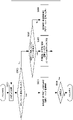
図1は、本発明の実施例の画像形成装置の概略断面図である。本実施例の画像形成装置100は、電子写真方式を利用して記録材上に画像を形成するレーザプリンタである。プリント信号が発生すると、画像情報に応じて変調されたレーザ光をスキャナユニット21が出射し、帯電ローラ16によって所定の極性に帯電された感光体19を走査する。これにより感光体19には静電潜像が形成される。この静電潜像に対して現像器17からトナーが供給され、感光体19上に画像情報に応じたトナー画像が形成される。一方、給紙カセット11に積載された記録材(記録紙)Pはピックアップローラ12によって一枚ずつ給紙され、ローラ13によってレジストローラ14に向けて搬送される。さらに記録材Pは、感光体19上のトナー画像が感光体19と転写ローラ20で形成される転写位置に到達するタイミングに合わせて、レジストローラ14から転写位置へ搬送される。記録材Pが転写位置を通過する過程で感光体19上のトナー画像は記録材Pに転写される。その後、記録材Pは定着部(像加熱部)としての定着装置(像加熱装置)200で加熱されてトナー画像が記録材Pに加熱定着される。定着済みのトナー画像を担持する記録材Pは、ローラ26、27によってレーザプリンタ100上部のトレイに排出される。なお、18は感光体19を清掃するクリーナである。商用の交流電源401に接続された制御手段(通電制御部)としての制御回路400から定着装置200へ電力供給している。上述した、感光体19、帯電ローラ16、スキャナユニット21、現像器17、転写ローラ20が、記録材Pに未定着画像を形成する画像形成部を構成している。15は交換ユニットとしてのカートリッジを示している。
[Example 1]
FIG. 1 is a schematic cross-sectional view of an image forming apparatus according to an embodiment of the present invention. The
本実施例のレーザプリンタ100は複数の記録材サイズに対応している。給紙カセット11には、Letter紙(約216mm×279mm)、A4紙(210mm×297mm)、Executive紙(約184mm×267mm)、A5紙(148mm×210mm)等をセットできる。
The
本実施例のプリンタは、基本的に紙を縦送りする(紙の長辺が搬送方向と平行になるように搬送する)レーザプリンタである。尚、紙を横送りするプリンタについても、本提案の構成を同様に適用できる。そして、装置が対応している定型の記録材の幅(カタログ上の記録材の幅)のうち最も大きな(幅が大きな)記録材はLetter紙であり、幅は約216mmである。また、上記の画像形成装置は、単色のモノクロトナーを使用したモノクロレーザプリンタを代表例に説明を行っているが、これに限られるものではない。例えば、2色以上のカラートナーを中間転写ベルトを介して記録材上に転写し画像形成するタンデム方式等のカラーレーザプリンタに本発明を適用することも可能である。 The printer of this embodiment is basically a laser printer that feeds the paper vertically (the long side of the paper is conveyed so as to be parallel to the conveying direction). The configuration of the present proposal can be similarly applied to a printer that feeds paper horizontally. The largest (larger) recording material among the widths of the standard recording materials (widths of the recording materials on the catalog) supported by the apparatus is Letter paper, and the width is about 216 mm. Further, the above-mentioned image forming apparatus is described by exemplifying a monochrome laser printer using a monochrome toner of a single color as a typical example, but the present invention is not limited thereto. For example, the present invention can be applied to a color laser printer such as a tandem system in which two or more color toners are transferred onto a recording material via an intermediate transfer belt to form an image.
図2は、本実施例に係る像加熱装置としての定着装置200の模式的断面図である。定着装置200は、加熱回転体である筒状のフィルム202と、フィルム202の内面に接触するヒータ1100と、フィルム202を介してヒータ1100と共に定着ニップ部Nを形成する加圧ローラ(加圧回転体)208と、を有する。フィルム202のベース層の材質は、ポリイミド等の耐熱樹脂、またはステンレス等の金属である。また、フィルム202には耐熱ゴム等の弾性層や、耐熱樹脂からなる離型層を設けても良い。加圧ローラ208は、鉄やアルミニウム等の材質の芯金209と、シリコーンゴム等の材質の弾性層210を有する。ヒータ1100は、液晶ポリマーのような耐熱樹脂製の保持部材201に保持されている。保持部材201は、フィルム202の回転を案内するガイド機能も有している。
FIG. 2 is a schematic cross-sectional view of the fixing
上記目的を達成するため、本発明の像加熱装置は、
基板と、前記基板上に設けられた前記基板の長手方向に並ぶ複数の発熱体と、を有するヒータを有し、前記ヒータの熱を利用して記録材に形成された画像を加熱する像加熱部と、
前記複数の発熱体の温度を検知する複数の温度検知素子と、
前記複数の温度検知素子のそれぞれによって検知された温度に基づいて、前記複数の発熱体に加熱される複数の加熱領域を選択的に加熱すべく、前記複数の発熱体に供給される電力を選択的に制御する通電制御部と、
を備える像加熱装置において、
前記複数の温度検知素子のうち少なくとも2つの温度検知素子が、前記複数の発熱体によって加熱される前記複数の加熱領域のそれぞれに配置されており、
前記通電制御部は、前記複数の加熱領域のうち記録材が通過しない非通過加熱領域を加熱するために前記複数の発熱体へ供給される電力を、前記非通過加熱領域に配置された前記複数の温度検知素子のうち、前記記録材の搬送基準位置から最も遠い温度検知素子によって検知された温度に基づいて、制御することを特徴とする。
上記目的を達成するため、本発明の像加熱装置は、
基板と、前記基板上に設けられた前記基板の長手方向に並ぶ複数の発熱体と、を有するヒータを有し、前記ヒータの熱を利用して記録材に形成された画像を加熱する像加熱部と、
前記複数の発熱体の温度を検知する複数の温度検知素子と、
前記温度検知素子のそれぞれによって検知された温度に基づいて、前記複数の発熱体に加熱される複数の加熱領域を選択的に加熱すべく、前記複数の発熱体に供給される電力を選択的に制御する通電制御部と、
を備える像加熱装置において、
前記複数の温度検知素子のうち少なくとも2つの温度検知素子が、前記複数の発熱体に加熱される前記複数の加熱領域のそれぞれに配置されており、
前記通電制御部は、前記複数の加熱領域のうち記録材に形成された画像が通過しない非画像加熱領域を加熱するために前記複数の発熱体に供給される電力を、前記非画像加熱領域に配置された前記複数の温度検知素子のうち、前記複数の加熱領域のうち記録材に形成された画像が通過する画像加熱領域から最も遠い温度検知素子によって検知された温度に基づいて、制御することを特徴とする。
上記目的を達成するため、本発明の画像形成装置は、
記録材に画像を形成する画像形成部と、
前記記録材に形成された画像を前記記録材に定着する定着部と、
を有する画像形成装置において、
前記定着部は、
基板と、前記基板上に設けられた前記基板の長手方向に並ぶ複数の発熱体とを有するヒータと、を有し、前記ヒータの熱を利用して前記記録材に形成された画像を加熱する像加熱部と、
前記複数の発熱体の温度を検知する複数の温度検知素子と、
前記複数の温度検知素子のそれぞれによって検知された温度に基づいて、前記複数の発熱体に加熱される複数の加熱領域を選択的に加熱すべく、前記複数の発熱体に供給される電力を選択的に制御する通電制御部と、
を有し、
前記複数の温度検知素子のうち少なくとも2つの温度検知素子が、前記複数の発熱体によって加熱される前記複数の加熱領域のそれぞれに配置されており、
前記通電制御部は、前記複数の加熱領域のうち記録材が通過しない非通過加熱領域を加
熱するために前記複数の発熱体へ供給される電力を、前記非通過加熱領域に配置された前記複数の温度検知素子のうち、前記記録材の搬送基準位置から最も遠い温度検知素子によって検知された温度に基づいて、制御することを特徴とする。
In order to achieve the above object, the image heating device of the present invention is used.
Image heating that has a heater having a substrate and a plurality of heating elements provided on the substrate and arranged in the longitudinal direction of the substrate, and uses the heat of the heater to heat an image formed on a recording material. Department and
A plurality of temperature detecting elements for detecting the temperature of the plurality of heating elements, and
Based on the temperature detected by each of the plurality of temperature detecting elements, the electric power supplied to the plurality of heating elements is selected in order to selectively heat the plurality of heating regions heated by the plurality of heating elements. And the energization control unit that controls
In an image heating device equipped with
At least two temperature detecting elements among the plurality of temperature detecting elements are arranged in each of the plurality of heating regions heated by the plurality of heating elements.
The energization control unit distributes electric power supplied to the plurality of heating elements to heat the non-passing heating region through which the recording material does not pass among the plurality of heating regions, which is arranged in the non-passing heating region. Among the temperature detecting elements, the temperature is controlled based on the temperature detected by the temperature detecting element farthest from the transport reference position of the recording material.
In order to achieve the above object, the image heating device of the present invention is used.
Image heating that has a heater having a substrate and a plurality of heating elements provided on the substrate and arranged in the longitudinal direction of the substrate, and uses the heat of the heater to heat an image formed on a recording material. Department and
A plurality of temperature detecting elements for detecting the temperature of the plurality of heating elements, and
Based on the temperature detected by each of the temperature detecting elements, the electric power supplied to the plurality of heating elements is selectively used to selectively heat the plurality of heating regions heated by the plurality of heating elements. The energization control unit to control and
In an image heating device equipped with
At least two temperature detecting elements among the plurality of temperature detecting elements are arranged in each of the plurality of heating regions heated by the plurality of heating elements.
The energization control unit transfers power supplied to the plurality of heating elements to the non-image heating region in order to heat the non-image heating region in which the image formed on the recording material does not pass among the plurality of heating regions. Of the plurality of arranged temperature detecting elements, control is performed based on the temperature detected by the temperature detecting element farthest from the image heating region through which the image formed on the recording material is passed among the plurality of heating regions. It is characterized by.
In order to achieve the above object, the image forming apparatus of the present invention is used.
An image forming part that forms an image on the recording material,
A fixing portion for fixing the image formed on the recording material to the recording material, and a fixing portion.
In an image forming apparatus having
The fixing part is
It has a substrate and a heater provided on the substrate and having a plurality of heating elements arranged in the longitudinal direction of the substrate, and the heat of the heater is used to heat an image formed on the recording material. Image heating part and
A plurality of temperature detecting elements for detecting the temperature of the plurality of heating elements, and
Based on the temperature detected by each of the plurality of temperature detecting elements, the electric power supplied to the plurality of heating elements is selected in order to selectively heat the plurality of heating regions heated by the plurality of heating elements. And the energization control unit that controls
Have,
At least two temperature detecting elements among the plurality of temperature detecting elements are arranged in each of the plurality of heating regions heated by the plurality of heating elements.
The energization control unit distributes electric power supplied to the plurality of heating elements to heat the non-passing heating region through which the recording material does not pass among the plurality of heating regions, which is arranged in the non-passing heating region. Among the temperature detecting elements, the temperature is controlled based on the temperature detected by the temperature detecting element farthest from the transport reference position of the recording material.
加圧ローラ208は、動力源としてのモータ30から動力を受けて矢印方向に回転する。加圧ローラ208が回転することによって、フィルム202が従動して回転する。未定着トナー画像を担持する記録材Pは、定着ニップ部Nで挟持搬送されつつ加熱されて定着処理される。このように、定着装置200は、筒状のフィルム202と、フィルム202の内面に接触するヒータ1100と、を有し、フィルム202を介したヒータ1100の熱で記録材に形成された画像を加熱する。
The pressurizing
ヒータ1100は、セラミック製の基板1105と、基板1105上に設けられ電力を供給することによって発熱する発熱抵抗体(発熱体)(図3参照)を有する。基板1105の定着ニップ部Nの面(第1の面)には、フィルム202の摺動性を確保するため、ガラス製の表面保護層1108が設けられている。基板1105の定着ニップ部N側の面とは反対側の面(第2の面)には、発熱抵抗体を絶縁するため、ガラス製の表面保護層1107が設けられている。第2の面には電極(ここでは代表としてE14を示してある)が露出しており、給電用の電気接点(ここでは代表としてC14を示してある)が電極に接触することにより発熱抵抗体が電気的に交流電源401と接続される。なお、ヒータ1100の詳細な説明は後述する。
The
212は、ヒータ1100の異常発熱により作動してヒータ1100に供給する電力を遮断するサーモスイッチや温度ヒューズ等の保護素子である。保護素子212は、ヒータ1100に当接、若しくはヒータ1100に対して若干のギャップを設けて配置されている。204は、保持部材201に不図示のバネの圧力を加えるための金属製のステーであり、保持部材201、及びヒータ1100を補強する役目もある。
図3(A)及び図3(B)は、実施例1のヒータ1100の構成図を示している。図3(A)は、図3(B)に示す記録材Pの搬送基準位置X付近のヒータ1100の断面図を示している。図3(B)は、ヒータ1100の各層の平面図を示している。図3(C)は、ヒータ1100を保持する保持部材の平面図である。
本実施例のプリンタは、記録材の幅方向(搬送方向に対して直交する方向)の中央を搬送基準位置Xに合わせて搬送する中央基準のプリンタである。
3A and 3B show a configuration diagram of the
The printer of this embodiment is a center reference printer that transports the center of the recording material in the width direction (direction orthogonal to the transport direction) in accordance with the transport reference position X.
次にヒータ1100の構成を詳述する。フィルム202と接触するヒータ面とは反対側のヒータ面であるヒータ1100の裏面層1には、第1の導電体1101と第2の導電体1103と発熱抵抗体(発熱体)1102との組からなる発熱ブロックがヒータ1100の長手方向に複数設けられている。本実施例のヒータ1100は、合計7つの発熱ブロックHB11~HB17を有し、その長手方向に7つに分割された加熱領域を選択的に組み合わせることで、記録材のサイズに応じた種々の発熱範囲を形成する。発熱ブロックの独立制御に関しては後述する。
Next, the configuration of the
各発熱ブロックは、夫々、基板の長手方向に沿って設けられている第1の導電体1101と、第1の導電体1101とは基板の短手方向(長手方向と直交する方向)で異なる位置で基板の長手方向に沿って設けられている第2の導電体1103と、を有する。更に第1の導電体1101と第2の導電体1103の間に設けられており第1の導電体1101と第2の導電体1103を介して供給される電力により発熱する発熱抵抗体1102を有する。
各発熱ブロックの発熱抵抗体1102は、ヒータ1100の短手方向における基板中央を基準に、互いに対称な位置に形成された発熱抵抗体1102a、及び発熱抵抗体1102bに分かれている。また、第1の導電体1101は、発熱抵抗体1102aと接続され
た導電体1101aと、発熱抵抗体1102bと接続された導電体1101bに分かれている。発熱抵抗体1102a、及び発熱抵抗体1102bが基板中央を基準に互いに対称な位置に形成されている。
Each of the heat generating blocks has a position different between the first conductor 1101 provided along the longitudinal direction of the substrate and the first conductor 1101 in the lateral direction (direction orthogonal to the longitudinal direction) of the substrate. It has a second conductor 1103, which is provided along the longitudinal direction of the substrate. Further, it has a heat generating resistor 1102 which is provided between the first conductor 1101 and the second conductor 1103 and generates heat by the electric power supplied via the first conductor 1101 and the second conductor 1103. ..
The heat-generating resistor 1102 of each heat-generating block is divided into a heat-generating
ヒータ1100は7つの発熱ブロックHB11~HB17を有するので、発熱抵抗体1102aは1102a-1~1102a-7の7つに分かれている。同様に、発熱抵抗体1102bは1102b-1~1102b-7の7つに分かれている。更に、第2の導電体1103も1103-1~1103-7の7つに分かれている。なお、発熱抵抗体1102a-1~1102a-7が、基板1105内において記録材Pの搬送方向の上流側に配置されており、発熱抵抗体1102b-1~1102b-7が基板1105内において記録材Pの搬送方向の下流側に配置されている。
Since the
ヒータ1100の裏面層2には、発熱抵抗体1102、第1の導電体1101、及び第2の導電体1103を覆う絶縁性(本実施例ではガラス)の表面保護層1107が設けられている。但し、表面保護層1107は、給電用の電気接点C11~C17、C18-1、C18-2が接触する電極部E11~E17、E18-1、E18-2は覆っていない。電極E11~E17は、夫々、第2の導電体1103-1~1103-7を介して、発熱ブロックHB11~HB17に電力供給するための電極である。電極E18-1、E18-2は、第1の導電体1101a、1101bを介して発熱ブロックHB11~HB17に電力給電するための電極である。
The
ところで、導電体の抵抗値はゼロではないため、ヒータ1100の長手方向における発熱分布に影響を与える。そこで、第1の導電体1101a、1101b、及び第2の導電体1103-1~1103-7の電気抵抗の影響を受けても発熱分布が不均一にならないように、電極E18-1、及びE18-2はヒータ1100の長手方向の両端部に分けて設けてある。
By the way, since the resistance value of the conductor is not zero, it affects the heat generation distribution in the longitudinal direction of the
図2に示したように、ステー204と保持部材201の間の空間には、安全素子212、電気接点C11~C17、C18-1、C18-2が設けられている。図3(C)に示すように、保持部材201には、電極E11~E17、E18-1、E18-2に接続される電気接点C11~C17、C18-1、C18-2を通す孔HC11~HC17、HC18-1、HC18-2が設けられている。また、保持部材201には保護素子212の感熱部を通す孔H212も設けられている。電気接点C11~C17、C18-1、C18-2は、バネによる付勢や溶接等の手法によって、対応する電極と電気的に接続されている。保護素子212もバネによって付勢されて、その感熱部が表面保護層1107に接触している。各電気接点は、ステー204と保持部材201の間の空間に設けられたケーブルや薄い金属板等の導電部材を介して、ヒータ1100の制御回路と接続している。
As shown in FIG. 2, a
ヒータ1100の裏面に電極を設けることで、第2の導電体1103-1~1103-7各々に電気的に接続する配線の為の領域を基板1105上に設ける必要がないため、基板1105の短手方向の幅を短くすることができる。そのため、ヒータのサイズアップを抑えることができる。なお、図3(B)に示すように、電極E12~E16は、基板の長手方向において発熱抵抗体が設けられた領域内に設けられている。
By providing an electrode on the back surface of the
後述するが、本例のヒータ1100は、複数の発熱ブロックを独立して制御することにより、種々の発熱分布(加熱領域)を形成可能になっている。例えば、記録材のサイズに応じた発熱分布を設定できる。更に、発熱抵抗体1102はPTC(Positive Temperature Coefficient)を有する材料で形成されている。PTCを有する材料を用いることで、記録材の端部と発熱ブロックの境界とが一致していないケースでも非通紙部の昇温を抑えることができる。
As will be described later, the
ヒータ1100の摺動面側の摺動面層1には、各発熱ブロックHB11~HB17の温度を検知するための複数のサーミスタT1-C~T7-C、T1-E~T3-E、T4-E1、T4-E2、T5-E~T7-Eが形成されている。摺動面とはヒータ1100においてフィルム202と接触する側の面のことである。サーミスタ(温度検知素子)の材料は、TCR(Temperature Coefficient of Resistance)が正又は負に大きい材料であれば良い。本例ではNTC(Negative Temperature Coefficient)を有する材料を基板上に薄く印刷して温度検知手段であるサーミスタを構成した。このサーミスタを使用して、フィルムが目標温度になるように制御を行う。
On the sliding
各発熱ブロックに対するサーミスタ配置について説明する。
図3(B)に示すように1つの発熱ブロックに対してサーミスタが複数配置されている。例えば発熱ブロックHB15に対して、2つのサーミスタT5-CとサーミスタT5-Eが設置されており、抵抗値検出用の導電パターンET5-C、ET5-Eと、共通導電パターンEG11によって、それぞれ温度検出可能な構成となっている。
The thermistor arrangement for each heat generation block will be described.
As shown in FIG. 3B, a plurality of thermistors are arranged for one heat generation block. For example, two thermistors T5-C and thermistor T5-E are installed on the heat generation block HB15, and the temperature is detected by the conductive patterns ET5-C and ET5-E for detecting the resistance value and the common conductive pattern EG11, respectively. It is a possible configuration.
本実施例の構成では、サーミスタT5-Cを発熱ブロックHB14に隣接する側の端部領域に配置し、サーミスタT5-Eを発熱ブロックHB16に隣接する側の端部領域に配置している。紙サイズによっては、発熱ブロックHB15の中を紙端が通過する場合がある。その際、サーミスタT5-Cは、紙幅が変わっても、なるべく通紙域内になるように、通紙基準に近い端部に配置している。逆に、サーミスタT5-Eは、なるべく非通紙域になるように通紙基準から遠い端部に配置している。 In the configuration of this embodiment, the thermistor T5-C is arranged in the end region on the side adjacent to the heat generation block HB14, and the thermistor T5-E is arranged in the end region on the side adjacent to the heat generation block HB16. Depending on the paper size, the paper edge may pass through the heat generation block HB15. At that time, the thermistor T5-C is arranged at the end close to the paper passing standard so as to be within the paper passing area as much as possible even if the paper width changes. On the contrary, the thermistor T5-E is arranged at the end far from the paper passing standard so as to be as non-passing area as possible.
同様に、各発熱ブロックHB11~HB17に対して、通紙基準に近いサーミスタT1-C~T7-C、及び通紙基準から遠いサーミスタT1-E~T3-E、T4-E1、T4-E2、T5-E~T7-Eが各々配置されている。
尚、サーミスタの長手位置に関しては、本実施例のものに限らない。例えば、サーミスタT1-C~T7-Cを各発熱ブロックの長手中央に配置するような構成でも構わない。
Similarly, for each heat generation block HB11 to HB17, thermistors T1-C to T7-C, which are close to the paper-passing standard, and thermistors T1-E to T3-E, T4-E1, T4-E2, which are far from the paper-passing standard, T5-E to T7-E are arranged respectively.
The longitudinal position of the thermistor is not limited to that of this embodiment. For example, the thermistors T1-C to T7-C may be arranged in the center of the longitudinal direction of each heat generation block.
基板1105の定着ニップ部Nの側の面(摺動面層2)には、フィルム202の摺動性を確保するため、絶縁性(本実施例はガラス製)の表面保護層1108がコーティングにより形成されている。表面保護層1108は、サーミスタ、導電パターン、及び共通導電パターンを覆っている。しかしながら、電気接点との接続を確保するため、図3(B)に示すように、ヒータ1100の両端部で、導電パターンの一部、及び共通導電パターンの一部は露出させている。
In order to ensure the slidability of the
分割された発熱ブロックのうち、記録材が通過する発熱ブロックは「通紙部」の目標温度に設定し、フィルム温度が記録材にトナー像を定着させるために必要な目標温度になるように制御を行う。一方、記録材が通過しない発熱ブロックは、「非通紙部」の目標温度に設定し、省エネルギーのためになるべく低い温度に設定(該発熱ブロックに対応する発熱体に供給する電力量を小さく)する。 Of the divided heat generation blocks, the heat generation block through which the recording material passes is set to the target temperature of the "paper passing section", and the film temperature is controlled to be the target temperature required to fix the toner image on the recording material. I do. On the other hand, the heat generation block through which the recording material does not pass is set to the target temperature of the "non-passing paper portion" and set to the lowest possible temperature for energy saving (the amount of power supplied to the heating element corresponding to the heat generation block is small). do.
(表1)

しかしながら、「非通紙部」の目標温度を低く設定しすぎると、フィルム202とヒータ1100の摺動面に塗布しているグリスの摺動性が失われてトルクが増大し、フィルム202が回転しにくくなる。その結果、記録材の搬送が安定しなくなることが懸念される。本実施例の構成では、フィルム202の温度が110℃を下回るとフィルム202の回転に支障をきたすため、そこに10℃のマージンを持たせ、「非通紙部」の目標温度を120℃としている。
However, if the target temperature of the "non-paper-passing portion" is set too low, the slidability of the grease applied to the sliding surfaces of the
本実施例の比較例として、従来例のように、記録材の幅(定着装置長手方向の通紙幅)によらず、通紙基準に近い側のサーミスタで各発熱ブロックを温調する場合について説明する。各発熱ブロックの温調に使用するサーミスタは、下表2のようになる。 As a comparative example of this embodiment, a case where each heat generating block is temperature-controlled by a thermistor on the side close to the paper passing standard will be described regardless of the width of the recording material (paper passing width in the longitudinal direction of the fixing device) as in the conventional example. do. The thermistors used to control the temperature of each heat generation block are as shown in Table 2 below.
(表2)

この例において、A5サイズ(148mm幅)の紙を連続通紙する場合を考える。本実施例で使用するプリンタは、A5サイズの紙を毎分70枚(=70ppm:Paper Per Minute)通紙することができるプリンタである。このときの各発熱ブロックの目標温度、およびフィルム温度の長手分布を図4に示す。なお、通紙基準に対して左右対称であるため、発熱ブロックHB14~HB17を用いて説明する。 In this example, consider the case of continuously passing A5 size (148 mm width) paper. The printer used in this embodiment is a printer capable of passing 70 sheets (= 70 ppm: Paper Per Minute) of A5 size paper per minute. FIG. 4 shows the target temperature of each heat generating block and the longitudinal distribution of the film temperature at this time. Since it is symmetrical with respect to the paper passing standard, the heat generation blocks HB14 to HB17 will be described.
図4(a)は、発熱ブロックとサーミスタ、A5紙の長手位置関係を表した概略図である。各発熱ブロックの中で、温調に使用しているサーミスタを網掛けして表記している。
図4(b)は、A5紙を数枚通紙した時点における長手方向の温度分布であり、実線が目標温度、破線がフィルム温度の分布である。発熱ブロックのうち、A5紙が通過する発熱ブロックHB14、HB15は、印字されるトナー画像を定着させるための温度で制御される(本実施例では170℃としている)。A5紙の紙端部位置に該当する発熱ブロックHB15は、A5紙の通紙域内となるサーミスタT5-Cが170℃となるように温調されるため、A5紙の非通紙部では、非通紙部昇温の影響により、フィルム温度が目標温度よりも高い温度となる。
FIG. 4A is a schematic view showing the longitudinal positional relationship between the heat generation block, the thermistor, and A5 paper. In each heat generation block, the thermistor used for temperature control is shaded.
FIG. 4B shows the temperature distribution in the longitudinal direction at the time when several sheets of A5 paper are passed, the solid line is the target temperature, and the broken line is the film temperature distribution. Of the heat-generating blocks, the heat-generating blocks HB14 and HB15 through which A5 paper passes are controlled by a temperature for fixing the toner image to be printed (170 ° C. in this embodiment). The heat generation block HB15, which corresponds to the position of the paper edge of A5 paper, is temperature-controlled so that the thermista T5-C, which is within the paper-passing area of A5 paper, has a temperature of 170 ° C. Due to the influence of the temperature rise of the paper passing portion, the film temperature becomes higher than the target temperature.
非通紙部に該当する発熱ブロックHB16、HB17は、省エネルギーのために低い温度で制御している(本実施例では120℃としている)。しかし、発熱ブロックHB15の非通紙部昇温が発熱ブロックHB16にも流入するため、発熱ブロックHB15に隣接したサーミスタT6-Cも非通紙部昇温の影響を受け、非通紙部目標温度よりも高い温度を検知してしまう。発熱ブロックHB16は、サーミスタT6-Cの温度が非通紙部目標温度になるように制御されるため、発熱量が小さくなる。そのため、通紙を継続していくと、フィルム温度は図4(c)の破線に示したような分布となり、発熱ブロックHB16の一部でフィルム202が回転するための下限温度である110℃より低い100℃まで温度が下がってしまう。その結果、フィルム202の回転を補助するグリスの摺動性が失われてトルクが増大し、フィルム202が回転しにくくなり、記録材Pの搬送が安定しなくなる可能性がある。
The heat generating blocks HB16 and HB17 corresponding to the non-paper-passing portion are controlled at a low temperature for energy saving (120 ° C. in this embodiment). However, since the temperature rise of the non-passing portion of the heat generation block HB15 also flows into the heat generation block HB16, the thermistor T6-C adjacent to the heat generation block HB15 is also affected by the temperature rise of the non-passing portion, and the target temperature of the non-passing portion is affected. It will detect a higher temperature than that. Since the heat generation block HB16 is controlled so that the temperature of the thermistor T6-C becomes the target temperature of the non-passing portion, the heat generation amount becomes small. Therefore, as the paper is continuously passed, the film temperature becomes a distribution as shown by the broken line in FIG. 4 (c), and the temperature is lower than 110 ° C., which is the lower limit temperature for the
この課題を解決するために、本実施例では、図5のフローチャートに示すように、記録材の幅情報を使用し、温調に使用するサーミスタの切り替えを行う。すなわち、プリント開始(画像形成開始)のジョブを受け取ると、画像形成装置の制御部は、記録材の幅情報を取得し(S102)、各発熱ブロックについて通紙領域が含まれるか否か確認する(S103)。通紙部に該当する発熱ブロック(通過加熱領域)は通紙基準に近いサーミスタで温調するように設定し(S104)、非通紙部に該当する発熱ブロック(非通過加熱領域)は通紙基準から遠いサーミスタで温調するように設定する(S105)。この制御を記録材のサイズが変更される度に実行する(S106)。表3に、本実施例における、紙幅と各発熱ブロックを制御するサーミスタの相関表を示す。 In order to solve this problem, in this embodiment, as shown in the flowchart of FIG. 5, the width information of the recording material is used to switch the thermistor used for temperature control. That is, upon receiving the job of starting printing (starting image formation), the control unit of the image forming apparatus acquires the width information of the recording material (S102) and confirms whether or not the paper passing area is included for each heat generating block. (S103). The heat generation block (passing heating area) corresponding to the paper passing section is set to control the temperature with a thermistor close to the paper passing standard (S104), and the heat generating block (non-passing heating area) corresponding to the non-passing section is set to pass paper. Set the temperature with a thermistor far from the standard (S105). This control is executed every time the size of the recording material is changed (S106). Table 3 shows the correlation table between the paper width and the thermistor that controls each heat generation block in this embodiment.
(表3)

表3に示すように、
記録材の幅WがW>210mmの場合は、全発熱ブロックが通紙部となるため、各発熱ブロックHB11~HB17は各発熱ブロックにおいて通紙基準に近いサーミスタにより制御を行う。
記録材の幅Wが185mm<W≦210mmの場合は、記録材が通過する発熱ブロックである発熱ブロックHB12~HB16は各発熱ブロックにおいて通紙基準に近いサーミスタT2-C~T6-Cにより制御を行う。また、非通紙部に該当する発熱ブロックHB11、HB17は、通紙基準から遠いサーミスタT1-E、T7-Eで制御する。
記録材の幅Wが105mm<W≦185mmの場合は、記録材が通過する発熱ブロックである発熱ブロックHB13~HB15は各発熱ブロックにおいて通紙基準に近いサーミスタT3-C~T5-Cにより制御を行う。また、非通紙部に該当する発熱ブロックHB11、HB12、HB16、HB17は、通紙基準から遠いサーミスタT1-E、T2-E、T6-E、T7-Eで制御する。
記録材の幅がW≦105mmの場合は、記録材が通過する発熱ブロックである発熱ブロックHB14は通紙基準に近いサーミスタT4-Cにより通電制御を行う。それ以外の発熱ブロックHB11~HB13、HB15~HB17は非通紙部に該当するため、通紙基準から遠いサーミスタT1-E~T3-E、T5-E~T7-Eで制御する。
As shown in Table 3,
When the width W of the recording material is W> 210 mm, the total heat generating block serves as the paper passing portion, so that each heat generating block HB11 to HB17 is controlled by a thermistor close to the paper passing standard in each heat generating block.
When the width W of the recording material is 185 mm <W≤210 mm, the heat generation blocks HB12 to HB16, which are heat generation blocks through which the recording material passes, are controlled by thermistors T2-C to T6-C, which are close to the paper passing standard, in each heat generation block. conduct. Further, the heat generating blocks HB11 and HB17 corresponding to the non-paper-passing portion are controlled by thermistors T1-E and T7-E far from the paper-passing standard.
When the width W of the recording material is 105 mm <W ≦ 185 mm, the heat generation blocks HB13 to HB15, which are heat generation blocks through which the recording material passes, are controlled by thermistors T3-C to T5-C, which are close to the paper passing standard, in each heat generation block. conduct. Further, the heat generating blocks HB11, HB12, HB16, and HB17 corresponding to the non-paper-passing portion are controlled by thermistors T1-E, T2-E, T6-E, and T7-E far from the paper-passing standard.
When the width of the recording material is W ≦ 105 mm, the heat generation block HB14, which is a heat generation block through which the recording material passes, is controlled to be energized by the thermistor T4-C, which is close to the paper passing standard. Since the other heat generation blocks HB11 to HB13 and HB15 to HB17 correspond to the non-passing section, they are controlled by thermistors T1-E to T3-E and T5-E to T7-E, which are far from the paper passing standard.
本実施例の制御を行った場合に、A5サイズ(148mm幅)の紙を連続通紙した場合を考える。図6(a)は、本実施例の制御を行った場合における発熱ブロックとサーミスタ、A5紙の長手位置関係を表した概略図である。各発熱ブロックの中で、温調に使用しているサーミスタを網掛けして表記している。比較例(図4)とは、発熱ブロックHB16、HB17の温調に使用するサーミスタが異なっている。 Consider the case where A5 size (148 mm width) paper is continuously passed when the control of this embodiment is performed. FIG. 6A is a schematic view showing the longitudinal positional relationship between the heat generation block, the thermistor, and A5 paper when the control of this embodiment is performed. In each heat generation block, the thermistor used for temperature control is shaded. The thermistor used for temperature control of the heat generation blocks HB16 and HB17 is different from that of the comparative example (FIG. 4).
発熱ブロックの目標温度、およびフィルム温度の長手分布を図6(b)に示す。なお、通紙基準に対して左右対称であるため、発熱ブロックHB14~HB17を用いて説明する。数枚時点の温度分布は図4(b)と同じであり、発熱ブロックHB15のうちA5紙の非通紙部では、非通紙部昇温の影響により、フィルム温度が目標温度よりも高い温度と
なる。この非通紙部昇温が発熱ブロックHB16にも流入するため、発熱ブロックHB15に隣接したサーミスタT6-Cも非通紙部昇温の影響を受け、非通紙部目標温度よりも高い温度を検知してしまう。一方、発熱ブロックHB15から遠いサーミスタT6-Eの部分では、非通紙部昇温の影響を受けず、非通紙部目標温度と同じ120℃となっている。
本実施例では、発熱ブロックHB16をサーミスタT6-Eで制御する。そのため、通紙を継続しても発熱ブロックHB16の発熱量は変化せず、図6(c)に示したように、発熱ブロックHB16全域で常に目標温度以上を保持できる。
The target temperature of the heat generation block and the longitudinal distribution of the film temperature are shown in FIG. 6 (b). Since it is symmetrical with respect to the paper passing standard, the heat generation blocks HB14 to HB17 will be described. The temperature distribution at the time of several sheets is the same as in FIG. 4 (b), and in the non-passing portion of A5 paper in the heat generation block HB15, the film temperature is higher than the target temperature due to the influence of the temperature rise of the non-passing portion. It becomes. Since the temperature rise of the non-passing portion also flows into the heat generation block HB16, the thermistor T6-C adjacent to the heat generation block HB15 is also affected by the temperature rise of the non-passing portion, and the temperature is higher than the target temperature of the non-passing portion. It will be detected. On the other hand, the portion of the thermistor T6-E far from the heat generation block HB15 is not affected by the temperature rise of the non-passing portion, and is 120 ° C., which is the same as the target temperature of the non-passing portion.
In this embodiment, the heat generation block HB16 is controlled by the thermistor T6-E. Therefore, the heat generation amount of the heat generation block HB16 does not change even if the paper is continuously passed, and as shown in FIG. 6C, the target temperature or higher can always be maintained in the entire heat generation block HB16.
なお、搬送基準線Xに対して長手反対側にある発熱ブロックHB12においても同様の効果を得ることができる。そのため、フィルム温度が非通紙部目標温度を下回った場合に発生する記録材の搬送不良を防止することが可能となる。 The same effect can be obtained with the heat generation block HB12 located on the side opposite to the transport reference line X. Therefore, it is possible to prevent a transfer defect of the recording material that occurs when the film temperature falls below the target temperature of the non-passing portion.
本実施例のプリンタは、ユーザーが設定した紙の幅情報を、通紙開始前に取得している。紙の幅情報を取得する方法としては、給紙カセットおよび給紙トレイに紙幅センサを設けて判定する方法、紙搬送経路上に設けられたフラグ等のセンサを用いて判定する方法等を選択することができる。
搬送経路上で幅情報を取得する場合は、先ず、プリント開始時点は全ての発熱ブロックを通紙基準に近いサーミスタで温調制御を行う。そして、紙がセンサ位置まで到達し、紙幅情報が確定した時点で、非通紙部に該当する発熱ブロックの制御を通紙基準から遠いサーミスタに切り替える。こうすることで、同様の効果を得ることができる。
The printer of this embodiment acquires the paper width information set by the user before the start of paper passing. As a method of acquiring the width information of the paper, a method of providing a paper width sensor in the paper cassette and the paper tray to make a judgment, a method of making a judgment using a sensor such as a flag provided on the paper transport path, and the like are selected. be able to.
When acquiring width information on the transport path, first, at the start of printing, temperature control is controlled by a thermistor that is close to the paper-passing standard for all heat-generating blocks. Then, when the paper reaches the sensor position and the paper width information is confirmed, the control of the heat generation block corresponding to the non-paper-passing portion is switched to the thermistor far from the paper-passing reference. By doing so, the same effect can be obtained.
また、本実施例では、非通紙部の温調に使用するサーミスタを、紙幅情報が確定した時点で通紙基準から遠いサーミスタに制御を切り替える例について説明したものの、切り替えるタイミングは紙幅情報が確定した時点でなくても構わない。例えば、最初は通紙基準に近いサーミスタで温調を行い、通紙基準から遠いサーミスタが所定温度を下回った時点で制御を切り替えるような方法でも構わない。 Further, in this embodiment, an example of switching the control of the thermistor used for controlling the temperature of the non-passing portion to the thermistor far from the paper passing standard when the paper width information is determined has been described, but the paper width information is determined at the switching timing. It doesn't have to be at that point. For example, the temperature may be adjusted with a thermistor close to the paper passing standard at first, and the control may be switched when the thermistor far from the paper passing standard falls below a predetermined temperature.
なお、本実施例では記録材の搬送基準位置が画像形成装置の長手中央にある中央基準について説明したものの、基準位置が中央になく、記録材を片側に寄せて搬送するような装置においても、本実施例と同じ制御をすることで同様の効果を得ることができる。また、本実施例は通紙部の目標温度を170℃、非通紙部の目標温度を120℃に設定しているが、目標温度についても本実施例の温度に限るものではない。 In this embodiment, the central reference position in which the reference position for transporting the recording material is in the center of the longitudinal direction of the image forming apparatus has been described, but even in an apparatus in which the reference position is not in the center and the recording material is transported to one side. The same effect can be obtained by performing the same control as in this embodiment. Further, in this embodiment, the target temperature of the paper-passing portion is set to 170 ° C. and the target temperature of the non-paper-passing portion is set to 120 ° C., but the target temperature is not limited to the temperature of this embodiment.
以上説明したように、非通紙部に該当する発熱ブロックの温度を、通紙基準から遠いサーミスタで制御することにより、発熱ブロックの長手全域でフィルムが回転する下限温度以上に保持することができ、安定した記録材の搬送が可能となる。 As described above, by controlling the temperature of the heat-generating block corresponding to the non-paper-passing portion with a thermistor far from the paper-passing standard, it is possible to maintain the temperature above the lower limit temperature at which the film rotates over the entire length of the heat-generating block. , Stable transport of recording material is possible.
[実施例2]
実施例1として、非通紙部に該当する発熱ブロックでは通紙基準から遠い領域でフィルム温度が低くなるため、制御に使用するサーミスタを通紙基準から遠いサーミスタに切り替えることで、所定温度を保持する方法について説明した。実施例2では、表2に示したものと同じく、温調に使用するサーミスタを通紙基準に近いサーミスタから切り替えず、他の方法で各発熱ブロックを所定温度以上に保持する例について説明する。なお、本体構成など、実施例1と同じ項目については説明を省略する。
[Example 2]
As the first embodiment, since the film temperature is low in the region far from the paper passing standard in the heat generation block corresponding to the non-paper passing portion, the predetermined temperature is maintained by switching the thermistor used for control to the thermistor far from the paper passing standard. I explained how to do it. In the second embodiment, as in the case shown in Table 2, an example in which the thermistor used for temperature control is not switched from the thermistor close to the paper standard and each heat generating block is held at a predetermined temperature or higher by another method will be described. The same items as in the first embodiment, such as the main body configuration, will be omitted.
実施例1と同じく、A5サイズ(148mm幅)の紙を連続通紙する場合を考える。A5紙の通紙を続けていくと、図4(c)に示したように、非通紙部に該当する発熱ブロックの通紙基準から遠い位置で、フィルム表面温度が非通紙部目標温度を下回ってしまう。その対策として、本実施例では、図7のフローチャートに示すように、非通紙部に該当す
る発熱ブロック内の通紙基準から遠いサーミスタの検知温度を監視しておく(S201)。そして、所定温度を下回ったら給紙間隔を開ける(スループットダウン)制御を行う(S202)。
As in the first embodiment, consider a case where A5 size (148 mm width) paper is continuously passed. As shown in FIG. 4C, when the A5 paper is continuously passed, the film surface temperature becomes the target temperature of the non-passing portion at a position far from the passing standard of the heat generating block corresponding to the non-passing portion. Will fall below. As a countermeasure, in this embodiment, as shown in the flowchart of FIG. 7, the detection temperature of the thermistor far from the paper passing standard in the heat generation block corresponding to the non-paper passing portion is monitored (S201). Then, when the temperature falls below the predetermined temperature, control is performed to open the paper feed interval (throughput down) (S202).
本実施例も、左右対称であるため、発熱ブロックHB14~HB17を使用して説明する。A5紙を通紙する場合には、非通紙部に該当する発熱ブロックHB16の通紙基準から遠いサーミスタであるサーミスタT6-Eの温度を監視しておく。そして、サーミスタT6-Eの検知温度が非通紙部目標温度の120℃を下回った場合には、給紙間隔(複数の記録材に連続的に画像形成を行う際の記録材の搬送間隔)を開ける対策を行う。具体的には、サーミスタT6-Eの温度が120℃を下回った際に、A5紙のスループットを70ppmから35ppmに落とす制御を行う。 Since this embodiment is also symmetrical, the heat generation blocks HB14 to HB17 will be used for description. When passing A5 paper, the temperature of the thermistor T6-E, which is a thermistor far from the paper passing standard of the heat generation block HB16 corresponding to the non-passing portion, is monitored. When the detection temperature of the thermistor T6-E is lower than the target temperature of the non-passing paper portion of 120 ° C., the paper feed interval (the transfer interval of the recording material when continuously forming an image on a plurality of recording materials). Take measures to open. Specifically, when the temperature of the thermistor T6-E falls below 120 ° C., the throughput of A5 paper is controlled to be reduced from 70 ppm to 35 ppm.
図8(a)に発熱ブロックとサーミスタ、A5紙の長手位置関係を表した概略図を、図8(b)にA5を数枚流した時点の目標温度とフィルム温度の長手分布を、図8(c)にスループットダウン後の目標温度とフィルム温度の長手分布を示す。スループットを落とすと、通紙部の目標温度を下げることができる。これは、スループットが下がることで紙間が広くなり、加圧ローラなどの部材が蓄熱するため、フィルム温度を低くしても、他の部材からの熱によってトナー像を定着できるためである。本実施例では、35ppmで通紙する場合の通紙部の目標温度を140℃としている。 FIG. 8A shows a schematic diagram showing the longitudinal positional relationship between the heat generation block, the thermistor, and A5 paper, and FIG. 8B shows the longitudinal distribution of the target temperature and the film temperature at the time when several sheets of A5 are flown. (C) shows the longitudinal distribution of the target temperature and the film temperature after the throughput is reduced. By reducing the throughput, the target temperature of the paper passing section can be lowered. This is because as the throughput decreases, the space between papers becomes wider and heat is stored in members such as pressure rollers, so that even if the film temperature is lowered, the toner image can be fixed by the heat from other members. In this embodiment, the target temperature of the paper-passing portion when the paper is passed at 35 ppm is set to 140 ° C.
通紙部の目標温度を140℃、非通紙部を120℃とすることで、通紙部と非通紙部の目標温度差が小さくなり、発熱ブロックHB15から発熱ブロックHB16に流入する熱量が低下する。また、スループットダウンして紙間を広くすることで、発熱ブロックHB15の非通紙部昇温が緩和される。以上の2つの効果により、70ppmで通紙した場合と比較して、発熱ブロックHB15から発熱ブロックHB16に流入する熱量は格段に小さくなる。その結果、図8(c)に示したように、サーミスタT6-Cの位置においても、フィルム温度は目標温度の120℃からほとんど変化しなくなる。そのため、発熱ブロックHB16の温調をサーミスタT6-Cで制御しても発熱量を小さくすることはなく、発熱ブロックHB16の全域で目標温度の120℃以上を保持できるようになる。 By setting the target temperature of the paper-passing section to 140 ° C and the non-passing section to 120 ° C, the target temperature difference between the paper-passing section and the non-paper-passing section becomes small, and the amount of heat flowing from the heat generation block HB15 to the heat generation block HB16 increases. descend. Further, by reducing the throughput and widening the space between the papers, the temperature rise of the non-passing portion of the heat generation block HB15 is alleviated. Due to the above two effects, the amount of heat flowing from the heat generation block HB15 to the heat generation block HB16 is significantly smaller than that in the case of passing paper at 70 ppm. As a result, as shown in FIG. 8C, the film temperature hardly changes from the target temperature of 120 ° C. even at the position of the thermistor T6-C. Therefore, even if the temperature control of the heat generation block HB16 is controlled by the thermistor T6-C, the heat generation amount is not reduced, and the target temperature of 120 ° C. or higher can be maintained in the entire area of the heat generation block HB16.
実施例2の手段を選択するメリットとして、像加熱装置に使用できる部材の選択肢が広がることが挙げられる。実施例1の方法をとる場合、発熱ブロックHB16の温度を全域で所定温度以上に保持できるものの、発熱ブロックHB15の非通紙部温度が高くなる傾向にある。そのため、非通紙部昇温の影響を受ける部材の耐熱温度を確保する必要がある。一方で、実施例2の方法をとる場合、発熱ブロックHB15の非通紙部昇温を緩和できるため、耐熱温度が低い部材を選択することが可能になる。
One of the merits of selecting the means of the second embodiment is that the choice of members that can be used for the image heating device is expanded. When the method of the first embodiment is adopted, the temperature of the heat
[実施例3]
非通紙部に該当する発熱ブロックの温調に使用するサーミスタを通紙基準に近いサーミスタから切り替えず、通紙基準から遠いサーミスタが所定温度を下回った場合に行う対策には、スループットダウン以外の手段を取ることもできる。実施例3において実施例1,2と共通する事項については説明を省略する。
[Example 3]
If the thermistor used to control the temperature of the heat generation block corresponding to the non-paper-passing part is not switched from the thermistor close to the paper-passing standard and the thermistor far from the paper-passing standard falls below the specified temperature, the measures other than throughput reduction are taken. You can also take measures. The matters common to Examples 1 and 2 in Example 3 will be omitted.
本実施例では、図9のフローチャートに示したように、非通紙部に該当する発熱ブロックの通紙基準から遠いサーミスタが所定温度を下回った場合(S301)に、目標温度を高く設定し直す制御(S302)を行う。この方法でA5紙を連続通紙した場合について図10を参照して説明する。図10(a)は、発熱ブロックとサーミスタ、A5紙の長手位置関係を表した概略図を示す。図10(b)は、A5紙を数枚流した時点の目標温度とフィルム温度の長手分布を示す。図10(c)は、目標温度変更後の目標温度およびフィルム温度の長手分布を示す。 In this embodiment, as shown in the flowchart of FIG. 9, when the thermistor far from the paper passing standard of the heat generation block corresponding to the non-paper passing portion falls below the predetermined temperature (S301), the target temperature is set high again. Control (S302) is performed. A case where A5 paper is continuously passed by this method will be described with reference to FIG. FIG. 10A shows a schematic view showing the longitudinal positional relationship between the heat generation block, the thermistor, and A5 paper. FIG. 10B shows the longitudinal distribution of the target temperature and the film temperature at the time when several sheets of A5 paper are flown. FIG. 10 (c) shows the longitudinal distribution of the target temperature and the film temperature after the target temperature is changed.
A5紙を通紙して図10(b)のような温度分布になったことで、サーミスタT6-Cによる温調で発熱量が絞られ、サーミスタT6-Eの温度が所定温度を下回る。その際に、発熱ブロックHB16(隣接加熱領域)の目標温度を、「通紙部」(通過加熱領域)の目標温度である170℃と、「非通紙部」(非隣接加熱領域)の目標温度である120℃の間の温度である140℃に変更している。そこから通紙を継続すると、図10(c)に示したように、温調を行っているサーミスタT6-C位置では、新たに設定された発熱ブロックHB16の目標温度である140℃になるように制御される。一方、サーミスタT6-Eの位置は140℃を下回るものの、「非通紙部」の目標温度と同じ120℃付近を維持することができている。そのため、発熱ブロックHB16の長手全域で120℃以上を維持でき、記録材の搬送不良を防止することができる。 Since the temperature distribution as shown in FIG. 10B is obtained by passing the A5 paper, the calorific value is reduced by the temperature control by the thermistor T6-C, and the temperature of the thermistor T6-E falls below the predetermined temperature. At that time, the target temperature of the heat generation block HB16 (adjacent heating region) is 170 ° C., which is the target temperature of the “paper passing portion” (passing heating region), and the target of the “non-passing portion” (non-adjacent heating region). It is changed to 140 ° C, which is a temperature between 120 ° C, which is the temperature. When the paper is continuously passed from there, as shown in FIG. 10 (c), at the thermistor T6-C position where the temperature is controlled, the temperature reaches 140 ° C., which is the target temperature of the newly set heat generation block HB16. Is controlled by. On the other hand, although the position of the thermistor T6-E is lower than 140 ° C., it can be maintained at around 120 ° C., which is the same as the target temperature of the “non-passing portion”. Therefore, it is possible to maintain 120 ° C. or higher over the entire length of the heat generation block HB16, and it is possible to prevent defective transportation of the recording material.
[実施例4]
実施例4では、非通紙部に該当する発熱ブロックの温調に使用するサーミスタを通紙基準に近いサーミスタから切り替えず、通紙基準から遠いサーミスタが所定温度を下回った場合に行う対策の更に別の手段を提案する。実施例4において実施例1~3と共通する事項については説明を省略する。本実施例では、図11のフローチャートに示したように、非通紙部に該当する発熱ブロックの通紙基準から遠いサーミスタが所定温度を下回った場合(S401)に、隣接する発熱ブロックの目標温度を高くして補助する制御(S402)を行う。この方法でA5紙を連続通紙した場合について図12を参照して説明する。図12(a)は、発熱ブロックとサーミスタ、A5紙の長手位置関係を表した概略図を示す。図12(b)は、A5を数枚流した時点の目標温度とフィルム温度の長手分布を示す。図12(c)は、目標温度変更後の目標温度およびフィルム温度の長手分布を示す。
[Example 4]
In the fourth embodiment, the thermistor used for controlling the temperature of the heat generation block corresponding to the non-paper-passing portion is not switched from the thermistor close to the paper-passing standard, and further measures are taken when the thermistor far from the paper-passing standard falls below the predetermined temperature. Propose another means. The matters common to Examples 1 to 3 in Example 4 will be omitted. In this embodiment, as shown in the flowchart of FIG. 11, when the thermistor far from the paper passing standard of the heat generating block corresponding to the non-paper passing portion falls below the predetermined temperature (S401), the target temperature of the adjacent heat generating block is reached. Control (S402) is performed to assist by raising the temperature. A case where A5 paper is continuously passed by this method will be described with reference to FIG. FIG. 12A shows a schematic view showing the longitudinal positional relationship between the heat generation block, the thermistor, and A5 paper. FIG. 12B shows the longitudinal distribution of the target temperature and the film temperature at the time when several sheets of A5 were flown. FIG. 12 (c) shows the longitudinal distribution of the target temperature and the film temperature after the target temperature is changed.
A5紙を通紙して図12(b)のような温度分布になったことで、サーミスタT6-Cによる温調で発熱量が絞られ、サーミスタT6-Eの温度が所定温度を下回る。その際に、サーミスタT6-Eに隣接する発熱ブロックHB17の目標温度を「通紙部」と同じ170℃まで上げている。その結果、図12(c)に示すように、発熱ブロックHB17の熱が発熱ブロックHB16に流入し、発熱ブロックHB16全域で120℃以上を維持できている。 Since the temperature distribution as shown in FIG. 12B is obtained by passing the A5 paper, the calorific value is reduced by the temperature control by the thermistor T6-C, and the temperature of the thermistor T6-E falls below the predetermined temperature. At that time, the target temperature of the heat generation block HB17 adjacent to the thermistor T6-E is raised to 170 ° C., which is the same as that of the “paper passing section”. As a result, as shown in FIG. 12 (c), the heat of the heat generation block HB17 flows into the heat generation block HB16, and the temperature of 120 ° C. or higher can be maintained in the entire heat generation block HB16.
以上説明してきたように、非通紙部に該当する発熱ブロックの通紙基準から遠いサーミスタの温度を監視しておき、所定温度を下回った際に対策を行うことで、発熱ブロック全域を所定温度以上に保持することができ、記録材の搬送不良を防止することができる。 As explained above, by monitoring the temperature of the thermistor far from the paper passing standard of the heat generation block corresponding to the non-paper-carrying part and taking measures when it falls below the predetermined temperature, the entire heat-generating block is heated to the predetermined temperature. It can be held as described above, and it is possible to prevent defective transportation of the recording material.
[実施例5]
本実施例では、記録材の幅ではなく、記録材上に形成されるトナー画像の幅によって温度制御を切り替える例について説明する。本体構成など、実施例1と同様のものについては、説明を省略する。
[Example 5]
In this embodiment, an example in which the temperature control is switched according to the width of the toner image formed on the recording material, not the width of the recording material, will be described. The description of the same as that of the first embodiment, such as the main body configuration, will be omitted.
長手方向に分割された発熱ブロックを有する定着装置では、通紙域中のトナー画像の有無に応じて温調することで、省エネルギー化を図る制御を行っている。すなわち、通紙域の中でも、トナー画像がある部分では、トナー画像を定着するために必要な温度まで上げ、トナー画像が無い部分では、フィルムが回転する下限温度まで温度を下げる。
例えば、図13に示したような幅216mmのLetter紙に、幅148mmの画像を印刷する場合、画像が通過する発熱ブロックHB13~HB15(画像加熱領域)は、トナー画像を定着させるための画像部目標温度(170℃)に制御する。一方、画像が通過しない発熱ブロックHB11、HB12、HB16、HB17(非画像加熱領域)は、フィルム202が回転するために必要な下限温度である非画像部目標温度(120℃)で制御する。
In the fixing device having a heat generating block divided in the longitudinal direction, energy saving is controlled by controlling the temperature according to the presence or absence of a toner image in the paper passing area. That is, even in the paper-passing area, the temperature is raised to the temperature required for fixing the toner image in the portion where the toner image is present, and the temperature is lowered to the lower limit temperature at which the film rotates in the portion where the toner image is not present.
For example, when printing an image having a width of 148 mm on Letter paper having a width of 216 mm as shown in FIG. 13, the heat generating blocks HB13 to HB15 (image heating region) through which the image passes are an image unit for fixing a toner image. Control to the target temperature (170 ° C). On the other hand, the heat generation blocks HB11, HB12, HB16, and HB17 (non-image heating regions) through which the image does not pass are controlled by the non-image portion target temperature (120 ° C.), which is the lower limit temperature required for the
従来例では、発熱ブロックの全域が画像部となる発熱ブロックHB14は、通紙基準位置Xに近いサーミスタT4-Cで温度制御を行っている。また、発熱ブロックの一部が画像部となる発熱ブロックHB13、HB15は、印字域の定着性を確保するために、印字域に含まれるサーミスタT3-C、T5-Cで温度制御を行っている。さらに、発熱ブロック全域が非画像部となるHB11、HB12,HB16,HB17については、通紙基準Xに近いT1-C、T2-C、T6-C、T7-Cで温度制御を行っている。しかしながら、非画像部の発熱ブロックを、従来例のように、通紙基準Xに使いサーミスタで制御する場合、実施例1で説明した従来例と同様の問題が発生してしまう。 In the conventional example, the heat generation block HB14 whose entire area of the heat generation block is an image unit is temperature controlled by the thermistor T4-C close to the paper passing reference position X. Further, the heat generation blocks HB13 and HB15, in which a part of the heat generation block is an image portion, are temperature-controlled by thermistors T3-C and T5-C included in the print area in order to secure the fixability of the print area. .. Further, for HB11, HB12, HB16, and HB17 in which the entire heat generation block is a non-image part, the temperature is controlled by T1-C, T2-C, T6-C, and T7-C, which are close to the paper passing standard X. However, when the heat generation block of the non-image portion is used for the paper passing standard X and controlled by the thermistor as in the conventional example, the same problem as in the conventional example described in the first embodiment occurs.
図14(a)に、従来の制御を使用して、図13のような幅216mmのLetter紙に、幅148mmの画像を印刷した場合の、紙と画像幅、サーミスタ位置の長手位置関係を表した概略図を示す。また、図14(b)に、上記Letter紙を数枚流した時点の目標温度とフィルム温度の長手分布を示す。さらに、図14(c)に、通紙を継続した後の目標温度およびフィルム温度の長手分布を示す。本例も通紙基準に対して左右対称であるため、発熱ブロックHB14~HB17を用いて説明する。なお、図14(a)において、温調に使用するサーミスタは網掛けして図示している。 FIG. 14A shows the longitudinal positional relationship between the paper, the image width, and the thermistor position when an image having a width of 148 mm is printed on a Letter paper having a width of 216 mm as shown in FIG. 13 using conventional control. The schematic diagram is shown. Further, FIG. 14B shows the longitudinal distribution of the target temperature and the film temperature at the time when several sheets of the Letter paper were flown. Further, FIG. 14 (c) shows the longitudinal distribution of the target temperature and the film temperature after continuing the paper passing. Since this example is also symmetrical with respect to the paper passing standard, the heat generation blocks HB14 to HB17 will be described. In FIG. 14A, the thermistor used for temperature control is shaded and shown.
発熱ブロックのうち、画像が通過する発熱ブロックHB14、HB15は、トナー画像を定着させるための温度(画像部目標温度:170℃)で制御される。ここで、画像の端部位置が通過する発熱ブロックHB15は、画像内となるサーミスタT5-Cが170℃となるように温調される。 Of the heat generation blocks, the heat generation blocks HB14 and HB15 through which the image passes are controlled by the temperature for fixing the toner image (image unit target temperature: 170 ° C.). Here, the heat generation block HB15 through which the end position of the image passes is temperature-controlled so that the thermistor T5-C in the image becomes 170 ° C.
トナー画像がある領域では、紙とトナーの両方にフィルムの熱が奪われるものの、トナー画像が無い領域では、紙だけに熱が奪われるため、熱の消費が少ない。そのため、図14(b)に示すように、発熱ブロックHB15の画像がない部分では、フィルム温度が目標温度よりも高温となる。 In the region where the toner image is present, the heat of the film is taken away by both the paper and the toner, but in the region where there is no toner image, the heat is taken away only by the paper, so that the heat consumption is small. Therefore, as shown in FIG. 14B, the film temperature becomes higher than the target temperature in the portion of the heat generating block HB15 where there is no image.
非通紙部に該当する発熱ブロックHB16、HB17は、省エネルギーのためにフィルムが回転する下限温度(非画像部目標温度:120℃)で制御している。しかし、発熱ブロックHB16よりも高温であり、かつ非画像部で昇温している発熱ブロックHB15の熱が発熱ブロックHB16にも流入するため、発熱ブロックHB15に隣接したサーミスタT6-Cは、目標温度よりも高い温度を検知してしまう。発熱ブロックHB16は、サーミスタT6-Cの温度が非画像部目標温度になるように制御されるため、発熱量が小さくなり、通紙を継続していくと、図14(c)に示したような温度分布となる。サーミスタT6-E付近では、フィルム202が回転するための下限温度である110℃より低い100℃まで温度が下がっている。そのため、フィルム202の回転を補助するグリスの粘性が失われてトルクが増大し、フィルム202が回転しにくくなり、記録材Pの搬送不良が発生することが懸念される。
The heat generating blocks HB16 and HB17 corresponding to the non-paper section are controlled by the lower limit temperature at which the film rotates for energy saving (target temperature of the non-image section: 120 ° C.). However, since the heat of the heat generation block HB15, which is higher than the heat generation block HB16 and is heated in the non-image area, also flows into the heat generation block HB16, the thermistor T6-C adjacent to the heat generation block HB15 has a target temperature. It will detect a higher temperature than that. Since the heat generation block HB16 is controlled so that the temperature of the thermistor T6-C becomes the target temperature of the non-image portion, the heat generation amount becomes small and the paper is continuously passed, as shown in FIG. 14 (c). The temperature distribution is good. In the vicinity of the thermistor T6-E, the temperature has dropped to 100 ° C., which is lower than the lower limit temperature of 110 ° C. for the
この課題を解決するために、本実施例では、図15のフローチャートに示すように、非画像部に該当する発熱ブロックを温調するサーミスタを、画像から遠いサーミスタに切り替える制御を行う。すなわち、プリント開始(画像形成開始)のジョブを受け取ると、画像形成装置の制御部は、記録材の形成する画像情報を取得し(S502)、各発熱ブロックについて画像が通過する画像部が含まれるか否か確認する(S503)。画像部に該当する発熱ブロックは通紙基準に近いサーミスタで温調するように設定し(S504)、非画像部に該当する発熱ブロックは通紙基準から遠いサーミスタで温調するように設定する(S505)。この制御を画像変更される度に実行する(S506)。 In order to solve this problem, in this embodiment, as shown in the flowchart of FIG. 15, the thermistor for controlling the temperature of the heat generation block corresponding to the non-image portion is controlled to be switched to the thermistor far from the image. That is, upon receiving the job of starting printing (starting image formation), the control unit of the image forming apparatus acquires the image information formed by the recording material (S502), and includes the image unit through which the image passes for each heat generating block. Check whether or not (S503). The heat-generating block corresponding to the image part is set to be temperature-controlled by a thermistor close to the paper-passing standard (S504), and the heat-generating block corresponding to the non-image part is set to be temperature-controlled by a thermistor far from the paper-passing standard (S504). S505). This control is executed every time the image is changed (S506).
図16(a)に、本制御を用いて通紙した際の、紙と画像幅、サーミスタ位置の長手位
置関係を表した概略図を示す。図16(b)に、数枚通紙した時点の目標温度とフィルム温度の長手分布を示す。さらに、図16(c)に、通紙を継続した後の目標温度およびフィルム温度の長手分布を示す。なお、図16(a)でも、温調に使用するサーミスタは網掛けして図示している。
FIG. 16A shows a schematic view showing the longitudinal positional relationship between the paper, the image width, and the thermistor position when the paper is passed using this control. FIG. 16B shows the longitudinal distribution of the target temperature and the film temperature at the time when several sheets are passed. Further, FIG. 16 (c) shows the longitudinal distribution of the target temperature and the film temperature after continuing the paper passing. Also in FIG. 16A, the thermistor used for temperature control is shaded and shown.
図16(b)に示すように、数枚通紙した時点の目標温度は図14(b)と同じである。発熱ブロックHB16の中で、高温の発熱ブロックHB15に隣接するサーミスタT6-Cでは、発熱ブロックHB15の熱が流入するため、目標温度よりも高い温度を検知してしまう。一方、発熱ブロックHB15から遠いサーミスタT6-Eの部分では影響を受けず、目標温度と同じ温度となっている。そのため、発熱ブロックHB16を画像から遠いサーミスタT6-Eで制御すると、通紙を継続しても発熱量は変化せず、図16(c)に示したように、発熱ブロックHB16全域で常に目標温度以上を保持できる。なお、搬送基準線Xに対して長手反対側にある発熱ブロックHB12においても同様の効果を得ることができる。以上説明したように、非画像部に該当する発熱ブロックを画像から遠いサーミスタで制御することで、フィルム温度が所定温度を下回ったことで発生する問題を回避することができる。 As shown in FIG. 16 (b), the target temperature at the time when several sheets are passed is the same as in FIG. 14 (b). In the heat generation block HB16, in the thermistor T6-C adjacent to the high temperature heat generation block HB15, the heat of the heat generation block HB15 flows in, so that a temperature higher than the target temperature is detected. On the other hand, the portion of the thermistor T6-E far from the heat generation block HB15 is not affected and has the same temperature as the target temperature. Therefore, when the heat generation block HB16 is controlled by the thermistor T6-E far from the image, the heat generation amount does not change even if the paper is continuously passed, and as shown in FIG. 16C, the target temperature is always in the entire heat generation block HB16. The above can be retained. The same effect can be obtained with the heat generation block HB12 located on the side opposite to the transport reference line X. As described above, by controlling the heat generation block corresponding to the non-image portion with a thermistor far from the image, it is possible to avoid the problem caused by the film temperature falling below the predetermined temperature.
本実施例では、左右対称の画像が通紙された場合について説明したが、左右対称ではない場合についても、同様の制御を使用することができる。例えば、図17のように、Leteer紙の左右どちらか一方にのみ画像が印刷される場合についても、同様の対策を使用できる。図17においても、温調に使用するサーミスタを網掛けして図示している。発熱ブロックの全域が画像部となる発熱ブロックHB12は通紙基準に近いサーミスタT2-Cを制御に使用し、発熱ブロックの一部が画像部となる発熱ブロックHB11、HB13は画像部となるサーミスタT1-C、T3-Eを制御に使用する。そして、発熱ブロックの全域が非画像部となる発熱ブロックHB14~HB17は画像部から遠いサーミスタT4-E2、T5-E~T7-Eを使用する。これにより、発熱ブロックHB13の熱が流入する発熱ブロックHB14でも長手全域でフィルム温度を目標温度以上に保持することができ、全ての発熱ブロックを目標温度以上に保持できる。 In this embodiment, the case where the symmetrical image is passed through the paper has been described, but the same control can be used even in the case where the symmetrical image is not passed. For example, as shown in FIG. 17, the same measures can be used when the image is printed on only one of the left and right sides of the Leter paper. Also in FIG. 17, the thermistor used for temperature control is shaded and shown. The heat generation block HB12 whose entire area of the heat generation block is an image part uses the thermista T2-C which is close to the paper passing standard for control, and the heat generation blocks HB11 and HB13 whose part of the heat generation block is an image part are the thermista T1 which is an image part. -C and T3-E are used for control. Then, the thermistors T4-E2 and T5-E to T7-E, which are far from the image portion, are used for the heat generation blocks HB14 to HB17 in which the entire area of the heat generation block is a non-image portion. As a result, even in the heat generation block HB14 into which the heat of the heat generation block HB13 flows, the film temperature can be maintained above the target temperature over the entire length, and all the heat generation blocks can be maintained above the target temperature.
なお、本実施例では、温調に使用するサーミスタを、画像情報が確定した時点で切り替えているものの、切り替えるタイミングは画像情報が確定した時点でなくても構わない。例えば、最初は通紙基準に近いサーミスタで温調を行い、画像部から遠いサーミスタが所定温度を下回った時点で制御を切り替えるような方法でも同様の効果を得ることができる。 In this embodiment, the thermistor used for temperature control is switched when the image information is confirmed, but the switching timing may not be the time when the image information is confirmed. For example, the same effect can be obtained by first adjusting the temperature with a thermistor close to the paper passing standard and then switching the control when the thermistor far from the image unit falls below a predetermined temperature.
以上説明したように、非画像部に該当する発熱ブロックの温度を、画像部から遠いサーミスタで制御することにより、発熱ブロックの長手全域でフィルムの目標温度以上に保持することができ、記録材の搬送不良を防止することができる。 As described above, by controlling the temperature of the heat generation block corresponding to the non-image part with a thermistor far from the image part, it is possible to maintain the temperature above the target temperature of the film over the entire length of the heat generation block, and the recording material can be kept above the target temperature. It is possible to prevent transport defects.
[実施例6]
本実施例では、記録材上に形成されるトナー画像の幅、およびトナー量によって温度制御を切り替える例について説明する。本体構成など、上記実施例と同様のものについては、説明を省略する。
[Example 6]
In this embodiment, an example of switching the temperature control according to the width of the toner image formed on the recording material and the amount of toner will be described. The same description as in the above embodiment, such as the main body configuration, will be omitted.
長手方向に分割された発熱ブロックを有する定着装置では、通紙域中のトナー画像の有無に応じて温調することで、省エネルギー化を図る制御を行っている。すなわち、通紙域の中でも、トナー画像がある部分では、トナー画像を定着するために必要な温度まで上げ、トナー画像が無い部分では、フィルムが回転する下限温度まで温度を下げる。また、トナー画像がある領域の中でも、トナー量が少ない領域は、目標温度を低くしても定着可能であるため、トナー量に応じた最適な温調を行うことで、省エネルギーを達成している。 In the fixing device having a heat generating block divided in the longitudinal direction, energy saving is controlled by controlling the temperature according to the presence or absence of a toner image in the paper passing area. That is, even in the paper-passing area, the temperature is raised to the temperature required for fixing the toner image in the portion where the toner image is present, and the temperature is lowered to the lower limit temperature at which the film rotates in the portion where the toner image is not present. Further, even in the area where the toner image is present, the area where the amount of toner is small can be fixed even if the target temperature is lowered. Therefore, energy saving is achieved by performing the optimum temperature control according to the amount of toner. ..
本実施例の画像形成装置では、印刷開始時に記録材上に印刷される画像のトナー量情報および位置情報を取得し、長手に分割された各発熱体に対して最適な温調を与えることで、使用する電力を最小化している。
具体的には、通紙する画像を単位面積(例:10mm×10mm)ごとに分割し、そのうちの何%の面積にトナーが印刷されるかを印字率Xとして計算する。計算した印字率がどの発熱ブロックの位置に該当するかを計算し、各発熱ブロックに含まれる単位面積の中で、最も高い印字率をその発熱ブロックの温度制御に使用する印字率(発熱ブロックHB-X)とする。各発熱ブロックは、発熱ブロックHB-Xの値に応じて下表4の目標温度で制御される。
In the image forming apparatus of this embodiment, the toner amount information and the position information of the image printed on the recording material at the start of printing are acquired, and the optimum temperature control is given to each heating element divided in the longitudinal direction. , Minimizes the power used.
Specifically, the image to be printed is divided into unit areas (eg, 10 mm × 10 mm), and the percentage of the area in which the toner is printed is calculated as the print rate X. The print rate (heat generation block HB) that calculates which heat generation block position the calculated print rate corresponds to and uses the highest print rate among the unit areas included in each heat generation block to control the temperature of the heat generation block. -X). Each heat generation block is controlled at the target temperature shown in Table 4 below according to the value of the heat generation block HB-X.
(表4)

このような例においても、フィルム温度が常に所定温度を上回るように、温調に使用するサーミスタを規定する必要がある。 Even in such an example, it is necessary to specify the thermistor used for temperature control so that the film temperature always exceeds a predetermined temperature.
例として、図18のように、Letter用紙に印字率100%の画像と印字率15%の文字が混在している場合について説明する。図18(a)として、紙と画像、発熱ブロック、サーミスタ位置の長手位置関係を、図18(b)として、各発熱ブロックの目標温度とフィルム表面温度を示す。なお、各発熱ブロックの温調に使用するサーミスタを網掛けして示している。 As an example, as shown in FIG. 18, a case where an image having a printing rate of 100% and characters having a printing rate of 15% are mixed on the Letter paper will be described. FIG. 18A shows the longitudinal positional relationship between the paper and the image, the heat generation block, and the thermistor position, and FIG. 18B shows the target temperature and the film surface temperature of each heat generation block. The thermistor used to control the temperature of each heat generation block is shaded.
発熱ブロックHB11、HB14、HB15は、発熱ブロック中を印字率100%の画像が通過するため、印字率100%に対応した温度である170℃で制御する。発熱ブロックHB14については、発熱ブロック中を印字率15%の文字と100%の画像の両方が通過しているものの、定着させるために必要な熱量が大きい、100%の画像を定着させるための温度を使用する。発熱ブロックHB13は、15%の文字を定着させるため、150℃で温調する。発熱ブロックHB12、HB16、HB17については、発熱ブロック中をトナー画像が通過しないため、フィルムが回転する最低温度に近い120℃に設定する。 Since the heat-generating blocks HB11, HB14, and HB15 pass through the heat-generating block for an image having a printing rate of 100%, they are controlled at 170 ° C., which is a temperature corresponding to the printing rate of 100%. Regarding the heat generation block HB14, although both characters with a print rate of 15% and an image with a print rate of 100% pass through the heat generation block, the amount of heat required for fixing is large, and the temperature for fixing a 100% image. To use. The heat generation block HB13 is temperature-controlled at 150 ° C. in order to fix the characters of 15%. Since the toner image does not pass through the heat generation blocks HB12, HB16, and HB17, the temperature is set to 120 ° C., which is close to the minimum temperature at which the film rotates.
次に、温調に使用するサーミスタについて説明する。トナー画像が通過する発熱ブロックについては、発熱ブロック中にあるサーミスタのうち、印字率が高い領域に該当するサーミスタを使用する。これは、印字率が高い領域の方が、トナーに熱を奪われてフィルム温度が下がるため、サーミスタが検知する温度も低くなってしまうからである。フィルム温度が低い部分で制御することで、発熱ブロック全域の温度を保持することが可能となる。 Next, the thermistor used for temperature control will be described. For the heat generation block through which the toner image passes, the thermistor corresponding to the area where the printing rate is high is used among the thermistors in the heat generation block. This is because in the region where the printing rate is high, the toner takes heat away and the film temperature is lowered, so that the temperature detected by the thermistor is also lowered. By controlling the portion where the film temperature is low, it is possible to maintain the temperature of the entire heat generation block.
例えば、発熱ブロックHB11は100%の画像部に該当するサーミスタT1-Eと0%の非画像部に該当するT1-Cの2つのサーミスタが存在する。このうち、サーミスタT1-Eの方が温度を低く検知するため、サーミスタT1-Eで温調することで、所定温度以上を保持することができる。同様に、発熱ブロックHB13、HB15についても、印字率が高いサーミスタT3-C、T5-Cを使用する。 For example, the heat generation block HB11 has two thermistors, T1-E, which corresponds to a 100% image portion, and T1-C, which corresponds to a non-image portion of 0%. Of these, the thermistor T1-E detects the temperature lower, so that the temperature can be maintained above a predetermined temperature by adjusting the temperature with the thermistor T1-E. Similarly, for the heat generating blocks HB13 and HB15, thermistors T3-C and T5-C having a high printing rate are used.
トナー画像が通過しない発熱ブロックは、基本的には実施例5と同じく、画像から遠い方のサーミスタを使用する。発熱ブロックHB16、HB17では、画像から遠いサーミスタT6-E、T7-Eを使用している。なお、図18の発熱ブロックHB12のように、自身はトナー画像が通過しなくても、トナー画像が通過する発熱ブロックに挟まれている場合には、隣接する発熱ブロックの目標温度を比較し、低い発熱ブロックに隣接したサーミスタを使用する。発熱ブロックHB12には、170℃で温調している発熱ブロックHB11と、150℃で温調している発熱ブロックHB13の熱が流入する。発熱ブロックHB12との目標温度差が大きいほど流入する熱量は大きくなるため、目標温度が高い側の発熱ブロックに隣接するサーミスタで温調すると、発熱量を絞って目標温度を下回りやすくなってしまう。そのため、目標温度が低い発熱ブロックに隣接するサーミスタを温調に使用することで、発熱量の低下を防ぐことができる。すなわち、発熱ブロックHB12では、150℃で温調している発熱ブロックHB13に隣接するサーミスタT2-Cを使用する。 As the heat generation block through which the toner image does not pass, basically the thermistor farther from the image is used as in the fifth embodiment. In the heat generation blocks HB16 and HB17, thermistors T6-E and T7-E far from the image are used. Even if the heat generation block HB12 in FIG. 18 does not pass the toner image, if it is sandwiched between the heat generation blocks through which the toner image passes, the target temperatures of the adjacent heat generation blocks are compared. Use a thermistor adjacent to the lower heat block. The heat of the heat generation block HB11 whose temperature is controlled at 170 ° C. and the heat generation block HB13 whose temperature is controlled at 150 ° C. flows into the heat generation block HB12. The larger the target temperature difference from the heat generation block HB12, the larger the amount of heat that flows in. Therefore, if the temperature is controlled by a thermistor adjacent to the heat generation block on the side where the target temperature is high, the heat generation amount is reduced and the temperature tends to fall below the target temperature. Therefore, by using the thermistor adjacent to the heat generation block having a low target temperature for temperature control, it is possible to prevent a decrease in the heat generation amount. That is, in the heat generation block HB12, the thermistor T2-C adjacent to the heat generation block HB13 whose temperature is controlled at 150 ° C. is used.
上記内容をフローチャートにまとめると、図19のようになる。すなわち、画像が含まれる発熱ブロックについては、印字率に応じた目標温度で、印字率の高い領域に配置されたサーミスタを用いて温調制御を行う(S601)。画像が含まれない発熱ブロックについては、隣接する2つの発熱ブロックが両方とも画像を含む発熱ブロックか否か確認する(S602)。両隣が画像を含む発熱ブロックの場合には、両発熱ブロックのうち印字率が低い方の発熱ブロックに近い位置にあるサーミスタを用いて、非画像部の目標温度で温調制御を行う(S603)。両隣のいずれか一方あるいは両方が画像を含まない発熱ブロックの場合には、画像から遠い方のサーミスタを用いて、非画像部の目標温度で温調制御を行う(S604)。 The above contents are summarized in a flowchart as shown in FIG. That is, for the heat generation block containing the image, the temperature control is controlled by using the thermistor arranged in the region where the printing rate is high at the target temperature according to the printing rate (S601). For the heat generation block that does not include an image, it is confirmed whether or not the two adjacent heat generation blocks are both heat generation blocks that include an image (S602). If both sides are heat-generating blocks containing images, temperature control is performed at the target temperature of the non-image area using a thermistor located near the heat-generating block with the lower print rate of both heat-generating blocks (S603). .. In the case of a heat generation block in which one or both of the two neighbors do not contain an image, temperature control is performed at the target temperature of the non-image portion by using a thermistor far from the image (S604).
図18の例では説明していないものの、サーミスタ位置には画像が無いものの、発熱ブロックの一部には画像があるような場合については、画像に近いサーミスタを使用して温調を行うことで、発熱ブロック全域を目標温度以上に保持できる。また、発熱ブロックの中に、サーミスタ位置よりも印字率が高い画像が存在する場合には、印字率が高い位置に近い方のサーミスタを用いて温調を行う方が好適である。 Although not explained in the example of FIG. 18, when there is no image at the thermistor position but there is an image in a part of the heat generation block, the temperature can be adjusted by using a thermistor close to the image. , The entire heat generation block can be kept above the target temperature. Further, when an image having a printing rate higher than that of the thermistor position exists in the heat generating block, it is preferable to control the temperature by using the thermistor closer to the position where the printing rate is high.
以上説明したように、画像位置とトナー量情報に応じて、各発熱ブロックの温調を切り替える構成において、温調に使用するサーミスタを切り替えることで、各発熱ブロックの目標温度を維持することができ、記録材の搬送不良を防止できる。
なお、画像の位置情報やトナー量情報を用いる場合に、各発熱ブロックを目標温度以上に保持する方法としては、上記方法に限らない。実施例2で説明したように、サーミスタ温度を監視しておき、所定温度を下回った際に対策を行う方法でも構わない。
As described above, in a configuration in which the temperature control of each heat generation block is switched according to the image position and toner amount information, the target temperature of each heat generation block can be maintained by switching the thermistor used for temperature control. , It is possible to prevent poor transportation of recording material.
When the position information of the image and the toner amount information are used, the method of holding each heat generation block above the target temperature is not limited to the above method. As described in the second embodiment, a method of monitoring the thermistor temperature and taking countermeasures when the temperature falls below a predetermined temperature may be used.
上記各実施例は、それぞれの構成を可能な限り互いに組み合わせることができる。 Each of the above embodiments can be combined with each other as much as possible.
200…定着装置、1100…ヒータ、1101、1103…導電体、1102…発熱抵抗体、1105…ヒータ基板、HB11~HB17…発熱ブロック、T1-C~T7-C、T1-E~T7-E…サーミスタ 200 ... Fixing device, 1100 ... Heater, 1101, 1103 ... Conductor, 1102 ... Heat generation resistor, 1105 ... Heater substrate, HB11 to HB17 ... Heat generation block, T1-C to T7-C, T1-E to T7-E ... Thermistor
Claims (8)
前記複数の発熱体の温度を検知する複数の温度検知素子と、
前記複数の温度検知素子のそれぞれによって検知された温度に基づいて、前記複数の発熱体に加熱される複数の加熱領域を選択的に加熱すべく、前記複数の発熱体に供給される電力を選択的に制御する通電制御部と、
を備える像加熱装置において、
前記複数の温度検知素子のうち少なくとも2つの温度検知素子が、前記複数の発熱体によって加熱される前記複数の加熱領域のそれぞれに配置されており、
前記通電制御部は、前記複数の加熱領域のうち記録材が通過しない非通過加熱領域を加熱するために前記複数の発熱体へ供給される電力を、前記非通過加熱領域に配置された前記複数の温度検知素子のうち、前記記録材の搬送基準位置から最も遠い温度検知素子によって検知された温度に基づいて、制御することを特徴とする像加熱装置。 Image heating that has a heater having a substrate and a plurality of heating elements provided on the substrate and arranged in the longitudinal direction of the substrate, and uses the heat of the heater to heat an image formed on a recording material. Department and
A plurality of temperature detecting elements for detecting the temperature of the plurality of heating elements, and
Based on the temperature detected by each of the plurality of temperature detecting elements, the electric power supplied to the plurality of heating elements is selected in order to selectively heat the plurality of heating regions heated by the plurality of heating elements. And the energization control unit that controls
In an image heating device equipped with
At least two temperature detecting elements among the plurality of temperature detecting elements are arranged in each of the plurality of heating regions heated by the plurality of heating elements.
The energization control unit distributes electric power supplied to the plurality of heating elements to heat the non-passing heating region through which the recording material does not pass among the plurality of heating regions, which is arranged in the non-passing heating region. An image heating device characterized by controlling based on the temperature detected by the temperature detecting element farthest from the transport reference position of the recording material among the temperature detecting elements of the above.
、
前記複数の発熱体の温度を検知する複数の温度検知素子と、
前記温度検知素子のそれぞれによって検知された温度に基づいて、前記複数の発熱体に加熱される複数の加熱領域を選択的に加熱すべく、前記複数の発熱体に供給される電力を選択的に制御する通電制御部と、
を備える像加熱装置において、
前記複数の温度検知素子のうち少なくとも2つの温度検知素子が、前記複数の発熱体に加熱される前記複数の加熱領域のそれぞれに配置されており、
前記通電制御部は、前記複数の加熱領域のうち記録材に形成された画像が通過しない非画像加熱領域を加熱するために前記複数の発熱体に供給される電力を、前記非画像加熱領域に配置された前記複数の温度検知素子のうち、前記複数の加熱領域のうち記録材に形成された画像が通過する画像加熱領域から最も遠い温度検知素子によって検知された温度に基づいて、制御することを特徴とする像加熱装置。 Image heating that has a heater having a substrate and a plurality of heating elements provided on the substrate and arranged in the longitudinal direction of the substrate, and uses the heat of the heater to heat an image formed on a recording material. Department and
A plurality of temperature detecting elements for detecting the temperature of the plurality of heating elements, and
Based on the temperature detected by each of the temperature detecting elements, the electric power supplied to the plurality of heating elements is selectively used to selectively heat the plurality of heating regions heated by the plurality of heating elements. The energization control unit to control and
In an image heating device equipped with
At least two temperature detecting elements among the plurality of temperature detecting elements are arranged in each of the plurality of heating regions heated by the plurality of heating elements.
The energization control unit transfers power supplied to the plurality of heating elements to the non-image heating region in order to heat the non-image heating region in which the image formed on the recording material does not pass among the plurality of heating regions. Of the plurality of arranged temperature detecting elements, control is performed based on the temperature detected by the temperature detecting element farthest from the image heating region through which the image formed on the recording material is passed among the plurality of heating regions. An image heating device characterized by.
前記記録材に形成された画像を前記記録材に定着する定着部と、
を有する画像形成装置において、
前記定着部は、
基板と、前記基板上に設けられた前記基板の長手方向に並ぶ複数の発熱体とを有するヒータと、を有し、前記ヒータの熱を利用して前記記録材に形成された画像を加熱する像加熱部と、
前記複数の発熱体の温度を検知する複数の温度検知素子と、
前記複数の温度検知素子のそれぞれによって検知された温度に基づいて、前記複数の発熱体に加熱される複数の加熱領域を選択的に加熱すべく、前記複数の発熱体に供給される電力を選択的に制御する通電制御部と、
を有し、
前記複数の温度検知素子のうち少なくとも2つの温度検知素子が、前記複数の発熱体によって加熱される前記複数の加熱領域のそれぞれに配置されており、
前記通電制御部は、前記複数の加熱領域のうち記録材が通過しない非通過加熱領域を加熱するために前記複数の発熱体へ供給される電力を、前記非通過加熱領域に配置された前記複数の温度検知素子のうち、前記記録材の搬送基準位置から最も遠い温度検知素子によって検知された温度に基づいて、制御することを特徴とする画像形成装置。 An image forming part that forms an image on the recording material,
A fixing portion for fixing the image formed on the recording material to the recording material, and a fixing portion.
In an image forming apparatus having
The fixing part is
It has a substrate and a heater provided on the substrate and having a plurality of heating elements arranged in the longitudinal direction of the substrate, and the heat of the heater is used to heat an image formed on the recording material. Image heating part and
A plurality of temperature detecting elements for detecting the temperature of the plurality of heating elements, and
Based on the temperature detected by each of the plurality of temperature detecting elements, the electric power supplied to the plurality of heating elements is selected in order to selectively heat the plurality of heating regions heated by the plurality of heating elements. And the energization control unit that controls
Have,
At least two temperature detecting elements among the plurality of temperature detecting elements are arranged in each of the plurality of heating regions heated by the plurality of heating elements.
The energization control unit distributes electric power supplied to the plurality of heating elements to heat the non-passing heating region through which the recording material does not pass among the plurality of heating regions, which is arranged in the non-passing heating region. An image forming apparatus characterized in that the temperature is controlled based on the temperature detected by the temperature detecting element farthest from the transport reference position of the recording material among the temperature detecting elements of the above.
Priority Applications (2)
| Application Number | Priority Date | Filing Date | Title |
|---|---|---|---|
| JP2018000873A JP7059013B2 (en) | 2018-01-05 | 2018-01-05 | Image forming device |
| US16/239,599 US10656573B2 (en) | 2018-01-05 | 2019-01-04 | Image heating apparatus and image forming apparatus that control electrical power supply to a plurality of heat generating elements based on a temperature detected by a temperature detecting element |
Applications Claiming Priority (1)
| Application Number | Priority Date | Filing Date | Title |
|---|---|---|---|
| JP2018000873A JP7059013B2 (en) | 2018-01-05 | 2018-01-05 | Image forming device |
Publications (3)
| Publication Number | Publication Date |
|---|---|
| JP2019120809A JP2019120809A (en) | 2019-07-22 |
| JP2019120809A5 JP2019120809A5 (en) | 2021-02-25 |
| JP7059013B2 true JP7059013B2 (en) | 2022-04-25 |
Family
ID=67139481
Family Applications (1)
| Application Number | Title | Priority Date | Filing Date |
|---|---|---|---|
| JP2018000873A Active JP7059013B2 (en) | 2018-01-05 | 2018-01-05 | Image forming device |
Country Status (2)
| Country | Link |
|---|---|
| US (1) | US10656573B2 (en) |
| JP (1) | JP7059013B2 (en) |
Families Citing this family (4)
| Publication number | Priority date | Publication date | Assignee | Title |
|---|---|---|---|---|
| JP7246872B2 (en) * | 2018-07-19 | 2023-03-28 | キヤノン株式会社 | Image heating device and image forming device |
| JP7237559B2 (en) * | 2018-12-19 | 2023-03-13 | キヤノン株式会社 | Image forming device and heater |
| JP2020134815A (en) | 2019-02-22 | 2020-08-31 | 東芝テック株式会社 | Image forming apparatus and control method |
| JP2020181053A (en) | 2019-04-24 | 2020-11-05 | キヤノン株式会社 | Image heating device, and image forming device |
Citations (5)
| Publication number | Priority date | Publication date | Assignee | Title |
|---|---|---|---|---|
| US20070237536A1 (en) | 2006-04-05 | 2007-10-11 | Xerox Corporation | High precision-heating and fusing apparatus |
| JP2010008526A (en) | 2008-06-25 | 2010-01-14 | Murata Mach Ltd | Image forming apparatus |
| JP2014153507A (en) | 2013-02-07 | 2014-08-25 | Ricoh Co Ltd | Fixing device and image forming apparatus |
| JP2015014645A (en) | 2013-07-03 | 2015-01-22 | 株式会社リコー | Fixing apparatus and image forming apparatus including the same |
| JP2017054071A (en) | 2015-09-11 | 2017-03-16 | キヤノン株式会社 | Image heating device and heater used for image heating device |
Family Cites Families (9)
| Publication number | Priority date | Publication date | Assignee | Title |
|---|---|---|---|---|
| JP2011112866A (en) | 2009-11-26 | 2011-06-09 | Kyocera Mita Corp | Image forming apparatus |
| JP2013015576A (en) | 2011-06-30 | 2013-01-24 | Ricoh Co Ltd | Image forming device, image forming system, and method for displaying waiting time for image forming |
| JP5561266B2 (en) * | 2011-10-27 | 2014-07-30 | コニカミノルタ株式会社 | Fixing device |
| JP6071366B2 (en) | 2012-09-19 | 2017-02-01 | キヤノン株式会社 | Heater and image heating apparatus equipped with the heater |
| JP6202381B2 (en) * | 2013-08-13 | 2017-09-27 | 株式会社リコー | Fixing apparatus and image forming apparatus |
| JP6335580B2 (en) | 2014-03-28 | 2018-05-30 | キヤノン株式会社 | Image forming apparatus |
| JP6582722B2 (en) | 2015-08-19 | 2019-10-02 | ヤマハ株式会社 | Content distribution device |
| US10401765B2 (en) * | 2017-03-06 | 2019-09-03 | Canon Kabushiki Kaisha | Heater, image heating device, and image forming apparatus which makes temperature distribution of region heated by heat generating element even |
| JP7071129B2 (en) * | 2017-03-06 | 2022-05-18 | キヤノン株式会社 | Heater and image heating device |
-
2018
- 2018-01-05 JP JP2018000873A patent/JP7059013B2/en active Active
-
2019
- 2019-01-04 US US16/239,599 patent/US10656573B2/en active Active
Patent Citations (5)
| Publication number | Priority date | Publication date | Assignee | Title |
|---|---|---|---|---|
| US20070237536A1 (en) | 2006-04-05 | 2007-10-11 | Xerox Corporation | High precision-heating and fusing apparatus |
| JP2010008526A (en) | 2008-06-25 | 2010-01-14 | Murata Mach Ltd | Image forming apparatus |
| JP2014153507A (en) | 2013-02-07 | 2014-08-25 | Ricoh Co Ltd | Fixing device and image forming apparatus |
| JP2015014645A (en) | 2013-07-03 | 2015-01-22 | 株式会社リコー | Fixing apparatus and image forming apparatus including the same |
| JP2017054071A (en) | 2015-09-11 | 2017-03-16 | キヤノン株式会社 | Image heating device and heater used for image heating device |
Also Published As
| Publication number | Publication date |
|---|---|
| JP2019120809A (en) | 2019-07-22 |
| US20190212679A1 (en) | 2019-07-11 |
| US10656573B2 (en) | 2020-05-19 |
Similar Documents
| Publication | Publication Date | Title |
|---|---|---|
| JP6918450B2 (en) | Image heating device and image forming device | |
| JP6071366B2 (en) | Heater and image heating apparatus equipped with the heater | |
| JP6594131B2 (en) | Image forming apparatus | |
| JP7059013B2 (en) | Image forming device | |
| JP6818574B2 (en) | Fixing device and image forming device | |
| CN113495465A (en) | Image forming apparatus and image heating apparatus | |
| JP2017092039A (en) | Heater and image heating device mounting heater | |
| JP7246872B2 (en) | Image heating device and image forming device | |
| JP7071129B2 (en) | Heater and image heating device | |
| US10401765B2 (en) | Heater, image heating device, and image forming apparatus which makes temperature distribution of region heated by heat generating element even | |
| US10649376B2 (en) | Image heating apparatus and image forming apparatus | |
| US11392066B2 (en) | Image heating apparatus, image forming apparatus and control method of image forming apparatus | |
| JP2018017906A (en) | Image heating device, and image formation device | |
| US10838328B2 (en) | Image forming apparatus that controls a setting used for temperature control based on thermal history information | |
| JP2019032356A (en) | Image heating device and image forming apparatus | |
| JP2016145909A (en) | Fixing device and heater used therefor | |
| KR102575264B1 (en) | Image heating device and image forming device | |
| US20200201214A1 (en) | Image forming apparatus | |
| JP2020194040A (en) | Image forming apparatus | |
| US20220206416A1 (en) | Image heating device and image forming apparatus | |
| JP2020181053A (en) | Image heating device, and image forming device | |
| JP6840545B2 (en) | Image forming device | |
| JP2023156013A (en) | Image heating device and image forming apparatus | |
| JP2017097224A (en) | Image forming apparatus | |
| JP2022183355A (en) | Image heating device and heater used for image heating device |
Legal Events
| Date | Code | Title | Description |
|---|---|---|---|
| RD02 | Notification of acceptance of power of attorney |
Free format text: JAPANESE INTERMEDIATE CODE: A7422 Effective date: 20181116 |
|
| A621 | Written request for application examination |
Free format text: JAPANESE INTERMEDIATE CODE: A621 Effective date: 20201218 |
|
| A521 | Request for written amendment filed |
Free format text: JAPANESE INTERMEDIATE CODE: A523 Effective date: 20210118 |
|
| A977 | Report on retrieval |
Free format text: JAPANESE INTERMEDIATE CODE: A971007 Effective date: 20211028 |
|
| A131 | Notification of reasons for refusal |
Free format text: JAPANESE INTERMEDIATE CODE: A131 Effective date: 20211102 |
|
| A521 | Request for written amendment filed |
Free format text: JAPANESE INTERMEDIATE CODE: A523 Effective date: 20211222 |
|
| TRDD | Decision of grant or rejection written | ||
| A01 | Written decision to grant a patent or to grant a registration (utility model) |
Free format text: JAPANESE INTERMEDIATE CODE: A01 Effective date: 20220315 |
|
| A61 | First payment of annual fees (during grant procedure) |
Free format text: JAPANESE INTERMEDIATE CODE: A61 Effective date: 20220413 |
|
| R151 | Written notification of patent or utility model registration |
Ref document number: 7059013 Country of ref document: JP Free format text: JAPANESE INTERMEDIATE CODE: R151 |