JP2015014645A - Fixing apparatus and image forming apparatus including the same - Google Patents
Fixing apparatus and image forming apparatus including the same Download PDFInfo
- Publication number
- JP2015014645A JP2015014645A JP2013139884A JP2013139884A JP2015014645A JP 2015014645 A JP2015014645 A JP 2015014645A JP 2013139884 A JP2013139884 A JP 2013139884A JP 2013139884 A JP2013139884 A JP 2013139884A JP 2015014645 A JP2015014645 A JP 2015014645A
- Authority
- JP
- Japan
- Prior art keywords
- heating
- fixing
- temperature
- area
- paper
- Prior art date
- Legal status (The legal status is an assumption and is not a legal conclusion. Google has not performed a legal analysis and makes no representation as to the accuracy of the status listed.)
- Pending
Links
Images


Abstract
Description
本発明は、定着装置およびこれを備えた画像形成装置に関する。 The present invention relates to a fixing device and an image forming apparatus including the same.
一般に、複写機、プリンタ、ファクシミリ等の画像形成装置には、記録紙上に転写されたトナー像を熱と圧力とにより当該記録紙上に定着させる定着装置が設けられている。 In general, image forming apparatuses such as copying machines, printers, and facsimiles are provided with a fixing device that fixes a toner image transferred onto a recording sheet onto the recording sheet with heat and pressure.
従来、この種の定着装置として、記録紙に付着したトナー像を定着させる定着部材と、定着部材の長手方向の中央部を加熱する中央部加熱用発熱体と、定着部材の長手方向の両端部を加熱する両端部加熱用発熱体とを備え、これら発熱体が定着部材に内蔵されたものが知られている(例えば、特許文献1参照)。 Conventionally, as a fixing device of this type, a fixing member for fixing a toner image attached to a recording paper, a heating element for heating a central portion for heating a central portion in the longitudinal direction of the fixing member, and both end portions in the longitudinal direction of the fixing member There is known a heating element that heats the both ends, and these heating elements are incorporated in a fixing member (see, for example, Patent Document 1).
また、この定着装置は、定着部材の長手方向の中央部および端部の表面温度を個別に検出する温度センサと、該温度センサの検出温度に基づき中央部加熱用発熱体と両端部加熱用発熱体の加熱制御を行う制御部と、記録紙の紙幅を検知する紙幅検知部とをさらに備えている。 The fixing device also includes a temperature sensor that individually detects the surface temperatures of the central portion and the end portion of the fixing member in the longitudinal direction, a heating element for heating the central portion, and a heating element for heating both ends based on the detected temperature of the temperature sensor. The apparatus further includes a control unit that performs heating control of the body and a paper width detection unit that detects the paper width of the recording paper.
この定着装置では、紙幅検知部で検知された紙幅に応じて、制御部が定着部材の必要部分のみ、すなわち定着部材の紙幅に対応する部分のみが所定温度となるよう中央部加熱用発熱体と両端部加熱用発熱体とを加熱制御するようになっている。 In this fixing device, according to the paper width detected by the paper width detection unit, the control unit has a heating part for heating the central part so that only a necessary part of the fixing member, that is, only a part corresponding to the paper width of the fixing member has a predetermined temperature. Heating control is performed on both ends of the heating element.
上記定着装置によれば、記録紙が通過しない定着部材の両端部の不要な加熱を防止することで不要な電力消費を抑制できるとともに、ユーザによる紙幅の設定ミスによる定着部材の両端部の定着温度不足に伴う定着不良を防止できる。 According to the above fixing device, unnecessary power consumption can be suppressed by preventing unnecessary heating at both ends of the fixing member through which the recording paper does not pass, and fixing temperatures at both ends of the fixing member due to a paper width setting error by the user. Fixing failure due to shortage can be prevented.
しかしながら、上述した従来の定着装置にあっては、定着装置のニップ部を通紙する記録紙の紙幅が、定着部材の端部の表面温度を検出する温度センサの検知可能な範囲内か範囲外かによって制御部による加熱制御が不安定になるという問題があった。 However, in the above-described conventional fixing device, the width of the recording paper passing through the nip portion of the fixing device is within or outside the range that can be detected by the temperature sensor that detects the surface temperature of the end of the fixing member. As a result, there is a problem that the heating control by the control unit becomes unstable.
例えば、図13に示すように、記録紙の紙幅が定着部材の端部の表面温度を検出する温度センサ104の検出可能な範囲外であった場合には、温度センサ104の検出範囲A(反対側の対応範囲A´)においては両端部加熱用発熱体102の熱が記録紙に奪われない。このため、検出範囲A(対応範囲A´)に対応する部分の定着部材の温度が、他の部分(例えば、中央部加熱用発熱体101により加熱される部分)と比較して上昇してしまう。
For example, as shown in FIG. 13, when the paper width of the recording paper is outside the detectable range of the
したがって、制御部は、こうした検出範囲A(対応範囲A´)に対応する部分の過昇温を防止するために両端部加熱用発熱体102による加熱を停止する制御を行う。
Therefore, the control unit performs control to stop heating by the
ところが、両端部加熱用発熱体102による加熱を停止すると、両端部加熱用発熱体102によって加熱され、かつ記録紙が通紙される領域B(反対側の対応領域B´)は、記録紙に熱を奪われることから、その温度が低下してしまう。つまり、検出範囲A(対応範囲A´)に対応する部分の過昇温防止のための両端部加熱用発熱体102による加熱停止に伴って、本来、定着温度に確保されるべき領域B(対応領域B´)についてまでも、その温度が低下してしまう。
However, when the heating by the both
この結果、従来の定着装置では、定着部材の温度が低下し、定着不良を引き起こすおそれがあった。 As a result, in the conventional fixing device, the temperature of the fixing member is lowered, which may cause a fixing failure.
本発明は、上述のような事情に鑑みてなされたもので、定着不良が生じることを防止することができる定着装置およびこれを備えた画像形成装置を提供することを目的とする。 SUMMARY An advantage of some aspects of the invention is that it provides a fixing device that can prevent a fixing failure and an image forming apparatus including the fixing device.
本発明に係る定着装置は、上記目的を達成するため、未定着画像を担持した記録紙に接触して回転する定着部材と、前記定着部材との間で定着ニップ部を形成する加圧部材と、前記定着部材を加熱する加熱部材と、前記加熱部材を制御する加熱制御手段とを備え、前記加圧部材による加圧と前記加熱部材による加熱とによって前記定着ニップ部を通過する前記記録紙上の前記未定着画像を定着させる定着装置であって、前記加熱部材は、前記記録紙の搬送方向と直交する幅方向に沿って少なくとも3つ以上に分割された加熱領域をそれぞれ加熱する複数の熱源で構成され、前記加熱部材あるいは前記定着部材の温度を検知する温度検知手段を、前記加熱領域ごとに設け、前記加熱制御手段は、前記定着ニップ部に通紙される前記記録紙が前記加熱領域のうち少なくとも一の加熱領域の一部を通紙領域、残りを非通紙領域とする紙幅を有するとき、前記一の加熱領域に対応する前記温度検知手段が前記非通紙領域側に位置する場合には、前記紙幅内に位置する他の加熱領域に対応する前記温度検知手段の検知結果に基づき前記一の加熱領域に対応する前記熱源を制御する構成を有する。 In order to achieve the above object, a fixing device according to the present invention includes a fixing member that rotates in contact with a recording paper carrying an unfixed image, and a pressure member that forms a fixing nip portion between the fixing member and the fixing member. A heating member that heats the fixing member; and a heating control unit that controls the heating member, and the recording paper that passes through the fixing nip portion by the pressure applied by the pressure member and the heating by the heating member. In the fixing device for fixing the unfixed image, the heating member is a plurality of heat sources that respectively heat at least three heating regions divided along a width direction orthogonal to the conveyance direction of the recording paper. A temperature detecting unit configured to detect the temperature of the heating member or the fixing member is provided for each of the heating regions, and the heating control unit is configured such that the recording paper passed through the fixing nip portion is When having a paper width in which a part of at least one heating region among the heat regions is a paper passing region and the rest is a non-paper passing region, the temperature detecting means corresponding to the one heating region is on the non-paper passing region side. When located, the heat source corresponding to the one heating area is controlled based on the detection result of the temperature detecting means corresponding to the other heating area located within the paper width.
本発明によれば、定着不良が生じることを防止することができる定着装置およびこれを備えた画像形成装置を提供することができる。 According to the present invention, it is possible to provide a fixing device capable of preventing the occurrence of fixing failure and an image forming apparatus including the same.
以下、本発明の実施の形態について、図面を参照して説明する。 Embodiments of the present invention will be described below with reference to the drawings.
(第1の実施の形態)
図1は、本発明の第1の実施の形態に係る定着装置が適用された画像形成装置の一例としてのプリンタの全体構成の概略図である。なお、本実施の形態に係る定着装置は、例えばプリンタ以外に、複写機やコピー機あるいはプリンタ/ファクシミリ/複写などの複合機能を有するMFP(MultiFunction Printer)等の画像形成装置 にも適用可能である。
(First embodiment)
FIG. 1 is a schematic diagram of an overall configuration of a printer as an example of an image forming apparatus to which a fixing device according to a first embodiment of the present invention is applied. The fixing device according to the present embodiment can be applied to, for example, an image forming apparatus such as a copying machine, a copying machine, or an MFP (Multi Function Printer) having a composite function such as a printer / facsimile / copying in addition to a printer. .
図1に示すように、プリンタ1は、給紙手段2と、レジストローラ対3と、像担持体としての感光体ドラム4と、転写手段5と、定着装置6とを含んで構成されている。
As shown in FIG. 1, the printer 1 includes a
給紙手段2は、記録材としての記録紙Pが積載状態で収容される給紙トレイ21と、給紙トレイ21に収容された記録紙Pのうち最上位のものから順に1枚ずつ分離して送り出す給紙コロ22とを有している。
The paper feeding means 2 separates the
給紙コロ22によって送り出された記録紙Pは、レジストローラ対3で一旦停止され、姿勢ずれを矯正される。
The recording paper P delivered by the
レジストローラ対3は、姿勢ずれが矯正された記録紙Pを感光体ドラム4の回転に同期するタイミングで、すなわち感光体ドラム4上に形成されたトナー像の先端と記録紙Pの搬送方向先端部の所定位置とが一致するタイミングで転写部位Nに送り出すようになっている。 The registration roller pair 3 is synchronized with the rotation of the photosensitive drum 4 with respect to the recording paper P whose posture deviation has been corrected, that is, the leading edge of the toner image formed on the photosensitive drum 4 and the leading edge of the recording paper P in the transport direction. It is sent out to the transfer site N at the timing when the predetermined position of the part coincides.
感光体ドラム4の周りには、矢印で示す回転方向順に、帯電ローラ41、図示しない露光手段の一部を構成するミラー42、現像ローラ43aを備えた現像手段43、転写手段5、クリーニングブレード44aを備えたクリーニング手段44等が配置されている。
Around the photosensitive drum 4, in the order of rotation indicated by arrows, a
帯電ローラ41は、感光体ドラム4の表面を均一に帯電するようになっている。
The
感光体ドラム4上には、帯電ローラ41と現像手段43との間に露光部4aが設けられ、図示しない露光手段から出射された露光光Lbがミラー42を介して感光体ドラム4上の露光部4aに照射され、走査されるようになっている。
On the photosensitive drum 4, an
感光体ドラム4は、その表面が帯電された状態で画像情報に基づく露光光Lbが照射されることにより形成すべき画像に対応した静電潜像を形成するようになっている。 The photosensitive drum 4 is configured to form an electrostatic latent image corresponding to an image to be formed by irradiating the exposure light Lb based on the image information with the surface charged.
現像手段43は、静電潜像が形成された感光体ドラム4上にトナーを供給してトナー像を形成するようになっている。 The developing means 43 supplies toner onto the photosensitive drum 4 on which the electrostatic latent image is formed to form a toner image.
転写手段5は、感光体ドラム4上に形成されたトナー像を転写バイアス印加により記録紙P上に転写するようになっている。
The
クリーニング手段44は、感光体ドラム4上に残った残留トナーをクリーニングブレード44aによって掻き落とすようになっている。
The cleaning means 44 scrapes off the residual toner remaining on the photosensitive drum 4 with a
定着装置6は、未定着画像を担持した記録紙Pに接触して回転する定着部材としての定着ベルト61と、定着ベルト61との間で定着ニップ部SNを形成する加圧部材としての加圧ローラ62と、定着ベルト61を加熱する加熱部材63(図2参照)とを含んで構成されている。定着装置6は、加圧ローラ62による加圧と加熱部材63による加熱とによって定着ニップ部SNを通過する記録紙P上の未定着画像を定着させるようになっている。定着装置6の詳細については、後述する。
The
このように構成されたプリンタ1における画像形成動作は、次の通り行われる。 The image forming operation in the printer 1 configured as described above is performed as follows.
すなわち、感光体ドラム4が回転を始めると、感光体ドラム4の表面が帯電ローラ41により均一に帯電される。その後、画像情報に基づいて露光光Lbが露光部4aに照射、走査され、形成すべき画像に対応した静電潜像が感光体ドラム4上に形成される。
That is, when the photosensitive drum 4 starts to rotate, the surface of the photosensitive drum 4 is uniformly charged by the
次いで、形成された静電潜像は、感光体ドラム4の回転により現像手段43へと移動し、ここでトナーが供給されて可視像化され、感光体ドラム4上にトナー像が形成される。 Next, the formed electrostatic latent image is moved to the developing means 43 by the rotation of the photosensitive drum 4, where toner is supplied to be visualized, and a toner image is formed on the photosensitive drum 4. The
感光体ドラム4上に形成されたトナー像は、所定のタイミングで転写部位Nに進入してきた記録紙P上に転写手段5による転写バイアス印加により転写される。
The toner image formed on the photosensitive drum 4 is transferred onto the recording paper P that has entered the transfer portion N at a predetermined timing by applying a transfer bias by the
トナー像を担持した記録紙Pは、定着装置6に向けて搬送され、定着装置6で定着された後、図示しない排紙トレイへ排出・スタックされる。
The recording paper P carrying the toner image is conveyed toward the fixing
転写部位Nで転写されずに感光体ドラム4上に残った残留トナーは、感光体ドラム4の回転に伴ってクリーニング手段44に至り、このクリーニング手段44を通過する間にクリーニングブレード44aにより掻き落とされて清掃される。
Residual toner remaining on the photosensitive drum 4 without being transferred at the transfer portion N reaches the cleaning means 44 as the photosensitive drum 4 rotates, and is scraped off by the
その後、感光体ドラム4上の残留電位が図示しない除電手段により除去され、次の作像工程に備えられる。 Thereafter, the residual potential on the photosensitive drum 4 is removed by a neutralizing unit (not shown), and is prepared for the next image forming process.
次に、図2を参照して、定着装置6の詳細について説明する。
Next, the details of the fixing
図2に示すように、定着装置6は、上述した定着ベルト61、加圧ローラ62および加熱部材63に加えて、押圧ローラ64と、電源65と、加熱制御手段66とを備えている。
As shown in FIG. 2, the fixing
定着ベルト61は、外径が40mmで厚みが40μmのSUS製の基体61aと、この基体61aの表面に被覆された弾性層61bとを有している。弾性層61bは、シリコーンゴムで形成されており、厚みは100μmである。なお、基体61aは、ポリイミドとしてもよい。
The fixing
定着ベルト61の表面には、耐久性を高めて離型性を確保するために、PFAやPTFE等のフッ素系樹脂による厚みが5〜50μmの離型層61cが形成されている。
On the surface of the fixing
また、定着ベルト61の内部には、ベルト支持部材70が設けられている。定着ベルト61は、このベルト支持部材70によって回転可能に支持されている。ベルト支持部材70は、定着ベルト61の長手方向(搬送方向と直交する幅方向)の両端に対向する位置に設けられたプリンタ1の図示しない側板に支持されている。
A
さらに、定着ベルト61の内部の定着ニップ部SNに対応する箇所には、加圧ローラ62とともに定着ニップ部SNを形成するニップ形成部材71が設置されている。このニップ形成部材71は、上述のベルト支持部材70に支持されている。
Further, a
加圧ローラ62は、外径が40mmで厚みが2mmの鉄製の芯金62aと、この芯金62aの表面に被覆された弾性層62bとを有している。
The
弾性層62bは、シリコーンゴムで形成されており、厚みは5mmである。弾性層62bの表面には、離型性を高めるために厚みが40μm程度のフッ素樹脂層を形成するのが望ましい。
The
加圧ローラ62は、図示しないコイルスプリングなどの加圧手段により定着ベルト61に所定の圧力で接している。
The
加熱部材63は、ステー部材73に取り付けられ、定着ベルト61の内周に接触できる位置に配置されている。加熱部材63は、基材がセラミックスでできた抵抗発熱ヒータで構成されている。加熱部材63の詳細については、後述する。
The
押圧ローラ64は、外径が15mmないし30mmで、外径が8mmの鉄製の芯金64aと、この芯金64aの表面に被覆された弾性層64bとを有している。弾性層64bは、シリコーンゴムで形成されており、厚みは3.5mmないし11mmである。弾性層64bの表面には、離型性を高めるために厚みが40μm程度のフッ素樹脂層を形成するのが望ましい。
The
押圧ローラ64は、定着ベルト61を挟んで加熱部材63と対向する位置で、図示しないコイルスプリングなどの加圧手段により定着ベルト61に所定の圧力で接している。これにより、定着ベルト61と加熱部材63の接触状態が良好に保たれる。なお、定着ベルト61と加熱部材63の接触状態が良好に保つ機構としては、押圧ローラ64に限らず、パッドやブラシなど、定着ベルト61と加熱部材63の接触状態が良好に保たれる機構であればどのような機構であっても構わない。
The
電源65は、抵抗発熱ヒータで構成された加熱部材63に接続され、加熱制御手段66からの制御信号に応じて加熱部材63に電力を供給するようになっている。
The
加熱制御手段66は、CPU、ROM、RAM、I/Oインターフェース等を包含するマイクロコンピュータで構成されており、後述するサーミスタ68a〜68gおよび電源65に接続されている。サーミスタ68a〜68gは、加熱部材63によって加熱される加熱領域の温度を検知するものである。
The heating control means 66 is composed of a microcomputer including a CPU, ROM, RAM, I / O interface, and the like, and is connected to
また、加熱制御手段66には、記録紙Pの紙幅を検知する紙幅検知手段としての紙幅検知センサ67が接続されている。紙幅検知センサ67は、例えば給紙トレイ21(図1参照)内に配置され、給紙トレイ21に収容された記録紙Pの紙幅を検知するものである。
The heating control means 66 is connected to a paper
加熱制御手段66は、サーミスタ68a〜68gおよび紙幅検知センサ67の検知結果に応じて電源65を制御して加熱部材63の加熱状態を制御、すなわち加熱制御するようになっている。
The heating control means 66 controls the
次に、図3、図4(a)、(b)を参照して、加熱部材63の詳細について説明する。
Next, with reference to FIG. 3, FIG. 4 (a), (b), the detail of the
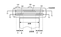
図3に示すように、加熱部材63は、記録紙Pの搬送方向と直交する幅方向(定着ベルト61の長手方向)に沿って少なくとも3つ以上(本実施の形態では7つ)に分割して配置された加熱領域をそれぞれ加熱する複数の抵抗発熱ヒータ63a〜63gで構成されている。
As shown in FIG. 3, the
ここで、加熱領域とは、各抵抗発熱ヒータ63a〜63gがそれぞれ加熱する定着ベルト61の内周面の特定の領域であって、抵抗発熱ヒータ63a〜63gの発熱領域に対向(接触)する定着ベルト61の内周面領域である。なお、以下においては、説明の便宜上、抵抗発熱ヒータ63a〜63gの発熱領域を加熱領域と称する場合がある。
Here, the heating area is a specific area on the inner peripheral surface of the fixing
これら各抵抗発熱ヒータ63a〜63gは、図4(a)に示すように、それぞれ独立して電源65に接続されており、加熱制御手段66によってその加熱状態が独立して制御できるようになっている。すなわち、各抵抗発熱ヒータ63a〜63gは、それぞれ独立して定着ベルト61の各々の対応する加熱領域を独立して加熱することができる。本実施の形態における抵抗発熱ヒータ63a〜63gは、それぞれ本発明に係る熱源を構成する。
Each of these
図4(b)に示すように、各抵抗発熱ヒータ63a〜63gの裏面(発熱領域を有するベルト接触面側と反対側の面)には、それぞれサーミスタ68a〜68gが取り付けられている。すなわち、サーミスタ68a〜68gは、各加熱領域ごとに設けられている。また、各サーミスタ68a〜68gは、各抵抗発熱ヒータ63a〜63gの裏面において、それぞれ定着ベルト61の長手方向の中央に配置されている。
As shown in FIG. 4B,
各サーミスタ68a〜68gは、各抵抗発熱ヒータ63a〜63gの発熱領域あるいは定着ベルト61の加熱領域の温度(定着ベルト温度)を検知するようになっている。加熱制御手段66は、各サーミスタ68a〜68gで検知された各加熱領域の温度に基づき定着ベルト61の温度を所望の温度に制御するようになっている。本実施の形態におけるサーミスタ68a〜68gは、本発明に係る温度検知手段を構成する。
Each of the
次に、図5(a)、(b)〜図9を参照して、加熱制御手段66により実行される各抵抗発熱ヒータ63a〜63gの加熱制御について説明する。
Next, with reference to FIGS. 5A and 5B to FIG. 9, the heating control of the
まず、上述の加熱制御を行うにあたっては、定着装置6に通紙される記録紙Pの紙幅に応じて第1の通紙パターン(図5(a)参照)と第2の通紙パターン(図7参照)とがあり、これら通紙パターンごとにその加熱制御内容が異なる。
First, in performing the above-described heating control, a first sheet passing pattern (see FIG. 5A) and a second sheet passing pattern (see FIG. 5A) are set according to the sheet width of the recording sheet P to be passed through the fixing
第1の通紙パターンは、図5(a)、(b)に示すように、定着ニップ部SNに通紙される記録紙Pが、各加熱領域(発熱領域)のうち少なくとも一の加熱領域(本実施の形態では、抵抗発熱ヒータ63b、63fの各加熱領域)の一部を通紙領域、残りを非通紙領域とする紙幅を有するとき、上記一の加熱領域に対応するサーミスタ(本実施の形態では、サーミスタ68b、68f)が通紙領域側、すなわち紙幅内に位置する場合である。
As shown in FIGS. 5A and 5B, the first sheet passing pattern is such that the recording sheet P to be passed through the fixing nip SN is at least one heating area (heating area). (In the present embodiment, the thermistor (this heating area of each of the
一方、第2の通紙パターンは、図7(a)、(b)に示すように、定着ニップ部SNに通紙される記録紙Pが、各加熱領域(発熱領域)のうち少なくとも一の加熱領域(本実施の形態では、抵抗発熱ヒータ63b、63fの各加熱領域)の一部を通紙領域、残りを非通紙領域とする紙幅を有するとき、上記一の加熱領域に対応するサーミスタ(本実施の形態では、サーミスタ68b、68f)が非通紙領域側、すなわち紙幅外に位置する場合である。なお、第2の通紙パターンにおける記録紙Pの紙幅は、第1の通紙パターンにおける記録紙Pの紙幅よりも小さい。
On the other hand, as shown in FIGS. 7A and 7B, the second paper passing pattern is such that the recording paper P passed through the fixing nip portion SN is at least one of the heating regions (heat generation regions). The thermistor corresponding to the one heating area when having a paper width in which a heating area (in this embodiment, each heating area of the
図5(a)、(b)に示すように、加熱制御手段66は、通紙パターンが第1の通紙パターンである場合には、上記一の加熱領域(本実施の形態では、抵抗発熱ヒータ63b、63fの各加熱領域)に対応するサーミスタ(本実施の形態では、サーミスタ68b、68f)の検知結果に基づき上記一の加熱領域に対応する抵抗発熱ヒータ(本実施の形態では、抵抗発熱ヒータ63b、63f)を制御する。
As shown in FIGS. 5A and 5B, when the sheet passing pattern is the first sheet passing pattern, the
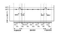
ここで、図6は、第1の通紙パターンで定着装置6の通紙後、所定時間(例えば、1分)経過後の定着ベルト61の表面の温度(定着ベルト温度)分布を示したものである。
Here, FIG. 6 shows the distribution of the surface temperature (fixing belt temperature) of the fixing
また、図6における領域Cは、抵抗発熱ヒータ63b、63fの各発熱領域内で、かつ定着ベルト61の熱が記録紙Pに奪われる領域である。これに対し、図6における領域C´は、抵抗発熱ヒータ63b、63fの各発熱領域内で、かつ定着ベルト61の熱が記録紙Pに奪われない領域である。
A region C in FIG. 6 is a region in which the heat of the fixing
第1の通紙パターンにおいて上述のような制御を行うと、図6に示すように、領域Cにおいては、抵抗発熱ヒータ63c、63d、63eの各加熱領域と同様、目標の定着ベルト温度(例えば160℃)に制御されている。これは、領域Cにおいては、抵抗発熱ヒータ63c、63d、63eの各加熱領域と同様、記録紙Pに熱が奪われるからである。
When the above-described control is performed in the first sheet passing pattern, the target fixing belt temperature (for example, in the area C, as in the heating areas of the
これに対して、領域C´においては、非通紙領域であるため領域Cに比べて抵抗発熱ヒータ63b、63fの熱が余り、定着ベルト温度が例えば180℃程度まで上昇してしまう。
On the other hand, since the region C ′ is a non-sheet passing region, the heat of the
このように、第1の通紙パターンでは、サーミスタ68b、68fが領域C内に位置するため、加熱領域を目標の定着ベルト温度(例えば160℃)に制御しようとすると、領域C´における定着ベルト温度が上昇してしまう。しかし、上昇した定着ベルト温度は、定着ベルト61の耐熱温度(例えば230℃)以下であるため、特に問題はないこととなる。
As described above, in the first sheet passing pattern, the
一方、図7(a)、(b)に示すように、加熱制御手段66は、通紙パターンが第2の通紙パターンである場合には、記録紙Pの紙幅(通紙領域)内に位置する他の加熱領域(本実施の形態では、例えば抵抗発熱ヒータ63c、63d、63eのいずれかの加熱領域)に対応するサーミスタ(本実施の形態では、サーミスタ68d)の検知結果に基づき上記一の加熱領域に対応する抵抗発熱ヒータ(本実施の形態では、抵抗発熱ヒータ63b、63f)を制御する。
On the other hand, as shown in FIGS. 7A and 7B, the heating control means 66 is within the sheet width (sheet passing area) of the recording sheet P when the sheet passing pattern is the second sheet passing pattern. Based on the detection result of the thermistor (
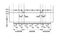
ここで、図8は、本実施の形態のような制御を行わない、つまり第2の通紙パターンにおいてサーミスタ68b、68fの検知結果に基づき抵抗発熱ヒータ63b、63fを制御する、従来の加熱部材63と定着ベルト温度との関係を示したものである。また、図8は、第2の通紙パターンで定着装置6の通紙後、所定時間(例えば、1分)経過後の定着ベルト61の表面の温度(定着ベルト温度)分布を示したものである。なお、図8では、従来の制御について説明するが、説明の便宜上、符号は本実施の形態と同様としている。
Here, FIG. 8 does not perform the control as in the present embodiment, that is, a conventional heating member that controls the
図8に示すように、第2の通紙パターンにおいて、領域Dは、抵抗発熱ヒータ63b、63fの各発熱領域内で、かつ定着ベルト61の熱が記録紙Pに奪われる領域である。これに対し、領域D´は、抵抗発熱ヒータ63b、63fの各発熱領域内で、かつ定着ベルト61の熱が記録紙Pに奪われない領域である。したがって、領域D´は、領域Dに比べて抵抗発熱ヒータ63b、63fの熱が余剰となるため、定着ベルト温度が上昇しやすい状況となっている。
As shown in FIG. 8, in the second sheet passing pattern, a region D is a region in which the heat of the fixing
このため、領域D´に位置するサーミスタ68b、68fの検知結果に基づき抵抗発熱ヒータ63b、63fを目標の定着ベルト温度(例えば160℃)に制御すると、抵抗発熱ヒータ63b、63fの発熱量が他の抵抗発熱ヒータ63c、63d、63eと比べて少なくなってしまう。これにより、記録紙Pに熱が奪われる領域Dにおける定着ベルト温度は、目標の定着ベルト温度よりも低下してしまう。
For this reason, if the
ここで、領域Dは、記録紙Pが通紙される領域であるため、上述のように定着ベルト温度が低下し過ぎると、トナーが定着せず、定着不良を発生させてしまうおそれがある。例えば、トナーが定着する下限温度(最低温度)が140℃であるとき、定着ベルト温度が130℃まで低下してしまうと、140℃以下となっている領域Dでは定着不良が発生するおそれがある。 Here, since the area D is an area through which the recording paper P is passed, if the fixing belt temperature is excessively lowered as described above, the toner is not fixed and there is a possibility that a fixing defect occurs. For example, when the lower limit temperature (minimum temperature) at which the toner is fixed is 140 ° C., if the fixing belt temperature is lowered to 130 ° C., there is a possibility that a fixing defect may occur in the region D of 140 ° C. or lower. .
そこで、本実施の形態では、上述したような領域Dでの定着不良の発生を防止するために、第2の通紙パターンにおいてサーミスタ68dの検知結果に基づき抵抗発熱ヒータ63b、63fを制御するようにした。
Therefore, in the present embodiment, in order to prevent the occurrence of fixing failure in the region D as described above, the
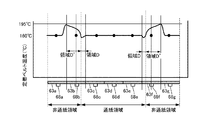
図9は、本実施の形態に係る制御を行った場合の加熱部材63と定着ベルト温度との関係を示したものであって、第2の通紙パターンで定着装置6の通紙後、所定時間(例えば、1分)経過後の定着ベルト温度分布を示したものである。
FIG. 9 shows the relationship between the
図9に示すように、本実施の形態では、上述の制御を行うことで抵抗発熱ヒータ63b、63fの発熱量が抵抗発熱ヒータ63dと同程度となる。この結果、領域Dにおける定着ベルト温度の低下が抑制される。
As shown in FIG. 9, in the present embodiment, the amount of heat generated by the
一方で、領域D´においては、抵抗発熱ヒータ63b、63fの発熱量が余剰となり、定着ベルト温度が上昇する。しかし、上昇した定着ベルト温度は、定着ベルト61の耐熱温度(例えば230℃)以下であるため、特に問題はないこととなる。このとき、サーミスタ68b、68fの検知温度は、目標の定着ベルト温度よりも高い状態で推移する。
On the other hand, in the region D ′, the heat generation amount of the
また、図9においては、領域Dの定着ベルト温度が目標の定着ベルト温度に対して若干ずれている。これは、抵抗発熱ヒータ63b、63fと抵抗発熱ヒータ63dの加熱タイミングは同じであるが、これら抵抗発熱ヒータ間にはもともと抵抗値のばらつきがあるため、同一時間、加熱しても(電流を流しても)、発熱量がずれてしまうことによる。
In FIG. 9, the fixing belt temperature in the region D is slightly deviated from the target fixing belt temperature. This is because the
本実施の形態では、第2の通紙パターンにおいてサーミスタ68dの検知結果に基づき抵抗発熱ヒータ63b、63fを制御する分だけ、領域Dにおける実際の定着ベルト温度と目標の定着ベルト温度と間にずれが生ずるが、図9に示すように定着品質(画質、定着性)には問題ない範囲に収まっている。
In the present embodiment, the actual fixing belt temperature in the region D is shifted from the target fixing belt temperature by an amount corresponding to the control of the
また、加熱制御手段66は、図示はしていないが、画像形成動作を実行する本体制御部に接続されている。この本体制御部は、サーミスタ68b、68fによって検知された定着ベルト温度が予め定められた所定温度以上となったことを条件に、記録紙間の間隔を広げるよう、定着ベルト温度が所定温度未満の場合と比較して画像形成速度を低下させる制御を行う。これにより、記録紙間の間隔が広がることで定着装置6における非通紙時間が画像形成動作を低下させる前と比べて多くなり、定着ベルト温度の過昇温が防止される。
Further, although not shown, the
以上のように、本実施の形態に係る定着装置6は、通紙パターンが第1の通紙パターンである場合には、サーミスタ68b、68fの検知結果に基づき抵抗発熱ヒータ63b、63fを制御するよう構成されている。このため、第1の通紙パターンでは、定着ベルト温度の低下を防止することができ、定着不良の発生を防止することができる。
As described above, when the sheet passing pattern is the first sheet passing pattern, the fixing
また、本実施の形態に係る定着装置6は、通紙パターンが第2の通紙パターンである場合には、サーミスタ68dの検知結果に基づき抵抗発熱ヒータ63b、63fを制御するよう構成されている。このため、第2の通紙パターンでは、特に記録紙Pに熱が奪われる領域Dにおける定着ベルト温度の低下を抑制することができる。したがって、従来、定着ベルト温度の低下に起因した定着不良が生じるおそれのあった領域Dにおいて目標の定着ベルト温度に近づけることができ、定着不良の発生を防止することができる。
Further, the fixing
なお、本実施の形態では、各サーミスタ68a〜68gを各抵抗発熱ヒータ63a〜63gの裏面において、それぞれ定着ベルト61の長手方向の中央に配置した例について説明したが、これに限らず、図10に示す配置としてもよい。
In the present embodiment, an example has been described in which the
すなわち、図10に示すように、各サーミスタ68a〜68g(ただし、サーミスタ68dは除く)は、それぞれ定着ベルト61の長手方向の中央(中央線O1)を基準に、各加熱領域の長手方向の中央(中央線O2)よりも外側に配置されるのが好ましい。
That is, as shown in FIG. 10, the
これにより、種々の紙幅の記録紙Pに対して第1の通紙パターンとなることを抑制することができる。このため、第1の通紙パターンで説明したような非通紙領域の定着ベルト温度の上昇を抑制することができる。したがって、定着ベルト61の耐熱性能に影響が生じるような温度(耐熱温度)まで定着ベルト温度が上昇する可能性を減らすことができる。
Thereby, it can suppress that it becomes the 1st paper passing pattern with respect to the recording paper P of various paper widths. For this reason, it is possible to suppress an increase in the fixing belt temperature in the non-sheet passing region as described in the first sheet passing pattern. Accordingly, it is possible to reduce the possibility that the fixing belt temperature rises to a temperature (heat resistant temperature) at which the heat resistance performance of the fixing
(第2の実施の形態)
次に、本発明の第2の実施の形態について説明する。
(Second Embodiment)
Next, a second embodiment of the present invention will be described.
本実施の形態は、第1の実施の形態とは、第2の通紙パターンにおける抵抗発熱ヒータ63b、63fの加熱制御に用いられるサーミスタが異なるが、他の構成は同一である。したがって、以下においては、図1から図9に示した第1の実施の形態と同一の符号を用いて説明し、特に相違点についてのみ詳述する。
The present embodiment is different from the first embodiment in the thermistors used for heating control of the
第1の実施の形態では、他の加熱領域は抵抗発熱ヒータ63c、63d、63eのいずれかの加熱領域として説明したが、本実施の形態では他の加熱領域は抵抗発熱ヒータ63b、63fに隣接する抵抗発熱ヒータ63c、63eの加熱領域である。
In the first embodiment, the other heating area has been described as one of the
したがって、加熱制御手段66は、通紙パターンが第2の通紙パターンである場合には、記録紙Pの紙幅(通紙領域)内に位置する他の加熱領域(本実施の形態では、抵抗発熱ヒータ63c、63eの加熱領域)に対応するサーミスタ(本実施の形態では、サーミスタ68c、68e)の検知結果に基づき上記一の加熱領域に対応する抵抗発熱ヒータ63b、63fを制御する。
Therefore, when the sheet passing pattern is the second sheet passing pattern, the heating control means 66 is another heating region (in this embodiment, a resistance in the present embodiment) positioned within the sheet width (sheet passing region). The
抵抗発熱ヒータ63b、63fの単位時間あたりの発熱量と他の抵抗発熱ヒータの単位時間あたりの発熱量とは、各部品のばらつき等のためずれてしまう。このため、サーミスタ68dの検知結果に基づき抵抗発熱ヒータ63b、63fを制御した場合には、徐々に抵抗発熱ヒータ63b、63fの加熱領域の温度は目標の定着ベルト温度からずれていってしまう。
The amount of heat generated per unit time of the
ここで、定着ベルト61や抵抗発熱ヒータは、長手方向にも伝熱するので、抵抗発熱ヒータ63b、63fの加熱領域の温度の影響は抵抗発熱ヒータ63c、63eの加熱領域にも伝わり、隣接するサーミスタ68c、68eの検知温度に影響を与える。こうした影響は、抵抗発熱ヒータ63b、63fの加熱領域の温度が目標の定着ベルト温度からずれにくくする方向に働く。
Here, since the fixing
したがって、隣接するサーミスタ68c、68eの検知結果に基づき加熱制御を行えば、サーミスタ68dで制御するよりも目標の定着ベルト温度に対する抵抗発熱ヒータ63b、63fの加熱領域の温度のずれを小さく抑えることができる。
Therefore, if the heating control is performed based on the detection results of the
(第3の実施の形態)
次に、本発明の第3の実施の形態について説明する。
(Third embodiment)
Next, a third embodiment of the present invention will be described.
本実施の形態は、第1の実施の形態とは、異なる紙幅の記録紙Pが混在した状態で通紙される点を考慮した点で異なるが、他の構成は同一である。したがって、以下においては、図1から図9に示した第1の実施の形態と同一の符号を用いて説明し、特に相違点についてのみ詳述する。 The present embodiment is different from the first embodiment in that the recording paper P having different paper widths is mixed and taken into consideration, but the other configurations are the same. Therefore, the following description will be made using the same reference numerals as those of the first embodiment shown in FIGS. 1 to 9, and only differences will be described in detail.
第1の実施の形態では、通紙パターンに応じてサーミスタ68b、68fまたはサーミスタ68dのいずれかを用いて抵抗発熱ヒータ63b、63fの加熱を行うようにしたが、本実施の形態では、通紙パターンが第1の通紙パターンか第2の通紙パターンかに関わらず、常に長手方向中央に配置されるサーミスタ68dの検知結果を用いて抵抗発熱ヒータ63b、63fを制御するようにした。
In the first embodiment, the
すなわち、同一の印刷ジョブ内において紙幅検知センサ67(図2参照)により検知された記録紙Pの紙幅が2種以上であって、第1の通紙パターンと第2の通紙パターンの記録紙Pが混在する場合に、加熱制御手段66は、常に、紙幅内に位置するサーミスタ68dの検知結果に基づき抵抗発熱ヒータ63b、63fを制御する。
That is, the recording paper P detected by the paper width detection sensor 67 (see FIG. 2) in the same print job has two or more paper widths, and the recording paper of the first paper passing pattern and the second paper passing pattern. When P is mixed, the heating control means 66 always controls the
例えば、第1の実施の形態では、奇数枚目は第1の通紙パターン、偶数枚目は第2の通紙パターンのように紙幅の異なる記録紙Pが交互に通紙される場合、加熱制御手段66は、奇数枚目はサーミスタ68b、68f、偶数枚目はサーミスタ68dの検知結果を用いて抵抗発熱ヒータ63b、63fの加熱制御を行うこととなる。
For example, in the first embodiment, when recording sheets P having different paper widths are alternately passed, such as a first sheet passing pattern for odd sheets and a second sheet passing pattern for even sheets, heating is performed. The control means 66 controls the heating of the
これでは、一枚ごとに温度を検知する場所が変わるため、検知温度が不連続となり加熱制御が不安定となる。特に、一般的に用いられているPID制御を行う場合、ある瞬間のヒータ加熱量を決定するためには、今回と前回の検知温度が必要となるため検知温度が不連続になると適切に加熱制御を行うことができない。 In this case, since the place where the temperature is detected is changed for each sheet, the detected temperature becomes discontinuous and the heating control becomes unstable. In particular, when performing PID control that is generally used, in order to determine the heater heating amount at a certain moment, the detected temperature of this time and the previous time are required. Can not do.
本実施の形態では、常に長手方向中央に配置されるサーミスタ68dの検知結果を用いて抵抗発熱ヒータ63b、63fを制御するので、検知温度が不連続となることがなく、適切に加熱制御を行うことができる。この点、第2の実施の形態のように隣接するサーミスタ68c、68eの検知結果を用いた場合には、大きなサイズ差のある記録紙Pが交互に通紙されると、やはり検知温度が不連続となってしまう。したがって、常に長手方向中央、すなわち通紙領域の中央に配置されたサーミスタ68dの検知結果を用いて抵抗発熱ヒータ63b、63fの加熱制御を行うことが好ましい。
In the present embodiment, the
なお、上述の各実施の形態では、通紙パターンの別による抵抗発熱ヒータ63a〜63gの加熱制御について説明してきたが、これとは別に記録紙Pに形成された画像領域に基づき抵抗発熱ヒータ63a〜63gの加熱割合を変更するようにしてもよい。
In each of the above-described embodiments, the heating control of the
例えば、図11(a)は、記録紙P上に図中、矢印で示す搬送方向の先端側から順に、画像領域a、非画像領域b、画像領域cが存在する画像形成パターンを示したものである。この場合、画像領域aと画像領域cでは、定着は必要であるが、非画像領域bでは定着対象のトナーが存在しないので定着の必要はない。 For example, FIG. 11A shows an image forming pattern in which an image area a, a non-image area b, and an image area c exist on the recording paper P in order from the leading end side in the transport direction indicated by an arrow in the figure. It is. In this case, the image area a and the image area c need to be fixed, but since there is no toner to be fixed in the non-image area b, there is no need for fixing.
このため、加熱制御手段66は、本体制御部から画像情報が入力されると、非画像領域bに対応する定着ベルト61の部位の温度が、画像領域a、cに対応する定着ベルト61の部位の温度よりも低くなるよう、抵抗発熱ヒータ63a〜63gへの通電量を制御する。ここで、画像領域a、cおよび非画像領域bに対応するとは、定着ベルト61が密着する位置という意味である。
For this reason, when the image information is input from the main body control unit, the
すなわち、加熱制御手段66は、まず画像領域aに対応する部位で抵抗発熱ヒータ63a〜63gの全加熱領域において定着温度が得られるよう、抵抗発熱ヒータ63a〜63gに電力を供給する。次いで、非画像領域bに対応する部位では、抵抗発熱ヒータ63a〜63gへの供給電力を遮断あるいは低減する。その後、画像領域cに対応する部位では、再度、定着温度が得られるよう抵抗発熱ヒータ63a〜63gに電力を供給する。
That is, the
このとき、実際の抵抗発熱ヒータ63a〜63gへの供給電力は、図中の斜線部で示すように画像領域aあるいは画像領域cが定着ニップ部SNに入るよりも前の部分(予備加熱領域という)を予備的に加熱するように供給される。この予備加熱領域は、主に加熱部材63の周方向の発熱長さや、抵抗発熱ヒータ63a〜63g自身の昇温時間のために必要となる領域である。こうした予備加熱領域は、省エネの観点から可能な限り小さい方が望ましい。
At this time, the power supplied to the actual
なお、図11(b)に示す画像形成パターンにおいても、図11(a)と画像領域cがない点で異なるが、基本的には上述した例と同様に抵抗発熱ヒータ63a〜63gへの供給電力の制御を行う。
The image forming pattern shown in FIG. 11B is also different from FIG. 11A in that there is no image area c, but is basically supplied to the
また、図12(a)は、記録紙P上に図中、矢印で示す搬送方向と直交する幅方向(定着ベルト61の長手方向)に、画像領域a、非画像領域bが存在する画像形成パターンを示したものである。 12A shows an image formation in which an image area a and a non-image area b exist on the recording paper P in the width direction (longitudinal direction of the fixing belt 61) perpendicular to the conveyance direction indicated by the arrow in the drawing. It shows a pattern.
このような場合にあっても、加熱制御手段66は、非画像領域bに対応する定着ベルト61の部位の温度が、画像領域aに対応する定着ベルト61の部位の温度よりも低くなるように抵抗発熱ヒータ63a〜63gへの通電量を制御する。
Even in such a case, the
すなわち、加熱制御手段66は、抵抗発熱ヒータ63a〜63gのうち、画像領域aに対応する抵抗発熱ヒータの加熱領域において定着温度が得られるよう、当該抵抗発熱ヒータに電力を供給する。一方で、抵抗発熱ヒータ63a〜63gのうち、非画像領域bに対応する抵抗発熱ヒータに対しては、供給電力を遮断あるいは低減する。このような例においても、上記図11に示した例と同様、図中の斜線部で示す予備加熱領域が必要となる。
That is, the heating control means 66 supplies power to the
なお、図12(b)に示す画像形成パターンにおいても、図12(a)と画像領域cがある点で異なるが、基本的には上述した例と同様に抵抗発熱ヒータ63a〜63gへの供給電力の制御を行う。ただし、この場合、画像領域cは、記録紙Pの幅方向全域に亘って形成されているので、図11(a)に示した例と同様の制御を行うことが好ましい。
Note that the image forming pattern shown in FIG. 12B also differs from FIG. 12A in that there is an image region c, but basically, it is supplied to the
1 プリンタ(画像形成装置)
6 定着装置
61 定着ベルト(定着部材)
62 加圧ローラ(加圧部材)
63 加熱部材
63a〜63g 抵抗発熱ヒータ(熱源)
65 電源
66 加熱制御手段
67 紙幅検知センサ(紙幅検知手段)
68a〜68g サーミスタ(温度検知手段)
P 記録紙
1 Printer (image forming device)
6 Fixing
62 Pressure roller (Pressure member)
63
65
68a-68g thermistor (temperature detection means)
P Recording paper
Claims (8)
前記加熱部材は、前記記録紙の搬送方向と直交する幅方向に沿って少なくとも3つ以上に分割された加熱領域をそれぞれ加熱する複数の熱源で構成され、
前記加熱部材あるいは前記定着部材の温度を検知する温度検知手段を、前記加熱領域ごとに設け、
前記加熱制御手段は、前記定着ニップ部に通紙される前記記録紙が前記加熱領域のうち少なくとも一の加熱領域の一部を通紙領域、残りを非通紙領域とする紙幅を有するとき、前記一の加熱領域に対応する前記温度検知手段が前記非通紙領域側に位置する場合には、前記紙幅内に位置する他の加熱領域に対応する前記温度検知手段の検知結果に基づき前記一の加熱領域に対応する前記熱源を制御することを特徴とする定着装置。 A fixing member that rotates in contact with a recording paper carrying an unfixed image, a pressure member that forms a fixing nip portion with the fixing member, a heating member that heats the fixing member, and the heating member A fixing device for fixing the unfixed image on the recording paper passing through the fixing nip portion by pressurization by the pressurizing member and heating by the heating member,
The heating member is composed of a plurality of heat sources that respectively heat at least three heating regions divided along a width direction orthogonal to the conveyance direction of the recording paper,
A temperature detecting means for detecting the temperature of the heating member or the fixing member is provided for each heating region,
When the recording paper that is passed through the fixing nip portion has a paper width in which a part of at least one of the heating areas is a passing area, and the rest is a non-passing area, When the temperature detection means corresponding to the one heating area is located on the non-sheet passing area side, the one temperature detection means corresponding to the other heating area located within the paper width is used to detect the one temperature detection means. A fixing device that controls the heat source corresponding to the heating area.
前記記録紙の紙幅を検知する紙幅検知手段と、を備えたことを特徴とする画像形成装置。 A fixing device according to claim 1;
An image forming apparatus comprising: a paper width detecting unit that detects a paper width of the recording paper.
Priority Applications (1)
| Application Number | Priority Date | Filing Date | Title |
|---|---|---|---|
| JP2013139884A JP2015014645A (en) | 2013-07-03 | 2013-07-03 | Fixing apparatus and image forming apparatus including the same |
Applications Claiming Priority (1)
| Application Number | Priority Date | Filing Date | Title |
|---|---|---|---|
| JP2013139884A JP2015014645A (en) | 2013-07-03 | 2013-07-03 | Fixing apparatus and image forming apparatus including the same |
Related Child Applications (1)
| Application Number | Title | Priority Date | Filing Date |
|---|---|---|---|
| JP2018010313A Division JP6421884B2 (en) | 2018-01-25 | 2018-01-25 | Fixing device and image forming apparatus having the same |
Publications (1)
| Publication Number | Publication Date |
|---|---|
| JP2015014645A true JP2015014645A (en) | 2015-01-22 |
Family
ID=52436412
Family Applications (1)
| Application Number | Title | Priority Date | Filing Date |
|---|---|---|---|
| JP2013139884A Pending JP2015014645A (en) | 2013-07-03 | 2013-07-03 | Fixing apparatus and image forming apparatus including the same |
Country Status (1)
| Country | Link |
|---|---|
| JP (1) | JP2015014645A (en) |
Cited By (10)
| Publication number | Priority date | Publication date | Assignee | Title |
|---|---|---|---|---|
| JP2017009848A (en) * | 2015-06-24 | 2017-01-12 | 株式会社リコー | Fixing device and image forming apparatus |
| JP2017227664A (en) * | 2016-06-20 | 2017-12-28 | 株式会社東芝 | Fixation device and image formation device |
| JP2018146957A (en) * | 2017-03-06 | 2018-09-20 | キヤノン株式会社 | Heater and image heating apparatus |
| CN109283817A (en) * | 2017-07-20 | 2019-01-29 | 东芝泰格有限公司 | Image forming apparatus and control method |
| US20190212679A1 (en) * | 2018-01-05 | 2019-07-11 | Canon Kabushiki Kaisha | Image heating apparatus and image forming apparatus that control electrical power supply to a plurality of heat generating elements based on a temperature detected by a temperature detecting element |
| JP2019168721A (en) * | 2019-06-26 | 2019-10-03 | 株式会社リコー | Fixing device and image forming apparatus |
| JP2020166009A (en) * | 2019-03-28 | 2020-10-08 | キヤノン株式会社 | Image heating device and image forming device |
| JP2021060626A (en) * | 2021-01-21 | 2021-04-15 | キヤノン株式会社 | Image heating device and image forming apparatus |
| JP2022120189A (en) * | 2016-06-20 | 2022-08-17 | 株式会社東芝 | Heating device and image forming apparatus |
| US11448986B2 (en) | 2016-07-01 | 2022-09-20 | Canon Kabushiki Kaisha | Image forming apparatus and image heating apparatus |
Citations (5)
| Publication number | Priority date | Publication date | Assignee | Title |
|---|---|---|---|---|
| JPH05135848A (en) * | 1991-11-13 | 1993-06-01 | Canon Inc | Heating device |
| JP2001343860A (en) * | 2000-03-31 | 2001-12-14 | Ricoh Co Ltd | Fixing device and image forming device |
| JP2003151722A (en) * | 2001-11-13 | 2003-05-23 | Sharp Corp | Heating device and heating system |
| JP2009186891A (en) * | 2008-02-08 | 2009-08-20 | Canon Inc | Image forming apparatus |
| JP2012145700A (en) * | 2011-01-11 | 2012-08-02 | Ricoh Co Ltd | Image forming device |
-
2013
- 2013-07-03 JP JP2013139884A patent/JP2015014645A/en active Pending
Patent Citations (5)
| Publication number | Priority date | Publication date | Assignee | Title |
|---|---|---|---|---|
| JPH05135848A (en) * | 1991-11-13 | 1993-06-01 | Canon Inc | Heating device |
| JP2001343860A (en) * | 2000-03-31 | 2001-12-14 | Ricoh Co Ltd | Fixing device and image forming device |
| JP2003151722A (en) * | 2001-11-13 | 2003-05-23 | Sharp Corp | Heating device and heating system |
| JP2009186891A (en) * | 2008-02-08 | 2009-08-20 | Canon Inc | Image forming apparatus |
| JP2012145700A (en) * | 2011-01-11 | 2012-08-02 | Ricoh Co Ltd | Image forming device |
Cited By (18)
| Publication number | Priority date | Publication date | Assignee | Title |
|---|---|---|---|---|
| JP2017009848A (en) * | 2015-06-24 | 2017-01-12 | 株式会社リコー | Fixing device and image forming apparatus |
| JP2017227664A (en) * | 2016-06-20 | 2017-12-28 | 株式会社東芝 | Fixation device and image formation device |
| JP7259118B2 (en) | 2016-06-20 | 2023-04-17 | 株式会社東芝 | Heating device, image forming device |
| JP2022120189A (en) * | 2016-06-20 | 2022-08-17 | 株式会社東芝 | Heating device and image forming apparatus |
| US11448986B2 (en) | 2016-07-01 | 2022-09-20 | Canon Kabushiki Kaisha | Image forming apparatus and image heating apparatus |
| JP7071129B2 (en) | 2017-03-06 | 2022-05-18 | キヤノン株式会社 | Heater and image heating device |
| JP2018146957A (en) * | 2017-03-06 | 2018-09-20 | キヤノン株式会社 | Heater and image heating apparatus |
| JP2019020655A (en) * | 2017-07-20 | 2019-02-07 | 株式会社東芝 | Image forming apparatus and control method |
| CN109283817A (en) * | 2017-07-20 | 2019-01-29 | 东芝泰格有限公司 | Image forming apparatus and control method |
| US10656573B2 (en) | 2018-01-05 | 2020-05-19 | Canon Kabushiki Kaisha | Image heating apparatus and image forming apparatus that control electrical power supply to a plurality of heat generating elements based on a temperature detected by a temperature detecting element |
| JP7059013B2 (en) | 2018-01-05 | 2022-04-25 | キヤノン株式会社 | Image forming device |
| JP2019120809A (en) * | 2018-01-05 | 2019-07-22 | キヤノン株式会社 | Image forming apparatus |
| US20190212679A1 (en) * | 2018-01-05 | 2019-07-11 | Canon Kabushiki Kaisha | Image heating apparatus and image forming apparatus that control electrical power supply to a plurality of heat generating elements based on a temperature detected by a temperature detecting element |
| JP2020166009A (en) * | 2019-03-28 | 2020-10-08 | キヤノン株式会社 | Image heating device and image forming device |
| JP7305400B2 (en) | 2019-03-28 | 2023-07-10 | キヤノン株式会社 | Image heating device and image forming device |
| JP2019168721A (en) * | 2019-06-26 | 2019-10-03 | 株式会社リコー | Fixing device and image forming apparatus |
| JP2021060626A (en) * | 2021-01-21 | 2021-04-15 | キヤノン株式会社 | Image heating device and image forming apparatus |
| JP7081006B2 (en) | 2021-01-21 | 2022-06-06 | キヤノン株式会社 | Image heating device and image forming device |
Similar Documents
| Publication | Publication Date | Title |
|---|---|---|
| JP2015014645A (en) | Fixing apparatus and image forming apparatus including the same | |
| CN108931907B (en) | Fixing device and image forming apparatus | |
| JP4804024B2 (en) | Image heating apparatus and image forming apparatus | |
| US9122212B2 (en) | Fixing device and image forming apparatus including same | |
| JP2015129792A (en) | image forming apparatus | |
| JP2015129789A (en) | image forming apparatus | |
| JP2015084082A (en) | Fixing device and image forming apparatus | |
| JP2016133711A (en) | Fixing device and image forming apparatus | |
| JP2014056146A (en) | Fixing device and image forming apparatus | |
| JP2015052722A (en) | Fixing device and image forming apparatus | |
| JP6421884B2 (en) | Fixing device and image forming apparatus having the same | |
| JP2014153480A (en) | Fixing device and image forming apparatus | |
| JP2006267234A (en) | Heating body and image heating apparatus | |
| JP2015121654A (en) | Fixing apparatus and image forming apparatus | |
| JP6300060B2 (en) | Fixing apparatus and image forming apparatus | |
| JP6673033B2 (en) | Fixing device and image forming device | |
| JP2014224924A (en) | Fixing device and image forming apparatus | |
| JP2014228677A (en) | Image forming apparatus | |
| JP2015165277A (en) | Fixing device and image forming apparatus | |
| JP2014109600A (en) | Fixing device and image forming apparatus using the same | |
| JP2014224927A (en) | Fixing device and image forming apparatus | |
| JP2014178427A (en) | Fixing device and image forming apparatus | |
| JP2011033998A (en) | Image heating device | |
| JP2017120392A (en) | Fixing device and image forming apparatus | |
| JP2007108296A (en) | Heating device |
Legal Events
| Date | Code | Title | Description |
|---|---|---|---|
| A621 | Written request for application examination |
Free format text: JAPANESE INTERMEDIATE CODE: A621 Effective date: 20160630 |
|
| A977 | Report on retrieval |
Free format text: JAPANESE INTERMEDIATE CODE: A971007 Effective date: 20170223 |
|
| A131 | Notification of reasons for refusal |
Free format text: JAPANESE INTERMEDIATE CODE: A131 Effective date: 20170307 |
|
| A521 | Request for written amendment filed |
Free format text: JAPANESE INTERMEDIATE CODE: A523 Effective date: 20170428 |
|
| A131 | Notification of reasons for refusal |
Free format text: JAPANESE INTERMEDIATE CODE: A131 Effective date: 20170613 |
|
| A521 | Request for written amendment filed |
Free format text: JAPANESE INTERMEDIATE CODE: A523 Effective date: 20170731 |
|
| A02 | Decision of refusal |
Free format text: JAPANESE INTERMEDIATE CODE: A02 Effective date: 20171107 |