JP7057497B2 - Biometric information detection system - Google Patents
Biometric information detection system Download PDFInfo
- Publication number
- JP7057497B2 JP7057497B2 JP2018085928A JP2018085928A JP7057497B2 JP 7057497 B2 JP7057497 B2 JP 7057497B2 JP 2018085928 A JP2018085928 A JP 2018085928A JP 2018085928 A JP2018085928 A JP 2018085928A JP 7057497 B2 JP7057497 B2 JP 7057497B2
- Authority
- JP
- Japan
- Prior art keywords
- point
- seat
- biosensors
- biosensor
- biometric information
- Prior art date
- Legal status (The legal status is an assumption and is not a legal conclusion. Google has not performed a legal analysis and makes no representation as to the accuracy of the status listed.)
- Active
Links
Images


Description
本発明は、生体情報検出システムに関する。 The present invention relates to a biological information detection system.
車両を運転する運転者(乗員)の健康状態が悪化した場合、車両の運転に悪影響を及ぼすおそれがあるため、健康状態の悪化を事前に検知して何らかの対策を施すことが望ましい。このような対策として、シートの座面及び背面部に埋め込まれるようにして設けられた非接触式の血流センサーによる脈波等の計測結果に基づいて、血流や血圧等の生体情報を推定して乗員の健康状態を把握する技術が知られている(特許文献1参照。)。 If the health condition of the driver (occupant) who drives the vehicle deteriorates, it may adversely affect the driving of the vehicle. Therefore, it is desirable to detect the deterioration of the health condition in advance and take some measures. As such a measure, biological information such as blood flow and blood pressure is estimated based on the measurement results of pulse waves and the like by a non-contact blood flow sensor provided so as to be embedded in the seat surface and the back surface of the seat. A technique for grasping the health condition of an occupant is known (see Patent Document 1).
ところが、例えばセンサーの故障など、何らかの原因で生体情報の検出が困難になってしまうと、乗員の健康状態を把握できない場合がある。
本発明は上記事情に鑑みてなされたものであり、例えばセンサーの故障などのトラブルが発生しても生体情報を検出する機能を継続させることが可能な生体情報検出システムを提供することを目的とする。
However, if it becomes difficult to detect biometric information for some reason, such as a sensor failure, it may not be possible to ascertain the health status of the occupant.
The present invention has been made in view of the above circumstances, and an object of the present invention is to provide a biometric information detection system capable of continuing the function of detecting biometric information even if a trouble such as a sensor failure occurs. do.
以上の課題を解決するため、請求項1に記載の発明は、人が着座するシートのうち、第一地点と第二地点の少なくとも2地点に、血流量の変化を計測する生体センサーが配置され、前記第一地点の前記生体センサーと前記第二地点の前記生体センサーとを連繋させて生体情報の検出を行う生体情報検出システムにおいて、
前記第一地点における前記生体センサーから前記第二地点における前記生体センサーまでの距離を算出し、前記第一地点の前記生体センサーと前記第二地点の前記生体センサーによって前記血流量の変化を計測し、
前記第一地点に配置された前記生体センサーは少なくとも一つであり、
前記第二地点に配置された前記生体センサーは少なくとも二つであり、
前記第二地点における少なくとも二つの前記生体センサーは、前記第一地点における少なくとも一つの前記生体センサーに対し、互いに異なる系統で連繋していることを特徴とする。
In order to solve the above problems, in the invention according to
The distance from the biosensor at the first point to the biosensor at the second point is calculated, and the change in blood flow is measured by the biosensor at the first point and the biosensor at the second point. ,
There is at least one biosensor located at the first point.
There are at least two biosensors located at the second point,
The at least two biosensors at the second point are linked to at least one biosensor at the first point by different systems.
請求項2に記載の発明は、請求項1に記載の生体情報検出システムにおいて、前記第一地点に前記生体センサーが複数配置されていることを特徴とする。
The invention according to
請求項3に記載の発明は、請求項1又は2に記載の生体情報検出システムにおいて、前記第二地点における少なくとも二つの前記生体センサーは、前記シートの左右に振り分けられて配置されていることを特徴とする。 According to the third aspect of the present invention, in the biometric information detection system according to the first or second aspect, at least two biosensors at the second point are arranged on the left and right sides of the sheet. It is a feature.
請求項4に記載の発明は、請求項1~3のいずれか一項に記載の生体情報検出システムにおいて、
前記シートは、人の臀部及び大腿部を支持するシートクッションと、下端部が前記シートクッションに支持されたシートバックと、を備えており、
前記第一地点と前記第二地点のうち一方は、前記シートクッションに位置し、他方は、前記シートバックに位置していることを特徴とする。
The invention according to
The seat includes a seat cushion that supports the buttocks and thighs of a person, and a seat back whose lower end is supported by the seat cushion.
One of the first point and the second point is located on the seat cushion, and the other is located on the seat back.
請求項5に記載の発明は、請求項1~3のいずれか一項に記載の生体情報検出システムにおいて、
前記シートは、人の臀部及び大腿部を支持するシートクッションと、下端部が前記シートクッションに支持されたシートバックと、を備えており、
前記第一地点と前記第二地点は、前記シートクッションと前記シートバックのうち、いずれか一方に位置していることを特徴とする。
The invention according to
The seat includes a seat cushion that supports the buttocks and thighs of a person, and a seat back whose lower end is supported by the seat cushion.
The first point and the second point are characterized in that they are located on either one of the seat cushion and the seat back.
請求項6に記載の発明は、請求項1~5のいずれか一項に記載の生体情報検出システムにおいて、
人の着座を検知する着座センサーを備えており、
前記第一地点に配置された前記生体センサーと、前記第二地点に配置された前記生体センサーのうち、少なくとも一方は前記着座センサーと連動していることを特徴とする。
The invention according to
Equipped with a seating sensor that detects the seating of a person,
One of the biosensors arranged at the first point and the biosensors arranged at the second point is characterized in that at least one of them is interlocked with the seating sensor.
請求項7に記載の発明は、請求項1~6のいずれか一項に記載の生体情報検出システムにおいて、
前記第一地点に配置された前記生体センサーと前記第二地点に配置された前記生体センサーとの、前記異なる系統における連繋が断たれているか、断たれていないかを自己診断する自己診断手段を備えることを特徴とする。
The invention according to
A self-diagnosis means for self-diagnosing whether or not the connection between the biosensor arranged at the first point and the biosensor located at the second point is broken or not in the different systems. It is characterized by being prepared.
請求項8に記載の発明は、請求項7に記載の生体情報検出システムにおいて、前記異なる系統のうち、いずれか一つの系統における連繋が断たれた場合の通知を出力する出力部を備えることを特徴とする。
The invention according to
請求項9に記載の発明は、請求項7又は8に記載の生体情報検出システムにおいて、外部との通信が可能とされ、前記異なる系統のうち、いずれか一つの系統における連繋が断たれた場合の通知を外部に送信する通信部を備えることを特徴とする。
The invention according to
請求項10に記載の発明は、請求項1~9のいずれか一項に記載の生体情報検出システムにおいて、前記シートは、乗物用シートであって、人の臀部及び大腿部を支持するシートクッションと、下端部が前記シートクッションに支持されたシートバックと、前記シートバックに設けられて人の頭部を支持するヘッドレストと、を備えており、
前記シートクッションは、骨格となるシートクッションフレームと、前記シートクッションフレーム上に設けられたクッションパッドと、前記シートクッションフレーム及び前記クッションパッドを被覆する表皮と、から構成され、
前記シートバックは、骨格となるシートバックフレームと、前記シートバックフレーム上に設けられたクッションパッドと、前記シートバックフレーム及び前記クッションパッドを被覆する表皮と、前記クッションパッドと前記表皮との間に設けられたシートヒーターと、から構成されていることを特徴とする。
The invention according to
The seat cushion is composed of a seat cushion frame serving as a skeleton, a cushion pad provided on the seat cushion frame, and a skin covering the seat cushion frame and the cushion pad.
The seat back is between a seat back frame serving as a skeleton, a cushion pad provided on the seat back frame, a skin covering the seat back frame and the cushion pad, and the cushion pad and the skin. It is characterized by being composed of a seat heater provided .
請求項1に記載の発明によれば、異なる系統のうち一つの系統における連繋が断たれても、残りの系統においては第一地点における生体センサーと第二地点における生体センサーとが連繋した状態を維持できるので、例えば第二地点におけるどちらか一方の生体センサーの故障などのトラブルが発生しても生体情報を検出する機能を継続させることが可能となり、シートに着座する人の健康状態を把握できる。
また、第二地点における生体センサーは複数であり、第一地点における生体センサーを含め、各生体センサーを万遍なく使用すれば、生体情報を検出する精度が向上しやすい。
According to the invention of
Further, there are a plurality of biosensors at the second point, and if each biosensor including the biosensor at the first point is used evenly, the accuracy of detecting biometric information can be easily improved.
請求項2に記載の発明によれば、第一地点に生体センサーが複数配置されているので、例えば第一地点における一つの生体センサーに何らかのトラブルが発生しても、残りの生体センサーによって生体情報を検出する機能を継続させることができる。
また、第一地点における生体センサーが複数であり、第二地点における生体センサーも複数であり、これらの生体センサーを万遍なく使用すれば、生体情報を検出する精度が向上しやすい。一方、第一地点における複数の生体センサーを、例えば一つを稼働させ、残りを停止させておくと、使用電力の削減を図ることができる。
According to the second aspect of the present invention, since a plurality of biosensors are arranged at the first point, even if some trouble occurs in one biosensor at the first point, the remaining biosensors provide biometric information. The function to detect is can be continued.
Further, there are a plurality of biosensors at the first point and a plurality of biosensors at the second point, and if these biosensors are used evenly, the accuracy of detecting biometric information can be easily improved. On the other hand, if a plurality of biosensors at the first point are operated, for example, and the rest are stopped, the power consumption can be reduced.
請求項3に記載の発明によれば、第二地点における少なくとも二つの生体センサーを、シートの左右に分散できるので、第二地点における少なくとも二つの生体センサーが同時に使用不可となるような事態を回避しやすい。 According to the third aspect of the present invention, at least two biosensors at the second point can be dispersed to the left and right of the seat, so that a situation in which at least two biosensors at the second point cannot be used at the same time is avoided. It's easy to do.
請求項4に記載の発明によれば、第一地点における生体センサーと、第二地点における生体センサーを、シートのシートクッション側とシートバック側に分散できるので、各生体センサーを配置できるスペースを確保しやすい。
According to the invention of
請求項5に記載の発明によれば、第一地点における生体センサーと、第二地点における生体センサーを、シートのシートクッション側若しくはシートバック側に寄せて配置できるので、各生体センサーを、ひとまとめにして配置することができる。
According to the invention of
請求項6に記載の発明によれば、シートへの人の着座を検知してから各生体センサーを稼働させることができるので、使用電力の削減を図ることができる。
According to the invention of
請求項7に記載の発明によれば、第一地点に配置された生体センサーと第二地点に配置された生体センサーによって生体情報の検出を行うことが可能な状態であるか否かを把握しやすくなる。
According to the invention of
請求項8に記載の発明によれば、異なる系統のうち、いずれか一つの系統における連繋が断たれた場合の通知を、出力部から出力できるので、第一地点に配置された生体センサーと第二地点に配置された生体センサーによって生体情報の検出を行うことが可能な状態であるか否かを、シートに着座する人や周囲の人が把握しやすくなる。
According to the invention of
請求項9に記載の発明によれば、異なる系統のうち、いずれか一つの系統における連繋が断たれた場合の通知を、通信部を通じて外部に送信できるので、第一地点に配置された生体センサーと第二地点に配置された生体センサーによって生体情報の検出を行うことが可能な状態であるか否かを、外部の人も把握しやすくなる。
According to the invention of
請求項10に記載の発明によれば、シートは、乗物用シートであるため、乗物用シートに着座する人の健康状態を把握できる。 According to the tenth aspect of the present invention, since the seat is a vehicle seat, the health condition of the person seated on the vehicle seat can be grasped.
以下、図面を参照して本発明の実施の形態について説明する。ただし、以下に述べる実施形態には、本発明を実施するために技術的に好ましい種々の限定が付されているが、本発明の技術的範囲を以下の実施形態および図示例に限定するものではない。 Hereinafter, embodiments of the present invention will be described with reference to the drawings. However, although the embodiments described below are provided with various technically preferable limitations for carrying out the present invention, the technical scope of the present invention is not limited to the following embodiments and illustrated examples. not.
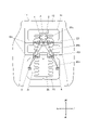
本実施形態における生体情報検出システムは、図1~図5に示すように、人が着座するシート10のうち、第一地点Aと第二地点Bの少なくとも2地点に生体センサーが配置され、第一地点Aの生体センサーと第二地点Bの生体センサーとを連繋させて生体情報の検出を行うためのものである。
また、このような生体情報検出システムは、第一地点Aにおける生体センサーと、第二地点Bにおける生体センサーの他に、制御部5、記憶部6、入力部7、出力部8、通信部9を備えている(図4参照。)。
なお、シート10は、乗物用シートであり、本実施形態においては、乗用車の運転席用シートとされている。ただし、これに限られるものではなく、乗用車の運転席以外のシートでもよいし、バスやトラック等の他の自動車におけるシートでもよいし、鉄道や船舶、航空機等の自動車以外の乗り物におけるシートでもよい。
In the biometric information detection system of the present embodiment, as shown in FIGS. 1 to 5, biosensors are arranged at at least two points, a first point A and a second point B, among the
Further, such a biometric information detection system includes a
The
第一地点A及び第二地点Bは、シート10における任意の部位を指しており、特に限定されるものではないが、本実施形態においては、第一地点Aが、シート10のシートバック14とされ、第二地点Bが、シート10のシートクッション11とされている。
すなわち、第一地点Aと第二地点Bは、シート10のうちの二箇所であり、互いに離間した位置とされており、各地点A,Bに配置された生体センサー同士も、シート10のうちの二箇所に、互いに離間して配置された状態となっている。
なお、第一地点Aが、シートクッション11に位置し、第二地点Bが、シートバック14に位置していてもよい。
The first point A and the second point B refer to arbitrary parts in the
That is, the first point A and the second point B are two points in the
The first point A may be located on the
第一地点Aに配置された生体センサーは少なくとも一つであり、第二地点Bに配置された生体センサーは少なくとも二つである。
図1に示す例において、第一地点Aに配置された少なくとも一つの生体センサーには、第一センサー1が含まれている。また、第二地点Bに配置された少なくとも二つの生体センサーには、第三センサー3と第四センサー4とが含まれている。
そして、第二地点Bにおける二つの生体センサー3,4は、第一地点Aにおける一つの生体センサー1に対し、互いに異なる系統で連繋している。
また、図1においては、異なる二つの系統があり、通常時は一つの系統のみが稼働状態であり、残りが予備として停止している状態にあって、稼働状態の系統における生体センサー同士の連繋が万が一断たれた場合に、非稼働状態の系統における生体センサー同士の連繋が稼働状態となる例を表している。
There is at least one biosensor located at the first point A and at least two biosensors located at the second point B.
In the example shown in FIG. 1, at least one biosensor located at the first point A includes the
Then, the two
Further, in FIG. 1, there are two different systems, in which only one system is normally in an operating state and the rest is stopped as a spare, and the biosensors in the operating system are connected to each other. However, in the unlikely event that it is cut off, the connection between the biosensors in the non-operating system becomes the operating state.
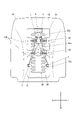
また、第一地点Aに配置される生体センサーは複数であってもよい。
図2,図3に示す例において、第一地点Aに配置された少なくとも一つの生体センサーには、第一センサー1と第二センサー2とが含まれている。また、第二地点Bに配置された少なくとも二つの生体センサーには、第三センサー3と第四センサー4とが含まれている。
そして、第二地点Bにおける二つの生体センサー3,4は、第一地点Aにおける二つの生体センサー1,2に対し、互いに異なる系統で連繋している。
また、図2においては、異なる四つの系統があり、通常時は、実線で示す二つの系統が稼働状態で、二点鎖線で示す残りの二つの系統が予備として停止している状態である例を表している。
さらに、図3においては、実線で示す異なる四つの系統の全てが稼働状態である例を表している。
Further, there may be a plurality of biosensors arranged at the first point A.
In the example shown in FIGS. 2 and 3, at least one biosensor arranged at the first point A includes the
Then, the two
Further, in FIG. 2, there are four different systems, and in a normal state, the two systems shown by the solid line are in the operating state, and the remaining two systems shown by the alternate long and short dash line are stopped as spares. Represents.
Further, FIG. 3 shows an example in which all four different systems shown by solid lines are in an operating state.
第一地点Aにおける生体センサーを一つにするか複数にするかは任意である。生体センサーを一つにすれば、製造コストやランニングコスト、製造の簡易性の面で有利であり、生体センサーを複数にすれば生体情報検出精度の向上を図る上で有利となる。
また、第二地点Bにおける生体センサーを、第一地点Aにおける生体センサーに対し、互いに異なる系統で連繋させ、当該異なる系統の全てを稼働状態にするか、一つの系統を稼働状態とさせ、残りを停止させておくかも任意である。全ての系統を稼働状態にすれば生体情報検出精度の向上を図る上で有利となり、一つの系統のみを稼働状態にすればランニングコストの面で有利である。
さらに、第一地点Aにおける生体センサーの数と、第二地点Bにおける生体センサーの数を共に複数とする場合は、それぞれ二つに限らず、三つ以上としてもよい。このように、使用される生体センサーの数が増えると、その分、第一地点Aにおける生体センサーと第二地点Bにおける生体センサーとを連繋させる系統の数も増えることになる。
It is arbitrary whether the number of biosensors at the first point A is one or multiple. A single biosensor is advantageous in terms of manufacturing cost, running cost, and ease of manufacturing, and a plurality of biosensors is advantageous in improving the accuracy of biometric information detection.
Further, the biosensor at the second point B is connected to the biosensor at the first point A by different systems, and all of the different systems are put into operation, or one system is put into operation, and the rest. It is also optional to stop. It is advantageous to improve the biometric information detection accuracy if all the systems are in the operating state, and it is advantageous in terms of running cost if only one system is in the operating state.
Further, when the number of biosensors at the first point A and the number of biosensors at the second point B are both plural, the number is not limited to two, and may be three or more. As described above, as the number of biosensors used increases, the number of systems connecting the biosensor at the first point A and the biosensor at the second point B also increases accordingly.
本実施形態においては、図5に示すように、第一地点Aにおける生体センサーには、第一センサー1と第二センサー2とが含まれているものとし、第二地点Bにおける生体センサーには、第三センサー3と第四センサー4とが含まれているものとする。
In the present embodiment, as shown in FIG. 5, it is assumed that the biosensor at the first point A includes the
第一地点Aに配置されたセンサーと第二地点Bに配置されたセンサーは、制御部5によって、システムの一部として間接的に連繋された状態となっている。ただし、これに限られるものではなく、実際に通信線や電源線によって直接的に接続された状態となるように連繋していてもよい。
The sensor arranged at the first point A and the sensor arranged at the second point B are indirectly connected as a part of the system by the
本実施形態における生体センサー1~4は、血流量の変化を計測して脈波を測定するためのものであり、電磁波によって人の生体情報を検出する非接触型とされ、被計測領域の皮膚表面に対向する位置の血流を計測することができる。
なお、電磁波とは、100MHz程度の電波やマイクロ波を始め、赤外光、可視光、紫外光、X線等を含む広義の電磁波を意味しており、人体に悪影響を及ぼさない範囲で好適な電磁波が使用される。
このような電磁波は、例えば鉄や銅、アルミ等を始めとする種々の金属を通過しにくいという特徴がある。そのため、本実施形態における生体センサー1~4は、シート10に対し、電磁波の通過を妨害する(おそれのある)部材を避けた位置に配置されている。特に、電磁波の通貨を妨害する部材よりも着座面側に設けられることが望ましい。
The
The electromagnetic wave means an electromagnetic wave in a broad sense including radio waves and microwaves of about 100 MHz, infrared light, visible light, ultraviolet light, X-rays, etc., and is suitable as long as it does not adversely affect the human body. Electromagnetic waves are used.
Such electromagnetic waves are characterized in that they do not easily pass through various metals such as iron, copper, and aluminum. Therefore, the
そして、第一地点Aにおける生体センサーと第二地点Bにおける生体センサーが、シート10のうちの二箇所に、互いに離間して配置されていると、シート10に着座する人の心臓の位置(心臓があると推定される位置)から、第一地点Aにおける生体センサーと第二地点Bにおける生体センサーまでの距離が算出できるため、脈波を測定する上で好ましい。
When the biosensor at the first point A and the biosensor at the second point B are arranged at two positions in the
生体情報検出システムは、シート10の第一地点Aと第二地点Bに設けられた各生体センサー1~4の他に、図4に示すように、制御部5、記憶部6、入力部7、出力部8、通信部9を備える。
制御部5、記憶部6、入力部7、出力部8、通信部9は、必ずしもシート10に設けられなくてもよく、シート10の周囲に設けられるものとしてもよい。本実施形態におけるシート10は、上述のように乗用車の運転席用シートとされているため、運転席の周囲に設けられてもよいし、乗用車に備えられていればよいものとする。
As shown in FIG. 4, the biometric information detection system includes a
The
制御部5は、CPU(Central Processing Unit)、RAM(Random Access Memory)、ROM(Read Only Memory)を備え、生体情報検出のための各種動作を行う。すなわち、当該制御部5による制御に基づいて、生体情報検出システムを構成する各部の動作を実行することができる。
The
記憶部6は、例えばRAM、ROM、不揮発性メモリ、ハードディスクドライブにより構成され、生体情報の検出に必要な各種プログラムや各種データが記憶されている。
この記憶部6に記憶された各種プログラムには、生体情報演算プログラム、生体情報検出プログラム、自己診断プログラム、通知プログラム、通信プログラムを始め、様々なプログラムが含まれている。各種プログラムは、制御部5によって実行されてその機能を発揮する。
The
The various programs stored in the
入力部7は、システムに対して各種データを入力するためのものであり、例えばシート10に周りに設置される機器の筐体に付属するボタンやタッチパネル等のような入力手段でもよいし、接続インターフェースによって接続された各種入力デバイスでもよい。このような入力部7によって、システムの各種設定を行うことができる。
The
出力部8は、システムによる生体情報の検出結果を出力するためのものであり、各種画像や文字等を表示するディスプレイ、音声を出力する音声出力手段(スピーカー)、光を発する発光手段(LED:light emitting diodeなど)、振動を起こすバイブレーターなど、様々なものが挙げられる。
The
通信部9は、インターネットやLAN(Local Area Network)等の通信ネットワーク(コンピュータネットワーク)に対して生体情報検出システムを通信可能に接続するものであり、当該通信部9を介してデータの送受信ができるようになっている。
The
記憶部6に記憶された各種プログラムについて説明すると、まず、生体情報演算プログラムは、シート10の第一地点Aと第二地点Bに設けられた各生体センサー1~4によって計測して得られた血流状態に係るデータを利用して、シート10に着座する人の血圧(動脈圧)などを演算して求めるためのプログラムである。
Explaining various programs stored in the
生体情報検出プログラムは、第一地点Aにおける生体センサーによる生体情報の検出結果と、第二地点Bにおける生体センサーによる生体情報の検出結果から、シート10に着座する人の脈波を測定するプログラムである。
このプログラムでは、第一地点Aにおける第一センサー1及び第二センサー2の稼働・非稼働状態や、第二地点Bにおける第三センサー3及び第四センサー4の稼働・非稼働状態についても設定することができる。
すなわち、第二地点Bにおける生体センサーを、第一地点Aにおける生体センサーに対し、互いに異なる系統で連繋させ、当該異なる系統の全てを稼働状態にするか、一つの系統を稼働状態とさせ、残りを停止させておくかなどをプログラムに設定しておくことができる。そのため、通常時には、生体情報検出プログラムに設定されたとおりに各生体センサーは動作する。
また、一つの系統のみが稼働状態であり、残りが停止している状態にあって、稼働状態の系統における生体センサー同士の連繋が万が一断たれた場合に、非稼働状態の系統における生体センサー同士の連繋が稼働状態となるようなプログラムとしてもよい。
また、異なる系統の全てが稼働状態であり、いずれかの系統における生体センサー同士の連繋が万が一断たれた場合に、残りの系統における生体センサー同士の連繋を継続して稼働状態とするプログラムとしてもよい。少なくとも一つの系統における生体センサー同士の連繋が継続されればよいものとする。
さらに、以上の動作を適宜選択して実行するプログラムとしてもよいし、入力部7からの情報入力によって選択されて動作を実行するプログラムとしてもよい。
The biometric information detection program is a program that measures the pulse wave of a person sitting on the
In this program, the operating / non-operating state of the
That is, the biosensor at the second point B is connected to the biosensor at the first point A by different systems, and all of the different systems are put into operation, or one system is put into operation, and the rest. It is possible to set in the program whether to stop or not. Therefore, in normal times, each biosensor operates as set in the biometric information detection program.
In addition, if only one system is in operation and the rest are stopped, and the connection between the biosensors in the operating system is broken, the biosensors in the non-operating system are connected to each other. It may be a program that activates the connection of.
In addition, if all of the different systems are in operation and the connection between the biosensors in one of the systems is interrupted, the connection between the biosensors in the remaining systems will be continuously put into operation. good. It suffices if the connection between the biosensors in at least one system is continued.
Further, it may be a program that appropriately selects and executes the above operation, or may be a program that is selected by inputting information from the
自己診断プログラムは、第一地点Aに配置された生体センサー1,2と第二地点Bに配置された生体センサー3,4との、異なる系統における連繋が断たれているか、断たれていないかを自己診断するためのものである。
自己診断の手法には、例えば生体センサーが電波式の脈波センサーであり、かつ反射型の脈波測定を行うものである場合に、生体センサーからテストパターンの電磁波を発し、反射して返ってくる電磁波が正しいか否かを確認する自己診断の手法や、生体センサーから発せられる電磁波の周波数が設定どおりか否かをマイコンで確認する手法など、様々なものが挙げられる。自己診断プログラムには、このような様々な手法のうち、システムに採用される生体センサーに好適な手法が適宜されて採用されてプログラミングされているものとする。
In the self-diagnosis program, is the connection between the
In the self-diagnosis method, for example, when the biosensor is a radio wave type pulse wave sensor and the reflection type pulse wave measurement is performed, the biosensor emits an electromagnetic wave of a test pattern, and the electromagnetic wave is reflected and returned. There are various methods such as a self-diagnosis method for confirming whether or not the incoming electromagnetic wave is correct, and a method for confirming whether or not the frequency of the electromagnetic wave emitted from the biological sensor is as set by the microcomputer. It is assumed that the self-diagnosis program is programmed by appropriately adopting the method suitable for the biosensor adopted in the system among such various methods.
通知プログラムは、異なる系統のうち、いずれか一つの系統における連繋が断たれた場合の通知を出力部8から出力するためのものである。
出力部8は、上述のように、ディスプレイ、スピーカー、LED、バイブレーターなどであり、これら出力部8によって通知を出力する。出力部8がディスプレイである場合は、画像や文字によって通知し、スピーカーである場合は音声で通知し、LEDである場合は光(点滅や点灯)で通知し、バイブレーターである場合は振動で通知する。また、これら各種の出力部8を組み合わせて通知を出力してもよい。
通知が出力部8から出力されれば、シート10に着座する人はもちろんのこと、シート10が搭載された乗用車に同乗する人にも、シート10に着座する人の健康状態を把握させることができる。
The notification program is for outputting a notification from the
As described above, the
If the notification is output from the
通信プログラムは、異なる系統のうち、いずれか一つの系統における連繋が断たれた場合の通知を、通信部9を介して外部に送信するためのものである。
通信部9は、上述のように、インターネットやLAN(Local Area Network)等の通信ネットワーク(コンピュータネットワーク)に対して生体情報検出システムを通信可能に接続するものであり、通信ネットワークに接続された外部の装置(サーバなど)や端末(スマートフォンやタブレットPCなど)に対して通知に係るデータを送信することができる。
外部の装置や端末は、例えばシート10が搭載された乗用車のディーラーが所有するものであってもよいし、医療機関が所有するものであってもよいし、シート10に着座する人若しくはその家族が所有するものであってもよい。
通知データが外部に送信されれば、外部の人にも、シート10に着座する人の健康状態を把握させることができる。
The communication program is for transmitting a notification when the connection in any one of the different systems is broken to the outside via the
As described above, the
The external device or terminal may be owned by, for example, a dealer of a passenger car equipped with the
If the notification data is transmitted to the outside, the outside person can also grasp the health condition of the person sitting on the
続いて、各生体センサー1~4が設けられるシート10について詳細に説明する。本実施形態におけるシート10は、図5に示すように、人の臀部及び大腿部を支持する上述のシートクッション11と、下端部がシートクッション11に支持されて背もたれとなる上述のシートバック14と、シートバック14に設けられて人の頭部を支持するヘッドレスト17と、を備える。
Subsequently, the
シートクッション11は、骨格となるシートクッションフレームと、シートクッションフレーム上に設けられたクッションパッド12と、シートクッションフレーム及びクッションパッド12を被覆する表皮13と、から主に構成されている。
本実施形態のシートクッション11は、さらにクッションパッド12と表皮13との間に設けられたシートヒーター20を備えている。
なお、シートヒーター20は、シートクッション11を温める面状発熱体であって、ポリエステルの布材等からなる面状の基材21と、基材21に接着固定される金属製のヒーター線22(電熱線ともいう)と、から主に構成されている。ヒーター線22は、クッションパッド12上面の前方側の区画に位置する前方ヒーター線22aと、中央側の区画に位置する中央ヒーター線22bと、後方側の区画に位置する後方ヒーター線22cと、前方ヒーター線22a、中央ヒーター線22b、後方ヒーター線22c同士を連結し、クッションパッド12に形成された溝12a内部に差し込まれる溝部ヒーター線23と、から構成されている(図6,図8参照。)。
The
The
The
シートバック14は、骨格となるシートバックフレームと、シートバックフレーム上に設けられたクッションパッド15と、シートバックフレーム及びクッションパッド15を被覆する表皮16と、から主に構成されている。
本実施形態のシートバック14は、さらにクッションパッド15と表皮16との間に設けられたシートヒーター30を備えている。
シートバック14におけるシートヒーター30も同様に、基材31と、ヒーター線32と、から主に構成されている。ヒーター線32は、クッションパッド15前面の上方側の区画に位置する上方ヒーター線32aと、中央側の区画に位置する中央ヒーター線32bと、下方側の区画に位置する下方ヒーター線32cと、上方ヒーター線32a、中央ヒーター線32b、下方ヒーター線32c同士を連結し、クッションパッド15に形成された溝15a内部に差し込まれる溝部ヒーター線33と、から構成されている(図7,図9参照。)。
The seat back 14 is mainly composed of a seat back frame serving as a skeleton, a
The seat back 14 of the present embodiment further includes a
Similarly, the
上述のとおり、第一地点Aは、シート10におけるシートバック14とされ、第二地点Bは、シート10のシートクッション11とされている。したがって、第一センサー1及び第二センサー2は、シートバック14に配置され、第三センサー3及び第四センサー4は、シートクッション11に配置されている。より詳細には、各生体センサー1~4は、表皮13,14の内側で、クッションパッド12,15に埋め込まれるようにして設けられている。
As described above, the first point A is the seat back 14 in the
第一センサー1及び第二センサー2は、シートバック14のうち、シートヒーター30よりも着座面に近い側であって、かつ中央側に配置され、左右に並んで設けられている。
第三センサー3及び第四センサー4は、シートクッション11のうち、シートヒーター20よりも着座面に近い側に配置され、左右に振り分けられて設けられている。すなわち、シート10に着座する人の左右の大腿部に対応して配置されている。
The
The
なお、シート10の着座面とは、シートクッション11の場合は、人の臀部及び大腿部が接する面を指し、シートバック14の場合は、人の背中(胸部側、腰部側)が接する面を指す。そのため、第一センサー1及び第二センサー2を、人の心臓の位置に対応して配置でき、胸部大動脈の血流状態を把握しやすくなる。また、第三センサー3及び第四センサー4を、大腿部の位置に対応して配置でき、膝窩動脈の血流状態を把握しやすくなる。
In the case of the
なお、本実施形態におけるシート10は、自動運転と手動運転とを切り替えて走行可能な車両に設けられていてもよい。また、安全性の向上のために、各生体センサー1~4と、シート10に着座する人の様子を撮影するカメラ(図示せず。)を併用してもよい。各生体センサー1~4とカメラを併用すれば、着座していてもハンドルに手が置かれていない人が、健康状態が悪化しているかいないかだけでなく、単に居眠りしているだけかどうかを判別することができる。
また、シート10に着座する人の声を集音するマイクを採用し、各生体センサー1~4とマイクを併用して、意識の有無を確認できるようにしてもよい。すなわち、シート10に着座する人に対して発話を促し、応答がない場合は、意識が無いと判断することができる。
The
Further, a microphone that collects the voice of a person sitting on the
生体センサー1~4によって計測して得られた血流状態に係るデータを利用することで、例えば、血圧、心拍数(脈拍数)、呼吸数、動脈血中酸素飽和度(SpO2)など、シート10に着座する人の様々な生体情報の取得に対応することが可能となる。用いる生体センサーの種類によっては、応用的にストレスレベルや血管年齢なども取得することができる。
By using the data related to the blood flow state measured by the
以上のような本実施の形態によれば、第二地点Bにおける少なくとも二つの生体センサー3,4は、第一地点Aにおける少なくとも一つの生体センサー1に対し、互いに異なる系統で連繋しているので、異なる系統のうち一つの系統における連繋が断たれても、残りの系統においては第一地点Aにおける生体センサー1と第二地点Bにおける生体センサー3,4とが連繋した状態を維持できる。これにより、例えば第二地点Bにおけるどちらか一方の生体センサー3(4)の故障などのトラブルが発生しても生体情報を検出する機能を継続させることが可能となり、シート10に着座する人の健康状態を把握できる。つまり、万が一の場合を考慮した所謂フェールセーフ機能を発揮することができる。
また、第二地点Bにおける生体センサー3,4は複数であり、第一地点Aにおける生体センサー1,2を含め、各生体センサー1~4を万遍なく使用すれば、生体情報を検出する精度が向上しやすい。
さらに、シート10は、乗物用シートであるため、乗物用シートに着座する人の健康状態を把握できる。
しかも、異なる系統での連繋を、シート10に着座する人が大人である場合と、子供である場合とで使い分けることも可能となり、利便性に優れる。
According to the present embodiment as described above, at least two
Further, there are a plurality of
Further, since the
Moreover, it is possible to properly use the connection in different systems depending on whether the person sitting on the
また、第一地点Aには生体センサーが複数配置されているので、例えば第一地点Aにおける一つの生体センサー1に何らかのトラブルが発生しても、残りの生体センサー2によって生体情報を検出する機能を継続させることができる。
さらに、第一地点Aにおける生体センサー1,2が複数であり、第二地点Bにおける生体センサー3,4も複数であり、これらの生体センサー1~4を万遍なく使用すれば、生体情報を検出する精度が向上しやすい。一方、第一地点Aにおける複数の生体センサー1,2を、例えば一つを稼働させ、残りを停止させておくと、使用電力の削減を図ることができる。
Further, since a plurality of biosensors are arranged at the first point A, for example, even if some trouble occurs in one
Further, there are a plurality of
また、第二地点Bにおける少なくとも二つの生体センサー3,4は、シート10の左右に振り分けられて配置されているので、第二地点Bにおける少なくとも二つの生体センサー3,4を、シート10の左右に分散できる。これにより、第二地点Bにおける少なくとも二つの生体センサー3,4が同時に使用不可となるような事態を回避しやすい。
Further, since at least two
また、第一地点Aと第二地点Bのうち一方は、シートクッション11に位置し、他方は、シートバック14に位置しているので、第一地点Aにおける生体センサー1,2と、第二地点Bにおける生体センサー3,4を、シート10のシートクッション11側とシートバック14側に分散できる。これにより、各生体センサー1~4を配置できるスペースを確保しやすい。
Further, since one of the first point A and the second point B is located on the
また、第一地点Aに配置された生体センサー1,2と第二地点Bに配置された生体センサー3,4との、異なる系統における連繋が断たれているか、断たれていないかを自己診断する自己診断手段を備えるので、第一地点Aに配置された生体センサー1,2と第二地点Bに配置された生体センサー3,4によって生体情報の検出を行うことが可能な状態であるか否かを把握しやすくなる。
In addition, it is self-diagnosed whether the connections between the
また、異なる系統のうち、いずれか一つの系統における連繋が断たれた場合の通知を出力する出力部8を備えるので、異なる系統のうち、いずれか一つの系統における連繋が断たれた場合の通知を、出力部8から出力できる。これにより、第一地点Aに配置された生体センサー1,2と第二地点Bに配置された生体センサー3,4によって生体情報の検出を行うことが可能な状態であるか否かを、シート10に着座する人や周囲の人が把握しやすくなる。
Further, since the
また、外部との通信が可能とされ、異なる系統のうち、いずれか一つの系統における連繋が断たれた場合の通知を外部に送信する通信部9を備えるので、異なる系統のうち、いずれか一つの系統における連繋が断たれた場合の通知を、通信部9を通じて外部に送信できる。これにより、第一地点Aに配置された生体センサー1,2と第二地点Bに配置された生体センサー3,4によって生体情報の検出を行うことが可能な状態であるか否かを、外部の人も把握しやすくなる。
Further, since communication with the outside is possible and the
〔変形例〕
なお、本発明を適用可能な実施形態は、上述した実施形態に限定されることなく、本発明の趣旨を逸脱しない範囲で適宜変更可能である。以下、変形例について説明する。以下に挙げる変形例は可能な限り組み合わせてもよい。
[Modification example]
The embodiment to which the present invention is applicable is not limited to the above-described embodiment, and can be appropriately changed without departing from the spirit of the present invention. Hereinafter, a modified example will be described. The following modifications may be combined as much as possible.
〔変形例1〕
本変形例においては、シートが、人の臀部及び大腿部を支持するシートクッション11と、下端部がシートクッション11に支持されたシートバック14と、を備えるものであり、第一地点Aと第二地点Bは、シートクッション11とシートバック14のうち、いずれか一方に位置している。
また、第二地点Bにおける少なくとも二つの生体センサー3,4は、シートの左右に振り分けられて配置されていてもよいし、第一地点Aにおける複数の生体センサー1,2も、シートの左右に振り分けられて配置されていてもよい。
さらに、第一地点A及び第二地点Bにおける各生体センサー1~4は、シートの左側若しくは右側に寄って配置されてもよい。なお、シートが、乗用車の運転席用シートとされている場合、各生体センサー1~4は、乗用車が側突された場合を考慮して左側に寄せて配置することが望ましい。
[Modification 1]
In this modification, the seat includes a
Further, at least two
Further, the
図6に示す例においては、第一地点Aと第二地点Bが、シートクッション11に位置している。より詳細に説明すると、第一地点Aは、シートクッション11における後方部分、すなわち、シートに着座する人の臀部を支持する部位に位置している。第二地点Bは、シートクッション11における前方部分、すなわち、シートに着座する人の大腿部を支持する部位に位置している。
第一地点Aにおける生体センサー(第一センサー1、第二センサー2)は、シートクッション11の後方部分における中央部に、左右に並んで配置されている。
第二地点Bにおける生体センサー(第三センサー3、第四センサー4)は、シートクッション11の前方部分における左右に振り分けられて配置されている。すなわち、シートに着座する人の左右の大腿部に対応して配置されている。
第一地点Aにおける第一センサー1及び第二センサー2は、互いに近接して配置されているが、人の臀部を支持する位置に配置されていればよいため、互いに離間して配置されていてもよい。
In the example shown in FIG. 6, the first point A and the second point B are located on the
The biosensors (
The biosensors (
The
図7に示す例においては、第一地点Aと第二地点Bが、シートバック14に位置している。より詳細に説明すると、第一地点Aは、シートバック14における上方部分、すなわち、シートに着座する人の胸部を支持する部位に位置している。第二地点Bは、シートバック14における下方部分、すなわち、シートに着座する人の腰部を支持する部位に位置している。
第一地点Aにおける生体センサー(第一センサー1、第二センサー2)は、シートバック14の上方部分における中央部に、左右に並んで配置されている。
第二地点Bにおける生体センサー(第三センサー3、第四センサー4)は、シートバック14の下方部分における左右に振り分けられて配置されている。ただし、これに限られるものではなく、中央部に、左右に並んで配置されるようにしてもよい。
In the example shown in FIG. 7, the first point A and the second point B are located on the seat back 14. More specifically, the first point A is located in the upper portion of the seat back 14, that is, the portion supporting the chest of the person sitting on the seat. The second point B is located in the lower portion of the seat back 14, that is, the portion supporting the waist of the person sitting on the seat.
The biosensors (
The biosensors (
図8に示す例においては、第一地点Aと第二地点Bが、シートクッション11に位置している。より詳細に説明すると、第一地点Aは、シートクッション11における後方部分、すなわち、シートに着座する人の臀部を支持する部位に位置している。第二地点Bは、シートクッション11における前方部分、すなわち、シートに着座する人の大腿部を支持する部位に位置している。さらに、第一地点Aと第二地点Bは、シートクッション11の左側に寄った部位に位置している。
第一地点Aにおける生体センサー(第一センサー1、第二センサー2)は、シートクッション11の後方部分における左側部に、左右に並んで配置されている。
第二地点Bにおける生体センサー(第三センサー3、第四センサー4)は、シートクッション11の前方部分における左側部に、左右に並んで配置されている。
第一地点Aにおける第一センサー1及び第二センサー2、第二地点Bにおける第三センサー3及び第四センサー4は、互いに近接して配置されている。
In the example shown in FIG. 8, the first point A and the second point B are located on the
The biosensors (
The biosensors (
The
図9に示す例においては、第一地点Aと第二地点Bが、シートバック14に位置している。より詳細に説明すると、第一地点Aは、シートバック14における上方部分、すなわち、シートに着座する人の胸部を支持する部位に位置している。第二地点Bは、シートバック14における下方部分、すなわち、シートに着座する人の腰部を支持する部位に位置している。
第一地点Aにおける生体センサー(第一センサー1、第二センサー2)は、シートバック14の上方部分における左側部に、左右に並んで配置されている。
第二地点Bにおける生体センサー(第三センサー3、第四センサー4)は、シートバック14の下方部分における左側部に、左右に並んで配置されている。
第一地点Aにおける第一センサー1及び第二センサー2、第二地点Bにおける第三センサー3及び第四センサー4は、互いに近接して配置されている。
In the example shown in FIG. 9, the first point A and the second point B are located on the seat back 14. More specifically, the first point A is located in the upper portion of the seat back 14, that is, the portion supporting the chest of the person sitting on the seat. The second point B is located in the lower portion of the seat back 14, that is, the portion supporting the waist of the person sitting on the seat.
The biosensors (
The biosensors (
The
本変形例によれば、第一地点Aと第二地点Bが、シートクッション11とシートバック14のうち、いずれか一方に位置しているので、第一地点Aにおける生体センサー1,2と、第二地点Bにおける生体センサー3,4を、シートのシートクッション11側若しくはシートバック14側に寄せて配置できる。これにより、各生体センサー1~4を、ひとまとめにして配置することができる。
さらに、第一地点Aにおける複数の生体センサー1,2と、第二地点Bにおける少なくとも二つの生体センサー3,4が、それぞれシートの左右に振り分けられて配置されているので、第一地点Aにおける複数の生体センサー1,2と、第二地点Bにおける少なくとも二つの生体センサー3,4を、シート10の左右に分散できる。これにより、第一地点Aと第二地点Bにおける生体センサー1~4が同時に使用不可となるような事態を回避しやすい。
また、第一地点A及び第二地点Bにおける各生体センサー1~4が、シートの左側若しくは右側に寄って配置されているので、各生体センサー1~4が配置されていない側に衝撃を受けた場合に、各生体センサー1~4が使用不可となるような事態を回避しやすい。
According to this modification, since the first point A and the second point B are located on either one of the
Further, since the plurality of
Further, since the
〔変形例2〕
本変形例における第一地点Aは、シートの左側に位置し、第二地点Bは、シートの右側に位置している。すなわち、上述の実施形態及び変形例1においては、第一地点Aと第二地点Bの位置関係が、シートの前後方向に振り分けられるか、上下方向に振り分けられるものであったが、本変形例における第一地点Aと第二地点Bの位置関係は、左右方向に振り分けられている。
本変形例によれば、例えば、どこか一つの生体センサーの故障などのトラブルが発生しても生体情報を検出する機能を継続させることが可能となるという効果を発揮することはもちろんのこと、生体センサー1~4の配置についてバリエーションを増やすことができる。
[Modification 2]
The first point A in this modification is located on the left side of the seat, and the second point B is located on the right side of the seat. That is, in the above-described embodiment and the first modification, the positional relationship between the first point A and the second point B is distributed in the front-rear direction or the vertical direction of the sheet. The positional relationship between the first point A and the second point B in the above is distributed in the left-right direction.
According to this modification, it is possible to continue the function of detecting biometric information even if a trouble such as a failure of any one biosensor occurs. Variations can be increased in the arrangement of
〔変形例3〕
本変形例におけるシート40には、図10に示すようなシートフレーム41が内蔵されている。シートフレーム41は、シートクッションを構成するクッションフレーム42と、シートバックを構成するシートバックフレーム43、を有している。
クッションフレーム42及びシートバックフレーム43には、それぞれクッションパッド42aが設けられ、さらに表皮42bが被せられることで、シート40を構成している。
[Modification 3]
The
A
クッションフレーム42は、前後に長く延びるとともに左右に離間して配置された一対のサイドフレーム44と、この一対のサイドフレーム44の前端部同士を接続する板金から構成されたパンフレーム45と、一対のサイドフレーム44の後端部同士を接続する金属パイプから構成された連結パイプ46とを備えて平面視で枠状に構成されている。
そして、パンフレーム45と連結パイプ46との間には、シートスプリング47が架設されている。
The
A seat spring 47 is erected between the
シートスプリング47は、前後に長く延びるとともに左右に並んだ4つのバネ部材47A~47Dと、これらのバネ部材47A~47D同士を連結する樹脂製の連結部材48A~48Cにより構成されている。
各バネ部材47A~47Dは、金属線が屈曲されてなり、後端に連結パイプ46に引っ掛けるためのフック部47Aa~47Daが形成され、このフック部47Aa~47Daから前方に向けて延びるとともに左右にジグザグに屈曲している。各バネ部材47A~47Dの前端は、図10に示すようにパンフレーム45に連結されており、各バネ部材47A~47Dの位置ずれを防いでいる。
The seat spring 47 is composed of four
Each of the
そして、生体センサー1~4が、クッションフレーム42に対して設けられている。本変形例においては、各バネ部材47A~47Dが、電磁波の通過を妨害する部材であり、生体センサー1~4は、これら各バネ部材47A~47Dを避けた位置に配置されている。
より具体的に説明すると、生体センサー1~4は、図11に示すように、連結部材48A~48Cに対して設けられている。その位置は、人の臀部における左右の坐骨の中央部に対応する箇所か、大腿部の位置に対応する箇所となっている。そして、本変形例においては、人の臀部における左右の坐骨の中央部に対応する箇所(クッションフレーム42の後方部分)が第一地点Aとされており、大腿部の位置に対応する箇所(クッションフレーム42の前方部分)が第二地点Bとされている。
第一地点Aにおける第一センサー1及び第二センサー2は、前後に並んで配置されている。一方、第二地点Bにおける第三センサー3及び第四センサー4は、左右に並んで配置されている。
The
More specifically, the
The
連結部材48A~48Cは、少なくとも上面が、各バネ部材47A~47Dよりも人に近い位置に配置されるものであり、生体センサー1~4は、このような連結部材48A~48Cに設けられているため、生体センサー1~4によって計測を行う上で、各バネ部材47A~47Dによる影響を受けにくくなっている。
連結部材48A~48Cは、各バネ部材47A~47Dを連結するように設けられている。連結部材48A~48Cは、換言すれば、板状に形成された箇所を有し、その箇所の上面が生体センサー1~4の設置面とされた被設置板である。
The connecting
The connecting
なお、以上の各連結部材48A~48Cの上には生体センサー1~4を配置することができるが、シート40におけるクッションパッド42aのうち、生体センサー1が配置された箇所の上方に位置する箇所には、生体センサー1を収容できる凹部420が形成されている。すなわち、凹部420は、図12に示すように、クッションパッド42aの下面において凹むように形成されている。
The
また、上述のように、各バネ部材47A~47Dの前端はパンフレーム45に連結されており、各バネ部材47A~47Dの位置ずれを防いでいるので、各バネ部材47A~47Dを連結する連結部材48A~48Cに設けられた生体センサー1~4の位置ずれも抑制することができる。
Further, as described above, the front ends of the
また、パンフレーム45の上にも生体センサー1~4を配置してもよい。パンフレーム45は、上述のように板金で構成されているため、電磁波の通過を妨害する部材であり、生体センサー1~4を配置する際は、その上面側に配置することが好ましい。すなわち、生体センサー1~4は、電磁波の通過を妨害する部材(パンフレーム45)よりも人に近い位置に配置されることになる。
パンフレーム45上面に生体センサー1~4を配置する場合は、パンフレーム45中央側の平らな箇所でもよいし、周縁側の傾斜した箇所であってもよい。
また、図10に示すような開口部45aを利用して、生体センサー1~4を、パンフレーム45よりも人に遠い位置に配置してもよい。
Further, the
When the
Further, the
また、生体センサー1~4は、図12に示すように、クッションフレーム42に設けられたクッションパッド42aに埋め込まれるようにして設けられてもよいものとする。生体センサー1~4をクッションパッド42aに埋め込むようにして設ける場合は、クッションパッド42a自体を、生体センサー1~4が埋設された状態で形成するような、いわゆるインサート成形によって設けてもよい。なお、生体センサー1~4が、クッションパッド42aに埋め込まれるようにして設けられる場合、クッションパッド42aに、生体センサー1~4を収容するための凹部(図示せず。)を形成して、生体センサー1~4を設置しやすくしてもよい。
Further, as shown in FIG. 12, the
また、生体センサー1~4をクッションパッド42aに埋め込むようにして設けるに当たっては、以上のようなインサート成形によるものだけに限られず、クッションパッド42aの成形後であっても生体センサー1~4を埋設できるようにすることが望ましい。すなわち、クッションパッド42aの一部(図12における取り外し部422)を取り外し可能に構成し、当該取り外し部422に対応する位置に生体センサー1~4を収容する凹部421を形成する形態を採用してもよい。
つまり、生体センサー1~4をクッションパッド42aに埋め込むようにして設ける際は、取り外し部422を取り外し、凹部421に生体センサー1を収容し、取り外し部422を嵌め込んで元に戻すことで、生体センサー1をクッションパッド42aに埋め込むことができる。
なお、本変形例においては、取り外し部422は、クッションパッド42aの下面側から取り外せる形態となっているが、上面側から取り外せる形態としてもよい。
また、クッションパッド42a内には、生体センサー1~4の他にも、生体センサー1~4と外部装置(例えば発電素子や記憶装置、制御装置等。)とを電気的に接続するハーネス(図示せず)を配線できる空間が形成されているものとする。
Further, when the
That is, when the
In this modification, the
Further, in the
また、クッションパッド42a内には、図12に示すように、シート40に対する人の着座を検知する着座センサー423が設けられる場合がある。
そして、第一地点Aに配置された生体センサー1,2と、第二地点Bに配置された生体センサー3,4のうち、少なくとも一方は着座センサー423と連動している。すなわち、第一地点Aに配置された生体センサー1,2と、第二地点Bに配置された生体センサー3,4のうち、少なくとも一方は、着座センサー423によって人の着座が検知された場合に作動するように設定されている。
Further, as shown in FIG. 12, a
Then, at least one of the
シートバックフレーム43は、図10に示すように、上下に長く延びるとともに左右に離間して配置された一対のサイドフレーム43aと、一対のサイドフレーム43aの上端部間に架け渡されて設けられた上部フレーム43bと、一対のサイドフレーム43aの下端部間に架け渡されて設けられた板状のロアメンバー43cと、を備えている。また、上部フレーム43bと、ロアメンバー43cとの間には、一対のサイドフレーム43a間に架け渡されるようにして複数のバネ部材からなるシートスプリング43dが設けられている。
シートスプリング43dを構成する複数のバネ部材は、左右に向けて延びるとともに上下にジグザグに屈曲している。
以上のように構成されたシートバックフレーム43に対しても、上述のクッションフレーム42側と同様に、生体センサー1~4を設けることができる。
すなわち、生体センサー1~4は、一対のサイドフレーム43aのうち、いずれか一方もしくは両方に対して設けられてもよい。その場合、サイドフレーム43aの内側の面に取り付けられてもよいし、外側の面に取り付けられてもよい。
また、生体センサー1~4は、ロアメンバー43cの前面に設けられてもよい。
さらに、生体センサー1~4は、シートスプリング43dに設けられてもよい。その場合は、上述のクッションフレーム42側と同様に、シートスプリング43dにおける各バネ部材同士を連結する連結部材(図示せず)に配置してもよいし、各バネ部材に粗密差がある場合には、各バネ部材の密度が粗い箇所に配置してもよい。
また、図示はしないが、シートバックフレーム43の前面側にもクッションパッドが設けられるが、上述のクッションフレーム42側と同様に、このクッションパッドに対して生体センサー1~4を埋設するようにして設けてもよい。
As shown in FIG. 10, the seat back
The plurality of spring members constituting the
The
That is, the
Further, the
Further, the
Although not shown, a cushion pad is also provided on the front side of the seat back
本変形例によれば、第一地点Aにおける第一センサー1及び第二センサー2が、前後に並んで配置され、第二地点Bにおける第三センサー3及び第四センサー4が、左右に並んで配置されていた場合に、例えば、どこか一つの生体センサーの故障などのトラブルが発生しても生体情報を検出する機能を継続させることが可能となるという効果を発揮することはもちろんのこと、生体センサー1~4の配置についてバリエーションを増やすことができる。
また、生体センサー1~4が、シート40に対し、シート40を構成する部材のうち電磁波の通過を妨害する部材47A~47Dを避けた位置に配置されているので、電磁波の通過を妨害する部材47A~47Dによって、生体センサー1による電磁波の照射が妨害されにくくなり、生体情報を正確に検出しやすくなる。
また、クッションフレーム42に設けられた生体センサー1が、人の臀部における左右の坐骨の中央部に対応して配置されているので、坐骨が当たらない位置に生体センサー1を配置でき、シート着座時の快適性を損なわない。さらに、クッションフレーム42に設けられた生体センサー3,4が、大腿部の位置に対応して配置されているので、膝窩動脈の血流状態を把握できる。そのため、例えば血流量の少ない細い血管を利用して生体情報を検出する場合に比して、生体情報を検出しやすい。
また、電磁波の通過を妨害する部材47A~47D,43dに対し、当該部材47A~47D,43dよりも人に近い位置に配置されるようにして取り付けられた樹脂製の被設置板(連結部材48A~48C)に生体センサー1~4が配置されているので、生体センサー1~4が電磁波の通過を妨害する部材47A~47D,43dの近傍に配置されても、当該電磁波の通過を妨害する部材47A~47D,43dの影響を受けにくくなる。
さらに、シート40におけるクッションパッド42aが、当該クッションパッド42aの一部(取り外し部422)が取り外し可能に構成されるとともに、当該一部422に対応する位置に生体センサー1~4を収容する凹部421を備えているので、シート40内に、生体センサー1~4を配置するスペースを確保できる。
しかも、シート40におけるクッションパッド42aが、生体センサー1~4が埋設された状態で形成されているので、生体センサー1~4がクッションパッド42aに埋設された状態でシート40の設置作業を行うことができるようになり、効率が良い。
その上、第一地点Aに配置された生体センサー1,2と、第二地点Bに配置された生体センサー3,4のうち、少なくとも一方は着座センサー423と連動しているので、シート40への人の着座を検知してから各生体センサー1~4を稼働させることができる。そのため、使用電力の削減を図ることができる。
According to this modification, the
Further, since the
Further, since the
Further, the resin-made mounted plate (connecting
Further, the
Moreover, since the
Moreover, since at least one of the
〔変形例4〕
本変形例におけるシート50は、図13に示すようなシートフレーム51が内蔵されている。シートフレーム51は、シートクッションを構成するクッションフレーム52と、シートバックを構成するシートバックフレーム53、を有している。
クッションフレーム52及びシートバックフレーム53には、それぞれクッションパッドが設けられ、さらに表皮が被せられることで、シート50を構成している。
[Modification 4]
The
A cushion pad is provided on each of the
シートバックフレーム53は、受圧部材であるランバーサポート装置LSを支持している。シートバックフレーム53は、左右に離間して配置された一対の板金フレーム54と、一対の板金フレーム54のそれぞれの上端に接続された、パイプ材をU字状に屈曲させてなるパイプフレーム55とを備えている。
シートバックフレーム53は、板金フレーム54の下部同士を連結する連結部材および支持部としてのロアフレーム56と、パイプフレーム55の左右を連結する架橋部材としての架橋フレーム57とを有している。
ロアフレーム56は、上縁および下縁が少し前方に延出した断面形状を有する板金からなる部材であり、左右の端部が板金フレーム54の左右内側に延出した部分に溶接により固着されている。
The seat back
The seat back
The
ランバーサポート装置LSは、乗員がシートバックにもたれかかる力を受け止めてシートバックフレーム53に伝えるとともに、乗員の腰部に当たる部分の形状を変化させて、乗員の好みに応じて腰部のサポート状態を変えるための装置であり、シートバックフレーム53に取り付けられる。
ランバーサポート装置LSは、乗員の背中からの荷重を、図示しないクッション部材を介して受ける樹脂製の受圧板60と、受圧板60を支持し、かつ受圧板60の形状を変化させる支持部材61と、支持部材61(ランバーサポート装置LS)の下部をロアフレーム56に固定するための下側掛止部62と、支持部材61の上端部を架橋フレーム57に固定するためのワイヤー63と、を備える。
The lumbar support device LS receives the force that the occupant leans against the seat back and transmits it to the seat back
The lumbar support device LS includes a resin
そして、生体センサー1~4が、ランバーサポート装置LSに対して設けられている。本変形例においては、支持部材61を構成する金属部品が、電磁波の通過を妨害する部材であり、生体センサー1~4は、支持部材61を構成する金属部品を避けた位置に配置されている。
より具体的に説明すると、ランバーサポート装置LSにおける樹脂製の受圧板60に対して、生体センサー1~4を装着させるための第一装着部64及び第二装着部65が一体形成されている。換言すれば、生体センサー1~4は、ランバーサポート装置LSにおける受圧板60を含んでユニット化された状態となっている。
そして、第一装着部64は、受圧板60の上方部分に形成され、第一地点Aとして機能している。第二装着部65は、受圧板60の下方部分に二つ形成され、第二地点Bとして機能している。第一装着部64と第二装着部65のそれぞれは、各生体センサー1~4を嵌め込むようにして装着可能な凹部を備えている。第一装着部64には、凹部が左右に二つ並んで形成されている。使用時には、凹部に対して各生体センサー1~4がそれぞれ嵌め込まれて装着される。
The
More specifically, the first mounting
The first mounting
本変形例によれば、例えば、どこか一つの生体センサーの故障などのトラブルが発生しても生体情報を検出する機能を継続させることが可能となるという効果を発揮することはもちろんのこと、生体センサー1~4を装着させる部位がユニット化されているので、取り扱いがしやすく、シート50への取り付けが容易となる。
According to this modification, it is possible to continue the function of detecting biometric information even if a trouble such as a failure of any one biosensor occurs. Since the parts to which the
A 第一地点
B 第二地点
1 第一センサー
2 第二センサー
3 第三センサー
4 第四センサー
5 制御部
6 記憶部
7 入力部
8 出力部
9 通信部
10 シート
11 シートクッション
14 シートバック
A 1st point B
Claims (10)
前記第一地点における前記生体センサーから前記第二地点における前記生体センサーまでの距離を算出し、前記第一地点の前記生体センサーと前記第二地点の前記生体センサーによって前記血流量の変化を計測し、
前記第一地点に配置された前記生体センサーは少なくとも一つであり、
前記第二地点に配置された前記生体センサーは少なくとも二つであり、
前記第二地点における少なくとも二つの前記生体センサーは、前記第一地点における少なくとも一つの前記生体センサーに対し、互いに異なる系統で連繋していることを特徴とする生体情報検出システム。 Of the seats on which a person sits, biosensors that measure changes in blood flow are placed at at least two points, the first point and the second point, and the biosensor at the first point and the living body at the second point. In a biometric information detection system that detects biometric information by connecting it to a sensor
The distance from the biosensor at the first point to the biosensor at the second point is calculated, and the change in blood flow is measured by the biosensor at the first point and the biosensor at the second point. ,
There is at least one biosensor located at the first point.
There are at least two biosensors located at the second point,
A biometric information detection system, wherein at least two biosensors at the second point are connected to at least one biosensor at the first point by different systems.
前記第一地点と前記第二地点のうち一方は、前記シートクッションに位置し、他方は、前記シートバックに位置していることを特徴とする請求項1~3のいずれか一項に記載の生体情報検出システム。 The seat includes a seat cushion that supports the buttocks and thighs of a person, and a seat back whose lower end is supported by the seat cushion.
The invention according to any one of claims 1 to 3, wherein one of the first point and the second point is located on the seat cushion and the other is located on the seat back. Biometric information detection system.
前記第一地点と前記第二地点は、前記シートクッションと前記シートバックのうち、いずれか一方に位置していることを特徴とする請求項1~3のいずれか一項に記載の生体情報検出システム。 The seat includes a seat cushion that supports the buttocks and thighs of a person, and a seat back whose lower end is supported by the seat cushion.
The biometric information detection according to any one of claims 1 to 3, wherein the first point and the second point are located on either one of the seat cushion and the seat back. system.
前記第一地点に配置された前記生体センサーと、前記第二地点に配置された前記生体センサーのうち、少なくとも一方は前記着座センサーと連動していることを特徴とする請求項1~5のいずれか一項に記載の生体情報検出システム。 Equipped with a seating sensor that detects the seating of a person,
Any of claims 1 to 5, wherein at least one of the biosensor arranged at the first point and the biosensor arranged at the second point is interlocked with the seating sensor. The biometric information detection system described in item 1.
前記シートクッションは、骨格となるシートクッションフレームと、前記シートクッションフレーム上に設けられたクッションパッドと、前記シートクッションフレーム及び前記クッションパッドを被覆する表皮と、から構成され、
前記シートバックは、骨格となるシートバックフレームと、前記シートバックフレーム上に設けられたクッションパッドと、前記シートバックフレーム及び前記クッションパッドを被覆する表皮と、前記クッションパッドと前記表皮との間に設けられたシートヒーターと、から構成されていることを特徴とする請求項1~9のいずれか一項に記載の生体情報検出システム。 The seat is a vehicle seat, and includes a seat cushion that supports a person's buttocks and thighs, a seat back whose lower end is supported by the seat cushion, and a person's head provided on the seat back. Equipped with a headrest that supports the part,
The seat cushion is composed of a seat cushion frame serving as a skeleton, a cushion pad provided on the seat cushion frame, and a skin covering the seat cushion frame and the cushion pad.
The seat back is between a seat back frame serving as a skeleton, a cushion pad provided on the seat back frame, a skin covering the seat back frame and the cushion pad, and the cushion pad and the skin. The biometric information detection system according to any one of claims 1 to 9, wherein the seat heater is provided .
Priority Applications (3)
| Application Number | Priority Date | Filing Date | Title |
|---|---|---|---|
| JP2018085928A JP7057497B2 (en) | 2018-04-27 | 2018-04-27 | Biometric information detection system |
| PCT/JP2019/014459 WO2019194121A1 (en) | 2018-04-02 | 2019-04-01 | Arrangement structure of biological sensor and sheet |
| JP2022063696A JP7436888B2 (en) | 2018-04-27 | 2022-04-07 | Biological information detection system |
Applications Claiming Priority (1)
| Application Number | Priority Date | Filing Date | Title |
|---|---|---|---|
| JP2018085928A JP7057497B2 (en) | 2018-04-27 | 2018-04-27 | Biometric information detection system |
Related Child Applications (1)
| Application Number | Title | Priority Date | Filing Date |
|---|---|---|---|
| JP2022063696A Division JP7436888B2 (en) | 2018-04-27 | 2022-04-07 | Biological information detection system |
Publications (2)
| Publication Number | Publication Date |
|---|---|
| JP2019187953A JP2019187953A (en) | 2019-10-31 |
| JP7057497B2 true JP7057497B2 (en) | 2022-04-20 |
Family
ID=68388364
Family Applications (2)
| Application Number | Title | Priority Date | Filing Date |
|---|---|---|---|
| JP2018085928A Active JP7057497B2 (en) | 2018-04-02 | 2018-04-27 | Biometric information detection system |
| JP2022063696A Active JP7436888B2 (en) | 2018-04-27 | 2022-04-07 | Biological information detection system |
Family Applications After (1)
| Application Number | Title | Priority Date | Filing Date |
|---|---|---|---|
| JP2022063696A Active JP7436888B2 (en) | 2018-04-27 | 2022-04-07 | Biological information detection system |
Country Status (1)
| Country | Link |
|---|---|
| JP (2) | JP7057497B2 (en) |
Families Citing this family (2)
| Publication number | Priority date | Publication date | Assignee | Title |
|---|---|---|---|---|
| JPWO2021065526A1 (en) * | 2019-09-30 | 2021-04-08 | ||
| WO2022145191A1 (en) * | 2020-12-28 | 2022-07-07 | テイ・エス テック株式会社 | Vehicle seat |
Citations (5)
| Publication number | Priority date | Publication date | Assignee | Title |
|---|---|---|---|---|
| JP2009055997A (en) | 2007-08-30 | 2009-03-19 | Honda Motor Co Ltd | Biological vibration frequency detector and vehicle |
| US20140276090A1 (en) | 2011-03-14 | 2014-09-18 | American Vehcular Sciences Llc | Driver health and fatigue monitoring system and method using optics |
| JP2015096383A (en) | 2013-11-15 | 2015-05-21 | テイ・エス テック株式会社 | Vehicle seat |
| JP2015123359A (en) | 2013-12-27 | 2015-07-06 | テイ・エス テック株式会社 | Vehicle seat |
| JP2016198121A (en) | 2013-09-27 | 2016-12-01 | アルプス電気株式会社 | Biological information detection device and seat with biological information detection device |
Family Cites Families (7)
| Publication number | Priority date | Publication date | Assignee | Title |
|---|---|---|---|---|
| US4513748A (en) * | 1983-08-30 | 1985-04-30 | Rca Corporation | Dual frequency heart rate monitor utilizing doppler radar |
| JPH1134710A (en) * | 1997-07-24 | 1999-02-09 | Bridgestone Corp | Seat with seating sensor |
| JP2002270338A (en) | 2001-03-14 | 2002-09-20 | Matsushita Electric Ind Co Ltd | Surface exothermic part with seating sensor |
| JP5673095B2 (en) | 2010-12-28 | 2015-02-18 | トヨタ紡織株式会社 | Vehicle seat |
| JP2013154854A (en) | 2012-01-31 | 2013-08-15 | Toyota Motor Corp | Seat |
| JP2015003580A (en) | 2013-06-20 | 2015-01-08 | トヨタ紡織株式会社 | Vehicle seat |
| JP2016146953A (en) | 2015-02-12 | 2016-08-18 | アイシン精機株式会社 | Biological information detector |
-
2018
- 2018-04-27 JP JP2018085928A patent/JP7057497B2/en active Active
-
2022
- 2022-04-07 JP JP2022063696A patent/JP7436888B2/en active Active
Patent Citations (5)
| Publication number | Priority date | Publication date | Assignee | Title |
|---|---|---|---|---|
| JP2009055997A (en) | 2007-08-30 | 2009-03-19 | Honda Motor Co Ltd | Biological vibration frequency detector and vehicle |
| US20140276090A1 (en) | 2011-03-14 | 2014-09-18 | American Vehcular Sciences Llc | Driver health and fatigue monitoring system and method using optics |
| JP2016198121A (en) | 2013-09-27 | 2016-12-01 | アルプス電気株式会社 | Biological information detection device and seat with biological information detection device |
| JP2015096383A (en) | 2013-11-15 | 2015-05-21 | テイ・エス テック株式会社 | Vehicle seat |
| JP2015123359A (en) | 2013-12-27 | 2015-07-06 | テイ・エス テック株式会社 | Vehicle seat |
Also Published As
| Publication number | Publication date |
|---|---|
| JP7436888B2 (en) | 2024-02-22 |
| JP2022089894A (en) | 2022-06-16 |
| JP2019187953A (en) | 2019-10-31 |
Similar Documents
| Publication | Publication Date | Title |
|---|---|---|
| JP2022089894A (en) | Biological information detection system | |
| WO2018186387A1 (en) | Arrangement structure for biological sensors | |
| CN109927603A (en) | Occupant sensing system for vehicle | |
| WO2019035337A1 (en) | Biosensor arrangement structure | |
| JP2023080159A (en) | Arrangement structure of biological sensor and seat | |
| JP5673122B2 (en) | Biological information detection apparatus and biological information detection method | |
| WO2019194121A1 (en) | Arrangement structure of biological sensor and sheet | |
| JP2024009043A (en) | Posture support system | |
| US11505090B2 (en) | Arrangement structure for biological sensors | |
| US20230226955A1 (en) | Vehicle Seat | |
| JP5730795B2 (en) | Vehicle seat and vehicle seat device | |
| JP2018175831A (en) | Arrangement structure of biological sensor | |
| US20200097745A1 (en) | Sensing apparatus | |
| JP2022118073A (en) | Biological sensor arrangement structure | |
| JP7401782B2 (en) | seat with sensor | |
| JP2023024251A (en) | vehicle seat | |
| JP7315875B2 (en) | vehicle seat | |
| JP5732670B2 (en) | Biological information detection device | |
| JP2014230588A (en) | Biological information detection device with vehicle seat | |
| JP2022058110A (en) | Vehicle seat | |
| JP2022040354A5 (en) | Biosensor placement structure and vehicle seat | |
| JP2020037289A (en) | Vehicle seat |
Legal Events
| Date | Code | Title | Description |
|---|---|---|---|
| A621 | Written request for application examination |
Free format text: JAPANESE INTERMEDIATE CODE: A621 Effective date: 20210324 |
|
| A131 | Notification of reasons for refusal |
Free format text: JAPANESE INTERMEDIATE CODE: A131 Effective date: 20211124 |
|
| A521 | Request for written amendment filed |
Free format text: JAPANESE INTERMEDIATE CODE: A523 Effective date: 20220124 |
|
| TRDD | Decision of grant or rejection written | ||
| A01 | Written decision to grant a patent or to grant a registration (utility model) |
Free format text: JAPANESE INTERMEDIATE CODE: A01 Effective date: 20220308 |
|
| A61 | First payment of annual fees (during grant procedure) |
Free format text: JAPANESE INTERMEDIATE CODE: A61 Effective date: 20220321 |
|
| R150 | Certificate of patent or registration of utility model |
Ref document number: 7057497 Country of ref document: JP Free format text: JAPANESE INTERMEDIATE CODE: R150 |