WO2018186387A1 - Arrangement structure for biological sensors - Google Patents
Arrangement structure for biological sensors Download PDFInfo
- Publication number
- WO2018186387A1 WO2018186387A1 PCT/JP2018/014243 JP2018014243W WO2018186387A1 WO 2018186387 A1 WO2018186387 A1 WO 2018186387A1 JP 2018014243 W JP2018014243 W JP 2018014243W WO 2018186387 A1 WO2018186387 A1 WO 2018186387A1
- Authority
- WO
- WIPO (PCT)
- Prior art keywords
- sensor
- seat
- biosensor
- cushion
- electromagnetic waves
- Prior art date
Links
- 210000000689 upper leg Anatomy 0.000 claims description 31
- 210000001217 buttock Anatomy 0.000 claims description 19
- 238000009434 installation Methods 0.000 claims description 15
- 239000011347 resin Substances 0.000 claims description 11
- 229920005989 resin Polymers 0.000 claims description 11
- 210000002615 epidermis Anatomy 0.000 claims description 4
- 230000004048 modification Effects 0.000 description 51
- 238000012986 modification Methods 0.000 description 51
- 229910052751 metal Inorganic materials 0.000 description 33
- 239000002184 metal Substances 0.000 description 33
- 239000000463 material Substances 0.000 description 29
- 230000017531 blood circulation Effects 0.000 description 26
- 230000036541 health Effects 0.000 description 21
- 238000001514 detection method Methods 0.000 description 19
- 210000003491 skin Anatomy 0.000 description 17
- 238000005259 measurement Methods 0.000 description 13
- 210000000988 bone and bone Anatomy 0.000 description 8
- 210000003137 popliteal artery Anatomy 0.000 description 7
- XEEYBQQBJWHFJM-UHFFFAOYSA-N Iron Chemical compound [Fe] XEEYBQQBJWHFJM-UHFFFAOYSA-N 0.000 description 6
- 210000002376 aorta thoracic Anatomy 0.000 description 6
- 238000005452 bending Methods 0.000 description 6
- 239000008280 blood Substances 0.000 description 6
- 210000004369 blood Anatomy 0.000 description 6
- 210000004204 blood vessel Anatomy 0.000 description 5
- 238000004891 communication Methods 0.000 description 5
- 238000006073 displacement reaction Methods 0.000 description 5
- 206010003210 Arteriosclerosis Diseases 0.000 description 4
- 102000001554 Hemoglobins Human genes 0.000 description 4
- 108010054147 Hemoglobins Proteins 0.000 description 4
- 208000011775 arteriosclerosis disease Diseases 0.000 description 4
- 230000036772 blood pressure Effects 0.000 description 4
- 210000000038 chest Anatomy 0.000 description 4
- 238000010438 heat treatment Methods 0.000 description 4
- 238000000465 moulding Methods 0.000 description 4
- RYGMFSIKBFXOCR-UHFFFAOYSA-N Copper Chemical compound [Cu] RYGMFSIKBFXOCR-UHFFFAOYSA-N 0.000 description 3
- 239000000853 adhesive Substances 0.000 description 3
- 230000001070 adhesive effect Effects 0.000 description 3
- 229910052782 aluminium Inorganic materials 0.000 description 3
- XAGFODPZIPBFFR-UHFFFAOYSA-N aluminium Chemical compound [Al] XAGFODPZIPBFFR-UHFFFAOYSA-N 0.000 description 3
- QVGXLLKOCUKJST-UHFFFAOYSA-N atomic oxygen Chemical compound [O] QVGXLLKOCUKJST-UHFFFAOYSA-N 0.000 description 3
- 230000008859 change Effects 0.000 description 3
- 229910052802 copper Inorganic materials 0.000 description 3
- 239000010949 copper Substances 0.000 description 3
- 229910052742 iron Inorganic materials 0.000 description 3
- 210000002414 leg Anatomy 0.000 description 3
- 150000002739 metals Chemical class 0.000 description 3
- 229910052760 oxygen Inorganic materials 0.000 description 3
- 239000001301 oxygen Substances 0.000 description 3
- 101000911772 Homo sapiens Hsc70-interacting protein Proteins 0.000 description 2
- 208000008765 Sciatica Diseases 0.000 description 2
- 230000005856 abnormality Effects 0.000 description 2
- 230000002411 adverse Effects 0.000 description 2
- 238000013459 approach Methods 0.000 description 2
- 230000004872 arterial blood pressure Effects 0.000 description 2
- 210000001367 artery Anatomy 0.000 description 2
- 230000005540 biological transmission Effects 0.000 description 2
- 230000008878 coupling Effects 0.000 description 2
- 238000010168 coupling process Methods 0.000 description 2
- 238000005859 coupling reaction Methods 0.000 description 2
- 239000004744 fabric Substances 0.000 description 2
- 230000002452 interceptive effect Effects 0.000 description 2
- 230000002093 peripheral effect Effects 0.000 description 2
- 229920000728 polyester Polymers 0.000 description 2
- 238000010248 power generation Methods 0.000 description 2
- 230000029058 respiratory gaseous exchange Effects 0.000 description 2
- 230000004044 response Effects 0.000 description 2
- 239000000758 substrate Substances 0.000 description 2
- 238000003466 welding Methods 0.000 description 2
- VEHLHPMXAGOESL-VEDVMXKPSA-N C1C(C2C#C[C@H]3CC2)=CC3=C1 Chemical compound C1C(C2C#C[C@H]3CC2)=CC3=C1 VEHLHPMXAGOESL-VEDVMXKPSA-N 0.000 description 1
- 208000000059 Dyspnea Diseases 0.000 description 1
- 206010013975 Dyspnoeas Diseases 0.000 description 1
- 206010021143 Hypoxia Diseases 0.000 description 1
- 206010033557 Palpitations Diseases 0.000 description 1
- 210000001015 abdomen Anatomy 0.000 description 1
- 230000001413 cellular effect Effects 0.000 description 1
- 230000006866 deterioration Effects 0.000 description 1
- 230000000694 effects Effects 0.000 description 1
- 230000001771 impaired effect Effects 0.000 description 1
- 238000000034 method Methods 0.000 description 1
- 230000005195 poor health Effects 0.000 description 1
- 230000010349 pulsation Effects 0.000 description 1
- 238000007493 shaping process Methods 0.000 description 1
- 208000013220 shortness of breath Diseases 0.000 description 1
- 208000024891 symptom Diseases 0.000 description 1
- 210000001519 tissue Anatomy 0.000 description 1
Images


Classifications
-
- A—HUMAN NECESSITIES
- A61—MEDICAL OR VETERINARY SCIENCE; HYGIENE
- A61B—DIAGNOSIS; SURGERY; IDENTIFICATION
- A61B5/00—Measuring for diagnostic purposes; Identification of persons
- A61B5/02—Detecting, measuring or recording pulse, heart rate, blood pressure or blood flow; Combined pulse/heart-rate/blood pressure determination; Evaluating a cardiovascular condition not otherwise provided for, e.g. using combinations of techniques provided for in this group with electrocardiography or electroauscultation; Heart catheters for measuring blood pressure
- A61B5/026—Measuring blood flow
- A61B5/0265—Measuring blood flow using electromagnetic means, e.g. electromagnetic flowmeter
-
- B—PERFORMING OPERATIONS; TRANSPORTING
- B60—VEHICLES IN GENERAL
- B60N—SEATS SPECIALLY ADAPTED FOR VEHICLES; VEHICLE PASSENGER ACCOMMODATION NOT OTHERWISE PROVIDED FOR
- B60N2/00—Seats specially adapted for vehicles; Arrangement or mounting of seats in vehicles
- B60N2/002—Seats provided with an occupancy detection means mounted therein or thereon
-
- A—HUMAN NECESSITIES
- A61—MEDICAL OR VETERINARY SCIENCE; HYGIENE
- A61B—DIAGNOSIS; SURGERY; IDENTIFICATION
- A61B5/00—Measuring for diagnostic purposes; Identification of persons
- A61B5/0059—Measuring for diagnostic purposes; Identification of persons using light, e.g. diagnosis by transillumination, diascopy, fluorescence
-
- A—HUMAN NECESSITIES
- A61—MEDICAL OR VETERINARY SCIENCE; HYGIENE
- A61B—DIAGNOSIS; SURGERY; IDENTIFICATION
- A61B5/00—Measuring for diagnostic purposes; Identification of persons
- A61B5/02—Detecting, measuring or recording pulse, heart rate, blood pressure or blood flow; Combined pulse/heart-rate/blood pressure determination; Evaluating a cardiovascular condition not otherwise provided for, e.g. using combinations of techniques provided for in this group with electrocardiography or electroauscultation; Heart catheters for measuring blood pressure
- A61B5/021—Measuring pressure in heart or blood vessels
- A61B5/02108—Measuring pressure in heart or blood vessels from analysis of pulse wave characteristics
-
- A—HUMAN NECESSITIES
- A61—MEDICAL OR VETERINARY SCIENCE; HYGIENE
- A61B—DIAGNOSIS; SURGERY; IDENTIFICATION
- A61B5/00—Measuring for diagnostic purposes; Identification of persons
- A61B5/02—Detecting, measuring or recording pulse, heart rate, blood pressure or blood flow; Combined pulse/heart-rate/blood pressure determination; Evaluating a cardiovascular condition not otherwise provided for, e.g. using combinations of techniques provided for in this group with electrocardiography or electroauscultation; Heart catheters for measuring blood pressure
- A61B5/021—Measuring pressure in heart or blood vessels
- A61B5/02141—Details of apparatus construction, e.g. pump units or housings therefor, cuff pressurising systems, arrangements of fluid conduits or circuits
-
- A—HUMAN NECESSITIES
- A61—MEDICAL OR VETERINARY SCIENCE; HYGIENE
- A61B—DIAGNOSIS; SURGERY; IDENTIFICATION
- A61B5/00—Measuring for diagnostic purposes; Identification of persons
- A61B5/02—Detecting, measuring or recording pulse, heart rate, blood pressure or blood flow; Combined pulse/heart-rate/blood pressure determination; Evaluating a cardiovascular condition not otherwise provided for, e.g. using combinations of techniques provided for in this group with electrocardiography or electroauscultation; Heart catheters for measuring blood pressure
- A61B5/024—Detecting, measuring or recording pulse rate or heart rate
- A61B5/02444—Details of sensor
-
- A—HUMAN NECESSITIES
- A61—MEDICAL OR VETERINARY SCIENCE; HYGIENE
- A61B—DIAGNOSIS; SURGERY; IDENTIFICATION
- A61B5/00—Measuring for diagnostic purposes; Identification of persons
- A61B5/02—Detecting, measuring or recording pulse, heart rate, blood pressure or blood flow; Combined pulse/heart-rate/blood pressure determination; Evaluating a cardiovascular condition not otherwise provided for, e.g. using combinations of techniques provided for in this group with electrocardiography or electroauscultation; Heart catheters for measuring blood pressure
- A61B5/024—Detecting, measuring or recording pulse rate or heart rate
- A61B5/0245—Detecting, measuring or recording pulse rate or heart rate by using sensing means generating electric signals, i.e. ECG signals
-
- A—HUMAN NECESSITIES
- A61—MEDICAL OR VETERINARY SCIENCE; HYGIENE
- A61B—DIAGNOSIS; SURGERY; IDENTIFICATION
- A61B5/00—Measuring for diagnostic purposes; Identification of persons
- A61B5/02—Detecting, measuring or recording pulse, heart rate, blood pressure or blood flow; Combined pulse/heart-rate/blood pressure determination; Evaluating a cardiovascular condition not otherwise provided for, e.g. using combinations of techniques provided for in this group with electrocardiography or electroauscultation; Heart catheters for measuring blood pressure
- A61B5/026—Measuring blood flow
- A61B5/0261—Measuring blood flow using optical means, e.g. infrared light
-
- A—HUMAN NECESSITIES
- A61—MEDICAL OR VETERINARY SCIENCE; HYGIENE
- A61B—DIAGNOSIS; SURGERY; IDENTIFICATION
- A61B5/00—Measuring for diagnostic purposes; Identification of persons
- A61B5/05—Detecting, measuring or recording for diagnosis by means of electric currents or magnetic fields; Measuring using microwaves or radio waves
- A61B5/0507—Detecting, measuring or recording for diagnosis by means of electric currents or magnetic fields; Measuring using microwaves or radio waves using microwaves or terahertz waves
-
- A—HUMAN NECESSITIES
- A61—MEDICAL OR VETERINARY SCIENCE; HYGIENE
- A61B—DIAGNOSIS; SURGERY; IDENTIFICATION
- A61B5/00—Measuring for diagnostic purposes; Identification of persons
- A61B5/145—Measuring characteristics of blood in vivo, e.g. gas concentration, pH value; Measuring characteristics of body fluids or tissues, e.g. interstitial fluid, cerebral tissue
- A61B5/1455—Measuring characteristics of blood in vivo, e.g. gas concentration, pH value; Measuring characteristics of body fluids or tissues, e.g. interstitial fluid, cerebral tissue using optical sensors, e.g. spectral photometrical oximeters
-
- A—HUMAN NECESSITIES
- A61—MEDICAL OR VETERINARY SCIENCE; HYGIENE
- A61B—DIAGNOSIS; SURGERY; IDENTIFICATION
- A61B5/00—Measuring for diagnostic purposes; Identification of persons
- A61B5/68—Arrangements of detecting, measuring or recording means, e.g. sensors, in relation to patient
- A61B5/6887—Arrangements of detecting, measuring or recording means, e.g. sensors, in relation to patient mounted on external non-worn devices, e.g. non-medical devices
- A61B5/6892—Mats
-
- A—HUMAN NECESSITIES
- A61—MEDICAL OR VETERINARY SCIENCE; HYGIENE
- A61B—DIAGNOSIS; SURGERY; IDENTIFICATION
- A61B5/00—Measuring for diagnostic purposes; Identification of persons
- A61B5/68—Arrangements of detecting, measuring or recording means, e.g. sensors, in relation to patient
- A61B5/6887—Arrangements of detecting, measuring or recording means, e.g. sensors, in relation to patient mounted on external non-worn devices, e.g. non-medical devices
- A61B5/6893—Cars
-
- A—HUMAN NECESSITIES
- A61—MEDICAL OR VETERINARY SCIENCE; HYGIENE
- A61B—DIAGNOSIS; SURGERY; IDENTIFICATION
- A61B5/00—Measuring for diagnostic purposes; Identification of persons
- A61B5/70—Means for positioning the patient in relation to the detecting, measuring or recording means
-
- A—HUMAN NECESSITIES
- A61—MEDICAL OR VETERINARY SCIENCE; HYGIENE
- A61B—DIAGNOSIS; SURGERY; IDENTIFICATION
- A61B5/00—Measuring for diagnostic purposes; Identification of persons
- A61B5/72—Signal processing specially adapted for physiological signals or for diagnostic purposes
- A61B5/7203—Signal processing specially adapted for physiological signals or for diagnostic purposes for noise prevention, reduction or removal
- A61B5/7207—Signal processing specially adapted for physiological signals or for diagnostic purposes for noise prevention, reduction or removal of noise induced by motion artifacts
- A61B5/721—Signal processing specially adapted for physiological signals or for diagnostic purposes for noise prevention, reduction or removal of noise induced by motion artifacts using a separate sensor to detect motion or using motion information derived from signals other than the physiological signal to be measured
-
- A—HUMAN NECESSITIES
- A61—MEDICAL OR VETERINARY SCIENCE; HYGIENE
- A61B—DIAGNOSIS; SURGERY; IDENTIFICATION
- A61B2503/00—Evaluating a particular growth phase or type of persons or animals
- A61B2503/20—Workers
- A61B2503/22—Motor vehicles operators, e.g. drivers, pilots, captains
-
- A—HUMAN NECESSITIES
- A61—MEDICAL OR VETERINARY SCIENCE; HYGIENE
- A61B—DIAGNOSIS; SURGERY; IDENTIFICATION
- A61B2560/00—Constructional details of operational features of apparatus; Accessories for medical measuring apparatus
- A61B2560/04—Constructional details of apparatus
- A61B2560/0462—Apparatus with built-in sensors
Definitions
- the present invention relates to a biosensor arrangement structure.
- the health condition of the driver driving the vehicle deteriorates, it may adversely affect the driving of the vehicle, so it is desirable to detect the deterioration of the health condition in advance and take some measures.
- biological information such as blood flow and blood pressure is estimated based on measurement results such as pulse waves by a non-contact blood flow sensor provided so as to be embedded in the seat surface and back surface of the seat.
- a technique for grasping the health condition of the driver is known (see Patent Document 1).
- a biosensor As a biosensor, a non-contact type sensor that irradiates an electromagnetic wave to a living body and detects biological information from a reflected wave from the living body is known. Difficult to pass through various metals including iron, copper and aluminum. Therefore, the electromagnetic wave irradiated from the biosensor provided on the sheet may be disturbed by the metal component built in the sheet, and it may be difficult to accurately detect biometric information.
- the present invention has been made in view of the above circumstances, and an object thereof is to provide an arrangement structure of a biological sensor that can easily detect biological information accurately.
- the invention according to claim 1 is provided with a non-contact type biosensor that detects biometric information of a person by electromagnetic waves on a seat on which a person is seated,
- the living body sensor is arranged at a position avoiding a member that obstructs passage of electromagnetic waves among members constituting the sheet with respect to the sheet.
- the invention according to claim 2 is the biosensor arrangement structure according to claim 1,
- the seat is provided in a vehicle capable of traveling by switching between automatic driving and manual driving.
- the invention according to claim 3 is the biosensor arrangement structure according to claim 1 or 2,
- the biological sensor is characterized in that, in the sheet, an irradiation center of electromagnetic waves emitted from the biological sensor is arranged at a position avoiding the member.
- the invention according to claim 4 is the biosensor arrangement structure according to claim 1 or 2,
- the biological sensor is arranged in a position where the member does not enter the irradiation range of the electromagnetic wave irradiated from the biological sensor in the sheet.
- the invention according to claim 5 is the biosensor arrangement structure according to any one of claims 1 to 4,
- the living body sensor is arranged at a position closer to a person than the member in the sheet.
- the invention according to claim 6 is the biosensor arrangement structure according to claim 5, A resin installation plate is attached to the member so as to be arranged closer to the person than the member, and the biosensor is arranged on the installation plate. To do.
- the invention according to claim 7 is the biosensor arrangement structure according to any one of claims 1 to 4, An opening is formed in the member, The living body sensor is disposed on the sheet at a position farther from the person than the member and corresponding to the position of the opening.
- the invention according to claim 8 is the biosensor arrangement structure according to any one of claims 1 to 7,
- the member is arranged so that there is a density difference inside the sheet,
- the biological sensor is arranged at a location where the density of the members is coarse.
- the invention according to claim 9 is the biosensor arrangement structure according to any one of claims 1 to 8,
- the seat includes a cushion pad covered by an epidermis,
- the cushion pad is configured such that a part of the cushion pad is detachable, and includes a recess for accommodating the biosensor at a position corresponding to the part.
- the invention according to claim 10 is the biosensor arrangement structure according to any one of claims 1 to 8,
- the seat includes a cushion pad covered by an epidermis,
- the cushion pad is formed with the biosensor embedded therein.
- the invention according to claim 11 is the biosensor arrangement structure according to any one of claims 1 to 10, The biosensor is disposed at least in two places on the sheet so as to be separated from each other.
- the invention according to claim 12 is the biosensor arrangement structure according to claim 1,
- the living body sensor includes a first sensor and a second sensor that emit electromagnetic waves of different frequencies toward a person, and the first sensor and the second sensor are arranged adjacent to each other.
- the invention according to claim 13 is the biosensor arrangement structure according to claim 12, The biosensor is disposed at least in two places on the sheet so as to be separated from each other.
- the invention according to claim 14 is the biosensor arrangement structure according to claim 12,
- the seat includes a seat cushion that supports a person's buttocks and thighs, and a seat back having a lower end supported by the seat cushion.
- the biological sensor is provided on at least one of the seat cushion and the seat back, and the first sensor and the second sensor are arranged adjacent to each other in a surface direction on a seating surface of the seat.
- the invention according to claim 15 is the biosensor arrangement structure according to claim 12,
- the seat includes a seat cushion that supports a person's buttocks and thighs, and a seat back having a lower end supported by the seat cushion.
- the biological sensor is provided on at least one of the seat cushion and the seat back, and the first sensor and the second sensor are arranged adjacent to each other in the thickness direction of at least one of the seat cushion and the seat back. It is characterized by being.
- the biosensor since the biosensor is disposed at a position avoiding a member that obstructs the passage of electromagnetic waves among the members constituting the sheet, the biosensor obstructs the passage of electromagnetic waves.
- the member makes it difficult for the biological sensor to interfere with the electromagnetic wave irradiation, and makes it easier to accurately detect biological information.
- the seat since the seat is provided in a vehicle capable of traveling by switching between automatic driving and manual driving, the biological information of the driver sitting on the seat can be detected. Thereby, for example, when a driver's health condition deteriorates, this can be detected in advance, so that safety during automatic driving or manual driving can be improved.
- the biological sensor is disposed in a position where the irradiation center of the electromagnetic wave emitted from the biological sensor is avoided in the sheet so as to avoid a member that obstructs the passage of the electromagnetic wave.
- the biological information can be detected by the biological sensor while being influenced by the member that obstructs the passage.
- the biosensor since the biosensor is disposed at a position on the sheet where the member does not enter the irradiation range of the electromagnetic wave emitted from the biosensor, the member that obstructs the passage of the electromagnetic wave.
- the biological information can be detected by the biological sensor without being affected by the above.
- the biosensor since the biosensor is disposed at a position closer to the person than the member that obstructs the passage of electromagnetic waves in the sheet, it is affected by the member that obstructs the passage of electromagnetic waves. It becomes difficult.
- the biosensor is disposed on the resin installation plate attached so as to be disposed closer to the person than the member with respect to the member that obstructs the passage of electromagnetic waves. Therefore, even if the biological sensor is disposed in the vicinity of the member that obstructs the passage of the electromagnetic wave, it is less susceptible to the influence of the member that obstructs the passage of the electromagnetic wave.
- the living body sensor is an opening formed in a member of the sheet that is farther from the person than the member that obstructs the passage of the electromagnetic wave and that obstructs the passage of the electromagnetic wave. Therefore, even if the biosensor is placed at a position farther away than the member that obstructs the passage of electromagnetic waves in the sheet, it is affected by the member that obstructs the passage of electromagnetic waves. It becomes difficult.
- the density of the members that obstruct the passage of electromagnetic waves is arranged in the sheet so that there is a difference in density between the members, and the biosensor is obstructed to pass the electromagnetic waves. Is disposed at a rough portion, so that it is less susceptible to the influence of a member that obstructs the passage of electromagnetic waves, compared to a case where the density of the member that obstructs the passage of electromagnetic waves is high.
- the cushion pad in the seat is configured so that a part of the cushion pad can be removed, and has a recess for accommodating the biosensor at a position corresponding to the part. Therefore, it is possible to secure a space for placing the biosensor in the seat.
- the cushion pad in the seat is formed in a state where the biosensor is embedded, the seat can be installed in a state where the biosensor is embedded in the cushion pad. It becomes possible and is efficient.
- the biosensor is disposed at least in two places on the sheet so as to be separated from each other, it is possible to detect biometric information from at least two places on the human body. Thereby, the precision in the case of calculating a human health state from the detected biometric information can be improved.
- either one of the first sensor and the second sensor included in the biological sensor is used for detection of biological information including a noise element, and the other is used for detection of the noise element. Only biological information can be extracted by taking the difference of noise elements. Furthermore, since the first sensor and the second sensor are arranged adjacent to each other, an error in detection is unlikely to occur between the first sensor and the second sensor, and biological information can be detected accurately.
- the biological information can be detected from at least two places on the human body, so that the accuracy in calculating the human health condition from the detected biological information can be improved.
- the biological sensor since the biological sensor is provided on at least one of the seat cushion and the seat back, the biological information can be detected from at least one of the upper body side and the lower body side of the human body. . Furthermore, since the first sensor and the second sensor are arranged adjacent to each other in the surface direction on the seating surface of the seat, for example, considering the internal structure of the seat cushion or the seat back, and the seating comfort at the time of seating, A 1st sensor and a 2nd sensor can be arrange
- the biological sensor is provided on at least one of the seat cushion and the seat back, the biological information can be detected from at least one of the upper body side and the lower body side of the human body.
- the first sensor and the second sensor are arranged adjacent to each other in the thickness direction of at least one of the seat cushion and the seat back, the first sensor and the second sensor Two sensors can be placed next to each other.
- FIG. 10 is a plan view showing a spring member in Modification 1.
- FIG. 10 is sectional drawing of the seat cushion in which the spring member in the modification 1 was incorporated.
- 12 is a plan view showing a spring member in Modification 3.
- FIG. It is sectional drawing of the seat cushion in which the spring member in the modification 3 was incorporated.
- FIG. 7 It is a figure explaining the example of arrangement
- FIG. 7 It is a figure explaining the positional relationship of a crew member and a plurality of living body sensors at the time of making the seat provided with the movable part in modification 7 into a reclining state.
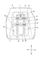
- reference numeral 10 denotes a seat on which a person is seated.
- the seat 10 is provided in a vehicle such as an automobile.
- the seat 10 is provided in a vehicle capable of traveling by switching between automatic driving and manual driving.
- the seat 10 includes a seat cushion 11 that supports a person's buttocks and thighs, a seat back 14 that has a lower end supported by the seat cushion 11 and serves as a backrest, and a seat back 14 that supports the person's head. And a headrest 17 to be provided.
- the seat cushion 11 mainly includes a seat cushion frame serving as a skeleton, a cushion pad 12 provided on the seat cushion frame, and a skin 13 covering the seat cushion frame and the cushion pad 12 (FIG. 2). reference).
- the seat cushion 11 of the present embodiment further includes a seat heater 20 provided between the cushion pad 12 and the skin 13.
- a groove 12 a that is long in the left-right direction of the seat 10 is formed on the upper surface of the cushion pad 12.
- Two grooves 12a are provided on the upper surface of the cushion pad 12 so as to divide the upper surface of the cushion pad 12 in the front-rear direction. That is, the upper surface of the cushion pad 12 is divided into a front side, a center side, and a rear side.
- the seat back 14 mainly includes a seat back frame serving as a skeleton, a cushion pad 15 provided on the seat back frame, and a skin 16 that covers the seat back frame and the cushion pad 15 (FIG. 3). reference).
- the seat back 14 of the present embodiment further includes a seat heater 30 provided between the cushion pad 15 and the skin 16.
- the front surface of the cushion pad 15 is formed with a groove 15 a that is long in the left-right direction of the seat 10.
- Two grooves 15a are provided on the front surface of the cushion pad 15 so as to divide the front surface of the cushion pad 15 in the vertical direction. That is, the upper surface of the cushion pad 15 is divided into an upper side, a center side, and a lower side.
- the seat heater 20 in the seat cushion 11 is a planar heating element that warms the seat cushion 11.
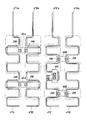
- a planar substrate 21 made of a polyester cloth material and the like, and adhesively fixed to the substrate 21. It is mainly composed of a metal heater wire 22 (also referred to as a heating wire).
- the heater wires 22 are bonded and fixed on the base material 21. As shown in FIG. 2, the two heater wires 22 meander from the rear of the seat cushion 11 toward the front in a substantially parallel manner. It is connected with. In addition, although the heater wire 22 of this embodiment meanders substantially parallel to the front-back direction and is being fixed on the base material 21, it is not limited to this, Even if arrangement
- the heater wire 22 is located in the front heater line 22 a located in the front section of the upper surface of the cushion pad 12, the central heater line 22 b located in the center section, and the rear section.
- the rear heater wire 22c, the front heater wire 22a, the central heater wire 22b, and the rear heater wire 22c are connected to each other, and the groove heater wire 23 is inserted into the groove 12a.
- the seat heater 30 in the seat back 14 is mainly composed of a base material 31 and a heater wire 32.
- the heater wire 32 is divided into an upper heater wire 32a located in the upper compartment of the front surface of the cushion pad 15, a central heater wire 32b located in the middle compartment, and a lower compartment.
- the lower heater wire 32c is positioned, and the upper heater wire 32a, the central heater wire 32b, and the lower heater wire 32c are connected to each other, and the groove heater wire 33 is inserted into the groove 15a.
- the seat 10 is provided in a vehicle capable of traveling by switching between automatic driving and manual driving, so that the form suitable for manual driving and the form not suitable for manual driving It is configured to be changeable. Since the driver can be in a relaxed state during automatic driving, the seat 10 is also changed to a form that is not suitable for manual driving. For example, the seat 10 during automatic driving can be repositioned toward the rear seat side or changed to a flat state.
- such a vehicle includes an operation control unit that switches between automatic operation and manual operation, the seat 10 that can be changed into a plurality of forms, and the operation of the seat 10 when the form is changed.
- a sheet control unit for controlling For example, when the vehicle is moved from a highway to a general road, or when the driving control unit approaches a road having a complicated shape, the driving control unit performs control to switch from automatic driving to manual driving. In such a case, if there is an abnormality in the health condition of the driver, it is not preferable to forcibly switch to manual driving. Conversely, if the driver's health condition deteriorates during manual driving, switching from manual driving to automatic driving may be considered. In such cases, it is necessary to know the health condition in advance. There is.
- the seat 10 is provided with biosensors 1 and 2 as means for grasping the health condition of the driver as shown in FIGS.
- the biometric sensors 1 and 2 in the present embodiment are for measuring the blood flow state of a person who is a person to be measured, for example, and can measure the blood flow at a position facing the skin surface of the measurement target region. it can.
- the biometric sensors 1 and 2 of this embodiment are non-contact types that detect human biometric information using electromagnetic waves, and are connected to the operation control unit so as to be able to perform data communication.
- the operation control unit switches between automatic operation and manual operation based on the data related to the biological information transmitted from the biometric sensors 1 and 2, and the seat control unit appropriately changes the form of the seat 10.
- the biometric sensors 1 and 2 in the present embodiment detect human biometric information using electromagnetic waves as described above.
- electromagnetic waves mean electromagnetic waves in a broad sense including radio waves and microwaves of about 100 MHz, infrared light, visible light, ultraviolet light, X-rays, etc., and are suitable in a range that does not adversely affect the human body.
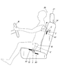
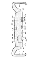
- Electromagnetic waves are used. Such electromagnetic waves have a feature that they do not easily pass through various metals such as iron, copper, and aluminum. Therefore, as shown in FIG. 4, the biosensors 1 and 2 in the present embodiment are arranged at positions avoiding the members A1 and A2 that interfere with (possibly) the passage of electromagnetic waves with respect to the sheet 10.
- the biosensor 1 provided on the seat cushion 11 is disposed in the seat 10 at a position where the member A1 does not enter the irradiation range R of the electromagnetic wave emitted from the biosensor 1. That is, when the biological sensor 1 is provided on the sheet 10, the fact that the interfering member A ⁇ b> 1 does not enter within the irradiation range R of the electromagnetic wave emitted from the biological sensor 1 is one of the points for accurately detecting biological information. It becomes one condition.
- the biosensor 2 provided on the seat back 14 is disposed in the seat 10 at a position where the irradiation center C of the electromagnetic wave irradiated from the biosensor 2 avoids the member A2. That is, when the biosensor 2 is provided on the sheet 10, the irradiation center C of the electromagnetic wave emitted from the biosensor 2 may be a position that avoids the obstructing member A2, and may be within the irradiation range R. Absent. This is also a condition for facilitating detection of biological information.
- the biosensor 1 is disposed at a position closer to a person than the member A3 that obstructs the passage of electromagnetic waves. That is, it is preferable that the biosensors 1 and 2 are disposed at a position closer to the person than the member (for example, the member A3) that obstructs the passage of electromagnetic waves in the sheet 10.
- the biological information can be detected even if the biological sensors 1 and 2 are arranged closer to the person than the biological sensors 1 and 2 as described above, the members A1 and 1 that the biological sensors 1 and 2 interfere with. Of course, it is desirable to arrange them near people rather than A2 because they are less likely to be disturbed by electromagnetic waves. This is also a condition for accurately detecting biological information.
- FIG. 4 is a supplementary explanation of an example of a state in which the sheet 10 is viewed from the side.
- the members A1, A2, and A3 are positioned close to the biosensors 1 and 2 in a side view, It is preferable that they are arranged so as to be shifted in the left-right direction) because it is difficult to obstruct the passage of electromagnetic waves.
- members A1, A2, and A3 that obstruct the passage of electromagnetic waves in the present embodiment are metal heater wires 22 and 32 in the seat heaters 20 and 30, as shown in FIGS.
- the living body sensors 1 and 2 are disposed in the sheet 10 at positions avoiding the heater wires 22 and 32.
- the biometric sensors 1 and 2 are disposed at least at two places on the sheet 10 so as to be separated from each other. More specifically, the biometric sensors 1 and 2 are provided on both the seat cushion 11 and the seat back 14.
- the living body sensor 1 provided in the seat cushion 11 is disposed corresponding to the central part of the left and right sciatic bones in a human hip as shown in FIG. 2 in order to improve the sitting comfort.
- the biosensor 1 is disposed in the center portion of the seat cushion 11 where the buttocks ride.
- the living body sensor 1 is arranged so as to correspond to the central portions of the left and right sciatic bones, but is not limited thereto.
- the biometric sensor 1 provided on the seat cushion 11 may be arranged corresponding to the position of the thigh. That is, in FIG. 2, reference signs P ⁇ b> 1 and P ⁇ b> 2 are locations that are candidates for placing the biosensor 1, and the candidate locations P ⁇ b> 1 and P ⁇ b> 2 correspond to the positions of the thighs of a person seated on the seat 10. Yes.
- the popliteal artery passes through the thigh and is suitable for measuring the blood flow state with the biosensor 1.
- the biosensor 2 provided on the seat back 14 is arranged corresponding to the position of the human heart.
- the thoracic aorta passes through the chest with the heart, which is suitable for measuring the blood flow state with the biosensor 2.
- the heater wire 32 of the seat heater 30 provided on the seat back 14 arranges the living body sensor 2 and avoids the position of the human heart in order to improve the measurement accuracy of the living body sensor 2.
- the heater wire 32 (22) that obstructs the passage of electromagnetic waves is arranged inside the sheet 10 so that there is a difference in density, and the biosensor 2 has a coarse density of the heater wire 32 (22). It is in a state of being placed at a location.
- the temperature of the heater wire 32 (22) where the density is high tends to be high.
- the living body sensor 2 is arranged corresponding to the position of the heart.
- the present invention is not limited to this, and any position suitable for measuring the blood flow state can be used. Be good.
- the data relating to the blood flow state in the popliteal artery and the thoracic aorta obtained by measurement by the biosensors 1 and 2 is used to be incorporated in advance in the operation control unit (another external device such as a computer). With the calculated program, the pulse wave velocity and the degree of arteriosclerosis can be obtained. Furthermore, the operation control unit can calculate the blood pressure (arterial pressure) of the person who is the measurement subject based on the pulse wave velocity and the degree of arteriosclerosis.
- the seat 10 in the present embodiment is provided in a vehicle that can travel by switching between automatic driving and manual driving as described above. Therefore, in order to improve safety, the biosensors 1 and 2 and a camera (not shown) that captures a person sitting on the seat 10 may be used in combination. If the biosensors 1 and 2 are used together with the camera, whether or not a person who is seated and does not have a hand on the handle H is just asleep, as well as whether or not his health has deteriorated Can be determined. In addition, a microphone that collects the voice of a person sitting on the seat 10 may be employed, and the presence or absence of consciousness may be confirmed by using the biometric sensors 1 and 2 and the microphone together. That is, when a person sitting on the seat 10 is prompted to speak and there is no response, it is determined that there is no consciousness.
- the biosensors 1 and 2 are disposed at positions where the members A1, A2 and A3 that obstruct the passage of electromagnetic waves among the members constituting the sheet 10 are avoided. Therefore, the members A1, A2, and A3 that obstruct the passage of the electromagnetic wave are less likely to interfere with the irradiation of the electromagnetic wave by the biosensors 1 and 2, and the biometric information is easily detected accurately.
- the seat 10 is provided in a vehicle that can travel by switching between automatic driving and manual driving, the biological information of the driver sitting on the seat can be detected. Thereby, for example, when a driver's health condition deteriorates, this can be detected in advance, so that safety during automatic driving or manual driving can be improved.
- the biological sensor 2 since the irradiation center C of the electromagnetic wave irradiated from the biological sensor 2 is arrange
- the biological information can be detected by the biological sensor 2 while being affected by the member A2.
- the biosensor 1 is disposed in the sheet 10 at a position where the member does not enter within the irradiation range R of the electromagnetic wave emitted from the biosensor 1, the influence of the members A1 and A3 that obstruct the passage of the electromagnetic wave.
- the biometric information can be detected by the biometric sensor 1 without receiving.
- the biosensor 1 is disposed in the sheet 10 at a position closer to a person than the member A3 that obstructs the passage of electromagnetic waves, it is less susceptible to the influence of the member A3 that obstructs the passage of electromagnetic waves.
- the biometric sensors 1 and 2 are disposed at a distance from each other in at least two places on the sheet, the biometric information can be detected from at least two places on the human body. Thereby, the precision in the case of calculating a human health state from the detected biometric information can be improved.
- biometric sensors 1 and 2 are provided on both the seat cushion 11 and the seat back 14, it is possible to detect biometric information on the upper and lower body sides of a human body. Thereby, the precision in the case of calculating a human health state from the detected biometric information can be improved.
- the biosensor 2 provided on the seat back 14 is arranged corresponding to the position of the human heart, the blood flow state of the thoracic aorta can be grasped. Therefore, for example, it is easier to detect biometric information than when biometric information is detected using a thin blood vessel with a small blood flow.
- the biosensor 1 provided on the seat cushion 11 is arranged corresponding to the central part of the left and right sciatic bones in the human buttock, the biosensor 1 can be arranged at a position where the sciata does not hit, Does not impair comfort.
- the biosensor 1 provided on the seat cushion 11 is arranged corresponding to the position of the thigh, the blood flow state of the popliteal artery can be grasped. Therefore, for example, it is easier to detect biometric information than when biometric information is detected using a thin blood vessel with a small blood flow.
- the seat 10 in the present embodiment is provided in a vehicle such as an automobile.
- the vehicle may travel only by manual driving, or may be capable of traveling by switching between automatic driving and manual driving.
- the seat 10 includes a seat cushion 11 that supports a person's buttocks and thighs, a seat back 14 that has a lower end supported by the seat cushion 11 and serves as a backrest, and a seat back 14 that supports the person's head. And a headrest 17 to be provided.
- the seat cushion 11 mainly includes a seat cushion frame serving as a skeleton, a cushion pad 12 provided on the seat cushion frame, and a skin 13 covering the seat cushion frame and the cushion pad 12 (FIG. 5). reference).
- the seat cushion 11 of the present embodiment further includes a seat heater 20 provided between the cushion pad 12 and the skin 13.
- a groove 12 a that is long in the left-right direction of the seat 10 is formed on the upper surface of the cushion pad 12.
- Two grooves 12a are provided on the upper surface of the cushion pad 12 so as to divide the upper surface of the cushion pad 12 in the front-rear direction. That is, the upper surface of the cushion pad 12 is divided into a front side, a center side, and a rear side.
- the seat back 14 mainly includes a seat back frame serving as a skeleton, a cushion pad 15 provided on the seat back frame, and a skin 16 covering the seat back frame and the cushion pad 15 (FIG. 6). reference).
- the seat back 14 of the present embodiment further includes a seat heater 30 provided between the cushion pad 15 and the skin 16.
- the front surface of the cushion pad 15 is formed with a groove 15 a that is long in the left-right direction of the seat 10.
- Two grooves 15a are provided on the front surface of the cushion pad 15 so as to divide the front surface of the cushion pad 15 in the vertical direction. That is, the upper surface of the cushion pad 15 is divided into an upper side, a center side, and a lower side.
- the seat heater 20 in the seat cushion 11 is a planar heating element that warms the seat cushion 11.
- a planar base material 21 made of a polyester cloth material or the like and an adhesive fixing to the base material 21. It is mainly composed of a metal heater wire 22 (also referred to as a heating wire).
- the heater wires 22 are bonded and fixed on the base material 21. As shown in FIG. 5, the two heater wires 22 meander from the rear of the seat cushion 11 to the front in a substantially parallel manner. It is connected with. In addition, although the heater wire 22 of this embodiment meanders substantially parallel to the front-back direction and is being fixed on the base material 21, it is not limited to this, Even if arrangement
- the heater wire 22 is located in the front heater line 22 a located in the front section of the upper surface of the cushion pad 12, the central heater line 22 b located in the center section, and the rear section.
- the rear heater wire 22c, the front heater wire 22a, the central heater wire 22b, and the rear heater wire 22c are connected to each other, and the groove heater wire 23 is inserted into the groove 12a.
- the seat heater 30 in the seat back 14 is mainly composed of a base material 31 and a heater wire 32.
- the heater wire 32 includes an upper heater wire 32a located in the upper compartment of the front surface of the cushion pad 15, a central heater wire 32b located in the middle compartment, and a lower compartment.
- the lower heater wire 32c is positioned, and the upper heater wire 32a, the central heater wire 32b, and the lower heater wire 32c are connected to each other, and the groove heater wire 33 is inserted into the groove 15a.
- the driver can also be in a relaxed state during automatic driving, so the seat 10 is also not suitable for manual driving. Be changed.
- the seat 10 during automatic driving can be repositioned toward the rear seat side or changed to a flat state.
- the seat 10 can be reclined when the vehicle is stopped.
- an operation control unit that switches between automatic driving and manual driving, and the seat 10 that can be changed into a plurality of forms.
- a sheet control unit that controls the operation of the sheet 10 when the form is changed. For example, when the vehicle is moved from a highway to a general road, or when the driving control unit approaches a road having a complicated shape, the driving control unit performs control to switch from automatic driving to manual driving. In such a case, if there is an abnormality in the health condition of the driver, it is not preferable to forcibly switch to manual driving. Conversely, if the driver's health condition deteriorates during manual driving, switching from manual driving to automatic driving may be considered.
- the operation of the seat 10 when the vehicle is stopped may be automatically controlled by the seat control unit. And you may enable it to grasp
- the following describes the case of a vehicle that can be switched between automatic driving and manual driving.
- the present invention is not limited to this, and a vehicle that can be driven only by manual driving may be adopted. Good.
- the seat 10 is provided with biosensors 100 and 200 as means for grasping the health condition of the driver.
- the biometric sensors 100 and 200 in the present embodiment are for measuring the blood flow state of a person who is a measurement subject, for example, and can measure blood flow at a position facing the skin surface of the measurement target region. it can.
- the biosensors 100 and 200 of the present embodiment are non-contact types that detect human biometric information using electromagnetic waves, and are connected to the operation control unit so as to be able to perform data communication.
- the operation control unit switches between automatic operation and manual operation based on the data related to the biological information transmitted from the biometric sensors 100 and 200, and the seat control unit changes the form of the seat 10 as appropriate.
- the biometric sensors 100 and 200 in the present embodiment detect human biometric information using electromagnetic waves as described above. More specifically, the biosensors 100 and 200 in the present embodiment include a first sensor 100 and a second sensor 200 that emit electromagnetic waves with different frequencies toward a person.
- the basic functions of the first sensor 100 and the second sensor 200 are to detect minute vibrations on the body surface due to pulsation by reflection of electromagnetic waves irradiated to a human body.
- the first sensor 100 and the second sensor 200 are also called Doppler sensors because they use the frequency change of the reflected wave due to the Doppler effect according to the speed of the object. Since such a Doppler sensor detects slight body movements, for example, during breathing, body movements other than pulse waves may be detected as noise, but the first sensor 100 and the second sensor 200 are used. Thus, the noise element can be removed and only the pulse wave can be extracted.
- the first sensor 100 is a biological sensor that emits electromagnetic waves having a frequency that reaches blood.
- a living body sensor in which electromagnetic waves reach blood also uses the fact that the reflectance of electromagnetic waves changes depending on the amount of hemoglobin in the blood.
- Hemoglobin plays a role in transporting oxygen throughout the body. When an oxygen deficiency occurs in the cellular tissues of the body, blood flow is accelerated in order to transport oxygen quickly (palpitations), and a large amount of oxygen enters the body. Symptoms such as faster breathing (shortness of breath) occur due to the intake.
- the first sensor 100 can detect such a body state (blood flow state: pulse wave).
- the first sensor 100 detects minute vibrations on the body surface when the amount of hemoglobin is detected.
- the waveform of detection data obtained by the first sensor 100 includes a pulse wave and a noise element.
- the frequency of the electromagnetic wave reaching the blood is, for example, 270 MHz, but is not particularly limited as long as it can reach the blood and detect the amount of hemoglobin.
- the first sensor 100 is configured by integrating a receiving unit that receives a reflected wave of an electromagnetic wave emitted from the first sensor 100. That is, the first sensor 100 has a transmission function for transmitting electromagnetic waves and a reception function for receiving electromagnetic waves.
- the receiving unit is connected so as to be able to perform data communication with a calculation unit (not shown) (provided in the operation control unit in this embodiment), and the detected pulse wave and data relating to the noise element are transmitted to the calculation unit and stored. Is done.
- the second sensor 200 is a biological sensor that emits electromagnetic waves having a frequency for detecting minute vibrations on the body surface.
- the second sensor 200 can detect only minute vibrations on the body surface, that is, noise elements. In other words, only the noise element is included in the waveform of the detection data obtained by the second sensor 200.
- the frequency of the electromagnetic wave for detecting fine vibrations on the body surface is, for example, 10 GHz, but is not particularly limited as long as fine vibrations on the body surface can be detected.
- the second sensor 200 is configured by integrating a receiving unit that receives a reflected wave of an electromagnetic wave emitted from the second sensor 200. That is, the second sensor 200 has a transmission function for transmitting electromagnetic waves and a reception function for receiving electromagnetic waves.
- the receiving unit is connected to a computing unit (not shown) so that data communication is possible (provided in the operation control unit in the present embodiment), and data relating to the detected noise element is transmitted to and stored in the computing unit.
- the first sensor 100 detects pulse waves and noise elements
- the second sensor 200 detects noise elements. Therefore, only the pulse wave can be extracted by taking the difference corresponding to the noise element. Therefore, if the first sensor 100 and the second sensor 200 are arranged at a large interval, it may be difficult to match the noise elements (an error occurs).
- the second sensor 200 are arranged next to each other. That is, the first sensor 100 and the second sensor 200 are arranged as close as possible to each other or arranged so as to contact each other.
- the biometric sensors 100 and 200 in the present embodiment detect human biometric information using electromagnetic waves as described above.
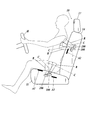
- electromagnetic waves have a feature that they do not easily pass through various metals such as iron, copper, and aluminum. Therefore, as shown in FIG. 7, the biosensors 100 and 200 in the present embodiment are arranged at positions avoiding the members A1 to A3 that obstruct (possibly) the passage of electromagnetic waves with respect to the sheet 10.
- the first sensor 100 and the second sensor 200 provided in the seat cushion 11 are within the irradiation range R of the electromagnetic wave irradiated from the first sensor 100 and the second sensor 200 in the seat 10. It arrange
- the first sensor 100 and the second sensor 200 provided on the seat back 14 are members of which the irradiation center C of the electromagnetic wave irradiated from the first sensor 100 and the second sensor 200 is a member. It is arranged at a position that avoids A2. That is, when the first sensor 100 and the second sensor 200 are provided on the sheet 10, the irradiation center C of the electromagnetic wave irradiated from the first sensor 100 and the second sensor 200 may be a position that avoids the obstructing member A2. It may be within the irradiation range R. This is also a condition for facilitating detection of biological information.
- the first sensor 100 and the second sensor 200 are arranged at a position closer to a person than the member A3 that obstructs the passage of electromagnetic waves. That is, it is preferable that the first sensor 100 and the second sensor 200 are disposed at a position closer to a person than the member (for example, the member A3) that obstructs the passage of electromagnetic waves in the sheet 10.
- the biological information can be detected even if the obstructing members A1 and A2 are arranged closer to the person than the first sensor 100 and the second sensor 200, the first sensor 100 and the second sensor 200 can be detected.
- the sensor 200 be disposed closer to the person than the members A1 and A2 that obstruct the sensor 200, because the electromagnetic wave is less likely to be obstructed. This is also a condition for accurately detecting biological information.
- FIG. 7 shows an example of a state in which the sheet 10 is viewed from the side.
- the members A1, A2, and A3 obstruct the passage of electromagnetic waves if they are displaced in the horizontal direction (left-right direction). Since it becomes difficult, it is preferable.
- the first sensor 100 and the second sensor 200 are arranged adjacent to each other as described above, which is one condition for accurately detecting biological information. Therefore, the first sensor 100 and the second sensor 200 are arranged adjacent to each other in the surface direction on the seating surface of the seat 10.
- the front portions of the portions that emit electromagnetic waves of the first sensor 100 and the second sensor 200 are arranged so as to be parallel or substantially parallel to the seating surface of the seat 10.
- the seating surface of the seat 10 refers to a surface that contacts the human buttocks and thighs as shown in FIG. 5, and in the case of the seatback 14, as shown in FIG. 6. , Refers to the surface that the person's back (chest side, waist side) touches.
- the first sensor 100 and the second sensor 200 are arranged adjacent to each other in the front-rear direction, the left-right direction, or the oblique direction.
- the first sensor 100 and the second sensor 200 are arranged adjacent to each other in the up-down direction, the left-right direction, or the oblique direction.
- the first sensor 100 and the second sensor 200 may be arranged adjacent to each other in the thickness direction of at least one of the seat cushion 11 and the seat back 14. In this case, the first sensor 100 and the second sensor 200 may be arranged so as to partially overlap. As described above, when the first sensor 100 and the second sensor 200 are arranged adjacent to each other in the thickness direction of at least one of the seat cushion 11 and the seat back 14, the first sensor that emits an electromagnetic wave having a frequency reaching the blood. When the second sensor 200 that emits electromagnetic waves having a frequency for detecting minute vibrations on the body surface is disposed on the side farther from the seating surface (rear side), 100 is the seating surface side (front side). .
- the members A1, A2, and A3 that obstruct the passage of electromagnetic waves in the present embodiment are seat heaters.
- 20 and 30 are metal heater wires 22 and 32
- the first sensor 100 and the second sensor 200 are disposed in the sheet 10 at positions avoiding the heater wires 22 and 32.
- the first sensor 100 and the second sensor 200 are spaced apart from each other in at least two locations of the sheet 10. More specifically, the first sensor 100 and the second sensor 200 are provided on both the seat cushion 11 and the seat back 14.
- the first sensor 100 and the second sensor 200 are arranged at least at two locations on the seat 10 so as to be separated from each other, the position of the heart of the person sitting on the seat 10 (estimated to have a heart).
- the distance from at least two biosensors 100 and 200 can be calculated, which is preferable in detecting pulse waves.
- the pulse wave is detected based on the sheet 10 in this way. Yes.
- the arrangement positions of at least two biosensors 100 and 200 are limited to the seat cushion 11 only, or limited to the seat back 14 only.
- the biosensors 100 and 200 are disposed in at least two locations of the seat cushion 11, it is preferable to dispose the biosensors 100 and 200 along either the left or right thigh. In the case where the biosensors 100 and 200 are arranged at at least two places on the seat back 14, the position (center) of the spine may be removed and arranged on the left or right side, or may be arranged along the spine.
- the first sensor 100 and the second sensor 200 provided on the seat cushion 11 are provided along the center of the seating surface of the seat cushion 11 as shown in FIG. That is, it arrange
- the first sensor 100 and the second sensor 200 are disposed in the center portion of the seat cushion 11 in the seat 10 where the buttocks ride.
- the 1st sensor 100 and the 2nd sensor 200 shall be arrange
- the first sensor 100 and the second sensor 200 provided on the seat cushion 11 may be arranged corresponding to the position of the thigh, and left and right in the human hip. It may be placed at any ischial location. That is, in FIG. 5, reference signs P ⁇ b> 1 and P ⁇ b> 2 are locations that are candidates for placing the first sensor 100 and the second sensor 200, and the candidate location P ⁇ b> 1 is the position of the thigh of a person seated on the seat 10.
- the candidate location P2 corresponds to the position of the left sciatic bone in the human buttocks.
- the popliteal artery passes through the thigh and is suitable for measuring the blood flow state by the biosensors 100 and 200.
- the first sensor 100 and the second sensor 200 provided on the seat back 14 are arranged along the center of the seating surface of the seat 10 and corresponding to the position of the human heart. .
- the thoracic aorta passes through the chest with the heart, and is suitable for measuring the blood flow state by the first sensor 100 and the second sensor 200.
- the heater wire 32 of the seat heater 30 provided on the seat back 14 arranges the first sensor 100 and the second sensor 200, and improves the measurement accuracy by the first sensor 100 and the second sensor 200. Therefore, it is arranged avoiding the position of the human heart.
- the heater wire 32 (22) that obstructs the passage of electromagnetic waves is disposed inside the sheet 10 so that there is a difference in density between the first sensor 100 and the second sensor 200. 22) is arranged in a place where the density is coarse. Note that the temperature of the heater wire 32 (22) where the density is high tends to be high. However, if the first sensor 100 and the second sensor 200 are arranged closer to the seating surface than the heater wire 32 (22), a problem is unlikely to occur in the detection of biological information.
- the first sensor 100 and the second sensor 200 are arranged corresponding to the position of the heart.
- the present invention is not limited to this, and the blood flow state is measured. Any suitable position may be used.
- the first sensor 100 and the second sensor 200 may be arranged corresponding to the center position of the human waist, or correspond to either the left or right of the human waist. May be arranged. That is, in FIG. 6, reference signs P3 and P4 are locations that are candidates for placing the first sensor 100 and the second sensor 200, and the candidate location P3 corresponds to the center position of the human waist, The candidate location P4 corresponds to the position on the left side of the human waist.
- Doppler sensors such as the first sensor 100 and the second sensor 200 also detect slight body movements. Therefore, the place where the first sensor 100 and the second sensor 200 are arranged is a part of the body of a person sitting on the seat 10 such as the buttocks, the thighs, and the lower part of the body. If it is determined that the position of the heart is good even if there are many body movements, the first sensor 100 and the second sensor 200 are arranged corresponding to the position of the heart. In addition, although the thigh is a position with little body movement, the thigh on the leg that operates the accelerator or brake may increase body movement, so do not operate the accelerator or brake.
- the first sensor 100 and the second sensor 200 are arranged corresponding to the thighs on the other leg. Further, in the position of the groove 12a in the cushion pad 12 of the seat cushion 11 and the position of the groove 15a in the cushion pad 15 of the seat back 14, the suspended portions of the skins 13 and 16 (see the suspended portion 49 shown in FIG. 14). ) Is provided, the first sensor 100 and the second sensor 200 are arranged avoiding the positions of the grooves 12a and 15a (that is, the suspended portions).
- the above operation control unit (an external device such as another computer may be used).
- the pulse wave propagation velocity and the degree of arteriosclerosis can be obtained by a calculation program incorporated in advance in ().
- the operation control unit can calculate the blood pressure (arterial pressure) of the person who is the measurement subject based on the pulse wave velocity and the degree of arteriosclerosis. That is, the operation control unit functions as the above calculation unit.
- the seat 10 in the present embodiment is provided in a vehicle that can travel by switching between automatic driving and manual driving as described above. Therefore, in order to improve safety, the first sensor 100 and the second sensor 200 may be used in combination with a camera (not shown) that captures the state of the person sitting on the seat 10. If the first sensor 100 and the second sensor 200 are used in combination with the camera, a person who is sitting but does not have a hand on the handle H will not only have a poor health condition, but will simply fall asleep. It can be determined whether or not there is only.
- a microphone that collects the voice of a person sitting on the seat 10 may be adopted, and the first sensor 100 and the second sensor 200 may be used in combination with the microphone so that the presence or absence of consciousness can be confirmed. That is, when a person sitting on the seat 10 is prompted to speak and there is no response, it is determined that there is no consciousness.
- one of the first sensor 100 and the second sensor 200 is used for detection of biological information including a noise element, and the other is used for detection of a noise element. Only biometric information can be extracted by taking the difference of elements. Furthermore, since the first sensor 100 and the second sensor 200 are arranged adjacent to each other, an error in detection is unlikely to occur between the first sensor 100 and the second sensor 200, and biological information can be easily detected accurately. .
- the biological information can be detected from at least two places on the human body, the accuracy in calculating the human health state from the detected biological information can be improved.
- the biometric sensor is provided on at least one of the seat cushion 11 and the seat back 14, biometric information can be detected from at least one of the upper body side and the lower body side of the human body. Furthermore, since the first sensor 100 and the second sensor 200 are arranged adjacent to each other in the surface direction on the seating surface of the seat 10, for example, the internal structure of the seat cushion 11 or the seat back 14, and the seating when the seat 10 is seated In consideration of comfort, the first sensor 100 and the second sensor 200 can be arranged adjacent to each other in the front-rear direction, the upper-lower direction, the left-right direction, or the oblique direction.
- first sensor 100 and the second sensor 200 are arranged adjacent to each other in the thickness direction of at least one of the seat cushion 11 and the seat back 14, when the first sensor 100 and the second sensor 200 are difficult to arrange adjacent to each other in the plane direction, One sensor 100 and the second sensor 200 can be arranged next to each other.
- first sensor 100 and the second sensor 200 are arranged so as to partially overlap, the first sensor 100 and the second sensor 200 interfere with each other when detecting biological information. It can be placed next to each other so as not to become.
- the biosensors 100 and 200 are provided along the center of the seating surface of the seat 10, the biosensors 100 and 200 are arranged along the positions of the rupture and the spine. Sitting comfort is less likely when sitting.
- the biosensors 100 and 200 are provided on one side of the seating surface of the seat 10, the biosensors 100 and 200 are disposed with the positions of the fissures and the spine removed, so that the biosensor The interval between 100, 200 and the human body is narrowed, and it is easy to detect biological information.
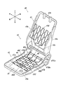
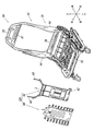
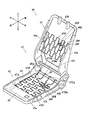
- the seat 40 in this modification includes a seat frame 41 as shown in FIG.
- the seat frame 41 includes a cushion frame 42 constituting a seat cushion and a seat back frame 43 constituting a seat back.
- the cushion frame 42 and the seat back frame 43 are each provided with a cushion pad 42 a and further covered with a skin 42 b, thereby constituting the seat 40.
- the cushion frame 42 includes a pair of side frames 44 that extend long in the front-rear direction and are spaced apart from each other left and right, a pan frame 45 that is configured by a sheet metal that connects the front ends of the pair of side frames 44, and a pair of side frames 44.
- a connecting pipe 46 made of a metal pipe that connects the rear ends of the side frames 44 is provided, and is configured in a frame shape in plan view.
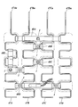
- a seat spring 47 is installed between the pan frame 45 and the connecting pipe 46.
- the seat spring 47 includes four spring members 47A to 47D that extend long in the front-rear direction and are arranged on the left and right sides, and resin connection members 48A to 48D that connect the spring members 47A to 47D.
- Each of the spring members 47A to 47D is formed by bending a metal wire, and hook portions 47Aa to 47Da for hooking on the connecting pipe 46 are formed at the rear end. It is bent zigzag.
- the front ends of the spring members 47A to 47D are connected to the pan frame 45 as shown in FIG. 8 to prevent the positional displacement of the spring members 47A to 47D.
- each spring member 47A to 47D is a member that obstructs the passage of electromagnetic waves, and the biosensor 1 is disposed at a position avoiding each of the spring members 47A to 47D. More specifically, the biosensor 1 is provided with respect to the connecting members 48A to 48D as shown in FIG.
- the position corresponds to the center part of the left and right sciatic bones in the human buttock or the position corresponding to the position of the thigh. When it is provided so as to correspond to the position of the thigh, it may be provided so as to correspond to the position of one thigh or both thighs.
- the connecting members 48A to 48D are arranged closer to the person than the spring members 47A to 47D, and the biosensor 1 is provided on such connecting members 48A to 48D. Thus, the measurement is less affected by the spring members 47A to 47D.
- the connecting members 48A to 48D are provided so as to connect the spring members 47A to 47D, but like the other connecting members 48E shown in FIG. 9, the spring members 47A formed by bending in a zigzag manner. It may be provided to connect the zigzag portions of .about.47D.
- the other connecting member 48E has a portion that connects the adjacent spring members 47A and 47B and a portion that connects the zigzag portions of the spring member 47A, and is formed in a substantially L shape in plan view. Yes.
- the biosensor 1 can be arrange
- the above-described connecting members 48A to 48E are plate to be installed having a plate-shaped portion, and the upper surface of the portion is the installation surface of the biosensor 1. That is, in the present modification, the biosensor 1 is arranged with respect to the connecting members 48A to 48E in this way, but is not limited to this, and is positioned below the cushion pad 42a, and Alternatively, a plate-like body whose upper surface is the installation surface of the biosensor 1 (that is, an installation plate having a form different from the connection members 48A to 48E) may be employed.
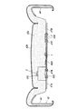
- the biosensor 1 can be disposed on each of the connecting members 48A to 48E. However, the cushion pad 42a on the seat 40 is located above the position where the biosensor 1 is disposed. A recess 420 that can accommodate the biosensor 1 is formed. That is, as shown in FIG. 10, the recess 420 is formed to be recessed on the lower surface of the cushion pad 42a.
- the front ends of the spring members 47A to 47D are connected to the pan frame 45 to prevent the positional displacement of the spring members 47A to 47D.
- the displacement of the biosensor 1 provided on the members 48A to 48D can also be suppressed.
- the biological sensor 1 may be disposed on the pan frame 45. Since the pan frame 45 is made of sheet metal as described above, it is a member that obstructs the passage of electromagnetic waves. When the biosensor 1 is disposed, it is preferably disposed on the upper surface side thereof. That is, the biosensor 1 is arranged at a position closer to a person than a member (pan frame 45) that obstructs the passage of electromagnetic waves. When the biological sensor 1 is arranged on the upper surface of the pan frame 45, the flat part on the center side of the pan frame 45 may be provided, or the inclined part on the peripheral side may be used. However, as shown in FIG.
- the biosensor 1 when the opening 45 a is formed in the pan frame 45 and corresponds to the position of the opening 45 a, the biosensor 1 is disposed at a position farther from the person than the pan frame 45. May be.
- electromagnetic waves can be irradiated toward a person through the opening 45a.
- the front ends of the pair of side frames 44 may be connected using a frame material or a pipe material (not shown) instead of the pan frame 45.
- the front ends of the spring members 47A to 47D are connected to the frame. It may be connected to a material or a pipe material.
- the biosensor 1 may be disposed on the frame material or the pipe material provided in place of the pan frame 45 in this manner by using a clip member (not shown) or the like.
- the biosensor 1 may be provided so as to be embedded in a cushion pad 42a provided in the cushion frame 42.
- the cushion pad 42a itself may be provided by so-called insert molding in which the biosensor 1 is embedded.
- a recess (not shown) for housing the biosensor 1 is formed in the cushion pad 42a, and the biosensor 1 is installed. It may be easy to do.
- the provision of the biosensor 1 so as to be embedded in the cushion pad 42a is not limited to the above-described insert molding, but the biosensor 1 can be embedded even after the cushion pad 42a is molded. It is desirable. That is, a configuration may be adopted in which a part of the cushion pad 42a (the detaching portion 422 in FIG. 10) is configured to be removable, and the concave portion 421 that accommodates the biosensor 1 is formed at a position corresponding to the detaching portion 422. .
- the biosensor 1 when the biosensor 1 is provided so as to be embedded in the cushion pad 42a, the biosensor 1 is removed by removing the detachable portion 422, housing the biosensor 1 in the concave portion 421, and fitting the detachable portion 422 back into place. Can be embedded in the cushion pad 42a.
- the removal part 422 becomes a form which can be removed from the lower surface side of the cushion pad 42a, it is good also as a form which can be removed from the upper surface side.
- a harness (not shown) that electrically connects the biological sensor 1 and an external device (for example, a power generation element, a storage device, a control device, etc.) is provided in the cushion pad 42a. It is assumed that a space for wiring is formed.
- the seat back frame 43 is provided to extend between a pair of side frames 43 a that extend vertically and are spaced apart from each other and the upper ends of the pair of side frames 43 a.
- An upper frame 43b and a plate-like lower member 43c provided between the lower ends of the pair of side frames 43a are provided.
- a seat spring 43d made of a plurality of spring members is provided between the upper frame 43b and the lower member 43c so as to be bridged between the pair of side frames 43a.
- the plurality of spring members constituting the seat spring 43d extend toward the left and right and bend up and down in a zigzag manner.
- the biological sensor 2 can be provided on the seat back frame 43 configured as described above.
- the biosensor 2 may be provided for either one or both of the pair of side frames 43a. In that case, it may be attached to the inner surface of the side frame 43a or may be attached to the outer surface.
- the biosensor 2 may be provided on the front surface of the lower member 43c. Further, when the lower member 43c is made of metal and the biosensor 2 is disposed on the rear surface side of the lower member 43c, an opening (not shown) is formed in the lower member 43c, and the opening is located at the position of the opening. Arrange them to correspond. Furthermore, the biosensor 2 may be provided on the seat spring 43d.
- cushion frame 42 side it may be arranged on a connecting member (not shown) for connecting the spring members in the seat spring 43d, or when there is a difference in density between the spring members. May be arranged at a location where the density of each spring member is coarse.
- a cushion pad is also provided on the front side of the seat back frame 43. Like the cushion frame 42 described above, the biosensor 2 is embedded in the cushion pad. Also good.
- the biosensor 1 is disposed at a position that avoids the members 47A to 47D that obstruct the passage of electromagnetic waves among the members constituting the sheet 40 with respect to the sheet 40.
- the obstructing members 47A to 47D make it difficult for the living body sensor 1 to interfere with the irradiation of electromagnetic waves, making it easier to accurately detect living body information.
- the biosensor 1 provided on the cushion frame 42 is arranged corresponding to the central part of the left and right sciatic bones in the person's buttocks, the biosensor 1 can be arranged at a position where the sciata does not hit, Does not impair comfort.
- the biosensor 1 provided on the cushion frame 42 is arranged corresponding to the position of the thigh, the blood flow state of the popliteal artery can be grasped. Therefore, for example, it is easier to detect biometric information than when biometric information is detected using a thin blood vessel with a small blood flow.
- a resin installation plate (coupling member 48A) attached to the members 47A to 47D and 43d that obstruct the passage of electromagnetic waves so as to be disposed closer to the person than the members 47A to 47D and 43d.
- the biosensor 1 (2) is arranged, so even if the biosensor 1 (2) is arranged in the vicinity of the members 47A to 47D, 43d that obstruct the passage of electromagnetic waves, the passage of the electromagnetic waves is obstructed. It becomes difficult to be affected by the members 47A to 47D and 43d. Furthermore, the biosensors 1 and 2 are located farther from the seat 40 than members (pan frame 45, lower member 43c) that obstruct the passage of electromagnetic waves, and members 45 that obstruct the passage of electromagnetic waves.
- the biosensors 1 and 2 are disposed in correspondence with the position of the opening 45a formed in 43c, the biosensors 1 and 2 are disposed in a position farther from the sheet 40 than the members 45 and 43c that obstruct the passage of electromagnetic waves. Even if it is done, it will become difficult to receive the influence of the members 45 and 43c which obstruct the passage of electromagnetic waves.
- members 47A to 47D, 43d that block the passage of electromagnetic waves are arranged in the sheet 40 so that there is a difference in density, and the members 47A that the biosensors 1, 2 block the passage of electromagnetic waves.
- the cushion pad 42a in the seat 40 is configured so that a part of the cushion pad 42a (removal part 422) can be removed, and includes a recess 421 that accommodates the biosensor 1 at a position corresponding to the part 422. Therefore, a space for arranging the biosensor 1 in the seat 40 can be secured.
- the cushion pad 42a in the seat 40 is formed with the biosensor 1 embedded therein, so that the seat 40 can be installed with the biosensor 1 embedded in the cushion pad 42a. And efficient.
- the seat 50 in this modification includes a seat frame 51 as shown in FIG.
- the seat frame 51 has a cushion frame 52 constituting a seat cushion and a seat back frame 53 constituting a seat back.
- the cushion frame 52 and the seat back frame 53 are each provided with a cushion pad and further covered with a skin to constitute the seat 50.
- the seat back frame 53 supports a lumbar support device LS that is a pressure receiving member.
- the seat back frame 53 includes a pair of sheet metal frames 54 that are spaced apart from each other on the left and right sides, and a pipe frame 55 that is connected to the upper ends of the pair of sheet metal frames 54 and is formed by bending a pipe material into a U shape. It has.
- the seat back frame 53 includes a lower frame 56 as a connecting member and a support part for connecting lower portions of the sheet metal frame 54, and a bridging frame 57 as a bridging member for connecting the left and right of the pipe frame 55.
- the lower frame 56 is a member made of a sheet metal having a cross-sectional shape with the upper edge and the lower edge extending slightly forward, and the left and right end portions are fixed to the portions extending to the left and right inner sides of the sheet metal frame 54 by welding. Yes.
- the lumbar support device LS receives the force that the occupant leans against the seat back and transmits it to the seat back frame 53, and changes the shape of the portion that contacts the occupant's waist to change the support state of the lumbar according to the occupant's preference. And is attached to the seat back frame 53.
- the lumbar support device LS includes a resin pressure plate 60 that receives a load from the back of the occupant through a cushion member (not shown), a support member 61 that supports the pressure plate 60 and changes the shape of the pressure plate 60.
- a lower latch 62 for fixing the lower part of the support member 61 (lumbar support device LS) to the lower frame 56, and a wire 63 for fixing the upper end of the support member 61 to the bridging frame 57. .
- a biosensor 2 is provided for the lumbar support device LS.
- the metal part that constitutes the support member 61 is a member that blocks the passage of electromagnetic waves, and the biosensor 2 is disposed at a position that avoids the metal part that constitutes the support member 61. More specifically, the biosensor 2 is provided on the surface of the resin pressure receiving plate 60 and at a place other than the metal parts constituting the support member 61. The position corresponds to the position of the human heart.
- the biosensor 2 is disposed at a position away from the member 61 that obstructs the passage of electromagnetic waves among the members constituting the sheet 50 with respect to the sheet 50, and therefore obstructs the passage of electromagnetic waves.
- the member 61 makes it difficult for the biological sensor 2 to interfere with the irradiation of electromagnetic waves, and makes it easier to accurately detect biological information.
- the biological sensor 2 provided in the lumbar support device LS on the seat back frame 53 side is disposed corresponding to the position of the human heart, the blood flow state of the thoracic aorta can be grasped. Therefore, for example, it is easier to detect biometric information than when biometric information is detected using a thin blood vessel with a small blood flow.
- the seat 40 in this modification includes a seat frame 41 as shown in FIG.
- the seat frame 41 includes a cushion frame 42 constituting a seat cushion and a seat back frame 43 constituting a seat back.
- the cushion frame 42 and the seat back frame 43 are each provided with a cushion pad 42 a and further covered with a skin 42 b, thereby constituting the seat 40.
- the cushion frame 42 includes a pair of side frames 44 that extend long in the front-rear direction and are spaced apart from each other left and right, a pan frame 45 that is configured by a sheet metal that connects the front ends of the pair of side frames 44, and a pair of side frames 44.
- a connecting pipe 46 made of a metal pipe that connects the rear ends of the side frames 44 is provided, and is configured in a frame shape in plan view.
- a seat spring 47 is installed between the pan frame 45 and the connecting pipe 46.
- the seat spring 47 in the cushion frame 42 is composed of four spring members 47A to 47D that extend long in the front-rear direction and are arranged side by side.
- Each of the spring members 47A to 47D is formed by bending a metal wire, and hook portions 47Aa to 47Da for hooking on the connecting pipe 46 are formed at the rear end. It is bent zigzag.
- the front ends of the spring members 47A to 47D are connected to the pan frame 45 to prevent displacement of the spring members 47A to 47D.
- a first sensor 100 and a second sensor 200 that are biological sensors are provided for the cushion frame 42.
- each spring member 47A to 47D is a member that obstructs the passage of electromagnetic waves, and the first sensor 100 and the second sensor 200 are arranged at positions avoiding these spring members 47A to 47D.
- the first sensor 100 and the second sensor 200 are provided with respect to resin connection members 48A and 48B that connect the spring members 47C and 47D. That is, the first sensor 100 is provided for the connecting member 48A, and the second sensor 200 is provided for the connecting member 48B.
- the position of the 1st sensor 100 and the 2nd sensor 200 is a location corresponding to the center part of the left and right sciatic bones in a person's buttocks, or the location corresponding to the position of a thigh. When it is provided so as to correspond to the position of the thigh, it may be provided so as to correspond to the position of one thigh or both thighs.
- the first sensor 100 and the second sensor 200 are arranged closer to the person than the connecting members 48A and 48B and the spring members 47A to 47D. Since they are provided on the connecting members 48A and 48B, the measurement by the first sensor 100 and the second sensor 200 is less affected by the spring members 47A to 47D. In FIG.
- the connecting member 48 ⁇ / b> A connects zigzag portions at distant positions among the adjacent spring members 47 ⁇ / b> C and 47 ⁇ / b> D (47 ⁇ / b> A and 47 ⁇ / b> B).
- the first sensor 100 and the second sensor 200 provided on the connection member 48A can be arranged so as not to overlap with the spring members 47C and 47D (47A and 47B).
- the connecting member 48 ⁇ / b> B connects zigzag portions that are close to each other among the adjacent spring members 447 ⁇ / b> C and 47 ⁇ / b> D (47 ⁇ / b> A and 47 ⁇ / b> B).
- the first sensor 100 and the second sensor 200 provided on the connecting member 48B may be arranged so as to overlap the spring members 47C and 47D (47A and 47B).
- the connecting members 48A and 48B are provided so as to connect the adjacent spring members 47C and 47D.
- the spring members 47A to 47D are provided. Can be provided so as to be appropriately connected.
- a zigzag portion of each of the spring members 47A to 47D formed by bending in a zigzag shape may be connected.
- the first sensor 100 and the second sensor 200 can also be disposed on the other connecting member 48C.
- the above-described connecting members 48A to 48C are plates to be installed having plate-shaped portions, and the upper surfaces of the portions are the installation surfaces of the first sensor 100 and the second sensor 200.
- the first sensor 100 and the second sensor 200 are arranged with respect to the connecting members 48A to 48C in this way, but the present invention is not limited to this, and rather than the cushion pad 42a.
- a plate-like body that is positioned below and whose upper surface is an installation surface of the first sensor 100 and the second sensor 200 (that is, an installation plate having a form different from the connection members 48A to 48C) is employed. May be.
- the first sensor 100 and the second sensor 200 can be disposed on each of the connecting members 48A to 48C. Of the cushion pads 42a in the seat 40, the first sensor 100 and the second sensor 200 are arranged. A recessed portion 420 that can accommodate the first sensor 100 and the second sensor 200 is formed at a position located above the disposed position. That is, as shown in FIG. 14, the recess 420 is formed to be recessed on the lower surface of the cushion pad 42a.
- the front ends of the spring members 47A to 47D are connected to the pan frame 45, and the positional displacement of the spring members 47A to 47D is prevented, so that the connection for connecting the spring members 47A to 47D is performed.
- the positional deviation of the first sensor 100 and the second sensor 200 provided on the members 48A to 48D can also be suppressed.
- the first sensor 100 and the second sensor 200 may be disposed on the pan frame 45. Since the pan frame 45 is made of sheet metal as described above, the pan frame 45 is a member that blocks the passage of electromagnetic waves. When the first sensor 100 and the second sensor 200 are disposed, the pan frame 45 can be disposed on the upper surface side thereof. preferable. That is, the first sensor 100 and the second sensor 200 are disposed at a position closer to a person than a member (pan frame 45) that obstructs the passage of electromagnetic waves. When the first sensor 100 and the second sensor 200 are disposed on the upper surface of the pan frame 45, the flat portion on the center side of the pan frame 45 or the inclined portion on the peripheral side may be used. However, as shown in FIG.
- the first sensor 100 and the second sensor 200 are placed more than the pan frame 45. You may arrange
- the front ends of the pair of side frames 44 may be connected using a frame material or a pipe material (not shown) instead of the pan frame 45.
- the front ends of the spring members 47A to 47D are connected to the frame. It may be connected to a material or a pipe material.
- the first sensor 100 and the second sensor 200 may be arranged on the frame material and the pipe material provided in place of the pan frame 45 in this way by using a clip member or the like (not shown).
- first sensor 100 and the second sensor 200 may be provided so as to be embedded in a cushion pad 42a provided on the cushion frame 42 as shown in FIG.
- a recess (not shown) for accommodating the first sensor 100 and the second sensor 200 in the cushion pad 42a. .) May be formed to facilitate the installation of the first sensor 100 and the second sensor 200.
- the provision of the first sensor 100 and the second sensor 200 so as to be embedded in the cushion pad 42a is not limited to the insert molding as described above, and the first sensor even after the cushion pad 42a is molded. It is desirable to be able to embed 100 and the second sensor 200. That is, a configuration in which a part of the cushion pad 42a (removal part 422 in FIG. 14) is configured to be removable, and a recess 421 for accommodating the first sensor 100 and the second sensor 200 is formed at a position corresponding to the removal part 422. May be adopted.
- the detaching part 422 is removed, the first sensor 100 and the second sensor 200 are accommodated in the concave part 421, and the detaching part 422 is provided. By fitting and returning, the first sensor 100 and the second sensor 200 can be embedded in the cushion pad 42a.
- the removal part 422 becomes a form which can be removed from the lower surface side of the cushion pad 42a, it is good also as a form which can be removed from the upper surface side.
- the first sensor 100 and the second sensor 200 and an external device are provided in the cushion pad 42a. It is assumed that a space in which a harness (not shown) to be electrically connected can be wired is formed.
- a seating sensor 3 that detects the seating of a person on the seat 10 may be provided in the cushion pad 42a.
- the sitting sensor 3 and the biometric sensors 100 and 200 are linked to each other, and the biometric sensors 100 and 200 are set to operate when a seating of a person is detected by the sitting sensor 3.
- the first sensor 100 and the second sensor 200 may be arranged so that the arrangement order is reversed as shown in FIG. That is, the first sensor 100 and the second sensor 200 are provided on the two connecting members 48A connecting the spring members 47A and 47B shown in FIG. 13, respectively, but provided on one connecting member 48A. The arrangement of the first sensor 100 and the second sensor 200 and the first sensor 100 and the second sensor 200 provided on the other connecting member 48A are reversed. Even in such a case, the biological information can be detected.
- the seat back frame 43 is provided to extend between a pair of side frames 43 a that extend vertically and are spaced apart from each other, and between the upper ends of the pair of side frames 43 a.
- An upper frame 43b and a plate-like lower member 43c provided between the lower ends of the pair of side frames 43a are provided.
- a seat spring 43d made of a plurality of spring members is provided between the upper frame 43b and the lower member 43c so as to be bridged between the pair of side frames 43a.
- the plurality of spring members constituting the seat spring 43d extend toward the left and right and bend up and down in a zigzag manner.
- the first sensor 100 and the second sensor 200 can be provided on the seat back frame 43 configured as described above, similarly to the above-described cushion frame 42 side. That is, the first sensor 100 and the second sensor 200 may be provided for either one or both of the pair of side frames 43a. In that case, it may be attached to the inner surface of the side frame 43a or may be attached to the outer surface.
- the first sensor 100 and the second sensor 200 may be provided on the front surface of the lower member 43c.
- an opening (not shown) is formed in the lower member 43c. It arrange
- first sensor 100 and the second sensor 200 may be provided on the seat spring 43d.
- the first sensor 100 is provided in a connecting member 48D that is configured in the same manner as the connecting member 48B and connects the spring members.
- the second sensor 200 is configured in the same manner as the connection member 48A described above, and is provided on a connection member 48E that connects the spring members.
- the spring members may be arranged at locations where the density of the spring members is coarse.
- a cushion pad is also provided on the front side of the seat back frame 43, but the first sensor 100 and the second sensor 200 are embedded in the cushion pad as in the above-described cushion frame 42 side. It may be provided as described.
- one of the first sensor 100 and the second sensor 200 is used for detection of biological information including a noise element, and the other is used for detection of a noise element. Only biometric information can be extracted. Furthermore, since the first sensor 100 and the second sensor 200 are arranged adjacent to each other, an error in detection is unlikely to occur between the first sensor 100 and the second sensor 200, and biological information can be easily detected accurately. . Further, since the first sensor 100 and the second sensor 200 are disposed at positions where the members 47A to 47D that obstruct the passage of electromagnetic waves among the members constituting the sheet 40 are avoided with respect to the sheet 40, the passage of electromagnetic waves.
- the members 47A to 47D that disturb the electromagnetic wave the irradiation of electromagnetic waves by the first sensor 100 and the second sensor 200 is not easily obstructed, and it becomes easy to accurately detect biological information.
- the 1st sensor 100 and the 2nd sensor 200 provided in the cushion frame 42 are arrange
- the first sensor 100 and the second sensor 200 provided on the cushion frame 42 are arranged corresponding to the position of the thigh, the blood flow state of the popliteal artery can be grasped. Therefore, for example, it is easier to detect biometric information than when biometric information is detected using a thin blood vessel with a small blood flow.
- a resin installation plate (coupling member 48A) attached to the members 47A to 47D and 43d that obstruct the passage of electromagnetic waves so as to be disposed closer to the person than the members 47A to 47D and 43d. 48E), the first sensor 100 and the second sensor 200 are arranged.
- the first sensor 100 and the second sensor 200 are arranged in the vicinity of the members 47A to 47D, 43d that obstruct the passage of electromagnetic waves, It becomes difficult to be affected by the members 47A to 47D and 43d that obstruct the passage of the electromagnetic waves. Further, the first sensor 100 and the second sensor 200 are located farther from the seat 40 than members (pan frame 45, lower member 43c) that obstruct the passage of electromagnetic waves, and obstruct the passage of electromagnetic waves. Since the first sensor 100 and the second sensor 200 are arranged to correspond to the positions of the openings 45a formed in the members 45 and 43c that perform, the members 45 and 43c that obstruct the passage of electromagnetic waves in the sheet 40.
- members 47A to 47D, 43d that block the passage of electromagnetic waves are arranged in the sheet 40 so as to have a difference in density, and the first sensor 100 and the second sensor 200 prevent passage of electromagnetic waves. Since the disturbing members 47A to 47D and 43d are arranged at a location where the density is rough, the passage of the electromagnetic waves is compared with the case where the members 47A to 47D and 43d which disturb the passage of the electromagnetic waves are arranged at high locations. Are less susceptible to the influence of the members 47A to 47D and 43d.
- the cushion pad 42a in the seat 40 is configured such that a part of the cushion pad 42a (removal part 422) can be removed, and the first sensor 100 and the second sensor 200 are disposed at positions corresponding to the part 422. Since the recessed part 421 to accommodate is provided, the space which arrange
- the seat 50 in this modification includes a seat frame 51 as shown in FIG.
- the seat frame 51 has a cushion frame 52 constituting a seat cushion and a seat back frame 53 constituting a seat back.
- the cushion frame 52 and the seat back frame 53 are each provided with a cushion pad and further covered with a skin to constitute the seat 50.
- the seat back frame 53 supports a lumbar support device LS that is a pressure receiving member.
- the seat back frame 53 includes a pair of sheet metal frames 54 that are spaced apart from each other on the left and right sides, and a pipe frame 55 that is connected to the upper ends of the pair of sheet metal frames 54 and is formed by bending a pipe material into a U shape. It has.
- the seat back frame 53 includes a lower frame 56 as a connecting member and a support part for connecting lower portions of the sheet metal frame 54, and a bridging frame 57 as a bridging member for connecting the left and right of the pipe frame 55.
- the lower frame 56 is a member made of a sheet metal having a cross-sectional shape with the upper edge and the lower edge extending slightly forward, and the left and right end portions are fixed to the portions extending to the left and right inner sides of the sheet metal frame 54 by welding. Yes.
- the lumbar support device LS receives the force that the occupant leans against the seat back and transmits it to the seat back frame 53, and changes the shape of the portion that contacts the occupant's waist to change the support state of the lumbar according to the occupant's preference. And is attached to the seat back frame 53.
- the lumbar support device LS includes a resin pressure plate 60 that receives a load from the back of the occupant through a cushion member (not shown), a support member 61 that supports the pressure plate 60 and changes the shape of the pressure plate 60.
- a lower latch 62 for fixing the lower part of the support member 61 (lumbar support device LS) to the lower frame 56, and a wire 63 for fixing the upper end of the support member 61 to the bridging frame 57. .
- the first sensor 100 and the second sensor 200 are provided for the lumbar support device LS.
- the metal component that constitutes the support member 61 is a member that obstructs the passage of electromagnetic waves, and the first sensor 100 and the second sensor 200 are located at positions that avoid the metal component that constitutes the support member 61.
- a mounting portion 64 for mounting the first sensor 100 and the second sensor 200 is integrally formed on the resin pressure plate 60 in the lumbar support device LS.
- the first sensor 100 and the second sensor 200 are in a unitized state including the pressure receiving plate 60 in the lumbar support device LS.
- the mounting portion 64 includes a first recess that can be mounted so as to fit the first sensor 100 and a second recess that can be mounted so as to fit the second sensor 200.
- the first sensor 100 is fitted and attached to the first recess
- the second sensor 200 is fitted and attached to the second recess. If the first sensor 100 and the second sensor 200 have the same shape and the first recess and the second recess are also formed in the same shape, the mounting positions of the first sensor 100 and the second sensor 200 are determined. You may do the opposite.
- the first sensor 100 and the second sensor 200 are disposed at positions where the member 61 that obstructs the passage of electromagnetic waves among the members constituting the sheet 50 is avoided with respect to the sheet 50.
- the member 61 that obstructs the passage of electromagnetic waves the irradiation of electromagnetic waves by the first sensor 100 and the second sensor 200 is less likely to be obstructed, and biological information can be easily detected accurately.
- the biosensors 100 and 200 are unitized so that the first sensor 100- and the second sensor 200 are arranged adjacent to each other, the first sensor 100 and the second sensor 200 are handled. Easy to attach to the seat 50.
- the biosensors 100 and 200 in this modification are unitized so that the first sensor 100 and the second sensor 200 are arranged adjacent to each other. That is, in the present modification, a housing 70 for mounting the first sensor 100 and the second sensor 200 is used.
- the housing 70 includes a first recess 71 that can be mounted so as to fit the first sensor 100, and a second recess 72 that can be mounted so as to fit the second sensor 200.
- the first sensor 100 is fitted and attached to the first recess 71
- the second sensor 200 is fitted and attached to the second recess 72. If the first sensor 100 and the second sensor 200 have the same shape and the first concave portion 71 and the second concave portion 72 are also formed in the same shape, the mounting positions of the first sensor 100 and the second sensor 200 are determined. You may do the opposite.
- the casing 70 itself is attached to an appropriate position of the sheet, so that the first sensor 100 and the second sensor 200 are arranged.
- the arrangement of the sensor 200 is performed.
- the biosensors 100 and 200 are unitized so that the first sensor 100-and the second sensor 200 are arranged adjacent to each other by the housing 70.
- the first sensor 100 and the second sensor 200 are easy to handle and can be easily attached to the seat.
- the biosensor is configured as a unit that integrally includes a receiving unit that receives electromagnetic waves emitted from the first sensor 100 and the second sensor 200.
- the receiving unit 3 is a separate body.
- the separate receiving unit 3 is provided along with the first sensor 100 and the second sensor 200 as shown in FIGS. 17A to 17D.
- the receiving part 3 may receive the reflected wave of the electromagnetic waves which the 1st sensor 100 and the 2nd sensor 200 emitted by one, and there may be two or more so that it can respond to the 1st sensor 100 and the 2nd sensor 200, respectively. May be used.
- the first sensor 100 and the second sensor 200 are arranged in parallel or substantially parallel to the seating surface of the seat 10, but in the present modification, the first sensor 100 is arranged.
- the second sensor 200 may be disposed at an angle (with an angle) with respect to the seating surface of the seat 80. That is, the first sensor 100 and the second sensor 200 may be arranged in parallel or substantially parallel to the seating surface of the seat 80, or arranged so as to be non-parallel to the seating surface of the seat 80. May be.
- the seat 80 in the present modification includes a seat cushion 81 and a seat back 84.
- the first sensor 100 and the second sensor 200 are arranged adjacent to each other in the left-right direction.
- the receiving unit 3 is provided below the first sensor 100 and the second sensor 200.
- the arrangement direction of the first sensor 100 and the second sensor 200 and the receiving unit 3 is not particularly limited.
- the receiving unit 3 is provided below the first sensor 100 and the second sensor 200.
- the receiving unit 3 may be provided on the upper side or provided side by side.
- 17A to 17D represents the spread (surface direction) of the seating surface when the seat 80 is viewed from the side.
- the receiving unit 3 may be arranged in parallel or substantially parallel to the seating surface of the seat 80, or non-parallel to the seating surface of the seat 80. You may arrange
- the first sensor 100 and the second sensor 200 are arranged so as to be parallel to the seating surface of the seat 80, and the receiving unit 3 is not parallel to the seating surface of the seat 80. It is arranged to be.
- the first sensor 100 and the second sensor 200 are arranged so as to be non-parallel to the seating surface of the seat 80, and the receiving unit 3 is non-parallel to the seating surface of the seat 80. It is arranged to become.
- the electromagnetic wave irradiation directions of the first sensor 100 and the second sensor 200 are arranged so that the electromagnetic wave reception direction of the receiving unit 3 intersects. In the example shown in FIG.
- the first sensor 100 and the second sensor 200 are arranged so as to be parallel to the seating surface of the seat 80, and the receiving unit 3 is also parallel to the seating surface of the seat 80.
- the first sensor 100 and the second sensor 200 are disposed so as to be non-parallel to the seating surface of the seat 80, and the receiving unit 3 is parallel to the seating surface of the seat 80. It is arranged to be.
- the arrangement structure as shown in FIGS. 17A to 17D can also be applied to the case where the receiving unit 3 is provided next to the first sensor 100 and the second sensor 200.
- the arrangement structure of the first sensor 100, the second sensor 200, and the receiving unit 3 in the present modification can be applied to a seat cushion.
- the three receiving portions that receive the electromagnetic waves respectively emitted from the first sensor 100 and the second sensor 200 are provided side by side with the first sensor 100 and the second sensor 200, the first sensor An error in detection is unlikely to occur between 100 and the second sensor 200, and biological information can be easily detected accurately. Furthermore, since the receiving accuracy of the electromagnetic wave by the receiving unit 3 can be adjusted by appropriately changing the angle of the first sensor 100 and the second sensor 200 and the receiving unit 3 with respect to the seating surface of the seat 80, the biological information can be adjusted. It becomes easier to detect more accurately.
- the biosensors 100 and 200 are disposed at least in two places in the seat 10 and are separated from each other, and are provided in at least two places in the seat cushion 11 and the seat back 14. It was supposed to be. That is, the seat cushion 11 may be provided with one or more sets of the first sensor 100 and the second sensor 200, and the seat back 14 may be provided with one or more sets of the first sensor 100 and the second sensor 200. Two or more sets of the first sensor 100 and the second sensor 200 may be provided only on the cushion 11, or two or more sets of the first sensor 100 and the second sensor 200 may be provided only on the seat back 14. It is. On the other hand, in this modification, as shown in FIGS.
- the seat 90 is supported by a seat cushion 91 that supports a person's buttocks and thighs, and a lower end portion is supported by the seat cushion 91.
- a seat back 94 and movable parts 95 to 99 attached to either the seat cushion 91 or the seat back 94 and operating with respect to either the seat cushion 91 or the seat back 94 are provided.
- the biosensors 100 and 200 are provided in at least one of the seat cushion 91, the seat back 94, and the movable portions 95 to 99.
- the seat cushion 91 supports the thigh P12 of a person sitting on the seat 90, and the seat back 94 supports the trunk P11.
- the body P11 includes a shoulder, a chest, an abdomen, a waist, and a buttocks. About a heel part, it is good also as what seat cushion 91 supports.
- the seat cushion 91 and the seat back 94 are the seat body in the seat 90, and the movable portions 95 to 99 are attached to the seat body.
- the movable portions 95 to 99 include an armrest 95 that supports the arm portion P13 of a person sitting on the seat 90, a headrest 12 that supports the head portion P14, a necklace 13 that supports the neck portion P15 of the occupant P, and legs.
- the ottoman 14 that supports the part P16 and the footrest 15 that supports the foot part P17 are included.
- the biosensors 100 and 200 are provided in any of the seat cushion 91, the seat back 94, and the movable portions 95 to 99.
- the biological information can be detected by the biological sensors 100 and 200 without the seat 90 being reclined.
- the biological information is detected by the first sensor 100 and the second sensor 200 provided on the seat cushion 91 and the seat back 94.
- the biological information can be detected by the biological sensors 100 and 200 with the seat 90 reclining.
- biological information can be detected by the biological sensors 100 and 200 provided on the entire sheet 90.
- the biological information may be detected by two or more biological sensors 100 and 200 selected as appropriate.
- the biometric sensors 100 and 200 are provided in at least one of the seat cushion 91, the seat back 94, and the movable parts 95 to 99, so that various parts of the human body are provided. Biological information can be detected through. Thereby, it is possible to improve accuracy in detecting living body information and measuring a person's health condition. Further, since the movable portions 95 to 99 are configured to be movable with respect to the seat cushion 91 and the seat back 94, detection of biometric information is performed both when the seat 90 is not reclined and when it is reclined. Can do. Thereby, for example, the vehicle on which the seat 90 is mounted can be suitably coped with when the vehicle can travel by switching between automatic driving and manual driving.
- the arrangement structure of the biosensor according to the present invention is such that the member that obstructs the passage of electromagnetic waves makes it difficult for the biosensor to irradiate the electromagnetic waves, and it is easy to detect biometric information accurately. High availability on.
- A1 A member that obstructs the passage of electromagnetic waves A2 A member that obstructs the passage of electromagnetic waves
- A3 A member that obstructs the passage of electromagnetic waves R Irradiation range C Irradiation center 1 Biosensor 2 Biosensor 10 Seat 11 Seat cushion 12 Cushion pad 12a Groove 13 Skin 14 Sheet Back 15 Cushion pad 15a Groove 16 Skin 17 Headrest 20 Seat heater 21 Base 22 Heater wire 22a Front heater wire 22b Central heater wire 22c Rear heater wire 23 Groove heater wire 30 Seat heater 31 Base material 32 Heater wire 32a Upper heater wire 32b Center Heater wire 32c Lower heater wire 33 Groove heater wire 100 First sensor 200 Second sensor
Abstract
Non-contact biological sensors 1, 2 that detect biological information of a person by electromagnetic waves are provided in a seat 10 on which the person sits. The biological sensors 1, 2 are disposed in the seat 10 at positions away from members A1, A2, A3 (22, 32) which are the members, from among the members that constitute the seat 10, that interfere with the passage of electromagnetic waves. The biological sensors each have a first sensor 100 and a second sensor 200 that emit electromagnetic waves of different frequencies towards the person, and the first sensor 100 is disposed adjacent to the second sensor 200. Due to this configuration, it becomes easier to accurately detect biological information.
Description
本発明は、生体センサーの配置構造に関する。
The present invention relates to a biosensor arrangement structure.
車両を運転する運転者の健康状態が悪化した場合、車両の運転に悪影響を及ぼすおそれがあるため、健康状態の悪化を事前に検知して何らかの対策を施すことが望ましい。このような対策として、シートの座面及び背面部に埋め込まれるようにして設けられた非接触式の血流センサーによる脈波等の計測結果に基づいて、血流や血圧等の生体情報を推定して運転者の健康状態を把握する技術が知られている(特許文献1参照。)。
If the health condition of the driver driving the vehicle deteriorates, it may adversely affect the driving of the vehicle, so it is desirable to detect the deterioration of the health condition in advance and take some measures. As such a measure, biological information such as blood flow and blood pressure is estimated based on measurement results such as pulse waves by a non-contact blood flow sensor provided so as to be embedded in the seat surface and back surface of the seat. Thus, a technique for grasping the health condition of the driver is known (see Patent Document 1).
ところで、生体センサーには、生体に対して電磁波を照射し、生体からの反射波から生体情報を検出する非接触型のものが知られているが、生体に向かって照射される電磁波は、例えば鉄や銅、アルミ等を始めとする種々の金属を通過しにくい。そのため、シートに設けられた生体センサーから照射された電磁波が、シートに内蔵された金属部品に妨害されてしまうことがあり、生体情報を正確に検出しにくい場合がある。
By the way, as a biosensor, a non-contact type sensor that irradiates an electromagnetic wave to a living body and detects biological information from a reflected wave from the living body is known. Difficult to pass through various metals including iron, copper and aluminum. Therefore, the electromagnetic wave irradiated from the biosensor provided on the sheet may be disturbed by the metal component built in the sheet, and it may be difficult to accurately detect biometric information.
本発明は上記事情に鑑みてなされたものであり、生体情報を正確に検出しやすい生体センサーの配置構造を提供することを目的とする。
The present invention has been made in view of the above circumstances, and an object thereof is to provide an arrangement structure of a biological sensor that can easily detect biological information accurately.
以上の課題を解決するため、請求項1に記載の発明は、人が着座するシートに対し、電磁波によって人の生体情報を検出する非接触型の生体センサーが設けられており、
前記生体センサーは、前記シートに対し、前記シートを構成する部材のうち電磁波の通過を妨害する部材を避けた位置に配置されていることを特徴とする。 In order to solve the above problems, the invention according toclaim 1 is provided with a non-contact type biosensor that detects biometric information of a person by electromagnetic waves on a seat on which a person is seated,
The living body sensor is arranged at a position avoiding a member that obstructs passage of electromagnetic waves among members constituting the sheet with respect to the sheet.
前記生体センサーは、前記シートに対し、前記シートを構成する部材のうち電磁波の通過を妨害する部材を避けた位置に配置されていることを特徴とする。 In order to solve the above problems, the invention according to
The living body sensor is arranged at a position avoiding a member that obstructs passage of electromagnetic waves among members constituting the sheet with respect to the sheet.
請求項2に記載の発明は、請求項1に記載の生体センサーの配置構造において、
前記シートは、自動運転と手動運転とを切り替えて走行可能な車両に設けられていることを特徴とする。 The invention according toclaim 2 is the biosensor arrangement structure according to claim 1,
The seat is provided in a vehicle capable of traveling by switching between automatic driving and manual driving.
前記シートは、自動運転と手動運転とを切り替えて走行可能な車両に設けられていることを特徴とする。 The invention according to
The seat is provided in a vehicle capable of traveling by switching between automatic driving and manual driving.
請求項3に記載の発明は、請求項1又は2に記載の生体センサーの配置構造において、
前記生体センサーは、前記シートのうち、前記生体センサーから照射される電磁波の照射中心が前記部材を避ける位置に配置されていることを特徴とする。 The invention according toclaim 3 is the biosensor arrangement structure according to claim 1 or 2,
The biological sensor is characterized in that, in the sheet, an irradiation center of electromagnetic waves emitted from the biological sensor is arranged at a position avoiding the member.
前記生体センサーは、前記シートのうち、前記生体センサーから照射される電磁波の照射中心が前記部材を避ける位置に配置されていることを特徴とする。 The invention according to
The biological sensor is characterized in that, in the sheet, an irradiation center of electromagnetic waves emitted from the biological sensor is arranged at a position avoiding the member.
請求項4に記載の発明は、請求項1又は2に記載の生体センサーの配置構造において、
前記生体センサーは、前記シートのうち、前記生体センサーから照射される電磁波の照射範囲内に前記部材が入らない位置に配置されていることを特徴とする。 The invention according toclaim 4 is the biosensor arrangement structure according to claim 1 or 2,
The biological sensor is arranged in a position where the member does not enter the irradiation range of the electromagnetic wave irradiated from the biological sensor in the sheet.
前記生体センサーは、前記シートのうち、前記生体センサーから照射される電磁波の照射範囲内に前記部材が入らない位置に配置されていることを特徴とする。 The invention according to
The biological sensor is arranged in a position where the member does not enter the irradiation range of the electromagnetic wave irradiated from the biological sensor in the sheet.
請求項5に記載の発明は、請求項1~4のいずれか一項に記載の生体センサーの配置構造において、
前記生体センサーは、前記シートのうち、前記部材よりも人に近い位置に配置されていることを特徴とする。 The invention according to claim 5 is the biosensor arrangement structure according to any one ofclaims 1 to 4,
The living body sensor is arranged at a position closer to a person than the member in the sheet.
前記生体センサーは、前記シートのうち、前記部材よりも人に近い位置に配置されていることを特徴とする。 The invention according to claim 5 is the biosensor arrangement structure according to any one of
The living body sensor is arranged at a position closer to a person than the member in the sheet.
請求項6に記載の発明は、請求項5に記載の生体センサーの配置構造において、
前記部材に対し、当該部材よりも人に近い位置に配置されるようにして樹脂製の被設置板が取り付けられており、前記生体センサーは、前記被設置板に配置されていることを特徴とする。 The invention according to claim 6 is the biosensor arrangement structure according to claim 5,
A resin installation plate is attached to the member so as to be arranged closer to the person than the member, and the biosensor is arranged on the installation plate. To do.
請求項7に記載の発明は、請求項1~4のいずれか一項に記載の生体センサーの配置構造において、
前記部材には開口部が形成されており、
前記生体センサーは、前記シートのうち、前記部材よりも人に遠い位置であって、かつ前記開口部の位置に対応して配置されていることを特徴とする。 The invention according to claim 7 is the biosensor arrangement structure according to any one ofclaims 1 to 4,
An opening is formed in the member,
The living body sensor is disposed on the sheet at a position farther from the person than the member and corresponding to the position of the opening.
前記部材には開口部が形成されており、
前記生体センサーは、前記シートのうち、前記部材よりも人に遠い位置であって、かつ前記開口部の位置に対応して配置されていることを特徴とする。 The invention according to claim 7 is the biosensor arrangement structure according to any one of
An opening is formed in the member,
The living body sensor is disposed on the sheet at a position farther from the person than the member and corresponding to the position of the opening.
請求項8に記載の発明は、請求項1~7のいずれか一項に記載の生体センサーの配置構造において、
前記部材は、前記シートの内部に、粗密差があるように配設されており、
前記生体センサーは、前記部材の密度が粗い箇所に配置されていることを特徴とする。 The invention according to claim 8 is the biosensor arrangement structure according to any one ofclaims 1 to 7,
The member is arranged so that there is a density difference inside the sheet,
The biological sensor is arranged at a location where the density of the members is coarse.
前記部材は、前記シートの内部に、粗密差があるように配設されており、
前記生体センサーは、前記部材の密度が粗い箇所に配置されていることを特徴とする。 The invention according to claim 8 is the biosensor arrangement structure according to any one of
The member is arranged so that there is a density difference inside the sheet,
The biological sensor is arranged at a location where the density of the members is coarse.
請求項9に記載の発明は、請求項1~8のいずれか一項に記載の生体センサーの配置構造において、
前記シートは、表皮によって被覆されるクッションパッドを備え、
前記クッションパッドは、当該クッションパッドの一部が取り外し可能に構成されるとともに、当該一部に対応する位置に前記生体センサーを収容する凹部を備えていることを特徴とする。 The invention according to claim 9 is the biosensor arrangement structure according to any one ofclaims 1 to 8,
The seat includes a cushion pad covered by an epidermis,
The cushion pad is configured such that a part of the cushion pad is detachable, and includes a recess for accommodating the biosensor at a position corresponding to the part.
前記シートは、表皮によって被覆されるクッションパッドを備え、
前記クッションパッドは、当該クッションパッドの一部が取り外し可能に構成されるとともに、当該一部に対応する位置に前記生体センサーを収容する凹部を備えていることを特徴とする。 The invention according to claim 9 is the biosensor arrangement structure according to any one of
The seat includes a cushion pad covered by an epidermis,
The cushion pad is configured such that a part of the cushion pad is detachable, and includes a recess for accommodating the biosensor at a position corresponding to the part.
請求項10に記載の発明は、請求項1~8のいずれか一項に記載の生体センサーの配置構造において、
前記シートは、表皮によって被覆されるクッションパッドを備え、
前記クッションパッドは、前記生体センサーが埋設された状態で形成されていることを特徴とする。 The invention according toclaim 10 is the biosensor arrangement structure according to any one of claims 1 to 8,
The seat includes a cushion pad covered by an epidermis,
The cushion pad is formed with the biosensor embedded therein.
前記シートは、表皮によって被覆されるクッションパッドを備え、
前記クッションパッドは、前記生体センサーが埋設された状態で形成されていることを特徴とする。 The invention according to
The seat includes a cushion pad covered by an epidermis,
The cushion pad is formed with the biosensor embedded therein.
請求項11に記載の発明は、請求項1~10のいずれか一項に記載の生体センサーの配置構造において、
前記生体センサーは、前記シートのうち少なくとも二箇所に、互いに離間して配置されていることを特徴とする。 The invention according toclaim 11 is the biosensor arrangement structure according to any one of claims 1 to 10,
The biosensor is disposed at least in two places on the sheet so as to be separated from each other.
前記生体センサーは、前記シートのうち少なくとも二箇所に、互いに離間して配置されていることを特徴とする。 The invention according to
The biosensor is disposed at least in two places on the sheet so as to be separated from each other.
請求項12に記載の発明は、請求項1に記載の生体センサーの配置構造において、
前記生体センサーは、異なる周波数の電磁波を人に向かって発する第一センサー及び第二センサーを有し、前記第一センサーと前記第二センサーは、隣り合って配置されていることを特徴とする。 The invention according toclaim 12 is the biosensor arrangement structure according to claim 1,
The living body sensor includes a first sensor and a second sensor that emit electromagnetic waves of different frequencies toward a person, and the first sensor and the second sensor are arranged adjacent to each other.
前記生体センサーは、異なる周波数の電磁波を人に向かって発する第一センサー及び第二センサーを有し、前記第一センサーと前記第二センサーは、隣り合って配置されていることを特徴とする。 The invention according to
The living body sensor includes a first sensor and a second sensor that emit electromagnetic waves of different frequencies toward a person, and the first sensor and the second sensor are arranged adjacent to each other.
請求項13に記載の発明は、請求項12に記載の生体センサーの配置構造において、
前記生体センサーは、前記シートのうち少なくとも二箇所に、互いに離間して配置されていることを特徴とする。 The invention according toclaim 13 is the biosensor arrangement structure according to claim 12,
The biosensor is disposed at least in two places on the sheet so as to be separated from each other.
前記生体センサーは、前記シートのうち少なくとも二箇所に、互いに離間して配置されていることを特徴とする。 The invention according to
The biosensor is disposed at least in two places on the sheet so as to be separated from each other.
請求項14に記載の発明は、請求項12に記載の生体センサーの配置構造において、
前記シートは、人の臀部及び大腿部を支持するシートクッションと、下端部が前記シートクッションに支持されたシートバックと、を備えており、
前記生体センサーは、前記シートクッションと前記シートバックのうち少なくとも一方に設けられ、前記第一センサー及び前記第二センサーは、前記シートの着座面における面方向に隣り合って配置されていることを特徴とする。 The invention according toclaim 14 is the biosensor arrangement structure according to claim 12,
The seat includes a seat cushion that supports a person's buttocks and thighs, and a seat back having a lower end supported by the seat cushion.
The biological sensor is provided on at least one of the seat cushion and the seat back, and the first sensor and the second sensor are arranged adjacent to each other in a surface direction on a seating surface of the seat. And
前記シートは、人の臀部及び大腿部を支持するシートクッションと、下端部が前記シートクッションに支持されたシートバックと、を備えており、
前記生体センサーは、前記シートクッションと前記シートバックのうち少なくとも一方に設けられ、前記第一センサー及び前記第二センサーは、前記シートの着座面における面方向に隣り合って配置されていることを特徴とする。 The invention according to
The seat includes a seat cushion that supports a person's buttocks and thighs, and a seat back having a lower end supported by the seat cushion.
The biological sensor is provided on at least one of the seat cushion and the seat back, and the first sensor and the second sensor are arranged adjacent to each other in a surface direction on a seating surface of the seat. And
請求項15に記載の発明は、請求項12に記載の生体センサーの配置構造において、
前記シートは、人の臀部及び大腿部を支持するシートクッションと、下端部が前記シートクッションに支持されたシートバックと、を備えており、
前記生体センサーは、前記シートクッションと前記シートバックのうち少なくとも一方に設けられ、前記第一センサー及び前記第二センサーは、前記シートクッションと前記シートバックのうち少なくとも一方の厚み方向に隣り合って配置されていることを特徴とする。 The invention according toclaim 15 is the biosensor arrangement structure according to claim 12,
The seat includes a seat cushion that supports a person's buttocks and thighs, and a seat back having a lower end supported by the seat cushion.
The biological sensor is provided on at least one of the seat cushion and the seat back, and the first sensor and the second sensor are arranged adjacent to each other in the thickness direction of at least one of the seat cushion and the seat back. It is characterized by being.
前記シートは、人の臀部及び大腿部を支持するシートクッションと、下端部が前記シートクッションに支持されたシートバックと、を備えており、
前記生体センサーは、前記シートクッションと前記シートバックのうち少なくとも一方に設けられ、前記第一センサー及び前記第二センサーは、前記シートクッションと前記シートバックのうち少なくとも一方の厚み方向に隣り合って配置されていることを特徴とする。 The invention according to
The seat includes a seat cushion that supports a person's buttocks and thighs, and a seat back having a lower end supported by the seat cushion.
The biological sensor is provided on at least one of the seat cushion and the seat back, and the first sensor and the second sensor are arranged adjacent to each other in the thickness direction of at least one of the seat cushion and the seat back. It is characterized by being.
請求項1に記載の発明によれば、生体センサーは、シートに対し、シートを構成する部材のうち電磁波の通過を妨害する部材を避けた位置に配置されているので、電磁波の通過を妨害する部材によって、生体センサーによる電磁波の照射が妨害されにくくなり、生体情報を正確に検出しやすくなる。
According to the first aspect of the present invention, since the biosensor is disposed at a position avoiding a member that obstructs the passage of electromagnetic waves among the members constituting the sheet, the biosensor obstructs the passage of electromagnetic waves. The member makes it difficult for the biological sensor to interfere with the electromagnetic wave irradiation, and makes it easier to accurately detect biological information.
請求項2に記載の発明によれば、シートは、自動運転と手動運転とを切り替えて走行可能な車両に設けられているので、シートに着座する運転者の生体情報を検出できる。これにより、例えば運転者の健康状態が悪化した場合に、これを事前に検知できるので、自動運転中又は手動運転中の安全性を向上できる。
According to the second aspect of the present invention, since the seat is provided in a vehicle capable of traveling by switching between automatic driving and manual driving, the biological information of the driver sitting on the seat can be detected. Thereby, for example, when a driver's health condition deteriorates, this can be detected in advance, so that safety during automatic driving or manual driving can be improved.
請求項3に記載の発明によれば、生体センサーは、シートのうち、生体センサーから照射される電磁波の照射中心が、電磁波の通過を妨害する部材を避ける位置に配置されているので、電磁波の通過を妨害する部材の影響を受けつつも、生体センサーによる生体情報の検出が可能となる。
According to the third aspect of the present invention, the biological sensor is disposed in a position where the irradiation center of the electromagnetic wave emitted from the biological sensor is avoided in the sheet so as to avoid a member that obstructs the passage of the electromagnetic wave. The biological information can be detected by the biological sensor while being influenced by the member that obstructs the passage.
請求項4に記載の発明によれば、生体センサーは、シートのうち、生体センサーから照射される電磁波の照射範囲内に部材が入らない位置に配置されているので、電磁波の通過を妨害する部材の影響を受けずに、生体センサーによる生体情報の検出が可能となる。
According to the fourth aspect of the present invention, since the biosensor is disposed at a position on the sheet where the member does not enter the irradiation range of the electromagnetic wave emitted from the biosensor, the member that obstructs the passage of the electromagnetic wave. The biological information can be detected by the biological sensor without being affected by the above.
請求項5に記載の発明によれば、生体センサーは、シートのうち、電磁波の通過を妨害する部材よりも人に近い位置に配置されているので、電磁波の通過を妨害する部材の影響を受けにくくなる。
According to the fifth aspect of the present invention, since the biosensor is disposed at a position closer to the person than the member that obstructs the passage of electromagnetic waves in the sheet, it is affected by the member that obstructs the passage of electromagnetic waves. It becomes difficult.
請求項6に記載の発明によれば、電磁波の通過を妨害する部材に対し、当該部材よりも人に近い位置に配置されるようにして取り付けられた樹脂製の被設置板に生体センサーが配置されているので、生体センサーが電磁波の通過を妨害する部材の近傍に配置されても、当該電磁波の通過を妨害する部材の影響を受けにくくなる。
According to the sixth aspect of the present invention, the biosensor is disposed on the resin installation plate attached so as to be disposed closer to the person than the member with respect to the member that obstructs the passage of electromagnetic waves. Therefore, even if the biological sensor is disposed in the vicinity of the member that obstructs the passage of the electromagnetic wave, it is less susceptible to the influence of the member that obstructs the passage of the electromagnetic wave.
請求項7に記載の発明によれば、生体センサーが、シートのうち、電磁波の通過を妨害する部材よりも人に遠い位置であって、かつ電磁波の通過を妨害する部材に形成された開口部の位置に対応して配置されているので、生体センサーが、シートのうち、電磁波の通過を妨害する部材よりも人に遠い位置に配置されても、電磁波の通過を妨害する部材の影響を受けにくくなる。
According to the seventh aspect of the present invention, the living body sensor is an opening formed in a member of the sheet that is farther from the person than the member that obstructs the passage of the electromagnetic wave and that obstructs the passage of the electromagnetic wave. Therefore, even if the biosensor is placed at a position farther away than the member that obstructs the passage of electromagnetic waves in the sheet, it is affected by the member that obstructs the passage of electromagnetic waves. It becomes difficult.
請求項8に記載の発明によれば、電磁波の通過を妨害する部材が、シートの内部に、粗密差があるように配設されており、生体センサーが、電磁波の通過を妨害する部材の密度が粗い箇所に配置されているので、電磁波の通過を妨害する部材の密度が高い箇所に配置された場合に比して、電磁波の通過を妨害する部材の影響を受けにくくなる。
According to the eighth aspect of the present invention, the density of the members that obstruct the passage of electromagnetic waves is arranged in the sheet so that there is a difference in density between the members, and the biosensor is obstructed to pass the electromagnetic waves. Is disposed at a rough portion, so that it is less susceptible to the influence of a member that obstructs the passage of electromagnetic waves, compared to a case where the density of the member that obstructs the passage of electromagnetic waves is high.
請求項9に記載の発明によれば、シートにおけるクッションパッドが、当該クッションパッドの一部が取り外し可能に構成されるとともに、当該一部に対応する位置に生体センサーを収容する凹部を備えているので、シート内に、生体センサーを配置するスペースを確保できる。
According to the invention described in claim 9, the cushion pad in the seat is configured so that a part of the cushion pad can be removed, and has a recess for accommodating the biosensor at a position corresponding to the part. Therefore, it is possible to secure a space for placing the biosensor in the seat.
請求項10に記載の発明によれば、シートにおけるクッションパッドが、生体センサーが埋設された状態で形成されているので、生体センサーがクッションパッドに埋設された状態でシートの設置作業を行うことができるようになり、効率が良い。
According to the invention described in claim 10, since the cushion pad in the seat is formed in a state where the biosensor is embedded, the seat can be installed in a state where the biosensor is embedded in the cushion pad. It becomes possible and is efficient.
請求項11に記載の発明によれば、生体センサーは、シートのうち少なくとも二箇所に、互いに離間して配置されているので、人の身体の少なくとも二箇所から生体情報を検出することができる。これにより、検出した生体情報から人の健康状態を算出する場合の精度を高めることができる。
According to the eleventh aspect of the present invention, since the biosensor is disposed at least in two places on the sheet so as to be separated from each other, it is possible to detect biometric information from at least two places on the human body. Thereby, the precision in the case of calculating a human health state from the detected biometric information can be improved.
請求項12に記載の発明によれば、生体センサーが有する第一センサーと第二センサーのうち、いずれか一方を、ノイズ要素を含む生体情報の検出に用い、他方をノイズ要素の検出に用い、ノイズ要素の分の差分を取ることで生体情報だけを抽出できる。さらに、第一センサーと第二センサーは隣り合って配置されているので、第一センサーと第二センサーとの間で検出に誤差が生じにくく、生体情報を正確に検出しやすくなる。
According to the twelfth aspect of the present invention, either one of the first sensor and the second sensor included in the biological sensor is used for detection of biological information including a noise element, and the other is used for detection of the noise element. Only biological information can be extracted by taking the difference of noise elements. Furthermore, since the first sensor and the second sensor are arranged adjacent to each other, an error in detection is unlikely to occur between the first sensor and the second sensor, and biological information can be detected accurately.
請求項13に記載の発明によれば、人の身体の少なくとも二箇所から生体情報を検出することができるので、検出した生体情報から人の健康状態を算出する場合の精度を高めることができる。
According to the thirteenth aspect of the present invention, the biological information can be detected from at least two places on the human body, so that the accuracy in calculating the human health condition from the detected biological information can be improved.
請求項14に記載の発明によれば、生体センサーは、シートクッションとシートバックのうち少なくとも一方に設けられているので、人の身体の上半身側と下半身側のうち少なくとも一方から生体情報を検出できる。
さらに、第一センサー及び第二センサーは、シートの着座面における面方向に隣り合って配置されているので、例えばシートクッション又はシートバックの内部構造や、シート着座時の座り心地を考慮して、第一センサーと第二センサーを前後や上下、左右、又は斜め方向に隣り合うように配置できる。 According to the invention described inclaim 14, since the biological sensor is provided on at least one of the seat cushion and the seat back, the biological information can be detected from at least one of the upper body side and the lower body side of the human body. .
Furthermore, since the first sensor and the second sensor are arranged adjacent to each other in the surface direction on the seating surface of the seat, for example, considering the internal structure of the seat cushion or the seat back, and the seating comfort at the time of seating, A 1st sensor and a 2nd sensor can be arrange | positioned so that it may adjoin back and forth, up and down, right and left, or diagonally.
さらに、第一センサー及び第二センサーは、シートの着座面における面方向に隣り合って配置されているので、例えばシートクッション又はシートバックの内部構造や、シート着座時の座り心地を考慮して、第一センサーと第二センサーを前後や上下、左右、又は斜め方向に隣り合うように配置できる。 According to the invention described in
Furthermore, since the first sensor and the second sensor are arranged adjacent to each other in the surface direction on the seating surface of the seat, for example, considering the internal structure of the seat cushion or the seat back, and the seating comfort at the time of seating, A 1st sensor and a 2nd sensor can be arrange | positioned so that it may adjoin back and forth, up and down, right and left, or diagonally.
請求項15に記載の発明によれば、生体センサーは、シートクッションとシートバックのうち少なくとも一方に設けられているので、人の身体の上半身側と下半身側のうち少なくとも一方から生体情報を検出できる。
さらに、第一センサー及び第二センサーは、シートクッションとシートバックのうち少なくとも一方の厚み方向に隣り合って配置されているので、面方向に隣り合って配置しにくい場合に、第一センサーと第二センサーとを隣り合って配置できる。 According to the fifteenth aspect of the present invention, since the biological sensor is provided on at least one of the seat cushion and the seat back, the biological information can be detected from at least one of the upper body side and the lower body side of the human body. .
Furthermore, since the first sensor and the second sensor are arranged adjacent to each other in the thickness direction of at least one of the seat cushion and the seat back, the first sensor and the second sensor Two sensors can be placed next to each other.
以下、図面を参照して本発明の実施の形態について説明する。ただし、以下に述べる実施形態には、本発明を実施するために技術的に好ましい種々の限定が付されているが、本発明の技術的範囲を以下の実施形態および図示例に限定するものではない。
Hereinafter, embodiments of the present invention will be described with reference to the drawings. However, the embodiments described below are provided with various technically preferable limitations for carrying out the present invention. However, the technical scope of the present invention is not limited to the following embodiments and illustrated examples. Absent.
<第1実施形態>
図1において符号10は、人が着座するシートを示す。このシート10は、自動車等の車両に設けられるものであって、本実施形態においては、特に自動運転と手動運転とを切り替えて走行可能な車両に設けられているものとする。 <First Embodiment>
In FIG. 1,reference numeral 10 denotes a seat on which a person is seated. The seat 10 is provided in a vehicle such as an automobile. In the present embodiment, the seat 10 is provided in a vehicle capable of traveling by switching between automatic driving and manual driving.
図1において符号10は、人が着座するシートを示す。このシート10は、自動車等の車両に設けられるものであって、本実施形態においては、特に自動運転と手動運転とを切り替えて走行可能な車両に設けられているものとする。 <First Embodiment>
In FIG. 1,
シート10は、人の臀部及び大腿部を支持するシートクッション11と、下端部がシートクッション11に支持されて背もたれとなるシートバック14と、シートバック14に設けられて人の頭部を支持するヘッドレスト17と、を備える。
The seat 10 includes a seat cushion 11 that supports a person's buttocks and thighs, a seat back 14 that has a lower end supported by the seat cushion 11 and serves as a backrest, and a seat back 14 that supports the person's head. And a headrest 17 to be provided.
シートクッション11は、骨格となるシートクッションフレームと、シートクッションフレーム上に設けられたクッションパッド12と、シートクッションフレーム及びクッションパッド12を被覆する表皮13と、から主に構成されている(図2参照)。
本実施形態のシートクッション11は、さらにクッションパッド12と表皮13との間に設けられたシートヒーター20を備えている。 Theseat cushion 11 mainly includes a seat cushion frame serving as a skeleton, a cushion pad 12 provided on the seat cushion frame, and a skin 13 covering the seat cushion frame and the cushion pad 12 (FIG. 2). reference).
Theseat cushion 11 of the present embodiment further includes a seat heater 20 provided between the cushion pad 12 and the skin 13.
本実施形態のシートクッション11は、さらにクッションパッド12と表皮13との間に設けられたシートヒーター20を備えている。 The
The
クッションパッド12の上面には、シート10の左右方向に長尺な溝12aが形成されている。溝12aは、クッションパッド12の上面を前後方向に区分けするようにして、クッションパッド12の上面に2本設けられている。すなわち、クッションパッド12の上面は、前方側と、中央側と、後方側に区分けされている。
A groove 12 a that is long in the left-right direction of the seat 10 is formed on the upper surface of the cushion pad 12. Two grooves 12a are provided on the upper surface of the cushion pad 12 so as to divide the upper surface of the cushion pad 12 in the front-rear direction. That is, the upper surface of the cushion pad 12 is divided into a front side, a center side, and a rear side.
シートバック14は、骨格となるシートバックフレームと、シートバックフレーム上に設けられたクッションパッド15と、シートバックフレーム及びクッションパッド15を被覆する表皮16と、から主に構成されている(図3参照)。
本実施形態のシートバック14は、さらにクッションパッド15と表皮16との間に設けられたシートヒーター30を備えている。 The seat back 14 mainly includes a seat back frame serving as a skeleton, acushion pad 15 provided on the seat back frame, and a skin 16 that covers the seat back frame and the cushion pad 15 (FIG. 3). reference).
The seat back 14 of the present embodiment further includes aseat heater 30 provided between the cushion pad 15 and the skin 16.
本実施形態のシートバック14は、さらにクッションパッド15と表皮16との間に設けられたシートヒーター30を備えている。 The seat back 14 mainly includes a seat back frame serving as a skeleton, a
The seat back 14 of the present embodiment further includes a
クッションパッド15の前面には、シート10の左右方向に長尺な溝15aが形成されている。溝15aは、クッションパッド15の前面を上下方向に区分けするようにして、クッションパッド15の前面に2本設けられている。すなわち、クッションパッド15の上面は、上方側と、中央側と、下方側に区分けされている。
The front surface of the cushion pad 15 is formed with a groove 15 a that is long in the left-right direction of the seat 10. Two grooves 15a are provided on the front surface of the cushion pad 15 so as to divide the front surface of the cushion pad 15 in the vertical direction. That is, the upper surface of the cushion pad 15 is divided into an upper side, a center side, and a lower side.
シートクッション11におけるシートヒーター20は、シートクッション11を温める面状発熱体であって、図2に示すように、ポリエステルの布材等からなる面状の基材21と、基材21に接着固定される金属製のヒーター線22(電熱線ともいう)と、から主に構成されている。
The seat heater 20 in the seat cushion 11 is a planar heating element that warms the seat cushion 11. As shown in FIG. 2, a planar substrate 21 made of a polyester cloth material and the like, and adhesively fixed to the substrate 21. It is mainly composed of a metal heater wire 22 (also referred to as a heating wire).
ヒーター線22は、基材21上に接着固定されており、図2に示すように、シートクッション11の後方から2本のヒーター線22が前方に向って略平行に蛇行しており、前方部分にて連結されている。
なお、本実施形態のヒーター線22は、前後方向に略平行に蛇行して基材21上に固定されているが、これに限定されることなく、ヒーター線22の配置を適宜変更しても良い。また、ヒーター線22は、接着剤によって基材21上に固着されているが、ヒーター線22が基材21の内部に折り込まれるように固定されても良い。 Theheater wires 22 are bonded and fixed on the base material 21. As shown in FIG. 2, the two heater wires 22 meander from the rear of the seat cushion 11 toward the front in a substantially parallel manner. It is connected with.
In addition, although theheater wire 22 of this embodiment meanders substantially parallel to the front-back direction and is being fixed on the base material 21, it is not limited to this, Even if arrangement | positioning of the heater wire 22 is changed suitably good. Moreover, although the heater wire 22 is fixed on the base material 21 with an adhesive, the heater wire 22 may be fixed so as to be folded inside the base material 21.
なお、本実施形態のヒーター線22は、前後方向に略平行に蛇行して基材21上に固定されているが、これに限定されることなく、ヒーター線22の配置を適宜変更しても良い。また、ヒーター線22は、接着剤によって基材21上に固着されているが、ヒーター線22が基材21の内部に折り込まれるように固定されても良い。 The
In addition, although the
ヒーター線22は、図2に示すように、クッションパッド12上面の前方側の区画に位置する前方ヒーター線22aと、中央側の区画に位置する中央ヒーター線22bと、後方側の区画に位置する後方ヒーター線22cと、前方ヒーター線22a、中央ヒーター線22b、後方ヒーター線22c同士を連結し、溝12a内部に差し込まれる溝部ヒーター線23とから構成されている。
As shown in FIG. 2, the heater wire 22 is located in the front heater line 22 a located in the front section of the upper surface of the cushion pad 12, the central heater line 22 b located in the center section, and the rear section. The rear heater wire 22c, the front heater wire 22a, the central heater wire 22b, and the rear heater wire 22c are connected to each other, and the groove heater wire 23 is inserted into the groove 12a.
シートバック14におけるシートヒーター30も同様に、基材31と、ヒーター線32と、から主に構成されている。
また、ヒーター線32は、図3に示すように、クッションパッド15前面の上方側の区画に位置する上方ヒーター線32aと、中央側の区画に位置する中央ヒーター線32bと、下方側の区画に位置する下方ヒーター線32cと、上方ヒーター線32a、中央ヒーター線32b、下方ヒーター線32c同士を連結し、溝15a内部に差し込まれる溝部ヒーター線33とから構成されている。 Similarly, theseat heater 30 in the seat back 14 is mainly composed of a base material 31 and a heater wire 32.
Further, as shown in FIG. 3, theheater wire 32 is divided into an upper heater wire 32a located in the upper compartment of the front surface of the cushion pad 15, a central heater wire 32b located in the middle compartment, and a lower compartment. The lower heater wire 32c is positioned, and the upper heater wire 32a, the central heater wire 32b, and the lower heater wire 32c are connected to each other, and the groove heater wire 33 is inserted into the groove 15a.
また、ヒーター線32は、図3に示すように、クッションパッド15前面の上方側の区画に位置する上方ヒーター線32aと、中央側の区画に位置する中央ヒーター線32bと、下方側の区画に位置する下方ヒーター線32cと、上方ヒーター線32a、中央ヒーター線32b、下方ヒーター線32c同士を連結し、溝15a内部に差し込まれる溝部ヒーター線33とから構成されている。 Similarly, the
Further, as shown in FIG. 3, the
このようなシート10は、上記したように、自動運転と手動運転とを切り替えて走行可能な車両に設けられているものであるため、手動運転に適した形態と、手動運転に適さない形態とに変更可能に構成されている。
自動運転中は、運転者もリラックス状態でいられるため、シート10も手動運転に適さない形態に変更される。例えば、自動運転中のシート10は、後部座席側に向けて位置変更したり、フラットな状態に変更したりすることができる。 As described above, theseat 10 is provided in a vehicle capable of traveling by switching between automatic driving and manual driving, so that the form suitable for manual driving and the form not suitable for manual driving It is configured to be changeable.
Since the driver can be in a relaxed state during automatic driving, theseat 10 is also changed to a form that is not suitable for manual driving. For example, the seat 10 during automatic driving can be repositioned toward the rear seat side or changed to a flat state.
自動運転中は、運転者もリラックス状態でいられるため、シート10も手動運転に適さない形態に変更される。例えば、自動運転中のシート10は、後部座席側に向けて位置変更したり、フラットな状態に変更したりすることができる。 As described above, the
Since the driver can be in a relaxed state during automatic driving, the
また、このような車両は、図示はしないが、自動運転と手動運転とを切り替える運転制御部と、複数の形態に変更可能な上記のシート10と、形態を変更する際のシート10の動作を制御するシート制御部と、を備える。
運転制御部は、例えば高速道路から一般道路へと車両を移す際や、複雑な形状の道路に差し掛かった際に、自動運転から手動運転に切り替える制御を行う。このような場合に、運転者の健康状態に異常が発生していると、強制的に手動運転に切り替えられるのは好ましくない。また、反対に、手動運転中に運転者の健康状態が悪化した場合には、手動運転から自動運転に切り替えることも考えられ、以上のような場合には事前に健康状態を把握しておく必要がある。 In addition, although not illustrated, such a vehicle includes an operation control unit that switches between automatic operation and manual operation, theseat 10 that can be changed into a plurality of forms, and the operation of the seat 10 when the form is changed. A sheet control unit for controlling.
For example, when the vehicle is moved from a highway to a general road, or when the driving control unit approaches a road having a complicated shape, the driving control unit performs control to switch from automatic driving to manual driving. In such a case, if there is an abnormality in the health condition of the driver, it is not preferable to forcibly switch to manual driving. Conversely, if the driver's health condition deteriorates during manual driving, switching from manual driving to automatic driving may be considered. In such cases, it is necessary to know the health condition in advance. There is.
運転制御部は、例えば高速道路から一般道路へと車両を移す際や、複雑な形状の道路に差し掛かった際に、自動運転から手動運転に切り替える制御を行う。このような場合に、運転者の健康状態に異常が発生していると、強制的に手動運転に切り替えられるのは好ましくない。また、反対に、手動運転中に運転者の健康状態が悪化した場合には、手動運転から自動運転に切り替えることも考えられ、以上のような場合には事前に健康状態を把握しておく必要がある。 In addition, although not illustrated, such a vehicle includes an operation control unit that switches between automatic operation and manual operation, the
For example, when the vehicle is moved from a highway to a general road, or when the driving control unit approaches a road having a complicated shape, the driving control unit performs control to switch from automatic driving to manual driving. In such a case, if there is an abnormality in the health condition of the driver, it is not preferable to forcibly switch to manual driving. Conversely, if the driver's health condition deteriorates during manual driving, switching from manual driving to automatic driving may be considered. In such cases, it is necessary to know the health condition in advance. There is.
そこで、シート10には、運転者の健康状態を把握するための手段として、図2,図3に示すように、生体センサー1,2が設けられている。本実施形態における生体センサー1,2は、例えば、被計測者である人の血流状態を計測するためのものであり、被計測領域の皮膚表面に対向する位置の血流を計測することができる。
Therefore, the seat 10 is provided with biosensors 1 and 2 as means for grasping the health condition of the driver as shown in FIGS. The biometric sensors 1 and 2 in the present embodiment are for measuring the blood flow state of a person who is a person to be measured, for example, and can measure the blood flow at a position facing the skin surface of the measurement target region. it can.
本実施形態の生体センサー1,2は、電磁波によって人の生体情報を検出する非接触型のものであり、運転制御部とデータ通信可能に接続されている。
運転制御部は、生体センサー1,2から伝達された生体情報に係るデータに基づいて自動運転と手動運転とを切り替えるようにし、シート制御部が、シート10の形態を適宜変更する。 The biometric sensors 1 and 2 of this embodiment are non-contact types that detect human biometric information using electromagnetic waves, and are connected to the operation control unit so as to be able to perform data communication.
The operation control unit switches between automatic operation and manual operation based on the data related to the biological information transmitted from the biometric sensors 1 and 2, and the seat control unit appropriately changes the form of the seat 10.
運転制御部は、生体センサー1,2から伝達された生体情報に係るデータに基づいて自動運転と手動運転とを切り替えるようにし、シート制御部が、シート10の形態を適宜変更する。 The
The operation control unit switches between automatic operation and manual operation based on the data related to the biological information transmitted from the
なお、本実施形態における生体センサー1,2は、上記のように、電磁波によって人の生体情報を検出するものである。
ここで、電磁波とは、100MHz程度の電波やマイクロ波を始め、赤外光、可視光、紫外光、X線等を含む広義の電磁波を意味しており、人体に悪影響を及ぼさない範囲で好適な電磁波が使用される。
このような電磁波は、例えば鉄や銅、アルミ等を始めとする種々の金属を通過しにくいという特徴がある。そのため、本実施形態における生体センサー1,2は、図4に示すように、シート10に対し、電磁波の通過を妨害する(おそれのある)部材A1,A2を避けた位置に配置されている。 Note that the biometric sensors 1 and 2 in the present embodiment detect human biometric information using electromagnetic waves as described above.
Here, electromagnetic waves mean electromagnetic waves in a broad sense including radio waves and microwaves of about 100 MHz, infrared light, visible light, ultraviolet light, X-rays, etc., and are suitable in a range that does not adversely affect the human body. Electromagnetic waves are used.
Such electromagnetic waves have a feature that they do not easily pass through various metals such as iron, copper, and aluminum. Therefore, as shown in FIG. 4, the biosensors 1 and 2 in the present embodiment are arranged at positions avoiding the members A1 and A2 that interfere with (possibly) the passage of electromagnetic waves with respect to the sheet 10.
ここで、電磁波とは、100MHz程度の電波やマイクロ波を始め、赤外光、可視光、紫外光、X線等を含む広義の電磁波を意味しており、人体に悪影響を及ぼさない範囲で好適な電磁波が使用される。
このような電磁波は、例えば鉄や銅、アルミ等を始めとする種々の金属を通過しにくいという特徴がある。そのため、本実施形態における生体センサー1,2は、図4に示すように、シート10に対し、電磁波の通過を妨害する(おそれのある)部材A1,A2を避けた位置に配置されている。 Note that the
Here, electromagnetic waves mean electromagnetic waves in a broad sense including radio waves and microwaves of about 100 MHz, infrared light, visible light, ultraviolet light, X-rays, etc., and are suitable in a range that does not adversely affect the human body. Electromagnetic waves are used.
Such electromagnetic waves have a feature that they do not easily pass through various metals such as iron, copper, and aluminum. Therefore, as shown in FIG. 4, the
図4に示す例において、シートクッション11に設けられた生体センサー1は、シート10のうち、生体センサー1から照射される電磁波の照射範囲R内に部材A1が入らない位置に配置されている。
すなわち、生体センサー1をシート10に設ける場合は、この生体センサー1から照射される電磁波の照射範囲R内に、妨害する部材A1が入らないことが、生体情報を正確に検出する上での一つの条件となる。 In the example shown in FIG. 4, thebiosensor 1 provided on the seat cushion 11 is disposed in the seat 10 at a position where the member A1 does not enter the irradiation range R of the electromagnetic wave emitted from the biosensor 1.
That is, when thebiological sensor 1 is provided on the sheet 10, the fact that the interfering member A <b> 1 does not enter within the irradiation range R of the electromagnetic wave emitted from the biological sensor 1 is one of the points for accurately detecting biological information. It becomes one condition.
すなわち、生体センサー1をシート10に設ける場合は、この生体センサー1から照射される電磁波の照射範囲R内に、妨害する部材A1が入らないことが、生体情報を正確に検出する上での一つの条件となる。 In the example shown in FIG. 4, the
That is, when the
図4に示す例において、シートバック14に設けられた生体センサー2は、シート10のうち、生体センサー2から照射される電磁波の照射中心Cが部材A2を避ける位置に配置されている。
すなわち、生体センサー2をシート10に設ける場合は、この生体センサー2から照射される電磁波の照射中心Cが、妨害する部材A2を避ける位置であればよく、照射範囲R内に入っていても構わない。この点も、生体情報を検出しやすくする上での一つの条件となる。 In the example illustrated in FIG. 4, thebiosensor 2 provided on the seat back 14 is disposed in the seat 10 at a position where the irradiation center C of the electromagnetic wave irradiated from the biosensor 2 avoids the member A2.
That is, when thebiosensor 2 is provided on the sheet 10, the irradiation center C of the electromagnetic wave emitted from the biosensor 2 may be a position that avoids the obstructing member A2, and may be within the irradiation range R. Absent. This is also a condition for facilitating detection of biological information.
すなわち、生体センサー2をシート10に設ける場合は、この生体センサー2から照射される電磁波の照射中心Cが、妨害する部材A2を避ける位置であればよく、照射範囲R内に入っていても構わない。この点も、生体情報を検出しやすくする上での一つの条件となる。 In the example illustrated in FIG. 4, the
That is, when the
図4に示す例において、生体センサー1は、電磁波の通過を妨害する部材A3よりも人に近い位置に配置されている。すなわち、生体センサー1,2は、シート10のうち、電磁波の通過を妨害する部材(例えば部材A3)よりも人に近い位置に配置されていることが好ましい。
上記した妨害する部材A1,A2のように、生体センサー1,2よりも人の近くに配置されていても、生体情報を検出することはできるが、生体センサー1,2が妨害する部材A1,A2よりも人の近くに配置されている方が当然電磁波を妨害されにくいため、望ましい。この点も、生体情報を正確に検出する上での一つの条件となる。 In the example illustrated in FIG. 4, thebiosensor 1 is disposed at a position closer to a person than the member A3 that obstructs the passage of electromagnetic waves. That is, it is preferable that the biosensors 1 and 2 are disposed at a position closer to the person than the member (for example, the member A3) that obstructs the passage of electromagnetic waves in the sheet 10.
Although the biological information can be detected even if the biological sensors 1 and 2 are arranged closer to the person than the biological sensors 1 and 2 as described above, the members A1 and 1 that the biological sensors 1 and 2 interfere with. Of course, it is desirable to arrange them near people rather than A2 because they are less likely to be disturbed by electromagnetic waves. This is also a condition for accurately detecting biological information.
上記した妨害する部材A1,A2のように、生体センサー1,2よりも人の近くに配置されていても、生体情報を検出することはできるが、生体センサー1,2が妨害する部材A1,A2よりも人の近くに配置されている方が当然電磁波を妨害されにくいため、望ましい。この点も、生体情報を正確に検出する上での一つの条件となる。 In the example illustrated in FIG. 4, the
Although the biological information can be detected even if the
電磁波の通過を妨害する部材A1,A2,A3は、生体センサー1,2に対する位置取りがそれぞれ異なるが、いずれの部材A1,A2,A3も電磁波の通過を完全に妨害するものではないので、いずれを採用してもよい。ただし、より正確な生体情報の検出が求められる場合は、部材A3の位置取りが最適であり、部材A1の位置取りも好適であると言える。部材A2の位置取りは不可ではない。
また、図4はシート10を側方から見た状態の例である補足説明すると、部材A1,A2,A3は、側面視で生体センサー1,2に近い位置取りであっても、水平方向(左右方向)にずれて配置されていれば、電磁波の通過を妨害しにくくなるので好ましい。 The members A1, A2, and A3 that obstruct the passage of electromagnetic waves have different positions with respect to the biosensors 1 and 2, but none of the members A1, A2, and A3 completely obstruct the passage of electromagnetic waves. May be adopted. However, when more accurate detection of biological information is required, it can be said that positioning of the member A3 is optimal and positioning of the member A1 is also preferable. The positioning of the member A2 is not impossible.
FIG. 4 is a supplementary explanation of an example of a state in which thesheet 10 is viewed from the side. Even if the members A1, A2, and A3 are positioned close to the biosensors 1 and 2 in a side view, It is preferable that they are arranged so as to be shifted in the left-right direction) because it is difficult to obstruct the passage of electromagnetic waves.
また、図4はシート10を側方から見た状態の例である補足説明すると、部材A1,A2,A3は、側面視で生体センサー1,2に近い位置取りであっても、水平方向(左右方向)にずれて配置されていれば、電磁波の通過を妨害しにくくなるので好ましい。 The members A1, A2, and A3 that obstruct the passage of electromagnetic waves have different positions with respect to the
FIG. 4 is a supplementary explanation of an example of a state in which the
より具体的に説明すると、本実施形態における電磁波の通過を妨害する部材A1,A2,A3は、図2,図3に示すように、シートヒーター20,30における金属製のヒーター線22,32であり、生体センサー1,2は、シート10のうち、ヒーター線22,32を避けた位置に配置されている。
生体センサー1,2は、シート10のうち少なくとも二箇所に、互いに離間して配置されている。より詳細には、生体センサー1,2は、シートクッション11とシートバック14の双方に設けられている。 More specifically, members A1, A2, and A3 that obstruct the passage of electromagnetic waves in the present embodiment are metal heater wires 22 and 32 in the seat heaters 20 and 30, as shown in FIGS. The living body sensors 1 and 2 are disposed in the sheet 10 at positions avoiding the heater wires 22 and 32.
The biometric sensors 1 and 2 are disposed at least at two places on the sheet 10 so as to be separated from each other. More specifically, the biometric sensors 1 and 2 are provided on both the seat cushion 11 and the seat back 14.
生体センサー1,2は、シート10のうち少なくとも二箇所に、互いに離間して配置されている。より詳細には、生体センサー1,2は、シートクッション11とシートバック14の双方に設けられている。 More specifically, members A1, A2, and A3 that obstruct the passage of electromagnetic waves in the present embodiment are
The
シートクッション11に設けられた生体センサー1は、座り心地をよくするために、図2に示すように、人の臀部における左右の坐骨の中央部に対応して配置されている。換言すれば、シートクッション11のうち、臀部が乗る位置の中央部分に、生体センサー1が配置されている。
The living body sensor 1 provided in the seat cushion 11 is disposed corresponding to the central part of the left and right sciatic bones in a human hip as shown in FIG. 2 in order to improve the sitting comfort. In other words, the biosensor 1 is disposed in the center portion of the seat cushion 11 where the buttocks ride.
本実施形態においては、生体センサー1が、このように左右の坐骨の中央部に対応して配置されるものとしたが、これに限定されるものではない。例えば、シートクッション11に設けられる生体センサー1は、大腿部の位置に対応して配置されてもよい。
すなわち、図2において符号P1,P2は、生体センサー1を配置する候補となる箇所であり、当該候補となる箇所P1,P2は、シート10に着座した人の大腿部の位置に対応している。
なお、大腿部には、膝窩動脈が通っており、生体センサー1によって血流状態を計測するのに好適である。 In the present embodiment, the livingbody sensor 1 is arranged so as to correspond to the central portions of the left and right sciatic bones, but is not limited thereto. For example, the biometric sensor 1 provided on the seat cushion 11 may be arranged corresponding to the position of the thigh.
That is, in FIG. 2, reference signs P <b> 1 and P <b> 2 are locations that are candidates for placing thebiosensor 1, and the candidate locations P <b> 1 and P <b> 2 correspond to the positions of the thighs of a person seated on the seat 10. Yes.
The popliteal artery passes through the thigh and is suitable for measuring the blood flow state with thebiosensor 1.
すなわち、図2において符号P1,P2は、生体センサー1を配置する候補となる箇所であり、当該候補となる箇所P1,P2は、シート10に着座した人の大腿部の位置に対応している。
なお、大腿部には、膝窩動脈が通っており、生体センサー1によって血流状態を計測するのに好適である。 In the present embodiment, the living
That is, in FIG. 2, reference signs P <b> 1 and P <b> 2 are locations that are candidates for placing the
The popliteal artery passes through the thigh and is suitable for measuring the blood flow state with the
シートバック14に設けられた生体センサー2は、図3に示すように、人の心臓の位置に対応して配置されている。心臓のある胸部には胸部大動脈が通っており、生体センサー2によって血流状態を計測するのに好適である。
裏を返せば、シートバック14に設けられたシートヒーター30のヒーター線32は、生体センサー2を配置し、当該生体センサー2による計測精度を向上させるために、人の心臓の位置を避けて配置されていることになる。すなわち、電磁波の通過を妨害するヒーター線32(22)には、シート10の内部に、粗密差があるように配設されており、生体センサー2は、ヒーター線32(22)の密度が粗い箇所に配置された状態となっている。なお、ヒーター線32(22)の密度が高い箇所は温度が高くなりやすい。
なお、本実施形態においては、生体センサー2が、心臓の位置に対応して配置されるものとしたが、これに限られるものではなく、血流状態を計測するのに好適な位置であればよいものとする。 As shown in FIG. 3, thebiosensor 2 provided on the seat back 14 is arranged corresponding to the position of the human heart. The thoracic aorta passes through the chest with the heart, which is suitable for measuring the blood flow state with the biosensor 2.
In other words, theheater wire 32 of the seat heater 30 provided on the seat back 14 arranges the living body sensor 2 and avoids the position of the human heart in order to improve the measurement accuracy of the living body sensor 2. Will be. That is, the heater wire 32 (22) that obstructs the passage of electromagnetic waves is arranged inside the sheet 10 so that there is a difference in density, and the biosensor 2 has a coarse density of the heater wire 32 (22). It is in a state of being placed at a location. Note that the temperature of the heater wire 32 (22) where the density is high tends to be high.
In the present embodiment, the livingbody sensor 2 is arranged corresponding to the position of the heart. However, the present invention is not limited to this, and any position suitable for measuring the blood flow state can be used. Be good.
裏を返せば、シートバック14に設けられたシートヒーター30のヒーター線32は、生体センサー2を配置し、当該生体センサー2による計測精度を向上させるために、人の心臓の位置を避けて配置されていることになる。すなわち、電磁波の通過を妨害するヒーター線32(22)には、シート10の内部に、粗密差があるように配設されており、生体センサー2は、ヒーター線32(22)の密度が粗い箇所に配置された状態となっている。なお、ヒーター線32(22)の密度が高い箇所は温度が高くなりやすい。
なお、本実施形態においては、生体センサー2が、心臓の位置に対応して配置されるものとしたが、これに限られるものではなく、血流状態を計測するのに好適な位置であればよいものとする。 As shown in FIG. 3, the
In other words, the
In the present embodiment, the living
生体センサー1,2によって計測して得られた膝窩動脈および胸部大動脈における血流状態に係るデータを利用して、上記の運転制御部(その他のコンピュータ等の外部装置でもよい。)に予め組み込まれた算出プログラムにより、脈波伝搬速度及び動脈硬化度を求めることができる。さらに、運転制御部は、脈波伝搬速度及び動脈硬化度に基づいて、被計測者である人の血圧(動脈圧)を演算により求めることができる。
The data relating to the blood flow state in the popliteal artery and the thoracic aorta obtained by measurement by the biosensors 1 and 2 is used to be incorporated in advance in the operation control unit (another external device such as a computer). With the calculated program, the pulse wave velocity and the degree of arteriosclerosis can be obtained. Furthermore, the operation control unit can calculate the blood pressure (arterial pressure) of the person who is the measurement subject based on the pulse wave velocity and the degree of arteriosclerosis.
なお、本実施形態におけるシート10は、上記のように、自動運転と手動運転とを切り替えて走行可能な車両に設けられているものである。そのため、安全性の向上のために、生体センサー1,2と、シート10に着座する人の様子を撮影するカメラ(図示せず。)を併用してもよい。生体センサー1,2とカメラを併用すれば、着座していてもハンドルHに手が置かれていない人が、健康状態が悪化しているかいないかだけでなく、単に居眠りしているだけかどうかを判別することができる。
また、シート10に着座する人の声を集音するマイクを採用し、生体センサー1,2とマイクを併用して、意識の有無を確認できるようにしてもよい。すなわち、シート10に着座する人に対して発話を促し、応答がない場合は、意識が無いと判断する。 Note that theseat 10 in the present embodiment is provided in a vehicle that can travel by switching between automatic driving and manual driving as described above. Therefore, in order to improve safety, the biosensors 1 and 2 and a camera (not shown) that captures a person sitting on the seat 10 may be used in combination. If the biosensors 1 and 2 are used together with the camera, whether or not a person who is seated and does not have a hand on the handle H is just asleep, as well as whether or not his health has deteriorated Can be determined.
In addition, a microphone that collects the voice of a person sitting on theseat 10 may be employed, and the presence or absence of consciousness may be confirmed by using the biometric sensors 1 and 2 and the microphone together. That is, when a person sitting on the seat 10 is prompted to speak and there is no response, it is determined that there is no consciousness.
また、シート10に着座する人の声を集音するマイクを採用し、生体センサー1,2とマイクを併用して、意識の有無を確認できるようにしてもよい。すなわち、シート10に着座する人に対して発話を促し、応答がない場合は、意識が無いと判断する。 Note that the
In addition, a microphone that collects the voice of a person sitting on the
以上のような本実施の形態によれば、生体センサー1,2は、シート10に対し、シート10を構成する部材のうち電磁波の通過を妨害する部材A1,A2,A3を避けた位置に配置されているので、電磁波の通過を妨害する部材A1,A2,A3によって、生体センサー1,2による電磁波の照射が妨害されにくくなり、生体情報を正確に検出しやすくなる。
According to the present embodiment as described above, the biosensors 1 and 2 are disposed at positions where the members A1, A2 and A3 that obstruct the passage of electromagnetic waves among the members constituting the sheet 10 are avoided. Therefore, the members A1, A2, and A3 that obstruct the passage of the electromagnetic wave are less likely to interfere with the irradiation of the electromagnetic wave by the biosensors 1 and 2, and the biometric information is easily detected accurately.
また、シート10は、自動運転と手動運転とを切り替えて走行可能な車両に設けられているので、シートに着座する運転者の生体情報を検出できる。これにより、例えば運転者の健康状態が悪化した場合に、これを事前に検知できるので、自動運転中又は手動運転中の安全性を向上できる。
In addition, since the seat 10 is provided in a vehicle that can travel by switching between automatic driving and manual driving, the biological information of the driver sitting on the seat can be detected. Thereby, for example, when a driver's health condition deteriorates, this can be detected in advance, so that safety during automatic driving or manual driving can be improved.
また、生体センサー2は、シート10のうち、生体センサー2から照射される電磁波の照射中心Cが、電磁波の通過を妨害する部材A2を避ける位置に配置されているので、電磁波の通過を妨害する部材A2の影響を受けつつも、生体センサー2による生体情報の検出が可能となる。
Moreover, since the irradiation center C of the electromagnetic wave irradiated from the biological sensor 2 is arrange | positioned in the position which avoids the member A2 which obstructs passage of electromagnetic waves, the biological sensor 2 obstructs passage of electromagnetic waves. The biological information can be detected by the biological sensor 2 while being affected by the member A2.
また、生体センサー1は、シート10のうち、生体センサー1から照射される電磁波の照射範囲R内に部材が入らない位置に配置されているので、電磁波の通過を妨害する部材A1,A3の影響を受けずに、生体センサー1による生体情報の検出が可能となる。
Moreover, since the biosensor 1 is disposed in the sheet 10 at a position where the member does not enter within the irradiation range R of the electromagnetic wave emitted from the biosensor 1, the influence of the members A1 and A3 that obstruct the passage of the electromagnetic wave. The biometric information can be detected by the biometric sensor 1 without receiving.
また、生体センサー1は、シート10のうち、電磁波の通過を妨害する部材A3よりも人に近い位置に配置されているので、電磁波の通過を妨害する部材A3の影響を受けにくくなる。
Moreover, since the biosensor 1 is disposed in the sheet 10 at a position closer to a person than the member A3 that obstructs the passage of electromagnetic waves, it is less susceptible to the influence of the member A3 that obstructs the passage of electromagnetic waves.
また、生体センサー1,2は、シートのうち少なくとも二箇所に、互いに離間して配置されているので、人の身体の少なくとも二箇所から生体情報を検出することができる。これにより、検出した生体情報から人の健康状態を算出する場合の精度を高めることができる。
In addition, since the biometric sensors 1 and 2 are disposed at a distance from each other in at least two places on the sheet, the biometric information can be detected from at least two places on the human body. Thereby, the precision in the case of calculating a human health state from the detected biometric information can be improved.
また、生体センサー1,2は、シートクッション11とシートバック14の双方に設けられているので、人の身体の上半身側と下半身側の生体情報を検出することができる。これにより、検出した生体情報から人の健康状態を算出する場合の精度を高めることができる。
Moreover, since the biometric sensors 1 and 2 are provided on both the seat cushion 11 and the seat back 14, it is possible to detect biometric information on the upper and lower body sides of a human body. Thereby, the precision in the case of calculating a human health state from the detected biometric information can be improved.
また、シートバック14に設けられた生体センサー2は、人の心臓の位置に対応して配置されているので、胸部大動脈の血流状態を把握できる。そのため、例えば血流量の少ない細い血管を利用して生体情報を検出する場合に比して、生体情報を検出しやすい。
Further, since the biosensor 2 provided on the seat back 14 is arranged corresponding to the position of the human heart, the blood flow state of the thoracic aorta can be grasped. Therefore, for example, it is easier to detect biometric information than when biometric information is detected using a thin blood vessel with a small blood flow.
また、シートクッション11に設けられた生体センサー1は、人の臀部における左右の坐骨の中央部に対応して配置されているので、坐骨が当たらない位置に生体センサー1を配置でき、シート着座時の快適性を損なわない。
Further, since the biosensor 1 provided on the seat cushion 11 is arranged corresponding to the central part of the left and right sciatic bones in the human buttock, the biosensor 1 can be arranged at a position where the sciata does not hit, Does not impair comfort.
また、シートクッション11に設けられた生体センサー1は、大腿部の位置に対応して配置されているので、膝窩動脈の血流状態を把握できる。そのため、例えば血流量の少ない細い血管を利用して生体情報を検出する場合に比して、生体情報を検出しやすい。
Moreover, since the biosensor 1 provided on the seat cushion 11 is arranged corresponding to the position of the thigh, the blood flow state of the popliteal artery can be grasped. Therefore, for example, it is easier to detect biometric information than when biometric information is detected using a thin blood vessel with a small blood flow.
<第2実施形態>
本実施形態におけるシート10(図1参照)は、自動車等の車両に設けられるものである。車両は、手動運転のみで走行するものでもよいし、自動運転と手動運転とを切り替えて走行可能なものであってもよい。 Second Embodiment
The seat 10 (see FIG. 1) in the present embodiment is provided in a vehicle such as an automobile. The vehicle may travel only by manual driving, or may be capable of traveling by switching between automatic driving and manual driving.
シート10は、人の臀部及び大腿部を支持するシートクッション11と、下端部がシートクッション11に支持されて背もたれとなるシートバック14と、シートバック14に設けられて人の頭部を支持するヘッドレスト17と、を備える。
The seat 10 includes a seat cushion 11 that supports a person's buttocks and thighs, a seat back 14 that has a lower end supported by the seat cushion 11 and serves as a backrest, and a seat back 14 that supports the person's head. And a headrest 17 to be provided.
シートクッション11は、骨格となるシートクッションフレームと、シートクッションフレーム上に設けられたクッションパッド12と、シートクッションフレーム及びクッションパッド12を被覆する表皮13と、から主に構成されている(図5参照)。
本実施形態のシートクッション11は、さらにクッションパッド12と表皮13との間に設けられたシートヒーター20を備えている。 Theseat cushion 11 mainly includes a seat cushion frame serving as a skeleton, a cushion pad 12 provided on the seat cushion frame, and a skin 13 covering the seat cushion frame and the cushion pad 12 (FIG. 5). reference).
Theseat cushion 11 of the present embodiment further includes a seat heater 20 provided between the cushion pad 12 and the skin 13.
本実施形態のシートクッション11は、さらにクッションパッド12と表皮13との間に設けられたシートヒーター20を備えている。 The
The
クッションパッド12の上面には、シート10の左右方向に長尺な溝12aが形成されている。溝12aは、クッションパッド12の上面を前後方向に区分けするようにして、クッションパッド12の上面に2本設けられている。すなわち、クッションパッド12の上面は、前方側と、中央側と、後方側に区分けされている。
A groove 12 a that is long in the left-right direction of the seat 10 is formed on the upper surface of the cushion pad 12. Two grooves 12a are provided on the upper surface of the cushion pad 12 so as to divide the upper surface of the cushion pad 12 in the front-rear direction. That is, the upper surface of the cushion pad 12 is divided into a front side, a center side, and a rear side.
シートバック14は、骨格となるシートバックフレームと、シートバックフレーム上に設けられたクッションパッド15と、シートバックフレーム及びクッションパッド15を被覆する表皮16と、から主に構成されている(図6参照)。
本実施形態のシートバック14は、さらにクッションパッド15と表皮16との間に設けられたシートヒーター30を備えている。 The seat back 14 mainly includes a seat back frame serving as a skeleton, acushion pad 15 provided on the seat back frame, and a skin 16 covering the seat back frame and the cushion pad 15 (FIG. 6). reference).
The seat back 14 of the present embodiment further includes aseat heater 30 provided between the cushion pad 15 and the skin 16.
本実施形態のシートバック14は、さらにクッションパッド15と表皮16との間に設けられたシートヒーター30を備えている。 The seat back 14 mainly includes a seat back frame serving as a skeleton, a
The seat back 14 of the present embodiment further includes a
クッションパッド15の前面には、シート10の左右方向に長尺な溝15aが形成されている。溝15aは、クッションパッド15の前面を上下方向に区分けするようにして、クッションパッド15の前面に2本設けられている。すなわち、クッションパッド15の上面は、上方側と、中央側と、下方側に区分けされている。
The front surface of the cushion pad 15 is formed with a groove 15 a that is long in the left-right direction of the seat 10. Two grooves 15a are provided on the front surface of the cushion pad 15 so as to divide the front surface of the cushion pad 15 in the vertical direction. That is, the upper surface of the cushion pad 15 is divided into an upper side, a center side, and a lower side.
シートクッション11におけるシートヒーター20は、シートクッション11を温める面状発熱体であって、図5に示すように、ポリエステルの布材等からなる面状の基材21と、基材21に接着固定される金属製のヒーター線22(電熱線ともいう)と、から主に構成されている。
The seat heater 20 in the seat cushion 11 is a planar heating element that warms the seat cushion 11. As shown in FIG. 5, a planar base material 21 made of a polyester cloth material or the like and an adhesive fixing to the base material 21. It is mainly composed of a metal heater wire 22 (also referred to as a heating wire).
ヒーター線22は、基材21上に接着固定されており、図5に示すように、シートクッション11の後方から2本のヒーター線22が前方に向って略平行に蛇行しており、前方部分にて連結されている。
なお、本実施形態のヒーター線22は、前後方向に略平行に蛇行して基材21上に固定されているが、これに限定されることなく、ヒーター線22の配置を適宜変更しても良い。また、ヒーター線22は、接着剤によって基材21上に固着されているが、ヒーター線22が基材21の内部に折り込まれるように固定されても良い。 Theheater wires 22 are bonded and fixed on the base material 21. As shown in FIG. 5, the two heater wires 22 meander from the rear of the seat cushion 11 to the front in a substantially parallel manner. It is connected with.
In addition, although theheater wire 22 of this embodiment meanders substantially parallel to the front-back direction and is being fixed on the base material 21, it is not limited to this, Even if arrangement | positioning of the heater wire 22 is changed suitably good. Moreover, although the heater wire 22 is fixed on the base material 21 with an adhesive, the heater wire 22 may be fixed so as to be folded inside the base material 21.
なお、本実施形態のヒーター線22は、前後方向に略平行に蛇行して基材21上に固定されているが、これに限定されることなく、ヒーター線22の配置を適宜変更しても良い。また、ヒーター線22は、接着剤によって基材21上に固着されているが、ヒーター線22が基材21の内部に折り込まれるように固定されても良い。 The
In addition, although the
ヒーター線22は、図5に示すように、クッションパッド12上面の前方側の区画に位置する前方ヒーター線22aと、中央側の区画に位置する中央ヒーター線22bと、後方側の区画に位置する後方ヒーター線22cと、前方ヒーター線22a、中央ヒーター線22b、後方ヒーター線22c同士を連結し、溝12a内部に差し込まれる溝部ヒーター線23とから構成されている。
As shown in FIG. 5, the heater wire 22 is located in the front heater line 22 a located in the front section of the upper surface of the cushion pad 12, the central heater line 22 b located in the center section, and the rear section. The rear heater wire 22c, the front heater wire 22a, the central heater wire 22b, and the rear heater wire 22c are connected to each other, and the groove heater wire 23 is inserted into the groove 12a.
シートバック14におけるシートヒーター30も同様に、基材31と、ヒーター線32と、から主に構成されている。
また、ヒーター線32は、図6に示すように、クッションパッド15前面の上方側の区画に位置する上方ヒーター線32aと、中央側の区画に位置する中央ヒーター線32bと、下方側の区画に位置する下方ヒーター線32cと、上方ヒーター線32a、中央ヒーター線32b、下方ヒーター線32c同士を連結し、溝15a内部に差し込まれる溝部ヒーター線33とから構成されている。 Similarly, theseat heater 30 in the seat back 14 is mainly composed of a base material 31 and a heater wire 32.
In addition, as shown in FIG. 6, theheater wire 32 includes an upper heater wire 32a located in the upper compartment of the front surface of the cushion pad 15, a central heater wire 32b located in the middle compartment, and a lower compartment. The lower heater wire 32c is positioned, and the upper heater wire 32a, the central heater wire 32b, and the lower heater wire 32c are connected to each other, and the groove heater wire 33 is inserted into the groove 15a.
また、ヒーター線32は、図6に示すように、クッションパッド15前面の上方側の区画に位置する上方ヒーター線32aと、中央側の区画に位置する中央ヒーター線32bと、下方側の区画に位置する下方ヒーター線32cと、上方ヒーター線32a、中央ヒーター線32b、下方ヒーター線32c同士を連結し、溝15a内部に差し込まれる溝部ヒーター線33とから構成されている。 Similarly, the
In addition, as shown in FIG. 6, the
このようなシート10が、自動運転と手動運転とを切り替えて走行可能な車両に設けられる場合、自動運転中は、運転者もリラックス状態でいられるため、シート10も手動運転に適さない形態に変更される。例えば、自動運転中のシート10は、後部座席側に向けて位置変更したり、フラットな状態に変更したりすることができる。
また、手動運転のみで走行可能な車両の場合も停車時には、シート10をリクライニングさせることができる。 When such aseat 10 is provided in a vehicle that can travel by switching between automatic driving and manual driving, the driver can also be in a relaxed state during automatic driving, so the seat 10 is also not suitable for manual driving. Be changed. For example, the seat 10 during automatic driving can be repositioned toward the rear seat side or changed to a flat state.
Further, in the case of a vehicle that can travel only by manual operation, theseat 10 can be reclined when the vehicle is stopped.
また、手動運転のみで走行可能な車両の場合も停車時には、シート10をリクライニングさせることができる。 When such a
Further, in the case of a vehicle that can travel only by manual operation, the
また、自動運転と手動運転とを切り替えて走行可能な車両を採用した場合は、図示はしないが、自動運転と手動運転とを切り替える運転制御部と、複数の形態に変更可能な上記のシート10と、形態を変更する際のシート10の動作を制御するシート制御部と、を備える。
運転制御部は、例えば高速道路から一般道路へと車両を移す際や、複雑な形状の道路に差し掛かった際に、自動運転から手動運転に切り替える制御を行う。このような場合に、運転者の健康状態に異常が発生していると、強制的に手動運転に切り替えられるのは好ましくない。また、反対に、手動運転中に運転者の健康状態が悪化した場合には、手動運転から自動運転に切り替えることも考えられ、以上のような場合には事前に健康状態を把握しておく必要がある。
手動運転のみで走行可能な車両を採用した場合も、停車時におけるシート10の動作をシート制御部によって自動で制御してもよい。そして、停車時に、健康状態を把握できるようにしてもよい。
なお、説明の便宜上、以下では、自動運転と手動運転とを切り替えて走行可能な車両の場合について説明するが、これに限られるものではなく、手動運転のみで走行可能な車両を採用してもよい。 In addition, when a vehicle capable of traveling by switching between automatic driving and manual driving is adopted, although not shown, an operation control unit that switches between automatic driving and manual driving, and theseat 10 that can be changed into a plurality of forms. And a sheet control unit that controls the operation of the sheet 10 when the form is changed.
For example, when the vehicle is moved from a highway to a general road, or when the driving control unit approaches a road having a complicated shape, the driving control unit performs control to switch from automatic driving to manual driving. In such a case, if there is an abnormality in the health condition of the driver, it is not preferable to forcibly switch to manual driving. Conversely, if the driver's health condition deteriorates during manual driving, switching from manual driving to automatic driving may be considered. In such cases, it is necessary to know the health condition in advance. There is.
Even when a vehicle capable of traveling only by manual operation is employed, the operation of theseat 10 when the vehicle is stopped may be automatically controlled by the seat control unit. And you may enable it to grasp | ascertain a health condition at the time of a stop.
For convenience of explanation, the following describes the case of a vehicle that can be switched between automatic driving and manual driving. However, the present invention is not limited to this, and a vehicle that can be driven only by manual driving may be adopted. Good.
運転制御部は、例えば高速道路から一般道路へと車両を移す際や、複雑な形状の道路に差し掛かった際に、自動運転から手動運転に切り替える制御を行う。このような場合に、運転者の健康状態に異常が発生していると、強制的に手動運転に切り替えられるのは好ましくない。また、反対に、手動運転中に運転者の健康状態が悪化した場合には、手動運転から自動運転に切り替えることも考えられ、以上のような場合には事前に健康状態を把握しておく必要がある。
手動運転のみで走行可能な車両を採用した場合も、停車時におけるシート10の動作をシート制御部によって自動で制御してもよい。そして、停車時に、健康状態を把握できるようにしてもよい。
なお、説明の便宜上、以下では、自動運転と手動運転とを切り替えて走行可能な車両の場合について説明するが、これに限られるものではなく、手動運転のみで走行可能な車両を採用してもよい。 In addition, when a vehicle capable of traveling by switching between automatic driving and manual driving is adopted, although not shown, an operation control unit that switches between automatic driving and manual driving, and the
For example, when the vehicle is moved from a highway to a general road, or when the driving control unit approaches a road having a complicated shape, the driving control unit performs control to switch from automatic driving to manual driving. In such a case, if there is an abnormality in the health condition of the driver, it is not preferable to forcibly switch to manual driving. Conversely, if the driver's health condition deteriorates during manual driving, switching from manual driving to automatic driving may be considered. In such cases, it is necessary to know the health condition in advance. There is.
Even when a vehicle capable of traveling only by manual operation is employed, the operation of the
For convenience of explanation, the following describes the case of a vehicle that can be switched between automatic driving and manual driving. However, the present invention is not limited to this, and a vehicle that can be driven only by manual driving may be adopted. Good.
シート10には、運転者の健康状態を把握するための手段として、図5,図6に示すように、生体センサー100,200が設けられている。本実施形態における生体センサー100,200は、例えば、被計測者である人の血流状態を計測するためのものであり、被計測領域の皮膚表面に対向する位置の血流を計測することができる。
As shown in FIGS. 5 and 6, the seat 10 is provided with biosensors 100 and 200 as means for grasping the health condition of the driver. The biometric sensors 100 and 200 in the present embodiment are for measuring the blood flow state of a person who is a measurement subject, for example, and can measure blood flow at a position facing the skin surface of the measurement target region. it can.
本実施形態の生体センサー100,200は、電磁波によって人の生体情報を検出する非接触型のものであり、運転制御部とデータ通信可能に接続されている。
運転制御部は、生体センサー100,200から伝達された生体情報に係るデータに基づいて自動運転と手動運転とを切り替えるようにし、シート制御部が、シート10の形態を適宜変更する。 The biosensors 100 and 200 of the present embodiment are non-contact types that detect human biometric information using electromagnetic waves, and are connected to the operation control unit so as to be able to perform data communication.
The operation control unit switches between automatic operation and manual operation based on the data related to the biological information transmitted from the biometric sensors 100 and 200, and the seat control unit changes the form of the seat 10 as appropriate.
運転制御部は、生体センサー100,200から伝達された生体情報に係るデータに基づいて自動運転と手動運転とを切り替えるようにし、シート制御部が、シート10の形態を適宜変更する。 The
The operation control unit switches between automatic operation and manual operation based on the data related to the biological information transmitted from the
なお、本実施形態における生体センサー100,200は、上記のように、電磁波によって人の生体情報を検出するものである。
より詳細に説明すると、本実施形態における生体センサー100,200は、異なる周波数の電磁波を人に向かって発する第一センサー100と第二センサー200とを有する。また、第一センサー100及び第二センサー200の基本的な機能は、人の身体に照射した電磁波の反射で、拍動による体表面の微細な振動を検出するものである。このような第一センサー100及び第二センサー200は、対象物の速度に応じ、ドップラー効果による反射波の周波数変化を利用するため、ドップラーセンサーともいう。このようなドップラーセンサーは、例えば呼吸時などの僅かな体動も検出するため、脈波以外の体動がノイズとして検出されてしまう場合があるが、第一センサー100及び第二センサー200を用いることで、ノイズ要素を除去し、脈波だけを抽出できるようになっている。 Note that the biometric sensors 100 and 200 in the present embodiment detect human biometric information using electromagnetic waves as described above.
More specifically, the biosensors 100 and 200 in the present embodiment include a first sensor 100 and a second sensor 200 that emit electromagnetic waves with different frequencies toward a person. The basic functions of the first sensor 100 and the second sensor 200 are to detect minute vibrations on the body surface due to pulsation by reflection of electromagnetic waves irradiated to a human body. The first sensor 100 and the second sensor 200 are also called Doppler sensors because they use the frequency change of the reflected wave due to the Doppler effect according to the speed of the object. Since such a Doppler sensor detects slight body movements, for example, during breathing, body movements other than pulse waves may be detected as noise, but the first sensor 100 and the second sensor 200 are used. Thus, the noise element can be removed and only the pulse wave can be extracted.
より詳細に説明すると、本実施形態における生体センサー100,200は、異なる周波数の電磁波を人に向かって発する第一センサー100と第二センサー200とを有する。また、第一センサー100及び第二センサー200の基本的な機能は、人の身体に照射した電磁波の反射で、拍動による体表面の微細な振動を検出するものである。このような第一センサー100及び第二センサー200は、対象物の速度に応じ、ドップラー効果による反射波の周波数変化を利用するため、ドップラーセンサーともいう。このようなドップラーセンサーは、例えば呼吸時などの僅かな体動も検出するため、脈波以外の体動がノイズとして検出されてしまう場合があるが、第一センサー100及び第二センサー200を用いることで、ノイズ要素を除去し、脈波だけを抽出できるようになっている。 Note that the
More specifically, the
第一センサー100は、血液まで到達する周波数の電磁波を発する生体センサーである。血液まで電磁波が到達する生体センサーは、血中のヘモグロビン量で電磁波の反射率が変化することを利用するものである。ヘモグロビンは、酸素を全身に運搬する役割を果たすものであり、身体の細胞組織において酸欠状態が生じると、酸素をいち早く運搬するために血流が早くなる(動悸)、大量の酸素を体内に取り込むために呼吸が速くなる(息切れ)、といった症状が出る。第一センサー100は、このような身体の状態(血流の状態:脈波)を検出することができる。
また、第一センサー100は、ヘモグロビン量の検出時における体表面の微細な振動を検出する。すなわち、第一センサー100によって得られる検出データの波形には、脈波とノイズ要素とが含まれることになる。
なお、血液まで到達する電磁波の周波数は、例えば270MHzとされているが、血液まで到達してヘモグロビン量を検出できる周波数であればよく、特に限定されない。 Thefirst sensor 100 is a biological sensor that emits electromagnetic waves having a frequency that reaches blood. A living body sensor in which electromagnetic waves reach blood also uses the fact that the reflectance of electromagnetic waves changes depending on the amount of hemoglobin in the blood. Hemoglobin plays a role in transporting oxygen throughout the body. When an oxygen deficiency occurs in the cellular tissues of the body, blood flow is accelerated in order to transport oxygen quickly (palpitations), and a large amount of oxygen enters the body. Symptoms such as faster breathing (shortness of breath) occur due to the intake. The first sensor 100 can detect such a body state (blood flow state: pulse wave).
Thefirst sensor 100 detects minute vibrations on the body surface when the amount of hemoglobin is detected. That is, the waveform of detection data obtained by the first sensor 100 includes a pulse wave and a noise element.
The frequency of the electromagnetic wave reaching the blood is, for example, 270 MHz, but is not particularly limited as long as it can reach the blood and detect the amount of hemoglobin.
また、第一センサー100は、ヘモグロビン量の検出時における体表面の微細な振動を検出する。すなわち、第一センサー100によって得られる検出データの波形には、脈波とノイズ要素とが含まれることになる。
なお、血液まで到達する電磁波の周波数は、例えば270MHzとされているが、血液まで到達してヘモグロビン量を検出できる周波数であればよく、特に限定されない。 The
The
The frequency of the electromagnetic wave reaching the blood is, for example, 270 MHz, but is not particularly limited as long as it can reach the blood and detect the amount of hemoglobin.
さらに、第一センサー100は、この第一センサー100が発する電磁波の反射波を受信する受信部が一体化されて構成されている。すなわち、第一センサー100は、電磁波を発信する発信機能と、電磁波を受信する受信機能とを備えたものとなっている。
受信部は、図示しない演算部(本実施形態では運転制御部が備える)との間でデータ通信可能に接続されており、検出した脈波とノイズ要素に係るデータは演算部に送信されて記憶される。 Further, thefirst sensor 100 is configured by integrating a receiving unit that receives a reflected wave of an electromagnetic wave emitted from the first sensor 100. That is, the first sensor 100 has a transmission function for transmitting electromagnetic waves and a reception function for receiving electromagnetic waves.
The receiving unit is connected so as to be able to perform data communication with a calculation unit (not shown) (provided in the operation control unit in this embodiment), and the detected pulse wave and data relating to the noise element are transmitted to the calculation unit and stored. Is done.
受信部は、図示しない演算部(本実施形態では運転制御部が備える)との間でデータ通信可能に接続されており、検出した脈波とノイズ要素に係るデータは演算部に送信されて記憶される。 Further, the
The receiving unit is connected so as to be able to perform data communication with a calculation unit (not shown) (provided in the operation control unit in this embodiment), and the detected pulse wave and data relating to the noise element are transmitted to the calculation unit and stored. Is done.
第二センサー200は、体表面の微細な振動を検出する周波数の電磁波を発する生体センサーである。この第二センサー200によっては、体表面の微細な振動、すなわちノイズ要素のみを検出することができる。すなわち、第二センサー200によって得られる検出データの波形には、ノイズ要素のみが含まれることになる。
なお、体表面の微細な振動を検出する電磁波の周波数は、例えば10GHzとされているが、体表面の微細な振動を検出できればよく、特に限定されるものではない。 Thesecond sensor 200 is a biological sensor that emits electromagnetic waves having a frequency for detecting minute vibrations on the body surface. The second sensor 200 can detect only minute vibrations on the body surface, that is, noise elements. In other words, only the noise element is included in the waveform of the detection data obtained by the second sensor 200.
The frequency of the electromagnetic wave for detecting fine vibrations on the body surface is, for example, 10 GHz, but is not particularly limited as long as fine vibrations on the body surface can be detected.
なお、体表面の微細な振動を検出する電磁波の周波数は、例えば10GHzとされているが、体表面の微細な振動を検出できればよく、特に限定されるものではない。 The
The frequency of the electromagnetic wave for detecting fine vibrations on the body surface is, for example, 10 GHz, but is not particularly limited as long as fine vibrations on the body surface can be detected.
さらに、第二センサー200は、この第二センサー200が発する電磁波の反射波を受信する受信部が一体化されて構成されている。すなわち、第二センサー200は、電磁波を発信する発信機能と、電磁波を受信する受信機能とを備えたものとなっている。
受信部は、図示しない演算部(本実施形態では運転制御部が備える)との間でデータ通信可能に接続されており、検出したノイズ要素に係るデータは演算部に送信されて記憶される。 Furthermore, thesecond sensor 200 is configured by integrating a receiving unit that receives a reflected wave of an electromagnetic wave emitted from the second sensor 200. That is, the second sensor 200 has a transmission function for transmitting electromagnetic waves and a reception function for receiving electromagnetic waves.
The receiving unit is connected to a computing unit (not shown) so that data communication is possible (provided in the operation control unit in the present embodiment), and data relating to the detected noise element is transmitted to and stored in the computing unit.
受信部は、図示しない演算部(本実施形態では運転制御部が備える)との間でデータ通信可能に接続されており、検出したノイズ要素に係るデータは演算部に送信されて記憶される。 Furthermore, the
The receiving unit is connected to a computing unit (not shown) so that data communication is possible (provided in the operation control unit in the present embodiment), and data relating to the detected noise element is transmitted to and stored in the computing unit.
第一センサー100は、脈波とノイズ要素を検出するものであり、第二センサー200は、ノイズ要素を検出するものである。したがって、ノイズ要素の分の差分を取ることで脈波だけを抽出することができるようになっている。
そのため、第一センサー100と第二センサー200とが、大きく間隔をあけて配置されてしまうと、ノイズ要素の整合が取りにくくなってしまう(誤差が生じる)場合があるため、これら第一センサー100と第二センサー200は隣り合って配置される。すなわち、第一センサー100と第二センサー200は、極力近くに寄せて配置されるか、互いに接するように配置されている。 Thefirst sensor 100 detects pulse waves and noise elements, and the second sensor 200 detects noise elements. Therefore, only the pulse wave can be extracted by taking the difference corresponding to the noise element.
Therefore, if thefirst sensor 100 and the second sensor 200 are arranged at a large interval, it may be difficult to match the noise elements (an error occurs). And the second sensor 200 are arranged next to each other. That is, the first sensor 100 and the second sensor 200 are arranged as close as possible to each other or arranged so as to contact each other.
そのため、第一センサー100と第二センサー200とが、大きく間隔をあけて配置されてしまうと、ノイズ要素の整合が取りにくくなってしまう(誤差が生じる)場合があるため、これら第一センサー100と第二センサー200は隣り合って配置される。すなわち、第一センサー100と第二センサー200は、極力近くに寄せて配置されるか、互いに接するように配置されている。 The
Therefore, if the
なお、本実施形態における生体センサー100,200は、上記のように、電磁波によって人の生体情報を検出するものである。
このような電磁波は、例えば鉄や銅、アルミ等を始めとする種々の金属を通過しにくいという特徴がある。そのため、本実施形態における生体センサー100,200は、図7に示すように、シート10に対し、電磁波の通過を妨害する(おそれのある)部材A1~A3を避けた位置に配置されている。 Note that the biometric sensors 100 and 200 in the present embodiment detect human biometric information using electromagnetic waves as described above.
Such electromagnetic waves have a feature that they do not easily pass through various metals such as iron, copper, and aluminum. Therefore, as shown in FIG. 7, the biosensors 100 and 200 in the present embodiment are arranged at positions avoiding the members A1 to A3 that obstruct (possibly) the passage of electromagnetic waves with respect to the sheet 10.
このような電磁波は、例えば鉄や銅、アルミ等を始めとする種々の金属を通過しにくいという特徴がある。そのため、本実施形態における生体センサー100,200は、図7に示すように、シート10に対し、電磁波の通過を妨害する(おそれのある)部材A1~A3を避けた位置に配置されている。 Note that the
Such electromagnetic waves have a feature that they do not easily pass through various metals such as iron, copper, and aluminum. Therefore, as shown in FIG. 7, the
図7に示す例において、シートクッション11に設けられた第一センサー100及び第二センサー200は、シート10のうち、第一センサー100及び第二センサー200から照射される電磁波の照射範囲R内に部材A1が入らない位置に配置されている。
すなわち、第一センサー100及び第二センサー200をシート10に設ける場合は、第一センサー100及び第二センサー200から照射される電磁波の照射範囲R内に、妨害する部材A1が入らないことが、生体情報を正確に検出する上での一つの条件となる。 In the example shown in FIG. 7, thefirst sensor 100 and the second sensor 200 provided in the seat cushion 11 are within the irradiation range R of the electromagnetic wave irradiated from the first sensor 100 and the second sensor 200 in the seat 10. It arrange | positions in the position where member A1 does not enter.
That is, when thefirst sensor 100 and the second sensor 200 are provided on the sheet 10, the interfering member A1 does not enter the irradiation range R of the electromagnetic waves emitted from the first sensor 100 and the second sensor 200. This is one condition for accurately detecting biological information.
すなわち、第一センサー100及び第二センサー200をシート10に設ける場合は、第一センサー100及び第二センサー200から照射される電磁波の照射範囲R内に、妨害する部材A1が入らないことが、生体情報を正確に検出する上での一つの条件となる。 In the example shown in FIG. 7, the
That is, when the
図7に示す例において、シートバック14に設けられた第一センサー100及び第二センサー200は、シート10のうち、第一センサー100及び第二センサー200から照射される電磁波の照射中心Cが部材A2を避ける位置に配置されている。
すなわち、第一センサー100及び第二センサー200をシート10に設ける場合は、第一センサー100及び第二センサー200から照射される電磁波の照射中心Cが、妨害する部材A2を避ける位置であればよく、照射範囲R内に入っていても構わない。この点も、生体情報を検出しやすくする上での一つの条件となる。 In the example shown in FIG. 7, thefirst sensor 100 and the second sensor 200 provided on the seat back 14 are members of which the irradiation center C of the electromagnetic wave irradiated from the first sensor 100 and the second sensor 200 is a member. It is arranged at a position that avoids A2.
That is, when thefirst sensor 100 and the second sensor 200 are provided on the sheet 10, the irradiation center C of the electromagnetic wave irradiated from the first sensor 100 and the second sensor 200 may be a position that avoids the obstructing member A2. It may be within the irradiation range R. This is also a condition for facilitating detection of biological information.
すなわち、第一センサー100及び第二センサー200をシート10に設ける場合は、第一センサー100及び第二センサー200から照射される電磁波の照射中心Cが、妨害する部材A2を避ける位置であればよく、照射範囲R内に入っていても構わない。この点も、生体情報を検出しやすくする上での一つの条件となる。 In the example shown in FIG. 7, the
That is, when the
図7に示す例において、第一センサー100及び第二センサー200は、電磁波の通過を妨害する部材A3よりも人に近い位置に配置されている。すなわち、第一センサー100及び第二センサー200は、シート10のうち、電磁波の通過を妨害する部材(例えば部材A3)よりも人に近い位置に配置されていることが好ましい。
上記した妨害する部材A1,A2のように、第一センサー100及び第二センサー200よりも人の近くに配置されていても、生体情報を検出することはできるが、第一センサー100及び第二センサー200が妨害する部材A1,A2よりも人の近くに配置されている方が当然電磁波を妨害されにくいため、望ましい。この点も、生体情報を正確に検出する上での一つの条件となる。 In the example shown in FIG. 7, thefirst sensor 100 and the second sensor 200 are arranged at a position closer to a person than the member A3 that obstructs the passage of electromagnetic waves. That is, it is preferable that the first sensor 100 and the second sensor 200 are disposed at a position closer to a person than the member (for example, the member A3) that obstructs the passage of electromagnetic waves in the sheet 10.
Although the biological information can be detected even if the obstructing members A1 and A2 are arranged closer to the person than thefirst sensor 100 and the second sensor 200, the first sensor 100 and the second sensor 200 can be detected. Of course, it is desirable that the sensor 200 be disposed closer to the person than the members A1 and A2 that obstruct the sensor 200, because the electromagnetic wave is less likely to be obstructed. This is also a condition for accurately detecting biological information.
上記した妨害する部材A1,A2のように、第一センサー100及び第二センサー200よりも人の近くに配置されていても、生体情報を検出することはできるが、第一センサー100及び第二センサー200が妨害する部材A1,A2よりも人の近くに配置されている方が当然電磁波を妨害されにくいため、望ましい。この点も、生体情報を正確に検出する上での一つの条件となる。 In the example shown in FIG. 7, the
Although the biological information can be detected even if the obstructing members A1 and A2 are arranged closer to the person than the
電磁波の通過を妨害する部材A1,A2,A3は、第一センサー100及び第二センサー200に対する位置取りがそれぞれ異なるが、いずれの部材A1,A2,A3も電磁波の通過を完全に妨害するものではないので、いずれを採用してもよい。ただし、より正確な生体情報の検出が求められる場合は、部材A3の位置取りが最適であり、部材A1の位置取りも好適であると言える。部材A2の位置取りは不可ではない。
また、図7はシート10を側方から見た状態の例である。補足説明すると、部材A1,A2,A3は、側面視で生体センサー100,200に近い位置取りであっても、水平方向(左右方向)にずれて配置されていれば、電磁波の通過を妨害しにくくなるので好ましい。 The members A1, A2, and A3 that obstruct the passage of electromagnetic waves have different positions relative to thefirst sensor 100 and the second sensor 200, but none of the members A1, A2, and A3 completely obstruct the passage of electromagnetic waves. Since there is no, either may be adopted. However, when more accurate detection of biological information is required, it can be said that positioning of the member A3 is optimal and positioning of the member A1 is also preferable. The positioning of the member A2 is not impossible.
FIG. 7 shows an example of a state in which thesheet 10 is viewed from the side. Supplementally, even if the members A1, A2, and A3 are positioned close to the biosensors 100 and 200 in a side view, the members A1, A2, and A3 obstruct the passage of electromagnetic waves if they are displaced in the horizontal direction (left-right direction). Since it becomes difficult, it is preferable.
また、図7はシート10を側方から見た状態の例である。補足説明すると、部材A1,A2,A3は、側面視で生体センサー100,200に近い位置取りであっても、水平方向(左右方向)にずれて配置されていれば、電磁波の通過を妨害しにくくなるので好ましい。 The members A1, A2, and A3 that obstruct the passage of electromagnetic waves have different positions relative to the
FIG. 7 shows an example of a state in which the
また、第一センサー100及び第二センサー200は、上述のように隣り合って配置されることも、生体情報を正確に検出する上での一つの条件となる。
そこで、第一センサー100及び第二センサー200は、シート10の着座面における面方向に隣り合って配置されている。また、本実施形態においては、第一センサー100及び第二センサー200の電磁波を発する部位の正面部分が、シート10の着座面に平行又は略平行するようにして配置されている。
なお、シート10の着座面とは、シートクッション11の場合は、図5に示すように、人の臀部及び大腿部が接する面を指し、シートバック14の場合は、図6に示すように、人の背中(胸部側、腰部側)が接する面を指す。シートクッション11の場合、第一センサー100と第二センサー200は、前後方向、左右方向、又は斜め方向に隣り合って配置される。シートバック14の場合、第一センサー100と第二センサー200は、上下方向、左右方向、又は斜め方向に隣り合って配置される。 In addition, thefirst sensor 100 and the second sensor 200 are arranged adjacent to each other as described above, which is one condition for accurately detecting biological information.
Therefore, thefirst sensor 100 and the second sensor 200 are arranged adjacent to each other in the surface direction on the seating surface of the seat 10. In the present embodiment, the front portions of the portions that emit electromagnetic waves of the first sensor 100 and the second sensor 200 are arranged so as to be parallel or substantially parallel to the seating surface of the seat 10.
In the case of theseat cushion 11, the seating surface of the seat 10 refers to a surface that contacts the human buttocks and thighs as shown in FIG. 5, and in the case of the seatback 14, as shown in FIG. 6. , Refers to the surface that the person's back (chest side, waist side) touches. In the case of the seat cushion 11, the first sensor 100 and the second sensor 200 are arranged adjacent to each other in the front-rear direction, the left-right direction, or the oblique direction. In the case of the seat back 14, the first sensor 100 and the second sensor 200 are arranged adjacent to each other in the up-down direction, the left-right direction, or the oblique direction.
そこで、第一センサー100及び第二センサー200は、シート10の着座面における面方向に隣り合って配置されている。また、本実施形態においては、第一センサー100及び第二センサー200の電磁波を発する部位の正面部分が、シート10の着座面に平行又は略平行するようにして配置されている。
なお、シート10の着座面とは、シートクッション11の場合は、図5に示すように、人の臀部及び大腿部が接する面を指し、シートバック14の場合は、図6に示すように、人の背中(胸部側、腰部側)が接する面を指す。シートクッション11の場合、第一センサー100と第二センサー200は、前後方向、左右方向、又は斜め方向に隣り合って配置される。シートバック14の場合、第一センサー100と第二センサー200は、上下方向、左右方向、又は斜め方向に隣り合って配置される。 In addition, the
Therefore, the
In the case of the
また、第一センサー100及び第二センサー200は、図7に示すように、シートクッション11とシートバック14のうち少なくとも一方の厚み方向に隣り合って配置されるようにしてもよい。この場合、第一センサー100と第二センサー200が、部分的にオーバーラップするようにして配置されてもよい。
このように、第一センサー100及び第二センサー200を、シートクッション11とシートバック14のうち少なくとも一方の厚み方向に隣り合って配置する場合は、血液まで到達する周波数の電磁波を発する第一センサー100を着座面側(前側)とし、体表面の微細な振動を検出する周波数の電磁波を発する第二センサー200を着座面から遠い側(後側)に配置すると、電磁波の照射距離が揃うので好ましい。 Further, as shown in FIG. 7, thefirst sensor 100 and the second sensor 200 may be arranged adjacent to each other in the thickness direction of at least one of the seat cushion 11 and the seat back 14. In this case, the first sensor 100 and the second sensor 200 may be arranged so as to partially overlap.
As described above, when thefirst sensor 100 and the second sensor 200 are arranged adjacent to each other in the thickness direction of at least one of the seat cushion 11 and the seat back 14, the first sensor that emits an electromagnetic wave having a frequency reaching the blood. When the second sensor 200 that emits electromagnetic waves having a frequency for detecting minute vibrations on the body surface is disposed on the side farther from the seating surface (rear side), 100 is the seating surface side (front side). .
このように、第一センサー100及び第二センサー200を、シートクッション11とシートバック14のうち少なくとも一方の厚み方向に隣り合って配置する場合は、血液まで到達する周波数の電磁波を発する第一センサー100を着座面側(前側)とし、体表面の微細な振動を検出する周波数の電磁波を発する第二センサー200を着座面から遠い側(後側)に配置すると、電磁波の照射距離が揃うので好ましい。 Further, as shown in FIG. 7, the
As described above, when the
第一センサー100及び第二センサー200の配置について、より具体的に説明すると、本実施形態における電磁波の通過を妨害する部材A1,A2,A3は、図5,図6に示すように、シートヒーター20,30における金属製のヒーター線22,32であり、第一センサー100及び第二センサー200は、シート10のうち、ヒーター線22,32を避けた位置に配置されている。
第一センサー100及び第二センサー200は、シート10のうち少なくとも二箇所に、互いに離間して配置されている。より詳細には、第一センサー100及び第二センサー200は、シートクッション11とシートバック14の双方に設けられている。
このように、第一センサー100と第二センサー200が、シート10のうち少なくとも二箇所に、互いに離間して配置されていると、シート10に着座する人の心臓の位置(心臓があると推定される位置)から、少なくとも二箇所の生体センサー100,200までの距離が算出できるため、脈波を検出する上で好ましい。
なお、被計測者の血圧を算出するためには動脈の長さを考慮する必要があるが、人の身体には個体差があるため、このようにシート10を基準として脈波を検出している。
また、動脈の長さを判別しやすくして脈波検出の精度を上げるために、少なくとも二箇所の生体センサー100,200の配置位置をシートクッション11のみに限定したり、シートバック14のみに限定したりしてもよい。シートクッション11の少なくとも二箇所に生体センサー100,200を配置する場合は、左右いずれかの大腿部に沿って配置することが好ましい。シートバック14の少なくとも二箇所に生体センサー100,200を配置する場合は、背骨の位置(中心)を外して左右いずれかに配置するか、又は背骨に沿って配置してもよい。 The arrangement of thefirst sensor 100 and the second sensor 200 will be described more specifically. As shown in FIGS. 5 and 6, the members A1, A2, and A3 that obstruct the passage of electromagnetic waves in the present embodiment are seat heaters. 20 and 30 are metal heater wires 22 and 32, and the first sensor 100 and the second sensor 200 are disposed in the sheet 10 at positions avoiding the heater wires 22 and 32.
Thefirst sensor 100 and the second sensor 200 are spaced apart from each other in at least two locations of the sheet 10. More specifically, the first sensor 100 and the second sensor 200 are provided on both the seat cushion 11 and the seat back 14.
As described above, when thefirst sensor 100 and the second sensor 200 are arranged at least at two locations on the seat 10 so as to be separated from each other, the position of the heart of the person sitting on the seat 10 (estimated to have a heart). The distance from at least two biosensors 100 and 200 can be calculated, which is preferable in detecting pulse waves.
In order to calculate the blood pressure of the measurement subject, it is necessary to consider the length of the artery. However, since there are individual differences in the human body, the pulse wave is detected based on thesheet 10 in this way. Yes.
In addition, in order to easily determine the length of the artery and improve the accuracy of pulse wave detection, the arrangement positions of at least two biosensors 100 and 200 are limited to the seat cushion 11 only, or limited to the seat back 14 only. You may do it. In the case where the biosensors 100 and 200 are disposed in at least two locations of the seat cushion 11, it is preferable to dispose the biosensors 100 and 200 along either the left or right thigh. In the case where the biosensors 100 and 200 are arranged at at least two places on the seat back 14, the position (center) of the spine may be removed and arranged on the left or right side, or may be arranged along the spine.
第一センサー100及び第二センサー200は、シート10のうち少なくとも二箇所に、互いに離間して配置されている。より詳細には、第一センサー100及び第二センサー200は、シートクッション11とシートバック14の双方に設けられている。
このように、第一センサー100と第二センサー200が、シート10のうち少なくとも二箇所に、互いに離間して配置されていると、シート10に着座する人の心臓の位置(心臓があると推定される位置)から、少なくとも二箇所の生体センサー100,200までの距離が算出できるため、脈波を検出する上で好ましい。
なお、被計測者の血圧を算出するためには動脈の長さを考慮する必要があるが、人の身体には個体差があるため、このようにシート10を基準として脈波を検出している。
また、動脈の長さを判別しやすくして脈波検出の精度を上げるために、少なくとも二箇所の生体センサー100,200の配置位置をシートクッション11のみに限定したり、シートバック14のみに限定したりしてもよい。シートクッション11の少なくとも二箇所に生体センサー100,200を配置する場合は、左右いずれかの大腿部に沿って配置することが好ましい。シートバック14の少なくとも二箇所に生体センサー100,200を配置する場合は、背骨の位置(中心)を外して左右いずれかに配置するか、又は背骨に沿って配置してもよい。 The arrangement of the
The
As described above, when the
In order to calculate the blood pressure of the measurement subject, it is necessary to consider the length of the artery. However, since there are individual differences in the human body, the pulse wave is detected based on the
In addition, in order to easily determine the length of the artery and improve the accuracy of pulse wave detection, the arrangement positions of at least two
シートクッション11に設けられた第一センサー100及び第二センサー200は、座り心地をよくするために、図5に示すように、シートクッション11の着座面における中心に沿って設けられている。つまり、人の臀部における左右の坐骨の中央部(臀裂)に対応して配置されている。換言すれば、シート10におけるシートクッション11のうち、臀部が乗る位置の中央部分に、第一センサー100及び第二センサー200が配置されている。
The first sensor 100 and the second sensor 200 provided on the seat cushion 11 are provided along the center of the seating surface of the seat cushion 11 as shown in FIG. That is, it arrange | positions corresponding to the center part (crack) of the left and right sciatic bones in a person's buttocks. In other words, the first sensor 100 and the second sensor 200 are disposed in the center portion of the seat cushion 11 in the seat 10 where the buttocks ride.
本実施形態においては、第一センサー100及び第二センサー200が、このように左右の坐骨の中央部に対応して配置されるものとしたが、これに限定されるものではない。例えば図5の二点鎖線で示すように、シートクッション11に設けられる第一センサー100及び第二センサー200は、大腿部の位置に対応して配置されてもよいし、人の臀部における左右いずれかの坐骨の位置に配置されてもよい。
すなわち、図5において符号P1,P2は、第一センサー100及び第二センサー200を配置する候補となる箇所であり、当該候補となる箇所P1は、シート10に着座した人の大腿部の位置に対応しており、候補となる箇所P2は、人の臀部における左側の坐骨の位置に対応している。
なお、大腿部には、膝窩動脈が通っており、生体センサー100,200によって血流状態を計測するのに好適である。 In this embodiment, although the1st sensor 100 and the 2nd sensor 200 shall be arrange | positioned corresponding to the center part of the left and right sciatica in this way, it is not limited to this. For example, as shown by a two-dot chain line in FIG. 5, the first sensor 100 and the second sensor 200 provided on the seat cushion 11 may be arranged corresponding to the position of the thigh, and left and right in the human hip. It may be placed at any ischial location.
That is, in FIG. 5, reference signs P <b> 1 and P <b> 2 are locations that are candidates for placing thefirst sensor 100 and the second sensor 200, and the candidate location P <b> 1 is the position of the thigh of a person seated on the seat 10. The candidate location P2 corresponds to the position of the left sciatic bone in the human buttocks.
The popliteal artery passes through the thigh and is suitable for measuring the blood flow state by the biosensors 100 and 200.
すなわち、図5において符号P1,P2は、第一センサー100及び第二センサー200を配置する候補となる箇所であり、当該候補となる箇所P1は、シート10に着座した人の大腿部の位置に対応しており、候補となる箇所P2は、人の臀部における左側の坐骨の位置に対応している。
なお、大腿部には、膝窩動脈が通っており、生体センサー100,200によって血流状態を計測するのに好適である。 In this embodiment, although the
That is, in FIG. 5, reference signs P <b> 1 and P <b> 2 are locations that are candidates for placing the
The popliteal artery passes through the thigh and is suitable for measuring the blood flow state by the
シートバック14に設けられた第一センサー100及び第二センサー200は、図6に示すように、シート10の着座面における中心に沿って、かつ人の心臓の位置に対応して配置されている。心臓のある胸部には胸部大動脈が通っており、第一センサー100及び第二センサー200によって血流状態を計測するのに好適である。
裏を返せば、シートバック14に設けられたシートヒーター30のヒーター線32は、第一センサー100及び第二センサー200を配置し、当該第一センサー100及び第二センサー200による計測精度を向上させるために、人の心臓の位置を避けて配置されていることになる。すなわち、電磁波の通過を妨害するヒーター線32(22)には、シート10の内部に、粗密差があるように配設されており、第一センサー100及び第二センサー200は、ヒーター線32(22)の密度が粗い箇所に配置された状態となっている。なお、ヒーター線32(22)の密度が高い箇所は温度が高くなりやすい。ただし、ヒーター線32(22)よりも着座面側に第一センサー100及び第二センサー200が配置されていれば、生体情報の検出に問題は生じにくい。 As shown in FIG. 6, thefirst sensor 100 and the second sensor 200 provided on the seat back 14 are arranged along the center of the seating surface of the seat 10 and corresponding to the position of the human heart. . The thoracic aorta passes through the chest with the heart, and is suitable for measuring the blood flow state by the first sensor 100 and the second sensor 200.
In other words, theheater wire 32 of the seat heater 30 provided on the seat back 14 arranges the first sensor 100 and the second sensor 200, and improves the measurement accuracy by the first sensor 100 and the second sensor 200. Therefore, it is arranged avoiding the position of the human heart. That is, the heater wire 32 (22) that obstructs the passage of electromagnetic waves is disposed inside the sheet 10 so that there is a difference in density between the first sensor 100 and the second sensor 200. 22) is arranged in a place where the density is coarse. Note that the temperature of the heater wire 32 (22) where the density is high tends to be high. However, if the first sensor 100 and the second sensor 200 are arranged closer to the seating surface than the heater wire 32 (22), a problem is unlikely to occur in the detection of biological information.
裏を返せば、シートバック14に設けられたシートヒーター30のヒーター線32は、第一センサー100及び第二センサー200を配置し、当該第一センサー100及び第二センサー200による計測精度を向上させるために、人の心臓の位置を避けて配置されていることになる。すなわち、電磁波の通過を妨害するヒーター線32(22)には、シート10の内部に、粗密差があるように配設されており、第一センサー100及び第二センサー200は、ヒーター線32(22)の密度が粗い箇所に配置された状態となっている。なお、ヒーター線32(22)の密度が高い箇所は温度が高くなりやすい。ただし、ヒーター線32(22)よりも着座面側に第一センサー100及び第二センサー200が配置されていれば、生体情報の検出に問題は生じにくい。 As shown in FIG. 6, the
In other words, the
なお、本実施形態においては、第一センサー100及び第二センサー200が、心臓の位置に対応して配置されるものとしたが、これに限られるものではなく、血流状態を計測するのに好適な位置であればよいものとする。例えば図6の二点鎖線で示すように、第一センサー100及び第二センサー200は、人の腰部の中心位置に対応して配置されていてもよいし、人の腰部の左右いずれかに対応して配置されてもよい。
すなわち、図6において符号P3,P4は、第一センサー100及び第二センサー200を配置する候補となる箇所であり、当該候補となる箇所P3は、人の腰部の中心位置に対応しており、候補となる箇所P4は、人の腰部における左側の位置に対応している。 In the present embodiment, thefirst sensor 100 and the second sensor 200 are arranged corresponding to the position of the heart. However, the present invention is not limited to this, and the blood flow state is measured. Any suitable position may be used. For example, as indicated by a two-dot chain line in FIG. 6, the first sensor 100 and the second sensor 200 may be arranged corresponding to the center position of the human waist, or correspond to either the left or right of the human waist. May be arranged.
That is, in FIG. 6, reference signs P3 and P4 are locations that are candidates for placing thefirst sensor 100 and the second sensor 200, and the candidate location P3 corresponds to the center position of the human waist, The candidate location P4 corresponds to the position on the left side of the human waist.
すなわち、図6において符号P3,P4は、第一センサー100及び第二センサー200を配置する候補となる箇所であり、当該候補となる箇所P3は、人の腰部の中心位置に対応しており、候補となる箇所P4は、人の腰部における左側の位置に対応している。 In the present embodiment, the
That is, in FIG. 6, reference signs P3 and P4 are locations that are candidates for placing the
なお、上述したように、第一センサー100及び第二センサー200のようなドップラーセンサーは、僅かな体動も検出する。そのため、第一センサー100及び第二センサー200が配置される箇所は、シート10に着座する人の身体のうち、臀部、大腿部、腰部など体動の少ない箇所とされている。また、体動が多くても、心臓の位置が良いと判断される場合は、第一センサー100及び第二センサー200は、心臓の位置に対応して配置される。また、大腿部は、体動の少ない位置であるものの、アクセルやブレーキを操作する方の脚における大腿部は、体動が多くなってしまう可能性があるため、アクセルやブレーキを操作しない方の脚における大腿部に対応して第一センサー100及び第二センサー200が配置される方が好ましい。
また、シートクッション11のクッションパッド12における溝12aの位置と、シートバック14のクッションパッド15における溝15aの位置には、表皮13,16の吊り込み部(図14に示す吊り込み部49参照。)を形成するための金属ワイヤーが設けられるため、第一センサー100及び第二センサー200は、溝12a,15a(すなわち、吊り込み部)の位置は避けて配置されている。 Note that, as described above, Doppler sensors such as thefirst sensor 100 and the second sensor 200 also detect slight body movements. Therefore, the place where the first sensor 100 and the second sensor 200 are arranged is a part of the body of a person sitting on the seat 10 such as the buttocks, the thighs, and the lower part of the body. If it is determined that the position of the heart is good even if there are many body movements, the first sensor 100 and the second sensor 200 are arranged corresponding to the position of the heart. In addition, although the thigh is a position with little body movement, the thigh on the leg that operates the accelerator or brake may increase body movement, so do not operate the accelerator or brake. It is preferable that the first sensor 100 and the second sensor 200 are arranged corresponding to the thighs on the other leg.
Further, in the position of thegroove 12a in the cushion pad 12 of the seat cushion 11 and the position of the groove 15a in the cushion pad 15 of the seat back 14, the suspended portions of the skins 13 and 16 (see the suspended portion 49 shown in FIG. 14). ) Is provided, the first sensor 100 and the second sensor 200 are arranged avoiding the positions of the grooves 12a and 15a (that is, the suspended portions).
また、シートクッション11のクッションパッド12における溝12aの位置と、シートバック14のクッションパッド15における溝15aの位置には、表皮13,16の吊り込み部(図14に示す吊り込み部49参照。)を形成するための金属ワイヤーが設けられるため、第一センサー100及び第二センサー200は、溝12a,15a(すなわち、吊り込み部)の位置は避けて配置されている。 Note that, as described above, Doppler sensors such as the
Further, in the position of the
第一センサー100及び第二センサー200によって計測して得られた膝窩動脈や胸部大動脈における血流状態に係るデータを利用して、上記の運転制御部(その他のコンピュータ等の外部装置でもよい。)に予め組み込まれた算出プログラムにより、脈波伝搬速度及び動脈硬化度を求めることができる。さらに、運転制御部は、脈波伝搬速度及び動脈硬化度に基づいて、被計測者である人の血圧(動脈圧)を演算により求めることができる。すなわち、運転制御部は、上記の演算部として機能する。
Using the data relating to the blood flow state in the popliteal artery and the thoracic aorta obtained by measurement by the first sensor 100 and the second sensor 200, the above operation control unit (an external device such as another computer may be used). The pulse wave propagation velocity and the degree of arteriosclerosis can be obtained by a calculation program incorporated in advance in (). Furthermore, the operation control unit can calculate the blood pressure (arterial pressure) of the person who is the measurement subject based on the pulse wave velocity and the degree of arteriosclerosis. That is, the operation control unit functions as the above calculation unit.
なお、本実施形態におけるシート10は、上記のように、自動運転と手動運転とを切り替えて走行可能な車両に設けられているものである。そのため、安全性の向上のために、第一センサー100及び第二センサー200と、シート10に着座する人の様子を撮影するカメラ(図示せず。)を併用してもよい。第一センサー100及び第二センサー200とカメラを併用すれば、着座していてもハンドルHに手が置かれていない人が、健康状態が悪化しているかいないかだけでなく、単に居眠りしているだけかどうかを判別することができる。
また、シート10に着座する人の声を集音するマイクを採用し、第一センサー100及び第二センサー200とマイクを併用して、意識の有無を確認できるようにしてもよい。すなわち、シート10に着座する人に対して発話を促し、応答がない場合は、意識が無いと判断する。 Note that theseat 10 in the present embodiment is provided in a vehicle that can travel by switching between automatic driving and manual driving as described above. Therefore, in order to improve safety, the first sensor 100 and the second sensor 200 may be used in combination with a camera (not shown) that captures the state of the person sitting on the seat 10. If the first sensor 100 and the second sensor 200 are used in combination with the camera, a person who is sitting but does not have a hand on the handle H will not only have a poor health condition, but will simply fall asleep. It can be determined whether or not there is only.
In addition, a microphone that collects the voice of a person sitting on theseat 10 may be adopted, and the first sensor 100 and the second sensor 200 may be used in combination with the microphone so that the presence or absence of consciousness can be confirmed. That is, when a person sitting on the seat 10 is prompted to speak and there is no response, it is determined that there is no consciousness.
また、シート10に着座する人の声を集音するマイクを採用し、第一センサー100及び第二センサー200とマイクを併用して、意識の有無を確認できるようにしてもよい。すなわち、シート10に着座する人に対して発話を促し、応答がない場合は、意識が無いと判断する。 Note that the
In addition, a microphone that collects the voice of a person sitting on the
以上のような本実施の形態によれば、第一センサー100と第二センサー200のうち、いずれか一方を、ノイズ要素を含む生体情報の検出に用い、他方をノイズ要素の検出に用い、ノイズ要素の分の差分を取ることで生体情報だけを抽出できる。さらに、第一センサー100と第二センサー200は隣り合って配置されているので、第一センサー100と第二センサー200との間で検出に誤差が生じにくく、生体情報を正確に検出しやすくなる。
According to the present embodiment as described above, one of the first sensor 100 and the second sensor 200 is used for detection of biological information including a noise element, and the other is used for detection of a noise element. Only biometric information can be extracted by taking the difference of elements. Furthermore, since the first sensor 100 and the second sensor 200 are arranged adjacent to each other, an error in detection is unlikely to occur between the first sensor 100 and the second sensor 200, and biological information can be easily detected accurately. .
また、人の身体の少なくとも二箇所から生体情報を検出することができるので、検出した生体情報から人の健康状態を算出する場合の精度を高めることができる。
Moreover, since the biological information can be detected from at least two places on the human body, the accuracy in calculating the human health state from the detected biological information can be improved.
また、生体センサーは、シートクッション11とシートバック14のうち少なくとも一方に設けられているので、人の身体の上半身側と下半身側のうち少なくとも一方から生体情報を検出できる。
さらに、第一センサー100及び第二センサー200は、シート10の着座面における面方向に隣り合って配置されているので、例えばシートクッション11又はシートバック14の内部構造や、シート10着座時の座り心地を考慮して、第一センサー100と第二センサー200を前後や上下、左右、又は斜め方向に隣り合うように配置できる。 Further, since the biometric sensor is provided on at least one of theseat cushion 11 and the seat back 14, biometric information can be detected from at least one of the upper body side and the lower body side of the human body.
Furthermore, since thefirst sensor 100 and the second sensor 200 are arranged adjacent to each other in the surface direction on the seating surface of the seat 10, for example, the internal structure of the seat cushion 11 or the seat back 14, and the seating when the seat 10 is seated In consideration of comfort, the first sensor 100 and the second sensor 200 can be arranged adjacent to each other in the front-rear direction, the upper-lower direction, the left-right direction, or the oblique direction.
さらに、第一センサー100及び第二センサー200は、シート10の着座面における面方向に隣り合って配置されているので、例えばシートクッション11又はシートバック14の内部構造や、シート10着座時の座り心地を考慮して、第一センサー100と第二センサー200を前後や上下、左右、又は斜め方向に隣り合うように配置できる。 Further, since the biometric sensor is provided on at least one of the
Furthermore, since the
また、第一センサー100及び第二センサー200は、シートクッション11とシートバック14のうち少なくとも一方の厚み方向に隣り合って配置されているので、面方向に隣り合って配置しにくい場合に、第一センサー100と第二センサー200とを隣り合って配置できる。
In addition, since the first sensor 100 and the second sensor 200 are arranged adjacent to each other in the thickness direction of at least one of the seat cushion 11 and the seat back 14, when the first sensor 100 and the second sensor 200 are difficult to arrange adjacent to each other in the plane direction, One sensor 100 and the second sensor 200 can be arranged next to each other.
また、第一センサー100と第二センサー200が、部分的にオーバーラップするようにして配置されているので、生体情報を検出する際に、第一センサー100と第二センサー200がお互いに妨げとならないように隣り合って配置できる。
In addition, since the first sensor 100 and the second sensor 200 are arranged so as to partially overlap, the first sensor 100 and the second sensor 200 interfere with each other when detecting biological information. It can be placed next to each other so as not to become.
また、生体センサー100,200が、シート10の着座面における中心に沿って設けられていると、生体センサー100,200が臀裂や背骨の位置に沿って配置された状態となるので、シート10着座時の座り心地を損ねにくくなる。
一方、生体センサー100,200が、シート10の着座面における片側に片寄って設けられていると、臀裂や背骨の位置を外して生体センサー100,200が配置された状態となるので、生体センサー100,200と人の身体との間隔が狭まり、生体情報を検出しやすい。 Further, when the biosensors 100 and 200 are provided along the center of the seating surface of the seat 10, the biosensors 100 and 200 are arranged along the positions of the rupture and the spine. Sitting comfort is less likely when sitting.
On the other hand, if the biosensors 100 and 200 are provided on one side of the seating surface of the seat 10, the biosensors 100 and 200 are disposed with the positions of the fissures and the spine removed, so that the biosensor The interval between 100, 200 and the human body is narrowed, and it is easy to detect biological information.
一方、生体センサー100,200が、シート10の着座面における片側に片寄って設けられていると、臀裂や背骨の位置を外して生体センサー100,200が配置された状態となるので、生体センサー100,200と人の身体との間隔が狭まり、生体情報を検出しやすい。 Further, when the
On the other hand, if the
〔変形例〕
なお、本発明を適用可能な実施形態は、上述した実施形態に限定されることなく、本発明の趣旨を逸脱しない範囲で適宜変更可能である。以下、変形例について説明する。以下に挙げる変形例は可能な限り組み合わせてもよい。 [Modification]
The embodiments to which the present invention can be applied are not limited to the above-described embodiments, and can be appropriately changed without departing from the spirit of the present invention. Hereinafter, modified examples will be described. The following modifications may be combined as much as possible.
〔変形例1〕
本変形例におけるシート40は、図8に示すようなシートフレーム41が内蔵されている。シートフレーム41は、シートクッションを構成するクッションフレーム42と、シートバックを構成するシートバックフレーム43、を有している。
クッションフレーム42及びシートバックフレーム43には、それぞれクッションパッド42aが設けられ、さらに表皮42bが被せられることで、シート40を構成している。 [Modification 1]
Theseat 40 in this modification includes a seat frame 41 as shown in FIG. The seat frame 41 includes a cushion frame 42 constituting a seat cushion and a seat back frame 43 constituting a seat back.
Thecushion frame 42 and the seat back frame 43 are each provided with a cushion pad 42 a and further covered with a skin 42 b, thereby constituting the seat 40.
本変形例におけるシート40は、図8に示すようなシートフレーム41が内蔵されている。シートフレーム41は、シートクッションを構成するクッションフレーム42と、シートバックを構成するシートバックフレーム43、を有している。
クッションフレーム42及びシートバックフレーム43には、それぞれクッションパッド42aが設けられ、さらに表皮42bが被せられることで、シート40を構成している。 [Modification 1]
The
The
クッションフレーム42は、前後に長く延びるとともに左右に離間して配置された一対のサイドフレーム44と、この一対のサイドフレーム44の前端部同士を接続する板金から構成されたパンフレーム45と、一対のサイドフレーム44の後端部同士を接続する金属パイプから構成された連結パイプ46とを備えて平面視で枠状に構成されている。
そして、パンフレーム45と連結パイプ46との間には、シートスプリング47が架設されている。 Thecushion frame 42 includes a pair of side frames 44 that extend long in the front-rear direction and are spaced apart from each other left and right, a pan frame 45 that is configured by a sheet metal that connects the front ends of the pair of side frames 44, and a pair of side frames 44. A connecting pipe 46 made of a metal pipe that connects the rear ends of the side frames 44 is provided, and is configured in a frame shape in plan view.
A seat spring 47 is installed between thepan frame 45 and the connecting pipe 46.
そして、パンフレーム45と連結パイプ46との間には、シートスプリング47が架設されている。 The
A seat spring 47 is installed between the
シートスプリング47は、前後に長く延びるとともに左右に並んだ4つのバネ部材47A~47Dと、これらのバネ部材47A~47D同士を連結する樹脂製の連結部材48A~48Dにより構成されている。
各バネ部材47A~47Dは、金属線が屈曲されてなり、後端に連結パイプ46に引っ掛けるためのフック部47Aa~47Daが形成され、このフック部47Aa~47Daから前方に向けて延びるとともに左右にジグザグに屈曲している。各バネ部材47A~47Dの前端は、図8に示すようにパンフレーム45に連結されており、各バネ部材47A~47Dの位置ずれを防いでいる。 The seat spring 47 includes fourspring members 47A to 47D that extend long in the front-rear direction and are arranged on the left and right sides, and resin connection members 48A to 48D that connect the spring members 47A to 47D.
Each of thespring members 47A to 47D is formed by bending a metal wire, and hook portions 47Aa to 47Da for hooking on the connecting pipe 46 are formed at the rear end. It is bent zigzag. The front ends of the spring members 47A to 47D are connected to the pan frame 45 as shown in FIG. 8 to prevent the positional displacement of the spring members 47A to 47D.
各バネ部材47A~47Dは、金属線が屈曲されてなり、後端に連結パイプ46に引っ掛けるためのフック部47Aa~47Daが形成され、このフック部47Aa~47Daから前方に向けて延びるとともに左右にジグザグに屈曲している。各バネ部材47A~47Dの前端は、図8に示すようにパンフレーム45に連結されており、各バネ部材47A~47Dの位置ずれを防いでいる。 The seat spring 47 includes four
Each of the
そして、生体センサー1が、クッションフレーム42に対して設けられている。本変形例においては、各バネ部材47A~47Dが、電磁波の通過を妨害する部材であり、生体センサー1は、これら各バネ部材47A~47Dを避けた位置に配置されている。
より具体的に説明すると、生体センサー1は、図9に示すように、連結部材48A~48Dに対して設けられている。その位置は、人の臀部における左右の坐骨の中央部に対応する箇所か、大腿部の位置に対応する箇所となっている。大腿部の位置に対応するように設けられる場合、片方の大腿部の位置でもよいし、両方の大腿部の位置に対応するように設けられてもよい。
連結部材48A~48Dは、各バネ部材47A~47Dよりも人に近い位置に配置されるものであり、生体センサー1は、このような連結部材48A~48Dに設けられているため、生体センサー1によって計測を行う上で、各バネ部材47A~47Dによる影響を受けにくくなっている。
連結部材48A~48Dは、各バネ部材47A~47Dを連結するように設けられているが、図9に示す他の連結部材48Eのように、ジグザグ状に屈曲して形成された各バネ部材47A~47Dのジグザグ部分を連結するように設けられてもよい。当該他の連結部材48Eは、隣り合うバネ部材47A,47B同士を連結する部位と、バネ部材47Aのジグザグ部分同士を連結する部位と、を有して平面視において略L字状に形成されている。そして、このような他の連結部材48Eの上にも、生体センサー1を配置することができる。
上述の連結部材48A~48Eは、換言すれば、板状に形成された箇所を有し、その箇所の上面が生体センサー1の設置面とされた被設置板である。つまり、本変形例においては、このように連結部材48A~48Eに対して生体センサー1が配置されるものとしたが、これに限られるものではなく、クッションパッド42aよりも下方に位置し、かつ、上面が生体センサー1の設置面とされた板状体(すなわち、連結部材48A~48Eとは異なる形態の被設置板を指す。)を採用してもよい。 Thebiosensor 1 is provided with respect to the cushion frame 42. In this modification, each spring member 47A to 47D is a member that obstructs the passage of electromagnetic waves, and the biosensor 1 is disposed at a position avoiding each of the spring members 47A to 47D.
More specifically, thebiosensor 1 is provided with respect to the connecting members 48A to 48D as shown in FIG. The position corresponds to the center part of the left and right sciatic bones in the human buttock or the position corresponding to the position of the thigh. When it is provided so as to correspond to the position of the thigh, it may be provided so as to correspond to the position of one thigh or both thighs.
The connectingmembers 48A to 48D are arranged closer to the person than the spring members 47A to 47D, and the biosensor 1 is provided on such connecting members 48A to 48D. Thus, the measurement is less affected by the spring members 47A to 47D.
The connectingmembers 48A to 48D are provided so as to connect the spring members 47A to 47D, but like the other connecting members 48E shown in FIG. 9, the spring members 47A formed by bending in a zigzag manner. It may be provided to connect the zigzag portions of .about.47D. The other connecting member 48E has a portion that connects the adjacent spring members 47A and 47B and a portion that connects the zigzag portions of the spring member 47A, and is formed in a substantially L shape in plan view. Yes. And the biosensor 1 can be arrange | positioned also on such another connection member 48E.
In other words, the above-described connectingmembers 48A to 48E are plate to be installed having a plate-shaped portion, and the upper surface of the portion is the installation surface of the biosensor 1. That is, in the present modification, the biosensor 1 is arranged with respect to the connecting members 48A to 48E in this way, but is not limited to this, and is positioned below the cushion pad 42a, and Alternatively, a plate-like body whose upper surface is the installation surface of the biosensor 1 (that is, an installation plate having a form different from the connection members 48A to 48E) may be employed.
より具体的に説明すると、生体センサー1は、図9に示すように、連結部材48A~48Dに対して設けられている。その位置は、人の臀部における左右の坐骨の中央部に対応する箇所か、大腿部の位置に対応する箇所となっている。大腿部の位置に対応するように設けられる場合、片方の大腿部の位置でもよいし、両方の大腿部の位置に対応するように設けられてもよい。
連結部材48A~48Dは、各バネ部材47A~47Dよりも人に近い位置に配置されるものであり、生体センサー1は、このような連結部材48A~48Dに設けられているため、生体センサー1によって計測を行う上で、各バネ部材47A~47Dによる影響を受けにくくなっている。
連結部材48A~48Dは、各バネ部材47A~47Dを連結するように設けられているが、図9に示す他の連結部材48Eのように、ジグザグ状に屈曲して形成された各バネ部材47A~47Dのジグザグ部分を連結するように設けられてもよい。当該他の連結部材48Eは、隣り合うバネ部材47A,47B同士を連結する部位と、バネ部材47Aのジグザグ部分同士を連結する部位と、を有して平面視において略L字状に形成されている。そして、このような他の連結部材48Eの上にも、生体センサー1を配置することができる。
上述の連結部材48A~48Eは、換言すれば、板状に形成された箇所を有し、その箇所の上面が生体センサー1の設置面とされた被設置板である。つまり、本変形例においては、このように連結部材48A~48Eに対して生体センサー1が配置されるものとしたが、これに限られるものではなく、クッションパッド42aよりも下方に位置し、かつ、上面が生体センサー1の設置面とされた板状体(すなわち、連結部材48A~48Eとは異なる形態の被設置板を指す。)を採用してもよい。 The
More specifically, the
The connecting
The connecting
In other words, the above-described connecting
なお、以上の各連結部材48A~48Eの上には生体センサー1を配置することができるが、シート40におけるクッションパッド42aのうち、生体センサー1が配置された箇所の上方に位置する箇所には、生体センサー1を収容できる凹部420が形成されている。すなわち、凹部420は、図10に示すように、クッションパッド42aの下面において凹むように形成されている。
The biosensor 1 can be disposed on each of the connecting members 48A to 48E. However, the cushion pad 42a on the seat 40 is located above the position where the biosensor 1 is disposed. A recess 420 that can accommodate the biosensor 1 is formed. That is, as shown in FIG. 10, the recess 420 is formed to be recessed on the lower surface of the cushion pad 42a.
また、上述のように、各バネ部材47A~47Dの前端はパンフレーム45に連結されており、各バネ部材47A~47Dの位置ずれを防いでいるので、各バネ部材47A~47Dを連結する連結部材48A~48Dに設けられた生体センサー1の位置ずれも抑制することができる。
Further, as described above, the front ends of the spring members 47A to 47D are connected to the pan frame 45 to prevent the positional displacement of the spring members 47A to 47D. The displacement of the biosensor 1 provided on the members 48A to 48D can also be suppressed.
また、パンフレーム45の上にも生体センサー1を配置してもよい。パンフレーム45は、上述のように板金で構成されているため、電磁波の通過を妨害する部材であり、生体センサー1を配置する際は、その上面側に配置することが好ましい。すなわち、生体センサー1は、電磁波の通過を妨害する部材(パンフレーム45)よりも人に近い位置に配置されることになる。
パンフレーム45上面に生体センサー1を配置する場合は、パンフレーム45中央側の平らな箇所でもよいし、周縁側の傾斜した箇所であってもよい。
ただし、図8に示すように、パンフレーム45に開口部45aが形成され、この開口部45aの位置に対応する場合であれば、生体センサー1を、パンフレーム45よりも人に遠い位置に配置してもよい。このように生体センサー1が配置されることで、開口部45aを通じて電磁波を人に向かって照射できるようになっている。 Further, thebiological sensor 1 may be disposed on the pan frame 45. Since the pan frame 45 is made of sheet metal as described above, it is a member that obstructs the passage of electromagnetic waves. When the biosensor 1 is disposed, it is preferably disposed on the upper surface side thereof. That is, the biosensor 1 is arranged at a position closer to a person than a member (pan frame 45) that obstructs the passage of electromagnetic waves.
When thebiological sensor 1 is arranged on the upper surface of the pan frame 45, the flat part on the center side of the pan frame 45 may be provided, or the inclined part on the peripheral side may be used.
However, as shown in FIG. 8, when the opening 45 a is formed in thepan frame 45 and corresponds to the position of the opening 45 a, the biosensor 1 is disposed at a position farther from the person than the pan frame 45. May be. By arranging the living body sensor 1 in this way, electromagnetic waves can be irradiated toward a person through the opening 45a.
パンフレーム45上面に生体センサー1を配置する場合は、パンフレーム45中央側の平らな箇所でもよいし、周縁側の傾斜した箇所であってもよい。
ただし、図8に示すように、パンフレーム45に開口部45aが形成され、この開口部45aの位置に対応する場合であれば、生体センサー1を、パンフレーム45よりも人に遠い位置に配置してもよい。このように生体センサー1が配置されることで、開口部45aを通じて電磁波を人に向かって照射できるようになっている。 Further, the
When the
However, as shown in FIG. 8, when the opening 45 a is formed in the
また、パンフレーム45に代わって、図示しないフレーム材やパイプ材を用いて一対のサイドフレーム44の前端部同士を接続してもよく、その場合、各バネ部材47A~47Dの前端は、当該フレーム材やパイプ材に連結されてもよい。そして、このようにパンフレーム45に代わって設けられたフレーム材やパイプ材に対しても、図示しないクリップ部材等を用いるなどして生体センサー1を配置してもよい。
Further, the front ends of the pair of side frames 44 may be connected using a frame material or a pipe material (not shown) instead of the pan frame 45. In this case, the front ends of the spring members 47A to 47D are connected to the frame. It may be connected to a material or a pipe material. In addition, the biosensor 1 may be disposed on the frame material or the pipe material provided in place of the pan frame 45 in this manner by using a clip member (not shown) or the like.
また、生体センサー1は、図10に示すように、クッションフレーム42に設けられたクッションパッド42aに埋め込まれるようにして設けられてもよいものとする。生体センサー1をクッションパッド42aに埋め込むようにして設ける場合は、クッションパッド42a自体を、生体センサー1が埋設された状態で形成するような、いわゆるインサート成形によって設けてもよい。なお、生体センサー1が、クッションパッド42aに埋め込まれるようにして設けられる場合、クッションパッド42aに、生体センサー1を収容するための凹部(図示せず。)を形成して、生体センサー1を設置しやすくしてもよい。
Further, as shown in FIG. 10, the biosensor 1 may be provided so as to be embedded in a cushion pad 42a provided in the cushion frame 42. When the biosensor 1 is provided so as to be embedded in the cushion pad 42a, the cushion pad 42a itself may be provided by so-called insert molding in which the biosensor 1 is embedded. In the case where the biosensor 1 is provided so as to be embedded in the cushion pad 42a, a recess (not shown) for housing the biosensor 1 is formed in the cushion pad 42a, and the biosensor 1 is installed. It may be easy to do.
また、生体センサー1をクッションパッド42aに埋め込むようにして設けるに当たっては、以上のようなインサート成形によるものだけに限られず、クッションパッド42aの成形後であっても生体センサー1を埋設できるようにすることが望ましい。すなわち、クッションパッド42aの一部(図10における取り外し部422)を取り外し可能に構成し、当該取り外し部422に対応する位置に生体センサー1を収容する凹部421を形成する形態を採用してもよい。
つまり、生体センサー1をクッションパッド42aに埋め込むようにして設ける際は、取り外し部422を取り外し、凹部421に生体センサー1を収容し、取り外し部422を嵌め込んで元に戻すことで、生体センサー1をクッションパッド42aに埋め込むことができる。
なお、本変形例においては、取り外し部422は、クッションパッド42aの下面側から取り外せる形態となっているが、上面側から取り外せる形態としてもよい。
また、クッションパッド42a内には、生体センサー1の他にも、生体センサー1と外部装置(例えば発電素子や記憶装置、制御装置等。)とを電気的に接続するハーネス(図示せず)を配線できる空間が形成されているものとする。 Further, the provision of thebiosensor 1 so as to be embedded in the cushion pad 42a is not limited to the above-described insert molding, but the biosensor 1 can be embedded even after the cushion pad 42a is molded. It is desirable. That is, a configuration may be adopted in which a part of the cushion pad 42a (the detaching portion 422 in FIG. 10) is configured to be removable, and the concave portion 421 that accommodates the biosensor 1 is formed at a position corresponding to the detaching portion 422. .
That is, when thebiosensor 1 is provided so as to be embedded in the cushion pad 42a, the biosensor 1 is removed by removing the detachable portion 422, housing the biosensor 1 in the concave portion 421, and fitting the detachable portion 422 back into place. Can be embedded in the cushion pad 42a.
In addition, in this modification, although theremoval part 422 becomes a form which can be removed from the lower surface side of the cushion pad 42a, it is good also as a form which can be removed from the upper surface side.
In addition to thebiological sensor 1, a harness (not shown) that electrically connects the biological sensor 1 and an external device (for example, a power generation element, a storage device, a control device, etc.) is provided in the cushion pad 42a. It is assumed that a space for wiring is formed.
つまり、生体センサー1をクッションパッド42aに埋め込むようにして設ける際は、取り外し部422を取り外し、凹部421に生体センサー1を収容し、取り外し部422を嵌め込んで元に戻すことで、生体センサー1をクッションパッド42aに埋め込むことができる。
なお、本変形例においては、取り外し部422は、クッションパッド42aの下面側から取り外せる形態となっているが、上面側から取り外せる形態としてもよい。
また、クッションパッド42a内には、生体センサー1の他にも、生体センサー1と外部装置(例えば発電素子や記憶装置、制御装置等。)とを電気的に接続するハーネス(図示せず)を配線できる空間が形成されているものとする。 Further, the provision of the
That is, when the
In addition, in this modification, although the
In addition to the
シートバックフレーム43は、図8に示すように、上下に長く延びるとともに左右に離間して配置された一対のサイドフレーム43aと、一対のサイドフレーム43aの上端部間に架け渡されて設けられた上部フレーム43bと、一対のサイドフレーム43aの下端部間に架け渡されて設けられた板状のロアメンバー43cと、を備えている。また、上部フレーム43bと、ロアメンバー43cとの間には、一対のサイドフレーム43a間に架け渡されるようにして複数のバネ部材からなるシートスプリング43dが設けられている。
シートスプリング43dを構成する複数のバネ部材は、左右に向けて延びるとともに上下にジグザグに屈曲している。
以上のように構成されたシートバックフレーム43に対しても、上述のクッションフレーム42側と同様に、生体センサー2を設けることができる。
すなわち、生体センサー2は、一対のサイドフレーム43aのうち、いずれか一方もしくは両方に対して設けられてもよい。その場合、サイドフレーム43aの内側の面に取り付けられてもよいし、外側の面に取り付けられてもよい。
また、生体センサー2は、ロアメンバー43cの前面に設けられてもよい。また、ロアメンバー43cが金属製とされ、生体センサー2をロアメンバー43cの後面側に配置する場合は、ロアメンバー43cに対して開口部(図示せず)を形成し、その開口部の位置に対応するようにして配置する。
さらに、生体センサー2は、シートスプリング43dに設けられてもよい。その場合は、上述のクッションフレーム42側と同様に、シートスプリング43dにおける各バネ部材同士を連結する連結部材(図示せず)に配置してもよいし、各バネ部材に粗密差がある場合には、各バネ部材の密度が粗い箇所に配置してもよい。
また、図示はしないが、シートバックフレーム43の前面側にもクッションパッドが設けられるが、上述のクッションフレーム42側と同様に、このクッションパッドに対して生体センサー2を埋設するようにして設けてもよい。 As shown in FIG. 8, the seat backframe 43 is provided to extend between a pair of side frames 43 a that extend vertically and are spaced apart from each other and the upper ends of the pair of side frames 43 a. An upper frame 43b and a plate-like lower member 43c provided between the lower ends of the pair of side frames 43a are provided. A seat spring 43d made of a plurality of spring members is provided between the upper frame 43b and the lower member 43c so as to be bridged between the pair of side frames 43a.
The plurality of spring members constituting theseat spring 43d extend toward the left and right and bend up and down in a zigzag manner.
Similarly to the above-describedcushion frame 42 side, the biological sensor 2 can be provided on the seat back frame 43 configured as described above.
That is, thebiosensor 2 may be provided for either one or both of the pair of side frames 43a. In that case, it may be attached to the inner surface of the side frame 43a or may be attached to the outer surface.
Thebiosensor 2 may be provided on the front surface of the lower member 43c. Further, when the lower member 43c is made of metal and the biosensor 2 is disposed on the rear surface side of the lower member 43c, an opening (not shown) is formed in the lower member 43c, and the opening is located at the position of the opening. Arrange them to correspond.
Furthermore, thebiosensor 2 may be provided on the seat spring 43d. In that case, like the above-mentioned cushion frame 42 side, it may be arranged on a connecting member (not shown) for connecting the spring members in the seat spring 43d, or when there is a difference in density between the spring members. May be arranged at a location where the density of each spring member is coarse.
Although not shown, a cushion pad is also provided on the front side of the seat backframe 43. Like the cushion frame 42 described above, the biosensor 2 is embedded in the cushion pad. Also good.
シートスプリング43dを構成する複数のバネ部材は、左右に向けて延びるとともに上下にジグザグに屈曲している。
以上のように構成されたシートバックフレーム43に対しても、上述のクッションフレーム42側と同様に、生体センサー2を設けることができる。
すなわち、生体センサー2は、一対のサイドフレーム43aのうち、いずれか一方もしくは両方に対して設けられてもよい。その場合、サイドフレーム43aの内側の面に取り付けられてもよいし、外側の面に取り付けられてもよい。
また、生体センサー2は、ロアメンバー43cの前面に設けられてもよい。また、ロアメンバー43cが金属製とされ、生体センサー2をロアメンバー43cの後面側に配置する場合は、ロアメンバー43cに対して開口部(図示せず)を形成し、その開口部の位置に対応するようにして配置する。
さらに、生体センサー2は、シートスプリング43dに設けられてもよい。その場合は、上述のクッションフレーム42側と同様に、シートスプリング43dにおける各バネ部材同士を連結する連結部材(図示せず)に配置してもよいし、各バネ部材に粗密差がある場合には、各バネ部材の密度が粗い箇所に配置してもよい。
また、図示はしないが、シートバックフレーム43の前面側にもクッションパッドが設けられるが、上述のクッションフレーム42側と同様に、このクッションパッドに対して生体センサー2を埋設するようにして設けてもよい。 As shown in FIG. 8, the seat back
The plurality of spring members constituting the
Similarly to the above-described
That is, the
The
Furthermore, the
Although not shown, a cushion pad is also provided on the front side of the seat back
本変形例によれば、生体センサー1が、シート40に対し、シート40を構成する部材のうち電磁波の通過を妨害する部材47A~47Dを避けた位置に配置されているので、電磁波の通過を妨害する部材47A~47Dによって、生体センサー1による電磁波の照射が妨害されにくくなり、生体情報を正確に検出しやすくなる。
また、クッションフレーム42に設けられた生体センサー1が、人の臀部における左右の坐骨の中央部に対応して配置されているので、坐骨が当たらない位置に生体センサー1を配置でき、シート着座時の快適性を損なわない。さらに、クッションフレーム42に設けられた生体センサー1が、大腿部の位置に対応して配置されているので、膝窩動脈の血流状態を把握できる。そのため、例えば血流量の少ない細い血管を利用して生体情報を検出する場合に比して、生体情報を検出しやすい。
また、電磁波の通過を妨害する部材47A~47D,43dに対し、当該部材47A~47D,43dよりも人に近い位置に配置されるようにして取り付けられた樹脂製の被設置板(連結部材48A~48E)に生体センサー1(2)が配置されているので、生体センサー1(2)が電磁波の通過を妨害する部材47A~47D,43dの近傍に配置されても、当該電磁波の通過を妨害する部材47A~47D,43dの影響を受けにくくなる。
さらに、生体センサー1,2が、シート40のうち、電磁波の通過を妨害する部材(パンフレーム45,ロアメンバー43c)よりも人に遠い位置であって、かつ電磁波の通過を妨害する部材45,43cに形成された開口部45aの位置に対応して配置されているので、生体センサー1,2が、シート40のうち、電磁波の通過を妨害する部材45,43cよりも人に遠い位置に配置されても、電磁波の通過を妨害する部材45,43cの影響を受けにくくなる。
加えて、電磁波の通過を妨害する部材47A~47D,43dが、シート40の内部に、粗密差があるように配設されており、生体センサー1,2が、電磁波の通過を妨害する部材47A~47D,43dの密度が粗い箇所に配置されているので、電磁波の通過を妨害する部材47A~47D,43dの密度が高い箇所に配置された場合に比して、電磁波の通過を妨害する部材47A~47D,43dの影響を受けにくくなる。
しかも、シート40におけるクッションパッド42aが、当該クッションパッド42aの一部(取り外し部422)が取り外し可能に構成されるとともに、当該一部422に対応する位置に生体センサー1を収容する凹部421を備えているので、シート40内に、生体センサー1を配置するスペースを確保できる。
その上、シート40におけるクッションパッド42aが、生体センサー1が埋設された状態で形成されているので、生体センサー1がクッションパッド42aに埋設された状態でシート40の設置作業を行うことができるようになり、効率が良い。 According to this modification, thebiosensor 1 is disposed at a position that avoids the members 47A to 47D that obstruct the passage of electromagnetic waves among the members constituting the sheet 40 with respect to the sheet 40. The obstructing members 47A to 47D make it difficult for the living body sensor 1 to interfere with the irradiation of electromagnetic waves, making it easier to accurately detect living body information.
In addition, since thebiosensor 1 provided on the cushion frame 42 is arranged corresponding to the central part of the left and right sciatic bones in the person's buttocks, the biosensor 1 can be arranged at a position where the sciata does not hit, Does not impair comfort. Furthermore, since the biosensor 1 provided on the cushion frame 42 is arranged corresponding to the position of the thigh, the blood flow state of the popliteal artery can be grasped. Therefore, for example, it is easier to detect biometric information than when biometric information is detected using a thin blood vessel with a small blood flow.
Further, a resin installation plate (coupling member 48A) attached to the members 47A to 47D and 43d that obstruct the passage of electromagnetic waves so as to be disposed closer to the person than the members 47A to 47D and 43d. 48E), the biosensor 1 (2) is arranged, so even if the biosensor 1 (2) is arranged in the vicinity of the members 47A to 47D, 43d that obstruct the passage of electromagnetic waves, the passage of the electromagnetic waves is obstructed. It becomes difficult to be affected by the members 47A to 47D and 43d.
Furthermore, the biosensors 1 and 2 are located farther from the seat 40 than members (pan frame 45, lower member 43c) that obstruct the passage of electromagnetic waves, and members 45 that obstruct the passage of electromagnetic waves. Since the biosensors 1 and 2 are disposed in correspondence with the position of the opening 45a formed in 43c, the biosensors 1 and 2 are disposed in a position farther from the sheet 40 than the members 45 and 43c that obstruct the passage of electromagnetic waves. Even if it is done, it will become difficult to receive the influence of the members 45 and 43c which obstruct the passage of electromagnetic waves.
In addition,members 47A to 47D, 43d that block the passage of electromagnetic waves are arranged in the sheet 40 so that there is a difference in density, and the members 47A that the biosensors 1, 2 block the passage of electromagnetic waves. Since the members 47A to 47D and 43d are arranged at places where the density is low, the members 47A to 47D and 43d which block the passage of the electromagnetic wave are obstructed compared with the case where the members 47A to 47D and 43d are arranged at a high density 47A to 47D and 43d are less affected.
In addition, thecushion pad 42a in the seat 40 is configured so that a part of the cushion pad 42a (removal part 422) can be removed, and includes a recess 421 that accommodates the biosensor 1 at a position corresponding to the part 422. Therefore, a space for arranging the biosensor 1 in the seat 40 can be secured.
In addition, thecushion pad 42a in the seat 40 is formed with the biosensor 1 embedded therein, so that the seat 40 can be installed with the biosensor 1 embedded in the cushion pad 42a. And efficient.
また、クッションフレーム42に設けられた生体センサー1が、人の臀部における左右の坐骨の中央部に対応して配置されているので、坐骨が当たらない位置に生体センサー1を配置でき、シート着座時の快適性を損なわない。さらに、クッションフレーム42に設けられた生体センサー1が、大腿部の位置に対応して配置されているので、膝窩動脈の血流状態を把握できる。そのため、例えば血流量の少ない細い血管を利用して生体情報を検出する場合に比して、生体情報を検出しやすい。
また、電磁波の通過を妨害する部材47A~47D,43dに対し、当該部材47A~47D,43dよりも人に近い位置に配置されるようにして取り付けられた樹脂製の被設置板(連結部材48A~48E)に生体センサー1(2)が配置されているので、生体センサー1(2)が電磁波の通過を妨害する部材47A~47D,43dの近傍に配置されても、当該電磁波の通過を妨害する部材47A~47D,43dの影響を受けにくくなる。
さらに、生体センサー1,2が、シート40のうち、電磁波の通過を妨害する部材(パンフレーム45,ロアメンバー43c)よりも人に遠い位置であって、かつ電磁波の通過を妨害する部材45,43cに形成された開口部45aの位置に対応して配置されているので、生体センサー1,2が、シート40のうち、電磁波の通過を妨害する部材45,43cよりも人に遠い位置に配置されても、電磁波の通過を妨害する部材45,43cの影響を受けにくくなる。
加えて、電磁波の通過を妨害する部材47A~47D,43dが、シート40の内部に、粗密差があるように配設されており、生体センサー1,2が、電磁波の通過を妨害する部材47A~47D,43dの密度が粗い箇所に配置されているので、電磁波の通過を妨害する部材47A~47D,43dの密度が高い箇所に配置された場合に比して、電磁波の通過を妨害する部材47A~47D,43dの影響を受けにくくなる。
しかも、シート40におけるクッションパッド42aが、当該クッションパッド42aの一部(取り外し部422)が取り外し可能に構成されるとともに、当該一部422に対応する位置に生体センサー1を収容する凹部421を備えているので、シート40内に、生体センサー1を配置するスペースを確保できる。
その上、シート40におけるクッションパッド42aが、生体センサー1が埋設された状態で形成されているので、生体センサー1がクッションパッド42aに埋設された状態でシート40の設置作業を行うことができるようになり、効率が良い。 According to this modification, the
In addition, since the
Further, a resin installation plate (
Furthermore, the
In addition,
In addition, the
In addition, the
〔変形例2〕
本変形例におけるシート50は、図11に示すようなシートフレーム51が内蔵されている。シートフレーム51は、シートクッションを構成するクッションフレーム52と、シートバックを構成するシートバックフレーム53、を有している。
クッションフレーム52及びシートバックフレーム53には、それぞれクッションパッドが設けられ、さらに表皮が被せられることで、シート50を構成している。 [Modification 2]
Theseat 50 in this modification includes a seat frame 51 as shown in FIG. The seat frame 51 has a cushion frame 52 constituting a seat cushion and a seat back frame 53 constituting a seat back.
Thecushion frame 52 and the seat back frame 53 are each provided with a cushion pad and further covered with a skin to constitute the seat 50.
本変形例におけるシート50は、図11に示すようなシートフレーム51が内蔵されている。シートフレーム51は、シートクッションを構成するクッションフレーム52と、シートバックを構成するシートバックフレーム53、を有している。
クッションフレーム52及びシートバックフレーム53には、それぞれクッションパッドが設けられ、さらに表皮が被せられることで、シート50を構成している。 [Modification 2]
The
The
シートバックフレーム53は、受圧部材であるランバーサポート装置LSを支持している。シートバックフレーム53は、左右に離間して配置された一対の板金フレーム54と、一対の板金フレーム54のそれぞれの上端に接続された、パイプ材をU字状に屈曲させてなるパイプフレーム55とを備えている。
シートバックフレーム53は、板金フレーム54の下部同士を連結する連結部材および支持部としてのロアフレーム56と、パイプフレーム55の左右を連結する架橋部材としての架橋フレーム57とを有している。
ロアフレーム56は、上縁および下縁が少し前方に延出した断面形状を有する板金からなる部材であり、左右の端部が板金フレーム54の左右内側に延出した部分に溶接により固着されている。 The seat backframe 53 supports a lumbar support device LS that is a pressure receiving member. The seat back frame 53 includes a pair of sheet metal frames 54 that are spaced apart from each other on the left and right sides, and a pipe frame 55 that is connected to the upper ends of the pair of sheet metal frames 54 and is formed by bending a pipe material into a U shape. It has.
The seat backframe 53 includes a lower frame 56 as a connecting member and a support part for connecting lower portions of the sheet metal frame 54, and a bridging frame 57 as a bridging member for connecting the left and right of the pipe frame 55.
Thelower frame 56 is a member made of a sheet metal having a cross-sectional shape with the upper edge and the lower edge extending slightly forward, and the left and right end portions are fixed to the portions extending to the left and right inner sides of the sheet metal frame 54 by welding. Yes.
シートバックフレーム53は、板金フレーム54の下部同士を連結する連結部材および支持部としてのロアフレーム56と、パイプフレーム55の左右を連結する架橋部材としての架橋フレーム57とを有している。
ロアフレーム56は、上縁および下縁が少し前方に延出した断面形状を有する板金からなる部材であり、左右の端部が板金フレーム54の左右内側に延出した部分に溶接により固着されている。 The seat back
The seat back
The
ランバーサポート装置LSは、乗員がシートバックにもたれかかる力を受け止めてシートバックフレーム53に伝えるとともに、乗員の腰部に当たる部分の形状を変化させて、乗員の好みに応じて腰部のサポート状態を変えるための装置であり、シートバックフレーム53に取り付けられる。
ランバーサポート装置LSは、乗員の背中からの荷重を、図示しないクッション部材を介して受ける樹脂製の受圧板60と、受圧板60を支持し、かつ受圧板60の形状を変化させる支持部材61と、支持部材61(ランバーサポート装置LS)の下部をロアフレーム56に固定するための下側掛止部62と、支持部材61の上端部を架橋フレーム57に固定するためのワイヤー63と、を備える。 The lumbar support device LS receives the force that the occupant leans against the seat back and transmits it to the seat backframe 53, and changes the shape of the portion that contacts the occupant's waist to change the support state of the lumbar according to the occupant's preference. And is attached to the seat back frame 53.
The lumbar support device LS includes aresin pressure plate 60 that receives a load from the back of the occupant through a cushion member (not shown), a support member 61 that supports the pressure plate 60 and changes the shape of the pressure plate 60. A lower latch 62 for fixing the lower part of the support member 61 (lumbar support device LS) to the lower frame 56, and a wire 63 for fixing the upper end of the support member 61 to the bridging frame 57. .
ランバーサポート装置LSは、乗員の背中からの荷重を、図示しないクッション部材を介して受ける樹脂製の受圧板60と、受圧板60を支持し、かつ受圧板60の形状を変化させる支持部材61と、支持部材61(ランバーサポート装置LS)の下部をロアフレーム56に固定するための下側掛止部62と、支持部材61の上端部を架橋フレーム57に固定するためのワイヤー63と、を備える。 The lumbar support device LS receives the force that the occupant leans against the seat back and transmits it to the seat back
The lumbar support device LS includes a
そして、生体センサー2が、ランバーサポート装置LSに対して設けられている。本変形例においては、支持部材61を構成する金属部品が、電磁波の通過を妨害する部材であり、生体センサー2は、支持部材61を構成する金属部品を避けた位置に配置されている。
より具体的に説明すると、生体センサー2は、樹脂製の受圧板60の表面や、支持部材61を構成する金属部品以外の箇所に設けられている。その位置は、人の心臓の位置に対応する箇所となっている。 Abiosensor 2 is provided for the lumbar support device LS. In the present modification, the metal part that constitutes the support member 61 is a member that blocks the passage of electromagnetic waves, and the biosensor 2 is disposed at a position that avoids the metal part that constitutes the support member 61.
More specifically, thebiosensor 2 is provided on the surface of the resin pressure receiving plate 60 and at a place other than the metal parts constituting the support member 61. The position corresponds to the position of the human heart.
より具体的に説明すると、生体センサー2は、樹脂製の受圧板60の表面や、支持部材61を構成する金属部品以外の箇所に設けられている。その位置は、人の心臓の位置に対応する箇所となっている。 A
More specifically, the
本変形例によれば、生体センサー2が、シート50に対し、シート50を構成する部材のうち電磁波の通過を妨害する部材61を避けた位置に配置されているので、電磁波の通過を妨害する部材61によって、生体センサー2による電磁波の照射が妨害されにくくなり、生体情報を正確に検出しやすくなる。
また、シートバックフレーム53側にあるランバーサポート装置LSに設けられた生体センサー2は、人の心臓の位置に対応して配置されているので、胸部大動脈の血流状態を把握できる。そのため、例えば血流量の少ない細い血管を利用して生体情報を検出する場合に比して、生体情報を検出しやすい。 According to this modification, thebiosensor 2 is disposed at a position away from the member 61 that obstructs the passage of electromagnetic waves among the members constituting the sheet 50 with respect to the sheet 50, and therefore obstructs the passage of electromagnetic waves. The member 61 makes it difficult for the biological sensor 2 to interfere with the irradiation of electromagnetic waves, and makes it easier to accurately detect biological information.
In addition, since thebiological sensor 2 provided in the lumbar support device LS on the seat back frame 53 side is disposed corresponding to the position of the human heart, the blood flow state of the thoracic aorta can be grasped. Therefore, for example, it is easier to detect biometric information than when biometric information is detected using a thin blood vessel with a small blood flow.
また、シートバックフレーム53側にあるランバーサポート装置LSに設けられた生体センサー2は、人の心臓の位置に対応して配置されているので、胸部大動脈の血流状態を把握できる。そのため、例えば血流量の少ない細い血管を利用して生体情報を検出する場合に比して、生体情報を検出しやすい。 According to this modification, the
In addition, since the
〔変形例3〕
本変形例におけるシート40は、図12に示すようなシートフレーム41が内蔵されている。シートフレーム41は、シートクッションを構成するクッションフレーム42と、シートバックを構成するシートバックフレーム43、を有している。
クッションフレーム42及びシートバックフレーム43には、それぞれクッションパッド42aが設けられ、さらに表皮42bが被せられることで、シート40を構成している。 [Modification 3]
Theseat 40 in this modification includes a seat frame 41 as shown in FIG. The seat frame 41 includes a cushion frame 42 constituting a seat cushion and a seat back frame 43 constituting a seat back.
Thecushion frame 42 and the seat back frame 43 are each provided with a cushion pad 42 a and further covered with a skin 42 b, thereby constituting the seat 40.
本変形例におけるシート40は、図12に示すようなシートフレーム41が内蔵されている。シートフレーム41は、シートクッションを構成するクッションフレーム42と、シートバックを構成するシートバックフレーム43、を有している。
クッションフレーム42及びシートバックフレーム43には、それぞれクッションパッド42aが設けられ、さらに表皮42bが被せられることで、シート40を構成している。 [Modification 3]
The
The
クッションフレーム42は、前後に長く延びるとともに左右に離間して配置された一対のサイドフレーム44と、この一対のサイドフレーム44の前端部同士を接続する板金から構成されたパンフレーム45と、一対のサイドフレーム44の後端部同士を接続する金属パイプから構成された連結パイプ46とを備えて平面視で枠状に構成されている。
そして、パンフレーム45と連結パイプ46との間には、シートスプリング47が架設されている。 Thecushion frame 42 includes a pair of side frames 44 that extend long in the front-rear direction and are spaced apart from each other left and right, a pan frame 45 that is configured by a sheet metal that connects the front ends of the pair of side frames 44, and a pair of side frames 44. A connecting pipe 46 made of a metal pipe that connects the rear ends of the side frames 44 is provided, and is configured in a frame shape in plan view.
A seat spring 47 is installed between thepan frame 45 and the connecting pipe 46.
そして、パンフレーム45と連結パイプ46との間には、シートスプリング47が架設されている。 The
A seat spring 47 is installed between the
まず、クッションフレーム42について説明する。
クッションフレーム42におけるシートスプリング47は、前後に長く延びるとともに左右に並んだ4つのバネ部材47A~47Dにより構成されている。
各バネ部材47A~47Dは、金属線が屈曲されてなり、後端に連結パイプ46に引っ掛けるためのフック部47Aa~47Daが形成され、このフック部47Aa~47Daから前方に向けて延びるとともに左右にジグザグに屈曲している。各バネ部材47A~47Dの前端は、図12に示すようにパンフレーム45に連結されており、各バネ部材47A~47Dの位置ずれを防いでいる。 First, thecushion frame 42 will be described.
The seat spring 47 in thecushion frame 42 is composed of four spring members 47A to 47D that extend long in the front-rear direction and are arranged side by side.
Each of thespring members 47A to 47D is formed by bending a metal wire, and hook portions 47Aa to 47Da for hooking on the connecting pipe 46 are formed at the rear end. It is bent zigzag. As shown in FIG. 12, the front ends of the spring members 47A to 47D are connected to the pan frame 45 to prevent displacement of the spring members 47A to 47D.
クッションフレーム42におけるシートスプリング47は、前後に長く延びるとともに左右に並んだ4つのバネ部材47A~47Dにより構成されている。
各バネ部材47A~47Dは、金属線が屈曲されてなり、後端に連結パイプ46に引っ掛けるためのフック部47Aa~47Daが形成され、このフック部47Aa~47Daから前方に向けて延びるとともに左右にジグザグに屈曲している。各バネ部材47A~47Dの前端は、図12に示すようにパンフレーム45に連結されており、各バネ部材47A~47Dの位置ずれを防いでいる。 First, the
The seat spring 47 in the
Each of the
そして、生体センサーである第一センサー100及び第二センサー200が、クッションフレーム42に対して設けられている。本変形例においては、各バネ部材47A~47Dが、電磁波の通過を妨害する部材であり、第一センサー100及び第二センサー200は、これら各バネ部材47A~47Dを避けた位置に配置されている。
より具体的に説明すると、第一センサー100及び第二センサー200は、図12に示すように、バネ部材47C,47D同士を連結する樹脂製の連結部材48A,48Bに対して設けられている。すなわち、連結部材48Aに対して第一センサー100が設けられ、連結部材48Bに対して第二センサー200が設けられている。
第一センサー100及び第二センサー200の位置は、人の臀部における左右の坐骨の中央部に対応する箇所か、大腿部の位置に対応する箇所となっている。大腿部の位置に対応するように設けられる場合、片方の大腿部の位置でもよいし、両方の大腿部の位置に対応するように設けられてもよい。
第一センサー100及び第二センサー200は、連結部材48A,48B、各バネ部材47A~47Dよりも人に近い位置に配置されるものであり、第一センサー100及び第二センサー200は、このような連結部材48A,48Bに設けられているため、第一センサー100及び第二センサー200によって計測を行う上で、各バネ部材47A~47Dによる影響を受けにくくなっている。
連結部材48Aは、図12においては、隣り合うバネ部材47C,47D(47A,47B)のうち、遠い位置にあるジグザグ部分同士を連結している。この連結部材48A上に設けられる第一センサー100及び第二センサー200は、バネ部材47C,47D(47A,47B)と重ならないように配置することができる。
連結部材48Bは、図12においては、隣り合うバネ部材447C,47D(47A,47B)のうち、近い位置にあるジグザグ部分同士を連結している。この連結部材48B上に設けられる第一センサー100及び第二センサー200は、バネ部材47C,47D(47A,47B)と重なるように配置される場合がある。 Afirst sensor 100 and a second sensor 200 that are biological sensors are provided for the cushion frame 42. In this modification, each spring member 47A to 47D is a member that obstructs the passage of electromagnetic waves, and the first sensor 100 and the second sensor 200 are arranged at positions avoiding these spring members 47A to 47D. Yes.
More specifically, as shown in FIG. 12, thefirst sensor 100 and the second sensor 200 are provided with respect to resin connection members 48A and 48B that connect the spring members 47C and 47D. That is, the first sensor 100 is provided for the connecting member 48A, and the second sensor 200 is provided for the connecting member 48B.
The position of the1st sensor 100 and the 2nd sensor 200 is a location corresponding to the center part of the left and right sciatic bones in a person's buttocks, or the location corresponding to the position of a thigh. When it is provided so as to correspond to the position of the thigh, it may be provided so as to correspond to the position of one thigh or both thighs.
Thefirst sensor 100 and the second sensor 200 are arranged closer to the person than the connecting members 48A and 48B and the spring members 47A to 47D. Since they are provided on the connecting members 48A and 48B, the measurement by the first sensor 100 and the second sensor 200 is less affected by the spring members 47A to 47D.
In FIG. 12, the connecting member 48 </ b> A connects zigzag portions at distant positions among the adjacent spring members 47 </ b> C and 47 </ b> D (47 </ b> A and 47 </ b> B). Thefirst sensor 100 and the second sensor 200 provided on the connection member 48A can be arranged so as not to overlap with the spring members 47C and 47D (47A and 47B).
In FIG. 12, the connecting member 48 </ b> B connects zigzag portions that are close to each other among the adjacent spring members 447 </ b> C and 47 </ b> D (47 </ b> A and 47 </ b> B). Thefirst sensor 100 and the second sensor 200 provided on the connecting member 48B may be arranged so as to overlap the spring members 47C and 47D (47A and 47B).
より具体的に説明すると、第一センサー100及び第二センサー200は、図12に示すように、バネ部材47C,47D同士を連結する樹脂製の連結部材48A,48Bに対して設けられている。すなわち、連結部材48Aに対して第一センサー100が設けられ、連結部材48Bに対して第二センサー200が設けられている。
第一センサー100及び第二センサー200の位置は、人の臀部における左右の坐骨の中央部に対応する箇所か、大腿部の位置に対応する箇所となっている。大腿部の位置に対応するように設けられる場合、片方の大腿部の位置でもよいし、両方の大腿部の位置に対応するように設けられてもよい。
第一センサー100及び第二センサー200は、連結部材48A,48B、各バネ部材47A~47Dよりも人に近い位置に配置されるものであり、第一センサー100及び第二センサー200は、このような連結部材48A,48Bに設けられているため、第一センサー100及び第二センサー200によって計測を行う上で、各バネ部材47A~47Dによる影響を受けにくくなっている。
連結部材48Aは、図12においては、隣り合うバネ部材47C,47D(47A,47B)のうち、遠い位置にあるジグザグ部分同士を連結している。この連結部材48A上に設けられる第一センサー100及び第二センサー200は、バネ部材47C,47D(47A,47B)と重ならないように配置することができる。
連結部材48Bは、図12においては、隣り合うバネ部材447C,47D(47A,47B)のうち、近い位置にあるジグザグ部分同士を連結している。この連結部材48B上に設けられる第一センサー100及び第二センサー200は、バネ部材47C,47D(47A,47B)と重なるように配置される場合がある。 A
More specifically, as shown in FIG. 12, the
The position of the
The
In FIG. 12, the connecting member 48 </ b> A connects zigzag portions at distant positions among the adjacent spring members 47 </ b> C and 47 </ b> D (47 </ b> A and 47 </ b> B). The
In FIG. 12, the connecting member 48 </ b> B connects zigzag portions that are close to each other among the adjacent spring members 447 </ b> C and 47 </ b> D (47 </ b> A and 47 </ b> B). The
なお、上記の連結部材48A,48Bは、図12に示す例においては、隣り合うバネ材47C,47Dを連結するように設けられているが、図13に示すように、各バネ部材47A~47Dを適宜連結するように設けることもできる。また、図13に示す他の連結部材48Cのように、ジグザグ状に屈曲して形成された各バネ部材47A~47Dのジグザグ部分を連結するように設けられてもよい。このような他の連結部材48Cの上にも、第一センサー100及び第二センサー200を配置することができる。
上述の連結部材48A~48Cは、換言すれば、板状に形成された箇所を有し、その箇所の上面が第一センサー100及び第二センサー200の設置面とされた被設置板である。つまり、本変形例においては、このように連結部材48A~48Cに対して第一センサー100及び第二センサー200が配置されるものとしたが、これに限られるものではなく、クッションパッド42aよりも下方に位置し、かつ、上面が第一センサー100及び第二センサー200の設置面とされた板状体(すなわち、連結部材48A~48Cとは異なる形態の被設置板を指す。)を採用してもよい。 In the example shown in FIG. 12, the connecting members 48A and 48B are provided so as to connect the adjacent spring members 47C and 47D. However, as shown in FIG. 13, the spring members 47A to 47D are provided. Can be provided so as to be appropriately connected. Further, like the other connecting member 48C shown in FIG. 13, a zigzag portion of each of the spring members 47A to 47D formed by bending in a zigzag shape may be connected. The first sensor 100 and the second sensor 200 can also be disposed on the other connecting member 48C.
In other words, the above-described connectingmembers 48A to 48C are plates to be installed having plate-shaped portions, and the upper surfaces of the portions are the installation surfaces of the first sensor 100 and the second sensor 200. In other words, in the present modification, the first sensor 100 and the second sensor 200 are arranged with respect to the connecting members 48A to 48C in this way, but the present invention is not limited to this, and rather than the cushion pad 42a. A plate-like body that is positioned below and whose upper surface is an installation surface of the first sensor 100 and the second sensor 200 (that is, an installation plate having a form different from the connection members 48A to 48C) is employed. May be.
上述の連結部材48A~48Cは、換言すれば、板状に形成された箇所を有し、その箇所の上面が第一センサー100及び第二センサー200の設置面とされた被設置板である。つまり、本変形例においては、このように連結部材48A~48Cに対して第一センサー100及び第二センサー200が配置されるものとしたが、これに限られるものではなく、クッションパッド42aよりも下方に位置し、かつ、上面が第一センサー100及び第二センサー200の設置面とされた板状体(すなわち、連結部材48A~48Cとは異なる形態の被設置板を指す。)を採用してもよい。 In the example shown in FIG. 12, the connecting
In other words, the above-described connecting
なお、以上の各連結部材48A~48Cの上には第一センサー100及び第二センサー200を配置することができるが、シート40におけるクッションパッド42aのうち、第一センサー100及び第二センサー200が配置された箇所の上方に位置する箇所には、第一センサー100及び第二センサー200を収容できる凹部420が形成されている。すなわち、凹部420は、図14に示すように、クッションパッド42aの下面において凹むように形成されている。
The first sensor 100 and the second sensor 200 can be disposed on each of the connecting members 48A to 48C. Of the cushion pads 42a in the seat 40, the first sensor 100 and the second sensor 200 are arranged. A recessed portion 420 that can accommodate the first sensor 100 and the second sensor 200 is formed at a position located above the disposed position. That is, as shown in FIG. 14, the recess 420 is formed to be recessed on the lower surface of the cushion pad 42a.
また、上述のように、各バネ部材47A~47Dの前端はパンフレーム45に連結されており、各バネ部材47A~47Dの位置ずれを防いでいるので、各バネ部材47A~47Dを連結する連結部材48A~48Dに設けられた第一センサー100及び第二センサー200の位置ずれも抑制することができる。
Further, as described above, the front ends of the spring members 47A to 47D are connected to the pan frame 45, and the positional displacement of the spring members 47A to 47D is prevented, so that the connection for connecting the spring members 47A to 47D is performed. The positional deviation of the first sensor 100 and the second sensor 200 provided on the members 48A to 48D can also be suppressed.
また、パンフレーム45の上にも第一センサー100及び第二センサー200を配置してもよい。パンフレーム45は、上述のように板金で構成されているため、電磁波の通過を妨害する部材であり、第一センサー100及び第二センサー200を配置する際は、その上面側に配置することが好ましい。すなわち、第一センサー100及び第二センサー200は、電磁波の通過を妨害する部材(パンフレーム45)よりも人に近い位置に配置されることになる。
パンフレーム45上面に第一センサー100及び第二センサー200を配置する場合は、パンフレーム45中央側の平らな箇所でもよいし、周縁側の傾斜した箇所であってもよい。
ただし、図12に示すように、パンフレーム45に開口部45aが形成され、この開口部45aの位置に対応する場合であれば、第一センサー100及び第二センサー200を、パンフレーム45よりも人に遠い位置に配置してもよい。このように第一センサー100及び第二センサー200が配置されることで、開口部45aを通じて電磁波を人に向かって照射できるようになっている。 In addition, thefirst sensor 100 and the second sensor 200 may be disposed on the pan frame 45. Since the pan frame 45 is made of sheet metal as described above, the pan frame 45 is a member that blocks the passage of electromagnetic waves. When the first sensor 100 and the second sensor 200 are disposed, the pan frame 45 can be disposed on the upper surface side thereof. preferable. That is, the first sensor 100 and the second sensor 200 are disposed at a position closer to a person than a member (pan frame 45) that obstructs the passage of electromagnetic waves.
When thefirst sensor 100 and the second sensor 200 are disposed on the upper surface of the pan frame 45, the flat portion on the center side of the pan frame 45 or the inclined portion on the peripheral side may be used.
However, as shown in FIG. 12, if the opening 45 a is formed in thepan frame 45 and corresponds to the position of the opening 45 a, the first sensor 100 and the second sensor 200 are placed more than the pan frame 45. You may arrange | position in the position far from a person. By arranging the first sensor 100 and the second sensor 200 in this manner, electromagnetic waves can be irradiated toward a person through the opening 45a.
パンフレーム45上面に第一センサー100及び第二センサー200を配置する場合は、パンフレーム45中央側の平らな箇所でもよいし、周縁側の傾斜した箇所であってもよい。
ただし、図12に示すように、パンフレーム45に開口部45aが形成され、この開口部45aの位置に対応する場合であれば、第一センサー100及び第二センサー200を、パンフレーム45よりも人に遠い位置に配置してもよい。このように第一センサー100及び第二センサー200が配置されることで、開口部45aを通じて電磁波を人に向かって照射できるようになっている。 In addition, the
When the
However, as shown in FIG. 12, if the opening 45 a is formed in the
また、パンフレーム45に代わって、図示しないフレーム材やパイプ材を用いて一対のサイドフレーム44の前端部同士を接続してもよく、その場合、各バネ部材47A~47Dの前端は、当該フレーム材やパイプ材に連結されてもよい。そして、このようにパンフレーム45に代わって設けられたフレーム材やパイプ材に対しても、図示しないクリップ部材等を用いるなどして第一センサー100及び第二センサー200を配置してもよい。
Further, the front ends of the pair of side frames 44 may be connected using a frame material or a pipe material (not shown) instead of the pan frame 45. In this case, the front ends of the spring members 47A to 47D are connected to the frame. It may be connected to a material or a pipe material. Further, the first sensor 100 and the second sensor 200 may be arranged on the frame material and the pipe material provided in place of the pan frame 45 in this way by using a clip member or the like (not shown).
また、第一センサー100及び第二センサー200は、図14に示すように、クッションフレーム42に設けられたクッションパッド42aに埋め込まれるようにして設けられてもよいものとする。第一センサー100及び第二センサー200をクッションパッド42aに埋め込むようにして設ける場合は、クッションパッド42a自体を、第一センサー100及び第二センサー200が埋設された状態で形成するような、いわゆるインサート成形によって設けてもよい。なお、第一センサー100及び第二センサー200が、クッションパッド42aに埋め込まれるようにして設けられる場合、クッションパッド42aに、第一センサー100及び第二センサー200を収容するための凹部(図示せず。)を形成して、第一センサー100及び第二センサー200を設置しやすくしてもよい。
Further, the first sensor 100 and the second sensor 200 may be provided so as to be embedded in a cushion pad 42a provided on the cushion frame 42 as shown in FIG. When the first sensor 100 and the second sensor 200 are provided so as to be embedded in the cushion pad 42a, a so-called insert in which the cushion pad 42a itself is formed with the first sensor 100 and the second sensor 200 embedded therein. You may provide by shaping | molding. When the first sensor 100 and the second sensor 200 are provided so as to be embedded in the cushion pad 42a, a recess (not shown) for accommodating the first sensor 100 and the second sensor 200 in the cushion pad 42a. .) May be formed to facilitate the installation of the first sensor 100 and the second sensor 200.
また、第一センサー100及び第二センサー200をクッションパッド42aに埋め込むようにして設けるに当たっては、以上のようなインサート成形によるものだけに限られず、クッションパッド42aの成形後であっても第一センサー100及び第二センサー200を埋設できるようにすることが望ましい。すなわち、クッションパッド42aの一部(図14における取り外し部422)を取り外し可能に構成し、当該取り外し部422に対応する位置に第一センサー100及び第二センサー200を収容する凹部421を形成する形態を採用してもよい。
つまり、第一センサー100及び第二センサー200をクッションパッド42aに埋め込むようにして設ける際は、取り外し部422を取り外し、凹部421に第一センサー100及び第二センサー200を収容し、取り外し部422を嵌め込んで元に戻すことで、第一センサー100及び第二センサー200をクッションパッド42aに埋め込むことができる。
なお、本変形例においては、取り外し部422は、クッションパッド42aの下面側から取り外せる形態となっているが、上面側から取り外せる形態としてもよい。
また、クッションパッド42a内には、第一センサー100及び第二センサー200の他にも、第一センサー100及び第二センサー200と外部装置(例えば発電素子や記憶装置、制御装置等。)とを電気的に接続するハーネス(図示せず)を配線できる空間が形成されているものとする。 Further, the provision of thefirst sensor 100 and the second sensor 200 so as to be embedded in the cushion pad 42a is not limited to the insert molding as described above, and the first sensor even after the cushion pad 42a is molded. It is desirable to be able to embed 100 and the second sensor 200. That is, a configuration in which a part of the cushion pad 42a (removal part 422 in FIG. 14) is configured to be removable, and a recess 421 for accommodating the first sensor 100 and the second sensor 200 is formed at a position corresponding to the removal part 422. May be adopted.
That is, when thefirst sensor 100 and the second sensor 200 are provided so as to be embedded in the cushion pad 42a, the detaching part 422 is removed, the first sensor 100 and the second sensor 200 are accommodated in the concave part 421, and the detaching part 422 is provided. By fitting and returning, the first sensor 100 and the second sensor 200 can be embedded in the cushion pad 42a.
In addition, in this modification, although theremoval part 422 becomes a form which can be removed from the lower surface side of the cushion pad 42a, it is good also as a form which can be removed from the upper surface side.
In addition to thefirst sensor 100 and the second sensor 200, the first sensor 100 and the second sensor 200 and an external device (for example, a power generation element, a storage device, a control device, etc.) are provided in the cushion pad 42a. It is assumed that a space in which a harness (not shown) to be electrically connected can be wired is formed.
つまり、第一センサー100及び第二センサー200をクッションパッド42aに埋め込むようにして設ける際は、取り外し部422を取り外し、凹部421に第一センサー100及び第二センサー200を収容し、取り外し部422を嵌め込んで元に戻すことで、第一センサー100及び第二センサー200をクッションパッド42aに埋め込むことができる。
なお、本変形例においては、取り外し部422は、クッションパッド42aの下面側から取り外せる形態となっているが、上面側から取り外せる形態としてもよい。
また、クッションパッド42a内には、第一センサー100及び第二センサー200の他にも、第一センサー100及び第二センサー200と外部装置(例えば発電素子や記憶装置、制御装置等。)とを電気的に接続するハーネス(図示せず)を配線できる空間が形成されているものとする。 Further, the provision of the
That is, when the
In addition, in this modification, although the
In addition to the
また、クッションパッド42a内には、図14に示すように、シート10に対する人の着座を検知する着座センサー3が設けられる場合がある。この着座センサー3と生体センサー100,200は連動しており、生体センサー100,200は、着座センサー3によって人の着座が検知された場合に作動するように設定されている。
In addition, as shown in FIG. 14, a seating sensor 3 that detects the seating of a person on the seat 10 may be provided in the cushion pad 42a. The sitting sensor 3 and the biometric sensors 100 and 200 are linked to each other, and the biometric sensors 100 and 200 are set to operate when a seating of a person is detected by the sitting sensor 3.
第一センサー100及び第二センサー200は、図13に示すように、並び順が逆になるように配置されてもよい。すなわち、図13に示すバネ部材47A,47Bを連結している二つの連結部材48Aには、それぞれ第一センサー100及び第二センサー200が設けられているが、一方の連結部材48Aに設けられた第一センサー100及び第二センサー200と、他方の連結部材48Aに設けられた第一センサー100及び第二センサー200とでは、その並びが逆になっている。このように配置した場合であっても、生体情報の検出を行うことができる。
The first sensor 100 and the second sensor 200 may be arranged so that the arrangement order is reversed as shown in FIG. That is, the first sensor 100 and the second sensor 200 are provided on the two connecting members 48A connecting the spring members 47A and 47B shown in FIG. 13, respectively, but provided on one connecting member 48A. The arrangement of the first sensor 100 and the second sensor 200 and the first sensor 100 and the second sensor 200 provided on the other connecting member 48A are reversed. Even in such a case, the biological information can be detected.
続いて、シートバックフレーム43について説明する。
シートバックフレーム43は、図12に示すように、上下に長く延びるとともに左右に離間して配置された一対のサイドフレーム43aと、一対のサイドフレーム43aの上端部間に架け渡されて設けられた上部フレーム43bと、一対のサイドフレーム43aの下端部間に架け渡されて設けられた板状のロアメンバー43cと、を備えている。また、上部フレーム43bと、ロアメンバー43cとの間には、一対のサイドフレーム43a間に架け渡されるようにして複数のバネ部材からなるシートスプリング43dが設けられている。
シートスプリング43dを構成する複数のバネ部材は、左右に向けて延びるとともに上下にジグザグに屈曲している。
以上のように構成されたシートバックフレーム43に対しても、上述のクッションフレーム42側と同様に、第一センサー100及び第二センサー200を設けることができる。
すなわち、第一センサー100及び第二センサー200は、一対のサイドフレーム43aのうち、いずれか一方もしくは両方に対して設けられてもよい。その場合、サイドフレーム43aの内側の面に取り付けられてもよいし、外側の面に取り付けられてもよい。
また、第一センサー100及び第二センサー200は、ロアメンバー43cの前面に設けられてもよい。また、ロアメンバー43cが金属製とされ、第一センサー100及び第二センサー200をロアメンバー43cの後面側に配置する場合は、ロアメンバー43cに対して開口部(図示せず)を形成し、その開口部の位置に対応するようにして配置する。
さらに、第一センサー100及び第二センサー200は、シートスプリング43dに設けられてもよい。その場合、図12に示すように、第一センサー100は、上記の連結部材48Bと同様に構成されてバネ部材同士を連結する連結部材48Dに設けられている。第二センサー200は、上記の連結部材48Aと同様に構成されてバネ部材同士を連結する連結部材48Eに設けられている。各バネ部材に粗密差がある場合には、各バネ部材の密度が粗い箇所に配置してもよい。
また、図示はしないが、シートバックフレーム43の前面側にもクッションパッドが設けられるが、上述のクッションフレーム42側と同様に、このクッションパッドに対して第一センサー100及び第二センサー200を埋設するようにして設けてもよい。 Next, the seat backframe 43 will be described.
As shown in FIG. 12, the seat backframe 43 is provided to extend between a pair of side frames 43 a that extend vertically and are spaced apart from each other, and between the upper ends of the pair of side frames 43 a. An upper frame 43b and a plate-like lower member 43c provided between the lower ends of the pair of side frames 43a are provided. A seat spring 43d made of a plurality of spring members is provided between the upper frame 43b and the lower member 43c so as to be bridged between the pair of side frames 43a.
The plurality of spring members constituting theseat spring 43d extend toward the left and right and bend up and down in a zigzag manner.
Thefirst sensor 100 and the second sensor 200 can be provided on the seat back frame 43 configured as described above, similarly to the above-described cushion frame 42 side.
That is, thefirst sensor 100 and the second sensor 200 may be provided for either one or both of the pair of side frames 43a. In that case, it may be attached to the inner surface of the side frame 43a or may be attached to the outer surface.
Thefirst sensor 100 and the second sensor 200 may be provided on the front surface of the lower member 43c. When the lower member 43c is made of metal and the first sensor 100 and the second sensor 200 are arranged on the rear surface side of the lower member 43c, an opening (not shown) is formed in the lower member 43c. It arrange | positions so that it may correspond to the position of the opening part.
Further, thefirst sensor 100 and the second sensor 200 may be provided on the seat spring 43d. In that case, as shown in FIG. 12, the first sensor 100 is provided in a connecting member 48D that is configured in the same manner as the connecting member 48B and connects the spring members. The second sensor 200 is configured in the same manner as the connection member 48A described above, and is provided on a connection member 48E that connects the spring members. When there is a difference in density between the spring members, the spring members may be arranged at locations where the density of the spring members is coarse.
Although not shown, a cushion pad is also provided on the front side of the seat backframe 43, but the first sensor 100 and the second sensor 200 are embedded in the cushion pad as in the above-described cushion frame 42 side. It may be provided as described.
シートバックフレーム43は、図12に示すように、上下に長く延びるとともに左右に離間して配置された一対のサイドフレーム43aと、一対のサイドフレーム43aの上端部間に架け渡されて設けられた上部フレーム43bと、一対のサイドフレーム43aの下端部間に架け渡されて設けられた板状のロアメンバー43cと、を備えている。また、上部フレーム43bと、ロアメンバー43cとの間には、一対のサイドフレーム43a間に架け渡されるようにして複数のバネ部材からなるシートスプリング43dが設けられている。
シートスプリング43dを構成する複数のバネ部材は、左右に向けて延びるとともに上下にジグザグに屈曲している。
以上のように構成されたシートバックフレーム43に対しても、上述のクッションフレーム42側と同様に、第一センサー100及び第二センサー200を設けることができる。
すなわち、第一センサー100及び第二センサー200は、一対のサイドフレーム43aのうち、いずれか一方もしくは両方に対して設けられてもよい。その場合、サイドフレーム43aの内側の面に取り付けられてもよいし、外側の面に取り付けられてもよい。
また、第一センサー100及び第二センサー200は、ロアメンバー43cの前面に設けられてもよい。また、ロアメンバー43cが金属製とされ、第一センサー100及び第二センサー200をロアメンバー43cの後面側に配置する場合は、ロアメンバー43cに対して開口部(図示せず)を形成し、その開口部の位置に対応するようにして配置する。
さらに、第一センサー100及び第二センサー200は、シートスプリング43dに設けられてもよい。その場合、図12に示すように、第一センサー100は、上記の連結部材48Bと同様に構成されてバネ部材同士を連結する連結部材48Dに設けられている。第二センサー200は、上記の連結部材48Aと同様に構成されてバネ部材同士を連結する連結部材48Eに設けられている。各バネ部材に粗密差がある場合には、各バネ部材の密度が粗い箇所に配置してもよい。
また、図示はしないが、シートバックフレーム43の前面側にもクッションパッドが設けられるが、上述のクッションフレーム42側と同様に、このクッションパッドに対して第一センサー100及び第二センサー200を埋設するようにして設けてもよい。 Next, the seat back
As shown in FIG. 12, the seat back
The plurality of spring members constituting the
The
That is, the
The
Further, the
Although not shown, a cushion pad is also provided on the front side of the seat back
本変形例によれば、第一センサー100と第二センサー200のうち、いずれか一方を、ノイズ要素を含む生体情報の検出に用い、他方をノイズ要素の検出に用い、ノイズ要素の分の差分を取ることで生体情報だけを抽出できる。さらに、第一センサー100と第二センサー200は隣り合って配置されているので、第一センサー100と第二センサー200との間で検出に誤差が生じにくく、生体情報を正確に検出しやすくなる。
また、第一センサー100及び第二センサー200が、シート40に対し、シート40を構成する部材のうち電磁波の通過を妨害する部材47A~47Dを避けた位置に配置されているので、電磁波の通過を妨害する部材47A~47Dによって、第一センサー100及び第二センサー200による電磁波の照射が妨害されにくくなり、生体情報を正確に検出しやすくなる。
また、クッションフレーム42に設けられた第一センサー100及び第二センサー200が、人の臀部における左右の坐骨の中央部に対応して配置されているので、坐骨が当たらない位置に第一センサー100及び第二センサー200を配置でき、シート着座時の快適性を損なわない。さらに、クッションフレーム42に設けられた第一センサー100及び第二センサー200が、大腿部の位置に対応して配置されているので、膝窩動脈の血流状態を把握できる。そのため、例えば血流量の少ない細い血管を利用して生体情報を検出する場合に比して、生体情報を検出しやすい。
また、電磁波の通過を妨害する部材47A~47D,43dに対し、当該部材47A~47D,43dよりも人に近い位置に配置されるようにして取り付けられた樹脂製の被設置板(連結部材48A~48E)に第一センサー100及び第二センサー200が配置されているので、第一センサー100及び第二センサー200が電磁波の通過を妨害する部材47A~47D,43dの近傍に配置されても、当該電磁波の通過を妨害する部材47A~47D,43dの影響を受けにくくなる。
さらに、第一センサー100及び第二センサー200が、シート40のうち、電磁波の通過を妨害する部材(パンフレーム45,ロアメンバー43c)よりも人に遠い位置であって、かつ電磁波の通過を妨害する部材45,43cに形成された開口部45aの位置に対応して配置されているので、第一センサー100及び第二センサー200が、シート40のうち、電磁波の通過を妨害する部材45,43cよりも人に遠い位置に配置されても、電磁波の通過を妨害する部材45,43cの影響を受けにくくなる。
加えて、電磁波の通過を妨害する部材47A~47D,43dが、シート40の内部に、粗密差があるように配設されており、第一センサー100及び第二センサー200が、電磁波の通過を妨害する部材47A~47D,43dの密度が粗い箇所に配置されているので、電磁波の通過を妨害する部材47A~47D,43dの密度が高い箇所に配置された場合に比して、電磁波の通過を妨害する部材47A~47D,43dの影響を受けにくくなる。
しかも、シート40におけるクッションパッド42aが、当該クッションパッド42aの一部(取り外し部422)が取り外し可能に構成されるとともに、当該一部422に対応する位置に第一センサー100及び第二センサー200を収容する凹部421を備えているので、シート40内に、第一センサー100及び第二センサー200を配置するスペースを確保できる。
その上、シート40におけるクッションパッド42aが、第一センサー100及び第二センサー200が埋設された状態で形成されているので、第一センサー100及び第二センサー200がクッションパッド42aに埋設された状態でシート40の設置作業を行うことができるようになり、効率が良い。 According to this modification, one of thefirst sensor 100 and the second sensor 200 is used for detection of biological information including a noise element, and the other is used for detection of a noise element. Only biometric information can be extracted. Furthermore, since the first sensor 100 and the second sensor 200 are arranged adjacent to each other, an error in detection is unlikely to occur between the first sensor 100 and the second sensor 200, and biological information can be easily detected accurately. .
Further, since thefirst sensor 100 and the second sensor 200 are disposed at positions where the members 47A to 47D that obstruct the passage of electromagnetic waves among the members constituting the sheet 40 are avoided with respect to the sheet 40, the passage of electromagnetic waves. By the members 47A to 47D that disturb the electromagnetic wave, the irradiation of electromagnetic waves by the first sensor 100 and the second sensor 200 is not easily obstructed, and it becomes easy to accurately detect biological information.
Moreover, since the1st sensor 100 and the 2nd sensor 200 provided in the cushion frame 42 are arrange | positioned corresponding to the center part of the left and right sciatica in a person's buttocks, the 1st sensor 100 is in the position where a sciatic does not hit. And the 2nd sensor 200 can be arrange | positioned and the comfort at the time of seating is not impaired. Furthermore, since the first sensor 100 and the second sensor 200 provided on the cushion frame 42 are arranged corresponding to the position of the thigh, the blood flow state of the popliteal artery can be grasped. Therefore, for example, it is easier to detect biometric information than when biometric information is detected using a thin blood vessel with a small blood flow.
Further, a resin installation plate (coupling member 48A) attached to the members 47A to 47D and 43d that obstruct the passage of electromagnetic waves so as to be disposed closer to the person than the members 47A to 47D and 43d. 48E), the first sensor 100 and the second sensor 200 are arranged. Therefore, even if the first sensor 100 and the second sensor 200 are arranged in the vicinity of the members 47A to 47D, 43d that obstruct the passage of electromagnetic waves, It becomes difficult to be affected by the members 47A to 47D and 43d that obstruct the passage of the electromagnetic waves.
Further, thefirst sensor 100 and the second sensor 200 are located farther from the seat 40 than members (pan frame 45, lower member 43c) that obstruct the passage of electromagnetic waves, and obstruct the passage of electromagnetic waves. Since the first sensor 100 and the second sensor 200 are arranged to correspond to the positions of the openings 45a formed in the members 45 and 43c that perform, the members 45 and 43c that obstruct the passage of electromagnetic waves in the sheet 40. Even if it is arranged at a position farther than a person, it is less likely to be affected by the members 45 and 43c that obstruct the passage of electromagnetic waves.
In addition,members 47A to 47D, 43d that block the passage of electromagnetic waves are arranged in the sheet 40 so as to have a difference in density, and the first sensor 100 and the second sensor 200 prevent passage of electromagnetic waves. Since the disturbing members 47A to 47D and 43d are arranged at a location where the density is rough, the passage of the electromagnetic waves is compared with the case where the members 47A to 47D and 43d which disturb the passage of the electromagnetic waves are arranged at high locations. Are less susceptible to the influence of the members 47A to 47D and 43d.
In addition, thecushion pad 42a in the seat 40 is configured such that a part of the cushion pad 42a (removal part 422) can be removed, and the first sensor 100 and the second sensor 200 are disposed at positions corresponding to the part 422. Since the recessed part 421 to accommodate is provided, the space which arrange | positions the 1st sensor 100 and the 2nd sensor 200 in the sheet | seat 40 is securable.
In addition, since thecushion pad 42a in the seat 40 is formed with the first sensor 100 and the second sensor 200 embedded, the first sensor 100 and the second sensor 200 are embedded in the cushion pad 42a. Thus, the installation work of the seat 40 can be performed, which is efficient.
また、第一センサー100及び第二センサー200が、シート40に対し、シート40を構成する部材のうち電磁波の通過を妨害する部材47A~47Dを避けた位置に配置されているので、電磁波の通過を妨害する部材47A~47Dによって、第一センサー100及び第二センサー200による電磁波の照射が妨害されにくくなり、生体情報を正確に検出しやすくなる。
また、クッションフレーム42に設けられた第一センサー100及び第二センサー200が、人の臀部における左右の坐骨の中央部に対応して配置されているので、坐骨が当たらない位置に第一センサー100及び第二センサー200を配置でき、シート着座時の快適性を損なわない。さらに、クッションフレーム42に設けられた第一センサー100及び第二センサー200が、大腿部の位置に対応して配置されているので、膝窩動脈の血流状態を把握できる。そのため、例えば血流量の少ない細い血管を利用して生体情報を検出する場合に比して、生体情報を検出しやすい。
また、電磁波の通過を妨害する部材47A~47D,43dに対し、当該部材47A~47D,43dよりも人に近い位置に配置されるようにして取り付けられた樹脂製の被設置板(連結部材48A~48E)に第一センサー100及び第二センサー200が配置されているので、第一センサー100及び第二センサー200が電磁波の通過を妨害する部材47A~47D,43dの近傍に配置されても、当該電磁波の通過を妨害する部材47A~47D,43dの影響を受けにくくなる。
さらに、第一センサー100及び第二センサー200が、シート40のうち、電磁波の通過を妨害する部材(パンフレーム45,ロアメンバー43c)よりも人に遠い位置であって、かつ電磁波の通過を妨害する部材45,43cに形成された開口部45aの位置に対応して配置されているので、第一センサー100及び第二センサー200が、シート40のうち、電磁波の通過を妨害する部材45,43cよりも人に遠い位置に配置されても、電磁波の通過を妨害する部材45,43cの影響を受けにくくなる。
加えて、電磁波の通過を妨害する部材47A~47D,43dが、シート40の内部に、粗密差があるように配設されており、第一センサー100及び第二センサー200が、電磁波の通過を妨害する部材47A~47D,43dの密度が粗い箇所に配置されているので、電磁波の通過を妨害する部材47A~47D,43dの密度が高い箇所に配置された場合に比して、電磁波の通過を妨害する部材47A~47D,43dの影響を受けにくくなる。
しかも、シート40におけるクッションパッド42aが、当該クッションパッド42aの一部(取り外し部422)が取り外し可能に構成されるとともに、当該一部422に対応する位置に第一センサー100及び第二センサー200を収容する凹部421を備えているので、シート40内に、第一センサー100及び第二センサー200を配置するスペースを確保できる。
その上、シート40におけるクッションパッド42aが、第一センサー100及び第二センサー200が埋設された状態で形成されているので、第一センサー100及び第二センサー200がクッションパッド42aに埋設された状態でシート40の設置作業を行うことができるようになり、効率が良い。 According to this modification, one of the
Further, since the
Moreover, since the
Further, a resin installation plate (
Further, the
In addition,
In addition, the
In addition, since the
〔変形例4〕
本変形例におけるシート50は、図15に示すようなシートフレーム51が内蔵されている。シートフレーム51は、シートクッションを構成するクッションフレーム52と、シートバックを構成するシートバックフレーム53、を有している。
クッションフレーム52及びシートバックフレーム53には、それぞれクッションパッドが設けられ、さらに表皮が被せられることで、シート50を構成している。 [Modification 4]
Theseat 50 in this modification includes a seat frame 51 as shown in FIG. The seat frame 51 has a cushion frame 52 constituting a seat cushion and a seat back frame 53 constituting a seat back.
Thecushion frame 52 and the seat back frame 53 are each provided with a cushion pad and further covered with a skin to constitute the seat 50.
本変形例におけるシート50は、図15に示すようなシートフレーム51が内蔵されている。シートフレーム51は、シートクッションを構成するクッションフレーム52と、シートバックを構成するシートバックフレーム53、を有している。
クッションフレーム52及びシートバックフレーム53には、それぞれクッションパッドが設けられ、さらに表皮が被せられることで、シート50を構成している。 [Modification 4]
The
The
シートバックフレーム53は、受圧部材であるランバーサポート装置LSを支持している。シートバックフレーム53は、左右に離間して配置された一対の板金フレーム54と、一対の板金フレーム54のそれぞれの上端に接続された、パイプ材をU字状に屈曲させてなるパイプフレーム55とを備えている。
シートバックフレーム53は、板金フレーム54の下部同士を連結する連結部材および支持部としてのロアフレーム56と、パイプフレーム55の左右を連結する架橋部材としての架橋フレーム57とを有している。
ロアフレーム56は、上縁および下縁が少し前方に延出した断面形状を有する板金からなる部材であり、左右の端部が板金フレーム54の左右内側に延出した部分に溶接により固着されている。 The seat backframe 53 supports a lumbar support device LS that is a pressure receiving member. The seat back frame 53 includes a pair of sheet metal frames 54 that are spaced apart from each other on the left and right sides, and a pipe frame 55 that is connected to the upper ends of the pair of sheet metal frames 54 and is formed by bending a pipe material into a U shape. It has.
The seat backframe 53 includes a lower frame 56 as a connecting member and a support part for connecting lower portions of the sheet metal frame 54, and a bridging frame 57 as a bridging member for connecting the left and right of the pipe frame 55.
Thelower frame 56 is a member made of a sheet metal having a cross-sectional shape with the upper edge and the lower edge extending slightly forward, and the left and right end portions are fixed to the portions extending to the left and right inner sides of the sheet metal frame 54 by welding. Yes.
シートバックフレーム53は、板金フレーム54の下部同士を連結する連結部材および支持部としてのロアフレーム56と、パイプフレーム55の左右を連結する架橋部材としての架橋フレーム57とを有している。
ロアフレーム56は、上縁および下縁が少し前方に延出した断面形状を有する板金からなる部材であり、左右の端部が板金フレーム54の左右内側に延出した部分に溶接により固着されている。 The seat back
The seat back
The
ランバーサポート装置LSは、乗員がシートバックにもたれかかる力を受け止めてシートバックフレーム53に伝えるとともに、乗員の腰部に当たる部分の形状を変化させて、乗員の好みに応じて腰部のサポート状態を変えるための装置であり、シートバックフレーム53に取り付けられる。
ランバーサポート装置LSは、乗員の背中からの荷重を、図示しないクッション部材を介して受ける樹脂製の受圧板60と、受圧板60を支持し、かつ受圧板60の形状を変化させる支持部材61と、支持部材61(ランバーサポート装置LS)の下部をロアフレーム56に固定するための下側掛止部62と、支持部材61の上端部を架橋フレーム57に固定するためのワイヤー63と、を備える。 The lumbar support device LS receives the force that the occupant leans against the seat back and transmits it to the seat backframe 53, and changes the shape of the portion that contacts the occupant's waist to change the support state of the lumbar according to the occupant's preference. And is attached to the seat back frame 53.
The lumbar support device LS includes aresin pressure plate 60 that receives a load from the back of the occupant through a cushion member (not shown), a support member 61 that supports the pressure plate 60 and changes the shape of the pressure plate 60. A lower latch 62 for fixing the lower part of the support member 61 (lumbar support device LS) to the lower frame 56, and a wire 63 for fixing the upper end of the support member 61 to the bridging frame 57. .
ランバーサポート装置LSは、乗員の背中からの荷重を、図示しないクッション部材を介して受ける樹脂製の受圧板60と、受圧板60を支持し、かつ受圧板60の形状を変化させる支持部材61と、支持部材61(ランバーサポート装置LS)の下部をロアフレーム56に固定するための下側掛止部62と、支持部材61の上端部を架橋フレーム57に固定するためのワイヤー63と、を備える。 The lumbar support device LS receives the force that the occupant leans against the seat back and transmits it to the seat back
The lumbar support device LS includes a
そして、第一センサー100及び第二センサー200が、ランバーサポート装置LSに対して設けられている。本変形例においては、支持部材61を構成する金属部品が、電磁波の通過を妨害する部材であり、第一センサー100及び第二センサー200は、支持部材61を構成する金属部品を避けた位置に配置されている。
より具体的に説明すると、ランバーサポート装置LSにおける樹脂製の受圧板60に対して、第一センサー100及び第二センサー200を装着させるための装着部64が一体形成されている。換言すれば、第一センサー100及び第二センサー200は、ランバーサポート装置LSにおける受圧板60を含んでユニット化された状態となっている。
装着部64は、第一センサー100を嵌め込むようにして装着可能な第一凹部と、第二センサー200を嵌め込むようにして装着可能な第二凹部と、を備えている。使用時には、第一凹部に対して第一センサー100が嵌め込まれて装着され、第二凹部に対して第二センサー200が嵌め込まれて装着されている。
なお、第一センサー100及び第二センサー200が同一の形状であって、第一凹部及び第二凹部も同一の形状に形成されていれば、第一センサー100と第二センサー200の装着位置を反対にしてもよい。 Thefirst sensor 100 and the second sensor 200 are provided for the lumbar support device LS. In the present modification, the metal component that constitutes the support member 61 is a member that obstructs the passage of electromagnetic waves, and the first sensor 100 and the second sensor 200 are located at positions that avoid the metal component that constitutes the support member 61. Has been placed.
More specifically, a mounting portion 64 for mounting thefirst sensor 100 and the second sensor 200 is integrally formed on the resin pressure plate 60 in the lumbar support device LS. In other words, the first sensor 100 and the second sensor 200 are in a unitized state including the pressure receiving plate 60 in the lumbar support device LS.
The mounting portion 64 includes a first recess that can be mounted so as to fit thefirst sensor 100 and a second recess that can be mounted so as to fit the second sensor 200. In use, the first sensor 100 is fitted and attached to the first recess, and the second sensor 200 is fitted and attached to the second recess.
If thefirst sensor 100 and the second sensor 200 have the same shape and the first recess and the second recess are also formed in the same shape, the mounting positions of the first sensor 100 and the second sensor 200 are determined. You may do the opposite.
より具体的に説明すると、ランバーサポート装置LSにおける樹脂製の受圧板60に対して、第一センサー100及び第二センサー200を装着させるための装着部64が一体形成されている。換言すれば、第一センサー100及び第二センサー200は、ランバーサポート装置LSにおける受圧板60を含んでユニット化された状態となっている。
装着部64は、第一センサー100を嵌め込むようにして装着可能な第一凹部と、第二センサー200を嵌め込むようにして装着可能な第二凹部と、を備えている。使用時には、第一凹部に対して第一センサー100が嵌め込まれて装着され、第二凹部に対して第二センサー200が嵌め込まれて装着されている。
なお、第一センサー100及び第二センサー200が同一の形状であって、第一凹部及び第二凹部も同一の形状に形成されていれば、第一センサー100と第二センサー200の装着位置を反対にしてもよい。 The
More specifically, a mounting portion 64 for mounting the
The mounting portion 64 includes a first recess that can be mounted so as to fit the
If the
本変形例によれば、第一センサー100及び第二センサー200が、シート50に対し、シート50を構成する部材のうち電磁波の通過を妨害する部材61を避けた位置に配置されているので、電磁波の通過を妨害する部材61によって、第一センサー100及び第二センサー200による電磁波の照射が妨害されにくくなり、生体情報を正確に検出しやすくなる。
また、生体センサー100,200が、第一センサー100ーと第二センサー200とが隣り合って配置された状態となるようにユニット化されているので、第一センサー100と第二センサー200の取り扱いがしやすく、シート50への取り付けが容易となる。 According to this modified example, thefirst sensor 100 and the second sensor 200 are disposed at positions where the member 61 that obstructs the passage of electromagnetic waves among the members constituting the sheet 50 is avoided with respect to the sheet 50. By the member 61 that obstructs the passage of electromagnetic waves, the irradiation of electromagnetic waves by the first sensor 100 and the second sensor 200 is less likely to be obstructed, and biological information can be easily detected accurately.
Moreover, since the biosensors 100 and 200 are unitized so that the first sensor 100- and the second sensor 200 are arranged adjacent to each other, the first sensor 100 and the second sensor 200 are handled. Easy to attach to the seat 50.
また、生体センサー100,200が、第一センサー100ーと第二センサー200とが隣り合って配置された状態となるようにユニット化されているので、第一センサー100と第二センサー200の取り扱いがしやすく、シート50への取り付けが容易となる。 According to this modified example, the
Moreover, since the
〔変形例5〕
本変形例における生体センサー100,200は、図16に示すように、第一センサー100と第二センサー200とが隣り合って配置された状態となるようにユニット化されている。
すなわち、本変形例においては、第一センサー100と第二センサー200とを装着させるための筐体70が用いられている。筐体70は、第一センサー100を嵌め込むようにして装着可能な第一凹部71と、第二センサー200を嵌め込むようにして装着可能な第二凹部72と、を備えている。
使用時には、第一凹部71に対して第一センサー100が嵌め込まれて装着され、第二凹部72に対して第二センサー200が嵌め込まれて装着されている。
第一センサー100及び第二センサー200が同一の形状であって、第一凹部71及び第二凹部72も同一の形状に形成されていれば、第一センサー100と第二センサー200の装着位置を反対にしてもよい。 [Modification 5]
As shown in FIG. 16, the biosensors 100 and 200 in this modification are unitized so that the first sensor 100 and the second sensor 200 are arranged adjacent to each other.
That is, in the present modification, ahousing 70 for mounting the first sensor 100 and the second sensor 200 is used. The housing 70 includes a first recess 71 that can be mounted so as to fit the first sensor 100, and a second recess 72 that can be mounted so as to fit the second sensor 200.
In use, thefirst sensor 100 is fitted and attached to the first recess 71, and the second sensor 200 is fitted and attached to the second recess 72.
If thefirst sensor 100 and the second sensor 200 have the same shape and the first concave portion 71 and the second concave portion 72 are also formed in the same shape, the mounting positions of the first sensor 100 and the second sensor 200 are determined. You may do the opposite.
本変形例における生体センサー100,200は、図16に示すように、第一センサー100と第二センサー200とが隣り合って配置された状態となるようにユニット化されている。
すなわち、本変形例においては、第一センサー100と第二センサー200とを装着させるための筐体70が用いられている。筐体70は、第一センサー100を嵌め込むようにして装着可能な第一凹部71と、第二センサー200を嵌め込むようにして装着可能な第二凹部72と、を備えている。
使用時には、第一凹部71に対して第一センサー100が嵌め込まれて装着され、第二凹部72に対して第二センサー200が嵌め込まれて装着されている。
第一センサー100及び第二センサー200が同一の形状であって、第一凹部71及び第二凹部72も同一の形状に形成されていれば、第一センサー100と第二センサー200の装着位置を反対にしてもよい。 [Modification 5]
As shown in FIG. 16, the
That is, in the present modification, a
In use, the
If the
筐体70によってユニット化された第一センサー100及び第二センサー200を、シートに配置する場合は、筐体70自体が、シートの適切な位置に取り付けられることで、第一センサー100及び第二センサー200の配置が行われる。
When the first sensor 100 and the second sensor 200 unitized by the casing 70 are arranged on the sheet, the casing 70 itself is attached to an appropriate position of the sheet, so that the first sensor 100 and the second sensor 200 are arranged. The arrangement of the sensor 200 is performed.
本変形例によれば、生体センサー100,200が、筐体70によって、第一センサー100ーと第二センサー200とが隣り合って配置された状態となるようにユニット化されているので、第一センサー100と第二センサー200の取り扱いがしやすく、シートへの取り付けが容易となる。
According to this modification, the biosensors 100 and 200 are unitized so that the first sensor 100-and the second sensor 200 are arranged adjacent to each other by the housing 70. The first sensor 100 and the second sensor 200 are easy to handle and can be easily attached to the seat.
〔変形例6〕
上記の実施形態において、生体センサーは、第一センサー100と第二センサー200がそれぞれ発する電磁波を受信する受信部を一体に備えたものとして構成されていたが、本変形例における生体センサー100,200は、受信部3が別体となっている。
別体とされた受信部3は、図17A~図17Dに示すように、第一センサー100及び第二センサー200と並んで設けられている。なお、受信部3は、一つで第一センサー100及び第二センサー200が発した電磁波の反射波を受信するものでもよいし、第一センサー100と第二センサー200にそれぞれ対応できるように複数用いられてもよい。 [Modification 6]
In the above-described embodiment, the biosensor is configured as a unit that integrally includes a receiving unit that receives electromagnetic waves emitted from thefirst sensor 100 and the second sensor 200. However, the biosensors 100 and 200 according to the present modification are provided. The receiving unit 3 is a separate body.
Theseparate receiving unit 3 is provided along with the first sensor 100 and the second sensor 200 as shown in FIGS. 17A to 17D. In addition, the receiving part 3 may receive the reflected wave of the electromagnetic waves which the 1st sensor 100 and the 2nd sensor 200 emitted by one, and there may be two or more so that it can respond to the 1st sensor 100 and the 2nd sensor 200, respectively. May be used.
上記の実施形態において、生体センサーは、第一センサー100と第二センサー200がそれぞれ発する電磁波を受信する受信部を一体に備えたものとして構成されていたが、本変形例における生体センサー100,200は、受信部3が別体となっている。
別体とされた受信部3は、図17A~図17Dに示すように、第一センサー100及び第二センサー200と並んで設けられている。なお、受信部3は、一つで第一センサー100及び第二センサー200が発した電磁波の反射波を受信するものでもよいし、第一センサー100と第二センサー200にそれぞれ対応できるように複数用いられてもよい。 [Modification 6]
In the above-described embodiment, the biosensor is configured as a unit that integrally includes a receiving unit that receives electromagnetic waves emitted from the
The
また、上記の実施形態において、第一センサー100及び第二センサー200は、シート10の着座面に対して平行又は略平行に配置されているものとしたが、本変形例において、第一センサー100及び第二センサー200は、シート80の着座面に対して傾いて(角度をつけて)配置されてもよい。すなわち、第一センサー100及び第二センサー200は、シート80の着座面に対して平行又は略平行に配置されていてもよいし、シート80の着座面に対して非平行となるように配置されてもよい。
なお、本変形例におけるシート80は、シートクッション81と、シートバック84と、を備えている。 In the above embodiment, thefirst sensor 100 and the second sensor 200 are arranged in parallel or substantially parallel to the seating surface of the seat 10, but in the present modification, the first sensor 100 is arranged. The second sensor 200 may be disposed at an angle (with an angle) with respect to the seating surface of the seat 80. That is, the first sensor 100 and the second sensor 200 may be arranged in parallel or substantially parallel to the seating surface of the seat 80, or arranged so as to be non-parallel to the seating surface of the seat 80. May be.
Note that theseat 80 in the present modification includes a seat cushion 81 and a seat back 84.
なお、本変形例におけるシート80は、シートクッション81と、シートバック84と、を備えている。 In the above embodiment, the
Note that the
図17A~図17Dにおいて、第一センサー100及び第二センサー200は、左右方向に隣り合って配置されているものとする。そして、これら第一センサー100及び第二センサー200の下側に、受信部3が設けられている。なお、第一センサー100及び第二センサー200と、受信部3との並び方向は、特に限定されるものではない。図17A~図17Dに示す例では、第一センサー100及び第二センサー200の下側に、受信部3が設けられているが、上側に設けられてもよいし、横に並んで設けられてもよい。
図17A~図17Dにおける双方向矢印Yは、シート80を側面視した場合の着座面の広がり(面方向)を表している。
受信部3も、第一センサー100及び第二センサー200と同様に、シート80の着座面に対して平行又は略平行に配置されていてもよいし、シート80の着座面に対して非平行となるように配置されてもよい。 17A to 17D, it is assumed that thefirst sensor 100 and the second sensor 200 are arranged adjacent to each other in the left-right direction. The receiving unit 3 is provided below the first sensor 100 and the second sensor 200. Note that the arrangement direction of the first sensor 100 and the second sensor 200 and the receiving unit 3 is not particularly limited. In the example shown in FIGS. 17A to 17D, the receiving unit 3 is provided below the first sensor 100 and the second sensor 200. However, the receiving unit 3 may be provided on the upper side or provided side by side. Also good.
17A to 17D represents the spread (surface direction) of the seating surface when theseat 80 is viewed from the side.
Similarly to thefirst sensor 100 and the second sensor 200, the receiving unit 3 may be arranged in parallel or substantially parallel to the seating surface of the seat 80, or non-parallel to the seating surface of the seat 80. You may arrange | position so that it may become.
図17A~図17Dにおける双方向矢印Yは、シート80を側面視した場合の着座面の広がり(面方向)を表している。
受信部3も、第一センサー100及び第二センサー200と同様に、シート80の着座面に対して平行又は略平行に配置されていてもよいし、シート80の着座面に対して非平行となるように配置されてもよい。 17A to 17D, it is assumed that the
17A to 17D represents the spread (surface direction) of the seating surface when the
Similarly to the
図17Aに示す例では、第一センサー100及び第二センサー200が、シート80の着座面に対して平行となるように配置され、受信部3が、シート80の着座面に対して非平行となるように配置されている。
図17Bに示す例では、第一センサー100及び第二センサー200が、シート80の着座面に対して非平行となるように配置され、受信部3が、シート80の着座面に対して非平行となるように配置されている。また、この例では、第一センサー100及び第二センサー200の電磁波の照射方向と、受信部3の電磁波の受信方向が交差するように配置されている。
図17Cに示す例では、第一センサー100及び第二センサー200が、シート80の着座面に対して平行となるように配置され、受信部3も、シート80の着座面に対して平行となるように配置されている。
図17Dに示す例では、第一センサー100及び第二センサー200が、シート80の着座面に対して非平行となるように配置され、受信部3が、シート80の着座面に対して平行となるように配置されている。 In the example shown in FIG. 17A, thefirst sensor 100 and the second sensor 200 are arranged so as to be parallel to the seating surface of the seat 80, and the receiving unit 3 is not parallel to the seating surface of the seat 80. It is arranged to be.
In the example shown in FIG. 17B, thefirst sensor 100 and the second sensor 200 are arranged so as to be non-parallel to the seating surface of the seat 80, and the receiving unit 3 is non-parallel to the seating surface of the seat 80. It is arranged to become. Further, in this example, the electromagnetic wave irradiation directions of the first sensor 100 and the second sensor 200 are arranged so that the electromagnetic wave reception direction of the receiving unit 3 intersects.
In the example shown in FIG. 17C, thefirst sensor 100 and the second sensor 200 are arranged so as to be parallel to the seating surface of the seat 80, and the receiving unit 3 is also parallel to the seating surface of the seat 80. Are arranged as follows.
In the example illustrated in FIG. 17D, thefirst sensor 100 and the second sensor 200 are disposed so as to be non-parallel to the seating surface of the seat 80, and the receiving unit 3 is parallel to the seating surface of the seat 80. It is arranged to be.
図17Bに示す例では、第一センサー100及び第二センサー200が、シート80の着座面に対して非平行となるように配置され、受信部3が、シート80の着座面に対して非平行となるように配置されている。また、この例では、第一センサー100及び第二センサー200の電磁波の照射方向と、受信部3の電磁波の受信方向が交差するように配置されている。
図17Cに示す例では、第一センサー100及び第二センサー200が、シート80の着座面に対して平行となるように配置され、受信部3も、シート80の着座面に対して平行となるように配置されている。
図17Dに示す例では、第一センサー100及び第二センサー200が、シート80の着座面に対して非平行となるように配置され、受信部3が、シート80の着座面に対して平行となるように配置されている。 In the example shown in FIG. 17A, the
In the example shown in FIG. 17B, the
In the example shown in FIG. 17C, the
In the example illustrated in FIG. 17D, the
なお、図17A~図17Dに示すような配置構造は、第一センサー100及び第二センサー200の横に受信部3が並んで設けられる場合にも適用できるものとする。
また、本変形例における第一センサー100及び第二センサー200と受信部3との配置構造は、シートクッションにも適用できるものとする。 Note that the arrangement structure as shown in FIGS. 17A to 17D can also be applied to the case where the receivingunit 3 is provided next to the first sensor 100 and the second sensor 200.
In addition, the arrangement structure of thefirst sensor 100, the second sensor 200, and the receiving unit 3 in the present modification can be applied to a seat cushion.
また、本変形例における第一センサー100及び第二センサー200と受信部3との配置構造は、シートクッションにも適用できるものとする。 Note that the arrangement structure as shown in FIGS. 17A to 17D can also be applied to the case where the receiving
In addition, the arrangement structure of the
本変形例によれば、第一センサー100と第二センサー200ーがそれぞれ発する電磁波を受信する受信3部が、第一センサー100及び第二センサー200と並んで設けられているので、第一センサー100と第二センサー200との間で検出に誤差が生じにくく、生体情報を正確に検出しやすくなる。
さらに、第一センサー100及び第二センサー200と受信部3における、シート80の着座面に対する角度を適宜変更することによって、受信部3による電磁波の受信精度を調整することができるので、生体情報をより正確に検出しやすくなる。 According to this modification, since the three receiving portions that receive the electromagnetic waves respectively emitted from thefirst sensor 100 and the second sensor 200 are provided side by side with the first sensor 100 and the second sensor 200, the first sensor An error in detection is unlikely to occur between 100 and the second sensor 200, and biological information can be easily detected accurately.
Furthermore, since the receiving accuracy of the electromagnetic wave by the receivingunit 3 can be adjusted by appropriately changing the angle of the first sensor 100 and the second sensor 200 and the receiving unit 3 with respect to the seating surface of the seat 80, the biological information can be adjusted. It becomes easier to detect more accurately.
さらに、第一センサー100及び第二センサー200と受信部3における、シート80の着座面に対する角度を適宜変更することによって、受信部3による電磁波の受信精度を調整することができるので、生体情報をより正確に検出しやすくなる。 According to this modification, since the three receiving portions that receive the electromagnetic waves respectively emitted from the
Furthermore, since the receiving accuracy of the electromagnetic wave by the receiving
〔変形例7〕
上記の実施形態においては、生体センサー100,200が、シート10のうち少なくとも二箇所に、互いに離間して配置されているものとし、シートクッション11及びシートバック14のうち、少なくとも二箇所に設けられるものとした。
すなわち、シートクッション11に一組以上の第一センサー100及び第二センサー200を設けた上で、シートバック14に一組以上の第一センサー100及び第二センサー200を設けてもよいし、シートクッション11だけに二組以上の第一センサー100及び第二センサー200を設けてもよいし、シートバック14だけに二組以上の第一センサー100及び第二センサー200を設けてもよい、というものである。
これに対して、本変形例においては、図18,図19に示すように、シート90が、人の臀部及び大腿部を支持するシートクッション91と、下端部がシートクッション91に支持されたシートバック94と、シートクッション91及びシートバック94のいずれかに付属し、シートクッション91及びシートバック94のいずれかに対して動作する可動部95~99と、を備える。
そして、生体センサー100,200は、シートクッション91と、シートバック94と、可動部95~99のうちの、少なくともいずれかに設けられている。 [Modification 7]
In the above-described embodiment, the biosensors 100 and 200 are disposed at least in two places in the seat 10 and are separated from each other, and are provided in at least two places in the seat cushion 11 and the seat back 14. It was supposed to be.
That is, theseat cushion 11 may be provided with one or more sets of the first sensor 100 and the second sensor 200, and the seat back 14 may be provided with one or more sets of the first sensor 100 and the second sensor 200. Two or more sets of the first sensor 100 and the second sensor 200 may be provided only on the cushion 11, or two or more sets of the first sensor 100 and the second sensor 200 may be provided only on the seat back 14. It is.
On the other hand, in this modification, as shown in FIGS. 18 and 19, theseat 90 is supported by a seat cushion 91 that supports a person's buttocks and thighs, and a lower end portion is supported by the seat cushion 91. A seat back 94 and movable parts 95 to 99 attached to either the seat cushion 91 or the seat back 94 and operating with respect to either the seat cushion 91 or the seat back 94 are provided.
The biosensors 100 and 200 are provided in at least one of the seat cushion 91, the seat back 94, and the movable portions 95 to 99.
上記の実施形態においては、生体センサー100,200が、シート10のうち少なくとも二箇所に、互いに離間して配置されているものとし、シートクッション11及びシートバック14のうち、少なくとも二箇所に設けられるものとした。
すなわち、シートクッション11に一組以上の第一センサー100及び第二センサー200を設けた上で、シートバック14に一組以上の第一センサー100及び第二センサー200を設けてもよいし、シートクッション11だけに二組以上の第一センサー100及び第二センサー200を設けてもよいし、シートバック14だけに二組以上の第一センサー100及び第二センサー200を設けてもよい、というものである。
これに対して、本変形例においては、図18,図19に示すように、シート90が、人の臀部及び大腿部を支持するシートクッション91と、下端部がシートクッション91に支持されたシートバック94と、シートクッション91及びシートバック94のいずれかに付属し、シートクッション91及びシートバック94のいずれかに対して動作する可動部95~99と、を備える。
そして、生体センサー100,200は、シートクッション91と、シートバック94と、可動部95~99のうちの、少なくともいずれかに設けられている。 [Modification 7]
In the above-described embodiment, the
That is, the
On the other hand, in this modification, as shown in FIGS. 18 and 19, the
The
シートクッション91は、シート90に着座する人の大腿部P12を支持し、シートバック94は、胴体P11を支持する。なお、胴体P11には、肩部、胸部、腹部、腰部、臀部が含まれているものとする。臀部については、シートクッション91が支持するものとしてもよい。シートクッション91及びシートバック94は、シート90におけるシート本体とされており、可動部95~99は、このシート本体に付属している。
可動部95~99には、シート90に着座する人の腕部P13を支持するアームレスト95と、頭部P14を支持するヘッドレスト12と、乗員Pの頸部P15を支持するネックレスト13と、脚部P16を支持するオットマン14と、足部P17を支持するフットレスト15と、が含まれている。
そして、本変形例においては、シートクッション91、シートバック94、可動部95~99のいずれにも生体センサー100,200が設けられている。なお、本変形例においては、第一センサー100及び第二センサー200が、シート90の左右方向に並んで配置されているものとする。 Theseat cushion 91 supports the thigh P12 of a person sitting on the seat 90, and the seat back 94 supports the trunk P11. The body P11 includes a shoulder, a chest, an abdomen, a waist, and a buttocks. About a heel part, it is good also as what seat cushion 91 supports. The seat cushion 91 and the seat back 94 are the seat body in the seat 90, and the movable portions 95 to 99 are attached to the seat body.
Themovable portions 95 to 99 include an armrest 95 that supports the arm portion P13 of a person sitting on the seat 90, a headrest 12 that supports the head portion P14, a necklace 13 that supports the neck portion P15 of the occupant P, and legs. The ottoman 14 that supports the part P16 and the footrest 15 that supports the foot part P17 are included.
In this modification, the biosensors 100 and 200 are provided in any of the seat cushion 91, the seat back 94, and the movable portions 95 to 99. In this modification, it is assumed that the first sensor 100 and the second sensor 200 are arranged side by side in the left-right direction of the sheet 90.
可動部95~99には、シート90に着座する人の腕部P13を支持するアームレスト95と、頭部P14を支持するヘッドレスト12と、乗員Pの頸部P15を支持するネックレスト13と、脚部P16を支持するオットマン14と、足部P17を支持するフットレスト15と、が含まれている。
そして、本変形例においては、シートクッション91、シートバック94、可動部95~99のいずれにも生体センサー100,200が設けられている。なお、本変形例においては、第一センサー100及び第二センサー200が、シート90の左右方向に並んで配置されているものとする。 The
The
In this modification, the
図18に示す例においては、シート90をリクライニングさせない状態で生体センサー100,200によって生体情報を検出することができる。この場合は、シートクッション91及びシートバック94に設けられた第一センサー100及び第二センサー200によって生体情報の検出を行う。
図19に示す例においては、シート90をリクライニングさせた状態で生体センサー100,200によって生体情報を検出することができる。この場合は、シート90全体に設けられた生体センサー100,200によって生体情報の検出を行うことができる。又は、適宜選択された二箇所以上の生体センサー100,200によって生体情報の検出を行ってもよい。 In the example shown in FIG. 18, the biological information can be detected by the biological sensors 100 and 200 without the seat 90 being reclined. In this case, the biological information is detected by the first sensor 100 and the second sensor 200 provided on the seat cushion 91 and the seat back 94.
In the example shown in FIG. 19, the biological information can be detected by the biological sensors 100 and 200 with the seat 90 reclining. In this case, biological information can be detected by the biological sensors 100 and 200 provided on the entire sheet 90. Alternatively, the biological information may be detected by two or more biological sensors 100 and 200 selected as appropriate.
図19に示す例においては、シート90をリクライニングさせた状態で生体センサー100,200によって生体情報を検出することができる。この場合は、シート90全体に設けられた生体センサー100,200によって生体情報の検出を行うことができる。又は、適宜選択された二箇所以上の生体センサー100,200によって生体情報の検出を行ってもよい。 In the example shown in FIG. 18, the biological information can be detected by the
In the example shown in FIG. 19, the biological information can be detected by the
本変形例によれば、生体センサー100,200は、シートクッション91と、シートバック94と、可動部95~99のうちの、少なくともいずれかに設けられているので、人の身体の様々な部位を通じて生体情報を検出できる。これにより、生体情報の検出を行って人の健康状態を測定する上で精度の向上を図ることができる。
また、可動部95~99が、シートクッション91及びシートバック94に対して可動する構成となっているため、シート90をリクライニングさせない場合と、リクライニングさせた場合の双方において生体情報の検出を行うことができる。これにより、例えばシート90が搭載される車両が、自動運転と手動運転とを切り替えて走行可能なものである場合に好適に対応できる。 According to this modification, the biometric sensors 100 and 200 are provided in at least one of the seat cushion 91, the seat back 94, and the movable parts 95 to 99, so that various parts of the human body are provided. Biological information can be detected through. Thereby, it is possible to improve accuracy in detecting living body information and measuring a person's health condition.
Further, since themovable portions 95 to 99 are configured to be movable with respect to the seat cushion 91 and the seat back 94, detection of biometric information is performed both when the seat 90 is not reclined and when it is reclined. Can do. Thereby, for example, the vehicle on which the seat 90 is mounted can be suitably coped with when the vehicle can travel by switching between automatic driving and manual driving.
また、可動部95~99が、シートクッション91及びシートバック94に対して可動する構成となっているため、シート90をリクライニングさせない場合と、リクライニングさせた場合の双方において生体情報の検出を行うことができる。これにより、例えばシート90が搭載される車両が、自動運転と手動運転とを切り替えて走行可能なものである場合に好適に対応できる。 According to this modification, the
Further, since the
本発明に係る生体センサーの配置構造は、電磁波の通過を妨害する部材によって、生体センサーによる電磁波の照射が妨害されにくくなるものであり、生体情報を正確に検出しやすくなるものであるから、産業上の利用可能性が高い。
The arrangement structure of the biosensor according to the present invention is such that the member that obstructs the passage of electromagnetic waves makes it difficult for the biosensor to irradiate the electromagnetic waves, and it is easy to detect biometric information accurately. High availability on.
A1 電磁波の通過を妨害する部材
A2 電磁波の通過を妨害する部材
A3 電磁波の通過を妨害する部材
R 照射範囲
C 照射中心
1 生体センサー
2 生体センサー
10 シート
11 シートクッション
12 クッションパッド
12a 溝
13 表皮
14 シートバック
15 クッションパッド
15a 溝
16 表皮
17 ヘッドレスト
20 シートヒーター
21 基材
22 ヒーター線
22a 前方ヒーター線
22b 中央ヒーター線
22c 後方ヒーター線
23 溝部ヒーター線
30 シートヒーター
31 基材
32 ヒーター線
32a 上方ヒーター線
32b 中央ヒーター線
32c 下方ヒーター線
33 溝部ヒーター線
100 第一センサー
200 第二センサー A1 A member that obstructs the passage of electromagnetic waves A2 A member that obstructs the passage of electromagnetic waves A3 A member that obstructs the passage of electromagnetic waves R Irradiation rangeC Irradiation center 1 Biosensor 2 Biosensor 10 Seat 11 Seat cushion 12 Cushion pad 12a Groove 13 Skin 14 Sheet Back 15 Cushion pad 15a Groove 16 Skin 17 Headrest 20 Seat heater 21 Base 22 Heater wire 22a Front heater wire 22b Central heater wire 22c Rear heater wire 23 Groove heater wire 30 Seat heater 31 Base material 32 Heater wire 32a Upper heater wire 32b Center Heater wire 32c Lower heater wire 33 Groove heater wire 100 First sensor 200 Second sensor
A2 電磁波の通過を妨害する部材
A3 電磁波の通過を妨害する部材
R 照射範囲
C 照射中心
1 生体センサー
2 生体センサー
10 シート
11 シートクッション
12 クッションパッド
12a 溝
13 表皮
14 シートバック
15 クッションパッド
15a 溝
16 表皮
17 ヘッドレスト
20 シートヒーター
21 基材
22 ヒーター線
22a 前方ヒーター線
22b 中央ヒーター線
22c 後方ヒーター線
23 溝部ヒーター線
30 シートヒーター
31 基材
32 ヒーター線
32a 上方ヒーター線
32b 中央ヒーター線
32c 下方ヒーター線
33 溝部ヒーター線
100 第一センサー
200 第二センサー A1 A member that obstructs the passage of electromagnetic waves A2 A member that obstructs the passage of electromagnetic waves A3 A member that obstructs the passage of electromagnetic waves R Irradiation range
Claims (15)
- 人が着座するシートに対し、電磁波によって人の生体情報を検出する非接触型の生体センサーが設けられており、
前記生体センサーは、前記シートに対し、前記シートを構成する部材のうち電磁波の通過を妨害する部材を避けた位置に配置されていることを特徴とする生体センサーの配置構造。 A non-contact type biosensor for detecting a person's biological information by electromagnetic waves is provided for a seat on which a person is seated,
An arrangement structure of a biosensor, wherein the biosensor is arranged at a position avoiding a member that obstructs passage of electromagnetic waves among members constituting the sheet with respect to the sheet. - 前記シートは、自動運転と手動運転とを切り替えて走行可能な車両に設けられていることを特徴とする請求項1に記載の生体センサーの配置構造。 2. The biosensor arrangement structure according to claim 1, wherein the seat is provided in a vehicle capable of traveling by switching between automatic driving and manual driving.
- 前記生体センサーは、前記シートのうち、前記生体センサーから照射される電磁波の照射中心が前記部材を避ける位置に配置されていることを特徴とする請求項1に記載の生体センサーの配置構造。 The biosensor arrangement structure according to claim 1, wherein the biosensor is arranged at a position where an irradiation center of an electromagnetic wave emitted from the biosensor is avoided from the member in the sheet.
- 前記生体センサーは、前記シートのうち、前記生体センサーから照射される電磁波の照射範囲内に前記部材が入らない位置に配置されていることを特徴とする請求項1に記載の生体センサーの配置構造。 2. The biosensor arrangement structure according to claim 1, wherein the biosensor is arranged at a position on the sheet where the member does not fall within an irradiation range of electromagnetic waves emitted from the biosensor. .
- 前記生体センサーは、前記シートのうち、前記部材よりも人に近い位置に配置されていることを特徴とする請求項1に記載の生体センサーの配置構造。 The biosensor arrangement structure according to claim 1, wherein the biosensor is arranged at a position closer to a person than the member in the sheet.
- 前記部材に対し、当該部材よりも人に近い位置に配置されるようにして樹脂製の被設置板が取り付けられており、前記生体センサーは、前記被設置板に配置されていることを特徴とする請求項5に記載の生体センサーの配置構造。 A resin installation plate is attached to the member so as to be arranged closer to the person than the member, and the biosensor is arranged on the installation plate. The biosensor arrangement structure according to claim 5.
- 前記部材には開口部が形成されており、
前記生体センサーは、前記シートのうち、前記部材よりも人に遠い位置であって、かつ前記開口部の位置に対応して配置されていることを特徴とする請求項1に記載の生体センサーの配置構造。 An opening is formed in the member,
2. The biosensor according to claim 1, wherein the biosensor is disposed at a position farther from the person than the member in the sheet and corresponding to the position of the opening. Placement structure. - 前記部材は、前記シートの内部に、粗密差があるように配設されており、
前記生体センサーは、前記部材の密度が粗い箇所に配置されていることを特徴とする請求項1に記載の生体センサーの配置構造。 The member is arranged so that there is a density difference inside the sheet,
The biosensor arrangement structure according to claim 1, wherein the biosensor is arranged at a location where the density of the members is coarse. - 前記シートは、表皮によって被覆されるクッションパッドを備え、
前記クッションパッドは、当該クッションパッドの一部が取り外し可能に構成されたことで形成された前記生体センサー用の収納空間をその内部に備えていることを特徴とする請求項1に記載の生体センサーの配置構造。 The seat includes a cushion pad covered by an epidermis,
The biosensor according to claim 1, wherein the cushion pad includes a storage space for the biosensor formed by detaching a part of the cushion pad. Arrangement structure. - 前記シートは、表皮によって被覆されるクッションパッドを備え、
前記クッションパッドは、前記生体センサーが埋設された状態で形成されていることを特徴とする請求項1に記載の生体センサーの配置構造。 The seat includes a cushion pad covered by an epidermis,
The biosensor arrangement structure according to claim 1, wherein the cushion pad is formed in a state where the biosensor is embedded. - 前記生体センサーは、前記シートのうち少なくとも二箇所に、互いに離間して配置されていることを特徴とする請求項1に記載の生体センサーの配置構造。 2. The biosensor arrangement structure according to claim 1, wherein the biosensors are arranged at a distance from each other in at least two locations of the sheet.
- 前記生体センサーは、異なる周波数の電磁波を人に向かって発する第一センサー及び第二センサーを有し、前記第一センサーと前記第二センサーは、隣り合って配置されていることを特徴とする請求項1に記載の生体センサーの配置構造。 The biological sensor includes a first sensor and a second sensor that emit electromagnetic waves of different frequencies toward a person, and the first sensor and the second sensor are arranged adjacent to each other. Item 4. A biosensor arrangement structure according to Item 1.
- 前記生体センサーは、前記シートのうち少なくとも二箇所に、互いに離間して配置されていることを特徴とする請求項12に記載の生体センサーの配置構造。 The biosensor arrangement structure according to claim 12, wherein the biosensor is arranged at a distance from each other in at least two locations of the sheet.
- 前記シートは、人の臀部及び大腿部を支持するシートクッションと、下端部が前記シートクッションに支持されたシートバックと、を備えており、
前記生体センサーは、前記シートクッションと前記シートバックのうち少なくとも一方に設けられ、前記第一センサー及び前記第二センサーは、前記シートの着座面における面方向に隣り合って配置されていることを特徴とする請求項12に記載の生体センサーの配置構造。 The seat includes a seat cushion that supports a person's buttocks and thighs, and a seat back having a lower end supported by the seat cushion.
The biological sensor is provided on at least one of the seat cushion and the seat back, and the first sensor and the second sensor are arranged adjacent to each other in a surface direction on a seating surface of the seat. The biosensor arrangement structure according to claim 12. - 前記シートは、人の臀部及び大腿部を支持するシートクッションと、下端部が前記シートクッションに支持されたシートバックと、を備えており、
前記生体センサーは、前記シートクッションと前記シートバックのうち少なくとも一方に設けられ、前記第一センサー及び前記第二センサーは、前記シートクッションと前記シートバックのうち少なくとも一方の厚み方向に隣り合って配置されていることを特徴とする請求項12に記載の生体センサーの配置構造。 The seat includes a seat cushion that supports a person's buttocks and thighs, and a seat back having a lower end supported by the seat cushion.
The biological sensor is provided on at least one of the seat cushion and the seat back, and the first sensor and the second sensor are arranged adjacent to each other in the thickness direction of at least one of the seat cushion and the seat back. The biosensor arrangement structure according to claim 12, wherein the biosensor is arranged.
Priority Applications (6)
| Application Number | Priority Date | Filing Date | Title |
|---|---|---|---|
| CN202310388874.8A CN116392096A (en) | 2017-04-03 | 2018-04-03 | Arrangement structure of biosensor |
| CN202310389094.5A CN116369889A (en) | 2017-04-03 | 2018-04-03 | Arrangement structure of biosensor |
| EP18780391.1A EP3607877A4 (en) | 2017-04-03 | 2018-04-03 | Arrangement structure for biological sensors |
| US16/500,526 US11505090B2 (en) | 2017-04-03 | 2018-04-03 | Arrangement structure for biological sensors |
| CN201880023761.5A CN110461223A (en) | 2017-04-03 | 2018-04-03 | The arrangement of biosensor |
| US17/966,447 US20230045261A1 (en) | 2017-04-03 | 2022-10-14 | Arrangement structure for biological sensors |
Applications Claiming Priority (6)
| Application Number | Priority Date | Filing Date | Title |
|---|---|---|---|
| JP2017-073719 | 2017-04-03 | ||
| JP2017073719 | 2017-04-03 | ||
| JP2017-156696 | 2017-08-15 | ||
| JP2017156696A JP2018175831A (en) | 2017-04-03 | 2017-08-15 | Arrangement structure of biological sensor |
| JP2018070548A JP2019180451A (en) | 2018-04-02 | 2018-04-02 | Arrangement structure of biological sensor and seat |
| JP2018-070548 | 2018-04-02 |
Related Child Applications (2)
| Application Number | Title | Priority Date | Filing Date |
|---|---|---|---|
| US16/500,526 A-371-Of-International US11505090B2 (en) | 2017-04-03 | 2018-04-03 | Arrangement structure for biological sensors |
| US17/966,447 Continuation US20230045261A1 (en) | 2017-04-03 | 2022-10-14 | Arrangement structure for biological sensors |
Publications (1)
| Publication Number | Publication Date |
|---|---|
| WO2018186387A1 true WO2018186387A1 (en) | 2018-10-11 |
Family
ID=63712537
Family Applications (1)
| Application Number | Title | Priority Date | Filing Date |
|---|---|---|---|
| PCT/JP2018/014243 WO2018186387A1 (en) | 2017-04-03 | 2018-04-03 | Arrangement structure for biological sensors |
Country Status (3)
| Country | Link |
|---|---|
| US (1) | US20230045261A1 (en) |
| CN (2) | CN116392096A (en) |
| WO (1) | WO2018186387A1 (en) |
Cited By (5)
| Publication number | Priority date | Publication date | Assignee | Title |
|---|---|---|---|---|
| WO2020111213A1 (en) * | 2018-11-29 | 2020-06-04 | テイ・エス テック株式会社 | Sensor unit, and seat equipped with sensor unit |
| JP2021003245A (en) * | 2019-06-25 | 2021-01-14 | 株式会社Soken | Biological information detection system |
| CN113163953A (en) * | 2018-11-29 | 2021-07-23 | 提爱思科技股份有限公司 | Sensor unit and seat with sensor unit |
| JP7364877B2 (en) | 2019-09-27 | 2023-10-19 | テイ・エス テック株式会社 | Seat cushion and vehicle seat including the seat cushion |
| JP7440735B2 (en) | 2018-11-30 | 2024-02-29 | テイ・エス テック株式会社 | Sensor unit and seat with sensor unit |
Families Citing this family (3)
| Publication number | Priority date | Publication date | Assignee | Title |
|---|---|---|---|---|
| JP2015535993A (en) * | 2012-09-25 | 2015-12-17 | スクート ネットワークス, インコーポレイテッドScoot Networks, Inc. | Vehicle access control system and method |
| CN110944878A (en) * | 2017-08-02 | 2020-03-31 | 卡瑞赛斯股份有限公司 | Non-contact detection and monitoring system for vital signs of vehicle occupants |
| WO2019204144A1 (en) | 2018-04-16 | 2019-10-24 | Bird Rides, Inc. | On-demand rental of electric vehicles |
Citations (7)
| Publication number | Priority date | Publication date | Assignee | Title |
|---|---|---|---|---|
| US4513748A (en) * | 1983-08-30 | 1985-04-30 | Rca Corporation | Dual frequency heart rate monitor utilizing doppler radar |
| JPH1134710A (en) * | 1997-07-24 | 1999-02-09 | Bridgestone Corp | Seat with seating sensor |
| US20140276090A1 (en) * | 2011-03-14 | 2014-09-18 | American Vehcular Sciences Llc | Driver health and fatigue monitoring system and method using optics |
| JP2015096383A (en) * | 2013-11-15 | 2015-05-21 | テイ・エス テック株式会社 | Vehicle seat |
| JP2015123359A (en) * | 2013-12-27 | 2015-07-06 | テイ・エス テック株式会社 | Vehicle seat |
| JP2016168177A (en) | 2015-03-12 | 2016-09-23 | 国立大学法人 筑波大学 | Biological information detector and seat with backrest |
| JP2016198121A (en) * | 2013-09-27 | 2016-12-01 | アルプス電気株式会社 | Biological information detection device and seat with biological information detection device |
Family Cites Families (1)
| Publication number | Priority date | Publication date | Assignee | Title |
|---|---|---|---|---|
| DE112006002892B4 (en) * | 2005-10-21 | 2022-01-27 | Deere & Company | Systems and methods for switching between autonomous and manual operation of a vehicle |
-
2018
- 2018-04-03 CN CN202310388874.8A patent/CN116392096A/en active Pending
- 2018-04-03 CN CN202310389094.5A patent/CN116369889A/en active Pending
- 2018-04-03 WO PCT/JP2018/014243 patent/WO2018186387A1/en unknown
-
2022
- 2022-10-14 US US17/966,447 patent/US20230045261A1/en active Pending
Patent Citations (7)
| Publication number | Priority date | Publication date | Assignee | Title |
|---|---|---|---|---|
| US4513748A (en) * | 1983-08-30 | 1985-04-30 | Rca Corporation | Dual frequency heart rate monitor utilizing doppler radar |
| JPH1134710A (en) * | 1997-07-24 | 1999-02-09 | Bridgestone Corp | Seat with seating sensor |
| US20140276090A1 (en) * | 2011-03-14 | 2014-09-18 | American Vehcular Sciences Llc | Driver health and fatigue monitoring system and method using optics |
| JP2016198121A (en) * | 2013-09-27 | 2016-12-01 | アルプス電気株式会社 | Biological information detection device and seat with biological information detection device |
| JP2015096383A (en) * | 2013-11-15 | 2015-05-21 | テイ・エス テック株式会社 | Vehicle seat |
| JP2015123359A (en) * | 2013-12-27 | 2015-07-06 | テイ・エス テック株式会社 | Vehicle seat |
| JP2016168177A (en) | 2015-03-12 | 2016-09-23 | 国立大学法人 筑波大学 | Biological information detector and seat with backrest |
Cited By (6)
| Publication number | Priority date | Publication date | Assignee | Title |
|---|---|---|---|---|
| WO2020111213A1 (en) * | 2018-11-29 | 2020-06-04 | テイ・エス テック株式会社 | Sensor unit, and seat equipped with sensor unit |
| CN113163953A (en) * | 2018-11-29 | 2021-07-23 | 提爱思科技股份有限公司 | Sensor unit and seat with sensor unit |
| JP7440735B2 (en) | 2018-11-30 | 2024-02-29 | テイ・エス テック株式会社 | Sensor unit and seat with sensor unit |
| JP2021003245A (en) * | 2019-06-25 | 2021-01-14 | 株式会社Soken | Biological information detection system |
| JP7238630B2 (en) | 2019-06-25 | 2023-03-14 | 株式会社Soken | Biometric information detection system |
| JP7364877B2 (en) | 2019-09-27 | 2023-10-19 | テイ・エス テック株式会社 | Seat cushion and vehicle seat including the seat cushion |
Also Published As
| Publication number | Publication date |
|---|---|
| CN116392096A (en) | 2023-07-07 |
| US20230045261A1 (en) | 2023-02-09 |
| CN116369889A (en) | 2023-07-04 |
Similar Documents
| Publication | Publication Date | Title |
|---|---|---|
| WO2018186387A1 (en) | Arrangement structure for biological sensors | |
| JP2023080159A (en) | Arrangement structure of biological sensor and seat | |
| US11505090B2 (en) | Arrangement structure for biological sensors | |
| JP7436888B2 (en) | Biological information detection system | |
| JP2004518104A (en) | Apparatus and method for weighing an object occupying a seat | |
| WO2019035337A1 (en) | Biosensor arrangement structure | |
| WO2019194121A1 (en) | Arrangement structure of biological sensor and sheet | |
| JP2018175831A (en) | Arrangement structure of biological sensor | |
| JP2024009043A (en) | Posture support system | |
| JP2022118073A (en) | Biological sensor arrangement structure | |
| US20230226955A1 (en) | Vehicle Seat | |
| JP7315875B2 (en) | vehicle seat | |
| JP2023024251A (en) | vehicle seat | |
| JP7401782B2 (en) | seat with sensor | |
| JP2022058110A (en) | Vehicle seat | |
| JP2022040354A5 (en) | Biosensor placement structure and vehicle seat | |
| JP2020092913A (en) | Biological information acquisition system and biological information acquisition method | |
| JP7428553B2 (en) | vehicle seat | |
| WO2023008512A1 (en) | Vehicle seat | |
| WO2022265107A1 (en) | Vehicle seat | |
| JP2022058115A (en) | Vehicle seat | |
| JP2021146986A (en) | Vehicular seat | |
| JP2023106276A (en) | vehicle seat | |
| JP2013154854A (en) | Seat | |
| JP2019034658A (en) | Arrangement structure of sensing member in seat |
Legal Events
| Date | Code | Title | Description |
|---|---|---|---|
| 121 | Ep: the epo has been informed by wipo that ep was designated in this application |
Ref document number: 18780391 Country of ref document: EP Kind code of ref document: A1 |
|
| NENP | Non-entry into the national phase |
Ref country code: DE |
|
| ENP | Entry into the national phase |
Ref document number: 2018780391 Country of ref document: EP Effective date: 20191104 |