JP7053068B2 - Buckle and belt - Google Patents

Buckle and belt Download PDF

Info

Publication number
JP7053068B2
JP7053068B2 JP2020535860A JP2020535860A JP7053068B2 JP 7053068 B2 JP7053068 B2 JP 7053068B2 JP 2020535860 A JP2020535860 A JP 2020535860A JP 2020535860 A JP2020535860 A JP 2020535860A JP 7053068 B2 JP7053068 B2 JP 7053068B2
Authority
JP
Japan
Prior art keywords
belt
buckle
trousers
button
engaging portion
Prior art date
Legal status (The legal status is an assumption and is not a legal conclusion. Google has not performed a legal analysis and makes no representation as to the accuracy of the status listed.)
Active
Application number
JP2020535860A
Other languages
Japanese (ja)
Other versions
JPWO2020032147A1 (en
Inventor
翔大 田中
Original Assignee
翔大 田中
Priority date (The priority date is an assumption and is not a legal conclusion. Google has not performed a legal analysis and makes no representation as to the accuracy of the date listed.)
Filing date
Publication date
Application filed by 翔大 田中 filed Critical 翔大 田中
Publication of JPWO2020032147A1 publication Critical patent/JPWO2020032147A1/ja
Application granted granted Critical
Publication of JP7053068B2 publication Critical patent/JP7053068B2/en
Active legal-status Critical Current
Anticipated expiration legal-status Critical

Links

Images

Classifications

    • AHUMAN NECESSITIES
    • A41WEARING APPAREL
    • A41FGARMENT FASTENINGS; SUSPENDERS
    • A41F9/00Belts, girdles, or waistbands for trousers or skirts
    • AHUMAN NECESSITIES
    • A41WEARING APPAREL
    • A41FGARMENT FASTENINGS; SUSPENDERS
    • A41F9/00Belts, girdles, or waistbands for trousers or skirts
    • A41F9/002Free belts
    • AHUMAN NECESSITIES
    • A44HABERDASHERY; JEWELLERY
    • A44BBUTTONS, PINS, BUCKLES, SLIDE FASTENERS, OR THE LIKE
    • A44B11/00Buckles; Similar fasteners for interconnecting straps or the like, e.g. for safety belts
    • A44B11/20Buckles; Similar fasteners for interconnecting straps or the like, e.g. for safety belts engaging holes or the like in strap
    • A44B11/24Buckle with movable prong
    • AHUMAN NECESSITIES
    • A41WEARING APPAREL
    • A41FGARMENT FASTENINGS; SUSPENDERS
    • A41F17/00Means for holding-down garments
    • A41F17/02Clips or the like for trousers or skirts, e.g. for cyclists
    • AHUMAN NECESSITIES
    • A44HABERDASHERY; JEWELLERY
    • A44BBUTTONS, PINS, BUCKLES, SLIDE FASTENERS, OR THE LIKE
    • A44B11/00Buckles; Similar fasteners for interconnecting straps or the like, e.g. for safety belts
    • A44B11/006Attachment of buckle to strap
    • AHUMAN NECESSITIES
    • A44HABERDASHERY; JEWELLERY
    • A44BBUTTONS, PINS, BUCKLES, SLIDE FASTENERS, OR THE LIKE
    • A44B11/00Buckles; Similar fasteners for interconnecting straps or the like, e.g. for safety belts
    • A44B11/20Buckles; Similar fasteners for interconnecting straps or the like, e.g. for safety belts engaging holes or the like in strap

Landscapes

  • Engineering & Computer Science (AREA)
  • Textile Engineering (AREA)
  • Details Of Garments (AREA)

Description

本発明は、バックル、及びベルトに関する。 The present invention relates to buckles and belts.

ズボン等の被服を着用する際には、被服のずれ(ずり下がり)を抑制するために帯状の布又は皮とバックルとから構成されるベルトが一般的によく用いられている。 When wearing clothes such as trousers, a belt made of a band-shaped cloth or leather and a buckle is generally often used in order to prevent the clothes from slipping down.

しかしながら、ズボン着用時にベルトをしていても、ズボン等被服のウエスト寸法が着用者の体型に合っていない場合には、体型に対する被服の弛みに起因して、ズボンの特に前開き部分がベルトに対してずり下がる場合がある。このようなずり下がりは見栄えが悪く、ファッション上好ましくない。また、ベルトのバックルは金属で形成されることが多いため、上記ずり下がりによって金属からなるバックルが肌に触れると、着用者に金属アレルギーを発症させる虞もある。 However, even if the belt is worn when wearing the trousers, if the waist size of the trousers or the like does not match the wearer's body shape, the trousers, especially the front opening part, become the belt due to the looseness of the clothes with respect to the body shape. On the other hand, it may slide down. Such sliding down looks bad and is not fashionable. Further, since the buckle of the belt is often made of metal, if the buckle made of metal comes into contact with the skin due to the above-mentioned sliding down, there is a possibility that the wearer may develop a metal allergy.

JP2006-183177Aでは、上述のようなずり下がりを抑制する道具として、上着衣の裏地を挟持するとともにズボンのウエスト部分の裏地を係止することにより、ズボンを上着衣に繋ぎ止めるズボンずり落ち防止具が開示されている。 In JP2006-183177A, as a tool for suppressing the slipping down as described above, a trouser slip prevention device that holds the trousers to the trousers by sandwiching the lining of the trousers and locking the lining of the waist part of the trousers. Is disclosed.

しかしながら、JP2006-183177Aに開示されたようなズボンずり落ち防止具は、ベルトとは別個に用意する必要がある。また、上着衣の裏地を挟持する必要がある等、脱着が面倒である。また、上着衣をズボンの中に収容しない場合には、上着衣の挟持される部分のしわが目立ち、且つ上着衣がズボンに繋ぎ止められてしまうため、利用することができない。 However, the trouser slip prevention device as disclosed in JP2006-183177A needs to be prepared separately from the belt. In addition, it is troublesome to put on and take off because it is necessary to sandwich the lining of the upper garment. Further, when the upper garment is not accommodated in the trousers, the wrinkles of the sandwiched portion of the upper garment are conspicuous, and the upper garment is tied to the trousers, so that it cannot be used.

本発明は、上着衣を利用することなく、ズボン等被服のずり下がりを容易に防止することができる技術を提供することを目的とする。 An object of the present invention is to provide a technique capable of easily preventing clothing such as trousers from slipping down without using a jacket.

本発明は、被服のずれを抑制するベルトのバックルであって、ベルトの一端が固定されるバックル本体と、バックル本体に設けられ、ベルトをバックル本体に係止するベルト係止部と、バックル本体またはベルト係止部に設けられ、被服の一部を下側から支持するように当該被服の一部に係合する係合部と、を備える。 The present invention is a belt buckle that suppresses slippage of clothing, a buckle body in which one end of the belt is fixed, a belt locking portion provided on the buckle body and locking the belt to the buckle body, and a buckle body. Alternatively, the belt locking portion is provided with an engaging portion that engages with the portion of the clothing so as to support the portion of the clothing from below.

図1は、第1実施形態のバックルを説明する図である。FIG. 1 is a diagram illustrating a buckle according to the first embodiment. 図2は、第1実施形態の係合部を説明する図である。FIG. 2 is a diagram illustrating an engaging portion of the first embodiment. 図3は、ズボン着用時に係合部がボタンを係合する態様を説明する図である。FIG. 3 is a diagram illustrating a mode in which the engaging portion engages the button when wearing the trousers. 図4は、第1実施形態の係合部が形成する空間の詳細を説明する図である。FIG. 4 is a diagram illustrating details of the space formed by the engaging portion of the first embodiment. 図5は、第2実施形態のバックルを説明する図である。FIG. 5 is a diagram illustrating a buckle of the second embodiment. 図6は、第2実施形態のバックルの他の例を説明する図である。FIG. 6 is a diagram illustrating another example of the buckle of the second embodiment. 図7は、第3実施形態のバックルを説明する図である。FIG. 7 is a diagram illustrating a buckle according to a third embodiment. 図8は、第4実施形態のバックルを説明する図である。FIG. 8 is a diagram illustrating a buckle according to a fourth embodiment. 図9は、第4実施形態のバックルが係合する被服の一部を説明する図である。FIG. 9 is a diagram illustrating a part of clothing to which the buckle of the fourth embodiment is engaged. 図10は、第5実施形態のバックルを説明する図である。FIG. 10 is a diagram illustrating a buckle according to a fifth embodiment. 図11は、第5実施形態の係合部を説明する図である。FIG. 11 is a diagram illustrating an engaging portion of the fifth embodiment. 図12は、第5実施形態の係合部の他の例を説明する図である。FIG. 12 is a diagram illustrating another example of the engaging portion of the fifth embodiment. 図13は、第5実施形態の係合部の他の例を説明する図である。FIG. 13 is a diagram illustrating another example of the engaging portion of the fifth embodiment. 図14は、第5実施形態のバックルの他の例を説明する図である。FIG. 14 is a diagram illustrating another example of the buckle of the fifth embodiment. 図15は、本願発明のバックルの変形例を説明する図である。FIG. 15 is a diagram illustrating a modified example of the buckle of the present invention. 図16は、本願発明のバックルのさらなる変形例を説明する図である。FIG. 16 is a diagram illustrating a further modification of the buckle of the present invention. 図17は、本発明が解決する課題を説明するための図である。FIG. 17 is a diagram for explaining a problem to be solved by the present invention. 図18は、第6実施形態のバックルを説明する図である。FIG. 18 is a diagram illustrating a buckle according to a sixth embodiment. 図19は、第7実施形態のベルトを説明する図である。FIG. 19 is a diagram illustrating a belt of the seventh embodiment. 図20は、第7実施形態のベルトの他の例を説明する図である。FIG. 20 is a diagram illustrating another example of the belt of the seventh embodiment. 図21は、第8実施形態のバックルを説明する図である。FIG. 21 is a diagram illustrating a buckle according to an eighth embodiment. 図22は、第9実施形態のバックルを説明する図である。FIG. 22 is a diagram illustrating a buckle according to a ninth embodiment. 図23は、第9実施形態のバックルが係合する被服の一部を説明する図である。FIG. 23 is a diagram illustrating a part of clothing to which the buckle of the ninth embodiment is engaged. 図24は、第10実施形態のベルトパーツを説明する図である。FIG. 24 is a diagram illustrating the belt parts of the tenth embodiment. 図25は、第10実施形態のベルトパーツの変形例を説明する図である。FIG. 25 is a diagram illustrating a modified example of the belt part of the tenth embodiment. 図26は、第10実施形態のベルトパーツのさらなる変形例を説明する図である。FIG. 26 is a diagram illustrating a further modification example of the belt part of the tenth embodiment. 図27は、第10実施形態のベルトパーツのさらなる変形例を説明する図である。FIG. 27 is a diagram illustrating a further modification example of the belt part of the tenth embodiment. 図28は、本願発明のバックルのさらなる変形例を説明する図である。FIG. 28 is a diagram illustrating a further modification of the buckle of the present invention.

以下、図面等を参照して本発明の実施形態について説明する。 Hereinafter, embodiments of the present invention will be described with reference to the drawings and the like.

-第1実施形態-
図1は、第1実施形態のバックル10を説明するための図である。本実施形態のバックル10は、被服のズレを抑制するベルトのバックルであって、帯状の布または皮等からなるベルト1の一端が固定されるバックル本体2と、ベルト係止部3と、ベルト係止部3に設けられた係合部4とから構成される。
-First Embodiment-
FIG. 1 is a diagram for explaining the buckle 10 of the first embodiment. The buckle 10 of the present embodiment is a belt buckle that suppresses the displacement of clothes, and is a buckle body 2 to which one end of a belt 1 made of a band-shaped cloth or leather is fixed, a belt locking portion 3, and a belt. It is composed of an engaging portion 4 provided on the locking portion 3.

バックル本体2は、略環状に形成された金属部材である。バックル本体2は、その一端部を構成する軸2aを備えている。軸2aには、ベルト1の一端が固定されるとともに、係止部3の一端に形成されたリング状の基部3aが回動可能に支持されている。また、略環状に形成されたバックル本体2の内空間は、着用時にベルト1の他端が通されるベルト通し部5が形成される。なお、バックル本体2の形状は、図示するような矩形形状に限らず、円形状、楕円形状、又は図示する以外の多角形状であってもよく特に限定されない。 The buckle body 2 is a metal member formed in a substantially annular shape. The buckle body 2 includes a shaft 2a constituting one end thereof. One end of the belt 1 is fixed to the shaft 2a, and the ring-shaped base portion 3a formed at one end of the locking portion 3 is rotatably supported. Further, in the inner space of the buckle body 2 formed in a substantially annular shape, a belt threading portion 5 through which the other end of the belt 1 is passed is formed when worn. The shape of the buckle body 2 is not limited to a rectangular shape as shown in the figure, but may be a circular shape, an elliptical shape, or a polygonal shape other than the shown in the figure, and is not particularly limited.

係止部3は、バックル本体2に回動可能に設けられたピン状部材(ツク棒)である。係止部3は、基部3aの逆側の端部がベルト通し部5を通ったベルト1の係止穴1a(図3参照)に差し込まれることによってベルト1をバックル本体2に係止する。 The locking portion 3 is a pin-shaped member (tuck rod) rotatably provided on the buckle main body 2. The locking portion 3 locks the belt 1 to the buckle body 2 by inserting the opposite end portion of the base portion 3a into the locking hole 1a (see FIG. 3) of the belt 1 that has passed through the belt threading portion 5.

係合部4は、係止部3の一部分である。係合部4は、被服着用時に当該被服の一部と係合して、当該被服の一部を下側から支持するように構成される。係合部4の詳細は、図2を参照して後述する。 The engaging portion 4 is a part of the locking portion 3. The engaging portion 4 is configured to engage with a part of the clothing when the clothing is worn and to support the part of the clothing from below. Details of the engaging portion 4 will be described later with reference to FIG.

ここで、本発明が解決する課題について説明する。 Here, the problem to be solved by the present invention will be described.

図15は、本発明が解決する課題を説明するための図である。ジーンズやスラックスを含むズボン等被服(ボトム)を着用する際には、ずり下がり(ずり落ち)を抑制するためにベルトを締めるのが一般的である。しかしながら、ズボン着用時にベルトを締めていても、ズボンのウエスト寸法が着用者の体型に合っていない場合、特にズボンのウエスト寸法が着用者の腰回り寸法よりも大きい場合には、体型に対する被服の緩みに起因してズボンの特に前面上端部分(前開き部分あるいはフライ部分)がベルトに対してずり下がる現象が起こる。 FIG. 15 is a diagram for explaining a problem to be solved by the present invention. When wearing clothing (bottom) such as jeans or trousers including slacks, it is common to tighten the belt to prevent it from slipping down. However, even if the belt is fastened when wearing the trousers, if the waist size of the trousers does not fit the wearer's body shape, especially if the waist size of the trousers is larger than the waist size of the wearer, the clothing for the body shape Due to the looseness, a phenomenon occurs in which the upper end portion (front opening portion or fly portion) of the trousers, in particular, slides down with respect to the belt.

図示するように、ズボンの前開き部分がベルトに対してずり下がっている姿は見る人にだらしない印象を与えるために見栄えが悪く、ファッション上好ましくない。また、ズボンがずり下がることにより着用者の肌に金属製のバックルが長く触れると、着用者に金属アレルギーを発症させるリスクがあるため、健康衛生上の観点からも好ましくない。本発明は、このような問題を生じさせるズボンのずり下がり現象を、外観に影響を与えず、且つ着用者に作業負担をかけずに容易に防止することを課題とする。当該課題を解決する具体的構成の一例である本実施形態の係合部4の詳細について以下に説明する。 As shown in the figure, the appearance of the front opening part of the trousers sliding down with respect to the belt is unattractive because it gives the viewer a sloppy impression, which is not preferable in terms of fashion. In addition, if the metal buckle touches the wearer's skin for a long time due to the trousers sliding down, there is a risk of causing a metal allergy to the wearer, which is not preferable from the viewpoint of health and hygiene. It is an object of the present invention to easily prevent the trouser slipping phenomenon that causes such a problem without affecting the appearance and without imposing a work load on the wearer. The details of the engaging portion 4 of the present embodiment, which is an example of a specific configuration for solving the problem, will be described below.

図2は、本実施形態のバックル10を示す図である。図2(a)はバックル10を正面から見た正面図、図2(b)はズボン着用時(ベルト装着時)におけるバックル10を上側(図1の矢印方向)から見た上面図である。また、図2(a)で示す両矢印は重力方向における上下方向を示し、図2(b)に示す白抜き矢印が指す方向は、ズボン着用時にバックル10を使用した場合における身体側(ズボン側)を示している。なお、以下では、「ズボン側」は、当該白抜き矢印が指す方向を示し、「表側」は、当該白抜き矢印が指す方向とは逆側の方向(着用者から見て前方)を示し、「上側」「下側」はズボン着用時におけるバックル10の重力方向の上下方向を示し、「左右方向」は上下方向に直交する水平方向を示すものとする。 FIG. 2 is a diagram showing a buckle 10 of the present embodiment. FIG. 2A is a front view of the buckle 10 as viewed from the front, and FIG. 2B is a top view of the buckle 10 when the trousers are worn (when the belt is worn) as viewed from above (in the direction of the arrow in FIG. 1). Further, the double-headed arrow shown in FIG. 2A indicates the vertical direction in the direction of gravity, and the direction indicated by the white arrow shown in FIG. 2B is the body side (trouser side) when the buckle 10 is used while wearing the trousers. ) Is shown. In the following, the "trousers side" indicates the direction pointed by the white arrow, and the "front side" indicates the direction opposite to the direction pointed to by the white arrow (front when viewed from the wearer). The "upper side" and "lower side" indicate the vertical direction of the buckle 10 in the gravity direction when wearing the trousers, and the "left-right direction" indicates the horizontal direction orthogonal to the vertical direction.

図2(a)で示すように、本実施形態の係止部3は、その基部3aがバックル本体2の軸2aにおける上下方向略中央部分に回動可能に支持され、正面視においては左右方向にほぼ直線な棒状(ピン形状)を示している。ただし、軸2aにおいて基部3aが支持される上下方向位置は略中央に限らず、特に後述するズボンの一部を係合部4に係合させる作業の容易性を向上させる観点から適宜設定されてよい。 As shown in FIG. 2A, the locking portion 3 of the present embodiment is rotatably supported by the base portion 3a of the buckle main body 2 at a substantially central portion in the vertical direction in the shaft 2a, and is laterally supported in the front view. Shows an almost straight rod shape (pin shape). However, the vertical position in which the base portion 3a is supported on the shaft 2a is not limited to substantially the center, and is appropriately set from the viewpoint of improving the ease of work of engaging a part of the trousers described later with the engaging portion 4. good.

本実施形態の係合部4は、係止部3の一部であって、ズボン側に凸形状となるように湾曲することにより表側に形成される凹形状部6にズボンの一部が係合するように構成される。ここでのズボンの一部とは、ズボンの特に前面上端近傍(前開き部分あるいはフライ部分の上端近傍)にあるボタン(いわゆるトップボタン)である。なお、ここでいうボタンには、ボタンとズボン生地とを連結する縫い糸やリジット等、ボタンとズボン生地との連結部も含むものとする。 The engaging portion 4 of the present embodiment is a part of the locking portion 3, and a part of the trousers is engaged with the concave portion 6 formed on the front side by being curved so as to have a convex shape on the trouser side. It is configured to fit. The part of the trousers here is a button (so-called top button) in the vicinity of the upper end of the front surface (near the upper end of the front opening portion or the fly portion) of the trousers. The button referred to here also includes a connecting portion between the button and the trouser fabric, such as a sewing thread or a rigid that connects the button and the trouser fabric.

係合部4は、単にズボン側に突出するだけでなく、図2(b)で示すようにバックル本体2の上側の軸(軸2b)と凹形状部6との間に所定幅の空間7を形成するように構成される方がより好ましい。このように構成された係合部4は、ズボン着用時にベルトを締める際に、バックル本体2との間に形成される空間7を通ってバックル本体2の内径側に導入されるボタンを引っ掛け、当該ボタンを下側から支持することができる。ズボンの前面の凹形状部6にズボンの一部が係合する態様について、図3を用いて説明する。 The engaging portion 4 not only protrudes toward the trousers, but also has a space 7 having a predetermined width between the upper shaft (shaft 2b) of the buckle body 2 and the concave portion 6 as shown in FIG. 2 (b). It is more preferable that it is configured to form. The engaging portion 4 configured in this way hooks a button introduced to the inner diameter side of the buckle body 2 through the space 7 formed between the engaging portion 4 and the buckle body 2 when the belt is tightened when wearing the trousers. The button can be supported from below. A mode in which a part of the trousers engages with the concave portion 6 on the front surface of the trousers will be described with reference to FIG.

図3は、ズボン着用時に係合部4がボタンを係合する態様を説明する図である。 FIG. 3 is a diagram illustrating a mode in which the engaging portion 4 engages the button when wearing the trousers.

図3(a)は、ズボン着用時にベルトを締める際に、係合部4にボタンが係合される態様を説明する図である。図3(a)では、着用者がバックル10のベルト通し部5にベルト1の他端側を通し、さらに係止穴1aに係止部3の先端を差し込んだ状態において、着用者が例えばバックル本体2を持って係止部3を移動させることで、ボタン8の下側を係合部4に引っ掛けた状態が表されている。すなわち、図3(a)は、ズボン着用時にベルトを締める過程において、係合部4を有する係止部3によってボタン8が下側から支持されている状態を正面から見た図を示している。 FIG. 3A is a diagram illustrating a mode in which a button is engaged with the engaging portion 4 when the belt is fastened while wearing trousers. In FIG. 3A, when the wearer passes the other end side of the belt 1 through the belt threading portion 5 of the buckle 10 and the tip of the locking portion 3 is further inserted into the locking hole 1a, the wearer, for example, buckles. By holding the main body 2 and moving the locking portion 3, the state in which the lower side of the button 8 is hooked on the engaging portion 4 is represented. That is, FIG. 3A shows a front view of a state in which the button 8 is supported from below by the locking portion 3 having the engaging portion 4 in the process of tightening the belt when wearing the trousers. ..

図3(b)は、図3(a)におけるバックル10を下側から見た図である(図3(b)の矢印方向参照)。図示するように、本例においてはボタン8の特に連結部8aが係合部4に引っ掛かることによってボタン8が下側から係止部3に支持されているのが分かる。これにより、ズボンがずり下がろうとしても当該ズボンの一部であるボタン8がバックル10に下側から支持されるので、ズボンがバックル10に対してずり下がることを抑制することができる。なお、本実施形態の係止部3はバックル本体2と係合部4との間に空間7を形成するように構成されているので、ボタン8を係合部4に係合させる際に、ボタン8がバックル本体2の軸2bと接触しにくくなる。すなわち、バックル10が空間7を有するように構成されることにより、ボタン8とバックル本体2とが接触しにくくなるので、ボタン8を係合部4により容易に係合させることができる。 FIG. 3B is a view of the buckle 10 in FIG. 3A as viewed from below (see the arrow direction in FIG. 3B). As shown in the figure, in this example, it can be seen that the button 8 is supported by the locking portion 3 from below by hooking the connecting portion 8a of the button 8 on the engaging portion 4. As a result, even if the trousers try to slide down, the button 8 which is a part of the trousers is supported by the buckle 10 from below, so that the trousers can be prevented from sliding down with respect to the buckle 10. Since the locking portion 3 of the present embodiment is configured to form a space 7 between the buckle main body 2 and the engaging portion 4, when the button 8 is engaged with the engaging portion 4, the locking portion 3 is configured to form a space 7. The button 8 is less likely to come into contact with the shaft 2b of the buckle body 2. That is, since the buckle 10 is configured to have the space 7, the button 8 and the buckle main body 2 are less likely to come into contact with each other, so that the button 8 can be easily engaged by the engaging portion 4.

図3(c)は、ズボン着用時にベルト1を締めた状態を示す図である。図示するとおり、ボタン8をバックル10の係合部4に係合した後、通常行うとおりにベルト1を締めることにより、ボタン8及び係合部4はベルト1とズボンとの間に収容され、正面から見えなくなる。すなわち、本実施形態のバックル10は、ズボン装着時における腰回りの外観に影響を及ぼすことなく、ズボンのずり下がり防止機能を発揮することができる。なお、本実施形態の係止部3および係合部4は、図2、3等で図示する形状に限らず、ボタン8を下側から係合して支持することができる限りにおいて様々な形状を含んでよい。 FIG. 3C is a diagram showing a state in which the belt 1 is fastened while wearing the trousers. As shown, the button 8 and the engaging portion 4 are accommodated between the belt 1 and the trousers by engaging the button 8 with the engaging portion 4 of the buckle 10 and then tightening the belt 1 as normally performed. It disappears from the front. That is, the buckle 10 of the present embodiment can exhibit the function of preventing the trousers from slipping down without affecting the appearance of the waist circumference when the trousers are worn. The locking portion 3 and the engaging portion 4 of the present embodiment are not limited to the shapes shown in FIGS. 2, 3 and the like, and have various shapes as long as the button 8 can be engaged and supported from below. May include.

図4は、本実施形態のバックル10の形状であって、特に係合部4が形成する空間7の詳細を説明する図である。図4(a)~(c)で示すバックル10は、ズボン装着時における上側から見た図を示す。また、図4(a)~(c)の左側に示す白抜き矢印は、ベルト装着時におけるズボン側を指すものとする。 FIG. 4 is a diagram showing the shape of the buckle 10 of the present embodiment, and in particular, explaining the details of the space 7 formed by the engaging portion 4. The buckle 10 shown in FIGS. 4A to 4C shows a view seen from above when the trousers are worn. Further, the white arrows shown on the left side of FIGS. 4A to 4C indicate the trouser side when the belt is worn.

図4(a)、(b)で示すように、係合部4がズボン側に凸形状となるように湾曲することにより表側に形成される凹形状部6は、図2(b)で示すような弧状に限らず、図示するような曲線や直線状等、適宜設定されてよい。 As shown in FIGS. 4A and 4B, the concave portion 6 formed on the front side by bending the engaging portion 4 so as to have a convex shape toward the trousers side is shown in FIG. 2B. Not limited to such an arc shape, a curved line or a straight line shape as shown in the figure may be appropriately set.

また、図4(c)で示すように、バックル本体2の上側の軸2bは、特にズボン側の形状が直線状である必要は必ずしもなく、表側に凸な湾曲形状を有していてもよい。 Further, as shown in FIG. 4C, the upper shaft 2b of the buckle body 2 does not necessarily have to have a linear shape on the trouser side, and may have a convex curved shape on the front side. ..

すなわち、本実施形態のバックル10の上面視において凹形状部6と軸2bとの間に形成される空間7の形状は適宜設定されてよい。ただし、空間7は、主にベルトを装着する際におけるボタン8とバックル本体2との接触機会を低減し、ボタン8を係合部4に係合させる作業をより容易にすることを目的として形成される。従って、空間7は、着用するズボンに備わるボタン8を上下方向から見た寸法(例えば図3(b)参照)が収まる程度の大きさに形成されるのが好ましい。 That is, the shape of the space 7 formed between the concave portion 6 and the shaft 2b in the top view of the buckle 10 of the present embodiment may be appropriately set. However, the space 7 is formed mainly for the purpose of reducing the contact opportunity between the button 8 and the buckle body 2 when the belt is attached, and facilitating the work of engaging the button 8 with the engaging portion 4. Will be done. Therefore, it is preferable that the space 7 is formed in such a size that the size of the button 8 provided on the trousers to be worn is accommodated in the size seen from the vertical direction (for example, see FIG. 3B).

例えば、本実施形態の空間7は、ある市販のジーンズに備わるトップボタンの直径が1.7cm、厚さが1.5mmであったことを考慮して、空間7のズボン装着時における上下方向に直交する左右方向の長さをA、ズボン側方向に平行な方向の長さをBとした場合に、Aが1.7cmより大きく、Bが1.5mmより大きい長さとなるように形成されてよい。換言すると、空間7は、少なくとも左右方向に1.7cmの辺とズボン側方向に1.5mmの辺とで形成される長方形の面積を含むように形成されてよい。このような空間7がバックル10に形成されることにより、着用者がベルト装着時にボタン8を係合部4に係合させる作業の容易性をより向上させることができる。なお、上記面積は、係合対象とするボタン8の側面の形状および大きさに応じて、係合のし易さの観点から適宜設定されてよい。 For example, in the space 7 of the present embodiment, considering that the diameter of the top button provided in a certain commercially available jeans is 1.7 cm and the thickness is 1.5 mm, the space 7 is in the vertical direction when the trousers are worn. When the length in the left-right direction orthogonal to each other is A and the length in the direction parallel to the trouser side is B, A is formed to be larger than 1.7 cm and B to be longer than 1.5 mm. good. In other words, the space 7 may be formed to include a rectangular area formed by at least a 1.7 cm side in the left-right direction and a 1.5 mm side in the trouser side direction. By forming such a space 7 in the buckle 10, it is possible to further improve the ease of work in which the wearer engages the button 8 with the engaging portion 4 when the belt is worn. The area may be appropriately set from the viewpoint of ease of engagement according to the shape and size of the side surface of the button 8 to be engaged.

以上、第1実施形態のバックル10によれば、被服のずれを抑制するベルト1のバックル10であって、ベルト1の一端が固定されるバックル本体2と、バックル本体2に設けられ、ベルト1をバックル本体2に係止する係止部3(ベルト係止部)と、バックル本体2または係止部3に設けられ、被服の一部を下側から支持するように当該被服の一部に係合する係合部4と、を備える。これにより、バックル10を従来のベルトに適用することによりズボン等被服の一部を下側から支持することができるので、ズボン等被服のずり下がりを容易に防止することができる。 As described above, according to the buckle 10 of the first embodiment, the buckle 10 of the belt 1 for suppressing the displacement of clothes, the buckle main body 2 to which one end of the belt 1 is fixed, and the belt 1 provided on the buckle main body 2. A locking portion 3 (belt locking portion) for locking the buckle body 2 and a part of the clothing provided on the buckle body 2 or the locking portion 3 so as to support a part of the clothing from below. An engaging portion 4 to be engaged is provided. As a result, by applying the buckle 10 to the conventional belt, a part of the clothes such as trousers can be supported from the lower side, so that the clothes such as trousers can be easily prevented from slipping down.

また、第1実施形態のバックル10によれば、被服の一部は、ズボンの前面上端に備わるボタン8である。また、係止部3は、ベルト1の係止穴1aに差し込まれることによりベルト1を係止するピン状部材である。そして、係合部4は、係止部3の一部であって、ズボン着用時における当該ズボン側に凸形状となるように湾曲することにより当該ズボン側の逆側(表側)に形成される凹形状部6(第1凹形状部)にボタン8が係合するように構成される。これにより、係合部4がより身体側に位置するように構成されるので、ベルト装着時に被服の一部としてのボタン8を係合部4に係合させる作業を容易にすることができる。また、バックル10においてボタン8を指示する係合部4が係止部3に構成されるので、ズボン着用時にベルトを締めることで外観への影響を排除することができる。 Further, according to the buckle 10 of the first embodiment, a part of the clothing is a button 8 provided on the upper end of the front surface of the trousers. Further, the locking portion 3 is a pin-shaped member that locks the belt 1 by being inserted into the locking hole 1a of the belt 1. The engaging portion 4 is a part of the locking portion 3 and is formed on the opposite side (front side) of the trousers side by being curved so as to have a convex shape on the trousers side when the trousers are worn. The button 8 is configured to engage the concave portion 6 (first concave portion). As a result, since the engaging portion 4 is configured to be located closer to the body side, it is possible to facilitate the work of engaging the button 8 as a part of the clothing with the engaging portion 4 when the belt is worn. Further, since the engaging portion 4 instructing the button 8 in the buckle 10 is configured in the locking portion 3, it is possible to eliminate the influence on the appearance by tightening the belt when wearing the trousers.

また、第1実施形態のバックル10は、ズボン着用時における上面視において、バックル本体2と凹形状部6との間に所定幅の空間7を有する。これにより、着用者がベルト装着時にボタン8を係合部4に係合させる際にボタン8とバックル本体2とが接触しにくくなるので、ボタン8を係合部4に係合させる作業の容易性をより向上させることができる。 Further, the buckle 10 of the first embodiment has a space 7 having a predetermined width between the buckle main body 2 and the concave portion 6 in a top view when wearing trousers. As a result, when the wearer engages the button 8 with the engaging portion 4 when the belt is worn, the button 8 and the buckle body 2 are less likely to come into contact with each other, so that the work of engaging the button 8 with the engaging portion 4 is easy. The sex can be further improved.

-第2実施形態-
本発明の第2実施形態にかかるバックル20について説明する。本実施形態のバックル20は、係止部3の形状が第1実施形態と相違する。以下では図面等を参照して当該相違点を中心に説明する。また、第1実施形態と同様の構成には同じ指示番号を付して説明は省略する。
-Second Embodiment-
The buckle 20 according to the second embodiment of the present invention will be described. The buckle 20 of the present embodiment has a different shape of the locking portion 3 from that of the first embodiment. In the following, the differences will be mainly described with reference to the drawings and the like. Further, the same instruction number will be assigned to the same configuration as that of the first embodiment, and the description thereof will be omitted.

図5は、第2実施形態のバックル20を説明する図である。図5(a)はバックル20を正面から見た正面図、図5(b)はベルト装着時におけるバックル20を上側から見た上面図である。また、図10(a)で示す両矢印は重力方向における上下方向を示し、図10(b)に示す白抜き矢印が指す方向は、ズボン着用時にバックル20を使用した場合におけるズボン側を示している。 FIG. 5 is a diagram illustrating the buckle 20 of the second embodiment. FIG. 5A is a front view of the buckle 20 as viewed from the front, and FIG. 5B is a top view of the buckle 20 when the belt is attached, as viewed from above. Further, the double-headed arrow shown in FIG. 10A indicates the vertical direction in the direction of gravity, and the direction indicated by the white arrow shown in FIG. 10B indicates the trouser side when the buckle 20 is used when wearing the trousers. There is.

図示するとおり、バックル20が有する係合部24は、係止部3の一部であって、下側に凸形状となるように湾曲することにより上側に形成される凹形状部26にズボンの一部(ボタン8)が係合するように構成される。このような構成によれば、ボタン8の特に連結部8aを係合部24に引っ掛けることでボタン8を下側から係止部3に支持することができる。また、特に連結部8aが下側に凸な凹形状部26に引っ掛かることにより、バックル20がズボンに対して左右方向にずれることをより好適に抑制することができる。なお、係合部24の形状は図5で図示する形状に限らず、ボタン8を下側から係合して支持することができる限りにおいて様々な形状を含む。 As shown in the figure, the engaging portion 24 of the buckle 20 is a part of the locking portion 3, and the concave portion 26 formed on the upper side by being curved so as to have a convex shape on the lower side of the trousers. A part (button 8) is configured to engage. According to such a configuration, the button 8 can be supported by the locking portion 3 from the lower side by hooking the connecting portion 8a of the button 8 in particular to the engaging portion 24. Further, in particular, when the connecting portion 8a is caught on the concave portion 26 which is convex downward, it is possible to more preferably suppress the buckle 20 from being displaced in the left-right direction with respect to the trousers. The shape of the engaging portion 24 is not limited to the shape shown in FIG. 5, and includes various shapes as long as the button 8 can be engaged and supported from below.

図6は、本実施形態のバックル20の形状の他の例を説明する図である。図6(a)~(d)で示すバックル20は、ベルト装着時における正面図である。また、図6(a)~(d)の左側に示す両矢印は、ベルト装着時における重力方向に対応する上下方向を指すものとする。 FIG. 6 is a diagram illustrating another example of the shape of the buckle 20 of the present embodiment. The buckle 20 shown in FIGS. 6A to 6D is a front view when the belt is attached. Further, the double-headed arrow shown on the left side of FIGS. 6 (a) to 6 (d) points to the vertical direction corresponding to the gravitational direction when the belt is attached.

図6(a)、(b)で示すように、係合部24が下側に凸形状となるように湾曲することで上側に形成される凹形状部26は、図5(a)で示すような曲線に限らず、三角形状や直線状等、適宜設定されてよい。 As shown in FIGS. 6A and 6B, the concave portion 26 formed on the upper side by bending the engaging portion 24 so as to have a convex shape downward is shown in FIG. 5A. The curve is not limited to the above, and may be appropriately set such as a triangular shape or a straight line shape.

また、図6(c)で示すように、バックル本体2の上側の軸2bは、特に下側(係合部24側)の形状が直線状である必要は必ずしもなく、上側に凸な湾曲形状を有していてもよい。換言すると、バックル本体2の軸2bの下側(係合部24側)は、上側に凹む凹形状部を有していてもよい。 Further, as shown in FIG. 6 (c), the upper shaft 2b of the buckle body 2 does not necessarily have to have a linear shape on the lower side (engagement portion 24 side), and has a curved shape that is convex upward. May have. In other words, the lower side (engagement portion 24 side) of the shaft 2b of the buckle main body 2 may have a concave portion recessed upward.

また、図6(d)で示すように、係止部3の基部3aはバックル本体2の軸2aにおいて必ずしも上下方向略中央部分に設けられる必要はなく、より下方に設定されてもよい。そして、係止部3の基部3aとは逆側の端部(先端)がバックル2本体の上下方向略中央に位置する場合に、係合部24は、係止部3の基部3aから先端までの間に設けられる段差として構成されてもよい。この場合、図6(d)で示すように、係止部3の基部3aから先端までの間において形成される段差であって、上下方向の高さが基部3aの位置と略一致する部分を凹形状部26として構成してもよい。 Further, as shown in FIG. 6D, the base portion 3a of the locking portion 3 does not necessarily have to be provided at the substantially central portion in the vertical direction on the shaft 2a of the buckle main body 2, and may be set further downward. When the end (tip) opposite to the base 3a of the locking portion 3 is located substantially in the center of the buckle 2 body in the vertical direction, the engaging portion 24 extends from the base 3a of the locking portion 3 to the tip. It may be configured as a step provided between the two. In this case, as shown in FIG. 6D, a step formed between the base portion 3a and the tip of the locking portion 3 where the height in the vertical direction substantially coincides with the position of the base portion 3a. It may be configured as a concave portion 26.

なお、本実施形態のバックル20の正面視における凹形状部26と軸2bとの間の長さCは、凹形状部26および軸2bの形状、或いは、係止部3の基部3aの軸2aにおける上下方向位置等を調整することにより適宜設定されてよい。ただし、長さCは、主にベルトを装着する際においてボタン8がバックル本体2に接触する機会を低減し、ボタン8を係合部4に係合させる作業をより容易にすることを目的として適宜調整されてよい。従って、長さCは、着用するズボンに備わるボタン8を正面から見た寸法(図3(a)参照)が収まる程度の大きさに形成されるのが好ましい。 The length C between the concave portion 26 and the shaft 2b in the front view of the buckle 20 of the present embodiment is the shape of the concave portion 26 and the shaft 2b, or the shaft 2a of the base portion 3a of the locking portion 3. It may be appropriately set by adjusting the vertical position and the like in. However, the length C is mainly intended to reduce the chance that the button 8 comes into contact with the buckle body 2 when the belt is attached, and to facilitate the work of engaging the button 8 with the engaging portion 4. It may be adjusted as appropriate. Therefore, it is preferable that the length C is formed to be large enough to accommodate the size (see FIG. 3A) of the button 8 provided on the trousers to be worn when viewed from the front.

例えば、本実施形態の長さCは、ある市販のジーンズに備わるトップボタンの直径が1.7cmであったことを考慮して、1.7cmより大きい長さとなるように設定される。これにより、バックル本体2の内径側における係合部4の上側の領域にボタン8を導入し易くなるので、着用者がベルト装着時にボタン8を係合部4に係合させる際の作業の容易性をより向上させることができる。 For example, the length C of the present embodiment is set to be longer than 1.7 cm in consideration of the fact that the diameter of the top button provided in a certain commercially available jeans is 1.7 cm. This facilitates the introduction of the button 8 into the area above the engaging portion 4 on the inner diameter side of the buckle body 2, so that the wearer can easily engage the button 8 with the engaging portion 4 when wearing the belt. The sex can be further improved.

以上、第2実施形態のバックル20によれば、被服の一部は、ズボンの前面上端に備わるボタンである。また、係止部3は、ベルト1の係止穴1aに差し込まれることによりベルト1を係止するピン状部材である。そして、係合部4は、係止部3の一部であって、ズボン着用時における下側に凸形状となるように湾曲することにより上側に形成される凹形状部26(第2凹形状部)に前記ボタンが係合するように構成される。これにより、係合部4がより下側に位置するように構成されるので、バックル本体2の内径側における係合部4の上側の領域が大きくなるので、ベルト装着時に被服の一部としてのボタン8を係合部4に係合させる作業を容易にすることができる。また、凹形状部26にボタン8を係合させることにより、バックル20がズボンに対して左右方向にずれることを抑制することができる。 As described above, according to the buckle 20 of the second embodiment, a part of the clothes is a button provided on the upper end of the front surface of the trousers. Further, the locking portion 3 is a pin-shaped member that locks the belt 1 by being inserted into the locking hole 1a of the belt 1. The engaging portion 4 is a part of the locking portion 3, and is a concave portion 26 (second concave shape) formed on the upper side by being curved so as to have a convex shape on the lower side when the trousers are worn. The button is configured to engage with the portion). As a result, the engaging portion 4 is configured to be located on the lower side, so that the area on the upper side of the engaging portion 4 on the inner diameter side of the buckle body 2 becomes large, so that it can be used as a part of clothing when the belt is attached. The work of engaging the button 8 with the engaging portion 4 can be facilitated. Further, by engaging the button 8 with the concave portion 26, it is possible to prevent the buckle 20 from shifting in the left-right direction with respect to the trousers.

-第3実施形態-
本発明の第3実施形態にかかるバックル30について説明する。本実施形態のバックル30は、係合部34の形状が上記実施形態と相違する。以下では図面等を参照して当該相違点を中心に説明する。また、上記実施形態と同様の構成には同じ指示番号を付して説明は省略する。
-Third Embodiment-
The buckle 30 according to the third embodiment of the present invention will be described. The buckle 30 of the present embodiment has a different shape of the engaging portion 34 from the above-described embodiment. In the following, the differences will be mainly described with reference to the drawings and the like. Further, the same instruction number will be assigned to the same configuration as that of the above embodiment, and the description thereof will be omitted.

図7は、第3実施形態の係合部34を説明する図である。本実施形態の係合部34は、係止部3の略中央部分の厚みを薄くすることにより形成され、図7(a)~(d)でそれぞれ図示する係合部34の特徴を少なくとも一以上備えて構成される。図7(a)に示す両矢印は重力方向における上下方向を示し、図7(b)~(d)に示す白抜き矢印が指す方向はズボン側を示している。 FIG. 7 is a diagram illustrating the engaging portion 34 of the third embodiment. The engaging portion 34 of the present embodiment is formed by reducing the thickness of the substantially central portion of the locking portion 3, and has at least one feature of the engaging portion 34 shown in FIGS. 7 (a) to 7 (d). It is configured with the above. The double-headed arrow shown in FIG. 7A indicates the vertical direction in the direction of gravity, and the direction indicated by the white arrow shown in FIGS. 7B to 7D indicates the trouser side.

図7(a)は、本実施形態の係合部34を説明する図であって、バックル30を正面から見た図である。本実施形態の係合部34は、係止部3の略中央部分に下側に凹む凹形状部34aが形成されることによって上下方向に薄くなることにより構成される。 FIG. 7A is a diagram illustrating the engaging portion 34 of the present embodiment, and is a view of the buckle 30 as viewed from the front. The engaging portion 34 of the present embodiment is configured to be thinned in the vertical direction by forming a concave portion 34a recessed downward in a substantially central portion of the locking portion 3.

図7(b)は、本実施形態の係合部34を説明する図であって、係止部3をベルト装着時における上側から見た図である。本実施形態の係合部34は、係止部3の略中央部分にズボン側に凹む凹形状部34bが形成されることによってズボン側方向に薄くなることにより構成される。 FIG. 7B is a diagram illustrating the engaging portion 34 of the present embodiment, and is a view of the locking portion 3 viewed from above when the belt is attached. The engaging portion 34 of the present embodiment is configured to be thinner in the trouser side by forming a concave portion 34b recessed on the trouser side in a substantially central portion of the locking portion 3.

図7(c)は、本実施形態の係合部34を説明する図であって、図7(b)に示す凹形状部34bのA-A断面図である。凹形状部34bは、図7(c)で示すように、ズボン側方向に垂直な面で凹むように構成される。 FIG. 7 (c) is a view for explaining the engaging portion 34 of the present embodiment, and is a sectional view taken along the line AA of the concave portion 34b shown in FIG. 7 (b). As shown in FIG. 7C, the concave portion 34b is configured to be recessed on a surface perpendicular to the trouser side.

図7(d)は、本実施形態の係合部34を説明する図であって、図7(b)に示す凹形状部34bのA-A断面図の他の例を示す図である。図示するように、凹形状部34bは、図7(d)で示すように、ズボン側方向に垂直な面に対して傾斜を有して凹むように構成されてもよい。さらに、凹形状部34bが有する上記傾斜の傾斜面は図示するように上方を向くように構成されるのが好ましい。これにより、凹形状部34bの上側が細くなり、ベルト装着時に凹形状部34bをボタン8のズボン側の下側へもぐり込ませやすくなるので、着用者がベルト装着時にボタン8を係合部4に係合させる際の作業の容易性をより向上させることができる。なお、傾斜は図示するような直線に限られず、例えばズボン側に湾曲するような曲線であってもよい。 FIG. 7D is a diagram illustrating the engaging portion 34 of the present embodiment, and is a diagram showing another example of the AA cross-sectional view of the concave portion 34b shown in FIG. 7B. As shown in the figure, the concave portion 34b may be configured to be recessed with an inclination with respect to a surface perpendicular to the trouser side as shown in FIG. 7 (d). Further, it is preferable that the inclined surface of the concave portion 34b is configured to face upward as shown in the figure. As a result, the upper side of the concave portion 34b becomes thin, and it becomes easy for the concave portion 34b to slip under the trouser side of the button 8 when the belt is attached. Therefore, the wearer engages the button 8 when the belt is attached. It is possible to further improve the ease of work when engaging with. The inclination is not limited to a straight line as shown in the figure, and may be a curve that curves toward the trousers, for example.

このような、凹形状部34a、34bの少なくとも一方を含む係合部34を備えるバックル30によっても、ベルト装着時にボタン8を容易に係合し、ズボンがベルトに対してずり下がることを防止することができる。 The buckle 30 including the engaging portion 34 including at least one of the concave portions 34a and 34b also easily engages the button 8 when the belt is attached and prevents the trousers from slipping down with respect to the belt. be able to.

以上、第3実施形態のバックル30によれば、被服の一部は、ズボンの前面上端に備わるボタンであって、ベルト係止部3は、ベルト1の係止穴1aに差し込まれることによりベルト1を係止するピン状部材であって、係合部34は、ベルト係止部3の一部であって、他の部分よりも薄く形成された凹形状部34a、b(第3凹形状部)にボタンが係合するように構成される。これにより、係止部3においてボタン8に係合される部分がより薄く(細く)なり、ボタン8とズボンとの間の領域(連結部8a近傍の領域)に入り込みやすくなるので、ベルト装着時に被服の一部としてのボタン8を係合部34に係合させる作業の容易性を向上させることができる。 As described above, according to the buckle 30 of the third embodiment, a part of the clothing is a button provided on the upper end of the front surface of the trousers, and the belt locking portion 3 is inserted into the locking hole 1a of the belt 1 to form a belt. The pin-shaped member for locking 1 and the engaging portion 34 is a part of the belt locking portion 3 and is formed thinner than the other portions, and the concave portions 34a and b (third concave shape). The button is configured to engage with the part). As a result, the portion of the locking portion 3 that is engaged with the button 8 becomes thinner (thinner), and it becomes easier to enter the region between the button 8 and the trousers (the region near the connecting portion 8a). It is possible to improve the ease of the work of engaging the button 8 as a part of the clothing with the engaging portion 34.

-第4実施形態-
本発明の第4実施形態にかかるバックル40について説明する。本実施形態のバックル40は、係合部44の配置、および形状が上記実施形態と相違する。以下では図面等を参照して当該相違点を中心に説明する。また、上記実施形態と同様の構成には同じ指示番号を付して説明は省略する。
-Fourth Embodiment-
The buckle 40 according to the fourth embodiment of the present invention will be described. The buckle 40 of the present embodiment is different from the above-described embodiment in the arrangement and shape of the engaging portion 44. In the following, the differences will be mainly described with reference to the drawings and the like. Further, the same instruction number will be assigned to the same configuration as that of the above embodiment, and the description thereof will be omitted.

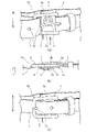
図8は、第4実施形態のバックル40を説明する図である。なお、本実施形態のバックル40は、主に図9で示すようなスラックスを着用する際に用いられるベルトに適用される。 FIG. 8 is a diagram illustrating the buckle 40 of the fourth embodiment. The buckle 40 of the present embodiment is mainly applied to a belt used when wearing a slacks as shown in FIG.

図8(a)はバックル30を裏側(ズボン側)斜め上方から見た斜視図、図8(b)はバックル40をズボン側から見た裏面図、図8(c)はベルト装着時においてバックル40を上側から見た上面図である。また、図8(a)(b)で示す両矢印は重力方向における上下方向を示し、図8(c)に示す白抜き矢印が指す方向はズボン側を示している。 8 (a) is a perspective view of the buckle 30 viewed from diagonally above the back side (trouser side), FIG. 8 (b) is a back view of the buckle 40 viewed from the trouser side, and FIG. 8 (c) is the buckle when the belt is attached. It is a top view which looked at 40 from the upper side. Further, the double arrows shown in FIGS. 8 (a) and 8 (b) indicate the vertical direction in the direction of gravity, and the direction indicated by the white arrow shown in FIG. 8 (c) indicates the trouser side.

図示するとおり、本実施形態の係合部44は、バックル本体2の下側の軸2cの一部であって、軸2cからズボン側へ突出するとともに上側へ湾曲する(折り曲げられる)ことにより形成されるフック形状部44aにズボンの一部が係合するように構成される。 As shown in the figure, the engaging portion 44 of the present embodiment is a part of the lower shaft 2c of the buckle body 2, and is formed by protruding from the shaft 2c toward the trousers and bending (bending) upward. A part of the trousers is configured to engage with the hook-shaped portion 44a to be formed.

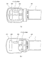
ここで、本実施形態の係合部44が係合するズボンの一部について図9を参照して説明する。ここでのズボンの一部は、ズボン(スラックス)のオビ(ウエストバンド)部分に備わる持ち出し部45である。持ち出し部45は、スラックスの正面から見てスラックス前面の上端部中央から正面視における少し左側に設けられるボタン45bを留めるための布部分であって、上記オビ部分から突出して設けられ、少なくともその下側45aは当該オビ部分に縫い付けられていない(図中の点線より矢印方向を参照)。 Here, a part of the trousers with which the engaging portion 44 of the present embodiment is engaged will be described with reference to FIG. A part of the trousers here is a carry-out portion 45 provided in the obi (waist band) portion of the trousers (slacks). The carry-out portion 45 is a cloth portion for fastening the button 45b provided slightly to the left side in front view from the center of the upper end portion of the front surface of the slacks when viewed from the front of the slacks, and is provided so as to project from the above-mentioned obi portion and at least below it. The side 45a is not sewn to the obi portion (see the arrow direction from the dotted line in the figure).

このようなスラックスを対象とする本実施形態の係合部44は、バックル本体2に設けられ、スラックスの持ち出し部45を係合するように構成される。より詳細には、係合部44は、ベルト装着時に持ち出し部45のズボン側(裏地)に入り込み、持ち出し部45の下側45aをフック形状部44aに引っ掛けるように構成される。これにより、着用者がベルト装着時に係合部44を持ち出し部45のズボン側(裏地)に挿入することにより、スラックスがベルトに対してずり下がることを容易に防止することができる。 The engaging portion 44 of the present embodiment for such slacks is provided on the buckle main body 2 and is configured to engage the carrying-out portion 45 of the slacks. More specifically, the engaging portion 44 is configured to enter the trouser side (lining) of the carry-out portion 45 when the belt is attached, and hook the lower side 45a of the carry-out portion 45 to the hook-shaped portion 44a. As a result, the wearer can easily prevent the slacks from slipping down with respect to the belt by inserting the engaging portion 44 into the trouser side (lining) of the carry-out portion 45 when the belt is worn.

なお、係合部44の形状、および配置は、スラックスの持ち出し部45を下側から支持できる限り適宜設定されてよい。例えば、軸2cの左右方向における係合部44の位置は、図示する位置に限られない。係合部44の位置は、少なくとも図8(c)の裏面図において中央より右側において、バックル40をスラックスの正面中央に配置した状態で持ち出し部45の裏側に入り込める限りにおいて適宜調整することができる。また、44の形状も、図示するような矩形状に限らず適宜設定可能であり、半円形状や棒状等であってもよい。 The shape and arrangement of the engaging portion 44 may be appropriately set as long as the carry-out portion 45 of the slacks can be supported from below. For example, the position of the engaging portion 44 in the left-right direction of the shaft 2c is not limited to the position shown in the figure. The position of the engaging portion 44 can be appropriately adjusted as long as it can enter the back side of the carry-out portion 45 with the buckle 40 arranged in the center of the front surface of the slacks, at least on the right side of the center in the back view of FIG. 8 (c). .. Further, the shape of 44 is not limited to the rectangular shape as shown in the figure, and can be appropriately set, and may be a semicircular shape, a rod shape, or the like.

なお、女性用のスラックス等、図9に示す持ち出し部45が正面視において右側に突出するように構成されるスラックスもある。このようなスラックスに使用されることを考慮して、バックル40が有する係合部44の位置を左右方向において逆側、すなわち、バックル40の裏側から見て左よりの位置に設定してもよい。 Some slacks, such as slacks for women, are configured such that the carry-out portion 45 shown in FIG. 9 projects to the right in front view. Considering that it is used for such a slacks, the position of the engaging portion 44 of the buckle 40 may be set to the opposite side in the left-right direction, that is, the position from the left side when viewed from the back side of the buckle 40. ..

以上、第4実施形態のバックル40によれば、被服の一部は、ズボンの前面上端において、当該ズボンのオビ部から突出して備わる持ち出し部45である。また、バックル本体2は、環状構造を有し、上下に対向する略平行な二つの軸を含む。そして、係合部44は、バックル本体2の一部であって、二つの軸の下方の軸2cにおいてズボン側に突出するとともにズボン着用時における上側に折り曲げられることにより形成されるフック形状部44aに持ち出し部45が係合するように構成される。これにより、いわゆるトップボタンを有さないスラックスのずり下がりを防止することができる。 As described above, according to the buckle 40 of the fourth embodiment, a part of the clothing is a carry-out portion 45 provided at the upper end of the front surface of the trousers so as to protrude from the obi portion of the trousers. Further, the buckle body 2 has an annular structure and includes two substantially parallel axes facing each other in the vertical direction. The engaging portion 44 is a part of the buckle main body 2, and is a hook-shaped portion 44a formed by projecting toward the trousers on the shaft 2c below the two shafts and bending upward when the trousers are worn. The take-out portion 45 is configured to engage with the trousers. This makes it possible to prevent the slacks that do not have a so-called top button from slipping down.

-第5実施形態-
本発明の第5実施形態にかかるバックル50について説明する。本実施形態のバックル50は、バックル本体52、係止部53、および、係合部54の形状が上記実施形態と相違する。以下では図面等を参照して当該相違点を中心に説明する。また、上記実施形態と同様の構成には同じ指示番号を付して説明は省略する。
-Fifth Embodiment-
The buckle 50 according to the fifth embodiment of the present invention will be described. The buckle 50 of the present embodiment is different from the above-described embodiment in the shapes of the buckle main body 52, the locking portion 53, and the engaging portion 54. In the following, the differences will be mainly described with reference to the drawings and the like. Further, the same instruction number will be assigned to the same configuration as that of the above embodiment, and the description thereof will be omitted.

図10は、本実施形態のバックル50を説明する図である。図10(a)は、バックル50を表から見た斜視図を示し、図10(b)はバックル50を裏側(ズボン側)から見た斜視図を示している。 FIG. 10 is a diagram illustrating the buckle 50 of the present embodiment. FIG. 10A shows a perspective view of the buckle 50 as viewed from the front, and FIG. 10B shows a perspective view of the buckle 50 as viewed from the back side (trousers side).

本実施形態のバックル50は、裏平板部52bと、裏平板部52bに設けられベルト1の一端が固定されるベルト固定部52cとからなるバックル本体52と、係止部53と、裏平板部52bに設けられた係合部54とを含んで構成される。 The buckle 50 of the present embodiment has a buckle main body 52 including a back flat plate portion 52b, a belt fixing portion 52c provided on the back flat plate portion 52b and one end of the belt 1 is fixed, a locking portion 53, and a back flat plate portion. It is configured to include an engaging portion 54 provided in 52b.

裏平板部52bは、略矩形状に形成された平板状部材であって、バックル50のズボン側を覆うように構成される。裏平板部52bの一端側にはベルト固定部52cが回動可能に設けられ、当該ベルト固定部52cとの間でベルト1の一端を固定する。また、裏平板部52bの他端側には係止部53が回動可能に設けられ、当該係止部53との間でベルト1の他端を係止する。そして、裏平板部52bには、係合部54としての開口部が形成される。係合部54の詳細については図11を用いて後述する。 The back flat plate portion 52b is a flat plate-shaped member formed in a substantially rectangular shape, and is configured to cover the trouser side of the buckle 50. A belt fixing portion 52c is rotatably provided on one end side of the back flat plate portion 52b, and one end of the belt 1 is fixed to the belt fixing portion 52c. Further, a locking portion 53 is rotatably provided on the other end side of the back plate portion 52b, and the other end of the belt 1 is locked with the locking portion 53. Then, an opening as an engaging portion 54 is formed in the back plate portion 52b. The details of the engaging portion 54 will be described later with reference to FIG.

ベルト固定部52cは、バックル本体52のズボン側において、バックル本体52の一端に回転軸52aを介して回動(開閉)可能に設けられている。ベルト固定部52aは、回転軸52aを支点に開いた状態で裏平板部52bとの間にベルト1を挿入した後、閉じることでベルト1を挟み込み、ベルト1の一端をバックル本体52に固定する。 The belt fixing portion 52c is provided on the trouser side of the buckle main body 52 so as to be rotatable (open / close) at one end of the buckle main body 52 via a rotating shaft 52a. The belt fixing portion 52a is inserted with the belt 1 between the back plate portion 52b and the back plate portion 52b in a state where the rotation shaft 52a is opened as a fulcrum, and then closed to sandwich the belt 1 and fix one end of the belt 1 to the buckle main body 52. ..

係止部53は、略矩形状に形成された平板状部材であって、バックル50の表側を覆うように構成される。係止部53は、バックル本体52の他端に回転軸53aを介して回動(開閉)可能に設けられている。係止部53は、回転軸53aを支点に開いた状態で裏平板部の一部との間にベルト1の他端を挿入した後(図中の矢印方向参照)、閉じることでベルト1を挟み込み、ベルト1の一端をバックル本体52に係止する。 The locking portion 53 is a flat plate-shaped member formed in a substantially rectangular shape, and is configured to cover the front side of the buckle 50. The locking portion 53 is provided at the other end of the buckle main body 52 so as to be rotatable (open / close) via the rotating shaft 53a. The locking portion 53 opens the belt 1 with the rotation shaft 53a as a fulcrum, inserts the other end of the belt 1 between the locking portion 53 and a part of the back plate portion (see the arrow direction in the figure), and then closes the belt 1. It is sandwiched and one end of the belt 1 is locked to the buckle body 52.

以上が本発明が適用されるバックル50の構成である。以下、バックル50が備える係合部54の詳細を説明する。 The above is the configuration of the buckle 50 to which the present invention is applied. Hereinafter, the details of the engaging portion 54 included in the buckle 50 will be described.

図11は、本実施形態の係合部54の形状を説明する図である。図11(a)はバックル本体2の裏平板部52bをズボン側からみた裏面図、図11(b)は裏平板部52bをベルト装着時に上方から見た上面図、図11(c)はベルト装着時に裏平板部52bを側面から見た側面図を示している。図11(a)で示す両矢印は重力方向における上下方向を示し、図11(b)、(c)に示す白抜き矢印が指す方向は、ズボン着用時にバックル50を使用した場合における身体側(ズボン側)を示している。なお、図11は、主にバックル本体52における裏平板部52bと係合部54の形状を説明するために図示したものであり、ベルト固定部52cや、ベルト装着時にベルトが通る孔等は省略されている(後述する図12、13についても同様)。 FIG. 11 is a diagram illustrating the shape of the engaging portion 54 of the present embodiment. 11 (a) is a back view of the back flat plate portion 52b of the buckle body 2 as viewed from the trouser side, FIG. 11 (b) is a top view of the back flat plate portion 52 b when the belt is attached, and FIG. 11 (c) is a belt. A side view of the back plate portion 52b as viewed from the side at the time of mounting is shown. The double-headed arrow shown in FIG. 11 (a) indicates the vertical direction in the direction of gravity, and the direction indicated by the white arrow shown in FIGS. 11 (b) and 11 (c) is the body side (when the buckle 50 is used while wearing trousers). (Pants side) is shown. Note that FIG. 11 is mainly for explaining the shapes of the back plate portion 52b and the engaging portion 54 in the buckle main body 52, and the belt fixing portion 52c, the hole through which the belt passes when the belt is attached, and the like are omitted. (The same applies to FIGS. 12 and 13 described later).

図11(a)で示すように、本実施形態の係合部54は、裏平板部52bの略中央(ベルト装着時にトップボタンと重なる位置)に形成された開口部である。本実施形態の係合部54は、下側に凸なU字形状部分を含む凸形状を示している。係合部54の大きさは、ズボンの一部としてのボタン8が導入可能であることを前提に適宜設定されてよい。例えば、係合部54の左右方向における幅Aは、上述のジーンズに備わるトップボタンの大きさを考慮して例えば1.7cmより大きい長さに設定される。また、上下方向における長さBは、当該トップボタンの厚みを考慮して、例えば1.5mmより大きい長さに設定される。 As shown in FIG. 11A, the engaging portion 54 of the present embodiment is an opening formed at substantially the center of the back plate portion 52b (a position overlapping the top button when the belt is attached). The engaging portion 54 of the present embodiment shows a convex shape including a downwardly convex U-shaped portion. The size of the engaging portion 54 may be appropriately set on the premise that the button 8 as a part of the trousers can be introduced. For example, the width A of the engaging portion 54 in the left-right direction is set to a length larger than, for example, 1.7 cm in consideration of the size of the top button provided on the above-mentioned jeans. Further, the length B in the vertical direction is set to a length larger than, for example, 1.5 mm in consideration of the thickness of the top button.

このような大きさの開口部(係合部54)が裏平板部52bに形成されることにより、ベルト装着時に係合部54にボタン8を導入することができるので、係合部54の下端54aにボタン8の特に連結部8aを引っ掛け、ボタン8を下側から支持することができる。これにより、バックル50を備えるベルト装着時において、ズボンがベルトに対してずり下がることを防止することができる。 By forming an opening (engagement portion 54) having such a size in the back plate portion 52b, the button 8 can be introduced into the engagement portion 54 when the belt is attached, so that the lower end of the engagement portion 54 can be introduced. A particularly connecting portion 8a of the button 8 can be hooked on the 54a to support the button 8 from below. This makes it possible to prevent the trousers from slipping down with respect to the belt when the belt provided with the buckle 50 is attached.

また、本実施形態の係合部54は、図11(b)、(c)で示す特徴を備えていてもよい。すなわち、係合部54は、係合部54の少なくとも一部としての下端54aがズボン側に突出することにより、係合部54の開口面の少なくとも一部が上方(斜め上方を含む)を向くように構成されてもよい。係合部54がこのように構成されることにより、係合部54の開口面の面積を増大させるとともに、ベルト装着時にボタン8を係合部54に導入する際に要求されるボタン8を傾ける角度をより緩やかにすることができるので、着用者がベルト装着時にボタン8を係合部4に係合させる作業の容易性を向上させることができる。 Further, the engaging portion 54 of the present embodiment may have the features shown in FIGS. 11 (b) and 11 (c). That is, in the engaging portion 54, at least a part of the opening surface of the engaging portion 54 faces upward (including diagonally upward) because the lower end 54a as at least a part of the engaging portion 54 projects toward the trousers. It may be configured as follows. By configuring the engaging portion 54 in this way, the area of the opening surface of the engaging portion 54 is increased, and the button 8 required for introducing the button 8 into the engaging portion 54 when the belt is attached is tilted. Since the angle can be made gentler, it is possible to improve the ease of work in which the wearer engages the button 8 with the engaging portion 4 when the belt is worn.

なお、係合部54の形状は、図11で示すものに限らず、ボタン8を下側から係合して支持することができる限りにおいて様々な形状を含んでよい。 The shape of the engaging portion 54 is not limited to that shown in FIG. 11, and may include various shapes as long as the button 8 can be engaged and supported from below.

図12は、本実施形態の係合部54の形状の他の例を説明する図である。図12(a)~(c)では、バックル50を裏側(ズボン側)から見た裏面図が示される。なお、各図の左側に示す両矢印は、ズボン着用時における重力方向に対応する上下方向を指すものとする。 FIG. 12 is a diagram illustrating another example of the shape of the engaging portion 54 of the present embodiment. 12 (a) to 12 (c) show a back view of the buckle 50 as viewed from the back side (trouser side). The double-headed arrow shown on the left side of each figure points to the vertical direction corresponding to the direction of gravity when wearing trousers.

図12(a)、(b)に示すとおり、係合部54は、図11(a)で示す形状に限らず、矩形状、又は半円状であってもよい。また、図示しないが、下側に頂点を有する三角形状であってもよい。すなわち、係合部54の下端54aは、直線形状、曲線形状、又は三角形の頂角形状等、適宜設定されてよい。 As shown in FIGS. 12A and 12B, the engaging portion 54 is not limited to the shape shown in FIG. 11A, and may be rectangular or semicircular. Further, although not shown, it may have a triangular shape having an apex on the lower side. That is, the lower end 54a of the engaging portion 54 may be appropriately set to have a linear shape, a curved shape, a triangular apex angle shape, or the like.

また、係合部54は、裏平板部52bの少なくとも一端に達するように形成されてもよい。例えば、係合部54は、図12(c)で示すように、裏平板部52bの裏側から見て右側の端部が開放するように形成されてもよい。係合部54がこのように形成されることにより、ベルト装着時にボタン8を係合部54に横から(左右方向から)導入することができるので、ボタン8を係合部54により容易に係合させることができる。 Further, the engaging portion 54 may be formed so as to reach at least one end of the back plate portion 52b. For example, as shown in FIG. 12 (c), the engaging portion 54 may be formed so that the end portion on the right side when viewed from the back side of the back plate portion 52b is open. By forming the engaging portion 54 in this way, the button 8 can be introduced into the engaging portion 54 from the side (from the left-right direction) when the belt is attached, so that the button 8 can be easily engaged by the engaging portion 54. Can be matched.

なお、図12(a)、(b)で示す係合部54の左右の幅方向の長さAと上下方向の長さBは図11(a)を用いて説明したのと同様である。ただし、図12(c)に示す長さBは、ボタン8の連結部8a(図3(b))を導入可能な長さ以上に設定される。例えば、ある市販のジーンズの連結部8a(リジット)の幅が8mmであることを考慮して、当該長さBを8mmより大きい長さに設定してもよい。また、対象とするボタン8の連結部8aが縫い糸である場合は、長さBを例えば3mm以上の長さに設定してもよい。なお、図12では示さないが、係合部54の少なくとも下端54aを含む一部は、図11(b)、(c)を用いて説明したのと同様にズボン側へ突出するように構成されてもよい。 The length A in the left-right width direction and the length B in the vertical direction of the engaging portion 54 shown in FIGS. 12 (a) and 12 (b) are the same as those described with reference to FIG. 11 (a). However, the length B shown in FIG. 12 (c) is set to be longer than the length to which the connecting portion 8a (FIG. 3 (b)) of the button 8 can be introduced. For example, considering that the width of the connecting portion 8a (rigid) of a certain commercially available jeans is 8 mm, the length B may be set to a length larger than 8 mm. Further, when the connecting portion 8a of the target button 8 is a sewing thread, the length B may be set to a length of, for example, 3 mm or more. Although not shown in FIG. 12, a part of the engaging portion 54 including at least the lower end 54a is configured to protrude toward the trousers as described with reference to FIGS. 11 (b) and 11 (c). You may.

またさらに、係合部54は、図13で示すような形状であってもよい。図13(a)は、バックル50を裏側(ズボン側)から見た裏面図を示し、図13(b)は、バックル50を左側から見た左側面図を示し、図13(c)は、バックル50を右側から見た右側面図を示し、図13(d)は、バックル50を裏側の上方から見た斜視図を示している。すなわち、係合部54は、図13(a)、(d)で示すように、裏平板部52bを左右方向の端部まで覆うように設けられてもよい。この場合は、係合部54は、図13(b)、(c)、(d)で示すように、裏平板部52bと係合部54とで形成される開口面が上方を向くように構成されてもよい。このような形状の係合部54であれば、ズボン着用時に係合部54が形成する開口部にボタン8を上方からより容易に導入することができるので、係合部54にボタン8をより容易に係合させることができる。 Furthermore, the engaging portion 54 may have a shape as shown in FIG. 13 (a) shows a back view of the buckle 50 as viewed from the back side (trousers side), FIG. 13 (b) shows a left side view of the buckle 50 as viewed from the left side, and FIG. 13 (c) shows a left side view. A right side view of the buckle 50 as viewed from the right side is shown, and FIG. 13 (d) shows a perspective view of the buckle 50 as viewed from above on the back side. That is, as shown in FIGS. 13A and 13D, the engaging portion 54 may be provided so as to cover the back plate portion 52b up to the end portion in the left-right direction. In this case, as shown in FIGS. 13B, 13C, and 13D, the engaging portion 54 has an opening surface formed by the back plate portion 52b and the engaging portion 54 facing upward. It may be configured. With the engaging portion 54 having such a shape, the button 8 can be more easily introduced from above into the opening formed by the engaging portion 54 when the trousers are worn, so that the button 8 can be more easily introduced into the engaging portion 54. Can be easily engaged.

このように、本実施形態の係合部54の形状は特に限定されず、ボタン8を係合可能な限り適宜設定されてよい。 As described above, the shape of the engaging portion 54 of the present embodiment is not particularly limited, and the button 8 may be appropriately set as long as it can be engaged.

以上、第5実施形態のバックル50によれば、被服の一部は、ズボンの前面上端に備わるボタンである。また、バックル本体52は、被服側に設けられる裏平板部52bと、裏平板部52bに設けられベルト1の一端を固定するベルト固定部52cとを有する。そして、係合部54は、裏平板部52bに設けられた開口部であって、開口部の下端54aはズボン側に突出した突出部(突出した下端54a)を有し、突出部により上方を向いた開口面にボタン8が係合するように構成される。これにより、上述のピン形状部材にかかる係止部を有さないバックルに対しても、本願発明にかかるズボン等被服のずり下がり防止機能を適用することができる。 As described above, according to the buckle 50 of the fifth embodiment, a part of the clothes is a button provided on the upper end of the front surface of the trousers. Further, the buckle main body 52 has a back flat plate portion 52b provided on the clothing side and a belt fixing portion 52c provided on the back flat plate portion 52b to fix one end of the belt 1. The engaging portion 54 is an opening provided in the back flat plate portion 52b, and the lower end 54a of the opening has a protruding portion (protruding lower end 54a) protruding toward the trousers, and the protruding portion moves upward. The button 8 is configured to engage the facing opening surface. Thereby, the slip-down prevention function of clothing such as trousers according to the present invention can be applied to the buckle having no locking portion on the pin-shaped member described above.

-第6実施形態-
本発明の第6実施形態にかかるバックル70について説明する。本実施形態のバックル70は、係止部3の形状が上記実施形態と相違する。以下、図18を参照して、特に第2実施形態にかかるバックル20(図5参照)との相違点について説明する。また、上記実施形態と同様の構成には同じ指示番号を付して説明は省略する。
-Sixth Embodiment-
The buckle 70 according to the sixth embodiment of the present invention will be described. The buckle 70 of the present embodiment has a different shape of the locking portion 3 from the above-described embodiment. Hereinafter, the differences from the buckle 20 (see FIG. 5) according to the second embodiment will be described with reference to FIG. Further, the same instruction number will be assigned to the same configuration as that of the above embodiment, and the description thereof will be omitted.

図18は、本実施形態のバックル70が備える係止部3を身体側(ズボン側)の上方から見た斜視図である。本実施形態の係止部3は、係合部24の両隣、すなわち係合部24の左右方向において当該係合部24と近接する位置、あるいは、係合部24の左右方向において凹形状部26と連続する位置から上方に突起するように形成された突起形状部71a、71bを有する。このような構成によれば、ボタン8が係合部24に係合された状態においてバックル70にズボンに対して左右方向にずれるような力が加えられた場合であっても、ボタン8の特に連結部8aが突起形状部71a、71bに引っ掛かり、バックル70の左右方向への移動が規制されるので、バックル70がズボンに対して左右方向にずれることをより確実に抑制することができる。 FIG. 18 is a perspective view of the locking portion 3 provided in the buckle 70 of the present embodiment as viewed from above on the body side (trousers side). The locking portion 3 of the present embodiment is located on both sides of the engaging portion 24, that is, at a position close to the engaging portion 24 in the left-right direction of the engaging portion 24, or a concave portion 26 in the left-right direction of the engaging portion 24. It has protrusion-shaped portions 71a and 71b formed so as to protrude upward from a position continuous with the above. According to such a configuration, even when a force is applied to the buckle 70 in a state where the button 8 is engaged with the engaging portion 24 so as to be displaced in the left-right direction with respect to the trousers, the button 8 is particularly provided. Since the connecting portion 8a is caught by the protrusion-shaped portions 71a and 71b and the movement of the buckle 70 in the left-right direction is restricted, it is possible to more reliably prevent the buckle 70 from shifting in the left-right direction with respect to the trousers.

なお、本実施形態の係止部3は、突起形状部71a、71bを両方とも有する必要は必ずしもなく、少なくとも一方の突起形状部(71aまたは71b)を備えていればよい。また、突起形状部71a、71bは、上述した第2実施形態の係止部3だけではなく、図7を参照して説明した第3実施形態の係止部3等、本明細書において説明した係合部を備える全ての係止部3に矛盾が生じない範囲で適用することができる。 The locking portion 3 of the present embodiment does not necessarily have to have both the protrusion-shaped portions 71a and 71b, and may have at least one protrusion-shaped portion (71a or 71b). Further, the protrusion-shaped portions 71a and 71b are described in the present specification not only as the locking portion 3 of the second embodiment described above, but also as the locking portion 3 of the third embodiment described with reference to FIG. It can be applied to all the locking portions 3 including the engaging portions as long as there is no contradiction.

以上、第6実施形態のバックル70によれば、ベルト係止部3は、係合部24の左右方向の少なくともいずれか一方であって、係合部24に近接する位置において上方に突起する突起形状部71a、71bをさらに有する。これにより、バックル70を左右にずらすように働く力が加わった場合でも、係合部24に係合した被服の一部が突起形状部71a、71bに引っ掛かるので、バックル70がズボンに対して左右方向にずれることをより確実に抑制することができる。 As described above, according to the buckle 70 of the sixth embodiment, the belt locking portion 3 is at least one of the engaging portions 24 in the left-right direction, and is a protrusion protruding upward at a position close to the engaging portion 24. It further has shape portions 71a and 71b. As a result, even when a force acting to shift the buckle 70 to the left or right is applied, a part of the clothing engaged with the engaging portion 24 is caught by the protrusion-shaped portions 71a and 71b, so that the buckle 70 is left and right with respect to the trousers. It is possible to more reliably suppress the deviation in the direction.

-第7実施形態-
本発明の第7実施形態に係るベルト200について説明する。なお、以下の説明において使用するベルト200の用語は、バックル本体を含むベルト全体を示すものとする。そして、上述の各実施形態の説明において用いた用語「ベルト1」に相当する部分、すなわち一端がバックル本体に固定された帯部分は、以下の説明においてもベルト1、あるいは、ベルト(帯部)1と称される。
-Seventh Embodiment-
The belt 200 according to the seventh embodiment of the present invention will be described. The term of the belt 200 used in the following description refers to the entire belt including the buckle body. The portion corresponding to the term "belt 1" used in the above description of each embodiment, that is, the belt portion having one end fixed to the buckle body, is also the belt 1 or the belt (belt portion) in the following description. It is called 1.

本実施形態のベルト200は、保護部材201をさらに備え、保護部材201に係合部203が設けられている点が上記実施形態と相違する。以下、図面を参照して本実施形態の詳細を説明する。 The belt 200 of the present embodiment is different from the above-described embodiment in that the protective member 201 is further provided and the protective member 201 is provided with the engaging portion 203. Hereinafter, the details of the present embodiment will be described with reference to the drawings.

図19(a)、(b)は、ベルト200を正面から見た図である。図示するように、本実施形態のベルト200は、ベルト1又はバックル本体に一端が固定され、バックル本体をベルト着用時における身体側から覆うように設けられた保護部材201を備えている。図19(b)は、バックル本体がめくりあげられた状態を示す図であって、保護部材201が正面から視認できる状態が表された図である。 19 (a) and 19 (b) are views of the belt 200 as viewed from the front. As shown in the figure, the belt 200 of the present embodiment includes a protective member 201 having one end fixed to the belt 1 or the buckle body and provided so as to cover the buckle body from the body side when the belt is worn. FIG. 19B is a diagram showing a state in which the buckle body is turned up, and is a diagram showing a state in which the protective member 201 can be visually recognized from the front.

保護部材201は、ベルト着用時において、バックル本体とズボンとの間に介在するように構成される部材である。保護部材201は、ベルト着用時にバックル本体が直接的に身体に当たるのを防止する機能、あるいは、ベルト着用時にバックル本体がズボン等被服を摩耗させることを防止する機能等を有する。保護部材201は、例えば運動をする時等、激しい動きを行うことが予想される際に着用するベルトに主に適用される。一例として、ベルト200は、野球をする際に装着されるいわゆる野球ベルトに適用される。 The protective member 201 is a member configured to intervene between the buckle body and the trousers when the belt is worn. The protective member 201 has a function of preventing the buckle body from directly hitting the body when wearing the belt, a function of preventing the buckle body from wearing clothes such as trousers when wearing the belt, and the like. The protective member 201 is mainly applied to a belt worn when it is expected to perform vigorous movement such as when exercising. As an example, the belt 200 is applied to a so-called baseball belt worn when playing baseball.

そして、保護部材201には、被服の一部を下側から支持するように当該被服の一部に係合する係合部203が形成される。本実施形態の係合部203は、保護部材201に形成された孔部(開口部)である。本実施形態の係合部203は、左右方向を長手方向とする長方形状に形成される。係合部203の大きさは、ズボンの一部としてのボタン8が導入可能であることを前提に適宜設定されてよい。そして、ベルト装着時に係合部203にボタン8を裏側(身体側)から挿入することにより、係合部203の下端がボタン8の特に連結部8aに係合し、ボタン8を下側から支持することができる。これにより、ベルト200の装着時において、ズボンがベルト200に対してずり下がることを抑制することができる。なお、図示するベルト通し202は、ベルト200の着用時にベルト1のバックル本体とは逆側の端部を通すために設けられた空間部分である。ベルト通し202は、必須の構成ではなく、適宜省略されてもよい。 Then, the protective member 201 is formed with an engaging portion 203 that engages with the part of the clothing so as to support the part of the clothing from below. The engaging portion 203 of the present embodiment is a hole (opening) formed in the protective member 201. The engaging portion 203 of the present embodiment is formed in a rectangular shape with the left-right direction as the longitudinal direction. The size of the engaging portion 203 may be appropriately set on the premise that the button 8 as a part of the trousers can be introduced. Then, by inserting the button 8 into the engaging portion 203 from the back side (body side) when the belt is attached, the lower end of the engaging portion 203 engages with the button 8 in particular, the connecting portion 8a, and the button 8 is supported from below. can do. As a result, it is possible to prevent the trousers from slipping down with respect to the belt 200 when the belt 200 is attached. The belt loop 202 shown in the figure is a space portion provided for passing the end portion of the belt 1 opposite to the buckle body when the belt 200 is worn. The belt loop 202 is not an essential configuration and may be omitted as appropriate.

なお、係合部203の形状は、図19に示すような長方形状である必要は必ずしもない。図20(a)で示すような楕円形状であってもよいし、図20(b)で示すようなT字形状であってもよい。また、係合部203は、保護部材201を貫通する孔部として形成される必要は必ずしもない。係合部203は、ズボン着用時にボタン8を下側から支持することができることを前提に、例えば、保護部材201の裏側(身体側)において、ボタン8の少なくとも下端側の一部が収まるように設けられた凹部であってもよい。 The shape of the engaging portion 203 does not necessarily have to be rectangular as shown in FIG. It may have an elliptical shape as shown in FIG. 20 (a) or a T-shape as shown in FIG. 20 (b). Further, the engaging portion 203 does not necessarily have to be formed as a hole portion penetrating the protective member 201. On the premise that the button 8 can be supported from below when the trousers are worn, the engaging portion 203 is set so that at least a part of the lower end side of the button 8 is accommodated on the back side (body side) of the protective member 201, for example. It may be a provided recess.

以上、第7実施形態のベルト200は、ズボンのずれを抑制するベルト200であって、ベルト(帯部)1の一端が固定されるバックル本体と、一端がベルト1又はバックル本体に固定され、ズボン着用時においてバックル本体をズボン側から覆うように設けられた保護部材201と、保護部材201に設けられ、ズボンの前面上端に備わるボタン8を下側から支持するように当該ボタンに係合する係合部203と、を備える。これにより、いわゆる野球ベルト等、保護部材201を備えるベルトの装着時においてもズボンがベルト200に対してずり下がることを抑制することができる。 As described above, the belt 200 of the seventh embodiment is a belt 200 that suppresses the displacement of the trousers, and has a buckle body to which one end of the belt (belt portion) 1 is fixed and one end to the belt 1 or the buckle body. When wearing the trousers, the protective member 201 provided so as to cover the buckle body from the trouser side and the button 8 provided on the protective member 201 and provided at the upper end of the front surface of the trousers are engaged with the button so as to be supported from below. The engaging portion 203 is provided. As a result, it is possible to prevent the trousers from slipping down with respect to the belt 200 even when a belt provided with the protective member 201, such as a so-called baseball belt, is attached.

また、第7実施形態のベルト200によれば、係合部203は、保護部材201に設けられた孔部であって、当該孔部にボタン8の少なくとも一部が挿入されることにより当該ボタンを下側から支持するように構成される。これにより、ズボン着用時にボタン8を確実に係合することができる。 Further, according to the belt 200 of the seventh embodiment, the engaging portion 203 is a hole portion provided in the protective member 201, and the button is inserted by inserting at least a part of the button 8 into the hole portion. Is configured to support from below. This makes it possible to securely engage the button 8 when wearing the trousers.

-第8実施形態-
本発明の第8実施形態にかかるバックル110について説明する。本実施形態のバックル110は、係止部3に備わる係合部111の形状が上記実施形態と相違する。以下、図21を参照して当該相違点について説明する。また、上記実施形態と同様の構成には同じ指示番号を付して説明は省略する。
-Eighth Embodiment-
The buckle 110 according to the eighth embodiment of the present invention will be described. The buckle 110 of the present embodiment is different from the above-described embodiment in the shape of the engaging portion 111 provided in the locking portion 3. Hereinafter, the difference will be described with reference to FIG. Further, the same instruction number will be assigned to the same configuration as that of the above embodiment, and the description thereof will be omitted.

図21は、本実施形態のバックル110が備える係止部3を身体側(ズボン側)から見た斜視図である。本実施形態のバックル110は、主に図9で示すようなスラックスを着用する際に用いられるベルトに適用される。 FIG. 21 is a perspective view of the locking portion 3 provided in the buckle 110 of the present embodiment as viewed from the body side (trousers side). The buckle 110 of the present embodiment is mainly applied to a belt used when wearing a slacks as shown in FIG.

図示するとおり、本実施形態の係合部111は、係止部3の下側から下方へ延びる棒形状部と、当該棒形状部の下端からズボン側へ突出するとともに上側へ折り曲げられることにより形成されるフック形状部111aとを有する。係合部111は、このフック形状部111aにスラックスの持ち出し部45の下側45a(図9参照)が係合するように構成される。これにより、ベルト装着時に着用者が係合部111の先端部分を持ち出し部45のズボン側(裏地)に挿入することによって、スラックスがベルトに対してずり下がることを容易に防止することができる。なお、係止部3の左右方向における係合部111の位置、および、係合部111の棒形状部分の長さ、フック形状部111aの形状等は、デザイン性、及び、スラックスの持ち出し部45への係合のし易さの観点から適宜変更されてよい。 As shown in the figure, the engaging portion 111 of the present embodiment is formed by having a rod-shaped portion extending downward from the lower side of the locking portion 3 and projecting from the lower end of the rod-shaped portion toward the trousers side and being bent upward. It has a hook shape portion 111a to be formed. The engaging portion 111 is configured so that the lower side 45a (see FIG. 9) of the slacks carry-out portion 45 engages with the hook-shaped portion 111a. As a result, the wearer can easily prevent the slacks from slipping down with respect to the belt by inserting the tip portion of the engaging portion 111 into the trouser side (lining) of the carry-out portion 45 when the belt is worn. The position of the engaging portion 111 in the left-right direction of the locking portion 3, the length of the rod-shaped portion of the engaging portion 111, the shape of the hook-shaped portion 111a, and the like are designable and the slacks carry-out portion 45. It may be changed as appropriate from the viewpoint of ease of engagement with.

以上、第8実施形態のバックル110によれば、被服の一部は、ズボンの前面上端において当該ズボンのオビ部から突出して備わる持ち出し部45であって、係合部111は、ベルト係止部の下側から下方へ延びる棒形状部と、当該棒形状部の下端からズボン側に突出するとともにズボン着用時における上側に折り曲げられることにより形成されるフック形状部111aとを有し、当該フック形状部111aに持ち出し部45が係合するように構成される。このような構成によっても、ズボン等被服のずり下がりを容易に抑制することができる。 As described above, according to the buckle 110 of the eighth embodiment, a part of the clothing is a carry-out portion 45 provided so as to project from the hook portion of the trousers at the upper end of the front surface of the trousers, and the engaging portion 111 is a belt locking portion. It has a rod-shaped portion extending downward from the lower side and a hook-shaped portion 111a formed by protruding from the lower end of the rod-shaped portion toward the trousers side and being bent upward when the trousers are worn. The take-out portion 45 is configured to engage with the portion 111a. Even with such a configuration, it is possible to easily prevent the clothes such as trousers from slipping down.

-第9実施形態-
本発明の第9実施形態にかかるバックル120について説明する。本実施形態のバックル120は、係止部3に備わる係合部121の形状が上記実施形態と相違する。以下、図22を参照して当該相違点について説明する。また、上記実施形態と同様の構成には同じ指示番号を付して説明は省略する。
-Ninth Embodiment-
The buckle 120 according to the ninth embodiment of the present invention will be described. The buckle 120 of the present embodiment is different from the above-described embodiment in the shape of the engaging portion 121 provided in the locking portion 3. Hereinafter, the difference will be described with reference to FIG. 22. Further, the same instruction number will be assigned to the same configuration as that of the above embodiment, and the description thereof will be omitted.

図22(a)~(d)は、本実施形態のバックル120が備える係止部3を身体側(ズボン側)の上方から見た斜視図である。本実施形態のバックル120は、主に図23で示すようなステイループ(ピンループ)230を備えるスラックスを着用する際に用いられるベルトに適用される。 22 (a) to 22 (d) are perspective views of the locking portion 3 provided in the buckle 120 of the present embodiment as viewed from above on the body side (trousers side). The buckle 120 of the present embodiment is mainly applied to a belt used when wearing a slacks having a stay loop (pin loop) 230 as shown in FIG. 23.

図示するように、本実施形態の係合部121は、係止部3の一部であって、係止部3から上方へ突出する棒形状部を含み、当該棒形状部がズボンの一部に係合するように構成される。 As shown in the figure, the engaging portion 121 of the present embodiment is a part of the locking portion 3, includes a rod-shaped portion protruding upward from the locking portion 3, and the rod-shaped portion is a part of the trousers. It is configured to engage with.

ここで、本実施形態の係合部121が係合するズボンの一部について、図23を参照して説明する。ここでのズボンの一部は、スラックスのオビ部分に備わるステイループ(ベルトステイループ、あるいはベルトピンループとも称される)230である。ステイループ230は、本来、係止部が挿入されることによって当該係止部を備えるバックルがスラックスに対して左右方向にずれないようにするために設けられる輪っかである。 Here, a part of the trousers with which the engaging portion 121 of the present embodiment is engaged will be described with reference to FIG. 23. A part of the trousers here is a stay loop (also referred to as a belt stay loop or a belt pin loop) 230 provided in the obi portion of the slacks. The stay loop 230 is originally a ring provided so that the buckle provided with the locking portion does not shift in the left-right direction with respect to the slacks due to the insertion of the locking portion.

このようなステイループ230を備えるスラックスを対象とする係合部121は、係止部3に設けられ、スラックスのステイループ230を係合するように構成される。より詳細には、係合部121は、ベルト装着時にステイループ230のループ内(輪っか内)に入り込み、ステイループ230を係合部121乃至係止部3に引っ掛けるように構成される。これにより、ベルト装着時に着用者が係合部121をステイループ230に挿入することにより、スラックスがベルトに対してずり下がることを容易に防止することができるとともに、バックル120がスラックスに対して左右方向にずれることを抑制することができる。 The engaging portion 121 for the slacks provided with such a stay loop 230 is provided in the locking portion 3 and is configured to engage the stay loop 230 of the slacks. More specifically, the engaging portion 121 is configured to enter the loop (inside the ring) of the stay loop 230 when the belt is attached, and hook the stay loop 230 on the engaging portion 121 to the locking portion 3. As a result, the wearer can easily prevent the slacks from slipping down with respect to the belt by inserting the engaging portion 121 into the stay loop 230 when the belt is worn, and the buckle 120 is left and right with respect to the slacks. It is possible to suppress the deviation in the direction.

なお、係合部121の形状、および配置は、ステイループ230を引っ掛けて下側から支持できる限り適宜設定されてよい。例えば、係合部121は、図22(a)、(b)に示すように、係止部3のズボン側の側面から上方へ湾曲するように突出してもよいし、図22(c)、(d)に示すように、係止部3の上側から上方へ真っ直ぐ突出してもよい。また、係合部121は、図22(a)、(c)に示すように、棒形状部の上端部分が左右方向に延びるT字形状であってもよいし、図22(b)、(d)に示すような棒形状であってもよい。すなわち、係合部121の形状、および配置は、ステイループ230への係合のしやすさの観点から、適宜変更されてよい。 The shape and arrangement of the engaging portion 121 may be appropriately set as long as the stay loop 230 can be hooked and supported from below. For example, as shown in FIGS. 22 (a) and 22 (b), the engaging portion 121 may protrude upward from the side surface of the locking portion 3 on the trouser side, or may project upward in FIG. 22 (c). As shown in (d), the locking portion 3 may project straight upward from the upper side. Further, as shown in FIGS. 22 (a) and 22 (c), the engaging portion 121 may have a T-shape in which the upper end portion of the rod-shaped portion extends in the left-right direction, or the engaging portion 121 may have a T-shape. It may have a rod shape as shown in d). That is, the shape and arrangement of the engaging portion 121 may be appropriately changed from the viewpoint of ease of engagement with the stay loop 230.

以上、第9実施形態のバックル120によれば、被服の一部は、ズボンの前面上端において当該ズボンのオビ部に備わるステイループ230であって、係合部121は、ベルト係止部3から上方へ延びる棒形状部を有し、当該棒形状部がステイループ230に挿入されることによって当該棒形状部にステイループ230が係合するように構成される。このような構成によっても、スラックスがベルトに対してずり下がることを容易に防止することができるとともにバックル120がスラックスに対して左右方向にずれることを抑制することができる。 As described above, according to the buckle 120 of the ninth embodiment, a part of the clothing is a stay loop 230 provided at the upper end of the front surface of the trousers in the oblivious portion of the trousers, and the engaging portion 121 is from the belt locking portion 3. It has a rod-shaped portion extending upward, and the stay loop 230 is configured to engage with the rod-shaped portion by inserting the rod-shaped portion into the stay loop 230. With such a configuration, it is possible to easily prevent the slacks from sliding down with respect to the belt, and it is possible to prevent the buckle 120 from shifting in the left-right direction with respect to the slacks.

-第10実施形態-
本発明の第10実施形態に係るベルトパーツ300について説明する。以下に説明するベルトパーツ300は、従来のベルトに着脱可能に構成されたベルト用のパーツである。ベルトパーツ300は、従来のベルトに取り付けられることによって、当該ベルトに、上記の各実施形態で説明したズボンのずれを抑制する機能を付加することができる。
-10th Embodiment-
The belt part 300 according to the tenth embodiment of the present invention will be described. The belt part 300 described below is a part for a belt configured to be removable from a conventional belt. By attaching the belt part 300 to a conventional belt, it is possible to add a function of suppressing the displacement of the trousers described in each of the above embodiments to the belt.

図24(a)、(b)は、本実施形態のベルトパーツ300を説明する図であって、ベルトパーツ300がベルト1に取り付けられた状態をベルト着用時における身体側(ズボン側)から見た図である。図24(a)と図24(b)にそれぞれ示すベルトパーツ300は、係合する対象が異なる。以下詳細を説明する。 24 (a) and 24 (b) are views for explaining the belt part 300 of the present embodiment, and the state in which the belt part 300 is attached to the belt 1 is viewed from the body side (trousers side) when the belt is worn. It is a figure. The belt parts 300 shown in FIGS. 24 (a) and 24 (b) are engaged with different objects. The details will be described below.

図24(a)に示すベルトパーツ300は、主に、保持部301と係合部302とを含んで構成される。図24(a)のベルトパーツ300は、主に図9、23で示すようなスラックスを着用する際に用いられるベルトに適用される。 The belt part 300 shown in FIG. 24A mainly includes a holding portion 301 and an engaging portion 302. The belt part 300 of FIG. 24A is mainly applied to a belt used when wearing slacks as shown in FIGS. 9 and 23.

保持部301は、環状形状を有し、その内径にベルト1が通るように構成される。これにより、保持部301の内径にベルト1を通して保持部301を移動させることにより、保持部301を備えるベルトパーツ300をベルト1の所望の位置に保持することができる。なお、ここでの環状形状は、完全に連続する環状だけでなく、一部切り欠かれた部分が存在する形状も含むものとする。この場合には、当該切り欠かれた部分からベルト1の上下方向いずれかの端部を挿入させてベルト1を保持部301の内径側に収めることによって、ベルトパーツ300をベルト1の所望の位置に保持することができる。さらに、保持部301は、例えば図26で示すような定革をベルト1に固定するための金具に当該定革とともに挟持されることによってベルトパーツ300をベルト1に保持するように構成されてもよい。 The holding portion 301 has an annular shape, and is configured so that the belt 1 passes through the inner diameter thereof. Thereby, by moving the holding portion 301 through the belt 1 to the inner diameter of the holding portion 301, the belt part 300 including the holding portion 301 can be held at a desired position of the belt 1. It should be noted that the annular shape here includes not only a completely continuous annular shape but also a shape in which a partially cutout portion exists. In this case, the belt part 300 is placed at a desired position of the belt 1 by inserting either end of the belt 1 in the vertical direction from the notched portion and fitting the belt 1 into the inner diameter side of the holding portion 301. Can be held in. Further, even if the holding portion 301 is configured to hold the belt part 300 on the belt 1 by being sandwiched together with the fixed leather by a metal fitting for fixing the fixed leather to the belt 1, for example, as shown in FIG. 26. good.

係合部302は、保持部301の下端からズボン側へ突出するとともに上側へ折り曲げられることにより形成されるフック形状部302aにスラックスの持ち出し部45の下側45a(図9参照)が係合するように構成される。これにより、ベルト装着時に着用者が係合部302の先端部分を持ち出し部45のズボン側(裏地)に挿入することで、スラックスがベルトに対してずり下がることを容易に防止することができる。 The engaging portion 302 projects from the lower end of the holding portion 301 toward the trousers and is bent upward so that the lower side 45a (see FIG. 9) of the slacks carry-out portion 45 engages with the hook-shaped portion 302a. It is configured as follows. As a result, the wearer can easily prevent the slacks from slipping down with respect to the belt by inserting the tip portion of the engaging portion 302 into the trouser side (lining) of the carry-out portion 45 when the belt is worn.

図24(b)に示すベルトパーツ300は、主に、保持部301と係合部303とを含んで構成される。図24(b)のベルトパーツ300は、主に図9、23で示すようなスラックスを着用する際に用いられるベルトに適用される。保持部301については、図24(a)のベルトパーツ300の構成と同様であるため説明を省略する。 The belt part 300 shown in FIG. 24B mainly includes a holding portion 301 and an engaging portion 303. The belt part 300 of FIG. 24 (b) is mainly applied to a belt used when wearing slacks as shown in FIGS. 9 and 23. Since the holding portion 301 has the same configuration as that of the belt part 300 in FIG. 24 (a), the description thereof will be omitted.

係合部303は、保持部301からズボン側へ突出するとともに上側へ折り曲げられることにより形成されるフック形状部の上端に形成された凹形状部303aに図9、23で示すようなスラックスが備えるボタン45bが係合するように構成される。ボタン45bは、スラックス(ズボン)の前面上端に備わるボタンであって、持ち出し部45を留めるために使用される。係合部303は、ベルト装着時に着用者が凹形状部303aをボタン45bの特に不図示の連結部(ボタン45bとズボン生地との連結部)に係合させることによってボタン45bを下側から支持することができるので、ズボンがベルトに対してずり下がることを容易に防止することができる。 The engaging portion 303 is provided with slacks as shown in FIGS. The button 45b is configured to engage. The button 45b is a button provided on the upper end of the front surface of the slacks (trousers) and is used to fasten the carry-out portion 45. The engaging portion 303 supports the button 45b from below by the wearer engaging the concave portion 303a with a connecting portion (connecting portion between the button 45b and the trouser fabric) of the button 45b (not shown) when the belt is attached. Therefore, it is possible to easily prevent the trousers from slipping down with respect to the belt.

また、ベルトパーツ300は、上述した保持部301に代えて、図25で示すような保持部304を備えて構成されてもよい。 Further, the belt part 300 may be configured to include the holding portion 304 as shown in FIG. 25 instead of the holding portion 301 described above.

図25(a)、(b)は、本実施形態のベルトパーツ300の変形例を説明する図である。図25に示すベルトパーツ300は、図24で示したベルトパーツとは、特に保持部304の態用が相違する。 25 (a) and 25 (b) are diagrams illustrating a modified example of the belt part 300 of the present embodiment. The belt part 300 shown in FIG. 25 is different from the belt part shown in FIG. 24 in particular in terms of the holding portion 304.

図25(a)、(b)に示すベルトパーツ300が備える保持部304は、ベルト1に形成された係止穴1a(図24参照)に挿入可能な棒形状部304aを含んで構成される。より詳細には、保持部304は、棒形状部304aを支持する基部304bと、基部304bから突出して形成される棒形状部304aとを有する。そして、棒形状部304aをベルト1の係止穴1aに挿入することにより、ベルトパーツ300をベルト1に保持することができる。なお、棒形状部304aの端部をナット等が螺合、あるいはキャップ等が嵌合可能な形状とし、棒形状部304aを係止穴1aに貫通させた後にその端部をナット等で固定することができるように構成してもよい。これにより、ベルトパーツ300をベルト1により確実に保持することができる。 The holding portion 304 included in the belt parts 300 shown in FIGS. 25 (a) and 25 (b) includes a rod-shaped portion 304a that can be inserted into the locking hole 1a (see FIG. 24) formed in the belt 1. .. More specifically, the holding portion 304 has a base portion 304b that supports the rod-shaped portion 304a, and a rod-shaped portion 304a that is formed so as to project from the base portion 304b. Then, by inserting the rod-shaped portion 304a into the locking hole 1a of the belt 1, the belt part 300 can be held by the belt 1. The end of the rod-shaped portion 304a is shaped so that a nut or the like can be screwed or a cap or the like can be fitted, and the rod-shaped portion 304a is passed through the locking hole 1a and then the end is fixed with a nut or the like. It may be configured so that it can be done. As a result, the belt part 300 can be reliably held by the belt 1.

なお、係合部302、303については、係合部302、303が基部304bから突出して形成される点を除いては、図25(a)に係る係合部302は図24(a)の係合部302と、図25(b)に係る係合部303は図24(b)の係合部303と、それぞれ同等の構成であるため説明を省略する。 Regarding the engaging portions 302 and 303, the engaging portion 302 according to FIG. 25 (a) is shown in FIG. 24 (a) except that the engaging portions 302 and 303 are formed so as to project from the base portion 304b. Since the engaging portion 302 and the engaging portion 303 according to FIG. 25 (b) have the same configurations as the engaging portion 303 of FIG. 24 (b), the description thereof will be omitted.

以上がベルト1に着脱可能に構成されるベルトパーツ300の詳細である。ただし、上述したベルトパーツ300の形状は一例であって、図24、25を参照して説明した態様に限られない。ベルトパーツ300は、上述したようなズボンのズレを抑制する機能をズボンに付加することができることを前提に、デザイン性、被服の一部への係合容易性、ベルト1に対する着脱のし易さ等を考慮して適宜変更されてよい。 The above is the details of the belt part 300 that can be attached to and detached from the belt 1. However, the shape of the belt part 300 described above is an example, and is not limited to the embodiment described with reference to FIGS. 24 and 25. The belt part 300 is designed, easy to engage with a part of clothing, and easy to be attached to and detached from the belt 1 on the premise that the function of suppressing the displacement of the trousers as described above can be added to the trousers. It may be changed as appropriate in consideration of the above.

また、ベルトパーツ300は、必ずしも着脱可能に構成される必要はなく、図26、27に示すようにベルトを構成する一部材として常時備わっていてもよい。 Further, the belt part 300 does not necessarily have to be detachably configured, and may be always provided as one member constituting the belt as shown in FIGS. 26 and 27.

図26は、ベルトパーツ300を備えるベルト400を説明する図である。図26(a)はベルト400を正面から見た正面図を示し、図26(b)はベルト400を上方から見た上面図を示し、図26(c)はベルト400をズボン側の上方から見た斜視図を示す。図示するベルト400は、主に図9で示すようなスラックスを着用する際に用いられるベルトに適用される。 FIG. 26 is a diagram illustrating a belt 400 including a belt part 300. 26 (a) shows a front view of the belt 400 as viewed from the front, FIG. 26 (b) shows a top view of the belt 400 as viewed from above, and FIG. 26 (c) shows the belt 400 from above the trousers side. The perspective view seen is shown. The illustrated belt 400 is mainly applied to a belt used when wearing a slacks as shown in FIG.

特に図26(b)に表されるように、ベルトパーツ300は、長手方向がベルト1の短手方向(上下方向)に一致するような平板形状部305を有する。本実施形態の平板形状部305(固定部)は、定革をベルト1に固定するための金具とバックル本体との間において、ベルト(帯部)1が前後方向に2重に重ね合わせられた部分において当該ベルト1に挟まれるようにして固定されている。また、平板形状部305の上側の端部は、ズボン側に突出するとともに下側に折り曲がることによりカギ形状部を形成し、当該カギ形上部がベルト1の上端に引かかるように構成されている。そして、図26(c)に示すように、ベルト400は、ベルトパーツ300の下端からズボン側へ突出するとともに上側へ折り曲げられることにより形成されるフック形状部302aが備わり、当該フック形状部302aにスラックスの持ち出し部45の下側45a(図9参照)が係合するように構成される。このような構成によっても、着用者がベルト装着時に係合部302の先端部分を持ち出し部45のズボン側(裏地)に挿入することによって、スラックスがベルトに対してずり下がることを容易に防止することができる。なお、ベルトパーツ300がベルト400に固定される態様、すなわち固定部305の態様は特に限定されず、適宜変更されてよい。例えば、ベルトパーツ300は、定革をベルト1に固定するための金具に当該定革とともに挟持されることによってベルト400に固定されるように構成されてもよい。 In particular, as shown in FIG. 26B, the belt part 300 has a flat plate-shaped portion 305 whose longitudinal direction coincides with the lateral direction (vertical direction) of the belt 1. In the flat plate shape portion 305 (fixing portion) of the present embodiment, the belt (belt portion) 1 is doubly superposed in the front-rear direction between the metal fitting for fixing the fixed leather to the belt 1 and the buckle main body. It is fixed so as to be sandwiched between the belt 1 in the portion. Further, the upper end portion of the flat plate shape portion 305 is configured to protrude toward the trousers side and bend downward to form a key shape portion, and the upper end of the key shape portion is hooked on the upper end of the belt 1. There is. As shown in FIG. 26 (c), the belt 400 is provided with a hook-shaped portion 302a formed by projecting from the lower end of the belt part 300 toward the trousers side and bending upward, and the hook-shaped portion 302a is provided with the hook-shaped portion 302a. The lower side 45a (see FIG. 9) of the slacks carry-out portion 45 is configured to engage. Even with such a configuration, the wearer can easily prevent the slacks from slipping down with respect to the belt by inserting the tip portion of the engaging portion 302 into the trouser side (lining) of the carry-out portion 45 when the belt is worn. be able to. The mode in which the belt part 300 is fixed to the belt 400, that is, the mode of the fixing portion 305 is not particularly limited and may be appropriately changed. For example, the belt part 300 may be configured to be fixed to the belt 400 by being sandwiched with the fixed leather by a metal fitting for fixing the fixed leather to the belt 1.

図27は、ベルトパーツ300を備えるベルト400の変形例を説明する図である。本変形例によれば、定革をベルト1に固定するための金具がベルトパーツ300として構成される。すなわち、本変形例におけるベルトパーツ300は、定革と共にベルト1を挟持して当該ベルト1に固定される固定部305と、固定部305の下端からズボン側へ突出するとともに上側へ折り曲げられることにより形成されるフック形状部302aとを備え、当該フック形状部302aにスラックスの持ち出し部45の下側45a(図9参照)が係合するように構成される。このような構成によっても、着用者がベルト装着時に係合部302の先端部分を持ち出し部45のズボン側(裏地)に挿入することによって、スラックスがベルトに対してずり下がることを容易に防止することができる。 FIG. 27 is a diagram illustrating a modified example of the belt 400 including the belt parts 300. According to this modification, the metal fitting for fixing the fixed leather to the belt 1 is configured as the belt part 300. That is, the belt part 300 in this modification is formed by sandwiching the belt 1 together with the fixed leather and fixing the belt 1 to the belt 1, and by projecting from the lower end of the fixing portion 305 toward the trousers and bending upward. The hook-shaped portion 302a is provided, and the lower side 45a (see FIG. 9) of the slacks carry-out portion 45 is configured to engage with the hook-shaped portion 302a. Even with such a configuration, the wearer inserts the tip portion of the engaging portion 302 into the trouser side (lining) of the carry-out portion 45 when the belt is worn, thereby easily preventing the slacks from slipping down with respect to the belt. be able to.

以上、第10実施形態のベルトパーツ300は、ズボンのずれを抑制するベルト1に着脱可能に構成されたベルトパーツであって、ズボンの前面上端において当該ズボンのオビ部から突出して備わる持ち出し部45、または、ズボンの前面上端に備わるボタン45bに係合する係合部302、303と、ベルトに着脱可能に保持される保持部301、304と、を備え、係合部302、303は、ズボン着用時においてズボン側に突出するとともに上側に折り曲げられることにより形成されるフック形状部302a、303aを有し、フック形状部302a、303aは、その一部が持ち出し部45、またはボタン45bを下側から支持するように構成される。このようなベルトパーツ300を従来のベルトに取り付けることによって、当該ベルトに上記の各実施形態で説明したズボンのずれを抑制する機能を容易に付加することができる。 As described above, the belt part 300 of the tenth embodiment is a belt part that is detachably configured on the belt 1 that suppresses the displacement of the trousers, and is a carry-out portion 45 that protrudes from the trousers' oblivious portion at the upper end of the front surface of the trousers. Alternatively, the engaging portions 302 and 303 that engage with the button 45b provided on the upper end of the front surface of the trousers and the holding portions 301 and 304 that are detachably held on the belt are provided, and the engaging portions 302 and 303 are the trousers. It has hook-shaped portions 302a and 303a formed by protruding toward the trousers and being bent upward when worn, and a part of the hook-shaped portions 302a and 303a has a take-out portion 45 or a button 45b on the lower side. It is configured to support from. By attaching such a belt part 300 to a conventional belt, it is possible to easily add the function of suppressing the displacement of the trousers described in each of the above embodiments to the belt.

また、第10実施形態のベルトパーツ300によれば、保持部304は、ベルト1に形成された係止穴1aに挿入可能な棒形状部を備える。これにより、ベルトに備わる係止穴1aを利用して、ベルトパーツ300を従来のベルトにより容易に取り付けることができる。 Further, according to the belt part 300 of the tenth embodiment, the holding portion 304 includes a rod-shaped portion that can be inserted into the locking hole 1a formed in the belt 1. As a result, the belt part 300 can be easily attached to the conventional belt by utilizing the locking hole 1a provided in the belt.

また、第10実施形態のベルト400は、ズボンのずれを抑制するベルト400であって、ベルトに固定され、ズボンの前面上端において当該ズボンのオビ部から突出して備わる持ち出し部45に係合する係合部を備え、係合部302は、ベルトに固定される固定部305と、ズボン着用時においてズボン側に突出するとともに上側に折り曲げられることにより形成されるフック形状部302aと、を有し、フック形状部302aは、ズボン着用時において持ち出し部45を下側から支持するように構成される。このような構成によっても、ズボン等被服のずり下がりを容易に抑制することができる。 Further, the belt 400 of the tenth embodiment is a belt 400 that suppresses the displacement of the trousers, and is fixed to the belt and engages with the carry-out portion 45 provided at the upper end of the front surface of the trousers so as to protrude from the trouser portion. The engaging portion 302 includes a fitting portion, and the engaging portion 302 has a fixing portion 305 fixed to the belt and a hook-shaped portion 302a formed by projecting to the trouser side and bending upward when wearing the trousers. The hook-shaped portion 302a is configured to support the carry-out portion 45 from below when the trousers are worn. Even with such a configuration, it is possible to easily prevent the clothes such as trousers from slipping down.

以上、本発明の実施形態について説明したが、上記実施形態は本発明の適用例の一部を示したに過ぎず、本発明の技術的範囲を上記実施形態の具体的構成に限定する趣旨ではない。上記の各実施形態および変形例は、矛盾が生じない範囲で適宜組み合わせ可能である。 Although the embodiments of the present invention have been described above, the above embodiments are only a part of the application examples of the present invention, and the technical scope of the present invention is limited to the specific configuration of the above embodiments. not. Each of the above embodiments and modifications can be appropriately combined as long as there is no contradiction.

例えば、第1実施形態と第2実施形態とを組み合わせて、下側とズボン側との双方に突出する係合部を備えるバックルを構成することもできる。また、第3実施形態において図7(d)を用いて説明した凹形状部34bの傾斜を第1実施形態の凹形状部6に適用してもよい。また、バックル40が備えるフック形状部44aは、バックル40以外の他のバックル(バックル50、60、100等)にも適用することができる。 For example, the first embodiment and the second embodiment can be combined to form a buckle having engaging portions protruding from both the lower side and the trouser side. Further, the inclination of the concave-shaped portion 34b described with reference to FIG. 7D in the third embodiment may be applied to the concave-shaped portion 6 of the first embodiment. Further, the hook shape portion 44a provided in the buckle 40 can be applied to buckles other than the buckle 40 (buckles 50, 60, 100, etc.).

また、上述した係合部(4、24、34、54、111、121、203、302、303、501)の上下方向及び左右方向に係る位置は、図示する位置に必ずしも限定されない。これら係合部(4、24、34、54、111、121、203、302、303、501)の位置は、ベルト着用時においてバックル(10、20、30、50等)を前面中央(へその真下付近)に配置した際にズボンのトップボタンを良好に係合できる位置に適宜調整されてよい。 Further, the positions of the above-mentioned engaging portions (4, 24, 34, 54, 111, 121, 203, 302, 303, 501) in the vertical direction and the horizontal direction are not necessarily limited to the positions shown in the drawings. The positions of these engaging portions (4, 24, 34, 54, 111, 121, 203, 302, 303, 501) are such that the buckle (10, 20, 30, 50, etc.) is placed in the center of the front surface (navel) when the belt is worn. It may be appropriately adjusted to a position where the top button of the trousers can be satisfactorily engaged when placed near the bottom).

また、本発明にかかる係合部が適用されるバックルの形状は上述したものに限定されず、ベルトの係止穴1aに差し込まれるピン形状部材、あるいは、バックルの身体側を覆うように構成される平板状部材等を備える限り、他の形状のバックルにも適用することができる。 Further, the shape of the buckle to which the engaging portion according to the present invention is applied is not limited to the above-mentioned one, and is configured to cover the pin-shaped member inserted into the locking hole 1a of the belt or the body side of the buckle. As long as it is provided with a flat plate-shaped member or the like, it can be applied to buckles of other shapes.

例えば、図10を用いて説明した第5実施形態に係る裏平板部52bは、図14で示すバックル60の裏平板部62bにも同様に適用することができる。 For example, the back plate portion 52b according to the fifth embodiment described with reference to FIG. 10 can be similarly applied to the back plate portion 62b of the buckle 60 shown in FIG.

なお、バックル60のバックル本体62は、裏平板部62bに加えて、バックル60の表側を覆うように構成された表平板部62aを備え、裏平板部62bと表平板部62aとの間にベルト通し部62cを形成する。また、バックル60の係止部63は、バックル本体内において上下方向(図の両矢印方向)に平行に配置されるとともに、バックル60の上下方向端面に設けられた開口部65を左右方向に移動可能に設けられた棒状部材である。そして、係止部63は、ベルト通し部62cに図中の点線矢印方向に沿って導入されるベルト1の他端を、バックル本体62の内壁との間で挟持することによりベルト1をバックル本体62に係止するように構成される。 The buckle body 62 of the buckle 60 includes a front flat plate portion 62a configured to cover the front side of the buckle 60 in addition to the back flat plate portion 62b, and a belt is provided between the back flat plate portion 62b and the front flat plate portion 62a. A through portion 62c is formed. Further, the locking portion 63 of the buckle 60 is arranged in parallel in the vertical direction (in the direction of the double-headed arrow in the figure) in the buckle main body, and moves in the horizontal direction through the opening 65 provided in the vertical end surface of the buckle 60. It is a rod-shaped member provided as possible. Then, the locking portion 63 holds the other end of the belt 1 introduced into the belt threading portion 62c along the direction of the dotted arrow in the drawing between the inner wall of the buckle main body 62, thereby holding the belt 1 into the buckle main body. It is configured to be locked to 62.

また、例えば、第1実施形態において、図4(c)を用いて説明した空間7は、図15(a)で示すような構成で形成することもできる。すなわち、図15(a)に示すバックル70は、従来の棒状のピン形状部材に対して、バックル本体2の上側の軸2bが表側に凸成形状を有することにより空間7を形成する。このような構成によっても、当該空間7に対して上側から下側へボタン8を導入することにより、ボタン8を従来の棒状のピン形状部材に係合させて下側から支持することができる。 Further, for example, in the first embodiment, the space 7 described with reference to FIG. 4 (c) can be formed with the configuration shown in FIG. 15 (a). That is, the buckle 70 shown in FIG. 15A forms a space 7 by having the upper shaft 2b of the buckle body 2 having a convex molding shape on the front side with respect to the conventional rod-shaped pin-shaped member. Even with such a configuration, by introducing the button 8 from the upper side to the lower side with respect to the space 7, the button 8 can be engaged with the conventional rod-shaped pin-shaped member and supported from the lower side.

また、上述した係合部は、図15(b)で示すような構成で形成することもできる。すなわち、図15(b)で示すバックル80が備える係合部84は、棒状のピン形状部材からズボン側に突出するとともに、上下方向に開口する開口部84aを有して構成される。このように構成されるバックル80によれば、ベルト装着時にボタン8を開口部84a内に上方から導入することにより係合してボタン8を下側から支持することができる。 Further, the above-mentioned engaging portion can also be formed with a configuration as shown in FIG. 15 (b). That is, the engaging portion 84 included in the buckle 80 shown in FIG. 15B is configured to have an opening 84a that protrudes from the rod-shaped pin-shaped member toward the trousers and opens in the vertical direction. According to the buckle 80 configured in this way, the button 8 can be engaged and supported from the lower side by introducing the button 8 into the opening 84a from above when the belt is attached.

またさらに、上述した係合部は、例えば、図15(c)、(d)で示すような構成で形成することもできる。すなわち、図15(c)、(d)で示すバックル90が備える係合部94は、棒状のピン形状部材からズボン側に突出するとともに上方に折り曲がって形成されており、その上方の端面に形成される凹形状部94aを有して構成される。このように構成されるバックル90によっても、ベルト装着時にボタン8の特に連結部8aを凹形状部94aに係合することによりボタン8を下側から支持することができる。 Furthermore, the above-mentioned engaging portion can be formed, for example, with the configuration shown in FIGS. 15 (c) and 15 (d). That is, the engaging portion 94 included in the buckle 90 shown in FIGS. 15 (c) and 15 (d) is formed by projecting from the rod-shaped pin-shaped member toward the trousers and bending upward, and is formed on the upper end surface thereof. It is configured to have a concave-shaped portion 94a to be formed. Even with the buckle 90 configured in this way, the button 8 can be supported from below by engaging the particularly connecting portion 8a of the button 8 with the concave portion 94a when the belt is attached.

さらに、本願発明は、図16で示すような形状のバックル100にも適用することができる。 Further, the present invention can be applied to a buckle 100 having a shape as shown in FIG.

図16は、本願発明が適用されるバックル100を示す図である。図16(a)はバックル100を正面から見た正面図を示し、図16(b)はバックル100をベルト着用時における上側からみた上面図を示し、図16(c)はバックル100を用いてのズボン着用時にベルト1を締めた状態を示している。 FIG. 16 is a diagram showing a buckle 100 to which the present invention is applied. FIG. 16A shows a front view of the buckle 100 as viewed from the front, FIG. 16B shows a top view of the buckle 100 as viewed from above when the belt is worn, and FIG. 16C shows the buckle 100 using the buckle 100. It shows the state where the belt 1 is tightened when wearing the trousers.

図16(a)が示すように、バックル100を構成するバックル本体2は、その左右方向の略中央部分において軸2aと略平行に設けられた軸2dを備えている。そして、バックル100では、軸2dにベルト1の一端が固定されるとともに、係止部3の一端に形成されたリング状の基部3aが回動可能に固定される。 As shown in FIG. 16A, the buckle main body 2 constituting the buckle 100 includes a shaft 2d provided substantially parallel to the shaft 2a in a substantially central portion thereof in the left-right direction. Then, in the buckle 100, one end of the belt 1 is fixed to the shaft 2d, and the ring-shaped base portion 3a formed at one end of the locking portion 3 is rotatably fixed.

図16(b)が示すように、バックル100が備える係止部3は、基部3aからズボン側へ突出するとともに、上面視において矩形の環状に形成された係合部104を有している。係合部104は、図示するようにバックル100の左右方向の略中央部分において、ズボン側に凸形状となるとともに、その内径のズボン側に凹形状部104aを形成する。これにより、バックル100の左右方向の略中央部分において、凹形状部104aと、軸2bとの間に空間7が構成される。このように構成される係合部104によっても、ズボン着用時にベルトを締める際に、空間7に導入されるボタンを引っ掛け、当該ボタンを下側から支持することができる。 As shown in FIG. 16B, the locking portion 3 included in the buckle 100 protrudes from the base portion 3a toward the trousers and has an engaging portion 104 formed in a rectangular annular shape in the top view. As shown in the figure, the engaging portion 104 has a convex shape on the trouser side at a substantially central portion in the left-right direction of the buckle 100, and a concave portion 104a is formed on the trouser side of the inner diameter thereof. As a result, a space 7 is formed between the concave portion 104a and the shaft 2b in the substantially central portion of the buckle 100 in the left-right direction. The engaging portion 104 configured in this way also allows the button introduced into the space 7 to be hooked and the button to be supported from below when the belt is tightened when wearing the trousers.

なお、本例における係合部104は、図示するような矩形状に限らず、楕円形状や円形状であってもよい。また、図示する空間7は、凹形状部104aと、軸2bとの間で形成されているが、係合部104の内径側の空間を空間7と見なすこともできる。その場合は、係合部104の内径の前面側(ズボン側の逆側)の部分が軸2bのズボン側よりもさらにズボン側に配置されていてもよい。バックル100がこのように構成される場合でも、ズボン着用時にベルトを締める際に、係合部104の内径側の空間にボタンを導入することにより、当該ボタンを下側から支持することができる。 The engaging portion 104 in this example is not limited to a rectangular shape as shown in the figure, but may be an elliptical shape or a circular shape. Further, although the illustrated space 7 is formed between the concave portion 104a and the shaft 2b, the space on the inner diameter side of the engaging portion 104 can also be regarded as the space 7. In that case, the portion of the inner diameter of the engaging portion 104 on the front surface side (opposite side of the trouser side) may be arranged further on the trouser side than the trouser side of the shaft 2b. Even when the buckle 100 is configured in this way, the button can be supported from below by introducing the button into the space on the inner diameter side of the engaging portion 104 when the belt is tightened when wearing the trousers.

なお、ズボン着用時にバックル100を用いてベルト1を締めた場合には、図16(c)が示すように正面視においてバックル本体2の軸2aを視認することができる。 When the belt 1 is fastened by using the buckle 100 when wearing the trousers, the shaft 2a of the buckle body 2 can be visually recognized in the front view as shown in FIG. 16 (c).

またさらに、本願発明は、図27で示すような形状のバックル500にも適用することができる。 Furthermore, the present invention can also be applied to the buckle 500 having a shape as shown in FIG. 27.

図27は、本願発明が適用されるバックル500をズボン側の上方から見た斜視図である。特徴を分かり易くするため、ベルト係止部は省略されている。図27が示すように、バックル500は、軸2aと略平行であって、バックル本体2の上側の軸2bと下側の軸2cとを繋ぐ二つの軸2d、2eを備える。そして、バックル500は、軸2d、2eを左右方向に繋ぐように構成された係合部501をさらに備える。係合部501は、バックル500の上面視(不図示)において少なくとも軸2cよりもズボン側に位置するように構成される。このように構成される係合部501によっても、ズボン着用時にベルトを締める際に、係合部501に形成された凹形状部501aがボタンを引っ掛け、当該ボタンを下側から支持することができる。 FIG. 27 is a perspective view of the buckle 500 to which the present invention is applied as viewed from above on the trouser side. The belt locking portion is omitted for the sake of clarity. As shown in FIG. 27, the buckle 500 is substantially parallel to the shaft 2a and includes two shafts 2d and 2e connecting the upper shaft 2b and the lower shaft 2c of the buckle body 2. The buckle 500 further includes an engaging portion 501 configured to connect the shafts 2d and 2e in the left-right direction. The engaging portion 501 is configured to be located at least on the trouser side of the shaft 2c in a top view (not shown) of the buckle 500. Even with the engaging portion 501 configured in this way, when the belt is tightened when the trousers are worn, the concave portion 501a formed on the engaging portion 501 can hook the button and support the button from below. ..

また、本明細書におけるズボン等被服には、スカートも含む。又、上述したバックル(10、20、30、40、50、60、70、80、90、100等)は、ベルトの一般的な使用態様を前提とする。すなわち、上記実施形態にかかるバックルは、被服用のベルトを着用者から見てズボンの前面左側から巻いて(着用者から見て前面左側のベルトループに先に通して)使用することを前提に構成されている。従って、逆の使用態様(ベルトをズボンの前面右側から巻いて使用すること)を前提とする場合には、同様の技術的効果が発揮されるように、例えば上下方向を逆にする等適宜修正されてよい。 In addition, clothing such as trousers in the present specification includes skirts. Further, the buckles (10, 20, 30, 40, 50, 60, 70, 80, 90, 100, etc.) described above are premised on the general usage of the belt. That is, it is premised that the buckle according to the above embodiment is used by winding the belt to be worn from the front left side of the trousers when viewed from the wearer (passing through the belt loop on the front left side when viewed from the wearer first). It is configured. Therefore, in the case of assuming the reverse usage mode (the belt is wound from the front right side of the trousers), it is appropriately modified, for example, by reversing the vertical direction so that the same technical effect can be exhibited. May be done.

なお、逆の使用態様(ベルトをズボンの前面右側から巻いて使用すること)時には、上述した係合部およびフック形状部を、例えばワンピース等の被服の着用時に当該被服の一部に引っ掛けて使用することもできる。このような使用方法によれば、係合部が被服の一部に引っ掛かることにより、被服着用時におけるバックルの位置を被服に合わせてより自由に設定できるとともに、当該バックルが被服に対して下方にずれることを抑制することができる。 In the reverse usage mode (the belt is wound from the front right side of the trousers), the above-mentioned engaging portion and hook-shaped portion are used by hooking the above-mentioned engaging portion and hook-shaped portion on a part of the clothing such as a dress. You can also do it. According to such a usage method, the engaging portion is caught on a part of the clothes, so that the position of the buckle when wearing the clothes can be set more freely according to the clothes, and the buckle is lowered with respect to the clothes. It is possible to suppress the deviation.

本願は、2018年8月7日に日本国特許庁に出願された特願2018-148769に基づく優先権を主張し、この出願の全ての内容は参照により本明細書に組み込まれる。 This application claims priority based on Japanese Patent Application No. 2018-148769 filed with the Japan Patent Office on August 7, 2018, and the entire contents of this application are incorporated herein by reference.

Claims (9)

被服のずれを抑制するベルトのバックルであって、
前記ベルトの一端が固定されるバックル本体と、
前記バックル本体に設けられ、前記ベルトを前記バックル本体に係止するベルト係止部 と、
前記バックル本体または前記ベルト係止部に設けられ、前記被服の一部を下側から支持するように当該被服の一部に係合する係合部と、を備え、
前記被服の一部は、ズボンの前面上端に備わるボタンであって、
前記ベルト係止部は、前記ベルトの係止穴に差し込まれることにより前記ベルトを係止するピン状部材であって、
前記係合部は、前記ベルト係止部の一部であって、ズボン着用時における下側に凸形状となるように湾曲することにより上側に形成される第2凹形状部に前記ボタンが係合するように構成される、
バックル。
A belt buckle that prevents clothes from slipping.
The buckle body to which one end of the belt is fixed and
A belt locking portion provided on the buckle body and locking the belt to the buckle body,
The buckle body or the belt locking portion is provided with an engaging portion that engages with the portion of the garment so as to support the portion of the garment from below.
Part of the clothing is a button on the front upper edge of the trousers.
The belt locking portion is a pin-shaped member that locks the belt by being inserted into the locking hole of the belt.
The engaging portion is a part of the belt locking portion, and the button is engaged with a second concave shaped portion formed on the upper side by being curved so as to have a convex shape on the lower side when wearing trousers. Configured to fit,
buckle.
被服のずれを抑制するベルトのバックルであって、
前記ベルトの一端が固定されるバックル本体と、
前記バックル本体に設けられ、前記ベルトを前記バックル本体に係止するベルト係止部と、
前記バックル本体または前記ベルト係止部に設けられ、前記被服の一部を下側から支持するように当該被服の一部に係合する係合部と、を備え、
前記被服の一部は、ズボンの前面上端に備わるボタンであって、
前記ベルト係止部は、前記ベルトの係止穴に差し込まれることにより前記ベルトを係止するピン状部材であって、
前記係合部は、前記ベルト係止部の一部であって、他の部分よりも薄く形成された第3凹形状部に前記ボタンが係合するように構成される、
バックル。
A belt buckle that prevents clothes from slipping.
The buckle body to which one end of the belt is fixed and
A belt locking portion provided on the buckle body and locking the belt to the buckle body,
The buckle body or the belt locking portion is provided with an engaging portion that engages with the portion of the garment so as to support the portion of the garment from below.
Part of the clothing is a button on the front upper edge of the trousers.
The belt locking portion is a pin-shaped member that locks the belt by being inserted into the locking hole of the belt.
The engaging portion is a part of the belt locking portion, and is configured such that the button engages with a third concave portion formed thinner than the other portion.
buckle.
被服のずれを抑制するベルトのバックルであって、
前記ベルトの一端が固定されるバックル本体と、
前記バックル本体に設けられ、前記ベルトを前記バックル本体に係止するベルト係止部と、
前記バックル本体または前記ベルト係止部に設けられ、前記被服の一部を下側から支持するように当該被服の一部に係合する係合部と、を備え、
前記被服の一部は、ズボンの前面上端に備わるボタンであって、
前記バックル本体は、前記被服側に設けられる裏平板部と、前記裏平板部に設けられ前記ベルトの一端を固定するベルト固定部とを有し、
前記係合部は、前記裏平板部に設けられた開口部であって、
前記開口部の下端は、前記ズボン側に突出した突出部を有し、当該突出部により上方を向いた開口面に前記ボタンが係合するように構成される、
バックル。
A belt buckle that prevents clothes from slipping.
The buckle body to which one end of the belt is fixed and
A belt locking portion provided on the buckle body and locking the belt to the buckle body,
The buckle body or the belt locking portion is provided with an engaging portion that engages with the portion of the garment so as to support the portion of the garment from below.
Part of the clothing is a button on the front upper edge of the trousers.
The buckle body has a back plate portion provided on the clothing side and a belt fixing portion provided on the back plate portion and fixing one end of the belt.
The engaging portion is an opening provided in the back plate portion, and is an opening.
The lower end of the opening has a protrusion protruding toward the trousers, and the button is configured to engage the opening surface facing upward by the protrusion.
buckle.
請求項1または2に記載のバックルであって、
前記ベルト係止部は、前記係合部の左右方向の少なくともいずれか一方であって、当該係合部に近接する位置において上方に突起する突起形状部をさらに有する、
バックル。
The buckle according to claim 1 or 2.
The belt locking portion further has a protrusion-shaped portion that is at least one of the engaging portions in the left-right direction and projects upward at a position close to the engaging portion.
buckle.
被服のずれを抑制するベルトのバックルであって、
前記ベルトの一端が固定されるバックル本体と、
前記バックル本体に設けられ、前記ベルトを前記バックル本体に係止するベルト係止部と、
前記バックル本体または前記ベルト係止部に設けられ、前記被服の一部を下側から支持するように当該被服の一部に係合する係合部と、を備え、
前記被服の一部は、ズボンの前面上端において当該ズボンのオビ部から突出して備わる持ち出し部であって、
前記係合部は、前記ベルト係止部の下側から下方へ延びる棒形状部と、当該棒形状部の下端から前記ズボン側に突出するとともにズボン着用時における上側に折り曲げられることにより形成されるフック形状部とを有し、当該フック形状部に前記持ち出し部が係合するように構成される、
バックル。
A belt buckle that prevents clothes from slipping.
The buckle body to which one end of the belt is fixed and
A belt locking portion provided on the buckle body and locking the belt to the buckle body,
The buckle body or the belt locking portion is provided with an engaging portion that engages with the portion of the garment so as to support the portion of the garment from below.
A part of the clothing is a carry-out portion provided at the upper end of the front surface of the trousers so as to protrude from the obi portion of the trousers.
The engaging portion is formed by a rod-shaped portion extending downward from the lower side of the belt locking portion, and protruding from the lower end of the rod-shaped portion toward the trousers side and being bent upward when the trousers are worn. It has a hook-shaped portion, and is configured so that the carry-out portion engages with the hook-shaped portion.
buckle.
被服のずれを抑制するベルトのバックルであって、
前記ベルトの一端が固定されるバックル本体と、
前記バックル本体に設けられ、前記ベルトを前記バックル本体に係止するベルト係止部と、
前記バックル本体または前記ベルト係止部に設けられ、前記被服の一部を下側から支持するように当該被服の一部に係合する係合部と、を備え、
前記被服の一部は、ズボンの前面上端において当該ズボンのオビ部に備わるステイループであって、
前記係合部は、前記ベルト係止部から上方へ延びる棒形状部を有し、当該棒形状部が前記ステイループに挿入されることによって当該棒形状部に当該ステイループが係合するように構成される、
バックル。
A belt buckle that prevents clothes from slipping.
The buckle body to which one end of the belt is fixed and
A belt locking portion provided on the buckle body and locking the belt to the buckle body,
The buckle body or the belt locking portion is provided with an engaging portion that engages with the portion of the garment so as to support the portion of the garment from below.
A part of the clothing is a stay loop provided on the obi portion of the trouser at the upper end of the front surface of the trouser.
The engaging portion has a rod-shaped portion extending upward from the belt locking portion, and the stay loop is engaged with the rod-shaped portion by inserting the rod-shaped portion into the stay loop. Composed,
buckle.
請求項1から6のいずれか一項に記載のバックルを備える、
ベルト。
The buckle according to any one of claims 1 to 6 is provided.
belt.
ズボンのずれを抑制するベルトであって、
前記ベルトの一端が固定されるバックル本体と、
一端が前記ベルト又は前記バックル本体に固定され、ズボン着用時において前記バックル本体をズボン側から覆うように設けられた保護部材と、
前記保護部材に設けられ、前記ズボンの前面上端に備わるボタンを下側から支持するように当該ボタンに係合する係合部と、を備える、
ベルト。
A belt that suppresses the slippage of trousers
The buckle body to which one end of the belt is fixed and
A protective member having one end fixed to the belt or the buckle body and provided so as to cover the buckle body from the trouser side when wearing the trousers.
It is provided with an engaging portion provided on the protective member and engaged with the button so as to support the button provided on the front upper end of the trousers from below.
belt.
請求項8に記載のベルトであって、
前記係合部は、前記保護部材に設けられた孔部であって、当該孔部に前記ボタンの少なくとも一部が挿入されることにより当該ボタンを下側から支持するように構成される、
ベルト。
The belt according to claim 8.
The engaging portion is a hole provided in the protective member, and is configured to support the button from below by inserting at least a part of the button into the hole.
belt.
JP2020535860A 2018-08-07 2019-08-07 Buckle and belt Active JP7053068B2 (en)

Applications Claiming Priority (3)

Application Number Priority Date Filing Date Title
JP2018148769 2018-08-07
PCT/JP2019/031272 WO2020032147A1 (en) 2018-08-07 2019-08-07 Buckle, belt, and belt part

Publications (2)

Publication Number Publication Date
JPWO2020032147A1 JPWO2020032147A1 (en) 2020-02-13
JP7053068B2 true JP7053068B2 (en) 2022-04-12

Family

ID=69414885

Family Applications (1)

Application Number Title Priority Date Filing Date
JP2020535860A Active JP7053068B2 (en) 2018-08-07 2019-08-07 Buckle and belt

Country Status (6)

Country Link
US (1) US20210259368A1 (en)
EP (1) EP3838052A4 (en)
JP (1) JP7053068B2 (en)
KR (1) KR20210009371A (en)
CN (1) CN112399808A (en)
WO (1) WO2020032147A1 (en)

Families Citing this family (2)

* Cited by examiner, † Cited by third party
Publication number Priority date Publication date Assignee Title
DE102020001053A1 (en) * 2020-02-19 2021-08-19 Span Set Gesellschaft für Transportsysteme und technische Bänder mit beschränkter Haftung & Co. Kommanditgesellschaft Closure and separator
FR3131508A1 (en) * 2022-01-04 2023-07-07 Thibault RAFFARIN Buckle-maintenance

Citations (1)

* Cited by examiner, † Cited by third party
Publication number Priority date Publication date Assignee Title
JP2009513229A (en) 2005-11-03 2009-04-02 ベゥムスン チョイ Waist belt buckle fixing device

Family Cites Families (25)

* Cited by examiner, † Cited by third party
Publication number Priority date Publication date Assignee Title
US750484A (en) * 1904-01-26 Howakd paekes
US849677A (en) * 1907-04-09 Benjamin A Grote Combined trousers-clasp and belt-holder.
US1008441A (en) * 1909-11-30 1911-11-14 Frank L Grout Fastening device for trousers.
GB191017811A (en) * 1910-07-27 1911-05-18 Patrick Alphonsus Martin Improvements in or relating to the Buckles of Belts for Personal Wear.
GB344283A (en) * 1930-05-02 1931-03-05 Holger Moller Belt suspenders
US1775929A (en) * 1930-06-27 1930-09-16 Bjornwald Holger Belt retainer
US2362732A (en) * 1942-10-10 1944-11-14 Tarbox Frances Body belt
US2554964A (en) * 1948-06-25 1951-05-29 Charles M Stephan Belt positioner
GB661159A (en) * 1949-12-02 1951-11-14 Antonie Aufermann Improvements in or relating to tongued buckles
US2649636A (en) * 1950-05-24 1953-08-25 North & Judd Mfg Co Ornamental belt buckle
FR1020736A (en) * 1950-06-23 1953-02-10 Method of mounting a belt or strap buckle, belts and straps thus obtained
JPS321144Y1 (en) * 1955-06-01 1955-06-01
DE2202822A1 (en) * 1971-11-10 1973-07-26 Johannes Ihmels BELT TROUSERS WITH CONTINUOUSLY ADJUSTABLE WAIST
JPS49120416U (en) * 1973-02-09 1974-10-16
JPH0396315U (en) * 1990-01-23 1991-10-02
JPH07108U (en) * 1993-02-13 1995-01-06 幸生 森上 Belt buckle
JPH0670611U (en) * 1993-03-25 1994-10-04 昌雄 花井 Buckle that does not lower pants
DE29711648U1 (en) * 1997-07-03 1997-10-09 Drechsle Stefanie Clasp with button pin
JPH11200114A (en) * 1997-12-30 1999-07-27 Kiyoushin Ookawa A pair of trousers and structure for junction between trousers and belt
JP2006183177A (en) 2004-12-27 2006-07-13 Ota Kosan:Kk Slipping-down preventive tool for trouser
CN200987370Y (en) * 2006-12-31 2007-12-12 顾洪钧 Anti-dropping trouser button used for waist belt
CN201491761U (en) * 2009-09-07 2010-06-02 吴宗龙 Waistband
CN201541854U (en) * 2009-10-22 2010-08-11 杨晓慧 Waistband buckle for preventing trousers from gliding
CN204292348U (en) * 2014-12-09 2015-04-29 昆山喜来豹皮具有限公司 Anti-slip belt buckle
JP6543292B2 (en) 2017-03-09 2019-07-10 矢崎総業株式会社 Electrical connection box and wire harness

Patent Citations (1)

* Cited by examiner, † Cited by third party
Publication number Priority date Publication date Assignee Title
JP2009513229A (en) 2005-11-03 2009-04-02 ベゥムスン チョイ Waist belt buckle fixing device

Also Published As

Publication number Publication date
CN112399808A (en) 2021-02-23
WO2020032147A1 (en) 2020-02-13
JPWO2020032147A1 (en) 2020-02-13
US20210259368A1 (en) 2021-08-26
EP3838052A1 (en) 2021-06-23
KR20210009371A (en) 2021-01-26
EP3838052A4 (en) 2021-11-03

Similar Documents

Publication Publication Date Title
EP2596711B1 (en) Supporter
JP7053068B2 (en) Buckle and belt
JP3140077U (en) Tie Fixture
JP3002460B1 (en) Adjustment structure of clothes
WO2008034949A1 (en) Headwear piece
US6715155B2 (en) Pair of pants equipped with a tightening strap
US20200323298A1 (en) Suspender and Suspender Fasteners
JP2008069508A (en) Belly band
EP1529452A2 (en) Shirts having neck size adjusting function
US20050278826A1 (en) Shirts having neck size adjusting function
JP3146747U (en) Waist stringing mechanism of the lower garment
US20080072621A1 (en) Combination fashion item and adornment
US20150040284A1 (en) Fastening arrangement for fastening an accessory object to an item of clothing
JP2015052182A (en) Breast pad cover
JP4726739B2 (en) Layered wrapping skirt
JP2020020049A (en) Bottom garment
JP3243028U (en) shirt
JP3168326U (en) Upper belt
JP2018123440A (en) Ladies' undergarment
JP3167731U (en) Belt without buckle
KR101110338B1 (en) School unifom skirt
KR20090004533U (en) Shirt with structure to prevent slack on pants
JP3212515U (en) Yukata
US705519A (en) Hose-supporter.
JP2022124752A (en) bottoms

Legal Events

Date Code Title Description
A529 Written submission of copy of amendment under article 34 pct

Free format text: JAPANESE INTERMEDIATE CODE: A5211

Effective date: 20210127

A621 Written request for application examination

Free format text: JAPANESE INTERMEDIATE CODE: A621

Effective date: 20210127

A871 Explanation of circumstances concerning accelerated examination

Free format text: JAPANESE INTERMEDIATE CODE: A871

Effective date: 20210708

AA64 Notification of invalidation of claim of internal priority (with term)

Free format text: JAPANESE INTERMEDIATE CODE: A241764

Effective date: 20210713

A521 Request for written amendment filed

Free format text: JAPANESE INTERMEDIATE CODE: A523

Effective date: 20210802

A521 Request for written amendment filed

Free format text: JAPANESE INTERMEDIATE CODE: A523

Effective date: 20211101

A521 Request for written amendment filed

Free format text: JAPANESE INTERMEDIATE CODE: A523

Effective date: 20211105

TRDD Decision of grant or rejection written
A01 Written decision to grant a patent or to grant a registration (utility model)

Free format text: JAPANESE INTERMEDIATE CODE: A01

Effective date: 20220315

A61 First payment of annual fees (during grant procedure)

Free format text: JAPANESE INTERMEDIATE CODE: A61

Effective date: 20220324

R150 Certificate of patent or registration of utility model

Ref document number: 7053068

Country of ref document: JP

Free format text: JAPANESE INTERMEDIATE CODE: R150