JP7050222B2 - Blower - Google Patents
Blower Download PDFInfo
- Publication number
- JP7050222B2 JP7050222B2 JP2018031447A JP2018031447A JP7050222B2 JP 7050222 B2 JP7050222 B2 JP 7050222B2 JP 2018031447 A JP2018031447 A JP 2018031447A JP 2018031447 A JP2018031447 A JP 2018031447A JP 7050222 B2 JP7050222 B2 JP 7050222B2
- Authority
- JP
- Japan
- Prior art keywords
- airflow
- outlet
- air
- pillar
- blown
- Prior art date
- Legal status (The legal status is an assumption and is not a legal conclusion. Google has not performed a legal analysis and makes no representation as to the accuracy of the status listed.)
- Active
Links
Images


Description
本発明は、居室内や屋外に設置され、直接気流による体感温度の減少や室内の空気の循環に使用される扇風機などの送風装置に関するものである。 The present invention relates to a blower device such as an electric fan, which is installed indoors or outdoors and is used for reducing the sensible temperature by direct airflow and circulating air in the room.
従来、この種の送風装置は、羽根車とモータを台座となる基部に内包して、基部上部に備えられた円環形状の送風部から床面と水平方向に吹出すようにして空気の循環及び空気の流れを生じさせる家庭用送風装置が知られている(例えば、特許文献1参照)。 Conventionally, in this type of blower, an impeller and a motor are enclosed in a base that serves as a pedestal, and air is circulated by blowing out from a ring-shaped blower provided at the upper part of the base in a horizontal direction with the floor surface. And a household blower that produces an air flow is known (see, for example, Patent Document 1).
以下、その送風装置について図8および図9を参照しながら説明する。 Hereinafter, the blower will be described with reference to FIGS. 8 and 9.
図8には、送風機組立体100の正面図を、図9には、送風機組立体100の要部断面図を示している。送風機組立体100は、中央開口部102を画定する環状ノズル101を有している。送風機組立体100の基部116内部には、環状ノズル101を通る空気流を生じさせる送風装置が配置されている。送風装置は、インペラ(羽根車)130が、モータハウジング126と共に配置されたモータ122から外方に延びる回転シャフトに連結され、ディフューザ132が、インペラ130の下流側に位置決めされている。モータ122は、図示しない電気接続部及び電源に接続され、図8に示す複数個の選択ボタン120により、ユーザは、送風機組立体100を操作することができる。
FIG. 8 shows a front view of the
上記構成で、送風機組立体100は、以下のように動作する。
With the above configuration, the
使用者が複数個の選択ボタン120の中から好みのボタンを選択してモータ122が起動されると、空気が空気入口124を介して送風機組立体100内に吸い込まれる。空気は、外側ケーシング118を通り、インペラ130の入口134まで流れる。ディフューザ132の出口136及びインペラ130の排気部を出た空気流は、内部通路110を通って互いに逆の方向に進む2つの空気流に分けられる。空気流は、口112に入る際に絞られ、口112の出口144で更に絞られる。この絞りにより、環状ノズル101内に圧力が生じる。
When the user selects a favorite button from the plurality of
このように作られた空気流は、絞りにより生じる圧力に打ち勝ち、一次空気流として出口144を通って出る。一次空気流は、ガイド部分148の配置により、ユーザに向かって集中または集束して向けられる。二次空気流は、外部環境、特に出口144周りの領域及び環状ノズル101の外縁部周りからの空気の吸引によって生じる。この二次空気流は、中央開口部102を通り、ここで、一次空気流と混ざり合って送風機組立体100から前方に放出される全空気流が生じる。
The airflow thus created overcomes the pressure generated by the throttle and exits through
このような従来の送風装置では、送風方向は常に変化することなく一定であるため、吹出す送風方向及び送風範囲が固定されたものであり、使用者がその時々に望む送風方向及び送風範囲を適宜変更できないという課題を有していた。 In such a conventional blower, the blower direction is always constant without changing, so that the blower direction and the blower range are fixed, and the blower direction and the blower range desired by the user at each time are fixed. It had the problem that it could not be changed as appropriate.
そこで本発明は、上記従来の課題を解決するため、誘引気流を用いて送風方向及び送風範囲及び風速を可変させる送風装置を提供することを目的とする。 Therefore, in order to solve the above-mentioned conventional problems, it is an object of the present invention to provide a blower device that changes a blower direction, a blower range, and a wind speed by using an induced airflow.
そして、この目的を達成するために、本発明に係る送風装置は、鉛直方向に起立させた複数のピラーと、ピラーの側部に設けられ、ピラーを起立させた方向に対して垂直方向に高圧空気発生部で発生した高圧空気を外部に吹出気流として吹き出す吹出口と、吹出口から送風される吹出気流を制御する制御部と、を備え、複数のピラーは、各ピラーの吹出口が同一方向となるように間隙を設けて配置され、隣接するピラーの間隙に吹出気流に誘引される誘引空気流が通過する誘引風路を構成し、複数のピラーには、鉛直方向上側に上側吹出口を設けた上側吹出ピラーと、鉛直方向下側に下側吹出口を設けた下側吹出ピラーとが含まれており、制御部は、前記吹出気流として、前記上側吹出口から定常風を送風し、前記下側吹出口からゆらぎ風を送風するものなどであり、これにより所期の目的を達成するものである。 In order to achieve this object, the blower according to the present invention has a plurality of pillars upright in the vertical direction and high pressure in the direction perpendicular to the direction in which the pillars are upright, which are provided on the side portions of the pillars. It is equipped with an outlet that blows out high-pressure air generated in the air generation unit to the outside as an outlet airflow and a control unit that controls the outlet airflow that is blown from the outlet. It is arranged with a gap so as to form an attracting air passage through which the attracted air flow attracted by the blown air flow passes through the gap between the adjacent pillars. An upper outlet pillar provided and a lower outlet pillar provided with a lower outlet on the lower side in the vertical direction are included, and the control unit blows steady air from the upper outlet as the outlet airflow. A fluctuating wind is blown from the lower air outlet , thereby achieving the intended purpose.
本発明に係る送風装置によれば、上側吹出吹出ピラーおよび下側吹出ピラーからそれぞれ異なる風量及び風速の気流を送風させることで、上昇方向及び下降方向における誘引気流が発生し、送風方向、送風範囲、風速を可変させることができる。したがって、本発明の送風装置は、様々な送風方向、送風範囲、風速の気流を送風でき、使用者が好む涼感を得るような送風や、室内の空気循環を目的とする送風等を適宜選択することができるという効果がある。 According to the blower device according to the present invention, by blowing airflows of different air volumes and speeds from the upper blowout pillar and the lower blowout pillar , attracted airflows are generated in the ascending direction and the descending direction, and the blowing direction and the blowing range are generated. , The wind speed can be changed. Therefore, the blower device of the present invention can blow airflow in various airflow directions, airflow ranges, and wind speeds, and appropriately select airflow for obtaining a cool feeling preferred by the user, airflow for the purpose of indoor air circulation, and the like. It has the effect of being able to.
本発明に係る送風装置は、鉛直方向に起立させた複数のピラーと、ピラーの側部に設けられ、ピラーを起立させた方向に対して垂直方向に高圧空気発生部で発生した高圧空気を外部に吹出気流として吹き出す吹出口と、吹出口から送風される吹出気流を制御する制御部と、を備え、複数のピラーは、各ピラーの吹出口が同一方向となるように間隙を設けて配置され、隣接するピラーの間隙に吹出気流に誘引される誘引空気流が通過する誘引風路を構成し、複数のピラーには、鉛直方向上側に上側吹出口を設けた上側吹出ピラーと、鉛直方向下側に下側吹出口を設けた下側吹出ピラーとが含まれており、制御部は、上側吹出口から送風される吹出気流と、下側吹出口から送風される吹出気流とをそれぞれ異なる気流で送風することを特徴とするものである。 The blower according to the present invention has a plurality of pillars upright in the vertical direction and high-pressure air generated in the high-pressure air generator in a direction perpendicular to the direction in which the pillars are upright, which is provided on the side of the pillars. It is equipped with an outlet that blows out as an outlet and a control unit that controls the outlet that is blown from the outlet, and a plurality of pillars are arranged with a gap so that the outlets of the pillars are in the same direction. In the gap between the adjacent pillars , an attracting air passage through which the attracting air flow attracted by the blowing air flow passes is constructed . It includes a lower outlet pillar with a lower outlet on the side, and the control unit has different airflows for the outlet to be blown from the upper outlet and the airflow to be blown from the lower outlet. It is characterized by blowing air with.
これにより、上側と下側の吹出口からそれぞれ異なる風量及び風速の気流を送風させることで、高さ方向において風量及び風速が異なる誘引気流が発生し、送風装置の下流側において送風方向、送風範囲、風速を適宜可変させることができる。したがって、本発明の送風装置は、様々な送風方向、送風範囲、風速の気流を送風でき、使用者が好む、涼感を得るような送風や、室内の空気循環を目的とする送風等を適宜選択することができるという効果がある。 As a result, by blowing airflow with different airflow and wind speed from the upper and lower air outlets, an attracted airflow with different airflow and wind speed in the height direction is generated, and the airflow direction and airflow range are generated on the downstream side of the blower. , The wind speed can be changed as appropriate. Therefore, the blower device of the present invention can blow airflow in various blowing directions, blowing ranges, and wind speeds, and appropriately selects a blowing air that is preferred by the user to obtain a cool feeling, a blowing air for the purpose of indoor air circulation, and the like. It has the effect of being able to.
また、本発明に係る送風装置では、制御部は、吹出気流として、上側吹出口から定常風を送風し、下側吹出口からゆらぎ風を送風する制御を行ってもよい。これにより、下側吹出口からのゆらぎ気流が上側吹出口からの定常気流よりも気流速度が大きい場合、気流速度が大きい気流方向に周囲の空気が引き寄せられるため、送風装置から送風される空気の流れは、ゆらぎ気流側の下方へ向かう。また、下側吹出口からのゆらぎ気流が、上側吹出口からの定常気流よりも気流速度が小さい場合、気流速度が速い方向に周囲の空気が引き寄せられるため、送風装置から送風される空気の流れは、定常気流側の上方へ向かうこととなる。よって、使用者が直接的な強い風を浴びず、室内の空気循環を行いたい場合、使用者に対して速度変化や風向変化のあるゆらぎ気流を送風することにより、より自然な風を提供することができ、また室内の空気循環を促すことができる。したがって、使用者は
、定常風を長時間浴びることで体温が低下するなどの不快なストレスを感じることなく、快適なゆらぎのある風を得ることができ、室内の空気循環を促すことができる。
Further, in the blower device according to the present invention, the control unit may control to blow steady air from the upper outlet and fluctuate air from the lower outlet as the blown airflow. As a result, when the fluctuating airflow from the lower outlet has a higher airflow velocity than the steady airflow from the upper outlet, the surrounding air is attracted in the direction of the airflow with a higher airflow velocity, so that the air blown from the blower The flow goes downward on the fluctuating airflow side. In addition, when the fluctuating airflow from the lower outlet is smaller than the steady airflow from the upper outlet, the surrounding air is attracted in the direction of higher airflow velocity, so the flow of air blown from the blower. Will go upward on the steady airflow side. Therefore, when the user wants to circulate the air in the room without being exposed to a direct strong wind, a more natural wind is provided by blowing a fluctuating air flow with a change in velocity or wind direction to the user. It can also promote indoor air circulation. Therefore, the user can obtain a comfortable fluctuating wind without feeling unpleasant stress such as a decrease in body temperature by being exposed to a steady wind for a long time, and can promote air circulation in the room.
また、本発明に係る送風装置では、制御部は、吹出気流として、上側吹出口から定常風を送風し、下側吹出口からは送風しない制御としてもよい。これにより、上部から風速の速い定常気流を送風し、下部からは送風されないため、使用者に直接的に風を当てることなく、室内の空気循環をより効率的に行い空気を攪拌することで温度ムラを抑制することも可能となる。 Further, in the blower device according to the present invention, the control unit may be controlled to blow steady air from the upper outlet and not to blow from the lower outlet as the blown airflow. As a result, a steady air flow with a high wind speed is blown from the upper part, and not from the lower part. It is also possible to suppress unevenness.
また、本発明に係る送風装置では、制御部は、吹出気流として、上側吹出口および下側吹出口から同一のゆらぎ風を位相が異なるように送風する制御としてもよい。これにより、上部と下部どちらもゆらぎ気流を吹出していることで、定常風を長時間浴びることで体温が低下するなどの不快なストレスを感じることなく、快適でより自然さを感じられるゆらぎの風を得ることができ、室内の空気循環を促すことができる。 Further, in the blower device according to the present invention, the control unit may be controlled to blow the same fluctuating wind from the upper outlet and the lower outlet so as to have different phases as the blown airflow. As a result, both the upper and lower parts blow out fluctuating airflow, so you can feel comfortable and more natural without feeling unpleasant stress such as a decrease in body temperature due to long-term exposure to steady wind. Can be obtained and air circulation in the room can be promoted.
以下、本発明を実施するための形態について、添付図面を参照して説明する。なお、以下の実施の形態は、本発明を具体化した一例であって、本発明の技術的範囲を限定する性格のものではない。また、重複を避けるため、全図面を通して、同一の部位については同一の符号を付して二度目以降の説明を省略している。 Hereinafter, embodiments for carrying out the present invention will be described with reference to the accompanying drawings. It should be noted that the following embodiments are examples that embody the present invention and do not limit the technical scope of the present invention. Further, in order to avoid duplication, the same parts are designated by the same reference numerals throughout the drawings, and the second and subsequent explanations are omitted.
(実施の形態1)
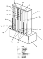
まず、図1、図2、図3を参照して、本発明の第1実施形態に係る送風装置1について説明する。図1は、居室に設置された送風装置1の斜視図であり、図2は、送風装置1の詳細な斜視図、図3は送風装置の正面図である。
(Embodiment 1)
First, the
送風装置1は、居室内に向かって気流を送風するものであり、図1に示す通り、居室の一壁面である床面から起立させた複数の等しい長さのピラー13(本実施形態では6個)を備えている。各ピラー13は、その断面形状が長方形形状となっており、これら複数のピラー13の上部は天板32で繋がれている。なお、ピラー13の上部を天板32で繋がず、複数のピラー13の間隙が上部で開放されていてもよい。また、ピラー13は、天井面から下方へ突出させてもよい。また、ピラー13はそれぞれ異なる長さや断面形状であってもよい。
The
図2に示すように、6本のピラー13のうち、中央の2本には上側吹出ピラー13aが配置され、上側吹出ピラー13aの外側にそれぞれ2本ずつ、合計4本の下側吹出ピラー13bが配置されている。上側吹出ピラー13aは、起立する方向に対して垂直方向に空気を吹き出す。一方、下側吹出ピラー13bは、起立する方向に対して垂直方向に空気を吹き出す吹出口5bを上側吹出ピラー13aの吹出口5aよりも筐体2側に備えている。
As shown in FIG. 2, of the six
上側吹出ピラー13aにおいて、高さ方向の中央部より上側に、中央部から筐体2とは異なる一方の端部(以後、上端と称する)にわたって吹出口5aを設け、下側吹出ピラー13bにおいて、高さ方向の中央部より下側に、中央部から筐体2側の端部(以後、下端と称する)にわたって吹出口5bを設けている。ここで、吹出口5a、吹出口5bをそれぞれのピラー13の上側半分、下側半分としたが、中央部に重なるように、吹出口5a、吹出口5bをピラー13の半分以上の寸法としても良く、すなわち吹出口5aを上側吹出ピラー13aの上端から半分以下の寸法、吹出口5bを下側吹出ピラー13bの下端から半分以上の寸法としても良い。上側吹出ピラー13aと下側吹出ピラー13bは、吹出口5a、吹出口5bの吹出方向が同一方向となるように、隣接するピラー13との間に誘引風路6としての間隙を設けて同一平面上に配置されている。ここで、同一平面とは、全てのピラー13の吹出口5a、吹出口5bを備える側面と吹出口5a、吹出口5bと対向する側面が一致し、一直線状に並んでいる状態を示す。
In the
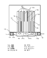
また、図2に示すように、筐体2は、吹出口5a、吹出口5bと相対する側面に空気を取り入れる吸込口7を備えている。また、図3に示すように、それぞれのファン8(ファン8a、ファン8b、ファン8c)の吹出口の下流で筐体2の内側上部に、チャンバー10a、チャンバー10b、チャンバー10cの3つが設けられ、それぞれのチャンバー10は1つのファン8と2本のピラー13と連通している。なお、本実施の形態では、1台のモータ、1個のファン、1個のチャンバー、2本のピラーという組み合わせを1送風単位としているが、それぞれ1つずつ組み合わせる構成や各構成部品を複数個の組み合わせる構成としてもよい。
Further, as shown in FIG. 2, the
また、ファン8とモータ9が配置される空間を1つの空間としているが、筐体2の内部に仕切りを設けて複数の空間、たとえば本実施の形態の場合では、ファン、モータの1つずつの空間に仕切り、3つの空間としても良い。
Further, although the space in which the fan 8 and the motor 9 are arranged is regarded as one space, a partition is provided inside the
また、筐体2には、吹出口から送風される気流を制御する制御部11が、筐体2の側面に配置されている。制御部11は、上側吹出ピラー13a及び下側吹出ピラー13bより送風される気流を制御するため、上側吹出ピラー13aのファン8bのモータ9b、下側吹出ピラー13bのファン8a、8cのモータ9a、9cに対して、回転数を制御する電気信号を送信する。これらの電気信号は、制御部11を構成する回路基板に設けられたマイクロプロセッサ及びメモリ等の情報演算処理を経て、各モータ9a、モータ9b、モータ9cに送信される。
Further, in the
次に、図3、図4、図5を用いて送風装置1の動作について説明する。図4、図5は送風装置1の側面図を示している。制御部11は、上側吹出ピラー13aからの送風気流と、下側吹出ピラー13bからの送風気流とをそれぞれ異なる気流制御で送風する。制御部11が下側吹出ピラー13bと連通するファン8a、ファン8c、モータ9a、モータ9cを駆動させると、ファン8a、ファン8cが回転することにより、室内空気は吸込口7から筐体2の内部に取り込まれる。取り込まれた空気は、ファン8a、ファン8cを通過し、チャンバー10a、10cへ流入する。チャンバー10a、10cに流入した空気は、チャンバー10a、10cでそれぞれ2本の下側吹出ピラー13bに分流され、下側吹出ピラー13bの内部を通過し、吹出口5bから室内空間へ吹出され、吹出気流14となる。
Next, the operation of the
制御部11は、上側吹出ピラー13aからの送風気流と、下側吹出ピラー13bからの送風気流とをそれぞれ異なる気流制御で送風する。異なる気流とは、上側吹出口5a及び下側吹出口5bから送風される気流の風速及び風量が異なる気流である。また、小風量を送風する弱気流と大風量を送風する強気流とを交互に発生させるゆらぎ気流の場合、ゆらぎの位相を異なるようにすることで、異なる気流を送風することも可能である。それぞれのモータ9a、モータ9cの回転数を適宜設定することで、上側吹出口5a及び下側吹出口5bからそれぞれ異なる気流を送風することができる。本実施の形態では、上側吹出口5a及び下側吹出口5bからそれぞれ異なる気流を送風させるため、個別の、ファン8a、ファン8cを設けているが、一つのファンであっても、上側吹出口5a及び下側吹出口5bにそれぞれダクトを備えることで、異なる気流を送風させることも可能である。
The
図3で示す誘引風路6と最外部の下側吹出ピラー13bの外側の空気が吹出気流14により誘引され、誘引気流15となる。吹出気流14と誘引気流15とは送風装置1の吹出方向前方で合流し、広範囲に略均一な風速の面気流が送風できる。
The air outside the attracting
また、図3に示すように、制御部11が上側吹出ピラー13aと連通するファン8b、モータ9bを駆動させると、ファン8bが回転することにより、室内空気は吸込口7から筐体2の内部に取り込まれる。取り込まれた空気は、ファン8bを通過し、チャンバー10bへ流入する。チャンバー10bに流入した空気は、チャンバー10bから2本の上側吹出ピラー13aに分流され、上側吹出ピラー13aの内部を通過し、吹出口5aから室内空間へ吹出され、吹出気流14となる。吹出気流14により、誘引風路6と最外部の下側吹出ピラー13bの外側の空気が誘引され、誘引気流15となる。吹出気流14と誘引気流15は送風装置1の吹出方向前方で合流され、送風装置1の上方でも広範囲に略均一な風速の面気流が送風できる。
Further, as shown in FIG. 3, when the
図4に示すように、制御部11は、上側吹出口5aからは定常気流22、下側吹出口5bからはゆらぎのあるゆらぎ気流23を吹き出す。
As shown in FIG. 4, the
このような構成によれば、図4(a)に示すように、下側吹出口5bからのゆらぎ気流23と誘引気流15が、上側吹出口5aからの定常気流22と誘引気流15よりも気流速度が大きい場合、気流速度が大きい気流方向に周囲の空気が引き寄せられるため、送風装置1から送風される空気の流れ24は、ゆらぎ気流23側の下方へ向かうこととなる。
According to such a configuration, as shown in FIG. 4A , the fluctuating
また、図4(b)に示すように、下側吹出口5bからのゆらぎ気流23と誘引気流15が、上側吹出口5aからの定常気流22と誘引気流15よりも気流速度が小さい場合、気流速度が速い方向に周囲の空気が引き寄せられるため、送風装置1から送風される空気の流れ24は、定常気流22側の上方へ向かうこととなる。さらに、下側吹口5bからのゆらぎ気流23は時間的に速度変化を行うためこのように空気の流れ24は上方や下方へ向きが変化することとなる。
Further, as shown in FIG. 4B , when the
このような上下の各吹出ピラー13から風量を変化させ送風させるモータ制御を行うことで、都度使用者が好む、涼感を得るような送風や、室内の空気循環をさせるような送風が可能となるという効果がある。例えば、春や秋などにおいては、直接的な強い風を浴びず、室内の空気循環を行いたい場合、図4(b)に示すような、気流制御を行うことができる。図4(b)に示すような気流制御を行うことで、座っている使用者に対して速度変化のあるゆらぎ気流23により自然な風を提供することができる。一方、上側吹出ピラーは、定常風の定常気流22を送風することで室内の空気循環を促すことができる。したがって、使用者は、定常風を長時間浴びることで体温が低下するなどの不快なストレスを感じることなく、快適なゆらぎの風を得ることができ、室内の空気循環を促すことができる。
By controlling the motor by changing the air volume from each of the upper and
なお、制御部11は、ゆらぎ気流23が定常気流22よりも常に速度が遅い、または速い制御を行ってもよい。これにより、送風装置1から送風される空気の流れ24は常に下方または上方へ向かうこととなる。
The
なお、図5(a)に示すように、制御部11は上側吹出口5aから定常気流22を吹出す制御を行い、下側吹出口5bからは送風しない制御でもよい。これにより、たとえば冬において、送風装置1を稼動させる場合、図3に示したように、制御部11が上側吹出ピラー13aと連通するファン8bのモータ9bを駆動させると、ファン8bが回転することにより、室内空気は吸込口7から筐体2の内部に取り込まれる。取り込まれた空気は、ファン8bを通過し、チャンバー10bへ流入する。チャンバー10bに流入した空気は、チャンバー10bで2本の上側吹出ピラー5aに分流され、上側吹出ピラー5aの内部を通過し、上側吹出口5aから室内空間へ吹出される吹出気流14となる。吹出気流14
により、2本の上側吹出ピラー13aの間に形成された誘引風路6と上側吹出ピラー13aと隣接する下側吹出ピラー13bとの間までに形成された誘引風路6の空気が誘引され、誘引気流15となる。よって、上部から定常気流22を送風し、下部からは送風されないため、使用者に直接的に風を当てることなく、室内の空気循環をより効率的に行い空気を攪拌することで室内の温度ムラを抑制することも可能となる。
As shown in FIG. 5A, the
As a result, the air in the attracting
また、図5(b)、(c)に示すように、制御部11は上側吹出口5aおよび下側吹出口5bから同一のゆらぎ気流23を位相が異なるように送風する制御を行ってもよい。さらに、図5(b)に示すように、下側吹出口5bからのゆらぎ気流23と誘引気流15が、上側吹出口5aからのゆらぎ気流23と誘引気流15よりも気流速度が小さい場合、気流速度が大きい気流方向に周囲の空気が引き寄せられる。よって、送風装置1から送風される空気の流れ24は、上側吹出口5aからのゆらぎ気流23側の上方へ向かうこととなる。
Further, as shown in FIGS. 5 (b) and 5 (c), the
また、図5(c)に示すように、下側吹出口5bからのゆらぎ気流23と誘引気流15が、上側吹出口5aからのゆらぎ気流23と誘引気流15よりも気流速度が大きい場合、気流速度が大きい方向に周囲の空気が引き寄せられるため、送風装置1から送風される空気の流れ24は、下側吹出口5bのゆらぎ気流23側の下方へ向かうこととなる。さらに、それぞれのゆらぎ気流23は時間的に速度変化を行うためこのように空気の流れ24は上方や下方へ向きや速度が変化することとなる。これにより、上側吹出口5aおよび下側吹出口5bどちらからも位相と速度の異なるゆらぎ気流23を吹出していることで、定常風を長時間浴びることで体温が低下するなどの不快なストレスを感じることなく、快適なゆらぎの風を得ることができ、室内の空気循環を促すことができる。さらに、上側吹出口5aおよび下側吹出口5bからどちらもゆらぎ気流23を吹出すことにより室内を動く空気は、使用者にとってより自然を感じるものとすることが可能となる。
Further, as shown in FIG. 5 (c), when the
図6にフローチャート図を示し、以下では制御方法について説明する。図6に示したS1で使用者が操作スイッチをONにすると、送風装置1に電源が入り、使用者は、たとえば送風装置1のリモコンで現在の季節を選択(S2)する。季節が選択されるとマイコンは、その季節に従って(S3、S4)送風モードを判断し、モータ8a、モータ8b、モータ8cに指示を出し、送風が開始される。たとえば、季節が冬と判断されれば、S5の上側・風量一定モードで送風が行われ(第一気流制御の一例)、季節が夏と判断されれば、S6の上側・下側ともにゆらぎ風モードで送風、季節が冬、夏以外と判断されれば、S7の上側定常・下側ゆらぎ風モード(第一気流制御の一例)で送風が行われることとなる。さらに、使用者がたとえばリモコンの停止を選択(S8)すると、S9で全てのモータが停止し、S10で送風も停止する。これにより、使用者はその都度の季節に応じて、リモコンなどで簡単に送風モードを変更することができ、より快適な室内空間で過ごすことが可能となる。
A flowchart is shown in FIG. 6, and a control method will be described below. When the user turns on the operation switch in S1 shown in FIG. 6, the power is turned on to the
なお、温度センサーを設けることで、送風速度を室温などによって変化させることができるノッチ制御を搭載してもよい。これにより、室内の温度が高いときと低いときでの風速を相対的に速くまたは遅くさせることで、より使用者が快適感を得られることができる。 By providing a temperature sensor, a notch control that can change the blowing speed depending on the room temperature or the like may be installed. As a result, the user can obtain a more comfortable feeling by making the wind speed relatively faster or slower when the temperature in the room is high and low.
なお、リモコンで季節を選択するとしたが、季節に限らず、現在の温度、気流モードなどをS3、S4の判断基準へ割り当てる構成としてもよい。 Although the season is selected by the remote controller, the current temperature, the airflow mode, and the like may be assigned to the judgment criteria of S3 and S4, not limited to the season.
なお、送風装置1は、図7に示す通り、床下40の内部に、高圧空気を発生するための羽根車と羽根車を駆動するためのモータで構成されたファンモータ18が設けられた構成でもよい。ピラー13を起立させた方向に対して垂直方向の一方向に、ファンモータ18で発生した高圧空気を吹出す吹出口19を備えている。吹出口19は、ピラー13の短辺
側の側面に設けられ、ピラー13の内部には、そのファンモータ18で発生した高圧空気を吹出口19に導くためのダクト20を備えている。ダクト20は、少なくともピラー13と同数備えている。ファンモータ18とダクト20の間には高圧空気を各ノズル13のダクト20へ分流するチャンバー21a、21bが、床下40に設けられている。
As shown in FIG. 7, the
また、図7に示すように、ファンモータ18、により発生した高圧空気は、床下40にある上側吹出ピラー13a用の流路12aを介してチャンバー21aに導かれ、それぞれのダクト20に分流される。また、同様にファンモータ18により発生した高圧空気は、床下40にある下側吹出ピラー13b用の流路12bを介してチャンバー21bに導かれ、それぞれのダクト20に分流される。このような構成によれば、制御部11からの指令で、送風装置1が稼動すると、ファンモータ18が駆動し、羽根車が回転することにより高圧空気が発生し、チャンバー21a、チャンバー21bで複数のダクト20に分流され、上側吹出口5a、下側吹出口5bから送風され、第一気流制御により、それぞれの送風が可能となる。なお、ファンモータ18やチャンバーなどを床下40に設ける構成としたが、それに限らず、たとえば天井裏などに全てまたは一部設ける構成としてもよい。
Further, as shown in FIG. 7, the high-pressure air generated by the
また、本実施の形態において、ピラー13は全て吹出方向と平行に備えられているが、ピラー13の向きや本数に特に制限は無い。ただし、ピラー13の中央から外側に設けられたピラー13に向かうにつれて、中央部のピラー13に対して空気の吹出方向が離れていくように広角に備えるようにしてもよい。これにより、送風装置1から一定の距離までは送風装置1中央部に気流が集まる現象を抑制することになり、風の範囲を広くすることが可能になる。
Further, in the present embodiment, all the
また、本実施の形態において、ピラー13の本数を6本としているが、これらの設計値に特に制限は無い。ただし、使用者がスペースやデザインによって、送風装置1の幅およびピラー13の本数等を適宜変更することができる。
Further, in the present embodiment, the number of
本発明にかかる送風装置および送風機は、使用者が風の範囲を適宜変更することができる送風装置として有用である。 The blower and the blower according to the present invention are useful as a blower in which the user can appropriately change the range of the wind.
1 送風装置
2 筐体
5a 上側吹出口
5b 下側吹出口
6 誘引風路
7 吸込口
8a ファン
8b ファン
8c ファン
9a モータ
9b モータ
9c モータ
10a チャンバー
10b チャンバー
10c チャンバー
11 制御部
12a 流路
12b 流路
13 ピラー
13a 上側吹出ピラー
13b 下側吹出ピラー
14 吹出気流
15 誘引気流
18 ファンモータ
19 吹出口
20 ダクト
21a チャンバー
21b チャンバー
22 定常気流
23 ゆらぎ気流
24 空気の流れ
32 天板
40 床下
100 送風機組立体
101 環状ノズル
102 中央開口部
110 内部通路
112 口
116 基部
118 外側ケーシング
120 選択ボタン
122 モータ
124 空気入口
126 モータハウジング
130 インペラ
132 ディフューザ
134 入口
136 出口
144 出口
148 ガイド部分
1
1 8
100 blower assembly
101 Circular nozzle
102 Central opening
110 internal passage
112 mouths
116 base
118 outer casing
120 selection button
Claims (3)
前記ピラーの側部に設けられ、前記ピラーを起立させた方向に対して垂直方向に高圧空気発生部で発生した高圧空気を外部に吹出気流として吹き出す吹出口と、
前記吹出口から送風される前記吹出気流を制御する制御部と、
を備え、
複数の前記ピラーは、各前記ピラーの前記吹出口が同一方向となるように間隙を設けて配置され、隣接する前記ピラーの前記間隙に前記吹出気流に誘引される誘引空気流が通過する誘引風路を構成し、
複数の前記ピラーには、鉛直方向上側に上側吹出口を設けた上側吹出ピラーと、鉛直方向下側に下側吹出口を設けた下側吹出ピラーとが含まれており、
前記制御部は、前記上側吹出口から送風される前記吹出気流と、前記下側吹出口から送風される前記吹出気流とをそれぞれ異なる気流で送風し、前記吹出気流として、前記上側吹出口から定常風を送風し、前記下側吹出口からゆらぎ風を送風することを特徴とする送風装置。 With multiple pillars standing vertically,
An outlet provided on the side of the pillar and blowing out the high-pressure air generated in the high-pressure air generating portion in the direction perpendicular to the direction in which the pillar is erected as a blown airflow to the outside.
A control unit that controls the airflow blown from the airflow outlet, and a control unit that controls the airflow.
Equipped with
The plurality of the pillars are arranged with a gap so that the outlets of the pillars are in the same direction, and the attracted air flow through which the attracted air flow attracted by the blown airflow passes through the gaps of the adjacent pillars. Make up the road,
The plurality of pillars include an upper outlet pillar having an upper outlet on the upper side in the vertical direction and a lower outlet pillar having a lower outlet on the lower side in the vertical direction.
The control unit blows the airflow blown from the upper outlet and the airflow blown from the lower outlet with different airflows, and makes the airflow steady from the upper outlet as the airflow. An air blower characterized by blowing air and blowing a fluctuating wind from the lower air outlet .
前記ピラーの側部に設けられ、前記ピラーを起立させた方向に対して垂直方向に高圧空気発生部で発生した高圧空気を外部に吹出気流として吹き出す吹出口と、 An outlet provided on the side of the pillar and blowing out the high-pressure air generated in the high-pressure air generating portion in the direction perpendicular to the direction in which the pillar is erected as a blown airflow to the outside.
前記吹出口から送風される前記吹出気流を制御する制御部と、 A control unit that controls the airflow blown from the airflow outlet, and a control unit that controls the airflow.
を備え、Equipped with
複数の前記ピラーは、各前記ピラーの前記吹出口が同一方向となるように間隙を設けて配置され、隣接する前記ピラーの前記間隙に前記吹出気流に誘引される誘引空気流が通過する誘引風路を構成し、 The plurality of the pillars are arranged with a gap so that the outlets of the pillars are in the same direction, and the attracted air flow through which the attracted air flow attracted by the blown airflow passes through the gaps of the adjacent pillars. Make up the road,
複数の前記ピラーには、鉛直方向上側に上側吹出口を設けた上側吹出ピラーと、鉛直方向下側に下側吹出口を設けた下側吹出ピラーとが含まれており、 The plurality of pillars include an upper outlet pillar having an upper outlet on the upper side in the vertical direction and a lower outlet pillar having a lower outlet on the lower side in the vertical direction.
前記制御部は、前記上側吹出口から送風される前記吹出気流と、前記下側吹出口から送風される前記吹出気流とをそれぞれ異なる気流で送風し、前記吹出気流として、前記上側吹出口から定常風を送風し、前記下側吹出口からは送風しないことを特徴とする送風装置 The control unit blows the airflow blown from the upper outlet and the airflow blown from the lower outlet with different airflows, and makes the airflow steady from the upper outlet as the airflow. An air blower characterized by blowing air and not blowing air from the lower air outlet.
。..
前記ピラーの側部に設けられ、前記ピラーを起立させた方向に対して垂直方向に高圧空気発生部で発生した高圧空気を外部に吹出気流として吹き出す吹出口と、 An outlet provided on the side of the pillar and blowing out the high-pressure air generated in the high-pressure air generating portion in the direction perpendicular to the direction in which the pillar is erected as a blown airflow to the outside.
前記吹出口から送風される前記吹出気流を制御する制御部と、 A control unit that controls the airflow blown from the airflow outlet, and a control unit that controls the airflow.
を備え、Equipped with
複数の前記ピラーは、各前記ピラーの前記吹出口が同一方向となるように間隙を設けて配置され、隣接する前記ピラーの前記間隙に前記吹出気流に誘引される誘引空気流が通過する誘引風路を構成し、 The plurality of the pillars are arranged with a gap so that the outlets of the pillars are in the same direction, and the attracted air flow through which the attracted air flow attracted by the blown airflow passes through the gaps of the adjacent pillars. Make up the road,
複数の前記ピラーには、鉛直方向上側に上側吹出口を設けた上側吹出ピラーと、鉛直方向下側に下側吹出口を設けた下側吹出ピラーとが含まれており、 The plurality of pillars include an upper outlet pillar having an upper outlet on the upper side in the vertical direction and a lower outlet pillar having a lower outlet on the lower side in the vertical direction.
前記制御部は、前記上側吹出口から送風される前記吹出気流と、前記下側吹出口から送風される前記吹出気流とをそれぞれ異なる気流で送風し、前記吹出気流として、前記上側吹出口および前記下側吹出口から同一のゆらぎ風を位相が異なるように送風することを特徴とする送風装置。 The control unit blows the airflow blown from the upper outlet and the airflow blown from the lower outlet with different airflows, and uses the upper outlet and the airflow as the airflow. A blower device characterized by blowing the same fluctuating wind from the lower outlet so that the phases are different.
Priority Applications (1)
| Application Number | Priority Date | Filing Date | Title |
|---|---|---|---|
| JP2018031447A JP7050222B2 (en) | 2018-02-26 | 2018-02-26 | Blower |
Applications Claiming Priority (1)
| Application Number | Priority Date | Filing Date | Title |
|---|---|---|---|
| JP2018031447A JP7050222B2 (en) | 2018-02-26 | 2018-02-26 | Blower |
Publications (3)
| Publication Number | Publication Date |
|---|---|
| JP2019148171A JP2019148171A (en) | 2019-09-05 |
| JP2019148171A5 JP2019148171A5 (en) | 2021-03-11 |
| JP7050222B2 true JP7050222B2 (en) | 2022-04-08 |
Family
ID=67849263
Family Applications (1)
| Application Number | Title | Priority Date | Filing Date |
|---|---|---|---|
| JP2018031447A Active JP7050222B2 (en) | 2018-02-26 | 2018-02-26 | Blower |
Country Status (1)
| Country | Link |
|---|---|
| JP (1) | JP7050222B2 (en) |
Families Citing this family (3)
| Publication number | Priority date | Publication date | Assignee | Title |
|---|---|---|---|---|
| CN115298442A (en) * | 2020-03-27 | 2022-11-04 | 松下知识产权经营株式会社 | Control system and control method |
| WO2023181535A1 (en) * | 2022-03-22 | 2023-09-28 | パナソニックIpマネジメント株式会社 | Airflow formation system |
| WO2024057863A1 (en) * | 2022-09-16 | 2024-03-21 | パナソニックIpマネジメント株式会社 | Ventilation system |
Citations (5)
| Publication number | Priority date | Publication date | Assignee | Title |
|---|---|---|---|---|
| CN101975179A (en) | 2010-11-24 | 2011-02-16 | 天津工业大学 | Fan structure |
| JP2013155684A (en) | 2012-01-31 | 2013-08-15 | Panasonic Corp | Fan device |
| JP2017160787A (en) | 2016-03-07 | 2017-09-14 | パナソニックIpマネジメント株式会社 | Blower |
| US20180023590A1 (en) | 2016-07-19 | 2018-01-25 | Jinhua City Xin'an Electric Co., Ltd | Multi-directional cooling fan |
| JP2018003658A5 (en) | 2016-06-30 | 2019-07-04 | Air blower |
Family Cites Families (2)
| Publication number | Priority date | Publication date | Assignee | Title |
|---|---|---|---|---|
| JPH0332795Y2 (en) * | 1981-05-11 | 1991-07-11 | ||
| JP6745427B2 (en) * | 2016-06-30 | 2020-08-26 | パナソニックIpマネジメント株式会社 | Blower |
-
2018
- 2018-02-26 JP JP2018031447A patent/JP7050222B2/en active Active
Patent Citations (5)
| Publication number | Priority date | Publication date | Assignee | Title |
|---|---|---|---|---|
| CN101975179A (en) | 2010-11-24 | 2011-02-16 | 天津工业大学 | Fan structure |
| JP2013155684A (en) | 2012-01-31 | 2013-08-15 | Panasonic Corp | Fan device |
| JP2017160787A (en) | 2016-03-07 | 2017-09-14 | パナソニックIpマネジメント株式会社 | Blower |
| JP2018003658A5 (en) | 2016-06-30 | 2019-07-04 | Air blower | |
| US20180023590A1 (en) | 2016-07-19 | 2018-01-25 | Jinhua City Xin'an Electric Co., Ltd | Multi-directional cooling fan |
Also Published As
| Publication number | Publication date |
|---|---|
| JP2019148171A (en) | 2019-09-05 |
Similar Documents
| Publication | Publication Date | Title |
|---|---|---|
| JP5828134B2 (en) | Blower | |
| JP6650562B2 (en) | Blower and air purifier with blower function | |
| JP6934598B2 (en) | Blower, airflow supply method and airflow provision program | |
| JP5659404B2 (en) | Blower | |
| JP7050222B2 (en) | Blower | |
| JP6650561B2 (en) | Blower | |
| JP6036383B2 (en) | Blower system | |
| JP2017115629A (en) | Blower module and air cleaner with blower module function | |
| JP6383935B2 (en) | Blower | |
| JP6745427B2 (en) | Blower | |
| JP2019148171A5 (en) | ||
| WO2012127664A1 (en) | Bathroom dryer | |
| WO2013140739A1 (en) | Air blower | |
| WO2017110058A1 (en) | Blower device and air purification device having air-blowing function | |
| JP6454871B2 (en) | Blower | |
| JP2019148172A (en) | Blower device | |
| JP2019148172A5 (en) | ||
| JP6954096B2 (en) | Blower and blower with air purifying function | |
| JP7065272B2 (en) | Blower | |
| JP7065274B2 (en) | Blower and air purifier with ventilation function | |
| JP7170192B2 (en) | blower | |
| JP2018053764A (en) | Blower | |
| JP7129606B2 (en) | blower | |
| WO2023002531A1 (en) | Heater | |
| JP4369801B2 (en) | Ventilation equipment |
Legal Events
| Date | Code | Title | Description |
|---|---|---|---|
| RD01 | Notification of change of attorney |
Free format text: JAPANESE INTERMEDIATE CODE: A7421 Effective date: 20190123 |
|
| A521 | Request for written amendment filed |
Free format text: JAPANESE INTERMEDIATE CODE: A523 Effective date: 20210127 |
|
| A621 | Written request for application examination |
Free format text: JAPANESE INTERMEDIATE CODE: A621 Effective date: 20210127 |
|
| A131 | Notification of reasons for refusal |
Free format text: JAPANESE INTERMEDIATE CODE: A131 Effective date: 20211116 |
|
| A977 | Report on retrieval |
Free format text: JAPANESE INTERMEDIATE CODE: A971007 Effective date: 20211117 |
|
| A521 | Request for written amendment filed |
Free format text: JAPANESE INTERMEDIATE CODE: A523 Effective date: 20220113 |
|
| TRDD | Decision of grant or rejection written | ||
| A01 | Written decision to grant a patent or to grant a registration (utility model) |
Free format text: JAPANESE INTERMEDIATE CODE: A01 Effective date: 20220208 |
|
| A61 | First payment of annual fees (during grant procedure) |
Free format text: JAPANESE INTERMEDIATE CODE: A61 Effective date: 20220221 |
|
| R151 | Written notification of patent or utility model registration |
Ref document number: 7050222 Country of ref document: JP Free format text: JAPANESE INTERMEDIATE CODE: R151 |