JP7045372B2 - Laser device for cutting brittle materials using aspherical focusing means and beam magnifier - Google Patents
Laser device for cutting brittle materials using aspherical focusing means and beam magnifier Download PDFInfo
- Publication number
- JP7045372B2 JP7045372B2 JP2019524886A JP2019524886A JP7045372B2 JP 7045372 B2 JP7045372 B2 JP 7045372B2 JP 2019524886 A JP2019524886 A JP 2019524886A JP 2019524886 A JP2019524886 A JP 2019524886A JP 7045372 B2 JP7045372 B2 JP 7045372B2
- Authority
- JP
- Japan
- Prior art keywords
- aspherical
- laser
- lens
- laser radiation
- effective aperture
- Prior art date
- Legal status (The legal status is an assumption and is not a legal conclusion. Google has not performed a legal analysis and makes no representation as to the accuracy of the status listed.)
- Active
Links
Images


Classifications
-
- B—PERFORMING OPERATIONS; TRANSPORTING
- B23—MACHINE TOOLS; METAL-WORKING NOT OTHERWISE PROVIDED FOR
- B23K—SOLDERING OR UNSOLDERING; WELDING; CLADDING OR PLATING BY SOLDERING OR WELDING; CUTTING BY APPLYING HEAT LOCALLY, e.g. FLAME CUTTING; WORKING BY LASER BEAM
- B23K26/00—Working by laser beam, e.g. welding, cutting or boring
- B23K26/36—Removing material
- B23K26/38—Removing material by boring or cutting
-
- B—PERFORMING OPERATIONS; TRANSPORTING
- B23—MACHINE TOOLS; METAL-WORKING NOT OTHERWISE PROVIDED FOR
- B23K—SOLDERING OR UNSOLDERING; WELDING; CLADDING OR PLATING BY SOLDERING OR WELDING; CUTTING BY APPLYING HEAT LOCALLY, e.g. FLAME CUTTING; WORKING BY LASER BEAM
- B23K26/00—Working by laser beam, e.g. welding, cutting or boring
- B23K26/0006—Working by laser beam, e.g. welding, cutting or boring taking account of the properties of the material involved
-
- B—PERFORMING OPERATIONS; TRANSPORTING
- B23—MACHINE TOOLS; METAL-WORKING NOT OTHERWISE PROVIDED FOR
- B23K—SOLDERING OR UNSOLDERING; WELDING; CLADDING OR PLATING BY SOLDERING OR WELDING; CUTTING BY APPLYING HEAT LOCALLY, e.g. FLAME CUTTING; WORKING BY LASER BEAM
- B23K26/00—Working by laser beam, e.g. welding, cutting or boring
- B23K26/02—Positioning or observing the workpiece, e.g. with respect to the point of impact; Aligning, aiming or focusing the laser beam
- B23K26/06—Shaping the laser beam, e.g. by masks or multi-focusing
- B23K26/062—Shaping the laser beam, e.g. by masks or multi-focusing by direct control of the laser beam
- B23K26/0622—Shaping the laser beam, e.g. by masks or multi-focusing by direct control of the laser beam by shaping pulses
- B23K26/0624—Shaping the laser beam, e.g. by masks or multi-focusing by direct control of the laser beam by shaping pulses using ultrashort pulses, i.e. pulses of 1ns or less
-
- B—PERFORMING OPERATIONS; TRANSPORTING
- B23—MACHINE TOOLS; METAL-WORKING NOT OTHERWISE PROVIDED FOR
- B23K—SOLDERING OR UNSOLDERING; WELDING; CLADDING OR PLATING BY SOLDERING OR WELDING; CUTTING BY APPLYING HEAT LOCALLY, e.g. FLAME CUTTING; WORKING BY LASER BEAM
- B23K26/00—Working by laser beam, e.g. welding, cutting or boring
- B23K26/02—Positioning or observing the workpiece, e.g. with respect to the point of impact; Aligning, aiming or focusing the laser beam
- B23K26/06—Shaping the laser beam, e.g. by masks or multi-focusing
- B23K26/062—Shaping the laser beam, e.g. by masks or multi-focusing by direct control of the laser beam
- B23K26/0626—Energy control of the laser beam
-
- B—PERFORMING OPERATIONS; TRANSPORTING
- B23—MACHINE TOOLS; METAL-WORKING NOT OTHERWISE PROVIDED FOR
- B23K—SOLDERING OR UNSOLDERING; WELDING; CLADDING OR PLATING BY SOLDERING OR WELDING; CUTTING BY APPLYING HEAT LOCALLY, e.g. FLAME CUTTING; WORKING BY LASER BEAM
- B23K26/00—Working by laser beam, e.g. welding, cutting or boring
- B23K26/02—Positioning or observing the workpiece, e.g. with respect to the point of impact; Aligning, aiming or focusing the laser beam
- B23K26/06—Shaping the laser beam, e.g. by masks or multi-focusing
- B23K26/064—Shaping the laser beam, e.g. by masks or multi-focusing by means of optical elements, e.g. lenses, mirrors or prisms
- B23K26/0648—Shaping the laser beam, e.g. by masks or multi-focusing by means of optical elements, e.g. lenses, mirrors or prisms comprising lenses
-
- B—PERFORMING OPERATIONS; TRANSPORTING
- B23—MACHINE TOOLS; METAL-WORKING NOT OTHERWISE PROVIDED FOR
- B23K—SOLDERING OR UNSOLDERING; WELDING; CLADDING OR PLATING BY SOLDERING OR WELDING; CUTTING BY APPLYING HEAT LOCALLY, e.g. FLAME CUTTING; WORKING BY LASER BEAM
- B23K26/00—Working by laser beam, e.g. welding, cutting or boring
- B23K26/02—Positioning or observing the workpiece, e.g. with respect to the point of impact; Aligning, aiming or focusing the laser beam
- B23K26/06—Shaping the laser beam, e.g. by masks or multi-focusing
- B23K26/064—Shaping the laser beam, e.g. by masks or multi-focusing by means of optical elements, e.g. lenses, mirrors or prisms
- B23K26/066—Shaping the laser beam, e.g. by masks or multi-focusing by means of optical elements, e.g. lenses, mirrors or prisms by using masks
-
- B—PERFORMING OPERATIONS; TRANSPORTING
- B23—MACHINE TOOLS; METAL-WORKING NOT OTHERWISE PROVIDED FOR
- B23K—SOLDERING OR UNSOLDERING; WELDING; CLADDING OR PLATING BY SOLDERING OR WELDING; CUTTING BY APPLYING HEAT LOCALLY, e.g. FLAME CUTTING; WORKING BY LASER BEAM
- B23K26/00—Working by laser beam, e.g. welding, cutting or boring
- B23K26/02—Positioning or observing the workpiece, e.g. with respect to the point of impact; Aligning, aiming or focusing the laser beam
- B23K26/06—Shaping the laser beam, e.g. by masks or multi-focusing
- B23K26/073—Shaping the laser spot
- B23K26/0738—Shaping the laser spot into a linear shape
-
- B—PERFORMING OPERATIONS; TRANSPORTING
- B23—MACHINE TOOLS; METAL-WORKING NOT OTHERWISE PROVIDED FOR
- B23K—SOLDERING OR UNSOLDERING; WELDING; CLADDING OR PLATING BY SOLDERING OR WELDING; CUTTING BY APPLYING HEAT LOCALLY, e.g. FLAME CUTTING; WORKING BY LASER BEAM
- B23K26/00—Working by laser beam, e.g. welding, cutting or boring
- B23K26/08—Devices involving relative movement between laser beam and workpiece
- B23K26/083—Devices involving movement of the workpiece in at least one axial direction
-
- B—PERFORMING OPERATIONS; TRANSPORTING
- B23—MACHINE TOOLS; METAL-WORKING NOT OTHERWISE PROVIDED FOR
- B23K—SOLDERING OR UNSOLDERING; WELDING; CLADDING OR PLATING BY SOLDERING OR WELDING; CUTTING BY APPLYING HEAT LOCALLY, e.g. FLAME CUTTING; WORKING BY LASER BEAM
- B23K26/00—Working by laser beam, e.g. welding, cutting or boring
- B23K26/36—Removing material
- B23K26/40—Removing material taking account of the properties of the material involved
- B23K26/402—Removing material taking account of the properties of the material involved involving non-metallic material, e.g. isolators
-
- B—PERFORMING OPERATIONS; TRANSPORTING
- B23—MACHINE TOOLS; METAL-WORKING NOT OTHERWISE PROVIDED FOR
- B23K—SOLDERING OR UNSOLDERING; WELDING; CLADDING OR PLATING BY SOLDERING OR WELDING; CUTTING BY APPLYING HEAT LOCALLY, e.g. FLAME CUTTING; WORKING BY LASER BEAM
- B23K26/00—Working by laser beam, e.g. welding, cutting or boring
- B23K26/50—Working by transmitting the laser beam through or within the workpiece
- B23K26/53—Working by transmitting the laser beam through or within the workpiece for modifying or reforming the material inside the workpiece, e.g. for producing break initiation cracks
-
- B—PERFORMING OPERATIONS; TRANSPORTING
- B23—MACHINE TOOLS; METAL-WORKING NOT OTHERWISE PROVIDED FOR
- B23K—SOLDERING OR UNSOLDERING; WELDING; CLADDING OR PLATING BY SOLDERING OR WELDING; CUTTING BY APPLYING HEAT LOCALLY, e.g. FLAME CUTTING; WORKING BY LASER BEAM
- B23K26/00—Working by laser beam, e.g. welding, cutting or boring
- B23K26/70—Auxiliary operations or equipment
- B23K26/702—Auxiliary equipment
-
- C—CHEMISTRY; METALLURGY
- C03—GLASS; MINERAL OR SLAG WOOL
- C03B—MANUFACTURE, SHAPING, OR SUPPLEMENTARY PROCESSES
- C03B33/00—Severing cooled glass
- C03B33/02—Cutting or splitting sheet glass or ribbons; Apparatus or machines therefor
- C03B33/0222—Scoring using a focussed radiation beam, e.g. laser
-
- C—CHEMISTRY; METALLURGY
- C03—GLASS; MINERAL OR SLAG WOOL
- C03B—MANUFACTURE, SHAPING, OR SUPPLEMENTARY PROCESSES
- C03B33/00—Severing cooled glass
- C03B33/09—Severing cooled glass by thermal shock
- C03B33/091—Severing cooled glass by thermal shock using at least one focussed radiation beam, e.g. laser beam
-
- G—PHYSICS
- G02—OPTICS
- G02B—OPTICAL ELEMENTS, SYSTEMS OR APPARATUS
- G02B27/00—Optical systems or apparatus not provided for by any of the groups G02B1/00 - G02B26/00, G02B30/00
- G02B27/09—Beam shaping, e.g. changing the cross-sectional area, not otherwise provided for
- G02B27/0938—Using specific optical elements
- G02B27/095—Refractive optical elements
- G02B27/0955—Lenses
-
- G—PHYSICS
- G02—OPTICS
- G02B—OPTICAL ELEMENTS, SYSTEMS OR APPARATUS
- G02B27/00—Optical systems or apparatus not provided for by any of the groups G02B1/00 - G02B26/00, G02B30/00
- G02B27/30—Collimators
-
- B—PERFORMING OPERATIONS; TRANSPORTING
- B23—MACHINE TOOLS; METAL-WORKING NOT OTHERWISE PROVIDED FOR
- B23K—SOLDERING OR UNSOLDERING; WELDING; CLADDING OR PLATING BY SOLDERING OR WELDING; CUTTING BY APPLYING HEAT LOCALLY, e.g. FLAME CUTTING; WORKING BY LASER BEAM
- B23K2103/00—Materials to be soldered, welded or cut
- B23K2103/50—Inorganic material, e.g. metals, not provided for in B23K2103/02 – B23K2103/26
- B23K2103/54—Glass
-
- Y—GENERAL TAGGING OF NEW TECHNOLOGICAL DEVELOPMENTS; GENERAL TAGGING OF CROSS-SECTIONAL TECHNOLOGIES SPANNING OVER SEVERAL SECTIONS OF THE IPC; TECHNICAL SUBJECTS COVERED BY FORMER USPC CROSS-REFERENCE ART COLLECTIONS [XRACs] AND DIGESTS
- Y02—TECHNOLOGIES OR APPLICATIONS FOR MITIGATION OR ADAPTATION AGAINST CLIMATE CHANGE
- Y02P—CLIMATE CHANGE MITIGATION TECHNOLOGIES IN THE PRODUCTION OR PROCESSING OF GOODS
- Y02P40/00—Technologies relating to the processing of minerals
- Y02P40/50—Glass production, e.g. reusing waste heat during processing or shaping
- Y02P40/57—Improving the yield, e-g- reduction of reject rates
Landscapes
- Physics & Mathematics (AREA)
- Optics & Photonics (AREA)
- Engineering & Computer Science (AREA)
- Plasma & Fusion (AREA)
- Mechanical Engineering (AREA)
- Chemical & Material Sciences (AREA)
- General Physics & Mathematics (AREA)
- Materials Engineering (AREA)
- Organic Chemistry (AREA)
- Chemical Kinetics & Catalysis (AREA)
- General Chemical & Material Sciences (AREA)
- Oil, Petroleum & Natural Gas (AREA)
- Thermal Sciences (AREA)
- Toxicology (AREA)
- Health & Medical Sciences (AREA)
- Laser Beam Processing (AREA)
- Re-Forming, After-Treatment, Cutting And Transporting Of Glass Products (AREA)
Description
本発明は、概して、透明な脆性材料のレーザ機械加工に関する。本発明は、具体的には、約20ピコ秒以下のパルス持続時間を有し、伸長焦点に形成される超短パルスレーザ放射のビームを使用する、ガラスワークピースの切断に関する。 The present invention generally relates to laser machining of transparent brittle materials. The present invention specifically relates to cutting a glass workpiece using a beam of ultrashort pulsed laser radiation formed at an extended focal point with a pulse duration of about 20 picoseconds or less.
レーザ機械加工は、ガラスおよびサファイア等の脆性材料を含む幅広い範囲の材料を切断、穿孔、マーキング、およびスクライビングするために使用されることが多くなっている。伝統的な機械加工は、加工材料が応力印加されると伝搬し、それによって、加工材料を劣化かつ脆弱化させ得る微小亀裂等の望ましくない欠陥を産出する。パルスレーザ放射の集束ビームを使用する脆性材料のレーザ機械加工は、高品質な縁および壁を有する精密な切断および孔を産出しながら、望ましくない欠陥の形成を最小限にする。産業進歩は、増加する範囲の脆性材料のレーザ機械加工を要求しながら、向上される加工速度および精度を要求する。 Laser machining is increasingly used to cut, drill, mark, and scribing a wide range of materials, including brittle materials such as glass and sapphire. Traditional machining propagates when a work material is stressed, thereby producing unwanted defects such as microcracks that can degrade and weaken the work material. Laser machining of brittle materials using a focused beam of pulsed laser radiation minimizes the formation of unwanted defects while producing precise cuts and holes with high quality edges and walls. Industrial advances demand improved machining speeds and precision while requiring laser machining of an increasing range of brittle materials.
透明な脆性材料は、レーザ放射の非線形吸収を通してパルスレーザ放射の集束ビームと相互作用する。パルスレーザ放射は、一連の個々のパルスまたはパルスの急速なバーストを含み得る。各個々のパルスまたはパルスのバーストは、ビームの焦点において透明な脆性材料の中に欠陥を作成する。欠陥のアレイが、パルスレーザ放射の集束ビームをワークピース内の切断経路に沿って平行移動させ、それによって、材料を脆弱化させることによって作成される。薄いワークピースが、次いで、自然に分離し得る一方、厚いワークピースは、応力を印加する付加的なステップにおいて分離され得る。1つのそのような方法は、材料によって吸収される波長を有するレーザビームを切断経路に沿って印加することであり、これは、加熱を通して機械的応力をもたらす。 The transparent brittle material interacts with the focused beam of pulsed laser radiation through the nonlinear absorption of laser radiation. Pulsed laser radiation can include a series of individual pulses or a rapid burst of pulses. Each individual pulse or burst of pulse creates a defect in the transparent brittle material at the focal point of the beam. An array of defects is created by translating a focused beam of pulsed laser radiation along a cutting path within the workpiece, thereby weakening the material. Thin workpieces can then be separated spontaneously, while thick workpieces can be separated in additional steps of applying stress. One such method is to apply a laser beam with a wavelength absorbed by the material along the cutting path, which results in mechanical stress through heating.
近年では、化学強化ガラスが、開発され、消費者電子機器デバイスのディスプレイスクリーンのためのカバーガラスとして広範囲にわたって使用されている。化学強化は、イオン交換プロセスによって達成される。ケイ酸塩板ガラスが、カリウムイオン(K+)を含む塩溶液内に浸漬される。より大きなカリウムイオンが、ガラスの表面近傍に位置するより小さいナトリウムイオン(Na+)と置換され、それによって、ガラスの表面層内に圧縮をもたらす。そのような表面層の間で、ガラスの内部が、緊張状態にあり、表面圧縮を補償する。その高い表面層圧縮が、化学強化ガラスを極めて硬質(モーズ硬度約6.5)かつ引掻および機械的衝撃に対して耐久性のあるものにする。サファイア(モーズ硬度9)は、いくつかのデバイスにおいて使用される代替の硬質カバーガラス材料である。 In recent years, chemically strengthened glass has been developed and widely used as a cover glass for display screens in consumer electronic equipment devices. Chemical enhancement is achieved by an ion exchange process. The silicate plate glass is immersed in a salt solution containing potassium ions (K + ). Larger potassium ions are replaced with smaller sodium ions (Na + ) located near the surface of the glass, thereby resulting in compression within the surface layer of the glass. Between such surface layers, the interior of the glass is in a tense state, compensating for surface compression. Its high surface layer compression makes chemically tempered glass extremely hard (mose hardness about 6.5) and resistant to scratches and mechanical impacts. Sapphire (Mose hardness 9) is an alternative hard cover glass material used in some devices.
消費者電子機器デバイスのためのカバーガラスは、典型的には、約300マイクロメートル(μm)~1.1ミリメートル(mm)の厚さを有する。良好に集束されるパルスレーザ放射は、典型的には、深度において数10マイクロメートルにわたって延在する欠陥を作成する。ワークピースの全厚を通した切断は、集束されるレーザ放射に、切断経路に沿って何度も走査されながら、焦点深度を変動させるように要求する。 Cover glass for consumer electronics devices typically has a thickness of about 300 micrometers (μm) to 1.1 millimeters (mm). Well-focused pulsed laser radiation typically creates defects that extend over tens of micrometers at depth. Cutting through the full thickness of the workpiece requires the focused laser radiation to vary in depth of focus as it is scanned many times along the cutting path.
商業的なレーザ機械加工プロセスは、長焦点を生成し、それによって、切断経路に沿って要求される走査数を低減させ、かつレーザ切断装置の生産性を向上させるような種々の手段を使用して開発された。「ベッセルビーム」が、集束要素としてアキシコンまたは均等な位相マスクを使用して、ガウス横モードを有するビームから生成される。アキシコンは、光学軸を中心して回転対称である、円錐プリズムである。位相マスクは、あるタイプの回折光学素子(DOE)であり、概して、加工するために幾分高価である。実践では、付加的な望遠鏡が、多くの場合、ベッセルビームを縮小し、アキシコンまたはDOEの不完全な加工によってもたらされる激しい強度変調を排除するために要求される。ベッセルビームを使用して作成される欠陥は、サテライト構造を有し得、これは、不良品質の切断縁をもたらし得る。 Commercial laser machining processes use a variety of means to generate long focal lengths, thereby reducing the number of scans required along the cutting path and increasing the productivity of the laser cutting equipment. Was developed. A "Bessel beam" is generated from a beam with Gaussian transverse mode, using an axicon or even phase mask as the focusing element. The axicon is a conical prism that is rotationally symmetric about its optical axis. Phase masks are a type of diffractive optics (DOE) and are generally somewhat expensive to process. In practice, additional telescopes are often required to reduce the Bessel beam and eliminate the intense intensity modulation caused by imperfect processing of the axicon or DOE. Defects created using Bessel beams can have satellite structures, which can result in poor quality cutting edges.
長焦点を生成するためのある代替方法は、自己誘導「フィラメント」を作成することである。材料において高強度を有するパルスレーザ放射の集束ビームが、その屈折率の非線形構成要素に起因してさらに集束される。非線形の集束と強度との間の正のフィードバックが、プラズマを作成する。プラズマ内のより低い屈折率が、脱集束をもたらす。集束と脱集束との間の平衡が、フィラメント内のプラズマ状態を維持する。フィラメントの伝搬が、集束要素の光学軸に沿って材料の中に空所を作成する。フィラメントレーザ機械加工が、高パルスエネルギーを要求し、超短パルスレーザ源の電流生成およびビームパラメータの全ての微調整の実践的な限界に接近する。材料物性(通常の材料不均質性等)およびビームパラメータ(放射毎の雑音およびレーザ毎のビーム品質等)における比較的に小さい違いが、フィラメントレーザ切断プロセスにおける制御の損失をもたらし得る。 One alternative method for producing long focal lengths is to create self-inducing "filaments". A focused beam of pulsed laser radiation with high intensity in the material is further focused due to its non-linear component of index of refraction. Positive feedback between non-linear focusing and intensity creates the plasma. The lower index of refraction in the plasma results in defocusing. The equilibrium between focusing and defocusing maintains the plasma state within the filament. Filament propagation creates a void in the material along the optical axis of the focusing element. Filament laser machining requires high pulse energy and approaches the practical limits of current generation and all fine tuning of beam parameters for ultrashort pulse laser sources. Relatively small differences in material properties (such as normal material inhomogeneity) and beam parameters (such as noise per radiation and beam quality per laser) can result in loss of control in the filament laser cutting process.
より低いパルスエネルギーを使用する、切断経路に沿った単一の経路において強化ガラスまたはサファイアを切断するであろう効率的なレーザ切断方法のための必要性が、存在する。好ましくは、本方法は、決定論的であり、かつ材料物性およびビームパラメータにおける違いの影響を受けないものであるべきである。 There is a need for an efficient laser cutting method that will cut tempered glass or sapphire in a single path along the cutting path, using lower pulse energy. Preferably, the method should be deterministic and unaffected by differences in material properties and beam parameters.
本発明は、入射面と、出射面とを有する脆性材料の切断を対象とする。本発明によるレーザ装置は、パルスレーザ放射のコリメートビームを送達するレーザ源を備える。パルスレーザ放射は、約20ピコ秒未満のパルス持続期間を有し、コリメートビームは、第1の直径を有する。光学軸と、有効開口とを有する非球面集束レンズが、提供される。レーザ源と非球面集束レンズとの間に位置する無限焦点ビーム拡大器が、提供される。無限焦点ビーム拡大器は、コリメートビームを第1の直径から第2の直径まで拡大するように配列される。第2の直径は、拡大されたコリメートビームの一部のみが有効開口の内側に存在するように、非球面集束レンズの有効開口より大きい。非球面集束レンズは、パルスレーザ放射のビームの一部を有効開口の内側に集束させる。集束されたビームは、光学軸と同軸である伸長焦点を有する。伸長焦点は、光学軸に沿ってほぼ一様な強度分布を有する。伸長焦点は、入射面と出射面との間の脆性材料に重複する。
本発明は、例えば、以下を提供する。
(項目1)
脆性材料を切断するためのレーザ装置であって、前記脆性材料は、入射面と、出射面とを有し、前記装置は、
パルスレーザ放射のコリメートビームを送達するレーザ源であって、前記パルスレーザ放射は、約20ピコ秒未満のパルス持続期間を有し、前記コリメートビームは、第1の直径を有する、レーザ源と、
光学軸と、有効開口とを有する非球面集束レンズと、
前記レーザ源と前記非球面集束レンズとの間に位置する無限焦点ビーム拡大器であって、前記無限焦点ビーム拡大器は、前記コリメートビームを前記第1の直径から第2の直径まで拡大するように配列され、前記第2の直径は、前記拡大されたコリメートビームの一部のみが前記有効開口の内側に存在するように、前記非球面集束レンズの有効開口より大きい、無限焦点ビーム拡大器と
を備え、
前記非球面集束レンズは、パルスレーザ放射の前記ビームの一部を前記有効開口の内側に集束させ、前記集束されたビームは、前記光学軸と同軸である伸長焦点を有し、前記伸長焦点は、前記光学軸に沿ってほぼ一様な強度分布を有し、
前記伸長焦点は、前記入射面と前記出射面との間の前記脆性材料に重複する、装置。
(項目2)
前記有効開口の内側の前記拡大されたコリメートビームの一部は、約85%~約95%である、項目1に記載のレーザ切断装置。
(項目3)
前記有効開口の内側の前記拡大されたコリメートビームの一部は、約90%である、項目1に記載のレーザ切断装置。
(項目4)
前記ほぼ一様な強度分布は、複数のピークを含み、前記ピーク強度は、平均ピーク強度から約20%未満変動する、項目1に記載のレーザ切断装置。
(項目5)
ほぼ一様な強度分布を有する前記伸長焦点は、前記入射面から前記出射面まで延在する、項目1に記載のレーザ切断装置。
(項目6)
前記非球面集束レンズの設計は、前記伸長焦点に送達される前記パルスレーザ放射のパルスエネルギーを最大限にし、前記伸長焦点は、前記入射面から前記出射面まで延在する、項目1に記載のレーザ切断装置。
(項目7)
前記有効開口は、前記無限焦点ビーム拡大器と前記非球面集束レンズとの間に位置する離散開口によって画定される、項目1に記載のレーザ切断装置。
(項目8)
前記有効開口は、前記非球面集束レンズの縁によって画定される、項目1に記載のレーザ切断装置。
(項目9)
前記非球面集束レンズは、凸面形の非球面表面と、反対側の平坦表面とを有する平凸レンズである、項目1に記載のレーザ切断装置。
(項目10)
前記非球面集束レンズは、前記拡大されたコリメートビームが前記凸面形の非球面表面上に入射するように配向される、項目9に記載のレーザ切断装置。
(項目11)
前記非球面集束レンズは、前記拡大されたコリメートビームが前記平坦表面上に入射するように配向される、項目9に記載のレーザ切断装置。
(項目12)
前記ワークピースは、平行移動され、切断線に沿って前記光学軸をトレースしながら、パルスレーザ放射の前記集束されたビームを印加する、項目1に記載のレーザ切断装置。
(項目13)
パルスレーザ放射の前記コリメートビームは、横方向のガウス強度分布を有する、項目1に記載のレーザ切断装置。
(項目14)
パルスレーザ放射の前記ビームは、一連のバーストを備え、各バーストは、複数の個々のパルスを含む、項目1に記載のレーザ切断装置。
(項目15)
各バーストは、2~10個の個々のパルスを含む、項目14に記載のレーザ切断装置。
(項目16)
各バーストは、5個の個々のパルスを含む、項目15に記載のレーザ切断装置。
(項目17)
パルス繰り返し数は、約40メガヘルツ~約50メガヘルツである、項目14に記載のレーザ切断装置。
(項目18)
バースト周波数は、約50キロヘルツ~約1メガヘルツである、項目14に記載のレーザ切断装置。
(項目19)
前記バースト周波数は、約100キロヘルツ~約400キロヘルツである、項目18に記載のレーザ切断装置。
(項目20)
前記ワークピースは、ガラスから作製される、項目1に記載のレーザ切断装置。
(項目21)
前記ワークピースは、化学強化ガラスから作製される、項目20に記載のレーザ切断装置。
(項目22)
脆性材料を切断するためのレーザ装置であって、前記脆性材料は、入射面と、出射面とを有し、前記装置は、
パルスレーザ放射のコリメートビームを送達するためのレーザ源であって、前記パルスレーザ放射は、約20ピコ秒未満のパルス持続期間を有する、レーザ源と、
光学軸と、有効開口とを有する非球面集束レンズと、
前記レーザ源と前記非球面集束レンズとの間のパルスレーザ放射の前記コリメートビームの中に位置するビーム拡大要素であって、前記ビーム拡大要素は、パルスレーザ放射の前記コリメートビームをパルスレーザ放射の拡大されたビームへと形成し、パルスレーザ放射の前記拡大されたビームは、パルスレーザ放射の前記拡大されたビームの一部のみが前記有効開口の内側に存在するように、前記非球面集束レンズの有効開口を過充填する、ビーム拡大要素と
を備え、
前記有効開口の内側のパルスレーザ放射の前記拡大されたビームの一部は、前記非球面集束レンズによってパルスレーザ放射の集束ビームへと形成され、パルスレーザ放射の前記集束ビームは、伸長焦点を有し、前記伸長焦点は、前記光学軸に沿ってほぼ一様な強度分布を有し、
前記伸長焦点は、前記入射面と前記出射面との間の前記脆性材料に重複する、レーザ装置。
(項目23)
前記非球面集束レンズは、凸面形の非球面表面と、反対側の平坦表面とを有する平凸レンズである、項目22に記載のレーザ切断装置。
(項目24)
前記非球面集束レンズは、球状集束レンズと、非球面位相板とを含む、項目22に記載のレーザ切断装置。
(項目25)
前記非球面位相板は、回折光学素子である、項目24に記載のレーザ切断装置。
(項目26)
前記ビーム拡大要素は、無限焦点ビーム拡大器である、項目22に記載のレーザ切断装置。
(項目27)
前記ビーム拡大要素は、凹面レンズである、項目22に記載のレーザ切断装置。
(項目28)
前記有効開口は、前記ビーム拡大要素と前記非球面集束レンズとの間のパルスレーザ放射の前記拡大されたビームの中に位置する離散開口によって画定される、項目22に記載のレーザ切断装置。
(項目29)
前記有効開口は、前記非球面集束レンズの縁によって画定される、項目22に記載のレーザ切断装置。
(項目30)
前記伸長焦点は、前記入射面から前記出射面まで延在するほぼ一様な強度分布を有する、項目22に記載のレーザ切断装置。
(項目31)
前記非球面集束レンズの設計は、前記伸長焦点に送達される前記パルスレーザ放射のパルスエネルギーを最大限にし、前記伸長焦点は、前記入射面から前記出射面まで延在する、項目22に記載のレーザ切断装置。
The present invention is intended for cutting brittle materials having an entrance surface and an exit surface. The laser apparatus according to the present invention comprises a laser source that delivers a collimated beam of pulsed laser radiation. The pulsed laser emission has a pulse duration of less than about 20 picoseconds and the collimated beam has a first diameter. An aspherical condensing lens with an optical axis and an effective aperture is provided. An infinite focus beam magnifier located between the laser source and the aspheric focused lens is provided. The infinite focus beam magnifier is arranged to magnify the collimated beam from a first diameter to a second diameter. The second diameter is larger than the effective aperture of the aspheric focused lens so that only part of the magnified collimated beam is inside the effective aperture. An aspheric focused lens focuses a portion of the beam of pulsed laser radiation inside the effective aperture. The focused beam has an extended focal point that is coaxial with the optic axis. The extension focus has a nearly uniform intensity distribution along the optical axis. The extension focus overlaps the brittle material between the entrance and exit surfaces.
The present invention provides, for example,:
(Item 1)
A laser device for cutting a brittle material, wherein the brittle material has an entrance surface and an exit surface.
A laser source that delivers a collimated beam of pulsed laser radiation, wherein the pulsed laser emission has a pulse duration of less than about 20 picoseconds, the collimated beam has a first diameter, and a laser source.
An aspherical condensing lens with an optical axis and an effective aperture,
An infinite focus beam magnifier located between the laser source and the aspherical focused lens, the infinite focus beam magnifier so as to magnify the collimated beam from the first diameter to the second diameter. With an infinite focus beam magnifier whose second diameter is larger than the effective aperture of the aspheric focused lens so that only part of the enlarged collimated beam is inside the effective aperture.
Equipped with
The aspheric focused lens focuses a portion of the beam of pulsed laser radiation inside the effective aperture, the focused beam having an extended focal point coaxial with the optic axis, and the extended focal point. , Has an almost uniform intensity distribution along the optical axis,
An apparatus in which the extension focus overlaps the brittle material between the entrance surface and the exit surface.
(Item 2)
The laser cutting apparatus according to
(Item 3)
The laser cutting device of
(Item 4)
The laser cutting apparatus according to
(Item 5)
The laser cutting device according to
(Item 6)
The design of the aspherical condensing lens maximizes the pulse energy of the pulsed laser radiation delivered to the extended focal point, wherein the extended focal point extends from the entrance surface to the exit surface. Laser cutting device.
(Item 7)
The laser cutting device according to
(Item 8)
The laser cutting device according to
(Item 9)
The laser cutting device according to
(Item 10)
9. The laser cutting device according to item 9, wherein the aspherical focusing lens is oriented so that the magnified collimated beam is oriented so as to be incident on the convex aspherical surface.
(Item 11)
The laser cutting device according to item 9, wherein the aspherical focusing lens is oriented so that the magnified collimated beam is incident on the flat surface.
(Item 12)
The laser cutting apparatus according to
(Item 13)
The laser cutting apparatus according to
(Item 14)
The laser cutting apparatus according to
(Item 15)
14. The laser cutting device of
(Item 16)
The laser cutting device of
(Item 17)
The laser cutting apparatus according to
(Item 18)
The laser cutting device according to
(Item 19)
Item 18. The laser cutting apparatus according to item 18, wherein the burst frequency is about 100 kilohertz to about 400 kilohertz.
(Item 20)
The laser cutting device according to
(Item 21)
The laser cutting device according to
(Item 22)
A laser device for cutting a brittle material, wherein the brittle material has an entrance surface and an exit surface.
A laser source for delivering a collimated beam of pulsed laser radiation, wherein the pulsed laser radiation has a pulse duration of less than about 20 picoseconds.
An aspherical condensing lens with an optical axis and an effective aperture,
A beam magnifying element located within the collimated beam of pulsed laser radiation between the laser source and the aspherical focused lens, wherein the beam magnifying element is a pulsed laser emission of the collimated beam of pulsed laser radiation. Formed into a magnified beam, the magnified beam of pulsed laser radiation is the aspherical focused lens such that only part of the magnified beam of pulsed laser radiation is inside the effective aperture. With a beam magnifying element that overfills the effective opening of
Equipped with
A portion of the magnified beam of pulsed laser radiation inside the effective aperture is formed by the aspherical focused lens into a focused beam of pulsed laser radiation, and the focused beam of pulsed laser radiation has an extended focal point. However, the extended focal point has a substantially uniform intensity distribution along the optical axis.
A laser device in which the extension focus overlaps the brittle material between the entrance surface and the exit surface.
(Item 23)
(Item 24)
(Item 25)
The laser cutting device according to
(Item 26)
The laser cutting device according to
(Item 27)
The laser cutting device according to
(Item 28)
22. The laser cutting apparatus of
(Item 29)
22. The laser cutting device of
(Item 30)
(Item 31)
22. The design of the aspherical condensing lens maximizes the pulse energy of the pulsed laser radiation delivered to the extended focal point, the extended focal point extending from the entrance surface to the exit surface. Laser cutting device.
本明細書に組み込まれ、かつその一部を構成する添付図面が、本発明の好ましい実施形態を図式的に図示し、上記に与えられる一般的な説明および下記に与えられる好ましい実施形態の詳細説明とともに、本発明の原理を説明する役割を果たす。 The accompanying drawings incorporated in and in part thereof are schematically illustrating preferred embodiments of the present invention, the general description given above and the detailed description of the preferred embodiments given below. At the same time, it serves to explain the principle of the present invention.
ここで、同様の構成要素が同様の数字によって指定される図面を参照すると、図1Aが、本発明によるレーザ切断装置の1つの好ましい実施形態10を図式的に図示する。装置10は、ビーム直径「D1」を有するパルスレーザ放射のコリメートビーム14を送達する、レーザ源12を含む。コリメートビーム14は、随意の回転鏡16によって、コリメートビーム14を捕捉し、そしてコリメートされてより大きなビーム直径「D2」を有するパルスレーザ放射の拡大されたビーム20を形成するように配列される無限焦点ビーム拡大器18の中に指向される。無限焦点ビーム拡大器は、光学設計の分野において周知のビーム拡大要素であり、その説明は、本発明の原理を理解するためには必要ではない。
Here, with reference to the drawings in which similar components are designated by similar numbers, FIG. 1A schematically illustrates one
非球面集束レンズ22が、拡大されたコリメートビーム20を捕捉し、パルスレーザ放射の集束ビーム24を形成するように配列される。ビーム直径D2が、非球面集束レンズ22の有効開口「CA」を過充填するように(D2>CA)選択される。拡大されたコリメートビーム20の一部のみが、有効開口CAの内側に存在する。その部分が、非球面集束レンズ22を通して伝送され、集束ビーム24へと形成される。拡大されたコリメートビーム20の周辺光線を含むより小さい相補的な部分は、非球面集束レンズ22によって集束されない。非球面集束レンズ22の有効開口CAは、無限焦点ビーム拡大器18と非球面集束レンズ22との間に位置する離散開口26によって画定され、描写されるように、周辺光線を物理的に遮断する。代替として、有効開口CAは、その光学縁またはその物理的縁であり得る、非球面集束レンズ22の縁28によって画定されてもよい。
The aspherical
非球面集束レンズ22は、光学軸30と、非球面表面32と、反対側の表面34とを有する。非球面表面32は、本明細書に下記に詳細に説明される凸面形の非球面形状を有する。表面34は、平坦であってもよく、または球状または非球面である凸面形状を有してもよい。非球面集束レンズ22は、好ましくは、平坦表面34を有する平凸レンズである。非球面集束レンズ22は、描写されるように、拡大されたコリメートビーム20を非球面表面32上に入射させるように配向されてもよい、または拡大されたコリメートビーム20を表面34上に入射させるように配向されてもよい。好ましい平凸非球面集束レンズ22に関して、拡大されたコリメートビーム20を平坦表面34上に入射させる配向は、非球面集束レンズの集束性質が、レンズの精密な厚さ「T」から影響を受けないという利点を有する。
The aspherical focusing
集束ビーム24は、光学軸30に沿って伸長焦点36に収束する。光学軸30に近接する非球面集束レンズ22から出現する近軸光線が、光学軸30に対して垂直である平面「A」に収束する。非球面集束レンズ22の「公称焦点距離」が、非球面集束レンズ22と平面Aとの間の距離として定義される。縁28に近接する非球面集束レンズ22から出現する光線が、平面Aより非球面集束レンズにより近い平面「B」に収束する。伸長焦点36が、平面AとBとの間に延在する。伸長焦点36は、平面AとBとの間の光学軸30に沿って一様な強度分布を有し、これは、本明細書に下記に詳細に説明される。
The
脆性材料から作製されるワークピース38が、光学軸30が太線によって図面内に示される切断線40を捕捉するように位置する。集束ビーム24は、入口表面42を通してワークピース38に進入し、反対側の出口表面44を通してワークピース38から退出する。ワークピース38は、伸長焦点36が入口表面42と出口表面44との間のワークピース38に重複するように位置する。ワークピース38における「公称焦点深度」「L」が、入口表面42と平面Aとの間の距離として定義される。ワークピース38は、描写されるように、表面42および44の両方を平面AとBとの間に位置させるように、伸長焦点36の中に完全に据え付けられてもよい。代替として、ワークピース38は、本発明の精神および範囲から逸脱することなく、伸長焦点36の中に部分的に据え付けられてもよい。切断は、描写されるように、ワークピース38を平行移動させ、切断線40に沿って光学軸30をトレースしながら、パルスレーザ放射の集束ビーム24を印加することによって遂行される。切断線40は、本願によって要求されるように、一直線または湾曲していてもよい。
A
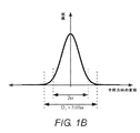
図1Bは、コリメートビーム14の断面強度分布を図式的に図示する。図1Bは、コリメートビーム14の中心からの半径方向の変位の関数としての、レーザ放射の強度のグラフである。多くのレーザ源内の光学共振器が、ガウス関数によって説明される最低次の横モードを有する。そのような横方向のガウス強度分布が、図面に描写され、ビームの中心における最大強度の
![]()
![]()
図1Cは、光学軸30に沿った集束ビーム24の一様な強度分布を図式的に図示する。伸長焦点36は、図面内の平面AとBとの間にほぼ一定の強度を有する。実践では、本発明によって形成される強度分布は、本明細書に下記に議論されるように、「ほぼ一様」である。
FIG. 1C graphically illustrates the uniform intensity distribution of the
図2は、本発明による、レーザ切断装置の別の好ましい実施形態50を図式的に図示する。装置50は、図1Aのレーザ切断装置10に類似するが、無限焦点ビーム拡大器18が、ビーム拡大要素として凹面レンズ52によって置換される。凹面レンズ52が、コリメートビーム14を捕捉し、そして、発散して非球面集束レンズ22の有効開口「CA」を過充填するパルスレーザ放射の拡大されたビーム54を形成する。図2は、非球面集束レンズ22の縁28によって画定されている開口CAの実施例を描写する。非球面集束レンズ22は、拡大された発散ビーム54を捕捉し、集束ビーム24を形成するように配列される。図面は、伸長焦点36の中に部分的に据え付けられているワークピース38の実施例を描写する。本実施例では、公称焦点深度Lは、ワークピース38の厚さを下回る。
FIG. 2 graphically illustrates another
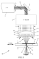
図3は、本発明による、レーザ切断装置のさらに別の好ましい実施形態60を図式的に図示する。装置60は、図1Aのレーザ切断装置10に類似するが、非球面集束レンズ22が、非球面集束レンズ66をともに形成する球状集束レンズ62および非球面位相板64によって置換される。球状集束レンズ62は、球状表面68と、反対側の表面34とを有する。球状表面68は、凸面形の球形状を有する。球状集束レンズ62および非球面位相板64は、伸長焦点36を有する集束ビーム24を協働可能に形成する。図面は、伸長焦点36内に部分的に据え付けられているワークピース38の別の実施例を描写する。この実施例では、公称焦点深度Lは、ワークピース38の厚さよりも大きい。
FIG. 3 graphically illustrates yet another preferred
非球面位相板64は、好ましくは、球状集束レンズ62から伝搬する集束ビームの波面を修正し、光学軸30に沿って伸長焦点36を形成する、回折光学要素(DOE)である。非球面位相板64は、球状集束レンズ62の具体的な設計に整合するようにカスタマイズされる。レーザ切断装置60は、球状集束レンズ62が商業的な光学系供給元から得られる標準的な平凸レンズであり得るという利点を有する。
The
DOEは、例えば、RPC Photonics Inc.(Rochester, New York)から商業的に入手可能である。プログラム可能な波面変調を有するアクティブなDOE(「空間光変調器」として公知である)もまた、例えば、HoloEye (Berlin, Germany)から商業的に利用可能である。非球面位相板64のためにアクティブなDOEを使用することは、いかなる光学要素の交換もなく、装置60が、異なる材料から作製されるまたは異なる厚さを有するワークピースをレーザ切断することを可能にする。開口は、要求される場合、非球面位相板64の設計の中に組み込まれ、有効開口CAを制限してもよい。
DOE can be described, for example, by RPC Photonics Inc. It is commercially available from (Rochester, New York). Active DOEs (known as "spatial light modulators") with programmable wavefront modulation are also commercially available, for example from HoloEye (Berlin, Germany). Using an active DOE for the
図4は、図1Aのパルスレーザ放射のコリメートビーム14内の超短パルスのバーストを図式的に図示する、タイミング図である。「超短」パルスは、約20ピコ秒(ps)未満のパルス持続時間「δT」を有するものとして、本明細書に定義される。一般的に、より短いパルス持続時間は、より良好な縁品質を有する切断されたワークピースを産出する。例えば、数百フェムト秒のδTを有するパルスを使用して形成される縁は、数十ピコ秒のδTを有するパルスを使用して形成される縁より低い面粗度を有する。
FIG. 4 is a timing diagram schematically illustrating the burst of ultrashort pulses in the collimated
バースト内の個々のパルスは、時間間隔「Tp」によって分離され、連続するバーストは、時間間隔「Tb」によって分離され、これは、1つのバーストの第1のパルスと次のバーストの第1のパルスとの間の分離である。これらの時間間隔は、それぞれ、パルス繰り返し数およびバースト周波数に対応する。バースト周波数とワークピースの平行移動速度が、切断線に沿った欠陥の間隔を決定する。具体的な厚さを有する具体的な材料から作製されるワークピースに関して、最良の縁品質を達成するための欠陥の最適な間隔が、存在する。 The individual pulses in the burst are separated by the time interval "T p " and the continuous bursts are separated by the time interval "T b ", which is the first pulse of one burst and the first pulse of the next burst. Separation between 1 pulse. These time intervals correspond to the number of pulse repetitions and the burst frequency, respectively. The burst frequency and the translation speed of the workpiece determine the spacing of defects along the cutting line. For workpieces made from specific materials with specific thickness, there is an optimal spacing of defects to achieve the best edge quality.
好ましくは、バースト毎に2~10個のパルスが、存在し、最も好ましくは、バースト毎に5個のパルスが、存在する。好ましくは、パルス繰り返し数は、約10メガヘルツ(MHz)よりも大きい。最も好ましくは、パルス繰り返し数は、約40メガヘルツ(MHz)~約50MHzである。好ましくは、バースト周波数は、約50キロヘルツ(kHz)~約1MHzである。最も好ましくは、バースト周波数は、約100kHz~約400kHzである。 Preferably there are 2-10 pulses per burst, and most preferably there are 5 pulses per burst. Preferably, the pulse repeat count is greater than about 10 MHz (MHz). Most preferably, the number of pulse repetitions is from about 40 MHz (MHz) to about 50 MHz. Preferably, the burst frequency is from about 50 kilohertz (kHz) to about 1 MHz. Most preferably, the burst frequency is from about 100 kHz to about 400 kHz.
図1のレーザ切断装置10、図2のレーザ切断装置50、および図3のレーザ切断装置60における使用のための好適なレーザ源12は、Coherent Inc.(Santa Clara, California)から入手可能であるHyperRapidTM 50 HEレーザシステムである。本レーザシステムは、主発振器電力増幅器(MOPA)アーキテクチャを使用し、40ワット(W)よりも大きい最大アクセス可能平均電力に対応する最高200kHzのバースト周波数において200マイクロジュール(μJ)よりも大きいエネルギーを有する超短パルスのバーストを送達する。バースト毎に最高10個のパルスが、約50MHzのパルス繰り返し数を伴って生成される。パルスレーザ放射の出力ビームは、10psの典型的なパルス持続時間と、約1,064ナノメートル(nm)の波長とを有する。HyperRapidTM 50 HEレーザシステムは、プロセスシャッタとして使用され得る音響光学変調器(AOM)を含む。本レーザシステムは、AOMが開放している間、連続的な一連のバーストを提供する。
図5は、図1Aのレーザ切断装置10における使用のための非球面集束レンズ22の例示的非球面表面32を図式的に図示する。表面34は、平坦である。例示的非球面表面32の精密な形状(実線)が、光学軸30からの半径方向の変位の関数として光学軸30に平行な変位(「サグ」として光学技術で公知である)によって断面図に図示される。比較のために、図5は、非球面表面32のものの近くにサグを有する、市販の球状平凸レンズの球状表面70の綿密な形状(点線)を含む。市販の球状平凸レンズは、Thorlabs (Newton, New Jersey)製の品番LA1027である。ThorlabsレンズLA1027は、+35ミリメートル(mm)の規定された焦点距離を有する。各表面の頂点72は、図面の原点に位置する。非球面表面32および球状表面70の精密な形状を計算するための等式が、本明細書の下記にもたらされる。
FIG. 5 graphically illustrates an exemplary
図6Aは、典型的なレーザ切断装置の焦点近傍の光学軸30に沿った変位の関数として計算される強度を図式的に図示する、グラフである。典型的なレーザ切断装置は、図2のレーザ切断装置50に類似するが、球状平凸集束レンズが、非球面表面32を有する非球面集束レンズ22の代わりとして、球状凸面形表面を有する。計算は、図5に描写される球状表面70を有するThorlabsレンズLA1027を使用する。凹面レンズ52は、-100mmの規定された焦点距離を有する、Thorlabsの品番LC1120である。例示的ワークピース38のための入口表面42および出口表面44の場所が、図6Aの垂直の点線によって示される。例示的ワークピース38は、1.51の屈折率と、1.1mmの厚さとを有する。GorillaTMガラス(Corning Inc.(Corning, New York)によって供給される化学強化ガラスである)およびBK7ガラス(一般的に入手可能な市販のガラスである)は両方とも、約1.51の屈折率を有する。
FIG. 6A is a diagram schematically illustrating the intensity calculated as a function of displacement along the
ThorlabsレンズLA1027によって集束ビーム上に付与される球面収差は、34mm未満から約37mmまでの光学軸に沿った拡張される範囲にわたって分散される強度として図6Aにおいて明白である伸長焦点を産出する。球面収差のない状態で、強度分布は、代わりに、約36.6mmを中心とする単一のピークであってもよい。例示的ワークピースの全体の厚さが、レーザ放射のパルスビームに暴露されるが、パルスエネルギーの多くのものが、例示的ワークピースの外側に送達され、これは、非効率的である。 The spherical aberration applied on the focused beam by the Thorlabs lens LA1027 produces an extended focal point that is evident in FIG. 6A as the intensity dispersed over an extended range along the optical axis from less than 34 mm to about 37 mm. In the absence of spherical aberration, the intensity distribution may instead be a single peak centered at about 36.6 mm. The entire thickness of the exemplary workpiece is exposed to the pulsed beam of laser radiation, but much of the pulse energy is delivered outside the exemplary workpiece, which is inefficient.
図6Bは、図1Aのレーザ切断装置10の伸長焦点36の近傍の光学軸30に沿った変位の関数として計算される強度を図式的に図示する、グラフである。単純な非球面集束レンズ22は、拡大されたコリメートビーム20の内の光線のための光学軸30から半径方向の変位「r」に対して線形に従属する焦点距離「f(r)」を有する。
![]()
![]()
式中、「f(0)」は、公称焦点距離であり、「Δf」は、定数である。図6Bに描写される強度分布を産出する単純な非球面集束レンズは、25mmの公称焦点距離f(0)と、0.16の定数Δfと、50mmの有効開口CAとを有する。拡大されたコリメートビーム20は、25mmのガウスビーム直径2ωを有する。図6Bに描写される焦点は、伸長されているが、図6Aに描写される伸長焦点よりも光学軸に沿った小さい範囲にわたっているにすぎず、これは、はるかにより高い割合のパルスエネルギーがワークピースに送達されることを可能にする。図6Bは、本発明における非球面集束レンズ22の利点を実証する。
In the equation, "f (0)" is the nominal focal length and "Δf" is a constant. A simple aspheric focused lens that produces the intensity distribution depicted in FIG. 6B has a nominal focal length f (0) of 25 mm, a constant Δf of 0.16, and an effective aperture CA of 50 mm. The magnified collimated
図6Cは、図6Bを計算するために使用される単純な非球面集束レンズ22を含むが、25mmのより小さい有効開口CAを有する、図1Aのレーザ切断装置10における光学軸30に沿った変位の関数として計算される強度を図式的に図示する、グラフである。より小さい有効開口は、パルスエネルギーの13.5%がワークピース38に到達することを防止するが、開口26の縁における回折が、図6Bと比較して、光学軸30に沿ってより一様な強度分布を形成する。図6B内の伸長焦点は、図6Bに描写される伸長焦点より良好に画定され、約23.2mmの変位から約24.8mmの変位まで拡張する。図6Cは、本発明における非球面集束レンズ22と組み合わせられる開口26の利点を実証する。
FIG. 6C includes a simple
図7Aは、図5に描写される例示的非球面表面32を有する図1Aのレーザ切断装置10の伸長焦点36の近傍の光学軸30に沿った変位の関数として計算される強度を図式的に図示する、グラフである。拡大されたコリメートビーム20は、25mmのガウスビーム直径2ωを有し、開口26は、30.6mmの直径を有する。開口26は、拡大されたコリメートビーム20内のパルスエネルギーの約5%が、1.51の屈折率と、1.1mmの厚さとを有する例示的ワークピース38に到達することを防止する。
FIG. 7A graphically illustrates the intensity calculated as a function of displacement along the
図5に描写される例示的非球面表面32は、例示的ワークピース内に伸長焦点を形成し、最小限の損失を伴って例示的ワークピースにパルスエネルギーを送達するように設計される。図7Aでは、レーザ放射のほぼ全てが、約24.1mmの変位と約25.2mmの変位との間の伸長焦点に送達され、それによって、例示的ワークピークの全厚を暴露する。例示的非球面表面32を有する非球面集束レンズ22は、拡大されたコリメートビーム20を平坦表面34上に入射させ、集束ビーム24を例示的非球面表面32から出現させるように配向されるように設計される。非球面集束レンズ22は、1.064μmの波長を有する放射に関して1.51の屈折率を有するBK7ガラスから作製される。
The
図7A、7B、および7Cは、開口26が30.6mm、25.0mm、および24.3mmの個別の直径を有する例示的非球面表面32を有する図1Aのレーザ切断装置10における光学軸30に沿った強度を図示する。開口26は、パルスエネルギーのそれぞれ、約5%、約10%、および約15%が例示的ワークピース38に到達することを防止する。図7Aは、出口表面44近傍に位置する最大強度ピークを有する。図7Bは、ほぼ一様な強度分布を有する。図7Cは、入口表面42に位置する最大強度ピークを有する。図7A、7B、および7Cは、伸長焦点36における強度分布が具体的なワークピース38の切断を最適化するように適合され得る方法を描写する。有効開口CAの内側に存在する拡大されたコリメートビーム20の部分は、好ましくは、約85%~約95%であり、最も好ましくは、約90%である。
7A, 7B, and 7C are on the
図7A、7B、および7Cに描写される計算される強度分布はそれぞれ、全体的に一様な強度分布上に課される複数のピークを有する。これらの高周波数ピークまたは強度における変調は、集束ビーム24内のコヒーレントレーザ放射の光学干渉によってもたらされる。伸長焦点36に沿った計算される強度におけるピークは、本発明を使用してワークピース内に作成される拡張される欠点において観察される変調にほぼ対応する。同様に、計算される強度の谷部が、時として、拡張される欠点における不連続性に対応する。
The calculated intensity distributions depicted in FIGS. 7A, 7B, and 7C each have multiple peaks imposed on an overall uniform intensity distribution. The modulation at these high frequency peaks or intensities is brought about by the optical interference of the coherent laser radiation in the
強度分布におけるピークに暴露される材料が、低い強度に暴露される材料より低いパルスエネルギーにおいて、制御される欠陥形成のための閾値および望ましくない欠陥形成のための閾値を超過する。したがって、脆性材料を加工するときは、ピーク強度を考慮することが、有用である。本明細書における「一様な強度分布」は、光学干渉によってもたらされる高周波数ピークを考慮することなく、平均強度から約20%未満変動する全体的な形状を有する強度分布を指す。「ほぼ一様な強度分布」は、平均ピーク強度から約20%変動するピーク強度を有する強度分布として本明細書に定義される。 The material exposed to the peak in the intensity distribution exceeds the threshold for controlled defect formation and the threshold for unwanted defect formation at lower pulse energies than the material exposed to low intensity. Therefore, it is useful to consider the peak strength when processing brittle materials. As used herein, "uniform intensity distribution" refers to an intensity distribution with an overall shape that varies by less than about 20% from the average intensity without considering the high frequency peaks caused by optical interference. A "nearly uniform intensity distribution" is defined herein as an intensity distribution having a peak intensity that varies by about 20% from the average peak intensity.
ここで図5に戻ると、非球面表面32の精密な形状が、非球面パラメータ「β」および半径パラメータ「R」のセットによって定義される。非球面表面32上の各点は、以下のサグを有する。

例示的非球面表面32のミリメートル単位の精密なサグが、R=22.6mm、β1=3.838×10⁻⁴、β2=-6.330×10⁻²mm-1、β3=8.990×10⁻⁵mm-2、β4=4.500×10⁻⁵mm-3、β5=1.424×10⁻⁶mm-4、β6=-4.250×10⁻⁷mm-5、β7=2.200×10⁻⁸mm-6、およびβ8=-4.650×10⁻¹⁰mm-7によって定義される。球状表面70のmm単位の精密なサグは、以下の通りである。

手短に言えば、パルスレーザ放射のビームは、脆性材料を切断するための一様な強度分布を有する伸長焦点を形成するように集束される。上記で説明される本実施形態は、非球面集束レンズおよび開口を使用し、横方向のガウス強度分布を有するパルスレーザ放射のビームから伸長焦点を形成する。光学設計は、レーザ放射を脆性材料の全厚を通して効率的に集束し、それによって、脆性材料が切断線に沿った単一の経路において切断されることを可能にする、拡張される欠点を作成するように最適化されることができる。拡張される欠陥を作成するための、制御されかつ効率的なレーザ放射の送達は、強化ガラス等の硬質の脆性材料から作製されるワークピースを切断するために要求されるパルスエネルギーおよび時間を低減させる。本発明は、各拡張される欠陥を作成するための自己誘導フィラメントを作成するステップに依拠しない。したがって、本発明は、パルスレーザ放射の源のビーム特性の影響を比較的に受けない。 Briefly, the beam of pulsed laser radiation is focused to form an extended focal point with a uniform intensity distribution for cutting brittle materials. The embodiment described above uses an aspheric focused lens and an aperture to form an extended focal point from a beam of pulsed laser radiation with a lateral Gaussian intensity distribution. The optical design efficiently focuses the laser radiation through the full thickness of the brittle material, thereby creating an extended drawback that allows the brittle material to be cut in a single path along the cutting line. Can be optimized to do. Controlled and efficient delivery of laser radiation to create extended defects reduces the pulse energy and time required to cut workpieces made from hard brittle materials such as tempered glass. Let me. The present invention does not rely on the steps of creating self-inducing filaments to create each extended defect. Therefore, the present invention is relatively unaffected by the beam characteristics of the source of pulsed laser radiation.
本発明は、好ましい実施形態および他の実施形態の観点から上記に説明される。しかしながら、本発明は、本明細書に説明されかつ描写される実施形態に限定されない。むしろ、本発明は、本明細書に添付される請求項によってのみ限定される。
The invention is described above in terms of preferred embodiments and other embodiments. However, the invention is not limited to embodiments described and described herein. Rather, the invention is limited only by the claims attached herein.
Claims (51)
パルスレーザ放射のコリメートビームを送達するレーザ源であって、前記パルスレーザ放射は、約20ピコ秒未満のパルス持続期間を有し、前記コリメートビームは、第1の直径を有する、レーザ源と、
光学軸と、有効開口とを有する非球面集束レンズと、
前記レーザ源と前記非球面集束レンズとの間に位置する無限焦点ビーム拡大器であって、前記無限焦点ビーム拡大器は、前記コリメートビームを前記第1の直径から第2の直径まで拡大するように配列され、前記第2の直径は、前記拡大されたコリメートビームの一部のみが前記有効開口の内側に存在しかつ前記有効開口を充填するように、前記非球面集束レンズの前記有効開口より大きい、無限焦点ビーム拡大器と
を備え、
前記非球面集束レンズは、パルスレーザ放射の前記ビームの前記一部を前記有効開口の内側に集束させ、前記集束は、前記有効開口の縁での回折と組み合わせて、前記光学軸と同軸である伸長焦点を形成し、前記伸長焦点は、前記光学軸に沿ってほぼ一様な強度分布を有し、
前記伸長焦点は、前記入射面と前記出射面との間の前記脆性材料に重複する、装置。 A laser device for cutting a brittle material, wherein the brittle material has an entrance surface and an exit surface.
A laser source that delivers a collimated beam of pulsed laser radiation, wherein the pulsed laser emission has a pulse duration of less than about 20 picoseconds, the collimated beam has a first diameter, and a laser source.
An aspherical condensing lens with an optical axis and an effective aperture,
An infinite focus beam magnifier located between the laser source and the aspherical focused lens, the infinite focus beam magnifier so as to magnify the collimated beam from the first diameter to the second diameter. The second diameter is from the effective aperture of the aspherical focused lens so that only part of the enlarged collimated beam is inside the effective aperture and fills the effective aperture. Equipped with a large, infinite focus beam magnifier,
The aspheric focusing lens focuses the portion of the beam of pulsed laser radiation inside the effective aperture, which is coaxial with the optical axis in combination with diffraction at the edge of the effective aperture. It forms an extension focus, which has a substantially uniform intensity distribution along the optical axis.
An apparatus in which the extension focus overlaps the brittle material between the entrance surface and the exit surface.
パルスレーザ放射のコリメートビームを送達するためのレーザ源であって、前記パルスレーザ放射は、約20ピコ秒未満のパルス持続期間を有する、レーザ源と、
光学軸と、有効開口とを有する非球面集束レンズと、
前記レーザ源と前記非球面集束レンズとの間のパルスレーザ放射の前記コリメートビームの中に位置するビーム拡大要素であって、前記ビーム拡大要素は、パルスレーザ放射の前記コリメートビームをパルスレーザ放射の拡大されたビームへと形成し、パルスレーザ放射の前記拡大されたビームは、パルスレーザ放射の前記拡大されたビームの一部のみが前記有効開口の内側に存在しかつ前記有効開口を充填するように、前記非球面集束レンズの前記有効開口を過充填する、ビーム拡大要素と
を備え、
前記有効開口の内側のパルスレーザ放射の前記拡大されたビームの前記一部の前記非球面集束レンズによる集束は、前記有効開口の有効縁での回折と組み合わせて、伸長焦点を有するパルスレーザ放射の集束ビームを形成し、前記伸長焦点は、前記光学軸に沿ってほぼ一様な強度分布を有し、
前記伸長焦点は、前記入射面と前記出射面との間の前記脆性材料に重複する、レーザ装置。 A laser device for cutting a brittle material, wherein the brittle material has an entrance surface and an exit surface.
A laser source for delivering a collimated beam of pulsed laser radiation, wherein the pulsed laser radiation has a pulse duration of less than about 20 picoseconds.
An aspherical condensing lens with an optical axis and an effective aperture,
A beam magnifying element located within the collimated beam of pulsed laser radiation between the laser source and the aspherical focused lens, wherein the beam magnifying element is a pulsed laser emission of the collimated beam of pulsed laser radiation. Formed into a magnified beam, the magnified beam of pulsed laser radiation is such that only part of the magnified beam of pulsed laser radiation is inside the effective opening and fills the effective opening. Also provided with a beam magnifying element that overfills the effective aperture of the aspherical focusing lens.
Focusing of the magnified beam of the pulsed laser emission inside the effective aperture by the aspheric focusing lens in combination with diffraction at the effective edge of the effective aperture of the pulsed laser emission having an extended focus. Forming a focused beam, the extended focal point has a nearly uniform intensity distribution along the optical axis.
A laser device in which the extension focus overlaps the brittle material between the entrance surface and the exit surface.
レーザ放射のビームを送達するステップであって、前記レーザ放射は、パルス化され、かつ約20ピコ秒未満のパルス持続時間を有する、ステップと、
レーザ放射の拡大されたビームの一部のみが有効開口の内側に存在しかつ前記有効開口を充填し、非球面集束レンズを通して伝送されるように、前記非球面集束レンズの前記有効開口を過充填するためにレーザ放射の前記ビームを拡大するステップと、
前記有効開口の縁でレーザ放射の前記ビームを回折させることと組み合わせて、レーザ放射の前記伝送されたビームを集束させることによって、伸長焦点を有するレーザ放射の集束ビームを形成するステップであって、前記伸長焦点は、前記非球面集束レンズの光学軸に沿ってほぼ一様な強度分布を有する、ステップと、
前記伸長焦点が前記ワークピースの入射面と出射面との間で前記ワークピースに重複しかつ前記光学軸が前記切断線を捕捉するように、前記ワークピースを位置付けるステップと、
前記切断線に沿って前記光学軸をトレースするステップと
を備える、方法。 A method for cutting a workpiece made of a brittle material along a cutting line.
A step of delivering a beam of laser radiation, wherein the laser radiation is pulsed and has a pulse duration of less than about 20 picoseconds.
The effective aperture of the aspherical condensing lens is overfilled so that only a portion of the magnified beam of laser radiation is inside the effective aperture and fills the effective aperture and is transmitted through the aspherical condensing lens. With the step of expanding the beam of laser radiation to
A step of forming a focused beam of laser radiation with an extended focal point by focusing the transmitted beam of laser radiation in combination with diffracting the beam of laser radiation at the edge of the effective aperture. The stretch focal point has a substantially uniform intensity distribution along the optical axis of the aspherical focused lens, with the step.
A step of positioning the work piece such that the extension focus overlaps the work piece between the entrance surface and the exit surface of the work piece and the optical axis captures the cutting line.
A method comprising a step of tracing the optic axis along the cutting line.
Applications Claiming Priority (3)
| Application Number | Priority Date | Filing Date | Title |
|---|---|---|---|
| US15/352,385 | 2016-11-15 | ||
| US15/352,385 US10668561B2 (en) | 2016-11-15 | 2016-11-15 | Laser apparatus for cutting brittle material |
| PCT/US2017/061386 WO2018093732A1 (en) | 2016-11-15 | 2017-11-13 | Laser apparatus for cutting brittle material with aspheric focusing means and a beam expander |
Publications (3)
| Publication Number | Publication Date |
|---|---|
| JP2020500810A JP2020500810A (en) | 2020-01-16 |
| JP2020500810A5 JP2020500810A5 (en) | 2020-10-15 |
| JP7045372B2 true JP7045372B2 (en) | 2022-03-31 |
Family
ID=60473679
Family Applications (1)
| Application Number | Title | Priority Date | Filing Date |
|---|---|---|---|
| JP2019524886A Active JP7045372B2 (en) | 2016-11-15 | 2017-11-13 | Laser device for cutting brittle materials using aspherical focusing means and beam magnifier |
Country Status (6)
| Country | Link |
|---|---|
| US (2) | US10668561B2 (en) |
| EP (1) | EP3541565B1 (en) |
| JP (1) | JP7045372B2 (en) |
| KR (1) | KR102420833B1 (en) |
| CN (2) | CN114535782B (en) |
| WO (1) | WO2018093732A1 (en) |
Families Citing this family (20)
| Publication number | Priority date | Publication date | Assignee | Title |
|---|---|---|---|---|
| EP2754524B1 (en) | 2013-01-15 | 2015-11-25 | Corning Laser Technologies GmbH | Method of and apparatus for laser based processing of flat substrates being wafer or glass element using a laser beam line |
| EP2781296B1 (en) | 2013-03-21 | 2020-10-21 | Corning Laser Technologies GmbH | Device and method for cutting out contours from flat substrates using a laser |
| US11556039B2 (en) | 2013-12-17 | 2023-01-17 | Corning Incorporated | Electrochromic coated glass articles and methods for laser processing the same |
| US10293436B2 (en) | 2013-12-17 | 2019-05-21 | Corning Incorporated | Method for rapid laser drilling of holes in glass and products made therefrom |
| US10442719B2 (en) | 2013-12-17 | 2019-10-15 | Corning Incorporated | Edge chamfering methods |
| KR102445217B1 (en) | 2014-07-08 | 2022-09-20 | 코닝 인코포레이티드 | Methods and apparatuses for laser processing materials |
| TWI659793B (en) | 2014-07-14 | 2019-05-21 | 美商康寧公司 | Systems and methods for processing transparent materials using adjustable laser beam focal lines |
| EP3274306B1 (en) | 2015-03-24 | 2021-04-14 | Corning Incorporated | Laser cutting and processing of display glass compositions |
| JP6654813B2 (en) * | 2015-06-02 | 2020-02-26 | 川崎重工業株式会社 | Chamfering apparatus and chamfering method |
| EP3507057A1 (en) * | 2016-08-30 | 2019-07-10 | Corning Incorporated | Laser processing of transparent materials |
| CN109803786B (en) | 2016-09-30 | 2021-05-07 | 康宁股份有限公司 | Apparatus and method for laser processing of transparent workpieces using non-axisymmetric beam spots |
| EP3529214B1 (en) | 2016-10-24 | 2020-12-23 | Corning Incorporated | Substrate processing station for laser-based machining of sheet-like glass substrates |
| EP3589084A1 (en) | 2018-06-26 | 2020-01-01 | Ecole Polytechnique | Reflective optical system |
| JP7043999B2 (en) * | 2018-07-11 | 2022-03-30 | 日本電信電話株式会社 | Groove fabrication method for hybrid optical devices and hybrid optical devices |
| US20200061750A1 (en) | 2018-08-22 | 2020-02-27 | Coherent Munich GmbH & Co. KG | Mitigating low surface quality |
| US10814433B2 (en) * | 2018-11-13 | 2020-10-27 | Vertiled Co. Limited | Laser based system for cutting transparent and semi-transparent substrates |
| WO2021127167A1 (en) * | 2019-12-19 | 2021-06-24 | Thermo Scientific Portable Analytical Instruments Inc. | Adjustable extended focus raman system |
| JP2022098586A (en) * | 2020-12-22 | 2022-07-04 | 大船企業日本株式会社 | Adjusting method of machining point power in aperture mounted on printed circuit board laser processing apparatus, and printed circuit board laser processing apparatus that implements adjusting method of machining point power in aperture mounted on printed circuit board laser processing apparatus |
| US11632179B1 (en) * | 2022-03-15 | 2023-04-18 | United States Of America As Represented By The Secretary Of The Navy | Remotely emitting confined electromagnetic radiation from laser-induced plasma filaments |
| KR102536286B1 (en) * | 2022-12-20 | 2023-05-26 | ㈜ 엘에이티 | Coating Layer Removal Method using Laser |
Citations (3)
| Publication number | Priority date | Publication date | Assignee | Title |
|---|---|---|---|---|
| JP2015119076A (en) | 2013-12-19 | 2015-06-25 | 信越ポリマー株式会社 | Internal processing layer formation single crystal member and manufacturing method therefor |
| JP2016113358A (en) | 2014-12-16 | 2016-06-23 | 旭硝子株式会社 | Method and device for forming through hole, and method for manufacturing glass substrate having through hole |
| JP2016509540A5 (en) | 2014-01-14 | 2017-07-13 |
Family Cites Families (25)
| Publication number | Priority date | Publication date | Assignee | Title |
|---|---|---|---|---|
| JP2002113711A (en) * | 2000-10-11 | 2002-04-16 | Murata Mfg Co Ltd | Method for processing ceramic green sheet and apparatus for laser processing used in the method |
| US7994450B2 (en) * | 2002-01-07 | 2011-08-09 | International Business Machines Corporation | Debris minimization and improved spatial resolution in pulsed laser ablation of materials |
| US7638730B2 (en) * | 2003-03-21 | 2009-12-29 | Rorze Systems Corporation | Apparatus for cutting glass plate |
| KR101193723B1 (en) | 2003-07-18 | 2012-10-22 | 하마마츠 포토닉스 가부시키가이샤 | Semiconductor substrate, cutting method for semiconductor substrate and cutting method for workpiece |
| JP4698200B2 (en) * | 2004-10-27 | 2011-06-08 | 日立造船株式会社 | Laser processing method and laser processing apparatus |
| JP2006216820A (en) * | 2005-02-04 | 2006-08-17 | Advanced Lcd Technologies Development Center Co Ltd | Laser beam machining method, laser processing apparatus and crystallization apparatus |
| JP5241525B2 (en) | 2009-01-09 | 2013-07-17 | 浜松ホトニクス株式会社 | Laser processing equipment |
| TWI490176B (en) * | 2009-03-20 | 2015-07-01 | Corning Inc | Process and apparatus for splitting glass sheet |
| US20120234807A1 (en) | 2009-12-07 | 2012-09-20 | J.P. Sercel Associates Inc. | Laser scribing with extended depth affectation into a workplace |
| TW201143947A (en) * | 2009-12-07 | 2011-12-16 | J P Sercel Associates Inc | Laser machining and scribing systems and methods |
| US10120112B2 (en) * | 2010-01-29 | 2018-11-06 | Beam Engineering For Advanced Measurements Co. | Diffractive waveplate lenses for correcting aberrations and polarization-independent functionality |
| US8836941B2 (en) * | 2010-02-10 | 2014-09-16 | Imra America, Inc. | Method and apparatus to prepare a substrate for molecular detection |
| DE102010020183B4 (en) * | 2010-05-11 | 2013-07-11 | Precitec Kg | Laser cutting head and method for cutting a workpiece by means of a laser cutting head |
| WO2012052985A1 (en) * | 2010-10-22 | 2012-04-26 | Highcon Ltd | Method and apparatus for laser cutting |
| TW201417928A (en) | 2012-07-30 | 2014-05-16 | Raydiance Inc | Cutting of brittle materials with tailored edge shape and roughness |
| EP2754524B1 (en) * | 2013-01-15 | 2015-11-25 | Corning Laser Technologies GmbH | Method of and apparatus for laser based processing of flat substrates being wafer or glass element using a laser beam line |
| CN103111755A (en) * | 2013-02-01 | 2013-05-22 | 武汉帝尔激光科技有限公司 | Bifocus laser processing system |
| WO2014144322A1 (en) * | 2013-03-15 | 2014-09-18 | Kinestral Technologies, Inc. | Laser cutting strengthened glass |
| US9102007B2 (en) | 2013-08-02 | 2015-08-11 | Rofin-Sinar Technologies Inc. | Method and apparatus for performing laser filamentation within transparent materials |
| US11053156B2 (en) * | 2013-11-19 | 2021-07-06 | Rofin-Sinar Technologies Llc | Method of closed form release for brittle materials using burst ultrafast laser pulses |
| US20150165563A1 (en) | 2013-12-17 | 2015-06-18 | Corning Incorporated | Stacked transparent material cutting with ultrafast laser beam optics, disruptive layers and other layers |
| US9676167B2 (en) * | 2013-12-17 | 2017-06-13 | Corning Incorporated | Laser processing of sapphire substrate and related applications |
| EP3205379A4 (en) * | 2014-10-10 | 2018-01-24 | Fujitsu Limited | Skill determination program, skill determination method, skill determination device, and server |
| US10074565B2 (en) | 2014-10-13 | 2018-09-11 | Evana Technologies, Uab | Method of laser processing for substrate cleaving or dicing through forming “spike-like” shaped damage structures |
| US20170313617A1 (en) * | 2016-04-27 | 2017-11-02 | Coherent, Inc. | Method and apparatus for laser-cutting of transparent materials |
-
2016
- 2016-11-15 US US15/352,385 patent/US10668561B2/en active Active
-
2017
- 2017-11-13 CN CN202210239106.1A patent/CN114535782B/en active Active
- 2017-11-13 CN CN201780069421.1A patent/CN109963683B/en active Active
- 2017-11-13 KR KR1020197016889A patent/KR102420833B1/en active IP Right Grant
- 2017-11-13 WO PCT/US2017/061386 patent/WO2018093732A1/en unknown
- 2017-11-13 EP EP17804775.9A patent/EP3541565B1/en active Active
- 2017-11-13 JP JP2019524886A patent/JP7045372B2/en active Active
-
2020
- 2020-04-28 US US16/860,300 patent/US11548093B2/en active Active
Patent Citations (3)
| Publication number | Priority date | Publication date | Assignee | Title |
|---|---|---|---|---|
| JP2015119076A (en) | 2013-12-19 | 2015-06-25 | 信越ポリマー株式会社 | Internal processing layer formation single crystal member and manufacturing method therefor |
| JP2016509540A5 (en) | 2014-01-14 | 2017-07-13 | ||
| JP2016113358A (en) | 2014-12-16 | 2016-06-23 | 旭硝子株式会社 | Method and device for forming through hole, and method for manufacturing glass substrate having through hole |
Also Published As
| Publication number | Publication date |
|---|---|
| CN109963683A (en) | 2019-07-02 |
| EP3541565B1 (en) | 2021-09-15 |
| US20180133837A1 (en) | 2018-05-17 |
| US20200254564A1 (en) | 2020-08-13 |
| CN114535782B (en) | 2024-08-13 |
| KR20190086703A (en) | 2019-07-23 |
| JP2020500810A (en) | 2020-01-16 |
| EP3541565A1 (en) | 2019-09-25 |
| WO2018093732A8 (en) | 2019-05-23 |
| CN109963683B (en) | 2022-04-12 |
| KR102420833B1 (en) | 2022-07-15 |
| WO2018093732A1 (en) | 2018-05-24 |
| CN114535782A (en) | 2022-05-27 |
| US10668561B2 (en) | 2020-06-02 |
| US11548093B2 (en) | 2023-01-10 |
Similar Documents
| Publication | Publication Date | Title |
|---|---|---|
| JP7045372B2 (en) | Laser device for cutting brittle materials using aspherical focusing means and beam magnifier | |
| CN114096371B (en) | Phase-modified quasi-non-diffracted laser beam for high angle laser machining of transparent workpieces | |
| US11130701B2 (en) | Apparatuses and methods for laser processing transparent workpieces using non-axisymmetric beam spots | |
| RU2689018C2 (en) | Device for projecting mask with beam of femtosecond and picosecond laser, containing limiter, mask and system of lenses | |
| US7912100B2 (en) | Femtosecond laser processing system with process parameters, controls and feedback | |
| CN111936434B (en) | Selective laser machining of transparent workpiece stacks | |
| JP2020500137A (en) | Fabrication of holes and slots in glass substrates | |
| TW201919805A (en) | Apparatuses and methods for laser processing transparent workpieces using an afocal beam adjustment assembly | |
| JP2021527616A (en) | Active control type laser machining of transparent workpieces | |
| WO2017138625A1 (en) | Laser beam shaping device, removal machining device, and annular phase element | |
| CN110753596B (en) | Device and method for laser-based separation of transparent and fragile workpieces | |
| US20210001430A1 (en) | Curved quasi-non-diffracting laser beams for laser processing of transparent workpieces | |
| TWI834649B (en) | Methods for laser processing rough transparent workpieces using pulsed laser beam focal lines and a fluid film | |
| Osbild et al. | Submicrometer surface structuring with a Bessel beam generated by a reflective axicon | |
| US20230036386A1 (en) | Phase modified quasi-non-diffracting laser beams for simultaneous high angle laser processing of transparent workpieces | |
| Hellstern et al. | Optical tools for laser machining along six orders of magnitude | |
| Tu et al. | Low-temperature evaporative glass scoring using a single-mode ytterbium fiber laser | |
| Jukna et al. | Analysis of higher order vector Bessel-Gauss beam applicability to transparent material processing | |
| KR20230065304A (en) | Method and optical assembly for high-angle laser processing of transparent workpieces | |
| Li | Tailored femtosecond laser beam micro/nano processing of brittle materials | |
| JP2023136442A (en) | Modified region forming method, through-hole forming method, condenser lens device, and method for manufacturing article having modified region | |
| CN117957086A (en) | Phase-modified quasi-non-diffracted laser beam for synchronized high angle laser machining of transparent workpieces |
Legal Events
| Date | Code | Title | Description |
|---|---|---|---|
| A521 | Request for written amendment filed |
Free format text: JAPANESE INTERMEDIATE CODE: A523 Effective date: 20200904 |
|
| A621 | Written request for application examination |
Free format text: JAPANESE INTERMEDIATE CODE: A621 Effective date: 20200904 |
|
| A131 | Notification of reasons for refusal |
Free format text: JAPANESE INTERMEDIATE CODE: A131 Effective date: 20210924 |
|
| A601 | Written request for extension of time |
Free format text: JAPANESE INTERMEDIATE CODE: A601 Effective date: 20211210 |
|
| A131 | Notification of reasons for refusal |
Free format text: JAPANESE INTERMEDIATE CODE: A131 Effective date: 20220203 |
|
| A521 | Request for written amendment filed |
Free format text: JAPANESE INTERMEDIATE CODE: A523 Effective date: 20220307 |
|
| TRDD | Decision of grant or rejection written | ||
| A01 | Written decision to grant a patent or to grant a registration (utility model) |
Free format text: JAPANESE INTERMEDIATE CODE: A01 Effective date: 20220317 |
|
| A61 | First payment of annual fees (during grant procedure) |
Free format text: JAPANESE INTERMEDIATE CODE: A61 Effective date: 20220318 |
|
| R150 | Certificate of patent or registration of utility model |
Ref document number: 7045372 Country of ref document: JP Free format text: JAPANESE INTERMEDIATE CODE: R150 |