KR102420833B1 - Laser device for cutting brittle material with aspherical focusing means and beam expander - Google Patents
Laser device for cutting brittle material with aspherical focusing means and beam expander Download PDFInfo
- Publication number
- KR102420833B1 KR102420833B1 KR1020197016889A KR20197016889A KR102420833B1 KR 102420833 B1 KR102420833 B1 KR 102420833B1 KR 1020197016889 A KR1020197016889 A KR 1020197016889A KR 20197016889 A KR20197016889 A KR 20197016889A KR 102420833 B1 KR102420833 B1 KR 102420833B1
- Authority
- KR
- South Korea
- Prior art keywords
- aspherical
- laser radiation
- laser
- clear aperture
- lens
- Prior art date
Links
Images


Classifications
-
- B—PERFORMING OPERATIONS; TRANSPORTING
- B23—MACHINE TOOLS; METAL-WORKING NOT OTHERWISE PROVIDED FOR
- B23K—SOLDERING OR UNSOLDERING; WELDING; CLADDING OR PLATING BY SOLDERING OR WELDING; CUTTING BY APPLYING HEAT LOCALLY, e.g. FLAME CUTTING; WORKING BY LASER BEAM
- B23K26/00—Working by laser beam, e.g. welding, cutting or boring
- B23K26/36—Removing material
- B23K26/38—Removing material by boring or cutting
-
- B—PERFORMING OPERATIONS; TRANSPORTING
- B23—MACHINE TOOLS; METAL-WORKING NOT OTHERWISE PROVIDED FOR
- B23K—SOLDERING OR UNSOLDERING; WELDING; CLADDING OR PLATING BY SOLDERING OR WELDING; CUTTING BY APPLYING HEAT LOCALLY, e.g. FLAME CUTTING; WORKING BY LASER BEAM
- B23K26/00—Working by laser beam, e.g. welding, cutting or boring
- B23K26/0006—Working by laser beam, e.g. welding, cutting or boring taking account of the properties of the material involved
-
- B—PERFORMING OPERATIONS; TRANSPORTING
- B23—MACHINE TOOLS; METAL-WORKING NOT OTHERWISE PROVIDED FOR
- B23K—SOLDERING OR UNSOLDERING; WELDING; CLADDING OR PLATING BY SOLDERING OR WELDING; CUTTING BY APPLYING HEAT LOCALLY, e.g. FLAME CUTTING; WORKING BY LASER BEAM
- B23K26/00—Working by laser beam, e.g. welding, cutting or boring
- B23K26/02—Positioning or observing the workpiece, e.g. with respect to the point of impact; Aligning, aiming or focusing the laser beam
- B23K26/06—Shaping the laser beam, e.g. by masks or multi-focusing
- B23K26/062—Shaping the laser beam, e.g. by masks or multi-focusing by direct control of the laser beam
- B23K26/0622—Shaping the laser beam, e.g. by masks or multi-focusing by direct control of the laser beam by shaping pulses
- B23K26/0624—Shaping the laser beam, e.g. by masks or multi-focusing by direct control of the laser beam by shaping pulses using ultrashort pulses, i.e. pulses of 1ns or less
-
- B—PERFORMING OPERATIONS; TRANSPORTING
- B23—MACHINE TOOLS; METAL-WORKING NOT OTHERWISE PROVIDED FOR
- B23K—SOLDERING OR UNSOLDERING; WELDING; CLADDING OR PLATING BY SOLDERING OR WELDING; CUTTING BY APPLYING HEAT LOCALLY, e.g. FLAME CUTTING; WORKING BY LASER BEAM
- B23K26/00—Working by laser beam, e.g. welding, cutting or boring
- B23K26/02—Positioning or observing the workpiece, e.g. with respect to the point of impact; Aligning, aiming or focusing the laser beam
- B23K26/06—Shaping the laser beam, e.g. by masks or multi-focusing
- B23K26/062—Shaping the laser beam, e.g. by masks or multi-focusing by direct control of the laser beam
- B23K26/0626—Energy control of the laser beam
-
- B—PERFORMING OPERATIONS; TRANSPORTING
- B23—MACHINE TOOLS; METAL-WORKING NOT OTHERWISE PROVIDED FOR
- B23K—SOLDERING OR UNSOLDERING; WELDING; CLADDING OR PLATING BY SOLDERING OR WELDING; CUTTING BY APPLYING HEAT LOCALLY, e.g. FLAME CUTTING; WORKING BY LASER BEAM
- B23K26/00—Working by laser beam, e.g. welding, cutting or boring
- B23K26/02—Positioning or observing the workpiece, e.g. with respect to the point of impact; Aligning, aiming or focusing the laser beam
- B23K26/06—Shaping the laser beam, e.g. by masks or multi-focusing
- B23K26/064—Shaping the laser beam, e.g. by masks or multi-focusing by means of optical elements, e.g. lenses, mirrors or prisms
- B23K26/0648—Shaping the laser beam, e.g. by masks or multi-focusing by means of optical elements, e.g. lenses, mirrors or prisms comprising lenses
-
- B—PERFORMING OPERATIONS; TRANSPORTING
- B23—MACHINE TOOLS; METAL-WORKING NOT OTHERWISE PROVIDED FOR
- B23K—SOLDERING OR UNSOLDERING; WELDING; CLADDING OR PLATING BY SOLDERING OR WELDING; CUTTING BY APPLYING HEAT LOCALLY, e.g. FLAME CUTTING; WORKING BY LASER BEAM
- B23K26/00—Working by laser beam, e.g. welding, cutting or boring
- B23K26/02—Positioning or observing the workpiece, e.g. with respect to the point of impact; Aligning, aiming or focusing the laser beam
- B23K26/06—Shaping the laser beam, e.g. by masks or multi-focusing
- B23K26/064—Shaping the laser beam, e.g. by masks or multi-focusing by means of optical elements, e.g. lenses, mirrors or prisms
- B23K26/066—Shaping the laser beam, e.g. by masks or multi-focusing by means of optical elements, e.g. lenses, mirrors or prisms by using masks
-
- B—PERFORMING OPERATIONS; TRANSPORTING
- B23—MACHINE TOOLS; METAL-WORKING NOT OTHERWISE PROVIDED FOR
- B23K—SOLDERING OR UNSOLDERING; WELDING; CLADDING OR PLATING BY SOLDERING OR WELDING; CUTTING BY APPLYING HEAT LOCALLY, e.g. FLAME CUTTING; WORKING BY LASER BEAM
- B23K26/00—Working by laser beam, e.g. welding, cutting or boring
- B23K26/02—Positioning or observing the workpiece, e.g. with respect to the point of impact; Aligning, aiming or focusing the laser beam
- B23K26/06—Shaping the laser beam, e.g. by masks or multi-focusing
- B23K26/073—Shaping the laser spot
- B23K26/0738—Shaping the laser spot into a linear shape
-
- B—PERFORMING OPERATIONS; TRANSPORTING
- B23—MACHINE TOOLS; METAL-WORKING NOT OTHERWISE PROVIDED FOR
- B23K—SOLDERING OR UNSOLDERING; WELDING; CLADDING OR PLATING BY SOLDERING OR WELDING; CUTTING BY APPLYING HEAT LOCALLY, e.g. FLAME CUTTING; WORKING BY LASER BEAM
- B23K26/00—Working by laser beam, e.g. welding, cutting or boring
- B23K26/08—Devices involving relative movement between laser beam and workpiece
- B23K26/083—Devices involving movement of the workpiece in at least one axial direction
-
- B—PERFORMING OPERATIONS; TRANSPORTING
- B23—MACHINE TOOLS; METAL-WORKING NOT OTHERWISE PROVIDED FOR
- B23K—SOLDERING OR UNSOLDERING; WELDING; CLADDING OR PLATING BY SOLDERING OR WELDING; CUTTING BY APPLYING HEAT LOCALLY, e.g. FLAME CUTTING; WORKING BY LASER BEAM
- B23K26/00—Working by laser beam, e.g. welding, cutting or boring
- B23K26/36—Removing material
- B23K26/40—Removing material taking account of the properties of the material involved
- B23K26/402—Removing material taking account of the properties of the material involved involving non-metallic material, e.g. isolators
-
- B—PERFORMING OPERATIONS; TRANSPORTING
- B23—MACHINE TOOLS; METAL-WORKING NOT OTHERWISE PROVIDED FOR
- B23K—SOLDERING OR UNSOLDERING; WELDING; CLADDING OR PLATING BY SOLDERING OR WELDING; CUTTING BY APPLYING HEAT LOCALLY, e.g. FLAME CUTTING; WORKING BY LASER BEAM
- B23K26/00—Working by laser beam, e.g. welding, cutting or boring
- B23K26/50—Working by transmitting the laser beam through or within the workpiece
- B23K26/53—Working by transmitting the laser beam through or within the workpiece for modifying or reforming the material inside the workpiece, e.g. for producing break initiation cracks
-
- B—PERFORMING OPERATIONS; TRANSPORTING
- B23—MACHINE TOOLS; METAL-WORKING NOT OTHERWISE PROVIDED FOR
- B23K—SOLDERING OR UNSOLDERING; WELDING; CLADDING OR PLATING BY SOLDERING OR WELDING; CUTTING BY APPLYING HEAT LOCALLY, e.g. FLAME CUTTING; WORKING BY LASER BEAM
- B23K26/00—Working by laser beam, e.g. welding, cutting or boring
- B23K26/70—Auxiliary operations or equipment
- B23K26/702—Auxiliary equipment
-
- C—CHEMISTRY; METALLURGY
- C03—GLASS; MINERAL OR SLAG WOOL
- C03B—MANUFACTURE, SHAPING, OR SUPPLEMENTARY PROCESSES
- C03B33/00—Severing cooled glass
- C03B33/02—Cutting or splitting sheet glass or ribbons; Apparatus or machines therefor
- C03B33/0222—Scoring using a focussed radiation beam, e.g. laser
-
- C—CHEMISTRY; METALLURGY
- C03—GLASS; MINERAL OR SLAG WOOL
- C03B—MANUFACTURE, SHAPING, OR SUPPLEMENTARY PROCESSES
- C03B33/00—Severing cooled glass
- C03B33/09—Severing cooled glass by thermal shock
- C03B33/091—Severing cooled glass by thermal shock using at least one focussed radiation beam, e.g. laser beam
-
- G—PHYSICS
- G02—OPTICS
- G02B—OPTICAL ELEMENTS, SYSTEMS OR APPARATUS
- G02B27/00—Optical systems or apparatus not provided for by any of the groups G02B1/00 - G02B26/00, G02B30/00
- G02B27/09—Beam shaping, e.g. changing the cross-sectional area, not otherwise provided for
- G02B27/0938—Using specific optical elements
- G02B27/095—Refractive optical elements
- G02B27/0955—Lenses
-
- G—PHYSICS
- G02—OPTICS
- G02B—OPTICAL ELEMENTS, SYSTEMS OR APPARATUS
- G02B27/00—Optical systems or apparatus not provided for by any of the groups G02B1/00 - G02B26/00, G02B30/00
- G02B27/30—Collimators
-
- B—PERFORMING OPERATIONS; TRANSPORTING
- B23—MACHINE TOOLS; METAL-WORKING NOT OTHERWISE PROVIDED FOR
- B23K—SOLDERING OR UNSOLDERING; WELDING; CLADDING OR PLATING BY SOLDERING OR WELDING; CUTTING BY APPLYING HEAT LOCALLY, e.g. FLAME CUTTING; WORKING BY LASER BEAM
- B23K2103/00—Materials to be soldered, welded or cut
- B23K2103/50—Inorganic material, e.g. metals, not provided for in B23K2103/02 – B23K2103/26
- B23K2103/54—Glass
-
- Y—GENERAL TAGGING OF NEW TECHNOLOGICAL DEVELOPMENTS; GENERAL TAGGING OF CROSS-SECTIONAL TECHNOLOGIES SPANNING OVER SEVERAL SECTIONS OF THE IPC; TECHNICAL SUBJECTS COVERED BY FORMER USPC CROSS-REFERENCE ART COLLECTIONS [XRACs] AND DIGESTS
- Y02—TECHNOLOGIES OR APPLICATIONS FOR MITIGATION OR ADAPTATION AGAINST CLIMATE CHANGE
- Y02P—CLIMATE CHANGE MITIGATION TECHNOLOGIES IN THE PRODUCTION OR PROCESSING OF GOODS
- Y02P40/00—Technologies relating to the processing of minerals
- Y02P40/50—Glass production, e.g. reusing waste heat during processing or shaping
- Y02P40/57—Improving the yield, e-g- reduction of reject rates
Abstract
취성 재료를 절단하는 장치는 비구면 초점 렌즈(22)와 결합되는 빔 확장기(18), 어퍼처(CA) 및 펄스 레이저 방사선의 빔(14)을 생성하는 레이저 소스(12)를 포함한다. 비구면 렌즈(22) 및 어퍼처(CA)는 비구면 초점 렌즈(22)의 광축을 따라 균일한 강도 분포를 갖는 가늘고 긴 초점 내로 펄스 레이저 방사선의 빔(24)을 형성한다. 상기 가늘고 긴 초점은 취성 재료로 제조된 워크피스(38)의 전체 두께를 통과해 연장된다. 워크피스(38)는 절단 선을 따라 광축을 트레이스하면서 절단된다. 펄스 레이저 방사선의 각 펄스 또는 버스트는 워크피스(38)의 전체 두께를 통과해 연장된 결함을 생성한다.An apparatus for cutting brittle material includes a beam expander 18 coupled with an aspherical focusing lens 22 , an aperture CA and a laser source 12 generating a beam 14 of pulsed laser radiation. The aspherical lens 22 and the aperture CA form a beam 24 of pulsed laser radiation into an elongated focal point having a uniform intensity distribution along the optical axis of the aspherical focusing lens 22 . The elongated focal point extends through the entire thickness of the workpiece 38 made of the brittle material. The workpiece 38 is cut while tracing the optical axis along the cutting line. Each pulse or burst of pulsed laser radiation creates a defect that extends through the entire thickness of the workpiece 38 .
Description
본 발명은 일반적으로 투명한 취성 재료의 레이저 가공에 관한 것이다. 본 발명은 특히, 약 20 피코초 이하의 펄스 지속 기간을 갖는 초단(ultra-short) 펄스 레이저 방사선의 빔을 사용하여 유리 워크피스를 절단하여, 가늘고 긴 초점으로 형성하는 것에 관한 것이다.FIELD OF THE INVENTION The present invention relates generally to laser processing of transparent brittle materials. The present invention particularly relates to cutting a glass workpiece using a beam of ultra-short pulsed laser radiation having a pulse duration of about 20 picoseconds or less to form an elongated focal point.
레이저 가공은 유리, 사파이어와 같은 취성(brittle) 재료를 포함하는 다양한 범위의 재료를 절단, 드릴링, 마킹 및 스크라이빙하는 것에 점차적으로 사용되고 있다. 종래의 기계 가공은 가공된 재료가 스트레스를 받을 때 전파될 수 있는 미세 균열(micro crack)과 같은 원하지 않는 결함을 생성하여, 가공된 재료를 열화시키고 약화시킨다. 펄스 레이저 방사선의 포커싱된 빔을 사용하는 취성 재료의 레이저 가공은 고품질의 에지와 벽을 갖는 정확한 절단 및 구멍을 생성하는 반면 원하지 않는 결함의 형성을 최소화한다. 산업적 진전은 취성 재료의 증가하는 범위의 레이저 가공을 필요로 하는 동시에 처리 속도와 정밀도를 향상을 요구한다.Laser machining is increasingly used for cutting, drilling, marking and scribing a wide range of materials, including brittle materials such as glass and sapphire. Conventional machining creates unwanted defects, such as micro-cracks, that can propagate when the machined material is subjected to stress, which deteriorates and weakens the machined material. Laser machining of brittle materials using a focused beam of pulsed laser radiation produces precise cuts and holes with high quality edges and walls while minimizing the formation of unwanted defects. Industrial advances require laser processing of an increasing range of brittle materials while simultaneously increasing processing speed and precision.
투명한 취성 재료는 레이저 방사선의 비선형 흡수를 통해 펄스 레이저 방사선의 포커싱된 빔과 상호 작용한다. 펄스 레이저 방사선은 일련의 개별 펄스 또는 펄스의 급격한 버스트를 포함할 수 있다. 개별 펄스 또는 펄스의 버스트 각각은 빔의 초점에서 투명한 취성 재료 내의 결함을 생성한다. 결함 어레이는 워크피스 내의 절단 경로를 따라 펄스 레이저 방사선의 포커싱된 빔을 병진 운동시킴으로써 생성되어, 재료를 약화시킨다. 얇은 워크피스는 자발적으로 분리될 수 있지만, 두꺼운 워크피스는 응력을 가하는 추가 단계에서 분리될 수 있다. 이러한 방법 중 하나는 절단 경로를 따라 재료에 의해 흡수된 파장을 갖는 레이저 빔을 적용하여 가열을 통해 기계적 응력을 유발하는 것이다.The transparent brittle material interacts with a focused beam of pulsed laser radiation through non-linear absorption of the laser radiation. Pulsed laser radiation may include a series of individual pulses or rapid bursts of pulses. Each individual pulse or burst of pulses creates a defect in the brittle material that is transparent at the focus of the beam. The defect array is created by translating a focused beam of pulsed laser radiation along a cutting path within the workpiece, weakening the material. Thin workpieces may separate spontaneously, whereas thick workpieces may separate in an additional step of applying stress. One of these methods is to apply a laser beam having a wavelength absorbed by the material along the cutting path to induce mechanical stress through heating.
최근에는 화학적으로 강화된 유리가 개발되어 가전제품의 디스플레이 스크린용 커버 유리로 광범위하게 사용된다. 화학적 강화는 이온 교환 프로세스에 의해 달성된다. 규산염 판유리는 칼륨 이온(K+)을 포함하는 염 용액에 담궈진다. 더 큰 칼륨 이온은 유리 표면 근처에 위치된 더 작은 나트륨 이온(Na+)을 대체하여 유리의 표면층 내에서 압축을 일으킨다. 이러한 표면층들 사이에서, 유리의 내부는 인장되어 표면 압축을 보상한다. 높은 표면층 압축은 화학적으로 강화된 유리를 매우 단단하게 만들고(모스 스케일 약 6.5) 긁힘과 기계적 충격에 강하게 한다. 사파이어(모스 스케일 9)는 일부 장치에 사용되는 대체 하드 커버 유리 재료이다.Recently, chemically strengthened glass has been developed and is widely used as cover glass for display screens of home appliances. Chemical strengthening is achieved by an ion exchange process. The silicate pane is immersed in a salt solution containing potassium ions (K + ). Larger potassium ions displace smaller sodium ions (Na + ) located near the glass surface, causing compression within the surface layer of the glass. Between these surface layers, the interior of the glass is stretched to compensate for surface compression. High surface layer compression makes chemically strengthened glass very hard (about 6.5 on the Mohs scale) and resistant to scratches and mechanical shocks. Sapphire (Mohs Scale 9) is an alternative hard cover glass material used in some devices.
가전제품용 커버 유리는 일반적으로 약 300 마이크로미터(㎛) 내지 1.1 밀리미터(㎜) 사이의 두께를 갖는다. 잘 포커싱된 펄스 레이저 방사선은 일반적으로 수십 마이크로미터 깊이로 확장되는 결함을 생성한다. 워크피스의 전체 두께를 절단할 때는 초점 깊이를 변화시키면서 포커싱된 레이저 방사선을 다수 회 절단 경로를 따라 스캔할 필요가 있다.Cover glass for home appliances generally has a thickness of between about 300 micrometers (μm) and 1.1 millimeters (mm). Well-focused pulsed laser radiation creates defects that typically extend to depths of tens of micrometers. When cutting the entire thickness of a workpiece, it is necessary to scan the focused laser radiation along the cutting path multiple times while varying the depth of focus.
긴 초점을 생성하는 다양한 수단을 사용하는 상업용 레이저 가공 프로세스가 개발되어, 절단 경로를 따라 필요한 스캔 횟수를 줄이고 레이저 절단 장치의 생산성을 높였다. "베셀 빔"은 포커싱 엘리먼트로서 액시콘(axicon) 또는 등가의 위상 마스크를 사용하여 가우스 횡단 모드를 갖는 빔으로부터 생성된다. 액시콘은 광축에 대해 회전 대칭인 원추 프리즘이다. 위상 마스크는 회절 광학 엘리먼트(DOE)의 일종이며, 일반적으로 제조하기에 다소 비싸다. 실제로, 추가적인 망원경은 종종 베셀 빔을 축소화하고(de-magnify) 액시콘 또는 DOE의 불완전한 제조로 인한 심각한 강도 변조를 제거하는 것이 요구된다. 베셀 빔을 사용하여 생성된 결함에는 위성 구조(satellite structure)가 있을 수 있고, 이로 인해 열화한 품질의 절단 에지를 가져올 수 있다.Commercial laser machining processes have been developed that use various means of creating long focal lengths, reducing the number of scans required along the cutting path and increasing the productivity of laser cutting devices. A “Bessel beam” is generated from a beam having a Gaussian traversal mode using an axicon or equivalent phase mask as the focusing element. An axicon is a conical prism that is rotationally symmetric about the optical axis. A phase mask is a type of diffractive optical element (DOE) and is generally rather expensive to manufacture. In practice, additional telescopes are often required to de-magnify the Bessel beam and eliminate severe intensity modulation due to incomplete fabrication of the axicon or DOE. Defects created using Bessel beams may have satellite structures, which may result in degraded quality cut edges.
긴 초점을 생성하는 또 다른 방법은 자가 안내 "필라멘트"를 만드는 것이다. 재료에서 높은 강도를 갖는 펄스 레이저 방사선의 포커싱된 빔은 굴절률의 비선형 컴포넌트로 인해 더 포커싱된다. 비선형 포커싱과 강도 사이의 긍정적인 피드백은 플라즈마를 생성한다. 플라즈마 내의 더 낮은 굴절률은 디포커싱을 야기한다. 포커싱과 디포커싱 간의 균형은 필라멘트 내에서 플라즈마 상태를 유지한다. 필라멘트의 전파는 포커싱 엘리먼트의 광축을 따라 재료 내에 보이드를 생성한다. 필라멘트 레이저 가공은 높은 펄스 에너지, 현재의 생성한 초단 펄스 레이저 소스의 실질적인 한계에 근접하고, 모든 빔 파라미터의 정밀한 제어를 필요로 한다. 재료 특성(정상적인 재료 비균질성과 같은)과 빔 파라미터(샷-투-샷 노이즈 및 레이저-대-레이저 빔 품질과 같은)의 상대적으로 작은 차이로 인해 필라멘트 레이저 절단 프로세스에서 제어가 손실될 수 있다.Another way to create long foci is to create self-guided “filaments”. A focused beam of pulsed laser radiation with high intensity in the material is more focused due to the non-linear component of the refractive index. Positive feedback between non-linear focusing and intensity creates a plasma. A lower refractive index in the plasma causes defocusing. A balance between focusing and defocusing maintains a plasma state within the filament. The propagation of the filament creates voids in the material along the optical axis of the focusing element. Filament laser processing is approaching the practical limits of high pulse energy, ultrashort pulse laser sources produced today, and requires precise control of all beam parameters. Relatively small differences in material properties (such as normal material inhomogeneities) and beam parameters (such as shot-to-shot noise and laser-to-laser beam quality) can result in loss of control in the filament laser cutting process.
더 낮은 펄스 에너지를 사용하는 절단 경로를 따라 단일 패스에서 강화 유리 또는 사파이어를 절단하는 효율적인 레이저 절단 방법이 필요하다. 바람직하게는, 이 방법은 재료 특성 및 빔 파라미터의 변화에 대해 결정적이고 민감하지 않아야 한다.There is a need for an efficient laser cutting method that cuts tempered glass or sapphire in a single pass along a cutting path that uses lower pulse energy. Preferably, the method should be deterministic and insensitive to changes in material properties and beam parameters.
본 발명은 입사면(entrance surface) 및 출사면(exit surface)을 갖는 취성 재료를 절단하는 것에 관한 것이다. 본 발명에 따른 레이저 장치는 펄스 레이저 방사선의 시준(collimated) 빔을 전달하는 레이저 소스를 포함한다. 펄스 레이저 방사선은 약 20 피코초 미만의 펄스 지속 기간을 가지며 시준 빔은 제1 직경을 갖는다. 광축 및 클리어(clear) 어퍼처를 갖는 비구면 초점 렌즈가 제공된다. 어포컬(afocal) 빔 확장기가 제공되며, 레이저 소스와 비구면 초점 렌즈 사이에 위치한다. 어포컬 빔 확장기는 시준 빔을 제1 직경에서 제2 직경으로 확장시키도록 배열된다. 제2 직경은 상기 비구면 초점 렌즈의 클리어 어퍼처보다 커서, 확장된 시준 빔의 일부만이 상기 클리어 어퍼처 내부에 있도록 한다. 상기 비구면 초점 렌즈는 상기 클리어 어퍼처 내부의 펄스 레이저 방사선의 일부를 포커싱한다. 포커싱된 빔은 상기 광축과 동축인 가늘고 긴(elongated) 초점을 갖는다. 상기 가늘고 긴 초점은 상기 광축을 따라 거의 균일한 강도 분포를 가진다. 상기 가늘고 긴 초점은 상기 입사면과 출사면 사이의 취성 재료와 겹쳐진다.FIELD OF THE INVENTION The present invention relates to cutting brittle materials having an entrance surface and an exit surface. A laser device according to the invention comprises a laser source delivering a collimated beam of pulsed laser radiation. The pulsed laser radiation has a pulse duration of less than about 20 picoseconds and the collimated beam has a first diameter. An aspherical focal lens having an optical axis and a clear aperture is provided. An afocal beam expander is provided and is positioned between the laser source and the aspherical focus lens. The afocal beam expander is arranged to expand the collimating beam from the first diameter to the second diameter. The second diameter is larger than the clear aperture of the aspherical focusing lens, such that only a portion of the expanded collimated beam is inside the clear aperture. The aspherical focusing lens focuses a portion of the pulsed laser radiation inside the clear aperture. The focused beam has an elongated focal point coaxial with the optical axis. The elongated focal point has a nearly uniform intensity distribution along the optical axis. The elongated focal point overlaps the brittle material between the entrance and exit surfaces.
본 명세서에 통합되고 명세서의 일부를 구성하는 첨부 도면은 본 발명의 바람직한 실시 예를 개략적으로 도시하고, 상기 전체적인 설명 및 하기에 주어진 바람직한 실시 예의 상세한 설명과 함께, 본 발명의 원리를 설명하는 기능을 한다.
도 1a는 취성 재료로 만들어진 워크피스에 연장된 결함을 생성하는 것에 대한 본 발명에 따른 레이저 절단 장치의 하나의 바람직한 실시 예를 개략적으로 도시하며, 상기 장치는 펄스 레이저 방사선의 빔을 전달하는 레이저 소스, 어포컬 빔 확장기 및 균일한 강도 분포를 가지는 가늘고 긴 초점을 형성하는 비구면 초점 렌즈를 포함한다.
도 1b는 도 1a의 펄스 레이저 방사선의 빔에서의 횡단 가우시안 강도 분포를 개략적으로 도시한다.
도 1c는 도 1a의 가늘고 긴 초점에서의 균일한 강도 분포를 개략적으로 도시한다.
도 2는 도 1a의 실시 예와 유사하게, 본 발명에 따른 레이저 절단 장치의 다른 바람직한 실시 예를 개략적으로 도시하지만, 그러나 어포컬 빔 확장기는 네거티브 렌즈로 대체된다.
도 3은 도 1a의 실시 예와 유사하게 본 발명에 따른 레이저 절단 장치의 또 다른 바람직한 실시 예를 개략적으로 도시하지만, 비구면 초점 렌즈는 구면 초점 렌즈 및 비구면 위상 판을 포함한다.
도 4는 도 1a의 레이저 방사선의 빔에서의 펄스를 개략적으로 예시하는 타이밍도이다.
도 5는 본 발명에 따른 비구면 초점 렌즈의 비구면 표면 및 상용 구면 렌즈의 구면 표면의 단면 형상을 개략적으로 도시한 그래프로서, 상기 표면들의 꼭지점들이 원점에 위치하고, 표면들이 광축으로부터 반지름 방향의 변위의 함수로서 새그(sag)에 의해 예시된다.
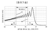
도 6a는 도 2의 실시 예와 유사한 종래의 레이저 절단 장치의 광축을 따른 변위의 함수로서 계산된 강도를 개략적으로 예시하는 그래프로서, 하지만 본 발명의 비구면 초점 렌즈 대신에 구면 평철 형상(plano-convex) 볼록 초점 렌즈를 가지며, 구면 평철 형상 초점 렌즈는 +35㎜의 특정 초점 거리를 갖는다.
도 6b는 도 1a의 레이저 절단 장치의 광축을 따른 변위의 함수로서 계산된 강도를 개략적으로 예시하는 그래프이고, 비구면 초점 렌즈는 +25㎜의 공칭 초점 거리를 갖고 펄스 레이저 방사선의 빔이 비구면 초점 렌즈의 클리어 어퍼처를 언더필링(underfilling)한다.
도 6c는 도 6b와 동일한 레이저 절단 장치의 광축을 따른 변위의 함수로서 계산된 강도를 개략적으로 예시하는 그래프이지만, 펄스 레이저 방사선의 빔은 비구면 초점 렌즈의 클리어 어퍼처를 오버필링(overfilling)한다.
도 7a는 도 1a의 레이저 절단 장치의 광축을 따른 변위의 함수로서 계산된 강도를 개략적으로 예시하는 그래프로서, 비구면 초점 렌즈의 클리어 어퍼처 외부의 레이저 방사선의 빔에서 펄스 에너지의 약 5%를 갖는다.
도 7b는 도 7a와 동일한 레이저 절단 장치의 광축을 따른 변위의 함수로서 계산된 강도를 개략적으로 예시하는 그래프이지만, 비구면 초점 렌즈의 클리어 어퍼처 외부의 레이저 방사선의 빔에서의 펄스 에너지의 약 10%를 갖는다.
도 7c는 도 7a와 동일한 레이저 절단 장치의 광축을 따른 변위의 함수로서 계산된 강도를 개략적으로 예시하는 그래프이지만, 비구면 초점 렌즈의 클리어 어퍼처 외부의 레이저 방사선의 빔에서의 펄스 에너지의 약 15%를 갖는다..BRIEF DESCRIPTION OF THE DRAWINGS The accompanying drawings, which are incorporated in and constitute a part of this specification, schematically illustrate a preferred embodiment of the invention and, together with the general description above and the detailed description of the preferred embodiment given below, serve to explain the principles of the invention. do.
1a schematically shows one preferred embodiment of a laser cutting apparatus according to the invention for producing an elongated defect in a workpiece made of a brittle material, said apparatus comprising a laser source delivering a beam of pulsed laser radiation; , an afocal beam expander, and an aspherical focusing lens forming an elongated focal point with a uniform intensity distribution.
FIG. 1B schematically shows a transverse Gaussian intensity distribution in the beam of pulsed laser radiation of FIG. 1A .
Fig. 1c schematically shows the uniform intensity distribution at the elongated focus of Fig. 1a.
Fig. 2 schematically shows another preferred embodiment of the laser cutting device according to the invention, similar to the embodiment of Fig. 1a, but the afocal beam expander is replaced by a negative lens.
Fig. 3 schematically shows another preferred embodiment of the laser cutting device according to the present invention similar to the embodiment of Fig. 1a, wherein the aspherical focus lens comprises a spherical focus lens and an aspherical phase plate.
FIG. 4 is a timing diagram schematically illustrating pulses in the beam of laser radiation of FIG. 1A ;
5 is a graph schematically showing the cross-sectional shape of an aspherical surface of an aspherical focus lens and a spherical surface of a commercial spherical lens according to the present invention, wherein the vertices of the surfaces are located at the origin, and the surfaces are a function of the displacement in the radial direction from the optical axis; As exemplified by sag.
Fig. 6a is a graph schematically illustrating the calculated intensity as a function of displacement along the optical axis of a conventional laser cutting device similar to the embodiment of Fig. 2, but instead of the aspherical focus lens of the present invention, a spherical plano-convex ) has a convex focus lens, and a spherical planar-convex focus lens has a specific focal length of +35 mm.
Fig. 6b is a graph schematically illustrating the calculated intensity as a function of displacement along the optical axis of the laser cutting apparatus of Fig. 1a, wherein the aspherical focus lens has a nominal focal length of +25 mm and the beam of pulsed laser radiation is Underfills the clear aperture of
Fig. 6c is a graph schematically illustrating the calculated intensity as a function of displacement along the optical axis of the same laser cutting apparatus as Fig. 6b, but the beam of pulsed laser radiation overfills the clear aperture of the aspherical focusing lens.
FIG. 7A is a graph schematically illustrating the calculated intensity as a function of displacement along the optical axis of the laser cutting apparatus of FIG. 1A , having about 5% of the pulse energy in a beam of laser radiation outside the clear aperture of an aspherical focusing lens; .
7B is a graph schematically illustrating the calculated intensity as a function of displacement along the optical axis of the same laser cutting device as FIG. 7A , but about 10% of the pulse energy in the beam of laser radiation outside the clear aperture of the aspherical focusing lens; has
Figure 7c is a graph schematically illustrating the calculated intensity as a function of displacement along the optical axis of the same laser cutting device as Figure 7a, but about 15% of the pulse energy in the beam of laser radiation outside the clear aperture of the aspherical focusing lens; have a..
도면을 참조하면, 유사한 컴포넌트는 동일한 참조 번호로 표시된다. 도 1a는 본 발명에 따른 레이저 절단 장치의 하나의 바람직한 실시 예(10)를 개략적으로 도시한다. 장치(10)는 빔 직경 "D1"을 갖는 펄스 레이저 방사선(14)의 시준 빔을 전달하는 레이저 소스(12)를 포함한다. 시준 빔(14)은 시준 빔(14)을 차단하고 시준되고 더 큰 빔 직경 "D2"를 갖는 펄스 레이저 방사선(20)의 확장된 빔을 형성하도록 배열된 어포컬 빔 확장기(18)로 선택적인 터닝 미러(16)에 의해 지향된다. 어포컬 빔 확장기는 광학 설계 분야에서 널리 공지된 빔 확장 엘리먼트이고, 그 설명은 본 발명의 원리를 이해하는데 필수적인 것은 아니다.Referring to the drawings, like components are denoted by like reference numerals. 1a schematically shows one
비구면 초점 렌즈(22)는 확장된 시준 빔(20)을 차단하고 펄스 레이저 방사선(24)의 포커싱된 빔을 형성하도록 배열된다. 빔 직경(D2)은 비구면 초점 렌즈(22)의 클리어 어퍼처 "CA"(D2 > CA)를 오버필링하도록 선택된다. 확장된 시준 빔(20)의 일부분만이 클리어 어퍼처(CA) 내부에 있다. 그 부분은 비구면 초점 렌즈(22)를 통해 전달되어 포커싱된 빔(24)으로 형성된다. 확장된 시준 빔(20)의 주변 광선을 포함하는 더 작은 보상 부분은 비구면 초점 렌즈(22)에 의해 포커싱되지 않는다. 비구면 초점 렌즈(22)의 클리어 어퍼처(CA)는 어포컬 빔 확장기(18)와 비구면 초점 렌즈(22) 사이에 위치하며, 도시된 바와 같이 주변 광선을 물리적으로 차단하는 별개의 어퍼처(26)에 의해 정의된다. 대안적으로, 클리어 어퍼처(CA)는 비구면 초점 렌즈(22)의 에지(28)에 의해 정의될 수 있고, 비구면 초점 렌즈(22)의 광학 에지 또는 그 물리적 에지일 수 있다.The aspherical focusing
비구면 초점 렌즈(22)는 광축(30), 비구면 표면(32) 및 대향 표면(34)을 갖는다. 비구면 표면(32)은 하기에서 상세하게 설명되는 볼록 비구면 형상을 갖는다. 표면(34)은 편평하거나 구형 또는 비구면인 볼록한 형상을 가질 수 있다. 비구면 초점 렌즈(22)는 바람직하게는 편평한 표면(34)을 가지는 평철 형상(plano-convex)의 렌즈일 수 있다. 비구면 초점 렌즈(22)는 비구면 표면(32) 상에 입사하는 확장된 시준 빔(20)을 가지면서 도시된 바와 같이 배향될 수 있거나, 표면(34) 상에 입사한 확장된 시준 빔(200)을 가지면서 배향될 수 있다. 바람직한 평철 형상 비구면 초점 렌즈(22)에 대해, 편평한 표면(34) 상에 입사하는 확장된 시준 빔(20)을 갖는 배향은 비구면 초점 렌즈의 초점 특성이 렌즈의 정확한 두께 "T"에 대해 민감하지 않다는 이점을 가진다.The
포커싱된 빔(24)은 광축(30)을 따라 가늘고 긴 초점(36)으로 수렴한다. 광축(30)에 근접한 비구면 초점 렌즈(22)로부터 나오는 근축 광선(paraxial ray)은 광축(30)에 수직인 평면 "A"로 수렴한다. 비구면 초점 렌즈(22)에 대한 "공칭 초점 거리"는 비구면 초점 렌즈(22)와 평면 A 사이의 거리로서 정의된다. 비구면 초점 렌즈(22)로부터 에지(28)에 근접하여 나오는 광선은 평면 A보다 비구면 초점 렌즈에 더 가까운 평면 "B"에 수렴한다. 가늘고 긴 초점(36)은 평면(A 및 B) 사이에서 연장한다. 가늘고 긴 초점(36)은 평면(A 및 B) 사이에서 광축을 따라 균일한 강도 분포를 가지며, 이는 이하에서 상세히 설명된다.The
취성 재료로 만들어진 워크피스(38)는 광축(30)이 굵은 선으로 도면에 도시된 절단 선(40)을 가로지르도록 위치된다. 포커싱된 빔(24)은 입사면(42)을 통해 워크피스(38)로 들어가고 대향 출사면(44)을 통해 워크피스(38)를 빠져나간다. 워크피스(38)는 가늘고 긴 초점(36)이 입사면(42)과 출사면(44) 사이의 워크피스(38)에 겹치도록 위치된다. 워크피스(38)에서의 "공칭 초점 깊이"는 입사면(42)과 평면(A) 사이의 거리로서 정의된다. 워크피스(38)는 도시된 바와 같이 평면(A 및 B) 사이에 위치한 양 표면(42 및 44)을 가지면서 가늘고 긴 초점(36) 내에 완전히 위치될 수 있다. 대안적으로, 워크피스(38)는 본 발명의 취지 및 범위를 벗어나지 않고 가늘고 긴 초점(36) 내에 부분적으로 위치할 수 있다. 절단은 펄스 레이저 방사선(24)의 포커싱된 빔을 인가하면서 절단 선(40)을 따라 광축(30)을 트레이스하면서 도시된 바와 같이 워크피스(38)를 병진 운동시킴으로써 달성된다. 절단 선(40)은 애플리케이션에 의해 요구되는 바와 같이 직선 또는 곡선일 수 있다.A
도 1b는 시준 빔(14)에 대한 단면 강도 분포를 개략적으로 도시한다. 도 1b는 시준 빔(14)의 중심으로부터의 반지름 방향의 변위의 함수로서 레이저 방사선의 강도의 그래프이다. 많은 레이저 소스에서의 광학적 공진기는 가우시안 함수에 의해 기술된 최저-차수 횡단 모드를 갖는다. 이러한 횡단 가우시안 강도 분포는 도면에 도시되어 있으며, 빔의 중심에서 최대 강도의 세기의 13.5%![]()
![]()
도 1c는 광축(30)을 따라 포커싱된 빔(24)에 대한 균일한 강도 분포를 개략적으로 도시한다. 가늘고 긴 초점(36)은 도면에서 평면(A 및 B) 사이에 거의 일정한 강도를 갖는다. 실제로, 본 발명에 의해 형성된 강도 분포는 이하에서 논의되는 바와 같이 "거의 균일"하다.1c schematically shows a uniform intensity distribution for a
도 2는 본 발명에 따른 레이저 절단 장치의 또 다른 바람직한 실시 예(50)를 개략적으로 도시한다. 장치(50)는 도 1a의 레이저 절단 장치(10)와 유사하지만, 그러나, 어포컬 빔 확장기(18)는 빔 확장 엘리먼트로서 네거티브 렌즈(52)로 대체된다. 네거티브 렌즈(52)는 시준 빔(14)을 차단하고, 비구면 초점 렌즈(22)의 클리어 어퍼처(CA)를 발산 및 오버 필링하는 펄스 레이저 방사선(54)의 확장된 빔을 형성한다. 도 2는 비구면 초점 렌즈(22)의 에지(28)에 의해 한정된 어퍼처(CA)의 예를 도시한다. 비구면 초점 렌즈(22)는 확장된 발산 빔(54)을 차단하고 포커싱된 빔(24)을 형성하도록 배열된다. 도면은 가늘고 긴 초점(36) 내에 부분적으로 위치된 워크피스(38)의 예를 도시한다. 이 예에서, 공칭 초점 깊이(L)는 워크피스(38)의 두께보다 작다.2 schematically shows another
도 3은 본 발명에 따른 레이저 절단 장치의 또 다른 바람직한 실시 예(60)를 개략적으로 도시한다. 장치(60)는 도 1a의 레이저 절단 장치(10)와 유사하지만, 비구면 초점 렌즈(22)는 비구면 초점 렌즈(66)를 함께 형성하는 구면 초점 렌즈(62) 및 비구면 위상 판(64)으로 대체된다. 구면 초점 렌즈(62)는 구면 표면(68) 및 대향 표면(34)을 갖는다. 구면 표면(68)은 볼록한 구형 형상을 가진다. 구면 초점 렌즈(62) 및 비구면 위상 판(64)은 가늘고 긴 초점(36)을 갖는 포커싱된 빔(24)을 공동으로 형성한다. 도면은 가늘고 긴 초점(36) 내에 부분적으로 위치된 워크피스(38)의 또 다른 예를 도시한다. 이 예시에서, 공칭 초점 깊이(L)는 워크피스(38)의 두께보다 더 크다.3 schematically shows another
비구면 위상 판(64)은 바람직하게는 구면 초점 렌즈(62)로부터 전파하는 포커싱된 빔의 파면을 수정하여 광축(30)을 따라 가늘고 긴 초점(36)을 형성하는 회절 광학 엘리먼트(DOE)이다. 비구면 위상 판(64)은 구면 초점 렌즈(62)의 특정 설계와 매칭하도록 커스터마이징된다. 레이저 절단 장치(60)는 구형 초점 렌즈(62)가 상용 광학 공급자로부터 얻어진 표준 평철 형상 렌즈일 수 있다는 이점을 갖는다.The
DOE는 예를 들어 뉴욕 로체스터의 RPC Photonics Inc.로부터 상업적으로 이용 가능하다. 프로그램 가능한 파면 변조를 갖는 능동형 DOE("공간 광 변조기"로도 알려짐)는 예를 들어 독일 베를린의 HoloEye로부터 상업적으로 이용 가능하다. 비구면 위상 판(64)에 능동형 DOE를 사용함으로써, 장치(60)는 임의의 광학 엘리먼트를 교체하지 않으면서 상이한 재료로 제조되거나 상이한 두께를 갖는 워크피스를 레이저 절단할 수 있다. 필요한 경우, 어퍼처는 클리어 어퍼처(CA)를 제한하기 위해 비구면 위상 판(64)의 설계에 통합될 수 있다.DOE is commercially available, for example, from RPC Photonics Inc. of Rochester, NY. Active DOEs with programmable wavefront modulation (also known as “spatial light modulators”) are commercially available, for example, from HoloEye, Berlin, Germany. By using an active DOE for the
도 4는 도 1a의 펄스 레이저 방사선(14)의 시준 빔에서의 초단(ultra-short) 펄스의 버스트를 개략적으로 예시하는 타이밍도이다. "초단" 펄스는 본 명세서에서 약 20 피코초(ps) 미만의 펄스 지속 시간 "![]()
![]()
![]()
![]()
![]()
![]()
버스트 내의 개별 펄스는 시간 간격 "Tp"에 의해 분리되고 연속 버스트는 하나의 버스트의 제1 펄스와 다음 버스트의 제1 펄스 사이의 간격인 시간 간격 "Tb"에 의해 분리된다. 이 시간 간격은 각각 펄스 반복률 및 버스트 주파수에 해당한다. 워크피스의 버스트 주파수 및 병진 운동 속도는 절단 선을 따라 결함 간격을 결정한다. 특정 두께를 갖는 특정 재료로 만들어진 워크피스에 대해, 최상의 에지 품질을 얻기 위한 최적의 결함 간격이 있다.The individual pulses within a burst are separated by a time interval “T p ” and successive bursts are separated by a time interval “T b ” which is the interval between the first pulse of one burst and the first pulse of the next. This time interval corresponds to the pulse repetition rate and burst frequency, respectively. The burst frequency and translational movement speed of the workpiece determine the defect spacing along the cut line. For a workpiece made of a particular material with a particular thickness, there is an optimal defect spacing to obtain the best edge quality.
바람직하게는, 버스트 당 2 내지 10 펄스가 있고, 가장 바람직하게는 버스트 당 5 펄스가 있다. 바람직하게는, 펄스 반복률은 약 10 메가헤르츠(MHz)보다 크다. 가장 바람직하게는, 펄스 반복률은 약 40MHz와 약 50MHz 사이이다. 바람직하게는, 버스트 주파수는 약 50㎑(킬로헤르츠)와 약 1㎒ 사이이다. 가장 바람직하게는, 버스트 주파수는 약 100kHz와 약 400kHz 사이이다.Preferably there are 2 to 10 pulses per burst, and most preferably there are 5 pulses per burst. Preferably, the pulse repetition rate is greater than about 10 megahertz (MHz). Most preferably, the pulse repetition rate is between about 40 MHz and about 50 MHz. Preferably, the burst frequency is between about 50 kHz (kilohertz) and about 1 MHz. Most preferably, the burst frequency is between about 100 kHz and about 400 kHz.
도 1의 레이저 절단 장치(10), 도 2의 레이저 절단 장치(50), 및 도 3의 레이저 절단 장치(60)에서 사용하기에 적합한 레이저 소스(12)는 캘리포니아 산타 클라라의 Coherent Inc.로부터 입수 가능한 HyperRapid™ 50 HE 레이저 시스템이다. 이 레이저 시스템은 마스터 발진기 파워 증폭기(MOPA) 아키텍처를 사용하여 200kHz까지의 버스트 주파수에서 200 마이크로 주울(μJ) 이상의 에너지를 갖는 초단 펄스의 버스트를 전달하고, 이는 40 와트(W) 이상의 최대 액세스 가능한 평균 파워에 해당한다. 버스트 당 최대 10개의 펄스가 약 50MHz의 펄스 반복률로 생성된다. 펄스 레이저 방사선의 출력 빔은 10ps의 전형적인 펄스 지속 기간과 약 1064 나노미터(nm)의 파장을 갖는다. HyperRapid™ 50 HE 레이저 시스템에는 프로세스 셔터로 사용할 수 있는 음향 광학 변조기(AOM)가 포함되어 있다. 레이저 시스템은 AOM이 열려있는 동안 계속적인 일련의 버스트를 제공한다.
도 5는 도 1a의 레이저 절단 장치(10)에 사용하기 위한 비구면 초점 렌즈(22)의 예시적인 비구면 표면(32)을 개략적으로 도시한다. 표면(34)은 편평하다. 예시적인 비구면 표면(32)(실선)의 정확한 형상은 광축(30)으로부터의 반지름 방향의 변위의 함수로서 광축(30)에 평행한 변위(광학 기술에서 "새그"로 알려져 있음)에 의해 단면으로 도시된다. 비교를 위해, 도 5는 비구면 표면(32)에 가까운 새그를 갖는 상업용 구면 평철 형상 렌즈의 구면 표면(70)(점선)의 정확한 형상을 포함한다. 상업용 구면 평철 형상 렌즈는 뉴저지 뉴턴의 Thorlabs의 파트 번호 LA1027이다. Thorlab 렌즈(LA1027)는 +35 밀리미터(mm)의 특정한 초점 거리를 가진다. 각 표면의 꼭지점(72)은 도면의 원점에 위치된다. 비구면 표면(32) 및 구면 표면(70)의 정확한 형상을 계산하기 위한 수학식은 하기에 제시된다.FIG. 5 schematically illustrates an exemplary
도 6a는 통상적인 레이저 절단 장치의 초점 근처에서 광축(30)을 따른 변위의 함수로서 계산된 강도를 개략적으로 예시하는 그래프이다. 전형적인 레이저 절단 장치는 도 2의 레이저 절단 장치(50)와 유사하지만, 비구면 표면(32)을 갖는 비구면 초점 렌즈(22) 대신에 구면 볼록 표면을 갖는 구면 평철 형상 초점 렌즈를 갖는다. 이 계산은 도 5에 도시된 구면 표면(70)을 갖는 Thorlab 렌즈(LA1027)를 사용한다. 네거티브 렌즈(52)는 Thorlabs의 파트 번호(LC1120)이며, 이는 -100mm의 특정 초점 거리를 가진다. 예시적인 워크피스(38)에 대한 입사면(42) 및 출사면(44)의 위치는 도 6a에서 수직 점선으로 표시된다. 예시적인 워크피스(38)는 1.51의 굴절률 및 1.1 mm의 두께를 갖는다. Gorilla™ 유리(뉴욕 코닝의 Corning Inc.에서 공급하는 화학적으로 강화된 유리)와 BK7 유리(일반적으로 판매되는 상업 유리)는 모두 굴절률이 약 1.51이다.6A is a graph schematically illustrating the calculated intensity as a function of displacement along the
Thorlabs 렌즈(LA1027)에 의해 포커싱된 빔 상에 부여된 구면 수차는 가늘고 긴 초점을 생성하며, 이는 도 6a에 광축을 따라 확장된 범위에 걸쳐 34mm 미만 내지 약 37mm 범위로 분포된 강도로서 나타난다. 구면 수차가 없으면, 강도 분포는 대신에 약 36.6mm를 중심으로 한 단일 피크가 된다. 예시적인 워크피스의 전체 두께가 레이저 방사선의 펄스 빔에 노출되더라도, 펄스 에너지의 대부분이 예시적인 워크피스의 외부로 전달되며, 이는 비효율적이다.The spherical aberration imparted on the focused beam by the Thorlabs lens (LA1027) produces an elongated focus, shown in FIG. 6A as an intensity distributed in the range of less than 34 mm to about 37 mm over an extended range along the optical axis. Without spherical aberration, the intensity distribution would instead be a single peak centered at about 36.6 mm. Even if the entire thickness of the exemplary workpiece is exposed to a pulsed beam of laser radiation, most of the pulse energy is transferred out of the exemplary workpiece, which is inefficient.
도 6b는 도 1a의 레이저 절단 장치(10)의 가늘고 긴 초점(36) 부근의 광축(30)을 따른 변위의 함수로서 계산된 강도를 개략적으로 도시하는 그래프이다. 단순한 비구면 초점 렌즈(22)는 확장된 시준 빔(20) 내의 광선들에 대해 광축(30)으로부터 반지름 방향의 변위 "r"에 선형적으로 의존하는 초점 길이 "f(r)"을 가진다:FIG. 6B is a graph schematically illustrating the calculated intensity as a function of displacement along the
![]()
![]()
여기서 "f(0)"는 공칭 초점 거리이고 "![]()
![]()
![]()
![]()
도 6c는 도 6b의 것을 연산하는 데에 이용되는 단순한 비구면 초점 렌즈(22)를 포함하지만 25mm의 더 작은 클리어 어퍼처(CA)를 가지는 도 1a의 레이저 절단 장치(10)에서 광축(30)을 따른 변위의 함수로서 계산된 강도를 개략적으로 예시하는 그래프이다. 더 작은 클리어 어퍼처가 워크피스(38)에 도달하는 펄스 에너지의 13.5%를 차단하지만, 어퍼처(26)의 에지에서의 회절은 도 6b와 비교하여 광축(30)을 따라 더 균일한 강도 분포를 형성한다. 도 6c의 가늘고 긴 초점은 약 23.2mm의 변위에서 약 24.8mm의 변위까지 연장되면서 도 6b에 도시된 가늘고 긴 초점보다 더 잘 정의된다. 도 6c는 본 발명의 비구면 초점 렌즈(22)와 조합된 어퍼처(26)의 이점을 나타낸다.Fig. 6c shows the
도 7a는 도 5에 도시된 예시적인 비구면 표면(32)을 갖는 도 1a의 레이저 절단 장치(10)의 가늘고 긴 초점(36) 부근의 광축(30)을 따른 변위의 함수로서 계산된 강도를 개략적으로 예시하는 그래프이다. 확장된 시준 빔(20)은 25mm의 가우시안 빔 직경(2ω)을 갖고, 어퍼처(26)는 30.6㎜의 직경을 갖는다. 어퍼처(26)는 확장된 시준 빔(20)의 펄스 에너지의 약 5%가 예시적인 워크피스(38)에 도달하는 것을 방지하고, 이는 1.51의 굴절률 및 1.1mm의 두께를 갖는다.7A schematically shows the calculated intensity as a function of displacement along the
도 5에 도시된 예시적인 비구면 표면(32)은 손실을 최소화하면서 예시적인 워크피스에 펄스 에너지를 전달하는 예시적인 워크피스 내에 가늘고 긴 초점을 형성하도록 설계된다. 도 7a에서, 거의 모든 레이저 방사선은 약 24.1mm의 변위와 약 25.2mm의 변위 사이에서 가늘고 긴 초점으로 전달되어, 예시적인 워크피스의 전체 두께를 노출시킨다. 예시적인 비구면 표면(32)을 갖는 비구면 초점 렌즈(22)는 편평한 표면(34) 상에 입사하는 확장된 시준 빔(20) 및 예시적인 비구면 표면(32)으로부터 나오는 포커싱된 빔(24)을 가지면서 지향하도록 설계된다. 비구면 초점 렌즈(22)는 1.064㎛의 파장을 갖는 방사선에 대해서 1.51의 굴절률을 가지는 BK7 유리로 만들어진다.The exemplary
또한, 도 7a, 도 7b 및 도 7c는 예시적인 비구면 표면(32)을 가지며, 어퍼처(26)가 각각 30.6mm, 25.0mm 및 24.3mm의 직경을 갖는 도 1a의 레이저 절단 장치(10)에서 광축(30)을 따른 강도를 도시한다. 어퍼처(26)는 각각 펄스 에너지의 약 5%, 약 10% 및 약 15%가 예시적인 워크피스(38)에 도달하는 것을 방지한다. 도 7a는 출사면(44) 근처에 위치한 최대 강도 피크를 갖는다. 도 7b는 거의 균일한 강도 분포를 갖는다. 도 7c는 입사면(42)에 위치한 최대 강도 피크를 갖는다. 도 7a, 도 7b 및 도 7c는 특정 워크피스(38)의 절단을 최적화하기 위해 가늘고 긴 초점(36)의 강도 분포가 어떻게 조정될 수 있는지를 도시한다. 클리어 어퍼처(CA) 내부에 있는 확장된 시준 빔(20)의 부분은 바람직하게는 약 85% 내지 약 95% 사이에 있고, 가장 바람직하게는 약 90%이다.7A, 7B, and 7C also show an exemplary
도 7a, 7b, 및 도 7c에 도시된 계산된 강도 분포 각각은 전체적으로 균일한 강도 분포에 부과된 복수의 피크를 갖는다. 이러한 고주파수 피크 또는 강도의 변조는 포커싱된 빔(24) 내의 간섭성 레이저 방사선의 광학 간섭에 의해 야기된다. 가늘고 긴 초점(36)을 따라서 있는 계산된 강도의 피크는 본 발명을 사용하는 워크피스에서 생성된 연장된 결함에서 관찰되는 변조에 거의 대응한다. 유사하게, 계산된 강도의 계곡은 연장된 결함의 불연속성에 대응하는 경우도 있다.Each of the calculated intensity distributions shown in FIGS. 7A, 7B, and 7C has a plurality of peaks imposed on the overall uniform intensity distribution. This modulation of high frequency peaks or intensity is caused by optical interference of coherent laser radiation in the
강도 분포에서 피크에 노출된 재료는 낮은 강도로 노출된 재료보다 낮은 펄스 에너지에서 제어된 결함 형성 및 원하지 않는 결함 형성에 대한 임계 값을 초과한다. 그러므로 취성 재료를 처리할 때 피크 강도를 고려하는 것이 유용하다. 여기에서, "균일한 강도 분포"란, 광학 간섭에 의한 고주파수 피크를 고려하지 않고, 평균 강도(mean intensity)로부터 약 20% 미만으로 변하는 전체 형상을 갖는 강도 분포를 가리킨다. "거의 균일한 강도 분포"는 본원에서 평균 피크 강도로부터 약 20% 미만으로 변하는 피크 강도를 갖는 강도 분포로서 정의된다.Materials exposed to peaks in the intensity distribution exceed thresholds for controlled and unwanted defect formation at lower pulse energies than materials exposed at lower intensity. Therefore, it is useful to consider peak intensity when processing brittle materials. Here, the "uniform intensity distribution" refers to an intensity distribution having an overall shape that varies less than about 20% from the mean intensity without considering high-frequency peaks due to optical interference. "Nearly uniform intensity distribution" is defined herein as an intensity distribution having a peak intensity that varies less than about 20% from the average peak intensity.
이제, 도 5를 참조하면, 비구면 표면(32)의 정확한 형상은 비구면 파라미터 "β"및 반경 파라미터 "R"의 세트에 의해 정의된다. 비구면 표면(32)상의 각 점은 새그를 갖는다 :Referring now to FIG. 5 , the exact shape of the

밀리미터 단위의 예시적인 비구면 표면(32)의 정확한 새그는: R = 22.6mm, β1 = 3.838 x 10⁻⁴, β2 = -6.330 x 10⁻²mm-1, β3 = 8.990 x 10⁻⁵mm-2, β4 = 4.500 x 10⁻⁵mm-3, β5 = 1.424 x 10⁻⁶mm-4, β6 = -4.250 x 10⁻⁷mm-5, β7 = 2.200 x 10⁻⁸mm-6, 및 β8 = -4.650 x 10⁻¹⁰mm-7이다. mm 단위의 구면 표면(70)의 정확한 새그는 다음과 같다:The exact sag of the exemplary

여기서 R은 -18.05mm이다. 구면 표면에 대해, R은 표면의 물리적 반경에 해당한다.where R is -18.05 mm. For a spherical surface, R corresponds to the physical radius of the surface.
요약하면, 펄스 레이저 방사선의 빔은 취성 재료를 절단하기 위한 균일한 강도 분포를 갖는 가늘고 긴 초점을 형성하도록 포커싱된다. 상술한 실시 예는 비구면 초점 렌즈 및 어퍼처를 사용하여 횡단 가우시안 강도 분포를 갖는 펄스 레이저 방사선의 빔으로부터 가늘고 긴 초점을 형성한다. 광학 설계는 취성 재료의 전체 두께를 통과해 레이저 방사선을 효율적으로 포커싱하도록 최적화되어, 절단 선을 따라 단일 패스에서 취성 재료를 절단할 수 있는 연장된 결함을 생성할 수 있다. 연장된 결함을 만들기 위한 레이저 방사선의 제어되고 효율적인 전달은 강화 유리와 같은 단단한 취성 재료로 만들어진 워크피스를 절단하는 데 필요한 펄스 에너지와 시간을 감소시킨다. 본 발명은 각각의 연장된 결함을 생성하기 위해 자가 안내 필라멘트를 만드는 것에 의존하지 않는다. 따라서, 본 발명은 펄스 레이저 방사선 소스의 빔 속성에 상대적으로 둔감하다.In summary, a beam of pulsed laser radiation is focused to form an elongated focal point with a uniform intensity distribution for cutting brittle materials. The above-described embodiment uses an aspherical focusing lens and aperture to form an elongated focal point from a beam of pulsed laser radiation having a transverse Gaussian intensity distribution. The optical design can be optimized to efficiently focus laser radiation through the entire thickness of the brittle material, creating elongated defects that can cut the brittle material in a single pass along the cut line. Controlled and efficient delivery of laser radiation to create elongated defects reduces the pulse energy and time required to cut workpieces made of hard brittle materials such as tempered glass. The present invention does not rely on making self-guided filaments to create each elongated defect. Accordingly, the present invention is relatively insensitive to the beam properties of a pulsed laser radiation source.
본 발명은 바람직한 실시 예 및 다른 실시 예와 관련하여 위에서 설명되었다. 그러나 본 발명은 여기에 기술되고 묘사된 실시 예들에 한정되지 않는다. 오히려, 본 발명은 여기에 첨부된 청구 범위에 의해서만 한정된다.The present invention has been described above in connection with preferred and other embodiments. However, the present invention is not limited to the embodiments described and depicted herein. Rather, the invention is limited only by the claims appended hereto.
Claims (51)
펄스 레이저 방사선의 시준 빔을 전달하는 레이저 소스로서, 상기 펄스 레이저 방사선은 20 피코초 미만의 펄스 지속기간을 갖고, 상기 시준 빔은 제1 직경을 갖는 상기 레이저 소스;
광축 및 클리어(clear) 어퍼처를 갖는 비구면 초점 렌즈;
상기 레이저 소스 및 상기 비구면 초점 렌즈 사이에 위치하는 어포컬(afocal) 빔 확장기로서, 상기 어포컬 빔 확장기는 상기 제1 직경으로부터 제2 직경으로 상기 시준 빔을 확장시키도록 배열되고, 상기 제2 직경은 상기 비구면 초점 렌즈의 상기 클리어 어퍼처보다 더 커서 확장된 상기 시준 빔의 일부만이 상기 클리어 어퍼처 내부에 있고 상기 클리어 어퍼처를 채우도록 하는 상기 어포컬 빔 확장기;
를 포함하고,
상기 비구면 초점 렌즈는 상기 클리어 어퍼처 내부에 상기 펄스 레이저 방사선의 빔의 일부분을 포커싱하고, 상기 포커싱은 상기 클리어 어퍼처의 에지에서 회절과 조합하여 상기 광축과 동축인 가늘고 긴(elongated) 초점을 형성하고, 상기 가늘고 긴 초점은 상기 광축을 따라 거의 균일한 강도 분포를 가지고; 및
상기 가늘고 긴 초점은 상기 입사면과 상기 출사면 사이의 상기 취성 재료와 중첩되는 것을 특징으로 하는 취성 재료를 절단하는 레이저 장치.A laser device for cutting a brittle material having an entrance surface and an exit surface, the laser device comprising:
a laser source delivering a collimated beam of pulsed laser radiation, the pulsed laser radiation having a pulse duration of less than 20 picoseconds, the collimating beam having a first diameter;
an aspherical focus lens having an optical axis and a clear aperture;
an afocal beam expander positioned between the laser source and the aspherical focal lens, the afocal beam expander arranged to expand the collimated beam from the first diameter to a second diameter, the second diameter is larger than the clear aperture of the aspherical focusing lens, so that only a portion of the expanded collimated beam is inside the clear aperture and fills the clear aperture;
including,
The aspherical focusing lens focuses a portion of the beam of pulsed laser radiation within the clear aperture, wherein the focusing combines with diffraction at the edge of the clear aperture to form an elongated focal point coaxial with the optical axis. and the elongated focal point has an almost uniform intensity distribution along the optical axis; and
and the elongated focal point overlaps the brittle material between the incident surface and the exit surface.
20 피코초 미만의 펄스 지속 기간을 갖는 펄스 레이저 방사선의 시준 빔을 전달하는 레이저 소스;
광축 및 클리어 어퍼처를 갖는 비구면 초점 렌즈;
상기 레이저 소스와 상기 비구면 초점 렌즈 사이의 상기 펄스 레이저 방사선의 시준 빔 내에 위치되고, 상기 펄스 레이저 방사선의 상기 시준 빔을 펄스 레이저 방사선의 확장된 빔으로 형성하는 빔 확장 엘리먼트로서, 상기 펄스 레이저 방사선의 상기 확장된 빔은 상기 비구면 초점 렌즈의 상기 클리어 어퍼처를 오버필링하여 상기 펄스 레이저 방사선의 상기 확장된 빔의 일부만이 상기 클리어 어퍼처 내부에 있고, 상기 클리어 어퍼처를 채우도록 하는 상기 빔 확장 엘리먼트;
를 포함하고,
상기 클리어 어퍼처 내부의 상기 펄스 레이저 방사선의 상기 확장된 빔의 일부를 상기 클리어 어퍼처의 클리어 에지에서 회절과 조합하여 상기 비구면 초점 렌즈에 의해 포커싱하는 것은 상기 광축을 따라서 거의 균일한 강도 분포를 가지는 가늘고 긴 초점을 갖는 펄스 레이저 방사선의 포커싱된 빔을 형성하고;
상기 가늘고 긴 초점은 상기 입사면과 상기 출사면 사이의 상기 취성 재료와 중첩되는 것을 특징으로 하는 취성 재료를 절단하는 레이저 장치.A laser device for cutting a brittle material having an incident surface and an exit surface, the laser device comprising:
a laser source delivering a collimated beam of pulsed laser radiation having a pulse duration of less than 20 picoseconds;
an aspherical focus lens having an optical axis and a clear aperture;
A beam expanding element positioned within the collimated beam of pulsed laser radiation between the laser source and the aspherical focusing lens, the beam expanding element forming the collimated beam of pulsed laser radiation into an expanded beam of pulsed laser radiation, wherein: the expanded beam overfills the clear aperture of the aspherical focusing lens such that only a portion of the expanded beam of pulsed laser radiation is inside the clear aperture and fills the clear aperture ;
including,
Focusing a portion of the expanded beam of the pulsed laser radiation inside the clear aperture by the aspherical focusing lens in combination with diffraction at the clear edge of the clear aperture has a nearly uniform intensity distribution along the optical axis. forming a focused beam of pulsed laser radiation having an elongated focus;
and the elongated focal point overlaps the brittle material between the incident surface and the exit surface.
레이저 방사선의 빔을 전달하는 단계로서, 상기 레이저 방사선은 펄싱되고 20 피코 초 미만의 펄스 지속 시간을 갖는 상기 레이저 방사선의 빔을 전달하는 단계;
레이저 방사선의 확장된 빔의 일부만이 클리어 어퍼처 내부에 있고 상기 클리어 어퍼처를 채우고 비구면 초점 렌즈를 통해 투과되도록, 상기 비구면 초점 렌즈의 상기 클리어 어퍼처를 오버필링 하기 위해 상기 레이저 방사선의 빔을 확장하는 단계;
상기 클리어 어퍼처의 에지에서 상기 레이저 방사선의 빔을 회절시키는 것과 조합하여 상기 레이저 방사선의 투과된 빔을 포커싱함으로써 가늘고 긴 초점을 갖는 레이저 방사선의 포커싱된 빔을 형성하는 단계로서, 상기 가늘고 긴 초점은 상기 비구면 초점 렌즈의 광축을 따라 거의 균일한 강도 분포를 갖는 상기 빔을 형성하는 단계;
상기 가늘고 긴 초점이 입사면과 출사면 사이에서 상기 워크피스와 중첩되고 상기 광축이 상기 절단 선을 가로지르도록 상기 워크피스를 위치시키는 단계; 및
상기 절단 선을 따라 상기 광축을 트레이싱하는 단계;
를 포함하는 것을 특징으로 하는 워크피스를 절단하는 방법.A method of cutting a workpiece made of a brittle material along a cutting line, the method comprising:
delivering a beam of laser radiation, the laser radiation being pulsed and having a pulse duration of less than 20 picoseconds;
expand the beam of laser radiation to overfill the clear aperture of the aspherical focusing lens such that only a portion of the expanded beam of laser radiation is inside the clear aperture and fills the clear aperture and is transmitted through the aspherical focusing lens to do;
forming a focused beam of laser radiation having an elongated focus by focusing the transmitted beam of laser radiation in combination with diffracting the beam of laser radiation at the edge of the clear aperture, the elongated focal point comprising: forming the beam having a nearly uniform intensity distribution along the optical axis of the aspherical focusing lens;
positioning the workpiece such that the elongated focal point overlaps the workpiece between the incident surface and the exit surface and the optical axis crosses the cutting line; and
tracing the optical axis along the cutting line;
A method of cutting a workpiece comprising a.
Applications Claiming Priority (3)
| Application Number | Priority Date | Filing Date | Title |
|---|---|---|---|
| US15/352,385 US10668561B2 (en) | 2016-11-15 | 2016-11-15 | Laser apparatus for cutting brittle material |
| US15/352,385 | 2016-11-15 | ||
| PCT/US2017/061386 WO2018093732A1 (en) | 2016-11-15 | 2017-11-13 | Laser apparatus for cutting brittle material with aspheric focusing means and a beam expander |
Publications (2)
| Publication Number | Publication Date |
|---|---|
| KR20190086703A KR20190086703A (en) | 2019-07-23 |
| KR102420833B1 true KR102420833B1 (en) | 2022-07-15 |
Family
ID=60473679
Family Applications (1)
| Application Number | Title | Priority Date | Filing Date |
|---|---|---|---|
| KR1020197016889A KR102420833B1 (en) | 2016-11-15 | 2017-11-13 | Laser device for cutting brittle material with aspherical focusing means and beam expander |
Country Status (6)
| Country | Link |
|---|---|
| US (2) | US10668561B2 (en) |
| EP (1) | EP3541565B1 (en) |
| JP (1) | JP7045372B2 (en) |
| KR (1) | KR102420833B1 (en) |
| CN (2) | CN109963683B (en) |
| WO (1) | WO2018093732A1 (en) |
Families Citing this family (19)
| Publication number | Priority date | Publication date | Assignee | Title |
|---|---|---|---|---|
| EP2754524B1 (en) | 2013-01-15 | 2015-11-25 | Corning Laser Technologies GmbH | Method of and apparatus for laser based processing of flat substrates being wafer or glass element using a laser beam line |
| EP2781296B1 (en) | 2013-03-21 | 2020-10-21 | Corning Laser Technologies GmbH | Device and method for cutting out contours from flat substrates using a laser |
| US9517963B2 (en) | 2013-12-17 | 2016-12-13 | Corning Incorporated | Method for rapid laser drilling of holes in glass and products made therefrom |
| US10442719B2 (en) | 2013-12-17 | 2019-10-15 | Corning Incorporated | Edge chamfering methods |
| US11556039B2 (en) | 2013-12-17 | 2023-01-17 | Corning Incorporated | Electrochromic coated glass articles and methods for laser processing the same |
| WO2016007572A1 (en) | 2014-07-08 | 2016-01-14 | Corning Incorporated | Methods and apparatuses for laser processing materials |
| LT3169477T (en) | 2014-07-14 | 2020-05-25 | Corning Incorporated | System for and method of processing transparent materials using laser beam focal lines adjustable in length and diameter |
| WO2016154284A1 (en) | 2015-03-24 | 2016-09-29 | Corning Incorporated | Laser cutting and processing of display glass compositions |
| JP6654813B2 (en) * | 2015-06-02 | 2020-02-26 | 川崎重工業株式会社 | Chamfering apparatus and chamfering method |
| US10522963B2 (en) * | 2016-08-30 | 2019-12-31 | Corning Incorporated | Laser cutting of materials with intensity mapping optical system |
| WO2018064409A1 (en) | 2016-09-30 | 2018-04-05 | Corning Incorporated | Apparatuses and methods for laser processing transparent workpieces using non-axisymmetric beam spots |
| EP3848333A1 (en) | 2016-10-24 | 2021-07-14 | Corning Incorporated | Substrate processing station for laser-based machining of sheet-like glass substrates |
| EP3589084A1 (en) | 2018-06-26 | 2020-01-01 | Ecole Polytechnique | Reflective optical system |
| JP7043999B2 (en) * | 2018-07-11 | 2022-03-30 | 日本電信電話株式会社 | Groove fabrication method for hybrid optical devices and hybrid optical devices |
| US20200061750A1 (en) | 2018-08-22 | 2020-02-27 | Coherent Munich GmbH & Co. KG | Mitigating low surface quality |
| US10814433B2 (en) * | 2018-11-13 | 2020-10-27 | Vertiled Co. Limited | Laser based system for cutting transparent and semi-transparent substrates |
| CN114846383A (en) * | 2019-12-19 | 2022-08-02 | 赛默科技便携式分析仪器有限公司 | Adjustable extended focus raman system |
| US11632179B1 (en) * | 2022-03-15 | 2023-04-18 | United States Of America As Represented By The Secretary Of The Navy | Remotely emitting confined electromagnetic radiation from laser-induced plasma filaments |
| KR102536286B1 (en) * | 2022-12-20 | 2023-05-26 | ㈜ 엘에이티 | Coating Layer Removal Method using Laser |
Citations (1)
| Publication number | Priority date | Publication date | Assignee | Title |
|---|---|---|---|---|
| JP2015119076A (en) * | 2013-12-19 | 2015-06-25 | 信越ポリマー株式会社 | Internal processing layer formation single crystal member and manufacturing method therefor |
Family Cites Families (21)
| Publication number | Priority date | Publication date | Assignee | Title |
|---|---|---|---|---|
| JP4337059B2 (en) * | 2003-03-21 | 2009-09-30 | ローツェ システムズ コーポレーション | Glass plate cutting device |
| KR101119387B1 (en) | 2003-07-18 | 2012-03-07 | 하마마츠 포토닉스 가부시키가이샤 | cutting method |
| JP5241525B2 (en) * | 2009-01-09 | 2013-07-17 | 浜松ホトニクス株式会社 | Laser processing equipment |
| US9302346B2 (en) * | 2009-03-20 | 2016-04-05 | Corning, Incorporated | Precision laser scoring |
| CN102639280A (en) * | 2009-12-07 | 2012-08-15 | Jp赛席尔联合股份有限公司 | Laser machining and scribing systems and methods |
| US20120234807A1 (en) | 2009-12-07 | 2012-09-20 | J.P. Sercel Associates Inc. | Laser scribing with extended depth affectation into a workplace |
| US10274650B2 (en) * | 2010-01-29 | 2019-04-30 | Beam Engineering For Advanced Measurements Co. | Diffractive waveplate lenses and applications |
| US8836941B2 (en) * | 2010-02-10 | 2014-09-16 | Imra America, Inc. | Method and apparatus to prepare a substrate for molecular detection |
| DE102010020183B4 (en) * | 2010-05-11 | 2013-07-11 | Precitec Kg | Laser cutting head and method for cutting a workpiece by means of a laser cutting head |
| EP2629920A1 (en) * | 2010-10-22 | 2013-08-28 | Highcon Ltd | Method and apparatus for laser cutting |
| TW201417928A (en) | 2012-07-30 | 2014-05-16 | Raydiance Inc | Cutting of brittle materials with tailored edge shape and roughness |
| EP2754524B1 (en) * | 2013-01-15 | 2015-11-25 | Corning Laser Technologies GmbH | Method of and apparatus for laser based processing of flat substrates being wafer or glass element using a laser beam line |
| EP2969375B1 (en) * | 2013-03-15 | 2018-09-12 | Kinestral Technologies, Inc. | Laser cutting strengthened glass |
| US9102007B2 (en) * | 2013-08-02 | 2015-08-11 | Rofin-Sinar Technologies Inc. | Method and apparatus for performing laser filamentation within transparent materials |
| US11053156B2 (en) * | 2013-11-19 | 2021-07-06 | Rofin-Sinar Technologies Llc | Method of closed form release for brittle materials using burst ultrafast laser pulses |
| US20150165563A1 (en) | 2013-12-17 | 2015-06-18 | Corning Incorporated | Stacked transparent material cutting with ultrafast laser beam optics, disruptive layers and other layers |
| US9676167B2 (en) * | 2013-12-17 | 2017-06-13 | Corning Incorporated | Laser processing of sapphire substrate and related applications |
| CN106794371B (en) * | 2014-10-10 | 2019-09-03 | 富士通株式会社 | Skill determination method, technical ability decision maker and server |
| RU2674916C2 (en) | 2014-10-13 | 2018-12-14 | Эвана Текнолоджис, Уаб | Laser treatment method for dividing or scribing substrate by forming wedge-like damaged structures |
| JP6104354B2 (en) * | 2014-12-16 | 2017-03-29 | 旭硝子株式会社 | Through-hole forming method, through-hole forming apparatus, and method for manufacturing glass substrate having through-hole |
| US20170313617A1 (en) * | 2016-04-27 | 2017-11-02 | Coherent, Inc. | Method and apparatus for laser-cutting of transparent materials |
-
2016
- 2016-11-15 US US15/352,385 patent/US10668561B2/en active Active
-
2017
- 2017-11-13 CN CN201780069421.1A patent/CN109963683B/en active Active
- 2017-11-13 JP JP2019524886A patent/JP7045372B2/en active Active
- 2017-11-13 CN CN202210239106.1A patent/CN114535782A/en active Pending
- 2017-11-13 KR KR1020197016889A patent/KR102420833B1/en active IP Right Grant
- 2017-11-13 EP EP17804775.9A patent/EP3541565B1/en active Active
- 2017-11-13 WO PCT/US2017/061386 patent/WO2018093732A1/en unknown
-
2020
- 2020-04-28 US US16/860,300 patent/US11548093B2/en active Active
Patent Citations (1)
| Publication number | Priority date | Publication date | Assignee | Title |
|---|---|---|---|---|
| JP2015119076A (en) * | 2013-12-19 | 2015-06-25 | 信越ポリマー株式会社 | Internal processing layer formation single crystal member and manufacturing method therefor |
Also Published As
| Publication number | Publication date |
|---|---|
| EP3541565A1 (en) | 2019-09-25 |
| CN109963683A (en) | 2019-07-02 |
| US10668561B2 (en) | 2020-06-02 |
| JP2020500810A (en) | 2020-01-16 |
| WO2018093732A1 (en) | 2018-05-24 |
| CN109963683B (en) | 2022-04-12 |
| EP3541565B1 (en) | 2021-09-15 |
| WO2018093732A8 (en) | 2019-05-23 |
| CN114535782A (en) | 2022-05-27 |
| JP7045372B2 (en) | 2022-03-31 |
| KR20190086703A (en) | 2019-07-23 |
| US20200254564A1 (en) | 2020-08-13 |
| US11548093B2 (en) | 2023-01-10 |
| US20180133837A1 (en) | 2018-05-17 |
Similar Documents
| Publication | Publication Date | Title |
|---|---|---|
| KR102420833B1 (en) | Laser device for cutting brittle material with aspherical focusing means and beam expander | |
| CN114096371B (en) | Phase-modified quasi-non-diffracted laser beam for high angle laser machining of transparent workpieces | |
| EP2859984B1 (en) | A method of laser processing a transparent material | |
| RU2689018C2 (en) | Device for projecting mask with beam of femtosecond and picosecond laser, containing limiter, mask and system of lenses | |
| CN109641315B (en) | Multi-zone focusing lens and laser processing system for wafer dicing or cutting | |
| US9873628B1 (en) | Filamentary cutting of brittle materials using a picosecond pulsed laser | |
| KR102582719B1 (en) | Apparatus and method for simultaneous multi-laser processing of transparent workpieces | |
| CN111936434B (en) | Selective laser machining of transparent workpiece stacks | |
| TW201919805A (en) | Apparatuses and methods for laser processing transparent workpieces using an afocal beam adjustment assembly | |
| JP2020507476A (en) | Apparatus and method for laser processing a transparent workpiece using a phase shift focal line | |
| KR20210022637A (en) | Active control of laser processing of transparent workpieces | |
| CN113056345A (en) | System and method for modifying transparent substrates | |
| US20210001430A1 (en) | Curved quasi-non-diffracting laser beams for laser processing of transparent workpieces | |
| US20190300418A1 (en) | Methods for laser processing rough transparent workpieces using pulsed laser beam focal lines and a fluid film | |
| CN112996627A (en) | Mitigation of low surface quality | |
| KR20210024008A (en) | Method of laser processing a substrate stack with one or more transparent workpieces and a black matrix layer | |
| TWI834649B (en) | Methods for laser processing rough transparent workpieces using pulsed laser beam focal lines and a fluid film | |
| KR20230175254A (en) | Method for controlling the distribution of energy introduced into a substrate by line focus of a laser beam, and the substrate | |
| WO2023009331A1 (en) | Phase modified quasi-non-diffracting laser beams for simultaneous high angle laser processing of transparent workpieces | |
| KR20230065304A (en) | Method and optical assembly for high-angle laser processing of transparent workpieces |
Legal Events
| Date | Code | Title | Description |
|---|---|---|---|
| E902 | Notification of reason for refusal | ||
| E701 | Decision to grant or registration of patent right | ||
| GRNT | Written decision to grant |