JP7040640B2 - Posture change device - Google Patents
Posture change device Download PDFInfo
- Publication number
- JP7040640B2 JP7040640B2 JP2020558121A JP2020558121A JP7040640B2 JP 7040640 B2 JP7040640 B2 JP 7040640B2 JP 2020558121 A JP2020558121 A JP 2020558121A JP 2020558121 A JP2020558121 A JP 2020558121A JP 7040640 B2 JP7040640 B2 JP 7040640B2
- Authority
- JP
- Japan
- Prior art keywords
- tire
- posture
- pallet
- pressing
- pressing member
- Prior art date
- Legal status (The legal status is an assumption and is not a legal conclusion. Google has not performed a legal analysis and makes no representation as to the accuracy of the status listed.)
- Active
Links
Images


Classifications
-
- B—PERFORMING OPERATIONS; TRANSPORTING
- B65—CONVEYING; PACKING; STORING; HANDLING THIN OR FILAMENTARY MATERIAL
- B65G—TRANSPORT OR STORAGE DEVICES, e.g. CONVEYORS FOR LOADING OR TIPPING, SHOP CONVEYOR SYSTEMS OR PNEUMATIC TUBE CONVEYORS
- B65G57/00—Stacking of articles
- B65G57/02—Stacking of articles by adding to the top of the stack
- B65G57/16—Stacking of articles of particular shape
- B65G57/20—Stacking of articles of particular shape three-dimensional, e.g. cubiform, cylindrical
-
- B—PERFORMING OPERATIONS; TRANSPORTING
- B65—CONVEYING; PACKING; STORING; HANDLING THIN OR FILAMENTARY MATERIAL
- B65G—TRANSPORT OR STORAGE DEVICES, e.g. CONVEYORS FOR LOADING OR TIPPING, SHOP CONVEYOR SYSTEMS OR PNEUMATIC TUBE CONVEYORS
- B65G57/00—Stacking of articles
- B65G57/28—Stacking of articles by assembling the articles and tilting the assembled articles to a stacked position
-
- B—PERFORMING OPERATIONS; TRANSPORTING
- B65—CONVEYING; PACKING; STORING; HANDLING THIN OR FILAMENTARY MATERIAL
- B65G—TRANSPORT OR STORAGE DEVICES, e.g. CONVEYORS FOR LOADING OR TIPPING, SHOP CONVEYOR SYSTEMS OR PNEUMATIC TUBE CONVEYORS
- B65G7/00—Devices for assisting manual moving or tilting heavy loads
- B65G7/02—Devices adapted to be interposed between loads and the ground or floor, e.g. crowbars with means for assisting conveyance of loads
- B65G7/08—Devices adapted to be interposed between loads and the ground or floor, e.g. crowbars with means for assisting conveyance of loads for tilting the loads
-
- B—PERFORMING OPERATIONS; TRANSPORTING
- B65—CONVEYING; PACKING; STORING; HANDLING THIN OR FILAMENTARY MATERIAL
- B65G—TRANSPORT OR STORAGE DEVICES, e.g. CONVEYORS FOR LOADING OR TIPPING, SHOP CONVEYOR SYSTEMS OR PNEUMATIC TUBE CONVEYORS
- B65G2201/00—Indexing codes relating to handling devices, e.g. conveyors, characterised by the type of product or load being conveyed or handled
- B65G2201/02—Articles
- B65G2201/0273—Tires
-
- B—PERFORMING OPERATIONS; TRANSPORTING
- B65—CONVEYING; PACKING; STORING; HANDLING THIN OR FILAMENTARY MATERIAL
- B65G—TRANSPORT OR STORAGE DEVICES, e.g. CONVEYORS FOR LOADING OR TIPPING, SHOP CONVEYOR SYSTEMS OR PNEUMATIC TUBE CONVEYORS
- B65G2814/00—Indexing codes relating to loading or unloading articles or bulk materials
- B65G2814/03—Loading or unloading means
- B65G2814/0301—General arrangements
- B65G2814/0304—Stacking devices
Description
本発明は、段積み状態のタイヤを保持する縦姿勢と、横並び状態のタイヤを保持する横姿勢との間でタイヤを保持するパレットの姿勢を転換する姿勢転換装置に関する。 The present invention relates to a posture changing device that changes the posture of a pallet holding tires between a vertical posture for holding tires in a stacked state and a horizontal posture for holding tires in a side-by-side state.
従来、タイヤを保管する方法として、横向きのタイヤを複数段積み重ねるいわゆる段積み状態(平積み)で保管する方法がある。また、複数の縦向きのタイヤを転がらないようにパレット上に並べるいわゆる横並び状態で保管する方法もある。 Conventionally, as a method of storing tires, there is a method of storing sideways tires in a so-called stacked state (flat stacking) in which a plurality of tires are stacked. There is also a method of storing a plurality of vertically oriented tires in a so-called side-by-side state in which they are arranged on a pallet so as not to roll.
特許文献1には、段積み状態のタイヤの姿勢を一括して自動的に横並び状態にし、パレットに搭載する装置が記載されている。 Patent Document 1 describes a device that automatically arranges the postures of tires in a stacked state side by side and mounts them on a pallet.
特許文献1に記載の技術では、横並び状態と段積み状態との間でタイヤの姿勢を転換させている。横並び状態の複数のタイヤを一括して段積み状態にした場合、タイヤがずれた状態で済み重なることがある。このようにタイヤがずれた段積み状態になると、ガントリークレーンの保持装置がタイヤに挿入できなくなるなどの不具合が起こるため、ずれのない段積み状態を維持する必要がある。 In the technique described in Patent Document 1, the posture of the tire is changed between the side-by-side state and the stacked state. When multiple tires in a side-by-side state are stacked together, the tires may be misaligned and overlap. When the tires are in a stacking state in which the tires are displaced in this way, problems such as the holding device of the gantry crane cannot be inserted into the tires occur, so it is necessary to maintain the stacking state without displacement.
本発明は上記課題に鑑みなされたものであり、横並び状態のタイヤをずらすことなく段積み状態に姿勢の転換を行うことができ、また逆の姿勢転換も可能とする姿勢転換装置の提供を目的とする。 The present invention has been made in view of the above problems, and an object of the present invention is to provide a posture change device capable of changing the posture to a stacked state without shifting the tires in a side-by-side state and also enabling the reverse posture change. And.
上記目的を達成するために、本発明の1つである姿勢転換装置は、縦向きの複数のタイヤが並べられた横並び状態のタイヤ群を保持する横姿勢のパレットを前記タイヤ群と共に縦姿勢にできる姿勢転換装置であって、前記パレットを保持する基台と、前記基台を回動させることにより、保持された前記パレットの姿勢を転換する転換駆動装置と、前記パレットに保持される前記タイヤ群の一端部に位置し、傾いている前記タイヤである傾斜タイヤを他端部に向かって起立させる起立装置と、前記タイヤ群の周面の少なくとも一部に当接して前記タイヤの動きを規制する規制装置とを備える。 In order to achieve the above object, the posture changing device, which is one of the present inventions, puts a horizontal pallet that holds a tire group in a side-by-side state in which a plurality of vertically-oriented tires are arranged in a vertical posture together with the tire group. A possible posture change device, a base for holding the pallet, a change drive device for changing the posture of the held pallet by rotating the base, and the tire held on the pallet. An erecting device that is located at one end of the group and causes the inclined tire, which is an inclined tire, to stand toward the other end, and a contact with at least a part of the peripheral surface of the tire group to regulate the movement of the tire. It is equipped with a regulation device.
これによれば、規制装置によりタイヤの動きを規制しつつパレットと共にタイヤの姿勢を転換することができるため、姿勢の転換時にタイヤがずれることを防止できる。また、起立装置により倒れたタイヤを起こした状態で横並び状態から段積み状態に転換できるため、ダイヤ同士のずれを抑制し、段積み状態のタイヤをガントリークレーンで容易に搬送することが可能となる。 According to this, since the movement of the tire can be regulated by the regulating device and the posture of the tire can be changed together with the pallet, it is possible to prevent the tire from shifting when the posture is changed. In addition, since the standing device can switch from the side-by-side state to the stacked state with the fallen tires raised, it is possible to suppress the displacement between the diamonds and easily transport the stacked tires with the gantry crane. ..
また、前記起立装置は、前記傾斜タイヤに対し前記タイヤ群の他端部に向かう押圧力を与える押圧部材と、前記押圧部材を前記傾斜タイヤと前記パレットとの間に出没させる出没装置と、進出状態の前記押圧部材に対し前記傾斜タイヤの他端部に向かう前記押圧力を発生させる移動装置とを備えてもよい。 Further, the standing device includes a pressing member that applies a pressing force toward the other end of the tire group to the inclined tire, and an infestation device that causes the pressing member to appear and disappear between the inclined tire and the pallet. A moving device that generates the pressing force toward the other end of the inclined tire may be provided with respect to the pressing member in the state.
これによれば、様々な径のタイヤや倒れた際のタイヤの様々な姿勢に柔軟に対応することができる。 According to this, it is possible to flexibly cope with various postures of tires having various diameters and tires when they fall down.
前記押圧部材は、前記傾斜タイヤと接触して回転するローラ部を備えてもよい。 The pressing member may include a roller portion that rotates in contact with the inclined tire.
これによれば、タイヤと押圧部材との摩擦を低減することができ、容易にタイヤを起立させることが可能となる。 According to this, the friction between the tire and the pressing member can be reduced, and the tire can be easily erected.
前記起立装置は、前記基台に取り付けられ、前記パレットの姿勢の転換と共に移動してもよい。また、前記規制装置は、前記基台に取り付けられて前記パレットの姿勢の転換と共に移動してもよい。 The standing device may be attached to the base and move with the change of posture of the pallet. Further, the regulating device may be attached to the base and move with the change of posture of the pallet.
これらによれば、姿勢転換中においても、ここのタイヤを安定させることができ、タイヤ同士のずれを抑制することが可能となる。 According to these, it is possible to stabilize the tires here even during the posture change, and it is possible to suppress the displacement between the tires.
本発明によれば、複数のタイヤを段積み状態と横並び状態との間でタイヤ同士のずれを抑制しながら姿勢転換を行う事ができる。 According to the present invention, it is possible to change the posture of a plurality of tires while suppressing the displacement between the tires between the stacked state and the side-by-side state.
以下に、本発明に係る姿勢転換装置の実施の形態について、図面を参照しつつ説明する。なお、以下で説明する実施の形態は、いずれも包括的または具体的な例を示すものである。以下の実施の形態で示される数値、形状、材料、構成要素、構成要素の配置位置及び接続形態などは、一例であり、本発明を限定する主旨ではない。また、以下の実施の形態における構成要素のうち、最上位概念を示す独立請求項に記載されていない構成要素については、任意の構成要素として説明される。 Hereinafter, embodiments of the posture changing device according to the present invention will be described with reference to the drawings. It should be noted that all of the embodiments described below show comprehensive or specific examples. Numerical values, shapes, materials, components, arrangement positions of components, connection forms, and the like shown in the following embodiments are examples, and are not intended to limit the present invention. Further, among the components in the following embodiments, the components not described in the independent claim indicating the highest level concept are described as arbitrary components.
また、図面は、本発明を示すために適宜強調や省略、比率の調整を行った模式的な図となっており、実際の形状や位置関係、比率とは異なる場合がある。 Further, the drawings are schematic views in which emphasis, omission, and ratio adjustment are appropriately performed to show the present invention, and may differ from the actual shape, positional relationship, and ratio.
(実施の形態1)
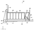
図1は、実施の形態1に係る姿勢転換装置を示す斜視図である。図2は、パレットの保持された横並び状態のタイヤを保持する姿勢転換装置を示す斜視図である。図3は、パレットの保持された段積み状態のタイヤを保持する姿勢転換装置を示す斜視図である。姿勢転換装置100は、図2に示すように、縦向きの複数のタイヤ200が並べられた横並び状態のタイヤ群を保持するパレット300をタイヤ群と共に図3に示す縦姿勢にし、また図3に示す横向きの複数のタイヤ200が積み重ねられた段積み状態でタイヤ群を保持するパレット300をタイヤ群と共に図2に示す横姿勢にする装置であり、基台110と、転換駆動装置120と、起立装置130と、規制装置140とを備えている。(Embodiment 1)
FIG. 1 is a perspective view showing a posture changing device according to the first embodiment. FIG. 2 is a perspective view showing a posture changing device for holding a tire held side by side on a pallet. FIG. 3 is a perspective view showing a posture changing device for holding the tires in a stacked state in which the pallets are held. As shown in FIG. 2, the
姿勢転換装置100によって段積み状態と横並び状態に転換されるタイヤ200は、例えば、タイヤ200は、自動車などの中型の車両に用いられるものや、トラックやバスなどの大型の車両に用いられるもの、農業機械や建設機械に用いられるものなど特に限定されるものではない。また、実施の形態1、請求の範囲等においてタイヤ群とは、パレット300に保持される複数のタイヤ200の一群を意味する。また、横並び状態のタイヤ群の端部に位置するタイヤ200であって、縦向きではなくパレット300にもたれかかった状態で傾斜しているタイヤ200を傾斜タイヤ201として称する。なお、傾斜タイヤ201はタイヤ200の1つであり、傾斜状態から縦向きになった段階で傾斜タイヤ201ではなくなる。
The
姿勢転換装置100の姿勢転換対象となるパレット300は、図4に示す横姿勢において横並び状態の複数のタイヤ200をそれぞれ載置する横載置部310と、縦姿勢において(図3参照)、段積み状態のタイヤ200を載置する縦載置部320とを備えている。実施の形態1の場合、パレット300は、横載置部310の端部において横載置部310と交差する方向に突出するように縦載置部320を配置するフレーム330を備えている。パレット300は、横載置部310に対し縦載置部320の反対側において傾斜タイヤ201を支えて落下を防止するストッパ340を縦載置部320に対向する様に備えている。パレット300は、縦載置部320の突出方向(図4中Z軸方向)に延在する柱状のスペーサ350を備えている。スペーサ350は、矩形のフレーム330の四隅にそれぞれ取り付けられており、二つのパレット300のスペーサ350の上端と下端とをそれぞれ接続することにより、横姿勢のパレット300を、タイヤ群を保持した状態で段積みできる機能を備えている。
The
パレット300は縦姿勢において、ガントリークレーンなどのクレーンによって搬送される段積み状態のタイヤ群を受け取ることができ、また保持しているタイヤ群をクレーンに受け渡すことが可能な構造となっている。具体的には、ストッパ340が、保持するタイヤ200の孔(ホイールが取り付けられる孔)と干渉しないようにタイヤ200を支持する形状、例えばU字形状やV字形状などの少なくともタイヤ200の側面に複数箇所当接可能、かつタイヤ200に対して横載置部310の反対側は、チャックが通過可能な隙間を有する形状である。またストッパ340は、クレーンを用いてタイヤ群を搬送する際にタイヤ200の孔に挿入されてタイヤ群を内部から保持するクレーンのチャックと干渉しないようにフレーム330に配置されている。
The
パレット300は、径の異なるタイヤ200を保持可能であり、例えば保持可能な最小径のタイヤ200に対し、1.5倍程度径の大きなタイヤ200まで保持可能となっている。また、パレット300は、他のパレット300と接続する接続部(図示せず)を備えており、二つのパレット300など複数のパレット300をひとつのパレットとして利用することができるものとなっている。実施の形態1の場合、姿勢転換装置100は、接続された二つのパレット300の姿勢を一度に転換できるものとなっている。なお、姿勢転換装置100は、一つのパレット300の姿勢を転換するものでもよく、3以上のパレット300の姿勢を一度に転換できるものでも構わない。
The
基台110は、パレット300を保持する構造部材であり、横姿勢のパレット300を保持し、縦姿勢になるまでの姿勢転換中においてもパレット300を保持し続け、またその逆の姿勢転換中においてもパレット300を保持し続けることができる。実施の形態1の場合基台110は、パレット300の横載置部310および縦載置部320に沿って配置される二つのL字状の保持部材111を対向状態で接続した構造を備えている。また、連結された2つのパレット300を、それぞれタイヤ群を保持したままの状態で姿勢転換中においても保持することができるものとなっている。
The
実施の形態1の場合また基台110は、横姿勢のパレット300を基台110の下方に配置された搬送装置(図示せず)に受け渡すことができる構造となっている。具体的には、基台110の保持部材111は、搬送装置であるローラコンベヤのローラの間を通過することができ、保持しているパレット300をローラコンベヤに載置できる。これにより、ローラコンベヤは載置された横姿勢のパレット300を搬送することが可能となる。また、ローラコンベヤにより基台110にまで搬送された横姿勢のパレット300は、基台110に保持されて縦姿勢に姿勢を転換することが可能となる。
In the case of the first embodiment, the
転換駆動装置120は、基台110を所定の回動軸周り(図中Y軸に平行な回動軸)に回動させ、保持されたパレット300の姿勢を横姿勢から縦姿勢、またはその逆に転換することができる装置である。実施の形態1の場合、基台110の保持部材111の角部の外側近傍に配置され基台110に固定される軸体121と、軸体121を回転可能に保持し床面等に固定される軸受122と、軸体121を回動させる減速機、モータを含む駆動源123とを備えている。なお、姿勢転換装置100は、モータ駆動に限定されるものではなく、エアーシリンダなどのアクチュエータにより基台110を回動させるものなどでも構わない。
The
起立装置130は、図5に示すような、横並び状態のタイヤ群の一端部に位置し、傾いているタイヤ200である傾斜タイヤ201を他端部である縦載置部320側に向かって起立させる装置である。起立装置130の具体的な構成は特に限定されるものではないが、実施の形態1の場合、起立装置130は、連結された2つのパレット300に保持される2つのタイヤ群にそれぞれ含まれる傾斜タイヤ201を同時に起立させることができる装置であり、押圧部材131と、出没装置132と、移動装置133とを備えている。
The standing
また実施の形態1の場合、起立装置130は、基台110に取り付けられており、転換駆動装置120によるパレット300の姿勢の転換と共に移動するものとなっている。起立装置130は、傾斜タイヤ201を起こした状態のままで基台110と共に移動することもできるものとなっている。
Further, in the case of the first embodiment, the standing
押圧部材131は、傾斜タイヤ201に対しタイヤ群の他端部に向かう押圧力を与える部材である。押圧部材131の具体的な形状は特に限定されるものではないが、実施の形態1の場合、押圧部材131は、全体視棒状であり、軸体、および軸体の外周に同軸上に配置され、傾斜タイヤ201と接触して軸体の軸周りに回転するローラ部とを備えている。ローラ部は樹脂のパイプである。なお、ローラ部は、押圧部材131のほぼ全長に渡って配置されてもよく、押圧部材131に沿って断続的に複数のローラ部が配置されるものでもよい。このように、押圧部材131がローラ部を備えることにより、傾斜タイヤ201を起立させる際に発生する傾斜タイヤ201の表面と押圧部材131との摩擦を低減することができる。
The pressing
また実施の形態1の場合、押圧部材131は、基台110の回動軸(図中Y軸方向)に沿うように延在し、基台110が保持する2つのパレット300にそれぞれ配置される2つのタイヤ群と重なる程度の長さを備えており、2つのタイヤ群にそれぞれ含まれる傾斜タイヤ201を同時に起立させることができる強度(剛性)を備えている。
Further, in the case of the first embodiment, the pressing
なお、押圧部材131は、一本であってもよく、複数の部材に分かれて伸縮するものでも構わない。例えば、テレスコピック構造の押圧部材131を例示することができる。
The pressing
出没装置132は、押圧部材131を傾斜タイヤ201とパレット300のとの間、具体的には傾斜タイヤ201とパレット300のストッパ340との間において、基台110の回動軸に沿う方向に出没させる装置である。実施の形態1の場合、出没装置132は、エアーシリンダにより押圧部材131の先端が最も近傍のパレット300に掛からない位置から押圧部材131が2つのタイヤ群と重なる位置になるまで押圧部材131を1ストロークで進出させ、その逆も1ストロークで没入させることができるものとなっている。
The
なお、出没装置132の駆動手段はエアーシリンダに限定されるものではなく、直動モータ、回転モータと歯車などの機構部品との組み合わせにより実現する装置などでも構わない。
The driving means of the
移動装置133は、進出状態の押圧部材131を傾斜タイヤ201の他端部に向かう押圧力を発生させる装置である。実施の形態1の場合、移動装置133は、出没装置132ごと押圧部材131を平行移動させるものとなっている。具体的には、基台110に保持されるパレット300の横載置部310の延在方向(図中X軸方向)に対して所定の角度で配置されるレール134(図5、図6参照)出没装置132を備えており、レール134にスライド可能に取り付けられた出没装置132をレール134に沿ってエアーシリンダにより駆動している。出没装置132と共に押圧部材131を、傾斜タイヤ201を起立させる方向に移動させる場合にエアーシリンダに入れる空気圧は、レギュレータにより調節可能であり、圧力を抑制することにより径の異なる傾斜タイヤ201でも汎用的に起立させることが可能となる。
The moving
なお、移動装置133が押圧部材131を移動させる方向は、直線に限定されるものではない。例えば、進出状態の押圧部材131を基台110の回動軸と平行、またはほぼ平行な軸周りで回転させても構わない。また、移動装置133の駆動手段はエアーシリンダに限定されるものではなく、直動モータ、回転モータと歯車などの機構部品との組み合わせにより実現する装置などでも構わない。つまり、傾斜タイヤ201を起立させる際の押圧部材131の軌跡は、直線状ばかりで無く、曲線状でも屈曲状などでも構わない。また、姿勢転換装置100の汎用性を高めるために、押圧部材131の軌跡の最終位置、つまり傾斜タイヤ201が縦向きのタイヤ200になった状態における押圧部材131の位置は、パレット300が保持可能な最小径のタイヤ200の頂上部近傍が好ましい。
The direction in which the moving
また、起立装置130が傾斜タイヤ201を起立させる際には、没入状態の押圧部材131を、横載置部310とストッパ340とで構成される内側の隅部に進出させることが好ましい。これにより、ストッパ340にもたれかかった状態の傾斜タイヤ201の径にかかわらず、押圧部材131を傾斜タイヤ201に干渉しないように進出させることができる可能性が高くなるからである。
Further, when the erecting
規制装置140は、姿勢転換装置100に保持されているタイヤ200の周面の少なくとも一部に当接してタイヤ群におけるそれぞれのタイヤ200の動きを規制する装置である。規制装置140の具体的な構成は特に限定されるものではないが、実施の形態1の場合、規制装置140は、当接部材141と、当接部材141をタイヤ群に対して離接させる離接装置142と、当接部材141と離接装置142とを接続するアーム部材143とを備えている。
The regulating
また実施の形態1の場合、規制装置140は、基台110に取り付けられており、転換駆動装置120によるパレット300の姿勢の転換と共に移動するものとなっている。規制装置140は、タイヤ群の周面に当接した状態のままで基台110と共に移動することもできるものとなっている。
Further, in the case of the first embodiment, the
実施の形態1の場合、基台110には二つのパレット300を介してそれぞれ2つのタイヤ群が保持されており、各タイヤ群のタイヤ200の動きを規制するため、姿勢転換装置100は、2つの規制装置140を備えている。また、2つの規制装置140は、動作の方向も含めて面対称となるように構成されている。
In the case of the first embodiment, two tire groups are held on the
当接部材141は、タイヤ群の周面に当接、またはタイヤ群に対し横載置部310に向かう押圧力を与える長尺状の部材である。当接部材141の具体的な形状は特に限定されるものではないが、実施の形態1の場合、当接部材141は丸棒である。当接部材141は、基台110が保持するパレット300の横載置部310の延在方向に沿って延在し、パレット300が保持しうるタイヤ群の軸方向の長さ程度の長さを備えている。
The abutting
離接装置142は、当接部材141の延在方向に沿い、当接部材141から所定の距離離れた回転軸回りに当接部材141を円弧状に回転揺動させるものとなっている。具体的には、離接装置142は、減速機、および回転モータを備え、回転モータの回転を減速機、およびアーム部材143を介して当接部材141に伝達している。離接装置142は、タイヤ群を構成するタイヤ200の径が所定範囲内で異なる場合でも、当接部材141をタイヤ群の周面に当接状態で維持、またはタイヤ群の周面を当接部材141で押圧した状態で維持することができる。離接装置142は、タイヤ群を保持するパレット300の姿勢転換中であっても、タイヤ群の周面に当接させた状態、またはタイヤ群の周面を当接部材141で押圧した状態を維持し続けることができる。
The
なお、離接装置142が当接部材141を移動させる方向は、回転揺動に限定されるものではない。例えば、実施の形態1の起立装置130のように、当接部材141をタイヤ群の周面に向かって直線的に移動させるものでも構わない。また、離接装置142の駆動手段は回転モータに限定されるものではなく、直動モータ、エアーシリンダなどにより実現する装置などでも構わない。
The direction in which the
また、アーム部材143は、湾曲状、直線状など任意の形状を採用することも可能である。特に、実施の形態1のアーム部材143のように屈曲した形状とすることにより、基台110に保持されたパレット300に桟等の障害物(図示せず)が存在する場合でも、当該障害物を回避しながらタイヤ200相互の位置ずれを規制することができる。
Further, the
上記実施の形態1に係る姿勢転換装置100によれば、横並び状態のタイヤ群の端部に傾斜タイヤ201があった場合、パレット300の姿勢を縦姿勢に変換する前に傾斜タイヤ201を起立させることで、姿勢転換中や姿勢転換後にタイヤ200の位置がずれたり、タイヤ200が落下したりすることを抑制できる。さらに、傾斜タイヤ201の起立後においてもタイヤ群の端部から縦載置部320に向かって起立装置130により押圧力を付与し続けることによって、さらにタイヤ200の維持ずれや落下を抑制することができる。
According to the
以上の様にタイヤ200のずれがほとんどない段積み状態のタイヤ群であれば、クレーンに取り付けられたチャックをタイヤ群の孔に容易に挿入することができ、タイヤ200のずれによりチャックがタイヤ群に挿入できないなどの不具合を回避してタイヤ群の搬出作業の効率化を図ることも可能となる。
As described above, if the tire group is in a stacked state with almost no displacement of the
規制装置140により、タイヤ群の周面を押さえながら姿勢の転換をすることで、姿勢転換中、および姿勢転換前後においてタイヤ200のずれや落下を抑制することができる。
By changing the posture while pressing the peripheral surface of the tire group by the regulating
また、段積み状態のタイヤ群を保持する縦姿勢のパレット300の姿勢転換後にタイヤ群の端部が傾斜タイヤ201になった場合、起立装置130を用いて傾斜タイヤ201を起立させることで、傾斜タイヤ201の状態で保管される状況を回避できる。
Further, when the end portion of the tire group becomes the
(実施の形態2)
続いて、姿勢転換装置100の他の実施の形態について説明する。なお、前記実施の形態1と同様の作用や機能、同様の形状や機構や構造を有するもの(部分)には同じ符号を付して説明を省略する場合がある。また、以下では実施の形態1と異なる点を中心に説明し、同じ内容については説明を省略する場合がある。(Embodiment 2)
Subsequently, another embodiment of the
図7は、実施の形態2に係る姿勢転換装置を示す側面図である。図7に示すように、姿勢転換装置100は、実施の形態1と同様に、複数のタイヤ200を保持するパレット300を横姿勢から縦姿勢に転換する装置であって、基台110と、転換駆動装置120と、起立装置130と、規制装置140とを備えている。実施の形態2の場合、姿勢転換装置100はさらに、制御装置150と、搬送装置160とを備えている。
FIG. 7 is a side view showing the posture changing device according to the second embodiment. As shown in FIG. 7, the
実施の形態2の場合、起立装置130は、実施の形態1と同様タイヤ群の一端部に位置し、傾斜タイヤ201を縦載置部320側に向かって起立させる装置であり、挿通部材135と、押圧部材131と、出退装置137と、押圧装置138と、昇降装置139と、を備えている。
In the case of the second embodiment, the erecting
挿通部材135は、少なくとも傾斜タイヤ201の孔に刺し通される部材である。挿通部材135の形状は、特に限定されるものではないが、タイヤ200を持ち上げた際にタイヤ200の内周を痛めないような丸棒、円筒などの形状が好ましい。また、姿勢転換装置100に順次運ばれてくる径の異なるタイヤ200の孔に差し込むことができる程度の径に設定されている。実施の形態2の場合、複数個(例えば3個)のタイヤ200を持ち上げることができる長さに設定されている。挿通部材135は、複数個のタイヤ200を片持ち状態で持ち上げることができる剛性に設定されている。
The
押圧部材131は、傾斜タイヤ201の一端部の端面に当接する部材である。実施の形態2の場合、押圧部材131は、タイヤ200の一端部外側からタイヤ200の並び方向に真っ直ぐタイヤ200を押圧する。押圧部材131の形状は、特に限定されるものではないが、上述の通り複数種類の径のタイヤ200の端面に当接する部材であるため、複数種類の径のタイヤ200のいずれの端面にも当接可能な面積(図中YZ面の面積)を有する板状の部材が望ましい。
The pressing
また、押圧部材131のタイヤ200と当接する面には、押圧部材131とタイヤ200との摩擦を軽減する部材を設けることが望ましい。例えば、水平面内においてタイヤ200の端面と平行に延在する軸周りに回転するローラを押圧部材131が備えていてもかまわない。
Further, it is desirable to provide a member for reducing friction between the
出退装置137は、挿通部材135を傾斜タイヤ201に対して抜き差しする装置である。実施の形態2の場合、出退装置137は、エアーシリンダにより挿通部材135の先端が最も近傍のタイヤ200から三番目のタイヤ200の位置にまで挿通部材135を進出させ、パレット300の姿勢を転換する際に挿通部材135がパレット300などに干渉しない位置にまで後退させることができる。
The entry /
押圧装置138は、押圧部材131により傾斜タイヤ201であったタイヤ200の上部を他端部(図中X軸負の方向)に向かって押しつけ、タイヤ200の位置を調整する装置である。押圧装置138の種類は特に限定されるものではないが、実施の形態2の場合、出退装置137と同様にエアーシリンダが用いられている。
The
なお、実施の形態2では、挿通部材135と押圧部材131とを別体とし、出退装置137、および押圧装置138を用いてそれぞれ独立して動作できるものとして説明したが、押圧部材131は、挿通部材135の外周面から外側に向かって突出し、挿通部材135に固定されるフランジ状の部材であってもかまわない。この場合、押圧部材131が傾斜タイヤ201を起立させる押圧力を発生させる装置は出退装置137となり、押圧装置138は出退装置137により実現される。
In the second embodiment, the
昇降装置139は、挿通部材135、押圧部材131、出退装置137、および押圧装置138を昇降させる装置である。昇降装置139は、挿通部材135が挿通された複数個のタイヤ200を一度に持ち上げるパワーを備えている。昇降装置139の種類は特に限定されるものではないが、実施の形態2の場合、チェーン、プーリー、を組み合わせた昇降機構を備え、モータによって昇降機構を駆動する装置が採用されている。
The elevating
実施の形態2の場合、搬送装置160によってタイヤ200が載置されたパレット300が搬送されるため、昇降装置139は、タイヤ200に挿通されていない状態の挿通部材135、押圧部材131、出退装置137、および押圧装置138をタイヤ200が載置されたパレット300が通過する領域の上側まで上昇させることができる。
In the case of the second embodiment, since the
搬送装置160は、横並び状態のタイヤ200の並び方向(図中X軸方向)に沿って姿勢転換装置100の配置位置までパレット300を搬送する装置である。搬送装置160の種類は、特に限定されるものではないが、実施の形態2の場合、コンベアが採用されている。
The
制御装置150は、出退装置137、押圧装置138、昇降装置139を制御し、傾斜タイヤ201を起立させるいわゆるコンピュータである。
The control device 150 is a so-called computer that controls the entry /
図8は、実施の形態2に係る姿勢転換装置100の動作の流れを示すフローチャートである。同図に示すように、パレット300を姿勢転換位置に搬送する前に、制御装置150は、挿通部材135、押圧部材131、出退装置137、および押圧装置138をタイヤ200が載置されたパレット300が通過する領域の上側まで上昇するように昇降装置139を制御する(S101)。
FIG. 8 is a flowchart showing the operation flow of the
次に、搬送装置160は、待機していたパレット300を挿通部材135などの下側に通過させて姿勢転換位置まで搬送する(S102)。なお、当該搬送装置160の制御も制御装置150が実行してもかまわない。
Next, the
パレット300が所定の位置に配置されると、図9に示すように、挿通部材135がタイヤ200の孔に差し込める位置まで、挿通部材135などが下降するように制御装置150が昇降装置139を制御する(S103)。
When the
所定の位置まで挿通部材135が下降すると、制御装置150は、図10に示すように、出退装置137を制御し、挿通部材135を複数個のタイヤ200の孔に挿入する(S104)。
When the
挿通部材135の挿入が完了すると、制御装置150は、図11に示すように、タイヤ200を持ち上げるように昇降装置139を制御する(S105)。持ち上げは、タイヤ200がパレット300に接触しない状態まで持ち上げる。
When the insertion of the
タイヤ200を持ち上げた後、図12に示すように、押圧部材131で持ち上げたタイヤ200を持ち上げられていないタイヤ200に押しつけるように制御装置150は、押圧装置138を制御する(S106)。
After lifting the
次に、図13に示すように、持ち上げたタイヤ200がパレット300に再び載置されるまで制御装置150は、昇降装置139を制御しタイヤ200を下降させる(S107)。加工後は、挿通部材135、および押圧部材131を後退させる。
Next, as shown in FIG. 13, the control device 150 controls the elevating
次に、規制装置140によってタイヤ200を規制し(S108)、規制状態のまま、パレット300の姿勢を転換して起立させ、タイヤ200を積み重ねられた段積み状態にする(S109)。
Next, the
次に、クレーンなどを用いてタイヤ200、パレット300を搬出する(S110)。
Next, the
次に、姿勢を転換すべきパレット300が待機している場合(S111:No)、ステップS101に戻り、待機パレット300がなければ終了する(S111:Yes)。
Next, when the
以上の様に、傾斜タイヤ201を吊り下げるように持ち上げることで、強い摩擦を発生させることなく傾斜タイヤ201を縦向きにすることができる。
As described above, by lifting the
また、傾斜タイヤ201を持ち上げる昇降装置139を用いて、挿通部材135、押圧部材131、押圧装置138、および出退装置137をパレット300の通過領域の上側にまで上昇させることで、次に姿勢を転換するパレット300を容易に姿勢転換位置にまで搬送することができる。
Further, by using the elevating
(実施の形態3)
続いて、姿勢転換装置100の他の実施の形態について説明する。なお、前記実施の形態1、2と同様の作用や機能、同様の形状や機構や構造を有するもの(部分)には同じ符号を付して説明を省略する場合がある。また、以下では実施の形態1、2と異なる点を中心に説明し、同じ内容については説明を省略する場合がある。(Embodiment 3)
Subsequently, another embodiment of the
図14は、実施の形態3に係る姿勢転換装置を示す側面図である。図14に示すように、姿勢転換装置100は、実施の形態1、2と同様に、複数のタイヤ200を保持するパレット300を横姿勢から縦姿勢に転換する装置であって、基台110と、転換駆動装置120と、起立装置130と、規制装置140とを備えている。実施の形態3の場合、姿勢転換装置100はさらに、搬送装置160と、を備えている。
FIG. 14 is a side view showing the posture changing device according to the third embodiment. As shown in FIG. 14, the
実施の形態3の場合、起立装置130は、斜め姿勢のタイヤ群の一端部に位置し、傾斜タイヤ201を縦載置部320側に向かって起立させる装置である。起立装置130は、押圧部材131と、押圧装置138と、搬送装置160と、を備えている。
In the case of the third embodiment, the standing
押圧部材131は、転換駆動装置120によって横姿勢と縦姿勢との間の斜め姿勢(図14参照)のパレット300に配置される傾斜タイヤ201に対しタイヤ群の他端部に向かう押圧力を与える部材である。実施の形態3の場合も、押圧部材131は、タイヤ200の一端部外側からタイヤ200の並び方向に真っ直ぐタイヤ200を押圧する。ただし、タイヤ群は斜め姿勢になっているため、押圧部材131は、斜め姿勢のタイヤ200の並び方向に垂直になるように配置されている。なお、押圧部材131は、押圧装置138との接続部分に上下に揺動できる首振り機構が設けられており、押圧部材131は、タイヤ200の並び方向に対し垂直に配置されない場合もある。
The pressing
押圧装置138は、押圧部材131により斜め姿勢のタイヤ群の一端部に配置される傾斜タイヤ201を他端部に向かって押しつける。実施の形態3の場合、押圧装置138は、転換駆動装置120によって斜め姿勢となったタイヤ群の並び方向に沿って押圧部材131を出退させるエアーシリンダが採用されている。
The
押圧部材131、および押圧部材131は、搬送装置160によるパレット300の通過領域の上側に固定的に配置されている。具体的には、転換駆動装置120によって斜め姿勢になったタイヤ200の並びの延長線上に押圧装置138が配置されている。
The pressing
転換駆動装置120によるタイヤ群の持ち上げ角度θは、押圧部材131の下側にタイヤ200が搭載されたパレット300が通過できる角度以上であり、45°未満が好ましい。傾斜タイヤ201を含むタイヤ群を45°以上に傾けると、傾斜タイヤ201に不本意な動きが発生する可能性があるからである。実施の形態3の場合、持ち上げ角度θは25°に設定されている。
The lifting angle θ of the tire group by the
図15は、実施の形態3に係る姿勢転換装置100の動作の流れを示すフローチャートである。同図に示すように、搬送装置160は、待機していたパレット300を押圧装置138の下側に通過させて姿勢転換位置まで搬送する(S201)。なお、当該搬送装置160の制御も制御装置150(実施の形態3において不図示)が実行してもかまわない。また、他のパレット300も順次搬送されている。
FIG. 15 is a flowchart showing the operation flow of the
パレット300が所定の位置に配置されると、転換駆動装置120は制御装置150に制御され、図14に示すように、押圧装置138の押圧方向とタイヤ200の並び方向とが直線状に並ぶ斜め姿勢までパレット300を回転させる(S202)。
When the
次に、押圧装置138は傾斜タイヤ201に押圧部材131を押しつけて他のタイヤ200と同じ姿勢に起立させる(S203)。
Next, the
次に、規制装置140によってタイヤ200を規制し(S204)、押圧装置138は、押圧部材131をパレット300などと干渉しない所定の位置まで後退させる(S205)。なお、規制と後退のタイミングは同時でも良く、いずれか一方が早くても良い。
Next, the
規制装置140がタイヤ群を規制した状態のまま、転換駆動装置120はパレット300を再び回転させて起立させ、タイヤ200を積み重ねられた段積み状態にする(S206)。
With the tire group regulated by the regulating
次に、クレーンなどを用いてタイヤ200、パレット300を搬出する(S207)。
Next, the
次に、姿勢を転換すべきパレット300が待機している場合(S208:No)、ステップS201に戻り、待機パレット300がなければ終了する(S208:Yes)。
Next, when the
実施の形態3に係る姿勢転換装置100によれば、押圧部材131、および押圧装置138に干渉することなく待機パレット300を保持部材110の近傍に配置することができるため、実施の形態2に比べて、効率良くパレット300を姿勢転換位置に送り出すことが可能となる。
According to the
また、姿勢転換装置100が出退装置137を備えず、昇降装置139も備えないため、簡単な構成で、傾斜タイヤ201を起立させることができる。
Further, since the
なお、本発明は、上記実施の形態に限定されるものではない。例えば、本明細書において記載した構成要素を任意に組み合わせて、また、構成要素のいくつかを除外して実現される別の実施の形態を本発明の実施の形態としてもよい。また、上記実施の形態に対して本発明の主旨、すなわち、請求の範囲に記載される文言が示す意味を逸脱しない範囲で当業者が思いつく各種変形を施して得られる変形例も本発明に含まれる。 The present invention is not limited to the above embodiment. For example, another embodiment realized by arbitrarily combining the components described in the present specification and excluding some of the components may be the embodiment of the present invention. The present invention also includes modifications obtained by making various modifications that can be conceived by those skilled in the art within the scope of the gist of the present invention, that is, the meaning indicated by the wording described in the claims, with respect to the above-described embodiment. Will be.
例えば、傾斜タイヤ201の存在の有無を検出するセンサからの情報、タイヤ群の端部の画像情報に基づき、傾斜タイヤ201が存在すると判断される場合にのみ起立装置130を動作させても構わない。
For example, the standing
また、実施の形態1では、2つのパレット300が連結され、2つのタイヤ群とともに姿勢の転換を行う姿勢転換装置100を説明したが、姿勢転換装置100は、1つのパレット300の姿勢を転換するものでもよく、3以上のパレット300の姿勢を転換するものでも構わない。また、複数のパレット300の姿勢を転換する場合、許容範囲内において異なる種類のパレット300の姿勢を同時に転換してもよい。また、径の異なるタイヤ群が保持されていても姿勢転換装置100はパレット300の姿勢を転換してもよい。
Further, in the first embodiment, the
また、実施の形態1では1本の押圧部材131を用いて2つのタイヤ群の傾斜タイヤ201をそれぞれ起立させていたが、姿勢転換装置100は、2つの起立装置130を備え、それぞれの起立装置130がそれぞれのタイヤ群の傾斜タイヤ201を起立させても構わない。
Further, in the first embodiment, the
また、実施の形態1の構成において、タイヤ群を斜め姿勢にした後、起立装置130により傾斜タイヤ201を起立させてもかまわない。
Further, in the configuration of the first embodiment, the
本発明は、タイヤ製造工場、タイヤ保管倉庫、タイヤの物流センターなどに利用可能である。 The present invention can be used in a tire manufacturing factory, a tire storage warehouse, a tire distribution center, and the like.
100 姿勢転換装置
110 基台
111 保持部材
120 転換駆動装置
121 軸体
122 軸受
123 駆動源
130 起立装置
131 押圧部材
132 出没装置
133 移動装置
134 レール
140 規制装置
141 当接部材
142 離接装置
143 アーム部材
200 タイヤ
201 傾斜タイヤ
300 パレット
310 横載置部
320 縦載置部
330 フレーム
340 ストッパ
350 スペーサ100
Claims (10)
前記パレットを保持する基台と、
前記基台を回動させることにより、保持された前記パレットの姿勢を転換する転換駆動装置と、
前記パレットに保持される前記タイヤ群の一端部に位置し、傾いている前記タイヤである傾斜タイヤを他端部に向かって起立させる起立装置と、
前記タイヤ群の周面の少なくとも一部に当接して前記タイヤの動きを規制する規制装置と
を備える姿勢転換装置。It is a posture change device that can make a pallet in a horizontal posture that holds a tire group in a side-by-side position in which a plurality of vertically-oriented tires are lined up in a vertical posture together with the tire group.
The base that holds the pallet and
A conversion drive device that changes the posture of the held pallet by rotating the base, and
An erecting device located at one end of the tire group held on the pallet and erecting the inclined tire, which is the inclined tire, toward the other end.
A posture changing device including a regulating device that abuts on at least a part of the peripheral surface of the tire group to regulate the movement of the tire.
前記傾斜タイヤに対し前記タイヤ群の他端部に向かう押圧力を与える押圧部材と、
前記押圧部材を前記傾斜タイヤと前記パレットとの間に出没させる出没装置と、
進出状態の前記押圧部材に対し前記傾斜タイヤの他端部に向かう前記押圧力を発生させる移動装置とを備える
請求項1に記載の姿勢転換装置。The standing device is
A pressing member that applies a pressing force toward the other end of the tire group to the inclined tire,
An infestation device that causes the pressing member to appear and disappear between the inclined tire and the pallet.
The posture changing device according to claim 1, further comprising a moving device that generates the pushing pressure toward the other end of the inclined tire with respect to the pushing member in the advanced state.
前記傾斜タイヤと接触して回転するローラ部を備える
請求項2に記載の姿勢転換装置。The pressing member is
The posture changing device according to claim 2, further comprising a roller portion that rotates in contact with the inclined tire.
少なくとも前記傾斜タイヤの孔に刺し通される挿通部材と、
前記傾斜タイヤであったタイヤの一端部の端面に当接する押圧部材と、
前記挿通部材を前記傾斜タイヤに対して抜き差しする出退装置と、
前記押圧部材により前記タイヤ群の一端部に配置される前記タイヤを他端部に向かって押しつける押圧装置と、
前記挿通部材、前記押圧部材、前記出退装置、および前記押圧装置を昇降させる昇降装置とを備える
請求項1に記載の姿勢転換装置。The standing device is
At least an insertion member that is pierced through the hole of the inclined tire, and
A pressing member that comes into contact with the end face of one end of the tire that was the inclined tire, and
An entry / exit device for inserting / removing the insertion member from the inclined tire,
A pressing device that presses the tire arranged at one end of the tire group toward the other end by the pressing member.
The posture change device according to claim 1, further comprising the insertion member, the pressing member, the exit / exit device, and an elevating device for raising and lowering the pressing device.
制御装置を備え、
前記制御装置は、
前記出退装置を制御することにより少なくとも前記傾斜タイヤの孔に前記挿通部材を挿入し、
前記昇降装置を制御することにより前記挿通部材が刺し通された前記タイヤが持ち上がるまで前記挿通部材、および前記出退装置を上昇させ、
前記押圧装置を制御することにより前記挿通部材により持ち上げられた前記タイヤを前記押圧部材により他端部に向かって押しつけ、
前記昇降装置を制御することにより持ち上げた前記タイヤが前記パレットに載置されるまで前記挿通部材、および前記出退装置を下降させる制御を行う
請求項6に記載の姿勢転換装置。The posture change device is
Equipped with a control device
The control device is
By controlling the entry / exit device, the insertion member is inserted into at least the hole of the inclined tire, and the insertion member is inserted.
By controlling the elevating device, the insertion member and the entrance / exit device are raised until the tire through which the insertion member is pierced is lifted.
By controlling the pressing device, the tire lifted by the insertion member is pressed toward the other end by the pressing member.
The posture change device according to claim 6, wherein the insertion member and the exit / exit device are controlled to be lowered until the lifted tire is placed on the pallet by controlling the lifting device.
横並び状態の前記タイヤの並び方向に沿って前記姿勢転換装置の配置位置まで前記パレットを搬送する搬送装置を備え、
前記制御装置は、
前記搬送装置による前記パレットの通過領域の上側にまで前記挿通部材、前記押圧部材、前記押圧装置、および前記出退装置を上昇させるよう前記昇降装置を制御する
請求項7に記載の姿勢転換装置。The posture change device is
A transport device for transporting the pallet to the position where the posture change device is arranged along the arrangement direction of the tires in a side-by-side arrangement is provided.
The control device is
The posture change device according to claim 7, wherein the elevating device is controlled so as to raise the insertion member, the pressing member, the pressing device, and the exiting device to the upper side of the passing region of the pallet by the transport device.
前記転換駆動装置によって横姿勢と縦姿勢との間の斜め姿勢の前記パレットに配置される前記傾斜タイヤに対し前記タイヤ群の他端部に向かう押圧力を与える押圧部材と、
前記押圧部材により前記タイヤ群の一端部に配置される前記タイヤを他端部に向かって押しつける押圧装置と、
を備える請求項1に記載の姿勢転換装置。The standing device is
A pressing member that applies a pressing force toward the other end of the tire group to the inclined tires arranged on the pallet in an oblique posture between a horizontal posture and a vertical posture by the conversion drive device.
A pressing device that presses the tire arranged at one end of the tire group toward the other end by the pressing member.
The posture change device according to claim 1.
横並び状態の前記タイヤの並び方向に沿って前記姿勢転換装置の配置位置まで前記パレットを搬送する搬送装置を備え、
前記押圧部材、および前記押圧装置は、前記搬送装置による前記パレットの通過領域の上側に固定的に配置される
請求項9に記載の姿勢転換装置。The posture change device is
A transport device for transporting the pallet to the position where the posture change device is arranged along the arrangement direction of the tires in a side-by-side arrangement is provided.
The posture changing device according to claim 9, wherein the pressing member and the pressing device are fixedly arranged on the upper side of a passing region of the pallet by the transport device.
Applications Claiming Priority (3)
| Application Number | Priority Date | Filing Date | Title |
|---|---|---|---|
| JP2018216879 | 2018-11-19 | ||
| JP2018216879 | 2018-11-19 | ||
| PCT/JP2019/036895 WO2020105268A1 (en) | 2018-11-19 | 2019-09-20 | Orientation changing device |
Publications (2)
| Publication Number | Publication Date |
|---|---|
| JPWO2020105268A1 JPWO2020105268A1 (en) | 2021-09-27 |
| JP7040640B2 true JP7040640B2 (en) | 2022-03-23 |
Family
ID=70773952
Family Applications (1)
| Application Number | Title | Priority Date | Filing Date |
|---|---|---|---|
| JP2020558121A Active JP7040640B2 (en) | 2018-11-19 | 2019-09-20 | Posture change device |
Country Status (6)
| Country | Link |
|---|---|
| US (1) | US20220002086A1 (en) |
| JP (1) | JP7040640B2 (en) |
| KR (1) | KR102538888B1 (en) |
| CN (1) | CN112955390B (en) |
| TW (1) | TWI818112B (en) |
| WO (1) | WO2020105268A1 (en) |
Families Citing this family (1)
| Publication number | Priority date | Publication date | Assignee | Title |
|---|---|---|---|---|
| US20240083695A1 (en) | 2021-01-21 | 2024-03-14 | Murata Machinery, Ltd. | Tire transport apparatus |
Citations (2)
| Publication number | Priority date | Publication date | Assignee | Title |
|---|---|---|---|---|
| JP2011256041A (en) | 2010-06-11 | 2011-12-22 | Hirata Corp | Device and method for loading tire |
| EP2589566A1 (en) | 2011-11-02 | 2013-05-08 | Hovmand A/S | Tire-stacking device, tire-stacking kit and method for handling of tires |
Family Cites Families (14)
| Publication number | Priority date | Publication date | Assignee | Title |
|---|---|---|---|---|
| US4037734A (en) * | 1976-03-05 | 1977-07-26 | Tropicana Products, Inc. | Method and apparatus for depalletizing |
| JPS60252529A (en) * | 1984-05-25 | 1985-12-13 | Shinko Electric Co Ltd | Circular article stacking device |
| IT1253922B (en) * | 1991-12-20 | 1995-08-31 | Gd Spa | TROLLEY FOR LOADING REELS INTO A FEEDING DEVICE OF A PACKAGING MACHINE |
| US5480277A (en) * | 1995-01-19 | 1996-01-02 | Minz; Charles A. | Machine for tipping large industrial articles |
| US5562401A (en) * | 1995-03-03 | 1996-10-08 | Moore Business Forms, Inc. | Forms tilt cart with cam action lock |
| US5681141A (en) * | 1996-04-12 | 1997-10-28 | Critel; Dexter L. | Tire stacker |
| US6357599B1 (en) * | 1999-09-01 | 2002-03-19 | Greif Bros. Corp. Of Ohio, Inc. | Machine and method for facilitating separation of members of a stack |
| EP1263650A1 (en) * | 2000-02-04 | 2002-12-11 | American Express Travel Related Services Company Inc. | Automated tire loading/unloading and compression system and tire transport frame |
| DE20115948U1 (en) * | 2001-09-27 | 2002-01-03 | Nedcon Magazijninrichting Bv | Device for stacking or unstacking empty transport pallets |
| JP5452372B2 (en) * | 2010-06-01 | 2014-03-26 | カヤバ工業株式会社 | Fluid pressure buffer |
| US9475659B2 (en) * | 2013-03-29 | 2016-10-25 | David Strickland, III | Apparatus for handing and moving a stack of tires |
| US9610963B2 (en) * | 2015-05-06 | 2017-04-04 | Chariot Concepts LLC | Vehicle tire cart |
| CN106395393B (en) * | 2015-07-18 | 2019-09-17 | 华晟(青岛)智能装备科技有限公司 | The palletizing method of tire stacker crane and tire |
| CN108661388B (en) * | 2018-06-13 | 2024-02-20 | 深圳怡丰自动化科技有限公司 | Tire clamping arm self-locking device and carrier |
-
2019
- 2019-09-20 KR KR1020217011046A patent/KR102538888B1/en active IP Right Grant
- 2019-09-20 US US17/291,677 patent/US20220002086A1/en active Pending
- 2019-09-20 JP JP2020558121A patent/JP7040640B2/en active Active
- 2019-09-20 CN CN201980069773.6A patent/CN112955390B/en active Active
- 2019-09-20 WO PCT/JP2019/036895 patent/WO2020105268A1/en active Application Filing
- 2019-11-06 TW TW108140284A patent/TWI818112B/en active
Patent Citations (2)
| Publication number | Priority date | Publication date | Assignee | Title |
|---|---|---|---|---|
| JP2011256041A (en) | 2010-06-11 | 2011-12-22 | Hirata Corp | Device and method for loading tire |
| EP2589566A1 (en) | 2011-11-02 | 2013-05-08 | Hovmand A/S | Tire-stacking device, tire-stacking kit and method for handling of tires |
Also Published As
| Publication number | Publication date |
|---|---|
| WO2020105268A1 (en) | 2020-05-28 |
| TW202106596A (en) | 2021-02-16 |
| CN112955390A (en) | 2021-06-11 |
| KR20210058915A (en) | 2021-05-24 |
| US20220002086A1 (en) | 2022-01-06 |
| CN112955390B (en) | 2022-05-03 |
| JPWO2020105268A1 (en) | 2021-09-27 |
| KR102538888B1 (en) | 2023-06-01 |
| TWI818112B (en) | 2023-10-11 |
Similar Documents
| Publication | Publication Date | Title |
|---|---|---|
| CN103111778B (en) | Sucker hoisting device and plate welding logistics conveying system | |
| US10081501B2 (en) | Adjustment device | |
| KR20170106811A (en) | Height-Adjustable Telescopic Fork | |
| JP2008272855A (en) | Pallet delivery system | |
| JP7040640B2 (en) | Posture change device | |
| JP5385947B2 (en) | Width alignment device, palletizing conveyance system, and palletizing method | |
| JP3094139B2 (en) | Stowage method and stowage device | |
| JP2010241547A (en) | Traveling vehicle system | |
| JP5060139B2 (en) | Tandem press machine | |
| CN207242977U (en) | Stacking pallet dispensing mechanism | |
| CN203612707U (en) | Paper roll position adjustment system of paper supply raw material rack | |
| CN207450382U (en) | Box-packed article palletizing apparatus | |
| JP5190053B2 (en) | Width alignment device, palletizing conveyance system, and palletizing method | |
| JP5130789B2 (en) | Board processing system | |
| JP4813580B2 (en) | Loader device | |
| JPH0731870Y2 (en) | Horizontal turning device for auto palletizer | |
| CN210619563U (en) | Multilayer pile up neatly mechanism | |
| KR101489271B1 (en) | Package delivery apparatus | |
| JP5258122B2 (en) | Load carrier supply / discharge device | |
| JP7131289B2 (en) | Work transfer device, work transfer method, rolling bearing transfer method, rolling bearing, machine, and vehicle manufacturing method | |
| JP4229327B2 (en) | Blank feeder | |
| JP2009242013A (en) | Tabular work piece vertical conveyance device | |
| JP2008081240A (en) | Stacking device | |
| CN116101791A (en) | Stacking pretreatment system | |
| CN115504258A (en) | Gypsum board stacking method and equipment |
Legal Events
| Date | Code | Title | Description |
|---|---|---|---|
| A621 | Written request for application examination |
Free format text: JAPANESE INTERMEDIATE CODE: A621 Effective date: 20210315 |
|
| TRDD | Decision of grant or rejection written | ||
| A01 | Written decision to grant a patent or to grant a registration (utility model) |
Free format text: JAPANESE INTERMEDIATE CODE: A01 Effective date: 20220208 |
|
| A61 | First payment of annual fees (during grant procedure) |
Free format text: JAPANESE INTERMEDIATE CODE: A61 Effective date: 20220221 |
|
| R150 | Certificate of patent or registration of utility model |
Ref document number: 7040640 Country of ref document: JP Free format text: JAPANESE INTERMEDIATE CODE: R150 |