JP7037902B2 - Bicycle control device - Google Patents
Bicycle control device Download PDFInfo
- Publication number
- JP7037902B2 JP7037902B2 JP2017189953A JP2017189953A JP7037902B2 JP 7037902 B2 JP7037902 B2 JP 7037902B2 JP 2017189953 A JP2017189953 A JP 2017189953A JP 2017189953 A JP2017189953 A JP 2017189953A JP 7037902 B2 JP7037902 B2 JP 7037902B2
- Authority
- JP
- Japan
- Prior art keywords
- mounting
- clamp
- bicycle
- central axis
- base
- Prior art date
- Legal status (The legal status is an assumption and is not a legal conclusion. Google has not performed a legal analysis and makes no representation as to the accuracy of the status listed.)
- Active
Links
- 238000004804 winding Methods 0.000 claims description 73
- 230000000149 penetrating effect Effects 0.000 claims description 7
- 238000003780 insertion Methods 0.000 description 14
- 230000037431 insertion Effects 0.000 description 14
- 230000002093 peripheral effect Effects 0.000 description 13
- 230000004048 modification Effects 0.000 description 4
- 238000012986 modification Methods 0.000 description 4
- 230000005540 biological transmission Effects 0.000 description 2
- 230000007423 decrease Effects 0.000 description 2
- 239000000725 suspension Substances 0.000 description 2
- 239000013585 weight reducing agent Substances 0.000 description 2
- 230000005484 gravity Effects 0.000 description 1
- 210000002445 nipple Anatomy 0.000 description 1
- 238000005096 rolling process Methods 0.000 description 1
Images


Classifications
-
- B—PERFORMING OPERATIONS; TRANSPORTING
- B62—LAND VEHICLES FOR TRAVELLING OTHERWISE THAN ON RAILS
- B62L—BRAKES SPECIALLY ADAPTED FOR CYCLES
- B62L3/00—Brake-actuating mechanisms; Arrangements thereof
- B62L3/02—Brake-actuating mechanisms; Arrangements thereof for control by a hand lever
- B62L3/023—Brake-actuating mechanisms; Arrangements thereof for control by a hand lever acting on fluid pressure systems
-
- F—MECHANICAL ENGINEERING; LIGHTING; HEATING; WEAPONS; BLASTING
- F16—ENGINEERING ELEMENTS AND UNITS; GENERAL MEASURES FOR PRODUCING AND MAINTAINING EFFECTIVE FUNCTIONING OF MACHINES OR INSTALLATIONS; THERMAL INSULATION IN GENERAL
- F16B—DEVICES FOR FASTENING OR SECURING CONSTRUCTIONAL ELEMENTS OR MACHINE PARTS TOGETHER, e.g. NAILS, BOLTS, CIRCLIPS, CLAMPS, CLIPS OR WEDGES; JOINTS OR JOINTING
- F16B43/00—Washers or equivalent devices; Other devices for supporting bolt-heads or nuts
-
- B—PERFORMING OPERATIONS; TRANSPORTING
- B62—LAND VEHICLES FOR TRAVELLING OTHERWISE THAN ON RAILS
- B62K—CYCLES; CYCLE FRAMES; CYCLE STEERING DEVICES; RIDER-OPERATED TERMINAL CONTROLS SPECIALLY ADAPTED FOR CYCLES; CYCLE AXLE SUSPENSIONS; CYCLE SIDE-CARS, FORECARS, OR THE LIKE
- B62K23/00—Rider-operated controls specially adapted for cycles, i.e. means for initiating control operations, e.g. levers, grips
- B62K23/02—Rider-operated controls specially adapted for cycles, i.e. means for initiating control operations, e.g. levers, grips hand actuated
- B62K23/06—Levers
-
- B—PERFORMING OPERATIONS; TRANSPORTING
- B62—LAND VEHICLES FOR TRAVELLING OTHERWISE THAN ON RAILS
- B62L—BRAKES SPECIALLY ADAPTED FOR CYCLES
- B62L3/00—Brake-actuating mechanisms; Arrangements thereof
- B62L3/02—Brake-actuating mechanisms; Arrangements thereof for control by a hand lever
-
- B—PERFORMING OPERATIONS; TRANSPORTING
- B62—LAND VEHICLES FOR TRAVELLING OTHERWISE THAN ON RAILS
- B62M—RIDER PROPULSION OF WHEELED VEHICLES OR SLEDGES; POWERED PROPULSION OF SLEDGES OR SINGLE-TRACK CYCLES; TRANSMISSIONS SPECIALLY ADAPTED FOR SUCH VEHICLES
- B62M25/00—Actuators for gearing speed-change mechanisms specially adapted for cycles
- B62M25/02—Actuators for gearing speed-change mechanisms specially adapted for cycles with mechanical transmitting systems, e.g. cables, levers
- B62M25/04—Actuators for gearing speed-change mechanisms specially adapted for cycles with mechanical transmitting systems, e.g. cables, levers hand actuated
-
- F—MECHANICAL ENGINEERING; LIGHTING; HEATING; WEAPONS; BLASTING
- F16—ENGINEERING ELEMENTS AND UNITS; GENERAL MEASURES FOR PRODUCING AND MAINTAINING EFFECTIVE FUNCTIONING OF MACHINES OR INSTALLATIONS; THERMAL INSULATION IN GENERAL
- F16B—DEVICES FOR FASTENING OR SECURING CONSTRUCTIONAL ELEMENTS OR MACHINE PARTS TOGETHER, e.g. NAILS, BOLTS, CIRCLIPS, CLAMPS, CLIPS OR WEDGES; JOINTS OR JOINTING
- F16B43/00—Washers or equivalent devices; Other devices for supporting bolt-heads or nuts
- F16B2043/008—Washers or equivalent devices; Other devices for supporting bolt-heads or nuts with a cavity for receiving the bolt head in order to make a flush surface
Description
本発明は、自転車用操作装置に関する。 The present invention relates to a bicycle operating device .
自転車用操作装置として、例えば、特許文献1のものが知られている。この自転車用操作装置は、クランプ部を介して自転車のハンドルバーに取り付けられる。
As an operation device for a bicycle, for example, the one of
自転車用操作装置を含む複数のコンポーネントをハンドルバーに取り付ける場合、各操作装置のクランプ部をハンドルバーに取り付けると、ハンドルバーまわりが煩雑になり、ユーザビリティが低下する。 When a plurality of components including a bicycle operating device are attached to the handlebar, if the clamp portion of each operating device is attached to the handlebar, the area around the handlebar becomes complicated and usability is deteriorated.
本発明の目的は、ユーザビリティに貢献できる自転車用操作装置を提供することである。 An object of the present invention is to provide a bicycle operating device that can contribute to usability.
本発明の第1側面に従う自転車用操作装置の一形態は、自転車のハンドルバーに取り付けるためのクランプ部に取り付け可能に構成されるベース部と、前記ベース部に対して機械式制御ケーブルを移動させるために前記ベース部に移動可能に連結される操作部と、を備え、前記ベース部は、前記クランプ部に取り付けるための取付部を含み、前記取付部は、前記取付部が前記クランプ部に取り付けられた状態において前記クランプ部の中心軸心に沿う長手方向を有する長穴を備え、かつ、前記長穴に挿入される締結具を介して前記クランプ部に取り付けられるように構成され、前記操作部は、前記ベース部に対して初期位置および操作位置の間で移動可能であり、前記操作部の前記初期位置および前記操作位置の間の移動において、前記機械式制御ケーブルを前記ベース部に対して機械的に位置決めしない。
上記自転車用操作装置は、締結具を介してクランプ部に取り付けることができるため、他のコンポーネントのクランプ部を利用できる。このため、ユーザビリティに貢献できる。また、自転車用操作装置にクランプ部を一体に設ける場合と比較して、自転車用操作装置の構造を簡略化でき、部品点数を削減でき、軽量化を図ることができる。また、初期位置および操作位置の間の移動において機械式制御ケーブルの機械的な位置決め機構を有しない操作部を有する自転車用操作装置をクランプ部に取り付けることができる。また、クランプ部に対する長穴の取付位置を、長穴の長手方向に沿って変更することによって、操作部の位置をユーザの所望の位置に調整することができる。
One form of a bicycle operating device according to the first aspect of the present invention is to move a mechanical control cable to a base portion that can be attached to a clamp portion for attaching to a handle bar of a bicycle and the base portion. The base portion comprises an operation portion that is movably connected to the base portion for the purpose of the base portion, the base portion includes a mounting portion for mounting on the clamp portion, and the mounting portion is such that the mounting portion is mounted on the clamp portion. It is configured to have an elongated hole having a longitudinal direction along the central axis of the clamp portion in the clamped state, and to be attached to the clamp portion via a fastener inserted into the elongated hole. Is movable between the initial position and the operating position with respect to the base portion, and in the movement between the initial position and the operating position of the operating portion, the mechanical control cable is moved with respect to the base portion. Do not position mechanically.
Since the bicycle operating device can be attached to the clamp portion via the fastener, the clamp portion of another component can be used. Therefore, it can contribute to usability. Further, as compared with the case where the clamp portion is integrally provided with the bicycle operating device, the structure of the bicycle operating device can be simplified, the number of parts can be reduced, and the weight can be reduced. Further, a bicycle operating device having an operating portion that does not have a mechanical positioning mechanism for the mechanical control cable in movement between the initial position and the operating position can be attached to the clamp portion. Further, by changing the mounting position of the long hole with respect to the clamp portion along the longitudinal direction of the long hole, the position of the operation portion can be adjusted to a desired position by the user.
前記第1側面に従う第2側面の自転車用操作装置において、前記取付部は、前記クランプ部に直接取り付けられるように構成される。
上記自転車用操作装置は、別部材を介することなく、クランプ部に取り付けることができる。
In the bicycle operating device on the second side surface according to the first side surface, the mounting portion is configured to be directly mounted on the clamp portion.
The bicycle operating device can be attached to the clamp portion without using a separate member.
前記第1または第2側面に従う第3側面の自転車用操作装置において、前記操作部の操作に応じて前記機械式制御ケーブルを巻取軸心まわりに巻き取る巻取部をさらに備え、前記巻取軸心は、前記締結具の中心軸心方向から見て前記取付部の前記長穴に対してオフセットされている。
上記自転車用操作装置は、巻取部の巻取軸心が長穴に対してオフセットされているため、巻取軸心がクランプ部から離れる。このため、操作部の位置をクランプ部から離すことができ、操作部が小さい場合であっても、適切な位置に操作部を配置しやすい。
The bicycle operating device on the third side surface according to the first or second side surface is further provided with a winding unit for winding the mechanical control cable around the winding axis in response to the operation of the operating unit. The axial center is offset with respect to the elongated hole of the mounting portion when viewed from the central axial center direction of the fastener.
In the bicycle operating device, the winding shaft center of the winding portion is offset with respect to the slotted hole, so that the winding shaft center is separated from the clamp portion. Therefore, the position of the operation unit can be separated from the clamp portion, and even when the operation unit is small, it is easy to arrange the operation unit at an appropriate position.
前記第3側面に従う第4側面の自転車用操作装置において、前記長穴は、前記巻取軸心に近い第1端部と、前記長手方向において前記第1端部と反対側の第2端部とを含み、前記操作部は、前記ベース部側の基端部と、前記基端部と反対側の遠位端部とを含み、前記巻取軸心は、前記締結具の中心軸心方向から見て前記第1端部と前記基端部との間に配置される。
上記自転車用操作装置によれば、巻取部の巻取軸心をクランプ部から離すことができるため、適切な位置に操作部を配置しやすい。
In the bicycle operating device on the fourth side surface according to the third side surface, the elongated hole has a first end portion close to the winding axis and a second end portion opposite to the first end portion in the longitudinal direction. The operation portion includes a proximal end portion on the base portion side and a distal end portion on the opposite side to the proximal end portion, and the take-up axis is in the direction of the central axis of the fastener. It is arranged between the first end portion and the base end portion when viewed from the viewpoint.
According to the bicycle operating device, the winding axis of the winding portion can be separated from the clamp portion, so that the operating portion can be easily arranged at an appropriate position.
前記第3または第4側面に従う第5側面の自転車用操作装置において、前記長穴は、前記締結具の中心軸心方向から見て前記長手方向に平行に延びる第1壁部および第1壁部と対向する第2壁部と、前記第1壁部の一方の端部と前記第2壁部の一方の端部とを接続する第3壁部と、前記第1壁部の他方の端部と前記第2壁部の他方の端部とを接続する第4壁部を備え、前記巻取部は、前記締結具の中心軸心方向から見て全体が前記第1壁部および前記第2壁部に対してオフセットしている。
上記自転車用操作装置によれば、巻取部の巻取軸心をクランプ部から離すことができるため、適切な位置に操作部を配置しやすい。
In the bicycle operating device on the fifth side surface according to the third or fourth side surface, the elongated hole is a first wall portion and a first wall portion extending parallel to the longitudinal direction when viewed from the central axis direction of the fastener. A second wall portion facing the surface, a third wall portion connecting one end portion of the first wall portion and one end portion of the second wall portion, and the other end portion of the first wall portion. The winding portion is provided with a fourth wall portion connecting the and the other end portion of the second wall portion, and the winding portion is entirely the first wall portion and the second wall portion when viewed from the central axis direction of the fastener. It is offset with respect to the wall.
According to the bicycle operating device, the winding axis of the winding portion can be separated from the clamp portion, so that the operating portion can be easily arranged at an appropriate position.
前記第1または第2側面に従う第6側面の自転車用操作装置において、前記操作部の操作に応じて前記機械式制御ケーブルを巻取軸心まわりに巻き取る巻取部をさらに備え、前記操作部は、前記取付部が前記クランプ部に取り付けられた状態において、前記ハンドルバーに最も近い第1部分を備え、前記第1部分から前記締結具の中心軸心および前記長穴の短手方向の中心を通る基準面までの第1距離は、6mm以上である。
上記自転車用操作装置によれば、ハンドルバーに対する操作部の位置を第1距離内において調整可能かつ、ハンドルバーに干渉しない位置に配置できる。
The bicycle operating device on the sixth side according to the first or second side surface further includes a winding unit that winds the mechanical control cable around the winding axis in response to the operation of the operating unit. With the first portion closest to the handlebar in a state where the mounting portion is attached to the clamp portion, from the first portion to the central axis of the fastener and the center of the elongated hole in the lateral direction. The first distance to the reference plane passing through the above is 6 mm or more.
According to the bicycle operating device, the position of the operating portion with respect to the handlebar can be adjusted within the first distance and can be arranged at a position that does not interfere with the handlebar.
前記第6側面に従う第7側面の自転車用操作装置において、前記第1距離は、10mm以上である。
上記自転車用操作装置によれば、ハンドルバーに対する操作部の位置を第1距離内において調整可能かつ、ハンドルバーに干渉しない位置に配置できる。
In the bicycle operating device on the seventh side surface according to the sixth side surface, the first distance is 10 mm or more.
According to the bicycle operating device, the position of the operating portion with respect to the handlebar can be adjusted within the first distance and can be arranged at a position that does not interfere with the handlebar.
前記第6または第7側面に従う第8側面の自転車用操作装置において、前記第1距離は、13mm以内である。
上記自転車用操作装置によれば、ハンドルバーに対する操作部の位置を第1距離内において調整可能かつ、ハンドルバーに干渉しない位置に配置できる。
In the bicycle operating device on the eighth side surface according to the sixth or seventh side surface, the first distance is within 13 mm.
According to the bicycle operating device, the position of the operating portion with respect to the handlebar can be adjusted within the first distance and can be arranged at a position that does not interfere with the handlebar.
前記第6~第8側面のいずれか1つに従う第9側面の自転車用操作装置において、前記基準面から、前記巻取部の前記機械式制御ケーブルが巻き取られる溝の前記巻取軸心方向における中央までの第2距離は、14.2mm以上である。
上記自転車用操作装置によれば、巻取部の距離を第2距離以上にすることによって、ハンドルバーに対する操作部の位置がハンドルバーに干渉しないように適切に配置できる。
In the bicycle operating device on the ninth side surface according to any one of the sixth to eighth sides, the winding axis direction of the groove in which the mechanical control cable of the winding portion is wound from the reference surface. The second distance to the center in is 14.2 mm or more.
According to the bicycle operating device, by setting the distance of the winding portion to the second distance or more, the position of the operating portion with respect to the handlebar can be appropriately arranged so as not to interfere with the handlebar.
前記第9側面に従う第10側面の自転車用操作装置において、前記第2距離は、22mm以内である。
上記自転車用操作装置によれば、巻取部の距離を第2距離以上にすることによって、ハンドルバーに対する操作部の位置がハンドルバーに干渉しないように適切に配置できる。
In the bicycle operating device on the tenth side surface according to the ninth side surface, the second distance is within 22 mm.
According to the bicycle operating device, by setting the distance of the winding portion to the second distance or more, the position of the operating portion with respect to the handlebar can be appropriately arranged so as not to interfere with the handlebar.
前記第1~第10側面のいずれか1つに従う第11側面の自転車用操作装置において、前記ベース部は、前記操作部が連結される本体、および、前記本体と前記取付部とを接続する中継部をさらに備え、前記中継部は、凹部または貫通孔の少なくとも一方を備える。
上記自転車用操作装置によれば、中継部によって操作部をハンドルバーから離すことができる。また、凹部または貫通孔によって自転車用操作装置を軽量化できる。
In the bicycle operation device on the eleventh side surface according to any one of the first to tenth side surfaces, the base portion is a main body to which the operation portion is connected, and a relay connecting the main body and the mounting portion. Further comprising a portion, said relay portion comprises at least one of a recess or a through hole.
According to the bicycle operating device, the operation unit can be separated from the handlebar by the relay unit. In addition, the weight of the bicycle operating device can be reduced by the recess or the through hole.
前記第11側面に従う第12側面の自転車用操作装置において、前記中継部の前記長手方向と平行な方向の長さは、前記取付部の前記長手方向と平行な方向の長さよりも短い。
上記自転車用操作装置によれば、中継部を小さくすることができるため、さらに自転車用操作装置の軽量化に貢献できる。
In the bicycle operating device on the twelfth side surface according to the eleventh side surface, the length of the relay portion in the direction parallel to the longitudinal direction is shorter than the length of the mounting portion in the direction parallel to the longitudinal direction.
According to the bicycle operating device, the relay unit can be made smaller, which can further contribute to the weight reduction of the bicycle operating device.
前記第11または第12側面に従う第13側面の自転車用操作装置において、前記中継部の前記長手方向と平行な方向における中心線は、前記取付部の前記長手方向と平行な方向における中心線に対して、前記締結具の中心軸心方向から見て前記操作部に向かってオフセットしている。
上記自転車用操作装置によれば、操作部を取付部に対して安定して接続できる。
In the bicycle operating device on the thirteenth side surface according to the eleventh or twelfth side surface, the center line in the direction parallel to the longitudinal direction of the relay portion is relative to the center line in the direction parallel to the longitudinal direction of the mounting portion. Therefore, it is offset toward the operation portion when viewed from the central axis direction of the fastener.
According to the bicycle operating device, the operating unit can be stably connected to the mounting unit.
本発明の第14側面に従う自転車用操作装置の一形態は、自転車のハンドルバーに取り付けるためのクランプ部に取り付け可能に構成されるベース部と、前記ベース部に対して機械式制御ケーブルを移動させるために前記ベース部に移動可能に連結される操作部と、前記操作部の操作に応じて前記機械式制御ケーブルを巻取軸心まわりに巻き取る巻取部と、を備え、前記ベース部は、前記クランプ部に取り付けるための取付部を含み、前記取付部は、前記取付部が前記クランプ部に取り付けられた状態において前記クランプ部の中心軸心に沿う長手方向を有する長穴を備え、かつ、前記長穴に挿入される締結具を介して前記クランプ部に取り付けられるように構成され、前記巻取軸心は、前記締結具の中心軸心方向から見て前記長穴に対してオフセットされている。
上記自転車用操作装置は、締結具を介してクランプ部に取り付けることができるため、ユーザビリティに貢献できる。また、適切な位置に操作部を配置しやすい。
One form of a bicycle operating device according to the fourteenth aspect of the present invention is to move a mechanical control cable to a base portion that can be attached to a clamp portion for attaching to a handle bar of a bicycle and the base portion. The base unit is provided with an operation unit that is movably connected to the base unit and a winding unit that winds the mechanical control cable around the winding axis in response to the operation of the operation unit. Includes a mounting portion for mounting to the clamp portion, the mounting portion comprising an elongated hole having a longitudinal direction along the central axis of the clamp portion in a state where the mounting portion is mounted on the clamp portion. Further, it is configured to be attached to the clamp portion via a fastener inserted into the slot, and the take-up axis is offset with respect to the slot when viewed from the central axis direction of the fastener. Has been done.
Since the bicycle operating device can be attached to the clamp portion via the fastener, it can contribute to usability. In addition, it is easy to arrange the operation unit at an appropriate position.
本発明の第15側面に従う自転車用操作装置の一形態は、自転車のハンドルバーに取り付けるためのクランプ部に取り付け可能に構成されるベース部と、前記ベース部に対して機械式制御ケーブルを移動させるように前記ベース部に移動可能に連結される操作部と、前記機械式制御ケーブルを巻取軸心まわりに巻き取る巻取部と、を備え、前記ベース部は、前記クランプ部に取り付けるための取付部を含み、前記取付部は、前記クランプ部の第1中心軸心方向に前記取付部の取付位置を調整可能な少なくとも1つの取付穴を備え、かつ、前記少なくとも1つの取付穴に挿入される締結具を介して前記クランプ部に取り付けられるように構成され、前記取付穴は、前記取付穴の中心を通り、かつ前記クランプ部の第1中心軸心に平行な第2中心軸心を定義し、前記操作部は、前記取付部が前記クランプ部に取り付けられた状態において、前記ハンドルバーに最も近い第1部分を備え、前記第1部分から前記締結具の第3中心軸心および取付穴の前記第2中心軸心を通る基準面までの第1距離は、6mm以上である。
上記自転車用操作装置は、締結具を介してクランプ部に取り付けることができるため、ユーザビリティに貢献できる。また、ハンドルバーに対する操作部の位置を第1距離内において調整可能かつ、ハンドルバーに干渉しない位置に配置できる。
One form of a bicycle operating device according to the fifteenth aspect of the present invention is to move a mechanical control cable to a base portion that can be attached to a clamp portion for attaching to a handlebar of a bicycle and the base portion. An operation unit that is movably connected to the base portion and a winding portion that winds the mechanical control cable around the winding shaft center are provided, and the base portion is for attaching to the clamp portion. The mounting portion includes the mounting portion, the mounting portion includes at least one mounting hole whose mounting position of the mounting portion can be adjusted in the direction of the first central axis of the clamp portion, and is inserted into the at least one mounting hole. The mounting hole is configured to be attached to the clamp portion via a fastener, and the mounting hole defines a second central axis that passes through the center of the mounting hole and is parallel to the first central axis of the clamp portion. The operation portion is provided with a first portion closest to the handlebar in a state where the mounting portion is mounted on the clamp portion, and the third central axis and the mounting hole of the fastener are provided from the first portion. The first distance to the reference plane passing through the second central axis is 6 mm or more.
Since the bicycle operating device can be attached to the clamp portion via the fastener, it can contribute to usability. Further, the position of the operation unit with respect to the handlebar can be adjusted within the first distance and can be arranged at a position that does not interfere with the handlebar.
前記第15側面に従う第16側面の自転車用操作装置において、前記少なくとも1つの取付穴は、前記取付部を前記巻取軸心と交差する方向に貫通する。
上記自転車用操作装置によれば、クランプ部とは反対側から締結具を取付穴に挿入して、取付部をクランプ部に取り付けることができる。
In the bicycle operating device on the 16th side surface according to the 15th side surface, the at least one mounting hole penetrates the mounting portion in a direction intersecting the winding axis.
According to the bicycle operating device, the fastener can be inserted into the mounting hole from the side opposite to the clamp portion, and the mounting portion can be attached to the clamp portion.
前記第16側面に従う第17側面の自転車用操作装置において、前記取付部は、前記クランプ部側の第1面、および、前記巻取軸心と交差する方向において前記第1面とは反対側の第2面を含み、前記第1面は、曲面である。
上記自転車用操作装置によれば、クランプ部の曲面に安定して取付部を取り付けることができる。また、クランプ部の曲面に沿って取付部を移動させやすいため、クランプ部の周方向における取付部の取付位置を調整しやすい。
In the bicycle operating device on the 17th side surface according to the 16th side surface, the mounting portion is on the first surface on the clamp portion side and on the side opposite to the first surface in the direction intersecting the winding axis. A second surface is included, and the first surface is a curved surface.
According to the bicycle operating device, the mounting portion can be stably attached to the curved surface of the clamp portion. Further, since the mounting portion can be easily moved along the curved surface of the clamp portion, it is easy to adjust the mounting position of the mounting portion in the circumferential direction of the clamp portion.
前記第17側面に従う第18側面の自転車用操作装置において、前記第2面は、前記巻取軸心と平行な方向に延びる平面である。
上記自転車用操作装置によれば、第2面および締結具の構造が簡便なものになる。
In the bicycle operating device on the 18th side surface according to the 17th side surface, the second surface is a plane extending in a direction parallel to the winding axis.
According to the bicycle operating device, the structure of the second surface and the fastener is simplified.
前記第17または第18側面に従う第19側面の自転車用操作装置において、前記第1面には、凹部が設けられ、前記取付穴は、前記凹部の底面を貫通する。
上記自転車用操作装置によれば、締結具と凹部の内周部とが接触することによって締結具の移動が規制されるため、取付部をクランプ部に安定して取り付けることができる。
In the bicycle operating device on the 19th side surface according to the 17th or 18th side surface, the first surface is provided with a recess, and the mounting hole penetrates the bottom surface of the recess.
According to the bicycle operating device, the movement of the fastener is restricted by the contact between the fastener and the inner peripheral portion of the recess, so that the mounting portion can be stably attached to the clamp portion.
本発明の第20側面に従う自転車用操作装置の一形態は、自転車のハンドルバーに取り付けるためのクランプ部に取り付け可能に構成されるベース部と、前記ベース部に対して機械式制御ケーブルを移動させるように前記ベース部に移動可能に連結される操作部と、を備え、前記ベース部は、前記操作部が連結される本体、取付部、および、前記本体と前記取付部とを接続する中継部を備え、前記取付部は、前記取付部を前記クランプ部に取り付けるための締結具が挿通される少なくとも1つの取付穴を有し、前記中継部は、凹部または貫通孔の少なくとも一方を備える。
上記自転車用操作装置は、締結具を介してクランプ部に取り付けることができるため、ユーザビリティに貢献できる。また、凹部または貫通孔によって自転車用操作装置を軽量化できる。
One embodiment of the bicycle operating device according to the twentieth aspect of the present invention is to move a mechanical control cable to a base portion that can be attached to a clamp portion for attaching to a handlebar of a bicycle and the base portion. The base portion includes an operation unit that is movably connected to the base portion, and the base portion includes a main body to which the operation portion is connected, a mounting portion, and a relay portion that connects the main body and the mounting portion. The mounting portion comprises at least one mounting hole through which a fastener for mounting the mounting portion to the clamp portion is inserted, and the relay portion includes at least one of a recess or a through hole.
Since the bicycle operating device can be attached to the clamp portion via the fastener, it can contribute to usability. In addition, the weight of the bicycle operating device can be reduced by the recess or the through hole.
前記第1~第20側面のいずれか1つに従う第21側面の自転車用操作装置において、前記操作部を前記ベース部に対して回転可能に支持する軸受をさらに備える。
上記自転車用操作装置によれば、操作部を軽い力で操作することができる。
The bicycle operating device on the 21st side surface according to any one of the 1st to 20th side surfaces further includes a bearing that rotatably supports the operating portion with respect to the base portion.
According to the bicycle operating device, the operating unit can be operated with a light force.
前記第1~第21側面のいずれか1つに従う第22側面の自転車用操作装置において、前記機械式制御ケーブルを前記操作部に固定するケーブル固定ボルトをさらに備える。
上記自転車用操作装置によれば、機械式制御ケーブルを、操作部の操作対象にはニップル等を介して取り付け、操作部にケーブルを固定することができる。
In the bicycle operation device on the 22nd side surface according to any one of the 1st to 21st side surfaces, a cable fixing bolt for fixing the mechanical control cable to the operation unit is further provided.
According to the bicycle operating device, the mechanical control cable can be attached to the operation target of the operation unit via a nipple or the like, and the cable can be fixed to the operation unit.
前記第22側面に従う第23側面の自転車用操作装置において、前記操作部は、前記ケーブル固定ボルトがねじ込まれる雌ねじ部、および、前記雌ねじ部の開口部の周辺に形成され、前記機械式制御ケーブルが配置されるケーブル配置溝をさらに備え、前記ケーブル配置溝は、前記雌ねじ部の開口部に沿って屈曲する屈曲部を含む。
上記自転車用操作装置によれば、機械式制御ケーブルと固定ボルトとの接触面積を増大させることができる。
In the bicycle operating device on the 23rd side surface according to the 22nd side surface, the operating portion is formed around the female threaded portion into which the cable fixing bolt is screwed and the opening of the female threaded portion, and the mechanical control cable is formed. Further provided with a cable placement groove to be arranged, the cable placement groove includes a bend that bends along the opening of the female thread.
According to the bicycle operating device, the contact area between the mechanical control cable and the fixing bolt can be increased.
前記第1~第23側面のいずれか1つに従う第24側面の自転車用操作装置において、前記機械式制御ケーブルの張力を調整する調整部をさらに備える。
上記自転車用操作装置によれば、調整部によってケーブルの張力を簡単に調整できる。
The bicycle operating device on the 24th side according to any one of the 1st to 23rd sides further includes an adjusting unit for adjusting the tension of the mechanical control cable.
According to the bicycle operating device, the tension of the cable can be easily adjusted by the adjusting unit.
本発明の第25側面に従う自転車用操作装置の一形態は、自転車のハンドルバーに取り付けるためのクランプ部に取り付け可能に構成されるベース部と、前記ベース部に対して機械式制御ケーブルを移動させるために前記ベース部に移動可能に連結される操作部と、を備え、前記ベース部は、前記クランプ部に取り付けるための取付部を含み、前記取付部は、前記クランプ部側の第1面、前記第1面とは反対側の第2面および、前記第1面および第2面を貫通する少なくとも1つの取付穴を含み、前記第1面は曲面であり、前記操作部は、前記ベース部に対して初期位置および操作位置の間で移動可能であり、前記操作部の前記初期位置および前記操作位置の間の移動において、前記機械式制御ケーブルを前記ベース部に対して機械的に位置決めしない。
上記自転車用操作装置は、締結具を介してクランプ部に取り付けることができるため、ユーザビリティに貢献できる。また、クランプ部の曲面に安定して取付部を取り付けることができる。また、初期位置および操作位置の間の移動において機械的な位置決めを有しない操作部を有する自転車用操作装置をクランプ部に取り付けることができる。
One form of a bicycle operating device according to the 25th aspect of the present invention is to move a mechanical control cable to a base portion that can be attached to a clamp portion for attaching to a handlebar of a bicycle and the base portion. The base portion comprises an operation portion that is movably connected to the base portion for the purpose, the base portion includes a mounting portion for mounting on the clamp portion, and the mounting portion is a first surface on the clamp portion side. The second surface opposite to the first surface and at least one mounting hole penetrating the first surface and the second surface are included, the first surface is a curved surface, and the operation portion is the base portion. It is movable between the initial position and the operating position with respect to, and does not mechanically position the mechanical control cable with respect to the base portion in the movement between the initial position and the operating position of the operating portion. ..
Since the bicycle operating device can be attached to the clamp portion via the fastener, it can contribute to usability. Further, the mounting portion can be stably mounted on the curved surface of the clamp portion. Further, a bicycle operating device having an operating portion that does not have mechanical positioning in movement between the initial position and the operating position can be attached to the clamp portion.
前記第25側面に従う第26側面の自転車用操作装置において、前記取付部が前記クランプ部に取り付けられた状態において、前記第1面は、自転車の後方を向くように配置される。
上記自転車用操作装置によれば、取付部のクランプ部とは反対側の自転車の前方から締結具を取付穴に挿入して、取付部をクランプ部に取り付けることができる。
In the bicycle operating device on the 26th side surface according to the 25th side surface, the first surface is arranged so as to face the rear of the bicycle in a state where the mounting portion is attached to the clamp portion.
According to the bicycle operating device, the fastener can be inserted into the mounting hole from the front of the bicycle on the side opposite to the clamp portion of the mounting portion, and the mounting portion can be mounted on the clamp portion.
本発明の第27側面に従う自転車用操作装置の一形態は、自転車のハンドルバーに取り付けるためのクランプ部に取り付け可能に構成されるベース部と、前記ベース部に対して機械式制御ケーブルを移動させるために前記ベース部に移動可能に連結される操作部と、を備え、前記ベース部は、前記クランプ部に取り付けるための取付部を含み、前記取付部は、前記クランプ部側の第1面、前記第1面とは反対側の第2面および、前記第1面および第2面を貫通する少なくとも1つの取付穴を備え、前記第1面は曲面であり、前記少なくとも1つの取付穴に挿入される締結具を介して前記クランプ部に取り付けられるように構成され、前記取付穴は、前記取付穴の中心を通り、かつ前記クランプ部の第1中心軸心に平行な第2中心軸心を定義し前記操作部は、前記取付部が前記クランプ部に取り付けられた状態において、前記ハンドルバーに最も近い第1部分を備え、前記第1部分から前記締結具の第3中心軸心および取付穴の前記第2中心軸心を通る基準面までの第1距離は、6mm以上である。
上記自転車用操作装置は、締結具を介してクランプ部に取り付けることができるため、ユーザビリティに貢献できる。また、クランプ部の曲面に安定して取付部を取り付けることができる。また、クランプ部の曲面に沿って取付部を移動させやすいため、クランプ部の周方向における取付部の取付位置を調整しやすい。また、ハンドルバーに対する操作部の位置を第1距離内において調整可能かつ、ハンドルバーに干渉しない位置に配置できる。
One form of a bicycle operating device according to the 27th aspect of the present invention is to move a mechanical control cable to a base portion that can be attached to a clamp portion for attaching to a handlebar of a bicycle and the base portion. The base portion comprises an operation portion that is movably connected to the base portion for the purpose, the base portion includes a mounting portion for mounting on the clamp portion, and the mounting portion is a first surface on the clamp portion side. The second surface opposite to the first surface and at least one mounting hole penetrating the first surface and the second surface are provided, and the first surface is a curved surface and is inserted into the at least one mounting hole. The mounting hole is configured to be attached to the clamp portion via a fastener to be clamped, and the mounting hole passes through the center of the mounting hole and has a second central axis parallel to the first central axis of the clamp portion. As defined, the operating portion comprises a first portion closest to the handlebar when the mounting portion is mounted to the clamp portion, from the first portion to a third central axis of the fastener and a mounting hole. The first distance to the reference plane passing through the second central axis is 6 mm or more.
Since the bicycle operating device can be attached to the clamp portion via the fastener, it can contribute to usability. Further, the mounting portion can be stably mounted on the curved surface of the clamp portion. Further, since the mounting portion can be easily moved along the curved surface of the clamp portion, it is easy to adjust the mounting position of the mounting portion in the circumferential direction of the clamp portion. Further, the position of the operation unit with respect to the handlebar can be adjusted within the first distance and can be arranged at a position that does not interfere with the handlebar.
本発明の第28側面に従う自転車用アダプタの一形態は、自転車用操作装置をハンドルバーに取り付けられるクランプ部に取り付けるための自転車用アダプタであって、前記クランプ部の外面に取り付けられるように構成される第1取付面と、前記自転車用操作装置に取り付けられるように構成される第2取付面と、を備え、前記第1取付面は、第1曲率を有し、前記第2取付面は、前記第1曲率と異なる第2曲率を有する、自転車用アダプタ。
上記自転車用アダプタによれば、取付面がクランプ部の外周面と対応しない曲率を有する取付部を備える自転車用操作装置を、アダプタを介してクランプ部に取り付けることができる。このため、ユーザビリティに貢献できる。
One form of a bicycle adapter according to the 28th aspect of the present invention is a bicycle adapter for attaching a bicycle operating device to a clamp portion attached to a handlebar, and is configured to be attached to the outer surface of the clamp portion. The first mounting surface is provided with a first mounting surface and a second mounting surface configured to be mounted on the bicycle operating device. The first mounting surface has a first curvature, and the second mounting surface has a first curvature. A bicycle adapter having a second curvature different from the first curvature.
According to the bicycle adapter, a bicycle operating device having a mounting portion having a curvature whose mounting surface does not correspond to the outer peripheral surface of the clamp portion can be attached to the clamp portion via the adapter. Therefore, it can contribute to usability.
前記第28側面に従う第29側面の自転車用アダプタにおいて、前記第2曲率は、前記第1曲率よりも小さい。
上記自転車用アダプタによれば、第2曲率と対応する曲率の取付面を有する取付部を備える自転車用操作装置を、アダプタによって、第2曲率よりも小さい曲率の外周面を有するクランプ部に取り付けることができる。
In the bicycle adapter on the 29th side according to the 28th side surface, the second curvature is smaller than the first curvature.
According to the bicycle adapter, a bicycle operating device having a mounting portion having a mounting surface having a curvature corresponding to the second curvature is attached to a clamp portion having an outer peripheral surface having a curvature smaller than the second curvature by the adapter. Can be done.
前記第28または第29側面に従う第30側面の自転車用アダプタにおいて、前記第1取付面および前記第2取付面に開口し、前記クランプ部に取り付けるためのナットが挿入される挿入孔をさらに備える。
上記自転車用アダプタは、ナットによってクランプ部に取り付けられる。
The bicycle adapter on the thirtieth side according to the 28th or 29th side surface is further provided with an insertion hole that opens into the first mounting surface and the second mounting surface and into which a nut for mounting the clamp portion is inserted.
The bicycle adapter is attached to the clamp portion by a nut.
前記第30側面に従う第31側面の自転車用アダプタにおいて、前記挿入孔は、少なくとも一部が平面状の内周面を有する。
上記自転車用アダプタによれば、ナットが挿入孔の内部において回転しにくい。
In the bicycle adapter of the 31st side surface according to the 30th side surface, the insertion hole has an inner peripheral surface which is at least partially flat.
According to the bicycle adapter, the nut is difficult to rotate inside the insertion hole.
前記第30または第31側面に従う第32側面の自転車用アダプタにおいて、前記第1取付面には、前記第2取付面側と反対方向に突出する凸部が設けられる。
上記自転車用アダプタによれば、凸部とナットとが接触することによってナットが挿入孔の内部において回転しにくい。
In the bicycle adapter on the 32nd side surface according to the 30th or 31st side surface, the first mounting surface is provided with a convex portion protruding in the direction opposite to the second mounting surface side.
According to the bicycle adapter, the nut does not easily rotate inside the insertion hole due to the contact between the convex portion and the nut.
本発明の第33側面に従う自転車用アセンブリの一形態は、上記第30~第32側面のいずれか1つの自転車用アダプタと、前記ナットと、を備える。
上記自転車用アセンブリによれば、自転車用アダプタおよびナットによって自転車用操作装置をクランプ部に取り付けることができる。このため、ユーザビリティに貢献できる。
One form of the bicycle assembly according to the 33rd aspect of the present invention includes the bicycle adapter according to any one of the 30th to 32nd aspects and the nut.
According to the bicycle assembly, the bicycle operating device can be attached to the clamp portion by the bicycle adapter and the nut. Therefore, it can contribute to usability.
前記第33側面に従う第34側面の自転車用アセンブリにおいて、前記ナットは、柱部とフランジ部とを含む。
上記自転車用アセンブリによれば、フランジ部によってナットが自転車用アダプタから抜けにくくなる。
In the bicycle assembly of the 34th side according to the 33rd side, the nut includes a pillar portion and a flange portion.
According to the bicycle assembly, the flange makes it difficult for the nut to come off the bicycle adapter.
前記第34側面に従う第35側面の自転車用アセンブリにおいて、前記柱部は、少なくとも一部が平面状の外周面を有する。
上記自転車用アセンブリによれば、ナットが挿入孔の内部において回転しにくい。
In the bicycle assembly of the 35th side surface according to the 34th side surface, the pillar portion has at least a partially planar outer peripheral surface.
According to the bicycle assembly, the nut is difficult to rotate inside the insertion hole.
前記第34または第35側面に従う第36側面の自転車用アセンブリにおいて、前記フランジ部は、前記クランプ部の内面と接触する当接面を含み、前記当接面は、前記第1曲率よりも大きい第3曲率を有する。
上記自転車用アセンブリによれば、自転車用アダプタをクランプ部の外周面に沿って移動させて自転車用操作装置のクランプ部の周方向の位置を調整する場合に、ナットをクランプ部の内面に沿って自転車用アダプタと一緒に移動させやすい。
In the bicycle assembly of the 36th side according to the 34th or 35th side surface, the flange portion includes a contact surface in contact with the inner surface of the clamp portion, and the contact surface is larger than the first curvature. It has 3 curvatures.
According to the bicycle assembly described above, when the bicycle adapter is moved along the outer peripheral surface of the clamp portion to adjust the circumferential position of the clamp portion of the bicycle operating device, the nut is placed on the inner surface of the clamp portion. Easy to move along with the bike adapter.
前記第34~第36側面のいずれか1つに従う第37側面の自転車用アセンブリにおいて、前記柱部は、前記ナットが前記挿入孔に挿入された状態において、前記挿入孔から突出する。
上記自転車用アセンブリによれば、自転車用操作装置側からナットを操作しやすい。
In the bicycle assembly of the 37th side according to any one of the 34th to 36th sides, the pillar portion protrudes from the insertion hole with the nut inserted into the insertion hole.
According to the above bicycle assembly, it is easy to operate the nut from the bicycle operating device side.
本発明の自転車用操作装置、自転車用アダプタ、および、自転車用アセンブリは、ユーザビリティに貢献できる。 The bicycle operating device, the bicycle adapter, and the bicycle assembly of the present invention can contribute to usability.
(第1実施形態)
図1~図13を参照して、実施形態の自転車用操作装置30について説明する。なお、図1~図13の自転車用操作装置30は、ハンドルバーHの左側に取り付けられるものを例示しているが、ハンドルバーHの右側に取り付けることもできる。ハンドルバーHの右側に取り付けられる自転車用操作装置30は、図1~図13に示す構造と、左右対称の構造を有することが好ましい。
(First Embodiment)
The
図1および図2に示されるとおり、自転車用コンポーネント10は、自転車BのハンドルバーHに取り付けるためのクランプ部12を有する。図1に示す例では、自転車用コンポーネント10は、油圧式のブレーキ操作装置14を有する。ブレーキ操作装置14は、クランプ部12と連結されることによってハンドルバーHに取り付けられる本体部16と、本体部16に取り付けられるブレーキレバー18とを有する。本体部16は、クランプ部12が取り付けられる取付部16A、マスタシリンダを含むシリンダハウジング16B、リザーバを含むリザーバハウジング16C、および、ハンドル支持部16Dを有する。
As shown in FIGS. 1 and 2, the
シリンダハウジング16Bは、クランプ部12の第1中心軸心CW1の延びる方向に沿って延びる。リザーバハウジング16Cは、クランプ部12の第1中心軸心CW1の延びる方向に沿って延びる。シリンダハウジング16Bおよびリザーバハウジング16Cは、クランプ部12の第1中心軸心CW1と交差する方向に並んで配置される。取付部16Aは、本体部16のうちの、クランプ部12の第1中心軸心CW1の延びる方向における中間部分からクランプ部12の第1中心軸心CW1と交差する方向に突出する。取付部16Aは、クランプ部12の第1中心軸心CW1の延びる方向において、シリンダハウジング16Bおよびリザーバハウジング16Cの中間部分と接続される。
The
ハンドル支持部16Dは、本体部16のうちのクランプ部12の第1中心軸心CW1の延びる方向における一方の端部に設けられる。ハンドル支持部16Dは、本体部16から、後述の回転軸18Aが設けられる部分とは反対側の方向に向かって突出する。第1中心軸心CW1の延びる方向において、ハンドル支持部16Dとクランプ部12との間には空間が形成される。ハンドル支持部16Dとクランプ部12との間の空間は、他のコンポーネント120の少なくとも一部が配置可能な大きさを有する。第1中心軸心CW1の延びる方向と直交する方向から見たとき、クランプ部12のハンドル支持面16E側の端部から、ハンドル支持面16Eのクランプ部12側の端部までの距離LYは、15mm以上、25mm以下であることが好ましい。より好ましくは、距離LYは、18mm以上、22mm以下であることが好ましい。なお、本実施例では、距離LYは、20.4mmに設定されている。他のコンポーネント120の少なくとも一部は、ハンドルバーHに取り付け可能なクランプ部を有していてもよい。他のコンポーネント120は操作部材を含んでいてもよい。この空間に他のコンポーネント120の操作部材を配置した場合、ブレーキ操作装置14、自転車用操作装置30、および、他のコンポーネント120の操作部材が所定の範囲内に集約されるため、ユーザは各操作を行いやすくなる。他のコンポーネント120は、サスペンションコントローラーやアジャスタブルシートポストの操作装置などであってもよい。本体部16には、クランプ部12の第1中心軸心CW1と交差する方向に延びる回転軸18Aが設けられる。ブレーキレバー18は、回転軸18Aを介して本体部16に取り付けられている。ブレーキレバー18は、回転軸18Aまわりに本体部16に対して揺動可能に本体部16に取り付けられる。ハンドル支持部16Dは、ハンドルバーHと接触可能な支持面16Eを含む。支持面16Eは、ハンドルバーHの外周面に沿った形状を有する。具体的には、支持面16Eは、円弧状の曲面を有する。支持面16Eは、ブレーキレバー18の揺動にともなってブレーキ操作装置14に生じる力を受ける。
The
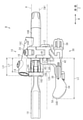
図3に示されるとおり、クランプ部12は、第1中心軸心CW1の延びる方向と直交する方向から見て、シリンダハウジング16Bの少なくとも一部と重複する。好ましくは、クランプ部12は、第1中心軸心CW1の延びる方向と直交する方向において、第1中心軸心CW1の延びる方向の一端から他端にかけてシリンダハウジング16Bと重複する。回転軸18Aは、第1中心軸心CW1の延びる方向と直交する方向から見て、クランプ部12に対してオフセットする。第1中心軸心CW1の延びる方向と直交する方向から見たとき、クランプ部12のハンドル支持面16E側の端部から、ハンドル支持面16Eのクランプ部12とは反対側の端部までの距離LXは、20mm以上、30mm以下であることが好ましい。より好ましくは、距離LXは、22mm以上、27mm以下であることが好ましい。なお、本実施例では、距離LXは、25mmに設定されている。
As shown in FIG. 3, the
図4および図5に示されるとおり、クランプ部12は、第1クランプ部20、第1クランプ部20と別体の第2クランプ部22、および、取付部材24を有する。第1クランプ部20および第2クランプ部22は、それぞれ本体部16とは別体に形成される。
As shown in FIGS. 4 and 5, the
第1クランプ部20は、円弧形状に形成される。第1クランプ部20は、第1端部20Aおよび第2端部20Bを有する。第1端部20Aは、本体部16に第1ピン26を介して取り付けられている。第1クランプ部20は、第1ピン26によって本体部16に対して揺動可能に本体部16に取り付けられる。第1クランプ部20の中間部分には、周方向に延びる第1孔20Cが形成されている。第1孔20Cは、矩形状の長孔である。
The
第2クランプ部22は、円弧形状に形成される。第2クランプ部22の円弧形状の曲率は、第1クランプ部20よりも曲率が小さい。本明細書においては、平面の曲率を0と定義する。第2クランプ部22は、第1端部22Aおよび第2端部22Bを有する。第1端部22Aは、第1クランプ部20の第2端部20Bに第2ピン28を介して取り付けられている。第2クランプ部22は、第2ピン28によって第1クランプ部20に対して揺動可能に第1クランプ部20に取り付けられる。第2クランプ部22の中間部分には、周方向に延びる第2孔22Cが形成されている。第2孔22Cは、軽量化のために形成された長穴である。第2クランプ部22の第2端部22Bには、第2クランプ部22を本体部16に取り付けるための第3孔22Dが形成されている。
The
取付部材24は、第3孔22Dに挿入される。取付部材24の端部は、取付部16Aと連結される。一例では、取付部材24は、ボルトであり、取付部16Aは、ボルトがねじ込まれる雌ねじを有する。第2クランプ部22の第2端部22Bが取付部材24のボルトヘッド24Aと取付部16Aとの間に挟み込まれることによって、第2クランプ部22が取付部16Aに取り付けられる。これにより、クランプ部12を、ハンドルバーHに取り付けることができる。
The mounting
図1および図2に示されるとおり、自転車用操作装置30は、締結具70を介してクランプ部12に取り付けられる。自転車用操作装置30は、クランプ部12のうちのブレーキ操作装置14とは異なる部分に取り付けられる。締結具70は、中心軸心CAを有する。以下では、中心軸心CAに平行な方向を中心軸心方向Zとする。締結具70の中心軸心CAは、締結具70の第3中心軸心と対応する。
As shown in FIGS. 1 and 2, the
図6に示されるとおり、自転車用操作装置30は、ベース部32と、操作部34と、を備える。自転車用操作装置30は、巻取部36をさらに備える。自転車用操作装置30は、調整部38をさらに備える。
As shown in FIG. 6, the
図1および図2に示されるとおり、ベース部32は、クランプ部12に取り付け可能に構成される。ベース部32は、クランプ部12に取り付けるための取付部40を含む。ベース部32は、操作部34が連結される本体42、および、本体42と取付部40とを接続する中継部44をさらに備える。取付部40は、クランプ部12に直接取り付けられるように構成される。
As shown in FIGS. 1 and 2, the
図6に示されるとおり、取付部40は、長穴46を備える。取付部40は、長手方向を有する。長穴46の長手方向Wは、取付部40の長手方向に沿って延びる。本実施形態では、長穴46は、長穴46の長手方向Wが取付部40の長手方向と一致するように形成される。取付部40は、クランプ部12側の第1面40A、第1面40Aとは反対側の第2面40B(図12参照)、および、第1面40Aおよび第2面40Bを貫通する少なくとも1つの取付穴48を含む。図6に示す自転車用操作装置30の取付部40は、1つの取付穴48を含む。取付穴48は、クランプ部12の第1中心軸心CW1方向に取付部40の取付位置を調整可能である。より詳細には、取付部40は、クランプ部12に対して第1中心軸心CW1方向に取付穴48の取付位置を調整することが可能である。これにより、第1中心軸心CW1方向において、取付部40がクランプ部12に取り付いた取付状態におけるクランプ部12と取付部40の相対位置を調整することができる。第1面40Aには、凹部50が設けられる。取付穴48は、凹部50の底面50Aを貫通する。長穴46は、凹部50の底面50Aに開口する。つまり、長穴46は、底面50Aを貫通する。
As shown in FIG. 6, the mounting
図9に示されるとおり、長穴46は、第1壁部46A、第2壁部46B、第3壁部46C、および、第4壁部46Dを備える。第1壁部46Aは、締結具70の中心軸心方向Zから見て長手方向Wに平行に延びる。第1壁部46Aは、締結具70の中心軸心方向Zから見て直線状に延びる。締結具70の中心軸心方向Zは、締結具70によって自転車用操作装置30をクランプ部12に取り付ける場合の、締結具70の挿入方向と対応する。第2壁部46Bは、第1壁部46Aと対向する。第2壁部46Bは、締結具70の中心軸心方向Zから見て長手方向Wに平行に延びる。第2壁部46Bは、締結具70の中心軸心方向Zから見て直線状に延びる。第3壁部46Cは、第1壁部46Aの一方の端部と第2壁部46Bの一方の端部とを接続する。第3壁部46Cは、第1壁部46Aの一方の端部から第2壁部46Bの一方の端部に向かって湾曲する。第4壁部46Dは、第1壁部46Aの他方の端部と第2壁部46Bの他方の端部とを接続する。第4壁部46Dは、第1壁部46Aの他方の端部から第2壁部46Bの他方の端部に向かって湾曲する。長穴46は、巻取部36の巻取軸心C2に近い第1端部46Eと、長手方向Wにおいて第1端部46Eと反対側の第2端部46Fとを含む。第3壁部46Cは第1端部46Eを含む。第4壁部46Dは第2端部46Fを含む。
As shown in FIG. 9, the
図11に示されるとおり、第1面40Aは、曲面である。第1面40Aは、取付部40がクランプ部12に取り付けられた状態において、自転車Bの後方を向くように配置される。第2面40Bは、平面である。第2面40Bは、取付部40がクランプ部12に取り付けられた状態において、自転車Bの前方を向くように配置される。第2面40Bの曲率は、第1面40Aの曲率よりも小さい。第2面40Bは、第1面40Aとは反対側の面である。取付穴48は、凹部50および長穴46を含む。凹部50の底面50Aは、第2面40Bと平行な平面である。第1面40Aは円弧状に形成される。第1面40Aの曲率は、クランプ部12の第1クランプ部20の外面12Bの曲率に対応する。すなわち、第1面40Aは、クランプ部12の第1クランプ部20の外面12Bに少なくとも部分的に面接触できるように形成されている。
As shown in FIG. 11, the
図7および図8に示されるとおり、本体42は、機械式制御ケーブルSを案内する案内部52および操作部34が取り付けられる支持部54を有する。案内部52は、機械式制御ケーブルSの外周を覆うアウタケーブルSAの端部が嵌め込まれる凹部48Aと、アウタケーブルSAから露出した機械式制御ケーブルSを操作部34に案内する孔48Bとを有する。支持部54は、円盤形状に形成される。支持部54は、案内部52の孔48Bのうちの凹部48Aとは反対側の開口に設けられる。支持部54は、案内部52と別体に形成される。支持部54は、案内部52に対しして移動不能に案内部52に取り付けられる。
As shown in FIGS. 7 and 8, the
図6および図9に示されるとおり、中継部44の長穴46の長手方向Wと平行な方向の長さは、取付部40の長手方向Wと平行な方向の長さよりも短い。中継部44は、取付部40から本体42に向かうにつれて長手方向Wの幅が小さくなるテーパ形状を有する。中継部44は、貫通孔44Aを備える。貫通孔44Aは、取付部40から本体42に向かうにつれて長手方向Wの幅が小さくなるテーパ形状を有する。
As shown in FIGS. 6 and 9, the length of the
中継部44は、取付部40と、本体42とを接続する。具体的には、本体42における案内部52と支持部54との接続部分と、取付部40とを接続する。中継部44は、長手方向Wと平行な方向における中心に、長手方向Wと直交する中心線CX1を含む。また、取付部40は、長手方向Wと平行な方向における中心に、長手方向Wと直交する中心線CX2を含む。中心線CX1は、中心線CX2に対して、締結具70の中心軸心方向Zから見て操作部34に向かってオフセットしている。中継部44の中心線CX1は、長手方向Wと直交する方向における中継部44の中央を通過する。取付部40の中心線CX2は、長手方向Wと直交する方向における取付部40の中央を通過する。貫通孔44Aは、中心Dを含む。貫通孔44Aの中心Dは、中心軸心方向Zから見て、貫通孔44Aと直交する方向の断面における貫通孔44Aの重心である。中心Dは、中心軸心方向Zから見て、取付部40の長手方向Wと平行な方向における中心線CX2に対して操作部34に向かってオフセットしている。
The
操作部34は、ベース部32に対して機械式制御ケーブルSを移動させるためにベース部32に移動可能に連結される。操作部34は、機械式制御ケーブルSを介して、例えばアジャスタブルシートポストを操作するために設けられる。操作部34を手動で操作することで、機械式制御ケーブルSを移動させ、アジャスタブルシートポストを、シートポストの高さ調整が可能な状態と、シートポストの高さが固定された状態とを切り替える。
The
操作部34は、ベース部32側の基端部56と、基端部56と反対側の遠位端部58とを含む。基端部56は、円盤形状に形成され、ベース部32の支持部54に取り付けられる。基端部56には、後述の巻取軸心C2に関する径方向外側に向かって突出する凸部60が設けられる。
The
図8に示されるとおり、操作部34は、ベース部32に対して初期位置P1および操作位置P2の間で移動可能である。操作部34は、基端部56まわりでベース部32に対して回転する。操作部34の回転中心から遠位端部58までの長さは26mm以上、70mm以下であることが好ましい。初期位置P1から操作位置P2の間における機械式制御ケーブルSのストロークは9mm以上、18mm以下であることが好ましい。より好ましくは、10mm以下であることが好ましい。操作部34には、付勢部材62が設けられる。付勢部材62は、操作部34を初期位置P1に向けて付勢する。付勢部材62は、ベース部32と操作部34との間に設けられる。一例では、付勢部材62は、つるまきばねを含む。
As shown in FIG. 8, the
自転車用操作装置30は、操作部34をベース部32に対して回転可能に支持する軸受64をさらに備える。軸受64は、操作部34の基端部56と支持部の間に配置される。軸受64は、一例では、すべり軸受である。軸受64は、転動体を有する軸受であってもよい。
The
自転車用操作装置30は、操作部34の初期位置P1および操作位置P2の間の移動において、機械式制御ケーブルSをベース部32に対して機械的に位置決めしない。つまり、自転車用操作装置30は、例えばラチェット機構などの機械的な位置決機構、を有していない。操作部34は、外部から力がかけられていない状態において、付勢部材62の付勢力、および、本体42の第1当接部42Aと基端部56の第2当接部56Aとの当接により、初期位置P1に維持される。操作部34は、外部から力(以下、外力)がかけられた場合、外力に応じて操作位置P2に向かって移動する。操作部34は、外力によって操作位置P2まで移動すると、操作部34の凸部60とベース部32とが接触することによってそれ以上の相対移動が規制されるため、外力により操作位置P2に維持される。このため、ユーザが操作部34を操作していない場合、操作部34は、初期位置P1に維持される。ユーザが操作部34を操作して、操作部34を操作位置P2または初期位置P1と操作位置P2の間の位置に移動させた後、ユーザが操作部34から手を離すと、操作部34は付勢部材62によって初期位置P1に戻される。
The
巻取部36は、機械式制御ケーブルSを巻取軸心C2まわりに巻き取る。巻取部36は、操作部34の操作に応じて機械式制御ケーブルSを巻取軸心C2まわりに巻き取る。巻取部36は、機械式制御ケーブルSが巻き取られる溝36Aを有する。巻取部36は、操作部34と一体に形成されるが、別体に形成されていてもよい。巻取部36は、操作部34の基端部56の外周部に設けられる。巻取軸心C2は、締結具70の中心軸心方向Zから見て取付部40の長穴46に対してオフセットされている。つまり、巻取軸心C2は、中心軸心方向Zから見て、長穴46と重ならないように配置される。巻取軸心C2は、締結具70の中心軸心方向Zから見て長穴46の第1端部46Eと操作部34の基端部56との間に配置される。巻取部36は、締結具70の中心軸心方向Zから見て全体が長穴46の第1壁部46Aおよび第2壁部46Bに対してオフセットしている。つまり、巻取部36は、中心軸心方向Zから見て、第1壁部46Aおよび第2壁部46Bと重ならないように配置される。
The take-up
図7に示されるとおり、自転車用操作装置30は、機械式制御ケーブルSを操作部34に固定するケーブル固定ボルト66をさらに備える。図10に示されるとおり、操作部34は、ケーブル固定ボルト66がねじ込まれる雌ねじ部60A、および、雌ねじ部60Aの開口部の周辺に形成され、機械式制御ケーブルSが配置されるケーブル配置溝60Bをさらに備える。ケーブル配置溝60Bは、雌ねじ部60Aの開口部に沿って屈曲する屈曲部60Cを含む。
As shown in FIG. 7, the
調整部38は、機械式制御ケーブルSの張力を調整する。調整部38は、案内部52に設けられる。機械式制御ケーブルSの端部がケーブル固定ボルト66によって固定されている状態において、調整部38を操作することによって、機械式制御ケーブルSの張力を調整することができる。
The adjusting
図11~図13を参照して、取付部40がクランプ部12に取り付けられた状態における各部の関係について説明する。
図11および図12に示されるとおり、取付穴48は、取付穴48の中心を通り、かつクランプ部12の第1中心軸心CW1に平行な第2中心軸心CW2を定義する。長穴46の長手方向Wは、取付部40がクランプ部12に取り付けられた状態においてクランプ部12の第1中心軸心CW1に沿う。第2面40Bは、巻取軸心C2と平行な方向に延びる平面である。第2面40Bは、巻取軸心とC2と交差する方向において第1面40Aとは反対側の面である。少なくとも1つの取付穴48は、取付部40を巻取軸心C2と交差する方向に貫通する。
With reference to FIGS. 11 to 13, the relationship between the mounting
As shown in FIGS. 11 and 12, the mounting
図12に示されるとおり、第1面40Aは、少なくとも1つの取付穴48に挿入される締結具70を介してクランプ部12に取り付けられるように構成される。取付穴48には、ナット80が挿入される。ナット80は、柱部82とフランジ部84とを含む。柱部82は、少なくとも一部が平面状の外周面を有する。フランジ部84は、クランプ部12の内面12Aと接触する当接面84Aを含む。当接面84Aの曲率は、クランプ部12の内面12Aの曲率と対応する。ナット80は、クランプ部12の第1孔20Cと取付穴48とが対応した状態において、第1孔20Cと取付穴48に挿入される。柱部82のフランジ部84とは反対側の端部は、ナット80が取付穴48に挿入された状態において、取付穴48から突出する。締結具70は、ナット80の雌ねじ部80Aに第2面40B側からねじ込まれる。自転車用操作装置30の取付部40は、クランプ部12とともにナット80のフランジ部84と締結具70のヘッド部とに挟み込まれることによってクランプ部12に取り付けられる。
As shown in FIG. 12, the
第1孔20Cは、周方向において延びる長穴形状を有するため、第1孔20Cにおけるナット80および締結具70の位置を移動させることによって、クランプ部12の周方向における自転車用操作装置30の取り付け位置を調整できる。自転車用操作装置30の取付穴48および長穴46に対して、長手方向Wにおけるナット80および締結具70の位置を移動させることによって、ハンドルバーHの延びる方向における自転車用操作装置30の位置を調整できる。
Since the
図13に示されるとおり、操作部34は、取付部40がクランプ部12に取り付けられた状態において、ハンドルバーHに最も近い第1部分34Aを備える。第1部分34Aは、操作部34の遠位端部58付近または遠位端部58に含まれる。締結具70および長穴46は、基準面Aを定義する。基準面Aは、締結具70の中心軸心CAと、長穴46の短手方向の中心を通り、かつ、長手方向Wに延びる直線と、を含む。また、基準面Aは、締結具70の中心軸心CAと、取付穴48の第2中心軸心CW2と、を含む。第1部分34Aから、基準面Aまでの第1距離LAは、6mm以上である。好ましくは、第1距離LAは、10mm以上である。より好ましくは、第1距離LAは、13mm以内である。基準面Aから、巻取部36の機械式制御ケーブルSが巻き取られる溝36A(図9参照)の巻取軸心方向における中央CBまでの第2距離LBは、14.2mm以上である。好ましくは、第2距離LBは、22mm以内である。なお、図13に示す自転車用操作装置30は、巻取軸心C2が基準面Aと直交しているが、巻取軸心C2が基準面Aに対して90度未満で傾斜していてもよい。
As shown in FIG. 13, the
図3に示されるとおり、操作部34は、締結具70の中心軸心方向Zから見て長手方向Wにおいてクランプ部12から最も遠い最遠位端34Bを含む。締結具70が長穴46のうちの操作部34から最も遠い部分に配置されている状態において、締結具70の中心軸心方向Zから見て長手方向Wにおいてクランプ部12のうちの操作部34側の端部から、最遠位端34Bまでの第3距離LCは、50mm以上、70mm以下であることが好ましい。より好ましくは、第3距離LCは、55mm以上、65mm以下であることが好ましい。本実施形態では、第3距離LCは、60.6mmに設定されている。
As shown in FIG. 3, the operating
自転車用操作装置30の作用について説明する。
初期位置P1と操作位置P2との間に機械的な位置決めを有しない自転車用操作装置30は、位置決めを有する自転車用操作装置と比較して操作部34の移動範囲が小さいため、操作部34の長さを短くできる。一方、ユーザの手の大きさまたは自転車Bの形状等によって、操作部34の適切な位置は異なる。自転車用操作装置30は、長穴46の長手方向Wにおいて自転車用操作装置30の取り付け位置を操作部34の操作位置になるように調整できる。また、長穴46の長手方向Wにおいて操作部34の操作位置と、ブレーキレバー18の操作位置との相対的な位置も所望の位置に調整できる。
The operation of the
The
(第2実施形態)
図14~図17を参照して、第2実施形態の自転車用アセンブリ90について説明する。自転車用アセンブリ90は、クランプ部12に取り付けるための取付部の形状がクランプ部12の外面12Bの形状と対応しない自転車用操作装置を、クランプ部12に取り付けるようにするためのものである。図14~図17では、自転車用操作装置の一例として、自転車用変速機を操作する自転車用変速操作装置としての自転車用操作装置100を用いているが、自転車用アセンブリ90によってクランプ部12に取り付けられる自転車用操作装置は自転車用変速操作装置に限定されない。自転車用アセンブリ90によってクランプ部12に取り付けられる自転車用操作装置はサスペンションコントローラーやアジャスタブルシートポストの操作装置などであってもよい。
(Second Embodiment)
The
自転車用操作装置100は、クランプ部12に取り付けるためのベース部102と、操作部104と、を備える。ベース部102は、クランプ部12に取り付け可能に構成される。ベース部102は、クランプ部12に取り付けるための取付部106を含む。
The
図15に示されるとおり、取付部106は、長穴108を備える。取付部106は、長手方向を有する。長穴108の長手方向は、取付部106の長手方向に沿って延びる。本実施形態では、長穴108は、長穴108の長手方向が取付部106の長手方向と一致するように形成される。取付部106は、クランプ部12側の第1面106A、第1面106Aとは反対側の第2面106B、および、第1面106Aおよび第2面106Bを貫通する少なくとも1つの取付穴110を含む。取付穴110は、クランプ部12の第1中心軸心CW1方向に取付部106の取付位置を調整可能である。第1面106Aには、凹部112が設けられる。取付穴110は、凹部112の底面112Aを貫通する。長穴108は、凹部112の底面112Aに開口する。つまり、長穴108は、底面112Aを貫通する。取付穴110は、凹部112および長穴108を含む。凹部112の底面112Aは、第2面106Bと平行な平面である。第1面106Aは円弧状に形成される。
As shown in FIG. 15, the mounting
自転車用アセンブリ90は、自転車用操作装置100をハンドルバーHに取り付けられるクランプ部12に取り付けるための自転車用アダプタ92と、ナット80と、を備える。自転車用アセンブリ90は、さらに締結具70を備えても良い。締結具70は、アダプタ92を介して自転車用操作装置100をクランプ部12に取り付けるために、ナット80に締結される。自転車用アダプタ92は、クランプ部12の外面12Bに取り付けられるように構成される第1取付面92Aと、自転車用操作装置100に取り付けられるように構成される第2取付面92Bと、を備える。
The
図16および図17に示される第1取付面92Aは、第1曲率を有する。第2取付面92Bは、第1曲率と異なる第2曲率を有する。本実施形態では、第2曲率は、第1曲率よりも小さいが、第2曲率が第1曲率よりも大きくなるように構成してもよい。取付部106の第1面106Aの曲率は、第2曲率と対応する。自転車用アダプタ92は、第1取付面92Aおよび第2取付面92Bに開口し、クランプ部12に取り付けるためのナット80が挿入される挿入孔92Cをさらに備える。挿入孔92Cは、少なくとも一部が平面状の内周面を有する。挿入孔92Cの内周面の形状は、ナット80の柱部82の外周面の形状と対応する。第1取付面92Aには、第2取付面92B側と反対方向に突出する凸部92Dが設けられる。凸部92Dは、第1取付面92Aの長手方向Wの両端部に設けられる。図14に示されるとおり、凸部92Dは、自転車用アダプタ92がクランプ部12に取り付けられた状態において、クランプ部12の第1中心軸心CW1方向の両端面と当接する。これにより、第1中心軸心CW1方向において自転車用アダプタ92をクランプ部12に対して位置決めすることができる。
The
図15に示されるとおり、ナット80は、柱部82とフランジ部84とを含む。柱部82は、少なくとも一部が平面状の外周面を有する。フランジ部84は、クランプ部12の内面12Aと接触する当接面84Aを含む。当接面84Aは、第1曲率よりも大きい第3曲率を有する。図17に示されるとおり柱部82は、ナット80が挿入孔92Cに挿入された状態において、挿入孔92Cから突出する。締結具70は、ナット80の雌ねじ部80Aに第2面40B側からねじ込まれる。自転車用操作装置100の取付部40は、クランプ部12および自転車用アダプタ92とともにナット80のフランジ部84と締結具70のヘッド部とに挟み込まれることによってクランプ部12に取り付けられる。
As shown in FIG. 15, the
(変形例)
上記実施形態に関する説明は、本発明に従う自転車用操作装置、自転車用アダプタ、および、自転車用アセンブリが取り得る形態の例示であり、その形態を制限することを意図していない。本発明に従う自転車用操作装置、自転車用アダプタ、および、自転車用アセンブリは、例えば以下に示される上記各実施形態の変形例、および、相互に矛盾しない少なくとも2つの変形例が組み合わせられた形態を取り得る。以下の変形例において、各実施形態の形態と共通する部分については、各実施形態と同一の符号を付してその説明を省略する。
(Modification example)
The description of the above embodiments is an example of possible embodiments of the bicycle operating device, the bicycle adapter, and the bicycle assembly according to the present invention, and is not intended to limit the embodiments. The bicycle operating device, the bicycle adapter, and the bicycle assembly according to the present invention take, for example, a modification of each of the above embodiments shown below and a combination of at least two modifications that do not contradict each other. obtain. In the following modification, the parts common to the embodiments of each embodiment are designated by the same reference numerals as those of the embodiments, and the description thereof will be omitted.
・中継部44は、貫通孔44Aに代えてまたは加えて凹部を備えてもよい。
・中継部44は、中心軸心方向Zから見て、矩形状に形成されてもよい。この場合、貫通孔44Aも中継部44の形状と相似する矩形状に形成されることが好ましい。
The
The
・取付穴48,110の形状は、長穴に限らず、長手方向を有しない穴に変更することもできる。その場合、取付穴48,110を、長手方向Wに複数設けてもよい。この場合、締結具70を挿入する取付穴48,110を複数の取付穴48,110のうちの1つから選択することによって、自転車用操作装置30,100の取り付け位置を変更することができる。
-The shapes of the mounting
・自転車用操作装置30,100は、機械式制御ケーブルSで自転車用コンポーネントを操作する操作装置に限定されず、電気式の操作装置(電気スイッチ)に変更することもできる。電気式の操作装置は、電気ケーブルで操作対称の自転車用コンポーネントと接続することができる。また、電気ケーブルでの接続に変えて、無線通信で操作装置と自転車用コンポーネント間の信号の送受信を行うこともできる。
The
B…自転車、H…ハンドルバー、S…機械式制御ケーブル、30…自転車用操作装置、32…ベース部、34…操作部、34A…第1部分、36…巻取部、36A…溝、38…調整部、40…取付部、40A…第1面、40B…第2面、42…本体、44…中継部、44A…貫通孔、46…長穴、46A…第1壁部、46B…第2壁部、46C…第3壁部、46D…第4壁部、48…取付穴、50…凹部、60A…雌ねじ部、60B…ケーブル配置溝、60C…屈曲部、64…軸受、66…ケーブル固定ボルト、70…締結具、80…ナット、82…柱部、84…フランジ部、84A…当接面、90…自転車用アセンブリ、92…自転車用アダプタ、92A…第1取付面、92B…第2取付面、92C…挿入孔、92D…凸部。 B ... Bicycle, H ... Handlebar, S ... Mechanical control cable, 30 ... Bicycle operating device, 32 ... Base part, 34 ... Operation part, 34A ... First part, 36 ... Winding part, 36A ... Groove, 38 ... Adjustment part, 40 ... Mounting part, 40A ... First surface, 40B ... Second surface, 42 ... Main body, 44 ... Relay part, 44A ... Through hole, 46 ... Long hole, 46A ... First wall part, 46B ... First 2 wall part, 46C ... 3rd wall part, 46D ... 4th wall part, 48 ... mounting hole, 50 ... recess, 60A ... female thread part, 60B ... cable placement groove, 60C ... bent part, 64 ... bearing, 66 ... cable Fixing bolt, 70 ... Fastener, 80 ... Nut, 82 ... Pillar part, 84 ... Flange part, 84A ... Contact surface, 90 ... Bicycle assembly, 92 ... Bicycle adapter, 92A ... First mounting surface, 92B ... No. 2 Mounting surface, 92C ... Insertion hole, 92D ... Convex part.
Claims (30)
前記ベース部に対して機械式制御ケーブルを移動させるために前記ベース部に移動可能に連結される操作部と、
前記機械式制御ケーブルを巻取軸心まわりに巻き取る巻取部と、を備え、
前記ベース部は、前記クランプ部に取り付けるための取付部と、前記操作部が連結される本体と、前記本体と前記取付部とを接続する中継部と、を含み、
前記取付部は、前記取付部が前記クランプ部に取り付けられた状態において前記クランプ部の中心軸心に沿う長手方向を有する長穴を備え、かつ、前記長穴に挿入される締結具を介して前記クランプ部に取り付けられるように構成され、
前記中継部は、前記取付部が前記クランプ部に取り付けられた状態において、前記締結具の中心軸心方向から見て、前記クランプ部の中心軸心と前記操作部との間に前記取付部が位置し、かつ、前記クランプ部の中心軸心に沿う方向に前記操作部が前記取付部に対してオフセットされるように、構成され、
前記操作部は、前記ベース部に対して初期位置および操作位置の間で移動可能であり、
前記操作部の前記初期位置および前記操作位置の間の移動において、前記機械式制御ケーブルを前記ベース部に対して機械的に位置決めせず、
前記巻取軸心は、前記締結具の中心軸心方向から見て前記長穴に対して、前記クランプ部の中心軸心に沿う方向において前記操作部の方向にオフセットされている、自転車用操作装置。 A base part that can be attached to the clamp part for attaching to the handlebar of the bicycle, and a base part
An operation unit that is movably connected to the base unit in order to move the mechanical control cable to the base unit, and an operation unit that is movably connected to the base unit.
A winding section for winding the mechanical control cable around the winding shaft center is provided.
The base portion includes a mounting portion for mounting on the clamp portion, a main body to which the operating portion is connected, and a relay portion for connecting the main body and the mounting portion .
The mounting portion is provided with an elongated hole having a longitudinal direction along the central axis of the clamp portion in a state where the mounting portion is attached to the clamp portion, and the mounting portion is provided via a fastener inserted into the elongated hole. It is configured to be attached to the clamp portion and is configured to be attached to the clamp portion.
In the relay portion, when the mounting portion is mounted on the clamp portion, the mounting portion is located between the central axis of the clamp portion and the operating portion when viewed from the central axis direction of the fastener. Positioned and configured such that the operating portion is offset with respect to the mounting portion in a direction along the central axis of the clamp portion.
The operation unit can be moved between the initial position and the operation position with respect to the base unit.
In the movement of the operating unit between the initial position and the operating position, the mechanical control cable is not mechanically positioned with respect to the base unit.
The winding shaft center is offset in the direction of the operation portion in the direction along the center axis of the clamp portion with respect to the slotted hole when viewed from the center axis direction of the fastener. Device.
機械式制御ケーブルを、前記ベース部に対して、巻き取ることで移動させるために前記ベース部に移動可能に連結される操作部と、を備え、
前記ベース部は、前記クランプ部に取り付けるための取付部を含み、
前記取付部は、前記取付部が前記クランプ部に取り付けられた状態において前記クランプ部の中心軸心に沿う長手方向に複数設けられた取付穴を備え、かつ、前記取付穴のうちの1つに挿入される締結具を介して前記クランプ部に取り付けられるように構成され、
前記取付部は、前記クランプ部側の第1面と、前記第1面とは異なる第2面と、を有し、
前記操作部は、前記ベース部に対して初期位置および操作位置の間で移動可能であり、
前記操作部の前記初期位置および前記操作位置の間の移動において、前記機械式制御ケーブルを前記ベース部に対して機械的に位置決めせず、
前記締結具は、前記機械式制御ケーブルを巻き取る巻取軸心とは異なる方向に前記取付穴に挿入され、
前記取付部の前記第2面は、巻取軸心と平行な方向に延びる平面として構成される、自転車用操作装置。 A base part that can be attached to the clamp part for attaching to the handlebar of the bicycle, and a base part
The mechanical control cable is provided with an operation unit that is movably connected to the base portion so as to be moved by winding with respect to the base portion.
The base portion includes a mounting portion for mounting on the clamp portion.
The mounting portion includes a plurality of mounting holes provided in the longitudinal direction along the central axis of the clamp portion in a state where the mounting portion is mounted on the clamp portion, and is provided in one of the mounting holes. It is configured to be attached to the clamp portion via a fastener to be inserted.
The mounting portion has a first surface on the side of the clamp portion and a second surface different from the first surface.
The operation unit can be moved between the initial position and the operation position with respect to the base unit.
In the movement of the operating unit between the initial position and the operating position, the mechanical control cable is not mechanically positioned with respect to the base unit.
The fastener is inserted into the mounting hole in a direction different from the winding shaft center for winding the mechanical control cable.
The second surface of the mounting portion is a bicycle operating device configured as a plane extending in a direction parallel to the winding axis .
前記操作部は、前記ベース部側の基端部と、前記基端部と反対側の遠位端部とを含み、
前記巻取軸心は、前記締結具の中心軸心方向から見て前記第1端部と前記基端部との間に配置される、請求項4に記載の自転車用操作装置。 The slot includes a first end close to the take-up axis and a second end opposite the first end in the longitudinal direction.
The operation portion includes a proximal end portion on the base portion side and a distal end portion on the opposite side to the proximal end portion.
The bicycle operating device according to claim 4, wherein the winding shaft center is arranged between the first end portion and the base end portion when viewed from the central axis direction of the fastener.
前記巻取部は、前記締結具の中心軸心方向から見て全体が前記第1壁部および前記第2壁部に対してオフセットしている、請求項4または5に記載の自転車用操作装置。 The elongated hole is one of a first wall portion extending parallel to the longitudinal direction of the fastener, a second wall portion facing the first wall portion, and one of the first wall portions. A third wall portion connecting the end portion and one end portion of the second wall portion, and a fourth wall portion connecting the other end portion of the first wall portion and the other end portion of the second wall portion. Equipped with a wall
The bicycle operating device according to claim 4 or 5, wherein the winding portion is entirely offset with respect to the first wall portion and the second wall portion when viewed from the central axis direction of the fastener. ..
前記操作部は、前記取付部が前記クランプ部に取り付けられた状態において、前記ハンドルバーに最も近い第1部分を備え、
前記第1部分から前記締結具の中心軸心および前記長穴の短手方向の中心を通る基準面までの第1距離は、6mm以上である、請求項1または3に記載の自転車用操作装置。 The take-up unit winds the mechanical control cable around the take-up axis in response to the operation of the operation unit.
The operating portion comprises a first portion that is closest to the handlebar when the mounting portion is mounted to the clamp portion.
The bicycle operating device according to claim 1 or 3, wherein the first distance from the first portion to the reference plane passing through the central axis of the fastener and the center of the elongated hole in the lateral direction is 6 mm or more. ..
前記ベース部に対して機械式制御ケーブルを移動させるために前記ベース部に移動可能に連結される操作部と、
前記操作部の操作に応じて前記機械式制御ケーブルを巻取軸心まわりに巻き取る巻取部と、を備え、
前記ベース部は、前記クランプ部に取り付けるための取付部と、前記操作部が連結される本体と、前記本体と前記取付部とを接続する中継部と、を含み、
前記取付部は、前記取付部が前記クランプ部に取り付けられた状態において前記クランプ部の中心軸心に沿う長手方向を有する長穴を備え、かつ、前記長穴に挿入される締結具を介して前記クランプ部に取り付けられるように構成され、
前記中継部は、前記取付部が前記クランプ部に取り付けられた状態において、前記締結具の中心軸心方向から見て、前記クランプ部の中心軸心と前記操作部との間に前記取付部が位置し、かつ、前記クランプ部の中心軸心に沿う方向に前記操作部が前記取付部に対してオフセットされるように、構成され、
前記巻取軸心は、前記締結具の中心軸心方向から見て前記長穴に対して、前記クランプ部の中心軸心に沿う方向において前記操作部の方向にオフセットされている、自転車用操作装置。 A base part that can be attached to the clamp part for attaching to the handlebar of the bicycle, and a base part
An operation unit that is movably connected to the base unit in order to move the mechanical control cable to the base unit, and an operation unit that is movably connected to the base unit.
A winding unit for winding the mechanical control cable around the winding shaft center according to the operation of the operating unit is provided.
The base portion includes a mounting portion for mounting on the clamp portion, a main body to which the operating portion is connected, and a relay portion for connecting the main body and the mounting portion .
The mounting portion is provided with an elongated hole having a longitudinal direction along the central axis of the clamp portion in a state where the mounting portion is attached to the clamp portion, and the mounting portion is provided via a fastener inserted into the elongated hole. It is configured to be attached to the clamp portion and is configured to be attached to the clamp portion.
In the relay portion, when the mounting portion is mounted on the clamp portion, the mounting portion is located between the central axis of the clamp portion and the operating portion when viewed from the central axis direction of the fastener. Positioned and configured such that the operating portion is offset with respect to the mounting portion in a direction along the central axis of the clamp portion.
The winding shaft center is offset in the direction of the operation portion in the direction along the center axis of the clamp portion with respect to the slotted hole when viewed from the center axis direction of the fastener. Device.
前記ベース部に対して機械式制御ケーブルを移動させるために前記ベース部に移動可能に連結される操作部と、
前記操作部の操作に応じて前記機械式制御ケーブルを巻取軸心まわりに巻き取る巻取部と、を備え、
前記ベース部は、前記クランプ部に取り付けるための取付部と、前記操作部が連結される本体と、前記本体と前記取付部とを接続する中継部と、を含み、
前記取付部は、前記取付部が前記クランプ部に取り付けられた状態において前記クランプ部の中心軸心に沿う長手方向を有する長穴を備え、かつ、前記長穴に挿入される締結具を介して前記クランプ部に取り付けられるように構成され、
前記中継部は、前記取付部が前記クランプ部に取り付けられた状態において、前記締結具の中心軸心方向から見て、前記クランプ部の中心軸心と前記操作部との間に前記取付部が位置し、かつ、前記クランプ部の中心軸心に沿う方向に前記操作部が前記取付部に対してオフセットされるように、構成され、
前記巻取軸心は、前記締結具の中心軸心方向から見て前記長穴に対して、前記クランプ部の中心軸心に沿う方向において前記操作部の方向に、前記長穴と重ならないように配置される、自転車用操作装置。 A base part that can be attached to the clamp part for attaching to the handlebar of the bicycle, and a base part
An operation unit that is movably connected to the base unit in order to move the mechanical control cable to the base unit, and an operation unit that is movably connected to the base unit.
A winding unit for winding the mechanical control cable around the winding shaft center according to the operation of the operating unit is provided.
The base portion includes a mounting portion for mounting on the clamp portion, a main body to which the operating portion is connected, and a relay portion for connecting the main body and the mounting portion .
The mounting portion is provided with an elongated hole having a longitudinal direction along the central axis of the clamp portion in a state where the mounting portion is attached to the clamp portion, and the mounting portion is provided via a fastener inserted into the elongated hole. It is configured to be attached to the clamp portion and is configured to be attached to the clamp portion.
In the relay portion, when the mounting portion is mounted on the clamp portion, the mounting portion is located between the central axis of the clamp portion and the operating portion when viewed from the central axis direction of the fastener. Positioned and configured such that the operating portion is offset with respect to the mounting portion in a direction along the central axis of the clamp portion.
The take-up axis does not overlap with the slot in the direction of the operation portion in the direction along the center axis of the clamp portion with respect to the slot when viewed from the direction of the center axis of the fastener. A bicycle control device located in.
前記ベース部に対して機械式制御ケーブルを移動させるように前記ベース部に移動可能に連結される操作部と、
前記機械式制御ケーブルを巻取軸心まわりに巻き取る巻取部と、を備え、
前記ベース部は、前記クランプ部に取り付けるための取付部と、前記操作部が連結される本体と、前記本体と前記取付部とを接続する中継部と、を含み、
前記取付部は、前記クランプ部の第1中心軸心方向に前記取付部の取付位置を調整可能な少なくとも1つの取付穴を備え、かつ、前記少なくとも1つの取付穴に挿入される締結具を介して前記クランプ部に取り付けられるように構成され、前記取付穴は、前記取付穴の中心を通り、かつ前記クランプ部の第1中心軸心に平行な第2中心軸心を定義し、
前記中継部は、前記取付部が前記クランプ部に取り付けられた状態において、前記締結具の中心軸心方向から見て、前記クランプ部の中心軸心と前記操作部との間に前記取付部が位置し、かつ、前記クランプ部の中心軸心に沿う方向に前記操作部が前記取付部に対してオフセットされるように、構成され、
前記操作部は、前記取付部が前記クランプ部に取り付けられた状態において、前記ハンドルバーに最も近い第1部分を備え、
前記第1部分から前記締結具の第3中心軸心および前記取付穴の前記第2中心軸心を通る基準面までの第1距離は、6mm以上であり、
前記巻取軸心は、前記締結具の中心軸心方向から見て前記取付穴に対して、前記クランプ部の中心軸心に沿う方向において前記操作部の方向にオフセットされている、自転車用操作装置。 A base part that can be attached to the clamp part for attaching to the handlebar of the bicycle, and a base part
An operation unit that is movably connected to the base portion so as to move the mechanical control cable to the base portion.
A winding section for winding the mechanical control cable around the winding shaft center is provided.
The base portion includes a mounting portion for mounting on the clamp portion, a main body to which the operating portion is connected, and a relay portion for connecting the main body and the mounting portion .
The mounting portion includes at least one mounting hole whose mounting position of the mounting portion can be adjusted in the direction of the first central axis of the clamp portion, and via a fastener inserted into the at least one mounting hole. The mounting hole is configured to be mounted on the clamp portion, and the mounting hole defines a second central axis that passes through the center of the mounting hole and is parallel to the first central axis of the clamp portion.
In the relay portion, when the mounting portion is mounted on the clamp portion, the mounting portion is located between the central axis of the clamp portion and the operating portion when viewed from the central axis direction of the fastener. Positioned and configured such that the operating portion is offset with respect to the mounting portion in a direction along the central axis of the clamp portion.
The operating portion comprises a first portion that is closest to the handlebar when the mounting portion is mounted to the clamp portion.
The first distance from the first portion to the reference surface passing through the third central axis of the fastener and the second central axis of the mounting hole is 6 mm or more.
The winding shaft center is offset in the direction of the operation portion in the direction along the center axis of the clamp portion with respect to the mounting hole when viewed from the center axis direction of the fastener. Device.
前記第1面は、曲面である、請求項18に記載の自転車用操作装置。 The mounting portion includes a first surface on the side of the clamp portion and a second surface on the side opposite to the first surface in a direction intersecting the winding axis.
The bicycle operating device according to claim 18 , wherein the first surface is a curved surface.
前記取付穴は、前記凹部の底面を貫通する、請求項19または20に記載の自転車用操作装置。 A recess is provided on the first surface.
The bicycle operating device according to claim 19 or 20 , wherein the mounting hole penetrates the bottom surface of the recess.
前記ベース部に対して機械式制御ケーブルを移動させるように前記ベース部に移動可能に連結される操作部と、
前記機械式制御ケーブルを巻取軸心まわりに巻き取る巻取部と、を備え、
前記ベース部は、前記クランプ部に取り付けるための取付部と、前記操作部が連結される本体と、前記本体と前記取付部とを接続する中継部と、を含み、
前記取付部は、前記取付部を前記クランプ部に取り付けるための締結具が挿通される少なくとも1つの取付穴を有し、
前記中継部は、凹部または貫通孔の少なくとも一方を備え、前記取付部が前記クランプ部に取り付けられた状態において、前記締結具の中心軸心方向から見て、前記クランプ部の中心軸心と前記操作部との間に前記取付部が位置し、かつ、前記クランプ部の中心軸心に沿う方向に前記操作部が前記取付部に対してオフセットされるように、構成され、
前記巻取軸心は、前記締結具の中心軸心方向から見て前記取付穴に対して、前記クランプ部の中心軸心に沿う方向において前記操作部の方向にオフセットされている、自転車用操作装置。 A base part that can be attached to the clamp part for attaching to the handlebar of the bicycle, and a base part
An operation unit that is movably connected to the base portion so as to move the mechanical control cable to the base portion.
A winding section for winding the mechanical control cable around the winding shaft center is provided.
The base portion includes a mounting portion for mounting on the clamp portion, a main body to which the operating portion is connected, and a relay portion for connecting the main body and the mounting portion.
The mounting portion has at least one mounting hole through which a fastener for mounting the mounting portion to the clamp portion is inserted.
The relay portion includes at least one of a recess or a through hole, and in a state where the mounting portion is attached to the clamp portion, the central axis of the clamp portion and the central axis when viewed from the central axis direction of the fastener. The mounting portion is positioned between the operating portion and the operating portion, and the operating portion is configured to be offset with respect to the mounting portion in a direction along the central axis of the clamp portion.
The winding shaft center is offset in the direction of the operation portion in the direction along the center axis of the clamp portion with respect to the mounting hole when viewed from the center axis direction of the fastener. Device.
前記ケーブル配置溝は、前記雌ねじ部の開口部に沿って屈曲する屈曲部を含む、請求項24に記載の自転車用操作装置。 The operation portion further includes a female screw portion into which the cable fixing bolt is screwed, and a cable placement groove formed around the opening of the female screw portion and in which the mechanical control cable is arranged.
24. The bicycle operating device according to claim 24 , wherein the cable arrangement groove includes a bent portion that bends along an opening of the female screw portion.
前記ベース部に対して機械式制御ケーブルを移動させるために前記ベース部に移動可能に連結される操作部と、
前記機械式制御ケーブルを巻取軸心まわりに巻き取る巻取部と、を備え、
前記ベース部は、前記クランプ部に取り付けるための取付部と、前記操作部が連結される本体と、前記本体と前記取付部とを接続する中継部と、を含み、
前記取付部は、前記クランプ部側の第1面、前記第1面とは反対側の第2面および、前記取付部を前記クランプ部に取り付けるための締結具が挿通される穴であって前記第1面および第2面を貫通する少なくとも1つの取付穴を含み、前記第1面は曲面であり、
前記中継部は、前記取付部が前記クランプ部に取り付けられた状態において、前記締結具の中心軸心方向から見て、前記クランプ部の中心軸心と前記操作部との間に前記取付部が位置し、かつ、前記クランプ部の中心軸心に沿う方向に前記操作部が前記取付部に対してオフセットされるように、構成され、
前記操作部は、前記ベース部に対して初期位置および操作位置の間で移動可能であり、
前記操作部の前記初期位置および前記操作位置の間の移動において、前記機械式制御ケーブルを前記ベース部に対して機械的に位置決めせず、
前記巻取軸心は、前記締結具の中心軸心方向から見て前記取付穴に対して、前記クランプ部の中心軸心に沿う方向において前記操作部の方向にオフセットされている、自転車用操作装置。 A base part that can be attached to the clamp part for attaching to the handlebar of the bicycle, and a base part
An operation unit that is movably connected to the base unit in order to move the mechanical control cable to the base unit, and an operation unit that is movably connected to the base unit.
A winding section for winding the mechanical control cable around the winding shaft center is provided.
The base portion includes a mounting portion for mounting on the clamp portion, a main body to which the operating portion is connected, and a relay portion for connecting the main body and the mounting portion .
The mounting portion is a hole through which a first surface on the clamp portion side, a second surface on the side opposite to the first surface, and a fastener for mounting the mounting portion on the clamp portion are inserted. It comprises at least one mounting hole penetrating the first and second surfaces, said first surface being curved.
In the relay portion, when the mounting portion is mounted on the clamp portion, the mounting portion is located between the central axis of the clamp portion and the operating portion when viewed from the central axis direction of the fastener. Positioned and configured such that the operating portion is offset with respect to the mounting portion in a direction along the central axis of the clamp portion.
The operation unit can be moved between the initial position and the operation position with respect to the base unit.
In the movement of the operating unit between the initial position and the operating position, the mechanical control cable is not mechanically positioned with respect to the base unit.
The winding shaft center is offset in the direction of the operation portion in the direction along the center axis of the clamp portion with respect to the mounting hole when viewed from the center axis direction of the fastener. Device.
前記ベース部に対して機械式制御ケーブルを移動させるために前記ベース部に移動可能に連結される操作部と、を備え、
前記ベース部は、前記クランプ部に取り付けるための取付部を含み、
前記取付部は、前記クランプ部側の第1面、前記第1面とは異なる第2面および、前記第1面および第2面を貫通する少なくとも1つの取付穴を含み、前記第1面は曲面であり、前記第2面は平面で、かつ、前記第2面の前記クランプ部の第1中心軸心に沿う方向と垂直な方向において、前記取付穴方向に見て前記クランプ部よりも前記クランプ部の第1中心軸心とは逆の方向に延び、
前記取付部の前記第2面は、巻取軸心と平行な方向に延びる平面として構成され、
前記操作部は、前記ベース部に対して初期位置および操作位置の間で移動可能であり、
前記操作部の前記初期位置および前記操作位置の間の移動において、前記機械式制御ケーブルを前記ベース部に対して機械的に位置決めせず、
前記操作部は、前記ベース部側の基端部と、前記基端部と反対側の遠位端部とを含み、
前記機械式制御ケーブルは、円盤状に形成される前記基端部に巻き取られることで移動する、自転車用操作装置。 A base part that can be attached to the clamp part for attaching to the handlebar of the bicycle, and a base part
It is provided with an operation unit that is movably connected to the base portion in order to move the mechanical control cable to the base portion.
The base portion includes a mounting portion for mounting on the clamp portion.
The mounting portion includes a first surface on the side of the clamp portion, a second surface different from the first surface, and at least one mounting hole penetrating the first surface and the second surface, and the first surface is The second surface is a curved surface, the second surface is a flat surface, and the clamp portion of the second surface is more than the clamp portion in the direction perpendicular to the direction along the first central axis of the clamp portion in the mounting hole direction. Extends in the direction opposite to the first central axis of the clamp part,
The second surface of the mounting portion is configured as a plane extending in a direction parallel to the take-up axis.
The operation unit can be moved between the initial position and the operation position with respect to the base unit.
In the movement of the operating unit between the initial position and the operating position, the mechanical control cable is not mechanically positioned with respect to the base unit.
The operation portion includes a proximal end portion on the base portion side and a distal end portion on the opposite side to the proximal end portion.
The mechanical control cable is a bicycle operating device that moves by being wound around the base end portion formed in a disk shape .
前記ベース部に対して機械式制御ケーブルを移動させるために前記ベース部に移動可能に連結される操作部と、
前記機械式制御ケーブルを巻取軸心まわりに巻き取る巻取部と、を備え、
前記ベース部は、前記クランプ部に取り付けるための取付部と、前記操作部が連結される本体と、前記本体と前記取付部とを接続する中継部と、を含み、
前記取付部は、前記クランプ部側の第1面、前記第1面とは反対側の第2面および、前記第1面および第2面を貫通する少なくとも1つの取付穴を備え、前記第1面は曲面であり、前記少なくとも1つの取付穴に挿入される締結具を介して前記クランプ部に取り付けられるように構成され、前記取付穴は、前記取付穴の中心を通り、かつ前記クランプ部の第1中心軸心に平行な第2中心軸心を定義し
前記中継部は、前記取付部が前記クランプ部に取り付けられた状態において、前記締結具の中心軸心方向から見て、前記クランプ部の中心軸心と前記操作部との間に前記取付部が位置し、かつ、前記クランプ部の中心軸心に沿う方向に前記操作部が前記取付部に対してオフセットされるように、構成され、
前記操作部は、前記取付部が前記クランプ部に取り付けられた状態において、前記ハンドルバーに最も近い第1部分を備え、
前記第1部分から前記締結具の第3中心軸心および前記取付穴の前記第2中心軸心を通る基準面までの第1距離は、6mm以上であり、
前記巻取軸心は、前記締結具の中心軸心方向から見て前記取付穴に対して、前記クランプ部の中心軸心に沿う方向において前記操作部の方向にオフセットされている、自転車用操作装置。 A base part that can be attached to the clamp part for attaching to the handlebar of the bicycle, and a base part
An operation unit that is movably connected to the base unit in order to move the mechanical control cable to the base unit, and an operation unit that is movably connected to the base unit.
A winding section for winding the mechanical control cable around the winding shaft center is provided.
The base portion includes a mounting portion for mounting on the clamp portion, a main body to which the operating portion is connected, and a relay portion for connecting the main body and the mounting portion .
The mounting portion includes a first surface on the side of the clamp portion, a second surface on the side opposite to the first surface, and at least one mounting hole penetrating the first surface and the second surface. The surface is curved and is configured to be attached to the clamp portion via fasteners inserted into the at least one mounting hole, the mounting hole passing through the center of the mounting hole and of the clamp portion. Define a second central axis parallel to the first central axis
In the relay portion, when the mounting portion is mounted on the clamp portion, the mounting portion is located between the central axis of the clamp portion and the operating portion when viewed from the central axis direction of the fastener. Positioned and configured such that the operating portion is offset with respect to the mounting portion in a direction along the central axis of the clamp portion.
The operating portion comprises a first portion that is closest to the handlebar when the mounting portion is mounted to the clamp portion.
The first distance from the first portion to the reference surface passing through the third central axis of the fastener and the second central axis of the mounting hole is 6 mm or more.
The winding shaft center is offset in the direction of the operation portion in the direction along the center axis of the clamp portion with respect to the mounting hole when viewed from the center axis direction of the fastener. Device.
Priority Applications (7)
| Application Number | Priority Date | Filing Date | Title |
|---|---|---|---|
| JP2017189953A JP7037902B2 (en) | 2017-09-29 | 2017-09-29 | Bicycle control device |
| US16/136,832 US10889348B2 (en) | 2017-09-29 | 2018-09-20 | Bicycle operating device, bicycle adapter, and bicycle assembly |
| TW107133612A TWI741219B (en) | 2017-09-29 | 2018-09-25 | Operating device for bicycle |
| DE102018123527.5A DE102018123527A1 (en) | 2017-09-29 | 2018-09-25 | Bicycle operating device, bicycle adapter and bicycle assembly |
| CN202110231747.8A CN113002680B (en) | 2017-09-29 | 2018-09-26 | Bicycle operating device, bicycle connector and bicycle component |
| CN201811123455.7A CN109572906B (en) | 2017-09-29 | 2018-09-26 | Bicycle operating device, bicycle connector and bicycle component |
| US17/115,112 US20210086864A1 (en) | 2017-09-29 | 2020-12-08 | Bicycle operating device, bicycle adapter, and bicycle assembly |
Applications Claiming Priority (1)
| Application Number | Priority Date | Filing Date | Title |
|---|---|---|---|
| JP2017189953A JP7037902B2 (en) | 2017-09-29 | 2017-09-29 | Bicycle control device |
Publications (3)
| Publication Number | Publication Date |
|---|---|
| JP2019064363A JP2019064363A (en) | 2019-04-25 |
| JP2019064363A5 JP2019064363A5 (en) | 2019-11-28 |
| JP7037902B2 true JP7037902B2 (en) | 2022-03-17 |
Family
ID=65727782
Family Applications (1)
| Application Number | Title | Priority Date | Filing Date |
|---|---|---|---|
| JP2017189953A Active JP7037902B2 (en) | 2017-09-29 | 2017-09-29 | Bicycle control device |
Country Status (5)
| Country | Link |
|---|---|
| US (2) | US10889348B2 (en) |
| JP (1) | JP7037902B2 (en) |
| CN (2) | CN113002680B (en) |
| DE (1) | DE102018123527A1 (en) |
| TW (1) | TWI741219B (en) |
Families Citing this family (5)
| Publication number | Priority date | Publication date | Assignee | Title |
|---|---|---|---|---|
| DE102020103602A1 (en) * | 2020-02-12 | 2021-08-12 | Shimano (Singapore) Pte. Ltd. | ACTUATOR AND ACTUATOR FOR A HUMAN DRIVEN VEHICLE |
| US11577800B2 (en) * | 2020-11-30 | 2023-02-14 | Shimano Inc. | Operating device |
| TWI753682B (en) * | 2020-12-04 | 2022-01-21 | 彥豪金屬工業股份有限公司 | Bicycle control assembly and mount seat thereof |
| US20220226691A1 (en) * | 2021-01-18 | 2022-07-21 | Zhang Zhou Fittek Health Technology Co | Integrated operating device of resistance and brake for exercise bike |
| CN115056912B (en) * | 2022-08-03 | 2023-12-19 | 珠海蓝图运动科技股份有限公司 | Finger dial and acousto-optic controller combined structure and bicycle |
Citations (8)
| Publication number | Priority date | Publication date | Assignee | Title |
|---|---|---|---|---|
| JP2007246074A (en) | 2006-02-16 | 2007-09-27 | Shimano Inc | Bicycle gearshift |
| US20110192249A1 (en) | 2008-12-09 | 2011-08-11 | Shimano Inc. | Bicycle operating device |
| US20110253863A1 (en) | 2010-04-16 | 2011-10-20 | Sram, Llc | Mounting Device for Bicycle Control Components |
| JP2014196060A (en) | 2013-03-29 | 2014-10-16 | 株式会社シマノ | Operation device |
| US20150000452A1 (en) | 2013-06-28 | 2015-01-01 | Shimano Inc. | Bicycle operating device mounting assembly |
| US20150068355A1 (en) | 2013-09-09 | 2015-03-12 | Kind Shock Hi-Tech Co., Ltd. | Shifting structure for a bicycle |
| US20150096399A1 (en) | 2013-10-07 | 2015-04-09 | Shimano Inc. | Bicycle operating device |
| US20170037894A1 (en) | 2015-08-06 | 2017-02-09 | Shimano Inc. | Bicycle operating device |
Family Cites Families (38)
| Publication number | Priority date | Publication date | Assignee | Title |
|---|---|---|---|---|
| JPS5145806Y2 (en) * | 1973-04-19 | 1976-11-06 | ||
| JPS63312291A (en) * | 1987-06-11 | 1988-12-20 | マエダ工業株式会社 | Brake lever device for bicycle |
| JPH01134591U (en) * | 1988-03-10 | 1989-09-13 | ||
| JPH0451113Y2 (en) * | 1988-04-21 | 1992-12-02 | ||
| JP3245188B2 (en) * | 1991-04-19 | 2002-01-07 | 株式会社シマノ | Speed change device for bicycle |
| EP0683092A1 (en) * | 1993-04-01 | 1995-11-22 | Guy V.O. Bulkeley | Motorcycle control lever connector |
| JP2597741Y2 (en) * | 1993-07-21 | 1999-07-12 | 株式会社シマノ | Bicycle brake lever device |
| US5584210A (en) * | 1993-10-26 | 1996-12-17 | Gelbein; Mark | Hand brake lever assembly |
| JPH07180574A (en) * | 1993-12-21 | 1995-07-18 | Kurieeteibu Technol Internatl:Kk | Fuel regulating device for internal combustion engine |
| JP2965878B2 (en) * | 1994-11-25 | 1999-10-18 | 株式会社シマノ | Chain guide positioning mechanism for bicycle front transmission |
| US5881602A (en) * | 1997-03-20 | 1999-03-16 | Cirami; Salvatore | Gearshift for dual derailleur bicycle |
| US6276227B1 (en) * | 1997-07-24 | 2001-08-21 | Shimano, Inc. | Bicycle shift control device |
| US8042427B2 (en) * | 2006-02-16 | 2011-10-25 | Shimano Inc. | Bicycle shifter |
| US8028601B2 (en) * | 2007-02-26 | 2011-10-04 | Shimano Inc. | Bicycle shift operating device |
| JP3141611U (en) * | 2008-02-28 | 2008-05-08 | 振峰 林 | Hand grip |
| CN201300957Y (en) * | 2008-09-25 | 2009-09-02 | 万样国际企业有限公司 | Griping distance and griping sense adjustable handle |
| US8584550B1 (en) * | 2009-05-18 | 2013-11-19 | John L. Calendrille, Jr. | Shift lever arrangement for a bicycle |
| US8375825B2 (en) * | 2009-10-08 | 2013-02-19 | Shimano Inc. | Bicycle operating device |
| US8511200B2 (en) * | 2009-12-09 | 2013-08-20 | Tien Hsin Industries Co., Ltd. | Speed control device for bicycle |
| JP2012140056A (en) * | 2010-12-28 | 2012-07-26 | Hi-Lex Corporation | Vehicle operating system |
| JP5961364B2 (en) * | 2011-11-18 | 2016-08-02 | 株式会社シマノ | Double-bearing reel handle assembly and dual-bearing reel |
| US9550544B2 (en) * | 2012-07-26 | 2017-01-24 | Shimano Inc. | Bicycle handlebar clamp assembly |
| JP2014083903A (en) | 2012-10-22 | 2014-05-12 | Bridgestone Cycle Co | Functional component clamp structure for bicycle |
| US9145183B2 (en) * | 2012-11-16 | 2015-09-29 | Shimano Inc. | Adjustable bicycle electric control device |
| JP3182206U (en) * | 2012-12-26 | 2013-03-14 | 株式会社シマノ | Bicycle control device |
| US9511815B2 (en) * | 2013-06-28 | 2016-12-06 | Shimano Inc. | Bicycle operating device mounting assembly |
| JP2015085855A (en) * | 2013-10-31 | 2015-05-07 | ヤマハ発動機株式会社 | Saddle riding type vehicle |
| US10597109B2 (en) * | 2014-01-28 | 2020-03-24 | Shimano Inc. | Bicycle component positioning device |
| CN203793538U (en) * | 2014-02-21 | 2014-08-27 | 元渝机械(深圳)有限公司 | Drive-by-wire rotary thumbing structure of bicycle |
| US9849932B2 (en) * | 2014-04-29 | 2017-12-26 | Shimano Inc. | Bicycle component operating apparatus |
| US10766561B2 (en) * | 2015-12-02 | 2020-09-08 | Shimano Inc. | Bicycle operating device and bicycle seatpost apparatus |
| JP2017105256A (en) * | 2015-12-07 | 2017-06-15 | 株式会社アルティマ | Tensile force transmission device by cable |
| DE102015224970A1 (en) * | 2015-12-11 | 2017-06-14 | Shimano Inc. | Clamping structure for mounting a rotary actuator to a bicycle and rotary actuator |
| WO2017119328A1 (en) * | 2016-01-06 | 2017-07-13 | 日信工業株式会社 | Hydraulic master cylinder device for handlebar vehicle |
| JP5963340B1 (en) | 2016-04-15 | 2016-08-03 | 邦明 辰己 | Block memo |
| US10562585B2 (en) * | 2017-06-05 | 2020-02-18 | Shimano Inc. | Bicycle operating device |
| US10473143B2 (en) * | 2017-08-27 | 2019-11-12 | Wolf Tooth Components, LLC | Control device |
| US10494053B2 (en) * | 2018-01-21 | 2019-12-03 | Shimano Inc. | Operating device |
-
2017
- 2017-09-29 JP JP2017189953A patent/JP7037902B2/en active Active
-
2018
- 2018-09-20 US US16/136,832 patent/US10889348B2/en active Active
- 2018-09-25 TW TW107133612A patent/TWI741219B/en active
- 2018-09-25 DE DE102018123527.5A patent/DE102018123527A1/en active Pending
- 2018-09-26 CN CN202110231747.8A patent/CN113002680B/en active Active
- 2018-09-26 CN CN201811123455.7A patent/CN109572906B/en active Active
-
2020
- 2020-12-08 US US17/115,112 patent/US20210086864A1/en active Pending
Patent Citations (8)
| Publication number | Priority date | Publication date | Assignee | Title |
|---|---|---|---|---|
| JP2007246074A (en) | 2006-02-16 | 2007-09-27 | Shimano Inc | Bicycle gearshift |
| US20110192249A1 (en) | 2008-12-09 | 2011-08-11 | Shimano Inc. | Bicycle operating device |
| US20110253863A1 (en) | 2010-04-16 | 2011-10-20 | Sram, Llc | Mounting Device for Bicycle Control Components |
| JP2014196060A (en) | 2013-03-29 | 2014-10-16 | 株式会社シマノ | Operation device |
| US20150000452A1 (en) | 2013-06-28 | 2015-01-01 | Shimano Inc. | Bicycle operating device mounting assembly |
| US20150068355A1 (en) | 2013-09-09 | 2015-03-12 | Kind Shock Hi-Tech Co., Ltd. | Shifting structure for a bicycle |
| US20150096399A1 (en) | 2013-10-07 | 2015-04-09 | Shimano Inc. | Bicycle operating device |
| US20170037894A1 (en) | 2015-08-06 | 2017-02-09 | Shimano Inc. | Bicycle operating device |
Also Published As
| Publication number | Publication date |
|---|---|
| JP2019064363A (en) | 2019-04-25 |
| TW201914887A (en) | 2019-04-16 |
| US20210086864A1 (en) | 2021-03-25 |
| US10889348B2 (en) | 2021-01-12 |
| DE102018123527A1 (en) | 2019-04-04 |
| CN113002680B (en) | 2022-11-15 |
| CN113002680A (en) | 2021-06-22 |
| CN109572906A (en) | 2019-04-05 |
| US20190100273A1 (en) | 2019-04-04 |
| TWI741219B (en) | 2021-10-01 |
| CN109572906B (en) | 2021-03-09 |
Similar Documents
| Publication | Publication Date | Title |
|---|---|---|
| JP7037902B2 (en) | Bicycle control device | |
| US7891268B2 (en) | Telescoping-tilting device of steering column for vehicle | |
| JP5333417B2 (en) | Steering device | |
| US9032834B2 (en) | Steering device | |
| JP3460813B2 (en) | Derailleur cable router and bicycle derailleur | |
| JP2006103674A (en) | Brake control device for bicycle with electric operation member | |
| TWI665125B (en) | Bicycle operating device | |
| US7770488B2 (en) | Tilt-and-telescope steering apparatus | |
| US8157238B2 (en) | Stay for the inside mirror of the vehicle | |
| JP2019064363A5 (en) | ||
| JP3145102U (en) | Wall mounting support | |
| CA2984870C (en) | Remote control lever assembly | |
| US8875595B2 (en) | Operating mechanism for a parking brake | |
| JP4457751B2 (en) | Steering column device | |
| JP3145101U (en) | Wall mounting support with cable capacity | |
| TW201725145A (en) | Bicycle disc brake caliper | |
| KR200387073Y1 (en) | optical fiber fixing device of connector for optical sensor | |
| CN114153044B (en) | Lens dismouting subassembly | |
| TWI833852B (en) | Bicycle operating device | |
| EP2889183B1 (en) | Vehicle rear view mirror assembly | |
| TWI826608B (en) | Bicycle operating device | |
| CA2341141A1 (en) | Cable operated actuator assembly | |
| JP2013177096A (en) | Brake lever | |
| TW202023884A (en) | Bicycle operating device | |
| JPH0128335Y2 (en) |
Legal Events
| Date | Code | Title | Description |
|---|---|---|---|
| A521 | Request for written amendment filed |
Free format text: JAPANESE INTERMEDIATE CODE: A523 Effective date: 20191018 |
|
| A621 | Written request for application examination |
Free format text: JAPANESE INTERMEDIATE CODE: A621 Effective date: 20191018 |
|
| A977 | Report on retrieval |
Free format text: JAPANESE INTERMEDIATE CODE: A971007 Effective date: 20200806 |
|
| A131 | Notification of reasons for refusal |
Free format text: JAPANESE INTERMEDIATE CODE: A131 Effective date: 20200908 |
|
| A521 | Request for written amendment filed |
Free format text: JAPANESE INTERMEDIATE CODE: A523 Effective date: 20201106 |
|
| A131 | Notification of reasons for refusal |
Free format text: JAPANESE INTERMEDIATE CODE: A131 Effective date: 20210224 |
|
| A521 | Request for written amendment filed |
Free format text: JAPANESE INTERMEDIATE CODE: A523 Effective date: 20210416 |
|
| A02 | Decision of refusal |
Free format text: JAPANESE INTERMEDIATE CODE: A02 Effective date: 20210901 |
|
| A521 | Request for written amendment filed |
Free format text: JAPANESE INTERMEDIATE CODE: A523 Effective date: 20211129 |
|
| C60 | Trial request (containing other claim documents, opposition documents) |
Free format text: JAPANESE INTERMEDIATE CODE: C60 Effective date: 20211129 |
|
| A911 | Transfer to examiner for re-examination before appeal (zenchi) |
Free format text: JAPANESE INTERMEDIATE CODE: A911 Effective date: 20211206 |
|
| C21 | Notice of transfer of a case for reconsideration by examiners before appeal proceedings |
Free format text: JAPANESE INTERMEDIATE CODE: C21 Effective date: 20211207 |
|
| TRDD | Decision of grant or rejection written | ||
| A01 | Written decision to grant a patent or to grant a registration (utility model) |
Free format text: JAPANESE INTERMEDIATE CODE: A01 Effective date: 20220215 |
|
| A61 | First payment of annual fees (during grant procedure) |
Free format text: JAPANESE INTERMEDIATE CODE: A61 Effective date: 20220307 |
|
| R150 | Certificate of patent or registration of utility model |
Ref document number: 7037902 Country of ref document: JP Free format text: JAPANESE INTERMEDIATE CODE: R150 |